Terry M. Button, Ph.D. Principals of Magnetic Resonance Image Formation

Terry M. Button, Ph.D. Principals of Magnetic Resonance Image Formation.
Dec 17, 2015
Welcome message from author
This document is posted to help you gain knowledge. Please leave a comment to let me know what you think about it! Share it to your friends and learn new things together.
Transcript
Terry M. Button, Ph.D.
Principals of Magnetic Resonance Image Formation
General Signal Localization
• Region of interest is excited with fL.
• Magnetic field is modified in a planned way using gradients.
• Emitted frequency is now dependent on location.
• Signal vs. time is collected, FT provides signal vs. f which is also signal vs. location!

2D FT
• Initial approach will be descriptive and non-mathematical.
• The second approach will be semi-mathematical.
Overview of 2D FT
• Slice selection
• Phase encoding
• Frequency encoding

Slice selection
• Apply a gradient along z• Excite with RF which covers (Bo- ) to (Bo+ )
Bo+
Bo+
Z
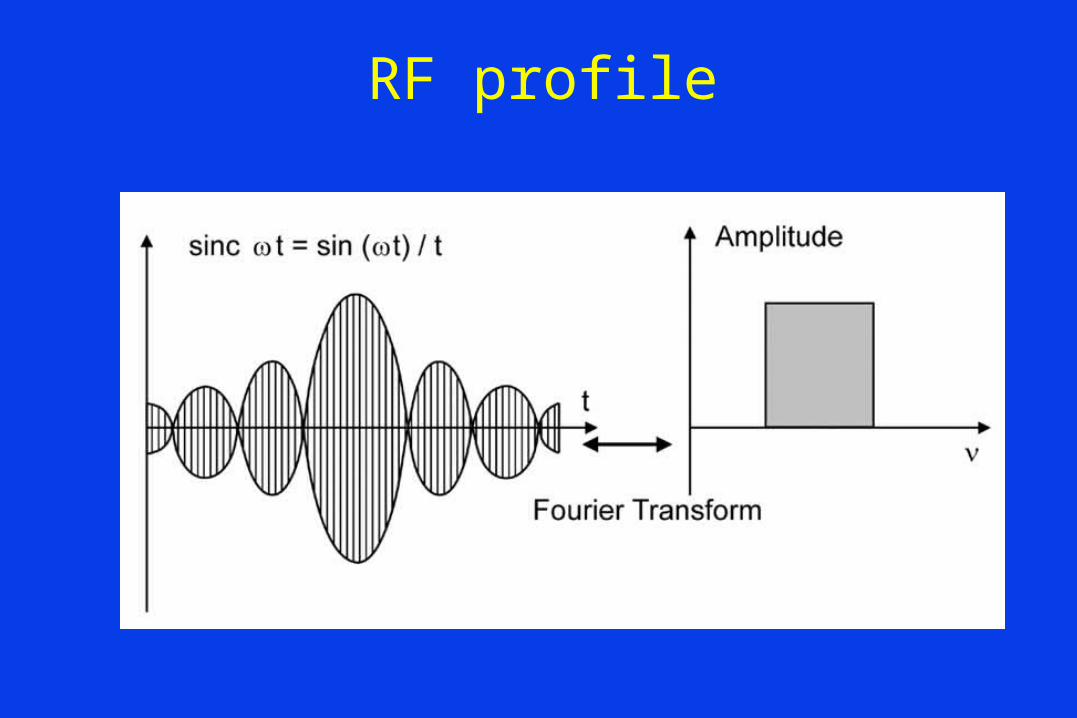
RF profile
I
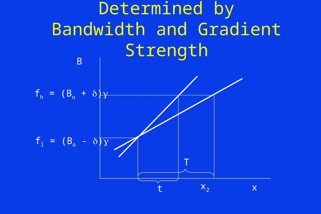
Slice Thickness is Determined by Bandwidth and Gradient Strength
x
B
fl = (Bo - )
fh = (Bo + )
x2t
T

Slice Selection
• Excite bandwidth (kHz) is usually fixed and gradient strength used to change slice thickness.
• Slice orientation is controlled using the gradients; oblique is one gradient tilted by a second gradient.
• Slice position is moved by changing reference frequency.
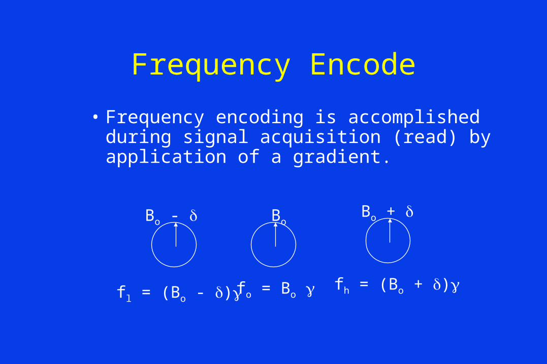
Frequency Encode
• Frequency encoding is accomplished during signal acquisition (read) by application of a gradient.
Bo - BoBo +
fl = (Bo - ) fo = Bo fh = (Bo + )
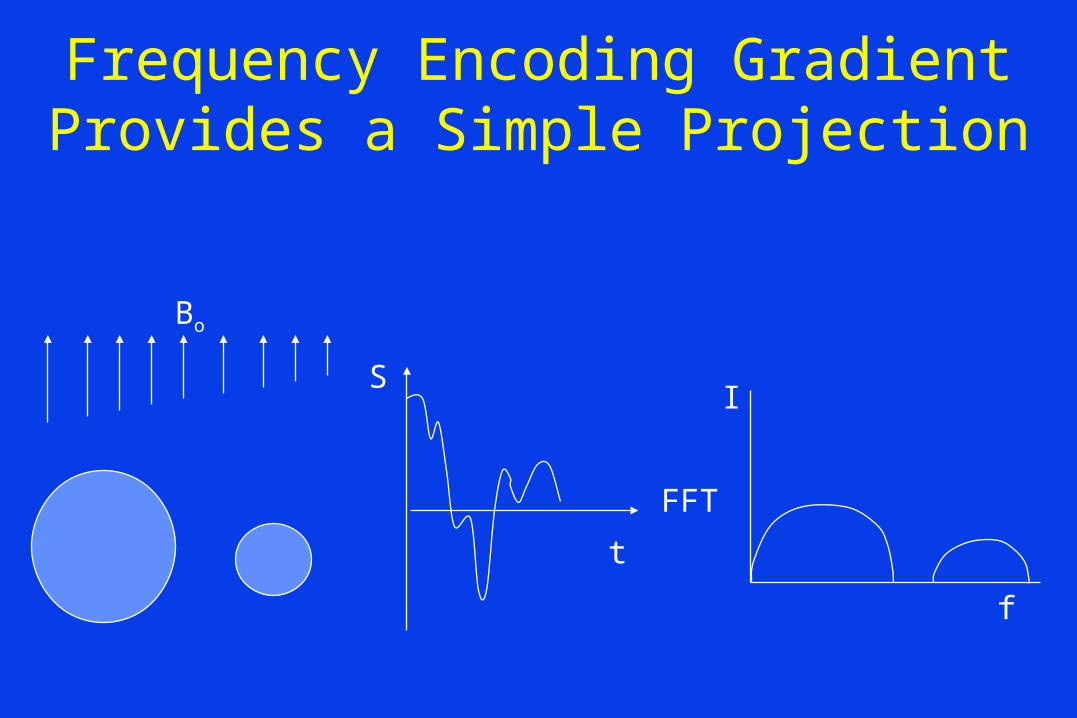
Frequency Encoding Gradient Provides a Simple Projection
Bo
S
t
I
f
FFT
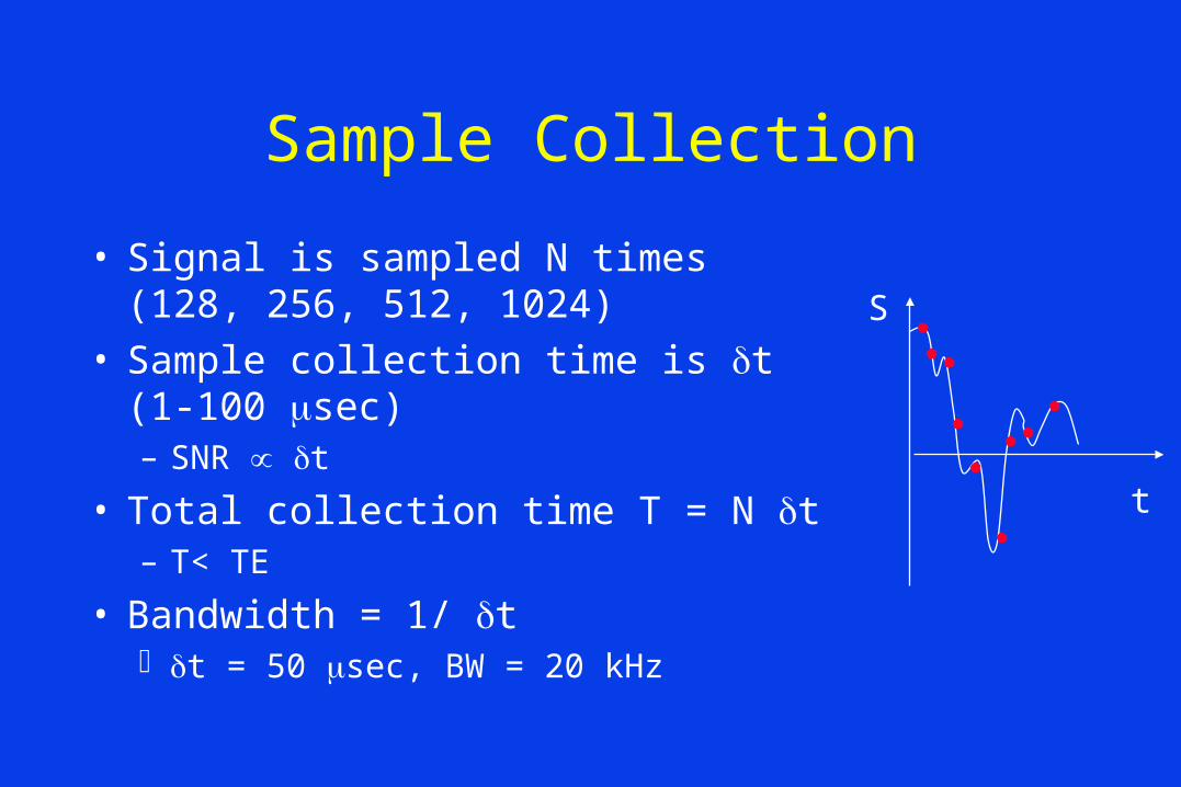
Sample Collection
• Signal is sampled N times (128, 256, 512, 1024)
• Sample collection time is t (1-100 sec)– SNR t
• Total collection time T = N t– T< TE
• Bandwidth = 1/ t t = 50 sec, BW = 20 kHz
S
t
FOV
• Field of view (FOV) is controlled by:– Gradient strength– Bandwidth
• From the last slide; BW = 20 kHz– Nyquist criteria; max freq 10 kHz– If the read gradient is 1mT/m then the FOV is:
42 MHz/T x 0.001T/m = 42 kHz/m
– The FOV is:(10 kHz)/(42 kHz/m) = 24 cm

Phase Encode
• Phase encoding is accomplished by applying a gradient for a time .
Bo - Bo Bo +
t = 0
t =

Slice Image formation
Frequency encode
Phase encode
fn,n
f1,1
Must Satisfy Nyquist Sampling: Phase Encode
• Suppose a 60o phase difference at each voxel:– 60o,120o,180o, 240o, 300o, 360o, 60o
– Phase encode is not unique; must repeat with incremented phase encoding gradient strength.
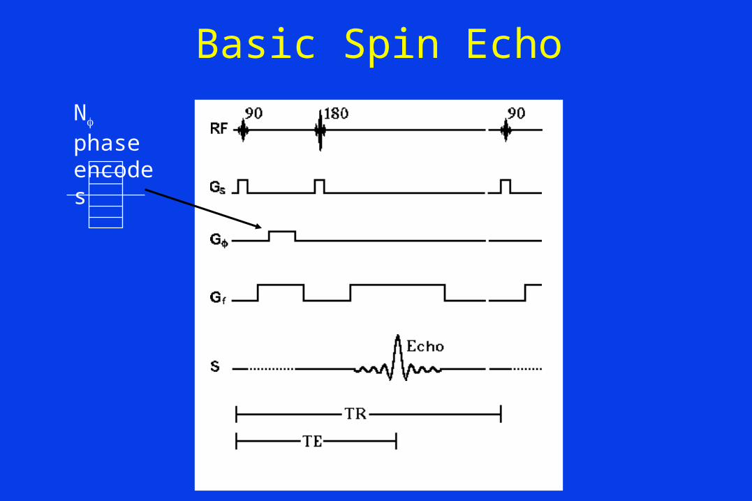
Basic Spin Echo
N phase encodes

Image Acquisition Time
• Suppose TE = 20 msec, TR = 500 msec, N = 256 and only one average is required.
• T = TR x N x Avg
• T = 0.5 sec x 256 x 1 = 128 sec = 2 min 8 sec
• This is the time to make one slice!!
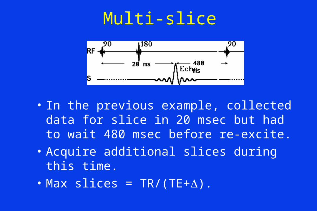
Multi-slice
• In the previous example, collected data for slice in 20 msec but had to wait 480 msec before re-excite.
• Acquire additional slices during this time.
• Max slices = TR/(TE+).
480 ms20 ms
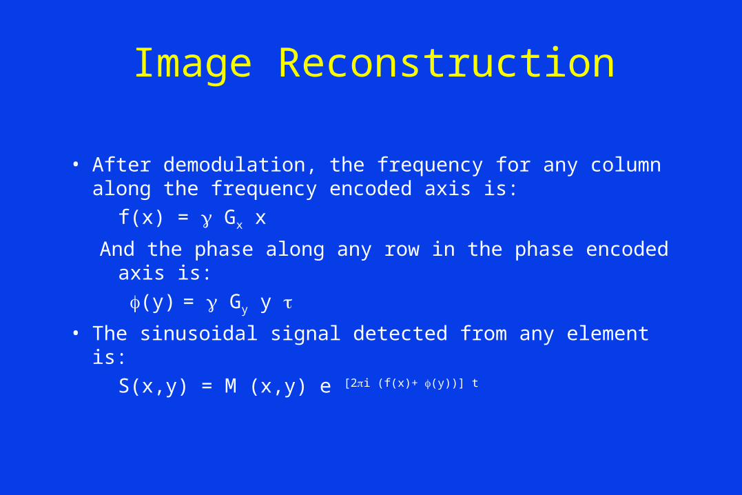
Image Reconstruction
• After demodulation, the frequency for any column along the frequency encoded axis is:
f(x) = Gx x
And the phase along any row in the phase encoded axis is:
(y) = Gy y
• The sinusoidal signal detected from any element is:
S(x,y) = M (x,y) e [2i (f(x)+ (y))] t
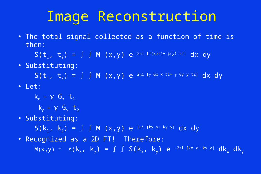
Image Reconstruction• The total signal collected as a function of time is then:
S(t1, t2) = M (x,y) e 2i [f(x)t1+ (y) t2] dx dy
• Substituting:
S(t1, t2) = M (x,y) e 2i [ Gx x t1+ Gy y t2] dx dy
• Let:
kx = Gx t1
ky = Gy t2
• Substituting:
S(k1, k2) = M (x,y) e 2i [kx x+ ky y] dx dy
• Recognized as a 2D FT! Therefore:
M(x,y) = s(kx, ky) = S(kx, ky) e -2i [kx x+ ky y] dkx dky
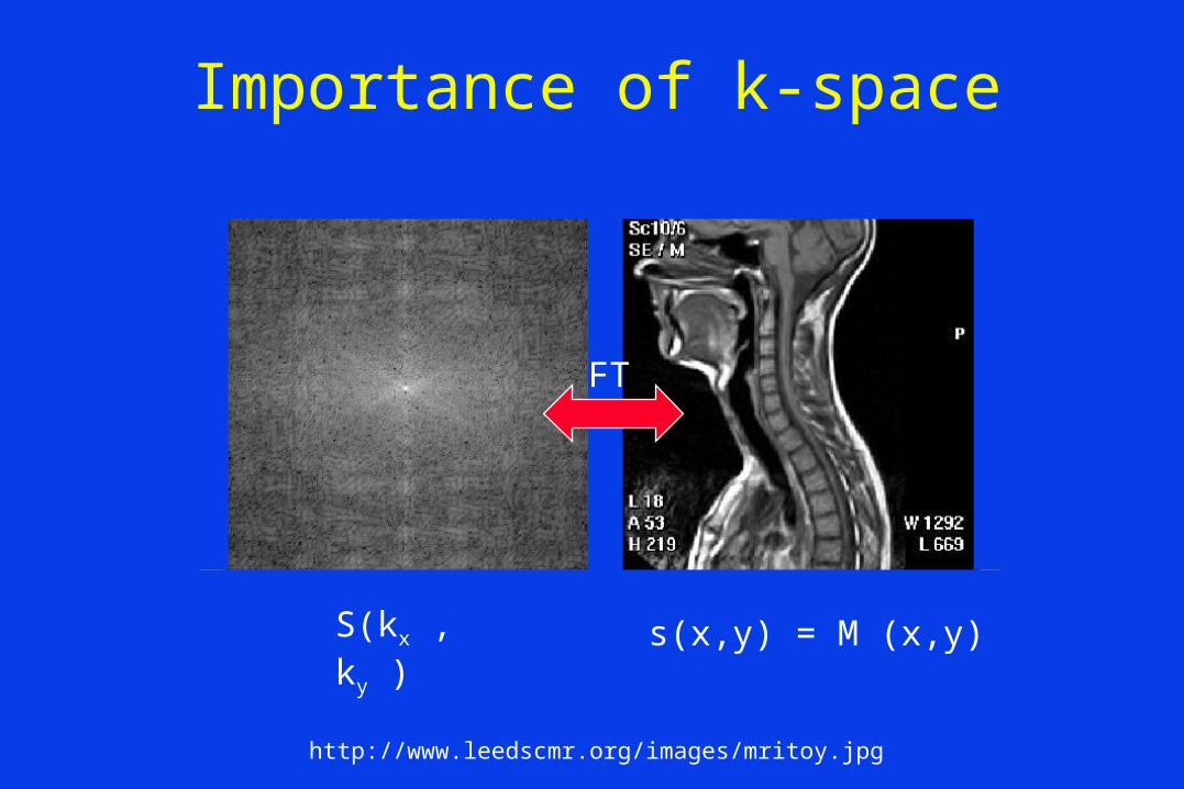
Importance of k-space
FT
http://www.leedscmr.org/images/mritoy.jpg
S(kx ,ky ) s(x,y) = M (x,y)
FT
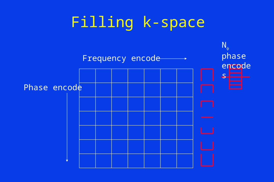
Filling k-space
Frequency encode
Phase encode
N phase encodes
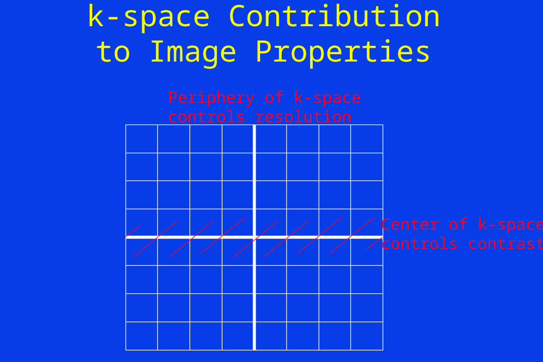
k-space Contribution to Image Properties
Center of k-spacecontrols contrast
Periphery of k-spacecontrols resolution
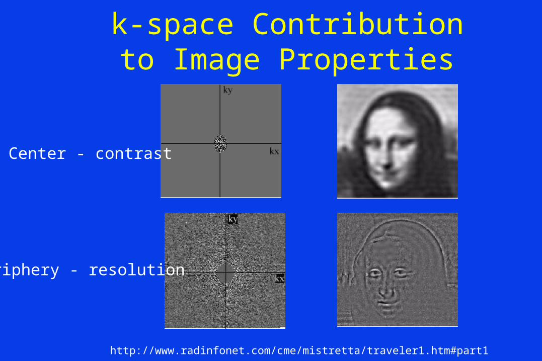
http://www.radinfonet.com/cme/mistretta/traveler1.htm#part1
k-space Contribution to Image Properties
Center - contrast
Periphery - resolution
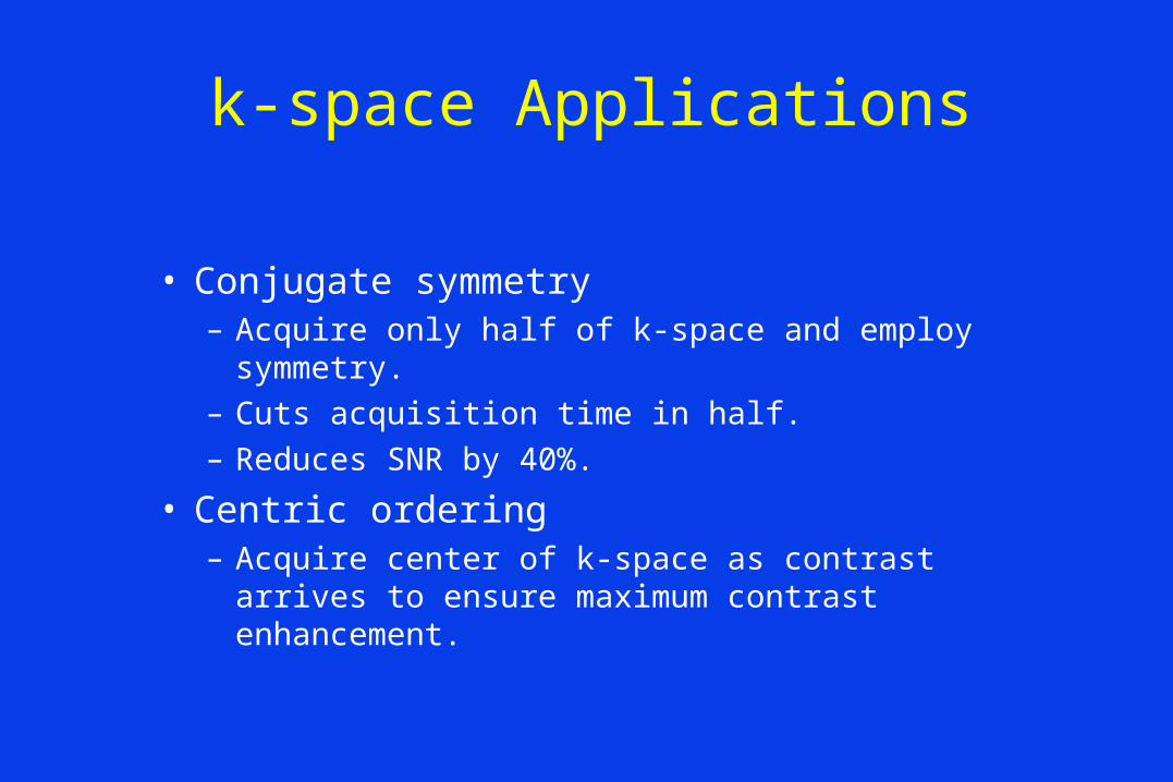
k-space Applications
• Conjugate symmetry– Acquire only half of k-space and employ symmetry.
– Cuts acquisition time in half.
– Reduces SNR by 40%.
• Centric ordering– Acquire center of k-space as contrast arrives to ensure
maximum contrast enhancement.
Spin Echo Contrast
• SE image contrast can be weighted to provide T1, T2 and dependence
• Weighting is adjusted by modifying TE and TR.
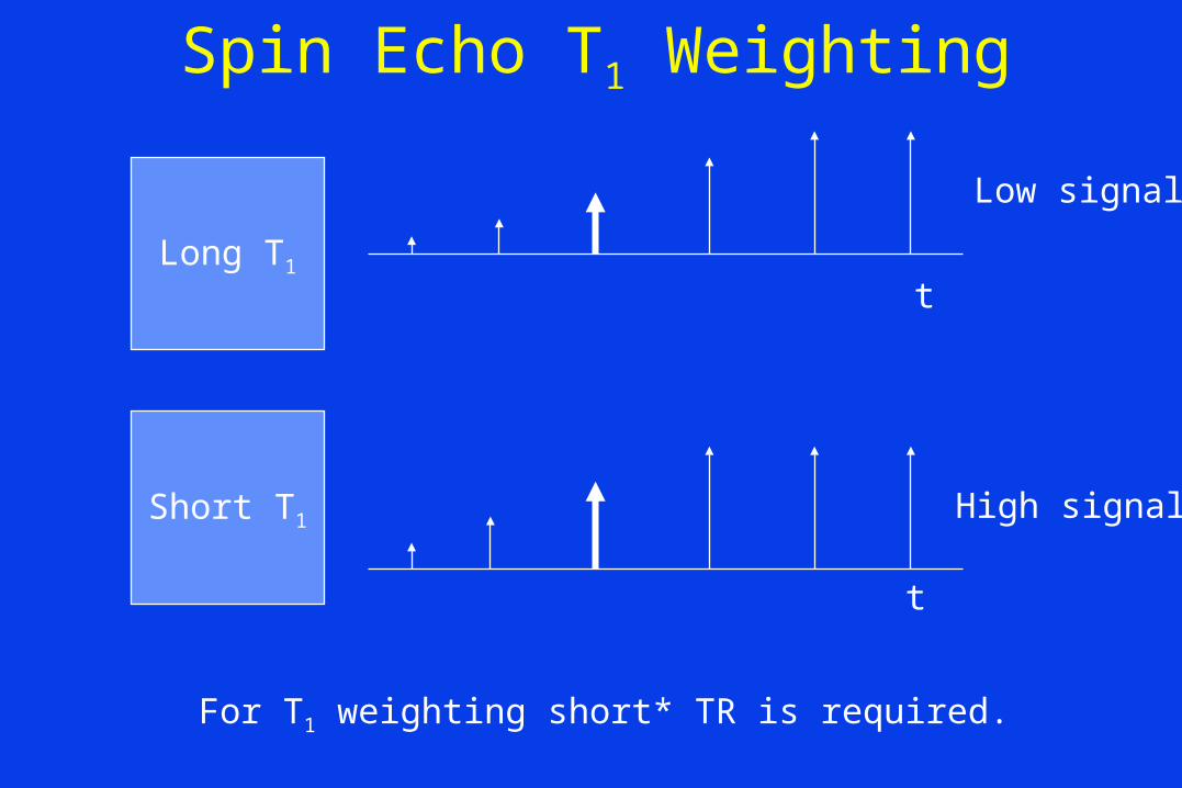
Spin Echo T1 Weighting
Long T1
Short T1
t
t
For T1 weighting short* TR is required.
Low signal
High signal

T1 Contrast
TR
Mz short T1
long T1
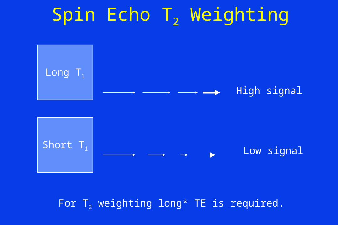
Spin Echo T2 Weighting
Long T1
Short T1
For T2 weighting long* TE is required.
High signal
Low signal

T2 Contrast
TE
Mz
short T2
long T2
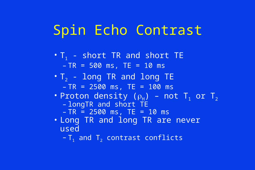
Spin Echo Contrast
• T1 - short TR and short TE – TR = 500 ms, TE = 10 ms
• T2 - long TR and long TE– TR = 2500 ms, TE = 100 ms
• Proton density (H) – not T1 or T2– longTR and short TE– TR = 2500 ms, TE = 10 ms
• Long TR and long TR are never used– T1 and T2 contrast conflicts
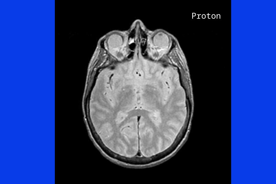
Proton
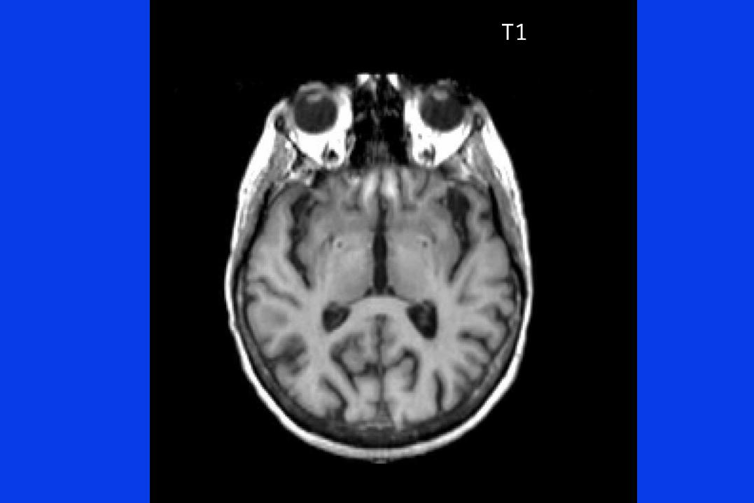
T1
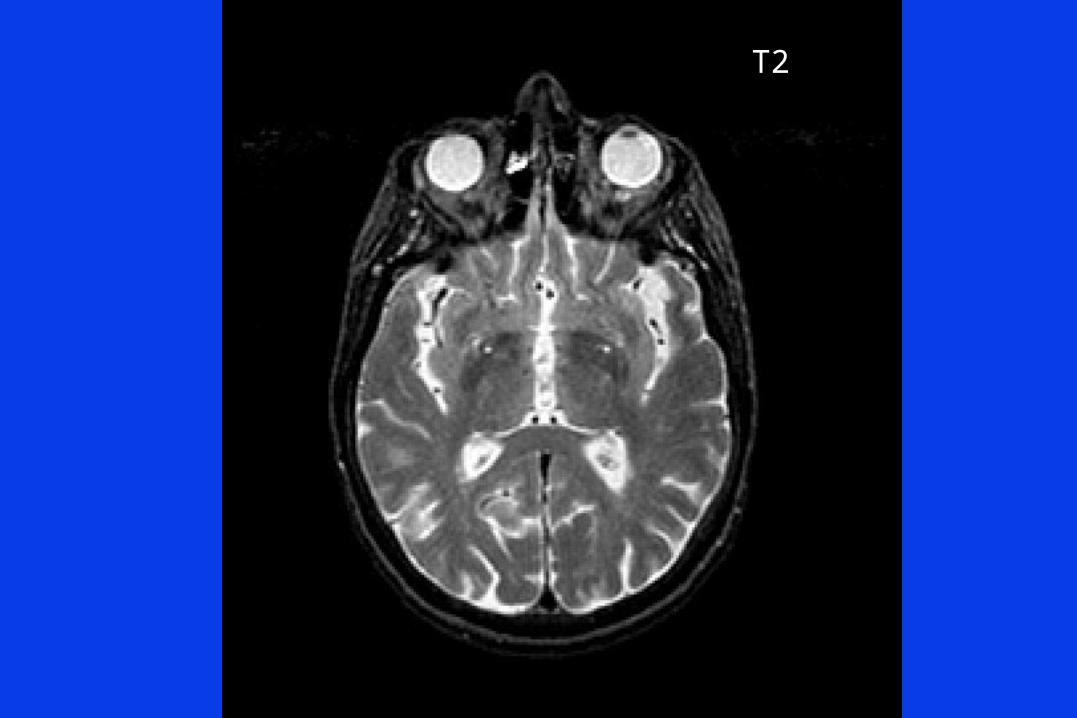
T2

T1
Proton
T2
Introduction to Contrast Agents

Magnetic Properties of Materials
Weakly repel:water and tissue
Weakly attract:Gd T1 and T2 Reducing agents
Interact strongly:Fe susceptibilityagents (T2*).
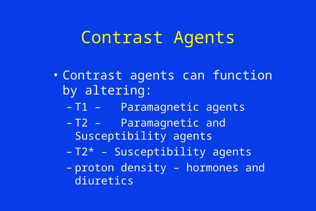
Contrast Agents
• Contrast agents can function by altering:– T1 – Paramagnetic agents– T2 – Paramagnetic and Susceptibility agents– T2* – Susceptibility agents– proton density – hormones and diuretics
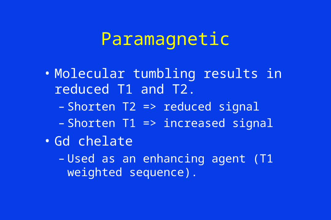
Paramagnetic
• Molecular tumbling results in reduced T1 and T2.– Shorten T2 => reduced signal– Shorten T1 => increased signal
• Gd chelate– Used as an enhancing agent (T1 weighted
sequence).
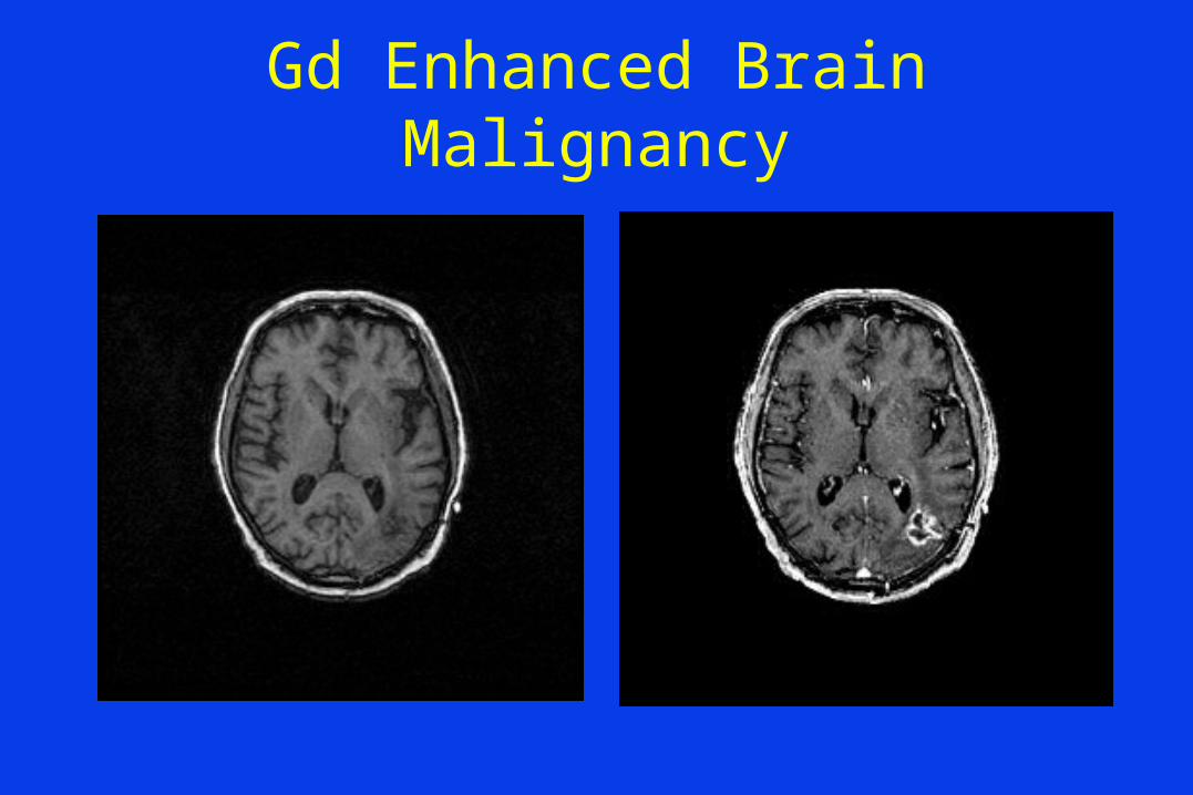
Gd Enhanced Brain Malignancy
Superparamagnetic
• Susceptibility agents– Cause local field inhomogeneity and very short
T2*.
– Used to remove signal on T2 or T2* weighted images.

Negative Contrast From Iron Oxide

Factors controlling SNR
• Basic factors– Field strength– Coil tune and match– Magnet shim
• Setup factors:– Coil selection (Filling factor)– Sequence selection (longer TR/shorten TE)
• Sequence variables:– Voxel volume– Averages– Bandwidth– Gap
Related Documents