Terragen 2 User Guide Part 1 Table of Contents Terragen 2 User Guide Part 1.....................................................................................................................1 Introduction...........................................................................................................................................2 Fundamental Concepts..........................................................................................................................2 Application Focus.............................................................................................................................2 Terragen 2 Conventions....................................................................................................................3 Nodes...........................................................................................................................................3 Shaders.........................................................................................................................................4 Heightfield vs. Procedural...........................................................................................................4 Scale.............................................................................................................................................5 User Interface Overview.......................................................................................................................6 Main Window User Interface Elements............................................................................................6 Working With Each User Interface Element.....................................................................................9 Menus...........................................................................................................................................9 File...........................................................................................................................................9 Edit........................................................................................................................................10 View......................................................................................................................................10 Project....................................................................................................................................10 Window.................................................................................................................................10 Help.......................................................................................................................................10 Top Toolbar................................................................................................................................11 Node Lists..................................................................................................................................11 Shader Preview..........................................................................................................................12 Parameter/Settings Pane.............................................................................................................13 Node Settings Layout Conventions...........................................................................................13 Standard Node Settings..............................................................................................................14 Common Node Settings.............................................................................................................15 3D Previews...............................................................................................................................17 The Node Network.....................................................................................................................21 Overview...............................................................................................................................21 Bottom Toolbar..........................................................................................................................22 Render Window.........................................................................................................................23 Preferences Window..................................................................................................................24 About Box..................................................................................................................................24 Mouse and Key Settings Window..............................................................................................25 Conclusion.................................................................................................................................26

Welcome message from author
This document is posted to help you gain knowledge. Please leave a comment to let me know what you think about it! Share it to your friends and learn new things together.
Transcript
Terragen 2 User Guide Part 1
Table of ContentsTerragen 2 User Guide Part 1.....................................................................................................................1
Introduction...........................................................................................................................................2Fundamental Concepts..........................................................................................................................2
Application Focus.............................................................................................................................2Terragen 2 Conventions....................................................................................................................3
Nodes...........................................................................................................................................3Shaders.........................................................................................................................................4Heightfield vs. Procedural...........................................................................................................4Scale.............................................................................................................................................5
User Interface Overview.......................................................................................................................6Main Window User Interface Elements............................................................................................6Working With Each User Interface Element.....................................................................................9
Menus...........................................................................................................................................9File...........................................................................................................................................9Edit........................................................................................................................................10View......................................................................................................................................10Project....................................................................................................................................10Window.................................................................................................................................10Help.......................................................................................................................................10
Top Toolbar................................................................................................................................11Node Lists..................................................................................................................................11Shader Preview..........................................................................................................................12Parameter/Settings Pane.............................................................................................................13Node Settings Layout Conventions...........................................................................................13Standard Node Settings..............................................................................................................14Common Node Settings.............................................................................................................153D Previews...............................................................................................................................17The Node Network.....................................................................................................................21
Overview...............................................................................................................................21Bottom Toolbar..........................................................................................................................22Render Window.........................................................................................................................23Preferences Window..................................................................................................................24About Box..................................................................................................................................24Mouse and Key Settings Window..............................................................................................25Conclusion.................................................................................................................................26
IntroductionThis user guide is intended to provide comprehensive but basic information on working with Terragen 2, starting with an overview of the User Interface, then introducing a simple way to build Your First Scene, and finally covering each aspect of Terragen 2 more thoroughly in the In-Depth Terrain, Shaders, Atmosphere, Lighting, Water, Objects, Cameras, Renderers, and Node Network sections. Some additional useful information is provided in several appendices, consisting of an explanation of all Menus, Windows and Preferences in Appendix A, a Glossary in Appendix B, and a list of additional Help Resources in Appendix C.
Throughout this guide certain formatting conventions are used to clarify terms or highlight specifically important information. Italics are used to refer to the proper name of a node, as displayed in Terragen 2 itself. For example Heightfield shader. When referring to named interface elements and settings, the name will be enclosed in single quotes, as in 'GI relative detail'. Important information is highlighted in bold.
Fundamental Concepts
Application FocusTerragen 2 is a powerful application which can be used to create and render virtually anything with sufficient time and effort, but its tools and technology have been developed and tuned specifically to create highly realistic landscapes and natural scenery. Terragen 2 is first and foremost a landscape rendering application. While it has the ability to render buildings, indoor scenes, and arbitrary objects of any kind, and includes powerful instancing technology, it is not intended as a general purpose object rendering system. Likewise, support for volumetric shading is provided and optimized for rendering clouds and other atmospheric phenomena, and while it can be used for smoke, or even fire, dedicated particle systems in other applications will naturally provide more power and flexibility.
For the hobbyist, Terragen 2 provides the ability to create beautiful and convincing images of landscapes, both realistic and fantastic. Rendered output can be used as-is, or combined with hand-painting, 3D output from other applications, and other elements to create a final image. With the level of quality Terragen 2 can provide for landscape-specific scenes, renders can often be printed or posted online without further adjustment, with results that easily stand alongside photography, or output from other 3D applications.
For the professional, Terragen 2 fits cleanly into an existing production pipeline with import and export of terrain and animation data to industry standard formats, and full support of High Dynamic Range throughout the rendering pipeline for accuracy, quality, and solid integration with other elements. It is expected that most production-level output will be created in combination with other applications as part of the artist's normal workflow. Applications that have strong object modeling and rendering functions would ideally be used for critical foreground object rendering, for example, while a compositing application would combine these and other elements with live action or animation to create the final output.
Terragen 2 is a foundational product upon which greater capabilities and functionality will be built. As it develops, the Terragen product line will remain focused on landscape modeling and rendering, and functions and features which are added will be aimed specifically at supporting this focus. Our passion is terrain and so Planetside Software's primary goal is to excel in this area, leaving other segments of
the Computer Graphics market such as object modeling and character animation to those who are best able to fully realize their potential. We strive to work with other applications effortlessly and cleanly, allowing each application to focus on its strengths.
Terragen 2 Conventions
Although we have stuck to the conventions of other 3D applications where possible to maintain consistency and familiarity, certain defaults and settings are unique to TG2. The most common confusion stems from the coordinate system. In many other applications, the Z axis is considered the “up” axis, whereas in TG2 it is the Y axis. The next sections will cover additional unique elements in more detail.
NodesTerragen 2 is based around the concept of “nodes” - individual functional elements with their own sets of specific controls and output that, when connected together, form your scene. These nodes include functions for creating terrain, textures, objects, and lighting, as well as cameras and renderers. Virtually every element of a Terragen 2 scene is defined by a node in some way.
Nodes are generally interconnected using a logical “data flow” concept, where information that defines each element of the scene flows from one node to the next through specific connections on each node. These nodes and their interconnections collectively are called “networks.” Nodes further down the data flow hierarchy act on the information from prior nodes that feed into them. Your scene structure depends on how you connect these nodes, and the settings used for each node's available controls.
Node connections and networks are divided into major areas, with terrain and texture nodes for a given planet forming a single network, individual objects forming their own networks, and other smaller sub-networks such as cameras and renderers, which are interconnected. In some cases nodes are “stand alone” in that they do not have a visible connection to other nodes; this is generally the case when a node may have a global effect (such as a light), or where the effect is “stand-alone” (e.g. a self-contained object and its accompanying texturing nodes, which are confined to that object). Nodes and their interconnections as a whole are called the 'Node Network'.Nodes are used to construct scenes, not only in the 'Node Network', but in every other part of the User Interface (UI) as well. However, due to the complexity and potential difficulty of making manual node connections without prior knowledge of the appropriate methods, a simplified 'Node List' view is provided. The 'Node List' organizes nodes into a logical hierarchy and, when nodes are added or removed using the list view, the connections are handled automatically. Scene construction and adjustment can be handled entirely through the 'Node List' views, so beginner and even intermediate users can avoid using the 'Node Network' altogether and focus in the list view as it is often a more comfortable way of working.
The 'Node Network' and 'Node Lists' display the same fundamental information, so changes in one affect the other, and you can move between them at any time. Thus you can construct a scene easily and quickly using the 'Node Lists' then, as you gain more experience, move to advanced adjustment in the 'Node Network', if necessary. Keep in mind that manual adjustment of node connections is not necessary for most normal scenes, so you should not feel hindered by sticking to the 'Node Lists' for your scene construction.
ShadersShaders are a familiar concept in the high-end Computer Graphics industry and are used in many other 3D applications. Fundamentally, a “shader” does just what the name implies – it “shades” something, a surface in your scene, where “shade” means literally “to apply colour to.” In computer graphics terminology, a “shader” is the set of instructions that dictate how a particular surface will be shaded, including aspects like diffuse colour, luminosity, specularity and reflectivity, transparency, displacement, and much more. Shaders often act on input from other elements of the scene such as light sources, determining the final colour of the surface by combining lighting effects with base surface properties.
In Terragen 2 all scene elements are depicted as “nodes,” and virtually any node that applies to a surface is a shader. Shader nodes are of two primary types in Terragen 2 - “compound nodes” and 'Function nodes'. The term “compound node” refers to shader nodes like the Power fractal which encompass a great deal of functionality and internal complexity in a single node interface. While you won't see the term “compound node” used to refer to any specific node in the Terragen 2 interface, it is a useful term to refer to nodes which are not function nodes and which have greater encapsulated functionality.
'Function nodes', on the other hand, are the most basic building blocks of a shader, often times comprised of individual simplistic math operations such as add, subtract, sine, and cosine. Experienced shader writers and those who have a firm grasp of how mathematics applies to computer graphics can use these individual functional components to build whole networks, with complex interactions that comprise surface shaders capable of producing unique and powerful effects. 'Function nodes' are the building blocks that those who are experienced writing shaders in other applications may find most familiar, however Terragen 2 provides so-called “compound nodes” for the most often-used and important effects like simple surface shading with altitude control, or image mapping. As a beginner or intermediate Terragen 2 user you will seldom have need to use 'Function nodes'. This capability is provided for those with unique requirements or who need more specific control over their shader output and who have the appropriate knowledge and experience to effectively build shaders from scratch.
Heightfield vs. ProceduralTerragen 2 allows the use of two different types of terrain, heightfield and procedural. Both terrain types can be used in the same scene. You can use procedural operators on heightfields, or convert procedurals into heightfields fin order to perform heightfield-specific operations or export to other applications.
Heightfields are the more traditional format for storing and representing terrain data. Heightfields in their simplest form are an ordered grid of height or greyscale values. Height information is ultimately represented numerically, but it can be interpreted as values along a spectrum from black to white for the purposes of editing in a graphics application. This means that heightfields are 2 dimensional and often very similar to any other image format, though they are generally only a single “channel” and are represented as greyscale. Additional information such as the “distance” between each value or “point,” or the position of the terrain on the globe can be included (“georeferencing”), but the basic heightfield concept consists of single heightfield values in a grid. The limitation of a single height value per point or pixel means you cannot store overhang information, for example.
Heightfields are useful because they store absolute values and can be loaded and edited much like any
other image format. Certain terrain-related editing functions are also significantly easier to perform on heightfields, for example erosion simulation. However heightfields are inherently limited by a finite resolution and detail, as well as only allowing a single height value at each point. Because they store a potentially high accuracy altitude value for each pixel, the larger the terrain, the larger the file, and at a certain point a heightfield will become too large to load and render easily. This point is generally well short of planetary scale.
Procedurals terrains resolve many of the issues of heightfields, but they come with some limitations of their own. Procedurals are essentially mathematical functions which can be computed accurately at virtually any scale. Terrain shapes are derived from these functions, which allow virtually infinite variety of output, while still maintaining a certain recognizable character based on their specific settings. As a result you can achieve theoretically “infinite” detail, and produce as much terrain with a similar “style” as you want, even covering a whole planet. Procedurals can also be computed in 3 dimensions, so you can create virtually any other shape, including overhangs. The downside of procedurals is that they generally need to be computed at render time in order to generate the right amount of detail for the camera position, which increases render time. They also tend to be harder to edit and to apply certain traditional terrain modification operations like erosion.
Fortunately in Terragen 2 you can easily mix heightfields and procedurals in a single scene. With the right approach, you can balance the influence of both in the scene, taking advantage of the strengths of each while minimizing their weaknesses. For scenes that need explicit terrain shapes but also have perspectives relatively close to your terrain, you can create your base with a carefully edited heightfield, then selectively blend in procedural displacements to add realistic smaller-scale detail. For larger-scale scenes, with important specific features in the foreground and a need for realistic terrain all the way to the horizon, you could blend in a heightfield in the foreground, with infinite procedural terrain in the background. You can even use multiple heightfields and procedurals in different areas and at different scales, making even the most challenging projects possible.
These concepts and their practical ramification are covered in more detail in the Terrain section of this User Guide.
ScaleIn Terragen 2 every scene is built in the context of an entire planet. While you may not always use this vast scale in your scene, the realism provided by this planetary context, including a properly curved atmosphere, will contribute to the quality of any scene. With the advantage of procedural displacement and texturing, you can achieve scenes from centimeter scale all the way up to a whole planet and beyond, all with consistent and realistic terrain forms and textures.
For many scenes, your focus will only be on a small area. The planet upon which you're building your scene won't affect your process that much, so you can often just ignore the area outside your scene. Having the planet as a background ensures that the scene doesn't just “end,” nor does it just go on forever as it would with an infinite plane. Instead it always curves realistically down to the horizon. Of course you can always use a separate plane if your intention is actually to achieve that look of “infinite flatness.”
The planet context comes into its own when you're building really large scale scenes. Terragen can realistically depict one or more planets from space, with highly realistic atmospherics and lighting.
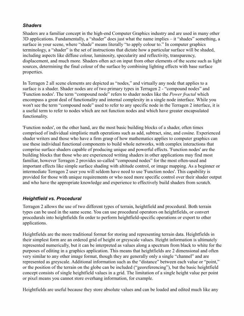
Even your average high mountain scene can also benefit from the same sense of scale, with the ability to place terrain elements and vegetation from foreground to background, all the way into the distance tens of kilometers away. From the top of Mt. St. Helens you can often see over 50 miles to Mt. Rainier for example, and proper depiction of scale and distance is vital for realizing a scene like this.
Mt. Rainier viewed from Mt. St. Helens
User Interface OverviewTerragen 2 is focused on creating and rendering procedural landscapes and we have tailored the interface layout and functionality to that purpose. The basic UI may be similar to others you have used in various 3D applications, but there are important differences. This section will give you an overview of the Terragen 2 UI, which should be enough to get you started using Terragen 2. If you you want more specific details on any particular UI element or function, please refer to the online User Interface Reference.
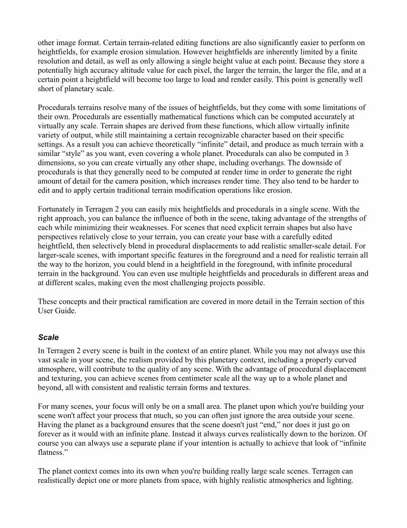
Main Window User Interface ElementsThe Terragen 2 UI is based around multiple “layouts,” accessed through tabs or buttons at the top of the application in a 'Top Toolbar', which allow you to quickly access and edit the major areas of your scene. Each tab consists of a layout with tools and functionality specific to one aspect of the scene. The tab buttons have text labels which should be self-explanatory if you've read the Fundamental Concepts section above. If not, the two which may be confusing are 'Shaders' and 'Node Network'. 'Shaders' in Terragen 2 terminology is essentially the same as surface mapping in Terragen Classic (although much more powerful), or analogous to most other application's “texturing” functions. The 'Node Network' is a powerful optional interface for editing your scene in more complex or non-standard ways.
Each button accesses a layout tab to edit that specific part of the scene
At the top of the interface is a standard menu bar which includes options for 'File' operations ('Save',

etc.), 'Edit' ('Copy'/'Paste' and 'Undo'), 'View' (opening of various windows of specific information), 'Project' (various project-related settings and information), 'Window' (window management), and 'Help' (documentation, key reference, etc.). To the left of the 'Layout Tabs' on the 'Top Toolbar' are standard 'New', 'Open', and 'Save' project buttons, as well as a button to open the 'Render View' and the '3D Preview'. Below the tabs on the left is the 'Node List' which displays items (nodes) which are relevant to the current layout in a hierarchical list format.
The Node List
Just to the right of the 'Node List' is a small 'Shader Preview' window, which generates a realtime preview of the currently selected node, when applicable (not all nodes can be previewed).
The Shader Preview
Below the 'Node List' and the 'Shader Preview' is the 'Parameter/Settings Pane', which will display the settings of the node currently selected in the 'Node List'.

The Parameter/Settings Pane
In the top-right is the '3D preview', which shows a progressively rendered “realtime” display of the current scene, including all scene elements, terrain, lighting, atmosphere effects, shaders, etc.
The 3D Preview
Below the '3D preview' is the 'Node Network' view, which is contextual when viewing any of the specific layouts such as 'Terrain', focusing on the nodes in the default Group corresponding to the current layout (there is also a separate 'Node Network' view which gives you a larger view of the entire 'Node Network' without the '3D Preview').
The Node Network
At the very bottom of the user interface is a toolbar that includes the 'Animation Timeline' and controls.

The Animation Timeline (red) & Errors and Warnings Notifications (green)
At the far right of the 'Bottom Toolbar' is the 'Errors and Warnings Display' which, when clicked, brings up a window with details on any errors and warnings triggered so far. Next let's explore each section in more detail.
Several of the windows in the UI can be resized by placing the mouse cursor between windows where a double-ended arrow appears, and then clicking and dragging. The '3D Preview' and 'Node Network' windows can also be expanded or closed completely with the buttons in the upper-right corners of these windows, which are similar to standard operating system window controls. If you close one of these windows and wish to display it again, use the 'Preview' and 'Node Network' options in the 'View' menu.
Working With Each User Interface ElementThis section will give you practical information on working with the major user interface elements. It does not cover every control and setting, only those that are most immediately and frequently used. For complete details on all controls in the TG2 UI, please see the online User Interface Reference.
Menus
FileOn the file menu are the normal 'New', 'Open', 'Open Recent', 'Save', and 'Save As' items. 'New' will load your default scene, which may be customized in the preferences (more on that later). 'Open Recent' shows the last 10 scene files you have opened. You can clear the list with the 'Clear Menu' option.
'Save Incremental' will save your scene as a new file with an incremented version number appended to the file. By default it will add _0001 to your file name, however if you have already added a version number of some kind, it will attempt to recognize your numbering format and increment it appropriately. For example if your file is scene1.tgd, using 'Save Incremental' will create scene2.tgd. The last number is always what will be incremented, so scene1_1.tgd would become scene1_2.tgd.
'Revert to Saved' will simply reload the last saved state of the current scene.
The clip file options work with Terragen 2 .TGC Clip Files, a subset of TG2's native .TGD XML file format. Clip files are specific nodes saved separately from an entire scene file, designed to be easily inserted into any project. Using this functionality you can save useful pieces of your scenes such as surface shaders, complex terrains, or other functions and re-use them later with ease. 'Insert Clip File' allows you to insert a previously created clip file. 'Insert Recent Clip File' works just like 'Open Recent', except it only shows recently loaded clip files. 'Save Nodes as Clip File' allows you to create a clip file from the currently selected nodes. You must select at least one node in the 'Node Network' in order to use this function.
'Explore Temporary Files' will open the Terragen 2 image output folder located in your Temp Folder. TG2 currently outputs all rendered images, including aborted renders, to a sub-folder in your Temp Folder. Alpha images are included. As a result you will want to check your Temp Folder regularly and
clean it out if space becomes an issue. Note that crashed renders are not currently saved in this way. A new uniquely numbered directory is created in this folder for every TG2 session. They are sequentially numbered.
EditThe 'Edit' menu contains the standard 'Cut', 'Copy', 'Paste', and 'Delete' functions. The 'Undo' function works as it does in most applications and operates on the majority of settings in Terragen 2. 'Group' and 'Ungroup' control the node grouping functions, which will be covered in the Node Network section. 'Preferences' accesses a number of settings to control behavior, UI, and other aspects of TG2 and its functionality.
ViewAll items on the 'View' menu control the visibility of functional or informational windows in the TG2 UI. In most cases new windows are opened with these options. The majority of these settings are used to customize the UI, or enabled more advanced workflows, so we will cover only the most important ones at this point. The 'Render' option opens the 'Render Window', which allows you to start and stop and view in-progress rendering tasks and save completed renders. The 'Undo History' option opens a sequential text list of actions which can be undone. To revert to a previous state, click the appropriate item in the list and press the 'Undo to Selection' button at the bottom. Note that all changes made after the selected action will also be undone.
Project'Render current render node' will automatically start a render with the currently selected render node. This can also be invoked with the shortcut Ctrl+R. This is faster and more direct than opening the 'Render Window' and pressing the 'Render Button'. The 'Purge Undo' function clears the undo buffer, which can sometimes become very large and take up memory. Remember that you will lose the option to undo to a previous state if you do this, but further changes will still be recorded in the undo buffer.
WindowThe 'Window' menu allows you to switch between currently open TG2 windows, and to show and hide any floating windows you may have opened. Note that unless you have opened any additional windows, there will be only one option here, 'Terragen 2'.
HelpThe 'Help' menu contains a link to the online documentation (where you can find this document, the Node Reference, and the User Interface Reference). The 'Mouse and Key Settings' option will show you a complete overview of all the currently assigned mouse and keyboard settings. You can change many of these key assignments with the 'Preferences' option under 'Edit'.
'Visit Planetside Forums on the Web' will take you to our active and informative forum user community. We encourage every TG2 user to signup and join the discussion.
'Check for Updates' will contact the Planetside servers and check your version of Terragen against the most recent available version. If your version is out of date you will be given the option to upgrade. The upgrade check is also performed automatically on startup of TG2, though you can turn this off in the preferences.

'About Terragen 2' displays the 'About Box', which most importantly will show the version number for your TG2 installation. This information can be important for troubleshooting purposes.
Top Toolbar
The 'Top Toolbar' holds standard 'New', 'Open', and 'Save' buttons on the left. If you click and hold the 'Save' button you will get a dropdown menu offering additional options such as 'Save Incremental' (see above for usage). Next are buttons to quickly access the 'Render Window' and '3D Preview' (note the '3D Preview' button has no effect if the '3D Preview' is already open, as it is in the default workspace). The rest of the toolbar contains buttons to access each of the specific UI layouts for editing the various aspects of your scene.
Node Lists'Node Lists' display structured lists of nodes in your scene. In the 'Node List' for a given layout, only nodes which correspond to the purpose of that layout will be shown. In the 'Terrain layout', for example, the 'Node List' displays nodes that control the shape of the terrain, a Heightfield shader and Heightfield generator in the default scene (note: you may need to click the small “+” sign to expand the list and see the Heightfield generator), while in the 'Atmosphere layout' the list will contain nodes that define the atmosphere and clouds. The only exception to this is the 'Node List' in the 'Node Network' layout, which displays all nodes in the scene.
Nodes are displayed hierarchically, with sub-nodes, also known as “child nodes,” indented and connected to the main node, or “parent node,” by a dashed line. This structure mirrors the structure of the 'Node Network', which we’ll discuss later. Single-clicking on any of these nodes will bring up its settings below the list in the 'Parameter/Settings Pane' (covered in a later section). The configuration of the Node List will vary depending on the layout you are in, but all of the lists include a button at the top to add additional nodes of appropriate type.
Terrain Node List
In the Terrain and Shaders 'Node Lists', the order of the nodes is also critical and can greatly affect the look of the final scene, so buttons are provided to change the position of shaders in the list. These are the 'Move' buttons at the bottom of the list, with arrows pointing up and down to indicate the direction the currently selected node will be moved. Nodes at the top of the list will generally be “covered” or superseded by nodes further down. When dealing specifically with Surface layers in the 'Shader Layout', parents are also covered by their children, but the children are limited to the coverage or area
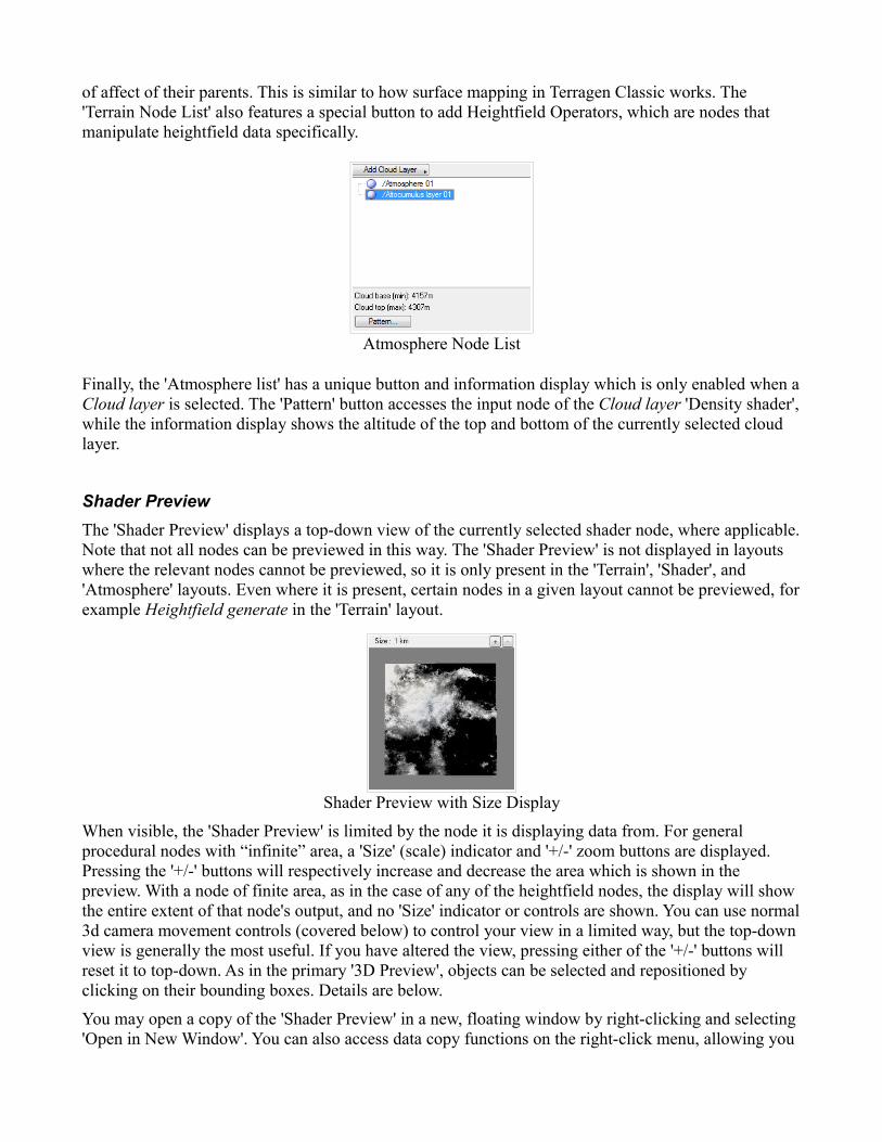
of affect of their parents. This is similar to how surface mapping in Terragen Classic works. The 'Terrain Node List' also features a special button to add Heightfield Operators, which are nodes that manipulate heightfield data specifically.
Atmosphere Node List
Finally, the 'Atmosphere list' has a unique button and information display which is only enabled when a Cloud layer is selected. The 'Pattern' button accesses the input node of the Cloud layer 'Density shader', while the information display shows the altitude of the top and bottom of the currently selected cloud layer.
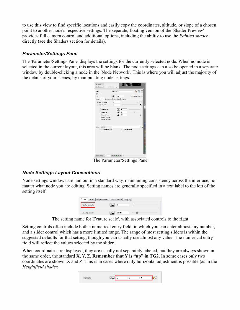
Shader PreviewThe 'Shader Preview' displays a top-down view of the currently selected shader node, where applicable. Note that not all nodes can be previewed in this way. The 'Shader Preview' is not displayed in layouts where the relevant nodes cannot be previewed, so it is only present in the 'Terrain', 'Shader', and 'Atmosphere' layouts. Even where it is present, certain nodes in a given layout cannot be previewed, for example Heightfield generate in the 'Terrain' layout.
Shader Preview with Size Display
When visible, the 'Shader Preview' is limited by the node it is displaying data from. For general procedural nodes with “infinite” area, a 'Size' (scale) indicator and '+/-' zoom buttons are displayed. Pressing the '+/-' buttons will respectively increase and decrease the area which is shown in the preview. With a node of finite area, as in the case of any of the heightfield nodes, the display will show the entire extent of that node's output, and no 'Size' indicator or controls are shown. You can use normal 3d camera movement controls (covered below) to control your view in a limited way, but the top-down view is generally the most useful. If you have altered the view, pressing either of the '+/-' buttons will reset it to top-down. As in the primary '3D Preview', objects can be selected and repositioned by clicking on their bounding boxes. Details are below.
You may open a copy of the 'Shader Preview' in a new, floating window by right-clicking and selecting 'Open in New Window'. You can also access data copy functions on the right-click menu, allowing you
to use this view to find specific locations and easily copy the coordinates, altitude, or slope of a chosen point to another node's respective settings. The separate, floating version of the 'Shader Preview' provides full camera control and additional options, including the ability to use the Painted shader directly (see the Shaders section for details).
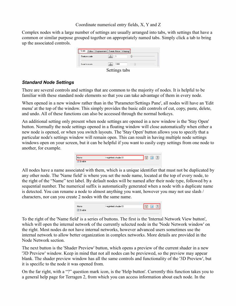
Parameter/Settings PaneThe 'Parameter/Settings Pane' displays the settings for the currently selected node. When no node is selected in the current layout, this area will be blank. The node settings can also be opened in a separate window by double-clicking a node in the 'Node Network'. This is where you will adjust the majority of the details of your scenes, by manipulating node settings.
The Parameter/Settings Pane
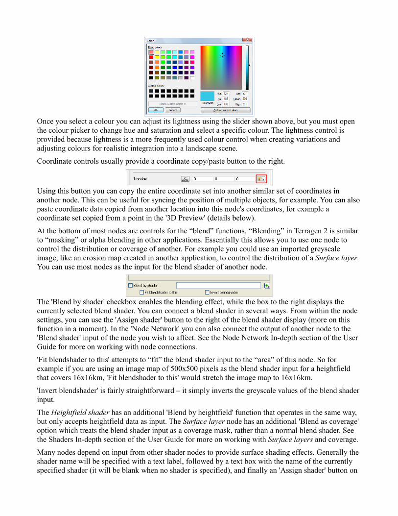
Node Settings Layout ConventionsNode settings windows are laid out in a standard way, maintaining consistency across the interface, no matter what node you are editing. Setting names are generally specified in a text label to the left of the setting itself.
The setting name for 'Feature scale', with associated controls to the right
Setting controls often include both a numerical entry field, in which you can enter almost any number, and a slider control which has a more limited range. The range of most setting sliders is within the suggested defaults for that setting, though you can usually use almost any value. The numerical entry field will reflect the values selected by the slider.
When coordinates are displayed, they are usually not separately labeled, but they are always shown in the same order, the standard X, Y, Z. Remember that Y is “up” in TG2. In some cases only two coordinates are shown, X and Z. This is in cases where only horizontal adjustment is possible (as in the Heightfield shader.
Coordinate numerical entry fields, X, Y and Z
Complex nodes with a large number of settings are usually arranged into tabs, with settings that have a common or similar purpose grouped together on appropriately named tabs. Simply click a tab to bring up the associated controls.
Settings tabs
Standard Node SettingsThere are several controls and settings that are common to the majority of nodes. It is helpful to be familiar with these standard node elements so that you can take advantage of them in every node.
When opened in a new window rather than in the 'Parameter/Settings Pane', all nodes will have an 'Edit menu' at the top of the window. This simply provides the basic edit controls of cut, copy, paste, delete, and undo. All of these functions can also be accessed through the normal hotkeys.
An additional setting only present when node settings are opened in a new window is the 'Stay Open' button. Normally the node settings opened in a floating window will close automatically when either a new node is opened, or when you switch layouts. The 'Stay Open' button allows you to specify that a particular node's settings window will remain open. This can result in having multiple node settings windows open on your screen, but it can be helpful if you want to easily copy settings from one node to another, for example.
All nodes have a name associated with them, which is a unique identifier that must not be duplicated by any other node. The 'Name field' is where you set the node name, located at the top of every node, to the right of the “Name” text label. By default nodes will be named after their node type, followed by a sequential number. The numerical suffix is automatically generated when a node with a duplicate name is detected. You can rename a node to almost anything you want, however you may not use slash / characters, nor can you create 2 nodes with the same name.
To the right of the 'Name field' is a series of buttons. The first is the 'Internal Network View button', which will open the internal network of the currently selected node in the 'Node Network window' on the right. Most nodes do not have internal networks, however advanced users sometimes use the internal network to allow better organization in complex networks. More details are provided in the Node Network section.
The next button is the 'Shader Preview' button, which opens a preview of the current shader in a new '3D Preview' window. Keep in mind that not all nodes can be previewed, so the preview may appear blank. The shader preview window has all the same controls and functionality of the '3D Preview', but it is specific to the node it was opened from.
On the far right, with a “?” question mark icon, is the 'Help button'. Currently this function takes you to a general help page for Terragen 2, from which you can access information about each node. In the

future it will be possible to link you directly to the relevant Node Reference page that describes the details of the current node type.
Most nodes also share the 'Enable checkbox' setting. This simply controls whether the current node is enabled or disabled. When disabled, the “flow” of information through the network will simply bypass this node and it will have no effect on the scene. The network is processed as if the node did not even exist.
Next to many settings is an 'Animation/Import' button. This button opens a pop-out menu with various options. The available options depend on whether you have the Animation Module for Terragen 2. If you don't have this module, the only option available will be 'Import from text file', which allows you import a single set of values for the current setting. The imported text file must be in Nuke .CHAN format and only data from the first keyframe will be imported.
The Animation button
With the Animation Module several more options are available. The import function becomes 'Import animation file' and data from all keyframes in the imported file will be loaded. You can also add keyframes for the current setting manually with the 'Set animation key' option. This will set a keyframe for the values in the current setting at the currently selected frame. To remove only the current keyframe, use 'Remove animation key', but remember that you must be on a frame that has a keyframe. You can also use the 'Delete animation' function to remove all keyframes, but be careful, this will delete all keyframes from all settings, not just the current one! You can find out more about how to animate in the Animation section of this User Guide.
Common Node SettingsThere are a few additional settings and controls that are shared by several nodes, but are not present in all of them.
Certain nodes operate with one or more colour attributes. For these attributes several colour controls are provided.
The numerical entry field and the value slider both control only the lightness of the chosen colour. To select a specific colour, you must click on the colour swatch on the far right (a light blue in this example image). This will bring up the standard colour picker for your operating system (Windows Vista shown here).
Once you select a colour you can adjust its lightness using the slider shown above, but you must open the colour picker to change hue and saturation and select a specific colour. The lightness control is provided because lightness is a more frequently used colour control when creating variations and adjusting colours for realistic integration into a landscape scene.
Coordinate controls usually provide a coordinate copy/paste button to the right.
Using this button you can copy the entire coordinate set into another similar set of coordinates in another node. This can be useful for syncing the position of multiple objects, for example. You can also paste coordinate data copied from another location into this node's coordinates, for example a coordinate set copied from a point in the '3D Preview' (details below).
At the bottom of most nodes are controls for the “blend” functions. “Blending” in Terragen 2 is similar to “masking” or alpha blending in other applications. Essentially this allows you to use one node to control the distribution or coverage of another. For example you could use an imported greyscale image, like an erosion map created in another application, to control the distribution of a Surface layer. You can use most nodes as the input for the blend shader of another node.
The 'Blend by shader' checkbox enables the blending effect, while the box to the right displays the currently selected blend shader. You can connect a blend shader in several ways. From within the node settings, you can use the 'Assign shader' button to the right of the blend shader display (more on this function in a moment). In the 'Node Network' you can also connect the output of another node to the 'Blend shader' input of the node you wish to affect. See the Node Network In-depth section of the User Guide for more on working with node connections.
'Fit blendshader to this' attempts to “fit” the blend shader input to the “area” of this node. So for example if you are using an image map of 500x500 pixels as the blend shader input for a heightfield that covers 16x16km, 'Fit blendshader to this' would stretch the image map to 16x16km.
'Invert blendshader' is fairly straightforward – it simply inverts the greyscale values of the blend shader input.
The Heightfield shader has an additional 'Blend by heightfield' function that operates in the same way, but only accepts heightfield data as input. The Surface layer node has an additional 'Blend as coverage' option which treats the blend shader input as a coverage mask, rather than a normal blend shader. See the Shaders In-depth section of the User Guide for more on working with Surface layers and coverage.
Many nodes depend on input from other shader nodes to provide surface shading effects. Generally the shader name will be specified with a text label, followed by a text box with the name of the currently specified shader (it will be blank when no shader is specified), and finally an 'Assign shader' button on
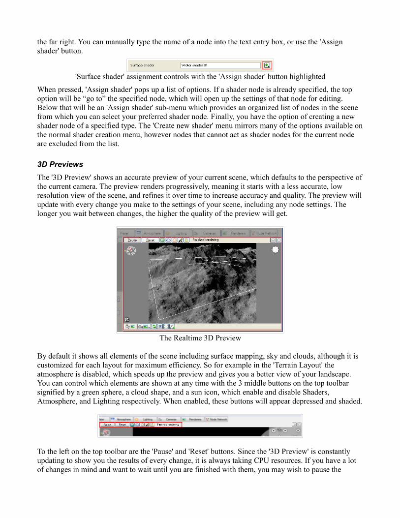
the far right. You can manually type the name of a node into the text entry box, or use the 'Assign shader' button.
'Surface shader' assignment controls with the 'Assign shader' button highlighted
When pressed, 'Assign shader' pops up a list of options. If a shader node is already specified, the top option will be “go to” the specified node, which will open up the settings of that node for editing. Below that will be an 'Assign shader' sub-menu which provides an organized list of nodes in the scene from which you can select your preferred shader node. Finally, you have the option of creating a new shader node of a specified type. The 'Create new shader' menu mirrors many of the options available on the normal shader creation menu, however nodes that cannot act as shader nodes for the current node are excluded from the list.
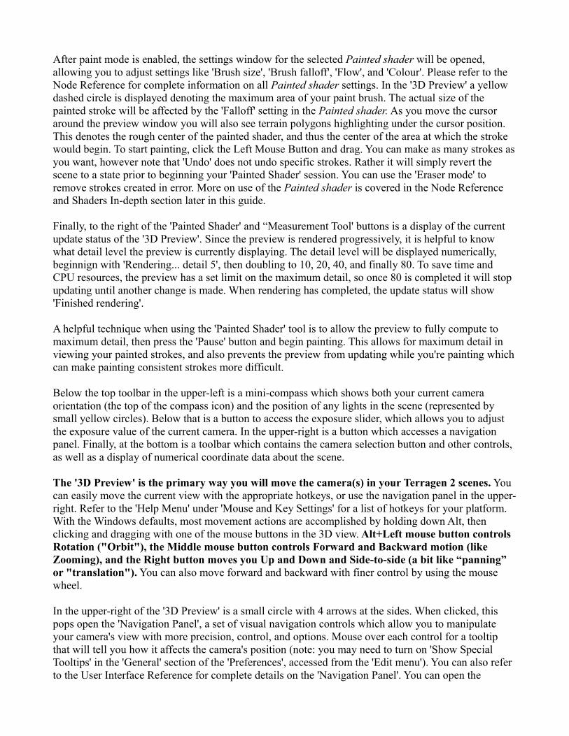
3D PreviewsThe '3D Preview' shows an accurate preview of your current scene, which defaults to the perspective of the current camera. The preview renders progressively, meaning it starts with a less accurate, low resolution view of the scene, and refines it over time to increase accuracy and quality. The preview will update with every change you make to the settings of your scene, including any node settings. The longer you wait between changes, the higher the quality of the preview will get.
The Realtime 3D Preview
By default it shows all elements of the scene including surface mapping, sky and clouds, although it is customized for each layout for maximum efficiency. So for example in the 'Terrain Layout' the atmosphere is disabled, which speeds up the preview and gives you a better view of your landscape. You can control which elements are shown at any time with the 3 middle buttons on the top toolbar signified by a green sphere, a cloud shape, and a sun icon, which enable and disable Shaders, Atmosphere, and Lighting respectively. When enabled, these buttons will appear depressed and shaded.
To the left on the top toolbar are the 'Pause' and 'Reset' buttons. Since the '3D Preview' is constantly updating to show you the results of every change, it is always taking CPU resources. If you have a lot of changes in mind and want to wait until you are finished with them, you may wish to pause the

preview rendering until you are finished. 'Pause' can also be useful when using the Painted shader and painting in the preview window. The 'Reset' button simply resets the preview and begins rendering from scratch, which can be useful if you want to immediately trigger a refresh of the preview for any reason.
On the far right of this toolbar are the 'Painted Shader' and 'Measurement Tool' buttons, signified by a paintbrush and ruler, respectively. We'll cover the 'Measurement Tool' first, because it is simpler. Clicking the 'Measurement Tool' button will enable a measurement system that allows you to measure the distance between two points in the '3D Preview' simply by clicking. When enabled, a measurement window will pop up with a display of the distance between the currently selected points, as well as some additional controls. Simply click in the preview to define the first point of your measurement, then move to your destination point and click again. You will see a yellow line extend between the two points and distance will be displayed in the 'Measure' window. You can also restrict the measurement axis to x, y, or z, as well as clear the current measurement points (note that you may need to reset the preview window to remove the display of the current measurement). During measurement you can use the normal camera navigation controls, so if you have switched into measurement mode and wish to measure something outside of the current view, you can still move your camera to accommodate that. To exit measurement mode, either close the pop-up 'Measure' window, or click the 'Measurement Tool' button again.
The Measurement Tool in use
The 'Painted Shader' tool and the associated Painted shader node are one of the most powerful systems in TG2. The Painted shader allows you to control virtually any aspect of your scene simply by painting in the preview window. You can create terrain shapes, control texture distribution, even create customized cloud shapes. The painting system relies on two elements – the Painted shader and paint strokes created in the preview window with the use of the 'Painted Shader' painting tool.
Pressing the 'Painted Shader' button brings up a menu of options. In its non-active state, the only option is 'Start painting shader', which has a sub-menu allowing you to either select an existing Painted shader to paint into, or create a new one and begin painting. Your existing Painted shaders will be listed at the top of this menu, above the 'Create and paint new shader' option. To begin a painting session simply select either an existing Painted shader, or create a new one with the menu option.
Once in a painting session the 'Painted Shader' button displays different options. You can switch between 'Paint mode' and 'Erase mode', where paint mode applies the current brush settings (specified in the Painted shader itself), and erase mode uses the same brush settings, but applies an inverse effect to your paint strokes, removing existing painted areas where you apply the erase effect. You can also use the 'Stop painting shader' button to stop your painting session.
After paint mode is enabled, the settings window for the selected Painted shader will be opened, allowing you to adjust settings like 'Brush size', 'Brush falloff', 'Flow', and 'Colour'. Please refer to the Node Reference for complete information on all Painted shader settings. In the '3D Preview' a yellow dashed circle is displayed denoting the maximum area of your paint brush. The actual size of the painted stroke will be affected by the 'Falloff' setting in the Painted shader. As you move the cursor around the preview window you will also see terrain polygons highlighting under the cursor position. This denotes the rough center of the painted shader, and thus the center of the area at which the stroke would begin. To start painting, click the Left Mouse Button and drag. You can make as many strokes as you want, however note that 'Undo' does not undo specific strokes. Rather it will simply revert the scene to a state prior to beginning your 'Painted Shader' session. You can use the 'Eraser mode' to remove strokes created in error. More on use of the Painted shader is covered in the Node Reference and Shaders In-depth section later in this guide.
Finally, to the right of the 'Painted Shader' and “Measurement Tool' buttons is a display of the current update status of the '3D Preview'. Since the preview is rendered progressively, it is helpful to know what detail level the preview is currently displaying. The detail level will be displayed numerically, beginnign with 'Rendering... detail 5', then doubling to 10, 20, 40, and finally 80. To save time and CPU resources, the preview has a set limit on the maximum detail, so once 80 is completed it will stop updating until another change is made. When rendering has completed, the update status will show 'Finished rendering'.
A helpful technique when using the 'Painted Shader' tool is to allow the preview to fully compute to maximum detail, then press the 'Pause' button and begin painting. This allows for maximum detail in viewing your painted strokes, and also prevents the preview from updating while you're painting which can make painting consistent strokes more difficult.
Below the top toolbar in the upper-left is a mini-compass which shows both your current camera orientation (the top of the compass icon) and the position of any lights in the scene (represented by small yellow circles). Below that is a button to access the exposure slider, which allows you to adjust the exposure value of the current camera. In the upper-right is a button which accesses a navigation panel. Finally, at the bottom is a toolbar which contains the camera selection button and other controls, as well as a display of numerical coordinate data about the scene.
The '3D Preview' is the primary way you will move the camera(s) in your Terragen 2 scenes. You can easily move the current view with the appropriate hotkeys, or use the navigation panel in the upper-right. Refer to the 'Help Menu' under 'Mouse and Key Settings' for a list of hotkeys for your platform. With the Windows defaults, most movement actions are accomplished by holding down Alt, then clicking and dragging with one of the mouse buttons in the 3D view. Alt+Left mouse button controls Rotation ("Orbit"), the Middle mouse button controls Forward and Backward motion (like Zooming), and the Right button moves you Up and Down and Side-to-side (a bit like “panning” or "translation"). You can also move forward and backward with finer control by using the mouse wheel.
In the upper-right of the '3D Preview' is a small circle with 4 arrows at the sides. When clicked, this pops open the 'Navigation Panel', a set of visual navigation controls which allow you to manipulate your camera's view with more precision, control, and options. Mouse over each control for a tooltip that will tell you how it affects the camera's position (note: you may need to turn on 'Show Special Tooltips' in the 'General' section of the 'Preferences', accessed from the 'Edit menu'). You can also refer to the User Interface Reference for complete details on the 'Navigation Panel'. You can open the

'Navigation Panel' in a separate floating window with the 'Navigation Window' option on the 'View' menu.
It is important to be aware that changing the current view with either of these methods will not change the current camera position and orientation, as defined in the current Camera node in your scene. Instead it affects the 'Perspective view', one of a set of standard cameras provided by the '3D Preview' which are not linked to any camera node. These views are 'Perspective view', 'Top view', 'Bottom view', 'Front view', 'Back view', 'Left view' and 'Right view'. You can access each of these views by clicking the 'Select Camera' button second from the right on the toolbar at the bottom of the '3D Preview'. Clicking this button will open a list of available views, including 'Current render camera'.
In order to set the render camera view to that which you have specified in the '3D Preview', you must use the 'Copy to current camera' button at the far left of the bottom toolbar in the '3D Preview'. This button will highlight whenever changes are made to the current view which are not reflected in the current camera. Pressing this button will sync the perspective camera with the current render camera. If you do not copy your current view to the render camera before you begin a render, your render will use the existing camera position and may not match your preview perspective.
At the bottom of the preview window is a set of 4 numbers labeled “x,” “y,” “z,” and “slope.” These will only appear when your mouse is positioned over the preview window. The x, y, and z figures indicate the current position of the scene element (usually the terrain) under the mouse cursor in the preview. Coordinates are measured in metric units, usually meters (‘m’) or kilometres (‘km’) and are relative to the coordinate origin. Slope indicates the slope of the terrain in that area and it is measured in degrees. Move the mouse around in the 3D preview and you will see the values update. These numbers can be extremely helpful in placing objects or fine-tuning surface mapping. The slope readout can be particularly useful in determining surface placement and distribution. In addition, you can easily copy these values into relevant settings in a particular node by right-clicking in the preview and selecting to copy the desired data (altitude, coordinates, or slope angle), then using the 'Paste button' next to an appropriate setting in a node. You can open this coordinate display in a separate floating window with the '3D Preview Location' option on the 'View' menu.
In addition to the 'Copy to current render camera' and 'Select Camera' buttons, the bottom toolbar includes several other useful functions. Next to 'Select Camera' is the 'Reset Camera' button, which provides several options for resetting the view shown by the '3D Preview'. You can 'Reset to current render camera', 'Centre on focus point' (the focus point is set with the next button on the toolbar), 'Centre on object or shader', or 'Centre on origin' (the coordinate origin: 0,0). Remember that, like any change in the view shown in the preview window, you must press 'Copy to current render camera' to save your view in the current camera in order to use it in rendering.
Next is the 'Look at point' button, which specifies the preview's “look at point,” a point in the scene toward which the camera will be oriented. Click the button then point and click on any part of the scene. You will see the polygon under your cursor highlight in yellow to indicate which polygon will be selected as the “look at point.” When you click, your camera will re-orient toward the selected point. This point is maintained throughout a session and you can use the command on the 'Reset Camera' button menu to recall your view to this point at any time.
The last two buttons on the 'Bottom Toolbar' are both related to the camera “orbit” mode. The first allows you to select the “orbit point” in much the same way as the “look at point” function described above. The orbit point defines the point which the camera will reference when orbiting. The next and
final button simply activates “Free Orbit Mode,” which allows the camera to roll freely during orbit movements, rather than being fixed to the original roll orientation. This is particularly useful when navigating with the camera at points far from the coordinate origin, for example on the other side of a planet, where the original roll value will not be parallel to the planet's surface.
For further information on all functions and settings for the '3D Preview' please see the User Interface Reference.
The Node Network
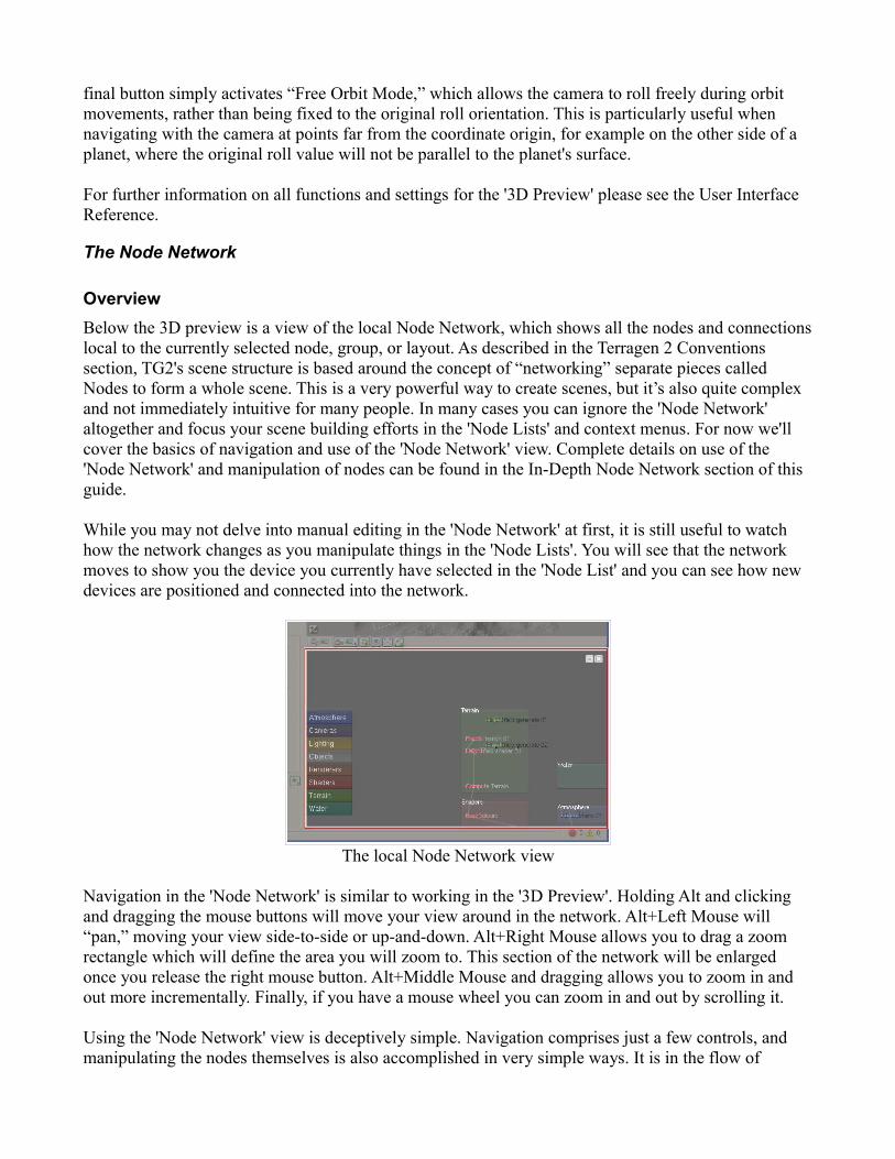
OverviewBelow the 3D preview is a view of the local Node Network, which shows all the nodes and connections local to the currently selected node, group, or layout. As described in the Terragen 2 Conventions section, TG2's scene structure is based around the concept of “networking” separate pieces called Nodes to form a whole scene. This is a very powerful way to create scenes, but it’s also quite complex and not immediately intuitive for many people. In many cases you can ignore the 'Node Network' altogether and focus your scene building efforts in the 'Node Lists' and context menus. For now we'll cover the basics of navigation and use of the 'Node Network' view. Complete details on use of the 'Node Network' and manipulation of nodes can be found in the In-Depth Node Network section of this guide.
While you may not delve into manual editing in the 'Node Network' at first, it is still useful to watch how the network changes as you manipulate things in the 'Node Lists'. You will see that the network moves to show you the device you currently have selected in the 'Node List' and you can see how new devices are positioned and connected into the network.
The local Node Network view
Navigation in the 'Node Network' is similar to working in the '3D Preview'. Holding Alt and clicking and dragging the mouse buttons will move your view around in the network. Alt+Left Mouse will “pan,” moving your view side-to-side or up-and-down. Alt+Right Mouse allows you to drag a zoom rectangle which will define the area you will zoom to. This section of the network will be enlarged once you release the right mouse button. Alt+Middle Mouse and dragging allows you to zoom in and out more incrementally. Finally, if you have a mouse wheel you can zoom in and out by scrolling it.
Using the 'Node Network' view is deceptively simple. Navigation comprises just a few controls, and manipulating the nodes themselves is also accomplished in very simple ways. It is in the flow of

information through the network and the interaction of settings for each node that complex results arise. As this section focuses on the User Interface overview, this will end our look at the 'Node Network' view for now. You can learn more about the node network and how to manipulate the nodes themselves in the In-Depth Node Network section later in this guide.
Bottom ToolbarAt the very bottom of the TG2 user interface is one final toolbar. Most of the controls here are specific to animation functions, although there are several other important settings.
The Bottom Toolbar
Beginning on the left, the 'Project Settings' button gives you access to several settings to control details and information about the current project. You can set the 'Name' of the project, program name and version (both filled in correctly by default), 'Author', and a short 'Comment'. You can also set the 'Current frame', 'Start frame', and 'End frame'.
The 'Start frame' and 'End frame' controls are particularly important to animations. In most cases your animation will start at frame 1, though in some cases starting at other frame numbers would be useful. The 'End frame' is usually changed much more frequently, as it defines the last frame, and thus the length of your animation (in combination with the 'Start frame'). You can set the 'End frame' to any value you wish. For a 10 second animation for example, at 30 frames per second, you would use 'Start frame' 1, 'End frame' 300. Like a 'Node settings' window, values that are changed here take effect immediately and there is no “apply” or “ok” button. When you are done changing these settings, simply close the window.
To the right of the 'Project Settings' button is a display of the current frame number, defaulting to 1. You can manually type values here to skip to a specific frame, use the frame controls to the right, or even drag on the timeline to change frame numbers. The frame number display will change as the current frame is adjusted.
Next to the 'Frame number display', are controls for moving through the animation timeline. The icons here may be familiar if you are accustomed to video editing, and they are also similar to that used in many other applications. The buttons featuring double arrows with lines skip to the beginning and end of the timeline, respectively. The single arrow with a line moves a single frame backward or forward in the timeline. Arrows facing backward move backward in the timeline, and forward facing arrows move forward. Once you change the current frame number, the '3D Preview' will update to reflect the settings of the curent frame. In the default scene no animation is defined so no changes will be visible. In the middle is a single right-facing arrow, the 'Play button', which will automatically move through the entire timeline in realtime. This will display any existing animation in the '3D Preview', though it will be rendered with limited detail based on the rendered detail already present in the preview when you press the 'Play button'.
The 'Timeline' comes next, a long slider that can be dragged to “scrub” through the animation and move quickly to a general part of an animation. Click and drag the position indicator on the slider to move the current frame, or click directly on the slider to jump 10 frames at a time, either forward or back, depending on whether your cursor is to the right or left of the slider bar, respectively.
Finally, on the far-right, is the 'Errors and warnings display'. The red circle signifies errors, with the number next to it showing how many have occurred since the start of the current program session. The yellow triangle and exclamation point next to it signifies warnings, again with a counter. An “error” is a serious problem, which may be something like a missing file or a critical render problem. A “warning”

is less serious and therefore less likely to have a significant impact on the scene. Clicking the “Errors and warnings display' will bring up the 'Errors and warnings window' which will give you more detailed descriptions of any errors and warnings that have occurred so far.
Render WindowThe 'Render window' is an important part of TG2. It is the window in which all your final rendered scene output will be generated and saved. There are several ways to bring up the 'Render window', including the 'R' button on the top toolbar, and the F3 key.
The Render Window
The 'Render window displays as a separate floating window and it can be maximized and minimized like most other such windows. It can also be resized by dragging its edges. The view of the render meanwhile remains static in size, based on the current zoom level.
The zoom is controlled by the 'Zoom button', signified by a magnifying glass and a small right-facing arrow. Clicking this button will bring up a list of zoom levels to choose from. This is especially useful for zooming in to see the full detail of larger renders when they are too big to display at the current screen resolution. The zoom level is automatically adjusted by default to keep the entire render in view, so when you want to view the full detail of the render, you can select the 100% option. When the image size and zoom level are too large to show in the current resolution, scroll bars will appear so you can move your view around the image.
The only other controls are the 'Render/Pause/Paused' and 'Save/Stop' buttons. The 'Render' button begins the rendering process and, during rendering, becomes the 'Pause' button, which simply pauses the render but does not stop it permanently. Once paused, the button shows 'Paused' and if pressed again it will resume the render. Before rendering, the 'Save' button appears greyed-out as there is nothing to save. During rendering, this button becomes the 'Stop' button, allowing you to permanently stop or “abort” a render. Once stopped, a partial render may be saved to an image file with the render progress it has so-far created. When a render completes, the 'Save' button becomes available. Pressing it will bring up a file dialog allowing you to assign a name and choose a format for your saved image. You can save in several different image formats.
Finally, to the right of these buttons is the an informational display that shows the current status of activity in the 'Render window'. During rendering, it will display “Rendering,” along with the number of hours, minutes, and seconds spent rendering the current image or image sequence thus far. If you

stop the render, it will display “Aborted render.” Finally, when an image completes, it will show the render time and number of “micro-triangles” that have been rendered.
Preferences WindowThe 'Preferences window' allows you to change a number of settings which control how TG2 operates. You can bring up the 'Preferences window' using the 'Preferences' option from the 'Edit' menu on Windows or the 'Terragen 2' on Mac.
The Preferences Window
On the left is a list of the major setting groupings, named to correspond with the part of TG2 the settings will affect. Clicking an item on the left will bring up a corresponding group of settings in the panel on the right. At the bottom is a small right-facing arrow with the text “Show more info” next top it. Clicking the arrow will open an information box which will display details about each setting when you mouse-over them.
At the bottom is the 'Reset Panel' button, which resets the settings in the currently displayed panel to their default state. The 'OK' button to the right will confirm the changes made and close the 'Preferences Window', while the 'Cancel' button will exit the dialog without making any changes.
About BoxThe 'About Box' may seem relatively unimportant, but it actually holds quite a bit of useful information and links. To access the 'About Box', select 'About Terragen 2' from the 'Help' menu on Windows, or the 'Terragen 2' menu on Mac. Some of this information can be particularly useful in troubleshooting various problems and tech support will often ask for information found here.

The About Box
The top of the 'About Box' shows the currently installed version of TG2. Just below that is a display of the licensing information. If you are using a registered version of TG2 this should show your registered name. Below this you can find the 'System Information', showing how many cores/CPUs TG2 has detected in your system. In some cases TG2 will not correctly identify the number of processing units you have available and this information can be useful in troubleshooting this and other problems.
In the bottom part of the window on the default 'Credits' tab can be found the image credits for the splash screens, as well as license information for software and libraries included in TG2. Clicking the 'Support' tab will bring up a list of basic support resources. Links here are active and can be clicked to open your web browser with the resource shown.
Mouse and Key Settings WindowThe 'Mouse and Key Settings Window' is simply a reference for the current mouse and key settings. It is reached through the 'Mouse and Key Settings' option on the 'Help' menu.
The Mouse and Key Settings Window
This window shows a collapsible view of controls, both mouse and keyboard, for the major UI areas of TG2. Click the + symbol next to each area label to expand the setting list for that area. In some cases there are sub-lists as well, accessed in the same way. Functions are listed by name, with their corresponding mouse or key control to the right. There is a “key” below, explaining the acronyms used. Many of these settings can be changed from 'Input Settings' panel of the 'Preferences Window', when the controls are set to 'Custom'. When you are finished reviewing the current control settings, simply

close the window as normal.
ConclusionYou should now have a good basic understanding of the major user interface areas you see upon first opening Terragen 2. For a more complete reference on all setting and controls in the User Interface, review the User Interface Reference. Read on in the User Guide to find out more about working with each aspect of your scene in Terragen 2.
Related Documents