505 160TJ001 060220 J Summary 1. Mounting rails .................................................................................................................. 506 2. End stops ......................................................................................................................... 508 3. Circuit separators, seperator end sections .................................................................. 512 4. Jumper bars Screw clamp jumper bars ..................................................................................................... 514 Screwless jumper bars .......................................................................................................... 517 Jumper bars for spring blocks .............................................................................................. 518 Jumper bars for railway terminal blocks ............................................................................... 519 5. Test accessories Test connectors ..................................................................................................................... 521 Test devices ........................................................................................................................... 523 6. Other accessories Comb-type jumper bars, insulation displacement jumper ................................................... 524 Connector plates, pivoting jumper bars, bridging or short-circuiting plugs, shield connectors ..... 525 7. Tools .................................................................................................................................. 526 Terminal blocks J - Accessories Gross Automation (877) 268-3700 · www.entrelecsales.com · [email protected]

Welcome message from author
This document is posted to help you gain knowledge. Please leave a comment to let me know what you think about it! Share it to your friends and learn new things together.
Transcript
505
160TJ001 060220
J
Summary
1. Mounting rails .................................................................................................................. 506
2. End stops ......................................................................................................................... 508
3. Circuit separators, seperator end sections .................................................................. 512
4. Jumper bars
Screw clamp jumper bars ..................................................................................................... 514
Screwless jumper bars .......................................................................................................... 517
Jumper bars for spring blocks .............................................................................................. 518
Jumper bars for railway terminal blocks ............................................................................... 519
5. Test accessories
Test connectors ..................................................................................................................... 521
Test devices ........................................................................................................................... 523
6. Other accessories
Comb-type jumper bars, insulation displacement jumper ................................................... 524
Connector plates, pivoting jumper bars, bridging or short-circuiting plugs, shield connectors ..... 525
7. Tools .................................................................................................................................. 526
Terminal blocks
J - Accessories
Gross Automation (877) 268-3700 · www.entrelecsales.com · [email protected]

506
160T11016 051129
J
1
(DIN 46277-3 - NFC 63015) DIN 3(DIN 46277-3 - NFC 63015) DIN 3 (DIN 46277-3 - NFC 63015) DIN 3
PR30 PR3.Z2 PR3.G2
PR5 0101 598.26PR3.10 0101 597.15 PR5 PR4
(DIN 46277-3 - NFC 63015) DIN 3
(NFC 63015) DIN 3
(A) AWG mm2
PR30 65 8 10PR3.Z2 - PR3.G2 87 6 16
Type P/NType P/N Type P/N
Mounting railsSymmetrical - DIN 3
Type P/NType P/NType P/N
Zinc bichromate plated steel, length2 m 6'6" (78") approx.
White, passivated galvanized steel,length 2 m 6'6" (78") approx.
Zinc bichromate plated steel, length2 m 6'6" (78") approx.
Type P/N
Zinc bichromate plated steel, length2 m 6'6" (78") approx.
Zinc bichromate plated steel,prepunched, length 2 m 6'6" (78")approx. The length and prepunchedcut out dimensions are approximate.
Zinc bichromate plated steel,prepunched length 2 m 6'6" (78")approx. The length and prepunchedcut out dimensions are approximate.
Zinc bichromate plated steel. Height10 mm (0.39"), length 2 m 6'6" (78")approx.
RAIL CURRENT CARRYING CAPACITY
In compliance with EN 50022 standardIn compliance with EN 50022 standard In compliance with EN 50022 standard
In compliance with EN 50022 standard
In compliance with EN 50022 standard
Current Wire sizeRail Material
SteelSteelSteelSteel
PR5 125 4 25PR4 143 2 35
1SNA 173 220 R0500 1SNA 174 300 R1700 1SNA 164 800 R0300
1SNA 168 700 R2200 1SNA 168 500 R1200
Type P/N
Type P/NType P/N
Mounting railsSymmetrical - DIN 3
PR30 (TS 35/F6) 0173 220.05 PR3.Z2 (TS 35) 0174 300.17White passivated galvanized steel.Length 2 m 6'6" (78") approx.
White passivated galvanized steel,prepunched length 2 m 6'6" (78")approx. The length and prepunchedcut out dimensions are approximate.
TS35/F6 53ST
TS 35/S
Current Wire sizeRail Material (A) AWG mm2
TS 35/F6 Steel 65 8 10TS 35 Steel 87 6 16TS 35/S Steel 87 6 16TS 35 Aluminum 265 000 95TS 35 Copper 150 0 50TS 35 Plastic 0
All rails are in compliance with EN 50022standard (DIN 46277-3 - NFC 63015)DIN 3.
Tolerances are ± unless otherwise noted.
RAIL CURRENT CARRYING CAPACITY
PR30 (TS 35/F6) 0101 508.04 PR3.Z2 (TS 35) 0101 513.10Length 1 m 3'3" (39") approx.Length 1 m 3'3" (39") approx.
PR3.10 (TS 35/S) 0101 512.17Length 1 m 3'3" (39") approx.
Type P/N
PR3.10 (TS 35/S) 0101 597.15
White passivated galvanized steel. Height10 mm (0.39"), length 2 m 6'6" (78")approx.
Type P/N
TS35AluminumRail
PR3.AL (TS 35) 0101 500.24Length 1 m 3'3" (39") approx.
PR3.AL (TS 35)
Aluminum rail.
These rails are often used as groundingbars. The current carrying capacityof these rails and the copper wire sizesrequired to carry that current aregiven below.
TS 35Copper Rail
PR3.CU (TS 35) 0101 592.10
PR3.CU (TS 35) 0101 595.13Length 1 m 3'3" (39") approx.
Copper rail.Length 2 m 6'6" (78") approx.
Sold in North America only.
1012468_alts.indd 5 9/28/06 9:17:43 AMGross Automation (877) 268-3700 · www.entrelecsales.com · [email protected]
507
160T11017 051129
J
1
PR2PR1.Z2
PR1.A2
(DIN 46277-1 - NFC 63018) DIN 1 (DIN 46277.2)
(A) AWG mm2
PR1.Z2 - PR1.Z3 143 2 35PR1.A2 265 000 95
EM45
PR1.Z3
EM90
PRH1P
PRH1A
PRH2P PRH2APRH2R
PR2P
PR2 35 12 4
Type P/N Type P/N
Zinc bichromate plated steel, length2 m 6'6" (78") approx.
Prepunched zinc bichromate platedsteel.
Mounting railsAsymmetrical - DIN 1Symmetrical - DIN 2
The “Series M” terminal blocks snaponto the PR1 asymmetrical DIN 1 railsdescribed here.
The “Series DR” terminal blocks snaponto the PR2 symmetrical DIN 2 raildescribed here.
The rails are often used as groundingbars. The current carrying capacityof the rails and the copper wire sizesrequired to carry that current are givenbelow.
Aluminum alloy, length3 m 9'9" (117") approx.
Rail offset brackets
Deflection 45° Deflection 90°
Asymmetrical 32 mm 1.26" G rail incompliance with EN 50035 standard
Symmetrical 15 mm .59" rail in compliancewith EN 50045 standard
Current Wire sizeRail Material
SteelAluminiumSteel
Zinc bichromate plated steel, length3 m 9'9" (117") approx.
Symmetrical type 1 12,2 x 5,1 rail incompliance with NFC 93461 standard
Type P/N
Aluminum anode-yellow alloy, notprepunched - Length 1 m
Prepunched aluminum anode-yellow alloyLength 1 m
Aluminum anode-yellow alloy, notprepunched - Length 2 m
Prepunched aluminum anode-yellowalloy - Length 2 m
Symmetrical type 2 21,8 x 6,4 mmin compliance with NFC 93461 standard
Symmetrical type 2 reinforced21,8 x 8,2 mm in compliance withNFC 93461 standard.
Aluminum anode-yellow alloy,length 2 m
Not prepunched zinc bichromateplated steel.
1SNA 164 600 R12001SNA 163 050 R0400
1SNA 167 120 R2300
1SNA 008 520 R0100 1SNA 008 521 R2600
1SNA 167 100 R0000
1SNA 163 370 R1100 1SNA 163 380 R04001SNA 163 350 R1500
1SNA 163 400 R0100
1SNA 163 390 R0600
1SNA 206 596 R2500
Mounting railsSymmetrical - DIN 3
Current Wire sizeRail Material (A) AWG mm2
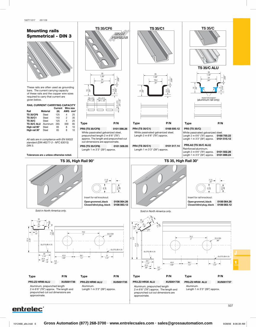
TS 35/CF6 Steel 125 4 25TS 35/C1 Steel 143 2 35TS 35/C Steel 125 4 25TS 35/C ALU Aluminum 265 000 95High rail 90° Steel 65 8 10High rail 30° Steel 65 8 10
All rails are in compliance with EN 50022standard (DIN 46277-3 - NFC 63015)DIN 3.
Tolerances are ± unless otherwise noted.
RAIL CURRENT CARRYING CAPACITY
These rails are often used as groundingbars. The current carrying capacityof these rails and the copper wire sizesrequired to carry that current aregiven below.
TS 35/C ALU
TS 35/CF6 TS 35/CTS 35/C1
(aluminum rail only)
Type P/N
PR5 (TS 35/CF6) 0101 509.05Length 1 m 3'3" (39") approx.
PR4 (TS 35/C1) 0101 517.14Length 1 m 3'3" (39") approx.
Type P/N
PR5 (TS 35/CF6) 0101 598.26White passivated galvanized steel.Length 2 m 6'6" (78") approx.
Type P/N
PR4 (TS 35/C1) 0168 500.12White passivated galvanized steel,prepunched length 2 m 6'6" (78")approx. The length and prepunched cutout dimensions are approximate.
PR5 (TS 35/C)
White passivated galvanized steel.Length 2 m 6'6" (78") approx. 0168 700.22Length 1 m 3'3" (39") approx. 0101 515.12
PR5.A2 (TS 35/C ALU)Reinforced aluminum.Length 2 m 6'6" (78") approx. 0101 502.26Length 1 m 3'3" (39") approx. 0101 899.24
TS 35, High Rail 90°
PR3.Z2 HR90 XUS001735
Aluminum.Length 1 m 3'3" (39") approx.
PR3.Z2 HR90 XUS001736
Aluminum, prepunched length2 m 6'6" (78") approx. The length andprepunched cut out dimensions areapproximate.
Type P/N Type P/N
Sold in North America only.
TS 35, High Rail 30°
Type P/N
PR3.Z2 HR30 XUS001737
Aluminum.Length 1 m 3'3" (39") approx.
PR3.Z2 HR30 XUS001738
Type P/N
Sold in North America only.
Insert for rail knockout:
Opengrommet,black 0106 064.26Closed blind plug, black 0106 083.12
Insert for rail knockout:
Opengrommet,black 0106 064.26Closed blind plug, black 0106 083.12
ALU ALU ALU ALU
Aluminum, prepunched length2 m 6'6" (78") approx. The length andprepunched cut out dimensions areapproximate.
507
160T11017 051129
J
1
PR2PR1.Z2
PR1.A2
(DIN 46277-1 - NFC 63018) DIN 1 (DIN 46277.2)
(A) AWG mm2
PR1.Z2 - PR1.Z3 143 2 35PR1.A2 265 000 95
EM45
PR1.Z3
EM90
PRH1P
PRH1A
PRH2P PRH2APRH2R
PR2P
PR2 35 12 4
Type P/N Type P/N
Zinc bichromate plated steel, length2 m 6'6" (78") approx.
Prepunched zinc bichromate platedsteel.
Mounting railsAsymmetrical - DIN 1Symmetrical - DIN 2
The “Series M” terminal blocks snaponto the PR1 asymmetrical DIN 1 railsdescribed here.
The “Series DR” terminal blocks snaponto the PR2 symmetrical DIN 2 raildescribed here.
The rails are often used as groundingbars. The current carrying capacityof the rails and the copper wire sizesrequired to carry that current are givenbelow.
Aluminum alloy, length3 m 9'9" (117") approx.
Rail offset brackets
Deflection 45° Deflection 90°
Asymmetrical 32 mm 1.26" G rail incompliance with EN 50035 standard
Symmetrical 15 mm .59" rail in compliancewith EN 50045 standard
Current Wire sizeRail Material
SteelAluminiumSteel
Zinc bichromate plated steel, length3 m 9'9" (117") approx.
Symmetrical type 1 12,2 x 5,1 rail incompliance with NFC 93461 standard
Type P/N
Aluminum anode-yellow alloy, notprepunched - Length 1 m
Prepunched aluminum anode-yellow alloyLength 1 m
Aluminum anode-yellow alloy, notprepunched - Length 2 m
Prepunched aluminum anode-yellowalloy - Length 2 m
Symmetrical type 2 21,8 x 6,4 mmin compliance with NFC 93461 standard
Symmetrical type 2 reinforced21,8 x 8,2 mm in compliance withNFC 93461 standard.
Aluminum anode-yellow alloy,length 2 m
Not prepunched zinc bichromateplated steel.
1SNA 164 600 R12001SNA 163 050 R0400
1SNA 167 120 R2300
1SNA 008 520 R0100 1SNA 008 521 R2600
1SNA 167 100 R0000
1SNA 163 370 R1100 1SNA 163 380 R04001SNA 163 350 R1500
1SNA 163 400 R0100
1SNA 163 390 R0600
1SNA 206 596 R2500
1012468_alts.indd 6 9/28/06 8:06:39 AMGross Automation (877) 268-3700 · www.entrelecsales.com · [email protected]
508160T11050 060112
J
2
BADL 9 mm
PEAD
RCPEAD 29 x 9 mm
EPR2
PIE24 (1) 37 x 24 mm
PEB 35 x 17 mmPEB 35 x 17 mm
PIB3 35 x 17 mm
PIB 35 x 17 mmEPR1
PEBM
PEH
RPEH 40 x 5 mm
RC810 8 mmRC1010 10 mmRPA
PEAD PIE24
PEB - PIB... RC...
BAM2 10 mm
BAM2 10 mmBAM2 10 mm
BADL
BAM2
PEH
BADL
BAM2
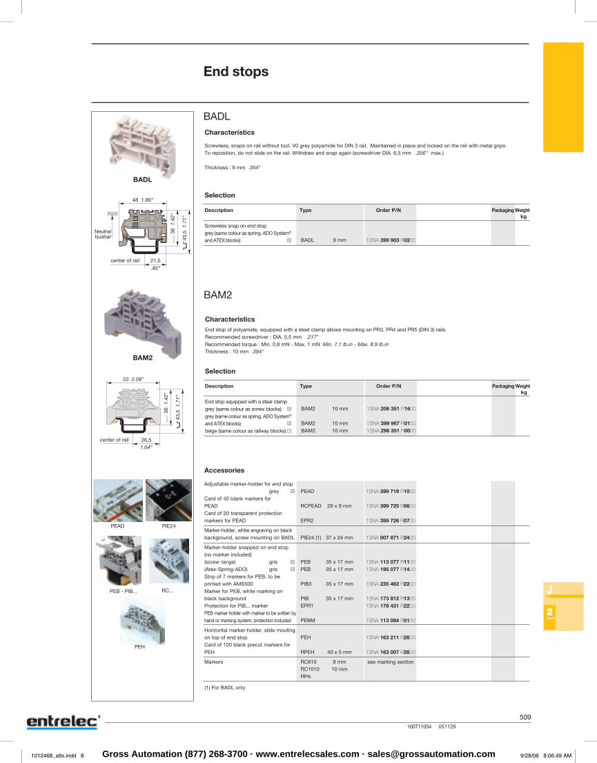
Characteristics
Description Type Order P/N Packaging Weightkg
Screwless snap on end stopgrey (same colour as spring, ADO System®
and ATEX blocks)
Selection
Accessories
Screwless, snaps on rail without tool. V0 grey polyamide for DIN 3 rail. Maintained in place and locked on the rail with metal grips.To reposition, do not slide on the rail. Withdraw and snap again (screwdriver DIA. 6,5 mm .256" max.)
Thickness : 9 mm .354"
End stops
Adjustable marker-holder for end stopgrey
Card of 40 blank markers forPEADCard of 20 transparent protectionmarkers for PEAD
Marker-holder, white engraving on blackbackground, screw mounting on BADL
Marker-holder snapped on end stop(no marker included)(screw range) gris(Atex-Spring-ADO) grisStrip of 7 markers for PEB, to beprinted with AMS500Marker for PEB, white marking onblack backgroundProtection for PIB... markerPEB marker holder with marker to be written byhand or marking system, protection included
Horizontal marker-holder, slide moutingon top of end stopCard of 120 blank precut markers forPEH
Markers see marking section
Characteristics
Description Type Order P/N Packaging Weightkg
End stop equipped with a steel clampgrey (same colour as screw blocks)grey (same colour as spring, ADO System®
and ATEX blocks)beige (same colour as railway blocks)
Selection
End stop of polyamide, equipped with a steel clamp allows mounting on PR3, PR4 and PR5 (DIN 3) rails.Recommended screwdriver : DIA. 5,5 mm .217"Recommended torque : Min. 0,8 mN - Max. 1 mN Min. 7.1 lb.in - Max. 8.9 lb.inThickness : 10 mm .394"
center of rail
(1) For BADL only
1SNA 399 903 R0200
1SNA 206 351 R1600
1SNA 399 967 R01001SNA 296 351 R0000
1SNA 399 719 R1000
1SNA 399 725 R0600
1SNA 399 726 R0700
1SNA 007 871 R2400
1SNA 113 077 R11001SNA 195 077 R1400
1SNA 235 462 R2200
1SNA 173 812 R13001SNA 178 431 R2200
1SNA 113 084 R0100
1SNA 163 211 R2600
1SNA 163 007 R2600
Type P/N Type P/N Type P/N
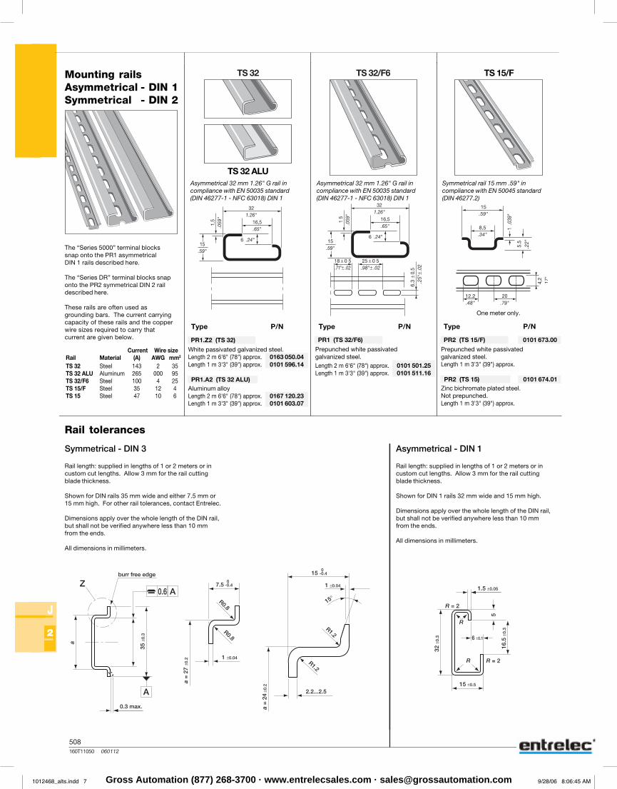
Mounting railsAsymmetrical - DIN 1Symmetrical - DIN 2
The “Series 5000” terminal blockssnap onto the PR1 asymmetricalDIN 1 rails described here.
The “Series DR” terminal blocks snaponto the PR2 symmetrical DIN 2 raildescribed here.
These rails are often used asgrounding bars. The current carryingcapacity of these rails and the copperwire sizes required to carry thatcurrent are given below.
TS 32 ALU
6F/23ST23ST
Asymmetrical 32 mm 1.26" G rail incompliance with EN 50035 standard(DIN 46277-1 - NFC 63018) DIN 1
Asymmetrical 32 mm 1.26" G rail incompliance with EN 50035 standard(DIN 46277-1 - NFC 63018) DIN 1
Symmetrical rail 15 mm .59" incompliance with EN 50045 standard(DIN 46277.2)
TS 15/F
Current Wire sizeRail Material (A) AWG mm2
TS 32 Steel 143 2 35TS 32 ALU Aluminum 265 000 95TS 32/F6 Steel 100 4 25TS 15/F Steel 35 12 4TS 15 Steel 47 10 6
PR1.Z2 (TS 32)
White passivated galvanized steel.Length 2 m 6'6" (78") approx. 0163 050.04Length 1 m 3'3" (39") approx. 0101 596.14
PR1.A2 (TS 32 ALU)Aluminum alloyLength 2 m 6'6" (78") approx. 0167 120.23Length 1 m 3'3" (39") approx. 0101 603.07
PR2 (TS 15/F) 0101 673.00
Prepunched white passivated galvanized steel.Length 1 m 3'3" (39") approx.
PR2 (TS 15) 0101 674.01Zinc bichromate plated steel.Not prepunched.Length 1 m 3'3" (39") approx.
PR1 (TS 32/F6)
Prepunched white passivated galvanized steel.Length 2 m 6'6" (78") approx. 0101 501.25Length 1 m 3'3" (39") approx. 0101 511.16
One meter only.
Rail tolerances
Symmetrical - DIN 3
Rail length: supplied in lengths of 1 or 2 meters or incustom cut lengths. Allow 3 mm for the rail cuttingblade thickness.
Shown for DIN rails 35 mm wide and either 7.5 mm or15 mm high. For other rail tolerances, contact Entrelec.
Dimensions apply over the whole length of the DIN rail,but shall not be verified anywhere less than 10 mmfrom the ends.
All dimensions in millimeters.
Asymmetrical - DIN 1
Rail length: supplied in lengths of 1 or 2 meters or incustom cut lengths. Allow 3 mm for the rail cuttingblade thickness.
Shown for DIN 1 rails 32 mm wide and 15 mm high.
Dimensions apply over the whole length of the DIN rail,but shall not be verified anywhere less than 10 mmfrom the ends.
All dimensions in millimeters.
1012468_alts.indd 7 9/28/06 8:06:45 AMGross Automation (877) 268-3700 · www.entrelecsales.com · [email protected]
509160T11054 051129
J
2
BADH 12 mm
BAEH 12 mm
PEB 35 x 17 mm
PIB3 35 x 17 mm
PIB 35 x 17 mmEPR1
PEBM
PEH
RPEH 40 x 5 mm
RC810 8 mmRC1010 10 mmRPA
PEB - PIB...
PEH
RC...
BAMH 9,1 mm
BAMH 9,1 mm
BAEH
BADH
BADH
BAMH
Characteristics
Description Type Order P/N Packaging Weightkg
Snap on end stop, mounting on symmetricalDIN 3 rails grey
Snap on end stop, mounting on asymmetricalDIN 1 rail grey
Selection
Accessories
Tall end stop of polyamide, for use with M 70/22, M 95/26 blocks, power blocks, double or triple deck blocks, and electronic interfacemodules series 7000, 8000, 10000, 11000 and 30000. Snaps on rail - Easy mounting and repositioning, even between 2 blocks.Recommended screwdriver : DIA. 5,5 mm .217"Recommended torque : Min. 1,2 Nm - Max. 1,4 NmMin. 10.6 lb.in - Max. 12.3 lb.inThickness : 12 mm .472"
End stops
Tall end stop BADH, BAEH
Marker-holder snapped on end stop(no marker included)Strip of 7 markers for PEB, to beprinted with AMS500Marker for PEB, white marking onblack backgroundProtection for PIB... markerPEB marker holder with marker to be written byhand or marking system, protection included
Horizontal marker-holder, slide moutingon top of end stopCard of 120 blank precut markers forPEH
Card of 100 markers for vertical marking see marking section
Characteristics
Description Type Order P/N Packaging Weightkg
Multi-rail end stop grey
Multi-rail end stop V0 beige
Selection
Tall end stop BAMH
Multi-rail end stop of V2 or V0 polyamide equipped with 2 blocking screws allows mounting on PR1, PR3, PR4 and PR5 (DIN 1, DIN 3) rails.Suitable for double deck blocks.Recommended screwdriver : DIA. 5,5 mm .217"Recommended torque : Min. 0,8 mN - Max. 1 mN Min. 7.1 lb.in - Max. 8.9 lb.inThickness : 9,1 mm .358"
1SNA 116 900 R2700
1SNA 116 934 R0400
1SNA 114 836 R0000
1SNA 194 836 R0100
1SNA 113 077 R1100
1SNA 235 462 R2200
1SNA 173 812 R13001SNA 178 431 R2200
1SNA 113 084 R0100
1SNA 163 211 R2600
1SNA 163 007 R2600
508160T11050 060112
J
2
BADL 9 mm
PEAD
RCPEAD 29 x 9 mm
EPR2
PIE24 (1) 37 x 24 mm
PEB 35 x 17 mmPEB 35 x 17 mm
PIB3 35 x 17 mm
PIB 35 x 17 mmEPR1
PEBM
PEH
RPEH 40 x 5 mm
RC810 8 mmRC1010 10 mmRPA
PEAD PIE24
PEB - PIB... RC...
BAM2 10 mm
BAM2 10 mmBAM2 10 mm
BADL
BAM2
PEH
BADL
BAM2
Characteristics
Description Type Order P/N Packaging Weightkg
Screwless snap on end stopgrey (same colour as spring, ADO System®
and ATEX blocks)
Selection
Accessories
Screwless, snaps on rail without tool. V0 grey polyamide for DIN 3 rail. Maintained in place and locked on the rail with metal grips.To reposition, do not slide on the rail. Withdraw and snap again (screwdriver DIA. 6,5 mm .256" max.)
Thickness : 9 mm .354"
End stops
Adjustable marker-holder for end stopgrey
Card of 40 blank markers forPEADCard of 20 transparent protectionmarkers for PEAD
Marker-holder, white engraving on blackbackground, screw mounting on BADL
Marker-holder snapped on end stop(no marker included)(screw range) gris(Atex-Spring-ADO) grisStrip of 7 markers for PEB, to beprinted with AMS500Marker for PEB, white marking onblack backgroundProtection for PIB... markerPEB marker holder with marker to be written byhand or marking system, protection included
Horizontal marker-holder, slide moutingon top of end stopCard of 120 blank precut markers forPEH
Markers see marking section
Characteristics
Description Type Order P/N Packaging Weightkg
End stop equipped with a steel clampgrey (same colour as screw blocks)grey (same colour as spring, ADO System®
and ATEX blocks)beige (same colour as railway blocks)
Selection
End stop of polyamide, equipped with a steel clamp allows mounting on PR3, PR4 and PR5 (DIN 3) rails.Recommended screwdriver : DIA. 5,5 mm .217"Recommended torque : Min. 0,8 mN - Max. 1 mN Min. 7.1 lb.in - Max. 8.9 lb.inThickness : 10 mm .394"
center of rail
(1) For BADL only
1SNA 399 903 R0200
1SNA 206 351 R1600
1SNA 399 967 R01001SNA 296 351 R0000
1SNA 399 719 R1000
1SNA 399 725 R0600
1SNA 399 726 R0700
1SNA 007 871 R2400
1SNA 113 077 R11001SNA 195 077 R1400
1SNA 235 462 R2200
1SNA 173 812 R13001SNA 178 431 R2200
1SNA 113 084 R0100
1SNA 163 211 R2600
1SNA 163 007 R2600
1012468_alts.indd 8 9/28/06 8:06:49 AMGross Automation (877) 268-3700 · www.entrelecsales.com · [email protected]

510160T11069 051129
J
2
BADRL 6,5 mm
PIE9 (1) 37 x 9 mm
PIE24 (1) 37 x 24 mmVST28 (1)
PEB 35 x 17 mm
PIB3 35 x 17 mm
PIB 35 x 17 mmEPR1
RC610 (2) 6 mmRPA (1)
BAR 10 mm
BADRL
BAR
PIE...
BADRL
BAR
PIB...
RPA
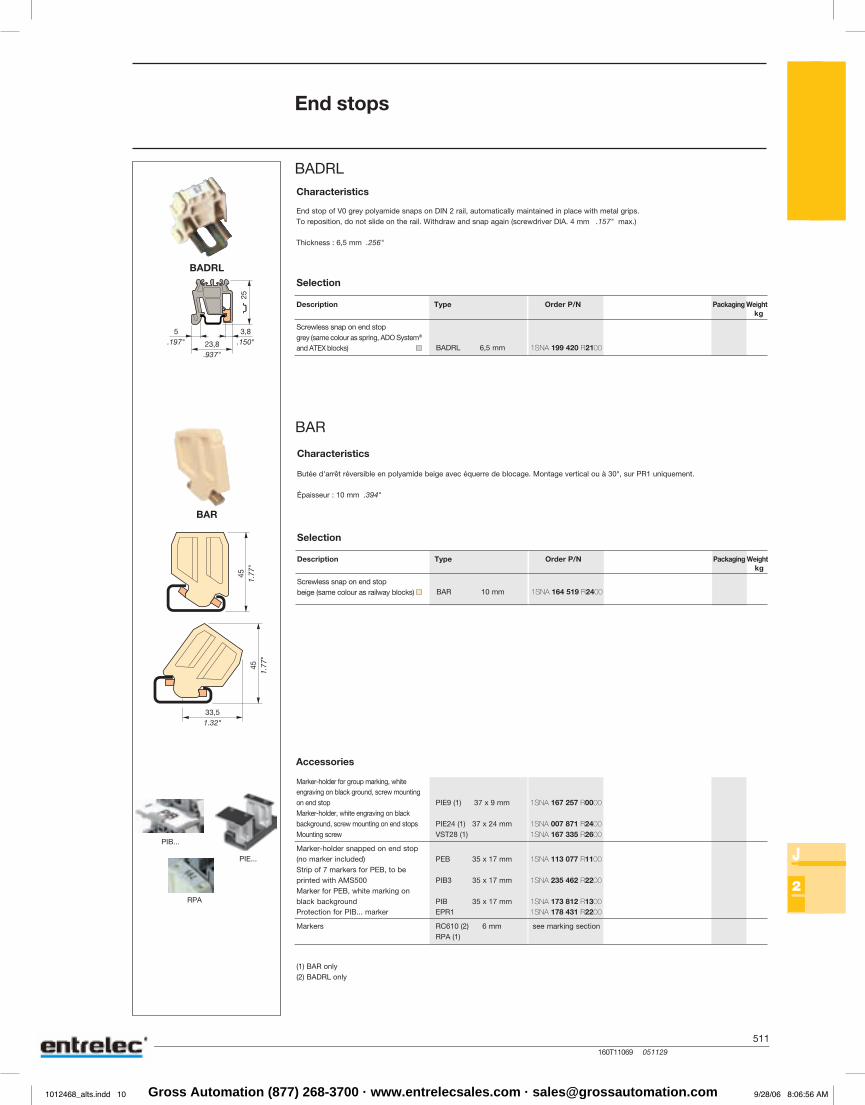
Characteristics
Description Type Order P/N Packaging Weightkg
Screwless snap on end stopgrey (same colour as spring, ADO System®
and ATEX blocks)
Selection
Accessories
End stop of V0 grey polyamide snaps on DIN 2 rail, automatically maintained in place with metal grips.To reposition, do not slide on the rail. Withdraw and snap again (screwdriver DIA. 4 mm .157" max.)
Thickness : 6,5 mm .256"
End stops
Marker-holder for group marking, whiteengraving on black ground, screw mountingon end stopMarker-holder, white engraving on blackbackground, screw mounting on end stopsMounting screw
Marker-holder snapped on end stop(no marker included)Strip of 7 markers for PEB, to beprinted with AMS500Marker for PEB, white marking onblack backgroundProtection for PIB... marker
Markers see marking section
Characteristics
Description Type Order P/N Packaging Weightkg
Screwless snap on end stopbeige (same colour as railway blocks)
Selection
Butée d'arrêt réversible en polyamide beige avec équerre de blocage. Montage vertical ou à 30°, sur PR1 uniquement.
Épaisseur : 10 mm .394"
(1) BAR only(2) BADRL only
1SNA 199 420 R2100
1SNA 164 519 R2400
1SNA 167 257 R0000
1SNA 007 871 R24001SNA 167 335 R2600
1SNA 113 077 R1100
1SNA 235 462 R2200
1SNA 173 812 R13001SNA 178 431 R2200
509160T11054 051129
J
2
BADH 12 mm
BAEH 12 mm
PEB 35 x 17 mm
PIB3 35 x 17 mm
PIB 35 x 17 mmEPR1
PEBM
PEH
RPEH 40 x 5 mm
RC810 8 mmRC1010 10 mmRPA
PEB - PIB...
PEH
RC...
BAMH 9,1 mm
BAMH 9,1 mm
BAEH
BADH
BADH
BAMH
Characteristics
Description Type Order P/N Packaging Weightkg
Snap on end stop, mounting on symmetricalDIN 3 rails grey
Snap on end stop, mounting on asymmetricalDIN 1 rail grey
Selection
Accessories
Tall end stop of polyamide, for use with M 70/22, M 95/26 blocks, power blocks, double or triple deck blocks, and electronic interfacemodules series 7000, 8000, 10000, 11000 and 30000. Snaps on rail - Easy mounting and repositioning, even between 2 blocks.Recommended screwdriver : DIA. 5,5 mm .217"Recommended torque : Min. 1,2 Nm - Max. 1,4 NmMin. 10.6 lb.in - Max. 12.3 lb.inThickness : 12 mm .472"
End stops
Tall end stop BADH, BAEH
Marker-holder snapped on end stop(no marker included)Strip of 7 markers for PEB, to beprinted with AMS500Marker for PEB, white marking onblack backgroundProtection for PIB... markerPEB marker holder with marker to be written byhand or marking system, protection included
Horizontal marker-holder, slide moutingon top of end stopCard of 120 blank precut markers forPEH
Card of 100 markers for vertical marking see marking section
Characteristics
Description Type Order P/N Packaging Weightkg
Multi-rail end stop grey
Multi-rail end stop V0 beige
Selection
Tall end stop BAMH
Multi-rail end stop of V2 or V0 polyamide equipped with 2 blocking screws allows mounting on PR1, PR3, PR4 and PR5 (DIN 1, DIN 3) rails.Suitable for double deck blocks.Recommended screwdriver : DIA. 5,5 mm .217"Recommended torque : Min. 0,8 mN - Max. 1 mN Min. 7.1 lb.in - Max. 8.9 lb.inThickness : 9,1 mm .358"
1SNA 116 900 R2700
1SNA 116 934 R0400
1SNA 114 836 R0000
1SNA 194 836 R0100
1SNA 113 077 R1100
1SNA 235 462 R2200
1SNA 173 812 R13001SNA 178 431 R2200
1SNA 113 084 R0100
1SNA 163 211 R2600
1SNA 163 007 R2600
1012468_alts.indd 9 9/28/06 8:06:53 AMGross Automation (877) 268-3700 · www.entrelecsales.com · [email protected]
NOTE_511 051129
511
Notes
509160T11054 051129
J
2
BADH 12 mm
BAEH 12 mm
PEB 35 x 17 mm
PIB3 35 x 17 mm
PIB 35 x 17 mmEPR1
PEBM
PEH
RPEH 40 x 5 mm
RC810 8 mmRC1010 10 mmRPA
PEB - PIB...
PEH
RC...
BAMH 9,1 mm
BAMH 9,1 mm
BAEH
BADH
BADH
BAMH
Characteristics
Description Type Order P/N Packaging Weightkg
Snap on end stop, mounting on symmetricalDIN 3 rails grey
Snap on end stop, mounting on asymmetricalDIN 1 rail grey
Selection
Accessories
Tall end stop of polyamide, for use with M 70/22, M 95/26 blocks, power blocks, double or triple deck blocks, and electronic interfacemodules series 7000, 8000, 10000, 11000 and 30000. Snaps on rail - Easy mounting and repositioning, even between 2 blocks.Recommended screwdriver : DIA. 5,5 mm .217"Recommended torque : Min. 1,2 Nm - Max. 1,4 NmMin. 10.6 lb.in - Max. 12.3 lb.inThickness : 12 mm .472"
End stops
Tall end stop BADH, BAEH
Marker-holder snapped on end stop(no marker included)Strip of 7 markers for PEB, to beprinted with AMS500Marker for PEB, white marking onblack backgroundProtection for PIB... markerPEB marker holder with marker to be written byhand or marking system, protection included
Horizontal marker-holder, slide moutingon top of end stopCard of 120 blank precut markers forPEH
Card of 100 markers for vertical marking see marking section
Characteristics
Description Type Order P/N Packaging Weightkg
Multi-rail end stop grey
Multi-rail end stop V0 beige
Selection
Tall end stop BAMH
Multi-rail end stop of V2 or V0 polyamide equipped with 2 blocking screws allows mounting on PR1, PR3, PR4 and PR5 (DIN 1, DIN 3) rails.Suitable for double deck blocks.Recommended screwdriver : DIA. 5,5 mm .217"Recommended torque : Min. 0,8 mN - Max. 1 mN Min. 7.1 lb.in - Max. 8.9 lb.inThickness : 9,1 mm .358"
1SNA 116 900 R2700
1SNA 116 934 R0400
1SNA 114 836 R0000
1SNA 194 836 R0100
1SNA 113 077 R1100
1SNA 235 462 R2200
1SNA 173 812 R13001SNA 178 431 R2200
1SNA 113 084 R0100
1SNA 163 211 R2600
1SNA 163 007 R2600
510160T11069 051129
J
2
BADRL 6,5 mm
PIE9 (1) 37 x 9 mm
PIE24 (1) 37 x 24 mmVST28 (1)
PEB 35 x 17 mm
PIB3 35 x 17 mm
PIB 35 x 17 mmEPR1
RC610 (2) 6 mmRPA (1)
BAR 10 mm
BADRL
BAR
PIE...
BADRL
BAR
PIB...
RPA
Characteristics
Description Type Order P/N Packaging Weightkg
Screwless snap on end stopgrey (same colour as spring, ADO System®
and ATEX blocks)
Selection
Accessories
End stop of V0 grey polyamide snaps on DIN 2 rail, automatically maintained in place with metal grips.To reposition, do not slide on the rail. Withdraw and snap again (screwdriver DIA. 4 mm .157" max.)
Thickness : 6,5 mm .256"
End stops
Marker-holder for group marking, whiteengraving on black ground, screw mountingon end stopMarker-holder, white engraving on blackbackground, screw mounting on end stopsMounting screw
Marker-holder snapped on end stop(no marker included)Strip of 7 markers for PEB, to beprinted with AMS500Marker for PEB, white marking onblack backgroundProtection for PIB... marker
Markers see marking section
Characteristics
Description Type Order P/N Packaging Weightkg
Screwless snap on end stopbeige (same colour as railway blocks)
Selection
Butée d'arrêt réversible en polyamide beige avec équerre de blocage. Montage vertical ou à 30°, sur PR1 uniquement.
Épaisseur : 10 mm .394"
(1) BAR only(2) BADRL only
1SNA 199 420 R2100
1SNA 164 519 R2400
1SNA 167 257 R0000
1SNA 007 871 R24001SNA 167 335 R2600
1SNA 113 077 R1100
1SNA 235 462 R2200
1SNA 173 812 R13001SNA 178 431 R2200
1012468_alts.indd 10 9/28/06 8:06:56 AMGross Automation (877) 268-3700 · www.entrelecsales.com · [email protected]

512160T11070 051129
J
3
SCF61
SCF6.D
SCF.D (1)
SCD (2)
SCF6G (1)SCF12 (2)SCF16 (3)SCF22 (4)SCFT2 (5)
CPM
RTC
PEP
SCD5.2LSCD5.2LSCD5.3LSCD5.4L SCF9
SCF.D
SCMA5 (1)
SCMA5D (2)
SCM6 (3)SCM6 (3)
SCM6D (4)
SCAD (5)
SCM...
SCF6SCF6
SCFM6
PEP
SCFT1*
SCD
CPM + RTC
Circuit separatorsSeparator end sections
Product Type Order P/N
Possibility of marking, by the user, on the back of theseparator.For blocks : M 4/6 except D and G
M 6/8 - M 10/10M 4/6.HM 1,5/6.HH and ADV
Width : 51 mm 2.01"Thickness : 2 mm .079"
Separator end section grey
For M 4/6.D block only. Extends 2 mm .079" around theblock.
Height : 61,5 mm 2.42"
69 mm 2.72" 66,5 mm 2.62"
Thickness : 1 mm .039"
Separator end section grey
Only for NTLP blocks.(1) With cut-out for busbar passage. Snapped on PR3, PR4and PR5 rails. Extends 3 mm .12" around the block exceptingon top.(2) Snapped onto the extremity of the BJM62 connector barsbefore they are mounted on the blocks.
Thickness (1) : 1,5 mm .059"
Separator end section grey
Circuit separator white
Product Type Order P/N
With possibility of mounting a protective cover CPM, and amarker-holder PEP. Extends 5 mm .20" on sides of the blockand 11,5 mm .45" on top.For blocks : M 4/6.G (1)
M 16/12 (2)M 35/16 (3)M 70/22 (4)M 6/8.ST(5)
Thickness : 3 mm .118"
Separator end section greygreygreygreygrey
Accessories :
Protective cover clearbeige
Top marking strip for CPM
Marker holder
CPM cover protects the user from accidental touch on livecircuits. It is clipped onto the end sections (FE), onto theintermediate sections (FJ) and onto the SCF, SCFT or SCFMseparators. It can also be used for marking the terminal unit bymeans of a blank strip RTC, which slides into the cover.
CPM width : 32 mm 1.26"CPM length : 500 mm 19.70"RTC width : 20 mm .79"RTC length : 1 m 39"
For spring blocks.
Thickness : 2,5 mm .098"
Separator end section greyorangeorangeorange
With possibility of mounting a protective cover CPM, and amarker-holder PEP. Snap on mounting on PR1, PR3, PR4and PR5. This separator does not replace an end sectionwhich must be used on the block.For blocks : M 6/9.EE
M 6/12.FFThickness : 1 mm .039"
Separator end section white
The SCM separator snaps onto the top of the open terminal blocks, oncethe terminal board is assembled. It does not increase the thickness of theblocks but extends 8 mm .315" on top.For blocks : MA 2,5/5 (1)
MA 2,5/5.D (2)M 1,5/6.HH and ADV blocks, M 4/6, M 6/8,M 10/10, M 16/12 (3)M 4/6.D (4)ADO System® blocks (5)
Circuit separator grey
grey
greyorange
grey
grey
With possibility of mounting a protective cover CPM, and amarker-holder PEP. Extends 5 mm .20" on sides of the blockand 11,5 mm .45" on top (1).For blocks : MA 2,5/5 (1)
M 4/6 except D and G (1) (2)M 6/8 - M 10/10 (1) (2)M 4/6.H (1)
Height : 59,5 mm 2.34"
67 mm 2.64" 64,5 mm 2.54"
Width : 51 mm 2.01"Thickness : 3 mm .118"
Separator end section greyblue
grey
(1) For SCF6, snapped on block(2) For SCFM6, mounting on PR1, PR4 and PR5 rails
This marker holder snaps on separator end sections SCF orSCFM and on the ECP and ECS power blocks' partitions.It can receive 1 label RC610.*Note : Not to be mounted on SCFT1 separator end section.
Separator for use with 1/4 turn terminal blocks, withpossibility of mounting one or two protective covers CPMside by side. Snap on mounting on PR1, PR3, PR4 and PR5rails.Height : 63 mm 2.48"
70,5 mm 2.78" 68 mm 2.68"
Width : 77,5 mm 3.05"Thickness : 1 mm .039"
Separator end section grey
1SNA 114 202 R2500
1SNA 118 495 R1700
1SNA 113 075 R17001SNA 113 102 R10001SNA 113 101 R17001SNA 113 851 R16001SNA 114 522 R0500
1SNA 187 312 R14001SNA 197 312 R16001SNA 163 156 R2700
1SNA 113 762 R2400
1SNA 291 351 R03001SNA 291 352 R04001SNA 291 362 R06001SNA 291 372 R0000 1SNA 103 672 R0100
1SNA 114 117 R0700
1SNA 103 189 R2600
1SNA 116 728 R2500
1SNA 116 720 R2100
1SNA 113 003 R10001SNA 103 233 R2100
1SNA 113 482 R0500
1SNA 196 896 R0000
1SNA 118 707 R03001SNA 128 707 R0500
1SNA 114 825 R0500
1SNA 103 588 R2600
Gross Automation (877) 268-3700 · www.entrelecsales.com · [email protected]
513160T11071 051129
J
3
SCFCV1-2 (1)SCFCV3 (2)SCFCV4 (3)SCFCV5 (4)
SCFCV + CPV
CPV1-2CPV3CPV4-SRTC
PEP
PEP
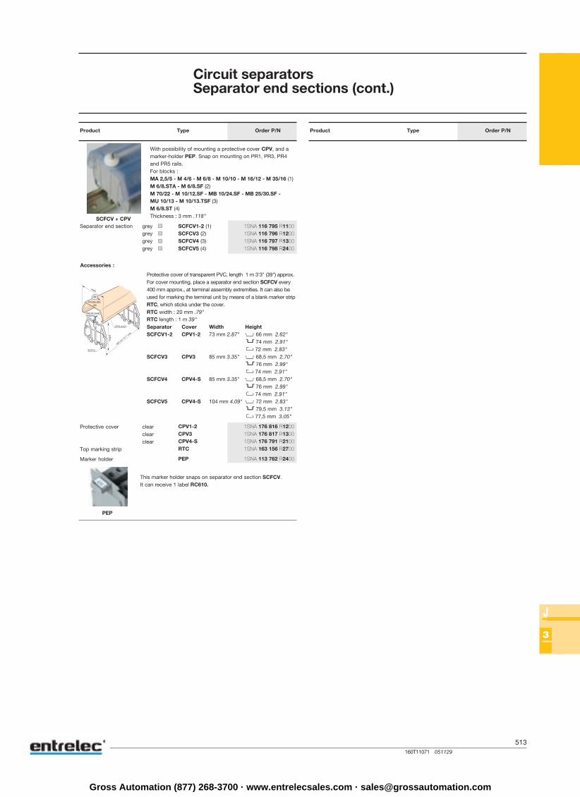
Circuit separatorsSeparator end sections (cont.)
Product Type Order P/N Product Type Order P/N
With possibility of mounting a protective cover CPV, and amarker-holder PEP. Snap on mounting on PR1, PR3, PR4and PR5 rails.For blocks :MA 2,5/5 - M 4/6 - M 6/8 - M 10/10 - M 16/12 - M 35/16 (1)M 6/8.STA - M 6/8.SF (2)M 70/22 - M 10/12.SF - MB 10/24.SF - MB 25/30.SF -MU 10/13 - M 10/13.TSF (3)M 6/8.ST (4)Thickness : 3 mm .118"
Separator end section greygreygreygrey
Accessories :
Protective cover clearclearclear
Top marking strip
Marker holder
Protective cover of transparent PVC, length 1 m 3'3" (39") approx.For cover mounting, place a separator end section SCFCV every400 mm approx., at terminal assembly extremities. It can also beused for marking the terminal unit by means of a blank marker stripRTC, which sticks under the cover.RTC width : 20 mm .79"RTC length : 1 m 39"Separator Cover Width HeightSCFCV1-2 CPV1-2 73 mm 2.87" 66 mm 2.62"
74 mm 2.91" 72 mm 2.83"
SCFCV3 CPV3 85 mm 3.35" 68,5 mm 2.70" 76 mm 2.99" 74 mm 2.91"
SCFCV4 CPV4-S 85 mm 3.35" 68,5 mm 2.70" 76 mm 2.99" 74 mm 2.91"
SCFCV5 CPV4-S 104 mm 4.09" 72 mm 2.83" 79,5 mm 3.13" 77,5 mm 3.05"
This marker holder snaps on separator end section SCFCV.It can receive 1 label RC610.
1SNA 116 795 R11001SNA 116 796 R12001SNA 116 797 R13001SNA 116 798 R2400
1SNA 176 816 R12001SNA 176 817 R13001SNA 176 791 R21001SNA 163 156 R2700
1SNA 113 762 R2400
Gross Automation (877) 268-3700 · www.entrelecsales.com · [email protected]
514160T11078 051129
J
44444
BJMI5BJMI5BJMI5BJMI5BJMI5
BJMI6BJMI6BJMI6BJMI6BJMI6
BJMI8BJMI8BJMI8BJMI8BJMI8
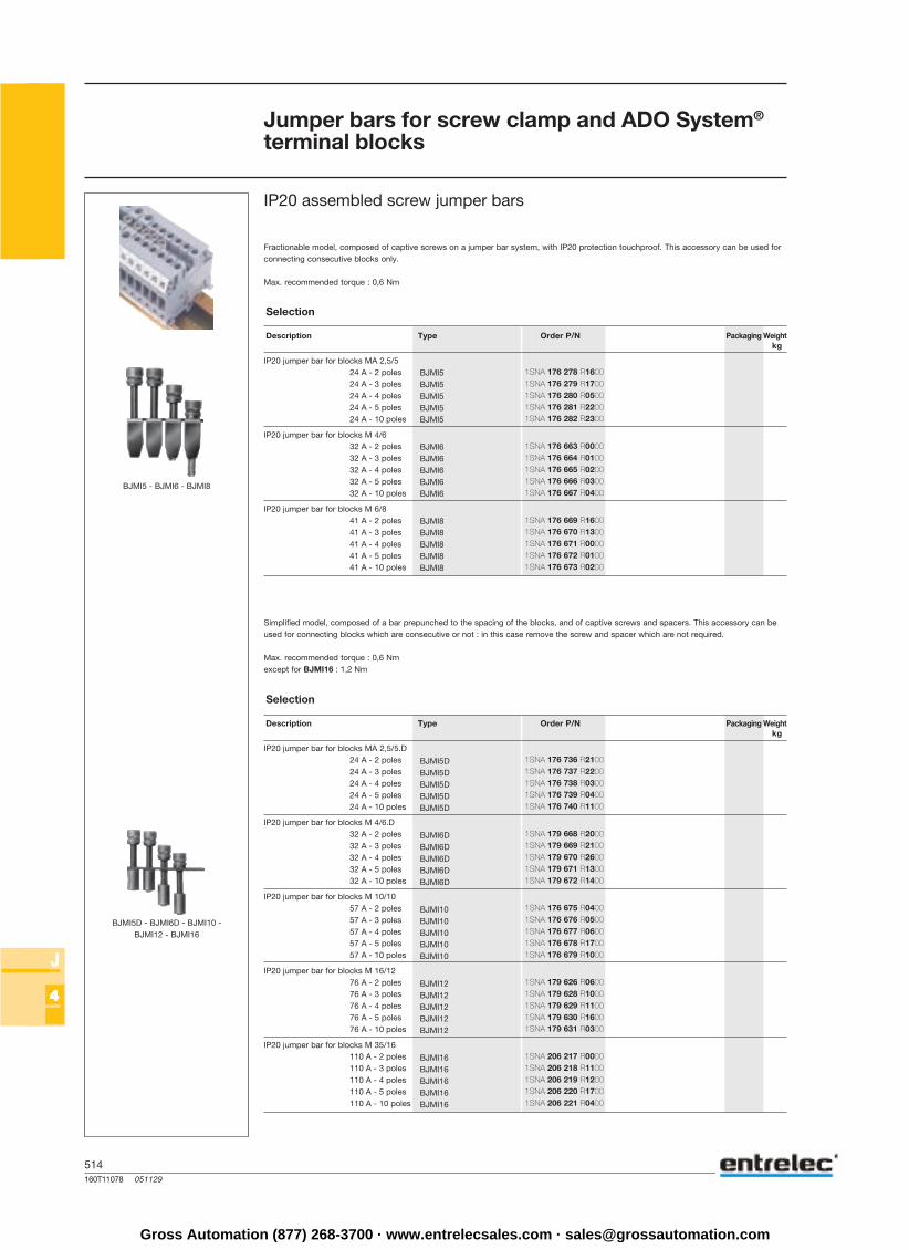
BJMI5 - BJMI6 - BJMI8
BJMI5DBJMI5DBJMI5DBJMI5DBJMI5D
BJMI6DBJMI6DBJMI6DBJMI6DBJMI6D
BJMI10BJMI10BJMI10BJMI10BJMI10
BJMI12BJMI12BJMI12BJMI12BJMI12
BJMI16BJMI16BJMI16BJMI16BJMI16
BJMI5D - BJMI6D - BJMI10 -BJMI12 - BJMI16
Description Type Order P/N Packaging Weightkg
IP20 jumper bar for blocks MA 2,5/524 A - 2 poles24 A - 3 poles24 A - 4 poles24 A - 5 poles24 A - 10 poles
IP20 jumper bar for blocks M 4/632 A - 2 poles32 A - 3 poles32 A - 4 poles32 A - 5 poles32 A - 10 poles
IP20 jumper bar for blocks M 6/841 A - 2 poles41 A - 3 poles41 A - 4 poles41 A - 5 poles41 A - 10 poles
Selection
Fractionable model, composed of captive screws on a jumper bar system, with IP20 protection touchproof. This accessory can be used forconnecting consecutive blocks only.
Max. recommended torque : 0,6 Nm
Jumper bars for screw clamp and ADO System®
terminal blocks
IP20 assembled screw jumper bars
Description Type Order P/N Packaging Weightkg
IP20 jumper bar for blocks MA 2,5/5.D24 A - 2 poles24 A - 3 poles24 A - 4 poles24 A - 5 poles24 A - 10 poles
IP20 jumper bar for blocks M 4/6.D32 A - 2 poles32 A - 3 poles32 A - 4 poles32 A - 5 poles32 A - 10 poles
IP20 jumper bar for blocks M 10/1057 A - 2 poles57 A - 3 poles57 A - 4 poles57 A - 5 poles57 A - 10 poles
IP20 jumper bar for blocks M 16/1276 A - 2 poles76 A - 3 poles76 A - 4 poles76 A - 5 poles76 A - 10 poles
IP20 jumper bar for blocks M 35/16110 A - 2 poles110 A - 3 poles110 A - 4 poles110 A - 5 poles110 A - 10 poles
Selection
Simplified model, composed of a bar prepunched to the spacing of the blocks, and of captive screws and spacers. This accessory can beused for connecting blocks which are consecutive or not : in this case remove the screw and spacer which are not required.
Max. recommended torque : 0,6 Nmexcept for BJMI16 : 1,2 Nm
1SNA 176 278 R16001SNA 176 279 R17001SNA 176 280 R05001SNA 176 281 R22001SNA 176 282 R2300
1SNA 176 663 R00001SNA 176 664 R01001SNA 176 665 R02001SNA 176 666 R03001SNA 176 667 R0400
1SNA 176 669 R16001SNA 176 670 R13001SNA 176 671 R00001SNA 176 672 R01001SNA 176 673 R0200
1SNA 176 736 R21001SNA 176 737 R22001SNA 176 738 R03001SNA 176 739 R04001SNA 176 740 R1100
1SNA 179 668 R20001SNA 179 669 R21001SNA 179 670 R26001SNA 179 671 R13001SNA 179 672 R1400
1SNA 176 675 R04001SNA 176 676 R05001SNA 176 677 R06001SNA 176 678 R17001SNA 176 679 R1000
1SNA 179 626 R06001SNA 179 628 R10001SNA 179 629 R11001SNA 179 630 R16001SNA 179 631 R0300
1SNA 206 217 R00001SNA 206 218 R11001SNA 206 219 R12001SNA 206 220 R17001SNA 206 221 R0400
Gross Automation (877) 268-3700 · www.entrelecsales.com · [email protected]
515160T11068 051129
J
44444
EV5
BJS5
EV5DBJS5D
EV6EV6IBJS6
EV6D
BJS61
EVDR6BJS62D
EV6EV8SVJS11
BJS8
BJS9,5
EV6BJS10
EV12
BJS12
BJS12,5
BJS13
BJS131
EV16BJS16
BJS22
BJS24
VJS51
BJS261
BJA5 24 ABJA5 24 A
BJA6 35 ABJA6 35 A
+
Description Type Order P/N Packaging Weightkg
Post + screw + washer for blocksMA 2,5/5 and DR 1,5/5Perforated jumper bar forblocks MA 2,5/5 and DR 1,5/5 20 poles - 24 A
Post + screw + washer for block MA 2,5/5.DJumper bar for block MA 2,5/5.D 20 poles - 24 A
Post + screw + washer for block M 4/6Insulated post + screw + washer for block M 4/6Jumper bar for block M 4/6 20 poles - 32 A
Post + screw + washer for blocksM 4/6.D and MD 2,5/6...Perforated jumper bar forblocks M 4/6.D and MD 2,5/6... 10 poles - 32 A
Post + screw + washer for block DR 4/6Jumper bar for block DR 4/6 10 poles - 24 A
Post + screw + washer for block M 6/8Post + screw + washer for block M 6/8.STPost + screw + washer for block M 4/8.D2.SF...JPerforated jumper bar for blocksM 6/8 - M 6/8.ST - M 4/8.D5.SF...J 20 poles - 41 A
Jumper bar for block M 6/9.EE 10 poles - 41 A
Post + screw + washer for block M 10/10Jumper bar for block M 10/10 20 poles - 57 A
Post + screw + washer for block M 16/12Screw for block MB 10/12.SFWasher for block MB 10/12.SFPerforated jumper bar forblocks M 16/12 and MB 10/12.SF 20 poles - 57 A
Jumper bar for block M 6/12.FF 10 poles - 41 A
Jumper bar for block M 6/13.FF 10 poles - 125 A
Screw for block ML 10/13.SFWasher for block ML 10/13.SFJumper bar for block ML 10/13.SF 10 poles - 57 A
Post + screw + washer for block M 35/16Jumper bar for block M 35/16 10 poles - 125 A
Screw for block M 70/22Washer for block M 70/22Jumper bar for block M 70/22 10 poles - 192 A
Screw for block MB 10/24.SFJumper bar for block MB 10/24.SF 10 poles - 30 A
Post + screw + washer for block M 95/26Washer for block M 95/26Jumper bar for block M 95/26 10 poles - 232 A
Selection
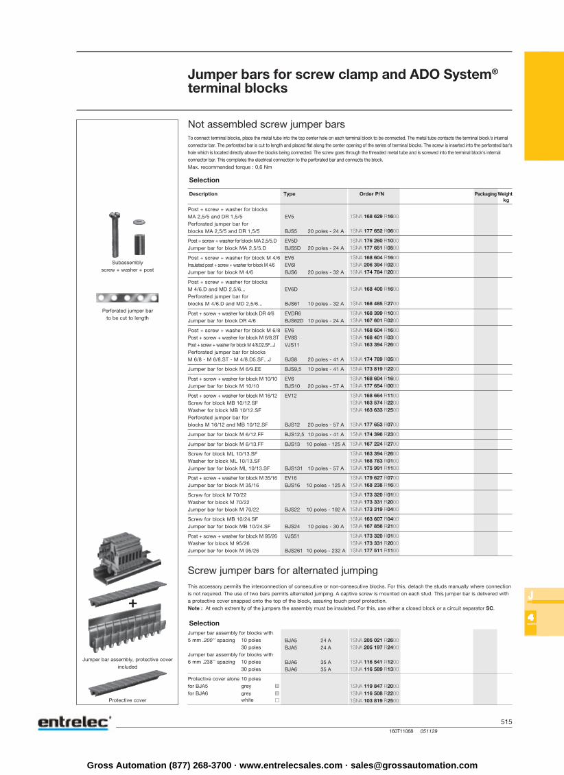
To connect terminal blocks, place the metal tube into the top center hole on each terminal block to be connected. The metal tube contacts the terminal block's internalconnector bar. The perforated bar is cut to length and placed flat along the center opening of the series of terminal blocks. The screw is inserted into the perforated bar'shole which is located directly above the blocks being connected. The screw goes through the threaded metal tube and is screwed into the terminal block's internalconnector bar. This completes the electrical connection to the perforated bar and connects the block.Max. recommended torque : 0,6 Nm
Jumper bars for screw clamp and ADO System®
terminal blocks
Not assembled screw jumper bars
Subassemblyscrew + washer + post
Perforated jumper barto be cut to length
Selection
This accessory permits the interconnection of consecutive or non-consecutive blocks. For this, detach the studs manually where connectionis not required. The use of two bars permits alternated jumping. A captive screw is mounted on each stud. This jumper bar is delivered witha protective cover snapped onto the top of the block, assuring touch proof protection.Note : At each extremity of the jumpers the assembly must be insulated. For this, use either a closed block or a circuit separator SC.
Screw jumper bars for alternated jumping
Jumper bar assembly for blocks with5 mm .200’’ spacing 10 poles
30 polesJumper bar assembly for blocks with6 mm .238’’ spacing 10 poles
30 poles
Protective cover alone 10 polesfor BJA5 greyfor BJA6 grey
white
Jumper bar assembly, protective coverincluded
Protective cover
1SNA 168 629 R1600
1SNA 177 652 R0600
1SNA 176 260 R10001SNA 177 651 R0500
1SNA 168 604 R16001SNA 206 394 R02001SNA 174 784 R2000
1SNA 168 400 R1600
1SNA 168 485 R2700
1SNA 168 399 R10001SNA 167 601 R0200
1SNA 168 604 R16001SNA 168 401 R03001SNA 163 394 R2600
1SNA 174 789 R0500
1SNA 173 819 R2200
1SNA 168 604 R16001SNA 177 654 R0000
1SNA 168 664 R11001SNA 163 574 R22001SNA 163 633 R2500
1SNA 177 653 R0700
1SNA 174 396 R2300
1SNA 167 224 R2700
1SNA 163 394 R26001SNA 168 783 R01001SNA 175 991 R1100
1SNA 179 627 R07001SNA 168 238 R1600
1SNA 173 320 R01001SNA 173 331 R20001SNA 173 319 R0400
1SNA 163 607 R04001SNA 167 856 R2100
1SNA 173 320 R01001SNA 173 331 R20001SNA 177 511 R1100
1SNA 205 021 R26001SNA 205 197 R2400
1SNA 116 541 R12001SNA 116 589 R1300
1SNA 119 847 R20001SNA 116 508 R22001SNA 103 819 R2500
Gross Automation (877) 268-3700 · www.entrelecsales.com · [email protected]
516160T11080 060529
J
44444
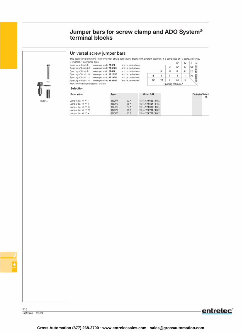
IV IV 8
V IV IV 10
III III III III 12
II I I I I 16
12 10 8 6.5 6
BJDP1 50 ABJDP2 95 ABJDP3 70 ABJDP4 50 ABJDP5 50 A
BJDP...
Jumper bars for screw clamp and ADO System®
terminal blocks
Selection
This accessory permits the interconnection of two consecutive blocks with different spacings. It is composed of : 2 posts, 2 screws,2 washers, 1 connector plate.Spacing of block 6 corresponds to M 4/6 and its derivatives.Spacing of block 6,5 corresponds to M 4/6,5 and its derivatives.Spacing of block 8 corresponds to M 6/8 and its derivatives.Spacing of block 10 corresponds to M 10/10 and its derivatives.Spacing of block 12 corresponds to M 16/12 and its derivatives.Spacing of block 16 corresponds to M 35/16 and its derivatives.Max. recommended torque : 0,6 Nm
Universal screw jumper bars
Spacing of block A
Spac
ing
of b
lock
B
Description Type Order P/N Packaging Weightkg
Jumper bar kit N° IJumper bar kit N° IIJumper bar kit N° IIIJumper bar kit N° IVJumper bar kit N° V
1SNA 179 623 R03001SNA 179 624 R04001SNA 179 625 R05001SNA 174 781 R25001SNA 174 782 R2600
Gross Automation (877) 268-3700 · www.entrelecsales.com · [email protected]
517160T11081 051129
J
44444
BJADO5.2 13,5 ABJADO5.3 13,5 ABJADO5.4 13,5 ABJADO5.5 13,5 ABJADO5.10 13,5 ABJADO5.20 13,5 A
BJADO5.2 17,5 ABJADO5.3 17,5 ABJADO5.4 17,5 ABJADO5.5 17,5 ABJADO5.10 17,5 ABJADO5.20 17,5 A
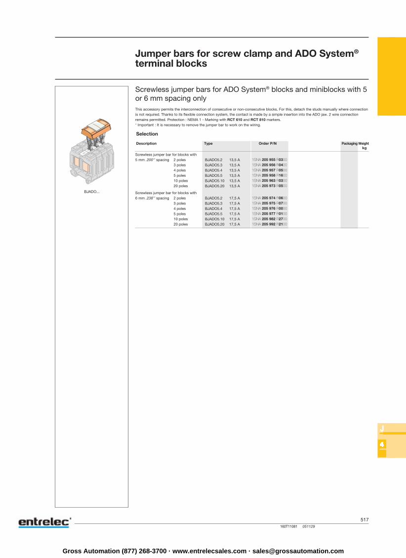
BJADO...
Jumper bars for screw clamp and ADO System®
terminal blocks
Screwless jumper bars for ADO System® blocks and miniblocks with 5or 6 mm spacing only
Selection
This accessory permits the interconnection of consecutive or non-consecutive blocks. For this, detach the studs manually where connectionis not required. Thanks to its flexible connection system, the contact is made by a simple insertion into the ADO jaw. 2 wire connectionremains permitted. Protection : NEMA 1 - Marking with RCT 610 and RCT 810 markers.* Important : It is necessary to remove the jumper bar to work on the wiring.
Description Type Order P/N Packaging Weightkg
Screwless jumper bar for blocks with5 mm .200’’ spacing 2 poles
3 poles4 poles5 poles10 poles20 poles
Screwless jumper bar for blocks with6 mm .238’’ spacing 2 poles
3 poles4 poles5 poles10 poles20 poles
1SNA 205 955 R03001SNA 205 956 R04001SNA 205 957 R05001SNA 205 958 R16001SNA 205 963 R03001SNA 205 973 R0500
1SNA 205 974 R06001SNA 205 975 R07001SNA 205 976 R00001SNA 205 977 R01001SNA 205 982 R27001SNA 205 992 R2100
Gross Automation (877) 268-3700 · www.entrelecsales.com · [email protected]

518160T11082 051129
J
44444
BJDL5.10
BJDL6.5
BJDL8.5
BJDL10.5 24 A
BJDL1.10.5 57 A
BJDL5.2
BJDPL5.6 24 A
BJDPL5.8 24 ABJDPL6.8 32 A
BJDPL5.10 24 ABJDPL6.10 32 ABJDPL8.10 41 A
BJDPL6.12 32 A
ETRES1
Jumper bars for spring blocks
BJDL... jumper bar for spring blocks with the same spacing
Selection
This accessory allows to connect two blocks next to each other or not. For this, remove manualy the unconnected metal pins by foldingthem several times. Identification of cut pins is possible.This flexible connecting system allows contact by simple insertion.
Description Type Order P/N Packaging Weightkg
Jumper bar for spring blocks with 5 mm.200’’ spacing 10 poles
Jumper bar for spring blocks with 6 mm.238’’ spacing 5 poles
Jumper bar for spring blocks with 8 mm.315’’ spacing 5 poles
Jumper bar for spring blocks with 10 mm.400’’ spacing 5 poles
Jumper bar for spring blocks with 10 mm.400’’ spacing 5 poles
BJDL5.4 + remove manualy(by successive folding)the unused metal pin
BJDPL... jumper bar for spring blocks with different spacings
This accessory allows the connection of 2 spring terminal blocks with different spacings to each other (spacing 5 and 6 mm, 6 and 8 mm, 5and 8 mm). It is not necessary to use a spring block with an additional spring to jump with a wire, but it is necessary to use an end sectionbetween the interconnected blocks, whatever the mounting direction of the blocks may be. These jumper bars and both slots for jumperbars permit current distribution (see ‘’Example’’ drawing).
Distributionblocks
End section
Powerblock
Example :
I = i1 + i2 + i3 + i4 < Imax shunt
Selection
Input block Output block Type Order P/N Current max.
6 mm .238’’ spacing 5 mm .200’’ spacing
8 mm .315’’ spacing 5 mm .200’’ spacing6 mm .238’’ spacing
10 mm .400’’ spacing 5 mm .200’’ spacing6 mm .238’’ spacing8 mm .315’’ spacing
12 mm .473’’ spacing 6 mm .238’’ spacing
ETRES1 explaining sticker
Selection
These stickers show how to use a spring block.
Description Type Order P/N Packaging Weightkg
Explaining sticker
1SNA 291 110 R2600
1SNA 291 195 R1000
1SNA 291 145 R2500
1SNA 291 325 R2100
1SNA 291 478 R0300
1SNA 291 150 R0600
1SNA 291 160 R00001SNA 291 170 R0200
1SNA 291 480 R22001SNA 291 482 R10001SNA 291 484 R1200
1SNA 399 613 R0600
1SNB 000 051 R0600
Gross Automation (877) 268-3700 · www.entrelecsales.com · [email protected]
519160T11074 051129
J
44444
BJHS-ENT7192BJHS-ENT7193
FEH3
VSJ6
RDJ6
BJHSBJHS
FEHD2
VSJ6
RDJ6
BJHS
BJM
BJHS
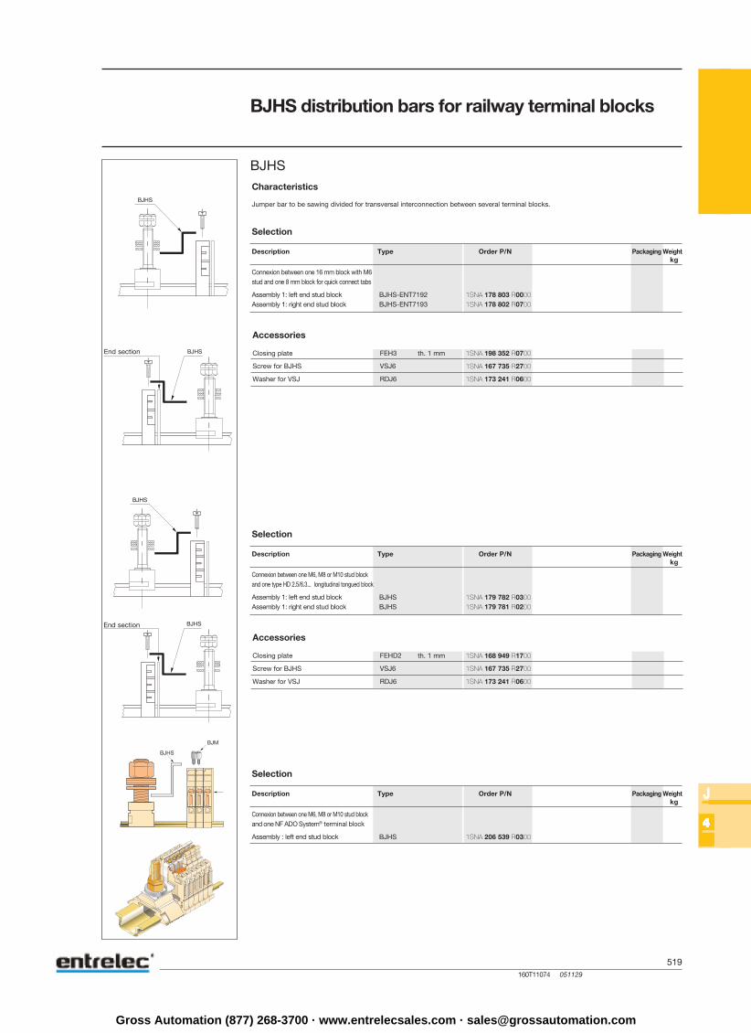
Characteristics
Description Type Order P/N Packaging Weightkg
Connexion between one 16 mm block with M6stud and one 8 mm block for quick connect tabs
Assembly 1: left end stud blockAssembly 1: right end stud block
Selection
Jumper bar to be sawing divided for transversal interconnection between several terminal blocks.
BJHS distribution bars for railway terminal blocks
BJHS
End section
Accessories
Closing plate th. 1 mm
Screw for BJHS
Washer for VSJ
Description Type Order P/N Packaging Weightkg
Connexion between one M6, M8 or M10 stud blockand one type HD 2.5/6.3... longitudinal tongued block
Assembly 1: left end stud blockAssembly 1: right end stud block
Selection
Accessories
Closing plate th. 1 mm
Screw for BJHS
Washer for VSJ
End section
Description Type Order P/N Packaging Weightkg
Connexion between one M6, M8 or M10 stud blockand one NF ADO System® terminal block
Assembly : left end stud block
Selection
1SNA 178 803 R00001SNA 178 802 R0700
1SNA 198 352 R0700
1SNA 167 735 R2700
1SNA 173 241 R0600
1SNA 179 782 R03001SNA 179 781 R0200
1SNA 168 949 R1700
1SNA 167 735 R2700
1SNA 173 241 R0600
1SNA 206 539 R0300
Gross Automation (877) 268-3700 · www.entrelecsales.com · [email protected]
520160T11076 051129
J
44444
VSJ6
RDJ6
VSJ11
RDJ11
BJH6BJH6BJH6BJH6BJH6
BJH7BJH7BJH7BJH7BJH7
BJH8BJH8BJH8BJH8BJH8
BJH9BJH9BJH9BJH9BJH9
BJH11
BJH13
INH1INH1
INH3
BJH131
BJH132
BJH14BJH14BJH14BJH14BJH14
BJH17
BJH18
BJH23
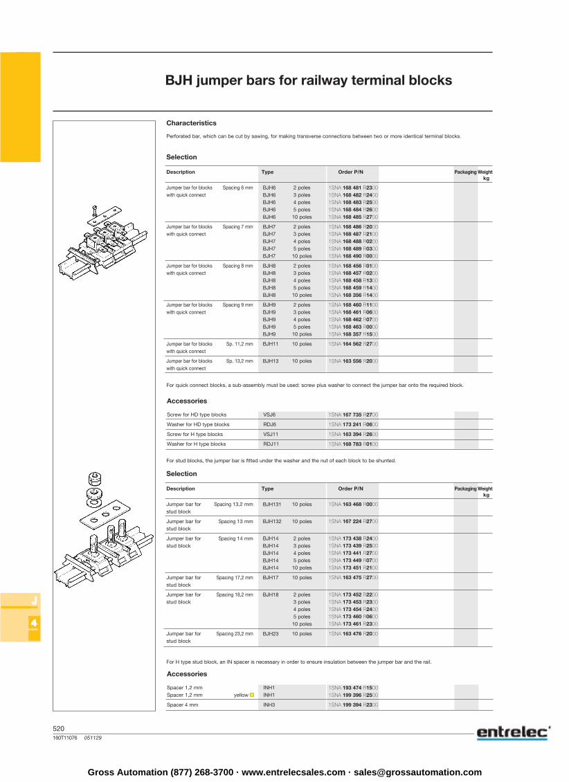
Characteristics
Description Type Order P/N Packaging Weightkg
Jumper bar for blocks Spacing 6 mm 2 poleswith quick connect 3 poles
4 poles5 poles
10 poles
Jumper bar for blocks Spacing 7 mm 2 poleswith quick connect 3 poles
4 poles5 poles
10 poles
Jumper bar for blocks Spacing 8 mm 2 poleswith quick connect 3 poles
4 poles5 poles
10 poles
Jumper bar for blocks Spacing 9 mm 2 poleswith quick connect 3 poles
4 poles5 poles
10 poles
Jumper bar for blocks Sp. 11,2 mm 10 poleswith quick connect
Jumper bar for blocks Sp. 13,2 mm 10 poleswith quick connect
Selection
Perforated bar, which can be cut by sawing, for making transverse connections between two or more identical terminal blocks.
BJH jumper bars for railway terminal blocks
Accessories
Screw for HD type blocks
Washer for HD type blocks
Screw for H type blocks
Washer for H type blocks
Description Type Order P/N Packaging Weightkg
Jumper bar for Spacing 13,2 mm 10 polesstud block
Jumper bar for Spacing 13 mm 10 polesstud block
Jumper bar for Spacing 14 mm 2 polesstud block 3 poles
4 poles5 poles
10 poles
Jumper bar for Spacing 17,2 mm 10 polesstud block
Jumper bar for Spacing 18,2 mm 2 polesstud block 3 poles
4 poles5 poles
10 poles
Jumper bar for Spacing 23,2 mm 10 polesstud block
Selection
Accessories
Spacer 1,2 mmSpacer 1,2 mm yellow
Spacer 4 mm
For quick connect blocks, a sub-assembly must be used: screw plus washer to connect the jumper bar onto the required block.
For stud blocks, the jumper bar is fitted under the washer and the nut of each block to be shunted.
For H type stud block, an IN spacer is necessary in order to ensure insulation between the jumper bar and the rail.
1SNA 168 481 R23001SNA 168 482 R24001SNA 168 483 R25001SNA 168 484 R26001SNA 168 485 R2700
1SNA 168 486 R20001SNA 168 487 R21001SNA 168 488 R02001SNA 168 489 R03001SNA 168 490 R0000
1SNA 168 456 R01001SNA 168 457 R02001SNA 168 458 R13001SNA 168 459 R14001SNA 168 356 R1400
1SNA 168 460 R11001SNA 168 461 R06001SNA 168 462 R07001SNA 168 463 R00001SNA 168 357 R1500
1SNA 164 562 R2700
1SNA 163 556 R2000
1SNA 167 735 R2700
1SNA 173 241 R0600
1SNA 163 394 R2600
1SNA 168 783 R0100
1SNA 193 474 R15001SNA 199 396 R2500
1SNA 199 394 R2300
1SNA 163 468 R0000
1SNA 167 224 R2700
1SNA 173 438 R24001SNA 173 439 R25001SNA 173 441 R27001SNA 173 449 R07001SNA 173 451 R2100
1SNA 163 475 R2700
1SNA 173 452 R22001SNA 173 453 R23001SNA 173 454 R24001SNA 173 460 R06001SNA 173 461 R2300
1SNA 163 476 R2000
Gross Automation (877) 268-3700 · www.entrelecsales.com · [email protected]
521160T11001 051129
J
5
250 (2)2
0.5(1) - 0,34
IEC UL CSANFC VDE
CEV 6.1CEV 6.10 6 mm
CEV 8.10 8 mm
CEV 10.10 10 mm
RC 55
1,5 mm²
IEC UL CSANFC VDE
CEL 1.5
CEL 1.6
CEL 1.8CEL 1.E
CEL 2.5CEL 2.E
Test connectorsFor screw clamp blocks DIN 1-3For spring blocks DIN 1-3
Characteristics
Wire sizemm²
Voltage VCurrent AShort circuit current (M 4/6.PI) A / sRated wire size mm² / AWGWire stripping length mm / inchesRecommended torque Nm / Ib.in
RigidFlexible
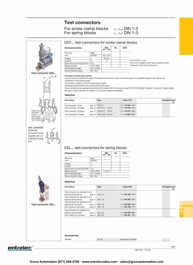
CEV... test connectors for screw clamp blocks
Description Type Order P/N Packaging Weightkg
Unit connector 1 pole greyTest connector 10 poles grey
Test connector 10 poles grey
Test connector 10 poles grey
Selection
CEL... test connectors for spring blocks
Accessories
(1) For CEV 6.1 only(2) For low voltages (<24 V) take a typical contactresistance of 50 mW into account.
To perform simple tests quickly :This connector completes the range of modular connectors to mount on terminal strips. It is supplied ready for use, without anymodification of the terminal strip :The contact is made on the wire-clamp screw heads.Fastening is performed on the terminal block wire inputs.These connectors are supplied connected with 2 meters (6.6 Ft.) long wires, size 0,34 mm² (22 AWG). Standard 1 pole and 10 pole modelsare kept in stock. However, on request, 4 to 15 pole models are available.
Unit connectorSimple testconnector (1 pole)supplied with a 2meters (6.6 Ft.) longwire.
Characteristics
Wire sizemm²
Voltage VCurrent AShort circuit current (M 4/6.PI) A / sRated wire size mm² / AWGWire stripping length mm / inchesRecommended torque Nm / Ib.in
RigidFlexible
Description Type Order P/N Packaging Weightkg
Test connector for standard 5 mmspacing spring blocks greyTest connector for standard 6 mmspacing spring blocks greyTest connector for standard 8 mmspacing spring blocks greyEnd module of connector grey
Test connector for angled 5 mmspacing spring blocks greyEnd module of connector grey
Selection
Test connector CEL...
Markers see section on markers
Test connector CEV...
1SNA 115 544 R14001SNA 115 573 R1100
1SNA 115 574 R1200
1SNA 115 652 R2000
1SNA 400 262 R1400
1SNA 400 263 R1500
1SNA 400 264 R16001SNA 400 265 R1700
1SNA 400 258 R20001SNA 400 261 R1300
Gross Automation (877) 268-3700 · www.entrelecsales.com · [email protected]

522160T11011 051129
J
5
(1)6 A
0,2 - 0,75 mm²
0,22 - 0,75 mm²
IEC UL CSANFC VDE
CEADO.5 5 mm
CEADO.6 6 mm
CEADO.7 7 mm
CEADO.8 8 mm
CEADOE
TGA3.156 156 mm
RC 55RTM
Test connectorsFor ADO System® blocks
Characteristics
Wire sizemm²
Voltage VCurrent AShort circuit current (M 4/6.PI) A / sRated wire size mm² / AWGWire stripping length mm / inchesRecommended torque Nm / Ib.in
RigidFlexible
CEADO... test connectors for ADO System® blocks
Description Type Order P/N Packaging Weightkg
Unit connector 1 pole black
Unit connector 1 pole black
Unit connector 1 pole black
Unit connector 1 pole black
End module black
Selection
Accessories
(1) Rated voltage : 250 V for CEADO.5400 V for CEADO.6500 V for CEADO.8
To perform simple tests quickly :This connector completes the range of modular connectors to be mounted on terminal block assembly.Contact is made on top of the ADO jaw.Hooking is made on the wire input of terminal blocks.It can be achieved without modifying the assembly.
Assembly rod for levers DIA. 3 mm
Markers see section on markers
5, 6or 8 mm
N CEADO... modules
Building a test connector
All modules joint together usingdog points. A connector can bemade of 20 poles max.The assembly rod for levers(TGA3.156) cut at the convenientlength is advised for connectors> 5 poles.
End moduleThis end module is the same forany unitary modulespacing : 5, 6 or 8 mm.
1SNA 206 277 R1400
1SNA 399 345 R1100
1SNA 399 346 R1200
1SNA 399 347 R1300
1SNA 399 348 R2400
1SNA 399 341 R1500
Gross Automation (877) 268-3700 · www.entrelecsales.com · [email protected]

523160T11077 051129
J
5
FC2
FC2.EI.PJP
FC4
FC2
FC2.EI.PJP
FC4
AL2
AL2
AL2
AL2
AL2
AL3
AL4
AL4
AL4
AL4
DCV
DCB
DCJ
DCG
DCO
AL...
DCJ
Test devicesTest plugsTest sockets
FC... test plugs
Description Type Order P/N Packaging Weightkg
Test plug DIA. 2 mm .079" - Solderedconnection : 1 mm² max. - 18 AWG
Test plug DIA. 2 mm .079" - Solderedconnection : 1 mm² max. - 18 AWG
Test plug DIA. 4 mm .16" - Solderedconnection : 1,5 mm² max. - 16 AWG
Selection
These accessories, when used with measuring or control equipment, are used for trouble shooting or testing of a circuit, on the blocksequipped with a test socket or by use of a test device (for FC2 only).
AL... test sockets
Description Type Order P/N Packaging Weightkg
Test socket DIA. 2 mm .079"H = 12 mm .472" - M3 screw
Test socket DIA. 2 mm .079"H = 11,7 mm .461" - M2,6 screw
Test socket DIA. 2 mm .079"H = 8,5 mm .335" - M3 screw
Test socket DIA. 2 mm .079"H = 9,6 mm .378" - M3 screw
Test socket DIA. 2 mm .079"H = 8,5 mm .335" - M2,6 screw
Test socket DIA. 3 mm .12"H = 9,5 mm .374" - M3 screw
Test socket DIA. 4 mm .16"H = 12 mm .472" - M3 screw
Test socket DIA. 4 mm .16"H = 12,3 mm .484" - M3 screw
Test socket DIA. 4 mm .16"H = 13,5 mm .532" - M4 screw
Test socket DIA. 4 mm .16"H = 17,5 mm .689" - M3 screw
Selection
This accessory is screwed into the tapped holes of the connector bar of the terminal blocks. Some blocks are delivered socket mounted.This socket receives an FC test plug. The test sockets are characterized by their internal diameter.
DC... test device on screw head
Description Type Order P/N Packaging Weightkg
Test device for blocks with 5 mmspacing green
Test device for MA 2,5/5 blocksblue
Test device for blocks with 6 mmspacing yellow
Test device for M4/6.D and MB 2,5/6blocks grey
Test device for blocks with 8 mmspacing orange
Selection
This patented device is mounted on the round screwdriver opening. It is used for trouble shooting, measuring and control for monitoring andrepairing an installation, on blocks without a test socket. For this, the device receives an FC2 test plug.
1SNA 007 865 R2600
1SNA 107 239 R0300
1SNA 167 860 R0100
1SNA 163 043 R2100
1SNA 163 046 R2400
1SNA 163 070 R0000
1SNA 164 950 R0000
1SNA 167 319 R0600
1SNA 163 261 R0000
1SNA 163 240 R1700
1SNA 163 262 R0100
1SNA 168 237 R0500
1SNA 179 762 R1600
1SNA 173 058 R0200
1SNA 105 028 R2100
1SNA 173 059 R0300
1SNA 163 218 R0500
1SNA 173 060 R0000
Gross Automation (877) 268-3700 · www.entrelecsales.com · [email protected]

524160T11083 051129
J
66666
MA 2,5/5... EIP 2 PC5 30 AMA 2,5/5.D... 10 PC5 30 A
DR 1,5/5... 10 PC51
M 4/6 - MS 4/6 - M 4/6.H EIP 2 PC6 35 AM 1,5/6.HH - M 4/6.M2 3 PC6 35 AM 4/6.G 4 PC6 35 A
10 PC6 35 A
M 4/6.D - M 4/6.S... 10 PC61 35 ADR 4/6 - DR 2,5/6 - DRP 4/6
M 6/8 - M 6/8.S... 2 PC8 50 A3 PC8 50 A4 PC8 50 A
10 PC8 50 A
M 4/8.S... 10 PC81 35 A
M 10/10 10 PC10 70 A
M 10/13.S... 10 PC13 70 A
MB 10/22.S... 2 PC22 70 A3 PC22 70 A
10 PC22 70 A
M 10/16.SF EIP 2 PC16 70 A3 PC16 70 A4 PC16 70 A
10 PC16 70 A
10 PC9 15 A
PC... + EIP
-55°C -> +110°CIP20 / NEMA1
600 60026 15
2,5 mm2 14 AWG
2,5 mm²14 AWG
2,5 mm²
IEC UL CSANFC VDE
AD 2,5
4
2
1
3
1
4
3
2
AD 2,5
Other accessories
PC... + EIP comb-type jumper bar + insulating tip
Selection
This accessory can be used only on the terminal blocks with at least one compression clamp connection. It permits the electrical connectionof 2 to 10 blocks.Interconnection of non-consecutive blocks is possible by removing the teeth opposite the blocks which must not be connected. The comb-type jumper bars can be cut using pliers (or a saw) : in this case, the use of an insulating tip EIP is recommended where possible ; otherwise,use an SCF separator or FE end section between two series of interconnected blocks, in order to preserve insulation. The comb is placed inthe compression clamp before tightening the screws, above the eventual conductor.
Insulating tip for comb Comb-type jumper bar
To be mounted on blocks Type Order P/N Nb of poles Type Order P/N Current
Series 7000 or 8000
IDC jumper (insulation displacement jumper)
Quick-jump lets you interconnect screw clamp terminals of different sizes, levels and all manufacturers quickly and safely. Its insulationdisplacement technology makes it easy to use, fast, economical and does not require a special tool. Use as a jumper between relays,switches and other electronic components. ABB Entrelec Quick-jump will fit any screw clamp type terminal block, from 6 mm .238" spacingand larger.
Characteristics
Wire sizemm² / AWG
Voltage VCurrent ARated wire size mm² / AWGWorking temperature °CProtection
RigidFlexible
Adding a shunt in an installation :
1 - Insert Entrelec Quick-jump into your terminal screw clamp.2 - Guide the terminal screw clamp into contact with the wire.3 - Secure the wire by closing the Quick-jump lever with any flat nose pliers.4 - Tighten the terminal screw.
How to use : connecting Quick-jump to your terminal
1 - Insert Entrelec Quick-jump into your terminal screw clamp.2 - Tighten the terminal screw.3 - Guide jumper wire through the V-shaped opening in the Quick-jump.4 - Secure the wire by closing the Quick-jump lever with any flat nose pliers.
Selection
Description Type Order P/N Packaging Weightkg
Insulation displacement jumper
1SNA 113 550 R2400 1SNA 113 542 R10001SNA 113 544 R1200
1SNA 167 908 R0600
1SNA 113 550 R2400 1SNA 113 546 R14001SNA 116 536 R05001SNA 116 537 R06001SNA 113 548 R2600
1SNA 163 311 R2200
1SNA 116 538 R17001SNA 116 539 R10001SNA 116 540 R25001SNA 163 313 R2400
1SNA 173 523 R1100
1SNA 163 315 R2600
1SNA 173 510 R2000
1SNA 205 294 R05001SNA 205 295 R06001SNA 174 151 R2500
1SNA 113 550 R2400 1SNA 116 729 R26001SNA 116 733 R12001SNA 116 734 R13001SNA 116 735 R1400
1SNA 210 160 R1200
1SNA 114 205 R2000
Gross Automation (877) 268-3700 · www.entrelecsales.com · [email protected]
525160T11084 051129
J
66666
EL...
EL6
EL61
BJP6 35 A
BJP61 35 A
BJP8 50 A
BJP82 50 A
BJP10 70 A
BJPD6 35 ABJP...
BP8.A4
BNSTP1
CBD5.2LCBM5DCBD2SCBD2CBD1CBM8CBM5
BP8.A4
BNSTP1
CB...
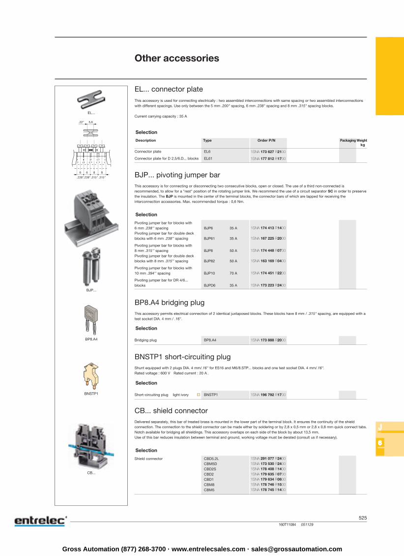
Other accessories
EL... connector plateThis accessory is used for connecting electrically : two assembled interconnections with same spacing or two assembled interconnectionswith different spacings. Use only between the 5 mm .200" spacing, 6 mm .238" spacing and 8 mm .315" spacing blocks.
Current carrying capacity : 35 A
BJP... pivoting jumper bar
Selection
Description Type Order P/N Packaging Weightkg
Connector plate
Connector plate for D 2,5/6.D... blocks
Selection
Pivoting jumper bar for blocks with6 mm .238’’ spacingPivoting jumper bar for double deckblocks with 6 mm .238’’ spacing
Pivoting jumper bar for blocks with8 mm .315’’ spacingPivoting jumper bar for double deckblocks with 8 mm .315’’ spacing
Pivoting jumper bar for blocks with10 mm .394’’ spacing
Pivoting jumper bar for DR 4/6...blocks
This accessory is for connecting or disconnecting two consecutive blocks, open or closed. The use of a third non-connected isrecommended, to allow for a "rest" position of the rotating jumper link. We recommend the use of a circuit separator SC in order to preservethe insulation. The BJP is mounted in the center of the terminal blocks, the connector bars of which are tapped for receiving theinterconnection accessories. Max. recommended torque : 0,6 Nm.
BP8.A4 bridging plug
Selection
Bridging plug
This accessory permits electrical connection of 2 identical juxtaposed blocks. These blocks have 8 mm / .315" spacing, are equipped with atest socket DIA. 4 mm / .16".
BNSTP1 short-circuiting plug
Selection
Short-circuiting plug light ivory
Shunt equipped with 2 plugs DIA. 4 mm/.16" for ES16 and M6/8.STP... blocks and one test socket DIA. 4 mm/.16".Rated voltage : 600 V Rated current : 20 A .
CB... shield connector
Selection
Shield connector
Delivered separately, this bar of treated brass is mounted in the lower part of the terminal block. It ensures the continuity of the shieldconnection. The connection to the shield connector can be made either by soldering or by 2,8 x 0,5 mm or 2,8 x 0,8 mm quick connect tabs.Notch available for bridging all shieldings. This accessory overlaps on each side of the block by about 13,5 mm.Use of this bar reduces insulation between terminal and ground, working voltage must be derated (consult us if necessary).
1SNA 173 627 R2100
1SNA 177 812 R1700
1SNA 174 413 R1400
1SNA 167 225 R2000
1SNA 174 448 R0700
1SNA 163 169 R0400
1SNA 174 451 R2200
1SNA 173 223 R2400
1SNA 173 888 R2000
1SNA 196 792 R1700
1SNA 291 077 R24001SNA 173 530 R24001SNA 178 408 R14001SNA 179 635 R07001SNA 179 634 R06001SNA 178 746 R15001SNA 178 745 R1400
Gross Automation (877) 268-3700 · www.entrelecsales.com · [email protected]
526160T11086 051129
J
77777
EXBN2
EXBN2
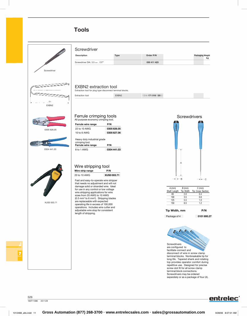
Tools
Screwdriver
Description Type Order P/N Packaging Weightkg
Screwdriver DIA. 3 mm .118"
EXBN2 extraction tool
Extraction tool
Extraction tool for plug type disconnect terminal blocks.
Screwdriver
1SNA 206 573 R0500
1SNA 171 018 R2000
Wire stripping tool
Screwdrivers
Screwdriversare configured tofacilitate connect anddisconnect of wire in screw clampterminal blocks. Nonbreakable tip forlong life. Tapered shank and rotatingtop provides operator comfort duringrepetitive use. Designed for precisescrew slot fit for all screw clampterminal block connections.Screwdrivers may be orderedseparately or as a package of four (4).
8 to 1 AWG 0304 441.03
Heavy duty industrial gradecrimping tool.Ferrule wire range P/N
A (mm) B (mm) C (mm)Shaft Length Tip Width Tip Cross Section
65 2.0 0.4100 3.5 0.6125 5.5 1.0150 6.5 1.2
22 to 10 AWG 0305 626.05
10 to 6 AWG 0305 627.06
All purpose economy crimping tool.
Ferrule wire range P/N
Fast and easy-to-operate wire stripperthat needs no adjustment and will notdamage solid or stranded wire. Idealfor use in any control or low voltagewire stripping applications for wiresizes from 20 AWG to 10 AWG(0.5 mm2 to 6 mm2). Stripping bladesare replaceable with expectedoperating life in excess of 100,000operations. Includes wire cutter andadjustable wire stop for consistentlength of stripping.
Tip Width, mm P/N
Package of 4 0101 695.27
20 to 10 AWG XUS0 003.71
Wire strip range P/N
Ferrule crimping tools
EXBN2
EXBN2
ScrewdriverN/PredrOepyTnoitpircseD Packaging Weight
kg
Screwdriver DIA. 3.5 mm .137"
EXBN2 extraction tool
Extraction tool
Extraction tool for plug type disconnect terminal blocks.
Screwdriver
030 411 423
1SNA 171 018 R2000
Tools
0305 626.05
0304 441.03
XUS0 003.71
1012468_alts.indd 11 9/28/06 8:07:01 AMGross Automation (877) 268-3700 · www.entrelecsales.com · [email protected]

NOTE_527 060529
527
Notes
Gross Automation (877) 268-3700 · www.entrelecsales.com · [email protected]

Related Documents