Term Paper on RF and Microwave Engineering Praveen Thakur Roll No. 40 B.Tech MBA ECE Integrated Topic: Comparison of operation and Magnetron of TWT Abstract: The topic of my term paper is to compare the operation of travelling wave tube and magnetron. Travelling wave tube (TWT) is a type of tube which has displayed considerable promise as a broad band amplifier. It was proposed by Pierce and others in 1946. TWT’s are broad band device in which there are no cavity resonators as in klystron amplifier/oscillator and Magnetron provides microwave oscillation of very high peak power. An improved high power magnetron was developed by Randall and Boot in 1939. In this term paper I have explain about the operation of travelling wave tube and magnetron and show that how they are different from each other in functioning and their applications. Introduction: A travelling-wave tube (TWT) is a specialized vacuum tube used in wireless communications, especially in satellite systems. The TWT can amplify or generate microwave signals. Two common types of TWT include the Klystron and the magnetron. In the Klystron, a negatively charged cathode emits a beam of high-speed, high-energy electron s that travel through the cylindrical tube in straight lines to a positively charged anode. A coil is wound around the tube. When the coil is energized with a radio-frequency ( RF ) signal, the electrons in the beam alternately bunch up and spread out. In the magnetron, the electrons move in circles rather than in straight lines. The circular motion, produced by magnets at either end of the tube,

Term Paper microwave final
Dec 15, 2015
Welcome message from author
This document is posted to help you gain knowledge. Please leave a comment to let me know what you think about it! Share it to your friends and learn new things together.
Transcript

Term Paper on RF and Microwave Engineering Praveen Thakur
Roll No. 40 B.Tech MBA ECE Integrated
Topic: Comparison of operation and Magnetron of TWT
Abstract: The topic of my term paper is to compare the operation of travelling wave tube and magnetron. Travelling wave tube (TWT) is a type of tube which has displayed considerable promise as a broad band amplifier. It was proposed by Pierce and others in 1946. TWT’s are broad band device in which there are no cavity resonators as in klystron amplifier/oscillator and Magnetron provides microwave oscillation of very high peak power. An improved high power magnetron was developed by Randall and Boot in 1939. In this term paper I have explain about the operation of travelling wave tube and magnetron and show that how they are different from each other in functioning and their applications.
Introduction:
A travelling-wave tube (TWT) is a specialized vacuum tube used in wireless communications, especially in satellite systems. The TWT can amplify or generate microwave signals. Two common types of TWT include the Klystron and the magnetron.
In the Klystron, a negatively charged cathode emits a beam of high-speed, high-energy electron s that travel through the cylindrical tube in straight lines to a positively charged anode. A coil is wound around the tube. When the coil is energized with a radio-frequency ( RF ) signal, the electrons in the beam alternately bunch up and spread out.
In the magnetron, the electrons move in circles rather than in straight lines. The circular motion, produced by magnets at either end of the tube, allows the electrons to pick up energy over a greater distance.
Inside the TWT, the regions of high and low electron concentration move along or around the tube in waves. When the tube is properly operating, some of the energy from the electrons is imparted to the signal in the coil. The result is amplification of the signal.
TWT (Travelling Wave Tube):
Fig 1.TWT DIAGRAM 1
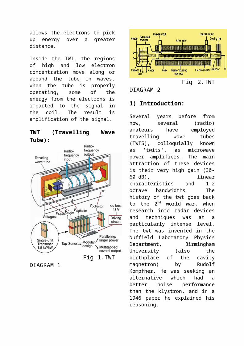
Fig 2.TWT DIAGRAM 2
1) Introduction:
Several years before from now, several (radio) amateurs have employed travelling wave tubes (TWTS), colloquially known as 'twits', as microwave power amplifiers. The main attraction of these devices is their very high gain (30-60 dB), linear characteristics and 1-2 octave bandwidths. The history of the twt goes back to the 2nd
world war, when research into radar devices and techniques was at a particularly intense level. The twt was invented in the Nuffield Laboratory Physics Department, Birmingham University (also the birthplace of the cavity magnetron) by Rudolf Kompfner. He was seeking an alternative which had a better noise performance than the klystron, and in a 1946 paper he explained his reasoning.
'One of the main reasons for the lack of sensitivity of the klystron as an amplifier is the inevitable energy exchange between the electron beam and the electric field in the rhumbatrons (resonators) ...It was therefore a very inviting thought to use the signal in the form of a travelling electric field (instead of a stationary one) and utilize the energy exchange between the travelling field and electrons which travel at about the same velocity.'
In December 1943 the first tube gave again of about 8 dB at a 9.1 cm wavelength, with a 13 dB noise figure. The work was later transferred to the Clarendon Laboratory, Oxford. Much of the mathematical
analysis of twt operation was developed by John R. Pierce, of Bell Labs, and in 1947 Kompfner joined Pierce to continue twt research.
Nowadays, TWTS are by far the most widely-used of microwave tubes, and are employed extensively in communication and radar systems. They are especially suited to airborne applications, where their small size and low weight are valuable. Satellite communication systems are another extremely important application, for the same reasons.
Practical travelling wave tube amplifiers (TWTAs) have applications in both receiver and transmitter systems, and come in all shapes and sizes, but they all consist of three basic parts-the tube, the tube mount (which includes the beam focussing magnets) and the power supply.
2) Construction:
The features of a typical TWT are shown in diagram above. The electron beam is provided by an electron gun which is very similar to those used in CRTs, though the beam current is much larger. Electrons from a heated cathode are accelerated towards the anode, which is held at a high positive potential with respect to the cathode, and a proportion pass through a hole in the anode to produce the beam. Some tubes have a grid between the cathode and anode, at a few tens of volts (adjustable) negative with respect to the cathode, the function of which is to control the beam current. The electron beam travels down the tube, inside the helix, to the collector, which is maintained at a high voltage referred to the cathode. The helix is also held at a high potential, but the helix current is low because of the beam focussing.

Fig 3: the focussing of the electron beam by the magnetic field
As is shown in fig 3 above, this focussing is achieved by a magnet (either a solenoid electromagnet or permanent magnets) round the outside of the tube. An electron with a component of velocity perpendicular to the magnetic field lines experiences a restoring force tending to bring back its direction parallel to the field lines.
To achieve good focussing by this method requires a very large magnetic field, which can mean a bulky, heavy magnet. However, the arrangement usually employed is called periodic permanent magnet (PPM) focussing, in which a number of toroidal permanent magnets of alternating polarity is arranged along the tube, as is shown below; this figure also shows the contour of the beam.
Fig 4: Periodic permanent magnet focussing
This arrangement reduces enormously the required weight of magnet (under ideal conditions by a factor 1/N*2; where N is the number of magnets used). The alternative method, solenoid focussing, is generally only used in high-power earth
station TWTS, where size and weight are unimportant.
The input to, and output from, the helix are via coaxial connectors, or occasionally via waveguide. In practice, it is impossible to provide a perfect match at these transitions, especially over a wide bandwidth, so an attenuator is used to prevent the energy reflected back down the helix causing instability. This usually takes the form of a resistive coating on the outside of the central portion of the tube, though a physical discontinuity in the helix is also used in some cases. The attenuator reduces the RF input signal, as well as any reflected signal, to nearly zero, but the electron bunches set up by the signal are unaffected.
The helix itself is a fairly delicate structure, and must be provided with adequate thermal dissipation to prevent damage. In medium-power tubes, the helix is often supported on a beryllia or alumina substrate, but for high-power TWTS, alternative slow-wave structures are employed (e.g. coupled cavities), though usually at the expense of bandwidth. In this form, the TWT resembles a klystron amplifier.
3) Theory:
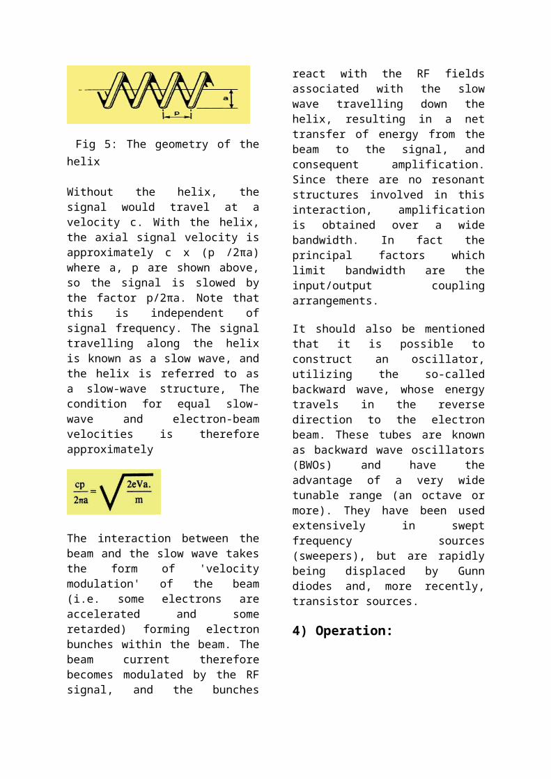
The essential principle of operation of a TWT lies in the interaction between an electron beam and an RF signal. The velocity, v, of an electron beam is given by:
An anode voltage of 5 kV gives an electron velocity of 4.2 x 10*7 mso*-1. The signal would normally travel at c, the

velocity of light (3x10*8 ms*-1), which is much faster than any 'reasonable' electron beam (relativistic effects mean that the electron mass actually increases as its velocity approaches c, so that achieving electron velocities approaching c is a complicated business), If, however, the signal can be slowed down to the same velocity as the electron beam, it is possible to obtain amplification of the signal by virtue of its interaction with the beam. This is usually achieved using the helix electrode, which is simply a spiral of wire around the electron beam,
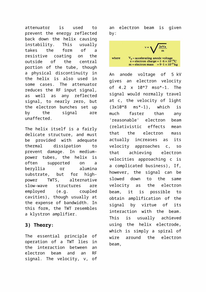
Fig 5: The geometry of the helix
Without the helix, the signal would travel at a velocity c. With the helix, the axial signal velocity is approximately c x (p /2πa) where a, p are shown above, so the signal is slowed by the factor p/2πa. Note that this is independent of signal frequency. The signal travelling along the helix is known as a slow wave, and the helix is referred to as a slow-wave structure, The condition for equal slow-wave and electron-beam velocities is therefore approximately
The interaction between the beam and the slow wave takes the form of 'velocity modulation' of the beam (i.e. some electrons are accelerated and some retarded) forming electron bunches within the beam. The beam current therefore becomes modulated by the RF signal, and the bunches react with the RF fields
associated with the slow wave travelling down the helix, resulting in a net transfer of energy from the beam to the signal, and consequent amplification. Since there are no resonant structures involved in this interaction, amplification is obtained over a wide bandwidth. In fact the principal factors which limit bandwidth are the input/output coupling arrangements.
It should also be mentioned that it is possible to construct an oscillator, utilizing the so-called backward wave, whose energy travels in the reverse direction to the electron beam. These tubes are known as backward wave oscillators (BWOs) and have the advantage of a very wide tunable range (an octave or more). They have been used extensively in swept frequency sources (sweepers), but are rapidly being displaced by Gunn diodes and, more recently, transistor sources.
4) Operation:
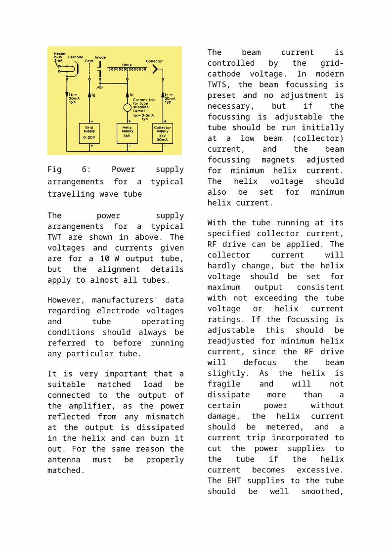
Fig 6: Power supply arrangements for a typical travelling wave tube
The power supply arrangements for a typical TWT are shown in above. The voltages and currents given are for a 10 W output tube, but the alignment details apply to almost all tubes.
However, manufacturers' data regarding electrode voltages and tube operating
conditions should always be referred to before running any particular tube.
It is very important that a suitable matched load be connected to the output of the amplifier, as the power reflected from any mismatch at the output is dissipated in the helix and can burn it out. For the same reason the antenna must be properly matched.
The beam current is controlled by the grid-cathode voltage. In modern TWTS, the beam focussing is preset and no adjustment is necessary, but if the focussing is adjustable the tube should be run initially at a low beam (collector) current, and the beam focussing magnets adjusted for minimum helix current. The helix voltage should also be set for minimum helix current.
With the tube running at its specified collector current, RF drive can be applied. The collector current will hardly change, but the helix voltage should be set for maximum output consistent with not exceeding the tube voltage or helix current ratings. If the focussing is adjustable this should be readjusted for minimum helix current, since the RF drive will defocus the beam slightly. As the helix is fragile and will not dissipate more than a certain power without damage, the helix current should be metered, and a current trip incorporated to cut the power supplies to the tube if the helix current becomes excessive. The EHT supplies to the tube should be well smoothed, since ripple will phase-modulate the output and give a rough note.
If the collector dissipates more than about 100 W it may be necessary to use a blower to cool the collector end of the tube. Typical efficiency of the TWTA is about 10 per cent, though some modern tubes may reach 40 per cent.
Fig 7: The transfer characteristic of a travelling wave tube amplifier
The transfer characteristic is essentially linear, which permits the tube to be used to amplify ssb-one of its great advantages in an amateur context. As the input is increased, however, the amplifier saturates. There is no harm to the tube in operating at saturated output power, except that amplification is no longer linear, although if appreciable harmonic power is generated this may be reflected at the output transition and damage the helix through over dissipation.
The output from the amplifier can also be amplitude-modulated by a signal on the grid, but the attendant phase modulation is quite high; this method is not normally used to produce a great depth of modulation, other than to operate the TWT in the pulsed mode. This is because at some voltages between maximum and minimum output, beam interception by the helix occurs, which causes excessive helix dissipation unless the transitions are rapid. Phase modulation is obtained by varying the helix voltage over a small range. Typically, plus or minus 100V from 2 kV nominal helix voltage will give 2 radian phase shift, with 1-2 dB reduction in output, which occurs because the gain is very sensitive to cathode-helix voltage.
It is very useful to include some permanent form of power monitor of the output from the amplifier. This can conveniently take
the form of a directional coupler and diode detector.
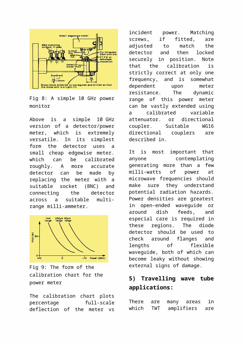
Fig 8: A simple 10 GHz power monitor
Above is a simple 10 GHz version of a detector/power meter, which is extremely versatile. In its simplest form the detector uses a small cheap edgewise meter. which can be calibrated roughly. A more accurate detector can be made by replacing the meter with a suitable socket (BNC) and connecting the detector across a suitable multi-range milli-ammeter.
Fig 9: The form of the calibration chart for the power meter
The calibration chart plots percentage full-scale deflection of the meter vs incident power. Matching screws, if fitted, are adjusted to match the detector and then locked securely in position. Note that the calibration is strictly correct at only one frequency, and is somewhat dependent upon meter resistance. The dynamic range of this power meter can be vastly extended using a calibrated variable attenuator. or
directional coupler. Suitable WG16 directional couplers are described in.
It is most important that anyone contemplating generating more than a few milli-watts of power at microwave frequencies should make sure they understand potential radiation hazards. Power densities are greatest in open-ended waveguide or around dish feeds, and especial care is required in these regions. The diode detector should be used to check around flanges and lengths of flexible waveguide, both of which can become leaky without showing external signs of damage.
5) Travelling wave tube applications:
There are many areas in which TWT amplifiers are used. They are an ideal form of RF amplifier for satellites and as a result they are extensively used for satellite transponders where low levels signals are received and need to be retransmitted at much higher levels. In addition to this TWT amplifiers are used in microwave radar systems where they are able to produce the high levels of power required. Traveling wave tube, TWT technology is also used for electronic warfare applications. In these applications the grid on the travelling wave tube may be used to pulse the transmission. Another major use of TWTAs is for the electromagnetic compatibility (EMC) testing industry for immunity testing of electronic devices.
6) Drawbacks:
The problem unfortunately still remains that TWTS are very difficult to acquire, nevertheless, their high power output, high gain, and ease of operation make them the ideal way to run power at frequencies above about 4 GHz, where conventional tubes like the 2C39A run out of steam, and they represent practically the only way to
run high-power SSB. It is relatively easy to generate the 1 mW or so of SSB at microwave frequencies required to drive most TWTS, which will produce over 1 W of power.
Magnetron:
In 1921 Albert Wallace Hull invented the magnetron as a microwave tube. During World War II it was developed by John Randall and Henry Boot to a powerful microwave generator for Radar applications.
It type of microwave tube in which the electric and magnetic fields are perpendicular to each other. The principal tube in this type are called M type i.e. Magnetron. A Magnetron is a high power microwave oscillator in which the potential energy of an electron cloud near the cathode is converted into radio frequency. In the linear tubes klystron, reflex klystron the electrons are interacted for shorter duration so efficiency is less as compare if increase the duration of interaction of electron the efficiency will increase.There are three type of magnetron:
1) Negative resistance magnetron (NRM)2) Cyclotron frequency magnetron (CFM).
3) Travelling wave or cavity magnetron (TWM or CM)
1) NRM: It make use of negative resistance between two anode segments but they have less efficiency and useful at low frequency i.e. less than 500MHz 2) CFM: It depends upon synchronism between an alternating component of electric and periodic oscillations of the electrons in a direction parallel to this field. These are useful only frequency greater than 100MHz.3) TWM or CM: It depends upon the interaction of electron with a rotating electromagnetic field of constant angular
velocity. It provides the oscillation of very high peak power. So we generally study the cavity magnetron.
Magnetrons function as self-excited microwave oscillators. Crossed electron and magnetic fields are used in the magnetron to produce the high-power output required in radar equipment. These multicavity devices may be used in radar transmitters as either pulsed or continuous wave oscillators at frequencies ranging from approximately 600 to 30,000 megahertz. The relatively simple construction has the disadvantage that the Magnetron usually can work only on a constructively fixed frequency.
Figure 1: Magnetron МИ 29Г of the Old Russian Radar „Bar Lock”
1) Physical construction of a magnetron:
The magnetron is classed as a diode because it has no grid. The anode of a magnetron is fabricated into a cylindrical solid copper block. The cathode and filament are at the center of the tube and are supported by the filament leads. The filament leads are large and rigid enough to keep the cathode and filament structure fixed in position. The cathode is indirectly heated and is constructed of a high-emission material. The 8 up to 20 cylindrical holes around its circumference are resonant cavities. The cavities control the output frequency. A narrow slot runs from each cavity into the central portion of the tube dividing the inner structure into as many segments as there are cavities.

resonant cavities Anode
filament leads
Figure 2: Cutaway view of a magnetron
The open space between the plate and the cathode is called the interaction space. In this space the electric and magnetic fields interact to exert force upon the electrons. The magnetic field is usually provided by a strong, permanent magnet mounted around the magnetron so that the magnetic field is parallel with the axis of the cathode.
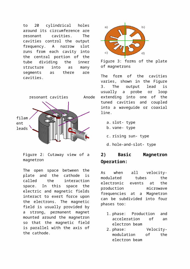
Figure 3: forms of the plate of magnetrons
The form of the cavities varies, shown in the Figure 3. The output lead is usually a probe or loop extending into one of the tuned cavities and coupled into a waveguide or coaxial line.
a. slot- typeb. vane- type
c. rising sun- type
d. hole-and-slot- type
2) Basic Magnetron Operation:
As when all velocity-modulated tubes the electronic events at the production microwave frequencies at a Magnetron can be subdivided into four phases too:
1. phase: Production and acceleration of an electron beam
2. phase: Velocity-modulation of the electron beam
3. phase: Forming of a „Space-Charge Wheel”
4. phase: Dispense energy to the ac field
1. Phase: Production and acceleration of an electron beam: When no magnetic field exists, heating the cathode results in a uniform and direct movement of the field from the cathode to the plate (the blue path in figure 4). The permanent magnetic field bends the electron path. If the electron flow reaches the plate, so a large amount of plate current is flowing. If the strength of the magnetic field is increased, the path of the electron will have a sharper bend. Likewise, if the velocity of the electron increases, the field around it increases and the path will bend more sharply. However, when the critical field value is reached, as shown in the figure as a red path, the electrons are deflected away from the plate and the plate current then drops quickly to a very small value. When the field strength is made still greater, the plate current drops to zero. When the magnetron is adjusted to the cut off, or critical value of the plate current and the electrons just fail to reach the plate in their circular motion, it can produce oscillations at microwave frequencies.
Figure 4: the electron path under the influence of different strength of the magnetic field2. Phase: Velocity-modulation of the electron beam: The electric field in the magnetron oscillator is a product of ac and dc fields. The dc field extends radially from adjacent anode segments to the cathode. The ac fields, extending between adjacent segments, are shown at an instant of maximum magnitude of one alternation of the RF oscillations occurring in the cavities. In the figure 5 is shown only the assumed high-frequency electrical ac field.
This ac field work in addition to the to the permanently available dc field. The ac field of each individual cavity increases or decreases the dc field like shown in the figure.
Well, the electrons which fly toward the anode segments loaded at the moment more positively are accelerated in addition. These get a higher tangential speed. On the other hand the electrons which fly toward the segments loaded at the moment more negatively are slow down. These get consequently a smaller tangential speed.
Figure 5: The high-frequency electrical field
3. Phase: Forming of a „Space-Charge Wheel”: On reason the different speeds of the electron groups a velocity modulation appears therefore. The cumulative action of many electrons returning to the cathode while others are moving toward the anode forms a pattern resembling the moving spokes of a wheel known as a „Space-Charge Wheel”, as indicated in figure 6. The space-charge wheel rotates about the cathode at an angular velocity of 2 poles (anode segments) per cycle of the ac field. This phase relationship enables the concentration of electrons to continuously deliver energy to sustain the RF oscillations.
One of the spokes just is near an anode segment which is loaded a little more negatively. The electrons are slowed down and pass her energy on to the ac field. This state isn't static, because both the ac- field and the wire wheel permanently circulate.

The tangential speed of the electron spokes and the cycle speed of the wave must be brought in agreement so.
Figure 6: Rotating space-charge wheel in an twelve-cavity magnetron
4. Phase: Dispense energy to the ac field: Recall that an electron moving against an E field is accelerated by the field and takes energy from the field. Also, an electron dispenses energy to a field and slows down if it is moving in the same direction as the field (positive to negative). The electron spends energy to each cavity as it passes and eventually reaches the anode when its energy is expended. Thus, the electron has helped sustain oscillations because it has taken energy from the dc field and given it to the ac field. This electron describes the path shown in figure 7 over a longer time period looked. By the multiple breaking of the electron the energy of the electron is used optimally. The effectiveness reaches values up to 80%.
Figure 7: Path of a single electron under influence of the electric RF-field
3) Modes of Oscillation:
The operation frequency depends on the sizes of the cavities and the interaction space between anode and cathode. But the single cavities are coupled over the interaction space with each other. Therefore several resonant frequencies exist for the complete system. Two of the four possible waveforms of a magnetron with 8 cavities are in the figure 8 represented. Several other modes of oscillation are possible (3/4π, 1/2π, 1/4π),
but a magnetron operating in the π mode has greater power and output and is the most commonly used.
Figure 8: Waveforms of the magnetron (Anode segments are represented „unwound”)
Strapping
Figure 9: cutaway view of a magnetron

(vane-type), showing the strapping rings and the slots.
So that a stable operational condition adapts in the optimal pi mode, two constructive measures are possible:
* Strapping rings:
The frequency of the π mode is separated from the frequency of the other modes by strapping to ensure that the alternate segments have identical polarities. For the pi mode, all parts of each strapping ring are at the same potential; but the two rings have alternately opposing potentials. For other modes, however, a phase difference exists between the successive segments connected to a given strapping ring which causes current to flow in the straps.
* Use of cavities of different resonance frequency e.g. such a variant is the anode form „Rising Sun”.
4) Magnetron coupling methods:
Energy (RF) can be removed from a magnetron by means of a coupling loop. At frequencies lower than 10,000 megahertz, the coupling loop is made by bending the inner conductor of a coaxial line into a loop. The loop is then soldered to the end of the outer conductor so that it projects into the cavity, as shown in figure 10, view (A). Locating the loop at the end of the cavity, as shown in view (B), causes the magnetron to obtain sufficient pickup at higher frequencies.
Figure 10: Magnetron coupling, view (A) and (B)
The segment-fed loop method is shown in view (C) of figure 11. The loop intercepts the magnetic lines passing between cavities. The strap-fed loop method (view (D), intercepts the energy between the strap and the segment. On the output side, the coaxial line feeds another coaxial line directly or feeds a waveguide through a choke joint. The vacuum seal at the inner conductor helps to support the line. Aperture, or slot, coupling is illustrated in view (E). Energy is coupled directly to a waveguide through an iris.
Figure 11: Magnetron coupling, view (C), (D) and (E)
5) Magnetron tuning:
A tunable magnetron permits the system to be operated at a precise frequency anywhere within a band of frequencies, as determined by magnetron characteristics. The resonant frequency of a magnetron may be changed by varying the inductance or capacitance of the resonant cavities.
Tuner frame anode block
additionalinductivetuningelements
Figure 12: Inductive magnetron tuning
An example of a tunable magnetron is the M5114B used by the ATC- Radar ASR-910. To reduce mutual interferences, the ASR-910 can work on different assigned frequencies. The frequency of the transmitter must be tunable therefore. This magnetron is provided with a mechanism to adjust the Tx- frequency of the ASR-910 exactly.
Figure 13 shows the inductive tuning elements of the TH3123 Magnetron used in ATC-radar Thomson ER713S. Note that the adjacent the filament supply lines resonant cavity and the coupling loop cavity are not tunable!
Coupling loop filament supply linesFigure 13: resonant cavities of an hole-and-slot- type magnetron with inductive tuning elements.
6) Applications of Magnetron:1) Radar: In radar devices the waveguide is connected to an antenna. The magnetron is operated with very short pulses of applied voltage, resulting in a short pulse of high power microwave energy being radiated. As in all radar systems, the radiation reflected off a target is analyzed to produce a radar map on a screen
2) Heating: In microwave ovens the waveguide leads to a radio frequency-transparent port into the cooking chamber.
3) Lighting: In microwave-excited lighting systems, such as a sulfur lamp, a magnetron provides the microwave field that is passed through a waveguide to the lighting cavity containing the light-emitting substance (e.g., sulfur, metal halides, etc.)
7) Health hazards:
Among more speculative hazards, at least one in particular is well known and documented. As the lens of the eye has no cooling blood flow, it is particularly prone to overheating when exposed to microwave radiation. This heating can in turn lead to a higher incidence of cataracts in later life. A microwave oven with a

warped door or poor microwave sealing can be hazardous.
There is also a considerable electrical hazard around magnetrons, as they require a high voltage power supply. Operating a magnetron with the protective covers removed and interlocks bypassed should therefore be avoided.
Some magnetrons have beryllium oxide (beryllia) ceramic insulators, which is dangerous if crushed and inhaled, or otherwise ingested. Single or chronic exposure can lead to berylliosis, an incurable lung condition. In addition, beryllia is listed as a confirmed human carcinogen by the IARC; therefore, broken ceramic insulators or magnetrons should not be directly handled.
References:
Books and article:
1. Travelling Wave Tubes, J.R.Pierce. Bell Lab Series.
2. VHF/UHF Manual, 3rd Editions, RSGB Publications.
3. Microwave Column, RadCom
4. R.F. and Microwave by M. Kulkarni.
Sites:
5. R-type.org6. radartutorial.eu
7. Wikipedia
Related Documents