TERASAKI ELECTRIC (EUROPE) LTD. 80 Beardmore Way, Clydebank Industrial Estate, Clydebank, Glasgow, G81 4HT, Scotland (UK) Telephone: 44-141-941-1940 Fax: 44-141-952-9246 Email: [email protected] http://www.terasaki.com TERASAKI MIDDLE EAST Saif Zone Q3-168, PO Box 120860 Sharjah, UAE Telephone: 971-56-676-4825 Fax: 976-655-78141 Email: [email protected] http://www.terasaki.com TERASAKI ELECTRIC (EUROPE) LTD. (FILIALE ITALIA) Via Ambrosoli, 4A-20090, Rodano, Milano, Italy Telephone: 39-02-92278300 Fax: 39-02-92278320 Email: [email protected] http://www.terasaki.it TERASAKI ELECTRIC (EUROPE) LTD. (SUCURSAL EN ESPAÑA) Pol. Ind. Coll de la Manya, C/Cal Ros dels Ocells 5 08403 Granollers , (Barcelona) España Telephone: 34-93-879-60-50 Fax: 34-93-870-39-05 Email: [email protected] http://www.terasaki.es TERASAKI ELECTRIC (EUROPE) LTD. (FILIAL SVERIGE) Snickarvägen 2, SE-132 38 SALTSJÖ-BOO, Sweden Telephone: 46-8-556-282-30 Fax: 46-8-556-282-39 Email: [email protected] http://www.terasaki.se TERASAKI CIRCUIT BREAKERS (S) PTD. LTD. 17 Tuas Street, Singapore, 638454 Telephone: 65-6744-9752 Fax: 65-6748-7592 Email: tecs@pacific.net.sg TERASAKI ELECTRIC CO., LTD. Head Office & Circuit Breaker Division 6-13-47 Kamihigashi, Hirano-ku, Osaka 547-0002, Japan Telephone: 81-6-6791-2763 Fax: 81-6-6791-2732 Email: [email protected] http://www.terasaki.co.jp TERASAKI ELECTRIC (M) SDN, BHD. Lot 3, Jalan 16/13D, 40000 Shah Alam, Selangor Darul Ehsan, Malaysia Telephone: 60-3-5549-3820 Fax: 60-3-5549-3960 Email: [email protected] TERASAKI DO BRASIL LTDA. Rua Cordovil, 259-Parada De Lucas, 21250-450, Rio De Janeiro-R.J., Brazil Telephone: 55-21-3301-9898 Fax: 55-21-3301-9861 Email: [email protected] http://www.terasaki.com.br TERASAKI ELECTRIC (CHINA) LTD. 72 Pacific Industrial Park, Xin Tang Zengcheng, Guangzhou 511340, China Telephone: 86-20-8270-8556 Fax: 86-20-8270-8586 Email: [email protected] TERASAKI ELECTRIC GROUP SHANGHAI REPRESENTATIVE OFFICE Room No. 1405-6, Tomson Commercial Building, 710 Dong Fang Road, Pudong, Shanghai, 200122, China Telephone: 86-21-58201611 Fax: 86-21-58201621 Email: [email protected]

Welcome message from author
This document is posted to help you gain knowledge. Please leave a comment to let me know what you think about it! Share it to your friends and learn new things together.
Transcript

TERASAKI ELECTRIC (EUROPE) LTD. 80 Beardmore Way, Clydebank Industrial Estate, Clydebank, Glasgow, G81 4HT, Scotland (UK) Telephone: 44-141-941-1940 Fax: 44-141-952-9246Email: [email protected]
http://www.terasaki.com
TERASAKI MIDDLE EAST Saif Zone Q3-168, PO Box 120860 Sharjah, UAE Telephone: 971-56-676-4825 Fax: 976-655-78141Email: [email protected]
http://www.terasaki.com
TERASAKI ELECTRIC (EUROPE) LTD. (FILIALE ITALIA) Via Ambrosoli, 4A-20090, Rodano, Milano, Italy Telephone: 39-02-92278300 Fax: 39-02-92278320Email: [email protected]
http://www.terasaki.it
TERASAKI ELECTRIC (EUROPE) LTD. (SUCURSAL EN ESPAÑA) Pol. Ind. Coll de la Manya, C/Cal Ros dels Ocells 5 08403 Granollers , (Barcelona) España Telephone: 34-93-879-60-50 Fax: 34-93-870-39-05Email: [email protected]
http://www.terasaki.es
TERASAKI ELECTRIC (EUROPE) LTD. (FILIAL SVERIGE) Snickarvägen 2, SE-132 38 SALTSJÖ-BOO, Sweden Telephone: 46-8-556-282-30 Fax: 46-8-556-282-39Email: [email protected]
http://www.terasaki.se
TERASAKI CIRCUIT BREAKERS (S) PTD. LTD. 17 Tuas Street, Singapore, 638454 Telephone: 65-6744-9752 Fax: 65-6748-7592 Email: [email protected]
TERASAKI ELECTRIC CO., LTD. Head Office & Circuit Breaker Division6-13-47 Kamihigashi, Hirano-ku,Osaka 547-0002, JapanTelephone: 81-6-6791-2763
Fax: 81-6-6791-2732Email: [email protected]
http://www.terasaki.co.jp
TERASAKI ELECTRIC (M) SDN, BHD. Lot 3, Jalan 16/13D, 40000 Shah Alam, Selangor Darul Ehsan, Malaysia Telephone: 60-3-5549-3820 Fax: 60-3-5549-3960 Email: [email protected]
TERASAKI DO BRASIL LTDA. Rua Cordovil, 259-Parada De Lucas, 21250-450, Rio De Janeiro-R.J., Brazil Telephone: 55-21-3301-9898 Fax: 55-21-3301-9861Email: [email protected]
http://www.terasaki.com.br
TERASAKI ELECTRIC (CHINA) LTD. 72 Pacific Industrial Park, Xin Tang Zengcheng, Guangzhou 511340, China Telephone: 86-20-8270-8556 Fax: 86-20-8270-8586 Email: [email protected]
TERASAKI ELECTRIC GROUP SHANGHAI REPRESENTATIVE OFFICE Room No. 1405-6, Tomson Commercial Building, 710 Dong Fang Road, Pudong, Shanghai, 200122, China Telephone: 86-21-58201611 Fax: 86-21-58201621 Email: [email protected]
KRB-5404
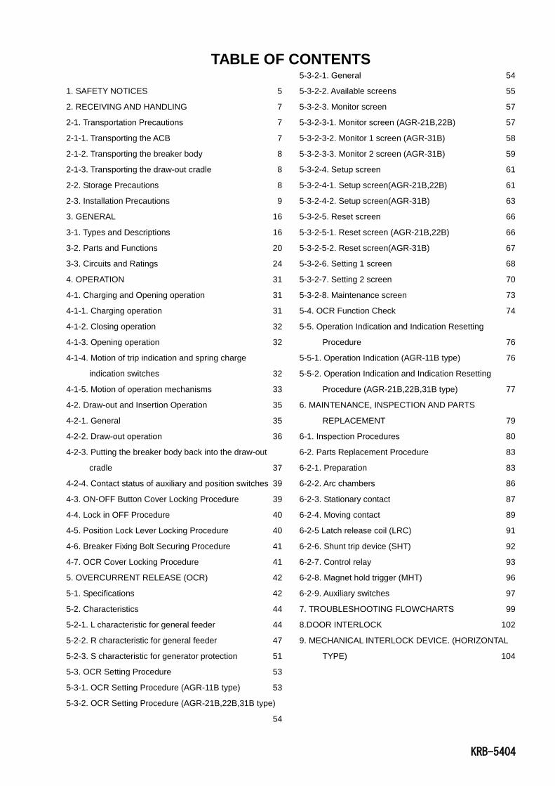
INSTRUCTION MANUAL FOR AIR CIRCUIT BREAKERS
(With Draw-out Cradle and Type AGR-11B,21B,22B,31B Overcurrent Protective Device)
Types: AR208S AR212S AR216S AR220S AR325S AR332S AR440S AR440SB AR212H AR216H AR220H AR316H AR320H AR325H AR332H AR420H AR440H AR208D AR212D AR216D
Notice Be sure to read this manual before installing, operating, servicing, or inspecting the ACB.
Please retain this manual for future reference.
Electrical work must be done by competent persons.
ACB maintenance, inspection, parts replacement, OCR field tests and setting changes must be
performed by competent persons.

KRB-5404
1. SAFETY NOTICES 5
2. RECEIVING AND HANDLING 7
2-1. Transportation Precautions 7
2-1-1. Transporting the ACB 7
2-1-2. Transporting the breaker body 8
2-1-3. Transporting the draw-out cradle 8
2-2. Storage Precautions 8
2-3. Installation Precautions 9
3. GENERAL 16
3-1. Types and Descriptions 16
3-2. Parts and Functions 20
3-3. Circuits and Ratings 24
4. OPERATION 31
4-1. Charging and Opening operation 31
4-1-1. Charging operation 31
4-1-2. Closing operation 32
4-1-3. Opening operation 32
4-1-4. Motion of trip indication and spring charge
indication switches 32
4-1-5. Motion of operation mechanisms 33
4-2. Draw-out and Insertion Operation 35
4-2-1. General 35
4-2-2. Draw-out operation 36
4-2-3. Putting the breaker body back into the draw-out
cradle 37
4-2-4. Contact status of auxiliary and position switches 39
4-3. ON-OFF Button Cover Locking Procedure 39
4-4. Lock in OFF Procedure 40
4-5. Position Lock Lever Locking Procedure 40
4-6. Breaker Fixing Bolt Securing Procedure 41
4-7. OCR Cover Locking Procedure 41
5. OVERCURRENT RELEASE (OCR) 42
5-1. Specifications 42
5-2. Characteristics 44
5-2-1. L characteristic for general feeder 44
5-2-2. R characteristic for general feeder 47
5-2-3. S characteristic for generator protection 51
5-3. OCR Setting Procedure 53
5-3-1. OCR Setting Procedure (AGR-11B type) 53
5-3-2. OCR Setting Procedure (AGR-21B,22B,31B type)
54
5-3-2-1. General 54
5-3-2-2. Available screens 55
5-3-2-3. Monitor screen 57
5-3-2-3-1. Monitor screen (AGR-21B,22B) 57
5-3-2-3-2. Monitor 1 screen (AGR-31B) 58
5-3-2-3-3. Monitor 2 screen (AGR-31B) 59
5-3-2-4. Setup screen 61
5-3-2-4-1. Setup screen(AGR-21B,22B) 61
5-3-2-4-2. Setup screen(AGR-31B) 63
5-3-2-5. Reset screen 66
5-3-2-5-1. Reset screen (AGR-21B,22B) 66
5-3-2-5-2. Reset screen(AGR-31B) 67
5-3-2-6. Setting 1 screen 68
5-3-2-7. Setting 2 screen 70
5-3-2-8. Maintenance screen 73
5-4. OCR Function Check 74
5-5. Operation Indication and Indication Resetting
Procedure 76
5-5-1. Operation Indication (AGR-11B type) 76
5-5-2. Operation Indication and Indication Resetting
Procedure (AGR-21B,22B,31B type) 77
6. MAINTENANCE, INSPECTION AND PARTS
REPLACEMENT 79
6-1. Inspection Procedures 80
6-2. Parts Replacement Procedure 83
6-2-1. Preparation 83
6-2-2. Arc chambers 86
6-2-3. Stationary contact 87
6-2-4. Moving contact 89
6-2-5 Latch release coil (LRC) 91
6-2-6. Shunt trip device (SHT) 92
6-2-7. Control relay 93
6-2-8. Magnet hold trigger (MHT) 96
6-2-9. Auxiliary switches 97
7. TROUBLESHOOTING FLOWCHARTS 99
8.DOOR INTERLOCK 102
9. MECHANICAL INTERLOCK DEVICE. (HORIZONTAL
TYPE) 104
TABLE OF CONTENTS

KRB-5404 4
KRB-5404 5
1. SAFETY NOTICES
Thank you for purchasing the TERASAKI AR-series Air Circuit Breaker (TemPower2).
This chapter contains important safety information.
Be sure to carefully read these safety notices, instruction in this manual, and other documents accompanying the Air Circuit Breaker
(hereinafter referred to as the ACB) to familiarize yourself with safe and correct procedures or practices before installing, operating,
or servicing the ACB.
In this manual, safety notices are divided into “DANGER” and “CAUTION” according to the hazard level:
DANGER : A danger notice with this symbol indicates a potentially hazardous situation which, if not avoided, could result in
death or serious injury.
CAUTION : A caution notice with this symbol indicates a potentially hazardous situation which, if not avoided, may result in
minor or moderate injury and/or property damage.
Note that failure to observe a caution notice could result in serious injury/damage in some situations. Because safety notices contain
important information, be sure to read and observe them.
Transportation Precaution
DANGER
Never stand under the ACB that has been lifted or suspended by a lifter or lifting attachments. The weight of the ACB may
cause serious injury.
Installation Precautions CAUTION
Electrical work must be done by competent persons.
Do not place the ACB in such an area that is subject to high temperatures, high humidity, dusty air, corrosive gases, strong
vibration and shock, or other unusual conditions. Mounting the ACB in such an area could cause a fire or malfunction.
Be careful to prevent foreign objects (such as debris, concrete powder, dust, chippings, and iron powder) and oil or rainwater
from entering the ACB. These materials inside the ACB could cause a fire or malfunction.
Prior to commencing any work on the ACB, open an upstream circuit breaker or the like to isolate all sources of
power/voltage. Otherwise, electric shock may result.
Fix the draw-out cradle of the ACB firmly on a flat, level surface using mounting screws. Otherwise, the draw-out operation
may cause the breaker body or the draw-out cradle to fall, resulting in damage to the ACB or personal injury.
Take care not to deform or bend protrusions in the bottom face of the draw-out cradle when fixing the draw-out cradle with
mounting screws. Deformation of the protrusions may cause a malfunction.
Connect conductors (including screws) to the main circuit terminals in the specified area. Otherwise, a short-circuit may
result.
When terminating conductors to the ACB, tighten terminal screws to the torque specified in this manual. Otherwise, a fire
could result.
For 4-pole ACBs, be sure to connect a 3-phase, 4-wire neutral conductor to the N-phase pole (on the right end). Otherwise, an
overcurrent may hinder the ACB from tripping, resulting in a fire.
Operation Precautions
DANGER
Never touch live terminal parts. Doing so will result in electric shock.
Do not leave the ACB body in the draw-out position. If the ACB body is accidentally dropped, its weight may cause serious
injury.
CAUTION
Do not force down the charging handle after completion of manual charging operation. Doing so may cause a malfunction.
The permissible operating voltage of the spring charging motor is 85 to 110% of the rated ac voltage or 75 to 110% of the rated
dc voltage. Be sure to supply a voltage within the above ranges to the motor. Otherwise, a malfunction, burnout, or fire may
result.
KRB-5404 6
Operation Precautions (continued) CAUTION
Repeated open/close operation by the motor charging mechanism without pause should not exceed 15 times. If repeated
continuous open/close operation is inevitable, a pause of at least 20 minutes should be provided after the repetitions of 15
times. Otherwise, a spring charging motor may be burnt out.
Do not bring your hand or face close to arc gas vent of the arc chamber while the ACB is closed. Otherwise, a burn may result
from high-temperature arc gas blowing out of the arc gas vent when the ACB trips open.
If the ACB trips open automatically, remove the cause of tripping operation before re-closing the ACB. Otherwise, a fire
could result.
If the ACB has the breaker fixing bolts, be sure to loose the fixing bolts before draw-out operation. Otherwise, damage to the
ACB may result.
Make sure the draw-out cradle is secured with mounting screws before inserting or drawing out the breaker body. Otherwise,
the insertion or draw-out operation may cause the breaker body or the draw-out cradle to fall, resulting in damage to the ACB
or personal injury.
When retracting the draw-out rail into the draw-out cradle, be sure to push the rail end. Do not hold the hook pin, body
stopper, or body stopper shaft. Doing so may cause your fingers to be pinched, resulting in injury.
Do not forcedly turn the draw-out handle clockwise when the breaker body is in the “CONN.” position. Doing so may cause a
malfunction.
If the ACB has the breaker fixing bolts, make sure the bolts on both sides are securely tightened before using the ACB.
Loosened fixing bolts may cause a malfunction of the ACB, in particular when it is installed in such an area that is subject to
strong vibrations.
OCR (Overcurrent Release) Handling Precautions CAUTION
OCR field tests and setting changes must be performed by competent persons.
After setting changes are made, the settings be checked with e.g., a type ANU-1 OCR checker (optional).
After completion of OCR tests, be sure to return the settings to the original values. Failure to do so may cause a fire or
burnout.
Before changing OCR settings, open the ACB and then lock the OFF button to prevent the ACB from being closed
inadvertently.
Do not push the SET button diagonally. Doing so may cause a poor in return and malfunction.
Maintenance and Inspection Precautions CAUTION
ACB maintenance, inspection and parts replacement must be performed by competent persons.
Do not touch ACB current carrying parts and ACB structural parts close to a current carrying part immediately after the ACB
trips open. Remaining heat may cause a burn.
Prior to commencing any work on the ACB, open an upstream circuit breaker or the like to isolate all sources of
power/voltage from the main and control circuits. Otherwise, electric shock may result.
Take care to avoid adhesion of dust to main and control circuit contacts. Dust on the contacts may result in a fire.
Prior to commencing maintenance, inspection, or parts replacement, make sure that the closing springs are released and the
ACB is open. Otherwise, unintentional open/close operation may lead to fingers or tools to be pinched by the open/close
mechanism, resulting in injury.
Retighten the terminal screws periodically to the specified torque. Otherwise, a fire could result.
When grinding a contact tip, be careful to prevent grinding dust from entering the breaker operating mechanism. Wipe the tip
clean after grinding. Otherwise, a malfunction or fire could result.
Do not perform dielectric withstand tests under other conditions than specified. Doing so may cause a malfunction.
Be sure to reinstall the arc chamber if removed. Failure to do so or incorrect installation of the arc chamber may result in a fire
or burn.
When charging the closing springs or performing open/close operation of the ACB with the arc chamber, front cover and/or
side covers removed during maintenance or inspection work, do not touch parts other than those required for the above
operation (charging handle, ON/OFF buttons, moving core and the like). Doing so may cause fingers or tools to be pinched,
resulting in injury.
When replacing an auxiliary, do not damage the control wire for the auxiliary or pinch the wire between the auxiliary and the
breaker body. Doing so may cause a malfunction.

KRB-5404 7
2. RECEIVING AND HANDLING
Upon receipt of your ACB, check the following. If you have any question or problem, contact us at the indicated on the back cover
of this manual.
Check that the ACB received is as ordered and that the accessories are as specified.
Check that the ACB is not damaged during shipment.
2-1. Transportation Precautions
DANGER
Never stand under the ACB that has been lifted or suspended by a lifter or lifting attachments. If the ACB body is accidentally
dropped, its weight may cause serious injury.
2-1-1. Transporting the ACB
Before transporting the ACB, make sure the breaker body is in the CONN. position. If the ACB has breaker fixing bolts, make
sure the breaker body is secured to the draw-out cradle with the fixing bolts.
When lifting the ACB, hold it using lifting attachments or wire ropes through the lifting holes. Take care that the position
switches, control circuit terminals, auxiliary switches, arc gas barrier and control terminal block cover which are shown in Fig. 1
are not damaged by the lifting rope. Lift the ACB carefully and gently. For transportation, place the ACB on a pallet and carry
slowly and carefully.
Avoid shock and vibration to the ACB during transportation.
Do not lay the ACB during transportation.
When transporting the ACB over great distances, crate it for protection against shock and vibration and secure the crate package
with wood or ropes.
When transporting the ACB while it is installed in a switchboard, you should fix the breaker body in the draw-out cradle with the
breaker fixing bolts (optional).
Lower the ACB onto a flat, level surface.
Front view Rear view
Fig. 1 Transporting the ACB
Breaker body
Breaker fixing bolt
Lifting attachment
Control terminal block cover
Lifting hole (ø20mm)
Arc gas barrier
Draw-out cradle
Position switches
Control circuit terminals
Auxiliary switches
KRB-5404 8
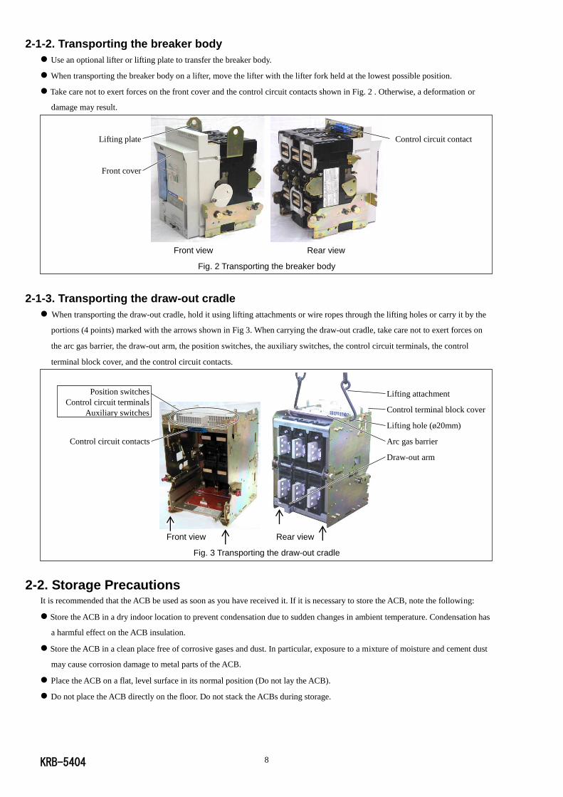
2-1-2. Transporting the breaker body
Use an optional lifter or lifting plate to transfer the breaker body.
When transporting the breaker body on a lifter, move the lifter with the lifter fork held at the lowest possible position.
Take care not to exert forces on the front cover and the control circuit contacts shown in Fig. 2 . Otherwise, a deformation or
damage may result.
Front view Rear view
Fig. 2 Transporting the breaker body
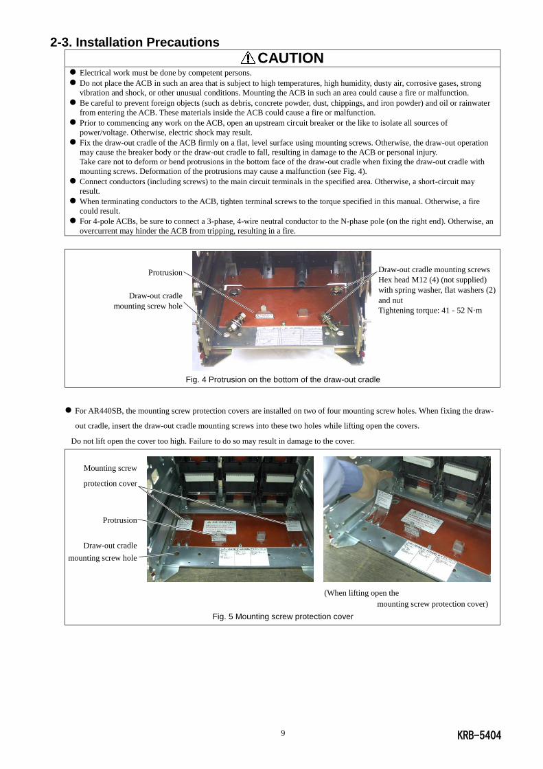
2-1-3. Transporting the draw-out cradle
When transporting the draw-out cradle, hold it using lifting attachments or wire ropes through the lifting holes or carry it by the
portions (4 points) marked with the arrows shown in Fig 3. When carrying the draw-out cradle, take care not to exert forces on
the arc gas barrier, the draw-out arm, the position switches, the auxiliary switches, the control circuit terminals, the control
terminal block cover, and the control circuit contacts.
Front view Rear view
Fig. 3 Transporting the draw-out cradle
2-2. Storage Precautions
It is recommended that the ACB be used as soon as you have received it. If it is necessary to store the ACB, note the following:
Store the ACB in a dry indoor location to prevent condensation due to sudden changes in ambient temperature. Condensation has
a harmful effect on the ACB insulation.
Store the ACB in a clean place free of corrosive gases and dust. In particular, exposure to a mixture of moisture and cement dust
may cause corrosion damage to metal parts of the ACB.
Place the ACB on a flat, level surface in its normal position (Do not lay the ACB).
Do not place the ACB directly on the floor. Do not stack the ACBs during storage.
Control circuit contact Lifting plate
Front cover
Lifting attachment
Control terminal block cover
Lifting hole (ø20mm)
Arc gas barrier
Draw-out arm
Position switches
Control circuit terminals
Auxiliary switches
Control circuit contacts
KRB-5404 9
2-3. Installation Precautions
CAUTION
Electrical work must be done by competent persons.
Do not place the ACB in such an area that is subject to high temperatures, high humidity, dusty air, corrosive gases, strong
vibration and shock, or other unusual conditions. Mounting the ACB in such an area could cause a fire or malfunction.
Be careful to prevent foreign objects (such as debris, concrete powder, dust, chippings, and iron powder) and oil or rainwater
from entering the ACB. These materials inside the ACB could cause a fire or malfunction.
Prior to commencing any work on the ACB, open an upstream circuit breaker or the like to isolate all sources of
power/voltage. Otherwise, electric shock may result.
Fix the draw-out cradle of the ACB firmly on a flat, level surface using mounting screws. Otherwise, the draw-out operation
may cause the breaker body or the draw-out cradle to fall, resulting in damage to the ACB or personal injury.
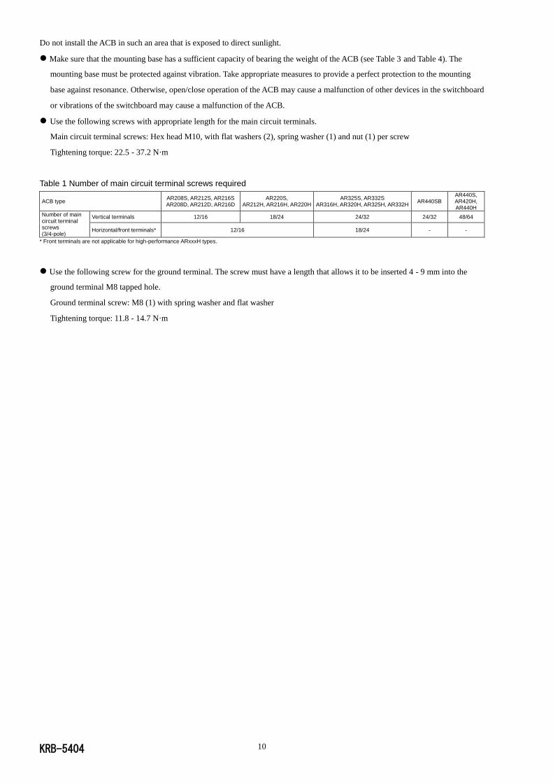
Take care not to deform or bend protrusions in the bottom face of the draw-out cradle when fixing the draw-out cradle with
mounting screws. Deformation of the protrusions may cause a malfunction (see Fig. 4).
Connect conductors (including screws) to the main circuit terminals in the specified area. Otherwise, a short-circuit may
result.
When terminating conductors to the ACB, tighten terminal screws to the torque specified in this manual. Otherwise, a fire
could result.
For 4-pole ACBs, be sure to connect a 3-phase, 4-wire neutral conductor to the N-phase pole (on the right end). Otherwise, an
overcurrent may hinder the ACB from tripping, resulting in a fire.
Fig. 4 Protrusion on the bottom of the draw-out cradle
For AR440SB, the mounting screw protection covers are installed on two of four mounting screw holes. When fixing the draw-
out cradle, insert the draw-out cradle mounting screws into these two holes while lifting open the covers.
Do not lift open the cover too high. Failure to do so may result in damage to the cover.
(When lifting open the
mounting screw protection cover)
Fig. 5 Mounting screw protection cover
Draw-out cradle mounting screws
Hex head M12 (4) (not supplied)
with spring washer, flat washers (2)
and nut
Tightening torque: 41 - 52 N·m
Protrusion
Draw-out cradle
mounting screw hole
Mounting screw
protection cover
Protrusion
Draw-out cradle
mounting screw hole
KRB-5404 10
Do not install the ACB in such an area that is exposed to direct sunlight.
Make sure that the mounting base has a sufficient capacity of bearing the weight of the ACB (see Table 3 and Table 4). The
mounting base must be protected against vibration. Take appropriate measures to provide a perfect protection to the mounting
base against resonance. Otherwise, open/close operation of the ACB may cause a malfunction of other devices in the switchboard
or vibrations of the switchboard may cause a malfunction of the ACB.
Use the following screws with appropriate length for the main circuit terminals.
Main circuit terminal screws: Hex head M10, with flat washers (2), spring washer (1) and nut (1) per screw
Tightening torque: 22.5 - 37.2 N·m
Table 1 Number of main circuit terminal screws required
ACB type AR208S, AR212S, AR216S AR208D, AR212D, AR216D
AR220S, AR212H, AR216H, AR220H
AR325S, AR332S AR316H, AR320H, AR325H, AR332H
AR440SB AR440S, AR420H, AR440H
Number of main circuit terminal screws (3/4-pole)
Vertical terminals 12/16 18/24 24/32 24/32 48/64
Horizontal/front terminals* 12/16 18/24 - -
* Front terminals are not applicable for high-performance ARxxxH types.
Use the following screw for the ground terminal. The screw must have a length that allows it to be inserted 4 - 9 mm into the
ground terminal M8 tapped hole.
Ground terminal screw: M8 (1) with spring washer and flat washer
Tightening torque: 11.8 - 14.7 N·m
KRB-5404 11
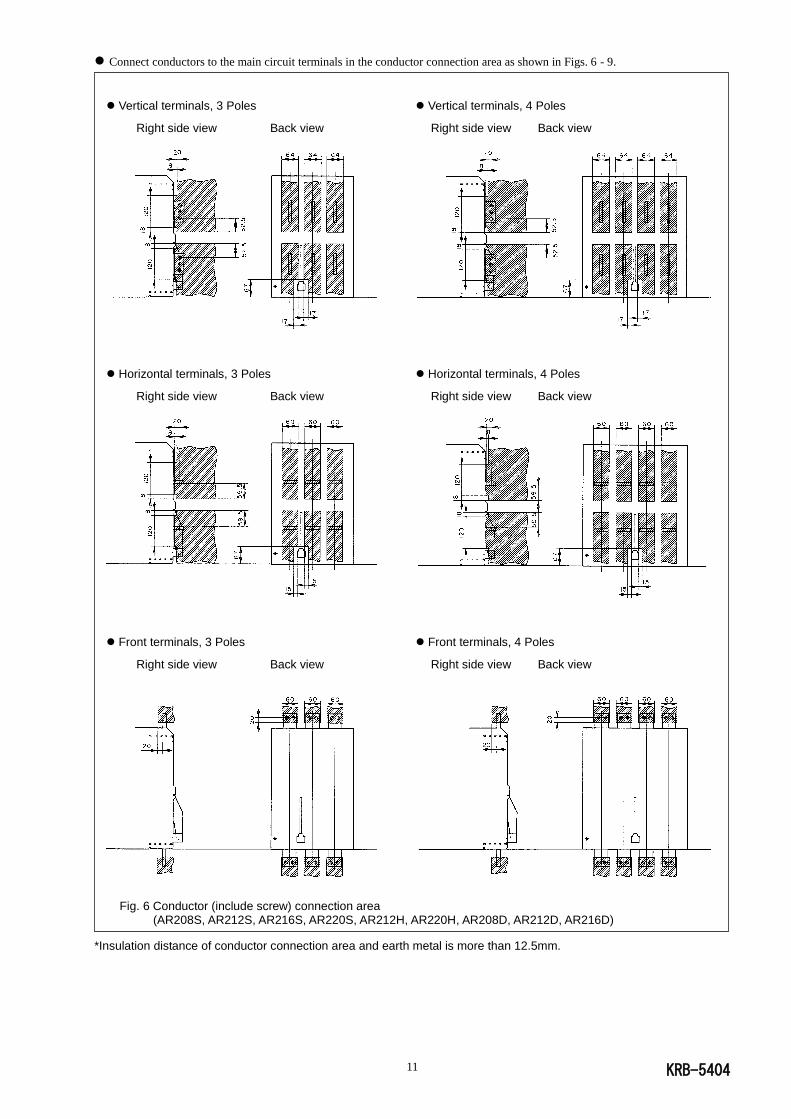
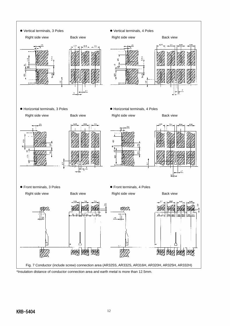
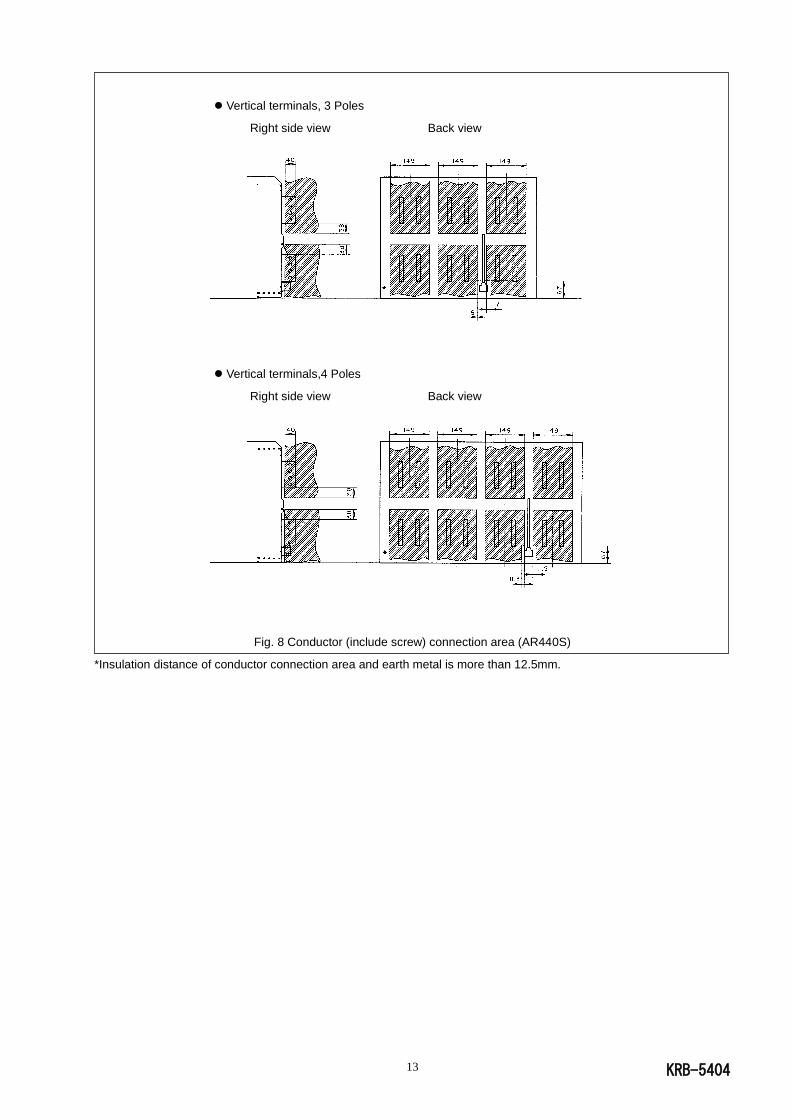
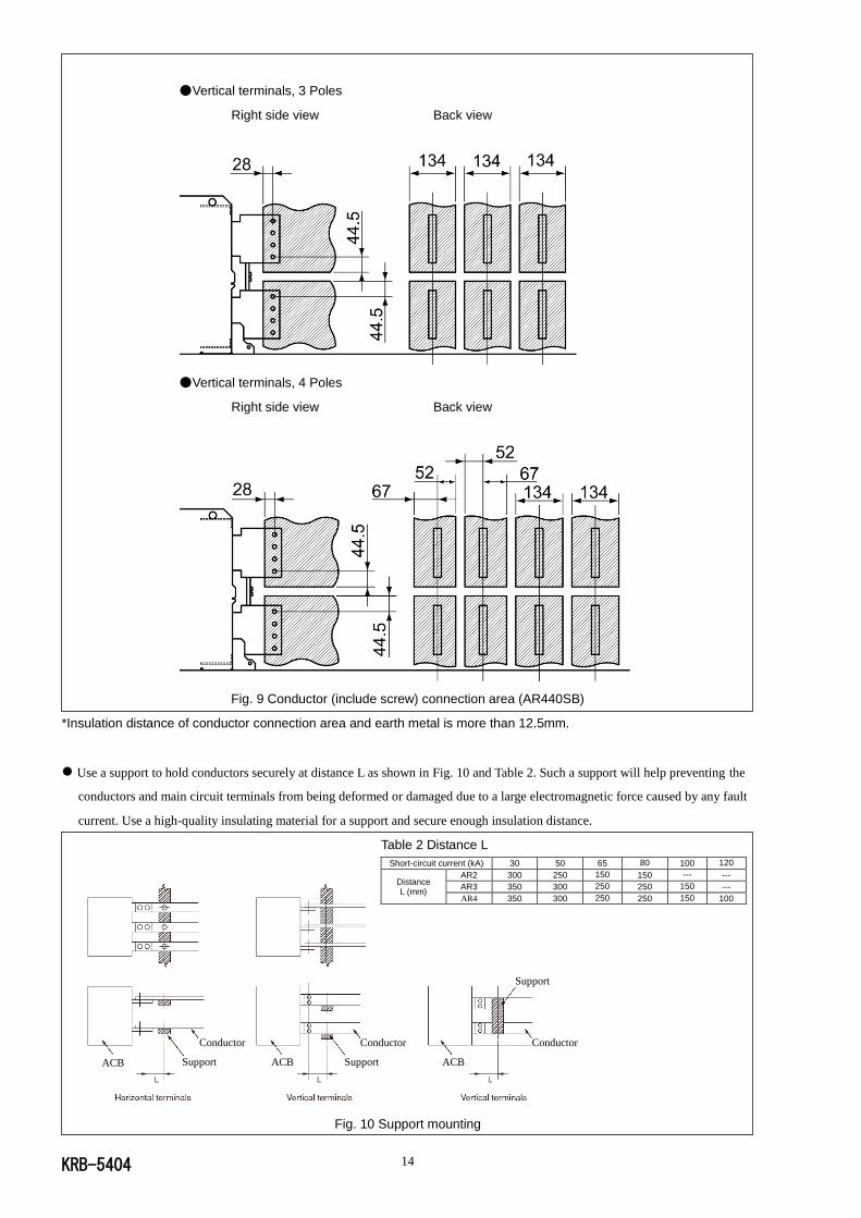
Connect conductors to the main circuit terminals in the conductor connection area as shown in Figs. 6 - 9.
Vertical terminals, 3 Poles Vertical terminals, 4 Poles
Right side view Back view Right side view Back view
Horizontal terminals, 3 Poles Horizontal terminals, 4 Poles
Right side view Back view Right side view Back view
Front terminals, 3 Poles Front terminals, 4 Poles
Right side view Back view Right side view Back view
Fig. 6 Conductor (include screw) connection area (AR208S, AR212S, AR216S, AR220S, AR212H, AR220H, AR208D, AR212D, AR216D)
*Insulation distance of conductor connection area and earth metal is more than 12.5mm.
KRB-5404 12
Vertical terminals, 3 Poles Vertical terminals, 4 Poles
Right side view Back view Right side view Back view
Horizontal terminals, 3 Poles Horizontal terminals, 4 Poles
Right side view Back view Right side view Back view
Front terminals, 3 Poles Front terminals, 4 Poles
Right side view Back view Right side view Back view
Fig. 7 Conductor (include screw) connection area (AR325S, AR332S, AR316H, AR320H, AR325H, AR332H)
*Insulation distance of conductor connection area and earth metal is more than 12.5mm.
KRB-5404 13
Vertical terminals, 3 Poles
Right side view Back view
Vertical terminals,4 Poles
Right side view Back view
Fig. 8 Conductor (include screw) connection area (AR440S)
*Insulation distance of conductor connection area and earth metal is more than 12.5mm.
KRB-5404 14
ACB ACB ACB Support Support
Support
Conductor Conductor Conductor
●Vertical terminals, 3 Poles
Right side view Back view
●Vertical terminals, 4 Poles
Right side view Back view
Fig. 9 Conductor (include screw) connection area (AR440SB)
*Insulation distance of conductor connection area and earth metal is more than 12.5mm.
Use a support to hold conductors securely at distance L as shown in Fig. 10 and Table 2. Such a support will help preventing the
conductors and main circuit terminals from being deformed or damaged due to a large electromagnetic force caused by any fault
current. Use a high-quality insulating material for a support and secure enough insulation distance.
Table 2 Distance L
Short-circuit current (kA) 30 50 65 80 100 120
Distance L (mm)
AR2 300 250 150 150 --- ---
AR3 350 300 250 250 150 ---
AR4 350 300 250 250 150 100
Fig. 10 Support mounting
KRB-5404 15
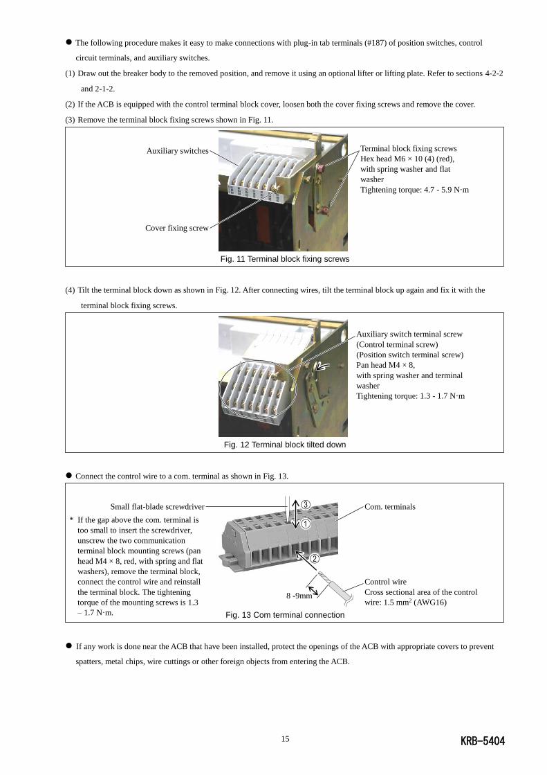
The following procedure makes it easy to make connections with plug-in tab terminals (#187) of position switches, control
circuit terminals, and auxiliary switches.
(1) Draw out the breaker body to the removed position, and remove it using an optional lifter or lifting plate. Refer to sections 4-2-2
and 2-1-2.
(2) If the ACB is equipped with the control terminal block cover, loosen both the cover fixing screws and remove the cover.
(3) Remove the terminal block fixing screws shown in Fig. 11.
Fig. 11 Terminal block fixing screws
(4) Tilt the terminal block down as shown in Fig. 12. After connecting wires, tilt the terminal block up again and fix it with the
terminal block fixing screws.
Fig. 12 Terminal block tilted down
Connect the control wire to a com. terminal as shown in Fig. 13.
Fig. 13 Com terminal connection
If any work is done near the ACB that have been installed, protect the openings of the ACB with appropriate covers to prevent
spatters, metal chips, wire cuttings or other foreign objects from entering the ACB.
Terminal block fixing screws
Hex head M6 × 10 (4) (red),
with spring washer and flat
washer
Tightening torque: 4.7 - 5.9 N·m
Auxiliary switches
Cover fixing screw
Auxiliary switch terminal screw
(Control terminal screw)
(Position switch terminal screw)
Pan head M4 × 8,
with spring washer and terminal
washer
Tightening torque: 1.3 - 1.7 N·m
Com. terminals
Control wire
Cross sectional area of the control
wire: 1.5 mm2 (AWG16)
Small flat-blade screwdriver
* If the gap above the com. terminal is
too small to insert the screwdriver,
unscrew the two communication
terminal block mounting screws (pan
head M4 × 8, red, with spring and flat
washers), remove the terminal block,
connect the control wire and reinstall
the terminal block. The tightening
torque of the mounting screws is 1.3
– 1.7 N·m.
8 -9mm
KRB-5404 16
3. GENERAL
3-1. Types and Descriptions
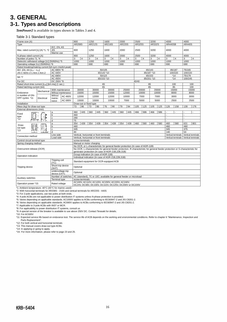
TemPower2 is available in types shown in Tables 3 and 4.
Table 3-1 Standard types
Frame size (A) 800 1250 1600 2000 2500 3200 4000 4000
Type AR208S AR212S AR216S AR220S AR325S AR332S AR440SB AR440S
Max. rated current [In] (A) *1, *2 IEC, EN, AS
800 1250 1600 2000 2500 3200 4000 4000 JIS Marine use
N-phase rated current (A) 800 1250 1600 2000 2500 3200 4000 4000
Number of poles *3, *4 3 4 3 4 3 4 3 4 3 4 3 4 3 4 3 4
Dielectric withstand voltage [Ui] (50/60Hz) *5 1000 1000 1000 1000 1000 1000 1000 1000
Operating voltage [Ue] (50/60Hz) *6 690 690 690 690 690 690 690 690
Rated breaking/making current [kA sym rms/kA peak]
IEC ,EN, AS [ICS = ICU]
JIS C 8201-2-1 Ann.1 Ann.2
AC 690V *8 50/105 65/143 85/187 75/165
AC 440V 65/143 *10 85/187 *10 100/220 100/220
NK *7 AC 690V 50/115 65/153 *14 75/179
AC 450V 65/153 *10 85/201 *10 *14 100/245
For DC DC 250V *9 40/40
Rated short-time current [ICW] [kA rms] (1 sec.) 65 85 100 100
Rated latching current (kA) 65 85 85 100
Endurance in number of ON-OFF cycles *11
Mechanical With maintenance 30000 30000 30000 25000 20000 20000 15000 15000
Without maintenance 15000 15000 15000 12000 10000 10000 8000 8000
Electrical Without mainte-nance
AC 460V 12000 12000 12000 10000 7000 7000 3000 3000
AC 690V 10000 10000 10000 7000 5000 5000 2500 2500
Installation Draw-out or fixed type Mass (kg) for draw-out type 73 86 73 86 76 90 79 94 105 125 105 125 126 158 139 176
External dimensions (mm)
Fixed type *12
a 360 445 360 445 360 445 360 445 466 586 466 586 - - - -
b 460 - -
c 290 - -
d 75 - -
Draw- out type *13
a 354 439 354 439 354 439 354 439 460 580 460 580 460 580 631 801
b 460 460 460
c 345 345 375
d 40 140 53
Connection method Line side Vertical, horizontal or front terminals Vertical terminals Vertical terminals Load side Vertical, horizontal or front terminals Vertical terminals Vertical terminals
Control circuit terminal type screw terminals Spring charging method Manual or motor charging
Overcurrent release (OCR) No OCR, or L-characteristic for general feeder protection (In case of AGR-11B)
No OCR, L-characteristic for general feeder protection, R-characteristic for general feeder protection or S-characteristic for generator protection (In case of AGR-21B,22B,31B)
Operation indication Group indication (In case of AGR-11B)
Individual indication (In case of AGR-21B,22B,31B)
Tripping device
Tripping coil (TC)
Standard equipment for OCR-equipped ACB
Shunt trip device (SHT)
Optional
undervoltage trip device (UVT)
Optional
Auxiliary switches Number of switches 4C (standard), 7C or 10C; available for general feeder or microload Terminal type screw terminals
Operation power *15 Rated voltage AC100V, AC110V, AC120V, AC200V, AC220V, AC240V, DC24V, DC48V, DC100V, DC110V, DC125V, DC200V or DC220V
*1: Ambient temperature: 40°C (45°C for marine used))
*2: With horizontal terminals for AR208S - 216S and vertical terminals for AR220S - 440S
*3: For 2-pole applications, use two poles at both ends.
*4: 4-pole ACBs are not applicable to power distribution IT systems unless N-phase protection is provided.
*5: Varies depending on applicable standards. AC1000V applies to ACBs conforming to IEC60947-2 and JIS C8201-2.
*6: Varies depending on applicable standards. AC690V applies to ACBs conforming to IEC60947-2 and JIS C8201-2.
*7: Applicable to 3-pole ACBs with INST or MCR.
*8: For applicability to power distribution IT systems, consult us
*9: A special version of the breaker is available to use above 250V DC. Contact Terasaki for details.
*10: For AC500V
*11: Expected service life based on endurance test. The service life of ACB depends on the working and environmental conditions. Refer to chapter 6 “Maintenance, Inspection and
Parts Replacement”.
*12: For both vertical and horizontal terminals
*13: This manual covers draw-out type ACBs.
*14: In applying or going to apply.
*15: For more information, please refer to page 23 and 25.

KRB-5404 17
Table 3-2 D types
Frame size (A) 800 1250 1600
Type AR208D AR212D AR216D
Max. rated current [In] (A) *1, *2 IEC, EN, AS
800 1250 1600 JIS Marine use
N-phase rated current (A) 800 1250 1600
Number of poles *3, *4 3 4 3 4 3 4
Dielectric withstand voltage [Ui] (50/60Hz) *5 1000 1000 1000
Operating voltage [Ue] (50/60Hz) *6 690 690 690
Rated breaking/making current [kA sym rms]
IEC ,EN, AS [ICS = ICU]
JIS C 8201-2-1 Ann.1 Ann.2
AC 690V *8 42
AC 440V 50
For DC DC 250V *10 40
Rated short-time current [ICW] [kA rms] (1 sec.) 50
Endurance in number of ON-OFF cycles *11
Mechanical With maintenance 26000 26000 26000
Without maintenance 12500 12500 12500
Electrical Without mainte-nance
AC 460V 11000 11000 11000
Installation Draw-out or fixed type Mass (kg) for draw-out type 73 86 73 86 76 90
External dimensions (mm)
Fixed type *12
a 360 445 360 445 360 445
b 460
c 290
d 75
Draw- out type *13
a 354 439 354 439 354 439
b 460
c 345
d 40
Connection method Line side Vertical, horizontal or front terminals Load side Vertical, horizontal or front terminals
Control circuit terminal type screw terminals Spring charging method Manual or motor charging
Overcurrent release (OCR)
No OCR, or L-characteristic for general feeder protection (In case of AGR-11B)
No OCR, L-characteristic for general feeder protection, R-characteristic for general feeder protection or S-characteristic for generator protection (In case of AGR-21B,22B,31B)
Operation indication Group indication (In case of AGR-11B)
Individual indication (In case of AGR-21B,22B,31B)
Tripping device
Tripping coil (TC)
Standard equipment for OCR-equipped ACB
Shunt trip device (SHT)
Optional
undervoltage trip device (UVT)
Optional
Auxiliary switches Number of switches
4C (standard), 7C or 10C; available for general feeder or microload
Terminal type screw terminals
Operation power *14 Rated voltage AC100, AC110V, AC120V, AC200V, AC220V, AC240V, DC24V, DC48V, DC100V, DC110V, DC125V, DC200V or DC220V
*1: Ambient temperature: 40°C (45°C for marine used))
*2: With horizontal terminals for AR208D – 216D
*3: For 2-pole applications, use two poles at both ends.
*4: 4-pole ACBs are not applicable to power distribution IT systems unless N-phase protection is provided.
*5: Varies depending on applicable standards. AC1000V applies to ACBs conforming to IEC60947-2 and JIS C8201-2.
*6: Varies depending on applicable standards. AC690V applies to ACBs conforming to IEC60947-2 and JIS C8201-2.
*7: Applicable to 3-pole ACBs with INST or MCR.
*8: For applicability to power distribution IT systems, consult us
*10: A special version of the breaker is available to use above 250V DC. Contact Terasaki for details.
*11: Expected service life based on endurance test. The service life of ACB depends on the working and environmental conditions. Refer to chapter 6 “Maintenance, Inspection and
Parts Replacement”.
*12: For both vertical and horizontal terminals
*13: This manual covers draw-out type ACBs.
*14: For more information, please refer to page 23 and 25.
KRB-5404 18
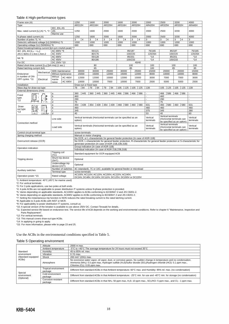
Table 4 High-performance types
Frame size (A) 1250 1600 2000 1600 2000 2000 2500 3200 4000
Type AR212H AR216H AR220H AR316H AR320H AR420H AR325H AR332H AR440H
Max. rated current [In] (A) *1, *2 IEC, EN, AS
1250 1600 2000 1600 2000 2000 2500 3200 4000 JIS Marine use
N-phase rated current (A) 1250 1600 2000 1600 2000 2000 2500 3200 4000
Number of poles *3, *4 3 4 3 4 3 4 3 4 3 4 3 3 4 3 4 3
Dielectric withstand voltage [Ui] (50/60Hz) *5 1000 1000 1000 1000 1000 1000 1000 1000 1000
Operating voltage [Ue] (50/60Hz) *6 690 690 690 690 690 690 690 690 690
Rated breaking/making current [kA sym rms/kA peak] *7
IEC ,EN, AS [ICS = ICU]
JIS C 8201-2-1 Ann.1 Ann.2
AC 690V *9 55/121 85/187 75/165 85/187 75/165
AC 440V 80/176 100/220 120/264 100/220 120/264
NK *8 AC 690V 55/128 85/201 *14 85/201 *14
AC 450V 80/186 100/233 *14 100/233 *14
For DC DC 250V *10 40/40
Rated short-time current [ICW] [kA rms] (1 sec.) 80 100 100 100 100
Rated latching current (kA) 65 85 100 85 85
Endurance in number of ON-OFF cycles *11
Mechanical With maintenance 30000 30000 25000 30000 25000 15000 20000 20000 15000
Without maintenance 15000 15000 12000 15000 12000 8000 10000 10000 8000
Electrical Without mainte-nance
AC 460V 12000 12000 10000 12000 10000 3000 7000 7000 3000
AC 690V 10000 10000 7000 10000 7000 2500 5000 5000 2500
Installation Draw-out or fixed type Mass (kg) for draw-out type 79 94 79 94 79 94 105 125 105 125 139 105 125 105 125 139
External dimensions (mm)
Fixed type *12
a 360 445 360 445 360 445 466 586 466 586 - 466 586 466 586 -
b 460 - 460 -
c 290 - 290 -
d 75 - 75 -
Draw- out type *13
a 354 439 354 439 354 439 460 580 460 580 631 460 580 460 580 631
b 460 460 460 460
c 345 375 345 380
d 40 53 40 60
Connection method
Line side Vertical terminals (Horizontal terminals can be specified as an option)
Vertical terminals
Vertical terminals (Horizontal terminals can be specified as an option)
Vertical terminals
Load side Vertical terminals (Horizontal terminals can be specified as an option)
Vertical terminals
Vertical terminals (Horizontal terminals can be specified as an option)
Vertical terminals
Control circuit terminal type screw terminals Spring charging method Manual or motor charging
Overcurrent release (OCR) No OCR, or L-characteristic for general feeder protection (In case of AGR-11B)
No OCR, L-characteristic for general feeder protection, R-characteristic for general feeder protection or S-characteristic for generator protection (In case of AGR-21B,22B,31B)
Operation indication Group indication (In case of AGR-11B)
Individual indication (In case of AGR-21B,22B,31B)
Tripping device
Tripping coil (TC)
Standard equipment for OCR-equipped ACB
Shunt trip device (SHT)
Optional
Undervoltage trip device (UVT)
Optional
Auxiliary switches Number of switches 4C (standard), 7C or 10C; available for general feeder or microload Terminal type screw terminals
Operation power *15 Rated voltage AC100V, AC110V, AC120V, AC200V, AC220V, AC240V, DC24V, DC48V, DC100V, DC110V, DC125V, DC200V or DC220V
*1: Ambient temperature: 40°C (45°C for marine used)
*2: For vertical terminals
*3: For 2-pole applications, use two poles at both ends.
*4: 4-pole ACBs are not applicable to power distribution IT systems unless N-phase protection is provided.
*5: Varies depending on applicable standards. AC1000V applies to ACBs conforming to IEC60947-2 and JIS C8201-2.
*6: Varies depending on applicable standards. AC690V applies to ACBs conforming to IEC60947-2 and JIS C8201-2.
*7: Setting the instantaneous trip function to NON reduces the rated breaking current to the rated latching current.
*8: Applicable to 3-pole ACBs with INST or MCR.
*9: For applicability to power distribution IT systems, consult us
*10: A special version of the breaker is available to use above 250V DC. Contact Terasaki for details.
*11: Expected service life based on endurance test. The service life of ACB depends on the working and environmental conditions. Refer to chapter 6 “Maintenance, Inspection and
Parts Replacement”.
*12: For vertical terminals
*13: This manual covers draw-out type ACBs.
*14: In applying or going to apply.
*15: For more information, please refer to page 23 and 25.
Use the ACBs in the environmental conditions specified in Table 5.
Table 5 Operating environment
Standard environment (Standard equipped ACBs)
Altitude 2000 m max. Ambient temperature -5°C to +40°C The average temperature for 24 hours must not exceed 35°C
Humidity 45 to 85% rel. max. Vibration 0.7G max. Shock 200 m/s2 (20G) max.
Atmosphere No excessive water vapor, oil vapor, dust, or corrosive gases. No sudden change in temperature and no condensation. Ammonia (NH3): 0.5 ppm max, Hydrogen sulfide (H2S)/sulfur dioxide (SO2)/hydrogen chloride (HCl): 0.1 ppm max., Chlorine (Cl2): 0.05 ppm max.
Special environment (Optional)
Tropical environment package
Different from standard ACBs in that Ambient temperature: 60°C max. and Humidity: 95% rel. max. (no condensation)
Cold environment package
Different from standard ACBs in that Ambient temperature: -25°C min. for use and -40°C min. for storage (no condensation)
Corrosion-resistant package
Different from standard ACBs in that NH3: 50 ppm max, H2S: 10 ppm max., SO2/HCl: 5 ppm max., and Cl2 : 1 ppm max.
KRB-5404 19
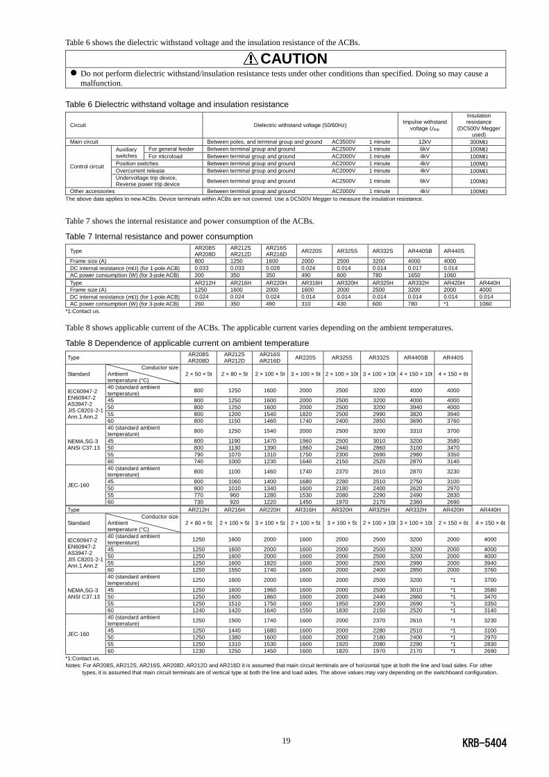
Table 6 shows the dielectric withstand voltage and the insulation resistance of the ACBs.
CAUTION
Do not perform dielectric withstand/insulation resistance tests under other conditions than specified. Doing so may cause a
malfunction.
Table 6 Dielectric withstand voltage and insulation resistance
Circuit Dielectric withstand voltage (50/60Hz) Impulse withstand
voltage Uimp
Insulation resistance
(DC500V Megger used)
Main circuit Between poles, and terminal group and ground AC3500V 1 minute 12kV 300M
Control circuit
Auxiliary switches
For general feeder Between terminal group and ground AC2500V 1 minute 6kV 100M
For microload Between terminal group and ground AC2000V 1 minute 4kV 100M
Position switches Between terminal group and ground AC2000V 1 minute 4kV 100M
Overcurrent release Between terminal group and ground AC2000V 1 minute 4kV 100M
Undervoltage trip device, Reverse power trip device
Between terminal group and ground AC2500V 1 minute 6kV 100M
Other accessories Between terminal group and ground AC2000V 1 minute 4kV 100M
The above data applies to new ACBs. Device terminals within ACBs are not covered. Use a DC500V Megger to measure the insulation resistance.
Table 7 shows the internal resistance and power consumption of the ACBs.
Table 7 Internal resistance and power consumption
Type AR208S AR208D
AR212S AR212D
AR216S AR216D
AR220S AR325S AR332S AR440SB AR440S
Frame size (A) 800 1250 1600 2000 2500 3200 4000 4000
DC internal resistance (m) (for 1-pole ACB) 0.033 0.033 0.028 0.024 0.014 0.014 0.017 0.014
AC power consumption (W) (for 3-pole ACB) 200 350 350 490 600 780 1650 1060
Type AR212H AR216H AR220H AR316H AR320H AR325H AR332H AR420H AR440H
Frame size (A) 1250 1600 2000 1600 2000 2500 3200 2000 4000
DC internal resistance (m) (for 1-pole ACB) 0.024 0.024 0.024 0.014 0.014 0.014 0.014 0.014 0.014
AC power consumption (W) (for 3-pole ACB) 260 350 490 310 430 600 780 *1 1060
*1:Contact us.
Table 8 shows applicable current of the ACBs. The applicable current varies depending on the ambient temperatures.
Table 8 Dependence of applicable current on ambient temperature
Type AR208S AR208D
AR212S AR212D
AR216S AR216D
AR220S AR325S AR332S AR440SB AR440S
Standard Conductor size
Ambient temperature (°C)
2 × 50 × 5t 2 × 80 × 5t 2 × 100 × 5t 3 × 100 × 5t 2 × 100 × 10t 3 × 100 × 10t 4 × 150 × 10t 4 × 150 × 6t
IEC60947-2 EN60947-2 AS3947-2 JIS C8201-2-1 Ann.1 Ann.2
40 (standard ambient temperature)
800 1250 1600 2000 2500 3200 4000 4000
45 800 1250 1600 2000 2500 3200 4000 4000
50 800 1250 1600 2000 2500 3200 3940 4000
55 800 1200 1540 1820 2500 2990 3820 3940
60 800 1150 1460 1740 2400 2850 3690 3760
NEMA,SG-3 ANSI C37.13
40 (standard ambient temperature)
800 1250 1540 2000 2500 3200 3310 3700
45 800 1190 1470 1960 2500 3010 3200 3580
50 800 1130 1390 1860 2440 2860 3100 3470
55 790 1070 1310 1750 2300 2690 2980 3350
60 740 1000 1230 1640 2150 2520 2870 3140
JEC-160
40 (standard ambient temperature)
800 1100 1460 1740 2370 2610 2870 3230
45 800 1060 1400 1680 2280 2510 2750 3100
50 800 1010 1340 1600 2180 2400 2620 2970
55 770 960 1280 1530 2080 2290 2490 2830
60 730 920 1220 1450 1970 2170 2360 2690
Type AR212H AR216H AR220H AR316H AR320H AR325H AR332H AR420H AR440H
Standard Conductor size
Ambient temperature (°C)
2 × 80 × 5t 2 × 100 × 5t 3 × 100 × 5t 2 × 100 × 5t 3 × 100 × 5t 2 × 100 × 10t 3 × 100 × 10t 2 × 150 × 6t 4 × 150 × 6t
IEC60947-2 EN60947-2 AS3947-2 JIS C8201-2-1 Ann.1 Ann.2
40 (standard ambient temperature)
1250 1600 2000 1600 2000 2500 3200 2000 4000
45 1250 1600 2000 1600 2000 2500 3200 2000 4000
50 1250 1600 2000 1600 2000 2500 3200 2000 4000
55 1250 1600 1820 1600 2000 2500 2990 2000 3940
60 1250 1550 1740 1600 2000 2400 2850 2000 3760
NEMA,SG-3 ANSI C37.13
40 (standard ambient temperature)
1250 1600 2000 1600 2000 2500 3200 *1 3700
45 1250 1600 1960 1600 2000 2500 3010 *1 3580
50 1250 1600 1860 1600 2000 2440 2860 *1 3470
55 1250 1510 1750 1600 1950 2300 2690 *1 3350
60 1240 1420 1640 1550 1830 2150 2520 *1 3140
JEC-160
40 (standard ambient temperature)
1250 1500 1740 1600 2000 2370 2610 *1 3230
45 1250 1440 1680 1600 2000 2280 2510 *1 3100
50 1250 1380 1600 1600 2000 2180 2400 *1 2970
55 1250 1310 1530 1600 1920 2080 2290 *1 2830
60 1230 1250 1450 1600 1820 1970 2170 *1 2690
*1:Contact us.
Notes: For AR208S, AR212S, AR216S, AR208D, AR212D and AR216D it is assumed that main circuit terminals are of horizontal type at both the line and load sides. For other
types, it is assumed that main circuit terminals are of vertical type at both the line and load sides. The above values may vary depending on the switchboard configuration.
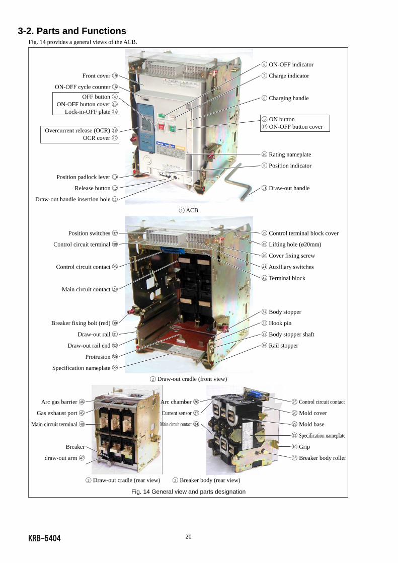
KRB-5404 20
3-2. Parts and Functions Fig. 14 provides a general views of the ACB.
◯1 ACB
◯2 Draw-out cradle (front view)
◯2 Draw-out cradle (rear view) ◯2 Breaker body (rear view)
Fig. 14 General view and parts designation
OFF button ◯4
ON-OFF button cover ◯15
Lock-in-OFF plate ◯14
◯5 ON button
◯15 ON-OFF button cover
◯6 ON-OFF indicator
◯7 Charge indicator
◯8 Charging handle
Position switches ◯37
Control circuit terminal ◯38
Control circuit contact ◯25
Main circuit contact ◯24
Breaker fixing bolt (red) ◯30
Draw-out rail ◯31
Draw-out rail end ◯32
Protrusion ◯50
Specification nameplate ◯22
Overcurrent release (OCR) ◯18
OCR cover ◯17
Front cover ◯19
ON-OFF cycle counter ◯16
◯20 Rating nameplate
◯9 Position indicator
◯51 Draw-out handle
Position padlock lever ◯13
Release button ◯12
Draw-out handle insertion hole ◯11
◯39 Control terminal block cover
◯49 Lifting hole (ø20mm)
◯40 Cover fixing screw
◯41 Auxiliary switches
◯42 Terminal block
◯34 Body stopper
◯33 Hook pin
◯35 Body stopper shaft
◯36 Rail stopper
Arc gas barrier ◯46
Gas exhaust port ◯45
Main circuit terminal ◯48
Breaker
draw-out arm ◯47
Ground terminal
M8 tapped hole ◯44
Arc chamber ◯26
Current sensor ◯27
Main circuit contact ◯24
◯25 Control circuit contact
◯28 Mold cover
◯29 Mold base
◯22 Specification nameplate
◯10 Grip
◯23 Breaker body roller

KRB-5404 21
◯1 ACB Consists of breaker body ◯3 and draw-out cradle ◯2 .
◯2 Draw-out cradle Comes with main circuit terminals ◯48 , control circuit terminals ◯38 , auxiliary switches ◯41 ,
and position switches ◯37 .
◯3 Breaker body Contains the ON-OFF mechanism, the closing coil,the tripping device, and overcurrent
release ◯19 .
◯4 OFF button Push to open the ACB.
◯5 ON button Push to close the ACB.
◯6 ON-OFF indicator Shows “OFF” when the ACB is open and “ON” when it is closed.
◯7 Charge indicator Shows “CHARGED” when the closing springs are charged and “DISCHARGED” when it
is released.
◯8 Charging handle Pump to charge the closing springs.
◯9 Position indicator Indicates the present breaker body position: CONN., TEST, or ISOLATED.
◯10 Grip Hold to draw out the breaker body.
◯11 Draw-out handle
insertion hole Insert the draw-out handle into this hole to move the breaker body.
◯12 Release button Push to move the breaker body from the TEST position.
◯13 Position padlock
lever (optional)
Accommodates up to three padlocks to lock the breaker body in the CONN., TEST or
ISOLATED position. (Padlocks are not supplied. Use padlocks with a 6 mm-diameter
shackle.)
◯14 Lock-in-OFF plate
(optional)
Padlocking this plate allows the ACB to be locked in the open (OFF) state. (Padlocks are
not supplied. Use padlocks with a 6 mm-diameter shackle.)
◯15 ON-OFF button cover
Provides protection against inadvertent button operation and can be padlocked. (Padlocks
are not supplied. Use padlocks with a 6 mm-diameter shackle.) Up to three padlocks can be
installed.
◯16 ON-OFF cycle
counter (optional)
Reads the number of ON-OFF cycles. It counts a series of operations from close to open as
one cycle.
◯17 OCR cover Padlocking this plate prevents settings of overcurrent release ◯18 to be inadvertently
changed. (Padlocks are not supplied. Use padlocks with a 6 mm-diameter shackle.)
◯18 Overcurrent release
(OCR)
This protective device is supplied power via the power CT installed in the ACB main
circuit. When the current sensor detects an overcurrent in the main circuit, the OCR
instructs the magnet hold trigger (MHT) to trip open the ACB.
◯19 Front cover A plastic cover of the breaker body front panel.
◯20 Rating nameplate Indicates the type, applicable standards and rated breaking capacity of the ACB.
◯22 Specification
nameplate
Indicates the number of poles, operation method, accessories, and serial number of the
ACB.
◯23 Breaker body roller Allows breaker body ◯3 to be moved on draw-out rail ◯31 .
◯24 Main circuit contact Closes when the breaker body is in the CONN. position.
◯25 Control circuit
contact Closes when the breaker body is in the CONN. or TEST position.
◯26 Arc chamber Extinguishes the arc that occurs in the breaking operation. Two arc chambers are fitted per
pole. See 6-2-2. "Arc chambers".
◯27 Current sensor Converts the current in the main circuit into a voltage signal in proportion to the magnitude
of the current and sends the signal to overcurrent release ◯18 .
◯28 Mold cover A plastic cover of the breaker body side face.
◯29 Mold base A plastic cover of the breaker body rear face.
◯30 Breaker fixing bolt
(red) (optional)
Allows the breaker body to be locked in the CONN. position even if the ACB is subject to
strong vibrations. Standard equipped on ACBs that conform to ship classification society
rules.
◯31 Draw-out rail Use to draw out the breaker body from the draw-out cradle.
◯32 Draw-out rail end Refer to chapter 1 “Operation Precautions”.
◯33 Hook pin Refer to chapter 1 “Operation Precautions”.
◯34 Body stopper Prevents the breaker body from falling when the body is drawn out from the draw-out
cradle.
◯35 Body stopper shaft Refer to chapter 1 “Operation Precautions”.
◯36 Rail stopper (red) Allows the draw-out rail to be locked in the drawn-out or retracted state.
◯37 Position switches
(optional)
Indicate the present breaker body position: CONN., TEST, ISOLATED or INSERTED. The
position switches are available in 2C or 4C configuration. Connections to the position
switches are made through M4 screws.

KRB-5404 22
◯38 Control circuit
terminals
Allow connections of external control wire to the control circuits. Wire connections are
made through M4 screw terminals. Fig. 15 shows the control circuit terminals.
Fig. 15 Control circuit terminals
◯39 Control terminal
block cover (optional)
Protects the position switches, the control circuit terminals and the auxiliary switches from
damage.
◯40 Cover fixing screw Secures the control terminal block cover.
◯41 Auxiliary switches
(optional)
Indicate the state of the ACB (ON or OFF). The auxiliary switches are available in 4C
configuration (standard), or 7C or 10C configuration (optional). Connections to the
switches are made through M4 screw terminals.
◯42 Terminal block Contains position switches ◯36 , control circuit terminals ◯37 , and auxiliary switches ◯38 .
◯44 Ground terminal M8
tapped hole Allows connection of a ground terminal.
◯45 Gas exhaust port Allows the arc gas to be discharged from arc chamber ◯25 in a horizontal direction when the
ACB trips open.
◯46 Arc gas barrier Prevents the arc gas from being discharged upwards from arc chamber ◯25 when the ACB
trips open.
◯47 Breaker draw-out arm Is retracted in the draw-out cradle when the breaker body is in the CONN. position.
◯48 Main circuit terminals Allow connections of external conductors. These terminals are available in three
configurations as shown in Fig. 16.
Vertical terminals Horizontal terminals Front terminals
Fig. 16 Main circuit terminals
◯49 Lifting hole (ø20mm) Allows lifting attachments or wire ropes to be used for lifting the ACB.
◯50 Protrusion Refer to section 2-3. “Installation Precautions”.
◯51 Draw-out handle
(removable) Use to draw out /insert the breaker body from/into the draw-out cradle.

KRB-5404 23
White paper
KRB-5404 24
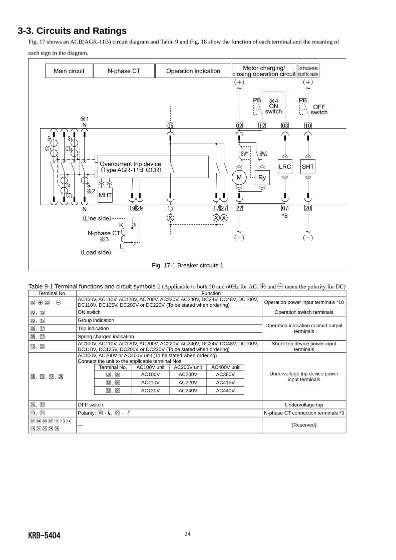
3-3. Circuits and Ratings Fig. 17 shows an ACB(AGR-11B) circuit diagram and Table 9 and Fig. 18 show the function of each terminal and the meaning of
each sign in the diagram.
Fig. 17-1 Breaker circuits 1
Table 9-1 Terminal functions and circuit symbols 1 (Applicable to both 50 and 60Hz for AC. ◯+ and ◯- mean the polarity for DC) Terminal No. Function
□02 , □22 AC100V, AC110V, AC120V, AC200V, AC220V, AC240V, DC24V, DC48V, DC100V, DC110V, DC125V, DC200V or DC220V (To be stated when ordering)
Operation power input terminals *10
□03 , □12 ON switch Operation switch terminals
□05 , □15 Group indication Operation indication contact output
terminals □05 , □17 Trip indication
□05 , □27 Spring charged indication
□10 , □20 AC100V, AC110V, AC120V, AC200V, AC220V, AC240V, DC24V, DC48V, DC100V, DC110V, DC125V, DC200V or DC220V (To be stated when ordering)
Shunt trip device power input terminals
□08 , □09 , □18 , □28
AC100V, AC200V or AC400V unit (To be stated when ordering) Connect the unit to the applicable terminal Nos.
Undervoltage trip device power input terminals
Terminal No. AC100V unit AC200V unit AC400V unit
□08 , □09 AC100V AC200V AC380V
□18 , □09 AC110V AC220V AC415V
□28 , □09 AC120V AC240V AC440V
□24 , □30 OFF switch Undervoltage trip
□19 , □29 Polarity: □19 - , □29 - N-phase CT connection terminals *3
□01□04□06□07□11□13□14
□16□21□23□25□26 — (Reserved)
07 *8
KRB-5404 25
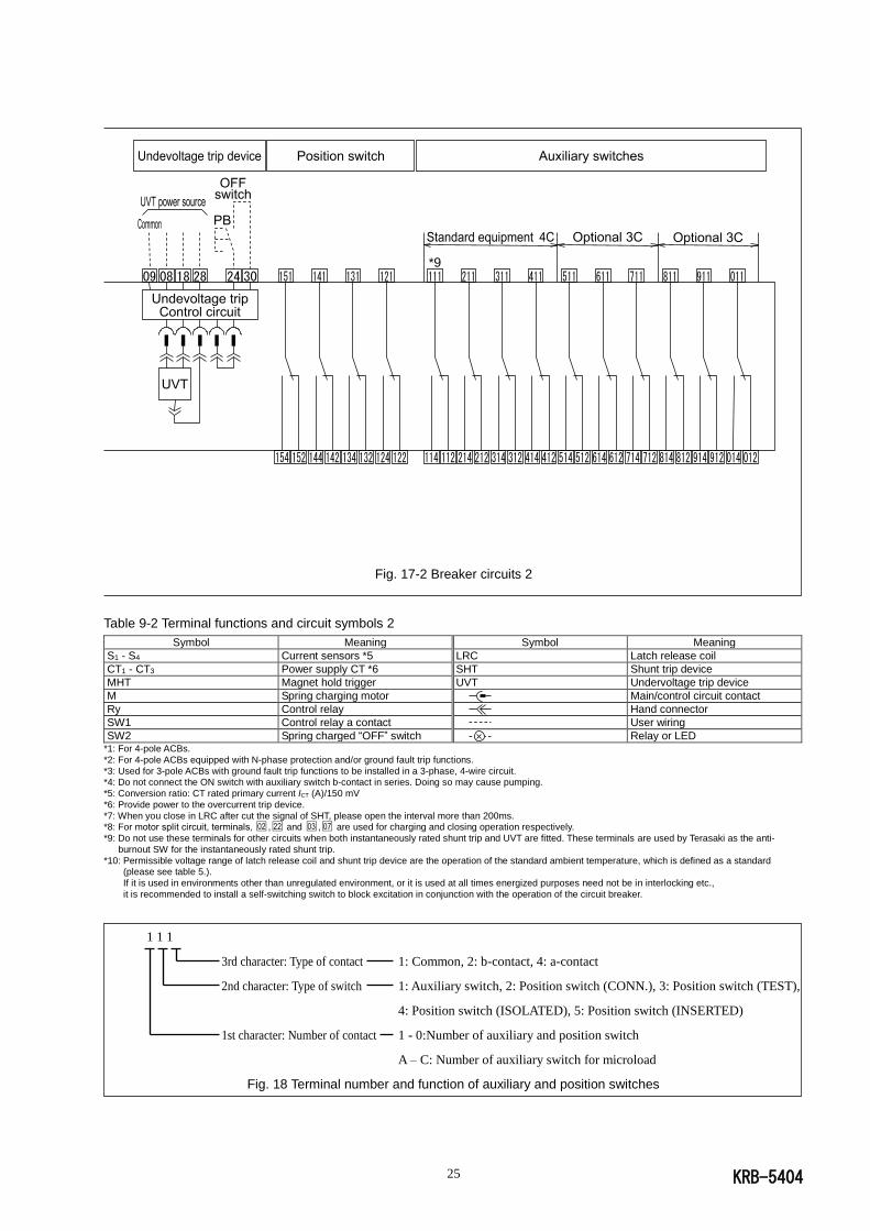
Fig. 17-2 Breaker circuits 2
Table 9-2 Terminal functions and circuit symbols 2
Symbol Meaning Symbol Meaning
S1 - S4 Current sensors *5 LRC Latch release coil
CT1 - CT3 Power supply CT *6 SHT Shunt trip device
MHT Magnet hold trigger UVT Undervoltage trip device
M Spring charging motor Main/control circuit contact
Ry Control relay Hand connector
SW1 Control relay a contact User wiring
SW2 Spring charged “OFF” switch Relay or LED *1: For 4-pole ACBs.
*2: For 4-pole ACBs equipped with N-phase protection and/or ground fault trip functions.
*3: Used for 3-pole ACBs with ground fault trip functions to be installed in a 3-phase, 4-wire circuit. *4: Do not connect the ON switch with auxiliary switch b-contact in series. Doing so may cause pumping.
*5: Conversion ratio: CT rated primary current ICT (A)/150 mV
*6: Provide power to the overcurrent trip device.
*7: When you close in LRC after cut the signal of SHT, please open the interval more than 200ms. *8: For motor split circuit, terminals‚ □02 ,□22 and □03 ,□07 are used for charging and closing operation respectively.
*9: Do not use these terminals for other circuits when both instantaneously rated shunt trip and UVT are fitted. These terminals are used by Terasaki as the anti-
burnout SW for the instantaneously rated shunt trip.
*10: Permissible voltage range of latch release coil and shunt trip device are the operation of the standard ambient temperature, which is defined as a standard (please see table 5.).
If it is used in environments other than unregulated environment, or it is used at all times energized purposes need not be in interlocking etc.,
it is recommended to install a self-switching switch to block excitation in conjunction with the operation of the circuit breaker.
1 1 1
3rd character: Type of contact 1: Common, 2: b-contact, 4: a-contact
2nd character: Type of switch 1: Auxiliary switch, 2: Position switch (CONN.), 3: Position switch (TEST),
4: Position switch (ISOLATED), 5: Position switch (INSERTED)
1st character: Number of contact 1 - 0:Number of auxiliary and position switch
A – C: Number of auxiliary switch for microload
Fig. 18 Terminal number and function of auxiliary and position switches
*9
KRB-5404 26
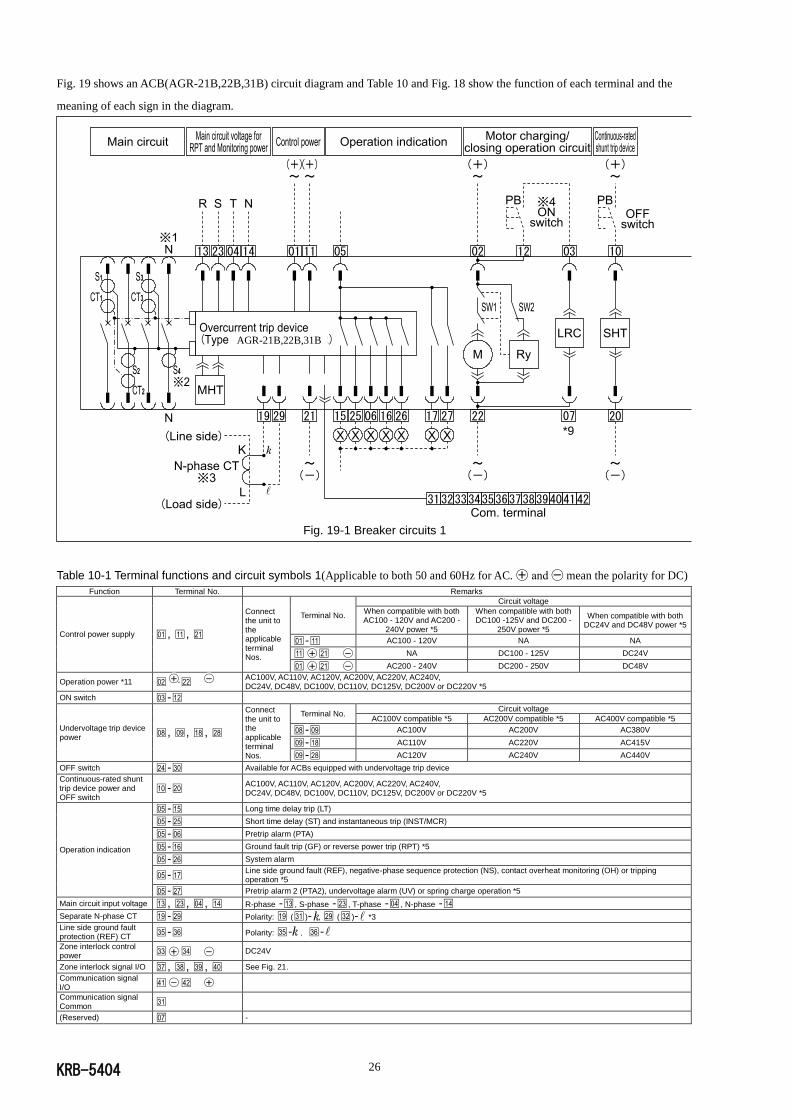
Fig. 19 shows an ACB(AGR-21B,22B,31B) circuit diagram and Table 10 and Fig. 18 show the function of each terminal and the
meaning of each sign in the diagram.
Fig. 19-1 Breaker circuits 1
Table 10-1 Terminal functions and circuit symbols 1(Applicable to both 50 and 60Hz for AC. ◯+ and ◯- mean the polarity for DC)
Function Terminal No. Remarks
Control power supply □01 , □11 , □21
Connect the unit to the applicable terminal Nos.
Terminal No.
Circuit voltage
When compatible with both AC100 - 120V and AC200 -
240V power *5
When compatible with both DC100 -125V and DC200 -
250V power *5
When compatible with both DC24V and DC48V power *5
□01 -□11 AC100 - 120V NA NA
□11 -□21 NA DC100 - 125V DC24V
□01 -□21 AC200 - 240V DC200 - 250V DC48V
Operation power *11 □02 -□22 AC100V, AC110V, AC120V, AC200V, AC220V, AC240V, DC24V, DC48V, DC100V, DC110V, DC125V, DC200V or DC220V *5
ON switch □03 -□12
Undervoltage trip device power □08 , □09 , □18 , □28
Connect the unit to the applicable terminal Nos.
Terminal No. Circuit voltage
AC100V compatible *5 AC200V compatible *5 AC400V compatible *5
□08 -□09 AC100V AC200V AC380V
□09 -□18 AC110V AC220V AC415V
□09 -□28 AC120V AC240V AC440V
OFF switch □24 -□30 Available for ACBs equipped with undervoltage trip device
Continuous-rated shunt trip device power and OFF switch
□10 -□20 AC100V, AC110V, AC120V, AC200V, AC220V, AC240V, DC24V, DC48V, DC100V, DC110V, DC125V, DC200V or DC220V *5
Operation indication
□05 -□15 Long time delay trip (LT)
□05 -□25 Short time delay (ST) and instantaneous trip (INST/MCR)
□05 -□06 Pretrip alarm (PTA)
□05 -□16 Ground fault trip (GF) or reverse power trip (RPT) *5
□05 -□26 System alarm
□05 -□17 Line side ground fault (REF), negative-phase sequence protection (NS), contact overheat monitoring (OH) or tripping operation *5
□05 -□27 Pretrip alarm 2 (PTA2), undervoltage alarm (UV) or spring charge operation *5
Main circuit input voltage □13 , □23 , □04 , □14 R-phase -□13 , S-phase -□23 , T-phase -□04 , N-phase -□14
Separate N-phase CT □19 -□29 Polarity: □19 (□31 )- , □29 (□32 )- *3
Line side ground fault protection (REF) CT □35 -□36 Polarity: □35 - ,□36 -
Zone interlock control power □33 -□34 DC24V
Zone interlock signal I/O □37 , □38 , □39 , □40 See Fig. 21.
Communication signal I/O □41 -□42
Communication signal Common □31
(Reserved) □07 -
AGR-21B,22B,31B
07 *9
KRB-5404 27
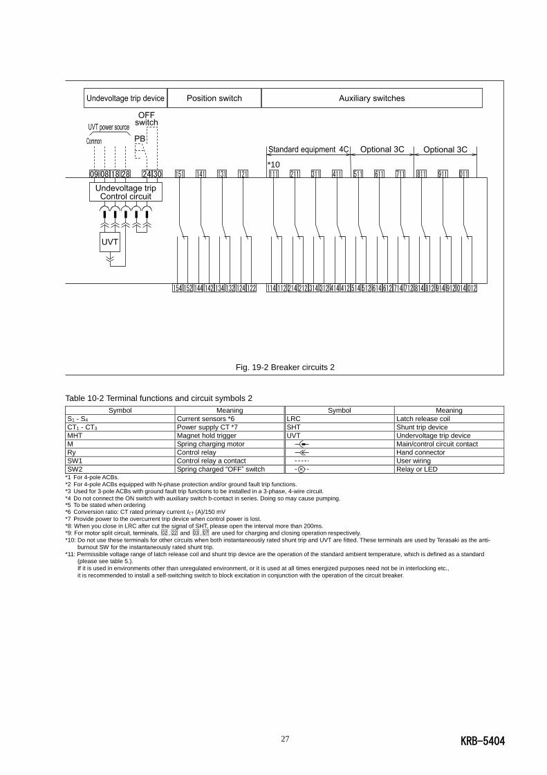
Fig. 19-2 Breaker circuits 2
Table 10-2 Terminal functions and circuit symbols 2
Symbol Meaning Symbol Meaning
S1 - S4 Current sensors *6 LRC Latch release coil
CT1 - CT3 Power supply CT *7 SHT Shunt trip device
MHT Magnet hold trigger UVT Undervoltage trip device
M Spring charging motor Main/control circuit contact
Ry Control relay Hand connector
SW1 Control relay a contact User wiring
SW2 Spring charged “OFF” switch Relay or LED *1 For 4-pole ACBs.
*2 For 4-pole ACBs equipped with N-phase protection and/or ground fault trip functions. *3 Used for 3-pole ACBs with ground fault trip functions to be installed in a 3-phase, 4-wire circuit.
*4 Do not connect the ON switch with auxiliary switch b-contact in series. Doing so may cause pumping. *5 To be stated when ordering *6 Conversion ratio: CT rated primary current ICT (A)/150 mV
*7 Provide power to the overcurrent trip device when control power is lost.
*8: When you close in LRC after cut the signal of SHT, please open the interval more than 200ms. *9: For motor split circuit, terminals‚ □02 ,□22 and □03 ,□07 are used for charging and closing operation respectively.
*10: Do not use these terminals for other circuits when both instantaneously rated shunt trip and UVT are fitted. These terminals are used by Terasaki as the anti-
burnout SW for the instantaneously rated shunt trip.
*11: Permissible voltage range of latch release coil and shunt trip device are the operation of the standard ambient temperature, which is defined as a standard (please see table 5.).
If it is used in environments other than unregulated environment, or it is used at all times energized purposes need not be in interlocking etc.,
it is recommended to install a self-switching switch to block excitation in conjunction with the operation of the circuit breaker.
*10
KRB-5404 28
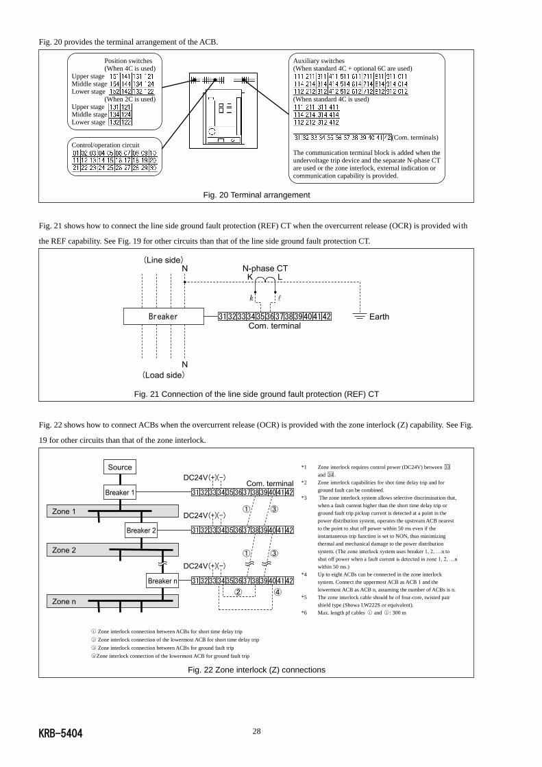
Fig. 20 provides the terminal arrangement of the ACB.
Position switches Auxiliary switches (When 4C is used) (When standard 4C + optional 6C are used)
Upper stage Middle stage Lower stage
(When 2C is used) (When standard 4C is used) Upper stage Middle stage Lower stage
(Com. terminals) Control/operation circuit
The communication terminal block is added when the undervoltage trip device and the separate N-phase CT are used or the zone interlock, external indication or communication capability is provided.
Fig. 20 Terminal arrangement
Fig. 21 shows how to connect the line side ground fault protection (REF) CT when the overcurrent release (OCR) is provided with
the REF capability. See Fig. 19 for other circuits than that of the line side ground fault protection CT.
Fig. 21 Connection of the line side ground fault protection (REF) CT
Fig. 22 shows how to connect ACBs when the overcurrent release (OCR) is provided with the zone interlock (Z) capability. See Fig.
19 for other circuits than that of the zone interlock.
*1 Zone interlock requires control power (DC24V) between □33
and □34 . *2 Zone interlock capabilities for shot time delay trip and for
ground fault can be combined. *3 The zone interlock system allows selective discrimination that,
when a fault current higher than the short time delay trip or
ground fault trip pickup current is detected at a point in the
power distribution system, operates the upstream ACB nearest
to the point to shut off power within 50 ms even if the
instantaneous trip function is set to NON, thus minimizing
thermal and mechanical damage to the power distribution
system. (The zone interlock system uses breaker 1, 2, …n to
shut off power when a fault current is detected in zone 1, 2, …n
within 50 ms.) *4 Up to eight ACBs can be connected in the zone interlock
system. Connect the uppermost ACB as ACB 1 and the
lowermost ACB as ACB n, assuming the number of ACBs is n.
*5 The zone interlock cable should be of four-core, twisted pair
shield type (Showa LW222S or equivalent).
*6 Max. length pf cables ○1 and ○3 : 300 m
Fig. 22 Zone interlock (Z) connections
○1 Zone interlock connection between ACBs for short time delay trip ○2 Zone interlock connection of the lowermost ACB for short time delay trip ○3 Zone interlock connection between ACBs for ground fault trip ○4 Zone interlock connection of the lowermost ACB for ground fault trip

KRB-5404 29
Tables 11 - 16 show the ratings of the operation power supply, the shunt trip device (SHT), the undervoltage trip device (UVT),
auxiliary switches, position switches, operation indication contacts, and the N-phase CT.
Table 11 Ratings of operation power supply
Rated voltage (V)
Permissible charging/closing
voltage range
Ratings of operation power supply
Peak motor starting current (A)
Steady-state motor current (A)
Peak making current (A)
Latch release coil (LRC) resistance
(ohm) *
AC100 85 - 110 7 1.1 0.29 300-380
AC110 94 - 121 7 1.1 0.25 350-440
AC120 102 - 132 7 1.1 0.22 440-540
AC200 170 - 220 4 0.7 0.14 1210-1490
AC220 187 - 242 4 0.7 0.13 1410-1740
AC240 204 - 264 4 0.7 0.11 1710-2090
DC24 18 - 26 14 4 1.04 20-26
DC48 36 - 53 10 1.6 0.51 85-105
DC100 75 - 110 6 0.8 0.25 350-440
DC110 82 - 121 6 0.8 0.22 440-540
DC125 93 - 138 6 0.8 0.21 540-680
DC200 150 - 220 4 0.5 0.13 1410-1740
DC220 165 - 242 4 0.5 0.12 1710-2090 * Ambient temperature: 20°C
Table 12 Ratings of shunt trip device (SHT)
Rated voltage (V) Permissible voltage
range (V)
Peak exciting current (max.)
(A)
Coil resistance (ohm) *
Max. contact parting time (ms)
AC100 70-110 0.29 300-380
40
AC110 77-121 0.25 350-440
AC120 84-132 0.22 440-540
AC200 140-220 0.14 1210-1490
AC220 154-242 0.13 1410-1740
AC240 168-264 0.11 1710-2090
DC24 16.8-26.4 1.04 20-26
DC48 33.6-52.8 0.51 85-105
DC100 70-110 0.25 350-440
DC110 77-121 0.22 440-540
DC125 87.5-137.5 0.21 540-680
DC200 140-220 0.13 1410-1740
DC220 154-242 0.12 1710-2090 * Ambient temperature: 20°C
Table 13 Ratings of undervoltage trip device (UVT)
Rated voltage (V)
Opening voltage range (V)
Attraction voltage (V)
Coil exciting current (A)
Power consumption (VA) Coil resistance (ohm) *
Normal Attraction
AC100 35 - 70 85
0.1 8 10 Holding coil: 410 – 510 Attraction coil: 5.6-6.8
AC110 38.5 - 77 93.5
AC120 42 - 84 102
AC200 70 - 140 170
AC220 77 - 154 187
AC240 84 - 168 204
AC380 133 - 266 323
AC415 145 - 290 352
AC440 154 - 308 374
DC24 8.4-16.8 20.4
DC48 16.8-33.6 40.8
DC100 35-70 85 * Ambient temperature: 20°C

KRB-5404 30
Table 14 Ratings of auxiliary and position switches
Voltage (V)
Auxiliary switches *1 *2 Position switches
For general feeder For microload *3
Resistive load (A) Inductive load (A)
*4 Resistive load (A)
Inductive load (A) *5
Resistive load (A) Inductive load (A)
*5
AC100 - 250 5 5 0.1 0.1 11 6
AC251 - 500 5 5 - - - -
DC8 - - - - 10 6
DC30 1 1 0.1 0.1 6 5
DC125 - - - - 0.6 0.6
DC250 - - - - 0.3 0.3
DC125 - 250 1 1 - - - - *1 Using b-contact results in contact chatter of 20 ms or less when the ACB opens or closes.
*2 Do not apply different voltages to contacts of a switch. *3 Min. applicable load: DC5V/1 mA
*4 AC cosø 0.3, DC L/R 0.01
*5 AC cosø 0.6, DC L/R 0.007
Table 15 Ratings of operation indication contacts
Voltage (V)
Rated contact current (A)
Individual indication Long-time delay trip, short-time delay trip,
instantaneous trip, pretrip alarm, ground fault trip, system alarm
Spring charging/tripping operation
Resistive load (A) Inductive load (A) *1 Resistive load (A) Inductive load (A) *1
AC250 0.5 0.2 3 3
DC30 2 0.7 3 2
DC125 0.5 0.2 0.5 0.5
DC250 0.27 0.04 0.1 0.1 *1 AC cosø 0.6, DC L/R 0.007
Table 16 Ratings of N-phase CT
Type of ACB Type of N-phase CT Ratings (A)
AR208S, AR212S, AR216S AR212H, AR216H, AR316H AR208D, AR212D, AR216D
CW80-40LS 200/5A 400/5A 800/5A
1250/5A 1600/5A
AR220S, AR325S, AR332S, AR440S
AR220H, AR320H, AR325H, AR332H
AR440SB,AR420H,AR440H
EC160-40LS 1600/5A 2000/5A 2500/5A
3200/5A 4000/5A
KRB-5404 31
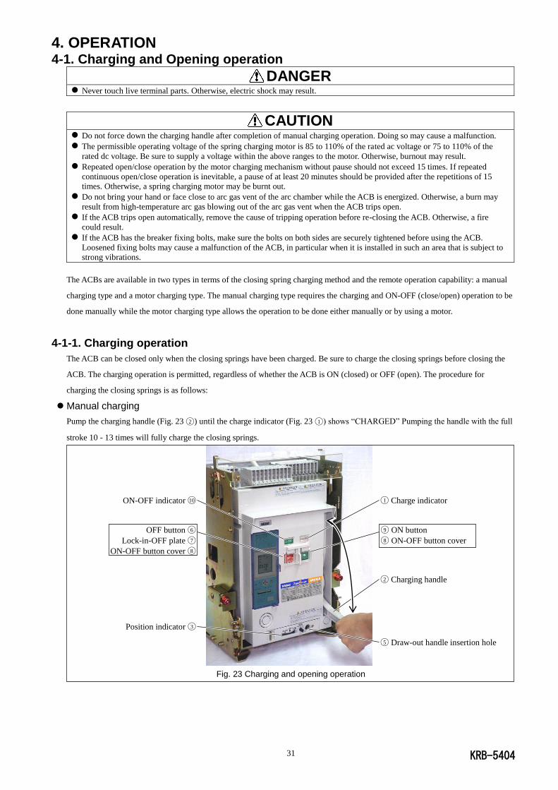
4. OPERATION 4-1. Charging and Opening operation
DANGER
Never touch live terminal parts. Otherwise, electric shock may result.
CAUTION
Do not force down the charging handle after completion of manual charging operation. Doing so may cause a malfunction.
The permissible operating voltage of the spring charging motor is 85 to 110% of the rated ac voltage or 75 to 110% of the
rated dc voltage. Be sure to supply a voltage within the above ranges to the motor. Otherwise, burnout may result.
Repeated open/close operation by the motor charging mechanism without pause should not exceed 15 times. If repeated
continuous open/close operation is inevitable, a pause of at least 20 minutes should be provided after the repetitions of 15
times. Otherwise, a spring charging motor may be burnt out.
Do not bring your hand or face close to arc gas vent of the arc chamber while the ACB is energized. Otherwise, a burn may
result from high-temperature arc gas blowing out of the arc gas vent when the ACB trips open.
If the ACB trips open automatically, remove the cause of tripping operation before re-closing the ACB. Otherwise, a fire
could result.
If the ACB has the breaker fixing bolts, make sure the bolts on both sides are securely tightened before using the ACB.
Loosened fixing bolts may cause a malfunction of the ACB, in particular when it is installed in such an area that is subject to
strong vibrations.
The ACBs are available in two types in terms of the closing spring charging method and the remote operation capability: a manual
charging type and a motor charging type. The manual charging type requires the charging and ON-OFF (close/open) operation to be
done manually while the motor charging type allows the operation to be done either manually or by using a motor.
4-1-1. Charging operation
The ACB can be closed only when the closing springs have been charged. Be sure to charge the closing springs before closing the
ACB. The charging operation is permitted, regardless of whether the ACB is ON (closed) or OFF (open). The procedure for
charging the closing springs is as follows:
Manual charging
Pump the charging handle (Fig. 23 ◯2 ) until the charge indicator (Fig. 23 ◯1 ) shows “CHARGED” Pumping the handle with the full
stroke 10 - 13 times will fully charge the closing springs.
Fig. 23 Charging and opening operation
◯1 Charge indicator
◯2 Charging handle
◯5 Draw-out handle insertion hole
Position indicator ◯3
◯9 ON button
◯8 ON-OFF button cover
ON-OFF indicator ◯10
OFF button ◯6
Lock-in-OFF plate ◯7 ON-OFF button cover ◯8

KRB-5404 32
Motor charging
When the charge indicator (Fig. 23 ◯1 ) changes to “DISCHARGED” while the specified operation voltage is applied to the control
circuit terminals □02 and □22 , the charging motor is activated to start charging the closing springs. Upon completion of the charging
operation, the charge indicator shows “CHARGED” and the charging motor is automatically deactivated. The time required for the
motor charging operation depends on the operation voltage or the ACB types, but does not exceed 10 seconds.
4-1-2. Closing operation
The ACB closing operation is not permitted unless all of the following conditions are met.
1) The charge indicator (Fig. 23 ◯1 ) shows "CHARGED".
2) The position indicator (Fig. 23 ◯3 ) shows "CONN.", "TEST" or "ISOLATED" (a halfway position not permitted).
3) The draw-out handle is not inserted in the draw-out handle insertion hole(Fig. 23 ◯5 ) .
4) The OFF button (Fig. 23 ◯6 ) is not locked with the lock-in-OFF plate (Fig. 23 ◯7 ).
5) The specified voltage is supplied to the undervoltage trip device .
The control power of the overcurrent release (OCR) must be supplied before closing operation in order that the internal program can
be started. If the OCR trips open directly after the control power is supplied to the OCR, operation indication may be incorrect.
Manual closing
Open the ON-OFF button cover (Fig. 23 ◯8 ) and press the ON button (Fig. 23 ◯9 ). The ACB will be closed with a sound. The ON-
OFF indicator (Fig. 23 ◯10 ) shows "ON" and the charge indicator (Fig. 23 ◯1 ) shows "DISCHARGED".
Electrical closing
Press the ON switch shown in Fig. 17,19. The latch release coil (LRC) (Fig. 17,19) will be excited and the ACB is closed with a
sound. The ON-OFF indicator (Fig. 23 ◯10 ) shows "ON", the charge indicator (Fig. 23 ◯1 ) shows "DISCHARGED", and the
charging motor starts charging the closing springs.
4-1-3. Opening operation
Manual opening
Open the ON-OFF button cover (Fig. 23 ◯8 ) and press the OFF button (Fig. 23 ◯16 ). The ACB will trip open with a sound. The ON-
OFF indicator (Fig. 23 ◯10 ) shows "OFF".
Electrical opening
Press the OFF switch shown in Fig. 17,19. The shunt trip device (SHT) or the fixed type undervoltage trip device (Fig. 17,19) will
be excited so that the ACB trips open with a sound. The ON-OFF indicator (Fig. 23 ◯10 ) shows "OFF".
4-1-4. Motion of trip indication and spring charge indication switches
The trip indication and spring charge indication switches provide the breaker status as shown in Table 16.
Table 17 Motion of trip indication and spring charge indication switches
Type of OCR Operation
Contact output
Terminal No. See Fig. 17
State
Closing spring ACB closed
ACB open
Charged Discharged Not ready to close * Ready to close *
All Trip □05 , □17 No change No change OFF ON OFF
Spring charge □05 , □27 ON OFF No change No change No change
* “Ready to close” means that all of the following conditions are met:
1. The closing springs are charged.
2. Opening operation is complete (At least 40 ms has elapsed after trip signal was produced).
3. The OFF button is released.
4. The specified voltage is applied to the undervoltage trip device (if equipped).

KRB-5404 33
4-1-5. Motion of operation mechanisms
Figs. 24 - 27 illustrate the motion of the charging and ON-OFF mechanisms.
For manual closing operation, ON button ◯1 rotates
counterclockwise. For electrical closing operation,
push rod ◯1 ' protrudes downward from the latch
release coil (LRC) and charge latch trigger ◯2 rotates
clockwise. This rotates closing trigger shaft ◯3
clockwise and closing release lever ◯4 disengages
from a semicircular pawl and rotates clockwise. And
charging cam ◯5 rotates counterclockwise, so that
charging lever ◯7 disengages from closing spring ◯6
and rotates counterclockwise. Closing cam ◯8 is
pushed up by charging lever ◯7 and rotates clockwise.
At this time, each component is positioned as shown in
Fig. 26. Continued to Fig. 25.
Fig. 24 Closing motion 1 (discharge motion)
Closing cam ◯8 rotating clockwise causes closing link
and top link ◯9 to be pushed straight. This rotates
closing toggle cam ◯10 connected with closing link ◯9
counterclockwise, so that crossbar ◯11 rotates clockwise
and thus moving contact ◯12 comes in contact with
stationary contact ◯13 . At this time, each component is
positioned as shown in Fig. 27.
Fig. 25 Closing motion 2
◯1 '
◯2 ◯1
◯4
◯5
◯6
◯7
◯8
◯3
◯10 ◯11
◯12
◯9
◯8
◯13
◯13
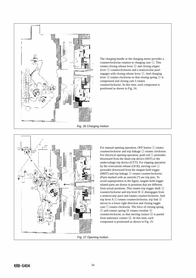
KRB-5404 34
The charging handle or the charging motor provides a
counterclockwise rotation to charging cam ◯1 . This
rotates closing release lever ◯2 and closing tripper
lever ◯3 counterclockwise and a semicircular pawl
engages with closing release lever ◯2 . And charging
lever ◯4 rotates clockwise so that closing spring ◯5 is
compressed and closing cam 5 rotates
counterclockwise. At this time, each component is
positioned as shown in Fig. 24.
Fig. 26 Charging motion
For manual opening operation, OFF button ◯1 rotates
counterclockwise and trip linkage ◯2 rotates clockwise.
For electrical opening operation, push rod ◯1 protrudes
downward from the shunt trip device (SHT) or the
undervoltage trip device (UVT). For tripping operation
by the overcurrent release (OCR), moving core ◯1
protrudes downward from the magnet hold trigger
(MHT) and trip linkage ◯2 rotates counterclockwise.
(Parts marked with an asterisk (*) are trip pins. To
avoid superposition in the figure, magnet hold trigger
related parts are drawn in positions that are different
from actual positions. This rotates trip trigger shaft ◯3
counterclockwise and trip lever B ◯4 disengages from
a semicircular pawl and rotates counterclockwise. And
trip lever A ◯5 rotates counterclockwise, trip link ◯6
moves to a lower right direction and closing toggle
cam ◯7 rotates clockwise. The force of closing spring
◯9 and contact spring ◯10 rotates crossbar ◯8
counterclockwise, so that moving contact ◯11 is parted
from stationary contact ◯12 . At this time, each
component is positioned as shown in Fig. 25.
Fig. 27 Opening motion
◯1
◯4
◯2
◯3
◯6
◯5
◯1 " ◯2 "
◯3
◯4 ◯5
◯6
◯7
◯8
◯11
◯1 '
◯1
◯2
*
◯9
◯10
◯10
◯12
◯12

KRB-5404 35
4-2. Draw-out and Insertion Operation
4-2-1. General
The draw-out type ACB consists of the breaker body and the draw-out cradle. The main and control circuit terminals are installed on
the draw-out cradle, which permits you to draw out and inspect or service the breaker body without the need for removing wiring
from the terminals.
The draw-out mechanism allows you to move the breaker body to any of the four positions as shown in Fig. 28. The switchboard
panel door can be shut with the breaker body drawn out to the CONN., TEST or ISOLATED position.
1. CONN. position 4. Removed position
In this position, the main circuit and the control
circuits of the ACB are connected to the external The breaker body is removed from the draw-out
circuits for normal service. cradle.
Draw-out Insert Insert Draw-out
2. TEST position 3. ISOLATED position
Insert
Draw-
out
In this position, the main circuit is isolated, and the In this position, both the main and control circuits
control circuits are connected. The ACB can be are isolated, and the ACB is completely de-energized.
tested with the switchboard panel door closed. The switchboard panel door can be closed.
Fig. 28 Positions of breaker body in draw-out cradle
Operation Durability
The AR series ACBs are designed to ensure the operation durability of 100 draw-out and insertion cycles in conformance to IEC
60947-1 and JIS C8201-2 (one cycle means that the breaker body is drawn out from the CONN. position to the Removed position
and inserted back to the CONN. position). Draw-out and insertion operation of more than 100 cycles could abrade the main circuit
contacts, resulting in an overheat of the contacts during energization.
Draw-out cradle
Main circuit
contact
Control circuit
contact
Breaker body
Rollers Draw-out rail
Position indicator
Position indicator
Position indicator
Position indicator

KRB-5404 36
4-2-2. Draw-out operation
DANGER
Never touch live terminal parts. Otherwise, electric shock may result.
Do not leave the ACB body in the removed position. The weight of the ACB may cause serious injury.
CAUTION
If the ACB has the breaker fixing bolts, be sure to loosen the bolts on both sides before draw-out operation. Otherwise,
damage to the ACB may result.
Make sure the draw-out cradle is secured with mounting screws before drawing out the breaker body. Otherwise, the draw-out
operation may cause the breaker body or the draw-out cradle to fall, resulting in damage to the ACB or personal injury.
When retracting the draw-out rail into the draw-out cradle, be sure to push the rail end. Do not hold the hook pin, body
stopper, or body stopper shaft. Doing so may cause your fingers to be pinched, resulting in injury.
Use the separate draw-out handle to draw-out the breaker body.
4-2-2-1. Moving the breaker body from the CONN. position to the TEST position
1) Open the ACB. (If the ACB remains closed, the draw-out handle (Fig. 29 ◯1 ) cannot be inserted).
2) Loosen the breaker fixing bolts (Fig. 29 ◯2 ), if used, to unlock the breaker body (Fig. 29 ◯3 ).
3) Unlock the position lock lever (Fig. 29 ◯14 ) if locked. See section 4-5.
4) Insert the draw-out handle into the draw-out handle insertion hole (Fig. 29 ◯4 ). And slowly turn counterclockwise until the
handle cannot be turned. The position indicator (Fig. 29 ◯5 ) shows “TEST”.
When the main circuit is disconnected at the disconnect contacts, the breaker body will be slightly pushed forward by the spring
action of the main circuit disconnect contacts. At this moment, a bang sound will be heard. This sound does not mean a
malfunction.
The ACB cannot be closed as long as the draw-out handle is in the draw-out handle insertion hole. To close the ACB e.g., for
ON-OFF testing, remove the draw-out handle.
Fig. 29 Draw-out and insertion operation
◯7 Draw-out cradle
◯3 Breaker body
◯2 Breaker fixing bolt
◯10 Grip
◯4 Draw-out handle insertion hole
◯1 Draw-out handle
◯9 Draw-out rail
Hook pin
◯8 Rail stopper
Com. terminal, manual connector ◯15
ON-OFF indicator ◯13
Position lock lever ◯14
Position indicator ◯5
Release button ◯6
Auto-discharging device ◯11
Body stopper
Body stopper shaft
Draw-out rail end ◯12
Draw-out direction
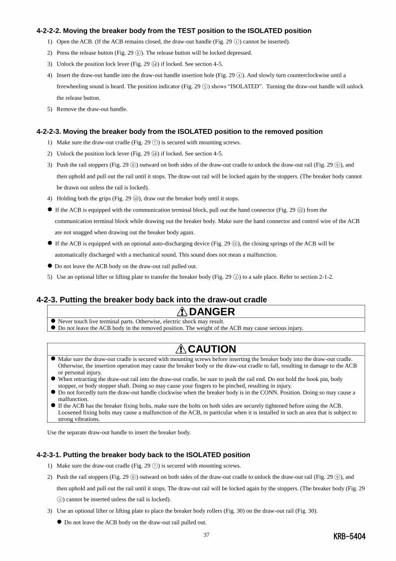
KRB-5404 37
4-2-2-2. Moving the breaker body from the TEST position to the ISOLATED position
1) Open the ACB. (If the ACB remains closed, the draw-out handle (Fig. 29 ◯1 ) cannot be inserted).
2) Press the release button (Fig. 29 ◯6 ). The release button will be locked depressed.
3) Unlock the position lock lever (Fig. 29 ◯14 ) if locked. See section 4-5.
4) Insert the draw-out handle into the draw-out handle insertion hole (Fig. 29 ◯4 ). And slowly turn counterclockwise until a
freewheeling sound is heard. The position indicator (Fig. 29 ◯5 ) shows “ISOLATED”. Turning the draw-out handle will unlock
the release button.
5) Remove the draw-out handle.
4-2-2-3. Moving the breaker body from the ISOLATED position to the removed position
1) Make sure the draw-out cradle (Fig. 29 ◯7 ) is secured with mounting screws.
2) Unlock the position lock lever (Fig. 29 ◯14 ) if locked. See section 4-5.
3) Push the rail stoppers (Fig. 29 ◯8 ) outward on both sides of the draw-out cradle to unlock the draw-out rail (Fig. 29 ◯9 ), and
then uphold and pull out the rail until it stops. The draw-out rail will be locked again by the stoppers. (The breaker body cannot
be drawn out unless the rail is locked).
4) Holding both the grips (Fig. 29 ◯10 ), draw out the breaker body until it stops.
If the ACB is equipped with the communication terminal block, pull out the hand connector (Fig. 29 ◯15 ) from the
communication terminal block while drawing out the breaker body. Make sure the hand connector and control wire of the ACB
are not snagged when drawing out the breaker body again.
If the ACB is equipped with an optional auto-discharging device (Fig. 29 ◯11 ), the closing springs of the ACB will be
automatically discharged with a mechanical sound. This sound does not mean a malfunction.
Do not leave the ACB body on the draw-out rail pulled out.
5) Use an optional lifter or lifting plate to transfer the breaker body (Fig. 29 ◯3 ) to a safe place. Refer to section 2-1-2.
4-2-3. Putting the breaker body back into the draw-out cradle
DANGER
Never touch live terminal parts. Otherwise, electric shock may result. Do not leave the ACB body in the removed position. The weight of the ACB may cause serious injury.
CAUTION
Make sure the draw-out cradle is secured with mounting screws before inserting the breaker body into the draw-out cradle. Otherwise, the insertion operation may cause the breaker body or the draw-out cradle to fall, resulting in damage to the ACB or personal injury.
When retracting the draw-out rail into the draw-out cradle, be sure to push the rail end. Do not hold the hook pin, body stopper, or body stopper shaft. Doing so may cause your fingers to be pinched, resulting in injury.
Do not forcedly turn the draw-out handle clockwise when the breaker body is in the CONN. Position. Doing so may cause a malfunction.
If the ACB has the breaker fixing bolts, make sure the bolts on both sides are securely tightened before using the ACB. Loosened fixing bolts may cause a malfunction of the ACB, in particular when it is installed in such an area that is subject to strong vibrations.
Use the separate draw-out handle to insert the breaker body.
4-2-3-1. Putting the breaker body back to the ISOLATED position
1) Make sure the draw-out cradle (Fig. 29 ◯7 ) is secured with mounting screws.
2) Push the rail stoppers (Fig. 29 ◯8 ) outward on both sides of the draw-out cradle to unlock the draw-out rail (Fig. 29 ◯9 ), and
then uphold and pull out the rail until it stops. The draw-out rail will be locked again by the stoppers. (The breaker body (Fig. 29
◯3 ) cannot be inserted unless the rail is locked).
3) Use an optional lifter or lifting plate to place the breaker body rollers (Fig. 30) on the draw-out rail (Fig. 30).
Do not leave the ACB body on the draw-out rail pulled out.
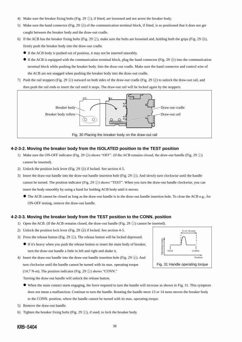
KRB-5404 38
4) Make sure the breaker fixing bolts (Fig. 29 ◯2 ), if fitted, are loosened and not arrest the breaker body.
5) Make sure the hand connector (Fig. 29 ◯15 ) of the communication terminal block, if fitted, is so positioned that it does not get
caught between the breaker body and the draw-out cradle.
6) If the ACB has the breaker fixing bolts (Fig. 29 ◯2 ), make sure the bolts are loosened and, holding both the grips (Fig. 29 ◯10 ),
firmly push the breaker body into the draw-out cradle.
If the ACB body is pushed out of position, it may not be inserted smoothly.
If the ACB is equipped with the communication terminal block, plug the hand connector (Fig. 29 ◯15 ) into the communication
terminal block while pushing the breaker body. Into the draw-out cradle. Make sure the hand connector and control wire of
the ACB are not snagged when pushing the breaker body into the draw-out cradle.
7) Push the rail stoppers (Fig. 29 ◯8 ) outward on both sides of the draw-out cradle (Fig. 29 ◯12 ) to unlock the draw-out rail, and
then push the rail ends to insert the rail until it stops. The draw-out rail will be locked again by the stoppers.
Fig. 30 Placing the breaker body on the draw-out rail
4-2-3-2. Moving the breaker body from the ISOLATED position to the TEST position
1) Make sure the ON-OFF indicator (Fig. 29 ◯13 ) shows “OFF”. (If the ACB remains closed, the draw-out handle (Fig. 29 ◯1 )
cannot be inserted).
2) Unlock the position lock lever (Fig. 29 ◯14 ) if locked. See section 4-5.
3) Insert the draw-out handle into the draw-out handle insertion hole (Fig. 29 ◯4 ). And slowly turn clockwise until the handle
cannot be turned. The position indicator (Fig. 29 ◯5 ) shows “TEST”. When you turn the draw-out handle clockwise, you can
insert the body smoothly by using a hand for holding ACB body until it moves.
The ACB cannot be closed as long as the draw-out handle is in the draw-out handle insertion hole. To close the ACB e.g., for
ON-OFF testing, remove the draw-out handle.
4-2-3-3. Moving the breaker body from the TEST position to the CONN. position
1) Open the ACB. (If the ACB remains closed, the draw-out handle (Fig. 29 ◯1 ) cannot be inserted).
2) Unlock the position lock lever (Fig. 29 ◯14 ) if locked. See section 4-5.
3) Press the release button (Fig. 29 ◯6 ). The release button will be locked depressed.
If it's heavy when you push the release button or insert the main body of breaker,
turn the draw-out handle a little in left and right and shake it.
4) Insert the draw-out handle into the draw-out handle insertion hole (Fig. 29 ◯4 ). And
turn clockwise until the handle cannot be turned with its max. operating torque
(14.7 N-m). The position indicator (Fig. 29 ◯5 ) shows “CONN.”
Turning the draw-out handle will unlock the release button.
When the main contact starts engaging, the force required to turn the handle will increase as shown in Fig. 31. This symptom
does not mean a malfunction. Continue to turn the handle. Rotating the handle more 13 or 14 turns moves the breaker body
to the CONN. position, where the handle cannot be turned with its max. operating torque.
5) Remove the draw-out handle.
6) Tighten the breaker fixing bolts (Fig. 29 ◯2 ), if used, to lock the breaker body.
Breaker body
Breaker body rollers
Draw-out cradle
Draw-out rail
13 or 14 turns
TEST CONN.
Oper
atin
g t
orq
ue
Position
Fig. 31 Handle operating torque
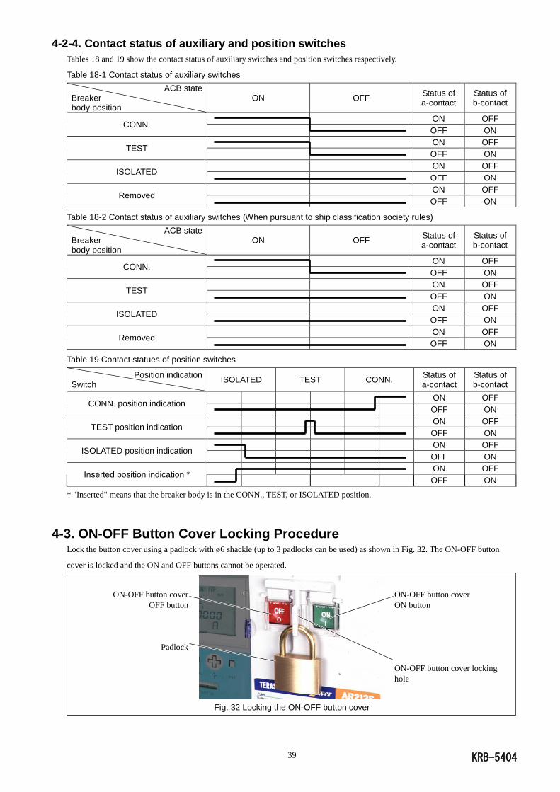
KRB-5404 39
4-2-4. Contact status of auxiliary and position switches
Tables 18 and 19 show the contact status of auxiliary switches and position switches respectively.
Table 18-1 Contact status of auxiliary switches
ACB state Breaker body position
ON OFF Status of a-contact
Status of b-contact
CONN. ON OFF
OFF ON
TEST ON OFF
OFF ON
ISOLATED ON OFF
OFF ON
Removed ON OFF
OFF ON
Table 18-2 Contact status of auxiliary switches (When pursuant to ship classification society rules)
ACB state Breaker body position
ON OFF Status of a-contact
Status of b-contact
CONN. ON OFF
OFF ON
TEST ON OFF
OFF ON
ISOLATED ON OFF
OFF ON
Removed ON OFF
OFF ON
Table 19 Contact statues of position switches
Position indication Switch
ISOLATED TEST CONN. Status of a-contact
Status of b-contact
CONN. position indication ON OFF
OFF ON
TEST position indication ON OFF
OFF ON
ISOLATED position indication ON OFF
OFF ON
Inserted position indication * ON OFF
OFF ON
* "Inserted" means that the breaker body is in the CONN., TEST, or ISOLATED position.
4-3. ON-OFF Button Cover Locking Procedure Lock the button cover using a padlock with ø6 shackle (up to 3 padlocks can be used) as shown in Fig. 32. The ON-OFF button
cover is locked and the ON and OFF buttons cannot be operated.
Fig. 32 Locking the ON-OFF button cover
ON-OFF button cover
OFF button
Padlock
ON-OFF button cover
ON button
ON-OFF button cover locking
hole
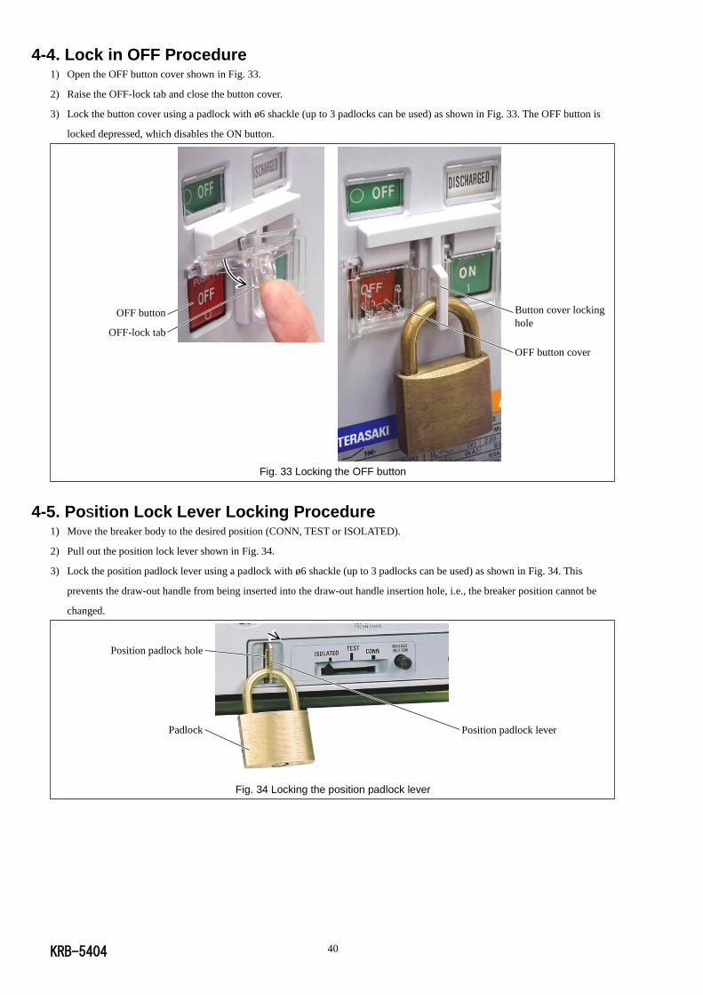
KRB-5404 40
OFF button
OFF-lock tab
Button cover locking
hole
OFF button cover
4-4. Lock in OFF Procedure
1) Open the OFF button cover shown in Fig. 33.
2) Raise the OFF-lock tab and close the button cover.
3) Lock the button cover using a padlock with ø6 shackle (up to 3 padlocks can be used) as shown in Fig. 33. The OFF button is
locked depressed, which disables the ON button.
Fig. 33 Locking the OFF button
4-5. Position Lock Lever Locking Procedure
1) Move the breaker body to the desired position (CONN, TEST or ISOLATED).
2) Pull out the position lock lever shown in Fig. 34.
3) Lock the position padlock lever using a padlock with ø6 shackle (up to 3 padlocks can be used) as shown in Fig. 34. This
prevents the draw-out handle from being inserted into the draw-out handle insertion hole, i.e., the breaker position cannot be
changed.
Fig. 34 Locking the position padlock lever
Position padlock lever
Position padlock hole
Padlock
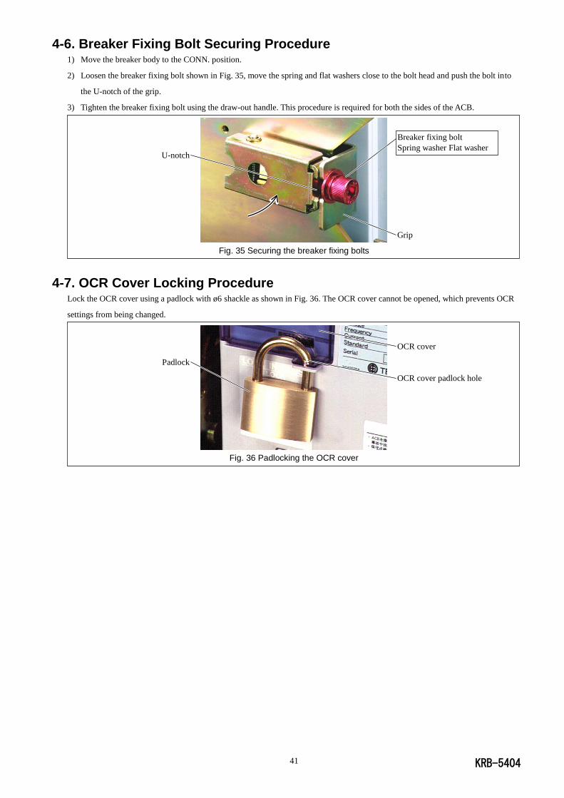
KRB-5404 41
4-6. Breaker Fixing Bolt Securing Procedure
1) Move the breaker body to the CONN. position.
2) Loosen the breaker fixing bolt shown in Fig. 35, move the spring and flat washers close to the bolt head and push the bolt into
the U-notch of the grip.
3) Tighten the breaker fixing bolt using the draw-out handle. This procedure is required for both the sides of the ACB.
Fig. 35 Securing the breaker fixing bolts
4-7. OCR Cover Locking Procedure
Lock the OCR cover using a padlock with ø6 shackle as shown in Fig. 36. The OCR cover cannot be opened, which prevents OCR
settings from being changed.
Fig. 36 Padlocking the OCR cover
OCR cover
OCR cover padlock hole
Padlock
Grip
Breaker fixing bolt
Spring washer Flat washer U-notch
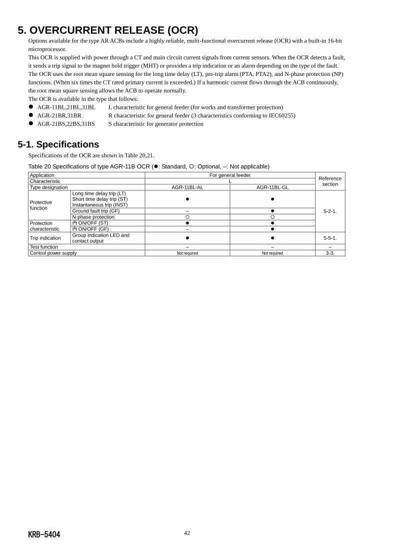
KRB-5404 42
5. OVERCURRENT RELEASE (OCR)
Options available for the type AR ACBs include a highly reliable, multi-functional overcurrent release (OCR) with a built-in 16-bit
microprocessor.
This OCR is supplied with power through a CT and main circuit current signals from current sensors. When the OCR detects a fault,
it sends a trip signal to the magnet hold trigger (MHT) or provides a trip indication or an alarm depending on the type of the fault.
The OCR uses the root mean square sensing for the long time delay (LT), pre-trip alarm (PTA, PTA2), and N-phase protection (NP)
functions. (When six times the CT rated primary current is exceeded.) If a harmonic current flows through the ACB continuously,
the root mean square sensing allows the ACB to operate normally.
The OCR is available in the type that follows:
AGR-11BL,21BL,31BL L characteristic for general feeder (for works and transformer protection)
AGR-21BR,31BR R characteristic for general feeder (3 characteristics conforming to IEC60255)
AGR-21BS,22BS,31BS S characteristic for generator protection
5-1. Specifications
Specifications of the OCR are shown in Table 20,21.
Table 20 Specifications of type AGR-11B OCR (: Standard, : Optional, –: Not applicable)
Application For general feeder Reference
section Characteristic L
Type designation AGR-11BL-AL AGR-11BL-GL
Protective function
Long time delay trip (LT) Short time delay trip (ST) Instantaneous trip (INST)
5-2-1. Ground fault trip (GF) –
N-phase protection
Protection characteristic
I2t ON/OFF (ST)
I2t ON/OFF (GF) –
Trip indication Group indication LED and contact output
5-5-1.
Test function – – –
Control power supply Not required Not required 3-3.
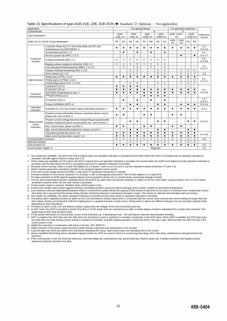
KRB-5404 43
Table 21 Specifications of type AGR-21B, 22B, 31B OCR (: Standard, : Optional, –: Not applicable)
Application For general feeder For generator protection
Reference section
Characteristic L R S
Type designation AGR-
21BL-XX AGR-
31BL-XX AGR-
21BR-XX AGR-
31BR-XX AGR- XXXX -
XX AGR-
31BS-XX
Suffix (XX or XXXX) of type designation PS PG PS PG PS PG PS PG 21BS -PS
22BS -PR
PS PR
Protective function
Long time delay trip (LT), short time delay trip (ST) and
Instantaneous trip (INST/MCR) ○1
5-2., 5-3-2-6.
Ground fault trip (GF) ○2 ○3 – – – – – – – – 5-2., 5-3-2-7. Reverse power trip (RPT) ○2 ○4 ○5 – – – – – – – – – –
N-phase protection (NP) ○1 ○6 – – – – 5-2.,
5-3-2-6.
Negative-phase sequence protection (NS) ○2 ○7 – – – – 5-2.,
5-3-2-7. Line side ground fault protection (REF) ○2 ○3 ○8 ○9 – – – – – – – –
Contact overheat monitoring (OH) ○2 ○9 ○10 – – – – –
Zone interlock (Z) ○9 ○11 – – – – – 3-3.
Alarm function
Pretrip alarm (PTA) ○9 ○12○13 5-2.,
5-3-2-7. Pretrip alarm 2 (PTA2) ○9 ○12○13 – – – – – – – – –
Undervoltage alarm (UV) ○5 ○9 ○12○14 – – – – –
Protection characteristic
COLD/HOT (LT) ○15 - - - - - - - -
5-2., 5-3-2-6.
I2t ON/OFF (ST) ○16
INST/MCR (Instantaneous trip) ○17
I0.02t/It/I2T/I3t/I4t (LT) ○18 – – – – – – – –
I2t ON/OFF (FG) ○16 – – – – – – – – 5-2.,
5-3-2-7.
Polarity NOR/REV (RPT) ○19 – – – – – 5-3-2-4.
Operation indication
Indication on LCD and contact output (individual indication) ○9 5-5-2.
Measurement /event
indication
Present current (switchable between respective phase current
phase max. and current) ○9 – – – – – –
5-3-2-3. Present current /voltage/electrical energy/frequency(switchable
between respective phase current phase max. and current) ○9 – – – – – –
Max. current (max. phase current) ○9 – – – – – –
Max. current /demanded power(max. phase current) ○9 – – – – – –
Trip event log (last trip event) ○9 ○20 5-3-2-8.
Alarm event log (last alarm event) ○9 ○20
Communication Functions 3-3.
External indicator – – – – – -
Test function○9 ○21 5-4.
Control power supply ○22 Required 3-3.
○1 Two modes are available; one where the ACB is tripped open and operation indication is provided and the other where the ACB is not tripped and no operation indication is
provided. Fail-safe against failure in setup (see 5-2). ○2 Three modes are available; the first where the ACB is tripped open and operation indication is provided, the second where the ACB is not tripped and only operation indication is
provided, and the third where the ACB is not tripped open and no operation indication is provided. ○3 Residual current sensing. When a 3-pole ACB applies to a 3-phase, 4-wire circuit, be sure to use the separate N-phase protection CT (see 3-3). ○4 Allows 3-phase generators operated in parallel to be protected against reverse power.
○5 If the main circuit voltage exceeds AC250V, a step-down PT (potential transformer) is needed. ○6 Provides protection to the neural conductor in a 3-phase, 4-wire circuit against overcurrent. This function applies to a 4-pole ACB. ○7 Provides protection to ACBs against negative-phase current caused by phase loss or reverse phase, preventing damage to loads.
○8 The line side ground fault protection capability allows the ACB to trip open when transformer windings or cables on the line side suffers a ground fault in TN-C or TN-S power distribution systems where the line side neutral is grounded.
○9 Control power supply is required. Disabled when control power is lost.
○10 Protects the breaker main contact against overheat, preventing troubles caused by thermal damage of the contact. Helpful for preventive maintenance. ○11 Zone selective interlock implemented between ACBs in a hierarchical system allows the upstream ACB nearest a fault point to trip open in a minimum time, irrespective of short
time delay trip or ground fault trip pickup timing, thereby minimizing thermal or mechanical damage to loads. This stands for selective discrimination with zero timing.
○12 Two modes are available; one where operation indication is provided and the other where no operation indication is provided. ○13 The pretrip alarm capability provides an alarm on the LCD and delivers contact output when it is detected that the current value exceeds the current setting for longer than the
time setting, thereby preventing the ACB from tripping due to a gradual increase in load current. Pretrip alarm 2 allows two different timings to be set and helps regulate loads
depending on their importance. ○14 Provides an alarm on the LCD and delivers contact output when the voltage of the main circuit becomes low. ○15 In HOT mode, the OCR is actuated in shorter time than in COLD mode when an overload occurs after a certain degree of load is maintained for a certain time of period. This
mode helps protect heat sensitive loads. ○16 I2t ON avoids intersection of characteristic curves of the ACB and e.g., a downstream fuse. This will improve selective discrimination flexibility. ○17 INST is enabled, the OCR trips open the ACB when the trip pickup current is reached or exceeded, irrespective of the ACB status. When MCR is enabled, the OCR trips open
the ACB when the ACB making current setting is reached or exceeded, and after tripping operation, it locks the ACB in the open state. MCR provides the INST function if the control power is lost.
○18 Helpful for protection in coordination with fuses or the like. (IEC 60255-3)
○19 Allows selection of the power supply terminal position between upstream and downstream of the breaker. ○20 Logs the latest trip event and alarm event and allows displaying the cause, fault current value and operating time of the events. ○21 Allows simplified field testing where simulation signals from/to the OCR are used to check for normal long time delay, short time delay, instantaneous and ground fault trip
functions. ○22 If the control power is lost, the long time delay trip, short time delay trip, instantaneous trip, ground fault trip, reverse power trip, N-phase protection and negative-phase
sequence protection functions are alive.
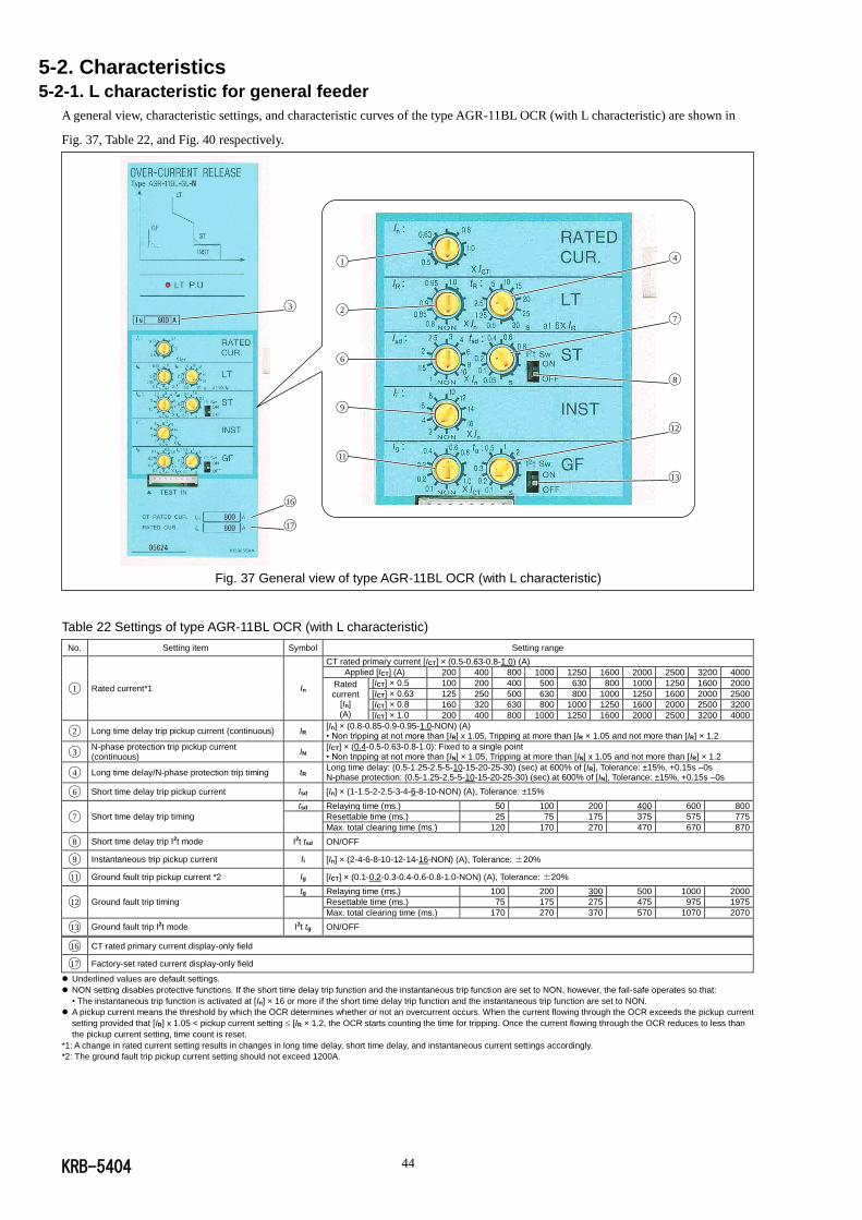
KRB-5404 44
5-2. Characteristics
5-2-1. L characteristic for general feeder
A general view, characteristic settings, and characteristic curves of the type AGR-11BL OCR (with L characteristic) are shown in
Fig. 37, Table 22, and Fig. 40 respectively.
Fig. 37 General view of type AGR-11BL OCR (with L characteristic)
Table 22 Settings of type AGR-11BL OCR (with L characteristic)
No. Setting item Symbol Setting range
◯1 Rated current*1 In
CT rated primary current [ICT] × (0.5-0.63-0.8-1.0) (A)
Applied [ICT] (A) 200 400 800 1000 1250 1600 2000 2500 3200 4000
Rated current
[In]
(A)
[ICT] × 0.5 100 200 400 500 630 800 1000 1250 1600 2000
[ICT] × 0.63 125 250 500 630 800 1000 1250 1600 2000 2500
[ICT] × 0.8 160 320 630 800 1000 1250 1600 2000 2500 3200
[ICT] × 1.0 200 400 800 1000 1250 1600 2000 2500 3200 4000
◯2 Long time delay trip pickup current (continuous) IR [In] × (0.8-0.85-0.9-0.95-1.0-NON) (A) • Non tripping at not more than [IR] x 1.05, Tripping at more than [IR × 1.05 and not more than [IR] × 1.2
◯3 N-phase protection trip pickup current (continuous)
IN [ICT] × (0.4-0.5-0.63-0.8-1.0): Fixed to a single point • Non tripping at not more than [IN] × 1.05, Tripping at more than [IN] x 1.05 and not more than [IR] × 1.2
◯4 Long time delay/N-phase protection trip timing tR Long time delay: (0.5-1.25-2.5-5-10-15-20-25-30) (sec) at 600% of [IR], Tolerance: ±15%, +0.15s –0s N-phase protection: (0.5-1.25-2.5-5-10-15-20-25-30) (sec) at 600% of [IN], Tolerance: ±15%, +0.15s –0s
◯6 Short time delay trip pickup current Isd [In] × (1-1.5-2-2.5-3-4-6-8-10-NON) (A), Tolerance: ±15%
◯7 Short time delay trip timing
tsd Relaying time (ms.) 50 100 200 400 600 800
Resettable time (ms.) 25 75 175 375 575 775
Max. total clearing time (ms.) 120 170 270 470 670 870
◯8 Short time delay trip I2t mode I2t tsd ON/OFF
◯9 Instantaneous trip pickup current Ii [In] × (2-4-6-8-10-12-14-16-NON) (A), Tolerance: ±20%
◯11 Ground fault trip pickup current *2 Ig [ICT] × (0.1-0.2-0.3-0.4-0.6-0.8-1.0-NON) (A), Tolerance: ±20%
◯12 Ground fault trip timing
tg Relaying time (ms.) 100 200 300 500 1000 2000
Resettable time (ms.) 75 175 275 475 975 1975
Max. total clearing time (ms.) 170 270 370 570 1070 2070
◯13 Ground fault trip I2t mode I2t tg ON/OFF
◯16 CT rated primary current display-only field
◯17 Factory-set rated current display-only field
Underlined values are default settings.
NON setting disables protective functions. If the short time delay trip function and the instantaneous trip function are set to NON, however, the fail-safe operates so that:
• The instantaneous trip function is activated at [In] × 16 or more if the short time delay trip function and the instantaneous trip function are set to NON.
A pickup current means the threshold by which the OCR determines whether or not an overcurrent occurs. When the current flowing through the OCR exceeds the pickup current
setting provided that [IR] x 1.05 < pickup current setting [IR × 1.2, the OCR starts counting the time for tripping. Once the current flowing through the OCR reduces to less than
the pickup current setting, time count is reset.
*1: A change in rated current setting results in changes in long time delay, short time delay, and instantaneous current settings accordingly.
*2: The ground fault trip pickup current setting should not exceed 1200A.
◯3
◯17
◯16
◯1
◯2
◯4
◯6
◯7
◯8
◯9
◯11
◯12
◯13
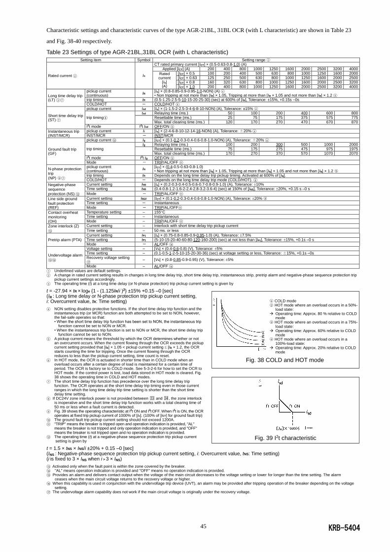
KRB-5404 45
Characteristic settings and characteristic curves of the type AGR-21BL, 31BL OCR (with L characteristic) are shown in Table 23
and Fig. 38-40 respectively.
Table 23 Settings of type AGR-21BL,31BL OCR (with L characteristic)
Setting item Symbol Setting range ○1
Rated current ◯2 In
CT rated primary current [ICT] × (0.5-0.63-0.8-1.0) (A) Applied [ICT] (A) 200 400 800 1000 1250 1600 2000 2500 3200 4000
Rated current
[In] (A)
[ICT] × 0.5 100 200 400 500 630 800 1000 1250 1600 2000 [ICT] × 0.63 125 250 500 630 800 1000 1250 1600 2000 2500 [ICT] × 0.8 160 320 630 800 1000 1250 1600 2000 2500 3200 [ICT] × 1.0 200 400 800 1000 1250 1600 2000 2500 3200 4000
Long time delay trip (LT) ◯3 ◯7
pickup current (continuous)
IR [In] × (0.8-0.85-0.9-0.95-1.0-NON) (A) ◯4 • Non tripping at not more than [IR] × 1.05, Tripping at more than [IR × 1.05 and not more than [IR] × 1.2 ◯5
trip timing tR (0.5-1.25-2.5-5-10-15-20-25-30) (sec) at 600% of [IR], Tolerance: ±15%, +0.15s –0s COLD/HOT - COLD/HOT ◯6
Short time delay trip (ST) ◯7
pickup current Isd [In] × (1-1.5-2-2.5-3-4-6-8-10-NON) (A), Tolerance: ±15% ◯4
trip timing◯8 tsd Relaying time (ms.) 50 100 200 400 600 800
Resettable time (ms.) 25 75 175 375 575 775 Max. total clearing time (ms.) 120 170 270 470 670 870
I2t mode I2t tsd OFF/ON ◯9
Instantaneous trip (INST/MCR)
pickup current Ii [In] × (2-4-6-8-10-12-14-16-NON) (A), Tolerance: ±20% ◯4 INST/MCR - INST/MCR
Ground fault trip (GF)
pickup current ◯10 Ig [ICT] × (0.1-0.2-0.3-0.4-0.6-0.8-1.0-NON) (A), Tolerance: ±20% ◯4
trip timing tg Relaying time (ms.) 100 200 300 500 1000 2000
Resettable time (ms.) 75 175 275 475 975 1975 Max. total clearing time (ms.) 170 270 370 570 1070 2070
I2t mode I2t tg OFF/ON ◯9 Mode - TRIP/AL/OFF ◯11
N-phase protection trip (NP) ○3 ◯7
pickup current (continuous)
IN [ICT] × (0.4-0.5-0.63-0.8-1.0) • Non tripping at not more than [IN] × 1.05, Tripping at more than [IN] × 1.05 and not more than [IN] × 1.2 ○5
trip timing tR Depends on the long time delay trip pickup timing. Activated at 600% of [IN]. COLD/HOT - Depends on the long time delay trip mode (COLD/HOT). ◯6
Negative-phase sequence protection (NS) ◯12
Current setting INS [In] × (0.2-0.3-0.4-0.5-0.6-0.7-0.8-0.9-1.0) (A), Tolerance: 10% Time setting tNS (0.4-0.8-1.2-1.6-2-2.4-2.8-3.2-3.6-4) (sec) at 150% of [INS], Tolerance: 20%, +0.15 s –0 s
Mode - TRIP/AL/OFF ◯11
Line side ground fault protection (REF)
Current setting IREF [ICT] × (0.1-0.2-0.3-0.4-0.6-0.8-1.0-NON) (A), Tolerance: 20% ○4 Time setting - Instantaneous
Mode - TRIP/AL/OFF◯11
Contact overheat monitoring (OH)
Temperature setting – 155C Time setting – Instantaneous Mode – TRIP/AL/OFF ◯11
Zone interlock (Z)
◯13
Current setting – Interlock with short time delay trip pickup current
Time setting – 50 ms. or less
Pretrip alarm (PTA)
Current setting IP1 [In] × (0.75-0.8-0.85-0.9-0.95-1.0) (A), Tolerance: 7.5% Time setting tP1 (5-10-15-20-40-60-80-120-160-200) (sec) at not less than [IP1], Tolerance: 15%, +0.1s –0 s Mode - AL/OFF ◯14
Undervoltage alarm
◯15◯16
Voltage setting – [Vn] × (0.4-0.6-0.8) (V), Tolerance: 5% Time setting – (0.1-0.5-1-2-5-10-15-20-30-36) (sec) at voltage setting or less, Tolerance: ±15%, +0.1s –0s Recovery voltage setting ◯17
– [Vn] × (0.8-0.85-0.9-0.95) (V), Tolerance: 5%
Mode – AL/OFF ◯14
◯1 Underlined values are default settings.
◯2 A change in rated current setting results in changes in long time delay trip, short time delay trip, instantaneous strip, pretrip alarm and negative-phase sequence protection trip pickup current settings accordingly.
◯3 The operating time (t) at a long time delay (or N-phase protection) trip pickup current setting is given by
t = -27.94 × tR × loge {1 - (1.125IR/i )2} ±15% +0.15 –0 [sec] (IR : Long time delay or N-phase protection trip pickup current setting, i: Overcurrent value, tR: Time setting) ◯4 NON setting disables protective functions. If the short time delay trip function and the
instantaneous trip (or MCR) function are both attempted to be set to NON, however, the fail-safe operates so that: • When the short time delay trip function has been set to NON, the instantaneous trip
function cannot be set to NON or MCR. • When the instantaneous trip function is set to NON or MCR, the short time delay trip
function cannot be set to NON. ◯5 A pickup current means the threshold by which the OCR determines whether or not
an overcurrent occurs. When the current flowing through the OCR exceeds the pickup current setting provided that [IR] × 1.05 < pickup current setting [IR × 1.2, the OCR starts counting the time for tripping. Once the current flowing through the OCR reduces to less than the pickup current setting, time count is reset.
◯6 In HOT mode, the OCR is actuated in shorter time than in COLD mode when an overload occurs after a certain degree of load is maintained for a certain time of period. The OCR is factory se to COLD mode. See 5-3-2-6 for how to set the OCR to HOT mode. If the control power is lost, load data stored in HOT mode is cleared. Fig. 38 shows the operating time in COLD and HOT modes.
◯7 The short time delay trip function has precedence over the long time delay trip function. The OCR operates at the short time delay trip timing even in those current ranges in which the long time delay trip time setting is shorter than the short time delay time setting.
◯8 If DC24V zone interlock power is not provided between □33 and □34 , the zone interlock is inoperative and the short time delay trip function works with a total clearing time of 50 ms or less when a fault current is detected.
◯9 Fig. 39 shows the operating characteristic at I2t ON and I2t OFF. When I2t is ON, the OCR operates at fixed trip pickup current of 1000% of [In]. (100% of [ICT] for ground fault trip)
◯10 The ground fault trip pickup current setting should not exceed 1200A. ◯11 "TRIP" means the breaker is tripped open and operation indication is provided, "AL"
means the breaker is not tripped and only operation indication is provided, and "OFF" means the breaker is not tripped open and no operation indication is provided.
◯12 The operating time (t) at a negative-phase sequence protection trip pickup current setting is given by
t = 1.5 × tNS × INS/i ±20% + 0.15 –0 [sec] (INS : Negative-phase sequence protection trip pickup current setting, i: Overcurrent value, tNS: Time setting) (i is fixed to 3 × INS when i > 3 × INS) ◯13 Activated only when the fault point is within the zone covered by the breaker. ◯14 "AL" means operation indication is provided and "OFF" means no operation indication is provided. ◯15 Provides an alarm and delivers contact output when the voltage of the main circuit decreases to the voltage setting or lower for longer than the time setting. The alarm
ceases when the main circuit voltage returns to the recovery voltage or higher. ◯16 When this capability is used in conjunction with the undervoltage trip device (UVT), an alarm may be provided after tripping operation of the breaker depending on the voltage
setting. ◯17 The undervoltage alarm capability does not work if the main circuit voltage is originally under the recovery voltage.
Fig. 39 I2t characteristic
○1 COLD mode ○2 HOT mode where an overload occurs in a 50%-
load state: Operating time: Approx. 80 % relative to COLD
mode ○3 HOT mode where an overload occurs in a 75%-
load state: Operating time: Approx. 60% relative to COLD
mode ○4 HOT mode where an overload occurs in a
100%-load state: Operating time: Approx. 20% relative to COLD
mode
Fig. 38 COLD and HOT mode
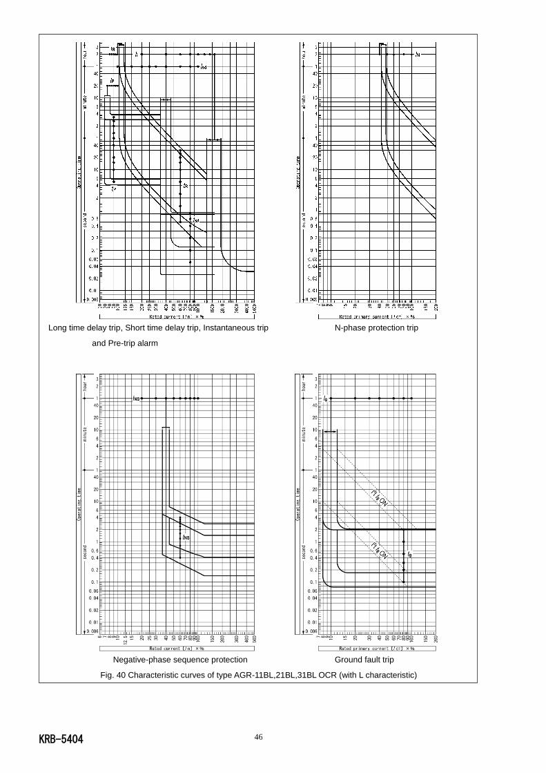
KRB-5404 46
Long time delay trip, Short time delay trip, Instantaneous trip N-phase protection trip
and Pre-trip alarm
Negative-phase sequence protection Ground fault trip
Fig. 40 Characteristic curves of type AGR-11BL,21BL,31BL OCR (with L characteristic)
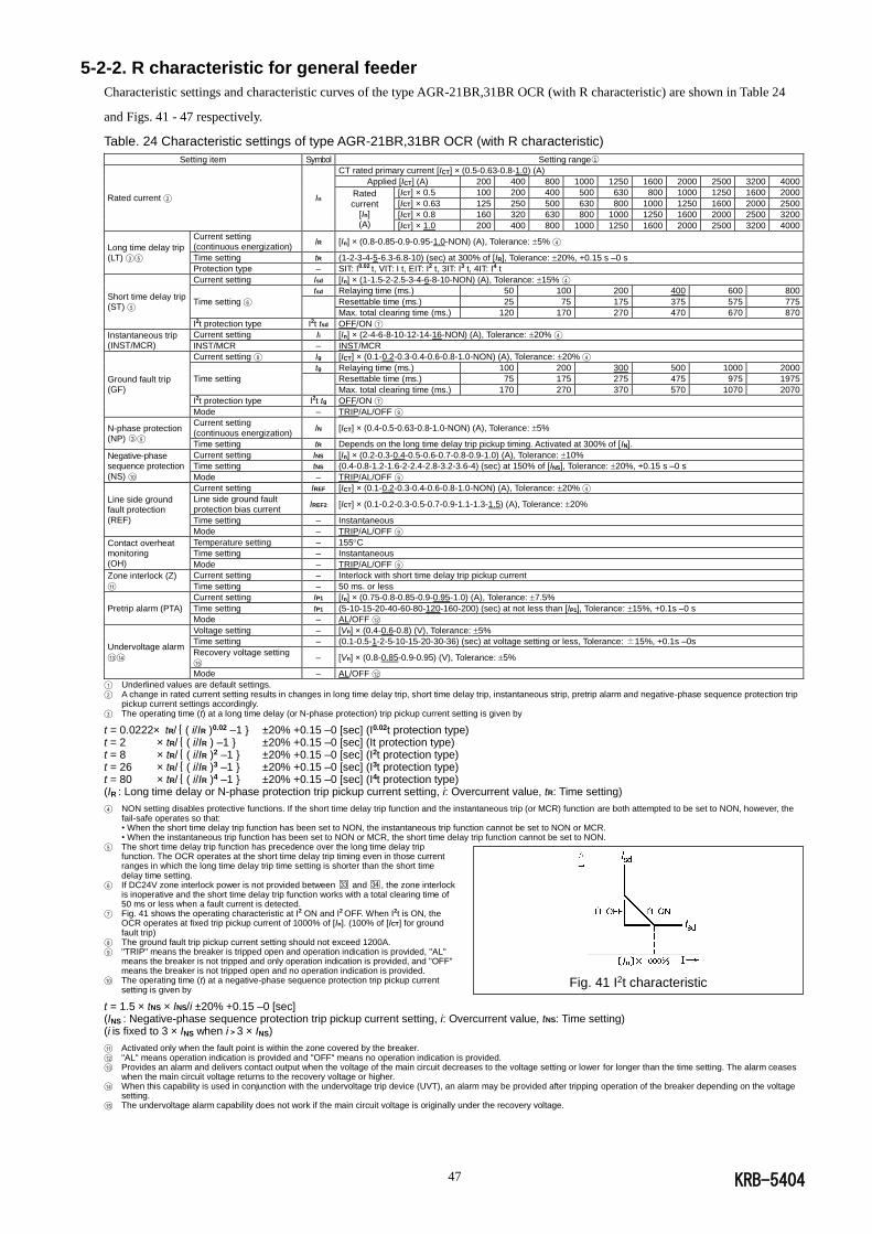
KRB-5404 47
5-2-2. R characteristic for general feeder
Characteristic settings and characteristic curves of the type AGR-21BR,31BR OCR (with R characteristic) are shown in Table 24
and Figs. 41 - 47 respectively.
Table. 24 Characteristic settings of type AGR-21BR,31BR OCR (with R characteristic)
Setting item Symbol Setting range○1
Rated current ◯2 In
CT rated primary current [ICT] × (0.5-0.63-0.8-1.0) (A)
Applied [ICT] (A) 200 400 800 1000 1250 1600 2000 2500 3200 4000
Rated
current [In] (A)
[ICT] × 0.5 100 200 400 500 630 800 1000 1250 1600 2000
[ICT] × 0.63 125 250 500 630 800 1000 1250 1600 2000 2500
[ICT] × 0.8 160 320 630 800 1000 1250 1600 2000 2500 3200
[ICT] × 1.0 200 400 800 1000 1250 1600 2000 2500 3200 4000
Long time delay trip (LT) ◯3 ◯5
Current setting (continuous energization)
IR [In] × (0.8-0.85-0.9-0.95-1.0-NON) (A), Tolerance: 5% ◯4
Time setting tR (1-2-3-4-5-6.3-6.8-10) (sec) at 300% of [IR], Tolerance: 20%, +0.15 s –0 s
Protection type – SIT: I0.02 t, VIT: I t, EIT: I2 t, 3IT: I3 t, 4IT: I4 t
Short time delay trip (ST) ◯5
Current setting Isd [In] × (1-1.5-2-2.5-3-4-6-8-10-NON) (A), Tolerance: 15% ◯4
Time setting ◯6
tsd Relaying time (ms.) 50 100 200 400 600 800
Resettable time (ms.) 25 75 175 375 575 775
Max. total clearing time (ms.) 120 170 270 470 670 870
I2t protection type I2t tsd OFF/ON ◯7
Instantaneous trip (INST/MCR)
Current setting Ii [In] × (2-4-6-8-10-12-14-16-NON) (A), Tolerance: 20% ◯4
INST/MCR – INST/MCR
Ground fault trip (GF)
Current setting ◯8 Ig [ICT] × (0.1-0.2-0.3-0.4-0.6-0.8-1.0-NON) (A), Tolerance: 20% ◯4
Time setting
tg Relaying time (ms.) 100 200 300 500 1000 2000
Resettable time (ms.) 75 175 275 475 975 1975
Max. total clearing time (ms.) 170 270 370 570 1070 2070
I2t protection type I2t tg OFF/ON ◯7
Mode – TRIP/AL/OFF ◯9
N-phase protection (NP) ○3 ◯5
Current setting
(continuous energization) IN [ICT] × (0.4-0.5-0.63-0.8-1.0-NON) (A), Tolerance: 5%
Time setting tR Depends on the long time delay trip pickup timing. Activated at 300% of [IN].
Negative-phase sequence protection
(NS) ◯10
Current setting INS [In] × (0.2-0.3-0.4-0.5-0.6-0.7-0.8-0.9-1.0) (A), Tolerance: 10%
Time setting tNS (0.4-0.8-1.2-1.6-2-2.4-2.8-3.2-3.6-4) (sec) at 150% of [INS], Tolerance: 20%, +0.15 s –0 s
Mode – TRIP/AL/OFF ◯9
Line side ground fault protection
(REF)
Current setting IREF [ICT] × (0.1-0.2-0.3-0.4-0.6-0.8-1.0-NON) (A), Tolerance: 20% ◯4
Line side ground fault protection bias current
IREF2 [ICT] × (0.1-0.2-0.3-0.5-0.7-0.9-1.1-1.3-1.5) (A), Tolerance: 20%
Time setting – Instantaneous
Mode – TRIP/AL/OFF ◯9
Contact overheat monitoring (OH)
Temperature setting – 155C
Time setting – Instantaneous
Mode – TRIP/AL/OFF ◯9
Zone interlock (Z)
◯11
Current setting – Interlock with short time delay trip pickup current
Time setting – 50 ms. or less
Pretrip alarm (PTA)
Current setting IP1 [In] × (0.75-0.8-0.85-0.9-0.95-1.0) (A), Tolerance: 7.5%
Time setting tP1 (5-10-15-20-40-60-80-120-160-200) (sec) at not less than [IP1], Tolerance: 15%, +0.1s –0 s
Mode – AL/OFF ◯12
Undervoltage alarm
◯13◯14
Voltage setting – [Vn] × (0.4-0.6-0.8) (V), Tolerance: 5%
Time setting – (0.1-0.5-1-2-5-10-15-20-30-36) (sec) at voltage setting or less, Tolerance: ±15%, +0.1s –0s
Recovery voltage setting
◯15 – [Vn] × (0.8-0.85-0.9-0.95) (V), Tolerance: 5%
Mode – AL/OFF ◯12
◯1 Underlined values are default settings.
◯2 A change in rated current setting results in changes in long time delay trip, short time delay trip, instantaneous strip, pretrip alarm and negative-phase sequence protection trip pickup current settings accordingly.
◯3 The operating time (t) at a long time delay (or N-phase protection) trip pickup current setting is given by
t = 0.0222× tR/{ ( i/IR )0.02 –1 } ±20% +0.15 –0 [sec] (I0.02t protection type) t = 2 × tR/{ ( i/IR ) –1 } ±20% +0.15 –0 [sec] (It protection type) t = 8 × tR/{ ( i/IR )2 –1 } ±20% +0.15 –0 [sec] (I2t protection type) t = 26 × tR/{ ( i/IR )3 –1 } ±20% +0.15 –0 [sec] (I3t protection type) t = 80 × tR/{ ( i/IR )4 –1 } ±20% +0.15 –0 [sec] (I4t protection type) (IR : Long time delay or N-phase protection trip pickup current setting, i: Overcurrent value, tR: Time setting) ◯4 NON setting disables protective functions. If the short time delay trip function and the instantaneous trip (or MCR) function are both attempted to be set to NON, however, the
fail-safe operates so that: • When the short time delay trip function has been set to NON, the instantaneous trip function cannot be set to NON or MCR. • When the instantaneous trip function has been set to NON or MCR, the short time delay trip function cannot be set to NON.
◯5 The short time delay trip function has precedence over the long time delay trip function. The OCR operates at the short time delay trip timing even in those current ranges in which the long time delay trip time setting is shorter than the short time delay time setting.
◯6 If DC24V zone interlock power is not provided between □33 and □34 , the zone interlock is inoperative and the short time delay trip function works with a total clearing time of 50 ms or less when a fault current is detected.
◯7 Fig. 41 shows the operating characteristic at I2 ON and I2 OFF. When I2t is ON, the OCR operates at fixed trip pickup current of 1000% of [In]. (100% of [ICT] for ground fault trip)
◯8 The ground fault trip pickup current setting should not exceed 1200A. ◯9 "TRIP" means the breaker is tripped open and operation indication is provided, "AL"
means the breaker is not tripped and only operation indication is provided, and "OFF" means the breaker is not tripped open and no operation indication is provided.
◯10 The operating time (t) at a negative-phase sequence protection trip pickup current setting is given by
t = 1.5 × tNS × INS/i ±20% +0.15 –0 [sec] (INS : Negative-phase sequence protection trip pickup current setting, i: Overcurrent value, tNS: Time setting) (i is fixed to 3 × INS when i > 3 × INS) ◯11 Activated only when the fault point is within the zone covered by the breaker.
◯12 "AL" means operation indication is provided and "OFF" means no operation indication is provided. ◯13 Provides an alarm and delivers contact output when the voltage of the main circuit decreases to the voltage setting or lower for longer than the time setting. The alarm ceases
when the main circuit voltage returns to the recovery voltage or higher. ◯14 When this capability is used in conjunction with the undervoltage trip device (UVT), an alarm may be provided after tripping operation of the breaker depending on the voltage
setting. ◯15 The undervoltage alarm capability does not work if the main circuit voltage is originally under the recovery voltage.
Fig. 41 I2t characteristic
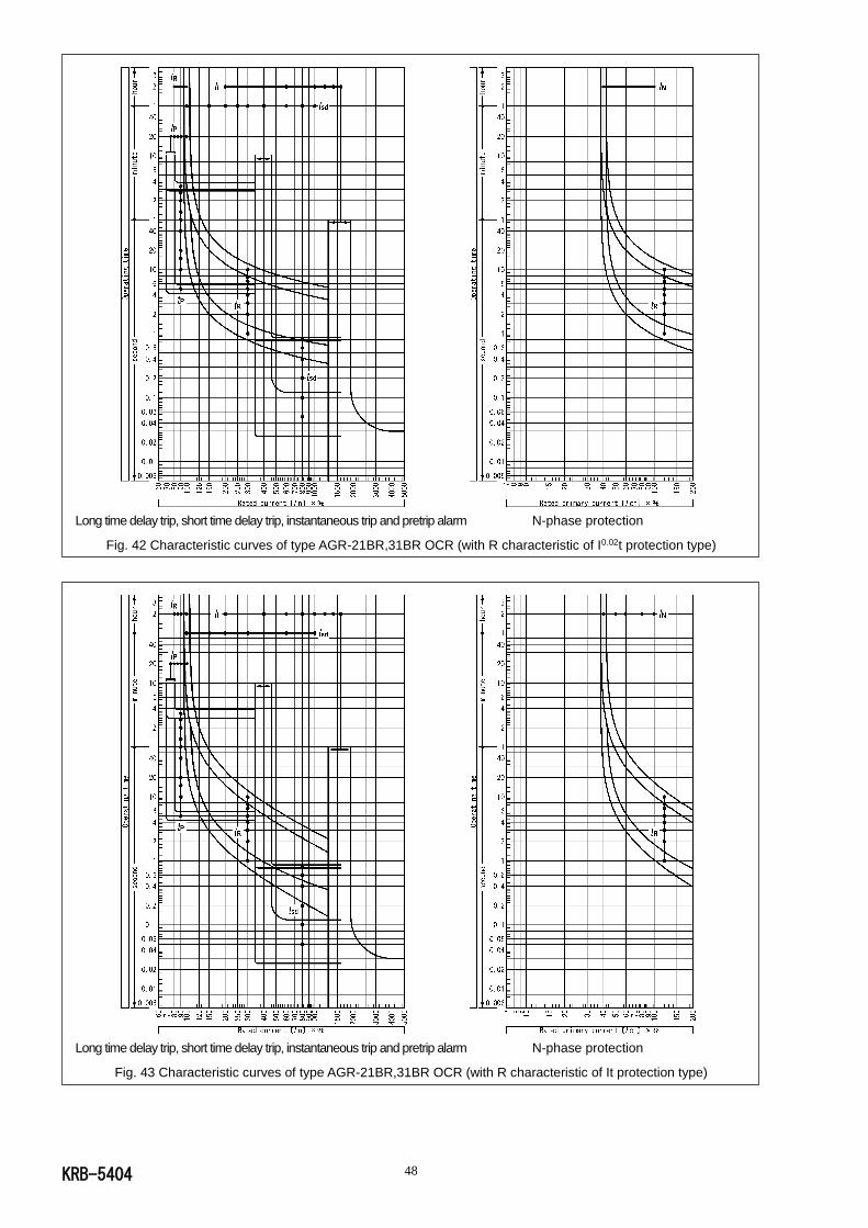
KRB-5404 48
Long time delay trip, short time delay trip, instantaneous trip and pretrip alarm N-phase protection
Fig. 42 Characteristic curves of type AGR-21BR,31BR OCR (with R characteristic of I0.02t protection type)
Long time delay trip, short time delay trip, instantaneous trip and pretrip alarm N-phase protection
Fig. 43 Characteristic curves of type AGR-21BR,31BR OCR (with R characteristic of It protection type)

KRB-5404 49
Long time delay trip, short time delay trip, instantaneous trip and pretrip alarm N-phase protection
Fig. 44 Characteristic curves of type AGR-21BR,31BR OCR (with R characteristic of I2t protection type)
Long time delay trip, short time delay trip, instantaneous trip and pretrip alarm N-phase protection
Fig. 45 Characteristic curves of type AGR-21BR,31BR OCR (with R characteristic of I3t protection type)
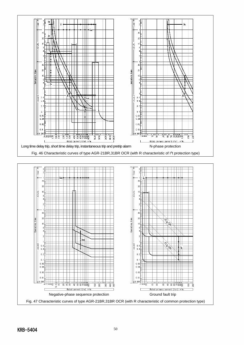
KRB-5404 50
Long time delay trip, short time delay trip, instantaneous trip and pretrip alarm N-phase protection
Fig. 46 Characteristic curves of type AGR-21BR,31BR OCR (with R characteristic of I4t protection type)
Negative-phase sequence protection Ground fault trip
Fig. 47 Characteristic curves of type AGR-21BR,31BR OCR (with R characteristic of common protection type)
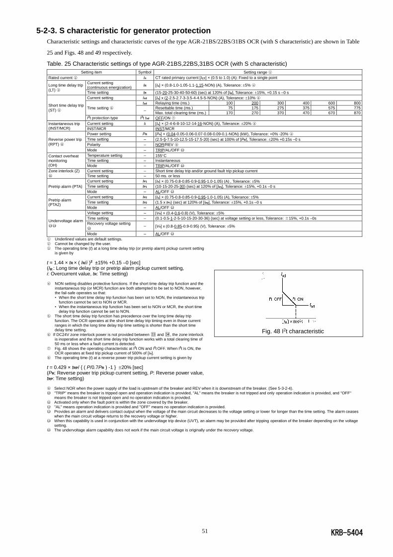
KRB-5404 51
5-2-3. S characteristic for generator protection
Characteristic settings and characteristic curves of the type AGR-21BS/22BS/31BS OCR (with S characteristic) are shown in Table
25 and Figs. 48 and 49 respectively.
Table. 25 Characteristic settings of type AGR-21BS,22BS,31BS OCR (with S characteristic)
Setting item Symbol Setting range ○1
Rated current ○2 In CT rated primary current [ICT] × (0.5 to 1.0) (A): Fixed to a single point
Long time delay trip
(LT) ○3
Current setting (continuous energization)
IR [In] × (0.8-1.0-1.05-1.1-1.15-NON) (A), Tolerance: 5% ○4
Time setting tR (15-20-25-30-40-50-60) (sec) at 120% of [IR], Tolerance: 15%, +0.15 s –0 s
Short time delay trip
(ST) ○5
Current setting Isd [In] x (2-2.5-2.7-3-3.5-4-4.5-5-NON) (A), Tolerance: 10% ○4
Time setting ○6
tsd Relaying time (ms.) 100 200 300 400 600 800
– Resettable time (ms.) 75 175 275 375 575 775
Max. total clearing time (ms.) 170 270 370 470 670 870
I2t protection type I2t tsd OFF/ON ○7
Instantaneous trip (INST/MCR)
Current setting Ii [In] × (2-4-6-8-10-12-14-16-NON) (A), Tolerance: 20% ○4
INST/MCR INST/MCR
Reverse power trip
(RPT) ○8
Power setting PR [Pn] × (0.04-0.05-0.06-0.07-0.08-0.09-0.1-NON) (kW), Tolerance: +0% -20% ○4
Time setting – (2.5-5-7.5-10-12.5-15-17.5-20) (sec) at 100% of [PR], Tolerance: 20% +0.15s –0 s
Polarity – NOR/REV ○9
Mode – TRIP/AL/OFF ○10
Contact overheat monitoring (OH)
Temperature setting – 155C
Time setting – Instantaneous
Mode – TRIP/AL/OFF ○10
Zone interlock (Z)
○11
Current setting – Short time delay trip and/or ground fault trip pickup current
Time setting – 50 ms. or less
Pretrip alarm (PTA)
Current setting IP1 [In] × (0.75-0.8-0.85-0.9-0.95-1.0-1.05) (A) , Tolerance: 5%
Time setting tP1 (10-15-20-25-30) (sec) at 120% of [IP1], Tolerance: 15%, +0.1s –0 s
Mode – AL/OFF ○12
Pretrip alarm (PTA2)
Current setting IP2 [In] × (0.75-0.8-0.85-0.9-0.95-1.0-1.05) (A), Tolerance: 5%
Time setting tP2 (1.5 x tP1) (sec) at 120% of [IP2], Tolerance: 15%, +0.1s –0 s
Mode – AL/OFF ○12
Undervoltage alarm
○13○14
Voltage setting – [Vn] × (0.4-0.6-0.8) (V), Tolerance: 5%
Time setting – (0.1-0.5-1-2-5-10-15-20-30-36) (sec) at voltage setting or less, Tolerance: ±15%, +0.1s –0s
Recovery voltage setting
○15 – [Vn] x (0.8-0.85-0.9-0.95) (V), Tolerance: 5%
Mode – AL/OFF ○12
○1 Underlined values are default settings. ○2 Cannot be changed by the user.
○3 The operating time (t) at a long time delay trip (or pretrip alarm) pickup current setting is given by
t = 1.44 × tR × ( IR/i )2 ±15% +0.15 –0 [sec] (IR : Long time delay trip or pretrip alarm pickup current setting, i: Overcurrent value, tR: Time setting) ○4 NON setting disables protective functions. If the short time delay trip function and the
instantaneous trip (or MCR) function are both attempted to be set to NON, however,
the fail-safe operates so that: • When the short time delay trip function has been set to NON, the instantaneous trip
function cannot be set to NON or MCR.
• When the instantaneous trip function has been set to NON or MCR, the short time delay trip function cannot be set to NON.
○5 The short time delay trip function has precedence over the long time delay trip
function. The OCR operates at the short time delay trip timing even in those current ranges in which the long time delay trip time setting is shorter than the short time delay time setting.
○6 If DC24V zone interlock power is not provided between □33 and □34 , the zone interlock is inoperative and the short time delay trip function works with a total clearing time of 50 ms or less when a fault current is detected.
○7 Fig. 48 shows the operating characteristic at I2t ON and I2t OFF. When I2t is ON, the OCR operates at fixed trip pickup current of 500% of [In].
○8 The operating time (t) at a reverse power trip pickup current setting is given by
t = 0.429 × tRP/ { ( P/0.7PR ) -1 } 20% [sec] (PR: Reverse power trip pickup current setting, P: Reverse power value, tRP: Time setting) ○9 Select NOR when the power supply of the load is upstream of the breaker and REV when it is downstream of the breaker. (See 5-3-2-4).
○10 "TRIP" means the breaker is tripped open and operation indication is provided, "AL" means the breaker is not tripped and only operation indication is provided, and "OFF" means the breaker is not tripped open and no operation indication is provided.
○11 Activated only when the fault point is within the zone covered by the breaker.
○12 "AL" means operation indication is provided and "OFF" means no operation indication is provided. ○13 Provides an alarm and delivers contact output when the voltage of the main circuit decreases to the voltage setting or lower for longer than the time setting. The alarm ceases
when the main circuit voltage returns to the recovery voltage or higher.
○14 When this capability is used in conjunction with the undervoltage trip device (UVT), an alarm may be provided after tripping operation of the breaker depending on the voltage setting.
○15 The undervoltage alarm capability does not work if the main circuit voltage is originally under the recovery voltage.
Fig. 48 I2t characteristic
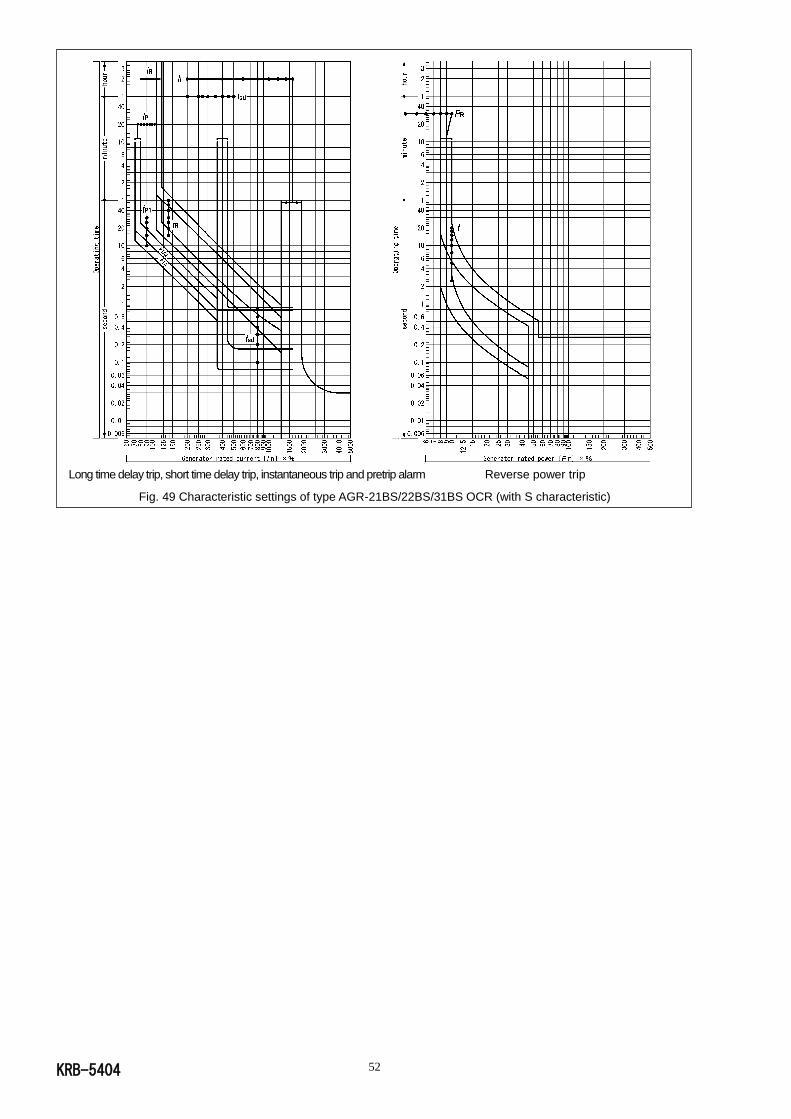
KRB-5404 52
Long time delay trip, short time delay trip, instantaneous trip and pretrip alarm Reverse power trip
Fig. 49 Characteristic settings of type AGR-21BS/22BS/31BS OCR (with S characteristic)
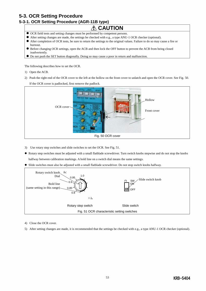
KRB-5404 53
5-3. OCR Setting Procedure 5-3-1. OCR Setting Procedure (AGR-11B type)
CAUTION OCR field tests and setting changes must be performed by competent persons.
After setting changes are made, the settings be checked with e.g., a type ANU-1 OCR checker (optional).
After completion of OCR tests, be sure to return the settings to the original values. Failure to do so may cause a fire or
burnout.
Before changing OCR settings, open the ACB and then lock the OFF button to prevent the ACB from being closed
inadvertently.
Do not push the SET button diagonally. Doing so may cause a poor in return and malfunction.
The following describes how to set the OCR.
1) Open the ACB.
2) Push the right end of the OCR cover to the left at the hollow on the front cover to unlatch and open the OCR cover. See Fig. 50.
If the OCR cover is padlocked, first remove the padlock.
Fig. 50 OCR cover
3) Use rotary step switches and slide switches to set the OCR. See Fig. 51.
Rotary step switches must be adjusted with a small flatblade screwdriver. Turn switch knobs stepwise and do not stop the knobs
halfway between calibration markings. A bold line on a switch dial means the same settings.
Slide switches must also be adjusted with a small flatblade screwdriver. Do not stop switch knobs halfway.
Rotary step switch Slide switch
Fig. 51 OCR characteristic setting switches
4) Close the OCR cover.
5) After setting changes are made, it is recommended that the settings be checked with e.g., a type ANU-1 OCR checker (optional).
OCR cover
Hollow
Front cover
IR: 1.0
0.95
0.9
0.85
0.8
×In
Rotary switch knob
Dial
Bold line
(same setting in this range)
Slide switch knob I2t SW ON OFF
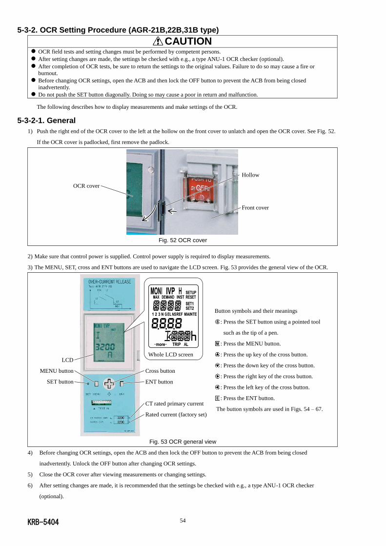
KRB-5404 54
5-3-2. OCR Setting Procedure (AGR-21B,22B,31B type)
CAUTION
OCR field tests and setting changes must be performed by competent persons.
After setting changes are made, the settings be checked with e.g., a type ANU-1 OCR checker (optional).
After completion of OCR tests, be sure to return the settings to the original values. Failure to do so may cause a fire or
burnout.
Before changing OCR settings, open the ACB and then lock the OFF button to prevent the ACB from being closed
inadvertently.
Do not push the SET button diagonally. Doing so may cause a poor in return and malfunction.
The following describes how to display measurements and make settings of the OCR.
5-3-2-1. General
1) Push the right end of the OCR cover to the left at the hollow on the front cover to unlatch and open the OCR cover. See Fig. 52.
If the OCR cover is padlocked, first remove the padlock.
Fig. 52 OCR cover
2) Make sure that control power is supplied. Control power supply is required to display measurements.
3) The MENU, SET, cross and ENT buttons are used to navigate the LCD screen. Fig. 53 provides the general view of the OCR.
Button symbols and their meanings
: Press the SET button using a pointed tool
such as the tip of a pen.
: Press the MENU button.
: Press the up key of the cross button.
: Press the down key of the cross button.
: Press the right key of the cross button.
: Press the left key of the cross button.
: Press the ENT button.
The button symbols are used in Figs. 54 – 67.
Fig. 53 OCR general view
4) Before changing OCR settings, open the ACB and then lock the OFF button to prevent the ACB from being closed
inadvertently. Unlock the OFF button after changing OCR settings.
5) Close the OCR cover after viewing measurements or changing settings.
6) After setting changes are made, it is recommended that the settings be checked with e.g., a type ANU-1 OCR checker
(optional).
OCR cover
Hollow
Front cover
Whole LCD screen
Cross button
ENT button
CT rated primary current
Rated current (factory set)
液晶画面の表示寿命は,一般的にコントラストが50%以下になる時間で定められ,週温25℃,湿度55%RHの条件の下で,約5.7年です。液晶画面が見にくくなった場合,OCR全体の交換を要します。OCRの交換については,弊社にお問合わせ下さい。
LCD
MENU button
SET button
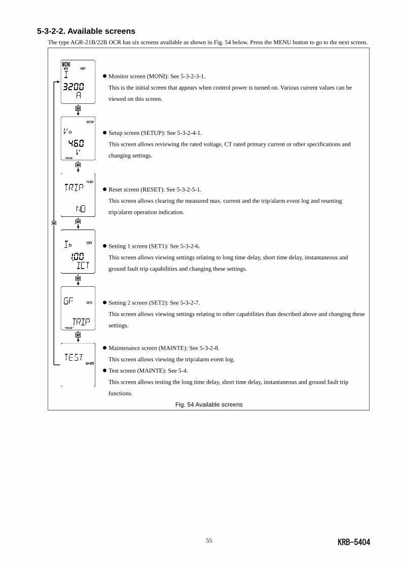
KRB-5404 55
5-3-2-2. Available screens
The type AGR-21B/22B OCR has six screens available as shown in Fig. 54 below. Press the MENU button to go to the next screen.
Monitor screen (MONI): See 5-3-2-3-1.
This is the initial screen that appears when control power is turned on. Various current values can be
viewed on this screen.
Setup screen (SETUP): See 5-3-2-4-1.
This screen allows reviewing the rated voltage, CT rated primary current or other specifications and
changing settings.
Reset screen (RESET): See 5-3-2-5-1.
This screen allows clearing the measured max. current and the trip/alarm event log and resetting
trip/alarm operation indication.
Setting 1 screen (SET1): See 5-3-2-6.
This screen allows viewing settings relating to long time delay, short time delay, instantaneous and
ground fault trip capabilities and changing these settings.
Setting 2 screen (SET2): See 5-3-2-7.
This screen allows viewing settings relating to other capabilities than described above and changing these
settings.
Maintenance screen (MAINTE): See 5-3-2-8.
This screen allows viewing the trip/alarm event log.
Test screen (MAINTE): See 5-4.
This screen allows testing the long time delay, short time delay, instantaneous and ground fault trip
functions.
Fig. 54 Available screens
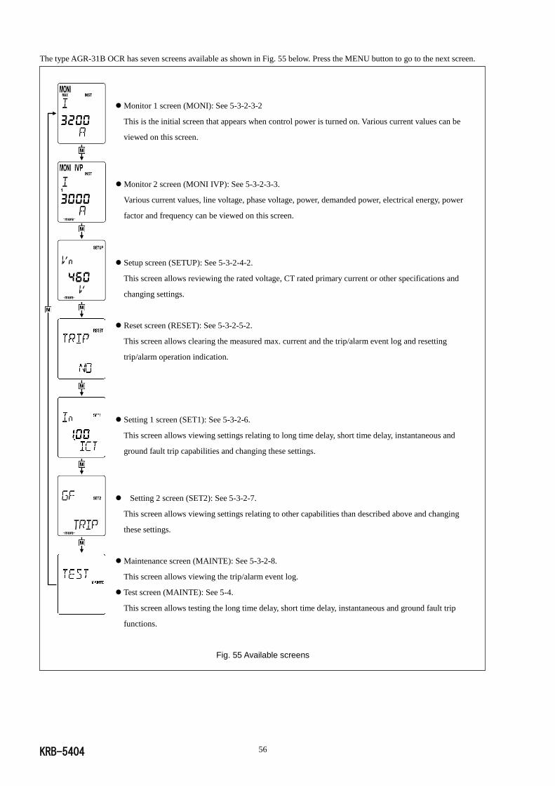
KRB-5404 56
The type AGR-31B OCR has seven screens available as shown in Fig. 55 below. Press the MENU button to go to the next screen.
Monitor 1 screen (MONI): See 5-3-2-3-2
This is the initial screen that appears when control power is turned on. Various current values can be
viewed on this screen.
Monitor 2 screen (MONI IVP): See 5-3-2-3-3.
Various current values, line voltage, phase voltage, power, demanded power, electrical energy, power
factor and frequency can be viewed on this screen.
Setup screen (SETUP): See 5-3-2-4-2.
This screen allows reviewing the rated voltage, CT rated primary current or other specifications and
changing settings.
Reset screen (RESET): See 5-3-2-5-2.
This screen allows clearing the measured max. current and the trip/alarm event log and resetting
trip/alarm operation indication.
Setting 1 screen (SET1): See 5-3-2-6.
This screen allows viewing settings relating to long time delay, short time delay, instantaneous and
ground fault trip capabilities and changing these settings.
Setting 2 screen (SET2): See 5-3-2-7.
This screen allows viewing settings relating to other capabilities than described above and changing
these settings.
Maintenance screen (MAINTE): See 5-3-2-8.
This screen allows viewing the trip/alarm event log.
Test screen (MAINTE): See 5-4.
This screen allows testing the long time delay, short time delay, instantaneous and ground fault trip
functions.
Fig. 55 Available screens
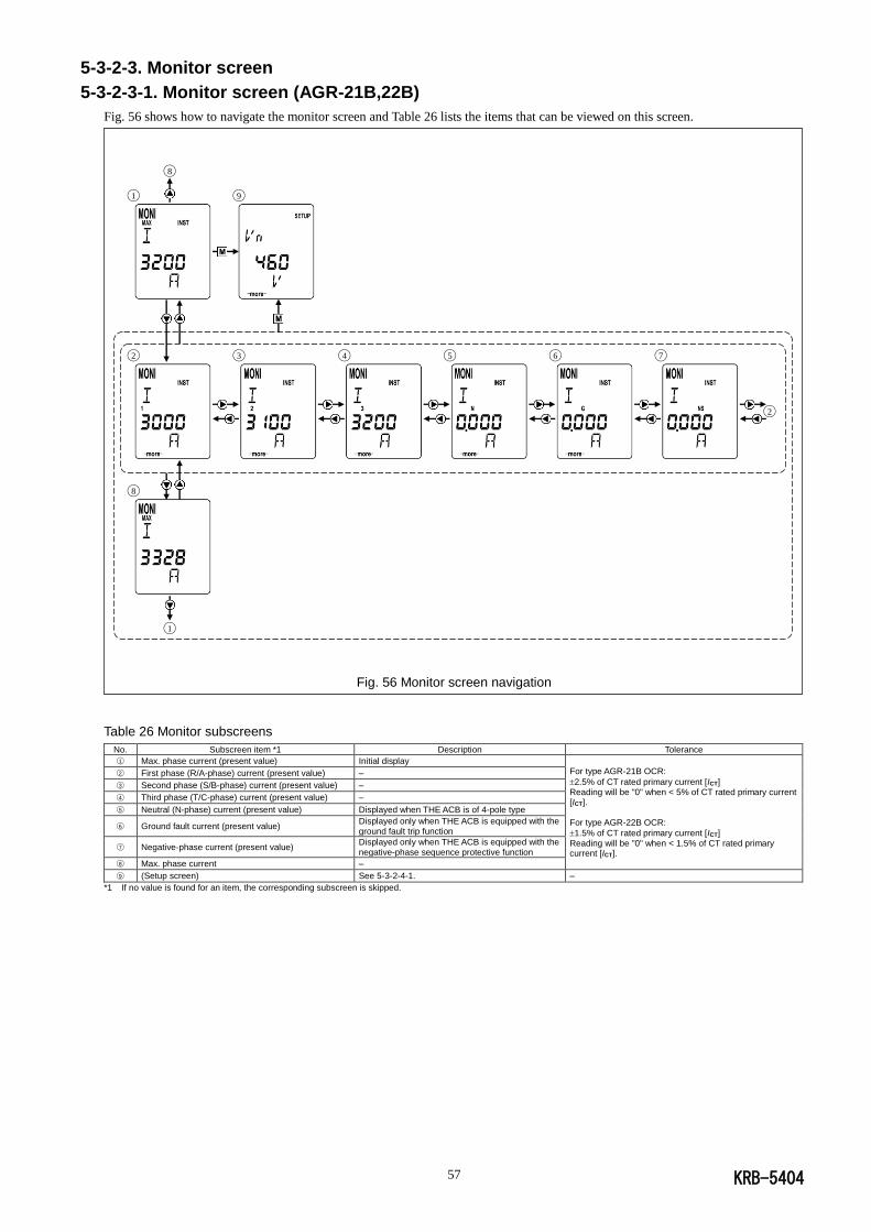
KRB-5404 57
◯8
◯1 ◯9
◯2 ◯3 ◯4 ◯5 ◯6 ◯7
◯2
◯8
◯1
5-3-2-3. Monitor screen
5-3-2-3-1. Monitor screen (AGR-21B,22B)
Fig. 56 shows how to navigate the monitor screen and Table 26 lists the items that can be viewed on this screen.
Fig. 56 Monitor screen navigation
Table 26 Monitor subscreens
No. Subscreen item *1 Description Tolerance
○1 Max. phase current (present value) Initial display For type AGR-21B OCR:
2.5% of CT rated primary current [ICT] Reading will be "0" when < 5% of CT rated primary current [ICT]. For type AGR-22B OCR:
1.5% of CT rated primary current [ICT] Reading will be "0" when < 1.5% of CT rated primary current [ICT].
○2 First phase (R/A-phase) current (present value) –
○3 Second phase (S/B-phase) current (present value) –
○4 Third phase (T/C-phase) current (present value) –
○5 Neutral (N-phase) current (present value) Displayed when THE ACB is of 4-pole type
○6 Ground fault current (present value) Displayed only when THE ACB is equipped with the ground fault trip function
○7 Negative-phase current (present value) Displayed only when THE ACB is equipped with the negative-phase sequence protective function
○8 Max. phase current –
○9 (Setup screen) See 5-3-2-4-1. –
*1 If no value is found for an item, the corresponding subscreen is skipped.

KRB-5404 58
◯4
◯1 ◯5
◯2
◯3
◯4
◯1
5-3-2-3-2. Monitor 1 screen (AGR-31B)
Fig. 57 shows how to navigate the monitor 1 screen and Table 27 lists the items that can be viewed on this screen.
Fig. 57 Monitor 1 screen navigation
Table 27 Monitor 1 subscreens
No. Subscreen item *1 Description Tolerance
○1 Max. phase current (present value) Initial display
1.5% of CT rated primary current [ICT] Reading will be "0" when < 1.5% of CT rated primary current [ICT].
○2 Ground fault current (present value) Displayed only when THE ACB is equipped with the ground fault trip function
○3 Max. phase current –
○4 Power (present value) -
○5 (Monitor 2 screen) See 5-3-2-3-3.
*1: If no value is found for an item, the corresponding subscreen is skipped.

KRB-5404 59
◯1 ◯18
◯2 ◯3 ◯4 ◯5 ◯6 ◯7
◯2
◯8
◯9 ◯10 ◯11 ◯9
◯9 ’ ◯10 ’ ◯11 ’
◯9 ’
◯12 ◯13 ◯14 ◯12
◯15 (from the next page) ◯15 (to the next page)
5-3-2-3-3. Monitor 2 screen (AGR-31B)
Fig. 58 shows how to navigate the monitor 2 screen and Table 28 lists the items that can be viewed on this screen.
Fig. 58-1 Monitor 2 screen navigation
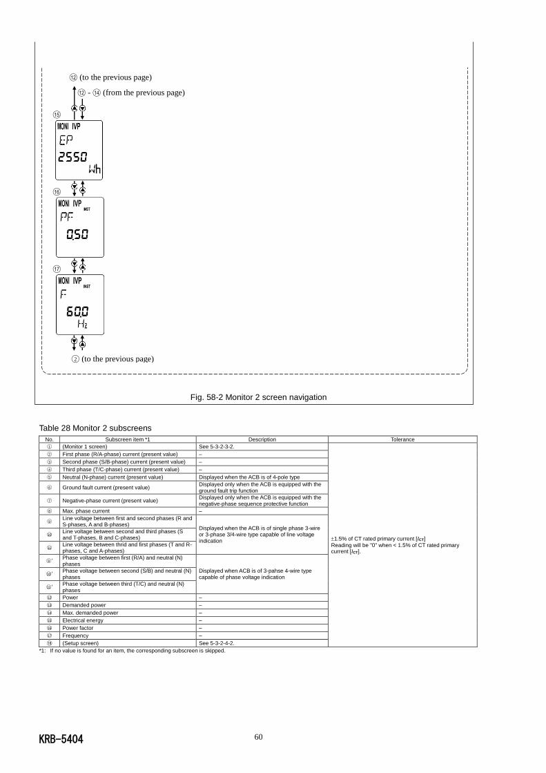
KRB-5404 60
Fig. 58-2 Monitor 2 screen navigation
Table 28 Monitor 2 subscreens
No. Subscreen item *1 Description Tolerance
○1 (Monitor 1 screen) See 5-3-2-3-2.
1.5% of CT rated primary current [ICT]
Reading will be "0" when < 1.5% of CT rated primary current [ICT].
○2 First phase (R/A-phase) current (present value) –
○3 Second phase (S/B-phase) current (present value) –
○4 Third phase (T/C-phase) current (present value) –
○5 Neutral (N-phase) current (present value) Displayed when the ACB is of 4-pole type
○6 Ground fault current (present value) Displayed only when the ACB is equipped with the ground fault trip function
○7 Negative-phase current (present value) Displayed only when the ACB is equipped with the negative-phase sequence protective function
○8 Max. phase current –
○9 Line voltage between first and second phases (R and S-phases, A and B-phases)
Displayed when the ACB is of single phase 3-wire or 3-phase 3/4-wire type capable of line voltage indication
○10 Line voltage between second and third phases (S and T-phases, B and C-phases)
○11 Line voltage between thrid and first phases (T and R-phases, C and A-phases)
○9 ’ Phase voltage between first (R/A) and neutral (N) phases
Displayed when ACB is of 3-pahse 4-wire type capable of phase voltage indication
○10 ’ Phase voltage between second (S/B) and neutral (N) phases
○11 ’ Phase voltage between third (T/C) and neutral (N) phases
○12 Power –
○13 Demanded power –
○14 Max. demanded power –
○15 Electrical energy –
○16 Power factor –
○17 Frequency –
◯18 (Setup screen) See 5-3-2-4-2.
*1: If no value is found for an item, the corresponding subscreen is skipped.
◯12 (to the previous page)
◯12 - ◯14 (from the previous page)
◯15
◯16
◯17 ◯2 (to the previous page)
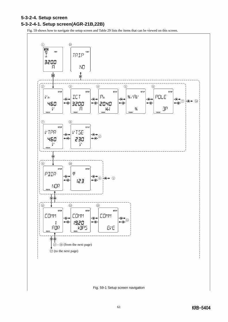
KRB-5404 61
5-3-2-4. Setup screen
5-3-2-4-1. Setup screen(AGR-21B,22B)
Fig. 59 shows how to navigate the setup screen and Table 29 lists the items that can be viewed on this screen.
Fig. 59-1 Setup screen navigation
◯1 ○21
◯2 ◯3 ◯4 ◯5 ◯6
◯7 ◯14
◯7 ◯8
◯2
◯9 ◯10
◯9 ◯2
◯11 ◯12 ◯13
◯11
◯17 - ◯19 (from the next page)
◯17 (to the next page)
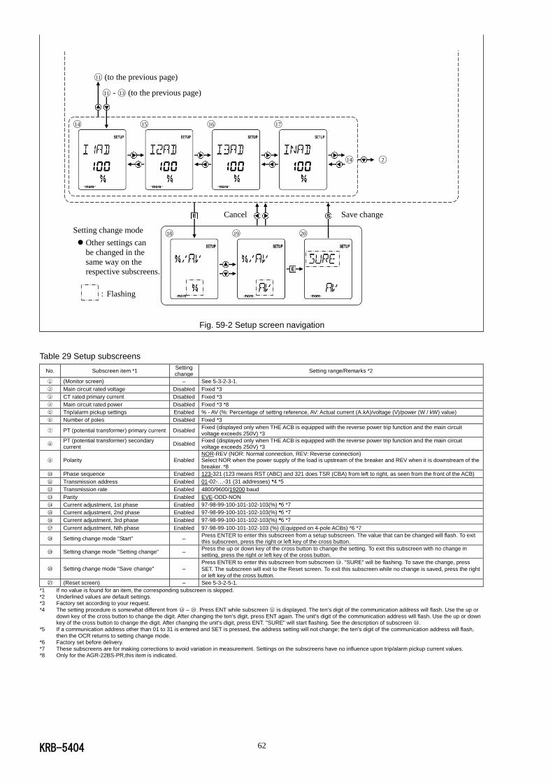
KRB-5404 62
Setting change mode
Other settings can
be changed in the
same way on the
respective subscreens.
:Flashing
Fig. 59-2 Setup screen navigation
Table 29 Setup subscreens
No. Subscreen item *1 Setting change
Setting range/Remarks *2
○1 (Monitor screen) – See 5-3-2-3-1.
○2 Main circuit rated voltage Disabled Fixed *3
○3 CT rated primary current Disabled Fixed *3
○4 Main circuit rated power Disabled Fixed *3 *8
○5 Trip/alarm pickup settings Enabled % - AV (%: Percentage of setting reference, AV: Actual current (A.kA)/voltage (V)/power (W / kW) value)
○6 Number of poles Disabled Fixed *3
○7 PT (potential transformer) primary current Disabled Fixed (displayed only when THE ACB is equipped with the reverse power trip function and the main circuit voltage exceeds 250V) *3
○8 PT (potential transformer) secondary current
Disabled Fixed (displayed only when THE ACB is equipped with the reverse power trip function and the main circuit voltage exceeds 250V) *3
○9 Polarity Enabled NOR-REV (NOR: Normal connection, REV: Reverse connection) Select NOR when the power supply of the load is upstream of the breaker and REV when it is downstream of the breaker. *8
○10 Phase sequence Enabled 123-321 (123 means RST (ABC) and 321 does TSR (CBA) from left to right, as seen from the front of the ACB)
○11 Transmission address Enabled 01-02-…-31 (31 addresses) *4 *5
○12 Transmission rate Enabled 4800/9600/19200 baud
○13 Parity Enabled EVE-ODD-NON
○14 Current adjustment, 1st phase Enabled 97-98-99-100-101-102-103(%) *6 *7
○15 Current adjustment, 2nd phase Enabled 97-98-99-100-101-102-103(%) *6 *7
○16 Current adjustment, 3rd phase Enabled 97-98-99-100-101-102-103(%) *6 *7 ○17 Current adjustment, Nth phase Enabled 97-98-99-100-101-102-103 (%) (Equipped on 4-pole ACBs) *6 *7
○18 Setting change mode "Start" – Press ENTER to enter this subscreen from a setup subscreen. The value that can be changed will flash. To exit this subscreen, press the right or left key of the cross button.
○19 Setting change mode "Setting change" – Press the up or down key of the cross button to change the setting. To exit this subscreen with no change in setting, press the right or left key of the cross button.
○20 Setting change mode "Save change" – Press ENTER to enter this subscreen from subscreen ○19 . "SURE" will be flashing. To save the change, press
SET. The subscreen will exit to the Reset screen. To exit this subscreen while no change is saved, press the right or left key of the cross button.
◯21 (Reset screen) – See 5-3-2-5-1.
*1 If no value is found for an item, the corresponding subscreen is skipped. *2 Underlined values are default settings. *3 Factory set according to your request.
*4 The setting procedure is somewhat different from ○18 – ○20 . Press ENT while subscreen ○11 is displayed. The ten's digit of the communication address will flash. Use the up or down key of the cross button to change the digit. After changing the ten's digit, press ENT again. The unit's digit of the communication address will flash. Use the up or down key of the cross button to change the digit. After changing the unit's digit, press ENT. "SURE" will start flashing. See the description of subscreen ○20 .
*5 If a communication address other than 01 to 31 is entered and SET is pressed, the address setting will not change; the ten's digit of the communication address will flash, then the OCR returns to setting change mode.
*6 Factory set before delivery.
*7 These subscreens are for making corrections to avoid variation in measurement. Settings on the subscreens have no influence upon trip/alarm pickup current values. *8 Only for the AGR-22BS-PR,this item is indicated.
◯11 (to the previous page)
◯11 - ◯13 (to the previous page)
◯14 ◯15 ◯16 ◯17
◯14 ◯2
Cancel Save change
◯18 ◯19 ◯20
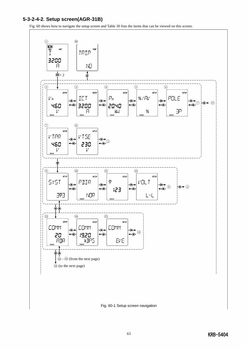
KRB-5404 63
5-3-2-4-2. Setup screen(AGR-31B)
Fig. 60 shows how to navigate the setup screen and Table 30 lists the items that can be viewed on this screen.
Fig. 60-1 Setup screen navigation
◯1 ○26
× 2
◯2 ◯3 ◯4 ◯5 ◯6
◯7 ◯17
◯7 ◯8
◯2
◯9 ◯10 ◯11 ◯12
◯9 ◯2
◯13 ◯14 ◯15
◯13
◯16 - ◯24 (from the next page)
◯16 (to the next page)

KRB-5404 64
Setting change mode
Other settings can
be changed in the
same way on the
respective subscreens.
: Flashing
Fig. 60-2 Setup screen navigation
◯13 (to the previous page)
◯13 - ◯15 (from the previous page)
◯16
◯17 ◯18 ◯19 ◯20
◯21 ◯2
◯21 ◯22
◯17
Cancel Save change
◯23 ◯24 ◯25

KRB-5404 65
Table 30 Setup subscreens
No. Subscreen item *1 Setting change
Setting range/Remarks *2
○1 (Monitor 1 screen) – See 5-3-2-3-2.
○2 Main circuit rated voltage Disabled Fixed *3
○3 CT rated primary current Disabled Fixed *3
○4 Main circuit rated power Disabled Determined (calculated with main circuit rated voltage and rated current [In]) Fixed *3 (for OCR type AGR-31BS-PR)
○5 Trip/alarm pickup settings Enabled % - AV (%: Percentage of setting reference, AV: Actual current (A/kA)/voltage (V)/power (W / kW) value)
○6 Number of poles Disabled Fixed *3
○7 PT (potential transformer) primary current Disabled Fixed (displayed only when THE ACB is equipped with the reverse power trip function and the main circuit voltage exceeds 250V) *3
○8 PT (potential transformer) secondary current
Disabled Fixed (displayed only when THE ACB is equipped with the reverse power trip function and the main circuit voltage exceeds 250V) *3
○9 Phase wiring scheme Enabled 13-33-34
○10 Polarity Enabled NOR-REV (NOR: Normal connection, REV: Reverse connection) Select NOR when the power supply of the load is upstream of the breaker and REV when it is downstream of the breaker. (for OCR type AGR-31B)
○11 Phase sequence Enabled 123-321 (123 means RST (ABC) and 321 does TSR (CBA) from left to right, as seen from the front of the ACB)
○12 Voltage indication Enabled L-N-L-L
○13 Transmission address Enabled 01-02-…-31 (31 addresses) *4 *5
○14 Transmission rate Enabled 4800/9600/19200 baud
○15 Parity Enabled EVE-ODD-NON
○16 Demand interval Enabled 5-30-60 (MIN)
○17 Current adjustment, 1st phase Enabled 97-98-99-100-101-102-103(%) *6 *7
○18 Current adjustment, 2nd phase Enabled 97-98-99-100-101-102-103(%) *6 *7
○19 Current adjustment, 3rd phase Enabled 97-98-99-100-101-102-103(%) *6 *7 ○20 Current adjustment, Nth phase Enabled 97-98-99-100-101-102-103 (%) (Equipped on 4-pole ACBs) *6 *7 ◯21 Voltge ratio adjustment Enabled 97-98-99-100-101-102-103 (%) *6 *7
◯22 Power adjustment Enabled 97-98-99-100-101-102-103 (%) *6 *7
◯23 Setting change mode "Start" – Press ENTER to enter this subscreen from a setup subscreen. The value that can be changed will flash. To exit this subscreen, press the right or left key of the cross button.
◯24 Setting change mode "Setting change" – Press the up or down key of the cross button to change the setting. To exit this subscreen with no change in setting, press the right or left key of the cross button.
◯25 Setting change mode "Save change" – Press ENTER to enter this subscreen from subscreen ○19 . "SURE" will be flashing. To save the change, press
SET. The subscreen will exit to the Reset screen. To exit this subscreen while no change is saved, press the right or left key of the cross button.
◯26 (Reset screen) – See 5-3-2-5-2.
*1: If no value is found for an item, the corresponding subscreen is skipped. *2: Underlined values are default settings. *3: Factory set according to your request.
*4: The setting procedure is somewhat different from ◯23 – ◯25. Press ENT while subscreen ○13 is displayed. The ten's digit of the communication address will flash. Use the up or down key of the cross button to change the digit. After changing the ten's digit, press ENT again. The unit's digit of the communication address will flash. Use the up or down key of the cross button to change the digit. After changing the unit's digit, press ENT. "SURE" will start flashing. See the description of subscreen ◯25. If SET is pressed when
the ten's digit is flashing, "SURE" will start flashing, indicating that the current subscreen has exited to subscreen ◯25. *5: If a communication address other than 01 to 31 is entered and SET is pressed, the address setting will not change; the ten's digit of the communication address will flash,
then the OCR returns to setting change mode.
*6: Factory set before delivery. *7: These subscreens are for making corrections to avoid variation in measurement. Settings on the subscreens have no influence upon trip/alarm pickup current values.
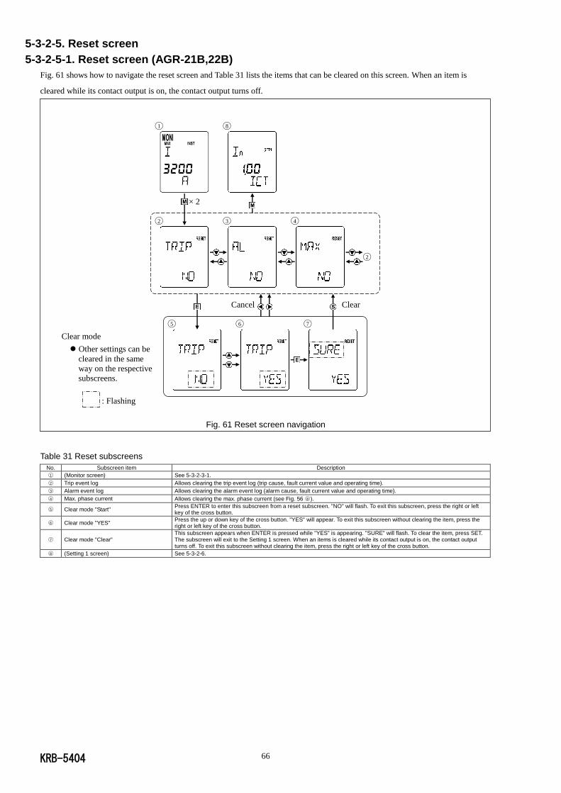
KRB-5404 66
5-3-2-5. Reset screen
5-3-2-5-1. Reset screen (AGR-21B,22B)
Fig. 61 shows how to navigate the reset screen and Table 31 lists the items that can be cleared on this screen. When an item is
cleared while its contact output is on, the contact output turns off.
Clear mode
Other settings can be
cleared in the same
way on the respective
subscreens.
: Flashing
Fig. 61 Reset screen navigation
Table 31 Reset subscreens
No. Subscreen item Description
○1 (Monitor screen) See 5-3-2-3-1.
○2 Trip event log Allows clearing the trip event log (trip cause, fault current value and operating time).
○3 Alarm event log Allows clearing the alarm event log (alarm cause, fault current value and operating time).
○4 Max. phase current Allows clearing the max. phase current (see Fig. 56 ○8 ).
○5 Clear mode "Start" Press ENTER to enter this subscreen from a reset subscreen. "NO" will flash. To exit this subscreen, press the right or left key of the cross button.
○6 Clear mode "YES" Press the up or down key of the cross button. "YES" will appear. To exit this subscreen without clearing the item, press the right or left key of the cross button.
○7 Clear mode "Clear" This subscreen appears when ENTER is pressed while "YES" is appearing. "SURE" will flash. To clear the item, press SET. The subscreen will exit to the Setting 1 screen. When an items is cleared while its contact output is on, the contact output turns off. To exit this subscreen without clearing the item, press the right or left key of the cross button.
○8 (Setting 1 screen) See 5-3-2-6.
◯1 ◯8
× 2
◯2 ◯3 ◯4
◯2
Cancel Clear
◯5 ◯6 ◯7
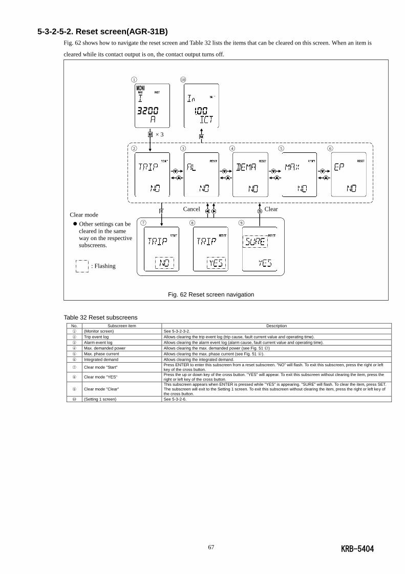
KRB-5404 67
5-3-2-5-2. Reset screen(AGR-31B)
Fig. 62 shows how to navigate the reset screen and Table 32 lists the items that can be cleared on this screen. When an item is
cleared while its contact output is on, the contact output turns off.
Clear mode
Other settings can be
cleared in the same
way on the respective
subscreens.
: Flashing
Fig. 62 Reset screen navigation
Table 32 Reset subscreens
No. Subscreen item Description
○1 (Monitor screen) See 5-3-2-3-2.
○2 Trip event log Allows clearing the trip event log (trip cause, fault current value and operating time).
○3 Alarm event log Allows clearing the alarm event log (alarm cause, fault current value and operating time).
○4 Max. demanded power Allows clearing the max. demanded power (see Fig. 51 ○17 )
○5 Max. phase current Allows clearing the max. phase current (see Fig. 51 ○9 ).
○6 Integrated demand Allows clearing the integrated demand.
○7 Clear mode "Start" Press ENTER to enter this subscreen from a reset subscreen. "NO" will flash. To exit this subscreen, press the right or left key of the cross button.
○8 Clear mode "YES" Press the up or down key of the cross button. "YES" will appear. To exit this subscreen without clearing the item, press the right or left key of the cross button.
○9 Clear mode "Clear" This subscreen appears when ENTER is pressed while "YES" is appearing. "SURE" will flash. To clear the item, press SET. The subscreen will exit to the Setting 1 screen. To exit this subscreen without clearing the item, press the right or left key of the cross button.
○10 (Setting 1 screen) See 5-3-2-6.
◯1 ◯10
× 3
◯2 ◯3 ◯4 ◯5 ◯6
Cancel Clear
◯7 ◯8 ◯9
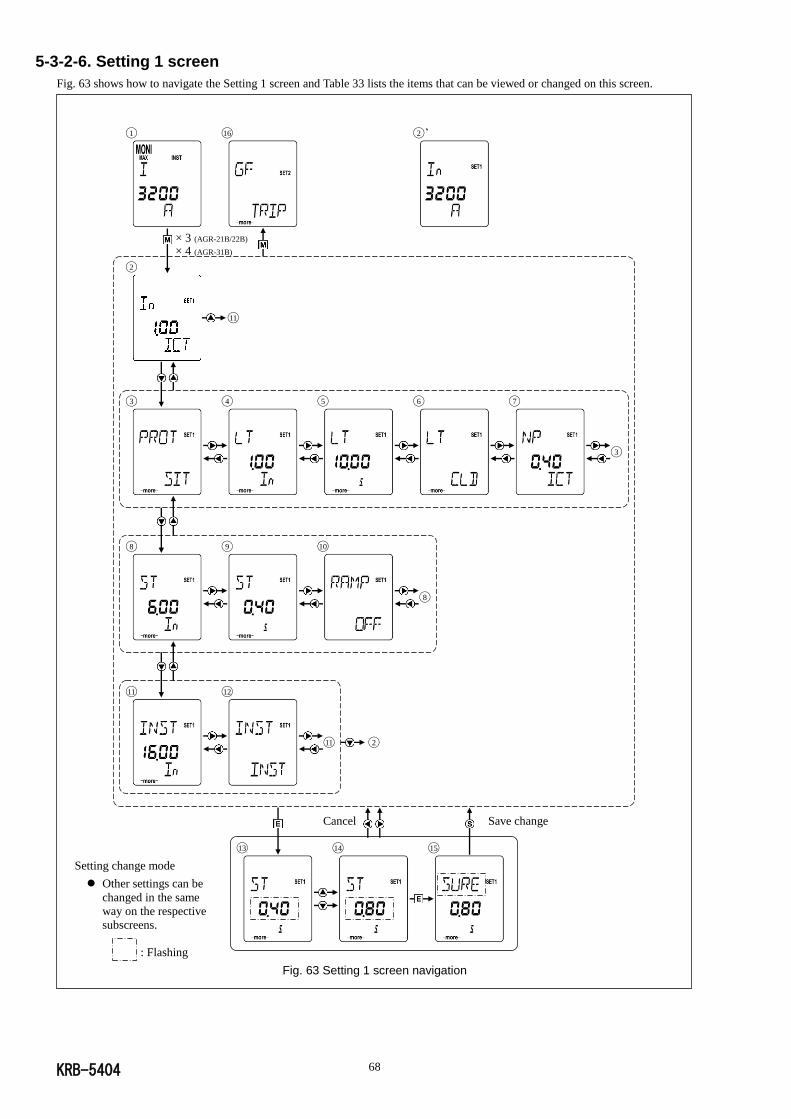
KRB-5404 68
5-3-2-6. Setting 1 screen
Fig. 63 shows how to navigate the Setting 1 screen and Table 33 lists the items that can be viewed or changed on this screen.
Setting change mode
Other settings can be
changed in the same
way on the respective
subscreens.
: Flashing
Fig. 63 Setting 1 screen navigation
◯1 ◯16 ◯2 ’
◯2
◯11
◯3 ◯4 ◯5 ◯6 ◯7
◯3
◯8 ◯9 ◯10
◯8
◯11 ◯12
◯11 ◯2
Cancel Save change
◯13 ◯14 ◯15
× 3 (AGR-21B/22B) × 4 (AGR-31B)
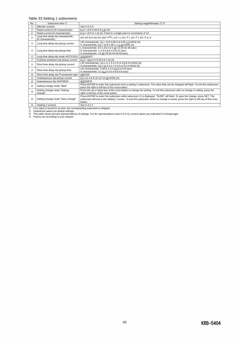
KRB-5404 69
Table 33 Setting 1 subscreens
No. Subscreen item *1 Setting range/Remarks *2 *3
○1 (Monitor screen) See 5-3-2-3.
○2 Rated current (L/R characteristic) [ICT] × (0.5-0.63-0.8-1.0) (A)
○2 ’ Rated current (S characteristic) [ICT] × (0.5 to 1.0) (A): Fixed to a single point in increments of 1A
○3 Long time delay trip characteristic (R characteristic)
SIT-VIT-EIT-3IT-4IT (SIT: I0.02 t, VIT: I t, EIT: I2 t, 3IT: I3 t, 4IT: I4 t) *4
○4 Long time delay trip pickup current L/R characteristic: [In] × (0.8-0.85-0.9-0.95-1.0-NON) (A) S characteristic: [In] × (0.8-1.05-1.1-1.15-NON) (A)
○5 Long time delay trip pickup time L characteristic: 0.5-1.25-2.5-5-10-15-20-25-30 (sec) R characteristic: 1-2-3-4-5-6.3-6.8-10 (sec) S characteristic: 15-20-25-30-40-50-60 (sec)
○6 Long time delay trip mode HOT/COLD COLD/HOT
○7 N-phase protection trip pickup current [ICT] × (0.4-0.5-0.63-0.8-1.0) (A)
○8 Short time delay trip pickup current L/R characteristic: [In] x (1-1.5-2-2.5-3-4-6-8-10-NON) (A) S characteristic: [In] x (2-2.5-2.7-3-3.5-4-4.5-5-NON) (A)
○9 Short time delay trip pickup time L/R characteristic: 0.05-0.1-0.2-0.4-0.6-0.8 (sec) S characteristic: 0.1-0.2-0.3-0.4-0.6-0.8 (sec)
○10 Short time delay trip I2t protection type OFF/ON
○11 Instantaneous trip pickup current [In] x (2-4-6-8-10-12-14-16-NON) (A)
○12 Instantaneous trip INST/MCR INST/MCR
○13 Setting change mode "Start" Press ENTER to enter this subscreen from a setting 1 subscreen. The value that can be changed will flash. To exit this subscreen, press the right or left key of the cross button.
○14 Setting change mode "Setting change"
Press the up or down key of the cross button to change the setting. To exit this subscreen with no change in setting, press the right or left key of the cross button.
○15 Setting change mode "Save change" Press ENTER to enter this subscreen while subscreen ○14 is displayed. "SURE" will flash. To save the change, press SET. The
subscreen will exit to the Setting 2 screen. To exit this subscreen while no change is saved, press the right or left key of the cross button.
○16 (Setting 2 screen) See 5-3-2-7.
*1 If no value is found for an item, the corresponding subscreen is skipped. *2 Underlined values are default settings. *3 This table shows percent representations of settings. For AV representations (see 5-3-2-4), current values are indicated in A (Amperage).
*4 Factory set according to your request.
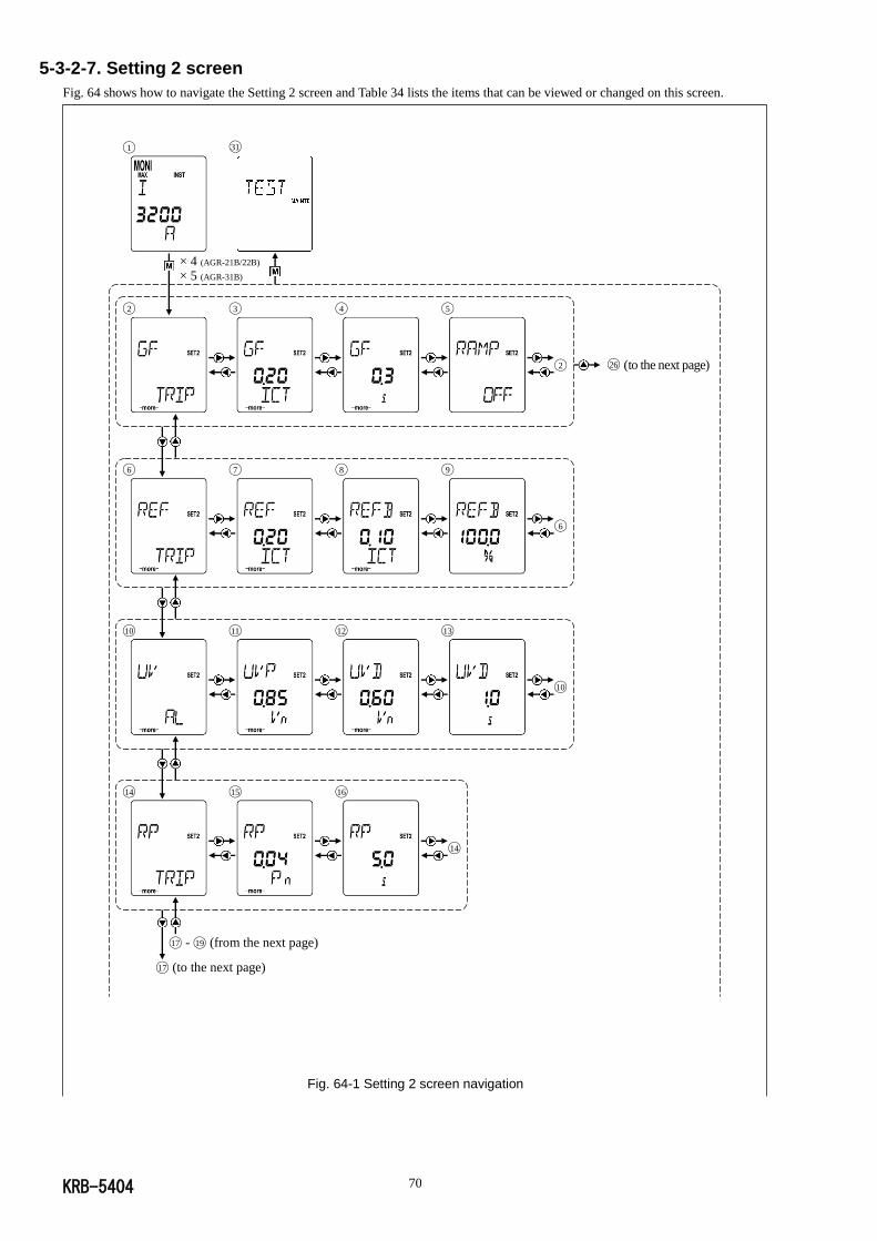
KRB-5404 70
5-3-2-7. Setting 2 screen
Fig. 64 shows how to navigate the Setting 2 screen and Table 34 lists the items that can be viewed or changed on this screen.
Fig. 64-1 Setting 2 screen navigation
◯1 ◯31
◯2 ◯3 ◯4 ◯5
◯2 ◯26 (to the next page)
◯6 ◯7 ◯8 ◯9
◯6
◯10 ◯11 ◯12 ◯13
◯10
◯14 ◯15 ◯16
◯14
◯17 - ◯19 (from the next page)
◯17 (to the next page)
× 4 (AGR-21B/22B) × 5 (AGR-31B)
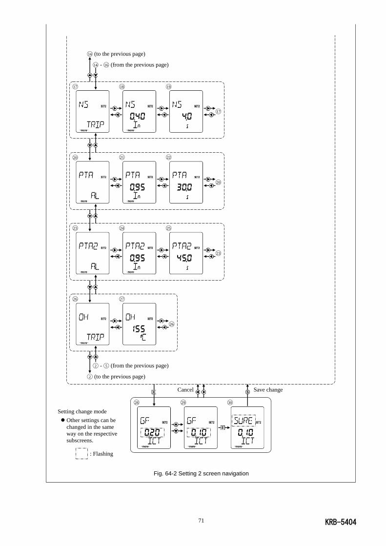
KRB-5404 71
◯14 (to the previous page)
◯14 - ◯16 (from the previous page)
◯17 ◯18 ◯19
◯17
◯20 ◯21 ◯22
◯20
◯23 ◯24 ◯25
◯23
◯26 ◯27
◯26
◯2 - ◯5 (from the previous page)
◯2 (to the previous page)
Cancel Save change
◯28 ◯29 ◯30
Setting change mode
Other settings can be
changed in the same
way on the respective
subscreens.
: Flashing
Fig. 64-2 Setting 2 screen navigation

KRB-5404 72
Table 34 Setting 2 subscreens
No. Subscreen item *1 Setting range/Remarks *2 *3
○1 (Monitor screen) See 5-3-2-3.
○2 Ground fault trip mode TRIP/AL/OFF
○3 Ground fault trip pickup current [ICT] × (0.1-0.2-0.3-0.4-0.6-0.8-1.0-NON) (A)
○4 Ground fault trip pickup time 0.1-0.2-0.3-0.5-1-2 (sec)
○5 Ground fault trip I2t protection type OFF/ON
○6 Line side ground fault protection mode TRIP/AL/OFF
○7 Line side ground fault protection trip pickup current
[ICT] × (0.1-0.2-0.3-0.4-0.6-0.8-1.0-NON) (A)
○8 Line side ground fault protection bias current [ICT] × (0.1-0.3-0.5-0.7-0.9-1.1-1.3-1.5) (A) *4
○9 Line side ground fault protection bias limit 100% (fixed) *4
○10 undervoltage alarm mode AL/OFF
○11 Undervoltage alarm recovery voltage [Vn] × (0.8-0.85-0.9-0.95) (V)
○12 Undervoltage alarm pickup voltage [Vn] × (0.4-0.6-0.8) (V)
○13 Undervoltage alarm pickup time 0.1-0.5-1-2-5-10-15-20-30-36 (sec)
○14 Reverse power trip mode TRIP/AL/OFF
○15 Reverse power trip pickup power [Pn] × (0.04-0.05-0.06-0.07-0.08-0.09-0.1-NON) (kW)
○16 Reverse power trip pickup time 2.5-5-7.5-10-12.5-15-17.5-20 (sec)
○17 Negative-phase sequence protection mode TRIP/AL/OFF
○18 Negative-phase sequence protection trip pickup current
[In] × (0.2-0.3-0.4-0.5-0.6-0.7-0.8-0.9-1.0) (A)
○19 Negative-phase sequence protection trip pickup time
0.4-0.8-1.2-1.6-2-2.4-2.8-3.2-3.6-4 (sec)
○20 Pretrip alarm mode AL/OFF
◯21 Pretrip alarm pickup current L/R characteristic: [In] × (0.75-0.8-0.85-0.9-0.95-1.0) (A) S characteristic: [In] × (0.75-0.8-0.85-0.9-0.95-1.0-1.05) (A)
◯22 Pretrip alarm pickup time L/R characteristic: 5-10-15-20-40-60-80-120-160-200) (sec) S characteristic: 10-15-20-25-30 (sec)
◯23 Pretrip alarm 2 mode AL/OFF
◯24 Pretrip alarm 2 pickup current [In] × (0.75-0.8-0.85-0.9-0.95-1.0-1.05) (A)
◯25 Pretrip alarm 2 pickup time 1.5× tP1 (sec) (determined by auto calculation)
◯26 Contact overheat monitor mode TRIP/AL/OFF
◯27 Contact overheat alarm pickup temperature 155C (fixed)
◯28 Setting change mode "Start" Press ENTER to enter this subscreen from a setting 2 subscreen. The value that can be changed will flash. To exit this subscreen, press the right or left key of the cross button.
◯29 Setting change mode "Setting change" Press the up or down key of the cross button to change the setting. To exit this subscreen with no change in setting, press the right or left key of the cross button.
◯30 Setting change mode "Save change" Press ENTER to enter this subscreen from subscreen ◯29. "SURE" will flash. To save the change, press SET. The
subscreen will exit to the Setting 2 screen. To exit this subscreen while no change is saved, press the right or left key of the cross button.
◯31 (Maintenance screen) See 5-3-2-8 and 5-4.
*1 If no value is found for an item, the corresponding subscreen is skipped.
*2 Underlined values are default settings. *3 This table shows percent representations of settings. For AV representations (see 5-3-2-4), current values are indicated in A (Amperage), V (voltage),or kW (kilowatt). *4 The line side ground fault protection bias current and bias limit are coefficients for strain. Because the line side ground fault protection function performs an arithmetic
operation using the difference between CTs with different characteristics, errors in measured line side ground fault current become significant when a large current flows through the ACB. "Strain" is to increase the line side ground fault trip pickup current with increasing current flowing through the ACB, thus preventing malfunctions caused by such an error. The following shows the relationship between the current flowing through the ACB and the line side ground fault protection trip pickup current under "strained"
conditions:
When ( i + iREFCT ) / 2 IREF2; IREFNOW = IREF When ( i + iREFCT ) / 2 > IREF2; IREFNOW = IREF [ 1 + a { ( i + iREFCT ) / 2 IREF2 - 1 } ] (IREF: Line side ground fault protection trip pickup current, IREF2: Line side ground fault protection bias current, a: Line side ground fault
protection bias limit, i: Max. phase current (present value), iREFCT: Line side ground fault current, IREFNOW: Line side ground fault protection pickup current calculated using strain coefficients)
Ex.: When ( i + iREF ) / 2 = 5 × IREF2 and other settings remain default; IREFNOW = IREF [ 1 + 1 × { 5 × IREF2 / IREF2 - 1 } ] = IREF [ 1 + 1× { 5 - 1 } ] = 5 × IREF
Fig. 65 Relationship between the current flowing through the ACB and the line side
ground fault protection trip pickup current under "strained" conditions
IREF2(◯8 )
IREF
(◯7 )
IREFNO
W
(I+IREFCT)/2
α × IREF/IREF2
(=◯9 ×◯7 /◯8 )
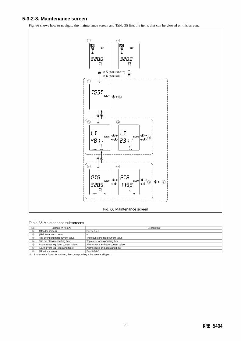
KRB-5404 73
5-3-2-8. Maintenance screen
Fig. 66 shows how to navigate the maintenance screen and Table 35 lists the items that can be viewed on this screen.
Fig. 66 Maintenance screen
Table 35 Maintenance subscreens
No. Subscreen item *1 Description
○1 (Monitor screen) See 5-3-2-3.
○2 (Maintenance screen) –
○3 Trip event log (fault current value) Trip cause and fault current value
○4 Trip event log (operating time) Trip cause and operating time
○5 Alarm event log (fault current value) Alarm cause and fault current value
○6 Alarm event log (operating time) Alarm cause and operating time
○7 (Monitor screen) See 5-3-2-3.
*1 If no value is found for an item, the corresponding subscreen is skipped.
× 5 (AGR-21B/22B) × 6 (AGR-31B)
◯1 ◯7
◯2
◯5
◯3 ◯4
◯3
◯5 ◯6
◯5 ◯2
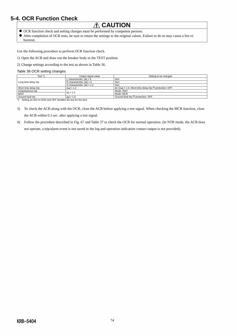
KRB-5404 74
5-4. OCR Function Check
CAUTION OCR function check and setting changes must be performed by competent persons.
After completion of OCR tests, be sure to return the settings to the original values. Failure to do so may cause a fire or
burnout.
Use the following procedure to perform OCR function check.
1) Open the ACB and draw out the breaker body to the TEST position.
2) Change settings according to the test as shown in Table 36.
Table 36 OCR setting changes
Test *1 Output signal value Setting to be changed
Long time delay trip
L characteristic: [IR] × 6 Non
R characteristic: [IR] × 3 Non
S characteristic: [IR] × 1.2 Non
Short time delay trip [Isd] × 1.2 [Ii] >[Isd] × 1.5, Short time delay trip I2t protection: OFF
Instantaneous trip [Ii] × 1.2
Mode: INST
MCR Mode: MCR
Ground fault trip [Ig] × 1.5 Ground fault trip I2t protection: OFF
*1 Setting an item to NON and OFF disables the test for the item.
3) To check the ACB along with the OCR, close the ACB before applying a test signal. When checking the MCR function, close
the ACB within 0.3 sec. after applying a test signal.
4) Follow the procedure described in Fig. 67 and Table 37 to check the OCR for normal operation. (In NTR mode, the ACB does
not operate, a trip/alarm event is not saved in the log and operation indication contact output is not provided).
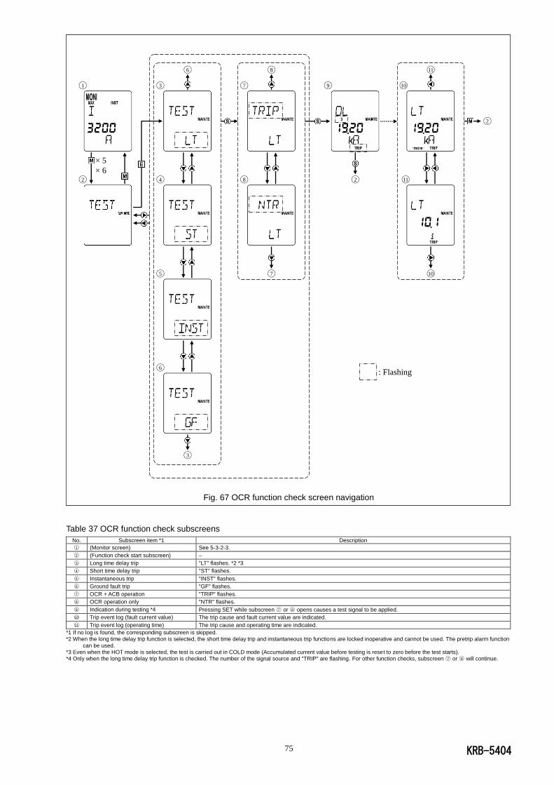
KRB-5404 75
: Flashing
Fig. 67 OCR function check screen navigation
Table 37 OCR function check subscreens
No. Subscreen item *1 Description
○1 (Monitor screen) See 5-3-2-3.
○2 (Function check start subscreen) –
○3 Long time delay trip "LT" flashes. *2 *3
○4 Short time delay trip "ST" flashes.
○5 Instantaneous trip "INST" flashes.
○6 Ground fault trip "GF" flashes.
○7 OCR + ACB operation "TRIP" flashes.
○8 OCR operation only "NTR" flashes.
○9 Indication during testing *4 Pressing SET while subscreen ○7 or ○8 opens causes a test signal to be applied.
○10 Trip event log (fault current value) The trip cause and fault current value are indicated.
○11 Trip event log (operating time) The trip cause and operating time are indicated.
*1 If no log is found, the corresponding subscreen is skipped. *2 When the long time delay trip function is selected, the short time delay trip and instantaneous trip functions are locked inoperative and cannot be used. The pretrip alarm function
can be used. *3 Even when the HOT mode is selected, the test is carried out in COLD mode (Accumulated current value before testing is reset to zero before the test starts). *4 Only when the long time delay trip function is checked. The number of the signal source and "TRIP" are flashing. For other function checks, subscreen ○7 or ○8 will continue.
◯6 ◯8 ◯11 ◯1 ◯3 ◯7 ◯9 ◯10
◯2
× 5
× 6 ◯2 ◯4 ◯8 ◯2 ◯11
◯5 ◯7 ◯10
◯6
◯3
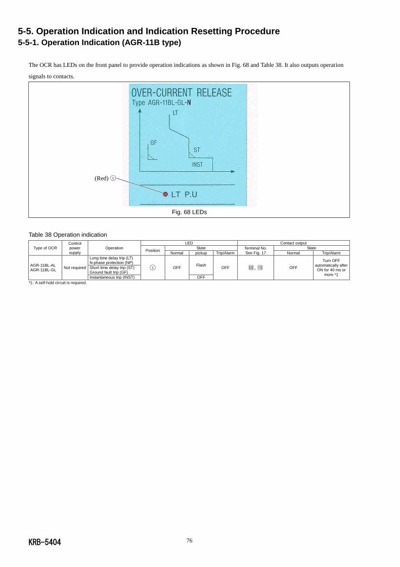
KRB-5404 76
5-5. Operation Indication and Indication Resetting Procedure 5-5-1. Operation Indication (AGR-11B type)
The OCR has LEDs on the front panel to provide operation indications as shown in Fig. 68 and Table 38. It also outputs operation
signals to contacts.
Fig. 68 LEDs
Table 38 Operation indication
Type of OCR Control power supply
Operation
LED Contact output
Position State Terminal No.
See Fig. 17
State
Normal pickup Trip/Alarm Normal Trip/Alarm
AGR-11BL-AL AGR-11BL-GL
Not required
Long time delay trip (LT) N-phase protection (NP)
◯1 OFF Flash
OFF □05 , □15 OFF
Turn OFF automatically after ON for 40 ms or
more *1
Short time delay trip (ST) Ground fault trip (GF)
Instantaneous trip (INST) OFF
*1: A self-hold circuit is required.
(Red) ◯1
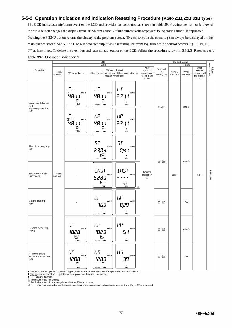
KRB-5404 77
5-5-2. Operation Indication and Indication Resetting Procedure (AGR-21B,22B,31B type)
The OCR indicates a trip/alarm event on the LCD and provides contact output as shown in Table 39. Pressing the right or left key of
the cross button changes the display from "trip/alarm cause" / "fault current/voltage/power" to "operating time" (if applicable).
Pressing the MENU button returns the display to the previous screen. (Events saved in the event log can always be displayed on the
maintenance screen. See 5.3.2.8). To reset contact output while retaining the event log, turn off the control power (Fig. 19 □01 , □11 ,
□21 ) at least 1 sec. To delete the event log and reset contact output on the LCD, follow the procedure shown in 5.3.2.5 "Reset screen".
Table 39-1 Operation indication 1
Operation
LCD Contact output
Con
tro
l p
ow
er
su
pp
ly
State
Terminal No.
See Fig. 19
State
Normal operation
When picked up When activated
(Use the right or left key of the cross button for screen navigation)
After control
power is off for at least
1 sec.
Normal operation
When activated
After control
power is off for at least
1 sec.
Long time delay trip (LT) N-phase protection (NP)
Normal indication
Normal indication
○1
□05 –□15
OFF
ON ○2
OFF
Req
uir
ed
Short time delay trip (ST)
–
□05 –□25 ON ○2
Instantaneous trip (INST/MCR)
–
○3
Ground fault trip (GF)
–
□05 –□16 ON
Reverse power trip (RPT)
□05 –□16 ON ○2
Negative-phase sequence protection (NS)
□05 –□17 ON
The ACB can be opened, closed or tripped, irrespective of whether or not the operation indication is reset. The operation indication is updated when a protective function is activated. means flashing.
○1 The event log is not cleared. ○2 For S characteristic, the delay is as short as 500 ms or more. ○3 "- - - - (kA)" is indicated when the short time delay or instantaneous trip function is activated and [ICT] × 17 is exceeded.
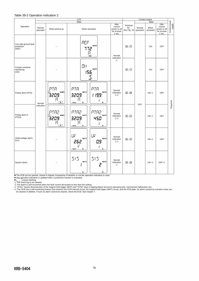
KRB-5404 78
Table 39-2 Operation indication 2
Operation
LCD Contact output
Con
tro
l p
ow
er
su
pp
ly
State
Terminal No.
See Fig. 19
State
Normal operation
When picked up When activated
After control
power is off for at least
1 sec.
Normal operation
When activated
After control
power is off for at least
1 sec.
Line side ground fault protection (REF)
Normal indication
–
Normal indication
○1
□05 –□17
OFF
ON OFF
Req
uir
ed
Contact overheat monitoring (OH)
–
□05 –□17 ON OFF
Pretrip alarm (PTA)
Normal indication
○1 ○2 □05 –□06 ON ○2 OFF
Pretrip alarm 2 (PTA2)
Normal indication
○1 ○2 □05 –□27 ON ○2 OFF
Undervoltage alarm (UV)
–
Normal indication
○1 ○2 □05 –□27 ON ○2 OFF
System alarm –
Normal indication
○1 □05 –□26 ON ○3 OFF ○4
The ACB can be opened, closed or tripped, irrespective of whether or not the operation indication is reset.
The operation indication is updated when a protective function is activated. means flashing ○1 The event log is not cleared.
○2 The alarm is self-recovered when the fault current decreases to less than the setting. ○3 "SYS1" means disconnection of the magnet hold trigger (MHT) and "SYS2" does a tripping failure (incorrect operating time, mechanical malfunction etc). ○4 The OCR has a self-monitoring feature that monitors the OCR internal circuit, the magnet hold tripper (MHT) circuit, and the ACB state. An alarm caused by transient noise can
be cleared or deleted. If such an alarm cannot be cleared, check the ACB. See chapter 7.

KRB-5404 79
6. MAINTENANCE, INSPECTION AND PARTS REPLACEMENT This chapter describes the maintenance and inspection procedure for the AR series ACBs.
The service life of the ACB depends on the working and environmental conditions. The ACB is exposed to mechanical and
electrical stresses and thus suffers gradual degradation during use, which will increase the possibility of malfunctions. Preventive
maintenance and periodical inspection are very important to avoid any functional degradation, prevent malfunctions, extend the
service life, and ensure safe operation.
The appropriate frequency of maintenance and inspection of the ACB varies depending on the installation conditions, the number of
tripping operations, the magnitude of breaking current, and other factors that are to be considered empirically. As a guideline, Table
40 shows the recommended inspection frequency. See section 6-1 for detailed maintenance and inspection procedures.
Table 40 Frequency of maintenance and inspection
Category Working and environmental
conditions Inspection
level
Frequency in interval or number of open/close cycles
Interval Number of open/close cycles
Normal
• Not so dusty, • Not so much corrosive gases,
• Ambient temperature: 35C or lower
• Not so humid, • Number of open/close cycles per day: 2 or less
Ex. Switchboards in electric installation rooms, Control rooms, Building installation
Normal/ Detailed
• Every year or 2 years • Every year after 3 years since installation
• Every half year after 6 years since installation
Open/close condition
800AF or less 1000AF - 2500AF
3200AF or more
Nearly no current level
Every 1000 cycles
Rated current level
Every 1000 cycles
Every 500 cycles
Every 100 cycles
Thorough
• Every 5 or 6 years • Every 4 years after 6 years since installation
• Every year or 2 years after 10 years since installation
Every 4000 cycles
Overhaul When abnormality is found during normal or through inspection
Harsh
• Highly dusty, • Much corrosive gases,
• Ambient temperature: 45C or higher,
• Highly humid, • Number of open/close cycles per day: 4 or more,
• Always exposed to vibrations Ex. Iron or chemical plants
Engine rooms (without ventilation), Cogeneration installation, Ferryboats
Normal/ Detailed
• Every year • Every half year after 2 years since installation
Open/close condition
800AF or less 1000AF - 2500AF
3200AF or more
Nearly no current level
• Every 1000 cycles • Every 500 cycles after 1000 cycles
Rated current level
• Every 1000 cycles
• Every 500 cycles after 1000 cycles
• Every 500 cycles
• Every 250 cycles after 500 cycles
• Every 100 cycles
• Every 50 cycles after 100 cycles
Thorough
• Every 2 or 3 years • Every 2 years after 6 years since installation
• Every year after 10 years since installation
• Every 2500 - 3000 cycles • Every 2000 cycles after 3000 cycles
Overhaul When abnormality is found during normal or through inspection
Abnormal
• Open/close operation due to overload,
• Tripping due to shortcircuit, • Accidentally submerged
Thorough When abnormality occurs
Open/close condition
800AF or less 1000AF - 2500AF
3200AF or more
Overcurrent level (approx. 6 times the rated current)
Every 25 cycles
Every 25 cycles
Every 25 cycles
Level exceeding overcurrent level
Every time Every time Every time
Overhaul When ACB is deemed to be repairable at through inspection
Normal inspection includes inspection and actions that can be done only with removing the arc chamber, contacts, front cover and
the like. Normal inspection can be performed by the user. Terasaki also provides normal inspection service.
Detailed inspection includes inspection, actions, and parts replacement that will be done to prevent functional degradation caused by
aging or the like when abnormality is found during normal inspection.
You are recommended to use Terasaki’s detailed inspection service.
Thorough inspection must be left to Terasaki. Overhaul will be done in a Terasaki’s factory.
About the service life
The expected service life of AR series ACBs is shown in the "Endurance in number of ON-OFF cycles" rows in Tables 3 and 4.
"With maintenance" in the tables means that appropriate inspection, maintenance, repair, and parts replacement are performed
according to the instructions in this chapter. But, when an ACB performs three times of tripping operation nearly at the rated
breaking current (three standard operating duty cycles), it is at the end of its safe service life even if thorough inspection is done
every time it trips open. Such an ACB will be apt to suffer malfunctions and should be replaced without delay to avoid frequent
inspection and parts replacement. See section 6-2 for detailed parts replacement procedures.
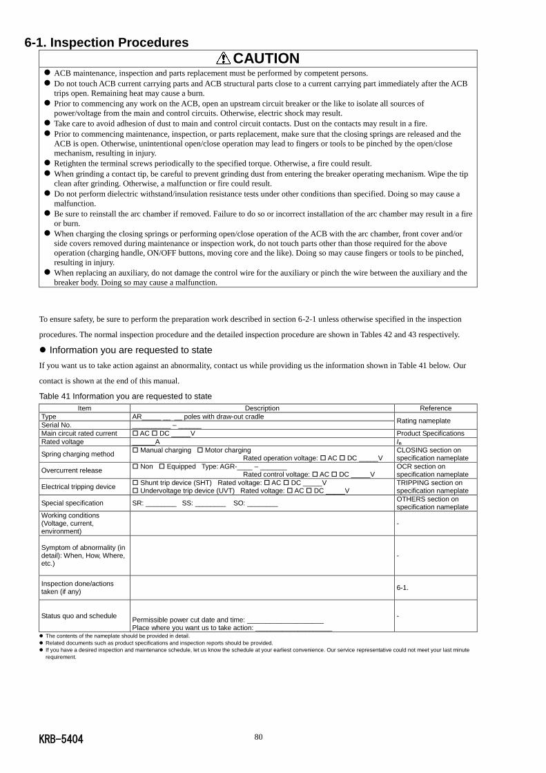
KRB-5404 80
6-1. Inspection Procedures
CAUTION
ACB maintenance, inspection and parts replacement must be performed by competent persons.
Do not touch ACB current carrying parts and ACB structural parts close to a current carrying part immediately after the ACB
trips open. Remaining heat may cause a burn.
Prior to commencing any work on the ACB, open an upstream circuit breaker or the like to isolate all sources of
power/voltage from the main and control circuits. Otherwise, electric shock may result.
Take care to avoid adhesion of dust to main and control circuit contacts. Dust on the contacts may result in a fire.
Prior to commencing maintenance, inspection, or parts replacement, make sure that the closing springs are released and the
ACB is open. Otherwise, unintentional open/close operation may lead to fingers or tools to be pinched by the open/close
mechanism, resulting in injury.
Retighten the terminal screws periodically to the specified torque. Otherwise, a fire could result.
When grinding a contact tip, be careful to prevent grinding dust from entering the breaker operating mechanism. Wipe the tip
clean after grinding. Otherwise, a malfunction or fire could result.
Do not perform dielectric withstand/insulation resistance tests under other conditions than specified. Doing so may cause a
malfunction.
Be sure to reinstall the arc chamber if removed. Failure to do so or incorrect installation of the arc chamber may result in a fire
or burn.
When charging the closing springs or performing open/close operation of the ACB with the arc chamber, front cover and/or
side covers removed during maintenance or inspection work, do not touch parts other than those required for the above
operation (charging handle, ON/OFF buttons, moving core and the like). Doing so may cause fingers or tools to be pinched,
resulting in injury.
When replacing an auxiliary, do not damage the control wire for the auxiliary or pinch the wire between the auxiliary and the
breaker body. Doing so may cause a malfunction.
To ensure safety, be sure to perform the preparation work described in section 6-2-1 unless otherwise specified in the inspection
procedures. The normal inspection procedure and the detailed inspection procedure are shown in Tables 42 and 43 respectively.
Information you are requested to state
If you want us to take action against an abnormality, contact us while providing us the information shown in Table 41 below. Our
contact is shown at the end of this manual.
Table 41 Information you are requested to state
Item Description Reference
Type AR_____ __ __ poles with draw-out cradle Rating nameplate
Serial No. __________ – ______
Main circuit rated current AC DC _____V Product Specifications
Rated voltage ______A In
Spring charging method Manual charging Motor charging Rated operation voltage: AC DC _____V
CLOSING section on specification nameplate
Overcurrent release Non Equipped Type: AGR-____ – _______ Rated control voltage: AC DC _____V
OCR section on specification nameplate
Electrical tripping device Shunt trip device (SHT) Rated voltage: AC DC _____V Undervoltage trip device (UVT) Rated voltage: AC DC _____V
TRIPPING section on specification nameplate
Special specification SR: ________ SS: ________ SO: ________ OTHERS section on specification nameplate
Working conditions (Voltage, current, environment)
-
Symptom of abnormality (in detail): When, How, Where, etc.)
-
Inspection done/actions taken (if any)
6-1.
Status quo and schedule
Permissible power cut date and time: ____________________ Place where you want us to take action: ____________________
-
The contents of the nameplate should be provided in detail.
Related documents such as product specifications and inspection reports should be provided.
If you have a desired inspection and maintenance schedule, let us know the schedule at your earliest convenience. Our service representative could not meet your last minute
requirement.
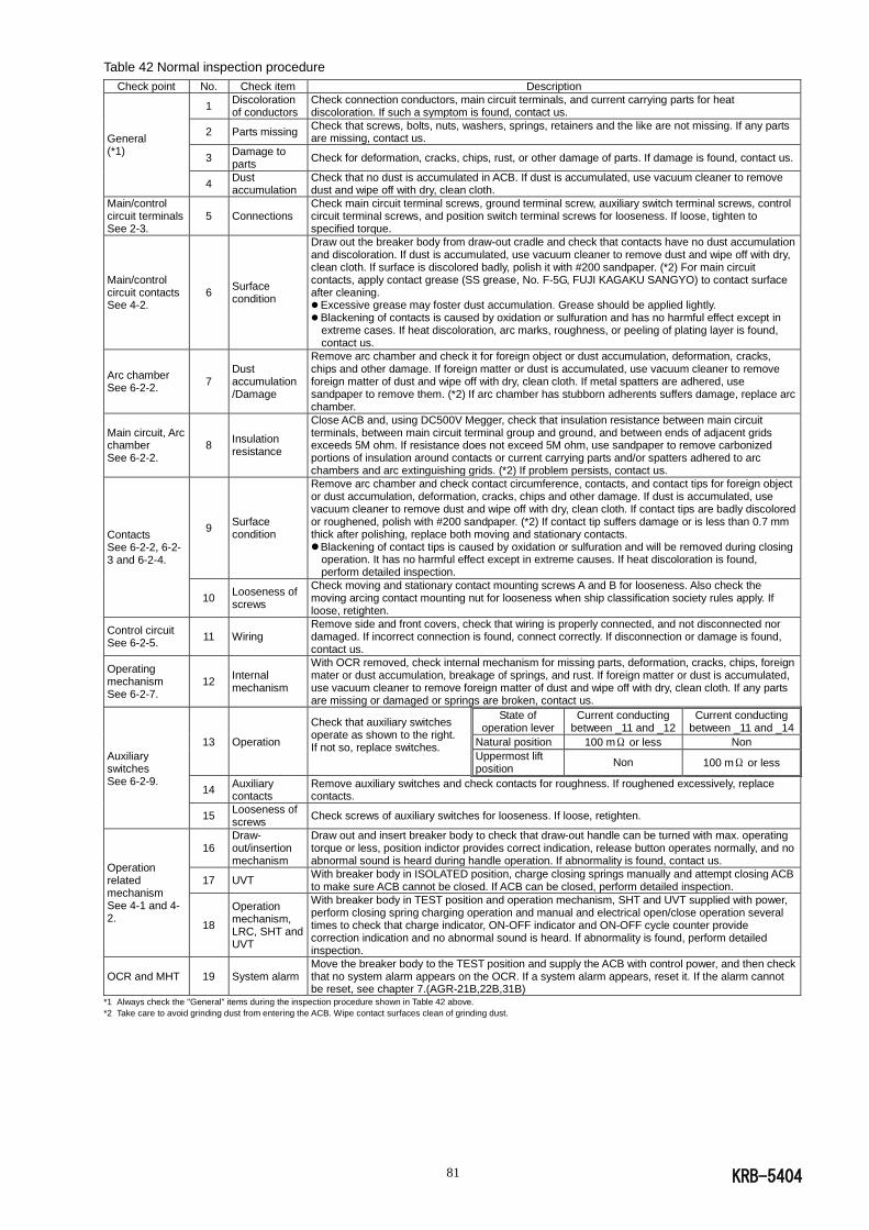
KRB-5404 81
Table 42 Normal inspection procedure
Check point No. Check item Description
General (*1)
1 Discoloration of conductors
Check connection conductors, main circuit terminals, and current carrying parts for heat discoloration. If such a symptom is found, contact us.
2 Parts missing Check that screws, bolts, nuts, washers, springs, retainers and the like are not missing. If any parts are missing, contact us.
3 Damage to parts
Check for deformation, cracks, chips, rust, or other damage of parts. If damage is found, contact us.
4 Dust accumulation
Check that no dust is accumulated in ACB. If dust is accumulated, use vacuum cleaner to remove dust and wipe off with dry, clean cloth.
Main/control circuit terminals See 2-3.
5 Connections Check main circuit terminal screws, ground terminal screw, auxiliary switch terminal screws, control circuit terminal screws, and position switch terminal screws for looseness. If loose, tighten to specified torque.
Main/control circuit contacts See 4-2.
6 Surface condition
Draw out the breaker body from draw-out cradle and check that contacts have no dust accumulation and discoloration. If dust is accumulated, use vacuum cleaner to remove dust and wipe off with dry, clean cloth. If surface is discolored badly, polish it with #200 sandpaper. (*2) For main circuit contacts, apply contact grease (SS grease, No. F-5G, FUJI KAGAKU SANGYO) to contact surface after cleaning. Excessive grease may foster dust accumulation. Grease should be applied lightly. Blackening of contacts is caused by oxidation or sulfuration and has no harmful effect except in
extreme cases. If heat discoloration, arc marks, roughness, or peeling of plating layer is found, contact us.
Arc chamber See 6-2-2.
7 Dust accumulation /Damage
Remove arc chamber and check it for foreign object or dust accumulation, deformation, cracks, chips and other damage. If foreign matter or dust is accumulated, use vacuum cleaner to remove foreign matter of dust and wipe off with dry, clean cloth. If metal spatters are adhered, use sandpaper to remove them. (*2) If arc chamber has stubborn adherents suffers damage, replace arc chamber.
Main circuit, Arc chamber See 6-2-2.
8 Insulation resistance
Close ACB and, using DC500V Megger, check that insulation resistance between main circuit terminals, between main circuit terminal group and ground, and between ends of adjacent grids exceeds 5M ohm. If resistance does not exceed 5M ohm, use sandpaper to remove carbonized portions of insulation around contacts or current carrying parts and/or spatters adhered to arc chambers and arc extinguishing grids. (*2) If problem persists, contact us.
Contacts See 6-2-2, 6-2-3 and 6-2-4.
9 Surface condition
Remove arc chamber and check contact circumference, contacts, and contact tips for foreign object or dust accumulation, deformation, cracks, chips and other damage. If dust is accumulated, use vacuum cleaner to remove dust and wipe off with dry, clean cloth. If contact tips are badly discolored or roughened, polish with #200 sandpaper. (*2) If contact tip suffers damage or is less than 0.7 mm thick after polishing, replace both moving and stationary contacts. Blackening of contact tips is caused by oxidation or sulfuration and will be removed during closing
operation. It has no harmful effect except in extreme causes. If heat discoloration is found, perform detailed inspection.
10 Looseness of screws
Check moving and stationary contact mounting screws A and B for looseness. Also check the moving arcing contact mounting nut for looseness when ship classification society rules apply. If loose, retighten.
Control circuit See 6-2-5.
11 Wiring Remove side and front covers, check that wiring is properly connected, and not disconnected nor damaged. If incorrect connection is found, connect correctly. If disconnection or damage is found, contact us.
Operating mechanism See 6-2-7.
12 Internal mechanism
With OCR removed, check internal mechanism for missing parts, deformation, cracks, chips, foreign mater or dust accumulation, breakage of springs, and rust. If foreign matter or dust is accumulated, use vacuum cleaner to remove foreign matter of dust and wipe off with dry, clean cloth. If any parts are missing or damaged or springs are broken, contact us.
Auxiliary switches See 6-2-9.
13 Operation
Check that auxiliary switches operate as shown to the right. If not so, replace switches.
State of operation lever
Current conducting between _11 and _12
Current conducting between _11 and _14
Natural position 100 mΩ or less Non
Uppermost lift position
Non 100 mΩ or less
14 Auxiliary contacts
Remove auxiliary switches and check contacts for roughness. If roughened excessively, replace contacts.
15 Looseness of screws
Check screws of auxiliary switches for looseness. If loose, retighten.
Operation related mechanism See 4-1 and 4-2.
16 Draw-out/insertion mechanism
Draw out and insert breaker body to check that draw-out handle can be turned with max. operating torque or less, position indictor provides correct indication, release button operates normally, and no abnormal sound is heard during handle operation. If abnormality is found, contact us.
17 UVT With breaker body in ISOLATED position, charge closing springs manually and attempt closing ACB to make sure ACB cannot be closed. If ACB can be closed, perform detailed inspection.
18
Operation mechanism, LRC, SHT and UVT
With breaker body in TEST position and operation mechanism, SHT and UVT supplied with power, perform closing spring charging operation and manual and electrical open/close operation several times to check that charge indicator, ON-OFF indicator and ON-OFF cycle counter provide correction indication and no abnormal sound is heard. If abnormality is found, perform detailed inspection.
OCR and MHT 19 System alarm Move the breaker body to the TEST position and supply the ACB with control power, and then check that no system alarm appears on the OCR. If a system alarm appears, reset it. If the alarm cannot be reset, see chapter 7.(AGR-21B,22B,31B)
*1 Always check the "General" items during the inspection procedure shown in Table 42 above.
*2 Take care to avoid grinding dust from entering the ACB. Wipe contact surfaces clean of grinding dust.

KRB-5404 82
Table 43 Detailed inspection procedure
Check point No. Check item Description
Undervoltage trip device (UVT) See 6-2-1.
1 Coil resistance Disconnect hand connector (red) and, using tester, measure coil resistance between terminals and make sure holding coil is rated at 410 - 510 and attraction coil at 5.6 - 6.8. (*) If not so, replace UVT.
2 Operation Remove UVT and press in plunger, and make sure releasing plunger causes plunger to be smoothly restored. If not so, replace UVT.
3 Length and stroke of plunger
Remove UVT and, using vernier caliper, make sure plunger length is 32.5 - 33.5mm in natural state and plunger stroke is 6.5 - 7.5 mm. If not so, replace UVT.
4 Hand connector
Check that hand connector (red) is connected to ACB hand connector (red) correctly. If incorrect , connect correctly.
5 Looseness of screws
Check UVT mounting screws for looseness. If loose, retighten.
Contacts See 6-2-2, 6-2-3 and 6-2-4
6 Parting distance
With ACB open, remove arc chamber and, using compass and vernier caliper, make sure distance between moving and stationary contact tips falls within the following ranges. If not so, replace both moving and stationary contacts. If it is useless to replace contacts, contact us.
Distances between moving and stationary contact tips(mm)
Types
Line side Load side
phase A-C phase N phase A-C phase N AR208S, AR212S, AR216S, AR220S, AR325S, AR332S, AR440S(3P),
AR440SB(3P), AR208D, AR212D, AR216D 17-20.5 16-20 17-20.5 16-20
AR440S(4P), AR440SB(4P) 17-21.5 17-21.5 17-21.5 17-21.5
AR212H, AR216H, AR220H, AR316H, AR320H, AR325H, AR332H, AR420H,
AR440H 17-20.5 16-20 16-20 16-20
7 Engagement
Insert 3.5 - 4.0-mm-dia x 50-mm-length rod into engagement measuring hole vertically until it stops, and measure protrusion of rod when ACB is open and closed. Make sure difference in protrusion is following: line side; 2.7-3.4mm, load side; 2.7-4.0mm. (The difference of the value of line side and load side must not exceed 1.0mm.) If not so, replace both moving and stationary contacts. If it is useless to replace contacts, contact us.
Current sensors See 6-2-3.
8 Looseness of screws
Check current sensor mounting screws for looseness. If loose, retighten.
Latch release coil (LRC) See 6-2-5.
9 Coil resistance Disconnect hand connector (green) that is closer to coil than the other and, using tester, measure coil resistance between terminals and make sure it is within range specified in Table 11. (*) If not so, replace LRC.
10 Length and stroke of plunger
Remove LRC and, using vernier caliper, make sure plunger length is 24.2 - 24.8 mm in natural state and protrusion of plunger is 6.3 - 7 mm when moving core is pushed in. If not so, replace LRC.
11 Hand connector
Check that hand connector (green) is connected to ACB hand connector (green) correctly. If incorrect, connect correctly.
12 Looseness of screws
Check LRC mounting screws for looseness. If loose, retighten.
13 Mechanical motion
With closing springs charged, check that pushing moving core results in ACB being closed slowly, and releasing moving core results in the core being restored smoothly. If not so, replace LRC. If it is useless to replace LRC, contact us. After inspection, open ACB and discharge closing springs.
Shunt trip device (SHT) See 6-2-6.
14 Coil resistance Disconnect hand connector (black) that is closer to coil than the other and, using tester, measure coil resistance between terminals and make sure it is within range specified in Table 12. (*) If not so, replace SHT.
15 Length and stroke of plunger
Remove SHT and, using vernier caliper, make sure plunger length is 24.2 - 24.8 mm in natural state and protrusion of plunger is 6.3 - 7 mm when moving core is pushed in. If not so, replace SHT.
16 Hand connector
Check that hand connector (black) is connected to ACB hand connector (black) correctly. If incorrect, connect correctly.
17 Looseness of screws
Check SHT mounting screws for looseness. If loose, retighten.
18 Mechanical motion
With ACB closed, check that pushing moving core results in ACB being opened slowly, and releasing moving core results in the core being restored smoothly. If not so, replace SHT. If it is useless to replace SHT, contact us. After inspection, discharge closing springs.
Magnet hold trigger (MHT) See 6-2-8.
19 Coil resistance Disconnect hand connector (red) and, using tester, measure coil resistance between terminals and make sure it is 1.8 - 2.2 . (*) If not so, replace MHT.
20 Operation Remove MHT and pull out moving core slowly, and make sure pushing moving core allows core to be smoothly retracted and attracted If not so, replace MHT.
21 Length and stroke of moving core
Remove MHT and, using vernier caliper, make sure protrusion of moving core is 6.7 - 7.3mm in pulled-out state. If not so, replace MHT.
22 Hand connector
Check that hand connector (red) is connected to ACB hand connector (red) correctly. If incorrect , connect correctly.
23 Looseness of screws
Check MHT mounting screws for looseness. If loose, retighten.
Charging motor and LRC
24 Electrical operation
With breaker body assembled to original state, move breaker body to TEST position, supply ACB with operation power, and attempt to perform motor charging and electrical closing operation with max. and min. voltages within permissible charging/closing voltage range to make sure ACB operates normally. (See Table 11). If ACB does not operate normally, contact us.
SHT 25 Electrical operation
With breaker body assembled to original state, move breaker body to TEST position, close ACB, supply SHT with power, and attempt to perform electrical opening operation with max. and min. voltages within permissible closing voltage range to make sure ACB trips open normally. (See Table 12). If ACB does not trip open, contact us.
UVT 26 Electrical operation
With breaker body assembled to original state, move breaker body to TEST position, charge closing springs, and make sure that ACB closes when UVT is supplied with attraction power. And decrease UVT supply voltage to make sure ACB opening voltage is within specified opening voltage range. (See Table 13.) If ACB does not operate normally, contact us.
OCR and MHT 27 Operation
With breaker body assembled to original state, check OCR and MHT with type ANU-1 OCR checker (optional) to make sure ACB operates normally. If ACB does not operate normally, contact us.(AGR-11B) With the breaker body assembled to the original state, perform the “OCR + ACB” test described in 5-5-2 to make sure ACB operates normally. If ACB does not operate normally, contact us.(AGR-21B,22B,31B)
Always check the "General" items in Table 42 during the inspection procedure shown in Table 43 above.
* Take care to avoid damaging or deforming terminal pins when bringing tester lead into contact with them.

KRB-5404 83
6-2. Parts Replacement Procedure
CAUTION
ACB maintenance, inspection and parts replacement must be performed by competent persons.
Do not touch ACB current carrying parts and ACB structural parts close to a current carrying part immediately after the ACB
trips open. Remaining heat may cause a burn.
Prior to commencing any work on the ACB, open an upstream circuit breaker or the like to isolate all sources of
power/voltage from the main and control circuits. Otherwise, electric shock may result.
Take care to avoid adhesion of dust to main and control circuit contacts. Dust on the contacts may result in a fire.
Prior to commencing maintenance, inspection, or parts replacement, make sure that the closing springs are released and the
ACB is open. Otherwise, unintentional open/close operation may lead to fingers or tools to be pinched by the open/close
mechanism, resulting in injury.
Be sure to reinstall the arc chamber if removed. Failure to do so or incorrect installation of the arc chamber may result in a fire
or burn.
When replacing an auxiliary, do not damage the control wire for the auxiliary or pinch the wire between the auxiliary and the
breaker body. Doing so may cause a malfunction.
6-2-1. Preparation
Be sure to make the following preparations for parts replacement in order to ensure safety.
1) Open an upstream circuit breaker or the like to isolate all sources of power/voltage from the main and control circuits.
2) Draw out the breaker body to the removed position, and remove it using an optional lifter or lifting plate. Refer to sections 4-2-2
and 2-1-2.
3) Discharge the closing springs and open the ACB. The procedure varies depending on whether or not the ACB is equipped with
the undervoltage trip device (UVT).
When the ACB is not equipped with the undervoltage trip device (UVT):
Perform manual closing/opening operation of the ACB. Refer to sections 4-1-2 and 4-1-3.
When the ACB is equipped with the undervoltage trip device (UVT):
(1) Turn the cover mounting screws five or six turns to loosen as shown in Fig. 69. If the ACB is equipped with side covers, first
remove the side covers and then loosen the front cover mounting screws. (The cover mounting screws are of captive type and
cannot be removed from the side and front covers.)
Location of cover mounting screws
AR2 series ACB AR2 series ACB AR3/4 series
with 3 poles with 4 poles
Fig. 69 Cover mounting screws
Front cover
Side covers
Cover mounting
screws
Cover mounting screw (captive),
Pan head M5 × 20 (4 - 8)
with spring and flat washers
Tightening torque: 2.7 - 3.5 N·m
Front cover
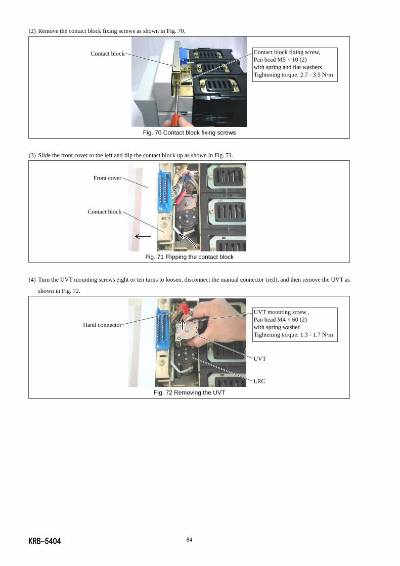
KRB-5404 84
(2) Remove the contact block fixing screws as shown in Fig. 70.
Fig. 70 Contact block fixing screws
(3) Slide the front cover to the left and flip the contact block up as shown in Fig. 71.
Fig. 71 Flipping the contact block
(4) Turn the UVT mounting screws eight or ten turns to loosen, disconnect the manual connector (red), and then remove the UVT as
shown in Fig. 72.
Fig. 72 Removing the UVT
Contact block Contact block fixing screw,
Pan head M5 × 10 (2)
with spring and flat washers
Tightening torque: 2.7 - 3.5 N·m
Front cover
Contact block
UVT mounting screw ,
Pan head M4 × 60 (2)
with spring washer
Tightening torque: 1.3 - 1.7 N·m
Hand connector
UVT
LRC
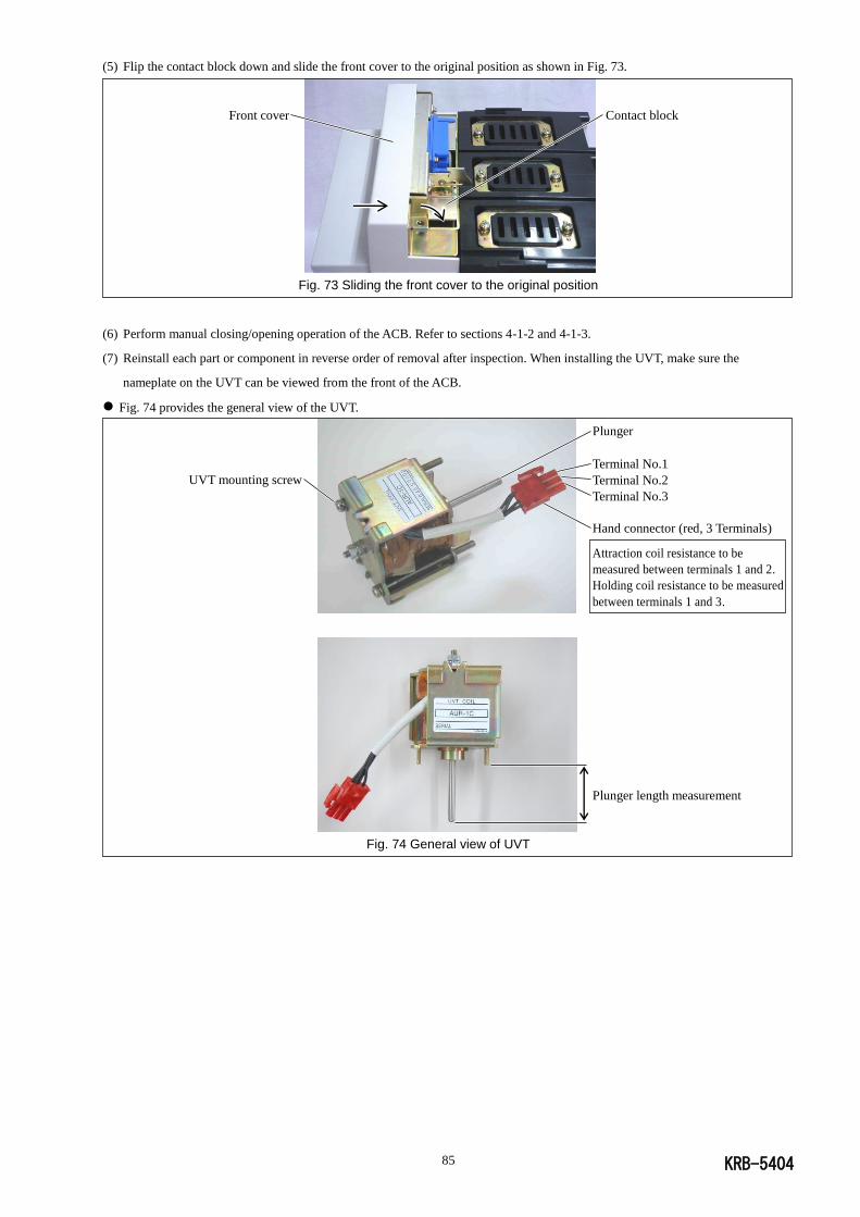
KRB-5404 85
(5) Flip the contact block down and slide the front cover to the original position as shown in Fig. 73.
Fig. 73 Sliding the front cover to the original position
(6) Perform manual closing/opening operation of the ACB. Refer to sections 4-1-2 and 4-1-3.
(7) Reinstall each part or component in reverse order of removal after inspection. When installing the UVT, make sure the
nameplate on the UVT can be viewed from the front of the ACB.
Fig. 74 provides the general view of the UVT.
Fig. 74 General view of UVT
Contact block Front cover
Plunger
Terminal No.1
Terminal No.2
Terminal No.3
Hand connector (red, 3 Terminals) Attraction coil resistance to be
measured between terminals 1 and 2.
Holding coil resistance to be measured
between terminals 1 and 3.
Plunger length measurement
UVT mounting screw

KRB-5404 86
6-2-2. Arc chambers
The following describes how to replace arc chambers.
1) Make preparations for parts replacement. Refer to section 6-2-1.
2) Carefully lay the breaker body on spacers with the backside down as shown in Fig. 75. The spacers must be at least 7-cm high to
prevent deformation of protrusions on the breaker body backside, and have the size and strength that allow the breaker body to
be safely laid on them. Take care to keep the main circuit contacts clean of dust.
Fig. 75 Laying the breaker body on spacers
3) Turn the arc chamber mounting screw eight or ten turns to loosen as shown in Fig. 76. (The arc chamber mounting screws are of
captive type and cannot be removed from the arc chamber.)
Arc chambers (at the top) Arc chambers (at the bottom)
Fig. 76 Arc chamber mounting screws
4) Holding the arc chamber mounting screw, remove the arc chamber.
5) Reinstall each part or component in reverse order of removal after inspection.
Fig. 77 shows a removed arc chamber.
Fig. 77 Arc chamber
Spacer
7 cm or higher
Breaker body
Arc chambers (6 - 8)
Arc chamber mounting screw
(captive),
Pan head M6 (12 - 32)
with spring and flat washers
Tightening torque: 4.7 - 5.9 N·m
Arc extinguishing grids
Arc chamber mounting screw
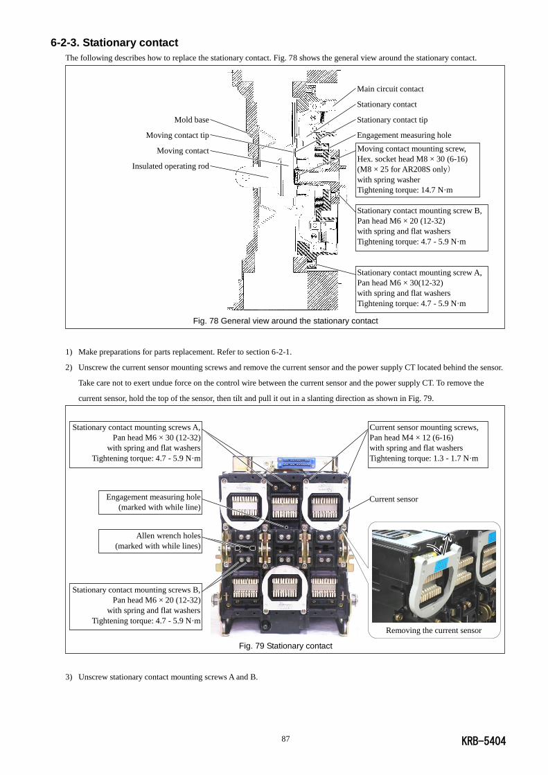
KRB-5404 87
6-2-3. Stationary contact
The following describes how to replace the stationary contact. Fig. 78 shows the general view around the stationary contact.
Fig. 78 General view around the stationary contact
1) Make preparations for parts replacement. Refer to section 6-2-1.
2) Unscrew the current sensor mounting screws and remove the current sensor and the power supply CT located behind the sensor.
Take care not to exert undue force on the control wire between the current sensor and the power supply CT. To remove the
current sensor, hold the top of the sensor, then tilt and pull it out in a slanting direction as shown in Fig. 79.
Fig. 79 Stationary contact
3) Unscrew stationary contact mounting screws A and B.
Mold base
Moving contact tip
Moving contact
Insulated operating rod
Moving contact mounting screw,
Hex. socket head M8 × 30 (6-16)
(M8 × 25 for AR208S only)
with spring washer
Tightening torque: 14.7 N·m
Stationary contact mounting screw A,
Pan head M6 × 30(12-32)
with spring and flat washers
Tightening torque: 4.7 - 5.9 N·m
Stationary contact mounting screw B,
Pan head M6 × 20 (12-32)
with spring and flat washers
Tightening torque: 4.7 - 5.9 N·m
Main circuit contact
Stationary contact
Stationary contact tip
Engagement measuring hole
Current sensor mounting screws,
Pan head M4 × 12 (6-16)
with spring and flat washers
Tightening torque: 1.3 - 1.7 N·m
Stationary contact mounting screws A,
Pan head M6 × 30 (12-32)
with spring and flat washers
Tightening torque: 4.7 - 5.9 N·m
Stationary contact mounting screws B,
Pan head M6 × 20 (12-32)
with spring and flat washers
Tightening torque: 4.7 - 5.9 N·m
Allen wrench holes
(marked with while lines)
Engagement measuring hole
(marked with while line) Current sensor
Removing the current sensor
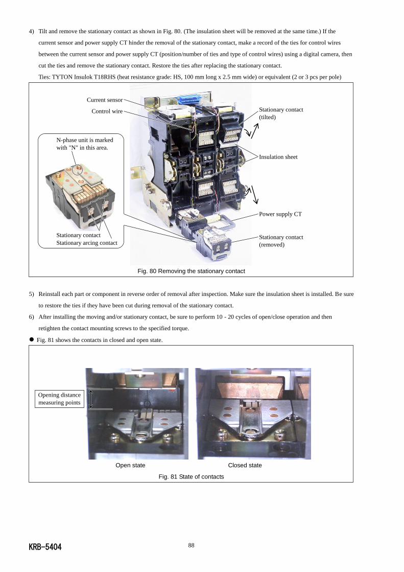
KRB-5404 88
4) Tilt and remove the stationary contact as shown in Fig. 80. (The insulation sheet will be removed at the same time.) If the
current sensor and power supply CT hinder the removal of the stationary contact, make a record of the ties for control wires
between the current sensor and power supply CT (position/number of ties and type of control wires) using a digital camera, then
cut the ties and remove the stationary contact. Restore the ties after replacing the stationary contact.
Ties: TYTON Insulok T18RHS (heat resistance grade: HS, 100 mm long x 2.5 mm wide) or equivalent (2 or 3 pcs per pole)
Fig. 80 Removing the stationary contact
5) Reinstall each part or component in reverse order of removal after inspection. Make sure the insulation sheet is installed. Be sure
to restore the ties if they have been cut during removal of the stationary contact.
6) After installing the moving and/or stationary contact, be sure to perform 10 - 20 cycles of open/close operation and then
retighten the contact mounting screws to the specified torque.
Fig. 81 shows the contacts in closed and open state.
Open state Closed state
Fig. 81 State of contacts
Opening distance
measuring points
Current sensor
Control wire
N-phase unit is marked
with "N" in this area.
Stationary contact
Stationary arcing contact
Stationary contact (tilted)
Insulation sheet
Power supply CT
Stationary contact (removed)
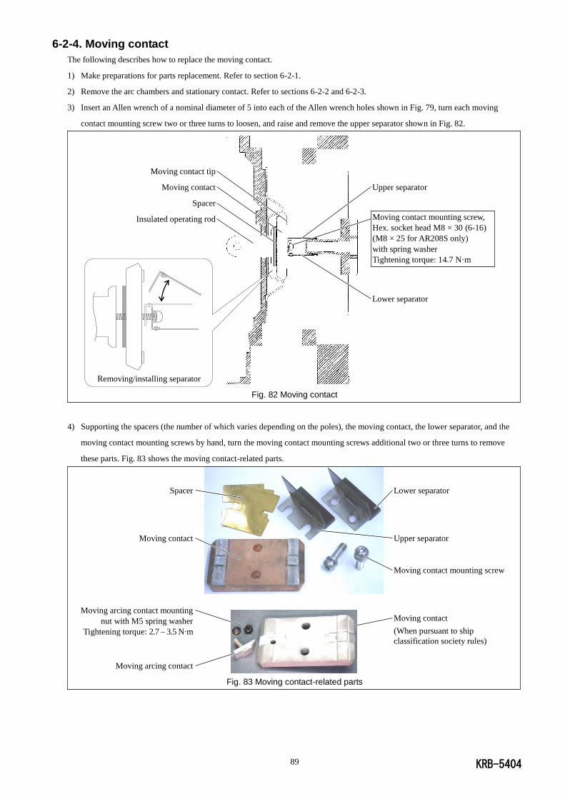
KRB-5404 89
6-2-4. Moving contact
The following describes how to replace the moving contact.
1) Make preparations for parts replacement. Refer to section 6-2-1.
2) Remove the arc chambers and stationary contact. Refer to sections 6-2-2 and 6-2-3.
3) Insert an Allen wrench of a nominal diameter of 5 into each of the Allen wrench holes shown in Fig. 79, turn each moving
contact mounting screw two or three turns to loosen, and raise and remove the upper separator shown in Fig. 82.
Removing/installing separator
Fig. 82 Moving contact
4) Supporting the spacers (the number of which varies depending on the poles), the moving contact, the lower separator, and the
moving contact mounting screws by hand, turn the moving contact mounting screws additional two or three turns to remove
these parts. Fig. 83 shows the moving contact-related parts.
Fig. 83 Moving contact-related parts
Moving contact mounting screw,
Hex. socket head M8 × 30 (6-16)
(M8 × 25 for AR208S only)
with spring washer
Tightening torque: 14.7 N·m
Moving contact tip
Moving contact
Spacer
Insulated operating rod
Upper separator
Lower separator
Lower separator
Upper separator
Moving contact mounting screw
Moving contact
(When pursuant to ship
classification society rules)
Spacer
Moving contact
Moving arcing contact mounting
nut with M5 spring washer
Tightening torque: 2.7 – 3.5 N·m
Moving arcing contact

KRB-5404 90
5) Reinstall each part or component in reverse order of removal after inspection. As to the moving contact-related parts, however,
install the spacer, moving contact, upper separator, lower separator, spring washer and moving contact mounting screw in this
order, beginning wit the side of insulated operation rod. See Fig. 82.
6) After installing the moving and/or stationary contact, be sure to perform 10 - 20 cycles of open/close operation and then
retighten the contact mounting screws to the specified torque.
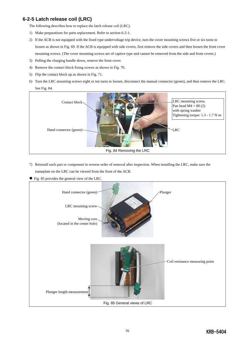
KRB-5404 91
6-2-5 Latch release coil (LRC)
The following describes how to replace the latch release coil (LRC).
1) Make preparations for parts replacement. Refer to section 6-2-1.
2) If the ACB is not equipped with the fixed type undervoltage trip device, turn the cover mounting screws five or six turns to
loosen as shown in Fig. 69. If the ACB is equipped with side covers, first remove the side covers and then loosen the front cover
mounting screws. (The cover mounting screws are of captive type and cannot be removed from the side and front covers.)
3) Pulling the charging handle down, remove the front cover.
4) Remove the contact block fixing screws as shown in Fig. 70.
5) Flip the contact block up as shown in Fig. 71.
6) Turn the LRC mounting screws eight or ten turns to loosen, disconnect the manual connector (green), and then remove the LRC.
See Fig. 84.
Fig. 84 Removing the LRC
7) Reinstall each part or component in reverse order of removal after inspection. When installing the LRC, make sure the
nameplate on the LRC can be viewed from the front of the ACB.
Fig. 85 provides the general view of the LRC.
Fig. 85 General views of LRC
LRC
Contact block
Hand connector (green)
LRC mounting screw,
Pan head M4 × 80 (2)
with spring washer
Tightening torque: 1.3 - 1.7 N·m
Plunger
Coil resistance measuring point
Hand connector (green)
LRC mounting screw
Moving core
(located in the center hole)
Plunger length measurement
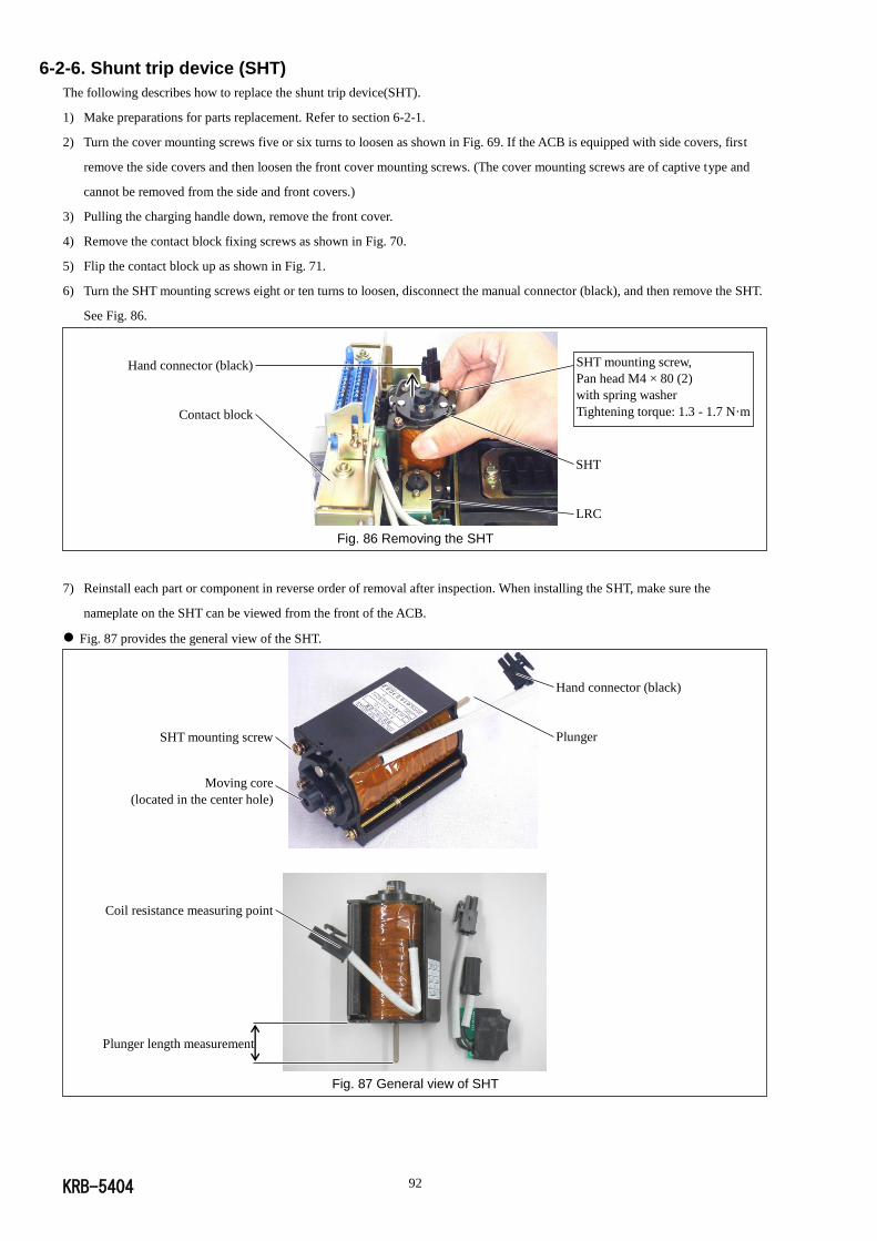
KRB-5404 92
6-2-6. Shunt trip device (SHT)
The following describes how to replace the shunt trip device(SHT).
1) Make preparations for parts replacement. Refer to section 6-2-1.
2) Turn the cover mounting screws five or six turns to loosen as shown in Fig. 69. If the ACB is equipped with side covers, first
remove the side covers and then loosen the front cover mounting screws. (The cover mounting screws are of captive type and
cannot be removed from the side and front covers.)
3) Pulling the charging handle down, remove the front cover.
4) Remove the contact block fixing screws as shown in Fig. 70.
5) Flip the contact block up as shown in Fig. 71.
6) Turn the SHT mounting screws eight or ten turns to loosen, disconnect the manual connector (black), and then remove the SHT.
See Fig. 86.
Fig. 86 Removing the SHT
7) Reinstall each part or component in reverse order of removal after inspection. When installing the SHT, make sure the
nameplate on the SHT can be viewed from the front of the ACB.
Fig. 87 provides the general view of the SHT.
Fig. 87 General view of SHT
Hand connector (black)
Contact block
SHT mounting screw,
Pan head M4 × 80 (2)
with spring washer
Tightening torque: 1.3 - 1.7 N·m
SHT
LRC
Hand connector (black)
Plunger SHT mounting screw
Moving core
(located in the center hole)
Coil resistance measuring point
Plunger length measurement
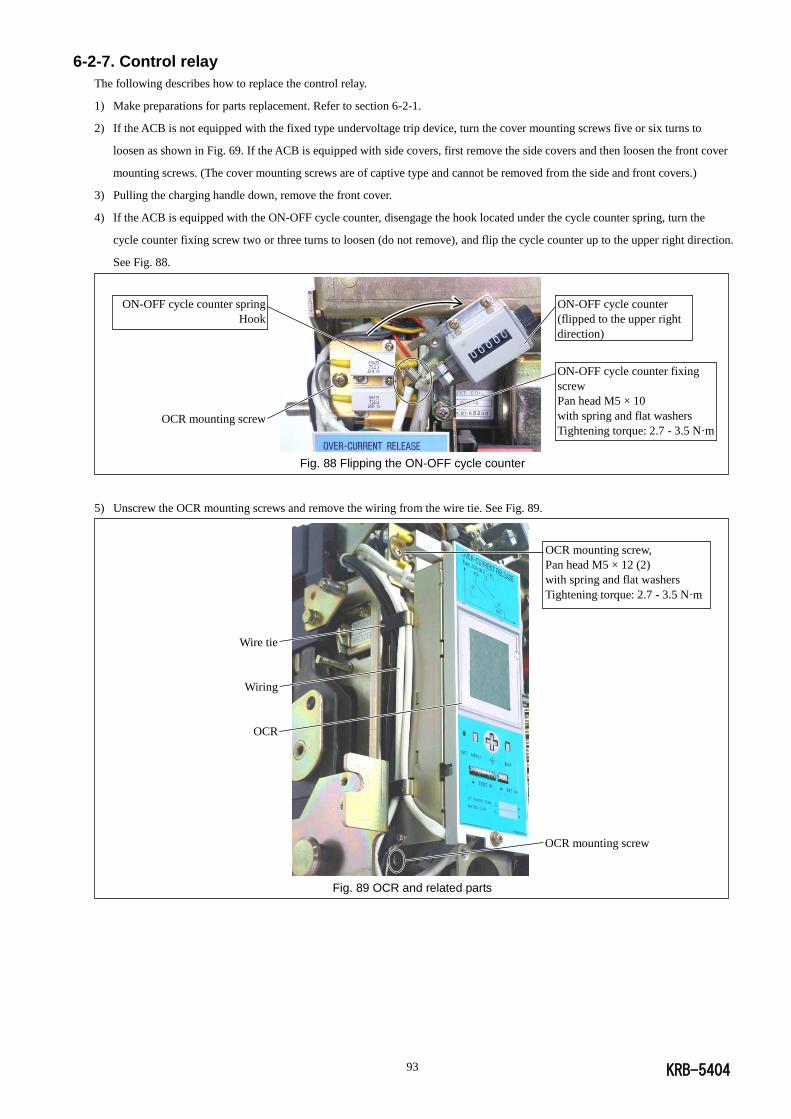
KRB-5404 93
6-2-7. Control relay
The following describes how to replace the control relay.
1) Make preparations for parts replacement. Refer to section 6-2-1.
2) If the ACB is not equipped with the fixed type undervoltage trip device, turn the cover mounting screws five or six turns to
loosen as shown in Fig. 69. If the ACB is equipped with side covers, first remove the side covers and then loosen the front cover
mounting screws. (The cover mounting screws are of captive type and cannot be removed from the side and front covers.)
3) Pulling the charging handle down, remove the front cover.
4) If the ACB is equipped with the ON-OFF cycle counter, disengage the hook located under the cycle counter spring, turn the
cycle counter fixing screw two or three turns to loosen (do not remove), and flip the cycle counter up to the upper right direction.
See Fig. 88.
Fig. 88 Flipping the ON-OFF cycle counter
5) Unscrew the OCR mounting screws and remove the wiring from the wire tie. See Fig. 89.
Fig. 89 OCR and related parts
ON-OFF cycle counter fixing
screw
Pan head M5 × 10
with spring and flat washers
Tightening torque: 2.7 - 3.5 N·m
ON-OFF cycle counter
(flipped to the upper right
direction)
OCR mounting screw
ON-OFF cycle counter spring
Hook
Wire tie
Wiring
OCR
OCR mounting screw,
Pan head M5 × 12 (2)
with spring and flat washers
Tightening torque: 2.7 - 3.5 N·m
OCR mounting screw
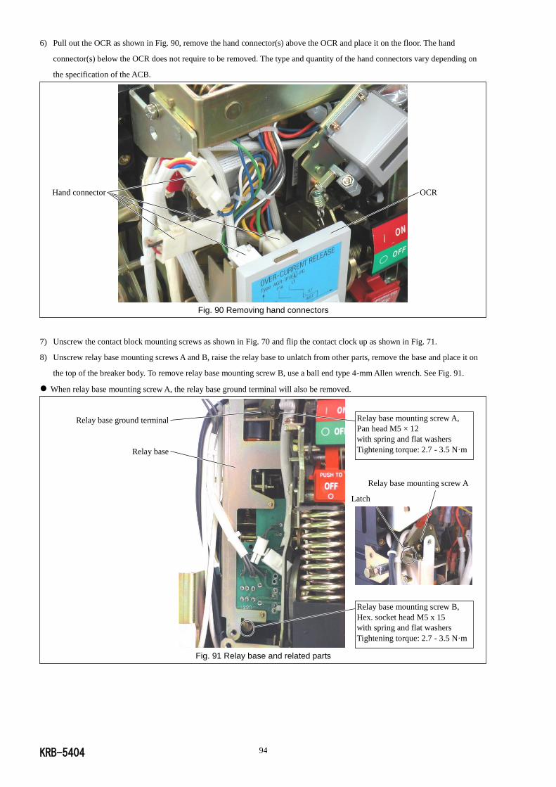
KRB-5404 94
6) Pull out the OCR as shown in Fig. 90, remove the hand connector(s) above the OCR and place it on the floor. The hand
connector(s) below the OCR does not require to be removed. The type and quantity of the hand connectors vary depending on
the specification of the ACB.
Fig. 90 Removing hand connectors
7) Unscrew the contact block mounting screws as shown in Fig. 70 and flip the contact clock up as shown in Fig. 71.
8) Unscrew relay base mounting screws A and B, raise the relay base to unlatch from other parts, remove the base and place it on
the top of the breaker body. To remove relay base mounting screw B, use a ball end type 4-mm Allen wrench. See Fig. 91.
When relay base mounting screw A, the relay base ground terminal will also be removed.
Fig. 91 Relay base and related parts
Latch
Relay base mounting screw A,
Pan head M5 × 12
with spring and flat washers
Tightening torque: 2.7 - 3.5 N·m
Relay base ground terminal
Relay base
Relay base mounting screw B,
Hex. socket head M5 x 15
with spring and flat washers
Tightening torque: 2.7 - 3.5 N·m
Relay base mounting screw A
OCR Hand connector
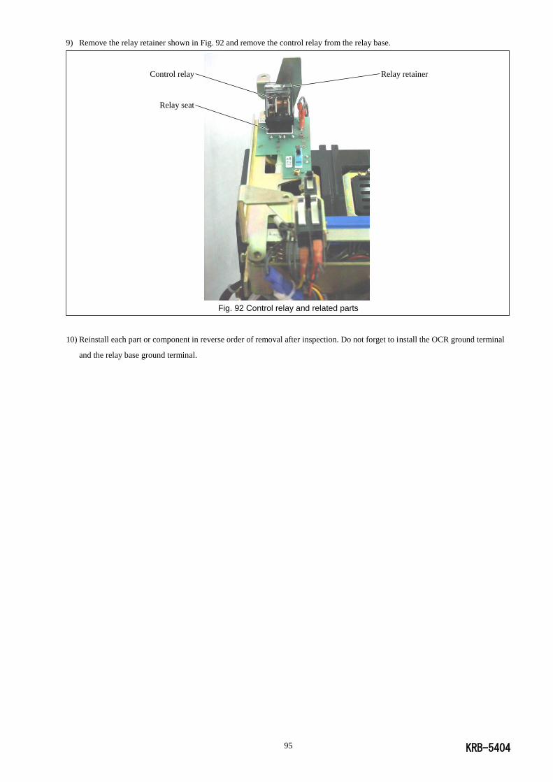
KRB-5404 95
9) Remove the relay retainer shown in Fig. 92 and remove the control relay from the relay base.
Fig. 92 Control relay and related parts
10) Reinstall each part or component in reverse order of removal after inspection. Do not forget to install the OCR ground terminal
and the relay base ground terminal.
Relay retainer Control relay
Relay seat
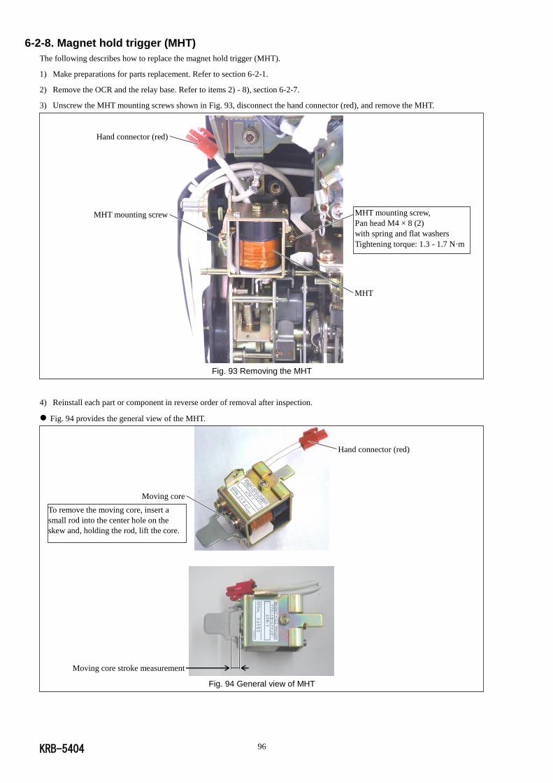
KRB-5404 96
6-2-8. Magnet hold trigger (MHT)
The following describes how to replace the magnet hold trigger (MHT).
1) Make preparations for parts replacement. Refer to section 6-2-1.
2) Remove the OCR and the relay base. Refer to items 2) - 8), section 6-2-7.
3) Unscrew the MHT mounting screws shown in Fig. 93, disconnect the hand connector (red), and remove the MHT.
Fig. 93 Removing the MHT
4) Reinstall each part or component in reverse order of removal after inspection.
Fig. 94 provides the general view of the MHT.
Fig. 94 General view of MHT
MHT mounting screw,
Pan head M4 × 8 (2)
with spring and flat washers
Tightening torque: 1.3 - 1.7 N·m
Hand connector (red)
MHT mounting screw
MHT
Hand connector (red)
Moving core
Moving core stroke measurement
To remove the moving core, insert a
small rod into the center hole on the
skew and, holding the rod, lift the core.
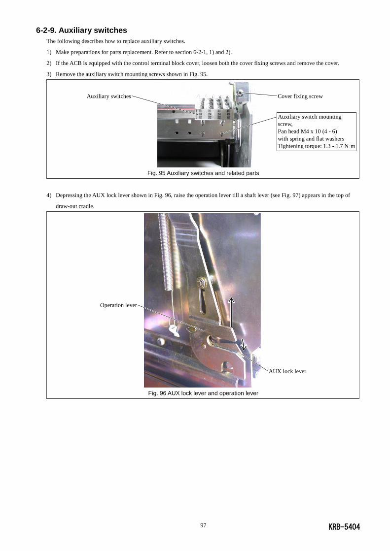
KRB-5404 97
6-2-9. Auxiliary switches
The following describes how to replace auxiliary switches.
1) Make preparations for parts replacement. Refer to section 6-2-1, 1) and 2).
2) If the ACB is equipped with the control terminal block cover, loosen both the cover fixing screws and remove the cover.
3) Remove the auxiliary switch mounting screws shown in Fig. 95.
Fig. 95 Auxiliary switches and related parts
4) Depressing the AUX lock lever shown in Fig. 96, raise the operation lever till a shaft lever (see Fig. 97) appears in the top of
draw-out cradle.
Fig. 96 AUX lock lever and operation lever
AUX lock lever
Operation lever
Auxiliary switches
Auxiliary switch mounting
screw,
Pan head M4 x 10 (4 - 6)
with spring and flat washers
Tightening torque: 1.3 - 1.7 N·m
Cover fixing screw
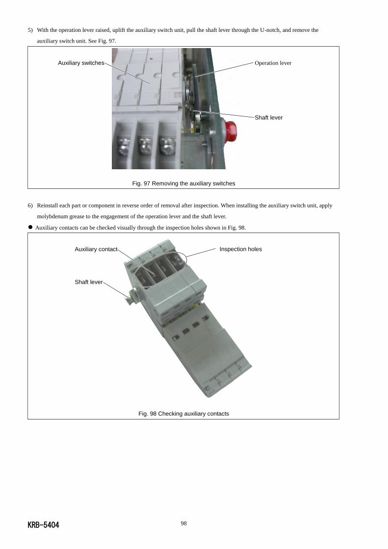
KRB-5404 98
5) With the operation lever raised, uplift the auxiliary switch unit, pull the shaft lever through the U-notch, and remove the
auxiliary switch unit. See Fig. 97.
Fig. 97 Removing the auxiliary switches
6) Reinstall each part or component in reverse order of removal after inspection. When installing the auxiliary switch unit, apply
molybdenum grease to the engagement of the operation lever and the shaft lever.
Auxiliary contacts can be checked visually through the inspection holes shown in Fig. 98.
Fig. 98 Checking auxiliary contacts
Operation lever
Shaft lever
Auxiliary switches
Inspection holes Auxiliary contact
Shaft lever
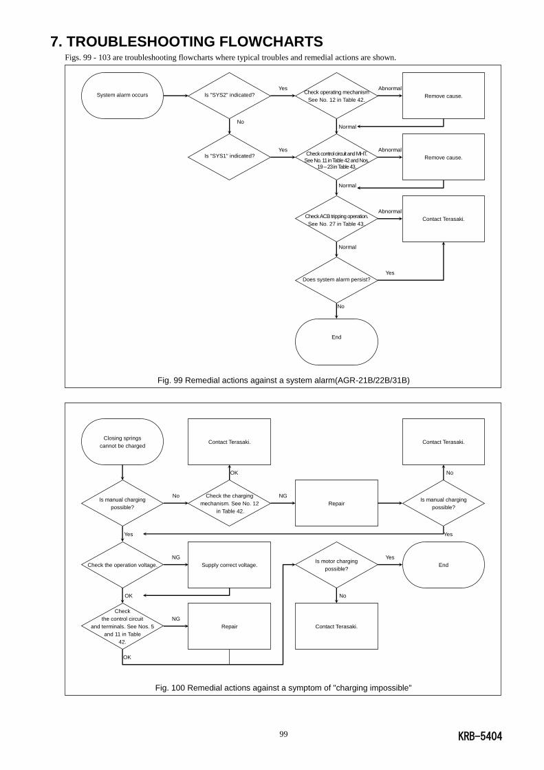
KRB-5404 99
7. TROUBLESHOOTING FLOWCHARTS Figs. 99 - 103 are troubleshooting flowcharts where typical troubles and remedial actions are shown.
Fig. 99 Remedial actions against a system alarm(AGR-21B/22B/31B)
Fig. 100 Remedial actions against a symptom of "charging impossible"
Closing springs
cannot be charged
Is manual charging
possible?
Yes
Check the operation voltage.
OK
Check
the control circuit
and terminals. See Nos. 5
and 11 in Table
42.
OK
No
NG
NG
Contact Terasaki.
OK
Check the charging
mechanism. See No. 12
in Table 42.
Supply correct voltage.
Repair
NG
Repair
Is motor charging
possible?
No
Contact Terasaki.
Yes
Contact Terasaki.
No
Is manual charging
possible?
Yes
End
System alarm occurs
Is "SYS2" indicated?
No
Is "SYS1" indicated?
Yes
Yes
Check operating mechanism
See No. 12 in Table 42.
Normal
Check control circuit and MHT.
See No. 11 in Table 42 and Nos. 19 – 23 in Table 43.
Normal
Check ACB tripping operation.
See No. 27 in Table 43.
Normal
Does system alarm persist?
No
End
Abnormal
Abnormal
Abnormal
Yes
Remove cause.
Remove cause.
Contact Terasaki.
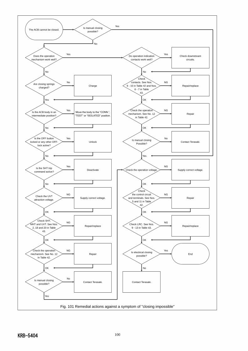
KRB-5404 100
Fig. 101 Remedial actions against a symptom of "closing impossible"
The ACB cannot be closed.
Does the operation
mechanism work well?
No
Are closing springs
charged?
Yes
Is the ACB body in an
intermediate position?
No
Is the OFF button
locked or any other OFF-
lock active?
No
Is the SHT trip
command active?
No
Check the UVT
attraction voltage.
OK
Check SHT,
MHT and UVT. See Nos.
2, 18 and 20 in Table
43.
OK
Check the operation
mechanism. See No. 12
In Table 42.
OK
Is manual closing
possible?
Yes
Yes
No
Yes
Yes
Yes
NG
NG
NG
No
Is manual closing
possible?
No
Charge
Move the body to the “CONN.”,
“TEST” or “ISOLATED” position.
Unlock
Deactivate
Supply correct voltage.
Repair/replace
Repair
Contact Terasaki.
Yes
Do operation indication
contacts work well?
No
Check
contacts. See Nos.
9 - 10 in Table 42 and Nos.
6 - 7 in Table
43.
OK
Check the operation
mechanism. See No. 12
in Table 42.
OK
Is manual closing
Possible?
Yes
Check the operation voltage.
OK
Check
the control circuit
and terminals. See Nos.
5 and 11 in Table
42.
OK
Check LRC. See Nos.
9 - 13 in Table 43.
OK
Is electrical closing
possible?
No
Contact Terasaki.
Yes
NG
NG
No
NG
NG
NG
Yes
Check downstream
circuits.
Repair/replace
Repair
Contact Terasaki.
Supply correct voltage.
Repair
Repair/replace
End
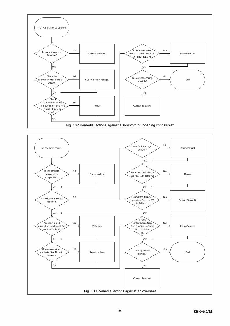
KRB-5404 101
Fig. 102 Remedial actions against a symptom of "opening impossible"
Fig. 103 Remedial actions against an overheat
An overheat occurs.
Is the ambient
temperature
as specified?
Yes
Is the load current as
specified?
Yes
Are main circuit
terminal screws loose? See
No. 5 in Table 42.
No
Check main circuit
contacts. See No. 6 in
Table 42.
OK
No
No
Yes
NG
Correct/adjust
Retighten
Repair/replace
Are OCR settings
correct?
Yes
Check the control circuit.
See No. 11 in Table 42.
OK
Check the tripping
operation. See No. 27
in Table 43.
OK
Check
contacts. See Nos.
9 - 10 in Table 42 and
No. 7 in Table
43.
OK
Is the problem
solved?
No
Contact Terasaki.
No
NG
NG
NG
Yes
Correct/adjust
Repair
Contact Terasaki.
Repair/replace
End
The ACB cannot be opened.
Is manual opening
Possible?
Yes
Check the
operation voltage and SHT
voltage.
OK
Check
the control circuit
and terminals. See Nos.
5 and 11 in Table
42.
OK
No
NG
NG
Contact Terasaki.
Supply correct voltage.
Repair
Check SHT, MHT
and UVT. See Nos. 1 - 5,
14 - 23 in Table 43.
OK
Is electrical opening
possible?
No
Contact Terasaki.
NG
Yes
Repair/replace
End

KRB-5404 102
8.DOOR INTERLOCK
Function of the Door Interlock
General:
The door interlock prevents the switchboard panel from being opened when the ACB is closed, or in the CONNECT or
TEST POSITION. The panel door is only operable when the ACB is OPEN and ISOLATED, thus preventing remote
operation of the ACB.
Normal Function:
When the ACB is CLOSED and in the connected position the draw-out handle cannot be inserted.
When the ACB is OPEN it can be drawn-out to the test or isolated position. This is indicated on the ACB’s position
indicator.
To open the panel door the ACB is required to be OPEN and in the isolated position.
Areas of Caution:
Ensure the panel door is fully closed and locked before attempting to draw-out or rack in the ACB, from any of thee three
positions (CONNECTED, TEST & ISOLATED) to another.
When moving the ACB body, care should be taken not to damage the door interlock pin, situated at the bottom left and
protruding from the ACB.
Interlock Release:
The door interlock can be defeated by releasing the spring-actuated catch on the interlock panel unit. This is
accessible
through a hole located between the interlock panel unit fasteners.
Door Interlock Adjustment
How to adjust the panel unit:
Once the ACB is installed into the switchboard and the panel door unit is fitted, check the position of the handle shutter
when the door is closed and the ACB is in the isolated position.
Draw-out handle shutter
The handle shutter
is a good position at the
centre of the hole and no
adjustment is required
Adjustment plate
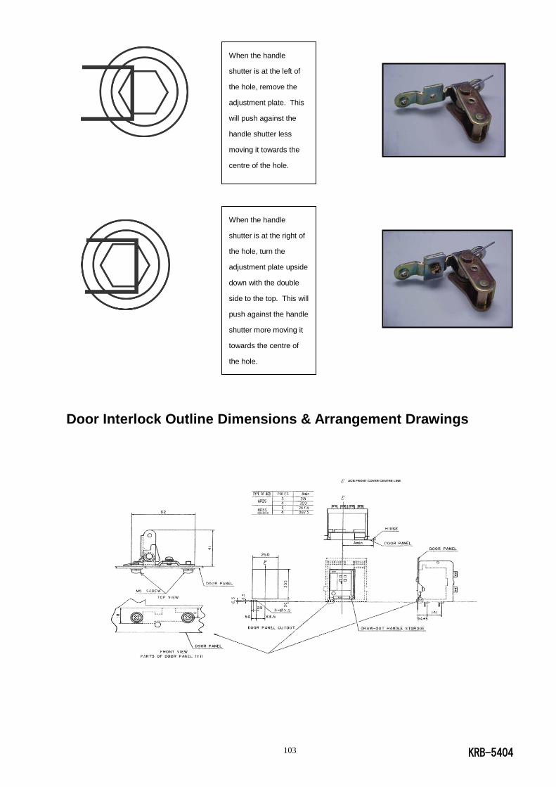
KRB-5404 103
Door Interlock Outline Dimensions & Arrangement Drawings
When the handle
shutter is at the left of
the hole, remove the
adjustment plate. This
will push against the
handle shutter less
moving it towards the
centre of the hole.
When the handle
shutter is at the right of
the hole, turn the
adjustment plate upside
down with the double
side to the top. This will
push against the handle
shutter more moving it
towards the centre of
the hole.
ACB FRONT COVER CENTRE LINE
AR440SB
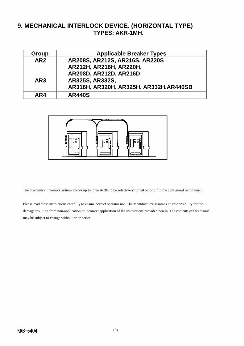
KRB-5404 104
9. MECHANICAL INTERLOCK DEVICE. (HORIZONTAL TYPE) TYPES: AKR-1MH.
Group Applicable Breaker Types
AR2 AR208S, AR212S, AR216S, AR220S AR212H, AR216H, AR220H, AR208D, AR212D, AR216D
AR3 AR325S, AR332S, AR316H, AR320H, AR325H, AR332H,AR440SB
AR4 AR440S
The mechanical interlock system allows up to three ACBs to be selectively turned on or off to the configured requirement.
Please read these instructions carefully to ensure correct operator use. The Manufacturer assumes no responsibility for the
damage resulting from non-application or incorrect application of the instructions provided herein. The contents of this manual
may be subject to change without prior notice.
KRB-5404 105
CAUTION
SAFETY:
Be sure and read all instructions and associated documents accompanying the product thoroughly to familiarise yourself
with the product handling, safety information, and all other safety precautions.
Installation Precautions:
Operation & Maintenance
Installation work of the interlock must only be carried out by qualified and authorised personnel.
Do not use the interlock in areas that are subject to high temperatures, high humidity, dusty air, corrosive gasses,
strong vibration and shock. Using the interlock in these conditions may cause a malfunction.
Care should be taken to prevent foreign objects (such as debris, concrete powder, dust, chippings), oil and
rainwater from entering the interlock. Using the interlock in these conditions may cause a malfunction.
If the ACBs are draw-out types, do not insert the bodies into the chassis until the installation of the interlock
system has been complete. If the ACBs are fixed insure the ACBs are locked off during installation Failure
to do so may result in damage to the interlock or personal injury.
Do not bend the interlock cables at the radius of less than 200mm. Doing this may result in damage to the
interlock cables causing the interlock to fail.
Insert the interlock wire until it stops at the grove end of the lever. Insufficient insertion of the wire could result
in damage to the interlock.
Be sure to adjust the distance between the support and the lever. Failure to do this can result in damage to the
interlock.
If the ACBs are draw-out types, ensure the ACBs are off while racking them into the chassis. Failure to do this
can result in damage to the interlock.
Do not touch the interlock during operation. Doing so may result in personal injury.
Maintenance and/or inspection of the interlock system must only be carried out by qualified and authorized personnel.
Before commencing maintenance work, remove the ACB bodies from the chassis or lock off the ACBs. Failure
to do so may result in damage to the interlock or personal injury.
If the ACBs are draw-out types, ensure the ACBs are off while racking them into the chassis. Failure to do this
can result in damage to the interlock.
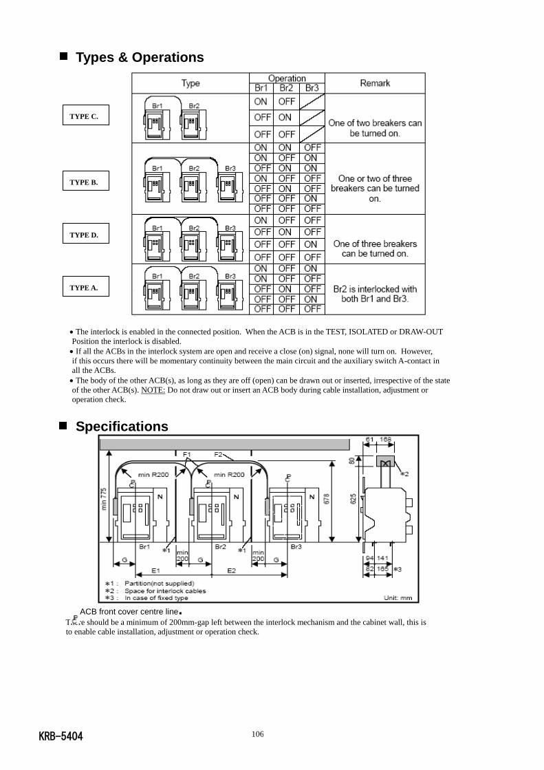
KRB-5404 106
Types & Operations
The interlock is enabled in the connected position. When the ACB is in the TEST, ISOLATED or DRAW-OUT
Position the interlock is disabled.
If all the ACBs in the interlock system are open and receive a close (on) signal, none will turn on. However,
if this occurs there will be momentary continuity between the main circuit and the auxiliary switch A-contact in
all the ACBs.
The body of the other ACB(s), as long as they are off (open) can be drawn out or inserted, irrespective of the state
of the other ACB(s). NOTE: Do not draw out or insert an ACB body during cable installation, adjustment or
operation check.
Specifications
ACB front cover centre line. There should be a minimum of 200mm-gap left between the interlock mechanism and the cabinet wall, this is
to enable cable installation, adjustment or operation check.
TYPE D.
TYPE A.
TYPE C.
TYPE B.
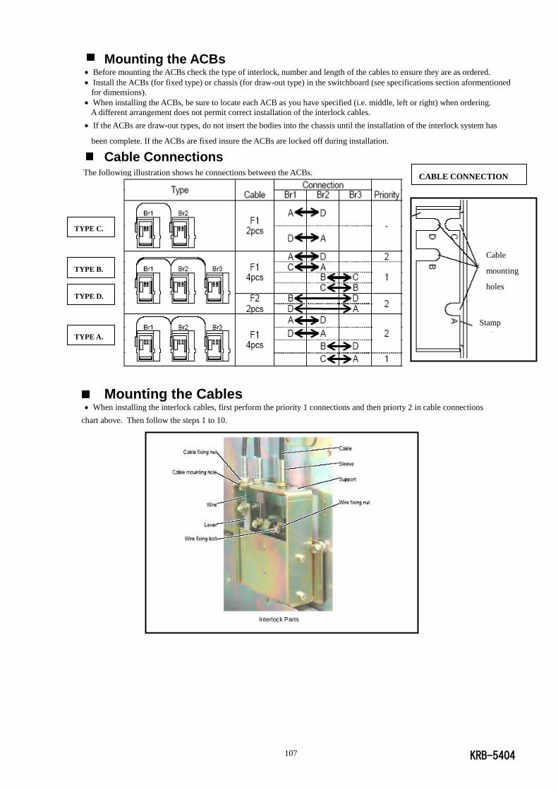
KRB-5404 107
Mounting the ACBs Before mounting the ACBs check the type of interlock, number and length of the cables to ensure they are as ordered.
Install the ACBs (for fixed type) or chassis (for draw-out type) in the switchboard (see specifications section aformentioned
for dimensions).
When installing the ACBs, be sure to locate each ACB as you have specified (i.e. middle, left or right) when ordering.
A different arrangement does not permit correct installation of the interlock cables.
If the ACBs are draw-out types, do not insert the bodies into the chassis until the installation of the interlock system has
been complete. If the ACBs are fixed insure the ACBs are locked off during installation.
Cable Connections The following illustration shows he connections between the ACBs.
Mounting the Cables When installing the interlock cables, first perform the priority 1 connections and then priorty 2 in cable connections
chart above. Then follow the steps 1 to 10.
TYPE C.
TYPE A.
TYPE B.
TYPE D.
CABLE CONNECTION
Stamp
Cable
mounting
holes
Interlock Parts
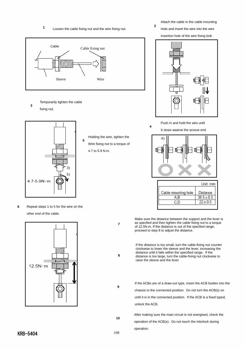
KRB-5404 108
1
Repeat steps 1 to 5 for the wire on the
other end of the cable.
Temporarily tighten the cable
fixing nut.
Holding the wire, tighten the
Wire fixing nut to a torque of
4.7 to 5.9 N.m.
Push in and hold the wire until
It stops against the groove end
of the level.
Loosen the cable fixing nut and the wire fixing nut.
Attach the cable in the cable mounting
Hole and insert the wire into the wire
Insertion hole of the wire fixing bolt.
6
Make sure the distance between the support and the lever is as specfied and then tighten the cable fixing nut to a torque of 12.5N.m. If the distance is out of the specfied range, proceed to step 8 to adjust the distance.
3
5
4
7
If the ACBs are of a draw-out type, insert the ACB bodies into the
chassis to the connected position. Do not turn the ACB(s) on
until it is in the connected position. If the ACB is a fixed typed,
unlock the ACB.
After making sure the main circuit is not energised, check the
operation of the ACB(s). Do not touch the interlock during
operation.
8
9
10
Cable
Sleeve
Cable fixing nut
Wire
2
If the distance is too small, turn the cable-fixing nut counter clockwise to lower the sleeve and the lever, increasing the distance until it falls within the specified range. If the distance is too large, turn the cable-fixing nut clockwise to raise the sleeve and the lever
KRB-5404 109
Inspection & Maintenance
If the ACBs are draw-out types, remove the ACB bodies from their chassis. If the ACBs are fixed ensure the ACBs
are locked off.
Check the wire fixing nut and cable fixing nut for tightness. If loose, retighten to the specified torque.
Make sure the distance between the support and the lever is as specified. If the distance is out of the specified range,
readjust it.
If the ACBs are of a draw-out type, insert the ACB bodies into the chassis to the connected position. Do not turn the
ACB(s) on until it is in the connected position. If the ACB is a fixed type, unlock the ACB.
After making sure the main circuit is not energised, check the operation of the ACB(s). Do not touch the interlock
during operation.
Published in March 2009. Revised in July 2011, Revised in August 2013, Revised in Aplil 2015.
The contents of this manual may be subject to change without notice.
Recycle paper used.
Related Documents