Brakes and clutches used for tensioning (constant slip) have one thing in common. Generally, heat dissipation capacity is the primary criteria for sizing, followed by torque capacity. Beyond this, each has unique sizing requirements that differ greatly. Information on particular Warner Electric tension brakes and clutches start on page 68. Brakes (Unwinds or Payoffs) Thermal Requirements Thermal requirements for a brake equals web HP; which is HP = Tension (lbs.) x Linear Speed (FPM) 33,000 This energy is constant throughout the unwinding process. Although energy is a function of torque and slip speed, slip speed is at its slowest when torque required is at its greatest (full roll), and slip speed is at its fastest when torque required is at its least (core). All that is needed, then to determine thermal capacity required in an unwind brake is tension and linear speed. Caution should be taken, however, on machines that run more than one material at different line speeds. All combina- tions of tensions and line speeds should be checked to insure that brake sizing satisfies the most demanding condi- tion (i.e. – the highest web HP). Torque Requirements There are generally three conditions under which a brake must supply sufficient torque: running torque, E-Stop (or emergency stop) torque and controlled stop torque (normal deceleration). a. Running Torque This is the torque required to maintain constant tension at any point in the roll being unwound. Since torque is force x dis- tance, with force being tension and distance being roll radius, then torque must change as radius changes if tension is to remain constant. Moreover, the maximum running torque will be at full roll, since that has the largest radius. b. E-Stop Torque, Web Break This is the torque required to stop the roll in the event of a web break or a safety related machine stop. There are basi- cally two types of stop conditions to be considered: web break where only the roll inertia stop time and RPM are major considerations, and controlled E-Stop where stopping is required due to some safety related issue, but web tension must be maintained. Warner Electric 800-825-9050 14 Tension Brakes and Clutches Design Considerations and Selection Tension R During web break E-Stop controlling tension is not a major concern, but getting the roll stopped in a specified time to minimize spillage. The time frame to stop may be a company specification or an OSHA requirement. For a web break E-Stop, the torque required is a function of roll inertia, roll RPM and E-Stop time requirements. T(torque) = WR 2 x RPM 308 x t where T = Torque (lb.ft.) t = E-Stop time requirement of machine Since the roll inertia is greatest when the roll is full, this condi- tion is normally used for calculating the worst-case E-Stop web break torque. RPM can be determined by dividing the linear speed by the roll diameter x pi (3.1416). E-Stop times as short as 2 seconds are not uncommon. Note that if the control system is open loop (i.e. – ultra-sonic, manual, etc.), maximum E-Stop torque must be obtained by having the S-Stop switch on the machine turn the brake to full on, otherwise the torque available will only be running torque. In the closed loop mode (dancer or load cell), maximum E-Stop torque will automatically be applied. c. E-Stop Torque, controlled In a controlled stop, the brake must stop the roll during the time the machine stops, all the while maintaining tension on the unwind roll. This differs from web break E-Stop torque in that the brake must stop the inertia as well as continue to maintain running torque or tension. T = WR 2 x RPM + Maximum Running Torque 308 x t where T = Torque (lb.ft.) t = E-Stop time requirements of machine It should be noted that controlled stops can only be accom- plished in the closed loop mode, as feedback is required to maintain tension. For the same stopping times, the controlled E-Stop will require more torque than the web break E-Stop, due to the additional load of maintaining tension. Controlled E-Stop torque is the worst case as the stop is the much faster than normal deceleration times. E-Stop whether it be for controlled purposes or web break is generally a set function of the machine. Caution should be made in that the faster the E-Stop requirements, the more torque that is required of the system and the more stress that is placed on the components in the machine. All categories must be investigated to determine the maxi- mum torque capacity required for the application.

Welcome message from author
This document is posted to help you gain knowledge. Please leave a comment to let me know what you think about it! Share it to your friends and learn new things together.
Transcript

Brakes and clutches used for tensioning (constant slip) haveone thing in common. Generally, heat dissipation capacity isthe primary criteria for sizing, followed by torque capacity.Beyond this, each has unique sizing requirements that differgreatly. Information on particular Warner Electric tensionbrakes and clutches start on page 68.
Brakes(Unwinds or Payoffs)
Thermal Requirements
Thermal requirements for a brake equals web HP; which is
HP = Tension (lbs.) x Linear Speed (FPM)33,000
This energy is constant throughout the unwinding process.Although energy is a function of torque and slip speed, slipspeed is at its slowest when torque required is at its greatest(full roll), and slip speed is at its fastest when torque requiredis at its least (core). All that is needed, then to determinethermal capacity required in an unwind brake is tension andlinear speed.
Caution should be taken, however, on machines that runmore than one material at different line speeds. All combina-tions of tensions and line speeds should be checked toinsure that brake sizing satisfies the most demanding condi-tion (i.e. – the highest web HP).
Torque Requirements
There are generally three conditions under which a brakemust supply sufficient torque: running torque, E-Stop (oremergency stop) torque and controlled stop torque (normaldeceleration).
a. Running Torque
This is the torque required to maintain constant tension at anypoint in the roll being unwound. Since torque is force x dis-tance, with force being tension and distance being rollradius, then torque must change as radius changes if tensionis to remain constant. Moreover, the maximum runningtorque will be at full roll, since that has the largest radius.
b. E-Stop Torque, Web Break
This is the torque required to stop the roll in the event of aweb break or a safety related machine stop. There are basi-cally two types of stop conditions to be considered: webbreak where only the roll inertia stop time and RPM are majorconsiderations, and controlled E-Stop where stopping isrequired due to some safety related issue, but web tensionmust be maintained.
Warner Electric 800-825-905014
Tension Brakes and ClutchesDesign Considerations and Selection
TensionR
During web break E-Stop controlling tension is not a majorconcern, but getting the roll stopped in a specified time tominimize spillage. The time frame to stop may be a companyspecification or an OSHA requirement.
For a web break E-Stop, the torque required is a function ofroll inertia, roll RPM and E-Stop time requirements.
T(torque) = WR2 x RPM308 x t
where T = Torque (lb.ft.)t = E-Stop time requirement of machine
Since the roll inertia is greatest when the roll is full, this condi-tion is normally used for calculating the worst-case E-Stopweb break torque. RPM can be determined by dividing thelinear speed by the roll diameter x pi (3.1416). E-Stop timesas short as 2 seconds are not uncommon.
Note that if the control system is open loop (i.e. – ultra-sonic,manual, etc.), maximum E-Stop torque must be obtained byhaving the S-Stop switch on the machine turn the brake to fullon, otherwise the torque available will only be running torque.In the closed loop mode (dancer or load cell), maximumE-Stop torque will automatically be applied.
c. E-Stop Torque, controlled
In a controlled stop, the brake must stop the roll during thetime the machine stops, all the while maintaining tension onthe unwind roll. This differs from web break E-Stop torque inthat the brake must stop the inertia as well as continue tomaintain running torque or tension.
T = WR2 x RPM + Maximum Running Torque308 x t
where T = Torque (lb.ft.)t = E-Stop time requirements of machine
It should be noted that controlled stops can only be accom-plished in the closed loop mode, as feedback is required tomaintain tension.
For the same stopping times, the controlled E-Stop willrequire more torque than the web break E-Stop, due to theadditional load of maintaining tension. Controlled E-Stoptorque is the worst case as the stop is the much faster thannormal deceleration times.
E-Stop whether it be for controlled purposes or web break isgenerally a set function of the machine. Caution should bemade in that the faster the E-Stop requirements, the moretorque that is required of the system and the more stress thatis placed on the components in the machine.
All categories must be investigated to determine the maxi-mum torque capacity required for the application.

Warner Electric 800-825-9050 15
Tension Brakes and ClutchesDesign Considerations and Selection
Other Considerations
In some instances, it may be desirable to have a gear ratio fromthe roll shaft to the brake, with the brake on the higher speedshaft. In addition to providing a torque multiplication equal tothe gear ratio, this also serves to reduce the effective inertiathat the brake sees, as reflected roll inertia is reduced by thesquare of the ratio. Note, however, that with brakes that have aspecified drag, or minimum torque, that drag torque is alsomultiplied, which could result in inability to address minimumrunning torque at or close to core diameter.
Also, it is important to realize that employing a gear ratio DOESNOT reduce the heat dissipation requirement of the brake.
Another instance where a gear ratio may be needed is whenany friction type brake is required to run at very low speeds,usually below 50 RPM. Although today’s friction materials havebeen perfected to the point where static and dynamic coeffi-cients or friction are very close, a certain amount of "sticktion"or stick slip phenomena may occur to the extent that precisecontrol of tension may be compromised. Employing a speed-upgear ratio can make the brake operate at a more efficientspeed.
Clutches(Rewinds or Winders)
Although motor drives are the more common choice forwinders, clutches can be used quite successfully, and offer amore economical alternative. Typically, the input to the clutchwill be a fixed RPM, and can be a take-off from the mainmachine drive, or an independent motor. RPM input should nor-mally be a least 10% higher than the fastest output. To calcu-late this, determine the core RPM at fastest line speed, andincrease this by at least 10%.
The output of the clutch will start at core RPM, and will gradual-ly decrease as the diameter builds. As in the unwind brake,torque will vary in proportion to the diameter change, but unlikethe brake, torque must increase as the diameter builds and theslip speed INCREASES. Slip speed increases because thefixed input RPM doesn’t change, but the output RPM keepsdecreasing as the roll diameter builds.
Energy dissipation capacity is the most critical sizing criteria ina winder clutch. Creation of heat is highest at full roll, since thisis where slip speed AND torque are at their maximum.Maximum heat, or thermal HP, can be found by the followingformulae:
HP = Torque(lb.ft.) @ full roll x Slip RPM @ full roll x 2 x Pi33,000
After the clutch size is selected based on the above thermalcalculation, clutch torque capacity should be checked by cal-culating maximum torque required, which is maximum tensiontimes full roll radius.
Taper Tension
With some materials, taper tension may be required. This isa means by which tension is gradually decreased as theroll diameter builds, and is employed if there is a risk ofcrushing cores due to build-up of internal pressure withinthe roll, or if telescoping (slippage to one side) of thewraps might occur. This becomes a function of the control,as the rate of torque increase must be reduced as diame-ter increases.
In single zone machines, where the unwind brake controlswinder tension, taper tension can be handled in a similarfashion.
Control of the clutch can be either open loop (manualadjust or diameter compensation) or closed loop (danceror load cell), depending upon the degree of precisionneeded.
For detailed sizing and selection for unwind, intermediateand rewind applications, see sizing selection section onpages 16 through 32.

Tension Control SystemsDesign Considerations and Selection
Warner Electric 800-825-905016
Design considerations and selection can be broken down bythe type of system being selected and the function it mustperform. Sizing and application for an unwind will be differentthan that for a rewind. Also, depending on whether it will befor a clutch, or brake or for a drive, certain system parame-ters will be required.
Additionally, will the system require a simple remote/analogcontrol, or will it require the option of a closed loop dancer orload cell controller? These factors must taken into considera-tion when sizing the proper system.
No matter which type of system is being considered, certainapplication parameters are necessary to make the calcula-tions for selecting the proper components. The selectionprocess is straight forward if the necessary data has beenobtained.
An application data sheet should be used for each applica-tion to insure the necessary data is available when doing thecalculations. In many cases, three or four data sheets may beused for a particular machine. Although this may seemexcessive, parameters will often vary between unwind, inter-mediate, or rewind sections of the machine.
Unwind Sizing Tension Brakes
Once the selection data has been obtained, sizing and cal-culations can be started. An application example is includedfor both a brake sizing and a drive sizing, showing the com-parison of the two type systems.
Application Data
Material: Paper; 30 lb. Basis weightTension: 36 lbs. max.Roll weight: 1,100 lb. avg.Web Width: 24 inchesLinear Speed: 800 ft./min.Core diameter: 3.00 inchesMax. roll diameter: 42.00 inchesMachine Acceleration Time: 15 secondsMachine Deceleration Time: 15 secondsMachine E-Stop Time: 3.8 seconds
Note: Tension = Material Tension (PLI) X Web Width
Sizing for a Unwind Tension Brake System
1. Energy Rate
Energy Rate = Tension x Linear Speed
ER = 36 X 800
ER = 28,800 ft. lbs./minute
2. Thermal Horsepower
Thermal HP = Energy Rate33,000
HP = 28,80033,000
HP = 0.873 HP
3. Minimum Roll Speed
Min. Roll Speed = Linear Speed X 3.82Max. Roll Diameter (in.)
Min. Roll Speed = 800 x 3.8242
Min. Roll Speed = 72.76 RPM
4. Maximum Roll Speed
Max. Roll Speed = Linear Speed X 3.82Core Diameter (in.)
Max. Roll Speed = 800 x 3.823
Max. Roll Speed = 1,018.67 RPM
5. Selection Speed
Selection Speed = (Max. Roll Speed – Minimum Roll Speed)
10
+ Min Roll Speed
Selection Speed = (1,018.67 – 72.76) + 72.7610
Selection Speed = 945.91 + 72.7610
Selection Speed = 94.591 + 72.76
Selection Speed = 167.35 RPM (Selection Speed)
Ref: Appropriate thermal curves on various catalogpages for possible brake selections (SelectionSpeed vs. Thermal)
6. Minimum Roll Torque
Minimum Roll Torque = Tension x Core Dia (in.)24
Minimum Roll Torque = 36 x 324
Minimum Roll Torque = 36 x 0.125
Minimum Roll Torque = 4.5 lb. ft.
7. Maximum Roll Torque
Maximum Roll Torque = Tension x Max. Roll Dia. (in.)24
Maximum Roll Torque = 36 x 4224
Maximum Roll Torque = 36 x 1.75
Maximum Roll Torque = 63.00 lb. ft.
Note: Refer to appropriate Running Torque vs. Speed CurvesNote: Constant values in formulas are in bold.
Warner Electric 800-825-9050 17
Tension Control SystemsDesign Considerations and Selection
Note: Constant values in formulas are in bold.
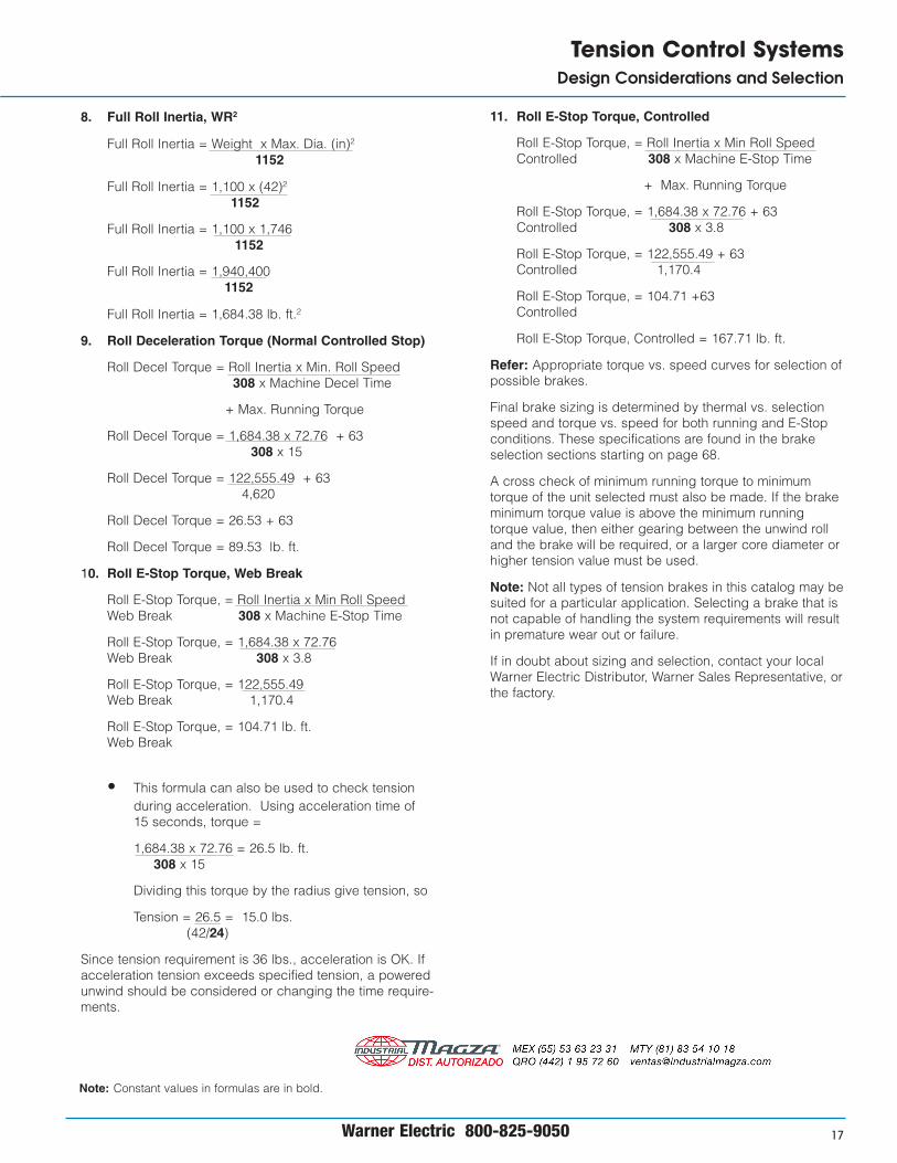
8. Full Roll Inertia, WR2
Full Roll Inertia = Weight x Max. Dia. (in)2
1152
Full Roll Inertia = 1,100 x (42)2
1152
Full Roll Inertia = 1,100 x 1,7461152
Full Roll Inertia = 1,940,4001152
Full Roll Inertia = 1,684.38 lb. ft.2
9. Roll Deceleration Torque (Normal Controlled Stop)
Roll Decel Torque = Roll Inertia x Min. Roll Speed308 x Machine Decel Time
+ Max. Running Torque
Roll Decel Torque = 1,684.38 x 72.76 + 63308 x 15
Roll Decel Torque = 122,555.49 + 634,620
Roll Decel Torque = 26.53 + 63
Roll Decel Torque = 89.53 lb. ft.
10. Roll E-Stop Torque, Web Break
Roll E-Stop Torque, = Roll Inertia x Min Roll SpeedWeb Break 308 x Machine E-Stop Time
Roll E-Stop Torque, = 1,684.38 x 72.76Web Break 308 x 3.8
Roll E-Stop Torque, = 122,555.49Web Break 1,170.4
Roll E-Stop Torque, = 104.71 lb. ft.Web Break
• This formula can also be used to check tensionduring acceleration. Using acceleration time of15 seconds, torque =
1,684.38 x 72.76 = 26.5 lb. ft.308 x 15
Dividing this torque by the radius give tension, so
Tension = 26.5 = 15.0 lbs.(42/24)
Since tension requirement is 36 lbs., acceleration is OK. Ifacceleration tension exceeds specified tension, a poweredunwind should be considered or changing the time require-ments.
11. Roll E-Stop Torque, Controlled
Roll E-Stop Torque, = Roll Inertia x Min Roll SpeedControlled 308 x Machine E-Stop Time
+ Max. Running Torque
Roll E-Stop Torque, = 1,684.38 x 72.76 + 63Controlled 308 x 3.8
Roll E-Stop Torque, = 122,555.49 + 63Controlled 1,170.4
Roll E-Stop Torque, = 104.71 +63Controlled
Roll E-Stop Torque, Controlled = 167.71 lb. ft.
Refer: Appropriate torque vs. speed curves for selection ofpossible brakes.
Final brake sizing is determined by thermal vs. selectionspeed and torque vs. speed for both running and E-Stopconditions. These specifications are found in the brakeselection sections starting on page 68.
A cross check of minimum running torque to minimumtorque of the unit selected must also be made. If the brakeminimum torque value is above the minimum runningtorque value, then either gearing between the unwind rolland the brake will be required, or a larger core diameter orhigher tension value must be used.
Note: Not all types of tension brakes in this catalog may besuited for a particular application. Selecting a brake that isnot capable of handling the system requirements will resultin premature wear out or failure.
If in doubt about sizing and selection, contact your localWarner Electric Distributor, Warner Sales Representative, orthe factory.

Warner Electric 800-825-905018
Tension Control SystemsDesign Considerations and Selection
Sizing for an Unwind Tension Drive System
Sizing for an unwind tension drive system is similar to a brakesystem; however, a few additional calculations are required toinsure that the proper motor is selected. As before, the samesystem data is used to make the calculations and selection.
1. Energy Rate
Energy Rate = Tension x Linear Speed x Max. Dia.(in.)Min. Dia (in.)
Energy Rate = 36 x 800 x 423
Energy Rate = 36 x 800 x 14
Energy Rate = 403, 200 ft. lbs./minute
2. Thermal Horsepower
Thermal Horsepower = Energy Rate33,000
Thermal Horsepower = 403,200.0033,000
Thermal Horsepower = 12.22 HP
3. Minimum Roll Speed
Min. Roll Speed = Linear Speed X 3.82Max. Roll Diameter (in.)
Min. Roll Speed = 800 x 3.8242
Min. Roll Speed = 72.76 RPM
4. Maximum Roll Speed
Max. Roll Speed = Linear Speed X 3.82Core Diameter (in.)
Max. Roll Speed = 800 x 3.823
Max. Roll Speed = 1,018.67 RPM
5. Minimum Roll Torque
Minimum Roll Torque = Tension x Core Dia (in.)24
Minimum Roll Torque = 36 x 324
Minimum Roll Torque = 36 x 0.125
Minimum Roll Torque = 4.5 lb. ft.
6. Maximum Roll Torque
Maximum Roll Torque = Tension x Max. Roll Dia. (in.)24
Maximum Roll Torque = 36 x 4224
Maximum Roll Torque = 36 x 1.75
Maximum Roll Torque = 63.00 lb. ft.
7. Full Roll Inertia, WR2
Full Roll Inertia = Weight x Max. Dia. (in)2
1152
Full Roll Inertia = 1,100 x (42)2
1152
Full Roll Inertia = 1,100 x 1,7461152
Full Roll Inertia = 1,940,4001152
Full Roll Inertia = 1,684.38 lb. ft.2
8. Acceleration Torque to Start Full Roll
Acceleration Torque = Inertia x Min Roll Speed308 x Machine Accel Time
+ Max. Roll Torque
Acceleration Torque = 1,684.38 x 72.76 + 63308 x 15
Acceleration Torque = 122,555.49 + 634,620.0
Acceleration Torque = 26.53 + 63.00
Acceleration Torque = 89.53 lb.ft.
9. Roll Deceleration Torque (Normal Controlled Stop)
Roll Decel Torque = Roll Inertia x Min. Roll Speed308 x Machine Decel Time
+ Max. Roll Torque
Roll Decel Torque = 1,684.38 x 72.76 + 63308 x 15
Roll Decel Torque = 122,555.49 + 634,620
Roll Decel Torque = 26.53 + 63
Roll Decel Torque = 89.53 lb. ft.
10. Roll E-Stop Torque, Web Break
Roll E-Stop Torque, = Roll Inertia x Min Roll SpeedWeb Break 308 x Machine E-Stop Time
Roll E-Stop Torque, = 1,684.38 x 72.76Web Break 308 x 3.8
Note: Constant values in formulas are in bold.
{ }
Warner Electric 800-825-9050 19
Tension Control SystemsDesign Considerations and Selection
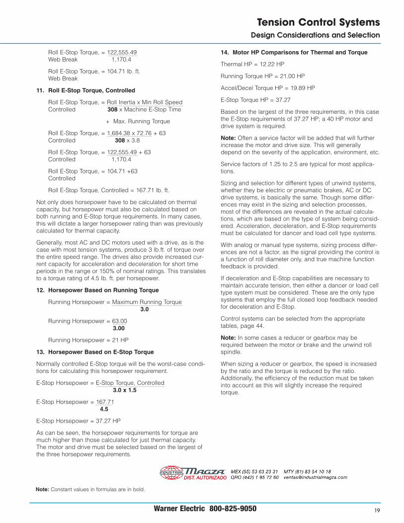
Roll E-Stop Torque, = 122,555.49Web Break 1,170.4
Roll E-Stop Torque, = 104.71 lb. ft.Web Break
11. Roll E-Stop Torque, Controlled
Roll E-Stop Torque, = Roll Inertia x Min Roll SpeedControlled 308 x Machine E-Stop Time
+ Max. Running Torque
Roll E-Stop Torque, = 1,684.38 x 72.76 + 63Controlled 308 x 3.8
Roll E-Stop Torque, = 122,555.49 + 63Controlled 1,170.4
Roll E-Stop Torque, = 104.71 +63Controlled
Roll E-Stop Torque, Controlled = 167.71 lb. ft.
Not only does horsepower have to be calculated on thermalcapacity, but horsepower must also be calculated based onboth running and E-Stop torque requirements. In many cases,this will dictate a larger horsepower rating than was previouslycalculated for thermal capacity.
Generally, most AC and DC motors used with a drive, as is thecase with most tension systems, produce 3 lb.ft. of torque overthe entire speed range. The drives also provide increased cur-rent capacity for acceleration and deceleration for short timeperiods in the range or 150% of nominal ratings. This translatesto a torque rating of 4.5 lb. ft. per horsepower.
12. Horsepower Based on Running Torque
Running Horsepower = Maximum Running Torque3.0
Running Horsepower = 63.003.00
Running Horsepower = 21 HP
13. Horsepower Based on E-Stop Torque
Normally controlled E-Stop torque will be the worst-case condi-tions for calculating this horsepower requirement.
E-Stop Horsepower = E-Stop Torque, Controlled3.0 x 1.5
E-Stop Horsepower = 167.714.5
E-Stop Horsepower = 37.27 HP
As can be seen, the horsepower requirements for torque aremuch higher than those calculated for just thermal capacity.The motor and drive must be selected based on the largest ofthe three horsepower requirements.
14. Motor HP Comparisons for Thermal and Torque
Thermal HP = 12.22 HP
Running Torque HP = 21.00 HP
Accel/Decel Torque HP = 19.89 HP
E-Stop Torque HP = 37.27
Based on the largest of the three requirements, in this casethe E-Stop requirements of 37.27 HP; a 40 HP motor anddrive system is required.
Note: Often a service factor will be added that will furtherincrease the motor and drive size. This will generallydepend on the severity of the application, environment, etc.
Service factors of 1.25 to 2.5 are typical for most applica-tions.
Sizing and selection for different types of unwind systems,whether they be electric or pneumatic brakes, AC or DCdrive systems, is basically the same. Though some differ-ences may exist in the sizing and selection processes,most of the differences are revealed in the actual calcula-tions, which are based on the type of system being consid-ered. Acceleration, deceleration, and E-Stop requirementsmust be calculated for dancer and load cell type systems.
With analog or manual type systems, sizing process differ-ences are not a factor, as the signal providing the control isa function of roll diameter only, and true machine functionfeedback is provided.
If deceleration and E-Stop capabilities are necessary tomaintain accurate tension, then either a dancer or load celltype system must be considered. These are the only typesystems that employ the full closed loop feedback neededfor deceleration and E-Stop.
Control systems can be selected from the appropriatetables, page 44.
Note: In some cases a reducer or gearbox may berequired between the motor or brake and the unwind rollspindle.
When sizing a reducer or gearbox, the speed is increasedby the ratio and the torque is reduced by the ratio.Additionally, the efficiency of the reduction must be takeninto account as this will slightly increase the requiredtorque.
Note: Constant values in formulas are in bold.

Warner Electric 800-825-905020
Tension Control SystemsDesign Considerations and Selection
Intermediate Sizing
Intermediate sizing and selection typically involves a roll thatretards or pulls the web to create tension.
A brake usually provides the retarding force, while a clutchdriven by a constant speed motor or a variable AC or DCdrive system provides pull force.
A few additional parameters are considered in addition tothose used in sizing and selecting an unwind.
Application Data
Material: Paper; 30 lb. Basis weightTension: 36 lbs. max.Roll weight: 1,100 lb. avg.Web Width: 24 inchesLinear Speed: 800 ft./min.Core diameter: 3.00 inchesMax. roll diameter: 42.00 inchesMachine Acceleration Time: 15 secondsMachine Deceleration Time: 15 secondsMachine E-Stop Time: 3.8 secondsLocation of Controlling Element: Nip Rolls, S-WrapRoller Diameter: 6.00 inchesRoller Width: 30.00 inchesRoller Weight: 100 lbs.Nip Roll Pressure: 25 lbs.
Sizing an Intermediate Tension Brake System
1. Nip Roll Speed
Nip Roll Speed = Linear Speed x 3.82Nip Roll Diameter
Nip Roll Speed = 800 X 3.826.00
Nip Roll Speed = 509.33 RPM
2. Tension Torque
Tension Torque = Tension x Nip Roll Diameter24
Tension Torque = 36 x 6.0024
Tension Torque = 36 x 0.25
Tension Torque = 9.00 lb. ft.
3. Torque Due to Nip Roll Pressure
Nip Roll Torque = Nip Roll Force x Nip Roll Diameter24
Nip Roll Torque = 25 x 6.0024
Nip Roll Torque = 25 x 0.25
Nip Roll Torque = 6.25 lb. ft.
4. Torque Required for Tensioning
Total Torque = Tension Torque – Nip Roll Torque
Total Torque = 9.00 – 6.25
Total Torque = 2.75 lb. ft.
5. Energy Rate Required from Brake
Energy Rate = 2 x Pi X Nip Roll Speed x Nip Roll Torque
Energy Rate = 2 x 3.1415927 x 509.33 x 2.75
Energy Rate = 8,800.59 ft. lbs./minute
6. Thermal Horsepower
Thermal Horsepower = Energy Rate33,000
Thermal Horsepower = 8,800.5933,000
Thermal Horsepower = 0.267 HP
Initial brake sizing is based on thermal requirements andoperating speeds from the appropriate speed vs. thermalcurves for the brake type being considered. This informationis found in the brake selection section starting on page 68.
7. Normal Deceleration Torque
Deceleration Torque = Nip Roll Inertia x Nip Roll Speed308 x Machine Deceleration Time
+ Total Running Torque
WR2 = Nip Roll Diameter 2 x Nip Roll Weight1152
WR2 = 62 x 1001152
WR2 = 3.125 lb.ft.2
Deceleration Torque = 3.125 x 509.33 + 2.75308 x 15
Deceleration Torque = 1591.66 + 2.754620
Deceleration Torque = 0.345 + 2.75
Deceleration Torque = 3.095 lb. ft.
8. E-Stop Torque
E-Stop Torque = Nip Roll Inertia x Nip Roll Speed308 x Machine E-Stop Time
+ Total Running Torque
E-Stop Torque = 3.125 x 509.33 + 2.75308 x 3.8
Note: Constant values in formulas are in bold.

Warner Electric 800-825-9050 21
Tension Control SystemsDesign Considerations and Selection
E-Stop Torque = 1591.66 + 2.751170.4
E-Stop Torque = 1.36 + 2.75
E-Stop Torque = 4.11 lb. ft.
Final brake selection is based on running torque and E-Stoptorque, based on torque vs. speed curves. The brake musthave sufficient torque capability to handle the application. Theappropriate curves for the brake type being considered shouldbe consulted.
Note: Not all brake types will be suitable for a given applica-tion.
Sizing an Intermediate Tension Clutch System
Clutch sizing for an intermediate tension system is similar tobrake sizing except the clutch input speed is recommended tobe 50 to 100 RPM higher than the maximum output speed toassure proper controllability.
Using the same parameters as that for the brake sizing, sizinga clutch is as follows:
1. Nip Roll Speed
Nip Roll Speed = Linear Speed x 3.82Nip Roll Diameter
Nip Roll Speed = 800 X 3.826.00
Nip Roll Speed = 509.33 RPM
2. Tension Torque
Tension Torque = Tension x Nip Roll Diameter24
Tension Torque = 36 x 6.0024
Tension Torque = 36 x 0.25
Tension Torque = 9.00 lb. ft.
3. Torque Due to Nip Roll Pressure
Nip Roll Torque = Nip Roll Force x Nip Roll Diameter24
Nip Roll Torque = 25 x 6.0024
Nip Roll Torque = 25 x 0.25
Nip Roll Torque = 6.25 lb. ft.
4. Total Torque Required for Tensioning
Total Torque = Tension Torque + Nip Roll Torque
Total Torque = 9.00 + 6.25
Total Torque = 15.25 lb. ft.
5 Clutch Input Speed
Clutch Input Speed = k x Linear SpeedNip Roll Diameter
k = 4.2 for 50 RPM Slip Difference
k = 4.57 for 100 RPM Slip Difference
Clutch Input Speed = 4.57 x 8006
Clutch Input Speed = 36566
Clutch Input Speed = 609.33 RPM
6. Energy Rate
Energy Rate = 2 x(Pi) π x Total Torque x Slip SpeedDifference
Energy Rate = 2 x 3.1415927 x 15.25 x 100
Energy Rate = 9,581.86 ft. lbs./minute
7. Thermal Horsepower
Thermal Horsepower = Energy Rate33,000
Thermal Horsepower = 9,581.8633,000
Thermal Horsepower = 0.3 HP
8. Acceleration Torque
Acceleration Torque = Nip Roll Inertia x Nip Roll Speed308 x Machine Acceleration Time
+ Total Running Torque
Acceleration Torque = 3.125 x 509.33 + 15.25308 x 15
Acceleration Torque = 1591.66 + 15.254620
Acceleration Torque = 0.345 + 15.25
Acceleration Torque = 15.595 lb. ft.
Final clutch sizing is based on running torque and accelera-tion torque requirements that are based on slip RPMbetween input and output. The appropriate torque vs. speedcurves should be consulted to insure that the clutch beingconsidered has the necessary torque capacity for the appli-cation. See clutch information starting on page 68.
Not every model of clutch will be suitable for a given appli-cation.
Note: Constant values in formulas are in bold.

Warner Electric 800-825-905022
Tension Control SystemsDesign Considerations and Selection
Note: Constant values in formulas are in bold.
Sizing an Intermediate Tension DriveSystem
Sizing a tension drive system for an intermediate tensionzone is as easy as sizing a clutch or brake. Often a reduceror gear head will be used between the motor and nip rollsbeing controlled.
Using the same application parameters as that for the previ-ous brake and clutch, sizing a drive is as follows:
1. Nip Roll Speed
Nip Roll Speed = Linear Speed x 3.82Nip Roll Diameter
Nip Roll Speed = 800 X 3.826.00
Nip Roll Speed = 509.33 RPM
2. Tension Torque
Tension Torque = Tension x Nip Roll Diameter24
Tension Torque = 36 x 6.0024
Tension Torque = 36 x 0.25
Tension Torque = 9.00 lb. ft.
3. Torque Due to Nip Roll Pressure
Nip Roll Torque = Nip Roll Force x Nip Roll Diameter24
Nip Roll Torque = 25 x 6.0024
Nip Roll Torque = 25 x 0.25
Nip Roll Torque = 6.25 lb. ft.
4. Total Torque Required for Tensioning
Total Torque = Tension Torque + Nip Roll Torque
Total Torque = 9.00 + 6.25
Total Torque = 15.25 lb. ft.
5. Energy Rate
Energy Rate = 2 x (Pi) π x Total Torque x Nip Roll RPM
Energy Rate = 2 x 3.1415927 x 15.25 x 509.33
Energy Rate = 48,803.3 ft. lbs./minute
6. Thermal Horsepower
Thermal Horsepower = Energy Rate33,000
Thermal Horsepower = 48,803.333,000
Thermal Horsepower = 1.48 HP
Initial motor selection would be for a 1.5 HP. However, thismust be checked to insure that the motor will have sufficienttorque capacity to handle the application.
In this application, a ratio between the nip rolls and the motorwould be advantageous as it will allow the motor to operatecloser to its base speed of 1,750 RPM.
To determine the ratio for the reducer or gear head, assumethe maximum motor speed is 1,750 RPM.
7. Reduction Ratio between Motor and Nip Rolls
Reduction Ratio = Motor Base SpeedNip Roll Speed
Reduction Ratio = 1750509.33
Reduction Ratio = 3.44 : 1
Based on this maximum ratio of 3.44 to 1, a 3:1 ratio wouldbe selected for use between the motor and nip rolls. Thiswould be a standard ratio and would be more readily avail-able in comparison to a 3.44:1 ration.
8. Acceleration Torque
Acceleration Torque = Nip Roll Inertia x Nip Roll Speed308 x Machine Acceleration Time
+ Total Running Torque
Acceleration Torque = 3.125 x 509.33 + 15.25308 x 15
Acceleration Torque = 1591.66 + 15.254620
Acceleration Torque = 0.345 + 15.25
Acceleration Torque = 15.595 lb. ft.
9. Deceleration Torque
Deceleration Torque = Nip Roll Inertia x Nip Roll Speed308 x Machine Deceleration Time
+ Total Running Torque
Deceleration Torque = 3.125 x 509.33 + 15.25308 x 15
Deceleration Torque = 1591.66 + 15.254620
Deceleration Torque = 0.345 + 15.25
Deceleration Torque = 15.595 lb. ft.

Warner Electric 800-825-9050 23
Tension Control SystemsDesign Considerations and Selection
Note: Constant values in formulas are in bold.
10. E-Stop Torque
E-Stop Torque = Nip Roll Inertia x Nip Roll Speed308 x Machine E-Stop Time
+ Total Running Torque
E-Stop Torque = 3.125 x 509.33 + 15.25308 x 3.8
E-Stop Torque = 1591.66 + 15.251170.4
E-Stop Torque = 1.36 + 15.25
E-Stop Torque = 16.61 lb. ft.
Because a 3:1 reduction is used between the nip rolls andmotor, the reflected torque the motor must produce is reducedby this ratio.
11. Running Torque reflected to Motor with ratio
Motor Run Torque(reflected) = Roll Running TorqueRatio
Efficiency of Reduction
Motor Run Torque(reflected) = 15.253.000.85
Motor Run Torque(reflected) = 5.98 lb. ft.
12. Acceleration Torque reflected to Motor with ratio
Motor Accel Torque(reflected) = Roll Acceleration TorqueRatio
Efficiency of Reduction
Motor Accel Torque(reflected) = 15.5953.000.85
Motor Accel Torque(reflected) = 6.12 lb. ft.
13. Deceleration Torque reflected to Motor with ratio
Motor Decel Torque(reflected) = Roll Acceleration TorqueRatio
Efficiency of Reduction
Motor Decel Torque(reflected) = 15.5953.000.85
Motor Decel Torque(reflected) = 6.12 lb. ft.
14. E-Stop Torque reflected to Motor with ratio
Motor E-Stop Torque(reflected) = Roll E-Stop TorqueRatio
Efficiency of Reduction
Motor E-Stop Torque(reflected) = 16.613.000.85
Motor E-Stop Torque(reflected) = 6.514 lb. ft.
The final selection of the motor is based on the torque/HPcapabilities. Motors will normally produce 3 lb.ft. of torqueper HP over the speed range when used with either an ACor DC drive. Knowing this, horsepower requirements canbe based on the various torque requirements and themotor selected accordingly. Additionally, most AC and DCdrives provide a 150% overload capability for a limited timefor acceleration, deceleration, and E-Stop conditions.
15. Motor HP based on Running Torque
Motor HP = Running Torque3.00
Motor HP = 5.983.00
Motor HP = 1.99 HP
16. Motor HP based on Acceleration Torque
Motor HP = Acceleration Torque4.50
Motor HP = 6.124.50
Motor HP = 1.36 HP
17. Motor HP based on Deceleration Torque
Motor HP = Deceleration Torque4.50
Motor HP = 6.124.50
Motor HP = 1.36 HP
18. Motor HP based on E-Stop Torque
Motor HP = E-Stop Torque4.50
Motor HP = 6.5144.50
Motor HP = 1.45 HP
19. Motor HP Comparisons for Thermal and Torque
Thermal HP = 1.48 HP
Running Torque HP = 1.99 HP
Accel/Decel Torque HP = 1.36 HP
E-Stop Torque HP = 1.45

Warner Electric 800-825-905024
Tension Control SystemsDesign Considerations and Selection
20. Minimum Motor Horsepower Selection
Minimum Motor Horsepower Selected = 2.00 HP.
This would be the absolute minimum motor horsepower thatwould satisfy the requirements for this application.
Note: The 2 HP motor sized does not take into account anytype of service factor for the application. Typically a servicefactor or 1.5 to 2.5 depending on the severity of the applica-tion, environment, hours per day operated, etc. are not unre-alistic.
By adding a service factor to the final requirements, you canhandle any additional friction, drag, etc. that may not beknown and can be handled safely. Additionally, this will alsohelp improve the life of the motor and system as well.
Using a service factor of 1.5 in this case, the motor HP wouldbe 2 x 1.5 = 3.00 HP for final motor size selection. This wouldbe much more preferred over using a 2 HP in this particularapplication.

Warner Electric 800-825-9050 25
Tension Control SystemsDesign Considerations and Selection
Note: Constant values in formulas are in bold.
Rewind Sizing
Rewind tension systems are different from unwind tension sys-tems only in that the material is being rewound on a roll. Manyof the calculations are similar. However, rewind tension systemswill use either a tension clutch or tension drive.
Selection data required for sizing a tension rewind system issimilar to that of an unwind system. The application data formunder the rewind section can be used for obtaining the properdata.
For purposes of our application example, the parameters usedon the previous unwind and intermediate sections will be used.
Application Data
Material: Paper; 30 lb. Basis weightTension: 36 lbs. max.Roll weight: 1,100 lb. avg.Web Width: 24 inchesLinear Speed: 800 ft./min.Core diameter: 3.00 inchesMax. roll diameter: 42.00 inchesMachine Acceleration Time: 15 secondsMachine Deceleration Time: 15 secondsMachine E-Stop Time: 3.8 secondsTaper Tension Requirements: None
Note: Tension = Material Tension (PLI) X Web Width
Sizing for a Rewind Tension Clutch System
1. Energy Rate
Energy Rate = Tension x Linear Speed x Max. Dia.(in.)Min. Dia (in.)
Energy Rate = 36 x 800 x 423
Energy Rate = 36 x 800 x 14
Energy Rate = 403, 200 ft. lbs./minute
2. Thermal Horsepower
Thermal Horsepower = Energy Rate33,000
Thermal Horsepower = 403,200.0033,000
Thermal Horsepower = 12.22 HP
3. Minimum Roll Speed
Min. Roll Speed = Linear Speed X 3.82Max. Roll Diameter (in.)
Min. Roll Speed = 800 x 3.8242
Min. Roll Speed = 72.76 RPM
4. Maximum Roll Speed
Max. Roll Speed = Linear Speed X 3.82Core Diameter (in.)
Max. Roll Speed = 800 x 3.823
Max. Roll Speed = 1,018.67 RPM
5. Clutch Input Speed
Clutch Input Speed = Maximum Roll Speed + Slip
Note: Slip Minimum = 50 RPMSlip Maximum = 100 RPM
Clutch Input Speed = 1018.67 + 50
Clutch Input Speed = 1068.67 RPM
Note: Clutch input speed must be at least 50 RPM greaterthan the maximum roll speed to provide a slip differencefor controlling the output. If a locked rotor condition isused, the slip torque cannot be controlled, especially atcore diameter.
6. Slip Speed at Core
Slip Speed at Core = Clutch Input Speed– Maximum Roll Speed
Slip Speed at Core = 1068.67 – 1018.67
Slip Speed at Core = 50 RPM
7. Slip Speed at Full Roll
Slip Speed at Full Roll = Clutch Input Speed– Minimum Roll Speed
Slip Speed at Full Roll = 1068.68 – 72.76
Slip Speed at Full Roll = 995.91 RPM
Thermal selection curves for the appropriate clutchesshould be checked to insure the clutch chosen can handlethe thermal requirements at the worst case slip speed.See clutch information starting on page 68.
In this example, a slip speed of 995.91 RPM and a thermalcapacity of 12.22 HP would be checked against the curvesto insure that the clutch selected would have sufficientcapacity to handle these requirements.
8. Minimum Torque at core
Minimum Roll Torque = Tension x Core Dia (in.)24
Minimum Roll Torque = 36 x 324
Minimum Roll Torque = 36 x 0.125
Minimum Roll Torque = 4.5 lb. ft.
{ }

Warner Electric 800-825-905026
Tension Control SystemsDesign Considerations and Selection
Note: Constant values in formulas are in bold.
9. Maximum Torque at full roll
Maximum Roll Torque = Tension x Max. Roll Dia. (in.)24
Maximum Roll Torque = 36 x 4224
Maximum Roll Torque = 36 x 1.75
Maximum Roll Torque = 63.00 lb. ft
Once maximum running torque has been determined, referthe appropriate clutch torque curves to insure that the clutchhas sufficient torque at the maximum slip speed. Clutch infor-mation starts on page 68.
If the clutch selected initially does not have sufficient torqueat the maximum slip speed, the next larger size unit shouldbe checked and selected.
Acceleration torque is the final step that must be consideredwhen selecting a clutch for a rewind application.Acceleration torque for starting the roll is in addition to therunning torque needed to maintain web tension.
Worst case for acceleration torque occurs when the roll isnear its maximum roll diameter. If worst-case conditions canbe met, there will be no problems when starting the roll atcore diameter.
10. Acceleration Torque at Full Roll
Acceleration Torque = Full Roll Inertia x Full Roll Speed308 x Machine Acceleration Time
+ Maximum Run Torque
Full Roll Inertia = Full Roll Weight x Max. Roll Dia2(in.)1152
Full Roll Inertia = 1,100 x 422
1152
Full Roll Inertia = 1,684.375 lb. ft.2
Acceleration Torque = 1,684.375 x 72.76 + 63.00308 x 15
Acceleration Torque = 122,555.13 + 63.004620
Acceleration Torque = 26.527 + 63.00
Acceleration Torque = 89.53 lb. ft.
This torque is required at the maximum slip speed of theclutch to insure the roll can be accelerated while under ten-sion.
As can be seen, the thermal requirements for a rewind clutchare much higher than those required for the same applicationin an unwind situation.
Generally if the roll build diameter exceeds a 3:1 range, it ismore than likely that a clutch will not be sufficient for a rewindapplication.
If in doubt during the sizing and selection, do not hesitate tocontact your Warner Electric Distributor, Warner Electric SalesRepresentative, or the factory directly.
Sizing for a Rewind Tension Drive System
Sizing a motor for a rewind drive application is almost identi-cal to that of an unwind system.
In this example, tension is constant to simplify sizing. In manyapplications, taper tension may be required due to the mate-rial being processed.
1. Energy Rate
Energy Rate = Tension x Linear Speed x Max. Dia.(in.)Min. Dia.(in.)
Energy Rate = 36 x 800 x 423
Energy Rate = 36 x 800 x 14
Energy Rate = 403, 200.00 ft. lbs./minute
2. Thermal Horsepower
Thermal Horsepower = Energy Rate33,000
Thermal Horsepower = 403,200.0033,000
Thermal Horsepower = 12.22 HP
3. Minimum Roll Speed
Min. Roll Speed = Linear Speed X 3.82Max. Roll Diameter (in.)
Min. Roll Speed = 800 x 3.8242
Min. Roll Speed = 72.76 RPM
4. Maximum Roll Speed
Max. Roll Speed = Linear Speed X 3.82Core Diameter (in.)
Max. Roll Speed = 800 x 3.823
Max. Roll Speed = 1,018.67 RPM
5. Minimum Roll Torque
Minimum Roll Torque = Tension x Core Dia (in.)24
Minimum Roll Torque = 36 x 324
Minimum Roll Torque = 36 x 0.125
Minimum Roll Torque = 4.5 lb. ft.
{ }

Warner Electric 800-825-9050 27
Tension Control SystemsDesign Considerations and Selection
Note: Constant values in formulas are in bold.
6. Maximum Roll Torque
Maximum Roll Torque = Tension x Max. Roll Dia. (in.)24
Maximum Roll Torque = 36 x 4224
Maximum Roll Torque = 36 x 1.75
Maximum Roll Torque = 63.00 lb. ft.
7. Full Roll Inertia, WR2
Full Roll Inertia = Weight x Max. Dia. (in)2
1152
Full Roll Inertia = 1,100 x (42)2
1152
Full Roll Inertia = 1,100 x 1,7461152
Full Roll Inertia = 1,940,4001152
Full Roll Inertia = 1,684.38 lb. ft.2
8. Acceleration Torque to Start Full Roll
Acceleration Torque = Inertia x Min Roll Speed308 x Machine Accel Time
+ Max. Roll Torque
Acceleration Torque = 1,684.38 x 72.76 + 63308 x 15
Acceleration Torque = 122,555.49 + 634,620.0
Acceleration Torque = 26.53 + 63.00
Acceleration Torque = 89.53 lb.ft.
9. Roll Deceleration Torque (Normal Controlled Stop)
Roll Decel Torque = Roll Inertia x Min. Roll Speed308 x Machine Decel Time
+ Max. Running Torque
Roll Decel Torque = 1,684.38 x 72.76 + 63308 x 15
Roll Decel Torque = 122,555.49 + 634,620
Roll Decel Torque = 26.53 + 63
Roll Decel Torque = 89.53 lb. ft.
10. Roll E-Stop Torque, Controlled
Roll E-Stop Torque, = Roll Inertia x Min Roll SpeedControlled 308 x Machine E-Stop Time
+ Max. Running Torque
Roll E-Stop Torque, = 1,684.38 x 72.76 + 63Controlled 308 x 3.8
Roll E-Stop Torque, = 122,555.49 + 63Controlled 1,170.4
Roll E-Stop Torque, = 104.71 + 63Controlled
Roll E-Stop Torque, Controlled = 167.71 lb. ft.
11. Horsepower Based on Running Torque
Running Horsepower = Maximum Running Torque3.0
Running Horsepower = 63.003.00
Running Horsepower = 21 HP
12. Motor HP based on Acceleration Torque
Motor HP = Acceleration Torque4.50
Motor HP = 89.534.50
Motor HP = 19.89 HP
13. Motor HP based on Deceleration Torque
Motor HP = Deceleration Torque4.50
Motor HP = 89.534.50
Motor HP = 19.89 HP
14. Horsepower Based on E-Stop Torque
Normally controlled E-Stop torque will be theworst-case conditions for calculating this horsepowerrequirement.
E-Stop Horsepower = E-Stop Torque, Controlled3.0 x 1.5
E-Stop Horsepower = 167.714.5
E-Stop Horsepower = 37.27 HP
15. Motor HP Comparisons for Thermal and Torque
Thermal HP = 12.22 HP
Running Torque HP = 21.00 HP
Accel/Decel Torque HP = 19.89 HP
E-Stop Torque HP = 37.27

Warner Electric 800-825-905028
Tension Control SystemsDesign Considerations and Selection
Not only must the motor selected be able to handle the heatdissipation of the application, but it also must be capable ofproviding the necessary torque to maintain proper tension.
Typically an AC or DC motor controlled by a frequency and/orvector drive, or a regenerative DC drive produces 3 lb.ft. oftorque per horsepower over the rated motor speed range.
The HP ratings based on the largest of the 4 conditions ofstep 15 would be the HP rating selected for the application.In this case, since a 37.27 HP motor is not a standard, thenext larger size motor would be selected. This applicationwould require a 40 HP motor and drive system.
In many applications a reduction or gear head would beused between the motor and rewind roll. Often this willreduce the HP rating of the required motor as a torqueadvantage is realized with the reducer or gear head. Itshould be noted that the maximum ratio that can be usedshould never exceed a 30:1 ratio or problems will result at thelow-end torque range of the motor possibly.
In the example above, no service factor was taken intoaccount and in many cases a service factor of 1.25 to 2.5may be considered. This would take into account anyunknown friction, bearing drag, etc. in the system.
In this example if a service factor of 1.25 is used, then themotor HP and drive system would be 50 HP. By going to thelarger system, motor life and trouble free operation would berealized.
For additional assistance in sizing and selecting a tensionrewind drive system contact your Warner Electric AuthorizedDistributor, Warner Electric Sales Representative, or the facto-ry technical support.

Warner Electric 800-825-9050 29
Tension Control SystemsDesign Considerations and Selection
Calculating Web Tensions
For sizing any clutch, brake or drive tension system, tensionmust be known to perform the calculations. In many cases,the tension ranges for the materials being processed will beknown. However, tensions may have to be calculated and/oreven estimated for a given application.
To determine an estimated tension value when the actualvalue is unknown, certain parameters must be known. Theseare:
1. Material being processed
2. Web width of material, minimum and maximum
3. Paper weights, material thickness or gauge, or wirediameter, or paperboard points
Approximate Tension value = Web Width x ApproximateMaterial Tension
Note: When dealing with film and foil materials, tension val-ues given are normally pounds per mil per inch of materialwidth.
Approximate Tension Values
The values shown are typically for unwind and intermediatetension systems. Values for rewind systems are normally 1.5to 2 times higher in many cases, especially when dealing withslitter-rewinders.
Tension Value Charts
Material TensionPounds per inch
of web widthPaper (Based on 3,000 sq. ft. / ream)15 lb. 0.50 lb./in.20 lb. 0.67 lb./in.30 lb. 1.00 lb./in.40 lb. 1.33 lb./in.50 lb. 1.67 lb./in.60 lb. 2.00 lb./in.70 lb. 2.33 lb./in.80 lb. 2.67 lb./in.100 lb. 3.33 lb./in.120 lb. 4.00 lb./in.140 lb. 4.67 lb./in.160 lb. 5.33 lb./in.180 lb. 6.00 lb./in.200 lb. 6.67 lb./in.
Paperboard ( Based on points thickness)8 pt. 3.00 lb./in.10 pt. 3.75 lb./in.12 pt. 4.75 lb./in.15 pt. 5.63 lb./in.20 pt. 6.00 lb./in.25 pt. 9.38 lb./in.30 pt. 11.25 lb./in.35 pt. 13.13 lb./in.40 pt. 15.00 lb./in.45 pt. 16.88 lb./in.50 pt. 18.75 lb./in.
Note: Typical tension is 0.375 lbs./point
Material TensionPounds per milof web width
Films and FoilsAluminum Foil 0.5 to 1.5 lbs./mil./in.
Typically 1.0 lb./mil./in.
Acetate 0.50 lbs./mil./inch
Cellophane 0.50 to 1.0 lbs./mil./in.Typically 0.75 lbs./mil./in.
Polyester 0.50 to 1.0 lbs./mil./in.Typically 0.75 lbs./mil./in.
Polyethylene 0.25 to 0.3 lbs./mil./in.
Polypropylene 0.25 to 0.3 lbs./mil./in.(Non-orientated)
Propylene 0.5 lbs./mil./in.(Oriented)
Polystyrene 1.0 lbs./mil./in.
Saran 0.05 to 0.2 lbs./mil./in.Typically o.1 lb./mil./in.
Vinyl 0.05 to 0.2 lbs./mil./in.Typically 0.1 lb./mil./in.
Mylar 0.5 lbs./mil./in.
Oriented Propylene 0.5 lbs./mil./in.
Metals and SteelsBeryllium Copper 8.0 lbs./mil./in.
Titanium, Tungsten, HighCarbon Steel, and Stainless Steel 8.0 lbs./mil./in.
Low Carbon Steels See Chart
Non-Ferrous Metals See Chart
Thickness Low Carbon Steels Non-Ferrous Metals(lbs./in. width) (lbs./in. width)
0.005 30.00 22.000.010 65.00 42.000.015 70.00 59.000.020 85.00 70.000.025 105.00 80.000.030 120.00 90.000.035 134.00 98.000.040 145.00 105.000.045 158.00 110.000.050 170.00 115.000.055 180.00 120.000.060 190.00 125.000.065 195.00 130.000.070 202.00 135.000.075 206.00 139.000.080 210.00 142.000.085 212.00 146.000.090 215.00 150.000.095 217.00 152.000.100 219.00 155.000.110 220.000.120 220.000.130 218.000.140 214.000.150 210.00Note: These values are for actual tensions; typically they are runat less.
Warner Electric 800-825-905030
Tension Control SystemsDesign Considerations and Selection
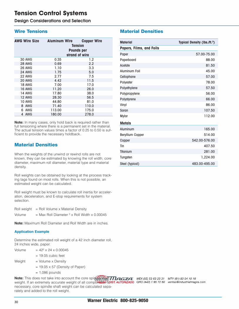
Material Densities
Material Typical Density (lbs./ft.3)
Papers, Films, and FoilsPaper 57.00-75.00
Paperboard 88.00
Acetate 81.50
Aluminum Foil 45.00
Cellophane 57.00
Polyester 78.00
Polyethylene 57.50
Polypropylene 56.00
Polystyrene 66.00
Vinyl 86.00
Saran 107.50
Mylar 112.00
MetalsAluminum 165.00
Beryllium Copper 514.00
Copper 542.00-576.00
Tin 407.50
Titanium 281.00
Tungsten 1,224.00
Steel (typical) 483.00-495.00
Wire Tensions
AWG Wire Size Aluminum Wire Copper WireTension
Pounds perstrand of wire
30 AWG 0.35 1.228 AWG 0.69 2.226 AWG 1.10 3.324 AWG 1.75 5.022 AWG 2.77 7.520 AWG 4.42 11.518 AWG 7.00 17.016 AWG 11.20 26.014 AWG 17.80 38.012 AWG 28.30 56.510 AWG 44.80 81.08 AWG 71.40 110.06 AWG 113.00 175.04 AWG 180.00 278.0
Note: In many cases, only hold back is required rather thanfull tensioning where there is a permanent set in the material.The actual tension values times a factor of 0.25 to 0.50 is suf-ficient to provide the necessary holdback.
Material Densities
When the weights of the unwind or rewind rolls are notknown, they can be estimated by knowing the roll width, corediameter, maximum roll diameter, material type and materialdensity.
Roll weights can be obtained by looking at the process track-ing tags found on most rolls. When this is not possible, anestimated weight can be calculated.
Roll weight must be known to calculate roll inertia for acceler-ation, deceleration, and E-stop requirements for systemselection.
Roll weight = Roll Volume x Material Density
Volume = Max Roll Diameter 2 x Roll Width x 0.00045
Note: Maximum Roll Diameter and Roll Width are in inches.
Application Example
Determine the estimated roll weight of a 42 inch diameter roll,24 inches wide, paper.
Volume = 422 x 24 x 0.00045
= 19.05 cubic feet
Weight = Volume x Density
= 19.05 x 57 (Density of Paper)
= 1,086 pounds
Note: This does not take into account the core spindle shaftweight. If an extremely accurate weight of all components isnecessary, core spindle shaft weight can be calculated sepa-rately and added to the roll weight.

Warner Electric 800-234-3369 31
Tension Control SystemsDesign Considerations and Selection
Additional Design Considerations
Considerations additional to the sizing process for the con-trolling device (brakes or clutches) are discussed below.
Torque
Although torque calculations are similar for unwind, interme-diate and rewind tension applications, both minimum andmaximum torque values of the controlling device must beconsidered for the application to be successful.
Minimum torque is the amount of force the controlling devicemust apply to maintain constant tension in the web. If theminimum torque exceeds the minimum torque necessary tomaintain web tension, the system cannot control properly,web tension will increase, and waste may result.
Maximum torque is the force provided by the controllingdevice to maintain proper web tension in worst-case condi-tions. If maximum torque is less than that required by theapplication, tension will be less than desirable and may resultin poor process.
E-Stop torque is the force the controlling device can applyduring machine E-Stop conditions. This E-Stop torquedepends on the type of controlling device used and the con-trol system employed. Not all control systems or controllingdevices, i.e., brakes, clutches, etc., have E-Stop capabilities.If E-Stop requirements are mandated by the application, thenboth the controller system and controlling device must havethe capabilities to provide this.
If the controlling device cannot produce the necessarytorque, then web spillage will occur and damage to machin-ery may result.
The controlling device must be large enough to cope with allapplication torque requirements. Even though most brakesand clutches have both static and dynamic torque capabili-ties, dynamic torque is more important than static torque intension applications.
Heat Dissipation
When a clutch, brake, or motor operates in a slipping modeor the motor is generating torque, heat is built up as a resultof the mechanical energy being converted to thermal energy.The controlling device must be able to dissipate this (heat)energy. If it doesn’t, it will fail, either electrically, mechanically,or both.
The heat dissipation capacity of the controlling device mustalways exceed the heat produced by the application.Environmental considerations must also be analyzed to insureproper operation. High ambient temperature, enclosures sur-rounding the controlling device limiting the airflow, or margin-al heat dissipation capacity have to be considered.
Some controlling devices may need additional cooling withfans or blowers to increase air flow.
The controlling device must be selected properly to handlethe application’s heat dissipation. This is probably one of themost critical factors in sizing and selection.
Speed
Brakes, clutches, and motors have minimum and maximumspeed ranges. Applications must always be checked toinsure that the requirements fall within the capabilities of thecontrolling device.
Failing to operate the controlling devices within their specifi-cations may result in the application failing to meet the speci-fied requirements; failure of the components mechanicallyand electrically, or even may result in serious damage orinjury.
Selection RPM is used to properly size a unit so that over siz-ing is minimized and an optimum system can be specified.
Inertia
By definition, inertia is that property of a body that makes itcontinue in the state of motion or rest in which it may beplaced until acted upon by some force.
Inertia is an important factor in tensioning applicationsbecause it has an effect in the sizing of the controlling deviceduring acceleration, deceleration, and E-Stop conditions.
Failure to consider inertia during the calculations can defi-nitely result in a system being undersized and unable to pro-vide optimum performance. This may result in instability atstart up and overrunning during deceleration and stopping.The end result in all cased will be poor product quality and,usually, excessive scrap.
With the exception of intermediate tension applications andanalog control systems, inertias are constantly changing inunwind and rewind applications. Worst-case inertia calcula-tions are normally used for sizing and selecting purposes.
Charts
Charts are provided for all clutches and brakes included inthe catalog. They provide a means of selecting the correctcontrolling device for a given application. Performance chartsand product specifications for brakes and clutches start onpage 68.
The charts provide thermal vs. selection speed data, themeans of selecting the unit based on thermal requirements.
Never select a controlling device whose thermal limits arenear or equal to those of the application. The next larger sizeunit should always be considered or the factory should beconsulted for additional options.
Selection charts are also provided for running torque vs.speed and E-Stop torque vs. speed. These charts provide ameans of checking the preliminary unit selection based onthermal requirements and torques.
The appropriate charts must be used in the sizing and selec-tion process.
Warner Electric 800-825-905032
Tension Control SystemsDesign Considerations and Selection
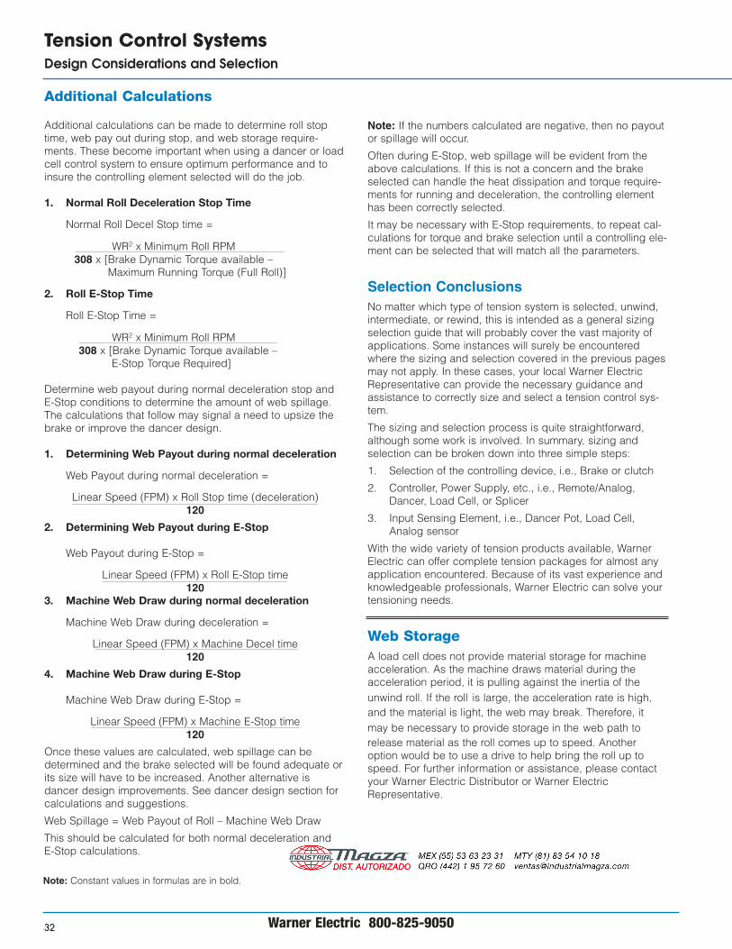
Additional Calculations
Additional calculations can be made to determine roll stoptime, web pay out during stop, and web storage require-ments. These become important when using a dancer or loadcell control system to ensure optimum performance and toinsure the controlling element selected will do the job.
1. Normal Roll Deceleration Stop Time
Normal Roll Decel Stop time =
WR2 x Minimum Roll RPM308 x [Brake Dynamic Torque available –
Maximum Running Torque (Full Roll)]
2. Roll E-Stop Time
Roll E-Stop Time =
WR2 x Minimum Roll RPM308 x [Brake Dynamic Torque available –
E-Stop Torque Required]
Determine web payout during normal deceleration stop andE-Stop conditions to determine the amount of web spillage.The calculations that follow may signal a need to upsize thebrake or improve the dancer design.
1. Determining Web Payout during normal deceleration
Web Payout during normal deceleration =
Linear Speed (FPM) x Roll Stop time (deceleration)120
2. Determining Web Payout during E-Stop
Web Payout during E-Stop =
Linear Speed (FPM) x Roll E-Stop time120
3. Machine Web Draw during normal deceleration
Machine Web Draw during deceleration =
Linear Speed (FPM) x Machine Decel time120
4. Machine Web Draw during E-Stop
Machine Web Draw during E-Stop =
Linear Speed (FPM) x Machine E-Stop time120
Once these values are calculated, web spillage can bedetermined and the brake selected will be found adequate orits size will have to be increased. Another alternative isdancer design improvements. See dancer design section forcalculations and suggestions.
Web Spillage = Web Payout of Roll – Machine Web Draw
This should be calculated for both normal deceleration andE-Stop calculations.
Note: If the numbers calculated are negative, then no payoutor spillage will occur.
Often during E-Stop, web spillage will be evident from theabove calculations. If this is not a concern and the brakeselected can handle the heat dissipation and torque require-ments for running and deceleration, the controlling elementhas been correctly selected.
It may be necessary with E-Stop requirements, to repeat cal-culations for torque and brake selection until a controlling ele-ment can be selected that will match all the parameters.
Selection ConclusionsNo matter which type of tension system is selected, unwind,intermediate, or rewind, this is intended as a general sizingselection guide that will probably cover the vast majority ofapplications. Some instances will surely be encounteredwhere the sizing and selection covered in the previous pagesmay not apply. In these cases, your local Warner ElectricRepresentative can provide the necessary guidance andassistance to correctly size and select a tension control sys-tem.
The sizing and selection process is quite straightforward,although some work is involved. In summary, sizing andselection can be broken down into three simple steps:
1. Selection of the controlling device, i.e., Brake or clutch
2. Controller, Power Supply, etc., i.e., Remote/Analog,Dancer, Load Cell, or Splicer
3. Input Sensing Element, i.e., Dancer Pot, Load Cell,Analog sensor
With the wide variety of tension products available, WarnerElectric can offer complete tension packages for almost anyapplication encountered. Because of its vast experience andknowledgeable professionals, Warner Electric can solve yourtensioning needs.
Web StorageA load cell does not provide material storage for machineacceleration. As the machine draws material during theacceleration period, it is pulling against the inertia of theunwind roll. If the roll is large, the acceleration rate is high,and the material is light, the web may break. Therefore, itmay be necessary to provide storage in the web path torelease material as the roll comes up to speed. Anotheroption would be to use a drive to help bring the roll up tospeed. For further information or assistance, please contactyour Warner Electric Distributor or Warner ElectricRepresentative.
Note: Constant values in formulas are in bold.

Warner Electric 800-825-9050 33
Tension Control SystemsDesign Considerations and Selection
Designing the Optimum Dancer StorageSystemFor closed loop dancer controlled systems, the actual webtension is determined by the downward pressure of thedancer roll or by the loading on the dancer on the web.Consequently, special attention should go into the design ofthe dancer arm system to provide both consistent tensionand adequate web storage for optimum web stop perform-ance.
Load Cell vs. DancerDeciding between a load cell and a dancer system requiresconsideration of many inter-related factors. Sometimes a loadcell control is selected when the material being tensioned isnot flexible and will not easily wrap around a dancer roll. Forexample, medium to heavy gauge metals are often tensionedwith load cell systems.
Load cell systems can also be selected because of spacelimitations in the application, or because they are easier toretrofit to existing applications. In retrofit applications, preci-sion balance or rollers may be required if line speeds aregreater than 650 feet per minute.
Dancer tension control is still the preferred method of controlin many applications. For example, high speed printing appli-cations may require the "forgiveness" of a dancer system totake-up or release material during the dynamically unstableconditions seen at the unwind or rewind roll. The reasons forunstable conditions include fast decelerations or accelera-tions, out-of-round rolls, and flying splices. A dancer systemshould be considered when speeds are high and tensioncontrol requires extreme precision.
Dancer Roll Design and ConstructionThe dancer roll and control arms are the heart of this tensioncontrol system. Dancer construction is simple, but veryimportant.
For optimum performance, the dancer should be a thinwalled tubing and be loaded by massless, low friction aircylinders. A rolling diaphragm device is most commonlyused. For greatest accuracy, the wrap on the dancer rollshould be exactly 180 degrees.
Anything attached to the dancer for loading will detract fromthe dancer’s ability to act as a buffer and should be made aslight and (in the case of air cylinders) efficient as possible.
Construction of Dancer Arms for WebsDancer arms should utilize boxed construction to providerigidity so that the web does not cause the arms to twist.This also insures that the web will track properly over thedancer roller.
The pivot point should be bearing mounted so the dancerarm can move freely. The dancer roller should also be bear-ing mounted and the bearings should be small in diameterand as frictionless as possible.
This will help reduce the bearing drag and friction changeswhich affect good tensioning. Standard feed conveyor rollersand bearings are usually sufficient.
Construction of Dancer Arms for WireWire dancers usually employ a single arm. The pivot pointand dancer roller should both be bearing mounted to mini-mize friction and drag. Standard wire rollers are very gooddancer rollers for these type systems. These rollers usuallycontain excellent integral bearings.
Dancer Systems
Dancer Design and Considerations
Warner Electric dancer control systems are designed to con-trol tension in unwind, intermediate, or rewind applications formaterials such as paper, foil, films, cloth, metals or wire. Thesystem consists of four parts:
1. The controlling device, i.e. brake, clutch, or drive motor,AC or DC
2. The controller
3. A pivot point sensor which determines the position of thedancer roll
4. The dancer arm and roll assembly (customer supplied)
Dancer Arm Design
Various configurations of dancer arms exist, but their purposeis the same. The dancer provides a means of creating ten-sion on the web by providing a force opposite to the directionthe web is pulled.
The effective force applied to the arm to create the desiredtension is a function of the number of dancer rollers on thedancer arm.
Single Roll Dancer
F = 2 x N x T
Where:
F = Effective loading force against the web
T = Tension desired in the web
N = Number of dancer rollers
Multiple Roll Dancers
F = 2 x N x T
Where:
F = Effective loading force against the web
T = Tension desired in the web
N = Number of dancer rollers
Warner Electric 800-825-905034
Tension Control SystemsDesign Considerations and Selection
T
F
T
F
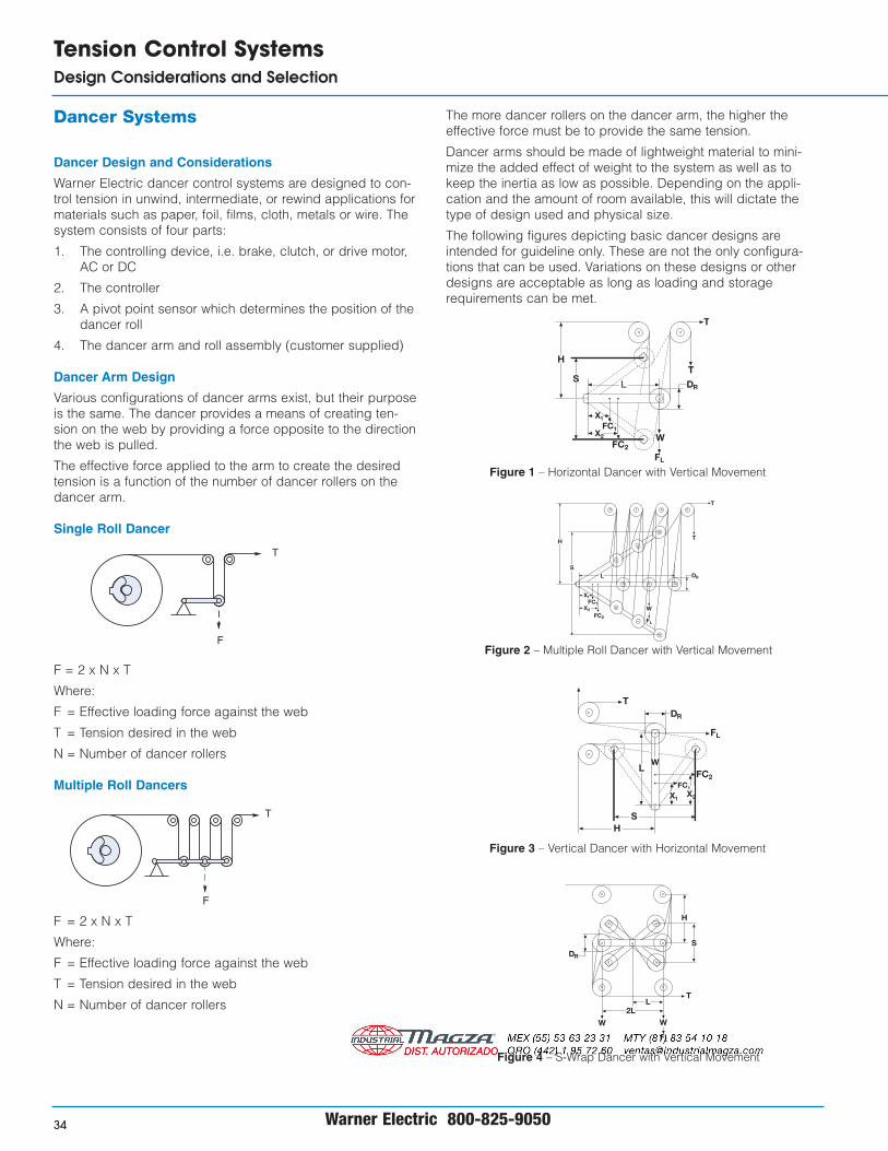
Figure 1 – Horizontal Dancer with Vertical Movement
Figure 2 – Multiple Roll Dancer with Vertical Movement
Figure 3 – Vertical Dancer with Horizontal Movement
Figure 4 – S-Wrap Dancer with Vertical Movement
H
ST
T
L
X1
DR
X2
FC1
FC2
FL
W
H
S
T
T
DR
FL
W
L
X2
FC1
FC2
X1
HS
T
X1
DR
X2
FC2
FL
WL
FC1
DR
H
S
2LL
T
FL
WW
The more dancer rollers on the dancer arm, the higher theeffective force must be to provide the same tension.
Dancer arms should be made of lightweight material to mini-mize the added effect of weight to the system as well as tokeep the inertia as low as possible. Depending on the appli-cation and the amount of room available, this will dictate thetype of design used and physical size.
The following figures depicting basic dancer designs areintended for guideline only. These are not the only configura-tions that can be used. Variations on these designs or otherdesigns are acceptable as long as loading and storagerequirements can be met.

Dancer Systems
The following calculations offer a guide for designing adancer arm. These will provide for an optimum system andfor proper loading and storage with the system.
1. Determine Dancer Arm Length, L
This can be done by calculating the length based on themaximum operating linear speed of the system or fromthe chart below.
a. Calculating Length
L = 12 + Max Web Speed (FPM) –200100
Minimum L to maximum L should normally be 12" to 40".
b. Chart Determination
Chart 1 – Dancer Arm Length vs. Web Speed
2. Determine Swing Height of Dancer Arm, S
S = 1.04 x L + DR
Where:L = Length of arm calculated or chosen in Step 1.DR = Diameter of dancer roller
3. Determine Height from edge of web to centerline ofDancer Pivot Point, H
H = S + DR
2Where:S = Swing height calculated from Step 2.DR = Diameter of dancer roller
Warner Electric 800-825-9050 35
Tension Control SystemsDesign Considerations and Selection
Dancer Arm Length (inches)
Max
. Web
Spe
ed a
t Unw
ind
(ft/m
in) 2000
1600
1200
800
400
00 8 16 24 32 40
UnsuitableLength
(Consult Factory)
Min
imum
Len
gth
SuitableLength
Because wide ranges of tensions are required from mostsystems, some type of loading is usually used to makesetting the tension easier. The preferred method is touse a pneumatic cylinder [normally a low inertia, frictionless type (Bello-fram) cylinder]. Weights or springs can beused, but these add weight and inertia to the system and aresometimes very difficult to stabilize.
4. Selecting the Loading Point, X
XMIN = 0.25 x LXMAX = 0.33 x L
Where :L = Length of the dancer arm
5.* Calculating Cylinder Force Required, FC
FC = F x LX
Where:F = Effective force of the dancerL = Length of the dancer calculated in Step 1X = Loading point calculated in Step 4
6. Calculating Cylinder Stroke required
Stroke = 2 x X Tan30 or 1.155 x X
Where:X = Loading point from Step 4
By following these guidelines, a dancer design with the+/- 30 degree swing will be achieved. This is the rangethe Warner Electric pivot point sensors require for opti-mum control performance.
The following chart depicts the percentage of tensionvariations based on the dancer position in a properlydesigned dancer.
Chart 2 - Tension variation vs. dancer arm angle
* See page 157 for effective cylinder force at a givenair pressure.
PivotPoint
Swing Radius ofDancer Arm (ft)
+30° min.
-30° max.
L
Dancer Angle
Ten
sion
Cha
nge
(per
cent
)
+20
0
+15
-10
+10
+5
-5
-40° -30° -20° -10° 0° +10° +20°+30°+40°
l/r = 2
+20° = +1%
-17° = -1%

Warner Electric 800-825-905036
Tension Control SystemsDesign Considerations and Selection
The following notes are provided for information purposesand should be considered in the design of a dancer arm.Following these guidelines will result in a more optimizedsystem.
I. Horizontal Dancer with Vertical Movement
A. Downward Loaded Dancer
Tension = Downward Loading Force2 x Number of Dancer Rolls
Total Downward loading force at dancer roll =
Downward force created by loading +weight of dancer arm
In this case, the pressure required will be lessbecause the dancer weight adds to the totalloading force.
B. Upward Loaded Dancer Arm
Tension = Upward Loading Force2 x Number of Dancer Rollers
Total Upward loading force at dancer roll =
Upward force created by loading -weight of dancer arm
In this case, the pressure required will be greaterbecause the dancer weight subtracts from the totalloading force.
II. Vertical Dancer with Horizontal Movement
Dancer weight in this case is no longer a factor on theloading force on the dancer.
Tension = Loading Force2 x Number of Dancer Rollers
Caution must be used when this type dancer anddiaphragm type cylinders as the rod assembly issupported by the cylinder bushing only. Secondarysupport is necessary to keep the cylinder shaft frombinding.
Related Documents