Technical Report No. 32-222 Tensile Properties of Five Low-Alloy and Stainless Steels Under High- Heafi’g-Rate and Constant-Temperature Conditions I 5 2 e#% P O 8 ” W. W. Gerberich U. E. Marfens R. A. Boundy JET PROPULSION LABORATORY CALIFORNIA INSTITUTE OF TECHNOLOGY PASADENA, CALIFORNIA June 1,1962

Welcome message from author
This document is posted to help you gain knowledge. Please leave a comment to let me know what you think about it! Share it to your friends and learn new things together.
Transcript
Technical Report No. 32-222
Tensile Properties of Five Low-Alloy and Stainless Steels Under High- Hea fi’g-Rate
and Constant- Temperature Conditions I
5 2 e # % P O 8 ”
W. W. Gerberich U. E. Marfens R. A. Boundy
JET P R O P U L S I O N L A B O R A T O R Y C A L I F O R N I A INSTITUTE OF TECHNOLOGY
PASADENA, CALIFORNIA
June 1,1962
NATIONAL AERONAUTICS AND S P A C E ADMINISTRATION CONTRACT No. NAS 7-100
Technical Report No. 32-222
Tensile Properties of Five Low-Alloy and Stainless Steels Under Higb -Heating -Rate
and Constant- Temperature Conditions
W. W. Gerberich H. E. Martens R. A. Boundy
Materials Reiearch Section
J E T P R O P U L S I O N L A B O R A T O R Y C A L I F O R N I A I N S T I T U T E OF T E C H N O L O G Y
P A S A D E N A , C A L I F O R N I A
June 1,1962

Copyright@ 1962 Jet Propulsion laboratory
California Institute of Technology

JPL Technical Report No. 32-222
CONTENTS
I.
II.
111.
IV.
V.
VI.
Introduction .. .. .. ... . .. . ........ ........ ........ .............. .......... .............. ...... ................ ................... , ...... ............ ........
Materials and Specimens ...................................................................................................................................
Experimental Test Equipment and Procedures .
Experimental Results and Discussion ..............................
A. 17-7 PH (TH 1050) Stainless Steel .....................................
B. 4340 Steel ........... ......................................... ........................................
C. 413O(80O0F Tem ..... ............................ .. ..... ....................................
D. 4130 (1050°F Temper) Steel ......................................................
..........................................................................
......................................................................
....................................
..........................................................
E. 410 Stainless Steel ..................................
Comparison of Results .................................. .......................................................................
Conc Ius ions . ... . . . .. . . . . . . .. . . . . . . . . . . . . . . . . . . . . . . . . . . . . . . . . .. . .... . . . . ..... ..........................................................................
. . . . . . . . . . . . . . . . . . . . . . . . . . . . . . . . . . . . . . . . . . . . . . . . . ......................................................................
. . . .. . . . . . . . . . . . . . . . . . . . . . . . . . . . . . . . . . . . . . . . . ......................................................................
Appendix. Test Equipment and Procedures ..........................................................................................................
References ......... .................................................................... ...................................................................
2
2
3
4
4
5
5
6
7
8
8
10
22
35
43
TABLES
1. Composition of materials ........................................ .................................................................................. 10
........ 10
11
12
13
2.
3.
4.
5.
Heat treatment of materials ....................................
Tensi le test results for 0.063-in.-thick sheet of 17-7 PH (1050) stainless steel ......................................
High-heating-rate results for O.W-in.-thick sheet of 17-7 PH (1050) stainless steel ..............................
Pseudo-heating-rate values calculated from tensile y ie ld data for a l l materials ......................................
iii

JPL Technical Report No . 32-222
TABLES (Cont'd)
6 . 7 . 8 . 9 .
10 . 11 . 12 . 13 .
Tensile test results for 0.130-in.-thick sheet of 4340 steel ......................................
High-heating-rate results for 0.130-in.-thick sheet of 4340 steel ............................
Tensile test results for 0.063-im-thick sheet of 4130 (800'F temper) steel
High-heating-rate results for 0.063-in.-thick sheet of 4130 (800'F temper) steel .........................
Tensile test results for 0.063-in.-thick sheet of 4130 (1050'F temper) steel ..........................................
High-heating-rate results for 0.063-in.dhick sheet of 4130 (1050'F temper) steel .................
Tensile tes t results for 0.063-in.-thick sheet of 410 stainless steel
High-heating-rate results for 0.063-in.-thick sheet of 410 stainless steel ................................................
.................
FIGURES
1 . Tensile and high-heating-rate test specimens ..............................................................................................
2 . Equipment for steady-state high-temperature tensi le tes ts ..........................................................................
3 . Equipment for high-heating-rate tes ts ............................................................................................................
4 . Clamp-on extensometer for high-heating-rate tests .....................................................................................
5 . Oscillograph recording of temperature and strain vs t ime ............................................................................
6 . Typical stress-strain curves for 17-7 PH (1050) stainless steel ................................................................
7 . Ultimate. yield. and modulus data for 17-7 PH (1050) stainless steel a t temperatures from 75 to 1200°F ..............................................................................................................................................
8 . Determination of 0.2% yield temperatures for 17-7 PH stainless steel a t the 20.7-ksi stress level ........................................................................................................................................................
9 . 10 . 11 .
High-heating-rate data for 17-7 PH (1050) stainless steel ..........................................................................
Typical stress-strain curves for 4340 steel ..................................................................................................
Ultimate, yield and modulus data for 4340 steel a t temperatures from 75 to 1200'F ..............................
14
15
16
17
18
19
20
21
22
23
24
24
25
25
25
26
26
27
27
JPL Technical Report No. 32-222
FIGURES (Cont'd)
12.
13.
14.
15.
16.
17.
18.
19.
20.
21.
22.
High-heating-rate data for 4340 steel ..............................................................................................................
Typical stress-strain curves for 4130 (800OF temper) steel .......... ..............................................................
Ultimate, yield, and modulus data for 4130(8OO0F temper) steel a t temperatures from 75 to 12OO0F .........
High-heating-rate data for 41 30 (80OoF temper) stee I ........................................................................
Typical stress-strain curves for 4130 (1050OF temper) steel ............................................................
Ultimate, yield, and modulus data for 4130 (1050OF temper) steel a t temperatures from 75 to 120OOF .........................................................
.................................................................................................................
...............................................
High-heating-rate data for 4130 (105OOF temper) steel .........
Typical stress-strain curves for 410 stainless steel ........................
......................................................
.............................................
Ultimate, yield, and modulus data for 410 stainless steel a t temperatures fr
High-heating-rate data for 410 stainless steel .................................................... ...............
Comparison of yield temperatures obtained under most and least severe conditions for a l l materials ..................................................................... . . . . . . . . . . . . . . . . . . . . . . . . . . . . . . . . . . . . . . . . . . . . . . . . . . . . . . . . . . . . . . . . . .
A-1. Thermal gradient calibration of 200OOF furnace for tensi le tests . . . . . . . . . . , . . . . .... . .. . . , . . . . . . . . . . .... . . .... . . . . . . . .
A-2. Pull-rods and extensometer for steady-state high-temperature tensi le tests ............................................
A-3. Calibration curves for high-temperature tensi le extensometer
A-4. Schematic of programmer and power units ...............................
A-5. Thermocouple circuit to eliminate super-imposed voltages ...............
A-6. Oscillograph and programmer units ............................................................ .......................................
A-7. Thermal gradient calibration of high-heating-rate equipment at about 6OO0F .......
...............................................
..................................................
........................................
.................
A-8. Thermal gradient calibration of high-heating-rate equipment a t about 1100'F .............
A-9. Calibration curves for high-heating-rate extensometer . . . . . . . . . . . . . . . . . . .
A-10. Assembly of thermocouples and extensometer on high-heating-rate specimen ...... . . . . . . . . . . .. . . . . . . . . .
28
28
29
30
30
31
31
32
32
33
34
38
38
39
39
40
40
41
41
42
42
V

-
IPL Technical Report No. 32-222
ABSTRACT
The purpose of this investigation was to fill several gaps in the literature on high-heating-rate properties of several commonly used aerospace, structural materials. High-heating-rate results were obtained for three low-alloy steels: 4340 (40O0F temper), 4130 (800°F temper), and 4130 (1050OF temper) and two stainless steels: 17-7 PH (TH 1050) and 410 (700°F temper). Stress levels ranging from 10 to 125 ksi and heating rates varying from 40 to 2000°F/sec. were the testing parameters. A method is devised to compare yield temperature data of high-heating- rate tests to tensile yield data of steady-state elevated temperature tests.
Results indicate that high-heating-rate properties of all the materials are superior to steady-state elevated temperature properties for heating rates of 40 to 2000°F/sec. For the low alloy steels, the higher the tempering tem- perature, the better the high-heating-rate properties. Pro- perties of 410 stainless steel are superior to those of all other materials investigated.
1
JPL Technical Report No. 32-222
1. INTRODUCTION
The transient temperature conditions encountered by many missile structural components are such
that it is necessary to have material design data for extreme cases . It has been shown (Ref. 1-9) that the
yield and ultimate strengths of materials under high-heating-rate conditions are, in general, higher than
those obtained from steady-state, high-temperature tensile tests. Thus, to obtain full capability of the
structural components, i t is necessary to know the strength of the materials used under the heating rates
encountered. .
A survey of the literature was made, and i t was determined that there was a lack of information for
commonly used structural materials at heating rates encountered i n rocket motor c a s e s or nozzles or in
aerodynamic heating of ballistic missiles. The short-time elevated temperature properties were of little value,
and the extremely high-heating-rate properties of the not commonly-used materials were also of little value.
Therefore, the present coordinated program w a s undertaken.
II. MATERIALS AND SPECIMENS
For this investigation a 0.130-in.-thick sheet of 4340 steel and 0 . 0 6 3 - i n ~ h i c k sheets of 4130 s teel ,
17-7 PH stainless steel , and 410 stainless s teel were used. All high-heating-rate and tensile specimens
(see Fig. 1) were machined from the same heat of each material. The chemical composition from the manu-
facturer's tes t report is shown for each material in Table 1. All heat treatments as shown in Table 2 are
standard specifications except for the 4340 which had a low tempering temperature of 400'F. This, along with
the two tempering temperatures for 4130, was expected to give a strength range of about 130 to 260 ksi over
which high-heating-rate properties of low alloy s teel could be evaluated.
2
JPL Technical Report No. 32-222
111. EXPERIMENTAL TEST EQUIPMENT AND PROCEDURES
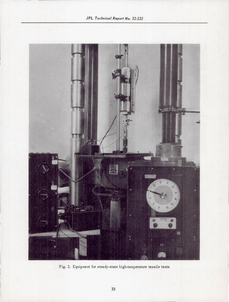
Tensi le testing at steady-state elevated temperatures utilized a universal testing machine and a
2000'F furnace with related equipment as shown in Fig. 2. The furnace was calibrated to give temperature
uniformity of +5'F over the specimen gage length for temperatures from 600 to 1800'F. For a tes t run, the
specimens were pulled at a strain rate of approximately 0.004 min-
at a crosshead speed of 0.1 in./min to fracture.
to slightly past the yield point and then
The equipment for the high-heating-rate t e s t s w a s comprised of a 50-Kva transformer with ignitron
pulser for self-resistance heating of the specimen, a temperature-control programmer to insure constant heating
rates, a 20,000-lb modified creep tester, a clamp-on extensometer, and a direct read-out oscillograph for
recording the temperature and deformation of the specimen. A complete layout of the equipment is shown in
Fig. 3.
Heating-rates up to 500°F/sec were obtained with the programmer unit; rates higher than 500'F/sec
were obtained manually. The linearity of the programmed heating rates were found to vary about i7% over
the entire temperature range. Somewhat larger variation was encountered for the manual runs at the beginning
and end of the run. For the test parameters of this investigation, the maximum thermal gradient was less than
5% of the average temperature at any particular time during the test.
The clamp-on extensometer utilized a linear potentiometer with a 2O:l lever arm as shown in Fig. 4.
Thermal transients were reduced by using sapphire gage points and an aluminum radiation shield. Calibration
indicated the extensometer system had an accuracy of about f2.0% of the measured strain a t all temperatures.
Tes t procedures for the high-heating-rate t e s t s consisted of dead-weight loading the specimen and
then resistance-heating i t using a programmed or manual temperature control. Outputs from a spot-welded
&mil, chromel-alumel thermocouple and the clamp-on extensometer were recorded on the oscillograph. A s
there was a limited range on the extensometer, the specimen was tested to slightly past the yield point. A
resulting temperature-time, strain-time record is shown in Fig. 5.
Details of calibration experiments, equipment, and procedures for both tensile and high-heating-rate
t e s t s are given in the Appendix.
3
JPL Technical Report No. 32-222
IV. EXPERIMENTAL RESULTS AND DISCUSSION
A. 17-7 PH (TH1050) Stainless Steel
Results of the steady-state high-temperature tensi le tes t s are given in Table 3. The elongation and
reduction of area values indicate there is an embrittling effect at 400 and 600°F. Typical stress-strain curves
for this alloy are shown in Fig. 6 for various temperatures from 80 to 1200°F. A summary graph of ultimate,
yield, and modulus data is given for all temperatures in Fig. 7. All three parameters decrease a t about the
same rate with increasing temperature. Also indicated in Fig. 7 is the fact that after the embrittling range
of 600"F, both the tensile and 0.2% offset yield strengths fall off rapidly. High-heating-rate results are
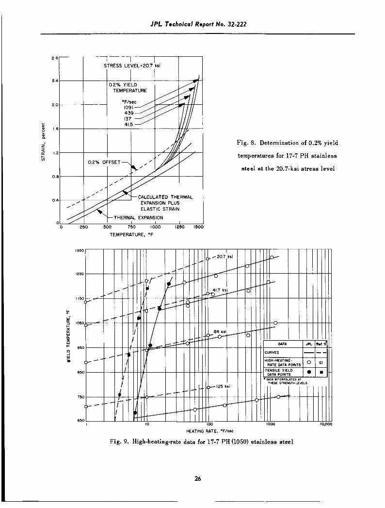
given in Table 4 for four heating ra tes a t each of four s t ress levels. The 0.2% offset yield temperatures are
obtained by experimentally determining the thermal expansion over the entire temperature range. To th is w a s
added an elastic strain which was obtained from the applied s t ress and the modulus at each particular
temperature. Thus a strain curve is calculated from
U = (T.E.) + -, n = 70, , 1400'F
T n 'Tn T n E
where E i s the total nonplastic strain, T.E. is the thermal expansion, uis the applied s t ress , E i s the
modulus of elasticity, and T n is a particular temperature. For an actual test, the strain deviates from the
calculated line as it becomes plastic. The yield temperature i s defined as the point a t which a 0.2% offset
line drawn parallel to the calculated line intersects with the experimental curve. This method of determining
the yield temperatures is shown in Fig. 8 for a l l heating rates a t the 20.7 ks i s t ress level. To compare with
the high-heating-rate data, yield temperatures and pseudo-heating rates were calculated from the tensile
data as follows: For a particular s t ress level, the temperature at which the yield strength occurs is found
from Fig. 7. For this yield temperature, the strain at yielding is determined from Fig. 6. Knowing the strain
rate to be 0.004 min'l allows the t ime to the yield point to be calculated. Dividing the yield temperature
by this t ime gives a pseudo-heating rate. Similar calculations for all materials and s t r e s s levels are given
in Table 5.

IPL Technical Report No. 32-222
A semi-log plot of yield temperature versus log heating-rate is shown in Fig. 9. For this material,
the high-heating-rate data extrapolate very well to the yield temperatures determined from the elevated
temperature tensile tests. For comparison purposes, data from Ref. 9 for the same material and heat treatment
are a l so shown in Fig. 9. These data which ran from 1 to 100°F/sec bracketed the pseudo-heating rates
calculated from their tensile data. Here again, the high-heating-rate yield temperatures were in close agreement
with the tensile test yield temperatures. The reason their pseudo-heating rates were shifted to the left in Fig.
9 i s that the strain rate of 0.002 min-' reported in Ref. 9 was half that of this investigation. Considering the
differences in material composition and tes t procedures, the observed differences are not large.
B. 4340 St8.I
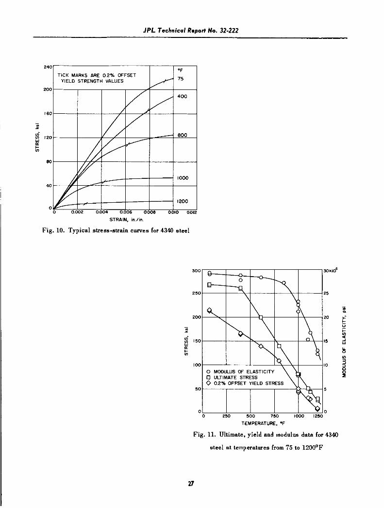
This material was the only one using 0.130-in. thick specimens as the others were aI1 0.063-in. thick.
A summary of all tensile test data covering a temperature range of 75 to 120O0F is given in Table 6.
Here, the elongation and reduction of area values indicate no embrittling effect a t the test temperatures from
400 to 1200OF. Typical stress-strain curves and a summary graph of elastic modulus, ultimate strength, and
yield strength are shown in Fig. 10 and 11. The data indicate that above the tempering temperature of 4W°F
the tensile strength drops very rapidly with increasing test temperature. The yield strength decreases at a
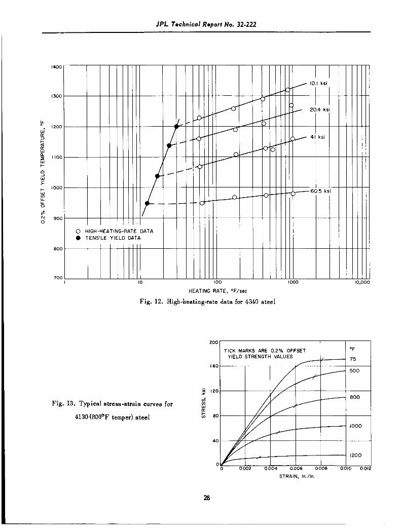
less rapid rate a t temperatures above room temperature. Table 7 gives all high-heating-rate resuIts for four
heating rates at each of four stress levels ranging from 10 to 60 ksi. These data are shown in a semi-log plot
(Fig. 12) along with pseudo-heating rate data calculated in Table 5 from the tensile data. A s before with the
17-7 PH, the yield temperatures of the high-heating-rate t e s t s extrapolated quite well to the yield data of the
i
tensile tests. The fastest heating rate of 1000°F/sec at the 60.5-ksi s t ress indicates only a slightly higher
yield temperature (Fig. 12) than that determined from the tensile yield data that used a half-hour soak time.
This suggests that any structural change a t 950°F is practically complete in the 1-sec heating time to this
yield temperature at the 60.5-ksi stress level
~
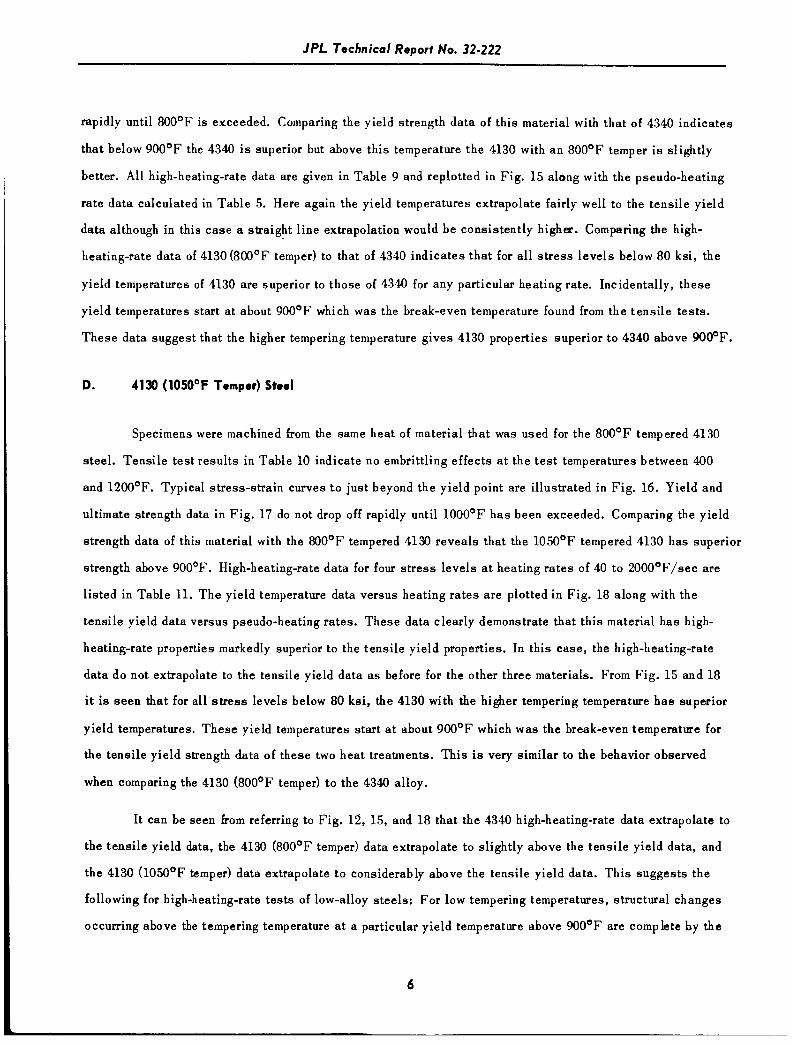
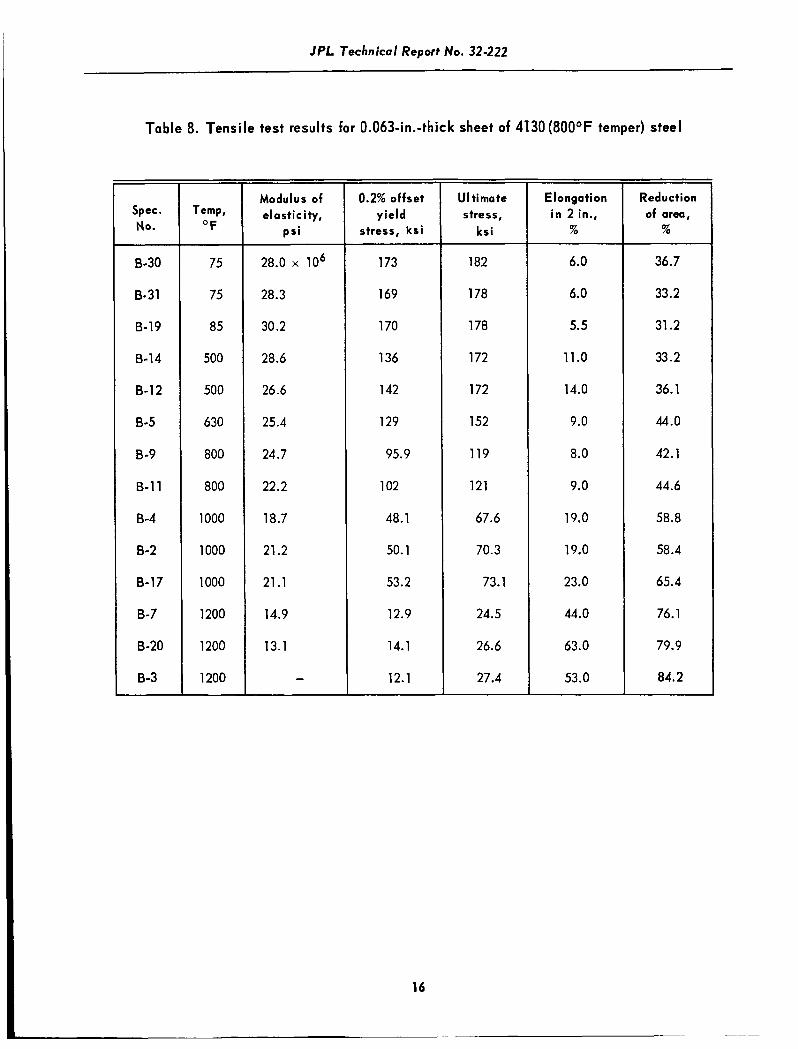
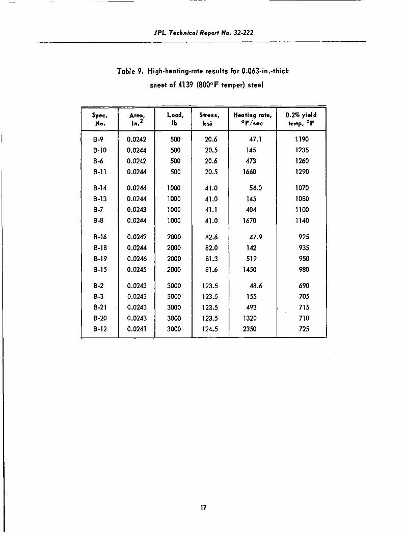
C. 4130 (8OOOF Temper) Stoel
Results of the elevated-temperature tests are given in Table 8. Reduction of area data give no in-
dication of any embrittling effects a t the tes t temperatures between 500 and 1200OF. Typical stress-strain
curves and modulus, yield strength, and ultimste strength data are shown in Fig. 13 and 14. There is a n
immediate fall-off in the tensile strength data above 500"F, but the yield strength data do not decrease as
5
IPL Technical Report No. 32-222
rapidly until 800'F is exceeded. Comparing the yield strength data of this material with that of 4340 indicates
that below 900'F the 4340 is superior but above this temperature the 4130 with an 800'F temper i s slightly
better. All high-heating-rate data are given i n Table 9 and repbt ted i n Fig. 15 along with the pseudo-heating
rate data calculated in Table 5. Here again the yield temperatures extrapolate fairly well to the tensile yield
data although in this case a straight line extrapolation would be consistently high=. Comparing the high-
heating-rate data of 4130 (800'F temper) to that of 4340 indicates that for all s t ress levels below 80 ks i , the
yield temperatures of 4130 are superior to those of 4340 for any particular heating rate. Incidentally, these
yield temperatures start at about 900'F which was the break-even temperature found from the tensi le tests.
These data suggest that the higher tempering temperature gives 4130 properties superior to 4340 above 9006F.
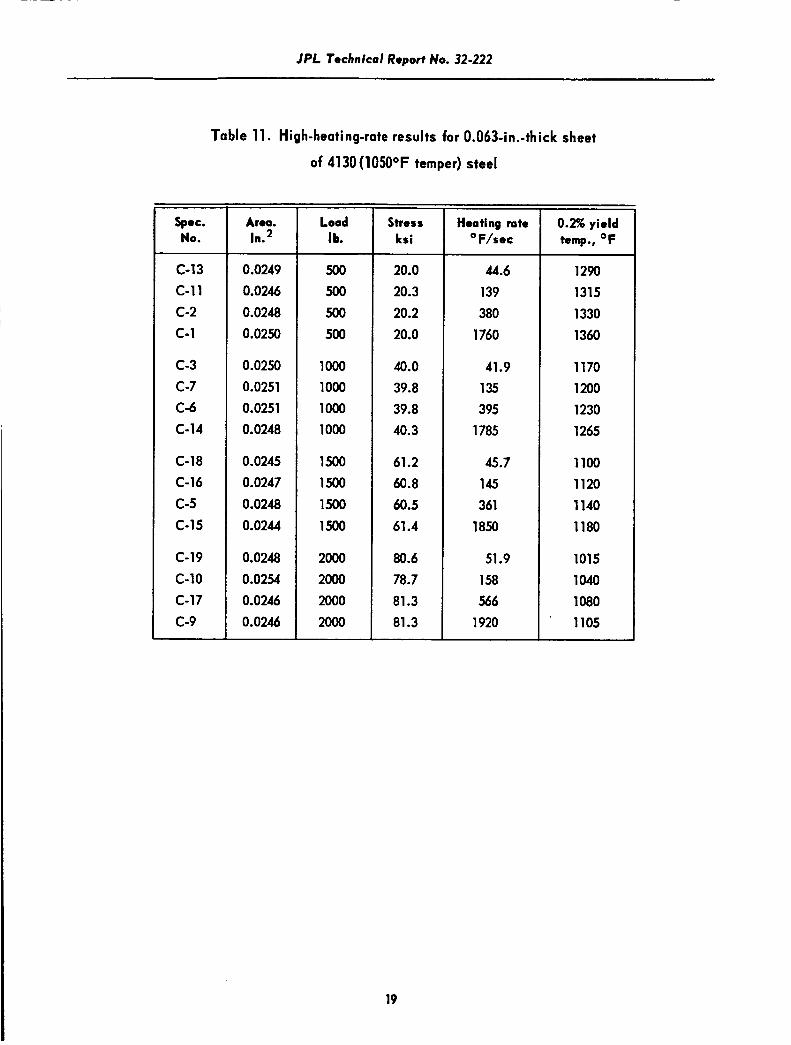
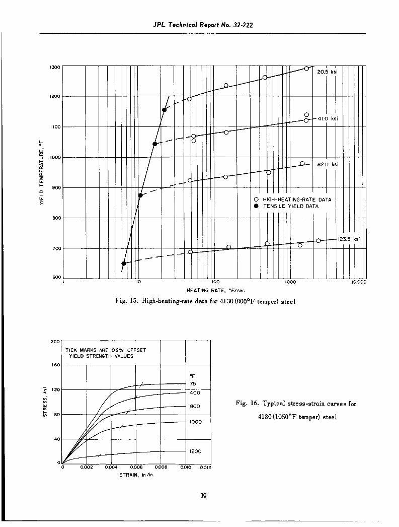
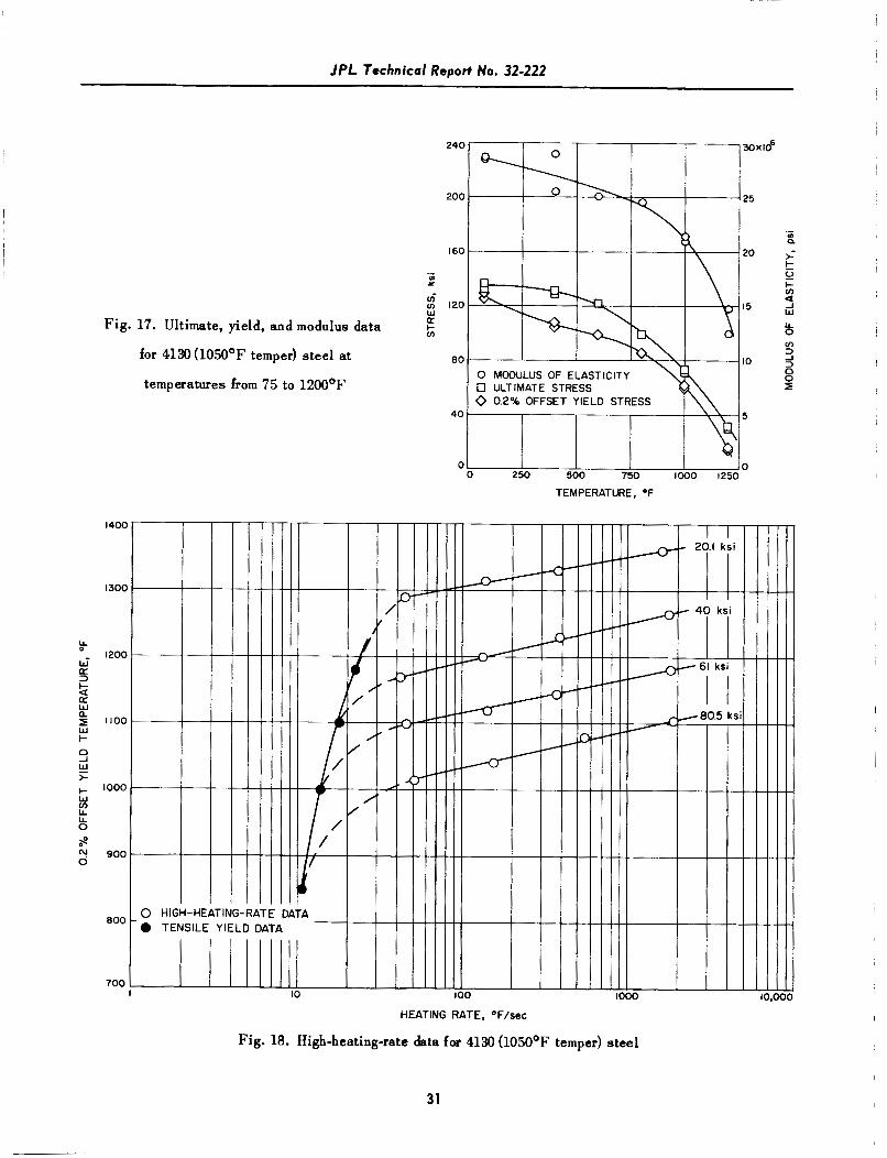
D. 4130 (105OOF Tomper) Stool
Specimens were machined from the same heat of material that was used for the 800'F tempered 4130
steel. Tensile tes t results in Table 10 indicate no embrittling effects a t the t e s t temperatures between 400
and 1200'F. Typical stress-strain curves to just beyond the yield point are illustrated in Fig. 16. Yield and
ultimate strength data in Fig. 17 do not drop off rapidly until lOOO'F has been exceeded. Comparing the yield
strength data of this material with the 800'F tempered 4130 reveals that the 1050'F tempered 4130 has superior
strength above 900'F. High-heating-rate data for four s t ress levels a t heating rates of 40 to 2000'F/sec are
listed in Table 11. The yield temperature data versus heating rates a re plotted in Fig. 18 along with the
tensile yield data versus pseudo-heating rates. These data clearly demonstrate that this material has high-
heating-rate properties markedly superior to the tensile yield properties. In this case, the high-heating-rate
data do not extrapolate to the tensile yield data a s before for the other three materials. From Fig. 15 and 18
it is seen that for all s t ress levels below 80 ksi, the 4130 with the higher tempering temperature h a s superior
yield temperatures. These yield temperatures start a t about 900'F which was the break-even temperature for
the tensile yield strength data of these two heat treatments. This is very similar to the behavior observed
when comparing the 4130 (800'F temper) to the 4340 alloy.
It can be seen from referring to Fig. 12, 15, and 18 that the 4340 high-heating-rate data extrapolate to
the tensi le yield data, the 4130 (800'F temper) data extrapolate to slightly above the tensile yield data, and
the 4130 (1050'F temper) data extrapolate to considerably above the tensile yield data. This suggests the
following for high-heating-rate tes ts of low-alloy steels: For low tempering temperatures, structural changes
occurring above the tempering temperature a t a particular yield temperature above 900'F are complete by the
6
IPL Technical Report No. 32-222
time th i s temperature i s reached. These particular structural changes are not quite complete for tempering
temperatures about equal to the yield temperatures. For high tempering temperatures, the original structure
i s sufficiently stable to give additional strengthening even a t yield temperatures approaching 1300'F.
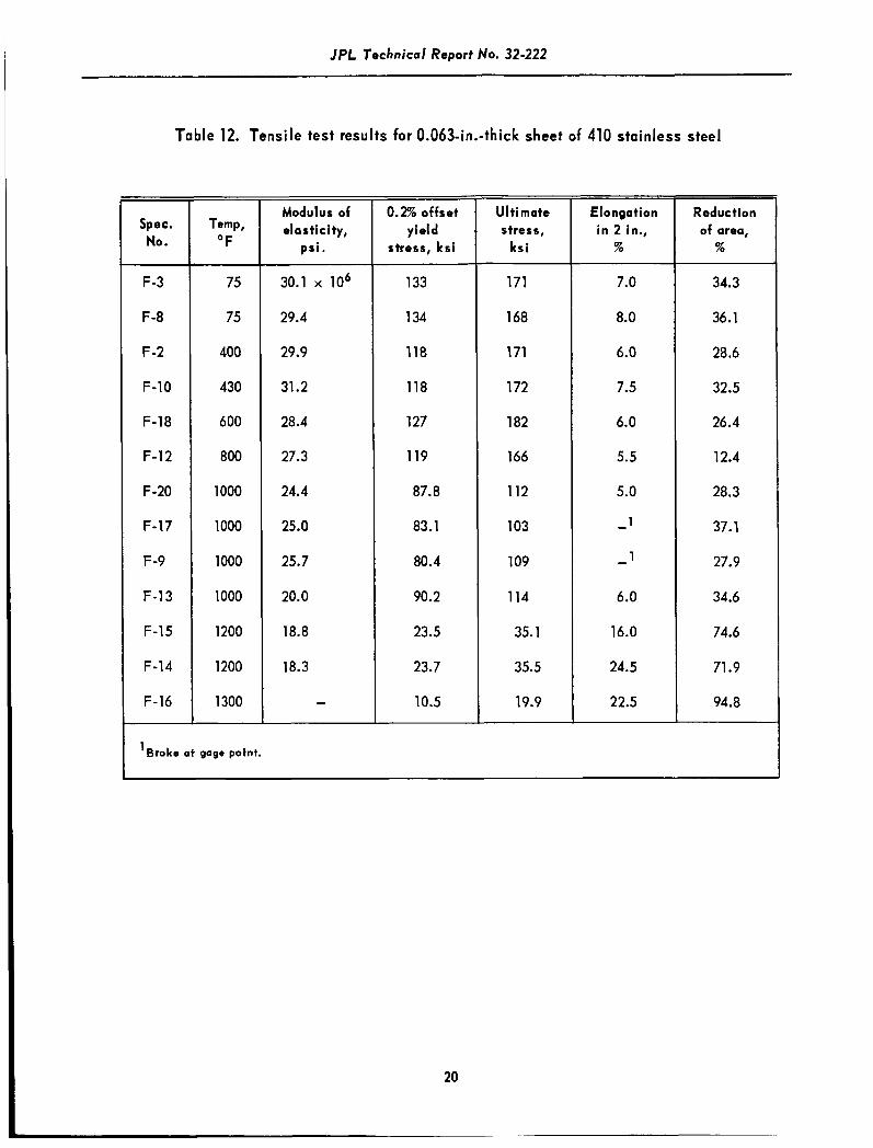
E. 410 Stainloss S t d
A summary of a l l tensile tes t results i s given in Table 12. Elongation and reduction of area data
indicate an extreme embrittling effect a t tes t temperatures from 600 to 1000'F. Several of the specimens at
1OOO'F were notch sensitive and broke a t one of the gage points. Typical stress-strain curves and ultimate,
yield, and modulus data are given in Fig. 19 and 20 for a temperature range of 75 to 1300'F. Several interest-
ing results are seen in Fig. 20. First, the modulus of elasticity increases slightly between room temperature
and 500'F. Similar behavior i s observed for 410 stainless in Ref. 10. Secondly, both the yield and ultimate
strengths increase in the temperature range of 500 to 750'F. It should be noted that the tempering temperature
of this alloy was 700'F. The yield strength does not start to fall off rapidly until about 1000'F. This
unusual tensile behavior is reflected in the high-heating-rate results given i n Table 13. The data replotted in
Fig. 21 along with the pseudo-heating rate data show that the high-heating-rate yield data extrapolate to a
much higher temperature than the tensile yield data. Even though the room temperature yield strength is
133 ksi, all of the 126-ksi s t ress level high-heating-rate tests have yield temperature above 1100OF.
Apparently some strengthening occurs when traversing the embrittling range of 600 to 1000OF. This i s in-
dicated by the strengthening that was observed in the tensile data. (See Fig. 20.) This mechanism i s
beneficial to the high-heating-rate results for s t ress levels greater than 20 ksi. For all heating-rates and
s t ress levels investigated, the 410 s ta inless s tee l i s superior to a l l other materials.
It should be cautioned here that such excellent properties of the 410 stainless might not be found
at heating rates much l e s s than the range covered. Also, the results presented here do not pertain to h e type
of heating cycle that heats rapidly to an elevated temperature, then holds a t that temperature for a con-
siderable length of time.
7

JPL Technical Report No. 32-222
V. COMPARISON OF RESULTS
All of the materials of this investigation are compared as to the most severe and least severe con-
ditions encountered during testing. As the lower heating rates gave lower yield temperatures, the most
severe condition w a s the slowest heating rate and the highest s t ress level. Therefore, a 40'F/sec heating
rate and an 82-ksi stress level were chosen. Actually, the most severe condition for several of the materials
was 125 ksi. However, since the room temperature yield strength of 4130 (1050OF temper) steel was 125 ksi,
the materials were not compared at this s t ress level. For the least severe condition, a 1000°F/sec heating
rate and a 20.5-ksi s t ress level were selected. The resulting comparison of the yield temperatures for each
of these conditions i s shown in Fig. 22. For both the most severe and least severe conditions, the materials
ranked in the same order starting with the best: 410 Stainless Steel (700'F temper), 4130 (1050'F temper)
steel , 17-7 PH Stainless Steel, 4130 (800'F temper) steel, and 4340 (400'F temper) steel .
VI. CONCLUSIONS
The investigation described in this Report h a s yielded the following conclusions:
1. The temperature a t which the 0.2% offset yield point occurs is greater than the corres-
ponding temperature a t which yielding occurs in a constant temperature tensile test. Th i s
is indicated by all of the materials investigated for heating rates of 40 to 2000°F/sec at
all stress levels.
2. For the materials of this investigation which have a rapid decrease of tensile yield
strength above 750°F, a semi-log plot of yield temperature versus heating rate extra-
polates approximately to the tensile yield data.
3. F o r the materials of this investigation which do not have a rapid decrease of tensile
yield strength until a b u t 1000°F, a semi-log plot of yield temperature versus heating rate
extrapolates to well above the tensile yield data.
8

I P L Technical Report No. 32-222
4. The high-heating-rate yield data show greater improvement over constant temperature
tensile yield data with increasing tempering temperatures for low alloy steels at heating
rates above 40'F/sec and stress levels below 80 ksi.
5. For the parameters of this investigation, high-heating-rate yield temperatures of 410
stainless steel are superior to those of all other materials investigated.
9

jPL Technical Report No. 32-222
Table 1. Composition of materials
4130 0.285 0.47 0.016 0.019 0.29 0.95 0.11 - 0.23 0.14
410 S.S. 0.08 0.35 0.021 0.009 0.34 12.88 0.29 0.015 0.05 - 0.08 0.015
Material Condition
17-7 PH TH( 1050)
I
41 30 8 O O O F Temper
4130 1 050' F Temper
410 S.S. I
Table 2. Heat treatment of materials
- ~ ~~
Heat treatment procedure Specification
140OOF for 1)/2 hr; cool to 6OOF. Within 1 hr, hold )/2 hr; temper a t 1O5O0F for 1M hr, air cool.
Armco Steel Corp.
Austenitize for 15 min at 1525OF; o i l quench and temper at 4OOOF for 3 hr, air cool.
Austenitize for )/2 hr at 1600OF; o i l quench and temper at 8OOOF for 1 hr, air cool.
Jet Propulsion Laboratory
Mil. Spec. H-6875 B
Austenitize for 5 hr a t 1600OF; o i l quench and temper at 105OOF for 1 hr, air cool.
Mil. Spec. H-6875 B
180OOF for )/2 hr; oil cool to room temp. and temper at 7OOOF for 1 hr, air cool.
Mil. Spec. H-6875 B
10
IPL Technical Report No. 32-222
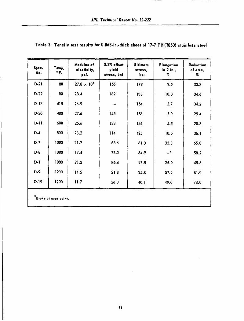
Table 3. Tensile test results for 0.063-in.-thick sheet of 17-7 PH (1050) stainless steel
Spec. No.
D-21
D-22
D-17
D-20
D-11
D-4
D-7
D-8
D-1
D-9
D-19
Temp, OF.
80
80
41 5
400
600
800
1000
1000
1000
1200
1200
Modulus of elostici ty,
psi.
27.8 x lo6
28.4
26.9
27.6
25.6
23.2
21.2
17.4
21.2
14.5
11.7
0.2% offset yield
stres E, k si
155
162
- 145
133
114
63.6
73.0
86.4
21.8
26.0
Ultimate stress,
kr i
178
183
1 54
1 56
146
125
81.3
84.9
97.5
35.8
40.1
Elongation in 2 in.,
%
9.5
10.0
5.7
5.0
5.5
10.0
35.3
* - 25.0
57.0
49.0
Reduction of area,
%
33.8
34.6
34.2
25.4
20.8
36.1
65.0
58.2
45.6
81 .O
78.0
c Broke at gage point.
11

JPL Technical Report No. 32-222
Spec. No.
A-1 3 A-12 A-7 A-6
A-8 A-14 A-9 A-15 A-1 1
A-1 9 A-1 0 A-20 A-1 6
A-4 A-5 A- 1 A-3
Table 4. High-heatinprate results for 0.063-in.-thick sheet of
17-7 PH (1050) stainless steel
Area, 2 In.
0.0244 0.0238 0.0239 0.0243
0.0244 0.0243 0.0238 0.0239 0.0240
0.0237 0.0238 0.0237 0.0242
0.0236 0.0240 0.0244 0.0242
Load, Ib.
500 500 500 500
1000 1000 1000 1000 1000
2000 2000 2000 2000
3000 3000 3000 3000
Stress, k r i
20.5
21.0 20.9 20.6
41 .O 41.2 42.0 41.8 41.7
84.4 84.0 84.4 82.6
127.0 125.0 123.0 124.0
Heating rate, OF/sec
41.5 137 439
1091
47.0 48.4
121 455 967
47.0 1 56 450
1238
44.1 138 409
1350
0.2% yield Temp., O F
1210 1240 1280 1315
1135 1120 1165 1180 1215
965 995
1000 1050
700 715 735 750
12

JPL Technical Report No. 32-222
Table 5. Pseudo-heating-rate values calculated from tensile yield
data for all materials
Material condition
~~
17-7 PH
TH( 1050)
4340
4130 8OOOF temper
41 30 105OOF temper
410 stainless
steel
Stress level,
ksi
21 .o 42.0 84.0
125.0
10.1 20.4 41 .O 60.5
20.5 41 .O 82.0
123.5
20.1 40.0 61 .O
80.5
21.2 42.0 84.0
126.0
0.2% (1) yield
temp., O F
1210 1110 960 685
1200 1140 1040 950
1155 1045 875 650
1180 1100 1000 850
1220 1125 1000 750
Strain (2) a t yield strength
0.0035 0.0045 0.0055 0.0070
0.0026 0.0031 0.0040 0.0050
0.0035 0.0041 0.0055 0.0068
0.0035 0.0040 0.0048 0.0052
0.0030 0.0043 0.0055 0.0064
Time to (3) yield strength,
sec
52 67 82
105
39 46 60 75
52 61 82
101
52 60 71 78
45 64 82 96
Pseudo - (4) heati ng-rate,
F/sec
23.3 16.5 11.7 6.5
30.8 24.8 17.3 12.7
22.2 17.1 10.7 6.4
22.6 18.3 14.1 10.9
27.0 17.6 12.2 7.8
'Determined from yield stress vs temperature curves (Fig. 17, 21, 24, 27, and 30). 2Determined from Fig. 16, 20, 23, 26, and 29. 3Yield strain divided by strain rate of 0.000067 in./in./sec.
4(1) divided by (3).
13
IPL Technical Report No. 32-222
Spec. No.
A-5
A-14
A-33
A-34
A-37
A-7
A-4
A-20
A-3 1
A-8
A-36
A-1 0
A-30
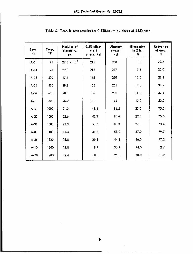
Table 6. Tensile test results for 0.130-in.-thick sheet of 4340 steel
75
75
400
400
620
800
1000
1000
1000
1100
1120
1200
1200
~ ~~
Modulus of el o sticity,
psi
29.3 x l o 6
29.0
27.7
28.8
28.3
26.2
21.2
22.6
23.3
15.3
16.8
12.8
12.4
0.2% offset yield
stress, ksi
215
213
166
165
139
110
43.4
46.3
50.3
31.3
29.1
9.7
10.0
14
U It i mate stress,
k s i
268
267
260
26 1
200
141
81.3
80.6
80.3
51.9
44.6
30.9
26.8
Elongation in 2 in.,
%
8.8
7.5
12.0
12.5
11 .o
12.0
23.0
22.0
27.0
47.0
36.0
74.0
70.0
Reduction of area,
%
29.2
25.0
27.1
34.7
47.4
52.0
75.2
75.5
73.4
79.7
77.2
82.7
81.2

~~~
IPL Technical Report No. 32-222
Spec. No.
10 11 12 15
7 8 9
16
4 5 6
20 18
1 2 3
19
Table 7. High-heating-rate results for 0.130-in.-thick
sheet of 4340 steel
Area, 2 In.
0.0486 0.0487 0.0505 0.0498
0.0502 0.0490 0.0485 0.0485
0.0482 0.04%
0.0483 0.0491 0.0488
0.0506 0.0493 0.0491 0.0496
Load, Ib
500 500 500 500
1000 1000 1000 1000
2000 2000 2000 2000 2000
3000 3000 3000 3000
Stress, kri
10.3 10.3 9.9
10.0
19.9 20.4 20.6 20.6
41.5 40.3 41.4 40.7 41 .O
59.4 60.8 61.1 60.5
Heating rate, O F/rec
60.8 172 41 4 835
60.6 182 428 965
62.4 185 450 560
1030
65.6 177 454
1030
0.2% yield temp, O F
1230 1260 1290 1320
1160 1190 1210 1270
1070 1110 1130 1125 1160
950 970 975
1000
15
JPL Technical Report No. 32-222
Table 8. Tensile test results for 0.063-in.-thick sheet of 4130 (800OF temper) steel
Spec. No.
8-30
B-31
B-19
B-14
8-12
8-5
B-9
B-11
8-4
8-2
B-17
B-7
B-20
B-3
Temp, O F
75
75
85
500
500
630
800
800
1000
1 GOO
1000
1200
1200
1200
~~~~
Modulus of el astic ity,
psi
28.0 x l o 6
28.3
30.2
28.6
26.6
25.4
24.7
22.2
18.7
21.2
21.1
14.9
13.1
-
~
0.2% offset yield
stress, ksi
173
169
170
136
142
129
95.9
102
48.1
50.1
53.2
12.9
14.1
12.1
UI ti ma te stress ,
ksi
182
178
178
172
172
152
119
121
67.6
70.3
73.1
24.5
26.6
27.4
Elongation in 2 in.,
%
6.0
6.0
5.5
11.0
14.0
9.0
8.0
9.0
19.0
19.0
23.0
44.0
63.0
53.0
Reduction of area,
%
36.7
33.2
31.2
33-2
36.1
44.0
42.1
44.6
58.8
58.4
65.4
76.1
79.9
84.2
16
IPL Technical Report No. 32-222
Table 9. High-heating-rate results for 0.063-in~hick
sheet of 4139 (800°F temper) steel
Spec. No.
B-9 B-10 B-6 B-11
B-14 B-13 B-7 8-8
B-16 B-18 B-19 B-15
B -2 8-3 8-21 8-20 B-12
Arm, In. 2
0.0242 0.0244 0.0242 0.0244
0.0244 0.0244 0.0243 0.0244
0.0242 0.0244 0.0246 0.0245
0.0243 0.0243 0.0243 0.0243 0.0241
Load, Ib
500 500 500 500
1000 1000 1000 1000
2000 2000 2000 2000
3000 3000 3000 3000 3000
Stress, ksi
20.6 20.5 20.6 20.5
41 .O 41 .O 41.1 41 .O
82.6 82.0 81 -3 81.6
123.5 123.5 123.5 123.5 124.5
Heating rate, F/sec
47.1 145 473
1660
54.0 145 404
1670
47.9 142 51 9
1450
48.6 155 493
1320 2350
0.2% yield temp, O F
1190 1235 1260 1290
1070 1080 1100 1140
925 935 950 980
690 705 71 5 71 0 725
17

JPL Technical Report No. 32-222
Table 10. Tensile test results for 0.063-in.-thick sheet of 4130(1O5O0F temper) steel
Spec. No.
E-3
E -7
E-1
E-4
E-2
E -5
E -6
E-20
E-10
E-1 1
Temp, "F
Modulus of elasticity,
psi
75
75
400
400
600
800
1000
1000
1200
1200
28.6 x lo6
28.5
25.4
28.8
25.1
24.6
21 .o
21.4
14.8
12.4
0.2% offset yield
stress, kr i
129
125
108
104
98.5
85.6
60.8
60;7
14.2
15.7
18
UI ti mate stress,
k s i
136
132
131
129
122
98.7
72.5
72.4
31.0
31.7
Elongation in 2 in.,
%
10.0
10.0
8.5
8.5
16.0
9.0
15.0
25.5
50.0
44.5
Reduction of area,
% ~
49.7
54.1
46.9
49.3
47.6
56.3
61.6
64.4
83.3
74.8
~~~~~~ ~ ~~~~
JPL Technical Report No. 32-222
Table 11. High-heating-rate results for 0 .063 - in~h ick sheet
of 4130(1O5O0F temper) steel
~~
Spec. No.
C-13 c-11 c-2 c-1
c-3 c-7 C-6 C-14
C-18 C-16 c-5 C-15
C-19 c-10 C-17 c-9
Area. 2 In.
0.0249 0.0246 0.0248 0.0250
0.0250 0.0251 0.0251 0.0248
0.0245 0.0247 0.0248 0.0244
0.0248 0.0254 0.0246 0.0246
~
Load Ib.
500 500 500 500
1000 lo00 lo00 1000
1500 ls00 1500 1500
2000 2000 2000 2000
Stress ksi
20.0 20.3 20.2 20.0
40.0 39.8 39.8 40.3
61 -2 60.8 60.5 61.4
80.6 78.7 81.3 81.3
Heating rate O F/sec
44.6 139 380
1760
41.9 135 395
1785
45.7 145 361
1850
51.9 158 566
1920
0.2% yield temp., O F
1290 1315 1330 1360
1170 1200 1230 1265
1100 1120 1140 1180
1015 1040 1080
' 1105
19
JPL Technical Report No. 32-222
Table 12. Tensile test results for O.O6Sin.-thick sheet of 410 stainless steel
Spec. No.
F-3
F-8
F -2
F-10
F-18
F-12
F-20
F-17
F-9
F-13
F-15
F-14
F-16
Modulus of elasticity,
psi.
75
75
400
430
600
800
1000
1000
1000
1000
1200
1200
1300
30.1 x lo6
29.4
29.9
31.2
28.4
27.3
24.4
25.0
25.7
20.0
18.8
18.3
-
0.2% offset yield
stress, ksi
133
134
118
118
127
119
87.8
83.1
80.4
90.2
23.5
23.7
10.5
Ultimate stress,
k s i
171
168
171
172
182
166
112
103
109
114
35.1
35.5
19.9
Elongation in 2 in.,
%
7.0
8.0
6.0
7.5
6.0
5.5
5.0
1
1
6.0
16.0
24.5
22.5
- -
Reduct ion of area,
%
34.3
36.1
28.6
32.5
26.4
12.4
28.3
37.1
27.9
34.6
74.6
71.9
94.8
'Broke at gage point.
20

JPL Technical Report No. 32-222
1
Table 13. High-heating-rate results for 0.063-in.-thick sheet
of 410 stainless steel
Spec. No.
10 8 7
5 2
11 12
13 16 1
15
17 18 20 19
Area, 2 In.
0.0236 0.0237 0.0236
0.0238 0.0241 0.0234 0.0237
0.0237 0.0237 0.0243 0.0237
0.0238 0.0238 0.0239 0.0237
Load, Ib.
500
500 500
1000 1 000
1000
1000
2000 2000 2000 2000
3000 3000 3000 3000
Stress, ks i
21.2 21.1 21.2
42.0 41.5 42.6 42.1
84.3 84.3 82.2 84.3
126.0 126.0 125.6 126.5
~~~ ~
Heating mte, "F/rec
43.6 132 379
40.0 132 380 895
41.5 133 40 1
1000
43.9 143 472
1305
0.2% yield temp, "F
1270 1340
1370
1210 1250 1325 1370
1145 1190 1245 1285
1110 1155 1190
1210
21

JPL Technical Report No. 32-222
INCHES
0.375+0.001 AT CENTER-
-m
3- 1-3/4
8.
' 4- 0.500+0.001
ti-
l l
a. TENSILE SPECIMEN
2
Y- b. H IGH-HEATING-RATE
SPECIMEN
Fig. 1. Tensile and high-heating-rate test specimens
22
JPL Technical Report No. 32-222
Fig. 2. Equipment for steady-state high-temperature tensile tests
23
-- --~---

JPL Technical Report No. 32·222
Fig. 3. Equipment for high-heating-rate tests
Fig. 4. Clamp-on extensometer
for high-heating-rate tests
24

JPL Technical Report No. 32-222
Fig. 5. Oscillograph recording of temperature
and strain vs time
200
TICK MARKS ARE 0.2% OFFSET
I
._ - I
v)-
a
x
v) w t v)
YIELD STRENGTH VALUES
60
20
80
4 0
0 0 0.002 0.004 0.006 0.008 0.010 0.01
/--e1 1200
STRAIN, in./in
Fig. 7. Ultimate, yield, and modulus data
for 17-7(1050) stainless steel at
temperatures from 75 to 1200'F
Fig. 6. Typical stress-strain curves for
17-7 PH (1050) stainless steel
2 4 0
2 0 0
I 60
.- ul x
co' 0) 120 a w
L 80
0 MODULUS OF ELASTICITY 0 ULTIMATE STRESS 0 0.2% OFFSET YIELD STRESS
40
0 0 250 500 750 l o 0 0 12:
TEMPERATURE, O F
3oXIO6
25
.- u) a
20 *- t u a tY
& 3
15
v)
10 3 n 0 E
5
0
1PL Technical Report No. 32-222
2.6
STRESS LEVEL.20.7 ksi
‘350F 1250
5 1050
950 n w -1
650 7 5 k
I
Fig. 8. Determination of 0.2% yield
temperatures for 17-7 PH stainless
steel at the 20.7-ksi stress level
TEMPERATURE, O F
HEATING RATE, Wrec
Fig. 9. High-heating-rate data for 17-7 PH (1050) stainless steel
26
JPL Technical Report No. 32-222
Fig. 10. Typical stress-strain curves for 4340 steel
TEMPERATURE, OF
Fig. 11. Ultimate, yield and modulus data for 4340
steel at temperatures from 75 to 1200'F
27
JPL Technical Report No. 32-222
1400
I300
1200 w'
a
(z 3 t- (z W
a 1100 5 t-
A
>-
W v) LA LA 0
n w + 1000
8 @! 900 0
800
700
0 HIGH-HEATING-RATE DATA 0 TENSILE YIELD DATA
10 I O 0
HEATING RATE, OF/sec
Fig. 12. High-heating-rate data for 4340 steel
200
I60
7 8 120
m- 1
v) W E
Fig. 13. Typical stress-strain curves for
4130 (800'F temper) steel 5 8 C
4c
C
10.1 ks i
IO00
I 5 ksi
10.000
TICK MARKS ARE 0.2% OFFSET YIELD STRENGTH VALUES
STRAIN, in./in
28

I P L Technical Report No. 32-222
280
240
200
.- f 160
cn W E
vi
Li 120
80
40
0
35X1O6
T[1, 25
20
15
IO 0 MODULUS OF ELASTICITY 0 ULTIMATE STRESS
5
0 0 250 500 750 1000 1250
TEMPERATURE, O F
Fig. 14. Ultimate, yield, and modulus data for 4130
.- m n i t- o I- cn
W
LL 0 v)
3 0 0 E
4
3
(80O0F temper) steel a t temperatures from
75 to lW°F
JPL Technical Report No. 32-222
I300
I200
I I00
5 u- 3 1000 [L
I-
w d 5 a
900 n
w J
>
800
700
600
200
I60
._ ul 120
ui r
v) w n $J 80
40
C
rK- 100
I I I I I I I I I I 0 HIGH-HEATING-RATE DATA 0 TENSILE YIELD DATA
1000
HEATING RATE, OF/sec
Fig. 15. High-heating-rate data for 4130 (800°F temper) steel
TICK MARKS ARE 0.2% OFFSET YIELD STRENGTH VALUES
0.002 0.004 0.006 0.008 0.010 0.01
STRAIN, in./in.
30
23.5 ksi
10.001
Fig. 16. Typical stress-strain curves for
4130 (1050'F temper) steel
IPL Technical Report No. 32-222 ~
I
0 MODULUS OF ELASTICITY 0 ULTIMATE STRESS
40
LWJV r temper! steel at
temperatures from 75 to 1200'F
0 750 0 250 500
TEMPERATURE, OF
HEATING RATE, "F/sec
Fig. 18. High-heating-rate data for 4130 (1050'F temper) steel
31

JPL Technical Report No. 32-222
200
TICK MARKS ARE 0.2% OFFSET YIELD STRENGTH VALUES
O F
I
U Y 0 0.002 0.004 c
STRAIN, in./in.
Fig. 19. Typical stress-strain curves for
410 stainless steel
TEMPERATURE, OF
Fig. 20. Ultimate, yield, and modulus data for 410
stainless steel at temperatures from 75 to 1300'F
32

IPL Technical Report No. 32-222
1400
I300
I200
I I00
I O 0 0
900
800
700 100
- 21.2 ksi
126 ksi
HEATING RATE, "F/sec
Fig. 21. High-heating-rate data for 410 stainless steel
0 HIGH-HEATING-RA
m lo00
33

JPL Technical Report No. 32-222
34
1
1550 0 40 OFIsec AT 82 ksi
1000°F/sec AT 20.5 ksi I
P W’ a +a 6 B
3
n
I- o J
> I-
LL LL 0
w
w
z 5 N
1350
950
050
750
MATERIAL
Fig. 22. Comparison of yield temperatures obtained
under most and least severe conditions
for all materials

IPL Technical Report No. 32-222
APPENDIX. TEST EQUIPMENT AND PROCEDURES
1. EXPERIMENTAL TEST EQUIPMENT
For the steady-state tensile tests, the equipment consisted of a 2000'F furnace, an automatic
temperature controller, a 300,000-lb universal testing machine, and a high-temperature extensometer as
pictured in Fig. 2. Prior to testing, calibrations of shunting resistors for the furnace were made at all
temperatures to insure a temperature uniformity of i5'F over the gage length of the specimen. In Fig. A-1,
the thermal gradients over the gage section after a half-hour soak time are shown for temperatures ranging
from 600 to 1800'F. High-temperature extensometer arms and tensile pull rods made of Inconnel and Inconnel
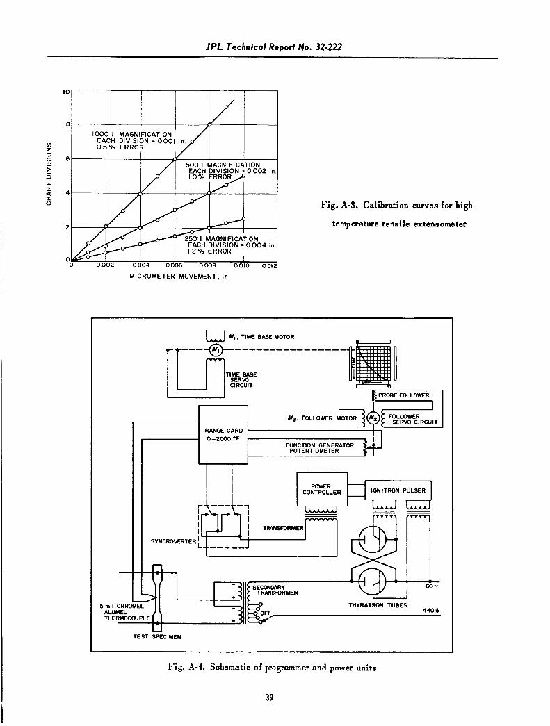
X are shown in Fig. A-2. Calibration of the extensometer was facilitated with a micrometer-screw j ig for the
three magnifications of the recording unit. Results in Fig. A-3 indicate the maximum error of the strain-
measuring system to b e 1.2%.
The equipment for the high-heating-rate t e s t s w a s comprised of a SO-Kva transformer with ignitron
pulser for self-resistance heating of the specimen; a temperature-control programmer to insure constant heat-
ing rates; a 20,000-lb modified creep tester; an extensometer and a direct read-out oscillograph for recording
the temperature and deformation of the specimen. A complete layout of the equipment i s shown in Fig. 3.
A s heating rates up to 2000'F/sec were desired, the 50-Kva transformer with an amperage range of
0 to 7500 amps was sufficient for all materials. However, the voltage range of 0 to 10 v limited the length of
reduced section in the specimens to 4 in. Specimens with reduced sections shorter than 4 in. gave higher
heating rates but the resulting thermal gradients were intolerable.
Any number of heating rates up to 5W0F/sec may be obtained with a single master chart for the
programmer by varying the t i m e and temperature range of the function generator. A probe follows a line of
conducting ink drawn on the chart and excites a millivolt signal representing the desired temperature. A
schematic of the programmer and power units is shown in Fig. A-4. The specimen temperature, T,, is measured
with a 5-mil chromel-alumel thermocouple spot-welded to the center of the specimen. This millivolt sigpal is
transmitted to the range card unit. At the same time the function generator imports a millivolt signal to the
unit as called out by the desired temperature, T,, from the programmer chart. A difference between the two,
T d - T,, causes a net dc error signal which eventually causes the ignitron pulser unit t o fire the thyratron
35

JPL Technical Report No. 32-222
tubes varying the power input to the specimen. This variable power input allows a constant heating rate t o
be achieved. T h i s method gave heating rates which varied about +7% over the entire temperature range.
Besides the thermocouple for the programmer, a thermocouple was used for recording the temperature.
Here a problem of superimposed voltages from the power supply was encountered. A s there was a voltage
gradient of about 6 v alternating across the 12-in.-long specimen, a O.Ol-in. gap between thermocouple leads
would cause a 5 millivolt oscillation of the galvonometer spot. Thus, i t was necessary to have the thermo-
couple leads spot-welded on top of each other. Even then there was some superimposed voltage which was
eliminated using a three-wire thermocouple as shown in Fig. A-5. The resistance, R,, varies the galvanometer
sensitivity and the resistance, R 2, nullifies the superimposed voltage.
To record relatively fas t temperature and strain-transients, a direct read-out oscillograph with a 12-in.
wide chart was used. This was equipped with galvanometers that yielded a 10-in. deflection for 45 millivolts.
These galvanometers have a frequency response of 120 cps. A close-up view of t he programmer and the
oscillograph with resistance box to handle five recording channels i s shown in Fig. A-6. These five channels
were used to determine the thermal gradient of the specimen gage length for heating rates of about 10 to
1000°F/sec. F ive 3-wire thermocouple were spot-welded at %-in. intervals over the 2-in. gage length.
Thermal gradient results for 410 stainless steel specimens heated a t several heating rates are shown for two
temperatures in Fig. A-7 and A-8. The maximum gradient resulting was l e s s than S% of the average temperature.
These and other tests indicated that a specimen with a 4-in. reduced section was adequate for heating rates
greater than 40°F/sec.
The strain measuring device consisted of a clamp-on extensometer with a 20:l lever arm actuating a
linear potentiometer. (See Fig. 4.) The potentiometer used a continuous carbon resistor S O that no stepping
was encountered. A constant voltage source of mercury cells in se r i e s with a variable carbon resistor pro-
vided the desired signal for the potentiometer. Two calibration curves in Fig. A-9 obtained with a micrometer-
screw j ig indicate the maximum error of the system to be t2.0%. To reduce any thermal effects on the
potentiometer, sapphire gage points to cut down conduction and an aluminum shield to cut down radiation were
used as shown in Fig. 4. Two tests were run to determine the temperature rise at the potentiometer. For one,
a specimen was held at l O O O O F for six minutes resulting in a 1°F r i se in temperature; for the other, the
specimen was held at 2000'F for one minute resulting in a 25'F rise in temperature. The latter test represented
more severe conditions than were encountered during any of the t e s t runs. The extensometer, when calibrated
at 2S°F above room temperature, had the same calibration as the room temperature runs.
36

IPL Technical Report No. 32-222
II. EXPERIMENTAL TEST PROCEDURES
During a tensile test run, the temperature was monitored by two chromel-alumel thermocouples spot-
welded to the center of the gage section. One thermocouple was connected to the controller, and the other to
a hand-balanced potentiometer. Both thermocouples were connected through a switching box so that either
could be used for the potentiometer or the controller. In this way, both thermocouples could he checked
against each other during the half hour soak time. Just preceding and during the test run, temperature was
recorded every three minutes. The average of these temperatures is reported as tes t temperature. The
specimens were pulled at a strain rate of approximately 0.004 min’l to slightly past the yield point and
then at a crosshead speed of approximately 0.1 in./min to fracture. A load-deformation curve was recorded
to a deformation of about .020 in.
In general, the test procedures for the high-heating-rate tests were to dead-weight load the specimen
and resistance-heat the specimen using a programmed or manual temperature control. For the programmed
runs, two 5-mil, chromel-alumel thermocauples were used: one to the oscillograph recorder and one for
feedback to the programmer. The two thermocouples were spot-welded to the center of the gage section ae
shown in Fig. A-10. A predetermined time scale was set on the function generator of the programmer for the
desired heating rate. After the extensometer was attached and the specimen was loaded, the programmer w a s
energized. A resulting temperature-time, strain-time record made to slightly past the yield point is shown in
Fig. 5. AS the extensometer had a limited range, a mechanical stop under the loading platform prevented the
specimen from deforming much past the yield point. These runs were limited to 500°F/sec by the programmer
response. For higher heating rates, a manually operated voltage regulator was used. W i t h 1 2 different settings,
heating rates from 500 to 2000°F/sec were obtained depending upon the specimen material.
37

JPL Technical Report No. 32-222
I I
I l
::::1= F==,,2±2·,=3=1 ::::~I E 1511 fi:j 1
; :::1= =k:==="98~=30F==3==1 ~
I ::::II.-.----J k:L....-.-------,----998 12., ---J::1---J1
::1 F- Boof2.' j I :jf--------{} 5B9h·,:-4 1
UPPER GAGE CENTER LOWER GAGE POINT POINT
TWO-INCH GAGE LENGTH
Fig. A-I. Thermal gradient calibration of 2000°F
furnace for tensile tests
38
I_~~_~_-
Fig_ A-2. Pull-rods and extensometer for
steady-state high-temperature tensile
tests
IPL Technical Report No. 32-222
I I I I I I
v) 2
2 n
a
>
I- n I 0
-
Fig. A-3. Calibration curves for high-
temperature tensile extensometer
MICROMETER MOVEMENT, i n
A f t , TIME BASE MOTOR I
TIME BASE SERVO CIRCUIT
a PROBE FOLLOWER
RANGE CARD '
0-2oOO0F
4 , FOLLOWER +E-' SERVO CIRCUIT
FUNCTION GENERATOR POTENTIOMETER
I I
I TRANSFORMER
SYNCROMRTEl3 ' --
- SECONDARY TRMSFORMER
THYRATRON TUBES 440 rl
5 m i l CHR( TL ALUMEL THERMOCOUPLE
TEST SPECIMEN
Fig. A-4. Schematic of programmer and power units
39

JPL Technical Report No. 32-222
SHIELDING TO GROUND
COLD JUNCTION L....,lr-----. ___ -.,I,--J SH IELDI NG TO GROUND
11r--t=i========l R I , 500 -.a POT
Ii I' II II II II II I II I SHIELDING TO GROUND 11~1-----~11====9 II II II II
TO GALVANOMETER
• CHROMEL LEADS • ALUMEL LEAD
*THESE LEADS SHOULD BE WELDED TOGETHER (NOT AS SHOWN) SO THAT NO GAP EXISTS
Fig. A-5. Thermocouple circuit to eliminate
super-imposed voltages
Fig. A-6. Oscillograph and
programmer units
40

JPL Ttchnical Rtport No. 32-222
I I AT RANGES FROM IBTO 3 6 O F
I300
W +
I I AT RANGES FROM I I TO 41 OF
I I
1025
29 I O 0
275
‘F/ sec 590
I025 400
275
I O 0 29
9001 I I I 1 -1.0 -0.5 0 0.5 I .o
(BOTTOM) (TOP)
DISTANCE FROM SPECIMEN CENTERLINE, in.
Fig. A-8. Thermal gradient calibration of high-heating-
rate equipment at about l l O O O F
41

JPL Techn ical Report No. 32-222
F ig. A-9. Calibration curves for high-heating-
rate extensometer
c
...: z w :0 w > 0 :0
a:: w I-w :0 0 a:: ~ ::;:
0 .028 .-- - -.-----.-----,---....... ,.,-------,
SETTING I AVERAGE CALIBRATION (5) = 0 .00374 in . 1 GALVANOMETER SPOT i n . ± 1.3 %
0 .0241------ +----+-----+-.... ----+----i
0 .020
0 .016
0 .012
0 .008
0.0041----~____,-jl6----+-----+------+----i
SETTING 2 AVERAGE CALI BRATION (5) = 0.00194 in.1 GALVANOMETER SPOT in . ± 2 .0 %
2 4 6 8
GALVANOMETER SPOT TRAVEL , i n.
Fig . A-lO. Assembly of thermocouples and
extenso meter on high-heating-rate
specimen
10
42

JPL Technical Report No. 32-222
REFERENCES
1. Cross, H.C., McMaster, R.C., Simmons, W.F., and VanEcho, J.A., Short-Time, High-Temperature
Properties of Heat-Resisting Alloy Sheet, Project RAND (USAF Project MX-791) RA-15077, Douglas
Aircraft Company, 1948.
2. Smith, W.K., Wetmore, W.O., and Woolsey, C.C., Jr., Tensile Properties of Metals While Being Heated at
High Rates, NAVORD Report 1178, Par ts 1, 2, and 3(NOTS 234, 319, 336), U.S. Naval Ordnance Test
Station, Inyokern, California, 1949-1950.
3. Heimerl, G. J., and Inge, J.E., Tensile Properties of 7075-T, and 2024-T, Aluminum Alloy Sheet Heated
at Uniform Temperature Rates Under Constant Load, NACA TN 3462, 1955.
4. Heimerl, G. J., and Inge, J.E., Tensile Properties of Some Sheet Materials Under Rapid-Heating Conditions,
NACA RM L55E 126, 1955.
5. Heimerl, G.J., Kurg, I.M., and Inge, J.E., Tensile Properties of Inconel and RS-I20 Titanium-Alloy Sheet
Under Rapid-Heating and Constant-Temperature Conditiong, NACA TN3731, 1956.
6. Kurg, I.M., Tensile Properties of AZ 31 A-0 Magnesium-Alloy Sheet Under Rapid-Heating and Constant-
Temperature Conditions, NACA TN 3752, 1956.
7. Heimerl, G. J., “Tensile Properties of Some Structural Sheet Materials Under Rapid-Heating Conditions,”
Proceeding of the Fourth Sagamore Ordnance Materials Research Conference, pp. 113-145, Syracuse
University Research Institute, Report No. MET 497-582, 1957.
8. Price, H.L., Tensile Properties of 6AL-4V Titanium-Alloy Sheet Under Rapid-Heating and Constant-
Temperature Conditions, NASA TN D-121, 1959.
9. Manning, C.R., Jr., and Price, H.L., Tensile Properties of 17-7 PH and 12 MoV Stainless-Steel Sheet
Under Rapid-Heating and Constant-Temperature Conditions, NASA TN D-823, 1961.
10. Some Physical Properties of Martensitic Stainless Steel, DMIC Memo. No. 68, Battelle Memorial
Institute, Columbus, Ohio, 1960.
43
Related Documents