Tensile and fatigue properties of fiber laser welded high strength low alloy and DP980 dual-phase steel joints W. Xu a , D. Westerbaan b , S.S. Nayak b , D.L. Chen a,⇑ , F. Goodwin c , Y. Zhou b a Department of Mechanical and Industrial Engineering, Ryerson University, 350 Victoria Street, Toronto, Ontario M5B 2K3, Canada b Department of Mechanical and Mechatronics Engineering, University of Waterloo, 200 University Avenue West, Waterloo, Ontario N2L 3G1, Canada c International Zinc Association, Durham, NC 27713, USA article info Article history: Received 2 June 2012 Accepted 8 July 2012 Available online 16 July 2012 Keywords: Fiber laser welding High strength low alloy steel Dual-phase steel Microstructure Fatigue abstract The study was aimed at evaluating the microstructure and mechanical properties of high-speed fiber laser welded high strength low alloy (HSLA) and DP980 dual-phase steel joints with varying weld geom- etries. Fusion zone (FZ) consisted of martensitic structure, and heat-affected zone (HAZ) contained newly-formed martensite in both steels and partially tempered martensite in DP980. While HAZ-soften- ing was present in DP980, it was absent in HSLA. A distinctive ‘‘suspension bridge’’-like hardness profile with the FZ hardness as a ‘‘pylon’’ appeared in the fiber laser welded joints. Both HSLA and DP980 joints showed a superior tensile strength, with a joint efficiency of 94–96% and 96–97%, respectively, despite a reduced elongation in DP980 joints. Fatigue strength was higher in DP980 joints than in HSLA joints at higher stress amplitudes, but had no obvious difference at lower stress amplitudes. DP980 multiple linear welds exhibited a larger scatter and lower fatigue strength. Fatigue failure of HSLA joints occurred in the base metal at a stress amplitude above 250 MPa, and at weld concavity at a lower stress amplitude below 250 MPa. Fatigue crack in DP980 joints initiated predominantly from the weld concavity at both high and low levels of stress amplitudes. Ó 2012 Elsevier Ltd. All rights reserved. 1. Introduction The demand of environment-friendly vehicles that have better fuel economy and lower CO 2 emissions compels automakers to apply advanced technology and new materials in vehicle manufac- turing [1–4]. During manufacturing of automotive components, welding and joining are unavoidable. Laser welding is an enabling technology which is fast and precise in joining a wide variety of materials with varying thicknesses and types [5,6]. A new genera- tion of fiber lasers has been developed for industrial applications and has multiple advantages, including high power with small beam divergence, flexible beam delivery, low maintenance costs, high efficiency, and compact size [7,8]. A lot of studies on laser welding of HSLA, DP980, and other steels have been reported in the literature [9–12]. For example, Saunders and Wagone [9] conducted a study on Nd:YAG and CO 2 laser welding of the aluminum-killed drawing quality (AKDQ) steel and HSLA steel sheets in which they concluded that the intrinsic ductility of AKDQ and HSLA steel reduced after laser welding. In another study, Sreenivasan et al. [10] investigated the mechanical properties and performance of DP980 steel tailor welded blanks manufactured using Nd:YAG and diode laser welding (DLW). Formability and uniaxial tensile strength of DP980 welded blanks significantly reduced due to the occurrence of heat affected zone (HAZ)-softening, i.e., the hardness at outer HAZ being significantly below that of the base material caused by tempering of martensite. Similar effect of HAZ-softening on the formability was observed by Xia et al. [11] in their comparative study of HSLA and DP980 steel joints prepared using DLW. The study suggested a lower formabil- ity of DP980 diode laser welded blanks compared to the base metal (BM), which could be improved by increasing welding speed which in turn reduced the HAZ-softening. In addition, it was also reported that changes in the microstructure and hardness in the HAZ and FZ, in diode laser welds with similar and dissimilar combination of DP600 and DP980 steel, resulted in a change of fatigue perfor- mance [13,14]. The important outcome of the above mentioned studies was that microstructural heterogeneity (mainly HAZ-softening) signifi- cantly affects the mechanical properties such as tensile and fatigue strength and also the formability of laser welded HSLA and DP980 joints. High speed fiber laser welding (FLW) is becoming increas- ingly important and its share in the total laser industry is expected to grow substantially [8]. One of the reasons is that the high power density, small beam divergence and focal spot diameter could lead to welds with a higher penetration and smaller width for a given welding speed [7]. However, there is no report so far on the effect of FLW on the microstructure and mechanical properties of the 0261-3069/$ - see front matter Ó 2012 Elsevier Ltd. All rights reserved. http://dx.doi.org/10.1016/j.matdes.2012.07.017 ⇑ Corresponding author. Tel.: +1 416 979 5000x6487; fax: +1 416 979 5265. E-mail address: [email protected] (D.L. Chen). Materials and Design 43 (2013) 373–383 Contents lists available at SciVerse ScienceDirect Materials and Design journal homepage: www.elsevier.com/locate/matdes

Welcome message from author
This document is posted to help you gain knowledge. Please leave a comment to let me know what you think about it! Share it to your friends and learn new things together.
Transcript
Materials and Design 43 (2013) 373–383
Contents lists available at SciVerse ScienceDirect
Materials and Design
journal homepage: www.elsevier .com/locate /matdes
Tensile and fatigue properties of fiber laser welded high strength low alloyand DP980 dual-phase steel joints
W. Xu a, D. Westerbaan b, S.S. Nayak b, D.L. Chen a,⇑, F. Goodwin c, Y. Zhou b
a Department of Mechanical and Industrial Engineering, Ryerson University, 350 Victoria Street, Toronto, Ontario M5B 2K3, Canadab Department of Mechanical and Mechatronics Engineering, University of Waterloo, 200 University Avenue West, Waterloo, Ontario N2L 3G1, Canadac International Zinc Association, Durham, NC 27713, USA
a r t i c l e i n f o
Article history:Received 2 June 2012Accepted 8 July 2012Available online 16 July 2012
Keywords:Fiber laser weldingHigh strength low alloy steelDual-phase steelMicrostructureFatigue
0261-3069/$ - see front matter � 2012 Elsevier Ltd. Ahttp://dx.doi.org/10.1016/j.matdes.2012.07.017
⇑ Corresponding author. Tel.: +1 416 979 5000x648E-mail address: [email protected] (D.L. Chen).
a b s t r a c t
The study was aimed at evaluating the microstructure and mechanical properties of high-speed fiberlaser welded high strength low alloy (HSLA) and DP980 dual-phase steel joints with varying weld geom-etries. Fusion zone (FZ) consisted of martensitic structure, and heat-affected zone (HAZ) containednewly-formed martensite in both steels and partially tempered martensite in DP980. While HAZ-soften-ing was present in DP980, it was absent in HSLA. A distinctive ‘‘suspension bridge’’-like hardness profilewith the FZ hardness as a ‘‘pylon’’ appeared in the fiber laser welded joints. Both HSLA and DP980 jointsshowed a superior tensile strength, with a joint efficiency of 94–96% and 96–97%, respectively, despite areduced elongation in DP980 joints. Fatigue strength was higher in DP980 joints than in HSLA joints athigher stress amplitudes, but had no obvious difference at lower stress amplitudes. DP980 multiple linearwelds exhibited a larger scatter and lower fatigue strength. Fatigue failure of HSLA joints occurred in thebase metal at a stress amplitude above 250 MPa, and at weld concavity at a lower stress amplitude below250 MPa. Fatigue crack in DP980 joints initiated predominantly from the weld concavity at both high andlow levels of stress amplitudes.
� 2012 Elsevier Ltd. All rights reserved.
1. Introduction
The demand of environment-friendly vehicles that have betterfuel economy and lower CO2 emissions compels automakers toapply advanced technology and new materials in vehicle manufac-turing [1–4]. During manufacturing of automotive components,welding and joining are unavoidable. Laser welding is an enablingtechnology which is fast and precise in joining a wide variety ofmaterials with varying thicknesses and types [5,6]. A new genera-tion of fiber lasers has been developed for industrial applicationsand has multiple advantages, including high power with smallbeam divergence, flexible beam delivery, low maintenance costs,high efficiency, and compact size [7,8].
A lot of studies on laser welding of HSLA, DP980, and othersteels have been reported in the literature [9–12]. For example,Saunders and Wagone [9] conducted a study on Nd:YAG and CO2
laser welding of the aluminum-killed drawing quality (AKDQ) steeland HSLA steel sheets in which they concluded that the intrinsicductility of AKDQ and HSLA steel reduced after laser welding. Inanother study, Sreenivasan et al. [10] investigated the mechanicalproperties and performance of DP980 steel tailor welded blanksmanufactured using Nd:YAG and diode laser welding (DLW).
ll rights reserved.
7; fax: +1 416 979 5265.
Formability and uniaxial tensile strength of DP980 welded blankssignificantly reduced due to the occurrence of heat affected zone(HAZ)-softening, i.e., the hardness at outer HAZ being significantlybelow that of the base material caused by tempering of martensite.Similar effect of HAZ-softening on the formability was observed byXia et al. [11] in their comparative study of HSLA and DP980 steeljoints prepared using DLW. The study suggested a lower formabil-ity of DP980 diode laser welded blanks compared to the base metal(BM), which could be improved by increasing welding speed whichin turn reduced the HAZ-softening. In addition, it was also reportedthat changes in the microstructure and hardness in the HAZ and FZ,in diode laser welds with similar and dissimilar combination ofDP600 and DP980 steel, resulted in a change of fatigue perfor-mance [13,14].
The important outcome of the above mentioned studies wasthat microstructural heterogeneity (mainly HAZ-softening) signifi-cantly affects the mechanical properties such as tensile and fatiguestrength and also the formability of laser welded HSLA and DP980joints. High speed fiber laser welding (FLW) is becoming increas-ingly important and its share in the total laser industry is expectedto grow substantially [8]. One of the reasons is that the high powerdensity, small beam divergence and focal spot diameter could leadto welds with a higher penetration and smaller width for a givenwelding speed [7]. However, there is no report so far on the effectof FLW on the microstructure and mechanical properties of the

Table 1Compositions of the HSLA and DP980 steel used in the present study.
Steel grade C Mn Si Al Mo Cr N
HSLA 0.0795 0.827 0.454 0.048 0.007 0.033 0.007DP980 0.15 1.5 0.31 0.05 N/A N/A N/A
374 W. Xu et al. / Materials and Design 43 (2013) 373–383
important automotive steels namely HSLA and DP980. It is unclearhow serious the HAZ softening in the HSLA and DP980 steels afterFLW is, and if the multiple linear FLW would have a significant ef-fect on the fatigue strength. This study was, therefore, aimed atidentifying the evolution of microstructure and the effects ofFLW on the fatigue resistance in HSLA and DP980 steels. The effectsof weld geometry, i.e., single and multiple linear welds, on themicrostructure and fatigue properties of the welded joints havealso been evaluated.
2. Material and experimental procedure
The starting materials in the present study were hot-dip galva-nizing (GI) coated HSLA and DP980 steel with a thickness of1.2 mm; the chemical compositions of the steels are given in Ta-ble 1. Butt welding of the steel sheets was carried out using anIPG PhotonicsYLS-6000 fiber laser system with a power of 6 kW,a welding speed of 16 m/min, a focal length of 30 cm. The fiber la-ser had a fiber core diameter of 0.3 mm with a laser beam spotsize/diameter of 0.6 mm. The weld geometries and dimensions ofthe steel sheets used in this study are shown in Fig. 1a. Weldingwas performed with 0� head angle, i.e., the laser beam was perpen-dicular to the surface of work pieces and without any shielding gas.The metallographic samples for the microstructural examinationwere cut from the weld cross-section, then mounted, ground,
(a)
(b)
Name G W RDimension (mm) 50 12.5 12.5
(d)
Single linear weld Two linear welds S
S
HSLA HSLA
Steel Steel
HSLA HS HSLA
Steel LA Steel
Welding lines
Rolling d
Fig. 1. Geometry and dimensions of work pieces and test specimens, (a) work pieces to bthe single linear weld indicated by the short-dashed lines at (a), (c) tensile and fatigue tesand (d) a table of the specimen dimensions.
polished, and etched with a 2% Nital solution. The etched sampleswere observed using a light microscope along with a Clemex imageanalysis system and JEOL JSM-6380 scanning electron microscope(SEM), equipped with Oxford energy dispersive X-ray spectroscopy(EDS) and three-dimensional fractographic analysis capacity. Vick-ers microhardness was measured on the polished samples acrossthe weld using a computerized microhardness tester at a load of200 g and a dwell time of 15 s. All indentations were adequatelyspaced to prevent any potential effect of strain fields caused byadjacent indentations. To ensure the validity of test results, twocalibration tests were done using a standard reference test blockbefore the microhardness tests on the welded joints.
Tensile and fatigue test samples following ASTM-E8/E8M stan-dard [15] were sectioned from the welded blanks in the rollingdirection (i.e., perpendicular to the welding direction), the exam-ples of which are indicated by the dashed line in Fig. 1a with thegeometry and dimensions of the test coupons shown in Fig. 1band c. The test coupons were machined in such a way that the weldwas positioned at the center of gauge length for the single linearweld (Fig. 1b), or two welds were located within the gauge lengthsymmetrically with respect to the middle of the sample (Fig. 1c).To identify the effect of welding and its geometry on the tensileand fatigue properties, coupons of the BM were also preparedand tested. Tensile tests were conducted using a fully computer-ized United tensile testing machine at room temperature and witha range of strain rates from 1 � 10�5 to 1 � 10�2 s�1. An extensom-eter with a gauge length of 50 mm and a strain limit of 20% wasused to measure the strain during the tensile tests. Load control fa-tigue tests were performed in accordance with ASTM E466 [16] ona fully computerized Instron 8801 servo-hydraulic testing system.To avoid potential buckling of the test specimens, tension–tensioncyclic loading at a stress ratio of R = 0.1 was applied at a frequency
(c)
L A B C200 57 50 20
ingle linear weld Two linear welds
DP DP
teel Steel
DP DP DP
Steel Steel
Welding lines
irection
e welded using a 6 kW fiber laser, (b) tensile and fatigue test samples sectioned fromt samples cut from the multiple linear weld indicated by the long-dashed lines at (a),
(a)
(f)
(c)
(b)
c de
(e)
(d)
hg f
(h)(g)
150 µm
150 µm
150 µm 150 µm
150 µm
150 µm
500 µm 500 µm
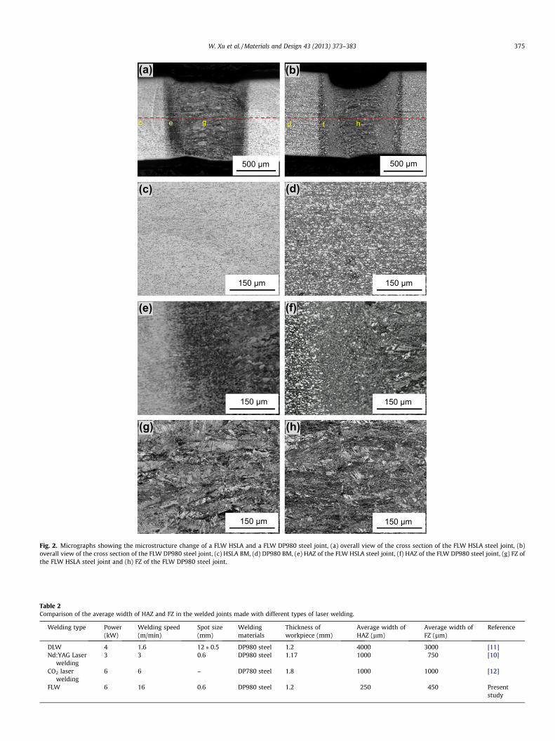
Fig. 2. Micrographs showing the microstructure change of a FLW HSLA and a FLW DP980 steel joint, (a) overall view of the cross section of the FLW HSLA steel joint, (b)overall view of the cross section of the FLW DP980 steel joint, (c) HSLA BM, (d) DP980 BM, (e) HAZ of the FLW HSLA steel joint, (f) HAZ of the FLW DP980 steel joint, (g) FZ ofthe FLW HSLA steel joint and (h) FZ of the FLW DP980 steel joint.
Table 2Comparison of the average width of HAZ and FZ in the welded joints made with different types of laser welding.
Welding type Power(kW)
Welding speed(m/min)
Spot size(mm)
Weldingmaterials
Thickness ofworkpiece (mm)
Average width ofHAZ (lm)
Average width ofFZ (lm)
Reference
DLW 4 1.6 12 ⁄ 0.5 DP980 steel 1.2 4000 3000 [11]Nd:YAG Laser
welding3 3 0.6 DP980 steel 1.17 1000 750 [10]
CO2 laserwelding
6 6 – DP780 steel 1.8 1000 1000 [12]
FLW 6 16 0.6 DP980 steel 1.2 250 450 Presentstudy
W. Xu et al. / Materials and Design 43 (2013) 373–383 375
376 W. Xu et al. / Materials and Design 43 (2013) 373–383
of 50 Hz and sinusoidal waveform. In both tensile and fatigue tests,at least two specimens were tested at each strain rate or eachcyclic stress amplitude. The fatigue fracture surfaces were exam-ined via a scanning electron microscope (SEM) to identify the ini-tiation sites and propagation mechanism of the fatigue crack.
3. Results and discussion
3.1. Microstructure evolution
The representative weld cross-section profiles and microstruc-ture at different weld zones of the HSLA and DP980 joints madewith the FLW are shown in Fig. 2. The cross-section of the weldsshowed a significant microstructural change in both HSLA andDP980 joints, indicating the formation of the middle FZ and twoadjacent HAZs which coexisted with the unaffected BM at both leftand right ends as indicated in Fig. 2a and b. It is seen that the widthof HAZ and FZ in both HSLA and DP980 joints was similar with anaverage of 200–300 lm, and 400–500 lm, respectively. The HAZand FZ were narrower when compared to those formed in other la-ser welding (Table 2). For instance, a 4 kW DLW of 1.2 mm thickDP980 steel sheets resulted in 4 mm wide HAZ and 3 mm wideFZ [11]. This was attributed to considerably larger laser beam size(6 mm2 for the DLW versus 0.28 mm2 for the FLW), where the low-er energy density (less than 106 W/cm2) produced conductionmode. In contrast, in the FLW process the higher energy densitywhich caused keyhole mode made welding more efficient com-pared with DLW [10,17,18], and the FLW could be operated athigher welding speed with a narrower weld (Table 2).
HSLA BM consisted of fine grained ferrite matrix with a uniformdispersion of fine alloy carbides (Fig. 2c), whereas martensitephase embedded in a continuous ferrite matrix was seen inDP980 BM (Fig. 2d). The volume fraction of martensite in theDP980 BM was estimated to be �56% using image analysis inSEM, which matched closely with the earlier studies on theDP980 steel of similar chemistry [13,19–21]. Fig. 2e and f showedthe microstructural changes of HAZ in both HSLA and DP980 joints,where the typical micrographs were taken from the HAZ
BM Inter-critical HAZ
(c)
((a)
b c
F
Upper-critical HAZ
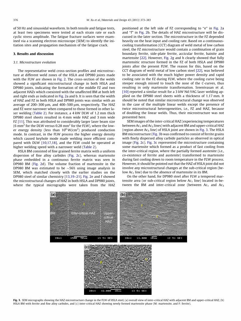
Fig. 3. SEM micrographs showing the HAZ microstructure change in the FLW of HSLA steHSLA BM with ferrite and fine alloy carbides, and (c) inter-critical HAZ showing newly
positioned at the left side of FZ corresponding to ‘‘e’’ in Fig. 2aand ‘‘f’’ in Fig. 2b. The details of HAZ microstructure will be dis-cussed in the later section. The microstructure in the FZ dependedheavily on the heat input and cooling rate. Based on a continuous-cooling transformation (CCT) diagram of weld metal of low carbonsteel, the FZ microstructure would contain a combination of grainboundary ferrite, side-plate ferrite, accicular ferrite, bainite andmartensite [22]. However, Fig. 2g and h clearly showed that fullymartensitic structure formed in the FZ of both HSLA and DP980joints after the present FLW. The reason for this, based on theCCT diagram of weld metal of low carbon steel [22], was believedto be associated with the much higher power density and rapidcooling rate in the FZ during FLW, where the cooling curve beingsteeper enough missed to touch the nose of the C-curves, thusresulting in only martensite transformation. Sreenivasan et al.[10] reported a similar result for a 3 kW Nd:YAG laser welding ap-plied on the DP980 steel sheets with a thickness of 1.17 mm. Itshould be noted that similar microstructural change was observedin the case of the multiple linear welds except the presence oftwice microstructural heterogeneities, i.e., FZ and HAZ, becauseof doubling the linear welds. Thus, their microstructure was notpresented here.
SEM images of the inter-critical HAZ (experiencing temperaturesbetween Ac1 and Ac3 lines) with adjacent BM and upper-critical HAZ(region above Ac3 line) of HSLA joint are shown in Fig. 3. The HSLABM microstructure (Fig. 3b was confirmed to consist of ferrite grainswith finely dispersed alloy carbide particles as observed in opticalimage (Fig. 2c). Fig. 3c represented the microstructure containingsome martensite which formed as a product of fast cooling fromthe inter-critical region, where the partially formed austenite (i.e.,co-existence of ferrite and austenite) transformed to martensiteduring fast cooling down to room temperature in the FLW process.However, it should be pointed out that the HAZ of HSLA joint did notinvolve any microstructural changes at the sub-critical region (be-low Ac1 line) due to the absence of martensite in its BM.
On the other hand, for DP980 steel after FLW a tempered mar-tensite area (or sub-critical region below Ac1 line) located in-be-tween the BM and inter-critical zone (between Ac1 and Ac3
b)
F
M
F
el, (a) overall view of inter-critical HAZ with adjacent BM and upper-critical HAZ, (b)formed martensite phase (M: martensite, and F: ferrite).

(c)
(b)F
M
TM
F
(a)b c
BM Tempered area (sub-
critical HAZ)
Inter-critical HAZ
Upper-critical HAZ
Fig. 4. SEM micrographs showing the microstructural change in a DP980 steel joint, (a) overall view of tempered martensite area in the HAZ with adjacent BM, inter-criticalHAZ, and upper-critical HAZ, (b) DP980 BM showing ferrite and martensite, and (c) tempered martensite region in the HAZ (M: martensite, TM: tempered martensite, and F:ferrite).
FLW HSLA-SFLW DP980-S
HAZ FZ HAZ
Soft zone Soft zone
BM BM
HAZ FZ HAZBM BM
0
100
200
300
400
500
600
-6 -4 -2 0 2 4 6
Vick
ers
hard
ness
, HV
Distance from weld centreline, mm
Fig. 5. Representative hardness profiles across the HSLA-S and DP980-S joints.
W. Xu et al. / Materials and Design 43 (2013) 373–383 377
lines), along with an upper-critical HAZ (above Ac3 line) could beseen in Fig. 4a. While the microstructure in the inter-critical zonewas somewhat similar to that in the BM with ferrite plus martens-ite islands, in the tempered martensite area some extent of decom-position of the martensite pre-existed in the BM (Fig. 4b) wasclearly visible at a higher magnification as shown in Fig. 4c. Tem-pered martensite and the resultant softening zone in the laserwelding of DP980 steel have been reported in many earlier studies[11,13,14,23]. In general, the temperature undergone in the soften-ing region during welding was close to or below the critical tem-perature (Ac1 at which austenite begins to form during heating)which led to high temperature tempering of martensite phase inthe BM of DP steels [11,13,14,20,23–25]. The microstructure oftempered martensite in DP980 welds has been reported to consisttypically of uniformly distributed fine precipitated cementite(Fe3C) particles embedded within a continuous ferrite matrix[20,26–28]. As seen from Fig. 4c, it was clear that only partial tem-pering of martensite occurred in the HAZ of DP980 in the FLWprocess.
3.2. Hardness profiles
Vickers microhardness profiles across the welds of the FLWHSLA single linear joint (FLW HSLA-S) and the FLW DP980 singlelinear joint (FLW DP980-S) (as indicated by the red1 dashed linesin Fig 2a and b) are showed in Fig. 5. The average hardness valueof the HSLA and DP980 steel BM was measured to be about170 HV and 340 HV, respectively. The higher hardness in theDP980 BM was attributed to the presence of higher fraction of hardmartensite phase (�56%, Fig. 2d and Fig. 4b), while the HSLA BMdid not contain any martensite (Fig. 2c and Fig. 3b). In accordancewith the microstructure (Fig. 2g and h) where fully martensiticstructure emerged, the hardness of the FZ became much higher
1 For interpretation of color in Figs. 2-11, the reader is referred to the web versionof this article.
and showed a decrease from FZ to the HAZ. Interestingly, the hard-ness curve though the whole HAZ was seen to merge smoothly intothe unaffected BM in the HSLA joint due to a decrease in the frac-tion of martensite in the HAZ which formed as a solid-state phasetransformation from austenite in the inter-critical region. On theother hand, the hardness pattern in the DP980 joint exhibitedtwo soft zone ‘‘valleys’’ beside the center FZ, where the hardnesslocally dropped significantly to an average of 280 HV which waswell below the DP980 BM hardness (�350 HV). This was attributedto the occurrence of martensite tempering (HAZ-softened region)as discussed above and also illustrated in Fig. 4. The narrow FZwith fully martensitic microstructure in both HSLA and DP980joints after FLW were characterized by a very high hardness(Fig. 5). However, the DP980 joint had a further higher hardnessaveraging 450 HV compared with the average FZ hardness(360 HV) in the HSLA joint. This was mainly due to the fact that

0
100
200
300
400
500
600
-4 0 4 8 12 16 20 24
Vick
ers
hard
ness
, HV
Distance from left weld line, mm
FLW HSLA-M
FLW DP980-M
Soft
zone
Soft
zone
Soft zone
Soft zone
FZHAZ HAZ BM HAZ FZ HAZBM BM
Fig. 6. Typical hardness profiles across the HSLA-M and DP980-M joints.
0
300
600
900
1200
0 5 10 15 20
Engi
neer
ing
stre
ss, M
Pa
Engineering strain, %
HSLA BMFLW HSLA-SFLW HSLA-MDP980 BMFLW DP980-SFLW DP980-M
Fig. 7. Representative engineering stress versus engineering strain curves of HSLABM, FLW HSLA-S joint, FLW HSLA-M joint, DP980 BM, FLW DP980-S joint, FLWDP980-M joint tested at a strain rate of 1 � 10�3 s�1.
378 W. Xu et al. / Materials and Design 43 (2013) 373–383
the martensite in the FZ of DP980 joint contained a higher amountof carbon, as seen in Table 1 where nearly twice carbon contentwas present in the DP980 steel compared with the HSLA steel.Additionally, nearly doubled manganese content in the DP980 steel(Table 1) also contributed to the higher hardness [29]. Calcagnottoet al. [30] noted that Mn was able to increase hardneabilitysubstantially just like carbon content in austenite on grain size sta-bility and hardneability in ultrafine-grained ferrite/martensitedual-phase steel.
Fig. 6 shows the microhardness profiles across the multiple lin-ear weld of FLW HSLA (FLW HSLA-M) and FLW DP980 (FLWDP980-M) joints. Both FLW HSLA-M and FLW DP980-M joints were
Table 3Tensile properties and fatigue parameters r0f and b for HSLA BM, FLW HSLA-S joint, FLW
Welding type Yield strength(MPa)
Ultimate tensile strength(MPa)
Elongation(%)
HSLA BM 455 546 24.7FLW HSLA-S 400 515 22.7FLW HSLA-M 398 523 20.7DP980 BM 720 1095 14.2FLW DP980-S 719 1048 4.6FLW DP980-M 717 1066 5.1
observed to display a ‘‘suspension bridge’’-like or ‘‘cable-stayedbridge’’-like hardness profile with two FZ hardness representingthe ‘‘pylons or towers’’. It is seen that each weld bead of the multi-ple linear joints (Fig. 6) had a similar hardness values when com-pared it to the single linear joints (Fig. 5), which was a result ofsimilar microstructures as noted in the previous section. The dis-tinction between the FLW HSLA-M and FLW DP980-M joints wasthat the hardness profile of the former was smoother without ‘‘val-leys’’ due to the absence of HAZ-softening (martensite tempering).On the contrary, in the FLW DP980-M joint each FZ hardness ‘‘py-lon’’ was accompanied by two soft zone ‘‘valleys’’ positioned at itstwo sides (Fig. 6). It would be of interest to see if doubling thenumber of soft zones would affect tensile strength and fatigue lifeof the HSLA and DP980 joints.
3.3. Tensile properties
The representative engineering stress versus engineering straincurves, determined at a strain rate of 1 � 10�3 s�1, of the BM, FLWsingle and multiple linear joints of both HSLA and DP980 steels areillustrated in Fig. 7. In the HSLA joints, both the strain to failure andthe yield strength (YS) after welding were observed to be veryclose to those of the BM. The evaluated tensile test results arelisted in Table 3. The YS and ultimate tensile strength (UTS) wereobtained to be 400 MPa and 515 MPa, respectively, for the FLWHSLA-S joint and 398 MPa and 523 MPa, respectively, for theFLW HSLA-M joint. These values were fairly close to those of theBM which had a YS of 455 MPa and UTS of 546 MPa (Table 3, andFig. 7). These tensile results suggested that the present FLW pro-cess, regardless of single or multiple linear welding had little influ-ence on the tensile properties of the HSLA steel. Obviously, this wasbecause the FLW of HSLA steel did not create any soft zone (Fig. 5and 6) in the HAZ that was detrimental to the mechanical proper-ties of the welds. This was also corroborated by the tensile failureof FLW HSLA joints that consistently occurred in the BM. This find-ing was also in agreement with the earlier observations on the ten-sile failure locations by Xia et al. in a DLW HSLA joint [11], Farabiet al. [31] in a diode laser welded DP600 steel joint, and Panda et al.[32] in a diode laser welded HSLA/DP980 dissimilar joint with athickness of 1.14 mm and 1.17 mm, respectively.
In contrast to the HSLA welds, the DP980 joints showed a lowerstrain to failure (Fig. 7 and Table 3). However, the YS and UTS werebasically unaffected by the FLW. As seen in Table 2, the strength ofFLW DP980-S joints (YS = 719 MPa; UTS = 1048 MPa) and FLWDP980-M joints (YS = 717 MPa, UTS = 1066 MPa) was very closeto those of the BM (YS = 720 MPa; UTS = 1095 MPa). The resultsindicated that the presence of narrow soft zone in the FLWDP980 welds was not detrimental to the tensile strength, and thehigh welding speed could greatly reduce the harmful influence ofthe soft zone by narrowing it down significantly.
It was also of interest to observe that a joint efficiency (i.e., a ra-tio of the UTS of welded joints to the UTS of the corresponding BM[33–35]) of both FLW HSLA joints and FLW DP980 joints reached ashigh as about 94–96% and 96–97% (Table 3), respectively. These
HSLA-M joint, DP980 BM, FLW DP980-S joint, and FLW DP980-M joint.
Joint efficiency(%)
Fatigue limit(MPa)
Fatigueratio
r0f(MPa)
b
– 200 0.366 302 �0.02394.3 125 0.243 328 �0.04195.8 125 0.239 343 �0.048– 250 0.228 1019 �0.09895.7 150 0.143 1169 �0.13297.3 150 0.141 1984 �0.185
100
150
200
250
300
1E+1 1E+3 1E+5 1E+7
Stre
ss a
mpl
itude
, MPa
Number of cycles to failure, Nf
HSLA BM
FLW HSLA-S
FLW HSLA-M
125
175
225
275
325
375
425
475
1E+1 1E+3 1E+5 1E+7
Stre
ss a
mpl
itude
, MPa
Number of cycles to failure, Nf
DP980 BM
FLW DP980-S
FLW DP980-M
100
150
200
250
300
350
400
450
500
1E+1 1E+3 1E+5 1E+7
Stre
ss a
mpl
itude
, MPa
Number of cycles to failure, Nf
FLW HSLA-S
FLW HSLA-M
FLW DP980-S
FLW DP980-M
(a)
(b)
(c)
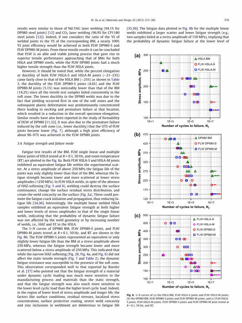
Fig. 8. S–N curves of (a) the HSLA BM, FLW HSLA-S joints and FLW HSLA-M joints,(b) the DP980 BM, FLW DP980-S joints and FLW DP980-M joints, and (c) FLW HSLA-S joints, FLW HSLA-M joints, FLW DP980-S joints and FLW DP980-M joint tested atR = 0.1, 50 Hz, and RT.
W. Xu et al. / Materials and Design 43 (2013) 373–383 379
results were similar to those of Nd:YAG laser welding (94.1% forDP980 steel joints) [12] and CO2 laser welding (96.9% for CP1180steel joints [12]). Indeed, if one considers the ratio of the YS ofwelded joints to the YS of the corresponding BM, a nearly 100%YS joint efficiency would be achieved in both FLW DP980-S andFLW DP980-M joints. From these tensile results it can be concludedthat FLW is an able and viable joining process that gave rise tosuperior tensile performance approaching that of BMs for bothHSLA and DP980 steels, while the FLW DP980 joints had a muchhigher tensile strength than the FLW HSLA joints.
However, it should be noted that, while the percent elongationor ductility of both FLW HSLA-S and HSLA-M joints (�21–23%)came fairly close to that of the HSLA BM (�25%) as shown in Table3, the ductility of the FLW DP980-S joints (4.6%) and the FLWDP980-M joints (5.1%) was noticeably lower than that of the BM(14.2%) since all the tensile test samples failed consistently in thesoft zone. The lower ductility in the DP980 welds was due to thefact that yielding occurred first in one of the soft zones and thesubsequent plastic deformation was predominantly concentratedthere leading to necking and premature failure at that location,which resulted in a reduction in the overall specimen elongation.Similar results have also been reported in the study of formabilityof DLW of DP980 [11,32]. It was also due to the premature failureinduced by the soft zone (i.e., lower ductility) that the UTS of FLWjoints became lower (Fig. 7), although a high joint efficiency ofabout 96–97% was achieved in the FLW DP980 joints.
3.4. Fatigue strength and failure mode
Fatigue test results of the BM, FLW single linear and multiplelinear joints of HSLA tested at R = 0.1, 50 Hz, and room temperature(RT) are plotted in the Fig. 8a. Both FLW HSLA-S and HSLA-M jointsexhibited an equivalent fatigue life within the experimental scat-ter. At a stress amplitude of above 250 MPa the fatigue life of thejoints was only slightly lower than that of the BM, whereas the fa-tigue strength became lower and more scattered at lower stressamplitudes (<250 MPa). In FLW HSLA welds, in spite of the absenceof HAZ-softening (Fig. 5 and 6), welding could destroy the surfacecontinuance, change the surface residual stress distribution, andcreate the weld concavity on the surface (Fig. 2a). These could pro-mote the fatigue crack initiation and propagation, thus reducing fa-tigue life [34,36]. Interestingly, the multiple linear welded HSLAsamples exhibited an equivalent fatigue strength at both higherand lower levels of stress amplitudes to that of the single linearwelds, indicating that the probability of dynamic fatigue failurewas not affected by the weld geometry or by increasing numberof welds, i.e., HAZ and FZ in the HSLA.
The S–N curves of DP980 BM, FLW DP980-S joints, and FLWDP980-M joints tested at R = 0.1, 50 Hz, and RT are shown in theFig. 8b. The FLW DP980-S joints represented an equivalent or onlyslightly lower fatigue life than the BM at a stress amplitude above250 MPa, whereas the fatigue strength became lower and morescattered below a stress amplitude of 250 MPa. This indicated thatwhile the narrow HAZ-softening (Fig. 2b, Fig. 4a, and Fig. 6) did notaffect the static tensile strength (Fig. 7 and Table 2), the dynamicfatigue resistance was susceptible to the presence of the soft zone.This observation corresponded well to that reported by Roesleret al. [37] who pointed out that the fatigue strength of a materialunder dynamic cyclic loading was much more sensitive to themanufacturing process and materials than the static strength,and that the fatigue strength was also much more sensitive tothe lower level cyclic load than the higher level cyclic load. Indeed,in the region of lower level of stress amplitude and longer life, thefactors like surface conditions, residual stresses, localized stressconcentration, surface protective coating, severe weld concavityand zinc inclusions in weldment are deleterious to fatigue life
[35,36]. The fatigue data plotted in Fig. 8b for the multiple linearwelds exhibited a larger scatter and lower fatigue strength (e.g.,two samples failed at a stress amplitude of 150 MPa), implying thatthe probability of dynamic fatigue failure at the lower level of
380 W. Xu et al. / Materials and Design 43 (2013) 373–383
stress amplitudes increased with increasing number of soft zonesin the higher grade of DP980.
To make a better comparison, fatigue test results of the FLWHSLA-S joints, the FLW HSLA-M joints, the FLW DP980-S joints,and the FLW DP980-M joints were plotted in Fig. 8c. The FLWDP980 joints were observed to have a much higher fatigue strengththan that of the FLW HSLA joints at a stress amplitude above250 MPa, but the fatigue strength was equivalent below a stressamplitude of 250 MPa for both DP980 and HSLA joints due to thefact that the higher grade/strength of DP980 was more sensitiveto the presence of severe weld concavity (Fig. 2b) especially atthe lower level of cyclic load than at the higher level of cyclic load.
Fatigue limit and fatigue ratio are tabulated in Table 3. The de-crease in fatigue limit for both FLW HSLA and FLW DP980 joints,
(a)
(f(e)
(d(c)
(b
20 mm
20 mm
20 mm
Fig. 9. Typical fatigue failure locations of (a) a HSLA-S joint at a stress amplitude above 2below stress amplitude of 250 MPa, (d) a HSLA-M joint below stress amplitude of 250 M
(a)
(d)
(b) (c
b
c
Weld concavity
Fig. 10. Typical SEM images of fatigue fracture surface of a FLW HSLA-S joint tested apropagation area, and (d) final fast crack propagation area.
with respect to their BM, were similar at 37.5% and 40%, respec-tively, while the fatigue limit of the FLW DP980 joints were 20%higher than that of the FLW HSLA joints. The fatigue ratio (i.e., a ra-tio of fatigue limit to the UTS) of the FLW HSLA-S joints and theFLW DP980-S joints were 0.243 and 0.143, respectively. The lowerfatigue ratio of FLW DP980-S joints was related to its much higher(or twice) UTS (Table 3). These results suggested that while thetensile strength of the FLW DP980 joints was much higher thanthat of the FLW HSLA joints, the fatigue strength was very closefor both joints at a lower level of stress amplitudes (<250 MPa).Another factor for the lower fatigue limit or fatigue ratio in bothtypes of FLW joints was associated with the notch effect of weldconcavity, since fatigue is a type of notch-sensitive dynamic fail-ure. As seen in Fig. 2a and b, the FLW ‘‘notch’’ or weld concavity
)
)
)
20 mm
20 mm
20 mm
50 MPa, (b) a HSLA-M joint at a stress amplitude above 250 MPa, (c) a HSLA-S jointPa, (e) a DP980-S joint, and (f) a DP980-M joint.
)
1 mmd
t a stress amplitude 200 MPa, (a) overall view, (b) crack initiation area, (c) crack
W. Xu et al. / Materials and Design 43 (2013) 373–383 381
in both joints was similar to a notched specimen studied by Cha-petti et al. [38] where the stress concentration was generated,and consequently a decreased fatigue limit or fatigue life at thelow level of stress amplitudes was observed. Further studies areneeded to eliminate the weld concavity and improve the fatigueresistance.
The obtained fatigue data plotted in Fig. 8 could be fitted usingthe following Basquin type equation,
ra ¼ r0f ð2NÞb ð1Þ
where ra is the stress amplitude, r0f is the fatigue strength coeffi-cient defined by the stress intercept at 2N = 1, N is the number ofcycle to failure, and b is the fatigue strength exponent. The obtainedvalues of r0f and b of the BM, the FLW single linear joint and the FLWmultiple linear joints for both HSLA and DP980 steels tested atR = 0.1, 50 Hz and room temperature are given in Table 3. Appar-ently, the fatigue life at a given stress amplitude was dependenton both fatigue strength coefficient r0f and fatigue strength expo-nent b with b being a predominant factor. The smaller the absolutevalue of b, the longer the fatigue life. It is seen from Table 3 thatafter FSW for both HSLA and DP980 steels the absolute values ofb became larger, giving rise to a lower fatigue life after welding.
3.5. Failure location and fractography
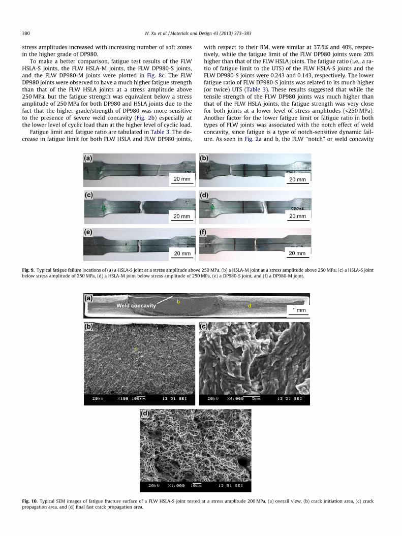
The typical fatigue failure locations for the HSLA-S joints, theHSLA-M joints, the DP980-S joints and the DP980-M joints areshown in Fig. 9. It is seen that the fatigue failure for the FLW HSLAjoints occurred in the BM with large deformation at a stress ampli-tude above 250 MPa (Fig. 9a and b), whereas it occurred at HAZ be-low a stress amplitude of 250 MPa (Fig. 9c and d), irrespective ofthe single or multiple linear welding. It was believed that while
(a)
(d)
(b) (c
cSurface defect
Fig. 11. Typical SEM images of fatigue fracture surface of a FLW DP980-S joint testedpropagation area, and (d) final fast crack propagation area.
the weld concavity in the FLW HSLA joints (Fig. 2a) did not signif-icantly influence the tensile strength (Fig. 7 and Table 3), the fati-gue strength at the condition of stress amplitude below 250 MPawas affected adversely. In contrast, the fatigue failure in the FLWDP980 joints always initiated in weld concavity (Fig. 9e and f)due to the presence of stress concentration, and then propagatedin the soft zone (Fig. 5 and 6). The failure location of the FLW jointswas similar to that of the DLW DP980 joints in which all the fatiguefailure occurred at the soft zones as reported in our earlier study[39].
SEM images of a fracture surface of a FLW HSLA-S joint tested atan applied stress amplitude of 200 MPa is shown in Fig. 10. Thecross section in Fig 10a indicated that the fatigue test sample expe-rienced a large deformation before the final fast crack propagationbecause of the superior ductility of HSLA steel in comparison withDP980 steel (Table 3). It was also confirmed from Fig. 10a and bthat crack initiation occurred from the weld concavity (Fig. 2a),corresponding well to the top view of the failed samples (Fig. 9cand d). A magnified SEM image near the crack initiation site isshown in Fig. 10b, where the crack initiated from the weld concav-ity could clearly be seen when the applied stress amplitude wasbelow 250 MPa. Fatigue crack propagation was mainly character-ized by the formation of fairly typical fatigue striations in conjunc-tion with secondary cracks, as shown in Fig. 10c, while the final fastpropagation area consisted of distinctive dimples (Fig. 10d). Fati-gue striations basically occurred through a repeated plastic blunt-ing–sharpening process via the slip of dislocations in the plasticzone in front of the fatigue crack tip [40].
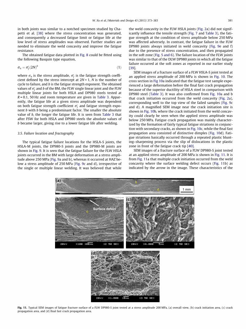
SEM images of a fracture surface of a FLW DP980-S joint testedat an applied stress amplitude of 200 MPa is shown in Fig. 11. It isfrom Fig. 11a that multiple crack initiation occurred from the weldconcavity where the surface welding defect occurs (Fig. 11b) asindicated by the arrow in the image. These characteristics of the
)
d
b
1 mm
at a stress amplitude 200 MPa, (a) overall view, (b) crack initiation area, (c) crack

382 W. Xu et al. / Materials and Design 43 (2013) 373–383
fatigue fractograph were similar to those observed on the fatiguefracture surface reported for a FLW AZ31B-H24 Mg alloy [35].The fatigue crack initiation in the present FLW DP980 steel wouldprimarily be related to the stress concentration caused by the se-vere weld concavity (Fig. 2b), in combination with the presenceof detrimental soft zones (Fig. 5 and 6). Like the HSLA welds, fati-gue crack propagation in the FLW DP980 joints was also character-ized by the occurrence of fatigue striations along with secondarycracks, as shown in Fig. 11c, whereas the final fast propagation areaconsisted of characteristic dimples as well, as shown in Fig. 11d,where some remaining inclusions located at the bottom of dimplescould be seen.
4. Conclusions
In this study the microstructure, hardness profile, tensile prop-erties, and fatigue performance of high speed fiber laser weldedHSLA and DP980 steel joints with single linear and multiple linearwelds are evaluated and compared. The following conclusions canbe drawn:
(1) Single phase microstructure containing martensite formedin the FZ of all the joints; however, newly formed martensiteand partially tempered martensite structure was observed inthe (HAZ) of HSLA and DP980 steels, respectively.
(2) The HSLA joints exhibited a hardness profile with HAZ hard-ness merging smoothly into the unaffected BM values, whilethe DP980 joints showed a significant drop of hardness inthe HAZ. Despite the formation of fully martensitic structurein the FZ, the higher carbon content in DP980 steel resultedin a higher FZ hardness (�450 HV) compared to HSLA steel(�360 HV). A characteristic ‘‘suspension bridge’’-likehardness profile with the FZ hardness as a ‘‘pylon’’ wasobserved.
(3) Both the HSLA and DP980 joints showed a superior tensilestrength with a joint efficiency reaching about 94–97%.While the ductility of DP980 joints decreased, the ductil-ity of HSLA joints was fairly close to that of BM. Despitethe presence of the soft zone, the ultimate tensilestrength of the DP980 joints was twice higher than thatof the HSLA joints, which corresponded well to the hard-ness results.
(4) The DP980 joints had a much longer fatigue life compared tothe HSLA joints at a stress amplitude above 250 MPa; how-ever, below this stress amplitude both the DP980 and HSLAjoints showed a similar fatigue life.
(5) No significant effect of weld geometry on the fatigue life ofHSLA joints was observed. On the other hand, the fatigue lifefor the multiple linear DP980 joints exhibited a larger scatterand also lower fatigue strength, indicating that the probabil-ity of dynamic fatigue failure at the lower level of stressamplitudes increased with increasing number of soft zoneand weld concavity in the weld.
(6) Above a stress amplitude of 250 MPa, fatigue failure of theHSLA joints occurred in the BM, signifying a superior struc-tural integrity of the fiber laser welded HSLA joints whensubjected to higher levels of cyclic loading. When theapplied stress amplitude was below 250 MPa, fatigue failureoccurred from the weld concavity.
(7) In the DP980 joints under both higher and lower levels ofcyclic loading, fatigue crack was observed to initiate pre-dominantly from the weld concavity and propagate in thesoft zone. Fatigue crack propagation in both HSLA andDP980 joints was characterized by the characteristic fatiguestriations coupled with secondary cracks.
Acknowledgements
The authors would like to thank the Natural Sciences and Engi-neering Research Council of Canada (NSERC) and AUTO21 Networkof Centers of Excellence for providing financial support. The finan-cial support from International Zinc Association (IZA) and Arcelor-Mittal Dofasco is highly acknowledged. One of the authors (D.L.Chen) is grateful for the financial support by the Premier’s Re-search Excellence Award (PREA), NSERC-Discovery AcceleratorSupplement (DAS) Award, Canada Foundation for Innovation(CFI), and Ryerson Research Chair (RRC) program. The authorswould like to thank Dr. J. Chen and Dr. Y.L. He (CANMET-MaterialsTechnology Laboratory, Natural Resources Canada, Hamilton, Can-ada), Mr. E. Biro (ArcelorMittal Global Research, Hamilton, Canada),and Dr. J. Villafuerte (CenterLine (Windsor) Ltd., Windsor, Canada)for their support and helpful discussion. The assistance of Q. Li, A.Machin, J. Amankrah, and R. Churaman in performing the experi-ments is gratefully acknowledged.
References
[1] Howey DA. Policy: a challenging future for cars. Nat Clim Change 2012;2:28–9.[2] Shindell D, Faluvegi G, Walsh M, Anenberg SC, Dingenen RV, Muller NZ, et al.
Climate, health, agricultural and economic impacts of tighter vehicle-emissionstandards. Nat Clim Change 2011;1:59–66.
[3] Kim HJ, McMillan C, Keoleian GA, Skerlos SJ. Greenhouse gas emissionspayback for lightweighted vehicles using aluminum and high-strength steel. JInd Ecol 2010;14(6):929–46.
[4] Hazratinezhad M, Arab NBM, Sufizadeh AR, Torkamany MJ. Mechanical andmetallurgical properties of pulsed neodymium-doped yttrium aluminumgarnet laser welding of dual phase steels. Mater Des 2012;33:83–7.
[5] Ahmed E, Reisgen U, Schleser M, Mokrov O. On formability of tailor laserwelded blanks of DP/TRIP steel sheets. Sci Technol Weld Joint 2010;15:337–42.
[6] Chan LC, Cheng CH, Chan SM, Lee TC, Chow CL. Formability analysis of tailor-welded blanks of different thickness ratios. J Manuf Sci E – T ASME2005;127:743–51.
[7] Quintino L, Costa A, Miranda R, Yapp D, Kumar V, Kong CJ. Welding with highpower fiber lasers – a preliminary study. Mater Des 2007;28:1231–7.
[8] Canning J. Fiber lasers and related technologies. Opt Laser Eng2006;44:647–76.
[9] Saunders FI, Wagoner RH. Forming of tailor-welded blanks. Metall Mater TransA 1996;27A:2605–16.
[10] Sreenivasan N, Xia M, Lawson S, Zhou Y. Effect of laser welding on formabilityof DP980 steel. J Eng Mater T 2008;130:0410041–410049.
[11] Xia M, Sreenivasan N, Lawson S, Zhou Y, Tian Z. A comparative study offormability of diode laser welds in DP980 and HSLA steels. J Eng Mater TechnolT A 2007;129:446–52.
[12] Kim CH, Choi JK, Kang MJ, Park YD. A study on the CO2 laser weldingcharacteristics of high strength steel up to 1500 MPa for automotiveapplication. J Achiev Mater Manuf Eng 2010;39:79–86.
[13] Farabi N, Chen DL, Zhou Y. Microstructure and mechanical properties of laserwelded dissimilar DP600/DP980 dual-phase steel joints. J Alloy Compd2011;509:982–9.
[14] Farabi N, Chen DL, Zhou Y. Fatigue properties of laser welded dual-phase steeljoints. Procedia Eng 2010;2:835–43.
[15] ASTM E8/E8M-11. Standard test methods for tension testing of metallicmaterials. ASTM international; 2012.
[16] ASTM E466–07. Standard practice for conducting force controlled constantamplitude axial fatigue tests of metallic materials. ASTM international; 2012.
[17] Duley WW. Laser welding. New York: Wiley & Sons, Inc; 1999.[18] Ready JF, Farson DF. LIA Handbook of laser materials processing. Laser Institute
of America; 2001.[19] Xia MS, Kuntz ML, Tian ZL, Zhou Y. Failure study on laser welds of dual phase
steel in formability testing. Sci Technol Weld Joint 2008;13(4):378–87.[20] Baltazar Hernandez VH, Nayak SS, Zhou Y. Tempering of martensite in dual-
phase steels and its effects on softening behavior. Metall Mater Trans A2011;42A:3115–29.
[21] Huang T, Sato YS, Kokawa H, Miles MP, Kohkonen K, Siemssen B, et al.Microstructural evolution of DP980 steel during friction bit joining. MetallMater Trans A 2009;40A:2994–3000.
[22] Kou S. Welding metallurgy. 2nd ed. Hoboken, NJ: John Wiley & Sons Inc; 2003.[23] Farabi N, Chen DL, Zhou Y. Tensile properties and work hardening behavior of
laser welded dual-phase steel joints. J Mater Eng Perform 2012;21(2):222–30.
[24] Xia M, Biro E, Tian ZL, Zhou Y. Effects of heat input and martensite on HAZsoftening in laser welding of dual phase steels. ISIJ Int 2008;48(6):809–14.
[25] Biro E, McDermid JR, Embury JD, Zhou Y. Softening kinetics in the subcriticalheat-affected zone of dual-phase steel welds. Metall Mater Trans A2010;41(9):2348–56.

W. Xu et al. / Materials and Design 43 (2013) 373–383 383
[26] Kuang S, Kang YL, Yu H, Liu RD. Effect of continuous annealing parameters onthe mechanical properties and microstructures of a cold rolled dual phasesteel. Int J Min Met Mater 2009;16(2):159–64.
[27] Dancette S, Massardier-Jourdan V, Fabregue D, Merlin J, Dupuy T, Bouzekri M.HAZ microstructures and local mechanical properties of high strength steelsresistance spot welds. ISIJ Int 2011;51(1):99–107.
[28] Waterschoot T, Verbeken K, De Cooman BC. Tempering kinetics of themartensitic phase in DP steel. ISIJ Int 2006;46(1):138–46.
[29] Grange RA. Estimating the hardneability of carbon steels. Metall Trans1973;4:2231–44.
[30] Calcagnotto M, Ponge D, Raabe D. On the effect of manganese on grain sizestability and hardneability in ultrafine-grained ferrite/martensite dual-phasesteels. Metall Mater Trans A 2012;43:37–46.
[31] Farabi N, Chen DL, Li J, Zhou Y, Dong SJ. Microstructure and mechanicalproperties of laser welded DP600 steel joints. Mater Sci Eng A2010;527:1215–22.
[32] Panda SK, Baltazar Hernandez VH, Kuntz ML, Zhou Y. Formability analysis ofdiode-laser-welded tailored blanks of advanced high-strength steel sheets.Metall Mater Trans A 2009;40A:1955–67.
[33] Chowdhury SM, Chen DL, Bhole SD, Powidajko E, Weckman DC, Zhou Y.Microstructure and mechanical properties of fiber–laser welded and diode–laser-welded AZ31 magnesium alloy. Metall Mater Trans A 2011;42A:1974–89.
[34] Chowdhury SM, Chen DL, Bhole SD, Cao X, Powidajko E, Weckman DC, et al.Tensile properties and strain hardening behavior of double-sided arc weldedand friction stir welded AZ31B magnesium alloy. Mater Sci Eng A2010;527:2951–61.
[35] Chowdhury SH, Chen DL, Bhole SD, Powidajko E, Weckman DC, Zhou Y. Fiberlaser welded AZ31 magnesium alloy: effect of welding speed onmicrostructure and mechanical properties. Metall Mater Trans A2012;43A:2133–47.
[36] Anand D, Chen DL, Bhole SD, Andreychuck P, Boudreau G. Fatigue behaviour oftailor (laser)-welded blanks for automotive applications. Mater Sci Eng A2006;420:199–207.
[37] Roesler J, Harders H, Baeker M. Mechanical behavior of engineering materials:metals, ceramics, polymers, and composites. 1st ed. New York: Springer;2007.
[38] Chapetti MD, Katsura N, Tagawa T, Miyata T. Static strengthening andfatigue blunt-notch sensitivity in low-carbon steels. Int J Fatigue 2001;23:207–14.
[39] Khan MS, Bhole SD, Chen DL, Boudreau G, Biro E, Deventer JV. Weldingbehavior, microstructure and mechanical properties of dissimilar resistancespot welds between galvannealed HSLA350 and DP600 steels. Sci TechnolWeld Joint 2009;14(7):616–25.
[40] Laird C. Fatigue crack propagation. West Conshohocken, PA: ASTM Spec. Tech.Publ.; 1967.
Related Documents


