Tenor BX VoIP MultiPath/Gateway Switch Product Guide 480-0073-00-11 Tenor and Quintum are registered trademarks. PacketSaver, Quintum Technologies, Inc., Risk Free VoP, VoIP Made Easy, and SelectNet Technology are trademarks of Quintum Technologies, Inc. VoIPon www.voipon.co.uk [email protected] Tel: +44 (0)1245 808195 Fax: +44 (0)1245 808299

Welcome message from author
This document is posted to help you gain knowledge. Please leave a comment to let me know what you think about it! Share it to your friends and learn new things together.
Transcript

Tenor BX VoIP MultiPath/Gateway Switch
Product Guide480-0073-00-11
Tenor and Quintum are registered trademarks. PacketSaver, Quintum Technologies, Inc., Risk Free VoP, VoIP Made Easy, and SelectNet Technology are trademarks of Quintum Technologies, Inc.
VoIPon www.voipon.co.uk [email protected] Tel: +44 (0)1245 808195 Fax: +44 (0)1245 808299
Table of Contents
Chapter 1: OverviewWhat is the Tenor BX? . . . . . . . . . . . . . . . . . . . . . . . . . . . . . . . . . . . . . . . . . . . . . . 1-2Features . . . . . . . . . . . . . . . . . . . . . . . . . . . . . . . . . . . . . . . . . . . . . . . . . . . . . . . . . 1-4
Complete Solution in one design . . . . . . . . . . . . . . . . . . . . . . . . . . . . . . . . . . . 1-4Multipath architecture . . . . . . . . . . . . . . . . . . . . . . . . . . . . . . . . . . . . . . . . . . . 1-4State of the art Management system. . . . . . . . . . . . . . . . . . . . . . . . . . . . . . . . 1-4Unique Design . . . . . . . . . . . . . . . . . . . . . . . . . . . . . . . . . . . . . . . . . . . . . . . . . 1-4SelectNet™ Technology Safety Net . . . . . . . . . . . . . . . . . . . . . . . . . . . . . . . . 1-5Easy Connect to Console . . . . . . . . . . . . . . . . . . . . . . . . . . . . . . . . . . . . . . . . 1-5Powerful System Monitoring . . . . . . . . . . . . . . . . . . . . . . . . . . . . . . . . . . . . . . 1-5
Capabilities . . . . . . . . . . . . . . . . . . . . . . . . . . . . . . . . . . . . . . . . . . . . . . . . . . . . . . . 1-6PacketSaver™ reduces bandwidth consumption . . . . . . . . . . . . . . . . . . . . . . 1-6Virtual Tie Line. . . . . . . . . . . . . . . . . . . . . . . . . . . . . . . . . . . . . . . . . . . . . . . . . 1-6SNMP Support. . . . . . . . . . . . . . . . . . . . . . . . . . . . . . . . . . . . . . . . . . . . . . . . . 1-6Call Detail Recording . . . . . . . . . . . . . . . . . . . . . . . . . . . . . . . . . . . . . . . . . . . . 1-7IVR/RADIUS Support . . . . . . . . . . . . . . . . . . . . . . . . . . . . . . . . . . . . . . . . . . . 1-7NATAccess™ . . . . . . . . . . . . . . . . . . . . . . . . . . . . . . . . . . . . . . . . . . . . . . . . . 1-7 Routing Table Options . . . . . . . . . . . . . . . . . . . . . . . . . . . . . . . . . . . . . . . . . . 1-7Call Management Features . . . . . . . . . . . . . . . . . . . . . . . . . . . . . . . . . . . . . . . 1-8H.323 Gatekeeper Services. . . . . . . . . . . . . . . . . . . . . . . . . . . . . . . . . . . . . . . 1-9Call Services . . . . . . . . . . . . . . . . . . . . . . . . . . . . . . . . . . . . . . . . . . . . . . . . . . 1-10SIP User Agent . . . . . . . . . . . . . . . . . . . . . . . . . . . . . . . . . . . . . . . . . . . . . . . . 1-11
Chapter 2: Hardware ComponentsHardware Description . . . . . . . . . . . . . . . . . . . . . . . . . . . . . . . . . . . . . . . . . . . . . . . 2-2
Front Panel Connections and Reset Options . . . . . . . . . . . . . . . . . . . . . . . . . 2-2Front Panel LEDs . . . . . . . . . . . . . . . . . . . . . . . . . . . . . . . . . . . . . . . . . . . . . . 2-4Back Panel. . . . . . . . . . . . . . . . . . . . . . . . . . . . . . . . . . . . . . . . . . . . . . . . . . . . 2-5
Cables. . . . . . . . . . . . . . . . . . . . . . . . . . . . . . . . . . . . . . . . . . . . . . . . . . . . . . . . . . . 2-6RJ-45 Cables . . . . . . . . . . . . . . . . . . . . . . . . . . . . . . . . . . . . . . . . . . . . . . . . . . 2-6DB-9 Serial RS-232 Cable. . . . . . . . . . . . . . . . . . . . . . . . . . . . . . . . . . . . . . . . 2-10
Specifications . . . . . . . . . . . . . . . . . . . . . . . . . . . . . . . . . . . . . . . . . . . . . . . . . . . . . 2-11Voice/Fax. . . . . . . . . . . . . . . . . . . . . . . . . . . . . . . . . . . . . . . . . . . . . . . . . . . . . 2-11
Table of Contents TOC-1VoIPon www.voipon.co.uk [email protected] Tel: +44 (0)1245 808195 Fax: +44 (0)1245 808299
LAN Connection. . . . . . . . . . . . . . . . . . . . . . . . . . . . . . . . . . . . . . . . . . . . . . . . 2-11Physical . . . . . . . . . . . . . . . . . . . . . . . . . . . . . . . . . . . . . . . . . . . . . . . . . . . . . . 2-11Electrical . . . . . . . . . . . . . . . . . . . . . . . . . . . . . . . . . . . . . . . . . . . . . . . . . . . . . 2-11Environmental . . . . . . . . . . . . . . . . . . . . . . . . . . . . . . . . . . . . . . . . . . . . . . . . . 2-11
Chapter 3: InstallationInstallation . . . . . . . . . . . . . . . . . . . . . . . . . . . . . . . . . . . . . . . . . . . . . . . . . . . . . . . 3-2
Pre-Installation Guidelines. . . . . . . . . . . . . . . . . . . . . . . . . . . . . . . . . . . . . . . . 3-2Inspect Package Contents. . . . . . . . . . . . . . . . . . . . . . . . . . . . . . . . . . . . . . . . 3-2Rack Install . . . . . . . . . . . . . . . . . . . . . . . . . . . . . . . . . . . . . . . . . . . . . . . . . . . 3-3
Connection . . . . . . . . . . . . . . . . . . . . . . . . . . . . . . . . . . . . . . . . . . . . . . . . . . . . . . . 3-6Connect to Line Interface - PBX . . . . . . . . . . . . . . . . . . . . . . . . . . . . . . . . . . . 3-6Connect to Trunk Interface - PSTN . . . . . . . . . . . . . . . . . . . . . . . . . . . . . . . . . 3-7Connect to Ethernet LAN. . . . . . . . . . . . . . . . . . . . . . . . . . . . . . . . . . . . . . . . . 3-8Connect to PC Console . . . . . . . . . . . . . . . . . . . . . . . . . . . . . . . . . . . . . . . . . . 3-9
Install Ground Safety Cable (if required) . . . . . . . . . . . . . . . . . . . . . . . . . . . . . . . . 3-10Power up the System . . . . . . . . . . . . . . . . . . . . . . . . . . . . . . . . . . . . . . . . . . . . . . . 3-11Assign IP Address . . . . . . . . . . . . . . . . . . . . . . . . . . . . . . . . . . . . . . . . . . . . . . . . . 3-12
Change IP Address . . . . . . . . . . . . . . . . . . . . . . . . . . . . . . . . . . . . . . . . . . . . . 3-13Load Software Upgrade . . . . . . . . . . . . . . . . . . . . . . . . . . . . . . . . . . . . . . . . . . . . . 3-15
Chapter 4: Configuration/MonitoringGetting Started with Configuration/Monitoring . . . . . . . . . . . . . . . . . . . . . . . . . . . . 4-2
Tenor Configuration Manager . . . . . . . . . . . . . . . . . . . . . . . . . . . . . . . . . . . . . 4-2Tenor Monitor . . . . . . . . . . . . . . . . . . . . . . . . . . . . . . . . . . . . . . . . . . . . . . . . . 4-3Command Line Interface . . . . . . . . . . . . . . . . . . . . . . . . . . . . . . . . . . . . . . . . . 4-3
Chapter 5: System AlarmsOverview. . . . . . . . . . . . . . . . . . . . . . . . . . . . . . . . . . . . . . . . . . . . . . . . . . . . . . . . . 8-2
How to Read Alarms . . . . . . . . . . . . . . . . . . . . . . . . . . . . . . . . . . . . . . . . . . . . 8-2Valid Alarms. . . . . . . . . . . . . . . . . . . . . . . . . . . . . . . . . . . . . . . . . . . . . . . . . . . 8-4
View Alarms . . . . . . . . . . . . . . . . . . . . . . . . . . . . . . . . . . . . . . . . . . . . . . . . . . . . . . 8-7Display all Alarms . . . . . . . . . . . . . . . . . . . . . . . . . . . . . . . . . . . . . . . . . . . . . . 8-7Display Active Alarms . . . . . . . . . . . . . . . . . . . . . . . . . . . . . . . . . . . . . . . . . . . 8-7Display Alarm History . . . . . . . . . . . . . . . . . . . . . . . . . . . . . . . . . . . . . . . . . . . 8-9
Chapter 6: Diagnostics/MaintenanceBefore you Begin . . . . . . . . . . . . . . . . . . . . . . . . . . . . . . . . . . . . . . . . . . . . . . . . . . 9-2Diagnostics . . . . . . . . . . . . . . . . . . . . . . . . . . . . . . . . . . . . . . . . . . . . . . . . . . . . . . . 9-3
Common Symptoms/Problems . . . . . . . . . . . . . . . . . . . . . . . . . . . . . . . . . . . . 9-3
Table of Contents TOC-2VoIPon www.voipon.co.uk [email protected] Tel: +44 (0)1245 808195 Fax: +44 (0)1245 808299

Diagnostic Procedures . . . . . . . . . . . . . . . . . . . . . . . . . . . . . . . . . . . . . . . . . . . . . . 9-5Verify Unit Provisioning . . . . . . . . . . . . . . . . . . . . . . . . . . . . . . . . . . . . . . . . . . 9-5Monitor LEDs . . . . . . . . . . . . . . . . . . . . . . . . . . . . . . . . . . . . . . . . . . . . . . . . . . 9-5Ping Unit . . . . . . . . . . . . . . . . . . . . . . . . . . . . . . . . . . . . . . . . . . . . . . . . . . . . . 9-5Monitor Alarms . . . . . . . . . . . . . . . . . . . . . . . . . . . . . . . . . . . . . . . . . . . . . . . . 9-5
General Maintenance . . . . . . . . . . . . . . . . . . . . . . . . . . . . . . . . . . . . . . . . . . . . . . . 9-5Restore Factory Defaults . . . . . . . . . . . . . . . . . . . . . . . . . . . . . . . . . . . . . . . . . 9-5Reset System . . . . . . . . . . . . . . . . . . . . . . . . . . . . . . . . . . . . . . . . . . . . . . . . . 9-6Change Password . . . . . . . . . . . . . . . . . . . . . . . . . . . . . . . . . . . . . . . . . . . . . . 9-6Change Unit Date and Time . . . . . . . . . . . . . . . . . . . . . . . . . . . . . . . . . . . . . . 9-6
If you need Additional Help. . . . . . . . . . . . . . . . . . . . . . . . . . . . . . . . . . . . . . . . . . . 9-7
Glossary
Warranty/Approvals
Table of Contents TOC-3VoIPon www.voipon.co.uk [email protected] Tel: +44 (0)1245 808195 Fax: +44 (0)1245 808299

Table of Contents TOC-4VoIPon www.voipon.co.uk [email protected] Tel: +44 (0)1245 808195 Fax: +44 (0)1245 808299
Chapter 1: Overview
This section gives you a general overview of the Tenor BX including feature descriptions and capabilities. Specifically, the following topics are covered:
What is the Tenor BX?
Features
Capabilities
Call Routing/Management Options
H.323 Gatekeeper Services
SIP User Agent
Chapter 1: Overview 1-1VoIPon www.voipon.co.uk [email protected] Tel: +44 (0)1245 808195 Fax: +44 (0)1245 808299

What is the Tenor BX?
The Tenor BX is a high-density VoIP (Voice over Internet Protocol) H.323/SIP switch that converts voice, fax, and modem data on digital circuit switched trunks, and transmits it over the IP network. The Tenor BX is suitable for small to medium enterprises and service provider applications by sup-porting 2, 4 or 8 BRI (Basic Rate Interfaces (2B+D channel) ports with S/T interface, supporting up to 16 voice channels.
Figure 1-1 Tenor BX VoIP Switch
Depending on the port configuration, the Tenor BX is available in two configuration types:
• MultiPath Switch (intended for PBX, PSTN and VoIP connectivity)
• Gateway (intended for VoIP and PSTN trunk port or PBX connectivity)
The MultiPath Switch is mainly intended for symmetrical multipath applications. The number of VoIP channels is equal to half the number of PSTN channels. The MultiPath Switch configuration enables connectivity between the customer equipment (i.e., PBX), PSTN and VoIP Network. The Gateway is mainly intended for trunking applications interfacing between the VoIP network and the circuit switched network (PSTN). The number of VoIP channels equals the number of PSTN chan-nels.
Table 1-1 Tenor BX MultiPath Switch configurations
Whichever configuration you choose, MultiPath or Gateway, the high performance unit provides one 10/100 BaseT connection and one RS-232 serial console port connection. The unit also incorpo-
Tenor BX MultiPath/Gateway
Configurations
RJ-45 Ports for BRI Connection
BRI Channels Supported VoIP Channels Supported
BX204 2 4 4 VoIP connections
BX408 4 8 8 VoIP connections
BX816 8 16 16 VoIP connections
Chapter 1: Overview 1-2VoIPon www.voipon.co.uk [email protected] Tel: +44 (0)1245 808195 Fax: +44 (0)1245 808299

rates an intelligent call routing engine which regulates system resources and configuration while coordinating all voice traffic activity in the unit.
Chapter 1: Overview 1-3VoIPon www.voipon.co.uk [email protected] Tel: +44 (0)1245 808195 Fax: +44 (0)1245 808299
Features
The Tenor BX’s specific features are explained below.
The gateway converts circuit switched calls to VoIP calls, the gatekeeper performs IP call routing functions, and the border element distributes the call routing directories throughout the network.
Complete Solution in one design
The Tenor BX integrates a gateway, gatekeeper, border element, intelligent call routing, and supports H.323/SIP, and QoS all in one solution, which is suitable for small to medium enterprises and ser-vice provider applications.
The unit’s simple plug and play embedded system architecture brings VoIP technology to your net-work without changing your existing telephony infrastructure. Your network stays as is, and the call type is transparent to the user. This technology boasts superior voice quality without compromising reliability.
Multipath architecture
With its MultiPath architecture, the Tenor BX can intelligently route calls between the PBX, the PSTN, and the IP network to achieve the best combination of cost and quality. It can also route calls over IP to reduce costs, and then transparently “hop off” to the PSTN, to reach off-net locations.
State of the art Management system
The Tenor BX is managed by the Tenor Configuration Manager and Tenor Monitor. Through the Configuration Manager, you can configure all options, such as signaling data, trunk groups, dial plans, and call routing numbers. An easy-to-use Java-based installation process enables you to an install the manager and start configuring within minutes. Through the Tenor Monitor, you can mon-itor the health of the system, including alarms, call detail records, etc. Both the Configuration Man-ager and Tenor Monitor provide comprehensive on-line help systems that are available at your fingertips.
In addition, you can configure the unit through the Command Line Interface (CLI). Through this simple telnet session, you can access all configuration options, including an online help system, built into the CLI, which provides help for all features and functions. Just type help with the com-mand name at any prompt, and data about that field will be displayed.
Unique Design
Tenor BX packs powerful VoIP features into one compact unit. The system’s embedded design enables you to configure the unit directly without depending on another operating system; it can be either placed on a table or mounted in a 19” rack.
With its MultiPath technology, the Tenor can be installed without upgrades to the existing voice or data network. Tenor connects to the data network through a 10/100 Ethernet interface, and to the enterprise and public voice network through BRI interfaces. In addition, with a wide range of con-
Chapter 1: Overview 1-4VoIPon www.voipon.co.uk [email protected] Tel: +44 (0)1245 808195 Fax: +44 (0)1245 808299

figurations available, it offers the flexibility for you to select a configuration that best matches your needs.
SelectNet™ Technology Safety Net
Quality of service is virtually guaranteed. Tenor BX ’s built-in patented SelectNet™ Technology provides a “safety net,” which virtually guarantees that each call going VoIP will not only be routed successfully, but will deliver high voice quality.
SelectNet monitors the IP network performance for VoIP calls. If the performance characteristics become unacceptable—according to the delay, jitter, and packet loss specifications you configure— the Tenor BX will switch the call to the PSTN automatically and transparently. The Tenor continu-ously monitors your data network for jitter, latency and packet loss, and transparently switches cus-tomer calls to the PSTN when required.
Easy Connect to Console
Plugging a serial cable between the unit’s RS-232 port and your PC’s console port, will allow local unit management. Through the console connection, you are able to assign an IP address. In addition, if you are directly connected to the unit, you are able to configure the unit via Command Line Inter-face (CLI).
Powerful System Monitoring
There are many different ways to monitor the health of the unit, including LEDs and alarms. LEDs appear on the front of the unit. The LEDs light up according to operations and alarms the system is experiencing.
Through the Tenor Monitor and the Command Line Interface (CLI) you can view a list of active sys-tem alarms, as well as view an alarm history. Each alarm indicates the unit’s operational status.
Chapter 1: Overview 1-5VoIPon www.voipon.co.uk [email protected] Tel: +44 (0)1245 808195 Fax: +44 (0)1245 808299

Capabilities
PacketSaver™ reduces bandwidth consumption
PacketSaver packet multiplexing technology reduces the amount of IP bandwidth required to sup-port multiple calls flowing between two endpoints. PacketSaver minimizes bandwidth usage by aggregating samples from multiple VoIP conversations and packing them into a larger IP packet with a single IP header. The process removes the need to send a bulky IP header with individual voice packets. As a result, it eliminates the transmission of redundant information.
.
Virtual Tie Line
Tenor BX can emulate a tie trunk. It provides all of the functionality of a tie trunk, including the con-siderable cost savings, but eliminates the need for a PBX trunk to be configured, or marked as a tie trunk. A traditional tie trunk is a PBX-configured direct connection between two PBXs in separate locations. The tie trunk bypasses the PSTN network.
Your PBX does not need any additional configuration. Tenor BX treats all the trunks the same with-out compromising voice quality.
SNMP Support
The Tenor BX supports Simple Network Management Protocol (SNMP), the standard protocol used to exchange network information between different types of networks. The Tenor BX unit acts as an SNMP agent—using HP® Openview™—to receive commands and issue responses to the Network Manager. The Network Manager will then be able to perform certain functions, such as receiving traps from the Tenor BX.
Conventional VoIP Transmission Sends Many Redundant Packet Headers
Tenor Tenor Tenor using PacketSaver to Minimize Bandwidth Usage
Chapter 1: Overview 1-6VoIPon www.voipon.co.uk [email protected] Tel: +44 (0)1245 808195 Fax: +44 (0)1245 808299
Call Detail Recording
Through the Call Detail Record (CDR) feature, the Tenor BX generates a call record at the comple-tion of each call, typically for accounting purposes. A CDR is a string of data that contains call information such as call date and time, call duration, calling party, and called party. Tenor BX may store Call Detail Records locally or they can be sent to a CDR server within the network. The CDR contains sufficient information to capture billing data, which can be used to create billing reports using third party billing software.
IVR/RADIUS Support
Interactive Voice Response (IVR) is a feature of the Tenor BX that enables you to offer services, such as Pre-paid calling cards and Post-paid accounts, to your customers.
The Tenor uses the RADIUS (Remote Authentication Dial-In User Service), for authenticating and authorizing user access to the VoIP network, including ANI Authentication (Types 1 and 2). The RADIUS is a standard protocol which provides a series of standardized message formats for trans-mitting and receiving dialed information, account data and authorization codes between the network access gateway and the billing server.
NATAccess™
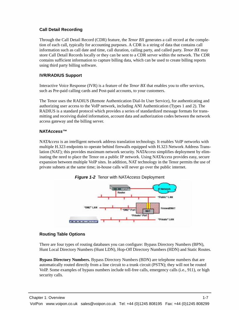
NATAccess is an intelligent network address translation technology. It enables VoIP networks with multiple H.323 endpoints to operate behind firewalls equipped with H.323 Network Address Trans-lation (NAT); this provides maximum network security. NATAccess simplifies deployment by elim-inating the need to place the Tenor on a public IP network. Using NATAccess provides easy, secure expansion between multiple VoIP sites. In addition, NAT technology in the Tenor permits the use of private subnets at the same time; in-house calls will never go over the public internet.
Figure 1-2 Tenor with NATAccess Deployment
Routing Table Options
There are four types of routing databases you can configure: Bypass Directory Numbers (BPN), Hunt Local Directory Numbers (Hunt LDN), Hop-Off Directory Numbers (HDN) and Static Routes.
Bypass Directory Numbers. Bypass Directory Numbers (BDN) are telephone numbers that are automatically routed directly from a line circuit to a trunk circuit (PSTN); they will not be routed VoIP. Some examples of bypass numbers include toll-free calls, emergency calls (i.e., 911), or high security calls.
Chapter 1: Overview 1-7VoIPon www.voipon.co.uk [email protected] Tel: +44 (0)1245 808195 Fax: +44 (0)1245 808299

Hunt Local Directory Numbers. A Hunt Local Directory Number (Hunt LDN) is a phone number reachable through local Line Circuits.
Hop-Off Directory Number. A Hop-off PBX call travels over IP, and then “hops” off into the pub-lic network (PSTN) on the distant side to reduce or eliminate public toll charges (also known as Leaky Area Map). A Hop-Off Directory Number is routed over the IP to another Tenor location and then out to the Trunk circuit, possibly to the PSTN as a local call.
Static Routes. Static Routes are used between networks and other H.323 devices that are not regis-tered to the network through the Border Element (such as non-Quintum gateways). A static route associates endpoints (as represented by their IP address (as represented by their IP address) with Directory Number patterns.
Call Management Features
Dynamic Call Routing. Tenor BX’s intelligent call routing capabilities are state-of-the-art. The unit automatically detects and supports three call types: voice, fax, and modem.
Tenor BX will first identify the call origination site—trunk circuit, line circuit, or IP routing group —and then route the call according to any parameters you have configured in the routing database. Each call may be routed via circuit switched path between any two circuit groups, or compressed and transported via VoIP when connecting to an IP routing group. Trunk circuits are those that typi-cally connect to another circuit switched network such as the PSTN. Line circuits typically connect to a termination device on the user premises, such as a PBX.
Public/Private Dial Plan Support.The Tenor BX supports public and private dial plans. A public dial plan includes numbers which conform to the international dialing plan (E.164) of a country code + city/area code + local number. For a public dial plan, you can define the numbering plan structure for the Tenor BX to use for outgoing calls.
A private dial plan does not conform to a public dialing plan (i.e., 3 digit dialing plan); through the Tenor BX you are able to configure the unique pattern/dialing plan structure, including number length.
You are able to configure which dial plan to use for incoming and outgoing calls, including whether other options such as hop-off calls, will use a public or private dial plan.
User Programmable Dial Plan Support. The User Programmable Dial Plan Support (UPDP) enables the Tenor to identify a completely customizable set of digit sequences, such as Local, National, International or Private Numbers.
PassThrough support for certain call types. Certain call types can be directly routed to a trunk circuit, without going IP. There are several routing tables you can configure via the Configuration Manager to adjust how the Tenor BX unit routes these types of “pass through” numbers. For exam-ple, you may want to configure 911 as a “bypass number”, which means that all 911 calls coming into Tenor BX from the line circuit will be routed directly to a Trunk circuit presumably connected to a PSTN. Bypass calls are never routed over IP.
Chapter 1: Overview 1-8VoIPon www.voipon.co.uk [email protected] Tel: +44 (0)1245 808195 Fax: +44 (0)1245 808299

Hop-off PBX Calls. Hop-off numbers are phone number patterns for calls to be routed out through trunks. They are entered in a Hop-off Number Directory and associated with trunks where matching calls should be sent.
Tenor BX supports those hop-off PBX calls where the destination Tenor BX is programmed to route the call to the PSTN via Trunk Circuit. (A hop-off PBX call is a toll call which hops through a pri-vate network to reduce or eliminate the toll charge.) The destination Tenor BX unit is configured with the phone numbers to be “supported” for this feature.
H.323 Gatekeeper Services
The Tenor BX unit’s built-in H.323 gatekeeper performs IP call routing functions, such as call con-trol and administrative services to another Tenor BX unit, or another H.323 endpoint. The gate-keeper’s functionality complies with the H.323 industry specifications for voice control and management.
Gatekeeper.A Gatekeeper in an H.323 network provides call control services and other services to H.323 endpoints (i.e., gateways, terminals, and MCUs). The Tenor BX has a built-in H.323 gate-keeper which complies to the H.323 industry specifications for voice control and management. The gatekeeper performs call routing functions for calls entering and exiting a site.
The Gatekeeper performs IP call routing functions, such as Call Control Signaling and Call Authori-zation for Gateways, IP phones, and H.323 terminals. The Gatekeeper communicates with other Gatekeepers through a Border Element. When using a group of Tenor BX units, you can assign one unit as the Gatekeeper for the network. We recommend you configure each as its own gatekeeper.
Tenor BX supports gatekeeper to gatekeeper communication using the standard LRQ (Location Request)/LCF (Location Confirm) messaging scheme.
Zone Management. A zone is a group of H.323 defined endpoints controlled by a Gatekeeper. End-points can be gateways (i.e., Tenor BX), terminals, and/or multipoint conferencing units (MCUs). Endpoints establish control channels with a gatekeeper for registration, admission, and security. Call routing information about the endpoint is sent to the gatekeeper, including: IP address, unit type (gateway, terminal, or MCU) and routing information (such as phone numbers, number patterns, etc.).
A collection of zones is an administrative domain. An administrative domain provides call routing services for its zones through gatekeeper to gatekeeper messages or gatekeeper to border element messages (see below for more information).
Call Registration. When registration from an H.323 endpoint is complete and a call is originated, the call request is sent to the gatekeeper. The call request provides the Gatekeeper with the dialed number and requests the routing information. The gatekeeper confirms the dialed number and sup-plies the endpoint with the destination IP address. For example, a Tenor BX’s gatekeeper will act as the gatekeeper for that zone and all of the other endpoints will register with it.
Border Element. The Tenor BX’s gatekeeper uses a border element to gain access to the routing database of the administrative domain for the purpose of call completion or any other services that involve communications with other endpoints out of the administrative domain. The border element functionality is built into the Tenor BX unit, along with the gateway and gatekeeper.
Chapter 1: Overview 1-9VoIPon www.voipon.co.uk [email protected] Tel: +44 (0)1245 808195 Fax: +44 (0)1245 808299

The primary function of the border element is to collect, manage, and distribute call routing infor-mation. A gatekeeper will establish a service relationship with a border element; the gatekeeper pro-vides its zones capabilities and the border element shares call routing capabilities of other zones in the administrative domain. Through the border element, gatekeepers from multiple zones will be able to communicate.
A border element also establishes relationships with other border elements to route between admin-istrative domains. If a gatekeeper cannot resolve an address, it contacts the border element.
In addition, if you are using more than one Tenor unit, you can configure one of the border elements for that zone. The Tenor BX unit can use two border elements: primary and secondary. These work together as one entity to provide redundancy and fault tolerance; there are no hierarchal differences.
Call Services
Gatekeepers provide services such as addressing, authorization and authentication of terminals and gateways, bandwidth management, accounting, billing, and charging. Gatekeepers also provide call-routing services. Specifically, the Tenor BX Gatekeeper provides the functions which follow:
Address Translation. The gatekeeper translates telephone numbers into IP addresses and vice versa. It performs Alias Address (phone number) to Transport Address (IP address) translation when an endpoint requests service. The Gatekeeper uses a translation table to translate an Alias Address (an address such as an H.323 identifier that a user may not understand) to a transport address. The translation table is updated using Registration messages.
Autodiscovery. The gatekeeper is discovered in one of the following ways: An endpoint sends an IP broadcast called a Gatekeeper Request message (GRQ) message (which includes that correct gate-keeper name) to discover a Gatekeeper OR the endpoint will discover a gatekeeper by its IP address.
Routing. The gatekeeper identifies the IP address of endpoints in its administrative domain. The gatekeeper builds a routing database from information obtained from the border element and also from gateways and H.323 endpoints.
Border Element
Gatekeeper
Zone
Gatekeeper
Zone
Gatekeeper
Zone
Administrative Domain
Border Element
Gatekeeper
Zone
Gatekeeper
Zone
Gatekeeper
Zone
Administrative Domain
Chapter 1: Overview 1-10VoIPon www.voipon.co.uk [email protected] Tel: +44 (0)1245 808195 Fax: +44 (0)1245 808299
Admissions Control. All H.323 endpoints must register and request permission to enter the gate-keeper’s zone; the gatekeeper will confirm or deny access to the network. The gatekeeper authorizes network access and protects the integrity of the network using Admissions Request (ARQ), Admis-sions Confirmation (ACF) and Admissions Reject (ARJ) messages.
SIP User Agent
SIP (Session Initiation Protocol) is a signaling protocol used to establish a session on an IP network for voice control and management; it is a request-response protocol that closely resembles Hypertext Transfer Protocol (HTTP), which forms the basis of the World Wide Web. SIP re-uses many of the constructs and concepts of Internet protocols such as HTTP and Simple Mail Transfer Protocol (SMTP). The purpose of SIP is only to establish/change/terminate sessions. SIP is not concerned with the content or details of the session.
SIP is Transport layer-independent, which means it can be used with any transport protocol: UDP, TCP, ATM, etc. It is text-based, so it requires no encoding/decoding like H.323. And SIP supports user mobility, using proxies and redirecting requests to your current location.
There are three basic components of SIP:
1. User Agent (Endpoint)
• client element, initiates calls
• server element, answers calls
2. Network Server (Proxy Server or Redirect Server)
• name resolution
• user location
• redirect and forking
3. Registrar
• Stores registration information in a location service using a non-SIP protocol.
Chapter 1: Overview 1-11VoIPon www.voipon.co.uk [email protected] Tel: +44 (0)1245 808195 Fax: +44 (0)1245 808299

Chapter 2: Hardware Components
This chapter tells you what is contained in your hardware package. A description of each component is also included. Specifically, the following topics are covered:
Hardware Description
Cables
Chapter 2: Hardware Components 2-1VoIPon www.voipon.co.uk [email protected] Tel: +44 (0)1245 808195 Fax: +44 (0)1245 808299

Hardware Description
The Tenor BX is a stackable/rack mountable device which provides PSTN and PBX connections (through BRI lines), as well as connections to the Ethernet LAN and a PC. The unit provides eight RJ-45 BRI S/T ports in which you can connect to a PBX or the PSTN.
The unit’s front panel includes connection jacks, LEDs, a reset button, and a diagnostics option; the back panel includes a power cord connection site, an on/off switch, and a label.
Front Panel Connections and Reset Options
Figure 2-1 Tenor BX Front Panel
• BRI Ports 1-8. One RJ-45 jack for each port supports a connection to a line side (PBX) or other customer equipment via upstream BRI lines, or to the trunk side (PSTN) via downstream BRI lines.
Each BRI line provides 2 B (Bearer) channels and 1 D (Data) signaling channel. All ports are software configurable as TE or NT.
• Reset. Enables you to reset the system.
• Diag. Enables you to perform software diagnostic procedures.
• LAN 1/LAN2. 10/100 Base-T Ethernet ports. LAN 1 port provides an RJ-45 jack for an indi-vidual connection to a 10/100 Ethernet LAN switch or hub via RJ-45 cable; it is individually configured with a unique IP and MAC address. LAN2 Ethernet port is reserved for future use.
Figure 2-2 10/100 BASE-T Ethernet Port Pin Order
BRI Port Reset Diag Console PortLAN1/LAN2
Chapter 2: Hardware Components 2-2VoIPon www.voipon.co.uk [email protected] Tel: +44 (0)1245 808195 Fax: +44 (0)1245 808299

Table 2-1 Input/Output 10/100 Ethernet port
• Console port. This RS-232 connector is used for connection to a PC’s serial port via DB-9 serial cable at 38400 bps 8 N 1, without flow control. The input/output signals are listed in Table 2-2.
Figure 2-3 DB-9 Female Connector Pin Order
Table 2-2 Serial RS232 DB-9 Connector Pinouts
Pin # Signal Definition Color
1 TX + Transmit Data White w/orange
2 TX - Transmit Data Orange
3 RX + Receive Data White w/green
4 RSVD Reserved Blue
5 RSVD Reserved White w/blue
6 RX - Receive Data Green
7 RSVD Reserved White w/Brown
8 RSVD Reserved Brown
Pin # Function Description
1 DTR Data Terminal Ready
2 TXD Transmit Data
3 RXD Receive Data
4 CD Carrier Detect
5 GND Signal Ground
6 N.C. No Connect
7 N.C. No Connect
8 N.C. No Connect
9 N.C. No Connect
5 4 3 2 1
9 8 7 6
Chapter 2: Hardware Components 2-3VoIPon www.voipon.co.uk [email protected] Tel: +44 (0)1245 808195 Fax: +44 (0)1245 808299

Front Panel LEDs
The LEDs display the health of the system. There are different types of LEDs: network, LAN, Alert and Power. For LED definitions, see Table 2-3.
Figure 2-4 Front Panel LEDs
Table 2-3 Front Panel LEDs Definitions
LED Label LED Color Description
Network (PSTN) or PBX
1-8
Flashing Amber Port is off-line.
Amber Receive Path Error Indication. Line is not connected or other receive errors; calls are not going through successfully.
Amber Layer 1: upLayer 2: down
Green Layer 1 and Layer 2: up
Off The port is empty or unconfigured.
LAN1LAN2 (LAN 2 is reserved for future use)
Link/ACT Green On: Link is good. Flashing: Line is working properly and activity is on the line. Off: Link has failed.
100 Green On: Activity is being transmitted at 100 Mbps. Off: Activity is being transmitted at 10 Mbps.
Power Power Green On: Indicates power is on. Off: Power is off.
Alert Alert Amber Operational Status. Off: Tenor BX is working properly.On: One or more diagnostic tests have failed.
Network LEDsLAN LEDs Alert LED
Power LED
Chapter 2: Hardware Components 2-4VoIPon www.voipon.co.uk [email protected] Tel: +44 (0)1245 808195 Fax: +44 (0)1245 808299

Back Panel
• AC Receptacle. Receptacle in which to plug in a power cord; the other end will plug into an AC outlet for power.
• Power Switch. Switch to turn power on and off.
• Ground Screw. An earth ground screw provided to connect to earth ground using a Ground Safety Cable (if your AC power plug only has two prongs and does not have a third, grounded prong).
• Label. A label that displays unit information.
AC Receptacle
Power Switch Ground ScrewLabel
Chapter 2: Hardware Components 2-5VoIPon www.voipon.co.uk [email protected] Tel: +44 (0)1245 808195 Fax: +44 (0)1245 808299

Cables
The cables listed in Table 2-4 are required to connect a Tenor BX to various interfaces. Contact Quintum for ordering information, if necessary.
NOTE: A crossover cable is required when connecting to a Line side (PBX, TE device) interface (when supplied by Quintum, this is a purple RJ-45 cable, P/N 303-0021-00). A straight cable is required when connecting to the trunk side (PSTN, NTI) interface. When supplied by Quintum, this is a green RJ-45 cable, P/N 303-5009-00).
Table 2-4 Cables Supported
RJ-45 Cables
RJ-45 cable connector pinouts are given in this section to help you identify the proper connector to accommodate your specific networking requirements. The RJ-45 (ISO 8877) connector is the EIA/TIA standard for Unshielded Twisted Pair (UTP) cable; the wiring color codes are UTP Standard Coloring. The pin order is shown in Figure 2-5.
Figure 2-5 RJ-45 Pin Order
Cable Usage
RJ-45 to RJ-45 Crossover Cable (this cable is pur-ple if provided by Quintum)
BRI connection Line Side (PBX) interface. TE connection.
RJ-45 to RJ-45 Straight Through cable (this cable is green if provided by Quintum)
BRI connection to Trunk Side (PSTN) inter-face. NT connection.
RJ-45 Ethernet cable (grey or white) Connection to Ethernet LAN 10/100.
DB-9 Serial RS-232 Connection to PC’s asynchronous console port.
Detachable (IEC) AC Power Supply Cord Connection to AC power jack.
8
1
1
8
Side View
Top View
Chapter 2: Hardware Components 2-6VoIPon www.voipon.co.uk [email protected] Tel: +44 (0)1245 808195 Fax: +44 (0)1245 808299
RJ-45 Ethernet Cable (10/100)
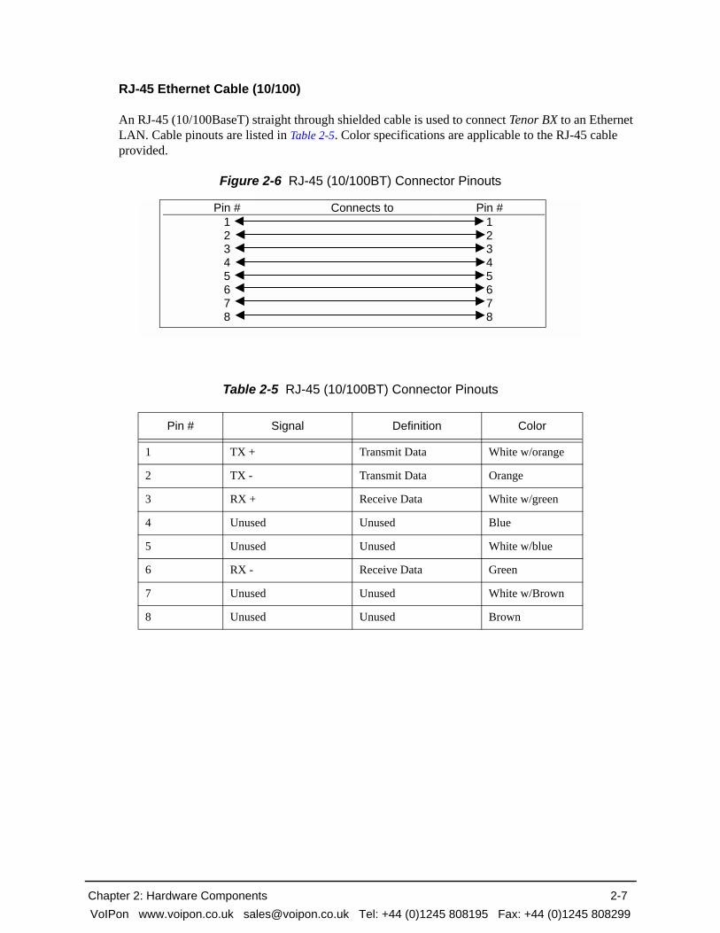
An RJ-45 (10/100BaseT) straight through shielded cable is used to connect Tenor BX to an Ethernet LAN. Cable pinouts are listed in Table 2-5. Color specifications are applicable to the RJ-45 cable provided.
Figure 2-6 RJ-45 (10/100BT) Connector Pinouts
Table 2-5 RJ-45 (10/100BT) Connector Pinouts
Pin # Signal Definition Color
1 TX + Transmit Data White w/orange
2 TX - Transmit Data Orange
3 RX + Receive Data White w/green
4 Unused Unused Blue
5 Unused Unused White w/blue
6 RX - Receive Data Green
7 Unused Unused White w/Brown
8 Unused Unused Brown
Pin # Connects to Pin # 1 2 3 4 5 6 7 8
1 2 3 4 5 6 7 8
Chapter 2: Hardware Components 2-7VoIPon www.voipon.co.uk [email protected] Tel: +44 (0)1245 808195 Fax: +44 (0)1245 808299

RJ-45 to RJ-45 Straight Cable (BRI WAN to Trunk Side)
An RJ-45 (BRI) straight cable is used to connect Tenor BX BRI port to the Trunk Side (PSTN). Cable pinouts are provided below. If this cable is provided by Quintum, the color is green. The color specifications are applicable to the RJ-45 straight cable provided.
Figure 2-7 RJ-45 (BRI) Connector Pinouts
Table 2-6 RJ-45 Connector Pinouts for BRI
Pin # Signal Polarity Color
1 Reserved White w/green
2 Reserved Green
3 Transmit + White w/orange
4 Receive + Blue
5 Receive - White w/blue
6 Transmit - Orange
7 Reserved White w/Brown
8 Reserved Brown
Pin # Connects to Pin # 1 2 3 4 5 6 7 8
1 2 3 4 5 6 7 8
Chapter 2: Hardware Components 2-8VoIPon www.voipon.co.uk [email protected] Tel: +44 (0)1245 808195 Fax: +44 (0)1245 808299

RJ-45 to RJ-45 Crossover Cable (BRI WAN to PBX)
An RJ-45 to RJ-45 (BRI) ISDN crossover cable is used to connect the Tenor BX BRI port to the Line Side (PBX). Cable pinouts are provided below. If this cable is provided by Quintum, the color is purple. The color specifications are applicable to the RJ-45 crossover cable provided.
Figure 2-8 RJ-45 Crossover Cable Pinouts
Table 2-7 RJ-45 Connector Pinouts for BRI port
Connector 1Pin # Color Connector 2
Pin #
1 White w/green 1
2 Green 2
3 White w/orange 4
6 Orange 5
4 White w/blue 3
5 Blue 6
7 White w/brown 7
8 Brown 8
Pin # Connects to Pin #12345678
12345678
Chapter 2: Hardware Components 2-9VoIPon www.voipon.co.uk [email protected] Tel: +44 (0)1245 808195 Fax: +44 (0)1245 808299

DB-9 Serial RS-232 Cable
The Serial RS-232 9-pin cable with a DB-9 male connector (with RS-232 interface) is used to con-nect the Tenor BX to your PC’s asynchronous serial port. The pin order for DB-9 male and female connectors are shown in Figure 2-9 and Figure 2-10.
Figure 2-9 DB-9 Male Connector Pin Order
Figure 2-10 DB-9 Female Connector Pin Order
Figure 2-11 DB-9 Connector Pinouts
Table 2-8 DB-9 Connector Pinouts
Pin # Function Description Pin #
1 DTR Data Terminal Ready 1
2 TXD Transmit Data 2
3 RXD Receive Data 3
4 CD Carrier Detect 4
5 GND Signal Ground 5
6 N.C. No Connect 6
7 N.C. No Connect 7
8 N.C. No Connect 8
9 N.C. No Connect 9
1 2 3 4 5
6 7 8 9
5 4 3 2 1
9 8 7 6
Pin # Connects to Pin # 1 2 3 4 5 6 7 8 9
1 2 3 4 5 6 7 8 9
Chapter 2: Hardware Components 2-10VoIPon www.voipon.co.uk [email protected] Tel: +44 (0)1245 808195 Fax: +44 (0)1245 808299

Specifications
Voice/Fax Call Routing: Line Side Interface/Trunk Side InterfaceCoding: A-law, u-lawVoice Algorithms: G.723, G.723.1A (5.3, 6.3 Kbps), G.726 (16, 24, 32, 40 Kbps), G.729,
G.711Fax Support: Group III at 2.4, 4.8, 7.2, 9.6, 12, 14.4 KbpsAutomatic Call Detection:Voice/Modem/Fax
LAN ConnectionLAN Support: 10/100 Mbps Ethernet Connection Type: Full Duplex/Half Duplex
Physical Position: 19” (48.7 cm) rack mountable or wall-mountable Depth: 10 3/4” (27.6 cm) Width 17 3/8” (44.5 cm)Height: 1 3/4 ” (4.5 cm) Weight 7.2 lbs (3.24 kg)
Electrical Ethernet: Standard 10/100Base-T RJ-45 interface (IEEE 802.3) PBX/PSTN Standard RJ-45 Connectors 8 RJ-45 connectors for BRI connection to the PBX and the digital net-
work Console Port: RS-232/DB-9 FemalePower 100-240 VAC, 2-1A, 50-60 Hz
Environmental Operating Temperature: 40° to 104° F (5° to -40° C)Operating Humidity: 20% to 80% non-condensingOperating Altitude: -200 to 10,000 feet (-60 to 3,000 meters) Storage Temperature: 14° to 140° F, (-10 to 60°C)
Chapter 2: Hardware Components 2-11VoIPon www.voipon.co.uk [email protected] Tel: +44 (0)1245 808195 Fax: +44 (0)1245 808299
Chapter 3: Installation
This chapter gives you installation instructions, as well as how to position the Tenor BX successfully within your network. Specifically, the following topics are covered:
Installation
Connection
Install Ground Cable
Power up the System
Assign IP Address
Load Software Upgrade
Chapter 3: Installation 3-1VoIPon www.voipon.co.uk [email protected] Tel: +44 (0)1245 808195 Fax: +44 (0)1245 808299
Installation
Before you begin the actual installation, review the pre-installation guidelines which follow and inspect the package contents.
Pre-Installation Guidelines• Always use an anti-static wrist strap when handling the unit.
• Do not open the unit cover. Inside parts have hazardous voltages and are extremely sensitive to static. If the unit has been opened, your warranty is void.
• Do not connect equipment in wet conditions and keep away from dusty areas.
• The area must not exceed the temperature and humidity guidelines outlined in Specifications.
• Avoid exposing the chassis to excessive vibrations.
• Mechanical loading of rack should be considered so that the rack remains stable and unlikely to tip over. Ensure no equipment is put on top of the chassis.
Inspect Package Contents
Before you install the hardware, ensure the following components are included in your shipment:
• Tenor BX and Mounting Hardware
• 1 AC Power Cable
• DB-9 RS-232 Serial Cable
• RJ-45 LAN Cable
• Correct quantity of RJ-45 cables associated with your custom configuration
• Product Guide in CD format
If a listed component is not included in your package, contact your customer service representative.
Chapter 3: Installation 3-2VoIPon www.voipon.co.uk [email protected] Tel: +44 (0)1245 808195 Fax: +44 (0)1245 808299

Rack Install
Locate the Tenor BX unit within the same area as your PBX, Ethernet hub, switch, router, and/or PSTN patch panel. The chassis is intended to be installed in a 19” rack.
Mounting brackets are attached to the chassis; the rack is not included with your system. Included with the chassis are the screws listed below. The sizes should allow installation in most racks. If your rack does not use the same size screws listed in the table, please consult the instructions you received with the rack.
Required Materials
• 19” rack (optional, not included with system)
• #8 - 32 x 3/8 screws (qty: 2) (included with the system)
• screws as required by your rack manufacturer
Install the chassis in a rack as follows:
1. Choose a position for the chassis within the rack.
WARNING: If the Tenor BX unit is the only equipment installed in the rack, ensure it is level with the rack to avoid the rack from becoming unbalanced. Mount as low as possible to avoid a high center of gravity.
2. Align the unit’s mounting brackets flush with the rack’s mounting holes (see Figure 3-1) and fol-low the vendor specific instructions for rack installation. The screws provided require a Phillips #2 screwdriver.
3. Ensure the chassis is secured firmly to the rack.
Chapter 3: Installation 3-3VoIPon www.voipon.co.uk [email protected] Tel: +44 (0)1245 808195 Fax: +44 (0)1245 808299

Figure 3-1 Rack Installation (Front View)
Wall Mount
There are two mounting brackets available to mount the unit to the wall.
Pre-installation Guidelines
• Ensure the wall is level and stable.
• Do not attach the unit to a temporary wall.
• Ensure the wall mounting area is within cord distance of the power outlet.
Required Materials
• 2 wall mounting brackets (including 2 screws)
• Drill
• 3/16 drill bit
• Measuring tape or ruler
• Hammer
• Phillips head screwdriver
Rack MountingHoles
Tenor BX
Chapter 3: Installation 3-4VoIPon www.voipon.co.uk [email protected] Tel: +44 (0)1245 808195 Fax: +44 (0)1245 808299

Attach the unit to the wall as follows:
1. Determine the wall area to mount the unit. With chalk or a soft pencil, mark the install area according to Figure 3-2.
NOTE: Ensure the unit is level.
Figure 3-2 Wall Mounting Dimensions
2. Position and attach one mounting bracket to the unit using a screw existing in the system and one screw included with the package. See Figure 3-3.
3. Position and attach the other mounting bracket using a screw existing in the system and the remaining screw in the package. See Figure 3-3.
Figure 3-3 Wall Mount Installation
4. Mount the unit to the wall using the four remaining screws included with the system.
5. Ensure the unit is firmly mounted against the wall.
7 3/4” (19.9cm)3/16”
MountingBrackets
Note: Ensure unit is level.
Attach each bracket to theunit using 1 screw already installed
and 1 screw already includedin the unit (unscrew and re-insert)
with the package.
Unit front
Chapter 3: Installation 3-5VoIPon www.voipon.co.uk [email protected] Tel: +44 (0)1245 808195 Fax: +44 (0)1245 808299

Connection
Connect to Line Interface - PBX
NOTE: When the Tenor is software configured as an NT (connecting to a PBX), termination should always be enabled (default). See the Command Line Interface Guide for configura-tion information.
Since there are many different PBX devices and connection methods, your individual PBX will determine the connection method you use to connect to the unit. For example, your PBX may be connected using a patch panel, punch down block, wire wrapped blocks, etc. If you are not sure about installation procedures, contact the network administrator or review the documentation you received with the PBX.
Adjacent port pairs (i.e., 1/2, 3/4, etc.) are configured by default not to connect to each other (Power Off Bypass) when the unit is turned off, or when the unit is in Offline mode. You should set Power-OffBypass to 1 when connecting one of the lines to a PBX, and its adjacent pair to the PSTN. This will ensure connectivity between the PSTN and PBX when the unit is turned off or when in offline mode. However, if you have adjacent port pairs that are connected to similar devices (i.e., both going to PSTN), you do not want the two ports to be connected to each other in case of power off or offline, and you should set the PowerOffBypass = 0. Each pair of ports (1/2, 3/4, 5/6 and 7/8) have their own online/offline and power off bypass control. See the Configuration Manager online help or the Command Line Interface (CLI) guide for specific configuration information.
You may use your PBX documentation, along with other PBX materials, to determine how to con-nect the other end of the RJ-45 cable to your PBX. See Chapter 2: Hardware Components for the RJ-45 cable pinouts you can use to acquire another cable or adapter that may be required to connect your specific PBX to the unit. No changes are required to the PBX itself; you will need only the cor-rect cable or adapter.
The instructions which follow tell you how to connect an RJ-45 cable (included in your package) between one of the eight network ports on the Tenor BX and a PBX. See Chapter 2: Hardware Com-ponents for a list of RJ-45 cable pinouts you can use to make a custom cable.
Figure 3-4 Connect to Line Interface
Connect to Line Interface as follows:
PBX
Insert ports 1-8
RJ-45 Crossover
Chapter 3: Installation 3-6VoIPon www.voipon.co.uk [email protected] Tel: +44 (0)1245 808195 Fax: +44 (0)1245 808299

1. Plug one end of the crossover RJ-45 cable into one of the eight BRI ports on the front of the unit. (This cable from Quintum would be the purple RJ-45 crossover cable, P/N 303-0021-00.) This port should be configured as an NT port. See Chapter 2: Hardware Components for cable pinouts if you are making your own cable.
2. Connect the other end of the crossover RJ-45 cable into the appropriate port on the PBX. (If another cable or adapter is required, see Chapter 2: Hardware Components for RJ-45 crossover pinout information.)
Connect to Trunk Interface - PSTN
NOTE: When the Tenor is software configured as a TE device (connecting to an NT1), termina-tion is enabled (default) when making a point-to-point connection between the TE port and the NT1. If other TE devices are sharing the bus of the Tenor going to the NT1, termi-nation on the TE port should be disabled. See the Command Line Interface Guide for con-figuration information.
Adjacent port pairs (i.e., 1/2, 3/4, etc.) are configured by default not to connect to each other (Power OffBypass) when the unit is turned off, or when the unit is in Offline mode. You should set Power-OffBypass to 1 when connecting one of the lines to a PBX, and its adjacent pair to the PSTN. This will ensure connectivity between the PSTN and PBX when the unit is turned off or when in offline mode. However, if you have adjacent port pairs that are connected to similar devices (i.e., both going to PSTN), you do not want the two ports to be connected to each other in case of power off or offline, and you should set the PowerOffBypass = 0. Each pair of ports (1/2, 3/4, 5/6 and 7/8) have their own online/offline and power off bypass control. See the Configuration Manager online help or the Command Line Interface (CLI) guide for specific configuration information.
Figure 3-5 Connect to Trunk Interface
1. Plug one end of the straight through RJ-45 cable (P/N 303-5009-00) into one of the eight BRI ports on the front of the unit. The cable from Quintum would be the green RJ-45 cable. This port should be configured as a TE port. See Chapter 2: Hardware Components for cable pinouts if you are making your own cables, or if you wish to attach the table to a punch down block.
PSTN
Patch Panel
RJ-45 Insert ports 1-8
Chapter 3: Installation 3-7VoIPon www.voipon.co.uk [email protected] Tel: +44 (0)1245 808195 Fax: +44 (0)1245 808299

2. Connect the other end of the RJ-45 straight cable to the patch panel which houses your telephone lines.
NOTE: Connecting to the patch panel may require trained telephone personnel.
Chapter 3: Installation 3-8VoIPon www.voipon.co.uk [email protected] Tel: +44 (0)1245 808195 Fax: +44 (0)1245 808299
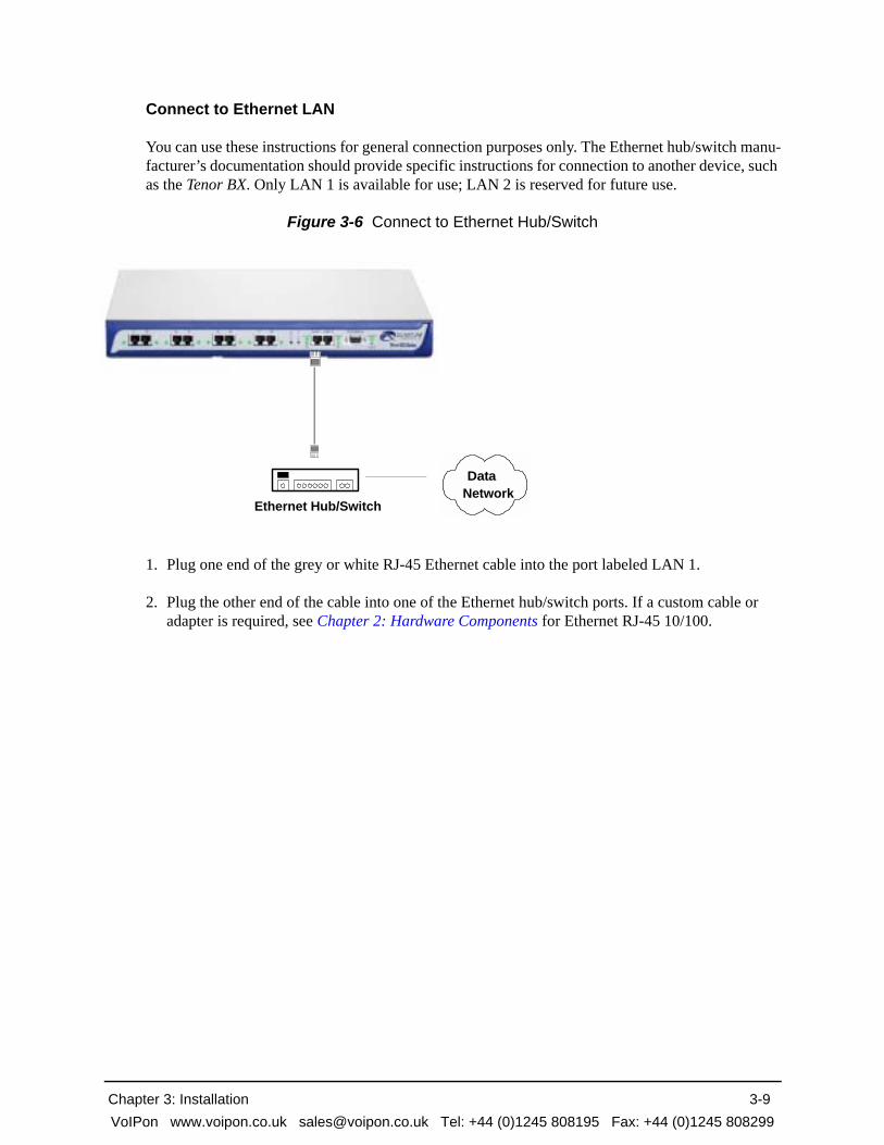
Connect to Ethernet LAN
You can use these instructions for general connection purposes only. The Ethernet hub/switch manu-facturer’s documentation should provide specific instructions for connection to another device, such as the Tenor BX. Only LAN 1 is available for use; LAN 2 is reserved for future use.
Figure 3-6 Connect to Ethernet Hub/Switch
1. Plug one end of the grey or white RJ-45 Ethernet cable into the port labeled LAN 1.
2. Plug the other end of the cable into one of the Ethernet hub/switch ports. If a custom cable or adapter is required, see Chapter 2: Hardware Components for Ethernet RJ-45 10/100.
DataNetwork
Ethernet Hub/Switch
Chapter 3: Installation 3-9VoIPon www.voipon.co.uk [email protected] Tel: +44 (0)1245 808195 Fax: +44 (0)1245 808299

Connect to PC Console
You will need to connect the Tenor BX to your workstation’s serial port via RS-232 connection. (This connection will be used when you assign an IP address to the unit.) For the instructions below, it is assumed you are connecting to a Windows PC.
Figure 3-7 Connect to PC Com Port
1. Insert the male end of the DB-9 cable into the port labeled Console. (See Chapter 2: Hardware Components for RS-232 connector pinouts.)
2. Insert the female end of the DB-9 cable into your workstation’s serial port (see your PC docu-mentation for more information about this port).
DB-9
Chapter 3: Installation 3-10VoIPon www.voipon.co.uk [email protected] Tel: +44 (0)1245 808195 Fax: +44 (0)1245 808299

Install Ground Cable (if required)
The Tenor BX provides an additional Earth Ground screw (a #6 screw). This screw provides earth ground to the unit if the AC power receptacle you are plugging into does not contain a ground prong (the Quintum supplied power cable has a three prong connector). To provide ground via the ground-ing screw, you will need to connect the grounding screw to a Ground Cable, which can then be con-nected to an approved earth ground.
Connect the Ground Cable (not provided) as follows:
1. Unscrew the existing screw from the grounding hole.
2. Place the screw through the connector of the ground cable.
3. Attach the screw securely to the threaded grounding hole.
4. Connect the other end of the ground cable to a approved electrically grounded point. Consult with a licensed electrician if you are unclear about this operation.
Figure 3-8 Install Ground Cable
Chapter 3: Installation 3-11VoIPon www.voipon.co.uk [email protected] Tel: +44 (0)1245 808195 Fax: +44 (0)1245 808299

Power up the System
Once you have all cables connected properly, you are ready to turn the system on as follows:
1. Plug in the power cord to an AC outlet.
2. Locate the on/off switch on the back of the unit and click the switch to On.
The unit will power up and the LEDs will flash and turn off; the power LED will remain lit. For information about the LEDs, see Chapter 2: Hardware Components.
Once the unit is powered up, you are ready to assign an IP address. See the following section Assign IP Address.
Chapter 3: Installation 3-12VoIPon www.voipon.co.uk [email protected] Tel: +44 (0)1245 808195 Fax: +44 (0)1245 808299

Assign IP Address
Before you can configure a Tenor BX, you need to assign a valid IP address. When a Tenor BX is shipped to a customer, you will need to assign a valid IP address for each unit. An IP address is a 32 bit (up to 12 numeric characters) address used to identify each network device in the TCP/IP net-work. If the unit does not have an IP address, data will not be able to be sent to or from the unit.
Communication between the Tenor and the PC is enabled via RS-232 connection and terminal emu-lation software. The instructions below assume you are running HyperTerminal (running Windows 95 or later) on your PC. For all other terminal emulation packages, the specific Tenor commands used to assign the IP address will be the same, but the software specific instructions will be different. Consult the applicable documentation for more information.
You can re-configure the IP address using the procedure which follows.
NOTE: The instructions below assume you are running Windows 2000 or above.
1. Press the Tenor BX’s power switch to On.
2. Click on Start> Programs> Accessories> Communications>HyperTerminal> Run. The Connec-tion Description window will be displayed.
3. Enter a connection name (i.e., name for each unit such as Tenor BX New Jersey).
4. Click Ok.
5. Choose the serial port on your PC from the Connect Using drop down list box (i.e., Direct to Com 1). Click Ok. The Com1 Properties window will be displayed. See Figure 3-9.
Chapter 3: Installation 3-13VoIPon www.voipon.co.uk [email protected] Tel: +44 (0)1245 808195 Fax: +44 (0)1245 808299

Figure 3-9 Port Settings Window
6. From the Bits Per Second drop down list box, choose 38400.
7. From the Data Bits drop down list box, choose 8.
8. From the Parity drop down list box, choose None.
9. From the Stop bits drop down list box, choose 1.
10.From the Flow control drop down list box, choose None.
11.Click Ok and a connection to the Tenor will be established. Information about the unit will scroll on the screen.
12.Enter login and password. Both are admin by default.
13.A message will appear on the screen “Tenor BX does not have an Ethernet interface configured. Would you like to configure an Ethernet Interface?” (y/n).
14.Type y.
15.For IP Address, enter the IP address for the Tenor unit (i.e., 192.168.1.444).
16.For Subnet Mask, enter the subnet mask (i.e.,255.255.255.0). This address is used to differentiate the network portion of the IP address from the host portion of the IP address.
Chapter 3: Installation 3-14VoIPon www.voipon.co.uk [email protected] Tel: +44 (0)1245 808195 Fax: +44 (0)1245 808299

17.For Default Gateway (i.e., 192.168.2.222) choose whether there should be a default gateway (router) which routes packet data outside of your LAN and enter its IP address.
18.A message will appear on the screen “Tenor BRI Ethernet Interface successfully configured.” The Tenor will restart using the new Ethernet settings.
Tenor will restart using the new Ethernet settings.
Change IP Address
You are able to change the IP address in which the unit is attached as follows:
NOTE: The instructions below assume you are running Windows 2000 or above.
1. Press the Tenor BX’s power switch to On.
2. Click on Start> Programs> Accessories> Communications>HyperTerminal> Run. The Connec-tion Description window will be displayed.
3. Enter a connection name (i.e., name for each unit such as Tenor BX New Jersey).
4. Click Ok.
5. Choose the serial port on your PC from the Connect Using drop down list box (i.e., Direct to Com 1). Click Ok. The Com1 Properties window will be displayed. See Figure 3-10.
Figure 3-10 Port Settings Window
Chapter 3: Installation 3-15VoIPon www.voipon.co.uk [email protected] Tel: +44 (0)1245 808195 Fax: +44 (0)1245 808299

6. From the Bits Per Second drop down list box, choose 38400.
7. From the Data Bits drop down list box, choose 8.
8. From the Parity drop down list box, choose None.
9. From the Stop bits drop down list box, choose 1.
10.From the Flow control drop down list box, choose None.
11.Press the Tenor AS power switch to On. After the bootup sequence, the login prompt will appear.
12.Enter a login name. The default login name is admin.
13.Enter a password. The default password is admin. (Once you are up and running, changing the password is a good idea for security purposes). Step through each of the following parameters and enter the correct values for your installation: IP address, Subnet Mask and Default Gateway.
14.At the Quintum prompt, type ei to reach the Ethernet prompt and then type config to change to the Configuration mode.
15.To set the IP address, type set ipa followed by the IP address.
16.To set the Subnet Mask, type set subnetmask, followed by the subnet mask.
17.Type siprd to change to the Static IP Route Directory.
18.To set the Default Gateway IP, type change 1 g followed by the IP address for the default gate-way IP.
19.Type submit.
20.Type maint to reach the maintenance mode and then mc. Type reset. A confirmation message will ask if you want to reset the unit. Type yes to reset the unit. The reboot enables the Tenor to incorporate the new settings.
Load Software Upgrade
To upgrade the software, download the upgrade from the CD ROM you received with the unit, or download the latest software/documentation from www.quintum.com.
Chapter 3: Installation 3-16VoIPon www.voipon.co.uk [email protected] Tel: +44 (0)1245 808195 Fax: +44 (0)1245 808299

Chapter 4: Configuration/Monitoring
This chapter tells you how to get started configuring and monitoring the Tenor BX, including the fol-lowing: Topics include:
Getting Started
Tenor Configuration Manager
Tenor Monitor
Command Line Interface (CLI)
Chapter 4: Configuration/Monitoring 4-1VoIPon www.voipon.co.uk [email protected] Tel: +44 (0)1245 808195 Fax: +44 (0)1245 808299

Getting Started with Configuration/Monitoring
There are different ways to configure and monitor the Tenor BX.
• Tenor Configuration Manager. A user-friendly windows-based stand-alone GUI which enables you to configure a number of Quintum products, including the Tenor BX. This software was designed to run on any PC; you simply designate the IP address for the Tenor BX.
• Tenor Monitor. A user-friendly windows-based stand-alone GUI which enables you to monitor the Alarms, Call Detail Records (CDRs) and perform call monitoring functions for the Tenor BX.
• Command Line Interface (CLI). Enables you to configure the Tenor BX through a CLI telnet-based session.
Basic information is included in this section; for complete information, including all field defini-tions and extensive usage instructions, see the Tenor Configuration Manager/Tenor Monitor User Guide and the Command Line Interface User Guide (or the Online Help available with the soft-ware). Along with the CD you received with the unit, you can also access the latest software and upgrade information from www.quintum.com.
Tenor Configuration Manager
The Tenor Configuration Manager is used to configure all aspects of the Tenor BX, including sys-tem, Ethernet, CDR, signaling, circuit, and VoIP configuration. Through the Configuration Man-ager, you are able to configure all aspects of the Tenor unit. The manager is a user-friendly GUI which enables you to configure Quintum products; you designate the IP address of the Tenor prod-uct you want to configure.
Get started with the Configuration Manager as follows:
NOTE: Ensure the software is installed and running.
1. Access the Tenor Configuration Manager icon (located in the area in which you specified during installation). For example, click on Start > Programs >Quintum Tenor Configuration Manager> Tenor Config Manager. The Tenor Configuration Manager will launch. The Specify Tenor IP Address window will be displayed.
2. From the Tenor IP Address drop down box, click on Specify New IP Address (if the IP address is already listed from a previous login, select that IP address and you will automatically be con-nected).
3. Enter the IP address of the Tenor unit in which you would like to configure.
4. Enter the Tenor Server Port (the value must match the port numbers set through the CLI; the default entry is 8080).
5. Click Ok. The Confirm Login and Password screen will be displayed.
Chapter 4: Configuration/Monitoring 4-2VoIPon www.voipon.co.uk [email protected] Tel: +44 (0)1245 808195 Fax: +44 (0)1245 808299

6. Enter a user name and password (the default user name is admin; the default password is admin). Click ok. You are now ready to configure the Tenor unit.
Once you have connected to the Configuration Manager, you can move around and configure data. For complete information about the field definitions, valid entries, and submit information, see the Tenor Configuration Manager/Tenor Monitor User Guide or the online help system that came with the system.
Tenor Monitor
The Tenor Monitor enables you to view alarms for all Tenor units, as well as Call Event Records, and Call Detail Records. There are three main functions of the Tenor Monitor.
• Alarm Monitor. Through the Alarm Monitor, you are able to view alarms for a specified IP address, as well as display active alarms, alarm history, and deleted alarms. You can configure a database table for the specific unit in which you would like to monitor alarms.
• Call Monitor. Through the Call Monitor, you are able to view call events for each call passing through the Tenor, including call type, duration, call state, etc. The Call Monitor continuously collects active, real-time call event data and displays it on the screen. You are able to select/edit/delete a Tenor to a database table for the specific unit in which you would like to view call events.
• Call Detail Record (CDR) Monitor. Through the CDR Monitor, you are able to view the Call Detail Record for each call, including the call connect/disconnect times, call path, and autoswitch information.
Through the Tenor Monitor, you can view real-time data for up to three Tenors at the same time. The Tenor Monitor can collect up to 500,000 CDR/Call Event Records per day.
View call monitoring information as follows:
NOTE: Ensure the software is installed and running.
1. Access the Tenor Monitor icon (located in the area in which you specified during installation. For example, click on Start > Programs >Quintum Tenor Monitor>Tenor Monitor. The Tenor Moni-tor will open up. The User Name and Password window will be displayed.
2. Enter a user name and password (the default user name is admin; the default password is admin). Click OK.
You are now ready to monitor a specific Tenor unit. See the Tenor Configuration Manager/Tenor Monitor User Guide for specific information about adding an IP address, moving around the Tenor Monitor, using screens, and switching between IP addresses to view alarms, CDR, and call informa-tion.
Command Line Interface
The Command Line Interface (CLI) is a Telnet-based (also accessible via serial port) list of menu options which enable you to configure and monitor any Tenor BX unit; you can configure features and capabilities such as numbering plans, channel usage, border element, signaling type, and routing
Chapter 4: Configuration/Monitoring 4-3VoIPon www.voipon.co.uk [email protected] Tel: +44 (0)1245 808195 Fax: +44 (0)1245 808299
information. In addition, you are also able to monitor system alarms and run diagnostic procedures. CLI attributes enable you to further configure CLI options; these provide additional configuration items according to the option type.
Through the CLI, there are also commands you execute to simplify the process of configuring and monitoring the Tenor BX unit. Some of these commands are globally used, others are specific to the mode in which you are working. For example, the set command, available globally from within the Configuration mode, enables you to set attributes for different options.
You can access the CLI through a Telnet session, a terminal-like access to any Tenor BX unit. If your PC is directly connected to the Tenor BX unit, you can configure the unit directly through the serial port using HyperTerminal. Both methods are described below.
NOTE: Alternatively, you may want to use other telnet clients, such as the Linux telnet client or free programs like Putty. If you choose to do so, you may have to make minor setting changes in the Telnet client in order to make it function correctly.
Telnet Connection. Once the Tenor BX has been initially configured with an IP address network and is connected, the easiest way to connect to the Tenor BX and use the CLI is through a standard Telnet session from any PC on your IP network. Connect to a Tenor BX unit via Telnet as follows:
For Windows 95/Windows 98:
1. Click on Start> Run. The Run dialog box will be displayed.
2. Type telnet and click on Ok.
3. Click on Connect> Remote System.
4. In the Host Name field type, enter the IP address assigned to your Tenor BX.
5. Click on Connect.
A connection to the Tenor BX unit will be established.
For Windows 2000 and above:
1. Click on Start> Run.
2. The Run dialog box will be displayed. Type telnet and click on Ok. (Or type telnet followed by the IP address and you will connect.)
3. At the telnet prompt, type open (followed by the IP address for the unit to which you want to connect.)
A connection to the Tenor BX unit will be established.
Serial Port Connection. When the Tenor BX is first shipped to you, you must connect to the unit using this method to assign an IP address. Once this is assigned, you can use the CLI to reach the serial port of the Tenor. A null-modem cable must be used to connect to the CLI using this port, if
Chapter 4: Configuration/Monitoring 4-4VoIPon www.voipon.co.uk [email protected] Tel: +44 (0)1245 808195 Fax: +44 (0)1245 808299

you are directly connected to the unit. To connect to the Tenor BX serial port, locate a workstation (PC) close to the Tenor BX unit. Connect as follows:
1. Insert one end of the DB-9 serial null modem cable into the Tenor BX’s serial port.
2. Insert the other end of the DB-9 serial cable into your workstation’s Com/serial port.
Once the cable is connected and the Tenor BX is powered on, open a HyperTerminal session (or other terminal emulation program) as follows:
3. Click Start > Programs > Accessories > Communications > HyperTerminal. The HyperTermi-nal window will be displayed.
4. Click on Hypertrm.
5. Enter a connection description (i.e., name for each unit such as Tenor BX 1).
6. Click Ok.
7. Choose a connection port (on your PC) from the Connect Using drop down list box (i.e., Direct to Com 1). Click Ok. The Com 1 properties window will be displayed.
8. From the Bit Per Second drop down list box, choose 38400.
9. From the Data Bits drop down list box, choose 8.
10.From the Parity drop down list box, choose None.
11.From the Stop bits drop down list box, choose 1.
12.From the Flow Control drop down list box, choose None.
13.Click on Call>Call. A connection to the Tenor BX will be established.
14.Enter a login name. The default login name is admin.
15.Enter a password. The default password is admin. Questions about the unit will scroll on the screen.
NOTE: Steps 16-18 are used for first time assignment of IP address.
16.For IP address, enter the IP address for the Tenor BX unit.
17.For Subnet Mask for LAN prompt, enter the subnet mask.This address is used to differentiate the network portion of the IP address from the host portion of the IP address.
18.For Default Gateway prompt, enter the IP address for the default gateway (router) which routes packet data outside of your LAN.
The Tenor BX will reboot automatically.
Chapter 4: Configuration/Monitoring 4-5VoIPon www.voipon.co.uk [email protected] Tel: +44 (0)1245 808195 Fax: +44 (0)1245 808299

Once you are connected to the Command Line Interface, you can configure the system, as well as perform diagnostics and monitor system information. For specific information, see the Online Help you received with the CD.
Chapter 4: Configuration/Monitoring 4-6VoIPon www.voipon.co.uk [email protected] Tel: +44 (0)1245 808195 Fax: +44 (0)1245 808299

Chapter 5: System Alarms
This chapter tells you how to use the Alarm Manager to view and understand alarms generated by the system.
Specifically, the following topics are included:
Overview
View Alarms
Chapter 5: System Alarms 5-1VoIPon www.voipon.co.uk [email protected] Tel: +44 (0)1245 808195 Fax: +44 (0)1245 808299

Overview
There are two ways to view alarms for the Tenor BX unit: through the Command Line Interface (CLI) or through Tenor Monitor. The information for accessing alarms via CLI is detailed in this chapter. see the Tenor Configuration Manager/Tenor Monitor User’s Guide or the Tenor Monitor’s online help system for information about viewing alarms via Tenor Monitor.
Alarms are brief text messages that appear on your workstation when the Tenor BX unit encounters a problem, such as a failed interface, disconnected call, etc. You can reach the Alarm Manager through the Command Line Interface (CLI) alarm monitoring system.
How to Read Alarms
The Alarm Manager reports alarms according to criteria such as the alarm’s severity level, line num-ber the alarm occurred on, channel number, etc. There are two alarm types displayed: Active Alarms and Alarm History. An Active Alarm list displays all the alarms still active on the system; these alarms have not been cleared or deleted. An Alarm History is a list of the last 100 alarms stored in the system since the last time you performed a delete operation.
Definitions for generated alarm fields appear in Table 5-1.
Table 5-1 Alarm Fields and Definitions
Field Definition Valid Entry
IP # The unit’s IP address (32 bit address).
Example: 192.168.1.34.
Sequence # Internal number used to iden-tify alarms.
01, 02, 03, etc.
Type (displays only if you generate an Alarm History)
The type of alarm generated. ALR = Alarm. This indicates an active alarm. CLR= Clear. This indicates an alarm that has been cleared from the sys-tem. RPT= Report. This indicates that the alarm has been gener-ated for a report. This entry is for internal use only; if you see an alarm that is causing problems, contact customer service.
Chapter 5: System Alarms 5-2VoIPon www.voipon.co.uk [email protected] Tel: +44 (0)1245 808195 Fax: +44 (0)1245 808299

Severity Level or alarm severity. 1 = Critical (complete system is affected). 2 = Major (major problem is detected).3 = Minor (minor problem is detected).4 = Info (Information about a minor problem).
Desc A text description of the alarm; see Table 5-2 for detailed description.
Varies.
Slot # Defines which slot the alarm occurred on.
Slot 1 or 2. Slot 1 refers to the system controller functions; slot 2 refers to DSP/Digital line functions.
Line Defines which line the alarm occurred on.
Line 1 through 8.
Channel # Specifies which channel the alarm occurred on.
Channels 1-2
Date/Time Date/time the event occurred on.
Day of week: name of day.Month: Jan, Feb, March, etc.Day of month: 1 or 2 digits.Time: 6 digits (hour minutes seconds based on a 24-hour clock).Year: 4 digits.
Field Definition Valid Entry
Chapter 5: System Alarms 5-3VoIPon www.voipon.co.uk [email protected] Tel: +44 (0)1245 808195 Fax: +44 (0)1245 808299

Valid Alarms
The following is a list of all alarm descriptions (text that appears in the Alarm Description field) for all possible alarms the system can generate. In the generated alarm list, the alarm description appears as part of the Description field.
Table 5-2 List of Valid Alarms
Severity (appears as
part of severity field)
Alarm Description(text appears in desc field) Definition
Critical Loss of Framing (Red Alarm) Signal is not being transmitted; there is no layer 1 synchronization.
Critical Remote Alarm indication (Yellow Alarm)
Tenor BX is receiving a yellow alarm signal from the network.
Critical Loss of signal A loss of signal (32 consecutive zeros) at least once during a 1 second period.
Critical AIS Reception (Blue Alarm) Alarm Indication Signal. An all ones condition used to alert the Tenor BX that its incoming signal (or frame) has been lost.
Critical Layer 2 Down Indicates that Layer 2 protocol is down.
Critical Ethernet Disconnected Ethernet cable has been disconnected from the Sys-tem Controller or CPU Card, or Ethernet connec-tivity has been lost. No new VoIP calls will be made and existing PSTN calls will be switched to the PSTN.
Critical Call Handler not registered with Gatekeeper
The Call Handler process cannot be registered with the Gatekeeper.
Critical Critical Software Error A software error has occurred that affects the oper-ability of the complete system.
Critical Tenor BX Chassis reset The chassis has reset.
Critical Primary Interface Clock Loss Clock source has been lost for BRI lines. The unit will automatically switch to the secondary digital interface clock source.
Critical Secondary Interface Clock Loss All clock sources have been lost, both primary and secondary. Check the BRI lines for the possible cause.
Critical Configuration Data Missing Configuration via CLI is missing. Check the con-figuration data and add the necessary information.
Chapter 5: System Alarms 5-4VoIPon www.voipon.co.uk [email protected] Tel: +44 (0)1245 808195 Fax: +44 (0)1245 808299

Critical IVR Configuration Missing Appears if an attempt to make an IVR call has been made when a valid IP address is not configured.
Occurs if an IVR call has been passed through accidently, without a real intention to use IVR for subsequent calls, while both of the servers were disabled. In order to clear the alarm, a user will have to change one of the IP addresses to some value, and then disable it again.
Critical RADIUS Configuration Missing Appears when a RADIUS request is made and one or more required configuration parameters are missing.
This alarm is cleared when the required RADIUS parameters are configured via CLI.
Critical RADIUS Server Not Responding Appears when none of the configured RADIUS servers respond.
This alarm is cleared when any of the RADIUS servers respond or the RADIUS server is disabled via CLI.
Major Major Software Error A software error has occurred that affects system signaling, interfaces, or other major operation.
Major File Missing in the File Server This alarm will be reported to the system when a particular voice prompt file is not found in the IVR Prompt Server.
This alarm applies only to the system with enabled IVR functionality.
Major Switch to other RADIUS server Appears when the current RADIUS server stops responding after three consecutive calls end in tim-eouts and another RADIUS server is configured, the Tenor will then switch to the next RADIUS server.
Minor Call Event(s) Lost A call has failed.
Minor Missing or Incorrect Profile The configuration profile has caused a problem.
Minor Minor Software Error A software error has occurred but will not affect the operation of the complete system.
Minor No response to seizure There has been a problem with the BRI line.
Severity (appears as
part of severity field)
Alarm Description(text appears in desc field) Definition
Chapter 5: System Alarms 5-5VoIPon www.voipon.co.uk [email protected] Tel: +44 (0)1245 808195 Fax: +44 (0)1245 808299

Minor Remote end did not back off in a glare situation
An incoming and outgoing call went through at the same time, and the remote end call did not back off.
Minor Unit resource constrained A shared resource in the unit loads the system.
Minor Hardware component failed A hardware component has failed. Check all com-ponents, hardware connections, etc.
Minor Log RADIUS server error Displayed when the RADIUS server fails to send required data or the data sent by the RADIUS server has improper values. Incorrect information may contain the following:
RADIUS Server: Credit amount (-1)RADIUS Server: Credit minus amountRADIUS Server: Not supported currencyRADIUS Server: Credit time (-1)RADIUS Server: Credit time < 6 secRADIUS Server: Invalid error code
Informational Gatekeeper status Reports the status of the Gatekeeper.
Informational Miscellaneous information Miscellaneous information about the unit is reported. The contents of this alarm will vary.
Informational Info Software Error Indicates information about miscellaneous soft-ware error. This does not affect system operation.
Informational Glare occurred An incoming and outgoing call went through at the same time, and the remote end call did not back off, but the situation was corrected.
Severity (appears as
part of severity field)
Alarm Description(text appears in desc field) Definition
Chapter 5: System Alarms 5-6VoIPon www.voipon.co.uk [email protected] Tel: +44 (0)1245 808195 Fax: +44 (0)1245 808299

View Alarms
The Command Line Interface (CLI) enables you to view alarms through the Monitor mode. You can view active alarms, as well as view an alarm history list.
You are now ready to view active alarms and an alarm history, or both. See the sections which fol-low:
Display all Alarms
You are able to display both active alarms and an alarm history as follows:
1. Through CLI, access the Monitor prompt.
2. Type alarm. Both active alarms and the alarm history will be displayed. See section How to Read Alarms for field definitions.
Figure 5-1 Alarm sample
Display Active Alarms
1. Through CLI, access the Monitor prompt.
2. Type alarm a. The active alarms will be listed. See section How to Read Alarms for field defini-tions. If you enter alarm without a command following it, both active alarms and the alarm his-tory will be displayed.
Chapter 5: System Alarms 5-7VoIPon www.voipon.co.uk [email protected] Tel: +44 (0)1245 808195 Fax: +44 (0)1245 808299

Figure 5-2 Active Alarm Sample
Chapter 5: System Alarms 5-8VoIPon www.voipon.co.uk [email protected] Tel: +44 (0)1245 808195 Fax: +44 (0)1245 808299

Display Alarm History
1. Through CLI, access the Monitor prompt.
2. Type alarm h. An alarm history will be displayed. See section How to Read Alarms for field defi-nitions. If you enter alarm without a command following it, both active alarms and the alarm his-tory will be displayed.
Figure 5-3 Alarm History Sample
Chapter 5: System Alarms 5-9VoIPon www.voipon.co.uk [email protected] Tel: +44 (0)1245 808195 Fax: +44 (0)1245 808299

Chapter 6: Diagnostics/Maintenance
This chapter tells you how to troubleshoot Tenor BX operation, as well as how to maintain the health of your system. You will find information about how to view the unit’s LEDs, as well as how to interpret the chassis’ alarms and check basic connections.
Specifically, the following topics are included:
Before you Begin
Diagnostics
General Maintenance
Finding Help
Chapter 6: Diagnostics/Maintenance 6-1VoIPon www.voipon.co.uk [email protected] Tel: +44 (0)1245 808195 Fax: +44 (0)1245 808299
Before you Begin
Before you begin troubleshooting a potential malfunction, it is a good idea to check your basic hard-ware connections. See below.
• Ensure power cord is firmly installed in the back panel’s power jack and the other end is plugged into the AC power source.
• Ensure the unit’s power switch is in the On position. If the unit is not working, toggle the power switch to reset the system. If the unit is reset, the settings you configured may be lost.
• Verify that all RJ-45 and DB-9 cables fit snugly in each front panel jack. Faulty connections may cause a number of network interfacing or connection issues.
If you suspect the problem to be on the network end, contact your Central Office to verify proper operation.
Chapter 6: Diagnostics/Maintenance 6-2VoIPon www.voipon.co.uk [email protected] Tel: +44 (0)1245 808195 Fax: +44 (0)1245 808299

Diagnostics
Common Symptoms/Problems
Below is a list of common symptoms and problems you may encounter. Use this list as a guideline; if your problem is not listed, use the diagnostic procedure explained in the beginning of this chapter.
Table 6-1 Common Symptoms/Problems
Common Symptom/Problem Description/Solution
Unit will not turn on. Check AC power source.
Communication between Tenor BX and the PBX or PSTN cannot be established.
There are several reasons why communication may not be successful. A few of the most common are listed below.
Verify correct cables are installed in the BRI ports. See Chapter 3: Installation.
Unit configuration may be wrong. Examine the con-figuration parameters via Configuration Manager or CLI.
Network issues may cause a number of problems. Contact the Central Office to perform test procedures.
Communication with Command Line Interface (CLI) cannot be established using Telnet.
The IP address of the Tenor BX unit may be incorrect.
Check Ethernet Cable.
Verify the IP address of Tenor BX. Check the Default Gateway Subnet Mask. Check Ethernet connection via RS-232 connection. See Chapter 3: Installation
Verify network connectivity using ping from another network host. See Chapter 4: Configuration/Monitor-ing.
ALERT LED is on and not flashing. One or more internal diagnostic tests have failed. Con-tact customer service. LED will stay on for a minute or so when the unit is powered up.
Communication with Ethernet Hub, or switch cannot be established.
Verify RJ-45 cable is firmly installed in the Ethernet port.
Check MDI/MDIX configuration. Check duplex set-ting on the switch in which they were connected and the speed of 10MB or 100MB.
Chapter 6: Diagnostics/Maintenance 6-3VoIPon www.voipon.co.uk [email protected] Tel: +44 (0)1245 808195 Fax: +44 (0)1245 808299

Communication between computer’s COM port and Tenor BX serial port can-not be established.
Verify DB-9 cable is firmly placed in the unit’s con-sole port and your PC’s serial port.
Verify Terminal port settings at 38400 BPS 8N1 No Flow Control.
Tenor BX cannot receive or transmit calls.
Check BRI port LEDs. If unlit, it indicates that the BRI lines may be down.
Generate alarm list for more information.
Contact Central Office for interface issues.
Common Symptom/Problem Description/Solution
Chapter 6: Diagnostics/Maintenance 6-4VoIPon www.voipon.co.uk [email protected] Tel: +44 (0)1245 808195 Fax: +44 (0)1245 808299

Diagnostic Procedures
Verify Unit Provisioning
An error with Tenor BX‘s provisioning may cause a number of problems. It may be a simple error, such as an incorrect IP address or telephone number, or it may be something more complex, such as incorrect BRI parameters.
Evaluate your system provisioning. Check all data provisioning information, and re-configure if necessary. See Chapter 5: System Alarms.
Monitor LEDs
LEDs monitor the health of the system; they are the first signal that the unit is not working properly or that an internal or external error has occurred. LEDs appear on the front of the unit (LED descrip-tions are detailed in Chapter 2: Hardware Components).
Check Chapter 2: Hardware Components to ensure the correct lighting of each LED and then see Common Symptoms/Problems for troubleshooting information. If the LEDs are not lighting at all, check the AC power source to ensure power is being supplied to the unit.
Ping Unit
Ping enables you to ping an IP address. Perform a ping as follows:
NOTE: The instructions assume you are running Windows 2000 or later.
1. Click on Start> Run.
2. From the Run box, type ping <IP address> and click Ok. The ping procedure will start.
If a reply is not displayed on the screen, the connection to the unit is not working correctly. Ensure all cables are connected correctly and an IP address is configured.
Monitor Alarms
Alarms help you identify where a specific problem is occurring with the Tenor BX unit. Through the CLI, you can review alarms through the Command Line Interface (CLI). Verify all severity 1 alarms first; these alarms indicate that the unit is in critical condition and the entire system is affected.
See Chapter 5: System Alarms for specific information about obtaining and reading alarms.
General Maintenance
Restore Factory Defaults
You can set all system configuration settings back to their factory defaults via Command Line Inter-face (CLI) as follows:
Chapter 6: Diagnostics/Maintenance 6-5VoIPon www.voipon.co.uk [email protected] Tel: +44 (0)1245 808195 Fax: +44 (0)1245 808299

1. Access the CLI through a Telnet session. See Chapter 4: Configuration/Monitoring for more information.
2. Access the Config-VOIPNetwork-1 prompt.
3. Type setfactory. You will be asked if you are sure you want to set the unit back to factory defaults.
4. Type yes to confirm (type no to cancel the restore).
Reset System
Reset the system as follows: turn the power switch to “off” and then back to “on”.
Change Password
For security purposes, you may want to change your password. You can change the password via Command Line Interface (CLI) as follows:
1. Access the CLI through a Telnet session. See Chapter 4: Configuration/Monitoring for more information.
2. Access the Maintain module.
3. Type password. A prompt will ask you for the old password.
4. Type the old password and press Enter. A prompt will ask you for the new password. Type the new password and press Enter. A confirmation will ask you to confirm the new password.
5. Re-type the new password and press Enter.
A message will tell you the password that changed successfully.
Change Unit Date and Time
You can change the unit’s date and time via Command Line Interface (CLI) as follows:
1. Access the CLI through a Telnet session. See Chapter 4: Configuration/Monitoring for more information.
2. Access the Config module.
3. Type date followed by mm/dd/yy/hh:mm:ss and press Enter.
4. For example, type config# date 06/14/02/22:14:00. This command will set the current time to June 14, 2004 at 10:14 p.m.
Chapter 6: Diagnostics/Maintenance 6-6VoIPon www.voipon.co.uk [email protected] Tel: +44 (0)1245 808195 Fax: +44 (0)1245 808299

If you need Additional Help
If you suspect the problem to be on the network end, contact your Central Office to verify proper operation.
After completing all troubleshooting/maintenance procedures and reviewing the Common Symp-toms/Problems section, you can contact the Customer Service Department at the following:
Quintum Technologies, Inc. 71 James Way Eatontown, NJ 07724For domestic calls: (877) 435-7553For international calls: (732) 460-9399email: [email protected]
Chapter 6: Diagnostics/Maintenance 6-7VoIPon www.voipon.co.uk [email protected] Tel: +44 (0)1245 808195 Fax: +44 (0)1245 808299

GLOSSARY
AAlarm. A brief message that appears on your screen
when the Tenor BX encounters a problem (i.e., failed interface). Alarms can be viewed through CLI (see Command Line Interface) or a Telnet connection.
Auto Switching. If a network packet delay for an IP call becomes unacceptable, the Tenor BX will automati-cally switch the call to PSTN.
BBorder Element. Provides access into or out of an admin-
istrative domain. The Tenor BX has two types of Bor-der Elements: Primary and Secondary.
BRI. Basic Rate Interface
Bypass Number. A telephone number that is automati-cally sent to the PSTN, without going VoIP.
CCAS. Channel Associated Signaling. A form of circuit
switched signaling.
CCS. Common Channel Signaling. A form of signaling that uses the D channel as the signal channel.
CDR. Call Detail Recording. A string of data which con-tains call information such as call date and time, call length, calling party and called party.
CDR Server. The server (or workstation) responsible for receiving and processing CDRs as they are generat-ed.
CLI. See Command Line Interface.
Command Line Interface (CLI). A configuration system you use to configure and monitor the Tenor BX unit via telnet connection.
Configuration Mode. A CLI module which enables you to configure all functions in the Tenor BX.
Console port. RS-232 connector is used for connection to a PC’s serial port via DB-9 null modem cable.
CSU. Channel Service Unit. A component used to termi-
nate a digital circuit (i.e., T1 line) at a customer site.
DDiagnostic Mode. A CLI module which provides a set of
utilities to perform diagnostic and testing procedures.
DSP. Digital Signal which provides the required signal processing for the Tenor BX.
EESD. Electrostatic Discharge occurs as a result of im-
properly handled electrostatic components. An ESD Antistatic Strap must be used to prevent ESD.
Ethernet. A Local Area Network (LAN) data network design that connects devices like computers, printers, and terminals. It transmits data over twisted pair or coaxial cable at speeds of 10 to 100 Mbps.
Ethernet port. A port on the Tenor BX which provides RJ-45 jacks for connection to a 10/100 Ethernet LAN switch or hub via RJ-45 cable.
Extranet. Communications with a source outside your company.
GGatekeeper. See H.323 Gatekeeper.
Gateway. A device (i.e., Tenor BX) which connects IP-based networks and circuit-switched networks.
Ground Strap. A ground connection on the front of the chassis is provided for ESD protection.
HH.323. A protocol standard for sending multimedia com-
munications (i.e., voice/data) simultaneously over packet-based networks, such as IP.
H.323 Gatekeeper. An H.323 built in gatekeeper which performs IP call routing functions such as call control and administrative services to another Tenor BX unit or another H.323 endpoint.
Hop-off PBX Call. A toll call which is “leaked out” of a PBX into a private network in order to eliminate toll charges.
IInternet. A packet based network which transports voice/
video/data over TCP/IP.
Glossary Glossary-1VoIPon www.voipon.co.uk [email protected] Tel: +44 (0)1245 808195 Fax: +44 (0)1245 808299

Intranet communication. Communication within the same company, usually through an Ethernet hub.
IP Address. A unique 32 bit address that identifies a net-work device is connected to the network via TCP/IP.
IVR. Interactive Voice Response enables you offer ser-vices, such as Pre-paid calling cards and Post-paid accounts to your customers.
LLAN. Local Area Network. A local area network that
carries data between workstations in the same loca-tion. Workstations in a LAN are connected togeth-er— typically by an Ethernet hub— to share information.
LEDs. Indicators as to the status of the chassis and other components of the system. LEDs appear on the chas-sis and other components.
MMaintenance Mode. A CLI module which provides util-
ities for maintaining the system.
Monitor Module. A CLI module which provides a set of utilities to monitor the network and all system com-ponents.
N
NT-1. Network Termination Type 1. Device that is re-quired to connect ISDN terminal equipment to an ISDN line.
Null modem cable. A 9-pin cable used to connect the Tenor BX to a PC’s asynchronous console port.
PPacketSaver. A packet multiplexing technology which
reduces the amount of IP bandwidth require to sup-port multiple calls flowing between two networks.
PBX. Private Branch Exchange. Telephone switch locat-ed on a customer’s premises that establishes circuits between users and the PSTN (public network).
Point-to-Point. A single Terminal Equipment is connect-ed to the NT1 which can be up to 1000m away.
Power Inlet. Inlet for which you insert the supplied AC power cord. The unit requires a 110-220 VAC.
PSTN. Public Switched Telephone Network (also known
as Central Office). Telephone Company Switching facility.
RRJ-45. A CAT 5 cable used to connect the Tenor BX to
an Ethernet, Line Circuit or Trunk Circuit.
RADIUS. When using IVR, the RADIUS (Remote Au-thentication Dial-In User Service) is used for authen-ticating and authorizing user access to the VoIP network.
SSelectNet™. The next generation of TASQ technology;
the functionality monitors your data network for jit-ter, latency, and packet loss, and transparently switches customer calls to the PSTN when required.
SIP. A signaling protocol used to establish a session on an IP network.
SNMP. Simple Network Management Protocol (SNMP) is the standard protocol used to exchange network in-formation between different types of networks.
S/T interface. A four-wire ISDN interface. Runs from TE1 devices to NT.
Subnet Mask. An IP address that determines how an IP address is divided into network and host portions ac-cording to the bits.
TTA. Terminal Adapter. Adapter that allows a TE-2 termi-
nal to connect to an ISDN user-network interface.
TE-1. Terminal Equipment type 1. Uses an interface that complies with the ISDN user-network interface re-commmendations. This device can connect and work with ISDN.
TE-2. Terminal Equipment type 2. This equipment uses an interface that complies with interface recommen-dations other than the ISDN interface recommenda-tions. This device requires a terminal adapter to connect and work with ISDN.
WWAN. Wide Area Network. A number of LANs connect-
ed together through a long distance communications medium. For example, your company may have a LAN in New York, a LAN in Tokyo, and a LAN in Los Angeles. When these sites connect together over
Glossary Glossary-2VoIPon www.voipon.co.uk [email protected] Tel: +44 (0)1245 808195 Fax: +44 (0)1245 808299

the data network or the public network, it is consid-ered a WAN. As a result, intra-corporate information is passed through the data network from one LAN to another LAN site in a remote location.
Zone. A group of endpoints (e.g, gateways, terminals, etc.) in one corporate site.
Glossary Glossary-3VoIPon www.voipon.co.uk [email protected] Tel: +44 (0)1245 808195 Fax: +44 (0)1245 808299

Warranty/Approvals
QUINTUM TECHNOLOGIES, INC.LIMITED WARRANTY AGREEMENT
Quintum Limited WarrantyQUINTUM WARRANTY: Quintum warrants that under normal use and conditions (i) the Quintum hardware products covered by this warranty,for a period of one year, and (ii) all software media, also for a period of one year, will be free from significant defects in materials and workmanshipfrom the date of purchase from Quintum or Quintum’s authorized reseller or distributor (the “Warranty Period”).
SERVICES:In the event that you believe that you have discovered any such defect during one of the Warranty Periods listed above, you must call the TechnicalAssistance Center (TAC) at 877-435-7553 within the United States or 732-460-9399 Internationally, 9:00 AM to 5:30 PM, Eastern Standard Time,for initial problem diagnosis. Quintum Technologies will perform warranty service at Quintum Technologies designated facility, provided the cus-tomer returns the Quintum Technologies Product in accordance with Quintum Technologies' shipping instructions. Quintum Technologies' soleresponsibility under this warranty shall be, at Quintum Technologies' option, to either repair or replace the Quintum Technologies Product within 10days. All defective Quintum Technologies Products, or defective components thereof, returned under this warranty shall become Quintum Technol-ogies' property. If Quintum Technologies determines that the original Quintum Technologies Product did not contain a Material Defect, Purchasershall pay Quintum Technologies all costs of handling, transportation, and repairs at Quintum Technologies' prevailing rates, including all costs ofproviding an interim Quintum Technologies Product.
The customer will also be given shipping instructions and a Return Material Authorization (RMA) number. This number is to be prominently dis-played on the shipping container and referenced on all correspondence pertaining to the returned product. Customers are responsible for shippingand insurance charges to return the defective product. Quintum shall pay for shipping and insurance charges for the part being sent to the customer.
Please return any hardware together with the accompanying software media to Quintum following the RMA Procedure set out below (you may alsobe asked to provide written documentation of your purchase).
CUSTOMER REMEDIES: Quintum and its suppliers’ entire liability and your exclusive remedy shall be, at Quintum’s option (i) repair or replace-ment of the software media or hardware that does not meet Quintum’s Limited Warranty with new or like-new software media or hardware or (ii)return of the price paid for software media or hardware that does not meet Quintum’s Limited Warranty. Quintum shall have no responsibility, war-ranty or other obligations whatsoever as a result of (i) the use of the hardware and/or software in a manner inconsistent with the accompanyingmanuals, license and limited warranty terms or this Agreement, or (ii) any modifications made to the hardware or software, or (iii) failure of thehardware or software as a result of accident, abnormal physical or electrical stress, including abuse, negligence, or misuse or (iv) any act of Godsuch as, but not limited to, floods, earthquakes, lighting or (iv) acts of terrorism or war, declared or not.
NO OTHER WARRANTIES: THE WARRANTIES SET FORTH ABOVE ARE EXCLUSIVE AND IN LIEU OF ALL OTHER WARRANTIES.QUINTUM MAKES NO OTHER WARRANTIES, EXPRESS OR IMPLIED, AND QUINTUM EXPRESSLY DISCLAIMS ALL OTHER WAR-RANTIES, INCLUDING, BUT NOT LIMITED TO, IMPLIED WARRANTIES OF MERCHANTABILITY AND FITNESS FOR A PARTICU-LAR PURPOSE. MOREOVER, THE PROVISIONS SET FORTH ABOVE STATE QUINTUM’S ENTIRE RESPONSIBILITY AND YOURSOLE AND EXCLUSIVE REMEDY WITH RESPECT TO ANY BREACH OF ANY WARRANTY.
LIMITATION ON LIABILITY: NO LIABILITY FOR CONSEQUENTIAL DAMAGES: UNDER NO CIRCUMSTANCES AND UNDER NOTHEORY OF LIABILITY SHALL QUINTUM OR QUINTUM’S SUPPLIERS BE LIABLE FOR COSTS OF PROCUREMENT OF SUBSTI-TUTE PRODUCTS OR SERVICES, LOST PROFITS, LOST SAVINGS, LOSS OF INFORMTION OR DATA, OR ANY OTHER SPECIAL,INDIRECT, CONSEQUENTIAL OR INCIDENTAL DAMAGES, ARISING IN ANY WAY OUT OF THE SALE, LICENSE OR USE OF, ORINABILITY TO USE, ANY QUINTUM PRODUCT (HARDWARE OR SOFTWARE) OR SERVICE, EVEN IF QUINTUM HAS BEENADVISED OF THE POSSIBILITY OF SUCH DAMAGES, AND NOTWITHSTANDING ANY FAILURE OR ESSENTIAL PURPOSE OFANY LIMITED WARRANTY.
PRODUCT RELOCATION: THE WARRANTIES SET FORTH ABOVE SHALL BE NULL AND VOID AND OF NO FURTHER EFFECT INTHE EVENT THAT EITHER: (A) THE PRODUCTS ARE RELOCATED, MOVED, SHIPPED OR EXPORTED (EITHER DIRECTLY ORINDIRECTLY) TO, OR TECHNOLOGY WITH REGARD TO THE PRODUCTS IS DISCLOSED TO, ANY DESTINATION THAT IS PRO-SCRIBED UNDER PART 740 OF THE U.S. DEPARTMENT OF COMMERCE EXPORT ADMINISTRATION REGULATIONS OR TO ANYNATIONAL OF ANY ONE OF THOSE COUNTRIES UNLESS PRIOR WRITTEN AUTHORIZATION HAS BEEN OBTAINED FROM THEU.S. DEPARTMENT OF COMMERCE OR SUCH ACTIONS ARE OTHERWISE PERMITTED BY THE U.S. DEPARTMENT OF COM-
VoIPon www.voipon.co.uk [email protected] Tel: +44 (0)1245 808195 Fax: +44 (0)1245 808299

MERCE EXPORT ADMINISTRATION REGULATIONS, EXPORT OR OTHERWISE (B) THE PRODUCTS ARE RELOCATED, MOVED,SHIPPED OR EXPORTED TO ANY LOCATION WHICH WOULD RESULT IN (WHETHER AS A RESULT OF THE USE OF THE PROD-UCTS OR FOR ANY OTHER REASON) A VIOLATION OF ANY INTERNATIONAL, NATIONAL OR LOCAL LAW, STATUTE, REGULA-TION, ORDER OR SIMILAR AUTHORITY.
Quintum RMA Procedure
1. Notify Quintum Technical Assistance Center on Telephone: 877-435-7553 within the United States, 732-460-9399 Internationally, Monday through Friday from 8:30am till 5:30pm U.S. Eastern time.
2. Provide Customer Services Department the following information:
• Customer Name and Contact Name• Product Part number(s) • Product serial numbers• Quantity to be returned• Type of return (i.e., warranty return)• Reason for return• Proof of purchase (invoice or PO)
3. An RMA number will be assigned for each shipment and that number must be quoted in all correspondence relating to the RMA in question
4. Shipment Instructions: Customer must follow any instructions supplied by the Customer Service Representative concerning where the Product is to be returned, how the Product is to be packaged, which carrier is to be used, who should pay for the shipment and any labels to be put on the package. Unless otherwise directed by Quintum’s Customer Services Representative, please return product to Quintum at:
REF RMA NumberQuintum Technologies, Inc.71 James WayEatontown, NJ 07724 USA
5. Following all directions given by Customer Services Representative return the Product to the address given by the Customer Services Repre-sentative quoting the RMA number.
6. Any product that is deemed failing under this Warranty and a replacement product has been shipped to the customer, the failing product must be returned and delivered to the address given by the Customer Services Representative within 30 days of the replacement being shipped.
PLEASE NOTE: All shipments require an authorized RMA number.
If the Customer does not comply with this procedure as set out above, Quintum reserves the right to charge Customer for the cost of the replace-ment Product and/or freight (including duties and taxes) from Quintum regardless of the reason for the return. Quintum also reserves the right toinvoice the Customer for a replacement Product at the same time as the replacement is cross-shipped. This invoice will, of course, be canceled ifthe original Product is returned within 30 days of cross-shipment and if found to be a valid warranty return.
VoIPon www.voipon.co.uk [email protected] Tel: +44 (0)1245 808195 Fax: +44 (0)1245 808299

Documentation Notice
Information in this document is subject to change without notice and does not represent a commitment on the part of Quintum Technologies, Inc. The recipient of this document has a personal, non-exclusive and non-transferable license to use the information contained within solely with Quintum Tech-nologies, Inc. products for the purpose intended by the agreement. No part of this document may be reproduced or transmitted in any form or by any means without the express written permission of Quintum Technologies, Inc. Quintum Technologies, Inc. disclaims liability for any and all damages that may result from publication or use of this document and/or its contents except for infringement of third party copyright or misappropriation of third party trade secrets.
US GOVERNMENT RESTRICTED AND LIMITED RIGHTS
All documentation supplied by Quintum Technologies, Inc. to the United States Government is provided with Restricted Rights. Use, duplication, or dis-closure by the Government is subject to restrictions as set forth in subparagraph (c) (2) of the Commercial Computer Software-Restricted Rights clause at FAR 52.227-19 or subparagraph (c) (1) (ii) of the Rights in Technical Data and Computer Software clause at DFARS 252.227-7013, as appropriate.
All documentation, other than the documentation which is provided with Restricted Rights, is provided with Limited Rights. U.S. Government rights to use, duplicate, or disclose documentation other than software documentation, is governed by the restrictions defined in paragraph (a) (15) of the Rights in Technical Data and computer software clause at DFARS 252.227-7013,
Manufacturer/Owner: Quintum Technologies, Inc. 71 James Way, Eatontown, NJ 07724
ACKNOWLEDGEMENTS
Quintum Technologies, Inc., the Quintum Technologies logo, Tenor MultiPath VoIP Gateway, and SelectNet are trademarks, and in some jurisdictions may be registered trademarks of Quintum Technologies, Inc. Other trademarks appearing in this packaging are the property of their respective owners.
© Copyright 2009 Quintum Technologies, Inc. All Rights Reserved.
VoIPon www.voipon.co.uk [email protected] Tel: +44 (0)1245 808195 Fax: +44 (0)1245 808299

FCC WARNINGS
This equipment has been tested and found to comply with the limits for Class A digital device, pursuant to Part 15 of the FCC Rules. These limits are designed to provide reasonable protection against harmful interfer-ence in a residential installation. This equipment generates, uses and can radiate radio frequency energy and, if not installed and used in accordance with the instructions, may cause harmful interference to radio commu-nications. However, there is no guarantee that interface will not occur in a particular installation. If this equip-ment does cause harmful interference to radio or television reception, which can be determined by turning the equipment off and on, the user is encouraged to try to correct the interference by one or more of the following measures.
· Reorient or relocate the receiving antenna. · Increase the separation between the equipment and receiver.· Connect the equipment into an outlet on a circuit different from that to which the receiver is connected. · Consult the dealer or an experienced radio/TV technician for help.
CAUTION: Changes or modifications not expressly approved by the party responsible for compliance could void the user's authority to operate the equipment.
This device complies with Part 68 of the FCC Rules. On the back of this equipment is a label that contains, among their information, the FCC registration number US:6LCPF01AAX-SERIES for this equipment. If requested, this information must be provided to the Telephone Company.
The REN (Ringer Equivalence Number) is used to determine the number of devices that may be connected to a telephone line. Excessive RENs on a telephone line may result in the devices not ringing in response to an incoming call. In most but not all areas, the sum of RENs should not exceed five (5.0). To be certain of the number of devices that may be connected to a line, as determined by the total RENs, contact the local tele-phone company. For products approved after July 23, 2001, the REN for this product is part of the product identifier that has the format US:AAAEQ##TXXXX. The digits represented by ## are the REN without a decimal point (e.g., 03 is a REN of 0.3). For earlier products, the REN is separately shown on the label.
Facility Interface Codes For Analog Services supported:
• 02LS2
Service Order Codes For Analog Services supported:
• 9.0F Full protection to the network from systems using live voice. Only approved terminal equipment can be connected to station ports
An FCC compliant telephone cord with a modular plug is provided with this equipment. This device connects to the telephone network via an RJ-11plug and jack. The plug and jack also comply with FCC part 68 rules.
If this device causes harm to the telephone network, the telephone company will notify you in advance that temporary discontinuance of service may be required. But, if advance notice is not practical, the Telephone Company will notify the customer as soon as possible. Also, you will be advised of your right to file a com-plaint with the FCC if you believe it is necessary.
The Telephone Company may make changes in its facilities, equipment, operations, or procedures that could effect the operation of the equipment. If this happens, the Telephone Company will provide advance notice in order for you to make necessary modifications to maintain uninterrupted service.
VoIPon www.voipon.co.uk [email protected] Tel: +44 (0)1245 808195 Fax: +44 (0)1245 808299

If trouble is experienced with this device, for repair and warranty information, please refer to the Technical Support insert for repair information and the warranty section of this Product Manual for warranty informa-tion.
In the event of device malfunction, all repairs should be performed by Quintum Technologies, Inc. or an authorized agent. It is the responsibility of users requiring service to report the need for service to our com-pany or to one of our authorized agents. In the event service is required, refer to the Technical Support insert for information.
If the device is causing harm to the telephone network, the telephone company may request that you discon-nect the equipment until the problem is resolved.
This registered device is capable of providing users access to interstate providers of operator services through those of equal access codes.
U.S Service Center Information
Quintum Technologies71 James WayEatontown, NJ 07721 USA
VoIPon www.voipon.co.uk [email protected] Tel: +44 (0)1245 808195 Fax: +44 (0)1245 808299

Canadian Notice
The Industry Canada label identifies certified equipment. This certification means that the equipment meets certain telecommunications network protective, operation, and safety requirements. The Department does not guarantee the equipment will operate to the users' satisfaction.
Before installing this equipment, users should ensure that it is permissible to be connected to the facilities of the local Telecommunications Company. The equipment must also be installed using an acceptable method of connection. In some cases, the inside wiring associated with a single-line individual service may be extended by means of a certified connector assembly. The customer should be aware that compliance with the above conditions may not prevent degradation of service in some situations.
Repairs to certified equipment should be made by an authorized Canadian maintenance facility designated by the supplier. Any repairs or alterations made by the user to this equipment, or equipment malfunctions, may give the telecommunications company cause to request the user to disconnect the equipment.
Users should ensure for their own protection that the electrical ground connections of the power utility, tele-phone lines, and internal metallic water pipe system, if present, are connected together. This precaution may be particularly important in rural areas.
CAUTION: Users should not attempt to make electrical ground connections by themselves, but should contact the appropriate inspection authority or an electrician, as appropriate.
VoIPon www.voipon.co.uk [email protected] Tel: +44 (0)1245 808195 Fax: +44 (0)1245 808299
Agency Approvals
EMC AS/NZS 3548EN55022:98 Class AEN55024:98EN61000-3-2:95EN61000-3-3:95
TELECOM TBR3AS/ACIF S031:2001
SAFETY UL/cUL 60950EN60950:92AS/NZS60950:2000
VoIPon www.voipon.co.uk [email protected] Tel: +44 (0)1245 808195 Fax: +44 (0)1245 808299

EU Directive on Disposal of Waste Electrical and Electronic Equip-ment (WEEE)
This equipment is classified as Type 3 IT and Telecommunications Equipment under the terms of EU Directives 2002/96/EC and 2003/108/EC. These directives are now being transposed into law by the individual EU member states.
At the end of life of this equipment it must be disposed of in an approved manner according to the laws of the EU member state in which the equipment is located. The equipment should be returned to the registered producer, from which it was obtained, for disposal.
VoIPon www.voipon.co.uk [email protected] Tel: +44 (0)1245 808195 Fax: +44 (0)1245 808299

A
S
M M TM Ws P D
KE T
Declaration of Conformity
DECLARATION OF CONFORMITY
pplication of Council Directives(s) 89/336/EEC, 93/68/ECC EMC Directives 73/23/EEC, 96/68/ECC Low Voltage Directives 99/5/EC, RTTE Directive
tandards to which Conformity is Declared: EN55022:98, EN55024:98 EN 60950:92 +A1:92+A2:93+A3:95+A4:96 EN 61000-3-2 :95, EN 61000-3-3:95 AS/NZS 60950:2000 TBR3, AS/ACIF S031:2001
anufacturer: Quintum Technologies Inc.
anufactured By: Quintum Technologies Inc. 71 James Way Eatontown NJ USA
ype of Equipment: Digital VoIP Gateway odel Number: Tenor BX Series
e, the undersigned, hereby declare that the equipment specified above conforms to the above Directive(s) and tandard(s) as of this date.
lace: Eatontown, NJ, USA
ate: 8/27/2004
arl V. Stahl III William J. Truex MC/Product Safety Engineer Director of Operations
echnical File available through: Quintum Technologies Inc. 71 James Way Eatontown, NJ 07724 USA
VoIPon www.voipon.co.uk [email protected] Tel: +44 (0)1245 808195 Fax: +44 (0)1245 808299
VoIPo
INDEX
AAlarms 5-2
definition 6-5display via CLI 5-7field definitions 5-2list of 5-4
BBack panel 2-5
AC receptacle 2-5ground screw 2-5label 2-5power switch 2-5
Bypass DN 1-7
CCables 2-6
AC power cord 2-6DB-9 2-10RJ-45 2-6, 2-7
Call 1-8Call management
hop-off PBX 1-9passthrough support 1-8public/private dial plan 1-8trunk group support 1-8
CapabilitiesCDR 1-7IVR/Radius 1-7NATAccess 1-7routing table options 1-7SNMP 1-6virtual tie line 1-6
CLIconfiguration 4-5
Configurationgetting started 4-2
Connectionconsole 3-10ethernet 3-9line interface (PBX) 3-6trunk interface (PSTN) 3-7
DDB-9 2-10
Ffactory defaults
restore 6-5Features 1-4
easy connect 1-5IVR/RADIUS 1-7PacketSaver 1-6SelectNet 1-5system monitoring 1-5unique design 1-4
Front PanelLAN1/LAN2 2-2LEDs 2-4
Front paneldiag 2-2ports 1-8 2-2reset 2-2
GGround Cable
install 3-11
HH.323 1-9
border element 1-9call registration 1-9call services 1-10gatekeeper 1-9zone 1-9
Hardwareconsole port 2-3description 2-2front panel 2-2
Hopoff Local DN 1-8Hunt LDN 1-8
IInstallation 3-2
ground cable 3-11guidelines 3-2package contents 3-2rack install 3-3required materials 3-3wall mount 3-4
IVR 1-7
LLEDs
front panel 2-4monitor 6-5
Index Index-1n www.voipon.co.uk [email protected] Tel: +44 (0)1245 808195 Fax: +44 (0)1245 808299

VoIPo
MMaintenance
change date/time 6-6change password 6-6reset system 6-6restore factory defaults 6-5
NNATAccess 1-7
PPacketSaver 1-5Password
change 6-6Ping command 6-5
RRack install 3-3RADIUS 1-7Reset 6-6RJ-45 2-6RJ-45 Crossover 2-9
SSelectNet 1-5SIP 1-11Specifications
electrical 2-11environmental 2-11LAN 2-11physical 2-11PSTN/PBX 2-11voice/fax 2-11
Static Routes 1-8System
AC power up 3-12reset 6-6
TTenor BX
capabilities 1-6description 1-2product types 1-2
Tenor Monitor 4-3Troubleshoot
common problems 6-3general maintenance 6-5monitor LEDs 6-5unit provisioning 6-5
UUPDP 1-8Upgrade 3-16
WWall mount
install dimensions 3-5installation 3-4required materials 3-4
Index Index-2n www.voipon.co.uk [email protected] Tel: +44 (0)1245 808195 Fax: +44 (0)1245 808299
Related Documents


![û6^BX]BX M±K - pku.edu.cn](https://static.cupdf.com/doc/110x72/61736064a433c678797cd078/6bxbx-mk-pkueducn.jpg)