1 | Page Request for Tender for the Replacement of the Clare Main Street Pedestrian Crossing Tender Number: T08-2021 Closing Date: 5:00pm Wednesday 23rd June 2021 Clare & Gilbert Valleys Council 4 Gleeson Street, Clare Ph: 8842 6400 [email protected]

Welcome message from author
This document is posted to help you gain knowledge. Please leave a comment to let me know what you think about it! Share it to your friends and learn new things together.
Transcript

1 | P a g e
Request for Tender for the Replacement of the
Clare Main Street Pedestrian Crossing
Tender Number: T08-2021
Closing Date: 5:00pm Wednesday 23rd June 2021
Clare & Gilbert Valleys Council 4 Gleeson Street, Clare Ph: 8842 6400

2 | P a g e
Invitation to Tender
The Clare & Gilbert Valleys Council invite tenders for the replacement of the Clare
main street pedestrian crossing
Background
The calling of this tender is in response to Council’s responsibility to meet its
procurement requirements as part of the Clare & Gilbert Valleys Council 2020/ 21
capital works budget.
The existing pedestrian crossing on Clare Main Street was originally constructed in
the 1980’s and it has been identified as having a number of deficiencies with regard
to modern standards and disability provisions.
Clare Main Street is a DIT owned road and CGVC has worked closely with Greenhill
Engineers and DIT to design a fully compliant new crossing.
Specifications
1.1 Contractors are invited to submit a Schedule of Rates for the
Replacement of the Clare Main Street Pedestrian Crossing in
compliance with the attached Technical specification documents.
1.2 Tenders shall include a Breakdown Schedule of Rates for all elements of
the project. (e.g. $ per m2, lm…)
1.3 The Technical Specification documents prepared by Greenhill
Engineering provide comprehensive technical details and site
information.
1.4 All Tenderers must be DIT pre-qualified and approved to carry out works
on DIT roads in accordance with DIT master specification.
1.5 Contractor to provide all traffic management requirements including
temporary fencing / barriers etc. and ensure traffic management plans
and setup are in accordance with AS1732 WZTM regulations.
1.6 The contractor must liaise through Council with property owners and
neighbouring properties for access authorisation and regarding the
timing of the works to ensure minimal disruption. (Night or after hours
works may be required)
1.7 Tenders shall be submitted electronically to the following email:
[email protected] or via SA Tenders and Contracts by 5.00pm
Wednesday, 23rd June 2021.

3 | P a g e
Selection
Contractors shall comply with Clare & Gilbert Valleys Councils Contractor
Management and WHS systems.
The Council reserves the right to select Contractors based upon;
− Contract price.
− Contractor availability at time of work offer.
− Contractors proposed project management plan (PMP)
− Contractors demonstrated qualifications and experience – including DIT
pre-qualification.
− Performance based criteria; including contractors previous works for Council
or previous similar Geotechnical Survey for stormwater detention works with
local or state government.
− Contractor’s willingness to comply with all terms of the Tender, Council
policies and procedures.
A selection criteria matrix that will be used in the contractor selection process is
attached.
The successful Tenderer will be required to complete Councils induction process for
preferred contractors.
Timing
The Works are required to start by Monday 2nd August 2021 and to be fully
completed within 4 weeks. If any contractor is only available to work before or after
the proposed timeline, please submit your tender with proposed work schedule to
be considered by Council.
A detailed project management plan is required to be submitted with the tender
and will form a key part of the selection criteria.
A site inspection with Council staff will be arranged on Tuesday 15th June 2021 at
11am. All tenderers are invited to attend and a pre-booking will be required which
can be made through [email protected].
Questions and requests for clarification can be submitted to [email protected]
by Wednesday 16h June 2021 at 5pm. Answers will be shared with all tenderers via
email on Friday 18th June 2021.
Tenders shall be submitted electronically to [email protected] or via SA
Tenders by 5.00pm Wednesday 23rd June 2021.
Site Review and Set out
The Contractor is deemed to have visited the site during the Tender period to
ascertain local conditions and the works involved. No claims for extra payments will
be considered on grounds of lack of knowledge of the actual site, the scope of the
Works or of the conditions under which the Works are to be executed.
The Contractor shall familiarise itself with the availability of temporary access,
temporary lighting and power, telephone services, water supply, waste disposal

4 | P a g e
facilities, labour supply, weather conditions, etc. and make allowance in its
quotation for provision of any services required to enable the works to be
performed.
The Contractor shall ensure that all plant, equipment, materials, temporary
workshops, stores and offices are kept within the confines of the site. The cost to
provide the Contractor’s temporary power, water and any other services required to
execute the works shall be borne by the Contractor.
The Contractor shall be responsible for:
− All matters relating to the establishment of site facilities to service the works in
accordance with the WHS Act.
− Securing and maintaining site facilities in a clean and orderly condition and in
a satisfactory state of repair.
− Any losses occurring from the site.
− Delivery of all materials used in the works and allocating sufficient storage
space for same.
Where the Contractor has commenced any component of the Works, it shall be
deemed that the Contractor has reviewed all dimensions and has accepted
responsibility.
The Contractor shall reinstate any infrastructure or road furniture which may have
been disturbed or damaged by its work. In any doubt, prior to start work consult with
the Superintendent.
Project Management
The Contractor shall prepare a comprehensive Project Management Plan (PMP) for
the works incorporating a detailed work method statement outlining how the
Contractor proposes to carry out the works.
The PMP shall clearly address the following items:
− Work, Health and Safety management
− Quality control processes
− Environmental management plan
− Traffic Management plan
− Detailed Construction Program with daily and weekly milestones – (MS Project
format preferred)
− Communication plan
A detailed draft PMP shall be included in the Tender response and will be a key
component of the tender evaluation.
The Contractor shall submit to the Superintendent a copy of the Final PMP within ten
working days of contract award and prior to taking possession of the site.
Traffic Management
The Contractor shall provide for the continuous operation of normal traffic and
pedestrian movements along all roads, and pedestrian and vehicular access to

5 | P a g e
properties included in or affected by the Contract. The Contractor shall, where
necessary, provide and maintain side-tracks to the satisfaction of the
Superintendent.
The Contractor shall prepare and submit to the Superintendent as part of its PMP,
detailed Traffic Management Plans to cover all works in accordance with all
relevant legislation, DIT specifications, regulations, guidelines, codes of practice and
Australian Standards.
The Contractor shall be responsible for the safety of all pedestrians and vehicular
traffic at or adjacent to the site of the Works, or in any way affected by the
execution of the Works.
Notwithstanding any action that the Superintendent may take in this regard, the
Contractor shall be liable for damages arising out of any accident in connection
with the carrying out of the Works.
General Construction
The Contractor shall act in compliance with all legislation, regulations, codes and
industry guidelines applicable to all works and provide all required notices and pay
all required fees, evidence of which shall be submitted to the Superintendent.
All works shall be carried out in accordance with the Specification and Drawings,
the applicable, DIT specifications, Australian Standards and Codes. In the absence
of any details provided in the aforementioned documents the Contractor shall
provide details of alternative recognised standards including but not limited to DIT,
Institute of Public Works Engineering Australia (IPWEA), Engineers Australia (EA)
and/or manufacturer’s recommendations.
The Contractor is fully responsible for choosing the appropriate plant, equipment
and work methods for the purpose and environment for which they are to be used.
The Contractor shall be fully responsible for the construction of the works and ensure
that acceptable work practices are used.
The Contractor is fully responsible for all identified services relocations including but
not limited to Telstra, SA Water, SAPN etc. Pricing for this to be including in the
schedule of rates.
Completion
On completion of the works, the Contractor shall remove all rubbish, debris, surplus
materials from the site of the works. The site shall be left in a neat and tidy condition
to the satisfaction of the Superintendent.
Any land contaminated through the occupation of the site by the Contractor will be
remedied to the satisfaction of the Superintendent. The Superintendent will inspect
the site at the conclusion of the contract. Any outstanding clean up works required
to leave the site in a satisfactory condition that is not carried out by the Contractor
will be completed by others and the cost of that work will be a charge levied
against the Contractor.

6 | P a g e
Pricing Schedule
Price payable by the Council for the Goods as quoted in the Schedule of Rates and
as agreed between the Council and the Contractor and in keeping with Payment
Terms Negotiated with the Council.
This Contract is a Lump Sum Contract for the whole of the Works and not subject to
rise and fall. All fees and charges necessary for the successful completion of the
Works shall be deemed to be included in the Lump Sum
The Contractor shall pay the Construction Industry Training Board (CITB) Levy
pertaining to the Works under this Contract in accordance with the Construction
Industry Training Fund Act 1993.
This purchase price will be authorised once the invoice for work has been authorised
by the Superintendent.
Prices must be listed exclusive of GST unless shown otherwise
Contractor shall in their response provide a detailed schedule of rates with a
breakdown of the costs for all fixed and variable costs (if applicable).
Work, Health and Safety Requirements
Formal Work Health & Safety Requirements
Under the Work Health & Safety Act 2012 (SA), the Councils have a duty as a
“person conducting a business or undertaking” (PCBU) to provide and maintain, so
far as is reasonably practicable, a safe working environment for its employees,
tenderers, contractors, sub-contractors, consultants, visitors and members of the
public. To align with The Councils’ WHS duties, the successful Tenderer must comply
and ensure that others comply with the following:
1. The Tenderer engaged in providing the Services must identify and discharge their
own duties as a PCBU;
2. The Tenderer must ensure through a documented and systematic approach, that
it complies with any Acts, regulations, local laws and by-laws or Guidelines
applicable to the performance of the Services; and
3. The Tenderer must comply with any reasonable directions of The Council’s
Contract Representative relating to safety and environmental matters if they
arise.
General Advice
It is the responsibility of the contractor to comply with relevant state WHS legislation,
relevant codes of practice, Australian standards and for reporting unsafe or
unsatisfactory working conditions, hazards and incidents.
The Contractor is to complete and provide all relevant Safe Work Method Statement
(SWMS), Job Safety Analysis (JSA), Risk Assessment (RA) or Safe Work Instruction (SWI)
paperwork to the Council.
Safe Work Method Statement (SWMS) is a document which records the significant
(prescribed) information relating to WHS for a construction project.

7 | P a g e
Job Safety Analysis (JSA) simply means looking at the work task and considering what
is the safest way to complete it. It is a way of becoming aware of the hazards involved
in doing the job and taking action to prevent an injury. The JSA form will allow you to
record that the safety assessment has been carried out.
A Risk Assessment (RA) identifies the hazards and evaluates likelihood and
consequences of a potential incident.
A Safe Work Instruction (SWI) lists the possible issues for a known work situation or
environment and allows you to check that there are no changes that may create
new hazards or issues that compromise safety.
The above documents will assist in deciding the following:-
Eliminate the risk
The most effective control measure involves eliminating the hazardous manual
task and its associated risk.
Minimise the risk
If it is not reasonably practicable to eliminate the risk, then you must minimise
the risk so far as is reasonably practicable.
More Information on WHS requirements are available at www.safework.sa.gov.au
The Tenderer shall provide copies of safe work procedures and practices relating to
the Works to be undertaken as part of the Tender.
Reporting Hazards / Issues / Near Misses
In the instance of any incident, assessed hazard or near-miss the Councils
Superintendent should be contacted as soon as safely practicable and informed of
the situation so that the Council can ensure the appropriate steps have been taken
and the incident recorded and reported.
Conflict of Interest
Contractors must inform Council of any circumstances or relationships which will
constitute a conflict or potential conflict of interest if the Contractor is successful. If
any conflict or potential conflict exists, the Contractor must advise how it proposes to
address this.
If any conflict or potential conflict of interest is omitted, Council may suspend the
whole or any part of the Works if considered necessary.

8 | P a g e
Format of Tender Response
Tender responses will be assessed and rated using Councils Tender Evaluation Matrix.
It is strongly encouraged for Contractors to address each of the schedules listed below
in their tender response so that the tender can be assessed thoroughly and fairly.
1: Schedule of Rates
2: Breakdown of Schedule of Rates for all elements of the project.
3: Detailed draft PMP including Project Schedule and milestones
4: Confirmation of Site inspection
5: Confirmation of Compliance with WHS requirements
6: Examples of Contractors site Safety management systems
7: Details of previously completed similar projects for Local/State Govt. agencies
8: Contact details for References for previous similar works completed
Attachments
1: 21564 DIT Technical Specification
2: 85745 Existing Drawings Sheet 1
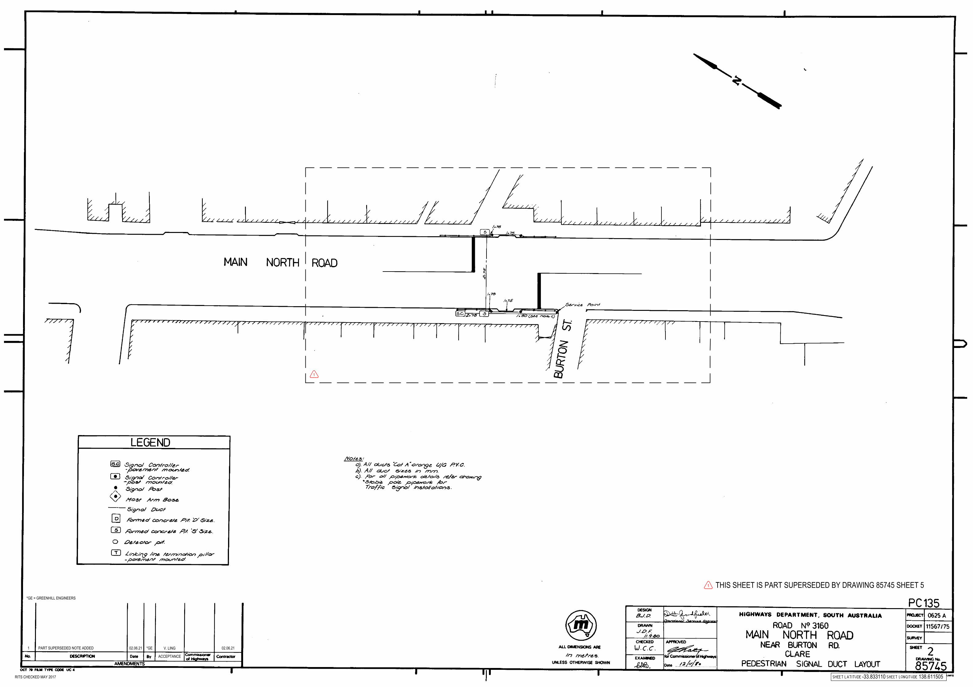
3: 85745 Existing Drawings Sheet 2
4: 85745 Sheet 0003 General Construction Drawing
5: 85475 Sheet 0004 Traffic Signal Drawing
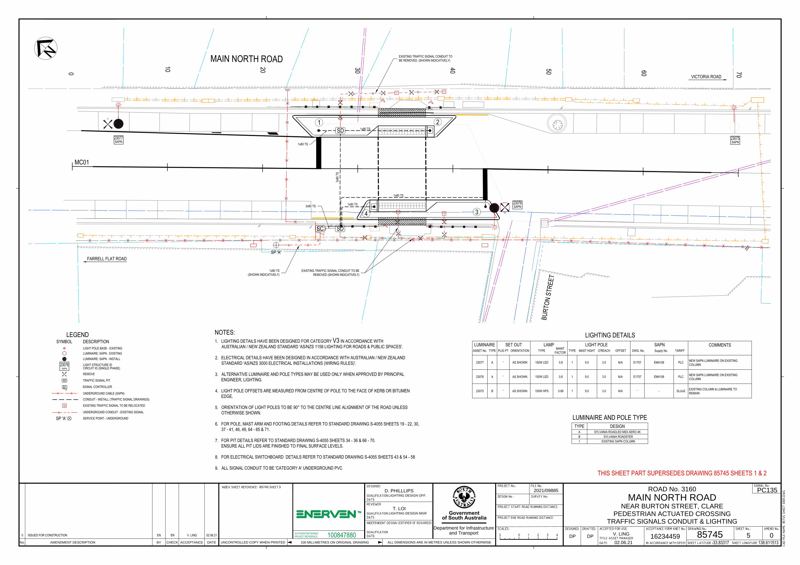
6: 85475 Sheet 0005 Traffic Signal Conduit and Road Lighting Drawing
7: Combined DIT Master Specification
8: Draft Tender Evaluation Matrix
9: Draft Contract

9 | P a g e
Schedule of Rates – (complete and return)
Replacement of Clare Main Street Pedestrian Crossing
Tender Number: T08-2021
Before completing this Pricing Schedule, Respondents should ensure that they have
read and understood the entire Tender.
The rates must remain constant for the Term of the proposed Contract for Works.
Clare and Gilbert Valleys Council cannot and will not guarantee the completeness
or accuracy of the Schedule and therefore it can only to be used as a guide. It is
therefore the Contractor’s responsibility to add items as appropriate to ensure that
all items necessary to complete the Works, as provided within the requirements of
the Tender documents.
Contract payments will be made based on the rates provided in this Priced
Schedule. The total provided will be used as the base price for assessing Quotes and
awarding the Contract. The rates provided may also be used for the purpose of
calculating variations to the Contract.
If any item contained in this Schedule is not priced it shall be deemed either (a) the
cost has been included elsewhere, or (b) no payment is required in respect to that
item.
I/We the undersigned, do hereby tender to perform the abovementioned work in
accordance with the Tender Documents.
TOTAL OF SCHEDULE OF RATES
$
CITB LEVY $
GOODS & SERVICES TAX (GST)
$
TOTAL CONTRACT SUM $
Tenderer’s Trading Name: .....................................................................................................
ABN: ..........................................................................................................................................
Contact Person: ......................................................................................................................
Address: ...................................................................................................................................
Telephone No: .................................................. Email.........................................................
Signature: .................................................... Witness: .............................................................
Dated the ....................................................day of ........................................……….. 2021

10 | P a g e
Schedule of Rates Breakdown
Total
Item Description Unit Rate $ Qty Amount $
1 Preliminaries
1.1 Establishment Item $ $
1.2 Administration Item $ $
1.3 Survey Setout, Survey Verification and As-Constructed Survey
Item $ $
1.4 Insurances Item $ $
1.5 Services Location and depthing including Identification of the Supply Point to the Signal Controller
Item $ $
1.6 Traffic Management Item $ $
1.7 Quality Management System Item $ $
1.8 OHS&W and Environmental Plans Item $ $
1.9 Clean up the Site and Demobilise Item $ $
1.10 Other Items (Please Specify)
$ $
$ $
Subtotal $
2 Demolition and Disposal
2.1 Saw Cutting existing pavement Lin. mM
$ $
2.2 Removal of Existing Pedestrian Fence Item $ $
2.3 Removal of Existing Kerb Ramps No. $ $
2.4 Removal and Disconnection of Existing Traffic Lights including existing conduits and Salvage Reusable Components
No. $ $
2.5 Material Disposal m3 $ $
2.6 Removal of Existing Pavement Marking Item $ $
2.6 Erosion Control Item $ $
2.7 Other Items (Please Specify)
$ $
Subtotal $
11 | P a g e
Schedule of Rates Breakdown
Total
Item Description Unit Rate $ Qty Amount $
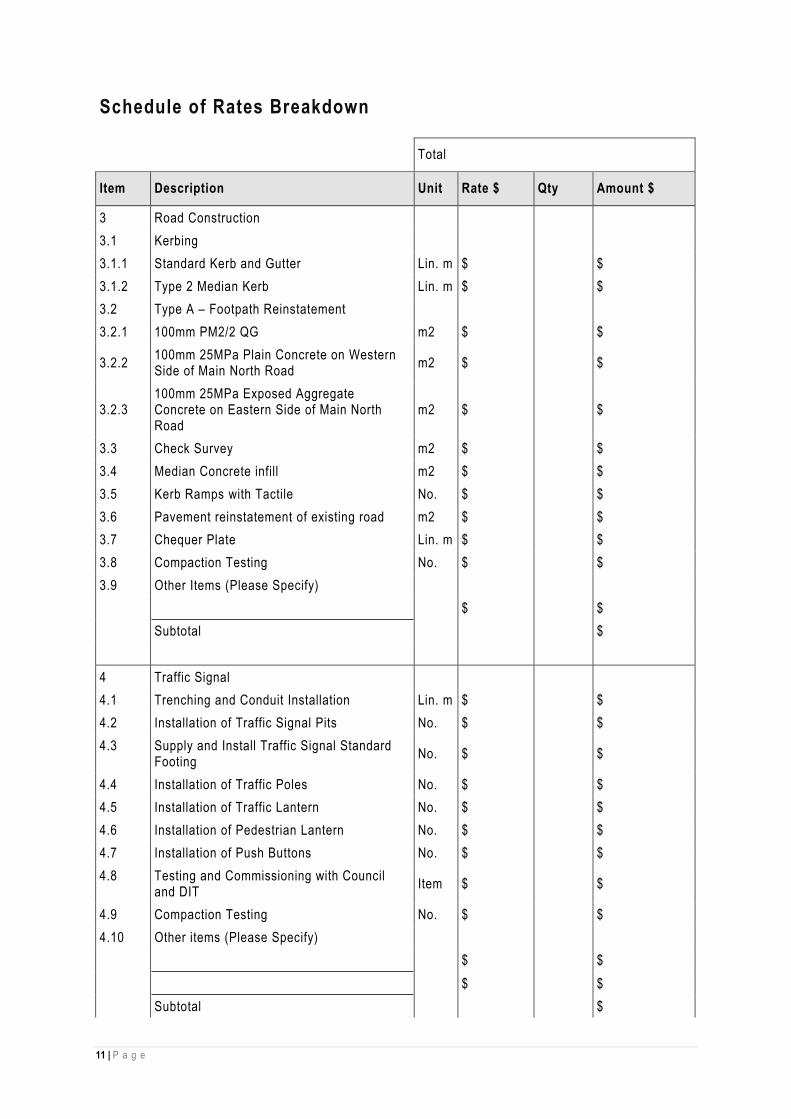
3 Road Construction
3.1 Kerbing
3.1.1 Standard Kerb and Gutter Lin. m $ $
3.1.2 Type 2 Median Kerb Lin. m $ $
3.2 Type A – Footpath Reinstatement
3.2.1 100mm PM2/2 QG m2 $ $
3.2.2 100mm 25MPa Plain Concrete on Western Side of Main North Road
m2 $ $
3.2.3 100mm 25MPa Exposed Aggregate Concrete on Eastern Side of Main North Road
m2 $ $
3.3 Check Survey m2 $ $
3.4 Median Concrete infill m2 $ $
3.5 Kerb Ramps with Tactile No. $ $
3.6 Pavement reinstatement of existing road m2 $ $
3.7 Chequer Plate Lin. m $ $
3.8 Compaction Testing No. $ $
3.9 Other Items (Please Specify)
$ $
Subtotal $
4 Traffic Signal
4.1 Trenching and Conduit Installation Lin. m $ $
4.2 Installation of Traffic Signal Pits No. $ $
4.3 Supply and Install Traffic Signal Standard Footing
No. $ $
4.4 Installation of Traffic Poles No. $ $
4.5 Installation of Traffic Lantern No. $ $
4.6 Installation of Pedestrian Lantern No. $ $
4.7 Installation of Push Buttons No. $ $
4.8 Testing and Commissioning with Council and DIT
Item $ $
4.9 Compaction Testing No. $ $
4.10 Other items (Please Specify)
$ $
$ $
Subtotal $
12 | P a g e
Schedule of Rates Breakdown
Total
Item Description Unit Rate $ Qty Amount $
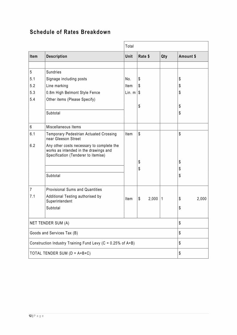
5 Sundries
5.1 Signage including posts No. $ $
5.2 Line marking Item $ $
5.3 0.8m High Belmont Style Fence Lin. m $ $
5.4 Other items (Please Specify)
$ $
Subtotal $
6 Miscellaneous Items
6.1 Temporary Pedestrian Actuated Crossing near Gleeson Street
Item $ $
6.2 Any other costs necessary to complete the works as intended in the drawings and Specification (Tenderer to itemise)
$ $
$ $
Subtotal $
7 Provisional Sums and Quantities
7.1 Additional Testing authorised by Superintendent
Item $ 2,000 1 $ 2,000
Subtotal $
NET TENDER SUM (A) $
Goods and Services Tax (B) $
Construction Industry Training Fund Levy (C = 0.25% of A+B) $
TOTAL TENDER SUM (D = A+B+C) $

Specification
PAC Upgrade - Clare Page 1 Revision A – 4 June 2021 21564 Technical Specification
Clare & Gilbert Valleys Council Main North Road Pedestrian Actuated Crossing (PAC) Upgrade
DIT TECHNICAL SPECIFICATION Project Number: 20.2368 Document Number: 21564 Contents: DIT Drawing Set Specification Introduction Scope of Works Project Specific Requirements Specifications: PC – Project Controls RD – Roads ST – Structures

Specification
PAC Upgrade - Clare Page 2 Revision A – 4 June 2021 21564 Technical Specification
The Documents include the drawings as listed below Schedule of Drawings DIT Drawing 85745 – Main North Road Pedestrian Actuated Crossing (PAC) Upgrade
Drawing No. Sheet No. Amendment No. 85745 3 General Construction MC01; CH 00 – CH 70
0
85745 4 Traffic Signals MC01; CH 00 – CH 70
0
85745 5 Traffic Conduit and Lighting MC01; CH 00 – CH 70
0

Specification
PAC Upgrade - Clare Page 3 Revision A – 4 June 2021 21564 Technical Specification
The Specification for this Work is based on the DIT Master Specification for Transport Infrastructure (“DIT Master Specification”). Any specific requirements for this Work are included in the part “Project Specific Requirements”. In the event of any inconsistency or ambiguity, the Contract Specific Requirements shall take precedence over any other part of the Specification or the drawings. For a list of recent amendments to the DIT Master Specification, refer to: https://www.dpti.sa.gov.au/contractor_documents/masterspecifications The Specification for this Work comprises of the Contract Specific Requirements and the following parts of the DIT Master Specification:
Part No. Title Edition PC – Project Controls PM1 to 5 Project Management Program and Reporting Personnel & Training Risk
Management 19 Sep 2019
WHS1 Work Health and Safety 19 Sep 2019 ENV1 Environmental Management 19 Sep 2019 ENV2 Environmental Protection Requirements August 2020 SM1 Traffic and Pedestrian Management August 2020 SM2 Site and Access Management 19 Sep 2019 US1 Utility Services August 2020 SI1 Site Survey 06 Sep 2019 CN1 Testing and Commissioning 19 Sep 2019 CN2 Asset Handover 19 Sep 2019 RD – Roads LM-S1 Materials for Pavement Marking 23 Sep 2019 LM-S2 Supply of Signs August 2020 LM-C1 Application of Pavement Marking August 2020 LM-C4 Sign Installation 23 Sep 2019 BF-C4 Supply and Installation of Fencing and Gates 16 Sep 2019 DK-C2 Kerbing 16 Sep 2019 EW-C1 Earthworks August 2020 PV-C5 Construction of Minor Pavements 18 Sep 2019 PV-C6 Reinstatement of Existing Pavements 18 Sep 2019 BP-S1 Supply of Bituminous Material 18 Sep 2019 BP-S2 Supply of Asphalt August 2020 BP-C3 Construction of Asphalt Pavement 19 Sep 2019 EL-S1 Supply of Lighting Components August 2020 EL-S2 Supply of Luminaires 19 Sep 2019 EL-S3 Supply of LED Lanterns 20 Sep 2019 EL-C1 Installation of Lighting for Road and Public Spaces August 2020 EL-C2 Installation of Traffic Signals August 2020 EL-C3 Supply and Installation of Conduits and Pits 20 Sep 2019 ITS-S2 Electrical Switchboards 19 Sep 2019 ST – Structures SC-S1 Normal Class Concrete 19 Sep 2019 SC-S7 Supply of Concrete 19 Sep 2019 SC-C6 Formwork 19 Sep 2019 SC-C7 Placement of Concrete 19 Sep 2019
If a part of the DIT Master Specification is not attached to this document, it will be available from: https://www.dpti.sa.gov.au/contractor_documents/masterspecifications

Specification
PAC Upgrade - Clare Page 4 Revision A – 4 June 2021 21564 Technical Specification
The project works include but are not limited to: Service locating and depthing Traffic management Removal of existing pedestrian ramp and the associated kerb and gutter Reinstate kerb and gutter and exposed concrete footpaths on Main North Road Footing installation of the traffic lights Installation of conduits for the new traffic lights Installation of a proposed kerb extension Installation / relocation of existing traffic lights Electrical works for the traffic lights Installation of pedestrian fencing on Main North Road Installation of pavement marking and associated signage Testing and commissioning of the pedestrian crossing
Road lighting upgrade will be undertaken by SAPN.

Specification: Project Specific Requirements
PAC Upgrade - Clare Page 5 Revision A – 4 June 2021 21564 Technical Specification
PROJECT SPECIFIC REQUIREMENTS

Project Controls Specification: Project Specific Requirements: PC-SM1 Traffic and Pedestrian Management
PAC Upgrade - Clare Page 6 Revision A – 4 June 2021 21564 Technical Specification
PC-SM1 TRAFFIC AND PEDESTRIAN MANAGEMENT 1. GENERAL Traffic controls shall be provided to protect the safety of the public and ensure that traffic and pedestrian do not damage the work during the period where the binder/asphalt/concrete requires to develop sufficient adhesion and strength. In addition to Clause 5 “Traffic Management Plan”, the Contractor shall prepare Traffic Management Plans for after hours when no activities are undertaken. At a minimum the plans shall address issues such as “Roadworks Ahead” signs, applicable speed signs and signage on side roads. Restrictions of traffic to one lane shall only occur when works are in progress. All lanes shall be open to traffic when the Contractor is not on site. Due to the need to maintain a high standard for road users the placement of pavement markings shall be as soon as practicable and as soon as completion of the proposed works. Immediately following the application of paint, all aftercare signage shall be removed unless a fault with the seal is evident or otherwise directed by the Superintendent. Access to commercial businesses and residential properties adjacent to the works shall be maintained at all times. While the existing Pedestrian Actuated Crossing (PAC)is being upgraded, a temporary pedestrian actuated crossing shall be established at the existing crossing point near Gleeson Street. The temporary PAC shall comply with the following requirements:
Three aspect lanterns (Vehicle Signal Lanterns) are installed so that the centre of the red lens is 4m above the footpath surface;
Pedestrian signal lanterns are installed with the centre of the walk lens 3m above the footpath surface; ‘Stop here on Red Signal’ signs and temporary stop bar must be provided (the stop bar will need to be
removed after work completion); Temporary crosswalk lines must be provided to AS1742.10-2009 (the crosswalk lines will need to be
removed after work completion). Products can be referred to in the Google Search in the link below: https://www.google.com/search?q=portable+pedestrian+signals&rlz=1C1GCEA_enAU911AU911&oq=portable+pedestrian&aqs=chrome.8.69i57j35i39l2j0l2j0i30l5.16173j0j1&sourceid=chrome&ie=UTF-8 Other alternative device achieving the same outcome is also welcomed for the temporary PAC. 2. NOTIFICATION OF ROAD WORKS AND WORKING HOURS Main North Road is under the care and control of DIT. The Contractor shall arrange and seek approval from DIT prior to works occurring. Restriction on working hours from DIT will be applied as conditions for the approval and the Contractor shall strictly follow those restrictions as required and shall allow such time restriction in the tender submission. The Contractor shall submit to the Superintendent a copy of the DIT approval (i.e. permits) for the traffic restriction no later than 3 days prior to construction. Contractor shall confirm the permitted working hours on Main North Road with DIT and the program of work shall be made in accordance with the permitted working hours. No additional payment will be made for this item. The Contractor shall lodge a Notification of Works Impacting DIT Roads form available from: http://www.dpti.sa.gov.au/contractor_documents/works_on_roads_by_other_organisations prior to any works commencing.
_________

Project Controls Specification: Project Specific Requirements: PC-SM2 Site and Access Management
PAC Upgrade - Clare Page 7 Revision A – 4 June 2021 21564 Technical Specification
PC-SM2 SITE AND ACCESS MANAGEMENT 1. CONTRACTOR'S COMPOUND The Contractor shall obtain written agreement with the landholder and/or the Council to establish a compound or any area used for the storage of plant or materials. Copies of these agreements shall be submitted to the Superintendent prior to establishment of the compound. A written release shall be obtained from the landholder and/or Council after de-establishment. Prior to completion of the Contract, the Contractor shall clean up all compound areas and leave them in a condition comparable to that encountered at the time of Possession of site. 2. TEMPORARY WORKS Temporary Works include:
(a) Temporary measures necessary to meet the needs of all road, and Service Authorities during all stages of construction;
(b) All environmental safeguards and measures necessary to mitigate environmental effects during construction;
(c) Cleaning, maintenance, repair, replacement and reinstatement, as required, of all areas occupied by the Contractor during construction;
(d) Temporary site facilities required for construction;
(e) Temporary storage of materials; and
(f) Temporary infrastructure installed or erected to undertake construction.
____________

Project Controls Specification: Project Specific Requirements: PC-US1 Utility Services
PAC Upgrade - Clare Page 8 Revision A – 4 June 2021 21564 Technical Specification
PC-US1 UTILITY SERVICES 1. UNDERGROUND SERVICES All utility services works must be completed in accordance with Part PC-US1 Utility Services. Prior to the commencement of work the Contractor shall undertake utility investigation, “Dial Before you Dig’ and confirm with service providers on the depth and vibration limit to any service nearby. The Principal is to be advised immediately of any conflicts between the existing services and the Works or any services required relocation. The supply point to the existing signal controller is indicative. The Contractor shall confirm the supply point to the signal controller as part of service investigation with a service locator.
__________

Roads Specification: Project Specific Requirements: RD-EW-C1 Earthworks
PAC Upgrade - Clare Page 9 Revision A – 4 June 2021 21564 Technical Specification
RD-EW-C1 EARTHWORKS
1. MANAGEMENT OF EXCAVATED MATERIAL Surplus excavated material shall be removed from the site and disposed of by the Contractor.
__________

Roads Specification: Project Specific Requirements: RD-PV-C5 Construction of Minor Pavements
PAC Upgrade - Clare Page 10 Revision A – 4 June 2021 21564 Technical Specification
RD-PV-C5 Construction of Minor Pavements The reinstatement of footpath shall match the existing footpath type and finish. The Contractor is advised that the footpath on the eastern side of Main North Road has recently been upgraded with exposed aggregate concrete as the finishing for the footpath. The western side of the footpath is the standard concrete footpath.
__________

Roads Specification: Project Specific Requirements: RD-EL-C2 Installation of Traffic Signals
PAC Upgrade - Clare Page 11 Revision A – 4 June 2021 21564 Technical Specification
RD-EL-C2 Installation of Traffic Signals The Contractor shall determine whether any existing component of the traffic signals could be recycled and reused for the new traffic signals. Any components that cannot be reused shall be replaced with new ones. Contractor shall allow this item in their tender submission. Existing Countdown timer is to be removed.
__________

Roads Specification: Project Specific Requirements: RD-LM-C1 Application of Pavement Marking
PAC Upgrade - Clare Page 12 Revision A – 4 June 2021 21564 Technical Specification
RD-LM-C1 Application of Pavement Marking The median kerb of the kerb protuberance shall be painted white as per DIT Pavement Marking Manual and Table RD-LM-C1 5-3 Pavement Marking Application. All existing line marking to be modified shall be grinded out either mechanically or water blasting. If water blasted, the water pressure shall be controlled such that it does not damage the seal or pavement underneath.
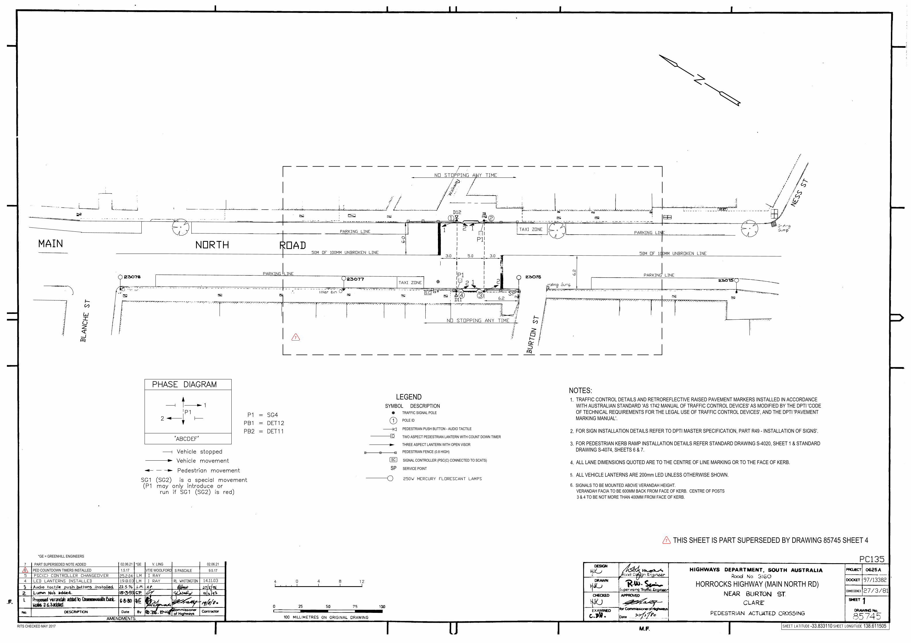
HORROCKS HIGHWAY (MAIN NORTH RD)
SIGNALS TO BE MOUNTED ABOVE VERANDAH HEIGHT.6.VERANDAH FACIA TO BE 600MM BACK FROM FACE OF KERB. CENTRE OF POSTS3 & 4 TO BE NOT MORE THAN 400MM FROM FACE OF KERB.
NOTES:1.
2.
3.
4.
PEDESTRIAN PUSH BUTTON - AUDIO TACTILE
SPSIGNAL CONTROLLER (PSC(C) CONNECTED TO SCATS)
PEDESTRIAN FENCE (0.8 HIGH)
SERVICE POINT
LEGENDSYMBOL DESCRIPTION
SC
TWO ASPECT PEDESTRIAN LANTERN WITH COUNT DOWN TIMER
TRAFFIC SIGNAL POLE
POLE ID1
THREE ASPECT LANTERN WITH OPEN VISOR
PED COUNTDOWN TIMERS INSTALLED6 1.5.17 VT/E WOOLFORD
-33.833110 138.611505RITS CHECKED MAY 2017
S PASCALE
TRAFFIC CONTROL DETAILS AND RETROREFLECTIVE RAISED PAVEMENT MARKERS INSTALLED IN ACCORDANCEWITH AUSTRALIAN STANDARD 'AS 1742 MANUAL OF TRAFFIC CONTROL DEVICES' AS MODIFIED BY THE DPTI 'CODEOF TECHNICAL REQUIREMENTS FOR THE LEGAL USE OF TRAFFIC CONTROL DEVICES', AND THE DPTI 'PAVEMENTMARKING MANUAL'.
FOR SIGN INSTALLATION DETAILS REFER TO DPTI MASTER SPECIFICATION, PART R49 - INSTALLATION OF SIGNS'.
FOR PEDESTRIAN KERB RAMP INSTALLATION DETAILS REFER STANDARD DRAWING S-4020, SHEET 1 & STANDARDDRAWING S-4074, SHEETS 6 & 7.
ALL LANE DIMENSIONS QUOTED ARE TO THE CENTRE OF LINE MARKING OR TO THE FACE OF KERB.
ALL VEHICLE LANTERNS ARE 200mm LED UNLESS OTHERWISE SHOWN.5.
*GE = GREENHILL ENGINEERS
7
THIS SHEET IS PART SUPERSEDED BY DRAWING 85745 SHEET 4
*GE02.06.21PART SUPERSEDED NOTE ADDED7
7
V. LING 02.06.219.5.17
-33.833110 138.611505RITS CHECKED MAY 2017
*GE = GREENHILL ENGINEERS
1
THIS SHEET IS PART SUPERSEDED BY DRAWING 85745 SHEET 5
*GEPART SUPERSEDED NOTE ADDED1
1
02.06.21 V. LING
ACCEPTANCE
02.06.21

MAIN NORTH ROAD
BURT
ON S
TREE
T
MC01
0
10 20 30 40 50 60 70
VICTORIA ROAD
FARRELL FLAT ROAD 0.8m HIGH PEDESTRIANFENCE
0.8m HIGH PEDESTRIANFENCE
EXISTING KERB RAMP TO BE REMOVED.INSTALL STANDARD KERB AND GUTTERAND REINSTATE FOOTPATH.
EXISTING KERB RAMP TO BE REMOVED.INSTALL STANDARD KERB AND GUTTERAND REINSTATE FOOTPATH.
0.8m HIGH PEDESTRIAN FENCE
0.8m HIGH PEDESTRIAN FENCE TO AVOIDEXISTING VERANDA COLUMNS
EXISTING SIGNAL CABINETTO BE RETAINED
EXISTING PEDESTRIANFENCE TO BE REMOVED
EXISTING PEDESTRIAN FENCE TOBE REMOVED
EXISTING STOP AND PEDESTRIANLINEMARKING TO BE REMOVED
EXISTING PEDESTRIAN FENCE TOBE REMOVED
STANDARD KERBAND GUTTER
MEDIAN KERB TYPE 2
MEDIAN KERB TYPE 2
STANDARD KERBAND GUTTER
EXISTING POLE ANDSIGNALS TO BE REMOVED
EXISTING POLE ANDSIGNALS TO BE REMOVED
PROVIDE CHEQUER PLATE COVER BETWEENPROPOSED MEDIAN KERB AND KERB AND GUTTER.PLATE THICKNESS TO BE 6mm. PLATE TO BE RECESSEDINTO KERB TO ENSURE PLATE IS FLUSH WITH KERB TOP.PLATE TO BE BOLTED TO KERB AND FIXED IN PLACE.
PROVIDE CHEQUER PLATE COVER BETWEEN PROPOSEDMEDIAN KERB AND KERB AND GUTTER. PLATE THICKNESS
TO BE 6mm. PLATE TO BE RECESSED INTO KERB TOENSURE PLATE IS FLUSH WITH KERB TOP. PLATE TO BE
BOLTED TO KERB AND FIXED IN PLACE.
EXISTING LINE MARKING TO BE REMOVED
0.6
0.45
Proj: 20-2368
GREENHILLLevel 1, 178 Fullarton RoadDulwich, SA 5065T: 08 8406 1300ABN 39 061 222 964
UNCONTROLLED COPY WHEN PRINTEDAMENDMENT DESCRIPTION BY CHECKNo. ACCEPTANCE DATE 100 MILLIMETRES ON ORIGINAL DRAWING ALL DIMENSIONS ARE IN METRES UNLESS SHOWN OTHERWISE
Government
of South Australia
Department for Infrastructureand Transport 0
ROAD No. 3160
MAIN NORTH ROADNEAR BURTON STREET, CLARE
PEDESTRIAN ACTUATED CROSSINGGENERAL CONSTRUCTION
3
2021/0988585745 3
0 ISSUED FOR CONSTRUCTION GE GE V. LING 02.06.21
TECHNICAL OFFICER
KAI ZHENGCIVIL ENGINEER
J.DAVIES
GE GEV. LING
02.06.21
16234459 85745-33.83317 138.611513
1. THE SERVICES INFORMATION INDICATED ON THIS DRAWING IS BASED ON FIELD OBSERVATIONS ANDDETAILS PROVIDED BY SERVICE AUTHORITIES. DIT, ITS SERVANTS OR AGENTS SHALL NOT BE LIABLEFOR ANY LOSS OR DAMAGE CAUSED BY THE USE OF THIS SERVICES INFORMATION.
2. THIS DESIGN MAY INCLUDE THE POSSIBILITY OF SERVICE CONFLICT AND / OR ENCROACHMENTWITHIN SAFETY CLEARANCES REQUIRING ASSESSMENT AND APPROVAL BY THE OFFICE OFTECHNICAL REGULATOR AND SERVICES AUTHORITIES. IF DURING CONSTRUCTION IT IS DETERMINEDTHAT THE CLEARANCES AS DETERMINED BY THE OFFICE OF THE TECHNICAL REGULATORS CANNOTBE MET, WORK MUST IMMEDIATELY CEASE AND THE DESIGN & PROJECT MANAGER NOTIFIED.
3. FOR KERB & GUTTER & MEDIAN KERB DETAILS REFER TO STANDARD DRAWING S-4070 SHEETS 6 & 7.
4. KERB RAMP TYPE 8 INSTALLED UNLESS INDICATED OTHERWISE. FOR PEDESTRIAN KERB RAMPINSTALLATION DETAILS REFER STANDARD DRAWING S-4074 SHEET 7.
5. REFERENCES TO PAVEMENT TREATMENT DETAILS SHOWN IN THE PAVEMENT TREATMENT LEGENDARE DESCRIPTIVE ONLY.
6. LEVEL DATUM IS AUSTRALIAN HEIGHT DATUM.
7. COORDINATE BASE IS MGA 20 PLANE.
NOTES:
TRAFFIC SIGNAL POLE
LEGENDSYMBOL DESCRIPTION
STOBIE POLE - EXISTING
UNDERGROUND CABLE
INSPECTION COVER
MARKER POST JUNCTION BOX
OVERHEAD CABLE (SAPN)UNDERGROUND CABLE (SAPN)
UNDERGROUND PIPEINSPECTION COVER
FIRE PLUG MARKER POST FIRE PLUG MARKER REFLECTOR
SERVICES LEGENDSYMBOL DESCRIPTION
COMMUNICATIONS
ELECTRICAL
WATER
STORMWATERPIPE / CULVERT
PROPERTY BOUNDARY - EXISTING (DCDB)
PAVEMENT TREATMENT LEGENDTYPE A (PAVEMENT DESIGN BY COUNCIL)100mm 25MPa CONCRETE100mm PM2/20 QG, 98% MDDFINISH TO MATCH EXISTING CONCRETETYPE
STANDARD KERB AND GUTTER
REMOVE
LIGHT POLE BASE - EXISTING
MEDIAN KERB TYPE 2
CHEQUER PLATE
2 0 2 431
X = 278963.463Y = 6253777.706
REF. STRING MC10
-3.1% 0.1% -4.3% 3.5% 0.3% 4%
EX3.1
720.0
0138
5.699
CB4.4
690.1
2038
5.659
CF4.6
08-0
.007
385.5
09CE
5.064
0.001
385.5
35CF
5.072
0.000
385.5
33CB
5.302
0.130
385.6
73EY
5.921
0.104
385.6
74CF
7.121
0.000
385.6
23
CF13
.721
0.000
385.6
26
EY14
.922
0.093
385.6
67
CB15
.791
0.133
385.6
70CF
16.02
10.0
0338
5.530
CE16
.296
-0.00
138
5.514
CF16
.594
-0.00
238
5.512
CB16
.736
0.123
385.6
62EX
17.66
2-0
.002
385.6
99
HORIZ. OFFSET
LEVEL DIFF.
DESIGN LABEL
DESIGN LEVELS
DATUM R.L. 384.2
TYPICAL SECTION THROUGH CENTRE OF PEDESTRIAN CROSSINGSCALE 1:100H 1:50V
EXISTING SURFACEDESIGN SURFACE
GENERAL CONSTRUCTIONSHEET LOCATION3 MC01; CH.0 - CH.70
TRAFFIC SIGNALSSHEET LOCATION4 MC01; CH.0 - CH.70
TRAFFIC SIGNALS CONDUIT & LIGHTINGSHEET LOCATION5 MC01; CH.0 - CH.70
DRAWING INDEX
LUMINAIRE: SA POWER NETWORKS - EXISTINGLUMINAIRE: SA POWER NETWORKS - PROPOSED
TYPE BN25 CONCRETE INFILL
PEDESTRIAN FENCE (0.8 HIGH)BELMONT STYLE OR SIMILAR APPROVED
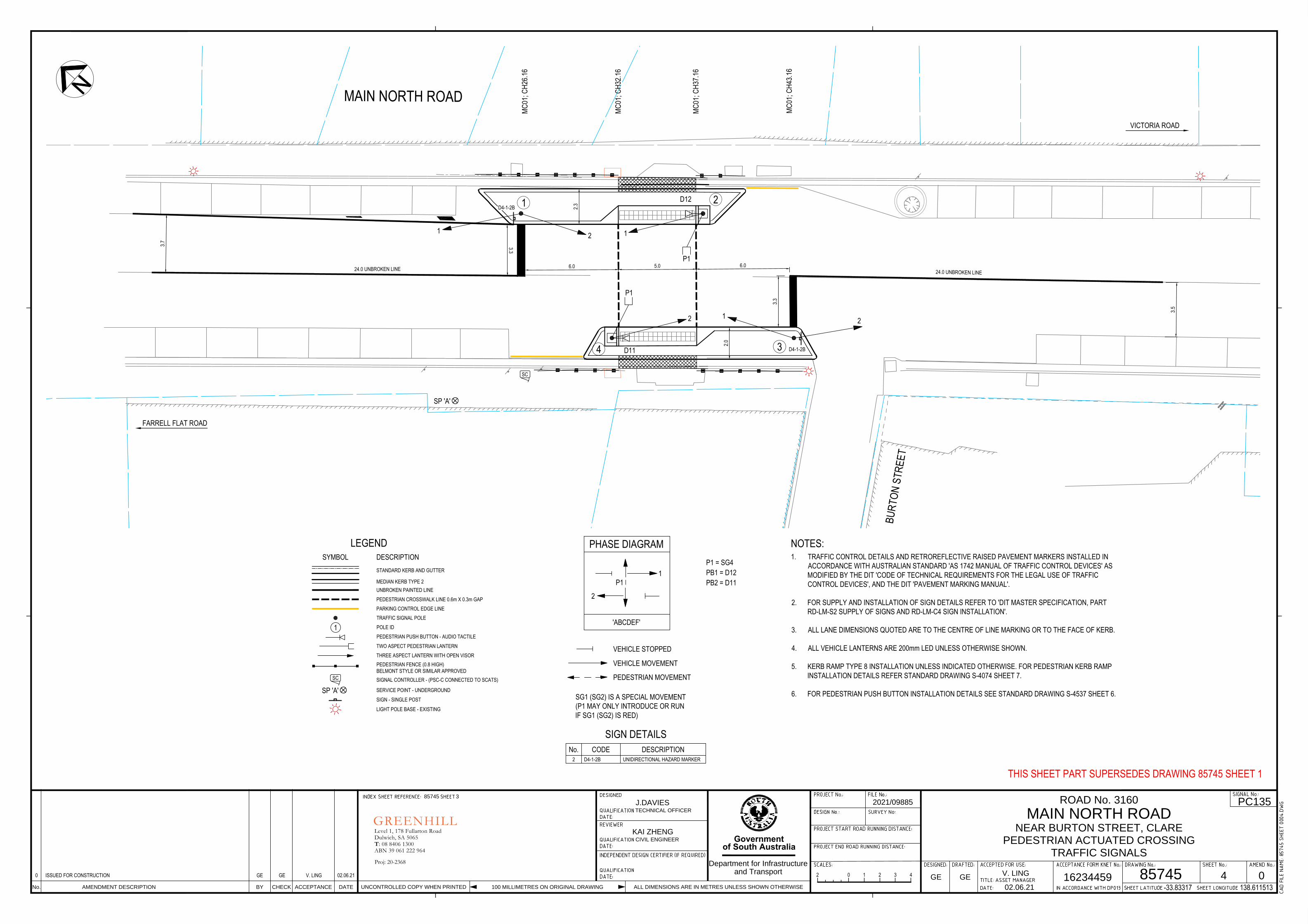
MAIN NORTH ROAD
BURT
ON S
TREE
T
P1
12
P1
121
2
1 2
34
VICTORIA ROAD
FARRELL FLAT ROAD
6.0 5.0 6.0
3.3
3.3
3.5
24.0 UNBROKEN LINE24.0 UNBROKEN LINE
2.3
2.0
MC01
; CH2
6.16
MC01
; CH3
2.16
MC01
; CH3
7.16
MC01
; CH4
3.16
D4-1-2B
D4-1-2B
D12
D11
3.7
Proj: 20-2368
GREENHILLLevel 1, 178 Fullarton RoadDulwich, SA 5065T: 08 8406 1300ABN 39 061 222 964
UNCONTROLLED COPY WHEN PRINTEDAMENDMENT DESCRIPTION BY CHECKNo. ACCEPTANCE DATE 100 MILLIMETRES ON ORIGINAL DRAWING ALL DIMENSIONS ARE IN METRES UNLESS SHOWN OTHERWISE
Government
of South Australia
Department for Infrastructureand Transport 0
ROAD No. 3160
MAIN NORTH ROADNEAR BURTON STREET, CLARE
PEDESTRIAN ACTUATED CROSSINGTRAFFIC SIGNALS
4
PC1352021/0988585745 3
0 ISSUED FOR CONSTRUCTION GE GE V. LING 02.06.21
TECHNICAL OFFICER
KAI ZHENGCIVIL ENGINEER
J.DAVIES
GE GEV. LING
02.06.21
16234459 85745-33.83317 138.611513
LEGENDSYMBOL DESCRIPTION
STANDARD KERB AND GUTTER
MEDIAN KERB TYPE 2
2 0 2 431
PHASE DIAGRAM
VEHICLE MOVEMENT
PEDESTRIAN MOVEMENT
P1 = SG4PB1 = D12
'ABCDEF'
PB2 = D11P1
2
1
1. TRAFFIC CONTROL DETAILS AND RETROREFLECTIVE RAISED PAVEMENT MARKERS INSTALLED INACCORDANCE WITH AUSTRALIAN STANDARD 'AS 1742 MANUAL OF TRAFFIC CONTROL DEVICES' ASMODIFIED BY THE DIT 'CODE OF TECHNICAL REQUIREMENTS FOR THE LEGAL USE OF TRAFFICCONTROL DEVICES', AND THE DIT 'PAVEMENT MARKING MANUAL'.
2. FOR SUPPLY AND INSTALLATION OF SIGN DETAILS REFER TO 'DIT MASTER SPECIFICATION, PARTRD-LM-S2 SUPPLY OF SIGNS AND RD-LM-C4 SIGN INSTALLATION'.
3. ALL LANE DIMENSIONS QUOTED ARE TO THE CENTRE OF LINE MARKING OR TO THE FACE OF KERB.
4. ALL VEHICLE LANTERNS ARE 200mm LED UNLESS OTHERWISE SHOWN.
5. KERB RAMP TYPE 8 INSTALLATION UNLESS INDICATED OTHERWISE. FOR PEDESTRIAN KERB RAMPINSTALLATION DETAILS REFER STANDARD DRAWING S-4074 SHEET 7.
6. FOR PEDESTRIAN PUSH BUTTON INSTALLATION DETAILS SEE STANDARD DRAWING S-4537 SHEET 6.
NOTES:
SG1 (SG2) IS A SPECIAL MOVEMENT(P1 MAY ONLY INTRODUCE OR RUNIF SG1 (SG2) IS RED)
VEHICLE STOPPEDPEDESTRIAN PUSH BUTTON - AUDIO TACTILE
TRAFFIC SIGNAL POLEPOLE ID1
TWO ASPECT PEDESTRIAN LANTERNTHREE ASPECT LANTERN WITH OPEN VISOR
UNBROKEN PAINTED LINEPEDESTRIAN CROSSWALK LINE 0.6m X 0.3m GAP
SC SIGNAL CONTROLLER - (PSC-C CONNECTED TO SCATS)
SC
CODE DESCRIPTION
SIGN DETAILSNo.
2 D4-1-2B UNIDIRECTIONAL HAZARD MARKER
SIGN - SINGLE POST
LIGHT POLE BASE - EXISTING
THIS SHEET PART SUPERSEDES DRAWING 85745 SHEET 1
PARKING CONTROL EDGE LINE
SP 'A'
SERVICE POINT - UNDERGROUNDSP 'A'
PEDESTRIAN FENCE (0.8 HIGH)BELMONT STYLE OR SIMILAR APPROVED
MAIN NORTH ROAD
BURT
ON S
TREE
T
VICTORIA ROAD
FARRELL FLAT ROAD
MC01
0
10 20 30 40 50 60 70
SD
SD1 2
34
SC
SP 'A'
UNCONTROLLED COPY WHEN PRINTEDAMENDMENT DESCRIPTION BY CHECKNo. ACCEPTANCE DATE 100 MILLIMETRES ON ORIGINAL DRAWING ALL DIMENSIONS ARE IN METRES UNLESS SHOWN OTHERWISE
Government
of South Australia
Department for Infrastructureand Transport 0
ROAD No. 3160
MAIN NORTH ROADNEAR BURTON STREET, CLARE
PEDESTRIAN ACTUATED CROSSINGTRAFFIC SIGNALS CONDUIT & LIGHTING
5
PC1352021/0988585745 3
0 ISSUED FOR CONSTRUCTION EN EN V. LING 02.06.21
LIGHTING DESIGN OFF.
T. LOILIGHTING DESIGN MGR
D. PHILLLIPS
DP DPV. LING
02.06.21
16234459 85745-33.83317 138.611513
2 0 2 431
THIS SHEET PART SUPERSEDES DRAWING 85745 SHEETS 1 & 2
SA POWER NETWORKSPROJECT REFERENCE: 100847880
DESIGNLUMINAIRE AND POLE TYPETYPE
A SYLVANIA ROADLED MIDI AERO 4K
LIGHTING DETAILSSET OUTLUMINAIRE
ASSET No. TYPELAMP LIGHT POLE
TYPE MAST HGHT O'REACH DWG. No. TARIFFPLIG PT TYPEORIENTATION MAINTFACTOR OFFSET Supply No.
SAPN COMMENTS
EM4108- AS SHOWN23077 A 150W LED 0.8 1 9.0 3.0 N/A E1757 PLC
EM4108- AS SHOWN23076 A 150W LED 0.8 1 9.0 3.0 N/A E1757 PLC
-- AS SHOWN23075 B 150W HPS 0.68 1 9.0 3.0 N/A - SLUoS
1 EXISTING SAPN COLUMNB SYLVANIA ROADSTER
NEW SAPN LUMINAIRE ON EXISTINGCOLUMN
EXISTING COLUMN & LUMINAIRE TOREMAIN
NEW SAPN LUMINAIRE ON EXISTINGCOLUMN
XX
23076SAPN
UNDERGROUND CABLE (SAPN)
CIRCUIT ID (SINGLE PHASE)LIGHT STRUCTURE ID
LEGENDSYMBOL DESCRIPTION
LIGHT POLE BASE - EXISTINGLUMINAIRE: SAPN - EXISTINGLUMINAIRE: SAPN - INSTALL
REMOVE
TRAFFIC SIGNAL PIT
CONDUIT - INSTALL (TRAFFIC SIGNAL DRAWINGS)
SIGNAL CONTROLLER
EXISTING TRAFFIC SIGNAL TO BE RELOCATED
SC
UNDERGROUND CONDUIT - EXISTING SIGNAL
SERVICE POINT - UNDERGROUNDSP 'A'
SD
LIGHTING DETAILS HAVE BEEN DESIGNED FOR CATEGORY V3 IN ACCORDANCE WITHAUSTRALIAN / NEW ZEALAND STANDARD 'AS/NZS 1158 LIGHTING FOR ROADS & PUBLIC SPACES'.
ELECTRICAL DETAILS HAVE BEEN DESIGNED IN ACCORDANCE WITH AUSTRALIAN / NEW ZEALANDSTANDARD 'AS/NZS 3000 ELECTRICAL INSTALLATIONS (WIRING RULES)'.
ALTERNATIVE LUMINAIRE AND POLE TYPES MAY BE USED ONLY WHEN APPROVED BY PRINCIPALENGINEER, LIGHTING.
LIGHT POLE OFFSETS ARE MEASURED FROM CENTRE OF POLE TO THE FACE OF KERB OR BITUMENEDGE.
ORIENTATION OF LIGHT POLES TO BE 90° TO THE CENTRE LINE ALIGNMENT OF THE ROAD UNLESSOTHERWISE SHOWN.
FOR POLE, MAST ARM AND FOOTING DETAILS REFER TO STANDARD DRAWING S-4055 SHEETS 19 - 22, 30,37 - 41, 46, 49, 64 - 65 & 71.
FOR PIT DETAILS REFER TO STANDARD DRAWING S-4055 SHEETS 34 - 36 & 66 - 70.ENSURE ALL PIT LIDS ARE FINISHED TO FINAL SURFACE LEVELS.
FOR ELECTRICAL SWITCHBOARD DETAILS REFER TO STANDARD DRAWING S-4055 SHEETS 43 & 54 - 58
ALL SIGNAL CONDUIT TO BE 'CATEGORY A' UNDERGROUND PVC
NOTES:1.
2.
3.
4.
5.
6.
7.
8.
9.
1x80 TS
1x80 TS
1x80 TS
3x80
TS
23076SAPN
1x80 TS
EXISTING TRAFFIC SIGNAL CONDUIT TOBE REMOVED. (SHOWN INDICATIVELY)
EXISTING TRAFFIC SIGNAL CONDUIT TO BEREMOVED (SHOWN INDICATIVELY)
23077SAPN
23075SAPN
3x80 TS
1x80 TS(SHOWN INDICATIVELY)

Project Controls
Master Specification
PC-PM 1 to 5 Project Management Document Information
K Net Number: 13325654 Document Version: 2 Document Date: 19/09/2019

Project Controls Contents
Master Specification 2
Document Amendment Record
Version Change Description Date Endorsement record (KNet ref.)
1 Initial Issue (formerly G10) 02/05/19 2 Minor formatting and content changes 19/09/19
Document Management This document is the Property of the Department for Infrastructure and Transport and contains information that is confidential to the Department. It must not be copied or reproduced in any way without the written consent of the Department. This is a controlled document and it will be updated and reissued as approved changes are made.

Project Controls Contents
Master Specification 3
Contents Contents 3
PC-PM1 Project Management & Reporting 4
1 General 4
2 Project Management System and Plan 4
3 Project Plans 4
4 Project Meetings 5
5 Project Reporting 6
6 Evaluation of the Contractor’s Performance 7
7 Prequalification and Certification / Accreditation 7
8 Recording of Activities 8
9 Proprietary Products 8
10 Lessons Learnt 8
11 Hold Points 8
PC-PM2 Contract Program 10
1 General 10
2 Contract Program Information 10
3 Contract Program - Baseline 11
4 Contract Program Updates 11
5 Hold Points 11
PC-PM3 Contractor’s Personnel & Training 12
1 General 12
2 Competence 12
3 Management of Contractor’s Key Personnel 12
4 Training 13
5 Hold Points 13
PC-PM4 Risk Management 14
1 General 14
2 Risk Management System & Plan 14
3 Risk Register 14
4 Hold Points 14
PC-PM5 Information Management 16
1 General 16
2 Information Management System 16
3 Content Ownership and Right of Access 17
4 Document Management 17
5 Archiving & Completion 18
6 Audits 18
7 Training and Support 19
8 Hold Points 19

Project Controls PC-PM1 Project Management & Reporting
Master Specification 4
PC-PM1 Project Management & Reporting
1 General
1.1 The Contractor must perform its obligations to effectively manage, control and deliver the project in accordance with the Contract.
1.2 This Part specifies the minimum requirements for the Contractor’s Project Management system, processes and reporting.
2 Project Management System and Plan
2.1 The Contractor must establish and implement a Project Management System.
2.2 The Contractor must prepare, implement and update a site specific Project Management Plan to identify and document how the Contractor will manage and control the delivery of the Contractor’s Activities.
2.3 The Project Management Plan is the overarching Plan that provides the:
a) approach to management of the Project;
b) management processes and systems to be employed;
c) management team structure, organisational chart, roles, resources, capabilities and experience;
d) details the interface between each Project Plan;
e) management procedures, processes, systems and resources which are not otherwise included in the other Project Plans;
f) process for the review and improvement of the Project Plans;
g) Contractor’s strategies and processes to collaborate with the Department and other Authorities.
2.4 The Contractor must ensure that all Sub-Contractors comply with the Project Management Plan and Project Plans and that any such plans required under the sub-contracts are consistent with the Project Plans.
2.5 The Contractor shall submit the Project Management Plan to the Principal for Acceptance within 10 days of execution of the Contract.
2.6 Submission and Acceptance of the Project Management Plan shall constitute a Hold Point.
2.7 The Contractor shall regularly review and update the Project Management Plan throughout the project lifecycle. As a minimum the Project Management plan shall be reviewed every 6 months.
3 Project Plans
3.1 Project Plans must be prepared, implemented and updated by the Contractor in accordance with Legislation and the Contract requirements
3.2 The Contractor must integrate all Project Plans within the Project Management Plan.
3.3 Project Plans are detailed within the Contract Documents and may include the Plans listed below:
Project Plan Referenced in Part
WHS Management Plan PC-WHS1 Work Health and Safety Quality Management Plan PC-QA1 Quality Management

Project Controls PC-PM1 Project Management & Reporting
Master Specification 5
Project Plan Referenced in Part
Environmental Management Plan(s) including the following sub-plans:
• Construction Noise and Vibration Management Plan
• Soil Erosion and Drainage Management Plan
Night Works Management Plan
PC-ENV1 Environmental Management and PC-ENV2 Environmental Protection Requirements
Engineering and Design Management Plan PC-PM4 Risk Management Construction Management Plan(s) PC-CN2 Asset Handover Community Engagement and Communications Media Management Plan
PC-CS1 Community Engagement & Media Management
Traffic Management Plan PC-SM1 Traffic & Pedestrian Management Industry Participation Policy Plan PC-PM1 Project Management & Reporting Risk Management Plan PC-PM4 Risk Management Safety and Systems Assurance Plan PC-RW20 Systems and Safety Assurance Rail Safety Management Plan PC-RW10 Railways Management Planning Rail Access Management Plan PC-RW40 Accessing the Rail Corridor
Sustainability Plan PC-ST1 Sustainability in Construction Training Management Plan PC-CN2 Asset Handover and / or PC-RW50
Inspection testing and Commissioning Asset Management and Asset Maintenance Plan(s)
PC-CN2 Asset Handover and / or PC-RW50 Inspection testing and Commissioning
Asset Completion and Handover Plan PC-CN2 Asset Handover and / or PC-RW50 Inspection testing and Commissioning
3.4 The Contractor may combine and integrate various Project Plans as commensurate with the specific project, as agreed by the Principal.
3.5 Where the Contractor elects to combine Project Plans, all the requirements pertaining to individual plans must be addressed in the combined Plan.
4 Project Meetings
4.1 The Contractor will establish and convene project meetings in accordance with the Contract Requirements and Project Control Requirements, including but not limited to:
a) Leadership Team meetings;
b) Management Team meetings;
c) Engineering & Design coordination;
d) Construction Management (site) meetings;
e) Safety meetings, site inspections and audits;
f) Rail Operations and Network interface management meetings;
g) Community & Stakeholder engagement meetings; and
h) Environmental review meetings.
4.2 The purpose of these meetings is to assist in attaining full co-operation between all concerned parties on the project, as well as checking progress of the work and providing the opportunity for general discussion.
4.3 The Contractor shall record meeting outcomes (minutes) to be provided to all parties no later than 7 days after each meeting.
4.4 The minutes or record of any meeting held pursuant to this clause do not form part of the Contract and are for information only.

Project Controls PC-PM1 Project Management & Reporting
Master Specification 6
4.5 If at a meeting, the Contractor propose an amendment to Contract or the Principal provides advice, which may be interpreted as a Contractual Direction, the amendment or Direction must be clearly identified and documented separately from the meeting minutes in accordance with the Contract.
5 Project Reporting
5.1 The Contactor shall provide regular and accurate project reports as detailed in the Contractual Requirements.
5.2 The Contractor shall provide a consolidated monthly project report within seven (7) days of the end of the month. Any specific requirements of the Contract should also form part of this report.
5.3 The monthly report shall include a “dashboard” summary including but not be limited to the following:
a) executive summary in the form of an A3 dashboard report summarising the key statistics and matters from each section of the report;
b) health and safety details including as a minimum:
i) hours worked this month, and the total to date;
ii) incidents / issues in the last month including commentary;
iii) lead indicators including inductions, training, toolbox meetings, audits / site inspection on a Month to Date and Year to Date basis;
iv) lag indicators including near misses, first aid injuries, lost time injuries, impact / property damage on a Month to Date and Year to Date basis;
v) relevant statistical data including rolling averages.
c) financial status analysis including:
i) variations / claims submitted , approved, rejected or under review by number and cost;
ii) cash-flow forecast vs actual including reasons for variance;
iii) percentage complete by time vs percentage complete by cost;
iv) EWN status and likely time, cost and / or quality impacts.
d) quality report including:
i) NCR and CAR summary and closure rates;
ii) lot closures rates;
iii) RFI status- submitted this period, to date and outstanding;
iv) audit and surveillance activities;
v) Hold Point details –submitted, released, outstanding.
e) program report including:
i) key and interim milestones and contract dates baseline, current and forecast;
ii) design progress planned vs actual at each stage of the review process (where applicable);
iii) procurement status and progress;
iv) construction progress – key metrics and quantities- planned , actual, remaining;
v) production graphs of key design and construction activities showing planned vs actual;
vi) any extensions of time claimed, approved and outstanding;
vii) explanation where works not meeting scheduled progress.
f) environmental performance report;
g) community engagement report;
h) workforce industry participation including:
i) any subcontracts let valued in excess of $100,000;

Project Controls PC-PM1 Project Management & Reporting
Master Specification 7
ii) employment hours worked vs target;
iii) progress of any initiatives to employ or train: the long term unemployed, local region and aboriginal people;
iv) total hours worked by people of Aboriginal or Torres Strait Islander descent vs target;
v) progress compared to the tendered Industry Participation Policy Plan / Economic Contribution Test.
i) key issues and opportunities with mitigations and actions and likely impacts;
j) any other matter that the Contractor may deem relevant.
6 Evaluation of the Contractor’s Performance
6.1 At any time, the Principal may undertake an evaluation of the Contractor’s (and any sub-Contractor’s) performance and compliance with the Contract requirements using the current version of the Principal’s relevant Contract Performance Evaluation Procedure.
6.2 The Evaluation of the Contractor’s Performance will be forwarded to the Contractor by the Principal including any reasons for below acceptance scores.
6.3 If the Contractor disagrees with the evaluation, they may forward a request to the Principal for review.
6.4 Where the evaluation of the Contractor’s performance identifies non-compliance to the requirements, the Principal may issue a Corrective Action Request (CAR).
7 Prequalification and Certification / Accreditation
7.1 Where work listed in the following table forms part of the Contract, that work should be carried out by a company that meets the requirements specified in the following tables.
Table PC-PM1 7-1 Prequalification
Work Element Prequalification with DIT Requirement
Arboriculture (tree trimming / removal) AB2 Asphalt A2 Roadworks and Bridgeworks (national prequalification system).
Appropriate category for the work element
Landscaping L2 for the appropriate class of work Pavement Materials Appropriate category for the material specified Professional Services Appropriate category for the professional service Sprayed Bituminous Surfacing S2 Supply of signs Category 1
Workzone traffic management Category 1 (where not self-performed by the Contractor)
Table PC-PM1 7-2 Accreditation
Work Element Certification / Accreditation
Minor fabricated steel products, including noise barrier components, sign gantries, grids, grates, pit covers and fabricated posts / poles / arms
Certified to Construction Category 2 in accordance with the National structural Steelwork Compliance Scheme
Major fabricated steel products in accordance with ST-SS-S1 Fabrication of structural Steel.
Certified to Construction Category 2 in accordance with the National structural Steelwork Compliance Scheme
Pavement Marking Painting Contractor’s Certification program accreditation appropriate for the type of pavement marking.
7.2 A list of companies who are prequalified with the Department may be obtained from the following internet site https://www.dpti.sa.gov.au/contractor_documents/prequalification.

Project Controls PC-PM1 Project Management & Reporting
Master Specification 8
8 Recording of Activities
8.1 The Contractor shall record its activities on a daily diary form or electronic information management system, which at a minimum includes:
a) Work completed each work day, including lot number and location; (e.g. lot number and chainage)
b) Plant and labour used on each work Lot;
c) Safety information;
d) Site conditions and Site issues; and
e) any other relevant information.
8.2 Each day’s records shall be signed by the Contractor or otherwise confirmed in an electronic information management system and submitted to the Principal prior to the end of the following day;
8.3 At any time the Principal may check the records compiled by the Contractor. In the event that in the Principal’s reasonable opinion the records do not reflect the actual activities undertaken, the Principal may record the discrepancy on the Daily Diary Form;
8.4 The purpose of these records is to assist in the valuation of variations and determination of any extension of time which may arise during the course of the Contract.
9 Proprietary Products
9.1 Where a proprietary product is specified in the Contract, that product shall be used in accordance with the manufacturer's instructions unless specified otherwise.
9.2 Where work is specified to be carried out “in accordance with the manufacturer’s instructions", at least 2 working days prior to the use of the product, the Contractor shall provide 2 copies of all relevant instructions and performance criteria provided by the manufacturer.
9.3 Advertising markings and proprietary names of a permanent nature shall not be applied to any component where these markings will be visible in the completed Works.
9.4 Alternatives to specified products (if any) will be considered provided that sufficient information is submitted to the Principal. Provision of a proposal to use an alternative product shall constitute a Hold Point.
9.5 The Principal may approve or reject any proposed alternative product at its discretion and is under no obligation to approve any such proposal for the convenience of, or to assist, the Contractor.
10 Lessons Learnt
10.1 To assist with the Department’s continuous improvements the Contractor shall provide “lessons learnt” from the project, including but not limited to:
a) Inconsistencies in the Department’s specified requirements;
b) Suggested improvements to the Master Specification Parts to reflect current industry practice and encourage innovation;
c) Other items identified by the Contractor to assist the Department in continuous improvement.
10.2 Lessons Learnt sessions are to be undertaken at times within the project lifecycle appropriate to the specific project scope (e.g. completion of planning / design / construction, etc.).
11 Hold Points
11.1 The following is a summary of Hold Points referenced in this Part:
Document Ref. Hold Point Response time
2.6 Submission for Acceptance the Project Management Plan 10 Working Days

Project Controls PC-PM1 Project Management & Reporting
Master Specification 9
Document Ref. Hold Point Response time
9.4 Submission of alternate proprietary products 10 Working Days

Project Controls PC-PM2 Contract Program
Master Specification 10
PC-PM2 Contract Program
1 General
1.1 The Contractor must perform its obligations to effectively manage, control and deliver the project in accordance with the Contract.
1.2 This Part specifies the minimum requirements for the Contractor’s Project Program.
2 Contract Program Information
2.1 The Contractor shall prepare and maintain a Contract Program to record the baseline project program and record actual progress of the Works to the baseline program.
2.2 The Contract Program is to record all of the Work under the Contract, including but not limited to:
a) procurement / manufacture;
b) design development for all packages including design review and acceptance;
c) installation / construction activities;
d) provision of manuals and training;
e) testing and commissioning, and
f) handover activities.
2.3 The Contract Program shall detail sufficient the information to demonstrate the Contractor’s proposed activities to deliver the Works, including but not limited to the following:
a) show the title, revision number and date;
b) include all Milestones;
c) unique activity description, duration and identifier organised according to work activities and the work breakdown structure;
d) dependencies with each activity must have at least one predecessor or one successor;
e) the critical path must be clearly identified with each activity logically linked within the identified in Critical Path Analysis methods (to enable analysis by the Principal);
f) show the Contract program baseline (bar) for each activity;
g) details of any proposed occupations or defined closure periods of roads including clearly identifying the area of work and the duration;
h) wet weather allowance and the Contractor’s risk allowance (program float);
i) all calendars used must be set in days and include relevant holiday periods, approved working hours and weekend works;
j) early start and early finish dates, late start and late finish dates and total float;
k) contain all resource and cost information required to undertake earned value analysis.
2.4 The output must be supplied in the native file format (e.g. Primavera P6 / MS project / pdf or other graphical file) and PDF format.
2.5 The Contract Program shall incorporate activities undertaken the Principal, Local Council, Authorities or other Contractors (e.g. supply of materials, adjacent Works or services) that may impact the Contractor’s program, including but not limited to the following:
a) the activity description, activity owner and duration;
b) dependencies of the activity with the Contractor’s program and critical path; and
c) the activity owner’s risk allowance (program float) prior to the activity impacting the Contractor’s program.

Project Controls PC-PM2 Contract Program
Master Specification 11
3 Contract Program - Baseline
3.1 Prior to commencement of Work under the Contract, the Contractor shall prepare and submit a baseline Contractor’s Program incorporating the Contract Milestones to the Principal for Acceptance.
3.2 The Contractor’s baseline program shall constitute a Hold Point.
4 Contract Program Updates
4.1 Each month the Contractor shall submit Contract Program updates to the Principal, including revised Contract Program (gantt chart) and supporting program status information summary (report).
4.2 The Principal may request a revised Contract Program update at any given time, in which case the Contractor must submit a revised program within 7 days of the direction.
4.3 The Program status summary shall describe project program updates including, but not limited to:
a) actual progress of the Works against the program baseline;
b) the reasons for any delay;
c) the mitigation measures that the Contractor proposes to undertake to reduce the impact of the delay;
d) analysis of the updated Contract Program to determine any change in critical path and extent potential impact to Contract Milestones;
e) list the measures taken, and the measures proposed, to prevent recurrence of the event which caused the delay and / or similar such events in the future; and
f) risks, mitigations and the time contingency within the program to address the major areas of risk.
4.4 The Submission of the Contractor’s monthly program updates shall constitute a Hold Point.
5 Hold Points
5.1 The following is a summary of Hold Points referenced in this Part:
Document Ref. Hold point Response time
3.2 Submission for acceptance of the Contract Baseline Program 10 working days 4.4 Submission of the Contractor’s monthly program update 10 working days

Project Controls PC-PM3 Contractor’s Personnel & Training
Master Specification 12
PC-PM3 Contractor’s Personnel & Training
1 General
1.1 The Contractor must perform its obligations to effectively manage its Personnel in accordance with the Contract Conditions.
1.2 The Contractor must ensure that the roles and responsibilities of its key Personnel nominated in the organisation chart are clearly defined against each position.
2 Competence
2.1 The Contractor shall ensure the management and supervision of the Contractor’s Works are undertaken by competent personnel with relevant and qualifications and experience commensurate with their responsibility and authority.
2.2 The competence of the Contractor’s Key personnel must meet the minimum requirements on projects of similar magnitude and complexity as detailed in the Table PC-PM3 2-1 Key Personnel Competencies.
Table PC-PM3 2-1 Key Personnel Competencies
Position Qualifications Experience (min)
Contractor’s Representative Professional Project Manager or Engineer 10 years Engineering Manager Professional Engineer 5 years Construction Manager Project Manager or Engineer 5 years on site Design Manager Chartered Professional Engineer (CPEng) 5 years Lead Discipline Engineer Chartered Professional Engineer (CPEng) 5 years Lead Discipline Designer Recognised professional qualification in discipline 5 years
Site Superintendent 10 years
Safety Representative Qualifications in Safety Management 5 years Quality Representative Qualifications in Quality Management 5 years Environmental Management Representative
Recognised tertiary environmental qualification 5 years
Rail Safety Competency
2.3 The Contractor shall note the Rail Commissioner Procedure PTS-AR-03-EG-PRC-00000048 Assessment Competency.
2.4 In addition to the requirements in Clause 2 Competence, the Contractor shall identify all positions that will be undertaking rail safety work. For all positions that are identified as undertaking rail safety work the Contractor shall identify the required competencies and ensure that these competencies are maintained.
3 Management of Contractor’s Key Personnel
3.1 The Contractor shall formally advise the Principal of its nominated Key Personnel including supporting information to demonstrate their competence to undertake the role.
3.2 Submission and acceptance of the Contractor’s Key Personnel shall constitute a Hold Point.
3.3 In the event the Contractor requires to change individuals nominated in the Contractor’s Key Personnel the Contractor shall advise the Principal of the reason and nominated replacement.
3.4 Submission and acceptance of changes to the Contractor’s Key Personnel shall constitute a Hold Point.
3.5 The Principal may instruct the Contractor to remove from the Site, or from any of the Contractor’s Activities, any person, who in the reasonable opinion of the Principal has not demonstrated the

Project Controls PC-PM3 Contractor’s Personnel & Training
Master Specification 13
required competencies or has been negligent, guilty of misconduct or failing to diligently undertake their duties.
3.6 The Contractor must within a 4 week timeframe provide replacement for key personnel with equivalent competencies.
4 Training
4.1 The Contractor shall provide all training for all employees and persons engage to complete the Works.
4.2 The Contractor shall provide and record training, including but not limited to:
a) inductions and Work Health and Safety (WHS) training;
b) inductions on environmental systems;
c) induction on community engagement and media management;
d) achieving the competencies required to carry out the Works;
e) to address gaps or deficiencies in competencies; and
f) training delivered by the Contractor.
4.3 The Contractor must ensure that all the above requirements are addressed and implemented by sub-Contractors.
5 Hold Points
5.1 The following is a summary of Hold Points referenced in this Part:
Document Ref. Hold point Response time
3.2 Acceptance of the Contractor’s Key Personnel 5 working days 3.4 Acceptance of changes to the Contractor’s Key Personnel 5 working days

Project Controls PC-PM4 Risk Management
Master Specification 14
PC-PM4 Risk Management
1 General
1.1 The Contractor must perform its obligations to effectively manage project risk in accordance with the Contract.
1.2 This Part specifies the minimum requirements for the Contractor’s management of risk.
2 Risk Management System & Plan
2.1 The Contractor must establish a risk management system for its activities under the Contract which meets the requirements of Clause 5 “Process” of AS 31000: Risk Management.
2.2 The Contractor must prepare, implement and update a Contract specific Risk Management Plan to identify and document how the Contractor will manage and control the risk of the Contractor’s Activities.
2.3 The Risk Management Plan must include, but is not limited to:
a) the risk management methodologies and processes that will be applied to the Contract;
b) how the Risk Management Plan integrates with other Project Plans;
c) the method of review, audit and update of the Risk Management Plan and register;
d) a methodology for managing records generated from the risk management process, including the status of risk treatments.
2.4 Submission of the Risk Management Plan shall constitute a Hold Point.
2.5 The Contractor may incorporate the Risk Management Plan into other Management plans such as the Safety Management Plan and Engineering and Design Management plan.
3 Risk Register
3.1 The Contractor must prepare, implement and update a Contract specific Risk Register to record the risk identification, analysis, evaluation, treatment and management responsibility in regards to
a) design and construction activities;
b) safety / quality / environment;
c) climate change / natural hazards;
d) commissioning, asset management and operations;
e) contractual requirements.
3.2 Climate change risks must be assessed and treated in accordance with the Department’s Climate Change Adaptation Guidelines.
3.3 The Risk register is to record any residual risks that remain on completion of testing and commissioning of each work package.
3.4 The Contractor is to regularly review the risk register and provide updates to the Principal at intervals as agreed with the Principal.
3.5 Submission of the Risk Management Register shall constitute a Hold Point.
4 Hold Points
4.1 The following is a summary of Hold Points referenced in this Part:

Project Controls PC-PM4 Risk Management
Master Specification 15
Document Ref. Hold point Response time
2.4 Submission of the Risk Management Plan 10 Working Days
3.5 Submission of the Risk Management Register and regular updates
10 Working Days

Project Controls PC-PM5 Information Management
Master Specification 16
PC-PM5 Information Management
1 General
1.1 This part specifies the requirements for the transmission, storage and retrieval of Documents.
1.2 The following definitions apply:
a) “Document” means all information that the Contractor and Principal are required to provide to the other party under this Contract, including the Contractor’s Documents, conformance / verification records, reports, notices, claims, certificates, requests and any other correspondence between the parties.
b) “Information Management System” (IMS) means a common data environment for the transmission, storage and retrieval of electronic documents.
2 Information Management System
2.1 The Principal and Contractor agree to use an Information Management System (IMS) for the storage and retrieval and transmission of all Documents between the parties.
2.2 The Contractor shall provide a fit-for-purpose Information Management System (IMS) to manage, store, transmit documents and notices until project closure (expiry of defects Liability) or as agreed by the Principal.
2.3 The operation and management of the Information Management System is the responsibility of the Contractor.
2.4 The Department’s data on the Information Management System must be hosted and backed up in Australia.
2.5 The Information Management System shall:
a) be accessible for use by each party’s employees and agents when reasonably necessary for the management of this Contract including the third party authorities, Independent Design Certifier and Contract Verifier (if any);
b) provide secure access via the Internet using the current or previous major versions of Internet Explorer, Chrome and FireFox;
c) store all metadata and documents securely in Australia including a secure off-site backup regime in place for the entire system and its content;
d) ensure all users of the Information Management System have their own unique and secure login credentials;
e) maintain a full audit log of:
f) all access to Documents including additions, deletions, edits and views;
g) all additions, changes and deletions to the security access of all IMS users;
h) manage version control of all Documents;
i) use a secure Internet communication protocol;
j) Allow staff to be included or removed on the Information Management System within 1 business day of notification;
k) Allow all nominated staff from the Principal simultaneous access within 10 days of notification by the Principal;
2.6 The following Information Management System (IMS) software has previously been reviewed and accepted as satisfactory by the Principal:
a) Aconex;
b) TeamBinder; and.

Project Controls PC-PM5 Information Management
Master Specification 17
c) iTWOCX
2.7 The Contractor shall submit details of the proposed Information Management System (IMS) software within its Tender submission.
2.8 Following Contract award of the Contractor shall submit details of the IMS to the Principal at least 28 days prior to the commencement of work under the Contract. The software shall be one of the previously reviewed and accepted IMS systems.
2.9 Acceptance of the proposed Information Management System shall constitute a Hold Point.
3 Content Ownership and Right of Access
3.1 The Principal has the right to access the Information Management System to locate all Documents, material, metadata and configuration within the system between the Principal and Other parties (e.g. Contractor, Authorities and third parties). The Principal reserves the right to access the information at any time.
3.2 This Part does not impact the ownership of intellectual property rights or “commercial in confidence” as defined within the Contract and any subcontracts between the Contractor and Sub-contractors or third parties.
3.3 This right of access extends to any reasonable third party specified by the Principal from time to time, such as internal or external auditors, related to the execution of the Principal’s business and execution of this Contract.
4 Document Management
4.1 Both parties shall use the Information Management System to fulfil their obligations under Clause 11 “Notices and Instructions” of the General Conditions of Contract.
4.2 Both parties shall use the Information Management System to fulfil their obligations under Clause 40 “Submitting Contractor’s Documents” of the General Conditions of Contract.
4.3 The Information Management System is to be the sole source for all Documents pertaining to the management and Works under this Contract. It is also the sole conduit for the exchange of Documents between the Contractor and Principal.
4.4 Both parties shall use the Information Management System for all claims, certificates, requests for information and all other correspondence between the parties.
Document Management Plan
4.5 The Contractor shall submit its proposed document management plan incorporating the operating processes and management protocols for the Information Management System review by the Principal’s representative.
4.6 Provision and acceptance of the document management plan shall constitute a Hold Point.
Naming and Version Control
4.7 All Documents added to the Information Management System shall have a comprehensive, descriptive and meaningful title.
4.8 Document naming convention shall be agreed between the Department and the Contractor. In the event of misalignment of the document naming convention the Department’s requirements shall take precedence.
4.9 Drawing naming shall conform to DP001 drawing naming convention.
4.10 The Information Management System shall manage version control of all Documents. All entries for multiple versions of a Document shall have the same title. A single version of each Document, being the latest version, is to be available to all users.

Project Controls PC-PM5 Information Management
Master Specification 18
4.11 The Information Management System shall be able to permit those suitably trained and authorised to access previous versions of the Document.
Document Metadata
4.12 Document metadata to enable the Principal to upload the documents to the government corporate records (KNET) including but not limited to:
a) Document unique identifier and title,
b) Document disk file name, size, date and time
c) Date and time of creation
d) Date and time registered into the Information Management System
e) Author’s name
f) Name of the Information Management System user who registered the document
g) Comments regarding the Document
Document formats
4.13 Documents are only to be provided in the following electronic formats;
a) Portable Document Format type A (PDF / A);
b) AutoCAD / AutoDesk;
c) Digital model files (12da, nwd);
d) Graphics Interchange Format (gif);
e) Windows Media Player;
f) Microsoft office formats, (xlsx, msg, pptx, docx, vcdx);
g) Microsoft Publisher;
h) Windows Notepad;
i) Windows Wordpad.
5 Archiving & Completion
5.1 The current version of all Documents that are Defined Content (and associated metadata) is to be provided to the Principal at Completion of the Works and any Milestones (if any) through the Information Management System.
5.2 At the Completion of the Contract, all project documents and data shall be archived and provided on a USB drive to the Principal and available for interested parties (Contractors, Subcontractors and Service Authorities) on the Principal’s Request.
5.3 The provision of all documents within the project archive is a Condition Precedent to project Completion before Final payment is eligible to be made.
5.4 Acceptance of the Information Management System Archive prior to Completion shall constitute a Hold Point.
6 Audits
6.1 The Lead Document Controller shall undertake monthly Audit of the meta-data within the Information Management System to ensure that the Information Management System meta-data is being entered accurately, consistently and in accordance with the Principal’s requirements.
6.2 Outcomes of the Audit shall be provided to the Principal.

Project Controls PC-PM5 Information Management
Master Specification 19
7 Training and Support
7.1 The Contractor, or their agent, shall provide sufficient training via a nominated trainer or online facility and written guidelines in the use of the Information Management System to all of the nominated Principal’s staff to allow for confident practical use of the Information Management System.
7.2 The Contractor will ensure that support in the use of the Information Management System is available to the Principal’s trained staff. A single contact point for the raising and follow-up of operational issues relating to the Information Management System will be provided by the Contractor.
Lead Document Controller
7.3 The Contractor shall nominate a Lead Document Controller to provide project specific support and remains dedicated to the role until all Documents have been provided to the Principal at Completion.
7.4 The Lead Document Controller shall:
a) demonstrate an understanding of the principles and practices of document control on major construction projects;
b) have 5 years previous experience in document control on projects of similar nature or can demonstrate an ability and knowledge to perform the Lead Document Controller role.
8 Hold Points
8.1 The following is a summary of Hold Points referenced in this Part:
Document Ref. Hold point Response time
2.9 Proposed Information Management System 10 Working Days 4.6 Document Management plan 10 Working Days 5.5 Information Management System Archive prior to Completion 10 Working Days

Project Controls
Master Specification
PC-WHS1 Work Health and Safety Document Information
KNet Number: 13505132 Document Version: 3 Document Date: August 2020

Project Controls Contents
Master Specification 2
Document Amendment Record Version Change Description Date
1 Initial Issue (formerly G30) 30/07/19 2 Minor formatting and content changes 19/09/19
3 Added clause in Section 6 regarding operational works on catastrophic fire danger days. Also, minor change to Section 2 heading
August 2020
Document Management This document is the Property of the Department for Infrastructure and Transport and contains information that is confidential to the Department. It must not be copied or reproduced in any way without the written consent of the Department. This is a controlled document and it will be updated and reissued as approved changes are made.
Project Controls Contents
Master Specification 3
Contents Contents 3
PC-WHS1 Work Health and Safety 4
1 General 4
2 Safety Culture Assessment 4
3 WHS Management System 5
4 WHS Management Plan 5
5 Safe Work Method Statements (SWMS) 5
6 Catastrophic Fire Danger Days 6
7 Site Safety Representative 6
8 Audits 6
9 Surveillance and Verification 7
10 Performance Reporting 7
11 Incident Notification & Reporting 7
12 Chain of Responsibility Management Plan 8
13 Chain of Responsibility Reporting 8
14 Non-Compliance 8
15 Hold Points 9

Project Controls PC-WHS1 Work Health and Safety
Master Specification 4
PC-WHS1 Work Health and Safety
1 General
1.1 This part specifies the Contractor’s obligations in regard to Work Health and Safety (WHS).
1.2 The Contractor shall be appointed as Principal Contractor for a construction project when the construction work is $450 000 or more.
1.3 The Contractor as the Principal Contractor for the work under the Contract is authorised to have management or control of the workplace and to discharge the duties of a principal contractor under the WHS Regulations.
1.4 The Contractor shall:
a) comply with the Work Health and Safety Act 2012 (SA) (“WHS Act”) and the Work Health and Safety Regulations 2012 (SA) (“WHS Regulations”). The definitions in the WHS Act and WHS Regulations apply to this Part (PC-WHS1);
b) follow the requirements of the relevant current SA Development Act, Rail Safety National Law Act, Road Traffic Act inclusive of all other relevant Acts, Standards, Codes and Guidelines related to the works; and
c) conform to all other legislative requirements relating to the safety of persons or property on or about the site.
1.5 Every part of the works must use materials and construction methodologies being fit for purpose for which they are intended including the provisions of safe access for maintenance and inspection.
1.6 The Principal may engage other resources or subject matter experts to act on its behalf.
1.7 The Department expects all Contractors, Consultants, Subcontractors and their employees involved in any Department business to show the same commitment to health and safety as the Department does.
2 Safety Culture Assessment
2.1 The Principal’s safety culture assessment and audit frameworks for construction Contracts are available https://www.dpti.sa.gov.au/contractor_documents/whs including:
a) the Principal’s Minimum Safety Expectations;
b) the Principal’s Outcome Based Safety Culture Measures; and
c) the Principal’s Safety Culture Assessment Tool.
2.2 The Principal requires the Contractor and all Sub-contractors to develop a high-standard safety culture.
2.3 The Contractor’s plans should consider actions to be taken by the Contractor to achieve a high-standard safety culture, including but not limited to:
a) leadership commitment;
b) communication and consultation;
c) hazard identification & prevention; and
d) performance review.
2.4 The Principal’s Safety Culture Assessment Tool is completed by the Principal as a means of assessing the Contractor’s safety culture during performance of the Contract. The Principal may conduct onsite safety audits, using the Assessment Tool to document evidence of compliance with the Measures.

Project Controls PC-WHS1 Work Health and Safety
Master Specification 5
2.5 The Principal’s Minimum Safety Expectations specify minimum onsite Safety Requirements to be met or exceeded by the Contractor. These Expectations apply in addition to the Contractor’s obligations under the WHS Act.
3 WHS Management System
3.1 The Contractor must demonstrate a third party certified WHS Management System in alignment with AS4801 or ISO 45001:2018.
3.2 The Contractor must demonstrate implementation and compliance to the WHS Management System provided under clause 3.1.
3.3 The Contractor’s WHS Management system and plans must take into account the general public and visitors to the site (including Department officers), as well the contractor’s own employees.
4 WHS Management Plan
4.1 The Contractor shall develop, implement and comply with a WHS Management Plan which details the processes and procedures to manage safety relating to the Work, and must include as a minimum:
a) the names, positions and health & safety responsibilities of all persons at the workplace whose positions or roles involve specific health and safety responsibilities in connection with the project;
b) the arrangements in place, between any persons conducting a business or undertaking at the workplace where the construction project is being undertaken, for consultation, co-operation and the co-ordination of activities in relation to compliance with their duties under the WHS Act and WHS Regulations;
c) the arrangements in place for managing any work health and safety incidents;
d) any site-specific health and safety rules, and the arrangements for ensuring that all persons at the workplace are informed of these rules;
e) the arrangements for the collection, assessment, monitoring and reviewing of Safe Work Method Statements (SWMS) at the workplace;
f) the emergency management procedures;
g) a requirement to review and ensure the WHS Management Plan (WHSMP) is current and any revisions are communicated to all PCBUs;
h) references to the relevant Safe Work Method Statements applicable to the work under the Contract;
i) documents of the Contractor’s methodology to ensure compliance with Clause 6 “Site Safety Representative”;
j) an Audit schedule; and
k) the inclusion of a site layout plan (covering temporary accommodation, storage, pedestrian and vehicular routes, plant location and emergency procedures).
4.2 If not previously provided, the Contractor shall submit a copy of its WHS Management Plan to the Principal prior to the commencement of work on the site.
4.3 The provision of a current WHS Management Plan shall constitute a Hold Point.
5 Safe Work Method Statements (SWMS)
5.1 The Contractor shall:
a) review and assess the work under the Contract to identify high risk construction work;
b) for work, which is identified as high risk construction work, prepare and comply with SWMS in accordance with clauses 299-300 of the WHS Regulations;

Project Controls PC-WHS1 Work Health and Safety
Master Specification 6
c) obtain and review SWMS prepared by another PCBU for works identified under the Contract as high risk construction work;
d) ensure that each SWMS is reviewed and revised when risk control measures are revised; and
e) ensure all SWMS required in accordance with Clause 5.1 are in place prior to the commencement of the work, and that copies of Safe Work Method Statements are readily accessible to all workers where the actual works is being conducted.
5.2 Ensure all workers engaged to carry out high risk construction work have understood and signed onto the relevant SWMS and comply with all risk control measures detailed on the SWMS.
6 Catastrophic Fire Danger Days
6.1 The Contractor shall not undertake any operational works on declared catastrophic fire danger days for the area including the site, except those works immediately required to ensure the safety of traffic through the site.
7 Site Safety Representative
7.1 The Contractor shall provide a Site Safety Representative permanently onsite (whilst works are being performed) who is directly responsible to the Contractor’s senior management and has responsibility for ensuring compliance with all WHS requirements specified in this Contract and WHS Management Plans.
7.2 At all times, the duties of the Site Safety Representative in regard to ensuring compliance with this Part (PC-WHS1) shall take precedence over any other activity undertaken by the Site Safety Representative.
7.3 The Site Safety Representative shall:
a) possess the skill knowledge and experience to:
i) facilitate an induction and training program for all persons involved in construction activities;
ii) influence behaviours on Site; and
iii) initiate, manage and co-coordinate safety initiatives.
b) have authority to:
i) enforce the implementation of all measures specified in the Contract, WHS Plan and the Safe Work Method Statements; and
ii) stop the progress of any part of the work that does not comply with the WHS Plan, any Safe Work Method Statement and / or for the protection or safety of any person or property.
7.4 To ensure site WHS monitoring, the Contractor shall provide sufficient qualified safety professionals onsite to meet the following, inclusive of all site personnel:
a) 1-50 workers - Site Safety Representative;
b) 51-250 workers - Site Safety Representative plus additional dedicated safety professional; and
c) over 250 workers - Site Safety Representative and two dedicated site safety professionals.
8 Audits
8.1 The Contractor’s WHS Management Plan shall include an audit schedule and reference an audit procedure.
8.2 In addition to audits arranged by the Contractor, the Contractor shall allow external audits of the Contractor and any subcontractor to be undertaken by or on behalf of the Principal. Audits may be undertaken of the Contractor’s compliance with any matter relating to the safety requirements of this contract or legislation. The audits may be undertaken without notice at any time.

Project Controls PC-WHS1 Work Health and Safety
Master Specification 7
8.3 The Contractor shall provide relevant requested documentation, access to all worksites and SSR input to enable the Principal to carry out auditing, surveillance and verification activities.
8.4 Where a non-conformance is detected during an audit, the Contractor shall commence immediate action to rectify the non-conformance.
9 Surveillance and Verification
9.1 In addition to audits arranged by the Contractor, the Contractor shall allow the Principal (either directly or via a third party) to undertake surveillance and verification of the Contractor’s (and sub-contractor’s) compliance with any matter relating to the safety requirements of this contract or legislation.
9.2 The Contractor shall provide relevant requested documentation, access to worksites and appropriate management and / or Safety representative input to enable the Principal to carry our surveillance and verification activities.
10 Performance Reporting
10.1 At each key site meeting or upon request, the Contractor shall provide evidence of the Contractor’s safety management performance, including the following information:
a) safety incidents which are deemed notifiable incidents to a regulator (i.e. SafeWork SA, Office of National Safety Rail Regulator (ONSRR), Office Technical Regulator – Gas, Electrical, Water);
b) Critical Incident Frequency Rate (CIFR) for all works;
c) Loss time Injuries (LTI);
d) Total Incidents;
e) Chain of Responsibility metrics as per Clause 12.2;
f) status of the implementation and outcomes of corrective actions undertaken as a result of WHS investigations from regulatory reporting or previous audits;
g) current Risk Register; and
h) any other key performance indicators (KPIs) noted in other relevant documentation.
10.2 When requested, the Contractor shall provide reports on WHS inspections, audits or assessments undertaken during the course of the Contract.
11 Incident Notification & Reporting
11.1 In the event of a notifiable incident occurring as defined under the WHS Act, the Contractor shall inform the Principal at the same time (immediately) as informing the Regulator.
11.2 Within 24 hours of a notifiable incident occurring the Contractor shall provide to the Principal written notification of the incident.
11.3 Written notification of the incident including confirmation the relevant regulatory body has been notified shall constitute a Hold Point.
11.4 Within 3 days of a notifiable incident occurring the Contractor shall:
a) provide either a preliminary report to the Principal detailing the event, immediate actions and methodologies to eliminate the risk; or
b) provide a completed report giving details of the incident, and finalised investigation including results of investigations into its cause and any recommendations or strategies for prevention in the future when completed;
c) where a preliminary report has been issued, provide a completed report within 2 weeks unless agreed with the Principal.

Project Controls PC-WHS1 Work Health and Safety
Master Specification 8
11.5 Provision and acceptance of the completed report on the notifiable incident shall constitute a Hold Point.
11.6 The Contractor shall cooperate and assist with any investigation into an incident which the Principal may undertake.
11.7 For non-notifiable incidents, the Contractor shall immediately inform the Principal:
a) of any injury involving medical treatment (treatment from a qualified medical practitioner) not otherwise defined as a notifiable incident; and
b) of any ‘near miss’ event requiring immediate action.
11.8 The Contractor shall, within 24 hours, provide to the Principal an Incident Report for all injuries or ‘near misses’ and as soon practicable, undertake an investigation proportionate to the severity, or potential severity, of the consequences of the incident.
11.9 Within 3 days of a non-notifiable incident occurring, the Contractor shall:
a) provide either a preliminary investigation report to the Principal outlining the cause and actions taken to eliminate or minimise the risk;
b) provide a completed investigation report giving details of the incident, and finalised investigation including results of investigations into its cause and any recommendations or strategies for prevention in the future when completed; or
c) where a preliminary investigation report has been issued, provide a completed investigation report within 2 weeks unless otherwise agreed with the Principal.
12 Chain of Responsibility Management Plan
12.1 The Contractor shall prepare a Chain of Responsibility (CoR) Management Plan.
12.2 As a minimum, the plan must address the following matters:
a) hazard identification, risk analysis and control of CoR issues;
b) methods to meet legal obligations and manage compliance with speed, fatigue, mass, dimension, loading and vehicle requirements;
c) reporting on safety metrics, near misses, accidents, incidents and infringements arising from CoR issues;
d) methods of managing interfaces with stakeholders, suppliers, subcontractors and other organisations related to CoR;
e) CoR related communication protocols; and
f) defined organisation responsibilities for CoR.
13 Chain of Responsibility Reporting
13.1 The Contractor shall, within 24 hours, notify the Principal of near misses, accidents, incidents and infringements arising from CoR issues, and provide details of associated corrective actions.
13.2 At each site meeting, or upon request, the Contractor shall report on:
a) CoR compliance performance; and
b) CoR metrics (e.g. fatigue, loading breaches, speeding, fleet maintenance).
14 Non-Compliance
14.1 The Contractor’s attention is drawn to the powers of the Principal under the General Conditions of Contract to direct the Contractor to suspend the progress of the whole, or part of, Work under the Contract for such time as the Principal is convinced the site is fit for the protection or safety of any person or property.

Project Controls PC-WHS1 Work Health and Safety
Master Specification 9
14.2 Any direction to suspend the whole, or part of, Works for the protection or safety of any person or property will not constitute grounds for an extension in time including the time taken to rectify and make safe to the satisfaction of the Principal.
14.3 Where a non-compliance has been identified the Contractor shall immediately eliminate or minimise ‘so far as reasonably practicable’ the risk and make safe.
14.4 The Contractor shall provide the Principal evidence of action(s) taken to address a non-conformance and make safe.
15 Hold Points
15.1 The following is a summary of Hold Points referenced in this Part:
Table PC-WSH1 15-1 Hold Points
Document Ref. Hold Point Response Time
4.3 Submission of WHS Management Plan or proposed amendments to the WHS Management Plan.
10 Working Days
11.3 Written notification of a notifiable incident including confirmation the relevant regulatory body has been notified
24 hours
11.5 Completed report on a notifiable incident 3 Working Days
Project Controls
Master Specification
PC-SM1 Traffic & Pedestrian Management Document Information
KNet Number: 13522437 Document Version: 3 Document Date: August 2020

Project Controls Contents
Master Specification 2
Document Amendment Record Version Change Description Date
1 Initial issue (formerly CH20 – Provision for Traffic) 22/02/19 2 Minor content and hyperlink changes 19/09/19
3 Revision of 6.6, referring only to the Instrument of General Approval. Minor revision to Night Works requirements.
August 2020
Document Management This document is the Property of the Department for Infrastructure and Transport and contains information that is confidential to the Department. It must not be copied or reproduced in any way without the written consent of the Department. This is a controlled document and it will be updated and reissued as approved changes are made.

Project Controls Contents
Master Specification 3
Contents Contents 2
PC-SM1 Traffic & Pedestrian Management 4
1 General 4
2 Traffic Control Devices 4
3 Prequalification and Quality Requirements 4
4 Personnel 5
5 Traffic Management Plan 5
6 Traffic Management 5
7 Local Access and Traffic Restrictions 7
8 Pedestrian Access and Management 7
9 Audits 8
10 Advice to the Public and Others 8
11 Temporarily Trafficked Areas 8
12 Temporary Use of Permanent Works 9
13 Hold Points 9

Project Controls PC-SM1 Traffic & Pedestrian Management
Master Specification 4
PC-SM1 Traffic & Pedestrian Management
1 General
1.1 The Contractor is responsible for Workzone Traffic Management (“WZTM”) at the worksite:
a) from the time of commencement of the Contractor’s activities at the worksite to the time of completion of the Contractor’s activities;
b) during any other period as specified by the Principal.
1.2 This includes ensuring that the road is safe for users of the road, providing a safe work area for those involved in work on the trafficked network and minimising any disruption to the smooth flow of traffic in accordance with the requirements of this Part.
1.3 The Contractor shall:
a) ensure that the worksite is safe for users of the road, pedestrians and cyclists;
b) provide a safe worksite in accordance with the Work Health and Safety Act 2012 (SA); and
c) minimise any disruption to the smooth flow of traffic in accordance with the requirements of this Part.
2 Traffic Control Devices
2.1 The Contractor shall ensure that traffic control devices used at the Site are in accordance with:
a) Road Traffic Act 1961 (SA);
b) Department: The Manual of Legal Responsibilities and Technical Requirements for Traffic Control Devices:
i) Part 1 – The Notice from the Commissioner of Highways for the Temporary Use of Traffic Control Devices by personnel other than Road Authorities;
ii) Part 2 – Code of Technical Requirements for the Legal Use of Traffic Control Devices; specifically Section 4 – Speed Control."; and
c) SA Standards for Workzone Traffic Management;
d) AS 1742.3 "Manual of Uniform Traffic Control Devices";
e) Department: Field Guide, “Traffic Control Devices for Workzone Traffic Management”.
2.2 In the event of an inconsistency between any of the above documents, the higher standard shall apply.
2.3 Copies of the Department’s publications are available on the following website: https://www.dpti.sa.gov.au/standards/tass.
2.4 Prior to commencing work on site, the Contractor shall notify the Principal of the names and telephone numbers of personnel for emergency call-outs.
3 Prequalification and Quality Requirements
3.1 If traffic management is carried out by a Sub-contractor, that company shall be prequalified with the Department for WZTM (refer https://www.dpti.sa.gov.au/contractor_documents/prequalification).
3.2 If the Contractor’s personnel undertake the traffic management, the Contractor shall have in place a management system which at a minimum includes detailed procedures / documentation for the following:
a) auditing of traffic control at the worksite;
b) keeping up to date with changes to traffic control requirements and practice;

Project Controls PC-SM1 Traffic & Pedestrian Management
Master Specification 5
c) ensuring that all traffic controllers are fully certified to undertake Workzone traffic management in South Australia and remain accredited while working in the state, and
d) ensuring that old and / or non-compliant equipment is not used.
3.3 If not submitted beforehand, the procedures and documentation shall be submitted at least 28 days prior to the commencement of site work.
3.4 Provision of the procedures / documentation listed in this Clause shall constitute a Hold Point.
4 Personnel
4.1 All persons undertaking Workzone traffic management shall have successfully completed WZTM training from an approved training provider and hold a current WZTM card. For details of training, refer to: https://www.dpti.sa.gov.au/standards/tass.
4.2 Workzone traffic management shall be carried out under the supervision of a person with at least 5 years’ experience with Workzone traffic control on arterial or major roads.
4.3 Each team placing, moving or removing traffic control devices shall have at least one traffic controller with at least 3 years’ experience with Workzone traffic control on arterial or major roads.
4.4 Prior to commencing work on site, the Contractor must notify the Principal of the names and telephone numbers of personnel for emergency call-outs.
5 Traffic Management Plan
5.1 The Contractor shall prepare and comply with a Traffic Management Plan.
5.2 The Traffic Management Plan shall show, where applicable, details of:
a) the traffic management proposed during the Contract;
b) any Sub-contractors to be used;
c) all Temporarily Trafficked Areas associated with the deviation of traffic, the estimated times that any proposed detour will be in operation and the relationship to the proposed Construction / Works Program;
d) any temporary access to properties affected by the Works;
e) proposals for the placement of safety barriers, Workzone traffic control devices and advance direction signs, including a list of the types and numbers of signs proposed to be used;
f) proposed speed restrictions;
g) any proposal to leave Traffic Control Devices in place while the worksite is unoccupied;
h) any proposed Night Work (where permitted); and
i) proposed audit / compliance schedules.
5.3 An accredited road safety auditor shall endorse the Traffic Management Plan.
5.4 A revised Traffic Management Plan shall be submitted whenever there is a change to the Construction / Contractor’s Program which affects the management of traffic on the worksite.
5.5 The Traffic Management Plan shall be submitted at least 7 days prior to the commencement of site work.
5.6 Provision of the Traffic Management Plan and any updated plans shall constitute a Hold Point.
6 Traffic Management
Temporary Traffic Control Devices
6.1 The Contractor shall:

Project Controls PC-SM1 Traffic & Pedestrian Management
Master Specification 6
a) supply all necessary Temporary Traffic Control Devices such as signs, barriers, bollards, cones and other approved devices;
b) locate and maintain the Temporary Traffic Control Devices such that they provide the required level of traffic control; and
c) replace any Temporary Traffic Control Devices that become ineffective during the course of the work, including those damaged by vehicles or vandalism.
6.2 A list of approved devices is included in the Department’s Approved Products List, available from: https://www.dpti.sa.gov.au/__data/assets/pdf_file/0012/330105/DPTI_Approved_Products_Contract_Works.pdf
6.3 The Contractor may submit a request for the approval of additional products.
6.4 Any portable Variable Message Signs (VMS) shall comply with the Department’s OI 2.36 - Variable Message Signs. The only pixel colours permitted to be displayed are:
a) white and red when a regulatory sign in accordance with AS 1742 is displayed;
b) white and yellow otherwise.
Approval to Temporarily Use Traffic Control Devices
6.5 Pursuant to Section 17 (3) of the Road Traffic Act 1961(SA), the Commission of Highways (with the approval of the Minister of Transport) has issued an Instrument of General Approval for the temporary use of traffic control devices by persons other than Road Authorities (refer to http://www.dpti.sa.gov.au/standards/tass).
6.6 The Contractor shall comply with the conditions specified the Instrument of General Approval.
Records
6.7 The Contractor shall maintain accurate records of all traffic management devices set up, moved and removed and activities (including audits) in accordance with the Department’s SA Standards for WZTM.
6.8 The records shall include where devices including speed restrictions are employed, the date, location, time of operation and the nature of the devices and speed restrictions.
Traffic Control
6.9 Whenever traffic from both directions is restricted to a single lane, Stop / Slow banners or temporary traffic signals shall be used in accordance with the Department’s SA Standards for WZTM.
Regulatory Devices
6.10 The Contractor shall not place or remove, obstruct or conceal, any regulatory devices (such as regulatory signs or pavement marking), without the approval of the Principal.
6.11 If at any time during the course of the work, any regulatory device is covered or removed, the Contractor shall accurately record the details and immediately advise the Principal in writing.
Barriers
6.12 If temporary longitudinal barriers are used, they shall be an Accepted Safety Barrier Product.
6.13 Where permanent barriers are to be installed, the traffic lanes adjacent to the barriers shall not be open to traffic until installation of the barriers is complete.
Pavement Marking
6.14 The Traffic Management Plan shall include details of any temporary pavement marking and / or existing pavement marking to be removed.

Project Controls PC-SM1 Traffic & Pedestrian Management
Master Specification 7
6.15 Any temporary markings shall not conflict with permanent markings and shall be removed immediately after the installation of permanent pavement marking.
6.16 Where practicable, permanent pavement marking shall be used to delineate traffic movement.
Detours on Local Roads
6.17 Traffic shall not be detoured onto local roads without the written approval of the local council. The Contractor is responsible for obtaining this approval.
Night Work
6.18 Wherever possible, the Contractor shall avoid working on a trafficked area between sunset and sunrise, as defined at https://www.sa.gov.au/topics/driving-and-transport/roads-and-traffic/sunrise-and-sunset-times (“Night Work”). Where necessary, the proposed locations and times of any Night Work shall be included in the Traffic Management Plan.
7 Local Access and Traffic Restrictions
Restrictions to Traffic Flow
7.1 Unless specified otherwise, provision for all existing traffic movements affected by the Works shall be maintained at all times.
Provision for Local Traffic
7.2 The Contractor shall provide and maintain access to any property entrances adjoining the Works and local traffic throughout the Contract. The Contractor shall provide temporary ramps for local traffic and access to side streets where necessary.
Property Access
7.3 Any work directly in front of and / or affecting property access shall be carried out such that:
a) where properties have access at more than one location, access shall be maintained at one location at all times and other accesses shall be constructed in stages to minimise restrictions to traffic;
b) all accesses to these properties shall be reinstated immediately after each operation which restricts access; and
c) the duration of works shall be minimised and shall be undertaken in consultation with the property occupiers.
7.4 The Contractor shall give advance notice in writing to occupants of properties at least 72 hours prior to commencement of any operation affecting property access and 24 hours’ notice before the undertaking of such work.
7.5 A draft copy of the advance notice shall be submitted to the Principal 7 days prior to the undertaking of such work.
7.6 Provision of a draft copy of the advance notice shall constitute a Hold Point.
Temporary Parking Restrictions
7.7 If temporary parking restrictions are necessary for the Works, the Contractor shall arrange the restrictions in consultation with Council.
8 Pedestrian Access and Management
8.1 The Contractor shall maintain provision for safe and convenient pedestrian traffic and control pedestrian movement through the work site in accordance with the Department’s SA Standards for WZTM and Field Guide.
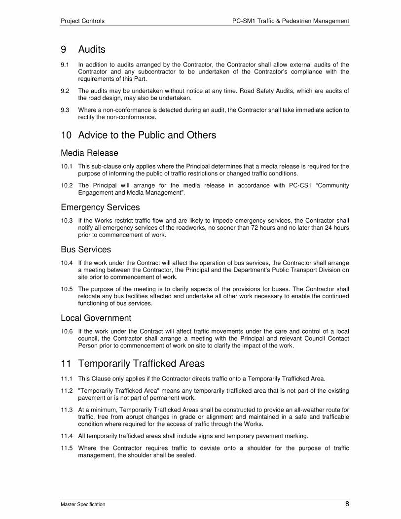
Project Controls PC-SM1 Traffic & Pedestrian Management
Master Specification 8
9 Audits
9.1 In addition to audits arranged by the Contractor, the Contractor shall allow external audits of the Contractor and any subcontractor to be undertaken of the Contractor’s compliance with the requirements of this Part.
9.2 The audits may be undertaken without notice at any time. Road Safety Audits, which are audits of the road design, may also be undertaken.
9.3 Where a non-conformance is detected during an audit, the Contractor shall take immediate action to rectify the non-conformance.
10 Advice to the Public and Others
Media Release
10.1 This sub-clause only applies where the Principal determines that a media release is required for the purpose of informing the public of traffic restrictions or changed traffic conditions.
10.2 The Principal will arrange for the media release in accordance with PC-CS1 “Community Engagement and Media Management”.
Emergency Services
10.3 If the Works restrict traffic flow and are likely to impede emergency services, the Contractor shall notify all emergency services of the roadworks, no sooner than 72 hours and no later than 24 hours prior to commencement of work.
Bus Services
10.4 If the work under the Contract will affect the operation of bus services, the Contractor shall arrange a meeting between the Contractor, the Principal and the Department’s Public Transport Division on site prior to commencement of work.
10.5 The purpose of the meeting is to clarify aspects of the provisions for buses. The Contractor shall relocate any bus facilities affected and undertake all other work necessary to enable the continued functioning of bus services.
Local Government
10.6 If the work under the Contract will affect traffic movements under the care and control of a local council, the Contractor shall arrange a meeting with the Principal and relevant Council Contact Person prior to commencement of work on site to clarify the impact of the work.
11 Temporarily Trafficked Areas
11.1 This Clause only applies if the Contractor directs traffic onto a Temporarily Trafficked Area.
11.2 "Temporarily Trafficked Area" means any temporarily trafficked area that is not part of the existing pavement or is not part of permanent work.
11.3 At a minimum, Temporarily Trafficked Areas shall be constructed to provide an all-weather route for traffic, free from abrupt changes in grade or alignment and maintained in a safe and trafficable condition where required for the access of traffic through the Works.
11.4 All temporarily trafficked areas shall include signs and temporary pavement marking.
11.5 Where the Contractor requires traffic to deviate onto a shoulder for the purpose of traffic management, the shoulder shall be sealed.
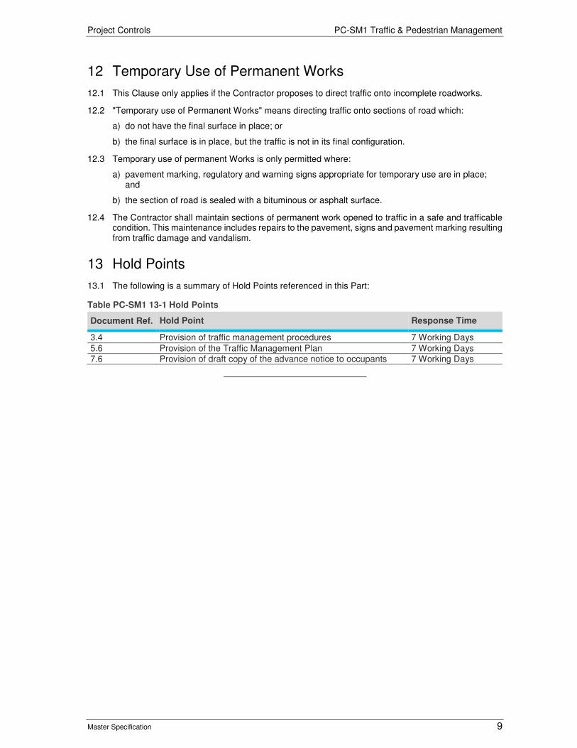
Project Controls PC-SM1 Traffic & Pedestrian Management
Master Specification 9
12 Temporary Use of Permanent Works
12.1 This Clause only applies if the Contractor proposes to direct traffic onto incomplete roadworks.
12.2 "Temporary use of Permanent Works" means directing traffic onto sections of road which:
a) do not have the final surface in place; or
b) the final surface is in place, but the traffic is not in its final configuration.
12.3 Temporary use of permanent Works is only permitted where:
a) pavement marking, regulatory and warning signs appropriate for temporary use are in place; and
b) the section of road is sealed with a bituminous or asphalt surface.
12.4 The Contractor shall maintain sections of permanent work opened to traffic in a safe and trafficable condition. This maintenance includes repairs to the pavement, signs and pavement marking resulting from traffic damage and vandalism.
13 Hold Points
13.1 The following is a summary of Hold Points referenced in this Part:
Table PC-SM1 13-1 Hold Points
Document Ref. Hold Point Response Time
3.4 Provision of traffic management procedures 7 Working Days 5.6 Provision of the Traffic Management Plan 7 Working Days 7.6 Provision of draft copy of the advance notice to occupants 7 Working Days

Project Controls
Master Specification
PC-SM2 Site and Access Management Document Information
K Net Number: 13664782 Document Version: 2 Document Date: 19/09/2019

Project Controls Contents
Master Specification 2
Document Amendment Record
Version Change Description Date Endorsement record (KNet ref.)
1 Initial issue (formerly CH20M) and amended to incorporate previous G part elements.
02/05/19
2 Minor content changes 19/09/19
Document Management This document is the Property of the Department for Infrastructure and Transport and contains information that is confidential to the Department. It must not be copied or reproduced in any way without the written consent of the Department. This is a controlled document and it will be updated and reissued as approved changes are made.

Project Controls Contents
Master Specification 3
Contents Contents 2
PC-SM2 Site and Access Management 4
1 General 4
2 Working days and hours of work 4
3 Property 4
4 Contractor’s Activity Zone 4
5 Stockpiling and Occupation of land 5
6 Contractor's Compound and Principal's requirements 6
7 Floods and Waterways 6
8 Protection of the works and reinstatement of damage 6
9 Fire prevention 7
10 Explosives 7
11 Vibrating compaction equipment 8
12 Control of fences and gates 8
13 Clearances from landholders 8
14 Water 8
15 Maintenance of existing trafficked pavement 8
16 Verification requirements and records 9
17 Hold Points 9

Project Controls PC-SM2 Site and Access Management
Master Specification 4
PC-SM2 Site and Access Management
1 General
1.1 Unless specified otherwise, the definitions in the Austroads Publication No. AP-C87-15 ”Glossary of Terms” apply to any term used in the Contract which is related to road or traffic engineering.
2 Working days and hours of work
2.1 For the purpose of administration of the Contract, ordinary working days and customary working hours will be those nominated on Schedule titled “Working Time".
2.2 The Contractor shall not work more than one shift per day exceeding 10 hours duration and shall not work on Sundays or public holidays without the prior approval of the Principal.
2.3 When adjusting a date pursuant to extension of time, account will be taken of non-working days (as determined from Schedule “Working Time”) that would normally fall in the extended period such that the number of ordinary working days in the extended period equals the number of days’ extension granted.
2.4 If Schedule “Working Time” is not included in this Contract, Sundays, Public Holidays, Rostered Days Off and the Christmas / New Year annual leave break are deemed to be non-working days.
3 Property
3.1 Were required the Principal will be undertake land acquisition and associated property works.
3.2 The Principal will advise the Contractor in writing prior to the commencement of any associated property works (e.g. demolition or fencing).
3.3 The Contractor must provide access to the Site to enable the Principal to carry out these works.
3.4 The Contractor must ensure that personnel undertaking work on behalf of the Principal receive Site Induction in accordance with the Contractor’s Occupational Health, Safety and Welfare Plan at no additional cost to the Principal.
Property Works undertaken by the Contractor on behalf of the Principal
3.5 Where the Principal may engage the Contractor to undertake property works on behalf of the Principal.
3.6 The Contractor must repair any damage to property caused by the Contractor as soon as possible and at no cost to the Principal or occupier of the relevant property. The property must be reinstated to a condition at least equivalent to the condition it was in immediately prior to the occurrence of the damage.
3.7 Access to properties affected by the property works must be provided by the Contractor to the Principal and property owners at all times while the Contractor has access to the relevant property.
4 Contractor’s Activity Zone
4.1 The Contractor’s Activity Zone (CAZ) is defined as the area of the Site where activities associated with construction of the Works are permitted to take place. The Contractor’s Activity Zone is:
a) the area defined by the plan area of the Works (“Footprint”) and an additional 1.0 m beyond the Footprint;
b) any other area necessary for the construction of the Works (which may be outside of the Site) including:
i) minimise resource use and waste generated during construction;

Project Controls PC-SM2 Site and Access Management
Master Specification 5
ii) access tracks;
iii) utility areas required for temporary stockpiling, refuelling, storage, waste management, equipment lay-down and the movement, turning or parking of vehicles;
iv) the site office compound; and
c) areas for the installation and maintenance of any erosion and sediment control devices.
4.2 The CAZ shall consist of the minimum area practicable to undertake the construction activities in accordance with this Contract;
4.3 Subject to compliance with all other requirements and approvals specified in this Contract, the Contractor shall undertake all construction related activities within the approved CAZ;
4.4 Prior to commencement of work on site, the Contractor must nominate the location of the CAZ. The activity zone must be documented on a set of design or construction drawings, or as otherwise agreed to by the Principal. Provision of the CAZ shall constitute a Hold Point;
4.5 If the Contractor wishes to alter the CAZ, prior approval of the Principal must be sought and obtained in writing. Submission of the request to change the CAZ shall constitute a Hold Point. Any approved changes must be documented in the Project Management Plan;
4.6 The approval of the CAZ and alterations to the CAZ will be based on the Principals desired outcomes for the land, community risks, environmental risk (including impacts to native vegetation), required approvals, land ownership and access and the practicality of restricting construction activities.
5 Stockpiling and Occupation of land
5.1 Should the Contractor identify the need for any on-site temporary storage / stockpiling areas required for the storage of excavated materials the Contractor shall seek approval from the Principal.
5.2 Stockpiling of surplus or actual / potentially contaminated materials will not be approved on land under the Principals ownership which, at Completion of the project, has the potential to be used for a sensitive land use, as defined by the Environment Protection Act 1993 or immediately adjacent to sensitive land uses.
5.3 If approved, the management of the stockpile must be included in the Contractor’s Environmental Management Plan (CEMP) Refer PC-ENV1 “Environmental Management”.
5.4 The stockpile(s) must be placed on an impermeable surface and then covered in its entirety with an impermeable cover so as to prevent leaching and contamination of underlying soil and to prevent any contaminants becoming airborne.
5.5 The request for on-site temporary storage / stockpiling areas, at least 4 weeks prior to commencement of work on the proposed area shall constitute a Hold Point. If the Hold Point is not released by the Principal then the Contractor is responsible for finding alternative options for stockpiling.
5.6 Should the Contractor either require or be deemed to be occupying any land where a potentially contaminating activity is being undertaken, including stockpiling, the Contractor must:
a) apply for and obtain any approvals required by Law to undertake a potentially contaminating activity; and
b) engage a suitably qualified environmental consultant to undertake a pre and post activity Environmental Site Assessment in accordance with NEPM and SA EPA guidelines; or
c) demonstrate on a case by case that it’s activities do not have the potential to contaminate the land and request the Principal for an exemption from the above item (b).
5.7 If subsequently, potentially contaminating activities are deemed to have occurred on the land then item 5.6(5.6b) must apply.
5.8 The Contract shall clean up and restore the Site and leave it in a physical and chemical condition comparable to that encountered at the time of commencement of the Contract, prior to Completion.

Project Controls PC-SM2 Site and Access Management
Master Specification 6
6 Contractor's Compound and Principal's requirements
6.1 The contractor shall provide the facilities specified by the Principal (if any) for the use of the Principal when administering the Contract.
6.2 If "Establishment Charges" is included in a payment schedule, this payment item is deemed to include establishment of site buildings, transport of major items of plant to the site, demobilisation and site clean-up.
6.3 The operation and maintenance of site buildings and associated costs are deemed to be included in on site overhead.
6.4 If the Principal makes any land available to the Contractor, the Contractor acknowledges that this land may not be sufficient for all site facilities and it is the Contractor’s responsibility to source additional land if required.
6.5 All electrical installations and alterations shall be carried out by an electrical worker who is licensed in South Australia to perform any electrical works. The installations shall comply with AS 3000 and the Service Rules and Conditions of Supply of SA Power Networks.
6.6 The Contractor shall arrange for Certificates of Compliance of all electrical work and shall submit copies of certification to the Principal.
6.7 Provision of the Certificates of Compliance of electrical work shall constitute a Hold Point.
6.8 The WHS Management Plan shall include a plan of the site compound and any associated facilities showing how the Contractor will comply with:
a) Section 40 – Duty in Relation to General Workplace Facilities of the Work Health and Safety Regulations 2012 (SA); and
b) Safework Australia Code of Practice for Managing the Work Environment and Facilities (available from: https://www.safework.sa.gov.au/resources/managing-work-environment-and-facilities#).
6.9 At a minimum, the plan shall show the general layout, buildings, emergency exits, egress and access points, fences, gates, power cables, paths (including surface treatment and delineation / separation of pedestrians / plant / vehicles), plant / vehicle parking, storage facilities and refuelling facilities in the site compound and any associated areas such as hazardous materials storage facilities.
6.10 Prior to Completion the Contractor must clean up any site compound and reinstate to a condition comparable (or better) than at the time of possession of site.
7 Floods and Waterways
7.1 The Contractor:
a) unless specified otherwise, shall not obstruct any waterway;
b) shall take all necessary precautions to prevent heading up of floodwaters and / or damage to the Works or Site from the effects of water; and
c) assumes responsibility for the repair of any damage to the Works due to surface water and bears the cost of any such repair.
8 Protection of the works and reinstatement of damage
8.1 The Contractor shall construct the works so to ensure that materials (including subgrade) do not become unsuitable or damaged by the Contractor’s work methods or insufficient protective measures This includes:
a) constructing the works so as to be free draining; and
b) maintaining the works so as to prevent deterioration in material properties between testing or acceptance of the work and subsequent work commencing.

Project Controls PC-SM2 Site and Access Management
Master Specification 7
8.2 Additional payment will not be made where any additional work or additional materials are required:
a) to comply with this Clause; or
b) as a result of the Contractor’s work methods.
8.3 Over-excavation (i.e. the Contractor excavates deeper or wider than the dimensions specified) is deemed to be included in sub-clause 6.2 (b).
9 Fire prevention
9.1 The Contractor shall comply with the Fire and Emergency Services Act 2005 (SA). If any of the work under Contract takes place during the Fire Danger Season, the Contractor’s Quality Management Plan, Environmental Management Plan or Work Health and Safety Management Plan shall include procedures / instructions which address the following at a minimum:
a) training of personnel;
b) monitoring the declaration of Total Fire Ban days;
c) liaising with the Country Fire Service, Metropolitan Fire Service and / or local council;
d) applying for Schedule 10 permits if appropriate;
e) implementing measures to identify and mitigate fire hazards;
f) working on Total Fire Ban days;
g) ensuring grinders, welders, chainsaws, grass trimmers, lawn mowers, slashers or similar equipment are only used in accordance with the requirements the Fire and Emergency Services Act;
h) emergency response in the event of a fire; and
i) all other relevant requirements the Fire and Emergency Services Act.
9.2 The Contractor shall:
a) ensure that any vehicle driven off road has a compliant exhaust system;
b) provide each work crew with appropriate extinguishers and firefighting equipment on Site;
c) notify the Principal if it intends to work on days of high fire danger;
d) provide the Principal with a copy of any Schedule 10 permit obtained for the work under the Contract;
e) ensure that any fire (where permitted under the Contract) complies with the requirements the Fire and Emergency Services Act; and
f) immediately notify the Principal in the event of any unplanned fire initiated at the Site.
10 Explosives
10.1 Unless specified otherwise by the Principal, the use of explosives is not permitted.
10.2 If the use of explosives is permitted by the Principal, the Contractor shall:
a) obtain the necessary licences from the appropriate authority;
b) conform to all Government regulations relating to the transport, handling, storage and use of explosives;
c) comply with the requirements and precautions set out in AS 2187, "Explosives - Storage, transport and use”;
d) be liable for any accident, damage or injury to any person or thing resulting from the use of explosives;
e) adjust blasting operations in accordance with the characteristics and structure of the rock formation so as to obtain the specified slopes with a minimum disturbance and over-breakage;

Project Controls PC-SM2 Site and Access Management
Master Specification 8
f) ensure that over cutting of batters due to blasting operations is not be more than 1.0 m outside the specified line of the batter and the completed batter has a regular shape;
g) ensure that when blasting operations are being carried out, traffic is stopped at a safe distance from the site of blasting, the sign "Blasting - Stop Await Signal" shown in AS 1742, Part 3, is erected at all approaches to traffic routes and a person is stationed at each sign to ensure that traffic is stopped;
h) sound a warning prior to each firing; and
i) give occupiers of adjoining properties at least 24 hours’ notice of the intention to blast.
11 Vibrating compaction equipment
11.1 Unless stated otherwise by the Principal, the use of vibrating compaction equipment shall comply with Table PC-SM2 11-1.
Table PC-SM2 11-1 Maximum permitted centrifugal of compaction equipment
Type of compaction equipment Maximum Permitted Centrifugal Force
Asphalt on bridge decks 30 kN Asphalt not on bridge decks No maximum Work other than asphalt 30 kN
12 Control of fences and gates
12.1 The Contractor shall maintain all fences affected by the Works in a condition equivalent to that existing at the Date of Acceptance of Tender for the duration of the Contract. Any temporary fences, gates and grids shall be removed upon completion of the Works.
13 Clearances from landholders
13.1 If any of the Contractor’s work is undertaken on adjoining private land, or affects private land, the Contractor shall use its best endeavours to obtain a written statement that the landholder’s property has been left in a satisfactory condition from each affected landholder.
14 Water
14.1 Water for construction, when not sourced from a SA Water pipeline, shall comply with any requirements outlined by the Principal and the following requirements:
a) Unless specified otherwise by the Principal, water for pavement construction shall not contain more than 10 000 ppm total dissolved salts for base and 20 000 ppm for other pavement layers. The salt content shall be determined using TP 751. The testing frequency shall be one test immediately prior to commencement of construction and thereafter every 2 weeks until completion of pavement construction.
b) Water for concrete production shall not contain more than:
i) 3 000 mg/L total dissolved salts;
ii) 1 000 mg/L chlorides; and
iii) 500 mg/L sulphates.
15 Maintenance of existing trafficked pavement
15.1 This clause applies if there is an existing trafficked pavement within the Site.
15.2 “Maintenance Provider” means an agent of the Principal who undertakes maintenance of an existing road

Project Controls PC-SM2 Site and Access Management
Master Specification 9
15.3 The Contractor shall regularly monitor the condition of any existing trafficked pavement and identify any defect that exceeds the Department’s intervention levels, as specified by the Principal.
15.4 The Contractor shall regularly monitor the condition of any footpaths or walkways and identify any hazard to pedestrians.
15.5 In the event that the Contractor identifies any such defect or hazard, the Contractor shall:
a) repair the defect or hazard or defect immediately if the hazard or defect is a result of the Contractor’s activities; or
b) notify the Principal immediately in writing if the hazard or defect is not a result of the Contractor’s activities.
15.6 If the hazard or defect is not a result of the Contractor’s activities, the Principal may arrange for the defect to be repaired by the Maintenance Provider. Except in emergency situations, the Principal will provide the Contractor with 2 days’ notice of the Maintenance Provider entering the site to undertake the repair(s).
15.7 Prior to commencement of the repair, the Contractor shall liaise with the Maintenance Provider to ensure that any traffic control devices proposed by the Maintenance Provider do not conflict with the Contractor’s Traffic Control Plan.
16 Verification requirements and records
16.1 The Contractor shall supply the following documentation to demonstrate that the requirements of this Part have been complied with and where appropriate, supply the documentation with the lot package.
Table PC-SM2 16-1 Supply documentation
Subject Record to be provided
Clearance from Landowners Statement of clearance from Landowners Materials Supplied by the Principal Receipt for materials Water not sourced from a SA Water Service Dissolved Salt Content
17 Hold Points
17.1 The following is a summary of Hold Points referenced in this Part:
Document Ref. Hold point Response time
4.4 Provision of Contractor’s Activity Zone 10 working days 4.5 Submission of request to change Contractor’s Activity Zone 2 working days 5.5 Request for on-site temporary storage / stockpiling areas 5 working days 6.7 Submission of Certificates of Compliance of electrical work 5 working days
Project Controls
Master Specification
PC-SI1 Site Surveys Document Information
K Net Number: 13520517 Document Version: 2 Document Date: 06/09/2019

Project Controls Contents
Master Specification 2
Document Amendment Record
Version Change Description Date Endorsement record (KNet ref.)
1 Initial issue (formerly CH30 Survey) 22/02/19 2 Formatting for publishing 06/09/19
Document Management This document is the Property of the Department for Infrastructure and Transport and contains information that is confidential to the Department. It must not be copied or reproduced in any way without the written consent of the Department. This is a controlled document and it will be updated and reissued as approved changes are made.

Project Controls Contents
Master Specification 3
Contents Contents 2
PC-SI1 Surveys 4
1 General 4
2 Surveyor 4
3 Survey Control Network 4
4 Survey Equipment 5
5 Survey Duties - General 6
6 Verification Certificates 9
7 Survey using Global Navigation Satellite System Equipment 11
8 Property Boundary Marking 11
9 Provision of As-Constructed Information 11
10 Audit 12
11 Payment 12
12 Hold Points 12
13 Appendix 1: Minimum Survey Requirements for Utility Services 13

Project Controls PC-SI1 Surveys
Master Specification 4
PC-SI1 Surveys
1 General
1.1 This Part specifies the requirements for the management of the survey control network and the general survey duties necessary for the delivery of Works.
1.2 This Part references the following document:
a) Survey Act 1992 (SA).
2 Surveyor
2.1 The Contractor shall engage a person (“Surveyor”) who:
a) is eligible for the grade of Member of the Spatial Sciences Institute, Australia or be eligible for membership of an allied professional organisation;
b) is accredited by completion of a Work Zone Traffic Management course with a trainer approved by the Department; and
c) has a minimum of 3 years’ experience as a survey party leader on major infrastructure work (which is appropriate for this Contract) since gaining qualification.
2.2 The Contractor shall ensure that:
a) the Surveyor complies with the requirements of this Part;
b) the Surveyor personally carries out the duties specified herein or be on site at all times during survey work; and
c) all survey duties are undertaken in accordance with a certified Quality Assurance system.
3 Survey Control Network
3.1 The Principal will provide the Survey Control Marks to the Contractor.
3.2 The Contractor:
a) is responsible for these marks and any additional marks that form the Survey Control Network;
b) shall verify the integrity of the marks before commencing survey work; and
c) shall supply to the Principal a final list of stations immediately prior to the project completion.
Verification
3.3 Verification of the survey control shall be conducted periodically (at intervals not exceeding 3 months) up to the Date of Completion.
3.4 If discrepancies are detected between apparently undisturbed adjacent control points, the Surveyor shall report the discrepancies to the Principal who may direct further survey control verification to be carried out.
Horizontal Control
3.5 For horizontal control only, survey stations numbered S001 to S799 shall be used. The S300 series of survey stations are permanent survey marks registered with the Surveyor General.
Vertical Control
3.6 Where deep bench marks (prefixed BM) are provided by the Principal, these deep bench marks shall be used for vertical control.

Project Controls PC-SI1 Surveys
Master Specification 5
3.7 If deep bench marks are not provided by the Principal, survey stations numbered S001 to S099 and S300 to S399 shall be used for vertical control.
Bridge Control
3.8 Where the Works include a bridge or major structure, the Contractor shall nominate a minimum of three control stations for each bridge site. Where the bridge length exceeds 100 m, the distance between control stations shall not exceed 100 m. Only these stations or their approved replacements are to be used for alignment, level and coordinate origin for the bridge set out and construction.
3.9 Where survey control for structures and bridgeworks is established, the Surveyor shall use ground distances (not grid distances) for all lines when calculating coordinates.
Re-Establishment of Control
3.10 If control survey stations have to be re-located or additional stations installed, these stations shall be connected to the existing survey control network. Adjustment computations for new control points shall be ancillary to the main control adjustment so that minor adjustments to the previously fixed stations are avoided. The Contractor is responsible for all costs associated with re-establishment of survey marks.
Principal Supplied Survey Coordinate Data
3.11 All Survey and design undertaken by the Principal is in planar Project Coordinate System.
3.12 All design undertaken prior to any issue of survey datasets provided by the Principal will be undertaken in either GDA 94 South Australian conformal conic projection or GDA 94 MGA Z 54H.
3.13 The Contractor shall be responsible for converting data to and from the preferred coordinate system as required, including for Service Authorities designs and GIS data.
4 Survey Equipment
4.1 The equipment used by the Surveyor shall be appropriate for the accuracy of work undertaken. The Surveyor’s procedures shall address all errors introduced by survey methods and make due allowance for the effects of:
a) survey equipment capability and adjustment;
b) integrity of the survey control network;
c) vertical refraction;
d) the grid scale factor;
e) the earth’s curvature; and
f) the geoid – ellipsoid separation.
Electronic Distance Measuring Equipment
4.2 Electronic Distance Measuring equipment shall have the following:
a) capability to measure distances to within 5mm +5ppm;
b) capability to for angular measurements for both horizontal and vertical angles to be less than 3” of arc;
c) one second of arc minimum count;
d) diametric vertical circle reading;
e) automatic tilt compensator; and
f) capable to electronically record and store field data including horizontal and vertical angles, distances, point notation, target and instrument heights.

Project Controls PC-SI1 Surveys
Master Specification 6
4.3 Prior to commencement of any survey work, the Contractor shall submit evidence that all Electronic Distance Measuring equipment used for work under the Contract has been tested within the last 12 months and every 12 months for the duration of the project
4.4 Electronic Distance Measuring equipment shall be tested at the University of South Australia, Mawson Campus or by a company certified by a National Association of Testing Authorities (NATA) to test the equipment within the last 12 months and every 12 months for the duration of the project.
4.5 Submission of this evidence shall be provided at least 10 working days prior to the commencement of work on site and shall constitute a Hold Point.
Verification of Level Equipment
4.6 Prior to commencement of any survey work, the Contractor shall undertake sufficient checks to ensure the level equipment is calibrated and in tolerance, evidence shall be documented and may be requested by the principal at any time.
Global Navigation Satellite System Equipment
4.7 This sub-clause applies to Global Navigation Satellite System (GNSS) hardware and software systems designed for geodetic survey applications operated in differential mode where carrier phase and pseudo- range observations are recorded by the receivers.
4.8 At a minimum, GNSS equipment shall:
a) include receivers capable of recording carrier waves;
b) be authorised for frequency to operate a two-way radio from the Australian Communication Authority for GNSS operations; and
c) incorporate braced support for the receiver pole.
4.9 Prior to commencement of any survey work using GNSS equipment, the Contractor shall submit evidence that all GNSS equipment used for work under the Contract has been tested within the last 12 months. This requirement is specific to utilising GNSS in a Quality Assurance system.
4.10 Submission of this evidence shall be provided at least 10 working days prior to the commencement of work on site and shall constitute a Hold Point.
4.11 GNSS systems shall be tested on a calibration network at least once per year, immediately after any repair, after a system upgrade (hardware and / or firmware). GNSS shall not be used as the sole method of measuring length in contractor surveys. Surveyors using GNSS for contract verification purposes shall adhere to the requirements of the Surveyor General.
5 Survey Duties - General
Permanent Survey Marks
5.1 Permanent Survey marks shall be protected in accordance with the Survey Act 1992 (SA). The Contractor’s attention is drawn to Section 52 – Interface with Survey Marks.
5.2 Prior to construction commencing, the Surveyor shall:
a) obtain location details of all permanent survey marks registered with the Surveyor General within the construction area;
b) give the Surveyor General a minimum of 10 working days’ notice in writing of:
i) the commencement date of construction activities; and
ii) the possible destruction of a permanent survey mark registered with the Surveyor General.
5.3 Notification to the Surveyor general shall be sent to [email protected]. A copy of these notifications shall be submitted to the Principal.
5.4 Submission of the notification shall constitute a Hold Point.

Project Controls PC-SI1 Surveys
Master Specification 7
Re-instatement and Placement of Permanent Survey Marks
5.5 In the event of damage, disturbance or removal of any permanent survey mark, the Contractor:
a) shall re-install and / or replace the permanent survey mark;
b) liaise with a representative from the Surveyor-General’s Office when undertaking these activities;
c) ensure this work is certified by the Surveyor; and
d) submit to the Surveyor General field observations, coordinates, locality sketches and other information as reasonably requested.
5.6 Details for placement of permanent survey marks are outlined in Section 14.1 to 14.3 of the Cadastral Survey Guidelines, available from: https://www.bing.com/search?q=https%3A%2F%2Fwww.sa.gov.au%2Ftopics%2Fhousing-property-and-land%2Findustry-+++professionals%2Fconveyancing-and-surveying-professionals%2Fcadastral-survey-guidelines-csg%23title5&src=IE-SearchBox&FORM=IESR3N.
5.7 Details for the requirements for the coordination of permanent survey marks are outlined in Sections 5.7 & 5.8 of the Cadastral Survey Guideline, available from https://www.bing.com/search?q=https%3A%2F%2Fwww.sa.gov.au%2Ftopics%2Fhousing-property-and-land%2Findustry-+++professionals%2Fconveyancing-and-surveying-professionals%2Fcadastral-survey-guidelines-csg%23title5&src=IE-SearchBox&FORM=IESR3N.
Review of Data
5.8 The Surveyor shall:
a) prepare and set out data from plans and digital design prior to and during construction;
b) provide a certificate verifying the survey coordinate information supplied by the Principal;
c) seek direction from the Superintendent if any survey stations are missing or disturbed; and
d) detect any design discrepancies or ambiguities.
5.9 Where there is disagreement with the Principal's co-ordinates and / or levels, the Contractor and the Principal will agree on the values to be adopted before any setting out is commenced.
Existing Survey Marks
5.10 The Surveyor shall maintain a site list of all existing survey marks, in the project site listing coordinates and status.
5.11 Prior to Completion, the Surveyor shall supply to the Principal a certificate of the site stations list, in hard copy and electronic format (MS Excel) detailing:
a) the survey stations supplied by the Department that are intact;
b) the survey stations supplied by the Department that have been destroyed or disturbed;
c) a sorted station listing by label detailing the coordinates, the type of ground mark and the witness mark, of all additional survey marks placed by the Contractor;
d) permanent survey marks registered with the Surveyor General that are intact; and
e) permanent survey marks registered with the Surveyor General that have been destroyed or disturbed.
5.12 Provision of this certificate shall constitute a Hold Point and is a condition precedent to Completion.
Survey Dataset
5.13 All design undertaken subsequent to the issue of the survey datatset (included any updated survey dataset) by the Principal shall be undertaken in accordance with the horizontal and vertical grid consistent with the issued dataset.

Project Controls PC-SI1 Surveys
Master Specification 8
Setout
5.14 The Contractor shall set out all necessary design information needed to achieve the required construction tolerances relevant for the Works. Verification certificates shall be provided for all points.
Survey checks for Pavement Layers
5.15 When undertaking pavement verification, the Contractor shall utilise the same point on all pavement layers, from subgrade to wearing course inclusive, for the purpose of determining total pavement thickness.
Survey checks for Rail Layers
5.16 The Contractor shall Provide Survey Data for the following:
a) Turnout Crossovers – K & V Crossings;
b) Rail Signals and associated infrastructure (tuning Units, axle counters etc.);
c) new or altered rail furniture including whistle boards, speed signs, etc.;
d) structural clearance verification; and
e) rail weights / locations.
Additional Potholing of Existing Utility Services
5.17 The Contractor shall survey locations of all depthed and constructed services including location of and top of service, as stated in the Department’s Engineering Survey Specification: SURCT-003.
5.18 For newly constructed services, actual positions (not offsets) of the service prior to any backfilling shall be observed.
5.19 The Contractor shall provide supporting information for each service:
a) details of service information where possible – i.e. diameter, material, number and configuration of conduits, condition;
b) where multiple conduits (banks) are observed, the Contractor shall:
i) expose all conduits in the top layer and excavate the sides of the bank until the conduits on the outsides of the lowest layer are exposed; and
ii) survey the top of each conduit in the upper layer of the bank and the underside of the outer conduits in the lowest layer, and record the configuration of the bank, (e.g. 4 X 4, 5 X 3).
c) for sewers, both the invert and obvert level of the pipe and size / diameter of the manhole / IP;
d) for Drainage structure, invert and pipe diameter for all pipes penetrating the structure, and a notation for ingress or egress of the pipe(s);
e) for water mains at valve covers, where possible record the main, otherwise record the top of the spindle and estimate a height above the main (in comments); and
f) any other relevant information, (e.g. blocked, broken, plugged, etc.).
Installation of New Underground Utility Services
5.20 The Contractor shall ensure that the Surveyor:
a) sets out the proposed alignment of any new service, including the location of any adjoining infrastructure that may impact on the placement of the new service; and
b) records the position of any services or conduit(s) laid in open trenches. Measurements shall be made at all changes of direction, or grade, and at regular intervals of length, (e.g. 10 m).
5.21 The Contractor shall ensure that the Surveyor has access to undertake measurements prior to any backfill of a services trench.

Project Controls PC-SI1 Surveys
Master Specification 9
5.22 The Contractor shall provide bore log reports and digitised data for all underground boring. Bore logs shall clearly define the entry and exit points and show regular incremental measurements, generally at each bore rod length, represented in the Planar Grid / Project Coordinate System (x,y,z).
5.23 The minimum survey requirements for new underground utility services are specified in Appendix 1: Minimum Survey Requirements for Utility Services.
6 Verification Certificates
6.1 Prior to Completion or within any other timeframe specified in this Contract, the Contractor shall ensure that the Surveyor provides verification certificates demonstrating that the Contractor’s work complies with the tolerances specified in the Contract. Unless specified otherwise, verification certificates shall:
a) identify the instrument used;
b) be provided electronically in Microsoft .xlsx format;
c) include tables which display the information in a clear and logical format;
d) for each design dimension / position / level, display:
i) the design value, (X &Y Coordinates);
ii) the actual value, (X &Y Coordinates); and
iii) the difference between actual value and design value.
e) for pavement layers, the individual layer and total pavement thicknesses.
6.2 Submission of verification certificates shall constitute a Hold Point and is a condition precedent to Completion.
6.3 Where the work described below forms part of the Contract, at a minimum the verification certificates shall confirm compliance of the following:
Roadworks
6.4 Confirmation of that as outlined in Table PC-SI1 6-1.
Table PC-SI1 6-1 Roadworks Compliance
String label chainage at interval of reference string
Offset from reference string
Design level
Actual level
Difference between actual and design levels
Displacement from horizontal position
Stripping Topsoil Yes Yes - - - - Cuts / Fills Yes Yes - - - Yes Subgrade Yes Yes Yes Yes Yes - Pavement Layers including Asphalt pavement treatments
Yes Yes Yes Yes Yes Yes
Earth Drains Yes Yes Yes Yes Yes Yes Kerb and Gutter (including bus guideway system)
Yes Yes Yes Yes Yes Yes
Median Kerb type 2, 3, 4, 4A Yes Yes Yes Yes Yes Yes Median Kerb type 1, 5, 6, 7, 8 Yes Yes - - - Yes Drainage culverts - - Yes Yes Yes Yes Drainage structures - - Yes Yes Yes Yes Lighting and Traffic Signal footings
Yes Yes Yes Yes Yes Yes
Steel Beam and Wire Rope Safety Barrier
Yes Yes - - - Yes
Settlement Monitoring Yes Yes Yes Yes Yes Yes
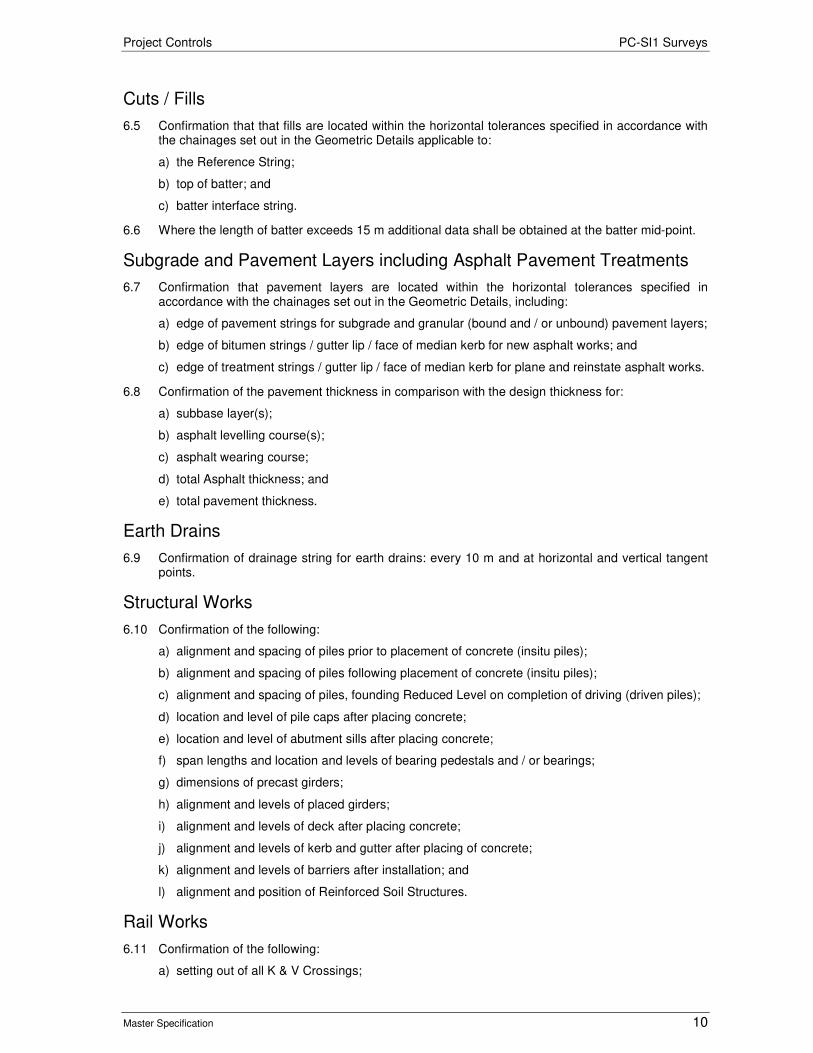
Project Controls PC-SI1 Surveys
Master Specification 10
Cuts / Fills
6.5 Confirmation that that fills are located within the horizontal tolerances specified in accordance with the chainages set out in the Geometric Details applicable to:
a) the Reference String;
b) top of batter; and
c) batter interface string.
6.6 Where the length of batter exceeds 15 m additional data shall be obtained at the batter mid-point.
Subgrade and Pavement Layers including Asphalt Pavement Treatments
6.7 Confirmation that pavement layers are located within the horizontal tolerances specified in accordance with the chainages set out in the Geometric Details, including:
a) edge of pavement strings for subgrade and granular (bound and / or unbound) pavement layers;
b) edge of bitumen strings / gutter lip / face of median kerb for new asphalt works; and
c) edge of treatment strings / gutter lip / face of median kerb for plane and reinstate asphalt works.
6.8 Confirmation of the pavement thickness in comparison with the design thickness for:
a) subbase layer(s);
b) asphalt levelling course(s);
c) asphalt wearing course;
d) total Asphalt thickness; and
e) total pavement thickness.
Earth Drains
6.9 Confirmation of drainage string for earth drains: every 10 m and at horizontal and vertical tangent points.
Structural Works
6.10 Confirmation of the following:
a) alignment and spacing of piles prior to placement of concrete (insitu piles);
b) alignment and spacing of piles following placement of concrete (insitu piles);
c) alignment and spacing of piles, founding Reduced Level on completion of driving (driven piles);
d) location and level of pile caps after placing concrete;
e) location and level of abutment sills after placing concrete;
f) span lengths and location and levels of bearing pedestals and / or bearings;
g) dimensions of precast girders;
h) alignment and levels of placed girders;
i) alignment and levels of deck after placing concrete;
j) alignment and levels of kerb and gutter after placing of concrete;
k) alignment and levels of barriers after installation; and
l) alignment and position of Reinforced Soil Structures.
Rail Works
6.11 Confirmation of the following:
a) setting out of all K & V Crossings;

Project Controls PC-SI1 Surveys
Master Specification 11
b) setting out of all rail gauge face including check rails;
c) setting out of all Signal Infrastructure;
d) verification of structural clearance envelope;
e) setting out and levels of piers prior to placing concrete;
f) setting out and levels of abutment sill prior to placing concrete;
g) setting out and levels of deck prior to placing of concrete; and
h) setting out of Reinforced Earth Walls.
7 Survey using Global Navigation Satellite System Equipment
7.1 This Clause applies where GNSS equipment is used. The Surveyor shall:
a) ensure that for each construction activity the instrument’s threshold suitably meets the specified construction tolerances outlined in the contract;
b) validate equipment and survey by occupying established survey control stations and comparing coordinates;
c) prior to undertaking any observations or set out, localise onto the planar project coordinate system by observing survey control stations. The results shall be documented;
d) verify a sample of set out by traditional survey methods; and
e) document and validate the methodology for modelling the geoid and its effects on heights.
7.2 Real Time Kinematic GNSS may be used for horizontal set out for clearing lines, batter lines, bulk earthwork quantities and initial set out of earthworks.
7.3 Real Time Kinematic GNSS shall not be used for horizontal set out for any feature placed on or above the pavement course such as kerb-lines, medians, side entry pits, drainage manholes, structures such as culverts and bridges.
8 Property Boundary Marking
8.1 Where contract documents indicate construction activity within 500mm of a property boundary, the property line shall be determined using the most current cadastral information supplied by the Department’s Land Services Group .The survey shall be carried out by or under the direct supervision of a licensed surveyor in accordance with the Survey Act (1992). SA.
9 Provision of As-Constructed Information
9.1 The Contractor shall provide:
a) an electronic copy of the combined verification certificates including 3D model in either 12d ascii, MX Genio or AutoCad dwg format containing the following as specified by the Principal:
i) final pavement layer;
ii) kerbs;
iii) light poles;
iv) side entry pits;
v) structural elements;
vi) rail infrastructure;
vii) all newly placed underground services;
viii) all existing underground services retained or redundant and left in place;
ix) any other elements as outlined in this Contract; and
b) all new survey control placed and used for this project.
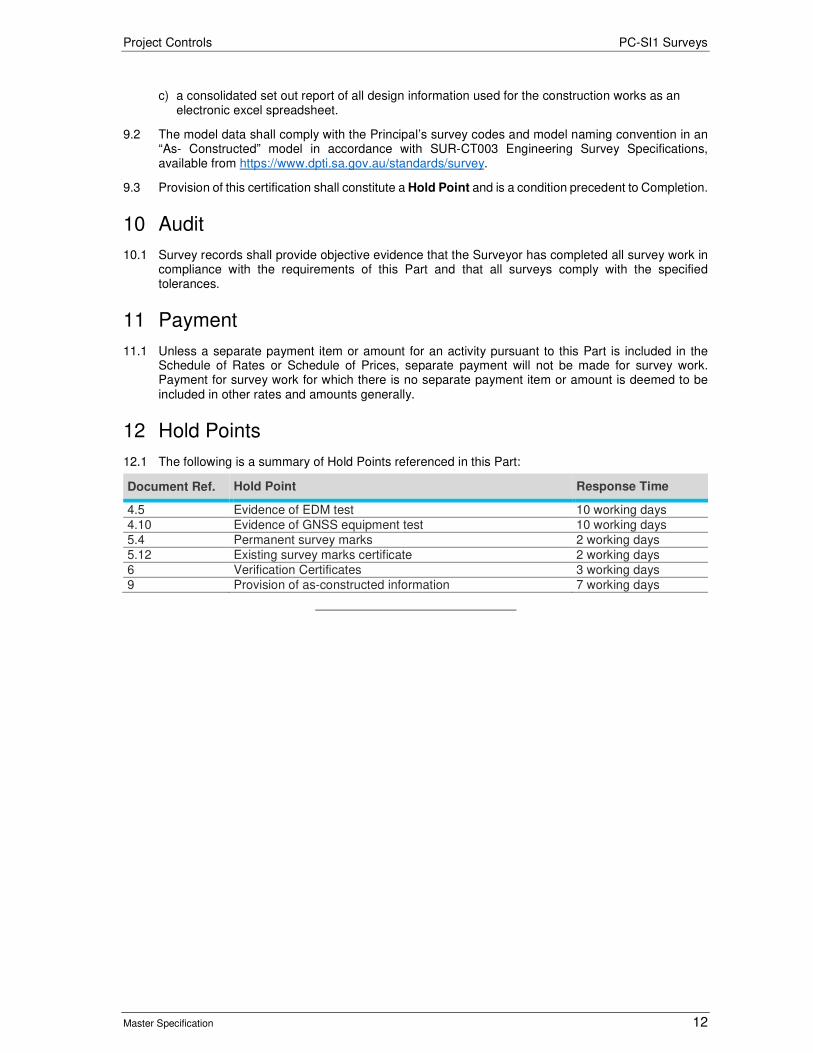
Project Controls PC-SI1 Surveys
Master Specification 12
c) a consolidated set out report of all design information used for the construction works as an electronic excel spreadsheet.
9.2 The model data shall comply with the Principal’s survey codes and model naming convention in an “As- Constructed” model in accordance with SUR-CT003 Engineering Survey Specifications, available from https://www.dpti.sa.gov.au/standards/survey.
9.3 Provision of this certification shall constitute a Hold Point and is a condition precedent to Completion.
10 Audit
10.1 Survey records shall provide objective evidence that the Surveyor has completed all survey work in compliance with the requirements of this Part and that all surveys comply with the specified tolerances.
11 Payment
11.1 Unless a separate payment item or amount for an activity pursuant to this Part is included in the Schedule of Rates or Schedule of Prices, separate payment will not be made for survey work. Payment for survey work for which there is no separate payment item or amount is deemed to be included in other rates and amounts generally.
12 Hold Points
12.1 The following is a summary of Hold Points referenced in this Part:
Document Ref. Hold Point Response Time
4.5 Evidence of EDM test 10 working days 4.10 Evidence of GNSS equipment test 10 working days 5.4 Permanent survey marks 2 working days 5.12 Existing survey marks certificate 2 working days 6 Verification Certificates 3 working days 9 Provision of as-constructed information 7 working days

Project Controls PC-SI1 Surveys
Master Specification 13
13 Appendix 1: Minimum Survey Requirements for Utility Services
Figure PC-SI1 13-1 Cross Section of a Hole
13.1 Example notation and requirements for a cross section of a hole by the verified method:
ZD – Z = denotes top of service; D = 100 m dia (letter varies depending on service diameter) PNSS – denotes natural surface RL at the hole Note – Labelling to be in accordance with the Department’s Geospatial Services Survey String Identifiers
Figure PC-SI1 13-2 Cross Section of a ‘Trenched Multi Conduit Run’ or ‘Trench / Slot’
13.2 Example notation and requirements for a cross section of a trench by the verified method:
Z1 – denotes pipe bundle edge ZD – Z= denotes top of service; D = 100 m dia (letter varies depending on service diameter) PNSS- denotes natural surface RL at the trench / slot Note – Labelling to be in accordance with the Department’s Geospatial Services Survey String Identifiers
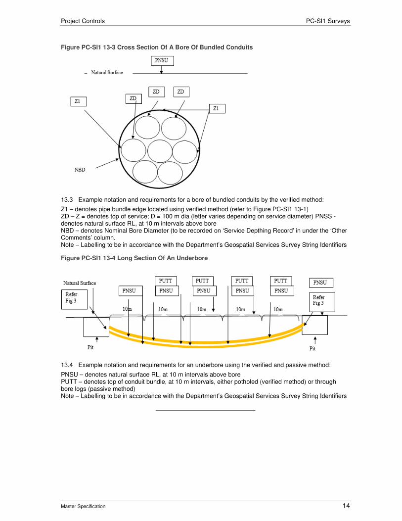
Project Controls PC-SI1 Surveys
Master Specification 14
Figure PC-SI1 13-3 Cross Section Of A Bore Of Bundled Conduits
13.3 Example notation and requirements for a bore of bundled conduits by the verified method:
Z1 – denotes pipe bundle edge located using verified method (refer to Figure PC-SI1 13-1) ZD – Z = denotes top of service; D = 100 m dia (letter varies depending on service diameter) PNSS - denotes natural surface RL, at 10 m intervals above bore NBD – denotes Nominal Bore Diameter (to be recorded on ‘Service Depthing Record’ in under the ‘Other Comments’ column. Note – Labelling to be in accordance with the Department’s Geospatial Services Survey String Identifiers
Figure PC-SI1 13-4 Long Section Of An Underbore
13.4 Example notation and requirements for an underbore using the verified and passive method:
PNSU – denotes natural surface RL, at 10 m intervals above bore PUTT – denotes top of conduit bundle, at 10 m intervals, either potholed (verified method) or through bore logs (passive method) Note – Labelling to be in accordance with the Department’s Geospatial Services Survey String Identifiers
Project Controls
Master Specification
PC-CN1 Testing and Commissioning Document Information K Net Number: 13710603
Document Version: 2
Document Date: 19/09/2019

Project Controls Contents
Master Specification 2
Document Amendment Record
Version Change Description Date Endorsement record (KNet ref.)
1 Initial issue (formerly CH80) 19/07/19
2 Formatting and Hold Point changes 19/09/19
Document Management This document is the Property of the Department for Infrastructure and Transport and contains information that is confidential to the Department. It must not be copied or reproduced in any way without the written consent of the Department. This is a controlled document and it will be updated and reissued as approved changes are made.

Project Controls Contents
Master Specification 3
Contents Contents 2 PC-CN1 Testing and Commissioning 4
1 General 4 2 Contractor's Responsibilities 4 3 Commissioning and Testing Management Plan 4 4 Pre-requisites to Commissioning and Testing 5 5 Inspection, Testing and Commissioning 6 6 Commissioning Reports and Records 9 7 Decommissioning 10 8 Commissioning Handover 10 9 Hold Points 10

Project Controls PC-CN1 Testing and Commissioning
Master Specification 4
PC-CN1 Testing and Commissioning
1 General
1.1 This part specifies the requirements for the management of the inspection, testing and commissioning process. Refer also to PC-QA1 “Quality Management Requirements”.
1.2
1.3 The following definitions apply to terms used in this Part:
Term Definition Component Includes materials, plant and equipment.
COTS Commercial Off The Shelf.
FAT Factory Acceptance Testing.
SAT Site Acceptance Testing.
SIT System Integration Testing.
Type Test The testing applied to a single component which enables other identical components to be used without further Testing.
2 Contractor's Responsibilities
2.1 The Contractor is responsible for the inspection, testing and commissioning in accordance with the requirements of this Part and Contract Documents.
2.2 The Contractor must:
a) appoint an experienced Commissioning Engineer;
b) establish, manage and co-ordinate the inspection, testing and commissioning principles, program, requirements and procedures;
c) co-operate fully with the Principal’s Representative who will take a support role throughout the inspection, testing and commissioning process;
d) manage the interfaces of its systems with other systems, the external Commissioner of Highways networks and the external facility networks;
e) provide all necessary and appropriate assistance and co-operation to the Principal’s Representative during all phases of the inspection, testing and commissioning process;
f) implement the inspection, testing and commissioning requirements included in this Contract in accordance with principles defined in this Part; and
g) take into account the rules, procedures, constraints and practices of the Principal’s Representative in formulating and implementing the inspection, testing and commissioning process.
3 Commissioning and Testing Management Plan
3.1 The Contractor must develop, implement and comply with the Commissioning and Testing Management Plan which is suitable for demonstrating that the Works comply with the requirements of this Contract.
3.2 The Inspection, Testing and Commissioning Management Plan must:
a) describe the subcontractors and personnel undertaking inspection, testing and commissioning, including contract details, organisational structure, roles and responsibilities;
b) describe the training, qualifications and / or certification of competency required for personnel undertaking inspection, testing and commissioning;
c) detail all Items and Systems that will be subject to inspection, testing and commissioning;
d) detail all test equipment and calibration requirements;

Project Controls PC-CN1 Testing and Commissioning
Master Specification 5
e) detail all processes and procedures to be used for testing and commissioning;
f) reference requirements, standards, specification and acceptance criteria;
g) integrate all Inspection and Test Plans (ITPs);
h) detail the appropriate parts of the Safety Management System (including how testing will be managed in a live operating environment);
i) define the validation and QA process that provides confirmation that all Requirements are met.
3.3 The inspection, testing and commissioning plan must address “Whole of System” inspection, testing and commissioning requirements to ensure all of the interfaces have been managed to prevent any “Whole of System” failure.
3.4 The Contractor must submit the first draft of the Commissioning and Testing Management Plan at least 30 working days prior to the first planned commissioning and testing.
3.5 The Commissioning and Testing Management Plan must include a draft Commissioning Report with a table of contents.
3.6 The Contract Program must identify the duration, critical path and interdependencies in relation to all inspection, testing and commissioning activities.
3.7 The Contractor must develop, implement, maintain and comply with Inspection and Test Plans (ITPs) for all commissioning and testing to provide objective evidence of compliance with the requirements of this Contract.
3.8 Approval of the Commissioning and Testing Management Plan by the Principal is a Hold Point.
4 Pre-requisites to Commissioning and Testing
4.1 The Contractor must submit the following documentation to the Principal with the Commissioning and Testing Management Plan.
4.2 The Issue For Construction (IFC) drawings must be updated to As-Constructed (or As-built) status as follows:
a) red pen mark-ups for any drafting changes;
b) blue pen mark-ups explaining why the change was made including:
i) a reference to the designers approval for the change; and
ii) the date of the change.
4.3 Each work lot to be commissioned and tested needs to closed and a signed ITP provided.
4.4 Each component incorporated into the permanent works must have a complying FAT certificate included in the completed work lot package.
4.5 All electrical and plumbing works must be issued a certificate of compliance in accordance with the following South Australian legislation:
a) Electricity Act 1996;
b) Water Industry Act 2012;
c) South Australia Public Health Act 2011.
4.6 Further information is available from:
a) https://www.sa.gov.au/topics/energy-and-environment/electrical-gas-and-plumbing-safety-and-technical-regulation/electricity-trades/electrical-certificates-of-compliance; and
b) https://www.sa.gov.au/topics/energy-and-environment/electrical-gas-and-plumbing-safety-and-technical-regulation/plumbing-trades/plumbing-certificates-of-compliance.
4.7 The Contractor’s Certificates of Compliance must be included in the completed work lot package.

Project Controls PC-CN1 Testing and Commissioning
Master Specification 6
4.8 If the contract requires a post-construction or pre-opening Road Safety Audit (RSA), the Contractor must provide a copy of the report, together with the Contractor’s response and close-out details of each issue raised in the RSA.
4.9 The Contractor must prepare and submit to the Principal for approval a table of contents together with a sample Operations and Maintenance (O&M) Manual prior to preparing the O&M Manual. Following approval, the Contractor must prepare and submit to the Principal for approval, the draft O&M Manual.
4.10 The Contractor must prepare and submit to the Principal for approval a Training Manual for any training associated with testing and commissioning.
4.11 The Training Manual must cover both classroom training and field training on site.
4.12 The Contractor must conduct pre-commissioning classroom training with the Principal’s nominated officers before undertaking any commissioning activities on site. The training must include commissioning activities, safe operations of the completed work and safe maintenance procedures for maintaining the completed work.
5 Inspection, Testing and Commissioning
5.1 Work-Zone Traffic Management aftercare must remain in place until all inspection, testing and commissioning is completed and Commissioning Handover takes place.
Bridges
5.2 The Contractor must request an inspection of bridge structures with the Principal’s Principal Structural Engineer 10 working days prior to the proposed inspection date.
5.3 The pre-commissioning records for all bridge components such as bearings, safety railing, pre-stressing, post-tensioning pre-cast elements, piling records, expansion joints etc. must be provided with the request for inspection. This constitutes a Hold Point.
5.4 If the bridge is an “opening bridge”, all electrical components, pumps and hydraulics need FAT prior to installation and testing.
5.5 The bridge shall only be accepted by the Principal after the Principal’s Principal Structure Engineer has inspected and approved the structure.
Closed Circuit Television (CCTV)
5.6 The Contractor must provide FATs and Warranty Certificates for each camera prior to inspection and testing. The CCTV must be operational and accepted by the Traffic Management Centre for the Principal to accept the works as completed and commissioned. The Contractor must commission all CCTV as one lot package.
Drainage and Stormwater (including pumps)
5.7 The Contractor must provide:
a) CCTV proving footage and photos showing all drains and joints are sealed, free of debris and free of damage from the construction activities;
b) Evidence that gradients of the drains are proved as free draining; and
c) FATs, Warranty Certificates and Certificates of Compliance to the Principal prior to inspection, testing and commissioning of any pumps.
Electrical Assets and Road Lighting
5.8 The Contractor must provide:
a) Electrical Certificates of Compliance for all electrical works prior to any inspection, testing and commissioning activities;
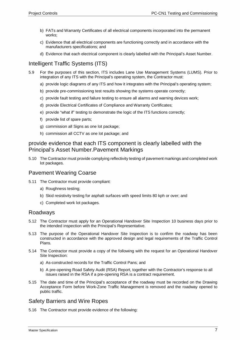
Project Controls PC-CN1 Testing and Commissioning
Master Specification 7
b) FATs and Warranty Certificates of all electrical components incorporated into the permanent works;
c) Evidence that all electrical components are functioning correctly and in accordance with the manufacturers specifications; and
d) Evidence that each electrical component is clearly labelled with the Principal’s Asset Number.
Intelligent Traffic Systems (ITS)
5.9 For the purposes of this section, ITS includes Lane Use Management Systems (LUMS). Prior to integration of any ITS with the Principal’s operating system, the Contractor must:
a) provide logic diagrams of any ITS and how it integrates with the Principal’s operating system;
b) provide pre-commissioning test results showing the systems operate correctly;
c) provide fault testing and failure testing to ensure all alarms and warning devices work;
d) provide Electrical Certificates of Compliance and Warranty Certificates;
e) provide “what if” testing to demonstrate the logic of the ITS functions correctly;
f) provide list of spare parts;
g) commission all Signs as one lot package;
h) commission all CCTV as one lot package; and
provide evidence that each ITS component is clearly labelled with the Principal’s Asset Number.Pavement Markings
5.10 The Contractor must provide complying reflectivity testing of pavement markings and completed work lot packages.
Pavement Wearing Coarse
5.11 The Contractor must provide compliant:
a) Roughness testing;
b) Skid resistivity testing for asphalt surfaces with speed limits 80 kph or over; and
c) Completed work lot packages.
Roadways
5.12 The Contractor must apply for an Operational Handover Site Inspection 10 business days prior to the intended inspection with the Principal’s Representative.
5.13 The purpose of the Operational Handover Site Inspection is to confirm the roadway has been constructed in accordance with the approved design and legal requirements of the Traffic Control Plans.
5.14 The Contractor must provide a copy of the following with the request for an Operational Handover Site Inspection:
a) As-constructed records for the Traffic Control Pans; and
b) A pre-opening Road Safety Audit (RSA) Report, together with the Contractor’s response to all issues raised in the RSA if a pre-opening RSA is a contract requirement.
5.15 The date and time of the Principal’s acceptance of the roadway must be recorded on the Drawing Acceptance Form before Work-Zone Traffic Management is removed and the roadway opened to public traffic.
Safety Barriers and Wire Ropes
5.16 The Contractor must provide evidence of the following:
Project Controls PC-CN1 Testing and Commissioning
Master Specification 8
a) Correct set-out and adjustments required to the design to ensure the permanent works operate correctly and in accordance with the manufacturer’s specification (e.g. clear distances behind barriers and ropes, minimum off-set from roadway, deflection of end terminals etc.);
b) Test results for tensioning;
c) Warranty Certificates;
d) Maintenance intervals; and
e) Testing and re-tensioning required for safe maintenance.
Safety Cameras
5.17 The Contractor must provide evidence of complying:
a) Wiring diagrams;
b) FAT results;
c) Warranty Certificates;
d) Electrical Certificates of Compliance;
e) SA Police Witness Testing;
f) Loop test results; and
g) Licensed survey of the position of the loops.
Static Signage
5.18 The Contractor must provide evidence of complying:
a) Reflectivity test results;
b) Positioning in accordance with the approved Traffic Control Layout;
c) Off-sets from the roadway;
d) Vertical height (both minimum off-set from NSL and maximum height); and
e) Height clearances in pedestrian areas.
Traffic Signals
5.19 The Contractor must provide:
a) Wiring diagram;
b) Warranty Certificates;
c) Electrical Certificates of Compliance;
d) Traffic Controller test results; and
e) Loop test results.
Tunnels
5.20 The Contractor must inspect, test and commission any tunnels in accordance with Austroads Publication No. AGRT02-15 Guide to Road Tunnels Part 2: Planning, Design and Commissioning.
5.21 Utility Services (Gas, Power, Sewer, Telecommunications, Water)
5.22 The Contractor must provide evidence of the asset owner’s acceptance of any modifications or impacts of the permanent works on any utility services.
Variable Message Signs (VMS)
5.23 The Contractor must provide complying FAT results, list of spare parts, Electrical Certificates of Compliance and Warranty Certificates. Each sign must be operational and accepted by the Traffic

Project Controls PC-CN1 Testing and Commissioning
Master Specification 9
Management Centre for the Principal to accept the works as completed and commissioned. The Contractor must commission all signs as one lot package.
Variable Speed Limit Signs (VSLS)
5.24 The Contractor must provide complying FAT results, list of spare parts, Electrical Certificates of Compliance and Warranty Certificates. Each sign must be operational and accepted by the Traffic Management Centre for the Principal to accept the works as completed and commissioned. The Contractor must commission all signs as one lot package.
Weather Stations
5.25 The Contractor must provide complying FAT results, list of spare parts, Electrical Certificates of Compliance and Warranty Certificates. Each weather station must be operational and accepted by the Traffic Management Centre for the Principal to accept the works as completed and commissioned. The Contractor must commission all weather stations as one lot package.
6 Commissioning Reports and Records
6.1 The Contractor must provide the following commissioning reports and records no later than 7 working days after the applicable commissioning activity.
6.2 All reports and manuals must be in the Department’s template MSWord format, convertible to Adobe, and be bookmarked electronically for easy navigation and referencing. They must have a formatted style guide and linked table of contents. The Contractor can obtain the Department’s current template from the Principal’s Representative.
6.3 The Contractor may add its company logo to the front page of the report or manual provided it is of high resolution quality and of a size no larger than the Department’s logo.
6.4 Approval of all commissioning reports and records by the Principal constitutes a Hold Point.
Commissioning Report
6.5 The Commissioning Report must include a table of contents, appendices with registers for all relevant ITPs, test results, NCRs, and commissioning certificates.
6.6 Completed ITPs and work lot packages must be included in the commissioning report.
6.7 All compliant test results for commissioning activities must be incorporated into the completed ITP and work lot package. Noncompliant test results must have an NCR raised and closed out and be included in the commissioning report.
6.8 Each commissioned item must have a Commissioning Certificate approved by the Principal’s Representative. These are to be included in the commissioning report.
Final Training Manuals and Records of Training
6.9 The Contractor must incorporate all of the Principal’s comments and amendments into the final Training Manual. Any issues that arise during the training, testing and commissioning activities must be addressed and incorporated in the final Training Manual.
Final Operation and Maintenance Manual
6.10 The Contractor must incorporate all of the Principal’s comments and amendments into the final Operations and Maintenance Manual. Any issues that arise during the training, testing and commissioning activities must be addressed and incorporated in the final Training Manual.
Road Safety Audit
6.11 If the Contract requires a post implementation Road Safety Audit (RSA), the Contractor must provide a copy of the report, together with the Contractor’s response and close-out details of each issue raised in the RSA.

Project Controls PC-CN1 Testing and Commissioning
Master Specification 10
7 Decommissioning
7.1 The Contractor must take into account any decommissioning and disposal of any items or systems in its Commissioning and Testing Plan. Disused materials should be recycled or re-used wherever possible.
7.2 The Contractor must identify and list each item or system which needs to be decommissioned and disposed in its Commissioning and Testing Plan.
7.3 The Contractor must develop, implement, maintain and comply with the plan for safe shut down or dismantling of the system.
7.4 The Contractor must dispose of all redundant material, items and systems during the commissioning to avoid any infringement, confusion or distraction to road users, operators or maintainers.
8 Commissioning Handover
8.1 At the time of commissioning hand over, all documentation related to tests carried during inspection, testing and commissioning must have been provided progressively by the Contractor to the Principal’s Representative and must have been accepted by the Principal.
8.2
8.3 Commissioning handover takes place when the Principal’s Representative has recommended to the Principal and the Principal has accepted that all the relevant tests of the inspection, testing and commissioning including trial or test run has been successfully completed.
8.4 Work-Zone Traffic Management aftercare signage must not be removed until commissioning handover takes place.
8.5 Refer to Master Specification PC-CN2 “Asset Handover” for further details on Asset Handover.
9 Hold Points
9.1 The following is a summary of Hold Points referenced in this Part:
Document Ref. Hold Point Response Time
3.8 Approval of the Commissioning and Testing Management Plan
30 working days
5.3 Request for an inspection of bridge structures including provision of pre-commissioning records
10 working days
6.4 Approval of all commissioning reports and records
Project Controls
Master Specification
PC-CN2 Asset Handover Document Information K Net Number: 13738110
Document Version: 2
Document Date: 19/09/2019

Project Controls Contents
Master Specification 2
Document Amendment Record
Version Change Description Date Endorsement record (KNet ref.)
1 Initial issue (formerly CH80) 27/06/19
2 Minor format and Hold Point changes 19/09/19
Document Management This document is the Property of the Department for Infrastructure and Transport and contains information that is confidential to the Department. It must not be copied or reproduced in any way without the written consent of the Department. This is a controlled document and it will be updated and reissued as approved changes are made.

Project Controls Contents
Master Specification 3
Contents Contents 2 PC-CN2 Asset Handover 4
1 General 4 2 Asset Management Planning 4 3 Pre-requisites to Asset Handover 4 4 Asset Handover 5 5 Hold Points 5

Project Controls PC-CN2 Asset Handover
Master Specification 4
PC-CN2 Asset Handover
1 General
1.1 The Contractor must handover all assets the Works in accordance with this Part.
1.2 The following documents are applicable to this Part:
a) ISO 55001 Asset Management – Management System Requirements.
b) RAMA-AM-PRC-003 Road & Marine Assets Technical Data Requirements for Projects (KNet#10925806).
c) RAMA-AM-APP-001 Asset Handover Report (KNet#10908454).
d) RAMA-AM-PRC-005 Road & Marine Assets – Asset Data Collection Manual (KNet#10918839).
e) Master Specification Part PC-CN1 “Testing and Commissioning”.
1.3 The asset handover shall occur after Testing and Commissioning and before Final Completion.
2 Asset Management Planning
2.1 The Contractor must develop an asset handover strategy and plan for asset handover at the beginning of the Contract.
2.2 A Preliminary Asset Completion and Handover Plan must be delivered prior to the start of design.
2.3 The Final Asset Completion and Handover Plan must be delivered and approved by the Principal’s Representative prior to construction commencing. Approval constitutes a Hold Point.
3 Pre-requisites to Asset Handover
3.1 The Contractor must submit the following documentation to the Principal for approval 20 working days prior to Asset Handover.
3.2 All reports and manuals must be in the Department’s template MSWord format, convertible to Adobe, and be bookmarked electronically for easy navigation and referencing. They must have a formatted style guide and linked table of contents. The Contractor can obtain the Department’s current template from the Principal’s Representative.
3.3 The Contractor may add its company logo to the front page of the report or manual provided it is of high resolution quality and of a size no larger than the Department’s logo.
3.4 The Contractor must submit a set of final approved As-Construction records.
3.5 If the Contract includes a design component, the Contractor must:
a) update the Issued For Construction Management Plans and back-draft the red pen “As-constructed” mark-ups into the Department’s format suitable for lodging into the Department’s Plan Room; and
b) provide certification from the designer that the design intent has been achieved in the final constructed works.
3.6 The Commissioning Report must be prepared in accordance with PC-CN1 “Testing and Commissioning”.
3.7 “”Final Training Manual and Records of Training must be in accordance with PC-CN1 “Testing and Commissioning”.
3.8 “”Final Operations and Maintenance Manual must be in accordance with PC-CN1 “Testing and Commissioning”.

Project Controls PC-CN2 Asset Handover
Master Specification 5
3.9 “”The Contractor must prepare an Asset Handover report in the format of RAMA-AM-APP-001 Asset Handover Report (KNet#10908454) and in accordance with RAMA-AM-PRC-005 Road & Marine Assets – Asset Data Collection Manual (KNet#10918839).
4 Asset Handover
4.1 The Contractor must provide an Asset Handover Certificate for approval by the Principal once all pre-requisites to Asset Handover have been approved by the Principal. This constitutes a Hold Point.
4.2 The final Asset Handover Certificate must be signed by the Principal and included in the Final Asset Handover Report to achieve Asset Handover.
4.3 At the time of Asset Handover, the Contract must provide to the Principal:
a) any keys and access cards;
b) spare parts and warranties;
c) software and electronic project files (e.g. Aconex);
d) Third Party Access arrangement and agreements;
e) Residual Risk and Hazard Register; and
f) final defects register demonstrating all defects have been rectified.
4.4 The final Bank Guarantee will not be released until Asset Handover occurs.
5 Hold Points
5.1 The following is a summary of Hold Points referenced in this Part:
Document Ref. Hold Point Response Time
2.2 Approval of the Final Asset Completion and Handover Plan 10 days
4.1 Provision of an Asset Handover Certificate

Project Controls
Master Specification
PC-ENV1 Environmental Management Document Information K Net Number: 13561970
Document Version: 2
Document Date: 19/09/2019

Project Controls Contents
Master Specification 2
Document Amendment Record Version Change Description Date Endorsement
record (KNet ref.)
1 Initial issue (formerly Part G50 and G51 Environmental Management and Environmental Management Systems) and amended.
01/03/19
2 Formatting for publishing. 19/09/19
Document Management This document is the Property of the Department for Infrastructure and Transport and contains information that is confidential to the Department. It must not be copied or reproduced in any way without the written consent of the Department. This is a controlled document and it will be updated and reissued as approved changes are made.

Project Controls Contents
Master Specification 3
Contents Contents 2 PC-ENV1 Environmental Management 4
1 General 4 2 Contractor’s Environmental Obligations 4 3 Environmental Authorisations 5 4 Environmental Objectives 5 5 Contractor’s Environmental Management System 6 6 Contractor’s Environmental Management Plan 6 7 Contractor’s Personnel 7 8 Training and Induction 7 9 Inspections, Auditing and Reporting 7 10 Environmental Incidents and marine spills 9 11 Hold Points 10

Project Controls PC-ENV1 Environmental Management
Master Specification 4
PC-ENV1 Environmental Management
1 General
1.1 This Part specifies the requirements for the Contractor’s Environmental Management and Environmental Management Systems (EMS) Requirements.
1.2 The work shall be undertaken in accordance with all applicable environmental legislation, including but not limited to:
a) Aboriginal Heritage Act 1988.
b) Development Act 1993.
c) Environment Protection Act 1993.
d) Environment Protection and Biodiversity Conservation Act 1999 (Commonwealth).
e) Heritage Places Act 1993.
f) Native Title (South Australia) Act 1994.
g) Native Vegetation Act 1991.
h) Natural Resources Management Act 2004.
1.3 DPTI environmental publications are available from: https://www.dpti.sa.gov.au/standards/environment.
1.4 The Contractor, except to the extent prohibited by law, indemnifies the Principal against any loss that the Principal suffers or incurs arising out of a failure by the Contractor to comply with any of its environmental obligations under this Contract.
1.5 If any damage to the environment occurs as a result of non-compliance with the requirements of this Contract, the Contractor shall, at its own expense, reinstate or rectify the damaged or impacted area to the condition existing prior to the commencement of work or as otherwise directed by the Principal. This includes, but is not limited to damage to vegetation and contamination of soil or water. If the damage is not satisfactorily reinstated or rectified, the cost incurred by the Principal for the reinstatement or rectification of the damage (or the loss in value where the damage cannot be adequately reinstated or rectified) is a debt due from the Contractor to the Principal.
1.6 If the Contractor impacts vegetation without the required approvals (obtained prior to impact), the Contractor will be liable to pay the offset amount in accordance with the Native Vegetation Act 1991 for native vegetation, the Development Act 1993 for regulated and significant trees, or the DPTI Vegetation Removal Policy for amenity vegetation. The Contractor shall obtain any retrospective approvals as required.
2 Contractor’s Environmental Obligations
2.1 The Contractor’s works under this Contract shall meet or exceed all environmental requirements specified in this Contract.
2.2 Where the Contractor’s design and / or construction activities vary from that contemplated in the design and environmental documentation provided by the Principal, the Contractor:
a) shall undertake all additional environmental assessments to ensure compliance with legislation and the Contract, resulting from the Contractor’s design;
b) bears all risks associated with compliance with legislation and the Contract, associated with a varied design;
c) shall obtain any additional authorisations, approvals and licences necessary; and
d) shall update the Contractor’s Environmental Management Plan to address all environmental protection matters resultant from the varied design and / or construction activities.

Project Controls PC-ENV1 Environmental Management
Master Specification 5
2.3 The Contractor, except to the extent prohibited by law, indemnifies the Principal against any loss that the Principal suffers or incurs arising out of a failure by the Contractor to comply with any of its environmental obligations under this Contract.
2.4 If any damage to the environment occurs as a result of non-compliance with the requirements of this Contract, the Contractor shall, at its own expense, reinstate or rectify the damaged or impacted area to the condition existing prior to the commencement of work or as otherwise directed by the Principal. This includes, but is not limited to damage to vegetation and contamination of soil or water.
2.5 If the damage is not satisfactorily reinstated or rectified, the cost incurred by the Principal for the reinstatement or rectification of the damage (or the loss in value where the damage cannot be adequately reinstated or rectified) is a debt due from the Contractor to the Principal.
2.6 If the Contractor impacts vegetation without the required approvals (obtained prior to impact), the Contractor will be liable to pay the offset amount in accordance with the Native Vegetation Act 1991 for native vegetation, the Development Act 1993 for regulated and significant trees, or the DPTI Vegetation Removal Policy for amenity vegetation. The Contractor shall obtain any retrospective approvals as required.
3 Environmental Authorisations
3.1 “Environmental Authorisation” includes environmental and planning approvals, licences, permits or exemptions.
3.2 The Contractor shall:
a) obtain all Environmental Authorisations for works under the Contract required by law or as specified by the Principal, other than those already obtained by the Principal;
b) comply with the requirements of all Environmental Authorisations, including those obtained by the Principal;
c) identify any required amendment or variance to the environmental authorisations obtained by the Principal, and prepare all relevant documentation and resubmit an amended / varied application for the Environmental Authorisation, unless otherwise agreed with the Principal;
d) allow for and program the appropriate authority or statutory assessment and approval timeframes; and
e) document the Environmental Authorisations in the Contractor’s Environmental Management Plan (CEMP).
3.3 Provision of the DRAFT and amended / varied environmental authorisation documentation prior to submission shall constitute a Hold Point.
3.4 Provision of any Environmental Authorisations obtained by the Contractor shall constitute a Hold Point.
4 Environmental Objectives
4.1 Subject to the requirements outlined by the Principal, the Contractor’s planning, design and construction methodology shall be undertaken to maximise the achievement of the following environmental objectives.
4.2 Methods used to address the Environmental Objectives shall be documented in the appropriate Planning or Design Report(s) or the Contractor’s Environmental Management Plan (CEMP).
4.3 The following environmental objectives apply to the Works under this contract. The Sustainability Objectives provided in PC-ED-M4 (Sustainability in Design), also apply to this Contract.
a) avoid mobilisation of contaminants and where feasible or required by the Contract, remediate of contaminated land on the Site;
b) avoid acid sulphate soils where possible or mitigate impacts;

Project Controls PC-ENV1 Environmental Management
Master Specification 6
c) manage pollutants generated from the operation and maintenance of the infrastructure and incorporate Water Sensitive Urban Design (WSUD) / Water Sensitive Road Design (WSRD) elements;
d) prevent pollution of surface, ground and marine waters;
e) protect and avoid damage, disturbance and / or interface to Aboriginal archaeological / anthropological sites, objects or remains;
f) avoid where possible areas where native title has been determined not to be extinguished, unless otherwise authorised by the Native Title Act 1994.
g) protect and prevent disturbance of non-Aboriginal heritage sites;
h) minimise the destruction or disturbance of native vegetation and other high value vegetation (refer PC-ENV2 Environmental Protection Requirements);
i) protect and prevent disturbance of non-target vegetation;
j) eliminate and prevent the spread of declared and environmental weeds;
k) minimise the destruction or disturbance of fauna habitat and provide safe fauna passage and habitat connection, where feasible during construction and operation of the project (e.g. fish passage, koala ladders, etc.);
l) prevent the spread or eradicate pest plants or animals on and adjacent to the site;
m) protect noise sensitive receivers from transport and construction noise; and
n) implement the principles of the waste hierarchy and dispose of waste to an appropriately licensed waste and / or recycling facility.
5 Contractor’s Environmental Management System
5.1 The Contractor shall establish, implement and maintain an Environmental Management System (EMS) in accordance with the requirements of AS/NZS ISO 14001 for the duration of this Contract. The Contractor’s EMS shall make provision for the work of subcontractors.
5.2 No part of the Contractor’s EMS shall be used to pre-empt, preclude or otherwise negate the technical requirements of the Contract.
5.3 Prior to commencement of any work on Site, the Contractor shall submit evidence of a certificate certifying the Contractor’s accreditation to AS/NZS ISO 14001 during the duration of the Contract. The Certification shall be provided by an appropriately qualified accredited organisation. Provision of the EMS Certification shall constitute a Hold Point.
6 Contractor’s Environmental Management Plan
6.1 The Contractor shall establish, implement and maintain a Contractor’s Environmental Management Plan (CEMP), which addresses the management of the environmental issues for this Contract. The CEMP shall comply with the DPTI "Contractor’s Environmental Management Plan Guidelines", available from: https://www.dpti.sa.gov.au/standards/environment.
6.2 In addition to the CEMP content requirements listed in the above document, the CEMP shall also include:
a) Construction Work Method Statements (or similar) for activities identified as high risk or above (pre-treatment) in the environmental risk assessment;
b) details of the Contractor’s Activity Zone (refer PC-SM3 “Construction Activity Zone and Access Management”); and
c) issue-specific (sub) management plans, where required (refer PC-ENV2 “Environmental Protection Requirements”).
6.3 Prior to commencement of any work on Site, the Contractor shall submit an electronic controlled copy of the CEMP and associated sub-plans, including all supporting documentation.

Project Controls PC-ENV1 Environmental Management
Master Specification 7
6.4 Provision of the CEMP including any stand-alone Management Plans, and any proposed amendments to the CEMP, and supporting documentation, shall constitute a Hold Point.
6.5 At a minimum the Contractor shall review and update the CEMP and associated sub-plans, identifying amendments to the previous version, every six months during the Contract period.
7 Contractor’s Personnel
Environmental Management Representative
7.1 The Contractor shall provide an Environmental Management Representative (EMR) for the duration of the Contract who is directly responsible to the Contractor’s senior management and has responsibility for ensuring that the requirements of the EMS and the environmental requirements of the Contract are complied with.
7.2 At all times, the duties of the EMR in regard to ensuring compliance with the environmental requirements of this Contract shall take precedence over any other activity undertaken by the EMR.
7.3 The EMR shall:
a) possess a recognised tertiary environmental qualification and have at least 5 years of recent relevant experience to the position; be available to attend the Site at any time that work is in progress; and
b) be on Site whenever activities are in progress that are identified in the CEMP as being of high risk to the environment.
7.4 Where a Contamination Specialist is not required for the works, as specified by the Principal, the EMR shall possess relevant industry experience in contamination management and remediation.
8 Training and Induction
Environmental Awareness Training
8.1 Prior to any works commencing on Site, the Contractor shall ensure that at least two of its staff who will be based on Site have attended DPTI Environmental Awareness training or equivalent training within the last 5 years. The Contractor’s Site representative / supervisor shall have attended the training. Recognition of equivalent training requires approval from the Principal.
8.2 Information about the DPTI Environmental Awareness training is available from the following web site: https://www.dpti.sa.gov.au/contractor_documents/contractor_environmental_training_programs.
8.3 The Contractor shall provide copies of the training certificates to the Principal prior to works commencing on Site and upon request.
Induction
8.4 The Contractor shall ensure that the Contractor’s (and any subcontractor’s) personnel attend an environmental induction before they commence work on Site. The induction shall be delivered by the EMR and shall address all environmental issues that are relevant to the person’s activities on Site as identified in the CEMP.
8.5 The Contractor shall provide evidence of environmental induction content and induction attendance records to the Principal upon request.
9 Inspections, Auditing and Reporting
9.1 The Contractor shall monitor its environmental performance, and that of its subcontractors, for the duration of this Contract. Environmental performance shall be measured against the Contractor’s EMS and CEMP, and the requirements of this Contract.

Project Controls PC-ENV1 Environmental Management
Master Specification 8
9.2 Unless otherwise agreed with the Principal, non-conformance reports (NCR) shall be raised for non-compliance with the requirements of the Contract and the CEMP(s). NCR’s shall be submitted to the Principal.
Inspections
9.3 The Environmental Management Representative shall undertake environmental inspections of the works being carried out under the Contract, no less than weekly, to assess compliance with the environmental requirements of the Contract and the CEMP(s). The frequency of inspections shall be greater during activities or events that have potential to cause environmental harm throughout the Contract period.
9.4 The Contractor’s EMR shall inspect and maintain records / register of any temporary and permanent siltation and erosion control devices:
a) before, during and immediately after a rain event; and
b) once per week during dry weather.
9.5 The Contractor shall rectify any defects revealed during an inspection immediately unless otherwise agreed with the Principal.
9.6 The Weekly Environmental Inspection Report shall include for that period, as a minimum, a summary of:
a) environmental issues identified and the date they were initially identified;
b) environmental incidents;
c) non-conformances, corrective actions raised and associated timeframes;
d) monitoring results and summary report (noise, vibration, water quality, air quality) including any exceedances of related limits / criteria;
e) details of any Aboriginal heritage monitoring and reported outcomes undertaken by Aboriginal groups or representatives;
f) evidence of weekly inspections being undertaken; and
g) other relevant data.
9.7 Completed environmental inspection checklist shall be provided to the Principal upon request.
Audits
9.8 The Contractor shall ensure that environmental audits of all works underway are conducted at intervals of no less than 3 months and at the completion of work on Site. Additional audits shall be undertaken for activities or events that have potential to cause environmental harm throughout the Contract period.
9.9 Environmental audits shall be conducted in accordance with AS/NZS ISO 19011: Guidelines for Auditing Management Systems.
9.10 In addition to the Contractor’s own audit schedule, the Contractor shall allow external audits of the Contractor's environmental performance to be undertaken at any time. The Contractor shall make available relevant staff to be involved in the audit.
9.11 Where a non-conformance is detected during an audit, the Contractor shall take immediate action to rectify the non-conformance.
Vegetation Removal Register
9.12 Every three months, or as requested by the Principal, the Contractor shall provide to the Principal a register and plan of all vegetation (including individual areas of native vegetation and regulated / significant trees) that has been removed as a result of the Works.
9.13 The register and plan shall show all vegetation removed using the associated number in the vegetation survey(s) and approval documentation.

Project Controls PC-ENV1 Environmental Management
Master Specification 9
9.14 The register shall include a summary of vegetation impacted during the reporting period as well as cumulative impact since commencement of the Contract and any SEB payments made under the Native Vegetation Act 1993.
Monthly Environmental Performance Status Report
9.15 At the end of each calendar month, the Contractor shall submit a Monthly Environmental Performance Status Report to the Principal which as a minimum includes:
a) A register showing status of all environmental and heritage related Hold Points;
b) summary of all environmental inspections and audits, including an action list with timeframes for rectification of issues identified;
c) details of any non-conformances / environmental incidents and corrective actions taken;
d) current Vegetation Removal Register and measures taken to minimise impacts to remaining vegetation;
e) details of all resource use and waste transfers inclusive of soil disposal and all other waste streams controlled by the Contractor; and
f) summary of any environmental monitoring / investigations undertaken by the Contractor or other documentation submitted to the Principal. Raw data for monitoring activities shall be provided to the Principal upon request.
9.16 Where this Contract has additional requirements for monthly reporting to a Joint Leadership Team (JLT), or equivalent, the Monthly Environmental Performance Status Report can be incorporated into that document.
Quarterly Environmental Conformance Certificate
9.17 The EMR shall prepare a report at intervals not greater than 3 months and at Completion, which identifies that:
a) the Contractor’s EMS is in accordance with AS/NZS ISO 14001 and the requirements of the Contract;
b) the Subcontractor’s EMS, which forms a part of the Contractor’s Environmental Management System, was in accordance with AS/NZS ISO 14001 and the requirements of the Contract;
c) the Contractor has complied with and satisfied the requirements of the Contract and the CEMP with the exception of any non- conformance reports (NCRs) raised during the period (details of NCRs to be provided);
d) environmental incidents have been managed and rectified in accordance the requirements of the Contract and relevant legislation; and
e) documentation was recorded and submitted to the Principal in accordance with the Specification.
9.18 The report shall be forwarded to the Principal and signed by the EMR and Project Manager / Director.
10 Environmental Incidents and marine spills
10.1 The Contractor shall develop and maintain an Environmental Emergency Response Plan / Procedure which is based on an environment-related risk assessment of all Site activities. It may form part of the Project’s Emergency Response Plan.
10.2 The plan shall ensure that all Personnel are able to identify and respond to environmental emergencies or incidents and ensure that relevant authorities are notified.
10.3 Environment incidents / accidents are those which:
a) lead to a warning, notice or order being issued by the EPA;
b) contravene applicable environmental legislation and / or an Environmental Authorisation (including the Principal’s internal approvals process);

Project Controls PC-ENV1 Environmental Management
Master Specification 10
c) cause environmental harm or nuisance (as defined by the Environment Protection Act 1993 or other applicable legislation); and / or
d) result in the spillage / release of noxious or hazardous substances (such as but not limited to hydrocarbons or any other machinery fluids) into sea or watercourses.
10.4 In the event of an environmental incident or accident, the Contractor shall:
a) take whatever remedial action is necessary as soon as practicable;
b) immediately notify the Principal and the EPA if the spill could cause serious and material environmental harm or other relevant authority;
c) provide an initial written notification report to the Principal within 24 hours of the incident occurring; and
d) provide a full written investigation report within 72 hours of the incident occurring.
10.5 In the event of a chemical spill in the marine environment, the Contractor shall:
a) Dial 000 if there is a fire or injury requiring medical attention or if the size of the spill or nature of the spilled material makes it readily apparent that the situation is dangerous;
b) Control access to the spill area and, if possible without risking injury, control the source of the spill and limit the spread of contamination;
c) Not apply dispersant / detergent or other substance - the spill should just be contained and ensure the safety of those on site and in the vicinity;
d) Report the spillage (no matter how small) to the Outer Harbour Signal Station on (08) 8248 3505 - who will contact the on-duty DPTI Incident Controller;
e) Comply with the direction of the DPTI Incident Controller;
f) Inform the Signal Station and the Principal of the circumstance, type and volume of the contamination as soon as possible after the occurrence along with contact details; and
g) Bear any cost to the Principal in cleaning up the spillage or clean up the spillage to the satisfaction of the DPTI Incident Controller.
11 Hold Points
11.1 The following is a summary of Hold Points referenced in this Part:
Document Ref. Hold Point Response Time
3.3 Amended / varied environmental authorisation documentation prior to submission
5 days
3.4 Environmental Authorisations obtained by the Contractor 5 days
5.3 Contractor’s Environmental Management System Certification 3 days
6.2 Contractor’s Environmental Management Plan / sub-plans or any proposed amendments, and supporting documentation
10 days
Project Controls
Master Specification
PC-ENV2 Environmental Protection Requirements Document Information
KNet Number: 13562691 Document Version: 3 Document Date: August 2020

Project Controls Contents
Master Specification 2
Document Amendment Record Version Change Description Date
1 Initial issue (formerly Part CH50 Environmental Protection Requirements) and amended.
01/03/19
2 Formatting for publishing 19/09/19
3 Amendments to Clause 8 (Noise and Vibration) and 13 (Non-Aboriginal heritage)
August 2020
Document Management This document is the Property of the Department for Infrastructure and Transport and contains information that is confidential to the Department. It must not be copied or reproduced in any way without the written consent of the Department. This is a controlled document and it will be updated and reissued as approved changes are made.
Project Controls Contents
Master Specification 3
Contents Contents 3
PC-ENV2 Environmental Protection Requirements 4
1 General 4
2 Construction Methods and Temporary Works 4
3 Vegetation Impacts and Protection 5
4 Fauna Protection 7
5 Weed, Pest and Disease Control 7
6 Protecting Waterways 8
7 Sand Management – Marine Environments 9
8 Construction Noise and Vibration Management 9
9 Air Quality Protection 10
10 Materials, Fuels and Waste Management 11
11 Contamination Management 11
12 Aboriginal Heritage 12
13 Non-Aboriginal Heritage 12
14 Environmental Handover Documentation 12
15 Hold Points 12

Project Controls PC-ENV2 Environmental Protection Requirements
Master Specification 4
PC-ENV2 Environmental Protection Requirements
1 General
1.1 This part specifies the minimum environmental protection requirements that the Contractor shall comply with. The requirements specified in this part apply unless stated otherwise by the Principal. It shall apply in conjunction with PC-ENV1 “Environmental Management”.
1.2 Where appropriate to the work being undertaken, the Contractor shall comply with the following:
a) any applicable environmental legislation;
b) SA Environment Protection Authority (EPA) standards and guidelines;
c) Department Protecting Waterways Manual;
d) Department Water Quality Monitoring Manual for Construction;
e) Department Environmental Code of Practice for Construction, Road, Rail and Marine Facilities;
f) Department Vegetation Removal Policy;
g) Department Environmental Instruction 21.7: Management of Noise and Vibration: Construction and Maintenance Activities;
h) Department Cultural Heritage Guidelines;
i) AS 1940 “The storage and handling of flammable and combustible liquids”;
j) AS 4373 “Pruning of Amenity Trees”; and
k) AS 4970 “Protection of Trees on Development Sites”.
1.3 Department publications are available from: https://www.dpti.sa.gov.au/standards/environment.
2 Construction Methods and Temporary Works
General
2.1 The Contractor’s construction methodology, including all temporary works, must be planned and undertaken to avoid environmental nuisance and harm and to minimise direct and indirect impacts to wetlands, watercourses, fauna habitat, native and non-native vegetation, the local community and other important environmental areas to the greatest extent possible.
2.2 Any Environmental Authorisations required shall be obtained by the Contractor (refer PC-ENV1 “Environmental Management”).
2.3 The Contractor must rehabilitate / remediate all disturbed areas progressively throughout the duration of the Contract. This includes all areas used for construction activities, such as, but not limited to, compound sites, stockpile sites and access and haul roads to, as a minimum, their original condition (as previously recorded by the Contractor) at the time of entering into the Contract, unless specified otherwise by the Principal.
2.4 The design and establishment of temporary creek crossings must ensure no changes to environmental flows, water quality and velocity, and maintain fish and fauna passage;
2.5 The design of temporary works shall address the management of contaminated material, wherever possible considering alignment with the waste management hierarchy within the Green Industries SA Act, 2004.
Borrow Pits
2.6 The Contractor shall rehabilitate / remediate any new or existing borrow pits that were established or utilised during the project. At a minimum, the Contractor shall ensure:
a) implementation of any Development Approval conditions, where required;

Project Controls PC-ENV2 Environmental Protection Requirements
Master Specification 5
b) the batter faces are flattened to a slope of 6:1 (Horizontal:Vertical) to reduce erosion potential;
c) the over-burden with vegetation that was removed prior to beginning of quarrying operation is spread over the new floor;
d) the existing floor of the pit is scarified to improve soil permeability and water infiltration; and
e) diversion drains are constructed around the edge of the pit to minimise erosion caused by water flowing into the pit across exposed soil surfaces (batter slopes).
Stack Sites
2.7 If Works under the Contract includes the use of existing stack sites, the Contractor shall:
a) ensure that the stack sites are left in a neat and tidy state, with any remaining material supplied by the Contractor removed;
b) avoid contamination of the stack sites by bituminous products and clean up any accidental spills in accordance with EPA requirements (including notification of the EPA);
c) prevent leachate contamination of sites where pre-coated materials are used; and
d) ensure weed hygiene controls are in place during stack site use.
3 Vegetation Impacts and Protection
Vegetation Clearing and Pruning
3.1 The Contractor shall not remove, disturb or damage any vegetation, including aquatic vegetation, unless otherwise approved by the Principal.
3.2 The Contractor shall obtain all approvals required in accordance with the Department’s Vegetation Removal Policy and relevant legislation prior to commencing vegetation clearance / removal and pruning work.
3.3 To obtain Hold Point Release, the Contractor shall provide vegetation impacts documentation that demonstrates the following:
a) the vegetation requiring removal or pruning is justified and corresponds with the vegetation impacts indicated on the drawings;
b) the vegetation offset requirements in accordance with the Department’s Vegetation Removal Policy;
c) the Contractor has obtained all necessary approvals under legislation and the Contract; and
d) the Contractor has undertaken all necessary stakeholder engagement regarding the vegetation impacts.
3.4 Provision of vegetation impact documentation to the Principal prior to vegetation pruning and / or removal shall constitute a Hold Point.
3.5 The Contractor shall:
a) undertake all tree pruning and removal in accordance with PR-LS-C11 “Tree Pruning and Removal” and in accordance with AS 4373 “Pruning of Amenity Trees”;
b) not prune, remove or otherwise damage any vegetation beyond the Contractor’s Activity Zone (CAZ) (refer PC-SM2 “Site and Access Management”). Vegetation clearance beyond the CAZ is only allowed with prior approval of the Principal or where pruning is required to meet AS 4373, however it must be limited to the minimum amount practicable;
c) identify and relocate tree hollows in accordance with Clause 4.3;
d) liaise and obtain any authorisations or approvals from the relevant landowner (e.g. private owners, local Council, Government Agencies, etc), and other key stakeholders, and obtain any necessary authorisations, prior to vegetation removal, canopy pruning or works within the Tree Protection Zone (including root pruning); and

Project Controls PC-ENV2 Environmental Protection Requirements
Master Specification 6
e) dispose of excess vegetative material in accordance with PR-LS-C11 “Tree Pruning and Removal” and PR-MA-M1 “Herbicide and Wood Weed Control”.
3.6 All tree pruning and removal shall be undertaken by a suitably qualified arborist, unless the vegetation removal:
a) is limited to clearing and grubbing; and
b) is wholly undertaken by plant such as a bulldozer, front end loader or grader.
3.7 The Contractor shall allow for and program the appropriate statutory assessment and approval timeframes (e.g. State Commission Assessment Panel; Local Government; Native Vegetation Council).
3.8 The Contractor is responsible for offsetting the vegetation removal and pruning in accordance with the Department’s Vegetation Removal Policy.
Protection of Non-target Vegetation
3.9 “Non-target Vegetation” means vegetation that is not authorised or approved to be impacted.
3.10 The Contractor shall ensure that any non-target vegetation is not damaged as a result of construction activities.
3.11 The Contractor shall:
a) not damage roots within the Structural Root Zone (as defined in AS 4970) of any remaining tree;
b) not park or store vehicles, plant or equipment, or stockpile material within the Tree Protection Zone (TPZ, as defined in AS 4970), or on any remaining native or amenity vegetation;
c) minimise root damage within the TPZ and clean saw cut any roots exposed during works;
d) undertake works close to trees using non-destructive methods (e.g. hydro-vacuum) or by hand to avoid damage by equipment;
e) minimise the number of anchoring points (marine environments); and
f) ensure works are planned to avoid impacting High Value Vegetation unless otherwise authorised by legislation and / or the Principal.
3.12 The Contractor must determine the Tree Protection Zone (TPZ) for High Value vegetation in accordance with AS4970, and must comply with the tree protection measures set out in AS4970. The TPZ must be included on design / construction drawings including any notes required to protect the trees.
3.13 Non-destructive excavation techniques (e.g. hydro vacuum / under boring) must be undertaken within the tree protection zones of High Value vegetation, unless otherwise approved by the Principal. A suitably qualified arborist must oversee and recommend a construction methodology to protect ongoing tree health and stability for working within the TPZ of High Value vegetation. The Contractor must comply with the arborist’s recommendations.
3.14 Provision of the arborist’s recommendation report to the Principal shall constitute a Hold Point.
3.15 Methods for protecting Non-target Vegetation shall be included in the Contractor’s Environmental Management Plan (CEMP) (refer “PC-ENV1 “Environmental Management Requirements”).
High Value Vegetation
3.16 High Value Vegetation is considered to be:
a) vegetation covered under the Native Vegetation Act 1991;
b) Regulated / Significant Tree under the Development Act 1993 (including those that may be exempt from Development Approval);
c) Native and non-native vegetation located in and on the margins of waterways;
d) vegetation covered by any other environmental legislation;
e) vegetation that is located on third party land (i.e. land not owned by the Principal);

Project Controls PC-ENV2 Environmental Protection Requirements
Master Specification 7
f) any other vegetation that may be identified by the Principal or the community as providing localised amenity or ecological value; or
g) Rail and Roadside Significant Sites.
4 Fauna Protection
4.1 Approval documentation for fauna impacts must be provided to the Principal prior to those impacts occurring and shall constitute a Hold Point. This applies to authorisations under the Environment Protection and Biodiversity Conservation Act 1999.
4.2 The Contractor shall:
a) implement all reasonably practicable measures to minimise disturbance to fauna (including marine mammals and other marine fauna, where applicable) and prevent injury to fauna;
b) contact Fauna Rescue SA, the RSPCA or a veterinarian for advice if any injured fauna is found on the Site;
c) under the supervision of a suitably qualified specialist, relocate any native fauna to a similar habitat if that fauna’s habitat will be destroyed by the Contractor’s work;
d) provide fauna ladders and fish passage devices, to enable fauna to pass through or around the construction site as required;
e) instigate work practices which allow marine fauna that are sensitive to noise to depart without risk of harm; and
f) notify the Principal if any injured or dead native fauna is found on the Site.
4.3 The Contractor must:
a) relocate hollows that have been removed from a tree where material of between 400 mm and 1000 mm in length that contains hollows greater than 50 mm in diameter or hollow apertures greater than 40% of the trunk diameter is removed from a tree; and
b) place these hollows on the ground amongst existing vegetation in a location where they do not smother native vegetation or present a hazard to persons or property.
4.4 Methods for protecting fauna on the site shall be included in the Contractor’s Environmental Management Plan (CEMP) (refer “PC-ENV1 “Environmental Management Requirements”)
5 Weed, Pest and Disease Control
5.1 The Contractor shall:
a) ensure that declared animals, declared plants and environmental weeds (including seeds and other propagules) are not introduced to the site or spread as a result of any site activities. Effective hygiene practices must be used on all vehicles, plant and equipment. Environmental weed species are listed in the Department’s Weeds List available from: https://www.dpti.sa.gov.au/standards/environment;
b) consult, obtain the required authorisations and comply with the requirements of the Natural Resources Management Act 2004 (NRM Act) in regard to declared animals and plants, including control, transport and disposal (advice can be obtained from DEW (http://www.naturalresources.sa.gov.au) and Primary Industries and Regions SA (PIRSA) BiosecuritySA (https://www.pir.sa.gov.au/biosecurity);
c) undertake all weed control activities in accordance with PR-MA-M1 “Herbaceous and Woody Weed Control”;
d) maintain all declared pest plants and environmental weeds within the Contractor’s Activity Zone to a height or spread less than 300 mm;
e) notify the Principal in the event of any outbreak of declared animal, declared plant or environmental weed resulting from activities associated with this Contract;

Project Controls PC-ENV2 Environmental Protection Requirements
Master Specification 8
f) develop and implement a management plan to control the outbreak of declared and environmental weeds, up to the end of the Defects Liability Period, until the outbreak is eradicated or as agreed to by the Principal;
g) ensure that any dredged sand / material being deposited in a location where it could reasonably return to the water is free of declared pests and weeds; and
h) ensure that, where relevant, marine vessels and floating plant should be cleaned in accordance with the EPA Code of Practice for vessel and facility Management (marine and inland waters) to avoid depositing exotic aquatic plants.
5.2 Methods for controlling weeds, pests and disease on or from the site shall be included in the Contractor’s Environmental Management Plan (CEMP) (refer “PC-ENV1 “Environmental Management Requirements”).
Phytophthora Control
5.3 Phytophthora is a plant pathogen that can result in dieback of vegetation. The Contractor must plan and undertake its construction activities in accordance with the Department’s Phytophthora (Dieback) Control Environmental Instruction 21.3.
5.4 The Contractor must undertake a Phytophthora Risk Assessment to determine the required hygiene procedures and disposal requirements, and must implement those procedures during work.
6 Protecting Waterways
6.1 The Contractor shall ensure that any water entering the natural watercourse system, marine environment or stormwater drainage system from areas disturbed by the Contractor complies with the Environment Protection (Water Quality) Policy 2015.
6.2 When working in a waterway the Contractor shall:
a) not cause destabilisation of the bed and banks of the watercourse;
b) ensure all excavated material are be removed from the watercourse and placed and stabilised in in a location where it will not return to the watercourse;
c) shall compact loose material placed in and around the bed and banks of the watercourse to prevent downstream sedimentation; and
d) immediately after the completion of earthworks areas (including batters, drains, cut and fill areas), or if earthworks areas are to remain essentially the same for 2 days or more, install temporary measures to prevent erosion and / or control sediment.
6.3 The Contractor shall not:
a) pollute groundwater sources; or
b) extract or reinject groundwater unless appropriate Environmental Authorisations (including those under the Natural Resources Management Act 2004) have been obtained where required.
Soil Erosion and Drainage Management Plan
6.4 The Contractor is responsible for the design, construction, operation and maintenance of drainage and temporary erosion control measures.
6.5 The Contractor shall develop, implement and maintain a Soil Erosion and Drainage Management Plan (SEDMP). The SEDMP shall be developed in accordance with:
a) EPA Stormwater Pollution Prevention Code of Practice for Local, State and Federal Government; and
b) Department Protecting Waterways Manual.
6.6 The SEDMP shall include the following, as required:
a) objectives, targets, responsibilities, permits / licences, control measures, monitoring and environmental incident / emergency response;

Project Controls PC-ENV2 Environmental Protection Requirements
Master Specification 9
b) any management requirements from a Water Affecting Activities Permit or EPA licence;
c) details on how any stormwater and intercepted groundwater collected during the course of the construction activities will be managed and treated prior to release;
d) details on how stormwater systems and waterways will be protected to ensure that no untreated stormwater is able to leave the project site;
e) site plans (e.g. Site Environmental Plans / Project Control Plans) that identify types of sediment and erosion control measures and their locations for all stages of construction works; and
f) the Water Quality Monitoring Plan (in accordance with the Department’s Water Quality Monitoring Manual for Construction Sites).
6.7 The SEDMP shall be updated prior to any changes to construction processes that may impact upon erosion or sedimentation.
6.8 The SEDMP shall be a sub-plan the Contractor’s Environmental Management Plan (CEMP) (refer PC-ENV1 “Environmental Management”).
6.9 Provision of the SEDMP and Site Environmental Plans / Project Control Plans or any amendments to shall constitute a Hold Point.
Water Quality Monitoring
6.10 The Contractor shall:
a) determine the required level of water quality monitoring in accordance with the Department’s Water Quality Monitoring Manual for Construction Sites;
b) develop and implement a Water Quality Monitoring Program (WQMP) to the level determined by the assessment in 6.10(a). The monitoring regime and frequency shall be designed to verify that site activities have not caused serious or environmental harm;
c) include the WQMP into the SEDMP;
d) undertake the required level of monitoring until Completion or as specified by the Principal;
e) provide results of water quality monitoring to the Principal upon request..
7 Sand Management – Marine Environments
7.1 The following applies where the works involve movement of sand in the marine environment.
7.2 The Contractor shall ensure the sand is free of litter, debris and weeds of any kind generated by the Works.
7.3 All vehicles shall give way to all pedestrian traffic on the beach and at shared use pathways. Appropriate signage indicating heavy machinery in use and the speed of vehicles on the beach shall not exceed 25 km/h.
7.4 Access points to the beach shall remain clear of any deposited sand stockpiles so as to allow vehicle and pedestrian access at all times.
7.5 The Contractor shall advise the Local Council when the sand movement will be undertaken.
8 Construction Noise and Vibration Management
8.1 The Contractor shall manage noise and vibration in accordance with the Department’s Environmental Instruction 21.7 Management of Noise and Vibration: Construction and Maintenance Activities.
8.2 The Contractor has liability for and shall bear all costs associated with any damage caused to existing structures, buildings and services as a result of any construction/ maintenance activity. This extends to responding to any claims of vibration induced damage, reinstatement or rectification of the damaged or impacted structures, buildings and services to the condition existing prior to the commencement of work or as otherwise directed by the Principal.

Project Controls PC-ENV2 Environmental Protection Requirements
Master Specification 10
8.3 The Contractor shall assess and implement methods to monitor and manage the risk of vibration-induced damage, and identify any required, pre and post condition surveys to be undertaken.
Construction Noise and Vibration Management Plan
8.4 The Contractor shall prepare and implement a Construction Noise and Vibration Management Plan in accordance with the Department’s Environmental Instruction 21.7 Management of Noise and Vibration: Construction and Maintenance Activities.
8.5 The CNVMP shall be a sub-plan the Contractor’s Environmental Management Plan (CEMP) (refer PC-ENV1 “Environmental Management Requirements”).
8.6 Submission of a CNVMP to the Principal shall constitute a Hold Point.
Night Works Management Plan
8.7 The Contractor shall prepare and implement Night Works Management Plans (NWMPs), where required in accordance with Environmental Instruction 21.7. NWMPs may be prepared as:
a) an All of Project NWMP, included as a sub-plan the Contractor’s Environmental Management Plan (CEMP) (refer “PC-ENV1 “Environmental Management Requirements”), that adequately covers all construction activities (including noise contour plans) and mitigation throughout the course of the Contract; or
b) NWMP for each individual works activities.
8.8 Submission of an All of Project NWMP or individual NWMP shall constitute a Hold Point.
Works in marine environments
8.9 Where piling or other activities potentially disturbing to marine mammals are to be undertaken, the Contractor shall prepare and implement an Underwater Noise and Vibration Management Plan in accordance with the Department’s Underwater Piling Noise Guideline.
8.10 Submission of an Underwater Noise and Vibration Noise Management Plan shall constitute a Hold Point.
9 Air Quality Protection
9.1 The Contractor shall suppress nuisance dust from any construction activities including access tracks, haul roads and stockpile sites and ensure that effective dust control measures are in place.
9.2 The Contractor shall:
a) cease any activity where that activity creates a dust hazard of nuisance to the public, personnel working on the Site or properties in the vicinity of the Works;
b) where dust is likely to be raised, ensure that appropriate dust control measures are planned and implemented including ensuring that an adequate number of water carts are on-site at all times during the Contract and that they are used appropriately (separate payment will not be made for the use of the water cart); and
c) not permit the emission of odorous substances or particulates, which create or are likely to create objectionable conditions for the public.
9.3 If specified by the Principal, the Contractor shall prepare and implement an Air Quality Management Plan that includes a dust monitoring regime to enable verification that applicable air quality criteria has not been exceeded and air quality conditions have not caused an environmental nuisance.
9.4 Air quality protection and monitoring measures shall be included in the Contractor’s Environmental Management Plan (CEMP) (refer PC-ENV1 “Environmental Management”).

Project Controls PC-ENV2 Environmental Protection Requirements
Master Specification 11
10 Materials, Fuels and Waste Management
10.1 Environmental management requirements identified in this Clause shall be included in the Contractor’s Environmental Management Plan (CEMP).
Construction Water
10.2 The water source(s) to be used for construction purposes (including dust control) shall be identified in the CEMP.
10.3 The Contractor shall comply with any permanent water conservation measures and current SA Water restrictions applicable to the Site.
Storage and Handling of Hydrocarbons and Hazardous Liquids
10.4 The Contractor shall ensure that any fuel, oil, lubricants and other chemicals stored on site:
a) are stored in accordance with the relevant Australian Standards;
b) are stored within a bund with an impervious floor; and
c) are not stored in an area which is subject to flooding or is within 20 metres of a natural or built drainage line.
10.5 The Contractor shall ensure that:
a) fuel, oil or lubricants do not leak from machinery;
b) appropriate methods during refuelling and maintenance are implemented to ensure that any spills / leaks are contained (including refuelling activities being attended at all times);
c) when operating in the marine environment, refuelling shall be undertaken in accordance with the EPA Code of Practice for Vessel and Facility Management (Marine and Inland Waters)
d) hydrocarbon spill kit(s) for the purpose of cleaning up oil and fuel spillage is accessible at all times and personnel trained in the efficient deployment of the spill kit are readily available in the event of a spill;
e) appropriately trained personnel shall be present and supervise refuelling activities by at all times;
f) maintenance of vehicles and machinery is carried out off-site where practicable. If maintenance is to occur on-site, the location and procedure shall be documented in the CEMP.
10.6 In the event of a spill to the terrestrial and marine environments the Contractor shall implement its Emergency Response Plan and Incident Control Systems (refer PC-ENV1 “Environmental Management”).
Waste Management
10.7 The Contractor shall implement the principles of the waste hierarchy and if required dispose of waste to an appropriately licensed waste and / or recycling facility.
10.8 Except for any material to be mulched, all waste material resulting from the work under the Contract is the property of the Contractor and shall be removed from the site within 7 days or placed in a container with fitted lids for disposal at a later date but prior to Completion.
10.9 On completion of the work on Site, all rubbish and waste shall be removed and the Site shall be left in a clean and tidy condition.
11 Contamination Management
11.1 All site contamination considerations and assessment are to be undertaken in accordance with PC-SC1 “Site Contamination”.

Project Controls PC-ENV2 Environmental Protection Requirements
Master Specification 12
12 Aboriginal Heritage
12.1 All Aboriginal Heritage assessments and management are to be undertaken in accordance with PC-H1 “Aboriginal Heritage and Native Title”.
12.2 The Contractor shall document in the Contractor’s Environmental Management Plan (refer “PC-ENV1 “Environmental Management”) or as sub-plan (e.g. Cultural Heritage Management Plan) any actions required to manage heritage and associated risks.
13 Non-Aboriginal Heritage
13.1 All Non-Aboriginal Heritage assessments and management are to be undertaken in accordance with PC-H2 “Non-Aboriginal Heritage”.
13.2 The Contractor shall document in the Contractor’s Environmental Management Plan (refer “PC-ENV1 “Environmental Management”) or as sub-plan (e.g. Conservation Plan) any actions required to manage heritage and associated risks.
14 Environmental Handover Documentation
14.1 At completion of the project, or as requested by the Principal, the Contractor shall handover any reports, monitoring data, models and raw data, spatial information and details of any ongoing management measures and / or Environmental Authorisation(s) conditions relevant to the ongoing operation and maintenance of the infrastructure.
15 Hold Points
15.1 The following is a summary of Hold Points referenced in this Part:
Table PC-ENV2 15-1 Hold Points
Document Ref. Hold Point Response Time
3.4 Provision of vegetation impact documentation 10 Working Days 3.14 Arborist’s recommendation report 10 Working Days 4.1 Approval documentation for fauna impacts 10 Working Days 6.9 Provision of the SEDMP and Site Environmental Plans / Project
Control Plans 10 Working Days
8.6 Submission of a Construction Noise and Vibration Management Plan
10 Working Days
8.8 Submission of an All of Project Night Works Management Plan or individual Night Works Management Plan
10 Working Days
8.10 Submission of an Underwater Noise and Vibration Noise Management Plan
10 Working Days

Project Controls
Master Specification
PC-US1 Utility Services Document Information
KNet Number: 13523906 Document Version: 3 Document Date: August 2020

Project Controls Contents
Master Specification 2
Document Amendment Record Version Change Description Date
1 Initial Issue (formerly CH40) 01/03/19 2 Minor formatting changes 19/09/19
3 Include reference to PC-SC1 regarding management of waste spoil as well as reference to new Hazmat Part PC-SI6
August 2020
Document Management This document is the Property of the Department for Infrastructure and Transport and contains information that is confidential to the Department. It must not be copied or reproduced in any way without the written consent of the Department. This is a controlled document and it will be updated and reissued as approved changes are made.

Project Controls Contents
Master Specification 3
Contents Contents 3
PC-US1 Utility Services 4
1 General 4
2 General Design Requirements 5
3 Authority Specific Design Requirements 8
4 Existing Utility Services 9
5 Utility Adjustments – Works by the Principal 11
6 Utility Adjustments – Works by the Contractor 11
7 Authority Specific Construction Requirements 15
8 Completion and Handover 21
9 Hold Points 21
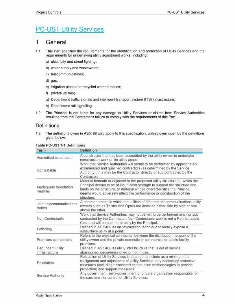
Project Controls PC-US1 Utility Services
Master Specification 4
PC-US1 Utility Services
1 General
1.1 This Part specifies the requirements for the identification and protection of Utility Services and the requirements for undertaking utility adjustment works, including:
a) electricity and street lighting;
b) water supply and wastewater;
c) telecommunications;
d) gas;
e) irrigation pipes and recycled water supplies;
f) private utilities;
g) Department traffic signals and intelligent transport system (ITS) infrastructure;
h) Department rail signalling.
1.2 The Principal is not liable for any damage to Utility Services or claims from Service Authorities resulting from the Contractor's failure to comply with the requirements of this Part.
Definitions
1.3 The definitions given in AS5488 also apply to this specification, unless overridden by the definitions given below.
Table PC-US1 1-1 Definitions
Term Definition
Accredited constructor A constructor that has been accredited by the utility owner to undertake construction work on its utility asset.
Contestable
Work that Service Authorities will permit to be performed by appropriately experienced and qualified contractors (as determined by the Service Authority); this may be the Contractor directly or sub contracted by the Contractor.
Inadequate foundation material
Material beneath or adjacent to the proposed utility structure(s), which the Principal deems to be of insufficient strength to support the structure and loads on the structure, or material whose characteristics the Principal deems would adversely affect the performance or construction of the structure.
Joint telecommunications trench
A common trench in which the utilities of different telecommunications utility owners such as Telstra and Optus are installed either side by side or one above the other.
Non Contestable Work that Service Authorities may not permit to be performed and / or sub contracted by the Contractor. Non Contestable work is not a Reimbursable Cost and will be paid for directly by the Principal.
Potholing Defined in AS 5488 as an “excavation technique to locally expose a subsurface utility at a point”.
Premises connections Refers to the physical connection between the distribution network of the utility owner and the private domestic or commercial or public facility premises.
Redundant utility infrastructure
Defined in AS 5488 as utility infrastructure that is out of service, abandoned, decommissioned or not in use.
Relocation
Relocation of Utility Services is deemed to include as a minimum the realignment and adjustment of Utility Services, any necessary protective measures (including associated construction methodologies to provide protection) and support measures.
Service Authority Any government, semi-government or private organisation responsible for the care and / or control of Utility Services.

Project Controls PC-US1 Utility Services
Master Specification 5
Term Definition
Shared trench Defined as a trench in which normally unrelated utilities such as gas and telecommunications, or electricity and telecommunications, are installed either side by side or one above the other.
Utility adjustment works
Includes both protection modification and / or relocation of existing utility infrastructure, and installation of new utility infrastructure. Existing utility infrastructure can be either above ground or underground. It also includes works for protection of existing utility infrastructure.
Utility owner Includes both the owner and operator of the assets associated with the utility service.
Utility Service
Defined in AS 5488 as “a publicly, privately or jointly owned and operated entity, located on either public or private property, the purpose of which is to transport for either the public or a private party a service or commodity such as electricity, communications, gas, light, oil, power, television, water and waste by means of cables, conduits, ducts, fibre optics, pipes and wires and includes related objects, such as access chambers, pits, valves and other appurtenances”.
1.4 Service Authorities responsible for Utility Services relating to the Works include:
a) APA Group – Envestra’s (gas) transmission and distribution infrastructure;
b) SA Power Networks – overhead and underground electrical distribution infrastructure including 66kV, 11kV and LV, plus their own telecommunications network;
c) SA Water – distribution water and sewer (gravity and pumping) infrastructure;
d) Telstra – distribution and local copper, fibre network; and
e) Telecommunications (Other) – SABRENet, Vocus (previously Amcom), Optus, Primus, Nextgen, NBN Co, iiNet, TPG and Others who manage fibre telecommunications networks.
2 General Design Requirements
General
2.1 The Contractor shall undertake all design works associated with relocation or protection of Service Authorities’ infrastructure, in accordance with the requirements set out in any agreements with the relevant Service Authority.
2.2 The Contractor shall submit designs to each Service Authority for review and approval where relevant.
2.3 The Contractor must maintain a Utility Services Register which outlines the current status and impact on Utility Services. If this register is provided by the Principal, the Contractor must maintain any pre-existing unique ID system for the identification of Utility Services.
2.4 The Contractor is responsible for:
a) assessing the impact on all Utility Services due to the works;
b) undertaking any additional service locating or depthing required to identify the Utility Services;
c) incorporating the requirements of the Service Authorities into the overall project design;
d) providing all the relevant information, and in the appropriate format, as requested by the Service Authority to allow the Service Authority to undertake their design;
e) undertaking the design of Utility Services as specified in this Part; and
f) including details of existing Utility Services and any relocations on the drawings.
2.5 The Contractor must forward any Service Authority designs to the Principal for independent review whenever a new design is provided to the Contractor.
2.6 The Contractor shall supply updated Design Documents via the IMS (within five (5) days) to Service Authorities when a modification to the design is proposed and:

Project Controls PC-US1 Utility Services
Master Specification 6
a) that changes the impact to a Utility Service; or
b) where the Service Authority has provided, or is undertaking a design for that Utility Service.
2.7 Where possible, the Contractor shall minimise or eliminate impacts (including outages) to existing Utility Services through innovative design practices and work methodologies.
2.8 Where possible, the Contractor shall align services in roadways so that any associated topstones and inspection point covers are located outside of the vehicular wheel paths.
2.9 Construction works shall be undertaken in such a manner that wherever possible temporary relocations are avoided or minimised. The Contractor shall demonstrate to the Principal the necessity for all temporary relocations.
2.10 The Contractor shall give consideration to constructability through design so that appropriate staging during construction can be undertaken to ensure that all Utility Services can be maintained until final cutover of the new service takes place.
2.11 Safety in design shall be considered especially for infrastructure that will need to be accessed frequently for maintenance.
2.12 The Contractor shall provide ongoing technical feedback to the Service Authorities relating to the placement of utility services within the Project’s footprint, so that relocations, designs and commencement of the procurement of critical long lead time items can continue in parallel with design development.
Coordinate System
2.13 Designs undertaken by Service Authorities may be in either the Project’s Local Coordinate System, or GDA 94 MGA Z 54H.
2.14 The Contractor shall provide Design Documents in both the Project’s Local Project Coordinate System and GDA 1994 MGA Zone 54 whenever a design is provided to the Service Authorities. The Contractor shall transform the Design Documents into the relevant co-ordinate system as required.
Common Service Trenches
2.15 The Contractor shall include common service trenches (CST) where appropriate.
2.16 The Contractor shall provide a detailed design for the common service trenches, including long sections and cross sections.
2.17 The Contractor must allow for additional, ‘spare’ conduits to be provided as directed by the service authorities.
Bridges
2.18 Where Utility Services are to be suspended from a bridge:
a) relevant materials for the conduits, pipes and supports shall be utilised as per Service Authority requirements;
b) the Utility Services shall be provided with mechanical protection to protect against impacts;
c) the minimum structural clearances as set out in the Department’s Master Specification – Structures shall be maintained;
d) adequate clearance around the Utility Services shall be provided for the purpose of inspection and maintenance;
e) urban design shall be considered in accordance with the Urban Design Framework; and
f) envelopers shall have appropriate durability.
2.19 Where utility services are to be located beneath approach slabs:
a) envelopers shall extend a minimum of two metres beyond the outer edge of the approach slabs;
b) envelopers shall have appropriate durability; and

Project Controls PC-US1 Utility Services
Master Specification 7
c) lengths of pipe shall contain no manufactured fittings.
2.20 The Contractor must ensure that any bridge abutments requiring penetrations are made so that they are of a suitable size to accept installation of the utility service, possibly on an angle, without the need for further widening of the penetration.
Separation, Cover and Access
2.21 The Contractor must ensure that all necessary vertical and horizontal separation and clearances, as approved by the applicable Service Authorities, are met, including Utility Services that run in parallel and / or cross.
2.22 Stacking of services, owned by different Service Authorities, will not generally be permitted. Where the required separation and / or clearances cannot be met, the Contractor shall seek dispensation from the Service Authorities. The Contractor shall provide adequate evidence to the Service Authority for the reasons behind the dispensation and seek written approval from the Service Authority for the stacking or reduced clearances of services.
2.23 Where Utility Services are to be located within Department roads, the Contractor shall ensure a minimum of one metre of clear cover from the finished surface level to the top of the Utility Service is provided. The Contractor must also ensure that the minimum clear cover is maintained as per the Service Authority requirements, as in some instances more than one metre may be required (i.e. for SA Water services).
2.24 The Contractor must ensure that Utility Services do not intrude into the pavement layers. The Design Documentation must have regard for any protective treatments that the Service Authorities require.
2.25 The location of Utility Services and their associated final and working cover and clearance (including Office of the Technical Regulator (OTR) and Service Authority requirements) shall be considered when designing temporary and permanent pavements (i.e. for activities such as piling pads, haul roads and temporary rail / traffic diversions).
2.26 Clear and sufficient access shall be provided to existing and relocated Utility Services for both maintenance and installation, through consideration of the placement of infrastructure such as other services, soil nails, piles and footings.
2.27 Where directional boring is to be utilised for the installation of conduits, the Service Authority shall specify the minimum permissible bend radii.
Services Design Model
2.28 The Contractor shall develop and maintain a 3D services model to accurately display existing and proposed Utility Services and stormwater throughout the Project Site. The model shall be used for the purpose of demonstrating clearance envelopes and clash detection. Prior to the Date of Completion, the Contractor shall provide a copy of the model to the Principal in a native file format.
Trench Cross Section Drawings
2.29 The Contractor must prepare trench cross section construction drawings as part of the Design Documents to incorporate the relevant requirements of Service Authorities, the Principal, local government (i.e. council) as follows:
a) The Service Authority specifications shall be adhered to for work directly associated with the physical Utility Service. E.g. conduits, pipe and pit works, backfill requirements around the conduits / pipe, warning tapes, etc.
b) On Department controlled roads trench backfill above the Service Authorities particular requirement surrounding conduits, pipes etc. shall be in accordance with the requirements of the Department’s Master Specification – Trench Excavation and Backfill and Pavement Reinstatement.
c) On Council controlled roads trench backfill above the Service Authorities particular requirements surrounding conduits, pipes etc. shall be in accordance with the relevant Council’s specifications.

Project Controls PC-US1 Utility Services
Master Specification 8
3 Authority Specific Design Requirements
APA
3.1 The Contractor must undertake all aspects of their design which interface with APA infrastructure in accordance with APA’s Recoverable Works Agreement, Schedule 11 – Standards, Procedures and Industry Practice.
South Australian Power Networks (SAPN)
3.2 The Contractor must undertake all aspects of their design which interface with SAPN infrastructure in accordance with the Information for Participants and Customers library; available from http://www.sapowernetworks.com.au/centric/industry/contractors_and_designers/network_information_for_contractors_customers.jsp.
3.3 The Contractor must nominate the location and anticipated loading of all electrical supply points so that they can be incorporated into the final SAPN design. Consideration shall be given to the use of existing transformers / supply points so as to minimise the number of new installations.
SA Water
3.4 The Contractor must undertake all aspects of their design which interfaces with SA Water’s infrastructure, in accordance with SA Water’s Engineering Standards and Guidelines, available from https://www.sawater.com.au/developers-and-builders/engineering-standards-and-guidelines-introduction.
3.5 Proving of the location, condition and size of SA Water infrastructure shall be undertaken prior to:
a) the Detailed Design of the elements, including structures, that are impacted or associated with the relocated Utility Services; and
b) the construction of all tie in points.
3.6 MSCL pipe shall be used where relocated water and sewer mains are to be incorporated into bridge structures, unless otherwise approved by SA Water.
3.7 Where non-standard angle bends are to be incorporated into new works, new Utility Services shall have the pipe runs surveyed and bends fabricated to suit.
3.8 The Contractor shall ensure there is a minimum of 1m of horizontal separation and 300mm of vertical separation between SA Water and adjacent services. Any relaxation of this requirement requires submission of details and supporting information to SA Water for approval.
Telstra
3.9 The Contractor must undertake all aspects of their design which interfaces with Telstra infrastructure in accordance with “Industry Code C524:2013- External Telecommunication Cable Networks”, available from https://www.commsalliance.com.au/Documents/all/codes/c524.
Telecommunications (Other)
3.10 The Contractor must design the new and relocated Telecommunications (Other) assets (excluding cabling design) in accordance with the respective Service Authority requirements. Designs for Telecommunications (Other), including proposed conduit alignment, placement within the trench, pit locations and conduit support systems, shall be submitted to the appropriate Service Authority for review and comment at each Design Stage Review. The Service Authority will use the Contractor’s design to undertake their own cabling design. The Contractor shall allow adequate duration in their program for this activity.
3.11 The Contractor shall minimise the length of the conduit routes for each Service Authority where possible.

Project Controls PC-US1 Utility Services
Master Specification 9
Installation of New Utility Services
3.12 This Clause applies where a Service Authority wishes to install a new Utility Service, prior to Completion that is not a relocation of an existing service:
a) The Contractor must negotiate in good faith with any Service Authority who wishes to install new Utility Services within the Site to agree on the terms on which the Service Authority may install a Utility Service; and
3.13 The Contractor must act reasonably in all their dealings with a Service Authority to identify the period in which the Utility Services can be installed and any other conditions required.
4 Existing Utility Services
Information Provided by the Principal
4.1 The location of Utility Services (either existing or proposed) shown on any drawings or other documentation provided by the Principal:
a) is approximate only; and
b) cannot be relied upon as being sufficiently accurate to carry out construction activities without further steps to determine the accurate location.
Location of Existing Utilities
4.2 Prior to commencement of construction work, the Contractor shall contact ‘Dial Before You Dig’ (DBYD) to obtain the plan locations of all existing utilities. The Contractor shall comply with all requirements stated in the DBYD documentation.
4.3 In addition to any information provided by the Principal, the Contractor shall undertake all investigations, including potholing or other non-destructive digging as may be necessary to locate and identify all existing utilities.
4.4 The Contractor must regularly inspect the Site to verify that Utility Services that have been identified are correctly located and check whether any Utility Services, not previously identified, are in existence.
Identified Utility Services
4.5 Costs incurred by the Contractor as a result of the any of following pursuant to this clause shall be borne by the Contractor:
a) liaison and negotiation with Service Authorities;
b) locating Utility Services;
c) changes in work methodology or the implementation of temporary protective measures or restrictions reasonably required by the Service Authorities during construction;
d) damage to the Utility Service due to the Contractor’s negligent work practices; and
e) staging, interruption, loss of productivity, rework, inefficiency or delay of the Contractor’s work resulting from the presence of Utility Services.
4.6 The Principal will not make separate payment for these costs. Compliance with the requirements of this clause will not entitle the Contractor to an extension of time.
4.7 The Contractor is deemed to be fully informed as to the nature and extent of the work necessary to accommodate the requirements of Service Authorities and is deemed to be aware of the policies of the Service Authorities in regard to:
a) locating of services and the costs thereof; and
b) using appropriately trained and / or accredited personnel to perform work which affects the Utility Services.
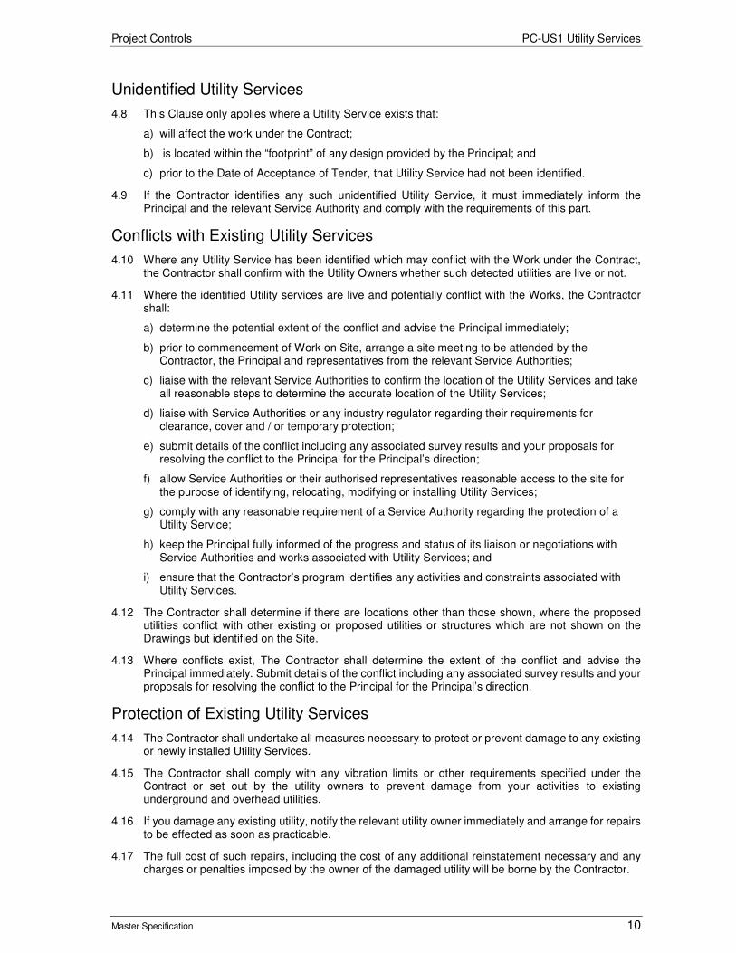
Project Controls PC-US1 Utility Services
Master Specification 10
Unidentified Utility Services
4.8 This Clause only applies where a Utility Service exists that:
a) will affect the work under the Contract;
b) is located within the “footprint” of any design provided by the Principal; and
c) prior to the Date of Acceptance of Tender, that Utility Service had not been identified.
4.9 If the Contractor identifies any such unidentified Utility Service, it must immediately inform the Principal and the relevant Service Authority and comply with the requirements of this part.
Conflicts with Existing Utility Services
4.10 Where any Utility Service has been identified which may conflict with the Work under the Contract, the Contractor shall confirm with the Utility Owners whether such detected utilities are live or not.
4.11 Where the identified Utility services are live and potentially conflict with the Works, the Contractor shall:
a) determine the potential extent of the conflict and advise the Principal immediately;
b) prior to commencement of Work on Site, arrange a site meeting to be attended by the Contractor, the Principal and representatives from the relevant Service Authorities;
c) liaise with the relevant Service Authorities to confirm the location of the Utility Services and take all reasonable steps to determine the accurate location of the Utility Services;
d) liaise with Service Authorities or any industry regulator regarding their requirements for clearance, cover and / or temporary protection;
e) submit details of the conflict including any associated survey results and your proposals for resolving the conflict to the Principal for the Principal’s direction;
f) allow Service Authorities or their authorised representatives reasonable access to the site for the purpose of identifying, relocating, modifying or installing Utility Services;
g) comply with any reasonable requirement of a Service Authority regarding the protection of a Utility Service;
h) keep the Principal fully informed of the progress and status of its liaison or negotiations with Service Authorities and works associated with Utility Services; and
i) ensure that the Contractor’s program identifies any activities and constraints associated with Utility Services.
4.12 The Contractor shall determine if there are locations other than those shown, where the proposed utilities conflict with other existing or proposed utilities or structures which are not shown on the Drawings but identified on the Site.
4.13 Where conflicts exist, The Contractor shall determine the extent of the conflict and advise the Principal immediately. Submit details of the conflict including any associated survey results and your proposals for resolving the conflict to the Principal for the Principal’s direction.
Protection of Existing Utility Services
4.14 The Contractor shall undertake all measures necessary to protect or prevent damage to any existing or newly installed Utility Services.
4.15 The Contractor shall comply with any vibration limits or other requirements specified under the Contract or set out by the utility owners to prevent damage from your activities to existing underground and overhead utilities.
4.16 If you damage any existing utility, notify the relevant utility owner immediately and arrange for repairs to be effected as soon as practicable.
4.17 The full cost of such repairs, including the cost of any additional reinstatement necessary and any charges or penalties imposed by the owner of the damaged utility will be borne by the Contractor.
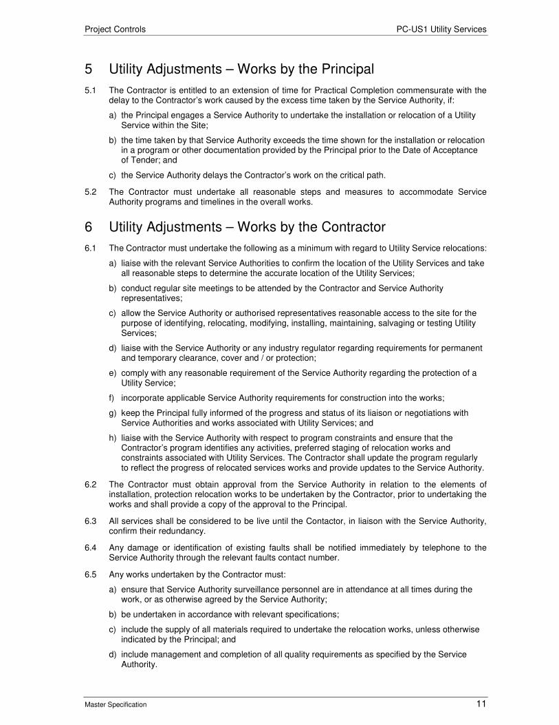
Project Controls PC-US1 Utility Services
Master Specification 11
5 Utility Adjustments – Works by the Principal
5.1 The Contractor is entitled to an extension of time for Practical Completion commensurate with the delay to the Contractor’s work caused by the excess time taken by the Service Authority, if:
a) the Principal engages a Service Authority to undertake the installation or relocation of a Utility Service within the Site;
b) the time taken by that Service Authority exceeds the time shown for the installation or relocation in a program or other documentation provided by the Principal prior to the Date of Acceptance of Tender; and
c) the Service Authority delays the Contractor’s work on the critical path.
5.2 The Contractor must undertake all reasonable steps and measures to accommodate Service Authority programs and timelines in the overall works.
6 Utility Adjustments – Works by the Contractor
6.1 The Contractor must undertake the following as a minimum with regard to Utility Service relocations:
a) liaise with the relevant Service Authorities to confirm the location of the Utility Services and take all reasonable steps to determine the accurate location of the Utility Services;
b) conduct regular site meetings to be attended by the Contractor and Service Authority representatives;
c) allow the Service Authority or authorised representatives reasonable access to the site for the purpose of identifying, relocating, modifying, installing, maintaining, salvaging or testing Utility Services;
d) liaise with the Service Authority or any industry regulator regarding requirements for permanent and temporary clearance, cover and / or protection;
e) comply with any reasonable requirement of the Service Authority regarding the protection of a Utility Service;
f) incorporate applicable Service Authority requirements for construction into the works;
g) keep the Principal fully informed of the progress and status of its liaison or negotiations with Service Authorities and works associated with Utility Services; and
h) liaise with the Service Authority with respect to program constraints and ensure that the Contractor’s program identifies any activities, preferred staging of relocation works and constraints associated with Utility Services. The Contractor shall update the program regularly to reflect the progress of relocated services works and provide updates to the Service Authority.
6.2 The Contractor must obtain approval from the Service Authority in relation to the elements of installation, protection relocation works to be undertaken by the Contractor, prior to undertaking the works and shall provide a copy of the approval to the Principal.
6.3 All services shall be considered to be live until the Contactor, in liaison with the Service Authority, confirm their redundancy.
6.4 Any damage or identification of existing faults shall be notified immediately by telephone to the Service Authority through the relevant faults contact number.
6.5 Any works undertaken by the Contractor must:
a) ensure that Service Authority surveillance personnel are in attendance at all times during the work, or as otherwise agreed by the Service Authority;
b) be undertaken in accordance with relevant specifications;
c) include the supply of all materials required to undertake the relocation works, unless otherwise indicated by the Principal; and
d) include management and completion of all quality requirements as specified by the Service Authority.

Project Controls PC-US1 Utility Services
Master Specification 12
6.6 The Contractor must maintain records which reflect the current status of service installations and removals or decommissioning.
6.7 The Contractor must survey all installed services in situ prior to any backfilling and when bored, provide bore logs with surveyed entry and exit points in accordance with PC-SI 2 “Site Survey”.
Utility Management Plan
6.8 The Contractor shall provide a Utility Management Plan (UMP) integrated with the Project Management Plan for the installation or relocation of Utility Services under the Contract.
6.9 The Utility Management Plan must include the following elements, where appropriate:
a) site management structure for managing the utility adjustment works;
b) name and responsibilities of the Utility Works Coordinator; where a full time Utility Works Coordinator is not required, the name(s) of the person(s) undertaking the duties of the Utilities Works Coordinator;
c) detailed program for utility adjustment works, showing proposed shutdown and cutover times and utility owners program float;
d) procedures for interfacing with concurrent works carried out directly by utility owners;
e) measures to locate, identify if necessary, and protect any existing or newly installed utilities from damage;
f) procedures for procurement and management of accredited constructors;
g) procedures for generating internal site specific permits to work near utilities;
h) Safe Work Method Statements for working near, or on, the utilities;
i) interface management details for Service Authorities working within or adjacent to the Contractor’s project site;
j) Construction Work Method Statements for the various utility adjustment works.
6.10 Provision of the Utility Services Management Plan shall constitute a Hold Point.
Program
6.11 The Contractor shall Plan and schedule Utility adjustment work, including any temporary utility adjustments that may be required under the Contract.
6.12 The Contractor shall integrate Utility adjustment work with the project Program as detailed in PC-PM2 “Contract Program and Schedule”.
6.13 The Contractor shall allow in its program for Construction times required by the utility owner, including procurement lead times, design review and approvals, delivery of components, shutdown notification periods, scheduled cutover periods installation actives and the Utility Owners float.
6.14 The Contractor shall plan and coordinate utility adjustment work with any such concurrent works carried out directly by the various utility owners, and with its Work under the Contract.
6.15 The Contractor shall notify the Principal immediately of any issues related to the Utility adjustment works which may impact on its Program and in particular the Critical Path under the Contract.
Contractor’s Utility Works Coordinator
6.16 The Contractor shall provide a suitably qualified and experienced Utility Works Coordinator for the duration of the utility adjustment works.
6.17 The Utility Works Coordinator must have at least 5 years relevant experience in utility adjustment works and have experience in the management of utility adjustment contractors.
6.18 The Utility Works Coordinator’s duties include the following:
a) liaising with the Principal and the Utility Owners and convening regular meetings as required;

Project Controls PC-US1 Utility Services
Master Specification 13
b) checking for potential conflicts between the proposed utilities and existing utilities and structures;
c) engagement and management of subcontractors undertaking the utility adjustment works;
d) coordinating the various utility adjustment works (including utility adjustment works carried out directly by the utility owners) with the rest of the Work Under the Contract;
e) managing any temporary utility adjustments required, whether as part of construction staging or otherwise;
f) notifying the utility owners for shutdowns and cutovers;
g) negotiations with property owners on utility adjustment matters.
Coordination and Communication with Utility Owners
6.19 Within 15 working days after the Date of Contract, the Contractor shall organise start-up meetings with each utility owner to:
a) confirm their requirements;
b) obtain their concurrence to the utility adjustment works; and
c) coordinate the utility adjustment works, including those carried out directly by the utility owner, with the rest of the Work Under the Contract.
6.20 Convene regular meetings with each utility owner to coordinate and assess the progress of the work.
6.21 Invite the Principal to the meetings. Record the minutes of these meetings and distribute them to all attendees and the Principal within 3 working days after the meeting.
6.22 Keep records of all communications with each utility owner.
6.23 The Contractor shall provide access required by the utility owners to construct and / or maintain their utilities located within the Site, or to inspect the completed utility adjustment works.
Notices to Utility Owners
6.24 Any notices to Utility Owners must be in writing, and be specific to a particular component of the utility infrastructure to be adjusted or near which work will be undertaken.
6.25 A copy of any notices to Utility Owners shall be provided to the Principal.
Variation Work Requested By Utility Owners
6.26 Where a Utility Owner requests work to be completed that is considered to be a Variation under the Contract, prior to carrying out the work, the Contractor shall notify the Principal in writing of that request.
6.27 The Contractor shall not undertake any Work it considers may be subject to a variation without first obtaining the Principal’s agreement.
6.28 The Principal’s agreement to Variations works requested by Utility Owners shall constitute a Hold Point.
Adjustments to Suit the Contractor’s Construction Method
6.29 If the Contactor proposes to undertake temporary utility adjustments to suit your construction method, the Contractor shall comply with the requirements of the utility owner for the design and installation of the temporary adjustments, including engagement of a designer and / or constructor acceptable to the utility owner.
6.30 Any such adjustments are deemed to be incorporated within the Contractor’s Works and Tender.
6.31 The Contractor is not entitled to any extensions of time for utility adjustments to suit your construction method, including any delays in design approval by the utility owner.

Project Controls PC-US1 Utility Services
Master Specification 14
Existing Penetrants
6.32 This Clause applies where a penetrant (e.g. inspection pit, top stone or sewer lid) will be directly affected by the work under the Contract and the penetrant is located within a road pavement, footpath, median and / or driveway.
a) Where work is carried out adjacent to, or around the penetrant, the Contractor must adjust the surface levels of the penetrant, if necessary, to ensure that its final level is flush with the final pavement surface. When measured with a 3 m straight edge centred over the penetrant, the maximum deviation in all directions between the straight edge and the surface must not exceed 5mm. Except for plane and reinstatement of asphalt pavements, the final adjustments to the penetrant must be completed prior to the application of surface course.
b) Where a penetrant protrudes through a temporary surface which is subject to traffic, it must not protrude by more than 60mm, must not be hazardous to traffic and must be ramped at the end of each working day with slopes not steeper than 1:10 in any direction.. Where a penetrant is covered with asphalt, its location must be marked with paint prior to being centrally exposed to a minimum diameter of 150 mm.
c) The Contractor must ensure that any penetrants requiring adjustment are adjusted by appropriately qualified personnel. All adjustment work must be undertaken in accordance with the relevant standards of each Service Authority.
d) The Contractor must ensure that access to fire hydrants is maintained at all times.
Shutdowns
6.33 The Contractor shall plan and carry out utility adjustment work in such a manner that disruption to the community, Utility Owners and road users is minimised.
6.34 The Contractor shall provide the required notices to the community in accordance with PC-CS1 “Community Engagement & Media Engagement”, in circumstances where such notices are not provided by the Utility Owner.
6.35 Times for shutdowns and cutovers of the utility services may be restricted by the Utility Owner (i.e. for seasonal or demand reasons). The Contractor must program all works to suit the utility owner’s permitted shutdown times.
Reconnections
6.36 After cutover to a new utility asset, the Contractor shall promptly reconnect services to premises supplied by that asset.
6.37 The Contractor shall consult with and obtain agreement from property owners regarding the locations of the reconnection points or poles or other infrastructure, and any minor adjustments to gardens or pathways within the property, which are required as a consequence of the reconnection.
Management of Trench Spoil
6.38 The Contractor shall manage risks associated with potentially contaminated trench spoil in accordance with legislative requirements and PC-SC1 “Site Contamination”.
Removal of Redundant Utility Services
6.39 The Contractor is responsible for removal of all redundant services, unless otherwise agreed with a Service Authority.
6.40 If the Contractor obtains agreement from the Service Authority that a redundant service(s) may remain in situ then the service to remain in situ must be decommissioned in accordance with the Service Authority Requirements.
6.41 The Contractor must advise the Service Authority prior to the removal or demolition of any redundant services.
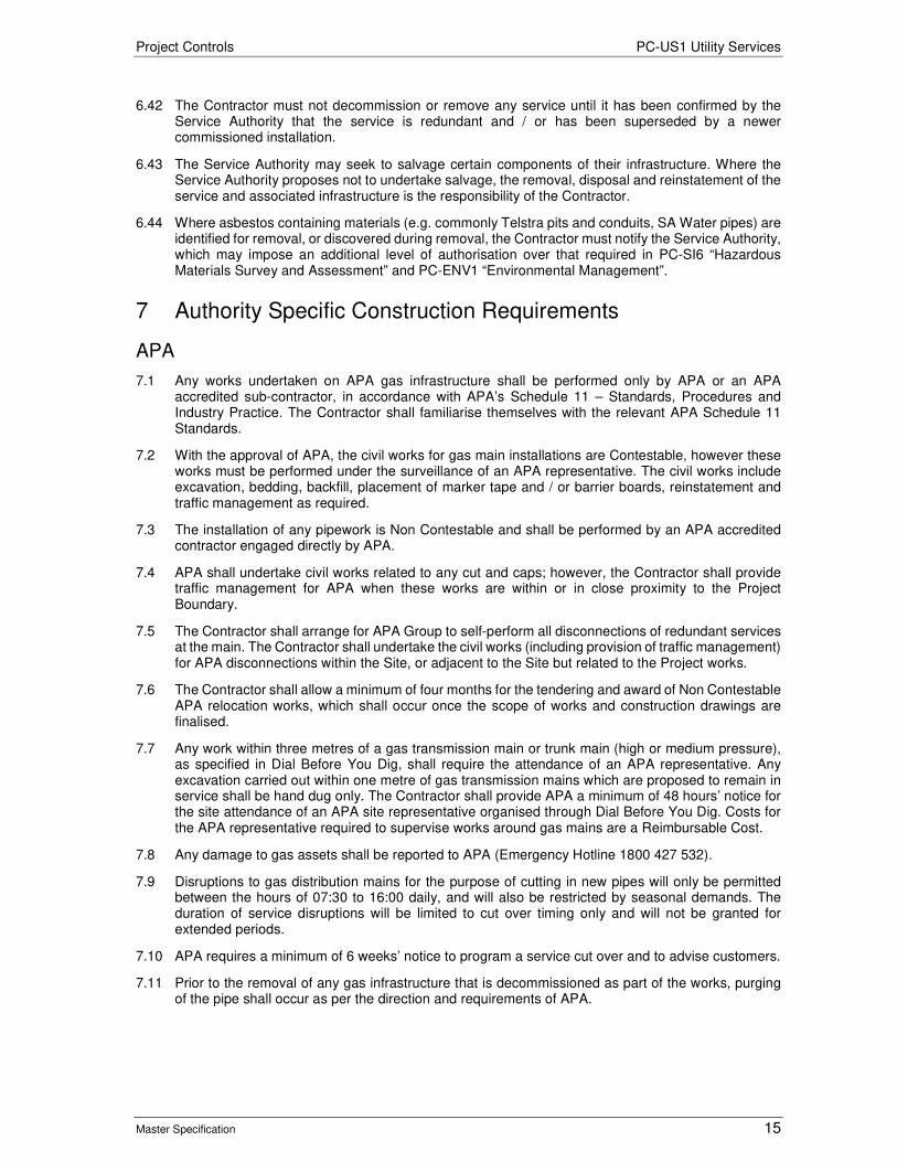
Project Controls PC-US1 Utility Services
Master Specification 15
6.42 The Contractor must not decommission or remove any service until it has been confirmed by the Service Authority that the service is redundant and / or has been superseded by a newer commissioned installation.
6.43 The Service Authority may seek to salvage certain components of their infrastructure. Where the Service Authority proposes not to undertake salvage, the removal, disposal and reinstatement of the service and associated infrastructure is the responsibility of the Contractor.
6.44 Where asbestos containing materials (e.g. commonly Telstra pits and conduits, SA Water pipes) are identified for removal, or discovered during removal, the Contractor must notify the Service Authority, which may impose an additional level of authorisation over that required in PC-SI6 “Hazardous Materials Survey and Assessment” and PC-ENV1 “Environmental Management”.
7 Authority Specific Construction Requirements
APA
7.1 Any works undertaken on APA gas infrastructure shall be performed only by APA or an APA accredited sub-contractor, in accordance with APA’s Schedule 11 – Standards, Procedures and Industry Practice. The Contractor shall familiarise themselves with the relevant APA Schedule 11 Standards.
7.2 With the approval of APA, the civil works for gas main installations are Contestable, however these works must be performed under the surveillance of an APA representative. The civil works include excavation, bedding, backfill, placement of marker tape and / or barrier boards, reinstatement and traffic management as required.
7.3 The installation of any pipework is Non Contestable and shall be performed by an APA accredited contractor engaged directly by APA.
7.4 APA shall undertake civil works related to any cut and caps; however, the Contractor shall provide traffic management for APA when these works are within or in close proximity to the Project Boundary.
7.5 The Contractor shall arrange for APA Group to self-perform all disconnections of redundant services at the main. The Contractor shall undertake the civil works (including provision of traffic management) for APA disconnections within the Site, or adjacent to the Site but related to the Project works.
7.6 The Contractor shall allow a minimum of four months for the tendering and award of Non Contestable APA relocation works, which shall occur once the scope of works and construction drawings are finalised.
7.7 Any work within three metres of a gas transmission main or trunk main (high or medium pressure), as specified in Dial Before You Dig, shall require the attendance of an APA representative. Any excavation carried out within one metre of gas transmission mains which are proposed to remain in service shall be hand dug only. The Contractor shall provide APA a minimum of 48 hours’ notice for the site attendance of an APA site representative organised through Dial Before You Dig. Costs for the APA representative required to supervise works around gas mains are a Reimbursable Cost.
7.8 Any damage to gas assets shall be reported to APA (Emergency Hotline 1800 427 532).
7.9 Disruptions to gas distribution mains for the purpose of cutting in new pipes will only be permitted between the hours of 07:30 to 16:00 daily, and will also be restricted by seasonal demands. The duration of service disruptions will be limited to cut over timing only and will not be granted for extended periods.
7.10 APA requires a minimum of 6 weeks’ notice to program a service cut over and to advise customers.
7.11 Prior to the removal of any gas infrastructure that is decommissioned as part of the works, purging of the pipe shall occur as per the direction and requirements of APA.
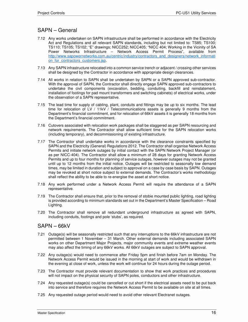
Project Controls PC-US1 Utility Services
Master Specification 16
SAPN – General
7.12 Any works undertaken on SAPN infrastructure shall be performed in accordance with the Electricity Act and Regulations and all relevant SAPN standards, including but not limited to: TS85; TS100; TS110; TS105; TS102; “E” drawings; NICC252; NICC405; “NICC 404; Working in the Vicinity of SA Power Networks Infrastructure – Network Access Permit Process”, available from http://www.sapowernetworks.com.au/centric/industry/contractors_and_designers/network_information_for_contractors_customers.jsp.
7.13 Any SAPN infrastructure relocated into a common service trench or adjacent / crossing other services shall be designed by the Contractor in accordance with appropriate design clearances.
7.14 All works in relation to SAPN shall be undertaken by SAPN or a SAPN approved sub-contractor. With the approval of SAPN, the Contractor shall directly engage SAPN approved sub-contractors to undertake the civil components (excavation, bedding, conduiting, backfill and reinstatement, installation of footings for pad mount transformers and switching cabinets) of electrical works, under the observation of a SAPN representative.
7.15 The lead time for supply of cabling, plant, conduits and fittings may be up to six months. The lead time for relocation of LV / 11kV / Telecommunications assets is generally 9 months from the Department’s financial commitment, and for relocation of 66kV assets it is generally 18 months from the Department’s financial commitment.
7.16 Cutovers associated with relocation work packages shall be staggered as per SAPN resourcing and network requirements. The Contractor shall allow sufficient time for the SAPN relocation works (including temporary), and decommissioning of existing infrastructure.
7.17 The Contractor shall undertake works in accordance with the clearance constraints specified by SAPN and the Electricity (General) Regulations 2012. The Contractor shall organise Network Access Permits and initiate network outages by initial contact with the SAPN Network Project Manager (or as per NICC-404). The Contractor shall allow a minimum of 28 days for granting Network Access Permits and up to four months for planning of service outages, however outages may not be granted until up to 12 months from the initial notice. Outages will be restricted to seasonally low demand times, may be limited in duration and subject to approval on a case by case basis by SAPN. Outages may be revoked at short notice subject to external demands. The Contractor’s works methodology shall reflect the ability to be able to re-energise the asset at short notice.
7.18 Any work performed under a Network Access Permit will require the attendance of a SAPN representative.
7.19 The Contractor shall ensure that, prior to the removal of stobie mounted public lighting, road lighting is provided according to minimum standards set out in the Department’s Master Specification – Road Lighting.
7.20 The Contractor shall remove all redundant underground infrastructure as agreed with SAPN, including conduits, footings and pole ‘stubs’, as required.
SAPN – 66kV
7.21 Outage(s) will be seasonally restricted such that any interruptions to the 66kV infrastructure are not permitted between 1 November – 31 March. Other external demands including associated SAPN works on other Department Major Projects, major community events and extreme weather events may also affect the timing of any 66kV works. All 66kV outages are subject to SAPN approval.
7.22 Any outage(s) would need to commence after Friday 5pm and finish before 7am on Monday. The Network Access Permit would be issued in the morning at start of work and would be withdrawn in the evening at close of work, unless the work will continue for 24 hours during the outage period.
7.23 The Contractor must provide relevant documentation to show that work practices and procedures will not impact on the physical security of SAPN poles, conductors and other infrastructure.
7.24 Any requested outage(s) could be cancelled or cut short if the electrical assets need to be put back into service and therefore requires the Network Access Permit to be available on site at all times.
7.25 Any requested outage period would need to avoid other relevant Electranet outages.

Project Controls PC-US1 Utility Services
Master Specification 17
7.26 Other conditions may become apparent at the time that SAPN outages are requested and SAPN may implement other measures to minimise the risk to their network. At all times, the Contractor must adhere to the directions as provided by SAPN.
SAPN 11kV and Other
7.27 Typically SAPN will remove redundant 11kV electrical infrastructure (including but not limited to cabling from within conduits, overhead conductors, poles, transformers, switching cubicles), however the Contractor shall be responsible for the removal of any additional redundant infrastructure (including but not limited to LV cabling, services, conduits) as required to complete the works.
7.28 Any new high demand sites (e.g. pump stations) are not Asset Relocation and shall be treated as Customer Connection. The Contractor must submit a SAPN Form B for these connections.
7.29 The Contractor shall be responsible for installation and connection to all required supply points. Any new LV supply points will require the Contractor to submit Form A / B as required.
7.30 SAPN are responsible for all telecommunication related works relating to SAPN pilot cable and fibre (if present), excluding any civil works or conduit installation.
7.31 The Contractor shall be responsible for removal and reconnection of any third party equipment (e.g. Telstra, Foxtel) from SAPN poles.
SA Water – General
7.32 Any works undertaken on SA Water infrastructure shall be performed in accordance with SA Water’s Engineering Standards and Guidelines, available from https://www.sawater.com.au/developers-and-builders/engineering-standards-and-guidelines-introduction.
7.33 Permanent and temporary (construction) cover to water and sewer infrastructure shall be in accordance with SA Water’s Technical Guideline TG120, unless otherwise approved by SA Water.
7.34 Design of any alterations to SA Water assets will need to be undertaken either by SA Water or by the Contractor and then approved by SA Water.
7.35 For each asset, the Contractor shall negotiate with SA Water the preferred delivery method for the alteration of the asset; the methods being:
a) Delivery Method 1 – SA Water self-perform / sub contract the works; or
b) Delivery Method 2 – the Contractor self-perform / sub contract the works.
7.36 Whilst SA Water will endeavour to do what is best for the project, SA Water reserves the right to make the final decision on whether Delivery Method 1 or 2 is selected for each asset.
7.37 If Delivery Method 1 is selected, SA Water will liaise closely with the Contractor to ensure alterations to that asset are completed by SA Water in line with the Contractor’s program and requirements.
7.38 If Delivery Method 2 is selected, the Contractor shall engage approved SA Water contractors (SA Water will confirm suitable contractors) to undertake all components of the installation and commissioning of water and sewer mains, with site auditing and key hold point releases by SA Water as required. For all works delivered under Delivery Method 2, the Contractor shall submit their construction staging plans and methodology statements for review by SA Water.
7.39 All materials for SA Water asset alteration works shall be sourced from approved SA Water suppliers. Note that large diameter MSCL will constitute a long lead-time item.
7.40 The Contractor shall be responsible for the relocation of all redundant water or sewer main(s) affected by construction activity, or if SA Water assets are located within one metre of a structural element, unless otherwise approved by SA Water. Redundant mains shall be removed to a minimum of one metre past the extent of the works. Any abandoned main 300mm in diameter or greater shall be fully grouted or removed.
7.41 The sequence of decommissioning shall be developed by the Contractor and submitted to SA Water for approval prior to any decommissioning works being undertaken.
7.42 Any redundant connections shall be disconnected at:

Project Controls PC-US1 Utility Services
Master Specification 18
a) the water main for water services; or
b) within one metre of the sewer main for sewer services.
7.43 All mechanical equipment, including valves, remains the property of SA Water and shall be dismantled in such a way that ensures no damage. The Contractor shall liaise with SA Water to determine which items are required to be salvaged from demolition of redundant water infrastructure. The Contractor shall return all dismantled equipment to:
a) All Water Network Depot, Happy Valley Reservoir
b) Chandlers Hill Road, Happy Valley, SA, 5158
c) Southern Main Repair Supervisor, Greg Jesson, telephone (08) 8381 0313.
SA Water – Water
7.44 The Contractor shall negotiate the staging of any water main relocation or cut over with SA Water.
7.45 Shutdowns will not be permitted on large diameter water mains during seasonal high demand times, and may be restricted in their duration. Duration of shutdowns will be at the discretion of SA Water. SA Water will require a minimum of 10 working days to issue notices of interruption of service to consumers, and shutdowns will need to be booked as per SA Water procedures.
7.46 When live network shutdowns are required to facilitate cut-ins or connections, the Contractor shall assume that all existing isolation valves will pass water (skeet) and the Contractor shall make suitable provision to capture and dispose of, or divert the excess water appropriately.
7.47 Hydrostatic (pressure) testing and disinfection will be required for any newly installed water main prior to commissioning. The Contractor installing the water main shall undertake pressure testing and All Water, SA Water’s maintenance contractor, will undertake all disinfection. The Contractor shall allow timely site access to undertake testing and disinfection processes, and shall make provision in the programme for these processes.
7.48 Any requirements for cathodic protection must be incorporated into the works as per SA Water’s direction. The Contractor shall negotiate with SA Water the preferred delivery method for construction of cathodic protection (either Delivery Method 1 or Delivery Method 2).
SA Water – Sewer
7.49 Sewer mains shall remain operational at all times, unless agreed otherwise by SA Water.
7.50 Directional boring shall not be permitted for the installation of new gravity sewer mains, but may be employed for the installation of pressure mains. In the scenario that pipe jacking is utilised, CCTV shall be used to prove the gradients have been achieved and results issued to SA Water for review. SA Water will not accept non-conformances on the grade, including any low points, and will request replacement of pipe.
7.51 The Contractor shall be responsible for:
a) removal of existing sewer connections from acquired properties; and
b) abandonment (and removal where appropriate) of existing sewer mains.
7.52 The Contractor shall undertake any reconnections of services as necessary.
7.53 Hydrostatic (pressure) testing is required for any newly installed sewer pressure mains prior to commissioning. The Contractor shall allow SA Water access to site to witness testing processes.
Telstra
7.54 Any works undertaken on Telstra infrastructure shall be performed in accordance with “Industry Code C524:2013 External Telecommunication Cable Networks”, available from https://www.commsalliance.com.au/Documents/all/codes/c524.
7.55 The Contractor shall engage Telstra directly or, with Telstra approval, accredited contractors to undertake the installation of conduiting, manholes and pits for any Telstra relocation works throughout the project area.

Project Controls PC-US1 Utility Services
Master Specification 19
7.56 The Contractor may undertake the civil components (excavation, bedding, backfill, placement of marker tape and reinstatement) and install conduit up to 1.5m from the existing and proposed Telstra pits / manholes, including under rail bores to comply with AS4799-2000. The Contractor shall also backfill around all manholes and pits.
7.57 Telstra will be responsible for excavation within 1.5m of all new, existing or re-built manholes and installing conduits the remaining 1.5m. Telstra can also supply Telstra branded conduits to the Contractor (if required), at the Contractor’s cost.
7.58 Third party (i.e. sub-ducted) telecoms are to install their own sub-ducting in new and existing Telstra conduit.
7.59 All cable and optical fibre hauling, jointing and hybrid-fibre coaxial (HFC) works shall be undertaken by a Telstra accredited contractor engaged directly by Telstra.
7.60 The Contractor must allow at least 3-4 months for the design, tender, approval and procurement of cable for the works associated with the relocation of Telstra infrastructure.
7.61 The Contractor must allow up to three (3) months for the installation and commissioning of cables following the completion of all related civil works, including all road, rail and bridge crossings, as the Telstra network is likely to consist of major inter exchange cables. Live cutover of this network is controlled by Telstra Global Operations.
7.62 Any redundant Telstra infrastructure exposed during earthworks or within one metre of a structural component (e.g. drainage pipe, footings, piles, light pole bases etc.) shall be removed by the Contractor to a minimum of one metre past the extent of the works.
7.63 Typically, Telstra will remove copper cabling from within conduits; however, the Contractor shall be responsible for the removal of any redundant cabling as required to complete the works.
7.64 The Contractor shall provide Telstra with a minimum of 28 days’ notice for attendance to site to salvage assets. Manhole lid sets and frames will be salvaged by Telstra Contractors.
7.65 The Contractor shall obtain the necessary approvals from Telstra prior to the removal of asbestos containing material, and on completion of each discrete removal, provide notice of completion and supply a copy of all necessary documentation to Telstra.
7.66 The Contractor shall be responsible for the removal and backfilling of all redundant Telstra manholes (including underlying cavity) and pits, unless otherwise organised with Telstra.
7.67 Where the Contractor is required to work around live Telstra cabling and manholes, the Contractor shall develop a work method statement, to be approved by Telstra prior to commencement of works.
Telecommunications (Other) – General
7.68 Telecommunications (Other) includes all telecommunication Service Authorities other than Telstra.
7.69 Unless otherwise indicated, the Contractor shall undertake civil components (excavation, bedding, backfill and reinstatement), conduit and pit installation for other telecommunications relocation works within the Site. The Contractor shall ensure that inspections are undertaken at the frequency as determined by the relevant telecommunications Service Authority. All other works, including cable hauling and jointing shall be arranged by accredited Contractors for the relevant telecommunications provider. The Contractor shall remove any redundant Other Telecommunications pits within the Site and backfill accordingly. Note that minor work outside of the Site may be required to connect to existing telecommunication services.
7.70 The Contractor shall provide a program of works to affected telecommunications Service Authorities 28 days prior to the commencement of works. Regular updates shall be provided, so that resourcing for inspections can be planned. A minimum of 48 hours’ notice shall be provided for attendance for inspections related to works, unless otherwise indicated by the Service Authority.
7.71 The Contractor shall make allowance in their program for cabling works (hauling, jointing) by the Service Authority and any necessary notification periods and scheduling relating to cutovers, as required by individual Authorities.

Project Controls PC-US1 Utility Services
Master Specification 20
7.72 The Contractor shall allow at least six weeks for Other Telecommunications Service Authorities to cutover the services. Scheduled cutovers typically take four to six hours each and are generally carried out between 12am and 6am.
7.73 The Contractor shall allow for Other Telecommunications Service Authorities personnel to be present on site for supervision of the contestable works (including installation of conduits and pits).
Optus
7.74 With approval from Optus, the Contractor shall install the required conduits within the Site. Note that minor work outside of the Site may be required to connect to existing telecommunication services.
7.75 Any works undertaken on Optus infrastructure shall be performed in accordance with relevant extracts from:
a) OM 36628 Optus ADSS Fibre Network Construction Part C - Installation Requirements V6;
b) OM 10987 Optus Underground Network Construction Part D - Trenching, Conduit Installation & Direct Buried Cable V32;
c) OM 10991 Optus Underground Network Construction Part H - Cable Installation V9; and
d) All other Optus Technical Specifications.
7.76 Installation of conduits and pits are contestable works, and can be completed by the Contractor. Optus will supply the pits. All cable hauling and cutovers will be undertaken by Optus. Optus requires a minimum of 6-8 weeks’ advance notice to program installation of pits. This is followed by a further 30 day lead time for cable hauling and cutover.
7.77 The Contractor shall allow a minimum of 1-2 weeknights for Optus to cutover the services, with cutovers needing to occur between the hours of 10pm and 6am. Cutovers will not be permitted to occur during ‘peak’ load periods (i.e. Christmas, Easter and major social events).
7.78 Any redundant connection joints, fibre cables and aerial strands will be recovered by Optus at the time the new service is cutover.
SABRENet
7.79 With approval from SABRENet, the Contractor shall install the required conduits and associated pits (and civil works) within the Site. Note that minor work outside of the Site may be required to connect to existing telecommunication services.
7.80 The Contractor shall allow at least six weeks for SABRENet to order cable and a further 3 weeks to cutover the services. Splicing of the SABRENet infrastructure can only occur between 10pm and 6am on weeknights excluding Fridays.
7.81 Any works undertaken on SABRENet infrastructure shall be performed in accordance with relevant SABRENet / Vocus specifications.
Telecoms Sub-ducted in Telstra Network
7.82 Telecommunications assets likely to be sub-ducted in the Telstra network include Primus, NBN Co, TPG and iinet (amongst others). Where these telecommunication cables are located within Telstra infrastructure, civil components will be installed by others (i.e. conduits / subducts by the Contractor and pits by Telstra). Where these telecommunication cables are located in their own conduits (i.e. not in Telstra sub-ducts), the Contractor can complete the civil components.
7.83 The Other Telecommunications Service Authorities will undertake all cable hauling and cutovers. These Service Authorities will also supply and install break-out pits as part of the Non Contestable works.

Project Controls PC-US1 Utility Services
Master Specification 21
8 Completion and Handover
Completion
8.1 Within 4 weeks of completing the utility adjustment works, the Contractor shall provide ‘as-constructed drawings.
8.2 The Contractor shall comply with AS 5488 and the respective Utility Owners’ requirements when preparing the “as-constructed” drawings.
8.3 Where the Utility Adjustment Work is not carried out directly by the Utility Owner, the Contractor shall submit to the respective Utility Owner the necessary project completion / handover documentation.
8.4 The Contractor shall obtain the Utility Owner’s acceptance of the completed utility adjustment works. The new utility asset will become the property of the Utility Owner when the Utility Owner accepts the new utility asset in writing.
8.5 The Contractor shall provide a copy of the documentation and the Utility Owner’s acceptance to the Principal. Provision of the Utility Owners acceptance shall constitute a Hold Point.
Records
8.6 The following records must be provided to the Principal:
a) approvals, including endorsement of any departures from standard requirements, agreements and correspondence with Service Authorities regarding the relocation or protective measures required for Utility Services;
b) Service Authority Designs;
c) field records (e.g. sketches, diagrams, survey data) showing the location of relocated Utility Services; and
d) “As-Constructed” drawings showing the position of all relocated Utility Services as per the requirements of the Department’s Master Specification – Survey.
9 Hold Points
9.1 The following is a summary of Hold Points referenced in this Part:
Table PC-US1 9-1 Hold Points
Document Ref. Hold Point Response Time
6.10 Utility Services Management Plan 10 Working Days 6.28 Principal’s agreement to Variation to Utility services 10 Working Days 8.5 Utility Owners written acceptance of the asset 10 Working Days

Roads
Master Specification
RD-BF-C4 Supply and Installation of Fencing & Gates Document Information
K Net Number: 13523972 Document Version: 2 Document Date: 16/09/2019

Roads Contents
Master Specification 2
Document Amendment Record
Version Change Description Date Endorsement record (KNet ref.)
1 Initial issue (formerly R86) 28/06/19 2 Formatting for publishing 16/09/19
Document Management This document is the Property of the Department for Infrastructure and Transport and contains information that is confidential to the Department. It must not be copied or reproduced in any way without the written consent of the Department. This is a controlled document and it will be updated and reissued as approved changes are made.

Roads Contents
Master Specification 3
Contents Contents 2
RD-BF-C4 Supply and Installation of Fencing & Gates 4
1 General 4
2 Ringlock Fencing 4
3 Pedestrian Safety Fence 4
4 Chain Link Fence 5

Roads RD-BF-C4 Supply and Installation of Fencing & Gates
Master Specification 4
RD-BF-C4 Supply and Installation of Fencing & Gates
1 General
1.1 This Part specifies the requirements for the supply and installation of Ringlock fencing, pedestrian fencing and chain-link fencing. The location and configuration of the fencing must be as stated in the Contract Documents or on the drawings. All fences must be installed in accordance with the manufacturer’s instructions.
1.2 When installed on a boundary, fence components must not be installed outside the line of the boundary.
1.3 Unless specified otherwise, any redundant existing fencing must become the property of the Contractor and must be removed and disposed of offsite.
2 Ringlock Fencing
2.1 This clause applies where Ringlock fencing is specified.
Materials
2.2 Mesh wire must be Boral Ringlock or similar approved.
2.3 Plain wire must be 2.8 mm high tensile, standard galvanized.
2.4 Barbed wire must be 1.5 mm high tensile wire, standard galvanized.
2.5 Droppers must be star droppers, manufactured of steel "Y" section 1 500 mm long with a painted finish, a pointed end and wire seating slots at the top. Engager holes must be spaced to match each of the horizontal fence wires.
2.6 Posts must be 100 mm minimum diameter, 1.8 m long, preservative treated in accordance with AS 1604.1 "Specification for Preservative Treatment, Part 1 Sawn and Round Timber".
Installation
2.7 Posts and droppers (if any) must be installed at intervals as specified in the Contract Documents or on the Drawings. The minimum depth of embedment of posts must be 600 mm. Posts must be driven into the ground where practicable. Alternatively, post holes must be pre-drilled and the hole firmly backfilled after placing of the post.
2.8 The Contractor is deemed to have allowed for pre-drilling with a large tractor mounted post-hole borer. The Contractor must provide immediate notification if the material cannot be penetrated with the posthole borer.
2.9 The fence must be constructed over any terrain, including creeks, in a stock proof configuration and must tie in with existing fencing as required.
2.10 Box strainers must be installed at 200 m intervals, at the end of each run of new fence, or at every change in direction.
3 Pedestrian Safety Fence
3.1 This clause applies where pedestrian safety fencing is specified.
3.2 Pedestrian safety fence must be tubular loop fencing, Belmont, or similar approved, erected in accordance with the manufacturer's instructions,
3.3 Fencing materials must consist of galvabond tubing of the following dimensions:
a) Uprights: Outside diameter 19.0 mm, 1.2 mm thick.
b) Cross rails: Outside diameter 31.8 mm, 1.6 mm thick.
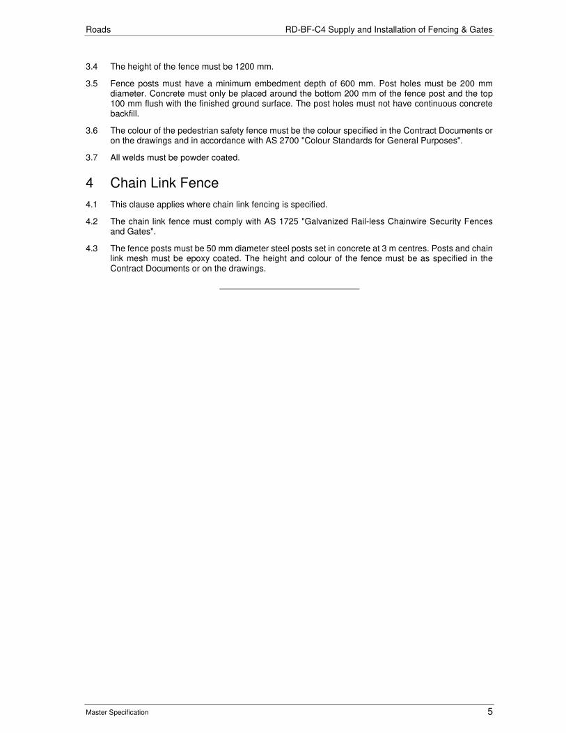
Roads RD-BF-C4 Supply and Installation of Fencing & Gates
Master Specification 5
3.4 The height of the fence must be 1200 mm.
3.5 Fence posts must have a minimum embedment depth of 600 mm. Post holes must be 200 mm diameter. Concrete must only be placed around the bottom 200 mm of the fence post and the top 100 mm flush with the finished ground surface. The post holes must not have continuous concrete backfill.
3.6 The colour of the pedestrian safety fence must be the colour specified in the Contract Documents or on the drawings and in accordance with AS 2700 "Colour Standards for General Purposes".
3.7 All welds must be powder coated.
4 Chain Link Fence
4.1 This clause applies where chain link fencing is specified.
4.2 The chain link fence must comply with AS 1725 "Galvanized Rail-less Chainwire Security Fences and Gates".
4.3 The fence posts must be 50 mm diameter steel posts set in concrete at 3 m centres. Posts and chain link mesh must be epoxy coated. The height and colour of the fence must be as specified in the Contract Documents or on the drawings.
Roads
Master Specification
RD-BP-C3 Construction of Asphalt Pavement Document Information
KNet Number: 13506232
Document Version: 3
Document Date: August 2020

Roads Contents
Master Specification 2
Document Amendment Record Version Change Description Date
1 Initial issue (formerly R28) 02/07/19
2 Formatting for publishing 19/09/19
3 Minor changes August 2020
Document Management This document is the Property of the Department for Infrastructure and Transport and contains information that is confidential to the Department. It must not be copied or reproduced in any way without the written consent of the Department. This is a controlled document and it will be updated and reissued as approved changes are made.
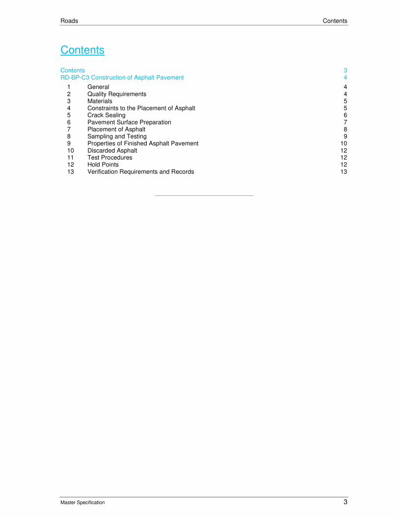
Roads Contents
Master Specification 3
Contents Contents 3
RD-BP-C3 Construction of Asphalt Pavement 4
1 General 4
2 Quality Requirements 4
3 Materials 5
4 Constraints to the Placement of Asphalt 5
5 Crack Sealing 6
6 Pavement Surface Preparation 7
7 Placement of Asphalt 8
8 Sampling and Testing 9
9 Properties of Finished Asphalt Pavement 10
10 Discarded Asphalt 12
11 Test Procedures 12
12 Hold Points 12
13 Verification Requirements and Records 13
Roads RD-BP-C3 Construction of Asphalt Pavement
Master Specification 4
RD-BP-C3 Construction of Asphalt Pavement
1 General
1.1 This Part specifies the requirements for the construction of asphalt pavements.
1.2 In the event of any inconsistency, ambiguity or discrepancy between any of the Contract Documents, the order of precedence shall be as follows:
a) this Part;
b) AS 2150 "Hot Mix Asphalt-A Guide to Good Practice"; and
c) Austroads Guide to Pavement Technology Part 4B “Asphalt”.
Definitions
1.3 The following definitions apply to terms used in this Part:
Table RD-BP-C3 1-1 Definitions
Term Definition
Additive An organic, chemical, or emulsion product used to assist in the compaction of asphalt.
Coarse Asphalt Mix (AC) Asphalt of a coarse nature suitable for Medium, Heavy and Very Heavy Duty applications unless used in Fine Asphalt Mix applications or expressly noted otherwise.
Fine Asphalt Mix (FineAC)
Asphalt of a fine nature suitable for Light to Medium Duty applications and suitable for Department patch maintenance, bikeways, footpaths, car parks and Local Government residential streets.
Hot Mix Asphalt (HMA)
Asphalt Mix manufactured and compacted at standard temperatures. It may also mean Hot Mix Asphalt manufactured at standard temperatures but with the addition of an “Additive” to assist in meeting compaction requirements and required to be registered as a different mix.
Special Process The Contractor’s documented and demonstrated techniques to achieve the requirements of this Part.
Warm Mix Asphalt (WMA)
Hot Mix Asphalt manufactured and compacted at lower temperatures with the addition of an “Additive” or by using the foaming technique.
1.4 The asphalt shall be placed in the configuration specified in the Drawings.
2 Quality Requirements
2.1 The Contractor shall prepare and implement a Quality Plan that includes detailed procedures for:
a) provision for traffic (if not covered in the Traffic Management Plan);
b) preparation of the surface;
c) setting out;
d) tack coating;
e) placing the mix;
f) placement of any mix less than 30 mm thick (vide Clause 4.1);
g) placement of any mix between 10 – 15°C or below 10°C (vide Clause 4 “Temperature Restrictions”);
h) protection of Wearing Course not open to traffic (vide Clause 4 “Wearing Course Restrictions”);
i) placement of crack sealing (including details of nominated product);
j) placement of Open Graded & Stone Mastic Asphalt mixes (vide Clause 4 “General”);
k) level control and Compaction;
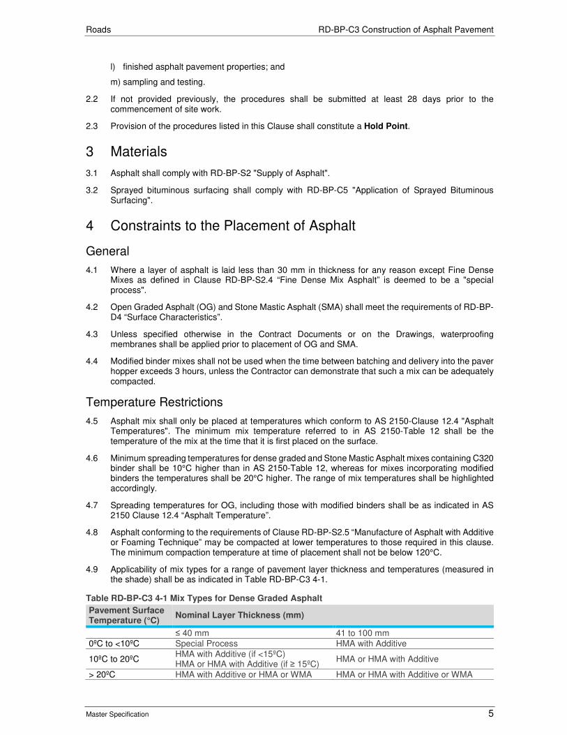
Roads RD-BP-C3 Construction of Asphalt Pavement
Master Specification 5
l) finished asphalt pavement properties; and
m) sampling and testing.
2.2 If not provided previously, the procedures shall be submitted at least 28 days prior to the commencement of site work.
2.3 Provision of the procedures listed in this Clause shall constitute a Hold Point.
3 Materials
3.1 Asphalt shall comply with RD-BP-S2 "Supply of Asphalt".
3.2 Sprayed bituminous surfacing shall comply with RD-BP-C5 "Application of Sprayed Bituminous Surfacing".
4 Constraints to the Placement of Asphalt
General
4.1 Where a layer of asphalt is laid less than 30 mm in thickness for any reason except Fine Dense Mixes as defined in Clause RD-BP-S2.4 “Fine Dense Mix Asphalt” is deemed to be a "special process".
4.2 Open Graded Asphalt (OG) and Stone Mastic Asphalt (SMA) shall meet the requirements of RD-BP-D4 “Surface Characteristics”.
4.3 Unless specified otherwise in the Contract Documents or on the Drawings, waterproofing membranes shall be applied prior to placement of OG and SMA.
4.4 Modified binder mixes shall not be used when the time between batching and delivery into the paver hopper exceeds 3 hours, unless the Contractor can demonstrate that such a mix can be adequately compacted.
Temperature Restrictions
4.5 Asphalt mix shall only be placed at temperatures which conform to AS 2150-Clause 12.4 "Asphalt Temperatures". The minimum mix temperature referred to in AS 2150-Table 12 shall be the temperature of the mix at the time that it is first placed on the surface.
4.6 Minimum spreading temperatures for dense graded and Stone Mastic Asphalt mixes containing C320 binder shall be 10°C higher than in AS 2150-Table 12, whereas for mixes incorporating modified binders the temperatures shall be 20°C higher. The range of mix temperatures shall be highlighted accordingly.
4.7 Spreading temperatures for OG, including those with modified binders shall be as indicated in AS 2150 Clause 12.4 “Asphalt Temperature”.
4.8 Asphalt conforming to the requirements of Clause RD-BP-S2.5 “Manufacture of Asphalt with Additive or Foaming Technique” may be compacted at lower temperatures to those required in this clause. The minimum compaction temperature at time of placement shall not be below 120°C.
4.9 Applicability of mix types for a range of pavement layer thickness and temperatures (measured in the shade) shall be as indicated in Table RD-BP-C3 4-1.
Table RD-BP-C3 4-1 Mix Types for Dense Graded Asphalt
Pavement Surface Temperature (°C)
Nominal Layer Thickness (mm)
≤ 40 mm 41 to 100 mm
0ºC to <10ºC Special Process HMA with Additive
10ºC to 20ºC HMA with Additive (if <15ºC) HMA or HMA with Additive (if ≥ 15ºC)
HMA or HMA with Additive
> 20ºC HMA with Additive or HMA or WMA HMA or HMA with Additive or WMA
Roads RD-BP-C3 Construction of Asphalt Pavement
Master Specification 6
Wearing Course Restrictions
4.10 The wearing course shall not be placed on a bituminous seals including a SAMI seal earlier than one day and no later than seven days of the seal being commenced.
4.11 The wearing course shall not be laid earlier than 2 weeks prior to the opening to traffic, unless the Contractor prepares and implements a procedure to protect the wearing course from any deleterious environmental effects.
4.12 Traffic shall not be permitted on any wearing course until it has cooled to a temperature below 65°C except for Stone Mastic Asphalt (SMA), Heavy Duty Dense Graded Asphalt (HD) and Very Heavy Duty Dense Graded Asphalt (VHD), which shall be not be trafficked until it has cooled to a temperature below 30ºC. Water sprays shall not be used to cool the road surface until the surface temperature is below 70°C.
4.13 Placement of asphalt wearing course shall meet the requirements of RD-BP-D4 “Surface Characteristics”.
4.14 Refer to Contract Documents or PC-SM1 "Provision for Traffic" for any additional constraints relating to traffic management.
5 Crack Sealing
General
5.1 Prior to the placement of asphalt for all pavement types, spray seals or wearing course any remaining cracks greater than 3 mm in width shall be sealed with an approved crack sealant.
5.2 Crack sealing treatment shall be undertaken in accordance with the requirements of RD-BP-S3 “Supply of Pavement Crack Sealant” and RD-BP-C8 “Application of Pavement Crack Sealant” and additional clauses below.
5.3 At least 14 days prior to the use of the product, the Contractor shall submit the manufacturer’s instructions and product performance data.
5.4 Submission of the information shall constitute a Hold Point.
Material
5.5 The crack sealing compound shall be Class 170 bitumen to AS 2008 "Residual Bitumen for Pavements", modified with an appropriate polymer, designed to penetrate the crack, adhere to the crack surface and resist further crack activity.
5.6 The material shall remain stable on the pavement surface during periods of extreme temperature.
5.7 Gritting off of sealant or plugging excessively deep cracks prior to sealing shall be undertaken with SA 5-2, 5-2 mm Sealing Aggregate.
Crack Sealing Treatment
5.8 Prior to placement of sealant, all cracks shall be thoroughly cleaned of foreign material, without damage to the adjoining sound pavement, to provide a clean, dry surrounding. If the pavement is damp, warm / hot compressed air may be used in the drying of the surface of the crack.
5.9 Crack sealing shall not be undertaken unless the surfaces of the cracks are dry. Cracks shall be cleaned to a depth of between 10 - 15 mm. In excessively deep cracks, the crack may be plugged with SA 5-2, 5-2 mm Sealing Aggregate to within 10 - 15 mm of the pavement surface. All cracks shall be filled with sealant material to a level of not less than 10 mm below the pavement surface.
5.10 The level of sealant after gritting shall be flush with the adjoining road pavement. The width of the visible bond on the pavement surface shall be as narrow as is practical. Run out of the sealant over the asphalt surface beyond the crack length will not be permitted.
Roads RD-BP-C3 Construction of Asphalt Pavement
Master Specification 7
Gritting
5.11 The Contractor shall place 5-2 mm Grit on the surface of all sealed material while it is hot and prior to vehicular traffic. Grit shall be placed at the minimum application necessary to prevent pick-up of the sealant by traffic.
5.12 Following completion of the crack sealing treatment A Hold Point shall apply.
6 Pavement Surface Preparation
General
6.1 Pavement surface preparation shall be carried out in accordance AS2150 Clause 10 “Preparation of Surface to be paved” and additional clauses below.
6.2 A Hold Point shall apply prior to the placement of asphalt.
Overlay Placed to Specified Design Levels
6.3 This Sub-clause only applies where an asphalt overlay is to be placed to specified design levels on an existing pavement.
6.4 The existing pavement shall be surveyed. For each layer, the required thickness of asphalt shall be written on the existing surface at each point where there is a specified level.
6.5 Crack sealing shall be applied to an existing pavement in accordance RD-BP-C3 Clause 5 “Crack Sealing”.
6.6 Where multiple layers are to be placed, the Contractor shall prepare a plan and cross sections showing the layer configurations and areas to be planed.
6.7 Submission of the survey data and overlay plan shall constitute a Hold Point.
Planing
6.8 Where the minimum layer thickness cannot be achieved within the specified tolerances, the existing surface shall be planed to achieve the required layer thickness.
6.9 Where an overlay has multiple layers, edge planing shall be undertaken for each layer so as to ensure that the minimum layer thickness is achieved and is keyed into the existing pavement.
6.10 All planing shall be carried out in accordance with RD-EW-C6 “Cold Planing”.
6.11 Following completion of the preparation of the surface and prior to the application of the tack coat a Hold Point shall apply.
Tack Coating
6.12 A tack coat shall consist of CRS grade emulsion to AS 1160 "Bitumen Emulsions for Construction and Maintenance of Pavements", uniformly sprayed at ambient temperature (for 60% residual bitumen emulsions or in accordance with the manufacturer's specification for higher percentages of bitumen).
6.13 Tack coat shall be applied at the following locations:
a) at vertical edges between old and new asphalt pavements;
b) on top of existing asphalt layers; and
c) on top of new asphalt not placed on the same day.
6.14 The tack coat for vertical edges above shall be applied at a rate sufficient to ensure bond at the joint between the old and new asphalt pavements.

Roads RD-BP-C3 Construction of Asphalt Pavement
Master Specification 8
6.15 The tack coat for the other locations above shall be applied at a rate between 0.2 l/m2 and 0.4 l/m2 of residual binder to ensure adequate bond between pavement layers and shall be uniformly applied to the surface prior to placement of asphalt.
6.16 Tack coat shall be applied with a tolerance of ± 0.05 litre/square metre of the specified application rate. The Contractor shall supply the actual spread rates, including litres used and area covered for each lot.
6.17 Asphalt shall not be placed until the tack coat is broken. Any construction traffic is to be minimised. The Contractor shall coordinate work so that no tack coated surface is opened to traffic.
7 Placement of Asphalt
General
7.1 The Contractor shall spread asphalt so as to:
a) minimise segregation and loss of materials;
b) produce a homogeneous product;
c) achieve the specified insitu air voids relative compaction for Dense Graded Asphalt, Stone Mastic Asphalt or Open Graded Asphalt before the asphalt has cooled; and
d) provide the specified thickness of asphalt.
7.2 Spreading methods shall follow the guide to good practice set out in AS 2150-Section 12 "Spreading". The paver shall be a self-propelled paving machine with automatic level control.
7.3 Hand placement of asphalt shall be used only for minor correction of the existing surface and in areas where placement with a paver is impracticable. Laying of mix shall be in the direction of traffic.
7.4 Other than in an emergency situation, if the Contractor proposes to source asphalt from another plant during a day’s production, the Contractor shall provide 48 hours prior notice. A procedure to ensure traceability of the product during placement shall be provided prior to production of mix from an alternative plant.
7.5 If it becomes necessary to use more than one plant because of a plant breakdown, the Contractor shall provide immediate notification and details of the alternative mix.
7.6 Each course shall be compacted uniformly to the full depth and over the full width. Compaction methods shall be in accordance with AS 2150-Section 13 "Compaction". The Contractor shall ensure that compaction does not commence before any deficiencies in the spreading of the mix are corrected.
7.7 At the time of placing asphalt, the existing surface shall be dry.
7.8 A Hold Point applies between individual layers of asphalt.
Protection of Road Fixtures
7.9 The Contractor shall prevent tack coat, binder, aggregate, asphalt or other material used on the work from entering, adhering or obstructing gratings, hydrants, valve boxes, inspection pit covers, kerbs and other road fixtures.
Joints
7.10 Joints shall be constructed in accordance with AS 2150-Clause 12.6 "Joints", Department Standard Drawings and the following additional requirements:
a) The mix shall be spread in a manner which ensures continuity of placing and the number and extent of joints is kept to a minimum.
b) Ensure that the density and surface finish at joints satisfies the requirements of this Specification, and the joints are well sealed.
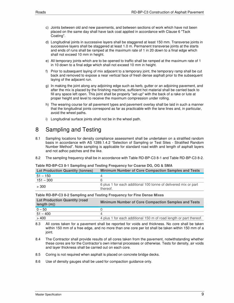
Roads RD-BP-C3 Construction of Asphalt Pavement
Master Specification 9
c) Joints between old and new pavements, and between sections of work which have not been placed on the same day shall have tack coat applied in accordance with Clause 6 "Tack Coating".
d) Longitudinal joints in successive layers shall be staggered at least 150 mm. Transverse joints in successive layers shall be staggered at least 1.0 m. Permanent transverse joints at the starts and ends of runs shall be ramped at the maximum rate of 1 in 20 down to a final edge which shall not exceed 10 mm in height.
e) All temporary joints which are to be opened to traffic shall be ramped at the maximum rate of 1 in 10 down to a final edge which shall not exceed 10 mm in height.
f) Prior to subsequent laying of mix adjacent to a temporary joint, the temporary ramp shall be cut back and removed to expose a near vertical face of fresh dense asphalt prior to the subsequent laying of the adjacent run.
g) In making the joint along any adjoining edge such as kerb, gutter or an adjoining pavement, and after the mix is placed by the finishing machine, sufficient hot material shall be carried back to fill any space left open. This joint shall be properly "set-up" with the back of a rake or lute at proper height and level to receive the maximum compression under rolling.
h) The wearing course for all pavement types and pavement overlay shall be laid in such a manner that the longitudinal joints correspond as far as practicable with the lane lines and, in particular, avoid the wheel paths.
i) Longitudinal surface joints shall not be in the wheel path.
8 Sampling and Testing
8.1 Sampling locations for density compliance assessment shall be undertaken on a stratified random basis in accordance with AS 1289.1.4.2 “Selection of Sampling or Test Sites - Stratified Random Number Method”. Note sampling is applicable for standard road width and length of asphalt layers and not adhoc patches and the like.
8.2 The sampling frequency shall be in accordance with Table RD-BP-C3 8-1 and Table RD-BP-C3 8-2.
Table RD-BP-C3 8-1 Sampling and Testing Frequency for Coarse DG, OG & SMA
Lot Production Quantity (tonnes) Minimum Number of Core Compaction Samples and Tests
51 – 150 4
151 – 300 6
> 300 6 plus 1 for each additional 100 tonne of delivered mix or part thereof.
Table RD-BP-C3 8-2 Sampling and Testing Frequency for Fine Dense Mixes
Lot Production Quantity (road length (m))
Minimum Number of Core Compaction Samples and Tests
0 – 50 0
51 – 400 4
> 400 4 plus 1 for each additional 150 m of road length or part thereof.
8.3 All cores taken for a pavement shall be reported for voids and thickness. No core shall be taken within 150 mm of a free edge, and no more than one core per lot shall be taken within 150 mm of a joint.
8.4 The Contractor shall provide results of all cores taken from the pavement, notwithstanding whether these cores are for the Contractor’s own internal processes or otherwise. Tests for density, air voids and layer thickness shall be carried out on each core.
8.5 Coring is not required when asphalt is placed on concrete bridge decks.
8.6 Use of density gauges shall be used for compaction guidance only.

Roads RD-BP-C3 Construction of Asphalt Pavement
Master Specification 10
9 Properties of Finished Asphalt Pavement
General
9.1 Finished asphalt shall comply with the requirements specified in Clause 13 "Verification Requirements and Records".
Compaction Acceptance Criteria – Quality Standards
9.2 Statistical analysis using an unknown variability scheme shall be used to determine acceptance of the compaction of asphalt layers.
9.3 Compliance will be based on the analysis of a random set of tests taken from each lot of the works. Compliance shall be determined indirectly in terms of percentage defective compared to the desired quality of the lot (10% defective) at either the low or high limit value.
9.4 A 90% probability assurance is required that accepted lots comply with the desired quality at either the low or high limit value. The acceptability characteristic k, quantified in Table RD-BP-C3 9-1 "k Value" is used to provide this statistical assurance. A lot shall not exceed a day’s work. Compliance will apply to the whole of the lot of the works from which the set of tests is taken.
Relative Compaction
9.5 The relative compaction of a core shall be the bulk density expressed as a percentage of mean maximum density and reported in in-situ air voids terms using AS 2891.8. The mean maximum density value shall be the arithmetic mean of the test results for that mix within a lot, provided that they meet all of the following criteria:
a) the binder content of the samples tested are within ± 0.3% of the job mix binder content; and
b) there has been no change in mix components or proportions.
9.6 A low and high characteristic value of air voids content (Lvc and Hvc) of a lot shall be calculated from the formula, x - ks in the case of the low value and x + ks in the case of the high value. x and s are the mean and standard deviations respectively of the individual air voids test values of the lot and k is a constant depending on the number of test values in the lot as shown in Table RD-BP-C3 9-1.
Table RD-BP-C3 9-1 k Value
Number of Tests k Number of Tests k
4 0.62 13 0.877
5 0.68 14 0.890
6 0.72 15 0.901
7 0.76 16 0.910
8 0.78 17 0.919
9 0.81 18 0.928
10 0.83 19 0.937
11 0.85 20 0.946
12 0.86 21 0.952
9.7 Compaction air voids data shall be calculated and reported to two decimal places and rounded to one for the first decimal point as described in AS 2706 – Clause 3.2 “Rounding to One Unit in The Last Place Retained”.
Compaction Criteria
9.8 Compaction shall comply with Table RD-BP-C3 9-2. The target insitu air voids is the mean of the limits provided.

Roads RD-BP-C3 Construction of Asphalt Pavement
Master Specification 11
Table RD-BP-C3 9-2 Compaction Criteria
Asphalt Mixes Characteristic Air Voids (%) – Min
Characteristic Air Voids (%) – Max
AC10 4.0 8.0
AC14 2.5 7.0
AC14 High Binder 1.0 5.0
Stone Mastic Asphalt 1.0 5.0
Open Graded Asphalt 18.0 25.0
FineAC7 2.0 6.0
FineAC10 2.5 7.0
Tolerances on Asphalt Layers
9.9 If the asphalt is to be placed to specified design levels, the finished level of asphalt layers shall be as specified in Contract Documents “Pavement Work” or on the Drawings.
9.10 Where asphalt is to be placed adjacent to kerb and gutter, the wearing course shall be constructed within a tolerance of +5 mm, -0 mm. At joints between the surface of new and existing pavements, the levels shall be flush. If tolerances of base courses and intermediate courses are not specified in Contract Documents “Pavement Work” or on the Drawings, the tolerance is +/-10 mm.
9.11 Tolerances on the specified lateral position of asphalt treatments shall be ± 50 mm.
9.12 The thickness of Dense Graded Mix, Stone Mastic and Open Graded Asphalt Wearing Course laid on asphalt base shall be determined from the specified spread rate using an assumed density of 2,400 kg/cubic metre, 2,400 kg/cubic metre and 1,900 kg/cubic metre respectively.
Surface Irregularity and Finish
9.13 The surface irregularities of asphalt courses, as measured by deviation from a 3 m straight edge, shall not exceed:
Table RD-BP-C3 9-3 Surface Irregularity – General
Asphalt Layer Deviation
Wearing Course 5 mm
Correction (Levelling) and Intermediate Courses 10 mm
Base Courses 15 mm
Base Courses (where no Correction and Intermediate Courses) 10 mm
9.14 The surface irregularities of asphalt courses at longitudinal and transverse joints, as measured by deviation from a 1.2 m straight edge placed centrally and at right angles over the joint, shall not exceed:
Table RD-BP-C3 9-4 Surface Irregularity – Joints
Asphalt Layer Deviation
Wearing Course 3 mm
Correction and Intermediate Courses 5 mm
9.15 The surface of finished asphalt courses shall be free of segregated or "bony" areas, soft and "fatty" areas, ravelling and loose material, surface cracking, shoving and ruts.
Major Project Requirements
9.16 Where a project is estimated to contain more than 50,000 ton of asphalt (“Major Project”), the Contractor shall:
a) use a material transfer device to place asphalt for all layers of asphalt pavement except localised areas within the acceptance of the Principal to increase the quality and consistence of asphalt placement and properties;
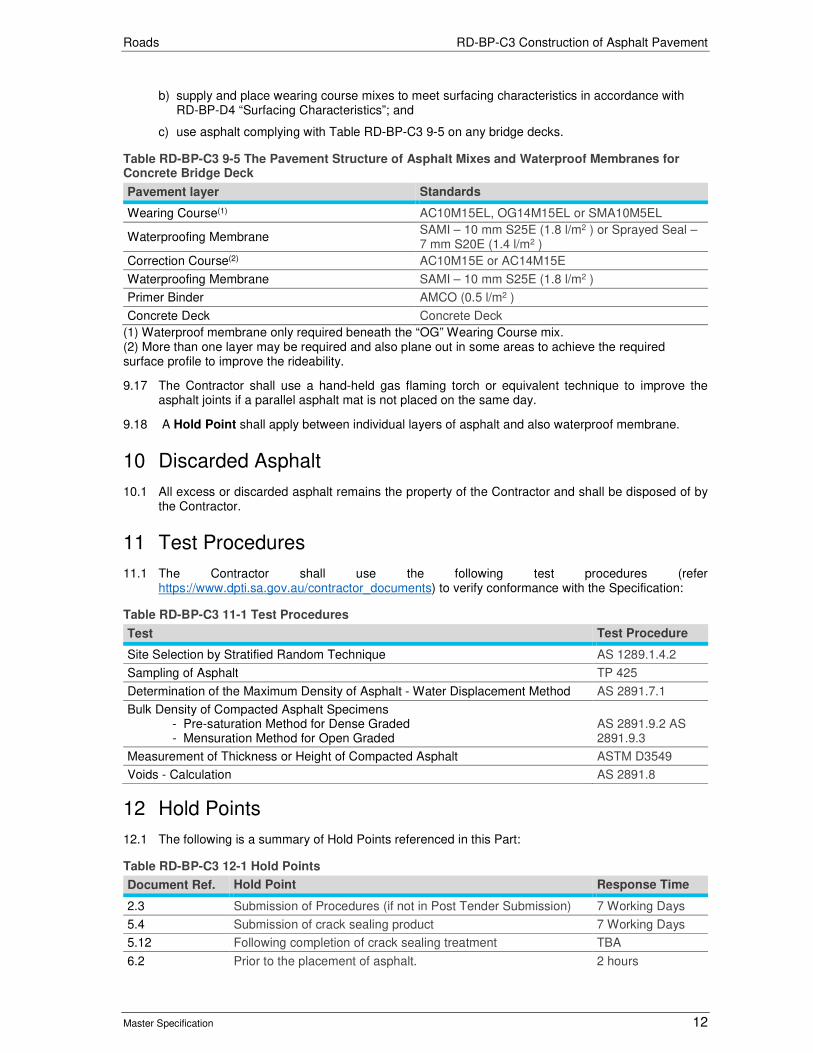
Roads RD-BP-C3 Construction of Asphalt Pavement
Master Specification 12
b) supply and place wearing course mixes to meet surfacing characteristics in accordance with RD-BP-D4 “Surfacing Characteristics”; and
c) use asphalt complying with Table RD-BP-C3 9-5 on any bridge decks.
Table RD-BP-C3 9-5 The Pavement Structure of Asphalt Mixes and Waterproof Membranes for Concrete Bridge Deck
Pavement layer Standards
Wearing Course(1) AC10M15EL, OG14M15EL or SMA10M5EL
Waterproofing Membrane SAMI – 10 mm S25E (1.8 l/m2 ) or Sprayed Seal – 7 mm S20E (1.4 l/m2 )
Correction Course(2) AC10M15E or AC14M15E
Waterproofing Membrane SAMI – 10 mm S25E (1.8 l/m2 )
Primer Binder AMCO (0.5 l/m2 )
Concrete Deck Concrete Deck
(1) Waterproof membrane only required beneath the “OG” Wearing Course mix. (2) More than one layer may be required and also plane out in some areas to achieve the required surface profile to improve the rideability.
9.17 The Contractor shall use a hand-held gas flaming torch or equivalent technique to improve the asphalt joints if a parallel asphalt mat is not placed on the same day.
9.18 A Hold Point shall apply between individual layers of asphalt and also waterproof membrane.
10 Discarded Asphalt
10.1 All excess or discarded asphalt remains the property of the Contractor and shall be disposed of by the Contractor.
11 Test Procedures
11.1 The Contractor shall use the following test procedures (refer https://www.dpti.sa.gov.au/contractor_documents) to verify conformance with the Specification:
Table RD-BP-C3 11-1 Test Procedures
Test Test Procedure
Site Selection by Stratified Random Technique AS 1289.1.4.2
Sampling of Asphalt TP 425
Determination of the Maximum Density of Asphalt - Water Displacement Method AS 2891.7.1
Bulk Density of Compacted Asphalt Specimens - Pre-saturation Method for Dense Graded - Mensuration Method for Open Graded
AS 2891.9.2 AS 2891.9.3
Measurement of Thickness or Height of Compacted Asphalt ASTM D3549
Voids - Calculation AS 2891.8
12 Hold Points
12.1 The following is a summary of Hold Points referenced in this Part:
Table RD-BP-C3 12-1 Hold Points
Document Ref. Hold Point Response Time
2.3 Submission of Procedures (if not in Post Tender Submission) 7 Working Days
5.4 Submission of crack sealing product 7 Working Days
5.12 Following completion of crack sealing treatment TBA
6.2 Prior to the placement of asphalt. 2 hours
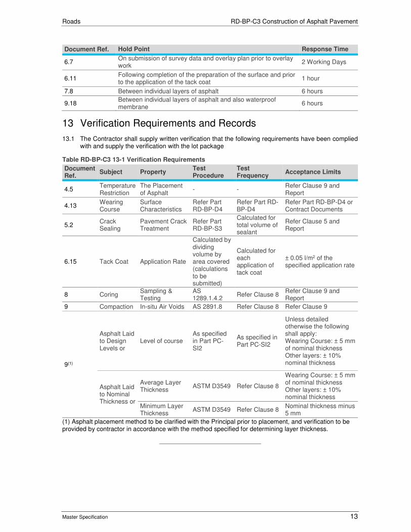
Roads RD-BP-C3 Construction of Asphalt Pavement
Master Specification 13
Document Ref. Hold Point Response Time
6.7 On submission of survey data and overlay plan prior to overlay work
2 Working Days
6.11 Following completion of the preparation of the surface and prior to the application of the tack coat
1 hour
7.8 Between individual layers of asphalt 6 hours
9.18 Between individual layers of asphalt and also waterproof membrane
6 hours
13 Verification Requirements and Records
13.1 The Contractor shall supply written verification that the following requirements have been complied with and supply the verification with the lot package
Table RD-BP-C3 13-1 Verification Requirements
Document Ref.
Subject Property Test Procedure
Test Frequency
Acceptance Limits
4.5 Temperature Restriction
The Placement of Asphalt
- - Refer Clause 9 and Report
4.13 Wearing Course
Surface Characteristics
Refer Part RD-BP-D4
Refer Part RD-BP-D4
Refer Part RD-BP-D4 or Contract Documents
5.2 Crack Sealing
Pavement Crack Treatment
Refer Part RD-BP-S3
Calculated for total volume of sealant
Refer Clause 5 and Report
6.15 Tack Coat Application Rate
Calculated by dividing volume by area covered (calculations to be submitted)
Calculated for each application of tack coat
± 0.05 l/m2 of the specified application rate
8 Coring Sampling & Testing
AS 1289.1.4.2
Refer Clause 8 Refer Clause 9 and Report
9 Compaction In-situ Air Voids AS 2891.8 Refer Clause 8 Refer Clause 9
9(1)
Asphalt Laid to Design Levels or
Level of course As specified in Part PC-SI2
As specified in Part PC-SI2
Unless detailed otherwise the following shall apply: Wearing Course: ± 5 mm of nominal thickness Other layers: ± 10% nominal thickness
Asphalt Laid to Nominal Thickness or
Average Layer Thickness
ASTM D3549 Refer Clause 8
Wearing Course: ± 5 mm of nominal thickness Other layers: ± 10% nominal thickness
Minimum Layer Thickness
ASTM D3549 Refer Clause 8 Nominal thickness minus 5 mm
(1) Asphalt placement method to be clarified with the Principal prior to placement, and verification to be provided by contractor in accordance with the method specified for determining layer thickness.

Roads
Master Specification
RD-BP-S1 Supply of Bituminous Materials Document Information
K Net Number: 13506220
Document Version: 2
Document Date: 18/09/2019

Roads Contents
Master Specification Revision A 2
Document Amendment Record
Version Change Description Date Endorsement record (KNet ref.)
1 Initial issue (formerly R25) 02/07/19
2 Formatting for publishing 18/09/19
Document Management This document is the Property of the Department for Infrastructure and Transport and contains information that is confidential to the Department. It must not be copied or reproduced in any way without the written consent of the Department. This is a controlled document and it will be updated and reissued as approved changes are made.
Roads Contents
Master Specification Revision A 3
Contents Contents 2
RD-BP-S1 Supply of Bituminous Materials 4
1 General 4
2 Residual Bitumen 4
3 Polymer Modified Binders (PMBs) 4
4 Primers and Primer Binders 7
5 Emulsions 7
6 Multigrade Bitumens 7
7 Crumb Rubber Binders (CRBs) 7
8 Bituminous Flux and Cutter 8
9 Test Procedures 9
10 Sampling and Testing 9
11 Hold Points 11
12 Verification Requirements and Records 12

Roads RD-BP-S1 Supply of Bituminous Materials
Master Specification Revision A 4
RD-BP-S1 Supply of Bituminous Materials
1 General
1.1 This Part specifies the requirements for the supply and delivery of bitumen, primers, primer binders, polymer modified binders, emulsions, multi-grades and crumb rubber.
1.2 Documents referenced in this Part are listed below:
a) AS 1160 Bituminous Emulsions for the Construction and Maintenance of Pavements.
b) AS 1289 Methods of Testing Soils for Engineering Purposes.
c) AS 2008 Residual Bitumen for Pavements.
d) AS 2341 Methods of Testing Bitumen and Related Road Making Products.
e) AS 3530 Solvents – Mineral Turpentine and White Spirit.
f) AS 3568 Oils for Reducing the Viscosity of Residual Bitumen for Pavements.
g) AP-T41/06 Specification Framework for Polymer Modified Binder & Multigrade Bitumens.
2 Residual Bitumen
2.1 Residual bitumen shall comply with AS 2008 with the following additional requirements for Class 170 & Class 320 bitumen:
Table RD-BP-S1 2-1 Additional Requirements for Class 170 Bitumen
Test Specified Properties
Test Procedure Minimum Maximum
Durability, (days) 9 - AS 2341.13 and AS 2341.5
Density at 15°C, (kg/L) 1.0 - AS 2341.7
Table RD-BP-S1 2-2 Additional Requirements for Class 320 Bitumen
Test Specified Properties
Test Procedure Minimum Maximum
Durability, (days) *BR - AS 2341.13 and AS 2341.5
Density at 15°C, (kg/L) 0.99 - AS 2341.7
n-Heptane insoluble, (%) TBR - ASTM D3279
Penetration at 35°C, 100g, 5s (pu) - TBR AS 2341.12
*TBR – To Be Recorded
3 Polymer Modified Binders (PMBs) Austroads Technical Report AP-T41/06 “Specification Framework for Polymer Modified Binders and Multigrade Bitumens” shall apply, except that Table 5.1 “Properties of PMBs for Sprayed Sealing Applications” and Table 5.2 “Properties of PMBs for Asphalt Applications” be deleted and replaced with Table RD-BP-S1 3-1and
3.1 Table RD-BP-S1 3-2.
3.2 PMB shall be suitable for the purpose of retaining the screenings in the seal by initial wetting and subsequent bonding. The base binder used in the manufacture of PMBs shall conform to the requirements of Clause 2 “Residual Bitumen”.
3.3 The product shall be prepared in a manufacturing plant or blending plant of proven performance and shall comply with the "Code of Practice: Manufacture, Storage and Handling of Polymer Modified Binders, First Edition", Australian Asphalt Pavement Association, June 2004.

Roads RD-BP-S1 Supply of Bituminous Materials
Master Specification Revision A 5
Table RD-BP-S1 3-1 Polymer Modified Binders for Sprayed Sealing
Test Procedure
Minimum Testing Frequency(1)
Class Binder Property
S10E S15E S20E S25E S35E S45E
PERFORMANCE RELATED PROPERTIES
AGPT/T121 Refer to Table 10.2 & 10.3 Consistency at 60°C (Pa.s)(1) Min 250 700 700 6000 300 1000
AGPT/T121 Refer to Table 10.2 & 10.3 Underlying viscosity at 60°C (Pa.s)(2) TBR(4) TBR(4) TBR(4) TBR(4) TBR(4) TBR(4)
AGPT/T121 Refer to Table 10.2 & 10.3 Stiffness at 15°C (kPa)(4) Max 140 140 130 95 180 180
AGPT/T142(1)(2) Refer to Table 10.2 & 10.3 Rubber Content by Analysis, (%) N/A(5) N/A(5) N/A(5) N/A(5) N/A(5) TBR(4)
AGPT/T132 Refer to Table 10.2 & 10.3 Compression limit at 70°C, 2 kg (mm)
Min N/A(5) N/A(5) N/A(5) N/A(5) N/A(5) 0.2
AGPT/T108 Refer to Table 10.2 & 10.3 Segregation Value (%) max Max 8 8 8 8 8 8
INDEX PROPERTIES
AGPT/T121 Refer to Table 10.2 & 10.3 Elastic recovery at 60°c, 100s (%)(1) Min N/A(5) N/A(5) N/A(5) 85 N/A(5) 25
HANDLING PROPERTIES
AGPT/T111 Each Batch Viscosity at 165°C (Pa.s)(3) Max 0.55 0.55 0.55 0.8 0.55 4.5(3)
AGPT/T112 Annually Flash point (°C) Min 250 250 250 250 250 250
AGPT/T103 Annually Loss on heating (%mass) max 0.6 0.6 0.6 0.6 0.6 0.6
PRODUCTION CONTROL PROPERTIES
AGPT/T122 Each Batch(7) Torsional recovery at 25°C, 30s (%) 22 – 50 32 – 60 45 – 74 54 – 85 16 – 32 25 – 55
AGPT/T131 Each Batch(7) Softening point (°C) 48 – 64 55 – 75 62 – 88 82 – 100 48 – 56 55 – 65
Other Each Batch As proposed by supplier TBR(4) TBR(4) TBR(4) TBR(4) TBR(4) TBR(4)
(1) For Consistency and elastic recovery, Mould B shall be used for S10E and S35E (breakpoint of 5 mm and a test speed of 1.5 mm/s). Other grades shall be tested using Mould A (breakpoint of 10 mm and a test speed of 1 mm/s) (2) Underlying viscosity is derived from the Elastometer data (i.e. tested under the same conditions as Consistency testing, refer to Note 1 above). (3) The shear rate involved in determining viscosity by AGPT/T111 shall be calculated and recorded. L series Brookfield is recommended together with spindle SC4-31, except in the case of S45R where spindle SC4-29 is recommended. (4) TBR = To Be Reported. (5) N/A indicates that the property is considered not applicable for that PMB class. (6) To assist users in determining the quantity of added cutter oil required for spraying, the manufacturer shall report on the concentration and type of process oil used in the formulation. (7) Applicable only to products failing to meet the requirements for segregation value. (8) Properties for S15E are experimental, and are to be regarded as trial values for such period until manufacturing capabilities are proven. (9) Alternatively a soxhlet with toluene may be used.

Roads RD-BP-S1 Supply of Bituminous Materials
Master Specification Revision A 6
Table RD-BP-S1 3-2 Polymer Modified Binders for Asphalt
Test Procedure
Minimum Testing Frequency(1)
Class Binder Property
A5E A10E A15E A20E A30E A35P(5)
Performance Related Properties
AGPT/T121 3-monthly Consistency at 60°C (Pa.s) Min 6000 6000 5000 600 1500 2000
AGPT/T121 3-monthly Consistency 6% at 60°C (Pa.s)(2) Min TBR(4) TBR(4) 900 500 TBR(4) 1200
AGPT/T121 3-monthly Stiffness at 25°C (kPa)(2) Max 80 min 30 30 35 100 120
AGPT/T108 3-monthly Segregation value (%) Max 8 8 8 8 8 8
Handling Properties
AGPT/T111 Each Batch Viscosity at 165°C (Pa.s)(3) Max 0.8 1.1 0.9 0.6 0.7 0.6
AGPT/T112 Annually Flash point (°C) Min 250 250 250 250 250 250
AGPT/T103 Annually Loss on heating (% mass) Max 0.6 0.6 0.6 0.6 0.6 0.6
Production Control Properties
AGPT/T122 Each Batch Torsional recovery at 25°C, 30s (%) 25 – 40 60 – 86 55 – 80 38 – 70 12 – 30 6 – 21
AGPT/T131 Each Batch Softening point (°C) Min 90 88 – 110 82 – 105 65 – 95 70 – 80 70 – 80
Other Each Batch As proposed by supplier TBR(4) TBR(4) TBR(4) TBR(4) TBR(4) TBR(4)
(1) Testing frequencies provided are suggested minima. Different testing frequencies may be agreed between the purchaser and the supplier.
(2) Consistency 6% at 60°C is derived from the Elastometer data (i.e. tested under the same conditions as Consistency testing). It shall be tested using Mould A (breakpoint of 10 mm and a test speed of 1 mm/s). (3) The shear rate involved in determining viscosity by AGPT/T111 shall be calculated and recorded. (4) TBR = To Be Reported. (5) Where A35P is produced through the addition of polymer as part of the asphalt produced process evidence shall be provided that the resultant binder can meet these values

Roads RD-BP-S1 Supply of Bituminous Materials
Master Specification 7
4 Primers and Primer Binders
4.1 The properties of cutback primes and primer binders shall be in accordance with AS 2157 Cutback Bitumen.
4.2 Where the use of field blended primers has been approved, the properties shall be consistent with the properties of laboratory prepared samples using components complying with Clause 2 "Residual Bitumen" and Clause 8 "Bituminous Flux and Cutter".
4.3 Where emulsion primers are to be used, the following information shall be submitted by the Contractor at least 14 days prior to application:
a) indicative application rates;
b) material safety data sheets;
c) minimum curing periods;
d) handling procedures including circulation requirements, maximum and minimum spraying temperatures, minimum pavement temperatures; and
e) quality control limits including bitumen, cutter and water contents, maximum and minimum viscosity.
4.4 0.5 parts of an approved bitumen adhesion additive shall be added to all primer binders.
5 Emulsions
5.1 Emulsions shall comply with AS 1160.
6 Multigrade Bitumens
6.1 Multigrade Bitumens shall comply with Austroads Technical Report AGPT/T190 “Specification Framework for Polymer Modified Binders and Multigrade Bitumens”.
7 Crumb Rubber Binders (CRBs)
General
7.1 Crumb rubber binders shall be blended on site in such a way to provide a homogenous product of consistent quality that can be sprayed to provide a uniform application of binder across the pavement. The Contractor’s quality plan shall include procedures related to mixing and storage processes together with minimum digestion times.
7.2 Field produced Crumb Rubber Binders shall comply with the properties set out in Table 5.4 of AP-T41/06 “Specification Framework for Polymer Modified Binders and Multigrade Bitumens”.
7.3 The Contractor shall prepare and test samples of the crumb rubber binder using the proposed plant, constituent materials and digestion times.
7.4 The samples may be sourced from work undertaken in the 3 months prior to the Contract commencing, or from the first batch of full scale production for this Contract. Samples shall be free of diluents or other contamination.
7.5 Results shall be supplied within 5 days of the Contract commencing. Submission of test results shall constitute a Hold Point.
7.6 Manufacturing, blending and storage details for each batch of binder shall be supplied by the Contractor including:
a) traceability details of input materials;
b) quantities of input materials added reported by weight / volume and parts;
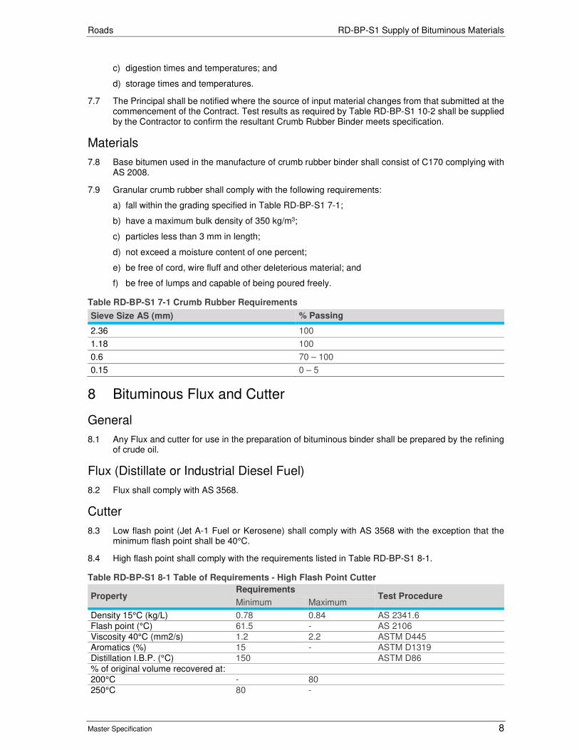
Roads RD-BP-S1 Supply of Bituminous Materials
Master Specification 8
c) digestion times and temperatures; and
d) storage times and temperatures.
7.7 The Principal shall be notified where the source of input material changes from that submitted at the commencement of the Contract. Test results as required by Table RD-BP-S1 10-2 shall be supplied by the Contractor to confirm the resultant Crumb Rubber Binder meets specification.
Materials
7.8 Base bitumen used in the manufacture of crumb rubber binder shall consist of C170 complying with AS 2008.
7.9 Granular crumb rubber shall comply with the following requirements:
a) fall within the grading specified in Table RD-BP-S1 7-1;
b) have a maximum bulk density of 350 kg/m3;
c) particles less than 3 mm in length;
d) not exceed a moisture content of one percent;
e) be free of cord, wire fluff and other deleterious material; and
f) be free of lumps and capable of being poured freely.
Table RD-BP-S1 7-1 Crumb Rubber Requirements
Sieve Size AS (mm) % Passing
2.36 100
1.18 100
0.6 70 – 100
0.15 0 – 5
8 Bituminous Flux and Cutter
General
8.1 Any Flux and cutter for use in the preparation of bituminous binder shall be prepared by the refining of crude oil.
Flux (Distillate or Industrial Diesel Fuel)
8.2 Flux shall comply with AS 3568.
Cutter
8.3 Low flash point (Jet A-1 Fuel or Kerosene) shall comply with AS 3568 with the exception that the minimum flash point shall be 40°C.
8.4 High flash point shall comply with the requirements listed in Table RD-BP-S1 8-1.
Table RD-BP-S1 8-1 Table of Requirements - High Flash Point Cutter
Property Requirements
Test Procedure Minimum Maximum
Density 15°C (kg/L) 0.78 0.84 AS 2341.6
Flash point (°C) 61.5 - AS 2106
Viscosity 40°C (mm2/s) 1.2 2.2 ASTM D445
Aromatics (%) 15 - ASTM D1319
Distillation I.B.P. (°C) 150 ASTM D86
% of original volume recovered at:
200°C - 80
250°C 80 -
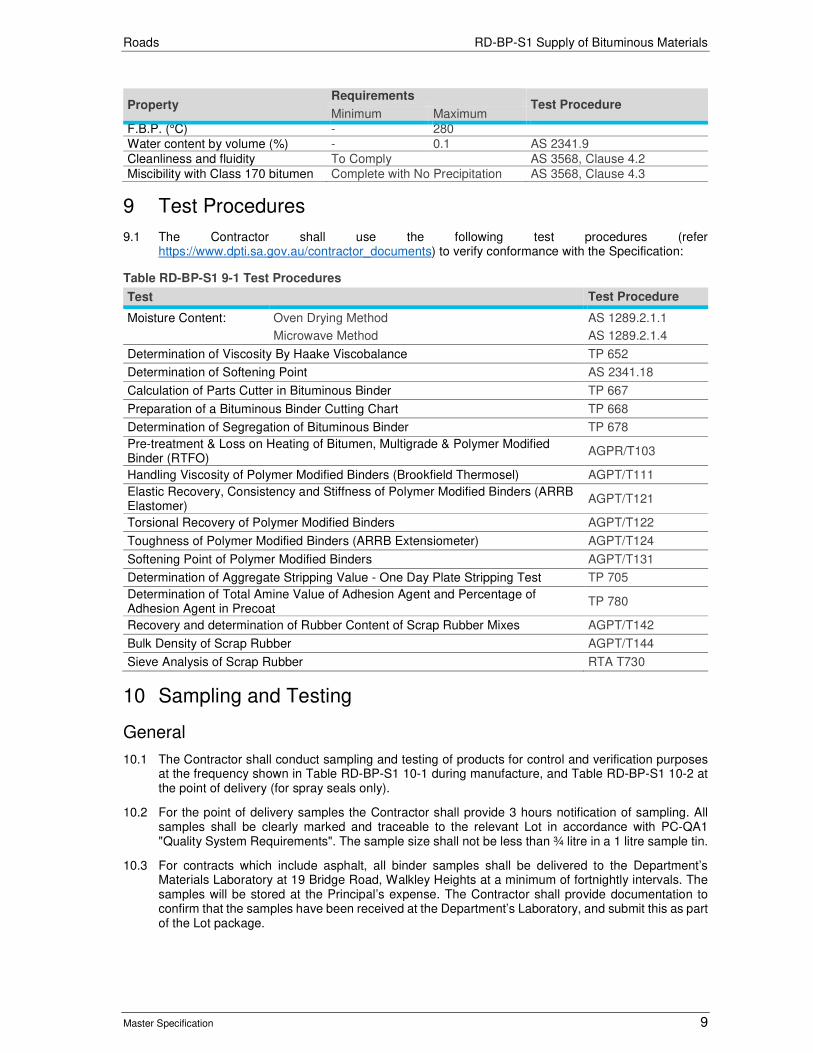
Roads RD-BP-S1 Supply of Bituminous Materials
Master Specification 9
Property Requirements
Test Procedure Minimum Maximum
F.B.P. (°C) - 280
Water content by volume (%) - 0.1 AS 2341.9
Cleanliness and fluidity To Comply AS 3568, Clause 4.2
Miscibility with Class 170 bitumen Complete with No Precipitation AS 3568, Clause 4.3
9 Test Procedures
9.1 The Contractor shall use the following test procedures (refer https://www.dpti.sa.gov.au/contractor_documents) to verify conformance with the Specification:
Table RD-BP-S1 9-1 Test Procedures
Test Test Procedure
Moisture Content: Oven Drying Method AS 1289.2.1.1
Microwave Method AS 1289.2.1.4
Determination of Viscosity By Haake Viscobalance TP 652
Determination of Softening Point AS 2341.18
Calculation of Parts Cutter in Bituminous Binder TP 667
Preparation of a Bituminous Binder Cutting Chart TP 668
Determination of Segregation of Bituminous Binder TP 678
Pre-treatment & Loss on Heating of Bitumen, Multigrade & Polymer Modified Binder (RTFO)
AGPR/T103
Handling Viscosity of Polymer Modified Binders (Brookfield Thermosel) AGPT/T111
Elastic Recovery, Consistency and Stiffness of Polymer Modified Binders (ARRB Elastomer)
AGPT/T121
Torsional Recovery of Polymer Modified Binders AGPT/T122
Toughness of Polymer Modified Binders (ARRB Extensiometer) AGPT/T124
Softening Point of Polymer Modified Binders AGPT/T131
Determination of Aggregate Stripping Value - One Day Plate Stripping Test TP 705
Determination of Total Amine Value of Adhesion Agent and Percentage of Adhesion Agent in Precoat
TP 780
Recovery and determination of Rubber Content of Scrap Rubber Mixes AGPT/T142
Bulk Density of Scrap Rubber AGPT/T144
Sieve Analysis of Scrap Rubber RTA T730
10 Sampling and Testing
General
10.1 The Contractor shall conduct sampling and testing of products for control and verification purposes at the frequency shown in Table RD-BP-S1 10-1 during manufacture, and Table RD-BP-S1 10-2 at the point of delivery (for spray seals only).
10.2 For the point of delivery samples the Contractor shall provide 3 hours notification of sampling. All samples shall be clearly marked and traceable to the relevant Lot in accordance with PC-QA1 "Quality System Requirements". The sample size shall not be less than ¾ litre in a 1 litre sample tin.
10.3 For contracts which include asphalt, all binder samples shall be delivered to the Department’s Materials Laboratory at 19 Bridge Road, Walkley Heights at a minimum of fortnightly intervals. The samples will be stored at the Principal’s expense. The Contractor shall provide documentation to confirm that the samples have been received at the Department’s Laboratory, and submit this as part of the Lot package.

Roads RD-BP-S1 Supply of Bituminous Materials
Master Specification 10
Point of Manufacture (Spray Seals only)
10.4 The Contractor shall undertake the following tests and supply results to demonstrate continual monitoring of product performance at point of manufacture. These test results may predate the award of this Contract. The time, date and sample temperature shall also be recorded when the test samples are taken and the tests are conducted.
Table RD-BP-S1 10-1 Process Control Testing Requirements
Product Properties Test Frequency at Point of Manufacture
Acceptance Limit
C170 Bitumen
As listed in AS 2008 & Table RD-BP-S1 2-1
3 months or after addition of bitumen into bulk storage
Clause 2
Flashpoint, Durability Annually Clause 2
C320 Bitumen As listed in AS 2008 & Table RD-BP-S1 2-2
3 months or after addition of bitumen into bulk storage
Clause 2
Flashpoint, Durability Annually Clause 2
Cutback Binder Viscosity at 60°C Each production batch Report Value
Primers and Primer Binder
As listed in AS 2157 Each production batch Clause 4
Multigrades
Viscosity at 60°C Each production batch
Clause 6
Penetration at 25°C Each production batch
Viscosity at 135°C Each production batch
Viscosity at 60°C after RTFOT Each production batch
Penetration at 25°C after RTFOT 100g, 5s
Each production batch
Matter Insoluble in Toluene Each production batch
Flashpoint & Loss on Heating Annually
Polymer Modified Binders* (refer Table RD-BP-S1 3-1 and Table RD-BP-S1 3-2)
Performance Related & Index Properties
Monthly Clause 3
Flash Point & Loss on Heating Annually Clause 3
Viscosity at 165°C Each production batch Clause 3
Torsional Recovery at 25°C Each production batch Clause 3
Softening Point Each production batch Clause 3
Cutter Viscosity at 40°C Each production batch Clause 9
Granular Crumb Rubber
Bulk Density One per 100 tonne lot Report value
Grading One per 100 tonne lot Clause 7
Crumb Rubber Binder
Properties as per Table 7.1 Refer Table 7.1 Refer Table 7.1
Bitumen Emulsion
Sieve residue Each production batch Clause 5
Residue from evaporation Each production batch Clause 5
* Pre-blended PMBs only
10.5 For Polymer Modified Binders, the following shall be undertaken:
a) one point of manufacture sample taken at the same time as the manufacturer’s sample, which is to be provided to the Principal;
b) one sample per transport bulker at the point of "load out" from the manufacturing yard to the bulker on request; and
c) provision of sampling records, including time, date and sample temperature when the test samples are taken (in accordance with the "Code of Practice: Manufacture, Storage and Handling of Polymer Modified Binders", AAPA June 2004, Clause 3.1).

Roads RD-BP-S1 Supply of Bituminous Materials
Master Specification 11
Point of Delivery (Spray Seals only)
10.6 The Contractor shall undertake the following tests and supply results to demonstrate continual monitoring of product performance at point of delivery. Unless indicated otherwise one sample for the Contractor and one sample for the Principal shall be taken at the frequency shown in Table RD-BP-S1 10-2.
Table RD-BP-S1 10-2 Deliver, Sampling and Testing Requirements
Product Properties Sample Frequency on Site
Testing Frequency
Acceptance Limit
*C170 & C320 Bitumen
As listed in Table RD-BP-S1 2-1
One Contractor sample per bulker
On request Clause 2
Cutback Binder Viscosity at 60°C On request On request Report value
Primers and Primer Binder
As listed in Table AS2157 4.1
Sample per bulker On request Clause 4
*Polymer Modified Binders Plant Blended Crumb Rubber (refer Table RD-BP-S1 3-1)
Viscosity at 165°; Torsional Recovery at
25°C; and Softening Point
Sample from each bulker at the point of delivery. The samples shall be taken at the time of discharge into the sprayer (for the first run) or at the time of discharge into the kettle / site storage
On request Report value
*Field Blended Crumb Rubber Binder
Viscosity at 165° Consistency at 60°C
Sample from each batch First batch of the Contract then on request
Report value
Torsional Recovery at
25°C; and Softening Point
Sample from each batch First batch of the Contract then on request
Clause 7
Rubber Content Sample from each batch On request Clause 7
*Multigrade
Viscosity at 60°C Penetration at 25°C Viscosity at 135°C Matter Insoluble in Toluene
Sample per bulker On request Clause R25.6
Cutter Viscosity at 40°C One per contract One per contract
Clause 8
Bitumen Emulsion
As listed in AS 1160 Sample per bulker On request Clause 5
Adhesion Agent Amine Value One per contract One per contract
Minimum 120
*Note: Samples shall be taken prior to addition of adhesion agent / cutter.
10.7 All Principal samples shall be delivered to the Department’s Materials Laboratory at 19 Bridge Road, Walkley Heights at a minimum of fortnightly intervals. The samples will be stored at the Principal’s expense. The Contractor shall provide documentation to confirm that the samples have been received at the Department’s Laboratory, and submit this as part of the lot package.
10.8 Where immediate testing of samples is not required in accordance with Table RD-BP-S1 10-2, the Contractor shall store the samples for not less than 12 months from the date of sampling.
11 Hold Points
11.1 The following is a summary of Hold Points referenced in this Part:
Document Ref. Hold Point Response Time
7.5 Submission of test results for crumb rubber binder. 5 working days

Roads RD-BP-S1 Supply of Bituminous Materials
Master Specification 12
12 Verification Requirements and Records
General
12.1 The Contractor shall supply written verification that the testing undertaken demonstrates compliance with the requirements of this Part and supply the verification with the lot package.
Binder Information to be submitted upon Delivery
12.2 At a minimum, the Contractor shall provide the following information with each delivery on site of PMB and Multigrade binder:
a) Contractor's batch number / identifier;
b) PMB Grade or Multigrade class;
c) location of manufacturing plant;
d) date and time of manufacture;
e) date, time and temperature of dispatch into the bulker;
f) delivery Details (delivery point, date, time and temperature); and
g) product heating information (heating start time, finish time, total heating time and temperature).

Roads
Master Specification
RD-BP-S2 Supply of Asphalt Document Information
KNet Number: 13506221
Document Version: 3
Document Date: August 2020

Roads Contents
Master Specification 2
Document Amendment Record Version Change Description Date
1 Initial issue (formerly R27). Updated from Asphalt Users Group meeting 10/1/2019 #9497825V5
02/07/19
2 Formatting for publishing 18/09/19
3 Minor changes to reduce complexity August 2020
Document Management This document is the Property of the Department for Infrastructure and Transport and contains information that is confidential to the Department. It must not be copied or reproduced in any way without the written consent of the Department. This is a controlled document and it will be updated and reissued as approved changes are made.

Roads Contents
Master Specification 3
Contents Contents 3
RD-BP-S2 Supply of Asphalt 4
1 General 4
2 Quality Requirements 5
3 Materials 6
4 Mix Requirements 7
5 Manufacture of Mixes 11
6 Production Sampling and Testing 12
7 Property Variations of Production Asphalt 13
8 Storage of Asphalt 14
9 Delivery of Mix 14
10 Test Procedures 14
11 Hold Points 15
12 Verification Requirements and Records 15
13 Appendix 1: Asphalt Inspection Test and Verification 17
14 Appendix 2: Assessment and Registration of Asphalt Mix Designs 19

Roads RD-BP-S2 Supply of Asphalt
Master Specification 4
RD-BP-S2 Supply of Asphalt
1 General
1.1 This Part specifies the requirements for the supply of Hot Mix Asphalt (HMA), with and without an Additive, and Warm Mix Asphalt (WMA) including the design and manufacture of the following:
a) Coarse Dense Mix Asphalt (AC10, AC14);
b) Fine Dense Mix Asphalt (FineAC7, FineAC10 & FineAC14);
c) Open Graded Asphalt (OG10 & OG14); and
d) Stone Mastic Asphalt (SMA7 & SMA10).
1.2 In the event of any inconsistency, ambiguity or discrepancy between any of the Contract Documents, the following order of precedence will apply:
a) this Part;
b) Austroads: Guide to Pavement Technology Part 4B: Asphalt;
c) AS 2150 “Hot Mix Asphalt - A Guide to Good Practice”; and
d) industry documentation.
1.3 Documents referenced in this Part are listed below:
a) Austroads Guide to Pavement Technology Part 4B: Asphalt.
b) AS 2150 Hot Mix Asphalt - A Guide to Good Practice.
1.4 The following definitions apply to terms used in this Part:
Table RD-BP-S2 1-1 Definitions
Term Definition
AAPA Australian Asphalt Pavement Association
AC
Coarse Asphalt Mix. Asphalt of a coarse nature suitable for Medium, Heavy and Very Heavy Duty applications unless used in Fine Asphalt Mix applications or expressly noted otherwise.
Additive An organic, chemical, or emulsion product used to assist in the compaction of asphalt.
Asphalt Mix Design Assessment
A documented assessment of a submitted asphalt mix design with an Asphalt Mix Register Number provided by the Department.
Asphalt Mix Register Number
A mix approval number provided by the Department to an accepted nominated mix. All mixes are placed on the Department’s Asphalt Mix Register and monitored by the Department.
FineAC
Fine Asphalt Mix. Asphalt of a fine nature suitable for Light to Medium Duty applications and suitable for Department patch maintenance, bikeways, footpaths, car parks and Local Government residential streets.
HMA
Hot Mix Asphalt. Asphalt Mix manufactured and compacted at standard temperatures. It may also mean Hot Mix Asphalt manufactured at standard temperatures but with the addition of an “Additive” to assist in meeting compaction requirements and required to be registered as a different mix.
Nominated Binder Content
The Contractor’s target design binder content for the Nominated Mix.
Nominated Combined Aggregate Grading
The Contractor’s target design gradings for the Nominated Mix.
Nominated Mix An asphalt mix design proposed by the Contractor.
Process Control A controlled documented system of practices and procedures used to monitor and control the product inputs, equipment and manufacturing processes to ensure the product replicates the product design.

Roads RD-BP-S2 Supply of Asphalt
Master Specification 5
Term Definition
Production Mix Manufactured product at an asphalt plant.
RAP Reclaimed Asphalt Pavement.
SDS Safety Data Sheets.
Special Process The Contractor’s documented and demonstrated techniques to achieve the requirements of this Part.
WMA Warm Mix Asphalt. Hot Mix Asphalt manufactured and compacted at lower temperatures with the addition of an “Additive” or by using the foaming technique.
2 Quality Requirements
Process Control
2.1 The Contractor shall develop and implement a Process Control System. The following requirements shall be submitted to the Department for the asphalt plant to obtain approved process control:
a) monthly RAP & Asphalt Production test results in electronic spreadsheet format;
b) audit samples;
c) monthly process control charts and invitation to process control meeting; and
d) monthly asphalt plant computing data outputs to match with samples being taken.
Quality Plan, Procedures and Documentation
2.2 Further to the requirements of PC-QA1 “Quality System Requirements”, the Contractor shall prepare and implement a Quality Plan that at a minimum, includes detailed procedures and documentation for:
a) Mix Design.
b) Manufacture of Mixes.
c) The asphalt production plant, including company brand, mixing type, capacity, year of manufacturing, functionalities, special abilities, silos, computer control system and production history.
d) The laboratory NATA Accreditation certificate, approved tests, and calibration schedule.
e) Process control requirements, which include a description of the flow of materials and the processes carried out on them from input materials to the plant through to delivery of asphalt to the customer. It shall incorporate a flow diagram and identification of the key elements of the manufacturing process requiring monitoring, measurement or verification.
f) Control of aggregates transferred from quarry stockpiles and delivered to an asphalt plant.
g) Control of Reclaimed Asphalt Pavement (RAP) transferred from stockpiles and delivered to an asphalt plant.
h) Requirements for labelling of storage bays, silos and bituminous tanks.
i) Requirements for heating, temperature control and insulation of tanks.
j) Requirements for controlling delivery of binders into the correct tanks.
k) Control requirements for binders, foam, additives, admixtures, fillers and reclaimed asphalt.
l) Plant calibration and maintenance.
m) Description of the characteristics of any hot storage system and define its mode of operation.
n) Handling, storage and delivery of asphalt mixture to ensure the minimum of segregation, degradation or binder drain down and that the asphalt remains within the specified temperature range.
o) An Inspection and Test Plan, vide Clause PC-QA1.6 "Inspection and Testing", which includes a schedule for monitoring and measuring the performance of the process (as identified in the key process element identification) and products. At a minimum, it shall meet the requirements of

Roads RD-BP-S2 Supply of Asphalt
Master Specification 6
Clauses 6 “Production Sampling and Testing”, Clause 7 “Property Variations of Production Asphalt” and Appendix 1: Asphalt Inspection Test and Verification.
p) Constant monitoring and statistical analysis of records to verify process capability and product characteristics.
q) A Calibration Schedule, which includes daily visual inspection of all equipment and calibration of weighting equipment, admixture dispensers, flow meters, batching or proportioning systems and temperature monitoring equipment (vide PC-QA1.6.4 "Inspection, Measuring and Test Equipment"). At a minimum, it shall meet the requirements of Appendix 1: Asphalt Inspection Test and Verification.
2.3 If not provided previously the procedures and documentation shall be submitted at least 10 days prior to the commencement of supply.
2.4 Provision of the procedures and documentation listed in this Clause shall constitute a Hold Point.
2.5 The Contractor shall use test procedures in accordance with Table RD-BP-S2 10-1 (refer https://www.dpti.sa.gov.au/materials_technology_documents/test_procedures2) to verify conformance to this Part.
3 Materials
Quality of Materials
3.1 Materials shall comply with the following:
a) Binder, Flux and Cutter RD-BP-S1 “Supply of Bituminous Materials”
b) Aggregate, Sand and Mineral Filler RD-PV-S1 “Supply of Pavement Materials”
c) Tack Coat AS 1160 Bitumen Emulsions for Construction and Maintenance of Pavements
d) AS 2157 Cutback Bitumen
e) Hydrated Lime Filler AS 1672.1 Limes for Building.
f) Rejuvenating Agent Rejuvenating agent shall comply with recognised standards for such materials. Diesel is not considered a suitable rejuvenating agent. Rejuvenation agent shall be fully disclosed for mix assessment including submission of Safety Data Sheets.
Reclaimed Asphalt Pavement Material
3.2 Reclaimed asphalt pavement material (RAP) shall be obtained from milling or excavation of existing asphalt pavements or asphalt plant waste.
3.3 For the use of RAP within asphalt mixes the Contractor’s Quality Plan shall include a Reclaimed Asphalt Pavement Management Plan and Industry Code of Practice meeting the following minimum requirements:
a) RAP shall be crushed and screened as necessary to ensure a maximum size no greater than the maximum size of asphalt being produced and to achieve a reasonably well graded, free flowing, and consistent product.
b) The processed RAP of each size shall be placed in separate stockpiles not exceeding 1,000 tonne and represent a lot. Each lot shall be tested for binder content, gradings, viscosity and moisture content at a minimum of one per lot. Test results shall be traceable to the asphalt mix containing the RAP. Alternatively, viscosity testing can be carried out on final mix on a regular basis sufficient to demonstrate viscosity is within the target range for binder type targeted (excluding polymer modified binders).
c) RAP that has been stockpiled for some time and has bound together in some way shall be reprocessed, to ensure that it is in a free flowing state at the time of use.

Roads RD-BP-S2 Supply of Asphalt
Master Specification 7
4 Mix Requirements
4.1 Mix requirements shall comply with the requirements of the latest edition of AUSTROADS 4B, except as varied below.
Nominated Mixes
4.2 All submissions of nominated mixes shall be in accordance with Appendix 2: Assessment and Registration of Asphalt Mix Designs.
4.3 The Contractor shall submit to the Department details of each approved asphalt mix proposed before commencing production / placement of asphalt.
4.4 Submission of the details of nominated mixes and Certificate(s) shall constitute a Hold Point.
Compliance of Nominated Mixes
4.5 If the Contractor has a current Asphalt Mix Register Number and the mix has not been varied in accordance with Clause 4 "Variations to Nominated Mixes", the following shall be submitted:
a) description of the Job Mix Formula (JMF); and
b) a copy of the latest Asphalt Mix Design Assessment.
4.6 Submission of the above information shall constitute a Hold Point.
4.7 The Contractor shall monitor the production results of all its registered mixes, and shall submit a summary of previous mix production data for the submitted mix and to include:
a) plot of voids verses binder content, max density verses binder content;
b) summary sheet of JMF data in an electronic spreadsheet format;
c) process control plots of binder content, max density, production voids & in-situ voids; and
d) summary of associated non-conformances and dispositions.
4.8 Where the analysis of the production test data shows that the Design Air Voids Target requires a different binder content to the nominated binder content, an alternative mix design shall be submitted.
Variations to Nominated Mixes
4.9 The Contractor shall submit a new nominated mix in compliance with Clause 4 “Nominated Mixes” if:
a) the Contractor proposes to vary the proportions of the constituents in a nominated mix;
b) the Contractor proposes to change the source of supply of any constituent; or
c) the Asphalt Mix Register Number is withdrawn by the Department.
Mobile Plants
4.10 The Contractor shall submit the asphalt mix history (including mix production data) and details of the nominated mobile plant in accordance Clause 2 “Quality Requirements”.
4.11 Plant settings and mix design parameters shall be met before proceeding with the permanent works and shall constitute a Hold Point.
4.12 A proposal to use plant fuel other than Liquefied Petroleum Gas (LPG), Liquefied Natural Gas (LNG), petrol or diesel shall constitute a Hold Point.
Asphalt Mix Applications
4.13 Standard mix for road pavements shall use AC10 coarse dense mix asphalt with either A15E to Medium Duty design or A5E to Light Duty design for wearing course. Generally C320 shall be used (or C170 with aged binder from RAP) for all other layers unless a modified binder is required, using either AC10 or AC14 mixes.
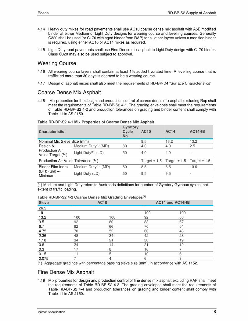
Roads RD-BP-S2 Supply of Asphalt
Master Specification 8
4.14 Heavy duty mixes for road pavements shall use AC10 coarse dense mix asphalt with A5E modified binder at either Medium or Light Duty designs for wearing course and levelling courses. Generally C320 shall be used (or C170 with aged binder from RAP) for all other layers unless a modified binder is required, using either AC10 or AC14 mixes as required.
4.15 Light Duty road pavements shall use Fine Dense mix asphalt to Light Duty design with C170 binder. Class C320 may also be used subject to approval.
Wearing Course
4.16 All wearing course layers shall contain at least 1% added hydrated lime. A levelling course that is trafficked more than 30 days is deemed to be a wearing course.
4.17 Design of asphalt mixes shall also meet the requirements of RD-BP-D4 “Surface Characteristics”.
Coarse Dense Mix Asphalt
4.18 Mix properties for the design and production control of coarse dense mix asphalt excluding Rap shall meet the requirements of Table RD-BP-S2 4-1. The grading envelopes shall meet the requirements of Table RD-BP-S2 4-2 and production tolerances on grading and binder content shall comply with Table 11 in AS 2150.
Table RD-BP-S2 4-1 Mix Properties of Coarse Dense Mix Asphalt
Characteristic Gyratory Cycle No.
AC10 AC14 AC14HB
Nominal Mix Sieve Size (mm) 9.5 13.2 13.2 Design & Production Air Voids Target (%)
Medium Duty(1) (MD) 80 4.0 4.0 2.5
Light Duty(1) (LD) 50 4.0 4.0 -
Production Air Voids Tolerance (%) Target ± 1.5 Target ± 1.5 Target ± 1.5
Binder Film Index (BFI) (µm) – Minimum
Medium Duty(1) (MD) 80 8.5 8.5 10.0
Light Duty (LD) 50 9.5 9.5 -
(1) Medium and Light Duty refers to Austroads definitions for number of Gyratory Gyropac cycles, not extent of traffic loading.
Table RD-BP-S2 4-2 Coarse Dense Mix Grading Envelopes(1)
Sieve AC10 AC14 and AC14HB
26.5
19 100 100
13.2 100 100 92 80
9.5 92 80 83 67
6.7 82 66 70 54
4.75 70 52 60 43
2.36 48 34 42 28
1.18 34 21 30 19
0.6 24 14 21 12
0.3 17 8 16 7
0.15 11 5 10 6
0.075 7 4 6 3
(1) Aggregate gradings with percentage passing sieve size (mm), in accordance with AS 1152.
Fine Dense Mix Asphalt
4.19 Mix properties for design and production control of fine dense mix asphalt excluding RAP shall meet the requirements of Table RD-BP-S2 4-3. The grading envelopes shall meet the requirements of Table RD-BP-S2 4-4 and production tolerances on grading and binder content shall comply with Table 11 in AS 2150.

Roads RD-BP-S2 Supply of Asphalt
Master Specification 9
Table RD-BP-S2 4-3 Mix Properties of Fine Dense Mix Asphalt
Characteristic Fine AC7 Fine AC10
Light Duty Design (Gyratory Cycles) 50 cycles 50 cycles
Nominal Mix Sieve Size (mm) 6.7 9.5
Minimum Binder Content (%) 6.0 5.7
Design & Production Air Voids Target (%) 4.0 4.0
Production Air Voids Tolerance (%) Target ± 1.5 Target ± 1.5
Target In-situ Voids (%) (refer to Spec RD-BP-C3)
2.0 – 6.0 2.5 – 7.0
Binder film Index (µm) Minimum 8.0 8.0
Table RD-BP-S2 4-4 Mix Grading Envelopes of Fine Dense Mix Asphalt(1)
Sieve FineAC7 FineAC10
13.2 100
9.5 100 100 90
6.7 100 90 90 75
4.75 90 75 77 63
2.36 65 51 56 43
1.18 47 35 41 30
0.6 33 23 29 20
0.3 22 15 20 13
0.15 14 9 13 8
0.075 8 5 8 5
(1) Aggregate gradings with percentage passing sieve size (mm), in accordance with AS 1152.
Coarse / Fine Dense Mix Asphalt Including Rap
4.20 In addition to the requirements of this clause, Dense Mix Asphalt incorporating Reclaimed Asphalt Pavement shall meet the design requirements of Clause 4 "Coarse Dense Mix Asphalt" or Clause 4 "Fine Dense Mix Asphalt" and the following:
a) for wearing course mixes, the proportion of RAP in the total mix shall not exceed 10% for “Coarse Dense Mix Asphalt” and 20% for “Fine Dense Mix Asphalt”;
b) for asphalt mixes with 10% RAP or less added, no added binder or rejuvenation is required;
c) for all layers except wearing course, the proportion of RAP in the total mix shall not exceed 50%; excepted for asphalt mixes using polymer modified binders (PMB) shall not exceed 20%;
d) for asphalt mixes with 10% or greater (5% increments) RAP content in the total mix, the actual percentage added shall be approved by the Department; and
e) for asphalt mixes with higher than 10% RAP incorporation, use the following additional design components of binder rejuvenation:
i) extract RAP Binder to determine binder content and viscosity;
ii) the Resilient Modulus of RAP Mixes to be the same as equivalent Virgin Mixes in accordance with Table RD-BP-S2 14-2. Testing frequency is one test (a pair of production pat per sample) per 10 production samples per mix; and
iii) rejuvenating agent shall be a softer grade bitumen and low volatility oil (if required) capable of combining with bitumen to counteract hardening and produce a lower viscosity grade of binder.
4.21 Asphalt mixes with standard binder types reflects the design viscosity recommended. For mixes including added binder from RAP, softer binder class and or rejuvenator may be required to achieve the target viscosity.
Open Graded Asphalt
4.22 The following applies to Open Graded Asphalt (OG):
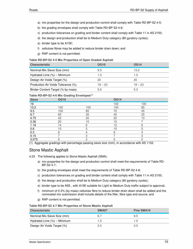
Roads RD-BP-S2 Supply of Asphalt
Master Specification 10
a) mix properties for the design and production control shall comply with Table RD-BP-S2 4-5;
b) the grading envelopes shall comply with Table RD-BP-S2 4-6;
c) production tolerances on grading and binder content shall comply with Table 11 in AS 2150;
d) the design and production shall be to Medium Duty category (80 gyratory cycles);
e) binder type to be A15E;
f) cellulose fibres may be added to reduce binder drain down; and
g) RAP content is not permitted.
Table RD-BP-S2 4-5 Mix Properties of Open Graded Asphalt
Characteristic OG10 OG14
Nominal Mix Sieve Size (mm) 9.5 13.2
Hydrated Lime (%) – Minimum 1.0 1.0
Design Air Voids Target (%) 20 20
Production Air Voids Tolerance (%) 18 – 23 18 – 23
Binder Content Target (% by mass) 5.6 5.3
Table RD-BP-S2 4-6 Mix Grading Envelopes(1)
Sieve OG10 OG14
19 100 100
13.2 100 100 100 85
9.5 100 85 70 45
6.7 65 35 45 25
4.75 45 20 25 10
2.36 20 10 15 7
1.18 14 6 12 6
0.6 10 5 10 5
0.3 8 4 8 4
0.15 7 3 7 3
0.075 5 2 5 2
(1) Aggregate gradings with percentage passing sieve size (mm), in accordance with AS 1152.
Stone Mastic Asphalt
4.23 The following applies to Stone Mastic Asphalt (SMA):
a) mix properties for the design and production control shall meet the requirements of Table RD-BP-S2 4-7;
b) the grading envelopes shall meet the requirements of Table RD-BP-S2 4-8;
c) production tolerances on grading and binder content shall comply with Table 11 in AS 2150;
d) the design and production shall be to Medium Duty category (80 gyratory cycles);
e) binder type to be A5E , with A15E suitable for Light to Medium Duty traffic subject to approval;
f) minimum of 0.3% (by mass) cellulose fibre to reduce binder drain down shall be added and the nominated mix submission shall include details of the filler, fibre type and source; and
g) RAP content is not permitted.
Table RD-BP-S2 4-7 Mix Properties of Stone Mastic Asphalt
Characteristic SMA07 Fine SMA10
Nominal Mix Sieve Size (mm) 6.7 9.5
Hydrated Lime (%) – Minimum 1.0 1.0
Design Air Voids Target (%) 3.5 3.5
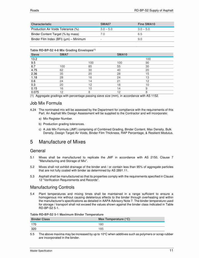
Roads RD-BP-S2 Supply of Asphalt
Master Specification 11
Characteristic SMA07 Fine SMA10
Production Air Voids Tolerance (%) 3.0 – 5.0 3.0 – 5.0
Binder Content Target (% by mass) 7.0 6.5
Binder Film Index (BFI) (µm) – Minimum - 9.0
Table RD-BP-S2 4-8 Mix Grading Envelopes(1)
Sieve SMA7 SMA10
13.2 100
9.5 100 100 90
6.7 100 85 55 30
4.75 62 30 40 20
2.36 35 20 28 15
1.18 28 16 24 13
0.6 24 14 21 12
0.3 20 12 18 10
0.15 16 10 14 9 0.075 12 8 12 8
(1) Aggregate gradings with percentage passing sieve size (mm), in accordance with AS 1152.
Job Mix Formula
4.24 The nominated mix will be assessed by the Department for compliance with the requirements of this Part. An Asphalt Mix Design Assessment will be supplied to the Contractor and will incorporate:
a) Mix Register Number.
b) Production grading tolerances.
c) A Job Mix Formula (JMF) comprising of Combined Grading, Binder Content, Max Density, Bulk Density, Design Target Air Voids, Binder Film Thickness, RAP Percentage, & Resilient Modulus.
5 Manufacture of Mixes
General
5.1 Mixes shall be manufactured to replicate the JMF in accordance with AS 2150, Clause 7 "Manufacturing and Storage of Mix".
5.2 Mixes shall not exhibit drainage of the binder and / or contain less than 95% of aggregate particles that are not fully coated with binder as determined by AS 2891.11.
5.3 Asphalt shall be manufactured so that its properties comply with the requirements specified in Clause 12 "Verification Requirements and Records".
Manufacturing Controls
5.4 Plant temperatures and mixing times shall be maintained in a range sufficient to ensure a homogenous mix without causing deleterious effects to the binder through overheating and within the manufacturer's specifications as detailed in AAPA Advisory Note 7. The binder temperature used for storage / transport shall not exceed the values shown against the binder class indicated in Table RD-BP-S2 5-1.
Table RD-BP-S2 5-1 Maximum Binder Temperature
Binder Class Max Temperature (°C)
170 180
320 185
5.5 The above maxima may be increased by up to 10°C when additives such as polymers or scrap rubber are incorporated in the binder.

Roads RD-BP-S2 Supply of Asphalt
Master Specification 12
5.6 Spray temperature of the binder into a pugmill type environment shall be such as to minimise oxidation or drainage of the binder.
5.7 The temperature of the mix delivered into each truck shall be recorded on the weigh note.
Manufacture of Mixes Including RAP
5.8 In batch mixing plants, the RAP shall be either:
a) metered into the asphalt plant after heating and drying of aggregates;
b) added directly to the weigh hopper with other aggregate materials, for each batch; or
c) weighed separately and added direct to the pugmill.
5.9 If necessary, batch mixing time shall be increased to ensure adequate heat transfer and dispersion of RAP. In drum mixing plants, RAP shall be protected from excessive temperatures by a combination of entry point to drum and shielding from direct flame contact.
Manufacture of Asphalt with Additive or Foaming Technique
5.10 Subject to prior approval, the Contractor may use an additive or foaming technique to manufacture:
a) at standard temperatures but air and pavement placement temperatures are reduced in Clause RD-BP-C3.(HMA);
b) at standard temperatures but time until placement is extended and mix placement temperature reduced (HMA); or
c) asphalt at lower temperatures (WMA).
5.11 Where placement temperature is reduced, compaction requirements shall still be in accordance with RD-BP-C3 “Construction of Asphalt Pavements”.
5.12 The Contractor shall provide the testing temperature of gyratory compaction when additives or foaming technique are used in accordance AS2891.2.2:2014.
5.13 The propriety product of the additive used shall be fully disclosed in accordance with Clause 4 “Nominated Mixes”.
6 Production Sampling and Testing
General
6.1 The Contractor shall conduct sampling and testing of asphalt and binder for control and verification purposes during manufacture. Minimum sampling and testing frequency for each mix type in a 24 hour period shall be as shown in Table RD-BP-S2 6-1.
Table RD-BP-S2 6-1 Asphalt Sampling and Testing Frequency
Sampling & Testing Frequency
Fixed Asphalt Plant and Approved(1) Process Control (tonne)
Fixed Asphalt Plant without Approved(1) Process Control (tonne)
Mobile Asphalt Plant (tonne)
1 50 – 200 50 – 150 0 – 30
2 Additional sample / test each 300 tonne >200
151 – 300 31 – 100
3 301 – 500 101 - 250
4 Additional sample / test each 300 tonne >500
251 – 400
5 Additional sample / test each 300 tonne >400
(1) As documented in Asphalt Mix Design Assessment.

Roads RD-BP-S2 Supply of Asphalt
Master Specification 13
6.2 For Fine Dense Mixes meeting the requirements in this Part, sample rate is one per lot (a lot defined as a day’s production).
6.3 For Coarse Dense Mixes, Stone Mastic Asphalt & Open Graded Asphalt meeting the requirements of this Part, sample rate is in accordance Table RD-BP-S2 6-1.
6.4 The following tests & calculations shall be performed and reported on each production sample:
a) Combined Grading;
b) Binder Content;
c) Maximum Density;
d) Bulk Density;
e) Air Voids;
f) Binder Film Index (BFI).
6.5 Test results and calculations of production mix shall be supplied to the Principal within 24 hours.
Audit Samples
6.6 The Contractor shall provide audit samples using the Department’s random selection template for product auditing purposes in accordance MAT-PC063 “Random Sample Template” for the following:
Asphalt
a) From each production mix sample, the Contractor shall provide a single sample (6L tin) of a minimum 11 kg asphalt for retention by the Department. These samples may be used for product auditing purposes. The Contractor shall submit asphalt audit samples using Random Sample Template (selection rate of 1 in 2 or otherwise as directed).
Asphalt for Performance Testing
b) The Contractor shall combine all audit samples per mix type (from “Asphalt” above) that are not required for other auditing purposes, and prepare bulk samples for performance testing. All production reports for each audit shall remain with the bulk sample.
Residual Bitumen
c) The Contractor shall provide one sample per type per delivery (minimum of 1 litre) for product auditing purposes. Audit samples are not required where a Department arrangement exists.
Polymer Modified Binder
d) The Contractor shall provide one sample per type per delivery (minimum of 1 litre) for product auditing purposes.
6.7 All samples shall be delivered to the Department’s Materials Laboratory at 19 Bridge Road, Walkley Heights at a minimum of monthly intervals, or as requested by the Principal. The Contractor may dispose remaining random asphalt samples after a minimum of 30 days.
6.8 All samples shall be a minimum of 11 kg and clearly labelled on the side of the container in clear indelible ink or paper sticker and shall include: materials, mix type, sample number, date of sampling and asphalt mix design register number and project.
6.9 The samples will be stored at the Department’s expense. The Contractor shall provide documentation to confirm that the samples have been received at the Department’s Laboratory, and submit this as part of the lot package. All samples shall be clearly marked and traceable to the relevant lot in accordance with PC-QA1 “Quality System Requirements”.
7 Property Variations of Production Asphalt
7.1 In replicating the JMF properties, production mix variations shall not exceed the limits shown in Table 11 of AS 2150.

Roads RD-BP-S2 Supply of Asphalt
Master Specification 14
7.2 Variations of the Production Air Voids from the Design Air Voids Targets shall not exceed the Limits of Production Air Voids Tolerance in:
a) Table RD-BP-S2 4-1;
b) Table RD-BP-S2 4-3;
c) Table RD-BP-S2 4-5; and
d) Table RD-BP-S2 4-7.
7.3 The Contractor shall ensure that the moisture content of production asphalt is less than 0.2%.
8 Storage of Asphalt
8.1 Asphalt shall be stored in accordance with AS 2150, Section 7.5 “Storage of Mix”.
9 Delivery of Mix
9.1 Mix shall be transported to site in a manner which does not result in a deterioration of the properties of the mix or contamination of the mix. The Contractor shall ensure that transport operations are arranged in a manner which ensures continuous placing of asphalt. If haulage distance is measured for the purpose of payment, the haulage distance shall be calculated from the Nominated Asphalt Plant which is closest to the work site, regardless of whether it is sourced from any other plant for any reason (including breakdown). The haulage distance includes the loaded trip only and excludes the return trip.
10 Test Procedures
10.1 The Contractor shall use the following test procedures (refer https://www.dpti.sa.gov.au/contractor_documents) to verify conformance with the Specification:
Table RD-BP-S2 10-1 Test Procedures
Test Test Procedure
Sampling of Raw Materials: - Aggregates & Processed RAP - Bitumen & Polymer Modified Binder - Mineral Filler
TP 226 AS 2008 TP 226
Sampling of Asphalt TP 425
Compaction of Asphalt Test Specimens using a Gyratory Compactor TP 428
Determination of the Maximum Density of Asphalt - Water Displacement Method (Duplicate sample testing not required)
AS 2891.7.1
Bulk Density of Compacted Asphalt Specimens: - Presaturation Method for Dense Graded and SMA - Bitumen & Polymer Modified Binder
AS 2891.9.2 AS 2891.9.3
Measurement of Thickness or Height of Compacted Asphalt ASTM D3549
Voids - Calculation AS 2891.8
Binder Film Index - Calculation AS 2891.8
Binder Content - Pressure Filtration Method AS 2891.3.3
Stripping Potential of Asphalt – Tensile Strength Ratio (TSR) AGPT/T232
Extractions of Bituminous Binder from Asphalt AGPT/T191
Design of Bituminous Binder Blends to a Specified Viscosity Value AGPT/T193
Characterisation of the Viscosity of RAP Binder using the Shear Rheometer (DSR) Asphalt Binder Viscosity
AGPT/T192 TP 664
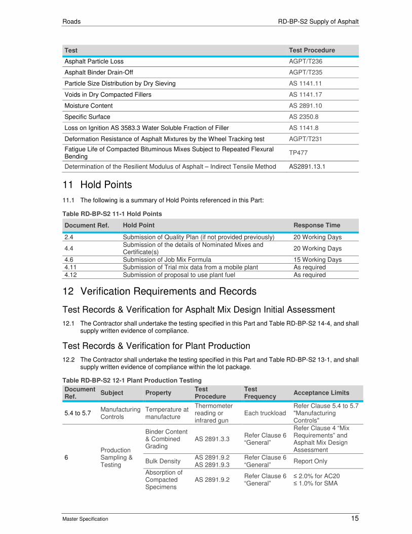
Roads RD-BP-S2 Supply of Asphalt
Master Specification 15
Test Test Procedure
Asphalt Particle Loss AGPT/T236
Asphalt Binder Drain-Off AGPT/T235
Particle Size Distribution by Dry Sieving AS 1141.11
Voids in Dry Compacted Fillers AS 1141.17
Moisture Content AS 2891.10
Specific Surface AS 2350.8
Loss on Ignition AS 3583.3 Water Soluble Fraction of Filler AS 1141.8
Deformation Resistance of Asphalt Mixtures by the Wheel Tracking test AGPT/T231
Fatigue Life of Compacted Bituminous Mixes Subject to Repeated Flexural Bending
TP477
Determination of the Resilient Modulus of Asphalt – Indirect Tensile Method AS2891.13.1
11 Hold Points
11.1 The following is a summary of Hold Points referenced in this Part:
Table RD-BP-S2 11-1 Hold Points
Document Ref. Hold Point Response Time
2.4 Submission of Quality Plan (if not provided previously) 20 Working Days
4.4 Submission of the details of Nominated Mixes and Certificate(s)
20 Working Days
4.6 Submission of Job Mix Formula 15 Working Days
4.11 Submission of Trial mix data from a mobile plant As required
4.12 Submission of proposal to use plant fuel As required
12 Verification Requirements and Records
Test Records & Verification for Asphalt Mix Design Initial Assessment
12.1 The Contractor shall undertake the testing specified in this Part and Table RD-BP-S2 14-4, and shall supply written evidence of compliance.
Test Records & Verification for Plant Production
12.2 The Contractor shall undertake the testing specified in this Part and Table RD-BP-S2 13-1, and shall supply written evidence of compliance within the lot package.
Table RD-BP-S2 12-1 Plant Production Testing
Document Ref.
Subject Property Test Procedure
Test Frequency
Acceptance Limits
5.4 to 5.7 Manufacturing Controls
Temperature at manufacture
Thermometer reading or infrared gun
Each truckload Refer Clause 5.4 to 5.7 "Manufacturing Controls"
6 Production Sampling & Testing
Binder Content & Combined Grading
AS 2891.3.3 Refer Clause 6 “General”
Refer Clause 4 “Mix Requirements” and Asphalt Mix Design Assessment
Bulk Density AS 2891.9.2 AS 2891.9.3
Refer Clause 6 “General”
Report Only
Absorption of Compacted Specimens
AS 2891.9.2 Refer Clause 6 “General”
≤ 2.0% for AC20 ≤ 1.0% for SMA

Roads RD-BP-S2 Supply of Asphalt
Master Specification 16
Document Ref.
Subject Property Test Procedure
Test Frequency
Acceptance Limits
Maximum Density
AS 2891.7.1 Refer Clause 6 “General”
Report Only
Voids on Compacted Specimens
AS 2891.8 Refer Clause 6 “General”
Refer Clause 4 “Mix Requirements” and Asphalt Mix Design Assessment
Binder Film Index (BFI)(1)
AS 2891.8 Refer Clause 6 “General”
Refer Clause 4 “Mix Requirements”
Resilient Modulus
AS2891.13.1 Refer Clause 6 “General”
Report only
(1) Absorption for RAP component assumed to be zero.
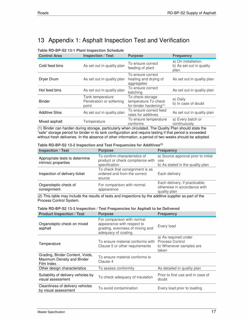
Roads RD-BP-S2 Supply of Asphalt
Master Specification 17
13 Appendix 1: Asphalt Inspection Test and Verification
Table RD-BP-S2 13-1 Plant Inspection Schedule
Control Area Inspection / Test Purpose Frequency
Cold feed bins As set out in quality plan To ensure correct feeding of plant
a) On installation. b) As set out in quality plan.
Dryer Drum As set out in quality plan To ensure correct heating and drying of aggregates
As set out in quality plan
Hot feed bins As set out in quality plan To ensure correct batching
As set out in quality plan
Binder Tank temperature Penetration or softening point
To check storage temperature To check for binder hardening(1)
a) Daily b) In case of doubt
Additive Silos As set out in quality plan To ensure correct feed rates for additives
As set out in quality plan
Mixed asphalt Temperature To ensure temperature conforms
a) Every batch or continuously
(1) Binder can harden during storage, particularly when circulated. The Quality Plan should state the “safe” storage period for binder in its tank configuration and require testing if that period is exceeded without fresh deliveries. In the absence of other information, a period of two weeks should be adopted.
Table RD-BP-S2 13-2 Inspection and Test Frequencies for Additives(2)
Inspection / Test Purpose Frequency
Appropriate tests to determine intrinsic properties
To confirm characteristics of product or check compliance with specification
a) Source approval prior to initial use b) As stated in the quality plan
Inspection of delivery ticket To check that consignment is as ordered and from the correct source
Each delivery
Organoleptic check of consignment
For comparison with normal appearance
Each delivery, if practicable; otherwise in accordance with quality plan
(2) This table may include the results of tests and inspections by the additive supplier as part of the Process Control System.
Table RD-BP-S2 13-3 Inspection / Test Frequencies for Asphalt to be Delivered
Product Inspection / Test Purpose Frequency
Organoleptic check on mixed asphalt
For comparison with normal appearance with respect to grading, evenness of mixing and adequacy of coating
Every load
Temperature To ensure material conforms with Clause 5 or other requirements
a) As required under Process Control b) Whenever samples are taken
Grading, Binder Content, Voids, Maximum Density and Binder Film Index
To ensure material conforms to Clause 4
Other design characteristics To assess conformity As detailed in quality plan
Suitability of delivery vehicles by visual assessment
To check adequacy of insulation Prior to first use and in case of doubt
Cleanliness of delivery vehicles by visual assessment
To avoid contamination Every load prior to loading
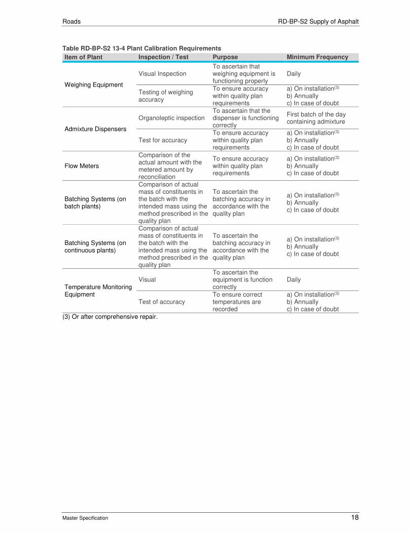
Roads RD-BP-S2 Supply of Asphalt
Master Specification 18
Table RD-BP-S2 13-4 Plant Calibration Requirements
Item of Plant Inspection / Test Purpose Minimum Frequency
Weighing Equipment
Visual Inspection To ascertain that weighing equipment is functioning properly
Daily
Testing of weighing accuracy
To ensure accuracy within quality plan requirements
a) On installation(3) b) Annually c) In case of doubt
Admixture Dispensers
Organoleptic inspection To ascertain that the dispenser is functioning correctly
First batch of the day containing admixture
Test for accuracy To ensure accuracy within quality plan requirements
a) On installation(3) b) Annually c) In case of doubt
Flow Meters
Comparison of the actual amount with the metered amount by reconciliation
To ensure accuracy within quality plan requirements
a) On installation(3) b) Annually c) In case of doubt
Batching Systems (on batch plants)
Comparison of actual mass of constituents in the batch with the intended mass using the method prescribed in the quality plan
To ascertain the batching accuracy in accordance with the quality plan
a) On installation(3) b) Annually c) In case of doubt
Batching Systems (on continuous plants)
Comparison of actual mass of constituents in the batch with the intended mass using the method prescribed in the quality plan
To ascertain the batching accuracy in accordance with the quality plan
a) On installation(3) b) Annually c) In case of doubt
Temperature Monitoring Equipment
Visual To ascertain the equipment is function correctly
Daily
Test of accuracy To ensure correct temperatures are recorded
a) On installation(3) b) Annually c) In case of doubt
(3) Or after comprehensive repair.

Roads RD-BP-S2 Supply of Asphalt
Master Specification 19
14 Appendix 2: Assessment and Registration of Asphalt Mix Designs
Submission
14.1 The Contractor shall submit the mix design together with supporting documentary evidence and laboratory and plant test results for mix and material properties to the Department.
14.2 The following details of Nominated Mix (NM) shall be submitted:
a) Constituent materials:
i) Aggregates - source, geological type;
ii) Added Mineral Filler - type, source;
iii) Binder - source, class or grade;
iv) Bitumen Adhesion Agent - name, type, source, SDS; and
v) relevant test results verifying material properties for the above mentioned materials.
b) Mix Design:
i) design mix maximum density;
ii) nominated combined aggregate grading and binder content;
iii) test results of the properties in tables of Clause 4 – “Mix Requirements” of each nominated mix;
iv) details of mixing plant location, description capacity, history and any relevant information in accordance Clause 2 “Quality Requirements”;
v) test results of representative material of each nominated mix produced by the mixing plant from which the asphalt is to be supplied; and
vi) manufacturer’s instructions of any additive including submission of SDS.
Table RD-BP-S2 14-1 Nominated Mixes - Testing Requirements
Characteristic(1) FineAC7 FineAC10 AC10 SMA7 SMA10 AC14 OG10 OG14
Gyropac Gyratory Compaction
Raw Aggregate Grading –Individual Sizes (%)
YES YES YES YES YES YES YES YES
Total Aggregates, Sand & Fillers Absorption (%)
YES YES YES YES YES YES YES YES
Mix Design Proportions
YES YES YES YES YES YES YES YES
Combined Gradings (%)
YES YES YES YES YES YES YES YES
Maximum Density (t/m3)
YES YES YES YES YES YES YES YES
Voids (%) YES YES YES YES YES YES YES YES Binder Content (%) YES YES YES YES YES YES YES YES
Binder Film Thickness (BFT) (µm)
YES YES YES YES YES YES NO NO
Tensile Strength Ratio (TSR)(3) (%)
YES YES YES NO NO YES NO NO
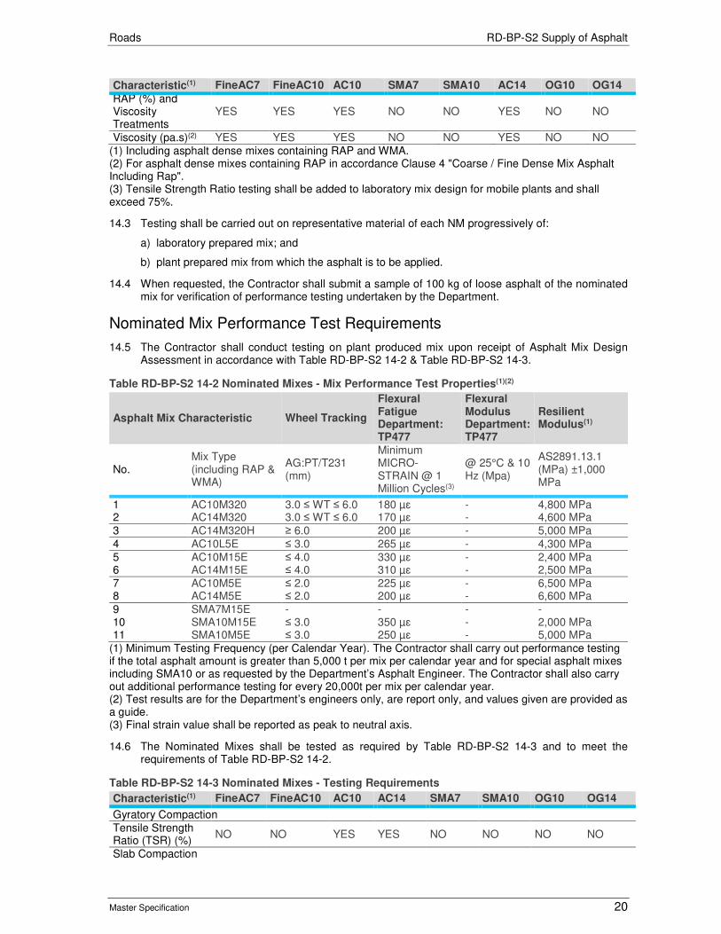
Roads RD-BP-S2 Supply of Asphalt
Master Specification 20
Characteristic(1) FineAC7 FineAC10 AC10 SMA7 SMA10 AC14 OG10 OG14
RAP (%) and Viscosity Treatments
YES YES YES NO NO YES NO NO
Viscosity (pa.s)(2) YES YES YES NO NO YES NO NO
(1) Including asphalt dense mixes containing RAP and WMA. (2) For asphalt dense mixes containing RAP in accordance Clause 4 "Coarse / Fine Dense Mix Asphalt Including Rap". (3) Tensile Strength Ratio testing shall be added to laboratory mix design for mobile plants and shall exceed 75%.
14.3 Testing shall be carried out on representative material of each NM progressively of:
a) laboratory prepared mix; and
b) plant prepared mix from which the asphalt is to be applied.
14.4 When requested, the Contractor shall submit a sample of 100 kg of loose asphalt of the nominated mix for verification of performance testing undertaken by the Department.
Nominated Mix Performance Test Requirements
14.5 The Contractor shall conduct testing on plant produced mix upon receipt of Asphalt Mix Design Assessment in accordance with Table RD-BP-S2 14-2 & Table RD-BP-S2 14-3.
Table RD-BP-S2 14-2 Nominated Mixes - Mix Performance Test Properties(1)(2)
Asphalt Mix Characteristic Wheel Tracking
Flexural Fatigue Department: TP477
Flexural Modulus Department: TP477
Resilient Modulus(1)
No. Mix Type (including RAP & WMA)
AG:PT/T231 (mm)
Minimum MICRO-STRAIN @ 1 Million Cycles(3)
@ 25°C & 10 Hz (Mpa)
AS2891.13.1 (MPa) ±1,000 MPa
1 2
AC10M320 AC14M320
3.0 ≤ WT ≤ 6.0 3.0 ≤ WT ≤ 6.0
180 µɛ 170 µɛ
- -
4,800 MPa 4,600 MPa
3 AC14M320H ≥ 6.0 200 µɛ - 5,000 MPa
4 AC10L5E ≤ 3.0 265 µɛ - 4,300 MPa
5 6
AC10M15E AC14M15E
≤ 4.0 ≤ 4.0
330 µɛ 310 µɛ
- -
2,400 MPa 2,500 MPa
7 8
AC10M5E AC14M5E
≤ 2.0 ≤ 2.0
225 µɛ 200 µɛ
- -
6,500 MPa 6,600 MPa
9 10 11
SMA7M15E SMA10M15E SMA10M5E
- ≤ 3.0 ≤ 3.0
- 350 µɛ 250 µɛ
- - -
- 2,000 MPa 5,000 MPa
(1) Minimum Testing Frequency (per Calendar Year). The Contractor shall carry out performance testing if the total asphalt amount is greater than 5,000 t per mix per calendar year and for special asphalt mixes including SMA10 or as requested by the Department’s Asphalt Engineer. The Contractor shall also carry out additional performance testing for every 20,000t per mix per calendar year. (2) Test results are for the Department’s engineers only, are report only, and values given are provided as a guide. (3) Final strain value shall be reported as peak to neutral axis.
14.6 The Nominated Mixes shall be tested as required by Table RD-BP-S2 14-3 and to meet the requirements of Table RD-BP-S2 14-2.
Table RD-BP-S2 14-3 Nominated Mixes - Testing Requirements
Characteristic(1) FineAC7 FineAC10 AC10 AC14 SMA7 SMA10 OG10 OG14
Gyratory Compaction
Tensile Strength Ratio (TSR) (%)
NO NO YES YES NO NO NO NO
Slab Compaction

Roads RD-BP-S2 Supply of Asphalt
Master Specification 21
Characteristic(1) FineAC7 FineAC10 AC10 AC14 SMA7 SMA10 OG10 OG14
Resilient Modulus NO NO YES YES YES YES NO NO
Flexural Fatigue and Modulus
NO NO YES YES YES YES NO NO
Wheel Tracking NO NO YES YES YES YES NO NO
(1) Including asphalt dense mixes containing RAP and WMA.
Asphalt Mix Design Assessment Progression
14.7 The following general stages apply to an asphalt mix design:
a) laboratory assessment;
b) plant production assessment;
c) performance testing assessment; and
d) field inspection (for surface course mixes).
14.8 On an ongoing basis, the following applies to an asphalt mix design:
a) plant production assessment including process control monitoring; and
b) performance testing on a minimum yearly basis.
14.9 If at any stage the Department deems a mix to be unsatisfactory, the registration may be withdrawn as indicated in Clause 4 “Variations to Nominated Mixes”.
Laboratory Assessment
14.10 The laboratory mix design shall incorporate the requirements of Clause 4 including following minimum requirements:
a) design grading curve based on raw aggregate gradings;
b) five point binder content verses voids laboratory analysis (washout binder content not required) using standard bitumen;
c) determination of design binder content at required target air voids;
d) provision of all Clause 4.24 requirements; and
e) plant trial of mix to verify aggregate gradings and design binder content,
14.11 The Contractor shall undertake the testing specified in this Part and Table RD-BP-S2 14-4, and submit the mix design together with supporting documentary evidence and laboratory and plant test results for mix and material properties to the Department.
Table RD-BP-S2 14-4 Initial Mix Design Testing
Ref. Subject Property Test Procedure Test Frequency Acceptance Limits
3.1 Materials for Asphalt
Binder, Flux and Cutter
Refer Clause 3.1 Refer Clause 3.1 Refer Clause 3.1
Aggregate, Sands & Mineral Filler
Refer Clause 3.1 Refer Clause 3.1 Refer Clause 3.1
Hydrated Lime Refer Clause 3.1 Refer Clause 3.1 Refer Clause 3.1
3.2
Reclaimed Asphalt Pavement Material (RAP)
Binder Content (wash out) & Grading
AS 2891.3.3 Refer Clause 3.3 Report Only
Asphalt Binder Viscosity
TP 664 Refer Clause 3.3 Report Only
Moisture Content AS 1289.B1.3 Refer Clause 3.3 Report Only
4 Mix Requirements
Total Absorption by Combined Agg.
AS 2891.9.2 Refer Clause 14 Report Only
Mix Design Proportions
Refer PC044 Refer Clause 14 Report Only
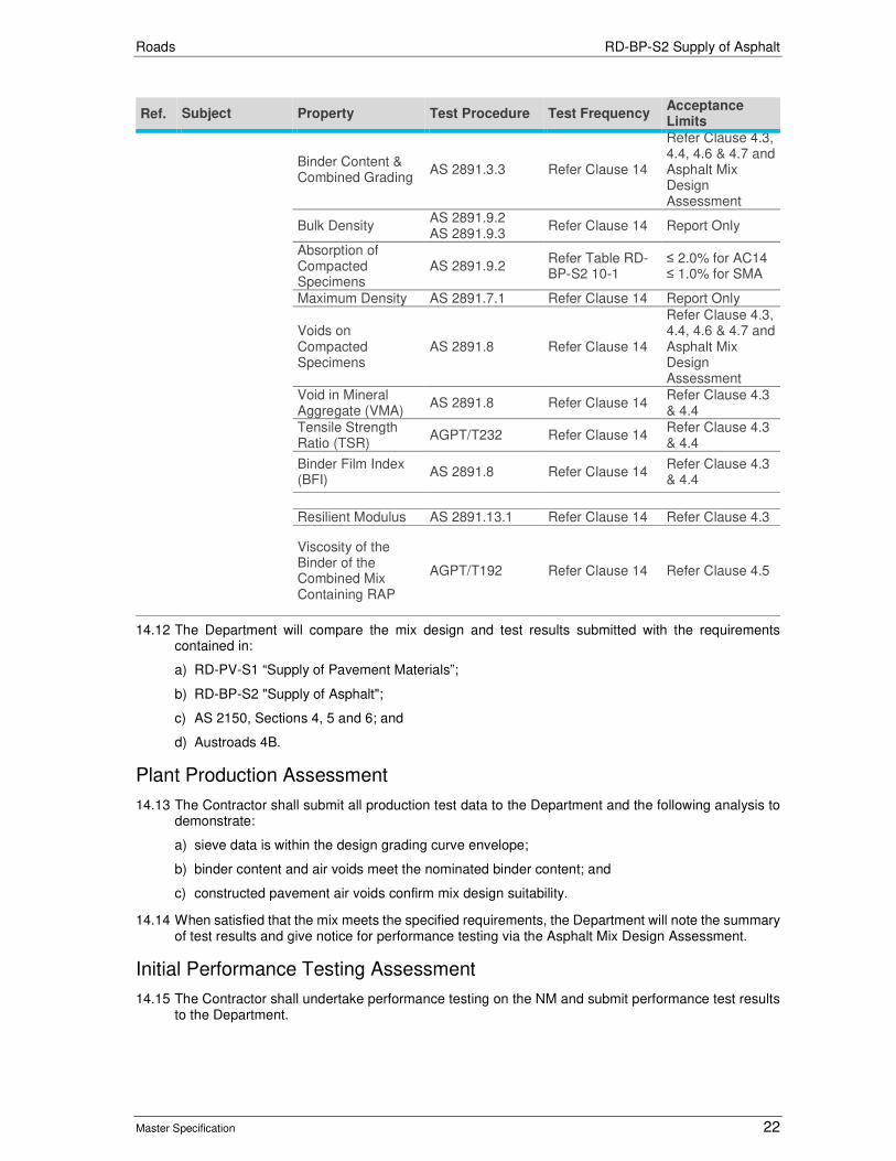
Roads RD-BP-S2 Supply of Asphalt
Master Specification 22
Ref. Subject Property Test Procedure Test Frequency Acceptance Limits
Binder Content & Combined Grading
AS 2891.3.3 Refer Clause 14
Refer Clause 4.3, 4.4, 4.6 & 4.7 and Asphalt Mix Design Assessment
Bulk Density AS 2891.9.2 AS 2891.9.3
Refer Clause 14 Report Only
Absorption of Compacted Specimens
AS 2891.9.2 Refer Table RD-BP-S2 10-1
≤ 2.0% for AC14 ≤ 1.0% for SMA
Maximum Density AS 2891.7.1 Refer Clause 14 Report Only
Voids on Compacted Specimens
AS 2891.8 Refer Clause 14
Refer Clause 4.3, 4.4, 4.6 & 4.7 and Asphalt Mix Design Assessment
Void in Mineral Aggregate (VMA)
AS 2891.8 Refer Clause 14 Refer Clause 4.3 & 4.4
Tensile Strength Ratio (TSR)
AGPT/T232 Refer Clause 14 Refer Clause 4.3 & 4.4
Binder Film Index (BFI)
AS 2891.8 Refer Clause 14 Refer Clause 4.3 & 4.4
Resilient Modulus AS 2891.13.1 Refer Clause 14 Refer Clause 4.3
Viscosity of the Binder of the Combined Mix Containing RAP
AGPT/T192 Refer Clause 14 Refer Clause 4.5
14.12 The Department will compare the mix design and test results submitted with the requirements contained in:
a) RD-PV-S1 “Supply of Pavement Materials”;
b) RD-BP-S2 "Supply of Asphalt";
c) AS 2150, Sections 4, 5 and 6; and
d) Austroads 4B.
Plant Production Assessment
14.13 The Contractor shall submit all production test data to the Department and the following analysis to demonstrate:
a) sieve data is within the design grading curve envelope;
b) binder content and air voids meet the nominated binder content; and
c) constructed pavement air voids confirm mix design suitability.
14.14 When satisfied that the mix meets the specified requirements, the Department will note the summary of test results and give notice for performance testing via the Asphalt Mix Design Assessment.
Initial Performance Testing Assessment
14.15 The Contractor shall undertake performance testing on the NM and submit performance test results to the Department.

Roads RD-BP-S2 Supply of Asphalt
Master Specification 23
Regular Mix Design Assessment
14.16 The Contractor shall submit asphalt plant production test data and material test data to the Department to support the NM.
14.17 The Contractor shall demonstrate to the Department the following:
a) The average air voids determined from production tests per mix are within ± 0.2% from target for 25 consecutive discrete samples.
b) The average binder content determined from production tests per mix shall not be lower than 0.05% from the nominated binder content for 25 consecutive discrete samples.
Regular Performance Testing Assessment
14.18 Performance testing shall be undertaken in accordance with Table RD-BP-S2 14-2 and Table RD-BP-S2 14-3 and submit them to the Department.
Registration
14.19 The Department shall maintain a register of assessed asphalt mixes. The Department will not issue additional mix register numbers if asphalt mixes are equal or less than 10% RAP incorporation, or Warm Mix Asphalt Additives or Foaming Technique are used. The “Mix Design Assessment” will consist of 5 pages, with a summary page that can be issued to the client. The “Registered Mix” number will be in this format: AASSDBBBZ-CCC-TXXX, where:
a) AA = Mix Type
b) SS = Nominal Mix Size (mm)
c) D = Duty Type
d) B = Binder Type
e) Z = additional suffix, e.g. L for Hydrated Lime, R for Regular, H for High Binder, and for inclusion of RAP, each 5% is given a number (1 to 9 for 5% through 45%)
f) CCC = Contractor’s name and plant
g) TXXX = sequential number for each mix combination, beginning at T001.

Roads
Master Specification
RD-DK-C2 Kerbing Document Information
K Net Number: 13524212
Document Version: 2
Document Date: 16/09/2019

Roads Contents
Master Specification 2
Document Amendment Record
Version Change Description Date Endorsement record (KNet ref.)
1 Initial issue (formerlyR05) 28/06/19
2 Formatting for publishing 16/09/19
Document Management This document is the Property of the Department for Infrastructure and Transport and contains information that is confidential to the Department. It must not be copied or reproduced in any way without the written consent of the Department. This is a controlled document and it will be updated and reissued as approved changes are made.

Roads Contents
Master Specification 3
Contents Contents 2
RD-DK-C2 Kerbing 4
1 General 4
2 Installation of Kerbing 4
3 Hold Points 5
4 Verification Requirements and Records 5
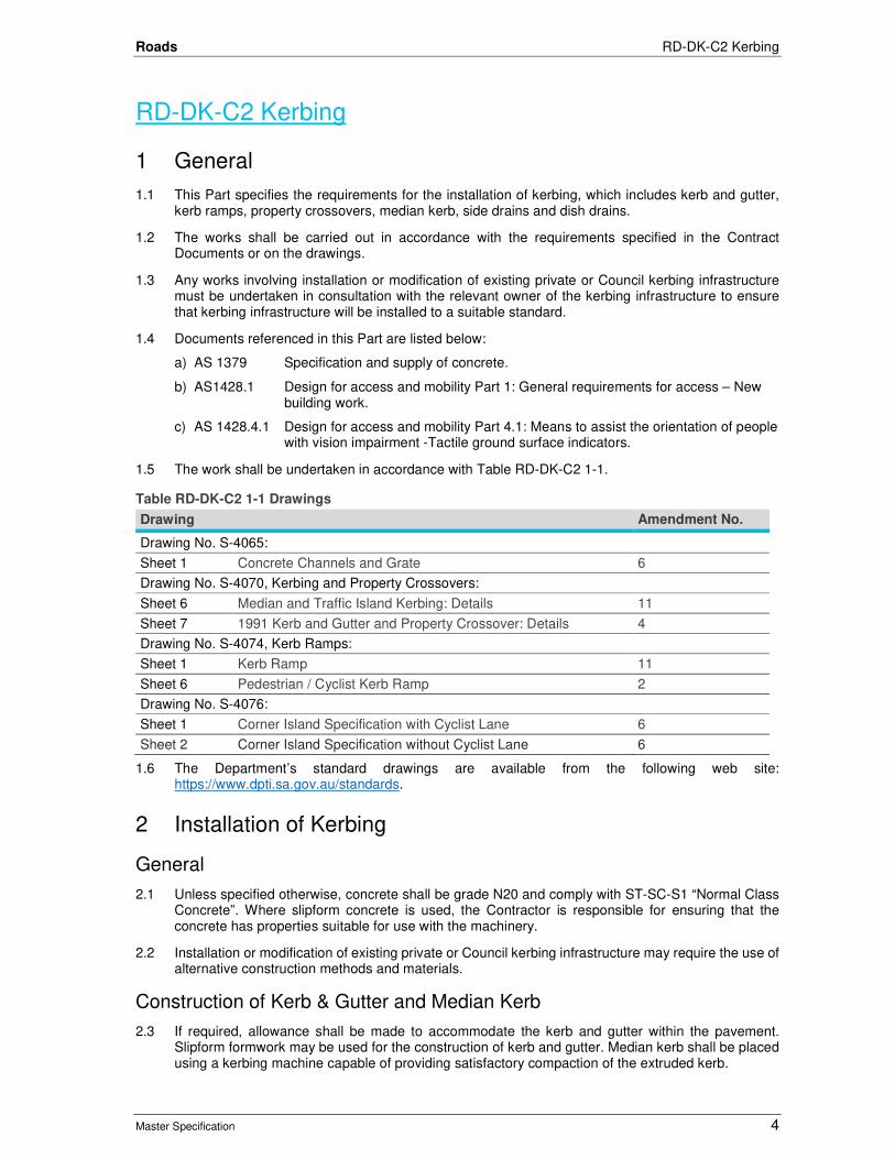
Roads RD-DK-C2 Kerbing
Master Specification 4
RD-DK-C2 Kerbing
1 General
1.1 This Part specifies the requirements for the installation of kerbing, which includes kerb and gutter, kerb ramps, property crossovers, median kerb, side drains and dish drains.
1.2 The works shall be carried out in accordance with the requirements specified in the Contract Documents or on the drawings.
1.3 Any works involving installation or modification of existing private or Council kerbing infrastructure must be undertaken in consultation with the relevant owner of the kerbing infrastructure to ensure that kerbing infrastructure will be installed to a suitable standard.
1.4 Documents referenced in this Part are listed below:
a) AS 1379 Specification and supply of concrete.
b) AS1428.1 Design for access and mobility Part 1: General requirements for access – New building work.
c) AS 1428.4.1 Design for access and mobility Part 4.1: Means to assist the orientation of people with vision impairment -Tactile ground surface indicators.
1.5 The work shall be undertaken in accordance with Table RD-DK-C2 1-1.
Table RD-DK-C2 1-1 Drawings
Drawing Amendment No.
Drawing No. S-4065:
Sheet 1 Concrete Channels and Grate 6
Drawing No. S-4070, Kerbing and Property Crossovers:
Sheet 6 Median and Traffic Island Kerbing: Details 11
Sheet 7 1991 Kerb and Gutter and Property Crossover: Details 4
Drawing No. S-4074, Kerb Ramps:
Sheet 1 Kerb Ramp 11
Sheet 6 Pedestrian / Cyclist Kerb Ramp 2
Drawing No. S-4076:
Sheet 1 Corner Island Specification with Cyclist Lane 6
Sheet 2 Corner Island Specification without Cyclist Lane 6
1.6 The Department’s standard drawings are available from the following web site: https://www.dpti.sa.gov.au/standards.
2 Installation of Kerbing
General
2.1 Unless specified otherwise, concrete shall be grade N20 and comply with ST-SC-S1 “Normal Class Concrete”. Where slipform concrete is used, the Contractor is responsible for ensuring that the concrete has properties suitable for use with the machinery.
2.2 Installation or modification of existing private or Council kerbing infrastructure may require the use of alternative construction methods and materials.
Construction of Kerb & Gutter and Median Kerb
2.3 If required, allowance shall be made to accommodate the kerb and gutter within the pavement. Slipform formwork may be used for the construction of kerb and gutter. Median kerb shall be placed using a kerbing machine capable of providing satisfactory compaction of the extruded kerb.

Roads RD-DK-C2 Kerbing
Master Specification 5
Property Crossovers
2.4 Unless specified otherwise, the nominal length of a crossover is 3.0 m (i.e. 1.5 m each side) greater than the width of the driveway at the property boundary. Exact lengths of property crossovers will be determined on site.
2.5 At least 7 days’ notice shall be given of when such determination is required. Allowance shall be made to accommodate reinforced property crossovers within the pavement.
2.6 Where works involve modification or replacement of existing Council crossovers, Council standard vehicle crossover details may apply with respect to cross over lengths and cross sectional profile.
Kerb Ramps
2.7 Kerb ramps at intersections shall be constructed of concrete and comply with AS 1428.1 and shall include tactile ground surface indicators complying with AS 1428.4.1.
Dish Drain
2.8 Allowance shall be made to accommodate dish drains within the pavement.
Joints
2.9 Joints shall be provided at intervals of 3 m maximum and shall be spaced uniformly where practicable. For median kerb Type 1 - 4a, polyethylene inserts shall be placed at 200 m intervals and at every change in horizontal direction. Polyethylene inserts shall be 50 mm thick closed cell polyethylene (as available from BIY Construction Supplies, Wingfield or equivalent approved).
Curing
2.10 The finished concrete kerbing shall be immediately sprayed with an accepted curing compound at a uniform application rate in accordance with the manufacturer's specifications. The Contractor shall nominate the curing compound to be used.
Backfill
2.11 Backfill of kerb and gutter shall be in accordance with RD-EW-C1 "Earthworks". Backfill to kerbing shall be completed prior to placing base against the kerbing.
Property Drainage Connections
2.12 Existing stormwater connections from private properties shall be maintained at all times.
3 Hold Points
3.1 There are no Hold Points referenced in this Part.
4 Verification Requirements and Records
4.1 The Contractor shall supply written verification that the following requirements have been complied with and supply the verification with the lot package.
Table RD-DK-C2 4-1 Verification Requirements
Document Ref.
Subject Property Test Procedure
Test Frequency
Acceptance Limits
2.1 – 2.7 Kerbing: dimensions, level and position
Variation in cross-sectional dimensions
As specified in PC-SI1 “Site Surveys”, Sections 6.1 – 6.4
As specified in PC-SI1 “Site Surveys”, Table PC-SI1 6 1 Roadworks Compliance
Within ± 3 mm of specified dimension
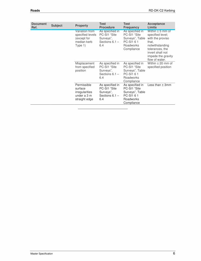
Roads RD-DK-C2 Kerbing
Master Specification 6
Document Ref.
Subject Property Test Procedure
Test Frequency
Acceptance Limits
Variation from specified levels (except for median kerb Type 1)
As specified in PC-SI1 “Site Surveys”, Sections 6.1 – 6.4
As specified in PC-SI1 “Site Surveys”, Table PC-SI1 6 1 Roadworks Compliance
Within ± 5 mm of specified level; with the proviso that, notwithstanding tolerances, the invert shall not impede the gravity flow of water.
Misplacement from specified position
As specified in PC-SI1 “Site Surveys”, Sections 6.1 – 6.4
As specified in PC-SI1 “Site Surveys”, Table PC-SI1 6 1 Roadworks Compliance
Within ± 20 mm of specified position
Permissible surface irregularities under a 3 m straight edge
As specified in PC-SI1 “Site Surveys”, Sections 6.1 – 6.4
As specified in PC-SI1 “Site Surveys”, Table PC-SI1 6 1 Roadworks Compliance
Less than ± 3mm

Roads
Master Specification
RD-EL-C1 Installation of Lighting for Roads and Public Spaces Document Information
KNet Number: 13469582
Document Version: 3
Document Date: August 2020

Roads Contents
Master Specification 2
Document Amendment Record Version Change Description Date
1 Initial issue (formerly R52). General document review and update; updated Referencing.
02/07/19
2 Formatting for publishing 20/09/19
3
Clarification of mounting plate setup requirement to cover both slip base and energy absorbing pole to ensure the acceptable verticality of the pole. Added requirement of 240V warning sicker to be installed on Combo pole at ELV traffic signal site.
August 2020
Document Management This document is the Property of the Department for Infrastructure and Transport and contains information that is confidential to the Department. It must not be copied or reproduced in any way without the written consent of the Department. This is a controlled document and it will be updated and reissued as approved changes are made.

Roads Contents
Master Specification 3
Contents Contents 3
RD-EL-C1 Installation of Lighting for Roads and Public Spaces 4
1 General 4
2 Materials 4
3 Pole Footings 4
4 Trenching, Boring and Backfill 5
5 Assembly and Erection of Poles 5
6 Electrical Work 6
7 Supply Points 7
8 Service Points 7
9 Wiring 7
10 Luminaires 8
11 Lamps 8
12 Other Lighting 8
13 Acceptance 8
14 Removal of Existing Poles and Footings 8
15 Hold Points 9
16 Verification Requirements and Records 9
17 Appendix 1: Street Lighting Pole Assembly Instructions 10

Roads RD-EL-C1 Installation of Lighting for Roads and Public Spaces
Master Specification 4
RD-EL-C1 Installation of Lighting for Roads and Public Spaces
1 General
1.1 This Part specifies the requirements for the installation of lighting for roads and public spaces.
1.2 Documents referenced in this Part are listed below:
a) AS/NZS 2053 Conduits and Fittings for Electrical Installations.
b) AS/NZS 3000 Electrical Installations (known as the Australian/New Zealand Wiring Rules).
1.3 The work shall comply with the following (in order of precedence):
a) AS/NZS 3000: Electrical Installations (known as the Australian/New Zealand Wiring Rules);
b) Contract specific drawings and specified by the Principal (if any);
c) Department Technical Standards and Guidelines including standard drawings are available from the following web site: https://www.dpti.sa.gov.au/standards; and
d) any other relevant Australian Standards.
1.4 Where necessary, the Contractor shall liaise with SA Power Networks regarding the removal of SA Power Networks’ poles and shall co-ordinate this work in conjunction with the installation and operation of the Principal's light poles.
2 Materials
2.1 Materials shall comply with the following:
a) Poles, Outreaches and Footing Units: RD-EL-S1 “Supply of Lighting Components”;
b) Luminaries: RD-EL-S2 “Supply of Luminaries”;
c) Conduits and Junction Pits: RD-EL-C3 “Installation of Conduits and Pits”;
d) Footing Reinforcement: ST-SC-S6 “Steel Reinforcement”;
e) Concrete: ST-SC-S1 “Normal Class Concrete”;
f) Flexible Conduit: Flexible Conduit to AS/NZS 2053; and
g) Other Conduit: Heavy Duty Rigid PVC Conduit to AS/NZS 2053 (colour orange).
2.2 If the Contractor supplies frangible poles, the Contractor shall provide evidence demonstrating compliance with requirements of RD-EL-S1 “Supply of Lighting Components. Provision of the documentation shall constitute a Hold Point.
3 Pole Footings
Setting Out
3.1 The positions of the footings shall be set out from the coordinates given in the Geometric Details document, on the drawings or as referenced by chainage and offset.
3.2 The direction of the outreach shall be as shown on the drawings.
3.3 The access hatch on poles shall be positioned on the rear of the pole so that it can be easily and safely accessed. If this is not practical, it shall be positioned on the side opposite to the on-coming traffic.
3.4 The level and slope of the concrete surround shall match the specified finished levels and slopes for the surrounding ground.
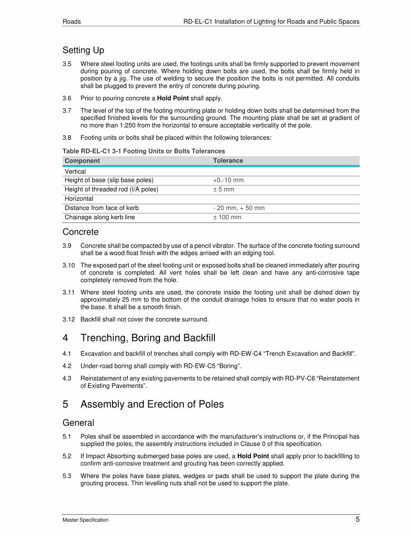
Roads RD-EL-C1 Installation of Lighting for Roads and Public Spaces
Master Specification 5
Setting Up
3.5 Where steel footing units are used, the footings units shall be firmly supported to prevent movement during pouring of concrete. Where holding down bolts are used, the bolts shall be firmly held in position by a jig. The use of welding to secure the position the bolts is not permitted. All conduits shall be plugged to prevent the entry of concrete during pouring.
3.6 Prior to pouring concrete a Hold Point shall apply.
3.7 The level of the top of the footing mounting plate or holding down bolts shall be determined from the specified finished levels for the surrounding ground. The mounting plate shall be set at gradient of no more than 1:250 from the horizontal to ensure acceptable verticality of the pole.
3.8 Footing units or bolts shall be placed within the following tolerances:
Table RD-EL-C1 3-1 Footing Units or Bolts Tolerances
Component Tolerance
Vertical
Height of base (slip base poles) +0,-10 mm
Height of threaded rod (I/A poles) ± 5 mm
Horizontal
Distance from face of kerb - 20 mm, + 50 mm
Chainage along kerb line ± 100 mm
Concrete
3.9 Concrete shall be compacted by use of a pencil vibrator. The surface of the concrete footing surround shall be a wood float finish with the edges arrised with an edging tool.
3.10 The exposed part of the steel footing unit or exposed bolts shall be cleaned immediately after pouring of concrete is completed. All vent holes shall be left clean and have any anti-corrosive tape completely removed from the hole.
3.11 Where steel footing units are used, the concrete inside the footing unit shall be dished down by approximately 25 mm to the bottom of the conduit drainage holes to ensure that no water pools in the base. It shall be a smooth finish.
3.12 Backfill shall not cover the concrete surround.
4 Trenching, Boring and Backfill
4.1 Excavation and backfill of trenches shall comply with RD-EW-C4 “Trench Excavation and Backfill”.
4.2 Under-road boring shall comply with RD-EW-C5 “Boring”.
4.3 Reinstatement of any existing pavements to be retained shall comply with RD-PV-C6 “Reinstatement of Existing Pavements”.
5 Assembly and Erection of Poles
General
5.1 Poles shall be assembled in accordance with the manufacturer’s instructions or, if the Principal has supplied the poles, the assembly instructions included in Clause 0 of this specification.
5.2 If Impact Absorbing submerged base poles are used, a Hold Point shall apply prior to backfilling to confirm anti-corrosive treatment and grouting has been correctly applied.
5.3 Where the poles have base plates, wedges or pads shall be used to support the plate during the grouting process. Thin levelling nuts shall not be used to support the plate.

Roads RD-EL-C1 Installation of Lighting for Roads and Public Spaces
Master Specification 6
5.4 After erection, all poles shall be vertical. Poles shall be marked with the Department identification no. (as shown on the drawings) using a Vinyl film label with permanent acrylic adhesive material (Brady B-7569 or equivalent accepted by the Principal), which:
a) has a white background with black numbers;
b) has numbers at least 40 mm high using a bold, sans-serif font;
c) is horizontally attached to the poles at a height of 1.7 m; and
d) is orientated 45° towards the oncoming traffic so that it can be easily read from an approaching vehicle.
5.5 Where combination traffic signal / road lighting poles are installed in ELV traffic signal intersection, if road lighting is fed from LV supply, dual Voltage 240V AC and 42V AC voltages present stickers shall be installed to the opening of the door of the Combination Pole.
5.6 GPS coordinates (latitude and longitude) for each asset shall be provided to the Department for inclusion in lighting database.
Slip Base Poles
5.7 At least 2 days prior to installation, the Contractor shall provide a copy of the current Calibration Certificate for the torque wrench. The certificate shall not be dated 12 months earlier than the Date of Acceptance of Tender. Provision of the Certification shall constitute a Hold Point.
5.8 Threads shall be cleaned to allow hand tightening of clamping bolts prior to torque being applied. The clamping bolts shall be tightened to the torque specified on the drawings using a calibrated torque wrench. The Contractor shall provide a copy of the certification that all clamping bolts have been correctly tensioned in accordance with this Clause.
6 Electrical Work
General
6.1 All electrical installations shall be carried out by an electrical worker who is licensed to perform any electrical works. The installations shall comply with AS 3000 and the Service Rules and Conditions of Supply of SA Power Networks.
Working in the Vicinity of Existing Overhead Cables
6.2 The Contractor shall:
a) comply with the requirements of the Technical Regulator when working in the vicinity of existing overhead electricity cables;
b) ensure that at least one person trained in working near overhead cables is present to supervise the work taking place near overhead cables; and
c) obtain approval from the Technical Regulator before working within the restricted zone as outlined in the Office of the Technical Regulator documents Building Safely Near Powerlines and Working Safely Near Powerline, available from:
i) https://www.sa.gov.au/__data/assets/pdf_file/0003/18606/150513-Building-safely-near-powerlines-web.pdf; and
ii) https://www.sa.gov.au/__data/assets/pdf_file/0003/6969/160708-Working-safely-near-overhead-powerlines.pdf.
6.3 Provision of the approval and evidence of training shall constitute a Hold Point.
Inspection
6.4 The Contractor shall:
a) arrange for Certificates of Compliance for all electrical work;

Roads RD-EL-C1 Installation of Lighting for Roads and Public Spaces
Master Specification 7
b) provide copies of the certificates to the Principal; and
c) pay for any applicable fees for the connections.
7 Supply Points
General
7.1 If the Principal has made arrangements for supply point locations, the locations will be shown on the drawings. The Contractor shall confirm the position of the supply points on-site and with SAPN before installing conduit runs to these points.
7.2 If the Contractor is to arrange service points, the Contractor shall:
a) complete and submit a SA Power Networks REX application;
b) provide a copy of the form to the Principal and the Department’s Electrical Asset Management Unit;
c) provide Certificates of Compliance to the Principal in accordance with the Electricity Act; and
d) apply for an electricity meter where required.
Temporary Supply and Service Points
7.3 For details of any temporary overhead supply points and / or service points refer to the Principal.
8 Service Points
General
8.1 SAPN underground or Stobie pole supply shall be connected in accordance with SA Power Networks service supply rules and regulations.
Layout
8.2 The layout of switchboards and general circuit arrangement of service points shall be substantially as shown on the drawings.
Location
8.3 Services fuses shall not be located in Department switchboards.
8.4 Isolation pit and fuse shall be installed in accordance with Department standard drawings. Three phase installation shall have all phases identified on both sides of the isolation fuse with appropriate coloured heat shrink.
9 Wiring
Combination / Combo Mast Arm poles
9.1 Unless specified otherwise, combination / combo mast arm poles shall be fed from the traffic signal controller.
Four Way Lighting Poles
9.2 Four way lighting poles shall have two circuits fed from the same phase in accordance with the drawing.
Conductors
9.3 Notwithstanding AS 3000, all neutrals shall have black primary insulation.

Roads RD-EL-C1 Installation of Lighting for Roads and Public Spaces
Master Specification 8
9.4 All active and neutral conductors shall be double insulated and comply with AS3000.
Circuit Breakers
9.5 All circuit breakers shall be as specified in the Contract specific drawings or standard drawings.
Jointing
9.6 All joints below ground shall be waterproofed using Department approved epoxy jointing kits. "Tee-offs" shall be of equivalent size to a "Scotchcast" 90-B1 or larger.
Cable Lengths
9.7 Spare cable shall be installed in each junction pit equal to the length plus the width of the junction pit. Spare cable shall be installed neatly in a loop and suitably cable tied.
Earthing
9.8 All earthing electrodes shall be 13 mm diameter copper sheathed steel stakes. Earth electrodes shall be provided in accordance with SA Power Networks Supply and Installation rules and shall be identified and protected in accordance with AS 3000.
10 Luminaires
General
10.1 Luminaires shall be the type specified on the drawings and in accordance with Department Approved Products list.
Mounting
10.2 Unless otherwise specified, luminaires shall be mounted horizontally with zero degree upcast.
Conductors
10.3 All single insulated conductors in the luminaires shall have a heat rating appropriate for the expected temperatures in their location in the housing.
11 Lamps
11.1 Unless specified otherwise, luminaires shall be LED of the wattage and type specified on the drawings.
12 Other Lighting
12.1 Any other lighting shall be as specified by the Principal or on the drawings.
13 Acceptance
13.1 The Contractor shall demonstrate that all lamps are operational as designed, prior to acceptance. All pits and infrastructure shall be free of vermin and debris at the time of asset handover.
14 Removal of Existing Poles and Footings
14.1 Where specified, the Contractor shall remove Department lighting poles and footings shown on the drawings. The Contractor shall provide 2 weeks’ notice prior to removal. Unless specified otherwise, backfill of holes resulting from removal of existing footings shall be in accordance with Clause 4 "Trenching, Boring and Backfill".
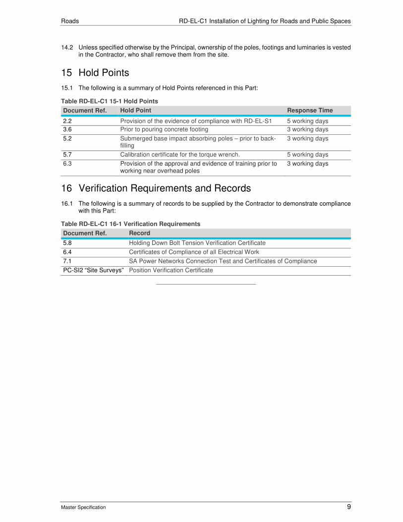
Roads RD-EL-C1 Installation of Lighting for Roads and Public Spaces
Master Specification 9
14.2 Unless specified otherwise by the Principal, ownership of the poles, footings and luminaries is vested in the Contractor, who shall remove them from the site.
15 Hold Points
15.1 The following is a summary of Hold Points referenced in this Part:
Table RD-EL-C1 15-1 Hold Points
Document Ref. Hold Point Response Time
2.2 Provision of the evidence of compliance with RD-EL-S1 5 working days
3.6 Prior to pouring concrete footing 3 working days
5.2 Submerged base impact absorbing poles – prior to back-filling
3 working days
5.7 Calibration certificate for the torque wrench. 5 working days
6.3 Provision of the approval and evidence of training prior to working near overhead poles
3 working days
16 Verification Requirements and Records
16.1 The following is a summary of records to be supplied by the Contractor to demonstrate compliance with this Part:
Table RD-EL-C1 16-1 Verification Requirements
Document Ref. Record
5.8 Holding Down Bolt Tension Verification Certificate
6.4 Certificates of Compliance of all Electrical Work
7.1 SA Power Networks Connection Test and Certificates of Compliance
PC-SI2 “Site Surveys” Position Verification Certificate
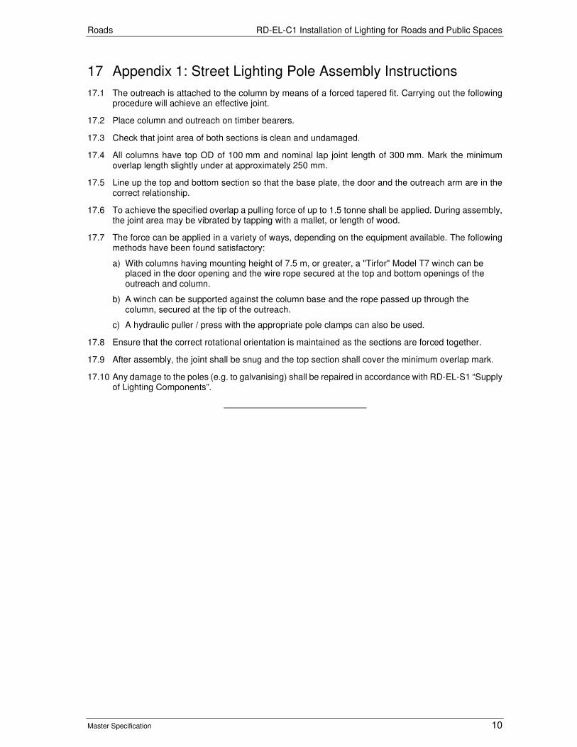
Roads RD-EL-C1 Installation of Lighting for Roads and Public Spaces
Master Specification 10
17 Appendix 1: Street Lighting Pole Assembly Instructions
17.1 The outreach is attached to the column by means of a forced tapered fit. Carrying out the following procedure will achieve an effective joint.
17.2 Place column and outreach on timber bearers.
17.3 Check that joint area of both sections is clean and undamaged.
17.4 All columns have top OD of 100 mm and nominal lap joint length of 300 mm. Mark the minimum overlap length slightly under at approximately 250 mm.
17.5 Line up the top and bottom section so that the base plate, the door and the outreach arm are in the correct relationship.
17.6 To achieve the specified overlap a pulling force of up to 1.5 tonne shall be applied. During assembly, the joint area may be vibrated by tapping with a mallet, or length of wood.
17.7 The force can be applied in a variety of ways, depending on the equipment available. The following methods have been found satisfactory:
a) With columns having mounting height of 7.5 m, or greater, a "Tirfor" Model T7 winch can be placed in the door opening and the wire rope secured at the top and bottom openings of the outreach and column.
b) A winch can be supported against the column base and the rope passed up through the column, secured at the tip of the outreach.
c) A hydraulic puller / press with the appropriate pole clamps can also be used.
17.8 Ensure that the correct rotational orientation is maintained as the sections are forced together.
17.9 After assembly, the joint shall be snug and the top section shall cover the minimum overlap mark.
17.10 Any damage to the poles (e.g. to galvanising) shall be repaired in accordance with RD-EL-S1 “Supply of Lighting Components”.

Roads
Master Specification
RD-EL-C2 Installation of Traffic Signals Document Information
KNet Number: 13055308
Document Version: 3
Document Date: August 2020

Roads Contents
Master Specification 2
Document Amendment Record Version Change Description Date
1 Initial issue (formerly R55). Updated SCATS Communication; added UPS requirement; updated referencing.
02/07/19
2 Formatting for publishing 19/09/19
3
Added requirement for separate fuse to be installed in traffic signal controller for RC1 signs fed off from signal controller which is more than 12 SGs. Emphasized spacing requirement between traffic signal controller and UPS cabinet and cross reference to Department standard drawing. Added the requirement of dual supply stickers. Added complementary process outlining switch-on requirements.
August 2020
Document Management This document is the Property of the Department for Infrastructure and Transport and contains information that is confidential to the Department. It must not be copied or reproduced in any way without the written consent of the Department. This is a controlled document and it will be updated and reissued as approved changes are made.
Roads Contents
Master Specification 3
Contents Contents 3
RD-EL-C2 Installation of Traffic Signals 4
1 General 4
2 Electrical Installation and Testing 6
3 Trench Work, Conduits and Pits 6
4 Construction of Footings 6
5 Cabling 7
6 Installation of Equipment 9
7 Traffic Signal Controller 12
8 Provision of Telecommunications for SCATS® 13
9 Bluetooth Capture Stations 14
10 Detector Loop Installation 14
11 Uninterrupted Power Supply (UPS) 15
12 Switch-On 16
13 Hold Points 16
14 Verification Requirements and Records 17
15 Appendix 1: Site Wiring Layout (Sample Only) 18
16 Appendix 2: UPS Warning Label sticker template, 110mm (w) x 80mm (h) 21
Roads RD-EL-C2 Installation of Traffic Signals
Master Specification 4
RD-EL-C2 Installation of Traffic Signals
1 General
References
1.1 This Part specifies the requirements for the installation of traffic signals.
a) "LV/ELV Cables" means cables complying with AS/NZS 2276.1.
b) "LV Cables" means cables complying with AS/NZS 5000.
c) "Detector Feeder Cables" means cables complying with AS/NZS 2276.2.
Definitions
1.2 The following definitions apply to terms used in this Part:
Table RD-EL-C2 1-1 Definitions
Term Definition
SCATS® Sydney Coordinated Adaptive Traffic System, property of RMS NSW.
TMC Traffic Management Centre (Norwood unless stated otherwise)
TSOPR Traffic Signal Operation Performance Report.
1.3 The Department, in the context of this Part of the specification, refers to officials of the department acting in a third party capacity to supply services or an administrative function not available elsewhere.
1.4 Documents referenced in this Part are listed below:
a) AS 2144 Traffic Signal Lanterns.
b) AS/NZS 2276 Cables for Traffic Signal Installations.
c) AS 2578 Traffic signal controllers.
d) AS 2339 Traffic Signal Posts, Mast Arms and Attachments.
e) AS/NZS 3000 Electrical Installations (known as the Australian/New Zealand Wiring Rules).
f) AS/NZS 5000 Electric Cables – Polymeric Insulated.
g) Specification No.TSI-SP-069 Control Equipment for Road Traffic Signals by Transport for New South Wales Road and Marine Services.
h) Department Operational Instruction 14.2: Traffic Signal Faces.
i) Department RD-EL-D2 Traffic Signal Design.
1.5 The work shall comply with the following documents:
a) TSOPR and Traffic Signals Design Report;
b) Traffic Signal Layout Drawings;
c) Traffic Signal Conduit Layout Drawings;
d) Site Wiring Diagram;
e) Cable Connection Schedule;
f) Detector Wiring Chart;
g) SA Power Networks Service Rules and Conditions of Supply; and
h) the following standard drawings, including all current published amendments:

Roads RD-EL-C2 Installation of Traffic Signals
Master Specification 5
Table RD-EL-C2 1-2 List of Department Standard Drawings referenced in this Part
Drawing No Sheet No.
Title
S-4055 30 Combination T-S Road Lighting Mast Arms & Existing Impact Absorbing Light Poles, Base Plate Mounted Pile Footing and Anchor Details
37 Impact Absorbing Light Pole - Base Plate Mounted Squat Footing & Anchor Detail
40 Impact Absorbing Road Lighting Poles (Base Plate Mounted) Standard & Combination Road Lighting Pole
41 Combination TS Road Lighting Mast Arm
42 Traffic Signal Mast Arm
48 Traffic Signals for Railway Crossing – Mast Arm
49 Traffic Signals for Railway Crossings - Combination TS / Road Lighting Mast Arm
50 Pits, Concrete Lids and Surrounds
51 Pits and Lockable Lids
66 Plastic Pits - Non Secured Concrete Lids & Surrounds
73 Signal Controller - UPS Distribution General Layout & Interconnection Single Line Diagram
S-4500 1 Detector Loop Layout (1 of 2)
2 Detector Loop Layout (2 of 2)
S-4512 3 Pavement Mounted Controller Base Details
S-4514 1 Post Mounted Controller, Foundation Details
S-4515 2 Standard Drawing - Traffic Signals Post - Post Footing and Installation
S-4516 2 Push Button Bracket for Stobie Poles
S-4517 1 Upper Mounting Assembly for Traffic Signal Post
S-4518 2 Terminal Box, Post Mounted
S-4537 6 Traffic Signal Post- Post Types and Post Mounting Details
S-4074 7 Kerb Ramps for Signalised Locations
S-4538 1 Traffic Signals Faces - Aiming Of Lantern Distances
2 Template for Checking Visor & Louvre Requirements
1.6 Department Technical Standards and Guidelines are available from the following web site: https://www.dpti.sa.gov.au/standards.
1.7 Where this Part specifies a higher standard than that required by the above Australian Standards, the requirements of this Part will take precedence.
Approval of Traffic Control Devices
1.8 Traffic signals are traffic control devices requiring approval pursuant to the Road Traffic Act 1961(SA) and the Road Rules.
1.9 The Contractor is responsible for ensuring that the traffic signals are formally approved by the Department. A minimum notice of 15 working days is required for this process. (See also Clause 7.6 and 7.7 in relation to programming the controller(s).)
1.10 Provision of suitable drawings showing the traffic control devices shall constitute a Hold Point.
1.11 The provision of an approved drawing and request for the preparation of a traffic signal personality requires 8 weeks’ notice. The provision of the approved drawing is a Hold Point as required in Clause 7.7. The Contractor should note that these periods run consecutively.
Products for Installation
1.12 Products provided as part of this Contract shall be approved by the Department. Supply of the list of products shall constitute a Hold Point.
1.13 For a list of traffic signal products approved by the Department refer to: https://www.dpti.sa.gov.au/__data/assets/pdf_file/0012/330105/DPTI_Approved_Products_Contract_Works.pdf.
1.14 The Contractor may submit a request for the approval of additional products.

Roads RD-EL-C2 Installation of Traffic Signals
Master Specification 6
2 Electrical Installation and Testing
2.1 Unless otherwise specified, the Traffic Signal Design shall incorporate extra low voltage (ELV) traffic signal controllers, Lanterns and other electrical equipment for new traffic signal sites.
2.2 All electrical installations shall be carried out by an electrical worker who is licensed to perform any electrical works. The installations shall comply with AS/NZS 3000 and the Service Rules and Conditions of Supply of SA Power Networks.
2.3 Prior to the commencement of this work, the Contractor shall provide evidence of the Licence and a Hold Point shall apply.
3 Trench Work, Conduits and Pits
3.1 The work shall comply with the following:
a) RD-EW-C2 “Trench Excavation and Backfill”;
b) RD-EW-C3 “Boring”;
c) RD-PV-C6 “Reinstatement of Existing Pavements”;
d) RD-EL-C3 “Supply and Installation of Conduits and Pits”; and
e) RD-EL-D3 “Conduit Design for Road Lighting, Traffic Signals and ITS”.
4 Construction of Footings
General
4.1 Cast-in-place concrete shall comply with ST-SC-S1 “Normal Class Concrete”.
4.2 Unless specified otherwise, all footings shall be constructed of unreinforced Normal class concrete, Grade N20. The top surface of concrete shall be finished with a wooden float to a smooth even surface.
Signal Post Footings
4.3 Signal post footings shall be constructed as shown on Drawings No. S-4515, sheet 2.
Mast Arm Footings
4.4 Mast arm footings and reinforcement shall be constructed in accordance with the Department’s Standard Drawing No. S-4055, sheet 30.
4.5 A Hold Point shall apply at the completion of excavation and prior to the construction of the footing to assess the suitability of the soil to support the footing.
Signal Controller Footings
4.6 The signal controller footing plus surround shall be of the type shown on the Traffic Signal Conduit Layout Drawing and shall be constructed as shown on the following Drawings:
a) Pavement Mounted Controller - Base Details: Drawing No. S 4512, sheet 3.
b) Holding Down Bolts for Traffic Signal Posts: Drawing No. S 4515, sheet 2.
4.7 The front of the housing is detailed on the Traffic Signal Conduit Layout Drawing.

Roads RD-EL-C2 Installation of Traffic Signals
Master Specification 7
5 Cabling
Cable Installation
General
5.1 LV / ELV cables shall be used for traffic signal multi-core power cables for both low voltage and extra low voltage applications. LV cables shall be used for low voltage applications.
5.2 Installation of cables shall be as detailed in the Site Wiring Diagrams, Cable Connection Schedules and in conjunction with the Traffic Signal Conduit Layout Drawing. All cables shall be continuous and without joins except at termination points.
5.3 The Contractor shall submit a Site Wiring Diagram prior to the installation of any cabling. The Site Wiring Diagram shall detail:
a) type of signal pole;
b) cable size and connection schedules;
c) pole, lantern and pedestrian signal groups;
d) detector feeder cables;
e) connections to audio and camera installations as applicable;
f) the installation shall include a minimum of 10 spare cores in road crossings and 3 spare cores to each signal post top; and
g) Junction Boxes.
5.4 Site Wiring Diagrams and Cable Connection Schedules shall be submitted in the format as shown in the sample in Appendix 1: Site Wiring Layout (Sample Only) shall constitute a Hold Point.
5.5 Cables shall be drawn through signal ducting using draw cords and shall be installed through pits and ducts without causing damage to the cable. Excessive strain shall not be placed on any individual core, individual cable or group of cables during the drawing in process. A draw cord shall remain in the conduit after the installation of the cable to enable to installation of additional cables in the future.
Signal Post and Controller Cables (LV / ELV Cables)
5.6 The length of signal post cable tails required on installation at the base of signal posts and signal controllers shall be as follows:
a) Signal Post Base: 5.5 m.
b) Signal Controller Base: 1.8 m.
5.7 After termination all spare cable shall be stored in the base of the signal post and signal controller.
Detector Feeder Cables
5.8 Detector feeder cables shall be drawn around the signal site in separate ducts to LV and LV / ELV cables unless otherwise specified on the Traffic Signal Conduit Layout Drawing. The length of detector feeder cable tails required on installation at the signal controller base and detector pit shall be as follows:
a) Signal Controller Base: 2 m.
b) Detector Pit: 0.5 m.
5.9 After termination all spare cable shall be stored in the base of the signal controller and the detector pit.
Consumer Mains Cable (LV Cable)
5.10 A consumer mains service cable shall be drawn in between the SA Power Networks supply service point, the underground service pit and the signal controller base as shown on the Traffic Signal Conduit Layout Drawing and in accordance with SA Power Networks Drawing E1163/B.

Roads RD-EL-C2 Installation of Traffic Signals
Master Specification 8
5.11 Where the electrical supply service point cannot be located conveniently close to the signal controller and the consumer mains cable is drawn to the signal controller base via the underground cable draw-in pits, this cable shall be drawn in through a separate conduit to all other cables unless otherwise specified on the Traffic Signal Conduit Layout Drawing and fixed with insulated saddles to the walls of such pits and clearly labelled as "CONSUMER MAINS SERVICE" in each pit.
5.12 The length of consumer mains cable tails required on installation at the signal controller base, underground service pit and the electricity supply authority service point shall be as follows:
a) Signal Controller Base: 0.75 m.
b) Underground Service Pit: 0.75 m each end of active core only. Neutral core continuous.
c) Electrical Service Point: 1.5 m.
5.13 After termination all spare cable shall be stored in the base of the signal controller, the underground service pit and the Electricity Supply Authority service point.
Telecommunications Cabling
5.14 Where the installation requires a physical connection to a telecommunications supplier, prior to completion of the installation, a telecommunications cable (provided by the telecommunications supplier) shall be drawn from the telecommunications pit shown on the Traffic Signal Conduit Layout Drawing to the line terminating box on the side of the signal controller housing.
5.15 A cable tail of 0.4 m in length shall be provided at the terminating box, any excess cable shall be neatly coiled in the service providers’ telecommunications pit. The contactor shall arrange with the telecommunications service provider for the installation of the telecommunications service into the traffic signal controller housing.
Cable Termination
General
5.16 Cable cores shall be terminated in such a manner to ensure that no movement of wires is possible.
5.17 All cables shall be terminated and labelled as detailed in the Site Wiring Diagrams and Cable Connection Schedules.
5.18 Labels shall be permanent in nature and stamped or embossed to avoid loss of identification. Hand written labels shall not be used.
Signal Posts
5.19 Upper Mounting Bracket Assembly shall be terminated as follows:
a) The signal post cable shall be secured to the terminal plate with cable ties.
b) The cores shall be separated into LV and ELV groups.
c) The resulting LV and ELV core forms shall be tied and further restricted to prevent movement of the core forms.
d) All work shall be in accordance with Drawing No. S-4517, sheet 1.
5.20 Post Mounted Terminal Box shall be terminated as follows:
a) Cables to mast arms, signal posts and other locations where an upper mounting bracket assembly cannot be utilised shall be terminated in a post mounted terminal box.
b) Cores shall be separated into LV and ELV allocations and terminated in the terminal strip as per the Site Wiring Diagram and Cable Connection Schedules and shall be tied and restrained to prevent movement of the LV and ELV core forms as per Drawing No. S-4518, sheet 2.
Consumer Mains
5.21 Department / SA Power Networks Underground Service Pit shall be terminated as follows:
Roads RD-EL-C2 Installation of Traffic Signals
Master Specification 9
a) The active core tails shall be terminated by crimping to the submersible line fuse holder (SA Power Networks Part No. URD 65). Fuse holding clips shall be placed onto the wall of the pit at a point 150 mm below the pit lid as shown on Drawing No. S-4530, sheet 5.
b) The main earth stake shall be laid in a trench in the ground through the hole provided in the pit base and shall provide a clearance from the pit lid of 150 mm.
5.22 The active and neutral cores of the consumer mains service cable shall be terminated at the signal controller power distribution panel and the main earth core terminated to comply with the MEN system of earthing
LV / ELV Cables at the Signal Controller
5.23 LV / ELV Cables shall be located and secured under the cable retaining clamps at the bottom of the controller frame. The outer sheath shall be stripped back to the top of the retaining clamps and cable cores separated into LV and ELV allocations. Each cable shall be clearly labelled to indicate the number of the post to which it is connected.
5.24 LV and ELV cores shall be formed and separately tied with cable ties and run to the relevant terminal strips within the controller. Segregation between LV and ELV cable forms shall be maintained.
Lanterns
5.25 Traffic signal vehicle and pedestrian lanterns shall be terminated to LV terminals.
5.26 Traffic signal vehicle and pedestrian lanterns shall be terminated at the terminal strip located on the upper mounting bracket assembly. Where the lanterns are mounted on a support other than a signal post with an upper mounting bracket assembly, the lantern cables shall be terminated in a post terminal box located on the support.
5.27 Termination to LV and ELV terminal strips in either the upper mounting bracket assembly or post terminal box shall be as detailed in the Site Cable Termination Chart.
Push Button and Audio Tactile Driver Unit
5.28 Push Button assemblies shall be terminated to ELV terminals at the terminal strip located on the upper mounting bracket assembly or as detailed in the Site Cable Termination Chart. Where the push buttons are mounted on a support other than a signal post with an upper mounting bracket assembly, the push button cables shall be terminated in a post terminal box located on the support.
5.29 The cable harness from the audio tactile amplifier assembly shall be terminated to the LV and ELV terminal strips on the upper mounting bracket assembly or post mounted termination box as detailed in the Site Cable Termination Chart.
Detector Feeders
5.30 Detector feeder cable screens shall be insulated and joined by crimping drain wires into a through crimp connector and extended with an insulated earth core to a terminal earth point.
5.31 The detector feeder cables shall be neatly formed, tied with cable ties and labelled to identify the loop to which it is connected.
Spare Cable Cores
5.32 Spare cores from signal post cables shall be separated from terminated cores, tied with cable ties and connected through crimp connector and extended with an insulated earth core to a terminal earth point.
6 Installation of Equipment
6.1 General traffic signal aspects will be 200 mm or 300 mm diameter arranged in accordance with the requirements of Operational Instruction 14.2 Traffic signal faces.
6.2 Signs clearly labelled "Signals Not Operating" (T1-SA1185) shall be installed on all signal posts at the same time as the lanterns are installed and shall remain in place until the signals are
Roads RD-EL-C2 Installation of Traffic Signals
Master Specification 10
commissioned, in accordance with the Department’s Operational Instruction 3.16 Signals Not Operating.
6.3 Where additional lanterns are to be provided at an existing signal site, refer to RD-EL-D2 for lantern requirements. 200 mm or 300 mm aspects and shall be provided in accordance with the Department’s Operational Instruction 14.2 Traffic Signal Faces.
Signal Posts
6.4 The type of signal post installed shall be as shown on the Traffic Signal Drawings. Post details are shown on Drawing No. S-4537, sheet 3, Post Types and Post Mounting Details, sheet 6 and Drawing No. S-4055, sheet 42, 48 and 49.
6.5 The threaded lower end of the signal post and the threaded collar on the prefabricated post base plate, together with the holding down bolts in the base foundation shall be treated with a rust inhibiting lubricant prior to erection of the post.
6.6 The base plate shall be firmly bolted down to the concrete foundation. Non-corrosive metal packing shims shall be used to ensure that the signal post is vertical. The signal post shall be tightened down to the base plate.
6.7 As mechanical means are used to tighten the signal post into the base plate, care shall be taken to ensure that the galvanized outer surface of the signal post is not damaged.
6.8 The push button assembly mounting holes shall be located correctly to match the alignment requirements for push buttons. Arrow legends and buttons shall be correctly oriented to guide visually impaired pedestrians to cross the road in the same direction indicated by cross walk markings.
Vehicle Signal Lanterns
6.9 Lanterns shall be attached to the signal post by upper and lower mounting brackets assemblies using appropriate galvanized mounting straps.
6.10 Where lanterns are to be attached to other supports (e.g. Stobie poles), brackets shall be supplied by the Contractor.
6.11 The lantern assembly including visors and backing boards shall be positioned 300 mm clear of the kerb line and sited as detailed on Drawing S-4538 sheets 1 and 2.
6.12 Three aspect lanterns shall be installed so that the centre of the red lens is 4.0 m above the footpath or median surface unless otherwise specified on the Traffic Signal Drawings.
6.13 Adjacent aspects shall be mounted so that doors giving access to internal lantern aspects open away from each other.
6.14 Disk and arrow signal faces shall be arranged so the same coloured signal aspect is horizontally aligned, and located in a six aspect lantern configuration. Right arrows shall be on the right of the corresponding disk and left arrows should be to the left of the corresponding disk. Where the signal face comprises less than three aspects, the vacant positions shall be blanked out.
Pedestrian Signal Lanterns
6.15 Lanterns shall be attached to the signal posts using appropriate galvanized mounting straps and two lower mounting brackets.
6.16 The lantern assembly including visors shall be positioned 300 mm clear of the kerb line and sited so that pedestrians have a clear view of the signal from the opposite side of the carriageway.
6.17 The lantern shall be installed with the centre of the walk lens 3 m above the foot pavement or median surface.
Mounting of Vehicle and Pedestrian Lanterns
6.18 Vehicle and pedestrian lanterns shall be secured to their respective lower mounting brackets with a locking mechanism as detailed in AS 2339.

Roads RD-EL-C2 Installation of Traffic Signals
Master Specification 11
Push Button Mounting Assemblies - Pedestrian and Cyclist
6.19 Push button assemblies shall be attached to signal posts indicated on the Traffic Signal Drawings.
6.20 Where push button assemblies are attached to other supports, mounting brackets shall be used as shown on Drawing No S-4516, sheet 2.
6.21 Where the push button assembly is mounted on a support other than a signal post it shall be terminated directly to the nearest ELV termination strip as detailed in the Site Wiring Diagram and Cable Connection Schedule. The cable connecting the push button assembly to the post mounted termination box shall be placed into a PVC sheathed flexible metal conduit (ANACONDA or similar). This conduit shall be attached to the push button by means of a flexible metal conduit terminator. The flexible conduit shall be securely attached to the support to prevent any movement of the conduit.
Pedestrian Push Buttons
6.22 Pedestrian push buttons shall include arrow legends in the audio tactile display.
6.23 Pedestrian push buttons driving different audio tactile signals shall be located on separate posts.
6.24 The Pedestrian push button assembly shall be positioned such that the face of the device is parallel with the direction of cross walk and the arrow shall point in the direction of crosswalk. (As shown on standard drawing S-4074 “Kerb Ramps for Signalised Locations”.)
6.25 Pedestrian Push button assemblies shall be located 1015 mm above the walking surface or standing place used by pedestrians when operating the button, measured to the Cable entry hole of the push button assembly. The height of the push button is measured to the Cable Entry hole as described on standard drawing S-4537 Post Types and Post Mounting Details Sheet 6. The height drilled to the bottom of the post is consistent with the 300 mm buried depth of the post shown on standard drawing S-4515 Post Footing and Installation Sheet 2.
Cyclist Push Buttons
6.26 Cyclist push buttons are not audio tactile and will include a cycle symbol in the assembly above the button.
6.27 Cyclist push buttons are orientated with the face of the device parallel to the direction of traffic, i.e. pointing generally towards a cyclist stopped at the stop line.
6.28 Cyclist push buttons shall be located 1015 mm above the adjacent road surface measured to the Cable Entry hole of the push button assembly. The cycle push button will normally be located on the same post as the primary traffic signal face. Where this signal post is located out of reach of a cyclist when waiting at the stop line an additional short post will be required.
6.29 Where the cycle button is co-located on the same post as a pedestrian push button, the cycle push button shall be positioned at the same level as determined by the height of the pedestrian push button.
Alternative Forms of Pedestrian Detection
6.30 Where the traffic signals design requires novel forms of pedestrian detection either to determine the presence of pedestrians or the clearance of pedestrians the equipment products shall be approved by the Department. This detection equipment shall be installed in accordance with the manufacturer’s recommendations in terms of its setup, location and orientation. (Note: Supply of product details is a Hold Point as per Clause 1.12.)
Audio Tactile Devices
Audio Tactile Push Button Assemblies
6.31 All pedestrian push buttons shall be audio tactile. The audio tactile push button assemblies shall be installed where shown on the Traffic Signal Drawings.

Roads RD-EL-C2 Installation of Traffic Signals
Master Specification 12
6.32 All push button assemblies including the driver unit on relocated / new poles shall be new Department approved equipment.
6.33 Audio tactile signal arrows shall be positioned horizontally and point to the far side of the road in the direction that a disabled person is expected to walk.
Audio Tactile Driver Unit
6.34 The audio tactile driver shall be mounted on the same support nominated for the audio tactile push button assembly it controls, otherwise on the closest suitable signal support. The brackets supplied as part of the housing shall be used to mount the audio tactile driver at a height of 4 m above the footpath or median surface.
CCTV Camera and Camera Supports
6.35 Where CCTV equipment is required to be installed at intersections, the roadside equipment shall be housed in an extension housing attached to the top of the traffic signal controller cabinet.
6.36 CCTV equipment and its mounting arrangement including the detail of supporting brackets should be approved by the Department. (Note: Supply of product details is a Hold Point as per Clause 1.12.)
Flexible Conduits to Equipment
6.37 Flexible black PVC conduits from the upper mounting bracket assembly or termination box to lanterns and audio tactile drivers shall be tied together and securely fixed using approved UV protected cable ties to the signal post or other support to prevent excessive movement. The flexible conduits shall be free from distortion and shall be positioned away from strap brackets and other supports likely to cause mechanical damage in the event of the equipment being hit by a vehicle.
6.38 The flexible conduit shall extend 50 mm inside the final assembly cap.
7 Traffic Signal Controller
General
7.1 The signal controller shall be installed as shown on the Traffic Signal Layout and Traffic Signal Conduit Layout Drawings. The Traffic Signal Controller cabinet shall be mounted on the controller base as detailed on Drawing No. S-4512, sheet 3.
7.2 It is the Contractor’s responsibility to ensure the traffic signal controller has sufficient capability in terms of the number of signal groups and detectors that can be terminated in the cabinet. There should be at least 2 spare signal groups and detectors for future expansion. Where an intersection is large, i.e. requiring 14 signal groups or more, and / or more than 22 detectors, the Contractor will need to supply a single controller capable of controlling 32 signal groups and 48 detectors (VC6 personality).
7.3 When RC1 signs are fed off from a traffic signal controller which is more than 12 signal groups, the Contractor shall install separate fuse in the traffic signal controller cabinet for the RC1 signs in order to balance the electrical load. Fuse type, fuse rating and holder type should be supplied in accordance with RMS Specification TSI-SP-069.
Documentation Requirements
7.4 Traffic Signal hardware requirements should be documented in the Traffic Signal Design Report, including:
a) The active core tails shall be terminated by crimping to the submersible line fuse holder (SA Power Networks Part No. URD 65). Fuse holding clips shall be placed onto the wall of the pit at a point 150 mm below the pit lid as shown on Drawing No. S 4530, sheet 5.
b) The main earth stake shall be laid in a trench in the ground through the hole provided in the pit base and shall provide a clearance from the pit lid of 150 mm.

Roads RD-EL-C2 Installation of Traffic Signals
Master Specification 13
7.5 Upon written request, the Department will supply the necessary information to enable the purchase of the communications services. The Department does not warrant the time of delivery of this information and at least 2 weeks from the request to delivery shall be allowed. The provision of the request for communications information is a Hold Point.
Controller Programming
7.6 The Contractor shall provide the Department with the Programmable Controller Personality Module(s) (PCPM) to contain the personalities for the controllers. The Contractor shall formally request that the Department undertake programming of the personalities. The Department requires 8 weeks from the formal request for personality programming to the delivery of programmed (PCPM) to the Contractor.
7.7 The formal request shall be accompanied by The Traffic Signal Operational Performance Report and traffic signal plans approved by the Department, which clearly show the required phasing. Provision of this documentation shall constitute a Hold Point. (Note: Clause 1.10 “Approval of Traffic Control Devices” requires an additional 15 days’ notice which is sequential to this Hold Point).
Installation
7.8 The signal controller shall be placed in position and bolted down to the frame.
7.9 Where required, the white telecommunications conduit shall be extended within the controller housing and joined to the line terminating box. The draw cord shall be drawn into the line terminating box.
8 Provision of Telecommunications for SCATS®
SCATS® Communication
8.1 All traffic signal controllers shall be connected to SCATS® via a Department approved method which will normally a connection directly to the Department’s fibre optic cable network or involve a combination of 3G/4G and ADSL service.
8.2 Traffic signals installed as a part of a major project will require a fibre optic connection to the Department’s network for both the traffic signals communications and CCTV link to the TMC. An alternative communications path will generally only be considered if this is considered impractical for logistical reasons.
8.3 The form of the SCATS® and CCTV connection shall be approved by the Department. The Contractor is responsible for making a written application for this information.
New Traffic Signal Sites
8.4 The traffic signal controller(s) shall be fitted with all the hardware necessary to connect into SCATS®. The Contractor is responsible for all costs associated with the communications connections and for the provision and connection of the modem and the Telecommunications Service Providers data service, which includes:
a) SCATS® compatible Modem hardware;
b) Bluetooth / 3G / GPS Antenna and Bluetooth transceiver;
c) Telecommunications 3G / 4G /ADSL IP-WAN;
d) Direct access to the Department network via Fibre optic connection; and
e) Traffic Site specific parameters.
8.5 The provision and connection into the Department’s fibre optic cable network includes:
a) installation of conduit and fibre optic cable from the specified Department access pit and the traffic signal controller;
b) splicing or patch panel connections in the Department network;

Roads RD-EL-C2 Installation of Traffic Signals
Master Specification 14
c) fibre optic transceivers, patching leads and rugged switch utilising power rails inside the traffic controller; and
d) SCATS® compatible modem / network hardware.
SCATS® Compatible Modem or Network Hardware
8.6 The Contractor is responsible for the procurement, installation and programming of the SCATS® compatible modem / network devices.
Telstra TRT (Telstra Remote Telemetry) Access
8.7 The Telstra TRT access consists of a 3G / 4G wireless service and in critical sites an additional ADSL copper connected service. The Contractor shall apply to Telstra for a Department TRT service on behalf of the Department. The Contractor shall confirm with the Department the type of service required and quote to Telstra the following products wen making the Telstra application:
a) TRT 400 T wireless 10GB only (Non Department Critical site); or
b) TRT 400 T wireless 10GB and ADSL (256/64 90 GB) (Department Critical site).
8.8 Telstra will provide a modem and SIM registered to the TRT solution. Telstra will also supply an ADSL connection for high availability if the site is determined critical by the Department.
Traffic Site Specific Parameters
8.9 The Contractor shall liaise with the Department to determine the following:
a) TRT modem username and password;
b) traffic site SIM and ADSL details; and
c) configuration parameters.
8.10 A formal request by the Contractor to provide this information shall constitute a Hold Point.
9 Bluetooth Capture Stations
9.1 The Contractor shall provide, install, test and commission Bluetooth Capture Stations within all new or upgraded traffic signal controller cabinets including intersections and pedestrian crossings or as nominated and approved by the Principal.
9.2 Bluetooth capture station shall comprise an industrial DIN-mount Programmable Communications platform capable of Bluetooth (Classic and Low Energy) and WI-Fi MAC address capture from passing vehicles, which shall be connected into a port at the nearest network (TrafficNet) access point (Layer 2 switch).
9.3 The installation shall include an external antenna configured to provide full intersection coverage.
9.4 Bluetooth Capture Stations shall be compatible with the Department’s AddInsight – Traffic Intelligence System, including beacon / broadcast functionality. Bluetooth Capture Station hardware shall be compatible with both “Classic” Bluetooth (v2.1), Bluetooth Low Energy (v4.x) and Wi-Fi (2.4GHz and 5Ghz) technology.
9.5 Bluetooth Capture equipment shall be approved by the Department. The supply of Bluetooth capturing product detail for approval is a Hold Point in accordance with Clause 1.12.
10 Detector Loop Installation
General
10.1 Detector loops shall be installed as specified on the Drawings. Loop types are detailed on Drawing No. S-4500, sheet 1. Loops located at the intersection stop bar shall be the quadruple type, while other loops shall be the passage type. Loop cable shall be polypropylene insulated detector loop cable.
Roads RD-EL-C2 Installation of Traffic Signals
Master Specification 15
10.2 A slot shall be cut to the pattern shown, and of the dimensions detailed, on Drawing No. S-4500, sheet 1 and 2 to suit the individual detector loop requirements. The cut depth detailed on Drawing No. S-4500, sheet 1, shall be strictly adhered to where cuts intersect to prevent any variation in level between cuts. All cuts shall be straight, over-run of cuts shall be to the minimum to maintain the 50 mm depth where cuts intersect.
10.3 The Contractor shall remove the cutting residue from the vicinity of the loop slots and within the loop slots, prior to the installation of loop cable, in a controlled manner that will not disperse the cutting residue into the surface drainage system.
10.4 The loop cable shall be laid in the slot in accordance with diagrams on Drawing No. S-4500, sheet 1 and 2 and care shall be taken to ensure that no damage is caused to the cable. Where loop cable enters the detector pit, individual loop cables shall be twisted together to ensure there are no secondary loops formed in the detector pit. Loop cables entering the detector pit shall be cut to a length of 0.5 m.
10.5 The loop cable shall be securely held in the slot in accordance with Drawing No. S-4500, sheet 1 and the slot sealed with a sealant which is compatible with both the loop cable insulation and the road surface material the sealant type is to be submitted for approval of the Department and submitting the sealant product for approval is a Hold Point. The approved sealant shall be applied in accordance with the manufacturer’s instructions.
10.6 Loop cables shall be connected to relevant detector feeder cables by soldering. The exposed screen drain wire shall be cut off level with the outer sheath and left unconnected. The resulting connection shall be encapsulated in a waterproof medium to prevent corrosion of the electrical joint. This encapsulation shall also include the outer insulating sheath of the detector feeder cable. All loops shall be identified in the pit by means of labelling (refer Clause 5.18) on the feeder cable.
Road Surface Condition
10.7 The road surface is to be in a good condition to be able to support the installation of loop detection, including feeder cable that is to be cut into the surface. The surface shall be in good condition for a minimum of two metres on all sides of the loops.
10.8 The road surface is considered not in a good condition if it has been repaired by patching, is rutted, cracked or the road has subsided. Where the road surface is not in a good conditions, the road surface is to be made good by a suitable asphalt surface prior to installing the loop detection. Spray sealed surfaces are not suitable for cutting loops and will be replaced with an asphalt surface.
Testing and Acceptance
10.9 The Contractor shall verify the integrity of detector loops immediately following installation of the loop cable and again on connection of the loop feeder cables to the controller.
11 Uninterrupted Power Supply (UPS)
11.1 The provision of UPS shall be in accordance with RD-EL-D2.
11.2 The spacing between UPS and the signal controller base shall be in accordance with Drawing No. S-4055 Sheet 0073.
11.3 The UPS shall be capable of providing back up power for normal operation of the traffic signals and any attached CCTV equipment for a minimum period of 4 hours. (NOTE: this requirement does not extend to road lighting.)
11.4 UPS equipment products shall be approved by the Department. The supply of the list of UPS products for approval is a Hold Point in accordance with Clause 1.12.
11.5 Subject to the approval of the Department, an internal UPS integrated into the signal controller cabinet may be allowed.
11.6 “Danger, Dual Supply” sticker (Refer to Appendix 2) shall be installed at the following locations to provide sufficient warning:
a) exterior of UPS and Traffic Signal Controller Cabinets, near upper key lock; and

Roads RD-EL-C2 Installation of Traffic Signals
Master Specification 16
b) interior of Traffic Signal Controller Cabinet, below TSC switchboard.
12 Switch-On
General
12.1 Prior to the switching on of any traffic signals the Contractor shall:
a) allow in the pre switch-on program at least 2 days testing with the Principal;
b) liaise with the Principal to arrange a suitable date for switch-on following completion of electrical and functional testing;
c) audit the site against drawings and provide the record in accordance with PC-CN2 Asset Handover RAMA-AM-PRC-005 Road & Marine Assets – Asset Data Collection Manual;
d) ensure that the SCATS® co-ordination plans have been installed by the Principal and confirmed as operational by the Principal; and
e) ensure that the lantern alignments have been reviewed prior to switch-on. (This is in addition to the requirements for the Site Acceptance Test.)
12.2 The Contractor shall supply and install DPTI asset identification sticker (300mm H x 250mm W) on the traffic signal controller and Pole number sticker (85mm H x 47mm W for single digit or 85mm H x 100mm H for double digit) as per the approved drawings. Asset Labels shall be yellow quality reflective type with black print and clear gloss laminate. Refer to RD-ITS-C1 Appendix 2 for an example of the artwork.
12.3 The Contractor shall provide as built traffic signals and conduit drawings, connection chart, electrical Certificate of Compliance, Signal Installation Information Sheet, Controller Operations Sheet, and asset data table as part of the asset handover documents. A copy of the documents shall be stored inside the cabinet door pocket with sealable folder.
12.4 The Contractor shall attend the switch on to complete the works. After the signals have been switched on and operation has been transferred to SCATS the Contractor shall remove all temporary traffic control devices and associated equipment from site.
Site Acceptance Test
12.5 At switch-on the Contractor shall undertake a Site Acceptance Test. The Contractor shall produce a Site Acceptance Test Schedule detailing the results of the following tests:
a) each traffic signal post, pedestal and the attached equipment is satisfactorily erected and is properly aimed at the appropriate traffic;
b) lanterns shall not be easily seen by traffic on the wrong approach;
c) the controller responds to the demands from each vehicle, pedestrian and other detector;
d) the controller is communicating with the SCATS®; and
e) the installation does not allow any unsafe situation.
13 Hold Points
13.1 The following is a summary of Hold Points referenced in this Part:
Table RD-EL-C2 13-1 Hold Points
Document Ref. Hold Point Response Time
1.10 Drawings submission showing the traffic control devices for approval
15 Working Days
1.12 Supply of the list of product details for approval 10 Working Days
2.3 Provision of Electrical Workers Licence prior to commencement of electrical work
2 hours
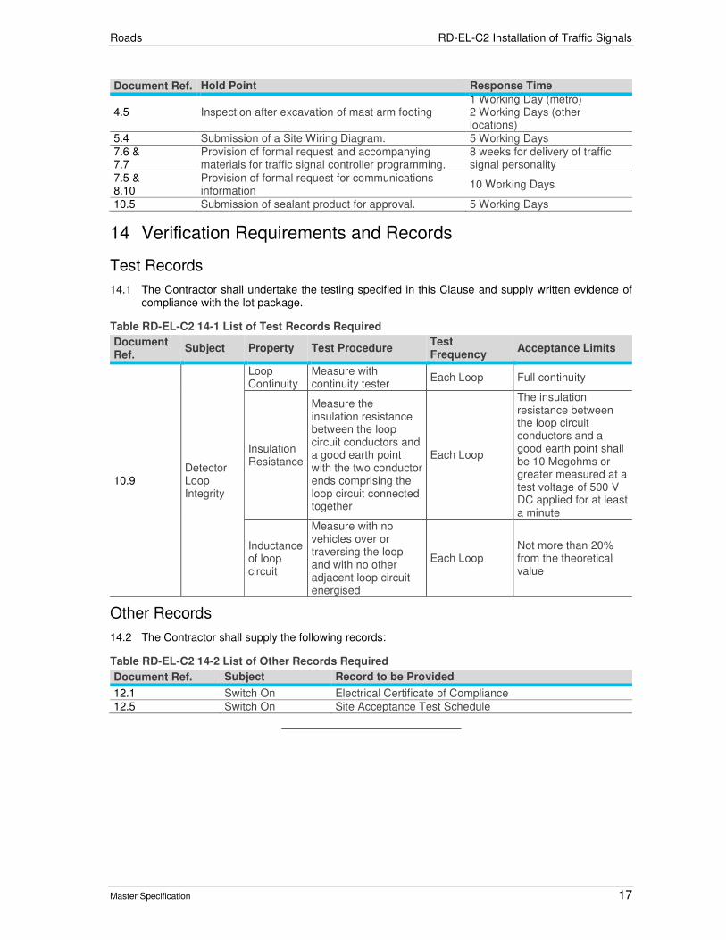
Roads RD-EL-C2 Installation of Traffic Signals
Master Specification 17
Document Ref. Hold Point Response Time
4.5 Inspection after excavation of mast arm footing 1 Working Day (metro) 2 Working Days (other locations)
5.4 Submission of a Site Wiring Diagram. 5 Working Days
7.6 & 7.7
Provision of formal request and accompanying materials for traffic signal controller programming.
8 weeks for delivery of traffic signal personality
7.5 & 8.10
Provision of formal request for communications information
10 Working Days
10.5 Submission of sealant product for approval. 5 Working Days
14 Verification Requirements and Records
Test Records
14.1 The Contractor shall undertake the testing specified in this Clause and supply written evidence of compliance with the lot package.
Table RD-EL-C2 14-1 List of Test Records Required
Document Ref.
Subject Property Test Procedure Test Frequency
Acceptance Limits
10.9 Detector Loop Integrity
Loop Continuity
Measure with continuity tester
Each Loop Full continuity
Insulation Resistance
Measure the insulation resistance between the loop circuit conductors and a good earth point with the two conductor ends comprising the loop circuit connected together
Each Loop
The insulation resistance between the loop circuit conductors and a good earth point shall be 10 Megohms or greater measured at a test voltage of 500 V DC applied for at least a minute
Inductance of loop circuit
Measure with no vehicles over or traversing the loop and with no other adjacent loop circuit energised
Each Loop Not more than 20% from the theoretical value
Other Records
14.2 The Contractor shall supply the following records:
Table RD-EL-C2 14-2 List of Other Records Required
Document Ref. Subject Record to be Provided
12.1 Switch On Electrical Certificate of Compliance
12.5 Switch On Site Acceptance Test Schedule

Roads RD-EL-C2 Installation of Traffic Signals
Master Specification 18
15 Appendix 1: Site Wiring Layout (Sample Only)
LOCATION: GRAND JUNCTION ROAD / PROSPECT ROAD
TS160 PSC ‘C’ Date: 06/11/2007
Main cable size 64 J. BOX 1
J. BOX 2
J. BOX 3 J. BOX 4
Pole cable size 18 18 18 18 18 18 18 18 18 18 Pole Numbers 10 1 2 3 4 5 6 7 8 9
Group Cont Function
A3 Green 1
SG1 A4 Amber 2 A5 Red 3
A6 Green 4
SG2 A7 Amber 5 A8 Red 6
A9 Green 7
SG3 A10 Amber 8 A11 Red 9
A12 Green 10
SG4 A13 Amber 11 A14 Red 12
B3 Green 13 1 1 7 7
SG5 B4 Amber 14 2 2 8 8 B5 Red 15 3 3 9 9
B6 Green 16 10 10
SG6 B7 Amber 17 11 11 B8 Red 16 12 12
B9 Green 19
SG7 B10 Amber 20 B11 Red 21
B12 Green 22 1 1 1
SG8 B13 Amber 23 2 2 2 B24 Red 24 3 3 3
SG9 C3 Green 25
C4 Amber 26 C5 Red 27
SG10 C6 Green 28
C7 Amber 29 C8 Red 30
SG11 C9 Green 31 1 4 4
C10 Amber 32 2 5 5 C11 Red 33 3 6 6
SG12 C12 Green 34
C13 Amber 35 C14 Red 36

Roads RD-EL-C2 Installation of Traffic Signals
Master Specification 19
LOCATION: GRAND JUNCTION ROAD / PROSPECT ROAD
TS160 PSC ‘C’ Date: 06/11/2007
Main cable size 64 J. BOX 1
J. BOX 2
J. BOX 3 J. BOX 4
Pole cable size 18 18 18 18 18 18 18 18 18 18 Pole Numbers 10 1 2 3 4 5 6 7 8 9
Group Cont Function 37
P1 D12 Walk 38 4 7
D14 Don’t Walk 5 8
WAIT F28 Push Button 56 15 15
P2 D9 Walk 39 4 7
D11 Don’t Walk 40 5 8
F1-2 WAIT F27 Push Button 57 15 15
P3 D6 Walk 41 4 4
D8 Don’t Walk 42 5 5
F1-3 WAIT 15 F26 Push Button 58 15
P4 D3 Walk 43 4 4
D5 Don’t Walk 44 5 5
F1-4 WAIT F25 Push Button 59 15 15
E3 PB Return 60 16 16 16 16 \\\\\ 16 16 16 16 \\\\\
A2 240VActv GREY
A1 Neutral BLACK = Earth GREEN
Spare 45 6 6 9 6 13 6 6 9 6 13
14 14
15 15 55 14 14 14 14 16 14 14 14 14 16

Roads RD-EL-C2 Installation of Traffic Signals
Master Specification 20
LOCATION: GRAND JUNCTION ROAD / PROSPECT ROAD
TS160 Date: 06/11/2007
Junction Box 1
18 Core Pole 10 Motion Det (M2 Even)
Controller PSC ‘C’
18 Core Pole 10 Mast Arm
64 Core
64 Core
Junction Box 2
18 Core Pole 2
18 Core Pole 3
64 Core
Junction Box 3
18 Core Pole 4
18 Core Pole 5 Combo Mast Arm / Motion Det (M3 Odd)
18 Core Pole 6
64 Core
Junction Box 4
18 Core Pole 7
18 Core Pole 8 Motion det (M1 Odd)
18 Core Pole 9

Roads RD-EL-C2 Installation of Traffic Signals
Master Specification 21
16 Appendix 2: UPS Warning Label sticker template, 110mm (w) x 80mm (h)

Roads
Master Specification
RD-EL-C3 Supply and Installation of Conduits and Pits Document Information
K Net Number: 13469967 Document Version: 2 Document Date: 20/09/2019

Roads Contents
Master Specification 2
Document Amendment Record
Version Change Description Date Endorsement record (KNet ref.)
1 Initial issue (formerly R53) General review and update. 02/07/19 2 Formatting for publishing 20/09/19
Document Management This document is the Property of the Department for Infrastructure and Transport and contains information that is confidential to the Department. It must not be copied or reproduced in any way without the written consent of the Department. This is a controlled document and it will be updated and reissued as approved changes are made.
Roads Contents
Master Specification 3
Contents Contents 2
RD-EL-C3 Supply and Installation of Conduits and Pits 4
1 General 4
2 Compliance with Legislation 4
3 Materials 5
4 Design of Conduits and Pits 6
5 Trenching, Boring and Backfill 6
6 Installation of Electrical Conduit 6
7 Installation of Electrical Pits 7
8 Installation of Telecommunications Conduit 8
9 Installation of Telecommunication Pits 9
10 Electrical Trench Caution Tape and Cable Position Marker Posts 10
11 Verification of Conduit Condition 10
12 “As-Constructed” Drawings 10
13 Hold Points 10
14 Verification Requirements and Records 10
15 Appendix 1: Buried Cable Warning Sign Post Details and Installation 11
16 Appendix 2: Buried Power Cable Warning Sign 12
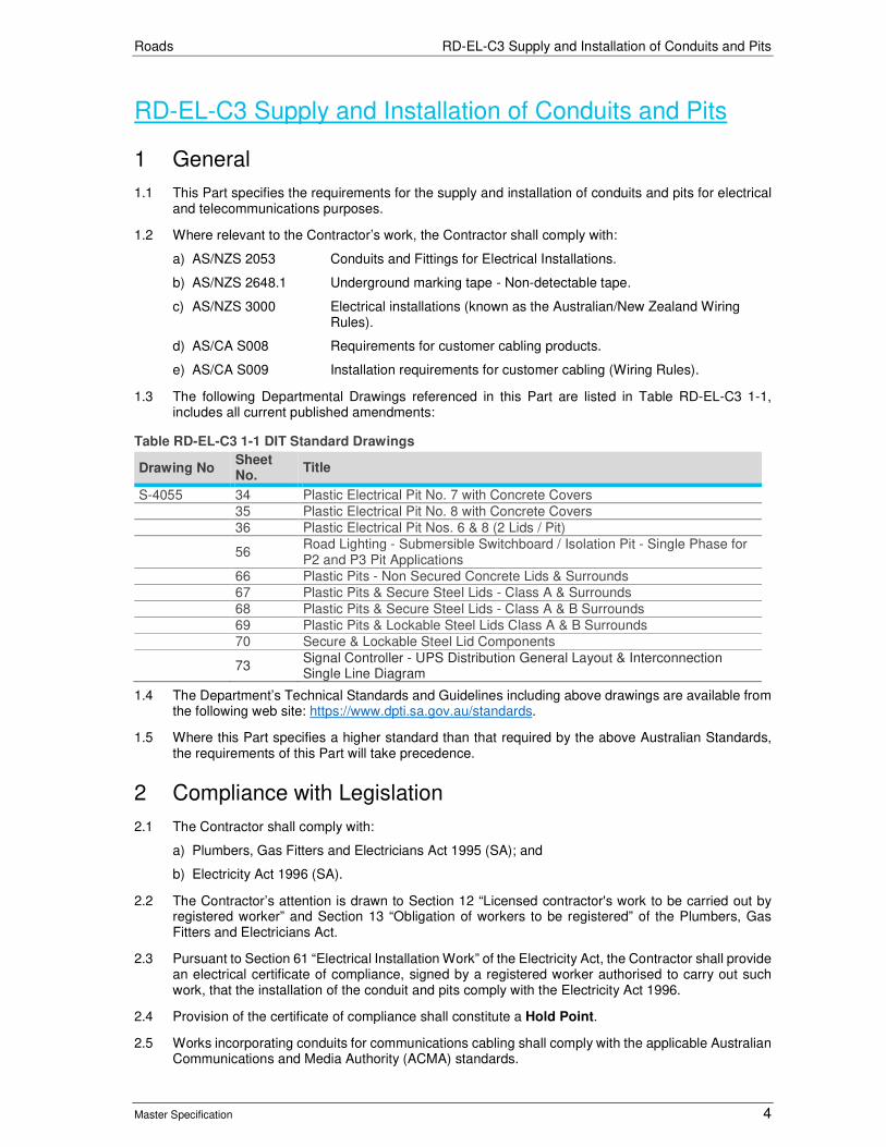
Roads RD-EL-C3 Supply and Installation of Conduits and Pits
Master Specification 4
RD-EL-C3 Supply and Installation of Conduits and Pits
1 General
1.1 This Part specifies the requirements for the supply and installation of conduits and pits for electrical and telecommunications purposes.
1.2 Where relevant to the Contractor’s work, the Contractor shall comply with:
a) AS/NZS 2053 Conduits and Fittings for Electrical Installations.
b) AS/NZS 2648.1 Underground marking tape - Non-detectable tape.
c) AS/NZS 3000 Electrical installations (known as the Australian/New Zealand Wiring Rules).
d) AS/CA S008 Requirements for customer cabling products.
e) AS/CA S009 Installation requirements for customer cabling (Wiring Rules).
1.3 The following Departmental Drawings referenced in this Part are listed in Table RD-EL-C3 1-1, includes all current published amendments:
Table RD-EL-C3 1-1 DIT Standard Drawings
Drawing No Sheet No.
Title
S-4055 34 Plastic Electrical Pit No. 7 with Concrete Covers 35 Plastic Electrical Pit No. 8 with Concrete Covers 36 Plastic Electrical Pit Nos. 6 & 8 (2 Lids / Pit)
56 Road Lighting - Submersible Switchboard / Isolation Pit - Single Phase for P2 and P3 Pit Applications
66 Plastic Pits - Non Secured Concrete Lids & Surrounds 67 Plastic Pits & Secure Steel Lids - Class A & Surrounds 68 Plastic Pits & Secure Steel Lids - Class A & B Surrounds 69 Plastic Pits & Lockable Steel Lids Class A & B Surrounds 70 Secure & Lockable Steel Lid Components
73 Signal Controller - UPS Distribution General Layout & Interconnection Single Line Diagram
1.4 The Department’s Technical Standards and Guidelines including above drawings are available from the following web site: https://www.dpti.sa.gov.au/standards.
1.5 Where this Part specifies a higher standard than that required by the above Australian Standards, the requirements of this Part will take precedence.
2 Compliance with Legislation
2.1 The Contractor shall comply with:
a) Plumbers, Gas Fitters and Electricians Act 1995 (SA); and
b) Electricity Act 1996 (SA).
2.2 The Contractor’s attention is drawn to Section 12 “Licensed contractor's work to be carried out by registered worker” and Section 13 “Obligation of workers to be registered” of the Plumbers, Gas Fitters and Electricians Act.
2.3 Pursuant to Section 61 “Electrical Installation Work” of the Electricity Act, the Contractor shall provide an electrical certificate of compliance, signed by a registered worker authorised to carry out such work, that the installation of the conduit and pits comply with the Electricity Act 1996.
2.4 Provision of the certificate of compliance shall constitute a Hold Point.
2.5 Works incorporating conduits for communications cabling shall comply with the applicable Australian Communications and Media Authority (ACMA) standards.

Roads RD-EL-C3 Supply and Installation of Conduits and Pits
Master Specification 5
3 Materials
Pits
3.1 Pits shall be made of materials that are capable of being buried in soil without adverse effects. Pits made from plastic or polycarbonate materials are acceptable. Plastic materials shall be UV stabilised. Pits and covers shall provide sufficient strength to support a wheel loading of at least one tonne without any visible damage, including to the underside of the lid.
3.2 Pits shall be made to the approximate dimensions shown on Drawing No. S-4055 Sheet 66-69.
Pit Covers
3.3 Pit covers shall:
a) be made of reinforced concrete, keyed steel or other suitable materials with appropriately positioned lifting holes;
b) be tapered to facilitate easy removal (with tools) and replacement of covers;
c) where specified, be of secure construction such that it is not possible to remove covers without the use purpose designed tools. Secure lids shall be fabricated as detailed on Drawing S-4055 Sheet 67 and 68;
d) incorporate a permanent non-slip pattern on the top, created by means of casting, engraving or moulding;
e) be designed such that ground water can escape without removing the cover and prevent the entry of soil or any other objects; and
f) fit flush with the pit and the pit surround when a gasket is installed.
3.4 All covers shall be marked with the State logo and the following:
a) "ELECTRICAL" or similar where the pits houses electrical power and / or control cabling; or
b) "COMMUNICATIONS" or similar where the pits houses communications cabling.
3.5 The markings shall be marked permanently on the top of the cover by means of casting, engraving, etching moulding or similar means in a clearly legible size and font. The method of marking shall be selected so as to remain legible, and to resist damage from abrasion and UV.
Conduit
3.6 Unless otherwise specified, electrical conduits shall be heavy duty rigid PVC conduit to AS 2053, colour orange for underground cable and UV stabilised for above ground. Communications conduits shall conform to ACMA and / or other relevant standards. Communications conduits shall be white and compliant with AS/CA S008. Flexible conduits shall not be used without the prior approval of the Principal. Minimum depths of cover within rail boundaries shall comply with the Table RD-EL-C3 8-1
3.7 Separation and size of Conduits shall comply with RD-EL-D3 “Conduit Design for Road Lighting, Traffic Signals and ITS”.
Marking Tape
3.8 Marking tape shall comply with the requirements of AS 2648.1.
3.9 Marking tape shall be installed in accordance with AS3000 (electrical) and / or AS/CA S009 (communications), as appropriate.
Concrete conduit protection
3.10 Concrete shall be minimum grade N20.
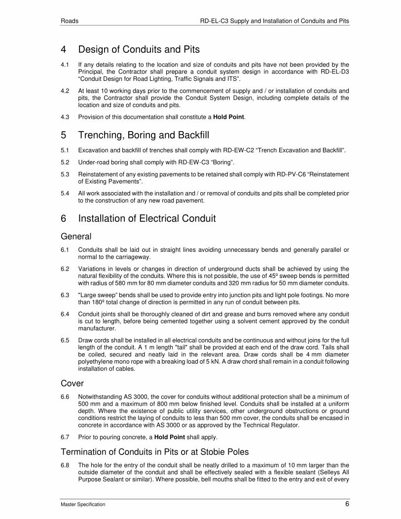
Roads RD-EL-C3 Supply and Installation of Conduits and Pits
Master Specification 6
4 Design of Conduits and Pits
4.1 If any details relating to the location and size of conduits and pits have not been provided by the Principal, the Contractor shall prepare a conduit system design in accordance with RD-EL-D3 “Conduit Design for Road Lighting, Traffic Signals and ITS”.
4.2 At least 10 working days prior to the commencement of supply and / or installation of conduits and pits, the Contractor shall provide the Conduit System Design, including complete details of the location and size of conduits and pits.
4.3 Provision of this documentation shall constitute a Hold Point.
5 Trenching, Boring and Backfill
5.1 Excavation and backfill of trenches shall comply with RD-EW-C2 “Trench Excavation and Backfill”.
5.2 Under-road boring shall comply with RD-EW-C3 “Boring”.
5.3 Reinstatement of any existing pavements to be retained shall comply with RD-PV-C6 “Reinstatement of Existing Pavements”.
5.4 All work associated with the installation and / or removal of conduits and pits shall be completed prior to the construction of any new road pavement.
6 Installation of Electrical Conduit
General
6.1 Conduits shall be laid out in straight lines avoiding unnecessary bends and generally parallel or normal to the carriageway.
6.2 Variations in levels or changes in direction of underground ducts shall be achieved by using the natural flexibility of the conduits. Where this is not possible, the use of 45º sweep bends is permitted with radius of 580 mm for 80 mm diameter conduits and 320 mm radius for 50 mm diameter conduits.
6.3 "Large sweep” bends shall be used to provide entry into junction pits and light pole footings. No more than 180º total change of direction is permitted in any run of conduit between pits.
6.4 Conduit joints shall be thoroughly cleaned of dirt and grease and burrs removed where any conduit is cut to length, before being cemented together using a solvent cement approved by the conduit manufacturer.
6.5 Draw cords shall be installed in all electrical conduits and be continuous and without joins for the full length of the conduit. A 1 m length "tail" shall be provided at each end of the draw cord. Tails shall be coiled, secured and neatly laid in the relevant area. Draw cords shall be 4 mm diameter polyethylene mono rope with a breaking load of 5 kN. A draw chord shall remain in a conduit following installation of cables.
Cover
6.6 Notwithstanding AS 3000, the cover for conduits without additional protection shall be a minimum of 500 mm and a maximum of 800 mm below finished level. Conduits shall be installed at a uniform depth. Where the existence of public utility services, other underground obstructions or ground conditions restrict the laying of conduits to less than 500 mm cover, the conduits shall be encased in concrete in accordance with AS 3000 or as approved by the Technical Regulator.
6.7 Prior to pouring concrete, a Hold Point shall apply.
Termination of Conduits in Pits or at Stobie Poles
6.8 The hole for the entry of the conduit shall be neatly drilled to a maximum of 10 mm larger than the outside diameter of the conduit and shall be effectively sealed with a flexible sealant (Selleys All Purpose Sealant or similar). Where possible, bell mouths shall be fitted to the entry and exit of every

Roads RD-EL-C3 Supply and Installation of Conduits and Pits
Master Specification 7
conduit, including intermediate points, prior to the commencement of cable installation and shall remain in place after installation.
6.9 For intermediate pits (i.e. pits which will have cable running through them but that cable will not exit the conduit system), the entry and exit conduits shall align as much as possible.
6.10 For terminating pits (i.e. pits where the cable exits the conduit system and terminates inside above ground equipment), the ends of conduits shall enter at 45º and protrude into the pit for a minimum of 25 mm and a maximum of 50 mm to facilitate drawing-in of cables.
6.11 The ends of conduits at post footings shall terminate 25 mm inside the recess in the concrete footing.
6.12 Where the conduits are to be connected into an SAPN underground service pit, the hole for the entry of the conduit shall be neatly drilled to a maximum of 10 mm larger than the outside diameter of the conduit or as specified by SAPN.
6.13 Where conduits are attached to stobie poles, the installation of 50 mm diameter conduit in the stobie pole channel or the face of the stobie pole shall be mechanically protected with galvanized pipe as shown on Drawing No. 4516, sheet 1. Bending of the galvanized pipe shall not be permitted after the 50 mm PVC conduit has been inserted.
Additional Requirements for Consumer Connections
6.14 Conduits shall be the diameter shown on the SAPN Drawing and laid in accordance with the Drawings.
6.15 Low voltage conduits shall be terminated in low voltage service pillars as shown on the Drawings and the following SAPN Drawings:
a) E1921 - UD LV Service or Junction Pit, Looped, Footpath Use.
b) E1922 - UD Low Voltage - Service Pillar – Looped.
6.16 The Contractor shall contact SAPN Utilities to obtain copies of these drawings.
7 Installation of Electrical Pits
General
7.1 The Contractor shall install all cable draw-in pits, intermediate and junction pits as necessary for the work.
7.2 Notwithstanding any drawing showing a formed pit, pits shall comply with Clause 3 "Materials". All pits shall be minimum size P2, unless shown otherwise on the drawings or otherwise approved by the Principal.
7.3 Pits shall be installed with the long dimension oriented in the direction of the main conduit run.
7.4 Prior to backfilling, covers shall be fitted and visually checked to ensure that the pit is parallel to the edge of the footpath, kerb or property boundary, and is flush with the surface of the surrounding footpath, or is built-up at a maximum grade of 1:14, to conform to the fall of the footpath.
7.5 Pits shall be bedded in Sa-C Type C sand. Sand shall be compacted following the pit manufacturer’s recommended procedures and practices. Pit sides shall be checked before and after compaction. No inward bowing of pit sides is acceptable. Temporary bracing shall be used in pits as required to prevent bowing of sides during compaction.
7.6 Pits shall be surrounded with a reinforced concrete apron of minimum 100 mm thickness and width (measured from each pit side). The edges of the apron shall be finished with an edging tool. Where multiple pits are installed together (e.g. Comms and Electrical), a shared apron may be used. At least 100 mm spacing shall be provided between pits to allow the installation of the shared concrete apron between pits.
7.7 A template constructed of timber (or other suitable material) slightly larger in size than the pit lid shall be installed in the top of the pits (in place of the lid) prior to pouring the concrete apron, to prevent the pit edges bowing in during pouring / curing of the concrete apron.
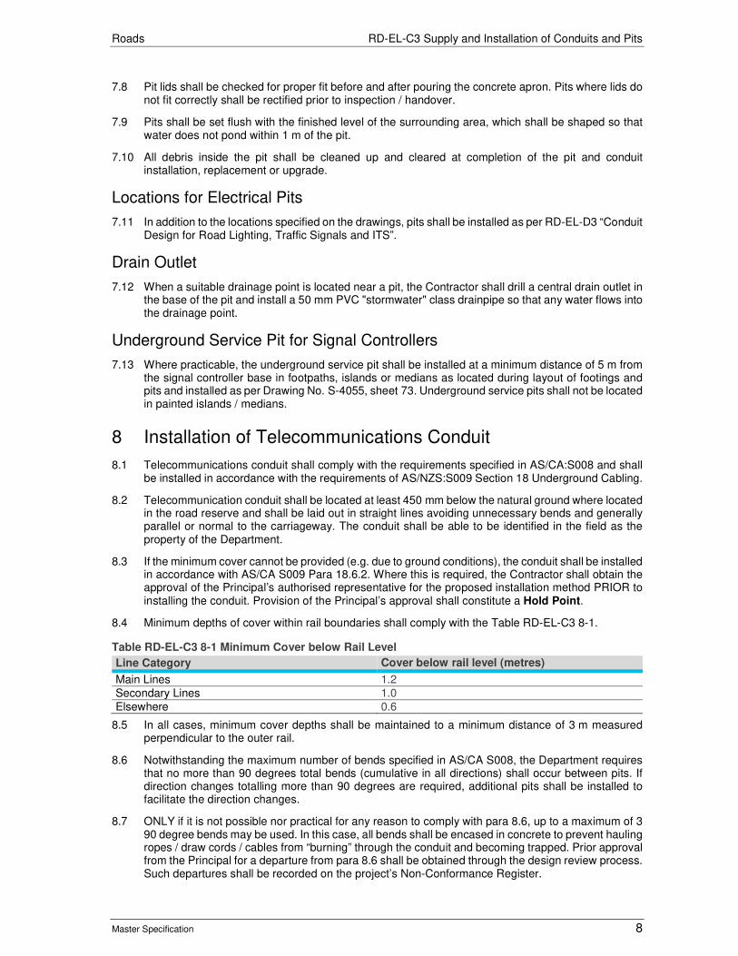
Roads RD-EL-C3 Supply and Installation of Conduits and Pits
Master Specification 8
7.8 Pit lids shall be checked for proper fit before and after pouring the concrete apron. Pits where lids do not fit correctly shall be rectified prior to inspection / handover.
7.9 Pits shall be set flush with the finished level of the surrounding area, which shall be shaped so that water does not pond within 1 m of the pit.
7.10 All debris inside the pit shall be cleaned up and cleared at completion of the pit and conduit installation, replacement or upgrade.
Locations for Electrical Pits
7.11 In addition to the locations specified on the drawings, pits shall be installed as per RD-EL-D3 “Conduit Design for Road Lighting, Traffic Signals and ITS”.
Drain Outlet
7.12 When a suitable drainage point is located near a pit, the Contractor shall drill a central drain outlet in the base of the pit and install a 50 mm PVC "stormwater" class drainpipe so that any water flows into the drainage point.
Underground Service Pit for Signal Controllers
7.13 Where practicable, the underground service pit shall be installed at a minimum distance of 5 m from the signal controller base in footpaths, islands or medians as located during layout of footings and pits and installed as per Drawing No. S-4055, sheet 73. Underground service pits shall not be located in painted islands / medians.
8 Installation of Telecommunications Conduit
8.1 Telecommunications conduit shall comply with the requirements specified in AS/CA:S008 and shall be installed in accordance with the requirements of AS/NZS:S009 Section 18 Underground Cabling.
8.2 Telecommunication conduit shall be located at least 450 mm below the natural ground where located in the road reserve and shall be laid out in straight lines avoiding unnecessary bends and generally parallel or normal to the carriageway. The conduit shall be able to be identified in the field as the property of the Department.
8.3 If the minimum cover cannot be provided (e.g. due to ground conditions), the conduit shall be installed in accordance with AS/CA S009 Para 18.6.2. Where this is required, the Contractor shall obtain the approval of the Principal’s authorised representative for the proposed installation method PRIOR to installing the conduit. Provision of the Principal’s approval shall constitute a Hold Point.
8.4 Minimum depths of cover within rail boundaries shall comply with the Table RD-EL-C3 8-1.
Table RD-EL-C3 8-1 Minimum Cover below Rail Level
Line Category Cover below rail level (metres)
Main Lines 1.2 Secondary Lines 1.0 Elsewhere 0.6
8.5 In all cases, minimum cover depths shall be maintained to a minimum distance of 3 m measured perpendicular to the outer rail.
8.6 Notwithstanding the maximum number of bends specified in AS/CA S008, the Department requires that no more than 90 degrees total bends (cumulative in all directions) shall occur between pits. If direction changes totalling more than 90 degrees are required, additional pits shall be installed to facilitate the direction changes.
8.7 ONLY if it is not possible nor practical for any reason to comply with para 8.6, up to a maximum of 3 90 degree bends may be used. In this case, all bends shall be encased in concrete to prevent hauling ropes / draw cords / cables from “burning” through the conduit and becoming trapped. Prior approval from the Principal for a departure from para 8.6 shall be obtained through the design review process. Such departures shall be recorded on the project’s Non-Conformance Register.
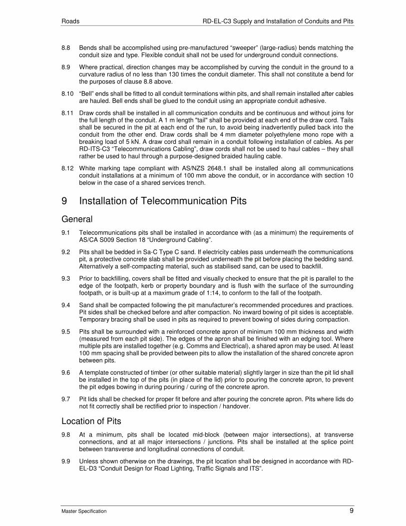
Roads RD-EL-C3 Supply and Installation of Conduits and Pits
Master Specification 9
8.8 Bends shall be accomplished using pre-manufactured “sweeper” (large-radius) bends matching the conduit size and type. Flexible conduit shall not be used for underground conduit connections.
8.9 Where practical, direction changes may be accomplished by curving the conduit in the ground to a curvature radius of no less than 130 times the conduit diameter. This shall not constitute a bend for the purposes of clause 8.8 above.
8.10 “Bell” ends shall be fitted to all conduit terminations within pits, and shall remain installed after cables are hauled. Bell ends shall be glued to the conduit using an appropriate conduit adhesive.
8.11 Draw cords shall be installed in all communication conduits and be continuous and without joins for the full length of the conduit. A 1 m length "tail" shall be provided at each end of the draw cord. Tails shall be secured in the pit at each end of the run, to avoid being inadvertently pulled back into the conduit from the other end. Draw cords shall be 4 mm diameter polyethylene mono rope with a breaking load of 5 kN. A draw cord shall remain in a conduit following installation of cables. As per RD-ITS-C3 “Telecommunications Cabling”, draw cords shall not be used to haul cables – they shall rather be used to haul through a purpose-designed braided hauling cable.
8.12 White marking tape compliant with AS/NZS 2648.1 shall be installed along all communications conduit installations at a minimum of 100 mm above the conduit, or in accordance with section 10 below in the case of a shared services trench.
9 Installation of Telecommunication Pits
General
9.1 Telecommunications pits shall be installed in accordance with (as a minimum) the requirements of AS/CA S009 Section 18 “Underground Cabling”.
9.2 Pits shall be bedded in Sa-C Type C sand. If electricity cables pass underneath the communications pit, a protective concrete slab shall be provided underneath the pit before placing the bedding sand. Alternatively a self-compacting material, such as stabilised sand, can be used to backfill.
9.3 Prior to backfilling, covers shall be fitted and visually checked to ensure that the pit is parallel to the edge of the footpath, kerb or property boundary and is flush with the surface of the surrounding footpath, or is built-up at a maximum grade of 1:14, to conform to the fall of the footpath.
9.4 Sand shall be compacted following the pit manufacturer’s recommended procedures and practices. Pit sides shall be checked before and after compaction. No inward bowing of pit sides is acceptable. Temporary bracing shall be used in pits as required to prevent bowing of sides during compaction.
9.5 Pits shall be surrounded with a reinforced concrete apron of minimum 100 mm thickness and width (measured from each pit side). The edges of the apron shall be finished with an edging tool. Where multiple pits are installed together (e.g. Comms and Electrical), a shared apron may be used. At least 100 mm spacing shall be provided between pits to allow the installation of the shared concrete apron between pits.
9.6 A template constructed of timber (or other suitable material) slightly larger in size than the pit lid shall be installed in the top of the pits (in place of the lid) prior to pouring the concrete apron, to prevent the pit edges bowing in during pouring / curing of the concrete apron.
9.7 Pit lids shall be checked for proper fit before and after pouring the concrete apron. Pits where lids do not fit correctly shall be rectified prior to inspection / handover.
Location of Pits
9.8 At a minimum, pits shall be located mid-block (between major intersections), at transverse connections, and at all major intersections / junctions. Pits shall be installed at the splice point between transverse and longitudinal connections of conduit.
9.9 Unless shown otherwise on the drawings, the pit location shall be designed in accordance with RD-EL-D3 “Conduit Design for Road Lighting, Traffic Signals and ITS”.
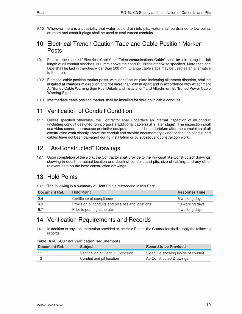
Roads RD-EL-C3 Supply and Installation of Conduits and Pits
Master Specification 10
9.10 Wherever there is a possibility that water could drain into pits, water shall be drained to low points en route and conduit plugs shall be used to seal vacant conduits.
10 Electrical Trench Caution Tape and Cable Position Marker Posts
10.1 Plastic tape marked "Electrical Cable" or "Telecommunications Cable" shall be laid along the full length of all conduit trenches, 300 mm above the conduit, unless otherwise specified. More than one tape shall be laid in trenches wider than 500 mm. Orange cable slabs may be used as an alternative to the tape.
10.2 Electrical cable position marker posts, with identification plate indicating alignment direction, shall be installed at changes of direction and not more than 200 m apart and in accordance with Attachment A: “Buried Cable Warning Sign Post Details and Installation” and Attachment B: “Buried Power Cable Warning Sign”.
10.3 Intermediate cable position marker shall be installed for fibre optic cable conduits.
11 Verification of Conduit Condition
11.1 Unless specified otherwise, the Contractor shall undertake an internal inspection of all conduit (including conduit designed to incorporate additional cable(s) at a later stage). The inspection shall use video camera, borescope or similar equipment. It shall be undertaken after the completion of all construction work directly above the conduit and provide documentary evidence that the conduit and cables have not been damaged during installation or by subsequent construction work.
12 “As-Constructed” Drawings
12.1 Upon completion of the work, the Contractor shall provide to the Principal “As-Constructed” drawings showing in detail the actual location and depth of conduits and pits, size of cabling, and any other relevant data on the base construction drawings.
13 Hold Points
13.1 The following is a summary of Hold Points referenced in this Part:
Document Ref. Hold Point Response Time
2.4 Certificate of compliance 5 working days
4.3 Provision of conduits and pit sizes and locations 10 working days
6.7 Prior to pouring concrete 1 working days
14 Verification Requirements and Records
14.1 In addition to any documentation provided at the Hold Points, the Contractor shall supply the following records:
Table RD-EL-C3 14-1 Verification Requirements
Document Ref. Subject Record to be Provided
11 Verification of Conduit Condition Video file showing inside of conduit
12 Conduit and pit location As-Constructed Drawings

Roads RD-EL-C3 Supply and Installation of Conduits and Pits
Master Specification 11
15 Appendix 1: Buried Cable Warning Sign Post Details and Installation
Note: 1. Sketch for illustration only – not to scale. 2. Capped steel post, 60 mm O/D, wall thickness 2 mm. 3. "Signal Red" powder coated finish over full length of post. 4. Posts to be located as shown on drawings.
50mm
Ground Level
400 mm 450 mm
1 200 mm
N20 Concrete
Warning Sign – refer to Attachment B
300 mm
Chamfer top of concrete
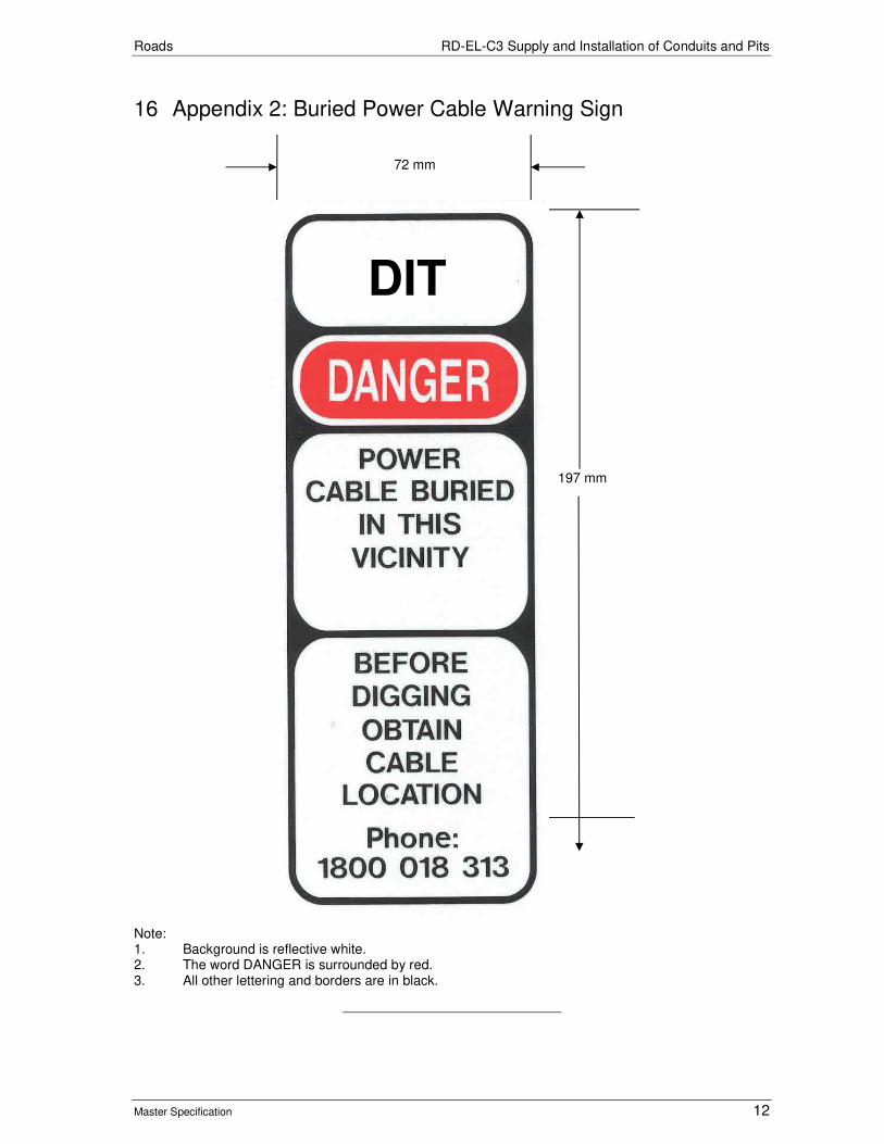
Roads RD-EL-C3 Supply and Installation of Conduits and Pits
Master Specification 12
16 Appendix 2: Buried Power Cable Warning Sign Note: 1. Background is reflective white. 2. The word DANGER is surrounded by red. 3. All other lettering and borders are in black.
197 mm
72 mm
DIT
Roads
Master Specification
RD-EL-S1 Supply of Lighting Components Document Information
KNet Number: 13010904
Document Version: 3
Document Date:: August 2020

Roads Contents
Master Specification 2
Document Amendment Record Version Change Description Date
1 Initial issue (formerly R50). Changes to crash test requirements in accordance with the latest Amendment (2017) of AS/NZS 3845. General document review and update.
02/07/19
2 Formatting for publishing 19/09/19
3 Section 9, the crash test for a vehicle with a mass ranging from 2000kg to 2270kg at 70 km/h has been changed to optional.
August 2020
Document Management This document is the Property of the Department for Infrastructure and Planning Transport and contains information that is confidential to the Department. It must not be copied or reproduced in any way without the written consent of the Department. This is a controlled document and it will be updated and reissued as approved changes are made.

Roads Contents
Master Specification 3
Contents Contents 3
RD-EL-S1 Supply of Lighting Components 4
1 General 4
2 Materials 5
3 Design and Testing of Lighting Poles and Mast Arms 5
4 General Requirements 6
5 Manufacture 6
6 Protective Treatment 7
7 Transportation and Storage of Galvanized Components 7
8 Hold Points 8
9 Appendix 1: Energy-Absorbing Pole Crash Test Requirements 9
Roads RD-EL-S1 Supply of Lighting Components
Master Specification 4
RD-EL-S1 Supply of Lighting Components
1 General
1.1 This Part specifies the requirements for the supply of poles and associated components used for the support of lighting and / or signalling equipment. It includes slip base poles, energy-absorbing poles and combination road lighting and traffic signal poles / mast arms.
1.2 Unless specified otherwise on Department drawings or specification, the definitions in AS 1798, AS 2339 and AS 4677 apply to this Part.
1.3 Standards and documents referenced in this Part are listed below, and unless specified otherwise, includes all current published parts and amendments:
a) AS 1111 ISO Metric Hexagon Commercial Bolts and Screws.
b) AS 1112 ISO Metric Hexagon Nuts.
c) AS/NZS 1158 Lighting for Roads and Public Spaces.
d) AS/NZS 1170 Structural Design Actions.
e) AS/NZS 1214 Hot-Dip Galvanized Coatings on Threaded Fasteners.
f) AS/NZS 1252 High-Strength Steel Bolts with Associated Nuts and Washers.
g) AS/NZS 1554 Structural Steel Welding.
h) AS/NZS 1594 Hot Rolled Steel Flat Products.
i) AS 1627 Metal Finishing – Preparation and Pre-Treatment of Surfaces.
j) AS 1798 Lighting Poles and Bracket Arms- Recommended Dimensions.
k) AS 2339 Traffic Signal Mast Arms.
l) AS/NZS 3678 Structural Steel- Hot Rolled Plates, Floor Plates and Slabs.
m) AS/NZS 3679 Structural Steel - Hot Rolled Bars and Sections.
n) AS/NZS 3845 Road Safety Barrier Systems and Devices.
o) AS 4100 Steel Structures.
p) AS/NZS 4600 Cold Formed Steel Structures.
q) AS 4676 Structural Design Requirements for Utility Service Poles. (Note: Although AS 4676 has been withdrawn from Standards Australia, the requirements of AS 4676 shall still apply to lighting pole structure design.)
r) AS/NZS 4677 Steel Utility Service Poles.
s) AS/NZS 4680 Hot Dip Galvanized (Zinc) Coatings on Fabricated Ferrous Articles.
t) AS 9001 Quality Management Systems – Requirements.
u) AASHTO Manual for Assessing Safety Hardware (MASH).
1.4 The following Department Drawings referenced in this Part are listed in Table RD-EL-S1 1-1, and include all current published amendments.
Table RD-EL-S1 1-1 List of Department Drawings referenced
Drawing No. Sheet No. Title
S-4055 30 Combination T-S Road Lighting Mast Arms & Existing Impact Absorbing (Energy-absorbing) Light Poles – Base Plate Mounted: Pile Footing and Anchor Details
37 Existing Impact Absorbing (Energy-absorbing) Light Pole – Base Plate Mounted: Squat Footing and Anchor Details
38 Slip Base Road Lighting Pole: Column and Outreach

Roads RD-EL-S1 Supply of Lighting Components
Master Specification 5
Drawing No. Sheet No. Title
39 Slip Base Road Lighting Pole: Pole Base and Footing.
40 Energy-absorbing Road Lighting Pole - Standard & Combination Road Lighting Pole: Column and Outreach
41 Combination Traffic Signal and Road Lighting Mast Arm: Column and Outreach
1.5 Department Technical Standards and Guidelines including above drawings are available from the following web site: https://www.dpti.sa.gov.au/standards.
1.6 Where this Part specifies a higher standard than that required by the above Australian Standards, the requirements of this Part will take precedence.
2 Materials
2.1 Materials used in the structural components of light poles shall comply with AS 4677.
2.2 Steel used in mounting plates / base plates shall comply with the requirements of AS 3678, Grade 250 or Grade 350.
2.3 The columns and outreach arms shall be fabricated from steel coil conforming to AS 1594, Grade HA300.
2.4 Notwithstanding the above, phosphorous and silicon content must comply with the formula: %Silicon + (2.5 x %Phosphorous) < 0.09% by weight
3 Design and Testing of Lighting Poles and Mast Arms
General
3.1 The poles shall be designed to comply with the following:
a) the requirements of AS 4676 for strength and serviceability;
b) the requirements of AS 1170.2 for Terrain Category 2 (TC2) winds;
c) loading from luminaire of up to the maximum mass limit specified in Table 2.2 AS 1158.6 and a projected wind area of 0.2 square metres; and
d) under serviceability limit state, the deflection of the pole from vertical position shall not exceed 4% of vertical section height and the deflection of the outreach shall not exceed 4% of the nominal horizontal outreach length.
3.2 The Contractor shall provide shop drawings including welding details for every type of light pole and drawings detailing a suitable pile footing and the high strength anchor bolts.
3.3 The poles and associated components shall be manufactured under a quality system certified to AS 9001.
3.4 Submission of the evidence of compliance with AS 4676, AS 1170.2 and this clause, including structural design calculations (where not previously provided) shall constitute a Hold Point.
Frangible Poles
3.5 There are two types of frangible poles, slip-base and energy-absorbing. The Contractor shall provide evidence of compliance with requirements of AS 1158, AS 3845.2 and Appendix R50A with regard to impact testing for frangibility and safety performance. Submission of the evidence of compliance shall constitute a Hold Point.
3.6 Crash testing is not required for slip-base poles, however the Contractor shall provide evidence of compliance with Department Drawing S-4055 Sheet 39 - Slip Base Road Lighting Pole: Pole Base and Footing. Submission of the evidence of compliance shall constitute a Hold Point.

Roads RD-EL-S1 Supply of Lighting Components
Master Specification 6
3.7 Crash testing is required for energy-absorbing poles. Submission of the evidence of compliance with AS 1158, AS 3845.2 and Clause 9, including crash test documentation and calculations (where not previously provided) shall constitute a Hold Point.
4 General Requirements
General
4.1 Unless specified otherwise by the Principal, all lighting components shall be manufactured to comply with AS 1798. Supplying of the pole design drawings with all associated equipment (door, panel mounting straps, brackets, bolts and washers) shall constitute a Hold Point.
4.2 Except for combination mast arm poles, the columns shall be supplied assembled as one section.
4.3 Outreaches and columns shall be separate units with no section exceeding 10 m in length. The columns and outreaches shall be such that for a specific pole type, any outreach can be assembled onto any column to form a pole. Traffic signal outreaches for combination mast arms shall be separate from the column and shall be such that they can be assembled onto any combination mast arm of the same type.
4.4 For gooseneck poles, the taper on an outreach shall be uniform from the tip to the lower extremity of the outreach. The taper of the outreach shall be similar to that of the vertical portion of the column, so that the transition from the vertical to the curved outreach is smooth and continuous.
4.5 For gooseneck poles, the straight end section of an outreach shall be perpendicular to the radius.
Spigot
4.6 The luminaire fixing spigot shall be straight, unthreaded Grade C250 CHS with a minimum clear aperture of 32 mm nominal bore and shall project 125 mm from the tip of the outreach in line with the axis of the outreach.
4.7 Spigot upcast angle (Loaded at 10kg) shall be: 0°.
Service Access Opening
4.8 The opening shall have a suitable lift out cover (door). The cover shall be made weatherproof and shall fit flush with the face of the column. A built-in locking device shall be incorporated, using an M8 dome-head stainless steel bolt with Allen key fitting. All opening covers shall be interchangeable for poles of the same type.
4.9 For combination pole with mast arm, access door opening shall be opposite to Traffic Signal Outreach. For slip base poles, refer to Drawing No. S 4055, Sheet 39 for the orientation of access door opening.
Wall Thickness
4.10 The road lighting columns and the outreaches shall have a minimum wall thickness of 3 mm.
Identification Plate
4.11 All lighting columns shall be permanently and legibly marked with an identification plate securely fixed to the column in accordance with AS 4677. The plate shall include manufacture date, model type and manufacturer.
5 Manufacture
General
5.1 Unless specified otherwise, poles shall be manufactured in accordance with AS 2339, AS3678, AS3679 and AS 4677.

Roads RD-EL-S1 Supply of Lighting Components
Master Specification 7
5.2 For gooseneck poles, bends shall be free of kinks and ripples in excess of 2 mm in amplitude. The maximum deviation from the true shape at any point on the curve shall be checked by means of an internal template, which allows for the diametrical taper of the outreach. When placed against the inside of the outreach any gaps between the outreach and the template shall not exceed 1 % of the radius and the rate of gap increase shall not exceed 1 in 50.
5.3 The manufacture of poles and outreaches shall be such that after assembly and standing, the vertical axis is straight and within 0.4 degrees perpendicular to the top mounting plate and the outreach is set in the plane of the vertical axis. For Combination Mast Arms, the traffic signal mounting pipe shall be vertical under fully loaded (approx. 15 kg) condition.
5.4 Components shall be manufactured within the following tolerance:
Table RD-EL-S1 5-1 Component Tolerances
Component Tolerance
Mounting plates / base plates: 2.0 mm
Slotted holes for base plate anchor bolts: 1.0 mm
5.5 One side of the square base plate shall be at right angles to the outreach.
Welding
5.6 All welding shall comply with AS 4677. All welds shall be Category SP and prequalified in accordance with AS 1554.1. Where intermittent fillet welds are used for attachment of reinforcement at door openings, gaps between welds shall not exceed 35 mm in length.
5.7 The column to base plate, inner seal weld shall be flush with the lower face of the base plate. Any deformation caused during fit-up shall be repaired.
6 Protective Treatment
Cleaning
6.1 Prior to galvanising, all sharp edges and burrs resulting from cutting and drilling shall be removed. The columns, outreaches and footing units shall be chemically cleaned and fluxed so that the surface of the steel is completely free from rust and mill scale and is suitable for hot-dip galvanising.
Hot-Dip Galvanising
6.2 Columns, outreaches, mounting plates and footing units shall be hot-dip galvanized after fabrication in accordance with AS 4680. Threads of bolts and nuts shall be cleaned by centrifuging, brushing or similar process after galvanising in accordance with AS 1214. The M8 dome-head bolt for aperture cover shall be stainless steel.
6.3 Galvanized Components shall have a bright zinc appearance and not show evidence of “white rust”.
Repair of Galvanized Components
6.4 Areas of galvanized components damaged during transport, handling or storage or left bare by cutting or welding subsequent to galvanising shall be cleaned of any weld slag, heavy wire brushed and painted with two coats of an organic zinc rich paint, as approved under APAS 29/16, which shall be applied before rusting occurs.
6.5 Damage to components galvanized after fabrication has been completed shall only be repaired by methods permitted by AS 4680, Appendix E Renovation of Damaged or Uncoated Areas.
7 Transportation and Storage of Galvanized Components
7.1 Components shall be stored in accordance with the recommendations of AS 4680, Appendix F.

Roads RD-EL-S1 Supply of Lighting Components
Master Specification 8
8 Hold Points
8.1 The following is a summary of Hold Points for the documents referenced in this Part:
Table RD-EL-S1 8-1 Hold Points
Document Ref. Hold Point Response Time
3.4 Evidence of compliance with AS 4676, AS1170.2 and submission of design calculations
10 Working Days
3.5 Evidence of compliance with AS 1158, AS 3845.2 and Appendix R50A
10 Working Days
3.6 Slip base poles: Evidence of compliance with Department Drawing S-4055 Sheet 39 - Slip Base Road Lighting Pole: Pole Base and Footing
10 Working Days
3.7 Energy-absorbing poles: Evidence of compliance with Appendix R50A “Frangible Crash Test Requirements” and AS 1158 and AS 3845.2.
15 Working Days
4.1 Pole design drawings with all associated equipment (door, panel mounting straps, brackets, bolts and washers)
15 Working Days

Roads RD-EL-S1 Supply of Lighting Components
Master Specification 9
9 Appendix 1: Energy-Absorbing Pole Crash Test Requirements
9.1 Crash testing shall be based on AS3845.2 and AASHTO Manual for Assessing Safety Hardware (MASH).
9.2 Test pole configuration and installation shall be representative of in-service pole installations and be installed as per Department standard drawing S-4055, sheet 30 or 37, as applicable to the type of the pole.
9.3 Test shall be conducted by NATA or ILAC accredited MASH/AASHTO testing facility, unless otherwise approved by the Principal.
9.4 The Principal shall reserve the right to accept any pole type where satisfactory evidence indicates that the crash test requirements are substantially, but not precisely, met.
Crash Tests
9.5 The crash test required for energy-absorbing poles is: 1100kg vehicle at 50 km/h with the same evaluation criteria MASH 1-40 as per AS3845.2 Table 9.2.
9.6 Optional crash test preferred to be undertaken in addition to Clause 9.5 for energy-absorbing pole is a vehicle with a mass ranging from 2000kg to 2270kg at 70 km/h, with the same evaluation criteria as per MASH 1-41 and AS3845.2.
9.7 Note: All tests to be conducted with typical luminaires attached.
Test Evaluation
9.8 Evaluation, based on the factors detailed in Table 5-1 of MASH, shall include the following:
a) Test article should collapse in a predictable manner as per 1158.1.2.
b) Acceptable test article performance.
c) Energy–absorbing: The pole should remain attached to the base structure and absorb any impact energy by progressively deforming and entrapping the impacting vehicle, as illustrated in AS 1158.1.2. The final position of the pole should not be expected to be on the road.
d) Occupant Risk from detached elements or intrusions.
e) No part of the pole / luminaire should penetrate the occupant compartment.
f) There should be limited deformation of the occupant compartment - refer MASH Section 5.3.
g) Pole elements that could present a hazard to other traffic or pedestrians (including luminaires, access doors and electrical components) should remain attached to the pole.
h) The vehicle should remain upright. Roll and pitch are not to exceed 75 degrees.
i) The Occupant Impact Velocities should not exceed 12 m/s.
j) The Occupant Ride Down Acceleration should be less than 15 G preferably and not exceed 20 G.
Test Documentation
9.9 A report shall be prepared detailing the crash tests. It shall contain:
a) a description of the tested pole installation, including drawings;
b) details of the test conditions, including type and mass of vehicle;
c) details of the tests, testing procedure and test equipment, including vehicle speed, pole and vehicle deformation and trajectory, supplemented with videos, sequential photographs and

Roads RD-EL-S1 Supply of Lighting Components
Master Specification 10
detail photographs including before and after pictures of the base mounting, door and door reinforcing, impact zone and the front of impacting vehicle;
d) calibration test certification of all measuring equipment;
e) an assessment of the performance compared with the evaluation factors listed above; and
f) a conclusion and recommendation about the acceptability of the pole.

Roads
Master Specification
RD-EL-S2 Supply of Luminaries Document Information
K Net Number: 13069642
Document Version: 2
Document Date: 19/09/2019

Roads Contents
Master Specification 2
Document Amendment Record
Version Change Description Date Endorsement record (KNet ref.)
1 Initial issue (formerly R51). Major update on Luminaire Requirements; added list of Hold Points including response time; updated referencing.
02/07/19
2 Formatting for publishing 19/09/19
Document Management This document is the Property of the Department for Infrastructure and Transport and contains information that is confidential to the Department. It must not be copied or reproduced in any way without the written consent of the Department. This is a controlled document and it will be updated and reissued as approved changes are made.

Roads Contents
Master Specification 3
Contents Contents 2
RD-EL-S2 Supply of Luminaries 4
1 General 4
2 Luminaire Requirements 4
3 Hold Points 5

Roads RD-EL-S2 Supply of Luminaries
Master Specification 4
RD-EL-S2 Supply of Luminaries
1 General
1.1 The luminaire shall comply with the following:
a) AS/NZS 1158 Lighting for roads and public spaces.
b) SA/SNZ TS 1158.6 Lighting for roads and public spaces Luminaires – Performance.
c) AS/NZS 3000 Electrical installations (known as the Australian/New Zealand Wiring Rules).
d) AS/NZS 60598.1 Luminaires - General requirements and tests.
e) AS/NZS 60598.2 Luminaires - Particular requirements.
1.2 Where this Part specifies a higher standard than that required by the above Australian Standards, the requirements of this Part will take precedence.
1.3 The submission of the luminaire photometric report as the evidence of compliance shall constitute a Hold Point.
1.4 The submission of isolux plot for the luminaire mounted at 12 m height pole showing any dimension shall constitute a Hold Point.
2 Luminaire Requirements
2.1 The luminaire shall, unless otherwise stated:
a) be LED (Light Emitting Diode) type;
b) be Aeroscreen (full cut-off) type;
c) be included in the AEMO table for unmetered lighting, refer to Australian Energy Market Operator (AEMO) approved load tables for unmetered connection point. https://www.aemo.com.au/-/media/Files/Electricity/NEM/Retail_and_Metering/Metering-Procedures/NEM-Load-Tables-For-Unmetered-Connection-Points.pdf. The submission of the evidence of AEMO load table shall constitute to a Hold Point;
d) be fitted with a 7-pin NEMA socket preferably on the underside of the luminaire;
e) be capable of 0-10 V dimming and have all necessary components fitted;
f) have an efficacy of greater than 110 lm/W;
g) have a CCT of 4000K;
h) have a control gear / wiring chamber which is accessible without the use of tools and resistant to damage or access by birds, e.g. cockatoos;
i) have a secure attachment point in the control gear / wiring chamber to attach the strain wire which supports the cable in the pole;
j) have an Ingress Protection Rating of IP65 or higher for the optical chamber;
k) have an Impact Rating of IK06 or higher;
l) retain at least 90% of initial lumen level after 100,000 hours of operation;
m) be light-grey in colour;
n) have shields available to reduce back-spill; and
o) have a 10 year on-pole warranty (includes all costs associated with the removal and replacement of the luminaire, materials, equipment, labour etc.).
2.2 Desirable options:
a) have a stepped, adjustable upcast angle between 5° and -15° with a minimum of four increments; and
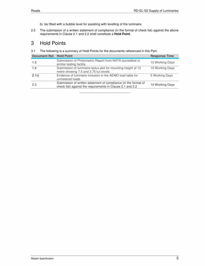
Roads RD-EL-S2 Supply of Luminaries
Master Specification 5
b) be fitted with a bubble level for assisting with levelling of the luminaire.
2.3 The submission of a written statement of compliance (in the format of check list) against the above requirements in Clause 2.1 and 2.2 shall constitute a Hold Point.
3 Hold Points
3.1 The following is a summary of Hold Points for the documents referenced in this Part:
Document Ref. Hold Point Response Time
1.3 Submission of Photometric Report from NATA accredited or similar testing facility
10 Working Days
1.4 Submission of luminaire isolux plot for mounting height of 12 metre showing 7.5 and 3.75 lux levels
10 Working Days
2.1c) Evidence of luminaire inclusion in the AEMO load table for unmetered loads
5 Working Days
2.3 Submission of written statement of compliance (in the format of check list) against the requirements in Clause 2.1 and 2.2
10 Working Days

Roads
Master Specification
RD-EL-S3 Supply of LED Traffic Signal Lanterns Document Information
K Net Number: 13496888
Document Version: 2
Document Date: 20/09/2019

Roads Contents
Master Specification 2
Document Amendment Record
Version Change Description Date Endorsement record (KNet ref.)
1
Initial issue (formerly R54). Updated clauses for the evidence of compliance with AS 2144; added new requirements including Type Approval and AEMO load table; added list of Hold Points including response time; updated referencing.
02/07/19
2 Formatting for publishing 20/09/19
Document Management This document is the Property of the Department for Infrastructure and Transport and contains information that is confidential to the Department. It must not be copied or reproduced in any way without the written consent of the Department. This is a controlled document and it will be updated and reissued as approved changes are made.
Roads Contents
Master Specification 3
Contents Contents 2
RD-EL-S3 Supply of LED Traffic Signal Lanterns 4
1 General 4
2 Technical Requirements 4
3 Compliance and Type Approval 5
4 Australian Energy Market Operator (AEMO) – NEM Load Table 7
5 Product Support 7
6 Installation of Spare Parts 7
7 Compatibility with Traffic Signal Controller 7
8 Environmental Considerations 8
9 Safe Handling Considerations 8
10 Modifications to Lanterns 8
11 Warranty 8
12 Certificate of Suitability 9
13 Immunity to Electromagnetic Interference 10
14 Hold Points 10

Roads RD-EL-S3 Supply of LED Traffic Signal Lanterns
Master Specification 4
RD-EL-S3 Supply of LED Traffic Signal Lanterns
1 General
1.1 This Part details the requirements for the supply and delivery of LED traffic signal lanterns.
1.2 Documents referenced in this Part are listed below:
a) AS 2144 Traffic Signal Lanterns.
b) AS 2339 Traffic signal posts, mast arms and attachments.
c) AS/NZS 3100 Approval and Test Specification - General Requirements for Electrical Equipment.
d) AS/NZS 61000.6.1 Electromagnetic compatibility (EMC) - Generic standards - Immunity for residential, commercial and light-industrial environments.
1.3 Where this Part specifies a higher standard than that required by the above Australian Standards, the requirements of this Part will take precedence.
2 Technical Requirements
General
2.1 The technical requirements of the traffic signal lanterns shall be in accordance with AS 2144 or as stated otherwise in this Specification. Pedestrian lanterns shall be supplied fully assembled ready for installation.
2.2 The mounting straps referred to in AS 2144, Clause 4.1.2 shall have the following dimensions:
a) For 200 mm diameter vehicle lanterns: L = 120 mm, T = 5 mm.
b) For all other lanterns: L = 250 mm, T = 5 mm.
Arrow Displays
2.3 All aspects with arrow displays shall be supplied as “right turn” aspects and shall be capable of field adjustment of the arrow orientation in 45° increments using simple hand tools. The resulting orientation of the arrow display shall allow for LEFT, RIGHT, UP, DOWN and intermediate directions.
Lens
2.4 All lenses shall be marked to identify the orientation necessary to achieve the intensity distributions of AS 2144.
Doors
2.5 The doors shall be capable of being hinged both left and right without the need for tools. It shall also be possible, as a simple field procedure, to replace any door without the need to disturb the lantern mountings. Doors shall be keyed to prevent inadvertent rotation of any replaced doors and consequent disorientation of lenses.
2.6 Where lantern display is contained within the door, the Contractor shall make available an attachable non transparent cover to obscure the aspect display for maintenance purposes. This is to prevent the possible indication of conflicting displays when the lantern door is opened for maintenance. The doors shall be fitted with a removable locking device to prevent unauthorized or accidental opening of the doors when in service. For security purposes, removal of the locking device shall require the use of a hand tool.

Roads RD-EL-S3 Supply of LED Traffic Signal Lanterns
Master Specification 5
Built-In Transformers
2.7 Built-In Transformers shall comply with AS 2144 Clause 5.4. The efficiency of the transformer supplied for each type of lantern shall be stated.
2.8 The transformer connections and terminations shall be insulated and mechanically protected to provide safe working conditions for personnel engaged on lantern maintenance while lanterns are operating. Mounting facilities and electrical connections shall permit ready replacement of transformers in the field without the need to remove the lantern from its normal position.
Segregation of Cabling
2.9 The cabling within the lanterns shall be arranged to provide full segregation between the low voltage and extra low voltage cables.
Terminals for the Connection of supply Conductors
2.10 Terminals described in AS 2144 shall be provided and labelled as follows:
a) Red signal active
b) Yellow signal active
c) Green signal active
d) Red signal neutral
e) Yellow signal neutral
f) Green signal neutral
g) Earth (if required)
Visors
2.11 All necessary screws, pins, brackets, etc., necessary to attach the visors shall be provided by the Contractor.
3 Compliance and Type Approval
Compliance With AS 2144
3.1 Submission of the evidence of compliance with AS 2144, including information to be provided in Table RD-EL-S3 3-1 shall constitute a Hold Point.
Table RD-EL-S3 3-1 Evidence of compliance with AS 2144
AS 2144 Requirement Information to be Provided
Clause 2.1 Written statement of compliance
Clause 3.2 Diagram showing the LED layout pattern (for discrete LED technology)
Clause 3.4 Written statement of compliance Diagram showing the LED layout pattern (for discrete LED technology)
Clause 4.1.3 Statement and / or diagram showing method of removal
Clause 4.1.5 Written statement of compliance
Clause 4.2 Written statement detailing the mass of each lantern for 1, 2 and 3 aspect lanterns
Clause 5.3.1 Table showing compliance

Roads RD-EL-S3 Supply of LED Traffic Signal Lanterns
Master Specification 6
AS 2144 Requirement Information to be Provided
Clause 5.5 Description of method used for compliance with Clause 5.5.4 Table showing power consumption for each aspect in normal mode and shutdown mode. Table to be provided for: 200 mm disc and arrow lanterns 300 mm disc and arrow lanterns 200 mm pedestrian lanterns Written statement of compliance with Clause 5.5.6.2
Clause 5.6 LED Manufacturer’s documentation in support of compliance
Clause 7.4 Written statement of compliance
Compliance with AS 2144 (NATA Certification)
3.2 The evidence shall attest that the lanterns being offered comply with the following requirements of AS 2144 (refer to Table RD-EL-S3 3-2). Submission of the evidence of compliance from a testing facility (endorsed by the National Association of Testing Authorities, NATA, for the appropriate tests) shall constitute a Hold Point.
Table RD-EL-S3 3-2 Evidence of compliance with AS 2144 (NATA Certification)
AS 2144 Requirement Information to be Provided
Table 2.1 and Figure 2.1 Tables and Figures showing compliance
Clause 3.3.2.1 Written statement of compliance
Table 3.1, 3.2, 3.3, 3.4, 3.5, 3.6 Tables showing compliance
Clause 3.5.2 and Table 3.7 Written statement of compliance Tables showing compliance (for 5 mm LEDs)
Clause 3.6 Written statement of compliance
Clause 3.7 and Table 3.8 Written statement of compliance Tables showing compliance (for 5 mm LEDs)
Clause 3.8 Written statement of compliance Tables showing compliance
Clause 3.9.1 Written statement of compliance Tables showing compliance
Clause 3.9.2 Written statement of performance
Clause 4.3 Written statement of compliance
Clause 4.6 Written statement of compliance
Clause 4.7 Written statement of compliance
Clause 4.8 Written test report
Clause 5.2 Written statement of compliance
Clause 5.5 Written Statements of compliance with Clause 5.5.2. Waveform diagrams of steady state supply current and voltage (as a reference) showing compliance with Clause 5.5.3.1. Waveform to be provided for 2 cycles of supply current incorporating 5 zero crossings. Written statement of compliance with Clause 5.5.6.1.
Clause 5.6.2 Written test report and graph indicating the LED drive current used for red, yellow and green LEDs verifying compliance
Clause 6.2 Graph showing compliance with Figure 6.1 Note: Preference will be given to Lanterns with the "linear dimming characteristic". The Department expects to operate LED Lanterns at 170 volts when dimmed.
Clause 6.3 Tables showing compliance for conditions of full brightness and dimmed. The voltage for each state shall be recorded.
Clause 6.5 Written statement of compliance with respect to the transition between dimmed and undimmed.
3.3 Where a Contractor has access to its own NATA testing facility, verification evidence from a third party testing facility shall be provided for the 200 mm 3-aspect general purpose lantern and the pedestrian lantern in support of its own data.

Roads RD-EL-S3 Supply of LED Traffic Signal Lanterns
Master Specification 7
Additional Compliance (NATA Certification)
3.4 Evidence from a testing facility (endorsed by the National Association of Testing Authorities, NATA, for the appropriate tests) shall be submitted with the tender. The evidence shall attest that the lanterns being offered comply with the following requirements.
Table RD-EL-S3 3-3 Evidence of Additional Compliance (NATA Certification)
Requirement Information to be Provided
Effect of temperature on lantern supply current for a 3-aspect 200 mm lantern
Graph indicating Supply Current vs Ambient Temperature from 20°C up to 50°C in 5°C increments (NOTE for ambient temperature of 50°C it is anticipated the LED module will be tested at 70°C). Note: The purpose of this test is to determine any potential adverse effects on current monitoring performed by traffic signal controllers.
Type Approval
3.5 Traffic signal lanterns supplied as part of this Contract shall be approved by the Department. For a list of traffic signal lanterns approved by the Department refer to https://www.dpti.sa.gov.au/__data/assets/pdf_file/0012/330105/DPTI_Approved_Products_Contract_Works.pdf.
3.6 If product type approval has been granted by other state road authority, the Contractor may submit a request to the Department for the supply of traffic signal lanterns which are not currently on the Department’s Approved product list. The submission of the Type Approval Certificate issued by other state road authority shall constitute to a Hold Point.
4 Australian Energy Market Operator (AEMO) – NEM Load Table
4.1 Due to unmetered supply connection for traffic signals in South Australia, LED Traffic Signal Lanterns supplied shall be included in the NEM Load Tables. Refer to Australian Energy Market Operator (AEMO) approved load tables for unmetered connection point. https://www.aemo.com.au/-/media/Files/Electricity/NEM/Retail_and_Metering/Metering-Procedures/NEM-Load-Tables-For-Unmetered-Connection-Points.pdf. The submission of the evidence of AEMO load table shall constitute to a Hold Point.
5 Product Support
5.1 The Contractor shall maintain a sufficient stock of all custom-made components and all of those which are not readily available from commercial sources. Availability of spare parts shall be maintained for at least 10 years following the last purchase date.
5.2 A comprehensive “catalogue” lifting of all lantern components shall be provided inclusive of part numbers and price for quantities of 1, 10 and 50.
6 Installation of Spare Parts
6.1 The Contractor shall submit details and installation methods of any lantern spare parts.
7 Compatibility with Traffic Signal Controller
7.1 The lanterns shall be compatible with traffic signal controllers used in South Australia. In addition there shall be no adverse effect of mixing lanterns from different contractors on the same circuit.
7.2 Compatibility shall be required for the following makes of Traffic Signal Controller:
a) ATC ATSC4 Controller.
b) Tyco Eclipse Controller.
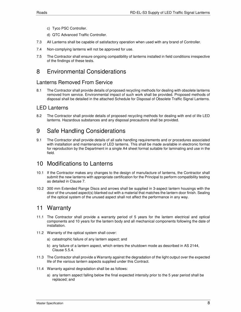
Roads RD-EL-S3 Supply of LED Traffic Signal Lanterns
Master Specification 8
c) Tyco PSC Controller.
d) QTC Advanced Traffic Controller.
7.3 All Lanterns shall be capable of satisfactory operation when used with any brand of Controller.
7.4 Non-complying lanterns will not be approved for use.
7.5 The Contractor shall ensure ongoing compatibility of lanterns installed in field conditions irrespective of the findings of these tests.
8 Environmental Considerations
Lanterns Removed From Service
8.1 The Contractor shall provide details of proposed recycling methods for dealing with obsolete lanterns removed from service. Environmental impact of such work shall be provided. Proposed methods of disposal shall be detailed in the attached Schedule for Disposal of Obsolete Traffic Signal Lanterns.
LED Lanterns
8.2 The Contractor shall provide details of proposed recycling methods for dealing with end of life LED lanterns. Hazardous substances and any disposal precautions shall be provided.
9 Safe Handling Considerations
9.1 The Contractor shall provide details of all safe handling requirements and or procedures associated with installation and maintenance of LED lanterns. This shall be made available in electronic format for reproduction by the Department in a single A4 sheet format suitable for laminating and use in the field.
10 Modifications to Lanterns
10.1 If the Contractor makes any changes to the design of manufacture of lanterns, the Contractor shall submit the new lanterns with appropriate certification for the Principal to perform compatibility testing as detailed in Clause 7.
10.2 300 mm Extended Range Discs and arrows shall be supplied in 3-aspect lantern housings with the door of the unused aspect(s) blanked out with a material that matches the lantern door finish. Sealing of the optical system of the unused aspect shall not affect the performance in any way.
11 Warranty
11.1 The Contractor shall provide a warranty period of 5 years for the lantern electrical and optical components and 10 years for the lantern body and all mechanical components following the date of installation.
11.2 Warranty of the optical system shall cover:
a) catastrophic failure of any lantern aspect; and
b) any failure of a lantern aspect, which enters the shutdown mode as described in AS 2144, Clause 5.5.4.
11.3 The Contractor shall provide a Warranty against the degradation of the light output over the expected life of the various lantern aspects supplied under this Contract.
11.4 Warranty against degradation shall be as follows:
a) any lantern aspect falling below the final expected intensity prior to the 5 year period shall be replaced; and
Roads RD-EL-S3 Supply of LED Traffic Signal Lanterns
Master Specification 9
b) any lantern aspect falling between the Expected Degradation and the Final Intensity period shall result in pro-rata cost recovery from the Contractor.
11.5 This Warranty is show in Figure RD-EL-S3 11-1.
Figure RD-EL-S3 11-1 Warranty against Intensity Loss
11.6 Any equipment failing In Service, or found to be defective within the warranty period, will be returned to the Contractor who shall make good the defect or arrange to have the defect made good, and have the equipment returned to the Principal.
11.7 During the warrant period, no more than 5% out of total number of lanterns procured shall fail in any given 30 day period. Failure rates in excess of this shall require the Contractor to undertake all associated field works until the problem is rectified.
11.8 Defective equipment shall be processed and returned within 30 calendar days from the date of receipt.
11.9 All costs associated with warranty claims shall be at no charge to the Principal, unless otherwise agreed.
11.10 Any equipment failing as a result of a traffic accident, abuse or act of vandalism after delivery shall not be covered by the warranty provisions.
11.11 In order to facilitate checking of warranty claims, each lantern shall be stamped or marked to show the date of manufacture. Each lantern aspect shall be stamped or marked to show the serial number and date of manufacture of the transformer and LED assembly including power supply.
12 Certificate of Suitability
12.1 The Contractor shall obtain a "Certificate of Suitability" for the complete signal lantern to ensure that the equipment meets minimum electrical safety requirements. The Certificate shall be issued by Electrical Regulatory Authorities Council (ERAC). Submission of the Certificate shall constitute a Hold Point.
Roads RD-EL-S3 Supply of LED Traffic Signal Lanterns
Master Specification 10
12.2 Once a "Certificate of Suitability" is issued, it shall be the Contractor's responsibility to ensure that the lantern complies with any subsequent amendments to State Regulations and Australian Standard Specifications relative to electrical safety. If the design of the equipment is changed, the Contractor shall have the "Certificate of Suitability" endorsed accordingly and a copy forwarded immediately to the Superintendent.
12.3 The approval number shown on the “Certificate of Suitability” shall be shown on the marking plate required by AS 3100, Section 7 “Approval and Test Specification – General Requirements for Electrical Equipment”.
13 Immunity to Electromagnetic Interference
13.1 Test specified in Clause 5.5.6.1 of AS 2144 shall be performed and all applicable performance criteria met.
14 Hold Points
14.1 The following is a summary of Hold Points referenced in this Part:
Document Ref. Hold Point Response Time
3.1 The evidence of compliance with AS 2144, including information to be provided in Table RD-EL-S3 3-1.
5 Working days
3.2 NATA test facility report showing the evidence that the lanterns being offered comply with the requirements of AS 2144 (refer to Table RD-EL-S3 3-2).
5 working days
3.6 Type Approval Certificate issued by other state road authority. This Hold Point is applicable only if the lanterns to be supplied are not already in the Department’s Approved Product list
5 working days
4.1 The evidence of lanterns to be supplied are included in the AEMO load table
5 working days
12.1 Submission of the Certificate of Suitability for electrical safety requirements
5 working days

Roads
Master Specification
RD-EW-C1 Earthworks Document Information
KNet Number: 13523396
Document Version: 3
Document Date: August 2020

Roads Contents
Master Specification 2
Document Amendment Record Version Change Description Date
1 Initial issue (formerly R10) 28/06/19
2 Formatting for publishing 11/09/19
3 Formatting for publishing August 2020
Document Management This document is the Property of the Department for Infrastructure and Transport and contains information that is confidential to the Department. It must not be copied or reproduced in any way without the written consent of the Department. This is a controlled document and it will be updated and reissued as approved changes are made.

Roads Contents
Master Specification 3
Contents Contents 3
RD-EW-C1 Earthworks 4
1 General 4
2 Quality Requirements 4
3 Materials for Earthworks 4
4 Site Preparation 6
5 Proof Rolling 6
6 Excavation 7
7 Preparation of the Existing Surface under Fill and the Subgrade in Cut 8
8 Geotextiles 8
9 Fill Construction 9
10 Completed Surface of the Subgrade and Batters 11
11 Treatment of the Constructed Surface 11
12 Test Procedures 12
13 Hold Points 12
14 Verification Requirements and Records 13

Roads RD-EW-C1 Earthworks
Master Specification 4
RD-EW-C1 Earthworks
1 General
1.1 This Part specifies the requirements for the construction of earthworks, including proof rolling, treatment of unsuitable material, excavation, the construction of fill, verges, levees, catch drains, earth side drains and swales.
1.2 Any information known to the Principal regarding the condition or nature of the existing ground, including existing pavements, will be included in report(s) of investigation and / or the Contract Documents.
1.3 The Contractor must construct earthworks in accordance with the drawings and the Contract Documents.
2 Quality Requirements
2.1 The Contractor must prepare and implement an Earthworks Management Plan that includes (where appropriate):
a) calculations of earthworks quantities (in cubic metres solid) and a mass – haul diagram;
b) assumed Bulking Factors;
c) table showing the estimated quantities of material excavated from the site, imported and spoiled;
d) nominated dump site;
e) overview of plant proposed to be used;
f) cross reference to Inspection and Test Plans;
g) methodology for managing any industrial by-products or recycled material used as fill;
h) methodology for placement and compaction of material (including management of moisture content), particularly for General Fill, Oversize Material and Type D Material; and
i) details of proposed haulage routes and copy of agreement with Council.
2.2 If not submitted previously, the Earthworks Management Plan must be submitted at least 28 days prior to the commencement of site work.
2.3 Provision of the Earthworks Management Plan shall constitute a Hold Point.
3 Materials for Earthworks
Material Classification
3.1 Subject to Clause 3.5 "Unsuitable Material", material is classified in accordance with Table RD-EW-C1 3-1.
Table RD-EW-C1 3-1 Material Classification
Classification A B C General Fill (GF)
Oversize D
Material Type Sand-clay, Sand, Rubble, Quarry or Pit overburden or by-product
Sand-clay, Sand, Rubble, Quarry or Pit overburden or by-product
Sand-clay Sand, Clay, Rubble, Quarry or Pit overburden or by-product
Refer to Contract Documents
Refer note(3)
Other material
Max. Particle Size (mm)
75 106 150 150 500 500
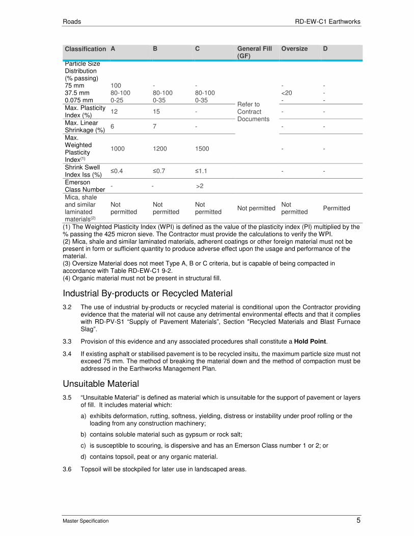
Roads RD-EW-C1 Earthworks
Master Specification 5
Classification A B C General Fill (GF)
Oversize D
Particle Size Distribution (% passing) 75 mm 37.5 mm 0.075 mm
100 80-100 0-25
- 80-100 0-35
- 80-100 0-35
Refer to Contract Documents
- <20 -
- - -
Max. Plasticity Index (%)
12 15 - - -
Max. Linear Shrinkage (%)
6 7 - - -
Max. Weighted Plasticity Index(1)
1000 1200 1500 - -
Shrink Swell Index Iss (%)
≤0.4 ≤0.7 ≤1.1 - -
Emerson Class Number
- - >2
Mica, shale and similar laminated materials(2)
Not permitted
Not permitted
Not permitted
Not permitted Not permitted
Permitted
(1) The Weighted Plasticity Index (WPI) is defined as the value of the plasticity index (PI) multiplied by the % passing the 425 micron sieve. The Contractor must provide the calculations to verify the WPI. (2) Mica, shale and similar laminated materials, adherent coatings or other foreign material must not be present in form or sufficient quantity to produce adverse effect upon the usage and performance of the material. (3) Oversize Material does not meet Type A, B or C criteria, but is capable of being compacted in accordance with Table RD-EW-C1 9-2. (4) Organic material must not be present in structural fill.
Industrial By-products or Recycled Material
3.2 The use of industrial by-products or recycled material is conditional upon the Contractor providing evidence that the material will not cause any detrimental environmental effects and that it complies with RD-PV-S1 “Supply of Pavement Materials”, Section "Recycled Materials and Blast Furnace Slag”.
3.3 Provision of this evidence and any associated procedures shall constitute a Hold Point.
3.4 If existing asphalt or stabilised pavement is to be recycled insitu, the maximum particle size must not exceed 75 mm. The method of breaking the material down and the method of compaction must be addressed in the Earthworks Management Plan.
Unsuitable Material
3.5 “Unsuitable Material” is defined as material which is unsuitable for the support of pavement or layers of fill. It includes material which:
a) exhibits deformation, rutting, softness, yielding, distress or instability under proof rolling or the loading from any construction machinery;
b) contains soluble material such as gypsum or rock salt;
c) is susceptible to scouring, is dispersive and has an Emerson Class number 1 or 2; or
d) contains topsoil, peat or any organic material.
3.6 Topsoil will be stockpiled for later use in landscaped areas.
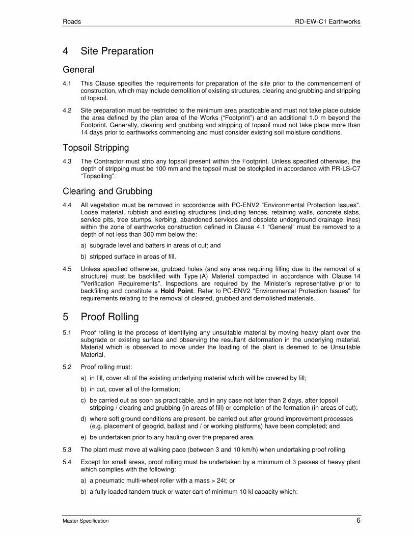
Roads RD-EW-C1 Earthworks
Master Specification 6
4 Site Preparation
General
4.1 This Clause specifies the requirements for preparation of the site prior to the commencement of construction, which may include demolition of existing structures, clearing and grubbing and stripping of topsoil.
4.2 Site preparation must be restricted to the minimum area practicable and must not take place outside the area defined by the plan area of the Works (“Footprint”) and an additional 1.0 m beyond the Footprint. Generally, clearing and grubbing and stripping of topsoil must not take place more than 14 days prior to earthworks commencing and must consider existing soil moisture conditions.
Topsoil Stripping
4.3 The Contractor must strip any topsoil present within the Footprint. Unless specified otherwise, the depth of stripping must be 100 mm and the topsoil must be stockpiled in accordance with PR-LS-C7 “Topsoiling”.
Clearing and Grubbing
4.4 All vegetation must be removed in accordance with PC-ENV2 "Environmental Protection Issues". Loose material, rubbish and existing structures (including fences, retaining walls, concrete slabs, service pits, tree stumps, kerbing, abandoned services and obsolete underground drainage lines) within the zone of earthworks construction defined in Clause 4.1 “General” must be removed to a depth of not less than 300 mm below the:
a) subgrade level and batters in areas of cut; and
b) stripped surface in areas of fill.
4.5 Unless specified otherwise, grubbed holes (and any area requiring filling due to the removal of a structure) must be backfilled with Type (A) Material compacted in accordance with Clause 14 "Verification Requirements". Inspections are required by the Minister’s representative prior to backfilling and constitute a Hold Point. Refer to PC-ENV2 "Environmental Protection Issues" for requirements relating to the removal of cleared, grubbed and demolished materials.
5 Proof Rolling
5.1 Proof rolling is the process of identifying any unsuitable material by moving heavy plant over the subgrade or existing surface and observing the resultant deformation in the underlying material. Material which is observed to move under the loading of the plant is deemed to be Unsuitable Material.
5.2 Proof rolling must:
a) in fill, cover all of the existing underlying material which will be covered by fill;
b) in cut, cover all of the formation;
c) be carried out as soon as practicable, and in any case not later than 2 days, after topsoil stripping / clearing and grubbing (in areas of fill) or completion of the formation (in areas of cut);
d) where soft ground conditions are present, be carried out after ground improvement processes (e.g. placement of geogrid, ballast and / or working platforms) have been completed; and
e) be undertaken prior to any hauling over the prepared area.
5.3 The plant must move at walking pace (between 3 and 10 km/h) when undertaking proof rolling.
5.4 Except for small areas, proof rolling must be undertaken by a minimum of 3 passes of heavy plant which complies with the following:
a) a pneumatic multi-wheel roller with a mass > 24t; or
b) a fully loaded tandem truck or water cart of minimum 10 kl capacity which:
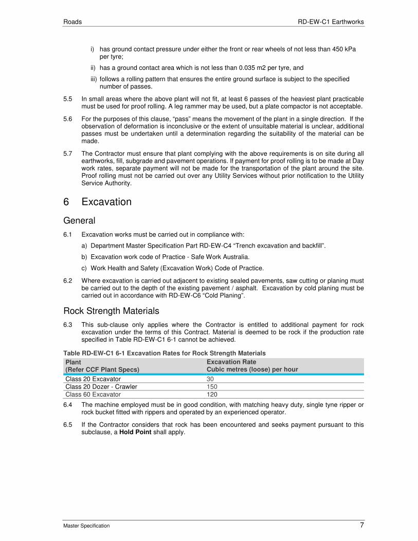
Roads RD-EW-C1 Earthworks
Master Specification 7
i) has ground contact pressure under either the front or rear wheels of not less than 450 kPa per tyre;
ii) has a ground contact area which is not less than 0.035 m2 per tyre, and
iii) follows a rolling pattern that ensures the entire ground surface is subject to the specified number of passes.
5.5 In small areas where the above plant will not fit, at least 6 passes of the heaviest plant practicable must be used for proof rolling. A leg rammer may be used, but a plate compactor is not acceptable.
5.6 For the purposes of this clause, “pass” means the movement of the plant in a single direction. If the observation of deformation is inconclusive or the extent of unsuitable material is unclear, additional passes must be undertaken until a determination regarding the suitability of the material can be made.
5.7 The Contractor must ensure that plant complying with the above requirements is on site during all earthworks, fill, subgrade and pavement operations. If payment for proof rolling is to be made at Day work rates, separate payment will not be made for the transportation of the plant around the site. Proof rolling must not be carried out over any Utility Services without prior notification to the Utility Service Authority.
6 Excavation
General
6.1 Excavation works must be carried out in compliance with:
a) Department Master Specification Part RD-EW-C4 “Trench excavation and backfill”.
b) Excavation work code of Practice - Safe Work Australia.
c) Work Health and Safety (Excavation Work) Code of Practice.
6.2 Where excavation is carried out adjacent to existing sealed pavements, saw cutting or planing must be carried out to the depth of the existing pavement / asphalt. Excavation by cold planing must be carried out in accordance with RD-EW-C6 “Cold Planing”.
Rock Strength Materials
6.3 This sub-clause only applies where the Contractor is entitled to additional payment for rock excavation under the terms of this Contract. Material is deemed to be rock if the production rate specified in Table RD-EW-C1 6-1 cannot be achieved.
Table RD-EW-C1 6-1 Excavation Rates for Rock Strength Materials
Plant (Refer CCF Plant Specs)
Excavation Rate Cubic metres (loose) per hour
Class 20 Excavator 30
Class 20 Dozer - Crawler 150
Class 60 Excavator 120
6.4 The machine employed must be in good condition, with matching heavy duty, single tyne ripper or rock bucket fitted with rippers and operated by an experienced operator.
6.5 If the Contractor considers that rock has been encountered and seeks payment pursuant to this subclause, a Hold Point shall apply.

Roads RD-EW-C1 Earthworks
Master Specification 8
7 Preparation of the Existing Surface under Fill and the Subgrade in Cut
General
7.1 This Clause applies at the completion of clearing and grubbing and topsoil stripping in accordance with Clause 4 “Site Preparation” in areas of fill and at the completion of excavation in cuts.
Assessment and Treatment of Existing Material
7.2 Prior to the placement of fill or pavement, the Contractor must provide a notice and arrange for a joint inspection and joint survey of the ground surface for the purpose of identifying unsuitable material, the foundation surface condition and the bed design elevation.
7.3 Provision of the notice shall constitute a Hold Point unless not addressed in the Earthworks Management Plan or the Contract Documents.
7.4 The assessment will be undertaken in the form of a visual assessment and by proof rolling of the areas of ground surface in accordance with Clause 5 "Proof Rolling". The Contractor must trim these areas prior to proof rolling. For the purpose of undertaking proof rolling in areas of cut, the Contractor may elect to excavate and trim the earthworks to within 50 mm of the final subgrade level before undertaking proof rolling.
7.5 Prior to placing fill or pavement, any unsuitable material identified must be:
a) removed and replaced with suitable compacted material; or
b) treated (e.g. by installing geotextile or stabilising the material).
7.6 To make the subgrade fit for its intended purpose:
a) Any filling required must be placed with a minimum thickness of 150 mm.
b) Where the material underlying a fill is either existing pavement or the existing formation of an unsealed road, the area must be scarified and Type (A) Material placed such that the thickness of loose material is not less than 150 mm, prior to compaction in accordance with Clause 9 “Fill Construction”.
c) Following Proof Rolling and / or treatment in accordance with this Clause, the Contractor must ensure that water does not pond on the surface and the earthworks material properties do not deteriorate.
8 Geotextiles
General
8.1 This Clause applies where the earthworks design incorporates geotextile for the purpose of filtration, drainage or separation. Geotextiles must be supplied in accordance with RD-EW-S1 "Supply of Geotextiles" and must be placed in accordance with the manufacturer’s instructions, unless amended by this clause.
Site Preparation over Soft Soils
8.2 The site must be prepared by clearing and grading the area required. All sharp objects and large stones must be removed. If the earthworks design specifies that site preparation in accordance with Clause 4 "Site Preparation" is not required, the topsoil and vegetation mat may remain with any trees and shrubs cut flush with the ground surface.
8.3 Geotextiles must be placed without puncture or tears ahead of associated construction works and be covered by relevant construction materials or suitable protective sheeting within 48 hours of placement. Geotextiles used in trench drains must be placed so as to conform loosely to the shape of the trenches. The geotextile must fully envelop the drainage material in the trench.

Roads RD-EW-C1 Earthworks
Master Specification 9
Initial Layer Thickness Requirements for Separation Applications
8.4 The minimum required initial layer thickness for fill material placed directly over the geotextile must meet the requirements specified in Table RD-EW-C1 8-1.
Table RD-EW-C1 8-1 Minimum Initial Layer Thickness
Nominal Maximum Fill Particle Size D85 (mm)
Minimum Initial Layer Thickness (mm)
< 150 The largest of 3 times Maximum Fill Particle Size or 200 mm minimum.
150 – 225 450 mm.
225 – 400 Two times Maximum Fill Particle Size.
Joining
8.5 Joining of geotextiles must be by overlap or by sewing. Unless otherwise specified, the minimum overlap must be 500 mm. Where the geotextile is used for drainage blankets the encapsulated overlap must be one metre unless otherwise specified. As an alternative to overlapping, sewing of seams is permitted. Sewing of joins must comply with the following:
a) Seam Type: J seam or double J seam.
b) Stitch Type: Double thread lock stitch. Two lines of stitching must be used.
c) Thread Type: Polyester thread 300 tex (minimum).
8.6 If it is necessary to measure geotextile for payment purposes, the measurement must be based on the final surface area covered, with no allowance for any overlaps.
8.7 Checking of the joints, the proposed initial layer thickness and the plant to be used for compaction will be made and will constitute a Hold Point.
Filling over Installed Geotextile
8.8 Construction equipment must not stand or travel directly on the laid geotextile. A minimum cover of 200 mm (uncompacted) of cover material must be placed over the geotextile prior to construction equipment travelling over the area concerned. Rock armour placed directly on the geotextile must be placed with a drop height not exceeding 1.0 m.
8.9 The mechanical equipment must be selected and operated so as not to cause rupture of the geotextile. Vibratory and heavy compaction plant must not be used on the initial lifts of filling material.
9 Fill Construction
General
9.1 Type (A) Material must be used within 0.5 m of the underside of the pavement.
9.2 Fill material must be placed and compacted uniformly in layers in accordance with Table RD-EW-C1 9-1.
Table RD-EW-C1 9-1 Fill Construction
Maximum Particle Size of Fill Material (mm)
Layer Thickness (mm loose)
Compaction Moisture Content when Compacted
150 or less: Types A, B and C
150 to 200 In accordance with Clause 14 "Verification Requirements and Records".
OMC ± 2%
150 or less: General Fill
150 to 200 In accordance with the Contract Documents.
In accordance with the Contract Documents.

Roads RD-EW-C1 Earthworks
Master Specification 10
Maximum Particle Size of Fill Material (mm)
Layer Thickness (mm loose)
Compaction Moisture Content when Compacted
> 150 Minimum layer thickness of one and a half times the maximum particle size, or 300 mm, whichever is greater.
In accordance Table RD-EW-C1 9-2.
In accordance with the Earthworks Management Plan.
Placement of Oversize Material
9.3 Material with a maximum particle size of 150 mm or more must:
a) not be placed within 500 mm of the underside of the pavement;
b) have the top surface of the material blinded with Type A or B Material to fill surface voids before the placement of subsequent layers; and
c) be compacted using of vibrating drum rollers in accordance with Table RD-EW-C1 9-2.
Table RD-EW-C1 9-2 Compaction of Oversize Material
Minimum Roller Classification* (Refer CCF Plant Specs)
Maximum Layer Thickness Minimum Number of Passes
Class 5 300 6
Class 10 500 6
Class 12.5 750 6
*The minimum static mass on the vibrating drum must be 4.5 tonnes.
9.4 Where alternative compaction specifications for oversized material are proposed verification test methods and frequencies are required to be submitted.
Placement of General Fill
9.5 General Fill must be placed and compacted in accordance with the requirements specified in the Contract Documents. Compaction of General Fill must be determined by Standard Compaction in accordance with AS 1289.5.1.1.
Placement of Type D Fill
9.6 Where the use of Type D materials is permitted, it must be placed and compacted in accordance with the Earthworks Management Plan to achieve a stable fill.
Miscellaneous
9.7 All filling must be supervised by a qualified civil / geotechnical engineer or earthworks site supervisor to address any issues related to fill construction.
9.8 Where new embankment fill is to be placed against an existing surface which is steeper than 3 horizontal to 1 vertical, benching within the existing surface must be carried out to allow placement of fill in layers. The width of benches must be 1 m minimum and must be constructed at 0.5 m vertical intervals to create a stepped surface.
9.9 The Contractor must maximise the usage of suitable material excavated from the site, which may involve double handling, to minimise the requirement for imported fill.
9.10 Any noise mounds must not contain material with a particle size greater than 150 mm and must contain more than 20% finer than 0.075 mm particle size. Notwithstanding Sub-Clause 9.2, fill in noise mounds may be compacted in layers up to 300 mm loose depth.
9.11 During construction surface grades shall be cut to allow for drainage of surface water to low points where removal of water is possible in a timely manner to prevent softening of subgrade soils or destabilisation of nearby cuttings and retaining structures.

Roads RD-EW-C1 Earthworks
Master Specification 11
10 Completed Surface of the Subgrade and Batters
10.1 The levels of points not detailed on the drawings must be determined by linear interpolation. The surface must be constructed to within the tolerances specified in Clause 14 “Verification Requirements and Records” at all interpolated and discrete points.
10.2 Lines, grades, cross-sections, levels, dimensions and tolerances specified in the Contract Documents do not include an allowance for a layer of topsoil.
10.3 Batters must be constructed to the slopes shown on the drawings. The slope of all batters must be even and consistent from top to bottom and free from abrupt changes in level. Tops of batters must be rounded over the width shown on the drawings to reduce erosion.
10.4 The Contractor must ensure that subgrade has a tight dense surface and does not deteriorate after proof rolling or verification testing. Completed sections of subgrade must be maintained in a well-drained condition.
10.5 Where the subgrade occurs in rock, the excavated surface must be blinded with subbase material and graded, shaped and compacted to produce a tight dense surface.
11 Treatment of the Constructed Surface
General
11.1 For the purpose of this clause only “Constructed Surface” means any location within the Site where the ground surface is disturbed or altered, excluding a hard surface such as pavement, footpath, compacted rubble or exposed bedrock.
11.2 The Contractor must:
a) apply the treatment specified in the Contract Documents to the Constructed Surface; and
b) comply with this clause until Completion.
11.3 Material placed near the surface of batters (including imported topsoil) must exhibit sufficient properties such that:
a) the surface is highly resistant to surface scour and erosion;
b) in cuts, any material which becomes detached is prevented from reaching the road shoulder; and
c) there is no undermining or destabilisation of any existing batter slopes or structures.
11.4 The Contractor must repair any surface scour and erosion that occurs prior to the establishment of permanent or temporary stabilisation or revegetation.
Cut-off Drains
11.5 Cut off drains are not to be constructed unless specified on the drawings. If specified, open trench "V" drains must be constructed and maintained on the top of batters for the full length of the cutting prior to commencement of excavation in cuttings.
Spreading of Topsoil
11.6 For spreading of topsoil refer to PR-LS-C7 “Topsoiling”.
11.7 Topsoil spread must be stabilised. Heavy compaction of topsoil should be avoided where landscape treatments are to be installed.
11.8 Any remaining site-won topsoil stockpiles must be rounded off with batters of maximum slope of 6 horizontal to 1 vertical. All topsoil won from the works and approved for use in landscaped areas must be used before any topsoil is imported. For imported topsoil refer to PR-LS-C7 “Topsoiling”.

Roads RD-EW-C1 Earthworks
Master Specification 12
Weed Control
11.9 The Contractor is responsible for the control of all declared and environmental weeds on the Constructed Surface. Weed control must be undertaken in accordance with PR-MA-M1 ““Herbicide and Wood Weed Control” ”. Unless specified otherwise in the Contract Documents, the Contractor is responsible for determining the details of the slashing frequency and / or herbicide application (including chemical used and application rate).
Surface Treatment
11.10 If details of the treatment of the Constructed Surface is not provided in the Contract Documents, the Contractor is responsible for determining all details necessary for ensuring that the treatment is successful for the design life of the treatment, such as the method of seedbed preparation / sowing and fertiliser application. Provision of these details shall constitute a Hold Point.
11.11 Treatments applied to the Constructed Surface must comply with the following:
a) Landscape Design: PR-LS-D1 “Landscaping Design”.
b) Erosion Control Matting: PR-LS-C1 “Erosion Control Matting”.
c) Planting: PR-LS-C2 “Planting”.
d) Hydroseeding and Direct Seeding: PR-LS-C6 “Hydroseeding and Direct Seeding”.
e) Maintenance of Plants: PR-LS-M1 “Maintenance of Plants”.
f) Maintenance of Seeded Areas:PR-LS-M2 “Maintenance of Hydroseeded and Direct Seeded Areas”.
12 Test Procedures
12.1 The Contractor must use the following test procedures (refer https://www.dpti.sa.gov.au/contractor_documents) to verify conformance with the Specification:
Table RD-EW-C1 12-1 Test Procedures
Test Test Procedure
Sampling of Soil, Aggregates and Rocks TP 226
Preparation of Samples AS 1289.1
Site Selection by Stratified Random Technique AS 1289.1.4.2
Field Density: Nuclear Method AS 1289.5.8.1
Moisture Content: Oven Drying Method Microwave Method
AS 1289.2.1.1 AS 1289.2.1.4
Maximum Dry Density: Standard Compaction* Modified Compaction Three Point Method
AS 1289.5.1.1 AS 1289.5.2.1 TP 164
Dry Density Ratio TP 320
Emerson Class AS 1289.3.8.1
Particle Size Distribution TP 134
Plasticity Index TP 141
Linear Shrinkage AS 1289.3.4.1
Shrink Swell AS 1289.7.1
* Used for General Fill only.
13 Hold Points The following is a summary of Hold Points referenced in this Part:
Table RD-EW-C1 13-1 Hold Points
Document Ref. Hold Point Response Time
2.3 Earthworks Management Plan 5 Working Days

Roads RD-EW-C1 Earthworks
Master Specification 13
Document Ref. Hold Point Response Time
3.3 Proposed use of industrial by-products or recycled material as fill
2 Working Days
4.5 Clearing and grubbing 1 Working Day
6.5 Notification that rock has been encountered 1 Working Day
7.3 Notice prior to a joint Inspection and joint survey of existing surface
1 Working Day
8.7 Checking joining of geotextile and initial layer thickness 1 Working Day
11.10 Provision of earthworks surface treatment details 2 Working Days
14 Verification Requirements and Records The Contractor must supply written verification that the following requirements have been complied with and supply the verification with the lot package.
Table RD-EW-C1 14-1 Verification requirements
Document Ref.
Subject Property Test Procedure Test Frequency Acceptance Limits
3.1. Fill Material Properties
Grading TP 134 AS 1152
One test per lot Refer Table RD-EW-C1 3-1
Plasticity Index TP 141 One test per lot Refer Table RD-EW-C1 3-1
Linear Shrinkage AS 1289.3.4.1 One test per lot Refer Table RD-EW-C1 3-1
Emerson class number
AS 1289.3.8.1 One test per day’s production
Classified as Emerson Class number 3 or higher
Shrink Swell Index AS 1289.7.1 One test per lot Refer Table RD-EW-C1 3-1
Weighted Plasticity Index
Refer Clause 3 One test per lot Refer Table RD-EW-C1 3-1
8, 9, 10, 11
Earthworks levels and position
Variation in subgrade level:
As specified in Part PC-SI1
As specified in Part PC-SI1
Within + 0, - 40 mm of design level
Variation in lateral position:
As specified in Part PC-SI1
As specified in Part PC-SI1
Within ± 50 mm of design level
Variation of reduced levels of fill batters:
As specified in Part PC-SI1
As specified in Part PC-SI1
Within ± 75 mm of design level
Variation of reduced levels of open drains:
As specified in Part PC-SI1
As specified in Part PC-SI1
Within ± 50 mm of design level with the proviso that, notwithstanding tolerances, open drains must be self-draining.
9 Earthworks Compaction
Type A Material in top 150 mm of fill
TP 320 1 test per 500 square metres with a minimum of 4 tests per lot*.
Compaction: Not less than 95% Modified Moisture Content: OMC ± 2%
Type A Material other than in top 150 mm of fill
TP 320 1 test per 400 cubic metres or part thereof with a minimum of 4 tests per lot*.
Compaction: Not less than 92% Modified Moisture Content: OMC ± 2%

Roads RD-EW-C1 Earthworks
Master Specification 14
Document Ref.
Subject Property Test Procedure Test Frequency Acceptance Limits
Type B & C Material TP 320 1 test per 400 cubic metres of compacted material or part thereof with a minimum of 4 tests per lot*.
Compaction: Not less than 90% Modified Moisture Content: OMC ± 2%
General Fill TP 320 1 test per 400 cubic metres of compacted material or part thereof with a minimum of 4 tests per lot*
Refer Contract Documents
* Every layer must be tested

Roads
Master Specification
RD-ITS-S2 Electrical Switchboard Document Information
K Net Number: 13138259
Document Version: 2
Document Date: 19/09/2019

Roads Contents
Master Specification 2
Document Amendment Record
Version Change Description Date Endorsement record (KNet ref.)
1 Initial issue (formerly R64) 02/07/19
2 Formatting for publishing 19/09/19
Document Management This document is the Property of the Department for Infrastructure and Transport and contains information that is confidential to the Department. It must not be copied or reproduced in any way without the written consent of the Department. This is a controlled document and it will be updated and reissued as approved changes are made.
Roads Contents
Master Specification 3
Contents Contents 2
RD-ITS-S2 – Electrical Switchboards 4
1 General 4
2 Definitions 4
3 Quality Requirements 5
4 Equipment Requirements 5
5 Circuit Protection Devices 7
6 Switchboard Electrics 8
7 Minor Switchboards 10
8 Design and Manufacture 11
9 Installation 11
10 Hold Points 12
11 Verification Requirements and Records 12

Roads RD-ITS-S2 Electrical Switchboards
Master Specification 4
RD-ITS-S2 Electrical Switchboards
1 General
1.1 This Part specifies the requirements for the supply and installation of electrical switchboards for applications other than road lighting and traffic signal controllers. This Part must be read in conjunction with RD-ITS-S1 “General Requirements for the Supply of ITS Equipment” and RD-ITS-C1 “Installation and Integration of ITS Equipment”.
1.2 Documents referenced in this Part are listed below:
a) AS/NZS 3000 Electrical Installations (also referred to as the “Wiring Rules”).
b) AS/NZS 3085.1 Telecommunications Installations – Administration of Communications Cabling Systems – Basic Requirement.
c) AS/NZS 1170 Structural design actions - General principles.
d) AS/NZS 3013 Electrical Installations – Classification of the Fire and Mechanical Performance of Wiring Systems.
e) AS/NZS 3100 Approval and Test Specification – General Requirements for Electrical Equipment.
f) AS/NZS 3111 Approval and Test Specification – Miniature Over-Current Circuit- Breakers.
g) AS/NZS 3190 Approval and Test Specification – Residual Current Devices (Current- Operated Earth-Leakage Devices).
h) AS/NZS 3947 Low-voltage Switchgear and Controlgear.
i) AS 4070 Recommended Practices for the Protection of Low Voltage Electrical Installations and Equipment in MEN Systems for Transient Over- Voltages.
j) AS/NZS 5000 Electrical Cables – Polymeric Insulated.
k) AS 61818 Application guide for low-voltage fuses.
l) AS 60529 Degrees of Protection Provided by Enclosures (IP Code).
m) AS/NZS 60947 Low-Voltage Switchgear and Controlgear.
n) AS/NZS 61439 Low-voltage Switchgear and Controlgear assemblies.
o) AS/NZS ISO 9001 Quality Management Systems – Requirements.
2 Definitions Term Definition
CSA Cross-Sectional Area
DB Distribution Board
Essential Circuit A circuit nominated as “Essential” on the drawings and / or a circuit connected to a batter-backed power supply (such as a UPS)
LV Low-Voltage as defined in AS/NZS 3000
MCB Miniature Circuit Breaker
MCCB Moulded Case Circuit Breaker
MEN Multiple-Earthed Neutral
MSB Main Switchboard
Switchboard Enclosure The switchboard mounting chassis.
Switchboard The entire functional unit, including electrical components and switchboard enclosure.
UPS Uninterruptible Power Supply

Roads RD-ITS-S2 Electrical Switchboards
Master Specification 5
3 Quality Requirements
3.1 All supplied equipment shall be manufactured under a quality system certified to AS/NZS 9001.
3.2 The Contractor shall prepare and implement a Quality Plan, in accordance with PC-QA1 “Quality Management Requirements” that includes or annexes the following documentation:
a) design documentation in accordance with RD-ITS-D1 "Design for Intelligent Transport System (ITS)";
b) sample(s) for acceptance in accordance with RD-ITS-S1 “General Requirements for the Supply of ITS Equipment”, Clause 3 (Equipment Requirements); and
c) drawings, manufacturer’s specifications and diagrams.
3.3 If not submitted beforehand, the documentation and samples required by this Clause must be submitted at least 20 working days prior to the commencement of site work or placing an order for Equipment.
3.4 Provision of the documentation and sample(s) listed in this Clause shall constitute a Hold Point.
4 Equipment Requirements
Design
4.1 The switchboard must be contained within a dedicated, sealed enclosure that prevents contact with any live LV surface. The switchboard enclosure must comply with the requirements of RD-ITS-S3 “ITS Enclosures” and RD-ITS-D1 “Design for Intelligent Transport System (ITS)”.
Electrical Requirements
4.2 All electrical design, wiring and associated Equipment must comply with the requirements of AS/NZS 3000. All electrical components must be suitable for operation on a mains 230 volt (and 240 volt) +5%/ - 10%, 50Hz ±0.1Hz system (and / or three-phase equivalent as appropriate) and rated for the respective calculated, prospective fault current. Unless otherwise noted, switchboard electrics / Equipment must be mounted on DIN rail complying with DIN 46277. DIN rail must be TH35 7.5, minimum 400 mm length and fixed securely by screws to prevent movement.
Identification and Labelling
General
4.3 Identification labels must be in accordance with AS/NZS 61439 and AS/NZS 3000. Labels must be provided for switchboards and their contents, including: instruments, controls, circuit designations and ratings, circuit protection devices, discrete devices, cabling, warning notices, and the like.
Electrical Insulation
4.4 Electrical insulation colours for wiring cores and busbars must be as shown in Table RD-ITS-S2 4-1.
Table RD-ITS-S2 4-1 Insulation Colours
Core Multiphase Installation (Colour) Single Phase Installations (Colour)
Active Red, white or blue Red
Neutral Black Black
Earth Green and yellow Green and yellow
LV Control White with numbered ferrules White with numbered ferrules
ELV Control Purple with numbered ferrules Purple with numbered ferrules
Labelling Requirements
4.5 Labels must be fixed by screws adjacent to the respective Equipment. Screws in areas accessible to the public must be of vandal-resistant design. The label must be located such that it cannot be

Roads RD-ITS-S2 Electrical Switchboards
Master Specification 6
mistaken as referring to another device. Unless otherwise specified, labels must not be fixed on the Equipment. Labels must be laminated plastic or brushed aluminium, and coloured as follows:
a) Warning Notices: White letters on red background.
b) Essential Circuits: Red lettering on white background.
c) Other Labels: Black on white background.
4.6 Lettering height must comply with that outlined in Table RD-ITS-S2 4-2.
Table RD-ITS-S2 4-2 Label Lettering Height
Label Lettering Height
“Main Switchboard” 25 mm
Name of other switchboards 15 mm
“Main Switch” 15 mm
DB feeder control switches 10 mm
Name of switchboard panel 6 mm
Equipment labels 4 mm
Warning notices 4 mm
Labelling of Circuit Protection Devices
4.7 Devices that protect switchboard and / or DB feeders must be labelled in a manner similar to the following examples:
a) Number of circuit protection device: Qxx [or] Fxx
b) Name of connected sub-board: DB 1 – General Light & Power
c) Setting / Rating of circuit protection device: 315A / 400A
d) Connected cable size and type: 4 x 1C 300 mm2 Cu/PVC/PVC
4.8 Devices that protect other circuits must be labelled in a manner similar to the following examples:
a) Number of circuit protection device: Qxx [or] Fxx
b) Name of final sub-circuit: L1 – S/L North 1
Schedule Cards
4.9 Circuit schedule cards must be provided to describe final sub-circuits. Cards must be at least 200 mm x 150 mm in size and contain computer-printed text showing:
a) number of circuit protection device;
b) sub-main or sub-circuit name;
c) destination area (where applicable); and
d) cable rating, type and length.
4.10 Each card must be mounted in a purpose-built holder fixed inside the door of the enclosure housing the protection devices. The card must be protected by a transparent plastic cover.
Neutral Earth
4.11 Unless otherwise specified, all new cabinets and switchboards must be bonded to earth by suitable cabling and earth conductor network as a MEN system in accordance with AS/NZS 3000. Clearly numbered terminals must be provided for all neutral and earth conductors, including the MEN link. Spare terminals must be provided for future circuits in each of the neutral and earth bars. The number of spare terminals must be the greater of: 10% of initial connected terminals; or 6 terminals. Cables with CSA of 16 mm2 or larger must be provided with stud connections.

Roads RD-ITS-S2 Electrical Switchboards
Master Specification 7
Switchboard Wiring
4.12 Wiring within the switchboard must:
a) have a minimum CSA or 2.5 mm2 (7/0.67) for power supply wiring;
b) have a minimum CSA of 1.0 mm2 (32/0.2) for control and indication wiring;
c) comply with AS/NZS 5000;
d) be sized to suit the rated current of the particular circuit; and
e) be de-rated in accordance with AS/NZS 3008 Part 1.
4.13 Only one wire must be connected to each terminal. Proprietary bonding links must be used for parallel connections between adjacent terminals. Unless otherwise specified, all wiring must use 0.6/1 V V-75 Cu/PVC cables that comply with AS/NZS 5000. Essential circuits must utilise a wiring system that complies with WS52 to AS/NZS 3013.
4.14 Where use of wiring ducts is impractical, it must be bundled and supported with PVC ties or strips so as to remain neat, functional, prevent excessive sagging, and avoid interference with maintenance activities within the enclosure. Protective insulated flashing must be provided where wiring or cables pass through cut-outs or other sharp edges.
Terminations
Terminals
4.15 Each wiring terminal must be clearly and indelibly identified. The terminal assembly must be arranged so that:
a) the connecting cables can be formed in a neat manner; and
b) all conductors can be connected or disconnected without disturbing other connections.
4.16 Stud-type terminals (minimum 5 mm diameter) must be used with wiring connections for CSA greater than 25.0 mm2. Only 1 lug may be installed per mounting stud. Tunnel-type terminals blocks must be DIN rail mounted as follows:
a) Wire CSA 10.0 mm2 to 25.0 mm2 (inclusive): Compression Screws.
b) Wire CSA up to 10.0 mm2 (exclusive): Compression Screws or Spring-Type.
4.17 Tunnel type terminals must only have one conductor connected to each end of the tunnel.
Lugs
4.18 Wiring must be terminated using compression type lugs / pins that are compatible with the terminals. Lugs / pins must be crimped in accordance with the manufacturer’s instructions.
Arrangement
4.19 All internal wiring must be terminated on one side of the terminal block; wiring that exits the switchboard enclosure must be terminated on the other side. Control terminals must be grouped for each circuit with each group physically segregated. DIN rails must provide 25% spare capacity for future circuits.
5 Circuit Protection Devices
General
5.1 Mains switching, outgoing circuit switching, motor control and starters, protection and auxiliary Equipment must be provided as shown on the design documentation. Circuit protection devices must be rated for:
a) full current of connected load – continuous duty; and
b) starting currents of connected load – a duty equal to the load’s rated number of starts per hour.

Roads RD-ITS-S2 Electrical Switchboards
Master Specification 8
5.2 The protection device’s make and break capacity must be equal to at least the calculated prospective short-circuit fault current of the installation. The minimum utilisation category must be AC-23 for circuits with motor or other highly inductive loads, and AC-22 for all other loads.
Switch-Isolator and Fuse-Switch Units
5.3 Switch-isolator and fuse-switch units must comply with AS/NZS 3947. Switch-isolator and fuse-switch units must allow manual operation with an integral ON-OFF indicator, and a facility to lock the device in the OFF position. The units must be totally enclosed and incorporated arc-control devices, and shrouded stationary contacts.
Fuses
5.4 Fuses must be enclosed, High Rupturing Capacity (HRC) type. Fuses must be installed in fuse-holders that allow a blown fuse to be identified while the fuse in installed in the service position. The fuse-holder must insulate all live parts when the fuse is withdrawn. A fuse insertion / extraction device must be provided to safely remove and insert fuses. The extraction device must be mounted on retention clips within the enclosure. Each switchboard must be provided with three (3) spare fuses for each size of fuse used in the switchboard. The spare fuses must be mounted in holders within the enclosure adjacent the fuse extraction device.
Moulded Case and Miniature Circuit Breakers
5.5 MCCBs and MCBs with fault capacities of 10 kA or more must be in accordance with AS/NZS 60947. MCBs with fault capacities less than 10 kA and a current rating up to 100 A must be in accordance with AS/NZS 3111. All circuit breakers must be able to be locked in the “Off” position. MCCBs need not be mounted on DIN rail.
Residual Current Devices
5.6 Residual Current Devices (RCD) must be in accordance with AS/NZS 3190 and AS/NZS 3111. Where RCD protection is provided on a circuit protected by a MCB, the RCD must be integral with the MCB. Unless otherwise specified, the tripping current for all RCDs must be 30 mA.
6 Switchboard Electrics
Protection against Electrical Transients and Over-Voltage
General
6.1 The installation must incorporate protection against electrical transients and over-voltage. Unless otherwise specified, the installation must follow the recommended practices for the MEN system, specified in AS 4070 for protection of low-voltage electrical installations and Equipment from transient over-voltages. The installation must follow the general guidelines for the protection of persons and property from hazards arising from exposure to lighting in accordance with AS 1768. The switchboard must also include the necessary devices to protect all Equipment being housed in the enclosure from electrical transients and over-voltage.
Surge Diverter
6.2 Surge diverters must be supplied and installed in the switchboard to provide protection against multiple impulses caused by lighting or other transient disturbances. Surge diverters must be connected on the load side of the installation’s main switch between the following terminals:
a) phase and neutral;
b) phase and earth; and
c) phase to phase (at multi-phase installations).
6.3 Surge Diverters must:
a) be in accordance with the Australian Standard AS 4070;

Roads RD-ITS-S2 Electrical Switchboards
Master Specification 9
b) have a minimum phase-to-neutral single shot 8/20us rating of 80kA and be suitably rated to withstand multiple impulses as defined by location category C in AS 1768;
c) be based on Metal Oxide Varistor (MOV) technology, with each MOV rated at no less than 40kA for an 8/20us pulse. MOVs must be internally fused such that they are disconnected if the unit experiences a surge that exceeds its rating;
d) have visual indication of MOV fuse operation, loss of power, and thermal overload. In the event of a thermal overload, the protection must remain in circuit;
e) have voltage free changeover contact (Alarm output). This must activate upon any MOV failure, power failure or thermal overload condition. The contact must be isolated to 4 kV to all active circuitry;
f) be rated for a nominal operating phase voltage of 230 V / 240 V, and a maximum operating voltage of at least 275 V rms; and
g) have a let through voltage (Residual Voltage) for a 6 kV 1.2/50us, 3 kA 8/20us impulse of less than 900 V when measured at the surge diverter terminals.
Surge Filters
6.4 A surge filter must be supplied and installed on the load side of the surge diverter, and on the line side of sub-circuits supplying electronic Equipment and the earth leakage protective devices of switched outlet sub-circuits. Surge filters must provide finer protection against multiple impulses caused by lighting and other (transient disturbances and interferences. The surge filter must be connected between phase and neutral in accordance with AS 4070.
6.5 Surge filters must:
a) have a minimum load current rating of 10A per phase;
b) have a single shot 8/20us rating of 16 kA per mode and must be suitably rated to withstand multiple impulses as defined by location category B in AS 1768;
c) be based upon MOV technology. The line side MOVs must be internally fused such that they are disconnected if the unit experiences a surge that exceeds its rating;
d) have visual tags and LED indicating “power” and “status” for each phase. The power LED must extinguish when power to the unit is lost. The status visual tags and LEDs must extinguish when the MOV fuse operates, when power to the unit is lost, or when the unit experiences a thermal overload. In the event of a thermal overload the protection must remain in circuit;
e) have a voltage free changeover contact (Alarm output). This must activate upon any MOV failure, power failure or temperature overload condition. The contact must be isolated to 4 kV to all active circuitry;
f) be rated for a nominal operating phase voltage of 230 V / 240 V and a maximum operating voltage of at least 275 V rms; and
g) have a let through voltage (Residual Voltage) for a 6 kV 1/2/50us, 3 kA 8/20us impulse of less than 600 V when measured at the surge filter terminals.
Switches and Push Buttons
6.6 Control and test switches and push buttons must comply with AS 60947.5.1. Switches and push buttons must have a minimum rating of 6A at 240 VAC at utilisation category AC-22 in compliance with AS/NZS 3947 Part 1. Control and test switches must meet IP56. Push buttons must be colour coded according to the following functions:
a) Start / On / Close: Green.
b) Stop / Off / Open: Red.
c) Reset / Acknowledge: Black.
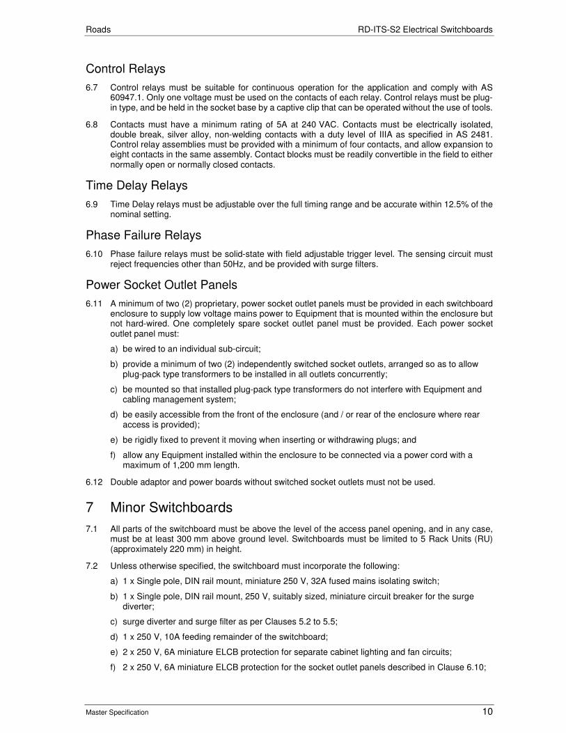
Roads RD-ITS-S2 Electrical Switchboards
Master Specification 10
Control Relays
6.7 Control relays must be suitable for continuous operation for the application and comply with AS 60947.1. Only one voltage must be used on the contacts of each relay. Control relays must be plug-in type, and be held in the socket base by a captive clip that can be operated without the use of tools.
6.8 Contacts must have a minimum rating of 5A at 240 VAC. Contacts must be electrically isolated, double break, silver alloy, non-welding contacts with a duty level of IIIA as specified in AS 2481. Control relay assemblies must be provided with a minimum of four contacts, and allow expansion to eight contacts in the same assembly. Contact blocks must be readily convertible in the field to either normally open or normally closed contacts.
Time Delay Relays
6.9 Time Delay relays must be adjustable over the full timing range and be accurate within 12.5% of the nominal setting.
Phase Failure Relays
6.10 Phase failure relays must be solid-state with field adjustable trigger level. The sensing circuit must reject frequencies other than 50Hz, and be provided with surge filters.
Power Socket Outlet Panels
6.11 A minimum of two (2) proprietary, power socket outlet panels must be provided in each switchboard enclosure to supply low voltage mains power to Equipment that is mounted within the enclosure but not hard-wired. One completely spare socket outlet panel must be provided. Each power socket outlet panel must:
a) be wired to an individual sub-circuit;
b) provide a minimum of two (2) independently switched socket outlets, arranged so as to allow plug-pack type transformers to be installed in all outlets concurrently;
c) be mounted so that installed plug-pack type transformers do not interfere with Equipment and cabling management system;
d) be easily accessible from the front of the enclosure (and / or rear of the enclosure where rear access is provided);
e) be rigidly fixed to prevent it moving when inserting or withdrawing plugs; and
f) allow any Equipment installed within the enclosure to be connected via a power cord with a maximum of 1,200 mm length.
6.12 Double adaptor and power boards without switched socket outlets must not be used.
7 Minor Switchboards
7.1 All parts of the switchboard must be above the level of the access panel opening, and in any case, must be at least 300 mm above ground level. Switchboards must be limited to 5 Rack Units (RU) (approximately 220 mm) in height.
7.2 Unless otherwise specified, the switchboard must incorporate the following:
a) 1 x Single pole, DIN rail mount, miniature 250 V, 32A fused mains isolating switch;
b) 1 x Single pole, DIN rail mount, 250 V, suitably sized, miniature circuit breaker for the surge diverter;
c) surge diverter and surge filter as per Clauses 5.2 to 5.5;
d) 1 x 250 V, 10A feeding remainder of the switchboard;
e) 2 x 250 V, 6A miniature ELCB protection for separate cabinet lighting and fan circuits;
f) 2 x 250 V, 6A miniature ELCB protection for the socket outlet panels described in Clause 6.10;

Roads RD-ITS-S2 Electrical Switchboards
Master Specification 11
g) neutral bar and cover (with a capacity suitable for the circuit requirements of the cabinet);
h) earth bar (with a capacity suitable for the circuit requirements of the cabinet); and
i) earth – Neutral link.
7.3 Where the switchboard enclosure is contained within a larger, shared enclosure, it must be mounted in the highest quarter of the enclosure. In such a case it must have a depth not greater than half that of the larger enclosure, and occupy less than 20% of the larger enclosure.
8 Design and Manufacture
General Design
8.1 Switchboards and control panels less than 100A per phase with the prospective fault current being less than 5kA must be designed and constructed to the requirements of AS/NZS 3000. Other manufactured switchgear assemblies must be in compliance with AS/NZS 61439. Unless otherwise specified, the switchboard must be of type Form 2B as specified in AS/NZS 61439.
External Design
8.2 Switchboard enclosures, panels, doors and the like must be designed and constructed in accordance with AS/NZS 61439 to provide the specified segregation and degree of protection The specified degree of protection must be in accordance with AS 60529
Supporting Structure
8.3 Supporting frames must be fabricated from rolled, cold formed or extruded metal sections with joints fully welded and ground smooth. Concealed fixings or brackets must be located to allow the assembly to be mounted and fixed in the specified location without the removal of the Equipment.
Panels
8.4 Sheet metal angles, corners and edges must be machine folded with a minimum return of 25 mm around the edges of front and rear panels, and 13 mm minimum return edge around doors. Where necessary, panels and doors must be provided with stiffening to prevent distortion or drumming.
Equipment Fixing
8.5 DIN rails and other Equipment must be mounted on Equipment mounting panel(s) that are fixed to threaded metal inserts located towards the rear of the enclosure.
Escutcheon Plates
8.6 Removable, hinged escutcheon plates with neat cut-outs for circuit breaker handles and the like, must be provided. The escutcheon plate must be fitted with lifting handles and captive fixings that can be operated without the use of tools. Sufficient clearance must be provided around equipment to allow for easy removal of escutcheon plates. Unless otherwise specified, the escutcheon plate must be transparent. A continuous support frame must be provided for the fixing of each escutcheon plate and to prevent panel distortion.
9 Installation
Switchboard Enclosure
9.1 Switchboards must be installed in accordance with AS/NZS 3000, and be fixed to comply with AS/NZS 1170. Switchboards must be plumb, level and fixed rigidly into position by at least four (4) fixing screws. Masonry anchors must be used as appropriate.
9.2 Floor mounted switchboards must be mounted on galvanized channel plinths, and fixed to a concrete floor by means of fixing screws at the front and rear, at both end and at intervals not exceeding 2 m

Roads RD-ITS-S2 Electrical Switchboards
Master Specification 12
along the length of the enclosure. After levelling, any space under the plinths must be neatly packed with sand-cement grout.
Electrics
9.3 Fuse-holders must be arranged such that the fuse may be extracted directly towards maintenance personnel and not towards live parts. Circuit breakers must be arranged so that the breaker operation status and current rating indications are clearly visible while the switchboard panel cover or escutcheon is in positon.
9.4 Where a preformed switchboard enclosure is used, it must be capable of housing single, double, or triple width MCBs and their related preformed busbars. Proprietary pole fillers must be provided in all unused portions of the clip tray switchboard enclosure.
10 Hold Points
10.1 The following is a summary of Hold Points referenced in this Part:
Document Ref. Hold Point Response Time
3.4 Provision of sample(s) 10 working days
3.4 Drawings, manufacturer’s specifications and diagrams 10 working days
11 Verification Requirements and Records
11.1 The Contractor must supply the following records:
Table RD-ITS-S2 11-1 Records
Document Ref. Subject Record to be Provided
RD-ITS-S1.11 Manuals Operation and maintenance manual(s)
RD-ITS-S1.14 System Documentation As-Built Documentation
Roads
Master Specification
RD-LM-C1 Application of Pavement Marking Document Information
KNet Number: 13623471
Document Version: 2
Document Date: August 2020

Roads Contents
Master Specification 2
Document Amendment Record
Version Change Description Date
1 Initial issue (formerly R46 – Application Of Pavement Marking) 28/06/19
2 Formatting for publishing August 2020
Document Management This document is the Property of the Department for Infrastructure and Transport and contains information that is confidential to the Department. It must not be copied or reproduced in any way without the written consent of the Department. This is a controlled document and it will be updated and reissued as approved changes are made.
Roads Contents
Master Specification 3
Contents Contents 3
RD-LM-C1 Application of Pavement Marking 4
1 General 4
2 Quality Requirements 4
3 Contractor Accreditation 4
4 Materials 5
5 Application of Pavement Marking 5
6 Raised Pavement Markers (PCCP Class 25-1) 12
7 Pavement Bars (PCCP Class 25-1) 12
8 Retroreflectivity 13
9 Skid Resistance 14
10 Test Procedures 14
11 Hold Points 14
12 Verification Requirements and Records 15
13 Measurement 15

Roads RD-LM-C1 Application of Pavement Marking
Master Specification 4
RD-LM-C1 Application of Pavement Marking
1 General This Part specifies the requirements for the application of pavement marking.
Definitions
1.1 The following definitions apply to terms used in this Part:
Term Definition
Line Marking All longitudinal lines.
Road Marking Transverse lines, arrows, symbols, chevrons, diagonals, messages and traffic island and median kerbing.
Pavement Marking The supply and application of line marking, road marking, pavement bars and raised pavement markers.
New Work The supply and application of pavement marking to an unmarked surface or the modification of existing markings.
Maintenance Repainting The supply and application of a single coat of paint to a previously painted surface.
PCCP Painting Contractors Certification Program (refer www.apas.gov.au/pccp).
1.2 Other terms shall be as defined in the Department’s Pavement Marking Manual, available from: https://www.dpti.sa.gov.au/standards/tass.
2 Quality Requirements
2.1 The Contractor shall prepare and implement a Quality Plan vide Part PC-QA1 “Quality Management Requirements” that includes detailed procedures, documentation and Work Instructions for pavement marking activities and ensuring required Performance Standards are met including the below:
a) ensuring that the plant, processes and personnel used to apply pavement marking comply with the specified certification requirements and are capable of delivering the quality of marking required;
b) controlling the quality of materials used;
c) verifying that materials have been applied at the specified application rates; and
d) verifying that the field performance meets specified requirements.
2.2 If not submitted beforehand, the procedures shall be submitted at least 28 days prior to the commencement of site work.
2.3 Submission of the Quality Management Plan shall constitute a Hold Point.
3 Contractor Accreditation
3.1 “PCCP” means Painting Contractors Certification Program (refer www.apas.gov.au/pccp).
3.2 The Works shall be undertaken by a company that has PCCP accreditation appropriate for the type of work being undertaken in accordance with Table RD-LM-C1 3-1.
Table RD-LM-C1 3-1 PCCP Accreditation
Class Accreditation Class Description Materials Sub-class
21 Long-run longitudinal pavement marking on major roads
Paint Class 20-1
22 Short to medium-run longitudinal pavement marking on minor roads
Paint Class 21-1
23 Pavement marking; Car park Paint Class 22-1
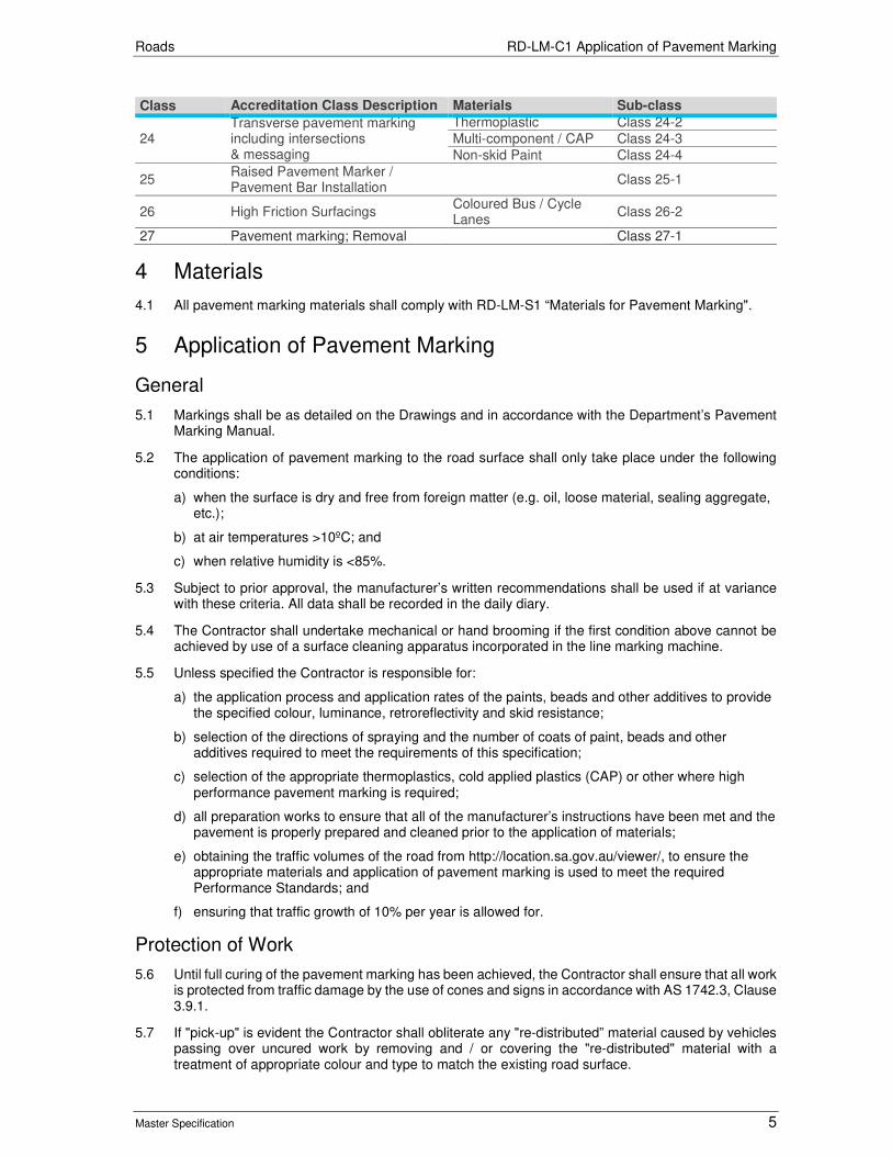
Roads RD-LM-C1 Application of Pavement Marking
Master Specification 5
Class Accreditation Class Description Materials Sub-class
24 Transverse pavement marking including intersections & messaging
Thermoplastic Class 24-2
Multi-component / CAP Class 24-3
Non-skid Paint Class 24-4
25 Raised Pavement Marker / Pavement Bar Installation
Class 25-1
26 High Friction Surfacings Coloured Bus / Cycle Lanes
Class 26-2
27 Pavement marking; Removal Class 27-1
4 Materials
4.1 All pavement marking materials shall comply with RD-LM-S1 “Materials for Pavement Marking".
5 Application of Pavement Marking
General
5.1 Markings shall be as detailed on the Drawings and in accordance with the Department’s Pavement Marking Manual.
5.2 The application of pavement marking to the road surface shall only take place under the following conditions:
a) when the surface is dry and free from foreign matter (e.g. oil, loose material, sealing aggregate, etc.);
b) at air temperatures >10ºC; and
c) when relative humidity is <85%.
5.3 Subject to prior approval, the manufacturer’s written recommendations shall be used if at variance with these criteria. All data shall be recorded in the daily diary.
5.4 The Contractor shall undertake mechanical or hand brooming if the first condition above cannot be achieved by use of a surface cleaning apparatus incorporated in the line marking machine.
5.5 Unless specified the Contractor is responsible for:
a) the application process and application rates of the paints, beads and other additives to provide the specified colour, luminance, retroreflectivity and skid resistance;
b) selection of the directions of spraying and the number of coats of paint, beads and other additives required to meet the requirements of this specification;
c) selection of the appropriate thermoplastics, cold applied plastics (CAP) or other where high performance pavement marking is required;
d) all preparation works to ensure that all of the manufacturer’s instructions have been met and the pavement is properly prepared and cleaned prior to the application of materials;
e) obtaining the traffic volumes of the road from http://location.sa.gov.au/viewer/, to ensure the appropriate materials and application of pavement marking is used to meet the required Performance Standards; and
f) ensuring that traffic growth of 10% per year is allowed for.
Protection of Work
5.6 Until full curing of the pavement marking has been achieved, the Contractor shall ensure that all work is protected from traffic damage by the use of cones and signs in accordance with AS 1742.3, Clause 3.9.1.
5.7 If "pick-up" is evident the Contractor shall obliterate any "re-distributed” material caused by vehicles passing over uncured work by removing and / or covering the "re-distributed" material with a treatment of appropriate colour and type to match the existing road surface.

Roads RD-LM-C1 Application of Pavement Marking
Master Specification 6
5.8 The Contractor shall reapply pavement marking damaged by vehicles passing over uncured work.
5.9 Longitudinal line marking shall be considered damaged where the initial retroreflectivity measured within 10 days of application using a calibrated low angle retroreflectometer using 30 metre geometry is below 240 mcd/m2/lx.
Spotting Alignment
5.10 For new work, the Contractor shall carry out spotting prior to the application of all pavement markings. Following spotting, the Contractor shall give 24 hours’ notice before any pavement marking is applied.
5.11 Provision of the above notice shall constitute a Hold Point.
Paint Application - General
5.12 New work means the supply and application of pavement marking to an unmarked surface or the medication of existing markings.
5.13 For new or resurfaced spray seals or asphalt roads, the following minimum requirements shall be met:
a) Newly laid spray seal shall be left to cure for a minimum of 7 days prior to the application of the first coat of paint (primer/base coat) and temporary retroreflective raised pavement markers (TRRPM) shall be installed to provide temporary line marking. The Contractor shall leave TRRPM in place until the final coats of paint or permanent RRPMs are installed;
b) At the final visit, the Contractor shall apply a minimum of two coats of paint to ensure that all new works meet the performance criteria of this specification. The retroreflectivity requirements shall be met in both directions of traffic flow on all separation lines;
c) Traffic speed restrictions can be removed once the first coat of paint (primer/base coat) has been placed for all line makings and the retro-reflectivity readings are above the minimum intervention level of 125 mcd; and
d) Until installation of the separation line, the Contractor shall maintain appropriate signage in accordance with AS 1742 (e.g. T3-12 “No lines do no not overtake unless safe”) and Part PC-SM1 “Traffic and Pedestrian Management”.
5.14 Unless specified otherwise, longitudinal line work in rural areas shall be undertaken with a Class A line marking machine. Longitudinal line marking in the metropolitan area shall be undertaken with a Class A line marking machine if practicable, otherwise a Class B line marking machine shall be used. Refer to the PCCP for details of Class A and Class B line marking machines.
5.15 Hand spraying with the use of templates to control the pattern and shape will be allowed for transverse lines, chevrons, diagonals, pavement messages, symbols and traffic island and median kerbing.
5.16 Where two coats of paint are to be applied for separation lines on carriageways with two-way traffic, the coats shall be applied in opposite directions. Paint for separation lines on carriageways with one-way traffic and all edge lines shall be applied in the direction of traffic.
5.17 Where two coats of paint are to be applied, the first coat shall be adequately cured prior to the application of the second coat. All paint and beads shall be evenly applied to the markings.
5.18 The time and date of installation of regulatory lines shall be recorded and the Contractor shall forward this information within 5 working days.
Longitudinal Paint Systems
5.19 The longitudinal paint system shall be as described in Table RD-LM-C1 5-1:
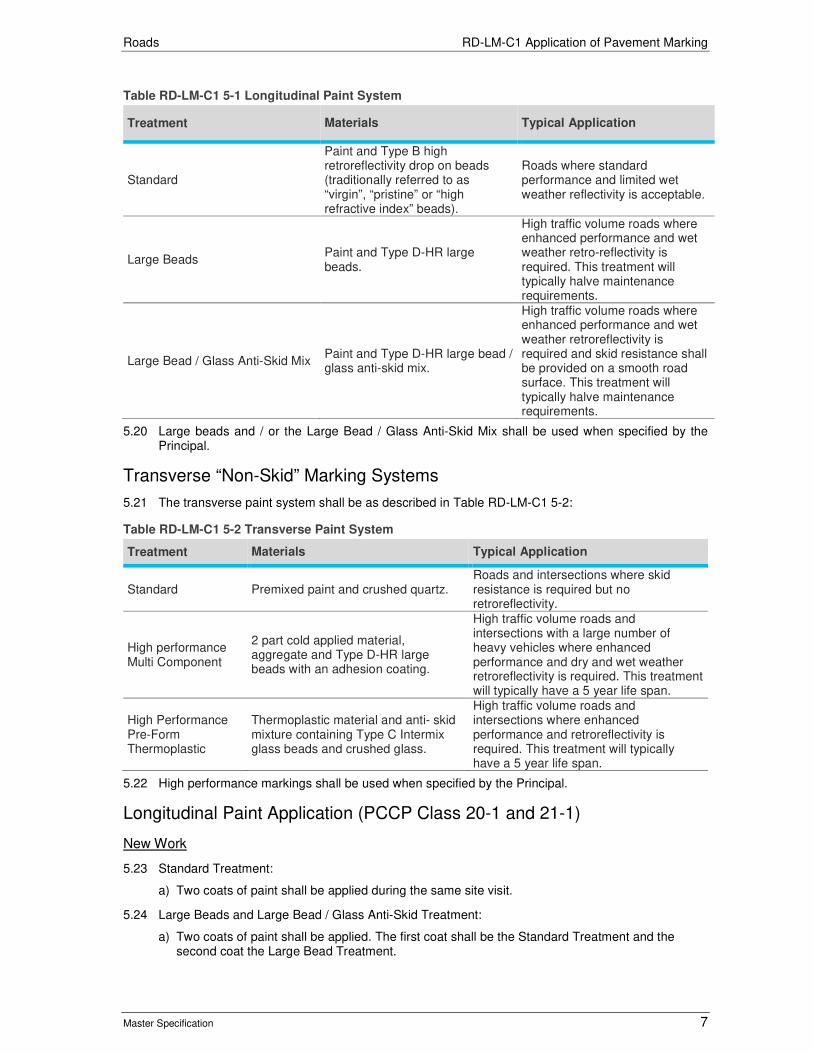
Roads RD-LM-C1 Application of Pavement Marking
Master Specification 7
Table RD-LM-C1 5-1 Longitudinal Paint System
Treatment Materials Typical Application
Standard
Paint and Type B high retroreflectivity drop on beads (traditionally referred to as “virgin”, “pristine” or “high refractive index” beads).
Roads where standard performance and limited wet weather reflectivity is acceptable.
Large Beads Paint and Type D-HR large beads.
High traffic volume roads where enhanced performance and wet weather retro-reflectivity is required. This treatment will typically halve maintenance requirements.
Large Bead / Glass Anti-Skid Mix Paint and Type D-HR large bead / glass anti-skid mix.
High traffic volume roads where enhanced performance and wet weather retroreflectivity is required and skid resistance shall be provided on a smooth road surface. This treatment will typically halve maintenance requirements.
5.20 Large beads and / or the Large Bead / Glass Anti-Skid Mix shall be used when specified by the Principal.
Transverse “Non-Skid” Marking Systems
5.21 The transverse paint system shall be as described in Table RD-LM-C1 5-2:
Table RD-LM-C1 5-2 Transverse Paint System
Treatment Materials Typical Application
Standard Premixed paint and crushed quartz. Roads and intersections where skid resistance is required but no retroreflectivity.
High performance Multi Component
2 part cold applied material, aggregate and Type D-HR large beads with an adhesion coating.
High traffic volume roads and intersections with a large number of heavy vehicles where enhanced performance and dry and wet weather retroreflectivity is required. This treatment will typically have a 5 year life span.
High Performance Pre-Form Thermoplastic
Thermoplastic material and anti- skid mixture containing Type C Intermix glass beads and crushed glass.
High traffic volume roads and intersections where enhanced performance and retroreflectivity is required. This treatment will typically have a 5 year life span.
5.22 High performance markings shall be used when specified by the Principal.
Longitudinal Paint Application (PCCP Class 20-1 and 21-1)
New Work
5.23 Standard Treatment:
a) Two coats of paint shall be applied during the same site visit.
5.24 Large Beads and Large Bead / Glass Anti-Skid Treatment:
a) Two coats of paint shall be applied. The first coat shall be the Standard Treatment and the second coat the Large Bead Treatment.

Roads RD-LM-C1 Application of Pavement Marking
Master Specification 8
5.25 Two coats of paint shall be applied together with a concurrent application of beads. The first coat shall be fully cured prior to the application of the second coat. The timing of the application of paint shall comply with any requirements specified by the Principal.
5.26 Until installation of the separation line, the Contractor shall maintain appropriate signing in accordance with AS 1742 (e.g. T3-12 "No lines do not overtake unless safe") and PC-SM1 “Traffic & Pedestrian Management".
Maintenance Repainting
5.27 One coat of the specified paint treatment shall be applied together with a concurrent application of glass beads.
Transverse "non-skid" paint application (PCCP Class 24-4)
New Work
5.28 Two coats of pre-mixed paint and crushed quartz shall be applied during the same site visit. The first coat shall be fully cured prior to the application of the second coat.
Maintenance Repainting
5.29 One coat of pre-mixed paint and crushed quartz shall be applied.
Transverse high Performance pavement marking application
5.30 Multi Component (PCCP Class 24-3) consists of a 2 part cold applied pavement marking material applied according to the manufacturer’s recommendations and comprising:
a) a base coat;
b) aggregate;
c) a top coat to encapsulate the aggregate; and
d) type D-HR beads with an adhesion coating.
5.31 The aggregate and beads shall be applied while the material is fluid to ensure embedment and shall be evenly distributed to provide a complete coverage.
5.32 Pre-Form Thermoplastic Pavement Marking (PCCP Class 24-2) consists of pre-formed thermoplastic pavement marking material applied according to the manufacturer’s recommendations. An anti-skid mixture containing Type C Intermix glass beads and crushed glass shall be applied immediately after heating while the material is still liquid. The mixture shall be evenly distributed to provide a complete coverage of the surface of the thermoplastic.
Coloured Pavement Surfacings Application (PCCP Class 26-2)
5.33 Coloured pavement surfacings are for use on pavement designated as bus or cycle lanes and shall be in accordance with Department’s Pavement Marking Manual.
5.34 Multi Component consists of a suitably pigmented 2 part cold applied pavement marking material applied according to the manufacturer’s recommendations and comprising:
a) a base coat;
b) aggregate; and
c) a top coat to encapsulate the aggregate.
5.35 The aggregate shall be applied while the material is fluid to ensure embedment and shall be evenly distributed to provide a complete coverage.
5.36 Pigmented Binder System consists of a 2 or more component thermosetting resin suitably pigmented to provide the necessary depth of specified colour in the finished surface coating and the application of coloured aggregate. The aggregate shall be applied while the material is fluid to ensure embedment and shall be evenly distributed to provide a complete coverage of the treated area.

Roads RD-LM-C1 Application of Pavement Marking
Master Specification 9
Kerb Treatment
New Work
5.37 The concrete surface of the kerb shall be dry and adequately cured prior to the application of paint, and any curing agents used shall be removed by an appropriate means. The paint shall be applied in one or more coats to achieve the specified minimum dry thickness. Glass beads shall be applied to the final coat immediately following the application of paint to ensure embedment and retention.
Maintenance Repainting
5.38 The Contractor shall remove and dispose of any lifting or flaking paint coatings, rubbish, grass and vegetation to achieve a sound surface prior the application of paint. Repainting shall consist of a single application of paint to achieve the specified minimum dry film thickness. Glass beads shall be applied immediately following the application of paint to ensure embedment and retention. The Contractor shall ensure that "over-spray" does not cause paint contamination to adjacent surfaces.
Glass Bead and Glass Bead / Anti-Skid Application
5.39 All beads and bead / anti-skid mix shall be applied using a method that ensures uniform cover and retention to the surface of the marking, and minimal wastage of material. The Contractor shall ensure excessive application of material, which may present a hazard for road users, does not occur. Glass beads and glass bead / anti-skid mix shall be applied immediately following application of pavement marking material to ensure embedment and retention.
Pavement Marking Application Rates
5.40 Pavement marking and additives shall be applied in accordance with Table RD-LM-C1 5-3.
5.41 Written verification of all application rates shall be provided, vide Clause 12 "Verification Requirements and Records".
Table RD-LM-C1 5-3 Pavement Marking Application
Item To Be Treated
Paint Additive
Type Colour Film Thickness Type Rate
Longitudinal Lines Standard Beads
Waterborne pavement marking
White Wet 300 – 375 um.
Type B High Retroreflectivity Drop-on Glass Beads
Min. Retained 275 g/m2
Longitudinal Lines Large Beads
Waterborne pavement marking
White Wet 600 um.
Type D-HR Large wet weather Glass Beads
Min. Retained 500 g/m2
Longitudinal Lines Large Bead / Glass anti-skid mix
Waterborne pavement marking
White Wet 600 um.
Type D-HR Large wet weather Glass Bead and 1 mm – 2 mm crushed glass mix
Min. Retained 750 g/m2 Mix Ratio 70:30
Pavement messages, symbols, chevrons, diagonals & transverse lines
Waterborne pavement marking
White Dry 250 – 350 um.
Premixed with Crushed Quartz
Min. 0.50 kg/L

Roads RD-LM-C1 Application of Pavement Marking
Master Specification 10
Item To Be Treated
Paint Additive
Pavement messages, symbols, chevrons, merge arrows, diagonals & transverse lines
High Performance Multi Component
White Yellow
Base coat 1mm Top coat 0.5 mm
1-3 mm aggregate Type D-HR Large wet weather Glass Beads with adhesion coating
400 gm/m2 400 gm/m2
High Performance Pre-Form Thermoplastic
White Yellow
Pre-Form Thickness 2.5 mm ± 0.5 mm
Type C Intermix Glass Bead and 1 mm – 2 mm crushed glass mix
1.60 Kg/m2
retained Mix Ratio 70:30
Bus and Cycle Lanes
Multi Component
Various Base coat 1 mm Top coat 0.5 mm
1-3 mm aggregate
1.50 Kg/m2
Pigmented Binder
Various
Binder Uniform thickness to provide adhesion to aggregate and substrate
1-3 mm aggregate
Complete coverage of treated area
Traffic island and median kerbing
Latex exterior flat or low gloss
White
New: dry 60 – 90 um.
Type B High Retroreflectivity Drop-on Glass Beads
Min. Retained 275 g/m2 Maintenance:
dry 40 – 60 um.
Pavement bars Latex exterior flat or low gloss
Yellow
New: dry 60 – 90 um.
Type B High Retroreflectivity Drop-on Glass Beads
Min. Retained 275 g/m2 Maintenance:
dry 40 – 60 um.
Clearway markings
Waterborne pavement marking
Yellow Wet 300 – 375 um.
Type B High Retroreflectivity Drop-on Glass Beads
Min. Retained 275 g/m2
No standing zones
Waterborne pavement marking
Yellow Wet 300 – 375 um.
Type B High Retroreflectivity Drop-on Glass Beads
Min. Retained 275 g/m2
Blacking-out Waterborne pavement marking
Black Dry 250 –350 um.
Premixed with Crushed Quartz
Min. 0.50 kg/L
Rail crossing box hatchings
Waterborne pavement marking
Yellow Dry 250 –350 um.
Premixed with Crushed Quartz
Min. 0.50 kg/L
Placement of Markings
5.42 For maintenance repainting, the existing road markings shall be repainted to restore the original size, shape and line pattern. Pavement marking shall be placed on the road surface in correct position within the following tolerances specified in Table RD-LM-C1 5-4.
Table RD-LM-C1 5-4 Placement of Markings
New Work Maintenance Repainting
Spotting
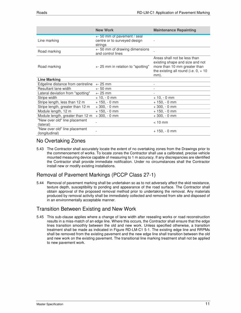
Roads RD-LM-C1 Application of Pavement Marking
Master Specification 11
New Work Maintenance Repainting
Line marking +- 50 mm of pavement / seal centre or to surveyed design strings
-
Road marking +- 50 mm of drawing dimensions and control lines
-
Road marking +- 25 mm in relation to "spotting"
Areas shall not be less than existing shape and size and not more than 10 mm greater than the existing all round (i.e. 0, + 10 mm).
Line Marking
Edgeline distance from centreline +- 25 mm -
Resultant lane width +- 50 mm -
Lateral deviation from "spotting" +- 25 mm -
Stripe width + 10, - 0 mm + 10, - 0 mm
Stripe length, less than 12 m + 150, - 0 mm + 150, - 0 mm
Stripe length, greater than 12 m + 300, - 0 mm + 300, - 0 mm
Module length, 12 m + 150, - 0 mm + 150, - 0 mm
Module length, greater than 12 m + 300, - 0 mm + 300, - 0 mm
"New over old" line placement (lateral)
- < 10 mm
"New over old" line placement (longitudinal)
- + 150, - 0 mm
No Overtaking Zones
5.43 The Contractor shall accurately locate the extent of no overtaking zones from the Drawings prior to the commencement of works. To locate zones the Contractor shall use a calibrated, precise vehicle mounted measuring device capable of measuring to 1 m accuracy. If any discrepancies are identified the Contractor shall provide immediate notification. Under no circumstances shall the Contractor install new or modify existing installations.
Removal of Pavement Markings (PCCP Class 27-1)
5.44 Removal of pavement marking shall be undertaken so as to not adversely affect the skid resistance, texture depth, susceptibility to ponding and appearance of the road surface. The Contractor shall obtain approval of the proposed removal method prior to undertaking the removal. Any materials produced by removal activity shall be immediately collected and removed from site and disposed of in an environmentally acceptable manner.
Transition Between Existing and New Work
5.45 This sub-clause applies where a change of lane width after resealing works or road reconstruction results in a miss-match of an edge line. Where this occurs, the Contractor shall ensure that the edge lines transition smoothly between the old and new work. Unless specified otherwise, a transition treatment shall be made as indicated in Figure RD-LM-C1 5-1. The existing edge line and RRPMs shall be removed from the existing pavement and the new edge line shall transition between the old and new work on the existing pavement. The transitional line marking treatment shall not be applied to new pavement work.
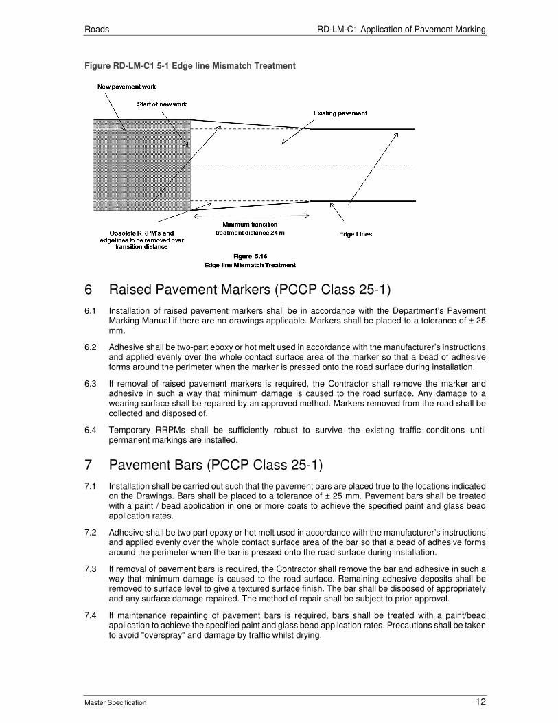
Roads RD-LM-C1 Application of Pavement Marking
Master Specification 12
Figure RD-LM-C1 5-1 Edge line Mismatch Treatment
6 Raised Pavement Markers (PCCP Class 25-1)
6.1 Installation of raised pavement markers shall be in accordance with the Department’s Pavement Marking Manual if there are no drawings applicable. Markers shall be placed to a tolerance of ± 25 mm.
6.2 Adhesive shall be two-part epoxy or hot melt used in accordance with the manufacturer’s instructions and applied evenly over the whole contact surface area of the marker so that a bead of adhesive forms around the perimeter when the marker is pressed onto the road surface during installation.
6.3 If removal of raised pavement markers is required, the Contractor shall remove the marker and adhesive in such a way that minimum damage is caused to the road surface. Any damage to a wearing surface shall be repaired by an approved method. Markers removed from the road shall be collected and disposed of.
6.4 Temporary RRPMs shall be sufficiently robust to survive the existing traffic conditions until permanent markings are installed.
7 Pavement Bars (PCCP Class 25-1)
7.1 Installation shall be carried out such that the pavement bars are placed true to the locations indicated on the Drawings. Bars shall be placed to a tolerance of ± 25 mm. Pavement bars shall be treated with a paint / bead application in one or more coats to achieve the specified paint and glass bead application rates.
7.2 Adhesive shall be two part epoxy or hot melt used in accordance with the manufacturer’s instructions and applied evenly over the whole contact surface area of the bar so that a bead of adhesive forms around the perimeter when the bar is pressed onto the road surface during installation.
7.3 If removal of pavement bars is required, the Contractor shall remove the bar and adhesive in such a way that minimum damage is caused to the road surface. Remaining adhesive deposits shall be removed to surface level to give a textured surface finish. The bar shall be disposed of appropriately and any surface damage repaired. The method of repair shall be subject to prior approval.
7.4 If maintenance repainting of pavement bars is required, bars shall be treated with a paint/bead application to achieve the specified paint and glass bead application rates. Precautions shall be taken to avoid "overspray" and damage by traffic whilst drying.
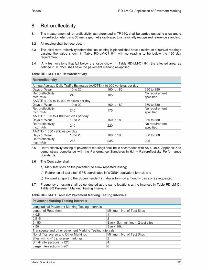
Roads RD-LM-C1 Application of Pavement Marking
Master Specification 13
8 Retroreflectivity
8.1 The measurement of retroreflectivity, as referenced in TP 950, shall be carried out using a low angle retroreflectometer using 30 metre geometry calibrated to a nationally recognised reference standard.
8.2 All reading shall be recorded.
8.3 The initial retro-reflectivity before the final coating is placed shall have a minimum of 90% of readings passing the value shown in Table RD-LM-C1 8-1 with no reading to be below the 160 day requirement.
8.4 Any test locations that fall below the value shown in Table RD-LM-C1 8-1, the affected area, as defined in TP 950, shall have the pavement marking re-applied.
Table RD-LM-C1 8-1 Retroreflectivity
Retroreflectivity
Annual Average Daily Traffic Estimates (AADTE) >10 000 vehicles per day
Days of Wear 10 to 20 160 to 180 360 to 380
Retroreflectivity, mcd/m2/lx
240 165 No requirement specified
AADTE 4 000 to 10 000 vehicles per day
Days of Wear 10 to 20 160 to 180 360 to 380
Retroreflectivity, mcd/m2/lx
240 175 No requirement specified
AADTE 1 000 to 4 000 vehicles per day
Days of Wear 10 to 20 160 to 180 360 to 380
Retroreflectivity, mcd/m2/lx
240 220 No requirement specified
AADTE<1 000 vehicles per day
Days of Wear 10 to 20 160 to 180 360 to 380
Retroreflectivity, mcd/m2/lx
265 235 225
8.5 Retroreflectivity testing of pavement markings shall be in accordance with AS 4049.4, Appendix K to demonstrate compliance with the Performance Standards in 6.1 – Retroreflectivity Performance Standards.
8.6 The Contractor shall:
a) Mark test sites on the pavement to allow repeated testing;
b) Reference all test sites’ GPS coordinates in WGS84 equivalent format; and
c) Forward a report to the Superintendent in tabular form on a monthly basis or as requested.
8.7 Frequency of testing shall be conducted at the same locations at the intervals in Table RD-LM-C1 Table 8-2 Pavement Marking Testing Intervals.
Table RD-LM-C1 Table 8-2 Pavement Marking Testing Intervals
Pavement Marking Testing Intervals
Longitudinal Pavement Marking Testing Intervals
Length of Road (km) Minimum No. of Test Sites
< 0.5 1
0.5 -5 2
5 - 50 Every 5km, minimum 2 test sites
> 50 Every 10km
Transverse and other pavement Marking Testing Intervals
No. of Transverse and Other Markings Minimum No. of Test Sites
Sites with < 4* transverse markings 2
Small Intersections (>12*) 4
Large Intersections (>20*) 6

Roads RD-LM-C1 Application of Pavement Marking
Master Specification 14
Pavement Marking Testing Intervals
Give Way and Stop Bars 1 at each site
All other markings (turn lines, chevrons, arrows etc.)
25% of overall No. of markings.
Note: “<4, “>12*” and “>20*” refers to the number of transverse and other pavement markings existing at given intersection.
8.8 At each test site the Contractor shall take the following minimum number of measurements of longitudinal lines:
a) 3 readings on all edge lines, outlines of lane lines taken in the viewing direction of rod users; and
b) 6 readings on all dividing lines (3 readings in each direction);
8.9 Readings at each test site shall be a minimum of 1m apart. Both individual and averaged tests results shall be presented as part of the Contractor’s test report.
8.10 At each test site the Contractor shall measure reflectorized transverse pavement marking as follows:
a) 2 readings on each reflectorized transverse pavement marking taking in the viewing direction of road users.
8.11 Readings at each test site shall be a minimum of 1m apart. Both individual and averaged test results shall be presented as part of the Contractor’s test report.
9 Skid Resistance
9.1 Skid resistance for transverse marking shall be greater than 45 BPN, until at least the issue of the Final Certificate, when measured in accordance with TP344 or TP345. If the skid resistance is below 45 BPN the Contractor shall re-apply pavement marking to the affected area.
10 Test Procedures
10.1 The Contractor shall use the following test procedures (refer https://www.dpti.sa.gov.au/contractor_documents) to verify conformance with the Specification:
Table RD-LM-C1 10-1 Test Procedures
Test Test Procedure
Determination of Skid Resistance with the Grip Tester TP344
Operation of a British Pendulum Portable Skid Tester TP345
Determination of Retroreflectivity of Pavement Markings TP907
Audit: Line Marking Product TP950
11 Hold Points
11.1 The following is a of summary Hold Points referenced in this Part:
Table 11-1 Hold Points
Document Ref. Hold Point Response Time
2.3 Submission of Quality Management Plan 7 Working Days
5.3 Following spotting and prior to application of pavement marking paint
1 Working Day
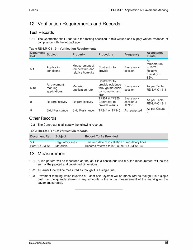
Roads RD-LM-C1 Application of Pavement Marking
Master Specification 15
12 Verification Requirements and Records
Test Records
12.1 The Contractor shall undertake the testing specified in this Clause and supply written evidence of compliance with the lot package.
Table RD-LM-C1 12-1 Verification Requirements
Document Ref.
Subject Property Procedure Frequency Acceptance Limits
5.1 Application conditions
Measurement of temperature and relative humidity
Contractor to provide
Every work session.
Air temperature > 10°C. Relative humidity < 85%.
5.13 All pavement marking applications
Material application rate
Contractor to provide evidence through materials consumption and area
Every work session.
As per Table RD-LM-C1 5-4
8 Retroreflectivity Retroreflectivity TP907 & TP950 Contractor to provide results
Every work session & TP950
As per Table RD-LM-C1 8-1
9 Skid Resistance Skid Resistance TP244 or TP345 As requested As per Clause 9
Other Records
12.2 The Contractor shall supply the following records:
Table RD-LM-C1 12-2 Verification records
Document Ref. Subject Record To Be Provided
5.4 Regulatory lines Time and date of installation of regulatory lines
Part RD-LM-S1 Materials Records referred to in Clause RD-LM-S1.13
13 Measurement
13.1 A line pattern will be measured as though it is a continuous line (i.e. the measurement will be the sum of the painted and unpainted dimensions).
13.2 A Barrier Line will be measured as though it is a single line.
13.3 Pavement marking which involves a 2-coat paint system will be measured as though it is a single coat (i.e. the quantity shown in any schedule is the actual measurement of the marking on the pavement surface).
Roads
Master Specification
RD-LM-C4 Sign Installation Document Information
K Net Number: 13623473
Document Version: 2
Document Date: 23/09/2019

Roads Contents
Master Specification 2
Document Amendment Record
Version Change Description Date Endorsement record (KNet ref.)
1 Initial issue (formerly R49 – Installation of Signs) 28/06/19
2 Format and cross reference revisions 23/09/19
Document Management This document is the Property of the Department for Infrastructure and Transport and contains information that is confidential to the Department. It must not be copied or reproduced in any way without the written consent of the Department. This is a controlled document and it will be updated and reissued as approved changes are made.
Roads Contents
Master Specification 3
Contents Contents 2
RD-LM-C4 Sign Installation 4
1 General 4
2 Supply of Sign Supports 4
3 Selection of Supports 6
4 Placement of Signs 7
5 Installation of Sign Supports 9
6 Installation of Signs 10
7 Records 11
8 Hold Points 11
9 Verification Requirements and Records 11
10 Appendix 1: Steel Post Selection 12
11 Appendix 2: Overview of Sign Support Selection Process 14
12 Appendix 3: Sign Support Selection Example 15
13 Appendix 4: Steel Sign Support – Hole Spacing 16
14 Appendix 5: Sign Height and Offset details 17

Roads RD-LM-C4 Sign Installation
Master Specification 4
RD-LM-C4 Sign Installation
1 General
1.1 This Part specifies the requirements for:
a) supply and selection of sign supports;
b) placement of signs;
c) installation of sign supports; and
d) installation of signs.
1.2 This Part does not cover:
a) the manufacture, testing and commissioning of electronic signage such as Changeable Message Sign (CMS) & Variable Message Sign (VMS);
b) the design and supply of bespoke support structures such as gantries, cantilevers, portal frames; or
c) signs for temporary works.
1.3 The Contractor shall install signs in accordance with the following (in order of precedence):
a) any contract specific drawings or Contract Documents;
b) the requirements of this Part; and
c) standard drawings.
1.4 The terminology in the applicable Austroads publications listed in Clause 1.5 applies to this Contract.
1.5 Documents referred to in this Part are listed below.
a) AS 1163 Cold Formed Structural Steel Hollow Sections.
b) AS 1450 Steel Tubes for Mechanical Purposes.
c) AS 1742.2 Manual of Uniform Traffic Control Devices - Traffic control devices for general use.
d) AS 1867 Aluminium and aluminium alloys - Drawn tubes.
e) AS 1906.1 Retroreflective Materials and Devices for Road Traffic Control Purposes - Retroreflective sheeting.
f) Austroads Guide to Road Design – Part 6: Roadside Design, Safety and Barriers.
g) Austroads Guide to Road Safety – Part 9: Roadside Hazard Management.
1.6 Any proprietary supports shall have a minimum design life of 40 years.
2 Supply of Sign Supports
General
2.1 Steel sign supports shall:
a) comply with either AS 1163 or AS 1450;
b) be manufactured using steel with a yield stress of ≥250 MPa; and
c) comply with the dimensions specified in Clause 3. “Selection of Sign Supports”.
2.2 The Contractor shall provide a certificate of compliance to AS 1163 or AS 1450. The mill supplying AS 1163 product shall be third party certified.

Roads RD-LM-C4 Sign Installation
Master Specification 5
2.3 Submission of the certificate of compliance shall constitute a Hold Point.
2.4 Steel Rectangular Hollow Sections (RHS) shall be drilled in accordance with Appendix 4: Steel Sign Support – Hole Spacing.
2.5 Steel Circular Hollow Sections (CHS) shall be capped and shall not consist of sections welded together unless the Contractor provides evidence that the strength and durability of the join welds meet the loading applicable to the support and has a 25-year design life.
Protective Coating
2.6 A protective coating that complies with the following shall be applied to steel posts:
a) RHS:
i) zinc coated to Class Z275 in accordance with AS 1397, Table 3.1;
ii) zinc alloy coated to Class ZM275 in accordance with AS 1397 Table 3.3; or
iii) hot-dip galvanized accordance with AS 4680.
b) CHS:
i) Where a coloured finish is specified:
• a coating applied in accordance with ST-SS-S2 “Protective Coating of Structural Steelwork " (the colour shall be G61 to AS 2700).
ii) Where a finish is not specified:
• zinc alloy coated ZM275 alloy in accordance with AS 1397, Table 3.3; or
• hot-dip galvanized in accordance with AS 4680.
Aluminium Circular Hollow Sections
2.7 Aluminium Circular Hollow Sections (CHS) shall comply with:
a) AS 1867; and
b) the dimensions specified in Clause 3. “Selection of Sign Supports”.
2.8 The Contractor shall provide a certificate of compliance to AS 1867.
Proprietary Frangible Posts
2.9 Proprietary frangible posts may be used if the product is approved by the Principal. A list of approved products is included in the Department’s Approved Products List, available from: https://www.dpti.sa.gov.au/documents The Contractor may apply for approval of a proprietary frangible post not included in the Approved Products List. Any request for approval of a post shall include all necessary supporting information and shall constitute a Hold Point.
2.10 The Contractor acknowledges that for efficiency of maintenance, the Principal requires that the number of types of proprietary frangible posts on the road network is kept to a minimum. The Principal reserves the right to withhold approval of any proprietary frangible posts at its absolute and unfettered discretion.
Identification of Sign Supports
2.11 The supports shall be clearly marked with the supplier / manufacturer’s name, applicable Australian Standard, grade, and any other information specified in the applicable Australian Standard.
2.12 The marking shall be applied after the application of any surface coating and consist of either indelible lettering or a durable, graffiti resistant, UV stable sticker. The marking / sticker shall be visible once the support has been installed.

Roads RD-LM-C4 Sign Installation
Master Specification 6
3 Selection of Supports
Small / Medium Signs
3.1 Small to medium size signs (i.e. general regulatory or warning type signs) shall be supported by steel RHS supports complying with Table RD-LM-C4 3-1. Circular Hollow Sections shall not be used for small to medium size signs under any circumstances.
Table RD-LM-C4 3-1 Rectangular Hollow Section Supports
Post Length (mm) Post Size width x depth x wall thickness (mm)
≤ 3 200 75 x 38 x 3.0 or 80 x 40 x 1.6
> 3 200 to ≤ 4 200 80 x 40 x 2.5
Large Signs
3.2 Except for overhead signs, steel CHS supports (nominal 100 mm diameter) shall be used where non- frangible posts are permitted.
3.3 Where frangible posts are required, the posts shall be either:
a) aluminium CHS complying with Table RD-LM-C4 3-2;
b) steel CHS complying with Table RD-LM-C4 3-2; or
c) an approved proprietary frangible sign support in accordance with Clause 2.9 “Proprietary Frangible Posts”.
Table RD-LM-C4 3-2 Posts Deemed to be Frangible
Speed Zone (Km/h) Diameter x Wall Thickness (mm)
Circular Steel Posts
≤ 80 80 x 3.3
≤ 70 90 x 3.3*
≤ 60 80 x 5.0 or 100 x 3.5*
≤ 40 125 x 3.5*
Circular Aluminium Posts
≤ 110 100 x 4.6/5.5
*indicates the preferred sizes for use on DPTI roads Note: All circular post sizes are shown as Nominal Bore (inside dimension).
3.4 Overhead signs shall be supported by cantilever, gantry or portal type structures.
Number of Supports
3.5 Where RHS or CHS steel supports are used, the number and spacing of supports shall be in accordance with Appendix 1: Steel Post Selection and Table RD-LM-C4 3-3. The sign height shall be determined from Appendix 3: Sign Support Selection Example. If the sign width is ≤ 1400 mm, the sign can be installed on one post.
3.6 Where CHS aluminium supports are used, the number and spacing of supports shall be in accordance with the manufacturer’s post selection specification. If the sign width is ≤ 1400 mm, the sign can be installed on one aluminium post.
3.7 Where other materials / type of supports are used, the Contractor shall verify that the posts will comply with applicable Australian Standards.
Support Spacing
3.8 The spacing of supports of signs shall comply with Table RD-LM-C4 3-3.

Roads RD-LM-C4 Sign Installation
Master Specification 7
Table RD-LM-C4 3-3 Support Spacing
Number of Supports % of Sign Width
Between outermost support and sign edge
Between supports
1 50 -
2 20 60
3 15 35
4 12.5 25
VMS and CMS
3.9 VMS and CMS signs that weigh in excess of 100 kg shall be supported on bespoke supports. VMS and CMS signs that weigh less than 100 kg may be supported by steel CHS supports (nominal 100 mm diameter).
4 Placement of Signs
General
4.1 Signs shall be installed as close as practical to the locations specified on the drawings. All signs shall be positioned to:
a) be clearly legible to all road users with adequate sight distance;
b) not create a hazard to road users;
c) provide adequate clearance from underground and overhead services;
d) not compete with other traffic signs, traffic control devices or roadside furniture;
e) where appropriate, be placed in locations that allow adequate reading time for all road users and adequate time and travel distance for the road user to act on the message; and
f) not be partially hidden by any roadside objects, furniture or vegetation.
Lateral Placement
4.2 Except for overhead signs, the edge of the sign shall be located in accordance with Table RD-LM-C4 4-1.
Table RD-LM-C4 4-1 Lateral Placement of Signs
Lateral Placement of Signs
Rigid safety barrier present: A minimum of 1.0 m from the face of the safety barrier (regardless of kerb position).
Wire rope safety barrier present: A minimum of 1.5 m from the face of the safety barrier (regardless of kerb position).
No safety barrier present, frangible post used:
The minimum clearance from the travelled way or kerb is:
• Rural area: 2.0 m
• Urban area (kerb & gutter): 0.3 m
• Urban area (semi mountable kerb): 0.5 m
No safety barrier present, non-frangible post used:
Outside of the Clear Zone (unless vehicles are prevented from impacting the supports e.g. steep cutting).
4.3 The nearest edge of an overhead sign shall not be further than 5.0 m from the closest running lane.
4.4 The Clear Zone shall be determined in accordance with Table RD-LM-C4 4-2.
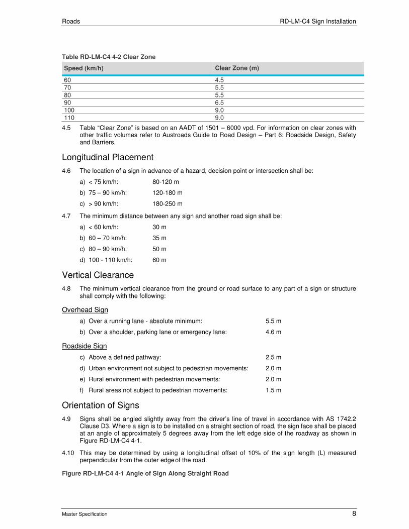
Roads RD-LM-C4 Sign Installation
Master Specification 8
Table RD-LM-C4 4-2 Clear Zone
Speed (km/h) Clear Zone (m)
60 4.5
70 5.5
80 5.5
90 6.5
100 9.0
110 9.0
4.5 Table “Clear Zone” is based on an AADT of 1501 – 6000 vpd. For information on clear zones with other traffic volumes refer to Austroads Guide to Road Design – Part 6: Roadside Design, Safety and Barriers.
Longitudinal Placement
4.6 The location of a sign in advance of a hazard, decision point or intersection shall be:
a) < 75 km/h: 80-120 m
b) 75 – 90 km/h: 120-180 m
c) > 90 km/h: 180-250 m
4.7 The minimum distance between any sign and another road sign shall be:
a) < 60 km/h: 30 m
b) 60 – 70 km/h: 35 m
c) 80 – 90 km/h: 50 m
d) 100 - 110 km/h: 60 m
Vertical Clearance
4.8 The minimum vertical clearance from the ground or road surface to any part of a sign or structure shall comply with the following:
Overhead Sign
a) Over a running lane - absolute minimum: 5.5 m
b) Over a shoulder, parking lane or emergency lane: 4.6 m
Roadside Sign
c) Above a defined pathway: 2.5 m
d) Urban environment not subject to pedestrian movements: 2.0 m
e) Rural environment with pedestrian movements: 2.0 m
f) Rural areas not subject to pedestrian movements: 1.5 m
Orientation of Signs
4.9 Signs shall be angled slightly away from the driver’s line of travel in accordance with AS 1742.2 Clause D3. Where a sign is to be installed on a straight section of road, the sign face shall be placed at an angle of approximately 5 degrees away from the left edge side of the roadway as shown in Figure RD-LM-C4 4-1.
4.10 This may be determined by using a longitudinal offset of 10% of the sign length (L) measured perpendicular from the outer edge of the road.
Figure RD-LM-C4 4-1 Angle of Sign Along Straight Road
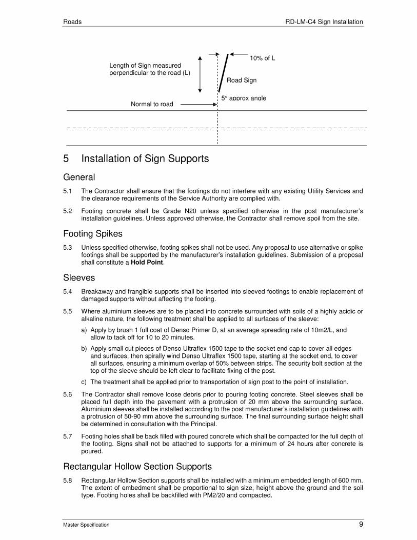
Roads RD-LM-C4 Sign Installation
Master Specification 9
Length of Sign measured perpendicular to the road (L)
10% of L Road Sign
5° approx angle
Normal to road
5 Installation of Sign Supports
General
5.1 The Contractor shall ensure that the footings do not interfere with any existing Utility Services and the clearance requirements of the Service Authority are complied with.
5.2 Footing concrete shall be Grade N20 unless specified otherwise in the post manufacturer’s installation guidelines. Unless approved otherwise, the Contractor shall remove spoil from the site.
Footing Spikes
5.3 Unless specified otherwise, footing spikes shall not be used. Any proposal to use alternative or spike footings shall be supported by the manufacturer’s installation guidelines. Submission of a proposal shall constitute a Hold Point.
Sleeves
5.4 Breakaway and frangible supports shall be inserted into sleeved footings to enable replacement of damaged supports without affecting the footing.
5.5 Where aluminium sleeves are to be placed into concrete surrounded with soils of a highly acidic or alkaline nature, the following treatment shall be applied to all surfaces of the sleeve:
a) Apply by brush 1 full coat of Denso Primer D, at an average spreading rate of 10m2/L, and allow to tack off for 10 to 20 minutes.
b) Apply small cut pieces of Denso Ultraflex 1500 tape to the socket end cap to cover all edges and surfaces, then spirally wind Denso Ultraflex 1500 tape, starting at the socket end, to cover all surfaces, ensuring a minimum overlap of 50% between strips. The security bolt section at the top of the sleeve should be left clear to facilitate fixing of the post.
c) The treatment shall be applied prior to transportation of sign post to the point of installation.
5.6 The Contractor shall remove loose debris prior to pouring footing concrete. Steel sleeves shall be placed full depth into the pavement with a protrusion of 20 mm above the surrounding surface. Aluminium sleeves shall be installed according to the post manufacturer’s installation guidelines with a protrusion of 50-90 mm above the surrounding surface. The final surrounding surface height shall be determined in consultation with the Principal.
5.7 Footing holes shall be back filled with poured concrete which shall be compacted for the full depth of the footing. Signs shall not be attached to supports for a minimum of 24 hours after concrete is poured.
Rectangular Hollow Section Supports
5.8 Rectangular Hollow Section supports shall be installed with a minimum embedded length of 600 mm. The extent of embedment shall be proportional to sign size, height above the ground and the soil type. Footing holes shall be backfilled with PM2/20 and compacted.

Roads RD-LM-C4 Sign Installation
Master Specification 10
Steel Circular Hollow Section Supports
5.9 Steel Circular Hollow Section supports shall have a minimum footing of 1m depth and a minimum of 0.5 m diameter. Footing holes shall be back filled with poured concrete or dry mix concrete which shall be compacted for the full depth of the footing. Signs shall not be attached to supports for a minimum of 24 hours after concrete is poured or compacted. The surface level of the footing shall be finished such that water is shed to the outer edge of the footing.
Breakaway Supports and Frangible Supports
5.10 Breakaway and frangible supports shall be installed in accordance with the drawings and / or manufacturer’s installation guidelines.
6 Installation of Signs
General
6.1 Signs shall be erected in accordance with the work method approved under the manufacturer's warranty provisions of RD-LM-S2 “Supply of Sign”. Where signs are to be installed on new works, the signs shall be installed prior to traffic using the new configuration.
Height of Signs
6.2 Signs shall be erected such that the lowest edge of the main sign plate is in accordance with the heights shown in Appendix 3: Sign Support Selection Example. The post shall not protrude above the top edge of a sign.
6.3 If multiple signs are installed, the gap between each plate shall be 50 mm -150 mm.
Fixing
6.4 All fittings shall be hot dipped galvanized to 125 g/m2 in accordance with AS 4680.
6.5 Signs shall be attached to one or more supports by either:
a) bolting directly to the support;
b) by means of Unistrut clamps; or
c) galvanized steel straps to existing furniture.
6.6 Unbraced signs shall be attached to Rectangular Hollow Section supports by using galvanized bolts, washers and vandal proof nuts. Braced signs shall be attached using galvanized steel clamps compatible with the bracing system, using galvanized bolts, washers and vandal proof nuts.
6.7 Signs shall not be attached to frangible or slip base light poles. All signs affixed to the post (i.e. metal or non-metallic) shall not create a punching through effect and shall not be affected by wind vibration. Signs attached to other street furniture by means of galvanized steel straps shall not damage the support.
Covering
6.8 Any temporary covering of the sign face after installation shall not void the manufacturer’s warranty.
Cleaning
6.9 Cleaning of the sign shall not damage the sign face or legend.
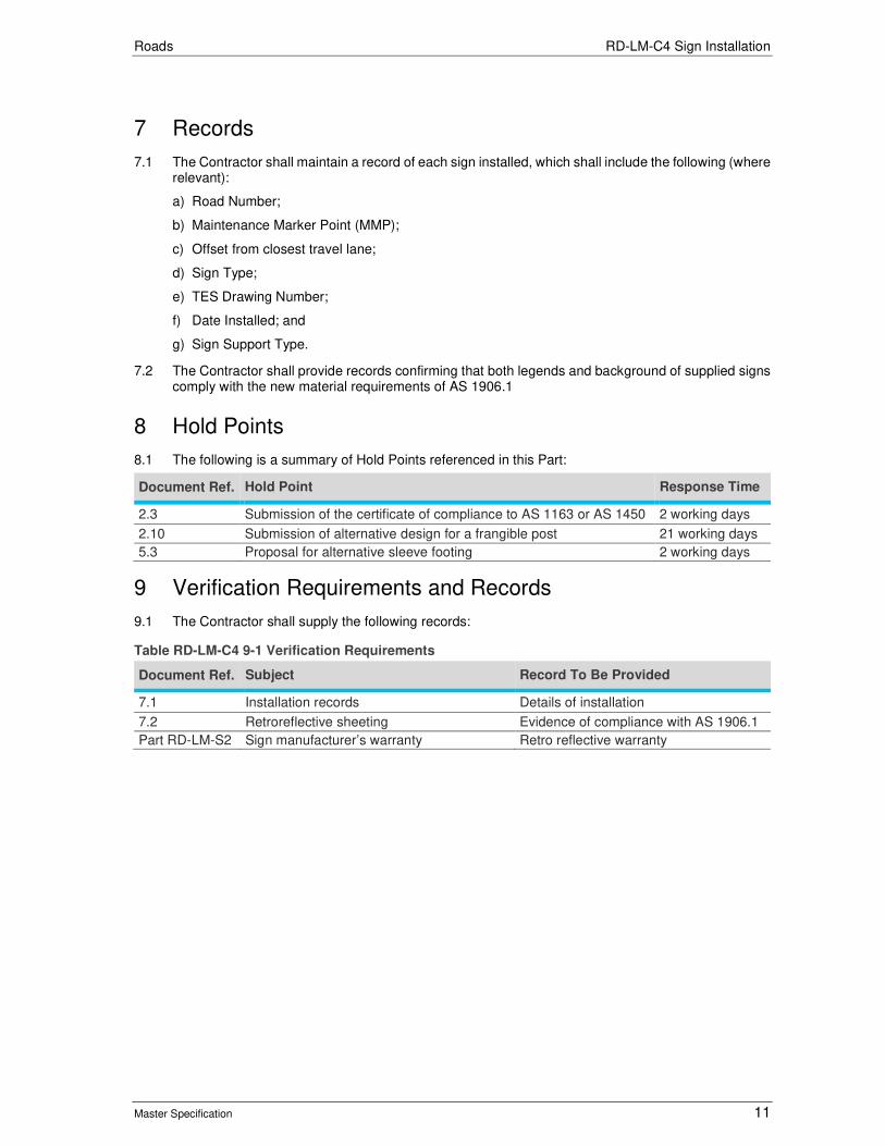
Roads RD-LM-C4 Sign Installation
Master Specification 11
7 Records
7.1 The Contractor shall maintain a record of each sign installed, which shall include the following (where relevant):
a) Road Number;
b) Maintenance Marker Point (MMP);
c) Offset from closest travel lane;
d) Sign Type;
e) TES Drawing Number;
f) Date Installed; and
g) Sign Support Type.
7.2 The Contractor shall provide records confirming that both legends and background of supplied signs comply with the new material requirements of AS 1906.1
8 Hold Points
8.1 The following is a summary of Hold Points referenced in this Part:
Document Ref. Hold Point Response Time
2.3 Submission of the certificate of compliance to AS 1163 or AS 1450 2 working days
2.10 Submission of alternative design for a frangible post 21 working days
5.3 Proposal for alternative sleeve footing 2 working days
9 Verification Requirements and Records
9.1 The Contractor shall supply the following records:
Table RD-LM-C4 9-1 Verification Requirements
Document Ref. Subject Record To Be Provided
7.1 Installation records Details of installation
7.2 Retroreflective sheeting Evidence of compliance with AS 1906.1
Part RD-LM-S2 Sign manufacturer’s warranty Retro reflective warranty

Roads RD-LM-C4 Sign Installation
Master Specification 12
10 Appendix 1: Steel Post Selection
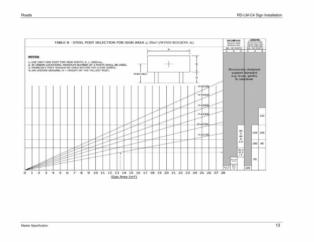
Roads RD-LM-C4 Sign Installation
Master Specification 13

Roads RD-LM-C4 Sign Installation
Master Specification 14
11 Appendix 2: Overview of Sign Support Selection Process To determine the number, size and position of the supports and placement of the sign, the process described below should be followed.
STEP REFERENCE
Determine Sign Size Dimensions: Width: A Height: B
Any Contract Specific Drawings AS 1742.2
Determine Clear Zone Clause 4.2 Austroads Guide to Road Design Part 6: Roadside Design, Safety & Barriers
Determine Lateral Clearance Any Contract Specific Drawings Clause 4.2 Appendix 1: Steel Post Selection Appendix D of AS 1742.2
Determine Frangibility Requirement Clauses 2, 3 and 4
Determine Sign Vertical Clearance Sign Ground Height: H
Clause 4.4 Appendix 1: Steel Post Selection
Calculate for Selection of Sign Post & Number Sign area = A x B H`= H + B/2 If sign area > 28m2, refer to Structural Engineer
Appendix 1: Steel Post Selection
Select Suitable Sign Supports Number & type of post: 1 support for sign width up to 1.4m. 2 or 3 supports for sign width over 1.4m.
Appendix 1: Steel Post Selection or Manufacturer’s Installation Guidelines
Determine Support Spacing Clause 3.4
Order & Install Clauses 4 and 5

Roads RD-LM-C4 Sign Installation
Master Specification 15
12 Appendix 3: Sign Support Selection Example An example calculation is provided to illustrate the use of these guidelines. Location = Mawson Lakes Type of sign = Advance Direction Sign
Step 1 – Sign Size Determine the dimension of the proposed sign face by measuring the sign width, A and sign height, B. Normal sign (single panel construction)
Sign width A = 3.75 m Sign height B = 2.10 m
Step 2– Vertical and Lateral Clearance A site assessment of the location is recommended to determine clearances and other site conditions. From site assessment and Standard Drawing MS-249-1, the sign ground height, H = 2.0 m
Step 3 – Selection of Number and Type of Support The selection of number and types of sign posts depends on sign face area. In order to make the right selection, calculate the sign face area (A x B) and the height from ground level to centre of sign, H` = H + B/2. From the calculated sign face area, and H’, select the appropriate number and type of support by referring the tables and appendices to this Part or to the post manufacturer’s guidelines. i.e. Sign area = A x B = 3.75 x 2.10 = 7.90 m2 Height from ground level to centre of sign H’ = H + B/2 = 2 + 2.10/2 = 3.05 m Since the sign width A, is greater than 1.40 m, a minimum of two supports should be used. An example from the Manufacturer’s Guideline, the number of posts required can be either one of the following: Steel CHS Posts 2 x 90 NB LIGHT C350 3 x 80 x 40 x 2.5 C350 Aluminium CHS Frangible Posts (determined from Manufacturer’s Guidelines) 2 x 90 NB 3 x 80 NB From these options, select the final number and types of posts that suits your requirements.
Step 4 – Support Spacing Sign width, A = 3.75 m For 2 supports - 3.75*60/100 = 2.25 m between posts and 3.75*20/100 = 0.75 m overhang For 3 supports - 3.75*35/100 = 1.31 m between posts and 3.75*15/100 = 0.56 m overhang NOTE: There may be occasions when non-frangible supports are used within the clear zone. The reason for their use in the clear zone, along with a risk assessment should be documented and signed off by the Principal.

Roads RD-LM-C4 Sign Installation
Master Specification 16
13 Appendix 4: Steel Sign Support – Hole Spacing
Rectangular hollow section post drilling pattern (all dimensions in mm)
Figure 1 Sign Post
Table RD-LM-C4 13-1 Steel Sign Support – Hole Spacing
Length (m) Dimension "A" (m) No. Of Holes
4.2 (Max) 1.35 10
3.7 1.2 9
3.2 1.65 12
2.8 1.05 8
2.1 0.9 7
1.7 0.9 7
1.3 0.6 5
13.1 Extra holes may be drilled for special installations subject to approval from the Principal.
13.2 Maximum length of a Rectangular Hollow Section post is 4.2 m, unless certified by a Structural Engineer and approved by the Principal.
Hole Spacing 150
50 A 50
Length

Roads RD-LM-C4 Sign Installation
Master Specification 17
14 Appendix 5: Sign Height and Offset details
Figure RD-LM-C4 14-1 Sign Height and Offset details

Roads
Master Specification
RD-LM-S1 Materials for Pavement Marking Document Information
K Net Number: 13623474
Document Version: 2
Document Date: 23/09/2019

Roads Contents
Master Specification 2
Document Amendment Record
Version Change Description Date Endorsement record (KNet ref.)
1 Initial issue (formerly R45 Supply of Materials for Pavement Marking)
28/06/19
2 Format and cross reference revisions 23/09/19
Document Management This document is the Property of the Department for Infrastructure and Transport and contains information that is confidential to the Department. It must not be copied or reproduced in any way without the written consent of the Department. This is a controlled document and it will be updated and reissued as approved changes are made.

Roads Contents
Master Specification 3
Contents Contents 2
RD-LM-S1 Materials for Pavement Marking 4
1 General 4
2 Paint 4
3 Quartz for "Non-Skid" Pavement Markings 5
4 Glass Beads 6
5 Crushed Glass Anti-Skid Mix 6
6 High Performance Pavement Marking 6
7 Coloured Pavement Surfacings 6
8 Raised Pavement Markers 6
9 Sheet Materials 7
10 Adhesives 7
11 Pavement Bars 7
12 Temporary Pavement Marking Materials 9
13 Records 9
14 Hold Points 9
15 Verification Requirements and Records 10
16 Appendix 1: Quartz Roundness Chart 11
17 Appendix 2: Pavement Bar 12

Roads RD-LM-S1 Materials for Pavement Marking
Master Specification 4
RD-LM-S1 Materials for Pavement Marking
1 General
1.1 This Part specifies the requirements for the supply of road pavement marking materials.
1.2 Documents referenced in this Part are listed below:
a) AS 1012 Methods of Testing Concrete.
b) AS 1289 Methods of Testing Soils for Engineering Purposes.
c) AS 1379 Specification and Supply of Concrete.
d) AS 1580 Paints and related materials - Methods of test.
e) AS1742.3 Traffic Control Devices for Works on Roads.
f) AS 1906.3 Raised Pavement Markers (Retroreflective and Non-Retroreflective).
g) AS 2009 Glass Beads for Pavement-marking Materials.
h) AS 2700 Colour Standards for General Purposes.
i) AS 3600 Concrete Structures.
j) AS 3610 Formwork for Concrete.
k) AS 3972 Portland and Blended Cements.
l) AS 4049.3 Paints and Related Materials - Road Marking Materials.
m) Concrete Institute of Australia: Recommended Practice: Curing of Concrete CIA, Appendix A, 1991.
n) Australian Paint Approval Scheme (APAS): Specification 0042 “Glass Beads for Pavement Marking Paint”, available from: http://www.apas.gov.au/.
1.3 DIT Procedures:
a) PC108 Waterborne Pavement Marking Paint.
b) PC109 Multi-Component Pavement Marking Materials.
c) PC111 High Friction Surfacings.
d) PC112 Pre-Form Thermoplastic.
e) PC113 Thermoplastic Pavement Marking Material.
Procedures are available from: https://www.dpti.sa.gov.au/standards
2 Paint
General
2.1 Pavement marking paint shall be approved to Departmental Procedure PC108.
2.2 A list of approved pavement marking paints is included in the Department’s Approved Products List, available from https://www.dpti.sa.gov.au/documents. The Contractor may submit a request for the approval of additional products.
2.3 Provision of evidence demonstrating compliance with this Clause shall constitute a Hold Point.
Colour
2.4 The paint colour shall comply with the following:
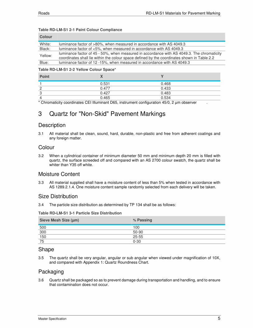
Roads RD-LM-S1 Materials for Pavement Marking
Master Specification 5
Table RD-LM-S1 2-1 Paint Colour Compliance
Colour
White: luminance factor of >80%, when measured in accordance with AS 4049.3
Black: luminance factor of <5%, when measured in accordance with AS 4049.3
Yellow: luminance factor of 45 - 50%, when measured in accordance with AS 4049.3. The chromaticity coordinates shall lie within the colour space defined by the coordinates shown in Table 2.2
Blue: luminance factor of 12 -15%, when measured in accordance with AS 4049.3
Table RD-LM-S1 2-2 Yellow Colour Space*
Point X Y
1 0.531 0.468
2 0.477 0.433
3 0.427 0.483
4 0.465 0.534
* Chromaticity coordinates CEI Illuminant D65, instrument configuration 45/0, 2 µm observer .
3 Quartz for "Non-Skid" Pavement Markings
Description
3.1 All material shall be clean, sound, hard, durable, non-plastic and free from adherent coatings and any foreign matter.
Colour
3.2 When a cylindrical container of minimum diameter 50 mm and minimum depth 20 mm is filled with quartz, the surface screeded off and compared with an AS 2700 colour swatch, the quartz shall be whiter than Y35 off white.
Moisture Content
3.3 All material supplied shall have a moisture content of less than 5% when tested in accordance with AS 1289.2.1.4. One moisture content sample randomly selected from each delivery will be taken.
Size Distribution
3.4 The particle size distribution as determined by TP 134 shall be as follows:
Table RD-LM-S1 3-1 Particle Size Distribution
Sieve Mesh Size (µm) % Passing
500 100
300 50-90
150 25-55
75 0-30
Shape
3.5 The quartz shall be very angular, angular or sub angular when viewed under magnification of 10X, and compared with Appendix 1: Quartz Roundness Chart.
Packaging
3.6 Quartz shall be packaged so as to prevent damage during transportation and handling, and to ensure that contamination does not occur.

Roads RD-LM-S1 Materials for Pavement Marking
Master Specification 6
4 Glass Beads
4.1 All glass beads shall comply with AS 2009 and APAS 0042 “Glass Beads for Pavement Marking Paint” with an additional requirement for Type B beads (drop-on) as modified below.
4.2 Type B beads (drop-on) shall comply with the properties defined in AS 2009 with an additional high performance retroreflectivity requirement requiring the delivery of a minimum 450 mcd/m2/lx when tested in accordance with a modified Appendix M of AS2009 as described below:
a) Section M4 Apparatus Clause a) Dry film thickness of paint will be 200 -250 µm.
b) Section M5 Procedure Clause b) Weigh 24 ± 0.5 grams of beads.
c) Section M5 Procedure Clause e) Wet Film thickness of paint will be 375 ± 25 µm.
5 Crushed Glass Anti-Skid Mix
5.1 Anti-skid mixtures shall consist of glass beads and crushed glass in the ratio of 70:30. Glass used in anti-skid mixtures shall be crushed to a cubic shape and contain no sign of glass shards. The particle size of the glass shall be 1 mm – 2 mm.
6 High Performance Pavement Marking
General
6.1 High performance pavement marking materials are used where greater durability than that provided by waterborne paint is required. Examples include intersection marking and messages. Products shall be approved to one or more of the following Departmental procedures: PC109, PC111, PC112 or PC113.
6.2 Current approved products are listed in included in the Department’s Approved Products List, available from: https://www.dpti.sa.gov.au/documents
6.3 Markings will be white or yellow to the requirements specified in the relevant PC as listed above.
7 Coloured Pavement Surfacings
General
7.1 Coloured pavement surfacings, such as that used for dedicated bus and cycle lanes, shall be approved to Departmental Procedure PC111. Current approved products are listed in included in the Department’s Approved Products List, available from: https://www.dpti.sa.gov.au/documents.
7.2 Coloured pavement surfacings shall be a commercial match to the following AS 2700 colours:
a) Bus lanes: Signal Red, R13.
b) Cycle lanes: Emerald, G13.
c) Pedestrian crossings: Golden Yellow, Y14.
d) Accessible boarding indicator patch (station platforms): Ultramarine, B21.
e) Dedicated parking patch for people with disabilities: Ultramarine, B21.
8 Raised Pavement Markers
8.1 Raised pavement markers shall comply with AS 1906.3. Non reflective raised pavement markers shall not be ceramic.
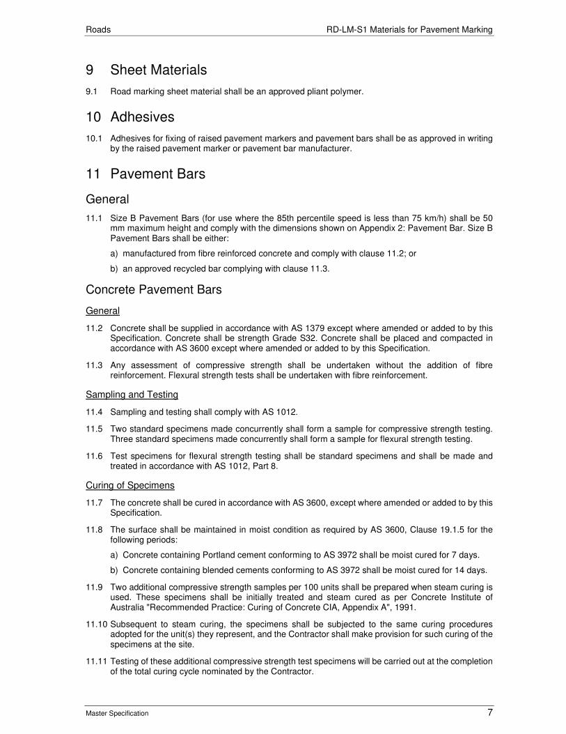
Roads RD-LM-S1 Materials for Pavement Marking
Master Specification 7
9 Sheet Materials
9.1 Road marking sheet material shall be an approved pliant polymer.
10 Adhesives
10.1 Adhesives for fixing of raised pavement markers and pavement bars shall be as approved in writing by the raised pavement marker or pavement bar manufacturer.
11 Pavement Bars
General
11.1 Size B Pavement Bars (for use where the 85th percentile speed is less than 75 km/h) shall be 50 mm maximum height and comply with the dimensions shown on Appendix 2: Pavement Bar. Size B Pavement Bars shall be either:
a) manufactured from fibre reinforced concrete and comply with clause 11.2; or
b) an approved recycled bar complying with clause 11.3.
Concrete Pavement Bars
General
11.2 Concrete shall be supplied in accordance with AS 1379 except where amended or added to by this Specification. Concrete shall be strength Grade S32. Concrete shall be placed and compacted in accordance with AS 3600 except where amended or added to by this Specification.
11.3 Any assessment of compressive strength shall be undertaken without the addition of fibre reinforcement. Flexural strength tests shall be undertaken with fibre reinforcement.
Sampling and Testing
11.4 Sampling and testing shall comply with AS 1012.
11.5 Two standard specimens made concurrently shall form a sample for compressive strength testing. Three standard specimens made concurrently shall form a sample for flexural strength testing.
11.6 Test specimens for flexural strength testing shall be standard specimens and shall be made and treated in accordance with AS 1012, Part 8.
Curing of Specimens
11.7 The concrete shall be cured in accordance with AS 3600, except where amended or added to by this Specification.
11.8 The surface shall be maintained in moist condition as required by AS 3600, Clause 19.1.5 for the following periods:
a) Concrete containing Portland cement conforming to AS 3972 shall be moist cured for 7 days.
b) Concrete containing blended cements conforming to AS 3972 shall be moist cured for 14 days.
11.9 Two additional compressive strength samples per 100 units shall be prepared when steam curing is used. These specimens shall be initially treated and steam cured as per Concrete Institute of Australia "Recommended Practice: Curing of Concrete CIA, Appendix A", 1991.
11.10 Subsequent to steam curing, the specimens shall be subjected to the same curing procedures adopted for the unit(s) they represent, and the Contractor shall make provision for such curing of the specimens at the site.
11.11 Testing of these additional compressive strength test specimens will be carried out at the completion of the total curing cycle nominated by the Contractor.

Roads RD-LM-S1 Materials for Pavement Marking
Master Specification 8
Flexural Strength and Fibre Cohesive Capability of a Sample
11.12 The composite concrete flexural strength with fibre shall comply with the requirements specified in Clause 12 "Verification Requirements".
11.13 After failure of the specimen, the upper rollers of the flexural test apparatus shall be advanced a further 40 mm and released. For acceptance of the failure the fractured pieces of concrete shall remain firmly held together by the fibre.
Fibre Reinforcement
11.14 Reinforcing fibre shall be Caricrete, fibre size various tex, fibre length 75 mm (Order Code KU10100) or an approved alternative. The amount of fibre in the mix shall be a minimum of 0.3% by mass.
Surface Finish
11.15 Concrete surfaces shall be finished so as to achieve the specified dimensions, texture and surface finish. The surface finish shall be Class 3 in accordance with AS 3610.
11.16 The bottom surface of the pavement bar shall have an exposed aggregate finish free of laitance for bonding purposes.
Painting of Concrete Pavement Bars
11.17 Pavement bars shall be painted with two coats of approved low gloss acrylic AS2700 Y14 “Golden Yellow” paint to a total dry film thickness of 60 mm. A coating of glass beads shall be added to each coat of paint whilst it is still wet to ensure embedment. 27/3. Current approved products are listed in included in the Department’s Approved Products List, available from: https://www.dpti.sa.gov.au/documents Recycled Pavement Bars
General
11.18 The Recycled Pavement Bars listed in the Department’s Approved Products List, available from: https://www.dpti.sa.gov.au/documents re approved for use on the Department’s roads.
11.19 The Contractor may request the approval of additional products by submitting:
a) results of recognised tests or other suitable documentation (to be evaluated on submission) in order to support the requirements of this Sub-clause 11.3;
b) disposal instruction for the recycled pavement bars; and
c) a guarantee/warranty statement of the life expectancy of the recycled pavement bars in relation to colour fastness and structural integrity of the material.
11.20 Approval will be subject to demonstrating satisfactory physical properties, proven durability and fixing method.
11.21 Provision of evidence demonstrating compliance with this Sub-clause shall constitute a Hold Point.
Manufacturing
11.22 Recycled pavement bars shall be manufactured from recyclable materials and materials that resist permanent deformation. Recycled pavement bars are to be manufactured so that they resist breaking under impact from traffic, or if breaks do occur, sections of the bar shall not detach and create the possibility of damage to vehicles or other road users. Materials used shall not be subject to becoming more brittle, or otherwise deteriorate structurally.
Compressive and Flexural Strength
11.23 Recycled pavement bars shall have a minimum compressive strength of 32 MPa and a minimum flexural strength of 4.5 MPa.
11.24 Some materials may not meet these strength requirements but possess a memory characteristic allowing the materials to regain its shape after deformation. These types of materials will be considered.

Roads RD-LM-S1 Materials for Pavement Marking
Master Specification 9
Colour
11.25 Recycled pavement bars shall be manufactured either yellow in colour or capable of accepting and retaining paint. The yellow colour shall be colour No. 14 Golden Yellow, as defined in AS2700. Each pavement bar shall have a colour match rating of 3 when compared to the Y14 colour, as described in AS 1580.601.1.
11.26 Pavement bars not requiring painting shall be capable of retaining their colour when exposed to weather conditions. The manufacturer shall provide information on the likely service life of the recycled pavement bar prior to paining being required.
11.27 Recycled pavement bars are not required to be retroreflective if used on roads which have a level of road lighting.
11.28 The manufacturer may nominate a preferred paint product which is compatible with the recycled pavement bar surface and will minimise discolouration due to wear or the accumulation of road grime.
Performance Requirements
11.29 Recycled pavement bar surfaces shall have a smooth surface and shall not be capable of causing damage to vehicle tyres. They shall exhibit self-cleaning properties whereby it will retain its yellow colour and minimise discolouration due to wear or the accumulation of road grime.
11.30 Recycled pavement bars shall be sufficiently rough enough to permit a good bond between it and the adhesive used. The bottom surface shall be flat so that it can rest firmly on a hard flat surface without rocking when a load is alternately applied to each end.
Fixing Methods
11.31 Recycled pavement bars shall be capable of being fixed to the road surface by the use of adhesives. Mechanical fixings are not acceptable. The manufacturer may nominate a preferred adhesive agent.
12 Temporary Pavement Marking Materials
Temporary Retroreflective Raised Pavement Markers
12.1 In accordance with AS 1742.3 Clause 3.9.5, temporary retroreflective raised pavement markers should be sufficiently robust to survive under traffic until permanent markings are installed.
Temporary Line Marking Tape
12.2 Temporary Line Marking Tape shall be subject to prior approval.
13 Records
13.1 Further to PC-QA1 “Quality Management Requirements”, traceability is required for all Pavement Marking Materials. A record of consignments and associated documentation shall be retained by the Contractor. The documentation shall include the following details:
a) product name;
b) product description;
c) batch no.;
d) date of manufacture; and
e) evidence that the material complies with the requirements of the Specification.
14 Hold Points
14.1 The following is a summary of Hold Points referenced in this Part:
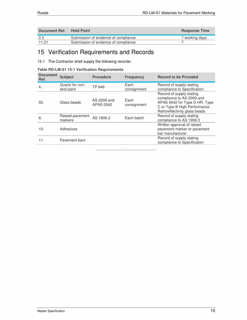
Roads RD-LM-S1 Materials for Pavement Marking
Master Specification 10
Document Ref. Hold Point Response Time
2.3 Submission of evidence of compliance 7 working days
11.21 Submission of evidence of compliance ?
15 Verification Requirements and Records
15.1 The Contractor shall supply the following records:
Table RD-LM-S1 15-1 Verification Requirements
Document Ref.
Subject Procedure Frequency Record to be Provided
4. Quartz for non-skid paint
TP 946 Each consignment
Record of supply stating compliance to Specification
55. Glass beads AS 2009 and APAS 0042
Each consignment
Record of supply stating compliance to AS 2009 and APAS 0042 for Type D-HR, Type C or Type B High Performance Retroreflectivity glass beads
8. Raised pavement markers
AS 1906.3 Each batch Record of supply stating compliance to AS 1906.3
10. Adhesives Written approval of raised pavement marker or pavement bar manufacturer
11. Pavement bars Record of supply stating compliance to Specification

Roads RD-LM-S1 Materials for Pavement Marking
Master Specification 11
16 Appendix 1: Quartz Roundness Chart
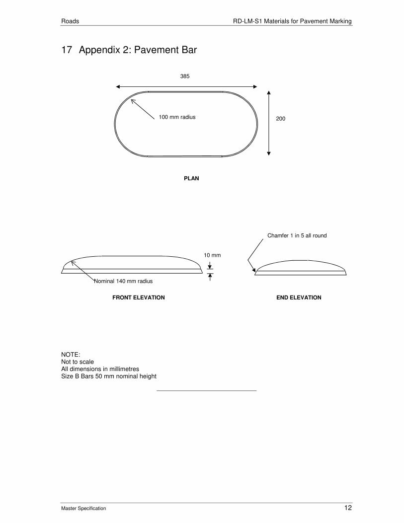
Roads RD-LM-S1 Materials for Pavement Marking
Master Specification 12
17 Appendix 2: Pavement Bar
NOTE: Not to scale All dimensions in millimetres Size B Bars 50 mm nominal height
200 100 mm radius
385
PLAN
10 mm
Nominal 140 mm radius
FRONT ELEVATION
Chamfer 1 in 5 all round
END ELEVATION
Roads
Master Specification
RD-LM-S2 Supply of Signs Document Information
KNet Number: 13623475
Document Version: 3
Document Date: August 2020

Roads Contents
Master Specification Revision A 2
Document Amendment Record Version Change Description Date
1 Initial issue (formerly R48 – Supply of Signs) 28/06/19
2 Formatting for publishing 16/09/19
3 Relevant details are stamped/engraved onto the back of signs instead of writing details on a sticker with permanent marker. This allows the details to be readable for life so the Department can initiate warranty claims.
August 2020
Document Management This document is the Property of the Department for Infrastructure and Transport and contains information that is confidential to the Department. It must not be copied or reproduced in any way without the written consent of the Department. This is a controlled document and it will be updated and reissued as approved changes are made.

Roads Contents
Master Specification Revision A 3
Contents Contents 3
RD-LM-S2 Supply of Signs 4
1 General 4
2 Prequalification 4
3 Design 5
4 Materials of Signs 5
5 Certification from Retroreflective Sheeting Manufacturer 7
6 Manufacture of Signs 7
7 Handling of Signs 11
8 Sign Performance Warranties 11
9 Hold Points 12
10 Verification Requirements and Records 12
11 Appendix 1: Sign Materials - Legends and Backgrounds 14
12 Appendix 2: Schedule of Hole and Stiffener Centre Locations 16
13 Appendix 3: Stiffener Joining Detail 19
14 Appendix 4: Sectioned Sign Joining 20
15 Appendix 5: Sign identification 22

Roads RD-LM-S2 Supply of Signs
Master Specification Revision A 4
RD-LM-S2 Supply of Signs
1 General
1.1 This Part sets out the requirements for the manufacture and delivery of all regulatory, warning, guide, information, freeway guide, direction and hazard marker signs. This Part does not cover electronic signs.
1.2 The Contractor shall supply signs in accordance with the following (in order of precedence):
a) any contract specific drawings or specified by the Principal;
b) the requirements of this Part; and
c) standard drawings.
1.3 "Standard Sign" means a sign in accordance with AS 1743 or a sign detailed on the Department’s Sign Index.
1.4 Documents referenced in this Part are listed below:
a) AS 1163 Cold-formed Structural Steel Hollow Sections.
b) AS 1170 SAA Loading Code – Wind Loads.
c) AS 1214 Hot-Dip Galvanized Coatings on Threaded Fasteners.
d) AS 1450 Steel Tubes for Mechanical Purposes.
e) AS 1397 Continuous Hot-Dip Metallic Coated Steel Sheet and Strip - Coatings of Zinc and Zinc Alloyed with Aluminium and Magnesium.
f) AS 1580 Paints and Related Materials - Methods of Test.
g) AS 1627 Metal Finishing - Preparation and Pre-treatment of Surfaces.
h) AS 1627.1 Metal finishing - Preparation and Pretreatment of Surfaces - Removal of Oil, Grease and related Contamination.
i) AS 1627.4 Metal Finishing - Preparation and Pretreatment of Surfaces - Abrasive Blast Cleaning.
j) AS 1734 Aluminium and Aluminium Alloys - Flat Sheet, Coiled Sheet and Plate.
k) AS 1742.1-15 Manual of Uniform Traffic Control Devices.
l) AS 1743 Road Signs – Specifications.
m) AS 1744 Standard Alphabets for Road Signs.
n) AS 1866 Aluminium and Aluminium Alloys - Extruded Rod, Bar, Solid and Hollow Shapes.
o) AS 1906.1 Retroreflective Materials and Devices for Road Traffic Control Purposes – Retroreflective Sheeting.
p) AS 2700 Colour Standards for General Purposes.
q) Department Standard Road Sign - Specification South Australia. Refer to online index at http://www.dteiapps.com.au/signindx/.
2 Prequalification
2.1 Signs shall be manufactured by a company prequalified with the Department – refer https://www.dpti.sa.gov.au/contractor_documents/prequalification.

Roads RD-LM-S2 Supply of Signs
Master Specification Revision A 5
3 Design
3.1 The design of a sign shall be in the format of either a Department Traffic Engineering Specification (TES) drawing or a standard drawing prefixed similar to the Australian Standard series, e.g. R1-2.
3.2 The dimensions, legend and background for each sign shall be in accordance with:
a) Specific Road Signs – Specifications, South Australia (TES drawing);
b) AS 1743;
c) AS 1744; and
d) Standard Road Sign – Specification South Australia.
4 Materials of Signs
Sign Blacks
Metallic Sign Blanks
4.1 Metallic sign blanks shall be manufactured from an aluminium alloy with a thickness of either 1.6 mm or 2.0 mm. The aluminium alloy shall be grade 5052 or 5251, temper H36 or H38 as specified in AS 1734. Sign blanks shall be free of cracks, tears and other surface blemishes and the edges shall be true and smooth.
Non-Metallic Substrate Sign Blanks
4.2 The Principal is trialling the use of non-metallic substrates for a limited range of signs and may permit, at its sole and unfettered discretion, the use of a non-metallic substrate. Any such sign blanks shall:
a) be no larger than 600 mm x 900 mm for signs from the Australian Standard series, as defined in the Department’s Standard Road Sign Index;
b) be no larger than 1200 mm x 900 mm for flat panel temporary warning signs or 1800 mm x 600 mm for temporary warning signs having a polycarbonate extruded edge, i.e. box edge signs, as defined in the Department’s Standard Road Sign Index;
c) comply with the provisions of AS1743 Clause 11.1;
d) be compatible with the material with which they will be covered;
e) be constructed of Polycarbonate or other approved UV stable product to guarantee an outdoor service life of at least 15 years;
f) be flexible, non-shattering and not subjected to fatigue cracking;
g) have a nominal thickness of 3 mm;
h) be smooth, free of cracks, surface blemishes, and all edges shall be true and smooth for the life of the product; and
i) not void the warranty given by the manufacturer of any sheeting or coating applied to the substrate.
4.3 Non-metallic substrates shall only be used in areas where there is a high probability of vehicle impact and the Principal’s written approval is obtained beforehand.
Stiffeners
4.4 Stiffeners shall be continuous horizontal lengths of galvanized cold rolled steel channel with cross- sectional dimensions of 41.3 x 21.0 mm or aluminium extruded section with cross-sectional dimensions of 28.5 x 25.5 mm.

Roads RD-LM-S2 Supply of Signs
Master Specification Revision A 6
4.5 Each stiffener section shall have internal clamping ridges compatible with the Unistrut Pipe and Tubing Clamping system. A minimum overlap length of 1000 mm is required when joining stiffeners on a multi-piece sign, as shown in Appendix 3: Stiffener Joining Detail.
Rivets
4.6 Rivets shall be from a self-piercing riveting system or conform to the following requirements:
a) 1 320 N minimum shear load;
b) 1 910 N minimum tensile load;
c) aluminium alloy with a steel stem and domed head;
d) 4.8 to 5 mm shank diameter; and
e) 8.5 to 9.5 mm head diameter.
4.7 The riveting process shall not project above the surface of the sign blank in a manner which will result in damage of the sign face material. The heads of rivets shall be coloured to match the surrounding material.
Backing Strips
4.8 Backing strips shall be the same material and condition as required in Clause 4.1 "Sign Blanks".
Double Sided Acrylic Foam Tapes
4.9 Foam tapes shall be double sided, medium firm, acrylic pressure sensitive adhesives that have high initial adhesion, good shear holding power and a demonstrated long-term holding strength. The tape shall also be capable of withstanding extremely high or low temperatures and have characteristics similar to 3M VHB 4952 double sided acrylic foam tape.
Hinges
4.10 Hinges shall comprise a continuous brass, galvanized steel or stainless steel piano type hinge approximately 40 to 60 mm wide when in the open position with a 1 to 2 mm blade thickness and a 3 to 5 mm diameter stainless steel or brass hinge pin that is securely locked in position.
Retroreflective Material for Background and Legend
4.11 Class 1A, Class 1100, Class 900, Class 400, Class 300 and Class 100 retroreflective sheeting shall conform to the requirements defined in AS 1906.1.
4.12 Details of the class of material to be used on Standard Signs are listed in Appendix 1: Sign Materials - Legends and Backgrounds.
4.13 Details of the class of material to be used on specific road signs designated by a TES number are noted on the Department’s “Specific Road Signs-Specifications, South Australia” drawing. The Contractor shall demonstrate that the luminance contrast ratios between legends and backgrounds is not less than that set out in Table B1, Appendix B, AS 1906.1.
Non–Retroreflective Material for Background and Legend
Paint
4.14 Paint shall be compatible with the legend and background material, both in application and durability, and shall meet the warranty requirement of the sign as set out in Table RD-LM-S2 8-1.
4.15 Colours shall approximate to that defined in AS 1743. Matt colours, when measured in accordance with method 602.2 detailed in AS 1580, shall have specular gloss value of:
a) 12 – 20 for an 85° head; or
b) 8 – 12 for a 60° head.

Roads RD-LM-S2 Supply of Signs
Master Specification Revision A 7
Sheet Material
4.16 The material shall be of uniform density and compatible with the material used for the legend and background both in application and durability. All sheeting shall be applied with pressure sensitive adhesive or tack-free heat activated adhesive. Adhesive cast vinyl legend and background material or equivalent product may be used.
5 Certification from Retroreflective Sheeting Manufacturer
5.1 The sign manufacturer shall provide the following details to support the sign performance warranty underwritten by the retroreflective sheeting manufacturer:
a) Report of the last audit of the manufacturing facility conducted by the retroreflective sheeting manufacturer to assess the Contractor's manufacturing performance.
b) Certification issued by the retroreflective sheeting manufacturer that the Contractor is currently eligible to offer a Sign Performance Warranty arrangement that is underwritten by the retroreflective sheeting manufacturer.
5.2 The Contractor shall have procedures in place to satisfy the requirements of the retroreflective sheeting manufacturer for storage and handling of signs.
6 Manufacture of Signs
Sign Blanks
6.1 Sign blanks shall be free of cracks, tears and other surface blemishes and the edges shall be true and smooth. The face of each sign blank shall be chemically cleaned and etched or mechanically abraded in accordance with AS 1627. The back of each sign blank shall be rendered dull and non-reflective either by mechanical or chemical means.
6.2 Sign blanks shall be fabricated from a single sheet of aluminium unless the sign is larger than the standard sheet size. Fingerblade signs shall be manufactured from extruded aluminium with an extruded rib, top and bottom of the blade.
Multi-Piece Signs
6.3 Where the sign is of such a size as to require more than one full standard sheet of aluminium, a multi-piece sign shall be made using the minimum number of sheets practicable.
6.4 A sign with more joins than necessary will not be accepted. All joints shall be covered by a backing strip except for horizontal joins in sectioned signs. This backing strip shall be fixed to the sign using double sided acrylic foam tapes or riveted to each sheet.
6.5 Double sided acrylic foam tapes shall be applied in accordance with the manufacturer's recommended application procedure.
Sectioned Signs
6.6 Where the sign is of such a size that it is necessary for the sign to be manufactured, transported or installed in sections, it shall be manufactured in accordance with Appendix 3: Stiffener Joining Detail (for vertical joints) and Appendix 4: Sectioned Sign Joining (for horizontal joints). Joins should not be made through legends or symbols wherever possible. Sectioned signs shall be clearly marked for ease of assembly in the field.
Hinge Signs
6.7 Hinged signs shall be manufactured with the hinge running the full length of the hinged section of the sign. The hinge shall be attached to the back of the sign such that when the sign is in the open position, only the pin roll is visible from the front of the sign.

Roads RD-LM-S2 Supply of Signs
Master Specification Revision A 8
6.8 Holes on the top and bottom or both sides of the sign shall be positioned to accommodate a 38 mm wide padlock (supplied by others) when the sign is in the closed position.
Dimensions and Tolerances
6.9 The dimensions of the sign blank shall be within 2.5 mm of those specified. The finished sign shall be flat within a maximum allowable warp or twist of 5 mm/metre in any direction.
6.10 Backing strips shall:
a) be of uniform width of at least 50 mm wide over full length; and
b) extend to within 25 mm of edge of sign.
6.11 Vertical backing strips shall stop at each horizontal stiffener or horizontal backing strip and shall butt against it with a gap of 1 mm.
6.12 Riveted backing strips, stiffeners and hinges shall be according to the following:
a) secured by regularly spaced rivets to each side of the joint;
b) rivet spacing shall not exceed 200 mm;
c) the end rivets shall be a maximum distance of 25 mm from each end; and
d) a minimum of 2 rivets shall be installed on each side of the joint.
6.13 Sections of multi-piece signs shall be butted together with a maximum gap of 1 mm at any point along the joint.
6.14 Hinged sign plates shall have sufficient clearance between the plates when the sign is in the closed position to clear the rivet heads. On sectioned signs, stiffeners shall be placed along the edge of the butted join and there shall be a maximum gap of 1 mm at any point along the joint.
6.15 Stiffeners shall comply with the following:
a) butt joins shall be 5 mm;
b) each end of the stiffener shall be 50 to 150 mm from the edge of the sign unless specified in Appendix 2: Schedule of Hole and Stiffener Centre Locations; and
c) maximum panel overhang at the top and bottom of the sign shall be an equal distance from the stiffener centres and shall be in the range of between 50 to 150 mm.
6.16 Where "High Wind Signs" are specified on the Drawings, rivet spacing shall not exceed 150 mm and at least 3 rivets shall be installed on each side of the joint.
Provision for Mounting of Signs
Non-Reinforced Signs
6.17 Non-reinforced signs shall be manufactured with square holes for mounting purposes. The holes shall be cleanly punched 11 mm square (0.5 mm) to accept a 10 mm diameter cup head square neck bolt. The hole spacing shall be in accordance with Appendix 2: Schedule of Hole and Stiffener Centre Locations.
Reinforced Signs
6.18 All signs with the following thicknesses shall have stiffeners fixed to the rear of the sign in accordance with Appendix 2: Schedule of Hole and Stiffener Centre Locations:
a) with a plate thickness t = 1.6 mm and overall width > 1200 mm; or
b) with a plate thickness t = 2.0 mm and overall width > 1400 mm.
6.19 Where the length of the stiffener exceeds 6.0 m, joining of stiffening sections is permitted. Joined stiffening sections shall be staggered so that the structural integrity of the sign is not compromised. Spacing shall be in accordance with the stiffener centre guide in Appendix 2: Schedule of Hole and Stiffener Centre Locations.

Roads RD-LM-S2 Supply of Signs
Master Specification Revision A 9
6.20 Where specified reinforcing for High Wind Category signs shall be as shown on the drawings. Stiffeners shall be attached to the sign blanks by rivets or double sided acrylic foam tapes.
Sectioned Signs
6.21 In addition to the requirements set out in Clause 6.6.19 "Reinforced Signs", sectioned signs shall have stiffeners fixed along the horizontal join of the two joining pieces in accordance Appendix 4: Sectioned Sign Joining.
Temporary Signs
6.22 No provision for attachment is required for temporary signs.
Fingerblade Signs
6.23 Spacers equal to the width of extrusion shall be used when mounting fingerblade signs on 80 x 40 mm rectangular hollow section posts.
Sign Overlays
6.24 Sign overlays used to modify or amend a sign legend shall be made from 1.6 mm thick aluminium sheet unless noted otherwise on the TES drawing.
Form of Letters and Numerals
6.25 All individual letters shall have neat, clearly defined edges with smooth curves on round letters conforming to AS 1744.
Retroreflective Sign Background and Legend
Retroreflective Material
6.26 Retroreflective material shall be applied to the sign blank in accordance with the Retroreflective Sheeting Manufacturer's recommendations. The material shall be applied in one continuous piece. Retroreflective materials used as background and legends of signs shall conform in colour and grade to the requirements of AS 1906.1.
6.27 Where sign dimensions exceed the standard retroreflective material width, joining of the material shall be in accordance with Clause 6.9 "Material Joins".
Screening Ink and Electronic Cuttable Films
6.28 Coloured legends or backgrounds may be provided by using either:
a) transparent screen process colours;
b) opaque screen process colours;
c) electronic cuttable films; or
d) digital printing.
6.29 Legends shall be manufactured by the retroreflective sheeting manufacturer to ensure compatibility and durability with the reflective sheeting.
6.30 The screen process colours or electronic cuttable films shall be applied using materials and techniques recommended by the retroreflective sheeting manufacturer.
6.31 For digital printing only:
a) matched component inks and printer devices recommended by the retro-reflective sheeting manufacturer shall be used; and
b) the ink and any protective coating shall be compatible with the background material, both in application and durability.

Roads RD-LM-S2 Supply of Signs
Master Specification Revision A 10
Material Joins
6.32 Joins of the material shall be in accordance with the Reflective Sheet Manufacturer's recommendations.
Non-Reflectorised Sign Background, Legend, Symbols and Borders
Background Paint
6.33 Where specified, the front of signs (background) shall be painted using a 2-pack polyurethane paint as approved to APAS-2911. Surface preparation of the sign substrate and the primer to be used shall be as specified by the finish coat manufacturer. All paints shall be from the one manufacturer.
6.34 The colour of the background paint shall be an approximate match to the appropriate colour as specified in AS 1743, Clause 10.1, when assessed in accordance with AS 1580.601.1. The specular gloss of the background paint shall be less than 20%, when assessed in accordance with AS 1580.602.2.
6.35 Where required, the backs of signs shall be painted as follows:
a) degrease all surfaces in accordance with AS 1627.1;
b) apply one coat of waterborne galvanized iron primer, as approved to APAS-0134; and
c) apply two coats of flat or low gloss latex paint, as approved to APAS-0280/3.
6.36 The colour of the paint shall be an approximate match to AS 2700, G61 Dark Green, unless otherwise specified, when assessed in accordance with AS 1580.601.1. All paints shall be from the one manufacturer.
6.37 Where paint is used it shall be applied with a minimum dry film thickness of 38 microns. Touching up of small areas by brush to fully match the spray painted surface shall be permissible using the colour base and hardener mixture without reducer.
Sheet Material Application
6.38 All sheeting and films shall be applied in accordance with the manufacturer's instructions so that it is securely fixed to the sign and the surface is free of bubbles, wrinkles and blemishes.
Screening Ink and Electronic Cuttable Films
6.39 Legends may be manufactured using either opaque screen process colours or electronic cuttable films and the sign manufacturer shall ensure compatibility and durability with the retroreflective sheeting. The screen process colours or electronic cuttable films shall be applied using materials and techniques recommended by the manufacturer of the retroreflective sheeting. Where joins in the cuttable films are required, they shall be of the "butt-join" type and shall overlap. Background material of the legend shall be compatible in application and durability.
Reference Markings
6.40 For aluminium signs, identification coding shall be clearly and permanently stamped or engraved on all signs produced. The coding shall appear in characters 6 mm to 10 mm high. Stamping and engraving shall be carried out in such a manner that the front face of the sign is not damaged.
6.41 For rectangular signs, the coding shall appear as near as practicable to the bottom rear left hand corner. For other shaped signs it shall be positioned on or below the horizontal centre line and as near to the left rear edge as practicable.
6.42 For printed signs the code may be printed on the sign face within the outer border strip as near as practicable to the bottom left hand corner – refer Appendix 5: Sign identification”. Identification codes printed on the front of a sign shall be encased under protective film to ensure the code remains legible for the life of the sign.
6.43 The format of the information shall include:

Roads RD-LM-S2 Supply of Signs
Master Specification Revision A 11
a) TES number or Sign Code;
b) sign manufacturer's name;
c) month and year of manufacture; and
d) manufacturer and class of retroreflective material.
6.44 For example:
Table RD-LM-S2 6-1 Sign Reference Marking
XYZ 11 17 3M1
Abbreviated to Signify Manufacturer
Month of Manufacturer
Year of Manufacture
Abbreviated to Signify Retroreflective Sheeting Manufacturer and Grade of Retroreflective Sheeting
7 Handling of Signs
7.1 All finished signs shall be handled, transported and stored to prevent damage to the sign face or other components. Large guide and information signs shall be adequately braced during transport to avoid buckling and rivet popping. Packaged signs shall not be stored wet.
7.2 Signs may only be stored outdoors if no practical indoor alternative exists. If the signs are stored in outdoor facilities, the signs shall be:
a) stored off the ground in an upright position;
b) supported to prevent damage to the face or sign blank;
c) free of transport packaging; and
d) well ventilated to prevent moisture build up on the face of the sign.
7.3 Moisture or condensation shall not come into contact with the face of the sign. Signs with wet packages shall immediately be removed and allowed to dry completely.
7.4 Signs shall not be stored in a high temperature or high humidity environment and shall be appropriately protected for the storage conditions.
8 Sign Performance Warranties
General
8.1 The Contractor shall establish, in conjunction with the manufacturer, procedures for storage, delivery and erection to ensure continuity of the retroreflective sheeting manufacturer's warranty.
8.2 The Contractor shall provide certification from the retroreflective sheeting manufacturer that in the event of a failure to the sign during the warranty period, the retroreflective sheeting manufacturer shall repair or replace the faulty sign.
8.3 In the event of a defect in a sign which has been installed, the Contractor shall either:
a) remove, replace and reinstall the defective sign at its own expense without additional payment; or
b) if agreed between the parties, compensate the Principal for all additional costs necessary incurred by the Principal (including removal and reinstallation) as a consequence of the defective sign.
8.4 This warranty shall not apply to signs that have failed in service as a result of vandalism, accidental damage or abnormal environmental conditions.

Roads RD-LM-S2 Supply of Signs
Master Specification Revision A 12
Sign Panel
8.5 The complete sign panel including all components thereon or attached except for the sign face or sheeting, shall be guaranteed against any defects caused by failure of the components for a period of at least 36 months from the date of manufacture.
8.6 This warranty does not apply to signs that have failed in service as a result of vandalism, accidental damage or abnormal environmental conditions.
Sign Face or Sheeting
8.7 The Contractor shall provide a manufacturer’s guarantee the signs for the warranty period shown in Table RD-LM-S2 8-1. Where materials with different performance characteristics are combined, such as a guide sign, the warranty period applicable is determined by the warranted performance of the material with the minimum durability ranking of the combination.
Table RD-LM-S2 8-1 Warranty Performance Schedule
Background Sheeting Class Used in combination with
Warranted Outdoor Exposure
Warranted Retained CIL/m² Percentile(1)
Class 900 Class 1A 10 years 80%(2)
Class 900 10 years
Class 400 12 years
Electronic Cuttable Films 14 years
Screen printed colours 10 years
Fluorescent Yellow, Yellow / Green 10 years
Fluorescent Red / Orange 3 years
Class 400 Class 400 12 years
Electronic Cuttable Films 14 years
Screen printed colours 10 years 80%(2)
Fluorescent Yellow, Yellow / Green 5 years
Fluorescent Red / Orange 3 years
Class 100 Class 1A 7 years 50%(2)
Class 900 10 years
Class 400 12 years
Electronic Cuttable Films 14 years
Fluorescent Yellow, Yellow / Green 10 years
Fluorescent Red / Orange 3 years
(1) Warranted retained brightness levels apply to reflective sheeting used for sign backgrounds, borders and legends. (2) Retained CIL percentile is based on minimum CIL values for new reflective sheeting by Class for all of the combinations of Observation and Entrance Angles defined in relevant tables included in AS1906.1.
Non-metallic Substrate Sign Blank and Sheeting
8.8 The combined manufacture of non-metallic substrate sign blank and sheeting as one item by the sign manufacturer shall guarantee the warranty period shown in Table RD-LM-S2 8-1 for the combination sign.
9 Hold Points
9.1 There are no Hold Points referenced in this Part.
10 Verification Requirements and Records
10.1 The Contractor shall supply the following records:

Roads RD-LM-S2 Supply of Signs
Master Specification Revision A 13
Table RD-LM-S2 10-1 Verification requirements
Document Ref. Subject Record To Be Provided
8. Sign manufacturer’s warranty Retro reflective warranty
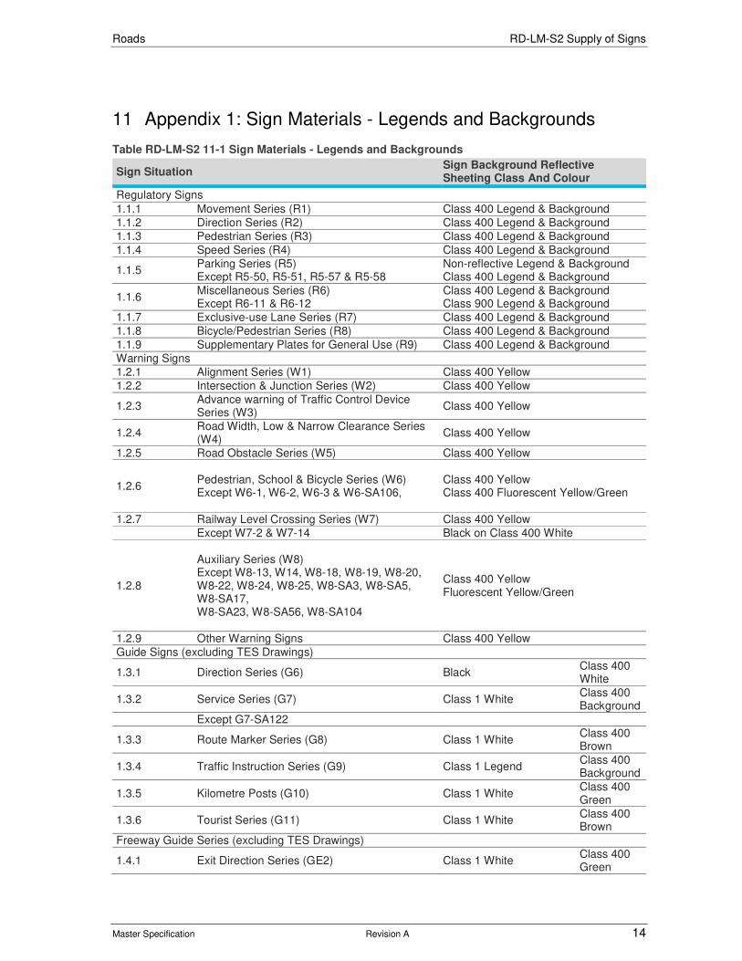
Roads RD-LM-S2 Supply of Signs
Master Specification Revision A 14
11 Appendix 1: Sign Materials - Legends and Backgrounds
Table RD-LM-S2 11-1 Sign Materials - Legends and Backgrounds
Sign Situation Sign Background Reflective Sheeting Class And Colour
Regulatory Signs
1.1.1 Movement Series (R1) Class 400 Legend & Background
1.1.2 Direction Series (R2) Class 400 Legend & Background
1.1.3 Pedestrian Series (R3) Class 400 Legend & Background
1.1.4 Speed Series (R4) Class 400 Legend & Background
1.1.5 Parking Series (R5) Except R5-50, R5-51, R5-57 & R5-58
Non-reflective Legend & Background Class 400 Legend & Background
1.1.6 Miscellaneous Series (R6) Except R6-11 & R6-12
Class 400 Legend & Background Class 900 Legend & Background
1.1.7 Exclusive-use Lane Series (R7) Class 400 Legend & Background
1.1.8 Bicycle/Pedestrian Series (R8) Class 400 Legend & Background
1.1.9 Supplementary Plates for General Use (R9) Class 400 Legend & Background
Warning Signs
1.2.1 Alignment Series (W1) Class 400 Yellow
1.2.2 Intersection & Junction Series (W2) Class 400 Yellow
1.2.3 Advance warning of Traffic Control Device Series (W3)
Class 400 Yellow
1.2.4 Road Width, Low & Narrow Clearance Series (W4)
Class 400 Yellow
1.2.5 Road Obstacle Series (W5) Class 400 Yellow
1.2.6 Pedestrian, School & Bicycle Series (W6) Except W6-1, W6-2, W6-3 & W6-SA106,
Class 400 Yellow Class 400 Fluorescent Yellow/Green
1.2.7 Railway Level Crossing Series (W7) Class 400 Yellow
Except W7-2 & W7-14 Black on Class 400 White
1.2.8
Auxiliary Series (W8) Except W8-13, W14, W8-18, W8-19, W8-20, W8-22, W8-24, W8-25, W8-SA3, W8-SA5, W8-SA17, W8-SA23, W8-SA56, W8-SA104
Class 400 Yellow Fluorescent Yellow/Green
1.2.9 Other Warning Signs Class 400 Yellow
Guide Signs (excluding TES Drawings)
1.3.1 Direction Series (G6) Black Class 400 White
1.3.2 Service Series (G7) Class 1 White Class 400 Background
Except G7-SA122
1.3.3 Route Marker Series (G8) Class 1 White Class 400 Brown
1.3.4 Traffic Instruction Series (G9) Class 1 Legend Class 400 Background
1.3.5 Kilometre Posts (G10) Class 1 White Class 400 Green
1.3.6 Tourist Series (G11) Class 1 White Class 400 Brown
Freeway Guide Series (excluding TES Drawings)
1.4.1 Exit Direction Series (GE2) Class 1 White Class 400 Green
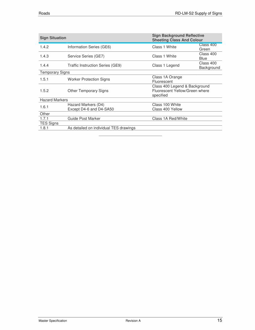
Roads RD-LM-S2 Supply of Signs
Master Specification Revision A 15
Sign Situation Sign Background Reflective Sheeting Class And Colour
1.4.2 Information Series (GE6) Class 1 White Class 400 Green
1.4.3 Service Series (GE7) Class 1 White Class 400 Blue
1.4.4 Traffic Instruction Series (GE9) Class 1 Legend Class 400 Background
Temporary Signs
1.5.1 Worker Protection Signs Class 1A Orange Fluorescent
1.5.2 Other Temporary Signs Class 400 Legend & Background Fluorescent Yellow/Green where specified
Hazard Markers
1.6.1 Hazard Markers (D4) Except D4-6 and D4-SA50
Class 100 White Class 400 Yellow
Other
1.7.1 Guide Post Marker Class 1A Red/White
TES Signs
1.8.1 As detailed on individual TES drawings
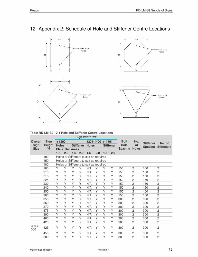
Roads RD-LM-S2 Supply of Signs
Master Specification Revision A 16
12 Appendix 2: Schedule of Hole and Stiffener Centre Locations
Table RD-LM-S2 12-1 Hole and Stiffener Centre Locations
Overall Sign Size
Sign Height
'H'
Sign Width ‘W’
Bolt Hole
Spacing
No. of
Holes
Stiffener Spacing
No. of Stiffeners
< 1200 1201-1400 > 1401
Holes Stiffener Holes Stiffener
Plate Thickness
1.6 2.0 1.6 2.0 1.6 2.0 1.6 2.0
100 Holes or Stiffeners to suit as required
150 Holes or Stiffeners to suit as required
180 Holes or Stiffeners to suit as required
200 Y Y Y Y N/A Y Y Y 150 2 150 2
210 Y Y Y Y N/A Y Y Y 150 2 150 2
215 Y Y Y Y N/A Y Y Y 150 2 150 2
225 Y Y Y Y N/A Y Y Y 150 2 150 2
230 Y Y Y Y N/A Y Y Y 150 2 150 2
240 Y Y Y Y N/A Y Y Y 150 2 150 2
250 Y Y Y Y N/A Y Y Y 150 2 150 2
300 Y Y Y Y N/A Y Y Y 150 2 150 2
350 Y Y Y Y N/A Y Y Y 300 2 300 2
360 Y Y Y Y N/A Y Y Y 300 2 300 2
370 Y Y Y Y N/A Y Y Y 300 2 300 2
375 Y Y Y Y N/A Y Y Y 300 2 300 2
390 Y Y Y Y N/A Y Y Y 300 2 300 2
400 Y Y Y Y N/A Y Y Y 300 2 300 2
420 Y Y Y Y N/A Y Y Y 300 2 300 2
300 x 300
425 Y Y Y Y N/A Y Y Y 300 2 300 2
450 Y Y Y Y N/A Y Y Y 300 2 300 2
500 Y Y Y Y N/A Y Y Y 300 2 300 2
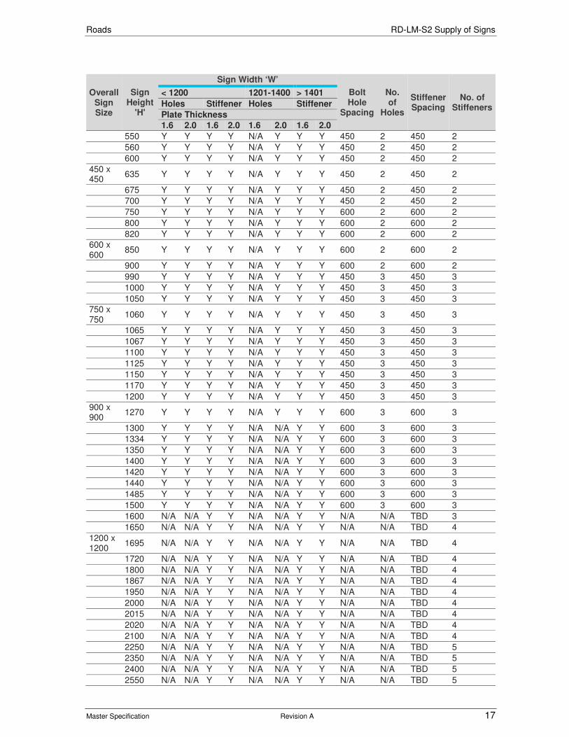
Roads RD-LM-S2 Supply of Signs
Master Specification Revision A 17
Overall Sign Size
Sign Height
'H'
Sign Width ‘W’
Bolt Hole
Spacing
No. of
Holes
Stiffener Spacing
No. of Stiffeners
< 1200 1201-1400 > 1401
Holes Stiffener Holes Stiffener
Plate Thickness
1.6 2.0 1.6 2.0 1.6 2.0 1.6 2.0
550 Y Y Y Y N/A Y Y Y 450 2 450 2
560 Y Y Y Y N/A Y Y Y 450 2 450 2
600 Y Y Y Y N/A Y Y Y 450 2 450 2
450 x 450
635 Y Y Y Y N/A Y Y Y 450 2 450 2
675 Y Y Y Y N/A Y Y Y 450 2 450 2
700 Y Y Y Y N/A Y Y Y 450 2 450 2
750 Y Y Y Y N/A Y Y Y 600 2 600 2
800 Y Y Y Y N/A Y Y Y 600 2 600 2
820 Y Y Y Y N/A Y Y Y 600 2 600 2
600 x 600
850 Y Y Y Y N/A Y Y Y 600 2 600 2
900 Y Y Y Y N/A Y Y Y 600 2 600 2
990 Y Y Y Y N/A Y Y Y 450 3 450 3
1000 Y Y Y Y N/A Y Y Y 450 3 450 3
1050 Y Y Y Y N/A Y Y Y 450 3 450 3
750 x 750
1060 Y Y Y Y N/A Y Y Y 450 3 450 3
1065 Y Y Y Y N/A Y Y Y 450 3 450 3
1067 Y Y Y Y N/A Y Y Y 450 3 450 3
1100 Y Y Y Y N/A Y Y Y 450 3 450 3
1125 Y Y Y Y N/A Y Y Y 450 3 450 3
1150 Y Y Y Y N/A Y Y Y 450 3 450 3
1170 Y Y Y Y N/A Y Y Y 450 3 450 3
1200 Y Y Y Y N/A Y Y Y 450 3 450 3
900 x 900
1270 Y Y Y Y N/A Y Y Y 600 3 600 3
1300 Y Y Y Y N/A N/A Y Y 600 3 600 3
1334 Y Y Y Y N/A N/A Y Y 600 3 600 3
1350 Y Y Y Y N/A N/A Y Y 600 3 600 3
1400 Y Y Y Y N/A N/A Y Y 600 3 600 3
1420 Y Y Y Y N/A N/A Y Y 600 3 600 3
1440 Y Y Y Y N/A N/A Y Y 600 3 600 3
1485 Y Y Y Y N/A N/A Y Y 600 3 600 3
1500 Y Y Y Y N/A N/A Y Y 600 3 600 3
1600 N/A N/A Y Y N/A N/A Y Y N/A N/A TBD 3
1650 N/A N/A Y Y N/A N/A Y Y N/A N/A TBD 4
1200 x 1200
1695 N/A N/A Y Y N/A N/A Y Y N/A N/A TBD 4
1720 N/A N/A Y Y N/A N/A Y Y N/A N/A TBD 4
1800 N/A N/A Y Y N/A N/A Y Y N/A N/A TBD 4
1867 N/A N/A Y Y N/A N/A Y Y N/A N/A TBD 4
1950 N/A N/A Y Y N/A N/A Y Y N/A N/A TBD 4
2000 N/A N/A Y Y N/A N/A Y Y N/A N/A TBD 4
2015 N/A N/A Y Y N/A N/A Y Y N/A N/A TBD 4
2020 N/A N/A Y Y N/A N/A Y Y N/A N/A TBD 4
2100 N/A N/A Y Y N/A N/A Y Y N/A N/A TBD 4
2250 N/A N/A Y Y N/A N/A Y Y N/A N/A TBD 5
2350 N/A N/A Y Y N/A N/A Y Y N/A N/A TBD 5
2400 N/A N/A Y Y N/A N/A Y Y N/A N/A TBD 5
2550 N/A N/A Y Y N/A N/A Y Y N/A N/A TBD 5

Roads RD-LM-S2 Supply of Signs
Master Specification Revision A 18
Overall Sign Size
Sign Height
'H'
Sign Width ‘W’
Bolt Hole
Spacing
No. of
Holes
Stiffener Spacing
No. of Stiffeners
< 1200 1201-1400 > 1401
Holes Stiffener Holes Stiffener
Plate Thickness
1.6 2.0 1.6 2.0 1.6 2.0 1.6 2.0
2700 N/A N/A Y Y N/A N/A Y Y N/A N/A TBD 5
2850 N/A N/A Y Y N/A N/A Y Y N/A N/A TBD 6
2950 N/A N/A Y Y N/A N/A Y Y N/A N/A TBD 6
3000 N/A N/A Y Y N/A N/A Y Y N/A N/A TBD 6
3150 N/A N/A Y Y N/A N/A Y Y N/A N/A TBD 6
3300 N/A N/A Y Y N/A N/A Y Y N/A N/A TBD 6
3450 N/A N/A Y Y N/A N/A Y Y N/A N/A TBD 7
3600 N/A N/A Y Y N/A N/A Y Y N/A N/A TBD 7
3750 N/A N/A Y Y N/A N/A Y Y N/A N/A TBD 7
3900 N/A N/A Y Y N/A N/A Y Y N/A N/A TBD 7
4050 N/A N/A Y Y N/A N/A Y Y N/A N/A TBD 7
4200 N/A N/A Y Y N/A N/A Y Y N/A N/A TBD 8
4350 N/A N/A Y Y N/A N/A Y Y N/A N/A TBD 8
4500 N/A N/A Y Y N/A N/A Y Y N/A N/A TBD 8
4650 N/A N/A Y Y N/A N/A Y Y N/A N/A TBD 9
4800 N/A N/A Y Y N/A N/A Y Y N/A N/A TBD 9
4950 N/A N/A Y Y N/A N/A Y Y N/A N/A TBD 9
Notes:
a) Dimensions to the centre of stiffener or bolt holes.
b) Stiffener spacing to be equidistant using required number of stiffeners for sign heights marked ‘TBD’ (To Be Determined).
c) Refer to TES 12186 for additional stiffener requirements needed for gantry and overhead mounted signs.
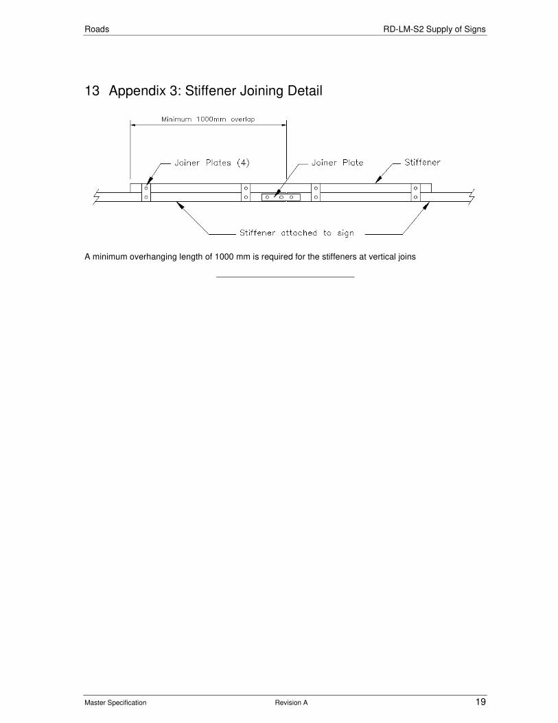
Roads RD-LM-S2 Supply of Signs
Master Specification Revision A 19
13 Appendix 3: Stiffener Joining Detail
A minimum overhanging length of 1000 mm is required for the stiffeners at vertical joins

Roads RD-LM-S2 Supply of Signs
Master Specification 20
14 Appendix 4: Sectioned Sign Joining
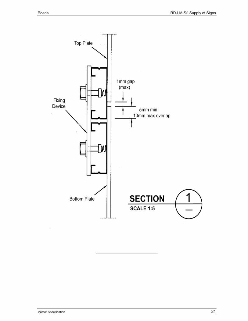
Roads RD-LM-S2 Supply of Signs
Master Specification 21

Roads RD-LM-S2 Supply of Signs
Master Specification 22
15 Appendix 5: Sign identification
Roads
Master Specification
RD-PV-C5 Construction of Minor Pavements Document Information
K Net Number: 13995848
Document Version: 2
Document Date: 18/09/2019

Roads Contents
Master Specification 2
Document Amendment Record
Version Change Description Date Endorsement record (KNet ref.)
1 Initial issue (formerly R84) 28/06/19
2 Formatting for publishing 18/09/19
Document Management This document is the Property of the Department for Infrastructure and Transport and contains information that is confidential to the Department. It must not be copied or reproduced in any way without the written consent of the Department. This is a controlled document and it will be updated and reissued as approved changes are made.
Roads Contents
Master Specification 3
Contents Contents 2
RD-PV-C5 Construction of Minor Pavements General 4
1 General 4
2 Finished Surface 4
3 Compaction 4
4 Rubble Surface 4
5 Bitumen Threated Surfaces 5
6 Asphalt 5
7 Concrete 5
8 Block Paving 6
9 Hold Points 8
10 Measurement 8
11 Appendix 1: Concrete Service Inspection Pit Surrounds 9

Roads RD-PV-C5 Construction of Minor Pavements General
Master Specification 4
RD-PV-C5 Construction of Minor Pavements General
1 General
1.1 This Part specifies the requirements for the construction of footpaths, verges, property driveways, egress and parking bays, median and traffic island infill and block paving (“Minor Pavements”).
1.2 Refer to RD-PV-C4 “Construction of Shared Paths” for the requirements for paths used for both cycling and pedestrians (“Shared Paths”).
1.3 Documents referenced in this Part are listed below:
a) Austroads AGPT04B-14 “Guide to Pavement Technology Part 4B: Asphalt”.
b) AS 2150 Hot mix asphalt - A guide to good practice.
2 Finished Surface
2.1 If a design Cross-section Report and Geometric Details are included in the Contract, the levels specified therein take precedence over any sketches.
2.2 The finished surface of the Secondary Pavement shall:
a) not vary more than 10 mm over a 3 m straight edge;
b) where a design finished level is specified, be constructed within:
i) ± 10 mm for concrete and block paving; or
ii) ± 20 mm for other surfaces.
c) drain to the top of any adjoining kerb;
d) be free draining so that water does not pond on the surface;
e) be free of irregularities that could present tripping hazards to users; and
f) smoothly abut any existing driveways and footpaths adjoining the new surface.
3 Compaction
3.1 Rubble, Sand and Bitumen Treated Sand pavement layers (including Base and Subbase) shall be compacted at Optimum Moisture Content (OMC) and comply with Table RD-PV-C5 3-1.
Table RD-PV-C5 3-1 Compaction Requirements
Plant Minimum Number of Passes Thickness 50 – 120 mm
Thickness > 120 mm
Small Vibration Plate (approx. mass 90 kg - Wacker VPA 90 or equiv.)
6 8
Large Vibration Plate (approx. mass 300 kg - Wacker BPU 3345 or equiv.)
3 4
Small Twin Drum Footpath Roller Minimum 1 t (e.g. Ingersoll Rand DD12)
2 3
3 tonne vibrating roller class VR10 (e.g. Ingersoll RandDD22)
2 3
Note: The Small Vibration Plate may only be used in areas inaccessible to larger plant.
4 Rubble Surface
4.1 Rubble Secondary Pavements shall comply with Table RD-PV-C5 4-1.

Roads RD-PV-C5 Construction of Minor Pavements General
Master Specification 5
Table RD-PV-C5 4-1 Rubble Surfaces
Footpaths Driveways
Material PM2/20 or PM3/20 PM2/20
Minimum Thickness (mm) 125 150
5 Bitumen Threated Surfaces
5.1 Bitumen Treated Secondary Pavements shall comply with Table RD-PV-C5 5-1.
Table RD-PV-C5 5-1 Bitumen Treated Surfaces
Footpaths Median and Traffic Island Infill
Surface Layer:
Material Sa-C Type C Sand, with the addition of 3% bitumen (i.e. Sa-C B3)
Sa-C Type C Sand with the addition of 3% bitumen (i.e. Sa-C B3)
Thickness (mm) min 100 50
Subbase:
Material Not required Cold Planed Asphalt or PM3/20, Class 3 Pavement Material
Minimum thickness (mm) - 90 mm
5.2 If cold planed asphalt is used, it shall be shaped and compacted to produce a tight dense surface.
6 Asphalt
6.1 Asphalt Secondary Pavements shall:
a) have been designed in accordance with the requirements of Austroads AGPT04B-14;
b) comply with AS2150; and
c) comply with Table RD-PV-C5 6-1.
Table RD-PV-C5 6-1 Asphalt Minor Pavements
Footpaths Residential / Light Duty Driveways
Heavy Duty Driveways
SURFACE COURSE
Material AC7 (C170) AC7 (C170) AC10M (C320)
Thickness (mm) min 25 30 35
BASE
Material PM2/20 or PM3/20 PM2/20 to 96% PM2/20 to 96%
Thickness (mm) min 100 150 125
SUBBASE
Material Not required Not required PM2/20 to 95%
Thickness (mm) min - - 150
Total Minimum Thickness (mm)
125 180 305
6.2 Subgrade shall be trimmed and compacted with at least 1 pass of the compaction plant.
6.3 Base and Subbase shall also comply with Clause 3.
6.4 Asphalt compaction shall be carried out using a minimum 2 passes of a steel double drum, vibrating footpath roller.
6.5 The surface of the finished asphalt shall be free of segregated or "bony" areas, soft and "fatty" areas, ravelling and loose material, surface cracking, shoving and ruts.
7 Concrete
7.1 Concrete Secondary Pavements comply with Table RD-PV-C5 7-1.
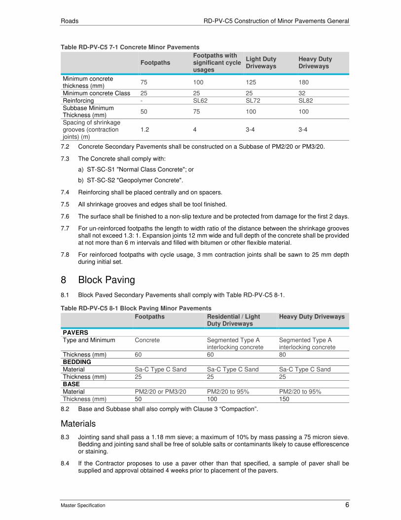
Roads RD-PV-C5 Construction of Minor Pavements General
Master Specification 6
Table RD-PV-C5 7-1 Concrete Minor Pavements
Footpaths
Footpaths with significant cycle usages
Light Duty Driveways
Heavy Duty Driveways
Minimum concrete thickness (mm)
75 100 125 180
Minimum concrete Class 25 25 25 32
Reinforcing - SL62 SL72 SL82
Subbase Minimum Thickness (mm)
50 75 100 100
Spacing of shrinkage grooves (contraction joints) (m)
1.2 4 3-4 3-4
7.2 Concrete Secondary Pavements shall be constructed on a Subbase of PM2/20 or PM3/20.
7.3 The Concrete shall comply with:
a) ST-SC-S1 "Normal Class Concrete"; or
b) ST-SC-S2 "Geopolymer Concrete".
7.4 Reinforcing shall be placed centrally and on spacers.
7.5 All shrinkage grooves and edges shall be tool finished.
7.6 The surface shall be finished to a non-slip texture and be protected from damage for the first 2 days.
7.7 For un-reinforced footpaths the length to width ratio of the distance between the shrinkage grooves shall not exceed 1.3: 1. Expansion joints 12 mm wide and full depth of the concrete shall be provided at not more than 6 m intervals and filled with bitumen or other flexible material.
7.8 For reinforced footpaths with cycle usage, 3 mm contraction joints shall be sawn to 25 mm depth during initial set.
8 Block Paving
8.1 Block Paved Secondary Pavements shall comply with Table RD-PV-C5 8-1.
Table RD-PV-C5 8-1 Block Paving Minor Pavements
Footpaths Residential / Light Duty Driveways
Heavy Duty Driveways
PAVERS
Type and Minimum Concrete Segmented Type A interlocking concrete
Segmented Type A interlocking concrete
Thickness (mm) 60 60 80
BEDDING
Material Sa-C Type C Sand Sa-C Type C Sand Sa-C Type C Sand
Thickness (mm) 25 25 25
BASE
Material PM2/20 or PM3/20 PM2/20 to 95% PM2/20 to 95%
Thickness (mm) 50 100 150
8.2 Base and Subbase shall also comply with Clause 3 “Compaction”.
Materials
8.3 Jointing sand shall pass a 1.18 mm sieve; a maximum of 10% by mass passing a 75 micron sieve. Bedding and jointing sand shall be free of soluble salts or contaminants likely to cause efflorescence or staining.
8.4 If the Contractor proposes to use a paver other than that specified, a sample of paver shall be supplied and approval obtained 4 weeks prior to placement of the pavers.

Roads RD-PV-C5 Construction of Minor Pavements General
Master Specification 7
8.5 Submission of the sample shall constitute a Hold Point.
Laying Paving Units
8.6 Paving units shall be placed on the uncompacted screeded sand bed to the laying pattern shown on the Drawings.
8.7 Paving units shall be placed to achieve gaps nominally 2 mm to 4 mm wide between adjacent units such that all joints are correctly aligned.
8.8 Except where it is necessary to correct any minor variations occurring in the laying bond, the paving units shall not be hammered into position. Where adjustment of position is necessary care shall be taken to avoid premature compaction of the sand bedding.
8.9 All unsupported edges shall have a concealed reinforced concrete edging. Cement mortar for concealed edging shall comprising three parts Sa-C Type C Sand and one part cement.
8.10 Footpaths shall have one row of header bricks along each edge. Where shown on the drawings, medians and traffic islands shall have one row of header bricks around the perimeter. Tree openings, where shown on the drawings, shall have one row of header bricks around the perimeter of the opening.
Block Paving Around Service Inspection Pits, etc.
8.11 Where an existing service inspection pit is greater than 10 mm above or below the proposed footpath level, the Contractor shall adjust the service inspection pit so that it is flush with the new footpath levels and comply with any requirement of the Service Authority for adjusting the pit.
8.12 The level of block paving placed around small square steel service inspection pits and steel stormwater channels shall match the pits or channel. The edge of the paving shall not be greater than 4 mm from the pit or channel, either vertically or horizontally. The Contractor shall make allowance to cut, if necessary, the paving units around these pits or channels.
8.13 Unless otherwise shown on the drawings, concrete infill shall be placed around service inspection pits (other than those referred to in Clause 8.10), survey marks, poles and street furniture within the paved area as shown in Appendix 1: Concrete Service Inspection Pit Surrounds.
8.14 Concrete infill shall be Grade 25 (or a 1:2:3 mix of cement, sand and 10 mm aggregate) and shall be placed to a minimum depth of 75 mm. The concrete shall be coloured to match the surrounding block paving.
Block Paving Abutting Boundary Structures and Kerb
8.15 Block paving shall be placed such that joints between paving units and boundary structures and / or kerb is no greater than 4 mm. Where it is impracticable to cut blocks to the shape required, gaps up to 50 mm shall be infilled using mortar (1 cement : 3 sand) coloured to match the paving units.
Compaction and Joint Filling of Block Paving
8.16 Paving units shall be compacted to achieve consolidation of the sand bedding by 3 passes of a suitable vibrating plate compactor. The compactor shall be a high-frequency, low-amplitude mechanical flat plate vibrator.
8.17 Compaction shall proceed as closely as practicable following laying. Compaction shall not be attempted within 1 m of the laying face and shall continue until lipping has been eliminated between adjoining units.
8.18 Any units which are structurally damaged during compaction shall be immediately replaced.
8.19 As soon as practical after compaction, sand for joint-filling shall be spread over the paving. The jointing sand shall be broomed in a dry condition into the joints and one pass of the plate vibrator shall be made to compact the jointing sand.
8.20 Joints between block paving and concrete edging greater than 4 mm shall be filled with a 1:3 mix of cement and sand and watered in.

Roads RD-PV-C5 Construction of Minor Pavements General
Master Specification 8
9 Hold Points The following is a summary of Hold Points referenced in this Part: Document Ref Hold Point Response Time
8.4 Proposal to use alternative paver 7 working days
10 Measurement
10.1 If measurement of a paved surface is required for the purpose of payment, no deduction for inspection pits and similar structures will be made in the measured area, except where any individual pit or structure equals or exceeds 2 square metres in area.

Roads RD-PV-C5 Construction of Minor Pavements General
Master Specification 9
11 Appendix 1: Concrete Service Inspection Pit Surrounds Notes: 1. Sketch not to scale – shapes shown are representative only. 2. All measurements are in millimetres.
Min 50 Max 100
Small Pits (Up to 300 x 300)
Min 80 Max 150
Medium Pits (Up to 1 000 x 600)
Min 100 Max 200
Large Pits (Up to 1 800 x 1 000)
Roads
Master Specification
RD-PV-C6 Reinstatement of Existing Pavements Document Information
K Net Number: 13704700 Document Version: 2 Document Date: 18/09/2019

Roads Contents
Master Specification 2
Document Amendment Record
Version Change Description Date Endorsement record (KNet ref.)
1 Initial issue 28/06/19 2 Formatting for publishing 18/09/19
Document Management This document is the Property of the Department for Infrastructure and Transport and contains information that is confidential to the Department. It must not be copied or reproduced in any way without the written consent of the Department. This is a controlled document and it will be updated and reissued as approved changes are made.

Roads Contents
Master Specification 3
Contents Contents 2
RD-PV-C6 Reinstatement of Existing Pavements 4
1 General 4
2 Construction of Pavement 4
3 Shoulders 4
4 Unbound and Cement Treated Pavements 4
5 Temporary Pavement Surface 4
6 Surfacing General 5
7 Asphalt Surfacing 5
8 Joint Sealing 5
9 Sprayed Bituminous Surfacing 6
10 Reinstatement of Other Infrastructure 6
11 Appendix 1: Minimum Surfacing Reinstatement Requirements 8
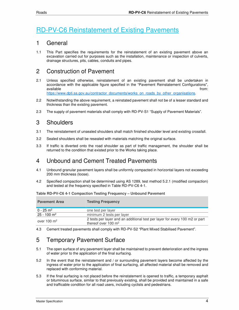
Roads RD-PV-C6 Reinstatement of Existing Pavements
Master Specification 4
RD-PV-C6 Reinstatement of Existing Pavements
1 General
1.1 This Part specifies the requirements for the reinstatement of an existing pavement above an excavation carried out for purposes such as the installation, maintenance or inspection of culverts, drainage structures, pits, cables, conduits and pipes.
2 Construction of Pavement
2.1 Unless specified otherwise, reinstatement of an existing pavement shall be undertaken in accordance with the applicable figure specified in the “Pavement Reinstatement Configurations", available from: https://www.dpti.sa.gov.au/contractor_documents/works_on_roads_by_other_organisations.
2.2 Notwithstanding the above requirement, a reinstated pavement shall not be of a lesser standard and thickness than the existing pavement.
2.3 The supply of pavement materials shall comply with RD-PV-S1 “Supply of Pavement Materials”.
3 Shoulders
3.1 The reinstatement of unsealed shoulders shall match finished shoulder level and existing crossfall.
3.2 Sealed shoulders shall be resealed with materials matching the original surface.
3.3 If traffic is diverted onto the road shoulder as part of traffic management, the shoulder shall be returned to the condition that existed prior to the Works taking place.
4 Unbound and Cement Treated Pavements
4.1 Unbound granular pavement layers shall be uniformly compacted in horizontal layers not exceeding 200 mm thickness (loose).
4.2 Specified compaction shall be determined using AS 1289, test method 5.2.1 (modified compaction) and tested at the frequency specified in Table RD-PV-C6 4-1.
Table RD-PV-C6 4-1 Compaction Testing Frequency – Unbound Pavement
Pavement Area Testing Frequency
0 - 25 m2 one test per layer 25 - 100 m2 minimum 2 tests per layer
over 100 m2 2 tests per layer and an additional test per layer for every 100 m2 or part thereof over 100 m2
4.3 Cement treated pavements shall comply with RD-PV-S2 “Plant Mixed Stabilised Pavement”.
5 Temporary Pavement Surface
5.1 The open surface of any pavement layer shall be maintained to prevent deterioration and the ingress of water prior to the application of the final surfacing.
5.2 In the event that the reinstatement and / or surrounding pavement layers become affected by the ingress of water prior to the application of final surfacing, all affected material shall be removed and replaced with conforming material.
5.3 If the final surfacing is not placed before the reinstatement is opened to traffic, a temporary asphalt or bituminous surface, similar to that previously existing, shall be provided and maintained in a safe and trafficable condition for all road users, including cyclists and pedestrians.

Roads RD-PV-C6 Reinstatement of Existing Pavements
Master Specification 5
5.4 Where asphalt is used as the temporary surface, the minimum depth of asphalt shall be 50 mm.
6 Surfacing General
6.1 The supply and placing of the surfacing shall be undertaken in accordance with the requirements of the applicable figure in the Pavement Reinstatement Configurations document.
6.2 Unless approved otherwise in writing, the final surfacing shall extend:
a) For a transverse Trench: Not less than that shown in Appendix 1: Minimum Surfacing Reinstatement Requirements.
b) For a longitudinal Trench: Full lane width.
6.3 The joint between the existing and reinstated final surfacing shall not be positioned within the wheel path.
7 Asphalt Surfacing
7.1 The final wearing course of the reinstatement of asphalt surfaced pavements shall be extended beyond the sides of the Trench by cold planning and reinstating to a minimum depth of 50 mm.
7.2 Unless approved otherwise in writing, the wearing course shall be laid with a paver. Within the Department’s Metropolitan Region, the wearing course shall contain polymer modified binder.
7.3 Asphalt layers, including the final surfacing, shall comply with the quality requirements, level tolerances and surface irregularity acceptance criteria of RD-BP-S2 “Supply of Asphalt” and RD-BP-C3 “Construction of Asphalt Pavements”, except that the frequency of sampling and testing shall be in accordance with Table RD-PV-C6 7-1.
Table RD-PV-C6 7-1 Sampling and Testing Frequency - Asphalt
Pavement Area Testing Frequency
0 - 30 tonnes 2 samples & tests
31 - 150 tonnes 4 samples & tests
151 - 300 tonnes 6 samples & tests
> 300 tonnes 6 samples & tests plus 1 sample & tests for each additional 200 tonnes or part thereof
7.4 The asphalt mix shall be registered with the Department in accordance with RD-BP-S2 "Supply of Asphalt" and be identified as such on cart notes.
7.5 Attention is drawn to Clause 6.4 “Tack Coating” of RD-BP-C3 "Construction of Asphalt Pavements" which requires tack coating to be applied to vertical edges between old and new asphalt pavements. On completion of reinstatement, any residual saw cuts shall be sealed to prevent water ingress into the pavement in accordance with Clause 6.3 “Joint Sealing”.
8 Joint Sealing
8.1 The joint sealing compound shall:
a) be Class 170 bitumen to AS 2008 "Residual Bitumen for Pavements", modified with an appropriate polymer;
b) be designed to penetrate the joint or saw cut, adhere to the surface, and resist crack propagation; and
c) remain stable on the pavement surface during periods of extreme temperature and shall be approved in accordance with RD-BP-S3 “Supply of Pavement Crack Sealant” prior to use.
8.2 The grit shall comply with Sealing Aggregate SA5-2.
8.3 Prior to placement of sealant, joints or saw cuts shall be thoroughly cleaned of foreign material, without damage to the adjoining sound pavement, to provide a clean, dry environment.

Roads RD-PV-C6 Reinstatement of Existing Pavements
Master Specification 6
8.4 If the pavement is damp, warm / hot compressed air may be used to dry of the surface of the joints or saw cut.
8.5 Sealing shall not be undertaken unless the surfaces that the sealant will be applied to are dry.
8.6 Joints and saw cuts shall be cleaned to a minimum depth 15 mm.
8.7 In excessively deep cuts, the void may be plugged with grit to within 15 mm of the pavement surface.
8.8 All voids shall be filled with sealant material to a level of not less than 15 mm below the pavement surface.
8.9 The level of sealant after gritting shall be flush with the adjoining road pavement.
8.10 The width of the visible bond on the pavement surface shall be as narrow as practical.
8.11 The sealant shall not run out over the pavement surface beyond the extent of the joint or saw cut.
8.12 Grit shall be placed on the surface of all sealant while it is sufficiently hot for the grit to adhere to the sealant.
8.13 Grit shall be placed at the minimum application necessary to provide adequate skid resistance and prevent pick-up of the sealant by traffic.
9 Sprayed Bituminous Surfacing
9.1 The reinstatement of sprayed bituminous surfacing shall be undertaken in accordance with the requirements of RD-BP-C5 "Application of Sprayed Bituminous Surfacing".
9.2 Sprayed bituminous surfacing shall comprise of a primer seal and sprayed bituminous surfacing, with the surfacing placed not less than 48 hours after the primer seal has been placed.
9.3 The surfacing shall match the size and texture of the existing adjacent road and be finished off evenly and flush with the adjoining pavement surface.
9.4 The resultant surfacing shall be within the tolerance of 15 mm as measured by a 3 m straight edge in any direction.
10 Reinstatement of Other Infrastructure
10.1 All pavement marking, road furniture, drainage systems, secondary paving and similar infrastructure which has been removed or damaged during the excavation and reinstatement work shall be replaced to the standard matching the existing and in accordance with the relevant parts of the Department’s Master Specification as listed in Table RD-PV-C6 10-1.
Table RD-PV-C6 10-1 Reinstatement of other infrastructure requirements
Infrastructure Type Requirement
Pavement marking (includes raised pavement markers or pavement bars)
Replacement in accordance with RD-LM-C1 "Application of Pavement Marking". The marking shall be completed within 5 working days of the completion of the final surfacing.
Road Furniture (includes road signs, guide posts, safety barrier)
Replacement in accordance with:
• RD-BF-C1 “Supply and Installation of Steel Beam Road Safety Barrier Systems”,
• RD-LM-S2 “Supply of Signs”; and
• RD-LM-C4 “Sign Installation”.
Suppliers of signs shall be prequalified with the Department.

Roads RD-PV-C6 Reinstatement of Existing Pavements
Master Specification 7
Infrastructure Type Requirement
Concrete kerb and gutter or median type kerb
Replacement in accordance with PV-DK-C2 “Kerbing”. Kerb reinstatement shall be completed within 3 days of reinstatement of the road pavement.
Vegetation Any vegetation shall be replaced with vegetation that is of the same type and in the same positions as that removed or damaged in accordance with Division L “Landscaping” of the Department’s Master Specification.
Medians and traffic islands
Where the existing median consists of compacted granular material, the median shall be reinstated with PM2/20 compacted to no less than 92% of the dry density determined using AS 1289, test method 5.2.1 (modified compaction).
Footpaths and brick paved areas
Match existing pavement (i.e. base and any sub-base) configuration and surfacing type.
Road drainage systems Report damage.

Roads RD-PV-C6 Reinstatement of Existing Pavements
Master Specification 8
11 Appendix 1: Minimum Surfacing Reinstatement Requirements

Structures
Master Specification
ST-SC-S7 Supply of Concrete Document Information
K Net Number: 13434798 Document Version: 2 Document Date: 19/09/2019

Structures Contents
Master Specification 2
Document Amendment Record
Version Change Description Date Endorsement record (KNet ref.)
1 Initial issue (formerly CC20) 28/06/19 2 Formatting for Publishing 19/09/19
Document Management This document is the Property of the Department for Infrastructure and Transport and contains information that is confidential to the Department. It must not be copied or reproduced in any way without the written consent of the Department. This is a controlled document and it will be updated and reissued as approved changes are made.

Structures Contents
Master Specification 3
Contents Contents 2
ST-SC-S7 Supply of Concrete 4
1 General 4
2 Quality Requirements 4
3 Concrete Materials 5
4 Concrete Properties 6
5 Sampling and Testing 6
6 High Durability Concrete 7
7 Test Procedures 8
8 Hold Points 8
9 Verification Requirements and Records 8

Structures ST-SC-S7 Supply of Concrete
Master Specification 4
ST-SC-S7 Supply of Concrete
1 General
1.1 This Part specifies the requirements for the design, supply, sampling and testing of special class concrete and normal class in excess of 32MPa. Refer to ST-SC-S1 "Normal Class Concrete" for the supply of N20, N25 and N32 normal class concrete.
1.2 Concrete and its constituent materials shall be supplied and tested in accordance with the following:
a) AS 1012 Methods of testing concrete.
b) AS 1141 Methods of sampling and testing aggregates.
c) AS 1379 Specification and supply of concrete.
d) AS 1478 Chemical admixtures for concrete.
e) AS 2758.1 Aggregates and rock for engineering purposes - Concrete aggregates.
f) AS 3582 Supplementary cementations materials for use with portland and blended cement.
g) AS 3972 Portland and blended cements.
h) ASTM C1621 / C1621M-09b Standard Test Method for Passing Ability of Self-Consolidating Concrete by J-Ring.
i) Vicroads Technical Note 30: Alkali Silica Reaction in Concrete, available from: https://www.vicroads.vic.gov.au
j) Vicroads Technical Note 73: Self Compacting Concrete, available from: https://www.vicroads.vic.gov.au
k) RMS QA Bridgeworks Specification B80 Concrete Work for Bridges, available from: https://www.rms.nsw.gov.au
l) Vicroads Standard Specification 610 Structural Concrete, available from: https://www.vicroads.vic.gov.au
m) Vicroads Code of Practice RC500.16 Selection of Test Methods for Testing of Materials and Work, available from: https://www.vicroads.vic.gov.au
1.3 Unless specified otherwise, the definitions in AS 1379 apply to this Part.
2 Quality Requirements
2.1 At a minimum, the Contractor’s Quality Plan shall include the following documents, procedures and instructions:
a) the concrete mix design, including:
i) the source, type and proportions of the constituent materials;
ii) aggregate gradings and saturated surface-dry densities;
iii) chemical admixtures details and manufacturer's recommended method of use;
iv) the nominated slump and where a superplasticizer is used the final slump;
v) if self-compacting concrete is proposed, details of the mix, T500 (measure of viscosity) and passing ability;
vi) the maximum water content and maximum water / cementitious material ratio;
vii) level of control, accuracy and method of determination of both the coarse and fine aggregate moisture content; and
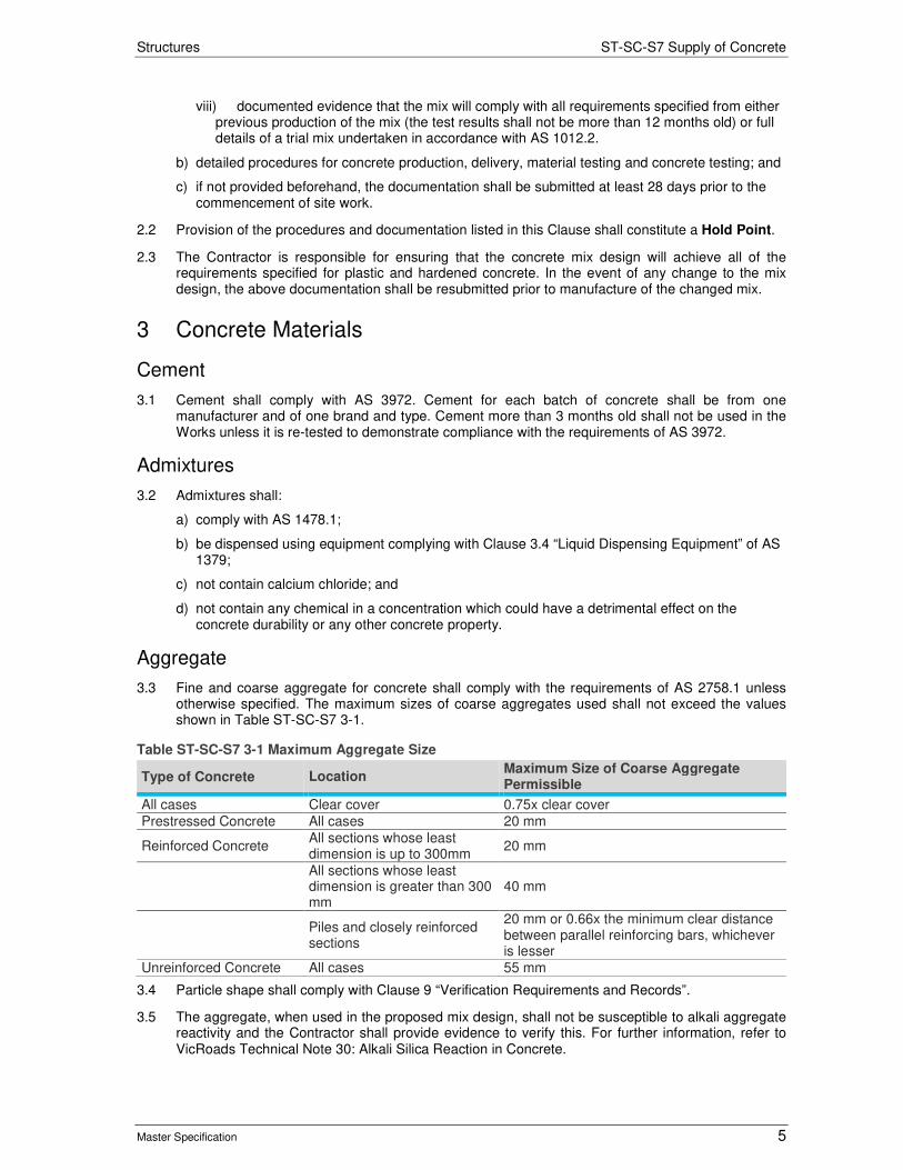
Structures ST-SC-S7 Supply of Concrete
Master Specification 5
viii) documented evidence that the mix will comply with all requirements specified from either previous production of the mix (the test results shall not be more than 12 months old) or full details of a trial mix undertaken in accordance with AS 1012.2.
b) detailed procedures for concrete production, delivery, material testing and concrete testing; and
c) if not provided beforehand, the documentation shall be submitted at least 28 days prior to the commencement of site work.
2.2 Provision of the procedures and documentation listed in this Clause shall constitute a Hold Point.
2.3 The Contractor is responsible for ensuring that the concrete mix design will achieve all of the requirements specified for plastic and hardened concrete. In the event of any change to the mix design, the above documentation shall be resubmitted prior to manufacture of the changed mix.
3 Concrete Materials
Cement
3.1 Cement shall comply with AS 3972. Cement for each batch of concrete shall be from one manufacturer and of one brand and type. Cement more than 3 months old shall not be used in the Works unless it is re-tested to demonstrate compliance with the requirements of AS 3972.
Admixtures
3.2 Admixtures shall:
a) comply with AS 1478.1;
b) be dispensed using equipment complying with Clause 3.4 “Liquid Dispensing Equipment” of AS 1379;
c) not contain calcium chloride; and
d) not contain any chemical in a concentration which could have a detrimental effect on the concrete durability or any other concrete property.
Aggregate
3.3 Fine and coarse aggregate for concrete shall comply with the requirements of AS 2758.1 unless otherwise specified. The maximum sizes of coarse aggregates used shall not exceed the values shown in Table ST-SC-S7 3-1.
Table ST-SC-S7 3-1 Maximum Aggregate Size
Type of Concrete Location Maximum Size of Coarse Aggregate Permissible
All cases Clear cover 0.75x clear cover Prestressed Concrete All cases 20 mm
Reinforced Concrete All sections whose least dimension is up to 300mm
20 mm
All sections whose least dimension is greater than 300 mm
40 mm
Piles and closely reinforced sections
20 mm or 0.66x the minimum clear distance between parallel reinforcing bars, whichever is lesser
Unreinforced Concrete All cases 55 mm
3.4 Particle shape shall comply with Clause 9 “Verification Requirements and Records”.
3.5 The aggregate, when used in the proposed mix design, shall not be susceptible to alkali aggregate reactivity and the Contractor shall provide evidence to verify this. For further information, refer to VicRoads Technical Note 30: Alkali Silica Reaction in Concrete.

Structures ST-SC-S7 Supply of Concrete
Master Specification 6
Soluble Salts
3.6 The acid-soluble chloride-ion content of concrete as placed (expressed as the percentage of the total mass of cementitious material in the concrete mix) shall not be greater than:
a) 0.1% for prestressed concrete;
b) 0.15% for reinforced concrete;
c) 0.03% for post-tensioning grout.
3.7 The sulphate content of concrete as placed (expressed as the percentage by mass of acid-soluble SO3 to the total cementitious material in the concrete mix) shall not be greater than 5%. Sulphate and chloride-ion content shall be determined by testing of hardened concrete in accordance with AS 1012.20.
Self-Compacting Concrete
3.8 Self-Compacting Concrete (SCC) (also called self-consolidating concrete or super-workable concrete) is concrete that is able to flow and consolidate under its own weight, completely fill the formwork or bore hole even in the presence of dense reinforcement, whilst maintaining homogeneity and without the need for additional compaction. For further information, refer to VicRoads Technical Note 73: Self Compacting Concrete, or Annexure G of RMS QA Bridgeworks Specification B80.
3.9 SCC shall incorporate the various cementitious materials, coarse and fine aggregate and any additional fine materials, water and chemical admixtures in such proportions as required, to achieve the rheological characteristics of flow and self-compaction and an absence of segregation. SCC shall be produced using high range polycarboxylate type water reducers or conventional superplasticizers with a viscosity modifying admixture which include a viscosity modifying capability.
4 Concrete Properties
Concrete Class
4.1 Unless specified otherwise, all concrete supplied in accordance with this Contract is Special-Class Concrete. The minimum cementitious content and the maximum water-cement ratio for each particular grade of concrete shall be accordance with Table ST-SC-S7 4-1.
Table ST-SC-S7 4-1 Cement and Water Content
Class of Concrete (MPa) Minimum Cementitious Content Kg/m3 of Concrete
Maximum Water-Cement Ratio by Mass (SSD Basis)
32 330 0.50 40 400 0.45 50 (Exposure Classification C1) 450 0.40 50 (Exposure Classification C2) 470 0.36
4.2 The exposure classification shall be as shown on the drawings.
Self-Compacting Concrete
4.3 SCC shall be homogeneous and free of balls of unmixed material. SCC shall only be used for the manufacture of precast concrete members and / or the construction of cast in-situ piles. The properties of fresh SCC shall comply with AS 1012.3.5
5 Sampling and Testing
5.1 All concrete shall be subject to Project Assessment unless specified otherwise on the drawings.
5.2 For Project Assessment, the following sampling and testing shall be undertaken in addition to that specified in AS1379:
a) a slump test (or Slump Flow if self-compacting concrete is used) on each truck load of concrete delivered to site; and
Structures ST-SC-S7 Supply of Concrete
Master Specification 7
b) sampling in accordance with Table ST-SC-S7 5-1.
Table ST-SC-S7 5-1 Sampling Frequency (per day)
No. of batches (trucks) supplied to the Project No. of samples to be taken
1 1 2 – 5 2
> 5 For each additional 5 batches: One additional sample
5.3 Samples shall be selected randomly.
5.4 Three cylinder specimens shall be obtained from each sample, to be tested as follows:
a) one tested at 7 days (to give an indication of the likely 28 day strength only); and
b) the remaining 2 cylinder specimens tested at 28 days (conformance testing).
5.5 If the Contractor proposes to conduct in-house testing for determination of concrete strength for lifting or transfer, evidence shall be provided showing that:
a) the testing equipment is adequately calibrated and maintained;
b) the testing processes are appropriate; and
c) the testing personnel are adequately trained.
Mortars and Grouts
5.6 All mortars and grouts must be cementitious, shrinkage compensating proprietary products with a consistency appropriate for the required use, and able to be placed and compacted to achieve full encapsulation. Cementitious mortars and grouts must have a minimum 28 day compressive strength of not less than 40 MPa.
5.7 Cementitious grouts must be, as a minimum, Type C Class dual shrinkage compensating.
5.8 Only whole bags of material must be used. Test certificates, material data sheets and health and safety data sheets must be available for all materials. The mortar and grout applications must be cured in accordance with the requirements of ST-SC-C7 "Placement of Concrete".
5.9 Three 75 mm test cubes must be taken from the first batch of material mixed, then three 75 mm cubes for every 100 kg of material used thereafter to test for compressive strength. The cubes must be cured for seven days. Two (2) cubes must be tested at seven days and the third cube at 28 days to confirm compliance with the minimum compressive strength requirements as specified on the drawings and the material manufacturer's technical data sheet. Test cubes must be made, cured and tested in accordance with AS 1478.2.
6 High Durability Concrete
6.1 This clause only applies where high durability concrete has been specified on the drawings. Concrete in Exposure Classification B2, or more severe, shall also satisfy this Part.
6.2 Testing for High Durability Concrete shall use AS1012.21 - Determination of water absorption and apparent volume of permeable voids in hardened concrete. The result of the test is a VPV value.
6.3 The test acceptance of a concrete mix design shall be carried out on test specimens taken from a concrete sample of age 28 days, which has undergone standard moist curing in accordance with AS 1012. The sample shall consist of 2 cylinders. The VPV value of each of the test cylinders shall be not greater than the specified value in Table ST-SC-S7 6-2. Frequency of sampling and testing must be as for Table ST-SC-S7 6-1.
Table ST-SC-S7 6-1 High Durability Sampling Frequency
Component No. of Samples to be Taken
Initial Mix Design 1 per mix design
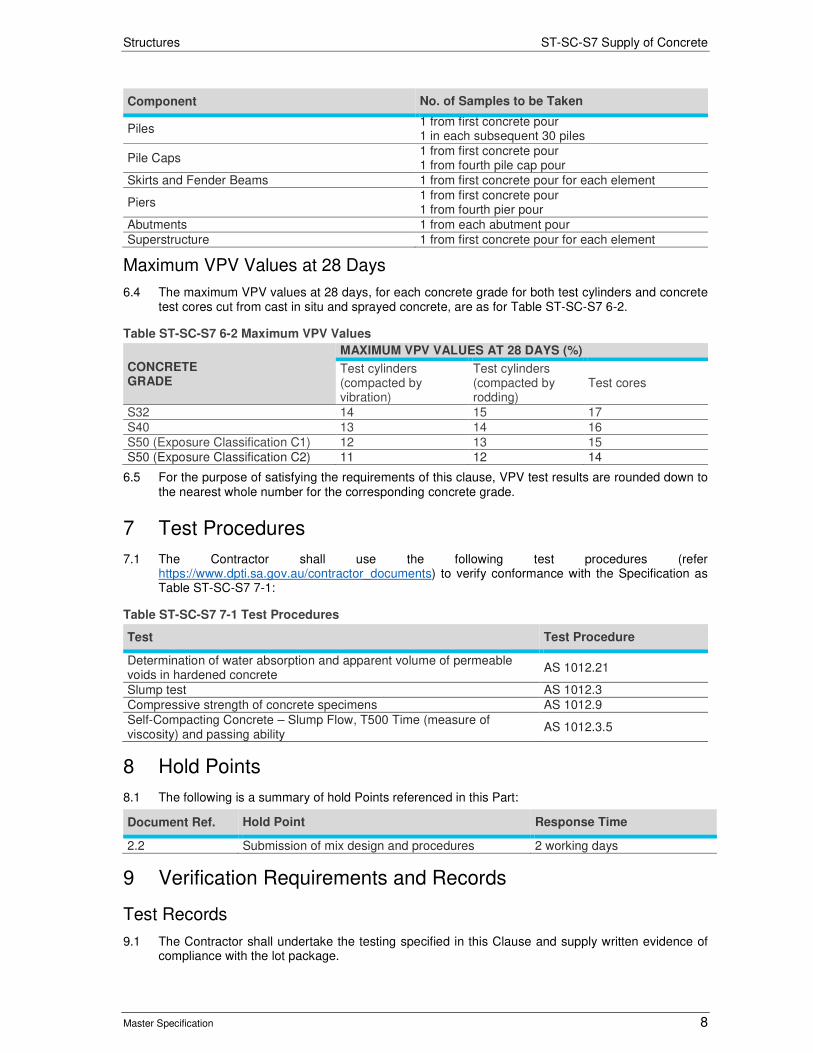
Structures ST-SC-S7 Supply of Concrete
Master Specification 8
Component No. of Samples to be Taken
Piles 1 from first concrete pour 1 in each subsequent 30 piles
Pile Caps 1 from first concrete pour 1 from fourth pile cap pour
Skirts and Fender Beams 1 from first concrete pour for each element
Piers 1 from first concrete pour 1 from fourth pier pour
Abutments 1 from each abutment pour Superstructure 1 from first concrete pour for each element
Maximum VPV Values at 28 Days
6.4 The maximum VPV values at 28 days, for each concrete grade for both test cylinders and concrete test cores cut from cast in situ and sprayed concrete, are as for Table ST-SC-S7 6-2.
Table ST-SC-S7 6-2 Maximum VPV Values
CONCRETE GRADE
MAXIMUM VPV VALUES AT 28 DAYS (%)
Test cylinders (compacted by vibration)
Test cylinders (compacted by rodding)
Test cores
S32 14 15 17 S40 13 14 16 S50 (Exposure Classification C1) 12 13 15 S50 (Exposure Classification C2) 11 12 14
6.5 For the purpose of satisfying the requirements of this clause, VPV test results are rounded down to the nearest whole number for the corresponding concrete grade.
7 Test Procedures
7.1 The Contractor shall use the following test procedures (refer https://www.dpti.sa.gov.au/contractor_documents) to verify conformance with the Specification as Table ST-SC-S7 7-1:
Table ST-SC-S7 7-1 Test Procedures
Test Test Procedure
Determination of water absorption and apparent volume of permeable voids in hardened concrete
AS 1012.21
Slump test AS 1012.3 Compressive strength of concrete specimens AS 1012.9 Self-Compacting Concrete – Slump Flow, T500 Time (measure of viscosity) and passing ability
AS 1012.3.5
8 Hold Points
8.1 The following is a summary of hold Points referenced in this Part:
Document Ref. Hold Point Response Time
2.2 Submission of mix design and procedures 2 working days
9 Verification Requirements and Records
Test Records
9.1 The Contractor shall undertake the testing specified in this Clause and supply written evidence of compliance with the lot package.

Structures ST-SC-S7 Supply of Concrete
Master Specification 9
Table ST-SC-S7 9-1 Test Procedures
Document Ref.
Subject Property Procedure Frequency Acceptance Limits
3.3
Aggregate properties (Project assessment only)
Particle shape As specified in AS 2758.1, Clause 8.3
At least once for each aggregate type
As specified in AS 2758.1, Clause 8.3
Water absorption
As specified in AS 2758.1, Clause 7.3
At least once for each aggregate type
< 2.5%
3.8 Self-Compacting Concrete
Slump flow AS 1012.3.5 Refer Table ST-SC-S7 5-1
550-750mm spread. Aggregate shall be evenly distributed throughout the concrete paste & shall not exhibit signs of segregation
T500 time (measure of viscosity)
AS 1012.3.5 Refer Table ST-SC-S7 5-1
A spread of 500 mm within 2 – 5 seconds. The final spread shall not exceed 750 mm diameter
Passing Ability AS 1012.3.5 Refer Table ST-SC-S7 5-1
The concrete shall not exhibit signs of segregation.
4 & 5 Concrete Properties
Cement and Water Content
Determined from identification certificate (refer AS1379 Clause 1.7.3)
Each truck load Table ST-SC-S7 4-1
Slump Refer AS1379 Each truck load Refer AS1379 Clause 5.2
Compressive Strength – Production Assessment
Refer AS1379 Refer AS1379 Refer AS1379
7 day Compressive Strength – Project Assessment
Refer AS1379 Refer Table ST-SC-S7 5-1 & Clause 5
Report only
28 day Compressive Strength – Project Assessment
Refer AS1379 Refer Table ST-SC-S7 5-1 & Clause 5
Refer AS1379
6 High Durability Concrete
VPV AS1012.21 Refer Table ST-SC-S7 6-1
Refer Table ST-SC-S7 6-2
Other Records
9.2 The Contractor shall supply the following records:

Structures ST-SC-S7 Supply of Concrete
Master Specification 10
Table ST-SC-S7 9-2 Verification Records
Document Ref. Subject Record to be Provided
5 In-house testing of concrete properties
Evidence of satisfactory equipment and processes and trained personnel
5 Concrete delivery information
Identification certificates in accordance with AS1379 Clause 1.7.3 “Identification Certificate”
5 7 day compressive strength
If the result is <65% of the specified 28 day compressive strength, a report outlining the Contractor’s proposed disposition is to be provided within 2 days of completion of the test.

Structures
Master Specification
ST-SC-S1 Normal Class Concrete Document Information
K Net Number: 13434807
Document Version: 2
Document Date: 19/09/2019

Structures Contents
Master Specification 2
Document Amendment Record
Version Change Description Date Endorsement record (KNet ref.)
1 Initial issue (formerly CC26) 28/06/19
2 Formatting for publishing 19/09/19
Document Management This document is the Property of the Department for Infrastructure and Transport and contains information that is confidential to the Department. It must not be copied or reproduced in any way without the written consent of the Department. This is a controlled document and it will be updated and reissued as approved changes are made.

Structures Contents
Master Specification 3
Contents Contents 2
ST-SC-S1 Normal Class Concrete 4
1 General 4
2 Concrete Production 4
3 Concrete Placement 4
4 Records 4
5 Hold Points 5

Structures ST-SC-S1 Normal Class Concrete
Master Specification 4
ST-SC-S1 Normal Class Concrete
1 General
1.1 This Part specifies the requirements for the supply and placement of normal class concrete N20, N25 and N32. Refer to ST-SC-S7 “Supply of Concrete” and ST-SC-C7 “Placement of Concrete” for other grades of normal class concrete and for special class concrete.
1.2 Any Reinforcing shall comply with ST-SC-S6 “Steel Reinforcement”.
1.3 Documents referenced in this Part are listed below:
a) AS 1379 The Specification and Supply of Concrete
b) AS 3600 Concrete Structures
c) AS 9001 Quality management systems – Requirements
d) HB 64 Guide to Concrete Construction (joint publication of the Cement and Concrete Association of Australia and Standards Australia.
2 Concrete Production
2.1 Concrete and its constituent materials shall be supplied and tested in accordance with AS 1379. The concrete plant shall operate under a quality system in accordance with AS 9001.
2.2 Unless specified otherwise:
a) the concrete shall be subject to production assessment in accordance with Clause 6.3 “Production Assessment” of AS 1379;
b) the maximum slump at the point of acceptance is 100 mm;
c) the maximum aggregate size is 20 mm; and
d) air entrainment is not required.
2.3 For each load of concrete supplied, the Contractor shall supply an identification certificate in accordance with Clause 1.7.3 “Identification Certificate” of AS 1379.
2.4 The Contractor shall ensure that production assessment reports are available in accordance with Clause 6.4.2 “Reports for Production Assessment” of AS 1379.
3 Concrete Placement
3.1 Concrete shall be transported, handled, placed, compacted and cured in accordance with Section 17 “Material and Construction Requirements of AS 3600, using the recommended processes described in HB 64. Hand mixing is not permitted
3.2 Concrete at the acceptance point shall have a temperature not less than 5°C nor greater than 35°C (refer AS 1379, Clause 4.4.2). Concreting in the open shall not be carried out during adverse conditions, such as rain, wind, dust or bushfires.
4 Records
4.1 The Contractor shall supply the following records
Table ST-SC-S1 4-1 Table Name
Document Name Document Ref
Concrete Delivery Information – Identification certificates in accordance with AS 1379, Clause 1.7.3 “Identification Certificate”
2 Concrete Production

Structures ST-SC-S1 Normal Class Concrete
Master Specification 5
5 Hold Points
5.1 There are no Hold Points referenced in this Part.

Structures
Master Specification
ST-SC-C7 Placement of Concrete Document Information
K Net Number: 13434810
Document Version: 2
Document Date: 19/09/2019

Structures Contents
Master Specification 2
Document Amendment Record
Version Change Description Date Endorsement record (KNet ref.)
1 Initial issue (formerly CC25) 28/06/19
2 Formatting for publishing 19/09/19
Document Management This document is the Property of the Department for Infrastructure and Transport and contains information that is confidential to the Department. It must not be copied or reproduced in any way without the written consent of the Department. This is a controlled document and it will be updated and reissued as approved changes are made.

Structures Contents
Master Specification 3
Contents Contents 2
ST-SC-C7 Placement of Concrete 4
1 General 4
2 Quality Requirements 4
3 Concrete Placement 4
4 Finishing of Uniformed Concrete Surfaces 5
5 Curing 6
6 Cracking of Concrete 7
7 Surface Finish 7
8 Tolerances 8
9 Hold Points 11

Structures ST-SC-C7 Placement of Concrete
Master Specification 4
ST-SC-C7 Placement of Concrete
1 General
1.1 This Part specifies the requirements for the placement, curing and stripping of concrete and the properties of the finished product.
1.2 Documents referenced in this Part are listed below:
a) AS 1379 The Specification and Manufacture of Concrete.
b) AS 1478.1 Admixtures for Concrete.
c) AS 2758.1 Concrete Aggregates.
d) AS 3610 Formwork for Concrete.
e) AS 3600 Concrete Structures.
f) AS 3799 Liquid Membrane - Forming Curing Compounds for Concrete.
g) AS 3972 Portland and Blended Cements.
h) HB64 Guide to Concrete Construction (joint publication of the Cement and Concrete Association of Australia and Standards Australia.
i) Vicroads Standard Specification 687 Repair of Concrete Cracks and 689 Cementitious Patch Repair of Concrete, available from http://webapps.vicroads.vic.gov.au/VRNE/csdspeci.nsf/.
2 Quality Requirements
2.1 At a minimum, the Contractor’s Quality Plan shall include the following documents, procedures and instructions:
a) procedures describing the proposed method of placing, compacting, finishing and curing the concrete, including the rate of placement, the number of personnel required and their responsibilities and required competencies, and the plant and equipment to be used, including required standby equipment;
b) procedures for set out and level control for bridge deck pours (where applicable);
c) procedures describing the measures that will be taken to protect freshly placed concrete and prevent evaporative moisture loss during finishing operations of concrete slabs;
d) details of the materials and measures to ensure compliance with the specified curing requirements;
e) the type of curing compound; and
f) procedures for precast abutment panel construction and installation (where applicable).
2.2 If not provided beforehand, the documentation shall be submitted at least 28 days prior to the commencement of site work.
2.3 Provision of the procedures and documentation listed in this Clause shall constitute a Hold Point.
3 Concrete Placement
General
3.1 Prior to placing concrete, a Hold Point shall apply. At least 24 hours’ notice shall be provided prior to placing concrete. If not previously provided, the Contractor shall submit evidence verifying that the reinforcement has been placed within the specified cover and tolerances (refer ST-SC-S6 “Steel Reinforcement”, Clause 3.6 “Cover and Tolerance”).

Structures ST-SC-C7 Placement of Concrete
Master Specification 5
3.2 Except where amended or added to by this Contract, concrete shall be transported, handled, placed, compacted, finished and cured in accordance with AS 3600, using the recommended processes described in HB64. Hand mixing is not permitted.
Stand-By Mixing Plant
3.3 The Contractor shall ensure that alternative supplies of concrete from stand-by mixing plant(s) can be made available immediately in the event of breakdown.
Traceability of Concrete
3.4 All concrete batches (truckloads) used in the works shall be traceable from the batch plant to its general location in the structure by a unique identification number.
Temperature at Time of Delivery
3.5 Concrete when delivered at the acceptance point shall have a temperature not less than 5°C nor greater than 35°C (refer AS 1379, Clause 4.4.2).
Construction Joints
3.6 All mandatory joints are shown on the drawings. Any proposal for additional planned joints shall constitute a Hold Point. All construction joints, including those with keys or dowels, shall be roughened to expose aggregate to provide a bond between the new and old concrete.
Environmental Conditions for Placing Concrete
Requirements for Temperature and Other Adverse Conditions
3.7 Concrete shall not be placed if the air temperature at the site is below 5°C or the shade temperature at the site is over 35°C. Concreting in the open shall not be carried out during adverse conditions, such as rain, wind, dust or bushfires.
Additional Requirements for Elements with high Area to Volume Ratios
3.8 Concrete shall not be placed in decks, approach slabs and like elements with an area to volume ratio greater than or equal to 5 unless the rate of evaporation determined in accordance with Figure ST-SC-C7 9-1 Evaporation Rate from Freshly Placed Concrete is less than 1 kg/square metre/hour. In addition, concrete shall not be placed when the rate of evaporation is between 0.5 kg/square metre/hour and 1 kg/square metre/hour unless precautionary measures are taken to ensure the concrete can be placed and finished without defects.
Self-Compacting Concrete
3.9 Self-Compacting Concrete (SCC) shall not be vibrated. The concrete shall not be subjected to any physical disturbance after deposition.
4 Finishing of Uniformed Concrete Surfaces
General
4.1 Finish on unformed concrete surfaces are classified as follows:
a) Finish U1 - Screeded Finish.
b) Finish U2 - Wood Floated Finish.
c) Finish U3 - Steel Floated Finish.
Finish U1 - Screeded Finish
4.2 A screeded finish will be applied to bridge decks and other surfaces that will be later covered with a bituminous wearing surface or to walkways and other surfaces required to take pedestrian traffic.

Structures ST-SC-C7 Placement of Concrete
Master Specification 6
The surface will be screeded, wood floated and then roughened by broom when the concrete has set sufficiently, to produce regular marks approximately 3 mm deep.
Finish U2 - Wood Floated Finish
4.3 A wood floated finish shall be applied to all surfaces that are not required to have either a U1 or U3 finish.
Finish U3 - Steel Floated Finish
4.4 Unless otherwise specified, a steel floated finish shall be applied to prominently exposed surfaces such as tops of wing walls, parapets, end walls, kerbs and the like. The steel floated finish shall provide a smooth uniform surface, true to line and level and free of marks.
5 Curing
5.1 Concrete must be cured for 7 days when the concrete contains cement Types GP or SR complying with AS 3972 without mineral additions to the concrete mix, except that decks, footways, approach slabs and like elements with an area to volume ratio greater than or equal to 5 must be cured for 14 days.
5.2 Where cement Types GB, LH or SL are a component of the concrete the curing times given here must be increased by 48 hours.
5.3 Curing of concrete must be by one of the following methods:
a) Water curing. All surfaces of the concrete must be kept moist for the specified periods of curing by continuous spraying, ponding, wet hessian, felt matting or sand blankets. Wet curing materials used on vertical surfaces must be effectively wrapped during the whole curing period.
b) Curing compounds. All curing compounds must comply with AS 3799. Curing compounds must not be applied to the upper surface of bridge decks unless approved otherwise. PVA based curing compounds are not permitted.
i) Such compounds must be pigmented sufficiently to allow visual inspection to ensure full application on the surface. The pigment must not be visible fourteen days after application. Curing compounds must not have a deleterious effect on the concrete or stain the surface of the concrete.
ii) The curing compound must be applied by a pressurised sprayer to give a uniform cover. The sprayer must incorporate a device for continuous agitation and mixing of the compound in its container during spraying. The curing compound must be applied using a fine spray at the rate stated on the certificate of compliance, or at a rate of 0.2 litres/m2 per coat, whichever is the greater. The application rate must be checked by calculating the amount of curing compound falling on felt mats, each approximately 0.25 m2 in area, placed on the concrete surface.
iii) Two coats must be applied at the full rate. The time between the first and second coat must be in accordance with the manufacturer's recommendation, or on the basis of a trial application.
iv) Curing compounds must not be applied to construction joints unless the joint is to be roughened or sandblasted at a later date.
v) Curing compounds must not be applied to surfaces which are to be subsequently coated unless they are compatible with the coating, waterproofing or surfacing system or provision is made for removal of the compound from these surfaces prior to the application of the coating, waterproofing or surfacing system.
c) Polyethylene sheet. Polyethylene sheet must be of sufficient strength to withstand wind and any imposed foot traffic or physical loading. Torn or punctured sheeting must not be used. Laps must be 300 mm minimum and edges and laps must be sealed by tape or held down by boards or other means. All edges and laps must be sealed against evaporative moisture losses for the duration of curing. Water must be sprayed under the sheeting at the edges and at laps on the day after placing concrete and at regular intervals to maintain moist conditions. Polyethylene
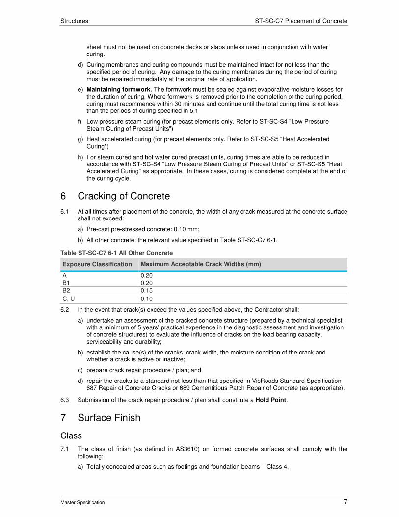
Structures ST-SC-C7 Placement of Concrete
Master Specification 7
sheet must not be used on concrete decks or slabs unless used in conjunction with water curing.
d) Curing membranes and curing compounds must be maintained intact for not less than the specified period of curing. Any damage to the curing membranes during the period of curing must be repaired immediately at the original rate of application.
e) Maintaining formwork. The formwork must be sealed against evaporative moisture losses for the duration of curing. Where formwork is removed prior to the completion of the curing period, curing must recommence within 30 minutes and continue until the total curing time is not less than the periods of curing specified in 5.1
f) Low pressure steam curing (for precast elements only. Refer to ST-SC-S4 "Low Pressure Steam Curing of Precast Units")
g) Heat accelerated curing (for precast elements only. Refer to ST-SC-S5 "Heat Accelerated Curing")
h) For steam cured and hot water cured precast units, curing times are able to be reduced in accordance with ST-SC-S4 "Low Pressure Steam Curing of Precast Units" or ST-SC-S5 "Heat Accelerated Curing" as appropriate. In these cases, curing is considered complete at the end of the curing cycle.
6 Cracking of Concrete
6.1 At all times after placement of the concrete, the width of any crack measured at the concrete surface shall not exceed:
a) Pre-cast pre-stressed concrete: 0.10 mm;
b) All other concrete: the relevant value specified in Table ST-SC-C7 6-1.
Table ST-SC-C7 6-1 All Other Concrete
Exposure Classification Maximum Acceptable Crack Widths (mm)
A 0.20
B1 0.20
B2 0.15
C, U 0.10
6.2 In the event that crack(s) exceed the values specified above, the Contractor shall:
a) undertake an assessment of the cracked concrete structure (prepared by a technical specialist with a minimum of 5 years’ practical experience in the diagnostic assessment and investigation of concrete structures) to evaluate the influence of cracks on the load bearing capacity, serviceability and durability;
b) establish the cause(s) of the cracks, crack width, the moisture condition of the crack and whether a crack is active or inactive;
c) prepare crack repair procedure / plan; and
d) repair the cracks to a standard not less than that specified in VicRoads Standard Specification 687 Repair of Concrete Cracks or 689 Cementitious Patch Repair of Concrete (as appropriate).
6.3 Submission of the crack repair procedure / plan shall constitute a Hold Point.
7 Surface Finish
Class
7.1 The class of finish (as defined in AS3610) on formed concrete surfaces shall comply with the following:
a) Totally concealed areas such as footings and foundation beams – Class 4.

Structures ST-SC-C7 Placement of Concrete
Master Specification 8
b) All other surfaces concealed from view such as back faces of abutment walls, retaining walls and wing walls - Class 3.
c) Visible surfaces such as front faces of abutment walls, retaining walls and wing walls, and both faces of piers and underside of deck slabs - Class 2. Tie rods shall be installed in a regular pattern.
d) Visible surfaces such as kerbs, end walls and deck slab edges - Class 2. No tie rods will be permitted for these surfaces.
Test Panels
7.2 Notwithstanding the requirement of AS 3610 for Class 2 finishes, no test panels are required.
Acceptable Surface Defects and Deviations
7.3 In addition to the requirements of AS 3610, all fins and irregular projections shall be removed, and broken arises and edges repaired. All blowholes of greater depth than 10% of the specified cover shall be filled with an acceptable material.
8 Tolerances
8.1 The deviation between the specified position / dimensions shown on the drawings / documentation and the finished concrete work shall not exceed the lesser of the tolerances specified in this Clause and those specified in AS 3610, Table 3.4.2.
8.2 The soffits of arches, box girders, beams and deck edges shall be continuous curves or straight lines as shown on the drawings, free from all visible irregularities.
8.3 Cast in situ slip-formed concrete kerbs and barriers and cast in situ off-structure concrete barriers shall comply with the tolerance requirements for precast concrete units as stated in Table ST-SC-C7 8-4. In addition, the vertical and horizontal alignment between adjacent segments shall not exceed 5 mm.
8.4 Unless specified otherwise, the tolerances in this Clause are specified in mm.
Table ST-SC-C7 8-1General Tolerances
Item Tolerance (mm)
Placing of reinforcement 5
Placing of post-tensioning sheeting 5
Concrete cover 0 to +5
Table ST-SC-C7 8-2 Cast In Siu Concrete
Item Tolerance (mm)
(i) Footings * Plan Dimensions: - Formed footings and pile caps - Uniformed footings * Thickness - < 300 mm - > 300 mm * Top of footing or pile cap reduced level * Departure from the plan position in any direction
-15 to +15 0 to +150 -5 to +25+ -10 to +50 -25 to +25 50
(ii) Cylinders * Variation from the vertical * Departure from the plan position in any direction
25 mm in 3 m 75
(iii) Variation in cross section of columns, piers, pier and abutment crossheads, slabs, walls, beams and similar parts (excluding deck slab and end posts) * < 3 m * > 3m
-5 to +15 -10 to +25

Structures ST-SC-C7 Placement of Concrete
Master Specification 9
Item Tolerance (mm)
(iv) Variation of cross section of end posts -5 to +5
(v) Deck * Thickness of deck slabs (excluding allowance for correction of camber or hog) * Deck surface reduced level
0 to +10 -10 to +10
(vi) Deck Joints * Width of slot
-3 to +3
(vii) Variation from vertical or specified batter of columns, piers, walls, handrail posts and arises * Unexposed concrete * Exposes concrete
10 mm in 2.5 m (1/250) 5 mm in 2.5 m (1/500)
(viii) Variation from grades indicated on drawings for railings, kerbs and arises
2.5 mm in 2.5 m (1/1000)
(ix) Reduced level of tops of pier and abutment crossheads and piers * with pedestals * without pedestals * difference in level across width of cross head
-10 to +10 -5 to +5 5
(x) Bearing pedestals * reduced level * variation from grade across the width of individual pedestals shall not exceed * deviation from flat surface
-2 to +2 1 in 200 +1 to -1
(xi) Departure from plan position at any level * columns, piers, walls, pier and abutment crossheads, beams, slabs, kerbs, railing and other similar parts * relative displacement of adjoining components shall not exceed
25 10
(xii) Departure from alignment * rows of columns, faces of piers or walls * handrails, faces of hand rail posts, kerbs
10 5
(xiii) Maximum allowance for irregularities in exposed concrete surfaces * sections less than 1 m in dimension when measured with a straightedge across the dimension of the section * sections greater than 1 m in dimension when measured with a straightedge across the dimension of the section, except that when section are greater than 2.5 m in dimension, a 2.5 m straightedge shall be used
2.5 5
(xiv) Irregularities in Railings 2.5 mm in 2.5 m
(xv) Slab surface finish 5 mm in 2.5 m
Table ST-SC-C7 8-3 Pre-Tensioned Concrete
Item Tolerance (mm)
(i) Cross Section * Dimensions: - < 2 m - > 2 m * Out of square - > 2 m
-3 to +3 -6 to +6 0.5 in 250, or desirable 3, maximum 5
(ii) Strand and Reinforcement * Placing of reinforcement * Placing of prestressing strand * Concrete cover
5 2 0 to +5
(iii) Squareness of Ends * Dimension - < 500 mm - > 500 mm
Deviation from a plane perpendicular to the longitudinal axis of a member, or from the specified end plane 3 6mm per metre (10 mm maximum)
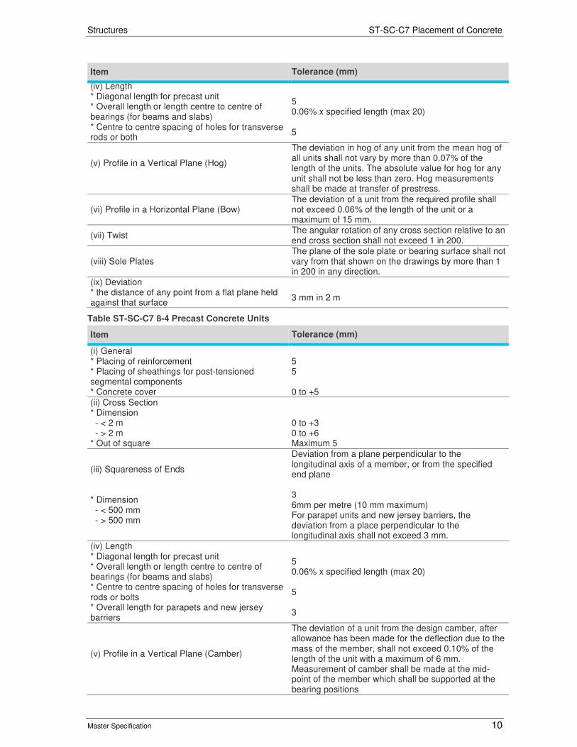
Structures ST-SC-C7 Placement of Concrete
Master Specification 10
Item Tolerance (mm)
(iv) Length * Diagonal length for precast unit * Overall length or length centre to centre of bearings (for beams and slabs) * Centre to centre spacing of holes for transverse rods or both
5 0.06% x specified length (max 20) 5
(v) Profile in a Vertical Plane (Hog)
The deviation in hog of any unit from the mean hog of all units shall not vary by more than 0.07% of the length of the units. The absolute value for hog for any unit shall not be less than zero. Hog measurements shall be made at transfer of prestress.
(vi) Profile in a Horizontal Plane (Bow) The deviation of a unit from the required profile shall not exceed 0.06% of the length of the unit or a maximum of 15 mm.
(vii) Twist The angular rotation of any cross section relative to an end cross section shall not exceed 1 in 200.
(viii) Sole Plates The plane of the sole plate or bearing surface shall not vary from that shown on the drawings by more than 1 in 200 in any direction.
(ix) Deviation * the distance of any point from a flat plane held against that surface
3 mm in 2 m
Table ST-SC-C7 8-4 Precast Concrete Units
Item Tolerance (mm)
(i) General * Placing of reinforcement * Placing of sheathings for post-tensioned segmental components * Concrete cover
5 5 0 to +5
(ii) Cross Section * Dimension - < 2 m - > 2 m * Out of square
0 to +3 0 to +6 Maximum 5
(iii) Squareness of Ends * Dimension - < 500 mm - > 500 mm
Deviation from a plane perpendicular to the longitudinal axis of a member, or from the specified end plane 3 6mm per metre (10 mm maximum) For parapet units and new jersey barriers, the deviation from a place perpendicular to the longitudinal axis shall not exceed 3 mm.
(iv) Length * Diagonal length for precast unit * Overall length or length centre to centre of bearings (for beams and slabs) * Centre to centre spacing of holes for transverse rods or bolts * Overall length for parapets and new jersey barriers
5 0.06% x specified length (max 20) 5 3
(v) Profile in a Vertical Plane (Camber)
The deviation of a unit from the design camber, after allowance has been made for the deflection due to the mass of the member, shall not exceed 0.10% of the length of the unit with a maximum of 6 mm. Measurement of camber shall be made at the mid-point of the member which shall be supported at the bearing positions
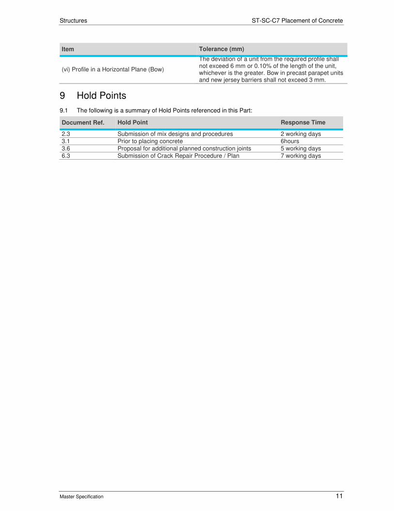
Structures ST-SC-C7 Placement of Concrete
Master Specification 11
Item Tolerance (mm)
(vi) Profile in a Horizontal Plane (Bow)
The deviation of a unit from the required profile shall not exceed 6 mm or 0.10% of the length of the unit, whichever is the greater. Bow in precast parapet units and new jersey barriers shall not exceed 3 mm.
9 Hold Points
9.1 The following is a summary of Hold Points referenced in this Part:
Document Ref. Hold Point Response Time
2.3 Submission of mix designs and procedures 2 working days
3.1 Prior to placing concrete 6hours
3.6 Proposal for additional planned construction joints 5 working days
6.3 Submission of Crack Repair Procedure / Plan 7 working days
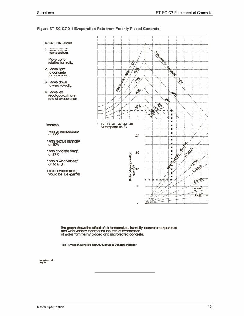
Structures ST-SC-C7 Placement of Concrete
Master Specification 12
Figure ST-SC-C7 9-1 Evaporation Rate from Freshly Placed Concrete

Structures
Master Specification
ST-SC-C6 Formwork Document Information
K Net Number: 13434812 Document Version: 2 Document Date: 19/09/2019

Structures Contents
Master Specification 2
Document Amendment Record
Version Change Description Date Endorsement record (KNet ref.)
1 Initial issue (formerly CC10) 28/06/19 2 Formatting for publishing 19/09/19
Document Management This document is the Property of the Department for Infrastructure and Transport and contains information that is confidential to the Department. It must not be copied or reproduced in any way without the written consent of the Department. This is a controlled document and it will be updated and reissued as approved changes are made.

Structures Contents
Master Specification 3
Contents Contents 2
ST-SC-C6 Formwork 4
1 General 4
2 Quality Requirements 4
3 Construction Requirements 4
4 Hold Points 5

Structures ST-SC-C6 Formwork
Master Specification 4
ST-SC-C6 Formwork
1 General
1.1 This specifies the requirements for the design, erection and stripping of formwork.
1.2 Documents referenced in this Part are listed below:
a) AS 3610 Formwork for Concrete
b) AS 3972 Portland and Blended Cements
1.3 Unless specified otherwise, formwork shall comply with AS 3610 and the definitions in AS 3610 shall apply to this Part (Note that the definition of “formwork” is inclusive of “falsework”).
2 Quality Requirements
General
2.1 The Contractor shall prepare and implement a Quality Plan that includes detailed procedures and documentation for:
a) Formwork - design and materials; and
b) Formwork documentation (refer AS 3610, Section 4).
2.2 If not provided beforehand, the procedures and documentation shall be submitted at least 14 days prior to the commencement of site work. The Contractor shall ensure that the formwork documentation (refer AS 3610, Section 4) is completed and available on site at all times during formwork construction, use and dismantling.
2.3 Provision of the procedures and documentation listed in this Clause shall constitute a Hold Point.
Formwork Design
2.4 This sub-clause applies to any formwork where there would be serious consequences (such as a risk to the safety of any person, a delay to work on the critical path or a compromise to the quality of the Works) in the event of the failure of the formwork to perform as intended.
2.5 The formwork design shall be certified by a design engineer that the design complies with the requirements of this Contract. The design engineer shall be a Chartered Professional Engineer with qualifications admitting to Corporate Membership of the Institution of Engineers and be experienced in the design of structures / formwork.
2.6 Provision of the formwork design shall constitute a Hold Point.
3 Construction Requirements
General
3.1 The Contractor shall ensure that the formwork will achieve the requirements of ST-SC-C7 “Placement of Concrete”, Clause 7 “Surface Finish” and Clause 8 “Tolerances”.
Stripping Times
3.2 Minimum formwork stripping times for vertical faces shall be in accordance with AS 3610, Table 5.4.1. Table 5.4.1 may also be used for stripping times in the case of beam or slab soffits provided that there is compliance with the following conditions:
a) The ratio of span between supports (permanent and / or retained temporary) to the overall depth of the member is less than:
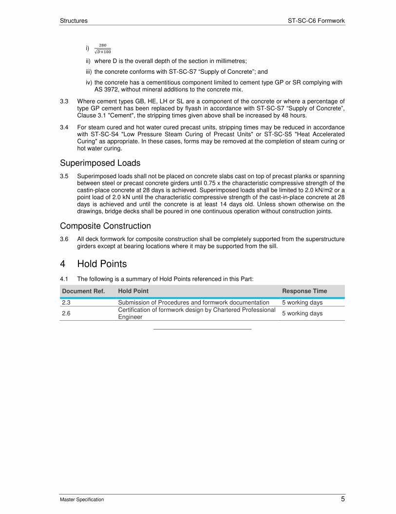
Structures ST-SC-C6 Formwork
Master Specification 5
i) ���
√�����
ii) where D is the overall depth of the section in millimetres;
iii) the concrete conforms with ST-SC-S7 “Supply of Concrete”; and
iv) the concrete has a cementitious component limited to cement type GP or SR complying with AS 3972, without mineral additions to the concrete mix.
3.3 Where cement types GB, HE, LH or SL are a component of the concrete or where a percentage of type GP cement has been replaced by flyash in accordance with ST-SC-S7 “Supply of Concrete”, Clause 3.1 "Cement", the stripping times given above shall be increased by 48 hours.
3.4 For steam cured and hot water cured precast units, stripping times may be reduced in accordance with ST-SC-S4 "Low Pressure Steam Curing of Precast Units" or ST-SC-S5 "Heat Accelerated Curing" as appropriate. In these cases, forms may be removed at the completion of steam curing or hot water curing.
Superimposed Loads
3.5 Superimposed loads shall not be placed on concrete slabs cast on top of precast planks or spanning between steel or precast concrete girders until 0.75 x the characteristic compressive strength of the castin-place concrete at 28 days is achieved. Superimposed loads shall be limited to 2.0 kN/m2 or a point load of 2.0 kN until the characteristic compressive strength of the cast-in-place concrete at 28 days is achieved and until the concrete is at least 14 days old. Unless shown otherwise on the drawings, bridge decks shall be poured in one continuous operation without construction joints.
Composite Construction
3.6 All deck formwork for composite construction shall be completely supported from the superstructure girders except at bearing locations where it may be supported from the sill.
4 Hold Points
4.1 The following is a summary of Hold Points referenced in this Part:
Document Ref. Hold Point Response Time
2.3 Submission of Procedures and formwork documentation 5 working days
2.6 Certification of formwork design by Chartered Professional Engineer
5 working days

Clare & Gilbert Valleys Council Tender Matrix
Tender Selection Criteria
Total Ranking
T08-2021 Main Street Pedestrian Crossing
Criteria Weighting (%) 100P
oin
t S
core
Wei
gh
ting
Wei
gh
ted
Sco
re
Poi
nt
Sco
re
Wei
gh
ting
Wei
gh
ted
Sco
re
Poi
nt
Sco
re
Wei
gh
ting
Wei
gh
ted
Sco
re
Poi
nt
Sco
re
Wei
gh
ting
Wei
gh
ted
Sco
re
Poi
nt
Sco
re
Wei
gh
ting
Wei
gh
ted
Sco
re
Poi
nt
Sco
re
Wei
gh
ting
Wei
gh
ted
Sco
re
Poi
nt
Sco
re
Wei
gh
ting
Wei
gh
ted
Sco
re
Pric
e (
ne
t)
Poi
nt
Sco
re
Wei
gh
ting
Wei
gh
ted
Sco
re
Hig
her
sco
re is
b
ette
r
Low
er
sco
re is
b
ette
r
Tenderer
15 0 5 0 15 0 10 0 15 0 5 0 10 0 #DIV/0! 25 #DIV/0! #DIV/0!15 0 5 0 15 0 10 0 15 0 5 0 10 0 #DIV/0! 25 #DIV/0! #DIV/0!15 0 5 0 15 0 10 0 15 0 5 0 10 0 #DIV/0! 25 #DIV/0! #DIV/0!15 0 5 0 15 0 10 0 15 0 5 0 10 0 #DIV/0! 25 #DIV/0! #DIV/0!15 0 5 0 15 0 10 0 15 0 5 0 10 0 0.0
Mean $0.00
Points where: $T = tender price5 $M = mean price43210
Previous similar works supplier to Clare & Gilbert
Valleys Council
Price
Ability to supply required services, Ability to complete works on time,
Adequate resources.
Management skills, Technical experience, Provision of required tender data, Satisfactory credit
rating, Financial stability, Proven experience in this service.
Principles of Quality Assurance, Customer
satisfaction.
Appropriate solution that meets tender specs.Provides options for
technology improvement.
Commitment, Programmes & Procedures.
Quality of submitted WHS documentation.
Proven experience with similar contract works
Reliability Business Capability Service and Warranty Technology WHS Experience CGVC
15 5 10 10
Abnormally low or high tenders, of more than 30% from the mean may be rejected.Good or better than average
15 15 255
After the allocation of point scores to criteria, they will be multiplied by the relevant nominated weights and summed to determine an overall score.
The following criteria will form the basis for the comparative evaluation of Tenders: Reliability of Tenderer; Busisness Capability of Tenderer; Quality of Service; Technological Applications; Occupational Health & Safety; References; Price.
For the assessment of price, the following point score formula will be used:During the evaluation process, each tender will be evaluated on the criteria nominated in the Tender. Point scores will be allocated in the range 0 to 5 on the following basis:
The Tender Selection System is a weighted point score system which allows both price and non-price attributes to be taken into account in the selcetion of the preferred tender.
Acceptable
P = 2.5 + 5 ($M - $T) / $M
Marginally adequate; or success likely but not assuredwill fail to satisfy required standards
DescriptionExcellentVery Good

© LOCAL GOVERNMENT ASSOCIATION MUTUAL LIABILITY SCHEME
Contract for Replacement of Clare Main
Street Pedestrian Crossing
T08-2021
Clare & Gilbert Valleys Council
and
XXXXXXX

© LOCAL GOVERNMENT ASSOCIATION MUTUAL LIABILITY SCHEME
CONTENTS
1. Interpretation ................................................................................................. 1
2. Status of Contractor ........................................................................................ 2
3. General Obligations ......................................................................................... 2
4. Starting and Completing .................................................................................. 3
5. Defects Liability .............................................................................................. 5
6. Variations and Extra Works ............................................................................. 6
7. Performance and Payment .............................................................................. 6
8. Assignment and Sub-Contracting .................................................................... 7
9. Statutory Obligations ...................................................................................... 7
10. Indemnities and Insurances ............................................................................ 9
11. Settlement of Disputes .................................................................................. 10
12. Default or Bankruptcy of Contractor ............................................................. 10
13. Default of Principal ....................................................................................... 11
14. Notices.......................................................................................................... 11
Page 1 of 16
© LOCAL GOVERNMENT ASSOCIATION MUTUAL LIABILITY SCHEME
1459323_1::160196::MKB::AJS
G E N E R A L C O N D I T I O N S O F C O N T R A C T
1. Interpretation
In the Contract, except where the context otherwise requires:
"Contract" means the agreement between the Principal and the Contractor and includes the tender documents, these General Conditions of Contract, the Specification, and any other items in the Contract schedule.
“Contract sum” means:
where the Principal accepted a lump sum, the lump sum; or
where the Principal accepted a schedule of rates, the sum determined by calculating the product of the rates and quantities listed in either the bill of quantities or the schedule of rates.
where the Principal accepts a lump sum and a schedule of rates then the “contract sum” is the aggregate of the sums calculated above (but does not include any deductions or additions which may be required to be made under the contract).
“Practical Completion” means:
the point when the works are complete except for minor omissions and defects, however, rectification of any minor omissions or defects must not prejudice the use of the works or prevent it from being reasonably used for its intended purpose and as further explained in Clause 4.6. The Superintendent must determine that the Contractor has reasonable grounds for not rectifying any minor omissions or defects immediately;
all tests which are required by the Contract have been carried out and passed; and
all information and documents which are essential for the use, operation and maintenance of the works have been supplied.
"Principal" means the council or subsidiary constituted under the Local Government Act 1999 (as amended) and nominated in the Contract for whom the works are to be provided.
"Site" means the land and other places on under in or through which the works are to be executed and any other lands or place provided by the Principal for the purposes of the Contract.
"Specification" means any technical specification, schedules, plans or drawings forming part of the Contract. Such specification shall be read with these General Conditions as an integral part of the Contract, but in the event of any inconsistency between the specification and these General Conditions the former shall (unless the Contract otherwise provides) prevail.
"Superintendent" means any officer or person authorised by the Principal and notified to the Contractor as an authorised officer for the purpose of the Contract.
"Works" means all work necessary for the completion of the Contract including any variations ordered or agreed by the Superintendent.
Words in the singular shall include the plural and words in the plural shall include the singular according to the requirements of the context, words importing the masculine
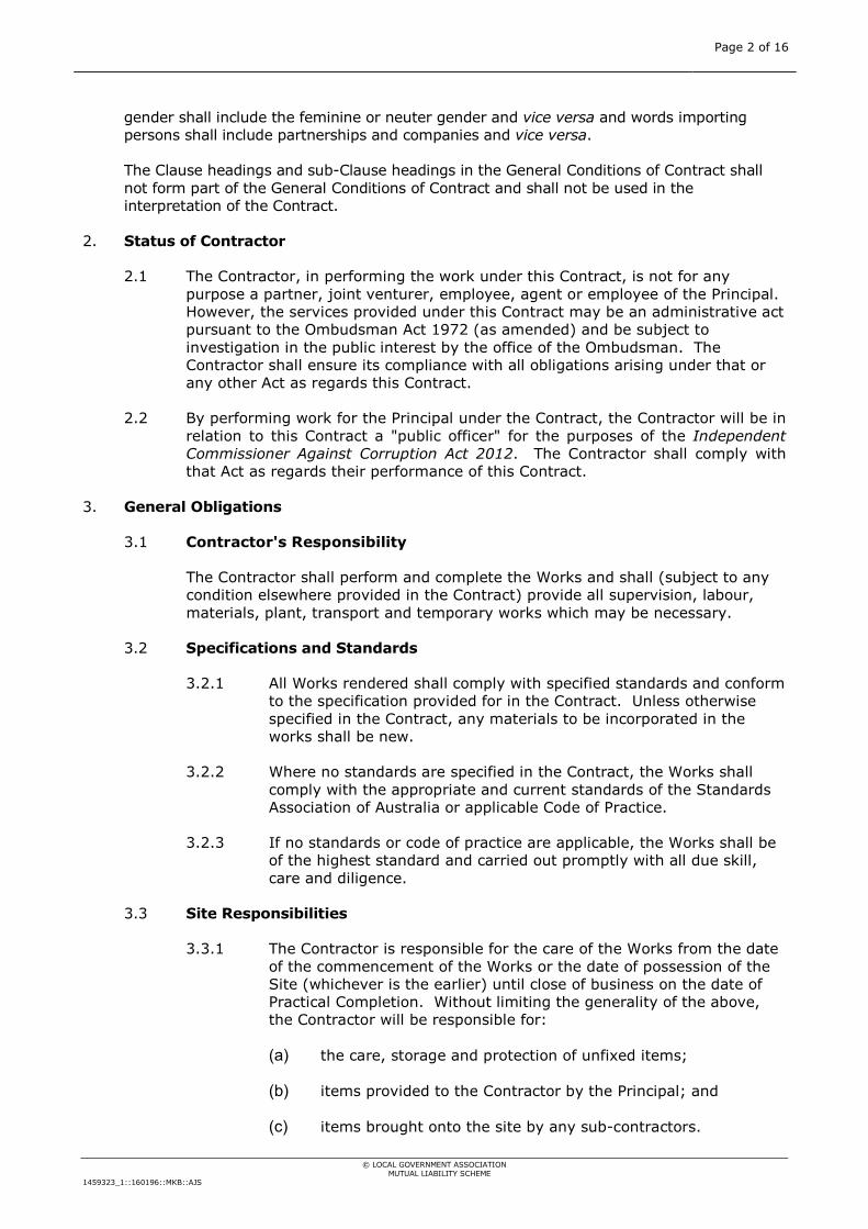
Page 2 of 16
© LOCAL GOVERNMENT ASSOCIATION MUTUAL LIABILITY SCHEME
1459323_1::160196::MKB::AJS
gender shall include the feminine or neuter gender and vice versa and words importing persons shall include partnerships and companies and vice versa.
The Clause headings and sub-Clause headings in the General Conditions of Contract shall not form part of the General Conditions of Contract and shall not be used in the interpretation of the Contract.
2. Status of Contractor
2.1 The Contractor, in performing the work under this Contract, is not for any purpose a partner, joint venturer, employee, agent or employee of the Principal. However, the services provided under this Contract may be an administrative act pursuant to the Ombudsman Act 1972 (as amended) and be subject to investigation in the public interest by the office of the Ombudsman. The Contractor shall ensure its compliance with all obligations arising under that or any other Act as regards this Contract.
2.2 By performing work for the Principal under the Contract, the Contractor will be in relation to this Contract a "public officer" for the purposes of the Independent Commissioner Against Corruption Act 2012. The Contractor shall comply with that Act as regards their performance of this Contract.
3. General Obligations
3.1 Contractor's Responsibility
The Contractor shall perform and complete the Works and shall (subject to any condition elsewhere provided in the Contract) provide all supervision, labour, materials, plant, transport and temporary works which may be necessary.
3.2 Specifications and Standards
3.2.1 All Works rendered shall comply with specified standards and conform to the specification provided for in the Contract. Unless otherwise specified in the Contract, any materials to be incorporated in the works shall be new.
3.2.2 Where no standards are specified in the Contract, the Works shall comply with the appropriate and current standards of the Standards Association of Australia or applicable Code of Practice.
3.2.3 If no standards or code of practice are applicable, the Works shall be of the highest standard and carried out promptly with all due skill, care and diligence.
3.3 Site Responsibilities
3.3.1 The Contractor is responsible for the care of the Works from the date of the commencement of the Works or the date of possession of the Site (whichever is the earlier) until close of business on the date of Practical Completion. Without limiting the generality of the above, the Contractor will be responsible for:
(a) the care, storage and protection of unfixed items;
(b) items provided to the Contractor by the Principal; and
(c) items brought onto the site by any sub-contractors.
Page 3 of 16
© LOCAL GOVERNMENT ASSOCIATION MUTUAL LIABILITY SCHEME
1459323_1::160196::MKB::AJS
3.3.2 The Contractors shall provide, erect and maintain all barricades, guards, fencing, signs, lighting, temporary roadways and footpaths, necessary for the protection of the Works, other property and for the safety and convenience of the public in accordance with accepted Standards or Codes of Practice and shall remove them when no longer required.
3.3.3 The Contractor shall keep the Site clean and tidy and regularly remove rubbish and surplus material. On completion of the Works, the Contractor shall clear away and remove from the Site all construction and surplus materials, rubbish and temporary works.
3.4 Urgent Protection
If urgent action is necessary to protect property, members of the public or any of the Works under the Contract and the Contractor fails to take the necessary action then the Principal may take such action as it sees fit. Where such action should have been taken at the Contractor’s expense then any costs incurred by the Principal will be a debt due to the Principal by the Contractor.
4. Starting and Completing
4.1 Possession of Site
The Principal shall on or before the expiration of the time stated in the Annexure give to the Contractor possession and control of the Site or sufficient of the Site to enable the Contractor to commence work and thereafter in accordance with the requirements of the Contract.
4.2 Starting the works
4.2.1 The Contractor shall commence work under the Contract within the time stated in the Annexure and shall, unless otherwise specified, give at least two (2) working days' notice to the Superintendent prior to the commencement of work.
4.2.2 Notwithstanding the provisions of Clauses 4.1 and 4.2.1, the Principal may refuse to give the Contractor possession of the Site or any part of the Site if the Contractor is in breach of Clauses 9.3 or 10.3.
4.3 Completion of the Works
4.3.1 The Contractor shall complete the Works to the satisfaction of the Superintendent within the time stated in the Annexure or within such extended time as agreed to in writing by the Superintendent.
4.3.2 The completion date may be extended by the Principal for any of the following reasons but will not be limited by the following:
(a) a variation to the Works ordered by the Superintendent;
(b) extra work ordered by the Superintendent;
(c) change to the Works program ordered by the Superintendent;
(d) encountering an obstruction or condition not known at the time of tendering;
Page 4 of 16
© LOCAL GOVERNMENT ASSOCIATION MUTUAL LIABILITY SCHEME
1459323_1::160196::MKB::AJS
(e) delay in receipt by the Contractor of necessary instructions, drawing or other information;
(f) delay in receipt by the Contractor of materials to be provided by the Principal under the Contract;
(g) exceptional adverse weather;
(h) other special circumstances of any kind whatsoever outside the control of the Contractor.
4.4 Program of the Works
4.4.1 The Contractor shall proceed with the Works with due expedition and without delay.
4.4.2 The Contractor shall within 14 days after the starting date, if so requested by the Superintendent, provide a programme of the Contractor's activities. The Contractor shall proceed in accordance with the programme, or any mutually agreed modification in writing, which the Contractor may require or which the Superintendent may request.
4.5 Suspension of the Works
4.5.1 The Superintendent may suspend the whole or any part of the Works if the Superintendent considers it necessary:
(a) as the result of an act or omission of the Principal, the Superintendent or an employee, consultant or agent of the Principal;
(b) as the result of an act or omission of the Contractor, a sub-contractor or an employee or agent of either;
(c) for the protection or safety of any person or property.
4.5.2 If the Contractor requires a suspension to the whole or part of the Works, the prior written approval of the Superintendent must be obtained and any such approval agreed by the Superintendent may have conditions of approval imposed. Where a suspension of the Works is caused by the Contractor, sub-contractor or their employees or agents the Contractor will bear all costs incurred.
4.5.3 Where the suspension of the Works is due to an act or omission of the Principal, Superintendent, or an employee, agent or consultant of the Principal, any variation in the costs will be determined in accordance with Clause 6.2.
4.6 Practical Completion
4.6.1 Practical Completion of the whole of the Works shall occur when the Works reach a state when, notwithstanding any defects or outstanding items therein, they are taken or are fit to be taken into use or possession by the Principal.
4.6.2 Practical Completion of part of the Works may occur if provided for elsewhere in this Contract but only if it is fit for such part to be taken into use or possession independently of the remainder.
Page 5 of 16
© LOCAL GOVERNMENT ASSOCIATION MUTUAL LIABILITY SCHEME
1459323_1::160196::MKB::AJS
4.6.3 Upon Practical Completion of the Works or part of the Works to the satisfaction of the Superintendent, a certificate of Practical Completion shall be issued by the Superintendent.
4.7 Quality Assurance
Where it is a requirement of the Contract, the Contractor will:
4.7.1 plan, establish and maintain a quality system which conforms to the requirements specified;
4.7.2 provide the Superintendent with access to the quality system of the Contractor and each of the sub-contractors to enable monitoring and quality auditing.
4.8 Examination and Testing of Materials
4.8.1 The Superintendent may at any time, and from time to time, direct that any materials or work to be used in or forming part of the Works be examined and tested.
4.8.2 The Superintendent may at any time and from time to time before the issue of the Final Certificate pursuant to Clause 5.3, direct the Contractor to open up or pull down for examination or testing any part of the Works.
If the part of the Works referred to above has been covered up or put out of view in contravention of a direction given by the Superintendent is found not to be in accordance with the Contract, then the whole of the cost of opening up, pulling down, reconstruction and making good shall be paid by the Contractor. If the part of the Works is found to be in accordance with the Contract, the whole cost of opening up, pulling down, reconstruction and making good shall be paid by the Principal.
4.8.3 If under a test any part of the works fails to fulfil the requirements of the Contract, tests on the remedial work of that part and tests on all other parts of the Works affected by the remedial work shall be repeated in accordance with the requirements of the Contact. The cost of such repeat tests shall be paid by the Contractor.
5. Defects Liability
5.1 Period of Defects Liability
From the date of Practical Completion of the Works, the Contractor shall maintain the Works for the defects liability period stated in the Annexure and shall make good, at the Contractor’s own expense, any omission or defect in the work or materials and all loss or damage to the Works occasioned by such omission or defect.
5.2 Principal May Correct
If any such defects are not corrected within a reasonable time by the Contractor, the Principal may, after giving 14 days' written notice to the Contractor, employ others to correct the same and the cost thereof shall be payable by the Contractor to the Principal.

Page 6 of 16
© LOCAL GOVERNMENT ASSOCIATION MUTUAL LIABILITY SCHEME
1459323_1::160196::MKB::AJS
5.3 Issue of Final Certificate
At the end of the defects liability period and when the Works and any remedial work have been finally and satisfactorily executed and the Contractor has fulfilled all his other obligations under the Contract, the Superintendent shall issue to the Contractor a Final Certificate.
6. Variations and Extra Works
6.1 Variations and Extra Works Ordered
6.1.1 The Superintendent may order the Contractor to do all or any one of the following things:
(a) increase, decrease or omit any part of the Works;
(b) change the character or quality of any material or work;
(c) change the levels, lines, positions or dimension of any part of the Works;
(d) execute additional work.
6.1.2 No variation shall be made to the Works by the Contractor except as directed by the Superintendent or approved in writing by the Superintendent.
6.1.3 Each agreed variation shall be valued before the work to which the variation relates is commenced. The value of the variation shall be taken into account in determining the final Contract sum.
6.2 Valuation of Variations
6.2.1 A variation shall be valued in accordance with the rates or prices in the Contract and in so far as the Superintendent determines that those rates are applicable to the variation.
6.2.2 Where the Superintendent determines that the rates or prices in the Contract do not apply to a variation, the rate or price payable for the variation shall be determined by an agreement between the Contractor and the Superintendent, but if the Contractor and the Superintendent fail to agree on the rate or price, the matter shall be determined by an arbiter in accordance with Clause 10.
6.2.3 Notwithstanding the existence of a dispute, the Contractor shall continue to fulfil all obligations under the Contract.
7. Performance and Payment
7.1 Value of the Contract
The value of the Works shall be the Contract sum adjusted by any additions or deductions made as provided for in the Contract.
7.2 Progress Payment
Unless otherwise provided and subject to these conditions, claims for payment shall be made at calendar monthly intervals. The Contractor shall be entitled to

Page 7 of 16
© LOCAL GOVERNMENT ASSOCIATION MUTUAL LIABILITY SCHEME
1459323_1::160196::MKB::AJS
such payment within thirty (30) days of receipt from the Contractor of a claim for work completed to the satisfaction of the Superintendent, except for such sum as may be retained pursuant to Clause 7.3.
7.3 Final Payment
Within thirty (30) days after the Final Certificate has been issued, the Principal shall pay to the Contractor all amounts then payable including any retention monies held by the Principal.
8. Assignment and Sub-Contracting
8.1 Assignment and Sub-Contracting
The Contractor shall not assign nor sub-contract the Works or any part thereof without the approval of the Superintendent in writing. Such approval shall not be unreasonably withheld.
8.2 Request to Sub-Contract
The Contractor shall provide to the Superintendent in writing a request for approval to sub-contract, particulars of the work to be sub-contracted and the name and the address of the proposed sub-contractor.
8.3 Approval to Sub-Contract
8.3.1 Approval may be conditional on the sub-contract including:
(a) provision that the sub-contractor shall not assign or sub-contract without the consent in writing of the Contractor.
(b) provisions which may be reasonably necessary to enable the Contractor to fulfil the Contractor's obligations to the Principal.
8.3.2 Approval to sub-contract shall not relieve the Contractor from any liability or obligation under the Contract. Except where the Contract otherwise provides, the Contractor shall be liable to the Principal for the acts and omissions of sub-contractors and employees and agents of sub-contractors as if they were acts or omissions of the Contractor.
9. Statutory Obligations
9.1 General
The Contractor must comply with and give all notices required by any Act of Parliament, ordinances, regulations or by-laws relating to the Works.
9.2 Variances
If, in the opinion of the Contractor, the provisions of any document forming part of the Contract are at variance with anything covered by this Clause 9, then the Contractor shall give written notice to the Principal specifying the departure from any such provisions which he considers necessary to comply with the legislation, notices, ordinances, by laws and the like.

Page 8 of 16
© LOCAL GOVERNMENT ASSOCIATION MUTUAL LIABILITY SCHEME
1459323_1::160196::MKB::AJS
9.3 Workplace Safety
9.3.1 Without limiting in any way the generality of the foregoing, the Contractor must comply with the provisions of the Work health and Safety Act 2012 and all associated regulations (as amended from time to time) and will ensure that its own contractors and employees will comply with the Act and all regulations, improvement notices, prohibition notices and codes of practice issued thereunder and having application to this contract.
9.3.2 The Contractor acknowledges that the Principal has non-delegable duties imposed upon it by the Work health and Safety Act 2012 and as such the Principal has the right:
(a) to ensure that the Contractor complies with the Act;
(b) to inspect safety measures and documentation; and
(c) to interrupt or suspend the Works if safety standards are violated.
9.3.3 The Principal must provide its Workplace Management Policy and may provide other documents to the Contractor and the Contractor must acknowledge that it has been provided with and has read and understands such policies and documents of the Principal. The Contractor also undertakes to ensure that such policies and documents (as amended from time to time) will be brought to the attention of the Contractor’s employees or any sub-contractors.
9.3.4 The Contractor agrees to immediately notify the Principal of any incident or accident occurring on or in relation to the Site or arising from the undertaking of the Contract including those involving the public.
9.4 WorkCover
9.4.1 The Contractor must ensure that it is registered as an employer under the Return to Work Act 2014 ("the Act") and that it must pay all monthly levies due thereunder in respect of its employees engaged in and about the Works.
9.4.2 The Contractor must produce to the Superintendent on the execution of this Contract a current certificate of registration as an employer under the Act.
9.4.3 The Contractor must ensure that all sub-contractors engaged by it have current certificates of registration as employers under the Act and must produce the same to the Superintendent upon request in writing by the Superintendent.
9.4.4 The Contractor must indemnify the Principal in respect of any action, claim, demand, suit or proceedings made by any employee brought in connection with the Act.
9.4.5 Insurance effected by the Contractor pursuant to this Clause is limited only by the amount stated in any statute and is in all other respects unlimited.

Page 9 of 16
© LOCAL GOVERNMENT ASSOCIATION MUTUAL LIABILITY SCHEME
1459323_1::160196::MKB::AJS
10. Indemnities and Insurances
10.1 Indemnity
10.1.1 The Contractor agrees to indemnify and to keep indemnified the Principal, its employees and agents and each of them from and against all actions, costs, claims, charges and expenses whatsoever which may be brought or made or claimed against them or any of them arising out of any negligent act or omission of the Contractor or its employees and agents in relation to the granting of this Contract.
10.1.2 Notwithstanding the above, the Contractor shall not be rendered liable for personal injury to or the death of any person or loss of or damage to any property resulting from any breach by the Principal of any provision of this Contract or any negligent act or omission of the Principal or its employees and agents.
10.2 Employee Indemnity
The Contractor shall indemnify and keep indemnified the Principal against liability for all loss or damage resulting from personal injury to or the death of the Contractor or any sub-contractor or any employee or agent of the Contractor or of any sub-contractor (other than such injury or death resulting from any breach by the Principal of any of the provisions of the Contract or any negligent act or omission of the Principal, the Superintendent, or the employees, professional consultants or agents of the Principal) occurring during the currency of the Contract and arising out of or in connection with the execution of the Works under the Contract or the performance of the Contract and against all claims, demands, actions, suits or proceedings, costs and expenses whatsoever in respect thereof or in relation thereto, whether at common law or under any applicable statute.
10.3 Public Liability Insurance
10.3.1 The Contractor shall take out and keep current a Public Liability Policy of insurance in the name of the Contractor which covers the Principal, the Contractor, the Superintendent and all sub-contractors employed from time to time in relation to the works under the Contract to cover their liabilities to third parties including any liability under Clause 10.1. The policy shall be for an amount not less than the sum stated in the Annexure.
10.3.2 The Contractor shall not commence the works until confirmation of the Public Liability Policy of insurance is given to the Principal.
10.4 Contract Works Insurance
The Contractor shall, whenever required to do so, take out contracts works insurance for an amount not less than the amount stated in the Annexure. The policy shall be maintained for the currency of the Contract.
10.5 Contractor Fails to Insure
If on demand, the Contractor fails to produce evidence of compliance with Clauses 10.3 and 10.4, the Superintendent, on behalf of the Principal, may effect such insurance and recover the costs thereof from money otherwise payable by the Principal to the Contractor.

Page 10 of 16
© LOCAL GOVERNMENT ASSOCIATION MUTUAL LIABILITY SCHEME
1459323_1::160196::MKB::AJS
10.6 Notices of Claim
The Contractor shall give immediate notice in writing to the Principal following any occurrence which may result in a claim against any of the insurances required in Clauses 10.3 and 10.4 above.
11. Settlement of Disputes
11.1 Disputes and Procedures
All disputes or differences between the Principal, or the Superintendent on behalf of the Principal, and the Contractor arising out of the Contract or concerning the performance or non-performance by either party of its obligations under the Contract whether raised during the execution of the Works or after the completion of the Works shall be referred to an arbitrator who shall be either:
11.1.1 mutually agreed upon by the parties in writing; or
11.1.2 in the absence of that agreement, one of at least three persons, none of whom shall be an employee of the Principal or the Contractor or have had any association with the work under the Contract, whose names are submitted in writing by the Principal for selection by the Contractor; or
11.1.3 in the absence of that selection, by an arbitrator nominated by the State Chapter of the Institute of Arbitrators & Mediators Australia and appointed in accordance with the provisions of the laws of South Australia.
11.2 Arbitration
The party requesting arbitration shall give notice in writing to the other party within twenty-eight (28) days of the dispute or difference arising and shall be responsible for the initial costs associated with arbitration.
12. Default or Bankruptcy of Contractor
12.1 General
If the Contractor fails to commence the Works within the time stated in the Annexure or fails to carry on the Works at a reasonable rate or commits any breach of the Contract or intimates that the Contractor is unable or unwilling to complete the Works or becomes insolvent or bankrupt, or being a company has an administrator, receiver or receiver and manager appointed to it or goes into liquidation, the Principal may suspend payment under the Contract and may call upon the Contractor, by notice in writing specifying the default, to show cause within fourteen (14) days, why the powers hereinafter contained should not be exercised. Such notice shall not be unreasonably given.
12.2 Determination of the Contract
If the Contractor fails within the fourteen (14) day period to show cause to the satisfaction of the Principal, then the Principal without prejudice to any other rights and remedies that it may possess may, by notice in writing to the Contractor, determine the Contract.

Page 11 of 16
© LOCAL GOVERNMENT ASSOCIATION MUTUAL LIABILITY SCHEME
1459323_1::160196::MKB::AJS
12.3 Principal May Complete Works
12.3.1 In the event of determination all monies that would otherwise be payable or refundable to the Contractor may be used by the Principal for the purpose of completing the Works.
12.3.2 If the Principal takes work out of the hands of the Contractor under Clause 12.2, the Principal shall complete that work and the Principal may without payment of compensation take possession of such of the plant, equipment, material and other things on or in the vicinity of the Site as are owned by the Contractor and are reasonably required by the Principal to facilitate completion of the work.
12.3.3 If the Principal takes possession of the plant, equipment, material or other things, the Principal shall maintain them and on completion of the work, the Principal shall return to the Contractor such plant, equipment, material or other things taken under this clause which are surplus.
13. Default of Principal
13.1 General
Without prejudice to any of the rights and remedies which the Contractor may possess if the Principal fails to make any payment due under the provisions of Clause 6 or if the Principal or his servants or agents seriously interfere with or obstruct the carrying out of the Works, then the Contractor may give written notice to the Principal specifying the default and calling on the Principal to show cause, within fourteen (14) days, why the powers hereinafter contained should not be exercised. Such notice shall not be unreasonably given.
13.2 Contractor May Take Action
If the Principal fails, within the fourteen (14) day period, to show cause to the reasonable satisfaction of the Contractor then the Contractor may by notice in writing to the Principal:
13.2.1 suspend the execution of the Works, or
13.2.2 determine the Contract.
Such notice shall not be unreasonably given.
14. Notices
Any notice to be given to the Contractor under the terms of the Contract may be served by sending by post, leaving the notice at the address given in the tender or by facsimile. When posted in a pre-paid letter, such notice shall be deemed to have been duly received at the time at which the notice would have reached that address in the ordinary course of post.

Page 12 of 16
© LOCAL GOVERNMENT ASSOCIATION MUTUAL LIABILITY SCHEME
1459323_1::160196::MKB::AJS
SIGNED for and on behalf of the Clare & Gilbert Valleys Council
…………………………………………….
Name …………………………………………….. Signature ……………………………………………… Title
…………………………………………………. Date
SIGNED for and on behalf of XXXXX
……………………………………………….. Name ………………………………………………… Signature …………………………………………………. Title …………………………………………………. Date

Page 13 of 16
© LOCAL GOVERNMENT ASSOCIATION MUTUAL LIABILITY SCHEME
1459323_1::160196::MKB::AJS
ANNEXURE TO THE GENERAL CONDITIONS OF CONTRACT
For the purpose of this Contract, the following items, in conjunction with the Conditions of Tendering, the General Conditions of Contract, any Special Conditions of Contract and the Specifications are to apply:
1. The Contract shall be governed by and construed with reference to the laws for the time being in force in the state of:
South Australia
2. All payments made under the Contract shall be made at:
4 Gleeson Street CLARE SA 5453
3. The Contract shall be: (Schedule of rates/lump sum)
Final Payment of 10% to be retained subject to Practical Completion sign off by Principal
Schedule
4. The Principal is: (Name of Principal)
Clare & Gilbert Valleys Council
5. The address of the Principal is: 4 Gleeson Street CLARE SA 5453
6. The Superintendent is: (Name of person nominated)
Ken Dolan
7. The address of the Superintendent is: 4 Gleeson Street CLARE SA 5453
8. The amount of Public Liability Insurance shall be not less than (Clause 10.3):
$20,000,000.00
9. The amount of Contract Works Insurance shall not be less than (Clause 10.4):
The amount of the contract
10. The time for giving possession of the site is (Clause 4.1):
11. Work to commence within (Clause 4.2):
12. Work to be completed within (Clause 4.3):
13. The Defects Liability Period for the works shall be (Clause 5):
12 months
14. Contract Term: For a period as agreed in Works Program

Page 14 of 16
© LOCAL GOVERNMENT ASSOCIATION MUTUAL LIABILITY SCHEME
1459323_1::160196::MKB::AJS
15.Tender Specifications: See attached, including scope and general conditions

Page 15 of 16
© LOCAL GOVERNMENT ASSOCIATION MUTUAL LIABILITY SCHEME
1459323_1::160196::MKB::AJS
16.XXXXX Tender Submission:

Page 16 of 16
© LOCAL GOVERNMENT ASSOCIATION MUTUAL LIABILITY SCHEME
1459323_1::160196::MKB::AJS
17.Additional clarification correspondence: See attached
Related Documents