BSES RAJDHANI POWER LIMITED NIT NO CMC/BR/21-22/RB/KG/930 Page 1 of 85 Bidders seal & signature Tender Notification for Survey, Design, Supply, Installation, Testing and Commissioning including Civil Works of 66/11 kV GIS Grid substation with 2 PTRs on Single point responsibility basis at Manglapuri, New Delhi NIT NO CMC/BR/21-22/RB/KG/930 DT 09.07.2021 Due Date for Submission: 30.07.2021 1530HRS BSES RAJDHANI POWER LTD (BRPL) Corporate Identification Number: U74899DL2001PLC111527 Telephone Number: +91 11 3009 9999 Fax Number: +91 11 2641 9833 Website: www.bsesdelhi.com

Welcome message from author
This document is posted to help you gain knowledge. Please leave a comment to let me know what you think about it! Share it to your friends and learn new things together.
Transcript
BSES RAJDHANI POWER LIMITED
NIT NO CMC/BR/21-22/RB/KG/930 Page 1 of 85 Bidders seal & signature
Tender Notification for
Survey, Design, Supply, Installation, Testing and Commissioning including Civil Works of 66/11 kV GIS Grid substation with 2 PTRs on Single point responsibility basis
at Manglapuri, New Delhi
NIT NO CMC/BR/21-22/RB/KG/930 DT 09.07.2021
Due Date for Submission: 30.07.2021 1530HRS
BSES RAJDHANI POWER LTD (BRPL)
Corporate Identification Number: U74899DL2001PLC111527 Telephone Number: +91 11 3009 9999
Fax Number: +91 11 2641 9833 Website: www.bsesdelhi.com
BSES RAJDHANI POWER LIMITED
NIT NO CMC/BR/21-22/RB/KG/930 Page 2 of 85 Bidders seal & signature
Table of Contents
Section No. Description
Section-I Request for Quotation
Section-II Instruction to Bidders
Section-III Special Terms & Condition of Contracts
Section-IV General Terms and Condition –Supply
Section-V Price format- Supply
Section-VI General Terms and Condition –Erection, Testing & Commissioning
Section-VII Price format- Erection, Testing & Commissioning
Section-VIII General Terms and Condition –Civil
Section-IX Price format- Civil
Section-X Grand Summary of the Quoted Price
Section-XI Vendor Code of Conduct
Annexure-I Technical Specifications
BSES RAJDHANI POWER LIMITED
NIT NO CMC/BR/21-22/RB/KG/930 Page 3 of 85 Bidders seal & signature
SECTION – I: REQUEST FOR QUOTATION 1.00 Event Information
BRPL invites sealed tenders in 2 envelopes for following scope of work
Sl. No. Description Estimated Cost (Rs.) Qty.
Delivery & Installation
at
1
Survey, Design, Supply, Installation, Testing and Commissioning including Civil Works of 66/11 kV GIS Grid substation with 2 PTRs on Single point responsibility basis at Manglapuri, New Delhi
26 Crores As per BOQ
Attached Delhi, Sites
The bidder must qualify the requirements as specified in clause 2.0 stated below. All envelopes shall be duly super scribed “Survey Survey, Design, Supply, Installation, Testing and Commissioning including Civil Works of 66/11 kV GIS Grid substation with 2 PTRs on Single point responsibility basis at Manglapuri, New Delhi NIT NO CMC/BR/21-22/RB/KG/930”
1.01 The schedule of specifications with detail terms & conditions can be obtained from address given below against submission of non-refundable demand draft of Rs.1180/- drawn in favour of BSES Rajdhani Power Ltd, payable at Delhi. The tender documents & detail terms and conditions can also be downloaded from the website “www.bsesdelhi.com --> Tenders --> BSES Rajdhani Power Ltd --> Open Tenders”. In case tender papers are downloaded from the above website, then the bidder has to enclose a demand draft covering the cost of bid documents.
1.02 Bids will be received up to 30/07/2021 1530 HRS at the address given at 3.01 below. Part A of the Bid shall be opened on 30/07/2021 1600 HRS. Part B of the Bid will be opened in case of Techno-Commercially qualified Bidders and the date of opening of same shall be intimated in due course. It is the sole responsibility of the bidder to ensure that the bid documents reach this office on or before the last date.
1.03 BSES Rajdhani Power Ltd reserves the right to accept/reject any or all Tenders without assigning any reason thereof in the event of following (i) Earnest Money Deposit (EMD) of value Rs 26,00,000/- is not deposited in shape of Demand Draft/Pay
Order/Banker’s Cheque /Bank Guarantee drawn in favour of BSES Rajdhani Power Ltd, payable at Delhi. (ii) The offer does not contain prices indicating break-up towards all taxes & duties in prescribed format (iii) Complete Technical details are not enclosed. (iv) Tender is received after due date and time. (iv) Technical offer contains any prices (v) Prices are not FIRM and subject to Price Variation
2.0 Qualification Criteria:-
Technical
BSES RAJDHANI POWER LIMITED
NIT NO CMC/BR/21-22/RB/KG/930 Page 4 of 85 Bidders seal & signature
The prospective bidder must qualify all of the following requirements to participate in the bidding process and bidder who meets following requirements will be considered as successful bidder and BRPL has a right to disqualify those bidders who do not meet these requirements.
a. The bidder shall be currently in the field of manufacturing of Gas Insulated Switchgear (GIS) of 66 KV or above rating, OEM of GIS can only participate and joint venture/collaboration is not allowed.
b. The bidder shall have servicing, repairing, testing & refurbishment facility in INDIA with necessary spares and testing equipment for providing prompt after sales service for GIS. Details of the set-up available shall be brought out in the offer, failing which the offer will be rejected. The bidder shall submit undertaking along with the bid to confirming compliance to qualifying criteria for bidder.
c. The GIS offered should have been successfully type-tested within past Five (5) years from date of Bid opening as per relevant IEC and copies of the test reports latest for the same shall be submitted along with the offer. In case type test reports are older than five (5) years from the date of bid opening, bidder shall submit the undertaking that there is “since the last type test, the product has not undergone any change in design and the materiel used and the dimensions of the product are the same as the one on which the type test was conducted”. Non submission of type test reports will lead to rejection of the offer. Type test older than ten (10) years shall not be acceptable and bid is liable for rejection.
d. The bidder must have designed, supplied, installed & commissioned at least 2 Nos 66 KV GIS grid substation or higher rating including civil works in last 5 years in India (Turnkey Basis). The list of such installations shall be furnished (List of Installations). Documentary evidence in support of the QR to be provided.
e. Bidder shall procure major equipments from the approved vendor list of BRPL who are meeting applicable qualification criteria for individual items. The vendor must be having valid type test reports carried out within five (5) years.
f. Bidder shall submit the performance certificates for 1 year satisfactory performance from 2 reputed companies for executed jobs.
g. The bidder should have technical & field services organization personnel at various stages of field erection & management services required for successful erection, testing & commissioning.
h. The bidder should have established field quality assurance system & safety organization designed to achieve high level of reliability at various stage of field services required for successful erection, testing, & commissioning.
i. The bidder should have qualified technical & dedicated QA personnel at various stages of manufacturing & testing. Financial:
a. Bidder must have average annual turnover of minimum Rs 50 Crores during last Three (3) years.
b. The bidder must have adequate financial stability and status to meet financial obligation pursuant to scope of work.
c. The bidder shall submit a “NO LITIGATION” statement as per attached format.
d. The Bidder should possess valid Electrical contractor license issued by competent statutory agency to undertake work in Delhi/NCR.
BSES RAJDHANI POWER LIMITED
NIT NO CMC/BR/21-22/RB/KG/930 Page 5 of 85 Bidders seal & signature
e. The bidder must possess valid ISO 9001:2000 certification
f. An undertaking (self-certificate) that the bidder has not been blacklisted/debarred by any central/state
government institution including electricity boards.
g. The bidder must have valid PAN No., GST No., in addition to other statuary compliances. The bidder must submit the copy of registrations and submit an undertaking that the bidder shall comply with all the statutory compliances as per the applicable laws/rules etc. before the start of the work. Note: All reference dates shall be taken as the date of technical bid opening For either of the PQR conditions listed below as 1, 2 & 3 , incase bidder is 100% owned subsidiary of their parent organization, credential of the parent organization shall be considered as a compliance to the QR requirements as listed , subjected to the fulfillment of the conditions as specified as (a) and (b): Incase bidder is 100% owned subsidiary of their parent organization then the credentials of the parent organization shall be considered as compliance to the QR requirement as listed below. The QR parameters against which the bidder can submit the credential of their parent company are as below:
1. Bidder shall submit the performance certificates for One (1) year satisfactory performance from two (2) reputed electricity board/transmission and distribution utilities for executed jobs.
2. The bidder must have designed, supplied, installed & commissioned at least two (2) Nos of GIS grid substation of similar rating or higher rating including civil works in last Five (5) years in India (Turnkey Basis). The list of such installations shall be furnished (list of installation).
3. Bidder must have average annual turnover of minimum Rs 50 crores during last Three (3) years . For either of the above PQR conditions listed as 1, 2 & 3 , incase bidder is 100% owned subsidiary of their parent organization, credential of the parent organization shall be considered as a compliance to the QR requirement , subjected to the fulfillment of the following conditions : a) The submission of Additional 5% contract performance bank Guarantee (CPBG) from the parent company (whose credential has been submitted against the QR requirement) This bank Guarantee shall be over and above the 10% CPBG as per NIT conditions.
• Parent organization shall submit the additional BG from Indian Bank only. • Additional BG shall be given by Parent company on behalf of the 100% Indian subsidiary company to M/s. BRPL
against the said tender NIT No-CMC/BR/21-22/RB/KG/930 , against which Parent company credential have been submitted to BRPL for the purpose of vendor qualification of 100% Indian subsidiary Company.
• In case of any default in the performance of the contract in terms of supplies/timely execution/ performance of the equipment /contract, BRPL shall raise the invocation notice to Indian subsidiary company only for both BGs i.e one submitted by the bidder (Indian Subsidiary) and the other submitted by the parent company and parent company shall have “NO Objection " in this regard. b) Extended warranty of two (2) years from the bidding Company for the installed GIS grid. ALL OTHER TERMS AND CONDITIONS OF THE NIT, INCLUDING BALANCE QUALIFYING CONDITIONS, SHALL REMAIN THE SAME. Notwithstanding anything stated above, BRPL reserves the right to assess bidder’s capability to perform the contract, assess the capability and installed capacity of the Bidder for carrying out the supplies, should the circumstances warrant such assessment in the overall interest of the purchaser. BRPL also reserves the right to evaluate the bidder based on performance of past supplies/projects executed in BRPL. In this regard the decision of the purchaser is final.
BSES RAJDHANI POWER LIMITED
NIT NO CMC/BR/21-22/RB/KG/930 Page 6 of 85 Bidders seal & signature
3.00 Bidding and Award Process
Bidders are requested to submit their offer strictly in line with this tender document. NO DEVIATION IS ACCEPTABLE. BRPL shall response to the clarifications raised by various bidders and the will be distributed to all participating bidders through website.
3.01 BID SUBMISSION
The bidders are required to submit the bids in 2(two) parts to the following address Head of Department Contracts & Material Department BSES Rajdhani Power Ltd 1st Floor, C Block BSES Bhawan, Nehru Place New Delhi 110019 PART A: TECHNICAL BID comprising of following (1 original + 1 copy)
EMD in prescribed format Non-refundable demand draft for Rs 1180/- in case the forms are downloaded
from website Documentary evidence in support of qualifying criteria Technical Details / Filled in GTP/Type test report etc Qualified Manpower available & Organization Chart Testing Facilities Copies of Orders, Execution /Performance Certificate & Other Documents to
support the QC as per clause 2.0 Original Tender documents duly stamped & signed on each page as token of
acceptance Acceptance to Commercial Terms and Conditions viz Delivery schedule/period,
Payment terms, PBG etc
PART B: FINANCIAL BID comprising of (1 original only)
Price strictly in the Format enclosed indicating Break up of basic price, taxes & duties, transportation etc
3.02 TIME SCHEDULE
The bidders should complete the following within the dates specified as under:
S. No. Steps
Date 1 Date of sale of bid documents 13.07.2021 2 Pre-Bid meeting 21.07.2021 1430 HRS 3 Pre-Bid meeting ink https://bsesbrpl.webex.com/webappng/site
s/bsesbrpl/dashboard?siteurl=bsesbrpl
BSES RAJDHANI POWER LIMITED
NIT NO CMC/BR/21-22/RB/KG/930 Page 7 of 85 Bidders seal & signature
S. No. Steps
Date 4 Last date of Queries, if any 23.07.2021 5 Last date of receipt of bid documents 30.07.2021 1530HRS 6 Date & time of opening of tender – Part A 30.07.2021 1600HRS
This is a two part bid process. Bidders are to submit the bids in 2(two) parts Both these parts should be furnished in separate sealed covers super scribing NIT no. DUE DATE OF SUBMISSION, with particulars as PART-A TECHNICAL BID & COMMERCIAL TERMS & CONDITIONS and Part-B FINANCIAL BID and these sealed envelopes should again be placed in another sealed cover which shall be submitted before the due date & time specified. Part – A: Technical Bid should not contain any cost information whatsoever and shall be submitted within the due date. PART B: This envelope will be opened after techno-commercial evaluation and only of the qualified bidders. REVERSE AUCTION: Purchaser reserves the right to use REVERSE AUCTION through SAP-SRM as an optional tool as an integral part of the entire tendering process. All techno-commercially qualified bidders shall participate in this event Notwithstanding anything stated above, the Purchaser reserves the right to assess bidder’s capability to perform the contract, should the circumstances warrant such assessment in the overall interest of the purchaser. In this regard the decision of the purchaser is final. In case RA is not concluded/conducted for any reasons, a "final no regret" financial bid in a sealed envelope will be called for from all qualified bidders BIDS RECEIVED AFTER DUE DATE AND TIME SHALL BE LIABLE TO REJECTION
4.00 Award Decision
4.01 Purchaser intends to award the business on a lowest bid basis, so suppliers are encouraged to submit the
bid competitively. The decision to place purchase order/LOI solely depends on purchaser on the cost competitiveness across multiple lots, quality, delivery and bidder‘s capacity, in addition to other factors that Purchaser may deem relevant.
4.02 In the event of your bid being selected by purchaser (and / or its affiliates) and you subsequent DEFAULT
on your bid; you will be required to pay purchaser (and / or its affiliates) an amount equal to the difference in your bid and the next lowest bid on the quantity declared in NIT/RFQ.
4.03 In case any supplier is found unsatisfactory during the delivery process, the award will be cancelled and
BRPL reserves the right to award other suppliers who are found fit. 4.04 Qty Variation: The purchaser reserves the rights to vary the quantity by (+/-) 30% of the tender quantity.
5.00 Market Integrity
We have a fair and competitive marketplace. The rules for bidders are outlined in the Terms & Conditions.
BSES RAJDHANI POWER LIMITED
NIT NO CMC/BR/21-22/RB/KG/930 Page 8 of 85 Bidders seal & signature
Bidders must agree to these rules prior to participating. In addition to other remedies available, we reserves the right to exclude a bidder from participating in future markets due to the bidder’s violation of any of the rules or obligations contained in the Terms & Condition. A bidder who violates the marketplace rules or engages in behavior that disrupts the fair execution of the marketplace shall be restricted from bidding for a length of time, depending upon the seriousness of the violation. Examples of violations include, but are not limited to: • Failure to honor prices submitted to the marketplace. • Breach of the terms of the published in Request for Quotation/NIT.
6.00 Confidentiality
All information contained in this RFQ is confidential and shall not be disclosed, published or advertised in any manner without written authorization from BRPL. This includes all bidding information submitted. All RFQ documents remain the property of BRPL and all bidders are required to return these documents to BRPL upon request. Bidders who do not honor these confidentiality provisions will be excluded from participating in future bidding events.
7.00 Contact Information
Technical or Commercial clarifications, if any, as regards this RFQ shall be sought in writing and sent by mail to following address. The same shall not be communicated through phone.
Technical Commercial Contact Person Mr. Sheshadri Krishnapura(HOD-TSG) Mr. Pankaj Goyal
Address BSES Rajdhani Power Ltd , 2nd Floor, B Block,
BSES Bhawan, Nehru Place, New Delhi 110019
BSES Rajdhani Power Ltd , 1st Floor, C Block, BSES Bhawan, Nehru Place, New
Delhi 110019
BSES RAJDHANI POWER LIMITED
NIT NO CMC/BR/21-22/RB/KG/930 Page 9 of 85 Bidders seal & signature
SECTION – II: INSTRUCTION TO BIDDERS
1.00 GENERAL
BSES Rajdhani Power Ltd, hereinafter referred to as “The Company “ are desirous of awarding work for “Survey, Design, Supply, Installation, Testing and Commissioning including Civil Works of 66/11 kV GIS Grid substation with 2 PTRs on Single point responsibility basis at Manglapuri, New Delhi”.
2.00 SCOPE OF WORK
The scope of the work is as per BOQ in the tender.
3.00 DISCLAIMER
This Document includes statements, which reflect various assumptions, which may or may not be correct .Each Bidder shall conduct its own estimation and analysis and should check the accuracy, reliability and completeness of the information in this Document and obtain independent advice from appropriate sources in their own interest.
Neither Purchaser nor its employees will have any liability whatsoever to any Bidder or any other person under the law or contract, the principles of restitution or unjust enrichment or otherwise for any loss, expense or damage whatsoever which may arise from or be incurred or suffered in connection with anything contained in this Document, any matter deemed to form part of this Document, provision of Services and any other information supplied by or on behalf of Purchaser or its employees, or otherwise a rising in any way from the selection process for the Supply.
Though adequate care has been taken while issuing the Bid document, the Bidder should satisfy itself that Documents are complete in all respects. Intimation of any discrepancy shall be given to this office immediately.
This Document and the information contained herein are Strictly Confidential and are for the use of only the person(s) to whom it is issued. It may not be copied or distributed by the recipient to third parties (other than in confidence to the recipient‘s professional advisors).
4.00 COST OF BIDDING
The Bidder shall bear all cost associated with the preparation and submission of its Bid and the company will be in no case be responsible or liable for those costs.
5.00 BIDDING DOCUMENTS
The Scope of Work, Bidding Procedures and Contract Terms are described in the Bidding Documents. In addition to the covering letter accompanying Bidding Documents, the Bidding Documents include:
Request for Quotation (RFQ) - Section - I Instructions to Bidders (ITB) - Section - II Special Terms & Conditions of Contract (SCC) - Section –III General Terms and Condition Supply (GCC-Supply) - Section –IV Price Format Supply- Section V
BSES RAJDHANI POWER LIMITED
NIT NO CMC/BR/21-22/RB/KG/930 Page 10 of 85 Bidders seal & signature
General Terms and Condition Erection, Testing & Commissioning (GCC-ETC) - Section –VI Price Format Erection, Testing & Commissioning - Section VII General Terms and Condition –Civil - Section VIII Price format- Civil – Section IX Grand Summary of the Quoted Price – Section X Vendor Code of Conduct - Section XI Technical Specifications - Annexure I
The Bidder is expected to examine the Bidding Documents, including all Instructions, Forms, Terms and Specifications. Failure to furnish all information required by the Bidding Documents or submission of a Bid not substantially responsive to the Bidding Documents in every respect will may result in the rejection of the Bid.
6.00 AMENDMENT OF BIDDING DOCUMENTS
At any time prior to the deadline for submission of Bids, the Company may for any reasons, whether at its own initiative or in response to a clarification requested by a prospective Bidder, modify the Bidding Documents by amendment. The Amendment shall be part of the Bidding Documents, pursuant to Clause 5.00, and it will be notified in web site www.bsesdelhi.com, and will be binding on them. In order to afford prospective Bidders reasonable time in which to take the Amendment into account in preparing their Bids, the Company may, at its discretion, extend the deadline for the submission of Bids. The same shall be published as a corrigendum in website www.bsesdelhi.com.
Purchaser shall reserve the rights to following
• extend due date of submission • modify tender document in part/whole • cancel the entire tender
Bidders are requested to visit website regularly for any modification/clarification/ corrigendum/addendum of the bid documents
7.00 LANGUAGE OF BID
The Bid prepared by the Bidder, and all correspondence and documents relating to the Bid exchanged by the Bidder and the Purchaser shall be written in the English Language. Any printed literature furnished by the Bidder may be written in another Language, provided that this literature is accompanied by English translation, in which case, for purposes of interpretation of the Bid, the English translation shall govern.
8.00 DOCUMENTS COMPRISING THE BID
The Bid prepared and submitted by the Bidder shall comprise the following components:
• Bid Form, Price & other Schedules (STRICTLY AS PER FORMAT) and Technical Data Sheets completed in accordance with Technical Specification
• All the Bids must be accompanied with the required EMD as mentioned in the Section-I against each tender.
• Tender documents duly stamped and signed on each page by authorized signatory
BSES RAJDHANI POWER LIMITED
NIT NO CMC/BR/21-22/RB/KG/930 Page 11 of 85 Bidders seal & signature
9.00 BID FORM 9.01 The Bidder shall submit one ”Original” and one ”Copy” of the Un-priced Bid Form, Price Schedules & Technical
Data Sheets duly filled in as per attached specification/BOM etc enclosed.
9.02 EMD The bidder shall furnish, as part of its bid, an EMD amounting as specified in the RFQ. The EMD is required to
protect the Purchaser against the risk of Bidder‘s conduct which would warrant forfeiture.
The EMD shall be denominated in any of the following form:
(a) Banker’s Cheque / Demand Draft/Pay Order drawn in favour of BSES Rajdhani Power Ltd, payable at Delhi.
(b) Bank Guarantee valid for One hundred Twenty (120) days after due date of submission or amended due date of submission drawn in favour of BSES Rajdhani Power Ltd, BSES Bhawan, Nehru Place, New Delhi 110019
The EMD may be forfeited in case of:
(a) The Bidder withdraws its bid during the period of specified bid validity
OR
(b) In the case of a successful Bidder, if the Bidder does not
(i) Accept the Purchase Order/ Work Order, or
(ii) Furnish the required performance security BG.
10.00 BID PRICES
10.01 Bidders shall quote for the entire Scope of Supply/Work with a break-up of prices for individual items and Taxes & Duties. The total Bid Price shall also cover all the Supplier's obligations mentioned in or reasonably to be inferred from the Bidding Documents in respect of Design, Supply, Transportation to site, Erection, testing & commissioning all in accordance with the requirement of Bidding Documents The Bidder shall complete the appropriate Price Schedules included herein, stating the Unit Price for each item & total Price with taxes, duties & freight upto destination.
10.02 The prices offered shall be inclusive of all costs as well as Duties, Taxes and Levies paid or payable during execution of the supply work, breakup of price constituents, should be there. The Bidder is required, at his expense, to obtain all the information he may require to enable him to submit his tender including necessary visits to the site to ascertain the local conditions, procurement of necessary materials, labour, etc., requirements of the local/government/public authorities in such matters.
10.03 Prices quoted by the Bidder shall be “Firm” and not subject to any price adjustment during the performance of the Contract. A Bid submitted with an adjustable price/ Price Variation Clause will be treated as non -responsive and rejected.
11.00 BID CURRENCIES
BSES RAJDHANI POWER LIMITED
NIT NO CMC/BR/21-22/RB/KG/930 Page 12 of 85 Bidders seal & signature
Prices shall be quoted in Indian Rupees Only.
12.00 PERIOD OF VALIDITY OF BIDS
12.01 Bids shall remain valid for 120 days from the due date of submission of the Bid & subsequent corrigendum/amendment/extension of due date of submission.
12.02 Notwithstanding Clause 12.01 above, the Purchaser may solicit the Bidder‘s consent to an extension of the Period of Bid Validity. The request and the responses thereto shall be made in writing and sent by post/courier.
13.00 ALTERNATIVE BIDS
Bidders shall submit Bids, which comply with the Bidding Documents. Alternative Bids will not be considered. The attention of Bidders is drawn to the provisions regarding the rejection of Bids in the terms and conditions, which are not substantially responsive to the requirements of the Bidding Documents.
14.00 FORMAT AND SIGNING OF BID
14.01 The original Bid Form and accompanying documents, clearly marked "Original Bid" and “copy” must be received by the Purchaser at the date, time and place specified pursuant to Clauses 15.0 and 16.0. In the event of any discrepancy between the original and the copy, the original shall govern.
14.02 The original and copies of the Bid shall be typed or written in indelible ink and shall be signed by the Bidder or a person or persons duly authorized to sign on behalf of the Bidder. Such authorization shall be indicated by written Power-of-Attorney accompanying the Bid.
14.03 The Bid shall contain no interlineations, erasures or overwriting except as necessary to correct errors made by the Bidder, in which case such corrections shall be initialed by the person or persons signing the Bid.
15.00 SEALING AND MARKING OF BIDS
15.01 Bid submission: One original & one Copy (hard copies) of all the Bid Documents shall be sealed and submitted to the Purchaser before the closing time for submission of the bid.
15.02 The Technical Documents and the EMD shall be enclosed in a sealed envelope and the said envelope shall be super scribed with —“Technical & EMD“. The price bid shall be inside another sealed envelope with super scribed “Financial Bid “. Both these envelopes shall be sealed inside another big envelope. All the envelopes should bear the Name and Address of the Bidder and marking for the Original and Copy. The envelopes should be super scribed with —“Tender Notice No. & Due date of opening“.
15.03 The Bidder has the option of sending the Bids in person. Bids submitted by Email/Telex/Telegram /Fax will be rejected. No request from any Bidder to the Purchaser to collect the proposals from Courier/Airlines/Cargo Agents etc shall be entertained by the Purchaser.
16.00 DEADLINE FOR SUBMISSION OF BIDS
16.01 The original Bid, together with the required copies, must be received by the Purchaser at the address specified earlier.
16.02 The Purchaser may, at its discretion, extend the deadline for the submission of Bids by amending the Bidding Documents, in which case all rights and obligations of the Purchaser and Bidders previously subject to the deadline will thereafter be subject to the deadline as extended.
BSES RAJDHANI POWER LIMITED
NIT NO CMC/BR/21-22/RB/KG/930 Page 13 of 85 Bidders seal & signature
17.00 ONE BID PER BIDDER
Each Bidder shall submit only one Bid by itself. No Joint Venture is acceptable. A Bidder who submits or participates in more than one Bid will cause all those Bids to be rejected.
18.00 LATE BIDS
Any Bid received by the Purchaser after the deadline for submission of Bids prescribed by the Purchaser, pursuant to Clause 16.0, will be declared "Late" and shall be rejected and returned unopened to the Bidder.
19.00 MODIFICATIONS AND WITHDRAWAL OF BIDS
19.01 The Bidder is not allowed to modify or withdraw its Bid after the Bid‘s submission.
20.00 PROCESS TO BE CONFIDENTIAL
Information relating to the examination, clarification, evaluation and comparison of Bids and recommendations for the award of a contract shall not be disclosed to Bidders or any other persons not officially concerned with such process. Any effort by a Bidder to influence the Purchaser's processing of Bids or award decisions may result in the rejection of the Bidder's Bid.
21.00 CLARIFICATION OF BIDS
To assist in the examination, evaluation and comparison of Bids, the Purchaser may, at its discretion, ask the Bidder for a clarification of its Bid. All responses to requests for clarification shall be in writing and no change in the price or substance of the Bid shall be sought, offered or permitted.
22.0 PRELIMINARY EXAMINATION OF BIDS / RESPONSIVENESS 22.01 Purchaser will examine the Bids to determine whether they are complete, whether any computational errors
have been made, whether required sureties have been furnished, whether the documents have been properly signed, and whether the Bids are generally in order. Purchaser may ask for submission of original documents in order to verify the documents submitted in support of qualification criteria.
22.02 Arithmetical errors will be rectified on the following basis. If there is a discrepancy between the unit price and the total price per item that is obtained by multiplying the unit price and quantity, the unit price shall prevail and the total price per item will be corrected. If there is a discrepancy between the Total Amount and the sum of the total price per item, the sum of the total price per item shall prevail and the Total Amount will be corrected.
22.03 Prior to the detailed evaluation, Purchaser will determine the substantial responsiveness of each Bid to the
Bidding Documents including production capability and acceptable quality of the Goods offered. A substantially responsive Bid is one, which conforms to all the terms and conditions of the Bidding Documents without material deviation.
22.04 Bid determined as not substantially responsive will be rejected by the purchaser and/or the Purchaser and may not subsequently be made responsive by the Bidder by correction of the non - conformity.
23.00 EVALUATION AND COMPARISON OF BIDS
The evaluation of Bids shall be done based on the delivered cost competitiveness basis.
23.01 The evaluation of the Bids shall be a stage-wise procedure. The following stages are identified for
BSES RAJDHANI POWER LIMITED
NIT NO CMC/BR/21-22/RB/KG/930 Page 14 of 85 Bidders seal & signature
evaluation purposes: In the first stage, the Bids would be subjected to a responsiveness check. The Technical Proposals and the Conditional ties of the Bidders would be evaluated.
23.02 Subsequently, the Financial Proposals along with Supplementary Financial Proposals, if any, of Bidders with Techno-commercially Acceptable Bids shall be considered for final evaluation.
23.03 The Purchaser's evaluation of a Bid will take into account, in addition to the Bid price, the following factors, in the manner and to the extent indicated in this Clause:
• Delivery Schedule • Conformance to Qualifying Criteria • Deviations from Bidding Documents
Bidders shall base their Bid price on the terms and conditions specified in the Bidding Documents. The cost of all quantifiable deviations and omissions from the specification, terms and conditions specified in Bidding Documents shall be evaluated. The Purchaser will make its own assessment of the cost of any deviation for the purpose of ensuring fair comparison of Bids.
23.04 Any adjustments in price, which result from the above procedures, shall be added for the purposes of comparative evaluation only to arrive at an "Evaluated Bid Price". Bid Prices quoted by Bidders shall remain unaltered.
24.00 CONTACTING THE PURCHASER 24.01 If any Bidder wishes to contact the Purchaser on any matter related to the Bid, from the time of Bid opening to
the time of contract award, the same shall be done in writing only. 24.02 Any effort by a Bidder to influence the Purchaser and/or in the Purchaser‘s decisions in respect of Bid
evaluation, Bid comparison or Contract Award, will result in the rejection of the Bidder‘s Bid.
25.00 THE PURCHASER ’S RIGHT TO ACCEPT ANY BID AND TO REJECT ANY OR A LL BIDS
The Purchaser reserves the right to accept or reject any Bid and to annul the Bidding process and reject all Bids at any time prior to award of Contract, without thereby incurring any liability to the affected Bidder or Bidders or any obligation to inform the affected Bidder or Bidders of the grounds for the Purchaser‘s action.
26.00 AWARD OF CONTRACT
26.01 The Purchaser will award the Contract to the successful Bidder whose Bid has been determined to be the lowest-evaluated responsive Bid, provided further that the Bidder has been determined to be qualified to satisfactorily perform the Contract. Purchaser reserves the right to award order to other bidders in the tender, provided it is required for timely execution of project & provided he agrees to come to the lowest rate.
26.02 The Purchaser intends to issue separate Purchase/Work Orders viz a) Purchase Order for Supply b) Work Order for Installation, Testing & Commissioning 27.00 THE PURCHASER ’S RIGHT TO VARY QUANTITIES
The Purchaser reserves the right to vary the quantity i.e. increase or decrease the numbers/quantities without any change in terms and conditions during the execution of the Order.
28.00 LETTER OF INTENT/ NOTIFICATION OF AWARD
BSES RAJDHANI POWER LIMITED
NIT NO CMC/BR/21-22/RB/KG/930 Page 15 of 85 Bidders seal & signature
The letter of intent/ Notification of Award shall be issued to the successful Bidder whose bids have been considered responsive, techno-commercially acceptable and evaluated to be the lowest (L1). The successful Bidder shall be required to furnish a letter of acceptance within 7 days of issue of the letter of intent /Notification of Award by Purchaser. The date of LOI/PO shall be treated as Start date of work.
29.00 CONTRACT PERFORMANCE BANK GAURANTEE
Within 15 days of the receipt of Notification of Award/ Letter of Intent/PO from the Purchaser, the successful Bidder shall furnish the Performance Bank Guarantee towards faithful performance of Contract for an amount of 10% (Ten percent) of the Contract Price. The Performance Bond shall be valid up to completion period/handing over, whichever is earlier plus 3 months claim period. Upon submission of the performance security, the EMD shall be released. 2 (two) nos. separate CPBG’s shall be submitted against Supply, ETC.
30.00 CORRUPT OR FRADULENT PRACTICES 30.01 The Company requires that the Bidders observe the highest standard of ethics during the procurement and
execution of the Project. In pursuance of this policy, the Company:
(a) Defines, for the purposes of this provision, the terms set forth below as follows:
"Corrupt practice" means behavior on the part of officials in the public or private sectors by which they improperly and unlawfully enrich themselves and/or those close to them, or induce others to do so, by misusing the position in which they are placed, and it includes the offering, giving, receiving, or soliciting of anything of value to influence the action of any such official in the procurement process or in contract execution; and "Fraudulent practice" means a misrepresentation of facts in order to influence a award process or the execution of a contract to the detriment of the Company, and includes collusive practice among Bidders (prior to or after Bid submission) designed to establish Bid prices at artificial non -competitive levels and to deprive the Company of the benefits of free and open competition.
(b) Will reject a proposal for award if it determines that the Bidder recommended for award has engaged in corrupt or fraudulent practices in competing for the contract in question ;
(c) Will declare a firm ineligible, either indefinitely or for a stated period of time, to be awarded a contract if it at any time determines that the firm has engaged in corrupt or fraudulent practices in competing for, or in executing, a contract.
30.02 Furthermore, Bidders shall be aware of the provision stated in the Terms and Conditions of Contract.
31.00 COMPLETION PERIOD
10 Months from the date of PO
2 months: Engineering - Drawing submission & approval and release of civil drawings to site for construction
5 months: Civil Construction at Site (by Consumer) and Electrical equipment Manufacturing
3 months: Erection, Testing and Commissioning of electrical equipment and related accessories and handing over
BSES RAJDHANI POWER LIMITED
NIT NO CMC/BR/21-22/RB/KG/930 Page 16 of 85 Bidders seal & signature
Section III
SPECIAL TERMS AND CONDITIONS OF CONTRACT
1.1. Bidders are requested to visit the site to understand the scope of work, site conditions and requirements prior to Bidding. Hence, no price/time escalation shall be admissible on these accounts.
1.2. The scope of this tender includes supply , survey , design , engineering , manufacturer , shop testing ,inspection , packing , dispatch , loading , unloading and storage at site, storage and construction insurance , assembly , erection ,structural , complete pre-commissioning checks , testing and commissioning at site , obtaining statutory clearance & certification from state electrical inspector and handing over of Grid to owner on single point responsibility basis.
1.3. The scope includes supply of all barricading, free issued materials (including installation, transportation,
loading & unloading), dewatering, watch and ward and transportation of scrap (generated at Site), balance free-issued material, dismantled material from site to BRPL store including loading & unloading and no additional charges shall be paid against these activities. Used barricading material will be taken back by bidder soon after job is handed over or as directed by BRPL Engineer-In-Charge (E-I-C). No additional cost for these items will be paid to the Bidder. Any leakage, pilferage and damage of the material shall be in vendor’s scope.
1.4. Joints & Terminations installation shall only be done by OEM. No additional cost for this item will be paid to the Bidder. Contractor to provide all support to the Jointers for doing Joints & Terminations of Joint Kits.
1.5. Prices for all the activities shall be FIRM till the actual completion of the job. Statutory variation will be
allowed for direct supplies only wherever breakup of Taxes & Duties are available in Price Bid. In case bidder has not submitted any price breakup, no variation on account of statuary variation shall be paid extra by BRPL.
1.6. There will be no price escalation given to bidder even if there is delay in the project due to ROW permission.
1.7. Permission from road owning agencies & statutory clearance for road cutting shall be taken by Bidder. The
Bidder shall follow-up with local authorities and other connected persons that may require carrying out the job under this work order.
1.8. Electrical Inspector Clearance fees shall be in Bidder’s scope. The related fees, payments and pursuance work
shall be in scope of Bidder only.
1.9. Bidder has to submit the technical parameters with details of Spares for each rating with catalogue, reference codes etc.
1.10. Wherever BRPL specifications are not available relevant IS/IEC to be followed. All Drawings mentioned in the
Tender Specification and other required for the completeness of the tender shall be submitted. Drawing submission process shall not be deemed complete if all the requirements are not complied during the submission of the same.
1.11. The bidder should have own testing equipment’s/they have to provide like IR Tester, Hi Pot Test Kit, Earth
Tester, etc with Calibration Certificates for testing.
BSES RAJDHANI POWER LIMITED
NIT NO CMC/BR/21-22/RB/KG/930 Page 17 of 85 Bidders seal & signature
1.12. The Bidder should have own Safety equipment like Neon Tester, Portable Earth, Earthing discharge rod etc. along with Calibration Certificates of all the equipment.
1.13. The Bidder should have all major tools and tackles required for installation, testing & commissioning works.
1.14. Bidder has to submit the item wise price bifurcation in bid. Un-priced copy must be attached with the Part A.
Reverse Auction will be carried out on Lump sum Basis/Total Landed Cost i.e. Supply + ETC+ Civil.
1.15. Any other material not specifically mentioned above but required for successful commissioning and operation is in the scope of bidder. Prior approval shall be taken from central engineering department before execution. Commercial approval shall be taken from C&M Department before execution.
1.16. Successful bidder has to adhere to the statutory compliance.
1.17. Successful Bidder has to depute the safety officer and quality officer separately at site for whole duration
and they have to submit the safety report and quality report to BRPL E-I-C on weekly basis.
1.18. Successful bidder has to send the weekly progress report to BRPL EIC.
1.19. In case of any major deviation, deletion or addition which bidder may feel is relevant to this project & for its safe operation and completion of works; Bidder may clearly highlight and communicate the same to the purchaser with his bid.
1.20. Necessary Statutory Clearances from CEI of Delhi & any other authority for energizing shall be in the scope
of this tender.
1.21. After commissioning of the complete system and final approval of Electrical Inspector & Compliance to punch points observed to the satisfaction of Projects as per statutory requirements, system shall be handed over to BRPL.
1.22. Guarantee period/Defect Liability period:
The Guarantee Period will be equipment/service/work specific and shall be as specified in the Technical Specifications for the equipment/material/service/work and where Technical specifications are not part of contract documents or guarantee period is not specified in the Technical specifications, the guarantee period shall be as per the Special Terms and Conditions of the Contract. In case of no mention of the guarantee period in Technical specifications, Defect liability period will be 24 Months from the Date of Commissioning or 30 months from the date of delivery of final lot of supplies made, whichever is later.
If during the defects liability period any materials / items are found to be defective, these shall be replaced or rectified by the bidder at his own cost within 30 days from the date of receipt of intimation
1.23. Failure during Guarantee Period:
If the equipment and material supplied/service or work rendered under the contract fails to perform its due, rated & intended quality performance, during the Guarantee period, the bidder is liable to undertake repair/rectify/replace the equipment and material supplied/service or work rendered under the contract within time frame as specified below at bidder’s cost to make the equipment and material supplied/service or work rendered under the contract of performing its due, rated and intended quality performance. If bidder fails to repair/rectify/replace the equipment or material supplied/service or work rendered under the contract, failed in Guarantee Period, purchaser will be at liberty to get the same done at bidder’s risks and costs and recover all such expenses plus the purchaser own charges (@ 15% of expenses incurred), from the bidder or from the “Performance Bank Guarantee” as the case may be.
BSES RAJDHANI POWER LIMITED
NIT NO CMC/BR/21-22/RB/KG/930 Page 18 of 85 Bidders seal & signature
If during the Warranty/ Guarantee period some parts of the supplies are replaced owing to the defects/ damages under the Warranty, the Warranty period for such replaced parts shall be until the expiry of twelve months from the date of such replacement or renewal or until the end of original Guarantee period, whichever is later.
a) Service Engineer Availability to Attend, Identify & Restore Defects (Minor) of materials/Equipment’s under Guarantee Period within 48 Working Hours (Exclusion of Material Support Cases)
b) Spare Material Delivery for rectification of defect (Major) Under Guarantee Period within Two Weeks. Bidder must keep Requisite Inventory of Critical Spares & Other Equipments Covered in Guarantee Period to Restore Equipment within Two Weeks. c) In Case Of Complete Replacement of material, within a Period of 4 Weeks.
Note: BRPL is in the business of Power distribution and is committed to providing reliable and continuous power supply to its customers. In case of any fault in the system, BRPL’s top most priority is to rectify the fault and restore the system as soon as possible and maintain the supply. If during the defect liability period any fault occurs in the system due to faulty materials, design or workmanship, BRPL shall intimate the vendor of such occurrence for taking immediate corrective action. However, if the situation, in BRPL’s sole discretion warrants an emergency restoration, it reserves the right to take immediate action for identifying the fault and restoring the system with available resources & materials or with help from any other third party agency under intimation to the Vendor. All costs of replacement, substitution, shipping, labour and other related expenses including taxes and levies incurred in connection with the restoration of fault plus 15% of expenses incurred as administrative overheads shall be for the account of Vendor. BRPL will charge the vendor for the costs incurred for fault restoration or may set off such costs against any amounts payable by BRPL to the Vendor or deduct from the PBG submitted by the Vendor. Vendor shall pay BRPL the amount within 30 days. Root cause analysis of the fault shall be done jointly by BRPL’s CES & O&M teams and Vendor. In case the fault is due to any reason other than faulty materials, design or workmanship, Vendor shall be exempted from any further action or Cost.
1.24. All the bay equipment (i.e- LA, CT, PT, Disc Insulator, String, Suspension Insulator, Bushing etc.) shall be Polymeric type in the place of porcelain with creepage 31mm/kV. Rest of the parameter to be followed as per tech spec.
1.25. PROJECT INFORMATION & COMPLETION
The contractor shall be fully responsible to complete the project in time. It is desired that the project should be completed as per the schedule from the date of LOI or purchase order whichever is earlier. The detailed completion schedule shall be prepared by vendor and shall be submitted at the time of detailed engineering for approval. Vendor has to submit the progress report fortnightly with this tender/as asked by the Purchaser.
1.26. PROJECT IMPLEMETATION & EXECUTION CONTROL The bidders are requested to submit the following along with the bid, about the project implementation &
execution methodology.
a) Write up/overview of project Plan
BSES RAJDHANI POWER LIMITED
NIT NO CMC/BR/21-22/RB/KG/930 Page 19 of 85 Bidders seal & signature
b) Implementation Methodology c) Project Organization Chart for Representatives, Project Office & site office teams along with the functions. d) Bar Chart & Network Diagram (with critical path) for various activities to achieve scheduled completion.
BSES RAJDHANI POWER LIMITED
NIT NO CMC/BR/21-22/RB/KG/930 Page 20 of 85 Bidders seal & signature
SECTION IV
GENERAL TERMS AND CONDITIONS - SUPPLY 1.01 All the Bids shall be prepared and submitted in accordance with these instructions. 1.02 Bidder shall bear all costs associated with the preparation and delivery of its Bid, and the Purchaser will in no
case shall be responsible or liable for these costs. 1.03 The Bid should be submitted by the Bidder in whose name the bid document has been issued and under no
circumstances it shall be transferred /sold to the other party. 1.04 The Purchaser reserves the right to request for any additional information and also reserves the right to reject
the proposal of any Bidder, if in the opinion of the Purchaser, the data in support of RFQ requirement is incomplete.
1.05 The Bidder is expected to examine all instructions, forms, terms & conditions and specifications in the Bid
Documents. Failure to furnish all information required in the Bid Documents or submission of a Bid not substantially responsive to the Bid Documents in every respect may result in rejection of the Bid. However, the Purchaser’s decision in regard to the responsiveness and rejection of bids shall be final and binding without any obligation, financial or otherwise, on the Purchaser.
2.0 Definition of Terms 2.01 “Purchaser” shall mean BSES Rajdhani Power Limited, on whose behalf this bid enquiry is issued by its
authorized representative / officers. 2.02 “Bidder” shall mean the firm who quotes against this bid enquiry issued by the Purchaser. “Supplier” or
“Supplier” shall mean the successful Bidder and/or Bidders whose bid has been accepted by the Purchaser and on whom the “Letter of Acceptance” is placed by the Purchaser and shall include his heirs, legal representatives, successors and permitted assigns wherever the context so admits.
2.03 “Supply” shall mean the Scope of Contract as described. 2.04 “Specification” shall mean collectively all the terms and stipulations contained in those portions of this bid
document known as RFQ, Commercial Terms & Condition, Instructions to Bidders, Technical Specifications and the Amendments, Revisions, Deletions or Additions, as may be made by the Purchaser from time to time.
2.05 “Letter of Acceptance” shall mean the official notice issued by the Purchaser notifying the Supplier that his
proposal has been accepted and it shall include amendments thereto, if any, issued by the Purchaser. The “Letter of Acceptance” issued by the Purchaser shall be binding on the “Supplier” The date of Letter of Acceptance shall be taken as the effective date of the commencement of contract.
2.06 “Month” shall mean the calendar month and “Day” shall mean the calendar day. 2.07 “Codes and Standards” shall mean all the applicable codes and standards as indicated in the Specification. 2.08 “Offer Sheet” shall mean Bidder's firm offer submitted to BRPL in accordance with the specification. 2.09 “Contract” shall mean the “Letter of Acceptance/Purchase Order” issued by the Purchaser.
BSES RAJDHANI POWER LIMITED
NIT NO CMC/BR/21-22/RB/KG/930 Page 21 of 85 Bidders seal & signature
2.10 “Contract Price” shall mean the price referred to in the “Letter of Acceptance/Purchase Order”. 2.11 “Contract Period” shall mean the period during which the “Contract” shall be executed as agreed between the
Supplier and the Purchaser in the Contract inclusive of extended contract period for reason beyond the control of the Supplier and/or Purchaser due to force majeure.
2.12 “Acceptance” shall mean and deemed to include one or more of the following as will be stipulated in the
specification: a) The written acceptance of material by the inspector at suppliers works to ship the materials. b) Acceptance of material at Purchaser site stores after its receipt and due inspection/ testing and release of
material acceptance voucher. c) Where the scope of the contract includes supplying, acceptance shall mean issue of necessary equipment /
material takeover receipt after installation & commissioning and final acceptance. 3.0 Contract Documents & Priority
Contract Documents: The terms and conditions of the contract shall consist solely of these RFQ conditions and the offer sheet. The several documents forming the Contract are to be taken as mutually explanatory of one another, but in case of ambiguities or discrepancies, the same shall be explained and adjusted by the Purchaser, who shall thereupon issue to the Contractor, instructions thereon. In such event, unless otherwise provided in the Contract, the priority of the documents forming the Contract shall be as follows:
1. Any amendments to Contract 2. Commercial Terms & Conditions of the Contract 3. Clarifications/addendum/corrigendum to Tender 4. Terms & Conditions of the Tender
4.0 Scope of Supply -General
4.01 The “Scope of Supply” shall be on the basis of Bidder’s responsibility, completely covering the obligations,
responsibility and supplies provided in this Bid enquiry whether implicit or explicit. 4.02 Bidder shall have to quote for the Bill of quantities as listed elsewhere. 4.03 All relevant drawings, data and instruction manuals.
5.0 Quality Assurance and Inspection 5.01 Immediately on award of contract, the bidder shall prepare detailed quality assurance plan/test procedure
identifying the various stages of manufacture, quality checks performed at each stage, raw material inspection and the Customer hold points. The document shall also furnish details of method of checking, inspection and acceptance standards / values and get the approval of Purchaser before proceeding with manufacturing. However, Purchaser shall have right to review the inspection reports, quality checks and results of suppliers in house inspection department which are not Customer hold points and the supplier shall comply with the remarks made by purchaser or his representative on such reviews with regards to further testing, rectification or rejection, etc. In case of standard items, BRPL shall forward the standard QAP which is to be followed by vendor during manufacturing.
5.02 Witness and Hold points are critical steps in manufacturing, inspection and testing where the supplier is obliged
to notify the Purchaser in advance so that it may be witnessed by the Purchaser. Final inspection is a mandatory hold point. The supplier can proceed with the work past a hold point only after clearance by purchaser or a witness waiver letter from BRPL.
5.03 The performance of waiver of QA activity by Purchaser at any stage of manufacturing does not relieve the
supplier of any obligation to perform in accordance with and meet all the requirements of the procurement
BSES RAJDHANI POWER LIMITED
NIT NO CMC/BR/21-22/RB/KG/930 Page 22 of 85 Bidders seal & signature
documents and also all the codes & reference documents mentioned in the procurement document nor shall it preclude subsequent rejection by the purchaser.
5.04 On completion of manufacturing the items can only be dispatched after receipt of dispatch instructions issued by
the Purchaser. 5.05 All in-house testing and inspection shall be done without any extra cost. The in-house inspection shall be carried
out in presence of BRPL/BRPL authorized third party inspection agency. Cost of Futile/abortive visit(s) shall be debited from the invoices
5.06 Purchaser reserves the right to send any material being supplied to any recognized laboratory for testing,
wherever necessary and the cost of testing shall be borne by the Bidder. In case the material is found not in order with the technical requirement / specification, the charges along with any other penalty which may be levied is to be borne by the bidder. To avoid any complaint the supplier is advised to send his representative to the stores to see that the material sent for testing is being sealed in the presence of bidder’s representative.
6.0 Packing, Packing List & Marking 6.01 Packing: Supplier shall pack or shall cause to be packed all Commodities in
crates/boxes/drums/containers/cartons and otherwise in such a manner as shall be reasonably suitable for shipment by road or rail to BRPL, Delhi/New Delhi stores/site without undue risk of damage in transit.
6.02 Packing List: The contents of each package shall be itemized on a detailed list showing the exact weight, extreme outside dimensions (length, width & weight) of each container/box/drum/carton, Item SAP Code, PO No & date. One copy of the packing list shall be enclosed in each package delivered.
7.01 Price basis for supply of materials Bidder has to quote their prices on Landed Cost Basis and quote separate price for each item. FIRM prices for supply to BRPL Delhi/New Delhi stores inclusive of packing, forwarding, loading at
manufacturer’s premises, payment of all taxes, GST, Freight, any other local charges etc. The above supply prices shall also include unloading at BRPL Delhi/New Delhi stores/site.
Transit insurance will be arranged by bidder.
8.0 Terms of payment and billing – SUPPLY
a) 10% advance against submission of BG of equivalent amount valid up to completion period/handing over , whichever is earlier plus 3 months claim period. In case of delay, the BG shall be extended suitably.
b) 75% pro-rata of supply value shall be payable against R/A bills for supply of equipment and materials within 30 days against receipt of material at site and submission of following documents duly certified by BRPL Project-in-charge: i.Consignee copy of LR ii.Detailed invoice showing commodity description, qty, unit & total price, iii.Original certificate issued by BRPL confirming receipt of material at site & acceptance iv.Dispatch clearance & inspection report issued by the inspection authority v.Packing List, Test Reports vi.Guarantee Certificate.
BSES RAJDHANI POWER LIMITED
NIT NO CMC/BR/21-22/RB/KG/930 Page 23 of 85 Bidders seal & signature
c) 10% pro-rata after installation/erection of equipment duly certified by BRPL Project-in-charge
d) 5% pro-rata after completion of successful acceptance testing, commissioning and Handing Over of the
entire Installation and duly certified by BRPL Project-in-charge and submission of PBG of 10% of contract value valid up to Defect Liability period i.e. 24 months from the date of Handing over of entire Installation Plus 3 months towards Claim period.
9.0 Price Validity 9.01 All bids submitted shall remain valid, firm and subject to unconditional acceptance by BRPL Delhi for 120 days
from the due date of submission & subsequent corrigendum/amendment/extension of due date of submission. For awarded suppliers/contractors, the prices shall remain valid and firm till contract completion.
10.0 Performance Guarantee
10.01 Bank guarantee shall be drawn in favour of “BSES Rajdhani Power Ltd” as applicable. The performance Bank guarantee shall be in the format as specified by BRPL.
10.02 Contract performance bank guarantee of total 10% of the contract price shall be submitted within 15 days of award of contract with the validity till completion of the contract period.
10.03 Contractor shall submit the performance bank guarantee equivalent to the 10% of the contract value at the time of claiming the last payment as per clause no. 8.0(C ) (Terms of payment and billing – SUPPLY), with the validity of the bank guarantee till Defect Liability Period plus 3 months towards Claim period.
11.0 Forfeiture 11.01 Each Performance Bond established under Clause 10.0 shall contain a statement that it shall be automatically
and unconditionally forfeited without recourse and payable against the presentation by BRPL of this Performance Bond, to the relevant bank referred to above, together with a simple statement that supplier has failed to comply with any term or condition set forth in the Contract.
11.02 Each Performance BG established under will be automatically and unconditionally forfeited without recourse if
BRPL at its sole discretion determines that supplier has failed to comply with any term or condition set forth in the contract.
12.0 Release
All Performance Bonds will be released without interest within seven (7) days from the last date up to which the Performance Bond has to be kept valid (as defined in Clause 10.0) except for the case set forth in Clause 21.0.
13.0 Guarantee of Performance
BSES RAJDHANI POWER LIMITED
NIT NO CMC/BR/21-22/RB/KG/930 Page 24 of 85 Bidders seal & signature
The bidder shall stand guarantee that the equipment and material supplied/service or work rendered under the contract is free from design, manufacturing, material, construction, erection & installation and workmanship & quality defects and is capable of its due, rated and intended quality performance, as an integrated product delivered under the contract for a specific period termed as Guarantee Period. The bidder should also guarantee that the equipment/material is new and unused except for the usage required for the tests and checks required as part of quality assurance.
14.0 Guarantee Period/Defects Liability Period
The Guarantee Period will be equipment/service/work specific and shall be as specified in the Technical Specifications for the equipment/material/service/work and where Technical specifications are not part of contract documents or guarantee period is not specified in the Technical specifications, the guarantee period shall be as per the Special Terms and Conditions of the Contract. In case of no mention of the guarantee period in Technical specifications, Defect liability period will be 24 Months from the Date of Commissioning or 30 months from the date of delivery of final lot of supplies made, whichever is later. If during the defects liability period any materials / items are found to be defective, these shall be replaced or rectified by the bidder at his own cost within 30 days from the date of receipt of intimation. Cost of repairs on failure in Guarantee Period:
The cost of repairs/rectification /replacement, apart from the actual cost of repairs/rectification/replacement is also inclusive of all bidder costs of required transportation, site inspection /mobilization/dismantling and re-installation costs as applicable, to be borne by the bidder. The bidder has to ensure that the interruption in the usage of intended purpose of the equipment is minimized to the maximum extent In lieu of the time taken for repairs/rectification/replacement.
15.0 Latent Defect:
Hidden defects in manufacturing or design of the product supplied and which could not be identified by the tests conducted but later manifested during operation of the equipment are termed as latent defects. Bidder shall further be responsible for ‘free replacement’ for another period of FIVE years from the end of the guarantee period for any ‘Latent Defects’ if noticed and reported by the Purchaser.
16.0 Support beyond the Guarantee Period
The Bidder shall ensure availability of spares and necessary support for a period of at least 10 years post completion of guarantee period of equipment /technology supplied against this contract. BRPL shall be duly intimated by the Vendor of End of Life Support for the product /technology supplied at least 12 months in advance.
17.0 Return, Replacement or Substitution
BRPL shall give Supplier notice of any defective Commodity promptly after becoming aware thereof. BRPL may at its discretion elect to return defective Commodities to Supplier for replacement, free of charge to BRPL, or may reject such Commodities and purchase the same or similar Commodities from any third party. In the latter case BRPL shall furnish proof to Supplier of the cost of such substitute purchase. In either case, all costs of any replacement, substitution, shipping, labour and other related expenses incurred in connection with the return and replacement or for the substitute purchase of a Commodity hereunder should be for the account of Supplier. BRPL may set off such costs against any amounts payable by BRPL to Supplier. Supplier shall reimburse BRPL for
BSES RAJDHANI POWER LIMITED
NIT NO CMC/BR/21-22/RB/KG/930 Page 25 of 85 Bidders seal & signature
the amount, if any, by which the price of a substitute Commodity exceeds the price for such Commodity as quoted in the Bid.
18.0 Effective Date of Commencement of Contract: The date of the issuance of the Letter of Acceptance/Purchase Order shall be treated as the effective date of the
commencement of Contract.
19.0 Time – The Essence of Contract The time and the date of completion of the “Supply”” as stipulated in the Letter Of Acceptance / Purchase order
issued to the Supplier shall be deemed to be the essence of the “Contract”. The Supply has to be completed not later than the aforesaid Schedule and date of completion of supply.
20.0 The Laws and Jurisdiction of Contract: The laws applicable to this Contract shall be the Laws in force in India. To the best of their ability, the parties
hereto shall endeavor to resolve amicably between themselves all disputes arising in connection with this work order. If the same remain unresolved within thirty (30) days of the matter being raised by either party, either party may refer the dispute for adjudication by arbitration. The arbitration shall be undertaken by the sole arbitrator jointly appointed by the parties. In case the parties fail to arrive at consensus to appoint the sole arbitrator, either party may approach the Court for appointing an arbitrator under Section 11 of the Arbitration and Conciliation Act, 1996 and the award of the said sole arbitrator, shall be final and binding upon the parties. The arbitration proceeding shall be conducted in accordance with this provisions of the Indian Arbitration & Conciliation Act, 1996 (as amended up to date) and the venue of such arbitration shall be the city of New Delhi only. The Arbitration shall be conducted in English language only. The courts at Delhi shall have the exclusive jurisdiction over the subject matter of Arbitration/dispute. The cost of the Arbitration shall be equally shared by the parties as per directions of the Sole Arbitrator.
21.0 Events of Default
21.01 Events of Default. Each of the following events or occurrences shall constitute an event of default ("Event of Default") under the Contract:
(a) Supplier fails or refuses to pay any amounts due under the Contract;
(b) Supplier fails or refuses to deliver Commodities conforming to this RFQ/ specifications, or fails to deliver Commodities within the period specified in P.O. or any extension thereof
(c) Supplier becomes insolvent or unable to pay its debts when due, or commits any act of bankruptcy, such as filing any petition in any bankruptcy, winding-up or reorganization proceeding, or acknowledges in writing its insolvency or inability to pay its debts; or the Supplier's creditors file any petition relating to bankruptcy of Supplier;
(d) Supplier otherwise fails or refuses to perform or observe any term or condition of the Contract and such failure is not remediable or, if remediable, continues for a period of 30 days after receipt by the Supplier of notice of such failure from BRPL.
BSES RAJDHANI POWER LIMITED
NIT NO CMC/BR/21-22/RB/KG/930 Page 26 of 85 Bidders seal & signature
22.0 Consequences of Default
(a) If an Event of Default shall occur and be continuing, BRPL may forthwith terminate the Contract by written notice.
(b) In the event of an Event of Default, BRPL may, without prejudice to any other right granted to it by law, or the Contract, take any or all of the following actions;
(i) present to Bank for forfeiture to the relevant bank the Performance Bond;
(ii) Purchase the same or similar Commodities from any third party; and/or
(iii) Recover any losses and/or additional expenses BRPL may incur as a result of Supplier's default.
23.0 Liquidated Damages 23.01 If supply of items / equipment is delayed beyond the supply schedule as stipulated in LOI/PO, then the Supplier
shall be liable to pay the Purchaser for delay a sum of 0.5% (half percent) of the total price for every week of delay or part thereof for undelivered units.
23.02 The total amount for delay under the contract will be subject to a maximum of ten percent (10%) of the total
contract value. 23.03 The Purchaser may, without prejudice to any method of recovery, deduct the amount for such damages from
any amount due or which may become due to the Supplier or from the Performance Bond or file a claim against the supplier. The levy payment or deduction of such damages shall not relieve the Contractor from his obligation to complete the Supply on time or from any other part of his obligation and liabilities under the Contract. Once the maximum is reached, the Company reserves the right for termination of contract without any liabilities to the Company.
In the event of an extension of time being granted by the EIC, in writing for the Completion of the works, this clause shall be applicable after the expiry of such an extended period.
24.0 Statutory variation in Taxes and Duties
The total order value shall remain FIRM within stipulated delivery period and shall not be adjusted on account
of any price increase/variations in commodities & raw materials. However Statutory Taxes, duties and Levies imposed by Competent Authorities by way of fresh notification(s) within the stipulated delivery period shall be borne by BRPL on submission of necessary documents claiming such variation. The variation will be applicable only on such value wherever price breakup of same is submitted by vendor/available in PO/WO
25.0 Force Majeure 25.01 General
An ”Event of Force Majeure" shall mean any event or circumstance not within the reasonable control directly or indirectly, of the Party affected, but only if and to the extent that: (i) Such event or circumstance materially and adversely affects the ability of the affected Party to perform
its obligations under this Contract, and the affected Party has taken all reasonable precautions, due care
BSES RAJDHANI POWER LIMITED
NIT NO CMC/BR/21-22/RB/KG/930 Page 27 of 85 Bidders seal & signature
and reasonable alternative measures in order to prevent or avoid the effect of such event on the affected party's ability to perform its obligations under this Contract and to mitigate the consequences thereof.
(ii) For the avoidance of doubt, if such event or circumstance would not have materially and adversely affected the performance of the affected party had such affected party followed good industry practice, such event or circumstance shall not constitute force majeure.
(iii) Such event is not the direct or indirect result of the failure of such Party to perform any of its obligations
under this Contract.
(iv) Such Party has given the other Party prompt notice describing such events, the effect thereof and the actions being taken in order to comply with above clause.
25.02 Specific Events of Force Majeure subject to the provisions of above clause, Events of Force Majeure
shall include only the following to the extent that they or their consequences satisfy the above requirements: (i) The following events and circumstances: a) Effect of any natural element or other acts of God, including but not limited to storm, flood, earthquake,
lightning, cyclone, landslides or other natural disasters. b) Explosions or fires (ii) War declared by the Government of India, provided that the ports at Mumbai are declared as a war zone. (iii) Dangers of navigation, perils of the sea.
25.03 Notice of Events of Force Majeure If a force majeure event prevents a party from performing any obligations under the Contract in part or in full that party shall: i) Immediately notify the other party in writing of the force majeure events within 7(seven) working days of
the occurrence of the force majeure event ii) Be entitled to suspend performance of the obligation under the Contract which is affected by force majeure
event for the duration of the force majeure event. iii) Use all reasonable efforts to resume full performance of the obligation as soon as practicable iv) Keep the other party informed of all such efforts to resume full performance of the obligation on a regular
basis. v) Provide prompt notice of the resumption of full performance or obligation to the other party.
25.04 Mitigation of Events of Force Majeure Each Party shall:
(i) Make all reasonable efforts to prevent and reduce to a minimum and mitigate the effect of any delay occasioned by an Event of Force Majeure including recourse to alternate methods of satisfying its obligations under the Contract;
(ii) Use its best efforts to ensure resumption of normal performance after the termination of any Event of Force Majeure and shall perform its obligations to the maximum extent practicable as agreed between the Parties; and
(iii) Keep the other Party informed at regular intervals of the circumstances concerning the event of Force Majeure, with best estimates as to its likely continuation and what measures or contingency planning it is taking to mitigate and or terminate the Event of Force Majeure.
25.05 Burden of Proof In the event that the Parties are unable in good faith to agree that a Force Majeure event has occurred to an affected party, the parties shall resolve their dispute in accordance with the provisions of this Agreement. The burden of proof as to whether or not a force Majeure event has occurred shall be upon the party claiming that the force majeure event has occurred and that it is the affected party.
25.06 Termination for Certain Events of Force Majeure. If any obligation of any Party under the Contract is or is reasonably expected to be delayed or prevented by a Force Majeure event for a continuous period of more than 3 months, the Parties shall promptly discuss in good faith how to proceed with a view to reaching a
BSES RAJDHANI POWER LIMITED
NIT NO CMC/BR/21-22/RB/KG/930 Page 28 of 85 Bidders seal & signature
solution on mutually agreed basis. If a solution on mutually agreed basis cannot be arrived at within a period of 30 days after the expiry of the period of three months, the Contract shall be terminated after the said period of 30 days and neither Party shall be liable to the other for any consequences arising on account of such termination.
25.07 The Purchaser may terminate the contract after giving 7(seven) days notice if any of following occurs:
a) Contractor fails to complete execution of works within the approved schedule of works, terms and conditions
b) In case the contractor commits any Act of Insolvency, or adjudged insolvent c) Has abandoned the contract d) Has failed to commence work or has suspended the progress of works e) Has failed to proceed the works with due diligence and failed to make such due progress
25.08 Limitation of Force Majeure event. The Supplier shall not be relieved of any obligation under the Contract solely because cost of performance is increased, whether as a consequence of adverse economic consequences or otherwise.
25.09 Extension of Contract Period due to Force Majeure event The Contract period may be extended by mutual agreement of Parties by way of an adjustment on account of any period during which an obligation of either Party is suspended due to a Force Majeure event.
25.10 Effect of Events of Force Majeure. Except as otherwise provided herein or may further be agreed between the Parties, either Party shall be excused from performance and neither Party shall be construed to be in default in respect of any obligations hereunder, for so long as failure to perform such obligations shall be due to an event of Force Majeure."
26.0 Transfer and Sub-Letting
The Supplier shall not sublet, transfer, assign or otherwise part with the Contract or any part thereof, either directly or indirectly, without prior written permission of the Purchaser.
27.0 Recoveries
When ever under this contract any money is recoverable from and payable by the bidder, the purchaser shall be entitled to recover such sum by appropriating in part or in whole by detecting any sum due to which any time thereafter may become due from the supplier in this or any other contract. Should the sum be not sufficient to cover the full amount recoverable the bidder shall pay to the purchaser on demand the remaining balance.
28.0 Waiver
Failure to enforce any condition herein contained shall not operate as a waiver of the condition itself or any subsequent breach thereof.
29.0 Indemnification
Notwithstanding contrary to anything contained in this RFQ, Supplier shall at his costs and risks make good any loss or damage to the property of the Purchaser and/or the other Supplier engaged by the Purchaser and/or the employees of the Purchaser and/or employees of the other Supplier engaged by the Purchaser whatsoever arising out of the negligence of the Supplier while performing the obligations under this contract.
30.0 Documentation: The Bidder’s shall procure all equipment from BRPL approved sources as per attached specifications. The Bidder’s shall submit 5 copies of Material/Type Test Certificates, O&M Manuals, and Approved & As-built drawings. The Bidder’s shall ensure for the strict compliance to the specifications and Field Quality Procedures issued by BRPL Engineer in-charge.
BSES RAJDHANI POWER LIMITED
NIT NO CMC/BR/21-22/RB/KG/930 Page 29 of 85 Bidders seal & signature
31.0 Commissioning Spares Commissioning Spares shall be deemed to be included in the quoted prices 32.0 Limitation on Liability
Notwithstanding anything to the contrary in the Purchase Order but subject to clause 33 Consequential Damages, the aggregate liability of either Party to the other Party in respect of all claims for Liabilities arising under the Purchase Order shall not exceed the aggregate value of the Purchase Order(s) under which the Liabilities arose except that such limitation shall not apply to the Contractor’s indemnification obligations in accordance with clause 29 Indemnification herein.
33.0 Consequential Damages
Notwithstanding anything to the contrary in the Purchase Order, except for breach of obligations under Non-disclosure and except as expressly provided in a Purchase Order, in no event, as a result of breach of contract or breach of warranty or otherwise, shall either Party hereto or either Party’s Affiliates or sub Contractors, be liable under the Purchase Order to the other Party for any consequential, special, indirect, exemplary or incidental damages, and/or for any lost profits, goodwill or revenues of such Party, howsoever arising, before or after Acceptance of the Goods and whether or not such damages are foreseeable.
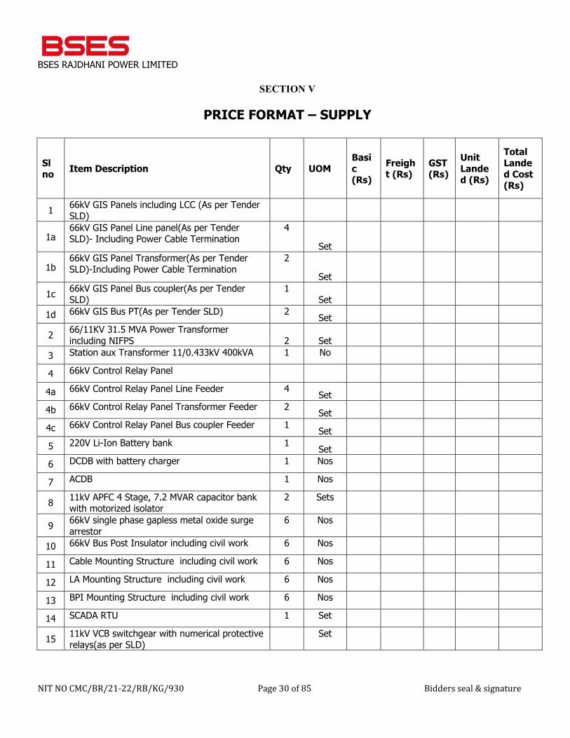
BSES RAJDHANI POWER LIMITED
NIT NO CMC/BR/21-22/RB/KG/930 Page 30 of 85 Bidders seal & signature
SECTION V
PRICE FORMAT – SUPPLY
Sl no Item Description Qty UOM
Basic (Rs)
Freight (Rs)
GST (Rs)
Unit Landed (Rs)
Total Landed Cost (Rs)
1 66kV GIS Panels including LCC (As per Tender SLD)
1a 66kV GIS Panel Line panel(As per Tender SLD)- Including Power Cable Termination
4
Set
1b 66kV GIS Panel Transformer(As per Tender SLD)-Including Power Cable Termination
2
Set
1c 66kV GIS Panel Bus coupler(As per Tender SLD)
1 Set
1d 66kV GIS Bus PT(As per Tender SLD) 2 Set
2 66/11KV 31.5 MVA Power Transformer including NIFPS 2 Set
3 Station aux Transformer 11/0.433kV 400kVA 1 No 4 66kV Control Relay Panel 4a 66kV Control Relay Panel Line Feeder 4 Set 4b 66kV Control Relay Panel Transformer Feeder 2 Set 4c 66kV Control Relay Panel Bus coupler Feeder 1 Set 5 220V Li-Ion Battery bank 1 Set 6 DCDB with battery charger 1 Nos 7 ACDB 1 Nos
8 11kV APFC 4 Stage, 7.2 MVAR capacitor bank with motorized isolator
2 Sets
9 66kV single phase gapless metal oxide surge arrestor
6 Nos
10 66kV Bus Post Insulator including civil work 6 Nos 11 Cable Mounting Structure including civil work 6 Nos 12 LA Mounting Structure including civil work 6 Nos 13 BPI Mounting Structure including civil work 6 Nos 14 SCADA RTU 1 Set
15 11kV VCB switchgear with numerical protective relays(as per SLD)
Set
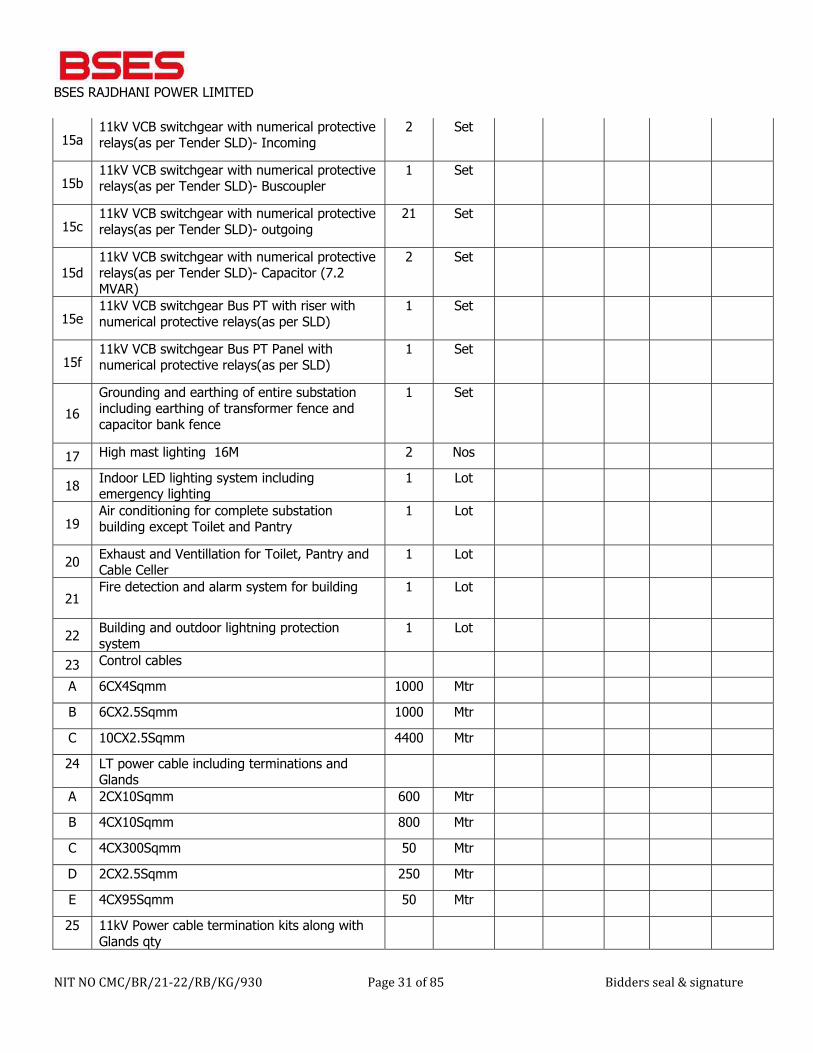
BSES RAJDHANI POWER LIMITED
NIT NO CMC/BR/21-22/RB/KG/930 Page 31 of 85 Bidders seal & signature
15a 11kV VCB switchgear with numerical protective relays(as per Tender SLD)- Incoming
2 Set
15b 11kV VCB switchgear with numerical protective relays(as per Tender SLD)- Buscoupler
1 Set
15c 11kV VCB switchgear with numerical protective relays(as per Tender SLD)- outgoing
21 Set
15d 11kV VCB switchgear with numerical protective relays(as per Tender SLD)- Capacitor (7.2 MVAR)
2 Set
15e 11kV VCB switchgear Bus PT with riser with numerical protective relays(as per SLD)
1 Set
15f 11kV VCB switchgear Bus PT Panel with numerical protective relays(as per SLD)
1 Set
16 Grounding and earthing of entire substation including earthing of transformer fence and capacitor bank fence
1 Set
17 High mast lighting 16M 2 Nos
18 Indoor LED lighting system including emergency lighting
1 Lot
19 Air conditioning for complete substation building except Toilet and Pantry
1 Lot
20 Exhaust and Ventillation for Toilet, Pantry and Cable Celler
1 Lot
21 Fire detection and alarm system for building 1 Lot
22 Building and outdoor lightning protection system
1 Lot
23 Control cables A 6CX4Sqmm 1000 Mtr B 6CX2.5Sqmm 1000 Mtr C 10CX2.5Sqmm 4400 Mtr 24 LT power cable including terminations and
Glands
A 2CX10Sqmm 600 Mtr B 4CX10Sqmm 800 Mtr C 4CX300Sqmm 50 Mtr D 2CX2.5Sqmm 250 Mtr E 4CX95Sqmm 50 Mtr 25 11kV Power cable termination kits along with
Glands qty
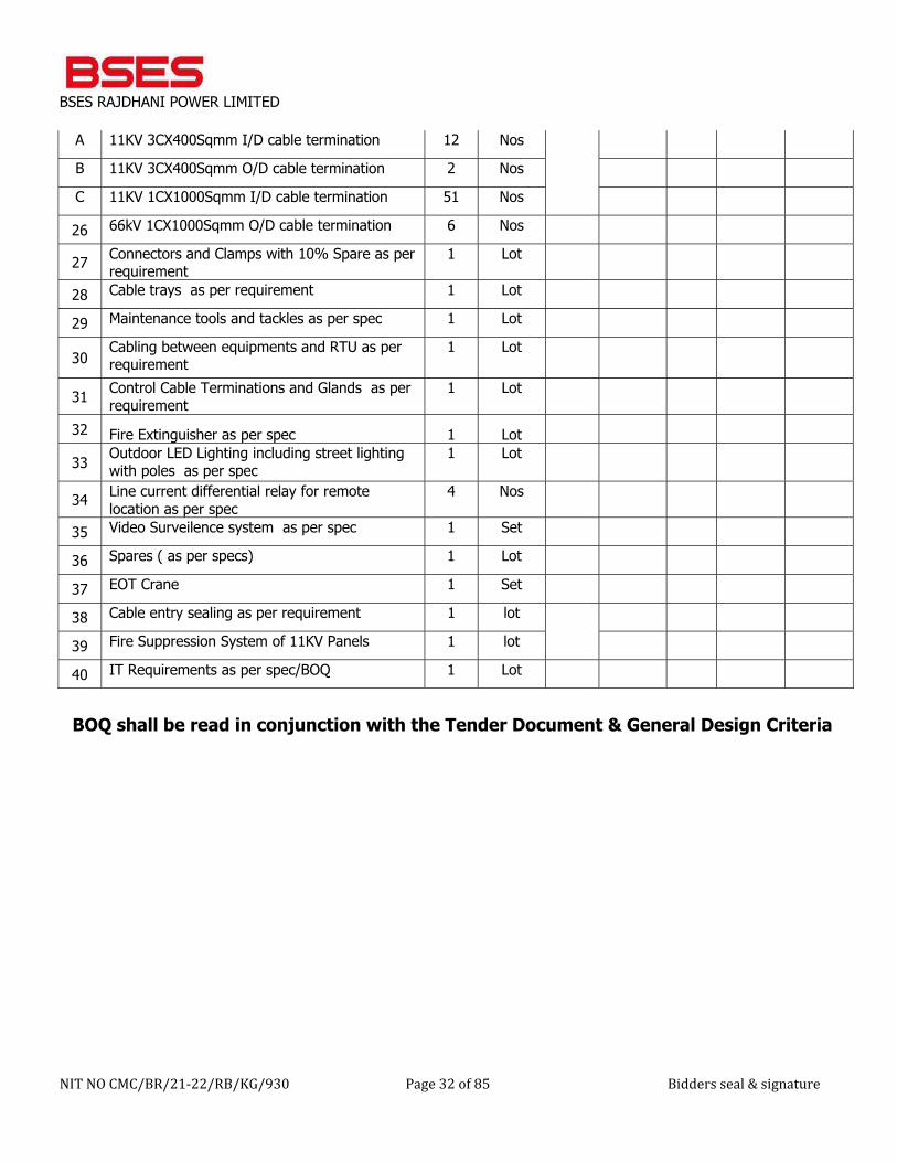
BSES RAJDHANI POWER LIMITED
NIT NO CMC/BR/21-22/RB/KG/930 Page 32 of 85 Bidders seal & signature
A 11KV 3CX400Sqmm I/D cable termination 12 Nos
B 11KV 3CX400Sqmm O/D cable termination 2 Nos C 11KV 1CX1000Sqmm I/D cable termination 51 Nos 26 66kV 1CX1000Sqmm O/D cable termination 6 Nos
27 Connectors and Clamps with 10% Spare as per requirement
1 Lot
28 Cable trays as per requirement 1 Lot 29 Maintenance tools and tackles as per spec 1 Lot
30 Cabling between equipments and RTU as per requirement
1 Lot
31 Control Cable Terminations and Glands as per requirement
1 Lot
32 Fire Extinguisher as per spec 1 Lot
33 Outdoor LED Lighting including street lighting with poles as per spec
1 Lot
34 Line current differential relay for remote location as per spec
4 Nos
35 Video Surveilence system as per spec 1 Set 36 Spares ( as per specs) 1 Lot 37 EOT Crane 1 Set 38 Cable entry sealing as per requirement 1 lot
39 Fire Suppression System of 11KV Panels 1 lot 40 IT Requirements as per spec/BOQ 1 Lot
BOQ shall be read in conjunction with the Tender Document & General Design Criteria
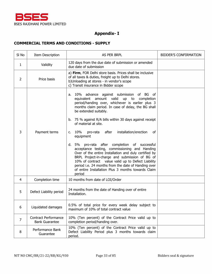
BSES RAJDHANI POWER LIMITED
NIT NO CMC/BR/21-22/RB/KG/930 Page 33 of 85 Bidders seal & signature
Appendix- I
COMMERCIAL TERMS AND CONDITIONS - SUPPLY
Sl No Item Description AS PER BRPL BIDDER’S CONFIRMATION
1 Validity 120 days from the due date of submission or amended due date of submission
2 Price basis a) Firm, FOR Delhi store basis. Prices shall be inclusive of all taxes & duties, freight up to Delhi stores. b)Unloading at stores - in vendor's scope c) Transit insurance in Bidder scope
3 Payment terms
a. 10% advance against submission of BG of
equivalent amount valid up to completion period/handing over, whichever is earlier plus 3 months claim period. In case of delay, the BG shall be extended suitably.
b. 75 % against R/A bills within 30 days against receipt of material at site.
c. 10% pro-rata after installation/erection of equipment
d. 5% pro-rata after completion of successful acceptance testing, commissioning and Handing Over of the entire Installation and duly certified by BRPL Project-in-charge and submission of BG of 10% of contract value valid up to Defect Liability period i.e. 24 months from the date of Handing over of entire Installation Plus 3 months towards Claim period
4 Completion time 10 months from date of LOI/Order
5 Defect Liability period 24 months from the date of Handing over of entire Installation.
6 Liquidated damages 0.5% of total price for every week delay subject to maximum of 10% of total contract value
7 Contract Performance Bank Guarantee
10% (Ten percent) of the Contract Price valid up to completion period/handing over.
8 Performance Bank Guarantee
10% (Ten percent) of the Contract Price valid up to Defect Liability Period plus 3 months towards claim period.
BSES RAJDHANI POWER LIMITED
NIT NO CMC/BR/21-22/RB/KG/930 Page 34 of 85 Bidders seal & signature
SECTION VI
GENERAL TERMS & CONDITIONS - ERECTION, TESTING & COMMISSIONING 1. DEFINITIONS and INTERPRETATION The following terms shall have the following meanings: 1.1 “Company”: means BSES Rajdhani Power Ltd, a company incorporated under the Companies Act 1956 and having its office at BSES Bhawan, Nehru Place, New Delhi 110 019, which expression shall include its authorized representatives, agents, successors and assigns. 1.2 “Contractor”: shall mean the successful Bidder / vendor to whom the contract has been awarded 1.3 “Rate”: The unit rates for the work to be carried out at site shall be as per finalized unit rates through tender. The finalized rates shall be firm for the entire duration of work to be carried out by the Contractor under the work order and are not subject to escalation for any reason whatsoever. 1.4. Contract Specification: The terms "Contract Specification" shall mean the Technical specification of the work as agreed by you and description of work as detailed in Annexure-I enclosed herewith and all such particulars mentioned directly/referred to or implied as such in the contract. 1.5 SITE: The terms "Site" shall mean the working location in BRPL area. Under this tender, working location shall be as mentioned elsewhere. 1.6 ENGINEER IN CHARGE: "Engineer In-charge" means the Company's authorized representative for the purpose of carrying out the work. 2. EXAMINATION OF SITE AND LOCAL CONDITIONS: The contractor is deemed to have visited the site of the work and ascertained therefore all site conditions and information pertaining to his work. The company shall not accept any claim whatsoever arising out of the difficult site/terrain/local conditions, if any. 3. LANGUAGE AND MEASUREMENT: The Contract issued to the contractor by the company and all correspondence and documents relating to the Contract placed on the Bidder shall be written in English language. Metric System shall be followed for all dimension, units etc. 4. SCOPE OF WORK: The scope includes survey , design , engineering , manufacture , shop testing ,inspection , packing , dispatch , loading, unloading and storage at site, storage and construction insurance , assembly , erection ,structural , complete pre-commissioning checks , testing and commissioning at site , obtaining statutory clearance & certification from state electrical inspector, Municipal Corporation department (if required), Fire Officer (if required),, Horticulture department (if required), and handing over to owner after successful testing & Commissioning of 66/11 kV GIS Substation at Manglapuri, New Delhi, BRPL on single point responsibility basis. Schedule of work shall be as per BOQ attached herewith. After completion of E/T/C work of the scheme, Bidder has to obtain the Electrical Inspectorate's Clearance from the Electrical Inspector of Delhi Govt. Electrical Inspector Clearance fees shall be in Bidder’s scope. The related fees, payments and pursuance work shall be in scope of Bidder only.
BSES RAJDHANI POWER LIMITED
NIT NO CMC/BR/21-22/RB/KG/930 Page 35 of 85 Bidders seal & signature
Bidder shall arrange any permission like road cutting clearance, if required, etc from the Delhi Civic authorities. The Bidder shall follow-up with local authorities and other connected persons that may be required to carry out the job under this work order. All the labour, cranes, tool and tackles, and technical supervision etc. are including in your scope of work. Adequate number of engineers, supervisors and laborers shall be posted at site and the list of the same along with certificate of Qualification of technical staff should be submitted by the Bidder to the Engineer In Charge for checking the adequacy immediately (within seven days) after award of contract. The Bidder shall also make his own arrangement for the accommodation/conveyance requirements for its staff at site. Company will be provided at site the adequate open space for Bidder's site store for storing the materials, tools, tackles etc. The entire Bidder's storage will be within the site premises. All the incoming and outgoing materials, equipment, tools, tackles and any other items related to said work shall be entered into the register kept for this purpose and shall be in the custody of Bidder, however company does not hold any responsibility for any loss or damage of Bidder's material etc. All loading/unloading, of materials at work-site shall be Bidder’s responsibility. Involvement of Crane/Hydra/Tractor/Trailer for this type of work shall be in your scope. Adequate weather protection shall be provided by the Bidder to keep the materials safe from sun & rain by providing covered storage space as well as using tarpaulins. The Bidder at his own shall arrange Water and Electricity Power at his cost. Special Instruction:- a. All Erection tools and tackles and testing equipment shall be available with Bidder in event of order. b. Penalty clause shall be incorporated in case any of workmen of Bidder is found violating safety protocol as per GCC-
ETC LD Clause no 15.
Any additional work beyond the scope enumerated in the work order above shall be carried out as per the instructions of Engineer-In Charge. The company shall not entertain any claim or increase in the Work Order value due to execution of such additional work if the same is not approved by Engineer in Charge.
5. RATES: The rates finalized for this order shall be firm for the entire duration of work carried out by the Bidder under the order and are not subject to any variation and escalation for any reason whatsoever. The cost of insurance during loading/unloading of materials/ equipments during its storage and handling/erection at site for installation is included in the Bidder's scope and value shall be included in the unit rates finalized. The unit rates finalized is also inclusive of barricading and watch & ward during execution and no separate charges shall be paid for the same. 6. TAXES AND DUTIES:
BSES RAJDHANI POWER LIMITED
NIT NO CMC/BR/21-22/RB/KG/930 Page 36 of 85 Bidders seal & signature
Prices are inclusive of all taxes and duties including GST as applicable. However, IT as per applicable rate will be deducted from your bills as Tax Deduction at Source (TDS). The total order value shall remain FIRM within stipulated delivery period and shall not be adjusted on account of any price increase/variations in labour. However Statutory Taxes, duties and Levies imposed by Competent Authorities by way of fresh notification(s) within the stipulated delivery period shall be borne by BRPL on submission of necessary documents claiming such variation. The variation will be applicable only on such value wherever price breakup of same is submitted by vendor/available in PO/WO. 7. TERMS OF PAYMENT (Erection, Testing & Commissioning) Payment shall be made as under: (i) 10% mobilization advance against submission of Advance Bank Guarantee of equivalent amount valid up to completion period/ handing over, whichever is earlier plus 3 months claim period. In case of delay, the BG shall be extended suitably. ii) 75% pro-rata of total installation value shall be payable against R/A bills payable within 45 days after installation / erection of material at site duly certified by Engineer in charge. iii) 10% pro-rata of total installation value shall be payable against R/A bills payable within 30 days after testing & commissioning of material at site. iv) 5% of contract value payable after completion of successful acceptance testing, commissioning and handing over of complete systems duly certified by Engineer in charge, submission of Electrical Inspector Clearance Certificate & submission of Performance Bank Guarantee of 10% of contract value valid up to defect liability period i.e. 24 months from the date of Handing over of entire Installation Plus 3 months towards Claim period. All the Bank guarantees shall be submitted as per Company’s format (Appendix I) and from any scheduled Bank approved by Company. Company shall make payments of the bills either; By crossed cheque or by electronic transfer directly to Bidder's designated bank account. 8. Guarantee of Performance The bidder shall stand guarantee that the equipment and material supplied/service or work rendered under the contract is free from design, manufacturing, material, construction, erection & installation and workmanship & quality defects and is capable of its due, rated and intended quality performance, as an integrated product delivered under the contract for a specific period termed as Guarantee Period. The bidder should also guarantee that the equipment/material is new and unused except for the usage required for the tests and checks required as part of quality assurance.
9. Guarantee period/Defect Liability period: The Guarantee Period will be equipment/service/work specific and shall be as specified in the Technical Specifications for the equipment/material/service/work and where Technical specifications are not part of contract documents or guarantee period is not specified in the Technical specifications, the guarantee period shall be as per the Special Terms and Conditions of the Contract. In case of no mention of the guarantee period in Technical specifications, Defect liability period will be 24 Months from the Date of Commissioning or 30 months from the date of delivery of final lot of supplies made, whichever is later.
BSES RAJDHANI POWER LIMITED
NIT NO CMC/BR/21-22/RB/KG/930 Page 37 of 85 Bidders seal & signature
If during the defects liability period any materials / items are found to be defective, these shall be replaced or rectified by the bidder at his own cost within 30 days from the date of receipt of intimation. 10. Performance Guarantee
10.01 Bank guarantee shall be drawn in favour of “BSES Rajdhani Power Ltd” as applicable. The performance Bank guarantee shall be in the format as specified by BRPL.
10.02 Contract performance bank guarantee of total 10% of the contract price shall be submitted within 15 days of award of contract with the validity till completion of the contract period.
10.03 Bidder shall submit the performance bank guarantee equivalent to the 10% of the contract value at the time of claiming the last payment as per clause no. 7.0 (iii) (TERMS OF PAYMENT (Erection, Testing & Commissioning)), with the validity of the bank guarantee till Defect Liability Period i.e. 24 months from the date of Handing over of entire Installation plus 3 months.
11. COMPLETION PERIOD You are required to mobilize your manpower and Tools & Tackles and furnish a list of equipments to be used for erection and commence the execution activity as per instructions of Engineer In-charge. The entire Erection, Testing & Commissioning work should be completed within 10 months from the date of issue of LOI/WO. The detailed schedule and milestone completion dates would be as per the contract schedules given from time to time by Engineer In-charge at site. You shall submit a weekly progress report to Engineer In charge. 12. CLEANLINESS All debris shall be removed and disposed of at assigned areas on daily basis. Surplus excavated earth shall be disposed of in an approved manner. In short, you shall be fully responsible for keeping the work site clean at all times. In case of non- compliance, company shall get the same done at Bidder's risk and costs. 13. COMMISSIONING & ACCEPTANCE TEST: After completion of the work, the Bidder shall conduct trial run/ operation in the presence of Engineer In charge. During such trial run the system shall be operated under the supervision of the Bidder. If any rectification/modification required during this period the Bidder shall do all necessary measures. On satisfactory completion of above, the system shall be deemed to have energized and placed in commercial operation. The Engineer-in-Charge will issue an acceptance certificate. 14. WORK COMPLETION CERTIFICATION, HANDING OVER. The work carried out by the Bidder under this order has to be certified by Engineer In-charge for satisfactory completion of work allotted to the Bidder with respect to specifications / Field Quality Procedures as per applicable standards. In case of modification/correction to be carried out, Bidder shall carry out the said modifications/correction without additional cost. The Bidder shall remain in close contact with Engineer In-Charge at site to report the general findings of the fieldwork during the initial as well as later stage of the work at site. The Bidder shall be solely responsible for any shortage or damage of materials issued to them handling of and / or in storage and erection at site and cost of the same will be recovered from the Bidder as certified by Engineer In-Charge. Bidder must submit a periodical material reconciliation statement in the approval format with every Running Bill raise by him or end of every month whichever is earlier. The Bidder shall maintain an accurate and exhaustive record detailing
BSES RAJDHANI POWER LIMITED
NIT NO CMC/BR/21-22/RB/KG/930 Page 38 of 85 Bidders seal & signature
out the list of all items received by him for the purpose of erection and keep such record open for the inspection of the company. 15. PENALTY AND LIQUIDATED DAMAGES 15.1 Penalty: A penalty of 2.5% of bill amount shall be levied in each case of non-compliance of safety practices and site cleanliness. 15.2 Liquidated Damages: In the event of any delay in completion of the work beyond the stipulated time given by in order due to reasons solely attributable to the Bidder, the Bidder shall pay to the Company liquidated damages. If the Bidder failed perform the services within the time period specified in the order, the Company shall, without prejudice to its other remedies under the contract, deduct liquidated damages a sum equivalent to 0.5 % of the total order value for each week or part there of delay until the actual date of completion up to a maximum deduction of 10% of total order value. The levy payment or deduction of such damages shall not relieve the Bidder from his obligation to complete the Works on time or from any other part of his obligation and liabilities under the Contract. Once the maximum is reached, the Company reserves the right for termination of contract without any liabilities to the Company. In the event of an extension of time being granted by the EIC, in writing for the Completion of the works, this clause shall be applicable after the expiry of such an extended period. Engineer In charge should specifically mention the amount of LD levied on the bill of Bidder. 18. SAFETY REGULATIONS & SAFETY CODE: The Bidder shall indemnify the Company from any consequence arising due to Bidder's failure in respect to safety compliance. First Aid facilities at easily accessible place shall be provided by the Bidder at his own cost as per provisions of Labor act or as advised by the Company wherever works are carried out. All critical injuries shall be reported promptly to the Company. The report shall cover type, nature, cause, physician's report and actions for prevention of those types again. To ensure effective enforcement of the rules and regulations relating to safety precautions, arrangements made by the Bidder shall be open to inspection by the Company. The cost so incurred by the Bidder in providing for safety standards and requirements as above shall be deemed to be included in the rates quoted for various items under the scope of Contract and no extra amounts shall be payable to the Bidder on this account. The Bidder shall furnish to the Company within seven days from issue of Work Order whichever is earlier, for approval of Company, the proposed safety program on how it intends to implement the safety procedures and precautions to ensure that the site is accident free. The Bidder shall ensure adequate safety precautions at site as required under the law of the land and shall be entirely responsible for the complete safety of their workman as well as other workers at site and premises. The Bidder shall not deploy any worker below the age of 18 years. The Bidder shall observe the safety requirements as laid down in the contract and in case of sub-contract (only after written approval of company), it shall be the responsibility of main Bidder that all safety requirements are followed by the employees and staff of the sub-vendor.
BSES RAJDHANI POWER LIMITED
NIT NO CMC/BR/21-22/RB/KG/930 Page 39 of 85 Bidders seal & signature
The Bidder employing two hundred employees or more, including contract workers, shall have a safety coordinator in order to ensure the implementation of safety requirements of the contract and a Bidder with lesser number of employees, including contract workers, shall nominate one of his employees to act as safety coordinator who shall liaise with the safety officer on matters relating to safety and his name shall be displayed on the notice board at a prominent place at the work site. The Bidder shall be responsible for non-compliance of the safety measures, implications, injuries, fatalities and compensation arising out of such situations or incidents. In case of any accident, the Bidder shall immediately submit a statement of the same to the owner and the safety officer, containing the details of the accident, any injury or causalities, extent of properly damage and remedial action taken to prevent recurrence and in addition, the Bidder shall submit a monthly statement of the accidents to the owner at the end of each month. 17. STATUTORY OBLIGATIONS: The Bidder shall take all steps as may be necessary to comply with the various applicable laws/rules including the provisions of contract labour (Regulation & Abolition Act) 1970 as amended, minimum wages Act, 1984, Workman Compensation Act, ESI Act, PF Act, Bonus Act and all other applicable laws and rules framed there under including any statutory approval required from the Central/State Govt. Ministry of Labour. Broadly, the compliance shall be as detailed below, but not limited to: a) An Electrical license issued by Govt.of Delhi. b) PF Code No. and all employees to have PF A/c No. under PF every Act, 1952. c) All employees to have a temporary or permanent ESI Card as per ESI Act. d) ESI Registration No. e) PAN No. f) Work Contract Tax Registration Number/ GSTN Registration. g) Labour License under Contract Labour Act (R & A) Act 1970 (The Bidder shall provide BRPL Engineer-in-charge a copy of Labour License responsible for execution of the job before start of the work.) The Bidder must follow: a) Third party Insurance Policy before start of work. b) To follow Minimum Wages Act prevailing in the state. c) Salary / Wages to be distributed in presence of representative of Company's representative not later than 7th of
each month. d) To maintain Wage- cum - Attendance Register. e) To maintain First Aid Box at Site. f) Latest P.F. and E.S.I. challans pertaining to the period in which work was undertaken along with a certificate
mentioning that P.F. and E.S.I. applicable to all the employees has been deducted and deposited with the Authorities within the time limits specified under the respective Acts.
g) Workman Compensation Policy. {If applicable} h) Labour license before start of work. {If applicable} 18. WORKMAN COMPENSATION: The Contactor shall take insurance policy under the Workman Compensation Act to cover such workers who are not covered under ESI and PF by the Bidder however engaged to undertake the jobs covered under this order and a copy of this insurance policy will be given to Company for reference and records. This insurance policy shall be kept valid at all

BSES RAJDHANI POWER LIMITED
NIT NO CMC/BR/21-22/RB/KG/930 Page 40 of 85 Bidders seal & signature
times. In case there are no worker involve other than those who are covered under ESI and PF by the Bidder, the Bidder shall certify for the same. The Bidder shall keep the company indemnified at all times, against all claims of compensation under the provision of Workmen Compensation Act 1923 and as amended from time to time or any compensation payable under any other law for the time being workman engaged by the Bidder/sub-contractor/sub-agent in carrying out the job involved under this work order and against costs and expenses, if any, incurred by the company in connection therewith and without prejudice to make any recovery. The company shall be entitled to deduct from any money due to or to become due to the Bidder, moneys paid or payable by way of compensation as aforesaid or cost or expenses in connection with any claims thereto and the Bidder shall abide by the decision of the Company as to the sum payable by the Bidder under the provisions of this clause. 19. STAFF AND WORKMAN It shall be responsibility of Bidder (a) To obtain Contract Labour License from the concerned authorities and maintain proper liaison with them. Necessary Forms for obtaining Labour License would be issued by the company. However you will bear all expenses for obtaining Labour license and registration in PF Department for your scope of work. You will deposit PF of your staff/laborer each month and all related documents should be furnished to us. b) To obtain workman insurance cover against deployment of workers etc. (II) To maintain, proper records relating to workmen employed, in the form of various Registers, namely, a) Register of workmen. b) Register of muster roll. c) Register of overtime. d) Register of wages. e) Any other register as per latest amendment Labour Act. The records shall be in the prescribed formats only. (III) To disburse monthly wages to your workers/ supervisors in time and in the presence of Company representatives or as directed by the Labour authorities. (IV) To maintain proper liaison with the Project authorities, local police and all other government and local bodies. (V) To pay your workmen at least not less than the minimum prescribed wages as per state/Central Labour laws as may be, applicable. The Bidder shall, be responsible for compliance of all the provisions of minimum Wages Act, PF, ESIC Act workmen Compensation Act and Contract Labour Regulation & Abolition Act the rules made there under. In case of non-compliance of the statutory requirements, the company would take necessary action at the risk and cost of the Bidder. (VI) To employ required number of skilled/semi-skilled and unskilled workmen as per site requirement to complete the entire project as per schedule. To provide safety shoes, safety helmets, safety belts, gloves etc. to your worker/staff as per requirement during erection work. (VII) To employ necessary engineering and supervisory staff for completion of the Project in time. While day-to-day management of the site and supervision of the works shall be the responsibility of your Engineer - In charge, he will report to the Engineer in charge to assist him to discharge the overall responsibility of the execution of the project.
BSES RAJDHANI POWER LIMITED
NIT NO CMC/BR/21-22/RB/KG/930 Page 41 of 85 Bidders seal & signature
20. INSURANCE a) THIRD PARTY INSURANCE Before commencing the execution of the work the Bidder shall take third party insurance policy at his own cost to insure against any damage or loss or injury which may occur to any property/public property or to any person or any employee or representative of any outside Agency / the company engaged or not engaged for the work of the company, by or arising out of the execution of the work or temporary work or in carrying out of this Agreement. For third party insurance policies, the Bidder shall be responsible for settlement of claims with the underwriters without any liability on the purchaser / owner and will arrange replacements / rectification expeditiously without awaiting settlement by insurance claim at Bidders own cost. b) ACCIDENTAL INSURANCE POLICY FOR LIFE COVER: Before commencing the execution of the work, the Bidder shall take Accidental insurance policy for the staff engaged by him for this work to insure against any loss of life which may occur during the contract for the work of the Company. The policy shall have coverage of Rs. 10 Lacs (Table C- Death + Permanent Total Disability + Partial permanent Disability due to external accidents). The Bidder shall be responsible for on the spot same day claim settlement with the victim' s legal heirs without waiting for settlement by insurance claim without any liability on BRPL. The premium amount for such life cover policy shall be borne by the Bidder. The Bidder shall furnish copy of policy when demanded by BRPL. c) INSURANCE FOR MAN, MATERIAL & MACHINERY DEPLOYED AT SITE Bidder shall be responsible for the insurance for his own man, material and machinery deployed at site for the package awarded. Bidder shall furnish the copy of this insurance policy to the purchaser, prior start of work. 21. SECURITY Adequate number of trained Security Guards shall be deployed both at the storage yard and stores as well as places of work to prevent theft and pilferage of material and accessories and various other materials. All security rules and safety rules enforced at site by company shall be strictly observed. 22. ENVIRONMENTAL, HEALTH & SAFETY PLAN: Bidder will make ensure that the Environment, Health & Safety (EHS) requirements are clearly understood and faithfully implemented at all levels at site as per instruction of Company. Bidders must comply with these requirements: a) Comply with all of the elements of the EHS Plan and any regulations applicable to the work
b) Comply with the procedures provided in the interests of Environment, Health and Safety
c) Ensure that all of their employees designated to work are properly trained and competent
d) Ensure that all plant and equipment they bring on to site has been inspected and serviced in accordance with legal requirement and manufacturer’s or suppliers’ instructions
e) Make arrangements to ensure that all employees designated to work on or visit the site present themselves for site induction prior to commencement of work
f) Provide details of any hazardous substances to be brought onsite
BSES RAJDHANI POWER LIMITED
NIT NO CMC/BR/21-22/RB/KG/930 Page 42 of 85 Bidders seal & signature
g) Ensure that a responsible person accompanies any of their visitors to site
All Bidders staffs are accountable for the following: 1. Use the correct tools and equipment for the job and use safety equipment and protective clothing supplied, e.g.
helmets, goggles, ear protection, etc. as instructed 2. Keep tools in good condition 3. Report to the Supervisor any unsafe or unhealthy condition or any defects in plant or equipment 4. Develop a concern for safety for themselves and for others 5. Prohibit horseplay 6. Not to operate any item of plant unless they have been specifically trained and are authorized to do so. 23. TEST CERTIFICATE & QUALITY ASSURANCE: The Bidder shall procure all equipment from genuine sources as approved by the Company and as per Company specifications. The Bidder shall submit all the test certificates and joint inspection reports related to major equipment wherever applicable. The Bidder shall ensure for the strict compliance to the specifications and Field Quality Procedures issued by company / Engineer in-charge. 24. SUB-CONTRACTING / SUBLETTING: BIDDER shall not assign or transfer the whole or any part of this Work Order or any other benefits accruing there from nor shall it subcontract / sublet the whole or any part of the Works without the prior written consent of COMPANY. In the event the Bidder assigns this work order, Bidder's assignees shall be bound by the terms and conditions of this work order and shall , if deemed necessary by COMPANY at the time of such assignment, undertake in writing to be so bound by this Work Order. Notwithstanding the subletting / subcontracting of any portion of the works, Bidder shall remain wholly responsible for the carrying out, completion and satisfactory execution of Works in all respects in accordance with this Work Order, specification, approved drawings and data sheets. 25. INDEMNITY: Bidder shall indemnify and save harmless COMPANY against and from any and all liabilities, claims, damages, losses or expenses arising due to or resulting from: A. Any breach non-observance or non-performance by Bidder or its employees or agents of any of the provisions of
this Work Order. B. Any act or omission of Bidder or its employees or agents. C. Any negligence or breach of duty on the part of Bidder, its employees or agents including any wrongful use by it
or them of any property or goods belonging to or by COMPANY or any other third party at site including adjoining neighbors.
Bidder shall at all times indemnify COMPANY against all liabilities to other persons, including the employees or agents of COMPANY or Bidder for bodily injury, damage to property or other loss which may arise out of or in consequence of the execution or completion of Works and against all costs charges and expenses that may be occasioned to COMPANY by the claims of such person. 26. EVENTS OF DEFAULTS: COMPANY may, without prejudice to any of its other rights or remedies under the Work Order or in law, terminate the whole or any part of this Work Order by giving written notice to the Bidder, if in the opinion of COMPANY, Bidder has
BSES RAJDHANI POWER LIMITED
NIT NO CMC/BR/21-22/RB/KG/930 Page 43 of 85 Bidders seal & signature
neglected to proceed with the works with due diligence or commits a breach of any of the provisions of this work order including but not limited to any of the following cases:
a) Failing to complete execution of work within the terms specified in this work order. b) Failing to complete works in accordance with the approved schedule of works. c) Failing to meet requirements of specifications, drawings, and designs as approved by COMPANY. d) Failing to comply with any reasonable instructions or orders issued by COMPANY in connection with the
works. e) Failing to comply with any of the terms or conditions of this work order.
In the event COMPANY terminates this work order, in whole or in part, on the occurrence of any event of default, COMPANY reserves the right to engage any other sub-vendor agency to complete the work or any part thereof, and in addition to any other right COMPANY may have under this work order or in law including without limitation the right to penalize for delay under clause 15.0 of this tender, the contractor shall be liable to COMPANY for any additional costs that may be incurred by COMPANY for the execution of the Work. 27. RISK & COST: If the Contractor of fails to execute the work as per specification / as per the direction of Engineer's In-change within the scheduled period and even after the extended period, the contract shall got cancel and company reserves the right to get the work executed from any other source at the Risk & Cost of the Contractor. The Extra Expenditure so incurred shall be debited to the Contractor. 28. ARBITRATION:
To the best of their ability, the parties hereto shall endeavor to resolve amicably between themselves all disputes arising in connection with this LOA. If the same remain unresolved within thirty (30) days of the matter being raised by either party, either party may refer the dispute for settlement by arbitration. The arbitration is to be undertaken by two arbitrators, one each to be appointed by either party. The arbitrators appointed by both the parties shall mutually nominate a person to act as presiding arbitrator before entering upon the reference in the event of a difference between the two arbitrators and the award of the said presiding arbitrator in such a contingency shall be conducted in accordance with this provisions of the Indian Arbitration & Conciliation Act, 1996 and the venue of such arbitration shall be in the city of New Delhi only. 29. FORCE MAJEURE: 29.1 General: An “Event of Force Majeure” shall mean any event or circumstance not within the reasonable control, of the Party affected, but only if and to the extent that: (i) Such event or circumstance, despite the exercise of reasonable diligence, could not have been prevented, avoided or reasonably foreseen by such Party; (ii) Such event or circumstance materially and adversely affects the ability of the affected Party to perform its obligations under this Contract, and the affected Party has taken all reasonable precautions, due care and reasonable alternative measures in order to prevent or avoid the effect of such event on the affected parties ability to perform its obligations under this Contract and to mitigate the consequences thereof. For the avoidance of doubt, if such event or circumstance would not have materially and adversely affected the performance of the affected party had such affected party followed good industry practice, such event or circumstance shall not constitute force majeure. (iii) Such event is not the direct or indirect result of the failure of such Party to perform any of its obligations under this Contract; and
BSES RAJDHANI POWER LIMITED
NIT NO CMC/BR/21-22/RB/KG/930 Page 44 of 85 Bidders seal & signature
(iv) Such Party has given the other Party prompt notice describing such events, the effect thereof and the actions being taken in order to comply with above clause 29.2 Specific Events of Force Majeure: Subject to the provisions of above clause, Events of Force Majeure shall include only the following to the extent that they or their consequences satisfy the above requirements: The following events and circumstances: a) Effect of any natural element or other acts of God, including but not limited to storm, flood, earthquake, lightning,
cyclone, landslides or other natural disasters, and b) Explosions or fires c) Declaration of the Site as war zone. d) Any order, regulation, directive, requirement from any Governmental, legislative, executive or judicial authority. 29.3 Notice of Events of Force Majeure If a force majeure event prevents a party from performing any obligations under the Contract in part or in full, that party shall: (i) Immediately notify the other party in writing of the force majeure events within 2 working days of the occurrence of the force majeure event (ii) Be entitled to suspend performance of the obligation under the Contract which is affected by force majeure event for the duration of the force majeure event (iii) Use all reasonable efforts to resume full performance of the obligation as soon as practicable (iv) Keep the other party informed of all such efforts to resume full performance of the obligation on a regular basis (v) Provide prompt notice of the resumption of full performance or obligation to the other party. 29.4 Mitigation of events of force majeure: The Bidder shall:
(i) Make all reasonable efforts to prevent and reduce to a minimum and mitigate the effect of any delay occasioned by an Event of Force Majeure, including applying other ways in which to perform the Contract;
(ii) Use its best efforts to ensure resumption of normal performance after the termination of any Event of Force Majeure and shall perform its obligations to the maximum extent practicable as agreed between the Parties; and Keep the Company informed at regular intervals of the circumstances concerning the event of Force Majeure, with best estimates as to its likely continuation and what measures or contingency planning it is taking to mitigate and or terminate the Event of Force Majeure.
29.5 Burden of proof: In the event that the Parties are unable in good faith to agree that a Force Majeure event has occurred to an affected party, the parties shall resolve their dispute in accordance with the provisions of this Contract. The burden of proof as to
BSES RAJDHANI POWER LIMITED
NIT NO CMC/BR/21-22/RB/KG/930 Page 45 of 85 Bidders seal & signature
whether or not a force majeure event has occurred shall be upon the party claiming that the force majeure event has occurred and that it is the affected party. 29.6 Terminations for certain events of force majeure: If any obligation of any Party under the Contract is or is reasonably expected to be delayed or prevented by a Force Majeure event for a continuous period of more than 1 (one) month during the Term of the Contract the Contract shall be terminated at the discretion of the Company and neither Party shall be liable to the other for any consequences arising on account of such termination. 30. SECRECY CLAUSE: The technical information, drawing and other related documents forming part of work order and the information obtained during the course of investigation under this work order shall be the Company's executive property and shall not be used for any other purpose except for the execution of the work order. The technical information drawing, records and other document shall not be copied, transferred, or divulged and/ or disclosed to third party in full/part, not misused in any form whatsoever except to the extent for the execution of this work order. This technical information, drawing and other related documents shall be returned to the Company with all approved copies and duplicates including drawing/plans as are prepared by the Bidder during the executions of this work order, if any, immediately after they have been used for agreed purpose. In the event of any breach of this provision, the Bidder shall indemnify the Company against any loss, cost or damage or claim by any party in respect of such breach. 31. TERMINATION "During the course of the execution, if at any time BRPL observe and form an opinion that the work under the order is not being performed in accordance with the terms of this Agreement, BRPL reserves its right to cancel this Agreement giving 15 days notice mentioning the reason for the termination of the agreement and BRPL will recover all damages including losses occurred due to loss of time from Bidder. 32. QUALITY Bidder shall ensure that strict quality is maintained and execution of works under the Work Order and Works are executed in conformity with the Specification. All tools, tackles, instruments and other equipments used in the execution of the Works shall be duly calibrated as required and Bidder shall maintain proper records of such tools, tackles, instruments and / or equipment. 33. LIABILITY OF BIDDERS Subject to the due discharge of its obligations under the Contract and except in case of gross negligence or willful misconduct on the part of the Bidder or on the part of any person acting on behalf of the Bidder, with respect to any loss or damage caused by the Bidder to the Employer’s property or the Site, the Bidders shall not be liable to the Employer for the following:
a) For any indirect or consequential loss or damage; and b) For any direct loss or damage that exceeds:
(i) The total payments made and expected to be made to the Bidder under the Contract including reimbursements, if any; or (ii) The insurance claim proceeds which the Bidder may be entitled to receive from any insurance purchased by the Bidder to cover such a liability, whichever is higher.

BSES RAJDHANI POWER LIMITED
NIT NO CMC/BR/21-22/RB/KG/930 Page 46 of 85 Bidders seal & signature
This limitation of liability shall not affect the Bidder’s liability, if any, for damage to any third party, caused by the Bidder or any Person or firm acting on behalf of the Bidder in executing the Works. Notwithstanding anything contained in the Contract, the Bidder shall not be liable for any gross negligence or willful misconduct on the part of the Employer or any of its affiliates, any Bidder, or any party, other than Bidder and/or, its directors, officers, agents or representatives or its affiliates, or Sub-vendor, or the Bidder or any third party engaged by it. Notwithstanding anything contained in the Contract, including but not limited to approval by the Employer of any drawings, documents, Bidder list, supply of information or data or the participation of the Employer in any meeting and/or discussion or otherwise, shall not absolve the Bidder from any of its liabilities or responsibilities arising in relation to or under the Contract.
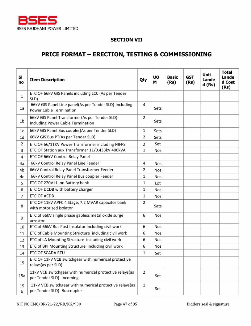
BSES RAJDHANI POWER LIMITED
NIT NO CMC/BR/21-22/RB/KG/930 Page 47 of 85 Bidders seal & signature
SECTION VII
PRICE FORMAT – ERECTION, TESTING & COMMISSIONING
Sl no Item Description Qty UO
M Basic (Rs)
GST (Rs)
Unit Landed (Rs)
Total Landed Cost (Rs)
1 ETC OF 66kV GIS Panels including LCC (As per Tender SLD)
1a 66kV GIS Panel Line panel(As per Tender SLD)-Including Power Cable Termination
4 Sets
1b 66kV GIS Panel Transformer(As per Tender SLD)-Including Power Cable Termination
2 Sets
1c 66kV GIS Panel Bus coupler(As per Tender SLD) 1 Sets 1d 66kV GIS Bus PT(As per Tender SLD) 2 Sets 2 ETC OF 66/11KV Power Transformer including NIFPS 2 Set 3 ETC OF Station aux Transformer 11/0.433kV 400kVA 1 Nos 4 ETC OF 66kV Control Relay Panel
4a 66kV Control Relay Panel Line Feeder 4 Nos 4b 66kV Control Relay Panel Transformer Feeder 2 Nos 4c 66kV Control Relay Panel Bus coupler Feeder 1 Nos 5 ETC OF 220V Li-Ion Battery bank 1 Lot 6 ETC OF DCDB with battery charger 1 Nos 7 ETC OF ACDB 1 Nos
8 ETC OF 11kV APFC 4 Stage, 7.2 MVAR capacitor bank with motorized isolator
2 Sets
9 ETC of 66kV single phase gapless metal oxide surge arrestor
6 Nos
10 ETC of 66kV Bus Post Insulator including civil work 6 Nos 11 ETC of Cable Mounting Structure including civil work 6 Nos 12 ETC of LA Mounting Structure including civil work 6 Nos 13 ETC of BPI Mounting Structure including civil work 6 Nos 14 ETC OF SCADA RTU 1 Set
15 ETC OF 11kV VCB switchgear with numerical protective relays(as per SLD)
15a 11kV VCB switchgear with numerical protective relays(as per Tender SLD)- Incoming
2 Set
15b
11kV VCB switchgear with numerical protective relays(as per Tender SLD)- Buscoupler
1 Set
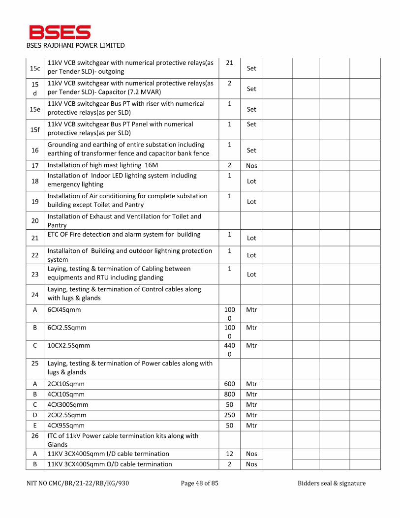
BSES RAJDHANI POWER LIMITED
NIT NO CMC/BR/21-22/RB/KG/930 Page 48 of 85 Bidders seal & signature
15c 11kV VCB switchgear with numerical protective relays(as per Tender SLD)- outgoing
21 Set
15d
11kV VCB switchgear with numerical protective relays(as per Tender SLD)- Capacitor (7.2 MVAR)
2 Set
15e 11kV VCB switchgear Bus PT with riser with numerical protective relays(as per SLD)
1 Set
15f 11kV VCB switchgear Bus PT Panel with numerical protective relays(as per SLD)
1 Set
16 Grounding and earthing of entire substation including earthing of transformer fence and capacitor bank fence
1 Set
17 Installation of high mast lighting 16M 2 Nos
18 Installation of Indoor LED lighting system including emergency lighting
1 Lot
19 Installation of Air conditioning for complete substation building except Toilet and Pantry
1 Lot
20 Installation of Exhaust and Ventillation for Toilet and Pantry
21 ETC OF Fire detection and alarm system for building 1 Lot
22 Installaiton of Building and outdoor lightning protection system
1 Lot
23 Laying, testing & termination of Cabling between equipments and RTU including glanding
1 Lot
24 Laying, testing & termination of Control cables along with lugs & glands
A 6CX4Sqmm 1000
Mtr
B 6CX2.5Sqmm 1000
Mtr
C 10CX2.5Sqmm 4400
Mtr
25 Laying, testing & termination of Power cables along with lugs & glands
A 2CX10Sqmm 600 Mtr B 4CX10Sqmm 800 Mtr C 4CX300Sqmm 50 Mtr D 2CX2.5Sqmm 250 Mtr E 4CX95Sqmm 50 Mtr
26 ITC of 11kV Power cable termination kits along with Glands
A 11KV 3CX400Sqmm I/D cable termination 12 Nos
B 11KV 3CX400Sqmm O/D cable termination 2 Nos
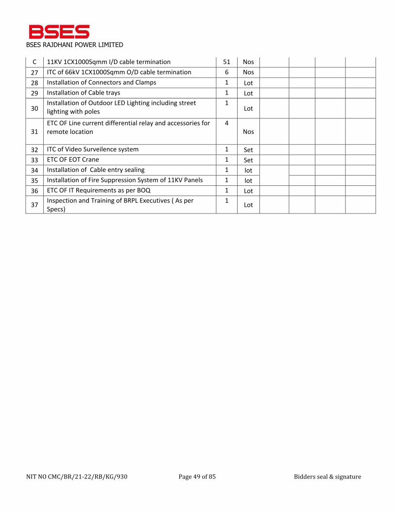
BSES RAJDHANI POWER LIMITED
NIT NO CMC/BR/21-22/RB/KG/930 Page 49 of 85 Bidders seal & signature
C 11KV 1CX1000Sqmm I/D cable termination 51 Nos 27 ITC of 66kV 1CX1000Sqmm O/D cable termination 6 Nos 28 Installation of Connectors and Clamps 1 Lot 29 Installation of Cable trays 1 Lot
30 Installation of Outdoor LED Lighting including street lighting with poles
1 Lot
31 ETC OF Line current differential relay and accessories for remote location
4 Nos
32 ITC of Video Surveilence system 1 Set 33 ETC OF EOT Crane 1 Set 34 Installation of Cable entry sealing 1 lot
35 Installation of Fire Suppression System of 11KV Panels 1 lot 36 ETC OF IT Requirements as per BOQ 1 Lot
37 Inspection and Training of BRPL Executives ( As per Specs)
1 Lot
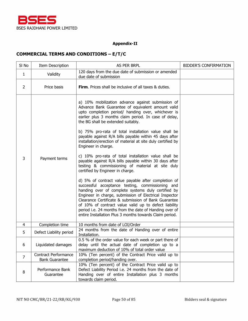
BSES RAJDHANI POWER LIMITED
NIT NO CMC/BR/21-22/RB/KG/930 Page 50 of 85 Bidders seal & signature
Appendix-II
COMMERCIAL TERMS AND CONDITIONS – E/T/C
Sl No Item Description AS PER BRPL BIDDER’S CONFIRMATION
1 Validity 120 days from the due date of submission or amended due date of submission
2 Price basis Firm. Prices shall be inclusive of all taxes & duties.
3 Payment terms
a) 10% mobilization advance against submission of Advance Bank Guarantee of equivalent amount valid upto completion period/ handing over, whichever is earlier plus 3 months claim period. In case of delay, the BG shall be extended suitably. b) 75% pro-rata of total installation value shall be payable against R/A bills payable within 45 days after installation/erection of material at site duly certified by Engineer in charge. c) 10% pro-rata of total installation value shall be payable against R/A bills payable within 30 days after testing & commissioning of material at site duly certified by Engineer in charge. d) 5% of contract value payable after completion of successful acceptance testing, commissioning and handing over of complete systems duly certified by Engineer in charge, submission of Electrical Inspector Clearance Certificate & submission of Bank Guarantee of 10% of contract value valid up to defect liability period i.e. 24 months from the date of Handing over of entire Installation Plus 3 months towards Claim period.
4 Completion time 10 months from date of LOI/Order
5 Defect Liability period 24 months from the date of Handing over of entire Installation.
6 Liquidated damages 0.5 % of the order value for each week or part there of delay until the actual date of completion up to a maximum deduction of 10% of total order value
7 Contract Performance Bank Guarantee
10% (Ten percent) of the Contract Price valid up to completion period/handing over.
8 Performance Bank Guarantee
10% (Ten percent) of the Contract Price valid up to Defect Liability Period i.e. 24 months from the date of Handing over of entire Installation plus 3 months towards claim period.
BSES RAJDHANI POWER LIMITED
NIT NO CMC/BR/21-22/RB/KG/930 Page 51 of 85 Bidders seal & signature
SECTION VIII
GENERAL TERMS & CONDITIONS – CIVIL WORKS
1. DEFINITIONS:
The following terms shall have the meaning hereby assigned to them except where the context otherwise requires:
a. Company shall mean BSES Rajdhani Power Limited, having its office at BSES Bhawan, Nehru Place, New
Delhi – 110019 and shall include its authorized representatives, agents, successors and assigns.
b. Engineer in Charge (EIC) shall be the person authorized by the Company or from time to time duly appointed by the Company for the purpose of the contract.
c. Contractor shall mean the successful Bidder / vendor to whom the contract has been awarded.
d. Sub-Contractor shall mean the persons, firm or company to whom any part of the contract has been sublet
by the Contractor with the prior written consent of the Company.
e. Contract, shall mean and include the general terms and conditions, technical specifications, drawings, priced bill of quantities, schedule of rates and prices, if any, tender, Company’s letter of intent, the work order and any correspondence letters concerned to the tender, when completed.
f. Site, shall mean the actual place in over or under which, permanent works or temporary works is to be
executed by the Contractor.
g. Contract Price shall mean the sum named in the letter of acceptance, subject to such additions thereto and /or deductions there from as may be made under the provisions hereinafter contained.
h. Specifications shall mean specification referred to in the tender and any modification thereof or addition
thereto as may, from time to time be instructed by the Company/ the Structural Consultant.
i. Approved, shall mean approved in writing by Company including subsequent written confirmation of previous verbal approval and “approval” means approval in writing by Company, including as aforesaid.
j. Defect Liability Period: Shall mean the period during which the contractor shall remain liable for repair or replacement of any defective part of the work performed under the contract, free of cost.
2. EXAMINATION OF SITE AND LOCAL CONDITIONS::
The contractor is deemed to have visited the site of the work under the Tender and ascertained therefore all site conditions and information pertaining to his work. Before submitting the bid, all bidders will at their expenses make or obtain any additional information, investigations, explorations, test and studies and obtain any additional information and data which pertains to the physical conditions at or contiguous to the site or otherwise which may affect cost, progress, performance of the work and which the bidder deems necessary to determine its Bid for performing the work in accordance with the time and other terms and conditions of the tender/contract documents. The company shall not entertain any claim whatsoever arising out of the difficult site/terrain/local conditions, if any.
3. LANGUAGE AND MEASUREMENT:
BSES RAJDHANI POWER LIMITED
NIT NO CMC/BR/21-22/RB/KG/930 Page 52 of 85 Bidders seal & signature
The Tender issued to the contractor by the company and all correspondence and documents relating to the Tender placed on the Contractor shall be written in English language. Metric System shall be followed for all dimension, units etc., the mode of measurement shall be as per IS 1200.
4. SCOPE OF WORK:
The scope of work shall be civil works of 66/11KV GIS Grid Substation at Manglapuri, New Delhi, including all statutory clearances & certification from State Electrical Inspector, Municipal corporation department (if required), Fire officer (if required), Horticulture department (if required) and various local bodies like RWA. Schedule of work shall be as mentioned in the Bill of quantity attached herewith. All the Labor, plant appliance, ladder, scaffoldings, materials, tool, tackles etc are included in contractor’s scope of work. Adequate number of engineers, supervisors and skilled and unskilled Labors shall be posted at site. The Contractor shall also make his own arrangement for the accommodation/conveyance requirements for its staff at site. Company will provide at site the adequate open space for setting up contractor's site store for storing the materials, tools, tackles etc. The entire Contractor's storage will be within the site premises. All the incoming and outgoing materials, equipment, tools, tackles and any other items related to said work shall be entered into the register kept for this purpose and shall be in the custody of Contractor, however company does not hold any responsibility for any loss or damage of Contractor's material etc. All loading/unloading, of materials at work-site shall be your responsibility. Involvement of Crane/Hydra/Tractor/Trailer for this type of work shall be in your scope. Adequate weather protection shall be provided by the contractor to keep the materials safe from sun & rain by providing covered storage space as well as using tarpaulins. Water and Electricity Power shall be arranged by the Contractor at his own. The cost of insurance during loading/unloading of materials/ equipments during its storage and handling/erection at site for installation is included in the contractor's scope and value is including in the above mentioned Tender value. The unit rates mentioned in annexure is inclusive of barricading, watch & ward during execution and no separate charges shall be paid for the same.
5. VALUE OF THE ORDER:
The rates finalized for this order shall be firm for the entire duration of work carried out by the Contractor under the order and are not subject to any variation and escalation for any reason whatsoever. The rates quoted for each item/work in the BOQ shall be deemed to include and cover all cost, expenses and liabilities to every description and all risk of every kind to be taken in executing, completing and handing over the work to the satisfaction of the Company. The Contractor shall on his own and at his own expense obtain all necessary permits and permissions to execute the job, including required registrations, agent’s etc. to perform its obligation under this Contract and shall indemnify the Company in all related matters.
6. TAXES & DUTIES:
Prices are inclusive of all taxes, duties, Construction Cess etc. leviable by State or Central Government or local bodies including any duties which may be levied by the Govt. during currency of this order. GST as applicable shall be paid on submission of GST Registration and self declaration on your letter head stating that you have deposited/or will deposit the Tax as per the applicable GST laws. However, Income Tax as per applicable rate will be deducted from your bills as Tax Deduction at Source (TDS). The total order value shall remain FIRM within stipulated delivery period and shall not be adjusted on account of any price increase/variations in labour & materials. However Statutory Taxes, duties and Levies imposed by
BSES RAJDHANI POWER LIMITED
NIT NO CMC/BR/21-22/RB/KG/930 Page 53 of 85 Bidders seal & signature
Competent Authorities by way of fresh notification(s) within the stipulated delivery period shall be borne by BRPL on submission of necessary documents claiming such variation.
7. TERMS OF PAYMENT:
Payment shall be made to you as under:
a) 10% of total civil works value shall be payable as advance against submission of Bank Guarantee of equivalent amount valid up to completion date plus 3 (three) months towards claim period. The advance shall be adjusted against R/A Bills. b) 80% pro-rata of total civil works value shall be payable against progressive R/A biils payable within 30 days duly certified by Engineer-In-Charge after completion. c) 10% of total civil works value shall be payable after completion against submission of Bank Guarantee of equivalent amount valid up to Defect liability period plus 3 (three) months towards claim period.
The Contractor shall submit the final bill along with duly checked final measurements and completion certificate towards the successful completion of the Contract as certified by the EIC. Payment of final bill shall not be considered conclusive evidence as to the sufficiency of any work or materials, to which it relates, nor shall it relieve as to the sufficiency of work or materials which it relates, nor shall it relieve the Contractor from his liabilities arising from any defects, which become apparent during the Defects Liability Period.
8. DEFECT LIABILITY PERIOD:
The civil works shall be guaranteed against any defect or failure which may arise due to faulty materials, design or workmanship for a period of 24 months from the date of handing over of the substation. In case any defect in the work is observed during the defect liability period, the same shall be rectified by the Contractor at own cost including supply of all materials, labour, equipments and any other appliance in this regards (as per prevailing rates) for the fulfillment of all obligations under the Contract and to the satisfaction of the Company, with in 10 day s from the date of receipt of intimation from BRPL. Under no circumstances any extra claim in terms of time and cost shall be entertained for such repair/ rectification.
9. SCHEDULE OF COMPLETION AND PERIOD OF MOBILISATION:
The time schedule for carrying out this work and period for mobilization shall be as under: 9.1 The Contractor shall mobilize their Plants & Equipments, Tools & Tackles, Work Labour Force, project team including Engineering Staff and materials required for execution of work at site for commencement of work immediately on receipt of the order. 9.2 The entire work under this order as indicated in the scope of work shall be carried out and completed within the validity period i.e. 300 days. A detailed L2 Schedule shall be submitted by the contractor within 15 days of WO. The contractor shall plan parallel working (round the clock working) f or completion of work as per schedule and mobilize manpower accordingly .

BSES RAJDHANI POWER LIMITED
NIT NO CMC/BR/21-22/RB/KG/930 Page 54 of 85 Bidders seal & signature
9.3 Progress Review Meeting between the Contractor and the Engineer In charge shall be held at site at least once in a week. Also the report giving the details of the manpower engaged at site and the details of the major job completion shall be submitted to Engineer In charge. 9.4 The above time schedule must be strictly adhered to and improved upon wherever possible. In the event we find that your work is not progressing in quality or time frame as per above agreed schedule and to our satisfaction, we reserve the right to withdraw the work in whole or in part without further notice and liability of the Company. 9.5 The completion of the work shall have to be certified by Engineer In charge. 9.6 In order to maintain the time schedule, if necessary the Contractor shall carry out the work on all Sunday & Holiday except National Holiday with prior written permission from Engineer-in- Charge. 9.7 Contractor shall arrange any permission like for the Road cutting etc. from the local authorities like DDA, PWD, and DJB. Contractor shall also follow up with local authorities and other connected persons that may be required to carry out the job under this order. All Statutory charges and direct fees except Electrical Inspector Clearance fees shall be borne by BRPL.
10. TEST CERTIFICATE & QUALITY ASSURANCE:
Quality Assurance Program: The Contractor before the start of work shall submit for approval a quality assurance program to the EIC indicating measures that he proposes to implement to ensure that the quality of work shall be in accordance with requirements, specifications laid down in the Contract. The Contractor shall strictly adhere to this program and any failure attributable to the Contractor shall attract the penal provisions determined by the EIC. Quality of materials and workmanship and tests: The Contractor shall procure all equipment from genius sources as approved by the Company & as per Company specifications. Cement shall be of grade 43 ordinary port land cement conforming to IS 8112/53 grade O.P.C. conforming to IS 12269, aggregate for cement concrete shall confirm to IS 383, reinforcement for cold twisted bars shall confirm to IS 1786, the bricks for brick work shall correspond to IS 1077, Structural steel shall confirm to relevant IS code, water to be used shall comply with requirement of IS 456. Contractor shall provide all requisite facilities for field tests and laboratory tests shall be carried out in the laboratory having ISO 9001-2000 Certified Testing Lab for which no extra payment shall be made. The Contractor shall maintain mandatory Test Register with Engineer-in-Charge as provided in latest Indian Standard Specifications. All materials and workmanship shall be of the respective kinds described in the Contract and in accordance with the Engineer-in-Charge's instructions and shall be subjected from time to time to such tests as the Engineer-in-Charge may direct at the place of manufacture or fabrication or on the site or at such other places as may be specified in the Contract, or at all or any of such places. The Contractor shall provide at no additional cost to the Company such assistance, instruments, machines, labour and materials as are normally required for examining, measuring and testing any work and the quality, weight or quantity of any material used and shall supply samples of materials before incorporation in the works for testing as may be selected and required by the EIC.
Cost of samples and tests: All samples shall be supplied to Company if required by the Contractor at his own cost. The Contractor shall take approval of the EIC prior to start the work for all samples of materials including mix design of concrete to be
BSES RAJDHANI POWER LIMITED
NIT NO CMC/BR/21-22/RB/KG/930 Page 55 of 85 Bidders seal & signature
utilized for the works to be executed. The mix design of concrete, testing of reinforcement steel and structural steel shall be carried out by an external agency approved by the Company. The cost of all such tests carried out by the external agencies or consultants shall be borne by the Contractor at his own cost and are deemed to be included in the unit rates quoted in the BOQ. Sampling and Testing Concrete on Site The Contractor can also have cubes tested in an approved laboratory in lieu of a testing machine at site but at his own cost and with the prior written consent of the Company. Inspection of operations: The Engineer-in-Charge/QC department or any person authorized by them shall at all times have access to the works and to all workshops and places where work is being prepared or from where materials, manufactured articles or machinery are being obtained for the works and the Contractor shall afford every facility for and every assistance in or in obtaining the right to such access. Examination of work before covering up: No work shall be covered up or put out of view without the approval of the EIC or his representative and the Contractor shall afford full opportunity to the EIC or his representative to examine and measure any work which is about to be covered up or put out of view and to examine foundations before permanent work is placed thereon. The Contractor shall give due notice to the EIC or his representative whenever any such work or foundations is or are ready or about to be ready for examination and the EIC or his representative shall, without unreasonable delay, unless he considers it unnecessary, attend for the purpose of the examining such foundations.
11. SUB-CONTRACTING / SUBLETTING:
CONTRACTOR shall not assign or transfer the whole or any part of this Work Order or any other benefits accruing there from nor shall it subcontract / sublet the whole or any part of the Works without the prior written consent of COMPANY. The Company may approve or reject sub-contractor, which in his opinion do not meet the prerequisite qualifications. The Contractor shall re-submit a fresh name for approval. In the event the contractor assigns this work order, contractor's assignees shall be bound by the terms and conditions of this work order and shall , if deemed necessary by COMPANY at the time of such assignment, undertake in writing to be so bound by this Work Order. Notwithstanding the subletting / subcontracting of any portion of the works, contractor shall remain wholly responsible for the carrying out, completion and satisfactory execution of Works in all respects in accordance with this Work Order, specification, approved drawings and data sheets.
12. INDEMNITY:
Contractor shall indemnify and save harmless COMPANY against and from any and all liabilities, claims, damages, losses or expenses arising due to or resulting from: a) Any breach non-observance or non-performance by contractor or its employees or agents of any of the provisions of this Work Order. b) Any act or omission of contractor or its employees or agents. c) Any negligence or breach of duty on the part of contractor, its employees or agents including any wrongful use by it or them of any property or goods belonging to or by COMPANY or any other third party at site including adjoining neighbors.
BSES RAJDHANI POWER LIMITED
NIT NO CMC/BR/21-22/RB/KG/930 Page 56 of 85 Bidders seal & signature
Contractor shall at all times indemnify COMPANY against all liabilities to other persons, including the employees or agents of COMPANY or contractor for bodily injury, damage to property or other loss which may arise out of or in consequence of the execution or completion of Works and against all costs charges and expenses that may be occasioned to COMPANY by the claims of such person.
13. EVENTS OF DEFAULTS:
COMPANY may, without prejudice to any of its other rights or remedies under the Work Order or in law, terminate the whole or any part of this Work Order by giving written notice to the Contractor, if in the opinion of COMPANY, contractor has neglected to proceed with the works with due diligence or commits a breach of any of the provisions of this work order including but not limited to any of the following cases:
a) Failing to complete execution of work within the terms specified in this work order. b) Failing to complete works in accordance with the approved schedule of works. c) Failing to meet requirements of specifications, drawings, and designs as approved by COMPANY. d) Failing to comply with any reasonable instructions or orders issued by COMPANY in connection
with the works. e) Failing to comply with any of the terms or conditions of this work order.
In the event COMPANY terminates this work order, in whole or in part, on the occurrence of any event of default, COMPANY reserves the right to engage any other subcontractor or agency to complete the work or any part thereof, and in addition to any other right COMPANY may have under this work order or in law including without limitation the right to penalize for delay under clause 17.0 of this tender, the contractor shall be liable to COMPANY for any additional costs that may be incurred by COMPANY for the execution of the Work.
14. RISK & COST:
If the Contractor of fails to execute the work as per specification / as per the direction of Engineer's In-change within the scheduled period and even after the extended period, the contract shall got cancel and company reserves the right to get the work executed from any other source at the Risk & Cost of the Contractor. The Extra Expenditure so incurred shall be debited to the Contractor.
15. ENVIRONMENTAL, HEALTH & SAFETY PLAN:
Contractor will make ensure that the Environment, Health & Safety (EHS) requirements are clearly understood and faithfully implemented at all levels at site as per instruction of Company. Contractors must comply with these requirements: a) Comply with all of the elements of the EHS Plan and any regulations applicable to the work
b) Comply with the procedures provided in the interests of Environment, Health and Safety
c) Ensure that all of their employees designated to work are properly trained and competent
d) Ensure that all plant and equipment they bring on to site has been inspected and serviced in accordance with legal requirement and manufacturer’s or suppliers’ instructions
e) Make arrangements to ensure that all employees designated to work on or visit the site present themselves for site induction prior to commencement of work
f) Provide details of any hazardous substances to be brought onsite
g) Ensure that a responsible person accompanies any of their visitors to site
BSES RAJDHANI POWER LIMITED
NIT NO CMC/BR/21-22/RB/KG/930 Page 57 of 85 Bidders seal & signature
All contractors’ staffs are accountable for the following: 1. Use the correct tools and equipment for the job and use safety equipment and protective clothing supplied,
e.g. helmets, goggles, ear protection, etc. as instructed 2. Keep tools in good condition 3. Report to the Supervisor any unsafe or unhealthy condition or any defects in plant or equipment 4. Develop a concern for safety for themselves and for others 5. Prohibit horseplay 6. Not to operate any item of plant unless they have been specifically trained and are authorized to do so.
16. WORK COMPLETION CERTIFICATION, HANDING OVER.
The work carried out by the Contractor under this order has to be certified by Engineer In-charge for satisfactory completion of work allotted to the contractor with respect to specifications / Field Quality Procedures as per applicable standards. In case of modification/correction to be carried out, contractor shall carry out the said modifications/correction without additional cost. The Contractor shall remain in close contact with Engineer In-Charge at site to report the general findings of the fieldwork during the initial as well as later stage of the work at site. If required, field findings and for revision of the method for site work if required. Work Completion Certificate shall be issued by the Engineer In charge within 10 days of satisfactory work completion subject to handing over of clear site i/c removal of Labor accommodation, stores, storage arrangements for water, plants, tackles, scaffoldings, ladders, leveling at site. The Contractor shall give undertaking that all standing dues to Labor have been paid and all the statutory obligations have been met with. Completion certificate has to be submitted with the final bill issued by Engineer-in- Charge.
17. PENALTY AND LIQUIDATED DAMAGES:
17.1 Penalty: A penalty of 2.5% of bill amount shall be levied in each case of non-compliance of safety practices and site cleanliness. 17.2 Liquidated Damages: In the event of any delay in completion of the work beyond the stipulated time given by in order due to reasons solely attributable to the Contractor, the Contractor shall pay to the Company liquidated damages. If the Contractor failed to complete the construction of subject work within the time period specified in the order, the Company shall, without prejudice to its other remedies under the contract, deduct liquidated damages a sum equivalent to 0.5 % of the total order value for each week or part there of delay until the actual date of completion up to a maximum deduction of 10% of total order value. The levy payment or deduction of such damages shall not relieve the Contractor from his obligation to complete the Works on time or from any other part of his obligation and liabilities under the Contract. Once the maximum is reached, the Company reserves the right for termination of contract without any liabilities to the Company. In the event of an extension of time being granted by the EIC, in writing for the Completion of the works, this clause shall be applicable after the expiry of such an extended period. Engineer In charge should specifically mention the amount of LD levied on the bill of contractor.
18. SAFETY REGULATIONS:
18.1 The Contractor shall indemnify the Company from any consequence arising due to contractor's failure in respect to safety compliance.
BSES RAJDHANI POWER LIMITED
NIT NO CMC/BR/21-22/RB/KG/930 Page 58 of 85 Bidders seal & signature
18.2 First Aid facilities at easily accessible place shall be provided by the Contractor at his own cost as per provisions of Labor act or as advised by the Company wherever works are carried out. 18.3 All critical injuries shall be reported promptly to the Company. The report shall cover type, nature, cause, physician's report and actions for prevention of those types again. 18.4 To ensure effective enforcement of the rules and regulations relating to safety precautions, arrangements made by the Contractor shall be open to inspection by the Company. 18.5 The cost so incurred by the Contractor in providing for safety standards and requirements as above shall be deemed to be included in the rates quoted for various items under the scope of Contract and no extra amounts shall be payable to the contractor on this account. 18.6 The Contractor shall furnish to the Company within seven days from issue of Work Order whichever is earlier, for approval of Company, the proposed safety program on how it intends to implement the safety procedures and precautions to ensure that the site is accident free.
19. SAFETY CODE:
The Contractor shall ensure adequate safety precautions at site as required under the law of the land and shall be entirely responsible for the complete safety of their workman as well as other workers at site and premises. The contractor shall not deploy any worker below the age of 18 years. The contractor shall observe the safety requirements as laid down in the contract and in case of sub-contract (only after written approval of company), it shall be the responsibility of main contractor that all safety requirements are followed by the employees and staff of the sub-contractor. The contractor employing two hundred employees or more, including contract workers, shall have a safety coordinator in order to ensure the implementation of safety requirements of the contract and a contractor with lesser number of employees, including contract workers, shall nominate one of his employees to act as safety coordinator who shall liaise with the safety officer on matters relating to safety and his name shall be displayed on the notice board at a prominent place at the work site. The contractor shall be responsible for non-compliance of the safety measures, implications, injuries, fatalities and compensation arising out of such situations or incidents. In case of any accident, the contractor shall immediately submit a statement of the same to the owner and the safety officer, containing the details of the accident, any injury or causalities, extent of properly damage and remedial action taken to prevent recurrence and in addition, the contractor shall submit a monthly statement of the accidents to the owner at the end of each month.
20. STATUTORY OBLIGATIONS:
The Contractor shall take all steps as may be necessary to comply with the various applicable laws/rules including the provisions of contract labour (Regulation & Abolition Act) 1970 as amended, minimum wages Act, 1984, Workman Compensation Act, ESI Act, PF Act, Bonus Act and all other applicable laws and rules framed there under including any statutory approval required from the Central/State Govt. Ministry of Labour. Broadly, the compliance shall be as detailed below, but not limited to: a) An Electrical license issued by Govt. of Delhi. b) PF Code No. and all employees to have PF A/c No. under PF every Act, 1952. c) All employees to have a temporary or permanent ESI Card as per ESI Act.
BSES RAJDHANI POWER LIMITED
NIT NO CMC/BR/21-22/RB/KG/930 Page 59 of 85 Bidders seal & signature
d) ESI Registration No. e) PAN No. f) GSTN Registration. g) Labour License under Contract Labour Act (R & A) Act 1970 (The Contractor shall provide BRPL Engineer-in-charge a copy of Labour License responsible for execution of the job before start of the work.) The Contractor must follow: a) Third party Insurance Policy before start of work. b) To follow Minimum Wages Act prevailing in the state. c) Salary / Wages to be distributed in presence of representative of Company's representative not later
than 7th of each month. d) To maintain Wage- cum - Attendance Register. e) To maintain First Aid Box at Site. f) Latest P.F. and E.S.I. challans pertaining to the period in which work was undertaken along with a
certificate mentioning that P.F. and E.S.I. applicable to all the employees has been deducted and deposited with the Authorities within the time limits specified under the respective Acts.
g) Workman Compensation Policy. {If applicable} h) Labour license before start of work. {If applicable} i) Group personnel accident insurance shall have coverage of Rs. 10 Lac (Table C- Death + Permanent
Total Disability + Partial permanent Disability due to external accidents).
Before issue of order it would be mandatory for the Contractor to furnish the Company the permanent PF code no, ESI registration, registration under W.C.T Act.
21. BOCW ACT:
BOCW Act applies to every establishment which employs, or had employed on any day of the preceding twelve months, ten or more building workers in any building or other construction work . The Contractor for carrying out any construction work, must get themselves registered with the Registering Officer under Section 7 of the Building and Other Construction Workers Act, 1996 and rules made thereto by the concerned State Govt .and submit certificate of Registration, issued from the Registering Officer of the concerned State Govt. (Labour Dept.). As per this Act, the Contractor shall be levied a cess @1% of cost of construction work, which would be deducted from each bill. Cost of material, when supplied under a separate schedule item, shall be outside the purview of cess. The Contractor shall also comply with all provisions of the said Act applicable to him.
22. WORKMAN COMPENSATION:
The Contactor shall take insurance policy under the Workman Compensation Act to cover such workers who are not covered under ESI and PF by the Contractor however engaged to undertake the jobs covered under this order and a copy of this insurance policy will be given to Company for reference and records. This insurance policy shall be kept valid at all times. In case there are no worker involved other than those who are covered under ESI and PF by the Contractor, the Contractor shall certify for the same. The contractor shall keep the company indemnified at all times, against all claims of compensation under the provision of Workmen Compensation Act 1923 and as amended from time to time or any compensation payable under any other law for the time being workman engaged by the contractor/sub-contractor/sub-agent in carrying out the job involved under this work order and against costs and expenses, if any, incurred by the company in connection therewith and without prejudice to make any recovery.
BSES RAJDHANI POWER LIMITED
NIT NO CMC/BR/21-22/RB/KG/930 Page 60 of 85 Bidders seal & signature
The company shall be entitled to deduct from any money due to or to become due to the Contractor, moneys paid or payable by way of compensation as aforesaid or cost or expenses in connection with any claims thereto and the Contractor shall abide by the decision of the Company as to the sum payable by the Contractor under the provisions of this clause.
23. INSURANCE a) THIRD PARTY INSURANCE
Before commencing the execution of the work the contractor shall take third party insurance policy at his own cost to insure against any damage or loss or injury which may occur to any property/public property or to any person or any employee or representative of any outside Agency / the company engaged or not engaged for the work of the company, by or arising out of the execution of the work or temporary work or in carrying out of this Agreement. For third party insurance policies, the contractor shall be responsible for settlement of claims with the underwriters without any liability on the purchaser / owner and will arrange replacements / rectification expeditiously without awaiting settlement by insurance claim at contractors own cost.
b) ACCIDENTAL INSURANCE POLICY FOR LIFE COVER:
Before commencing the execution of the work, the CONTRACTOR shall take Accidental insurance policy for the staff engaged by him for this work to insure against any loss of life which may occur during the contract for the work of the COMPANY. The policy shall have coverage of Rs. 10 Lacs (Table C- Death + Permanent Total Disability + Partial permanent Disability due to external accidents). The Contractor shall be responsible for on the spot same day claim settlement with the victim' s legal heirs without waiting for settlement by insurance claim without any liability on BRPL. The premium amount for such life cover policy shall be borne by the contractor. The contractor shall furnish copy of policy when demanded by BRPL.
c) INSURANCE FOR MAN, MATERIAL & MACHINERY DEPLOYED AT SITE
Contractor shall be responsible for the insurance for his own man, material and machinery deployed at site for the package awarded. Contractor shall furnish the copy of this insurance policy to the purchaser, prior start of work.
24. ARBITRATION:
To the best of their ability, the parties hereto shall endeavor to resolve amicably between themselves all disputes arising in connection with this LOA. If the same remain unresolved within thirty (30) days of the matter being raised by either party, either party may refer the dispute for settlement by arbitration. The arbitration is to be undertaken by two arbitrators, one each to be appointed by either party. The arbitrators appointed by both the parties shall mutually nominate a person to act as presiding arbitrator before entering upon the reference in the event of a difference between the two arbitrators and the award of the said presiding arbitrator in such a contingency shall be conducted in accordance with this provisions of the Indian Arbitration & Conciliation Act, 1996 and the venue of such arbitration shall be in the city of New Delhi only.
25. Performance Guarantee:
Bank guarantee shall be drawn in favour of “BSES Rajdhani Power Ltd” as applicable. The performance Bank guarantee shall be in the format as specified by BRPL.
BSES RAJDHANI POWER LIMITED
NIT NO CMC/BR/21-22/RB/KG/930 Page 61 of 85 Bidders seal & signature
Contract performance bank guarantee of total 10% of the contract price shall be submitted for due performance of this Contract within 15 days of award of contract with the validity till completion of the contract period. The same shall be released after completion of the job Contractor shall submit the performance bank guarantee equivalent to the 10% of the contract value at the time of claiming the last payment with the validity of the bank guarantee till Defect Liability Period i.e. 24 months from the date of Handing over of entire Installation plus 3 months. The Company shall reserve the right to invoke the performance bond unconditionally and without recourse to the Contractor, if there is failure to perform any part of the Contract for whatsoever reason. This clause is pertaining to performance of contractual obligations and the decision of Company shall be final in this regard. In the event, in Company’s sole judgment, if the Contractor has fulfilled all its obligations under this Contract, Company shall release the performance bank guarantee without interest, within seven (7) days from the last date up to which the performance bank guarantee is to be kept valid or if it is assessed by the Company that Contractor has not fulfilled its obligation, then the performance bank guarantee shall be extended by the Contractor till that period as requested by the Company.
26. GENERAL CONDITIONS: 26.1) No idle labour charges will be admissible in the event of any suspension of work by the Company or stoppage
caused in the work due to any other reason resulting in contractors’ labour or equipments being rendered idle at any time during the duration of contract.
26.2) In the event of any ambiguity, the work order shall supersede LOI & all other correspondence and conditions of
contract if furnished earlier. 26.3) If the Contractor needs to carry out any work or rework due to change in drawings or structural consultants
instructions, the Contractor shall take the prior permission of the Company/ EIC before commencing such works. The Contractors quoted price shall include such rework or incidentals due to quantity variation, or methodology to carry out the works, wherever required and shall not be entitled for any extra payment or extension of time.
26.4) The Company reserves the right to claim and recover from the security deposit the damages/ losses incurred due to non-compliance to work, delay in the progress of work by the Contractor as agreed upon. The decision of the Company in this regard shall be final and binding.
26.5) The Contractor agrees to abide by other terms and conditions stipulated by the Company from time to time in addition to the above for the proper and satisfactory performance of their obligations under this Contract.
27. STAFF AND WORKMAN It shall be responsibility of contractor (a) To obtain Contract Labour License from the concerned authorities and maintain proper liaison with them. Necessary Forms for obtaining Labour License would be issued by the company. However you will bear all expenses for obtaining Labour license and registration in PF Department for your scope of work. You will deposit PF of your staff/laborer each month and all related documents should be furnished to us. b) To obtain workman insurance cover against deployment of workers etc. (II) To maintain, proper records relating to workmen employed, in the form of various Registers, namely,
BSES RAJDHANI POWER LIMITED
NIT NO CMC/BR/21-22/RB/KG/930 Page 62 of 85 Bidders seal & signature
a) Register of workmen. b) Register of muster roll. c) Register of overtime. d) Register of wages. e) Any other register as per latest amendment Labour Act. The records shall be in the prescribed formats only. (III) To disburse monthly wages to your workers/ supervisors in time and in the presence of Company representatives or as directed by the Labour authorities. (IV) To maintain proper liaison with the Project authorities, local police and all other government and local bodies. (V) To pay your workmen at least not less than the minimum prescribed wages as per state/Central Labour laws as may be, applicable. The contractor shall, be responsible for compliance of all the provisions of minimum Wages Act, PF, ESIC Act workmen Compensation Act and Contract Labour Regulation & Abolition Act the rules made there under. In case of non- compliance of the statutory requirements. the company would take necessary action at the risk and cost of the Contractor. (VI) To employ required number of skilled/semi-skilled and unskilled workmen as per site requirement to complete the entire project as per schedule. To provide safety shoes, safety helmets, safety belts, gloves etc. to your worker/staff as per requirement during erection work. (VII) To employ necessary engineering and supervisory staff for completion of the Project in time. While day-to-day management of the site and supervision of the works shall be the responsibility of your Engineer - In charge, he will report to the Engineer in charge to assist him to discharge the overall responsibility of the execution of the project.
28. POLLUTION CONTROL: All debris shall be removed and disposed of at assigned areas on daily basis. Surplus excavated earth shall be disposed of in an approved manner. In short, the contractor shall be fully responsible for keeping the work site clean at all times. In case of non- compliance, company shall get the same done at Contractor' s risk and costs. All BRPL vendors and execution engineers are hereby advice to adhere below mentioned guidelines while carrying out any civil work including road/ pit digging, plinth/ fence making, road restoration etc.
I. No construction material/ debris shall be stored on metalled road. II. Wind breakers of appropriate height on all sides of ear marked area using CGI sheets shall be raised to ensure
that no construction material dust fly outside ear marked area. III. The construction material i.e. coarse sand, stone aggregates, excavated earth, cement and any other material to
and from the site shall be transported under wet and covered condition to ensure their non-slippage en-route to avoid air contamination.
IV. The contractor shall provide mask and helmet to every worker working on the construction site and involved in loading/unloading and carriage of construction material and construction debris to prevent inhalation of dust particles.
V. Over loading of vehicles shall be strictly prohibited VI. The construction material at site shall be stored under wet and covered condition.
The dumping sites for temporarily storing the excavated earth shall be properly leveled, watered and rehabilitated by plantation to avoid flying of dust.
VII. The worker at the site shall be sensitized to adopt / observe the dust controlled measures in true spirit.
BSES RAJDHANI POWER LIMITED
NIT NO CMC/BR/21-22/RB/KG/930 Page 63 of 85 Bidders seal & signature
VIII. If any C&D waste is generated at site the same will be transported to the C&D waste site only and the record for the same will be maintained by the agency.
IX. Wet jet in grinding and stone cutting is being permitted at site. X. The necessary record for dust control is being maintained by the department on day to day basis and being
monitored regularly. The Contractor shall be responsible for all the preventive and protective environmental steps as per guidelines. Execution in- charge has to ensure all vendors comply with these instructions. Any violations from the above guidelines have been viewed very seriously by the authorities. Concerned agency is liable for the penalties / other action by the authorities, The Agency shall indemnify BRPL from all liabilities on this account.
29. FORCE MAJEURE: 29.1 General:
An “Event of Force Majeure” shall mean any event or circumstance not within the reasonable control, of the Party affected, but only if and to the extent that: (i) Such event or circumstance, despite the exercise of reasonable diligence, could not have been prevented, avoided or reasonably foreseen by such Party; (ii) Such event or circumstance materially and adversely affects the ability of the affected Party to perform its obligations under this Contract, and the affected Party has taken all reasonable precautions, due care and reasonable alternative measures in order to prevent or avoid the effect of such event on the affected parties ability to perform its obligations under this Contract and to mitigate the consequences thereof. For the avoidance of doubt, if such event or circumstance would not have materially and adversely affected the performance of the affected party had such affected party followed good industry practice, such event or circumstance shall not constitute force majeure. (iii) Such event is not the direct or indirect result of the failure of such Party to perform any of its obligations under this Contract; and (iv) Such Party has given the other Party prompt notice describing such events, the effect thereof and the actions being taken in order to comply with above clause
29.2 Specific Events of Force Majeure:
Subject to the provisions of above clause, Events of Force Majeure shall include only the following to the extent that they or their consequences satisfy the above requirements: The following events and circumstances: e) Effect of any natural element or other acts of God, including but not limited to storm, flood, earthquake,
lightning, cyclone, landslides or other natural disasters, and f) Explosions or fires g) Declaration of the Site as war zone. h) Any order, regulation, directive, requirement from any Governmental, legislative, executive or judicial
authority. 29.3 Notice of Events of Force Majeure
BSES RAJDHANI POWER LIMITED
NIT NO CMC/BR/21-22/RB/KG/930 Page 64 of 85 Bidders seal & signature
If a force majeure event prevents a party from performing any obligations under the Contract in part or in full, that party shall: (i) Immediately notify the other party in writing of the force majeure events within 2 working days of the occurrence of the force majeure event (ii) Be entitled to suspend performance of the obligation under the Contract which is affected by force majeure event for the duration of the force majeure event (iii) Use all reasonable efforts to resume full performance of the obligation as soon as practicable (iv) Keep the other party informed of all such efforts to resume full performance of the obligation on a regular basis (v) Provide prompt notice of the resumption of full performance or obligation to the other party.
29.4 Mitigation of events of force majeure:
The Contractor shall:
(i) Make all reasonable efforts to prevent and reduce to a minimum and mitigate the effect of any delay occasioned by an Event of Force Majeure, including applying other ways in which to perform the Contract;
(ii) Use its best efforts to ensure resumption of normal performance after the termination of any Event of Force Majeure and shall perform its obligations to the maximum extent practicable as agreed between the Parties; and Keep the Company informed at regular intervals of the circumstances concerning the event of Force Majeure, with best estimates as to its likely continuation and what measures or contingency planning it is taking to mitigate and or terminate the Event of Force Majeure.
29.5 Burden of proof: In the event that the Parties are unable in good faith to agree that a Force Majeure event has occurred to an affected party, the parties shall resolve their dispute in accordance with the provisions of this Contract. The burden of proof as to whether or not a force majeure event has occurred shall be upon the party claiming that the force majeure event has occurred and that it is the affected party.
29.6 Terminations for certain events of force majeure:
If any obligation of any Party under the Contract is or is reasonably expected to be delayed or prevented by a Force Majeure event for a continuous period of more than 1 (one) month during the Term of the Contract the Contract shall be terminated at the discretion of the Company and neither Party shall be liable to the other for any consequences arising on account of such termination.
30. SECRECY CLAUSE:
The Contractor shall not communicate or use in advertising, publicity, sales release or in any medium photograph or reproduction of the works under this contract, or description of the site, dimensions, quantity or any other information concerning the works unless prior written permission is obtained from Company. The Contractor shall keep all the information obtained directly or indirectly through appointment of this contract confidential and shall not reveal the same to any other party without the prior written permission of the Company. The technical information, drawing and other related documents forming part of work order and the information obtained during the course of investigation under this work order shall be the Company's executive property and shall not be used for any other purpose except for the execution of the work order. The technical information
BSES RAJDHANI POWER LIMITED
NIT NO CMC/BR/21-22/RB/KG/930 Page 65 of 85 Bidders seal & signature
drawing, records and other document shall not be copied, transferred, or divulged and/ or disclosed to third party in full/part, not misused in any form whatsoever except to the extent for the execution of this work order. This technical information, drawing and other related documents shall be returned to the Company with all approved copies and duplicates including drawing/plans as are prepared by the Contractor during the executions of this work order, if any, immediately after they have been used for agreed purpose. In the event of any breach of this provision, the contractor shall indemnify the Company against any loss, cost or damage or claim by any party in respect of such breach.
31. APPROACHES:
The Contractor shall have to make his own arrangements for all approaches to the site required for transporting his men and material to site of work. The Company shall entertain no payment or claims on account of “Making of Approaches”.
32. SITE LOCATION:
The Contractor must see the site of the work, surrounding locality, local traffic rules, site approaches etc. carefully. No claim of any sort shall be entertained on account of any site conditions. If any approach from main road is required or existing approach is to be improved and maintained, for cartage of materials by the contractor, the same shall be provided, improved and maintained by him at his own cost.
33. CO-ORDINATION WITH OTHER AGENCIES:
The Contractor shall execute the work in strict consultation with the Company and in co-ordination with other agencies appointed by the Company who will also simultaneously execute the components of work allotted to them. The Contractor at his own cost shall also extend their site facilities, plant and equipments on written request of the Company/ EIC for use by other contractors appointed by the Company
34. TERMINATION OF CONTRACT:
If in case the Contractor; a) becomes bankrupt or insolvent, has a receiving order issued against it compounds with its creditors, or if the Contractor is a corporation a resolution is passed or order is made for its winding up (other than a voluntary liquidation for the purposes of amalgamation or reconstruction) a receiver is appointed over any part of its undertaking or assets or if the Contractor takes or suffers any other analogous action in consequence of debt. b) Assigns or transfers the Contract or any right or interest therein in violation of the provision of given work to sub-contractor. c) In the judgment of the Company, has engaged in corrupt or fraudulent practices in competing for or in executing the Contract. For the purpose of this Sub-clause “Corrupt practice” means the offering, giving, receiving or soliciting of anything of value to influence the action of a public official in the procurement process or in Contract execution.
BSES RAJDHANI POWER LIMITED
NIT NO CMC/BR/21-22/RB/KG/930 Page 66 of 85 Bidders seal & signature
“Fraudulent practice” means misrepresentation of facts in order to influence a procurement process or the execution of a Contract detriment to Company and includes collusive practice among Bidders (prior to or after bid submission) designed to establish bid prices at artificial non-competitive levels and to deprive the Purchaser of the benefits of free and open competition. a) Has abandoned or repudiated the Contract b) Has without valid reason failed to commence work on the Facilities promptly or has suspended days after receiving a written instruction from the Company to proceed. c) Persistently fails to execute the Contract in accordance with the Contract or persistently neglects to carry out its obligations under the Contract without just cause. d) Refuses or is unable to provide sufficient materials, services or labour to execute and complete the Facilities in the manner specified in the program furnished and at rate of progress that give reasonable assurance to the Company that the Contractor can attain completion of the Facilities by the time for completion. The Company may, without prejudice to any other rights it may possess under the Contract, give a notice to the Contractor stating the nature of the default and requiring the Contractor to remedy the same. If the Contractor fails to remedy or to take steps to remedy the same within fourteen (14) days of its receipt of such notice the Company may terminate the Contract forthwith by giving a notice of termination to the Contractor. In case, Contractor fails to carry out the work as specified in the schedule or left in between, it will be got done through any other agency at contractors’ risk and cost, the same shall be recovered from the amount payable to the Contractor. In case the Contractor fails to start work / to carry out the work within the specified period i.e. mutually agreed schedule and the work is not found to be satisfactory, the Company reserves the right to terminate the contract, at any stage without assigning any reasons thereof. In such case, the Company shall have the right to forfeit the entire / part amount of EMD / Security Deposit.
35. LIABILITY OF CONTRACTORS
Subject to the due discharge of its obligations under the Contract and except in case of gross negligence or willful misconduct on the part of the Contractor or on the part of any person acting on behalf of the Contractor, with respect to any loss or damage caused by the Contractor to the Employer’s property or the Site, the Contractors shall not be liable to the Employer for the following:
a) For any indirect or consequential loss or damage; and b) For any direct loss or damage that exceeds:
(i) The total payments made and expected to be made to the Contractor under the Contract including reimbursements, if any; or (ii) The insurance claim proceeds which the Contractor may be entitled to receive from any insurance purchased by the Contractor to cover such a liability, whichever is higher. This limitation of liability shall not affect the Contractor’s liability, if any, for damage to any third party, caused by the Contractor or any Person or firm acting on behalf of the Contractor in executing the Works. Notwithstanding anything contained in the Contract, the Contractor shall not be liable for any gross negligence or willful misconduct on the part of the Employer or any of its affiliates, any Contractor, or any party, other than Contractor and/or, its directors, officers, agents or representatives or its affiliates, or Subcontractor, or the Contractor or any third party engaged by it. Notwithstanding anything contained in the Contract, including but not limited to approval by the Employer of any drawings, documents, Contractor list, supply of information or data or the participation of the Employer in any meeting and/or discussion or otherwise, shall not absolve the Contractor from any of its liabilities or responsibilities arising in relation to or under the Contract.
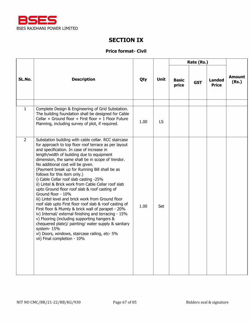
BSES RAJDHANI POWER LIMITED
NIT NO CMC/BR/21-22/RB/KG/930 Page 67 of 85 Bidders seal & signature
SECTION IX
Price format- Civil
SL.No. Description Qty Unit
Rate (Rs.)
Amount(Rs.) Basic
price GST Landed Price
1 Complete Design & Engineering of Grid Substation.
The building foundation shall be designed for Cable Cellar + Ground floor + First floor + 1 Floor Future Planning, including survey of plot, if required. 1.00 LS
2 Substation building with cable cellar. RCC staircase for approach to top floor roof terrace as per layout and specification. In case of increase in length/width of building due to equipment dimension, the same shall be in scope of Vendor. No additional cost will be given. (Payment break up for Running Bill shall be as follows for this item only.) i) Cable Cellar roof slab casting -25% ii) Lintel & Brick work from Cable Cellar roof slab upto Ground floor roof slab & roof casting of Ground floor - 10% iii) Lintel level and brick work from Ground floor roof slab upto First floor roof slab & roof casting of First floor & Mumty & brick wall of parapet - 20% iv) Internal/ external finishing and terracing - 15% v) Flooring (including supporting hangers & chequered plate)/ painting/ water supply & sanitary system- 15% vi) Doors, windows, staircase railing, etc- 5% vii) Final completion - 10%
1.00 Set
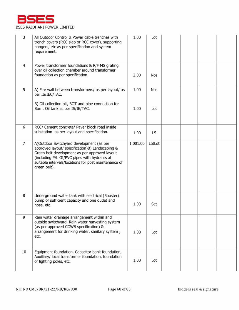
BSES RAJDHANI POWER LIMITED
NIT NO CMC/BR/21-22/RB/KG/930 Page 68 of 85 Bidders seal & signature
3 All Outdoor Control & Power cable trenches with trench covers (RCC slab or RCC cover), supporting hangers, etc as per specification and system requirement.
1.00 Lot
4 Power transformer foundations & P/F MS grating over oil collection chamber around transformer foundation as per specification. 2.00 Nos
5 A) Fire wall between transformers/ as per layout/ as per IS/IEC/TAC. B) Oil collection pit, BOT and pipe connection for Burnt Oil tank as per IS/IE/TAC.
1.00
1.00
Nos
Lot
6 RCC/ Cement concrete/ Paver block road inside substation as per layout and specification. 1.00 LS
7 A)Outdoor Switchyard development (as per approved layout/ specification)B) Landscaping & Green belt development as per approved layout (including P/L GI/PVC pipes with hydrants at suitable intervals/locations for post maintenance of green belt).
1.001.00 LotLot
8 Underground water tank with electrical (Booster) pump of sufficient capacity and one outlet and hose, etc. 1.00 Set
9 Rain water drainage arrangement within and outside switchyard, Rain water harvesting system (as per approved CGWB specification) & arrangement for drinking water, sanitary system , etc.
1.00 Lot
10 Equipment foundation, Capacitor bank foundation, Auxiliary/ local transformer foundation, foundation of lighting poles, etc. 1.00 Lot
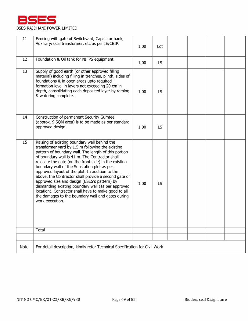
BSES RAJDHANI POWER LIMITED
NIT NO CMC/BR/21-22/RB/KG/930 Page 69 of 85 Bidders seal & signature
11 Fencing with gate of Switchyard, Capacitor bank, Auxiliary/local transformer, etc as per IE/CBIP. 1.00 Lot
12 Foundation & Oil tank for NIFPS equipment. 1.00 LS
13 Supply of good earth (or other approved filling material) including filling in trenches, plinth, sides of foundations & in open areas upto required formation level in layers not exceeding 20 cm in depth, consolidating each deposited layer by raming & watering complete.
1.00 LS
14 Construction of permanent Security Gumtee (approx. 9 SQM area) is to be made as per standard approved design. 1.00 LS
15 Raising of existing boundary wall behind the transformer yard by 1.5 m following the existing pattern of boundary wall. The length of this portion of boundary wall is 41 m. The Contractor shall relocate the gate (on the front side) in the existing boundary wall of the Substation plot as per approved layout of the plot. In addition to the above, the Contractor shall provide a second gate of approved size and design (BSES’s pattern) by dismantling existing boundary wall (as per approved location). Contractor shall have to make good to all the damages to the boundary wall and gates during work execution.
1.00 LS
Total
Note: For detail description, kindly refer Technical Specification for Civil Work
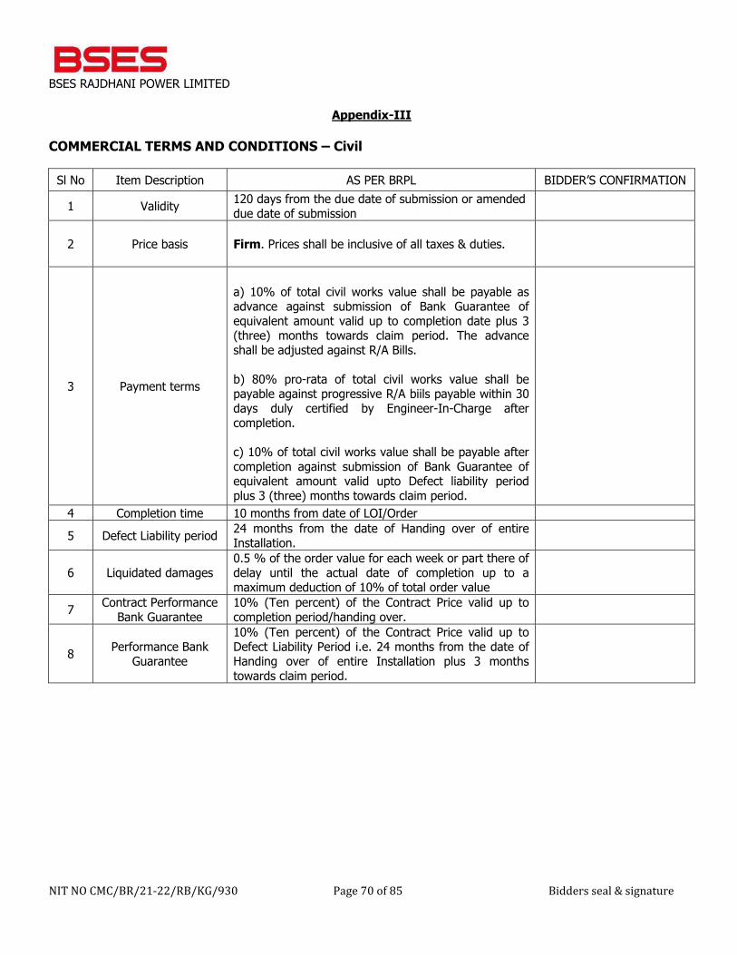
BSES RAJDHANI POWER LIMITED
NIT NO CMC/BR/21-22/RB/KG/930 Page 70 of 85 Bidders seal & signature
Appendix-III
COMMERCIAL TERMS AND CONDITIONS – Civil
Sl No Item Description AS PER BRPL BIDDER’S CONFIRMATION
1 Validity 120 days from the due date of submission or amended due date of submission
2 Price basis Firm. Prices shall be inclusive of all taxes & duties.
3 Payment terms
a) 10% of total civil works value shall be payable as advance against submission of Bank Guarantee of equivalent amount valid up to completion date plus 3 (three) months towards claim period. The advance shall be adjusted against R/A Bills. b) 80% pro-rata of total civil works value shall be payable against progressive R/A biils payable within 30 days duly certified by Engineer-In-Charge after completion. c) 10% of total civil works value shall be payable after completion against submission of Bank Guarantee of equivalent amount valid upto Defect liability period plus 3 (three) months towards claim period.
4 Completion time 10 months from date of LOI/Order
5 Defect Liability period 24 months from the date of Handing over of entire Installation.
6 Liquidated damages 0.5 % of the order value for each week or part there of delay until the actual date of completion up to a maximum deduction of 10% of total order value
7 Contract Performance Bank Guarantee
10% (Ten percent) of the Contract Price valid up to completion period/handing over.
8 Performance Bank Guarantee
10% (Ten percent) of the Contract Price valid up to Defect Liability Period i.e. 24 months from the date of Handing over of entire Installation plus 3 months towards claim period.
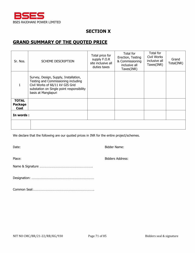
BSES RAJDHANI POWER LIMITED
NIT NO CMC/BR/21-22/RB/KG/930 Page 71 of 85 Bidders seal & signature
SECTION X GRAND SUMMARY OF THE QUOTED PRICE
We declare that the following are our quoted prices in INR for the entire project/schemes. Date: Bidder Name: Place: Bidders Address: Name & Signature ……………………………………………………. Designation: ……………………………………………………………… Common Seal:…………………………………………………………….
Sr. Nos. SCHEME DESCRIPTION Total price for supply F.O.R
site inclusive all duties taxes
Total for Erection, Testing & Commissioning
inclusive all Taxes(INR)
Total for Civil Works inclusive all Taxes(INR)
Grand Total(INR)
1
Survey, Design, Supply, Installation, Testing and Commissioning including Civil Works of 66/11 kV GIS Grid substation on Single point responsibility basis at Manglapuri
TOTAL Package
Cost
In words :
BSES RAJDHANI POWER LIMITED
NIT NO CMC/BR/21-22/RB/KG/930 Page 72 of 85 Bidders seal & signature
APPENDIX IV
BID FORM
To
Head of Department Contracts & Material Deptt. BSES Rajdhani Power Ltd New Delhi 110019 Sir,
1 We understand that BRPL is desirous of execution of …………………………………………………………………………………………………(Name of work) 2 Having examined the Bidding Documents for the above named works, we the undersigned, offer to deliver the goods in full conformity with the Terms and Conditions and technical specifications for the sum indicated in Price Bid or such other sums as may be determined in accordance with the terms and conditions of the contract .The above amounts are in accordance with the Price Schedules attached herewith and are made part of this bid. 3 If our Bid is accepted, we undertake to deliver the entire goods as) as per delivery schedule mentioned in Section IV from the date of award of purchase order/letter of intent. 4 If our Bid is accepted, we will furnish a performance bank guarantee for an amount of 10% (Ten)percent of the total contract value for due performance of the Contract in accordance with the Terms and Conditions. 5 We agree to abide by this Bid for a period of 120 days from the due date of bid submission & subsequent corrigendum/amendment/extension of due date of submission. It shall remain binding upon us and may be accepted at any time before the expiration of that period.
6 We declare that we have studied the provision of Indian Laws for supply of equipments/materials and the prices have been quoted accordingly.
7 Unless and until Letter of Intent is issued, this Bid, together with your written acceptance there of, shall constitute a binding contract between us.
8 We understand that you are not bound to accept the lowest, or any bid you may receive. 9 There is provision for Resolution of Disputes under this Contract, in accordance with the Laws and Jurisdiction of
Contract. Dated this............................... day of................................................. 20…..
Signature.............................................. In the capacity of
………………………………..................................................................duly authorized to sign for
and on behalf of
(IN BLOCK CAPITALS)...............................................................................
BSES RAJDHANI POWER LIMITED
NIT NO CMC/BR/21-22/RB/KG/930 Page 73 of 85 Bidders seal & signature
Appendix V
ACCEPTANCE FORM FOR PARTICIPATION IN REVERSE AUCTION EVENT
(To be signed & stamped by the bidder along-with bid)
BSES Rajdhani Power Ltd (BRPL) intends to use reverse auction through SAP-SRM tool as an integral part of entire tendering process. All techno-commercially qualified bidders shall participate in the reverse auction. The following terms and conditions are deemed as accepted by the bidder on participation in the bid:- 1. In case of bidding through Internet medium, bidders are advised to ensure availability of all associated infrastructure
as required to participate in the reverse auction event. Inability to bid due to telephone glitch, internet response issues, software & hardware hangs/failures, power failures or any other reason shall not be the responsibility of BRPL.
2. In case bidder fails to participate in the reverse auction event due to any reason whatsoever, it shall be presumed that the bidder has no further discounts to offer and the initial bid submitted by them as a part of tender shall be considered as bidder’s Final No Regret offer. Any off-line price bids received from a bidder in lieu of non-participation in the reverse auction event shall be rejected by BRPL.
3. The bidder is advised to understand the auto bid process t safeguard themselves against any possibility of non-participation in the reverse auction event.
4. The bidder shall be prepared with competitive price quotes during the day of reverse auction event. 5. The prices quoted by bidder in reverse auction event shall be on FOR Landed cost BRPL Store/site basis inclusive of all
relevant taxes, duties, levies, transportation charges etc. 6. The prices submitted by the bidder during reverse auction event shall be binding on the Bidder. 7. The bidder agrees to non-disclosure of trade information regarding bid details e.g. purchase, Identity, bid
process/technology, bid documentation etc. 8. BRPL will make every effort to make the bid process transparent. However award decision of BRPL will be final and binding on the bidder. 9. The prices submitted during reverse auction event shall be binding on the bidder. 10. No request for Time extension of the reverse auction event shall be considered by BRPL. 11. BRPL shall provide the user id and password to the authorized representative of the bidder. Authorization letter in
lieu of the same shall be submitted along with the signed and stamped acceptance form. 12. The original price bids of the bidders shall be reduced on pro-rata basis against each line item based on the final all
inclusive prices offered during conclusion of the reverse auction event for arriving at contract amount
BSES RAJDHANI POWER LIMITED
NIT NO CMC/BR/21-22/RB/KG/930 Page 74 of 85 Bidders seal & signature
APPENDIX VI
FORMAT FOR EMD BANK GUARANTEE (To be issued in a Non Judicial Stamp Paper of Rs.50/-purchased in the name of the bank)
Whereas [name of the Bidder] (herein after called the “Bidder“) has submitted its bid dated [date of submission of bid] for the supply of [name and/or description of the goods] (here after called the “Bid”).
KNOW ALL PEOPLE by these presents that WE [name of bank] at [Branch Name and address],having our registered office at[address of the registered office of the bank](herein after called the “Bank“),are bound unto BSES Rajdhani Power Ltd., with it‘s Corporate Office at BSES Bhawan Nehru Place, New Delhi -110019 ,(herein after called —the “Purchaser“)in the sum of Rs. ……………/- (Rupees ……………………………….. only) for which payment well and truly to be made to the said Purchaser, the Bank binds itself, its successors, and assigns by these presents.
Sealed with the Common Seal of the said Bank this_____ day of________ 20____.
THE CONDITIONS of this obligation are:
1 If the Bidder withdraws its Bid during the period of bid validity specified by the Bidder on the Bid Form ; or 2. If the Bidder, having been notified of the acceptance of its Bid by the Purchaser during the period of bid validity: (a) Fails or refuses to execute the Contract Form, if required; or (b) Fails or refuses to furnish the performance security, In accordance with the Instructions to Bidders/ Terms and Conditions; We undertake to pay to the Purchaser up to the above amount upon receipt of its first written demand, without the Purchaser having to substantiate its demand, provided that is its demand the purchaser will note that amount claimed by it is due to it, owing to the occurrence of one or both of the two condition(s), specifying the occurred condition or condition(s).
This guarantee will remain in force up to and including One Hundred Twenty (120) days after the due date of submission bid, and any demand in respect thereof should reach the Bank not later than the above date. (Stamp & signature of the bank) Signature of the witness
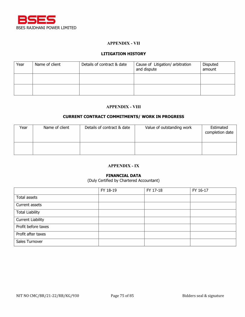
BSES RAJDHANI POWER LIMITED
NIT NO CMC/BR/21-22/RB/KG/930 Page 75 of 85 Bidders seal & signature
APPENDIX - VII
LITIGATION HISTORY
Year Name of client Details of contract & date Cause of Litigation/ arbitration
and dispute Disputed amount
APPENDIX - VIII
CURRENT CONTRACT COMMITMENTS/ WORK IN PROGRESS
Year Name of client Details of contract & date Value of outstanding work Estimated completion date
APPENDIX - IX
FINANCIAL DATA (Duly Certified by Chartered Accountant)
FY 18-19 FY 17-18 FY 16-17 Total assets
Current assets
Total Liability
Current Liability Profit before taxes
Profit after taxes
Sales Turnover
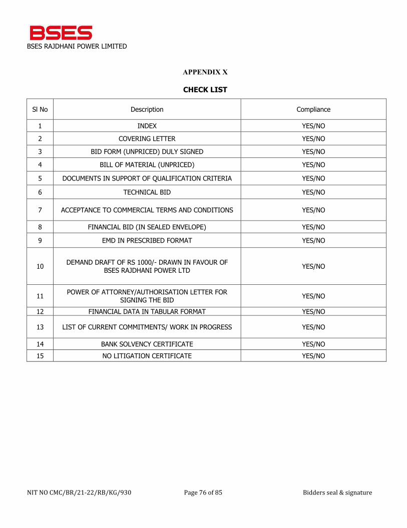
BSES RAJDHANI POWER LIMITED
NIT NO CMC/BR/21-22/RB/KG/930 Page 76 of 85 Bidders seal & signature
APPENDIX X
CHECK LIST
Sl No Description Compliance
1 INDEX YES/NO
2 COVERING LETTER YES/NO
3 BID FORM (UNPRICED) DULY SIGNED YES/NO
4 BILL OF MATERIAL (UNPRICED) YES/NO
5 DOCUMENTS IN SUPPORT OF QUALIFICATION CRITERIA YES/NO
6 TECHNICAL BID YES/NO
7 ACCEPTANCE TO COMMERCIAL TERMS AND CONDITIONS YES/NO
8 FINANCIAL BID (IN SEALED ENVELOPE) YES/NO
9 EMD IN PRESCRIBED FORMAT YES/NO
10 DEMAND DRAFT OF RS 1000/- DRAWN IN FAVOUR OF BSES RAJDHANI POWER LTD YES/NO
11 POWER OF ATTORNEY/AUTHORISATION LETTER FOR SIGNING THE BID YES/NO
12 FINANCIAL DATA IN TABULAR FORMAT YES/NO
13 LIST OF CURRENT COMMITMENTS/ WORK IN PROGRESS YES/NO
14 BANK SOLVENCY CERTIFICATE YES/NO 15 NO LITIGATION CERTIFICATE YES/NO
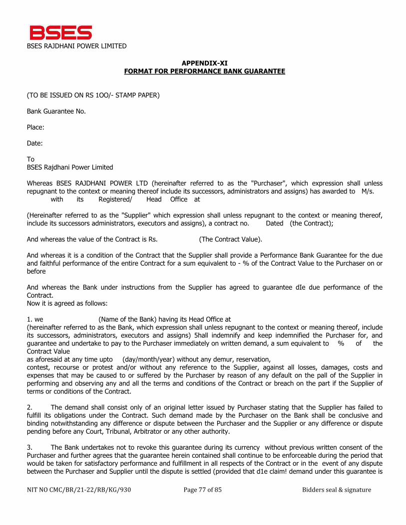
BSES RAJDHANI POWER LIMITED
NIT NO CMC/BR/21-22/RB/KG/930 Page 77 of 85 Bidders seal & signature
APPENDIX-XI FORMAT FOR PERFORMANCE BANK GUARANTEE
(TO BE ISSUED ON RS 1OO/- STAMP PAPER) Bank Guarantee No. Place: Date: To BSES Rajdhani Power Limited Whereas BSES RAJDHANI POWER LTD (hereinafter referred to as the "Purchaser", which expression shall unless repugnant to the context or meaning thereof include its successors, administrators and assigns) has awarded to M/s. with its Registered/ Head Office at (Hereinafter referred to as the "Supplier" which expression shall unless repugnant to the context or meaning thereof, include its successors administrators, executors and assigns), a contract no. Dated (the Contract); And whereas the value of the Contract is Rs. (The Contract Value). And whereas it is a condition of the Contract that the Supplier shall provide a Performance Bank Guarantee for the due and faithful performance of the entire Contract for a sum equivalent to - % of the Contract Value to the Purchaser on or before And whereas the Bank under instructions from the Supplier has agreed to guarantee dIe due performance of the Contract. Now it is agreed as follows: 1. we (Name of the Bank) having its Head Office at (hereinafter referred to as the Bank, which expression shall unless repugnant to the context or meaning thereof, include its successors, administrators, executors and assigns) 5hall indemnify and keep indemnified the Purchaser for, and guarantee and undertake to pay to the Purchaser immediately on written demand, a sum equivalent to % of the Contract Value as aforesaid at any time upto (day/month/year) without any demur, reservation, contest, recourse or protest and/or without any reference to the Supplier, against all losses, damages, costs and expenses that may be caused to or suffered by the Purchaser by reason of any default on the pall of the Supplier in performing and observing any and all the terms and conditions of the Contract or breach on the part if the Supplier of terms or conditions of the Contract. 2. The demand shall consist only of an original letter issued by Purchaser stating that the Supplier has failed to fulfill its obligations under the Contract. Such demand made by the Purchaser on the Bank shall be conclusive and binding notwithstanding any difference or dispute between the Purchaser and the Supplier or any difference or dispute pending before any Court, Tribunal, Arbitrator or any other authority. 3. The Bank undertakes not to revoke this guarantee during its currency without previous written consent of the Purchaser and further agrees that the guarantee herein contained shall continue to be enforceable during the period that would be taken for satisfactory performance and fulfillment in all respects of the Contract or in the event of any dispute between the Purchaser and Supplier until the dispute is settled (provided that d1e claim! demand under this guarantee is
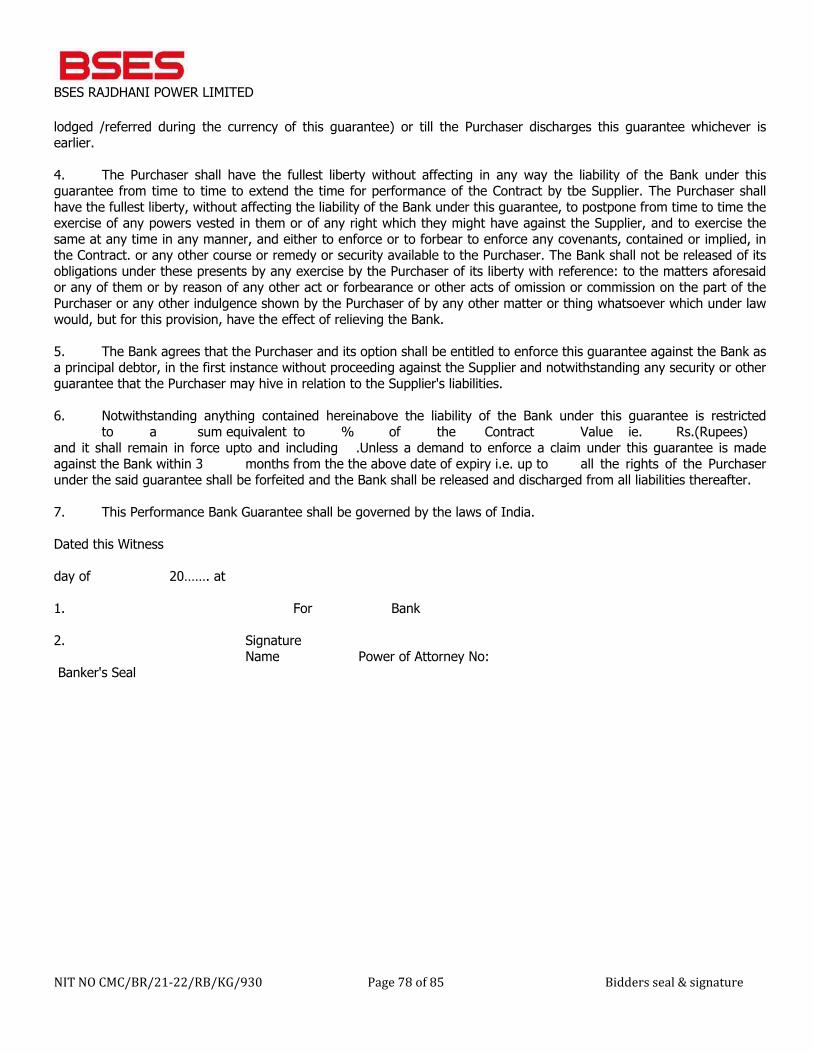
BSES RAJDHANI POWER LIMITED
NIT NO CMC/BR/21-22/RB/KG/930 Page 78 of 85 Bidders seal & signature
lodged /referred during the currency of this guarantee) or till the Purchaser discharges this guarantee whichever is earlier. 4. The Purchaser shall have the fullest liberty without affecting in any way the liability of the Bank under this guarantee from time to time to extend the time for performance of the Contract by tbe Supplier. The Purchaser shall have the fullest liberty, without affecting the liability of the Bank under this guarantee, to postpone from time to time the exercise of any powers vested in them or of any right which they might have against the Supplier, and to exercise the same at any time in any manner, and either to enforce or to forbear to enforce any covenants, contained or implied, in the Contract. or any other course or remedy or security available to the Purchaser. The Bank shall not be released of its obligations under these presents by any exercise by the Purchaser of its liberty with reference: to the matters aforesaid or any of them or by reason of any other act or forbearance or other acts of omission or commission on the part of the Purchaser or any other indulgence shown by the Purchaser of by any other matter or thing whatsoever which under law would, but for this provision, have the effect of relieving the Bank. 5. The Bank agrees that the Purchaser and its option shall be entitled to enforce this guarantee against the Bank as a principal debtor, in the first instance without proceeding against the Supplier and notwithstanding any security or other guarantee that the Purchaser may hive in relation to the Supplier's liabilities. 6. Notwithstanding anything contained hereinabove the liability of the Bank under this guarantee is restricted to a sum equivalent to % of the Contract Value ie. Rs.(Rupees) and it shall remain in force upto and including .Unless a demand to enforce a claim under this guarantee is made against the Bank within 3 months from the the above date of expiry i.e. up to all the rights of the Purchaser under the said guarantee shall be forfeited and the Bank shall be released and discharged from all liabilities thereafter. 7. This Performance Bank Guarantee shall be governed by the laws of India. Dated this Witness day of 20……. at 1. For Bank 2. Signature Name Power of Attorney No: Banker's Seal
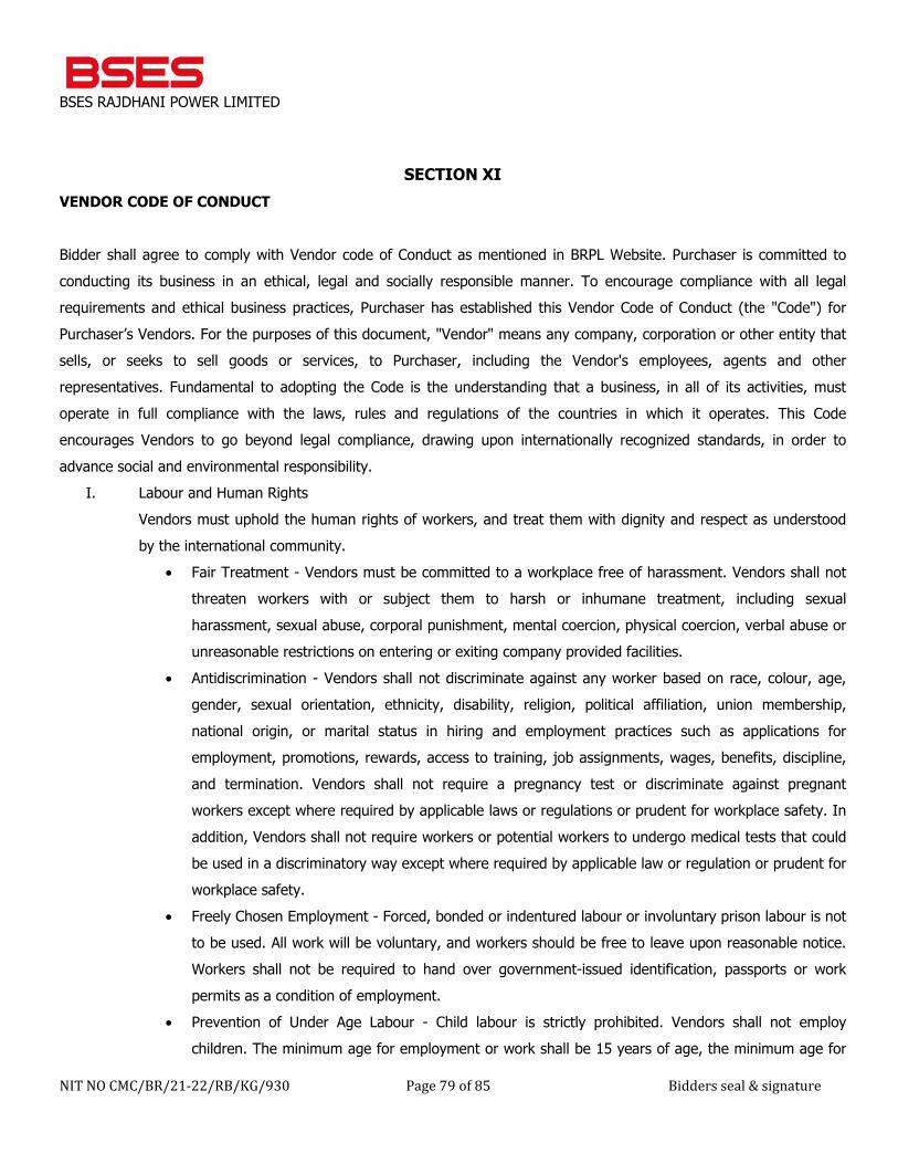
BSES RAJDHANI POWER LIMITED
NIT NO CMC/BR/21-22/RB/KG/930 Page 79 of 85 Bidders seal & signature
SECTION XI
VENDOR CODE OF CONDUCT Bidder shall agree to comply with Vendor code of Conduct as mentioned in BRPL Website. Purchaser is committed to conducting its business in an ethical, legal and socially responsible manner. To encourage compliance with all legal requirements and ethical business practices, Purchaser has established this Vendor Code of Conduct (the "Code") for Purchaser’s Vendors. For the purposes of this document, "Vendor" means any company, corporation or other entity that sells, or seeks to sell goods or services, to Purchaser, including the Vendor's employees, agents and other representatives. Fundamental to adopting the Code is the understanding that a business, in all of its activities, must operate in full compliance with the laws, rules and regulations of the countries in which it operates. This Code encourages Vendors to go beyond legal compliance, drawing upon internationally recognized standards, in order to advance social and environmental responsibility.
I. Labour and Human Rights Vendors must uphold the human rights of workers, and treat them with dignity and respect as understood by the international community.
• Fair Treatment - Vendors must be committed to a workplace free of harassment. Vendors shall not threaten workers with or subject them to harsh or inhumane treatment, including sexual harassment, sexual abuse, corporal punishment, mental coercion, physical coercion, verbal abuse or unreasonable restrictions on entering or exiting company provided facilities.
• Antidiscrimination - Vendors shall not discriminate against any worker based on race, colour, age, gender, sexual orientation, ethnicity, disability, religion, political affiliation, union membership, national origin, or marital status in hiring and employment practices such as applications for employment, promotions, rewards, access to training, job assignments, wages, benefits, discipline, and termination. Vendors shall not require a pregnancy test or discriminate against pregnant workers except where required by applicable laws or regulations or prudent for workplace safety. In addition, Vendors shall not require workers or potential workers to undergo medical tests that could be used in a discriminatory way except where required by applicable law or regulation or prudent for workplace safety.
• Freely Chosen Employment - Forced, bonded or indentured labour or involuntary prison labour is not to be used. All work will be voluntary, and workers should be free to leave upon reasonable notice. Workers shall not be required to hand over government-issued identification, passports or work permits as a condition of employment.
• Prevention of Under Age Labour - Child labour is strictly prohibited. Vendors shall not employ children. The minimum age for employment or work shall be 15 years of age, the minimum age for

BSES RAJDHANI POWER LIMITED
NIT NO CMC/BR/21-22/RB/KG/930 Page 80 of 85 Bidders seal & signature
employment in that country, or the age for completing compulsory education in that country, whichever is higher. This Code does not prohibit participation in legitimate workplace apprenticeship programs that are consistent with Article 6 of ILO Minimum Age Convention No. 138 or light work consistent with Article 7 of ILO Minimum Age Convention No. 138.
• Juvenile Labour - Vendors may employ juveniles who are older than the applicable legal minimum age for employment but are younger than 18 years of age, provided they do not perform work likely to jeopardize their heath, safety, or morals, consistent with ILO Minimum Age Convention No. 138.
• Minimum Wages - Compensation paid to workers shall comply with all applicable wage laws, including those relating to minimum wages, overtime hours and legally mandated benefits. Any disciplinary wage deductions are to conform to local law. The basis on which workers are being paid is to be clearly conveyed to them in a timely manner.
• Working Hours - Studies of good manufacturing practices clearly link worker strain to reduced productivity, increased turnover and increased injury and illness. Work weeks are not to exceed the maximum set by local law. Further, a work week should not be more than 60 hours per week, including overtime, except in emergency or unusual situations. Workers should be allowed at least one day off per seven-day week.
• Freedom of Association - Open communication and direct engagement between workers and management are the most effective ways to resolve workplace and compensation issues. Vendors are to respect the rights of workers to associate freely and to communicate openly with management regarding working conditions without fear of reprisal, intimidation or harassment. Workers’ rights to join labour unions, seek representation and or join worker’s councils in accordance with local laws should be acknowledged.
II. Health and Safety Vendors must recognize that in addition to minimizing the incidence of work-related injury and illness, a safe and healthy work environment enhances the quality of products and services, consistency of production and worker retention and morale. Vendors must also recognize that ongoing worker input and education is essential to identifying and solving health and safety issues in the workplace. The health and safety standards are:
• Occupational Injury and Illness - Procedures and systems are to be in place to prevent, manage, track and report occupational injury and illness, including provisions to: a) encourage worker reporting; b) classify and record injury and illness cases; c) provide necessary medical treatment; d) investigate cases and implement corrective actions to eliminate their causes; and e) facilitate return of workers to work.
• Emergency Preparedness - Emergency situations and events are to be identified and assessed, and• their impact minimized by implementing emergency plans and response procedures, including:
BSES RAJDHANI POWER LIMITED
NIT NO CMC/BR/21-22/RB/KG/930 Page 81 of 85 Bidders seal & signature
emergency reporting, employee notification and evacuation procedures, worker training and drills, appropriate fire detection and suppression equipment, adequate exit facilities and recovery plans.
• Occupational Safety - Worker exposure to potential safety hazards (e.g., electrical and other energy sources, fire, vehicles, and fall hazards) are to be controlled through proper design, engineering and administrative controls, preventative maintenance and safe work procedures (including lockout/tagout), and ongoing safety training. Where hazards cannot be adequately controlled by these means, workers are to be provided with appropriate, well-maintained, personal protective equipment. Workers shall not be disciplined for raising safety concerns.
• Machine Safeguarding - Production and other machinery is to be evaluated for safety hazards. Physical guards, interlocks and barriers are to be provided and properly maintained where machinery presents an injury hazard to workers.
• Industrial Hygiene - Worker exposure to chemical, biological and physical agents is to be identified, evaluated, and controlled. Engineering or administrative controls must be used to control overexposures. When hazards cannot be adequately controlled by such means, worker health is to be protected by appropriate personal protective equipment programs.
• Sanitation, Food, and Housing - Workers are to be provided with ready access to clean toilet facilities, potable water and sanitary food preparation, storage, and eating facilities. Worker dormitories provided by the Participant or a labour agent are to be maintained clean and safe, and provided with appropriate emergency egress, hot water for bathing and showering, and adequate heat and ventilation and reasonable personal space along with reasonable entry and exit privileges.
• Physically Demanding Work - Worker exposure to the hazards of physically demanding tasks,• including manual material handling and heavy or repetitive lifting, prolonged standing and highly repetitive or forceful assembly tasks is to be identified, evaluated and controlled.
III. Environmental
Vendors should recognize that environmental responsibility is integral to producing world class products. In manufacturing operations, adverse effects on the environment and natural resources are to be minimized while safeguarding the health and safety of the public. The environmental standards are:
• Product Content Restrictions - Vendors are to adhere to applicable laws and regulations regarding prohibition or restriction of specific substances including labeling laws and regulations for recycling and disposal. In addition, Vendors are to adhere to all environmental requirements specified by Purchaser.
BSES RAJDHANI POWER LIMITED
NIT NO CMC/BR/21-22/RB/KG/930 Page 82 of 85 Bidders seal & signature
• Chemical and Hazardous Materials -Chemical and other materials posing a hazard if released to the environment are to be identified and managed to ensure their safe handling, movement, storage, recycling or reuse and disposal.
• Air Emissions - Air emissions of volatile organic chemicals, aerosols, corrosives, particulates, ozone depleting chemicals and combustion by-products generated from operations are to be characterized, monitored, controlled and treated as required prior to discharge.
• Pollution Prevention and Resource Reduction -Waste of all types, including water and energy, are to be reduced or eliminated at the source or by practices such as modifying production, maintenance and facility processes, materials substitution, conservation, recycling and re-using materials.
• Wastewater and Solid Waste - Wastewater and solid waste generated from operations, industrial processes and sanitation facilities are to be monitored, controlled and treated as required prior to discharge or disposal.
• Environmental Permits and Reporting - All required environmental permits (e.g. discharge• monitoring) and registrations are to be obtained, maintained and kept current and their operational and reporting requirements are to be followed.
IV. Ethics Vendors must be committed to the highest standards of ethical conduct when dealing with workers, Vendors, and customers.
• Corruption, Extortion, or Embezzlement - Corruption, extortion, and embezzlement, in any form, are strictly prohibited. Vendors shall not engage in corruption, extortion or embezzlement in any form and violations of this prohibition may result in immediate termination as an Vendor and in legal action.
• Disclosure of Information - Vendors must disclose information regarding its business activities, structure, financial situation, and performance in accordance with applicable laws and regulations and prevailing industry practices.
• No Improper Advantage - Vendors shall not offer or accept bribes or other means of obtaining undue or improper advantage.
• Fair Business, Advertising, and Competition - Vendors must uphold fair business standards in• advertising, sales, and competition.
• Business Integrity - The highest standards of integrity are to be expected in all business interactions. Participants shall prohibit any and all forms of corruption, extortion and embezzlement. Monitoring and enforcement procedures shall be implemented to ensure conformance.

BSES RAJDHANI POWER LIMITED
NIT NO CMC/BR/21-22/RB/KG/930 Page 83 of 85 Bidders seal & signature
• Community Engagement - Vendors are encouraged to engage the community to help foster social and economic development and to contribute to the sustainability of the communities in which they operate.
• Protection of Intellectual Property - Vendors must respect intellectual property rights; safeguard customer information; and transfer of technology and know-how must be done in a manner that protects intellectual property rights.
V. Management System Vendors shall adopt or establish a management system whose scope is related to the content of this Code. The management system shall be designed to ensure (a) compliance with applicable laws, regulations and customer requirements related to the Vendors’ operations and products; (b) conformance with this Code; and (c) identification and mitigation of operational risks related to this Code. It should also facilitate continual improvement. The management system should contain the following elements:
• Company Commitment - Corporate social and environmental responsibility statements affirming Vendor’s commitment to compliance and continual improvement.
• Management Accountability and Responsibility - Clearly identified company representative[s] responsible for ensuring implementation and periodic review of the status of the management systems.
• Legal and Customer Requirements - Identification, monitoring and understanding of applicable laws, regulations and customer requirements.
• Risk Assessment and Risk Management - Process to identify the environmental, health and safety and labour practice risks associated with Vendor’s operations. Determination of the relative significance for each risk and implementation of appropriate procedural and physical controls to ensure regulatory compliance to control the identified risks.
• Performance Objectives with Implementation Plan and Measures - Areas to be included in a risk assessment for health and safety are warehouse and storage facilities, plant/facilities support equipment, laboratories and test areas, sanitation facilities (bathrooms), kitchen/cafeteria and worker housing /dormitories. Written standards, performance objectives, targets and implementation plans including a periodic assessment of Vendor’s performance against those objectives.
• Training - Programs for training managers and workers to implement Vendor’s policies, procedures and improvement objectives.
• Communication - Process for communicating clear and accurate information about Vendor’s performance, practices and expectations to workers, Vendors and customers.
BSES RAJDHANI POWER LIMITED
NIT NO CMC/BR/21-22/RB/KG/930 Page 84 of 85 Bidders seal & signature
• Worker Feedback and Participation - Ongoing processes to assess employees’ understanding of• and obtain feedback on practices and conditions covered by this Code and to foster continuous improvement.
• Audits and Assessments - Periodic self-evaluations to ensure conformity to legal and regulatory• requirements, the content of the Code and customer contractual requirements related to social and environmental responsibility.
• Corrective Action Process - Process for timely correction of deficiencies identified by internal or• external assessments, inspections, investigations and reviews.
• Documentation and Records - Creation of documents and records to ensure regulatory compliance• and conformity to company requirements along with appropriate confidentiality to protect privacy.
The Code is modelled on and contains language from the Recognized standards such as International Labour Organization Standards (ILO), Universal Declaration of Human Rights (UDHR), United Nations Convention against Corruption, and the Ethical Trading Initiative (ETI) were used as references in preparing this Code and may be useful sources of additional information.
BSES RAJDHANI POWER LIMITED
NIT NO CMC/BR/21-22/RB/KG/930 Page 85 of 85 Bidders seal & signature
ANNEXURE-I
TECHNICAL SPECIFICATIONS
BSES Bhawan, Nehru Place, New Delhi- 19
TECHNICAL SPECIFICATION
FOR
ERECTION, TESTING & COMMISIONING OF 66/11kV MANGLAPURI GIS GRID SUBSTATION
AT NEW DELHI ON TURNKEY BASIS
( SPEC NO. BRPL-EHV-TS- MGL)
Prepared by Javed Ahmed Rev: 0
Reviewed by Abhinav Srivastava Date: 17.05.2021
Approved by K.Sheshadri
BSES Bhawan, Nehru Place, New Delhi- 19
Technical Specification for 66/11KV Manglapuri GIS Grid Substation in New Delhi
INDEX
S.No Description Page. No 1 General Design Criteria 1 2 Civil Work 14 3 66kV GIS 42 4 66kV CRP 79 5 Battery Charger 96 6 Li-Ion Battery 103 7 415 V AC Distribution Board 113 8 Grounding & Lightning Protection System 118 9 LT Power Cable 128 10 Control Cable 150
11 Illumination System 159 12 11KV Indoor Switchgear 165 13 Cable Installation & Accessories 182 14 Exhaust and Ventilation 188 15 Fire Extinguisher 192 16 Fire Suppression system 195 17 Video Surveillance System 203 18 Fire Detection & Alarm System 208 19 Packing & Transportation 212 20 Materials Workmanship & Tests 215 21 Misc Activities 219 22 EOT Crane 226 23 Cable Seal Solution 232 24 Spares Maintenance Tools and Tackles 238 25 Station Transformer 241 26 SCADA Interface Works & Automation 276 27 11KV Auto-Switched Capacitor Bank 303 28 Power Transformer 315 29 Structural Work 381 30 Lightning Arrestor 388 31 High Mast 391 32 Outdoor Switchyard Material 404 33 IT Devices 416 34 Approved Vendors 424 35 Training and Inspection 429
BSES Bhawan, Nehru Place, New Delhi- 19
Technical Specification for 66/11KV Manglapuri GIS Grid Substation in New Delhi
SCHEDULE & ANNEXURE
Volume-2
Schedule Description Page No. Technical Specification of ABT Meter 434 Annexure M Specification for Measurement Instruments 447 Annexure-O Technical specification for New Grids 24x7 O&M support 450 Schedule – A Schedule of General Information 451 Schedule – C1 Technical Data Sheets of HT Indoor Switchgear 453 Schedule – C2 Technical Data Sheets of CRP 467 Schedule – C3 Technical Data Sheets of Battery Chargers 471 Schedule – C4 Technical Data Sheets of Battery Bank 473 Schedule – C6 Technical Data Sheets of 11KV Capacitor Bank 474 Schedule – C7 Technical Data Sheets of LT Power Cable 481 Schedule – C8 Technical Data Sheets of Control Cable 483 Schedule – C9 Technical Data Sheets of Illumination System 487 Schedule – C10 Technical Data Sheets of 415 V AC Distribution Board 490 Schedule – C11 Technical Data Sheets of Station Transformer 492 Schedule – C12 Technical Data Sheets of Grounding & Lightning Protection System 502 Schedule – C13 Technical Data Sheets of Cable Accessories 503 Schedule – C14 Technical Data Sheets of Cable Trays 504 Schedule – C15 Technical Data Sheets of 66kV GIS 505 Schedule – C16 Technical Data Sheets of Power Transformer 521 Schedule – C17 Technical Data Sheets of Outdoor LA 530 Schedule – E1 & E2 Deviation from Specification 533 Schedule – F List of Drawings enclosed with Bid 535 Schedule – G Schedule of Tests 536
Schedule – H List of instruments, Testing Equipment, Tools & Tackles for Erection & Maintenance
537
Schedule – I List of Installation 538 Schedule – J Delivery, Terms and Conditions 539 Schedule – K Schedule of Recommended Spares 541 Schedule – L Declaration 542 Drawings.
1 Main Single Line Diagram 543 2 Substation Layout Plan (suggestive) 544
Prepared by Javed Ahmed Rev: 0
Reviewed by Abhinav Srivastava Date: 17th May, 2021
Approved by K.Sheshadri
TECHNICAL SPECIFICATION
FOR
GENERAL DESIGN CRITERIA
1
Volume – I Technical Specification | General Design Criteria
BSES Bhawan, Nehru Place, New Delhi- 19
1.0 INTENT OF SPECIFICATION
This specification is intended to cover complete design, engineering, manufacturing, assembling,
testing at manufacturer’s works, supply and Transportation F.O.R. site of all equipment and
accessories, steel structures, all structural work, substation building, Civil and architectural work,
complete erection, testing, commissioning & putting into successful commercial operation of 66/11
KV GIS substation including supply of all Labour, supervision, tools & plants and supplies as
required.
The 66kV Gas insulated Double Bus substation shall have following bays with equipments and civil
works: - Four (04) no’s Feeder Bay – Two (02) no’s Transformer bay - One (01) no Bus Coupler bay.
-Two (02) sets Bus PT.
The substation shall have control room building with 11kV Indoor Switchgear, 66kV Control and
Relay Panel, 66kV GIS, Battery & Battery Charger, ACDB and DCDB etc. The suggestive Layout
Plan and Single Line diagram of the substation is enclosed.
This specification shall be read in conjunction with other sections of bidding document. In the event
of any discrepancy with the listed document, the most stringent one shall govern. In the tender
document, the term ‘Contractor’, ‘Bidder’ and ‘Vendor’ has been used interchangeably.
It is advisable that bidder should visit the site to confirm its present status prior to submission of their
bid.
2.0 SCOPE OF SUPPLY
This scope of work shall include design, engineering, manufacture, shop floor testing, inspection,
packing, dispatch, loading, unloading and storage at site, transit/storage and construction insurance,
assembly, erection, civil structural, architectural work, complete pre-commissioning checks, testing &
commissioning at site, obtaining statutory clearance & certification from State Electrical Inspector,
Municipal Corporation department, Fire officer, Horticulture department etc. and handing over to the
Owner after satisfactory commissioning of complete 66/11 kV substation of BSES Rajdhani Power
Ltd. at Manglapuri, New Delhi.
The scope includes all material, equipment and works required for the construction of the Substation
complete with all items considered essential for safe and trouble-free continuous commercial
operation of the system in a manner acceptable to the Owner and complying with latest revision of
National and International Standards, Codes & Practices, Indian Electricity Rules, CEA (Measures
relating to Safety and Electric Supply) Regulations 2010 and Indian Electricity Act.
The scope of supply broadly includes the following:
2
Volume – I Technical Specification | General Design Criteria
BSES Bhawan, Nehru Place, New Delhi- 19
2.1 Major Equipments:
� 11kV Auto-Switched Capacitor Bank (APFC) Outdoor Type - o 7.2 MVAR -2 Sets
� 66/11kV 31.5MVA Power Transformer and NIFPS along with accessories- 2 Sets
� 66KV GIS Panels (as per SLD) -9 Sets
� 220V Lithium Ion Battery bank-1 Set
� Battery charger with DCDB -1 Set
� ACDB -1 No.
� Station Aux. Transformer, 11/0.433kV, 400kVA -1 No with Station transformer to ACDB cable shall be 4CX150 sqmm
� SCADA RTU-1 Set
� High mast lights 16 M high-2 Nos
� Gas filling device with filter and leakage detector for above GIS Panel (DILO Make)- 1 Set
2.2 Item as System
� 11kV VCB Switchgear Panel board with Numerical protection relays (refer SLD).
� Earthing trucks for 11KV Panels -2Nos of bus earthing truck and 2Nos of cable earthing truck for each size of panel.
� All Numerical protection Relay shall be supplied with Conformal coating
� Grounding and earthing of entire substation including all the fences such as Power Transformer Fencing, Aux. transformer fencing and capacitor bank fencing as per Technical Specification. 220V Lithium Ion Battery bank, one set of Battery charger compatible with Li Ion battery.
� Outdoor illumination including street lighting with Poles.
� Indoor illumination including emergency lighting (DC lighting incase of black out)
� Air Conditioning, Exhaust and Ventilation for complete substation building.
� Fire detection and alarm system including its SCADA integration.
� Direct stroke lightning protection by shielding spikes.
� 11kV Panel Fire Suppression System including its SCADA integration
� Video Surveillance system including its SCADA integration.
� Material GPS Tracking System.
� Fiber optic Cable including patch cord, LIU splicing inside substation for line differential protection.
� Cable Trench Indoor and Outdoor (Control and Power Cable Trench shall be separate)
� In GIS room height till the hook of EOT crane shall not be less than twice the GIS height plus sling sag clearance. Additional height for EOT Crane Maintenance space shall be provided.
� Plinth of Power Transformer shall be considered for minimum 31.5MVA Power Transformer.
� GIS Cable cellar minimum height 3000mm with spare cable entry provision at least 4 nos circuit.
� Culvert for road crossing
� The building foundation shall be designed for Cable Cellar + Ground floor + First floor + 1 Floor ( Future expansion )
� Fire retardant paint for all cable entering to panels till the cable opening
� 6 Months O&M from the date of handing over of Substation (refer Annexure-O for Details).
� AC and DC Failure Hooter near Security gate at any pole
2.3 Items as Lot
� LT Power & Control cables (fire retardant type) supply and termination and Glands.
� Building Cable entry Sealing
3
Volume – I Technical Specification | General Design Criteria
BSES Bhawan, Nehru Place, New Delhi- 19
� Supply and providing 11KV Power cable termination kits and Glands.
� Cable trays
� Supply and ETC of GIS Termination Kits
� Supply and installation of Fire extinguisher
� Direct Stroke Lightning Protection for outdoor equipments
� Maintenance tools & tackles including testing & measuring instruments
� Cabling between equipments and RTU
� Supply Erection testing and commissioning of Line differential protection Relay at remote end
� Rubber Mat for all Indoor equipments front and back side
� Material required for IMS (Entry and Exit Sign,First aid Box)
2.4 Civil Works
� As per Civil specification
2.5. Design Work
Design documentation in sufficient copies including design memo, calculations, general
arrangement, plans, elevations and sectional drawings, sag/tension calculations, short circuit
calculations, electro-dynamic force calculations, single line diagrams, schematic interconnection
drawings, wiring diagrams, foundation calculations, foundation plans/details, cable schedules, bill of
materials, lighting system design calculations, earthing system design calculations, illumination
system design, calculation, conductor sizing, calculation insulation coordination, protection
coordination etc.
� Operation & Maintenance Manuals and As-built drawings. (Six sets hard copy & two sets
soft copy)
� Documentation required by State Electrical Inspector or by other statutory body for statutory
approval/certification of the Substation installation. (as required)
� Temporary sheds for storage of equipment, tools & tackles, construction offices with
required fittings & furnishings.
The above equipment and services are specifically listed for the guidance of the Bidder. Apart from
the above, Single Line Diagram and Layout Plan (suggestive) may also be referred for further details
of equipment. However, it is to be understood that the Contractor’s scope is not limited to the items
specifically listed above but covers all items required for the completion of a safe and fully functional
Substation.
2.6 Tools and Spares
Tools & Commissioning Spares: Contractor should be equipped with all tools, tackles and
commissioning spares for successful commissioning of substation.
Recommended Spares: Contractor shall be providing the Owner a list of recommended spares
along with quantity and market/budgetary prices. This shall be a recommendation only and shall not
be a part of quotation for price bid
4
Volume – I Technical Specification | General Design Criteria
BSES Bhawan, Nehru Place, New Delhi- 19
3.0 COMPLETION SCHEDULE The contractor shall be fully responsible to complete the project in time. It is desired that the total project should complete in 300 days from the date of LOA. The broad completion schedule is attached here under for reference. The detailed completion schedule shall be prepared by contractor in MS-Project or Primavera software and shall be submitted at the time of detail engineering for approval. The detailed schedule shall be finalized with the help of schedule given by Owner.
Activity schedule shall be as tabulated below. The reference date shall be the date of LOA.
Sl. No. Description of Work Time Line from
Zero Date(in days)
Responsibility
1 Zero Date (Letter of Award) 0 BRPL
2 Mobilization of manpower 15 Contractor
3 Inception Report 15 Contractor
4
PERT chart approval / L2 schedule majorly including :
� Manpower & Machinery to be deployed
� Procurement of major equipment
� Dispatch schedule of the major item
� Intermediate milestone schedule
15 Contractor
5 Submission of Drawings/Documents/ calculations for Engineering Approval
30 Contractor
6 Engineering Approval 60 BRPL
7 Civil Works 130 Contractor
8 Procurement/Supplies 210 Contractor
9 Equipment Erection 240 Contractor
10 Commissioning of 66kV line 255 BRPL
11 Commissioning of 1st
Power Transformer 255 Contractor
12 Commissioning of 2nd Power Transformer 270 Contractor
13 Testing & Commissioning of entire substation 285 Contractor
14 Handing Over 300 Contractor
4.0 ELECTRICITY & WATER FOR CONSTRUCTION
Electricity Supply and Water for construction purpose shall be arranged by Contractor.
5.0 SUPPLY AND WORKS BY BIDDER
The termination kits/jumpers, Glands, Cable Seal and interconnections for all the Cables/Conductors shall be in the scope of Contractor. Extension of 48 core (12 Single Mode and 36 Multimode) Fiber optic embedded in Infeed Power Cable and interconnections for all the Cables/Conductors (with all the accessories of 48 core FO including LIU, joint box, patch cord and extension of fiber optic from Power Cable to LIU), shall be in the scope of Contractor. Laying of cables and stringing of Conductors including its hardware fitting and insulators in the substation premises shall also be in the scope of Contractor only. Cable mounting structure for Power transformer Incoming shall be in Contractors scope.
5
Volume – I Technical Specification | General Design Criteria
BSES Bhawan, Nehru Place, New Delhi- 19
Works for Future Transformer like Transformer Foundation, Cable trench, Earthing, Cable Seal, Cable Trays shall be in Contractors scope. Also Earthing and grounding, DSLP, illumination, trenches for future transformer shall be in Contractors scope.
.WORKS BY OWNER: The following works shall be carried out by Owners: 1. Soil Investigation and Soil resistivity test 2. Topographical survey
The trenches and cable trays for Incoming/outgoing cables inside the Substation premises shall be in the scope of Contractor.
6.0 SUPPLIES AS FREE ISSUE ITEMS:
The following items shall be supplied free of cost to vendor:
� ACSR Zebra Conductor
� 11 kV 1x1000 sq. mm. XLPE Cables
� 11 kV 3x300 sq. mm. XLPE Cables
� 66kV 3Cx300 sq. mm XLPE Cables (If required)
� 66 kV 1x1000 sq.mm. XLPE Cables (if required)
However, the termination kits/jumpers, Glands and interconnections for the above Cables/Conductors shall be in the scope of vendor. Laying of these free issued cables, stringing of Conductors including its hardware fitting & insulators and ETC of Power Transformers in the substation premises shall also be in the scope of vendor only. Free issue and return of items/excess materials Transportation from BRPL Stores to Site or Site to BRPL stores shall be in Vendors Scope of work.
7.0 COORDINATION WITH STATUTORY BODIES & OUTSIDE AGENCIES
The Contractor shall be fully responsible for getting all statutory clearances, including but not limited to Electrical Inspector clearance, Civic Agencies (MCD/DDA/PWD or any other), Horticulture department, Fire officer or any other statutory bodies for implementation of the work.
The contractor shall be fully responsible for carrying out all co-ordination and liaison work as may be required with Electrical Inspector, Civic Agencies (MCD/DDA/PWD or any other), Horticulture department, Fire officer or any other statutory bodies for implementation of the work. The application on behalf of BRPL for submission to the Electrical Inspector and other statutory bodies along with copies of drawings complete in all respects shall be done by the contractor & approval / certificates shall be obtained by the contractor well ahead of time so that the actual commissioning of equipment is not delayed for want of inspection and approval by the inspector & statutory bodies. The contractor shall arrange the actual inspection work by Electrical Inspector. Official fees to electrical inspector / statutory bodies shall be paid by the Contractor.
8.0 COORDINATION WITH OTHER CONTRACTOR & OWNER’S SYSTEM
The contractor shall be fully responsible for carrying out all the co-ordination work required with their sub-contractors, if any, as well as with Owners system for execution and completion of work.
6
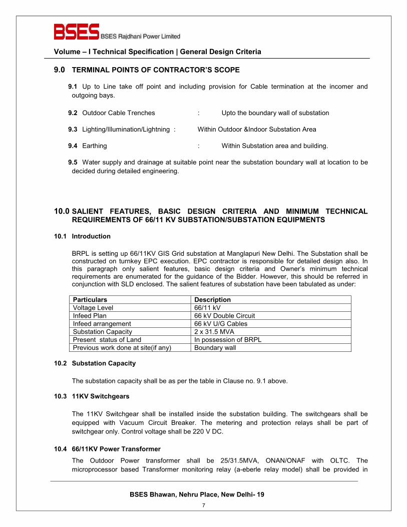
Volume – I Technical Specification | General Design Criteria
BSES Bhawan, Nehru Place, New Delhi- 19
9.0 TERMINAL POINTS OF CONTRACTOR’S SCOPE
9.1 Up to Line take off point and including provision for Cable termination at the incomer and
outgoing bays.
9.2 Outdoor Cable Trenches : Upto the boundary wall of substation
9.3 Lighting/Illumination/Lightning : Within Outdoor &Indoor Substation Area
9.4 Earthing : Within Substation area and building.
9.5 Water supply and drainage at suitable point near the substation boundary wall at location to be
decided during detailed engineering.
10.0 SALIENT FEATURES, BASIC DESIGN CRITERIA AND MINIMUM TECHNICAL REQUIREMENTS OF 66/11 KV SUBSTATION/SUBSTATION EQUIPMENTS
10.1 Introduction
BRPL is setting up 66/11KV GIS Grid substation at Manglapuri New Delhi. The Substation shall be constructed on turnkey EPC execution. EPC contractor is responsible for detailed design also. In this paragraph only salient features, basic design criteria and Owner’s minimum technical requirements are enumerated for the guidance of the Bidder. However, this should be referred in conjunction with SLD enclosed. The salient features of substation have been tabulated as under:
Particulars Description Voltage Level 66/11 kV
Infeed Plan 66 kV Double Circuit
Infeed arrangement 66 kV U/G Cables
Substation Capacity 2 x 31.5 MVA
Present status of Land In possession of BRPL
Previous work done at site(if any) Boundary wall
10.2 Substation Capacity
The substation capacity shall be as per the table in Clause no. 9.1 above.
10.3 11KV Switchgears The 11KV Switchgear shall be installed inside the substation building. The switchgears shall be
equipped with Vacuum Circuit Breaker. The metering and protection relays shall be part of
switchgear only. Control voltage shall be 220 V DC.
10.4 66/11KV Power Transformer
The Outdoor Power transformer shall be 25/31.5MVA, ONAN/ONAF with OLTC. The
microprocessor based Transformer monitoring relay (a-eberle relay model) shall be provided in
7
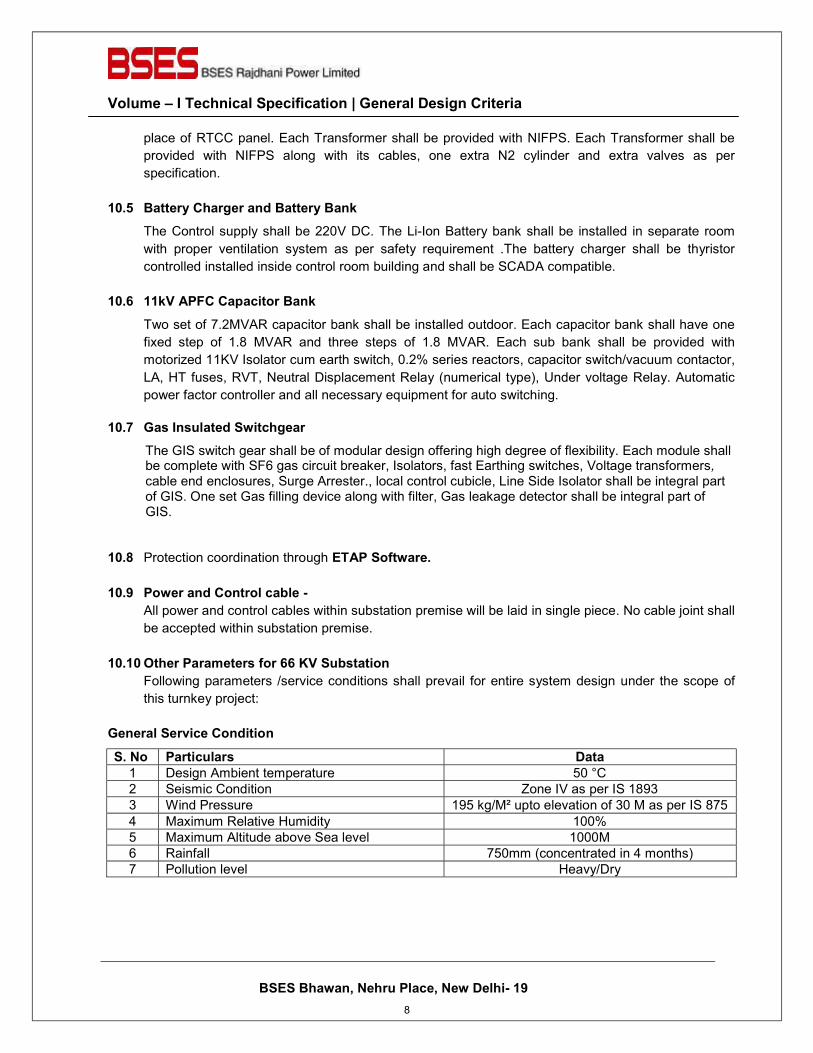
Volume – I Technical Specification | General Design Criteria
BSES Bhawan, Nehru Place, New Delhi- 19
place of RTCC panel. Each Transformer shall be provided with NIFPS. Each Transformer shall be
provided with NIFPS along with its cables, one extra N2 cylinder and extra valves as per
specification.
10.5 Battery Charger and Battery Bank
The Control supply shall be 220V DC. The Li-Ion Battery bank shall be installed in separate room
with proper ventilation system as per safety requirement .The battery charger shall be thyristor
controlled installed inside control room building and shall be SCADA compatible.
10.6 11kV APFC Capacitor Bank
Two set of 7.2MVAR capacitor bank shall be installed outdoor. Each capacitor bank shall have one
fixed step of 1.8 MVAR and three steps of 1.8 MVAR. Each sub bank shall be provided with
motorized 11KV Isolator cum earth switch, 0.2% series reactors, capacitor switch/vacuum contactor,
LA, HT fuses, RVT, Neutral Displacement Relay (numerical type), Under voltage Relay. Automatic
power factor controller and all necessary equipment for auto switching.
10.7 Gas Insulated Switchgear
The GIS switch gear shall be of modular design offering high degree of flexibility. Each module shall be complete with SF6 gas circuit breaker, Isolators, fast Earthing switches, Voltage transformers, cable end enclosures, Surge Arrester., local control cubicle, Line Side Isolator shall be integral part of GIS. One set Gas filling device along with filter, Gas leakage detector shall be integral part of GIS.
10.8 Protection coordination through ETAP Software.
10.9 Power and Control cable - All power and control cables within substation premise will be laid in single piece. No cable joint shall
be accepted within substation premise.
10.10 Other Parameters for 66 KV Substation Following parameters /service conditions shall prevail for entire system design under the scope of
this turnkey project:
General Service Condition
S. No Particulars Data 1 Design Ambient temperature 50 °C
2 Seismic Condition Zone IV as per IS 1893
3 Wind Pressure 195 kg/M² upto elevation of 30 M as per IS 875
4 Maximum Relative Humidity 100%
5 Maximum Altitude above Sea level 1000M
6 Rainfall 750mm (concentrated in 4 months)
7 Pollution level Heavy/Dry
8
Volume – I Technical Specification | General Design Criteria
BSES Bhawan, Nehru Place, New Delhi- 19
System Parameters S. No. Parameters HV Side LV Side
1 Nominal Voltage (kV) 66 11
2 Rated Voltage (kV) 72.5 12
3 Rated Frequency (Hz) 50 +/- 3% 50 +/- 3%
4 System Neutral Earthing Solidly Grounded Solidly Grounded
5 Short Circuit rating (for 3 sec) 3600 MVA / 31.5 kA 500 MVA / 26.3 kA
6 Basic Insulation Level
6.1 Impulse frequency withstand voltage (kVp) 325 75
6.2 Power frequency withstand voltage (kV rms) 140 28
Parameters for Switchyard Equipments (66kV) S.No Particulars 66kV 11kV
1 Minimum Creepage 31mm/KV 31mm/KV
2 Minimum Clearances
2.1 Phase to Phase 630 mm 280mm
2.2 Phase to Earth 630 mm 140mm
3 Safety Clearances
3.1 Sectional Clearances 3000 mm
3.2 Height of lowest live point on the insulator from the ground
4300 mm
4 Bus Configuration Double Bus Single Bus
5 Conductor Silver Platted/tinned electrolytic copper / ACSR Zebra(For Jumpering)
Silver Platted/tinned electrolytic copper
Site Service Conditions (considering main external road at 0.00 level) S. No. Particulars Level
1 Substation Road level +750 mm
2 Final top level of gravel in outdoor yard +750 mm
3 Final top level of Equipment & gantry foundation +1050 mm
4 Control Room Building Plinth Level +1500 mm
11.0 CODES & STANDARDS
The contractor shall follow latest Indian Standards or international standard. Refer respective equipment specification for applicable standards.
12.0 ENGINEERING DELIVERABLES
The Bidder shall submit following minimum Engineering Deliverables from award of the Contract. Any other drawing / calculation which is not listed below and may be required for execution of the job shall also be submitted by the bidder.
9
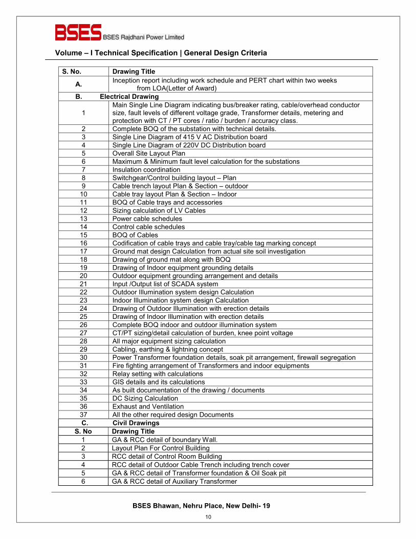
Volume – I Technical Specification | General Design Criteria
BSES Bhawan, Nehru Place, New Delhi- 19
S. No. Drawing Title
A. Inception report including work schedule and PERT chart within two weeks from LOA(Letter of Award)
B. Electrical Drawing
1 Main Single Line Diagram indicating bus/breaker rating, cable/overhead conductor size, fault levels of different voltage grade, Transformer details, metering and protection with CT / PT cores / ratio / burden / accuracy class.
2 Complete BOQ of the substation with technical details.
3 Single Line Diagram of 415 V AC Distribution board
4 Single Line Diagram of 220V DC Distribution board
5 Overall Site Layout Plan
6 Maximum & Minimum fault level calculation for the substations
7 Insulation coordination
8 Switchgear/Control building layout – Plan
9 Cable trench layout Plan & Section – outdoor
10 Cable tray layout Plan & Section – Indoor
11 BOQ of Cable trays and accessories
12 Sizing calculation of LV Cables
13 Power cable schedules
14 Control cable schedules
15 BOQ of Cables
16 Codification of cable trays and cable tray/cable tag marking concept
17 Ground mat design Calculation from actual site soil investigation
18 Drawing of ground mat along with BOQ
19 Drawing of Indoor equipment grounding details
20 Outdoor equipment grounding arrangement and details
21 Input /Output list of SCADA system
22 Outdoor Illumination system design Calculation
23 Indoor Illumination system design Calculation
24 Drawing of Outdoor Illumination with erection details
25 Drawing of Indoor Illumination with erection details
26 Complete BOQ indoor and outdoor illumination system
27 CT/PT sizing/detail calculation of burden, knee point voltage
28 All major equipment sizing calculation
29 Cabling, earthing & lightning concept
30 Power Transformer foundation details, soak pit arrangement, firewall segregation
31 Fire fighting arrangement of Transformers and indoor equipments
32 Relay setting with calculations
33 GIS details and its calculations
34 As built documentation of the drawing / documents
35 DC Sizing Calculation
36 Exhaust and Ventilation
37 All the other required design Documents
C. Civil Drawings S. No Drawing Title
1 GA & RCC detail of boundary Wall.
2 Layout Plan For Control Building
3 RCC detail of Control Room Building
4 RCC detail of Outdoor Cable Trench including trench cover
5 GA & RCC detail of Transformer foundation & Oil Soak pit
6 GA & RCC detail of Auxiliary Transformer
10
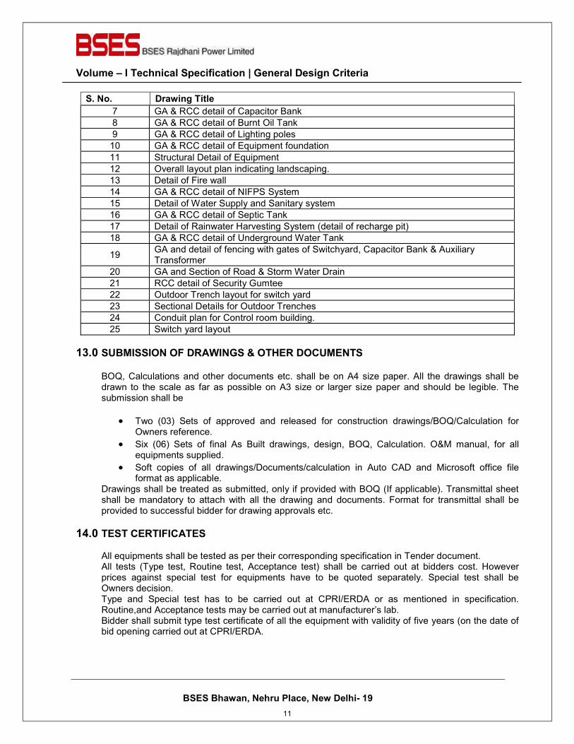
Volume – I Technical Specification | General Design Criteria
BSES Bhawan, Nehru Place, New Delhi- 19
S. No. Drawing Title 7 GA & RCC detail of Capacitor Bank
8 GA & RCC detail of Burnt Oil Tank
9 GA & RCC detail of Lighting poles
10 GA & RCC detail of Equipment foundation
11 Structural Detail of Equipment
12 Overall layout plan indicating landscaping.
13 Detail of Fire wall
14 GA & RCC detail of NIFPS System
15 Detail of Water Supply and Sanitary system
16 GA & RCC detail of Septic Tank
17 Detail of Rainwater Harvesting System (detail of recharge pit)
18 GA & RCC detail of Underground Water Tank
19 GA and detail of fencing with gates of Switchyard, Capacitor Bank & Auxiliary Transformer
20 GA and Section of Road & Storm Water Drain
21 RCC detail of Security Gumtee
22 Outdoor Trench layout for switch yard
23 Sectional Details for Outdoor Trenches
24 Conduit plan for Control room building.
25 Switch yard layout
13.0 SUBMISSION OF DRAWINGS & OTHER DOCUMENTS BOQ, Calculations and other documents etc. shall be on A4 size paper. All the drawings shall be drawn to the scale as far as possible on A3 size or larger size paper and should be legible. The submission shall be
� Two (03) Sets of approved and released for construction drawings/BOQ/Calculation for Owners reference.
� Six (06) Sets of final As Built drawings, design, BOQ, Calculation. O&M manual, for all equipments supplied.
� Soft copies of all drawings/Documents/calculation in Auto CAD and Microsoft office file format as applicable.
Drawings shall be treated as submitted, only if provided with BOQ (If applicable). Transmittal sheet shall be mandatory to attach with all the drawing and documents. Format for transmittal shall be provided to successful bidder for drawing approvals etc.
14.0 TEST CERTIFICATES All equipments shall be tested as per their corresponding specification in Tender document. All tests (Type test, Routine test, Acceptance test) shall be carried out at bidders cost. However prices against special test for equipments have to be quoted separately. Special test shall be Owners decision. Type and Special test has to be carried out at CPRI/ERDA or as mentioned in specification. Routine,and Acceptance tests may be carried out at manufacturer’s lab. Bidder shall submit type test certificate of all the equipment with validity of five years (on the date of bid opening carried out at CPRI/ERDA.
11
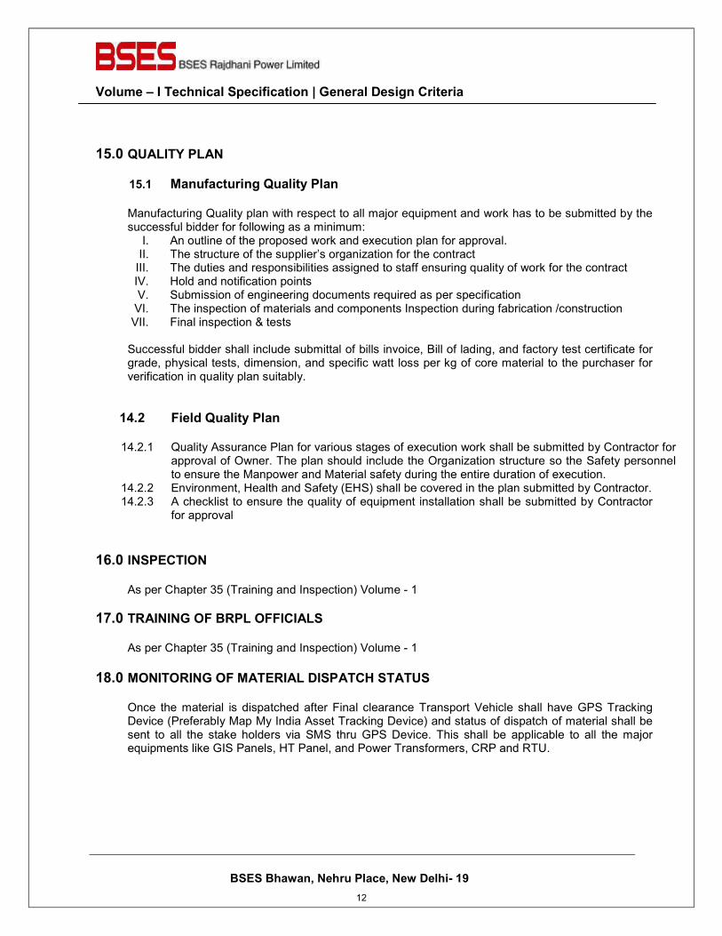
Volume – I Technical Specification | General Design Criteria
BSES Bhawan, Nehru Place, New Delhi- 19
15.0 QUALITY PLAN
15.1 Manufacturing Quality Plan
Manufacturing Quality plan with respect to all major equipment and work has to be submitted by the successful bidder for following as a minimum:
I. An outline of the proposed work and execution plan for approval. II. The structure of the supplier’s organization for the contract
III. The duties and responsibilities assigned to staff ensuring quality of work for the contract IV. Hold and notification points V. Submission of engineering documents required as per specification
VI. The inspection of materials and components Inspection during fabrication /construction VII. Final inspection & tests
Successful bidder shall include submittal of bills invoice, Bill of lading, and factory test certificate for grade, physical tests, dimension, and specific watt loss per kg of core material to the purchaser for verification in quality plan suitably.
14.2 Field Quality Plan
14.2.1 Quality Assurance Plan for various stages of execution work shall be submitted by Contractor for approval of Owner. The plan should include the Organization structure so the Safety personnel to ensure the Manpower and Material safety during the entire duration of execution.
14.2.2 Environment, Health and Safety (EHS) shall be covered in the plan submitted by Contractor. 14.2.3 A checklist to ensure the quality of equipment installation shall be submitted by Contractor
for approval
16.0 INSPECTION As per Chapter 35 (Training and Inspection) Volume - 1
17.0 TRAINING OF BRPL OFFICIALS As per Chapter 35 (Training and Inspection) Volume - 1
18.0 MONITORING OF MATERIAL DISPATCH STATUS
Once the material is dispatched after Final clearance Transport Vehicle shall have GPS Tracking Device (Preferably Map My India Asset Tracking Device) and status of dispatch of material shall be sent to all the stake holders via SMS thru GPS Device. This shall be applicable to all the major equipments like GIS Panels, HT Panel, and Power Transformers, CRP and RTU.
12
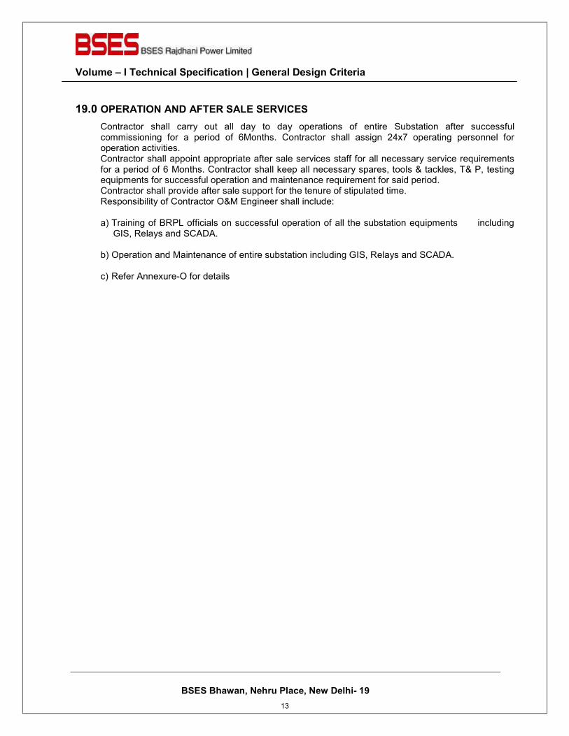
Volume – I Technical Specification | General Design Criteria
BSES Bhawan, Nehru Place, New Delhi- 19
19.0 OPERATION AND AFTER SALE SERVICES
Contractor shall carry out all day to day operations of entire Substation after successful commissioning for a period of 6Months. Contractor shall assign 24x7 operating personnel for operation activities. Contractor shall appoint appropriate after sale services staff for all necessary service requirements for a period of 6 Months. Contractor shall keep all necessary spares, tools & tackles, T& P, testing equipments for successful operation and maintenance requirement for said period. Contractor shall provide after sale support for the tenure of stipulated time. Responsibility of Contractor O&M Engineer shall include: a) Training of BRPL officials on successful operation of all the substation equipments including
GIS, Relays and SCADA.
b) Operation and Maintenance of entire substation including GIS, Relays and SCADA.
c) Refer Annexure-O for details
13
BSES Bhawan, Nehru Place, New Delhi- 19
Prepared by Amrita Singh Rev: 0
Reviewed by Date: 22th May, 2021
Approved by Rajinder Rajpal
TECHNICAL SPECIFICATION
FOR
CIVIL WORK
14
BSES Bhawan, Nehru Place, New Delhi- 19 Volume – I Technical Specification for Civil Work
1.0 GENERAL REQUIREMENT
1.1. This chapter includes the technical requirements for 66kV GIS Sub-station at Manglapuri including associated design and preparation of all civil & structural drawings and execution of all associated civil works. This chapter deals mainly with technical specifications for the design, supervision and construction of complete civil & structural works.
1.2. The specifications are intended for general description of work, quality and workmanship. The
specifications are not however exhaustive to cover minute details and the work shall be executed according to relevant latest Indian Standards/IRC specifications/CPWD specifications. In the absence of the above, the work shall be executed according to the best prevailing practices in the trade, recommendations of relevant American or British Standards or to the instructions of Engineer. The IS standards/IRC specifications/CPWD specifications to be followed are mentioned in the technical specifications attached hereto. They shall be latest editions/ version of the same. The Contractor is expected to get him clarified on any doubts about the specifications, etc. before bidding and the discussions recorded in writing with the Owner in respect to interpretation of any portion of this document.
1.3. The work shall be carried out according to the design / drawings to be developed by the Contractor
and approved by the Owner based on Tender Drawings (tentative layout) supplied to the Contractor by the Owner. For all buildings, structures, foundations etc. necessary layout and details shall be developed by the Contractor keeping in view the functional requirement of the Sub-Station facilities and providing enough space and access for operation, use and maintenance based on the input provided by the Owner. Certain minimum requirements are indicated in this specification for guidance purposes only. However, the Contractor shall quote according to the complete requirements.
1.4. The Contractor shall take all necessary precautions to protect all the existing equipments, structures,
facilities & buildings, etc. from damage. In case any damage occurs due to the activities of the Contractor on account of negligence, ignorance, accidental or any other reason whatsoever, the damage shall be made good by the Contractor at his own cost to the satisfaction of the Engineer. The Contractor shall also take all necessary safety measures, at his own cost, to avoid any harm / injury to his workers and staff from the equipment & facilities of the power station.
1.5. During the progress of work, the Engineer will exercise supervision of the work to ensure that the
technical provisions of the contract are being followed and the work is being executed accurately and properly. However, such supervision shall in no way relieve the Contractor of the responsibility for executing the work in accordance with the specifications.
1.6. Before submitting the bid, the Contractor shall inspect and examine the site and its surroundings and
shall satisfy himself as to the nature of the ground and subsoil, the availability of materials necessary for completion of the work, means of access to site and in general shall himself obtain all necessary information as to risks, contingencies and other circumstances which may influence or affect his offer. No extra claim consequent on any misunderstanding or otherwise shall be allowed.
1.7. In view of pandemic, the Contractor shall be bound to follow all guidelines issued by the Government &
take all necessary arrangements & precautions for his workers & staff. 2.0 GEOTECHNICAL INVESTIGATION
The Owner has carried out Geo Technical Investigation and Topographical Survey for the entire Sub-Station including switchyard. The copy of the report is attached with the tender document as input to
15
BSES Bhawan, Nehru Place, New Delhi- 19 Volume – I Technical Specification for Civil Work
Contractor for Civil Design & Estimation Work.
3.0 SITE PREPARATION 3.1. Scope
3.1.1. This clause covers the design and execution of the work and site preparation such as
clearing of the site, the supply and compaction of fill material as per requirement upto desired formation levels, excavation and compaction of backfill for foundations, road construction, drainage, trenches, etc..
3.2. General
3.2.1. The layout and levels of all structures, etc. shall be made by the Contractor at his own cost
from the general grids of the plot and benchmarks finalized / approved by the Owner. (The required filling up to formation level shall be in the scope of Vendor). The Contractor shall give all help in instruments, materials and personnel to the Owner for checking the detailed layout and shall be solely responsible for the correctness of the layout and levels.
3.2.2. Raising of existing boundary wall behind the transformer yard by 1.5 m following the existing pattern of boundary wall. The length of this portion of boundary wall is 41 m. The Contractor shall relocate the gate (on the front side) in the existing boundary wall of the Substation plot as per approved layout of the plot. In addition to the above, the Contractor shall provide a second gate of approved size and design (BSES’s pattern) by dismantling existing boundary wall (as per approved location). Contractor shall have to make good to all the damages to the boundary wall and gates during work execution.
3.2.3. Contractor shall develop a building layout and other layouts so that if the trees are there inside the grid plot, they may be escaped from cutting. In extreme conditions when the tree cutting is unavoidable, necessary liaison for permission shall be on part of Contractor from respective Govt. Agency. Requisite formalities shall be carried out by Owner. Fee shall be borne by the Owner. Compensatory plantation shall be done (if required) by Contractor; BRPL shall provide space for the same.
3.2.4. The Contractor shall develop the site area to meet the requirements of the intended purpose. The site preparation shall conform to the requirements of relevant sections of this specification or as per stipulations of standard specifications.
3.2.5. If fill material is required, the fill material shall be suitable for the above requirement. The fill shall be designed to prevent the erosion by wind and water of material from its final compacted position or the in-situ position of undisturbed soil.
3.2.6. Material unsuitable for founding of foundations shall be removed and replaced by suitable fill material and to be approved by the Owner.
3.2.7. Backfill material around foundations or other works shall be suitable for the purpose for which it is used and shall be compacted to the density described under Compaction (clause 3.4 of this Specification). Excavated material not suitable or not required for backfill shall be disposed off by the Contractor in areas as directed by Owner upto a maximum lead of 5 km. Backfill material if found having mix of earth and fly ash should not be used for top 30 cm of
16
BSES Bhawan, Nehru Place, New Delhi- 19 Volume – I Technical Specification for Civil Work
formation level and should be supplemented with good earth at the cost of Contractor.
3.3. Excavation and Backfill
3.3.1. Excavation and backfill for foundations shall be in accordance with the relevant code.
3.3.2. Whenever water level is met during the excavation, it shall be dewatered and water level
shall be maintained below the bottom of the excavation level during excavation, concreting and backfilling. Nothing extra shall be payable by the owner on this account.
3.3.3. When embankments are to be constructed on slopes of 15% or greater, benches or steps with horizontal and vertical faces shall be cut in the original slope prior to placement of embankment material. Vertical face shall measure not more than 1 m in height.
3.3.4. Embankments adjacent to abutments, culverts, retaining walls and similar structures shall be constructed by compacting of the material in successive uniform horizontal layers not exceeding 15 cm in thickness (of loose material before compaction). Each layer shall be compacted as required by means of mechanical tampers approved by the Owner. Rocks larger than 10cm in any direction shall not be placed in embankment adjacent to structures.
3.3.5. Earth embankments of roadways and site areas adjacent to buildings shall be placed in successive uniform horizontal layers not exceeding 20 cm in thickness in loose stage measurement and compacted to the full width specified. The upper surface of the embankment shall be shaped so as to provide complete drainage of surface water at all times.
3.4. Compaction
3.4.1. The density to which fill materials shall be compacted shall be as per, relevant IS and as per
direction of Owner. All compacted sand filling shall be confined as far as possible. Backfilled earth shall be compacted to minimum 95% of the Standard Proctor's density at OMC. The sub grade for the roads and embankment filling shall be compacted to minimum 95% of the Standard Proctor's density at OMC. Cohesion less material sub grade shall be compacted to 70% relative density (minimum).
3.4.2. At all times unfinished construction shall have adequate drainage system. Upon completion of the roads surface course, adjacent shoulders shall be given a final shaping, true alignment and grade.
3.4.3. Each layer of earth embankment when compacted shall be as close to optimum moisture content as practicable. Embankment material which does not contain sufficient moisture to obtain proper compaction shall be wetted. If the material contains any excess moisture, then it shall be allowed to dry before rolling. The rolling shall begin at the edges overlapping half the width of the roller each time and progress to the center of the road or towards the building as applicable. Rolling will also be required on rock fills. No compaction shall be carried out in rainy weather.
3.5. Requirement for fill material under foundation
3.5.1. The thickness of fill material under the foundations shall be such that the maximum pressure
17
BSES Bhawan, Nehru Place, New Delhi- 19 Volume – I Technical Specification for Civil Work
from the footing, transferred through the fill material and distributed onto the original undisturbed soil will not exceed the allowable soil bearing pressure of the original undisturbed soil. For expansive soils the fill materials and other protections etc. to be used under the foundation has to be approved by the Owner.
4.0 CODES AND STANDARDS
All standards, specifications, acts and code of practice (latest revision) shall be followed. In case of conflict between this specification and those (IS standard/ IRC specification/CPWD Specification, etc.) referred to herein, the former shall prevail.
5.0 SUBMISSIONS
The following documents shall be submitted by the Contractor for approval of the BRPL prior to commencement of fabrication and erection / construction. This list is not exhaustive but indicative only. Final list of drawings shall be prepared by successful Contractor during detailed engineering.
i. Design calculation, general arrangement drawings, foundation drawing & detailed erection / construction drawings including R/F drawings for Sub-Station Building.
ii. Foundation design & drawing of all equipment foundations. iii. Structural steel fabrication drawings for equipment support structure. iv. Site preparation plan including filling up to formation level, etc. v. Foundation design & drawing of Power Transformer vi. Design & drawing of transformer grating, firewall & burnt oil tank vii. Foundation design & drawing for lighting pole. viii. Foundation design & drawing for Capacitor Bank, Auxiliary Transformer and design of fencing
for both. ix. Complete fencing along with gate for the Sub-Station yard x. Details of Indoor and Outdoor Cable Trenches with cable tray supports and trench covers xi. Design & drawing of Rainwater Harvesting System, sewerage system including septic tank,
water supply arrangement, landscaping, etc. xii. Design & drawing of roads and complete drainage system (with final connection to Rain Water
Harvesting recharge pit) within Sub-Station including crossings. xiii. Design & drawing Security room. xiv. Design & drawing NIFPS system & underground water tank.
6.0 SUB-STATION BUILDING GENERAL REQUIREMENTS
6.1. General
6.1.1. The scope includes the design, engineering and construction including antI-termite
treatment, plinth protection, DPC of buildings including sanitary, water supply, electrification, fire fighting system, etc. The building shall be of RCC framed structure of minimum concrete grade M25. The Sub-Station Building shall include rooms as specified below:
S. No. Facility
i. Control Room
18
BSES Bhawan, Nehru Place, New Delhi- 19 Volume – I Technical Specification for Civil Work
ii. Switchgear Room iii. GIS Room iv. Maintenance Room v. Pantry vi. Toilet
6.1.2. Minimum floor area requirements have been given in tender drawings, which may be
increased at the time of detailed engineering to suit project requirements.
6.1.3. An open space of 1200 mm minimum shall be provided on the periphery of the rows of panel and equipment generally in order to allow easy operator movement and access as well as maintenance.
6.1.4. The building shall be aesthetically designed keeping in view the surrounding landscape; proper architecture shall be used to design the exterior look and finish. The architectural drawing shall be submitted for Owner’s approval.
6.1.5. Future extension of one floor shall be considered at the time of design. Any other possibility of annex building shall be taken care of while finalizing the layout of the Control Room building.
6.1.6. Control Room cum Administrative building shall be constructed as per the approved drawings by Owner. CPWD specification shall be followed in all the building works. The clear height of building except GIS hall & Cable Cellar shall be minimum 4.5 m (from floor level to bottom of roof slab of ground floor/first floor). The height of GIS hall shall be as per requirement of GIS equipment & EOT. Height of Cable Cellar shall be as per electrical requirement/ design.
6.2. Design
a) The building shall be designed on Green Building Concept. The design of Control Room building shall be such decided that’s minimum one floor can be added in future.
Following parameters shall be followed: -
� To follow & fulfill the requirements of the National Building Code of India and the standards quoted therein.
� The specified climatic & loading conditions shall be considered. � The building shall have RCC framed super structure. � To adequately suit the requirements of the equipment and apparatus contained in the buildings
and in all respects to be compatible with the intended use and occupancy.
� To meet functional and economical space arrangement for maximum utilization of the building.
� To be aesthetically pleasing with uniformity and consistency in architectural design.
� To allow for easy access to equipment for their maintenance.
19
BSES Bhawan, Nehru Place, New Delhi- 19 Volume – I Technical Specification for Civil Work
� Using fire retarding materials for walls, ceilings and doors to prevent spreading of fire wherever required.
� Using materials preventing dust accumulation. b) Suitable expansion joints shall be provided in the longitudinal direction wherever necessary with
provision of twin columns. c) Individual members of the buildings frame shall be designed for the worst combination of forces
such as bending moment, axial force, shear force, torsion etc. d) Permissible stresses for different load combinations shall be taken as per relevant IS Codes. e) The building lighting shall be designed in accordance with the requirements of relevant section. f) The building shall have at least two entry/exits gates.
6.3. Design Loads Building structures shall be designed for the most critical combinations of dead loads, super- imposed
loads, equipment loads, wind loads, seismic loads, and temperature loads. Dead loads shall include the weight of structures complete with finishes, fixtures and partitions and should be taken as per IS: 875 (latest revision). Super-imposed loads in different areas shall include live loads, minor equipment loads, cable trays, small pipe racks & hangers and erection, operation and maintenance loads. Equipment loads shall constitute, if applicable, all load of equipments to be supported on the building frame. The wind loads shall be computed as per IS: 875 (latest revision). Seismic Coefficient method shall be used for the seismic analysis as per IS: 1893 (latest revision) with importance factor 1.5.
For temperature loading, the total temperature variation shall be considered as 2/3 of the average
maximum annual variation in temperature. The average maximum annual variation in temperature for the purpose shall be taken as the difference between the mean of the daily minimum temperature during the coldest month of the year and mean of daily maximum temperature during the hottest month of the year. The structure shall be designed to withstand stresses due to 50% of the total temperature variation. Wind and Seismic forces shall not be considered to act simultaneously.
Floors/slabs shall be designed to carry live loads & equipment loads. Cable and piping loads shall also
be considered additionally for floors where these loads are expected. In addition, beams shall be designed for any incidental point loads to be applied at any point along the
beams. The floor loads shall be subject to Owner’s approval. For consideration of loads on structures IS: 875 (latest revision), the following minimum superimposed
live loads shall however be considered for the design.
Roof 2.5 KN/M2 for accessible roofs 0.75 KN/M2 for in-accessible roofs RCC-Floor (i) 5 KN/M2 for offices, for equipment (ii) 15 KN/M2 (min) for floors or actual requirement
20
BSES Bhawan, Nehru Place, New Delhi- 19 Volume – I Technical Specification for Civil Work
if higher than 15KN/M2 based on equipment weight and layout plan Stairs 5 KN/M2 & balconies Toilet Rooms 2 KN/M2 Any additional load coming in the structure shall be calculated as per IS: 875 (latest revision).
6.4. Submission The following information shall be submitted for review and approval to the Owner:
a) Design criteria shall comprise the codes and standards used. Applicable climatic data including wind loads, earthquake factors, maximum and minimum temperatures applicable to the building locations, assumptions of dead and live loads, including equipment loads, impact factors, safety factors and other relevant information.
b) Structural design calculations and drawing (including construction/fabrication) for all reinforced
concrete and structural steel structures.
c) Fully, dimensioned concept plan including floor plans, cross sections, longitudinal sections, elevations and perspective view of each building. These drawings shall be drawn at a scale not smaller than I:50 and shall identify the major building components.
d) Fully dimensioned drawings showing details and sections drawn to scales of sufficient size to
clearly show sizes and configuration of the building components and the relationship between them.
e) Product information of building components and materials, including walls partitions, flooring,
ceiling, roofing, door and windows and building finishes.
f) A detailed schedule of building finishes including colour schemes.
g) A door & window schedule showing door types and locations, door lock sets, latch sets and other door hardware.
h) Copy of all tests/ studies/ investigation carried out by bidder as per scope.
Approval of the above information shall be obtained before ordering materials or starting fabrication
or construction activity. 6.5. Flooring Flooring in various rooms of control room building shall be as per detailed schedules given in Table –
1. Pantry countertop shall be of granite stone of required specification as per direction of Engineer-In- Charge
21
BSES Bhawan, Nehru Place, New Delhi- 19 Volume – I Technical Specification for Civil Work
6.6. Walls Control room building shall be of framed superstructure. All walls shall be non-load bearing walls. Minimum thickness of walls shall be 340mm upto DPC level in cement mortar 1:6 (1 Cement : 6 Coarse sand) and 230mm above DPC level in cement mortar 1: 4 (1 Cement :4 coarse sand).
6.7. Plastering All internal walls shall have minimum 12mm / 15mm thick 1:4 (1 Cement : 4 fine Sand) cement sand
plaster. The ceiling shall have 6mm thick 1:3 cement sand plaster. 6.8. Finishing All external surfaces (control room building and boundary wall) shall have stone grit/ Marble Chips with
colour pigment (with groves formed) (item no.13.72-DSR 2012) finish over 12mm thick cement sand plaster 1:4 (1 cement : 4 coarse sand) mixed with water proofing compound in the ratio as recommended by the manufacturer. Suitable pigment shall be added to render the surface aesthetically pleasing as per directions of Engineer-in-charge.
6.9. Door & Window The details of doors and windows of the control room building shall be as per finish schedule Table-l
and tender drawing with the relevant IS code. Paints used in the work shall be of best quality specified in CPWD specification.
6.10. Partition
Partition made of powder coated aluminum frame provided with 12.0 mm thick toughened glass shall be installed at locations as per requirement/ direction of Engineer in Charge.
6.11. Plumbing & Sanitation a) All plumbing and sanitation works shall be executed to comply with the requirements of the
appropriate bye-laws, rules and regulations of the Local Authority having jurisdiction over such matters. The Contractor shall arrange for all necessary formalities to be met in regard to inspection, testing, obtaining approval and giving notices etc.
b) PVC sintex or equivalent make Roof water tank of adequate capacity depending on the number of
users for 24 hours storage shall be provided. Minimum 2 Nos. 1000 litre capacity shall be provided.
c) Unplasticised PVC/ Chlorinated Polyvinyl- chloride (CPVC) pipe shall be used for internal &
external piping work for potable water supply. d) PVC pipes for all sanitary works.
e) All sanitary/ water supply fittings shall be of Hindware/ Parryware/ Cera. f) Each toilet shall have minimum fittings
22
BSES Bhawan, Nehru Place, New Delhi- 19 Volume – I Technical Specification for Civil Work
i) Water closet (European type W.C. pan) 390 mm high (item no. 17.3.1- DSR 2012) or water closet (Indian type W.C. pan) Orissa Pattern (580 x 440 mm) (item no. 17.1.1- DSR 2012) with all fittings (both types of WCs shall be provided at alternate locations).
ii) Half Stall Urinal (580 x 380 x 350 mm) with all fittings (item no. 17.5.2- DSR-2012).
iii) Wash basin (630 x 450 mm) with all fittings (item no. 17.7.1- DSR 2012).
iv) Bathroom mirror (600 x 450 x 6 mm thick) hard board backing (item no. 17.31- DSR 2012).
v) CP brass towel rail (600 x 20 mm) with C. P. brass brackets.
vi) Soap holder and liquid soap dispenser.
g) Water cooler for drinking water with adequate water storage facility shall be provided and located near control room instead of toilet block.
h) 1 No stainless steel A ISI 304(18/8) kitchen sink as per IS 13893 with Drain board (510 x 1040 x
225mm bowl depth for pantry shall be provided complete with all fittings (item no. 17.10.1.2-DSR 2012).
i) All fittings, fastener, grating shall be chromium plated.
j) All sanitary fixtures and fittings shall be of approved quality and type manufactured by well known
manufacturers. All items brought to site must bear identification marks of the Manufacturer.
k) Soil, waste and drain pipes for underground works shall be stoneware for areas not subject to traffic load. Heavy-duty cast iron pipes shall be used otherwise.
7.0 STORM WATER DRAINAGE FOR CONTROL ROOM BUILDING The building drain shall be provided for the collection of storm water from the roofs. This water shall be
collected in chambers and these chambers shall drain to the main drainage system of the station which shall in turn be connected to rain water harvesting recharge pits.
Unplasticised Rigid PVC rain water down comers (150 dia) conforming to IS: 13592 Type A, including
jointing with seal ring conforming to IS:5382, leaving 10 mm gap for thermal expansion shall be provided to drain off the rain water from the roof.
All external drains along road shall be covered with precast perforated RCC covers of suitable size
and thickness. For all buildings, suitable arrangement for draining out water collected from equipment blow down,
leakages, floor washings fire fighting etc. shall be provided for each floor. 8.0 DEVELOPMENT OF YARD
8.1. Scope
23
BSES Bhawan, Nehru Place, New Delhi- 19 Volume – I Technical Specification for Civil Work
8.1.1. The Contractor shall furnish all labour, equipment and materials required for complete performance of the work in accordance with the drawings, specifications and direction of the Owner.
8.1.2. Stone spreading shall be done in the Outdoor Sub-Station Yard area, Power Transformer, Capacitor Bank and wherever equipment and structures are to be provided under the present scope of work.
General Requirement:
The material required for site surfacing / stone filling shall be free from all types of organic materials and shall be of standard quality and as approved by the Owner. Test for aggregates should be as follows: a) Sieve Analysis limits (Gradation)
As per IS: 383-1970
The material to be used for stone filling / site surfacing shall be uncrushed / crushed / broken stone of 20 mm nominal size (ungraded single size) conforming to Table 2 of IS:383 - 1970.
Sieve Analysis (Gradation): (IS: 383 - Table - 2) Sieve % passing by weight size 40mm 100 20mm 85-100 10mm 0 – 20 4.75mm 0-5 One test shall be conducted for every 50 cum. b) Hardness: Abrasion value (IS: 2386 Part-IV) - not more than 40% Impact value (IS: 2386 Part-IV) - not more than 30% and frequency shall be one test per 50 cum with a minimum of one test per source c) Flakiness Index As per IS: 2386 Part I
8.1.3. Before taking up the final yard treatment, antiweed treatment shall be applied in the switchyard area wherever yard treatment is to be done and the area shall be thoroughly de-weeded including removal of roots. The recommendation of local agriculture or horticulture department shall be sought wherever feasible while choosing the type of chemical to be used. Nevertheless the effectiveness of the chemical shall be demonstrated by the contractor in a test area of 10M x 10M (approx.) and monitored over a period of two to three weeks by the Engineer-in-Charge. The final approval shall be given by Engineer-in-Charge based on the results.
24
BSES Bhawan, Nehru Place, New Delhi- 19 Volume – I Technical Specification for Civil Work
8.1.4. The antiweed chemical shall be procured from reputed manufacturers. The dosage and application of chemical shall be strictly followed as per manufacturer's recommendation. The contractor shall be required to maintain the area free of weeds for a period of 1 year from the date of application of 1st dose of antiweed chemicals.
8.1.5. After all the structures/equipment are erected and antiweed treatment is complete, the surface of the substation area shall be maintained, rolled/compacted to the lines and grades as decided by Engineer-in-Charge. De-weeding including removal of roots shall be done before rolling is commenced. Engineer-in-Charge shall decide final formation level so as to ensure that the site appears uniform free from undulations. The final formation level shall however be very close to the formation level using manual or machine roller with suitable water sprinkling arrangement to form a smooth and compact surface.
8.1.6. After antiweed treatment & compaction of earth, final yard treatment shall be carried out in the 3 layers as follows:
a. Providing and laying in position 75mm thick base layer of cement concrete
1:5:10 (1 cement : 5 coarse sand : 10 brick aggregate 40mm nominal size).
b. Flat brick flooring with over burnt bricks /class designation 100 as per approval of BRPL on the bed of 12 mm thick cement mortar 1:6 (1 cement : 6 coarse sand) and filling the joints 12mm thick all around the bricks with same mortar.
c. Over the flat brick flooring, a final surface course of minimum 100 mm thickness of
20 mm nominal size (single size ungraded) broken stone shall be spread and uniformly leveled.
8.1.7. In areas that are considered by the Engineer-in-Charge to be too congested with
foundations and structures for proper rolling of the site surfacing material by normal rolling equipments, the material shall be compacted by hand, if necessary. Due care shall be exercised so as not to damage any foundation, structure or equipment during rolling/ compaction.
8.1.8. The sub grade shall be in moist condition at the time the cement concrete is placed. If necessary, it should be saturated with water for not less than 6 hours but not exceeding 20 hours before placing of cement concrete. If it becomes dry prior to the actual placing of cement concrete, it shall be sprinkled with water and it shall be ensured that no pools of water or soft patches are formed on the surface.
9.0 SUB-STATION TRENCHES
9.1. The cable trenches and precast removable RCC cover (with lifting arrangement) shall be constructed using RCC of minimum grade M25.
9.2. The cable trench wall shall be designed for the following loads.
� Dead load of 155 kg/m length of cable support + 75 Kg on one tier at the end. � Triangular earth pressure + uniform surcharge pressure of 2T/m2.
9.3. Cable trench covers shall be 50 mm thick. All trench covers shall have desired reinforcement welded
to M.S. frame of angle 50 x 50 x 6 mm all round the cover. Size of covers shall be as per site
25
BSES Bhawan, Nehru Place, New Delhi- 19 Volume – I Technical Specification for Civil Work
requirement / direction of Engineer In Charge.
9.4. All cable trenches inside the buildings shall have covers comprising of 6 mm thick chequered plates fixed on angle 40 x 40 x 5 mm frame with arrangement of MS holes for lifting of cover.
9.5. Cable trench crossing the road/rails shall be designed for class AA loading of IRC/relevant IS Code
and should be checked for transformer/reactor loading.
9.6. Trenches shall have proper slope. Necessary sumps to be constructed and automatic sump pumps of minimum 2.0 HP capacity of approved make with complete electrical fittings shall be installed. Cable trenches shall not be used as storm water drains.
9.7. The top of cable trench shall be such that the surface rain water does not enter the trench.
9.8. The trench bed shall be perpendicular to the run. Trench wall shall not foul with the foundation.
Suitable clear gap shall be provided.
9.9. The trench bed shall have a slope of 1/500 along the run & 1/250 perpendicular to the run.
9.10. All the construction joints of cable trenches i.e. between base slab to base slab and the junction of vertical wall to base slab as well as from vertical wall to wall and all the expansion joints shall be provided with approved quality PVC water stops of approx. 230 x 5 mm size for those sections where the ground water table is expected to rise above the junction of base slab and vertical wall of cable trenches.
9.11. Cable trenches shall be blocked at the ends if required with brick masonry in cement sand mortar 1:6 and plaster with 12mm/15mm thick 1:4 cement sand mortar.
9.12. Provision of sump and pump is to be done for disposal of rain water from trench.
10.0 SUB-STATION DRAINAGE SYSTEM Adequate site drainage system shall be provided by the Contractor. The Contractor shall design the
storm water drainage system covering all culverts, ditches, drains, etc. The run off shall be calculated on the basis of maximum rainfall intensity that is likely to occur over the catchment area in one hour period on an average of once in ten years. The surface of the site shall be sloped to prevent the ponding of water. Outfall of drainage shall be suitably connected to rainwater harvesting recharge pits. While designing the drainage system following points shall be taken care of:
1. The maximum velocity for pipe drains and open drains shall be limited to 2.4m/sec and 1.8m/sec
respectively. However, minimum non-silting velocity of 0.6m/sec shall be ensured. Longitudinal bed slope not milder than 1 in 1000 shall be provided.
2. For design of RCC pipes for drains and culverts, IS: 456 and IS: 783 shall be followed. 3. The Contractor shall ensure that water drains are away from the site area and shall prevent
damage to adjacent property by this water. Adequate protection shall be given to site surfaces, roads, ditches, culverts, etc. to prevent erosion of material by water.
4. For pipe drains, concrete pipe of class NP2 shall be used. However, for road crossings etc. higher
strength pipe of class NP3 shall be provided. For rail crossings, pipes conforming to railway
26
BSES Bhawan, Nehru Place, New Delhi- 19 Volume – I Technical Specification for Civil Work
loading standards or at least NP4 class shall be provided. Manholes shall be provided at every 30m interval, at connection points and at every change of alignment.
5. Pipe drains shall be connected through manholes at an interval of maximum 30m. Effluents shall
be suitably treated by the Contractor to meet all the prevalent statutory requirements and local pollution control norms and treated effluents shall be conveyed to the storm water drainage system at a suitable location for its final disposal.
6. All internal site drainage system, including the final connection/disposal to rainwater harvesting
recharge pits shall be part of Contractor’s scope including all required civil work, mechanical & electrical systems. The Contractor shall connect drain(s) at one or more points to rainwater harvesting recharge pits as feasible at site. The drainage layout of the substation shall be approved by the Owner & all works shall be carried out by the Contractor.
7. The drainage scheme and associated drawings shall be got approved from the Owner.
11.0 SUB-STATION ROAD 11.1. Inside substation roads to be provided with accessibility for open parking, if adequate space is
available in the grid layout. Building and parking are in the scope of bidder. Layout of the roads shall be based on layout drawing for the substation. Parking areas shall be provided for Site personnel and visitors as per layout drawing. Adequate turning space for vehicles shall be provided and bend radius shall be set accordingly. It has to be connected suitably with roads.
11.2. All substation roads shall be constructed so as to permit transportation of all heavy equipment upto 60 MT. The main approach roads upto Control Room Building and other relevant roads will be RCC Roads. The other connecting roads and pathways shall be of Paver blocks/ CC Road as per site requirement. The pavers blocks used for the roads shall be M-35 grade 60 mm thick cement concrete pavers manufactured by PLC based automated block/paver making machine having compression and vibration both in sequence using multi cavity precision steel moulds in place of M-30 grade 60 mm thick CC Paver manufactured by vibratory compaction method.
11.3. Design of road shall be as per IRC standard.
11.4. Adequate provision shall be made for road drainage.
11.5. All the culverts and its allied structure (required for road/rail, drain, trench crossings, etc.) shall be
designed for class AA loading as per IRC standard/IS code. All trenches inside the substation shall cross the road through culverts.
12.0 TRANSFORMER FOUNDATION, RAIL TRACK/ ROAD CUM RAIL TRACK
12.1. The Contractor shall construct a proper approach to the power transformer foundation. The approach
system shall be suitable to permit the movement of any failed unit fully assembled with integral radiators and oil without the de-energization of any other equipment in the station. This system shall enable the removal of any failed unit from its foundation to a repair area and the installation of the spare unit. This system, preferably, shall not interfere with the normal internal road and trench system. If trench/ drain crossings are required then suitable RCC culverts shall be provided in accordance with I.R.C Code/ relevant IS.
12.2. The space between the transformer foundation pedestals shall be suitably filled with local sand and 75
27
BSES Bhawan, Nehru Place, New Delhi- 19 Volume – I Technical Specification for Civil Work
mm thick PCC of grade 1:3:6 placed over sand filling. The top of PCC shall be upto the formation level. Suitable drainage system between the pedestals shall be provided.
12.3. The rails shall be of first quality 52 kg/m medium manganese steel as per Indian Railway specification T-12-64 and its subsequent revision, joined together by fish plates as per Indian Railway specification T-1/57 and their drawing no. 090M and 27 mm diameter fish bolts. No joint shall be provided at less than L/3 of the longest part.
12.4. The grating shall be made of MS flat of size 50 mm x 5 mm placed at 30 mm center to center and 25 mm x 5mm MS flat at a pacing of 150 mm at right angle to each other with all around frame of MS angle 50 x 50 x 5 mm. Maximum length of grating shall be 1500 mm and width shall not be more than 500 mm. The gratings supported on ISMB 150 mm shall be placed at the formation level and will be covered with 100 mm thick layer of broken/crushed/non-crushed stone having size 40 mm to 60 mm which acts as an extinguisher for flaming oil.
13.0 TRANSFORMER OIL PIT & BURNT OIL TANK 13.1. All transformers shall have oil collection pit (transformer oil pit) connected to burnt oil tank.
13.2. Each transformer including oil conservator tank, cooler banks, etc. shall fall within the periphery of the
transformer pit (pit walls) constructed around the transformer foundation. The clear distance of the retaining wall from the transformer shall be 20% of the transformer height or 0.8m whichever is more. The transformer pit thus formed shall have a capacity equal to volume of oil in the transformers. The MS grating placed at the formation level shall be covered with 100mm thick gravel of 40mm nominal size which acts as an extinguisher for flaming oil.
13.3. Each transformer pit shall be drained towards a burnt oil tank whose role is to recover the infiltrating
water and the drained oil from the pit. The burnt oil tank shall have sufficient capacity to receive without overflowing the oil content of large transformers plus the water content of any fixed fire fighting system and a certain quantity of rain water collected from the pit connected to it. The system shall be provided with air vents large enough to avoid over pressure during operation. The whole internal surface of the burnt oil tank should be impermeable.
13.4. The walls which make up the transformer pit shall be made of fire resistant material such as reinforced
cement concrete, etc and shall be impervious to oil.
13.5. The floor of the transformer pit shall be of plain cement concrete of grade M15.
13.6. Pump house with minimum 2.0 HP capacity & of approved make with electrical fittings of ISI mark shall be supplied and installed by the Contractor to evacuate the fire fighting & rainwater from the burnt oil tank.
13.7. If the height of the retaining wall which form the transformer pit exceed 60cm, steps shall be provided to facilitate access to the transformer and its ancillaries.
13.8. When designing the transformer pit, the movement of the transformer must be taken into account.
14.0 FIRE PROTECTION WALLS 14.1. General
28
BSES Bhawan, Nehru Place, New Delhi- 19 Volume – I Technical Specification for Civil Work
14.1.1. Fire protection walls shall be provided, if required, in accordance with Tariff Advisory Committee (TAC) recommendations.
14.2. Material
14.2.1. The firewall may be made of reinforced cement concrete (M-25 grade), fire brick or concrete
blocks as per the system requirements. Materials used must conform to the standards of the National Fire Prevention Association & TAC Norms.
14.3. Fire Resistance
14.3.1. The firewall shall have a minimum fire resistance of 3 hours. The walls of the building which
are used as firewalls shall also have a minimum fire resistance of 3 hours.
14.3.2. The firewall shall be designed to protect against the effect of radiant heat and flying debris from an adjacent fire.
14.4. Dimensions 14.4.1. The height of firewall shall be minimum 6m and shall extend at least 300 mm above the
topmost part of the transformer and length wise 600 mm beyond the transformer (on both sides) including any radiators and tap changer enclosure.
14.4.2. These dimensions might be reduced in special cases, as per the approval of Owner where there is lack of space. 14.4.3. The building walls which act as firewalls shall extend at least 1 m above the roof in order to protect it.
15.0 DESIGN CONSIDERATION FOR FOUNDATION
15.1. General
15.1.1. Scope of Work under this Clause of the Specification comprises the design and construction
of foundations and other RCC constructions for switchyard structures, equipment supports, trenches, drains, jacking pad, pulling block, control cubicles, bus supports, Power transformer/Reactors, NIFPS system, marshalling kiosks, auxiliary equipment, tanks or any other equipment foundations required to complete the work.
15.1.2. Concrete shall conform to the requirements mentioned in IS: 456 and all the tests shall be conducted as per relevant Indian Standard Codes as mentioned in Standard field quality plan appended with the specification. A minimum grade of M25 concrete shall be used for all structural/load bearing members as per IS: 456 (latest revision).
15.1.3. If the site is sloppy, the foundation height will be adjusted to maintain the exact level of the top of structures to compensate such slopes.
15.1.4. The top of switchyard equipment foundations shall be minimum 300mm above finished yard level.
15.1.5. Minimum 75mm thick lean concrete (1:4:8) shall be provided below all underground
29
BSES Bhawan, Nehru Place, New Delhi- 19 Volume – I Technical Specification for Civil Work
structures, foundations, trenches etc. to provide a base for construction.
15.1.6. Concrete made with Portland cement shall be carefully cured and special importance shall be given during the placing of concrete and removal of shuttering.
15.1.7. The design and detailing of foundations shall be done based on the approved soil data and sub-soil conditions as well as for all possible critical loads and the combinations thereof. The Spread footing or pile foundation as may be required based on soil/sub-soil conditions and superimposed loads shall be provided.
15.1.8. If pile foundations are adopted, the same shall be cast-in-situ driven/bored or precast or under reamed type as per relevant parts of IS: 2911. In every condition only RCC piles shall be provided. Suitability of the adopted pile foundations shall be justified by way of full design calculations. Detailed design calculations shall be submitted by the bidder showing complete details of piles/pile groups proposed to be used. Necessary initial load test shall also be carried out by the bidder at their cost to establish the piles design capacity. The Contractor shall take up the job of piling only after the design capacities of piles have been established. Routine tests for the piles shall also be conducted. All the work (design & testing) shall be planned in such a way that these shall not cause any delay in project completion. The contractor shall go for vertical load testing, lateral load testing & pullout load testing. The contractor may choose static or dynamic load testing upon site condition and time constraint.
15.2. Design
15.2.1. All foundation shall be of reinforced cement concrete. The design and construction of RCC structures shall be carried out as per IS: 456 and minimum grade of concrete shall be M-25.
15.2.2. Limit state method of design shall be adopted unless specified otherwise in the specification.
15.2.3. For detailing of reinforcement IS: 2502 and SP: 16 shall be followed. TMT bars conforming to IS: 1786 shall be used as reinforcement. However, in specific areas mild steel (Grade I) conforming to IS: 432 can also be used. Two layers of reinforcement (on inner and outer face) shall be provided for wall having thickness of 150 mm and above. For footings minimum cover shall be 50 mm.
15.2.4. RCC water retaining structures like storage tanks, etc. shall be designed as uncracked section in accordance with IS: 3370 (Part I to IV) by working stress method. However, water channels shall be designed as cracked section with limited steel stresses as per IS: 3370 (Part I to IV) by working stress method.
15.2.5. The procedure used for the design of the foundations shall be the most critical loading combination of the steel structure and/or equipment and/or superstructure and other conditions which produces the maximum stresses in the foundation or the foundation component and as per the relevant IS Codes of foundation design. Detailed design calculations shall be submitted by the bidder showing complete detail of piles/pile groups proposed to be used.
15.2.6. Design shall consider any sub-soil water pressure that may be encountered following relevant standard strictly.
30
BSES Bhawan, Nehru Place, New Delhi- 19 Volume – I Technical Specification for Civil Work
15.2.7. Necessary protection to the foundation work if required shall be provided to take care of any special requirement for aggressive alkaline soil, black cotton soil or any other type of soil which is detrimental / harmful to the concrete foundations.
15.2.8. RCC columns shall be provided with rigid connection at the base.
15.2.9. All sub-structures shall be checked for sliding and overturning stability during construction as well as operation for various combinations of loads. Factor of safety for these cases shall be taken as mentioned in relevant IS Codes or as stipulated elsewhere in this Specification. For checking against overturning weight of soil vertically above footing shall be taken and inverted frustum of pyramid of earth on the foundation should not be considered.
15.2.10. Earth pressure for all underground structures shall be calculated using coefficient of earth pressure at rest. Co-efficient of active or passive earth pressure (whichever is applicable). However, for the design of substructures of any underground enclosures, earth pressure at rest shall be considered.
15.2.11. In addition to earth pressure, ground water pressure, etc., a surcharge load of 2T/ Square metre shall also be considered for the design of all underground structures including channels, sumps, tanks, trenches, substructure of any underground hollow enclosure, etc, for taking in account the vehicular traffic in the vicinity of the structure.
15.2.12. Following conditions shall be considered for the design of water tank in pumps house, channels, sumps, trenches and other underground structures:
a) Full water pressure from inside and no earth pressure, ground water pressure & surcharge pressure from outside (application only to structures, which are liable to be filled up with water or any other liquid).
b) Full earth pressure, surcharge pressure and ground water pressure from outside and no water pressure from inside.
c) Design shall also be checked against buoyancy due to the ground water during
construction and maintenance stages. Minimum factor of safety of 1.5 against buoyancy shall be ensured ignoring the superimposed loadings.
15.2.13. Base slab of any underground enclosure shall also be designed for empty condition during
construction and maintenance stages with maximum groundwater table (GWT). Minimum factor of safety of 1.5 against buoyancy shall be ensured ignoring the super-imposed loadings.
15.2.14. Base slab of any underground enclosure like water storage tank shall also be designed for the condition of different combination of pump sumps being empty during maintenance stages with maximum GWT. Intermediate dividing piers of such enclosures shall be designed considering water in one pump sump only and the other pumps sump being empty for maintenance.
15.2.15. The foundations shall be proportioned so that the estimated total and differential movements
of the foundations are not greater than the movements that the structure or equipment is designed to accommodate.
31
BSES Bhawan, Nehru Place, New Delhi- 19 Volume – I Technical Specification for Civil Work
15.2.16. The equipment foundations shall be checked for a factor of safety of 2.2 for normal condition and 1.65 for short circuit condition against sliding, overturning and pullout. The same factors shall be used as partial safety factor over loads in limit state design also.
15.3. Admixture & Additives
15.3.1. Only approved admixtures shall be used in the concrete for the Civil Work. When more than one admixture is to be used, each admixture shall be batched in its own batch and added to the mixing water separately before discharging into the mixer. Admixtures shall be delivered in suitably labeled containers to enable identification.
15.3.2. Admixtures in concrete shall conform to IS: 9103. The waterproofing cement additives shall conform to IS: 2645. Owner shall approve concrete Admixtures/ Additives.
15.3.3. The contractor may propose and the Owner may improve the use of a water-reducing set-retarding admixture in some of the concrete. The use of such an admixture will not be approved to overcome problems associated with inadequate concrete plant capacity or improperly planned placing operation sand shall only be approved as an aid to overcoming unusual circumstances and placing conditions.
15.3.4. The water-reducing set-retarding admixture shall be an approved brand of Ligno-sulphonate type admixture.
15.3.5. The waterproofing cement additives shall be used as required/advised by the Owner.
15.3.6. Water proofing treatment on roof shall be as per Item No 22.7.1 - DSR 2012.
16.0 FENCING OF SUB-STATION (LIVE PART) AREA
16.1. General Fencing shall be designed for the most critical loading combination taking care of wind force, stability,
tension on wires, minimum requirements as per this clause for are materials IS 8910 and fabrication IS 800 as per recommendations
16.2. Areas Requiring Fencing
16.3. Fencing shall be providing for the following areas: 16.3.1. Site fencing for the complete Outdoor substation Yard area including Power transformer area.
Gates shall be provided for men and machine / equipment to be taken out of the substation. 16.3.2. The IRC weld mesh panels fencing of Capacitor Bank with roof cover (as per approved BRPL
pattern) if required.
16.3.3. Fencing of Aux. Substation Transformer (as per approved BRPL pattern).
16.4. Product Material 16.4.1. The minimum requirements are as follows:
IRC Weld Mesh fencing in accordance to relevant IS Code
32
BSES Bhawan, Nehru Place, New Delhi- 19 Volume – I Technical Specification for Civil Work
� Size of IRC mesh 25X75mm � Nominal wire size 6 gauge/ 7.75 kg/m2 � Width of fencing panel 2400mm � Height of fencing 2000mm � Fabrication of panels 40mm Nominal bore M.S. Pipe
(medium duty). Providing elbow/bend at corners & 40 x 5 mm M.S. flats in beading
� Paint Aluminum Paint
16.4.2. Posts
� Intermediate Straining Post : 65mm Nominal bore, M.S. Pipe (Medium duty) � Base Plate : 12mm M.S. Plate with 4 nos of hole. Nuts & bolts of suitable diameter. � Paint : shall be painted with a coat of approved
steel primer and two coats of synthetic enamel paint
The IRC weld mesh Panels shall be fixed to the post at the top and bottom of the 65mm Nominal bore, M.S. Pipe by Nuts and bolts. The Intermediate straining Posts to be erected by using holding down bolts and nuts grouted in toe wall around the Yard (the height of Yard Toe wall to be at least 450 mm above the yard level and upto 340 mm wide).
16.5. Installation
16.5.1. Fence shall be installed along switchyard line.
16.5.2. Post holes shall be excavated by approved methods.
16.5.3. Intermediate posts shall be spaced 2.5 m apart measured parallel to ground surface.
16.5.4. Posts shall be set in 1:2:4 plain cement concrete blocks of minimum dimension (340 mm x
340 mm x 750 mm deep) Concrete work shall conform to relevant clause. Post shall be braced and held in plumb position and true alignment and elevation until concrete has set.
16.5.5. Fence fabric shall not be installed until concrete has cured a minimum of 7 days.
16.5.6. Bottom and top of the fence panels shall be fixed with post by MS flats of 50 mm x 6 mm (min).
16.5.7. Toe wall of Brick masonry over 75 mm thick PCC (1:4:8 ) shall be provided below all fencing and shall be minimum 400 mm above and 450 mm below finished ground level. 50 mm thick coping (M15) to be provided over brick wall. All exposed surfaces of brick toe wall shall be provided with 1:4 cement sand plaster (1 cement : 4 coarse sand) and coated with two coats of Acrylic Smooth exterior paint with a base coat of approved cement primer.
16.6. M.S. Gate
16.6.1. M.S. Gate of 6.0 m wide x 2.3 m height (2 nos) and 1.55 m x 2.3 m height (1 no) shall be
33
BSES Bhawan, Nehru Place, New Delhi- 19 Volume – I Technical Specification for Civil Work
provided to provide access through the fencing to the yard. M.S. Gate of 6.0 m wide x 2.3 m height shall be made in two leaf and 1.55 m x 2.3 m height shall be made in one leaf with locking arrangements. The gate shall be made with outer frame of 40 NB (Medium) M. S. Pipe. Weld mesh of opening size 25 x 75 mm and nominal wire size of mesh is 6 gauge/ 7.75 kg/m2 (as per standard approved drawing of BSES).
16.6.2. Hinges, al-drops and other accessories shall be provided for effective working of the gate.
17.0 GATES
17.1. The main gates in boundary wall shall be provided as per BRPL approved standard design / drawing. Make of MS materials shall be Sail/ Jindal/ TATA.
17.2. The gates shall be fabricated with welded joints to achieve rigid connections. The gate frames shall be
painted with one or more coat of approved steel primmer and two coats of synthetic enamel paint.
17.3. Gates shall be fitted with approved quality iron hinges. Hinges shall permit gates to swing through 180 degree.
17.4. Double gates shall be fitted with centre rest and drop bolt to secure gates in closed position.
17.5. Main Gate shall be 6m wide. Gates shall be installed in locations shown on drawings. As per
availability of space, next to the main gate, a men gate (1.25 m wide, single leaf) shall also be provided as a wicked gate otherwise wicked gate shall be provided within the larger gate.
17.6. Bottom of gates shall be set approximately 40mm above ground surface and necessary guiding mechanism shall be fitted as per site requirement.
17.7. The gates shall be provided with suitable locking arrangement.
18.0 MISCELLANEOUS GENERAL REQUIREMENTS
18.1. Bricks having minimum 100 kg/cm2 compressive strength can only be used for masonry work. Contractor shall ascertain himself at site regarding the availability of bricks of minimum 100 kg/cm2 compressive strength before submitting his offer.
18.2. Doors and windows on external walls of the building (other than areas provided, with insulated metal claddings) shall be provided with RCC sunshade over the openings with 150 mm projection on either side of the openings. Projection of sunshade from the wall shall be minimum 600mm over window & door openings.
18.3. RCC staircase shall be provided for access to roof of the entire building. All stairs shall have maximum riser height of 150 mm and a minimum tread width of 300 mm. Minimum width of stairs shall be 1500 mm. Steel doors shall be provided in the Mumty and height of Mumty should be 2.6m.
18.4. Angles 50x50x6 mm (minimum) with lugs shall be provided for edge protection all round cut outs/openings in floor slab, edges of drains supporting covers, edges of RCC cable/pipe trenches supporting covers, edges of manholes supporting covers, supporting edges of manhole precast cover and any other place where breakage of corners of concrete is expected.
18.5. Anti termite chemical treatment shall be given to column pits, wall trenches, foundations of buildings,
34
BSES Bhawan, Nehru Place, New Delhi- 19 Volume – I Technical Specification for Civil Work
filling below the floors etc. as per IS: 6313 and other relevant Indian Standards.
18.6. The railing of staircase shall be 0.9 m average height comprising of 20 mm square bars of length 1.05 m and 150 mm centre to centre with teak wood handrail on top of railing including fixing of vertical bars in steps by grouting of required hold fast as per direction of Engineer in Charge.
18.7. All buildings shall have 750mm wide plinth protection all round.
18.8. 50mm thick DPC shall be provided before laying of masonry (item no. 4.11 & 4.13-DSR 2012).
18.9. BSES Display board is to be provided of required size and as per approved pattern /drawing of BRPL with name of the grid.
18.10. Water and Sewer line connections to be done with running line of CIVIC agency, if approval of CIVIC
agency is available.
18.11. The details given in tender drawings shall be considered along with details available in this section of the specification while deciding various components of the building. Items/components of buildings not explicitly covered in the specification but required for completion of the project shall be deemed to be included in the scope.
19.0 INTERFACING The proper coordination & execution of all interfacing civil works activities like fixing of conduits in
roofs/walls/floors, fixing of lighting fixtures, fixing of supports/ embedment, provision of cutouts, etc for indoor illumination, ventilation & Air conditioning shall be the sole responsibility of the Contractor. He shall plan all such activities in advance and execute in such a manner that interfacing activities do not become bottlenecks and dismantling, breakage etc. is reduced to minimum
20.0 FIELD QUALITY PLAN FOR CIVIL WORKS The field quality plan for all civil works shall be in accordance with CPWD specification and other
relevant Indian Standard Codes. All quality checks and procedures shall be followed as per relevant CPWD norms.
21.0 WATER SUPPLY
21.1. Arrangement of water for construction work as well as drinking purpose shall be in the scope of
Contractor.
21.2. The Contractor shall carry out all the plumbing/erection works required for supply of water in Substation building.
21.3. A scheme shall be prepared by the Contractor indicating the layout and details of water supply which
shall be got approved from the Owner before actual start of' work including all other incidental items not shown or specified but as may be required for complete performance of the works.
21.4. Pumps for water supply shall be in the scope of contractor. The Contractor shall provide an
underground water reservoir, near the gate of minimum 20 M3 capacity. Pump house for pumping
35
BSES Bhawan, Nehru Place, New Delhi- 19 Volume – I Technical Specification for Civil Work
water from underground water tank to the overhead water tank on top of the building shall be of minimum 2.0 HP capacity & electrical fittings of ISI mark.
21.5. The details of tanks, pipes, fittings, fixtures etc for water supply shall be approved by engineer in charge.
22.0 SEWERAGE SYSTEM
22.1. Sewerage system shall be provided for control room building.
22.2. The Contractor shall construct septic tank and soak pit suitable for 20 users or make connection with nearby existing sewerage system of Civic agency, if approval of Civic agency is available
22.3. The system shall be designed as per relevant IS Codes.
22.4. External sewerage system including connection with internal services of building shall be within the scope of this contract. The connection and laying of sewer lines and manholes upto the point of connection with the sewer line of local civic agency if existing within 100m from any point of boundary of sub-station. If the sewer line of local civic agency does not exist in the area then septic tank with soak pit shall be constructed for control room building (suitable for 20 users). BRPL shall obtain necessary approval from civic agency for laying of sewer lines as aforesaid and connection thereof. Any municipal charges for approval and connection shall be paid by BRPL directly to the local authorities.
23.0 RAIN WATER HARVESTING
(a) Providing recharge structures with bore wells at different locations as per approved drawing for rainwater harvesting system. The recharge structures shall be suitably located within the sub-station. Branch drains from the main drain carrying rainwater from entire switchyard, constructed in accordance with clause 9 & 10 shall be connected to the recharge structures.
(b) The internal diameter of recharge shafts shall be 4.5 meter with 230mm thick lining of brick work
upto a depth of 2.0 meter from ground level and 345mm thick brickwork below 2.0 meter depth. The brickwork shall be constructed with cement mortar 1:6 (1cement: 6 coarse sand). The overall depth of shaft shall be 5.0 meter below invert level of drain. The shaft shall be covered with RCC slab for a live load of 300 kg. per sqm. Two openings of size 0.7 x 0.7 meter shall be provided in the RCC cover slab. An iron cover made of 5mm thick chequered plate with hinges shall be provided on the openings. Galvanized M.S. rungs of 16mm diameter at spacing of 300 mm shall be provided in the wall of shaft below the opening in the RCC slab to facilitate cleaning of shaft.
(c) A 300 mm diameter bore well shall be drilled in the centre of the shaft. The depth of bore well
shall be 5.0 meter more than the depth of sub soil water.
(d) A 100 mm diameter medium duty MS/ PVC pipe conforming to IS: 1161 shall be lowered in the bore well keeping bail plug towards bottom of bore well. The pipe shall have 1.58mm holes for 4.0 meter length starting from 1.0 meter from bottom of bore well. Holes of 3.0mm diameter shall be provided for a length of 2.0 meter starting from the bottom level of coarse sand and down wards. The overall length of pipe shall be equal to total depth of bore well plus depth of shaft.
(e) Gravel of size 3mm to 6mm shall be filled around 100 diameter MS pipe in the bore well. The
36
BSES Bhawan, Nehru Place, New Delhi- 19 Volume – I Technical Specification for Civil Work
shaft shall be filled with 500 mm thick layers each from the bottom of shaft with boulders of size 50mm to 150mm, gravel of size 5mm to 10mm, coarse sand having particle size 1.5mm to 2.0mm and boulders of size not less than 200mm respectively.
(f) Drawing based on above details of recharge structure for rainwater harvesting has to be prepared
by contractor and to be approved from engineer in charge.
24.0 STATUTORY RULES
24.1. Contractor shall comply with all the applicable statutory rules pertaining to factories act (as applicable far the State), Fire Safety Rules of Tariff Advisory Committee. Water Act for pollution control, Energy Conservation Act, etc.
24.2. Statutory clearance and norms of State Pollution Control Board shall be followed.
24.3. Foundation system adopted by Bidder shall ensure that relative settlement and other criteria shall be as per provision in IS: 1904 and other Indian Standards.
24.4. All water retaining structures designed as uncracked section shall also be tested for water tightness at full water level in accordance with clause no. 10 of IS :3370 (Part-I).
24.5. Construction joints shall be as per IS: 456.
24.6. All building/construction materials shall conform to the best quality specified in CPWD specifications if not otherwise mentioned in this specification.
24.7. All tests as required in the standard field quality plans of CPWD or as per sound engineering practices
have to be carried out.
24.8. The type and treatment of all foundation shall be as per recommendation of geo-technical investigation reports.
25.0 TESTS FOR MATERIAL / WORKMANSHIP
All tests required for various bought out items, materials, quality of workmanship or any other tests as
desired by Project Manager and as specified in technical specification shall be carried out by the Bidder at his own cost in the presence of the authorized representative of the Engineer.
The Bidder shall submit comprehensive Quality Assurance plan for all materials, equipment, workmanship, services etc. and get it approved from the Engineer. This shall include setting up a test laboratory at site. However, such check list shall in no way limit the liability and responsibility of the Bidder in regard to quality of workmanship as detailed out in the specifications.
The sampling & testing of the construction materials shall be in accordance to latest CPWD Specifications related to all activities of the building and other civil construction works.
26.0 DRAWINGS The successful Bidder shall first submit the structural design calculations along with general
arrangement drawings for approval. After the approval of the design calculations by the owner detailed construction drawings shall be prepared and submitted for Employer’s approval along with revised design calculations if required within 7 days. Required number of sets of design calculations,
37
BSES Bhawan, Nehru Place, New Delhi- 19 Volume – I Technical Specification for Civil Work
drawings and documents shall be submitted by the Bidder. Calculations and other documents etc. shall be on A4 size paper. All the drawings shall be drawn to
the scale as far as possible on A1 size or larger size paper and should be legible. The submission shall be � Three (03) Sets of approved and released for construction drawings/Calculation for Owners
reference. � Two (02) Sets of final As Built drawings, design, Calculation & O&M manual for all equipments
supplied. � Soft copies of all drawings/Documents/calculation in Auto CAD and Microsoft office file format as
applicable. Transmittal sheet shall be mandatory to attach with all the drawing and documents. Format for
transmittal shall be provided to successful bidder for drawing approvals etc.
38
BSES Bhawan, Nehru Place, New Delhi- 19 Volume – I Technical Specification for Civil Work
27.0 ALTERATION IN SPECIFICATION AND DESIGN The Project Manager shall have the power to make any alteration and omissions from, additions to or
substitution for the original specifications, drawings, designs and instructions that may appear to him to be necessary during the progress of the work and the Bidder shall carry out the work in accordance with any instruction which may be given to him in writing signed by the Project Manager and such alterations, omissions, additions or substitutions shall not invalidate the contract. Any altered, added or substituted work which the Bidder may be directed to do in the manner above specified as part of the work shall be carried out by the Bidder on the same conditions in all respects on which the Bidder agreed to do the original contract work. The time for completion of work shall be altered in the proportion that the altered, added or substituted work bears to the original contract work and the certificate of the Project Manager shall be conclusive as to such proportion.
The rates for the altered items of work shall be worked out on the following basis and necessary
alternations in the total amount shall be made on that basis: (a) The rates to be reimbursed or recovered shall be taken as same as those given in CPWD-DSR
(latest) for those items for which the rates are available in CPWD - DSR (latest). However, the premium as officially declared by CPWD’s official circulars, at the time of carrying out these works, the same shall also be applicable.
(b) Rates for the items not covered under CPWD - DSR (latest) shall be derived from the rates of similar items of CPWD schedule of rates. However, the premium as officially declared by CPWD on the above DSR rates if existing or prevalent through CPWD’s official circulars, at the time of carrying out these works, the same shall be applicable.
(c) In the event there is no similar class of work specified in the CPWD - DSR (latest), the Bidder shall work on a rate for such an item on the basis of the prevalent market rates for materials / men / machines and submit the same together with the detailed analysis to the Project Manager within 7 days. The Project Manager shall thereafter review the correctness and then forward to BRPL C&M for conducting necessary negotiations with the Bidder to arrive at a mutually agreeable rate. Engineer’s decision in regard to rates of such items shall be final and binding on the Bidder.
In case of conflict between this chapter and other Chapters of Technical Specifications, provisions given in this chapter shall govern.
39
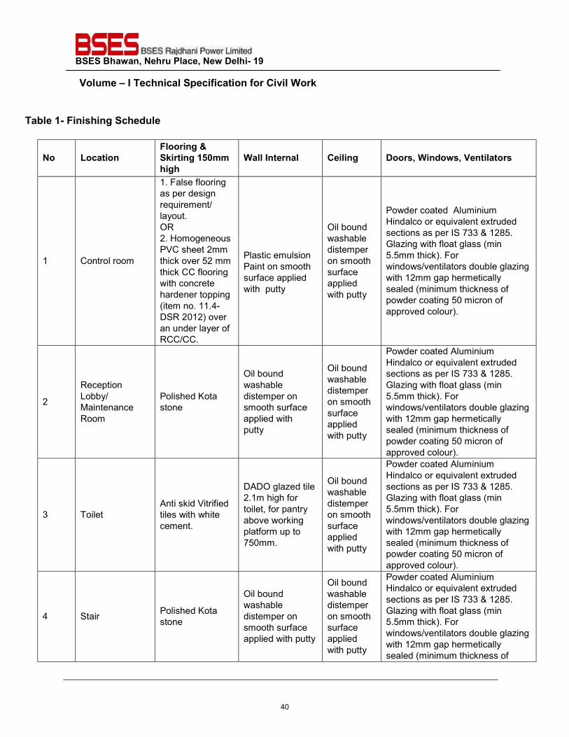
BSES Bhawan, Nehru Place, New Delhi- 19 Volume – I Technical Specification for Civil Work
Table 1- Finishing Schedule
No Location Flooring & Skirting 150mm high
Wall Internal Ceiling Doors, Windows, Ventilators
1 Control room
1. False flooring as per design requirement/ layout. OR 2. Homogeneous PVC sheet 2mm thick over 52 mm thick CC flooring with concrete hardener topping (item no. 11.4- DSR 2012) over an under layer of RCC/CC.
Plastic emulsion Paint on smooth surface applied with putty
Oil bound washable distemper on smooth surface applied with putty
Powder coated Aluminium Hindalco or equivalent extruded sections as per IS 733 & 1285. Glazing with float glass (min 5.5mm thick). For windows/ventilators double glazing with 12mm gap hermetically sealed (minimum thickness of powder coating 50 micron of approved colour).
2
Reception Lobby/ Maintenance Room
Polished Kota stone
Oil bound washable distemper on smooth surface applied with putty
Oil bound washable distemper on smooth surface applied with putty
Powder coated Aluminium Hindalco or equivalent extruded sections as per IS 733 & 1285. Glazing with float glass (min 5.5mm thick). For windows/ventilators double glazing with 12mm gap hermetically sealed (minimum thickness of powder coating 50 micron of approved colour).
3 Toilet Anti skid Vitrified tiles with white cement.
DADO glazed tile 2.1m high for toilet, for pantry above working platform up to 750mm.
Oil bound washable distemper on smooth surface applied with putty
Powder coated Aluminium Hindalco or equivalent extruded sections as per IS 733 & 1285. Glazing with float glass (min 5.5mm thick). For windows/ventilators double glazing with 12mm gap hermetically sealed (minimum thickness of powder coating 50 micron of approved colour).
4 Stair Polished Kota stone
Oil bound washable distemper on smooth surface applied with putty
Oil bound washable distemper on smooth surface applied with putty
Powder coated Aluminium Hindalco or equivalent extruded sections as per IS 733 & 1285. Glazing with float glass (min 5.5mm thick). For windows/ventilators double glazing with 12mm gap hermetically sealed (minimum thickness of
40
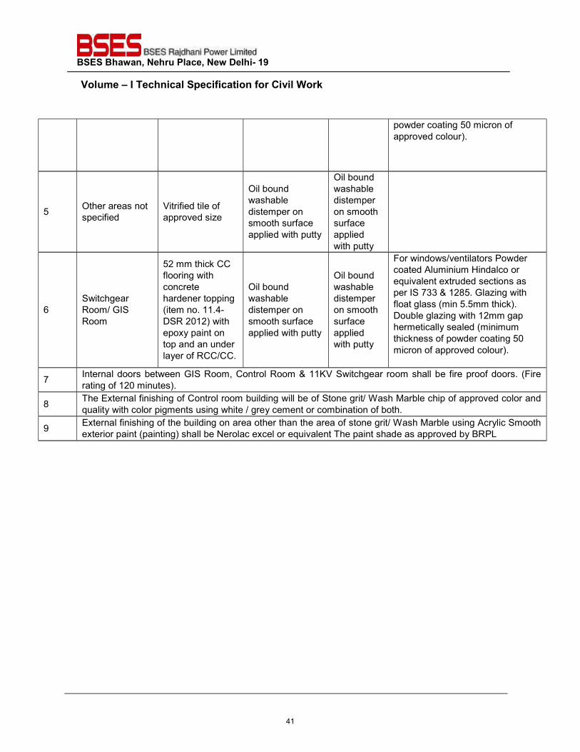
BSES Bhawan, Nehru Place, New Delhi- 19 Volume – I Technical Specification for Civil Work
powder coating 50 micron of approved colour).
5 Other areas not specified
Vitrified tile of approved size
Oil bound washable distemper on smooth surface applied with putty
Oil bound washable distemper on smooth surface applied with putty
6 Switchgear Room/ GIS Room
52 mm thick CC flooring with concrete hardener topping (item no. 11.4- DSR 2012) with epoxy paint on top and an under layer of RCC/CC.
Oil bound washable distemper on smooth surface applied with putty
Oil bound washable distemper on smooth surface applied with putty
For windows/ventilators Powder coated Aluminium Hindalco or equivalent extruded sections as per IS 733 & 1285. Glazing with float glass (min 5.5mm thick). Double glazing with 12mm gap hermetically sealed (minimum thickness of powder coating 50 micron of approved colour).
7 Internal doors between GIS Room, Control Room & 11KV Switchgear room shall be fire proof doors. (Fire rating of 120 minutes).
8 The External finishing of Control room building will be of Stone grit/ Wash Marble chip of approved color and quality with color pigments using white / grey cement or combination of both.
9 External finishing of the building on area other than the area of stone grit/ Wash Marble using Acrylic Smooth exterior paint (painting) shall be Nerolac excel or equivalent The paint shade as approved by BRPL
41
BSES Bhawan, Nehru Place, New Delhi- 19
Prepared by Reviewed by Reviewed by Approved by Revision Date
Javed Ahmed Alok Kumar Mandal Abhinav Srivastava Vijay Panpalia 0 28.03.2017
Javed Ahmed Abhinav Srivastava Abhinav Srivastava Vijay Panpalia 1 12.12.2017
Javed Ahmed Abhinav Srivastava Abhinav Srivastava K.Sheshadri 2 18.07.2018
Javed Ahmed Abhinav Srivastava Abhinav Srivastava K.Sheshadri 3 18.05.2021
TECHNICAL SPECIFICATION
FOR
66kV GAS INSULATED SWITCHGEAR
Specification No. GN101-03-SP-53-00
42
BSES Bhawan, Nehru Place, New Delhi- 19 Volume-I Technical Specification 66KV GIS
1.0 SCOPE OF SUPPLY 1.1 This specification covers the design, manufacture, testing, supply, erection & commissioning of 66kV, Gas Insulated (GIS), GIS bay module, connecting flanges, support structure, GIS ducts, SF6/Air Bushing, gas monitoring devices, barriers, pressure switches etc. Metal enclosed and factory assembled switchgear for BSES Rajdhani Power Ltd at Delhi. 1.2 This specification shall be used in conjunction with all specifications, switchgear data sheet, 66kV switchgear single line diagram and other drawing attached to the specification / Purchase requisition. 1.3 The GIS shall be modular type design with all the components as per SLD it shall be extensible type for adding additional bays in future on the either side. The incomer, bus coupler feeder & Transfer feeder shall be rated for 2000A. 1.4 The Bill of Quantity ( BOQ) The apparatus to be supplied by the bidder shall include but not be limited to the following:
1. Circuit Breaker 2. Disconnect switches 3. Surge Arrestor for both incoming and outgoing. 4. Maintenance earthing switches 5. Voltage detector 6. Current Transformers 7. Arc Detection System including its all accessories and measuring device/instrument 8. Bus and Elbow sections 9. Cable and enclosures 10. Ground connections to the stations ground grid 11. Auxiliary material to complete the GIS installations (Like density switches, secondary cable &
Bolts etc.) 12. Support structure for the GIS 13. Terminal boxes, junction boxes, marshalling boxes as required. 14. Insulating SF6 Gas. 15. Local control cubical 16. Special tools for installation and maintenance (including Gas filling, evacuation & Gas Filter kit -1
Set, Gas leakage detector-1 Set. Both shall be DILO Make) 17. Spare parts for start-up for minimum 5years of operation. 18. Technical direction for the site assembly and testing by a competent service engineer 19. All the documentation as required in the specification 20. 66kV End termination kit supply and installation 21. Test plug for Cable Hipot testing of rated voltage for each GIS Bay 22. Cable Dummy Plugs 12 Nos suitable for 3Cx300 Cable.
Note: Biddder to confirm that in the event of maintainance/dismantling of any bus isolator the affected bay shall remain in service through another bus isolator. Any gas barriers / intermediate compartment, if required to achieve the same shall be considered by bidder. 1.5 Layout and civil design information Special attention shall be given to an optimized GIS design with minimum space requirements. The contractor shall propose as part of this contract with the layout design of the GIS building to ensure that the most suitable
43
BSES Bhawan, Nehru Place, New Delhi- 19 Volume-I Technical Specification 66KV GIS
arrangement is obtained for housing, supporting and fixing of the GIS. The bidder shall also provide a complete floor plan detailing the fixing points, size of foundation, required cable trenches, wall openings, doors, transport ways and lay down areas. All static and dynamic loads plus dimensional tolerances shall be given on these drawings to enable the civil works design to be optimized. Supplier shall furnished all material , necessary hardware’s, special tools for installation and maintenance, drawings and instructions for the constructions for the construction of the complete and ready to operate 72.5k V Part of the substation. The following attached drawings are part of the specification:
a. SLD. b. Proposed Layout. c. Layout for 66kV GIS indoor installation shall be submitted by bidder along with bid.
1.6 PERFOMANCE The design, manufacture , testing and performance of 72.5k V SF6 aluminum enclosure gas Switchgear are offered shall have designed , manufactured and type tested as per IEC / IS and supplied the same for the system voltage of 72.5k V or above. 2.0 CODES AND STANDARDS 2.1 The design, manufacturing, testing and performance of 72.5 kV SF6 gas insulated switchgear covered under this specification shall comply with latest IS/IEC mentioned below. However, the list of standards given below is not exhaustive and shall not be considered as limiting. The equipment furnished under this specification shall be of best design and sound engineering practice. 2.2 The performance , testing, and rating of the switchgear shall confirm to the following standards:
Standard Code Standard Description Indian electricity act CBIP manual IS-2516 Specification for Circuit Breaker. IS-13118-1991 Specification for high voltage altering current circuit breaker IS-2090-1973 Bushing for alternating voltage above 1000 volts. IS-731-1971 Insulator for Overhead lines. IS -996-1979 Single phase small AC and Universal Electric Motors. IS-7572-1974 Guide for testing single phase AC and Universal motors. IS 4237-1967 General Requirement for switchgear for voltage not exceeding 1Kv. IS-2147-1962 Degree of protection provided by enclosure for low-voltage switchgear
control gear. IS-1554 Part-I 1988 PVC insulated cables up to & including 1100 volts. IS-2208 HRC Cartridge fuses links up to 650 volts. IS-375 Outdoor switchgear & control gear matching with latest IS/IEC
requirement
44
BSES Bhawan, Nehru Place, New Delhi- 19 Volume-I Technical Specification 66KV GIS
IS-2544 Porcelain Post Insulator IS-5621 Hollow insulators for use in electrical equipment IEC-56 Specification for high voltage alternating current circuit breaker IEC-62271 - 100 High Voltage alternating Current Circuit Breaker IEC-60694 Common specification for high voltage switchgear and control gear
standards IEC-376 SF6 Gas IEC 60376 Specification for acceptance of new Sulphur Hexa fluoride
IEC 62271-203 Gas insulated metal enclosed switchgear for rated voltage above 52KV
IEC 62271-1 Common clauses for high voltage switchgear and control gear Standards.
IEC 62271-102 Alternating current disconnector and earthing switches. IEC 60137 Bushing for alternating voltages above 1000V IEC 62271-209 Cable connection for gas insulated switchgear
IEC 60480 Guide to checking of sulphur hexafluoride taken from electrical equipments.
IEC 60099-1/4 Non-linear resistor type arrestors for AC systems IEC 61439 Factory built assemblies of low voltage switchgear and control gear.
IEC 62271-101 Report on synthetic testing of high voltage alternating current circuit breaker
IEEE 80 Guide for safety in A.C. substation grounding IEC: 185 Specification for current transformers IS-3156 (Part I to IV) Specification for Voltage transformer.
IEC 61128 Alternating current disconnectors . Bus –transformer current switching by disconnectors
IEC 66044-1 CT IEC66044-2 VT IEC 60859 Cable connection for gas insulated switchgear CIGRE-44 Earthing of GIS an application guide ( Electra no. 151 , Dec 93 )
IEC 61639 Direct connection between power transformers and gas insulated switchgear for rated voltage above 72.5KV and above ( if applicable )
The components and devices which are not covered by the above device shall confirm to comply with the latest applicable standards rules, codes, and regulated of the internationally recognized standardizing bodies and professional societies and may be approved by the owner. The manufacturer shall list all the applicable standards. 3.1 Rating and Features The 72.5 k V SF6 gas insulated switchgear shall be designed to comply with the following general ratings.
Rating Voltage 66k V Number of phases 3 Lighting impulse withstand voltage 325 kV ( Peak)
45
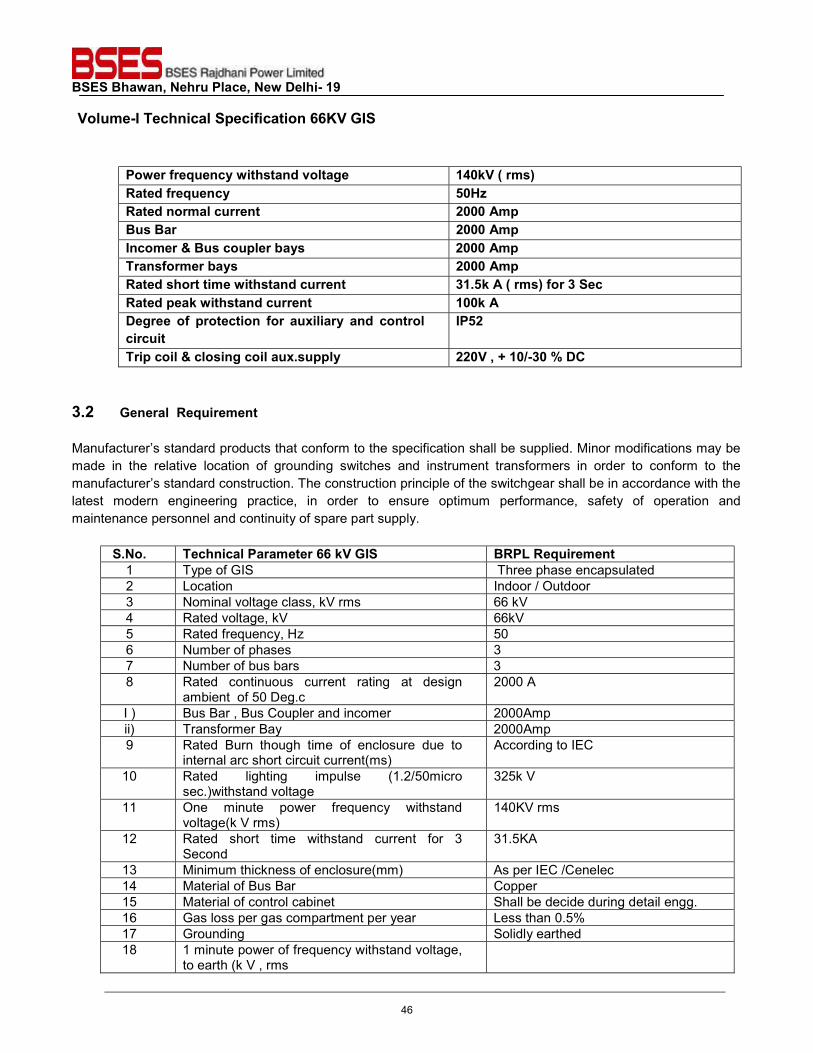
BSES Bhawan, Nehru Place, New Delhi- 19 Volume-I Technical Specification 66KV GIS
Power frequency withstand voltage 140kV ( rms) Rated frequency 50Hz Rated normal current 2000 Amp Bus Bar 2000 Amp Incomer & Bus coupler bays 2000 Amp Transformer bays 2000 Amp Rated short time withstand current 31.5k A ( rms) for 3 Sec Rated peak withstand current 100k A Degree of protection for auxiliary and control circuit
IP52
Trip coil & closing coil aux.supply 220V , + 10/-30 % DC 3.2 General Requirement Manufacturer’s standard products that conform to the specification shall be supplied. Minor modifications may be made in the relative location of grounding switches and instrument transformers in order to conform to the manufacturer’s standard construction. The construction principle of the switchgear shall be in accordance with the latest modern engineering practice, in order to ensure optimum performance, safety of operation and maintenance personnel and continuity of spare part supply.
S.No. Technical Parameter 66 kV GIS BRPL Requirement 1 Type of GIS Three phase encapsulated 2 Location Indoor / Outdoor 3 Nominal voltage class, kV rms 66 kV 4 Rated voltage, kV 66kV 5 Rated frequency, Hz 50 6 Number of phases 3 7 Number of bus bars 3 8 Rated continuous current rating at design
ambient of 50 Deg.c 2000 A
I ) Bus Bar , Bus Coupler and incomer 2000Amp ii) Transformer Bay 2000Amp 9 Rated Burn though time of enclosure due to
internal arc short circuit current(ms) According to IEC
10 Rated lighting impulse (1.2/50micro sec.)withstand voltage
325k V
11 One minute power frequency withstand voltage(k V rms)
140KV rms
12 Rated short time withstand current for 3 Second
31.5KA
13 Minimum thickness of enclosure(mm) As per IEC /Cenelec 14 Material of Bus Bar Copper 15 Material of control cabinet Shall be decide during detail engg. 16 Gas loss per gas compartment per year Less than 0.5% 17 Grounding Solidly earthed 18 1 minute power of frequency withstand voltage,
to earth (k V , rms
46
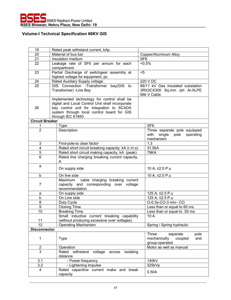
BSES Bhawan, Nehru Place, New Delhi- 19 Volume-I Technical Specification 66KV GIS
19 Rated peak withstand current, kAp 20 Material of bus bar Copper/Aluminum Alloy 21 Insulation medium SF6 22 Leakage rate of SF6 per annum for each
compartment <0.5%
23 Partial Discharge of switchgear assembly at highest voltage for equipment, pc
<5
24 Rated Auxiliary Supply voltage 220 V DC 25 GIS Connection -Transformer bay(GIS to
Transformer) -Line Bay 66/11 kV Gas insulated substation 3RX3CX300 Sq.mm /ph Al-XLPE 66k V Cable
26
Implemented technology for control shall be digital and Local Control Unit shall incorporate bay control unit for integration to SCADA system through local control board for GIS through IEC 61850
Circuit Breaker 1 Type SF6 2 Description Three separate pole equipped
with single pole operating mechanism
3 First-pole-to clear factor 1.3 4 Rated short circuit breaking capacity, kA (r.m.s) 31.5kA 5 Rated short circuit making capacity, kA (peak) 79KA 6 Rated line charging breaking current capacity,
A
a On supply side 10 A, ≤2.5 P.u
b On line side 10 A, ≤2.5 P.u 7
Maximum cable charging breaking current capacity and corresponding over voltage recommendation
a On supply side 125 A, ≤2.5 P.u b On Line side 125 A, ≤2.5 P.u 8 Duty Cycle O-0.3s-CO-3 min– CO 9 Closing Time Less than or equal to 60 ms 10 Breaking Time Less than or equal to 50 ms
11
Small inductive current breaking capability (without producing excessive over voltages)
10 A
12 Operating Mechanism Spring / Spring hydraulic Disconnector
1 Type
Three separate pole mechanically coupled and group-operated
2 Operation Motor as well as manual 3 Rated withstand voltage across isolating
distance
3.1 - Power frequency 140kV 3.2 - Lightening Impulse 325kVp 4 Rated capacitive current make and break
capacity 0.50A
47
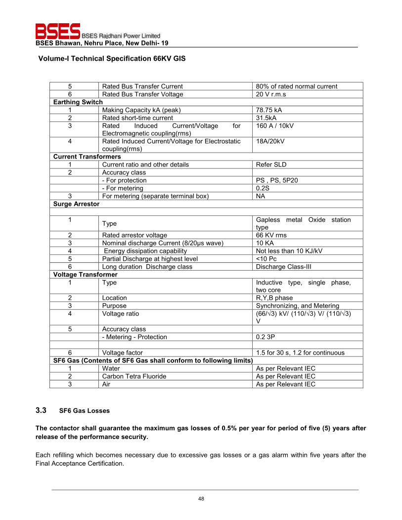
BSES Bhawan, Nehru Place, New Delhi- 19 Volume-I Technical Specification 66KV GIS
5 Rated Bus Transfer Current 80% of rated normal current 6 Rated Bus Transfer Voltage 20 V r.m.s
Earthing Switch 1 Making Capacity kA (peak) 78.75 kA 2 Rated short-time current 31.5kA 3 Rated Induced Current/Voltage for
Electromagnetic coupling(rms) 160 A / 10kV
4 Rated Induced Current/Voltage for Electrostatic coupling(rms)
18A/20kV
Current Transformers 1 Current ratio and other details Refer SLD 2 Accuracy class - For protection PS , PS, 5P20 - For metering 0.2S 3 For metering (separate terminal box) NA
Surge Arrestor
1 Type Gapless metal Oxide station type
2 Rated arrestor voltage 66 KV rms 3 Nominal discharge Current (8/20μs wave) 10 KA 4 Energy dissipation capability Not less than 10 KJ/kV 5 Partial Discharge at highest level <10 Pc 6 Long duration Discharge class Discharge Class-III
Voltage Transformer 1 Type Inductive type, single phase,
two core 2 Location R,Y,B phase 3 Purpose Synchronizing, and Metering 4 Voltage ratio (66/√3) kV/ (110/√3) V/ (110/√3)
V 5 Accuracy class - Metering - Protection 0.2 3P 6 Voltage factor 1.5 for 30 s, 1.2 for continuous
SF6 Gas (Contents of SF6 Gas shall conform to following limits) 1 Water As per Relevant IEC 2 Carbon Tetra Fluoride As per Relevant IEC 3 Air As per Relevant IEC
3.3 SF6 Gas Losses The contactor shall guarantee the maximum gas losses of 0.5% per year for period of five (5) years after release of the performance security. Each refilling which becomes necessary due to excessive gas losses or a gas alarm within five years after the Final Acceptance Certification.
48
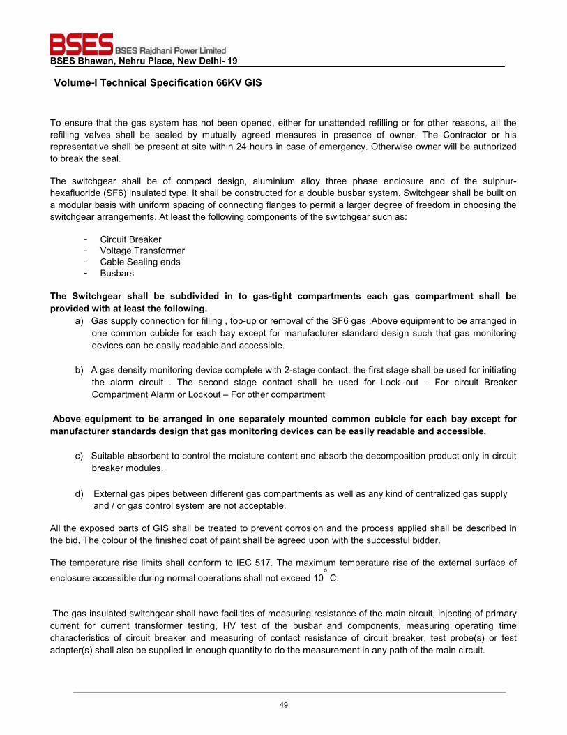
BSES Bhawan, Nehru Place, New Delhi- 19 Volume-I Technical Specification 66KV GIS
To ensure that the gas system has not been opened, either for unattended refilling or for other reasons, all the refilling valves shall be sealed by mutually agreed measures in presence of owner. The Contractor or his representative shall be present at site within 24 hours in case of emergency. Otherwise owner will be authorized to break the seal. The switchgear shall be of compact design, aluminium alloy three phase enclosure and of the sulphur-hexafluoride (SF6) insulated type. It shall be constructed for a double busbar system. Switchgear shall be built on a modular basis with uniform spacing of connecting flanges to permit a larger degree of freedom in choosing the switchgear arrangements. At least the following components of the switchgear such as:
- Circuit Breaker - Voltage Transformer - Cable Sealing ends - Busbars
The Switchgear shall be subdivided in to gas-tight compartments each gas compartment shall be provided with at least the following.
a) Gas supply connection for filling , top-up or removal of the SF6 gas .Above equipment to be arranged in one common cubicle for each bay except for manufacturer standard design such that gas monitoring devices can be easily readable and accessible.
b) A gas density monitoring device complete with 2-stage contact. the first stage shall be used for initiating
the alarm circuit . The second stage contact shall be used for Lock out – For circuit Breaker Compartment Alarm or Lockout – For other compartment
Above equipment to be arranged in one separately mounted common cubicle for each bay except for manufacturer standards design that gas monitoring devices can be easily readable and accessible.
c) Suitable absorbent to control the moisture content and absorb the decomposition product only in circuit breaker modules.
d) External gas pipes between different gas compartments as well as any kind of centralized gas supply
and / or gas control system are not acceptable. All the exposed parts of GIS shall be treated to prevent corrosion and the process applied shall be described in the bid. The colour of the finished coat of paint shall be agreed upon with the successful bidder. The temperature rise limits shall conform to IEC 517. The maximum temperature rise of the external surface of
enclosure accessible during normal operations shall not exceed 10o C.
The gas insulated switchgear shall have facilities of measuring resistance of the main circuit, injecting of primary current for current transformer testing, HV test of the busbar and components, measuring operating time characteristics of circuit breaker and measuring of contact resistance of circuit breaker, test probe(s) or test adapter(s) shall also be supplied in enough quantity to do the measurement in any path of the main circuit.
49
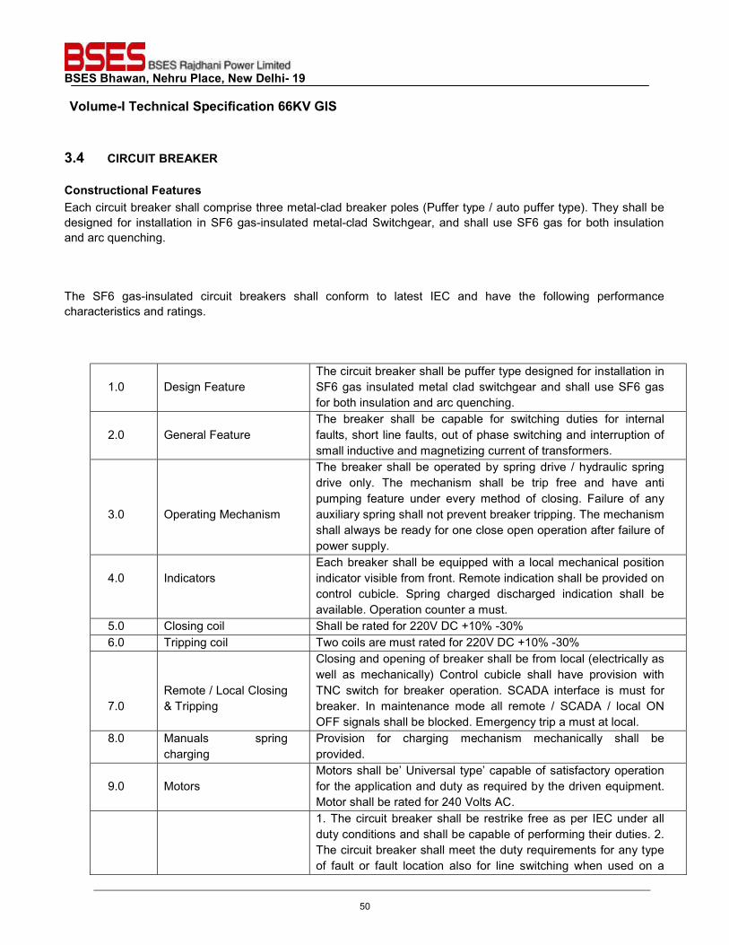
BSES Bhawan, Nehru Place, New Delhi- 19 Volume-I Technical Specification 66KV GIS
3.4 CIRCUIT BREAKER Constructional Features Each circuit breaker shall comprise three metal-clad breaker poles (Puffer type / auto puffer type). They shall be designed for installation in SF6 gas-insulated metal-clad Switchgear, and shall use SF6 gas for both insulation and arc quenching. The SF6 gas-insulated circuit breakers shall conform to latest IEC and have the following performance characteristics and ratings.
1.0
Design Feature
The circuit breaker shall be puffer type designed for installation in SF6 gas insulated metal clad switchgear and shall use SF6 gas for both insulation and arc quenching.
2.0
General Feature
The breaker shall be capable for switching duties for internal faults, short line faults, out of phase switching and interruption of small inductive and magnetizing current of transformers.
3.0
Operating Mechanism
The breaker shall be operated by spring drive / hydraulic spring drive only. The mechanism shall be trip free and have anti pumping feature under every method of closing. Failure of any auxiliary spring shall not prevent breaker tripping. The mechanism shall always be ready for one close open operation after failure of power supply.
4.0
Indicators
Each breaker shall be equipped with a local mechanical position indicator visible from front. Remote indication shall be provided on control cubicle. Spring charged discharged indication shall be available. Operation counter a must.
5.0 Closing coil Shall be rated for 220V DC +10% -30% 6.0 Tripping coil Two coils are must rated for 220V DC +10% -30%
7.0
Remote / Local Closing & Tripping
Closing and opening of breaker shall be from local (electrically as well as mechanically) Control cubicle shall have provision with TNC switch for breaker operation. SCADA interface is must for breaker. In maintenance mode all remote / SCADA / local ON OFF signals shall be blocked. Emergency trip a must at local.
8.0 Manuals spring charging
Provision for charging mechanism mechanically shall be provided.
9.0
Motors
Motors shall be’ Universal type’ capable of satisfactory operation for the application and duty as required by the driven equipment. Motor shall be rated for 240 Volts AC.
1. The circuit breaker shall be restrike free as per IEC under all duty conditions and shall be capable of performing their duties. 2. The circuit breaker shall meet the duty requirements for any type of fault or fault location also for line switching when used on a
50
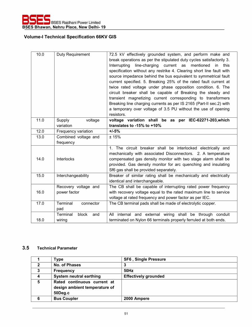
BSES Bhawan, Nehru Place, New Delhi- 19 Volume-I Technical Specification 66KV GIS
10.0 Duty Requirement 72.5 kV effectively grounded system, and perform make and break operations as per the stipulated duty cycles satisfactorily 3. Interrupting line-charging current as mentioned in this specification without any restrike 4. Clearing short line fault with source impedance behind the bus equivalent to symmetrical fault current specified. 5. Breaking 25% of the rated fault current at twice rated voltage under phase opposition condition. 6. The circuit breaker shall be capable of Breaking the steady and transient magnetizing current corresponding to transformers Breaking line charging currents as per IS 2165 (Part-II sec.2) with a temporary over voltage of 3.5 PU without the use of opening resistors.
11.0 Supply voltage variation
voltage variation shall be as per IEC-62271-203,which translates to -15% to +10%
12.0 Frequency variation +/-5% 13.0 Combined voltage and
frequency ± 15%
14.0
Interlocks
1. The circuit breaker shall be interlocked electrically and mechanically with associated Disconnectors. 2. A temperature compensated gas density monitor with two stage alarm shall be provided. Gas density monitor for arc quenching and insulating Sf6 gas shall be provided separately.
15.0 Interchangeability Breaker of similar rating shall be mechanically and electrically identical and interchangeable.
16.0
Recovery voltage and power factor
The CB shall be capable of interrupting rated power frequency with recovery voltage equal to the rated maximum line to service voltage at rated frequency and power factor as per IEC.
17.0 Terminal connector pad
The CB terminal pads shall be made of electrolytic copper.
18.0
Terminal block and wiring
All internal and external wiring shall be through conduit terminated on Nylon 66 terminals properly ferruled at both ends.
3.5 Technical Parameter
1 Type SF6 , Single Pressure 2 No. of Phases 3 3 Frequency 50Hz 4 System neutral earthing Effectively grounded 5 Rated continuous current at
design ambient temperature of 50Deg.c
6 Bus Coupler 2000 Ampere
51
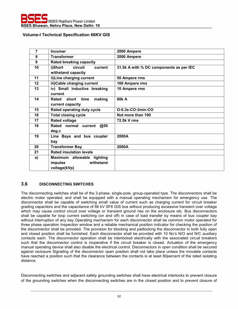
BSES Bhawan, Nehru Place, New Delhi- 19 Volume-I Technical Specification 66KV GIS
7 Incomer 2000 Ampere 8 Transformer 2000 Ampere 9 Rated breaking capacity 10 i)Short circuit current
withstand capacity 31.5k A with % DC components as per IEC
11 ii)Line charging current 50 Ampere rms 12 iii)Cable charging current 160 Ampere rms 13 iv) Small inductive breaking
current 10 Ampere rms
14 Rated short time making current capacity
80k A
15 Rated operating duty cycle O-0.3s-CO-3min-CO 16 Total closing cycle Not more than 100 17 Rated voltage 72.5k V rms 18 Rated normal current @50
deg.c
19 Line Bays and bus coupler bay
2000A
20 Transformer Bay 2000A 21 Rated insulation levels a) Maximum allowable lighting
impulse withstand voltage(kVp)
3.6 DISCONNECTING SWITCHES The disconnecting switches shall be of the 3-phase, single-pole, group-operated type. The disconnectors shall be electric motor operated, and shall be equipped with a manual operating mechanism for emergency use. The disconnector shall be capable of switching small value of current such as charging current for circuit breaker grading capacitors and the capacitance of 66 kV SF6 GIS bus without producing excessive transient over voltage which may cause control circuit over voltage or transient ground rise on the enclosure etc. Bus disconnectors shall be capable for loop current switching (on and off) in case of load transfer by means of bus coupler bay without interruption of any bay Operating mechanism for each disconnector shall be common motor operated for three phase operation Inspection window and a reliable mechanical position indicator for checking the position of the disconnector shall be provided. The provision for blocking and padlocking the disconnector in both fully open and closed position shall be furnished. Each disconnector shall be provided with 10 No’s N/O and N/C auxiliary contacts each. The disconnector operation shall be interlocked electrically with the associated circuit breakers such that the disconnector control is inoperative if the circuit breaker is closed. Actuation of the emergency manual operating device shall also disable the electrical control. Disconnectors in open condition shall be secured against reclosure Signaling of the disconnector open position shall not take place unless the movable contacts have reached a position such that the clearance between the contacts is at least 80percent of the rated isolating distance. Disconnecting switches and adjacent safety grounding switches shall have electrical interlocks to prevent closure of the grounding switches when the disconnecting switches are in the closed position and to prevent closure of
52
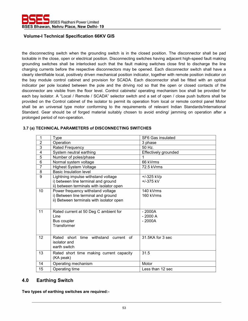
BSES Bhawan, Nehru Place, New Delhi- 19 Volume-I Technical Specification 66KV GIS
the disconnecting switch when the grounding switch is in the closed position. The disconnector shall be pad lockable in the close, open or electrical position. Disconnecting switches having adjacent high-speed fault making grounding switches shall be interlocked such that the fault making switches close first to discharge the line charging currents before the respective disconnectors may be opened. Each disconnector switch shall have a clearly identifiable local, positively driven mechanical position indicator, together with remote position indicator on the bay module control cabinet and provision for SCADA. Each disconnector shall be fitted with an optical indicator per pole located between the pole and the driving rod so that the open or closed contacts of the disconnector are visible from the floor level. Control cabinets/ operating mechanism box shall be provided for each bay isolator. A “Local / Remote / SCADA” selector switch and a set of open / close push buttons shall be provided on the Control cabinet of the isolator to permit its operation from local or remote control panel Motor shall be an universal type motor conforming to the requirements of relevant Indian Standards/International Standard. Gear should be of forged material suitably chosen to avoid ending/ jamming on operation after a prolonged period of non-operation. 3.7 (a) TECHNICAL PARAMETERS of DISCONNECTING SWITCHES
1 Type SF6 Gas insulated 2 Operation 3 phase 3 Rated Frequency 50 Hz. 4 System neutral earthing Effectively grounded 5 Number of poles/phase 1 6 Normal system voltage 66 kVrms 7 Highest System Voltage 72.5 kVrms 8 Basic Insulation level 9 Lightning impulse withstand voltage
i) between line terminal and ground ii) between terminals with isolator open
+/-325 kVp +/-375 kV
10 Power frequency withstand voltage i) Between line terminal and ground ii) Between terminals with isolator open
140 kVrms 160 kVrms
11 Rated current at 50 Deg C ambient for Line Bus coupler Transformer
- 2000A - 2000 A - 2000A
12 Rated short time withstand current of isolator and earth switch
31.5KA for 3 sec
13 Rated short time making current capacity (KA peak)
31.5
14 Operating mechanism Motor 15 Operating time Less than 12 sec
4.0 Earthing Switch Two types of earthing switches are required:-
53
BSES Bhawan, Nehru Place, New Delhi- 19 Volume-I Technical Specification 66KV GIS
High speed earthing switches for earthing the 66k V incoming cable circuit shall be capable of closing on to full short circuit fault without any damage and after that it shall still retain its full insulation strength. Three-pole, group operated, work in progress maintenance earthing shall also provided each earthing switch group shall be electric motor operated . A means of emergency manual operation shall also be provided. In order to provide test facilities, certain earthing switches may require to be insulated from the enclosure and have easily removable ground connections. 4.1 Maintenance earthing switches Each maintenance-earthing switch shall be electrically interlocked with its associated disconnecting switch and circuit breaker such that it can only be closed if both the circuit breaker and disconnecting switch are open. Once closed it shall be secured against re-opening. Maintenance earthing switch shall be operable locally from the bay module control cabinet only; SCADA operation not required. Positive mechanical position indication through reliable optical indicator shall be provided locally. Interlocks shall be provided such that manual operation of the switches or insertion of the manual operating device will disable the electrical control circuits. Each earthing switches shall be provided either 4NO & 4NC auxiliary Switches. Provision shall be made for padlocking the earthing switches in either the open or closed positions. All portions of the earthing switches and operating mechanism – requiring grounding shall be connected together utilizing flexible copper copper conductors. On opening, the line earthing switch should be able to break current induced by parallel lines according to IEC provisions. 4.2 High Speed earthing switches Grounding switches for line circuits shall be of the high-speed and shall be used to discharge the respective charging currents, in addition to their safety grounding function. These grounding switches shall also be capable of interrupting the inductive and capacitive currents and to withstand the associated TRV. The switches shall be fitted with a stored energy closing system to provide fault-making capability. The short-circuit making current rating of each ground switch shall be at least equal to its peak withstand current rating. Each switch shall have a positive local mechanical position indicator and a remote indicator. These high-speed grounding switches shall be electrically interlocked with line side disconnections / associated circuit breakers for safety. The grounding switches shall be required to close before the disconnect or switches are opened in order to dissipate the trapped charges, when the lines are taken out of service for maintenance, etc. Interlocks shall be provided such that insertion of the manual operating devices will disable the electrical control
54
BSES Bhawan, Nehru Place, New Delhi- 19 Volume-I Technical Specification 66KV GIS
circuits. Each high-speed grounding switch shall be fitted with 6 NO and 6 NC auxiliary switches for use by others, over and above those required for local interlocking and position indication. All contacts shall be wired to terminal blocks in the local bay control cabinet. Provision shall be made for padlocking the grounding switches in either the open or closed position. All portions of the grounding switches and operating mechanism requiring connection to ground shall be connected together utilizing flexible copper conductor. 4.3 CURRENT TRANSFORMER Current transformer may be module type in the GIS or ring type placed around the power cable right after the GIS cable ending module. The secondary windings is preferred to be embedded in cast resin to secure them against slip-off. The CTs shall have multicores with multi-ratio, which shall be changeable by means of taps on the secondary side. All current transformers shall have effective electromagnetic shields to protect against high frequency transients. All CT’s shall comply to IEC. The ratings shall be: -
S.No. Description Particulars 1. Rated Voltage 72.5kV 2 Rated frequency 50Hz 3 System neutral earthing Effectively earth 4 Maximum temperature rise over ambient of 50
deg.C As per IEC60044-1
5 One minute power frequency withstand voltage between secondary terminal and earth
5kV rms
6 Partial discharge level 10 Pico Coulombs 7 Rated insulation levels i) 1.2 /50 micro second impulse voltage 325 KV Peak ii) 1minute power frequency withstand voltage 140 kV Peak
The manufacturer shall provide the wiring between each CT core and the marshaling box. Suitable provision shall be made for primary current injection testing of current transformer circuits. The current transformer shall be furnished with shorting arrangement. 4.4 VOLTAGE TRANSFORMER Voltage transformer shall be inductive module type with graded insulation, and shall be effectively shielded against high frequency electromagnetic transients, fully encapsulated in the gas compartment segregated from the adjacent compartments, complying with IEC, having the ratings: - Line Voltage Transformer / Bus Voltage Transformer
S.NO. Description Particulars 1 Rated primary voltage (kV rms) 66
55
BSES Bhawan, Nehru Place, New Delhi- 19 Volume-I Technical Specification 66KV GIS
2 Rated frequency 50Hz 3 System neutral earthing Effectively earthed 4 Type Electromagnetic 5 No. of secondary 2 6 Rated voltage factor 1.2 –continuous 1.5 - 30 seconds 7 Voltage ratio (kV) 66/√3 / 110/√3 8 Accuracy 0.2 and 3P 9 Output burden (VA) (minimum) 50 VA 10 Highest System Voltage 72.5 KV 11 Basic Insulation Level (BIL) 325 KVp 12 Power frequency withstand voltage 140kV
4.5 SURGE ARRESTER The gapless arrester shall conform to IEC and shall have the following technical Performance characteristics and ratings.
1 Highest system Voltage 72.5KV 2 Rated Arrester Voltage 60 kV 3 System neutral earthing Effectively earthed 4 Continuous operating Voltage 60 KV 5 Type Gapless type / metal zinc oxide 6 Long duration class Class 3 7 Frequency 50 Hz 8 Lightning impulse withstand
voltage for insulation 325 kV
9 Power frequency withstand voltage for insulation
10 Nominal discharge current with 8/20 micro-sec wave
10 kA
11 Discharge current at which insulation coordination will be done
20 kA or 8/20 micro sec wave
12 Minimum discharge capability 5 kJ/kV referred to rated arrester voltage and at minimum discharge characteristics whichever is higher
13 Maximum switching surge residual voltage (1 KA)
14 Maximum residual voltage i) 5 KA ii) 10KA
15 Current for pressure relief test
As per IEC
16 Pressure relief class A 17 Prospective symmetrical fault
current 40 KA rms for 0.2 sec.
56
BSES Bhawan, Nehru Place, New Delhi- 19 Volume-I Technical Specification 66KV GIS
18 Low current long duration test value (2000 micro sec.)
As per IEC
19 Discharge counter and leakage current meter to be provided
Yes
It is preferred to go with air insulated LA instead of gas insulated, bidder should clearly state if they have any reservation issue while going with air insulated LA. 4.6 BUSBAR AND TEE-OFF CONNECTION Busbar shall have ratings of 2000 Ampere( Min.) and if required vendor will submit the calculations, at an ambient of 50 DEG C. Busbar conductor and enclosure shall have provision for absorbing thermal expansion and contraction. No mechanical stress shall be allowed to impose on insulating parts. Arrangement of the busbar compartments shall be designed in such a way that future extension and maintenance of any busbar compartment shall be made without shut down the power distribution system. The SF6 3-phase encapsulated busbars and busducts shall be mounted in horizontal configuration to suit the switchgear layout and shall be single phase Encapsulated. The conductors of the busbars shall be decided during detail engineering. The material of the bus Bar shall filled with pressurized SF6 gas. The conductor shall be supported from the enclosures by homogeneous epoxy resin insulator shaped to ensure uniform electrical field distribution at rated voltage. Metal bellow type compensators with adjustable tensioners shall be provided, where required. The enclosures shall be designed to eliminate as much as possible all external effects of the flux created by normal and fault currents. The induced voltages on the enclosures shall not be allowed to exceed reasonable limits of safety for operating personnel. The Supplier shall furnish supporting calculations in respect of induced voltage and losses guaranteed for the enclosure. Bus end connections shall be made with multi-contact connectors to allow for axial thermal expansion of the bus. Enclosure end connections shall be flanged. The common point of the two bus bars should be in a separate enclosure with an earthing switch in order to ensure availability of one busbar in service at all times Each end of the busbar shall be designed for convenient future extension of the Switchgear. 4.7 CABLE TERMINATION Each circuit of the underground cable shall consist of 2 (Runs) Three core Aluminum cable one per phase) 300 mm2, 66 kV, compact round concentric lay stranded or compact round segmental stranded conductor, cross-linked polyethylene insulated, with Aluminum corrugated metallic sheath and HDPE outer sheath. The cable will be supplied from owner stock. Supplier shall supply complete terminating kit including gas partitioning for every incoming and outgoing terminal for terminating the cable to the switchgear cable-ending module. No part shall be furnished by owner except the cable. Cable termination shall be designed in such a way that DC voltage test of the cable can be carried out safely and conveniently. Supplier shall provide test bushing and associated devices in order that power frequency high voltage test can be carried out after completion of the installation.
57
BSES Bhawan, Nehru Place, New Delhi- 19 Volume-I Technical Specification 66KV GIS
4.8 CONTROL EQUIPMENT The owner has its own SCADA system; all the equipments shall be SCADA compatible IEC 61850. All-important analogue and digital signals shall be available for SCADA. All control wiring and terminations internal to the switchgear, and connecting the switchgear to the bay module control cabinets, shall be provided by manufacturer. This cabinet shall be made out of stainless steel of grade not less than 314L. the enclosure shall be IP56. All control cables shall be shielded. Cable shields shall be grounded at both ends. Grounding connections shall be as short and direct as possible and shall terminate at the point of entry to cabinets or terminal boxes. Co-axial type cable glands suitable for use with shielded cables shall be used at each termination. All control cables shall be installed and terminated in such a manner as to limit the effects of transient electromagnetic voltages on the control conductors to an acceptable level 5.0 BAY MODULE CONTROL CABINETS Each Switchgear bay module shall be supplied with a main control cabinet of the floor mounted free standing type. The cabinet shall have full height, hinged, gasketed, lockable double doors. One door shall have a safety glass window through which the various. Switchgear controls can be viewed without opening the doors. The cabinet will be utilized as both the Switchgear bay local control module and as the terminating center for all power supply, control, annunciation and supervisory wiring interfacing with Purchaser's systems. Detailed specification for control & relay panel please see “Specification for Control and Relay Panel”. It is preferred to have complete protection and control panel as integrated part of gas insulated switchgear provided bidder does not see have any reservation regarding performance of these relays near high voltage gas module. Ambient temperature outside shall also be taken into account. Else bidder shall go with separate CRP installed inside building 5.1 RELAYS AND PROTECTION Approved make of protection relay and various components shall be as per 66kV Control & Relay Panel specification of BRPL 5.2 GAS TREATMENT REQUIREMENTS Under normal operating conditions it shall not be necessary to treat the insulating SF6 gas between major overhauls. In all gas compartments permanent efficient filters and desiccants shall be effective for the duration of time between major overhauls. Notwithstanding this, the insulators in the circuit breaker shall be made of epoxy resin composition that will resist decomposition products in contract with moisture. 5.3 GAS MONITORING DEVICES Each single phase, gas filed compartment, shall be fitted with a temperature compensated pressure switch, It shall be directly secured on the enclosure, and shall have two threshold levels to continuously monitor the Gas density. With the first level operating the user shall refill the compartment with SF6 as soon as possible while keeping GIS in service. On Operation of the second level, the user shall quickly de-energise the compartment. or pressure monitoring devices shall be provided for each gas compartment. The devices shall provide continuous and automatic monitoring of the state of the gas. The SF6 gas monitoring device shall have two supervision and
58
BSES Bhawan, Nehru Place, New Delhi- 19 Volume-I Technical Specification 66KV GIS
alarm settings. These shall be set so that, an advanced warning can be given that the gas density/pressure is reducing to an unacceptable level. After an urgent alarm, operative measures can be taken to immediately isolate the particular compartment electrically by tripping circuit breakers and opening disconnectors. It shall be ensured that there is no chance of the gas liquefying at the lowest ambient temperature. The gas monitoring device shall monitor at least the following, locally and remote.
a) "Gas Refill" Level- This will be used to annunciate the need for gas refilling.
b) “Breaker Block" Level- This is the minimum gas density at which the manufacturer will guarantee the rated fault interrupting capability of the breaker. At this level the device contact shall trip the breaker and block the closing circuits.
c) Over pressure alarm level- This alarm level shall be provided to indicate abnormal pressure rise in the
gas compartment. It shall be possible to test all gas monitoring relays without de energizing the primary equipment and without reducing pressure in the main section. Disconnecting type plugs and sockets shall be used for test purposes; the pressure/density device shall be suitable for connecting to the male portion of the plug. Two potential free electrical contacts shall be provided with each and every alarm condition.
The metal enclosures for the SF6 gas insulated equipment modules shall be made from Aluminum alloy. Suitable anti corrosive paints shade 631 of IS:5, must be applied on the exterior of the enclosures. The enclosure shall be suitable for three phases, i.e. Single Enclosure. 6.0 The external fixtures should be made of corrosion resistant material and should be capped where required. Bellow compensators shall be made of Stainless steel to preserve the mechanical strength of the equipment at the connection portions to deal with the following problems:
a) Expansion and Contraction of outer enclosure and conductor due to temperature variations. b) Mismatch in various components of GIS c) Vibration of the transformer and switching equipment d) Dimensional variations due to uneven settling of foundation e) Seismic forces as mentioned in climatic condition.
6.0 Type Test Bidder shall submit valid type test reports (as per relevant latest IEC Standard) for approval. The bidder should have conducted type test on identical or similar equipment/ components to those offered. In case type test reports are found to be technically unacceptable to BSES RAJDHANI POWER LIMITED, the type tests shall be conducted without any additional cost and delivery implication to BSES RAJDHANI POWER LIMITED. 6.1 Drawing / Documents The drawings / documents submitted shall be project and product specific and shall incorporate all project details and title block and numbering scheme of the customer. 7.0 General It is understood that each manufacturer has its own particular design concept and it is not the purpose of this specification to impose unreasonable restrictions. However, in the interest of safety, reliability and maintainability, the switchgear offered shall meet the following minimum modular concept and design requirements:
59
BSES Bhawan, Nehru Place, New Delhi- 19 Volume-I Technical Specification 66KV GIS
Fail safe inter and intra bay Inter locking scheme, Maintenance of one bus bar with the other bus bar in service, Interchange ability of similar parts, Future extension of bays, with maximum one bus outage at a time, Possible to remove and replace the fully assembled parts of circuit breaker, Pressure relief device for each pressurised section, Gas density monitoring device for each isolated section/module. All mechanical parts, which are outside of gas filled compartment, must be externally accessible and serviceable without disconnecting the main bus bar or feeder circuits. All current carrying components of the equipment specified shall be capable of continuous operation at the specified rated current without exceeding the maximum temperature rises specified in the relevant IEC standards. 7.1 Arrangement and assembly The bus bars shall be single-phase segregated metal-enclosed type. The enclosure design shall essentially be based on following considerations Temperature and solar radiations, Thermal cycling, vibration, shock and seismic, Design Pressure on normal and abnormal conditions. Conductors and live part shall be mounted on moulded epoxy resin insulators specially made for the EHV application. The conductors shall be made of tubular copper. Silver plated finger contacts at the ends of conductor or mounted on support insulators shall be provided to form sliding contact permitting the conductor to expand axially on a temperature rise, without imposing any mechanically stresses on the supporting insulators. Metal bellows compensators shall be provided on enclosure for permitting longitudinal expansion. The enclosure shall be dimensioned for the full return current. Compensators shall be bypassed by copper straps. 7.2. Welding Members to be joined by welding may be cut to shape and size by mechanical means such as shearing, machining, grinding, or by gas or arc cutting, to suit the conditions. Edges shall be shaped according to relevant IEC . Design of welded joints and selection of weld filler metal shall be in accordance with approved standards and shall allow thorough penetration and good fusion of the weld with the base metal. The edges of surfaces to be welded shall be sound metal free of visible defects such as laminations or defects caused by cutting operation at least 30 mm back from the edge of the weld, and free from rust, oil, grease, and other foreign matter. The qualification of welding procedures, welders, and welding operators for all welding, including weld repairs, shall conform to the relevant IEC . Weld-fabricated pressure-containing parts shall be designed, fabricated, inspected and tested, unless otherwise. Weld-fabricated pressure-containing parts shall be designed, fabricated, inspected and tested, unless otherwise specified, in accordance with approved standards and shall be stress relieved as a unit prior to final machining. 8.0 Workmanship
i) Electric Welding All welds shall be made continuous and watertight. The minimum size of fillet welds shall be 6 mm measured on the leg. All butt welds shall be full penetration welds welded from both sides. Welds shall in general be treated so that they will display good appearance and a surface suitable for painting. Structural welds shall be ground and blended to avoid stress raisers. All welds, which require non-destructive examination, shall be dressed by chipping and grinding as required for good interpretation by the selected weld examination method. All butt welds in the flanges and webs of beams and girders shall be radio-graphically inspected. The fillet welds between flanges and webs shall be tested by the magnetic particle method.
60
BSES Bhawan, Nehru Place, New Delhi- 19 Volume-I Technical Specification 66KV GIS
ii) Machine work All tolerances, allowances, and gauges for metal fits between plain (non threaded) cylindrical parts shall be indicated. Sufficient machining stock shall be allowed on parts to be machined to ensure true surfaces of solid material. Finished contact or bearing surfaces shall be true and exact to secure full contact. Journal and sliding surfaces shall be polished, and all surfaces shall be finished with sufficient smoothness and accuracy to ensure proper operation when assembled. No machining shall be done on working surfaces of self-lubricating bushings or washers. iii) Finished Work All surfaces that are so indicated on the drawings or those that require machining for their intended function, or those that are usually machined according to good workshop practice shall be machined. Surface finish qualities shall be adequate for the intended use and shall be indicated on the Contractor's Drawings. Suitable measuring device such as Scatter meter or other acceptable measuring device will be used to determine compliance with specified surface. iv) Unfinished Surfaces So far as practicable, all work shall be laid out to secure proper matching of adjoining unfinished surfaces. Where there is a large discrepancy between adjoining unfinished surfaces they shall be chipped and ground smooth, or machined, to secure proper alignment. If surfaces not designated as finished in the Contract Documents require machining to obtain the tolerances or straightness specified or needed for correct function, such machining shall be performed by the Contractor. v) Dimensional Checks and Visual Inspection Dimensional checks shall be performed on all major parts, components and partial assemblies, especially when close tolerances and fits are involved ( between stationary and moving parts, connecting dimensions for the assembly with other supplies, etc.). If the dimensional checks show discrepancies in measurement, which may affect the fit, assembly or dismantling of the respective part or component, the same have to be corrected correspondingly. Such correction or modification shall, however, in no way lead to sacrifices with respect to reliability of operation or inter-changeability, and shall be performed only after the agreement of the Engineer in-charge has been obtained. If the correction or modification cannot be carried out in accordance with the terms mentioned above, the part or component concerned may be subject to rejection. Faulty machine parts or equipment shall by no means be delivered. vi) Castings shall be inspected visually at the foundry after they are cleaned and while defects are being removed. Castings shall also be inspected after repairs and after heat treatment. Radiographic or other non destructive tests will be required as specified under non-destructive testing and as directed by Engineer in-charge when granting permission to repair major defects. The Engineer in-charge reserves the right to require conducting non-destructive tests at the Contractor's expense to determine: the full extent of defects; that area is properly prepared for welding that the repairs are satisfactory.
61
BSES Bhawan, Nehru Place, New Delhi- 19 Volume-I Technical Specification 66KV GIS
9.0 Electrical System Design : 9.1 The SF6 gas insulated metal enclosed switchgear (GIS) should be totally safe against inadvertent touch of any of its live constituent parts. It should be designed for outdoor application with meteorological conditions at site. All parts of the switchgear should be single phase enclosed. The arrangement of gas sections or compartments shall be such as to facilitate future extension of any make on either end without any drilling, cutting or welding on the existing equipment. To add equipment, it shall not be necessary to move or dislocate the existing switchgear bays. The design should be such that all parts subjected to wear and tear are easily accessible for maintenance purposes. The equipment offered should be protected against all types of voltage surges and any equipment necessary to satisfy this requirement shall be deemed to be included. 9.2 Switchgear shall be 66Kv, 3Phase, 3 wires, 50 Hz, Solidly earthed unless other wise specified. Current and short circuit rating will be shown on single line diagram. The rating of equipment / Component shall be take full account of heat sources with in enclosure. 9.3 The electrical arrangement of the switchgear, including protection, metering, control, interlocking and inter-tripping, shall be shown on the single line diagram with their metering and protection requirement. And further can be amend during detail engineering as per requirement of the BSES Rajdhani power system requirement. 10.0 Structural and mechanical requirement
a) GIS switchgear shall be an indoor gas insulated and metal –clad cubicle design with single line diagram and data sheet .Each panel sheet shall be metal enclosed, free standing, floor mounting, flush fronted and arranged to form a single structure with common busbar assembly. Each compartment shall be protected by a metal enclosure with enclosure with enclosure rated IP65 or better for gas compartments and IP4X for the supporting frames, low voltage and other compartments. Construction, including cable entry, shall be vermin proof.
b) Switchgear shall be permit to future extension at both the ends. SELLER shall confirm the minimum safe operational clearances around the switchgear with the quotation. GIS switchgear shall partition both between bus bar and circuit breaker and from panel to panel.
c) Switchgear shall be designed such that all high voltage parts (including busbar, core module with built in circuit breaker etc.) shall be located in an insulated inert gas. Cable termination compartment shall include provisions for conventional CT, VT, Plug in connections. Low voltage compartment shall include built in switch drives and secondary equipment. A gas leakage rate less than 0.5% per annum is required for gas insulated compartment. SELLER shall specify the type, required quantity and operating pressure for any gas filled compartment or equipment.
d) Structure, including doors and panel shall be capable of withstanding of internal pressures created by fault with in the structure (Equal to the maximum fault –current rating) without danger to operating personnel. Active and passive protection system against internal faults in each portioned panel shall be provided for safety of operators. In case of internal fault, the detection system shall open all circuit
62
BSES Bhawan, Nehru Place, New Delhi- 19 Volume-I Technical Specification 66KV GIS
breakers with in 60ms (Min.) Pressure detection shall be effected by temperature compensated pressure sensors. A Passive safety section shall ensure that hot gases shall be guided via pressure relief disk from each compartment connected. The pressure relief duct end shall be guided to open air or fitted with absorbers to cool the hot gases. Relief in to cable basement or cavity below a false floor is not acceptable. Hazards to person or risk of fire shall be reliably prevented. Temperature –compensated sensor for permanently monitor the relevant gas compartment. The entire system shall be monitored with the aid of sensors. It shall be possible to schedule maintenance operations from this monitoring system. Structure shall be provided with barriers to prevent the transfer of ionized gases between two adjacent compartments except bus chamber.
An arching fault in one compartment should not cause major damage to other compartment. Separate pressure relief vent shall be providing in busbar cable and circuit breaker compartment to release pressure to release arc fault pressure quickly and safely. The orientation of pressure relief vents and gas pressure The GIS shall be designed, manufactured and tested in accordance with the latest applicable Indian Standard, IEC standard and CBIP manuals as listed below – 11.0 GIS Design and Safety Features
a) The specification covers scope of design, engineering, fabrication, manufacturing, shop assembly, inspection and testing before supply, transportation, delivery at destination, unloading & storage at site or store of BRPL , site erection, site testing, commissioning and putting in to successful operation complete with all materials, support structures, anchoring bolts, accessories, commissioning spares & maintenance spares, special spanners, tools & tackles, any specific required ancillary services, SF6 Gas for first filling & spare, etc., for efficient and trouble free operation along with for 66 kV metal (aluminum alloy) encapsulated SF6 gas insulated switch-gear suitable for INDOOR installation.
The scope also covers provision of additional bays (without equipments) over and above bays shown in SLD, with foundations & earthing arrangements so as to install the bay module as and when required without any works pending except the procurement of the required bay module and other related equipments.
b) The station layout and equipment rating shall be based on the single line diagram and as per site conditions. The supplier has to work out an optimum layout and building size based on the specific features of his product within the constraints of overall dimensions of the plot. All equipment, accessories and wiring shall have tropical protection, involving special treatment of metal and insulation against fungus, insects and corrosion.
Further more, no part of the enclosure, or any loose parts may fly off the switchgear in such an event, and no holes may burn through the enclosure until the nearest protective relay has tripped. All grounding connections must remain operational during and after an arc fault. Proper grounding for mitigating over voltages during disconnector operation shall be included. Viewing windows shall be provided at the Disconnectors and earthing switches to ensure that each contact position can be inspected easily from the floor level. Each section shall have plug-in modules or easily removable connection pieces to allow for easy replacement of any Component with the minimum of disturbance to the remainder of the equipments.
63
BSES Bhawan, Nehru Place, New Delhi- 19 Volume-I Technical Specification 66KV GIS
c) The arrangement shall afford maximum flexibility for routine maintenance. Equipment removal and SF6 handling should be accomplished with ease. The ease of operation shall be ensured. In general the contours of energized metal parts of the GIS and any other accessory shall be such as to eliminate areas or points of high electrostatic flux concentrations. Surfaces shall be smooth with no projection or irregularities, which may cause corona.
d) The GIS switch gear shall be of modular design offering high degree of flexibility. Each module shall be complete with SF6 gas circuit breaker, Disconnectors, Maintenance Grounding switches, fast Earthing switches, voltage transformers, Current transformers, bus & elbow sections, cable end enclosures, L.A., local control cubicle and all necessary components required for safe & reliable operation and maintenance. All the three phases of the busbars and associated equipments like breakers, disconnectors, instrument transformers & earthing switches etc., as detailed in enclosed single line diagram are to be encapsulated in a single gas filled metallic enclosure. The bus bars shall be sub-divided into compartments including the associated bus bar disconnector. Bus bars are partitioned at each bay with an objective to isolate Busbar compartment for the purpose of extension and at the same time avoid damage to adjacent bays in the event of fault. The bus enclosure should be sectionalized in a manner that maintenance work on any bus disconnector (when bus and bus disconnector are enclosed in a single enclosure) can be carried out by isolating and evacuating the small effected section and not the entire bus.
e) The GIS assembly shall be consist of separate modular compartments e.g. Circuit Breaker compartment, Bus bar compartment filled with SF6 Gas and separated by gas tight partitions so as to minimize risk to human life, allow ease of maintenance and limit the effects of gas leaks failures & internal arcs etc. All components shall be such that maintenance on one feeder may be performed without de energizing the adjacent feeders. These compartments shall be designed to minimize the risk of damage to adjacent sections and protection of personnel in the event of a failure occurring within the compartments. Rupture diaphragms with suitable deflectors shall be provided to prevent uncontrolled bursting pressures developing within the enclosures under worst operating conditions, thus providing controlled pressure relief in the affected compartment. The detail of chambering system needs to be submitted along with tender documents for assessment of suitability of chambering system.
f) The switchgear shall be of the freestanding, self-supporting dead-front design, with all high-voltage equipment installed inside gas-insulated, metallic grounded enclosures, and suitably sub-divided into individual arc and gas-proof compartments.
The switchgear described in this specification is intended for continuous duty at the specified ratings and under all system operating conditions including sudden change of load and voltage within its ratings and at specified ambient conditions 24 hours a day, 365 days a year unless indicated other wise. The assembled equipment shall be capable of withstanding the electrical, mechanical and thermal ratings of the specified system. All joints and connections shall be required to withstand the forces of expansion, vibration, contraction, and specified seismic requirements without Deformation or malfunction and leakage.
g) The control equipment or LED used in LCP should be IEC 61850 compatible. All the data and alarm from
LCP should be integrated with the SCADA system.
12.0 Local Control
64
BSES Bhawan, Nehru Place, New Delhi- 19 Volume-I Technical Specification 66KV GIS
Separate control cubicle including gas monitoring kiosk shall be provided for each bay which shall be installed near the switchgear for local control & monitoring of respective switchgear bay. Local control cubicle for GIS shall be equipped with suitable hardware & software for remote control operation and conform to the bay level controller and it should be compatible with IEC 61850.
Local control cubicle shall be housed in IP-42 Enclosure (kiosks).
The LCC should have minimum following functions
1. AC Supply for drives, heating, lighting. 2. DC supply for drives, alarms, protection. 3. General control functions: Remote & local control selection, interlocks. 4. Control of disconnectors & earth switches. 5. Control of CBs: closing, tripping coils, anti-pumping, interface to synchronizing. devices,
interface to protection devices, supervision of spring mechanism. 6. Interfacing. 7. Alarm indication and signalization. 8. Supervision of Gas Compartment.
a) All the elements shall be accessible without removing support structures for routine inspections and
possible repairs. The removal of individual enclosure parts or entire breaker bays shall be possible without disturbing the enclosures of neighbouring bays.
b) It should be impossible to unwillingly touch live parts of the switchgear or to perform operations that lead to
arcing faults without the use of special tools or brute force. c) In case of any repair or maintenance on one bus bar disconnections, the other bus bar should be live and in
service. d) All interlocks that prevent potentially dangerous mal-operations shall be constructed such that they can not
be operated easily, i.e. the operator must use special tools to over-ride them. e) The enclosure shall be designed to practically eliminate the external electromagnetic field and thereby
electro-dynamic stresses, even under short circuit conditions. f) The elbows, bends, cross and T-sections of interconnections shall include the insulators bearing the
conductor when the direction changes take place in order to ensure that live parts remain perfectly centred and the electrical field is not increased at such points.
g) The Average Intensity of electromagnetic field shall not be more than 50 micro Tesla on the surface of the
enclosure. The contractor shall furnish all calculations and documents in support of the above during detailed engineering.
h) The switchgear shall have provision for connection with ground mat risers. This provision shall consist of
grounding pads to be connected to the ground mat riser in the vicinity of the equipment.
i) Wherever required, the heaters shall be provided for the equipment in order to ensure the proper functioning of the switchgear at specified ambient temperatures The heaters shall be rated for 240V AC supply and shall be complete with thermostat, control switches and fuses, connected as a balanced 3-phsase, 4-wire load. The heaters shall be so arranged and protected as to create no hazard to adjacent equipment from the heat produced.
65
BSES Bhawan, Nehru Place, New Delhi- 19 Volume-I Technical Specification 66KV GIS
j) All chambers of GIS should have separate density monitor switch with separate alarm to LCP. The common
density switch 3 phase connection is not acceptable.
k) LCC and GIS shall be separate and LCC shall be ground mounted 13.0 GIS Enclosure
a) The switchgear gas enclosures must be sectionalized, with gas tight barriers between sections or compartments. The sections shall be so designed as to minimize the extent of plant rendered inoperative when gas pressure is reduced, ether by excessive leakage or for maintenance purposes, and to minimize the quantity of gas that has to be evacuated and then recharged before and after maintaining any item of equipment. The arrangement of gas sections or compartments shall be such that it is possible to extend existing bus-bars without having to take out of service another section of the bus-bar at a time. For limitation of any internal arc to the concerned bay and to reduce the extent of necessary gas works of each section of the bus-bar must be sectionalized bay by bay. Sectionalization shall ensure that circuit breaker enclosure will not include any other equipment in its gas compartment. internal arc fault with a safety factor of 2.
b) The layout shall sufficiently take care to the thermal expansion /contraction of the assembly by the
provision of expansion joints. Expansion joints shall be placed in between any bay section of the busbar. All joint surfaces shall be machined, and all castings shall be spot Faced for all bolt heads or nuts and washers.
c) If necessary, the number and position of expansion joints or flexible connections are to be determined by
the manufacturer to ensure that the complete installation will not be subject to any expansion stresses which could lead to distortion or premature failure of any piece of the SF6 equipment, support structures or foundations.
d) The enclosure & support structure shall be designed that a person 1780 mm in height and 80 Kg in weight is able to climb on the equipment for maintenance. All structural steel should be hot dipped galvanized (7 tank process) with 610 g/sqm (equivalent to 85 micron) zinc coating. The details of bolt sizes and threading shall be shown on the appropriate drawings and adequate calculations to be furnished where self locking types of nuts are to be used, the pressed type of nuts is not acceptable.
e) The sealing provided between flanges of two modules / enclosures shall be such that long term tightness is achieved.
f) Alarm circuit shall not respond to faults for momentary conditions. The following indications including those required elsewhere in the specifications shall be generally provided in the alarm and indication circuits.
Gas Insulating System:
a) Loss of Gas Density. b) Loss of Heater power (if required). c) Any other alarm necessary to indicate deterioration of the gas insulating system.
66
BSES Bhawan, Nehru Place, New Delhi- 19 Volume-I Technical Specification 66KV GIS
` Operating System:
a) Low operating pressure b) Loss of Heater power. c) Loss of operating power. d) Loss of control. e) Pole Discordance.
Bracing shall be provided for all mechanical components against the effects of short circuit currents specified under system parameter. The design of the equipment shall be such that the agreed permitted movement of foundations or thermal effects does not impair the assigned performance of the equipment. The design calculations for all the supports shall be submitted to ensure care taken. The continuity of service during thermal expansion / contraction and vibrations shall be ensured. Expansion joints, flexible connections and adjustable mountings shall be provided to compensate for reasonable manufacturing and construction tolerances in the associated equipment to which the GIS may be connected. Required sliding plug-in contacts for conductors shall be provided. This is to ensure that unreasonably excessive accuracy is not required when installing such equipment and constructing the associated foundations or support structures, e.g. transformers or the interconnection of isolated sections of switch-gear by means of long GIS bus-bar or duct installations. Flexible joints may also be provided to allow more efficient maintenance and future extensions of the GIS. 14.0 BARRIER AND NON-BARRIER INSULATORS Support insulators shall be used to maintain the conductors and enclosure in proper relation. These support insulators may be of two types. Barrier insulators which are employed to isolate gas compartments and non-barrier insulators which allow the gas pressure to equalize. The gas barrier insulators sealing to the conductors and the enclosure wall shall be designed to withstand the maximum pressure difference that could occur across the barrier, i.e. maximum operating pressure at one side while a vacuum is drawn at the other side & in case of internal arc fault with a safety factor of 2. The support insulators and section barriers / insulators shall be manufactured from the highest quality material. They shall be free form all voids and the design shall be such as to reduce the electrical stresses in the insulators to a minimum. They shall also be of sufficient strength to ensure that the conductor spacing and clearances are maintained when short circuit occurs. Tests shall be carried out during the manufacture of the Switchgear to ensure that all parts of the equipment are free of partial discharge with a partial discharge extinction voltage which is at least 10% higher than the rated voltage.
67
BSES Bhawan, Nehru Place, New Delhi- 19 Volume-I Technical Specification 66KV GIS
15.0 GAS SEALS, GAS DENSITY & PRESSURE AND OTHER REQUIREMENTS Single sealing of O-ring type shall be used for sealing the connections between the switch-gear modules. The leakage rates shall be kept to an absolute minimum under all normal pressure, temperature, electrical load and fault conditions. The guaranteed leakage rate of each individual gas compartment and between compartments must be less than 0.5%p.a for the service life of equipments. Piping’s and fittings for gas monitoring and gas supply shall be made of copper or brass. The gas monitor device should be installed at each individual compartment of the module. Each gas compartment must be independent, external gas pipe connections should be avoided to minimize leakage. All gas compartments shall be fitted with filter material which absorbs the residual moisture and moisture entering inside the High-voltage enclosure. Filters in gas compartments with switching devices must also be capable to absorb the gas decomposition products resulting from the switching arc. The rated pressure of the SF6 insulating gas in the metal-clad equipment shall be as low as is compatible with the requirements for electrical insulation and space limitations to reduce the effects of leaks. The SF6 switch-gear shall be designed for use with SF6 gas complying with the recommendations of IEC – 60376 at the time of the first charging with gas. Connections including bolts and nuts shall be adequately protected from corrosion and easily accessible with the proper tools. All components shall be fire retardant and shall be tested in accordance with relevant standards. Gas emissivity when the Material is heated shall be minimal. 16.0 ENCLOSURE DETAILS
a) Standard paint shade 631 of IS:5 shall be used with satin mat finish having high scratch resistance.
b) The gas-filled enclosures shall conform to the pressure vessel code applied in the country of manufacturer. Gas section barriers including seals to the conductor and enclosure wall shall be gas-tight and shall be capable of withstanding the maximum pressure differential that could occur across the barrier, i.e., with a vacuum drawn on the one side of the barrier and on the other side, at least the maximum gas pressure that can exist under normal operating or maintenance conditions and in case of internal arc fault.
. c) The finish of interior surfaces of the metal-clad enclosures shall facilitate cleaning and inspection. High
quality primer followed by two coats of anti corrosive paint of glossy white shade shall be used such that they will not deteriorate when exposed to the SF6 gas and other vapors, Arc products, etc., which may present in the enclosures. They shall also not contain any substances which could contaminate the enclosed gas or affect its insulating properties over a period of time. Gas filling and Evacuating Plant/Gas reclaimer for 66 kV GIS unit.
All apparatus necessary for filling, evacuating, and recycling the SF6 gas into and from the switch-gear equipment shall be supplied from the compartments. 17.0 MAINTENANCE
68
BSES Bhawan, Nehru Place, New Delhi- 19 Volume-I Technical Specification 66KV GIS
Where any item of the filling and evacuating apparatus is of such a weight that it cannot easily be carried by maintenance personnel, it shall be provided with facilities for lifting and moving with the overhead cranes. The apparatus for filling, evacuating and recycling all gases to be used shall be provided with all necessary pipes, couplings flexible hoses, tubes and valves for coupling to the switch-gear equipment. The gas compartments shall preferably be fitted with permanent vacuum couplings through which the gas is pumped into or evacuated Details of the filling and evacuating apparatus that will be supplied, and also a description of the filling, evacuating and recycling procedures, shall be provided with the bid. The initial gas filling of the entire switch-gear including the usual losses during commissioning shall be supplied over and above the required quantity of spare gas. An additional quantity of SF6 gas for compensation of possible losses during installation shall be supplied. The quantity of the same shall be indicated in GTP, considering leakage rate of 1% per year for complete GIS system, even if, the designed leakage rate is lower than 0.5% per annum. Such spare gas shall be supplied in sealed cylinders of uniform size, which shall be decided during detailed engineering. 18.0 SUPPORT STRUCTURES All supporting structures necessary for the support of the GIS equipment including associated parts such as anchor bolts, beams etc. shall be supplied. Sufficient attachment points to the apparatus and concrete foundations shall be furnished to ensure successful installation, with required clearances, while taking into account thermal expansion and contraction. Earthquake requirements are also to be considered. Any scaffolding or a movable platform, required for maintenance, shall also be supplied. All steel structure members shall be hot-dip galvanized after fabrication. Minimum thickness of Galvanizing shall be 610 grams per square meter. All field assembly joints shall be bolted. Field welding shall not be acceptable. Non-corrosive metal or plated steel shall be used for bolts and nuts throughout the work. Manufacturer shall provide suitable foundation channels and anchor bolts to support the switchgear assemblies. All mounting bolts, nuts and washers shall be provided to fasten the switchgear base frames to the foundation channels. Foundation channels and anchor bolts shall be installed in the civil works in accordance with instructions provided by the manufacturer. One Crane mounted over the roof shall also be provided for lifting the GIS bay in case of maintenance with adequate loading capacity 19.0 AUXILIARY EQUIPMENT The following items shall be included for a complete installation:
a) Control system including local control cabinets b) Cable and wiring between individual items of supplier supplied equipment. c) Nameplates d) All ladders, platforms, stairs, walkways, and supports necessary to operate and maintain all equipment safely and efficiently. e) Special tools and tackles for installation f) Special tools and tackles for maintenance
20.0 GROUNDING OF GIS
69
BSES Bhawan, Nehru Place, New Delhi- 19 Volume-I Technical Specification 66KV GIS
GIS will be housed on GIS floor. The bidder will provide under-ground mat below the substation. The bidder shall also provide adequate number of Galvanized steel risers to be connected to grounding mat, as per relevant standards and in consultation with BRPL during detailed engineering, in the event of an order. The bidder shall supply entire material for ground bus of GIS such as conductor, clamps, joints, operating and safety platforms etc. to be laid /embedded in GIS floors. The bidder is also required to supply all grounding connectors and associated hardware material for: l) Connecting all GIS equipment, Bus duct, enclosures, control cabinets, supporting structures etc. to the
ground bus of GIS.
ii) Connecting ground bus of GIS to the ground mat risers. The grounding arrangement of GIS shall ensure that touch and step voltages are limited to safe values as per IEEE std. 80-2000. The enclosures of the GIS shall be grounded at several points such that there shall be a grounded cage around all live parts. The ground continuity between each enclosure shall be affected over flanges, with or without links or straps to bridge the flanges. Copper/Aluminum straps shall however bridge the metallic expansion bellows. The grounding switches shall be connected to ground through the enclosure. Individual ground leads for the ground switches are not allowed. Where operating mechanism cabinets are mounted on the switchgear, the grounding shall be made by separate conductor. Bay control cabinets shall be grounded through a separate conductor. All conduits and control cable sheaths shall be connected to the control cabinet grounding bus. All steel structures shall be grounded. Each removable section of catwalk shall be bolted to the support structure for ground continuity. The enclosure grounding system shall be designed to minimize circulating currents and to ensure that the potential rise during an external or internal fault is kept to an acceptable level. The guidelines of IEEE Std. 80-2000 on GIS grounding, especially the transient ground potential rise caused by high frequency phenomena, shall be taken into consideration while designing the grounding system for GIS. The manufacturer shall furnish readily accessible connectors of sufficient mechanical strength to withstand electromagnetic forces as well as capable of carrying the anticipated maximum fault current without overheating by at least from two paths to ground from the main ground bus. Provisions of IEC 517 & 694 regarding safeguards in grounding of connected cables, testing during maintenance and other safety measures shall be ensured. Earthing conductors shall be designed to allow flow of short circuit current. Conductors with copper bars are preferred over copper wires. 21.0 Future Extension The modular design of GIS switch gear shall be capable of extension in the future on either end by the addition of extra feeders, bus couplers, busbars, circuit breakers, Disconnectors, and other switch gear components without drilling cutting, welding or dismantling any major part of the equipment. The Vendor is required to demonstrate clearly in his submitted documents the suitability of the switchgear design in this respect. The arrangement shall be such that expansion of the original installation can be accomplished with minimum GIS down time. In case of extension, the interface shall incorporate facilities for installation and testing of extension to limit the part of the existing GIS to be re-tested and to allow for connection to the existing GIS without further dielectric testing. 22.0 GIS Equipments specifications
70
BSES Bhawan, Nehru Place, New Delhi- 19 Volume-I Technical Specification 66KV GIS
CIRCUIT BREAKER DESIGN FEATURES a) Type of the Circuit Breaker Each circuit breaker shall comprise three metal-clad breaker poles (Puffer type / auto puffer type ) . They shall be designed for installations in SF6 Gas- insulated metal-clad switchgear, and shall use SF6 gas for both insulation and arc quenching. The SF6 gas-insulated circuit breakers shall conform to latest IEC and have the following performance characteristics and ratings. 1 Design feature The circuit breaker shall be puffer type designed for
installation in SF6 gas insulated metal clad switchgear and shall use SF6 gas for both Insulation and arc quenching.
2 General feature The breaker shall be capable for switching duties for internal faults, short line faults, out of phase switching and interruption of small inductive and magnetizing current of transformers
3 Operating Mechanism The breaker shall be operated by spring drive / hydraulic spring drive only. The mechanism shall be trip free and have anti pumping feature under every method of closing. Failure of any auxiliary spring shall not prevent breaker tripping. The mechanism shall always be ready for one close open operation after failure of power supply
4 Indicators Each breaker shall be equipped with a local mechanical position indicator visible from front. Remote indication shall be provided on control cubicle. Spring charged discharged indication shall be available. Operation counter a must.
5 Closing Coil Shall be rated for 220V DC +10% -20% 6 Tripping Coil Two coils are must rated for 220V DC +10% -20% 7 Remote / Local closing &
Tripping Closing and opening of breaker shall be from local (electrically as well as mechanically) Control cubicle shall have provision with TNC switch for breaker operation. SCADA interface is must for breaker. In maintenance mode all remote / SCADA / local ON OFF signals shall be blocked. Emergency trip a must at local.
8 Manual spring charging Provision for charging mechanism mechanically shall be provided.
9 Motors Motors shall be’ Universal type’ capable of satisfactory operation for the application and duty as required by the driven equipment. Motor shall be rated for 240 Volts AC
10 Duty requirement 1. The circuit breaker shall be restrike free as per IEC under all duty conditions and shall be capable of performing their duties. 2. The circuit breaker shall meet the duty requirements for any type of fault or fault location also for line switching when used on a 72.5 kV effectively grounded system, and
71
BSES Bhawan, Nehru Place, New Delhi- 19 Volume-I Technical Specification 66KV GIS
perform make and break operations as per the stipulated duty cycles satisfactorily 3. Interrupting line-charging current as mentioned in this specification without any restrike 4. Clearing short line fault with source impedance behind the bus equivalent to symmetrical fault current specified. 5. Breaking 25% of the rated fault current at twice rated voltage under phase opposition condition. 6. The circuit breaker shall be capable of Breaking the steady and transient magnetizing current corresponding to transformers Breaking line charging currents as per IS 2165 (Part-II sec.2) with a temporary over voltage of 3.5 PU without the use of opening resistors.
11 Supply Voltage Variation ± 10% 12 Frequency variation ± 5% 13 Combined voltage &
Frequency ± 15%
14 Interlocks 1. The circuit breaker shall be interlocked electrically and mechanically with associated Disconnectors. 2. A temperature compensated gas density monitor With two stages alarm shall be provided. Gas density monitor for arc quenching and insulating Sf6 gas shall be provided separately.
15 Interchangeability Breaker of similar rating shall be mechanically and electrically identical and interchangeable
16 Recovery voltage and power Factor
The CB shall be capable of interrupting rated power frequency with recovery voltage equal to the rated maximum line to service voltage at rated frequency and power factor as per IEC
17 Terminal connector pad The CB terminal pads shall be made of electrolytic copper.
18 Terminal block and wiring All internal and external wiring shall be through conduit terminated on Nylon 66 terminals properly Ferruled at both ends.
23.0 TESTING & INSPECTION A) Type tests The equipment offered must be of type-tested quality. It shall conform to the type tests in accordance with the latest relevant IEC Standards. The list of type tests conducted by the bidder shall be listed out and the type test reports submitted by the bidder. along with the quotation. The type test reports shall be for the tests conducted within the last five (5) years. The purchaser may like to conduct any of the type tests repeated. The price for conducting the type tests in such cases shall be indicated in the offer.
72
BSES Bhawan, Nehru Place, New Delhi- 19 Volume-I Technical Specification 66KV GIS
The following type tests should be submitted for the GIS / CB / other equipments as applicable. Tests shall be conducted on one GIS bay of Each type
1. Dielectric voltage withstand tests • Power frequency withstand voltage • Impulse withstand voltage 2. Making and breaking capability test 3. Short time current test and peak current test 4. Electrical / Mechanical endurance test 5. Continuous current carrying and temperature rise test 6. Current path resistance measurement 7. Pressure Tests 8. Partial discharge test 9. Internal arc tests
10. Proof tests for enclosures a) Circuit breakers (in accordance with IEC 56)
- Tests to prove performance when breaking line charging currents. - Tests to prove performance when breaking small inductive currents. - Mechanical and environmental test
b) Gapless Surge Arresters (in accordance with IEC 99 - 4)
- Insulation withstand test - Residual voltage test
c) Steep current test d) Lightning current test e) Switching current test
- Long duration current impulse withstands test - Operating duty test
f) Disconnectors and Earthing Switches (in accordance with IEC 1259) - bus charging current switching test
g) Current Transformers (in accordance with IEC 185) h) Potential Transformer (in accordance with IEC 186) i) Pressure Vessel Test
- Test according to Pressure Vessel Code of the country of origin or CENELEC standards shall be performed on the enclosures.
73
BSES Bhawan, Nehru Place, New Delhi- 19 Volume-I Technical Specification 66KV GIS
24.0 Inspection / Tests during manufacturing / commissioning at site it will be complete responsibility of the manufacturer. Shall be carried out as per the approved QA plan
a) Routine tests
All the routine shall be carried out by the manufacture as per relevant IEC standards.
b) Witnessing of tests
The purchaser will witness the tests as identified in the approved QA plan, arrangement for inspection by 5 engineer shall be in scope of the bidder.
25.0 Site tests The following tests shall be performed on the completely assembled switchgear at site after installation. Test results as well as test conditions like ambient temperature, gas pressure, dew point etc. shall be documented and the results compared with the relevant instructions and factory test reports. A final site test report shall be supplied to the owner within 3 weeks after the tests have been finished. The vendor shall arrange all the required test equipments.
1. Visual inspection, checks and verifications. The following shall be inspected and verified: - Conformity of the assembly with the manufacturer's drawings and instructions. - Tightening of all pipe junctions, bolts and terminal connections. - Visual check of all control circuits, PT circuits, and CT circuits. - Proper function of the control, measuring, protective and regulating equipment including heating and lighting by means of the relevant commissioning reports. - Mechanical operation tests of Circuit Breaker, Disconnecting switch, earthing switch and fast acting earthing switch. - Rated SF6 gas pressure and control voltage: - O-C-O operation. - Maximum control voltage: O-C-O operation. - Minimum control voltage: O-C-O operation.
2. SF6 gas leakage test. The following parts shall be checked, using a leakage detector for SF6 gas
indication: - each flange connection installed on site - each gas coupling - each bursting disc
2a. Internal fault location after arching
3. DC resistance measurement of the main circuits: 4. Gas density monitor check 5. Interlock test 6. Measurement of moisture content:
74
BSES Bhawan, Nehru Place, New Delhi- 19 Volume-I Technical Specification 66KV GIS
The moisture test (dew point measuring) shall be made on > 10% of the SF6 gas compartments 3-4 weeks after gas filling. The moisture level shall then be within the specified level. 7. Manual operating check of circuit breaker, disconnect switch, earthing switch and fault making earthing switch . 8. Power frequency withstand of main circuit: After the completion of installation the GIS shall be tested with 80% of the AC voltage applied for the factory routine tests. Test duration shall be 1 minute. These tests shall be performed by means of special HV testing equipment connected to the GIS. The special testing equipment and special test adapters for flange connection (if required) shall be supplied by the manufacturer for temporary use during the tests. 9. Power frequency test of control circuit at 2 kV r.m.s. (1 min) 10. Any other tests to be recommended by the manufacturer.
26.0 SHIPMENT, STORAGE AND INSTALLATION Packing, Shipment and Storage
Covers securely mounted for shipment. All covers to be removed during installation shall be clearly marked. Each shipping section shall be carefully sealed and filled with dry gas to slightly all equipment shall be suitably packed and protected during shipment. Each shipping unit, after passing all specified manufacturing tests, shall be sealed in a clean dry Condition with leak-tight shipping positive pressure to prevent the Entrance of moisture and contamination. The Vendor shall notify the user whether the Shipping sections contain SF6 or another type of dry gas. The packing method for the GIS equipment shall meet the manufacturers or International packing standard and it shall be guaranteed that each component of the Equipment will not be damaged, deformed or lost during shipping.
On each packing case the following details shall be provided:
i) Individual serial number ii) Purchaser's name iii) PO number iv) Destination v) Supplier's name vi) Name and address of supplier's agent vii) Description and numbers of contents viii) Manufacturer’s name ix) Country of origin x) Case dimensions xi) Gross and net weights in kilograms xii) All necessary slinging and stacking instructions.
The Vendor shall supply instructions for storage of the equipment at site and for long term storage. Components requiring indoor storage shall be so identified. The Instructions shall outline any special precautions required for adequate storage including identification of components required to be stored indoors or in heated environments.
75
BSES Bhawan, Nehru Place, New Delhi- 19 Volume-I Technical Specification 66KV GIS
27. Installation, testing and commissioning
All assembly, installation, testing and commissioning of the GIS shall be done by the vendor under direct technical supervision of the manufacturer’s qualified and experienced engineer. All tools and equipment required for assembly, installation, testing and commissioning of the GIS shall be in Vendor’s scope
28. REQUIRED SUPPLY OF SPARE PARTS AND TOOLS
The Vendor shall include in his proposal the recommended spare parts for operation, testing and maintenance of GIS for next 5 years. Following tools / test equipment shall be supplied as a minimum:-
- Precision pressure gauge – 1nos - Gas handling Machine (Including Gas filter, Gas Filling and Gas evacuation in single device) - 1 set of Dilo Make Model no B143R11 - Gas Leakage detector - 1 piece (DILO Make) - Greasing tools and grease if required for greasing gasket ring for 2 years. - UHF Sensor spectrum analyzer for Partial Discharge (GIS shall be fitted with UHF sensors)- 1 Set - Electronic moisture/SF6 gas humidity tester with dew point - Circuit breaker analyzer one No.
Note :
1. All the mounting hardware is in the scope of Bidders. 2. Tentative proposed Layout plan will be submitted by the owner. 3. Bidders shall give dimensional GIS Building layout and sectional layout as per requirement of
owner for approval and review. a. Location of GIS b. Maintenance space required. c. Location of local control cabinet. d. Height of the EOT crane with building matches with site layout provide by BRPL. e. All embedded parts drawings. f. Trench Layout drawing. g. Routing of GIS Bus duct. h. Before approval of drawing of GIS bidder will submit complete control philosophy of the system
29. QUALITY ASSURANCE
The Contractor shall have established a comprehensive and effective quality assurance (QA) - system for engineering, design, manufacturing and installation in close relation to QA standard ISO 9001, representing the highest level of quality system. The equipment shall be designed, manufactured and assembled according to IEC and ISO-standards. All steps of manufacturing of main equipment are done under guidelines and control of a standard inspection plan. The bidder shall submit a copy of the detailed quality plan followed in his own manufacturing plant and sub-contactor’s plant in the quotation for purchaser’s review.
76
BSES Bhawan, Nehru Place, New Delhi- 19 Volume-I Technical Specification 66KV GIS
After award of contract the QA plan shall be reviewed and approved by the purchaser indicating the inspection hold points which purchaser may like to witness during manufacturing.
a) Document to be submitted The document to be submitted by the Vendor shall include but not limited to the following. All documentation and application drawings and diagrams shall be in English.
Along with Quotation 1. Scope 2. Guaranteed technical particulars 3. Deviation with respect to the specification 4. General arrangement dwg 5. Single line diagram 6. Gas schematic diagram 7. Bill of material 8. Description of system equipment 9. Technical brochure 10. Details pertaining to GIS inherent self supervision / fault location 11. Details to effect bay extensibility. 12. Details pertaining to gas handling equipment, gas treatment plant 13. List of recommended spare parts 14. List of special tools or fixtures required for installation, testing, maintaining and operating the equipment. 15. Type test report 16. Estimated time schedule for installation and commissioning. 17. List of previously supplied GIS, along with contact address and email 18. Shipping dimension, weight and space required for handling parts for maintenance. 19. QA Plan 20. Cable side termination arrangement. 21. Details pertaining to filter, painting etc.
30. After award of contract
A- Approval R- For reference Primary Equipment:
1 Elect. Single line diagram. 2 Guaranteed technical particulars 3 General arrangement drawing, plan, sections, elevation(A) 4 Foundation drawing. Including static and dynamic load and all civil requirements(R) 5 QA Plan(R/A) 6 One line and gas schematic (R) 7 Gas system alarm elementary diagram(R)
77
BSES Bhawan, Nehru Place, New Delhi- 19 Volume-I Technical Specification 66KV GIS
8 Wiring interface diagram(A) 9 Voltage Transformer documentation(R) 10 Current transformer documentation(R) 11 Terminal / Marshalling box GA and wiring diagrams. 12 Local control cubical GA and wiring diagram. 13 Cable side termination arrangement.(A) 14 Name plate drawing(A) 15 Factory routine test reports(A) 16 Test reports for on site test. 17 Instruction manual for installation, commissioning operation and maintenance (R) 18 Environmental guide for handling of SF6 and decommissioning ( R) 19 Any other drawing / documents as required by the system.
31. DEVIATIONS Deviation from this specification, if any, shall be clearly brought out in the offer. Unless owner explicitly accepts such deviations, it shall be considered that the offer fully complies with the specification.
78
BSES Bhawan, Nehru Place, New Delhi- 19
\
1.0
Prepared by Javed Ahmed Rev: 3
Reviewed by
Abhinav Srivastava Date: 14.01.2019
Approved by K.Sheshadri
TECHNICAL SPECIFICATION OF 66KV CONTROL & RELAY PANEL
FOR NEW GRIDS
Specification no – SP-CRP-01-R2
79
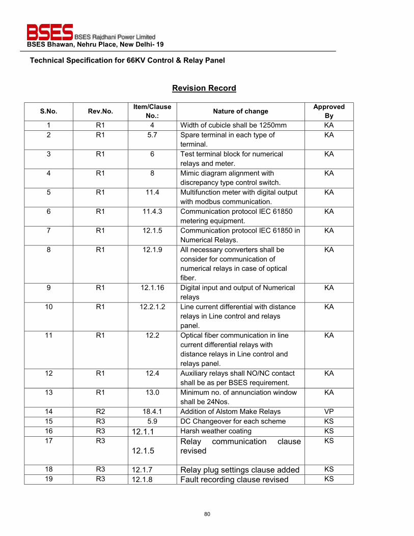
BSES Bhawan, Nehru Place, New Delhi- 19 Technical Specification for 66KV Control & Relay Panel
Revision Record
S.No. Rev.No. Item/Clause No.: Nature of change Approved
By 1 R1 4 Width of cubicle shall be 1250mm KA 2 R1 5.7 Spare terminal in each type of
terminal. KA
3 R1 6 Test terminal block for numerical relays and meter.
KA
4 R1 8 Mimic diagram alignment with discrepancy type control switch.
KA
5 R1 11.4 Multifunction meter with digital output with modbus communication.
KA
6 R1 11.4.3 Communication protocol IEC 61850 metering equipment.
KA
7 R1 12.1.5 Communication protocol IEC 61850 in Numerical Relays.
KA
8 R1 12.1.9 All necessary converters shall be consider for communication of numerical relays in case of optical fiber.
KA
9 R1 12.1.16 Digital input and output of Numerical relays
KA
10 R1 12.2.1.2 Line current differential with distance relays in Line control and relays panel.
KA
11 R1 12.2 Optical fiber communication in line current differential relays with distance relays in Line control and relays panel.
KA
12 R1 12.4 Auxiliary relays shall NO/NC contact shall be as per BSES requirement.
KA
13 R1 13.0 Minimum no. of annunciation window shall be 24Nos.
KA
14 R2 18.4.1 Addition of Alstom Make Relays VP 15 R3 5.9 DC Changeover for each scheme KS 16 R3 12.1.1 Harsh weather coating KS 17 R3
12.1.5 Relay communication clause revised
KS
18 R3 12.1.7 Relay plug settings clause added KS 19 R3 12.1.8 Fault recording clause revised KS
80
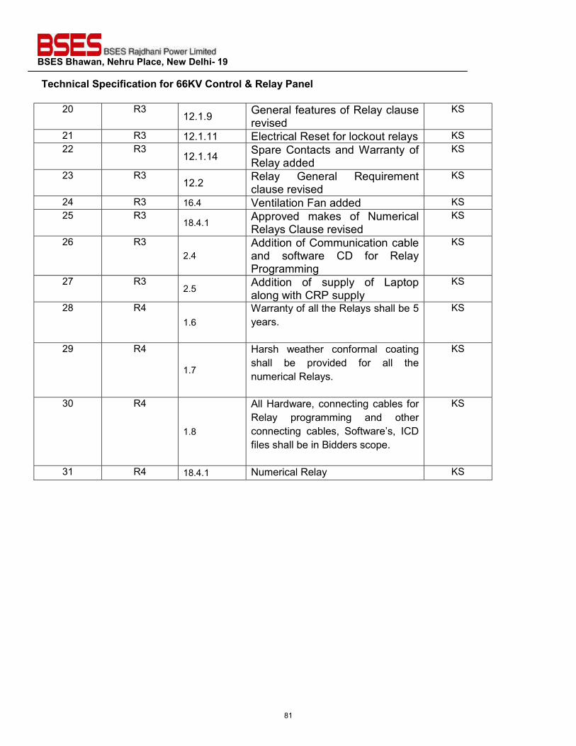
BSES Bhawan, Nehru Place, New Delhi- 19 Technical Specification for 66KV Control & Relay Panel
20 R3 12.1.9 General features of Relay clause
revised KS
21 R3 12.1.11 Electrical Reset for lockout relays KS 22 R3
12.1.14 Spare Contacts and Warranty of Relay added
KS
23 R3 12.2 Relay General Requirement
clause revised KS
24 R3 16.4 Ventilation Fan added KS 25 R3
18.4.1 Approved makes of Numerical Relays Clause revised
KS
26 R3 2.4
Addition of Communication cable and software CD for Relay Programming
KS
27 R3 2.5 Addition of supply of Laptop
along with CRP supply KS
28 R4 1.6
Warranty of all the Relays shall be 5 years.
KS
29 R4
1.7
Harsh weather conformal coating shall be provided for all the numerical Relays.
KS
30 R4
1.8
All Hardware, connecting cables for Relay programming and other connecting cables, Software’s, ICD files shall be in Bidders scope.
KS
31 R4 18.4.1 Numerical Relay KS
81
BSES Bhawan, Nehru Place, New Delhi- 19 Technical Specification for 66KV Control & Relay Panel
SCOPE OF SUPPLY
1.1 This specification covers design, manufacture, testing at manufacturer’s works, packing and delivery of control and relay panel for substation equipments.
1.2 The control and relay panel shall be complete with all components and accessories, which are necessary or usual for their efficient performance and trouble free operation under the various operating and atmospheric conditions as specified in the Annexure A of data sheet.
1.3 Such parts which may have not been specifically included, but otherwise form part of
the CRP as per standard trade and/or professional practice and/or are necessary for proper operation of control and relay panel, will be deemed to be also included in this specification.
1.4 All the Necessary Communication Cable for Relay programming and software CDs
1.5 Laptop of Lenovo/Dell make i7 with 1TB HD and 8 GB RAM shall be supplied with
CRP free of cost
1.6 Warranty of all the Relays shall be 5 years.
1.7 Harsh weather conformal coating shall be provided for all the numerical Relays.
1.8 All Hardware, connecting cables for Relay programming and other connecting cables, Software’s, ICD files shall be in Bidders scope.
1.9 Grid Energy Meter/ABT Trivector ABT meter as per Tender SLD
2.0 CODES & STANDARDS:
Control and Relay panel should be designed and manufactured in accordance with the following standards – National Standard Standard Code Standard Description IS-1248, Part 1- 1993 Direct acting indicating analogue electrical measuring
instruments and their accessories. IS-3231, Part 1- 1986 Part 2 &3 -1987
Electrical relays for power system protection
IS-9000 Part 1 -1988 Basic environmental testing procedures for electronics & electrical items
IS-13703 1993 Low voltage fuses for Voltages not exceeding 1000V
82
BSES Bhawan, Nehru Place, New Delhi- 19 Technical Specification for 66KV Control & Relay Panel
AC or 1500 V DC IS-13947 Part 1 - 1993 Low voltage switchgear & control gear IEC-60255 - 1989 Specification for electrical relays IEC 60688 1997 Electrical measuring transducers
3.0 PANEL CONSTRUCTION Description Requirement / Rating
4.1 Panel Type Simplex panels of standard dimensions. Equipment shall be mounted on the front of the panel and doors for wiring access shall be at the back of panels.
4.2 Enclosure type Completely metal enclosed and dust, moisture and vermin proof. Degree of protection not less than IP-4X in accordance with IS 13947
4.3 Enclosure material
Cold-rolled sheet steel of thickness not less than 2.0 mm. Stiffeners shall be provided wherever necessary.
4.4 Doors
Doors shall be at the rear. For panels having width should be more than or equal to 1250mm, double leaf doors shall be provided. Doors shall have handles with either built-in locking facility or be provided with padlock.
4.5 Gland Plate At least two separate gland plates of removable type shall be provided for each panel. They shall be of sheet steel of thickness not less than 3.0 mm.
4.6 Cable Entry Shall be from the bottom
4.7 Gaskets All doors, removable covers and panels shall be gasketed all around with neoprene gaskets.
4.8 Ventilating louvers Ventilating louvers, if provided shall have screens and filters. The screens shall be made of either brass or GI wires mesh.
4.9 Foundation
The panels shall be fixed on the embedded foundation channels with intervening layers anti vibration strips made of shock absorbing materials. Base frames shall be supplied along with panels.
4. 10 Mounting
Equipment on front of panel shall be flush mounted. Cutouts if any, provided for future mounting of equipment shall be properly blanked off with blanking plate no equipment shall be mounted on the doors.
4.11 Mounting level
The center lines of switches, push buttons and indicating lamps shall not be less than 750mm and that for relays, meters and recorders shall be not less than 450 mm from the bottom of the panel.
4.12 Appearance
The center lines of switches, push buttons and indicating lamps shall be matched to give a neat and uniform appearance. Like wise the top lines of all meters, relays and recorders etc, shall be matched.
4.13 DC Changeover DC changeover scheme for each panel with DC1 & DC2
83
BSES Bhawan, Nehru Place, New Delhi- 19 Technical Specification for 66KV Control & Relay Panel
4.0 WIRING
5.1 Internal wiring 1100V grade, single core, stranded copper conductor wires with PVC insulation. Note: all control cables shall be FRLS type
5.2 Size 4 sqmm for CT circuits, 2.5 sqmm for PT and control circuits.
5.3 Colour Code R ph - Red, Yph - Yellow, B ph - Blue, Neutral - Black for CT and PT circuits. DC - Grey, AC - Black and Earth - Green
5.4 Ferrules
Ferrules marked to correspond with panel wiring diagram shall be fitted at both ends of each wire. Ferrules shall fit tightly on the wire. Wires directly connected to trip circuit shall be distinguished by the addition of red colored unlettered ferrule.
5.5 Termination Fork type, pin type and ring type (as applicable) tinned copper lugs to be used. Insulated sleeves shall be provided at all the wire terminations.
5.6 Wiring Enclosure Plastic channels to be used as enclosures. PVC sleeves to be used for inter panel wiring.
5.7 Spare Contacts Spare contacts of relays and contactors etc. should be wired upto the terminal block
5.8 Inter panel wiring
When panels are arranged adjacent to each other inter panel wiring of common bus wires between the panels shall be furnished. These adjacent inter panel wiring shall be clearly indicated in the wiring tables.
5.9 Auxiliary supply
Auxiliary bus wiring for AC and DC supplies, voltage transformer circuits, annunciation circuits and other common services shall be provided on the same set of terminals in all the panels with proper segregation. DC Changeover scheme for each panel
5.0 TERMINAL BLOCKS
6.1 Rating and Type
1100 V grade, minimum 10 amps continuous rating, Nylon 66, molded piece, complete with insulated barriers, stud type terminals, washers, nuts and lock nuts. White fiber markings strip with clear plastic, slip-on / clip-on terminal covers to be provided.
6.2 CT & PT Terminals
Terminal Blocks (TB) for current transformer and voltage transformer secondary leads shall be Ring Type provided with test links and isolating facilities. Also current transformer secondary leads shall be provided with short-circuiting and earthing facilities.
6.3 Spare Terminals 20% in each type of TB row 6.4 Clearance with Minimum 250mm
84
BSES Bhawan, Nehru Place, New Delhi- 19 Technical Specification for 66KV Control & Relay Panel
gland plate
6.5 Clearance between two TBs Minimum 150mm
6.6 Test Terminal Blocks
Screw driver operated stud type for each type of numerical relays and metering
6.7 Suitability
Unless otherwise specified, terminal blocks shall be suitable for connecting the following conductors of cable on each side: a) All circuits including current / voltage transformer circuits: 4 sq.mm copper. b) AC / DC power supply circuits: one no. of 10 mm2 Al./ 6 sq.mm Cu.
6.8 Arrangement
Arrangement of the terminal block assemblies and the wiring channel within the enclosure shall be such that a row of terminal block runs in parallel and close proximity to each side of the wiring duct. The side of the terminal block opposite the wiring duct shall be reserved for the external cable connection.
6.0 PAINT
7.1 Paint Type Powder coated. Pure Polyester base Grade-A, structure finish.
7.2 Paint Shade RAL7032 ‘Siemens Grey’ 7.3 Paint Thickness Minimum 50 microns
7.0 MIMIC DIAGRAM
8.1 System Representation
Colored mimic diagram and symbols showing the exact representation of the system shall be provided in the front of control panels and it shall be properly align with all discrepancy type control switch of panels.
8.2 Material
Mimic diagram shall be made preferably of painted Aluminum or plastic of approved fast color material, which shall be screwed on to the panel and can be easily cleaned. Painted overlaid mimic is also acceptable. The mimic bus shall be 2-3 mm thick. The width of the mimic bus shall be 12mm for bus bars and 10 mm for other connections.
8.3 Mimic Indications Discrepancy type switches are to be used for breaker and isolator control indication and semaphore indicators shall be used for earth switch position.
8.0 NAME PLATES & MARKINGS
9.1 Provision of Nameplates
All equipment mounted on front side as well as equipment mounted inside the panels shall be provided with individual name plates with equipment designation engraved. Also, large and bold name plate carrying the feeder identification
85
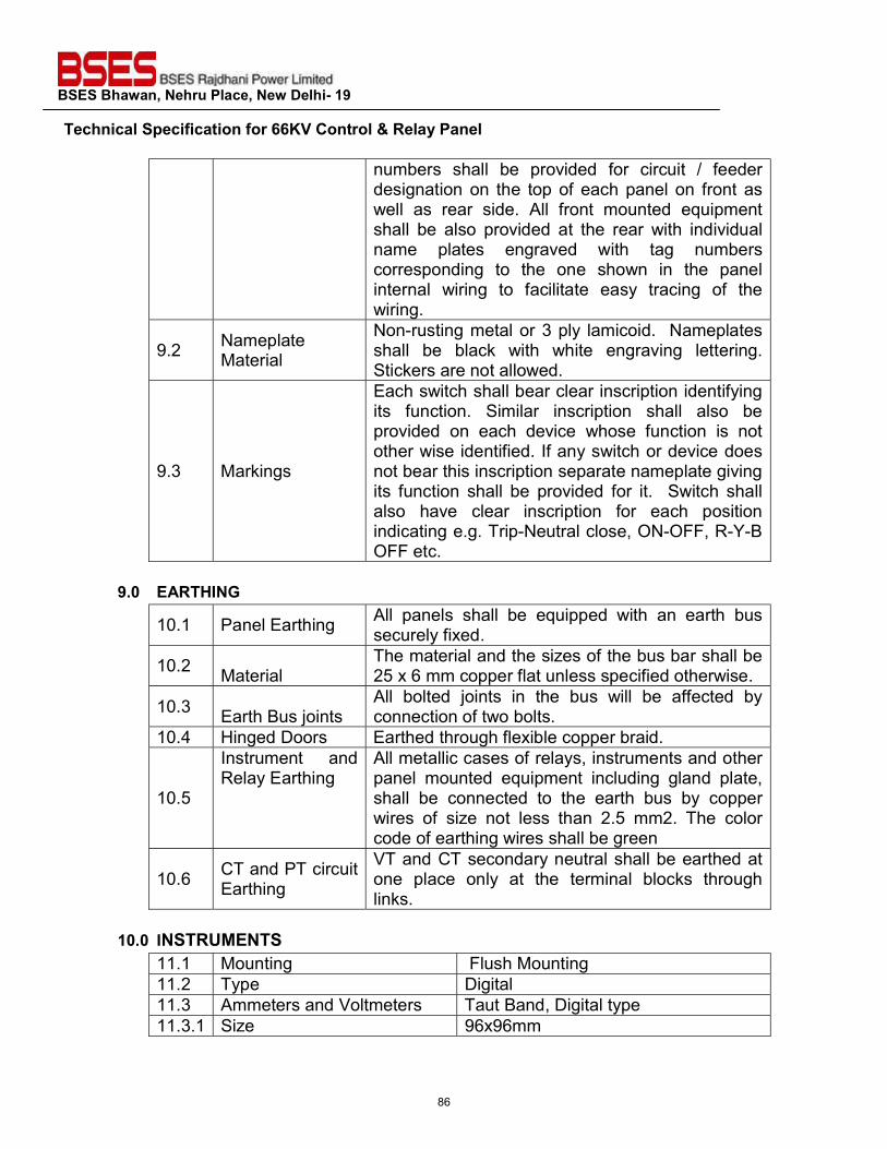
BSES Bhawan, Nehru Place, New Delhi- 19 Technical Specification for 66KV Control & Relay Panel
numbers shall be provided for circuit / feeder designation on the top of each panel on front as well as rear side. All front mounted equipment shall be also provided at the rear with individual name plates engraved with tag numbers corresponding to the one shown in the panel internal wiring to facilitate easy tracing of the wiring.
9.2 Nameplate Material
Non-rusting metal or 3 ply lamicoid. Nameplates shall be black with white engraving lettering. Stickers are not allowed.
9.3 Markings
Each switch shall bear clear inscription identifying its function. Similar inscription shall also be provided on each device whose function is not other wise identified. If any switch or device does not bear this inscription separate nameplate giving its function shall be provided for it. Switch shall also have clear inscription for each position indicating e.g. Trip-Neutral close, ON-OFF, R-Y-B OFF etc.
9.0 EARTHING
10.1 Panel Earthing All panels shall be equipped with an earth bus securely fixed.
10.2 Material The material and the sizes of the bus bar shall be 25 x 6 mm copper flat unless specified otherwise.
10.3 Earth Bus joints All bolted joints in the bus will be affected by connection of two bolts.
10.4 Hinged Doors Earthed through flexible copper braid.
10.5
Instrument and Relay Earthing
All metallic cases of relays, instruments and other panel mounted equipment including gland plate, shall be connected to the earth bus by copper wires of size not less than 2.5 mm2. The color code of earthing wires shall be green
10.6 CT and PT circuit Earthing
VT and CT secondary neutral shall be earthed at one place only at the terminal blocks through links.
10.0 INSTRUMENTS
11.1 Mounting Flush Mounting 11.2 Type Digital 11.3 Ammeters and Voltmeters Taut Band, Digital type 11.3.1 Size 96x96mm
86
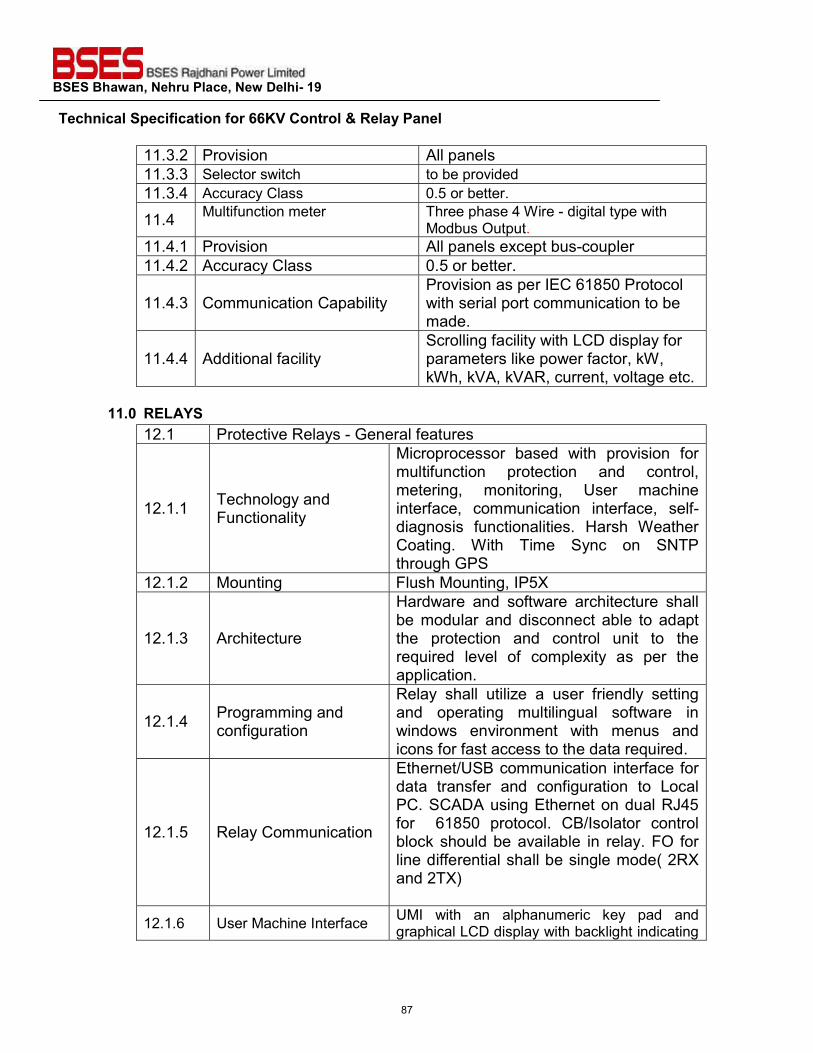
BSES Bhawan, Nehru Place, New Delhi- 19 Technical Specification for 66KV Control & Relay Panel
11.3.2 Provision All panels 11.3.3 Selector switch to be provided 11.3.4 Accuracy Class 0.5 or better.
11.4 Multifunction meter Three phase 4 Wire - digital type with Modbus Output.
11.4.1 Provision All panels except bus-coupler 11.4.2 Accuracy Class 0.5 or better.
11.4.3 Communication Capability Provision as per IEC 61850 Protocol with serial port communication to be made.
11.4.4 Additional facility Scrolling facility with LCD display for parameters like power factor, kW, kWh, kVA, kVAR, current, voltage etc.
11.0 RELAYS
12.1 Protective Relays - General features
12.1.1 Technology and Functionality
Microprocessor based with provision for multifunction protection and control, metering, monitoring, User machine interface, communication interface, self-diagnosis functionalities. Harsh Weather Coating. With Time Sync on SNTP through GPS
12.1.2 Mounting Flush Mounting, IP5X
12.1.3 Architecture
Hardware and software architecture shall be modular and disconnect able to adapt the protection and control unit to the required level of complexity as per the application.
12.1.4 Programming and configuration
Relay shall utilize a user friendly setting and operating multilingual software in windows environment with menus and icons for fast access to the data required.
12.1.5 Relay Communication
Ethernet/USB communication interface for data transfer and configuration to Local PC. SCADA using Ethernet on dual RJ45 for 61850 protocol. CB/Isolator control block should be available in relay. FO for line differential shall be single mode( 2RX and 2TX)
12.1.6 User Machine Interface UMI with an alphanumeric key pad and graphical LCD display with backlight indicating
87
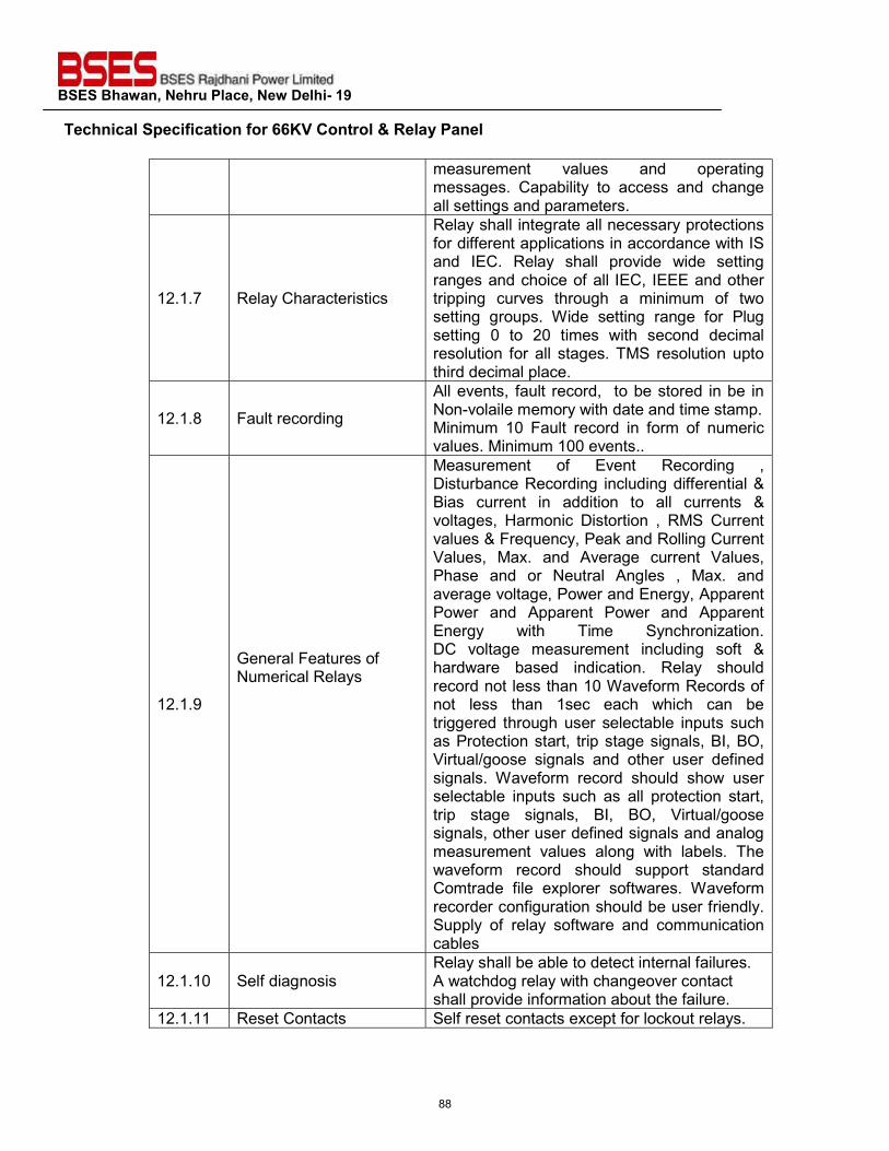
BSES Bhawan, Nehru Place, New Delhi- 19 Technical Specification for 66KV Control & Relay Panel
measurement values and operating messages. Capability to access and change all settings and parameters.
12.1.7 Relay Characteristics
Relay shall integrate all necessary protections for different applications in accordance with IS and IEC. Relay shall provide wide setting ranges and choice of all IEC, IEEE and other tripping curves through a minimum of two setting groups. Wide setting range for Plug setting 0 to 20 times with second decimal resolution for all stages. TMS resolution upto third decimal place.
12.1.8 Fault recording
All events, fault record, to be stored in be in Non-volaile memory with date and time stamp. Minimum 10 Fault record in form of numeric values. Minimum 100 events..
12.1.9
General Features of Numerical Relays
Measurement of Event Recording , Disturbance Recording including differential & Bias current in addition to all currents & voltages, Harmonic Distortion , RMS Current values & Frequency, Peak and Rolling Current Values, Max. and Average current Values, Phase and or Neutral Angles , Max. and average voltage, Power and Energy, Apparent Power and Apparent Power and Apparent Energy with Time Synchronization. DC voltage measurement including soft & hardware based indication. Relay should record not less than 10 Waveform Records of not less than 1sec each which can be triggered through user selectable inputs such as Protection start, trip stage signals, BI, BO, Virtual/goose signals and other user defined signals. Waveform record should show user selectable inputs such as all protection start, trip stage signals, BI, BO, Virtual/goose signals, other user defined signals and analog measurement values along with labels. The waveform record should support standard Comtrade file explorer softwares. Waveform recorder configuration should be user friendly. Supply of relay software and communication cables
12.1.10 Self diagnosis Relay shall be able to detect internal failures. A watchdog relay with changeover contact shall provide information about the failure.
12.1.11 Reset Contacts Self reset contacts except for lockout relays.
88
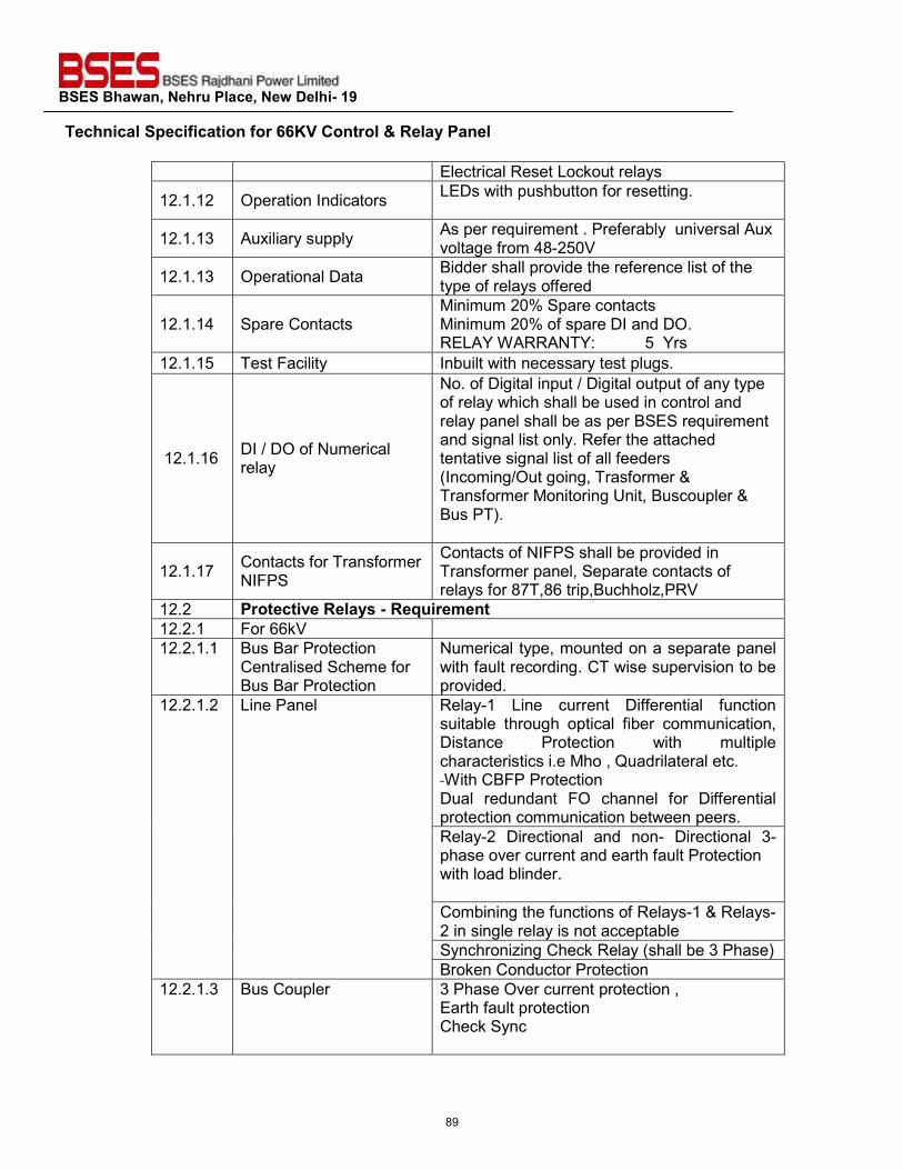
BSES Bhawan, Nehru Place, New Delhi- 19 Technical Specification for 66KV Control & Relay Panel
Electrical Reset Lockout relays
12.1.12 Operation Indicators LEDs with pushbutton for resetting.
12.1.13 Auxiliary supply As per requirement . Preferably universal Aux voltage from 48-250V
12.1.13 Operational Data Bidder shall provide the reference list of the type of relays offered
12.1.14 Spare Contacts Minimum 20% Spare contacts Minimum 20% of spare DI and DO. RELAY WARRANTY: 5 Yrs
12.1.15 Test Facility Inbuilt with necessary test plugs.
12.1.16 DI / DO of Numerical relay
No. of Digital input / Digital output of any type of relay which shall be used in control and relay panel shall be as per BSES requirement and signal list only. Refer the attached tentative signal list of all feeders (Incoming/Out going, Trasformer & Transformer Monitoring Unit, Buscoupler & Bus PT).
12.1.17 Contacts for Transformer NIFPS
Contacts of NIFPS shall be provided in Transformer panel, Separate contacts of relays for 87T,86 trip,Buchholz,PRV
12.2 Protective Relays - Requirement 12.2.1 For 66kV 12.2.1.1 Bus Bar Protection
Centralised Scheme for Bus Bar Protection
Numerical type, mounted on a separate panel with fault recording. CT wise supervision to be provided.
12.2.1.2 Line Panel Relay-1 Line current Differential function suitable through optical fiber communication, Distance Protection with multiple characteristics i.e Mho , Quadrilateral etc. With CBFP Protection Dual redundant FO channel for Differential protection communication between peers. Relay-2 Directional and non- Directional 3-phase over current and earth fault Protection with load blinder. Combining the functions of Relays-1 & Relays-2 in single relay is not acceptable Synchronizing Check Relay (shall be 3 Phase) Broken Conductor Protection
12.2.1.3 Bus Coupler 3 Phase Over current protection , Earth fault protection Check Sync
89
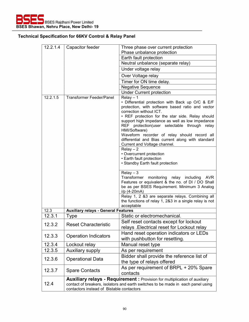
BSES Bhawan, Nehru Place, New Delhi- 19 Technical Specification for 66KV Control & Relay Panel
12.2.1.4 Capacitor feeder Three phase over current protection Phase unbalance protection Earth fault protection Neutral unbalance (separate relay) Under voltage relay Over Voltage relay Timer for ON time delay. Negative Sequence Under Current protection
12.2.1.5 Transformer Feeder/Panel Relay – 1 • Differential protection with Back up O/C & E/F protection, with software based ratio and vector correction without ICT. • REF protection for the star side. Relay should support high impedance as well as low impedance REF protection(user selectable through relay HMI/Software) Waveform recorder of relay should record all differential and Bias current along with standard Current and Voltage channel. Relay – 2 • Overcurrent protection • Earth fault protection • Standby Earth fault protection Relay – 3 Transformer monitoring relay including AVR Features or equivalent & the no. of DI / DO Shall be as per BSES Requirement. Minimum 3 Analog i/p (4-20mA) Relay 1, 2 &3 are separate relays. Combining all the functions of relay 1, 2&3 in a single relay is not acceptable
12.3 Auxiliary relays - General Features 12.3.1 Type Static or electromechanical.
12.3.2 Reset Characteristic Self reset contacts except for lockout relays .Electrical reset for Lockout relay
12.3.3 Operation Indicators Hand reset operation indicators or LEDs with pushbutton for resetting.
12.3.4 Lockout relay Manual reset type 12.3.5 Auxiliary supply As per requirement
12.3.6 Operational Data Bidder shall provide the reference list of the type of relays offered
12.3.7 Spare Contacts As per requirement of BRPL + 20% Spare contacts
12.4 Auxiliary relays - Requirement : Provision for multiplication of auxiliary contact of breakers, isolators and earth switches to be made in each panel using contactors instead of Bistable contactors
90
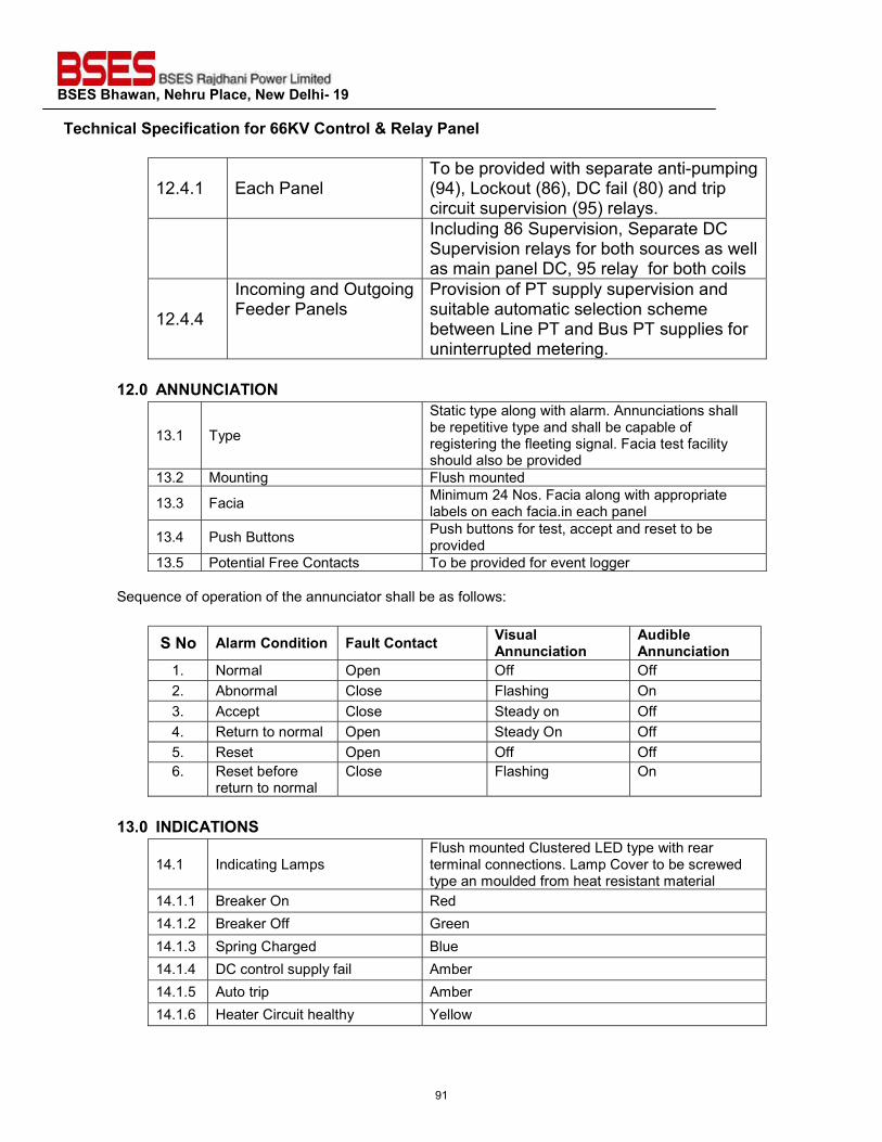
BSES Bhawan, Nehru Place, New Delhi- 19 Technical Specification for 66KV Control & Relay Panel
12.4.1 Each Panel To be provided with separate anti-pumping (94), Lockout (86), DC fail (80) and trip circuit supervision (95) relays.
Including 86 Supervision, Separate DC Supervision relays for both sources as well as main panel DC, 95 relay for both coils
12.4.4
Incoming and Outgoing Feeder Panels
Provision of PT supply supervision and suitable automatic selection scheme between Line PT and Bus PT supplies for uninterrupted metering.
12.0 ANNUNCIATION
13.1 Type
Static type along with alarm. Annunciations shall be repetitive type and shall be capable of registering the fleeting signal. Facia test facility should also be provided
13.2 Mounting Flush mounted
13.3 Facia Minimum 24 Nos. Facia along with appropriate labels on each facia.in each panel
13.4 Push Buttons Push buttons for test, accept and reset to be provided
13.5 Potential Free Contacts To be provided for event logger Sequence of operation of the annunciator shall be as follows:
S No Alarm Condition Fault Contact Visual Annunciation
Audible Annunciation
1. Normal Open Off Off 2. Abnormal Close Flashing On 3. Accept Close Steady on Off 4. Return to normal Open Steady On Off 5. Reset Open Off Off 6. Reset before
return to normal Close Flashing On
13.0 INDICATIONS
14.1 Indicating Lamps Flush mounted Clustered LED type with rear terminal connections. Lamp Cover to be screwed type an moulded from heat resistant material
14.1.1 Breaker On Red 14.1.2 Breaker Off Green 14.1.3 Spring Charged Blue 14.1.4 DC control supply fail Amber 14.1.5 Auto trip Amber 14.1.6 Heater Circuit healthy Yellow
91
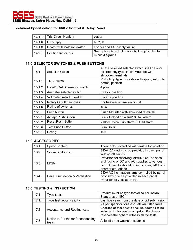
BSES Bhawan, Nehru Place, New Delhi- 19 Technical Specification for 66KV Control & Relay Panel
14.1.7 Trip Circuit Healthy White 14.1.8 PT supply R, Y, B 14.1.9 Hooter with isolation switch For AC and DC supply failure
14.2 Position Indicators Semaphore type indicators shall be provided for mimic diagrams
14.0 SELECTOR SWITCHES & PUSH BUTTONS
15.1 Selector Switch All the selected selector switch shall be only discrepancy type Flush Mounted with shrouded terminals
15.1.1 TNC Switch Pistol Grip type, Lockable with spring return to normal position
15.1.2 Local/SCADA selector switch 4 pole 15.1.3 Ammeter selector switch 6way 7 position 15.1.4 Voltmeter selector switch 6 way 7 position 15.1.5 Rotary On/Off Switches For heater/illumination circuit 15.1.6 Rating of switches 16 A 15.2 Push button Flush Mounted with shrouded terminals 15.2.1 Accept Push Button Black Color-Trip alarm/DC fail alarm 15.2.2 Reset Push Button Yellow Color- Trip alarm/DC fail alarm 15.2.3 Test Push Button Blue Color 15.2.4 Rating 10A
15.0 ACCESSORIES
16.1 Space heaters Thermostat controlled with switch for isolation
16.2 Socket and switch 240V, 5A socket to be provided in each panel with on-off switch
16.3 MCBs
Provision for receiving, distribution, isolation and fusing of DC and AC supplies to various control circuits should be made using MCBs of appropriate ratings.
16.4 Panel illumination & Ventillation 240V AC illumination lamp controlled by panel door switch to be provided in each panel. Provision of ventilation fan.
16.0 TESTING & INSPECTION
17.1 Type tests Product must be type tested as per Indian Standards or IEC
17.1.1 Type test report validity Last five years from the date of bid submission
17.2 Acceptance and Routine tests
As per specifications and relevant standards. Charges of these tests shall be deemed to be included in the equipment price. Purchaser reserves the right to witness all the tests.
17.3 Notice to Purchaser for conducting tests At least three weeks in advance
92
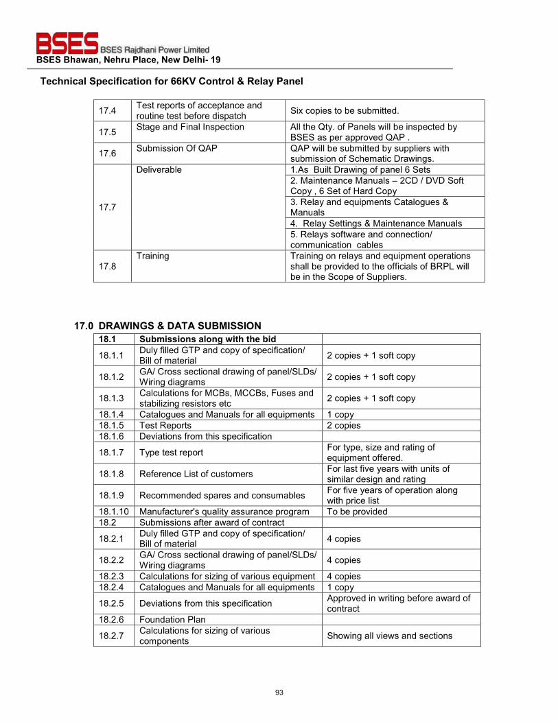
BSES Bhawan, Nehru Place, New Delhi- 19 Technical Specification for 66KV Control & Relay Panel
17.4 Test reports of acceptance and routine test before dispatch Six copies to be submitted.
17.5 Stage and Final Inspection All the Qty. of Panels will be inspected by BSES as per approved QAP .
17.6 Submission Of QAP QAP will be submitted by suppliers with submission of Schematic Drawings.
17.7
Deliverable 1.As Built Drawing of panel 6 Sets 2. Maintenance Manuals – 2CD / DVD Soft Copy , 6 Set of Hard Copy 3. Relay and equipments Catalogues & Manuals 4. Relay Settings & Maintenance Manuals 5. Relays software and connection/ communication cables
17.8 Training Training on relays and equipment operations
shall be provided to the officials of BRPL will be in the Scope of Suppliers.
17.0 DRAWINGS & DATA SUBMISSION
18.1 Submissions along with the bid
18.1.1 Duly filled GTP and copy of specification/ Bill of material 2 copies + 1 soft copy
18.1.2 GA/ Cross sectional drawing of panel/SLDs/ Wiring diagrams 2 copies + 1 soft copy
18.1.3 Calculations for MCBs, MCCBs, Fuses and stabilizing resistors etc 2 copies + 1 soft copy
18.1.4 Catalogues and Manuals for all equipments 1 copy 18.1.5 Test Reports 2 copies 18.1.6 Deviations from this specification
18.1.7 Type test report For type, size and rating of equipment offered.
18.1.8 Reference List of customers For last five years with units of similar design and rating
18.1.9 Recommended spares and consumables For five years of operation along with price list
18.1.10 Manufacturer's quality assurance program To be provided 18.2 Submissions after award of contract
18.2.1 Duly filled GTP and copy of specification/ Bill of material 4 copies
18.2.2 GA/ Cross sectional drawing of panel/SLDs/ Wiring diagrams 4 copies
18.2.3 Calculations for sizing of various equipment 4 copies 18.2.4 Catalogues and Manuals for all equipments 1 copy
18.2.5 Deviations from this specification Approved in writing before award of contract
18.2.6 Foundation Plan
18.2.7 Calculations for sizing of various components Showing all views and sections
93
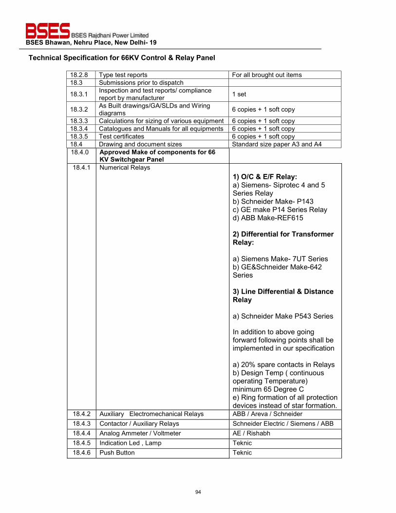
BSES Bhawan, Nehru Place, New Delhi- 19 Technical Specification for 66KV Control & Relay Panel
18.2.8 Type test reports For all brought out items 18.3 Submissions prior to dispatch
18.3.1 Inspection and test reports/ compliance report by manufacturer 1 set
18.3.2 As Built drawings/GA/SLDs and Wiring diagrams 6 copies + 1 soft copy
18.3.3 Calculations for sizing of various equipment 6 copies + 1 soft copy 18.3.4 Catalogues and Manuals for all equipments 6 copies + 1 soft copy 18.3.5 Test certificates 6 copies + 1 soft copy 18.4 Drawing and document sizes Standard size paper A3 and A4 18.4.0 Approved Make of components for 66
KV Switchgear Panel 18.4.1 Numerical Relays
1) O/C & E/F Relay: a) Siemens- Siprotec 4 and 5 Series Relay b) Schneider Make- P143 c) GE make P14 Series Relay d) ABB Make-REF615 2) Differential for Transformer Relay: a) Siemens Make- 7UT Series b) GE&Schneider Make-642 Series 3) Line Differential & Distance Relay a) Schneider Make P543 Series In addition to above going forward following points shall be implemented in our specification a) 20% spare contacts in Relays b) Design Temp ( continuous operating Temperature) minimum 65 Degree C e) Ring formation of all protection devices instead of star formation.
18.4.2 Auxiliary Electromechanical Relays ABB / Areva / Schneider 18.4.3 Contactor / Auxiliary Relays Schneider Electric / Siemens / ABB 18.4.4 Analog Ammeter / Voltmeter AE / Rishabh 18.4.5 Indication Led , Lamp Teknic 18.4.6 Push Button Teknic
94
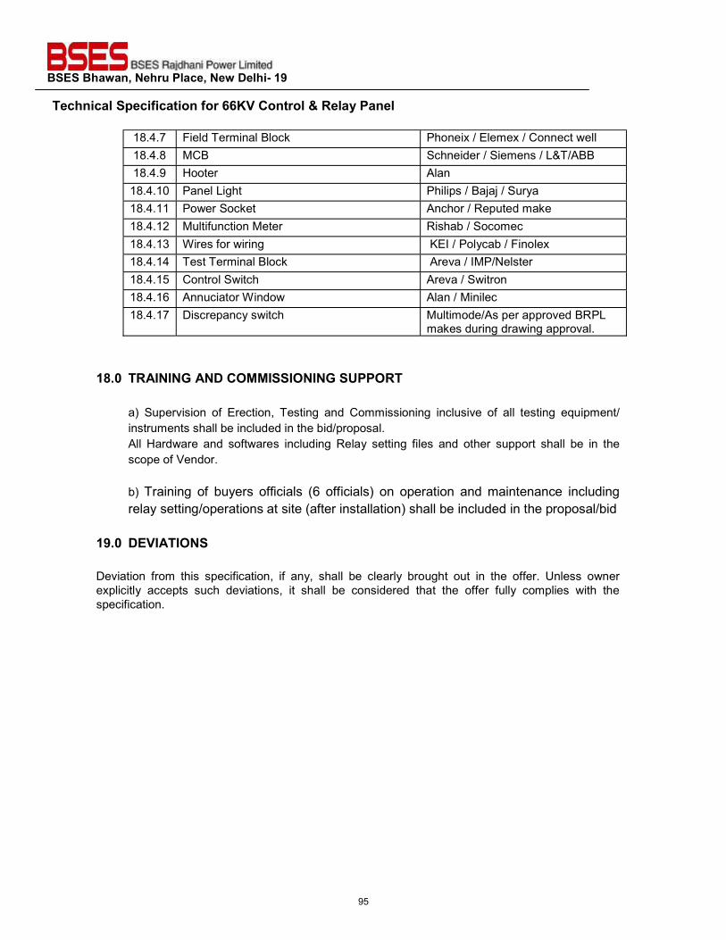
BSES Bhawan, Nehru Place, New Delhi- 19 Technical Specification for 66KV Control & Relay Panel
18.4.7 Field Terminal Block Phoneix / Elemex / Connect well 18.4.8 MCB Schneider / Siemens / L&T/ABB 18.4.9 Hooter Alan 18.4.10 Panel Light Philips / Bajaj / Surya 18.4.11 Power Socket Anchor / Reputed make 18.4.12 Multifunction Meter Rishab / Socomec 18.4.13 Wires for wiring KEI / Polycab / Finolex 18.4.14 Test Terminal Block Areva / IMP/Nelster 18.4.15 Control Switch Areva / Switron 18.4.16 Annuciator Window Alan / Minilec 18.4.17 Discrepancy switch Multimode/As per approved BRPL
makes during drawing approval.
18.0 TRAINING AND COMMISSIONING SUPPORT a) Supervision of Erection, Testing and Commissioning inclusive of all testing equipment/ instruments shall be included in the bid/proposal. All Hardware and softwares including Relay setting files and other support shall be in the scope of Vendor. b) Training of buyers officials (6 officials) on operation and maintenance including relay setting/operations at site (after installation) shall be included in the proposal/bid
19.0 DEVIATIONS Deviation from this specification, if any, shall be clearly brought out in the offer. Unless owner explicitly accepts such deviations, it shall be considered that the offer fully complies with the specification.
95
BSES Bhawan, Nehru Place, New Delhi- 19
Prepared by Javed Ahmed Rev: 0
Reviewed by Abhinav Srivastava Date:
Approved by KS
TECHNICAL SPECIFICATION
FOR
BATTERY CHARGER
96
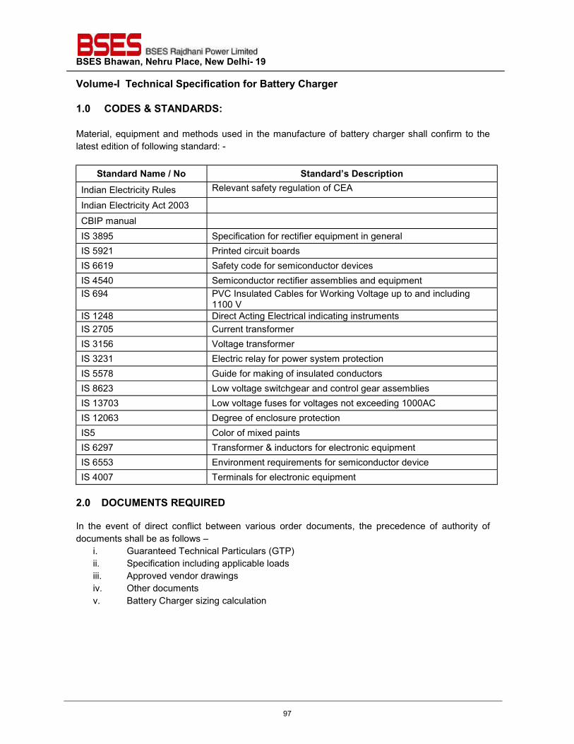
BSES Bhawan, Nehru Place, New Delhi- 19 Volume-I Technical Specification for Battery Charger
1.0 CODES & STANDARDS: Material, equipment and methods used in the manufacture of battery charger shall confirm to the latest edition of following standard: -
Standard Name / No Standard’s Description Indian Electricity Rules Relevant safety regulation of CEA
Indian Electricity Act 2003
CBIP manual
IS 3895 Specification for rectifier equipment in general IS 5921 Printed circuit boards IS 6619 Safety code for semiconductor devices IS 4540 Semiconductor rectifier assemblies and equipment IS 694 PVC Insulated Cables for Working Voltage up to and including
1100 V IS 1248 Direct Acting Electrical indicating instruments IS 2705 Current transformer IS 3156 Voltage transformer IS 3231 Electric relay for power system protection IS 5578 Guide for making of insulated conductors IS 8623 Low voltage switchgear and control gear assemblies IS 13703 Low voltage fuses for voltages not exceeding 1000AC IS 12063 Degree of enclosure protection IS5 Color of mixed paints IS 6297 Transformer & inductors for electronic equipment IS 6553 Environment requirements for semiconductor device IS 4007 Terminals for electronic equipment
2.0 DOCUMENTS REQUIRED In the event of direct conflict between various order documents, the precedence of authority of documents shall be as follows –
i. Guaranteed Technical Particulars (GTP) ii. Specification including applicable loads iii. Approved vendor drawings iv. Other documents v. Battery Charger sizing calculation
97
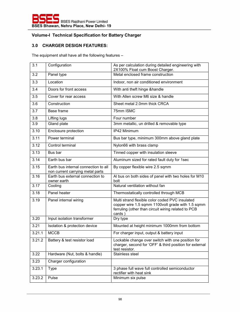
BSES Bhawan, Nehru Place, New Delhi- 19 Volume-I Technical Specification for Battery Charger
3.0 CHARGER DESIGN FEATURES:
The equipment shall have all the following features –
3.1 Configuration As per calculation during detailed engineering with 2X100% Float cum Boost Charger.
3.2 Panel type Metal enclosed frame construction
3.3 Location Indoor, non air conditioned environment
3.4 Doors for front access With anti theft hinge &handle
3.5 Cover for rear access With Allen screw M6 size & handle
3.6 Construction Sheet metal 2.0mm thick CRCA
3.7 Base frame 75mm ISMC
3.8 Lifting lugs Four number 3.9 Gland plate 3mm metallic, un drilled & removable type
3.10 Enclosure protection IP42 Minimum
3.11 Power terminal Bus bar type, minimum 300mm above gland plate
3.12 Control terminal Nylon66 with brass clamp
3.13 Bus bar Tinned copper with insulation sleeve
3.14 Earth bus bar Aluminum sized for rated fault duty for 1sec
3.15 Earth bus internal connection to all non current carrying metal parts
By copper flexible wire 2.5 sqmm
3.16 Earth bus external connection to owner earth
Al bus on both sides of panel with two holes for M10 bolt
3.17 Cooling Natural ventilation without fan
3.18 Panel heater Thermostatically controlled through MCB
3.19 Panel internal wiring Multi strand flexible color coded PVC insulated copper wire 1.5 sqmm 1100volt grade with 1.5 sqmm ferruling (other than circuit wiring related to PCB cards )
3.20 Input isolation transformer Dry type
3.21 Isolation & protection device Mounted at height minimum 1000mm from bottom
3.21.1 MCCB For charger input, output & battery input
3.21.2 Battery & test resistor load Lockable change over switch with one position for charger, second for ‘OFF’ & third position for external test resistor.
3.22 Hardware (Nut, bolts & handle) Stainless steel
3.23 Charger configuration
3.23.1 Type 3 phase full wave full controlled semiconductor rectifier with heat sink
3.23.2 Pulse Minimum six pulse
98
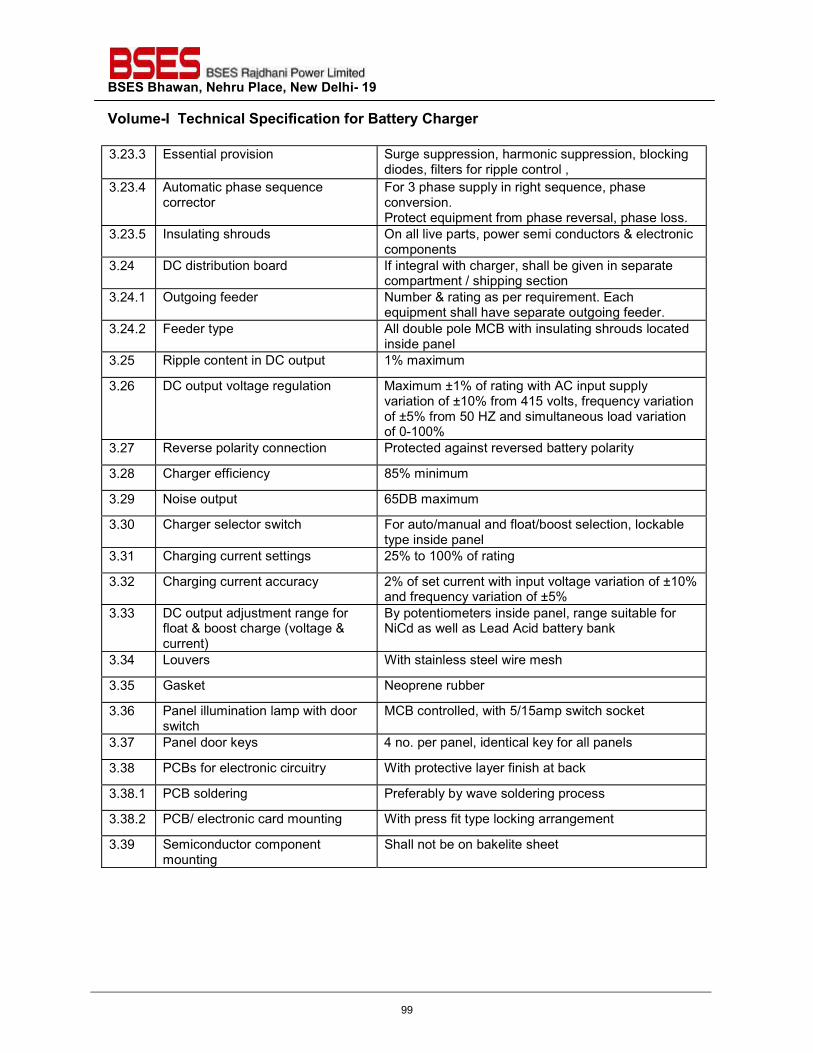
BSES Bhawan, Nehru Place, New Delhi- 19 Volume-I Technical Specification for Battery Charger
3.23.3 Essential provision Surge suppression, harmonic suppression, blocking diodes, filters for ripple control ,
3.23.4 Automatic phase sequence corrector
For 3 phase supply in right sequence, phase conversion. Protect equipment from phase reversal, phase loss.
3.23.5 Insulating shrouds On all live parts, power semi conductors & electronic components
3.24 DC distribution board If integral with charger, shall be given in separate compartment / shipping section
3.24.1 Outgoing feeder Number & rating as per requirement. Each equipment shall have separate outgoing feeder.
3.24.2 Feeder type All double pole MCB with insulating shrouds located inside panel
3.25 Ripple content in DC output 1% maximum
3.26 DC output voltage regulation Maximum ±1% of rating with AC input supply variation of ±10% from 415 volts, frequency variation of ±5% from 50 HZ and simultaneous load variation of 0-100%
3.27 Reverse polarity connection Protected against reversed battery polarity
3.28 Charger efficiency 85% minimum
3.29 Noise output 65DB maximum
3.30 Charger selector switch For auto/manual and float/boost selection, lockable type inside panel
3.31 Charging current settings 25% to 100% of rating
3.32 Charging current accuracy 2% of set current with input voltage variation of ±10% and frequency variation of ±5%
3.33 DC output adjustment range for float & boost charge (voltage & current)
By potentiometers inside panel, range suitable for NiCd as well as Lead Acid battery bank
3.34 Louvers With stainless steel wire mesh
3.35 Gasket Neoprene rubber
3.36 Panel illumination lamp with door switch
MCB controlled, with 5/15amp switch socket
3.37 Panel door keys 4 no. per panel, identical key for all panels
3.38 PCBs for electronic circuitry With protective layer finish at back
3.38.1 PCB soldering Preferably by wave soldering process
3.38.2 PCB/ electronic card mounting With press fit type locking arrangement
3.39 Semiconductor component mounting
Shall not be on bakelite sheet
99
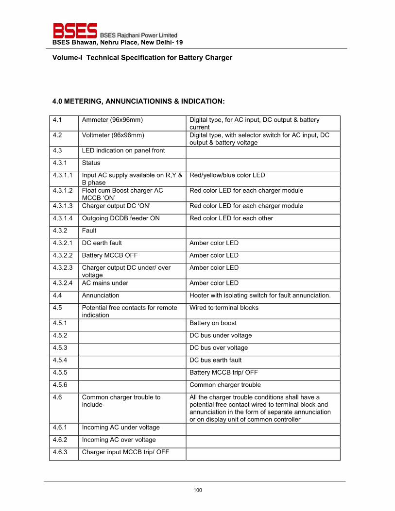
BSES Bhawan, Nehru Place, New Delhi- 19 Volume-I Technical Specification for Battery Charger
4.0 METERING, ANNUNCIATIONINS & INDICATION: 4.1 Ammeter (96x96mm) Digital type, for AC input, DC output & battery
current 4.2 Voltmeter (96x96mm) Digital type, with selector switch for AC input, DC
output & battery voltage 4.3 LED indication on panel front
4.3.1 Status
4.3.1.1 Input AC supply available on R,Y & B phase
Red/yellow/blue color LED
4.3.1.2 Float cum Boost charger AC MCCB ‘ON’
Red color LED for each charger module
4.3.1.3 Charger output DC ‘ON’ Red color LED for each charger module
4.3.1.4 Outgoing DCDB feeder ON Red color LED for each other
4.3.2 Fault
4.3.2.1 DC earth fault Amber color LED
4.3.2.2 Battery MCCB OFF Amber color LED
4.3.2.3 Charger output DC under/ over voltage
Amber color LED
4.3.2.4 AC mains under Amber color LED
4.4 Annunciation Hooter with isolating switch for fault annunciation.
4.5 Potential free contacts for remote indication
Wired to terminal blocks
4.5.1 Battery on boost
4.5.2 DC bus under voltage
4.5.3 DC bus over voltage
4.5.4 DC bus earth fault
4.5.5 Battery MCCB trip/ OFF
4.5.6 Common charger trouble
4.6 Common charger trouble to include-
All the charger trouble conditions shall have a potential free contact wired to terminal block and annunciation in the form of separate annunciation or on display unit of common controller
4.6.1 Incoming AC under voltage
4.6.2 Incoming AC over voltage
4.6.3 Charger input MCCB trip/ OFF
100
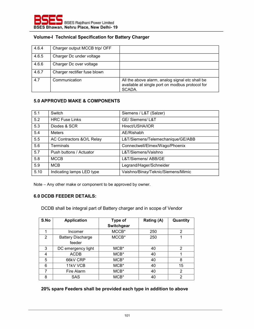
BSES Bhawan, Nehru Place, New Delhi- 19 Volume-I Technical Specification for Battery Charger
4.6.4 Charger output MCCB trip/ OFF
4.6.5 Charger Dc under voltage
4.6.6 Charger Dc over voltage
4.6.7 Charger rectifier fuse blown
4.7 Communication All the above alarm, analog signal etc shall be available at single port on modbus protocol for SCADA.
5.0 APPROVED MAKE & COMPONENTS 5.1 Switch Siemens / L&T (Salzer) 5.2 HRC Fuse Links GE/ Siemens/ L&T 5.3 Diodes & SCR Hirect/USHA/IOR 5.4 Meters AE/Rishabh 5.5 AC Contractors &O/L Relay L&T/Siemens/Telemechanique/GE/ABB 5.6 Terminals Connectwell/Elmex/Wago/Phoenix 5.7 Push buttons / Actuator L&T/Siemens/Vaishno 5.8 MCCB L&T/Siemens/ ABB/GE 5.9 MCB Legrand/Hager/Schneider 5.10 Indicating lamps LED type Vaishno/Binay/Teknic/Siemens/Mimic
Note – Any other make or component to be approved by owner.
6.0 DCDB FEEDER DETAILS:
DCDB shall be integral part of Battery charger and in scope of Vendor S.No Application Type of
Switchgear Rating (A) Quantity
1 Incomer MCCB* 250 2 2 Battery Discharge
feeder MCCB* 250 1
3 DC emergency light MCB* 40 2 4 ACDB MCB* 40 1 5 66kV CRP MCB* 40 8 6 11kV VCB MCB* 40 15 7 Fire Alarm MCB* 40 2 8 SAS MCB* 40 2
20% spare Feeders shall be provided each type in addition to above
101
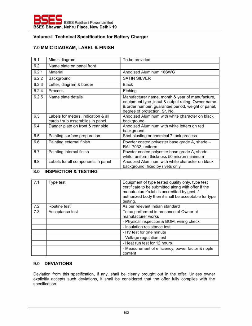
BSES Bhawan, Nehru Place, New Delhi- 19 Volume-I Technical Specification for Battery Charger
7.0 MMIC DIAGRAM, LABEL & FINISH
6.1 Mimic diagram To be provided 6.2 Name plate on panel front 6.2.1 Material Anodized Aluminum 16SWG 6.2.2 Background SATIN SILVER 6.2.3 Letter, diagram & border Black 6.2.4 Process Etching 6.2.5 Name plate details Manufacturer name, month & year of manufacture,
equipment type ,input & output rating, Owner name & order number, guarantee period, weight of panel, degree of protection, Sr. No.
6.3 Labels for meters, indication & all cards / sub assemblies in panel
Anodized Aluminum with white character on black background
6.4 Danger plate on front & rear side Anodized Aluminum with white letters on red background
6.5 Painting surface preparation Shot blasting or chemical 7 tank process 6.6 Painting external finish Powder coated polyester base grade A, shade –
RAL 7032, uniform 6.7 Painting internal finish Powder coated polyester base grade A, shade –
white, uniform thickness 50 micron minimum 6.8 Labels for all components in panel Anodized Aluminum with white character on black
background, fixed by rivets only 8.0 INSPECTION & TESTING
7.1 Type test Equipment of type tested quality only, type test
certificate to be submitted along with offer If the manufacturer’s lab is accredited by govt. / authorized body then it shall be acceptable for type testing.
7.2 Routine test As per relevant Indian standard 7.3 Acceptance test To be performed in presence of Owner at
manufacturer works - Physical inspection & BOM, wiring check - Insulation resistance test - HV test for one minute - Voltage regulation test - Heat run test for 12 hours - Measurement of efficiency, power factor & ripple
content
9.0 DEVIATIONS Deviation from this specification, if any, shall be clearly brought out in the offer. Unless owner explicitly accepts such deviations, it shall be considered that the offer fully complies with the specification.
102

Prepared by Amar Deep Singh Rev: 3
Reviewed by Abhinav Srivastava
Approved by Sheshadri Krishnapura Date:
Registered Office: BSES Bhavan, Nehru Place, Delhi - 110019
TECHNICAL SPECIFICATION
FOR
LITHIUM ION BATTERY
Specification No-GN101-03-SP-118-00
103
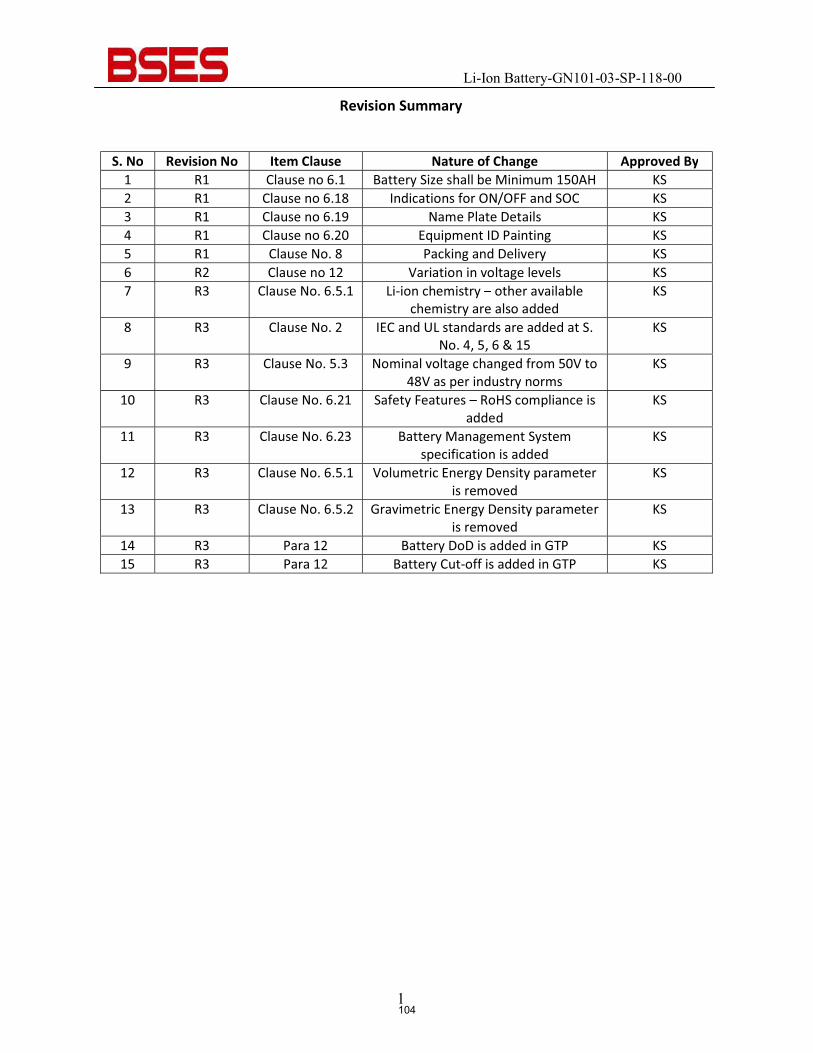
Li-Ion Battery-GN101-03-SP-118-00
1
Revision Summary
S. No Revision No Item Clause Nature of Change Approved By 1 R1 Clause no 6.1 Battery Size shall be Minimum 150AH KS 2 R1 Clause no 6.18 Indications for ON/OFF and SOC KS 3 R1 Clause no 6.19 Name Plate Details KS 4 R1 Clause no 6.20 Equipment ID Painting KS 5 R1 Clause No. 8 Packing and Delivery KS 6 R2 Clause no 12 Variation in voltage levels KS 7 R3 Clause No. 6.5.1 Li-ion chemistry – other available
chemistry are also added KS
8 R3 Clause No. 2 IEC and UL standards are added at S. No. 4, 5, 6 & 15
KS
9 R3 Clause No. 5.3 Nominal voltage changed from 50V to 48V as per industry norms
KS
10 R3 Clause No. 6.21 Safety Features – RoHS compliance is added
KS
11 R3 Clause No. 6.23 Battery Management System specification is added
KS
12 R3 Clause No. 6.5.1 Volumetric Energy Density parameter is removed
KS
13 R3 Clause No. 6.5.2 Gravimetric Energy Density parameter is removed
KS
14 R3 Para 12 Battery DoD is added in GTP KS 15 R3 Para 12 Battery Cut-off is added in GTP KS
104
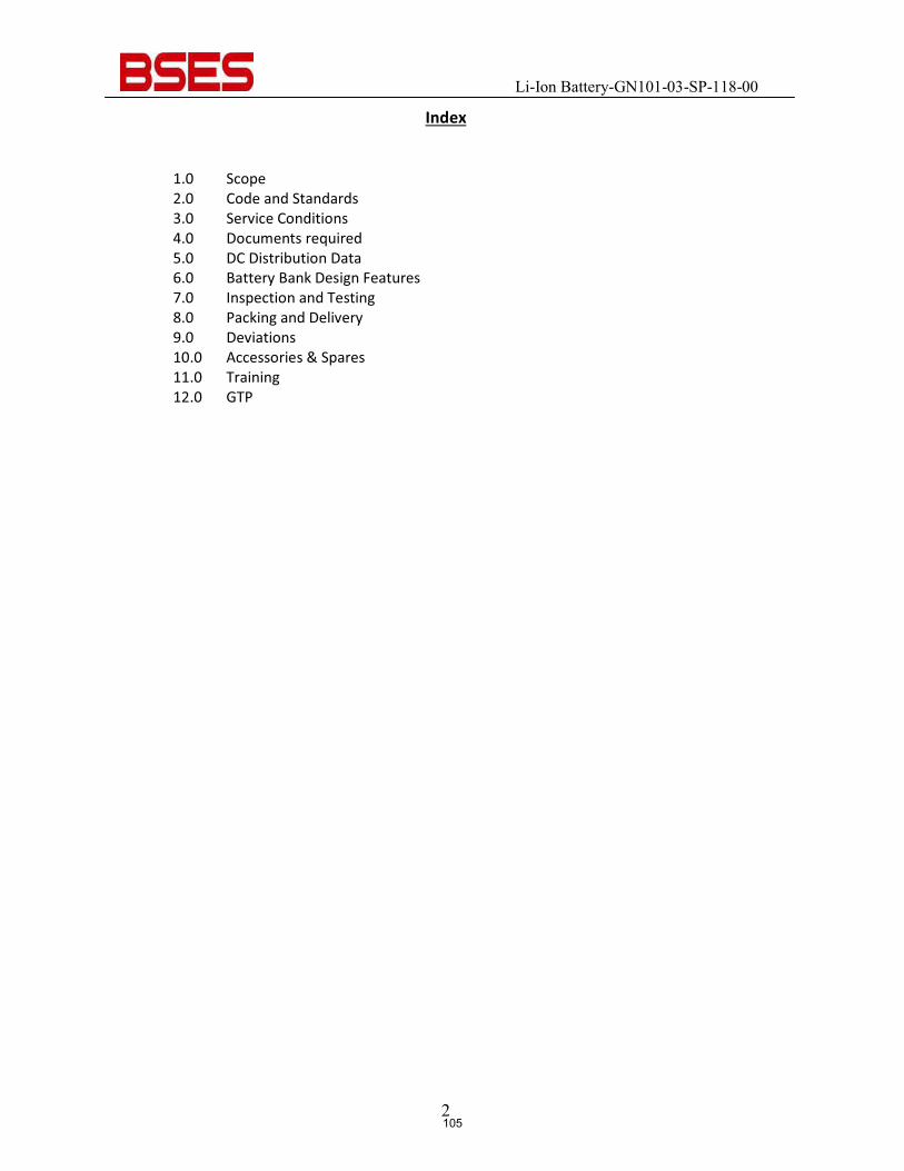
Li-Ion Battery-GN101-03-SP-118-00
2
Index
1.0 Scope 2.0 Code and Standards 3.0 Service Conditions 4.0 Documents required 5.0 DC Distribution Data 6.0 Battery Bank Design Features 7.0 Inspection and Testing 8.0 Packing and Delivery 9.0 Deviations 10.0 Accessories & Spares 11.0 Training 12.0 GTP
105
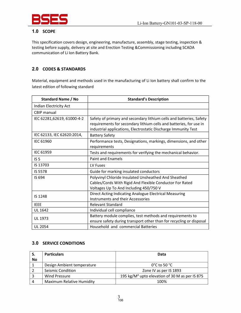
Li-Ion Battery-GN101-03-SP-118-00
3
1.0 SCOPE
This specification covers design, engineering, manufacture, assembly, stage testing, inspection & testing before supply, delivery at site and Erection Testing &Commissioning including SCADA communication of Li Ion Battery Bank.
2.0 CODES & STANDARDS Material, equipment and methods used in the manufacturing of Li Ion battery shall confirm to the latest edition of following standard
Standard Name / No Standard’s Description Indian Electricity Act CBIP manual IEC 62281,62619, 61000-4-2 Safety of primary and secondary lithium cells and batteries, Safety
requirements for secondary lithium cells and batteries, for use in industrial applications, Electrostatic Discharge Immunity Test
IEC 62133, IEC 62620:2014, Battery Safety IEC 61960 Performance tests, Designations, markings, dimensions, and other
requirements IEC 61959 Tests and requirements for verifying the mechanical behavior. IS 5 Paint and Enamels IS 13703 LV Fuses IS 5578 Guide for marking insulated conductors IS 694 Polyvinyl Chloride Insulated Unsheathed And Sheathed
Cables/Cords With Rigid And Flexible Conductor For Rated Voltages Up To And Including 450/750 V
IS 1248 Direct Acting Indicating Analogue Electrical Measuring Instruments and their Accessories
IEEE Relevant Standard UL 1642 Individual cell compliance
UL 1973 Battery module complies, test methods and requirements to ensure safety during transport other than for recycling or disposal
UL 2054 Household and commercial Batteries 3.0 SERVICE CONDITIONS
S. No
Particulars Data
1 Design Ambient temperature 0°C to 50 °C 2 Seismic Condition Zone IV as per IS 1893 3 Wind Pressure 195 kg/M² upto elevation of 30 M as per IS 875 4 Maximum Relative Humidity 100%
106
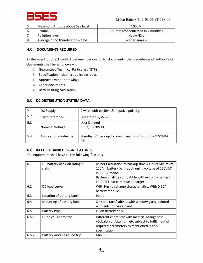
Li-Ion Battery-GN101-03-SP-118-00
4
5 Maximum Altitude above Sea level 1000M 6 Rainfall 750mm (concentrated in 4 months) 7 Pollution level Heavy/Dry 8 Average of no thunderstorm days 40 per annum
4.0 DOCUMENTS REQUIRED In the event of direct conflict between various order documents, the precedence of authority of documents shall be as follows –
i. Guaranteed Technical Particulars (GTP) ii. Specification including applicable loads iii. Approved vendor drawings iv. Other documents v. Battery sizing calculation
5.0 DC DISTRIBUTION SYSTEM DATA 5.1 DC Supply 2 wire, with positive & negative polarity 5.2 Earth reference Unearthed system 5.3
Nominal Voltage User Defined
a) 220V DC
5.4 Application - Industrial Standby DC back up for switchgear control supply & SCADA RTU
6.0 BATTERY BANK DESIGN FEATURES: The equipment shall have all the following features –
6.1 DC battery bank Ah rating &
sizing As per Calculation of backup time 4 Hours Minimum 150Ah battery bank at charging voltage of 220VDC in CC-CV mode. Battery Shall be compatible with existing chargers i.e Dual Float cum Boast Charger
6.2 DC load curve With High discharge characteristics. With 0.5C/ battery module
6.3 Location of battery bank Indoor
6.4 Mounting of battery bank On steel rack/cabinet with window glass, painted with anti corrosive paint.
6.5 Battery type Li-ion Battery only
6.5.1 Li-ion cell chemistry Different chemistry with material Manganese /Cobalt/iron/titanium etc subject to fulfillment of required parameters as mentioned in this specification.
6.5.2 Battery module round trip Min. 92
107
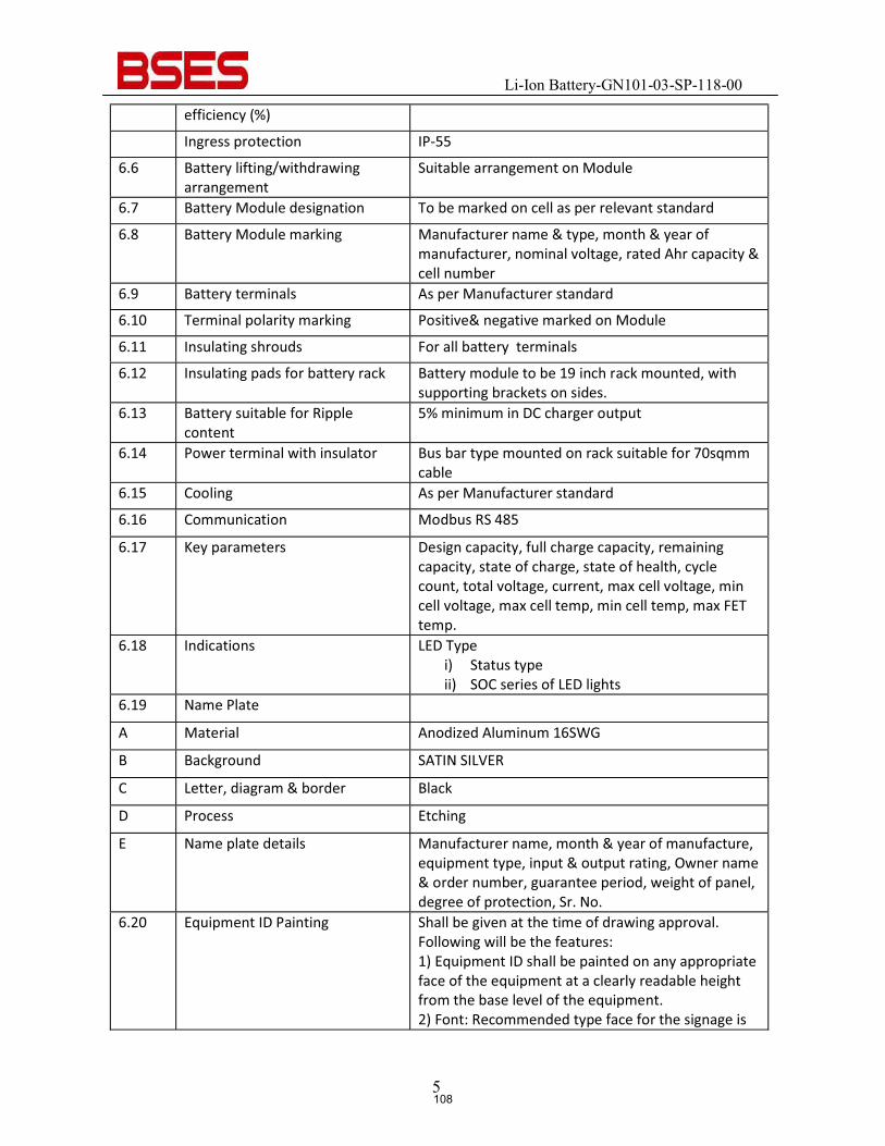
Li-Ion Battery-GN101-03-SP-118-00
5
efficiency (%)
Ingress protection IP-55
6.6 Battery lifting/withdrawing arrangement
Suitable arrangement on Module
6.7 Battery Module designation To be marked on cell as per relevant standard
6.8 Battery Module marking Manufacturer name & type, month & year of manufacturer, nominal voltage, rated Ahr capacity & cell number
6.9 Battery terminals As per Manufacturer standard
6.10 Terminal polarity marking Positive& negative marked on Module
6.11 Insulating shrouds For all battery terminals
6.12 Insulating pads for battery rack Battery module to be 19 inch rack mounted, with supporting brackets on sides.
6.13 Battery suitable for Ripple content
5% minimum in DC charger output
6.14 Power terminal with insulator Bus bar type mounted on rack suitable for 70sqmm cable
6.15 Cooling As per Manufacturer standard
6.16 Communication Modbus RS 485
6.17 Key parameters Design capacity, full charge capacity, remaining capacity, state of charge, state of health, cycle count, total voltage, current, max cell voltage, min cell voltage, max cell temp, min cell temp, max FET temp.
6.18 Indications LED Type i) Status type ii) SOC series of LED lights
6.19 Name Plate
A Material Anodized Aluminum 16SWG
B Background SATIN SILVER
C Letter, diagram & border Black
D Process Etching
E Name plate details Manufacturer name, month & year of manufacture, equipment type, input & output rating, Owner name & order number, guarantee period, weight of panel, degree of protection, Sr. No.
6.20 Equipment ID Painting Shall be given at the time of drawing approval. Following will be the features: 1) Equipment ID shall be painted on any appropriate face of the equipment at a clearly readable height from the base level of the equipment. 2) Font: Recommended type face for the signage is
108
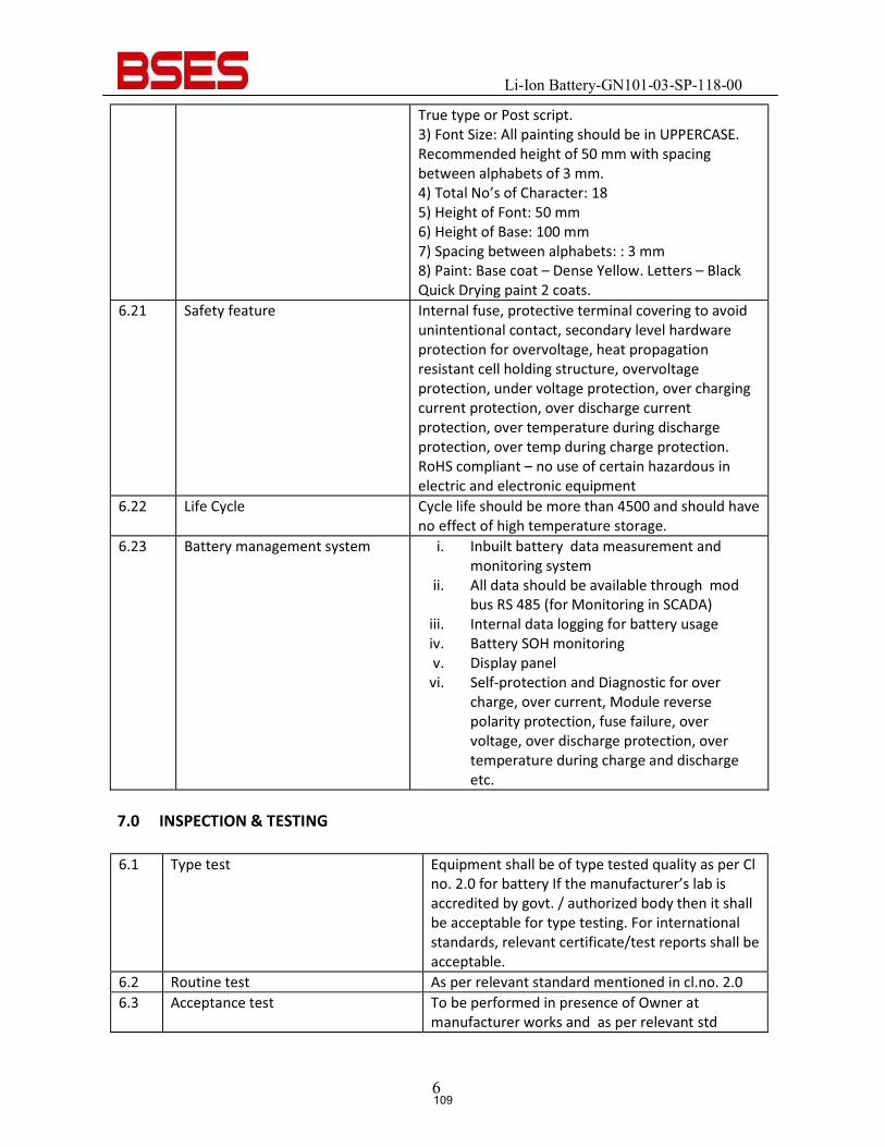
Li-Ion Battery-GN101-03-SP-118-00
6
True type or Post script. 3) Font Size: All painting should be in UPPERCASE. Recommended height of 50 mm with spacing between alphabets of 3 mm. 4) Total No’s of Character: 18 5) Height of Font: 50 mm 6) Height of Base: 100 mm 7) Spacing between alphabets: : 3 mm 8) Paint: Base coat – Dense Yellow. Letters – Black Quick Drying paint 2 coats.
6.21 Safety feature Internal fuse, protective terminal covering to avoid unintentional contact, secondary level hardware protection for overvoltage, heat propagation resistant cell holding structure, overvoltage protection, under voltage protection, over charging current protection, over discharge current protection, over temperature during discharge protection, over temp during charge protection. RoHS compliant – no use of certain hazardous in electric and electronic equipment
6.22 Life Cycle Cycle life should be more than 4500 and should have no effect of high temperature storage.
6.23 Battery management system i. Inbuilt battery data measurement and monitoring system
ii. All data should be available through mod bus RS 485 (for Monitoring in SCADA)
iii. Internal data logging for battery usage iv. Battery SOH monitoring v. Display panel vi. Self-protection and Diagnostic for over
charge, over current, Module reverse polarity protection, fuse failure, over voltage, over discharge protection, over temperature during charge and discharge etc.
7.0 INSPECTION & TESTING
6.1 Type test Equipment shall be of type tested quality as per Cl
no. 2.0 for battery If the manufacturer’s lab is accredited by govt. / authorized body then it shall be acceptable for type testing. For international standards, relevant certificate/test reports shall be acceptable.
6.2 Routine test As per relevant standard mentioned in cl.no. 2.0 6.3 Acceptance test To be performed in presence of Owner at
manufacturer works and as per relevant std
109
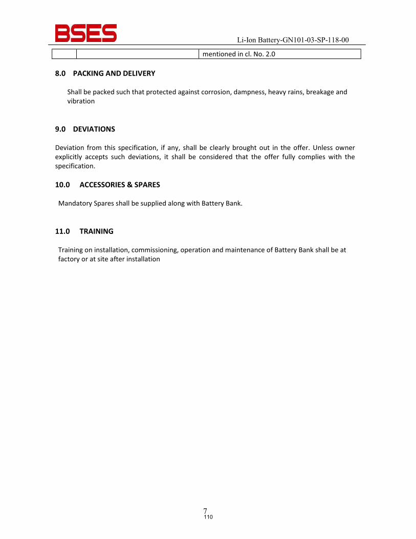
Li-Ion Battery-GN101-03-SP-118-00
7
mentioned in cl. No. 2.0
8.0 PACKING AND DELIVERY Shall be packed such that protected against corrosion, dampness, heavy rains, breakage and vibration
9.0 DEVIATIONS Deviation from this specification, if any, shall be clearly brought out in the offer. Unless owner explicitly accepts such deviations, it shall be considered that the offer fully complies with the specification.
10.0 ACCESSORIES & SPARES
Mandatory Spares shall be supplied along with Battery Bank.
11.0 TRAINING Training on installation, commissioning, operation and maintenance of Battery Bank shall be at factory or at site after installation
110
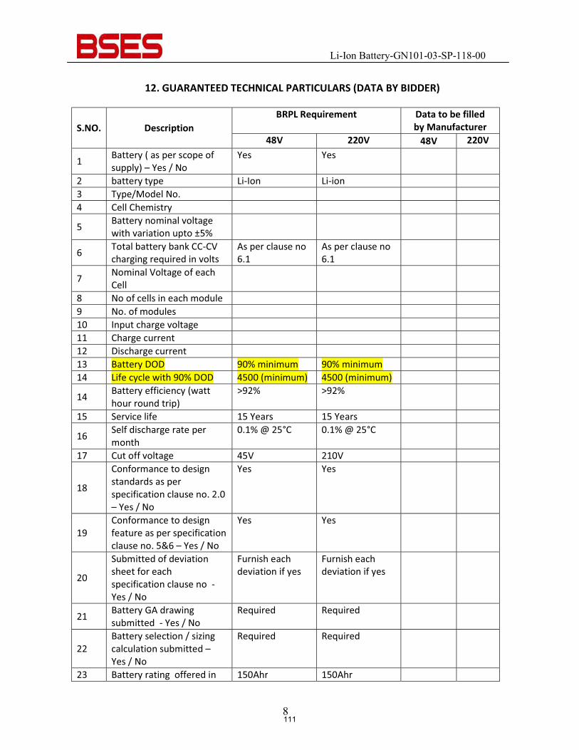
Li-Ion Battery-GN101-03-SP-118-00
8
12. GUARANTEED TECHNICAL PARTICULARS (DATA BY BIDDER)
S.NO. Description BRPL Requirement Data to be filled
by Manufacturer 48V 220V 48V 220V
1 Battery ( as per scope of supply) – Yes / No
Yes Yes
2 battery type Li-Ion Li-ion 3 Type/Model No. 4 Cell Chemistry
5 Battery nominal voltage with variation upto ±5%
6 Total battery bank CC-CV charging required in volts
As per clause no 6.1
As per clause no 6.1
7 Nominal Voltage of each Cell
8 No of cells in each module 9 No. of modules 10 Input charge voltage 11 Charge current 12 Discharge current 13 Battery DOD 90% minimum 90% minimum 14 Life cycle with 90% DOD 4500 (minimum) 4500 (minimum)
14 Battery efficiency (watt hour round trip)
>92% >92%
15 Service life 15 Years 15 Years
16 Self discharge rate per month
0.1% @ 25°C 0.1% @ 25°C
17 Cut off voltage 45V 210V
18
Conformance to design standards as per specification clause no. 2.0 – Yes / No
Yes Yes
19 Conformance to design feature as per specification clause no. 5&6 – Yes / No
Yes Yes
20
Submitted of deviation sheet for each specification clause no - Yes / No
Furnish each deviation if yes
Furnish each deviation if yes
21 Battery GA drawing submitted - Yes / No
Required Required
22 Battery selection / sizing calculation submitted – Yes / No
Required Required
23 Battery rating offered in 150Ahr 150Ahr
111
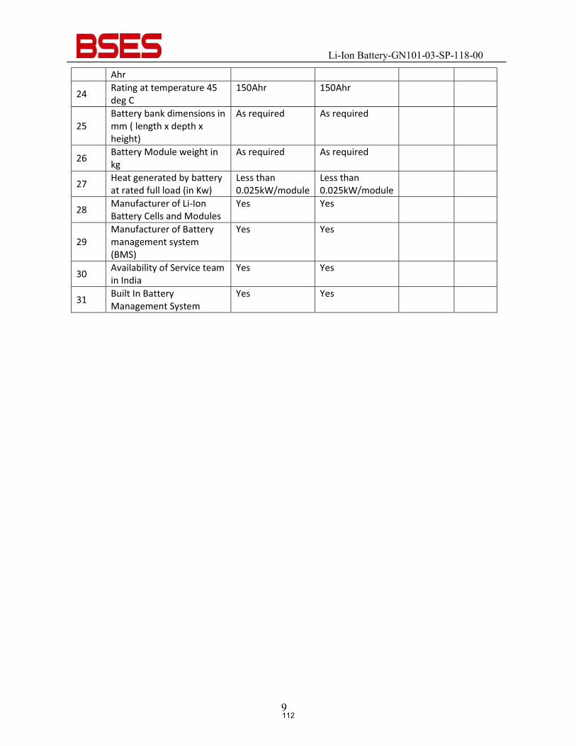
Li-Ion Battery-GN101-03-SP-118-00
9
Ahr
24 Rating at temperature 45 deg C
150Ahr 150Ahr
25 Battery bank dimensions in mm ( length x depth x height)
As required As required
26 Battery Module weight in kg
As required As required
27 Heat generated by battery at rated full load (in Kw)
Less than 0.025kW/module
Less than 0.025kW/module
28 Manufacturer of Li-Ion Battery Cells and Modules
Yes Yes
29 Manufacturer of Battery management system (BMS)
Yes Yes
30 Availability of Service team in India
Yes Yes
31 Built In Battery Management System
Yes Yes
112
BSES Bhawan, Nehru Place, New Delhi- 19
Prepared by Supriya Raina Rev: 0
Reviewed by Abhinav Srivastava Date: 25.11.2013
Approved by Vijay Panpalia
TECHNICAL SPECIFICATION
FOR
415V AC DISTRIBUTION BOARDS
113
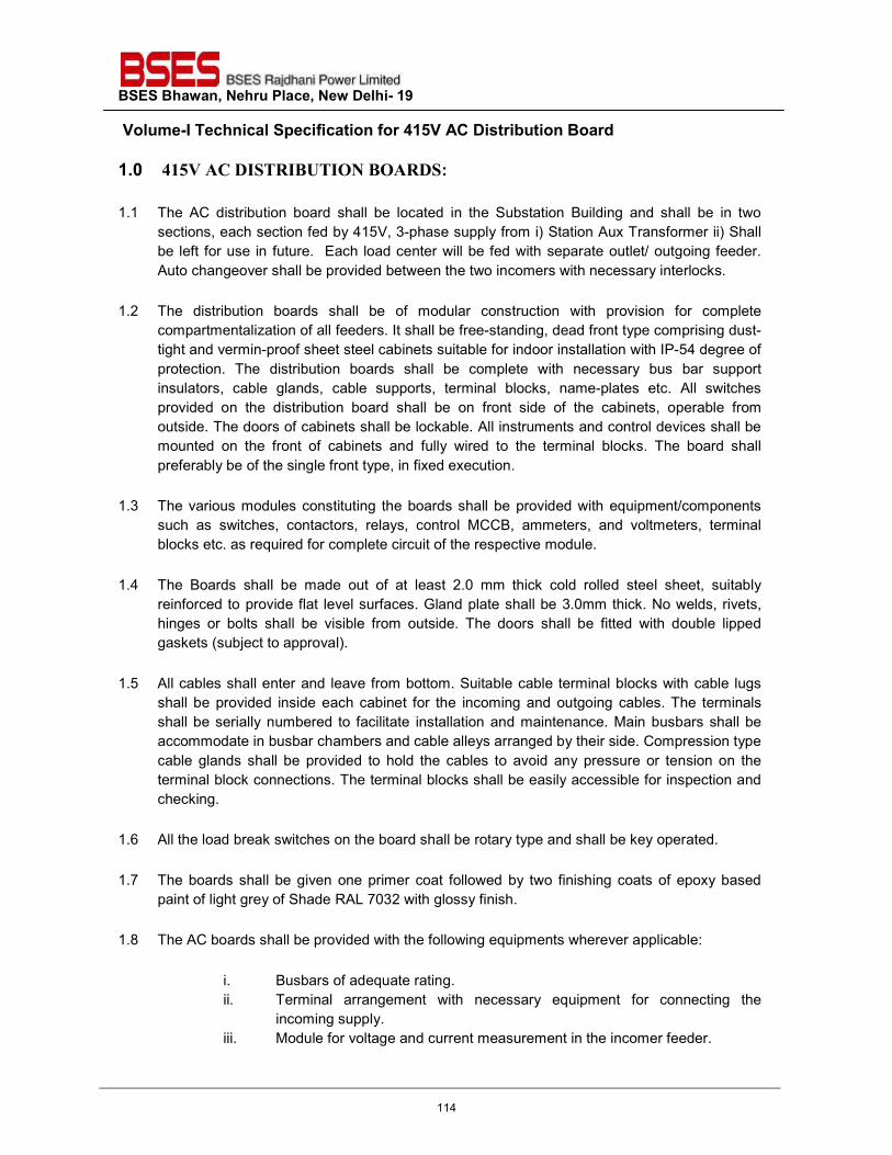
BSES Bhawan, Nehru Place, New Delhi- 19 Volume-I Technical Specification for 415V AC Distribution Board
1.0 415V AC DISTRIBUTION BOARDS:
1.1 The AC distribution board shall be located in the Substation Building and shall be in two sections, each section fed by 415V, 3-phase supply from i) Station Aux Transformer ii) Shall be left for use in future. Each load center will be fed with separate outlet/ outgoing feeder. Auto changeover shall be provided between the two incomers with necessary interlocks.
1.2 The distribution boards shall be of modular construction with provision for complete compartmentalization of all feeders. It shall be free-standing, dead front type comprising dust-tight and vermin-proof sheet steel cabinets suitable for indoor installation with IP-54 degree of protection. The distribution boards shall be complete with necessary bus bar support insulators, cable glands, cable supports, terminal blocks, name-plates etc. All switches provided on the distribution board shall be on front side of the cabinets, operable from outside. The doors of cabinets shall be lockable. All instruments and control devices shall be mounted on the front of cabinets and fully wired to the terminal blocks. The board shall preferably be of the single front type, in fixed execution.
1.3 The various modules constituting the boards shall be provided with equipment/components
such as switches, contactors, relays, control MCCB, ammeters, and voltmeters, terminal blocks etc. as required for complete circuit of the respective module.
1.4 The Boards shall be made out of at least 2.0 mm thick cold rolled steel sheet, suitably
reinforced to provide flat level surfaces. Gland plate shall be 3.0mm thick. No welds, rivets, hinges or bolts shall be visible from outside. The doors shall be fitted with double lipped gaskets (subject to approval).
1.5 All cables shall enter and leave from bottom. Suitable cable terminal blocks with cable lugs
shall be provided inside each cabinet for the incoming and outgoing cables. The terminals shall be serially numbered to facilitate installation and maintenance. Main busbars shall be accommodate in busbar chambers and cable alleys arranged by their side. Compression type cable glands shall be provided to hold the cables to avoid any pressure or tension on the terminal block connections. The terminal blocks shall be easily accessible for inspection and checking.
1.6 All the load break switches on the board shall be rotary type and shall be key operated.
1.7 The boards shall be given one primer coat followed by two finishing coats of epoxy based
paint of light grey of Shade RAL 7032 with glossy finish.
1.8 The AC boards shall be provided with the following equipments wherever applicable:
i. Busbars of adequate rating. ii. Terminal arrangement with necessary equipment for connecting the
incoming supply. iii. Module for voltage and current measurement in the incomer feeder.
114
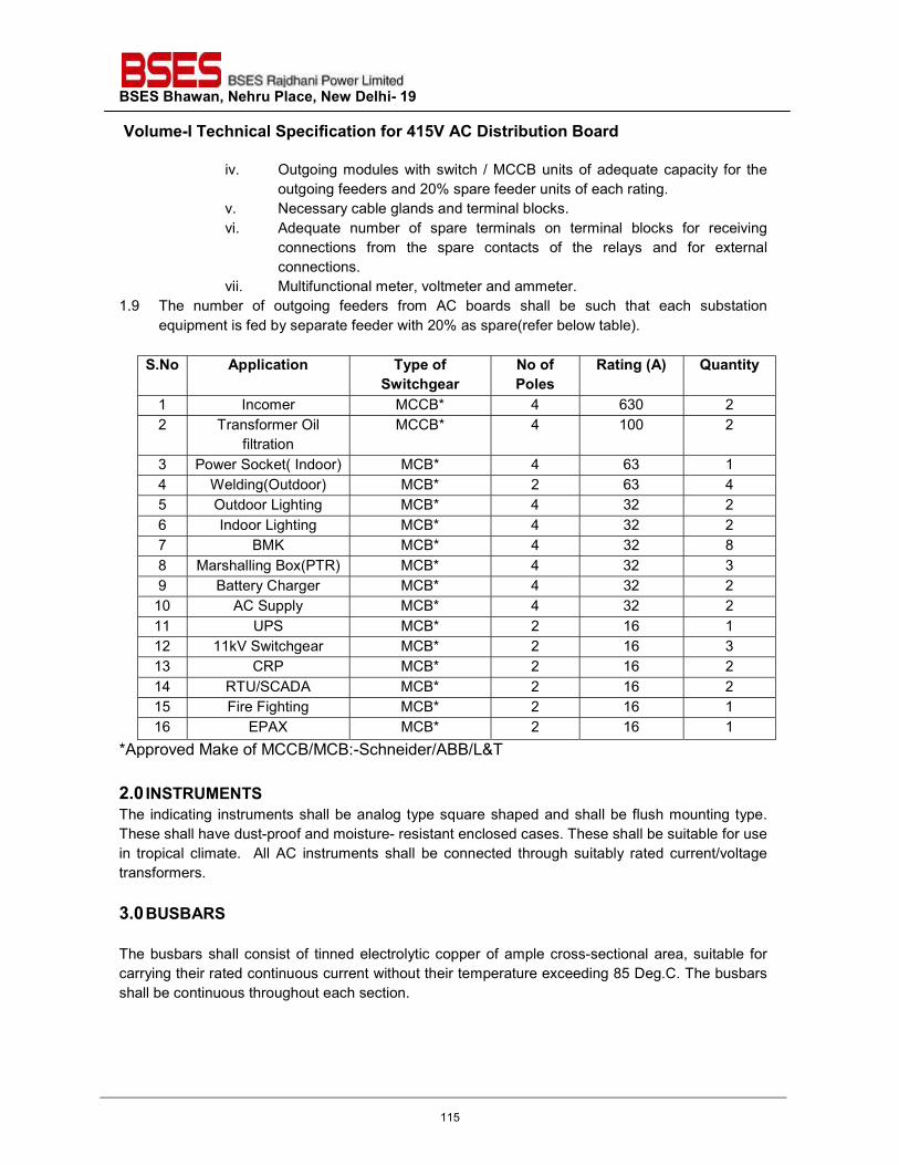
BSES Bhawan, Nehru Place, New Delhi- 19 Volume-I Technical Specification for 415V AC Distribution Board
iv. Outgoing modules with switch / MCCB units of adequate capacity for the outgoing feeders and 20% spare feeder units of each rating.
v. Necessary cable glands and terminal blocks. vi. Adequate number of spare terminals on terminal blocks for receiving
connections from the spare contacts of the relays and for external connections.
vii. Multifunctional meter, voltmeter and ammeter. 1.9 The number of outgoing feeders from AC boards shall be such that each substation
equipment is fed by separate feeder with 20% as spare(refer below table).
S.No Application Type of Switchgear
No of Poles
Rating (A) Quantity
1 Incomer MCCB* 4 630 2 2 Transformer Oil
filtration MCCB* 4 100 2
3 Power Socket( Indoor) MCB* 4 63 1 4 Welding(Outdoor) MCB* 2 63 4 5 Outdoor Lighting MCB* 4 32 2 6 Indoor Lighting MCB* 4 32 2 7 BMK MCB* 4 32 8 8 Marshalling Box(PTR) MCB* 4 32 3 9 Battery Charger MCB* 4 32 2 10 AC Supply MCB* 4 32 2 11 UPS MCB* 2 16 1 12 11kV Switchgear MCB* 2 16 3 13 CRP MCB* 2 16 2 14 RTU/SCADA MCB* 2 16 2 15 Fire Fighting MCB* 2 16 1 16 EPAX MCB* 2 16 1
*Approved Make of MCCB/MCB:-Schneider/ABB/L&T 2.0 INSTRUMENTS The indicating instruments shall be analog type square shaped and shall be flush mounting type. These shall have dust-proof and moisture- resistant enclosed cases. These shall be suitable for use in tropical climate. All AC instruments shall be connected through suitably rated current/voltage transformers. 3.0 BUSBARS The busbars shall consist of tinned electrolytic copper of ample cross-sectional area, suitable for carrying their rated continuous current without their temperature exceeding 85 Deg.C. The busbars shall be continuous throughout each section.
115
BSES Bhawan, Nehru Place, New Delhi- 19 Volume-I Technical Specification for 415V AC Distribution Board
The busbars shall have current rating to suit the requirements corresponding to the loads incident thereon under the various operating conditions and shall withstand the applicable voltage and maximum short circuit stresses. The busbars shall be insulated from supporting structure by means of durable non-hygroscopic, non-combustible and non-tracking polyester fiberglass material or porcelain. Busbars shall be encased in heat-shrunk sleeves of insulating material which shall be suitable for the operating temperature of busbars during normal service. The busbar joints shall be provided with removable thermosetting plastic shrouds. The busbars shall be housed in totally enclosed busbar chambers. The incoming connections from the busbar to the various feeders shall be so designed as not to disturb cable connections and to ensure safety to the operating and maintenance personnel and to facilitate working outside any outgoing module without the need for switching off in-feed to the adjacent modules, as far as possible. A cable alley preferably 230 mm wide shall be provided in each vertical section for taking cables into the compartments. 4.0 CONTROL WIRING
Each board shall be furnished completely factory wired upto terminal blocks ready for external connections. All wires shall consist of 1100 V grade PVC insulated flexible stranded copper wires with a cross-
section of 2.5 mm2 (min.) suitable for switchboard wiring and complying with the requirements of
the relevant IS. Each wire shall bear an identifying ferrule or tag at each end or connecting point. Control cables for external connections shall consist of stranded copper wire with 1.5, 2.5, 4.0 sq.mm or higher cross-sectional areas and shall enter from bottom. All interconnecting/outgoing control wiring shall terminate on stud type terminals on terminal blocks. The terminals shall be marked with identification numbers to facilitate connections. The terminal blocks shall be made of moulded, non-inflammable, plastic material and arranged to provide maximum accessibility for inspection and maintenance. The terminals shall be made of hard brass and have diameter of not less than 6 mm. The studs shall be securely locked within the mounting base to prevent turning. The terminal blocks shall be provided with twenty (20) percent spare terminals. The terminals shall be suitable for connections through crimped lugs. 5.0 INDICATING LAMPS Indicating lamps shall be of low wattage LED cluster type. The lamps shall be provided with translucent lamp covers which shall diffuse coloured light to give the specified indications. The lamp covers shall be unbreakable and moulded from heat-resistant fast coloured material. Necessary wiring shall be provided accordingly.
116
BSES Bhawan, Nehru Place, New Delhi- 19 Volume-I Technical Specification for 415V AC Distribution Board
6.0 INCOMER The ACDB shall have two incomer suitable as per station auxiliaries transformer rating. Each incomer shall have electrically operated MCCB of category B with automatic changeover arrangement. All outgoings shall be provided with MCCB/MCB of suitable rating. MCCB shall have over current and earth fault release. 7.0 NAME PLATES & MARKING Each panel shall be provided with legible and indelibly marked/ engraved name plates. Name-plates of all the modules shall be white with black engraved letters. On top of each module, name-plates with bold letters shall be provided for feeder designation. Each device shall also be suitably marked for identification inside the panels. Name- plates with full and clear inscriptions shall be provided inside the panels for all isolating switches, links, fuse blocks, test blocks and cable terminals. Every switch shall be provided with a nameplate giving its function clearly. Switches shall also have clear inscriptions for each position indication e.g. 'ON' 'OFF' etc.
8.0 DEVIATIONS Deviation from this specification, if any, shall be clearly brought out in the offer. Unless owner explicitly accepts such deviations, it shall be considered that the offer fully complies with the specification.
117
BSES Bhawan, Nehru Place, New Delhi- 19
Prepared by Pronab Bairagi Rev: 2
Reviewed by AS Amit Tomar Date: 27nd May, 2021
Approved by VP
TECHNICAL SPECIFICATION
FOR
GROUNDING & LIGHTNING PROTECTION SYSTEM
118

BSES Bhawan, Nehru Place, New Delhi- 19 Technical Specification Grounding and Lightning Protection
1.0 GROUNDING & LIGHTNING PROTECTION SYSTEM:
1.1 GROUNDING SYSTEM Earthing Installation shall be carried out as per IS 3043/IEEE 80-2000/IEC-517. The Station Earth mat shall be designed to meet required minimum area of cross section, current Density, Resistance, Touch & Step voltage criteria’s mathematically before installation and shall be tested after installation to ensure the resistance of earth mats to be less than 0.5Ohms. Bare Earthmat conductors (Strips/ Rods) to be installed below the ground as per safe designed to spacing in a grid pattern. Each junction of the grid shall be bonded by an electric arc welding process. Each bond has to be painted by Anti corrosive Paint (Bitumen).All ground wires installed in conduits shall be insulated. Bare ground conductors shall penetrate concrete through a PVC Sleeve. Equipment shall be generally being furnished with two separate ground pads with tapped holes, bolts, nuts & spring washers etc. Metallic frame of all electrical equipment shall be earthed by two separate and distinct connections to earthing system, each 100% capacity. Steel Columns, metallic stairs, hand rails etc. of the building housing electrical equipment shall be connected to the nearby earthing grid conductor by one Earthing. Metallic Sheaths, Screens and armour of all multi core cables shall be earthed at both ends. Sheaths and armour of single core cables shall be earthed at switch gear end only All ground wires installed in conduit shall be insulated. Bare ground wires shall penetrate concrete through a PVC sleeve. Earthing of equipment shall generally be furnished with two separate ground pads with tapped holes, bolts, nuts and spring washers etc. Equipment ground connections, after being checked and tested shall be coated with anti-corrosive paint. Metallic frame of all electrical equipment shall be earthed by two separate and distinct connections to earthing system, each of 100% capacity. Steel columns, metallic stairs, hand rails etc. of the building housing electrical equipment shall be connected to the nearby earthing grid conductor by one earthing. Metallic sheaths, screens, and armour of all multi core cables shall be earthed at both ends. Sheaths and armour of single core cables shall be earthed at switchgear end only unless otherwise instructed by Owner. Every alternate post of the metallic fence shall be connected to earthing grid by one GS flat and gates by flexible lead to the earthed post. Rail for transformers within the plant area shall be bonded across fish plate and connected to earthing grid at several locations. For prefabricated cable trays, a separate ground conductor shall run along the entire length of cable tray and shall be suitably clamped on each cable tray at periodic intervals. Each continuous laid out lengths of cable tray shall be earthed at minimum two places by GS flats to Owner's earthing system, the distance between earthing points shall not exceed 30 metre. Wherever earthmat is not available Contractor shall do the necessary connections by driving an earth electrode in the ground. Neutral points of transformer shall be solidly earthed by means of 2 Nos 75X10mm GI flat. Neutral Earth Electrode dimension shall be calculated by Long duration overloading of the
119
BSES Bhawan, Nehru Place, New Delhi- 19 Technical Specification Grounding and Lightning Protection
Soil (i.e.) 40 A/sq.mtr as per IS 3043-1987 Clause 10.3.a Each earthing lead from the neutral of the Transformers shall be directly connected to two electrodes in treated earth pits which in turn shall be connected to station earthing grid. Neutral connections and metallic conduits/pipes shall not be used for the equipment earthing. Lightning protection system down conductors shall not be connected to other earthing conductors above the ground level. Connections between earth leads and equipment shall normally be of bolted type. Contact surfaces shall be thoroughly cleaned before connections. All ground conductor connections shall be made by electric arc welding and all equipment earth connections shall be made by bolting with the earthing pads through flexible insulated cable leads. Ground connections shall be made from nearest available station ground grid risers. Suitable earth risers approved by Engineer shall be provided above finished floor/ground level, if the equipment is not available at the time of laying of main earth conductor Resistance of the joint shall not be more than the resistance of the equivalent length of conductor. For rust protection the welds should be treated with red lead compound and afterwards thickly coated with bitumen compound. Earthing conductors buried in ground shall be laid minimum 600 mm below grade level unless otherwise indicated in the drawing. Earthing conductor’s crossings the road shall be installed at 1000 mm depth and where adequate earth coverage is not provided it shall be installed in Hume pipes. Earthing conductors embedded in the concrete floor of the building shall have approximately 50mm concrete cover. Minimum earth coverage of 300mm shall be provided between earth conductor and the bottom of trench/foundation/underground pipes at crossings. Wherever earthing conductor crosses on runs at less than 300mm distance along metallic structures such as gas, water, steam pipe lines, steel reinforcement in concrete, it shall be bonded to the same. Earthing conductors along their run on columns, walls, etc. shall be supported by suitable welding/cleating at interval of 750mm. Electrodes shall be embedded below permanent moisture level. Minimum spacing electrodes shall be decided by calculation referred in IEEE-80 based on soil resistivity value .If soil resistivity is poor and desired reduction in ground resistance is not achieved by adding more Grid Conductor Earth pits shall be treated with Permanent maintenance free artificial treatment compounds as per IEEE 80-2000 Clause14.5d. On completion of installation, continuity of earth conductors and efficiency of all bonds and joints shall be checked. Earth resistance at each termination shall be measured as per
120
BSES Bhawan, Nehru Place, New Delhi- 19 Technical Specification Grounding and Lightning Protection
IEEE81-1983 (Wenner 3 point method). Earth resistance at earth terminations shall be measured in presence of Owner's representatives. Thickness of galvanizing shall be atleast 610gm/sq.m or 86 microns for all galvanized steel conductors.
1.2 The grounding/Earthing material shall be Terec++ or Marconite. 1.3 Earthing rods in RCC floor for GIS substation
1.4 Ground Electrode shall be 3M long MS rod of required size. These are to be fabricated and
driven into the ground by the side of mat conductors. All connection to the conductors shall be done by arc welding process.
1.5 Risers are required for connecting the equipment and structures with the ground mat. These
will be MS rod, laid from ground mat to above ground level properly clamped or supported along the outer edge of the concrete foundation. Connection to the ground mat shall be done by arc welding and the other end is to be kept free, at least 300 mm above ground level.
1.6 All steel Structures are required to be grounded at two points from ground mat. Laying
supporting and connection at both end are within the scope of this specification. All Earth Pits provided at the grid substation shall be interconnected with each other by MS Rod/Flat of adequate size as per symmetrical fault current.. The GI flat shall be buried in the earth at a minimum depth of 300 mm. Minimum ground coverage of 300mm shall be maintained between main earth grid and bottom of trench, tunnels, underground pipes other services / foundations. The earth grid conductor shall be run along the building column wall etc. with adequate and suitable supports at 750mm interval, if site conditions warrant so. The riser for equipment earthing shall be 75X10 mm GI flat. The orientation of these risers shall be such that minimum earthing strip is consumed for equipment earthing. All the further joints / connection of GI Flat shall be arc welded.
1.7 To ensure good welding, it should be carried out only after scratching off the galvanization, dirt, grease etc by thorough cleaning of contact surface. After welding it will be made with anticorrosive zinc rich paint. The equipment connection with GI Flat shall be bolted connection. Each bolted connection shall be taken through two numbers bolts at each joint to ensure tightness and avoid loosening with passage of time. In case the GI flat is to cross any obstruction, it shall be laid below the obstruction. At the crossing of building walls, floors etc the earth conductor shall pass through PVC conduit. Both ends of conduits shall be sealed after laying of conductor to prevent ingress of water. Contractor shall use GI strip of following specification: - The GI flat will have minimum 610 gm/mm2 Zinc coating and minimum 86 microns thickness. The galvanization provided shall be as per IS 2629. The galvanized surface shall consist of a continuous and uniform thick coating of zinc, firmly adhering to the surfaces of steel. The finished surface shall be clean and smooth and shall be free from defects like discolored patches, bare spots, and unevenness of coating, spiky deposits, and blistered surfaces, flaking or peeling off.
121
BSES Bhawan, Nehru Place, New Delhi- 19 Technical Specification Grounding and Lightning Protection
All hardware like bolts, nuts, spring and flat washers shall be galvanized; Stainless Steel or Zinc passivated shall be arranged by contractor. 1.7. Earthing Calculation parameters shall be taken as: 1) Duration of shock current in secs ts=1sec. 2) Top Gravel resistivity shall be 3000 Ohm Meter. 3) Split Factor shall be considered as 1
2.0 EQUIPMENT EARTHING
All the equipment should be grounded with double run earth strip directly connected to earth mat at two different points.
2.1 The table provides the guidelines for Selection of Cross section of Earth conductor as per IEEE 80-2000 Clause 11.3.1 Equation 37 & Mild Steel as an Earth Conductor. S. No Fault current Level (KA) Minimum Required Area of Cross Section (Sq.mm) 2.1.1 5 54 2.1.2 10 108 2.1.3 15 163 2.1.4 20 217 2.1.5 25 271 2.1.6 30 325 2.1.7 35 379 2.1.8 40 433
For various Equipments such as Power Transformer, Station Transformer, 11 KV Switch gear, 415V Panel, Light panel, Junction box, Street Lighting pole, Metallic fence, Isolator, Gantry tower & Electronic Earthing different cross sections of Earth conductor shall be selected as per the fault level. For switch gear rooms, a local earth conductor of adequate size of G.I flat may be run around the room below floor level to facilitate earthing of equipments in switchgear room.
122
BSES Bhawan, Nehru Place, New Delhi- 19 Technical Specification Grounding and Lightning Protection
2.2 However the table below provides general guidelines for selection of Earth Conductor for each Equipment
2.2.1 Description/location Size
2.2.2 Earth mat 40 mm (min) to be selected by the contractor based on the calculations.
2.2.3 Power Transformer 100 X 8mm 2.2.4 Station transformer 50x6mm 2.2.5 11KV Switchgear 50x6mm 2.2.6 415V panel 50x6mm 2.2.7 Lighting panel 25x3 mm 2.2.8 Junction box 7/8 SWG 2.2.9 Street lighting pole 25x3 mm 2.2.10 Metallic fence 25x3 mm 2.2.11 Transformer yard fence and gate 50x6 GI flat with the help of flexible copper braid.
2.2.12 HV/LV/ LV Neutral cable box 50x6 GI flat 2.2.13 OLTC Drive mechanism body 25X3 GI flat 2.2.14 Battery charger panel 25X3 GI flat 2.2.15 DCDB 25X3 GI flat 2.2.16 Capacitor Bank Structure 50 X 6 GI flat 2.2.17 Capacitor unit and reactors 50 x 6 GI flat 2.2.18 Outdoor Circuit breaker, CT, PT &
CVT 50 X 6
2.2.19 Secondary terminal Box of outdoor CT, PT & CVT
25 X 6 mm
2.2.20 Isolator Mechanism box, earth switch box
25 X 6 mm
2.2.21 Gantry tower and structure 75 X 10 mm 2.2.22 Earthing Strip along with Cable
Tray 50x6
2.2.23 Electronic Earthing Separate design and installation for all communication devices and electronic equipments including SCADA RTU, MOXA, Router/Switch. As per recommendation of SCADA vendor
123
BSES Bhawan, Nehru Place, New Delhi- 19 Technical Specification Grounding and Lightning Protection
Power Transformer Neutral earthing
75x10 sqmm
The most stringent size of conductor among the two tables above shall be selected
2.3 For switchgear rooms, a local earth conductor of size 50x 6 mm GI flat may be run around the room below floor to facilitate earthing of equipments in switchgear room. This grid shall be connected to the main earth grid at minimum two points. Size of the conductor shall be selected considering the provisions in clause 2.1 and 2.2 above.
2.4 It is to be ensured that all the switchgears and transformers earth points/ connections are
connected to earth grid and all the main and auxiliary earth grids are interconnected at minimum two points. With the above arrangement, the return path to the respective transformer neutral will have a predominantly metallic path. (i.e. Cable armour >>switchgear earth bus>>external earth flat>>earth grid>>transformer neutral.).
2.5 Where a 66 kV overhead line terminates at the substation, a metallic continuity between the
end tower and the substation earth grid should be established with two independent connections.
2.6 The GI Flat shall be laid minimum 300 mm below the ground level but for the indoor location,
it shall be embedded in the concrete floor; 50mm below the FFL. .
2.7 The GI flat shall be welded after scratching off the galvanization locally and thorough cleaning of contact surface. After welding or bolting arrangement the joint shall be provided with anticorrosive Bitumen compound or zinc Phosphate paint. Wherever bolted connection is taken, it shall be taken through two bolts at each joint to ensure tightness and avoid loosening with passage of time.
2.8 Details of welding, bolting arrangement for various types of joints shall be as per Indian Standard.
2.9 Two separate and distinct earth connections shall be used for safety earthing of non-current
carrying metallic enclosure of all equipments.
2.10 Two separate and distinct earth connections shall be used for earthing of Lightning / surge absorber.
2.11 Neutral bushing of oil/dry type Station transformer shall be connected to two independent
earth pits by two no’s separate GI strips.
2.12 Transformer yard fence, structures shall also be connected with the earth mat by 50X6 GI Flat with the help of flexible copper braid.
2.13 All damages to the galvanized finishes shall be made perfect with zinc rich or bitumen paint.
124
BSES Bhawan, Nehru Place, New Delhi- 19 Technical Specification Grounding and Lightning Protection
2.14 RTU, marshalling box of SCADA or any other equipment installed in substation for SCADA shall not be connected to the earth grid, it shall be connected to separate two earth pits connected at two separate points of the panel.
3.0. LIGHTNING PROTECTION
DESIGN OF LIGHTNING PROTECTION
3.1 Direct stroke lightning protection (DSLP) shall be provided in the EHV switchyard by shield wires. The final arrangement shall be decided after approval of the DSLP calculations. The Contractor is required to carry out the DSLP calculations and submit the same to the Owner for approval of the same at detailed engineering stage after award of contract.
3.2 The lightning protection system shall not be in direct contact with underground metallic service ducts and cables.
3.3 A 40 mm dia. 3000mm long MS earth electrode with test links, CI frame & Cover shall be
provided to connect down conductor of towers with peak. The test joint shall be directly connected to the earthing system.
3.4 Conductors of the lightning protection system shall not be connected with the conductors of
the safety earthing system above ground level.
3.5 Down conductors used for lightning protection shall be cleated on the structures at 2000mm interval.
3.6 Connection between each down conductor and rod electrodes shall be made via test joint
(pad type compression clamp) located approximately 150 mm aboveground level.
3.7 Lightning conductors shall not pass through or run inside G.I. conduits.
3.8 All metallic structures within a vicinity of 2000 mm in air and 5000mm below ground shall be bound to the conductors of lightning protection system.
3.9 In addition to Earth wires above the EHV switchyard, ESE Lightning conductor shall provides zone of Protection. Snapping of Earth wire does not make accidental situations during Lightning.
3.10 This ESE Lightning Protection system requires an Air terminal, down conductor, Lightning Counter & an Earthing System. If the structure is more than 30m height then 2 no’s of down conductor shall be used for side flashing. The Earthing system should not exceed more than 10Ω.
3.11 A 40mm dia M.S Earth Electrodes with Test Links, HDPE Cover shall be provided to connect down conductor. The test Link shall be directly connected to earthing system
3.12 Conductors of Lightning Protection system shall not be connected with conductors of Safety earthing system above ground level. Lightning Earth Pits shall be connected other earthing conductor below ground level by using Equipotential bonds which will not allow Surge current to flow from Lightning pits to other Earth pits
125
BSES Bhawan, Nehru Place, New Delhi- 19 Technical Specification Grounding and Lightning Protection
3.13 Connection between each down conductor & Test link shall be located approximately 2000mm above ground Level.
3.14 The Down conductor should be high conductivity bare copper tape with minimum size of 75 Sq.mm
3.15 Constructional Features
3.15.1 Galvanized Steel (Applicable for exposed G.S. flats)
a) Steel conductors shall be galvanized according to IS: 2629. b) The minimum weight of zinc coating shall be 610gm/sq. m. and minimum thickness
shall be 86 microns. c) The galvanized surfaces shall consist of a continuous and uniformly thick coating of
zinc, firmly adhering to the surfaces of steel. The finished surface shall clean and smooth and shall be free from defects like discolored patches, bare spots, unevenness of coating, spelter which is loosely attached to the steel globules, spiky deposits, blistered surfaces, flaking or peeling off etc. The presence of any of these defects noticed on visual or microscopic inspection shall render the material liable to rejection.
3.16 Tests
3.16.1 The Contractor shall perform all tests and inspection to ensure that material and workmanship are according to the relevant standards. Contractor shall have to demonstrate all tests as per specification and equipment shall comply with all requirements of the specification.
a) The galvanized steel shall be subjected to four one-minute dips in copper sulphate solution as per IS: 2633.
b) Zinc Coating thickness : As per IS: 4759 c) Uniformity of zinc coating : As per IS: 2633 d) Adhesion Test : As per IS: 2629 e) Mass of zinc coating : As per IS: 6745 f) Chemical Analysis: As per IS: 513 & IS: 1079
3.16.2 The accessories for GSS Groundwire such as Tension Clamps, Copper braided wire etc.
shall conform to & meet the test requirements of IS: 2121.
126

BSES Bhawan, Nehru Place, New Delhi- 19 Technical Specification Grounding and Lightning Protection
4.0. DEVIATIONS Deviation from this specification, if any, shall be clearly brought out in the offer. Unless owner explicitly accepts such deviations, it shall be considered that the offer fully complies with the specification.
127
Technical Specification for
LT POWER CABLE WITH FRLS OUTER SHEATH
(Single & Multi-Core)
Specification no – SP-EWLP-01-R5
Prepared By Reviewed By Approved By Rev/Pages
Date
Name Sign Name Sign Name Sign
Rohit Patil
Amit Tomar
K. Sheshadri
R5/22
02.03.2020
128
SP-EWLP-01-R5
TECHNICAL SPECIFICATION OF LT POWER CABLE
Page 2 of 22
INDEX
Contents RECORD OF REVISION ............................................................................................................................. 3
1.0 SCOPE OF SUPPLY ............................................................................................................................ 4
2.0 CODES & STANDARDS ..................................................................................................................... 4
3.0 CABLE DESIGN .................................................................................................................................. 6
4.0 CABLE DRUM ..................................................................................................................................... 7
5.0 PACKING , SHIPPING , HANDLING & STORAGE ................................................................................. 8
6.0 QUALITY ASSURANCE ,TESTING & INSPECTION ................................................................................ 9
7.0 DRAWING, DATA & MANUALS ........................................................................................................ 10
8.0 PROGRESS REPORTING ................................................................................................................... 10
9.0 DEVIATION ...................................................................................................................................... 11
10.0 TECHNIACL PARTICULARS ............................................................................................................. 12
11.0 ANNEXURE – A .............................................................................................................................. 13
12.0 ANNEXURE – B .............................................................................................................................. 14
13.0 ANNEXTURE- C .............................................................................................................................. 18
14.0 ANNEXTURE – D ............................................................................................................................ 21
15.0 ANNEXTURE – E ............................................................................................................................. 22
129
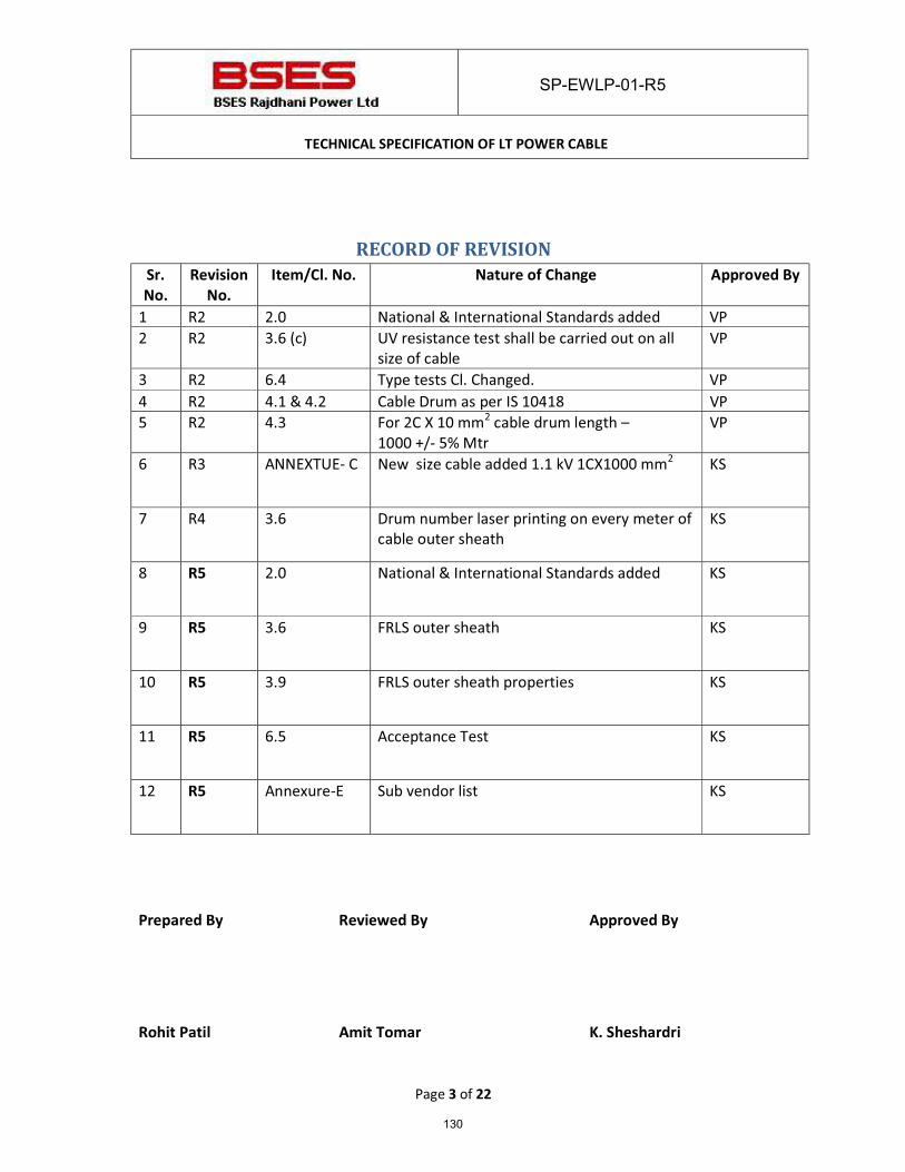
SP-EWLP-01-R5
TECHNICAL SPECIFICATION OF LT POWER CABLE
Page 3 of 22
RECORD OF REVISION Sr.
No.
Revision
No.
Item/Cl. No. Nature of Change Approved By
1 R2 2.0 National & International Standards added VP 2 R2 3.6 (c) UV resistance test shall be carried out on all
size of cable VP
3 R2 6.4 Type tests Cl. Changed. VP 4 R2 4.1 & 4.2 Cable Drum as per IS 10418 VP 5 R2 4.3 For 2C X 10 mm2 cable drum length –
1000 +/- 5% Mtr VP
6 R3 ANNEXTUE- C
New size cable added 1.1 kV 1CX1000 mm2 KS
7 R4 3.6 Drum number laser printing on every meter of cable outer sheath
KS
8 R5 2.0 National & International Standards added KS
9 R5 3.6 FRLS outer sheath KS
10 R5 3.9 FRLS outer sheath properties KS
11 R5 6.5 Acceptance Test KS
12 R5 Annexure-E Sub vendor list KS
Prepared By Reviewed By Approved By
Rohit Patil Amit Tomar K. Sheshardri
130
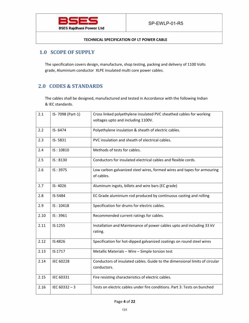
SP-EWLP-01-R5
TECHNICAL SPECIFICATION OF LT POWER CABLE
Page 4 of 22
1.0 SCOPE OF SUPPLY
The specification covers design, manufacture, shop testing, packing and delivery of 1100 Volts grade, Aluminium conductor XLPE insulated multi core power cables.
2.0 CODES & STANDARDS
The cables shall be designed, manufactured and tested in Accordance with the following Indian & IEC standards.
2.1 IS- 7098 (Part-1) Cross linked polyethylene insulated PVC sheathed cables for working voltages upto and including 1100V.
2.2 IS- 6474 Polyethylene insulation & sheath of electric cables.
2.3 IS- 5831 PVC insulation and sheath of electrical cables.
2.4 IS : 10810 Methods of tests for cables.
2.5 IS : 8130 Conductors for insulated electrical cables and flexible cords.
2.6 IS : 3975 Low carbon galvanized steel wires, formed wires and tapes for armouring of cables.
2.7 IS- 4026 Aluminum ingots, billets and wire bars (EC grade)
2.8 IS-5484 EC Grade aluminium rod produced by continuous casting and rolling
2.9 IS : 10418 Specification for drums for electric cables.
2.10 IS : 3961 Recommended current ratings for cables.
2.11 IS:1255 Installation and Maintenance of power cables upto and including 33 kV rating.
2.12 IS:4826 Specification for hot-dipped galvanized coatings on round steel wires
2.13 IS:1717 Metallic Materials – Wire – Simple torsion test
2.14 IEC 60228 Conductors of insulated cables. Guide to the dimensional limits of circular conductors.
2.15 IEC 60331 Fire resisting characteristics of electric cables.
2.16 IEC 60332 – 3 Tests on electric cables under fire conditions. Part 3: Tests on bunched
131
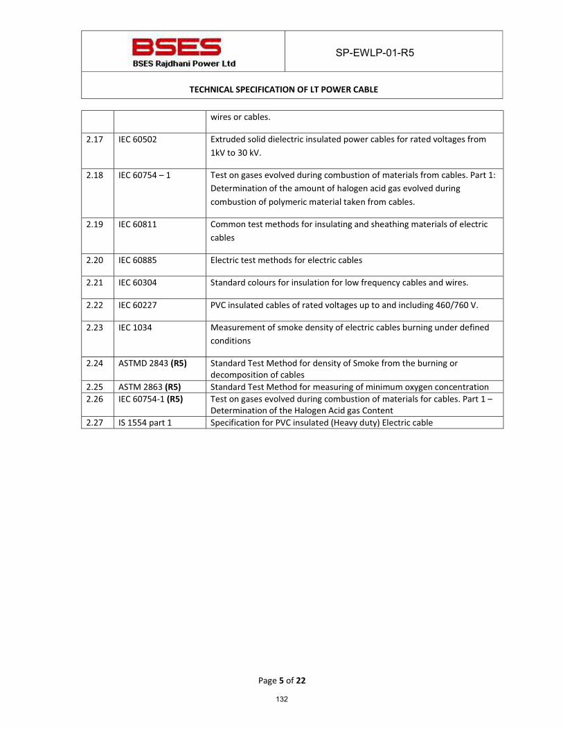
SP-EWLP-01-R5
TECHNICAL SPECIFICATION OF LT POWER CABLE
Page 5 of 22
wires or cables.
2.17 IEC 60502 Extruded solid dielectric insulated power cables for rated voltages from 1kV to 30 kV.
2.18 IEC 60754 – 1 Test on gases evolved during combustion of materials from cables. Part 1: Determination of the amount of halogen acid gas evolved during combustion of polymeric material taken from cables.
2.19 IEC 60811 Common test methods for insulating and sheathing materials of electric cables
2.20 IEC 60885 Electric test methods for electric cables
2.21 IEC 60304 Standard colours for insulation for low frequency cables and wires.
2.22 IEC 60227 PVC insulated cables of rated voltages up to and including 460/760 V.
2.23 IEC 1034 Measurement of smoke density of electric cables burning under defined conditions
2.24 ASTMD 2843 (R5) Standard Test Method for density of Smoke from the burning or decomposition of cables
2.25 ASTM 2863 (R5) Standard Test Method for measuring of minimum oxygen concentration 2.26 IEC 60754-1 (R5) Test on gases evolved during combustion of materials for cables. Part 1 –
Determination of the Halogen Acid gas Content 2.27 IS 1554 part 1 Specification for PVC insulated (Heavy duty) Electric cable
132
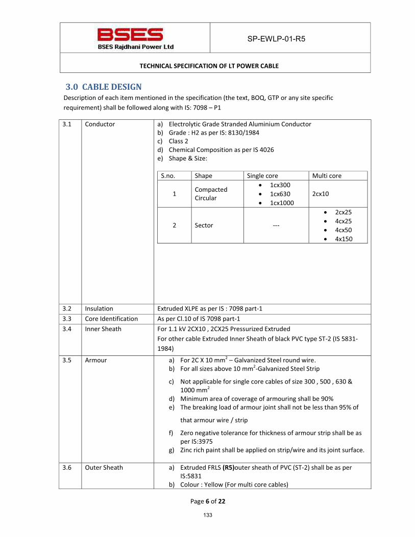
SP-EWLP-01-R5
TECHNICAL SPECIFICATION OF LT POWER CABLE
Page 6 of 22
3.0 CABLE DESIGN Description of each item mentioned in the specification (the text, BOQ, GTP or any site specific requirement) shall be followed along with IS: 7098 – P1
3.1 Conductor a) Electrolytic Grade Stranded Aluminium Conductor b) Grade : H2 as per IS: 8130/1984 c) Class 2 d) Chemical Composition as per IS 4026 e) Shape & Size:
S.no. Shape Single core Multi core
1 Compacted Circular
� 1cx300 � 1cx630 � 1cx1000
2cx10
2 Sector ---
� 2cx25 � 4cx25 � 4cx50 � 4x150
3.2 Insulation Extruded XLPE as per IS : 7098 part-1 3.3 Core Identification As per Cl.10 of IS 7098 part-1 3.4 Inner Sheath For 1.1 kV 2CX10 , 2CX25 Pressurized Extruded
For other cable Extruded Inner Sheath of black PVC type ST-2 (IS 5831-1984)
3.5 Armour a) For 2C X 10 mm2 – Galvanized Steel round wire. b) For all sizes above 10 mm2-Galvanized Steel Strip
c) Not applicable for single core cables of size 300 , 500 , 630 & 1000 mm2
d) Minimum area of coverage of armouring shall be 90% e) The breaking load of armour joint shall not be less than 95% of
that armour wire / strip
f) Zero negative tolerance for thickness of armour strip shall be as per IS:3975
g) Zinc rich paint shall be applied on strip/wire and its joint surface.
3.6 Outer Sheath a) Extruded FRLS (R5)outer sheath of PVC (ST-2) shall be as per IS:5831
b) Colour : Yellow (For multi core cables)
133
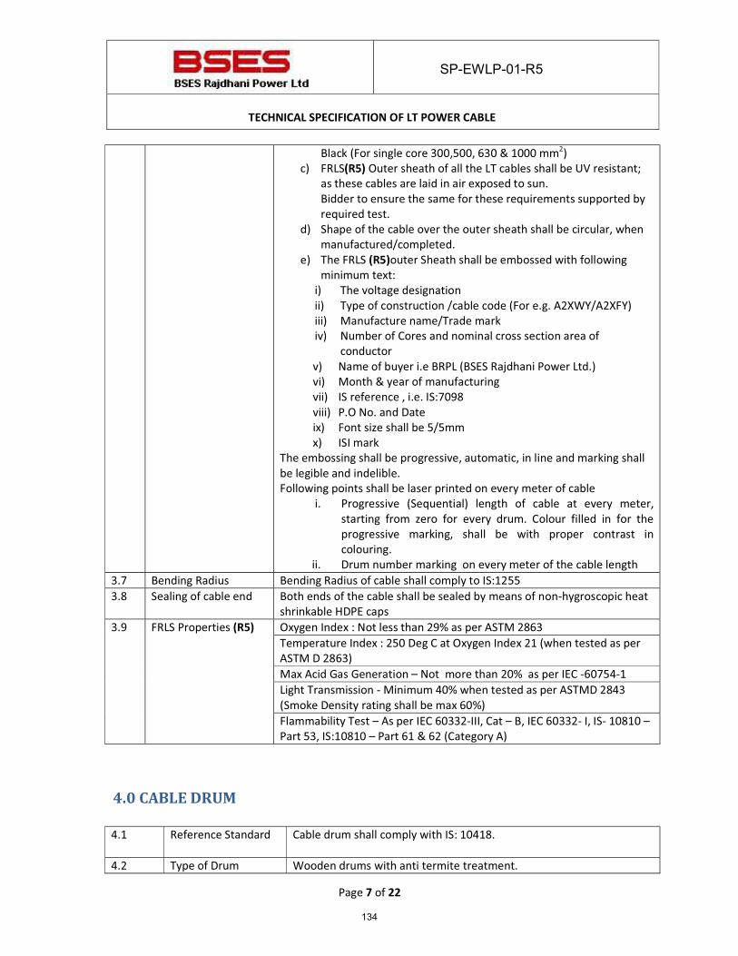
SP-EWLP-01-R5
TECHNICAL SPECIFICATION OF LT POWER CABLE
Page 7 of 22
Black (For single core 300,500, 630 & 1000 mm2) c) FRLS(R5) Outer sheath of all the LT cables shall be UV resistant;
as these cables are laid in air exposed to sun. Bidder to ensure the same for these requirements supported by required test.
d) Shape of the cable over the outer sheath shall be circular, when manufactured/completed.
e) The FRLS (R5)outer Sheath shall be embossed with following minimum text:
i) The voltage designation ii) Type of construction /cable code (For e.g. A2XWY/A2XFY) iii) Manufacture name/Trade mark iv) Number of Cores and nominal cross section area of
conductor v) Name of buyer i.e BRPL (BSES Rajdhani Power Ltd.) vi) Month & year of manufacturing vii) IS reference , i.e. IS:7098 viii) P.O No. and Date ix) Font size shall be 5/5mm x) ISI mark
The embossing shall be progressive, automatic, in line and marking shall be legible and indelible. Following points shall be laser printed on every meter of cable
i. Progressive (Sequential) length of cable at every meter, starting from zero for every drum. Colour filled in for the progressive marking, shall be with proper contrast in colouring.
ii. Drum number marking on every meter of the cable length 3.7 Bending Radius Bending Radius of cable shall comply to IS:1255 3.8 Sealing of cable end Both ends of the cable shall be sealed by means of non-hygroscopic heat
shrinkable HDPE caps 3.9 FRLS Properties (R5) Oxygen Index : Not less than 29% as per ASTM 2863
Temperature Index : 250 Deg C at Oxygen Index 21 (when tested as per ASTM D 2863) Max Acid Gas Generation – Not more than 20% as per IEC -60754-1 Light Transmission - Minimum 40% when tested as per ASTMD 2843 (Smoke Density rating shall be max 60%) Flammability Test – As per IEC 60332-III, Cat – B, IEC 60332- I, IS- 10810 – Part 53, IS:10810 – Part 61 & 62 (Category A)
4.0 CABLE DRUM 4.1 Reference Standard Cable drum shall comply with IS: 10418.
4.2 Type of Drum Wooden drums with anti termite treatment.
134
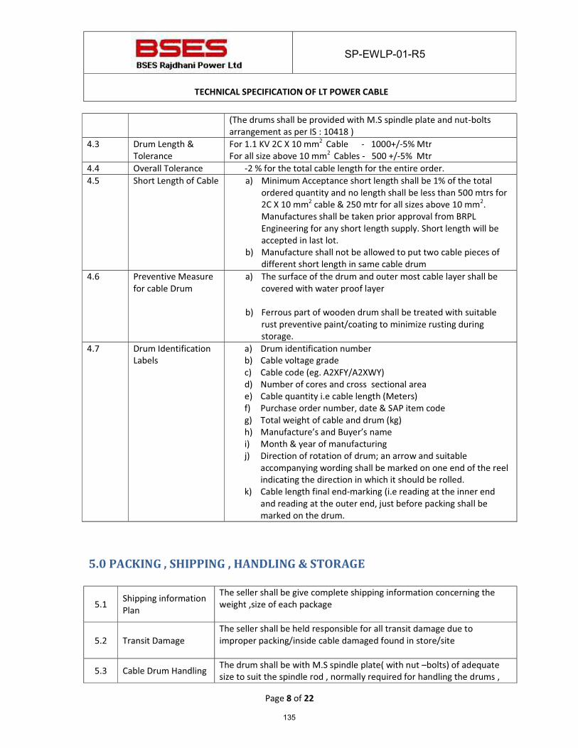
SP-EWLP-01-R5
TECHNICAL SPECIFICATION OF LT POWER CABLE
Page 8 of 22
(The drums shall be provided with M.S spindle plate and nut-bolts arrangement as per IS : 10418 )
4.3 Drum Length & Tolerance
For 1.1 KV 2C X 10 mm2 Cable - 1000+/-5% Mtr For all size above 10 mm2 Cables - 500 +/-5% Mtr
4.4 Overall Tolerance -2 % for the total cable length for the entire order. 4.5 Short Length of Cable a) Minimum Acceptance short length shall be 1% of the total
ordered quantity and no length shall be less than 500 mtrs for 2C X 10 mm2 cable & 250 mtr for all sizes above 10 mm2. Manufactures shall be taken prior approval from BRPL Engineering for any short length supply. Short length will be accepted in last lot.
b) Manufacture shall not be allowed to put two cable pieces of different short length in same cable drum
4.6 Preventive Measure for cable Drum
a) The surface of the drum and outer most cable layer shall be covered with water proof layer
b) Ferrous part of wooden drum shall be treated with suitable rust preventive paint/coating to minimize rusting during storage.
4.7 Drum Identification Labels
a) Drum identification number b) Cable voltage grade c) Cable code (eg. A2XFY/A2XWY) d) Number of cores and cross sectional area e) Cable quantity i.e cable length (Meters) f) Purchase order number, date & SAP item code g) Total weight of cable and drum (kg) h) Manufacture’s and Buyer’s name i) Month & year of manufacturing j) Direction of rotation of drum; an arrow and suitable
accompanying wording shall be marked on one end of the reel indicating the direction in which it should be rolled.
k) Cable length final end-marking (i.e reading at the inner end and reading at the outer end, just before packing shall be marked on the drum.
5.0 PACKING , SHIPPING , HANDLING & STORAGE
5.1 Shipping information Plan
The seller shall be give complete shipping information concerning the weight ,size of each package
5.2 Transit Damage The seller shall be held responsible for all transit damage due to improper packing/inside cable damaged found in store/site
5.3 Cable Drum Handling The drum shall be with M.S spindle plate( with nut –bolts) of adequate size to suit the spindle rod , normally required for handling the drums ,
135
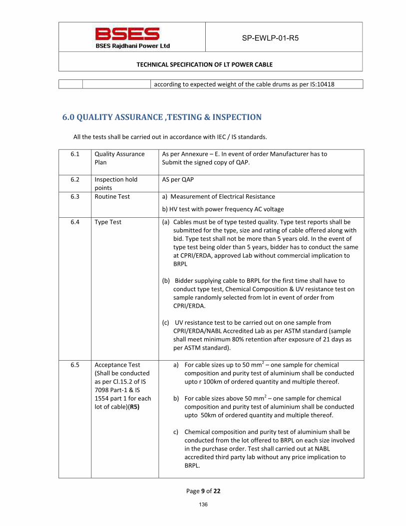
SP-EWLP-01-R5
TECHNICAL SPECIFICATION OF LT POWER CABLE
Page 9 of 22
according to expected weight of the cable drums as per IS:10418
6.0 QUALITY ASSURANCE ,TESTING & INSPECTION
All the tests shall be carried out in accordance with IEC / IS standards.
6.1 Quality Assurance Plan
As per Annexure – E. In event of order Manufacturer has to Submit the signed copy of QAP.
6.2 Inspection hold points
AS per QAP
6.3 Routine Test a) Measurement of Electrical Resistance
b) HV test with power frequency AC voltage
6.4 Type Test (a) Cables must be of type tested quality. Type test reports shall be submitted for the type, size and rating of cable offered along with bid. Type test shall not be more than 5 years old. In the event of type test being older than 5 years, bidder has to conduct the same at CPRI/ERDA, approved Lab without commercial implication to BRPL
(b) Bidder supplying cable to BRPL for the first time shall have to conduct type test, Chemical Composition & UV resistance test on sample randomly selected from lot in event of order from CPRI/ERDA.
(c) UV resistance test to be carried out on one sample from
CPRI/ERDA/NABL Accredited Lab as per ASTM standard (sample shall meet minimum 80% retention after exposure of 21 days as per ASTM standard).
6.5 Acceptance Test
(Shall be conducted as per Cl.15.2 of IS 7098 Part-1 & IS 1554 part 1 for each lot of cable)(R5)
a) For cable sizes up to 50 mm2 – one sample for chemical composition and purity test of aluminium shall be conducted upto r 100km of ordered quantity and multiple thereof.
b) For cable sizes above 50 mm2 – one sample for chemical composition and purity test of aluminium shall be conducted upto 50km of ordered quantity and multiple thereof.
c) Chemical composition and purity test of aluminium shall be conducted from the lot offered to BRPL on each size involved in the purchase order. Test shall carried out at NABL accredited third party lab without any price implication to BRPL.
136
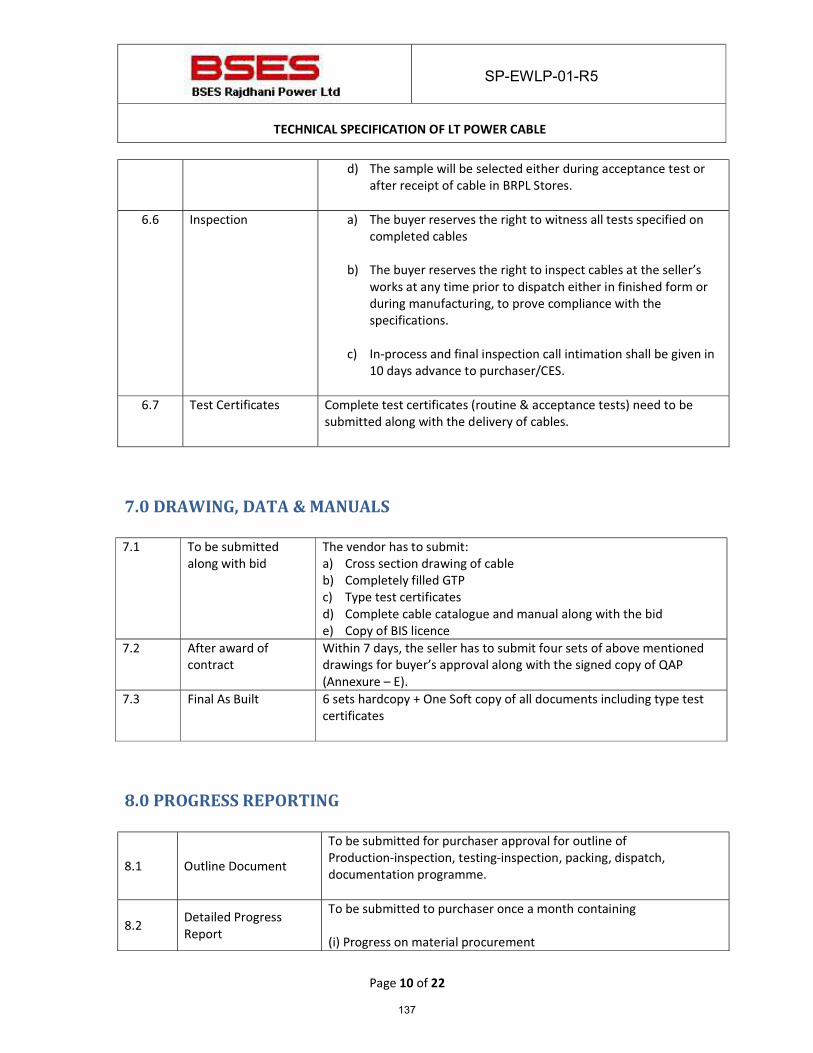
SP-EWLP-01-R5
TECHNICAL SPECIFICATION OF LT POWER CABLE
Page 10 of 22
d) The sample will be selected either during acceptance test or after receipt of cable in BRPL Stores.
6.6 Inspection a) The buyer reserves the right to witness all tests specified on
completed cables
b) The buyer reserves the right to inspect cables at the seller’s works at any time prior to dispatch either in finished form or during manufacturing, to prove compliance with the specifications.
c) In-process and final inspection call intimation shall be given in
10 days advance to purchaser/CES.
6.7 Test Certificates Complete test certificates (routine & acceptance tests) need to be submitted along with the delivery of cables.
7.0 DRAWING, DATA & MANUALS 7.1 To be submitted
along with bid The vendor has to submit: a) Cross section drawing of cable b) Completely filled GTP c) Type test certificates d) Complete cable catalogue and manual along with the bid e) Copy of BIS licence
7.2 After award of contract
Within 7 days, the seller has to submit four sets of above mentioned drawings for buyer’s approval along with the signed copy of QAP (Annexure – E).
7.3 Final As Built 6 sets hardcopy + One Soft copy of all documents including type test certificates
8.0 PROGRESS REPORTING
8.1 Outline Document
To be submitted for purchaser approval for outline of Production-inspection, testing-inspection, packing, dispatch, documentation programme.
8.2 Detailed Progress Report
To be submitted to purchaser once a month containing (i) Progress on material procurement
137
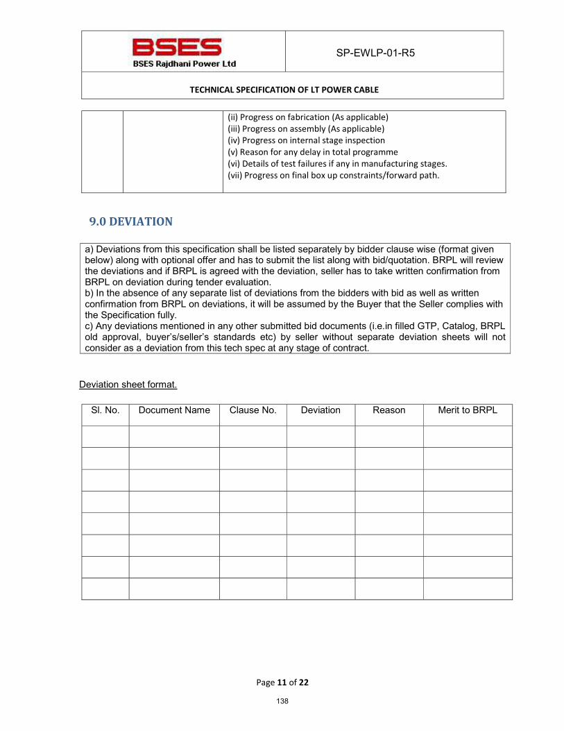
SP-EWLP-01-R5
TECHNICAL SPECIFICATION OF LT POWER CABLE
Page 11 of 22
(ii) Progress on fabrication (As applicable) (iii) Progress on assembly (As applicable) (iv) Progress on internal stage inspection (v) Reason for any delay in total programme (vi) Details of test failures if any in manufacturing stages. (vii) Progress on final box up constraints/forward path.
9.0 DEVIATION a) Deviations from this specification shall be listed separately by bidder clause wise (format given below) along with optional offer and has to submit the list along with bid/quotation. BRPL will review the deviations and if BRPL is agreed with the deviation, seller has to take written confirmation from BRPL on deviation during tender evaluation. b) In the absence of any separate list of deviations from the bidders with bid as well as written confirmation from BRPL on deviations, it will be assumed by the Buyer that the Seller complies with the Specification fully. c) Any deviations mentioned in any other submitted bid documents (i.e.in filled GTP, Catalog, BRPL old approval, buyer’s/seller’s standards etc) by seller without separate deviation sheets will not consider as a deviation from this tech spec at any stage of contract.
Deviation sheet format.
Sl. No. Document Name Clause No. Deviation Reason Merit to BRPL
138
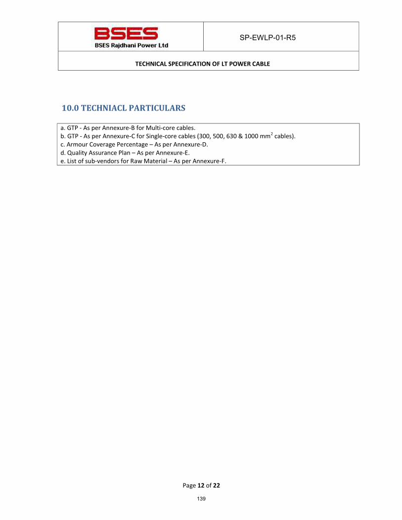
SP-EWLP-01-R5
TECHNICAL SPECIFICATION OF LT POWER CABLE
Page 12 of 22
10.0 TECHNIACL PARTICULARS a. GTP - As per Annexure-B for Multi-core cables. b. GTP - As per Annexure-C for Single-core cables (300, 500, 630 & 1000 mm2 cables). c. Armour Coverage Percentage – As per Annexure-D. d. Quality Assurance Plan – As per Annexure-E. e. List of sub-vendors for Raw Material – As per Annexure-F.
139
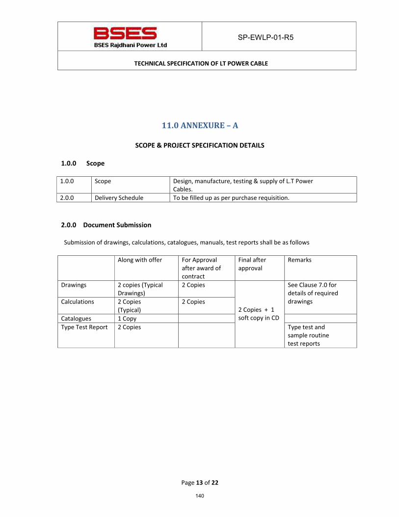
SP-EWLP-01-R5
TECHNICAL SPECIFICATION OF LT POWER CABLE
Page 13 of 22
11.0 ANNEXURE – A
SCOPE & PROJECT SPECIFICATION DETAILS
1.0.0 Scope
1.0.0 Scope Design, manufacture, testing & supply of L.T Power
Cables. 2.0.0 Delivery Schedule To be filled up as per purchase requisition. 2.0.0 Document Submission
Submission of drawings, calculations, catalogues, manuals, test reports shall be as follows Along with offer For Approval
after award of contract
Final after approval
Remarks
Drawings 2 copies (Typical Drawings)
2 Copies 2 Copies + 1 soft copy in CD
See Clause 7.0 for details of required drawings Calculations 2 Copies
(Typical) 2 Copies
Catalogues 1 Copy Type Test Report 2 Copies Type test and
sample routine test reports
140
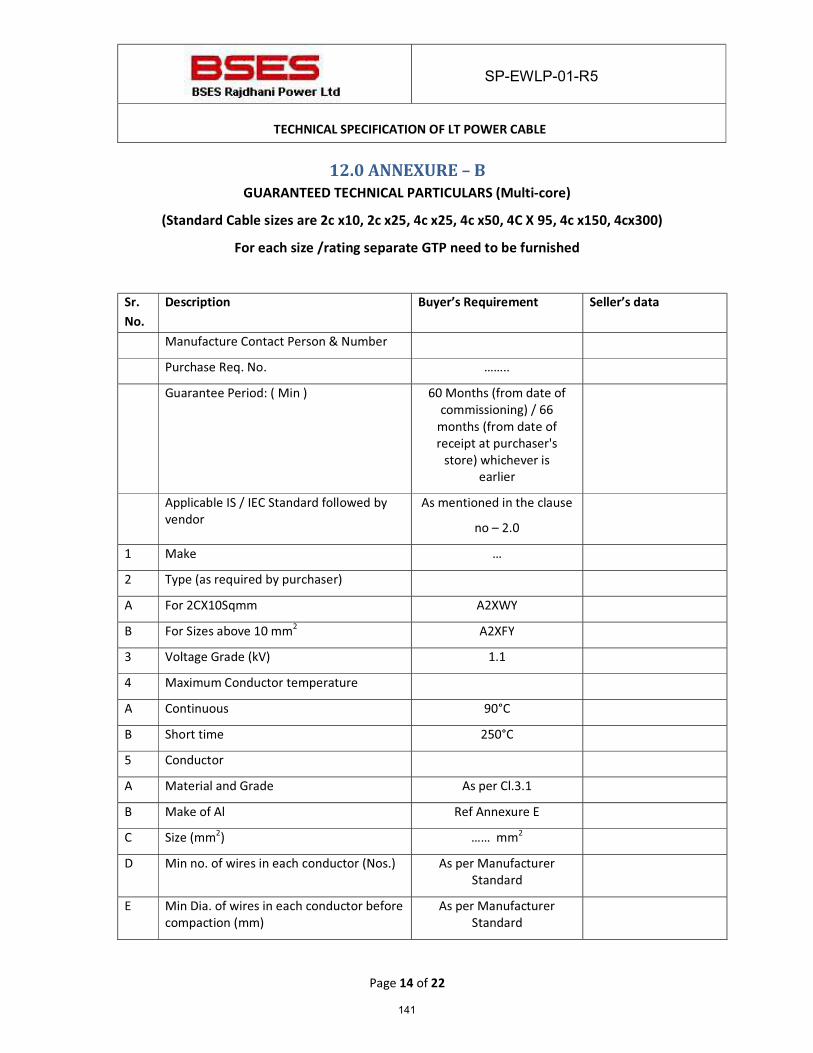
SP-EWLP-01-R5
TECHNICAL SPECIFICATION OF LT POWER CABLE
Page 14 of 22
12.0 ANNEXURE – B GUARANTEED TECHNICAL PARTICULARS (Multi-core)
(Standard Cable sizes are 2c x10, 2c x25, 4c x25, 4c x50, 4C X 95, 4c x150, 4cx300)
For each size /rating separate GTP need to be furnished
Sr.
No.
Description Buyer’s Requirement Seller’s data
Manufacture Contact Person & Number
Purchase Req. No. ……..
Guarantee Period: ( Min ) 60 Months (from date of commissioning) / 66
months (from date of receipt at purchaser's
store) whichever is earlier
Applicable IS / IEC Standard followed by vendor
As mentioned in the clause
no – 2.0
1 Make …
2 Type (as required by purchaser)
A For 2CX10Sqmm A2XWY
B For Sizes above 10 mm2 A2XFY
3 Voltage Grade (kV) 1.1
4 Maximum Conductor temperature
A Continuous 90°C
B Short time 250°C
5 Conductor
A Material and Grade As per Cl.3.1
B Make of Al Ref Annexure E
C Size (mm2) …… mm2
D Min no. of wires in each conductor (Nos.) As per Manufacturer Standard
E Min Dia. of wires in each conductor before compaction (mm)
As per Manufacturer Standard
141
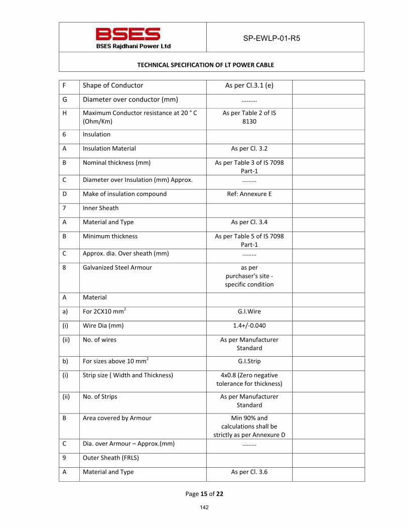
SP-EWLP-01-R5
TECHNICAL SPECIFICATION OF LT POWER CABLE
Page 15 of 22
F Shape of Conductor As per Cl.3.1 (e)
G Diameter over conductor (mm) ……… H Maximum Conductor resistance at 20 ° C
(Ohm/Km) As per Table 2 of IS
8130
6 Insulation A Insulation Material As per Cl. 3.2
B Nominal thickness (mm) As per Table 3 of IS 7098 Part-1
C Diameter over Insulation (mm) Approx. ……… D Make of insulation compound Ref: Annexure E 7 Inner Sheath A Material and Type As per Cl. 3.4 B Minimum thickness As per Table 5 of IS 7098
Part-1
C Approx. dia. Over sheath (mm) ……… 8 Galvanized Steel Armour as per
purchaser's site - specific condition
A Material a) For 2CX10 mm2 G.I.Wire (i) Wire Dia (mm) 1.4+/-0.040
(ii) No. of wires As per Manufacturer Standard
b) For sizes above 10 mm2 G.I.Strip (i) Strip size ( Width and Thickness) 4x0.8 (Zero negative
tolerance for thickness)
(ii) No. of Strips As per Manufacturer Standard
B Area covered by Armour Min 90% and calculations shall be
strictly as per Annexure D
C Dia. over Armour – Approx.(mm) ………
9 Outer Sheath (FRLS) A Material and Type As per Cl. 3.6
142
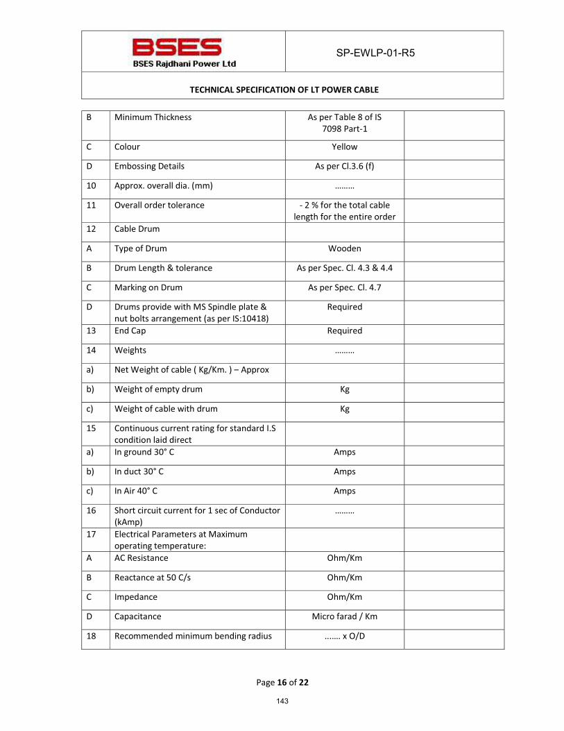
SP-EWLP-01-R5
TECHNICAL SPECIFICATION OF LT POWER CABLE
Page 16 of 22
B Minimum Thickness As per Table 8 of IS 7098 Part-1
C Colour Yellow D Embossing Details As per Cl.3.6 (f) 10 Approx. overall dia. (mm) ……… 11 Overall order tolerance - 2 % for the total cable
length for the entire order
12 Cable Drum A Type of Drum Wooden B Drum Length & tolerance As per Spec. Cl. 4.3 & 4.4 C Marking on Drum As per Spec. Cl. 4.7 D Drums provide with MS Spindle plate &
nut bolts arrangement (as per IS:10418) Required
13 End Cap Required 14 Weights ……… a) Net Weight of cable ( Kg/Km. ) – Approx b) Weight of empty drum Kg
c) Weight of cable with drum Kg 15 Continuous current rating for standard I.S
condition laid direct
a) In ground 30° C Amps b) In duct 30° C Amps c) In Air 40° C Amps 16 Short circuit current for 1 sec of Conductor
(kAmp) ………
17 Electrical Parameters at Maximum operating temperature:
A AC Resistance Ohm/Km
B Reactance at 50 C/s Ohm/Km C Impedance Ohm/Km D Capacitance Micro farad / Km
18 Recommended minimum bending radius ...…. x O/D
143
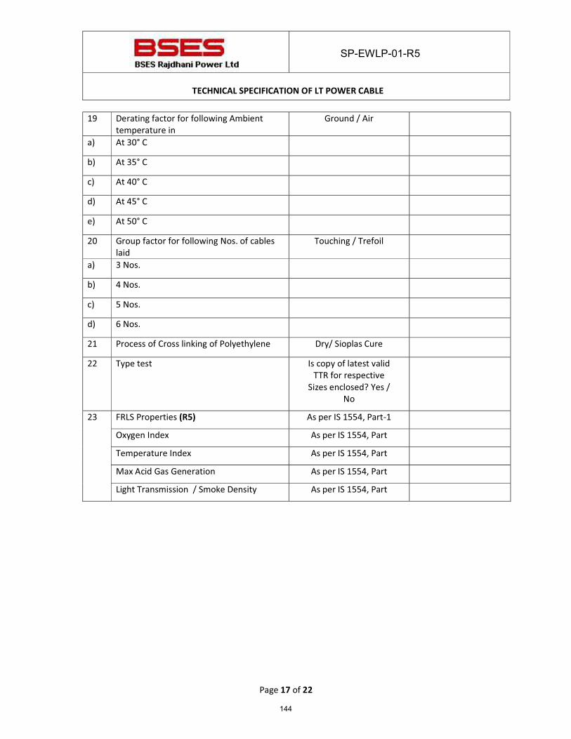
SP-EWLP-01-R5
TECHNICAL SPECIFICATION OF LT POWER CABLE
Page 17 of 22
19 Derating factor for following Ambient temperature in
Ground / Air
a) At 30° C b) At 35° C c) At 40° C d) At 45° C e) At 50° C 20 Group factor for following Nos. of cables
laid Touching / Trefoil
a) 3 Nos. b) 4 Nos.
c) 5 Nos. d) 6 Nos. 21 Process of Cross linking of Polyethylene Dry/ Sioplas Cure 22 Type test Is copy of latest valid
TTR for respective Sizes enclosed? Yes /
No
23 FRLS Properties (R5) As per IS 1554, Part-1
Oxygen Index As per IS 1554, Part
Temperature Index As per IS 1554, Part
Max Acid Gas Generation As per IS 1554, Part
Light Transmission / Smoke Density As per IS 1554, Part
144
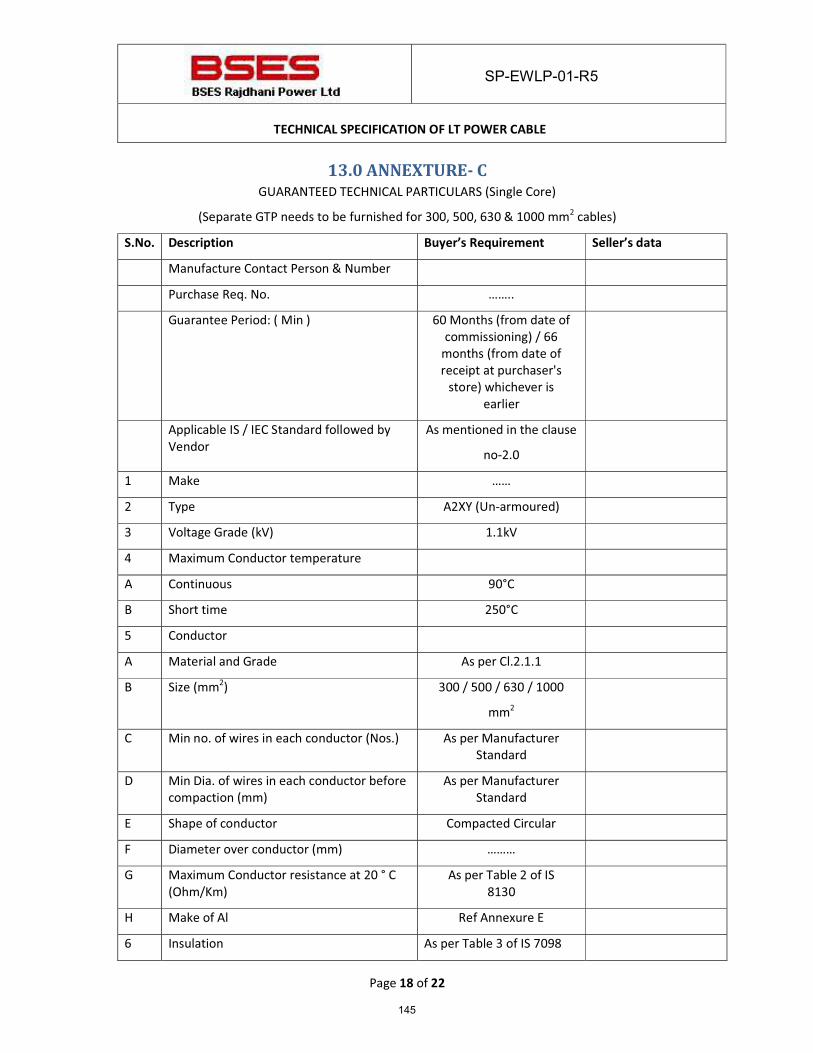
SP-EWLP-01-R5
TECHNICAL SPECIFICATION OF LT POWER CABLE
Page 18 of 22
13.0 ANNEXTURE- C GUARANTEED TECHNICAL PARTICULARS (Single Core)
(Separate GTP needs to be furnished for 300, 500, 630 & 1000 mm2 cables)
S.No. Description Buyer’s Requirement Seller’s data
Manufacture Contact Person & Number
Purchase Req. No. ……..
Guarantee Period: ( Min ) 60 Months (from date of commissioning) / 66
months (from date of receipt at purchaser's
store) whichever is earlier
Applicable IS / IEC Standard followed by Vendor
As mentioned in the clause
no-2.0
1 Make ……
2 Type A2XY (Un-armoured)
3 Voltage Grade (kV) 1.1kV
4 Maximum Conductor temperature
A Continuous 90°C
B Short time 250°C
5 Conductor
A Material and Grade As per Cl.2.1.1
B Size (mm2) 300 / 500 / 630 / 1000
mm2
C Min no. of wires in each conductor (Nos.) As per Manufacturer Standard
D Min Dia. of wires in each conductor before compaction (mm)
As per Manufacturer Standard
E Shape of conductor Compacted Circular
F Diameter over conductor (mm) ………
G Maximum Conductor resistance at 20 ° C (Ohm/Km)
As per Table 2 of IS 8130
H Make of Al Ref Annexure E
6 Insulation As per Table 3 of IS 7098
145
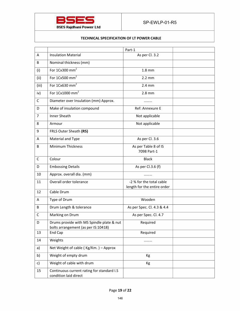
SP-EWLP-01-R5
TECHNICAL SPECIFICATION OF LT POWER CABLE
Page 19 of 22
Part-1 A Insulation Material As per Cl. 3.2
B Nominal thickness (mm)
(i) For 1Cx300 mm2 1.8 mm
(ii) For 1Cx500 mm2 2.2 mm
(iii) For 1Cx630 mm2 2.4 mm
iv) For 1Cx1000 mm2 2.8 mm
C Diameter over Insulation (mm) Approx. ………
D Make of insulation compound Ref: Annexure E
7 Inner Sheath Not applicable
8 Armour Not applicable
9 FRLS Outer Sheath (R5)
A Material and Type As per Cl. 3.6
B Minimum Thickness As per Table 8 of IS 7098 Part-1
C Colour Black
D Embossing Details As per Cl.3.6 (f)
10 Approx. overall dia. (mm) ………
11 Overall order tolerance -2 % for the total cable length for the entire order
12 Cable Drum
A Type of Drum Wooden
B Drum Length & tolerance As per Spec. Cl. 4.3 & 4.4
C Marking on Drum As per Spec. Cl. 4.7
D Drums provide with MS Spindle plate & nut bolts arrangement (as per IS:10418)
Required
13 End Cap Required
14 Weights ………
a) Net Weight of cable ( Kg/Km. ) – Approx
b) Weight of empty drum Kg
c) Weight of cable with drum Kg
15 Continuous current rating for standard I.S condition laid direct
146
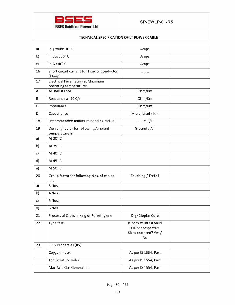
SP-EWLP-01-R5
TECHNICAL SPECIFICATION OF LT POWER CABLE
Page 20 of 22
a) In ground 30° C Amps
b) In duct 30° C Amps
c) In Air 40° C Amps
16 Short circuit current for 1 sec of Conductor (kAmp)
………
17 Electrical Parameters at Maximum operating temperature:
A AC Resistance Ohm/Km
B Reactance at 50 C/s Ohm/Km
C Impedance Ohm/Km
D Capacitance Micro farad / Km
18 Recommended minimum bending radius ...…. x O/D
19 Derating factor for following Ambient temperature in
Ground / Air
a) At 30° C
b) At 35° C
c) At 40° C
d) At 45° C
e) At 50° C
20 Group factor for following Nos. of cables laid
Touching / Trefoil
a) 3 Nos.
b) 4 Nos.
c) 5 Nos.
d) 6 Nos.
21 Process of Cross linking of Polyethylene Dry/ Sioplas Cure
22 Type test
Is copy of latest valid TTR for respective
Sizes enclosed? Yes / No
23 FRLS Properties (R5)
Oxygen Index As per IS 1554, Part
Temperature Index As per IS 1554, Part
Max Acid Gas Generation As per IS 1554, Part
147
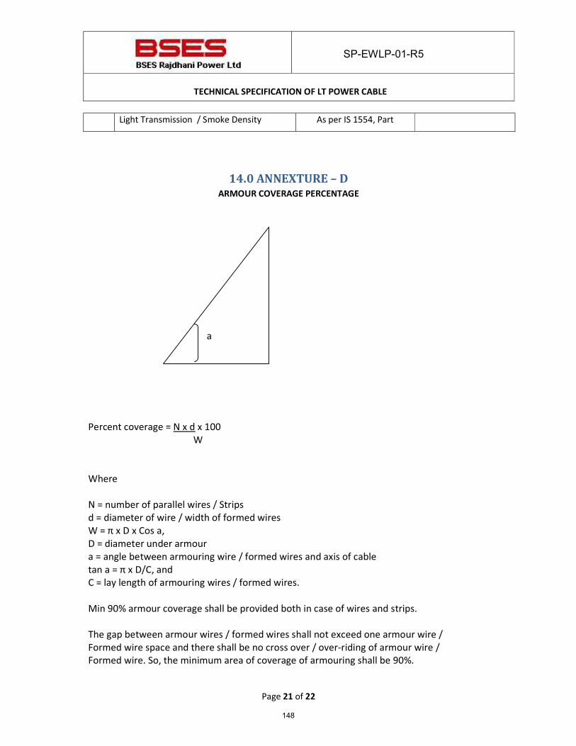
SP-EWLP-01-R5
TECHNICAL SPECIFICATION OF LT POWER CABLE
Page 21 of 22
Light Transmission / Smoke Density As per IS 1554, Part
14.0 ANNEXTURE – D ARMOUR COVERAGE PERCENTAGE
a
Percent coverage = N x d x 100
W Where N = number of parallel wires / Strips d = diameter of wire / width of formed wires W = π x D x Cos a, D = diameter under armour a = angle between armouring wire / formed wires and axis of cable tan a = π x D/C, and C = lay length of armouring wires / formed wires. Min 90% armour coverage shall be provided both in case of wires and strips. The gap between armour wires / formed wires shall not exceed one armour wire / Formed wire space and there shall be no cross over / over-riding of armour wire / Formed wire. So, the minimum area of coverage of armouring shall be 90%.
148
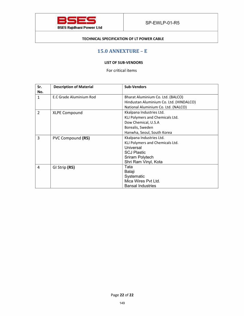
SP-EWLP-01-R5
TECHNICAL SPECIFICATION OF LT POWER CABLE
Page 22 of 22
15.0 ANNEXTURE – E
LIST OF SUB-VENDORS For critical items
Sr.
No. Description of Material Sub-Vendors
1 E.C Grade Aluminium Rod Bharat Aluminium Co. Ltd. (BALCO) Hindustan Aluminium Co. Ltd. (HINDALCO) National Aluminium Co. Ltd. (NALCO)
2 XLPE Compound Kkalpana Industries Ltd. KLJ Polymers and Chemicals Ltd. Dow Chemical, U.S.A Borealis, Sweden Hanwha, Seoul, South Korea
3 PVC Compound (R5) Kkalpana Industries Ltd. KLJ Polymers and Chemicals Ltd. Universal SCJ Plastic Sriram Polytech Shri Ram Vinyl, Kota
4 GI Strip (R5) Tata Balaji Systematic Mica Wires Pvt Ltd. Bansal Industries
149
SPECIFICATION OF
FRLS CONTROL CABLE
Specification no: SP-EWLP-01-R3
Prepared By Reviewed By Approved By Rev. No.
Date Name Sign. Name Sign. Name Sign.
HK MB KA 02 27.01.14
RP AT VP 03 13.03.18
150
SP-EWLP-01-R3
SPECIFICATION OF FRLS CONTROL CABLE
INDEX RECORD OF REVISION
1. General Specification…………………………………………………………………………………. 4 to 8
2. Annexure A: Scope & Project specific details…………………………………………….. 9
3. Annexure B: General Technical Particulars……………………………………………….. 10
151
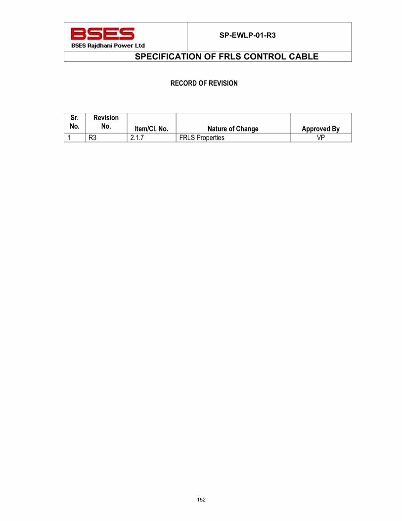
SP-EWLP-01-R3
SPECIFICATION OF FRLS CONTROL CABLE
RECORD OF REVISION
Sr. No.
Revision No. Item/Cl. No. Nature of Change Approved By
1 R3 2.1.7 FRLS Properties VP
152
SP-EWLP-01-R3
SPECIFICATION OF FRLS CONTROL CABLE
General Specification 1.0.0 Codes & Standards: The cables shall be designed, manufactured and tested in
accordance with the following Indian & IEC standards.
National Standards
Indian Standards IS- 1554 Part-1 PVC insulated Cables
IS- 5831 : 1984 PVC insulation & sheath of electric cables.
IS- 10810 : 1984 Methods of test for cables.
IS- 8130 : 1984 Conductors for insulated electric cables and flexible cords.
IS- 3975 : 1999 Mild steel wires, formed wires and tapes for armouring of cables.
International Standards IEC 60228 Ed.3.0 b Conductors of insulated cables.
IEC 60332-3-21 Ed.1.0 b Tests on electric cables under fire conditions. Part 3-21. Tests on
bunched wires or cables. IEC 60502-1 Ed. 2.1 b Power cables with extruded insulation and their accessories for rated
voltage from 1kV upto 30kV –Part 1: cables for rated voltages of 1kV and 3kV
IEC 60811
Common test methods for insulating and sheathing materials of electric cables.
IEC 60885 Ed.1.0 b Electric test methods for electric cables. IEC 60227
PVC insulated cables of rated voltages up to and including 450/750 V.
IEC 60028 Ed. 2.0 b International Standard of Resistance for Copper ASTMD 2843 Standard Test Method for density of Smoke from the burning or
decomposition of cables ASTM 2863 Standard Test Method for measuring of minimum oxygen concentration IEC 60754-1 Test on gases evolved during combustion of materials fro cables. Part
1 – Determination of the Halogen Acid gas Content
2.0.0 Cable construction Features Size & dimensions of each item mentioned under this
clause shall be followed as detailed out in GTP, refer Annexure B
153
SP-EWLP-01-R3
SPECIFICATION OF FRLS CONTROL CABLE
2.1.1 Conductor Stranded, plain copper, circular Shall be made from high conductivity copper rods
2.1.2 Insulation Extruded PVC Insulation Type A as per IS 5831 2.1.3 Core Identification Each core shall have different color of insulation. 2.1.4 Inner Sheath Extruded Inner Sheath of Black PVC type ST-2
as per IS 5831
2.1.5 Armour a) As per Cl 13.2 of IS 1554 Part-1: Galvanized steel
round wire armour. b) Minimum area of coverage of armouring shall be 90
%. 2.1.6 Outer Sheath a) Extruded outer sheath of PVC type ST-2 as per IS
5831 having FRLS properties b) Color : Black
c) The Outer Sheath shall be embossed with: � The voltage designation � Type of construction / cable code (for e.g.
AYWY) � Manufacturers Name or Trade mark � Number of Cores and nominal cross sectional
area of conductors � The drum progressive length of cable at every
meter. (By Printing) � Name of buyer i.e. BSES � Month & Year of Manufacturing � P.O. No. and P.O. Date 2.1.7 FRLS Properties a) Oxygen Index : Not less than 29% as per ASTM 2863 b) Temperature Index : 250 Deg C at Oxygen Index 21
(when tested as per ASTM D 2863) c) Max Acid Gas Generation – Not more than 20% as
per IEC -60754-1 d) Light Transmission - Minimum 40% when tested as
per ASTMD 2843 (Smoke Density rating shall be max 60%)
e) Flammability Test – As per IEC 60332-III, Cat – B, IEC 60332- I, IS- 10810 – Part 53, IS:10810 – Part 61 & 62 (Category A)
2.1.7 Sealing of Cable end Both ends of the cable shall be sealed with PVC Cap.
154
SP-EWLP-01-R3
SPECIFICATION OF FRLS CONTROL CABLE
3.0.0 Testing & Inspection Tests shall be carried out in accordance with IEC / IS
standards.
a) Routine Test: As per IS 1554 part -1 b) Type Test � Cables must be of type tested quality. Type test
reports shall be submitted for the type, size & rating of cable offered along with bid.
� If the manufacturer’s lab is accredited by govt. /authorised body then it shall be acceptable for type testing.
� Type test on one cable drum of each rating and type, from first lot, shall be conducted at Govt. approved / internationally accredited labs.
c) Acceptance test : Shall be conducted as per IS 1554
Part-1 for each lot of cable d) Inspection � The Buyer reserves the right to witness all tests
specified on completed cables
� The Buyer reserves the right to inspect cables at the Sellers works at any time prior to dispatch, to prove compliance with the specifications.
� In-process and final inspection call intimation shall be given in advance to purchaser.
e) Test certificates: Three sets of complete test certificates (routine & acceptance tests) need to be submitted along with the delivery of cables.
4.0.0 Drawing, Data & Manuals 4.0.1 To be submitted along with bid The seller has to submit: � Cross section drawing of cable � Completely filled GTP � Type test certificates � Complete cable catalogue and Manual along with the
bid. 4.0.2 After award of contract Within 15 days, the seller has to submit four sets of
above-mentioned drawings for buyer’s approval.
155
SP-EWLP-01-R3
SPECIFICATION OF FRLS CONTROL CABLE
4.0.3 Final As Built 6 sets hardcopy + One Soft copy of all documents including type test certificates
5.0.0 Drum Length & tolerance 500+ - 5% Mtr. 5.0.1 Overall tolerance in cable
Length - 2 % 5.0.2
Short length of cables � Minimum acceptable short length shall be above 100
Mtrs. Manufacturer shall be required to take prior approval from engineering for any short length supply.
� Manufacturer shall not be allowed to put two cable pieces of different short lengths in same cable drum.
� Only 1% of the total ordered quantity. 6.0.0 Packing, Shipping, Handling
& Storage a) Drum Identification Labels � Drum identification number � Cable voltage grade � Cable code (e.g. YWY) � Number of cores and cross sectional area � Cable quantity (Meters) � Purchase order number and SAP item code � Total weight of cable and drum number
� Manufacturer's & Buyer’s name � Month & Year of Manufacturing � Direction of rotation of drum � Cable length initial reading & end reading shall be
marked on drum. Cable starting end shall be taken out from winding to read this drum reading with proper sealing to protect against external damage.
b) Shipping information The seller shall give complete shipping information concerning the weight, size of each package.
c) Transit damage The seller shall be held responsible for all transit damage due to improper packing.
d) Type of Drum Wooden drums with anti termite treatment. (The drums shall be with M.S. spindle plate with nut-bolts)
7.0.0 Quality Assurance 7.0.1 Vendor quality plan To be submitted for purchaser approval 7.0.2 Inspection points To be mutually identified & agreed in quality plan 8.0.0 Progress reporting
156
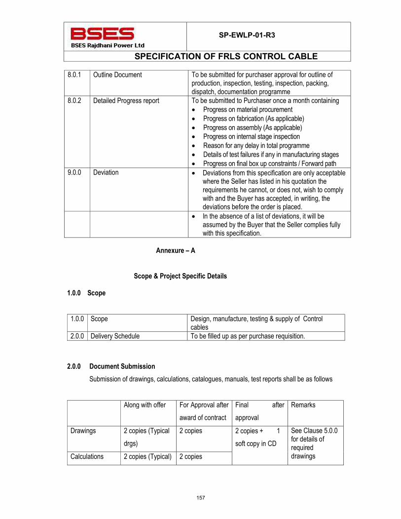
SP-EWLP-01-R3
SPECIFICATION OF FRLS CONTROL CABLE
8.0.1 Outline Document To be submitted for purchaser approval for outline of production, inspection, testing, inspection, packing, dispatch, documentation programme
8.0.2 Detailed Progress report To be submitted to Purchaser once a month containing � Progress on material procurement � Progress on fabrication (As applicable) � Progress on assembly (As applicable) � Progress on internal stage inspection � Reason for any delay in total programme � Details of test failures if any in manufacturing stages � Progress on final box up constraints / Forward path
9.0.0 Deviation � Deviations from this specification are only acceptable where the Seller has listed in his quotation the requirements he cannot, or does not, wish to comply with and the Buyer has accepted, in writing, the deviations before the order is placed.
� In the absence of a list of deviations, it will be assumed by the Buyer that the Seller complies fully with this specification.
Annexure – A
Scope & Project Specific Details
1.0.0 Scope
1.0.0 Scope Design, manufacture, testing & supply of Control
cables 2.0.0 Delivery Schedule To be filled up as per purchase requisition.
2.0.0 Document Submission
Submission of drawings, calculations, catalogues, manuals, test reports shall be as follows
Along with offer For Approval after
award of contract
Final after
approval
Remarks
Drawings 2 copies (Typical
drgs)
2 copies 2 copies + 1
soft copy in CD
See Clause 5.0.0 for details of required drawings Calculations 2 copies (Typical) 2 copies
157
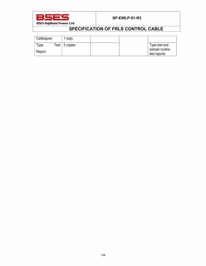
SP-EWLP-01-R3
SPECIFICATION OF FRLS CONTROL CABLE
Catalogues 1 copy
Type Test
Report
2 copies Type test and sample routine test reports
158
BSES Bhawan, Nehru Place, New Delhi- 19
Prepared by Javed Ahmed Rev: 0
Reviewed by AK AS Date: 28th Mar, 2017
Approved by VP
TECHNICAL SPECIFICATION
FOR
ILLUMINATION SYSTEM
159
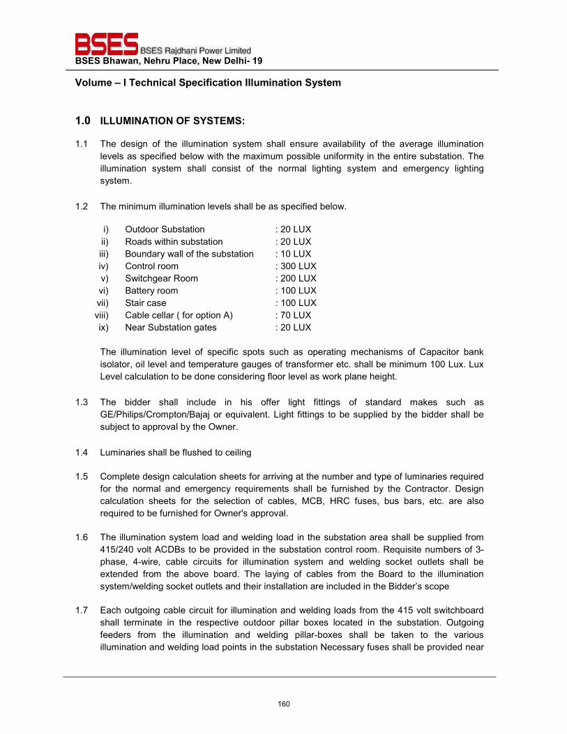
BSES Bhawan, Nehru Place, New Delhi- 19 Volume – I Technical Specification Illumination System
1.0 ILLUMINATION OF SYSTEMS:
1.1 The design of the illumination system shall ensure availability of the average illumination levels as specified below with the maximum possible uniformity in the entire substation. The illumination system shall consist of the normal lighting system and emergency lighting system.
1.2 The minimum illumination levels shall be as specified below. i) Outdoor Substation : 20 LUX ii) Roads within substation : 20 LUX iii) Boundary wall of the substation : 10 LUX iv) Control room : 300 LUX v) Switchgear Room : 200 LUX vi) Battery room : 100 LUX vii) Stair case : 100 LUX viii) Cable cellar ( for option A) : 70 LUX ix) Near Substation gates : 20 LUX
The illumination level of specific spots such as operating mechanisms of Capacitor bank isolator, oil level and temperature gauges of transformer etc. shall be minimum 100 Lux. Lux Level calculation to be done considering floor level as work plane height.
1.3 The bidder shall include in his offer light fittings of standard makes such as GE/Philips/Crompton/Bajaj or equivalent. Light fittings to be supplied by the bidder shall be subject to approval by the Owner.
1.4 Luminaries shall be flushed to ceiling
1.5 Complete design calculation sheets for arriving at the number and type of luminaries required for the normal and emergency requirements shall be furnished by the Contractor. Design calculation sheets for the selection of cables, MCB, HRC fuses, bus bars, etc. are also required to be furnished for Owner's approval.
1.6 The illumination system load and welding load in the substation area shall be supplied from
415/240 volt ACDBs to be provided in the substation control room. Requisite numbers of 3-phase, 4-wire, cable circuits for illumination system and welding socket outlets shall be extended from the above board. The laying of cables from the Board to the illumination system/welding socket outlets and their installation are included in the Bidder’s scope
1.7 Each outgoing cable circuit for illumination and welding loads from the 415 volt switchboard
shall terminate in the respective outdoor pillar boxes located in the substation. Outgoing feeders from the illumination and welding pillar-boxes shall be taken to the various illumination and welding load points in the substation Necessary fuses shall be provided near
160
BSES Bhawan, Nehru Place, New Delhi- 19 Volume – I Technical Specification Illumination System
light fixtures in the substation. 06 No’s Welding socket shall be provided in the substation, out of which 4 no’s shall be outdoor and two inside the control room building.
1.8 The emergency illumination load shall be supplied from the main emergency illumination
board located in the control room. Necessary cable circuits with appropriate fuses shall be provided by the Contractor for the supply system for emergency illumination load of the substation.
1.9 Complete manufacturer's literature/catalogues, performance curves, illumination distribution
curves, G.A. drawings, specification sheets, etc. as relevant in respect of all materials/equipment to be supplied shall be submitted by the Contractor.
1.10 Dome lights shall be provided at gates.
1.11 Redundancy shall be provided wherever single luminary is considered.
1.12 After completion of installation of the illumination system in the substation, the actual
illumination level at different locations shall be measured by the Contractor in the presence of Owner's authorized representative. If the average value of the measured illumination levels is found to fall short of the specified levels, the Contractor shall have to provide additional lighting fixtures so as to achieve the specified levels of illumination at no additional cost to the Owner. While measuring the illumination levels due allowance shall be made on account of maintenance factor. The specified lux levels shall be suitably increased to cover maintenance factor of 0.6 for outdoor areas.
1.13 Emergency DC lighting system shall be provided in the substation wherever required. The
emergency lighting shall be adequate for safe movement by the operating personnel in the substation in the event of failure of normal lighting system. A total 0f minimum 12 no’s individually controllable 60 watt lamps shall be provided in the substation.
2.0 DISTRIBUTION PILLARS FOR NORMAL ILLUMINATION SYSTEM
Distribution pillars of adequate dimensions shall be constructed from sheet steel having a thickness not less than 2 mm. The pillars shall be totally enclosed weather-proof, dustproof, vermin-proof, having hinged doors with locking arrangement and shall be capable of being mounted in the substation. The pillars suitable for cable entry at the bottom shall be designed for easy access of connections to terminals and inspection of equipment mounted therein. Each pillar shall accommodate the following i) One incoming, 4-pole (3 phase and neutral) isolating switch with cartridge fuses or
MCB of appropriate current rating ii) 3-phase and neutral bus bars of appropriate current rating iii) Single-pole earth leakage circuit breakers of suitable current ratings on all outgoing
circuits.
161
BSES Bhawan, Nehru Place, New Delhi- 19 Volume – I Technical Specification Illumination System
iv) Neutral links for all outgoing circuits v) Cable lugs, compression type cable glands, name plates, circuit numbers, earthing
lugs, etc. to make the pillar complete in all respects. vi) 20% spare outlets shall be provided for outgoing feeders. vii) Three (3) indicating lamps with fuses to indicate that supply is 'ON'.
Local junction boxes for emergency illumination in the substation shall be provided, as required
3.0 LIGHTING DISTRIBUTION BOARDS
The Lighting Distribution Boards shall consist of the followings: i) Metal-clad enclosure with minimum 2 mm CRCA sheets for load-bearing members and
1.6 mm for non load-bearing members suitably reinforced with structural. ii) 3-phase, 4-wire busbar system with high conductivity Aluminum busbars mounting on
FRP insulators having anti-tractive property with minimum 25 mm phase-to-phase and minimum 19 mm phase-to-earth clearances. The busbars shall be uniform throughout the length of the LDB and busbar joints shall be silver plated and covered with shrouds.
iii) The busbars shall be suitable for short-time current rating of 40KA for 1 Sec. iv) The busbar temperature rise shall not exceed 35 Deg.C over an ambient of 50 Deg.C. v) The degree of protection for the LDB shall be IP-54. vi) All cables shall enter from the bottom. vii) Three (3) Nos. indication lamps (Red, Yellow, Blue) shall be provided to indicate that
the incoming supply is available. Similarly, 3 Nos. indication lamps shall be provided to indicate that the busbar is energized.
viii) The LDBs shall be provided with a continuous busbar of 25 x 6 sq.mm (electrolytic copper) with suitable hardware for connection to the main grounding grid.
ix) The enclosure shall be painted externally with Shade No., 692 to IS:5 and internally with brilliant white of semi-glossy finish to IS:5.
4.0 MAIN EMERGENCY LIGHTING BOARD The Main Emergency Lighting Board shall consist of the following: i) Automatic changeover contactor ii) Voltage sensing relays. iii) Time delay relay. iv) Bus Bars v) Two pole/three pole rotary switches with HRC fuse for incoming and outgoing feeders vi) Test switch, push button type. vii) Indicating lamps, ac - Green, dc - Red. viii) Terminals for remote indication.
162
BSES Bhawan, Nehru Place, New Delhi- 19 Volume – I Technical Specification Illumination System
ix) Cable lugs, compression type cable glands, name-plates, circuit numbers, earthing lugs and remote indication wiring upto substation 415V a.c. control board, to make the board complete in all respects.
x) Change over DC lighting in case of black out. The main emergency lighting board shall have an automatic changeover switch to energize the dc lighting system in the event of AC power failure. It shall have voltage-sensing relays to perform the changeover automatically when AC voltage of any one phase falls below 70 percent of 240 volts and continues at that low level for more than 10 seconds. These shall changeover from DC to AC again when 70 percent of 240 volt is restored and this continues for 10 seconds. Local Emergency Lighting Pillar shall be identical in details to Lighting Distribution Pillar specified in above para except that it shall have two pole isolating switch fuse unit on the incoming side and only two busbars and shall be without neutral links.
5.0 LUMINARIES
5.1 Luminaries for use in normal and emergency illumination systems in the substation are suggested below. In case the bidder intends to use luminaries of different types, he shall clearly furnish the advantages and reasons for the proposed luminaries in his bid. All the luminaries shall be supplied complete with all accessories and lamps Sl. No. Area / Type of Illumination
System Types of fitting & Lamps
1 Indoor Fitting and fixtures suitable for LED Type lamps
2 Outdoor Fitting and fixtures suitable for LED Type lamps
3 Roads Fitting and fixtures suitable for LED Type lamps
4 Specific spots flood light Fitting and fixtures suitable for LED Type lamps
5.2 The flood light luminaries in the substation shall be fixed at suitable height on the substation
structures/ building, so as to provide the specified average illumination in the substation area without causing any glare to the operational/ maintenance staff working in the substation. While fixing the luminaries it shall be ensured that the stipulated electrical clearances are not violated. The Contractor shall supply and install suitable type of pole structures, required for installing the fittings for illuminating the roads, fence etc
163
BSES Bhawan, Nehru Place, New Delhi- 19 Volume – I Technical Specification Illumination System
6.0 WIRING All lighting fixtures and 5A convenience outlets shall be wired with 1.1 KV grade PVC insulated extra flexible, multi stranded, copper conductor cables of size not less than 2.5 sq.mm. For 15A heavy-duty outlets copper conductor cables of size not less than 6 sq. mm shall be used. The wiring shall consist of phase, neutral and ground. For grounding the lighting fixtures/convenience outlets etc.,2.5sqmm Green wire shall be used. The phase and neutral conductor shall be suitably colour coded. Supply shall be looped between the lighting fixtures of the same circuit by using junction boxes. For this purpose one (1) 100 mm x 100 mm square junction box shall be provided for each lighting fixture. For recessed lighting fixtures, supply shall be extended from the junction boxes to the fixtures by means of flexible conduits. While for stem-mounted/wall-mounted lighting fixtures the junction box shall be mounted below one of the mounting stems. For lighting branch circuits the nos. of lighting switches shall be decided keeping in mind the ease of control, as well as to limit the current to 2.5A per circuit. For convenience outlets, the bidder shall design the wiring scheme so as to limit 6 nos. of 5A outlets per branch circuit and two nos. of 15A outlets per branch circuit. All wiring materials such as terminals, crimping lugs, ferrules etc. shall also be provided by the Contractor. No section of the conduit shall be filled with more than 70% of its area. Any consumable material that is required for pulling the wires through conduit shall also be provided by the Contractor. Lighting fixtures coming in one area shall be evenly distributed between three phases so that tripping of one phase or two phases does not cause total loss of illumination in that area.
7.0 JUNCTION BOX / WALL BOX
100 mm x 100 mm junction boxes and wall boxes of standard size shall be provided. Wall boxes and junction boxes shall be made of sheet metal with a thickness of 14 gauge (minimum). Necessary conduit termination fittings such as bushings, locknuts etc. also be provided.
8.0 DEVIATIONS Deviation from this specification, if any, shall be clearly brought out in the offer. Unless owner explicitly accepts such deviations, it shall be considered that the offer fully complies with the specification.
164
165
BSES Bhawan, Nehru Place, New Delhi- 19
Volume – I Technical Specification for 11KV Indoor Switchgear
Page 2 of 17
RECORD OF REVISION
S. No
Revision no & Date Revision Clause No. Revision Details
1 R1 11.03.21 15.1.0 & 15.1.1 Sync check feature added in the
relays.
2 R1 11.03.21 15.1.0 – 15.1.4 Relays shall be directional
3 R1 11.03.21 26.1.19
Vacuum interrupter make mentioned. Schneider, Siemens, BEL, BHEL, ABB, CGL & L&T.
166
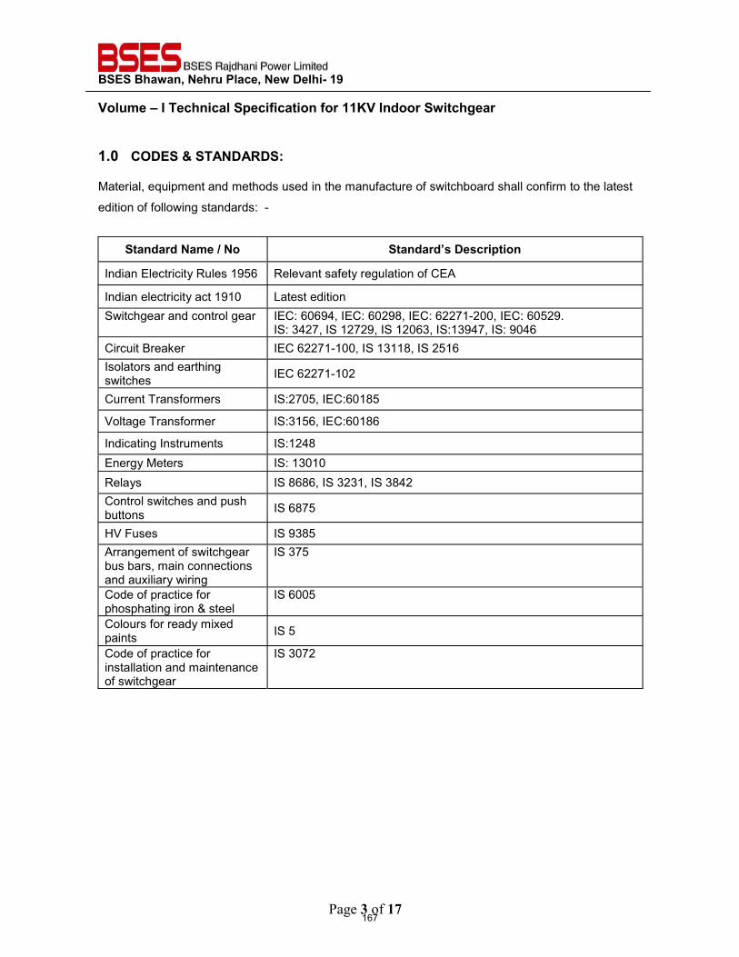
BSES Bhawan, Nehru Place, New Delhi- 19
Volume – I Technical Specification for 11KV Indoor Switchgear
Page 3 of 17
1.0 CODES & STANDARDS: Material, equipment and methods used in the manufacture of switchboard shall confirm to the latest
edition of following standards: -
Standard Name / No Standard’s Description
Indian Electricity Rules 1956 Relevant safety regulation of CEA
Indian electricity act 1910 Latest edition Switchgear and control gear IEC: 60694, IEC: 60298, IEC: 62271-200, IEC: 60529.
IS: 3427, IS 12729, IS 12063, IS:13947, IS: 9046 Circuit Breaker IEC 62271-100, IS 13118, IS 2516 Isolators and earthing switches IEC 62271-102
Current Transformers IS:2705, IEC:60185
Voltage Transformer IS:3156, IEC:60186
Indicating Instruments IS:1248 Energy Meters IS: 13010 Relays IS 8686, IS 3231, IS 3842 Control switches and push buttons IS 6875
HV Fuses IS 9385 Arrangement of switchgear bus bars, main connections and auxiliary wiring
IS 375
Code of practice for phosphating iron & steel
IS 6005
Colours for ready mixed paints IS 5
Code of practice for installation and maintenance of switchgear
IS 3072
167
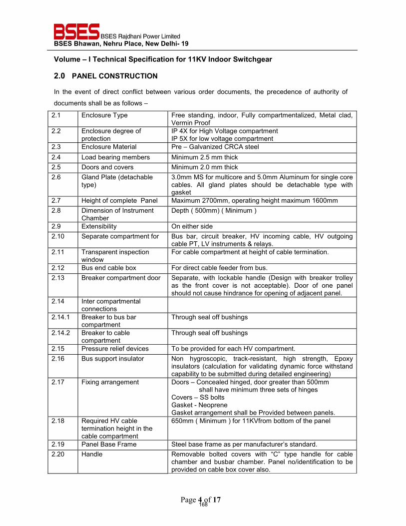
BSES Bhawan, Nehru Place, New Delhi- 19
Volume – I Technical Specification for 11KV Indoor Switchgear
Page 4 of 17
2.0 PANEL CONSTRUCTION
In the event of direct conflict between various order documents, the precedence of authority of
documents shall be as follows –
2.1 Enclosure Type Free standing, indoor, Fully compartmentalized, Metal clad, Vermin Proof
2.2 Enclosure degree of protection
IP 4X for High Voltage compartment IP 5X for low voltage compartment
2.3 Enclosure Material Pre – Galvanized CRCA steel 2.4 Load bearing members Minimum 2.5 mm thick 2.5 Doors and covers Minimum 2.0 mm thick 2.6 Gland Plate (detachable
type) 3.0mm MS for multicore and 5.0mm Aluminum for single core cables. All gland plates should be detachable type with gasket
2.7 Height of complete Panel Maximum 2700mm, operating height maximum 1600mm 2.8 Dimension of Instrument
Chamber Depth ( 500mm) ( Minimum )
2.9 Extensibility On either side 2.10 Separate compartment for Bus bar, circuit breaker, HV incoming cable, HV outgoing
cable PT, LV instruments & relays. 2.11 Transparent inspection
window For cable compartment at height of cable termination.
2.12 Bus end cable box For direct cable feeder from bus. 2.13 Breaker compartment door Separate, with lockable handle (Design with breaker trolley
as the front cover is not acceptable). Door of one panel should not cause hindrance for opening of adjacent panel.
2.14 Inter compartmental connections
2.14.1 Breaker to bus bar compartment
Through seal off bushings
2.14.2 Breaker to cable compartment
Through seal off bushings
2.15 Pressure relief devices To be provided for each HV compartment. 2.16 Bus support insulator Non hygroscopic, track-resistant, high strength, Epoxy
insulators (calculation for validating dynamic force withstand capability to be submitted during detailed engineering)
2.17 Fixing arrangement
Doors – Concealed hinged, door greater than 500mm shall have minimum three sets of hinges Covers – SS bolts Gasket - Neoprene Gasket arrangement shall be Provided between panels.
2.18 Required HV cable termination height in the cable compartment
650mm ( Minimum ) for 11KVfrom bottom of the panel
2.19 Panel Base Frame Steel base frame as per manufacturer’s standard. 2.20 Handle Removable bolted covers with “C” type handle for cable
chamber and busbar chamber. Panel no/identification to be provided on cable box cover also.
168
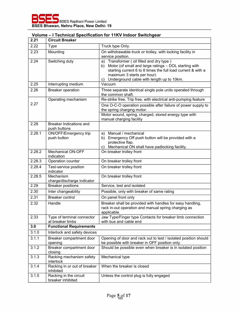
BSES Bhawan, Nehru Place, New Delhi- 19
Volume – I Technical Specification for 11KV Indoor Switchgear
Page 5 of 17
2.21 Circuit Breaker 2.22 Type Truck type Only. 2.23 Mounting On withdrawable truck or trolley, with locking facility in
service position. 2.24 Switching duty a) Transformer ( oil filled and dry type )
b) Motor (of small and large ratings – DOL starting with starting current 6 to 8 times the full load current & with a maximum 3 starts per hour)
c) Underground cable with length up to 10km. 2.25 Interrupting medium Vacuum 2.26 Breaker operation Three separate identical single pole units operated through
the common shaft. 2.27
Operating mechanism Re-strike free, Trip free, with electrical anti-pumping feature One O-C-O operation possible after failure of power supply to the spring charging motor. Motor wound, spring, charged, stored energy type with manual charging facility
2.28 Breaker Indications and push buttons
2.28.1 ON/OFF/Emergency trip push button
a) Manual / mechanical b) Emergency Off push button will be provided with a
protective flap. c) Mechanical ON shall have padlocking facility.
2.28.2 Mechanical ON-OFF indication
On breaker trolley front
2.28.3 Operation counter On breaker trolley front 2.28.4 Test-service position
indicator On breaker trolley front
2.28.5 Mechanism charge/discharge indicator
On breaker trolley front
2.29 Breaker positions Service, test and isolated 2.30 Inter changeability Possible, only with breaker of same rating 2.31 Breaker control On panel front only 2.32 Handle Breaker shall be provided with handles for easy handling,
rack in-out operation and manual spring charging as applicable.
2.33 Type of terminal connector at breaker limbs
Jaw Type/Finger type Contacts for breaker limb connection with bus and cable end
3.0 Functional Requirements 3.1.0 Interlock and safety devices 3.1.1 Breaker compartment door
opening Opening of door and rack out to test / isolated position should be possible with breaker in OFF position only.
3.1.2 Breaker compartment door closing
Should be possible even when breaker is in isolated position
3.1.3 Racking mechanism safety interlock
Mechanical type
3.1.4 Racking in or out of breaker inhibited
When the breaker is closed
3.1.5 Racking in the circuit breaker inhibited
Unless the control plug is fully engaged
169
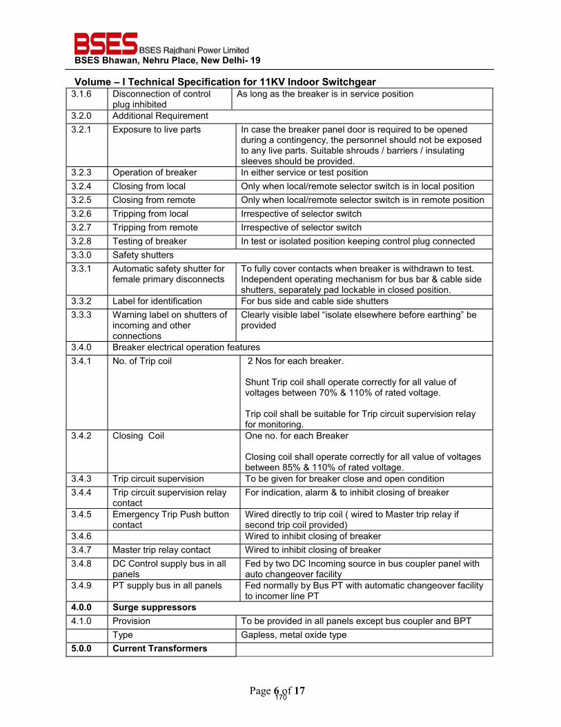
BSES Bhawan, Nehru Place, New Delhi- 19
Volume – I Technical Specification for 11KV Indoor Switchgear
Page 6 of 17
3.1.6 Disconnection of control plug inhibited
As long as the breaker is in service position
3.2.0 Additional Requirement 3.2.1 Exposure to live parts In case the breaker panel door is required to be opened
during a contingency, the personnel should not be exposed to any live parts. Suitable shrouds / barriers / insulating sleeves should be provided.
3.2.3 Operation of breaker In either service or test position 3.2.4 Closing from local Only when local/remote selector switch is in local position 3.2.5 Closing from remote Only when local/remote selector switch is in remote position 3.2.6 Tripping from local Irrespective of selector switch 3.2.7 Tripping from remote Irrespective of selector switch 3.2.8 Testing of breaker In test or isolated position keeping control plug connected 3.3.0 Safety shutters 3.3.1 Automatic safety shutter for
female primary disconnects To fully cover contacts when breaker is withdrawn to test. Independent operating mechanism for bus bar & cable side shutters, separately pad lockable in closed position.
3.3.2 Label for identification For bus side and cable side shutters 3.3.3 Warning label on shutters of
incoming and other connections
Clearly visible label “isolate elsewhere before earthing” be provided
3.4.0 Breaker electrical operation features 3.4.1 No. of Trip coil 2 Nos for each breaker.
Shunt Trip coil shall operate correctly for all value of voltages between 70% & 110% of rated voltage. Trip coil shall be suitable for Trip circuit supervision relay for monitoring.
3.4.2 Closing Coil One no. for each Breaker Closing coil shall operate correctly for all value of voltages between 85% & 110% of rated voltage.
3.4.3 Trip circuit supervision To be given for breaker close and open condition 3.4.4 Trip circuit supervision relay
contact For indication, alarm & to inhibit closing of breaker
3.4.5 Emergency Trip Push button contact
Wired directly to trip coil ( wired to Master trip relay if second trip coil provided)
3.4.6 Wired to inhibit closing of breaker 3.4.7 Master trip relay contact Wired to inhibit closing of breaker 3.4.8 DC Control supply bus in all
panels Fed by two DC Incoming source in bus coupler panel with auto changeover facility
3.4.9 PT supply bus in all panels Fed normally by Bus PT with automatic changeover facility to incomer line PT
4.0.0 Surge suppressors 4.1.0 Provision To be provided in all panels except bus coupler and BPT Type Gapless, metal oxide type 5.0.0 Current Transformers
170
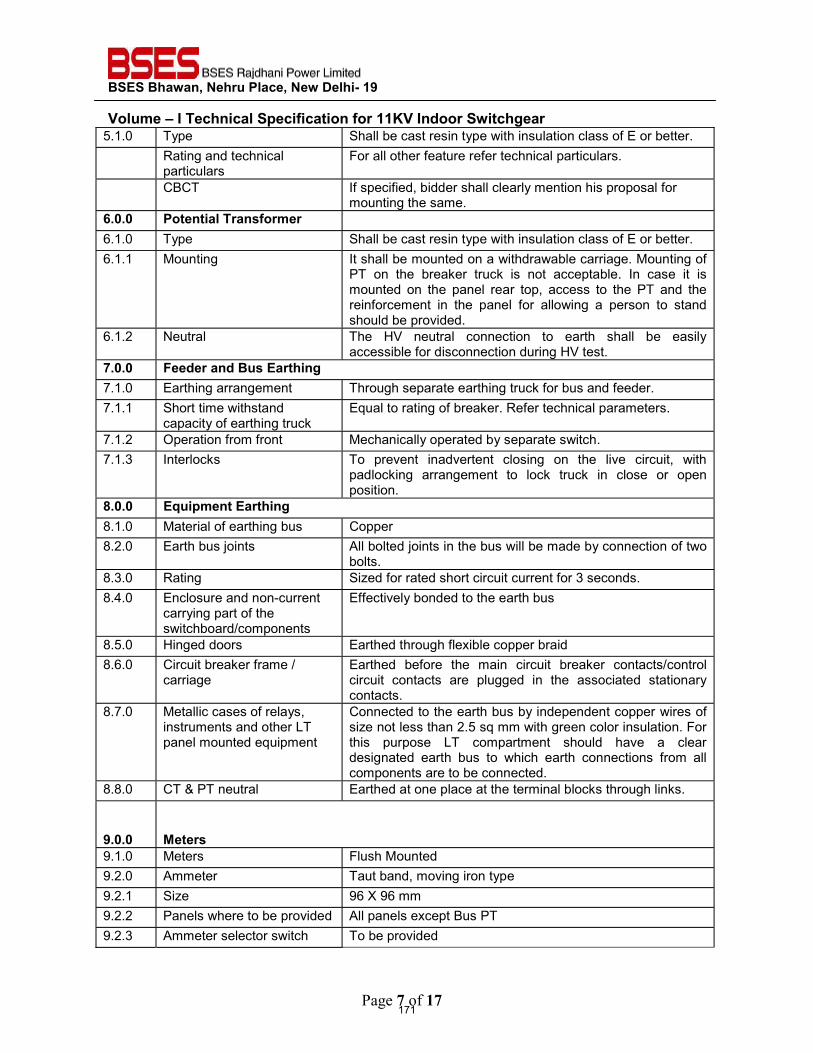
BSES Bhawan, Nehru Place, New Delhi- 19
Volume – I Technical Specification for 11KV Indoor Switchgear
Page 7 of 17
5.1.0 Type Shall be cast resin type with insulation class of E or better. Rating and technical
particulars For all other feature refer technical particulars.
CBCT If specified, bidder shall clearly mention his proposal for mounting the same.
6.0.0 Potential Transformer 6.1.0 Type Shall be cast resin type with insulation class of E or better. 6.1.1 Mounting It shall be mounted on a withdrawable carriage. Mounting of
PT on the breaker truck is not acceptable. In case it is mounted on the panel rear top, access to the PT and the reinforcement in the panel for allowing a person to stand should be provided.
6.1.2 Neutral The HV neutral connection to earth shall be easily accessible for disconnection during HV test.
7.0.0 Feeder and Bus Earthing 7.1.0 Earthing arrangement Through separate earthing truck for bus and feeder. 7.1.1 Short time withstand
capacity of earthing truck Equal to rating of breaker. Refer technical parameters.
7.1.2 Operation from front Mechanically operated by separate switch. 7.1.3 Interlocks To prevent inadvertent closing on the live circuit, with
padlocking arrangement to lock truck in close or open position.
8.0.0 Equipment Earthing 8.1.0 Material of earthing bus Copper 8.2.0 Earth bus joints All bolted joints in the bus will be made by connection of two
bolts. 8.3.0 Rating Sized for rated short circuit current for 3 seconds. 8.4.0 Enclosure and non-current
carrying part of the switchboard/components
Effectively bonded to the earth bus
8.5.0 Hinged doors Earthed through flexible copper braid 8.6.0 Circuit breaker frame /
carriage Earthed before the main circuit breaker contacts/control circuit contacts are plugged in the associated stationary contacts.
8.7.0 Metallic cases of relays, instruments and other LT panel mounted equipment
Connected to the earth bus by independent copper wires of size not less than 2.5 sq mm with green color insulation. For this purpose LT compartment should have a clear designated earth bus to which earth connections from all components are to be connected.
8.8.0 CT & PT neutral Earthed at one place at the terminal blocks through links.
9.0.0 Meters 9.1.0 Meters Flush Mounted 9.2.0 Ammeter Taut band, moving iron type 9.2.1 Size 96 X 96 mm 9.2.2 Panels where to be provided All panels except Bus PT 9.2.3 Ammeter selector switch To be provided
171
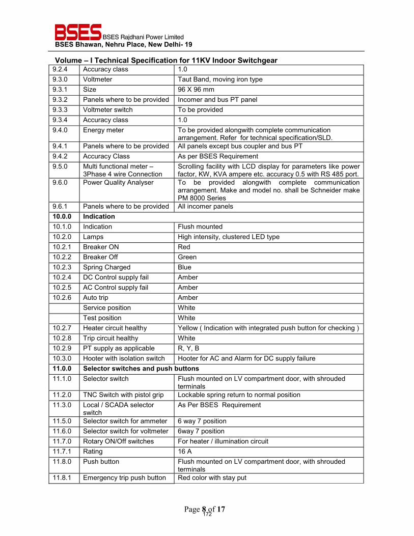
BSES Bhawan, Nehru Place, New Delhi- 19
Volume – I Technical Specification for 11KV Indoor Switchgear
Page 8 of 17
9.2.4 Accuracy class 1.0 9.3.0 Voltmeter Taut Band, moving iron type 9.3.1 Size 96 X 96 mm 9.3.2 Panels where to be provided Incomer and bus PT panel 9.3.3 Voltmeter switch To be provided 9.3.4 Accuracy class 1.0 9.4.0 Energy meter To be provided alongwith complete communication
arrangement. Refer for technical specification/SLD. 9.4.1 Panels where to be provided All panels except bus coupler and bus PT 9.4.2 Accuracy Class As per BSES Requirement 9.5.0 Multi functional meter –
3Phase 4 wire Connection Scrolling facility with LCD display for parameters like power factor, KW, KVA ampere etc. accuracy 0.5 with RS 485 port.
9.6.0 Power Quality Analyser To be provided alongwith complete communication arrangement. Make and model no. shall be Schneider make PM 8000 Series
9.6.1 Panels where to be provided All incomer panels 10.0.0 Indication10.1.0 Indication Flush mounted 10.2.0 Lamps High intensity, clustered LED type 10.2.1 Breaker ON Red 10.2.2 Breaker Off Green 10.2.3 Spring Charged Blue 10.2.4 DC Control supply fail Amber 10.2.5 AC Control supply fail Amber 10.2.6 Auto trip Amber Service position White Test position White 10.2.7 Heater circuit healthy Yellow ( Indication with integrated push button for checking ) 10.2.8 Trip circuit healthy White 10.2.9 PT supply as applicable R, Y, B 10.3.0 Hooter with isolation switch Hooter for AC and Alarm for DC supply failure 11.0.0 Selector switches and push buttons 11.1.0 Selector switch Flush mounted on LV compartment door, with shrouded
terminals 11.2.0 TNC Switch with pistol grip Lockable spring return to normal position 11.3.0 Local / SCADA selector
switch As Per BSES Requirement
11.5.0 Selector switch for ammeter 6 way 7 position 11.6.0 Selector switch for voltmeter 6way 7 position 11.7.0 Rotary ON/Off switches For heater / illumination circuit 11.7.1 Rating 16 A 11.8.0 Push button Flush mounted on LV compartment door, with shrouded
terminals 11.8.1 Emergency trip push button Red color with stay put
172
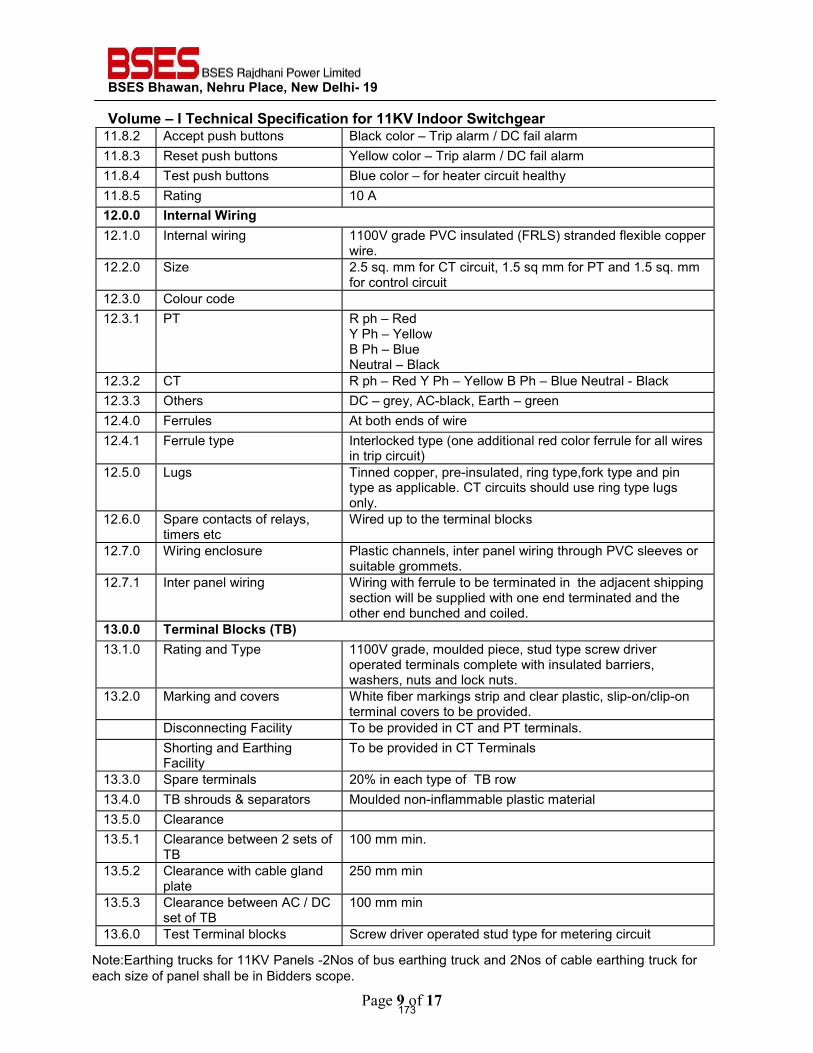
BSES Bhawan, Nehru Place, New Delhi- 19
Volume – I Technical Specification for 11KV Indoor Switchgear
Page 9 of 17
11.8.2 Accept push buttons Black color – Trip alarm / DC fail alarm 11.8.3 Reset push buttons Yellow color – Trip alarm / DC fail alarm 11.8.4 Test push buttons Blue color – for heater circuit healthy 11.8.5 Rating 10 A 12.0.0 Internal Wiring 12.1.0 Internal wiring 1100V grade PVC insulated (FRLS) stranded flexible copper
wire. 12.2.0 Size 2.5 sq. mm for CT circuit, 1.5 sq mm for PT and 1.5 sq. mm
for control circuit 12.3.0 Colour code 12.3.1 PT R ph – Red
Y Ph – Yellow B Ph – Blue Neutral – Black
12.3.2 CT R ph – Red Y Ph – Yellow B Ph – Blue Neutral - Black 12.3.3 Others DC – grey, AC-black, Earth – green 12.4.0 Ferrules At both ends of wire 12.4.1 Ferrule type Interlocked type (one additional red color ferrule for all wires
in trip circuit) 12.5.0 Lugs Tinned copper, pre-insulated, ring type,fork type and pin
type as applicable. CT circuits should use ring type lugs only.
12.6.0 Spare contacts of relays, timers etc
Wired up to the terminal blocks
12.7.0 Wiring enclosure Plastic channels, inter panel wiring through PVC sleeves or suitable grommets.
12.7.1 Inter panel wiring Wiring with ferrule to be terminated in the adjacent shipping section will be supplied with one end terminated and the other end bunched and coiled.
13.0.0 Terminal Blocks (TB) 13.1.0 Rating and Type 1100V grade, moulded piece, stud type screw driver
operated terminals complete with insulated barriers, washers, nuts and lock nuts.
13.2.0 Marking and covers White fiber markings strip and clear plastic, slip-on/clip-on terminal covers to be provided.
Disconnecting Facility To be provided in CT and PT terminals. Shorting and Earthing
Facility To be provided in CT Terminals
13.3.0 Spare terminals 20% in each type of TB row 13.4.0 TB shrouds & separators Moulded non-inflammable plastic material 13.5.0 Clearance 13.5.1 Clearance between 2 sets of
TB 100 mm min.
13.5.2 Clearance with cable gland plate
250 mm min
13.5.3 Clearance between AC / DC set of TB
100 mm min
13.6.0 Test Terminal blocks Screw driver operated stud type for metering circuit
173
Note:Earthing trucks for 11KV Panels -2Nos of bus earthing truck and 2Nos of cable earthing truck for each size of panel shall be in Bidders scope.
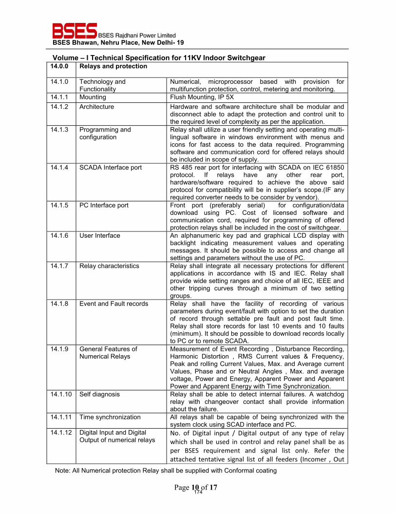
BSES Bhawan, Nehru Place, New Delhi- 19
Volume – I Technical Specification for 11KV Indoor Switchgear
Page 10 of 17
14.0.0 Relays and protection
14.1.0 Technology and Functionality
Numerical, microprocessor based with provision for multifunction protection, control, metering and monitoring.
14.1.1 Mounting Flush Mounting, IP 5X 14.1.2 Architecture Hardware and software architecture shall be modular and
disconnect able to adapt the protection and control unit to the required level of complexity as per the application.
14.1.3 Programming and configuration
Relay shall utilize a user friendly setting and operating multi-lingual software in windows environment with menus and icons for fast access to the data required. Programming software and communication cord for offered relays should be included in scope of supply.
14.1.4 SCADA Interface port RS 485 rear port for interfacing with SCADA on IEC 61850 protocol. If relays have any other rear port, hardware/software required to achieve the above said protocol for compatibility will be in supplier’s scope.(IF any required converter needs to be consider by vendor).
14.1.5 PC Interface port Front port (preferably serial) for configuration/data download using PC. Cost of licensed software and communication cord, required for programming of offered protection relays shall be included in the cost of switchgear.
14.1.6 User Interface An alphanumeric key pad and graphical LCD display with backlight indicating measurement values and operating messages. It should be possible to access and change all settings and parameters without the use of PC.
14.1.7 Relay characteristics Relay shall integrate all necessary protections for different applications in accordance with IS and IEC. Relay shall provide wide setting ranges and choice of all IEC, IEEE and other tripping curves through a minimum of two setting groups.
14.1.8 Event and Fault records Relay shall have the facility of recording of various parameters during event/fault with option to set the duration of record through settable pre fault and post fault time. Relay shall store records for last 10 events and 10 faults (minimum). It should be possible to download records locally to PC or to remote SCADA.
14.1.9 General Features of Numerical Relays
Measurement of Event Recording , Disturbance Recording, Harmonic Distortion , RMS Current values & Frequency, Peak and rolling Current Values, Max. and Average current Values, Phase and or Neutral Angles , Max. and average voltage, Power and Energy, Apparent Power and Apparent Power and Apparent Energy with Time Synchronization.
14.1.10 Self diagnosis Relay shall be able to detect internal failures. A watchdog relay with changeover contact shall provide information about the failure.
14.1.11 Time synchronization All relays shall be capable of being synchronized with the system clock using SCAD interface and PC.
14.1.12 Digital Input and Digital Output of numerical relays
No. of Digital input / Digital output of any type of relay which shall be used in control and relay panel shall be as per BSES requirement and signal list only. Refer the attached tentative signal list of all feeders (Incomer , Out
174
Note: All Numerical protection Relay shall be supplied with Conformal coating
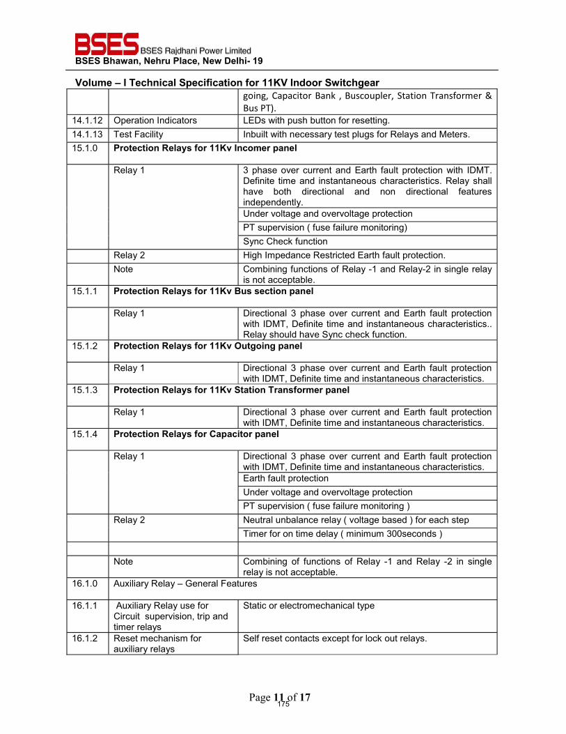
BSES Bhawan, Nehru Place, New Delhi- 19
Volume – I Technical Specification for 11KV Indoor Switchgear
Page 11 of 17
going, Capacitor Bank , Buscoupler, Station Transformer & Bus PT).
14.1.12 Operation Indicators LEDs with push button for resetting. 14.1.13 Test Facility Inbuilt with necessary test plugs for Relays and Meters. 15.1.0 Protection Relays for 11Kv Incomer panel
Relay 1 3 phase over current and Earth fault protection with IDMT. Definite time and instantaneous characteristics. Relay shall have both directional and non directional features independently. Under voltage and overvoltage protection PT supervision ( fuse failure monitoring) Sync Check function
Relay 2 High Impedance Restricted Earth fault protection. Note Combining functions of Relay -1 and Relay-2 in single relay
is not acceptable. 15.1.1 Protection Relays for 11Kv Bus section panel
Relay 1 Directional 3 phase over current and Earth fault protection with IDMT, Definite time and instantaneous characteristics.. Relay should have Sync check function.
15.1.2 Protection Relays for 11Kv Outgoing panel
Relay 1 Directional 3 phase over current and Earth fault protection with IDMT, Definite time and instantaneous characteristics.
15.1.3 Protection Relays for 11Kv Station Transformer panel
Relay 1 Directional 3 phase over current and Earth fault protection with IDMT, Definite time and instantaneous characteristics.
15.1.4 Protection Relays for Capacitor panel
Relay 1 Directional 3 phase over current and Earth fault protection with IDMT, Definite time and instantaneous characteristics. Earth fault protection Under voltage and overvoltage protection PT supervision ( fuse failure monitoring )
Relay 2 Neutral unbalance relay ( voltage based ) for each step Timer for on time delay ( minimum 300seconds )
Note Combining of functions of Relay -1 and Relay -2 in single
relay is not acceptable. 16.1.0 Auxiliary Relay – General Features
16.1.1 Auxiliary Relay use for
Circuit supervision, trip and timer relays
Static or electromechanical type
16.1.2 Reset mechanism for auxiliary relays
Self reset contacts except for lock out relays.
175
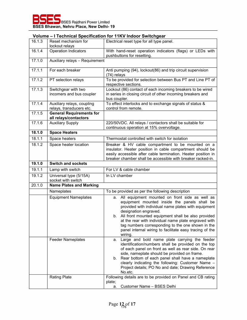
BSES Bhawan, Nehru Place, New Delhi- 19
Volume – I Technical Specification for 11KV Indoor Switchgear
Page 12 of 17
16.1.3 Reset mechanism for lockout relays
Electrical reset type for all type panel.
16.1.4 Operation Indicators With hand-reset operation indicators (flags) or LEDs with pushbuttons for resetting.
17.1.0 Auxiliary relays – Requirement
17.1.1 For each breaker Anti pumping (94), lockout(86) and trip circuit supervision (74) relays
17.1.2 PT selection relays To be provided for selection between Bus PT and Line PT of respective sections.
17.1.3 Switchgear with two incomers and bus coupler
Lockout (86) contact of each incoming breakers to be wired in series in closing circuit of other incoming breakers and bus coupler.
17.1.4 Auxiliary relays, coupling relays, transducers etc.
To effect interlocks and to exchange signals of status & control from remote.
17.1.5 General Requirements for all relays/contactors
17.1.6 Auxiliary Supply 220/50VDC. All relays / contactors shall be suitable for continuous operation at 15% overvoltage.
18.1.0 Space Heaters 18.1.1 Space heaters Thermostat controlled with switch for isolation 18.1.2 Space heater location Breaker & HV cable compartment to be mounted on a
insulator. Heater position in cable compartment should be easily accessible after cable termination. Heater position in breaker chamber shall be accessible with breaker racked-in.
19.1.0 Switch and sockets 19.1.1 Lamp with switch For LV & cable chamber 19.1.2 Universal type (5/15A)
socket with switch In LV chamber
20.1.0 Name Plates and Marking Nameplates To be provided as per the following description Equipment Nameplates a. All equipment mounted on front side as well as
equipment mounted inside the panels shall be provided with individual name plates with equipment designation engraved.
b. All front mounted equipment shall be also provided at the rear with individual name plate engraved with tag numbers corresponding to the one shown in the panel internal wiring to facilitate easy tracing of the wiring.
Feeder Nameplates a. Large and bold name plate carrying the feeder identification/numbers shall be provided on the top of each panel on front as well as rear side. On rear side, nameplate should be provided on frame.
b. Rear bottom of each panel shall have a nameplate clearly indicating the following: Customer Name – Project details; PO No and date; Drawing Reference No.etc.
Rating Plate Following details are to be provided on Panel and CB rating plate;
a. Customer Name – BSES Delhi
176
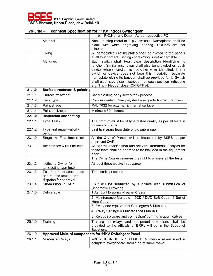
BSES Bhawan, Nehru Place, New Delhi- 19
Volume – I Technical Specification for 11KV Indoor Switchgear
Page 13 of 17
b. P.O.No. and Date – As per respective PO. Material Non – rusting metal or 3 ply lamicoid. Nameplates shall be
black with white engraving lettering. Stickers are not allowed.
Fixing All nameplates / rating plates shall be riveted to the panels at all four corners. Bolting / screw2ing is not acceptable.
Markings Each switch shall bear clear description identifying its function. Similar inscription shall also be provided on each device whose function is not other wise identified. If any switch or device does not bear this inscription separate nameplate giving its function shall be provided for it. Switch shall also have clear inscription for each position indicating e.g. Trip – Neutral close, ON-OFF etc.
21.1.0 Surface treatment & painting 21.1.1 Surface treatment Sand blasting or by seven tank process 21.1.2 Paint type Powder coated. Pure polyster base grade A structure finish 21.1.3 Paint shade RAL 7032 for external & internal surface 21.1.4 Paint thickness Minimum 50 microns 22.1.0 Inspection and testing 22.1.1 Type Tests The product must be of type tested quality as per all tests in
Indian standards 22.1.2 Type test report validity
period Last five years from date of bid submission
23.1.0 Stage and Final Inspection All the Qty. of Panels will be inspected by BSES as per approved QAP.
23.1.1 Acceptance & routine test As per the specification and relevant standards. Charges for these tests shall be deemed to be included in the equipment price.
The Owner/owner reserves the right to witness all the tests. 23.1.2 Notice to Owner for
conducting type tests. At least three weeks in advance.
23.1.3 Test reports of acceptance and routine tests before dispatch for approval
To submit six copies
23.1.4 Submission Of QAP QAP will be submitted by suppliers with submission of Schematic Drawings.
24.1.0 Deliverable 1.As Built Drawing of panel 6 Sets 2. Maintenance Manuals – 2CD / DVD Soft Copy , 6 Set of Hard Copy 3. Relay and equipments Catalogues & Manuals 4. Relay Settings & Maintenance Manuals 5. Relays software and connection/ communication cables
25.1.0 Training Training on relays and equipment operations shall be provided to the officials of BRPL will be in the Scope of Suppliers.
26.1.0 Approved Make of components for 11KV Switchgear Panel26.1.1 Numerical Relays ABB / SCHNEIDER / SIEMENS Numerical relays used in
complete switchboard should be of same make.
177
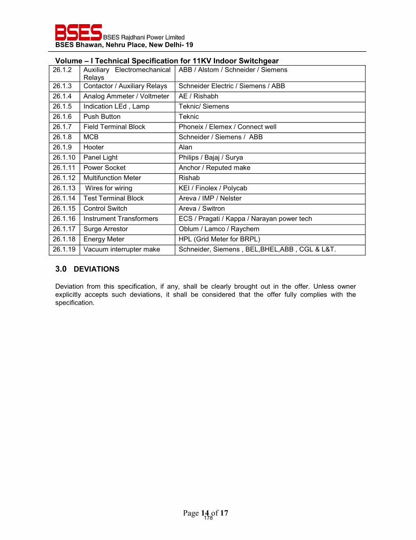
BSES Bhawan, Nehru Place, New Delhi- 19
Volume – I Technical Specification for 11KV Indoor Switchgear
Page 14 of 17
26.1.2 Auxiliary Electromechanical Relays
ABB / Alstom / Schneider / Siemens
26.1.3 Contactor / Auxiliary Relays Schneider Electric / Siemens / ABB 26.1.4 Analog Ammeter / Voltmeter AE / Rishabh 26.1.5 Indication LEd , Lamp Teknic/ Siemens 26.1.6 Push Button Teknic 26.1.7 Field Terminal Block Phoneix / Elemex / Connect well 26.1.8 MCB Schneider / Siemens / ABB 26.1.9 Hooter Alan 26.1.10 Panel Light Philips / Bajaj / Surya 26.1.11 Power Socket Anchor / Reputed make 26.1.12 Multifunction Meter Rishab 26.1.13 Wires for wiring KEI / Finolex / Polycab 26.1.14 Test Terminal Block Areva / IMP / Nelster 26.1.15 Control Switch Areva / Switron 26.1.16 Instrument Transformers ECS / Pragati / Kappa / Narayan power tech 26.1.17 Surge Arrestor Oblum / Lamco / Raychem 26.1.18 Energy Meter HPL (Grid Meter for BRPL) 26.1.19 Vacuum interrupter make Schneider, Siemens , BEL,BHEL,ABB , CGL & L&T.
3.0 DEVIATIONS
Deviation from this specification, if any, shall be clearly brought out in the offer. Unless owner explicitly accepts such deviations, it shall be considered that the offer fully complies with the specification.
178
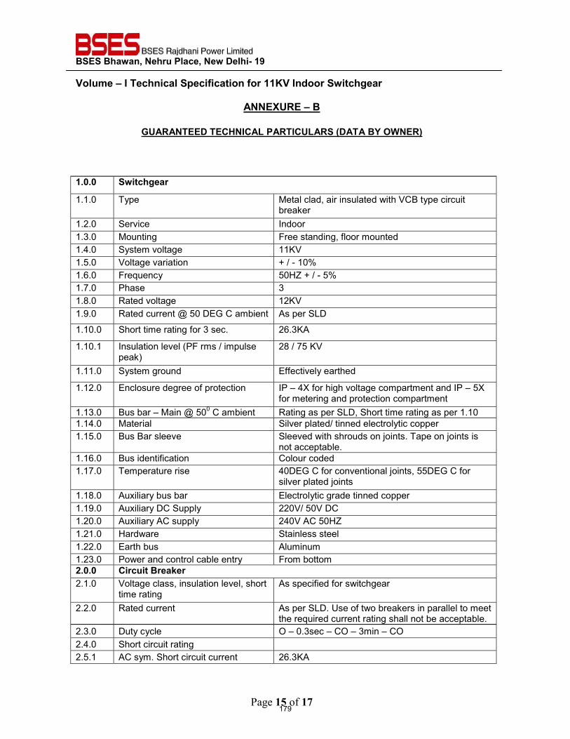
BSES Bhawan, Nehru Place, New Delhi- 19
Volume – I Technical Specification for 11KV Indoor Switchgear
Page 15 of 17
ANNEXURE – B
GUARANTEED TECHNICAL PARTICULARS (DATA BY OWNER)
1.0.0 Switchgear
1.1.0 Type Metal clad, air insulated with VCB type circuit breaker
1.2.0 Service Indoor 1.3.0 Mounting Free standing, floor mounted 1.4.0 System voltage 11KV 1.5.0 Voltage variation + / - 10% 1.6.0 Frequency 50HZ + / - 5% 1.7.0 Phase 3 1.8.0 Rated voltage 12KV 1.9.0 Rated current @ 50 DEG C ambient As per SLD
1.10.0 Short time rating for 3 sec. 26.3KA
1.10.1 Insulation level (PF rms / impulse peak)
28 / 75 KV
1.11.0 System ground Effectively earthed
1.12.0 Enclosure degree of protection IP – 4X for high voltage compartment and IP – 5X for metering and protection compartment
1.13.0 Bus bar – Main @ 500 C ambient Rating as per SLD, Short time rating as per 1.10 1.14.0 Material Silver plated/ tinned electrolytic copper 1.15.0 Bus Bar sleeve Sleeved with shrouds on joints. Tape on joints is
not acceptable. 1.16.0 Bus identification Colour coded 1.17.0 Temperature rise 40DEG C for conventional joints, 55DEG C for
silver plated joints 1.18.0 Auxiliary bus bar Electrolytic grade tinned copper 1.19.0 Auxiliary DC Supply 220V/ 50V DC 1.20.0 Auxiliary AC supply 240V AC 50HZ 1.21.0 Hardware Stainless steel 1.22.0 Earth bus Aluminum 1.23.0 Power and control cable entry From bottom 2.0.0 Circuit Breaker 2.1.0 Voltage class, insulation level, short
time rating As specified for switchgear
2.2.0 Rated current As per SLD. Use of two breakers in parallel to meet the required current rating shall not be acceptable.
2.3.0 Duty cycle O – 0.3sec – CO – 3min – CO 2.4.0 Short circuit rating 2.5.1 AC sym. Short circuit current 26.3KA
179
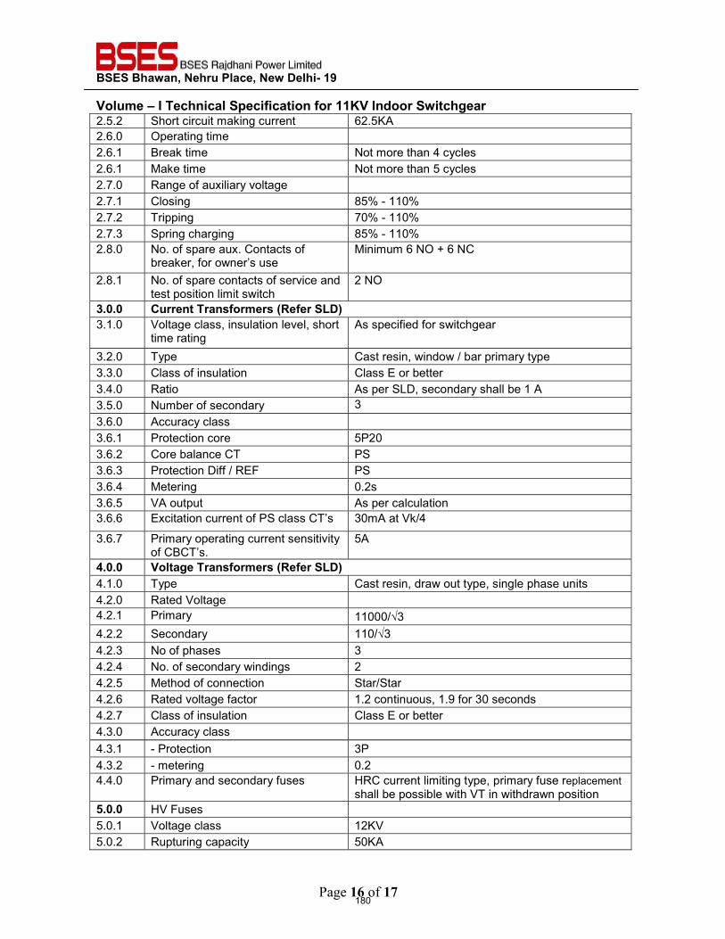
BSES Bhawan, Nehru Place, New Delhi- 19
Volume – I Technical Specification for 11KV Indoor Switchgear
Page 16 of 17
2.5.2 Short circuit making current 62.5KA 2.6.0 Operating time 2.6.1 Break time Not more than 4 cycles 2.6.1 Make time Not more than 5 cycles 2.7.0 Range of auxiliary voltage 2.7.1 Closing 85% - 110% 2.7.2 Tripping 70% - 110% 2.7.3 Spring charging 85% - 110% 2.8.0 No. of spare aux. Contacts of
breaker, for owner’s use Minimum 6 NO + 6 NC
2.8.1 No. of spare contacts of service and test position limit switch
2 NO
3.0.0 Current Transformers (Refer SLD)3.1.0 Voltage class, insulation level, short
time rating As specified for switchgear
3.2.0 Type Cast resin, window / bar primary type 3.3.0 Class of insulation Class E or better 3.4.0 Ratio As per SLD, secondary shall be 1 A 3.5.0 Number of secondary 3 3.6.0 Accuracy class 3.6.1 Protection core 5P20 3.6.2 Core balance CT PS 3.6.3 Protection Diff / REF PS 3.6.4 Metering 0.2s 3.6.5 VA output As per calculation 3.6.6 Excitation current of PS class CT’s 30mA at Vk/4
3.6.7 Primary operating current sensitivity of CBCT’s.
5A
4.0.0 Voltage Transformers (Refer SLD)4.1.0 Type Cast resin, draw out type, single phase units 4.2.0 Rated Voltage 4.2.1 Primary 11000/√3 4.2.2 Secondary 110/√3 4.2.3 No of phases 3 4.2.4 No. of secondary windings 2 4.2.5 Method of connection Star/Star 4.2.6 Rated voltage factor 1.2 continuous, 1.9 for 30 seconds 4.2.7 Class of insulation Class E or better 4.3.0 Accuracy class 4.3.1 - Protection 3P 4.3.2 - metering 0.2 4.4.0 Primary and secondary fuses HRC current limiting type, primary fuse replacement
shall be possible with VT in withdrawn position 5.0.0 HV Fuses 5.0.1 Voltage class 12KV 5.0.2 Rupturing capacity 50KA
180
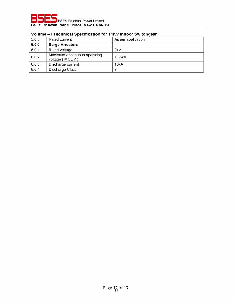
BSES Bhawan, Nehru Place, New Delhi- 19
Volume – I Technical Specification for 11KV Indoor Switchgear
Page 17 of 17
5.0.3 Rated current As per application 6.0.0 Surge Arrestors 6.0.1 Rated voltage 9kV
6.0.2 Maximum continuous operating voltage ( MCOV ) 7.65kV
6.0.3 Discharge current 10kA 6.0.4 Discharge Class 3
181
BSES Bhawan, Nehru Place, New Delhi- 19
Prepared by Javed Ahmed Rev: 1
Reviewed by Abhinav Srivastava Date: 12th June 2018
Approved by K.Sheshadri
TECHNICAL SPECIFICATION
FOR
CABLE INSTALLATION & ACCESSORIES
182
BSES Bhawan, Nehru Place, New Delhi- 19 Technical Specification for Cable Installation and Accessories
1.0 INSTALLATION OF CABLES:
1.1 The cable shall be laid as per IS 1255. The Contractor shall prepare cable schedules for all the cable circuits associated with the equipment in the substation showing length, size and routing of each cable which shall be given suitable code numbers and submit the same for Owner’s/Engineer’s information/approval. Cable and Conduit laying shall be done strictly in accordance with the cable schedules.
1.2 The control and power cables shall be laid in conduits, concrete pipes, ducts, trays or cable trenches unless indicated otherwise. The power and control cables shall be laid in different trays. Cables shall be cleated to the cable tray after properly dressing.
1.3 Ducts shall be provided wherever cable trenches cross roads with provision of one spare duct
for future use.
1.4 All civil works, viz, excavations, sand cover, providing brick cover on directly laid cables, construction of foundations, trenches with cable tray supports, cable ducts under roads, back filling, finishing associated with cabling work shall be duly completed.
1.5 The Contractor shall supply and install all the surface mounted/ embedded rigid and flexible
conduits, their connections, and associated clamps, bushings, lock-nuts, caps etc required in the cabling work.
1.6 All conduits and their accessories shall be made of galvanized heavy gauge steel as per BIS
Specification. The internal bore of all pipes shall be smooth and suitable for pulling PVC sheathed cables without damage.
1.7 The Contractor shall supply all fittings including ordinary tees and elbows, check nuts, male
and female fittings pull boxes, junction boxes, conduit outlets, outlet boxes, splice boxes, terminal boxes, gaskets and box covers, saddles and all supporting steel work and all such arrangements which are required to complete the conduit installations.
1.8 Pre-fabricated junction boxes, conduit boxes and conduits shall be shop fabricated out of
malleable iron or steel plates and shall be galvanized and provided with galvanized malleable iron or steel plate covers and rubber gaskets
1.9 All the apparatus, connections and cable work shall be designed and arranged to eliminate
the risk of fire and minimize damage which might be caused in the event of fire. Wherever cables pass through floor or wall openings or other partitions, suitable bushes of approved type shall be supplied and put in position by the Contractor.
1.10 Standard cable grips, reels and rollers shall be utilized for cable pulling.
1.11 Each cable, whether power or control, shall be provided with a metallic or plastic tag of an
approved type, bearing cable reference number indicated in the cable schedule prepared by the Contractor, at every 10 meter run and at both ends of the cable, adjacent to the
183
BSES Bhawan, Nehru Place, New Delhi- 19 Technical Specification for Cable Installation and Accessories
terminations as well as where cables enter or leave ducts. Cable routing shall be so done that cables are accessible for identification and maintenance easily, and are arranged neatly.
1.12 In no case the cables shall be bent sharply or kinked with the radius of bending falling below
15D where D is the overall diameter of the cable.
1.13 When power cables are laid in the proximity of communication cables, the minimum horizontal and vertical separation between power and communication cables shall be 600 mm. Wherever possible the power and communication cables shall be located as far from each other as possible. The power and communication cables shall cross each other at right angles.
1.14 Wherever cables cross roads, water, oil, sewage or steam-lines, special care shall be taken
while designing the trenches/ducts for protection of the cables.
1.15 In each cable run, some extra length shall be provided at a suitable location to enable making of one or two straight-through joints for carrying out repairs if the cable develops fault at a later date.
1.16 Cable splices shall not be permitted except where called for as per the construction drawings,
or where permitted by the Engineer. Straight-through joints in the run of cables wherever unavoidable shall be through joint-boxes.
1.17 The termination of cables at various equipments shall be carefully made in accordance with
the manufacturer's instructions and detailed connection diagrams.
Termination materials for all cables shall match with the type of cable insulation and have thermal and electrical ratings and chemical properties similar to those of the associated cable. All terminating materials except for those already supplied with the electrical equipment shall be provided by the Contractor.
1.18 Control cable terminations shall be made in accordance with the color code marked wiring
diagrams of control circuits. Multi-conductor control cable jackets shall be removed as required to train and terminate the conductors. The cable jacket shall be left on the cable, to the extent possible. The insulated conductors from which the jacket is removed shall be neatly trained in bundles and terminated. The bundles shall be firmly, but not tightly, tied utilizing plastic or nylon ties or specially treated fungus-proof cord.
1.19 The connectors for control cables shall preferably terminate in Ross Courteny terminals and washers and be covered with transparent insulating sleeves so as to prevent accidental contact with ground or adjacent terminals. The insulating sleeves shall be fire resistant and shall be long enough to overlap the conductor insulation.
184
BSES Bhawan, Nehru Place, New Delhi- 19 Technical Specification for Cable Installation and Accessories
1.20 When control cables are to be fanned out and tied together with cord, the Contractor shall make connections to terminal blocks and test the equipment for proper operation before tying the cables together with cord.
1.21 Jointing of cables shall be made in accordance with the applicable Bureau of Indian
Standards Code of practice, Owners approval and manufacturer's special instructions. The materials and tools required for cable jointing work shall be in the Contractor's scope.
1.22 The supply of joint boxes shall include all hardware fittings, compounds, tapes and other
materials required for making the joints. Special tools, clips and saddles, glands, seals, PVC sealing compound, locknut, etc, required for connection and termination of cables shall be in the Contractor's scope.
1.23 All cables shall be megger-tested before jointing. After jointing is completed all L.V cables shall be megger-tested. Cable cores shall be tested for:
i. Continuity. ii. Absence of cross phasing iii. Insulation resistance to earth. iv. Insulation resistance between conductors.
2.0 CABLE TRAYS, ACCESSORIES & TRAY SUPPORTS, CONDUITS, PIPES AND
DUCTS
2.1 Cable trays shall be run either in concrete cable trench or overhead supported from building steel. The cable trays shall be ladder type for power cable and perforated type for Control cable. The trays shall be supplied with matching fittings and accessories.
2.2 Cable tray shall be fabricated out of rolled mild steel sheets free from flaws such as laminations, rolling marks, pitting etc. Minimum thickness of cable trays shall be 2.0mm.
2.3 Cables shall be clamped to the cable trays in the horizontal runs with 18 gauge GI wires. For
vertical runs the cables shall be clamped with suitable site-fabricated clamps.
2.4 All cable trays including perforated sheet trays, weld mesh trays, vertical raceways shall be hot-dip galvanized and epoxy coated. The trays shall be of standard width of 150mm, 300mm, 450mm & 600mm and standard length of 2.5M. Trays upto 300mm shall be perforated type and above 300 mm shall be ladder type.
2.5 The conductors carrying AC and DC supplies shall not be bunched together in a conduit.
Where single-core cables are individually drawn into separate pipes, HDPE pipes shall be used.
185
BSES Bhawan, Nehru Place, New Delhi- 19 Technical Specification for Cable Installation and Accessories
2.6 Flexible metallic conduits shall be used for termination of connections to equipment to be disconnected at periodic intervals and also for termination of connections to level switches, limit switches, pressure switches etc.
2.7 In order to minimize condensation or sweating inside the conduit, all outlets of the conduit system shall be properly drained and ventilated so to prevent entry of insects and water as far as possible.
2.8 The conduits or pipes shall be run along walls, floor and ceilings, on steel supports,
embedded in soil, floor, wall or foundation, in accordance with the relevant layout drawings, approved by the Owner.
2.9 All fittings in the conduit systems having threaded connections shall be tightened with full
thread engagement and with a minimum of wrench work in order to avoid wrench outs.
2.10 Embedded conduits running parallel to a masonry surface shall, wherever possible, have a cover of at least 38 mm.
2.11 The conduits shall be lead into terminal boxes through the entry points provided by the
equipment manufacturers unless otherwise shown in the drawings or unless otherwise directed by the Engineer.
2.12 While installing asbestos pipe or other fiber conduit, cracked pieces shall not be used. The
sections cracked or broken during or after placement shall be replaced.
2.13 For underground conduit runs the Contractor shall excavate and backfill as necessary.
2.14 Exposed conduit shall be adequately supported by racks and clamps or straps or by other approved means.
2.15 Where conduits are stubbed out of masonry for future extension outside the structure, they
shall be specially protected against corrosion and shall be boxed in against possible physical damage.
2.16 Each conduit run shall be marked with its designation as indicated on the drawings -
'Identification'.
2.17 Where conduit and boxes in locations of severe exposure require, painting of galvanized surfaces with Alkyd Resin Zinc Dust paint following by a finish coat of Aluminum paint, shall be performed by the Contractor in a good and approved manner.
2.18 The Contractor shall bond of metal pipes or conduits in which cables have been installed to
the main earthing system.
2.19 The conduits and accessories shall be adequately protected against mechanical damage as well as corrosion.
186
BSES Bhawan, Nehru Place, New Delhi- 19 Technical Specification for Cable Installation and Accessories
3.0 TERMINATION AND STRIGHT THROUGH JOINTS 3.1 Termination and jointing kits for 11KV and 33KV grade XLPE insulated Aluminum cables
shall be proven design and make already been extensively used and type tested. Termination kit and jointing kits shall be pre moulded type, taped type or heat shrinkable. The joints and termination shall be tested as per IS 13573. The kit contents shall be of proven design and type tested. Kit contents shall be supplied from the same source as were used for type tested. The kit shall be complete with Aluminum solderless crimping cable lugs and ferrules as DIN standard The termination kit make and specification shall be strictly as per approval of the Owner.
3.2 The straight through and termination kit shall be suitable to withstand the fault level for 11KV and 33KV system
4.0 CABLE GLANDS, LUGS & ACCESSORIES
4.1 The cable shall be terminated using double compression type cable glands. The cable glands shall confirm to BS 6121 and of robust construction capable of clamping the cables and armour firmly without injury to the insulation. The cable glands shall be made out of heavy duty brass machine finished and nickel chrome plated. The thickness of plating shall not be less than 10 micron. The rubber component shall be made out of neoprene and tested quality.
4.2 The trefoil clamps for single core cables shall be pressurized die cast Aluminum or fiber Glass or Nylon and shall include necessary fixing accessories such as GI bolts and nuts. Trefoil clamps shall have adequate mechanical strength to withstand the forces generated by short circuit current.
4.3 Cable End seal (Roxtec/MCT Brattberg) shall be provided for all Control Cable and Power
Cable (including outgoing HT panels) at all the points wherever cable entries in the control room building or between room to room. 30% Spare modules shall be provided along with centre core has to be provided. System shall take up variation margin of +/-3mm in diameter of Cable. For details refer specs.
5.0 DEVIATIONS Deviation from this specification, if any, shall be clearly brought out in the offer. Unless owner explicitly accepts such deviations, it shall be considered that the offer fully complies with the specification.
187
BSES Bhawan, Nehru Place, New Delhi- 19
Prepared by Rev: 0
Reviewed by Date:
Approved by
TECHNICAL SPECIFICATION
FOR
EXHAUST & VENTILATION SYSTEM INCLUDING AIRCONDITIONING
188
BSES Bhawan, Nehru Place, New Delhi- 19 Technical Specification Exhaust and Ventilation System
1.0 INTENT OF SPECIFICATION
1.1 This specification is intended to cover the design, manufacture, assembly, testing at manufacturer’s works, supply & delivery, properly packed for transport for site of Air Conditioning system and Ventilation system for substation control room building complete with all materials and accessories for efficient and trouble free operation
1.2 In the event of any discrepancy with the listed documents, the stipulation this specification shall govern.
2.0 SCOPE OF SUPPLY The following equipment shall be furnished with all accessories. a) Exhaust Fan system. b) Air Conditioning c) All necessary components for operation of the above equipment. d) All wiring & accessories to complete the installation. e) All relevant drawings, data & instruction manuals. f) Mandatory spares. g) Commissioning spares and recommended spare part list for three (3)
3.0 GENERAL REQUIREMENT 3.1 All equipment and material shall be designed, manufactured and tested in accordance with
the latest applicable Indian Standards except where modified and/or supplemented by this specification.
3.2 Equipment and materials conforming to any other standard, which ensures equal or greater quality, may be accepted. In such case copies of the English version of the standard adopted shall be submitted along with the bid.
3.3 In particular, the following standards and specifications are applicable.
3.4 Air conditioners suitable for 230V, 50 Hz single phase AC supply shall be capable of
performing the functions as cooling, dehumidifying, air circulating and filtering. The air conditioners shall be complete with automatic temperature control and cut-in and cutout etc. for temperature range 16 to 25 degree C.
3.5 Outdoor unit of the air conditioners shall be fitted discharge cooled type rotary Compressor.
3.6 Air Conditioner shall be 5 Star rated
189
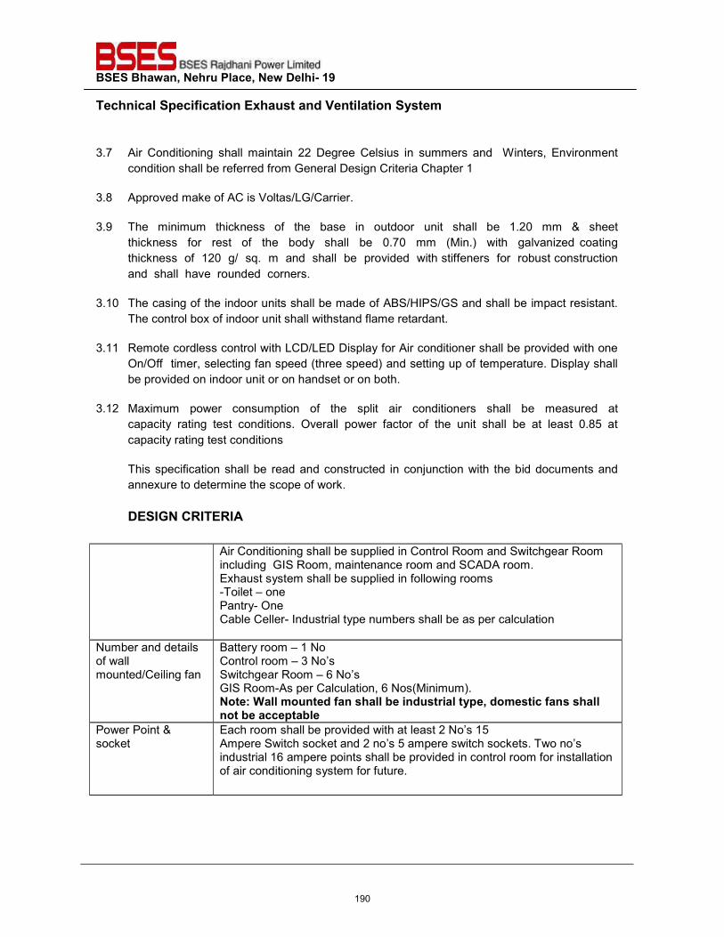
BSES Bhawan, Nehru Place, New Delhi- 19 Technical Specification Exhaust and Ventilation System
3.7 Air Conditioning shall maintain 22 Degree Celsius in summers and Winters, Environment condition shall be referred from General Design Criteria Chapter 1
3.8 Approved make of AC is Voltas/LG/Carrier.
3.9 The minimum thickness of the base in outdoor unit shall be 1.20 mm & sheet
thickness for rest of the body shall be 0.70 mm (Min.) with galvanized coating thickness of 120 g/ sq. m and shall be provided with stiffeners for robust construction and shall have rounded corners.
3.10 The casing of the indoor units shall be made of ABS/HIPS/GS and shall be impact resistant.
The control box of indoor unit shall withstand flame retardant.
3.11 Remote cordless control with LCD/LED Display for Air conditioner shall be provided with one On/Off timer, selecting fan speed (three speed) and setting up of temperature. Display shall be provided on indoor unit or on handset or on both.
3.12 Maximum power consumption of the split air conditioners shall be measured at
capacity rating test conditions. Overall power factor of the unit shall be at least 0.85 at capacity rating test conditions
This specification shall be read and constructed in conjunction with the bid documents and annexure to determine the scope of work.
DESIGN CRITERIA
Air Conditioning shall be supplied in Control Room and Switchgear Room including GIS Room, maintenance room and SCADA room. Exhaust system shall be supplied in following rooms -Toilet – one Pantry- One Cable Celler- Industrial type numbers shall be as per calculation
Number and details of wall mounted/Ceiling fan
Battery room – 1 No Control room – 3 No’s Switchgear Room – 6 No’s GIS Room-As per Calculation, 6 Nos(Minimum). Note: Wall mounted fan shall be industrial type, domestic fans shall not be acceptable
Power Point & socket
Each room shall be provided with at least 2 No’s 15 Ampere Switch socket and 2 no’s 5 ampere switch sockets. Two no’s industrial 16 ampere points shall be provided in control room for installation of air conditioning system for future.
190
BSES Bhawan, Nehru Place, New Delhi- 19 Technical Specification Exhaust and Ventilation System
All equipment, accessories and wiring shall have fungus protection, involving special treatment of insulation and metal against fungus, insects and corrosion.
4.0 DEVIATIONS Deviation from this specification, if any, shall be clearly brought out in the offer. Unless owner explicitly accepts such deviations, it shall be considered that the offer fully complies with the specification.
191
BSES Bhawan, Nehru Place, New Delhi- 19
Prepared by Rev: 1
Reviewed by Date: 24.05.21
Approved by
TECHNICAL SPECIFICATION
FOR
FIRE EXTINGUISHER
192
BSES Bhawan, Nehru Place, New Delhi- 19 Technical Specification Fire Extinguisher
1.0 INTENT OF SPECIFICATION: This specification is intended to cover the design, manufacture, assembly, testing at manufacturer’s works, supply & delivery, properly packed for transport FOR site of Portable wall and trolley mounted Fire extinguisher and fire buckets for substation control room building complete with all materials and accessories for efficient and trouble free operation. In the even of any discrepancy with the listed documents, the stipulation of this specification shall govern.
2.0 SCOPE OF WORK
2.1 Scope of Supply
The following equipment shall be furnished with all accessories:-
a) Wall mounted fire extinguisher-15 Nos. of 4.5kG (CO2 Type) b) Trolley mounted fire extinguisher- 5 Nos. of 22.5kg (CO2 Type) c) Sand buckets with stand- 4 Set with 4 bucket in each stand d) All installation hardware. e) All relevant drawings, data & instruction manuals. f) Mandatory spares. g) Commissioning spares and recommended spare part list for three (3) years of
operation. h) Rubber Mat for entire Indoor equipments front and backside(as per latest IS)
3.0 GENERAL REQUIREMENT
3.1 Codes and Standard
All equipment and material shall be designed, manufactured and tested in accordance with the latest applicable Indian Standards except where modified and/or supplemented by this specification. Equipment and materials conforming to any other standard which ensures equal or greater quality may be accepted. In such case copies of the English version of the standard adopted shall be submitted along with the bid. In particular, the following standards and specifications are applicable.
193
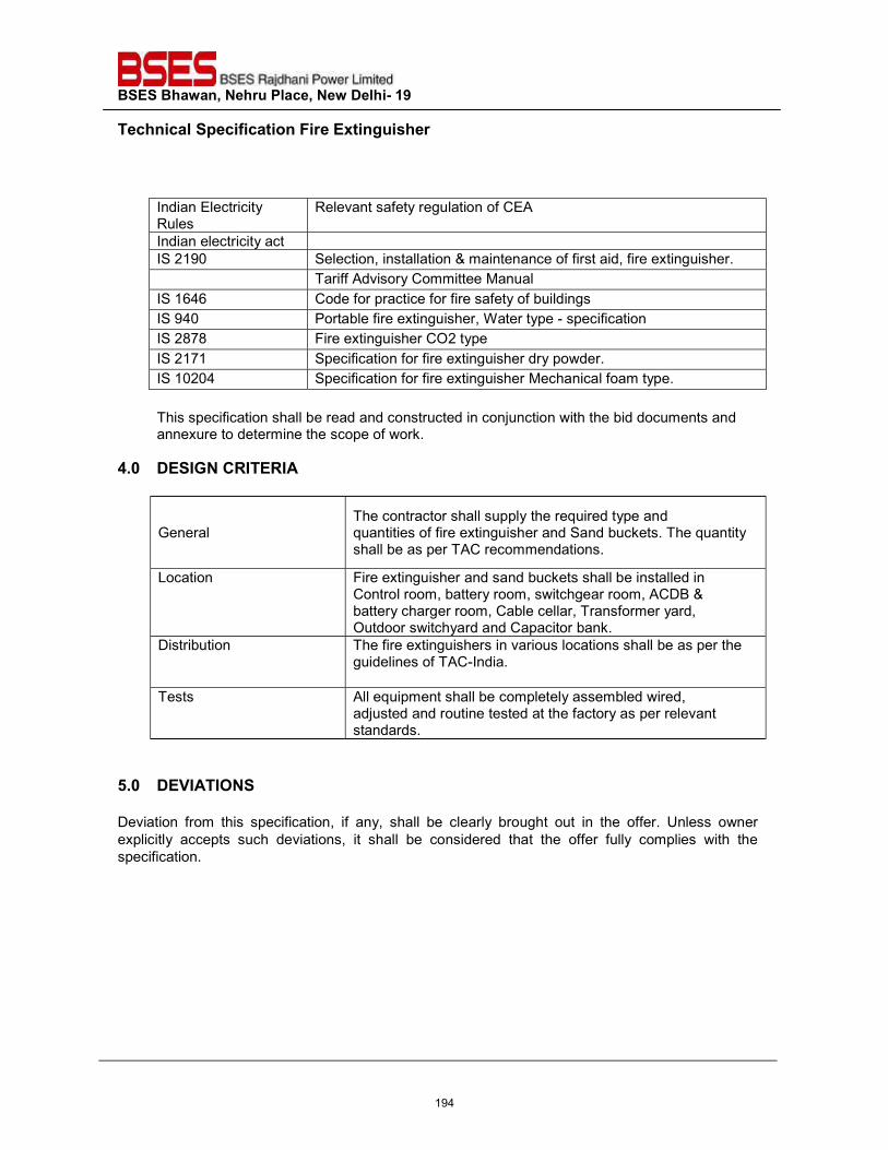
BSES Bhawan, Nehru Place, New Delhi- 19 Technical Specification Fire Extinguisher
Indian Electricity Rules
Relevant safety regulation of CEA
Indian electricity act IS 2190 Selection, installation & maintenance of first aid, fire extinguisher. Tariff Advisory Committee Manual IS 1646 Code for practice for fire safety of buildings IS 940 Portable fire extinguisher, Water type - specification IS 2878 Fire extinguisher CO2 type IS 2171 Specification for fire extinguisher dry powder. IS 10204 Specification for fire extinguisher Mechanical foam type.
This specification shall be read and constructed in conjunction with the bid documents and annexure to determine the scope of work.
4.0 DESIGN CRITERIA
General The contractor shall supply the required type and quantities of fire extinguisher and Sand buckets. The quantity shall be as per TAC recommendations.
Location Fire extinguisher and sand buckets shall be installed in Control room, battery room, switchgear room, ACDB & battery charger room, Cable cellar, Transformer yard, Outdoor switchyard and Capacitor bank.
Distribution The fire extinguishers in various locations shall be as per the guidelines of TAC-India.
Tests All equipment shall be completely assembled wired, adjusted and routine tested at the factory as per relevant standards.
5.0 DEVIATIONS Deviation from this specification, if any, shall be clearly brought out in the offer. Unless owner explicitly accepts such deviations, it shall be considered that the offer fully complies with the specification.
194
Prepared by Javed Ahmed Rev: 1
Checked by Javed Ahmed
Reviewed by Abhinav Srivastava
Approved by Sheshadri Krishnapura Date: 21 May 2021
Registered Office: BSES Bhavan, Nehru Place, Delhi - 110019
DASHBOARD.pdf
TECHNICAL SPECIFICATION
FOR
FIRE SUPPRESSION SYSTEM
Specification No- GN101-03-SP-139-00
195
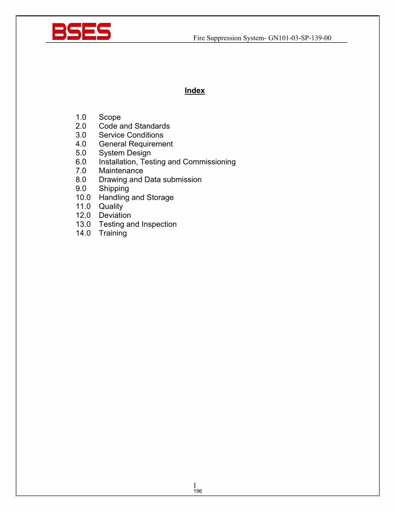
Fire Suppression System- GN101-03-SP-139-00
1
Index
1.0 Scope 2.0 Code and Standards 3.0 Service Conditions 4.0 General Requirement 5.0 System Design 6.0 Installation, Testing and Commissioning 7.0 Maintenance 8.0 Drawing and Data submission 9.0 Shipping 10.0 Handling and Storage 11.0 Quality 12.0 Deviation 13.0 Testing and Inspection 14.0 Training
196
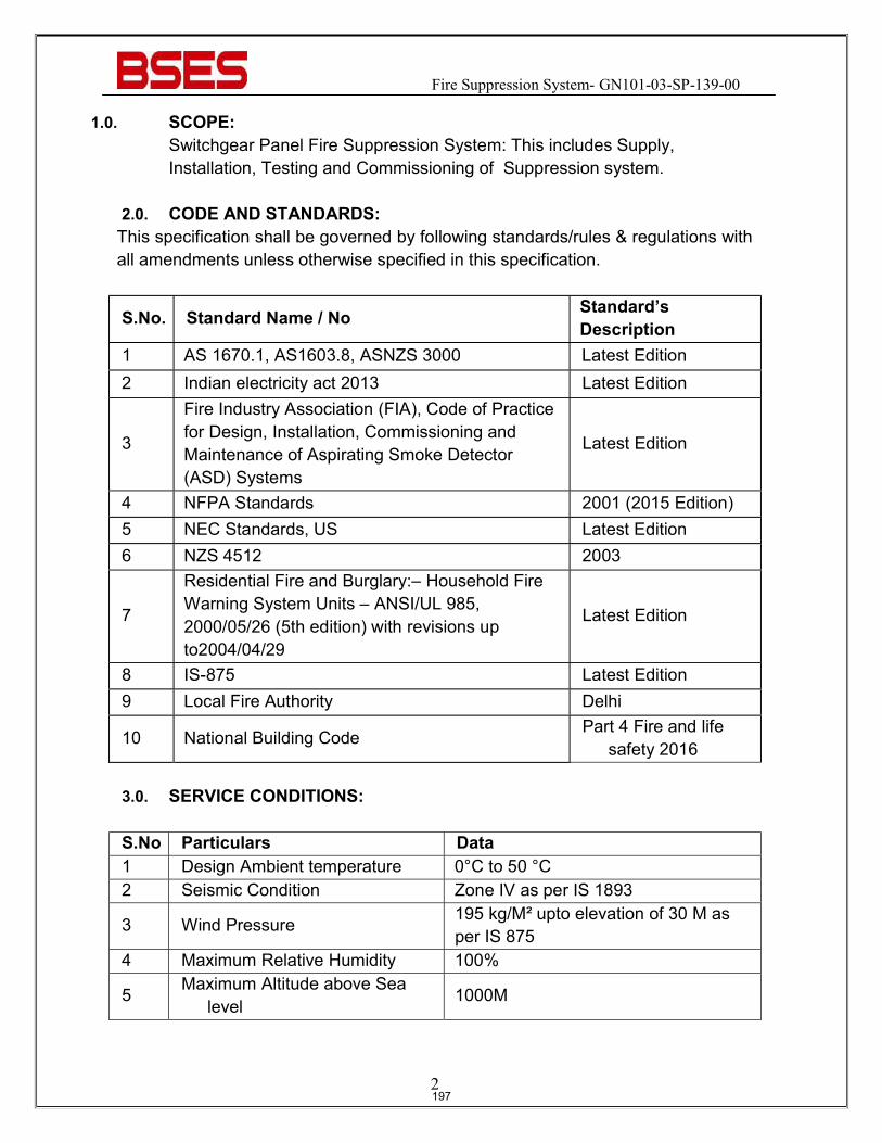
Fire Suppression System- GN101-03-SP-139-00
2
1.0. SCOPE: Switchgear Panel Fire Suppression System: This includes Supply, Installation, Testing and Commissioning of Suppression system.
2.0. CODE AND STANDARDS: This specification shall be governed by following standards/rules & regulations with all amendments unless otherwise specified in this specification.
S.No. Standard Name / No Standard’s Description
1 AS 1670.1, AS1603.8, ASNZS 3000 Latest Edition 2 Indian electricity act 2013 Latest Edition
3
Fire Industry Association (FIA), Code of Practice for Design, Installation, Commissioning and Maintenance of Aspirating Smoke Detector (ASD) Systems
Latest Edition
4 NFPA Standards 2001 (2015 Edition) 5 NEC Standards, US Latest Edition 6 NZS 4512 2003
7
Residential Fire and Burglary:– Household Fire Warning System Units – ANSI/UL 985, 2000/05/26 (5th edition) with revisions up to2004/04/29
Latest Edition
8 IS-875 Latest Edition 9 Local Fire Authority Delhi
10 National Building Code Part 4 Fire and life
safety 2016 3.0. SERVICE CONDITIONS: S.No Particulars Data 1 Design Ambient temperature 0°C to 50 °C 2 Seismic Condition Zone IV as per IS 1893
3 Wind Pressure 195 kg/M² upto elevation of 30 M as per IS 875
4 Maximum Relative Humidity 100%
5 Maximum Altitude above Sea level
1000M
197
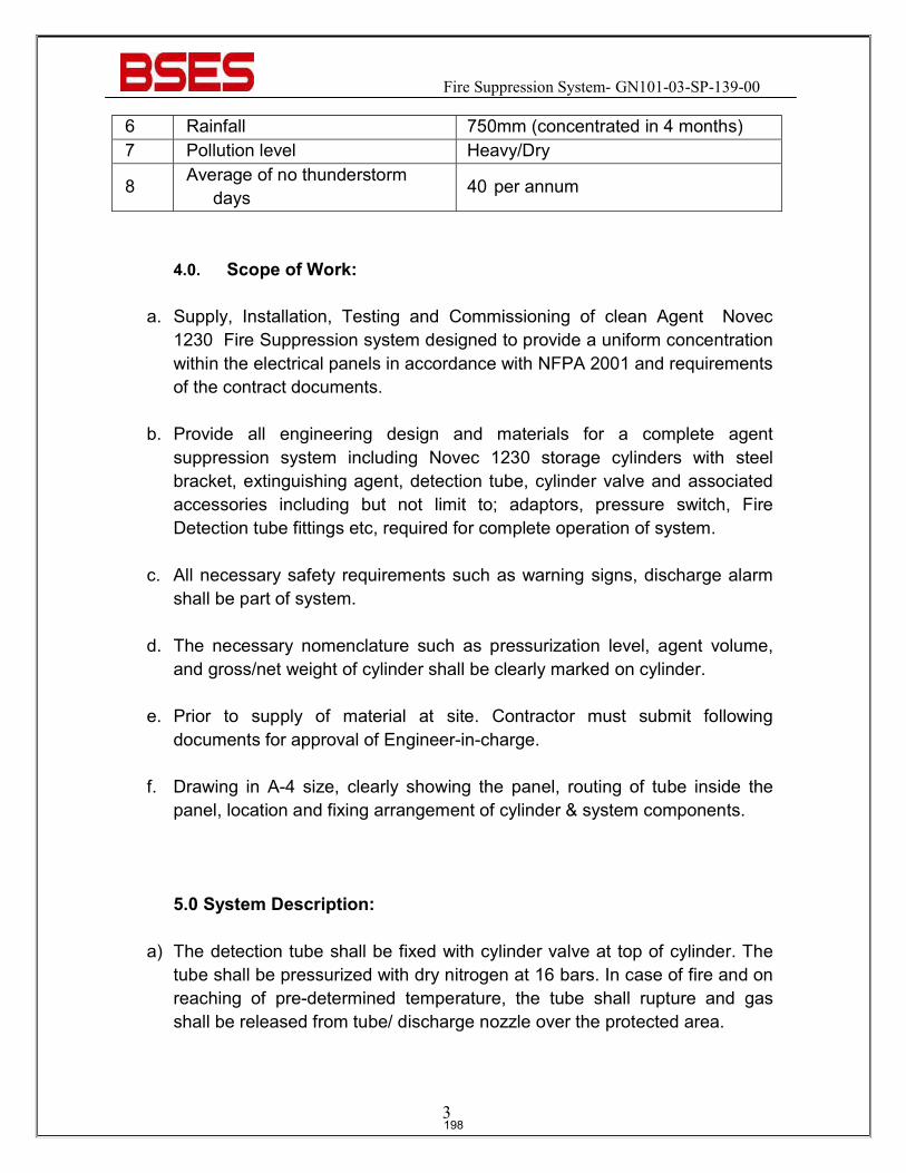
Fire Suppression System- GN101-03-SP-139-00
3
6 Rainfall 750mm (concentrated in 4 months) 7 Pollution level Heavy/Dry
8 Average of no thunderstorm days 40 per annum
4.0. Scope of Work:
a. Supply, Installation, Testing and Commissioning of clean Agent Novec 1230 Fire Suppression system designed to provide a uniform concentration within the electrical panels in accordance with NFPA 2001 and requirements of the contract documents.
b. Provide all engineering design and materials for a complete agent
suppression system including Novec 1230 storage cylinders with steel bracket, extinguishing agent, detection tube, cylinder valve and associated accessories including but not limit to; adaptors, pressure switch, Fire Detection tube fittings etc, required for complete operation of system.
c. All necessary safety requirements such as warning signs, discharge alarm
shall be part of system.
d. The necessary nomenclature such as pressurization level, agent volume, and gross/net weight of cylinder shall be clearly marked on cylinder.
e. Prior to supply of material at site. Contractor must submit following
documents for approval of Engineer-in-charge.
f. Drawing in A-4 size, clearly showing the panel, routing of tube inside the panel, location and fixing arrangement of cylinder & system components.
5.0 System Description:
a) The detection tube shall be fixed with cylinder valve at top of cylinder. The tube shall be pressurized with dry nitrogen at 16 bars. In case of fire and on reaching of pre-determined temperature, the tube shall rupture and gas shall be released from tube/ discharge nozzle over the protected area.
198
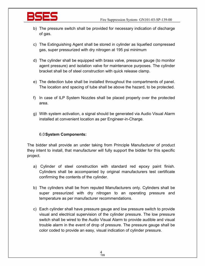
Fire Suppression System- GN101-03-SP-139-00
4
b) The pressure switch shall be provided for necessary indication of discharge of gas.
c) The Extinguishing Agent shall be stored in cylinder as liquefied compressed
gas, super pressurized with dry nitrogen at 195 psi minimum
d) The cylinder shall be equipped with brass valve, pressure gauge (to monitor agent pressure) and isolation valve for maintenance purposes. The cylinder bracket shall be of steel construction with quick release clamp.
e) The detection tube shall be installed throughout the compartments of panel.
The location and spacing of tube shall be above the hazard, to be protected.
f) In case of ILP System Nozzles shall be placed properly over the protected area.
g) With system activation, a signal should be generated via Audio Visual Alarm
installed at convenient location as per Engineer-in-Charge.
6.0 System Components:
The bidder shall provide an under taking from Principle Manufacturer of product they intent to install, that manufacturer will fully support the bidder for this specific project.
a) Cylinder of steel construction with standard red epoxy paint finish. Cylinders shall be accompanied by original manufacturers test certificate confirming the contents of the cylinder.
b) The cylinders shall be from reputed Manufacturers only. Cylinders shall be
super pressurized with dry nitrogen to an operating pressure and temperature as per manufacturer recommendations.
c) Each cylinder shall have pressure gauge and low pressure switch to provide
visual and electrical supervision of the cylinder pressure. The low pressure switch shall be wired to the Audio Visual Alarm to provide audible and visual trouble alarm in the event of drop of pressure. The pressure gauge shall be color coded to provide an easy, visual indication of cylinder pressure.
199
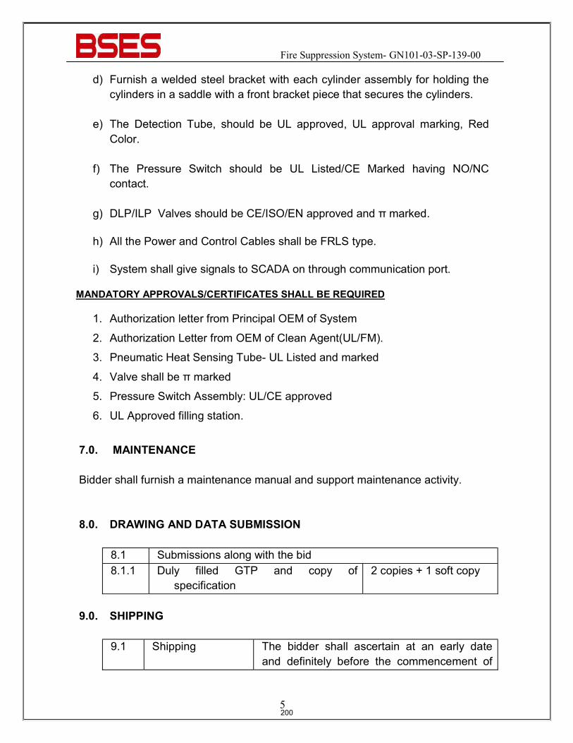
Fire Suppression System- GN101-03-SP-139-00
5
d) Furnish a welded steel bracket with each cylinder assembly for holding the cylinders in a saddle with a front bracket piece that secures the cylinders.
e) The Detection Tube, should be UL approved, UL approval marking, Red
Color.
f) The Pressure Switch should be UL Listed/CE Marked having NO/NC contact.
g) DLP/ILP Valves should be CE/ISO/EN approved and π marked.
h) All the Power and Control Cables shall be FRLS type.
i) System shall give signals to SCADA on through communication port.
MANDATORY APPROVALS/CERTIFICATES SHALL BE REQUIRED
1. Authorization letter from Principal OEM of System
2. Authorization Letter from OEM of Clean Agent(UL/FM).
3. Pneumatic Heat Sensing Tube- UL Listed and marked
4. Valve shall be π marked
5. Pressure Switch Assembly: UL/CE approved
6. UL Approved filling station.
7.0. MAINTENANCE
Bidder shall furnish a maintenance manual and support maintenance activity. 8.0. DRAWING AND DATA SUBMISSION
8.1 Submissions along with the bid 8.1.1 Duly filled GTP and copy of
specification 2 copies + 1 soft copy
9.0. SHIPPING
9.1 Shipping The bidder shall ascertain at an early date and definitely before the commencement of
200
Fire Suppression System- GN101-03-SP-139-00
6
manufacture, any transport limitations such as weights, dimensions, road culverts, Overhead lines, free access etc. from the Manufacturing plant to the project site. Bidder shall furnish the confirmation that the proposed Packages can be safely transported, as normal or oversize packages, up to the site. Any modifications required in the infrastructure and cost thereof in this connection shall be brought to the notice of the Purchaser. The Bidder shall be responsible for all transit damage due to improper packing.
10.0. HANDLING AND STORAGE
10.0 Handling and Storage
Manufacturer instruction shall be followed. Detail handling & storage instruction sheet / manual needs to be furnished before commencement of supply.
11.0. QUALITY & INSPECTION
11.1 Vendor quality plan To be submitted for purchaser approval 11.2 Testing &
Inspection As per relevant standards
12.0 Warranty Warranty shall be 5 Years Minimum. Vendor shall provide free maintenance during warranty period. Following activities shall be included during period of warranty.
1. one visit by service engineer for general check up -- once in a six month
time on each location.
2. Functionality test of the entire system -- once in one year time on each
Location.
201
Fire Suppression System- GN101-03-SP-139-00
7
3. Mandatory Spares shall be provided for upkeeping of system for the period
of 5 Years.
13.0 DEVIATION
13.1 Deviation Deviations from this Specification shall be stated in writing with the tender by reference to the Specification clause/GTP/Drawing and a description of the alternative offer. In absence of such a statement, it will be assumed that the bidder complies fully with this specification. No deviation will be acceptable post order.
14.0 TRAINING Training on installation, commissioning, operation and maintenance shall be included in the quotation.
- At site after installation- 1 Manday
202
Prepared by Javed Ahmed Rev: 2
Reviewed by Abhinav Srivastava
Approved by K.Sheshadri Date: 2rd Feb 2021
Registered Office: BSES Bhavan, Nehru Place, Delhi - 110019
TECHNICAL SPECIFICATION
FOR
VIDEO SURVEILLANCE SYSTEM
203
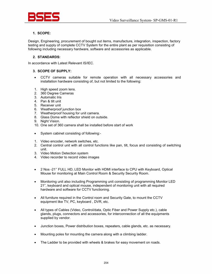
Video Surveillance System- SP-GMS-01-R1
1. SCOPE:
Design, Engineering, procurement of bought out items, manufacture, integration, inspection, factory testing and supply of complete CCTV System for the entire plant as per requisition consisting of following including necessary hardware, software and accessories as applicable.
2. STANDARDS: In accordance with Latest Relevant IS/IEC.
3. SCOPE OF SUPPLY:
� CCTV cameras suitable for remote operation with all necessary accessories and installation hardware consisting of, but not limited to the following:
1. High speed zoom lens. 2. 360 Degree Cameras 3. Automatic Iris 4. Pan & tilt unit 5. Receiver unit 6. Weatherproof junction box 7. Weatherproof housing for unit camera. 8. Glass Dome with reflector shield on outside. 9. Night Vision. 10. One set of 360 camera shall be installed before start of work
� System cabinet consisting of following:-
1. Video encoder, network switches, etc. 2. Central control unit with all control functions like pan, tilt, focus and consisting of switching
unit. 3. Video Motion Detection system 4. Video recorder to record video images
� 2 Nos -21’’ FULL HD, LED Monitor with HDMI interface to CPU with Keyboard, Optical Mouse for monitoring at Main Control Room & Security Security Room.
� Monitoring unit also including Programming unit consisting of programming Monitor LED
21”, keyboard and optical mouse, independent of monitoring unit with all required hardware and software for CCTV functioning.
� All furniture required in the Control room and Security Gate, to mount the CCTV
equipment like TV, PC, keyboard , DVR, etc.
� All types of Cables (Video, Control/data, Optic Fiber and Power Supply etc.), cable glands, plugs, connectors and accessories, for interconnection of all the equipments supplied by vendor.
� Junction boxes, Power distribution boxes, repeaters, cable glands, etc. as necessary.
� Mounting poles for mounting the camera along with a climbing ladder.
� The Ladder to be provided with wheels & brakes for easy movement on roads.
204
Video Surveillance System- SP-GMS-01-R1
� HDPE pipe with required pipe fittings for laying optical fiber cables between CCTV Cameras and main control room, and between main control room and security control room (gate / security house).
� Cable trays for CCTV cables within control rooms with required accessories in case required at site. Cable trays outside control room (where main cable duct is not available). Buried cable trench for cabling along the boundary walls.
� All necessary supports for installation of all items supplied by vendor.
� All mounting accessories required to mount various items supplied by vendor.
� Earthing material required for earthing of CCTV equipment installed by Vendor.
� Necessary base frame support for mounting CCTV cabinets in main control room.
� Any other item necessary but not specifically listed for successful operation of CCTV system.
� Packing, forwarding, transportation and storage at site of complete CCTV system and accessories.
� Supply of special instrument or tools needed for testing, calibration and maintenance of offered CCTV system.
� Supply of consumables and commissioning spares as per requisition for CCTV system.
� Any other item or/and activity not listed/indicated specifically but necessary for successful operation of CCTV system.
� CCTV monitoring of the site & image capture in case of an intrusion
� Future hardware expansion facility.
� The CCTV system shall be support high resolution viewing & recording.
� The images shall be transferred to a central location or on Mobile using Internet connectivity.
� The System shall be CE & FCC certified
� Complete system shall be from the same manufacturer.
� System should be design to work on low bandwidth WAN with following considerations:
1) Camera stream : H.265 2) Camera resolution : 4CIF (704x480) 3) Video quality : Medium 4) Number of cameras : 01 5) Frame rate per camera at site :25FPS 6) Frame rate per camera at Centre :15FPS 7) Recording type : Continuous 24 Hours per day 8) Desired days of storage per camera : 30 Days
205
Video Surveillance System- SP-GMS-01-R1
All cameras should support dual stream and configured in such a way that one stream should provide feed to central control centre and other stream should be capable to support edge recording (memory card on camera or NVR). System should be intelligent to monitor WAN and whenever there is outage or central control centre not reachable camera should start recording on memory card or NVR present on camera and capable to restore the data to the central system in the missing area.
4. SCOPE OF SERVICE :
� Installation, integration of complete CCTV system and associated accessories including
calibration, cabling, junction boxes, power supply, distribution boxes, etc.
� Installation of CCTV Cameras. The Cameras to be mounted on top of Pole, so as no blind spot is created due to pole.
� Installation of CCTV monitors for monitors located in main control room and monitors
located in security control room (gate / security house).
� Installation of monitor located in MCR and security control room.
� Installation of mounting poles wherever applicable.
� Installation of CCTV cabinets for various units.
� Installation of programming unit PC.
� Installation of various junction boxes (signal, power, control) supplied by vendor.
� Laying of co-axial / optical fiber cable between CCTV Camera & Control Console Cabinets.
� Laying of power cable between CCTV Cameras and CCTV Cabinet in MCR.
� Laying of CCTV Cables (video, control, data, power).
� Laying of CCTV fiber optic Cables between MCR and security control room.
� Termination, ferruling and glanding at both ends and interconnection of various cables (video, optical, control, power) supplied by vendor for complete CCTV system.
� Distribution of power supply and reduction to required levels to various CCTV equipment supplied by vendor.
� Integration of CCTV Camera with BRPL Network
The entire IP surveillance system to be designed to control and monitor the locations provided based on following considerations:
� Camera to be of 4 MP (all to be integrated in the VMS present and future)
� CCTV system should be design to work on WAN with at lower bandwidth as low as (256Kbps per camera). Objects or persons should be identified under low bandwidth Scenario
� Bandwidth should be configurable
206
Video Surveillance System- SP-GMS-01-R1
� System should be design to work and record on 15fps and 1 MP centrally
� System should be design with event based and continuous recording as and when
required Four types of cameras shall be considered to monitor the movement of the people as follows:
1) Indoor 2) Outdoor 3) PTZ 4) 360 degrees outdoor
� All cameras shall be True Day/Night function IP camera
� Analytics to be in built at camera side like – Face capture, Trip Wire, Counter,
Object removal, Motion detection.
� All accessories with the outdoor cameras like JBs, power supply, media converter etc. should be in water poof and dust proof housing
� All cabling including LAN network will be in scope of vendor in case of open through ISI mark PVC / GI pipes or concealed through ISI mark PVC / HDPE pipe
� L2 POE Cisco switches should be used to power-up the camera in case of 4 or more at a location else power adapter to be used to power up the cameras
� Servers should be either HP / IBM
� Servers should be planned in redundancy
5. TESTS. All equipment with their terminal connectors, and other hardware etc., shall conform to type tests and shall be subjected to routine and acceptance tests in accordance with Latest Relevant IS . 6. COMPLETENESS OF EQUIPMENT: Any fittings, accessories or apparatus which may not have been specifically mentioned in this specification but which are usually necessary for the satisfactory operation of the equipment, shall be deemed to have been included in this specification. 7. PACKINGS: All material shall be suitably packed for transport, direct to site and Manufacturer shall be responsible for all damages/losses due to improper packing. All boxes shall be marked with signs indicating the up and down sides of the boxes along with the unpacking instructions, if considered necessary by the Manufacturers. Note: All critical areas/rooms to be covered fully leaving no grey area. Placement of cameras shall be such that there should be no shadow portion.
207
BSES Bhawan, Nehru Place, New Delhi- 19
Prepared by Rev: 0
Reviewed by Date:
Approved by
TECHNICAL SPECIFICATION
FOR
FIRE DETECTION AND ALARM SYSTEM
208
BSES Bhawan, Nehru Place, New Delhi- 19 Technical Specification Fire Detection and Alarm System
1.0 INTENT OF SPECIFICATION: This specification is intended to cover the design, manufacture, assembly, testing at manufacturer’s works, supply & delivery, properly packed for transport FOR site of Fire and smoke Detection & Alarm System for substation control room building complete with all materials and accessories for efficient and trouble free operation. In the even of any discrepancy with the listed documents, the stipulation of this specification shall govern.
2.0 SCOPE OF WORK
2.1 Scope of Supply
The following equipment shall be furnished with all accessories :-
a) Smoke and heat detectors and installation. b) Manual call point for the substation building. c) Fire detection alarm panels which shall be SCADA compatible along with
its integration with SCADA. d) All wiring & accessories to complete the installation. e) All installation hardware. f) All relevant drawings, data & instruction manuals.
3.0 GENERAL REQUIREMENT
3.1 Codes and Standard
All equipment and material shall be designed, manufactured and tested in accordance with the latest applicable Indian Standards except where modified and/or supplemented by this specification. Equipment and materials conforming to any other standard which ensures equal or greater quality may be accepted. In such case copies of the English version of the standard adopted shall be submitted along with the bid. In particular, the following standards and specifications are applicable. Indian Electricity Rules Relevant safety regulation of CEA Indian electricity act CBIP manual IS 2189 Code of practice for selection, installation & maintenance of
automatic fire alarm system. IS 2190 Selection, installation & maintenance of first aid, fire extinguisher. IS 1646 Tariff Advisory Committee Manual Code for practice for fire safety of buildings
209
BSES Bhawan, Nehru Place, New Delhi- 19 Technical Specification Fire Detection and Alarm System
This specification shall be read and constructed in conjunction with the bid documents and annexure to determine the scope of work.
4.0 DESIGN CRITERIA
General
1. The fire detection system shall consist of various types of fire detectors, control cabling, fire alarm panels, central monitoring station, annunciation/control panels, local panels.
2. The fire detection and alarm system shall be microprocessor based, analogue addressable system.
3. A central monitoring system shall be provided in the control room covering complete substation.
4. The control system shall be compatible to be interfaced with SCADA system through separate communication port.
Location Fire detectors shall be provided for the entire substation building including control room, switchgear room, battery charger, corridors, Cable Celler etc.Fire detectors shall be located at strategic location in various rooms of the building.
Operation The operation of any of the fire detectors / manual call point should result in the following :
a) A visual signal exhibited in the alarm panel indicating the area where the fire is detected.
b) An audible alarm (Hooter) sounded in the panel. c) An external alarm sounded in the building, location of
which shall be decided during detailed engineering. d) An alarm should be signaled to the control room.
Detection & Alarm system 1. Each zone shall be provided with two zone cards in the panel so that system will remain healthy even if one the cards become defective which shall be indicated at SCADA .
2. The control panel shall be suitable for 230V AC and 220V DC as power supply.
Cabling
The detector cable and the other control cable shall be armoured, screened and twisted FRLS type in external areas and shall be of unarmoured FRLS type inside building (in conduits)
Tests All equipment shall be completely assembled wired, adjusted and routine tested at the factory as per relevant standards. Following tests shall be performed on the system
a) Response characteristics of fire detectors. b) Performance test on fire extinguisher as required in
the code. c) A comprehensive visual and functional check for the
fire alarm panel. d) Verification of wiring as per approved schematic. e) Testing of fire detection panel as per BS3116 Part IV.
Site Test All the detectors installed shall be tested for actuation by bringing a suitable smoke source near the detector creating a stream smoke over the detector. After each test smoky atmosphere should be cleared so that the detector shall reset.
210
BSES Bhawan, Nehru Place, New Delhi- 19 Technical Specification Fire Detection and Alarm System
Certify proper operation of all detectors and call points. One of each type of extinguisher shall be tested for its performance.
5.0 DEVIATIONS Deviation from this specification, if any, shall be clearly brought out in the offer. Unless owner explicitly accepts such deviations, it shall be considered that the offer fully complies with the specification.
211

BSES Bhawan, Nehru Place, New Delhi- 19
Prepared by Rev: 0
Reviewed by Date:
Approved by
TECHNICAL SPECIFICATION
FOR
PACKING & TRANSPORTATION
212
BSES Bhawan, Nehru Place, New Delhi- 19 Technical Specification Packing and Transportation
1.0 PACKING AND TRANSPORTATION
1.1 Packing shall be sturdy and adequate to protect all assemblies, components and accessories from injury by corrosion, dampness, heavy rains, breakage and vibration encountered during transportation, handling and storage at the plant site. All accessories, which are likely to get damaged during transit if transported mounted on the equipment, shall be removed, adequately packed and shipped separately. All openings shall be sealed. Spare parts shall be packed separately and clearly marked. They shall be specially packed for long storage without injury.
1.2 The bidder shall after proper painting, pack and crate all plant equipment for sea shipment/air freight in a manner suitable for export to a tropical humid and saline air borne climate region as per Internationally accepted export practice in such a manner so as to protect it from damage and deterioration in transit by road, rail and/or sea and during storage at site till the time of erection. The bidder shall be held responsible for all damages due to improper packing.
1.3 The bidder shall give complete shipping information concerning the weight, size, contents of
each package including any other information the Owner may require. The weight and size of the package shall be such that they can be easily transported from the maker's works to the plant site by ship/air, road ways and railways.
1.4 The bidder shall ascertain at an early date and definitely before the commencement of
manufacture, any transport limitations such as weights, dimensions, road culverts, overhead lines, free access etc. from the manufacturing plant to the project site; and furnish to the Owner confirmation that the proposed packages can be safely transported, as normal or oversize packages, upto the plant site. Any modifications required in the infrastructure and cost thereof in this connection shall be done and borne by the bidder.
1.5 The bidder shall prepare detailed packing list of all packages and containers, bundles and
loose materials forming each and every consignment dispatched to 'site'. The bidder shall further be responsible, for making all necessary arrangements for loading, unloading and other handling right from his works; and from Indian port for equipment under the Off-shore Supply till the 'site' and also till the equipment is erected, tested and commissioned. The bidder shall be solely responsible for proper storage and safe custody of all equipment.
1.6 All packages must be marked consecutively from number one upwards covering all
shipments until completion of the plant equipment execution without repeating the same number. Each box, crate, case bundle or each piece of lose material shall be painted with a combination of one white band and one yellow band of a least 4 cm wide each, round the body of the box, crates, etc as the case be for easy identification.
2.0 GPS instrument must be installed for proper tracking of material during transit of major
equipment like Transformer, GIS Panel,11KV & 66 KV panels etc. of MAP my india make (asset tracking system)
213

BSES Bhawan, Nehru Place, New Delhi- 19 Technical Specification Packing and Transportation
3.0 DEVIATIONS Deviation from this specification, if any, shall be clearly brought out in the offer. Unless owner explicitly accepts such deviations, it shall be considered that the offer fully complies with the specification.
214
BSES Bhawan, Nehru Place, New Delhi- 19
Prepared by Rev: 0
Reviewed by Date:
Approved by
TECHNICAL SPECIFICATION
FOR
MATERIALS WORKMANSHIP & TEST
215
BSES Bhawan, Nehru Place, New Delhi- 19 Technical Specification Materials Workmanship and Tests
1.0 MATERIAL, WORKMANSHIP & TESTS
1.1 General
All materials used in the manufacture of the offered plant equipment shall be of high grade, free from defects and imperfections, of recent manufacture and unused. Materials not specifically described elsewhere, shall as far as applicable and practicable conform to the latest specification of ISS where applicable and equivalent International Standards. Liberal factors of safety shall be used throughout the design for all parts of plant equipment when subjected to the most severe operating conditions. The working stress in all parts of the plant equipment shall be bestowed with ample margins for possible overstressing due to shock. All work shall be performed and completed in accordance with the best modern shop practice in manufacture of high grade equipment. Castings shall be free from blow-holes, flaws, cracks or other defects; and shall be smooth, close-grained and of true form and dimensions. No plugged or filled-up holes or other defects will be accepted. No casting shall be burned, plugged, patched or welded; and no repairs or defects will be accepted. All materials, supplies, parts and assemblies supplied under this specification shall be tested as far as reasonably practical. All welded joints shall be free from defects such as blow-holes, slag inclusions, lack of penetrations, under-cuts, cracks etc; and shall be made by qualified and tested welders. Slag shall be ground after joint completion; and well reinforced smooth welds shall be made.
1.2 Inspection, Testing program and Notification
Before manufacture commences, the contractor shall submit an outline of the proposed inspection and testing programmes (Quality Assurance Programme - QAP) for all major stages during manufacturing of major equipment. This inspection and testing programme shall include for the various items, the designation number, the kind of test, test standard and the extent of witness by the Owner/Engineer or third party.
The notification of the individual witness inspections made by the Owner/Engineer or the third party, shall be given by the contractor using facsimile or telex or e-mail in a format to be agreed upon. The contractor shall notify the Owner/Engineer within 21 days prior to the date on and the place at which item shall be ready for testing. If any postponement becomes necessary, the contractor shall provide written notification of same at least 72 hours prior to the originally scheduled date. If the Owner/Engineer does not attend the test at the place and at the date which the contractor has stated in his notification, the contractor shall proceed with the test, which shall
216
BSES Bhawan, Nehru Place, New Delhi- 19 Technical Specification Materials Workmanship and Tests
be deemed to have been made in their presence and shall forthwith forward to them duly certified copies of the test readings. Before erection commences, the contractor shall submit an outline of the proposed erection inspection and test programme during the erection of major systems. The individual testing procedure shall be submitted as progress of erection work of the equipment, systems and/or units, coordinated with relevant work of the complete plant. Before commissioning commences, the contractor shall submit an outline of the proposed commissioning test procedure. The test programmes shall be maintained by the contractor during erection and commissioning.
1.3 Test : General During manufacture, the Owner's representative shall have the right to expedite and/or inspect design, materials, workmanship and progress of manufacture of the contractor's and his sub-contractor's plant system equipment and may reject any defective materials considered unsuitable for the intended purpose or which does not comply with the intent of this specification. The contractor, upon any such rejection by the Owner or his representative, shall rectify or replace the defective or unsuitable material. The contractor shall provide every reasonable inspection facility to the Owner's inspector or representative at his own and his sub-contractor's works. Material being furnished against this order shall only be shipped when factory inspection satisfactory to the Owner and/or his representative has been conducted. Such inspection and acceptance for shipment shall not however, relieve the contractor from entire responsibility for furnishing the plant system equipment conforming to the requirement of this specification nor shall prejudice any claim, right or privilege which the Owner may have, because of the use or supply of defective or unsatisfactory materials for the plant system equipment. Should the inspection be waived by the Owner, such waiver shall not also relieve the contractor in any way, from his entire obligations under this order. The plant system equipment shall at factory or after installation be demonstrated capable of performing satisfactorily upto the contractor's guaranteed performance. All tests required by this specification, including retests and inspection, that may be necessary owing to failure to meet any tests specified, shall be made at the contractor's expense. Additional tests, as necessary, shall be made to locate any such failure and after determining the causes of failure and rectifying it, specified tests shall be repeated to establish that the rebuilt plant system equipment meets with the specification in every respect. Should the equipment ultimately fail to pass the tests specified, the Owner will have the option to reject the unit. The bidder shall state in the proposal, the shop testing facilities available. Should full capacity testing equipment be not available, the bidder shall state the method proposed to be adopted with detailed computations and justification for adopting such a method to reliably ascertain the equipment characteristics corresponding to full capacity testing.
1.4 Test Certificate
217
BSES Bhawan, Nehru Place, New Delhi- 19 Technical Specification Materials Workmanship and Tests
In accordance with approved QCP, the results of the tests shall be certified by the Owner/Engineer or independent agency as applicable. As and when the item of the plant equipment has passed the tests, the Owner/Engineer shall furnish to the contractor a certificate in writing to that effect. The Quality Control Plan (QCP) shall be issued by the contractor within 1 months after NTP. Document files containing material certificates, test reports, etc shall be compiled for each QCP item of plant equipment; and shall be suitably identified (including equipment classification reference) and bound. Copies of compiled file shall be submitted as per distribution schedule
1.5 Tests at Manufacturers Works The major equipment of the plant to be supplied under this contract shall be subjected to shop inspection and tests. After NTP, the contractor shall issue within 1 months a QCP indicating the kind and extent of inspection and tests to be carried out on the offered plant equipment components to prove whether the equipment fulfills the requirement of the contract in view of:
� Safety Conditions � Consideration of the applied standards and regulations � Execution of workmanship
SITE TESTS Tests conducted at sites shall be indicated by bidder.
2.0 DEVIATIONS Deviation from this specification, if any, shall be clearly brought out in the offer. Unless owner explicitly accepts such deviations, it shall be considered that the offer fully complies with the specification.
218

BSES Bhawan, Nehru Place, New Delhi- 19
Prepared by Rev: 0
Reviewed by Date:
Approved by
TECHNICAL SPECIFICATION
FOR
MISCELLANEOUS ACTIVITIES
219
BSES Bhawan, Nehru Place, New Delhi- 19 Chapter 6b Technical Specification Misc Activities
1.0 SERVICE AFTER SALES 1.1 The bidder shall furnish in detail about his organization for rendering service after sales,
covering deployment of personnel and supply of spares, for ensuring efficient operation and maintenance of the offered plant equipment. The details of spares and service facilities possessed by them should be elaborated.
1.2 The bidder shall guarantee furnishing of the following in respect of after sales services
including spares:- i) Providing services of his specialists on indent from the Owner for periodical or
special maintenance of the plant; as well as for identifying sources of trouble, if any, reported and measures for immediate rectification.
ii) The bidder shall guarantee maintenance of adequate spares at his works to be supplied on indent from the Owner at short notice during the life of the plant.
2.0 BID DATA, DRAWINGS AND INFORMATION REQUIRED
2.1 Technical data sheets, drawings, schedules with supporting information incorporating the
details in compliance to spec but not limited to the following shall be furnished along with the proposal:
2.2 Duly filled in 'Schedule of Guaranteed and other Technical Particulars Schedules ‘C’ except for data which cannot be finally furnished with the Bid. The Price and Delivery Schedule-B duly filled in.
2.3 Dimensioned outline drawings of the offered overall plant and separately for equipment
including cross-sectional drawings showing dimensions, net weights, shipping weights and suggested arrangement layout of proposed plant & equipment with auxiliaries etc. Technical Literature/leaflets of the above plant equipment.
2.4 Manufacturers' catalogues showing the construction details of various equipments should be
furnished indicating clearly the technical preference of the offered equipment over the specified equipment.
2.5 List of users of comparable plant equipment with the year in which the Diesel plant and other
critical plant equipment was put actually into service. For technical acceptability of the bid, proven experience of the bidder in manufacture and satisfactory and trouble free performance of the critical plant equipment for at least three (3) years is essential for which the bidder shall furnish necessary documents in support of the above.
2.6 A bar chart of design, engineering, procurement, manufacture, testing, delivery, installation,
commissioning and site testing including civil structural and architectural works of the proposed plant equipment.
220
BSES Bhawan, Nehru Place, New Delhi- 19 Chapter 6b Technical Specification Misc Activities
2.7 Technical description of the proposed plant equipment and materials particularly outlining any additional list out features proposed for safety & reliability. List out items of work & services not included and which has to be provided by the Owner for satisfactory commissioning of the offered plant equipment supplied.
2.8 The bid shall not be considered if the bidder fails to submit all the details asked for. Proposal
should be complete without ambiguity and should be clearly written against each item.
2.9 Bidder shall furnish Quality Assurance Programme for design, manufacture, assembly, erection, testing & commissioning including civil, structural and architectural works along with the proposal for all equipment covered under this specification whether manufactured by the bidder or procured from other sources.
2.10 Technical deviations from the specification, if any, shall be clearly listed in the Schedule-E. In
absence of any deviation given in Schedule-E and accepted by Owner, it will be bidder's responsibility and his contractual obligation to supply the Plant equipment as per specification to Owner/Engineer's approval.
2.11 List of shop and site tests, the bidder proposes to carry out including those pertaining to their
sub-suppliers works shall be clearly brought out in Schedule – G. In addition to above tests, the bidder shall conduct any other tests, to Owner/Engineer's approval, which are considered important for satisfactory operation of plant equipment.
2.12 Bidder shall furnish all required mandatory and startup commissioning spare parts as well as
maintenance tools and tackles with unit prices for the offered plant equipment.
3.0 POST CONTRACT DATA AND DRAWINGS 3.1 The contractor shall submit within thirty (30) days from the date of the order and Notice to
Proceed (NTP) certified dimensioned drawings and technical schedules giving every detail of the offered plant equipment particularly the following:
3.2 Completely filled in schedule of guaranteed particulars and other technical particulars.
3.3 Single line diagrams; logic diagrams, dimensioned general arrangement and equipment layout drawings showing front and side elevations, plan and sectional views of the offered equipment forming part of the contractor's supply; The drawings should also indicate structures & supporting details including foundation outline and loading data etc.
3.4 Final version of all drawings and data submitted along in the proposal mentioned above.
3.5 Structural, thermodynamic and pressure part calculations showing compliance with specifications and codes as and when required.
3.6 Any other drawings/details not specified herein and required by the Owner/Engineer to
correctly coordinate the offered plant equipment with other contractor's work.
221
BSES Bhawan, Nehru Place, New Delhi- 19 Chapter 6b Technical Specification Misc Activities
3.7 Civil design calculations.
3.8 Detailed specifications and data sheets of the plant equipment with auxiliaries.
3.9 Detail drawings of critical equipment units, assemblies, parts etc. as deemed necessary.
3.10 Design calculations of conductor sizing, cable sizing, main equipment sizing etc.
3.11 Schematic wiring diagrams along with write-ups for control, interlocks, instrumentation, protection, circuits. Terminal blocks and terminals arrangement drawings showing power & control cable connections.
3.12 Owner/Engineer will return to the contractor one (1) print of each drawing either.
(a) stamped approved or (b) marked up with the comments. In case of (a), no further submission of a drawing will be required. In case of (b), the contractor shall correct his original drawings to conform to comments made by the Owner/Engineer and resubmit within two (2) weeks of receipt of comments in the same manner as stated in the Distribution Schedule. The Owner/Engineer's approval shall not relieve the contractor from any of his obligation and responsibility to manufacture and supply equipment conforming to this specification, unless a written amendment to the specification is issued by the Owner.
3.13 After approval of the drawings, reproducible of each drawing shall be supplied. Final
drawings shall be certified as Approved for Construction. Should any minor revision be made after approval the contractor shall re-distribute prints and reproducible as per the Distribution Schedule. Every revision shall be marked by a number, date and subject in a revision block provided in the drawing.
3.14 Reproducible shall be of quality to produce clear and legible prints and any inferior reproducible will be returned by the Owner for replacement with suitable reproducible. All reproducible shall be mailed rolled (not folded) on the outside of regular mailing tubes except for small sizes which can be mailed unfolded in envelope with a cardboard backing. The prints and reproducible shall be mailed in the most expeditious manner and shall be accompanied with a letter of transmittal.
4.0 INSTRUCTION MANUAL
4.1 At least one (1) month prior to the dispatch of the plant equipment, fifteen (15) copies of installation, testing and adjustments after installation, operation and maintenance manuals shall be furnished. These manuals shall be sturdily bound volumes and shall contain every drawings and information required for installation, testing, setting and adjustment of all components after installation, operation and maintenance of the equipment and all its components. Separate tabs shall be used for such instructions concerning each equipment control components, electrical and other accessories. The other data needed for servicing the components and ordering their spare parts.
222
BSES Bhawan, Nehru Place, New Delhi- 19 Chapter 6b Technical Specification Misc Activities
4.2 Marked erection prints identifying the components parts of the equipment, as transported, with its assembly drawings.
4.3 Detailed dimensioned assembly and cross sectional drawings and description of all the plant
system equipment with auxiliaries and drawings identifying all spare parts for re-order.
4.4 Documentation
Correspondence, drawings, progress reports, schedules, tests reports and instruction manuals shall be mailed in requisite copies in accordance with Distribution Schedule.
5.0 WORK SCHEDULE
5.1 Time being the essence of the proposal, preference will be given for the offers quoting earlier
deliveries. The bidder shall include in his proposal his programme for furnishing and erecting the offered plant & equipment.
5.2 The programme shall be in the form of master network identifying the key phases in various areas of total plant work, such as design work, procurement of raw materials, manufacture of components & subassemblies; complete erection of equipment and all other field activities. The master network shall conform to completion of trial operation from the date of Letter of Award within a period of 4 months. The trial operations shall commence any day within 15 days prior to the date of completion indicated above.
5.3 This master network shall be discussed and agreed before the issue of letter of award. Engineering drawings as well as technical data sheets submission schedule shall also be discussed and finalized before the issue of letter of award. Provisions of the liquidated damages leviable for delays in completion of trial operation shall become effective after the above mentioned date.
5.4 After the contract award, the contractor shall plan the sequence of work of manufacture and erection including associated civil works to meet the Owner's power plant commissioning requirements; and shall ensure that all work/manufacture, shop testing, inspection & shipment of the equipment in accordance with the required construction/erection sequence.
5.5 Within seven (7) days of acceptance of the letter of award, the contractor shall submit, for review and approval, two copies (1 reproducible and 1 print) of Detailed Network schedules, based on the Master Network (mutually agreed by the Owner & contractor) to the Owner/Engineer showing the logic & duration of the activities in the following areas i) Engineering, Procurement, Manufacturing & Supply Detailed engineering activities
in regard to procurement of raw materials including bought out items, manufacture, dispatch/ shipment & receipt at site.
ii) Civil, Structural & Architectural Works:
Detailed engineering activities in regard to civil & structural works execution based on the offered equipment and approved drawings including detailed execution of execution activities covering the complete scope of work.
iii) Erection, Testing and Commissioning:
223
BSES Bhawan, Nehru Place, New Delhi- 19 Chapter 6b Technical Specification Misc Activities
Detailed erection, testing and commissioning activities, covering the complete scope of work of the offered plant equipment coordinated with the civil and structural works executed.
5.6 Detailed Manufacturing Program
Detailed manufacturing PERT/PRIMAVERA programme for all the manufacturing activities of the offered plant equipment at contractor's/subcontractor's works shall be furnished within 7 days of letter of award. The manufacturing network shall be supported by detailed procurement programme for critical bought out items/raw materials Pre-erection Activity Programme A) Manpower Deployment B) Tools and plant mobilization plan C) Detailed Site Mobilization Plan
5.7 Within a week of approval of the Network schedule, the contractor shall forward to the
owner/Engineer copies of the Computer initial run data in an acceptable manner
5.8 The network shall be updated every month; or as frequency as possible to mutual agreement. Within seven (7) days following the monthly review, a progress meeting shall be held at the work (possible) wherein the major items of the plant or equipment are being produced. The meeting will be attended by the Owner/Engineer and responsible representatives of the contractor. The contractor shall be responsible for minuting the proceedings of the meeting, a report of which shall reach the Owner or the Owner/Engineer not later than 7 days following the meeting.
5.9 Access to the contractor's and/or sub-contractor's work shall be granted to the
Owner/Engineer at all reasonable times for the purpose of ascertaining the progress
6.0 PROGRESS REPORTS
During execution of the contract either in manufacture or erection/commissioning, the contractor shall furnish monthly progress report to the Owner or the Owner/Engineer in a format as specified indicating the progress achieved during the month, and total progress upto the month as against scheduled and anticipated completion dates in respect of key phase of work or manufacture and shipment such as release of drawings for fabrication, procurement of raw materials, inspection and testing. If called for by the Owner/Engineer, the contractor shall also furnish to the Owner or the Owner/Engineer resources data in a specified format and time schedule. The contractor shall also furnish any other information necessary to ascertain progress if called for by the Owner/Engineer
224
BSES Bhawan, Nehru Place, New Delhi- 19 Chapter 6b Technical Specification Misc Activities
7.0 DEVIATIONS Deviation from this specification, if any, shall be clearly brought out in the offer. Unless owner explicitly accepts such deviations, it shall be considered that the offer fully complies with the specification.
225
BSES Bhawan, Nehru Place, New Delhi- 19
Prepared by Javed Ahmed Rev: 0
Reviewed by Abhinav Srivastava Date: 28.03.2017
Approved by Vijay Panpalia
TECHNICAL SPECIFICATION
EOT (ELECTRICAL OVERHEAD TRAVELLING) CRANE
226
BSES Bhawan, Nehru Place, New Delhi- 19 Technical Specification for EOT (Electrical Overhead Travelling) Crane
Scope: This specification applies to the design, engineering, manufacturing/fabrication, assembly, inspection, testing before dispatch, packing, forwarding, supply and delivery at destination by suitable transport, unloading at site, installation and commissioning of indoor EOT crane on Turnkey basis and as specified in the following sections of this document. Reference Standards: 1
IS:325-1978
3-Phase induction motors (fourth revision
2 IS:807-2006
Code of practice for design, manufacture, erection and testing (structural portion) of cranes and hoists.
3 IS: 2062-1992
Specification for structural steel (fusion welding quality)
4 IS:2266-1989
Steel wire ropes for general engineering purposes
5 IS:3177- 1999
Code of practice for electric overhead travelling cranes and gantry cranes other than steel work cranes.
6 IS:l3947(Part-1)-1993
Low voltage switches and control gear PI-general rules
7 IS:l3947(Part-4, Section-1) -1993
Low voltage switchgear and control gear P-4 - contactors and indoor starters sec 1, electromechanical contactors and motor starters (superseding IS:2959 and IS:8544 – all parts)
Introduction: The EOT cranes will consist of the following major components: • Single girder. • Trolley frame. • Brakes. • Wheels and rails. • Hooks (main/auxiliary) and hoist rope. • Operator’s cabin/radio control. • Conductors. • AC motor. • Shrouded down shop leads (DSL) with maintenance cage. • Control panel.
227
BSES Bhawan, Nehru Place, New Delhi- 19 Technical Specification for EOT (Electrical Overhead Travelling) Crane
Technical Details: The girder will be of box type construction and will ensure that water/oil do not accumulate inside the box. The trolley frame will be fabricated from rolled sections/steel plates. The main hoist, auxiliary hoist, cross travel trolley, and long travel trolley of the crane will be motor driven. The structural portion of the EOT crane will be designed to meet the requirements of Class II of IS 807 (Indian Standard). The EOT crane will be designed (other than the structural steel portion) to meet the requirements of Class M5 of IS 3177.
Sideward approaches from the operating floor level to the rail level will be provided in both rows for access to the bridge. Safe means of access will be provided in the cabin and other areas of the crane where maintenance of any equipment or component is involved. A platform will extend the full length of the crane bridge on both sides of the bridge girder The EOT crane will have a permanent inscription in English and Hindi on each side, readily visible from the operating floor level, stating the safe working loads in metric tons for both the hooks, the year of manufacture, crane serial number, and manufacturer’s name. Features:
� The EOT crane will be of double girder, bridge type. � Access to EOT Crane shall be provided with Caged Ladder inside control room � A permanent cage ladder with steel grating platform all along the length of the
room between side wall and main beam which has power tapping DSL. � Safety Railing on EOT Crane for maintenance � The EOT crane shall be designed for lifting 25% more than the heaviest piece of
equipment (detailed calculation shall be submitted by Vendor for approval), However minimum capacity shall not be less than 5 Ton.
� Steel will be of tested quality steel conforming to IS 2062 (Grade B). � Handrails will be of galvanized steel pipe of flush welded construction, ground
smooth using 32 mm.Nominal bore medium class pipe conforming to IS 1239 (Part II).
� The wheels and rails act as a guide for EOT cranes to provide smooth and linear motion.
� The crane panel will have two incoming supplies. The two isolators will have mechanical interlock(through Castell key) to prevent simultaneous closing of the two isolators.
� Electrical motors will be selected with an S4 duty, a 25 percent cycle duty factor, and 150 starts per hour.
� Speed of the hoist shall be 3-4 meter per min and the creep speed through DCEM clutch and pony geared motor shall be maximum 0.5 meter per min.
� The height of lift and length of long travel shall be in accordance to the GIS room.
� The end carriage & Trolley frame shall be fabricated with MS Rolled channels and MS plates, suitable stiffeners and diaphragms shall also be provided.
228
BSES Bhawan, Nehru Place, New Delhi- 19 Technical Specification for EOT (Electrical Overhead Travelling) Crane
� Antiskid skid chequered plate with suitable maintenance platform for Hoist Block and long travel drive shall be provided. Sufficiently wide full length walk way with hand railing should be provided on the girder. Drawing &all other related document are to be approved from the user Dept.
� Totally enclosed helical splashed oil bath lubricated gear box shall be used for all motion. All gear & pinion shall be hardened and tempered alloy steel having metric module machine cut teeth. The housing shall be graded cast iron / cast steel or fabricated from steel plates. Fabricated housing shall be stress relieved before the machining. The gear box shall be oil tight and fitted with oil level indicator, breather plug, inspection cover and oil drain out plug. The internal surface of gearbox shall be painted with oil resistant type paint.
� Rope drum shall be fabricated form rolled steel plates or seamless tube. Fabricated rope drum shall be stress relieved before machining. The rope drum shall be designed for single layer of rope; the helical groove shall be smooth finished.
� Wire rope shall be regular right hand lay fiber core as per IS: 2266. The construction of wire rope shall be 6X36 constructions. The factor of safety shall be 6 minimum. Rope sheaves shall be graded cast iron. The rope sheaves shall be mounted on anti friction bearing.
� Lifting hook shall be single point with shank as per IS: 3815. The hook shall be mounted on anti friction thrust bearing which shall be enclosed by protective skirt for360° smooth swivelling of the load on the hook. The block sheaves · shall be fully encased in close fitting guards fabricated out of steel plate. Smooth opening shall be provided in the guard to allow free movement of rope. Hook block should be tested and certified with proof load from Govt. accredited testing authorities. Test certificates for lifting hook shall be furnished during the supply.
� All electrical motors shall be totally enclosed fan cooled, S4 Duty, Squirrel Cage Induction Motor. The starting motion of all travel shall be jerking free. Suitable starting arrangement shall be provided for all LT motor to reduce the starting current to achieve smooth starting and thereby jerk free operation in all motions of the crane. Motor shaft shall be connected to the gear box through gear type flexible coupling.
� Pendent push button shall be suspended from crane by link chain so that no undue stress can come on the cables. · The Push button station shall be independently movable. Separate cable track with cable trolley etc. shall be provided for the push button station. The unit shall comprise of push button marked as follows and 1no. Indication lamp for control of indication: (1)Start (2) Emergency stop (3) Up (hoist) (4) Down (lower) (5) Slow down (6) Slow UP (7) Left -CT (8) Right- CT (9) Forward - LT (10) Reverse –LT
� The unit shall comprise incoming ACB / MCCB with positive isolation contactor, line chock, three phase diode bridge rectifier acting as line converter and three phase inverter as load converter interconnected through DC link reactor and capacitor unit.
229
BSES Bhawan, Nehru Place, New Delhi- 19 Technical Specification for EOT (Electrical Overhead Travelling) Crane
Inspection and Testing: The crane supplier shall put up the crane for inspection at his Works as well as at site and the following tests shall be carried out by him in the presence of the Purchaser or his authorised representatives
� All the dimensions of the crane shall be checked as per the approved general arrangement drawings. Diagonal measurement of the crane and trolley shall also be carried out in the fabrication shops before despatch to site.
� The deflection of the bridge girders shall not exceed 1/1000 of span with the fully loaded trolley stationed at mid-span with safe working load at rest. The measurement shall not be taken on the first application of the load. The datum line for measuring the deflection should be obtained by placing the unloaded trolley at the extreme end of the crane span
� The girders shall be tested for permanent set by applying 125% of the safe working load when the trolley is stationed at mid-span. At the end of the test there shall be no sign of permanent set of the girders
� Height of lift shall be checked by measuring the length of hook travel from its topmost position to the bottom-most position and this shall not be less than the lift specified
� All the motions of the crane shall be tested with rated load and the rated speeds shall be attained within the tolerance limits
� All the motions of the crane shall be tested with 25% overload in which case the rated speeds need not be attained but the crane shall show itself capable of dealing with the overload without difficulty.
� For checking the performance of the hoist motion the speed at each notch of the master controller with different loads both during hoisting and lowering shall be found out and the load/ speed characteristics shall tally with the speed/torques graph submitted.
� For the performance of long travel and cross travel motions, the crane shall be tested with rated load and the running time for a particular distance shall be as per the acceleration values specified.
� The hoist brakes shall be tested so as to enable to brake the movement under all conditions without any jerk on the load . The brakes shall also be tested with overload condition.
� The long and cross travel brakes shall be capable of arresting the motion within a distance in metres equal to 10% of the rated speed in metres/minute.
� Limit switches for all the motions shall be tested for their proper operation and shall be set right so as to obtain the required hook approaches and lifting height.
� Insulation and other tests as per applicable codes shall be carried out. � Trolley frames shall be designed in accordance with applicable sections of IS
2062/IS 12075.
230
BSES Bhawan, Nehru Place, New Delhi- 19 Technical Specification for EOT (Electrical Overhead Travelling) Crane
� The main function of the trolley frames is to provide rigid support and strength to the EOT cranes to carry a load from one place to another.
� The trolley frame will be fabricated from rolled sections/steel plates. End carriages will be of welded Construction. Mountings will be designed to facilitate easy removal of the wheels, bearings, and journals for quick and easy maintenance. Wheel or wheel end carriage mountings will be complete with safety pads to prevent an accidental drop of more than 25 mm. Jack pads will also be provided on the trolley and bridge wheel mounting structural frames for the removal of wheels.
Drawing and Documents: Following drawings are to be submitted for scrutiny and approval
� The detailed general arrangement drawing containing all basic dimensions and vital particulars of the crane. These drawings should indicate the main specification, number and location of joints provided on the girder plates, CT rails etc. structural calculation, drawings of main load carrying members, if asked for by Purchaser
� General arrangement drawing of the trolley. � Motor power &brake selection calculation. � Cabin layout drawing showing location and mounting of all equipment. � Control equipment supplier's schematic control circuit diagrams for individual drives
along with speed-torque characteristics and explanatory notes. � General arrangement drawing for control panel with sections.
Transportation of Equipment at Site: The contractor shall be responsible for the loading, transport, handling and offloading of all equipment and materials from the place of manufacture or supply to site. The contractor shall be responsible to select and verify the route, mode of transportation and make all necessary arrangement with the appropriate authorities as well as determining any transport restrictions and regulations imposed by the government and other local authorities. Packing , Storing and Unpacking: All the equipment shall be carefully packed for transport in such a manner that it is protected against the climatic conditions and the variations in such conditions that will be encountered enroute from the manufacturer’s works to the site.
231

Prepared by Javed Ahmed Rev: 0
Reviewed by Abhinav Srivastava
Approved by Sheshadri Krishnapura Date: 16th April 2018
Registered Office: BSES Bhavan, Nehru Place, Delhi - 110019
TECHNICAL SPECIFICATION
FOR
CABLE SEAL SOLUTION
Specification No- SP-GMS-01-R0
232
Cable Seal Solution- SP-GMS-01-R0
1
Index
1.0 Scope 2.0 Basic Features 3.0 Service Conditions 4.0 System Design 5.0 Installation, Testing and Commissioning 6.0 Maintenance 7.0 Approved Makes. 8.0 Drawing and Data submission 9.0 Shipping 10.0 Handling and Storage 11.0 Quality 12.0 Deviation 13.0 Testing and Inspection 14.0 Training
233
Cable Seal Solution- SP-GMS-01-R0
2
1.0. SCOPE: This specification covers design, engineering, manufacture, assembly, stage testing, inspection & testing before supply & delivery at site and installation testing and commissioning including handover the system to BRPL after successful execution of Cable Seal Solution This Scope includes the following a) Supply of Cable Seal System including its transportation to BRPL Site b) Installation testing commissioning of Cable seal solutions with all the accessories including minor civil work if any. 2.0. Basic Features:
Following requirements shall be fulfilled and supported with valid test reports/certificates:
1. Minimum IP 65 Protection level Certificate for protection from Dust and Water. 2. Heat sink test report of Cable transit system. 3. Certificate/ Test Report for Protection from Rats and Rodents. 4. ATEX, PESO Approval for Explosive atmosphere. 5. NEMA Certificate as per UL 508A for the safety of Cabinets & Enclosures mandatory. 6. Material of Frame shall be of Aluminum (Grade EN AC 44300)/Stainless Steel. 7. System must have Bonding & grounding (Armour Earthing) feature as per IS 3043-1987
using a suitable Tin Plated Copper Braid to be used wherever required. It should be also tested for Impulse withstands as per IEC 62305-1 for minimum 50kA for 1 sec.
8. Manufacturer should have direct presence in India with all the after Sale & Service support from last 10 years.
9. Cable sealing system should have been tested for F- Rating Fire for 3 hrs as per UL 1479/ EN, Insulation and Integrity for 120 mins as mentioned in Indian National Building Code(EI 120) Certificate from BS 476 are mandatory.
10. Cable sealing system should have been tested for GAS tightness of 2.5 bar pressure. 11. EPDM modules in System must have Halogen content less than 200ppm with low smoke
index-F1 Classification as per NF16-101 & NF16-102, Heat Radiation test in compliance with M2 classification, UV Ageing Test as per ISO-4892-2:2006 & ISO-815- 1:2008, Oxygen Index Test as per ASTM D 2863-00, Shock & Vibration Test as per NES 510.
12. System must have Bonding & grounding (ArmourEarthing) feature as per IS 3043-1987 using a suitable Tin Plated Copper Braid to be used wherever required. It should be also tested for Impulse withstand as per IEC 62305-1 for minimum 50kA for 1 sec.
13. Smoke Index shall be low. Type test reports for the same shall be provided by the supplier. 14. Shelf life of module - 25 Years 15. Solubility – Insoluble in water.
234
Cable Seal Solution- SP-GMS-01-R0
3
3.0. SERVICE CONDITIONS: S.No Particulars Data 1 Design Ambient temperature 0°C to 50 °C 2 Seismic Condition Zone IV as per IS 1893
3 Wind Pressure 195 kg/M² upto elevation of 30 M as per IS 875
4 Maximum Relative Humidity 100% 5 Maximum Altitude above Sea level 1000M 6 Rainfall 750mm (concentrated in 4 months) 7 Pollution level Heavy/Dry 8 Average of no thunderstorm days 40 per annum
4.0. SYSTEM DESIGN 1. Modules with concentric peel able/removable layered multi-diameter cable sealing system
consisting of frames, blocks and accessories shall be installed where the cables enter or leave any type of Electrical Panel/Cabinet/Transformer cable box.Each concentric module shall have a minimum of 10 mm range between smallest and largest adaptable diameter. System should be designed with minimum +/- 3 mm design margin. System should have provision for usable spares of 30% with no loose/ hanging / add layer / plug in type or to be stored components of modules / seals, each spare module should be concentric peelable/removable multi-diameter layered with complete range installed on Frame and solid Block are not acceptable..
2. It Shall cover following openings For all Cable entry from outside to control room building and between room to room
5.0. MAINTENANCE Bidder shall furnish a maintenance manual and support maintenance activity. 6.0. APPROVED MAKES
Roxtec, MCT Brattberg
7.0. APPROVED MAKES
8.1 Submissions along with the bid 8.1.1 Duly filled GTP and
copy of 2 copies + 1 soft copy
235
Cable Seal Solution- SP-GMS-01-R0
4
specification 8.0. SHIPPING
9.1 Shipping The bidder shall ascertain at an early date and definitely before the commencement of manufacture, any transport limitations such as weights, dimensions, road culverts, Overhead lines, free access etc. from the Manufacturing plant to the project site. Bidder shall furnish the confirmation that the proposed Packages can be safely transported, as normal or oversize packages, up to the site. Any modifications required in the infrastructure and cost thereof in this connection shall be brought to the notice of the Purchaser. The Bidder shall be responsible for all transit damage due to improper packing.
9.0. HANDLING AND STORAGE
10.0 Handling and Storage Manufacturer instruction shall be followed. Detail handling & storage instruction sheet / manual needs to be furnished before commencement of supply.
10.0. QUALITY
11.1 Vendor quality plan To be submitted for purchaser approval 11.2 Inspection points To be mutually identified & agreed in quality plan
11.0. DEVIATION
12.1 Deviation Deviations from this Specification shall be stated in writing with the tender by reference to the Specification clause/GTP/Drawing and a description of the alternative offer. In absence of such a statement, it will be assumed that
236
Cable Seal Solution- SP-GMS-01-R0
5
the bidder complies fully with this specification. No deviation will be acceptable post order.
12.0. TESTING AND INSPECTION Shall be as per latest relevant standards 13.0. TRAINING
Training on installation, commissioning, operation and maintenance shall be included in the proposal.
- at factory/site- 1 Manday
237
BSES Bhawan, Nehru Place, New Delhi- 19
Prepared by Javed Ahmed Rev: 1
Reviewed by AS Date: 11.07.2018
Approved by KS
TECHNICAL SPECIFICATION
SPARES MAINTENANCE TOOLS AND TACKLES
238
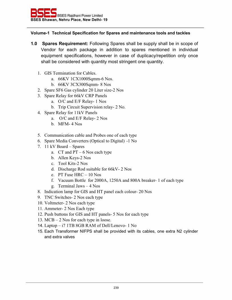
BSES Bhawan, Nehru Place, New Delhi- 19 Volume-1 Technical Specification for Spares and maintenance tools and tackles
1.0 Spares Requirement: Following Spares shall be supply shall be in scope of
Vendor for each package in addition to spares mentioned in individual equipment specifications, however in case of duplicacy/repetition only once shall be considered with quantity most stringent one quantity. 1. GIS Termination for Cables.
a. 66KV 1CX1000Sqmm-6 Nos.
b. 66KV 3CX300Sqmm- 8 Nos
2. Spare SF6 Gas cylinder 20 Liter size-2 Nos
3. Spare Relay for 66kV CRP Panels
a. O/C and E/F Relay- 1 Nos
b. Trip Circuit Supervision relay- 2 No. 4. Spare Relay for 11kV Panels
a. O/C and E/F Relay- 2 Nos
b. MFM- 4 Nos
5. Communication cable and Probes one of each type 6. Spare Media Converters (Optical to Digital) -1 No
7. 11 kV Board – Spares
a. CT and PT – 6 Nos each type
b. Allen Keys-2 Nos c. Tool Kits-2 Nos d. Discharge Rod suitable for 66kV- 2 Nos e. PT Fuse HRC – 10 Nos
f. Vacuum Bottle for 2000A, 1250A and 800A breaker- 1 of each type
g. Terminal Jaws – 4 Nos 8. Indication lamp for GIS and HT panel each colour- 20 Nos
9. TNC Switches- 2 Nos each type
10. Voltmeter- 2 Nos each type 11. Ammeter- 2 Nos Each type
12. Push buttons for GIS and HT panels- 5 Nos for each type
13. MCB – 2 Nos for each type in loose.
14. Laptop – i7 1TB 8GB RAM of Dell/Lenovo- 1 No 15. Each Transformer NIFPS shall be provided with its cables, one extra N2 cylinder
and extra valves
239
BSES Bhawan, Nehru Place, New Delhi- 19 Volume-1 Technical Specification for Spares and maintenance tools and tackles
2.0 Maintenance tools and tackles: Following supply shall be in scope of Vendor for each package in addition to maintenance tools and tackles mentioned in individual equipment specifications, however in case of duplicacy/repetition only once shall be considered with quantity most stringent one quantity.
1. Cable Spiking tool (UV Make)---1 No 2. Torque Spanners---4 Nos 3. Three Phase Secondary Injection Kit (as per specs) of Omicron make– 1 No
Note: Approval of Model no and make wherever not defined shall be done at the time of Bid evaluation
240
BSES Bhawan, Nehru Place, New Delhi- 19
Prepared by Seema Rev: 7
Reviewed by Amit Tomar Date: 16.01.2018
Approved by Vijay Panpalia
1.0 CODES & STANDARDS:
TECHNICAL SPECIFICATION
FOR
STATION TRANSFORMER
241
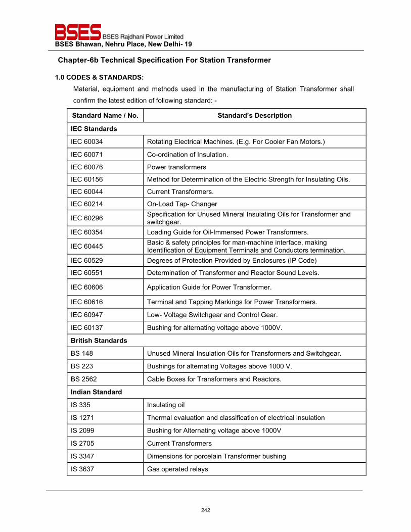
BSES Bhawan, Nehru Place, New Delhi- 19
Chapter-6b Technical Specification For Station Transformer
1.0 CODES & STANDARDS:Material, equipment and methods used in the manufacturing of Station Transformer shall
confirm the latest edition of following standard: -
Standard Name / No. Standard’s Description
IEC Standards
IEC 60034 Rotating Electrical Machines. (E.g. For Cooler Fan Motors.)
IEC 60071 Co-ordination of Insulation.
IEC 60076 Power transformers
IEC 60156 Method for Determination of the Electric Strength for Insulating Oils.
IEC 60044 Current Transformers.
IEC 60214 On-Load Tap- Changer
IEC 60296 Specification for Unused Mineral Insulating Oils for Transformer and switchgear.
IEC 60354 Loading Guide for Oil-Immersed Power Transformers.
IEC 60445 Basic & safety principles for man-machine interface, making Identification of Equipment Terminals and Conductors termination.
IEC 60529 Degrees of Protection Provided by Enclosures (IP Code)
IEC 60551 Determination of Transformer and Reactor Sound Levels.
IEC 60606 Application Guide for Power Transformer.
IEC 60616 Terminal and Tapping Markings for Power Transformers.
IEC 60947 Low- Voltage Switchgear and Control Gear.
IEC 60137 Bushing for alternating voltage above 1000V.
British Standards
BS 148 Unused Mineral Insulation Oils for Transformers and Switchgear.
BS 223 Bushings for alternating Voltages above 1000 V.
BS 2562 Cable Boxes for Transformers and Reactors.
Indian Standard
IS 335 Insulating oil
IS 1271 Thermal evaluation and classification of electrical insulation
IS 2099 Bushing for Alternating voltage above 1000V
IS 2705 Current Transformers
IS 3347 Dimensions for porcelain Transformer bushing
IS 3637 Gas operated relays
242
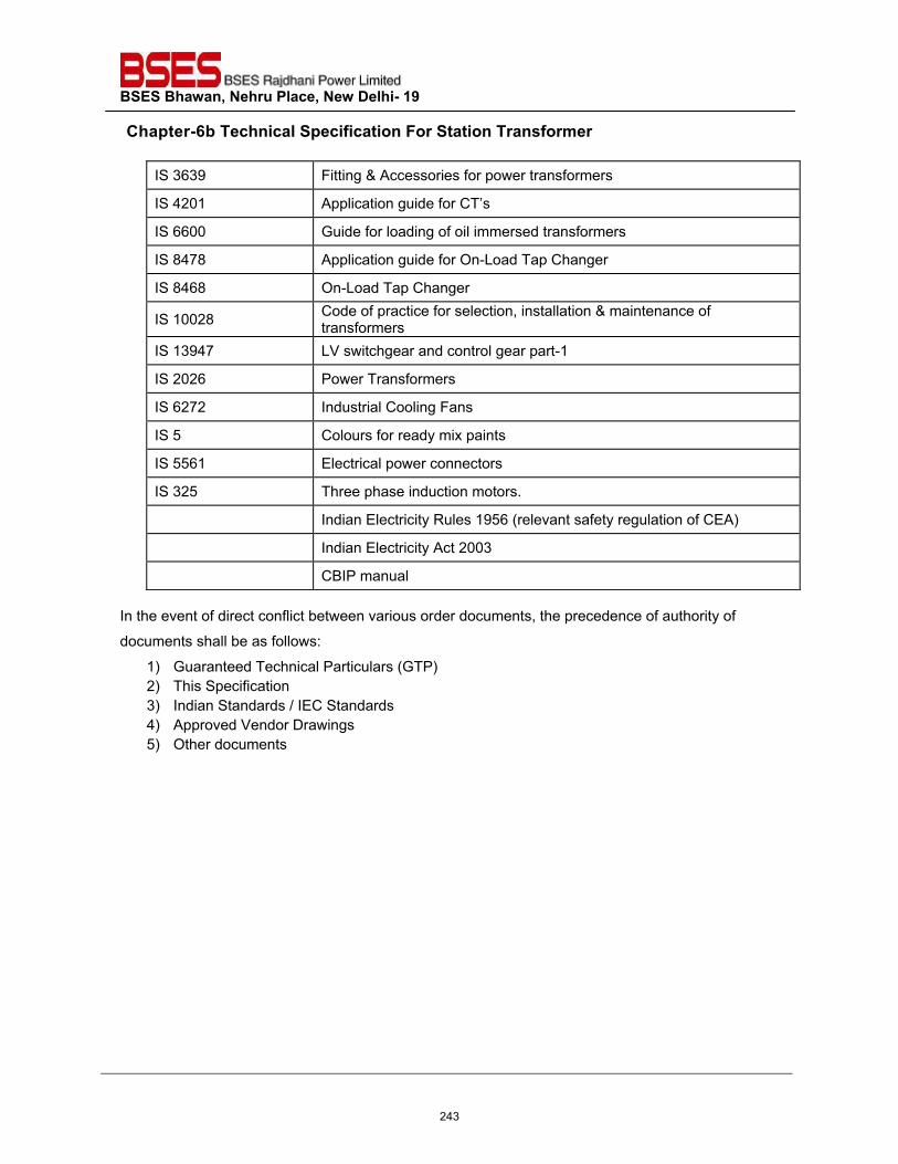
BSES Bhawan, Nehru Place, New Delhi- 19
Chapter-6b Technical Specification For Station Transformer
IS 3639 Fitting & Accessories for power transformers
IS 4201 Application guide for CT’s
IS 6600 Guide for loading of oil immersed transformers
IS 8478 Application guide for On-Load Tap Changer
IS 8468 On-Load Tap Changer
IS 10028 Code of practice for selection, installation & maintenance of transformers
IS 13947 LV switchgear and control gear part-1
IS 2026 Power Transformers
IS 6272 Industrial Cooling Fans
IS 5 Colours for ready mix paints
IS 5561 Electrical power connectors
IS 325 Three phase induction motors.
Indian Electricity Rules 1956 (relevant safety regulation of CEA)
Indian Electricity Act 2003
CBIP manual In the event of direct conflict between various order documents, the precedence of authority of
documents shall be as follows:
1) Guaranteed Technical Particulars (GTP) 2) This Specification 3) Indian Standards / IEC Standards 4) Approved Vendor Drawings 5) Other documents
243
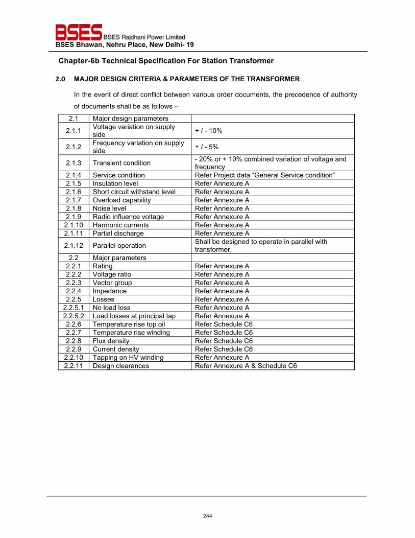
BSES Bhawan, Nehru Place, New Delhi- 19
Chapter-6b Technical Specification For Station Transformer
2.0 MAJOR DESIGN CRITERIA & PARAMETERS OF THE TRANSFORMER In the event of direct conflict between various order documents, the precedence of authority
of documents shall be as follows –
2.1 Major design parameters
2.1.1 Voltage variation on supply side + / - 10%
2.1.2 Frequency variation on supply side + / - 5%
2.1.3 Transient condition - 20% or + 10% combined variation of voltage and frequency
2.1.4 Service condition Refer Project data “General Service condition” 2.1.5 Insulation level Refer Annexure A 2.1.6 Short circuit withstand level Refer Annexure A 2.1.7 Overload capability Refer Annexure A 2.1.8 Noise level Refer Annexure A 2.1.9 Radio influence voltage Refer Annexure A 2.1.10 Harmonic currents Refer Annexure A 2.1.11 Partial discharge Refer Annexure A 2.1.12 Parallel operation Shall be designed to operate in parallel with
transformer. 2.2 Major parameters
2.2.1 Rating Refer Annexure A 2.2.2 Voltage ratio Refer Annexure A 2.2.3 Vector group Refer Annexure A 2.2.4 Impedance Refer Annexure A 2.2.5 Losses Refer Annexure A
2.2.5.1 No load loss Refer Annexure A 2.2.5.2 Load losses at principal tap Refer Annexure A 2.2.6 Temperature rise top oil Refer Schedule C6 2.2.7 Temperature rise winding Refer Schedule C6 2.2.8 Flux density Refer Schedule C6 2.2.9 Current density Refer Schedule C6 2.2.10 Tapping on HV winding Refer Annexure A 2.2.11 Design clearances Refer Annexure A & Schedule C6
244
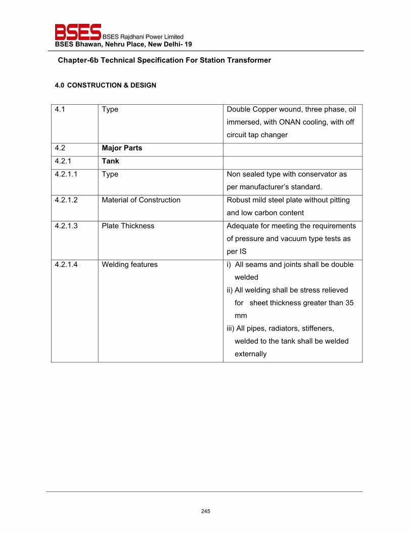
BSES Bhawan, Nehru Place, New Delhi- 19
Chapter-6b Technical Specification For Station Transformer
4.0 CONSTRUCTION & DESIGN
4.1 Type Double Copper wound, three phase, oil
immersed, with ONAN cooling, with off
circuit tap changer
4.2 Major Parts
4.2.1 Tank
4.2.1.1 Type Non sealed type with conservator as
per manufacturer’s standard.
4.2.1.2 Material of Construction Robust mild steel plate without pitting
and low carbon content
4.2.1.3 Plate Thickness Adequate for meeting the requirements
of pressure and vacuum type tests as
per IS
4.2.1.4 Welding features i) All seams and joints shall be double
welded
ii) All welding shall be stress relieved
for sheet thickness greater than 35
mm
iii) All pipes, radiators, stiffeners,
welded to the tank shall be welded
externally
245
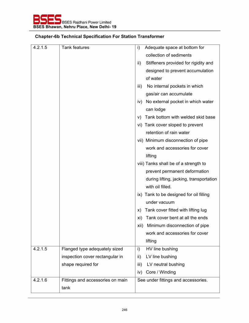
BSES Bhawan, Nehru Place, New Delhi- 19
Chapter-6b Technical Specification For Station Transformer
4.2.1.5 Tank features i) Adequate space at bottom for
collection of sediments
ii) Stiffeners provided for rigidity and
designed to prevent accumulation
of water
iii) No internal pockets in which
gas/air can accumulate
iv) No external pocket in which water
can lodge
v) Tank bottom with welded skid base
vi) Tank cover sloped to prevent
retention of rain water
vii) Minimum disconnection of pipe
work and accessories for cover
lifting
viii) Tanks shall be of a strength to
prevent permanent deformation
during lifting, jacking, transportation
with oil filled.
ix) Tank to be designed for oil filling
under vacuum
x) Tank cover fitted with lifting lug
xi) Tank cover bent at all the ends
xii) Minimum disconnection of pipe
work and accessories for cover
lifting
4.2.1.5 Flanged type adequately sized
inspection cover rectangular in
shape required for
i) HV line bushing
ii) LV line bushing
iii) LV neutral bushing
iv) Core / Winding
4.2.1.6 Fittings and accessories on main
tank
See under fittings and accessories.
246
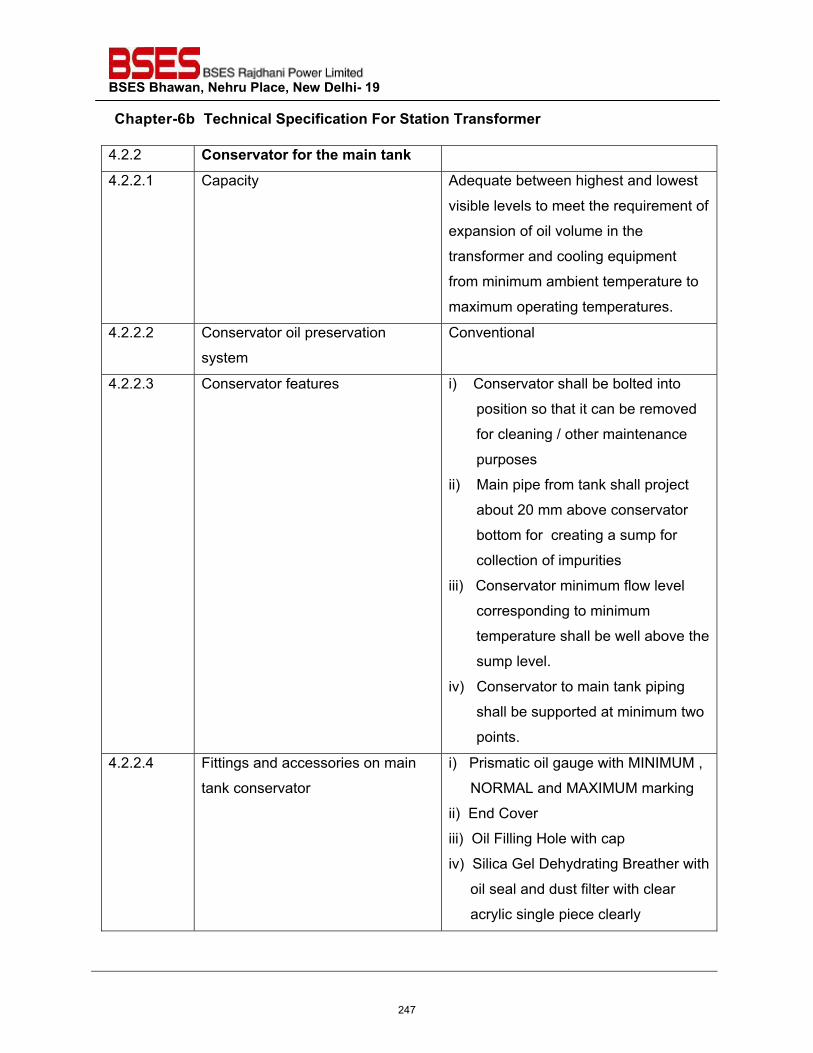
BSES Bhawan, Nehru Place, New Delhi- 19
Chapter-6b Technical Specification For Station Transformer
4.2.2 Conservator for the main tank
4.2.2.1 Capacity Adequate between highest and lowest
visible levels to meet the requirement of
expansion of oil volume in the
transformer and cooling equipment
from minimum ambient temperature to
maximum operating temperatures.
4.2.2.2 Conservator oil preservation
system
Conventional
4.2.2.3 Conservator features i) Conservator shall be bolted into
position so that it can be removed
for cleaning / other maintenance
purposes
ii) Main pipe from tank shall project
about 20 mm above conservator
bottom for creating a sump for
collection of impurities
iii) Conservator minimum flow level
corresponding to minimum
temperature shall be well above the
sump level.
iv) Conservator to main tank piping
shall be supported at minimum two
points.
4.2.2.4 Fittings and accessories on main
tank conservator
i) Prismatic oil gauge with MINIMUM ,
NORMAL and MAXIMUM marking
ii) End Cover
iii) Oil Filling Hole with cap
iv) Silica Gel Dehydrating Breather with
oil seal and dust filter with clear
acrylic single piece clearly
247
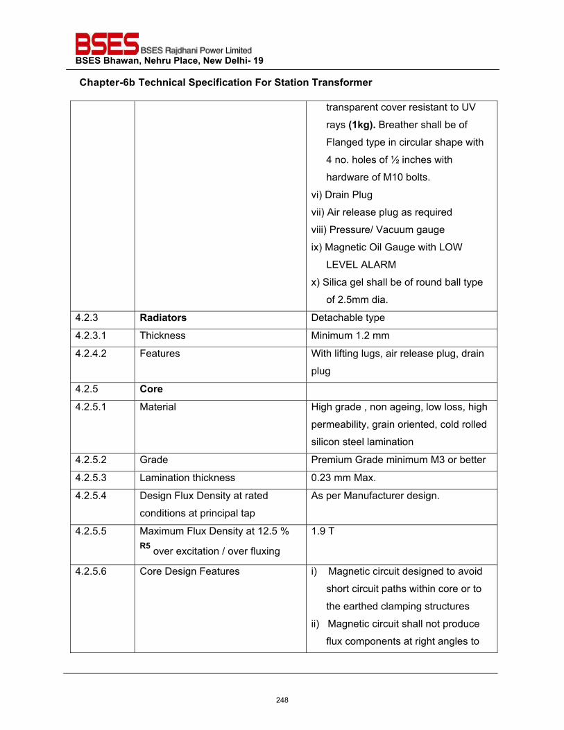
BSES Bhawan, Nehru Place, New Delhi- 19
Chapter-6b Technical Specification For Station Transformer
transparent cover resistant to UV
rays (1kg). Breather shall be of
Flanged type in circular shape with
4 no. holes of ½ inches with
hardware of M10 bolts.
vi) Drain Plug
vii) Air release plug as required
viii) Pressure/ Vacuum gauge
ix) Magnetic Oil Gauge with LOW
LEVEL ALARM
x) Silica gel shall be of round ball type
of 2.5mm dia.
4.2.3 Radiators Detachable type
4.2.3.1 Thickness Minimum 1.2 mm
4.2.4.2 Features With lifting lugs, air release plug, drain
plug
4.2.5 Core
4.2.5.1 Material High grade , non ageing, low loss, high
permeability, grain oriented, cold rolled
silicon steel lamination
4.2.5.2 Grade Premium Grade minimum M3 or better
4.2.5.3 Lamination thickness 0.23 mm Max.
4.2.5.4 Design Flux Density at rated
conditions at principal tap
As per Manufacturer design.
4.2.5.5 Maximum Flux Density at 12.5 % R5 over excitation / over fluxing
1.9 T
4.2.5.6 Core Design Features i) Magnetic circuit designed to avoid
short circuit paths within core or to
the earthed clamping structures
ii) Magnetic circuit shall not produce
flux components at right angles to
248
BSES Bhawan, Nehru Place, New Delhi- 19
Chapter-6b Technical Specification For Station Transformer
the plane of lamination to avoid local
heating
iii) Least possible air gap and rigid
clamping for minimum core loss
and noise generation
iv) Adequately braced to withstand
bolted faults on secondary
terminals without mechanical
damage and damage/
displacement during transportation
and positioning.
v) Percentage harmonic potential with
the maximum flux density under
any condition limited to avoid
capacitor overloading in the system
vi) All steel sections used for
supporting the core shall be
thoroughly sand blasted after
cutting , drilling, welding
vii) Provision of lifting lugs for core coil
assembly
viii) Supporting framework designed not
to obstruct complete drainage of oil
from transformer
4.2.6 Winding
4.2.6.1 Material Electrolytic Copper
4.2.6.2 Maximum Current Density allowed 3 Amp per sq mm at all taps.
4.2.6.3 Winding Insulating material Class A, non catalytic, inert to
transformer oil, free from compounds
liable to ooze out, shrink or collapse.
4.2.6.4 Winding Insulation Uniform
249
BSES Bhawan, Nehru Place, New Delhi- 19
Chapter-6b Technical Specification For Station Transformer
4.2.6.5 Design features i) Stacks of winding to receive
adequate shrinkage treatment
ii) Connections braced to withstand
shock during transport, switching,
short circuit, or other transients.
iii) Minimum out of balance force in the
transformer winding at all voltage
ratios.
iv) Conductor width on edge
exceeding six times its thickness
v) Transposed at sufficient intervals.
vi) Coil assembly shall be suitably
supported between adjacent
sections by insulating spacers +
barriers
vii) Winding leads rigidly supported ,
using guide tubes if practicable
viii) Winding structure and major
insulation not to obstruct free flow
of oil through ducts
ix) Provision of taps as per clause
3.41
4.2.7 Transformer Oil
4.2.7.1 Type Should be in accordance with
specification as per Annex C of this
document One sample of oil shall be drawn from
every lot of transformer offered for
inspection should be tested at
CPRI/ERDA for tests as listed under
BSES Standard QAP[R6].The cost of this
testing should be included within the cost
250
BSES Bhawan, Nehru Place, New Delhi- 19
Chapter-6b Technical Specification For Station Transformer
of transformer. The results shall be
confirming to BSES specification Annex
CR4
4.2.8 Bushings and Terminations
4.2.8.1 Type of HV side bushing Outdoor, Epoxy Resin cast, rated
voltage and creepage as per 31mm/kV
with voltage class of 12kV respectively
4.2.8.2 Type of LV side bushing Outdoor, Epoxy resin cast, rated
voltage and creepage as per 31mm/kV
with voltage class of 1.1 kV respectively
Additional neutral bushing shall be
provided of porcelain.
4.2.8.2.1 Essential provision for LV side line
bushing
It shall be complete with copper palm
complete with tinned copper busbar of
size 100 x 12 mm for cable connection
4.2.8.2.2 Essential provision for LV side
neutral bushing
In case of neutral bushing the stem and
busbar shall be integral without bolted,
threaded, brazed joints. Busbar size
shall be 100 x 12 mm for cable
connection.
4.2.8.3 Arcing Horns Not required
4.2.8.4 Support insulators inside HV cable
box if provided
Epoxy resin cast, rated voltage 12 kV
4.2.8.5 Termination on HV side bushing By bimetallic terminal connectors
suitable for ACSR/AAAC conductor /
Cable connection through cable box
with disconnecting link suitable for
11kV(E) grade,A2XFY 3Cx 150sqmm
4.2.8.6 Termination of LV side bushing By bimetallic terminal connectors
suitable for LV Cable size of
650/1100VGrade, A2XY Cable single
251
BSES Bhawan, Nehru Place, New Delhi- 19
Chapter-6b Technical Specification For Station Transformer
core 630sqmm(Approx dia. 40mm)
4.2.8.7 Minimum creepage distance of all
bushings and support insulators.
31mm/KV
4.2.8.8 Protected creepage distance At least 50 % of total creepage distance
4.2.8.9 Continuous Current rating Minimum 20 % higher than the current
corresponding to the minimum tap of
the transformer
4.2.8.10 Rated thermal short time current 25 times the rated current for 2 sec
4.2.8.11 Atmospheric protection for clamp
and fitting of iron and steel
Hot dip galvanizing as per IS 2633
4.2.8.12 Bushing terminal lugs in oil and air Tinned copper
4.2.8.13 Sealing washers /Gasket ring Nitrile cork rubber (RC70C)/ Expanded
TEFLON (PTFE) as applicable.
4.2.9 HV & LV cable box Required
4.2.9.1 Material of Construction Sheet Steel min. 2.5 mm thick
4.2.9.2 Cable entry At bottom through detachable gland
plate with cable clamps of non
magnetic material
4.2.9.3 Cable size for HV 11 kV (E) grade , A2XFY 3C x 150
sqmm
4.2.9.4 Cable size for LV LV cable size, 650 /1100 V grade
,A2XY cable single core 630 sqmm
unarmoured (approx cable dia. 40 mm)
4.2.9.5 Cable size for LV Neutral LV cable size, 650 /1100 V grade
,A2XY cable single core 630 sqmm
unarmoured (approx cable dia. 40 mm)
4.2.9.6 Detachable Gland Plate material
for HV, LV, LV Neutral box
MS/Al for HV & LV respectively.
4.2.9.7 Gland plate thickness for HV, LV,
LV Neutral box
3 /5mm for HV & LV respectively.
4.2.9.8 Cable gland for HV, LV, LV Neutral Nickel plated brass double compression
252
BSES Bhawan, Nehru Place, New Delhi- 19
Chapter-6b Technical Specification For Station Transformer
cables weatherproof cable gland
4.2.9.9 Cable lug for HV, LV, LV Neutral
cables
Tinned copper pre insulated Pin, Ring,
Fork type as applicable
4.2.9.10 Essential parts i) Flange type removable front cover
with handles min two nos.
ii) Tinned Copper Busbar of adequate
size for Purchaser’s cable
termination with busbar supports
iii) Earthing boss for the cable box
iv) Earthing link for the gasketted joints
at two point for each joint
v) Earthing provision for cable Armour/
Screen
vi) Flanged type inspection cover on top
for bushing inspection and
maintenance with handle
vii) Drain plug
viii) Rainhood on gasketted vertical joint
ix) Danger / caution plate
4.2.9.11 Terminal Clearances 700mm, Minimum
4.2.9.12 Termination height required for
cable termination
1000mm, Minimum
4.2.10 Current Transformers
4.2.10.1 Provision On all three phases on LV side
4.2.10.2 Mounting On LV side bushings on all three
phases with the help of fiber glass
mounting plate affixed to main tank by
nut bolt arrangement
4.2.10.3 Maintenance requirements Replacement should be possible by
removing fixing nut of mounting plate
after removal of LT cable without
253
BSES Bhawan, Nehru Place, New Delhi- 19
Chapter-6b Technical Specification For Station Transformer
disturbing LT bushing
4.2.10.4 Accuracy Class 0.5
4.2.10.5 Burden 10VA
4.2.10.6 Type Resin Cast Ring type suitable for
outdoor use
4.2.10.7 CT ratio
400KVA 600/5
630KVA 1000/5
1000KVA 1500/5
4.2.10.8 CT terminal Box
4.2.10.8.1 Size 650 mm height x 450 mm width x 275
mm depth.
4.2.10.8.2 Fixing of instrument / meters within
box
On slotted channel 40 x 12 mm size,
channel fixed on vertical slotted angle
40 x 40 mm size at two ends
4.2.10.8.3 No of horizontal channels to be
provided
Four
4.2.10.8.4 Fixing of terminals within the box On horizontal slotted channel with the
help of C channel available with the
terminals
4.2.10.8.5 Location On tank wall
4.2.10.8.6 Box door design Openable from outside with antitheft
hinge, padlock facility, door fixed by
stainless steel allen screw M6 size ,
door shall have canopy for rain
protection
4.2.10.8.7 Terminal strip Nylon 66 material, minimum 4 sq mm,
screw type for control wiring and
potential circuit.
4.2.10.8.8 Cables and wires PVC insulated, extruded PVC inner
sheathed, armoured, extruded PVC
254
BSES Bhawan, Nehru Place, New Delhi- 19
Chapter-6b Technical Specification For Station Transformer
outer sheathed 1100 V grade control
cable as per latest edition of IS 1554
part 1 minimum 2.5 sq mm for signals
and 4 sq mm for CT with multi strand
copper conductor
4.2.10.8.9 Cable Glands Nickel plated brass double
compression weatherproof cable gland
4.2.10.8.10 Lugs on wires Tinned copper pre insulated Pin, Ring,
Fork type as applicable
4.2.10.8.11 Potential signal in CT box i)Tapped from main LV busbar
ii) Neutral Link and Fuse to be provided
by bidder for PT
4.2.10.8.12 Essential provision Wiring diagram to be fixed on the back
of door along with CT spec. on
Aluminum engraved plate fixed by rivet.
4.2.11 Off Circuit tap Switch
4.2.11.1 Range /Step Off circuit taps on HV winding, +5% to -
10% in steps of 2.5%, change of taps
by externally operated switch.
4.2.11.2 Type Rotary type, 3 pole gang operated,
draw out type
4.2.11.3 Operating Voltage 11kV
4.2.11.4 Rated Current for tap Switch 400 KVA - 60 Amps
630/1000 KVA - 100 Amps
4.2.11.5 Operating Handle External at suitable height to be
operated from ground level.
4.2.11.6 Essential provision Tap position indicator, direction
changing facility, locking arrangement,
and caution plate metallic fixed by rivet.
4.2.12 Pressure Relief Device
4.2.12.1 Type Explosion vent
255
BSES Bhawan, Nehru Place, New Delhi- 19
Chapter-6b Technical Specification For Station Transformer
4.2.12.2 Provision on explosion vent Double diaphragm & sight glass
4.3 Hardware
4.3.1 External Stainless Steel
4.3.2 Internal Cadmium plated except special
hardware for frame parts and core
assembly as per manufacturer’s design
4.4 Gasket
4.4.1 For Transformer , surfaces
interfacing with oil like inspection
cover etc.
Nitrile cork rubber RC70C grade
4.4.2 For Cable boxes, Marshalling box,
etc.
Neoprene rubber based/ cork nitrile
4.5 Valves
4.5.1 Material of construction Brass / gun metal
4.5.2 Type Both end flanged gate valve / butterfly
valve depending on application
4.5.3 Size As per manufacturer’s standard
4.5.4 Essential provision Position indicator, locking rod,
padlocking facility, valve guard, cover
plate.
4.6 Cable routing on Transformer Control cables for accessories on
transformer tank shall be routed
through perforated GI trays
4.6.1 Control cable specification PVC insulated, extruded PVC inner
sheathed, armoured, extruded PVC
outer sheathed 1100 V grade control
cable as per latest edition of IS 1554
part 1 minimum 2.5 sq mm for signals
and 4 sq mm for CT with multi strand
copper conductor
4.6.2 Specification of wires to be used PVC insulated multi-strand flexible
256
BSES Bhawan, Nehru Place, New Delhi- 19
Chapter-6b Technical Specification For Station Transformer
inside marshalling box , OLTC
drive mechanism
copper wires of minimum 2.5 sq mm
size, 1100 V grade as per latest edition
of relevant IS
4.7 Terminal Blocks to be used by the vendor
Nylon 66 material, minimum 4 sq mm,
screw type for control wiring and
potential circuit.
4.7.1 Essential provision for CT terminals Sliding link type disconnecting terminal
block screwdriver operated stud type
with facility for CT terminal shorting
material of housing melamine/ Nylon66
4.8 Cable glands to be used by the vendor
Nickel plated brass double compression
weatherproof cable gland
4.9 Cable lugs to be used by the vendor
4.9.1 For power cables Long barrel medium duty Aluminum lug
with knurling on inside surface.
4.9.2 For Control Cable Tinned copper pre insulated Pin, Ring,
Fork type as applicable
4.10 Painting of transformer, Radiator, marshalling box for CT, cable boxes etc.
4.10.1 Surface preparation By 7 tank pretreatment process or shot
blasting method
4.10.2 Finish on internal surfaces of the
transformer
Bright Yellow heat resistant and oil
resistant paint two coats. Paint shall
neither react nor dissolve in hot
transformer insulating oil.
4.10.3 Finish on inner surface of the CT
terminal box, HV/LV/LVN cable box
White Polyurethane paint anti
condensation type two coats , minimum
dry film thickness 80 microns
4.10.4 Finish on outer surface of the Battle ship Grey shade 632
257
BSES Bhawan, Nehru Place, New Delhi- 19
Chapter-6b Technical Specification For Station Transformer
transformer, radiator, CT terminal
box, HV/LV/LVN cable box
Polyurethane paint two coats ,
minimum dry film thickness 80 microns
4.10.5 Frame parts Battle ship grey shade 632 IS 5, 80
micron minimum insulating oil resistant
paint. Paint shall neither react nor
dissolve in hot transformer insulating
oil.
4.11 Winding /Oil Temperature scanner for 1000KVA DT [R7]
Required
4.11.1 No. of RTD inputs Five (Three for windings, one for
enclosure & one shall be spare) RTD
for enclosure temperature monitoring
shall be fixed at enclosure Top from
inside to give max. Enclosure temp
reading & shall be wired up to temp.
Scanner to indicate the reading.
4.11.2 Location of winding RTD At location of winding where maximum
Temperature is expected.
4.11.3 No of potential free trip contacts Two
4.11.4 No of potential free Alarm contacts Two
4.11.5 Auxiliary Supply 240 V AC, 1 phase, 50 Hz. Tapped
from LV side busbar through a MCB
located inside box.
4.11.6 Winding Temperature Scanner
terminal Box
Required
4.11.7 Size As per manufacturers standard
4.11.8 Fixing of instrument within box On side wall of enclosure
4.11.9 Fixing of terminals within the box On C channel available with the
terminals
4.11.10 Location Within enclosure frame such that
Marshalling Box & WTI on same side &
free access to all LV side doors.
258
BSES Bhawan, Nehru Place, New Delhi- 19
Chapter-6b Technical Specification For Station Transformer
4.11.11 Terminal Strip Nylon 66 material, minimum 4 sq mm,
screw type for control wiring and
potential circuit.
4.11.12 Cables & Wires PVC insulated, extruded PVC inner
sheathed, armoured, extruded PVC
outer sheathed 1100 V grade control
cable as per latest edition of IS 1554
part 1 minimum 2.5 sqmm for signals
and 4 sqmm for CT with multistrand
copper conductor & PVC insulated
multistrand flexible copper wires of
minimum 2.5 sqmm size, 1100 V grade
as per latest edition of relevant IS
4.11.13 Cable Glands Nickel plated brass double compression
weatherproof cable gland
4.11.14 Lugs on wires Tinned copper preinsulated Pin, Ring,
Fork type as applicable
4.11.15 Auxiliary supply in box Tapped from main LV busbars, taken
via MCB for isolation and protection of
scanner, MCB to be fixed on DIN rail
with clamps on two sides.
4.11.16 Essential provision Wiring diagram to be fixed on the back
of door along with brief details of
scanner, HV side, LV side door limit
switches to be wired up-to Terminal
Block, Service socket to be provided
with switch, fuse and link.
5.0 FITTINGS AND ACCESSORIES ON TRANSFORMER
5.1 Rating and Diagram Plate Required
5.1.1 Material Anodized aluminum 16SWG
259
BSES Bhawan, Nehru Place, New Delhi- 19
Chapter-6b Technical Specification For Station Transformer
5.1.2 Background SATIN SILVER
5.1.3 Letters, diagram & border Black
5.1.4 Process Etching
5.1.5 Rating and Diagram Plate details Following details shall be provided on
rating and diagram plate as a minimum
i) type/kind of transformer with
winding material
ii) standard to which it is
manufactured
iii) manufacturer's name;
iv) transformer serial number;
v) month and year of manufacture
vi) rated frequency in Hz
vii) rated voltages in kV
viii) number of phases
ix) rated power in KVA
x) type of cooling (ONAN)
xi) rated currents in A
xii) vector group connection symbol
xiii) 1.2/50μs wave impulse voltage
withstand level in kV
xiv) power frequency withstand voltage
in kV
xv) impedance voltage at rated current
and frequency in percentage at
principal, minimum and maximum
tap
xvi) Max. Total losses at 50 % rated
load
xvii) Max. Total losses at 100 % rated
load
260
BSES Bhawan, Nehru Place, New Delhi- 19
Chapter-6b Technical Specification For Station Transformer
xviii) Load loss at 50% & 100% rated
load
xix) No-load loss at rated voltage and
frequency
xx) Energy efficiency level.
xxi) continuous ambient temperature
at which ratings apply in deg C
xxii) top oil and winding temperature
rise at rated load in deg C;
xxiii) winding connection diagram with
taps and table of tapping voltage,
current and power
xxiv) transport weight of transformer
xxv) weight of core and windings
xxvi) total weight
xxvii) volume of oil
xxviii) weight of oil
xxix) name of the purchaser
xxx) PO no and date
xxxi) Guarantee period
5.2 Terminal marking Plate for
Bushing, anodized aluminium
black lettering on satin silver
background both inside cable
boxes near termination and on
cable box cover (all fixed by rivet)
Required
5.3 Company Monogram Plate fixed
by rivet
Required
5.4 Lifting Lug to lift complete
transformer with oil
Required
5.5 Lifting lug for top cover Required
261
BSES Bhawan, Nehru Place, New Delhi- 19
Chapter-6b Technical Specification For Station Transformer
5.6 Lashing Lug Required
5.7 Jacking Pad with Haulage hole to
raise or lower complete
transformer with oil
Required
5.8 Detachable Bidirectional flat roller
Assembly
Required
5.8.1 Roller center to center distance Minimum 900 mm on the side of HV
and LV cable box
Maximum 800 mm on the other side
(perpendicular to HV, LV cable box).
5.8.2 Essential provision Roller dia 150 mm min., roller to be
fixed in such a way so that the
lowermost part of the skid is above
ground by at least 100 mm when the
transformer is installed on roller.
5.9 Pockets for ordinary thermometer
on tank cover with metallic
identification plate fixed by rivet.
Required
5.10 Drain valve (gate valve) for the
main tank with cork above ground
by 150mm minimum with
padlocking and valve guard with
metallic identification plate fixed by
rivet.
Required
5.11 Filter valve (gate valve) at top with
padlocking and valve guard with
metallic identification plate fixed by
rivet.
Required
5.12 Air Release Plug on tank cover
with metallic identification plate
fixed by rivet.
Required
262
BSES Bhawan, Nehru Place, New Delhi- 19
Chapter-6b Technical Specification For Station Transformer
5.13 Equalizer pipe connection
between conservator and
explosion vent
Required
5.14 Earthing pad on tank for
transformer earthing complete with
non ferrous nut ., bolt, washers,
spring washers etc. with metallic
identification plate fixed by rivet
Required
5.15 Rainhood for vertical gasketted
joints , in cable boxes,
Conservator
Required Not required as per
Annexure A Scope of supply
5.16 Earthing bridge by copper strip
jumpers on all gasketted joints at
at least two points for electrical
continuity
Required
5.17 Skid base welded type with
haulage hole
Required
5.18 Core , Frame to tank Earthing Required
5.19 Danger plate made of Anodized
aluminum with white letters on red
background on Transformer, cable
boxes (all fixed by rivet)
Required
5.20 Caution plate for Off Circuit tap
changer fixed by rivet.
Required
5.21 MOG with auxiliary contact wired
up to Terminal Box
Required
5.22 Buchholz relay with auxiliary
contact wired up to Terminal Box
for 1000KVA DT [R7]
Required
5.23 WTI/OTI Scanner with auxiliary
contact wired up to Terminal Box
Required
263
BSES Bhawan, Nehru Place, New Delhi- 19
Chapter-6b Technical Specification For Station Transformer
for 1000KVA DT [R7]
6.0 APPROVED MAKE AND COMPONENTS
6.1 CT Pragati / ECS / Kappa
6.2 Bushings Baroda Bushing/CJI/Jaipur Glass
6.3 Tap Changer Alwaye /Paragon
6.4 MOG Sukrut/Atvus
6.5 Valves Newman
6.6 CRGO Nippon/JFE/Posco
6.7 Copper Birla copper/Sterlite
6.8 Pre compressed Pressboard Raman Board, Mysore/Senapathy
Whiteley
6.9 Laminated Wood Permalli Wallance / Rochling
Engineers
6.10 Oil Apar/Savita/Raj
6.11 Steel TATA/Jindal/SAIL
6.12 Lugs/Glands Jainson/Dowells/Comet
6.13 Radiators CTR/Hi-Tech Radiators /Tarang
Engineers
6.14 Buchholz Relay [R7] Sukrut/Atvus
6.15 WTI/OTI Scanner [R7] Pecon/Precimeaure
Note – Any other make of component to be approved by purchaser
7.0 INSPECTION & TESTING
7.1 Inspection and Testing during
manufacture
Only type tested equipment shall be
acceptable
7.1.1 Tank and Conservator i) Check correct dimensions between wheels demonstrate turning of wheels through 90 deg and further dimensional check.
ii) Check for physical properties of materials for lifting lugs, jacking
264
BSES Bhawan, Nehru Place, New Delhi- 19
Chapter-6b Technical Specification For Station Transformer
pads etc. All load bearing welds, including lifting lug welds shall be subjected to
required load tests. iii) Leakage test of the conservator. i) Certification of all test results. ii) Oil leakage test. iii) Vacuum and Pressure test on tank
as type test as per IS 7.1.2 Core i) Sample testing of core material for
checking specific loss, bend properties, magnetization characteristics and thickness.
ii) Check on the quality of varnish if used on the stampings. a) Measurement of thickness and
hardness of varnish on stampings.
b) Solvent resistance test to check that varnish does not react in hot oil.
c) Check over all quality of varnish by sampling to ensure uniform hipping colour, no bare spots. No ever burnt varnish layer and no bubbles on varnished surface.
iii) Check on the amount of burns. iv) Bow check on stampings. v) Check for the overlapping of
stampings. Corners of the sheet are to be apart.
vi) Visual and dimensional check during assembly stage.
vii) Check on complete core for measurements of iron-loss and check for any hot spot by exciting the core so as to induce the designed value of flux density in the core.
viii) Check for inter laminar insulation
265
BSES Bhawan, Nehru Place, New Delhi- 19
Chapter-6b Technical Specification For Station Transformer
between core sectors before and after pressing.
ix) Visual and dimensional checks for straightness and roundness of core, thickness of limbs and suitability of clamps.
x) High voltage test (2 KV for one minute) between core and clamps.
xi) Certification of all test results. 7.1.3 Insulating Materials i) Sample check for physical
properties of materials. ii) Check for dielectric strength. iii) Visual and dimensional
checks. iv) Check for the reaction of hot oil on
insulating materials. v) Certification of all test results.
7.1.4 Windings i) Sample check on winding conductor for mechanical properties and electrical conductivity.
ii) Visual and dimensional check on conductor for scratches, dept. mark etc.
iii) Sample check on insulating paper for PE value, Bursting strength, Electric strength.
iv) Check for the reaction of hot oil on insulating paper.
v) Check for the bending of the insulating paper on conductor.
vi) Check and ensure that physical condition of all materials taken for winding is satisfactory and free of dust.
vii) Check for absence of short circuit between parallel strands.
viii) Check for Brazed joints wherever applicable.
ix) Measurement of voltage ratio to be carried out when core/ yoke is
266
BSES Bhawan, Nehru Place, New Delhi- 19
Chapter-6b Technical Specification For Station Transformer
completely restocked and all connections are ready.
x) Certification of all test results. 7.1.4.1 Checks before drying process i) Check conditions of insulation on
the conductor and between the windings.
ii) Check insulation distance between high voltage connection distance between high voltage connection cables and earthed and other live parts.
iii) Check insulation distance between low voltage connection and earthed and other parts.
iv) Insulation test of core earthing. v) Check for proper cleanliness vi) Check tightness of coils i.e. no
free movement. vii) Certification of all test results.
7.1.4.2 Checks during drying process i) Measurement and recording of temperature and drying time during vacuum treatment.
ii) Check for completeness of drying. iii) Certification of all test results.
7.1.5 Oil As per IS 335/Standard QAP[R6] 7.1.6 Test on fittings and accessories As per manufacturer’s standard
7.2 Routine tests The sequence of routine testing shall be as follows i) Visual and dimension check for
completely assembled transformer ii) Measurements of voltage ratio iii) Measurements of winding
resistance at principal tap and two extreme taps.
iv) Vector Group and polarity test v) Measurements of insulation
resistance* vi) Separate sources voltage
withstand test. vii) Measurement of iron losses and
exciting current at rated frequency
267
BSES Bhawan, Nehru Place, New Delhi- 19
Chapter-6b Technical Specification For Station Transformer
and 90%, 100% and 112.5% rated voltage.
viii) Induced voltage withstand test. ix) Load losses measurement at 50
% & 100 % of load. x) Impedance measurement of
principal tap (HV and LV) of the transformer.
x) Routine test of tanks xi) Induced voltage withstand test (to
be repeated if type tests are conducted).
xii) Measurement of Iron loss (to be repeated if type test are conducted).
xiii) Measurement of capacitance and Tan Delta for transformer winding and Tan Delta for transformer oil (for all transformers).
xiv) Ratio of CT xv) Oil leakage test on completely
assembled transformer xvi) Magnetic balance test xvii) Power frequency voltage
withstand test on all auxiliary circuits
xviii) Certification of all test results. xix) Temperature Rise Test # a) *Insulation resistance measurement shall be carried out at 5kV for HV and 1kV for LV. Value of IR should not be less than 2000 M ohms [R6]. Polarization Index (PI = IR10min/IR1min) should not be less than 1.5 (If one minute IR value is above 5000 M ohms and it is not be possible to obtain an accurate 10 minutes reading, in such cases polarization index can be disregarded as a measure of winding condition.) b) #Temperature rise test may be
268
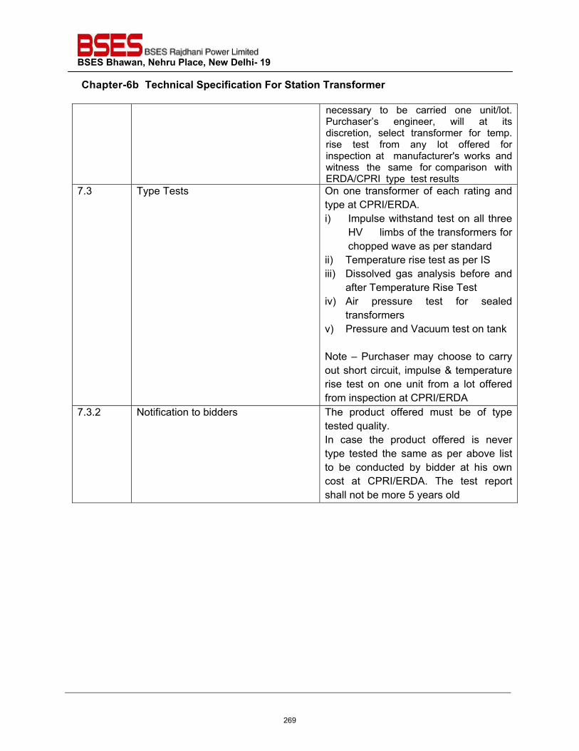
BSES Bhawan, Nehru Place, New Delhi- 19
Chapter-6b Technical Specification For Station Transformer
necessary to be carried one unit/lot. Purchaser’s engineer, will at its discretion, select transformer for temp. rise test from any lot offered for inspection at manufacturer's works and witness the same for comparison with ERDA/CPRI type test results
7.3 Type Tests On one transformer of each rating and type at CPRI/ERDA. i) Impulse withstand test on all three
HV limbs of the transformers for chopped wave as per standard
ii) Temperature rise test as per IS iii) Dissolved gas analysis before and
after Temperature Rise Test iv) Air pressure test for sealed
transformers v) Pressure and Vacuum test on tank
Note – Purchaser may choose to carry out short circuit, impulse & temperature rise test on one unit from a lot offered from inspection at CPRI/ERDA
7.3.2 Notification to bidders The product offered must be of type tested quality. In case the product offered is never type tested the same as per above list to be conducted by bidder at his own cost at CPRI/ERDA. The test report shall not be more 5 years old
269
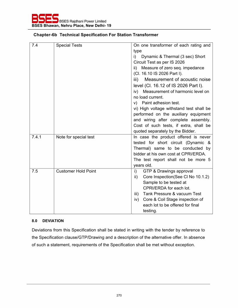
BSES Bhawan, Nehru Place, New Delhi- 19
Chapter-6b Technical Specification For Station Transformer
7.4 Special Tests On one transformer of each rating and type i) Dynamic & Thermal (3 sec) Short Circuit Test as per IS 2026 ii) Measure of zero seq. impedance (Cl. 16.10 IS 2026 Part I). iii) Measurement of acoustic noise level (Cl. 16.12 of IS 2026 Part I). iv) Measurement of harmonic level on no load current. v) Paint adhesion test. vi) High voltage withstand test shall be performed on the auxiliary equipment and wiring after complete assembly. Cost of such tests, if extra, shall be quoted separately by the Bidder.
7.4.1 Note for special test In case the product offered is never tested for short circuit (Dynamic & Thermal) same to be conducted by bidder at his own cost at CPRI/ERDA. The test report shall not be more 5 years old.
7.5 Customer Hold Point i) GTP & Drawings approval ii) Core Inspection(See Cl No 10.1.2)
Sample to be tested at CPRI/ERDA for each lot.
iii) Tank Pressure & vacuum Test iv) Core & Coil Stage inspection of
each lot to be offered for final testing.
8.0 DEVIATION
Deviations from this Specification shall be stated in writing with the tender by reference to
the Specification clause/GTP/Drawing and a description of the alternative offer. In absence
of such a statement, requirements of the Specification shall be met without exception.
270
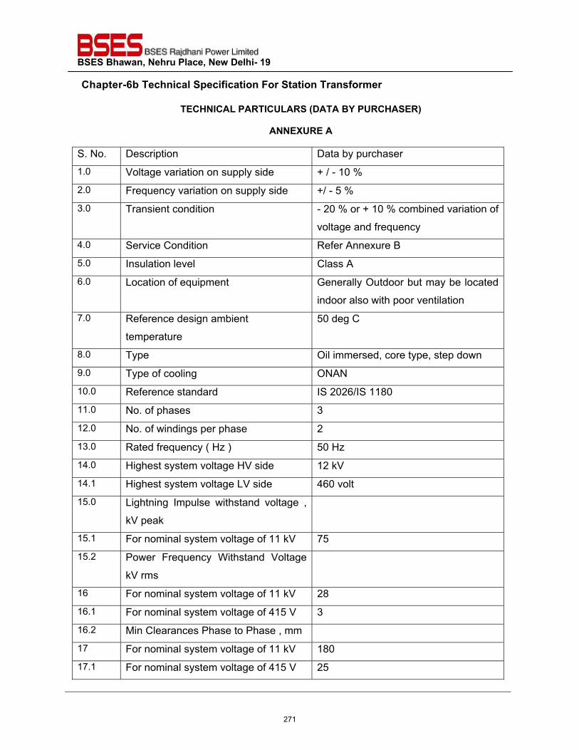
BSES Bhawan, Nehru Place, New Delhi- 19
Chapter-6b Technical Specification For Station Transformer
TECHNICAL PARTICULARS (DATA BY PURCHASER)
ANNEXURE A
S. No. Description Data by purchaser 1.0 Voltage variation on supply side + / - 10 % 2.0 Frequency variation on supply side +/ - 5 % 3.0 Transient condition - 20 % or + 10 % combined variation of
voltage and frequency 4.0 Service Condition Refer Annexure B 5.0 Insulation level Class A 6.0 Location of equipment Generally Outdoor but may be located
indoor also with poor ventilation 7.0 Reference design ambient
temperature
50 deg C
8.0 Type Oil immersed, core type, step down 9.0 Type of cooling ONAN 10.0 Reference standard IS 2026/IS 1180 11.0 No. of phases 3 12.0 No. of windings per phase 2 13.0 Rated frequency ( Hz ) 50 Hz 14.0 Highest system voltage HV side 12 kV 14.1 Highest system voltage LV side 460 volt 15.0 Lightning Impulse withstand voltage ,
kV peak
15.1 For nominal system voltage of 11 kV 75 15.2 Power Frequency Withstand Voltage
kV rms
16 For nominal system voltage of 11 kV 28 16.1 For nominal system voltage of 415 V 3 16.2 Min Clearances Phase to Phase , mm 17 For nominal system voltage of 11 kV 180 17.1 For nominal system voltage of 415 V 25
271
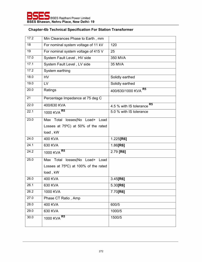
BSES Bhawan, Nehru Place, New Delhi- 19
Chapter-6b Technical Specification For Station Transformer
17.2 Min Clearances Phase to Earth , mm 18 For nominal system voltage of 11 kV 120 19 For nominal system voltage of 415 V 25 17.0 System Fault Level , HV side 350 MVA 17.1 System Fault Level , LV side 35 MVA 17.2 System earthing 18.0 HV Solidly earthed 19.0 LV Solidly earthed 20.0 Ratings 400/630/1000 KVA R5
21 Percentage Impedance at 75 deg C
22.0 400/630 KVA 4.5 % with IS tolerance R5 22.1 1000 KVA R5 5.0 % with IS tolerance
23.0 Max Total losses(No Load+ Load
Losses at 75⁰C) at 50% of the rated
load , kW
24.0 400 KVA 1.225[R6] 24.1 630 KVA 1.86[R6] 24.2 1000 KVA R5 2.79 [R6]
25.0 Max Total losses(No Load+ Load
Losses at 75⁰C) at 100% of the rated
load , kW
26.0 400 KVA 3.45[R6] 26.1 630 KVA 5.30[R6] 26.2 1000 KVA 7.70[R6] 27.0 Phase CT Ratio , Amp 28.0 400 KVA 600/5 29.0 630 KVA 1000/5 30.0
1000 KVA R5 1500/5
272
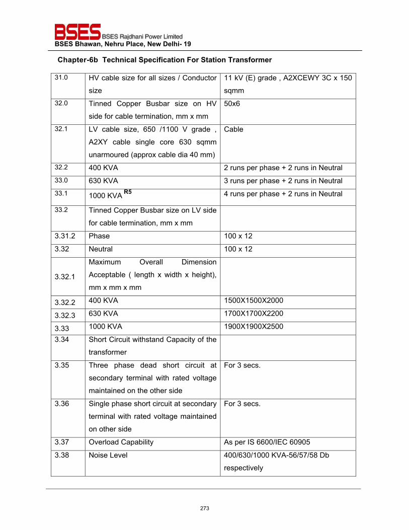
BSES Bhawan, Nehru Place, New Delhi- 19
Chapter-6b Technical Specification For Station Transformer
31.0 HV cable size for all sizes / Conductor
size
11 kV (E) grade , A2XCEWY 3C x 150
sqmm 32.0 Tinned Copper Busbar size on HV
side for cable termination, mm x mm
50x6
32.1 LV cable size, 650 /1100 V grade ,
A2XY cable single core 630 sqmm
unarmoured (approx cable dia 40 mm)
Cable
32.2 400 KVA 2 runs per phase + 2 runs in Neutral 33.0 630 KVA 3 runs per phase + 2 runs in Neutral 33.1 1000 KVA R5 4 runs per phase + 2 runs in Neutral
33.2 Tinned Copper Busbar size on LV side
for cable termination, mm x mm
3.31.2 Phase 100 x 12
3.32 Neutral 100 x 12
3.32.1
Maximum Overall Dimension
Acceptable ( length x width x height),
mm x mm x mm
3.32.2 400 KVA 1500X1500X2000
3.32.3 630 KVA 1700X1700X2200
3.33 1000 KVA 1900X1900X2500
3.34 Short Circuit withstand Capacity of the
transformer
3.35 Three phase dead short circuit at
secondary terminal with rated voltage
maintained on the other side
For 3 secs.
3.36 Single phase short circuit at secondary
terminal with rated voltage maintained
on other side
For 3 secs.
3.37 Overload Capability As per IS 6600/IEC 60905
3.38 Noise Level 400/630/1000 KVA-56/57/58 Db
respectively
273
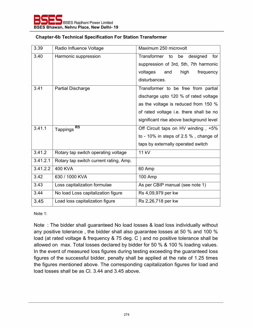
BSES Bhawan, Nehru Place, New Delhi- 19
Chapter-6b Technical Specification For Station Transformer
3.39 Radio Influence Voltage Maximum 250 microvolt
3.40 Harmonic suppression Transformer to be designed for
suppression of 3rd, 5th, 7th harmonic
voltages and high frequency
disturbances.
3.41 Partial Discharge Transformer to be free from partial
discharge upto 120 % of rated voltage
as the voltage is reduced from 150 %
of rated voltage i.e. there shall be no
significant rise above background level
3.41.1 Tappings R5 Off Circuit taps on HV winding , +5%
to - 10% in steps of 2.5 % , change of
taps by externally operated switch
3.41.2 Rotary tap switch operating voltage 11 kV
3.41.2.1 Rotary tap switch current rating, Amp.
3.41.2.2 400 KVA 60 Amp
3.42 630 / 1000 KVA 100 Amp
3.43 Loss capitalization formulae As per CBIP manual (see note 1)
3.44 No load Loss capitalization figure Rs 4,09,979 per kw
3.45 Load loss capitalization figure Rs 2,26,718 per kw
Note 1: Note : The bidder shall guaranteed No load losses & load loss individually without any positive tolerance , the bidder shall also guarantee losses at 50 % and 100 % load (at rated voltage & frequency & 75 deg. C ) and no positive tolerance shall be allowed on max. Total losses declared by bidder for 50 % & 100 % loading values. In the event of measured loss figures during testing exceeding the guaranteed loss figures of the successful bidder, penalty shall be applied at the rate of 1.25 times the figures mentioned above. The corresponding capitalization figures for load and load losses shall be as Cl. 3.44 and 3.45 above.
274
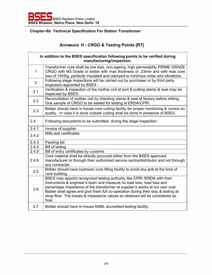
BSES Bhawan, Nehru Place, New Delhi- 19
Chapter-6b Technical Specification For Station Transformer
A n n ex u r e H - CRGO & Testing Points [R7]
In addition to the BSES specification following points to be verified during manufacturing/inspection.
1 Transformer core shall be low loss, non-ageing, high permeability PRIME GRADE CRGO with M3 Grade or better with max thickness of .23mm and with max core loss of 1W/Kg, perfectly insulated and clamped to minimize noise and vibrations.
2 Following stage inspections will be carried out by purchaser or by third party engineers appointed by BSES :
2.1 Verification & inspection of the mother coil at port & putting stamp & seal may be inspected by BSES.
2.2 Reconciliation of mother coil by checking stamp & seal at factory before slitting. One sample of CRGO to be sealed for testing at ERDA/CPRI.
2.3 Bidder should have in house core cutting facility for proper monitoring & control on quality. In case it is done outside cutting shall be done in presence of BSES.
2.4 Following documents to be submitted during the stage inspection :
2.4.1 Invoice of supplier
2.4.2 Mills test certificates
2.4.3 Packing list 2.4.4 Bill of lading 2.4.5 Bill of entry certificates by customs
2.4.6 Core material shall be directly procured either from the BSES approved manufacturer or through their authorized service centre/distributor and not through any contractor.
2.5 Bidder should have hydraulic core lifting facility to avoid any jerk at the time of core building.
2.6
BSES may appoint recognized testing authority like CPRI /ERDA with their instruments & engineer’s team and measure no load loss, load loss and percentage impedance of the transformer at supplier’s works at our own cost. Bidder shall agree and give them full co-operation during their stay & testing at shop floor. The losses & impedance values so obtained will be considered as final.
2.7 Bidder should have in-house NABL accredited testing facility.
275
BSES Bhawan, Nehru Place, New Delhi- 19
Prepared by K A SENTIL KUMARAN Rev: 7.2
Reviewed & Approved by
GOPAL NARIYA Date: 22-04-2021
NEW GRID
TECHNICAL SPECIFICATION
FOR
SCADA INTERFACE WORK & AUTOMATION
276
BSES Bhawan, Nehru Place, New Delhi- 19 Technical Specification for SCADA interface work & Automation
1.0 INTENT OF SPECIFICATION:
This specification is intended to cover the supply and execute work related to interface of all electrical equipments with RTU panel complete with all materials and accessories for efficient and trouble free operation. In the event of any discrepancy with the listed documents, the stipulation of this specification shall govern.
2.0 SCOPE OF WORK
For substation, it is proposed to lay and terminate panel wirings / control cables if any between the equipments such as CT, PT, Circuit Breaker, Isolators, 11 KV Switchgear, 66,33,11 KV Control & Relay Panels, Power Transformer & its sensors – OTI, WTI, TPI, AVR, etc, REGDA relay, Capacitor Bank,NIFPS,Smoke Detectors and Battery Charger. The scope of work under this category would include:
� Supply of SCADA materials – BCU,BCPU & RTU with Processors (Basic License - IEC 870-
5,101,103,104, Modbus, IEC 61850-8-1, IEC -104 Master, IEC 104 Slave + PLC License) along with IO Modules. Other accessories such as Communication Rack, Power Supply Modules, MFM,GPS, Converters for DC to DC & Other FO Converters, Cables Cables - FO, CAT-6, RS485, Control Cables, Connectors if any shall be in SCADA vendor’s scope of supply.
� Installation, Testing & Commissioning of SCADA equipments with Control Center via IEC-104 Protocol.
� Integration, Database development & Testing of SCADA Front end equipments (Sub Station level equipments integration over Modbus TCP IP,Serial/IEC-103/IEC-61850 Protocols.
� Extraction of ICD/SCD files from IED and further integration with RTU over IEC-61850/IEC103 Protocols at site with Supplied Hardware.
� Supply of Necessary RTU Till Tool with Licenses & Softwares if any (Ex:IET600) required for ICD/SCD file configuartion in RTU.
� Laying and Termination of armored Communication cables (Ethernet, Fiber Optic Patch Cards/Cable,RS 485 cables) between grid devices (Numerical Relays/BCPU, Transformer Monitoring Modules, Smoke detector, NIFPS panel, MFM, Battery Charger) to RTU/DCU/Gateway with proper tagging,and dressing upto RTU panel. Supply of Suitable Glands, White Sleeve PVC ferrule, tagging, lugs shall be scope of vendor’s supply.
� Laying and termination of control cables between grid equipments (control and relay panel, NIFPS, Battery Units) to RTU for hardwired signals.
� Installation of cable trays with accessories or trench as required for the cabling work. � Integration of PQA over Modbus TCP IP/IEC-61850 with dedicated network. � Integration Li-Ion Battery Charger Over Modbus TCP IP/Serial with RTU.
277
BSES Bhawan, Nehru Place, New Delhi- 19 Technical Specification for SCADA interface work & Automation
� Preparation of cable schedule, Wiring diagrams,Training documents with Step by Step
Procedures and Interconnection as built drawings. � Separate earthing bus bars to be provided for RTU panel and it will be directly connected
to grid earthing.Earth BAR material should be Copper. � Seprate earth pit with connections for Electronic cards,gateway,Switches,DCU.,etc..
earthing. � All internal wiring between BCU and C&R Panel terminals, All Numerical relays,MFM
(Multifunctional meters) and other grid equipment integration should be under SCADA vendor’s scope.
� Hardware & software integration of RTU, Bay Control Units along with other equipments viz. Battery Chargers, Multi Function Meters, Fire Fighting System Signals, Transformer relays (for OTI, WTI, TPI, AVR, etc.),Smoke Detector Panels, Numerical Relays, 11&33&66KV Control and Relay panel signals etc. shall be in Vendor’s scope.
� FAT and Training arrangements at factory/Work shop for BSES SCADA team (6 Persons for 5 days) – Travel ,Boarding, accommodation and local conveyance etc..shall be under SCADA Vendor’s Scope.
2.1 Cables The following types of cables / wirings will be required for extending signals and commands. Tagging is mandatory for all types of cables. Heat shrinking ferrule sleeves with printed ferrules to be used for identifying cables & Signals.
� 2.5 mm2, multi-stranded flexible copper wire, FRLS 1.1KV HRPVC for AC & DC Supply & 1.5 mm2 multi strand cables for other internal wiring for RTU.
� Red(P)and Black(N) color cable core to be used for AC and DC wiring. � Fiber Optic Cables (GLASS&PLASTIC Types) with suitable connectors & Ethernet cables
(CAT6) with conduit pipe for internal connections and GI Armored Cables for external connections.
� 2 C X 2.5 MM2 multi strained copper cable, ARM FRLS 1.1KV HRPVC for external AC / DC Power Supply.
� 16 C x 1.5 mm2,multi strained copper cable, ARM FRLS 1.1KV HRPVC ,Application: digital signal feed back.
� 3P X 1.5 mm2 for DO (Digital output) � 2P X 0.5 mm2 Screened GI Armored RS485,Twisted pair, 22gauge Belden 8761 or
equivalent for external (RTU to BCUs /MFM/BATT.CHG/Transformer Monitoring Devices) RS 485 connections.
The supplied cable shall be as a latest IS, also refer control cable specification.
� Cable Gland
278

BSES Bhawan, Nehru Place, New Delhi- 19 Technical Specification for SCADA interface work & Automation
Double Compression cable glands ( Materials - Brass and Stainless Steel & Suitable for Industrial Grade) of different sizes for cable entry into the RTU,DCU,CRP & Other Panels
� Cable Trays and NS cable Support
Perforated / ladder type (galvanized Iron) with cover for laying the cables.
2.2 Multifunction Meters (Accuracy – 0.2)
To extend the current / voltage / active and reactive power, power factor, etc. to RTU, MFMs, to be installed in C & R Panel individually for each feeder/ breakers and should be integrated with RTU.The outputs of these meters (in groups of 5) connections should be made using twisted pair screened cable (Typically 22gauge Belden 8761 or equivalent) & two wires (A and B) connections are daisy chained together and integrated with RTUs. All hardware’s or protocol converters for having Modbus Protocol output, CT & PT wirings to MFMs and its Configuration should be in Vendor’s scope. For the protection of MFMs and RTU cards against Surges and electrical leakages, it is necessary to install Surge Protection Devices in b/w RTU & MFM serial loops. The typical diagram for this connection is mentioned in the System Architecture diagram. MFM should be powered through Grid Battery Voltage (220 Volt or 50 Volts DC). The following parameters of MFM must be available for communication with RTU.
� Phase Voltages (L1-N, L2-N, L3-N) � Line Voltages (L1-L2, L2-L3, L1-L3) � Line Currents (IL1 , IL2, IL3) � Active Power & Reactive Power � Maximum Demand (KW) & Frequency � Power factor � Active Energy � THD mean current & THD mean Voltage � Neutral Current. � Phase Angles
Approved Makes – RISH 3440 and Conzerv EM 6400NG
2.3 Numerical Relays or Bay Control Protection Units for all feeders (11,33,66KV)
Numerical Relays(BCPU) shall be integrated with Remote Terminal Units. All hardware’s and protocol converters if required for compatibility with SCADA shall be in Vendor’s scope. The respective BCU,BCPU & Numerical Relays must have dual redundancy communication ports (Ethernet/Copper Ports) with PRP & RSTP protocols for SCADA connections & It will be connected to RTU via IEC 61850 protocol. (Dual Ports required to form a Ring or PRP Networks b/w relay to relay connections). Hot Standby/Dual Power Supply Unit shall be supplied along with BCU.It will increase the BCU availability, if any one Power supply card fails the other one should keep the bay control unit continuous live.
279
BSES Bhawan, Nehru Place, New Delhi- 19 Technical Specification for SCADA interface work & Automation
Data Base File must be downloadable and Uploadable from BCU. The following signals are to be taken from Numerical Relays to the BCUs through internal hard wiring. This list is indicative and signals should not be limited to this. Additional signals can be taken during review of actual drawings. – Refer Para 2.8 for detail signals list with data format (DPI,DCO,SPI,SCO,Measured Values) types.
� Online Currents / Voltage & Relay General trip signal � All breaker,Isolators,Control & Relay Panel indications and commands � Fault current and phase indication of faulty phase viz. R,Y,B, Earth, Unbalance(O/C & E/F
Relay). � Fault Differential and Bias current in Line and Transformer Differential Relay � Fault voltage and phase indication of faulty phase viz. R,Y,B (Voltage Protection Relay). � Post fault currents (R, Y, B phase separately) measured value & Relay Internal Fault � Fault distance (in case of distance relays - R, Y, B Phase separately) � Unbalance Current (in case of neutral displacement relay of capacitor feeders).
2.4 Transformer Signal - TMD (REGDA, A-EBERLE relays):
OTI, WTI, TPI, AVR and Transformer auxiliary protection signals should be integrated with RTU via IEC 61850 Protocol. TMD must have dual communication ports & have the option of RSTP and PRP Protocols for SCADA Connections. All field installations of these sensors and its wiring/cabling and configuration along with hardware’s or protocol converters, if any, should be in Contractor‘s scope. - Refer Para 2.8 for detail signal’s list with data types.
2.5 Battery Charger and Lithium Battery Integrations:
All signals of Battery Chargers/Lithium Ion should have MODBUS Protocol output and integrated with an RTU through serial communication (RS 485) cables. Laying communication cables through conduit pipe and battery charger signals (Soft & Hard Signals) integration with an RTU shall be in Vendor’s Scope. - Refer Para 2.8 for detail Battery Charger signal's list with data types.
2.6 Data Concentrator Unit/Gateway & Remote Terminal Units For extending the signals from the grid to the Master Control Centre & Backup Control Centre, BCUs and RTUs are to be installed. BCUs needs to be initially physically integrated with Numerical relays of respective breakers to enable soft signals and commands for breakers to be configured there and respectice BCU or BCPU integrated with Remote Terminal Units through IEC – 61850 protocol. However the options for IEC-60870-103 protocol along with the MODBUS protocol option is required for other devices integrations. BCUs can be of ABB, Siemens,Schneider Electric, etc ., make is depending on the type/ make of switch gears.Remote Terminal Units need to be installed for interface between the BCUs and Control Centers (Main and Backup) through IEC – 60870 – 104 Protocol. The
280
BSES Bhawan, Nehru Place, New Delhi- 19 Technical Specification for SCADA interface work & Automation
size of RTU will depend on the size of the substation, no. of the feeders/ number of signals and command outputs along with sufficient spares (20%) for future requirement. All associated equipments and Supply of accessories including software &Operating tool / multiple user licenses for RTU & BCU, MCBs for DC and AC Supply, DC to DC Converter (in case station battery voltage level is 220 volts DC), etc. should be in Vendor’s scope. Hardware & software integration of RTUs, BCU along with other equipments viz. Battery Chargers, Multi Function Meters, Fire Fighting Systems, Signals, Transformer relays (for OTI, WTI, TPI, AVR, etc.), Numerical Relays, etc. should be in Vendor’s scope. In case of more than one BCPU,RTU,DATA Concentrator than these units must be able to communicate with other units on internal local IPs (Ex – 192.168.0.1) other than LAN IP(Ex- 10.125.107.1) series. Hot redundancy is required for Main Processor cards, rack/board and Gateway for MCC & BCC Communications.Each main processor must have two Ethernet ports dedicated for communication with SCADA servers over IEC 60870-104 protocol. First card will be live and 2nd card will be hot standby. Communication switchover between either cards in case of failure. Main Processor cards along with Rack for MCC communication should be separate from the IO cards. Data Base File must be downloadable and Uploadable from RTU,CPU and Gateway. Approved RTU makes – ABB-RTU560,Schneider-SAITEL DP. Bidders who are OEM of RTU and Numerical Relays are only acceptable. Note : System shall be approved if they are agree to fulfill the following terms & Conditions,
� AMC period should be given 3 years along with this proposal. � AMC period should be started after handovering the system to BSES. � During AMC period all the issues pertaiting to RTU/Gateway/BCU should be handled by
OEM at site(this included unlimited site visit) � 5 Year replacement warranty is applicable for all OEM for Electronic cards & Gateway
Units…If any hardware (or) Software fails during this period will be rectified by OEM. � 5 years warranty is mandatory for all SCADA/RTU products(Electronic
cards,GPS,Switches,HMI,etc…).If any cards fails/burnt due to surges from CT,PT via RS485/serial,Surges through cables then replacement will be in your scope up to 5 years. So suitable SPD to be incorporate in the system according to site requirements for avoid card failures.
RTU,Data Concentrator Unit Features & Performance capabilities
2.6.1 RTU,DCU Size and Expandability
20% Spare for RTU,DCU - Provision for 20 % (Basic IO Count +20% Spare) of the total DI / DO signals (hard/soft) as a spare should be made available for future requirement.
Spare Ports – 20% Spare ports (Minimum – 3 to 4 No’s Serial ports are essential) for IEC 103/Mod Bus Protocol Connections
281
BSES Bhawan, Nehru Place, New Delhi- 19 Technical Specification for SCADA interface work & Automation
20% Spare for BCU,BCPU - Each Control and Relay panel BCU must have 20% (Basic + 20% Spare) of the particular bay DI/DO signals as a spare should be available.
Panel Size & Hardware Capacity - The RTU panel sizing should be capable of accommodating additional 50% of the basic I/O counts by way of addition of hardware such as modules, racks, panels, Terminal Blocks of basic I/O counts.
Software Capacity - The RTU software and database generation should be sized to accommodate for additional 50% of the basic I/O count without requiring software or database regeneration or License.
2.6.2 Remote database, downloading of RTU from master station/SCADA control center.
2.6.3 RTU shall have the capability of automatic start-up and initialization following restoration of power after an outage without the need for manual intervention. All restarts shall be reported to the connected master stations.
2.6.4 Act as a data concentrator on IEC60870-5-101/104/MODBUS/IEC 61850 protocols and Support for IEC 60870-5-103, IEC 60870-5-101, IEC 61850,MODBUS TCP IP and RS485 Modbus RTU protocols & ability to act as a gateway for Numerical relays.
2.6.5 Cyber Security
As the SCADA system will use public domain, such LAN/VSAT/GPRS/CDMA etc. therefore it is mandatory to guard the data/ equipment from intrusion/damage/breach of security & shall have SSL/VPN based security.
2.6.6 Internal battery backup to hold data in SOE buffer memory & also maintaining the time & date.
2.6.7 RTU must have the capability of time synchronization with a GPS receiver and the GPS at the control room will be used for this synchronization purpose. In case of failure of the GPS receiver, the RTUs time synchronization should be through the Master’s SCADA clock.
2.6.8 GPS for Time Synchronization - The RTU must have inbuilt (or) external GPS with antenna & internal real time clock to synchronize the IEDs connected to it over their respective protocol. GPS must have dual redundant LAN port for time synchronizations.
Approved Makes – MASSIBUS & SANDS
2.6.9 Main Processor(CPU in RTU & Gateway ) HOT Retundancy for MCC & BCC communication
Main processor (DCU) /RTU should have adequate capacity for data handling / processing and main processor/CPU must have required number of communication ports for simultaneous communication with Master Stations (MCC & BCC), /MFTs and RTU configuration & maintenance tool.RTU main processor and Gateway must have HOT redundancy features for control center communications.
2.6.10 Hot Standby/Dual Power Supply Unit & Redundancy in power source for RTU and BCU/BCPU - Possibility to increase the RTU,BCU main rack availability by having a second power supply card in case the first one fails , if any one Power supply card fails the other one should keep the system continuous live.
282
BSES Bhawan, Nehru Place, New Delhi- 19 Technical Specification for SCADA interface work & Automation
2.6.11 CPU/RTU Soft Configuration Future (Communicate to multiple master stations simultaneously on IEC60870-5-104.)
RTU/DAU must have multiple location (minimum 5 Locations) data transmission facility VAZ Master Control Centre, Backup Control Centre, etc.
2.6.12 Protection Devices for RTU,BCPU – All modules (all Digital, Analog Input modules) and ports (Serial and Ethernet ports) must have in-built or external surge protection devices and optical isolation
2.6.13 Diagnostic Software & Multi user tool/License for RTU/(Numerical Relay) BCU -
Diagnostic Software tool with licensed version shall be provided to continuously monitor the operation of the RTU and report RTU hardware errors to the connected master stations. The software shall check for memory, processor, and input/output ports errors and failures of other functional areas defined in the specification of the RTU. If any system tries to connect to RTU for download/ Upload files,itshould be stored as a log in RTU.
2.6.14 RTU Panels
At least 50% of the space inside each enclosure shall be unused (spare) space that shall be reserved for future use. The Contractor shall provide required panels conforming to IEC 529 for housing the RTU modules/racks, relays etc. and other required hardware. The panels shall meet the following requirements:
� Shall be free standing, floor mounted and height shall not exceed 2200 mm. � RTU Panel should have air conditioner and should be mounted on side wall of RTU panel
with temperature/humidity control facility. FAN with Filters shall be considered for for back up cooling.
� Seprate room / Cabinet with AC Provision to be considered for RTU and IT Equipments. � All doors and removable panels shall be fitted with long life rubber beading. � All non load bearing panels/doors ,top and bottom portion, rear cover shall be fabricated
from minimum 2.0 mm thickness steel sheet and all load bearing panels, frames, top & bottom panels shall be fabricated from minimum 3.0 mm thickness steel sheet.
� Shall have maintenance access to the hardware and wiring through lockable full height doors.
� Shall have the provisions for bottom cable entry. � All panels shall be supplied with 230V AC, 50 Hz, single-phase switch and 15/5A duplex
socket arrangement for the maintenance. � All panels shall be provided with an internal maintenance lamp, space heaters and
gaskets. � All panels shall be indoor, dust-proof with rodent protection, and meet IP54 class of
Ingress protection. � There shall be no sharp corners or edges. All edges shall be rounded to prevent injury. � Document Holder shall be provided inside the cabinet to keep test report, drawing,
maintenance register etc.
283
BSES Bhawan, Nehru Place, New Delhi- 19 Technical Specification for SCADA interface work & Automation
� All materials used in the enclosures including cable insulation or sheathing, wire troughs, terminal blocks, and enclosure trims shall be made of flame retardant material and shall not produce toxic gases under fire conditions.
2.6.15 RTU Grounding
The safety ground shall be isolated from the signal ground and shall be connected to the ground network. Safety ground shall be a copper bus bar. The contractor shall connect the panel’s safety ground to the grid grounding network. Separate grounding(2Pits) is created for communication equipments and Signal ground shall be connected to the communication equipment signal ground.
2.7 Ethernet /Fiber Switch
The Ethernet/Fiber optic switches Should be a managed switch and are intended to be installed in the control room and shall be complaint to IEC-61850 electrical substation networks and IEEE 1613 standards. Provisions for additional feeders on the Ring Configuration should be provided on the same switch.
� Laying of Ethernet/Fiber cables for relay/BCU port to the RTU via switch through conduit pipe and integration with an RTU shall be in Vendor’s Scope.
� Switch, Standard Features � Switch design should withstand for power substation automation applications that
operate in extremely harsh environments (High and medium voltage S/Stn environments) and it also withstands vibration, electrical surges, fast transients, electrostatic discharge, and extreme temperatures and humidity. Industrial managed Fast Ethernet Switch shall be supplied according to IEEE 802.3.
� Switch features and configuration should be easy to user interface and it must directly integrate with any other IEC-61850 devices. Shall be managed type,Layer-2 Switches and have KEMA certifications for IEC 61850.One switch should be supplied with Layer 3 feautures.
� The FO switch shall support Multimode fiber and single mode fiber in 100Mbps ports on an SFP (simple form factor pluggable), for ease of functionality and maintenance.100Mbps ports for sub station level communications & 2 or 4 Gigabit Port for uplink communications.
� Retundancy Ring : Dual Ring to be consider between Ethernet switches for maintaining redundancy network.
� Hot Standby/Dual PSU & Redundancy in power source - Possibility to increase the switch availability by having a second power source in case the first one fails & should be available with 48VDC.Each PSU should be connected with a different power source, if any one power source or Power supply card fails then other one should keep the switch continuous operation.
� 20% Spare ports - Each switch must have 20% spare ports for future/back up requirements.
284
BSES Bhawan, Nehru Place, New Delhi- 19 Technical Specification for SCADA interface work & Automation
� Link Failure contact alarm - Failure contact alarm shall be achieved by hardware contact that is activated when a link problem occurs.
� Logs and alarms with Time Stamp - Statistics about link status alarms are to be stored with the accurate timestamp duly tracing all events.
� Security features - The FO switches shall support different user levels with different passwords, including the facility to work with different VLANs, following the 802.1Q standard, port security based on MAC addresses, possibility to disable unused ports, authentication protocols shall be provided. The FO switches shall have advanced security features to be implemented to avoid unauthorized access to the system Such as RADIUS/TACACS & VPN gateway support with IP Sec & SSH.
� High Speed Implementation of RSTP protocol - The FO switches shall support STP and RSTP protocols, and shall facilitate for recovery and the fault recovery times shall be within 5 -10msec per switch, always fulfilling the RST protocol.
� Time Synchronization to RTU/Server and Connected IED/BCU - The FO switch shall have an internal clock and shall be synchronized from a network SNTP/NTP server, so all time stamped events shall be with a reliable time reference.
� Tools with License - Diagnostics tool, other necessary tools with a multi user license to be provided along with the switch.
� Mounting Options - Switch should be DIN Rail Mountable & also need to quote for Optional Wall/Rack Mountable kit.
� Local USB port for emergency boot is Mandatory. � Network based distributed security by having a firewall on each port of the switch for all
the standard Industrial protocol like IEC-61850 should be available. � The FO switch shall have the facility of Port mirroring and the user shall configure one port
to replicate traffic flows of different ports, so the system administrator can monitor the incoming, outgoing, or all kinds of traffic that is going through the ports under study.
� ITU-T G.8032 support for Ethernet Ring redundancy, ensuring fast failure detection is preferred.
� They FO switches shall sustain the stringent levels in temperature range and electromagnetic immunity defined in the 61850-3, but also the advanced functional requirements defined for operation with other IEC-61850 devices. The Switch should be certified on IEC-61850, functional & Environmental specifications by KEMA.
� Approved Makes – RUGGEDCOM & HIRSCHMANN 2.8 SIGNAL LIST (11/33/66KV)
List of Abbreviations
AI - Analog Input/Analog Values MV - Measured Value MFM - Multi Function Meter DCO - Double Command Output
285
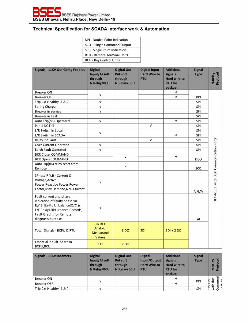
BSES Bhawan, Nehru Place, New Delhi- 19 Technical Specification for SCADA interface work & Automation
DPI - Double Point Indication SCO - Single Command Output SPI - Single Point Indication RTU - Remote Terminal Units BCU - Bay Control Units
Signals - 11KV Out Going Feeders Digital
Input/AI soft through N.Relay/BCU
Digital Out Put soft through N.Relay/BCU
Digital Input Hard Wire to RTU
Additional signals Hard wire to RTU for backup
Signal Type
N.R
elay
Pr
otoc
ol
Breaker ON √
√ DPI
IEC-
6185
0 w
ith D
ual C
omm
unic
atio
n Po
rts
Breaker OFF √ Trip Ckt Healthy -1 & 2 √ SPI Spring Charge √ SPI Breaker in service √ SPI Breaker in Test SPI Auto Trip(86) Operated √ √ SPI Panel DC Fail √ SPI L/R Switch in Local
√ SPI
L/R Switch in SCADA √ SPI Relay Int Fault. √ SPI Over Current Operated √ SPI Earth Fault Operated √ SPI BKR Close COMMAND
√
√ DCO BKR Open COMMAND
AutoTrip(86) relay reset from Remote
√ SCO
3Phase R,Y,B - Current & Voltage,Active Power,Reactive Power,Power Factor,Max.Demand,Neu.Current
√
AI/MV Fault current and phase indication of faulty phase viz. R,Y,B, Earth, Unbalance(O/C & E/F Relay).Disturbance Records, Fault Graphs for Remote diagnosis purpose
√
AI
Total Signals - BCPU & RTU
13 DI + Analog , Measurand
Values
3 DO 2DI 5DI + 2 DO
Essential inbuilt Spare in BCPU,BCU
3 DI 2 DO
Signals - 11KV Incomers Digital
Input/AI soft through N.Relay/BCU
Digital Out Put soft through N.Relay/BCU
Digital Input/Output Hard Wire to RTU
Additional signals Hard wire to RTU for backup
Signal Type
N.R
elay
Pr
otoc
ol
Breaker ON √
√ DPI
6185
0 w
ith d
ual
Com
mun
ica
tion
Breaker OFF √ Trip Ckt Healthy -1 & 2 √ SPI
286
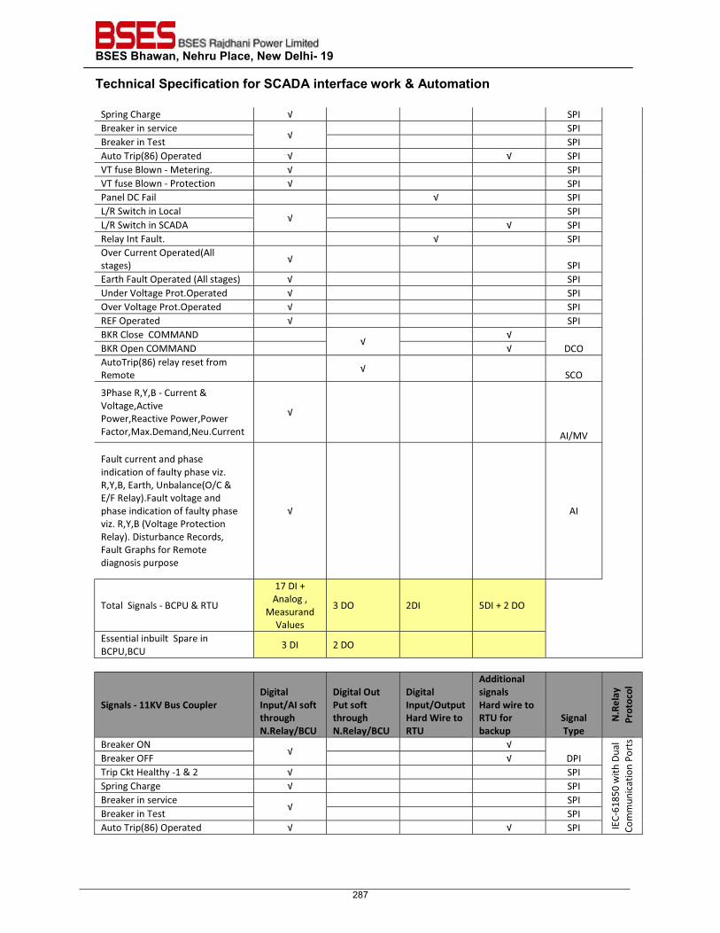
BSES Bhawan, Nehru Place, New Delhi- 19 Technical Specification for SCADA interface work & Automation
Spring Charge √ SPI Breaker in service
√ SPI
Breaker in Test SPI Auto Trip(86) Operated √ √ SPI VT fuse Blown - Metering. √ SPI VT fuse Blown - Protection √ SPI Panel DC Fail √ SPI L/R Switch in Local
√ SPI
L/R Switch in SCADA √ SPI Relay Int Fault. √ SPI Over Current Operated(All stages) √ SPI Earth Fault Operated (All stages) √ SPI Under Voltage Prot.Operated √ SPI Over Voltage Prot.Operated √ SPI REF Operated √ SPI BKR Close COMMAND
√ √
DCO BKR Open COMMAND √ AutoTrip(86) relay reset from Remote
√ SCO
3Phase R,Y,B - Current & Voltage,Active Power,Reactive Power,Power Factor,Max.Demand,Neu.Current
√
AI/MV
Fault current and phase indication of faulty phase viz. R,Y,B, Earth, Unbalance(O/C & E/F Relay).Fault voltage and phase indication of faulty phase viz. R,Y,B (Voltage Protection Relay). Disturbance Records, Fault Graphs for Remote diagnosis purpose
√ AI
Total Signals - BCPU & RTU
17 DI + Analog , Measurand
Values
3 DO 2DI 5DI + 2 DO
Essential inbuilt Spare in BCPU,BCU
3 DI 2 DO
Signals - 11KV Bus Coupler Digital Input/AI soft through N.Relay/BCU
Digital Out Put soft through N.Relay/BCU
Digital Input/Output Hard Wire to RTU
Additional signals Hard wire to RTU for backup
Signal Type
N.R
elay
Pr
otoc
ol
Breaker ON √
√ DPI
IEC-
6185
0 w
ith D
ual
Com
mun
icat
ion
Port
s
Breaker OFF √ Trip Ckt Healthy -1 & 2 √ SPI Spring Charge √ SPI Breaker in service
√ SPI
Breaker in Test SPI Auto Trip(86) Operated √ √ SPI
287
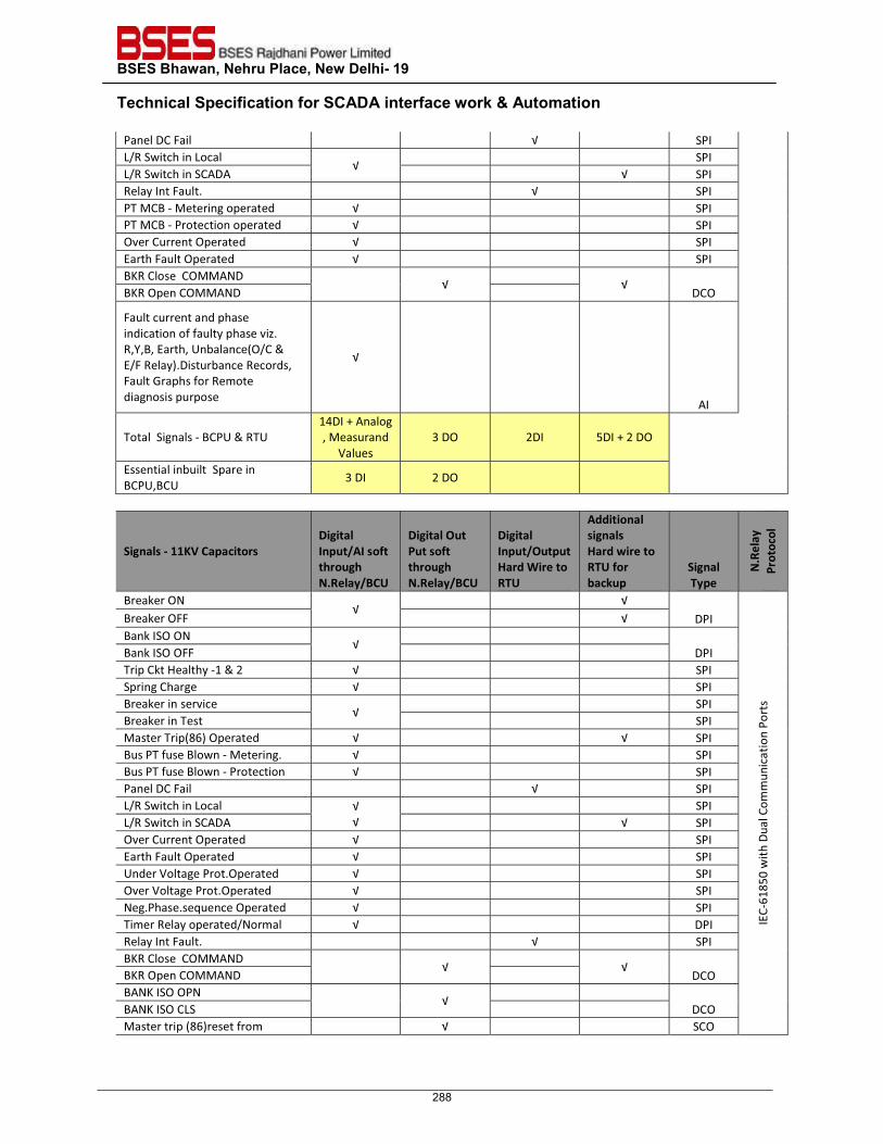
BSES Bhawan, Nehru Place, New Delhi- 19 Technical Specification for SCADA interface work & Automation
Panel DC Fail √ SPI L/R Switch in Local
√ SPI
L/R Switch in SCADA √ SPI Relay Int Fault. √ SPI PT MCB - Metering operated √ SPI PT MCB - Protection operated √ SPI Over Current Operated √ SPI Earth Fault Operated √ SPI BKR Close COMMAND
√
√ DCO BKR Open COMMAND
Fault current and phase indication of faulty phase viz. R,Y,B, Earth, Unbalance(O/C & E/F Relay).Disturbance Records, Fault Graphs for Remote diagnosis purpose
√
AI
Total Signals - BCPU & RTU 14DI + Analog , Measurand
Values 3 DO 2DI 5DI + 2 DO
Essential inbuilt Spare in BCPU,BCU
3 DI 2 DO
Signals - 11KV Capacitors Digital Input/AI soft through N.Relay/BCU
Digital Out Put soft through N.Relay/BCU
Digital Input/Output Hard Wire to RTU
Additional signals Hard wire to RTU for backup
Signal Type
N.R
elay
Pr
otoc
ol
Breaker ON √
√ DPI
IEC-
6185
0 w
ith D
ual C
omm
unic
atio
n Po
rts
Breaker OFF √ Bank ISO ON
√
DPI Bank ISO OFF Trip Ckt Healthy -1 & 2 √ SPI Spring Charge √ SPI Breaker in service
√ SPI
Breaker in Test SPI Master Trip(86) Operated √ √ SPI Bus PT fuse Blown - Metering. √ SPI Bus PT fuse Blown - Protection √ SPI Panel DC Fail √ SPI L/R Switch in Local √
√ SPI
L/R Switch in SCADA √ SPI Over Current Operated √ SPI Earth Fault Operated √ SPI Under Voltage Prot.Operated √ SPI Over Voltage Prot.Operated √ SPI Neg.Phase.sequence Operated √ SPI Timer Relay operated/Normal √ DPI Relay Int Fault. √ SPI BKR Close COMMAND
√
√ DCO BKR Open COMMAND
BANK ISO OPN √
DCO BANK ISO CLS
Master trip (86)reset from √ SCO
288
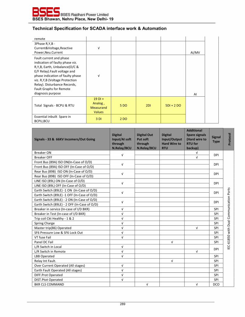
BSES Bhawan, Nehru Place, New Delhi- 19 Technical Specification for SCADA interface work & Automation
remote 3Phase R,Y,B - Current&Voltage,Reactive Power,Neu.Current
√ AI/MV
Fault current and phase indication of faulty phase viz. R,Y,B, Earth, Unbalance(O/C & E/F Relay).Fault voltage and phase indication of faulty phase viz. R,Y,B (Voltage Protection Relay). Disturbance Records, Fault Graphs for Remote diagnosis purpose
√
AI
Total Signals - BCPU & RTU
19 DI + Analog , Measurand
Values
5 DO 2DI 5DI + 2 DO
Essential inbuilt Spare in BCPU,BCU
3 DI 2 DO
Signals - 33 & 66KV Incomers/Out Going Digital Input/AI soft through N.Relay/BCU
Digital Out Put soft through N.Relay/BCU
Digital Input/Output Hard Wire to RTU
Additional Spare signals (Hard wire to RTU for backup)
Signal Type
Prot
ocol
Breaker ON √
√ DPI
IEC-
6185
0 w
ith D
ual C
omm
unic
atio
n Po
rts
Breaker OFF √ Front Bus (89A) ISO ON(In-Case of O/D)
√
DPI Front Bus (89A) ISO OFF (In-Case of O/D) Rear Bus (89B) ISO ON (In-Case of O/D)
√
DPI Rear Bus (89B) ISO OFF (In-Case of O/D) LINE ISO (89L) ON (In-Case of O/D)
√
DPI LINE ISO (89L) OFF (In-Case of O/D) Earth Switch (89LE) -1 ON (In-Case of O/D)
√
DPI Earth Switch (89LE) -1 OFF (In-Case of O/D) Earth Switch (89LE) - 2 ON (In-Case of O/D)
√
DPI Earth Switch (89LE) - 2 OFF (In-Case of O/D) Breaker in service (In-case of I/D BKR) √ SPI Breaker in Test (In-case of I/D BKR) √ SPI Trip coil Ckt Healthy - 1 & 2 √ SPI Spring Charge √ SPI Master trip(86) Operated √ √ SPI SF6 Pressure Low & SF6 Lock Out √ SPI VT fuse Fail √ SPI Panel DC Fail √ SPI L/R Switch in Local √
DPI L/R Switch in Remote √ √ LBB Operated √ SPI Relay Int Fault. √ SPI Over Current Operated (All stages) √ SPI Earth Fault Operated (All stages) √ SPI DIFF.Prot Operated √ SPI DIST.Ptot Operated √ SPI BKR CLS COMMAND √ √ DCO
289
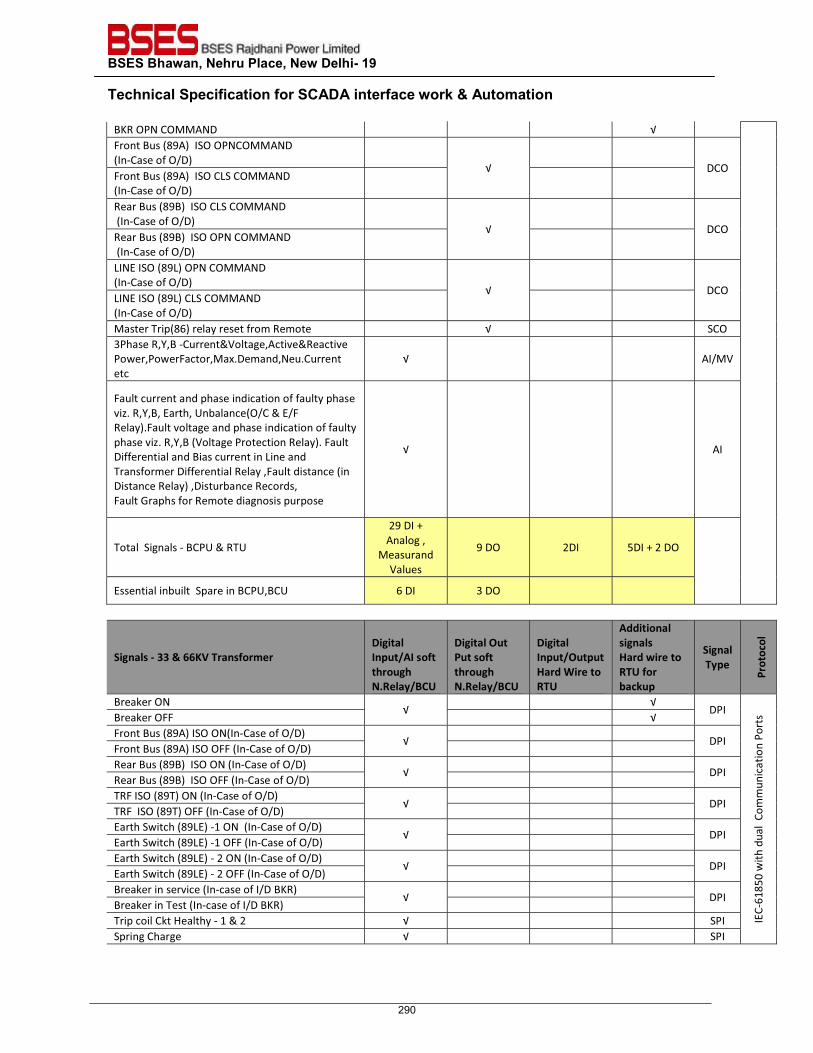
BSES Bhawan, Nehru Place, New Delhi- 19 Technical Specification for SCADA interface work & Automation
BKR OPN COMMAND √ Front Bus (89A) ISO OPNCOMMAND (In-Case of O/D)
√
DCO
Front Bus (89A) ISO CLS COMMAND (In-Case of O/D)
Rear Bus (89B) ISO CLS COMMAND (In-Case of O/D)
√
DCO
Rear Bus (89B) ISO OPN COMMAND (In-Case of O/D)
LINE ISO (89L) OPN COMMAND (In-Case of O/D)
√
DCO
LINE ISO (89L) CLS COMMAND (In-Case of O/D)
Master Trip(86) relay reset from Remote √ SCO 3Phase R,Y,B -Current&Voltage,Active&Reactive Power,PowerFactor,Max.Demand,Neu.Current etc
√ AI/MV
Fault current and phase indication of faulty phase viz. R,Y,B, Earth, Unbalance(O/C & E/F Relay).Fault voltage and phase indication of faulty phase viz. R,Y,B (Voltage Protection Relay). Fault Differential and Bias current in Line and Transformer Differential Relay ,Fault distance (in Distance Relay) ,Disturbance Records, Fault Graphs for Remote diagnosis purpose
√ AI
Total Signals - BCPU & RTU
29 DI + Analog , Measurand
Values
9 DO 2DI 5DI + 2 DO
Essential inbuilt Spare in BCPU,BCU 6 DI 3 DO
Signals - 33 & 66KV Transformer Digital Input/AI soft through N.Relay/BCU
Digital Out Put soft through N.Relay/BCU
Digital Input/Output Hard Wire to RTU
Additional signals Hard wire to RTU for backup
Signal Type
Prot
ocol
Breaker ON √
√ DPI
IEC-
6185
0 w
ith d
ual Co
mm
unic
atio
n Po
rts Breaker OFF √
Front Bus (89A) ISO ON(In-Case of O/D) √
DPI
Front Bus (89A) ISO OFF (In-Case of O/D) Rear Bus (89B) ISO ON (In-Case of O/D)
√
DPI Rear Bus (89B) ISO OFF (In-Case of O/D) TRF ISO (89T) ON (In-Case of O/D)
√
DPI TRF ISO (89T) OFF (In-Case of O/D) Earth Switch (89LE) -1 ON (In-Case of O/D)
√
DPI Earth Switch (89LE) -1 OFF (In-Case of O/D) Earth Switch (89LE) - 2 ON (In-Case of O/D)
√
DPI Earth Switch (89LE) - 2 OFF (In-Case of O/D) Breaker in service (In-case of I/D BKR)
√
DPI Breaker in Test (In-case of I/D BKR) Trip coil Ckt Healthy - 1 & 2 √ SPI Spring Charge √ SPI
290
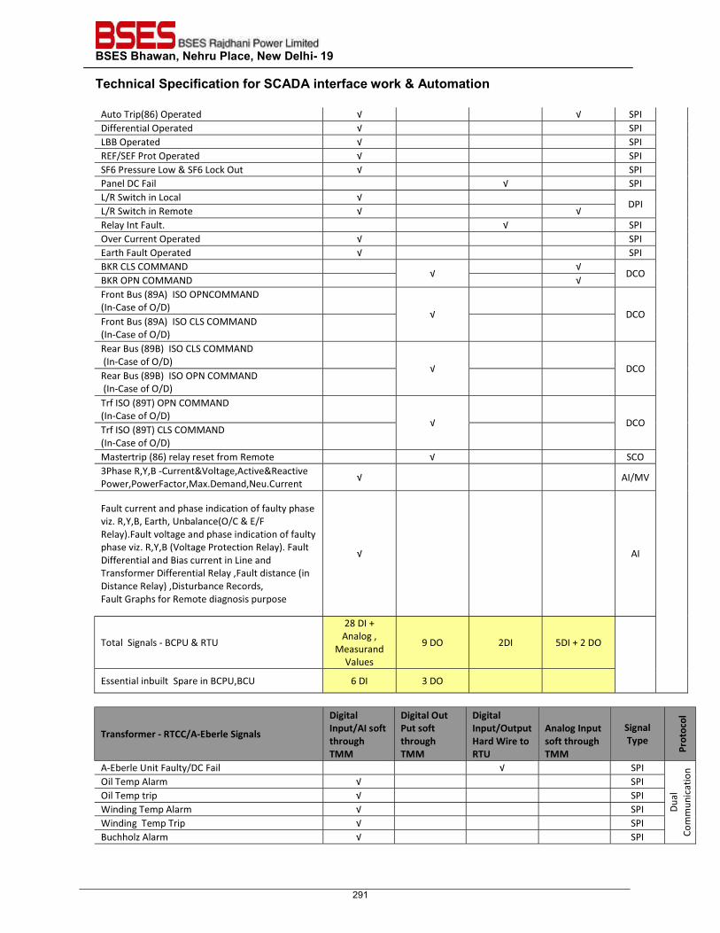
BSES Bhawan, Nehru Place, New Delhi- 19 Technical Specification for SCADA interface work & Automation
Auto Trip(86) Operated √ √ SPI Differential Operated √ SPI LBB Operated √ SPI REF/SEF Prot Operated √ SPI SF6 Pressure Low & SF6 Lock Out √ SPI Panel DC Fail √ SPI L/R Switch in Local √
DPI L/R Switch in Remote √ √ Relay Int Fault. √ SPI Over Current Operated √ SPI Earth Fault Operated √ SPI BKR CLS COMMAND
√ √
DCO BKR OPN COMMAND √ Front Bus (89A) ISO OPNCOMMAND (In-Case of O/D)
√
DCO Front Bus (89A) ISO CLS COMMAND (In-Case of O/D)
Rear Bus (89B) ISO CLS COMMAND (In-Case of O/D)
√
DCO
Rear Bus (89B) ISO OPN COMMAND (In-Case of O/D)
Trf ISO (89T) OPN COMMAND (In-Case of O/D)
√
DCO
Trf ISO (89T) CLS COMMAND (In-Case of O/D)
Mastertrip (86) relay reset from Remote √ SCO 3Phase R,Y,B -Current&Voltage,Active&Reactive Power,PowerFactor,Max.Demand,Neu.Current √ AI/MV
Fault current and phase indication of faulty phase viz. R,Y,B, Earth, Unbalance(O/C & E/F Relay).Fault voltage and phase indication of faulty phase viz. R,Y,B (Voltage Protection Relay). Fault Differential and Bias current in Line and Transformer Differential Relay ,Fault distance (in Distance Relay) ,Disturbance Records, Fault Graphs for Remote diagnosis purpose
√ AI
Total Signals - BCPU & RTU
28 DI + Analog , Measurand
Values
9 DO 2DI 5DI + 2 DO
Essential inbuilt Spare in BCPU,BCU 6 DI 3 DO
Transformer - RTCC/A-Eberle Signals
Digital Input/AI soft through TMM
Digital Out Put soft through TMM
Digital Input/Output Hard Wire to RTU
Analog Input soft through TMM
Signal Type
Prot
ocol
A-Eberle Unit Faulty/DC Fail √ SPI
Dual
Co
mm
unic
atio
n
Oil Temp Alarm √ SPI Oil Temp trip √ SPI Winding Temp Alarm √ SPI Winding Temp Trip √ SPI Buchholz Alarm √ SPI
291
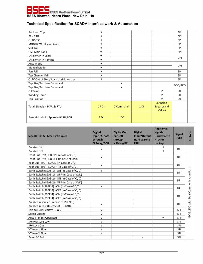
BSES Bhawan, Nehru Place, New Delhi- 19 Technical Specification for SCADA interface work & Automation
Buchholz Trip √ SPI PRV TRIP √ SPI OLTC OSR √ SPI MOG/LOW Oil level Alarm √ SPI SPR Trip √ SPI OSR Main Tank √ SPI L/R Switch in Local √
DPI L/R Switch in Remote √ Auto Mode √
DPI Manual Mode √ Fan Fail √ SPI Tap Changer Fail √ SPI OLTC Out of Step/Stuck Up/Motor trip √ SPI Tap Rise/Tap Low Command √
DCO/RCO Tap Rise/Tap Low Command √ Oil Temp √ AI Winding Temp √ AI Tap Position √ AI
Total Signals - BCPU & RTU 19 DI 2 Command 1 DI 3 Analog , Measurand
Values
Essential inbuilt Spare in BCPU,BCU 2 DI 1 DO
Signals - 33 & 66KV BusCoupler Digital Input/AI soft through N.Relay/BCU
Digital Out Put soft through N.Relay/BCU
Digital Input/Output Hard Wire to RTU
Additional signals Hard wire to RTU for backup
Signal Type
Prot
ocol
Breaker ON √
√ DPI
IEC-
6185
0 w
ith D
ual C
omm
unic
atio
n Po
rts
Breaker OFF √ Front Bus (89A) ISO ON(In-Case of O/D)
√
DPI Front Bus (89A) ISO OFF (In-Case of O/D) Rear Bus (89B) ISO ON (In-Case of O/D)
√
DPI Rear Bus (89B) ISO OFF (In-Case of O/D) Earth Switch (89AE-1) - ON (In-Case of O/D) √
DPI Earth Switch (89AE-1) - OFF (In-Case of O/D) Earth Switch (89AE-2) - ON (In-Case of O/D)
DPI Earth Switch (89AE-2) - OFF (In-Case of O/D) Earth Switch(89BE-3) - ON (In-Case of O/D) √
DPI Earth Switch(89BE-3) - OFF (In-Case of O/D) Earth Switch(89BE-4) - ON (In-Case of O/D)
DPI Earth Switch(89BE-4) - OFF (In-Case of O/D) Breaker in service (In-case of I/D BKR)
√
DPI Breaker in Test (In-case of I/D BKR) Trip coil Ckt Healthy - 1 & 2 √ SPI Spring Charge √ SPI Auto Trip(86) Operated √ √ SPI SF6 Pressure Low √ SPI SF6 Lock Out √ SPI VT fuse-1 Blown √ SPI VT fuse-2 Blown √ SPI Panel DC Fail √ SPI
292
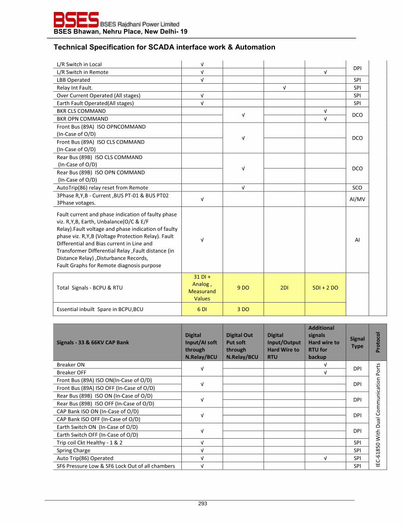
BSES Bhawan, Nehru Place, New Delhi- 19 Technical Specification for SCADA interface work & Automation
L/R Switch in Local √ DPI
L/R Switch in Remote √ √ LBB Operated √ SPI Relay Int Fault. √ SPI Over Current Operated (All stages) √ SPI Earth Fault Operated(All stages) √ SPI BKR CLS COMMAND
√ √
DCO BKR OPN COMMAND √ Front Bus (89A) ISO OPNCOMMAND (In-Case of O/D)
√
DCO
Front Bus (89A) ISO CLS COMMAND (In-Case of O/D)
Rear Bus (89B) ISO CLS COMMAND (In-Case of O/D)
√
DCO
Rear Bus (89B) ISO OPN COMMAND (In-Case of O/D)
AutoTrip(86) relay reset from Remote √ SCO 3Phase R,Y,B - Current ,BUS PT-01 & BUS PT02 3Phase votages. √ AI/MV
Fault current and phase indication of faulty phase viz. R,Y,B, Earth, Unbalance(O/C & E/F Relay).Fault voltage and phase indication of faulty phase viz. R,Y,B (Voltage Protection Relay). Fault Differential and Bias current in Line and Transformer Differential Relay ,Fault distance (in Distance Relay) ,Disturbance Records, Fault Graphs for Remote diagnosis purpose
√ AI
Total Signals - BCPU & RTU
31 DI + Analog , Measurand
Values
9 DO 2DI 5DI + 2 DO
Essential inbuilt Spare in BCPU,BCU 6 DI 3 DO
Signals - 33 & 66KV CAP Bank Digital Input/AI soft through N.Relay/BCU
Digital Out Put soft through N.Relay/BCU
Digital Input/Output Hard Wire to RTU
Additional signals Hard wire to RTU for backup
Signal Type
Prot
ocol
Breaker ON √
√ DPI
IEC-
6185
0 W
ith D
ual C
omm
unic
atio
n Po
rts
Breaker OFF √ Front Bus (89A) ISO ON(In-Case of O/D)
√
DPI Front Bus (89A) ISO OFF (In-Case of O/D) Rear Bus (89B) ISO ON (In-Case of O/D)
√
DPI Rear Bus (89B) ISO OFF (In-Case of O/D) CAP Bank ISO ON (In-Case of O/D)
√
DPI CAP Bank ISO OFF (In-Case of O/D) Earth Switch ON (In-Case of O/D)
√
DPI Earth Switch OFF (In-Case of O/D) Trip coil Ckt Healthy - 1 & 2 √ SPI Spring Charge √ SPI Auto Trip(86) Operated √ √ SPI SF6 Pressure Low & SF6 Lock Out of all chambers √ SPI
293
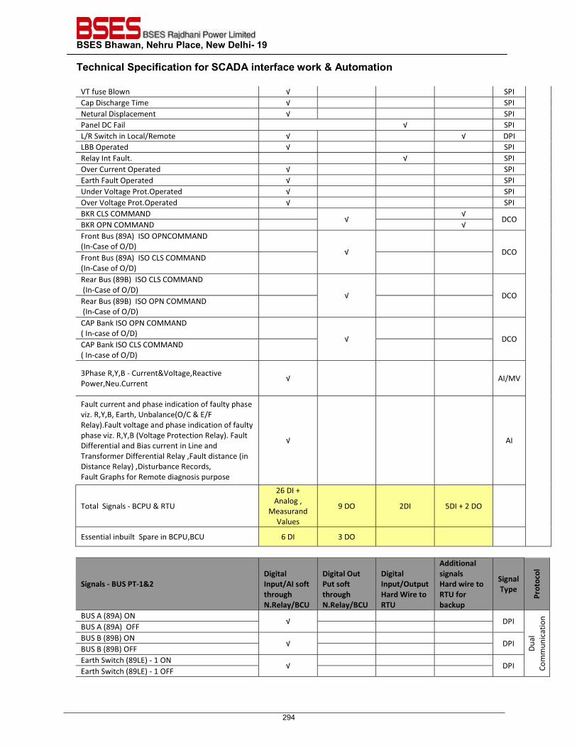
BSES Bhawan, Nehru Place, New Delhi- 19 Technical Specification for SCADA interface work & Automation
VT fuse Blown √ SPI Cap Discharge Time √ SPI Netural Displacement √ SPI Panel DC Fail √ SPI L/R Switch in Local/Remote √ √ DPI LBB Operated √ SPI Relay Int Fault. √ SPI Over Current Operated √ SPI Earth Fault Operated √ SPI Under Voltage Prot.Operated √ SPI Over Voltage Prot.Operated √ SPI BKR CLS COMMAND
√ √
DCO BKR OPN COMMAND √ Front Bus (89A) ISO OPNCOMMAND (In-Case of O/D)
√
DCO Front Bus (89A) ISO CLS COMMAND (In-Case of O/D)
Rear Bus (89B) ISO CLS COMMAND (In-Case of O/D)
√
DCO
Rear Bus (89B) ISO OPN COMMAND (In-Case of O/D)
CAP Bank ISO OPN COMMAND ( In-case of O/D)
√
DCO
CAP Bank ISO CLS COMMAND ( In-case of O/D)
3Phase R,Y,B - Current&Voltage,Reactive Power,Neu.Current
√ AI/MV
Fault current and phase indication of faulty phase viz. R,Y,B, Earth, Unbalance(O/C & E/F Relay).Fault voltage and phase indication of faulty phase viz. R,Y,B (Voltage Protection Relay). Fault Differential and Bias current in Line and Transformer Differential Relay ,Fault distance (in Distance Relay) ,Disturbance Records, Fault Graphs for Remote diagnosis purpose
√ AI
Total Signals - BCPU & RTU
26 DI + Analog , Measurand
Values
9 DO 2DI 5DI + 2 DO
Essential inbuilt Spare in BCPU,BCU 6 DI 3 DO
Signals - BUS PT-1&2 Digital Input/AI soft through N.Relay/BCU
Digital Out Put soft through N.Relay/BCU
Digital Input/Output Hard Wire to RTU
Additional signals Hard wire to RTU for backup
Signal Type
Prot
ocol
BUS A (89A) ON √
DPI
Dual
Co
mm
unic
atio
n
BUS A (89A) OFF BUS B (89B) ON
√
DPI BUS B (89B) OFF Earth Switch (89LE) - 1 ON
√
DPI Earth Switch (89LE) - 1 OFF
294
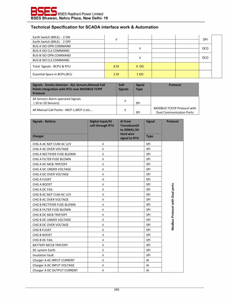
BSES Bhawan, Nehru Place, New Delhi- 19 Technical Specification for SCADA interface work & Automation
Earth Switch (89LE) - 2 ON √
DPI
Earth Switch (89LE) - 2 OFF BUS-A ISO OPN COMMAND
√
DCO BUS-A ISO CLS COMMAND BUS-B ISO OPN COMMAND
√
DCO BUS-B ISO CLS COMMAND
Total Signals - BCPU & RTU 8 DI 4 DO
Essential Spare in BCPU,BCU 2 DI 1 DO
Signals - Smoke Detector - ALL Sensors,Manual Call Points Integration with RTU over MODBUS TCPIP Protocol.
Soft Signals
Signal Type
Protocol
All Sensors Alarm operated Signals ( 10 to 20 Sensors)
√ SPI
MODBUS TCP/IP Protocol with Dual Communication Ports
All Manual Call Points - MCP-1,MCP-2.etc… √ SPI
Signals - Battery Digital Input/AI
soft through RTU AI from Transducer(4 to 20MA) /AI Hard wire signal to RTU
Signal Protocol
Charger Type
CHG A AC M/F CUM AC U/V √ SPI
Mod
bus P
roto
col w
ith D
ual p
orts
CHG A AC OVER VOLTAGE √ SPI CHG A RECTIFIER FUSE BLOWN √ SPI CHG A FILTER FUSE BLOWN √ SPI CHG A DC MCB TRIP/OFF √ SPI CHG A DC UNDER VOLTAGE √ SPI CHG A DC OVER VOLTAGE √ SPI CHG A FLOAT √ SPI CHG A BOOST √ SPI CHG A DC FAIL √ SPI CHG B AC M/F CUM AC U/V √ SPI CHG B AC OVER VOLTAGE √ SPI CHG B RECTIFIER FUSE BLOWN √ SPI CHG B FILTER FUSE BLOWN √ SPI CHG B DC MCB TRIP/OFF √ SPI CHG B DC UNDER VOLTAGE √ SPI CHG B DC OVER VOLTAGE √ SPI CHG B FLOAT √ SPI CHG B BOOST √ SPI CHG B DC FAIL √ SPI BATTERY MCCB TRIP/OFF √ SPI DC system Earth √ SPI Insulation fault √ SPI Charger A AC INPUT CURRENT √ AI Charger A AC INPUT VOLTAGE √ AI Charger A DC OUTPUT CURRENT √ AI
295
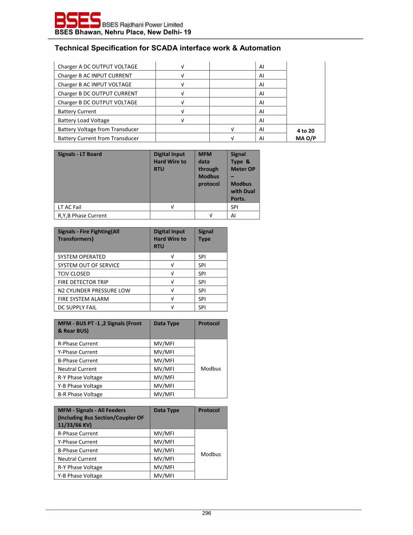
BSES Bhawan, Nehru Place, New Delhi- 19 Technical Specification for SCADA interface work & Automation
Charger A DC OUTPUT VOLTAGE √ AI Charger B AC INPUT CURRENT √ AI Charger B AC INPUT VOLTAGE √ AI Charger B DC OUTPUT CURRENT √ AI Charger B DC OUTPUT VOLTAGE √ AI Battery Current √ AI Battery Load Voltage √ AI Battery Voltage from Transducer √ AI 4 to 20
MA O/P Battery Current from Transducer √ AI Signals - LT Board Digital Input
Hard Wire to RTU
MFM data through Modbus protocol
Signal Type & Meter OP – Modbus with Dual Ports.
LT AC Fail √ SPI R,Y,B Phase Current √ AI
Signals - Fire Fighting(All Transformers)
Digital Input Hard Wire to RTU
Signal Type
SYSTEM OPERATED √ SPI SYSTEM OUT OF SERVICE √ SPI TCIV CLOSED √ SPI FIRE DETECTOR TRIP √ SPI N2 CYLINDER PRESSURE LOW √ SPI FIRE SYSTEM ALARM √ SPI DC SUPPLY FAIL √ SPI
MFM - BUS PT -1 ,2 Signals (Front & Rear BUS)
Data Type Protocol
R-Phase Current MV/MFI
Modbus
Y-Phase Current MV/MFI B-Phase Current MV/MFI Neutral Current MV/MFI R-Y Phase Voltage MV/MFI Y-B Phase Voltage MV/MFI B-R Phase Voltage MV/MFI
MFM - Signals - All Feeders (Including Bus Section/Coupler OF 11/33/66 KV)
Data Type Protocol
R-Phase Current MV/MFI
Modbus
Y-Phase Current MV/MFI B-Phase Current MV/MFI Neutral Current MV/MFI R-Y Phase Voltage MV/MFI Y-B Phase Voltage MV/MFI
296
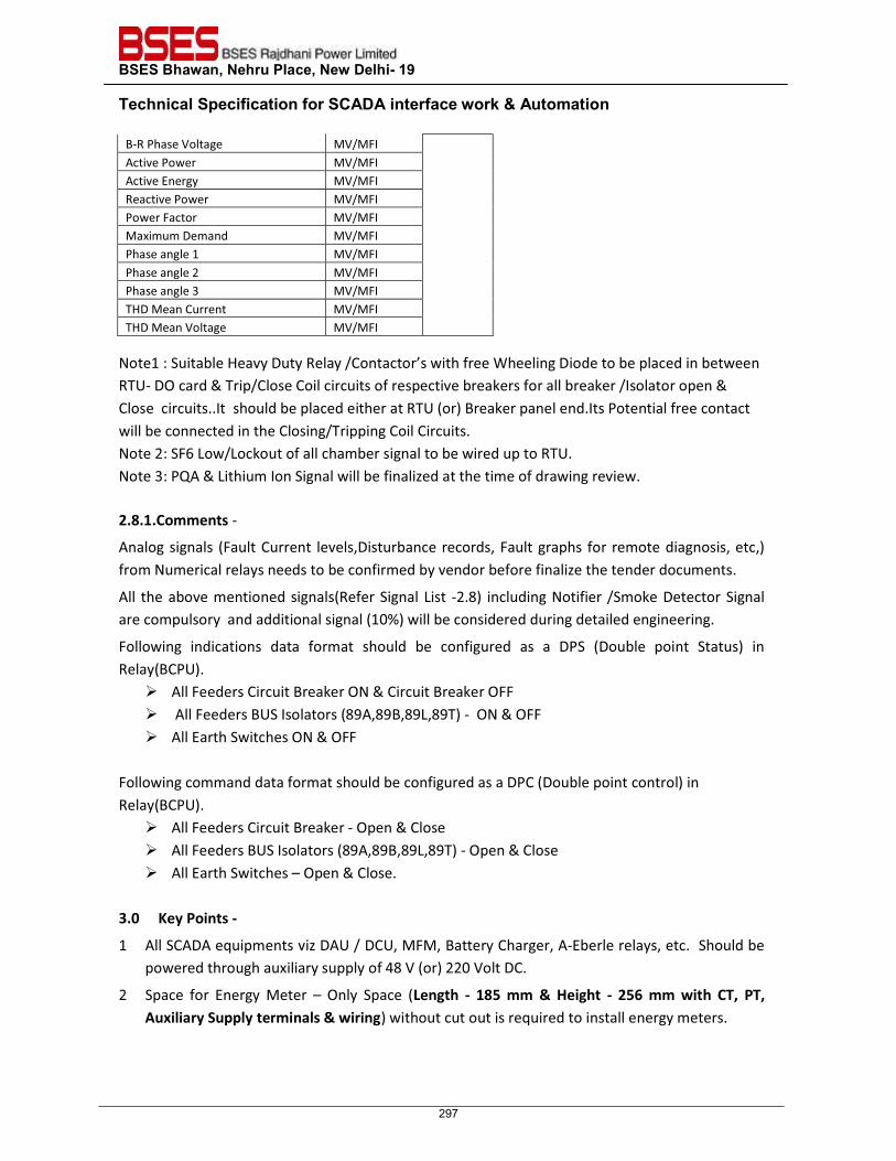
BSES Bhawan, Nehru Place, New Delhi- 19 Technical Specification for SCADA interface work & Automation
B-R Phase Voltage MV/MFI Active Power MV/MFI Active Energy MV/MFI Reactive Power MV/MFI Power Factor MV/MFI Maximum Demand MV/MFI Phase angle 1 MV/MFI Phase angle 2 MV/MFI Phase angle 3 MV/MFI THD Mean Current MV/MFI THD Mean Voltage MV/MFI
Note1 : Suitable Heavy Duty Relay /Contactor’s with free Wheeling Diode to be placed in between RTU- DO card & Trip/Close Coil circuits of respective breakers for all breaker /Isolator open & Close circuits..It should be placed either at RTU (or) Breaker panel end.Its Potential free contact will be connected in the Closing/Tripping Coil Circuits. Note 2: SF6 Low/Lockout of all chamber signal to be wired up to RTU. Note 3: PQA & Lithium Ion Signal will be finalized at the time of drawing review. 2.8.1.Comments -
Analog signals (Fault Current levels,Disturbance records, Fault graphs for remote diagnosis, etc,) from Numerical relays needs to be confirmed by vendor before finalize the tender documents.
All the above mentioned signals(Refer Signal List -2.8) including Notifier /Smoke Detector Signal are compulsory and additional signal (10%) will be considered during detailed engineering.
Following indications data format should be configured as a DPS (Double point Status) in Relay(BCPU).
� All Feeders Circuit Breaker ON & Circuit Breaker OFF � All Feeders BUS Isolators (89A,89B,89L,89T) - ON & OFF � All Earth Switches ON & OFF
Following command data format should be configured as a DPC (Double point control) in Relay(BCPU).
� All Feeders Circuit Breaker - Open & Close � All Feeders BUS Isolators (89A,89B,89L,89T) - Open & Close � All Earth Switches – Open & Close.
3.0 Key Points -
1 All SCADA equipments viz DAU / DCU, MFM, Battery Charger, A-Eberle relays, etc. Should be powered through auxiliary supply of 48 V (or) 220 Volt DC.
2 Space for Energy Meter – Only Space (Length - 185 mm & Height - 256 mm with CT, PT, Auxiliary Supply terminals & wiring) without cut out is required to install energy meters.
297
BSES Bhawan, Nehru Place, New Delhi- 19 Technical Specification for SCADA interface work & Automation
3 Power Supply for Routers/ Gateway (IT Equipments) through an existing battery bank via DC to DC Converters (Input: 48 VDC/220 VDC, Output: 12 Volt DC) or as per the requirements of Routers.
Converter 01 Speifications : Input 220 Volt DC & Output 12 to 48 Volt DC
Converter 02 Specifications:Input 220 Volt DC (or) 48 Volt DC & OutPut 12 Volt DC
4 Any other wiring / cabling if required due to non availability of serial communication /MODBUS/IEC 61850 protocols (with justified reason) should be hardwired and that is in Contractor’s scope.
5 Suitable transducers with an output of 4-20 mA have to be installed in the RTCC /Battery charger if required and the outputs of these transducers should be extended to terminal for further extension to the RTU.
6 STATION BUS : Topology � Dual Homing (or) Redundant Ring with Ehernet/Copper Cable – From BCPU,BCU to Switch � Redundant Ring with Fiber Optic Cable – From Switch to RTU/Gateway. � Note : Dual Homing (or) Redunt Ring Network topology will be decided during the detail
engineering stage.
7 The C & R ,RTCC,Battery Charger Panel should have additional spare contacts (potential free) for all SCADA signals – Refer Signal List 2.8
8 Data Base File must be downloadable and Uploadable from RTU,CPU,BCPU,BCU and Gateway.
9 Separate Room/Cabinet With AC for RTU and IT Equipments.
10 Warranty (5 Years) for SCADA products - All Supplied SCADA material should cover warranty for the duration of 5 years & Warranty period will start after successful commissioning of the SCADA equipments at site. If any SCADA materials found faulty during warranty period should be replaced within two weeks.
11 Training should be provided on configuration, installation, commissioning aspects of RTU,DCU,BCU and Numerical Relay - BCPU at your training/work center to the BSES SCADA team (4 to 5 persons ) & Training Expenses (Air & Local Travel, boarding and Lodging for 4 to 5 persons) at factory/training center(5 days) comes under Vendor’s scope.
Training documents to be submitted for approval & Documents should contain all the necessary installations,connections and Data Base development procedure & further trouble shooting procedure,etc..shall also be provided in the manual. Training at Site:Vendor shall provide One trainer at site for training after commissioning of SCADA RTU at site.
12 Antivirus/Cyber Security solution for Gateway/RTU unit with 5 years validity need to be considered.
298
BSES Bhawan, Nehru Place, New Delhi- 19 Technical Specification for SCADA interface work & Automation
13 Spares: loose Spare Materials for following items with below mentioned quantity to be supplied for emergency back up/maintenance purpose. � CPU (Main Processor) with Ethernet Interface Card/Memory in RTU – 1 No � CPU(Main Processor Module in BCU) – 1 No � Gateway – 1 No � RTU Rack – 1 No � BCU Rack – 1 No � Communication Module for IEC-103 & Modbus Communications with Serial Interface
Card/Memory in RTU – 1 No � DO Contactots – 10% of supplied qty. � DI/DO/AI/ Cards in RTU – 10% of the total IO signals � DI/DO/AI/ Cards in BCU – 10% of the total IO signals � PSU Cards in RTU – 1 No � Ethernet Switches (9 ,16 & 24 Ports) – 1 No’s � Ethernet Switches (16 & 24 Ports) – 1 No’s � LIU Unit – 1 No � Fiber Optic Patch Cards with Connectors - 20% of total installed cables. � MFM – 5% of Supplied Qty. � DC to DC converters if any for RTU Supply – 1 No.
14 Protection devices for all SCADA Equipmentes – � Surge Protection devices installation between RTU & MFM Serial loops. � SPD for Main DC Source. � HDR/Inter Posing Relay for all Digital Output Signal’s. � All modules (All Digital, Analog Input modules in BCPU and RTU) and ports (Serial and
Ethernet ports) must have in-built or external surge protection devices and optical isolation.
15 Local HMI shold be consider along with RTU : � Human machine interface (HMI) with control software package, which shall contain an
extensive range of system monitoring and data acquisition (SCADA) and control functions. � Local control function shall have an access control for various level of authorities (for
viewing, analyzing and operating). Logistics (Table & Chairs) shall be included in supply. HMI shall have 19” foldable monitor ,it should be fixed inside RTU Panels. HMI have a backup battery (UPS, APC make) system for 4 hours back up. All necessary accessories shall be a part of supply and installation work. HMI (KVM Type)shall be fixed inside RTU panel.
� Incase of failure of communication equipments then DR shall be extracted from HMI for further diagonosis purpose only.So,It will not be used as a Gateway for control center data process.
� The LDMS shall be used for local data acquisition, monitoring and control of substation parameters through RTU. The LDMS shall be a mini SCADA system providing MMI
299
BSES Bhawan, Nehru Place, New Delhi- 19 Technical Specification for SCADA interface work & Automation
capability for use in the sub-station control room building. The LDMS software shall include following functions:
o data acquisition for analog, digital, events and pulse accumulator type data o data processing – Conversion to engineering units, limit monitoring, data validity
test, calculated data o Calculated data (such as maximum, minimum, average values with associated
time-stamping etc.) of all the station parameters. o Sequence of Events Processing o Supervisory control o Alarm, tagging, trending, quality codes etc. o Single Line Diagrams, Trends, daily, weekly, monthly reports etc. shall be prepared
by the bidder and integrated on LDMS system. The LDMS shall also have capability to generate additional displays, single line diagrams, reports and trends.
o The LDMS shall store all real-time telemetered data. All alarms, events, SOE etc. shall also be stored on regular basis. It shall be possible to define daily, weekly, monthly Sub-Station reports on LDMS. It shall be possible to generate reports highlighting the maximum, minimum, average with associated time-stamping etc. of all the station parameters. The historical data stored on the storage medium shall be in standard format and necessary tools for its export to standard spreadsheet programs (Excel and .csv) shall be provided.
16 Syatem Architecture : System Architecture should be submitted at the time of tendering process.
17 Following tools to be supplied
� laptop 1 No to be supplied with following specification Make : Lenova & Model : Think Pad L Series 10th Generation Intel Core TM i5-10210UProcessor(4Cores/8Threads, 1.60-GHZ up to 2.10 GHZ with Turbo Boost, 6MB Casche),Windows 10 Pro 64, 35.56cms(14.0)FHD (1366x768)TN220nts Anti-glare, 8GB RAM DDR4 5Years Onsite Warranty,Stereo,Dolby@AudioTM 65W Adaptor,Carry Bag & Wired Mouse,Integrated Intel@UHD Graphics HDMI Port,2xUSB 3.2Gen1, 1xUSB 32 Type-C Gen 1.1xUSB3.2 Type-C Gen2. Laptop Battery 3 Cell,45Wh,CAM 720p HD Intel Wi-FI & Blue tooth 5.1
� Tool Bag 1 No’s along with following tools,
S.no. Items Make QTY
1 Vacuum Cleaner cum blower Eureka Forbes Euro Clean 1
2 Screw driver set Taparia 1 3 Drill machine Bosch 1
300
BSES Bhawan, Nehru Place, New Delhi- 19 Technical Specification for SCADA interface work & Automation
4 RJ45 crimping tool D-Link 1 5 Plier ,Taparia 1 6 wire cable cutter Taparia 1
7 LAN continuity tester MOELISSA MS-LT02 1
8 Soldering Iron and accessories Kit ESKON 1 9 RS485/RS232 to USB Converter moxa 1
10 PT sequence tester HTC 1 11 Head Torch AG TRADE 1 12 Tool Bag Standard 1
� Ferrule Printing Machine – 1 No with Sleeves for 1.5,2.5 Sqmm Cables.
18 Drawings/GTP shall be submitted to BRPL-3 Sets hardcopy for approval in the event of award of work.
19 As Built Drawings 3 Sets Hard copy and 2 Set in Pen drive shall be submitted at the time of Handover of project for Final billing.
20 DB back up along with Software in Pen drive shall be handover at the time of Handover of project for Final billing.
21 All the above features are indicative only and detailed engineering and deviation will be analyzed just before actual procurement and with discussion through a supplier/ vendor.
4.0 System Architecture Diagram
The Tentative System Architecture diagram is enclosed for reference. It will be revised during the approval stage of drawings..
5.0 PACKING AND SHIPMENT Shall be packed such that protected against corrosion, dampness, heavy rains, breakage and vibration in GPS Enabled Vehicle and shipment status through GPS Device shall be sent to BRPL Project incharge Via SMS/Email. 6.0 QUALITY ASSURANCE Factory Acceptance Test : BRPL executives shall be visiting the vendors factory for inspection of Supply material. Travel Ticket (return flight), local travel, boarding and lodging shall be in vendor’s scope. Field Quality Plan : Vendor shall submit a field quality paln for approval of buyer before taking up the execution work at site.
301
BSES Bhawan, Nehru Place, New Delhi- 19 Technical Specification for SCADA interface work & Automation
7.0 DEVIATIONS Deviation from this specification, if any, shall be clearly brought out in the offer. Unless the owner explicitly accepts such deviations, it shall be considered that the offer fully complies with the specification.No deviations will be acceptable post order.
302
SP-ASCB-19-R0
TECHNICAL SPECIFICATION FOR 11 KV AUTO SWITCHED CAPACITOR BANK OUTDOOR / INDOOR
TYPE
Prepared by Reviewed by Approved by
Rev
00
Date 11 Nov 2016
HK AS VP Page 1 of 12
TECHNICAL SPECIFICATION
FOR
11KV AUTO SWITCHED CAPACITOR BANK
INDOOR / OUTDOOR TYPE
303
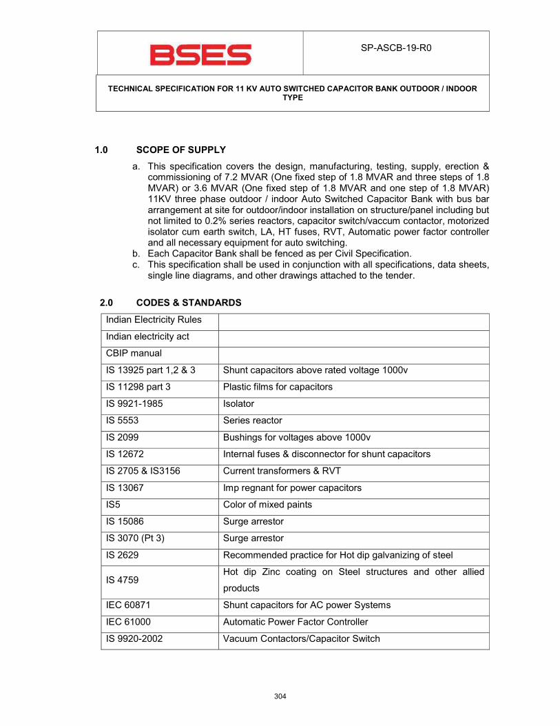
SP-ASCB-19-R0
TECHNICAL SPECIFICATION FOR 11 KV AUTO SWITCHED CAPACITOR BANK OUTDOOR / INDOOR
TYPE
1.0 SCOPE OF SUPPLY
a. This specification covers the design, manufacturing, testing, supply, erection & commissioning of 7.2 MVAR (One fixed step of 1.8 MVAR and three steps of 1.8 MVAR) or 3.6 MVAR (One fixed step of 1.8 MVAR and one step of 1.8 MVAR) 11KV three phase outdoor / indoor Auto Switched Capacitor Bank with bus bar arrangement at site for outdoor/indoor installation on structure/panel including but not limited to 0.2% series reactors, capacitor switch/vaccum contactor, motorized isolator cum earth switch, LA, HT fuses, RVT, Automatic power factor controller and all necessary equipment for auto switching.
b. Each Capacitor Bank shall be fenced as per Civil Specification. c. This specification shall be used in conjunction with all specifications, data sheets,
single line diagrams, and other drawings attached to the tender.
2.0 CODES & STANDARDS
Indian Electricity Rules
Indian electricity act
CBIP manual
IS 13925 part 1,2 & 3 Shunt capacitors above rated voltage 1000v
IS 11298 part 3 Plastic films for capacitors
IS 9921-1985 Isolator
IS 5553 Series reactor
IS 2099 Bushings for voltages above 1000v
IS 12672 Internal fuses & disconnector for shunt capacitors
IS 2705 & IS3156 Current transformers & RVT
IS 13067 Imp regnant for power capacitors
IS5 Color of mixed paints
IS 15086 Surge arrestor
IS 3070 (Pt 3) Surge arrestor
IS 2629 Recommended practice for Hot dip galvanizing of steel
IS 4759 Hot dip Zinc coating on Steel structures and other allied
products
IEC 60871 Shunt capacitors for AC power Systems
IEC 61000 Automatic Power Factor Controller
IS 9920-2002 Vacuum Contactors/Capacitor Switch
304
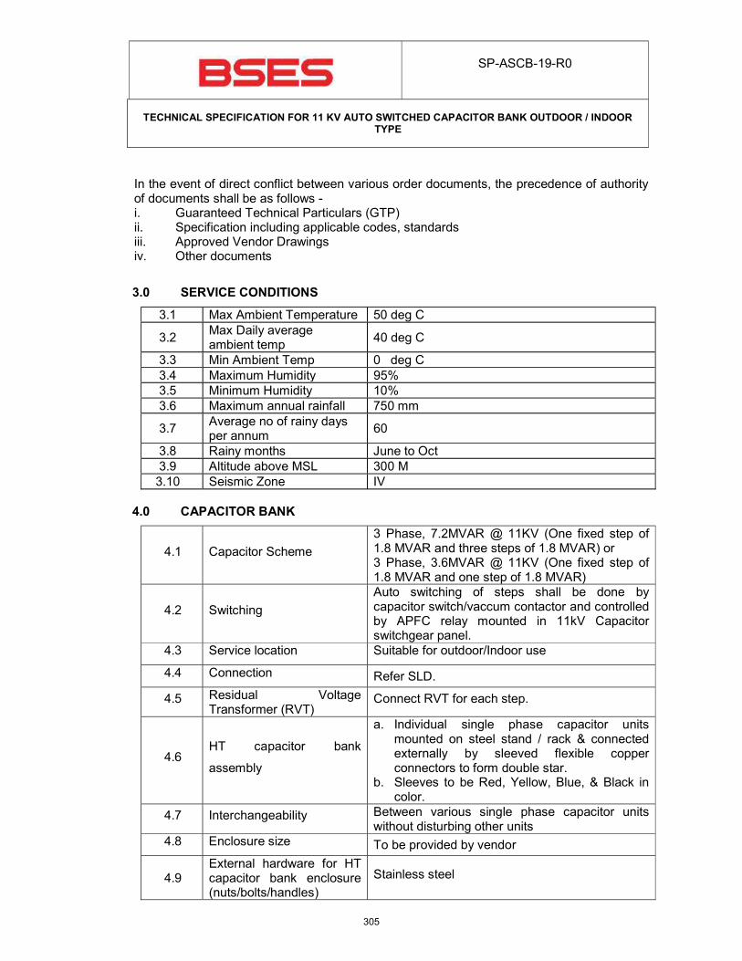
SP-ASCB-19-R0
TECHNICAL SPECIFICATION FOR 11 KV AUTO SWITCHED CAPACITOR BANK OUTDOOR / INDOOR
TYPE
In the event of direct conflict between various order documents, the precedence of authority of documents shall be as follows - i. Guaranteed Technical Particulars (GTP) ii. Specification including applicable codes, standards iii. Approved Vendor Drawings iv. Other documents
3.0 SERVICE CONDITIONS
3.1 Max Ambient Temperature 50 deg C
3.2 Max Daily average ambient temp
40 deg C
3.3 Min Ambient Temp 0 deg C
3.4 Maximum Humidity 95%
3.5 Minimum Humidity 10%
3.6 Maximum annual rainfall 750 mm
3.7 Average no of rainy days per annum
60
3.8 Rainy months June to Oct
3.9 Altitude above MSL 300 M
3.10 Seismic Zone IV
4.0 CAPACITOR BANK
4.1 Capacitor Scheme
3 Phase, 7.2MVAR @ 11KV (One fixed step of 1.8 MVAR and three steps of 1.8 MVAR) or 3 Phase, 3.6MVAR @ 11KV (One fixed step of 1.8 MVAR and one step of 1.8 MVAR)
4.2 Switching
Auto switching of steps shall be done by capacitor switch/vaccum contactor and controlled by APFC relay mounted in 11kV Capacitor switchgear panel.
4.3 Service location Suitable for outdoor/Indoor use
4.4 Connection Refer SLD.
4.5 Residual Voltage Transformer (RVT)
Connect RVT for each step.
4.6 HT capacitor bank
assembly
a. Individual single phase capacitor units mounted on steel stand / rack & connected externally by sleeved flexible copper connectors to form double star.
b. Sleeves to be Red, Yellow, Blue, & Black in color.
4.7 Interchangeability Between various single phase capacitor units without disturbing other units
4.8 Enclosure size To be provided by vendor
4.9 External hardware for HT capacitor bank enclosure (nuts/bolts/handles)
Stainless steel
305
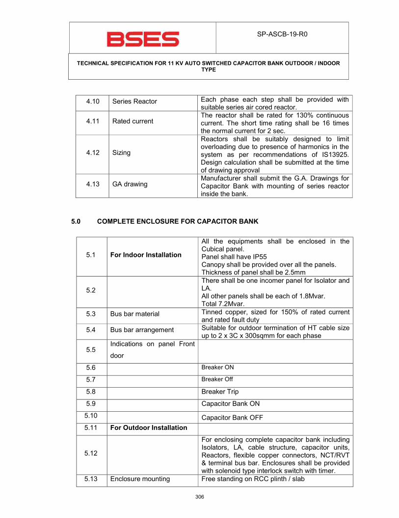
SP-ASCB-19-R0
TECHNICAL SPECIFICATION FOR 11 KV AUTO SWITCHED CAPACITOR BANK OUTDOOR / INDOOR
TYPE
4.10 Series Reactor Each phase each step shall be provided with suitable series air cored reactor.
4.11 Rated current The reactor shall be rated for 130% continuous current. The short time rating shall be 16 times the normal current for 2 sec.
4.12 Sizing
Reactors shall be suitably designed to limit overloading due to presence of harmonics in the system as per recommendations of IS13925. Design calculation shall be submitted at the time of drawing approval
4.13 GA drawing Manufacturer shall submit the G.A. Drawings for Capacitor Bank with mounting of series reactor inside the bank.
5.0 COMPLETE ENCLOSURE FOR CAPACITOR BANK
5.1 For Indoor Installation
All the equipments shall be enclosed in the Cubical panel. Panel shall have IP55 Canopy shall be provided over all the panels. Thickness of panel shall be 2.5mm
5.2
There shall be one incomer panel for Isolator and LA. All other panels shall be each of 1.8Mvar. Total 7.2Mvar.
5.3 Bus bar material Tinned copper, sized for 150% of rated current and rated fault duty
5.4 Bus bar arrangement Suitable for outdoor termination of HT cable size up to 2 x 3C x 300sqmm for each phase
5.5 Indications on panel Front
door
5.6 Breaker ON
5.7 Breaker Off
5.8 Breaker Trip
5.9 Capacitor Bank ON
5.10 Capacitor Bank OFF
5.11 For Outdoor Installation
5.12
For enclosing complete capacitor bank including Isolators, LA, cable structure, capacitor units, Reactors, flexible copper connectors, NCT/RVT & terminal bus bar. Enclosures shall be provided with solenoid type interlock switch with timer.
5.13 Enclosure mounting Free standing on RCC plinth / slab
306
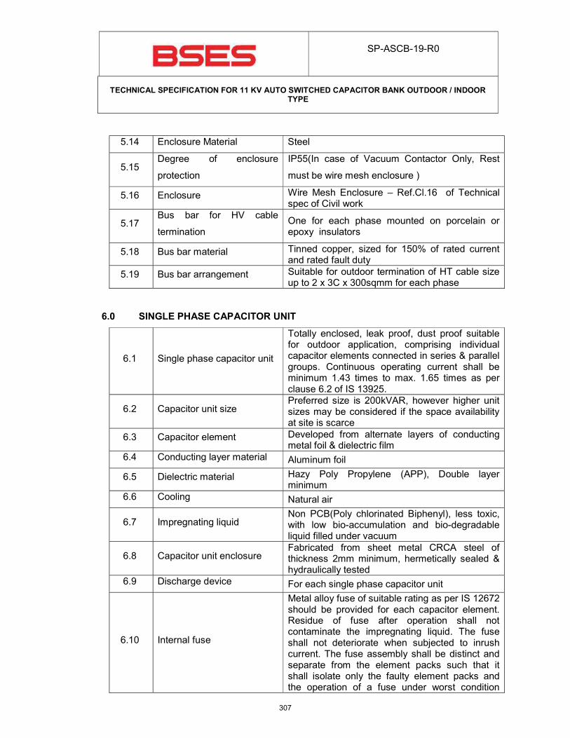
SP-ASCB-19-R0
TECHNICAL SPECIFICATION FOR 11 KV AUTO SWITCHED CAPACITOR BANK OUTDOOR / INDOOR
TYPE
5.14 Enclosure Material Steel
5.15 Degree of enclosure
protection
IP55(In case of Vacuum Contactor Only, Rest
must be wire mesh enclosure )
5.16 Enclosure Wire Mesh Enclosure – Ref.Cl.16 of Technical spec of Civil work
5.17 Bus bar for HV cable
termination One for each phase mounted on porcelain or epoxy insulators
5.18 Bus bar material Tinned copper, sized for 150% of rated current and rated fault duty
5.19 Bus bar arrangement Suitable for outdoor termination of HT cable size up to 2 x 3C x 300sqmm for each phase
6.0 SINGLE PHASE CAPACITOR UNIT
6.1 Single phase capacitor unit
Totally enclosed, leak proof, dust proof suitable for outdoor application, comprising individual capacitor elements connected in series & parallel groups. Continuous operating current shall be minimum 1.43 times to max. 1.65 times as per clause 6.2 of IS 13925.
6.2 Capacitor unit size Preferred size is 200kVAR, however higher unit sizes may be considered if the space availability at site is scarce
6.3 Capacitor element Developed from alternate layers of conducting metal foil & dielectric film
6.4 Conducting layer material Aluminum foil
6.5 Dielectric material Hazy Poly Propylene (APP), Double layer minimum
6.6 Cooling Natural air
6.7 Impregnating liquid Non PCB(Poly chlorinated Biphenyl), less toxic, with low bio-accumulation and bio-degradable liquid filled under vacuum
6.8 Capacitor unit enclosure Fabricated from sheet metal CRCA steel of thickness 2mm minimum, hermetically sealed & hydraulically tested
6.9 Discharge device For each single phase capacitor unit
6.10 Internal fuse
Metal alloy fuse of suitable rating as per IS 12672 should be provided for each capacitor element. Residue of fuse after operation shall not contaminate the impregnating liquid. The fuse shall not deteriorate when subjected to inrush current. The fuse assembly shall be distinct and separate from the element packs such that it shall isolate only the faulty element packs and the operation of a fuse under worst condition
307
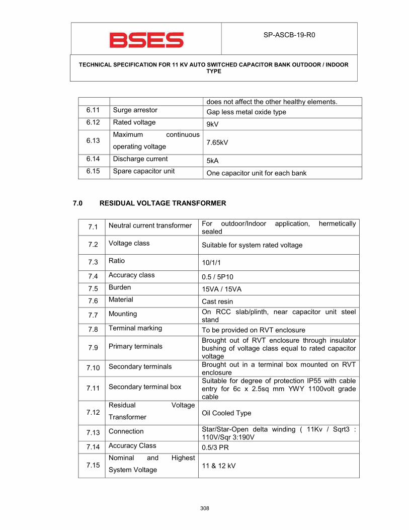
SP-ASCB-19-R0
TECHNICAL SPECIFICATION FOR 11 KV AUTO SWITCHED CAPACITOR BANK OUTDOOR / INDOOR
TYPE
does not affect the other healthy elements. 6.11 Surge arrestor Gap less metal oxide type
6.12 Rated voltage 9kV
6.13 Maximum continuous
operating voltage 7.65kV
6.14 Discharge current 5kA
6.15 Spare capacitor unit One capacitor unit for each bank
7.0 RESIDUAL VOLTAGE TRANSFORMER
7.1 Neutral current transformer For outdoor/Indoor application, hermetically sealed
7.2 Voltage class Suitable for system rated voltage
7.3 Ratio 10/1/1
7.4 Accuracy class 0.5 / 5P10
7.5 Burden 15VA / 15VA
7.6 Material Cast resin
7.7 Mounting On RCC slab/plinth, near capacitor unit steel stand
7.8 Terminal marking To be provided on RVT enclosure
7.9 Primary terminals Brought out of RVT enclosure through insulator bushing of voltage class equal to rated capacitor voltage
7.10 Secondary terminals Brought out in a terminal box mounted on RVT enclosure
7.11 Secondary terminal box Suitable for degree of protection IP55 with cable entry for 6c x 2.5sq mm YWY 1100volt grade cable
7.12 Residual Voltage
Transformer Oil Cooled Type
7.13 Connection Star/Star-Open delta winding ( 11Kv / Sqrt3 : 110V/Sqr 3:190V
7.14 Accuracy Class 0.5/3 PR
7.15 Nominal and Highest
System Voltage 11 & 12 kV
308
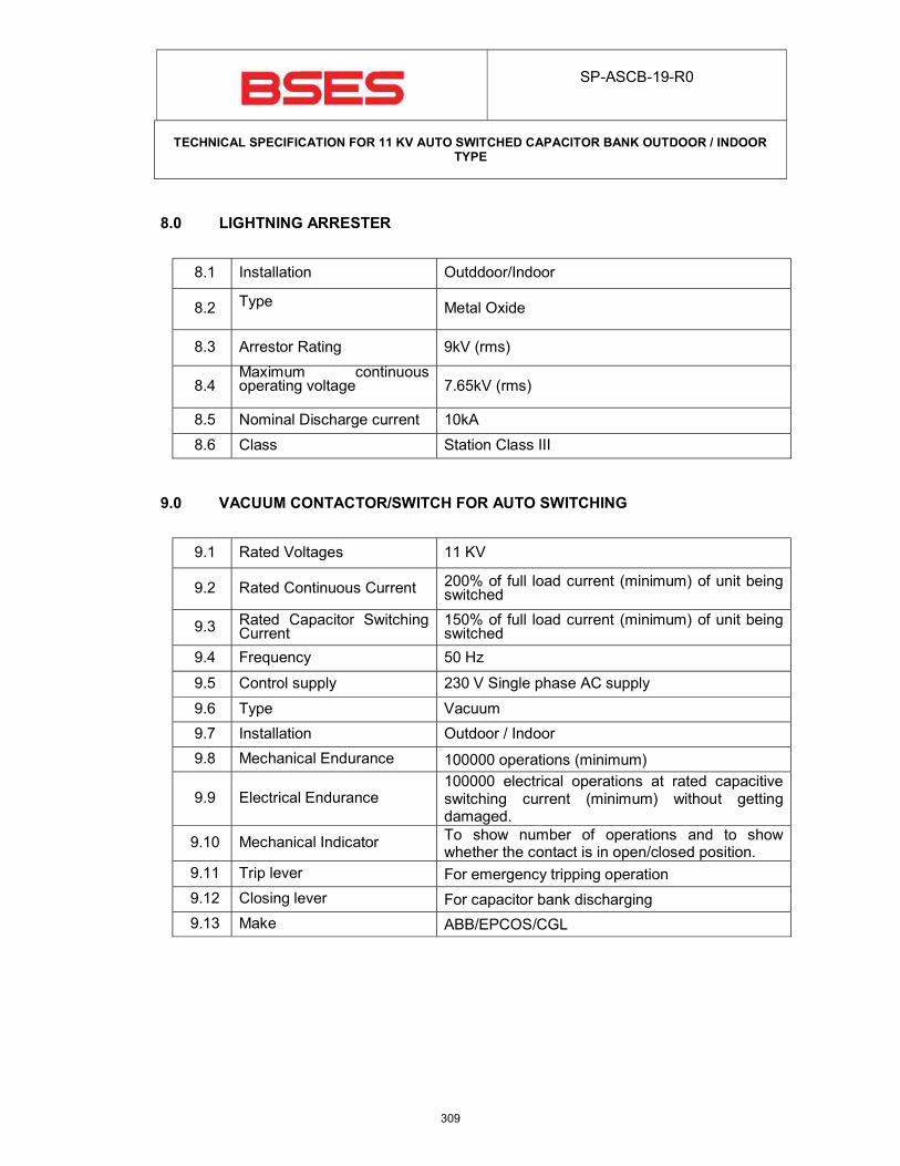
SP-ASCB-19-R0
TECHNICAL SPECIFICATION FOR 11 KV AUTO SWITCHED CAPACITOR BANK OUTDOOR / INDOOR
TYPE
8.0 LIGHTNING ARRESTER
8.1 Installation Outddoor/Indoor
8.2 Type Metal Oxide
8.3 Arrestor Rating 9kV (rms)
8.4 Maximum continuous operating voltage
7.65kV (rms)
8.5 Nominal Discharge current 10kA
8.6 Class Station Class III
9.0 VACUUM CONTACTOR/SWITCH FOR AUTO SWITCHING
9.1 Rated Voltages 11 KV
9.2 Rated Continuous Current 200% of full load current (minimum) of unit being switched
9.3 Rated Capacitor Switching Current
150% of full load current (minimum) of unit being switched
9.4 Frequency 50 Hz
9.5 Control supply 230 V Single phase AC supply
9.6 Type Vacuum
9.7 Installation Outdoor / Indoor
9.8 Mechanical Endurance 100000 operations (minimum)
9.9 Electrical Endurance 100000 electrical operations at rated capacitive switching current (minimum) without getting damaged.
9.10 Mechanical Indicator To show number of operations and to show whether the contact is in open/closed position.
9.11 Trip lever For emergency tripping operation
9.12 Closing lever For capacitor bank discharging
9.13 Make ABB/EPCOS/CGL
309
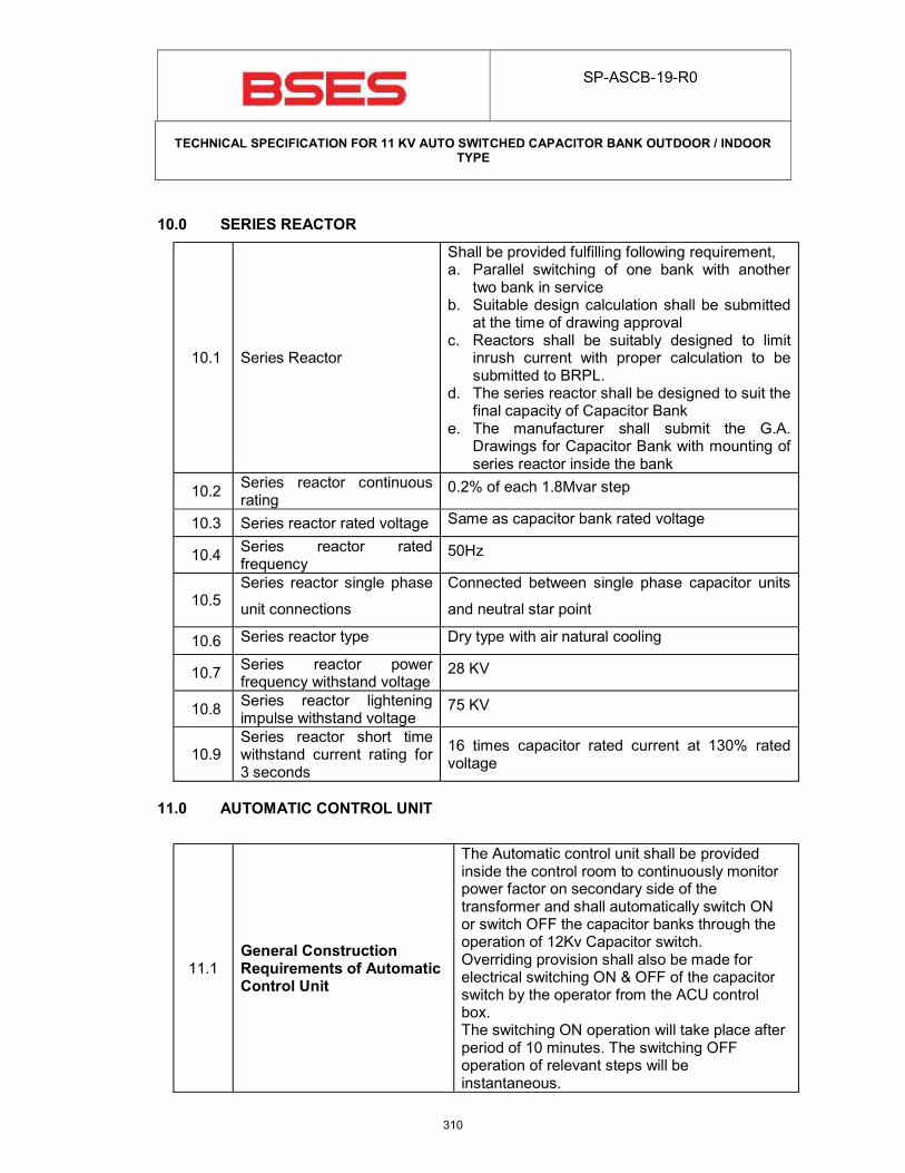
SP-ASCB-19-R0
TECHNICAL SPECIFICATION FOR 11 KV AUTO SWITCHED CAPACITOR BANK OUTDOOR / INDOOR
TYPE
10.0 SERIES REACTOR
10.1 Series Reactor
Shall be provided fulfilling following requirement, a. Parallel switching of one bank with another
two bank in service b. Suitable design calculation shall be submitted
at the time of drawing approval c. Reactors shall be suitably designed to limit
inrush current with proper calculation to be submitted to BRPL.
d. The series reactor shall be designed to suit the final capacity of Capacitor Bank
e. The manufacturer shall submit the G.A. Drawings for Capacitor Bank with mounting of series reactor inside the bank
10.2 Series reactor continuous rating
0.2% of each 1.8Mvar step
10.3 Series reactor rated voltage Same as capacitor bank rated voltage
10.4 Series reactor rated frequency
50Hz
10.5 Series reactor single phase
unit connections
Connected between single phase capacitor units
and neutral star point
10.6 Series reactor type Dry type with air natural cooling
10.7 Series reactor power frequency withstand voltage
28 KV
10.8 Series reactor lightening impulse withstand voltage
75 KV
10.9 Series reactor short time withstand current rating for 3 seconds
16 times capacitor rated current at 130% rated voltage
11.0 AUTOMATIC CONTROL UNIT
11.1 General Construction Requirements of Automatic Control Unit
The Automatic control unit shall be provided inside the control room to continuously monitor power factor on secondary side of the transformer and shall automatically switch ON or switch OFF the capacitor banks through the operation of 12Kv Capacitor switch. Overriding provision shall also be made for electrical switching ON & OFF of the capacitor switch by the operator from the ACU control box. The switching ON operation will take place after period of 10 minutes. The switching OFF operation of relevant steps will be instantaneous.
310
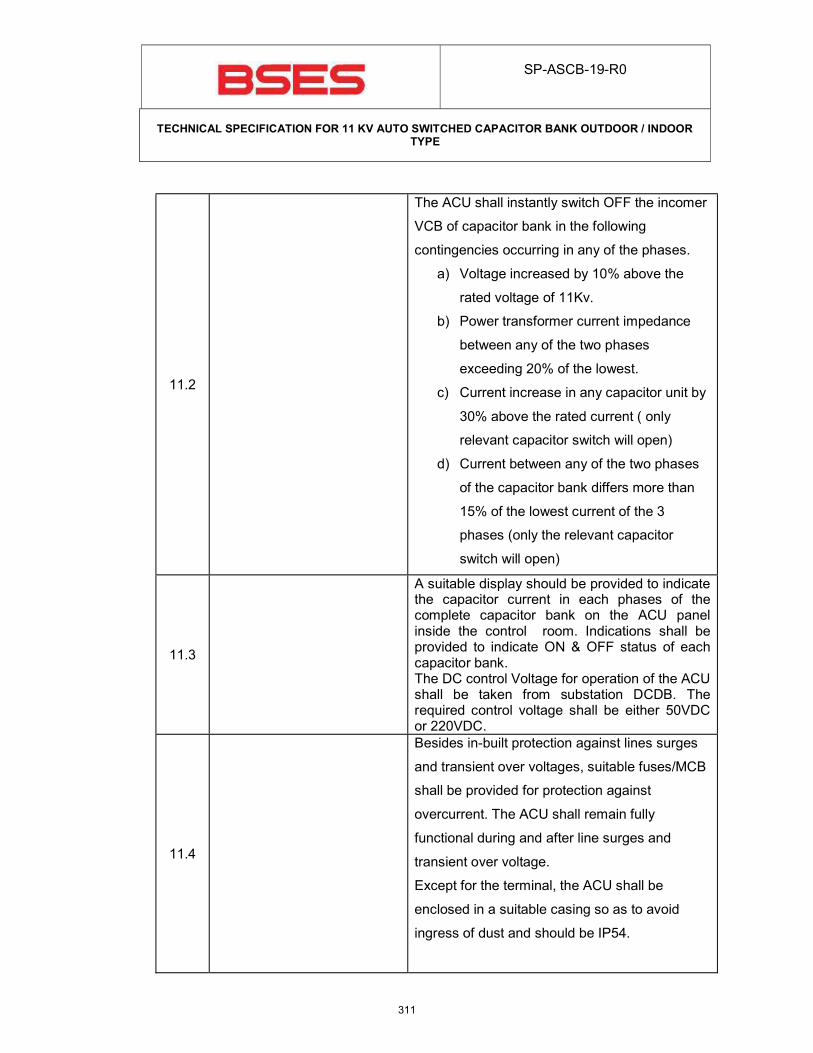
SP-ASCB-19-R0
TECHNICAL SPECIFICATION FOR 11 KV AUTO SWITCHED CAPACITOR BANK OUTDOOR / INDOOR
TYPE
11.2
The ACU shall instantly switch OFF the incomer
VCB of capacitor bank in the following
contingencies occurring in any of the phases.
a) Voltage increased by 10% above the
rated voltage of 11Kv.
b) Power transformer current impedance
between any of the two phases
exceeding 20% of the lowest.
c) Current increase in any capacitor unit by
30% above the rated current ( only
relevant capacitor switch will open)
d) Current between any of the two phases
of the capacitor bank differs more than
15% of the lowest current of the 3
phases (only the relevant capacitor
switch will open)
11.3
A suitable display should be provided to indicate the capacitor current in each phases of the complete capacitor bank on the ACU panel inside the control room. Indications shall be provided to indicate ON & OFF status of each capacitor bank. The DC control Voltage for operation of the ACU shall be taken from substation DCDB. The required control voltage shall be either 50VDC or 220VDC.
11.4
Besides in-built protection against lines surges
and transient over voltages, suitable fuses/MCB
shall be provided for protection against
overcurrent. The ACU shall remain fully
functional during and after line surges and
transient over voltage.
Except for the terminal, the ACU shall be
enclosed in a suitable casing so as to avoid
ingress of dust and should be IP54.
311
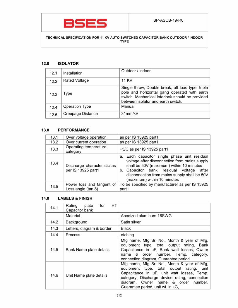
SP-ASCB-19-R0
TECHNICAL SPECIFICATION FOR 11 KV AUTO SWITCHED CAPACITOR BANK OUTDOOR / INDOOR
TYPE
12.0 ISOLATOR
12.1 Installation Outdoor / Indoor
12.2 Rated Voltage 11 KV
12.3 Type
Single throw, Double break, off load type, triple pole and horizontal gang operated with earth switch. Mechanical interlock should be provided between isolator and earth switch.
12.4 Operation Type Manual
12.5 Creepage Distance 31mm/kV
13.0 PERFORMANCE
13.1 Over voltage operation as per IS 13925 part1
13.2 Over current operation as per IS 13925 part1
13.3 Operating temperature category
+5/C as per IS 13925 part1
13.4
Discharge characteristic as per IS 13925 part1
a. Each capacitor single phase unit residual voltage after disconnection from mains supply shall be 50V (maximum) within 10 minutes
b. Capacitor bank residual voltage after disconnection from mains supply shall be 50V (maximum) within 10 minutes
13.5 Power loss and tangent of Loss angle (tan δ)
To be specified by manufacturer as per IS 13925 part1
14.0 LABELS & FINISH
14.1 Rating plate for HT Capacitor bank
Material Anodized aluminum 16SWG
14.2 Background Satin silver
14.3 Letters, diagram & border Black
14.4 Process etching
14.5 Bank Name plate details
Mfg name, Mfg Sr. No., Month & year of Mfg, equipment type, total output rating, Bank Capacitance in μF, Bank watt losses, Owner name & order number, Temp. category, connection diagram, Guarantee period.
14.6 Unit Name plate details
Mfg name, Mfg Sr. No., Month & year of Mfg, equipment type, total output rating, unit Capacitance in μF, unit watt losses, Temp. category, Discharge device rating, connection diagram, Owner name & order number, Guarantee period, unit wt. in kG,
312
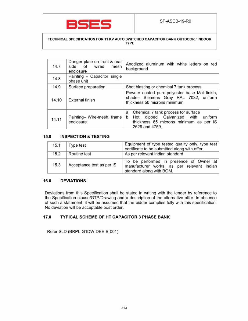
SP-ASCB-19-R0
TECHNICAL SPECIFICATION FOR 11 KV AUTO SWITCHED CAPACITOR BANK OUTDOOR / INDOOR
TYPE
14.7 Danger plate on front & rear side of wired mesh enclosure
Anodized aluminum with white letters on red background
14.8 Painting - Capacitor single phase unit
14.9 Surface preparation Shot blasting or chemical 7 tank process
14.10 External finish
Powder coated pure-polyester base Mat finish, shade– Siemens Gray RAL 7032, uniform thickness 50 microns minimum
14.11 Painting– Wire-mesh, frame enclosure
a. Chemical 7 tank process for surface b. Hot dipped Galvanized with uniform
thickness 65 microns minimum as per IS 2629 and 4759.
15.0 INSPECTION & TESTING
15.1 Type test Equipment of type tested quality only, type test certificate to be submitted along with offer.
15.2 Routine test As per relevant Indian standard
15.3 Acceptance test as per IS To be performed in presence of Owner at manufacturer works, as per relevant Indian standard along with BOM.
16.0 DEVIATIONS
Deviations from this Specification shall be stated in writing with the tender by reference to the Specification clause/GTP/Drawing and a description of the alternative offer. In absence of such a statement, it will be assumed that the bidder complies fully with this specification. No deviation will be acceptable post order. 17.0 TYPICAL SCHEME OF HT CAPACITOR 3 PHASE BANK
Refer SLD (BRPL-G1DW-DEE-B-001).
313
SP-ASCB-19-R0
TECHNICAL SPECIFICATION FOR 11 KV AUTO SWITCHED CAPACITOR BANK OUTDOOR / INDOOR
TYPE
18.0 MANDATORY SPARES
Following spares have to be provided with capacitor banks
a. Capacitor Units – 2 nos b. Series Reactors – 2 nos c. Vacuum Switch – 2 nos
314
Registered Office: BSES Bhavan, Nehru Place, Delhi - 110019
Specification for
Power Transformer Including NIFPS
Specification no – SP-TRPU-01-R8 Prepared by: Checked by : Approved by: Rev Date
Name Sign Name Sign Name Sign 01 21-Nov-08
DS SR DG 02 10 -Aug-09
Supriya Meenakshi K.K.Alla 03 16-July-14
Javed Ahmed Abhinav Srivastava Kiran Alla 04 18-July-16
Javed Ahmed Abhinav Srivastava Vijay Panpalia 05 26-July-17
Javed Ahmed Abhinav Srivastava K. Sheshadri 06 22-June-18
JA/SS Abhinav Srivastava K. Sheshadri 07 13-Dec-19
JA/SS Abhinav Srivastava K. Sheshadri 08 24-May-21
315
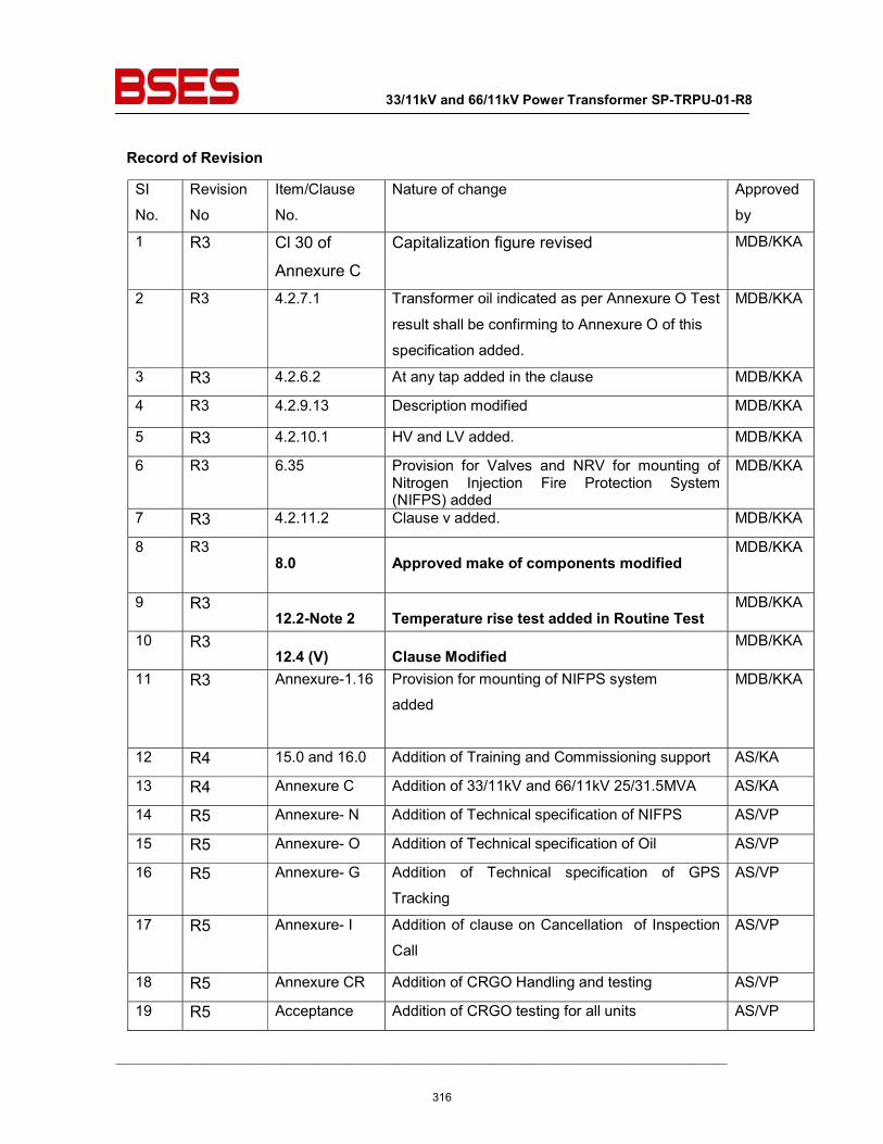
33/11kV and 66/11kV Power Transformer SP-TRPU-01-R8
__________________________________________________________________________________________
Record of Revision SI
No.
Revision
No
Item/Clause
No.
Nature of change Approved
by
1 R3 Cl 30 of
Annexure C Capitalization figure revised MDB/KKA
2 R3 4.2.7.1 Transformer oil indicated as per Annexure O Test
result shall be confirming to Annexure O of this
specification added.
MDB/KKA
3 R3 4.2.6.2 At any tap added in the clause MDB/KKA
4 R3 4.2.9.13 Description modified MDB/KKA
5 R3 4.2.10.1 HV and LV added. MDB/KKA
6 R3 6.35 Provision for Valves and NRV for mounting of Nitrogen Injection Fire Protection System (NIFPS) added
MDB/KKA
7 R3 4.2.11.2 Clause v added. MDB/KKA
8 R3 8.0 Approved make of components modified
MDB/KKA
9 R3 12.2-Note 2 Temperature rise test added in Routine Test
MDB/KKA
10 R3 12.4 (V) Clause Modified
MDB/KKA
11 R3 Annexure-1.16 Provision for mounting of NIFPS system
added
MDB/KKA
12 R4 15.0 and 16.0 Addition of Training and Commissioning support AS/KA
13 R4 Annexure C Addition of 33/11kV and 66/11kV 25/31.5MVA AS/KA
14 R5 Annexure- N Addition of Technical specification of NIFPS AS/VP
15 R5 Annexure- O Addition of Technical specification of Oil AS/VP
16 R5 Annexure- G Addition of Technical specification of GPS
Tracking
AS/VP
17 R5 Annexure- I Addition of clause on Cancellation of Inspection
Call
AS/VP
18 R5 Annexure CR Addition of CRGO Handling and testing AS/VP
19 R5 Acceptance Addition of CRGO testing for all units AS/VP
316
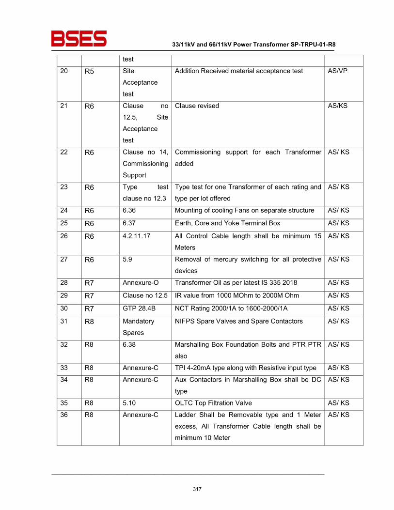
33/11kV and 66/11kV Power Transformer SP-TRPU-01-R8
__________________________________________________________________________________________
test
20 R5 Site
Acceptance
test
Addition Received material acceptance test AS/VP
21 R6 Clause no
12.5, Site
Acceptance
test
Clause revised AS/KS
22 R6 Clause no 14,
Commissioning
Support
Commissioning support for each Transformer
added
AS/ KS
23 R6 Type test
clause no 12.3
Type test for one Transformer of each rating and
type per lot offered
AS/ KS
24 R6 6.36 Mounting of cooling Fans on separate structure AS/ KS
25 R6 6.37 Earth, Core and Yoke Terminal Box AS/ KS
26 R6 4.2.11.17 All Control Cable length shall be minimum 15
Meters
AS/ KS
27 R6 5.9 Removal of mercury switching for all protective
devices
AS/ KS
28 R7 Annexure-O Transformer Oil as per latest IS 335 2018 AS/ KS
29 R7 Clause no 12.5 IR value from 1000 MOhm to 2000M Ohm AS/ KS
30 R7 GTP 28.4B NCT Rating 2000/1A to 1600-2000/1A AS/ KS
31 R8 Mandatory
Spares
NIFPS Spare Valves and Spare Contactors AS/ KS
32 R8 6.38 Marshalling Box Foundation Bolts and PTR PTR
also
AS/ KS
33 R8 Annexure-C TPI 4-20mA type along with Resistive input type AS/ KS
34 R8 Annexure-C Aux Contactors in Marshalling Box shall be DC
type
AS/ KS
35 R8 5.10 OLTC Top Filtration Valve AS/ KS
36 R8 Annexure-C Ladder Shall be Removable type and 1 Meter
excess, All Transformer Cable length shall be
minimum 10 Meter
AS/ KS
317
33/11kV and 66/11kV Power Transformer SP-TRPU-01-R8
__________________________________________________________________________________________
1.0 Scope of supply
For scope of supply, refer Annexure A, Annexure-N, Annexure-G, Annexure-I and Annexure O
2.0 Codes & standards Materials, equipment and methods used in the manufacture of Power Transformer shall conform
to the latest edition of following –
IEC Standards IEC 60034 Rotating Electrical Machines. (e.g. For Cooler Fan Motors.) IEC 60071 Co-ordination of Insulation. IEC 60076 Power transformers. IEC 60156 Method for Determination of the Electric Strength for Insulating Oils. IEC 60044 Current Transformers. IEC 60214 On-Load Tap-Changers. IEC 60296 Specification for Unused Mineral Insulating Oils for Transformers and
Switchgear.
IEC 60354 Loading Guide for Oil-Immersed Power Transformers. IEC 60445 Basic & safety principles for man-machine interface, marking and
identification- Identification of Equipment Terminals and Conductor termination.
IEC 60529 Degrees of Protection Provided by Enclosures (IP Code).
IEC 60551 Determination of Transformer and Reactor Sound Levels. IEC 60606 Application Guide for Power Transformers. IEC 60616 Terminal and Tapping Markings for Power Transformers.
IEC 60947 Low-Voltage Switchgear and Control gear. IEC 60137 Bushing for alternating voltages above 1000V
British Standards BS 148 Unused Mineral Insulation Oils for Transformers and Switchgear
BS 223 Bushings for Alternating Voltages above 1000 V. BS 2562 Cable Boxes for Transformers and Reactors.
Indian Standards IS:335 Insulating oil
IS:1271 Thermal evaluation and classification of electrical insulation
IS:2099 Bushing for Alternating voltage above 1000V IS:2705 Current Transformers IS:3347 Dimensions for Porcelain Transformer bushing IS:3637 Gas operated relays
318
33/11kV and 66/11kV Power Transformer SP-TRPU-01-R8
__________________________________________________________________________________________
IS:3639 Fitting & Accessories for power transformers IS:4201 Application guide for CTs IS:6600 Guide for loading of oil immersed transformers IS:8478 Application guide for On-load tap changer IS:8468 On-load tap changer IS:10028 Code of practice for selection, installation & maintenance of
transformers IS:13947 LV switchgear and Controlgear-Part1 IS 2026 Power Transformers IS 5561 Electrical Power Connectors
IS 5 Colours for ready mix paints
IS 6272 Industrial cooling fans
IS 325 Three phase induction motors
IS 12676 OIP Paper insulated condenser bushing dimension and requirements
Indian Electricity Rules
Indian electricity act
CBIP manual
In the event of direct conflict between various order documents, the precedence of authority of documents shall be as follows:
i. Guaranteed Technical Particulars (GTP)
ii. This Specification
iii Referenced Standards
iv Approved Vendor Drawings
v. Other documents
3.0 Major Design Criteria & Parameters of the Transformer
3.1 Major Design criteria
3.1.1 Voltage variation on supply side + / - 10 %
3.1.2 Frequency variation on supply side +/ - 5 %
3.1.3 Transient condition - 20 % or + 10 % combined variation of
voltage and frequency
3.1.4 Service Condition Refer Annexure B
3.1.5 Insulation level Refer Annexure C
3.1.6 Short Circuit withstand level Refer Annexure C
3.1.7 Overload capability Refer Annexure C
3.1.8 Noise level Refer Annexure C
319
33/11kV and 66/11kV Power Transformer SP-TRPU-01-R8
__________________________________________________________________________________________
3.1.9 Radio Influence Voltage Refer Annexure C
3.1.10 Harmonic currents Refer Annexure C
3.1.11 Partial Discharges Refer Annexure C
3.1.12 Parallel operation Shall be designed to operate in parallel with existing transformer. Details of existing transformers shall be forwarded to the bidder on request
3.2 Major Parameters
3.2.1 Rating Refer Annexure C
3.2.2 Voltage Ratio Refer Annexure C
3.2.3 Vector Group Refer Annexure C
3.2.4 Impedance Refer Annexure C
3.2.5 Losses Refer Annexure C
3.2.5.1 No load Loss Refer Annexure C
3.2.5.2 Load losses at principal tap Refer Annexure C
3.2.6 Temperature Rise top oil Refer Annexure C
3.2.7 Temperature winding Refer Annexure C
3.2.8 Flux density Refer Annexure C
3.2.9 Current density Refer Annexure C
3.2.10 Tapping on HV winding Refer Annexure C
3.2.11 Design Clearances Refer Annexure C
4.0 Construction & Design 4.1 Type ONAN/ONAF, Copper wound, three phase, oil
immersed with on load tap changer 4.1.1 Essential provision for ONAF
cooling See note 1 of Annexure C
4.1.2 Provision of mounting cooling fan at site in future at service condition
Required.
4.1.3 Provision of replacement of cooling fan at site in future at service condition
Required
4.1.4 Fan guard Required 4.2 Major Parts 4.2.1 Tank 4.2.1.1 Material of Construction As per Annexure D GTP Cl. 17.1 4.2.1.2 Plate Thickness Adequate for meeting the requirements of
pressure and vacuum type tests as per CBIP 4.2.1.3 Welding features i) All seams and joints shall be double welded
ii) All welding shall be stress relieved for sheet thickness greater than 35 mm
iii) All pipes, radiators, stiffeners, welded to the tank shall be welded externally
320
33/11kV and 66/11kV Power Transformer SP-TRPU-01-R8
__________________________________________________________________________________________
4.2.1.4
Tank features
i) Adequate space at bottom for collection of
sediments ii) Stiffeners provided for rigidity shall be
adequately sloped to prevent accumulation of water
iii) No internal pockets in which gas/air can accumulate
iv) No external pocket in which water can lodge
v) Tank bottom with welded skid base vi) Tank cover sloped to prevent retention of
rain water vii) Minimum disconnection of pipe work and
accessories for cover lifting viii) Tanks shall be of strength to prevent
permanent deformation during lifting, jacking, transportation with oil filled.
ix) Tank to be designed for oil filling under vacuum
x) Fitted with lifting lug to lift the tank cover only
xi) Manhole of sufficient size required for inspection of core and winding
xii) Oil level indicator for transportation 4.2.1.5 Flanged type adequately sized
inspection cover rectangular in shape required for
i) HV line bushing ii) LV line bushing iii) LV neutral bushing and NCT connection iv) OLTC to winding connection from both
sides v) Core assembly earthing Inspection covers should be provided with jacking screws & handle and shall not weigh more than 25KG Overall design shall be in such a way that there shall not be any hindrance / overlapping of some other component, in front of any of the inspection covers.
4.2.1.6 Fittings and accessories on main tank
See under fittings and accessories.
4.2.2 Conservator for the main tank
4.2.2.1 Capacity Adequate between highest and lowest visible levels to meet the requirement of expansion of oil volume in the transformer and cooling equipment from minimum ambient temperature to 100⁰ cent.
4.2.2.2 Conservator oil preservation system
By flexible rubber bag (air cell) placed inside conservator
321
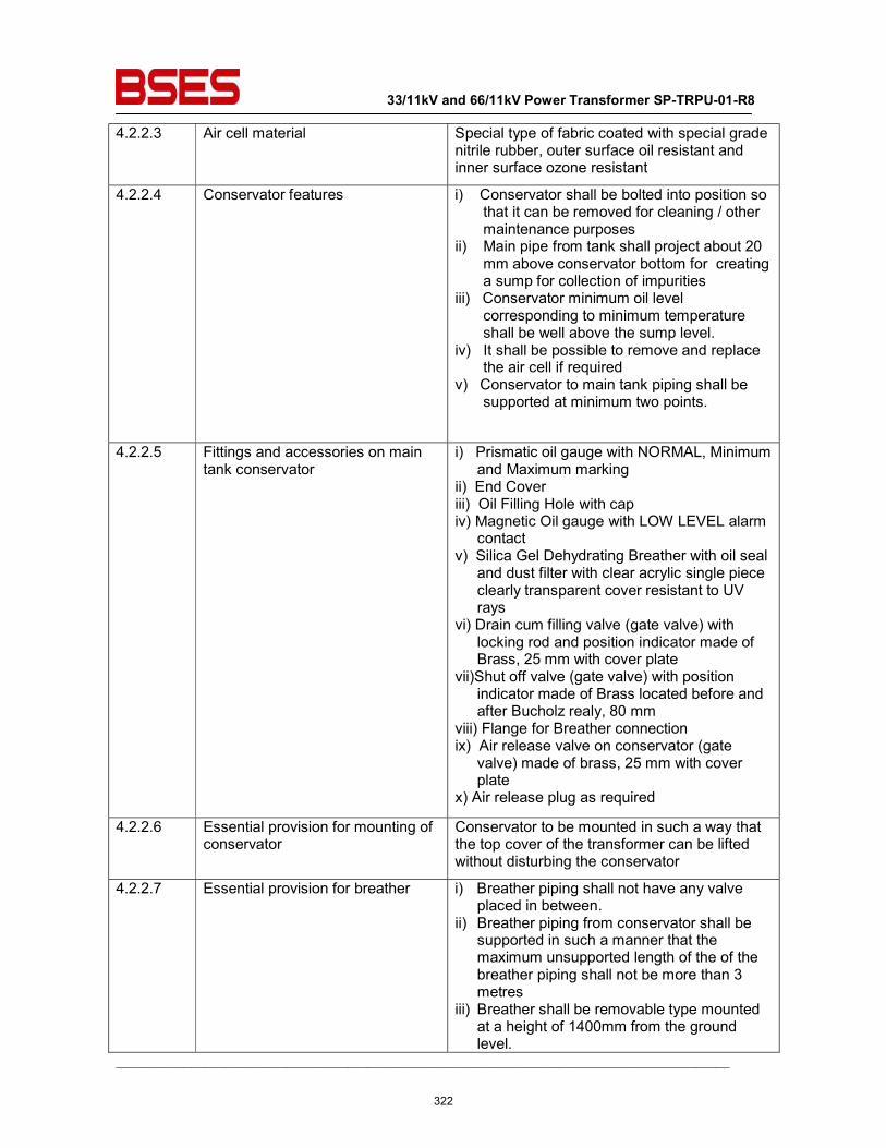
33/11kV and 66/11kV Power Transformer SP-TRPU-01-R8
__________________________________________________________________________________________
4.2.2.3 Air cell material Special type of fabric coated with special grade nitrile rubber, outer surface oil resistant and inner surface ozone resistant
4.2.2.4 Conservator features i) Conservator shall be bolted into position so that it can be removed for cleaning / other maintenance purposes
ii) Main pipe from tank shall project about 20 mm above conservator bottom for creating a sump for collection of impurities
iii) Conservator minimum oil level corresponding to minimum temperature shall be well above the sump level.
iv) It shall be possible to remove and replace the air cell if required
v) Conservator to main tank piping shall be supported at minimum two points.
4.2.2.5 Fittings and accessories on main tank conservator
i) Prismatic oil gauge with NORMAL, Minimum and Maximum marking
ii) End Cover iii) Oil Filling Hole with cap iv) Magnetic Oil gauge with LOW LEVEL alarm contact
v) Silica Gel Dehydrating Breather with oil seal and dust filter with clear acrylic single piece clearly transparent cover resistant to UV rays
vi) Drain cum filling valve (gate valve) with locking rod and position indicator made of Brass, 25 mm with cover plate
vii)Shut off valve (gate valve) with position indicator made of Brass located before and after Bucholz realy, 80 mm
viii) Flange for Breather connection ix) Air release valve on conservator (gate valve) made of brass, 25 mm with cover plate
x) Air release plug as required
4.2.2.6 Essential provision for mounting of conservator
Conservator to be mounted in such a way that the top cover of the transformer can be lifted without disturbing the conservator
4.2.2.7 Essential provision for breather i) Breather piping shall not have any valve placed in between.
ii) Breather piping from conservator shall be supported in such a manner that the maximum unsupported length of the of the breather piping shall not be more than 3 metres
iii) Breather shall be removable type mounted at a height of 1400mm from the ground level.
322
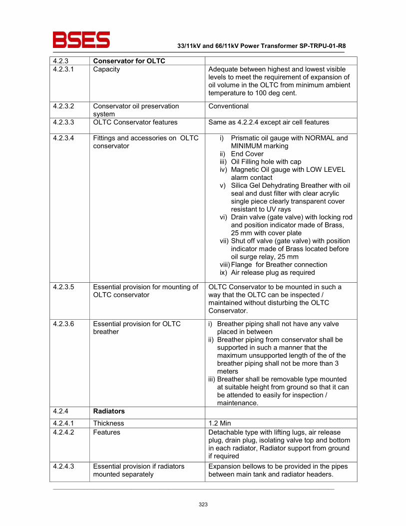
33/11kV and 66/11kV Power Transformer SP-TRPU-01-R8
__________________________________________________________________________________________
4.2.3 Conservator for OLTC 4.2.3.1 Capacity Adequate between highest and lowest visible
levels to meet the requirement of expansion of oil volume in the OLTC from minimum ambient temperature to 100 deg cent.
4.2.3.2 Conservator oil preservation system
Conventional
4.2.3.3 OLTC Conservator features Same as 4.2.2.4 except air cell features
4.2.3.4 Fittings and accessories on OLTC conservator
i) Prismatic oil gauge with NORMAL and MINIMUM marking
ii) End Cover iii) Oil Filling hole with cap iv) Magnetic Oil gauge with LOW LEVEL
alarm contact v) Silica Gel Dehydrating Breather with oil
seal and dust filter with clear acrylic single piece clearly transparent cover resistant to UV rays
vi) Drain valve (gate valve) with locking rod and position indicator made of Brass, 25 mm with cover plate
vii) Shut off valve (gate valve) with position indicator made of Brass located before oil surge relay, 25 mm
viii) Flange for Breather connection ix) Air release plug as required
4.2.3.5 Essential provision for mounting of OLTC conservator
OLTC Conservator to be mounted in such a way that the OLTC can be inspected / maintained without disturbing the OLTC Conservator.
4.2.3.6 Essential provision for OLTC breather
i) Breather piping shall not have any valve placed in between
ii) Breather piping from conservator shall be supported in such a manner that the maximum unsupported length of the of the breather piping shall not be more than 3 meters
iii) Breather shall be removable type mounted at suitable height from ground so that it can be attended to easily for inspection / maintenance.
4.2.4 Radiators
4.2.4.1 Thickness 1.2 Min 4.2.4.2 Features Detachable type with lifting lugs, air release
plug, drain plug, isolating valve top and bottom in each radiator, Radiator support from ground if required
4.2.4.3 Essential provision if radiators mounted separately
Expansion bellows to be provided in the pipes between main tank and radiator headers.
323
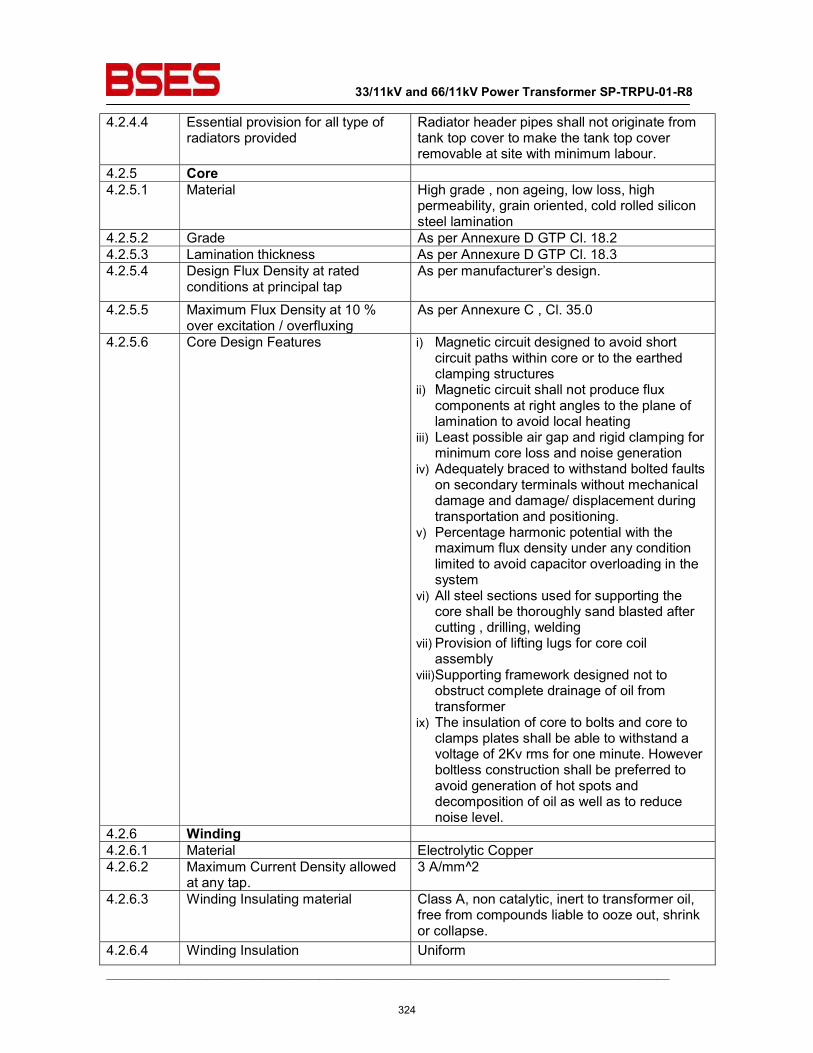
33/11kV and 66/11kV Power Transformer SP-TRPU-01-R8
__________________________________________________________________________________________
4.2.4.4 Essential provision for all type of radiators provided
Radiator header pipes shall not originate from tank top cover to make the tank top cover removable at site with minimum labour.
4.2.5 Core 4.2.5.1 Material High grade , non ageing, low loss, high
permeability, grain oriented, cold rolled silicon steel lamination
4.2.5.2 Grade As per Annexure D GTP Cl. 18.2 4.2.5.3 Lamination thickness As per Annexure D GTP Cl. 18.3 4.2.5.4 Design Flux Density at rated
conditions at principal tap As per manufacturer’s design.
4.2.5.5 Maximum Flux Density at 10 % over excitation / overfluxing
As per Annexure C , Cl. 35.0
4.2.5.6 Core Design Features i) Magnetic circuit designed to avoid short circuit paths within core or to the earthed clamping structures
ii) Magnetic circuit shall not produce flux components at right angles to the plane of lamination to avoid local heating
iii) Least possible air gap and rigid clamping for minimum core loss and noise generation
iv) Adequately braced to withstand bolted faults on secondary terminals without mechanical damage and damage/ displacement during transportation and positioning.
v) Percentage harmonic potential with the maximum flux density under any condition limited to avoid capacitor overloading in the system
vi) All steel sections used for supporting the core shall be thoroughly sand blasted after cutting , drilling, welding
vii) Provision of lifting lugs for core coil assembly
viii)Supporting framework designed not to obstruct complete drainage of oil from transformer
ix) The insulation of core to bolts and core to clamps plates shall be able to withstand a voltage of 2Kv rms for one minute. However boltless construction shall be preferred to avoid generation of hot spots and decomposition of oil as well as to reduce noise level.
4.2.6 Winding 4.2.6.1 Material Electrolytic Copper 4.2.6.2 Maximum Current Density allowed
at any tap. 3 A/mm^2
4.2.6.3 Winding Insulating material Class A, non catalytic, inert to transformer oil, free from compounds liable to ooze out, shrink or collapse.
4.2.6.4 Winding Insulation Uniform
324
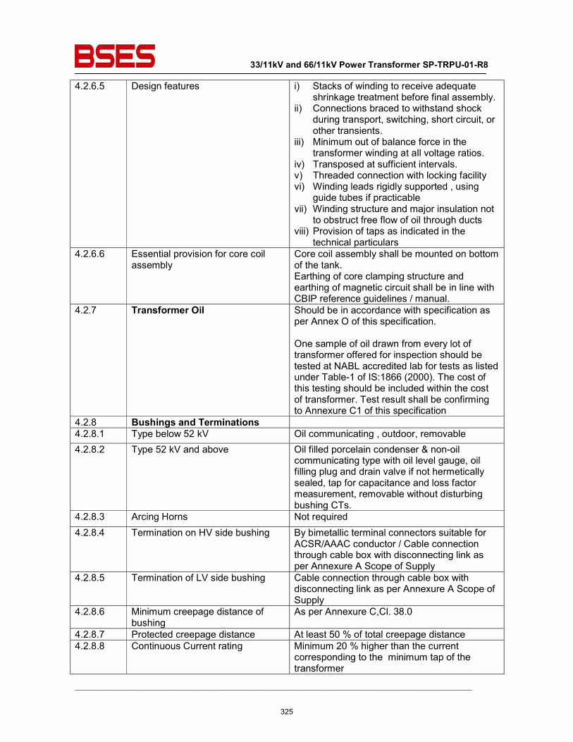
33/11kV and 66/11kV Power Transformer SP-TRPU-01-R8
__________________________________________________________________________________________
4.2.6.5 Design features i) Stacks of winding to receive adequate shrinkage treatment before final assembly.
ii) Connections braced to withstand shock during transport, switching, short circuit, or other transients.
iii) Minimum out of balance force in the transformer winding at all voltage ratios.
iv) Transposed at sufficient intervals. v) Threaded connection with locking facility vi) Winding leads rigidly supported , using
guide tubes if practicable vii) Winding structure and major insulation not
to obstruct free flow of oil through ducts viii) Provision of taps as indicated in the
technical particulars 4.2.6.6 Essential provision for core coil
assembly Core coil assembly shall be mounted on bottom of the tank. Earthing of core clamping structure and earthing of magnetic circuit shall be in line with CBIP reference guidelines / manual.
4.2.7 Transformer Oil Should be in accordance with specification as per Annex O of this specification. One sample of oil drawn from every lot of transformer offered for inspection should be tested at NABL accredited lab for tests as listed under Table-1 of IS:1866 (2000). The cost of this testing should be included within the cost of transformer. Test result shall be confirming to Annexure C1 of this specification
4.2.8 Bushings and Terminations 4.2.8.1 Type below 52 kV Oil communicating , outdoor, removable 4.2.8.2 Type 52 kV and above Oil filled porcelain condenser & non-oil
communicating type with oil level gauge, oil filling plug and drain valve if not hermetically sealed, tap for capacitance and loss factor measurement, removable without disturbing bushing CTs.
4.2.8.3 Arcing Horns Not required 4.2.8.4 Termination on HV side bushing By bimetallic terminal connectors suitable for
ACSR/AAAC conductor / Cable connection through cable box with disconnecting link as per Annexure A Scope of Supply
4.2.8.5 Termination of LV side bushing Cable connection through cable box with disconnecting link as per Annexure A Scope of Supply
4.2.8.6 Minimum creepage distance of bushing
As per Annexure C,Cl. 38.0
4.2.8.7 Protected creepage distance At least 50 % of total creepage distance 4.2.8.8 Continuous Current rating Minimum 20 % higher than the current
corresponding to the minimum tap of the transformer
325
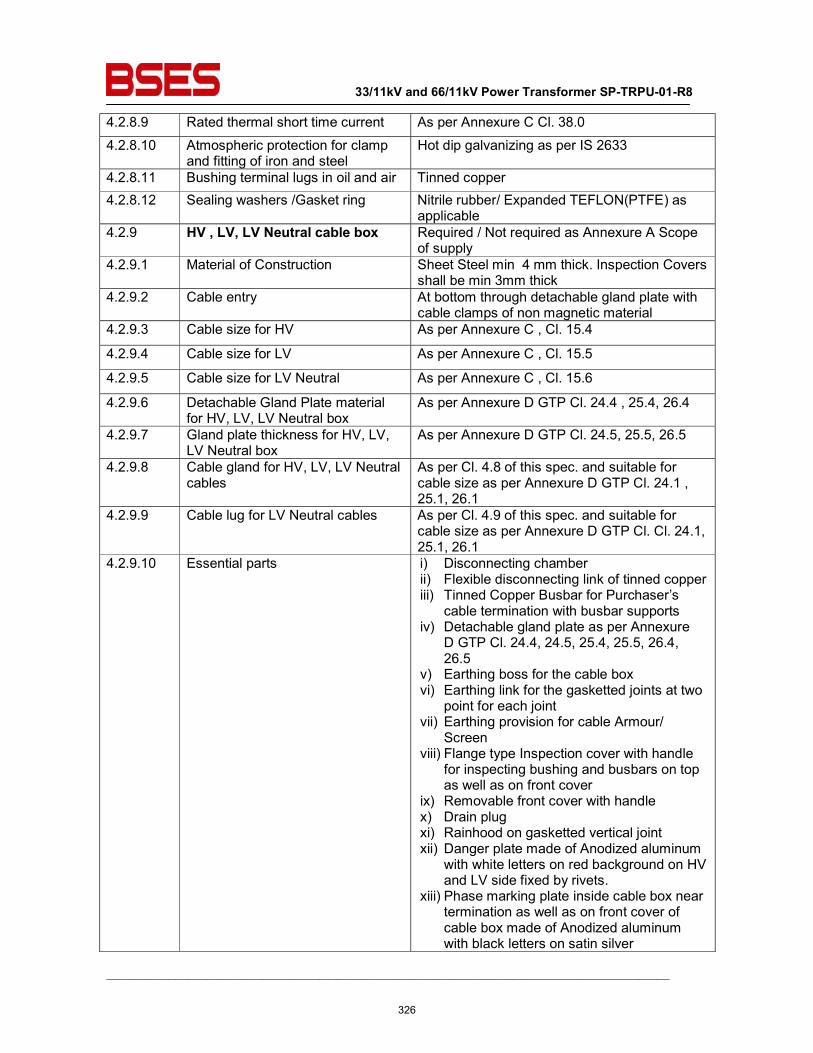
33/11kV and 66/11kV Power Transformer SP-TRPU-01-R8
__________________________________________________________________________________________
4.2.8.9 Rated thermal short time current As per Annexure C Cl. 38.0
4.2.8.10 Atmospheric protection for clamp and fitting of iron and steel
Hot dip galvanizing as per IS 2633
4.2.8.11 Bushing terminal lugs in oil and air Tinned copper 4.2.8.12 Sealing washers /Gasket ring Nitrile rubber/ Expanded TEFLON(PTFE) as
applicable 4.2.9 HV , LV, LV Neutral cable box Required / Not required as Annexure A Scope
of supply 4.2.9.1 Material of Construction Sheet Steel min 4 mm thick. Inspection Covers
shall be min 3mm thick 4.2.9.2 Cable entry At bottom through detachable gland plate with
cable clamps of non magnetic material 4.2.9.3 Cable size for HV As per Annexure C , Cl. 15.4
4.2.9.4 Cable size for LV As per Annexure C , Cl. 15.5
4.2.9.5 Cable size for LV Neutral As per Annexure C , Cl. 15.6
4.2.9.6 Detachable Gland Plate material for HV, LV, LV Neutral box
As per Annexure D GTP Cl. 24.4 , 25.4, 26.4
4.2.9.7 Gland plate thickness for HV, LV, LV Neutral box
As per Annexure D GTP Cl. 24.5, 25.5, 26.5
4.2.9.8 Cable gland for HV, LV, LV Neutral cables
As per Cl. 4.8 of this spec. and suitable for cable size as per Annexure D GTP Cl. 24.1 , 25.1, 26.1
4.2.9.9 Cable lug for LV Neutral cables As per Cl. 4.9 of this spec. and suitable for cable size as per Annexure D GTP Cl. Cl. 24.1, 25.1, 26.1
4.2.9.10 Essential parts i) Disconnecting chamber ii) Flexible disconnecting link of tinned copper iii) Tinned Copper Busbar for Purchaser’s
cable termination with busbar supports iv) Detachable gland plate as per Annexure
D GTP Cl. 24.4, 24.5, 25.4, 25.5, 26.4, 26.5
v) Earthing boss for the cable box vi) Earthing link for the gasketted joints at two
point for each joint vii) Earthing provision for cable Armour/
Screen viii) Flange type Inspection cover with handle
for inspecting bushing and busbars on top as well as on front cover
ix) Removable front cover with handle x) Drain plug xi) Rainhood on gasketted vertical joint xii) Danger plate made of Anodized aluminum
with white letters on red background on HV and LV side fixed by rivets.
xiii) Phase marking plate inside cable box near termination as well as on front cover of cable box made of Anodized aluminum with black letters on satin silver
326
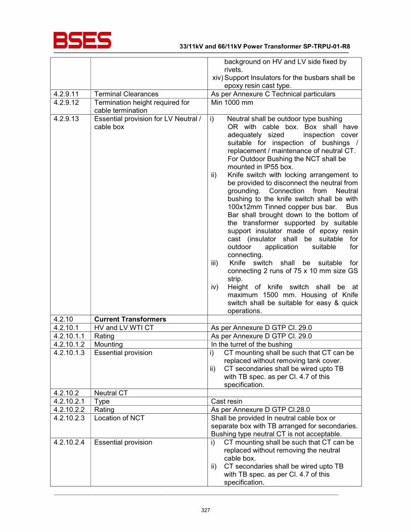
33/11kV and 66/11kV Power Transformer SP-TRPU-01-R8
__________________________________________________________________________________________
background on HV and LV side fixed by rivets.
xiv) Support Insulators for the busbars shall be epoxy resin cast type.
4.2.9.11 Terminal Clearances As per Annexure C Technical particulars 4.2.9.12 Termination height required for
cable termination Min 1000 mm
4.2.9.13 Essential provision for LV Neutral / cable box
i) Neutral shall be outdoor type bushing OR with cable box. Box shall have adequately sized inspection cover suitable for inspection of bushings / replacement / maintenance of neutral CT. For Outdoor Bushing the NCT shall be mounted in IP55 box.
ii) Knife switch with locking arrangement to be provided to disconnect the neutral from grounding. Connection from Neutral bushing to the knife switch shall be with 100x12mm Tinned copper bus bar. Bus Bar shall brought down to the bottom of the transformer supported by suitable support insulator made of epoxy resin cast (insulator shall be suitable for outdoor application suitable for connecting.
iii) Knife switch shall be suitable for connecting 2 runs of 75 x 10 mm size GS strip.
iv) Height of knife switch shall be at maximum 1500 mm. Housing of Knife switch shall be suitable for easy & quick operations.
4.2.10 Current Transformers 4.2.10.1 HV and LV WTI CT As per Annexure D GTP Cl. 29.0 4.2.10.1.1 Rating As per Annexure D GTP Cl. 29.0 4.2.10.1.2 Mounting In the turret of the bushing 4.2.10.1.3 Essential provision i) CT mounting shall be such that CT can be
replaced without removing tank cover. ii) CT secondaries shall be wired upto TB
with TB spec. as per Cl. 4.7 of this specification.
4.2.10.2 Neutral CT 4.2.10.2.1 Type Cast resin 4.2.10.2.2 Rating As per Annexure D GTP Cl.28.0 4.2.10.2.3 Location of NCT Shall be provided In neutral cable box or
separate box with TB arranged for secondaries. Bushing type neutral CT is not acceptable.
4.2.10.2.4 Essential provision i) CT mounting shall be such that CT can be replaced without removing the neutral cable box.
ii) CT secondaries shall be wired upto TB with TB spec. as per Cl. 4.7 of this specification.
327
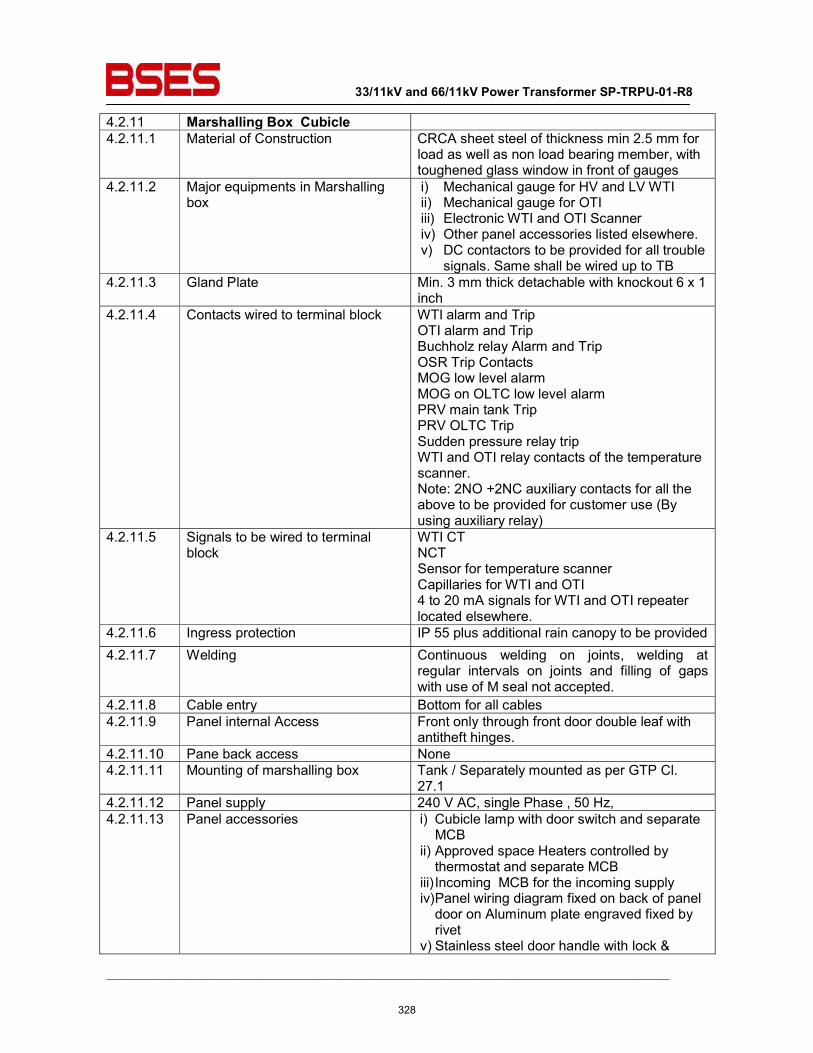
33/11kV and 66/11kV Power Transformer SP-TRPU-01-R8
__________________________________________________________________________________________
4.2.11 Marshalling Box Cubicle 4.2.11.1 Material of Construction CRCA sheet steel of thickness min 2.5 mm for
load as well as non load bearing member, with toughened glass window in front of gauges
4.2.11.2 Major equipments in Marshalling box
i) Mechanical gauge for HV and LV WTI ii) Mechanical gauge for OTI iii) Electronic WTI and OTI Scanner iv) Other panel accessories listed elsewhere. v) DC contactors to be provided for all trouble
signals. Same shall be wired up to TB 4.2.11.3 Gland Plate Min. 3 mm thick detachable with knockout 6 x 1
inch 4.2.11.4 Contacts wired to terminal block WTI alarm and Trip
OTI alarm and Trip Buchholz relay Alarm and Trip OSR Trip Contacts MOG low level alarm MOG on OLTC low level alarm PRV main tank Trip PRV OLTC Trip Sudden pressure relay trip WTI and OTI relay contacts of the temperature scanner. Note: 2NO +2NC auxiliary contacts for all the above to be provided for customer use (By using auxiliary relay)
4.2.11.5 Signals to be wired to terminal block
WTI CT NCT Sensor for temperature scanner Capillaries for WTI and OTI 4 to 20 mA signals for WTI and OTI repeater located elsewhere.
4.2.11.6 Ingress protection IP 55 plus additional rain canopy to be provided 4.2.11.7 Welding Continuous welding on joints, welding at
regular intervals on joints and filling of gaps with use of M seal not accepted.
4.2.11.8 Cable entry Bottom for all cables 4.2.11.9 Panel internal Access Front only through front door double leaf with
antitheft hinges. 4.2.11.10 Pane back access None 4.2.11.11 Mounting of marshalling box Tank / Separately mounted as per GTP Cl.
27.1 4.2.11.12 Panel supply 240 V AC, single Phase , 50 Hz, 4.2.11.13 Panel accessories i) Cubicle lamp with door switch and separate
MCB ii) Approved space Heaters controlled by thermostat and separate MCB
iii) Incoming MCB for the incoming supply iv) Panel wiring diagram fixed on back of panel door on Aluminum plate engraved fixed by rivet
v) Stainless steel door handle with lock &
328
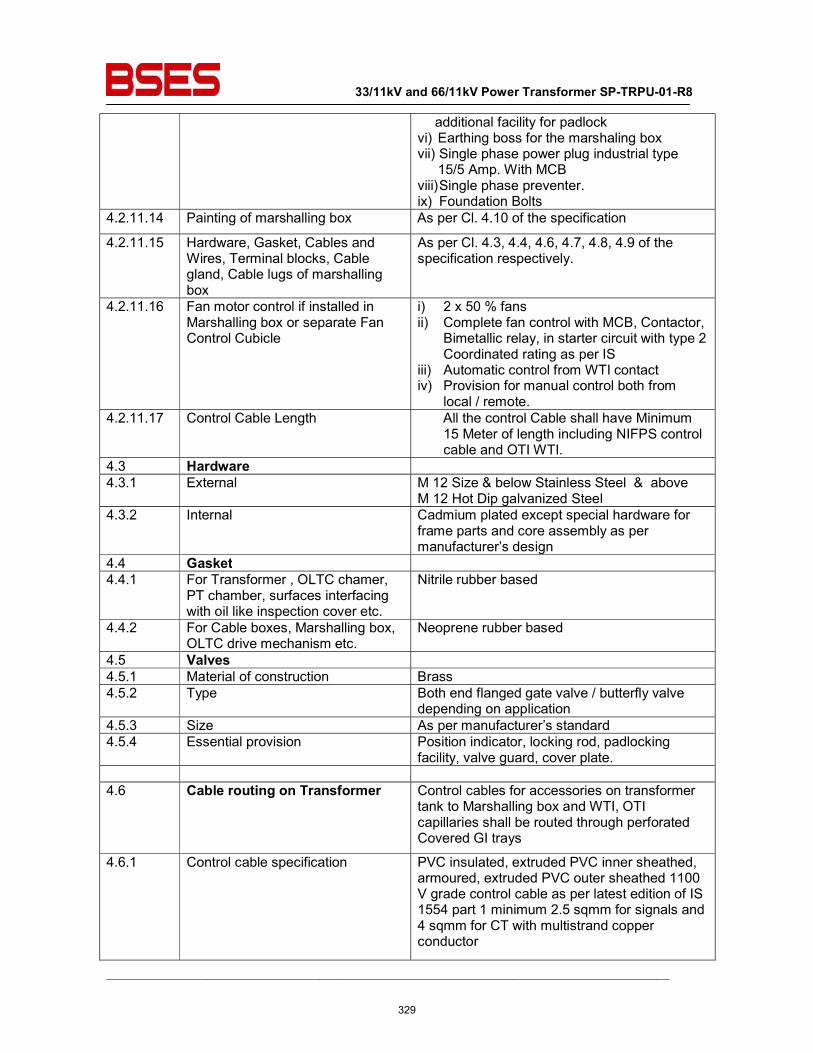
33/11kV and 66/11kV Power Transformer SP-TRPU-01-R8
__________________________________________________________________________________________
additional facility for padlock vi) Earthing boss for the marshaling box vii) Single phase power plug industrial type 15/5 Amp. With MCB
viii) Single phase preventer. ix) Foundation Bolts
4.2.11.14 Painting of marshalling box As per Cl. 4.10 of the specification
4.2.11.15 Hardware, Gasket, Cables and Wires, Terminal blocks, Cable gland, Cable lugs of marshalling box
As per Cl. 4.3, 4.4, 4.6, 4.7, 4.8, 4.9 of the specification respectively.
4.2.11.16 Fan motor control if installed in Marshalling box or separate Fan Control Cubicle
i) 2 x 50 % fans ii) Complete fan control with MCB, Contactor,
Bimetallic relay, in starter circuit with type 2 Coordinated rating as per IS
iii) Automatic control from WTI contact iv) Provision for manual control both from
local / remote. 4.2.11.17 Control Cable Length All the control Cable shall have Minimum
15 Meter of length including NIFPS control cable and OTI WTI.
4.3 Hardware 4.3.1 External M 12 Size & below Stainless Steel & above
M 12 Hot Dip galvanized Steel 4.3.2 Internal Cadmium plated except special hardware for
frame parts and core assembly as per manufacturer’s design
4.4 Gasket 4.4.1 For Transformer , OLTC chamer,
PT chamber, surfaces interfacing with oil like inspection cover etc.
Nitrile rubber based
4.4.2 For Cable boxes, Marshalling box, OLTC drive mechanism etc.
Neoprene rubber based
4.5 Valves 4.5.1 Material of construction Brass 4.5.2 Type Both end flanged gate valve / butterfly valve
depending on application 4.5.3 Size As per manufacturer’s standard 4.5.4 Essential provision Position indicator, locking rod, padlocking
facility, valve guard, cover plate. 4.6 Cable routing on Transformer Control cables for accessories on transformer
tank to Marshalling box and WTI, OTI capillaries shall be routed through perforated Covered GI trays
4.6.1 Control cable specification PVC insulated, extruded PVC inner sheathed, armoured, extruded PVC outer sheathed 1100 V grade control cable as per latest edition of IS 1554 part 1 minimum 2.5 sqmm for signals and 4 sqmm for CT with multistrand copper conductor
329
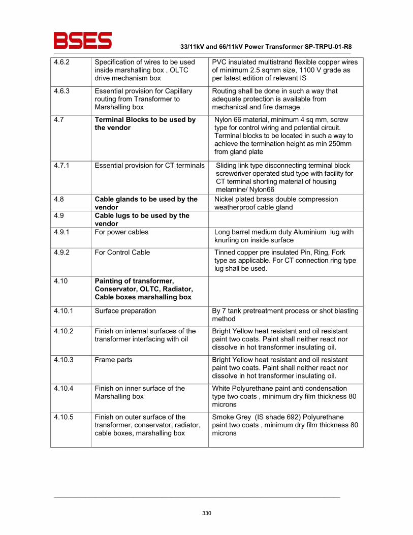
33/11kV and 66/11kV Power Transformer SP-TRPU-01-R8
__________________________________________________________________________________________
4.6.2 Specification of wires to be used inside marshalling box , OLTC drive mechanism box
PVC insulated multistrand flexible copper wires of minimum 2.5 sqmm size, 1100 V grade as per latest edition of relevant IS
4.6.3 Essential provision for Capillary routing from Transformer to Marshalling box
Routing shall be done in such a way that adequate protection is available from mechanical and fire damage.
4.7 Terminal Blocks to be used by the vendor
Nylon 66 material, minimum 4 sq mm, screw type for control wiring and potential circuit. Terminal blocks to be located in such a way to achieve the termination height as min 250mm from gland plate
4.7.1 Essential provision for CT terminals Sliding link type disconnecting terminal block screwdriver operated stud type with facility for CT terminal shorting material of housing melamine/ Nylon66
4.8 Cable glands to be used by the vendor
Nickel plated brass double compression weatherproof cable gland
4.9 Cable lugs to be used by the vendor
4.9.1 For power cables Long barrel medium duty Aluminium lug with knurling on inside surface
4.9.2 For Control Cable Tinned copper pre insulated Pin, Ring, Fork type as applicable. For CT connection ring type lug shall be used.
4.10 Painting of transformer, Conservator, OLTC, Radiator, Cable boxes marshalling box
4.10.1 Surface preparation By 7 tank pretreatment process or shot blasting method
4.10.2 Finish on internal surfaces of the transformer interfacing with oil
Bright Yellow heat resistant and oil resistant paint two coats. Paint shall neither react nor dissolve in hot transformer insulating oil.
4.10.3 Frame parts Bright Yellow heat resistant and oil resistant paint two coats. Paint shall neither react nor dissolve in hot transformer insulating oil.
4.10.4 Finish on inner surface of the Marshalling box
White Polyurethane paint anti condensation type two coats , minimum dry film thickness 80 microns
4.10.5 Finish on outer surface of the transformer, conservator, radiator, cable boxes, marshalling box
Smoke Grey (IS shade 692) Polyurethane paint two coats , minimum dry film thickness 80 microns
330
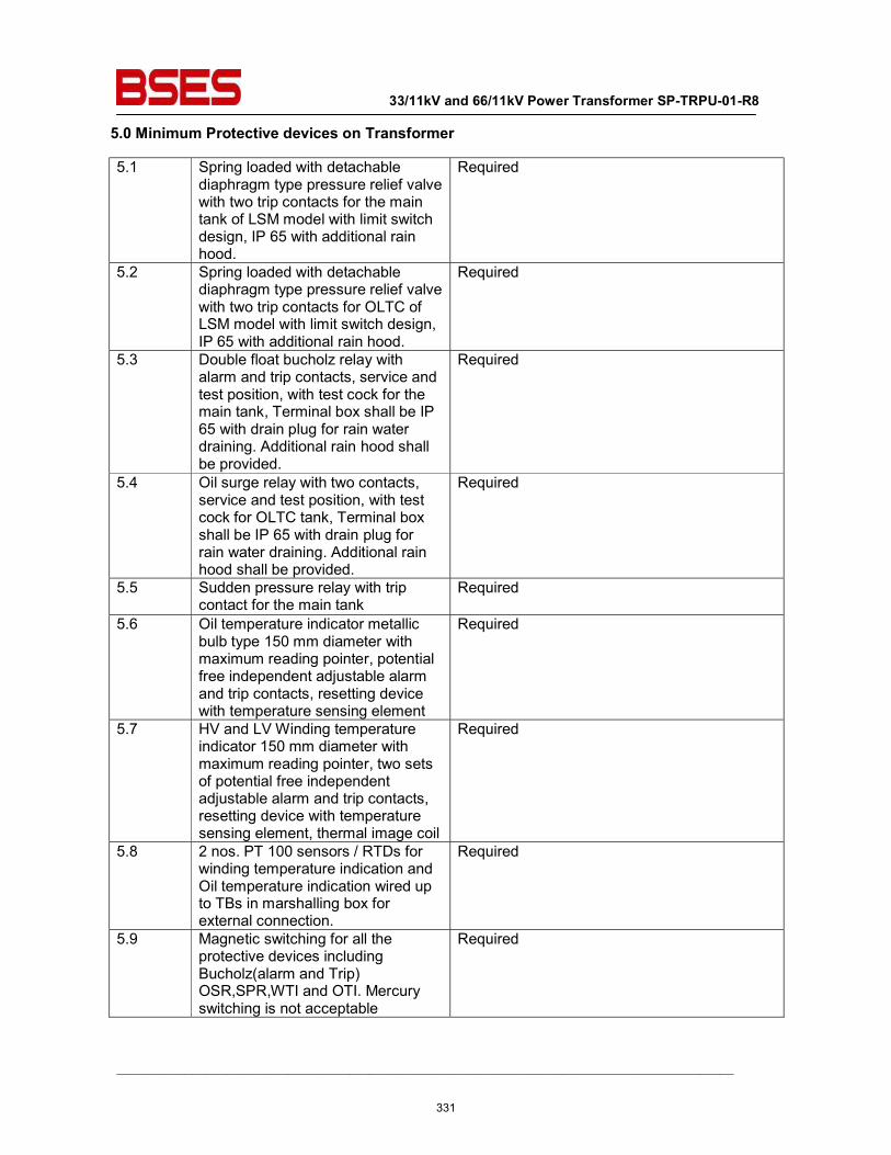
33/11kV and 66/11kV Power Transformer SP-TRPU-01-R8
__________________________________________________________________________________________
5.0 Minimum Protective devices on Transformer
5.1 Spring loaded with detachable diaphragm type pressure relief valve with two trip contacts for the main tank of LSM model with limit switch design, IP 65 with additional rain hood.
Required
5.2 Spring loaded with detachable diaphragm type pressure relief valve with two trip contacts for OLTC of LSM model with limit switch design, IP 65 with additional rain hood.
Required
5.3 Double float bucholz relay with alarm and trip contacts, service and test position, with test cock for the main tank, Terminal box shall be IP 65 with drain plug for rain water draining. Additional rain hood shall be provided.
Required
5.4 Oil surge relay with two contacts, service and test position, with test cock for OLTC tank, Terminal box shall be IP 65 with drain plug for rain water draining. Additional rain hood shall be provided.
Required
5.5 Sudden pressure relay with trip contact for the main tank
Required
5.6 Oil temperature indicator metallic bulb type 150 mm diameter with maximum reading pointer, potential free independent adjustable alarm and trip contacts, resetting device with temperature sensing element
Required
5.7 HV and LV Winding temperature indicator 150 mm diameter with maximum reading pointer, two sets of potential free independent adjustable alarm and trip contacts, resetting device with temperature sensing element, thermal image coil
Required
5.8 2 nos. PT 100 sensors / RTDs for winding temperature indication and Oil temperature indication wired up to TBs in marshalling box for external connection.
Required
5.9 Magnetic switching for all the protective devices including Bucholz(alarm and Trip) OSR,SPR,WTI and OTI. Mercury switching is not acceptable
Required
331
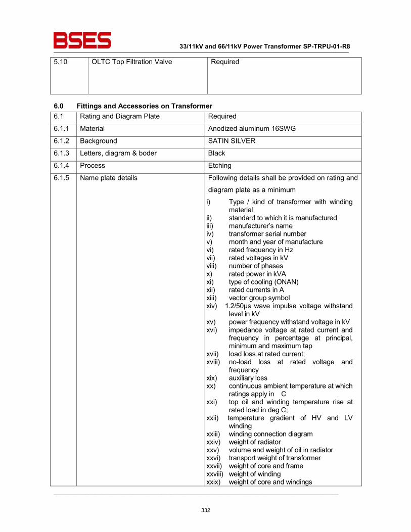
33/11kV and 66/11kV Power Transformer SP-TRPU-01-R8
__________________________________________________________________________________________
5.10 OLTC Top Filtration Valve Required
6.0 Fittings and Accessories on Transformer 6.1 Rating and Diagram Plate Required
6.1.1 Material Anodized aluminum 16SWG
6.1.2 Background SATIN SILVER
6.1.3 Letters, diagram & boder Black
6.1.4 Process Etching
6.1.5 Name plate details Following details shall be provided on rating and
diagram plate as a minimum
i) Type / kind of transformer with winding material
ii) standard to which it is manufactured iii) manufacturer’s name iv) transformer serial number v) month and year of manufacture vi) rated frequency in Hz vii) rated voltages in kV viii) number of phases x) rated power in kVA xi) type of cooling (ONAN) xii) rated currents in A xiii) vector group symbol xiv) 1.2/50μs wave impulse voltage withstand
level in kV xv) power frequency withstand voltage in kV xvi) impedance voltage at rated current and
frequency in percentage at principal, minimum and maximum tap
xvii) load loss at rated current; xviii) no-load loss at rated voltage and
frequency xix) auxiliary loss xx) continuous ambient temperature at which
ratings apply in C xxi) top oil and winding temperature rise at
rated load in deg C; xxii) temperature gradient of HV and LV
winding xxiii) winding connection diagram xxiv) weight of radiator xxv) volume and weight of oil in radiator xxvi) transport weight of transformer xxvii) weight of core and frame xxviii) weight of winding xxix) weight of core and windings
332
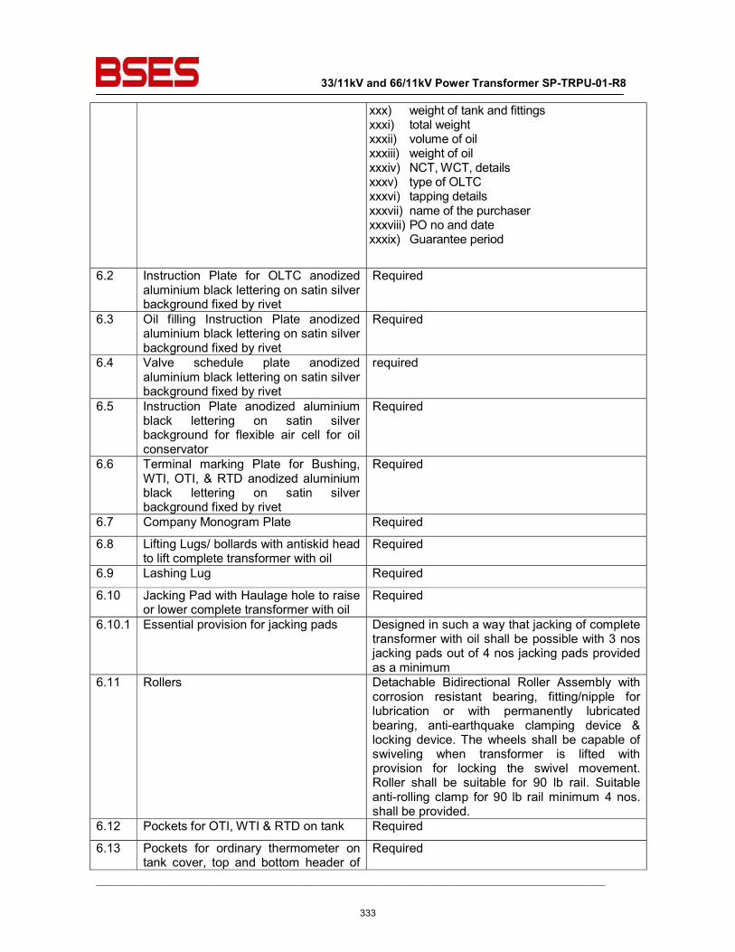
33/11kV and 66/11kV Power Transformer SP-TRPU-01-R8
__________________________________________________________________________________________
xxx) weight of tank and fittings xxxi) total weight xxxii) volume of oil xxxiii) weight of oil xxxiv) NCT, WCT, details xxxv) type of OLTC xxxvi) tapping details xxxvii) name of the purchaser xxxviii) PO no and date xxxix) Guarantee period
6.2 Instruction Plate for OLTC anodized aluminium black lettering on satin silver background fixed by rivet
Required
6.3 Oil filling Instruction Plate anodized aluminium black lettering on satin silver background fixed by rivet
Required
6.4 Valve schedule plate anodized aluminium black lettering on satin silver background fixed by rivet
required
6.5 Instruction Plate anodized aluminium black lettering on satin silver background for flexible air cell for oil conservator
Required
6.6 Terminal marking Plate for Bushing, WTI, OTI, & RTD anodized aluminium black lettering on satin silver background fixed by rivet
Required
6.7 Company Monogram Plate Required
6.8 Lifting Lugs/ bollards with antiskid head to lift complete transformer with oil
Required
6.9 Lashing Lug Required
6.10 Jacking Pad with Haulage hole to raise or lower complete transformer with oil
Required
6.10.1 Essential provision for jacking pads Designed in such a way that jacking of complete transformer with oil shall be possible with 3 nos jacking pads out of 4 nos jacking pads provided as a minimum
6.11 Rollers Detachable Bidirectional Roller Assembly with corrosion resistant bearing, fitting/nipple for lubrication or with permanently lubricated bearing, anti-earthquake clamping device & locking device. The wheels shall be capable of swiveling when transformer is lifted with provision for locking the swivel movement. Roller shall be suitable for 90 lb rail. Suitable anti-rolling clamp for 90 lb rail minimum 4 nos. shall be provided.
6.12 Pockets for OTI, WTI & RTD on tank Required
6.13 Pockets for ordinary thermometer on tank cover, top and bottom header of
Required
333
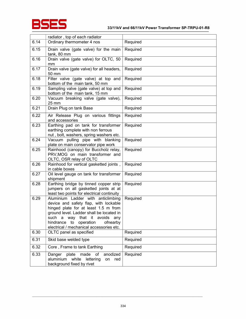
33/11kV and 66/11kV Power Transformer SP-TRPU-01-R8
__________________________________________________________________________________________
radiator , top of each radiator 6.14 Ordinary thermometer 4 nos Required
6.15 Drain valve (gate valve) for the main tank, 80 mm
Required
6.16 Drain valve (gate valve) for OLTC, 50 mm
Required
6.17 Drain valve (gate valve) for all headers, 50 mm
Required
6.18 Filter valve (gate valve) at top and bottom of the main tank, 50 mm
Required
6.19 Sampling valve (gate valve) at top and bottom of the main tank, 15 mm
Required
6.20 Vacuum breaking valve (gate valve), 25 mm
Required
6.21 Drain Plug on tank Base Required
6.22 Air Release Plug on various fittings and accessories
Required
6.23 Earthing pad on tank for transformer earthing complete with non ferrous nut , bolt, washers, spring washers etc.
Required
6.24 Vacuum pulling pipe with blanking plate on main conservator pipe work
Required
6.25 Rainhood (canopy) for Buccholz relay, PRV,MOG on main transformer and OLTC, OSR relay of OLTC
Required
6.26 Rainhood for vertical gasketted joints , in cable boxes
Required
6.27 Oil level gauge on tank for transformer shipment
Required
6.28 Earthing bridge by tinned copper strip jumpers on all gasketted joints at at least two points for electrical continuity
Required
6.29 Aluminium Ladder with anticlimbing device and safety flap, with lockable hinged plate for at least 1.5 m from ground level. Ladder shall be located in such a way that it avoids any hindrance to operation ofnearby electrical / mechanical accessories etc.
Required
6.30 OLTC panel as specified Required
6.31 Skid base welded type Required
6.32 Core , Frame to tank Earthing Required
6.33 Danger plate made of anodized aluminium white lettering on red background fixed by rivet
Required
334
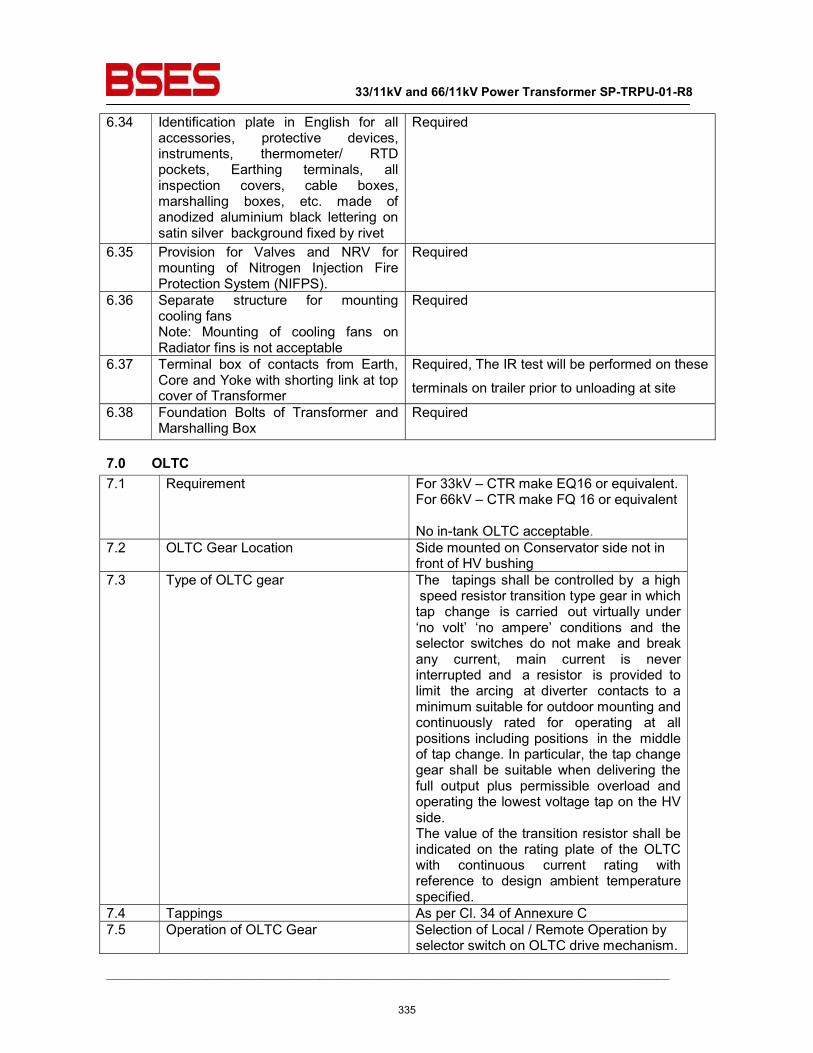
33/11kV and 66/11kV Power Transformer SP-TRPU-01-R8
__________________________________________________________________________________________
6.34 Identification plate in English for all accessories, protective devices, instruments, thermometer/ RTD pockets, Earthing terminals, all inspection covers, cable boxes, marshalling boxes, etc. made of anodized aluminium black lettering on satin silver background fixed by rivet
Required
6.35 Provision for Valves and NRV for mounting of Nitrogen Injection Fire Protection System (NIFPS).
Required
6.36 Separate structure for mounting cooling fans Note: Mounting of cooling fans on Radiator fins is not acceptable
Required
6.37 Terminal box of contacts from Earth, Core and Yoke with shorting link at top cover of Transformer
Required, The IR test will be performed on these
terminals on trailer prior to unloading at site
6.38 Foundation Bolts of Transformer and Marshalling Box
Required
7.0 OLTC 7.1 Requirement For 33kV – CTR make EQ16 or equivalent.
For 66kV – CTR make FQ 16 or equivalent No in-tank OLTC acceptable.
7.2 OLTC Gear Location Side mounted on Conservator side not in front of HV bushing
7.3 Type of OLTC gear The tapings shall be controlled by a high speed resistor transition type gear in which tap change is carried out virtually under ‘no volt’ ‘no ampere’ conditions and the selector switches do not make and break any current, main current is never interrupted and a resistor is provided to limit the arcing at diverter contacts to a minimum suitable for outdoor mounting and continuously rated for operating at all positions including positions in the middle of tap change. In particular, the tap change gear shall be suitable when delivering the full output plus permissible overload and operating the lowest voltage tap on the HV side. The value of the transition resistor shall be indicated on the rating plate of the OLTC with continuous current rating with reference to design ambient temperature specified.
7.4 Tappings As per Cl. 34 of Annexure C 7.5 Operation of OLTC Gear Selection of Local / Remote Operation by
selector switch on OLTC drive mechanism.
335
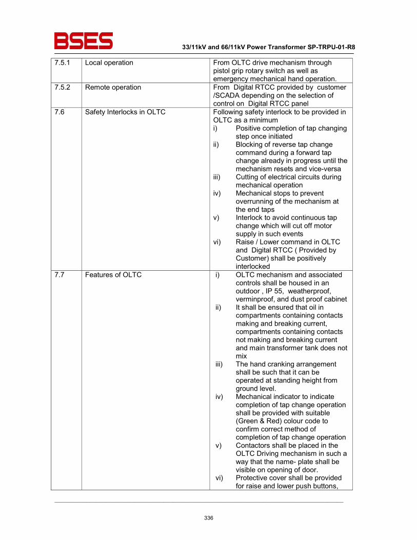
33/11kV and 66/11kV Power Transformer SP-TRPU-01-R8
__________________________________________________________________________________________
7.5.1 Local operation From OLTC drive mechanism through pistol grip rotary switch as well as emergency mechanical hand operation.
7.5.2 Remote operation From Digital RTCC provided by customer /SCADA depending on the selection of control on Digital RTCC panel
7.6 Safety Interlocks in OLTC Following safety interlock to be provided in OLTC as a minimum i) Positive completion of tap changing
step once initiated ii) Blocking of reverse tap change
command during a forward tap change already in progress until the mechanism resets and vice-versa
iii) Cutting of electrical circuits during mechanical operation
iv) Mechanical stops to prevent overrunning of the mechanism at the end taps
v) Interlock to avoid continuous tap change which will cut off motor supply in such events
vi) Raise / Lower command in OLTC and Digital RTCC ( Provided by Customer) shall be positively interlocked
7.7 Features of OLTC i) OLTC mechanism and associated controls shall be housed in an outdoor , IP 55, weatherproof, verminproof, and dust proof cabinet
ii) It shall be ensured that oil in compartments containing contacts making and breaking current, compartments containing contacts not making and breaking current and main transformer tank does not mix
iii) The hand cranking arrangement shall be such that it can be operated at standing height from ground level.
iv) Mechanical indicator to indicate completion of tap change operation shall be provided with suitable (Green & Red) colour code to confirm correct method of completion of tap change operation
v) Contactors shall be placed in the OLTC Driving mechanism in such a way that the name- plate shall be visible on opening of door.
vi) Protective cover shall be provided for raise and lower push buttons,
336
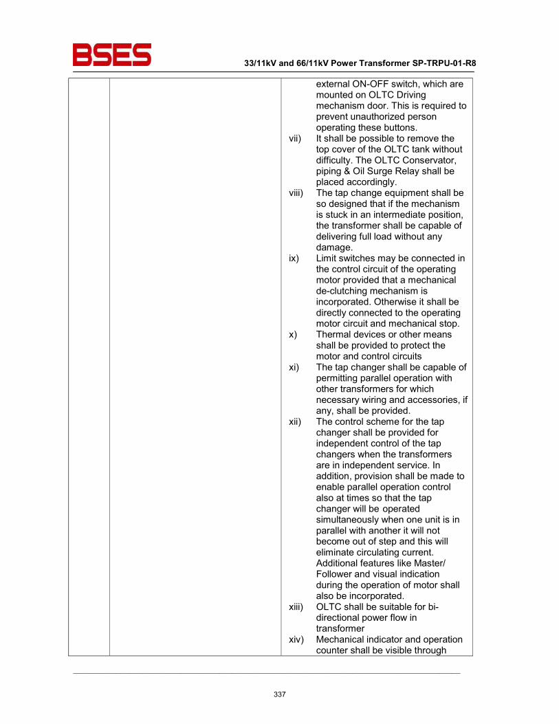
33/11kV and 66/11kV Power Transformer SP-TRPU-01-R8
__________________________________________________________________________________________
external ON-OFF switch, which are mounted on OLTC Driving mechanism door. This is required to prevent unauthorized person operating these buttons.
vii) It shall be possible to remove the top cover of the OLTC tank without difficulty. The OLTC Conservator, piping & Oil Surge Relay shall be placed accordingly.
viii) The tap change equipment shall be so designed that if the mechanism is stuck in an intermediate position, the transformer shall be capable of delivering full load without any damage.
ix) Limit switches may be connected in the control circuit of the operating motor provided that a mechanical de-clutching mechanism is incorporated. Otherwise it shall be directly connected to the operating motor circuit and mechanical stop.
x) Thermal devices or other means shall be provided to protect the motor and control circuits
xi) The tap changer shall be capable of permitting parallel operation with other transformers for which necessary wiring and accessories, if any, shall be provided.
xii) The control scheme for the tap changer shall be provided for independent control of the tap changers when the transformers are in independent service. In addition, provision shall be made to enable parallel operation control also at times so that the tap changer will be operated simultaneously when one unit is in parallel with another it will not become out of step and this will eliminate circulating current. Additional features like Master/ Follower and visual indication during the operation of motor shall also be incorporated.
xiii) OLTC shall be suitable for bi-directional power flow in transformer
xiv) Mechanical indicator and operation counter shall be visible through
337
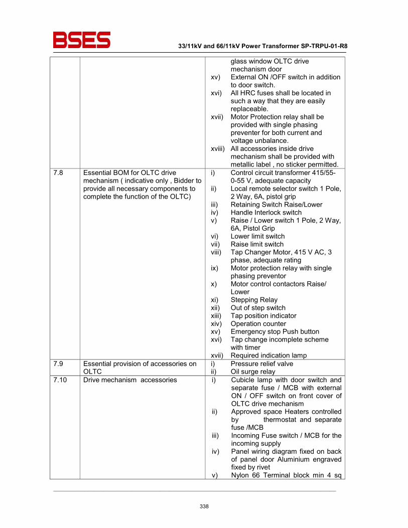
33/11kV and 66/11kV Power Transformer SP-TRPU-01-R8
__________________________________________________________________________________________
glass window OLTC drive mechanism door
xv) External ON /OFF switch in addition to door switch.
xvi) All HRC fuses shall be located in such a way that they are easily replaceable.
xvii) Motor Protection relay shall be provided with single phasing preventer for both current and voltage unbalance.
xviii) All accessories inside drive mechanism shall be provided with metallic label , no sticker permitted.
7.8 Essential BOM for OLTC drive mechanism ( indicative only , Bidder to provide all necessary components to complete the function of the OLTC)
i) Control circuit transformer 415/55-0-55 V, adequate capacity
ii) Local remote selector switch 1 Pole, 2 Way, 6A, pistol grip
iii) Retaining Switch Raise/Lower iv) Handle Interlock switch v) Raise / Lower switch 1 Pole, 2 Way,
6A, Pistol Grip vi) Lower limit switch vii) Raise limit switch viii) Tap Changer Motor, 415 V AC, 3
phase, adequate rating ix) Motor protection relay with single
phasing preventor x) Motor control contactors Raise/
Lower xi) Stepping Relay xii) Out of step switch xiii) Tap position indicator xiv) Operation counter xv) Emergency stop Push button xvi) Tap change incomplete scheme
with timer xvii) Required indication lamp
7.9 Essential provision of accessories on OLTC
i) Pressure relief valve ii) Oil surge relay
7.10 Drive mechanism accessories i) Cubicle lamp with door switch and separate fuse / MCB with external ON / OFF switch on front cover of OLTC drive mechanism
ii) Approved space Heaters controlled by thermostat and separate fuse /MCB
iii) Incoming Fuse switch / MCB for the incoming supply
iv) Panel wiring diagram fixed on back of panel door Aluminium engraved fixed by rivet
v) Nylon 66 Terminal block min 4 sq
338
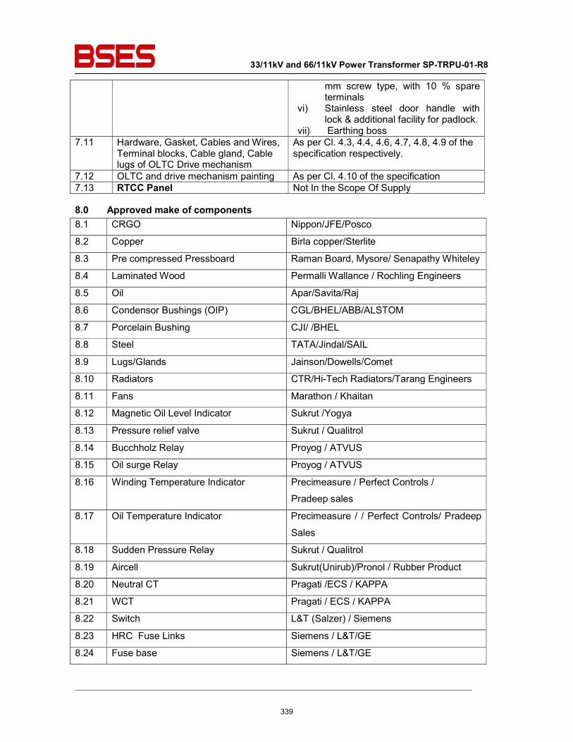
33/11kV and 66/11kV Power Transformer SP-TRPU-01-R8
__________________________________________________________________________________________
mm screw type, with 10 % spare terminals
vi) Stainless steel door handle with lock & additional facility for padlock.
vii) Earthing boss 7.11 Hardware, Gasket, Cables and Wires,
Terminal blocks, Cable gland, Cable lugs of OLTC Drive mechanism
As per Cl. 4.3, 4.4, 4.6, 4.7, 4.8, 4.9 of the specification respectively.
7.12 OLTC and drive mechanism painting As per Cl. 4.10 of the specification 7.13 RTCC Panel Not In the Scope Of Supply
8.0 Approved make of components 8.1 CRGO Nippon/JFE/Posco
8.2 Copper Birla copper/Sterlite
8.3 Pre compressed Pressboard Raman Board, Mysore/ Senapathy Whiteley
8.4 Laminated Wood Permalli Wallance / Rochling Engineers
8.5 Oil Apar/Savita/Raj
8.6 Condensor Bushings (OIP) CGL/BHEL/ABB/ALSTOM
8.7 Porcelain Bushing CJI/ /BHEL
8.8 Steel TATA/Jindal/SAIL
8.9 Lugs/Glands Jainson/Dowells/Comet
8.10 Radiators CTR/Hi-Tech Radiators/Tarang Engineers
8.11 Fans Marathon / Khaitan
8.12 Magnetic Oil Level Indicator Sukrut /Yogya
8.13 Pressure relief valve Sukrut / Qualitrol
8.14 Bucchholz Relay Proyog / ATVUS
8.15 Oil surge Relay Proyog / ATVUS
8.16 Winding Temperature Indicator Precimeasure / Perfect Controls /
Pradeep sales
8.17 Oil Temperature Indicator Precimeasure / / Perfect Controls/ Pradeep
Sales
8.18 Sudden Pressure Relay Sukrut / Qualitrol
8.19 Aircell Sukrut(Unirub)/Pronol / Rubber Product
8.20 Neutral CT Pragati /ECS / KAPPA
8.21 WCT Pragati / ECS / KAPPA
8.22 Switch L&T (Salzer) / Siemens
8.23 HRC Fuse Links Siemens / L&T/GE
8.24 Fuse base Siemens / L&T/GE
339
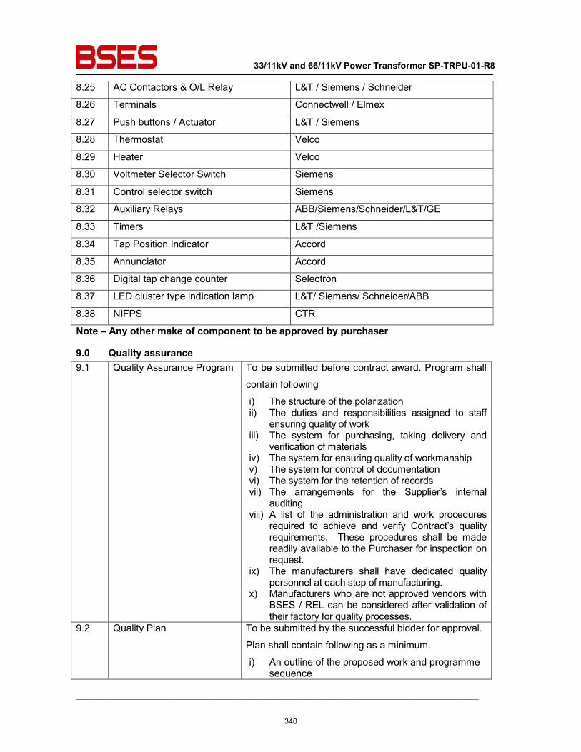
33/11kV and 66/11kV Power Transformer SP-TRPU-01-R8
__________________________________________________________________________________________
8.25 AC Contactors & O/L Relay L&T / Siemens / Schneider
8.26 Terminals Connectwell / Elmex
8.27 Push buttons / Actuator L&T / Siemens
8.28 Thermostat Velco
8.29 Heater Velco
8.30 Voltmeter Selector Switch Siemens
8.31 Control selector switch Siemens
8.32 Auxiliary Relays ABB/Siemens/Schneider/L&T/GE
8.33 Timers L&T /Siemens
8.34 Tap Position Indicator Accord
8.35 Annunciator Accord
8.36 Digital tap change counter Selectron
8.37 LED cluster type indication lamp L&T/ Siemens/ Schneider/ABB
8.38 NIFPS CTR
Note – Any other make of component to be approved by purchaser
9.0 Quality assurance 9.1 Quality Assurance Program To be submitted before contract award. Program shall
contain following
i) The structure of the polarization ii) The duties and responsibilities assigned to staff
ensuring quality of work iii) The system for purchasing, taking delivery and
verification of materials iv) The system for ensuring quality of workmanship v) The system for control of documentation vi) The system for the retention of records vii) The arrangements for the Supplier’s internal
auditing viii) A list of the administration and work procedures
required to achieve and verify Contract’s quality requirements. These procedures shall be made readily available to the Purchaser for inspection on request.
ix) The manufacturers shall have dedicated quality personnel at each step of manufacturing.
x) Manufacturers who are not approved vendors with BSES / REL can be considered after validation of their factory for quality processes.
9.2 Quality Plan To be submitted by the successful bidder for approval.
Plan shall contain following as a minimum.
i) An outline of the proposed work and programme sequence
340
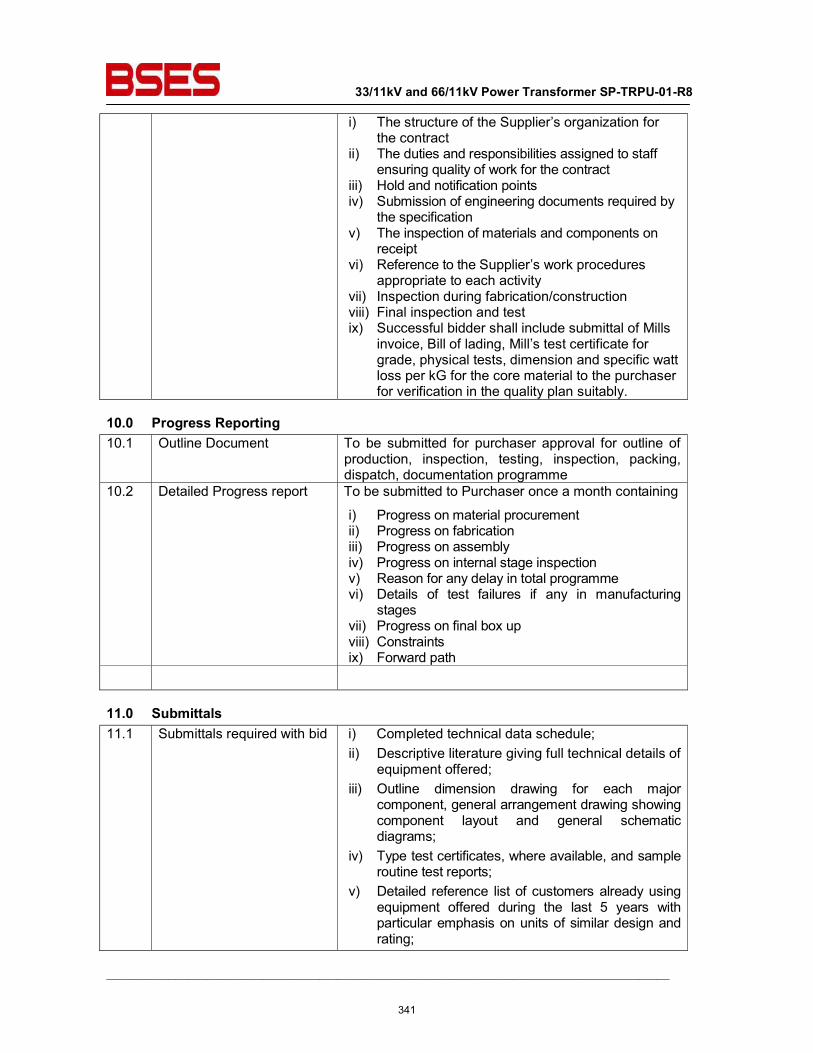
33/11kV and 66/11kV Power Transformer SP-TRPU-01-R8
__________________________________________________________________________________________
i) The structure of the Supplier’s organization for the contract
ii) The duties and responsibilities assigned to staff ensuring quality of work for the contract
iii) Hold and notification points iv) Submission of engineering documents required by
the specification v) The inspection of materials and components on
receipt vi) Reference to the Supplier’s work procedures
appropriate to each activity vii) Inspection during fabrication/construction viii) Final inspection and test ix) Successful bidder shall include submittal of Mills
invoice, Bill of lading, Mill’s test certificate for grade, physical tests, dimension and specific watt loss per kG for the core material to the purchaser for verification in the quality plan suitably.
10.0 Progress Reporting 10.1 Outline Document To be submitted for purchaser approval for outline of
production, inspection, testing, inspection, packing, dispatch, documentation programme
10.2 Detailed Progress report To be submitted to Purchaser once a month containing
i) Progress on material procurement ii) Progress on fabrication iii) Progress on assembly iv) Progress on internal stage inspection v) Reason for any delay in total programme vi) Details of test failures if any in manufacturing
stages vii) Progress on final box up viii) Constraints ix) Forward path
11.0 Submittals 11.1 Submittals required with bid i) Completed technical data schedule;
ii) Descriptive literature giving full technical details of equipment offered;
iii) Outline dimension drawing for each major component, general arrangement drawing showing component layout and general schematic diagrams;
iv) Type test certificates, where available, and sample routine test reports;
v) Detailed reference list of customers already using equipment offered during the last 5 years with particular emphasis on units of similar design and rating;
341
33/11kV and 66/11kV Power Transformer SP-TRPU-01-R8
__________________________________________________________________________________________
vi) Details of manufacturer’s quality assurance standards and programme and ISO 9000 series or equivalent national certification;
vii) Deviations from this specification. Only deviations approved in writing before award of contract shall be accepted;
viii) Recommended spare parts and consumable items for five years of operation with prices and spare parts catalogue with price list for future requirements
ix) Transport / Shipping dimension and weights, space required for handling parts for maintenance
x) Write up on oil preservation system xi) Write up on OLTC xii) Quality Assurance Program
342
33/11kV and 66/11kV Power Transformer SP-TRPU-01-R8
__________________________________________________________________________________________
11.2 Submittals required after award for Approval (A), Reference I, and subsequent distribution
i) Programme for production and testing (A) ii) Guaranteed Technical Particulars (A) iii) General description of the equipment and all
components, including brochures I iv) Calculations to substantiate choice of electrical,
structural, mechanical component size/ratings (A) v) Detailed dimension drawing for all components,
general arrangement drawing showing detailed component layout and detailed schematic and wiring drawings for all components like marshalling box and OLTC drive mechanism box
vi) Detailed loading drawing to enable the Purchaser to design and construct foundations for the transformer I
vii) Transport / shipping dimensions with weights, wheel base details, untanking height etc I
viii) Terminal arrangements and cable box details (A) ix) Flow diagram of cooling system showing no of
cooling banks (A) x) Drawings of major components like Bushing , CT
etc (A) xi) Valve schedule diagram plate (A) xii) Instruction plate for flexible separator (A) xiii) Rating and diagram plate with OLTC connection
details xiv) List of makes of all fittings and accessories (A) xv) Statement drawing attention to all exposed points
in the equipment at which contact with or in close proximity to other metals and stating clearly what protection is employed to prevent corrosion at each point (A)
xvi) Detailed installation and commissioning instructions
xvii) Quality Plan 11.3 Submittals required at the
final hold point prior to dispatch
i) Inspection and test reports carried out in manufacturer’s works (A)
ii) Test certificates of all bought out items iii) Operation and maintenance Instructions as well as
trouble shooting charts 11.4 Drawing and document
sizes Standard size paper A0, A1, A2, A3, A4
11.5 No of drgs /Documents required at different stages
As per Annexure A Scope of Supply
12.0 Inspection & Testing 12.1 Inspection and Testing
343
33/11kV and 66/11kV Power Transformer SP-TRPU-01-R8
__________________________________________________________________________________________
during manufacture
12.1.1 Tank and Conservator i) Check correct dimensions between wheels demonstrate turning of wheels through 90 deg and further dimensional check.
ii) Check for physical properties of materials for lifting lugs, jacking pads etc. All load bearing welds, including lifting lug welds shall be subjected to required load tests.
iii) Leakage test of the conservator as per CBIP. iv) Certification of all test results. v) Oil leakage test on all tanks at normal head of oil
plus 35 kN/sqm at the base of the tank for 24 hrs vi) Vacuum and Pressure test on tank as type test as
per CBIP vii) Leakage test of radiators as per CBIP
12.1.2 Core i) Vendor to submit the documentary evidence for procurement of CRGO laminations and prove that they have procured / used new core material. During in process inspection at lamination sub vendor , Customer shall randomly select / seal lamination for testing at ERDA / CPRI ( Accredited NABL labs) for Specific core loss , accelerated ageing test , surface insulation resistivity , AC permeability and magnetization , Stacking factor , ductility etc . This testing shall be in the scope of vendor.
ii) Check on the quality of varnish if used on the stampings. a) Measurement of thickness and hardness of
varnish on stampings. b) Solvent resistance test to check that varnish does
not react in hot oil. c) Check overall quality of varnish by sampling to
ensure uniform hipping color, no bare spots. No ever burnt varnish layer and no bubbles on varnished surface.
iii) Check on the amount of burrs. iv) Bow check on stampings. v) Check for the overlapping of stampings. Corners of
the sheet are to be apart. vi) Visual and dimensional check during assembly
stage. vii) Check on complete core for measurements of iron-
loss and check for any hot spot by exciting the core so as to induce the designed value of flux density in the core.
viii) Check for inter laminar insulation between core sectors before and after pressing.
ix) Visual and dimensional checks for straightness and roundness of core, thickness of limbs and suitability of clamps.
x) High voltage test (2 KV for one minute) between core and clamps.
344
33/11kV and 66/11kV Power Transformer SP-TRPU-01-R8
__________________________________________________________________________________________
xi) Certification of all test results. 12.1.3 Insulating Materials i) Sample check for physical properties of
materials. ii) Check for dielectric strength. iii) Visual and dimensional checks. iv) Check for the reaction of hot oil on insulating
materials. v) Certification of all test results.
12.1.4 Windings i) Sample check on winding conductor for mechanical properties and electrical conductivity.
ii) Visual and dimensional check on conductor for scratches, dept. mark etc.
iii) Sample check on insulating paper for PE value, Bursting strength, Electric strength.
iv) Check for the reaction of hot oil on insulating paper. v) Check for the bending of the insulating paper on
conductor. vi) Check and ensure that physical condition of all
materials taken for winding is satisfactory and free of dust.
vii) Check for absence of short circuit between parallel strands.
viii) Check for Brazed joints wherever applicable. ix) Measurement of voltage ratio to be carried out
when core/ yoke is completely restocked and all connections are ready.
x) Certification of all test results. 12.1.4.1 Checks before drying
process
i) Check conditions of insulation on the conductor and between the windings.
ii) Check insulation distance between high voltage connection distance between high voltage connection cables and earthed and other live parts.
iii) Check insulation distance between low voltage connection and earthed and other parts.
iv) Insulation test of core earthing. v) Check for proper cleanliness vi) Check tightness of coils i.e. no free movement. vii) Certification of all test results.
12.1.4.2 Checks during drying
process
i) Measurement and recording of temperature and drying time during vacuum treatment.
ii) Check for completeness of drying. iii) Certification of all test results.
12.1.5 Oil As per BSES specification.
12.1.6 Test on fittings and
accessories
As per manufacturer’s standard
12.2 Routine / Acceptance
tests
The sequence of routine testing shall be as follows i) Visual and dimension check for completely
assembled transformer ii) Measurements of voltage ratio iii) Measurements of winding resistance at each taps.
345
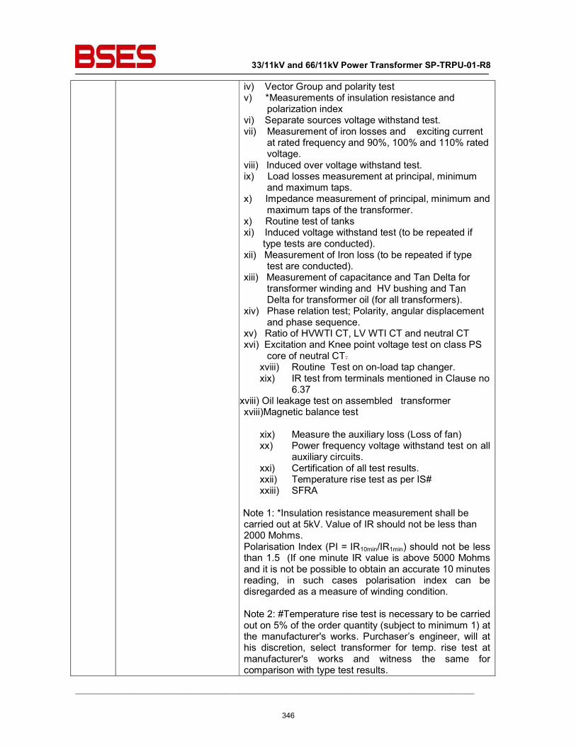
33/11kV and 66/11kV Power Transformer SP-TRPU-01-R8
__________________________________________________________________________________________
iv) Vector Group and polarity test v) *Measurements of insulation resistance and
polarization index vi) Separate sources voltage withstand test. vii) Measurement of iron losses and exciting current
at rated frequency and 90%, 100% and 110% rated voltage.
viii) Induced over voltage withstand test. ix) Load losses measurement at principal, minimum
and maximum taps. x) Impedance measurement of principal, minimum and
maximum taps of the transformer. x) Routine test of tanks xi) Induced voltage withstand test (to be repeated if
type tests are conducted). xii) Measurement of Iron loss (to be repeated if type
test are conducted). xiii) Measurement of capacitance and Tan Delta for
transformer winding and HV bushing and Tan Delta for transformer oil (for all transformers).
xiv) Phase relation test; Polarity, angular displacement and phase sequence.
xv) Ratio of HVWTI CT, LV WTI CT and neutral CT xvi) Excitation and Knee point voltage test on class PS
core of neutral CT. xviii) Routine Test on on-load tap changer. xix) IR test from terminals mentioned in Clause no
6.37 xviii) Oil leakage test on assembled transformer xviii)Magnetic balance test
xix) Measure the auxiliary loss (Loss of fan) xx) Power frequency voltage withstand test on all
auxiliary circuits. xxi) Certification of all test results. xxii) Temperature rise test as per IS# xxiii) SFRA
Note 1: *Insulation resistance measurement shall be carried out at 5kV. Value of IR should not be less than 2000 Mohms. Polarisation Index (PI = IR10min/IR1min) should not be less than 1.5 (If one minute IR value is above 5000 Mohms and it is not be possible to obtain an accurate 10 minutes reading, in such cases polarisation index can be disregarded as a measure of winding condition. Note 2: #Temperature rise test is necessary to be carried out on 5% of the order quantity (subject to minimum 1) at the manufacturer's works. Purchaser’s engineer, will at his discretion, select transformer for temp. rise test at manufacturer's works and witness the same for comparison with type test results.
346
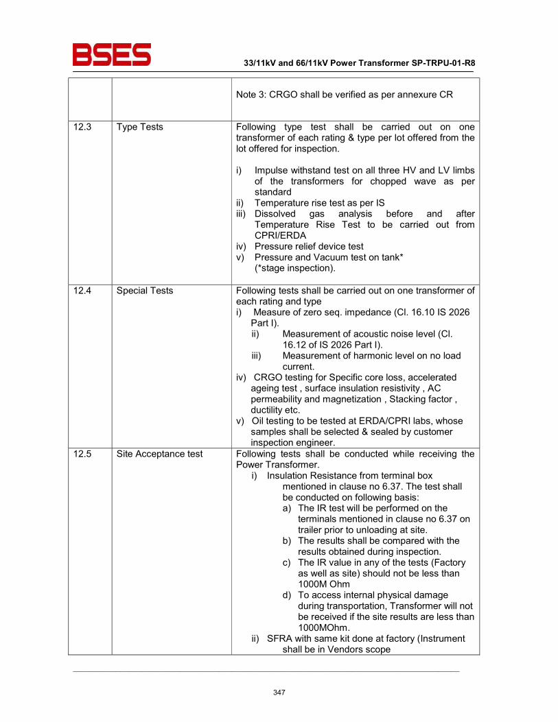
33/11kV and 66/11kV Power Transformer SP-TRPU-01-R8
__________________________________________________________________________________________
Note 3: CRGO shall be verified as per annexure CR
12.3 Type Tests Following type test shall be carried out on one transformer of each rating & type per lot offered from the lot offered for inspection. i) Impulse withstand test on all three HV and LV limbs
of the transformers for chopped wave as per standard
ii) Temperature rise test as per IS iii) Dissolved gas analysis before and after
Temperature Rise Test to be carried out from CPRI/ERDA
iv) Pressure relief device test v) Pressure and Vacuum test on tank*
(*stage inspection).
12.4 Special Tests Following tests shall be carried out on one transformer of each rating and type i) Measure of zero seq. impedance (Cl. 16.10 IS 2026
Part I). ii) Measurement of acoustic noise level (Cl.
16.12 of IS 2026 Part I). iii) Measurement of harmonic level on no load
current. iv) CRGO testing for Specific core loss, accelerated
ageing test , surface insulation resistivity , AC permeability and magnetization , Stacking factor , ductility etc.
v) Oil testing to be tested at ERDA/CPRI labs, whose samples shall be selected & sealed by customer inspection engineer.
12.5 Site Acceptance test Following tests shall be conducted while receiving the Power Transformer.
i) Insulation Resistance from terminal box mentioned in clause no 6.37. The test shall be conducted on following basis: a) The IR test will be performed on the
terminals mentioned in clause no 6.37 on trailer prior to unloading at site.
b) The results shall be compared with the results obtained during inspection.
c) The IR value in any of the tests (Factory as well as site) should not be less than 1000M Ohm
d) To access internal physical damage during transportation, Transformer will not be received if the site results are less than 1000MOhm.
ii) SFRA with same kit done at factory (Instrument shall be in Vendors scope
347
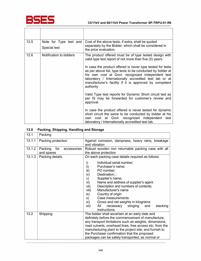
33/11kV and 66/11kV Power Transformer SP-TRPU-01-R8
__________________________________________________________________________________________
12.5 Note for Type test and
Special test
Cost of the above tests, if extra, shall be quoted separately by the Bidder, which shall be considered in the price evaluation.
12.6 Notification to bidders The product offered must be of type tested design with valid type test report of not more than five (5) years. In case the product offered is never type tested for tests as per above list, type tests to be conducted by bidder at his own cost at Govt. recognized independent test laboratory / Internationally accredited test lab or at manufacturer’s facility if it is approved by competent authority Valid Type test reports for Dynamic Short circuit test as per IS may be forwarded for customer’s review and approval. In case the product offered is never tested for dynamic short circuit the same to be conducted by bidder at his own cost at Govt. recognized independent test laboratory / Internationally accredited test lab.
13.0 Packing, Shipping, Handling and Storage 13.1 Packing
13.1.1 Packing protection Against corrosion, dampness, heavy rains, breakage and vibration
13.1.2 Packing for accessories and spares
Robust wooden non returnable packing case with all the above protection
13.1.3 Packing details On each packing case details required as follows
i) Individual serial number; ii) Purchaser’s name; iii) PO number; iv) Destination; ; v) Supplier’s name; vi) Name and address of supplier’s agent vii) Description and numbers of contents; viii) Manufacturer’s name ix) Country of origin x) Case measurements xi) Gross and net weights in kilograms xii) All necessary slinging and stacking
instructions. 13.2 Shipping The bidder shall ascertain at an early date and
definitely before the commencement of manufacture, any transport limitations such as weights, dimensions, road culverts, overhead lines, free access etc. from the manufacturing plant to the project site; and furnish to the Purchaser confirmation that the proposed packages can be safely transported, as normal or
348
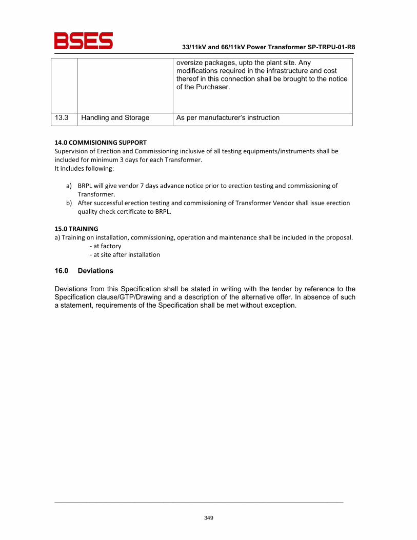
33/11kV and 66/11kV Power Transformer SP-TRPU-01-R8
__________________________________________________________________________________________
oversize packages, upto the plant site. Any modifications required in the infrastructure and cost thereof in this connection shall be brought to the notice of the Purchaser.
13.3 Handling and Storage As per manufacturer’s instruction
14.0 COMMISIONING SUPPORT Supervision of Erection and Commissioning inclusive of all testing equipments/instruments shall be included for minimum 3 days for each Transformer. It includes following:
a) BRPL will give vendor 7 days advance notice prior to erection testing and commissioning of Transformer.
b) After successful erection testing and commissioning of Transformer Vendor shall issue erection quality check certificate to BRPL.
15.0 TRAINING a) Training on installation, commissioning, operation and maintenance shall be included in the proposal.
- at factory - at site after installation
16.0 Deviations Deviations from this Specification shall be stated in writing with the tender by reference to the Specification clause/GTP/Drawing and a description of the alternative offer. In absence of such a statement, requirements of the Specification shall be met without exception.
349
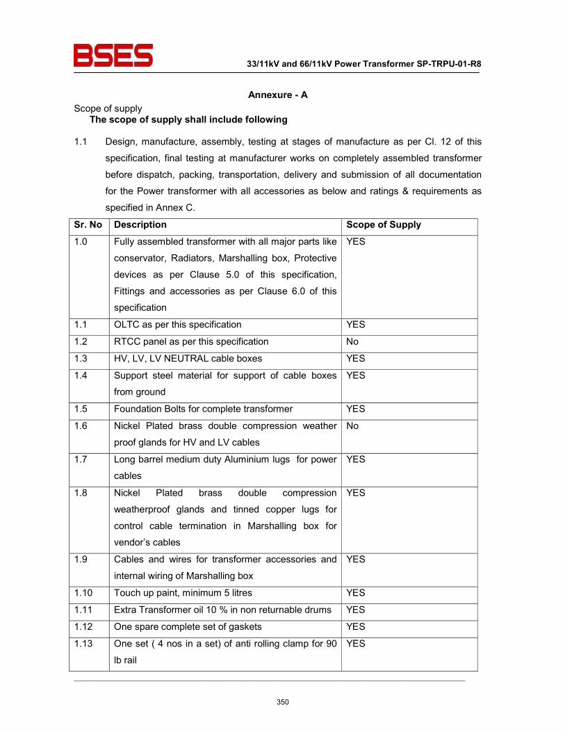
33/11kV and 66/11kV Power Transformer SP-TRPU-01-R8
__________________________________________________________________________________________
Annexure - A Scope of supply The scope of supply shall include following 1.1 Design, manufacture, assembly, testing at stages of manufacture as per Cl. 12 of this
specification, final testing at manufacturer works on completely assembled transformer
before dispatch, packing, transportation, delivery and submission of all documentation
for the Power transformer with all accessories as below and ratings & requirements as
specified in Annex C.
Sr. No Description Scope of Supply 1.0 Fully assembled transformer with all major parts like
conservator, Radiators, Marshalling box, Protective
devices as per Clause 5.0 of this specification,
Fittings and accessories as per Clause 6.0 of this
specification
YES
1.1 OLTC as per this specification YES
1.2 RTCC panel as per this specification No
1.3 HV, LV, LV NEUTRAL cable boxes YES
1.4 Support steel material for support of cable boxes
from ground
YES
1.5 Foundation Bolts for complete transformer YES
1.6 Nickel Plated brass double compression weather
proof glands for HV and LV cables
No
1.7 Long barrel medium duty Aluminium lugs for power
cables
YES
1.8 Nickel Plated brass double compression
weatherproof glands and tinned copper lugs for
control cable termination in Marshalling box for
vendor’s cables
YES
1.9 Cables and wires for transformer accessories and
internal wiring of Marshalling box
YES
1.10 Touch up paint, minimum 5 litres YES
1.11 Extra Transformer oil 10 % in non returnable drums YES
1.12 One spare complete set of gaskets YES
1.13 One set ( 4 nos in a set) of anti rolling clamp for 90
lb rail
YES
350
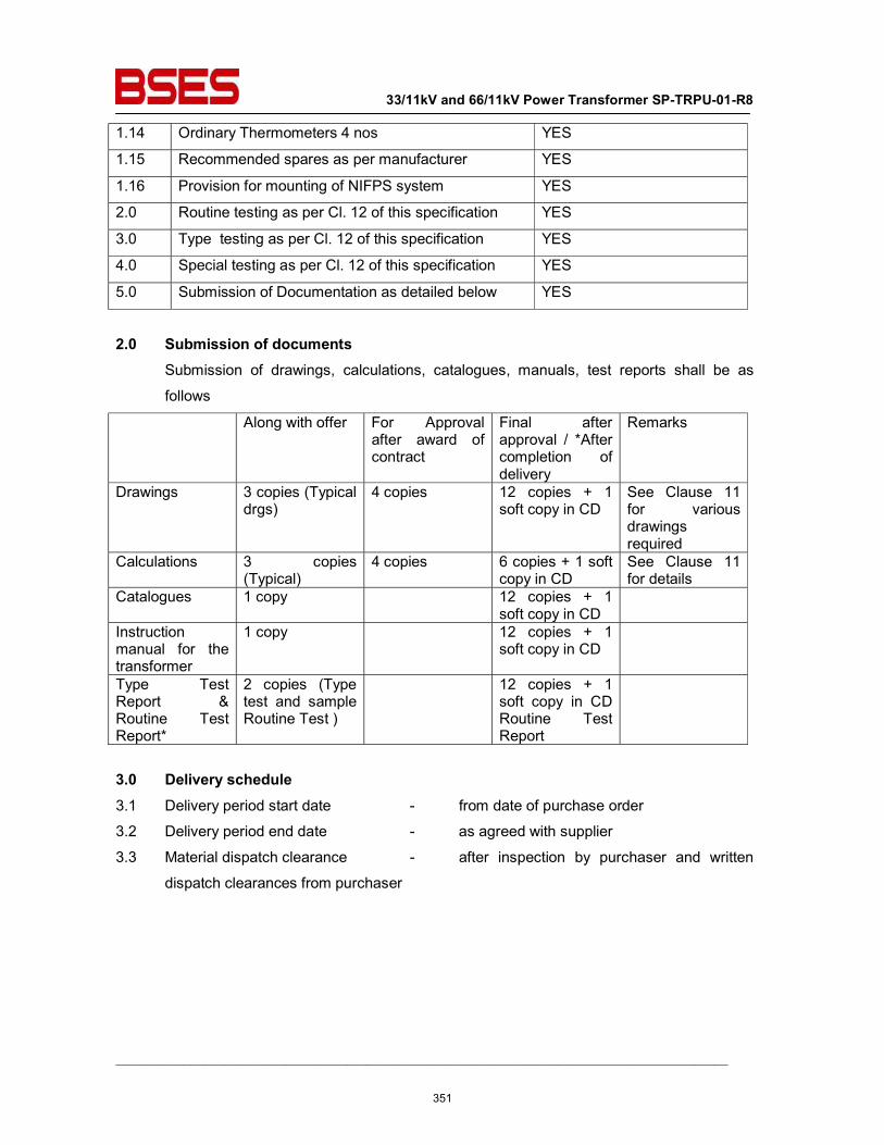
33/11kV and 66/11kV Power Transformer SP-TRPU-01-R8
__________________________________________________________________________________________
1.14 Ordinary Thermometers 4 nos YES
1.15 Recommended spares as per manufacturer YES
1.16 Provision for mounting of NIFPS system YES
2.0 Routine testing as per Cl. 12 of this specification YES
3.0 Type testing as per Cl. 12 of this specification YES
4.0 Special testing as per Cl. 12 of this specification YES
5.0 Submission of Documentation as detailed below YES
2.0 Submission of documents Submission of drawings, calculations, catalogues, manuals, test reports shall be as
follows
Along with offer For Approval after award of contract
Final after approval / *After completion of delivery
Remarks
Drawings 3 copies (Typical drgs)
4 copies 12 copies + 1 soft copy in CD
See Clause 11 for various drawings required
Calculations 3 copies (Typical)
4 copies 6 copies + 1 soft copy in CD
See Clause 11 for details
Catalogues 1 copy 12 copies + 1 soft copy in CD
Instruction manual for the transformer
1 copy 12 copies + 1 soft copy in CD
Type Test Report & Routine Test Report*
2 copies (Type test and sample Routine Test )
12 copies + 1 soft copy in CD Routine Test Report
3.0 Delivery schedule 3.1 Delivery period start date - from date of purchase order
3.2 Delivery period end date - as agreed with supplier
3.3 Material dispatch clearance - after inspection by purchaser and written
dispatch clearances from purchaser
351
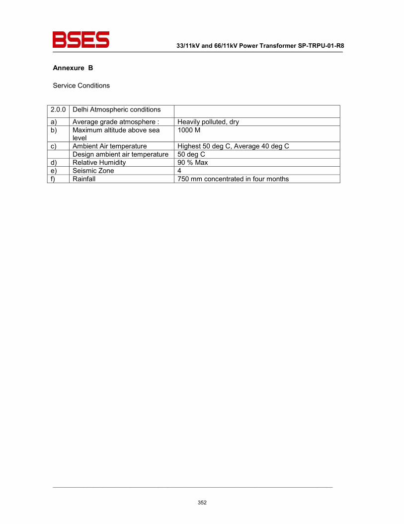
33/11kV and 66/11kV Power Transformer SP-TRPU-01-R8
__________________________________________________________________________________________
Annexure B Service Conditions
2.0.0 Delhi Atmospheric conditions
a) Average grade atmosphere : Heavily polluted, dry b) Maximum altitude above sea
level 1000 M
c) Ambient Air temperature Highest 50 deg C, Average 40 deg C Design ambient air temperature 50 deg C d) Relative Humidity 90 % Max e) Seismic Zone 4 f) Rainfall 750 mm concentrated in four months
352
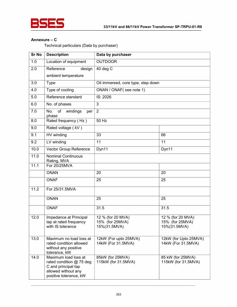
33/11kV and 66/11kV Power Transformer SP-TRPU-01-R8
__________________________________________________________________________________________
Annexure – C Technical particulars (Data by purchaser)
Sr No Description Data by purchaser 1.0 Location of equipment OUTDOOR
2.0 Reference design
ambient temperature
40 deg C
3.0 Type Oil immersed, core type, step down
4.0 Type of cooling ONAN / ONAF( see note 1)
5.0 Reference standard IS: 2026
6.0 No. of phases 3
7.0 No. of windings per phase
2
8.0 Rated frequency ( Hz ) 50 Hz
9.0 Rated voltage ( kV )
9.1 HV winding 33 66
9.2 LV winding 11 11
10.0 Vector Group Reference Dyn11 Dyn11
11.0 Nominal Continuous Rating, MVA
11.1 For 20/25MVA
ONAN 20 20
ONAF 25 25
11.2 For 25/31.5MVA
ONAN 25 25
ONAF 31.5 31.5
12.0 Impedance at Principal tap at rated frequency with IS tolerance
12 % (for 20 MVA) 15% (for 25MVA) 15%(31.5MVA)
12 % (for 20 MVA) 15% (for 25MVA) 15%(31.5MVA)
13.0 Maximum no load loss at rated condition allowed without any positive tolerance, kW
12kW (For upto 25MVA) 14kW (For 31.5MVA)
12kW (for Upto 25MVA) 14kW (For 31.5MVA)
14.0 Maximum load loss at rated condition @ 75 deg C and principal tap allowed without any positive tolerance, kW
85kW (for 25MVA) 115kW (for 31.5MVA)
85 kW (for 25MVA) 115kW (for 31.5MVA)
353
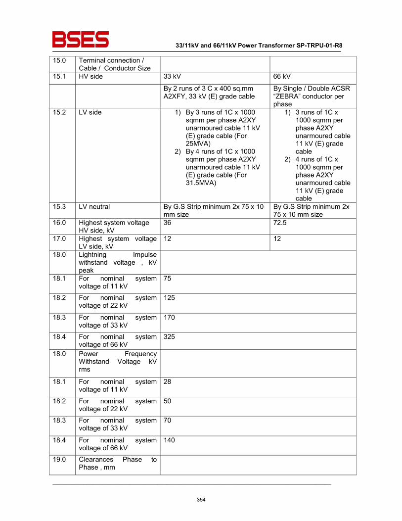
33/11kV and 66/11kV Power Transformer SP-TRPU-01-R8
__________________________________________________________________________________________
15.0 Terminal connection / Cable / Conductor Size
15.1 HV side 33 kV 66 kV
By 2 runs of 3 C x 400 sq.mm A2XFY, 33 kV (E) grade cable
By Single / Double ACSR “ZEBRA” conductor per phase
15.2 LV side 1) By 3 runs of 1C x 1000 sqmm per phase A2XY unarmoured cable 11 kV (E) grade cable (For 25MVA)
2) By 4 runs of 1C x 1000 sqmm per phase A2XY unarmoured cable 11 kV (E) grade cable (For 31.5MVA)
1) 3 runs of 1C x 1000 sqmm per phase A2XY unarmoured cable 11 kV (E) grade cable
2) 4 runs of 1C x 1000 sqmm per phase A2XY unarmoured cable 11 kV (E) grade cable
15.3 LV neutral By G.S Strip minimum 2x 75 x 10 mm size
By G.S Strip minimum 2x 75 x 10 mm size
16.0 Highest system voltage HV side, kV
36 72.5
17.0 Highest system voltage LV side, kV
12 12
18.0 Lightning Impulse withstand voltage , kV peak
18.1 For nominal system voltage of 11 kV
75
18.2 For nominal system voltage of 22 kV
125
18.3 For nominal system voltage of 33 kV
170
18.4 For nominal system voltage of 66 kV
325
18.0 Power Frequency Withstand Voltage kV rms
18.1 For nominal system voltage of 11 kV
28
18.2 For nominal system voltage of 22 kV
50
18.3 For nominal system voltage of 33 kV
70
18.4 For nominal system voltage of 66 kV
140
19.0 Clearances Phase to Phase , mm
354
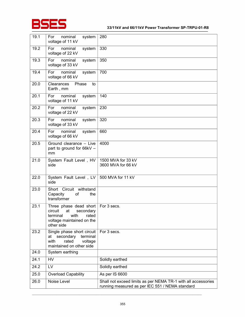
33/11kV and 66/11kV Power Transformer SP-TRPU-01-R8
__________________________________________________________________________________________
19.1 For nominal system voltage of 11 kV
280
19.2 For nominal system voltage of 22 kV
330
19.3 For nominal system voltage of 33 kV
350
19.4 For nominal system voltage of 66 kV
700
20.0 Clearances Phase to Earth , mm
20.1 For nominal system voltage of 11 kV
140
20.2 For nominal system voltage of 22 kV
230
20.3 For nominal system voltage of 33 kV
320
20.4 For nominal system voltage of 66 kV
660
20.5 Ground clearance – Live part to ground for 66kV – mm
4000
21.0 System Fault Level , HV side
1500 MVA for 33 kV 3600 MVA for 66 kV
22.0 System Fault Level , LV side
500 MVA for 11 kV
23.0 Short Circuit withstand Capacity of the transformer
23.1 Three phase dead short circuit at secondary terminal with rated voltage maintained on the other side
For 3 secs.
23.2 Single phase short circuit at secondary terminal with rated voltage maintained on other side
For 3 secs.
24.0 System earthing
24.1 HV Solidly earthed
24.2 LV Solidly earthed
25.0 Overload Capability As per IS 6600
26.0 Noise Level Shall not exceed limits as per NEMA TR-1 with all accessories running measured as per IEC 551 / NEMA standard
355
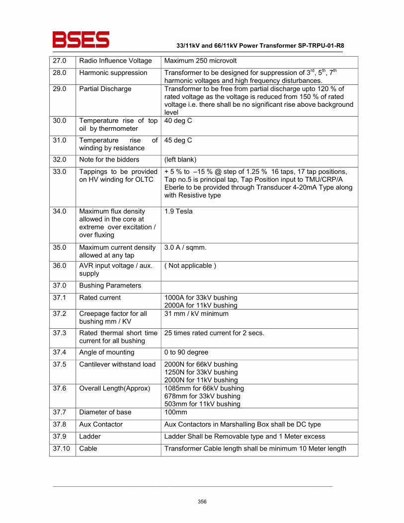
33/11kV and 66/11kV Power Transformer SP-TRPU-01-R8
__________________________________________________________________________________________
27.0 Radio Influence Voltage Maximum 250 microvolt
28.0 Harmonic suppression Transformer to be designed for suppression of 3rd, 5th, 7th harmonic voltages and high frequency disturbances.
29.0 Partial Discharge Transformer to be free from partial discharge upto 120 % of rated voltage as the voltage is reduced from 150 % of rated voltage i.e. there shall be no significant rise above background level
30.0 Temperature rise of top oil by thermometer
40 deg C
31.0 Temperature rise of winding by resistance
45 deg C
32.0 Note for the bidders (left blank)
33.0 Tappings to be provided on HV winding for OLTC
+ 5 % to –15 % @ step of 1.25 % 16 taps, 17 tap positions, Tap no.5 is principal tap, Tap Position input to TMU/CRP/A Eberle to be provided through Transducer 4-20mA Type along with Resistive type
34.0 Maximum flux density allowed in the core at extreme over excitation / over fluxing
1.9 Tesla
35.0 Maximum current density allowed at any tap
3.0 A / sqmm.
36.0 AVR input voltage / aux. supply
( Not applicable )
37.0 Bushing Parameters
37.1 Rated current 1000A for 33kV bushing 2000A for 11kV bushing
37.2 Creepage factor for all bushing mm / KV
31 mm / kV minimum
37.3 Rated thermal short time current for all bushing
25 times rated current for 2 secs.
37.4 Angle of mounting 0 to 90 degree
37.5 Cantilever withstand load 2000N for 66kV bushing 1250N for 33kV bushing 2000N for 11kV bushing
37.6 Overall Length(Approx) 1085mm for 66kV bushing 678mm for 33kV bushing 503mm for 11kV bushing
37.7 Diameter of base 100mm
37.8 Aux Contactor Aux Contactors in Marshalling Box shall be DC type
37.9 Ladder Ladder Shall be Removable type and 1 Meter excess
37.10 Cable Transformer Cable length shall be minimum 10 Meter length
356
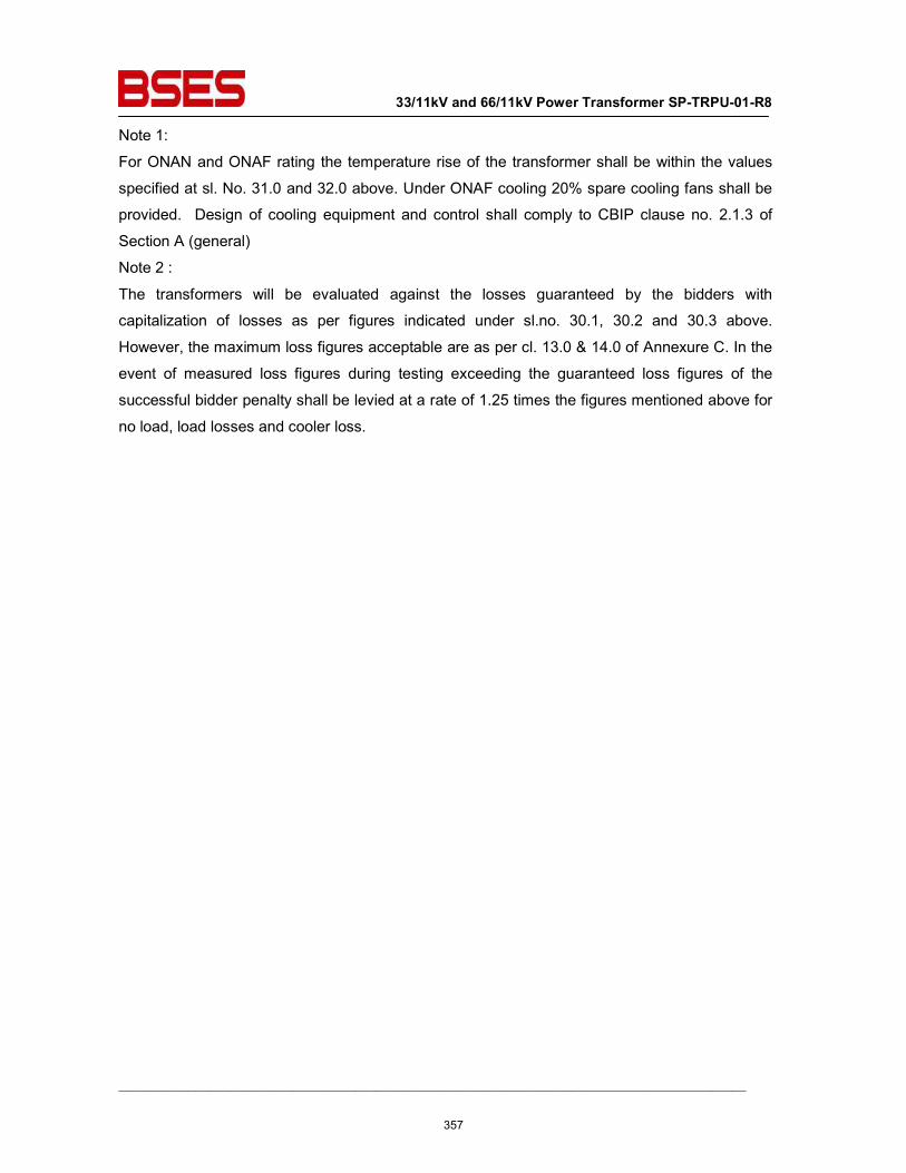
33/11kV and 66/11kV Power Transformer SP-TRPU-01-R8
__________________________________________________________________________________________
Note 1:
For ONAN and ONAF rating the temperature rise of the transformer shall be within the values
specified at sl. No. 31.0 and 32.0 above. Under ONAF cooling 20% spare cooling fans shall be
provided. Design of cooling equipment and control shall comply to CBIP clause no. 2.1.3 of
Section A (general)
Note 2 :
The transformers will be evaluated against the losses guaranteed by the bidders with
capitalization of losses as per figures indicated under sl.no. 30.1, 30.2 and 30.3 above.
However, the maximum loss figures acceptable are as per cl. 13.0 & 14.0 of Annexure C. In the
event of measured loss figures during testing exceeding the guaranteed loss figures of the
successful bidder penalty shall be levied at a rate of 1.25 times the figures mentioned above for
no load, load losses and cooler loss.
357
33/11kV and 66/11kV Power Transformer SP-TRPU-01-R8
__________________________________________________________________________________________
Annexure-N ( Technical specification of NIFPS)
1.0.0 SUPPLY AND SCOPE WORK
Design, manufacture, testing of the assembled system at manufacturer’s works before dispatch, packing and supply at site, erection and commissioning of the Nitrogen Injection Fire Protection system
Installation testing and commissioning of Nitrogen Injection Fire Protection system shall be in scope of bidder. All material including Pipes, ducts control cables, tools, tackles, hardware, testing equipments and manpower required for the work shall be in scope of bidder except for any type of civil work like fire wall, soak pit etc. Bidder if feels shall conduct physical survey of the power transformer to check feasibility and quantum of work involved.
2.0.0 INTRODUCTION
Nitrogen Injection Fire Protection System (NIFPS) shall use nitrogen as fire quenching medium. The protective system shall prevent transformer / Reactor oil tank explosion and possible fire in case of internal faults. In the event of fire by external causes such as bushing fire, OLTC fires, fire from surrounding equipment etc, it shall act as a fast and effective fire fighter without any manual intervention. It shall accomplish its role as fire preventer and extinguisher without employing water and / or carbon dioxide. Fire shall be extinguished within 3 minutes (Maximum) of system activation and within 30 seconds (maximum) of commencement of nitrogen injection.
3.0.0 APPLICABLE CODES AND STANDARDS
The design and installation of the complete fire protection system shall comply with the latest applicable Indian standards
a) IS 10028 (Part II) : Code of practice for selection, installation, and maintenance of
transformer
S Tariff Advisory Committee : Regulations for the electrical equipment of buildings
S National fire Codes 1993 of National Fire Protection Association (NFPA) USA d) Central Electricity Authority, The Gazette of India, Extraordinary 2010 :
Safety provisions for electrical installations and apparatus of voltage exceeding 650V 4.0.0 ACTIVATION OF THE FIRE PROTECTIVE SYSTEM
Mal-functioning of fire prevention / extinguishing system could lead to interruption in power supply. The supplier shall ensure that the probability of chances of malfunctioning of the fire protective system is practically zero. To achieve this objective, the supplier shall plan out his scheme of activating signals which should not be too complicated to make the fire protective system inoperative in case of actual need and should not be
358
33/11kV and 66/11kV Power Transformer SP-TRPU-01-R8
__________________________________________________________________________________________
dependent on auxiliary power source. The system shall be provided with automatic control for fire prevention and fire extinction without any manual intervention. Besides automatic control, remote electrical push button control at Control box and local manual control in the fire extinguishing cubicle shall also be provided. The following electrical-signals shall be required for activating the fire protective system under prevention mode / fire extinguishing mode.
4.1.0 Auto Mode 4.1.1 For prevention of fire :
Differential relay operation + Buchholz relay paralleled with pressure relief valve or RPRR (Rapid Pressure Rise Relay) + Tripping of all or one circuit breakers (on HV & LV/IV side) associated with transformer / reactor is the pre-requisite for activation of system. The system shall have sufficient Input modules.
4.1.2 For extinguishing fire : Fire detector + Buchholz relay paralleled with pressure relief valve (PRV) or sudden pressure relay (SPR) + tripping of all circuit breakers (on HV & LV/IV side) associated with transformer / reactor is the pre-requisite for activation of system.
4.2.0 Manual Mode (Local / Remote electrical)
Tripping of all circuit breakers (on HV & LV/IV side) associated with transformer/reactor is the pre-requisite for activation of system.
4.3.0 Manual Mode (Mechanical) Tripping of all circuit breakers (on HV & LV/IV side) associated with transformer / Reactor is the pre-requisite for activation of system. The system shall be designed to be operated manually in case of failure of power supply to fire protection system.
5.0.0 GENERAL DESCRIPTION
Nitrogen injection fire protection system should be a dedicated system for each oil filled transformer / reactor. It should have a Fire Extinguishing Cubicle (FEC) placed on a plinth at 5-7m away (as per statutory requirement) from transformer / reactor or placed next to the fire wall if fire wall exists. The FEC shall be connected to the top of transformer / reactor oil tank for depressurization of tank and to the oil pit as per Indian standard and CBIP from its bottom through oil pipes. The fire extinguishing cubicle should house a pressurized nitrogen cylinder(s) which is connected to the oil tank of transformer/reactor oil tank at bottom. The Transformer Conservator Isolation Valve (TCIV) is fitted between the conservator tank and Buchholz relay. Cable connections are to be provided from signal box to the control box in the control room, control box to fire extinguishing cubicle, TCIV to signal box and any other wiring to ensure proper functioning of the fire protection system. Fire detectors placed on the top of transformer/reactor tank are to be connected in parallel to the signal box by Fire survival cables. Control box is also to be connected to relay panel in control room for receiving system activation signals. All panel or control equipments shall be fire proof so as to ensure that they do not fail themselves in event of fire.
359
33/11kV and 66/11kV Power Transformer SP-TRPU-01-R8
__________________________________________________________________________________________
6.0.0 OPERATION
On receipt of all activating signals, the system shall drain pre-determined volume of hot oil from the top of tank (i.e top oil layer), through outlet valve, to reduce tank pressure by removing top oil and simultaneously injecting nitrogen gas at high pressure for stirring the oil at pre-fixed rate and thus bringing the temperature of top oil layer down. Transformer conservator isolation valve blocks the flow of oil from conservator tank in case of tank rupture / explosion or bushing bursting. Nitrogen occupies the space created by oil drained out and acts as an insulating layer over oil in the tank and thus preventing aggravation of fire.
7.0.0 SYSTEM COMPONENTS
Nitrogen injection fire protection system shall broadly consist of the following components. However, all other components which are necessary for fast reliable and effective working of the fire protective system shall be deemed to be included in the scope of supply.
7.1.0 Fire Extinguishing Cubicle (FEC)
The FEC shall be made of CRCA sheet of 3 mm (minimum) thick complete with the base frame, painted inside and outside with post office red colour (shade 538 of IS-5).It shall have hinged split doors fitted with high quality tamper proof lock. The degree of protection shall be IP55. The following items shall be provided in the FEC. a. Nitrogen gas cylinder with regulator and falling pressure electrical contact
manometer b. Oil drain pipe with mechanical quick drain valve. c. Control equipment for draining of oil of pre-determined volume and injecting
regulated volume of nitrogen gas d. Pressure monitoring switch for back-up protection for nitrogen release e. Limit switches for monitoring of the system f. Butterfly valve with flanges on the top of panel for connecting oil drain pipe and
nitrogen injection pipes for transformer/reactors g. Panel lighting (CFL Type) h. Oil drain pipe extension of suitable sizes for connecting pipes to oil pit.
7.2.0 Control box Control box is to be placed in the control room for monitoring system operation, automatic control and remote operation. Control supply will be 50/220VDC (15% tolerance) based on site requirement. The following alarms, indications, switches, push buttons, audio signal etc. shall be provided. a. System on b. TCIV open c. Oil drain valve closed d. Gas inlet valve closed e. TCIV closed* f. Fire detector trip * g. Buchholz relay trip h. Oil drain valve open* i. Extinction in progress *
360
33/11kV and 66/11kV Power Transformer SP-TRPU-01-R8
__________________________________________________________________________________________
j. Cylinder pressure low * k. Differential relay trip l. PRV / SPR trip m . Master relay of Transformer/reactor trip n. System out of service * o. Fault in cable connecting fault fire detector p. Fault in cable connecting differential relay q. Fault in cable connecting Buchholz relay r. Fault in cable connecting PRV / SPR s. Fault in cable connecting transformer /reactor trip t. Fault in cable connecting TCIV u. Auto/ Manual / Off v. Extinction release on / off w. Lamp test x. Visual/ Audio alarm* y. Visual/ Audio alarm for DC supply fail *
Suitable provision shall be made in the control box, for monitoring of the system from remote substation using the substation automation system. 7.3.0 Transformer Conservator Isolation Valve
Transformer conservator isolation valve (TCIV) to be fitted in the conservator pipe line, between conservator and buchholz relay which shall operate for isolating the conservator during abnormal flow of oil due to rupture / explosion of tank or bursting of bushing. The valve shall not isolate conservator during normal flow of oil during filtration or filling or refilling, locking plates to be provided with handle for pad locking. It shall have proximity switch for remote alarm and indication glass window for visual inspection for physical checking of the status of valve. The TCIV should be of the best quality as malfunctioning of TCIV could lead to serious consequence. The closing of TCIV means stoppage of breathing of transformer/reactor. Fire survival cable connecting TCIV shall be terminated in transformer marshalling box.
7.4.0 Fire detectors
The system shall be complete with adequate number of fire detectors (quartz bulb) fitted on the top cover of the transformer / reactor oil tank. The system generates signal after sensing higher temperature. The placing of fire detectors and numbers shall be designed and finalized by bidder as per requirement.
7.5.0 Signal box
It shall be mounted away from transformer / reactor main tank, preferably near the transformer marshalling box, for terminating cable connections from TCIV & firedetectors and for further connection to the control box. The degree of protection shall be IP55.
7.6.0 Cables
Fire survival cables (capable to withstand 750° C.) of 4 core x 1.5 sq. mm size for connection of fire detectors in parallel shall be used. The fire survival cable shall conform to BS 7629-1, BS 8434-1, BS 7629-1 and BS 5839-1,BS EN 50267-2-1 or relevant Indian standards.
361
33/11kV and 66/11kV Power Transformer SP-TRPU-01-R8
__________________________________________________________________________________________
Fire Retardant Low Smoke (FRLS) cable of 12 core x 1.5 sq. mm size shall be used for connection of signal box / marshalling box near transformer/reactor and FEC mounted near transformer/reactor with control box mounted in control room. Fire Retardant Low Smoke (FRLS) cable of 4 core x 1.5 sq. mm size shall be used for connection between control box to DC and AC supply source, fire extinguishing cubicle to AC supply source, signal box/ marshalling box to transformer conservator isolation valve connection on transformer/reactor.
7.7.0 Pipes
Heavy duty pipe connecting the transformer/reactor tank for oil rain, and for nitrogen injection shall be provided. Pipes connecting oil tank laid underground, shall be preferably be used for interconnection. Pipes, complete with connections, flanges, bends and tees etc. shall be supplied along with the system.
7.8.0 Other items 7.8.1 Oil drain and nitrogen injection openings with gate valves on transformer / reactor tank at
suitable locations. 7.8.2 Flanges with dummy piece in conservator pipe between Buchholz relay and conservator
Tank for fixing TCIV. 7.8.3 Fire detector brackets on transformer / reactor tank top cover. 7.8.4 Spare potential free contacts for activating the system i.e. in differential relay, Buchholz
relay, Pressure Relief Device / RPRR, Circuit Breaker of transformer/reactor 7.8.5 Pipe connections between transformer / reactor and FEC and between FEC and oil pit
required for collecting top oil. 7.8.6 Cabling for fire detectors mounted on transformer /reactor top cover 7.8.7 Inter cabling between signal box, control box and Fire Extinguishing Cubicle (FEC).
All external cables from / to the system i.e. signal box to control box and control box to FEC shall be provided by the purchaser. All internal cables within the system i.e. between detectors / signal box / marshalling box / FEC / TCIV shall be in the scope of NIFPS supplier.
7.8.8 Butterfly valves /Gate valves on oil drain pipe and nitrogen injection pipe which should be able to withstand full vacuum.
7.8.9 Supports, signal box etc. which are to be painted with enamelled paint.
The doors, removable covers and panels shall be gasketted all round with neoprene gaskets.
8.0.0 MANDATORY SPARES Cylinder filled with Nitrogen of required capacity per substation
1 No.
Fire Detectors per transformer 3 No’s. Regulator assembly per sub-station 1 No. NIFPs Spare Valves 2 Nos Spare Contactors in Marshalling Box 2 Nos
362
33/11kV and 66/11kV Power Transformer SP-TRPU-01-R8
__________________________________________________________________________________________
9.0.0 TESTS
Reports of all type test conducted as per relevant IS/IEC standards in respect of various bought out items including test reports for degree of protection for FEC /control box / signal box shall be submitted by the supplier.
The supplier shall demonstrate the functional test associated with the following: • Fire Extinguishing Cubicle, Control Box. • Fire Detector. • Transformer Conservator Isolation Valve
The performance test of the complete system shall be carried out after erection of the system with transformer at site. 10.0.0 DOCUMENTS TO BE SUBMITTED 10.1.0 To be submitted along with offer 10.1.1 General outline of the system. 10.1.2 Detailed write-up on operation of the offered protection system including
maintenance and testing aspects / schedules. 10.1.3 Technical Data particulars (GTP), the format of which is attached in Annexure A of the
specification 10.1.4 Data regarding previous supplies, date of commissioning, performance feedback etc. 10.1.5 Document related to Type test / proof of design as required by statutory body /
electrical inspector
10.2.0 To be submitted after award of contract:
Detailed dimensional layout drawing of the system with complete bill of materials, clearances from ground and other live points, details of detectors, equipment layout drawings, detailed drawings pertaining to signal box, control box, FEC equipment, wiring and schemes, 4 sets of testing, commissioning, Operation and Maintenance manual along with soft copies (in CDs) shall be submitted by the supplier.
11.0.0 PACKING, SHIPPING, HANDLING & SITE SUPPORT 11.1.0
Packing Protection
The packing shall be fit to withstand rough handling during transit and storage at destination. The test set should be properly protected against corrosion, dampness & damage.
11.2.0
Packing for accessories and spares
Robust non-returnable packing case with all the above protection & identification Label. Thebidder should get the packing list approved before dispatching the material.
11.3.0 Packing Identification Label On each packing case, following details are required:
11.3.1 Individual serial number 11.3.2 Purchaser’s name 11.3.3 PO number (along with SAP item code, if any) & date
363
33/11kV and 66/11kV Power Transformer SP-TRPU-01-R8
__________________________________________________________________________________________
11.3.4 Equipment Tag no. (if any) 11.3.5 Destination 11.3.6 Manufacturer / Supplier’s name 11.3.7 Address of Manufacturer / Supplier / it’s agent 11.3.8 Description 11.3.9 Country of origin 11.3.10 Month & year of Manufacturing 11.3.11 Case measurements 11.3.12 Gross and net weight 11.3.13 All necessary slinging and stacking instructions 11.4.0
Shipping
The seller shall be responsible for all transit damage due to improper packing.
11.5.0 Handling and Storage Manufacturer instruction shall be followed.
11.6.0 Detail handling & storage instruction sheet / manual to be furnished before commencement of supply.
12.0.0 DEVIATIONS
List of deviations shall be stated in writing with the tender by reference to the Specification clause / GTP/ Drawing. In absence of such a statement, requirements of the Specification shall be assumed to be met without exception by the bidder.
364
33/11kV and 66/11kV Power Transformer SP-TRPU-01-R8
__________________________________________________________________________________________
Annexure-O ( Technical specification of Transformer Oil)
Sr. No. Item Description Specification Requirement A Function
1 Viscosity Max. 15 mm2 /s at 400C 1800 mm2 /s at 00C
2 Pour Point, Max - 100C 3 Water content, Max 30 mg/Kg
4 Breakdown voltage i) New unfiltered oil. Min. 30 kV ii) After filtration Min. 70 kV
5 Density Max. 0.895 g/ml at 200C 6 Dielectric dissipation factor
(DDF) at 90 0C, Max 0.005 at 90 0C,
7 Particle Content Value to be provided by the vendor B Refining/Stability
1 Appearance of oil Clear, free from sediment and suspended matter
2 Acidity Max 0.01 mg KOH/g 3 Interfacial tension at 270C,
Min 40 mN/m
4 Total sulphur content Value to be provided by the vendor 5 Corrosive sulphur Not-corrosive 6 Potentially Corrosive sulphur Not-corrosive 7 Dibenzyl Disulphide (DBDS) Not detectable (<5 mg/kg) 8 Inhibitor Not detectable (<0.01%) 9 Metal Passivator Not detectable (<5 mg/kg) 10 Other additives Type and concentration of additives to be
provided
11 2-furfural and related Compounds content
Not detectable (<0.05 mg/kg) for each individual compound
C Performance 1 Oxidation stability a) Total acidity, Max 1.2 mg KOH/g b) Sludge Max 0.8% c) Dielectric dissipation factor
(DDF) at 90 0C, Max 0.5
1 Gassing Tendency Value to be provided by the vendor 2 Electrostatic charging
tendency (ECT) Value to be provided by the vendor
D Health, safety and Environment
1 Flash point Min. 1350C, 2 Polycyclic Aromatics content
(PCA) Max 3%
3 Polychlorinated Biphenyls (PCB) content Not detectable (<2 mg/Kg)
365
33/11kV and 66/11kV Power Transformer SP-TRPU-01-R8
__________________________________________________________________________________________
Annexure-G (Technical specification of Material Tracking-GPS Device) Supply of GPS Device shall be in Vendors scope, however it shall be returned to Vendor once Goods are received. Detailed requirement of GPS Device is as below: Once the material is dispatched after Final clearance Transport Vehicle shall have GPS Tracking Device and status of dispatch of material shall be sent to all the stake holders via SMS thru GPS Device. Approve make is Map my India Asset Tracking device.
Annexure-I (Cancellation of Inspection Call) Penalty equivalent to cost incurred in assigning the inspector shall be levied on vendor in following case:
1) Inspector reaches the factory and equipment is not ready for inspection 2) Inspection call cancelled by Vendor after making all arrangements (booking tickets and hotel) are
done by buyer. 3) Any deficiency found in equipment/material during inspection and re inspection is called for.
Annexure-CR (Technical specification for purchase of CRGO ,its handling and its testing)
1) Core material shall be directly procured either from the BSES approved manufacturer or through their authorized service centre/distributor and not through any contractor.
2) Vendor should have hydraulic core lifting facility to avoid any jerk at the time of core building.
3) BSES may appoint recognized testing authority like CPRI /ERDA with their instruments & engineer’s team and measure no load loss, load loss and percentage impedance of the transformer at supplier’s works at Vendor cost . Bidder shall agree and give them full co-operation during their stay & testing at shop floor. The losses & impedance values so obtained will be considered as final.
4) Following stage inspections will be carried out by purchaser or by third party engineers appointed by BSES : A) Verification & inspection of the mother coil at port & putting stamp & seal may be inspected by
BSES. B) Reconciliation of mother coil by checking stamp & seal at factory before slitting. One sample
of CRGO to be sealed for testing at ERDA/CPRI. C) Bidder should have in house core cutting facility for proper monitoring & control on quality. In
case it is done outside cutting shall be done in presence of BSES.
5) Following documents to be submitted during the stage inspection : A) Invoice of supplier B) Mills test certificates C) Packing list D) Bill of lading E) Bill of entry certificates by customs
366
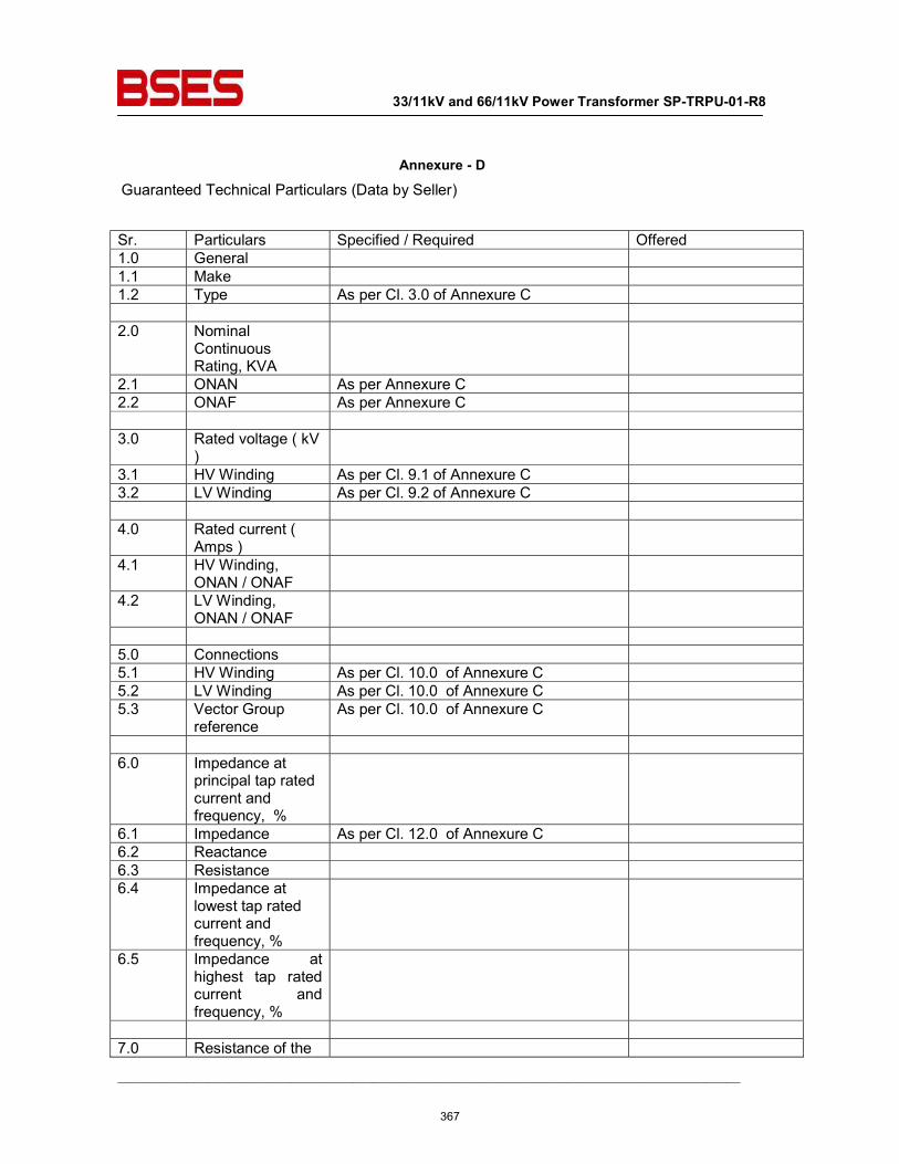
33/11kV and 66/11kV Power Transformer SP-TRPU-01-R8
__________________________________________________________________________________________
Annexure - D
Guaranteed Technical Particulars (Data by Seller)
Sr. Particulars Specified / Required Offered 1.0 General 1.1 Make 1.2 Type As per Cl. 3.0 of Annexure C 2.0 Nominal
Continuous Rating, KVA
2.1 ONAN As per Annexure C 2.2 ONAF As per Annexure C 3.0 Rated voltage ( kV
)
3.1 HV Winding As per Cl. 9.1 of Annexure C 3.2 LV Winding As per Cl. 9.2 of Annexure C 4.0 Rated current (
Amps )
4.1 HV Winding, ONAN / ONAF
4.2 LV Winding, ONAN / ONAF
5.0 Connections 5.1 HV Winding As per Cl. 10.0 of Annexure C 5.2 LV Winding As per Cl. 10.0 of Annexure C 5.3 Vector Group
reference As per Cl. 10.0 of Annexure C
6.0 Impedance at
principal tap rated current and frequency, %
6.1 Impedance As per Cl. 12.0 of Annexure C 6.2 Reactance 6.3 Resistance 6.4 Impedance at
lowest tap rated current and frequency, %
6.5 Impedance at highest tap rated current and frequency, %
7.0 Resistance of the
367
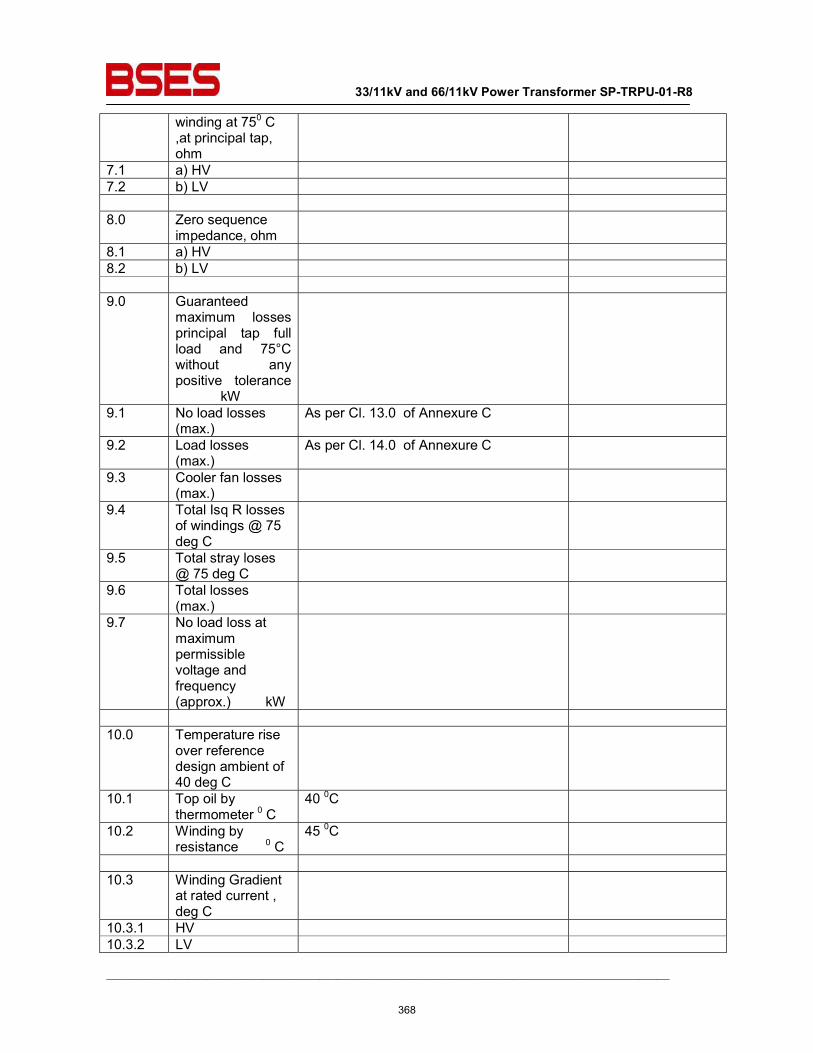
33/11kV and 66/11kV Power Transformer SP-TRPU-01-R8
__________________________________________________________________________________________
winding at 750 C ,at principal tap, ohm
7.1 a) HV 7.2 b) LV 8.0 Zero sequence
impedance, ohm
8.1 a) HV 8.2 b) LV 9.0 Guaranteed
maximum losses principal tap full load and 75°C without any positive tolerance kW
9.1 No load losses (max.)
As per Cl. 13.0 of Annexure C
9.2 Load losses (max.)
As per Cl. 14.0 of Annexure C
9.3 Cooler fan losses (max.)
9.4 Total Isq R losses of windings @ 75 deg C
9.5 Total stray loses @ 75 deg C
9.6 Total losses (max.)
9.7 No load loss at maximum permissible voltage and frequency (approx.) kW
10.0 Temperature rise
over reference design ambient of 40 deg C
10.1 Top oil by thermometer 0 C
40 0C
10.2 Winding by resistance 0 C
45 0C
10.3 Winding Gradient
at rated current , deg C
10.3.1 HV 10.3.2 LV
368
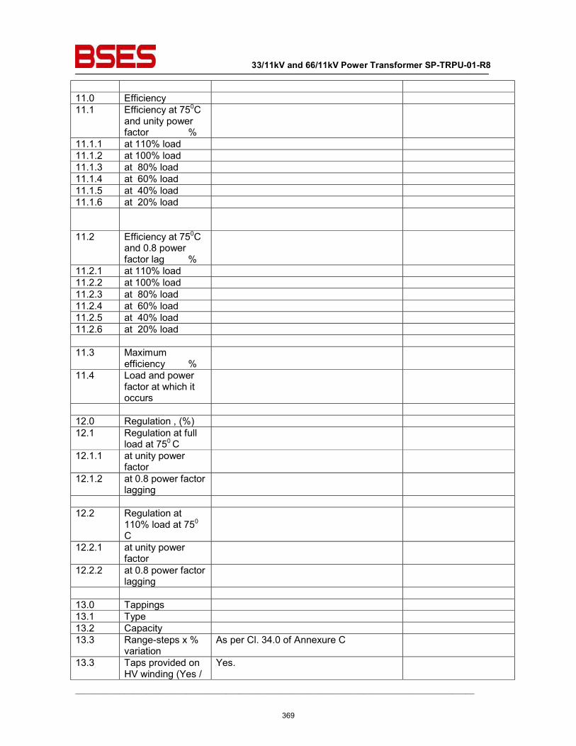
33/11kV and 66/11kV Power Transformer SP-TRPU-01-R8
__________________________________________________________________________________________
11.0 Efficiency 11.1 Efficiency at 750C
and unity power factor %
11.1.1 at 110% load 11.1.2 at 100% load 11.1.3 at 80% load 11.1.4 at 60% load 11.1.5 at 40% load 11.1.6 at 20% load
11.2 Efficiency at 750C and 0.8 power factor lag %
11.2.1 at 110% load 11.2.2 at 100% load 11.2.3 at 80% load 11.2.4 at 60% load 11.2.5 at 40% load 11.2.6 at 20% load 11.3 Maximum
efficiency %
11.4 Load and power factor at which it occurs
12.0 Regulation , (%) 12.1 Regulation at full
load at 750 C
12.1.1 at unity power factor
12.1.2 at 0.8 power factor lagging
12.2 Regulation at
110% load at 750 C
12.2.1 at unity power factor
12.2.2 at 0.8 power factor lagging
13.0 Tappings 13.1 Type 13.2 Capacity 13.3 Range-steps x %
variation As per Cl. 34.0 of Annexure C
13.3 Taps provided on HV winding (Yes /
Yes.
369
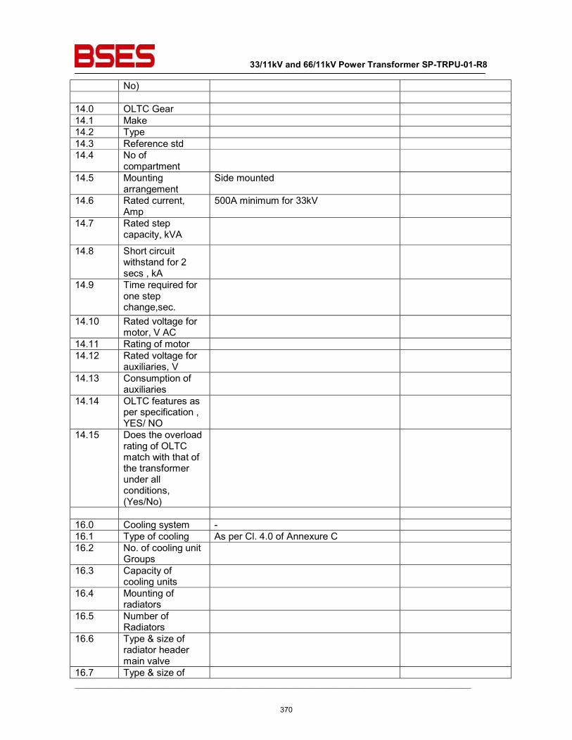
33/11kV and 66/11kV Power Transformer SP-TRPU-01-R8
__________________________________________________________________________________________
No) 14.0 OLTC Gear 14.1 Make 14.2 Type 14.3 Reference std 14.4 No of
compartment
14.5 Mounting arrangement
Side mounted
14.6 Rated current, Amp
500A minimum for 33kV
14.7 Rated step capacity, kVA
14.8 Short circuit withstand for 2 secs , kA
14.9 Time required for one step change,sec.
14.10 Rated voltage for motor, V AC
14.11 Rating of motor 14.12 Rated voltage for
auxiliaries, V
14.13 Consumption of auxiliaries
14.14 OLTC features as per specification , YES/ NO
14.15 Does the overload rating of OLTC match with that of the transformer under all conditions, (Yes/No)
16.0 Cooling system - 16.1 Type of cooling As per Cl. 4.0 of Annexure C 16.2 No. of cooling unit
Groups
16.3 Capacity of cooling units
16.4 Mounting of radiators
16.5 Number of Radiators
16.6 Type & size of radiator header main valve
16.7 Type & size of
370
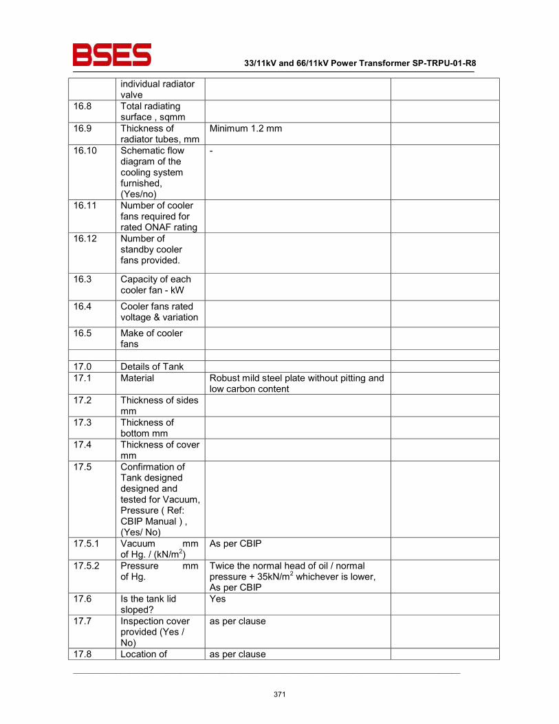
33/11kV and 66/11kV Power Transformer SP-TRPU-01-R8
__________________________________________________________________________________________
individual radiator valve
16.8 Total radiating surface , sqmm
16.9 Thickness of radiator tubes, mm
Minimum 1.2 mm
16.10 Schematic flow diagram of the cooling system furnished, (Yes/no)
-
16.11 Number of cooler fans required for rated ONAF rating
16.12 Number of standby cooler fans provided.
16.3 Capacity of each cooler fan - kW
16.4 Cooler fans rated voltage & variation
16.5 Make of cooler fans
17.0 Details of Tank 17.1 Material Robust mild steel plate without pitting and
low carbon content
17.2 Thickness of sides mm
17.3 Thickness of bottom mm
17.4 Thickness of cover mm
17.5 Confirmation of Tank designed designed and tested for Vacuum, Pressure ( Ref: CBIP Manual ) , (Yes/ No)
17.5.1 Vacuum mm of Hg. / (kN/m2)
As per CBIP
17.5.2 Pressure mm of Hg.
Twice the normal head of oil / normal pressure + 35kN/m2 whichever is lower, As per CBIP
17.6 Is the tank lid sloped?
Yes
17.7 Inspection cover provided (Yes / No)
as per clause
17.8 Location of as per clause
371
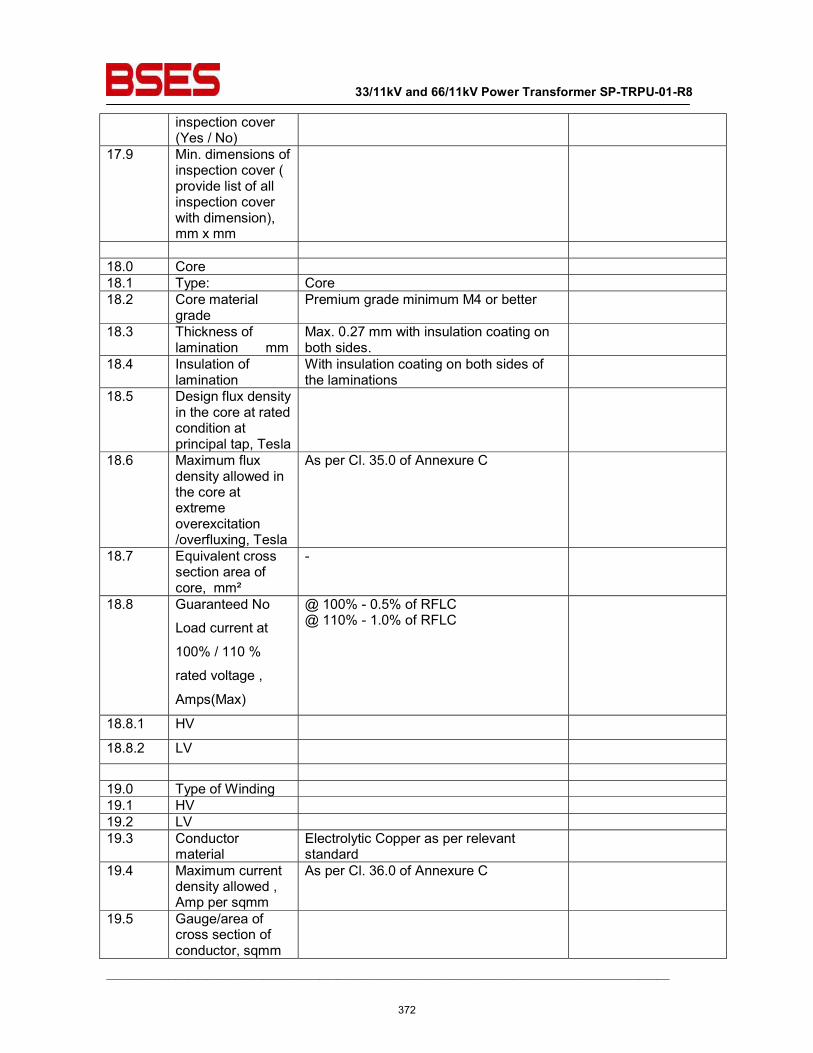
33/11kV and 66/11kV Power Transformer SP-TRPU-01-R8
__________________________________________________________________________________________
inspection cover (Yes / No)
17.9 Min. dimensions of inspection cover ( provide list of all inspection cover with dimension), mm x mm
18.0 Core 18.1 Type: Core 18.2 Core material
grade Premium grade minimum M4 or better
18.3 Thickness of lamination mm
Max. 0.27 mm with insulation coating on both sides.
18.4 Insulation of lamination
With insulation coating on both sides of the laminations
18.5 Design flux density in the core at rated condition at principal tap, Tesla
18.6 Maximum flux density allowed in the core at extreme overexcitation /overfluxing, Tesla
As per Cl. 35.0 of Annexure C
18.7 Equivalent cross section area of core, mm²
-
18.8 Guaranteed No
Load current at
100% / 110 %
rated voltage ,
Amps(Max)
@ 100% - 0.5% of RFLC @ 110% - 1.0% of RFLC
18.8.1 HV
18.8.2 LV
19.0 Type of Winding 19.1 HV 19.2 LV 19.3 Conductor
material Electrolytic Copper as per relevant standard
19.4 Maximum current density allowed , Amp per sqmm
As per Cl. 36.0 of Annexure C
19.5 Gauge/area of cross section of conductor, sqmm
372
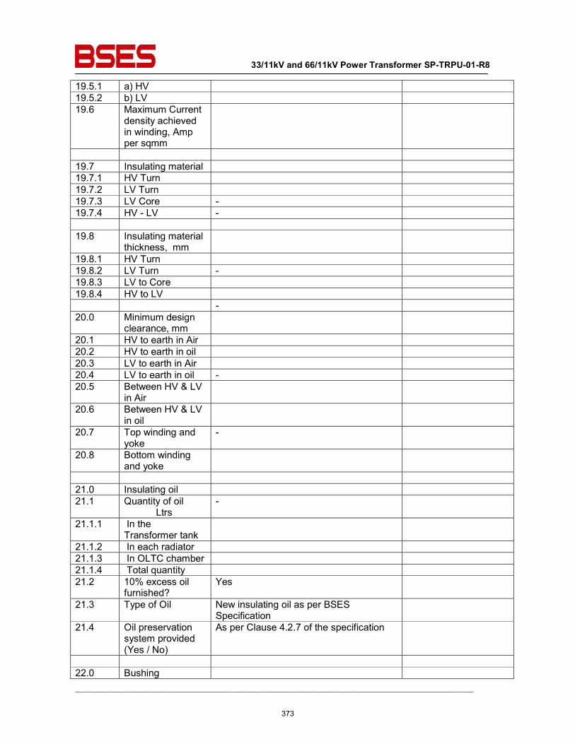
33/11kV and 66/11kV Power Transformer SP-TRPU-01-R8
__________________________________________________________________________________________
19.5.1 a) HV 19.5.2 b) LV 19.6 Maximum Current
density achieved in winding, Amp per sqmm
19.7 Insulating material 19.7.1 HV Turn 19.7.2 LV Turn 19.7.3 LV Core - 19.7.4 HV - LV - 19.8 Insulating material
thickness, mm
19.8.1 HV Turn 19.8.2 LV Turn - 19.8.3 LV to Core 19.8.4 HV to LV - 20.0 Minimum design
clearance, mm
20.1 HV to earth in Air 20.2 HV to earth in oil 20.3 LV to earth in Air 20.4 LV to earth in oil - 20.5 Between HV & LV
in Air
20.6 Between HV & LV in oil
20.7 Top winding and yoke
-
20.8 Bottom winding and yoke
21.0 Insulating oil 21.1 Quantity of oil
Ltrs -
21.1.1 In the Transformer tank
21.1.2 In each radiator 21.1.3 In OLTC chamber 21.1.4 Total quantity 21.2 10% excess oil
furnished? Yes
21.3 Type of Oil New insulating oil as per BSES Specification
21.4 Oil preservation system provided (Yes / No)
As per Clause 4.2.7 of the specification
22.0 Bushing
373
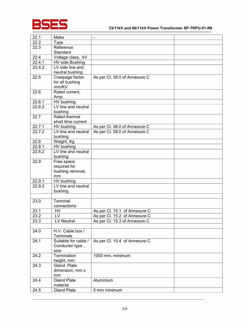
33/11kV and 66/11kV Power Transformer SP-TRPU-01-R8
__________________________________________________________________________________________
22.1 Make - 22.2 Type 22.3 Reference
Standard
22.4 Voltage class, kV 22.4.1 HV side Bushing 22.4.2 LV side line and
neutral bushing
22.5 Creepage factor for all bushing mm/KV
As per Cl. 38.0 of Annexure C
22.6 Rated current, Amp.
22.6.1 HV bushing 22.6.2 LV line and neutral
bushing
22.7 Rated thermal short time current
22.7.1 HV bushing As per Cl. 38.0 of Annexure C 22.7.2 LV line and neutral
bushing As per Cl. 38.0 of Annexure C
22.8 Weight, Kg 22.8.1 HV bushing 22.8.2 LV line and neutral
bushing
22.9 Free space required for bushing removal, mm
22.9.1 HV bushing 22.9.2 LV line and neutral
bushing
23.0 Terminal
connections
23.1 HV As per Cl. 15.1 of Annexure C 23.2 LV As per Cl. 15.2 of Annexure C 23.3 LV Neutral As per Cl. 15.3 of Annexure C 24.0 H.V. Cable box /
Terminals
24.1 Suitable for cable / Conductor type , size
As per Cl. 15.4 of Annexure C
24.2 Termination height, mm
1000 mm, minimum
24.3 Gland Plate dimension, mm x mm
24.4 Gland Plate material
Aluminium
24.5 Gland Plate 5 mm minimum
374
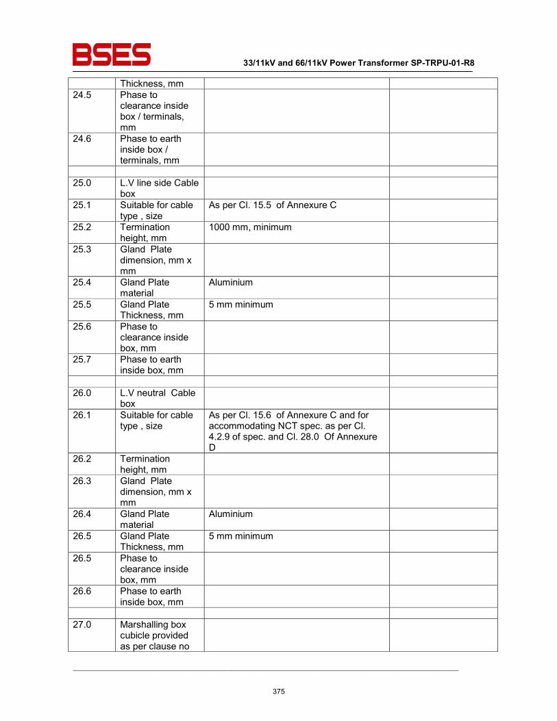
33/11kV and 66/11kV Power Transformer SP-TRPU-01-R8
__________________________________________________________________________________________
Thickness, mm 24.5 Phase to
clearance inside box / terminals, mm
24.6 Phase to earth inside box / terminals, mm
25.0 L.V line side Cable
box
25.1 Suitable for cable type , size
As per Cl. 15.5 of Annexure C
25.2 Termination height, mm
1000 mm, minimum
25.3 Gland Plate dimension, mm x mm
25.4 Gland Plate material
Aluminium
25.5 Gland Plate Thickness, mm
5 mm minimum
25.6 Phase to clearance inside box, mm
25.7 Phase to earth inside box, mm
26.0 L.V neutral Cable
box
26.1 Suitable for cable type , size
As per Cl. 15.6 of Annexure C and for accommodating NCT spec. as per Cl. 4.2.9 of spec. and Cl. 28.0 Of Annexure D
26.2 Termination height, mm
26.3 Gland Plate dimension, mm x mm
26.4 Gland Plate material
Aluminium
26.5 Gland Plate Thickness, mm
5 mm minimum
26.5 Phase to clearance inside box, mm
26.6 Phase to earth inside box, mm
27.0 Marshalling box
cubicle provided as per clause no
375
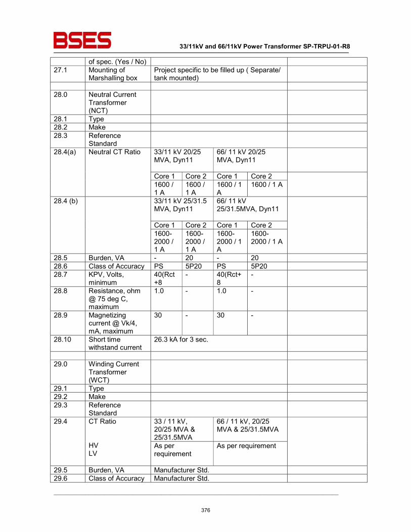
33/11kV and 66/11kV Power Transformer SP-TRPU-01-R8
__________________________________________________________________________________________
of spec. (Yes / No) 27.1 Mounting of
Marshalling box Project specific to be filled up ( Separate/ tank mounted)
28.0 Neutral Current
Transformer (NCT)
28.1 Type 28.2 Make 28.3 Reference
Standard
28.4(a) Neutral CT Ratio 33/11 kV 20/25 MVA, Dyn11
66/ 11 kV 20/25 MVA, Dyn11
Core 1 Core 2 Core 1 Core 2 1600 / 1 A
1600 / 1 A
1600 / 1 A
1600 / 1 A
28.4 (b) 33/11 kV 25/31.5 MVA, Dyn11
66/ 11 kV 25/31.5MVA, Dyn11
Core 1 Core 2 Core 1 Core 2 1600-2000 / 1 A
1600-2000 / 1 A
1600-2000 / 1 A
1600-2000 / 1 A
28.5 Burden, VA - 20 - 20 28.6 Class of Accuracy PS 5P20 PS 5P20 28.7 KPV, Volts,
minimum 40(Rct+8
- 40(Rct+8
-
28.8 Resistance, ohm @ 75 deg C, maximum
1.0 - 1.0 -
28.9 Magnetizing current @ Vk/4, mA, maximum
30 - 30 -
28.10 Short time withstand current
26.3 kA for 3 sec.
29.0 Winding Current
Transformer (WCT)
29.1 Type 29.2 Make 29.3 Reference
Standard
29.4 CT Ratio HV LV
33 / 11 kV, 20/25 MVA & 25/31.5MVA
66 / 11 kV, 20/25 MVA & 25/31.5MVA
As per requirement
As per requirement
29.5 Burden, VA Manufacturer Std. 29.6 Class of Accuracy Manufacturer Std.
376
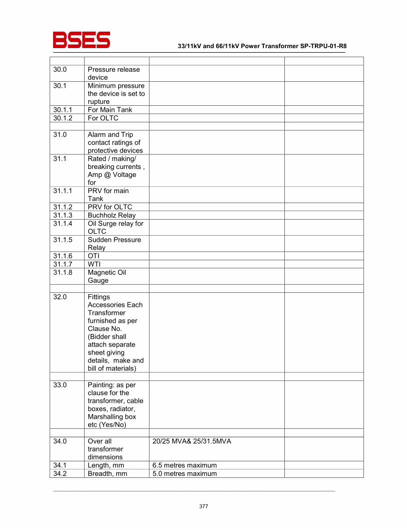
33/11kV and 66/11kV Power Transformer SP-TRPU-01-R8
__________________________________________________________________________________________
30.0 Pressure release
device
30.1 Minimum pressure the device is set to rupture
30.1.1 For Main Tank 30.1.2 For OLTC 31.0 Alarm and Trip
contact ratings of protective devices
31.1 Rated / making/ breaking currents , Amp @ Voltage for
31.1.1 PRV for main Tank
31.1.2 PRV for OLTC 31.1.3 Buchholz Relay 31.1.4 Oil Surge relay for
OLTC
31.1.5 Sudden Pressure Relay
31.1.6 OTI 31.1.7 WTI 31.1.8 Magnetic Oil
Gauge
32.0 Fittings
Accessories Each Transformer furnished as per Clause No. (Bidder shall attach separate sheet giving details, make and bill of materials)
33.0 Painting: as per
clause for the transformer, cable boxes, radiator, Marshalling box etc (Yes/No)
34.0 Over all
transformer dimensions
20/25 MVA& 25/31.5MVA
34.1 Length, mm 6.5 metres maximum 34.2 Breadth, mm 5.0 metres maximum
377

33/11kV and 66/11kV Power Transformer SP-TRPU-01-R8
__________________________________________________________________________________________
34.3 Height, mm 5.0 metres maximum 35.0 Transformer Tank
Dimensions
35.1 Length, mm 35.2 Breadth, mm 35.3 Height, mm 36.0 Marshalling Box
dimensions
36.1 Length, mm 36.2 Breadth, mm 36.3 Height, mm 37.0 Weight data 37.1 Core, kG 37.2 Frame parts, kG 37.3 Core and frame,
kG
37.4 Total Winding, kG 37.5 Core , Frame,
Winding, kG
37.6 Tank, kG 37.7 Tank lid, kG 37.8 Empty conservator
tank, kG
37.9 Each radiator empty, kG
37.10 Total weight of all radiators empty, kG
37.11 Weight of oil in Tank, kG
37.12 Weight of oil in Conservator, kG
37.13 Weight of oil in each Radiators, kG
37.14 Total weight of oil in Radiators, kG
37.15 OLTC gear including oil, kG
-
37.16 Total Transport weight of the transformer, kG
37.17 Total weight of the transformer with OLTC and all accessories
38.0 Volume Data 38.1 Volume of oil in
378
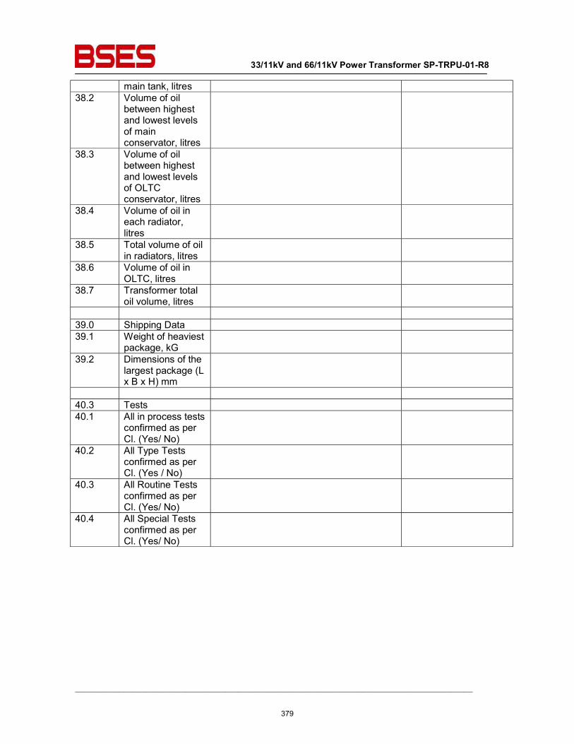
33/11kV and 66/11kV Power Transformer SP-TRPU-01-R8
__________________________________________________________________________________________
main tank, litres 38.2 Volume of oil
between highest and lowest levels of main conservator, litres
38.3 Volume of oil between highest and lowest levels of OLTC conservator, litres
38.4 Volume of oil in each radiator, litres
38.5 Total volume of oil in radiators, litres
38.6 Volume of oil in OLTC, litres
38.7 Transformer total oil volume, litres
39.0 Shipping Data 39.1 Weight of heaviest
package, kG
39.2 Dimensions of the largest package (L x B x H) mm
40.3 Tests 40.1 All in process tests
confirmed as per Cl. (Yes/ No)
40.2 All Type Tests confirmed as per Cl. (Yes / No)
40.3 All Routine Tests confirmed as per Cl. (Yes/ No)
40.4 All Special Tests confirmed as per Cl. (Yes/ No)
379
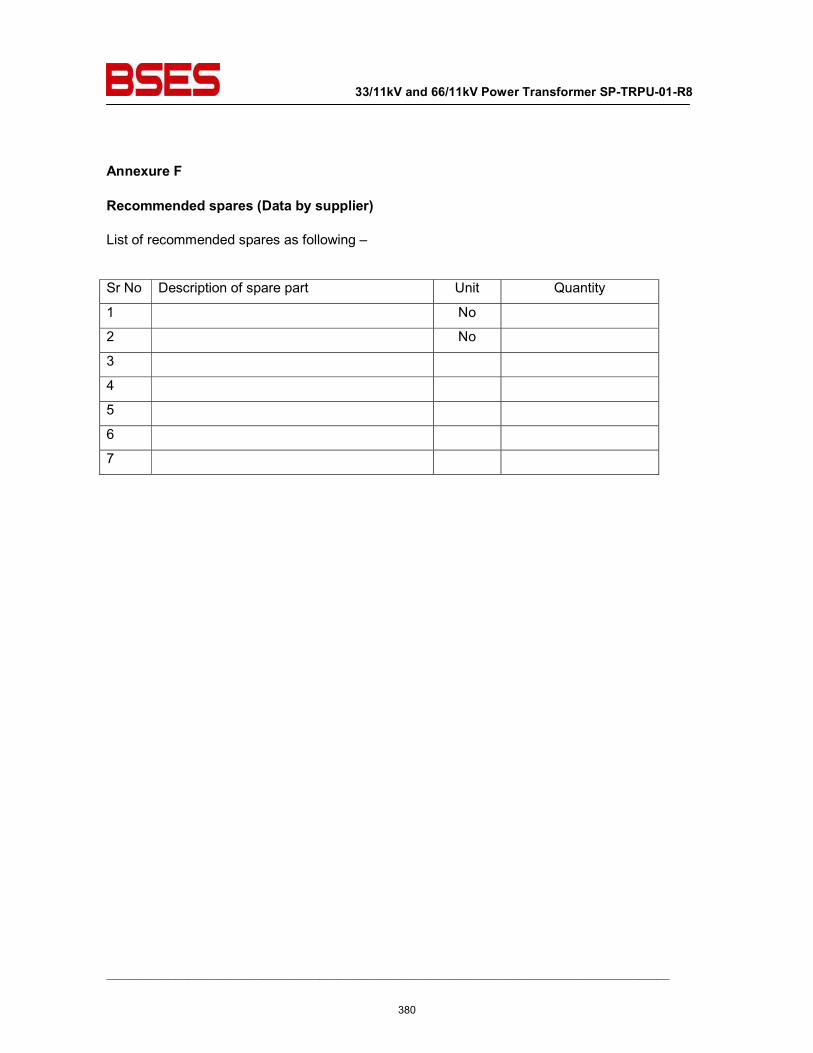
33/11kV and 66/11kV Power Transformer SP-TRPU-01-R8
__________________________________________________________________________________________
Annexure F
Recommended spares (Data by supplier)
List of recommended spares as following –
Sr No Description of spare part Unit Quantity
1 No
2 No
3
4
5
6
7
380
BSES Bhawan, Nehru Place, New Delhi- 19
Prepared by Rev: 0
Reviewed by Date:
Approved by
TECHNICAL SPECIFICATION
FOR
STRUCTURAL WORK
381
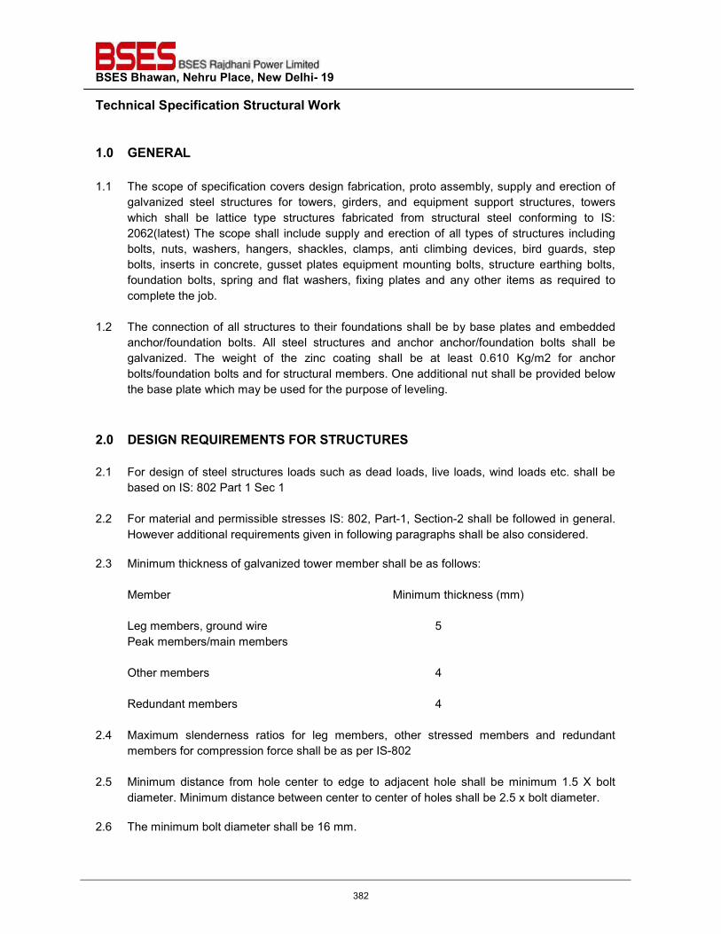
BSES Bhawan, Nehru Place, New Delhi- 19 Technical Specification Structural Work
1.0 GENERAL
1.1 The scope of specification covers design fabrication, proto assembly, supply and erection of galvanized steel structures for towers, girders, and equipment support structures, towers which shall be lattice type structures fabricated from structural steel conforming to IS: 2062(latest) The scope shall include supply and erection of all types of structures including bolts, nuts, washers, hangers, shackles, clamps, anti climbing devices, bird guards, step bolts, inserts in concrete, gusset plates equipment mounting bolts, structure earthing bolts, foundation bolts, spring and flat washers, fixing plates and any other items as required to complete the job.
1.2 The connection of all structures to their foundations shall be by base plates and embedded anchor/foundation bolts. All steel structures and anchor anchor/foundation bolts shall be galvanized. The weight of the zinc coating shall be at least 0.610 Kg/m2 for anchor bolts/foundation bolts and for structural members. One additional nut shall be provided below the base plate which may be used for the purpose of leveling.
2.0 DESIGN REQUIREMENTS FOR STRUCTURES 2.1 For design of steel structures loads such as dead loads, live loads, wind loads etc. shall be
based on IS: 802 Part 1 Sec 1
2.2 For material and permissible stresses IS: 802, Part-1, Section-2 shall be followed in general. However additional requirements given in following paragraphs shall be also considered.
2.3 Minimum thickness of galvanized tower member shall be as follows:
Member Minimum thickness (mm) Leg members, ground wire 5 Peak members/main members Other members 4 Redundant members 4
2.4 Maximum slenderness ratios for leg members, other stressed members and redundant members for compression force shall be as per IS-802
2.5 Minimum distance from hole center to edge to adjacent hole shall be minimum 1.5 X bolt diameter. Minimum distance between center to center of holes shall be 2.5 x bolt diameter.
2.6 The minimum bolt diameter shall be 16 mm.
382
BSES Bhawan, Nehru Place, New Delhi- 19 Technical Specification Structural Work
2.7 Step Bolts
In order to facilitate inspection and maintenance, the structures shall be provided with climbing devices. Each tower shall be provided with step bolts not less than 16mm diameter and 175mm long spaced not more than 450mm apart, staggered on faces on one leg extending from about 0.5M above ground level to the top of the tower. The step bolt shall conform to IS: 10238
2.8 Design Criteria a) All structures be designed for the worst combination of dead loads, live loads, wind loads
as per code IS 802 seismic forces as per code IS : 1893, importance factor of 1.5, loads due to deviation of conductor, load due to unbalanced tension in conductor, torsion load due to unbalanced vertical and horizontal forces, erection loads, short circuit forces shall be calculated considering a fault level of 31.5KA for 3 secs. IEC-865 may be followed for evaluation of short circuit forces.
b) Switchyard girders structure shall be designed for the two conditions i.e. normal condition and short circuit condition. In both conditions the design of all structures shall be based on the assumption that stringing is done only on one side i.e. all the three (phase) conductors broken on the other side. Factor of safety of 2.0 under normal conditions and 1.5 under short circuit condition shall be considered on all external loads for the design of switchyard structures, which are of lattice type.
c) Vertical load of half the span of conductors/string and the earth wires on either side of the
beam shall be taken into account for the purpose of design. Weight of man with tools shall be considered as 150KGs for the design of structures.
d) Terminal / line take off girders shall be designed for a minimum conductor tension of
1000Kg per sub conductor per phase for 66KV. The distance between terminal girders and the dead end tower shall be taken as per standard. The design of these terminal girders shall also be checked considering +/- 30 deg deviation of conductor in both vertical and horizontal planes. For other girders the structural layout requirements shall be adopted in design.
e) The girders shall be connected with lattice columns be bolted joints.
f) All support structures used for supporting equipments shall be designed for the worst
combination of dead loads, erection load. Wind load/seismic forces, short circuit forces. Short circuit forces shall be calculated considering a fault level of 31.5KA for 3 seconds.
g) Foundation bolts shall be designed for the loads for which the structures are designed
383
BSES Bhawan, Nehru Place, New Delhi- 19 Technical Specification Structural Work
3.0 DESIGN DRAWINGS, BILL OF MATERIAL & DOCUMENTS 3.1 The contractor shall furnish design, drawing and BOMs to the Owner after award of the
contract. However contractor shall have to prepare and submit any other drawings, bill of material additionally required during design and construction stage which the Owner feels necessary. In case Owner feels that any design drawing, BOM are to be modified even after its approval, contractor shall modify the design & drawings and resubmit the design drawing, BOM as required in the specification.
3.2 The fabrication drawings are to be provided and furnished by the contractor shall be based on design approved by Owner. These fabrication drawings shall be based on the design approved by the Owner. These fabrication drawings shall indicate complete details of fabrication and erection including all erection splicing details, lacing details, weld sizes and lengths. BOM in the Performa approved by the Owner shall be submitted. Bolt details and all customary details in accordance with standard structural engineering practice whether or not given by the Owner.
3.3 The fabrication work shall start only after the final approval to the design and drawings is
accorded by the Owner. The design drawing should indicate not only profile, but section, numbers and sizes of bolts and details of typical joints.
3.4 Such approval shall however not relieve the contractor his responsibility for the safety of the
structure and good connections and any loss or damage occurring due to defective fabrication design or workmanship shall be borne by the contractor.
4.0 FABRICATION OF STEEL MEMBERS 4.1 The fabrication and erection works shall be carried out generally in accordance with IS 802. A
reference however may be made to IS 800 in case of non-stipulation of some particular provision in IS 802. All materials shall be completely shop fabricated and finished with proper connection material and erection marks for ready assembly in the field.
5.0 PROTO – ASSEMBLY
5.1 The component parts shall be assembled in such a manner that are neither twisted not
otherwise damaged and shall be so prepared that the specific camber, if any, is provided. In order to minimize distortion in member the component parts shall be positioned by using the clamps, Clips, lugs, jigs and other suitable means and fasteners (bolts and weld) shall be placed in a balanced pattern. If the individual components are to be bolted, paralleled and tapered drifts shall be used to align the part so that the bolts can be accurately positioned.
5.2 Sample towers, beams and lightning masts and equipment structures shall be trial assembled in the fabrication shop and shall be inspected and cleared by contractor based on the design approval accorded by the Owner before mass fabrication.
384
BSES Bhawan, Nehru Place, New Delhi- 19 Technical Specification Structural Work
5.3 Pursuant to above the BOM’s along with proto-corrected fabrication drawing shall be
prepared and submitted by the main vendor to Owner as document for information. Such BOM, which shall be the basis for the Owner to carry out inspection.
6.0 BOLTING
6.1 Every bolt shall be provided with two flat and one spring washer under the nut so that no part of the threaded portion of the bolt is within the thickness of the parts bolted together. Locking nut shall be provided with each grouting bolt.
6.2 All steel items, bolts, nuts and washers shall be hot dip galvanized.
6.3 2.0% extra nuts and bolts shall be supplied for erection. 7.0 WELDING
7.1 The work shall be done as per approved fabrication drawings, which clearly indicate various
details of joints to be welded, type of weld, length and size of weld, whether shop or site weld etc. Symbols for welding on erection and shop drawings shall be according to IS 813. Efforts shall be made to reduce site welding so as to avoid improper joints due to constructional difficulties.
8.0 FOUNDATION BOLTS
8.1 Foundation bolts for the towers and equipment supporting structures and elsewhere shall be embedded in first stage concrete while the foundation is cast. The contractor shall ensure the proper alignment of these bolts to match the holes in the base plate.
8.2 The contractor shall be responsible for the correct alignment and leveling of all steel work on site to ensure that the towers/structures are plumb.
8.3 All foundation bolts for lattice structures are to be supplied by the contractor.
8.4 All foundation bolts shall be fully galvanized so as to achieve 0.610 kg. Per Sq.m. of Zinc
coating as per specifications.
8.5 All foundation bolts shall conform to IS 5624 but the material shall be MS conforming to IS 2062.
9.0 STABILITY OF STRUCTURES The method of grouting the column bases shall be subject to approval of Owner and shall be such as to ensure complete uniformity of contact over the whole area of the steel base. The contractor will be fully responsible for the grouting operations.
385
BSES Bhawan, Nehru Place, New Delhi- 19 Technical Specification Structural Work
10.0 GROUTING The method of grouting the column bases shall be subject to approval of Owner and shall be such as to ensure complete uniformity of contact over the whole area of the steel base. The contractor will be fully responsible for the grouting operations. 11.0 GALVANISING 11.1 All structural steel works and support shall be galvanized after fabrication.
11.2 Zinc required for galvanizing shall have to be arranged by the manufacturer. Purity of zinc to
be used shall be 99.95% as per IS 209.
11.3 The contractor shall be required to make arrangement for frequent inspection by the Owner as well as continuous inspection by a resident representative of the Owner, if so desired for fabrication work.
12.0 TOUCH UP PAINTING The touch up primers and paint shall consist of Zinc phosphate / Zinc chromate conforming to the requirements of IS 2074 with a pigment to be specified by the Owner. 13.0 INSPECTION BEFORE DESPATCH
13.1 Each part of the fabricated steel work shall be inspected as per approved quality plans and
certified by the Owner or his authorized representative as satisfactory before it is dispatched to the erection site.
13.2 Such certification shall not relieve the contractor of his responsibility regarding adequacy and completeness of fabrication.
14.0 TEST CERTIFICATE
Copies of all test certificates relating to material by the contractor for the works shall be forwarded to the Owner.
15.0 ERECTION
The contractor should arrange on his own all plant and equipment, welding set, tools and tackles, scaffolding, trestles equipments and all other accessories and ancillaries required for carrying out erection without causing any stresses in the members which may cause deformation and permanent damage.
386
BSES Bhawan, Nehru Place, New Delhi- 19 Technical Specification Structural Work
16.0 SAFETY & PRECAUTION
The contractor shall strictly follow at all fabrication, transportation and erection of steel structures, raw m, materials and other tools and tackles, the stipulations contained in Indian standard code for safety during erection of structural steel work.
17.0 DEVIATIONS Deviation from this specification, if any, shall be clearly brought out in the offer. Unless owner explicitly accepts such deviations, it shall be considered that the offer fully complies with the specification.
387
BSES Bhawan, Nehru Place, New Delhi- 19
Prepared by Hemanshi Rev: 0
Reviewed by Abhinav Srivastava Date: 2.11.2013
Approved by Vijay Panpalia
TECHNICAL SPECIFICATION
FOR
LIGHTNING ARRESTERS
388
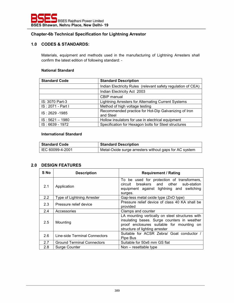
BSES Bhawan, Nehru Place, New Delhi- 19 Chapter-6b Technical Specification for Lightning Arrestor
1.0 CODES & STANDARDS: Materials, equipment and methods used in the manufacturing of Lightning Arresters shall confirm the latest edition of following standard: - National Standard Standard Code Standard Description Indian Electricity Rules (relevant safety regulation of CEA) Indian Electricity Act 2003 CBIP manual IS: 3070 Part-3 Lightning Arresters for Alternating Current Systems IS : 2071 - Part I Method of high voltage testing
IS : 2629 -1985 Recommended practice for Hot-Dip Galvanizing of Iron and Steel
IS : 5621 – 1980 Hollow insulators for use in electrical equipment IS : 6639 - 1972 Specification for Hexagon bolts for Steel structures International Standard Standard Code Standard Description IEC 60099-4-2001 Metal-Oxide surge arresters without gaps for AC system
2.0 DESIGN FEATURES S No Description Requirement / Rating
2.1 Application
To be used for protection of transformers, circuit breakers and other sub-station equipment against lightning and switching surges.
2.2 Type of Lightning Arrester Gap-less metal oxide type (ZnO type)
2.3 Pressure relief device Pressure relief device of class 40 KA shall be provided
2.4 Accessories Clamps and counter
2.5 Mounting
LA mounting vertically on steel structures with insulating bases. Surge counters in weather proof enclosures suitable for mounting on structure of lighting arrester
2.6 Line-side Terminal Connectors Suitable for ACSR Zebra/ Goat conductor / Pipe Bus
2.7 Ground Terminal Connectors Suitable for 50x6 mm GS flat 2.8 Surge Counter Non – resettable type
389
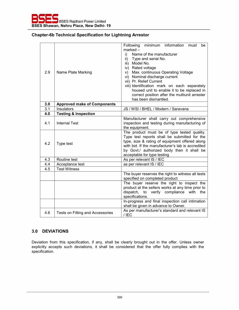
BSES Bhawan, Nehru Place, New Delhi- 19 Chapter-6b Technical Specification for Lightning Arrestor
2.9 Name Plate Marking
Following minimum information must be marked – i) Name of the manufacturer ii) Type and serial No. iii) Model No. iv) Rated voltage v) Max. continuous Operating Voltage vi) Nominal discharge current vii) Pr. Relief Current viii) Identification mark on each separately
housed unit to enable it to be replaced in correct position after the multiunit arrester has been dismantled.
3.0 Approved make of Components 3.1 Insulators JS / WSI / BHEL / Modern / Saravana 4.0 Testing & Inspection
4.1 Internal Test Manufacturer shall carry out comprehensive inspection and testing during manufacturing of the equipment.
4.2 Type test
The product must be of type tested quality. Type test reports shall be submitted for the type, size & rating of equipment offered along with bid. If the manufacturer’s lab is accredited by Govt./ authorized body then it shall be acceptable for type testing
4.3 Routine test As per relevant IS / IEC 4.4 Acceptance test as per relevant IS / IEC 4.5 Test Witness
The buyer reserves the right to witness all tests specified on completed product
The buyer reserve the right to inspect the product at the sellers works at any time prior to dispatch, to verify compliance with the specifications.
In-progress and final inspection call intimation shall be given in advance to Owner.
4.6 Tests on Fitting and Accessories As per manufacturer’s standard and relevant IS / IEC
3.0 DEVIATIONS Deviation from this specification, if any, shall be clearly brought out in the offer. Unless owner explicitly accepts such deviations, it shall be considered that the offer fully complies with the specification.
390
Specification for
Lighting High Mast
Specification no – GN101-03-SP-33-00
Prepared by Reviewed by Approved by Rev No. Date Name Sign Name Sign Name Sign
Hemanshi Abhinav Srivastav
a
Vijay Panpalia
00 04.01.2012
391
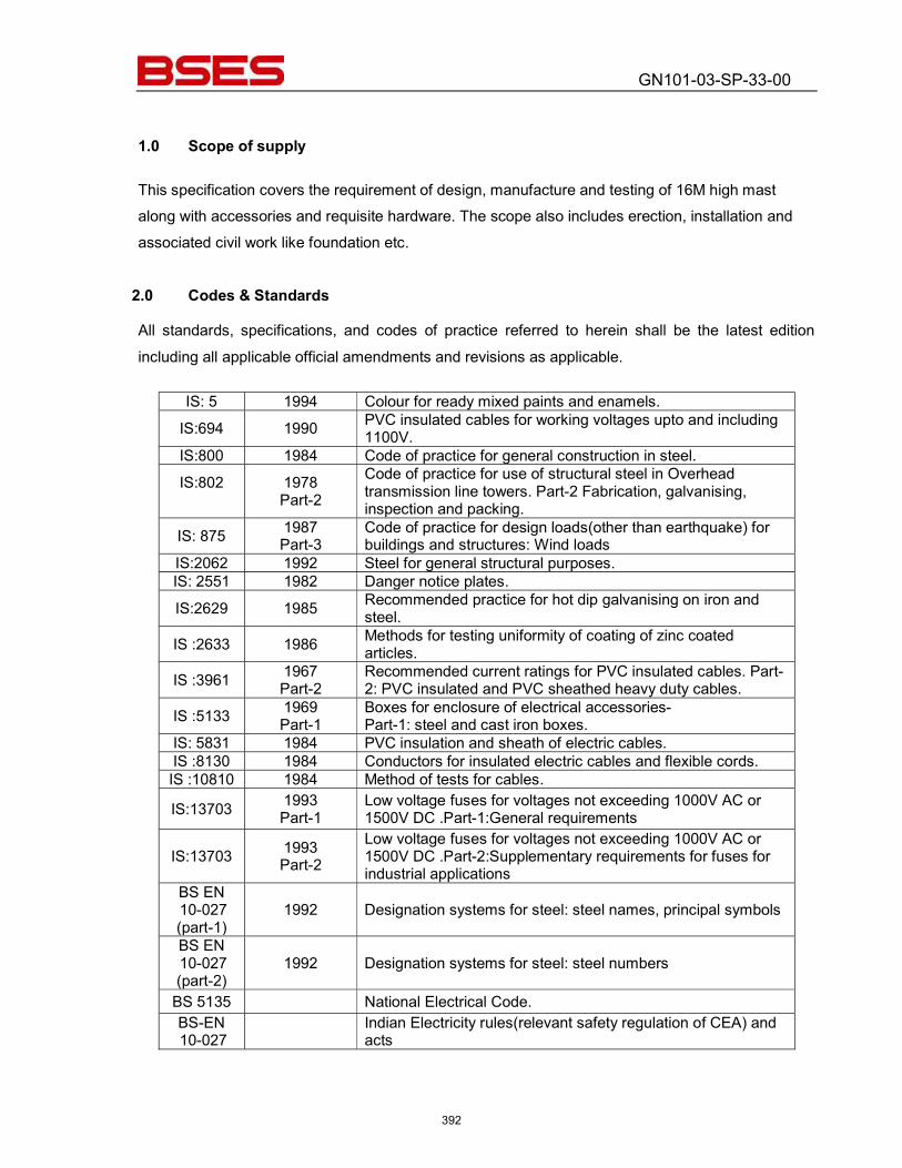
GN101-03-SP-33-00
1.0 Scope of supply
This specification covers the requirement of design, manufacture and testing of 16M high mast along with accessories and requisite hardware. The scope also includes erection, installation and associated civil work like foundation etc.
2.0 Codes & Standards All standards, specifications, and codes of practice referred to herein shall be the latest edition including all applicable official amendments and revisions as applicable.
IS: 5 1994 Colour for ready mixed paints and enamels. IS:694 1990 PVC insulated cables for working voltages upto and including
1100V. IS:800 1984 Code of practice for general construction in steel. IS:802
1978 Part-2
Code of practice for use of structural steel in Overhead transmission line towers. Part-2 Fabrication, galvanising, inspection and packing.
IS: 875 1987 Part-3
Code of practice for design loads(other than earthquake) for buildings and structures: Wind loads
IS:2062 1992 Steel for general structural purposes. IS: 2551 1982 Danger notice plates. IS:2629 1985 Recommended practice for hot dip galvanising on iron and
steel. IS :2633 1986 Methods for testing uniformity of coating of zinc coated
articles. IS :3961 1967
Part-2 Recommended current ratings for PVC insulated cables. Part-2: PVC insulated and PVC sheathed heavy duty cables.
IS :5133 1969 Part-1
Boxes for enclosure of electrical accessories- Part-1: steel and cast iron boxes.
IS: 5831 1984 PVC insulation and sheath of electric cables. IS :8130 1984 Conductors for insulated electric cables and flexible cords. IS :10810 1984 Method of tests for cables.
IS:13703 1993 Part-1
Low voltage fuses for voltages not exceeding 1000V AC or 1500V DC .Part-1:General requirements
IS:13703 1993 Part-2
Low voltage fuses for voltages not exceeding 1000V AC or 1500V DC .Part-2:Supplementary requirements for fuses for industrial applications
BS EN 10-027 (part-1)
1992 Designation systems for steel: steel names, principal symbols
BS EN 10-027 (part-2)
1992 Designation systems for steel: steel numbers
BS 5135 National Electrical Code. BS-EN 10-027 Indian Electricity rules(relevant safety regulation of CEA) and
acts
392
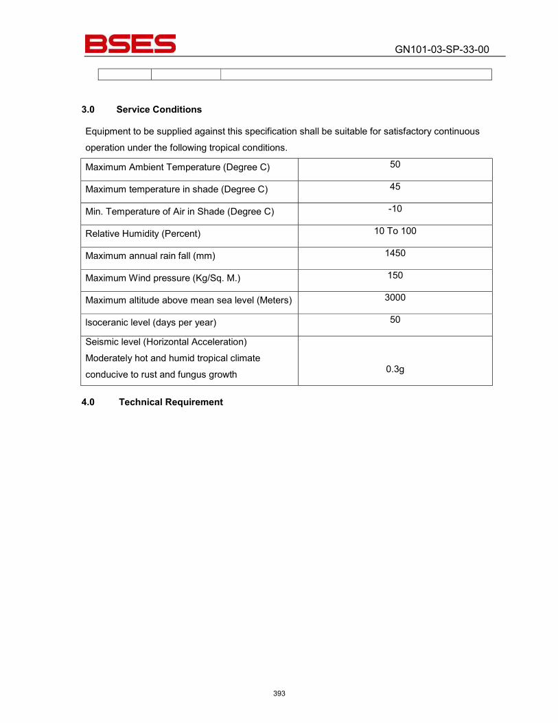
GN101-03-SP-33-00
3.0 Service Conditions Equipment to be supplied against this specification shall be suitable for satisfactory continuous operation under the following tropical conditions.
Maximum Ambient Temperature (Degree C) 50
Maximum temperature in shade (Degree C) 45
Min. Temperature of Air in Shade (Degree C) -10
Relative Humidity (Percent) 10 To 100
Maximum annual rain fall (mm) 1450
Maximum Wind pressure (Kg/Sq. M.) 150
Maximum altitude above mean sea level (Meters) 3000
lsoceranic level (days per year) 50
Seismic level (Horizontal Acceleration) Moderately hot and humid tropical climate conducive to rust and fungus growth 0.3g
4.0 Technical Requirement
393
GN101-03-SP-33-00
4.1. Structure The High mast shall be of continuously tapered, galvanised polygonal cross section, at least 20 sided, presenting a good and pleasing appearance, based on proven In-Tension design, conforming to the standards referred to above, to give an assured performance, and reliable service. The structure shall be suitable for wind loading as per IS - 875 Part -III, 1987.
4.2. Construction
The mast shall be fabricated from special steel plates, conforming to BS-EN10-027, cut and folded to form a polygonal section and telescopically jointed and welded. The welding shall be in accordance with BS-5135. The sections are joined together by slip-stressed-fit method. No site welding shall be done. Only bolted joint shall be done on the mast at the site. The minimum over lap distance shall be 1.5 times the diameter at penetration. The dimensions of the mast shall be decided based on proper design and accordingly design calculations shall be submitted for review / approval. The mast shall be provided with fully penetrated flange, free from any lamination or incursion. The welded connection of the base flange shall be fully developed to the strength of the entire section. The base flange shall be provided with supplementary gussets between the bolt holes to ensure elimination of helical stress concentration. The entire fabricated mast shall be hot dip galvanised both internally and externally.
4.3. Door Opening
An adequate door opening shall be provided at the base of the mast and the opening shall be such that it permits clear access to equipment like winches, cables, plug and socket, etc. and also facilitate easy removal of the winch. The door opening shall be complete with a close fitting, vandal resistant, weatherproof door, provided with a heavy-duty double internal lock with special paddle key.
4.4. Dynamic Loading for the Mast
The mast structure shall designed as per TR No-7 of Institutions of lightning engineers of UK and shall be suitable to sustain maximum reaction arising from a wind speed as per IS-875 (three second gust), and is measured at a height of 10 meters above ground level.
4.5. Lantern Carriage A fabricated Lantern Carriage shall be provided for fixing and holding the flood light fittings and control gear boxes. The lantern Carriage shall be of special design and shall be of steel tube construction, the tubes acting as conduits for wires, with holes fully protected by
394
GN101-03-SP-33-00
grommets. (The lantern carriage tube should not be used as conduit. Separate flexible conduits are used from CG Boxes to the Flood Light Fixtures) The Lantern Carriage shall be designed and fabricated to hold the required number of flood light fittings and the control gear boxes, and also have a perfect self balance. The Lantern Carriage shall be fabricated in two halves and joined by bolted flanges with stainless steel bolts and plastic lock type stainless steel nuts to enable easy installation or removal from the erected mast. The inner lining of the carriage shall be provided with protective PVC arrangement, so that no damage is caused to the surface of the mast during the raising and lowering operation of the carriage. The entire Lantern Carriage is hot dip galvanised after fabrication.
4.6. Junction Box The junction box shall be cast aluminium or SS, weather proof IP67 junction box. It shall be provided on the Carriage Assembly as required, from which the inter-connections to the designed number of the flood light luminaries and associated control gears fixed on the carriage, is made.
4.7. Raising and lowering mechanism It will be necessary to lower and raise the Lantern Carriage Assembly to install and maintain the luminaries and lamps. To enable this, a suitable Winch Arrangement shall be provided, with the winch fixed at the base of the mast and the specially designed head frame assembly at the top.
4.8. Winch The winch shall be of completely self-sustaining type, without the need for brake, shoe, springs or clutches. Each driving spindle of the winch is positively locked when not in use. Individual drum also should be operated for the fine adjustment of lantern carriage. The capacity, operating speed, safe working load, recommended lubrication and serial number of the winch shall be clearly marked on each winch. The gear ratio of the winch shall be 53 : 1 or as recommended by manufacturer. However, the minimum working load shall not be less than 750 kg. The winch shall be self-lubricating type by means of an oil bath and the oil shall be readily available grades of reputed manufacturers and details of the oil shall be furnished. The winch drums shall be grooved to ensure perfect seat for stable and tidy rope lay, with no chances of rope slippage. The rope termination in the winch shall be such that distortion or twisting is eliminated and at least 5 to 6 turns of rope remains on the drum even when the
395
GN101-03-SP-33-00
lantern carriage is fully lowered and rested on the rest pads. It should be possible to operate the winch manually by a suitable handle and/or by an external power tool. It would be possible to remove the double drum after dismantling, through the door opening provided at the base of the mast. Also, a winch gearbox for simultaneous and reversible operation of the double drum winch shall be provided as part of the contract. The winch shall be type tested in a reputed test lab/ Institution and the test certificates shall be furnished before supply of materials. Test certificate shall be furnished by the bidder from the original equipment manufacturer, for each winch in support of the maximum load operated by the winch.
4.9. Head Frame The head frame, which is to be designed, as a capping unit of the mast, shall be of welded steel construction, galvanised both internally and externally after assembly. The top pulley shall be of appropriate diameter, large enough to accommodate the stainless steel wire ropes and the multi-core electric cable. The pulley block shall be made of corrosion resistant material, and is of the cast Aluminium Alloy (LM-6) or SS. Pulley made of synthetic materials such as Plastic or PVC is not acceptable. Self-lubricating bearings and stainless steel shaft shall be provided to facilitate smooth and maintenance free operation for a long period. The pulley assembly shall be fully protected by a canopy galvanised internally and externally. Close fitting guides and sleeves shall be provided to ensure that the ropes and cables do not dislodge from their respective position in the grooves. The head frame shall be provided with guides and stops with PVC buffer for docking the lantern carriage.
4.10 Stainless Steel Wire Ropes
The suspension system shall essentially be without any intermediate joint and shall consist of only non-corrodable stainless steel of AISI - 316 or better grade. The stainless steel wire ropes shall be of 7/19 construction, the central core being of the same material. The overall diameter of the rope shall be more than 6 mm keeping in mind contingency. The breaking load of each rope shall not be less than 2350 kg. The design shall have a factor of safety over 5 for the system at full load. The end constructions of ropes to the winch drum shall be fitted with talurit. The thimbles are secured on ropes by compression splices. Two continuous lengths of stainless steel wire ropes are used in the system and no intermediate joints are acceptable in view of the required safety. No intermediate joints, either bolted or else, shall be provided on the wire ropes between winch and lantern carriage.
396
GN101-03-SP-33-00
4.11 Electrical System, Cable and Cable Connections
A suitable terminal box shall be provided as part of the supply at the base compartment of the high mast for terminating the incoming cable. The electrical connections from the bottom to the top shall be made by special trailing cable. The cable is EPR insulated and PCP sheathed to get flexibility and endurance. Size of the cable is minimum 5 core 2.5 sq mm copper, in case of failure of any core 2 spare cores shall be available. The cable shall be of reputed make. At the top necessary weatherproof junction box to terminate the trailing cable shall be provided. Connections from the top junction box to the individual luminaries is made by using 3 core 1.5 sq mm flexible PVC cables of reputed make. The system shall have in built facilities for testing the luminaries while in lowered position. Also, suitable provision shall be made at the base compartment of the mast to facilitate the operation of externally mounted, electrically operated power tool for raising and lowering of the lantern carriage assembly. The trailing cables of the lantern carriage rings shall be terminated by means of specially designed, metal clad, multi pin plug and socket provided in the base compartment to enable easy disconnection when required.
4.12 Power Tool for the Winch A suitable, high-powered, electrically driven, externally mounted power tool, with manual over ride, together with an operating stand shall be supplied for the raising and lowering of the lantern carriage for maintenance purposes. The speed of the power tool may preferably of slow speed, of 1.5 to 1.8 m/minute, so that vibrations associated with high speed operation are avoided. The power tool shall be single speed, provided with a motor of the required rating, suitable for hand/stand operation. The power tool shall be supplied complete with push button type remote control switch, together with 6 (six) meters of power cable, so that the operations can be carried out from a safe distance of 5 (five) meters. The capacity and speed of the electric motor used in the power tool shall be suitable for the lifting of the design load installed on the lantern carriage. The power tool stand shall be so designed that it will not only be self-supporting but also aligns the power tool perfectly with respect to the winch spindle during the operations. Also, a handle for the manual operation of the winches in case of problems with the electrically operated tool shall be provided and shall incorporate a torque-limiting device. A separate torque-limiting device to protect the wire ropes from over stretching shall be provided. It shall be mechanical with suitable load adjusting device. The torque limiter is a requirement as per the relevant standards in view of the overall safety of the system.
397
GN101-03-SP-33-00
4.13 Lightning Finial One number heavy-duty hot dip galvanised lightning finial shall be provided for each mast. The lightning finial shall be minimum 1.2 m in length and shall be provided at the centre of the head frame. It shall be bolted solidly to the head frame to get a direct conducting path to the earth through the mast. The lightning finial shall not be provided on the lantern carriage under any circumstances in view of safety of the system.
4.14 Aviation Obstruction Lights: Based on site and project specific requirements, 2 nos. Low Intensity Type-B (as per Table 6.3 of Volume-1, Annexure-14 of ICAO Guideline for Aerodrome Design & Operations) LED type aviation obstruction lights of reliable design and reputed manufacturer shall be provided on top of each mast.
4.15 Earthing Terminals:
Suitable earth terminal pad using twin 12 mm diameter stainless steel bolts shall be provided at a convenient location on the base of the Mast, for lighting and electrical earthing of the mast.
4.16 Luminaries:
The non-integral floodlight luminaries with LED Lamp shall be provided with each mast. Optical compartment of the luminary shall be IP 66 and control gear compartment shall be IP 54 or better. Bajaj, Crompton and Philips make luminaries are approved. Detailed technical brochure shall be provided along with the bid.
4.17 Feeder Pillar: Feeder pillar required for feeding power to the Lighting mast shall also be supplied along with the mast and its accessories. The feeder pillar is fed from the main switchgear / main lighting distribution board. The outgoings of this feeder pillar are connected to the MCBs in the mast. The feeder pillar shall be FLP or WP IP 54 with rain protection canopy in galvanised CRCA sheet or cast Aluminium body (for FLP) and finished with two coats of epoxy primer and grey enamel paint of shade 631 of IS-5. The feeder Pillar shall comprise of incoming 32 Amp TPN switch, HRC fuses, outgoing 25 Amp SP MCB, Time switch and contactor for automatic on & off of circuit with manual override, TP MCB for power tool contactors for reversing the motor and overload Protection of motor. Feeder pillar shall be mounted on suitable foundation near to the mast.
398
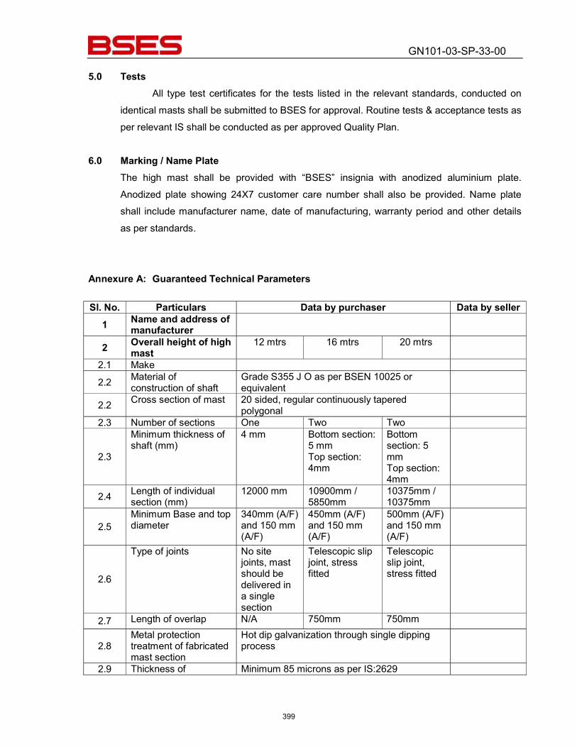
GN101-03-SP-33-00
5.0 Tests
All type test certificates for the tests listed in the relevant standards, conducted on identical masts shall be submitted to BSES for approval. Routine tests & acceptance tests as per relevant IS shall be conducted as per approved Quality Plan.
6.0 Marking / Name Plate
The high mast shall be provided with “BSES” insignia with anodized aluminium plate. Anodized plate showing 24X7 customer care number shall also be provided. Name plate shall include manufacturer name, date of manufacturing, warranty period and other details as per standards.
Annexure A: Guaranteed Technical Parameters
Sl. No. Particulars Data by purchaser Data by seller
1 Name and address of manufacturer
2 Overall height of high mast
12 mtrs 16 mtrs 20 mtrs
2.1 Make 2.2 Material of
construction of shaft Grade S355 J O as per BSEN 10025 or equivalent
2.2 Cross section of mast 20 sided, regular continuously tapered polygonal
2.3 Number of sections One Two Two
2.3
Minimum thickness of shaft (mm)
4 mm Bottom section: 5 mm Top section: 4mm
Bottom section: 5 mm Top section: 4mm
2.4 Length of individual section (mm)
12000 mm 10900mm / 5850mm
10375mm / 10375mm
2.5 Minimum Base and top diameter
340mm (A/F) and 150 mm (A/F)
450mm (A/F) and 150 mm (A/F)
500mm (A/F) and 150 mm (A/F)
2.6
Type of joints No site joints, mast should be delivered in a single section
Telescopic slip joint, stress fitted
Telescopic slip joint, stress fitted
2.7 Length of overlap N/A 750mm 750mm
2.8 Metal protection treatment of fabricated mast section
Hot dip galvanization through single dipping process
2.9 Thickness of Minimum 85 microns as per IS:2629
399
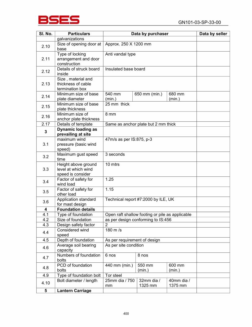
GN101-03-SP-33-00
Sl. No. Particulars Data by purchaser Data by seller galvanizations
2.10 Size of opening door at base
Approx. 250 X 1200 mm
2.11 Type of locking arrangement and door construction
Anti vandal type
2.12 Details of struck board inside
Insulated base board
2.13 Size , material and thickness of cable termination box
2.14 Minimum size of base plate diameter
540 mm (min.)
650 mm (min.) 680 mm (min.)
2.15 Minimum size of base plate thickness
25 mm thick
2.16 Minimum size of anchor plate thickness
8 mm
2.17 Details of template Same as anchor plate but 2 mm thick 3 Dynamic loading as
prevailing at site
3.1 maximum wind pressure (basic wind speed)
47m/s as per IS:875, p-3
3.2 Maximum gust speed time
3 seconds
3.3 Height above ground level at which wind speed is consider
10 mtrs
3.4 Factor of safety for wind load
1.25
3.5 Factor of safety for other load
1.15
3.6 Application standard for mast design
Technical report #7:2000 by ILE, UK
4 Foundation details 4.1 Type of foundation Open raft shallow footing or pile as applicable 4.2 Size of foundation as per design conforming to IS:456 4.3 Design safety factor 2 4.4 Considered wind
speed 180 m /s
4.5 Depth of foundation As per requirement of design 4.6 Average soil bearing
capacity As per site condition
4.7 Numbers of foundation bolts
6 nos 8 nos
4.8 PCD of foundation bolts
440 mm (min.) 550 mm (min.)
600 mm (min.)
4.9 Type of foundation bolt Tor steel 4.10 Bolt diameter / length 25mm dia / 750
mm 32mm dia / 1325 mm
40mm dia / 1375 mm
5 Lantern Carriage
400
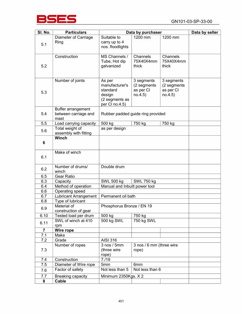
GN101-03-SP-33-00
Sl. No. Particulars Data by purchaser Data by seller
5.1 Diameter of Carriage Ring
Suitable to carry up to 4 nos. floodlights
1200 mm 1200 mm
5.2
Construction MS Channels / Tube, Hot dip galvanized
Channels 75X40X4mm thick
Channels 75X40X4mm thick
5.3
Number of joints As per manufacturer's standard design (2 segments as per Cl no.4.5)
3 segments (2 segments as per Cl no.4.5)
3 segments (2 segments as per Cl no.4.5)
5.4 Buffer arrangement between carriage and mast
Rubber padded guide ring provided
5.5 Load carrying capacity 500 kg 750 kg 750 kg 5.6 Total weight of
assembly with fitting as per design
6 Winch
6.1 Make of winch
6.2 Number of drums/ winch
Double drum
6.5 Gear Ratio 6.3 Capacity SWL 500 kg SWL 750 kg 6.4 Method of operation Manual and Inbuilt power tool 6.6 Operating speed 6.7 Lubricant Arrangement Permanent oil bath 6.8 Type of lubricant 6.9 Material of
construction of gear Phosphorus Bronze / EN 19
6.10 Tested load per drum 500 kg 750 kg 6.11 SWL of winch at 410
rpm 500 kg SWL 750 kg SWL
7 Wire rope 7.1 Make 7.2 Grade AISI 316
7.3 Number of ropes 3 nos / 5mm
(three wire rope)
3 nos / 6 mm (three wire rope)
7.4 Construction 7./19 7.5 Diameter of Wire rope 5mm 6mm 7.6 Factor of safety Not less than 5 Not less than 6 7.7 Breaking capacity Minimum 2350Kgs. X 2 8 Cable
401
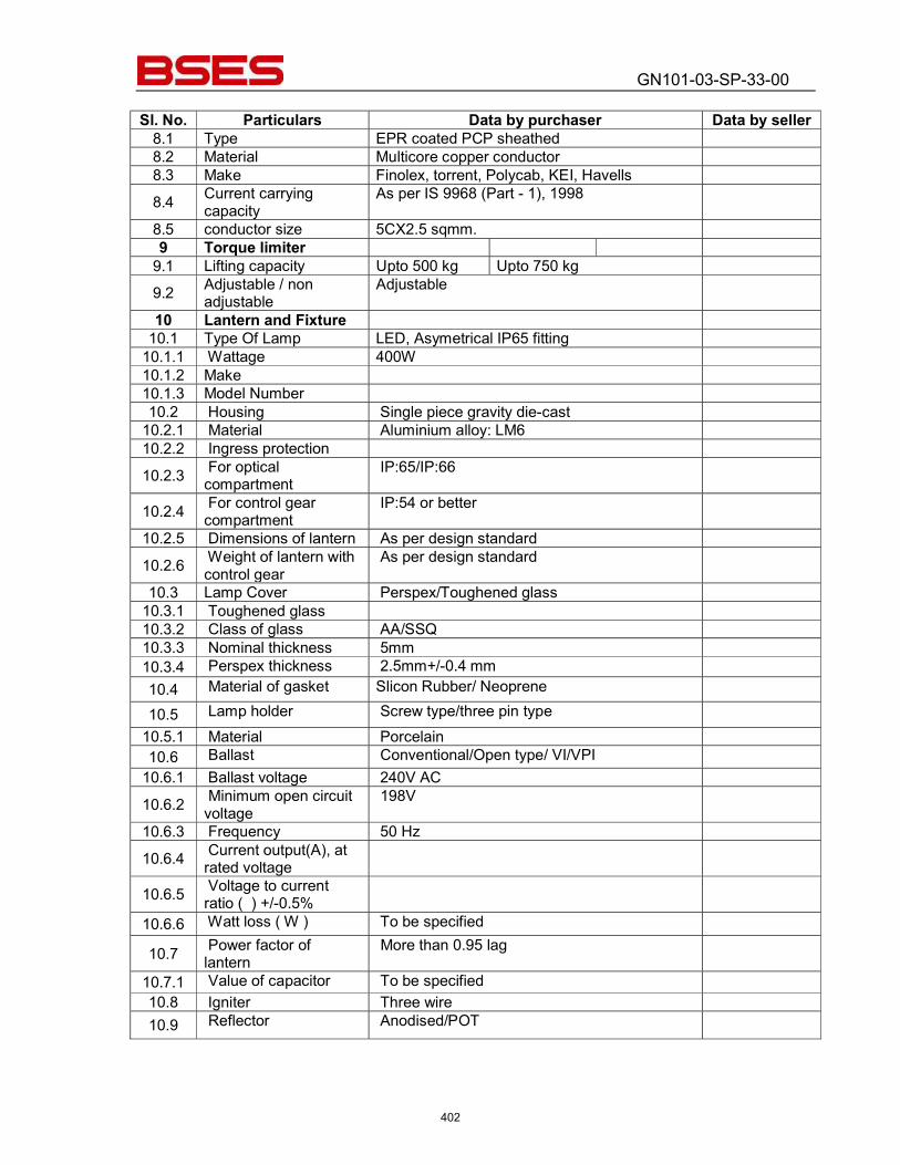
GN101-03-SP-33-00
Sl. No. Particulars Data by purchaser Data by seller 8.1 Type EPR coated PCP sheathed 8.2 Material Multicore copper conductor 8.3 Make Finolex, torrent, Polycab, KEI, Havells 8.4 Current carrying
capacity As per IS 9968 (Part - 1), 1998
8.5 conductor size 5CX2.5 sqmm. 9 Torque limiter
9.1 Lifting capacity Upto 500 kg Upto 750 kg 9.2 Adjustable / non
adjustable Adjustable
10 Lantern and Fixture 10.1 Type Of Lamp LED, Asymetrical IP65 fitting
10.1.1 Wattage 400W 10.1.2 Make 10.1.3 Model Number 10.2 Housing Single piece gravity die-cast
10.2.1 Material Aluminium alloy: LM6 10.2.2 Ingress protection 10.2.3 For optical
compartment IP:65/IP:66
10.2.4 For control gear compartment
IP:54 or better
10.2.5 Dimensions of lantern As per design standard 10.2.6 Weight of lantern with
control gear As per design standard
10.3 Lamp Cover Perspex/Toughened glass 10.3.1 Toughened glass 10.3.2 Class of glass AA/SSQ 10.3.3 Nominal thickness 5mm 10.3.4 Perspex thickness 2.5mm+/-0.4 mm 10.4 Material of gasket Slicon Rubber/ Neoprene
10.5 Lamp holder Screw type/three pin type 10.5.1 Material Porcelain 10.6 Ballast Conventional/Open type/ VI/VPI
10.6.1 Ballast voltage 240V AC 10.6.2 Minimum open circuit
voltage 198V
10.6.3 Frequency 50 Hz 10.6.4 Current output(A), at
rated voltage
10.6.5 Voltage to current ratio ( ) +/-0.5%
10.6.6 Watt loss ( W ) To be specified
10.7 Power factor of lantern
More than 0.95 lag
10.7.1 Value of capacitor To be specified 10.8 Igniter Three wire 10.9 Reflector Anodised/POT
402
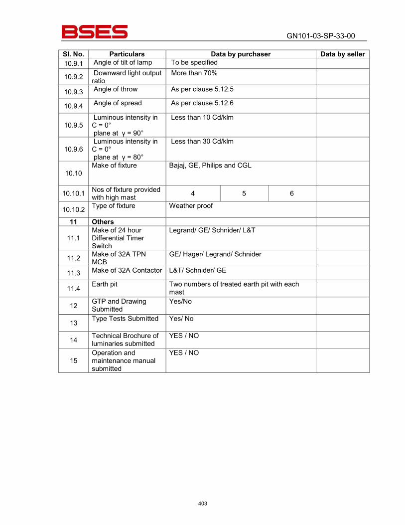
GN101-03-SP-33-00
Sl. No. Particulars Data by purchaser Data by seller 10.9.1 Angle of tilt of lamp To be specified
10.9.2 Downward light output ratio
More than 70%
10.9.3 Angle of throw As per clause 5.12.5
10.9.4 Angle of spread As per clause 5.12.6
10.9.5 Luminous intensity in C = 0° plane at γ = 90°
Less than 10 Cd/klm
10.9.6 Luminous intensity in C = 0° plane at γ = 80°
Less than 30 Cd/klm
10.10 Make of fixture Bajaj, GE, Philips and CGL
10.10.1 Nos of fixture provided with high mast 4 5 6
10.10.2 Type of fixture Weather proof
11 Others
11.1 Make of 24 hour Differential Timer Switch
Legrand/ GE/ Schnider/ L&T
11.2 Make of 32A TPN MCB
GE/ Hager/ Legrand/ Schnider
11.3 Make of 32A Contactor L&T/ Schnider/ GE
11.4 Earth pit Two numbers of treated earth pit with each mast
12 GTP and Drawing Submitted
Yes/No
13 Type Tests Submitted Yes/ No
14 Technical Brochure of luminaries submitted
YES / NO
15 Operation and maintenance manual submitted
YES / NO
403
BSES Bhawan, Nehru Place, New Delhi- 19
Prepared by Rev: 1
Reviewed by Date:
Approved by
TECHNICAL SPECIFICATION
FOR
OUTDOOR SWITCHYARD MATERIAL
404

BSES Bhawan, Nehru Place, New Delhi- 19 Technical Specification Outdoor Switchyard Material
1.0 INTENT OF SPECIFICATION
1.1 This specification is intended to cover the design, manufacture, assembly, testing at manufacturer’s works, supply & delivery, properly packed for transport F.O.R site of 66KV Outdoor Switchyard Material and Hardware complete with all accessories for efficient and trouble free operation.
1.2 In the event of any discrepancy between listed documents, the stipulation of this specification shall govern.
1.3 The specification shall be read and constructed in conjunction with other sections of bidding
document.
2.0 SCOPE OF WORK
2.1 Scope of Supply
Type, rating, connections etc. of the materials shall be as detailed in the drawings and annexure. The materials shall be furnished in strict compliance with the same.
2.2 Following materials and hardware’s are to be furnished: a) ACSR ZEBRA Conductor b) Disc Insulator & Post Insulators c) Conductor Spacers, Clamps, Connectors. Any material or accessory, which may not have been specifically mentioned but which is usual and / or necessary shall be supplied free of cost to the Owner. PG Clamps for ACSR Conductors shall not be acceptable. However, C-Wedge Connector can be offered in place of PG Clamp.
3.0 GENERAL REQUIREMENTS 3.1 Codes and Standards
i) All equipment and materials shall be designed, manufactured and tested in
accordance with the latest applicable Indian Standards (IS) & IEC Standard except where modified and / or supplemented by this specification.
ii) Equipment and material conforming to any other standard, which ensures equal or
better quality, may be accepted. In such cases, copies of the English version of the standard adopted shall be submitted along with the bid.
405
BSES Bhawan, Nehru Place, New Delhi- 19 Technical Specification Outdoor Switchyard Material
iii) The electrical installation shall meet the requirements of Indian Electricity Rules as amended upto date and relevant IS Codes of Practice. In addition other rules or regulations applicable to the work followed. In case of any discrepancy, the more restrictive rule shall be binding.
4.0 DESIGN CRITERIA 4.1 All the ACSR conductors, disc and string insulators, clamps & connectors, hardware’s etc.
will be used in extra high voltage system having characteristics as listed in the annexure.
4.2 All equipments, conductors, hardware’s, insulators & clamps etc. will be installed outdoor in a hot, humid & tropical atmosphere.
4.3 The maximum temperature in any part of the clamps, connectors, conductors etc at specified
rating shall not exceed the permissible limit as stipulated in the relevant standards.
4.4 All equipments, conductors, clamps, connectors, insulators etc shall be capable of withstanding the dynamic & thermal stresses of maximum short circuit current without any damages or deterioration.
4.5 In order to avoid concentration of stresses, all sharp edges of clamps, connectors etc. shall
be rounded off.
4.6 Bi-metallic connectors shall be used for any connection between dissimilar materials.
5.0 SPECIFIC REQUIREMENT 5.1 Equipment & Materials
i) Equipment & material shall comply with description, rating etc. as detailed in this
specification and annexure. ii) All accessories, fittings, supports, bolts etc. which form part of the equipment or
which are necessary for safe and satisfactory installation and operation of the equipment shall be furnished.
iii) All parts shall be made accurately to standard gauges so as to facilitate replacement and repair. All corresponding parts of similar equipment shall be interchangeable.
iv) After the treatment of steel surfaces damaged during transit sufficient quantity of anti-corrosive paint shall be applied and subsequently finished with two coats of final paint of approved shade.
406
BSES Bhawan, Nehru Place, New Delhi- 19 Technical Specification Outdoor Switchyard Material
5.2 ACSR Conductor i) The Aluminum Standard conductor and steel reinforced shall have the technical
parameters matching with the requirements given in Annexure. ACSR conductors shall conform to the latest revision of IS-398.
ii) The material for ACSR conductor shall conform to the following: Aluminum The Aluminum strands shall be hard drawn from electrolytic Aluminium rods having purity not less than 99.5% and a copper content not exceeding 0.04%. Steel The steel wire strands shall be drawn from high carbon steel wire rods and shall conform to the following chemical composition: Element -% Composition Carbon - 0.50 to 0.85 Manganese - 0.50 to 1.10 Phosphorous -not more than 0.035 Sulphur -not more than 0.045 Silicon - 0.10 to 0.35 Zinc The zinc used for galvanizing shall be electrolytic High Grade Zinc of 99.95% purity. It shall conform to and satisfy all the requirements of IS: 209-1979.
5.3 Clamps and connectors i) All clamps, connectors and hardware’s shall be designed manufactured and tested
as per relevant standards.
ii) All clamps & connectors for connection with ACSR conductors shall have high tensile Aluminum alloy grade A6 body. U- Bolt and nut for the clamp shall be made of non-magnetic material e.g. chromium steel.
iii) Bolt, nut, washer, shackle etc. required for other purpose shall be of forged steel with
adequate strength and the surface shall be so protected as to offer maximum resistance to corrosion. Malleable iron wherever used for any part shall be of best quality and shall correspond to latest amendments of relevant IS.
iv) Various fittings & accessories of the clamps & connectors shall be so designed as to
eliminate sharp edges & maintain bright smooth surface. All bolts, nuts, rivets etc. shall have round profiles.
5.4 Disc Insulator
i) All disc insulators shall be dimensioned appropriately so as to have the required
Electro- Mechanical strength for EHV outdoor duties.
407
BSES Bhawan, Nehru Place, New Delhi- 19 Technical Specification Outdoor Switchyard Material
ii) Suspension and tension insulators shall be wet process porcelain with ball and
socket connection. Glazing of the porcelain shall be uniform brown colour, free from blisters, burrs and other similar defects. Insulators shall be interchangeable and shall be suitable for forming either suspension or strain strings. Each insulator shall have rated strength markings on porcelain printed and applied before firing.
iii) When operating at normal rated voltage there shall be no electric discharge between
conductor and insulator which would cause corrosion or injury to conductors or insulators by the formation of substances due to chemical action. No radio interference shall be caused when operating at normal rated voltage.
iv) Insulating shall be co-ordinated with basis impulse level of the system. The creepage
distance shall correspond to very heavily polluted atmosphere (31mm/KV)
v) Porcelain used in insulator manufacture shall be homogeneous, free from lamination, cavities and other flaws or imperfection that might affect the mechanical or dielectric quality and shall be thoroughly vitrified, tough and impervious to moisture.
vi) The design of the insulator shall be such that stresses due to expansion and
contraction in any part of the insulator shall not lead to deterioration. All ferrous parts shall be hot dip galvanized in accordance with the latest edition of IS: 209. The zinc coating shall be uniform, adherent, smooth, reasonably bright, continuous and free from imperfection such as flux, ash, rust stains bulky white deposits and blisters.
vii) Bidder shall make available data on the essential features of design including the
method of assembly of discs and metal parts, number of discs per insulators, the manner in which mechanical stresses are transmitted through discs to adjacent parts, provision for meeting expansion stresses, results of corona and thermal shock tests, recommended working strength and any special design or arrangement employed to increase life under service conditions.
viii) Insulator hardware shall be of forged steel. Malleable cast iron shall not be accepted
except for insulator disc cap. The surface of hardware must be clean, smooth, without cuts, abrasion or projections. No part shall be subjected to excessive localized pressure. The metal parts shall not produce any noise generating corona under operating conditions.
ix) The insulator hardware assembly and clamps shall be designed for 120KN Tensile
load. The clamps shall be designed for 700 Kg tensile load. Earth wire tension clamp shall be designed for 1000 Kg tensile load with a factor of safety of two (2).
x) The tension string assemblies shall be supplied along with suitable turn buckle.
408
BSES Bhawan, Nehru Place, New Delhi- 19 Technical Specification Outdoor Switchyard Material
6.0 TESTS
6.1 Routine Tests
i) During manufacture and on completion of all equipment, conductors, insulators,
clamps, connectors and accessories shall be routine tested as per applicable standards at manufacture’s works.
ii) The suspension and tension strings, insulator discs and hardware shall be subjected
to the following, acceptance tests and routine tests:
a) Visual examination b) Verification of Dimensions as per Cl no. 10.5 of IS: 731 c) Temperature cycle test as per Cl no. 10.6 of IS: 731 d) Puncture test as per Cl no. 10.10 of IS: 731 e) Galvanizing test as per Cl no. 10.12 of IS: 731 f) Mechanical performance test as per IEC-575 Cl. 4 g) Test on locking device for ball & socket coupling as per IEC-372 (2) h) Porosity test as per Cl no. 10.11 of IS: 731
Acceptance Tests
a) Visual examination as per CI. 5.10 Of IS: 2468 (Part-1) b) Verification of Dimensions as per CI. 5.8 Of IS: 2468 (Part-1) c) Galvanizing / Electroplating test as per CI. 5.9 Of IS: 2468 (Part-1) d) Slip strength test as per CI. 5.4 Of IS: 2468 (Part-1) e) Shore hardness test for the Elastomer (if applicable as per the value guaranteed
by the Bidder) f) Mechanical strength test for each component (including grading rings and arcing
horns). g) Test on locking devices for ball and socket coupling as per IEC: 372 (2)
Routine Tests on Disc Insulator / Long rod Insulator
a) Visual Inspection as per CI No. 10.13 of IS: 731 b) Mechanical Routine Test as per CI No. 10.14 of IS: 731 c) Electrical Routine Test as per CI No. 10.15 of IS: 731
Routine Tests on Hardware Fittings
a) Visual examination as per CI. 5.10 Of IS: 2468 (Part-1) b) Mechanical strength Test as per CI. 5.11 Of IS: 2468 (Part-1)
Test during manufacture on all components as applicable on Disc Insulator
409
BSES Bhawan, Nehru Place, New Delhi- 19 Technical Specification Outdoor Switchyard Material
a) Chemical analysis of zinc used for galvanizing: Samples taken from the zinc ingot shall be chemically analyzed as per IS: 209. The purity of zinc shall not be less than 99.95%. b) Chemical analysis, mechanical hardness tests and magnetic particle inspection
for malleable casting:
The chemical analysis, hardness tests and magnetic particle inspection for malleable casting will be as per the internationally recognized procedure for these tests. The sampling will be based on heat number and heat treatment batch
Test during manufacture on all components as applicable on hardware fittings
a) Chemical analysis of zinc used for galvanizing Samples taken from the zinc ingot shall be chemically analyzed as per IS: 209. The purity of zinc shall not be less than 99.95%. b) Chemical analysis, mechanical hardness tests and magnetic particle inspection
for malleable casting:
The chemical analysis, hardness tests and magnetic particle inspection for malleable casting will be as per the internationally recognized procedure for these tests. The sampling will be based on heat number and heat treatment batch c) Chemical analysis, mechanical hardness tests and magnetic particle inspection
for fabricated hardware.
The chemical analysis, hardness tests and magnetic particle inspection for fabricated hardware will be as per the internationally recognized procedure for these tests. The sampling will be based on heat number and heat treatment batch.
iii) The following, acceptance & routine tests and tests during manufacturing shall be carried out on the conductor.
Acceptance Tests a) Visual check for joints, scratches etc. and
length of conductor
b) Dimensional check on steel and Aluminum strands
c) Check for lay ratio of various layers d) Galvanizing test on steel strands
410
BSES Bhawan, Nehru Place, New Delhi- 19 Technical Specification Outdoor Switchyard Material
e) Torsion and Elongation test on steel strands
f) Breaking load test on steel and Aluminum strands
g) Wrap test on steel and Aluminum strands IS: 398(Part-V) 1982 Clauses 12.5.2, 12.7 & 12.8
h) DC resistance test on Aluminum strands
i) UTS test on welded joint of Aluminum strands
NOTE: All the above tests except test mentioned at (i) shall be carried out on Aluminum and steel strands after stranding only Routine Tests
a) Check to ensure that the joints are as per specification b) Check that there are no cuts, fins etc. on the strands
iv) The following type, routine & acceptance tests and tests during manufacturing shall
be carried out on the earth wire.
Acceptance Tests
a) Visual check for joints, scratches etc. and length of Earth wire b) Dimensional check c) Galvanizing test d) Lay length check e) Torsion test f) Elongation test g) Wrap test h) DC resistance test : IS: 398 (Part lll) 1976 i) Breaking load test j) Chemical Analysis of steel
Routine Tests
a) Check that there are no cuts, fins etc. on the strands. b) Check for correctness of stranding
411
BSES Bhawan, Nehru Place, New Delhi- 19 Technical Specification Outdoor Switchyard Material
6.2 Type Test
Test certificates for type tests shall be from CPRI/ERDA/NABL approved lab, as stipulated in Indian Standards carried out on similar equipment shall be furnished. If test certificate for any of the type test is not available, the same shall be carried out free of cost from CPRI/ERDA/NABL.
6.3 Test Witness Tests shall be performed in presence of Owner’s representative if so desired by the Owner. The contractor shall give at least fifteen (15) days advance notice of the date when the tests are to be carried out.
6.4 Test Certificates
i) Certified copies of all tests carried out at works shall be furnished in requisite no. of
copies as stated in the condition of contract for approval of the Owner. The certificates shall furnish complete identification, date including serial number of each material and accessory.
ii) Equipment shall be dispatched from works only after receipt of Owner’s written approval of shop test reports.
iii) Type test certificate on any equipment, if so desired by the Owner, shall be furnished.
Otherwise, the equipment shall have to be type tested, free of charge, to prove the design.
7.0 SPARES The Bidder shall submit a list of recommended spare parts for three (3) years of satisfactory and trouble free operation, indicating itemized price of each item of the spares.
412
BSES Bhawan, Nehru Place, New Delhi- 19 Technical Specification Outdoor Switchyard Material
8.0 DRAWING & DOCUMENTS TO BE FURNISHED
8.1 To be submitted with each copy of the Bid i) Typical general arrangement drawing of the equipment / items. ii) Technical leaflets on equipment / items expending constructional features. iii) Type test certificates on similar equipment / items.
8.2 To be submitted for Approval and Distribution
i) Dimensional general arrangement drawing showing disposition of various fittings for
equipment, accessories, components etc. ii) Assembly drawing for erection at site with part numbers and schedule of materials. iii) Type & Routine test certificates iv) Technical leaflets on equipment / items v) Back-up calculation for:
a) Selection of equipment / material ratings. b) Sag-Tension of ACSR. c) Lighting protection system d) Selection of rigid bus support spacing.
vi) Any other relevant drawing, documents, calculations and data necessary for
satisfactory installation, operation and maintenance.
9.0 DEVIATIONS Deviation from this specification, if any, shall be clearly brought out in the offer. Unless owner explicitly accepts such deviations, it shall be considered that the offer fully complies with the specification.
413
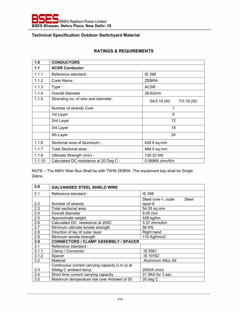
BSES Bhawan, Nehru Place, New Delhi- 19 Technical Specification Outdoor Switchyard Material
RATINGS & REQUIREMENTS
1.0 CONDUCTORS 1.1 ACSR Conductor 1.1.1 Reference standard : IS 398 1.1.2 Code Name : ZEBRA 1.1.3 Type : ACSR 1.1.4 Overall diameter 28.62mm 1.1.5 Stranding no. of wire and diameter : 54/3.18 (Al) 7/3.18 (St)
Number of strands Core 1 1st Layer 6 2nd Layer 12
3rd Layer 18
4th Layer 24
1.1.6 Sectional area of Aluminum : 428.9 sq.mm 1.1.7 Total Sectional area : 484.5 sq.mm 1.1.9 Ultimate Strength (min) : 130.32 KN 1.1.10 Calculated DC resistance at 20 Deg C : 0.06868 ohm/Km
NOTE – The 66KV Main Bus Shall be with TWIN ZEBRA. The equipment bay shall be Single Zebra.
2.0 GALVANISED STEEL SHIELD WIRE 2.1 Reference standard : IS 398
2.2. Number of strands Steel core-1, outer Steel layer-6
2.3 Total sectional area 54.55 sq.mm 2.4 Overall diameter 9.45 mm 2.5 Approximate weight 428 kg/km 2.6 Calculated DC. resistance at 200C 3.37 ohms/km 2.7 Minimum ultimate tensile strength 56 KN 2.8 Direction of lay of outer layer Right hand 2.9 Minimum tensile strength 110 Kgf/mm2 3.0 CONNECTORS / CLAMP ASSEMBLY / SPACER 3.1 Reference standard : 3.1.1 Clamp / Connector IS 5561 3.1.2 Spacer IS 10162 3.2 Material Aluminum Alloy A6
3.3 Continuous current carrying capacity (r.m.s) at 50deg C ambient temp. 2000A (min)
3.4 Short time current carrying capacity 31.5KA for 3 sec 3.5 Maximum temperature rise over Ambient of 50 35 deg C
414
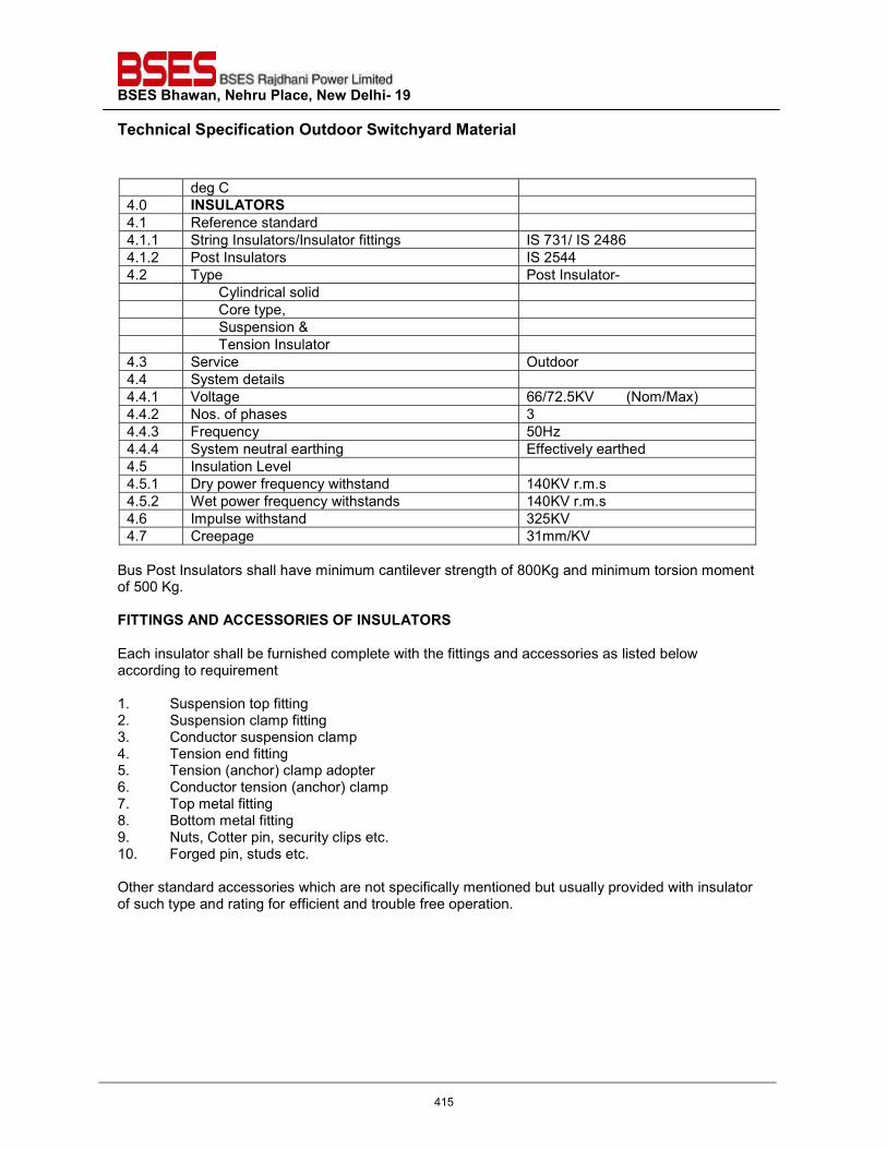
BSES Bhawan, Nehru Place, New Delhi- 19 Technical Specification Outdoor Switchyard Material
deg C 4.0 INSULATORS 4.1 Reference standard 4.1.1 String Insulators/Insulator fittings IS 731/ IS 2486 4.1.2 Post Insulators IS 2544 4.2 Type Post Insulator- Cylindrical solid Core type, Suspension & Tension Insulator 4.3 Service Outdoor 4.4 System details 4.4.1 Voltage 66/72.5KV (Nom/Max) 4.4.2 Nos. of phases 3 4.4.3 Frequency 50Hz 4.4.4 System neutral earthing Effectively earthed 4.5 Insulation Level 4.5.1 Dry power frequency withstand 140KV r.m.s 4.5.2 Wet power frequency withstands 140KV r.m.s 4.6 Impulse withstand 325KV 4.7 Creepage 31mm/KV
Bus Post Insulators shall have minimum cantilever strength of 800Kg and minimum torsion moment of 500 Kg. FITTINGS AND ACCESSORIES OF INSULATORS Each insulator shall be furnished complete with the fittings and accessories as listed below according to requirement 1. Suspension top fitting 2. Suspension clamp fitting 3. Conductor suspension clamp 4. Tension end fitting 5. Tension (anchor) clamp adopter 6. Conductor tension (anchor) clamp 7. Top metal fitting 8. Bottom metal fitting 9. Nuts, Cotter pin, security clips etc. 10. Forged pin, studs etc.
Other standard accessories which are not specifically mentioned but usually provided with insulator of such type and rating for efficient and trouble free operation.
415
TECHNICAL SPECIFICATION OF IT DEVICES FOR GRID COMMUNICATION
DOCUMENT NO.: BRPL-IT-SCADA-0001
Rev.: 00
BSES RAJDHANI POWER LIMITED
BSES Bhawan, Nehru Place, New Delhi - 1100049
416
Technical Specification of IT devices for Grid
communication-
BRPL-IT-SCADA-0001, Rev. 00 Technical Specification Page 2 of 8
DOCUMENT CONTROL SHEET
DOCUMENT : TECHNICAL SPECIFICATION OF IT DEVICES FOR GRID COMMUNICATION
DOCUMENT NO. : BRPL-IT-SCADA-001
REV. NO. : 00
ENDORSEMENT
00 05.02.2019 First issue Suman Kumar Mrityunjay Kumar
Rev No.
Date Description
GM - IT HOD - IT
Prepared by Approved By
BSES Rajdhani Power Limited
(This document is a property of BSES Rajdhani Power Limited. This is not transferable and shall not be used for any purpose other than for which it is issued)
417
Technical Specification of IT devices for Grid
communication-
BRPL-IT-SCADA-0001, Rev. 00 Technical Specification Page 3 of 8
Contents
Sr. No. Clause No. Description Page no.
1. 1.0 INTENT OF SPECIFICATION 4
2. 2.0 SCOPE OF SUPPLY AND SERVICES 5
3. 2.1 IT RACK ROOM REQUIREMENT 5
4. 2.2 POWER SUPPLY REQUIREMENTS 5
5. 2.3 EARTHING REQUIREMENTS 5
6. 2.4 IT RACK SPECIFICATION 6
7. 2.5 IT devices 7
8. 3.0 Terminal Points 7
9. 4.0 Exclusions 7
10. 5.0 Bill of Quantity and vendor list of each item per rack for each grid 7
418
Technical Specification of IT devices for Grid
communication-
BRPL-IT-SCADA-0001, Rev. 00 Technical Specification Page 4 of 8
POINTS TO BE CONSIDERED DURING DESIGNING OF NEW GRID
1.0 INTENT OF SPECIFICATION
1.1 Tender Specification is intended to cover design, engineering, manufacture, assembly,
inspection, shop testing, supply, packing, forwarding to site, unloading, storage and preservation, handling at site, insurance, erection & supervision of erection, pre–commissioning, testing & commissioning, completion of facilities, conducting reliability run tests and performance guarantee tests and handing over the complete IT system to IT department of BSES Rajdhani power limited.
The scope shall also cover the following activities and services in respect of all the equipment and works specified in various sections of this specification.
a) Basic engineering of all equipment and equipment systems.
b) Detailed design of all the equipment and equipment system(s).
c) Providing engineering drawings, data, instruction manuals, as built drawings and other information for owner’s review, approval and records.
d) Compliance with statutory requirements and obtaining clearances from
statutory authorities, wherever required.
e) Complete manufacturing including shop testing.
f) Packing and transportation from the manufacturer’s works to the site including customs clearance, port charges, if any.
g) Receipt, movement to proper storage, storage, preservation and
conservation of equipment at the site, movement from storage area to interim/ final foundation location.
h) Supply of spares as per specified list.
i) All items and equipment though not specifically mentioned in the
specification, but needed to complete the system to meet the intent of the specification shall be deemed to be included in the scope of the bidder.
It is not the intent to completely specify all details of design and construction, but only to lay down broad sizing and quality criteria for the major equipment and systems and it is expected that the equipments shall conform in all respects to high standards of engineering, design and workmanship and shall be capable of performing in continuous commercial operation up to the contractor’s guarantee in a specified manner acceptable to the owner.
419
Technical Specification of IT devices for Grid
communication-
BRPL-IT-SCADA-0001, Rev. 00 Technical Specification Page 5 of 8
2.0 SCOPE OF SUPPLY AND SERVICES The scope of supply and services shall be complete but not limited to the following:
2.1 IT RACK ROOM REQUIREMENT
2.1.1 Air conditioned room shall be provided for proper functioning of all IT devices. The temperature
shall be maintained to 220 to 240 C 2.1.2 Room size shall be minimum as –
a) Length – 3.5 mtrs b) Width – 2.5 mtrs. c) Height – 3 mtrs.
2.1.3 Cable trench/ duct – 200mm wide cable trench/ duct shall be provided below the finished floor
for proper routing of cables up to IT rack. 100mm size conduit shall be provided for cable entry from outside of the building to inside cable trench/ duct. The cable trench / duct shall be connected to nearest DCDB for proper power cable routing up to IT rack.
2.1.4 Room door width shall be minimum 4 ft. for ease of rack entry and height shall be as per
standard norms. Door shall have locking arrangement. 2.1.5 Room’s front side shall be provided with glass partition to have the clear view of IT rack from
outside the room. 2.1.6 Towers (2nos.) for communication link shall be installed at the roof the building. The area
required for base of the tower shall be 5 ft X 5 ft and the tower load shall be maximum 250 kg. Link shall be delivered by RCOM/ Airtel/ Sify ISPs. These links delivery shall be directly taken care by owner. Bidder to provide the suitable platform as motioned in the clause for tower erection.
2.2 POWER SUPPLY REQUIREMENTS
2.2.1 Required power supply for communication devices inside the IT rack shall be provided. Two numbers 48V DC power through suitable MCB shall be provided for owner’s use in the IT rack this power supply shall be used for communication link’s POE devices.
2.2.2 All internal wiring of rack for various ratings of power supply required by other devices i.e switch, routers, cooling fan, light etc shall be provided.
2.2.2 All communication equipments/ devices inside the IT rack shall be on DC supply .
2.3 EARTHING REQUIREMENTS
2.3.1 Dedicated electronic earthing shall be provided for IT rack and their devices. The earth pit resistance should be between 0.6 ohm to 1 ohm.
420
Technical Specification of IT devices for Grid
communication-
BRPL-IT-SCADA-0001, Rev. 00 Technical Specification Page 6 of 8
2.3.2 Electronic Earthing cable from earth pit to IT rack shall be of minimum 16 sq.mm multi stranded copper cable PVC insulated and internal devices shall be done with minimum of 06 sq.mm multi stranded copper cable PVC insulated.
2.4 IT RACK SPECIFICATION
2.4.1 The design of IT rack and layout of all equipment, terminal blocks etc. shall be based on human engineering considerations, fully keeping in view the convenience of operation and maintenance personnel and shall be subject to Owner’s approval during detailed engineering.
2.4.2 Rack shall be free standing type and have bottom/ top entry for cables to be decided application wise during detailed engineering. The bottom of rack shall be sealed with bottom plate, double compression cable glands and fire proof sealing material to prevent ingress of dust and propagation of fire.
2.4.3 Rack size shall be 12U and made of CRCA sheet with 1.6 mm thickness. The rack shall be of front and back opening with 2 mm thick door frame. Front and back door shall have full length of 3 mm thick glass panel for clear view of inside equipments. Cable gland plate shall be detachable type and of 2mm thickness. Door hinges and locks shall be as per manufacturer standards. Special key type locks are not acceptable. Rack colour shade shall be powder coated RAL 7035.
2.4.4 Two nos. adjustable height tray shall be provided in the rack for routers and ISP devices.
2.4.5 Following are the minimum equipment/ accessories shall be provided in the rack however same shall be decided during detail engineering –
1. DC Power supply converter -
i) Input source – 48V DC – 1 no.
ii) Output – 12V DC - 4 nos., 5VDC – 2 nos.
iii) Input and output connection shall be of terminal type.
iv) Input terminals - suitable for 4 sq.mm cable
v) Output terminals - suitable for 2.5 sq.mm cable
2. AC power supply extension board -
i) Input source – 230V AC – 1 no.
ii) Output sockets with individual switch – 230V AC – 5 nos.
3. Rack Fan and filter – size 6”
4. MCB and Terminal blocks – MCB DP type and terminals shall be mounted on DIN rail. Minimum four nos. MCB shall be provided in the rack. One no. for 48 V DC (20A), one no.
421
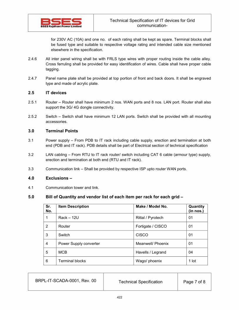
Technical Specification of IT devices for Grid
communication-
BRPL-IT-SCADA-0001, Rev. 00 Technical Specification Page 7 of 8
for 230V AC (10A) and one no. of each rating shall be kept as spare. Terminal blocks shall be fused type and suitable to respective voltage rating and intended cable size mentioned elsewhere in the specification.
2.4.6 All inter panel wiring shall be with FRLS type wires with proper routing inside the cable alley. Cross ferruling shall be provided for easy identification of wires. Cable shall have proper cable tagging.
2.4.7 Panel name plate shall be provided at top portion of front and back doors. It shall be engraved type and made of acrylic plate.
2.5 IT devices
2.5.1 Router – Router shall have minimum 2 nos. WAN ports and 8 nos. LAN port. Router shall also support the 3G/ 4G dongle connectivity.
2.5.2 Switch – Switch shall have minimum 12 LAN ports. Switch shall be provided with all mounting accessories.
3.0 Terminal Points
3.1 Power supply – From PDB to IT rack including cable supply, erection and termination at both end (PDB and IT rack). PDB details shall be part of Electrical section of technical specification
3.2 LAN cabling – From RTU to IT rack router/ switch including CAT 6 cable (armour type) supply, erection and termination at both end (RTU and IT rack).
3.3 Communication link – Shall be provided by respective ISP upto router WAN ports.
4.0 Exclusions –
4.1 Communication tower and link.
5.0 Bill of Quantity and vendor list of each item per rack for each grid –
Sr. No.
Item Description Make / Model No. Quantity (in nos.)
1 Rack – 12U Rittal / Pyrotech 01
2 Router Fortigate / CISCO 01
3 Switch CISCO 01
4 Power Supply converter Meanwell/ Phoenix 01
5 MCB Havells / Legrand 04
6 Terminal blocks Wago/ phoenix 1 lot
422
Technical Specification of IT devices for Grid
communication-
BRPL-IT-SCADA-0001, Rev. 00 Technical Specification Page 8 of 8
7 AC extension board Havells / Anchor 1
8 Wires for Internal wiring RR cable, Finolex, Havells 1 lot
9 Spare Terminal blocks with fuses (mounted in the rack) Wago/ phoenix 20%
10 Terminal fuses of each rating (loose supply) 20%
423
BSES Bhawan, Nehru Place, New Delhi- 19
Prepared by Abhinav Srivastava Rev: 1
Reviewed by k.Sheshadri Date: 22.07.2018
Approved by k.Sheshadri
TECHNICAL SPECIFICATION
APPROVED MAKES & VENDERS
424
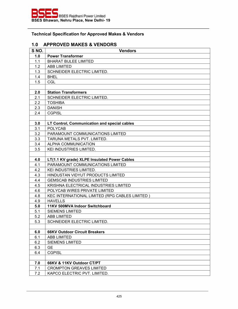
BSES Bhawan, Nehru Place, New Delhi- 19 Technical Specification for Approved Makes & Vendors
1.0 APPROVED MAKES & VENDORS S NO. Vendors
1.0 Power Transformer 1.1 BHARAT BIJLEE LIMITED 1.2 ABB LIMITED 1.3 SCHNEIDER ELECTRIC LIMITED. 1.4 BHEL 1.5 CGL
2.0 Station Transformers 2.1 SCHNEIDER ELECTRIC LIMITED. 2.2 TOSHIBA 2.3 DANISH 2.4 CGPISL
3.0 LT Control, Communication and special cables 3.1 POLYCAB 3.2 PARAMOUNT COMMUNICATIONS LIMITED 3.3 TARUNA METALS PVT. LIMITED. 3.4 ALPHA COMMUNICATION 3.5 KEI INDUSTRIES LIMITED.
4.0 LT(1.1 KV grade) XLPE Insulated Power Cables 4.1 PARAMOUNT COMMUNICATIONS LIMITED 4.2 KEI INDUSTRIES LIMITED. 4.3 HINDUSTAN VIDYUT PRODUCTS LIMITED 4.4 GEMSCAB INDUSTRIES LIMITED 4.5 KRISHNA ELECTRICAL INDUSTRIES LIMITED 4.6 POLYCAB WIRES PRIVATE LIMITED 4.8 KEC INTERNATIONAL LIMITED (RPG CABLES LIMITED ) 4.9 HAVELLS 5.0 11KV 500MVA Indoor Switchboard 5.1 SIEMENS LIMITED 5.2 ABB LIMITED 5.3 SCHNEIDER ELECTRIC LIMITED.
6.0 66KV Outdoor Circuit Breakers 6.1 ABB LIMITED 6.2 SIEMENS LIMITED 6.3 GE 6.4 CGPISL
7.0 66KV & 11KV Outdoor CT/PT 7.1 CROMPTON GREAVES LIMITED 7.2 KAPCO ELECTRIC PVT. LIMITED.
425
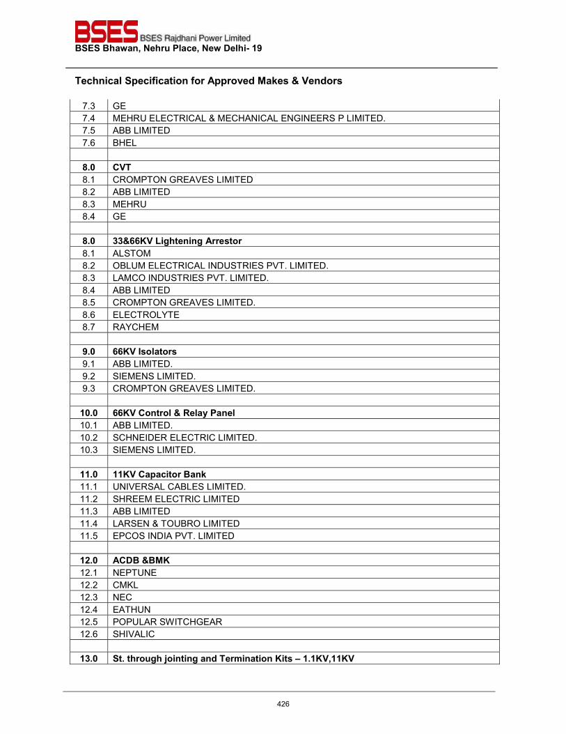
BSES Bhawan, Nehru Place, New Delhi- 19 Technical Specification for Approved Makes & Vendors
7.3 GE 7.4 MEHRU ELECTRICAL & MECHANICAL ENGINEERS P LIMITED. 7.5 ABB LIMITED 7.6 BHEL
8.0 CVT 8.1 CROMPTON GREAVES LIMITED 8.2 ABB LIMITED 8.3 MEHRU 8.4 GE
8.0 33&66KV Lightening Arrestor 8.1 ALSTOM 8.2 OBLUM ELECTRICAL INDUSTRIES PVT. LIMITED. 8.3 LAMCO INDUSTRIES PVT. LIMITED. 8.4 ABB LIMITED 8.5 CROMPTON GREAVES LIMITED. 8.6 ELECTROLYTE 8.7 RAYCHEM
9.0 66KV Isolators 9.1 ABB LIMITED. 9.2 SIEMENS LIMITED. 9.3 CROMPTON GREAVES LIMITED.
10.0 66KV Control & Relay Panel 10.1 ABB LIMITED. 10.2 SCHNEIDER ELECTRIC LIMITED. 10.3 SIEMENS LIMITED.
11.0 11KV Capacitor Bank 11.1 UNIVERSAL CABLES LIMITED. 11.2 SHREEM ELECTRIC LIMITED 11.3 ABB LIMITED 11.4 LARSEN & TOUBRO LIMITED 11.5 EPCOS INDIA PVT. LIMITED
12.0 ACDB &BMK 12.1 NEPTUNE 12.2 CMKL 12.3 NEC 12.4 EATHUN 12.5 POPULAR SWITCHGEAR 12.6 SHIVALIC
13.0 St. through jointing and Termination Kits – 1.1KV,11KV
426
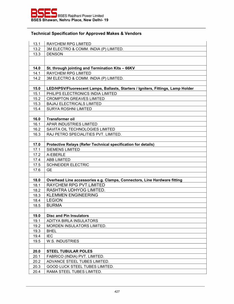
BSES Bhawan, Nehru Place, New Delhi- 19 Technical Specification for Approved Makes & Vendors
13.1 RAYCHEM RPG LIMITED 13.2 3M ELECTRO & COMM. INDIA (P) LIMITED. 13.3 DENSON
14.0 St. through jointing and Termination Kits – 66KV 14.1 RAYCHEM RPG LIMITED 14.2 3M ELECTRO & COMM. INDIA (P) LIMITED.
15.0 LED/HPSV/Fluorescent Lamps, Ballasts, Starters / Igniters, Fittings, Lamp Holder 15.1 PHILIPS ELECTRONICS INDIA LIMITED 15.2 CROMPTON GREAVES LIMITED 15.3 BAJAJ ELECTRICALS LIMITED 15.4 SURYA ROSHNI LIMITED
16.0 Transformer oil 16.1 APAR INDUSTRIES LIMITED 16.2 SAVITA OIL TECHNOLOGIES LIMITED 16.3 RAJ PETRO SPECIALITIES PVT. LIMITED.
17.0 Protective Relays (Refer Technical specification for details) 17.1 SIEMENS LIMITED 17.2 A-EBERLE 17.4 ABB LIMITED 17.5 SCHNEIDER ELECTRIC 17.6 GE
18.0 Overhead Line accessories e.g. Clamps, Connectors, Line Hardware fitting 18.1 RAYCHEM RPG PVT.LIMITED 18.2 RASHTRA UDHYOG LIMITED. 18.3 KLEMMEN ENGINEERING 18.4 LEGION 18.5 BURMA
19.0 Disc and Pin Insulators 19.1 ADITYA BIRLA INSULATORS 19.2 MORDEN INSULATORS LIMITED. 19.3 BHEL 19.4 IEC 19.5 W.S. INDUSTRIES
20.0 STEEL TUBULAR POLES 20.1 FABRICO (INDIA) PVT. LIMITED. 20.2 ADVANCE STEEL TUBES LIMITED. 20.3 GOOD LUCK STEEL TUBES LIMITED. 20.4 RAMA STEEL TUBES LIMITED.
427
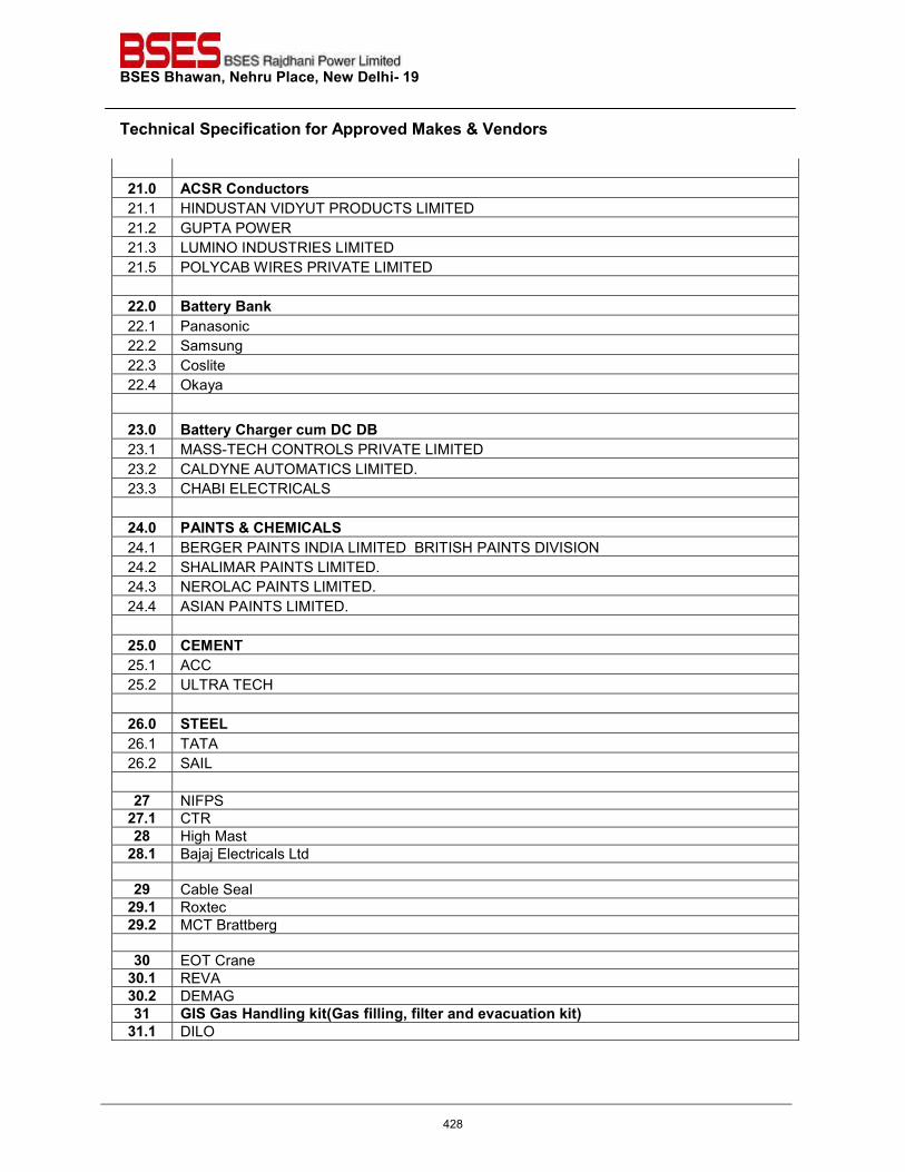
BSES Bhawan, Nehru Place, New Delhi- 19 Technical Specification for Approved Makes & Vendors
21.0 ACSR Conductors 21.1 HINDUSTAN VIDYUT PRODUCTS LIMITED 21.2 GUPTA POWER 21.3 LUMINO INDUSTRIES LIMITED 21.5 POLYCAB WIRES PRIVATE LIMITED
22.0 Battery Bank 22.1 Panasonic 22.2 Samsung 22.3 Coslite 22.4 Okaya
23.0 Battery Charger cum DC DB 23.1 MASS-TECH CONTROLS PRIVATE LIMITED 23.2 CALDYNE AUTOMATICS LIMITED. 23.3 CHABI ELECTRICALS
24.0 PAINTS & CHEMICALS 24.1 BERGER PAINTS INDIA LIMITED BRITISH PAINTS DIVISION 24.2 SHALIMAR PAINTS LIMITED. 24.3 NEROLAC PAINTS LIMITED. 24.4 ASIAN PAINTS LIMITED.
25.0 CEMENT 25.1 ACC 25.2 ULTRA TECH
26.0 STEEL 26.1 TATA 26.2 SAIL
27 NIFPS 27.1 CTR
28 High Mast 28.1 Bajaj Electricals Ltd
29 Cable Seal
29.1 Roxtec 29.2 MCT Brattberg
30 EOT Crane
30.1 REVA 30.2 DEMAG 31 GIS Gas Handling kit(Gas filling, filter and evacuation kit)
31.1 DILO
428
BSES Bhawan, Nehru Place, New Delhi- 19
Prepared by Javed Ahmed Rev: 0
Reviewed by Abhinav Srivastava Date: 17.05.2021
Approved by K.Sheshadri
TECHNICAL SPECIFICATION
TRAINING AND INSPECTION
429
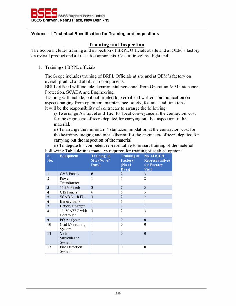
BSES Bhawan, Nehru Place, New Delhi- 19 Volume – I Technical Specification for Training and Inspections
Training and Inspection The Scope includes training and inspection of BRPL Officials at site and at OEM’s factory on overall product and all its sub-components. Cost of travel by flight and
1. Training of BRPL officials
The Scope includes training of BRPL Officials at site and at OEM’s factory on overall product and all its sub-components. BRPL official will include departmental personnel from Operation & Maintenance, Protection, SCADA and Engineering. Training will include, but not limited to, verbal and written communication on aspects ranging from operation, maintenance, safety, features and functions. It will be the responsibility of contractor to arrange the following:
i) To arrange Air travel and Taxi for local conveyance at the contractors cost for the engineers/ officers deputed for carrying out the inspection of the material. ii) To arrange the minimum 4 star accommodation at the contractors cost for the boarding/ lodging and meals thereof for the engineers/ officers deputed for carrying out the inspection of the material. ii) To depute his competent representative to impart training of the material.
Following Table defines mandays required for training of each equipment. S. No.
Equipment Training at Site (No. of Days)
Training at Factory (No of Days)
No. of BRPL Representatives for Factory Visit
1 C&R Panels 6 2 3
2 Power Transformer
1 1 2
3 11 kV Panels 3 2 3
4 GIS Panels 6 5 5
5 SCADA – RTU 3 2 2
6 Battery Bank 1 1 1
7 Battery Charger 1 1 1
8 11kV APFC with Controller
3 2 3
9 PQ Analyser 1 0 0
10 Grid Monitoring System
1 0 0
11 Video Surveillance System
1 0 0
12 Fire Detection System
1 0 0
430
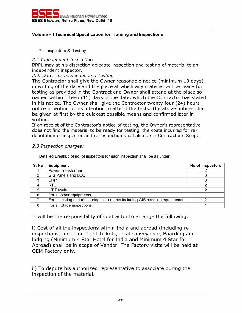
BSES Bhawan, Nehru Place, New Delhi- 19 Volume – I Technical Specification for Training and Inspections
2. Inspection & Testing
2.1 Independent Inspection BRPL may at his discretion delegate inspection and testing of material to an independent inspector. 2.2. Dates for Inspection and Testing The Contractor shall give the Owner reasonable notice (minimum 10 days) in writing of the date and the place at which any material will be ready for testing as provided in the Contract and Owner shall attend at the place so named within fifteen (15) days of the date, which the Contractor has stated in his notice. The Owner shall give the Contractor twenty four (24) hours notice in writing of his intention to attend the tests. The above notices shall be given at first by the quickest possible means and confirmed later in writing. If on receipt of the Contractor’s notice of testing, the Owner’s representative does not find the material to be ready for testing, the costs incurred for re-deputation of inspector and re-inspection shall also be in Contractor’s Scope. 2.3 Inspection charges:
Detailed Breakup of no. of inspectors for each inspection shall be as under. S. No Equipment No of Inspectors 1 Power Transformer 2 2 GIS Panels and LCC 3 3 CRP 3 4 RTU 2 5 HT Panels 2 6 For all other equipments 1 7 For all testing and measuring instruments including GIS handling equipments 2 8 For all Stage inspections 1
It will be the responsibility of contractor to arrange the following: i) Cost of all the inspections within India and abroad (including re inspections) including flight Tickets, local conveyance, Boarding and lodging (Minimum 4 Star Hotel for India and Minimum 4 Star for Abroad) shall be in scope of Vendor. The Factory visits will be held at OEM Factory only. ii) To depute his authorized representative to associate during the inspection of the material.
431
BSES Bhawan, Nehru Place, New Delhi- 19 Volume – I Technical Specification for Training and Inspections
In case of fake call or rejection of material or any other cause, the Owner is not liable for reimbursement of the expenditure so incurred by the contractor. 2.4 Rejection If as-a-result of the inspection, examination or testing as per approved QAP, the Owner decides that any equipment is defective or otherwise not in accordance with the Contract, he may reject such equipment and shall notify the Contractor there-of, immediately. The notice shall state the Owner’s objections with reasons. The Contractor shall then with all speed make good the defect or ensure that any rejected equipment complies with the Contract. If the Owner requires such Equipment to be re-tested, the tests shall be repeated under same terms and conditions. All costs incurred for re-deputation of inspector and re-inspection shall also be in Contractor’s Scope.
432
��������������� �����������������������
�
��������
����������
�� ���������������������
433
Scanned by CamScanner434
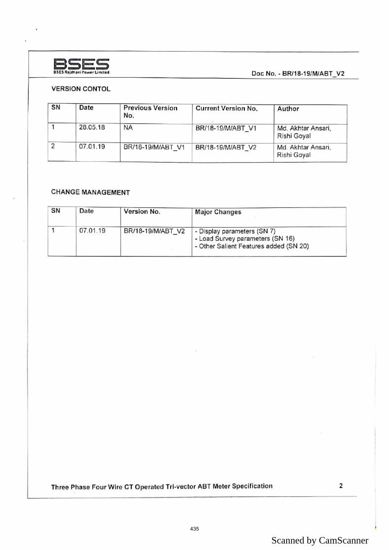
Scanned by CamScanner435
Scanned by CamScanner436
Scanned by CamScanner437
Scanned by CamScanner438
Scanned by CamScanner439
Scanned by CamScanner440
Scanned by CamScanner441
Scanned by CamScanner442
Scanned by CamScanner443
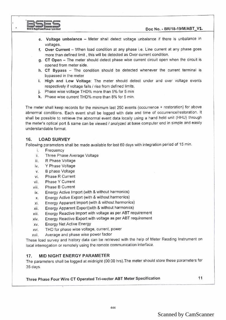
Scanned by CamScanner444
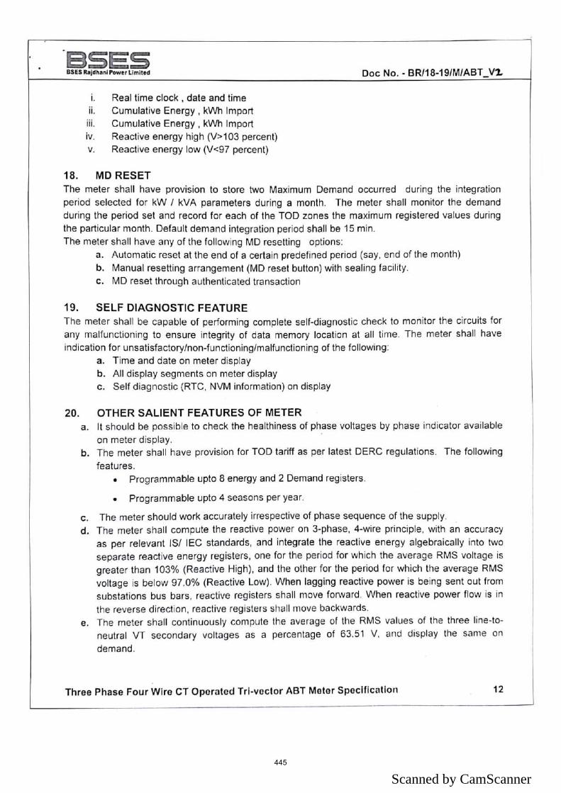
Scanned by CamScanner445
Scanned by CamScanner446
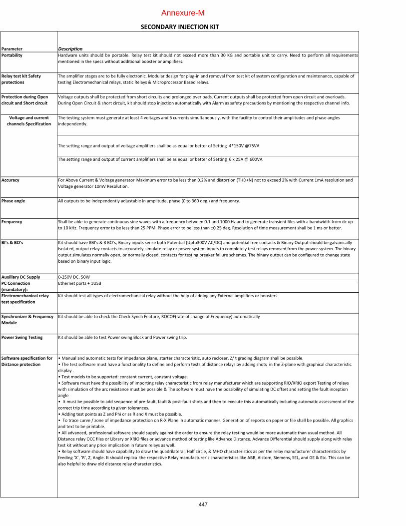
Parameter DescriptionPortability Hardware units should be portable. Relay test kit should not exceed more than 30 KG and portable unit to carry. Need to perform all requirements
mentioned�in�the�specs�without�additional�booster�or�amplifiers.
Relay�test�kit�Safety�protections
The�amplifier�stages�are�to�be�fully�electronic.�Modular�design�for�plug�in�and�removal�from�test�kit�of�system�configuration�and�maintenance,�capable�of�testing�Electromechanical�relays,�static�Relays�&�Microprocessor�Based�relays.�
Protection�during�Open�circuit�and�Short�circuit
Voltage�outputs�shall�be�protected�from�short�circuits�and�prolonged�overloads.�Current�outputs�shall�be�protected�from�open�circuit�and�overloads.�During�Open�Circuit�&�short�circuit,�kit�should�stop�injection�automatically�with�Alarm�as�safety�precautions�by�mentioning�the�respective�channel�info.
The�testing�system�must�generate�at�least�4�voltages�and�6�currents�simultaneously,�with�the�facility�to�control�their�amplitudes�and�phase�angles�independently.���
The�setting�range�and�output�of�voltage�amplifiers�shall�be�as�equal�or�better�of�Setting��4*150V�@75VA
The�setting�range�and�output�of�current�amplifiers�shall�be�as�equal�or�better�of�Setting��6�x�25A�@�600VA
Accuracy For�Above�Current�&�Voltage�generator� Maximum�error�to�be�less�than�0.2%�and�distortion�(THD+N)�not�to�exceed�2%�with�Current�1mA�resolution�and�Voltage�generator�10mV�Resolution.
Phase�angle All�outputs�to�be�independently�adjustable�in�amplitude,�phase�(0�to�360�deg.)�and�frequency.
Frequency Shall�be�able�to�generate�continuous�sine�waves�with�a�frequency�between�0.1�and�1000�Hz�and�to�generate�transient�files�with�a�bandwidth�from�dc�up�to�10�kHz.�Frequency�error�to�be�less�than�25�PPM.�Phase�error�to�be�less�than�±0.25�deg.�Resolution�of�time�measurement�shall�be�1�ms�or�better.
BI’s�&�BO’s Kit�should�have�8BI’s�&�8�BO’s,�Binary�inputs�sense�both�Potential�(Upto300V�AC/DC)�and�potential�free�contacts�&�Binary�Output�should�be�galvanically�isolated,�output�relay�contacts�to�accurately�simulate�relay�or�power�system�inputs�to�completely�test�relays�removed�from�the�power�system.�The�binary�output�simulates�normally�open,�or�normally�closed,�contacts�for�testing�breaker�failure�schemes.�The�binary�output�can�be�configured�to�change�state�based�on�binary�input�logic.
Auxillary�DC�Supply 0�250V�DC,�50WPC�Connection�(mandatory):
Ethernet�ports�+�1USB
Electromechanical�relay�test�specification
Kit�should�test�all�types�of�electromechanical�relay�without�the�help�of�adding�any�External�amplifiers�or�boosters.
Synchronizer�&�Frequency�Module
Kit�should�be�able�to�check�the�Check�Synch�Feature,�ROCOF(rate�of�change�of�Frequency)�automatically
Power�Swing�Testing Kit�should�be�able�to�test�Power�swing�Block�and�Power�swing�trip.
Software�specification�for�Distance�protection
•�Manual�and�automatic�tests�for�impedance�plane,�starter�characteristic,�auto�recloser,�Z/�t�grading�diagram�shall�be�possible.�•�The�test�software�must�have�a�functionality�to�define�and�perform�tests�of�distance�relays�by�adding�shots��in�the�Z�plane�with�graphical�characteristic�display�.•�Test�models�to�be�supported:�constant�current,�constant�voltage.•�Software�must�have�the�possibility�of�importing�relay�characteristic�from�relay�manufacturer�which�are�supporting�RIO/XRIO�export�Testing�of�relays�with�simulation�of�the�arc�resistance�must�be�possible�&�The�software�must�have�the�possibility�of�simulating�DC�offset�and�setting�the�fault�inception�angle•��It�must�be�possible�to�add�sequence�of�pre�fault,�fault�&�post�fault�shots�and�then�to�execute�this�automatically�including�automatic�assessment�of�the�correct�trip�time�according�to�given�tolerances.�•�Adding�test�points�as�Z�and�Phi�or�as�R�and�X�must�be�possible.•��To�trace�curve�/�zone�of�impedance�protection�on�R�X�Plane�in�automatic�manner.�Generation�of�reports�on�paper�or�file�shall�be�possible.�All�graphics�and�text�to�be�printable.�•�All�advanced,�professional�software�should�supply�against�the�order�to�ensure�the�relay�testing�would�be�more�automatic�than�usual�method.�All�Distance�relay�OCC�files�or�Library�or�XRIO�files�or�advance�method�of�testing�like�Advance�Distance,�Advance�Differential�should�supply�along�with�relay�test�kit�without�any�price�implication�in�future�relays�as�well.•�Relay�software�should�have�capability�to�draw�the�quadrilateral,�Half�circle,�&�MHO�characteristics�as�per�the�relay�manufacturer�characteristics�by�feeding�‘X’,�‘R’,�Z,�Angle.�It�should�replica��the�respective�Relay�manufacturer’s�characteristics�like�ABB,�Alstom,�Siemens,�SEL,�and�GE�&�Etc.�This�can�be�also�helpful�to�draw�old�distance�relay�characteristics.
Voltage�and�current�channels�Specification
SECONDARY�INJECTION�KIT
447
Annexure-M
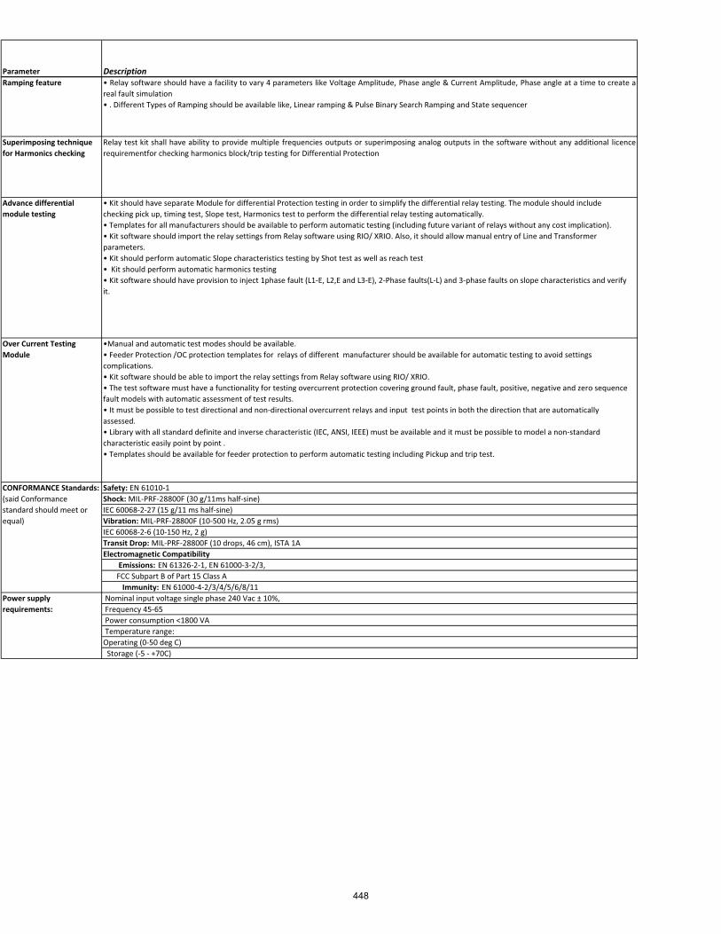
Parameter DescriptionRamping�feature • Relay software should have a facility to vary 4 parameters like Voltage Amplitude, Phase angle & Current Amplitude, Phase angle at a time to create a
real�fault�simulation•�.�Different�Types�of�Ramping�should�be�available�like,�Linear�ramping�&�Pulse�Binary�Search�Ramping�and�State�sequencer
Superimposing�technique�for�Harmonics�checking
Relay test kit shall have ability to provide multiple frequencies outputs or superimposing analog outputs in the software without any additional licencerequirementfor�checking�harmonics�block/trip�testing�for�Differential�Protection
Advance�differential�module�testing
•�Kit�should�have�separate�Module�for�differential�Protection�testing�in�order�to�simplify�the�differential�relay�testing.�The�module�should�include�checking�pick�up,�timing�test,�Slope�test,�Harmonics�test�to�perform�the�differential�relay�testing�automatically.•�Templates�for�all�manufacturers�should�be�available�to�perform�automatic�testing�(including�future�variant�of�relays�without�any�cost�implication).•�Kit�software�should�import�the�relay�settings�from�Relay�software�using�RIO/�XRIO.�Also,�it�should�allow�manual�entry�of�Line�and�Transformer�parameters.•�Kit�should�perform�automatic�Slope�characteristics�testing�by�Shot�test�as�well�as�reach�test�•��Kit�should�perform�automatic�harmonics�testing�•�Kit�software�should�have�provision�to�inject�1phase�fault�(L1�E,�L2,E�and�L3�E),�2�Phase�faults(L�L)�and�3�phase�faults�on�slope�characteristics�and�verify�it.�
Over�Current�Testing�Module
•Manual�and�automatic�test�modes�should�be�available.�•�Feeder�Protection�/OC�protection�templates�for��relays�of�different��manufacturer�should�be�available�for�automatic�testing�to�avoid�settings�complications.�•�Kit�software�should�be�able�to�import�the�relay�settings�from�Relay�software�using�RIO/�XRIO.�•�The�test�software�must�have�a�functionality�for�testing�overcurrent�protection�covering�ground�fault,�phase�fault,�positive,�negative�and�zero�sequence�fault�models�with�automatic�assessment�of�test�results.•�It�must�be�possible�to�test�directional�and�non�directional�overcurrent�relays�and�input��test�points�in�both�the�direction�that�are�automatically�assessed.•�Library�with�all�standard�definite�and�inverse�characteristic�(IEC,�ANSI,�IEEE)�must�be�available�and�it�must�be�possible�to�model�a�non�standard�characteristic�easily�point�by�point�.�•�Templates�should�be�available�for�feeder�protection�to�perform�automatic�testing�including�Pickup�and�trip�test.
Safety:�EN�61010�1Shock:�MIL�PRF�28800F�(30�g/11ms�half�sine)IEC�60068�2�27�(15�g/11�ms�half�sine)Vibration:�MIL�PRF�28800F�(10�500�Hz,�2.05�g�rms)IEC�60068�2�6�(10�150�Hz,�2�g)Transit�Drop:�MIL�PRF�28800F�(10�drops,�46�cm),�ISTA�1AElectromagnetic�Compatibility��������Emissions:�EN�61326�2�1,�EN�61000�3�2/3,�������FCC�Subpart�B�of�Part�15�Class�A����������Immunity:�EN�61000�4�2/3/4/5/6/8/11�Nominal�input�voltage�single�phase�240�Vac�±�10%,��Frequency�45�65�Power�consumption�<1800�VA�Temperature�range:Operating�(0�50�deg�C)��Storage�(�5���+70C)
CONFORMANCE�Standards:��(said�Conformance�standard�should�meet�or�equal)
Power�supply�requirements:
448
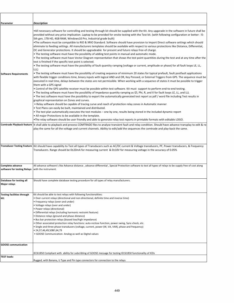
Parameter Description
Software�Requirements
•All�necessary�software�for�controlling�and�testing�through�kit�should�be�supplied�with�the�Kit.�Any�upgarade�in�the�software�in�future�shall�be�provided�without�any�price�implication.�Laptop�to�be�provided�for�onsite�testing�with�the�Test�kit.�(with�following�configuration�or�better:��I5�5th�gen,�1TB�HD,�4GB�RAM,�Windows10�Pro,�Industrial�grade�built)•The�software�must�be�compatible�to�RIO�&�XRIO�Standard.�Software�should�have�provision�to�Import�Direct�software�settings�which�should�eliminate�to�feeding�settings.�All�manufacturers�templates�should�be�available�with�respect�to�various�protections�like�Distance,�Differential,�OC�and�Generator�protections.�It�should�be�upgradeable��for�present�and�future�relays�free�of�charge.•�The�testing�software�must�have�the�possibility�of�adding�test�points�in�manual�and�automatic�mode.•�The�testing�software�must�have�Vector�Diagram�representation�that�shows�the�test�point�quantities�during�the�test�and�at�any�time�after�the�test�is�finished�if�the�specific�test�point�is�selected.�•�The�testing�software�must�have�the�possibility�of�fault�quantity�ramping�(voltage�or�current,�amplitude�or�phase)�for�all�fault�loops�LE,�LL,�LLL)•�The�testing�software�must�have�the�possibility�of�creating�sequence�of�minimum�20�states�for�typical�prefault,�fault�postfault�applications�with�flexible�trigger�conditions�time,�binary�inputs�with�logical�AND�and�OR,�Key�Pressed,�or�External�Triggers�from�GPS.�The�sequence�must�be�executed�in�real�time,�delays�between�the�states�are�not�permissible.�When�working�with�a�sequence�of�states�it�must�be�possible�to�trigger�them�with�a�GPS�signal��•�Control�of�the�GPS�satellite�receiver�must�be�possible�within�test�software.�Kit�must��support�to�perform�end�to�end�testing.��•�The�testing�software�must�have�the�possibility�of�Impedance�quantity�ramping�as�IZI,�Phi,�R,�and�X�for�fault�loops�LE,�LL,�and�LLL�•�The�test�software�must�have�the�possibility�to�export�the�automatically�generated�test�report�as�pdf�/�word�file�including�Test�results�in�graphical�representation�on�Zones�and�curves.��•�Relay�software�should�be�capable�of�tracing�curve�and�reach�of�protection�relay�zones�in�Automatic�manner�����•�Test�Plans�can�easily�be�built,�maintained�and�distributed.•�The�test�plan�automatically�executes�the�test�modules�–�one�by�one,�results�being�stored�in�the�included�dynamic�report•�All�major�Protections�to�be�available�in�the�template.•The�relay�software�should�be�user�friendly�and�able�to�generate�relay�test�reports�in�printable�formats�with�editable�LOGO.
Comtrade�Playback�feature It�shall�able�to�playback�and�process�COMTRADE�files�to�analyse�transient�fault�and�relay�condition.�Should�have�advance�transplay�to�edit�&�re�play�the�same�for�all�the�voltage�and�current�channels.�Ability�to�edit/add�the�sequences�the�comtrade�and�play�back�the�same.
Transducer�Testing�Feature Kit�should�have�capability�to�Test�all�types�of�Transducers�such�as�AC/DC�current�&�Voltage�transducers,�PF,�Power�transducers,�&�Frequency�Transducers.�Range�should�be�0±20mA�for�measuring�current��&�0±10V�for�measuring�voltage�in�the�accuracy�of�0.05%
Complete�advance�software�for�testing�Relays
All�advance�software’s�like�Advance�distance�,�advance�differential�,�Special�Protection�software�to�test�all�types�of�relays�to�be�supply�free�of�cost�along�with�the�instrument.
Database�for�testing�all�Major�relays�
Should�have�complete�database�testing�procedure�for�all�types�of�relay�manufacturers.
Testing�facilities�through�kit:
Kit�should�be�able�to�test�relays�with�following�functionalities:�•�Over�current�relays�(directional�and�non�directional,�definite�time�and�inverse�time)•�Frequency�relays�(over�and�under)•�Voltage�relays�(over�and�under)•�Power�relays�(directional)•�Differential�relays�(including�harmonic�restraint�feature)•�Distance�relays�(ground�and�phase�distance)•�Bus�bar�protection�relays�(biased�low/high�impedance)•�Other�associated�protection�relay�functions:�auto�reclose�function,�power�swing,�Sync�check,�etc.•�Single�and�three�phase�transducers�(voltage,�current,�power�(W,�VA,�VAR),�phase�and�frequency)•�24,37,46,49,50BF,64,79��•�GOOSE�Communication��Analog�as�well�as�Digital�values�������������������������������������������������������������
GOOSE�communication
IEC61850�Compliant�with��ability�for�subcribling�of�GOOSE�message�for�testing�IEC61850�functionality�of�IEDsTEST�leads:
Rugged,�with�Banana,�U�Type�and�Pin�type�connectors�for�connection�to�the�relays
449
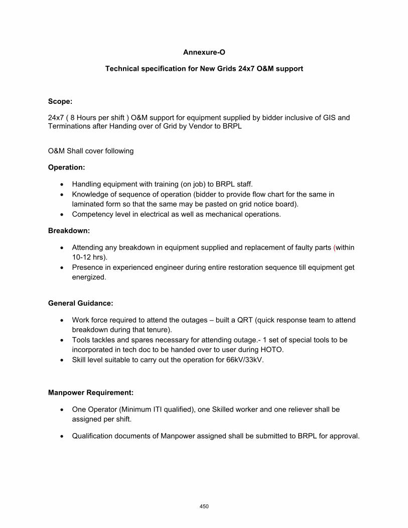
���� ����
������������������������ �����! �"��#$�%��'*������ ���
�����+
24x7 ( 8 Hours per shift ) O&M support for equipment supplied by bidder inclusive of GIS and Terminations after Handing over of Grid by Vendor to BRPL
O&M Shall cover following
��� ����+�
� Handling equipment with training (on job) to BRPL staff. � Knowledge of sequence of operation (bidder to provide flow chart for the same in
laminated form so that the same may be pasted on grid notice board). � Competency level in electrical as well as mechanical operations.
� ��;"��+��
� Attending any breakdown in equipment supplied and replacement of faulty parts (within 10-12 hrs).
� Presence in experienced engineer during entire restoration sequence till equipment get energized.
!�� ���!��"���+�
� Work force required to attend the outages – built a QRT (quick response team to attend breakdown during that tenure).
� Tools tackles and spares necessary for attending outage.- 1 set of special tools to be incorporated in tech doc to be handed over to user during HOTO.
� Skill level suitable to carry out the operation for 66kV/33kV.
*����� �<�=�� �>��+�
� One Operator (Minimum ITI qualified), one Skilled worker and one reliever shall be assigned per shift.�
� Qualification documents of Manpower assigned shall be submitted to BRPL for approval.�
�
450
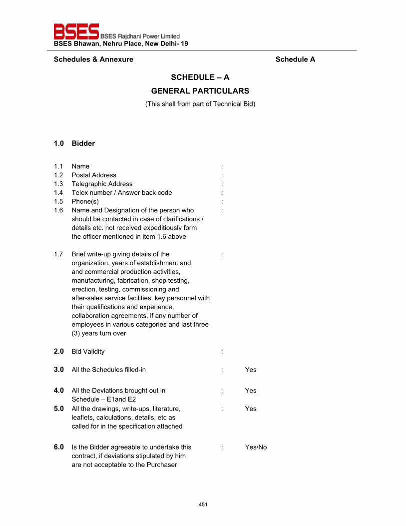
��������������� ����������������������
�����"�����'����� ���������������������������������������������������������������������������"�������
�?@��QZ��\����!���<�Z���<�^?QZ�<��
(This shall from part of Technical Bid)
�_`� ��""� � 1.1 Name : 1.2 Postal Address : 1.3 Telegraphic Address : 1.4 Telex number / Answer back code : 1.5 Phone(s) : 1.6 Name and Designation of the person who :
should be contacted in case of clarifications / details etc. not received expeditiously form the officer mentioned in item 1.6 above
1.7 Brief write-up giving details of the : organization, years of establishment and and commercial production activities, manufacturing, fabrication, shop testing, erection, testing, commissioning and after-sales service facilities, key personnel with their qualifications and experience, collaboration agreements, if any number of employees in various categories and last three (3) years turn over
#_`� Bid Validity :
z_`� All the Schedules filled-in : Yes
$_`� All the Deviations brought out in : Yes Schedule – E1and E2
{_`� All the drawings, write-ups, literature, : Yes leaflets, calculations, details, etc as called for in the specification attached
|_`� Is the Bidder agreeable to undertake this : Yes/No contract, if deviations stipulated by him are not acceptable to the Purchaser
451
��������������� ����������������������
�����"�����'����� ����������������������������������������������������������������������"�������
Bidders Name : ____________________
Signature : ____________________
Name : ____________________
Designation : ____________________
Seal of Company Date : ____________________
��
452
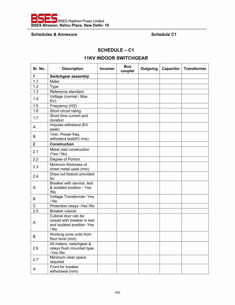
��������������� ����������������������
�����"�����'����� ��������������������������������������������������������������������"����?���
�
�?@��QZ��\�?�����}~�^����<���^�?@!��<�
� _���_� ���� ������ ^��>� ���������� � ������� ?������� � � ���� >�
�� ��������� �����>���� 1.1 Make 1.2 Type 1.3 Reference standard
1.4 Voltage (normal / Max. KV)
1.5 Frequency (HZ) 1.6 Short circuit rating
1.7 Short time current and duration
A Impulse withstand (KV peak)
B 1min. Power freq. withstand test(KV rms)
#� ?��� ������
2.1 Metal clad construction (Yes / No)
2.2 Degree of Portion
2.3 Minimum thickness of sheet metal used (mm)
2.4 Draw out feature provided for
A Breaker with service, test & isolated position - Yes /No
B Voltage Transformer- Yes / No
C Protection relays -Yes /No 2.5 Breaker cubicle
A
Cubical door can be closed with breaker in test and isolated position -Yes / No
B Working zone units from floor level (mm)
2.6 All meters, switchgear & relays flush mounted type -Yes /No
2.7 Minimum clear space required
A Front for breaker withdrawal (mm)
453
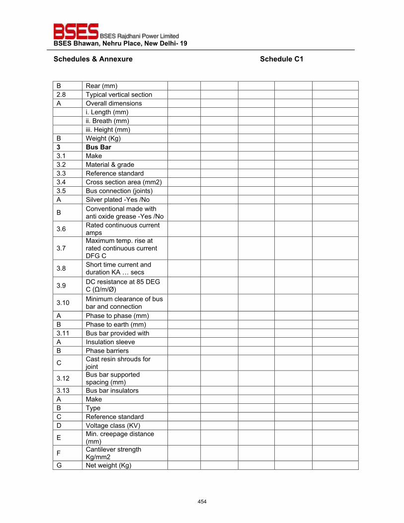
��������������� ����������������������
�����"�����'����� ��������������������������������������������������������������������"����?���
�B Rear (mm) 2.8 Typical vertical section A Overall dimensions i. Length (mm) ii. Breath (mm) iii. Height (mm) B Weight (Kg) z� ������ � 3.1 Make 3.2 Material & grade 3.3 Reference standard 3.4 Cross section area (mm2) 3.5 Bus connection (joints) A Silver plated -Yes /No
B Conventional made with anti oxide grease -Yes /No
3.6 Rated continuous current amps
3.7 Maximum temp. rise at rated continuous current DFG C
3.8 Short time current and duration KA … secs
3.9 DC resistance at 85 DEG C (Ω/m/Ø)
3.10 Minimum clearance of bus bar and connection
A Phase to phase (mm) B Phase to earth (mm) 3.11 Bus bar provided with A Insulation sleeve B Phase barriers
C Cast resin shrouds for joint
3.12 Bus bar supported spacing (mm)
3.13 Bus bar insulators A Make B Type C Reference standard D Voltage class (KV)
E Min. creepage distance (mm)
F Cantilever strength Kg/mm2
G Net weight (Kg)
454
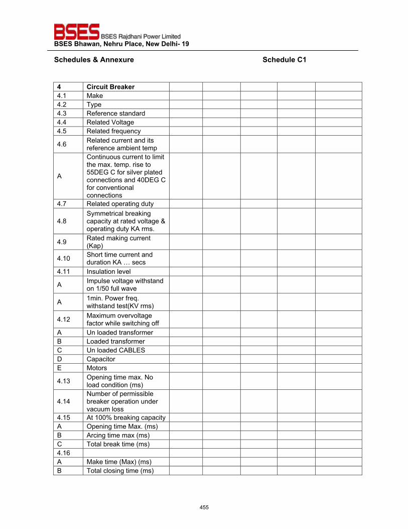
��������������� ����������������������
�����"�����'����� ��������������������������������������������������������������������"����?���
�$� ?� ������ ��;� � 4.1 Make 4.2 Type 4.3 Reference standard 4.4 Related Voltage 4.5 Related frequency
4.6 Related current and its reference ambient temp
A
Continuous current to limit the max. temp. rise to 55DEG C for silver plated connections and 40DEG C for conventional connections
4.7 Related operating duty
4.8 Symmetrical breaking capacity at rated voltage & operating duty KA rms.
4.9 Rated making current (Kap)
4.10 Short time current and duration KA … secs
4.11 Insulation level
A Impulse voltage withstand on 1/50 full wave
A 1min. Power freq. withstand test(KV rms)
4.12 Maximum overvoltage factor while switching off
A Un loaded transformer B Loaded transformer C Un loaded CABLES D Capacitor E Motors
4.13 Opening time max. No load condition (ms)
4.14 Number of permissible breaker operation under vacuum loss
4.15 At 100% breaking capacity A Opening time Max. (ms) B Arcing time max (ms) C Total break time (ms) 4.16 A Make time (Max) (ms) B Total closing time (ms)
455
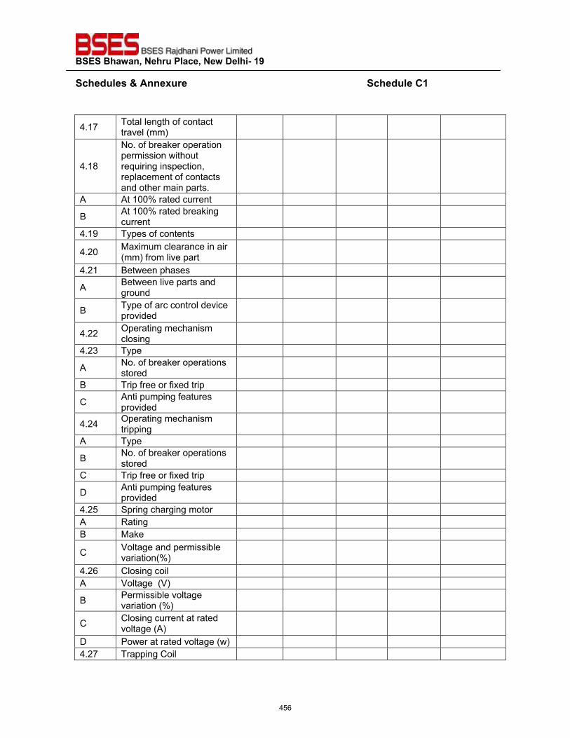
��������������� ����������������������
�����"�����'����� ��������������������������������������������������������������������"����?���
�
4.17 Total length of contact travel (mm)
4.18
No. of breaker operation permission without requiring inspection, replacement of contacts and other main parts.
A At 100% rated current
B At 100% rated breaking current
4.19 Types of contents
4.20 Maximum clearance in air (mm) from live part
4.21 Between phases
A Between live parts and ground
B Type of arc control device provided
4.22 Operating mechanism closing
4.23 Type
A No. of breaker operations stored
B Trip free or fixed trip
C Anti pumping features provided
4.24 Operating mechanism tripping
A Type
B No. of breaker operations stored
C Trip free or fixed trip
D Anti pumping features provided
4.25 Spring charging motor A Rating B Make
C Voltage and permissible variation(%)
4.26 Closing coil A Voltage (V)
B Permissible voltage variation (%)
C Closing current at rated voltage (A)
D Power at rated voltage (w) 4.27 Trapping Coil
456
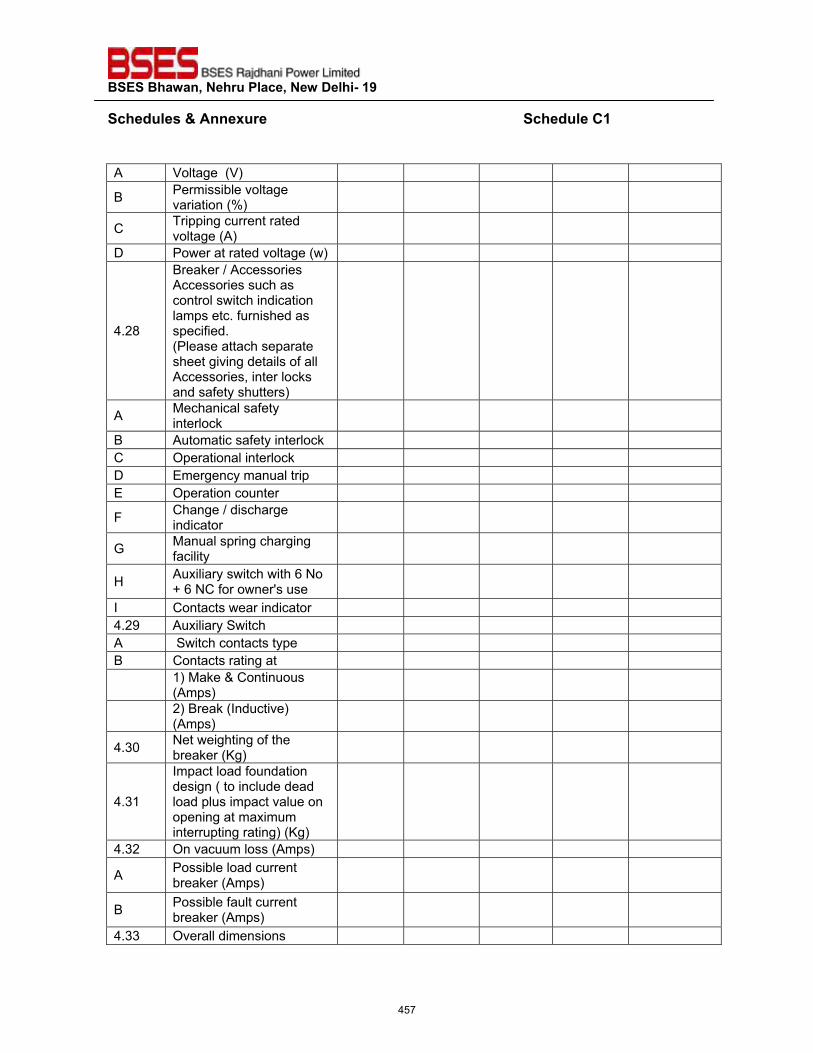
��������������� ����������������������
�����"�����'����� ��������������������������������������������������������������������"����?���
�A Voltage (V)
B Permissible voltage variation (%)
C Tripping current rated voltage (A)
D Power at rated voltage (w)
4.28
Breaker / Accessories Accessories such as control switch indication lamps etc. furnished as specified. (Please attach separate sheet giving details of all Accessories, inter locks and safety shutters)
A Mechanical safety interlock
B Automatic safety interlock C Operational interlock D Emergency manual trip E Operation counter
F Change / discharge indicator
G Manual spring charging facility
H Auxiliary switch with 6 No + 6 NC for owner's use
I Contacts wear indicator 4.29 Auxiliary Switch A Switch contacts type B Contacts rating at
1) Make & Continuous (Amps)
2) Break (Inductive) (Amps)
4.30 Net weighting of the breaker (Kg)
4.31
Impact load foundation design ( to include dead load plus impact value on opening at maximum interrupting rating) (Kg)
4.32 On vacuum loss (Amps)
A Possible load current breaker (Amps)
B Possible fault current breaker (Amps)
4.33 Overall dimensions
457
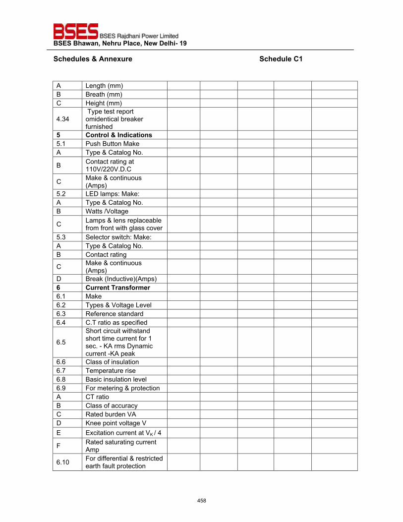
��������������� ����������������������
�����"�����'����� ��������������������������������������������������������������������"����?���
�A Length (mm) B Breath (mm) C Height (mm)
4.34 Type test report omidentical breaker furnished
{� ?�� ���'�^"�������� 5.1 Push Button Make A Type & Catalog No.
B Contact rating at 110V/220V.D.C
C Make & continuous (Amps)
5.2 LED lamps: Make: A Type & Catalog No. B Watts /Voltage
C Lamps & lens replaceable from front with glass cover
5.3 Selector switch: Make: A Type & Catalog No. B Contact rating
C Make & continuous (Amps)
D Break (Inductive)(Amps) |� ?� ���� ���� >� � 6.1 Make 6.2 Types & Voltage Level 6.3 Reference standard 6.4 C.T ratio as specified
6.5
Short circuit withstand short time current for 1 sec. - KA rms Dynamic current -KA peak
6.6 Class of insulation 6.7 Temperature rise 6.8 Basic insulation level 6.9 For metering & protection A CT ratio B Class of accuracy C Rated burden VA D Knee point voltage V E Excitation current at VK / 4
F Rated saturating current Amp
6.10 For differential & restricted earth fault protection
458
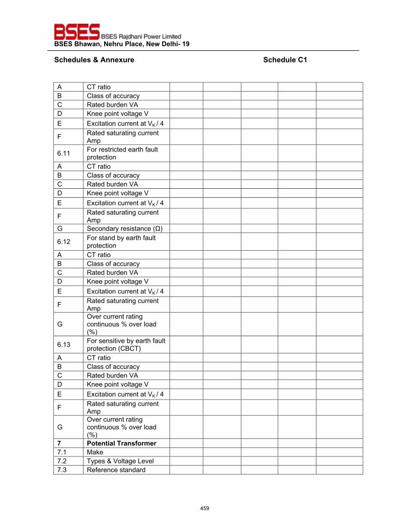
��������������� ����������������������
�����"�����'����� ��������������������������������������������������������������������"����?���
�A CT ratio B Class of accuracy C Rated burden VA D Knee point voltage V E Excitation current at VK / 4
F Rated saturating current Amp
6.11 For restricted earth fault protection
A CT ratio B Class of accuracy C Rated burden VA D Knee point voltage V E Excitation current at VK / 4
F Rated saturating current Amp
G Secondary resistance (Ω)
6.12 For stand by earth fault protection
A CT ratio B Class of accuracy C Rated burden VA D Knee point voltage V E Excitation current at VK / 4
F Rated saturating current Amp
G Over current rating continuous % over load (%)
6.13 For sensitive by earth fault protection (CBCT)
A CT ratio B Class of accuracy C Rated burden VA D Knee point voltage V E Excitation current at VK / 4
F Rated saturating current Amp
G Over current rating continuous % over load (%)
%� ���������� ���� >� � 7.1 Make 7.2 Types & Voltage Level 7.3 Reference standard
459
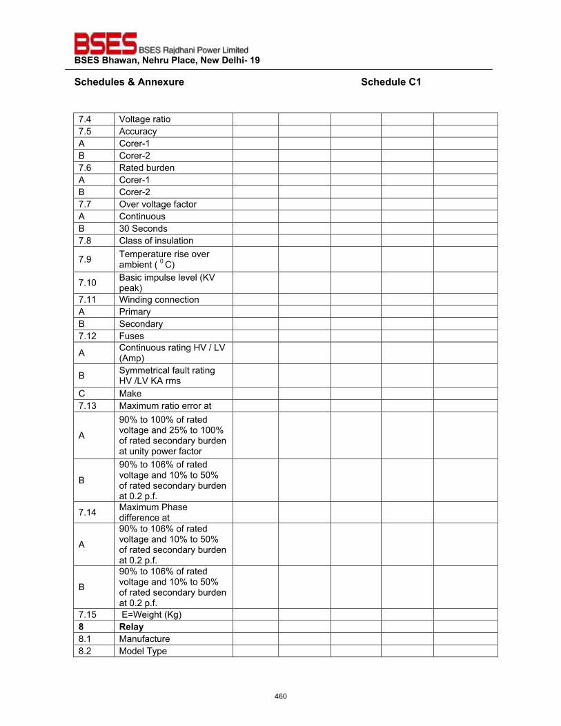
��������������� ����������������������
�����"�����'����� ��������������������������������������������������������������������"����?���
�7.4 Voltage ratio 7.5 Accuracy A Corer-1 B Corer-2 7.6 Rated burden A Corer-1 B Corer-2 7.7 Over voltage factor A Continuous B 30 Seconds 7.8 Class of insulation
7.9 Temperature rise over ambient ( 0 C)
7.10 Basic impulse level (KV peak)
7.11 Winding connection A Primary B Secondary 7.12 Fuses
A Continuous rating HV / LV (Amp)
B Symmetrical fault rating HV /LV KA rms
C Make 7.13 Maximum ratio error at
A
90% to 100% of rated voltage and 25% to 100% of rated secondary burden at unity power factor
B
90% to 106% of rated voltage and 10% to 50% of rated secondary burden at 0.2 p.f.
7.14 Maximum Phase difference at
A
90% to 106% of rated voltage and 10% to 50% of rated secondary burden at 0.2 p.f.
B
90% to 106% of rated voltage and 10% to 50% of rated secondary burden at 0.2 p.f.
7.15 E=Weight (Kg) �� <����� 8.1 Manufacture 8.2 Model Type
460
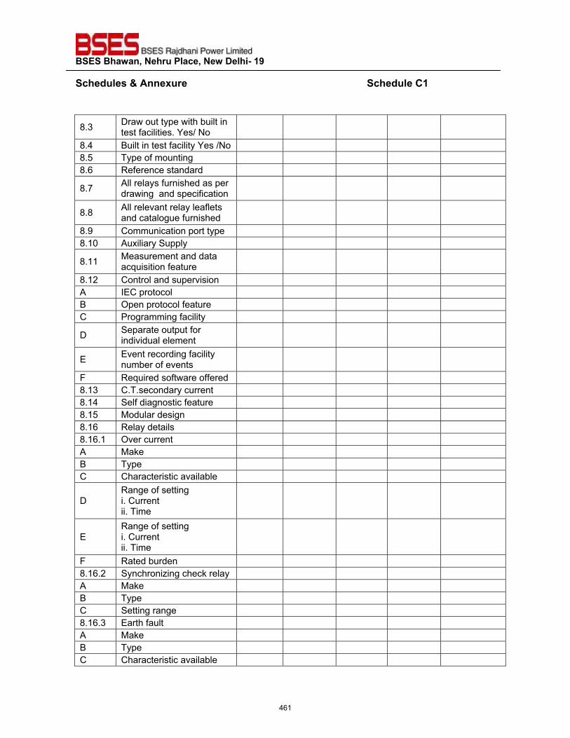
��������������� ����������������������
�����"�����'����� ��������������������������������������������������������������������"����?���
�
8.3 Draw out type with built in test facilities. Yes/ No
8.4 Built in test facility Yes /No 8.5 Type of mounting 8.6 Reference standard
8.7 All relays furnished as per drawing and specification
8.8 All relevant relay leaflets and catalogue furnished
8.9 Communication port type 8.10 Auxiliary Supply
8.11 Measurement and data acquisition feature
8.12 Control and supervision A IEC protocol B Open protocol feature C Programming facility
D Separate output for individual element
E Event recording facility number of events
F Required software offered 8.13 C.T.secondary current 8.14 Self diagnostic feature 8.15 Modular design 8.16 Relay details 8.16.1 Over current A Make B Type C Characteristic available
D Range of setting i. Current ii. Time
E Range of setting i. Current ii. Time
F Rated burden 8.16.2 Synchronizing check relay A Make B Type C Setting range 8.16.3 Earth fault A Make B Type C Characteristic available
461
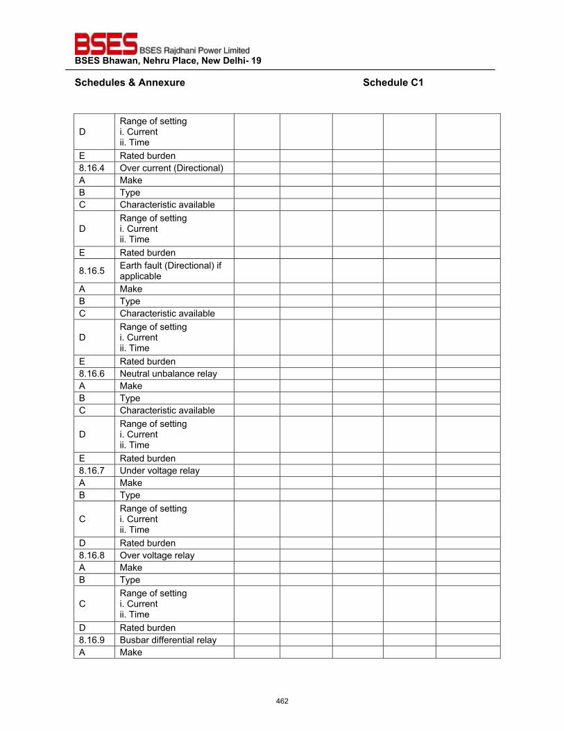
��������������� ����������������������
�����"�����'����� ��������������������������������������������������������������������"����?���
�
D Range of setting i. Current ii. Time
E Rated burden 8.16.4 Over current (Directional) A Make B Type C Characteristic available
D Range of setting i. Current ii. Time
E Rated burden
8.16.5 Earth fault (Directional) if applicable
A Make B Type C Characteristic available
D Range of setting i. Current ii. Time
E Rated burden 8.16.6 Neutral unbalance relay A Make B Type C Characteristic available
D Range of setting i. Current ii. Time
E Rated burden 8.16.7 Under voltage relay A Make B Type
C Range of setting i. Current ii. Time
D Rated burden 8.16.8 Over voltage relay A Make B Type
C Range of setting i. Current ii. Time
D Rated burden 8.16.9 Busbar differential relay A Make
462
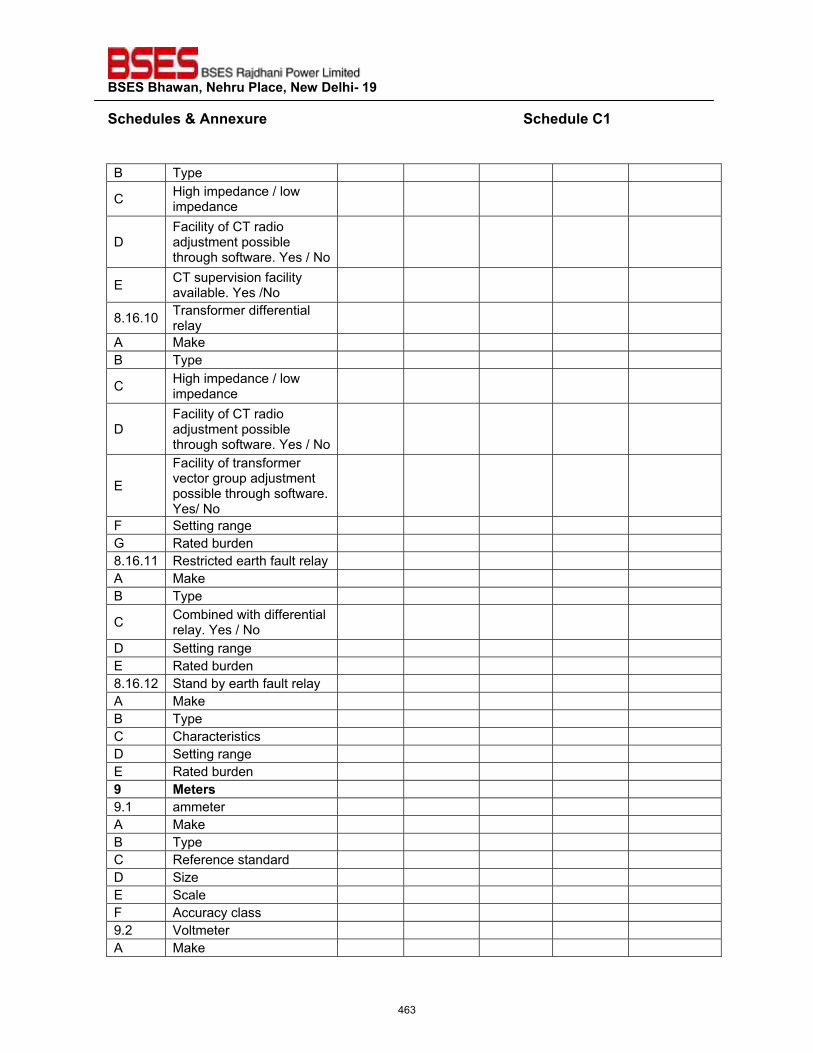
��������������� ����������������������
�����"�����'����� ��������������������������������������������������������������������"����?���
�B Type
C High impedance / low impedance
D Facility of CT radio adjustment possible through software. Yes / No
E CT supervision facility available. Yes /No
8.16.10 Transformer differential relay
A Make B Type
C High impedance / low impedance
D Facility of CT radio adjustment possible through software. Yes / No
E
Facility of transformer vector group adjustment possible through software. Yes/ No
F Setting range G Rated burden 8.16.11 Restricted earth fault relay A Make B Type
C Combined with differential relay. Yes / No
D Setting range E Rated burden 8.16.12 Stand by earth fault relay A Make B Type C Characteristics D Setting range E Rated burden �� *��� �� 9.1 ammeter A Make B Type C Reference standard D Size E Scale F Accuracy class 9.2 Voltmeter A Make
463
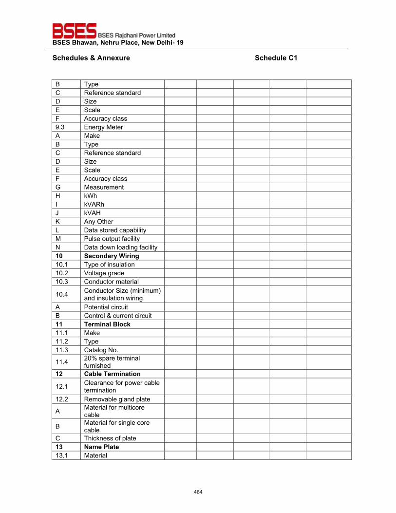
��������������� ����������������������
�����"�����'����� ��������������������������������������������������������������������"����?���
�B Type C Reference standard D Size E Scale F Accuracy class 9.3 Energy Meter A Make B Type C Reference standard D Size E Scale F Accuracy class G Measurement H kWh I kVARh J kVAH K Any Other L Data stored capability M Pulse output facility N Data down loading facility �`� ����"� ���� ��� 10.1 Type of insulation 10.2 Voltage grade 10.3 Conductor material
10.4 Conductor Size (minimum) and insulation wiring
A Potential circuit B Control & current circuit ��� �� >��������;� 11.1 Make 11.2 Type 11.3 Catalog No.
11.4 20% spare terminal furnished
�#� ?������� >������
12.1 Clearance for power cable termination
12.2 Removable gland plate
A Material for multicore cable
B Material for single core cable
C Thickness of plate �z� ��>�������� 13.1 Material
464
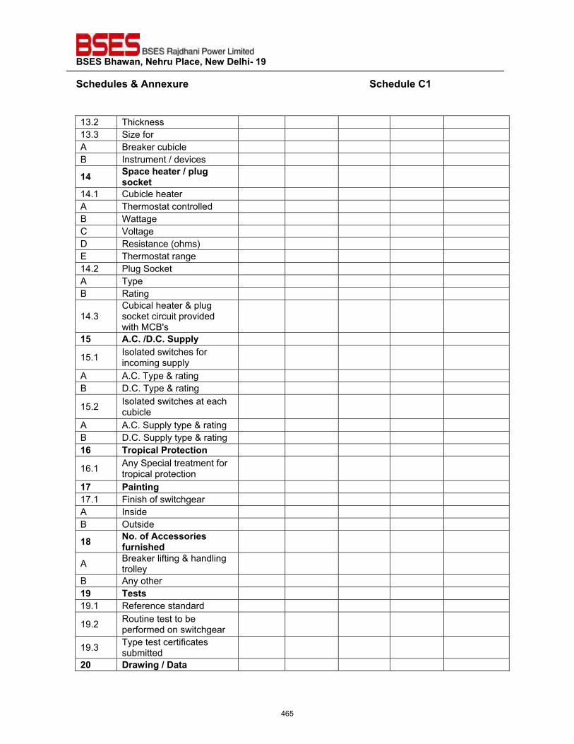
��������������� ����������������������
�����"�����'����� ��������������������������������������������������������������������"����?���
�13.2 Thickness 13.3 Size for A Breaker cubicle B Instrument / devices
�$� ����������� �����������;���
14.1 Cubicle heater A Thermostat controlled B Wattage C Voltage D Resistance (ohms) E Thermostat range 14.2 Plug Socket A Type B Rating
14.3 Cubical heater & plug socket circuit provided with MCB's
�{� �_?_���_?_��������
15.1 Isolated switches for incoming supply
A A.C. Type & rating B D.C. Type & rating
15.2 Isolated switches at each cubicle
A A.C. Supply type & rating B D.C. Supply type & rating �|� � �������� ��������
16.1 Any Special treatment for tropical protection
�%� ������� 17.1 Finish of switchgear A Inside B Outside
��� ��_����������� ������ ����"�
A Breaker lifting & handling trolley
B Any other ��� ������ 19.1 Reference standard
19.2 Routine test to be performed on switchgear
19.3 Type test certificates submitted
#`� � ������������
465
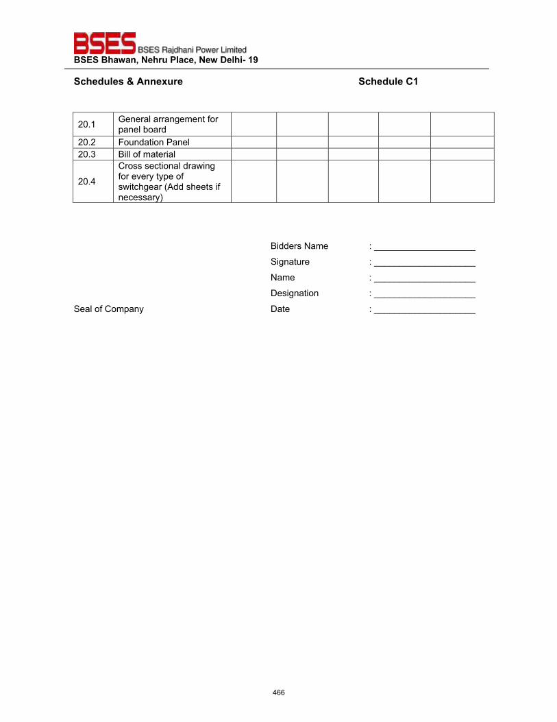
��������������� ����������������������
�����"�����'����� ��������������������������������������������������������������������"����?���
�
20.1 General arrangement for panel board
20.2 Foundation Panel 20.3 Bill of material
20.4
Cross sectional drawing for every type of switchgear (Add sheets if necessary)
����
Bidders Name : ____________________
Signature : ____________________
Name : ____________________
Designation : ____________________
Seal of Company Date : ____________________
�
466
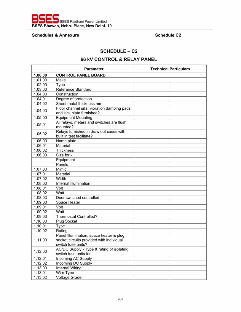
��������������� ����������������������
�����"�����'����� ��������������������������������������������������������������������"����?#��
�
�?@��QZ��\�?#��||�;~�?���<�Z�'�<�Z�������Z�
� �� �>��� � ����������� ������ ���_``_``� ?���<�Z�����Z����<��1.01.00 Make 1.02.00 Type 1.03.00 Reference Standard 1.04.00 Construction 1.04.01 Degree of protection 1.04.02 Sheet metal thickness mm
1.04.03 Floor channel sills, vibration damping pads and kick plate furnished?
1.05.00 Equipment Mounting
1.05.01 All relays, meters and switches are flush mounted?
1.05.02 Relays furnished in draw out cases with built in test facilitate?
1.06.00 Name plate 1.06.01 Material 1.06.02 Thickness 1.06.03 Size for:-
Equipment Panels
1.07.00 Mimic 1.07.01 Material 1.07.02 Width 1.08.00 Internal Illumination 1.08.01 Volt 1.08.02 Watt 1.08.03 Door switched controlled 1.09.00 Space Heater 1.09.01 Volt 1.09.02 Watt 1.09.03 Thermostat Controlled? 1.10.00 Plug Socket 1.10.01 Type 1.10.02 Rating
1.11.00 Panel Illumination, space heater & plug socket circuits provided with individual switch fuse units?
1.12.00 AC/DC Supply - Type & rating of isolating switch fuse units for
1.12.01 Incoming AC Supply 1.12.02 Incoming DC Supply 1.13.00 Internal Wiring 1.13.01 Wire Type 1.13.02 Voltage Grade
467
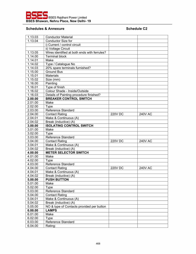
��������������� ����������������������
�����"�����'����� ��������������������������������������������������������������������"����?#��1.13.03 Conductor Material 1.13.04 Conductor Size for
i) Current / control circuit ii) Voltage Circuit
1.13.05 Wires identified at both ends with ferrules? 1.14.00 Terminal block 1.14.01 Make 1.14.02 Type / Catalogue No 1.14.03 20% spare terminals furnished? 1.15.00 Ground Bus 1.15.01 Materials 1.15.02 Size (mm) 1.16.00 Painting 1.16.01 Type of finish 1.16.02 Colour Shade - Inside/Outside 1.16.03 Details of Painting procedure finished? #_``_``� �<��}�<�?���<�Z���^�?@�2.01.00 Make 2.02.00 Type 2.03.00 Reference Standard 2.04.00 Contact Rating 220V DC 240V AC 2.04.01 Make & Continuous (A) 2.04.02 Break (inductive) (A) z_``_``� ^��Z��^�!�?���<�Z���^�?@�3.01.00 Make 3.02.00 Type 3.03.00 Reference Standard 3.04.00 Contact Rating 220V DC 240V AC 3.04.01 Make & Continuous (A) 3.04.02 Break (inductive) (A) $_``_``� *���<���Z�?��<���^�?@�4.01.00 Make 4.02.00 Type 4.03.00 Reference Standard 4.04.00 Contact Rating 220V DC 240V AC 4.04.01 Make & Continuous (A) 4.04.02 Break (inductive) (A) {_``_``� �Q�@��Q�����5.01.00 Make 5.02.00 Type 5.03.00 Reference Standard 5.04.00 Contact Rating 5.04.01 Make & Continuous (A) 5.04.02 Break (inductive) (A) 5.05.00 NO & type of Contacts provided per button |_``_``� Z�*���6.01.00 Make 6.02.00 Type 6.03.00 Reference Standard 6.04.00 Rating:
468
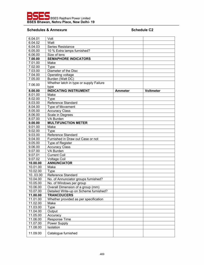
��������������� ����������������������
�����"�����'����� ��������������������������������������������������������������������"����?#��6.04.01 Volt 6.04.02 Watt 6.04.03 Series Resistance 6.05.00 10 % Extra lamps furnished? 6.06.00 Size of lens %_``_``� ��*��@�<��^��^?���<��7.01.00 Make 7.02.00 Type 7.03.00 Diameter of the Disc 7.04.00 Operating voltage 7.05.00 Burden (Watt DC)
7.06.00 Whether latch in type or supply Failure type
�_``_``� ^��^?��^�!�^���<Q*���� �>>��� � ~���>��� �8.01.00 Make 8.02.00 Type 8.03.00 Reference Standard 8.04.00 Type of Movement 8.05.00 Accuracy Class 8.06.00 Scale in Degrees 8.07.00 VA Burden �_``_``� *QZ�^�Q�?�^���*���<�9.01.00 Make 9.02.00 Type 9.03.00 Reference Standard 9.04.00 Furnished in Draw out Case or not 9.05.00 Type of Register 9.06.00 Accuracy Class 9.07.00 VA Burden 9.07.01 Current Coil 9.07.02 Voltage Coil �`_``_``� ���Q�?^���<�10.01.00 Make 10.02.00 Type 10..03.00 Reference Standard 10.04.00 No. of Annunciator groups furnished? 10.05.00 No. of Windows per group 10.06.00 Overall Dimension of a group (mm) 10.07.00 Detailed Write-up on Scheme furnished? ��_``_``� �<��?�Q?�<��11.01.00 Whether provided as per specification 11.02.00 Make 11.03.00 Type 11.04.00 Output 11.05.00 Accuracy 11.06.00 Response Time 11.07.00 Power Supply 11.08.00 Isolation
11.09.00 Catalogue furnished
469
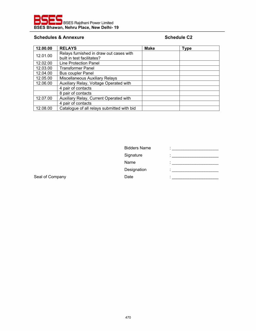
��������������� ����������������������
�����"�����'����� ��������������������������������������������������������������������"����?#���#_``_``� <�Z���� *�;�� �����12.01.00 Relays furnished in draw out cases with
built in test facilitates? 12.02.00 Line Protection Panel 12.03.00 Transformer Panel 12.04.00 Bus coupler Panel 12.05.00 Miscellaneous Auxiliary Relays 12.06.00 Auxiliary Relay, Voltage Operated with
4 pair of contacts 8 pair of contacts
12.07.00 Auxiliary Relay, Current Operated with 4 pair of contacts
12.08.00 Catalogue of all relays submitted with bid ���
�Bidders Name : ____________________
Signature : ____________________
Name : ____________________
Designation : ____________________
Seal of Company Date : ____________________
470
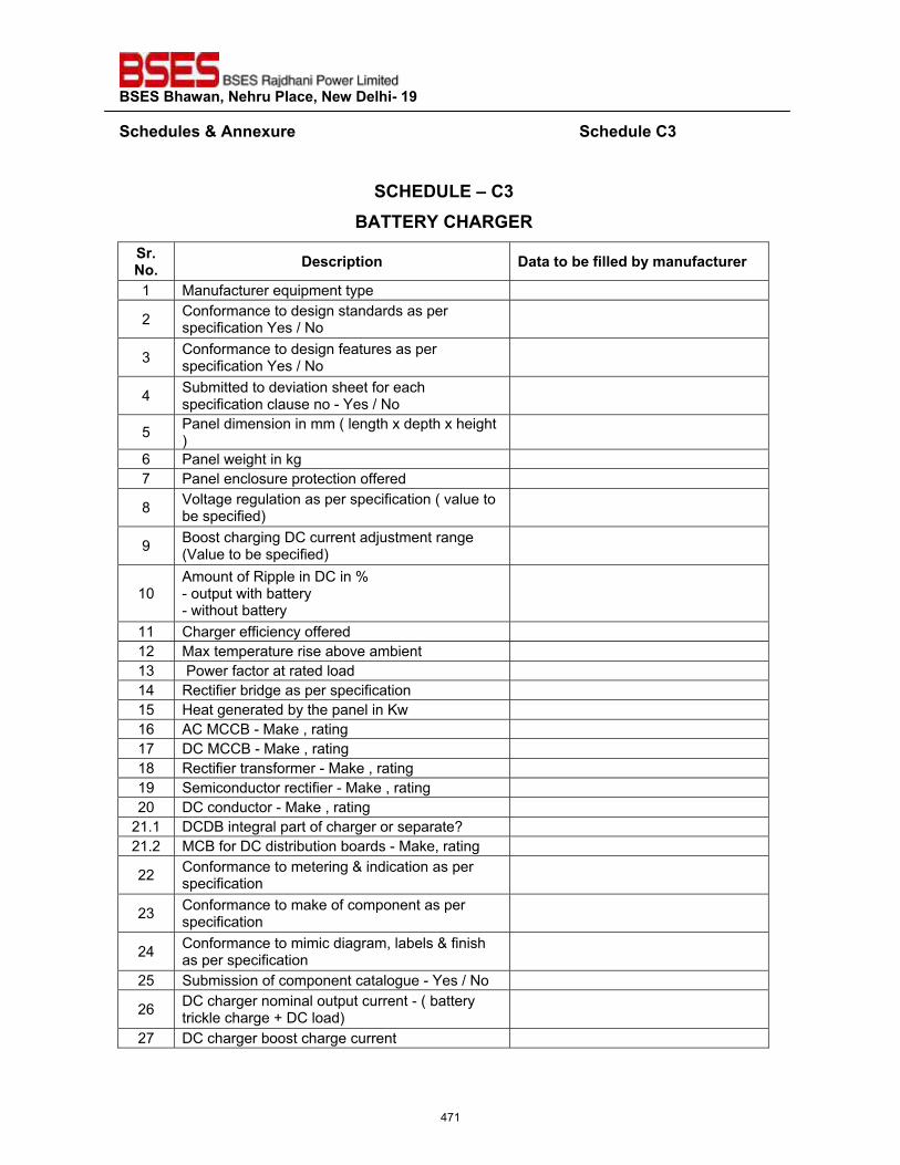
��������������� ����������������������
�����"�����'����� ��������������������������������������������������������������������"����?z��
�
�?@��QZ��\�?z�������<��?@�<!�<�
� _���_� ���� ������� ����������������"����>������� � �
1 Manufacturer equipment type
2 Conformance to design standards as per specification Yes / No
3 Conformance to design features as per specification Yes / No
4 Submitted to deviation sheet for each specification clause no - Yes / No
5 Panel dimension in mm ( length x depth x height )
6 Panel weight in kg 7 Panel enclosure protection offered
8 Voltage regulation as per specification ( value to be specified)
9 Boost charging DC current adjustment range (Value to be specified)
10 Amount of Ripple in DC in % - output with battery - without battery
11 Charger efficiency offered 12 Max temperature rise above ambient 13 Power factor at rated load 14 Rectifier bridge as per specification 15 Heat generated by the panel in Kw 16 AC MCCB - Make , rating 17 DC MCCB - Make , rating 18 Rectifier transformer - Make , rating 19 Semiconductor rectifier - Make , rating 20 DC conductor - Make , rating
21.1 DCDB integral part of charger or separate? 21.2 MCB for DC distribution boards - Make, rating
22 Conformance to metering & indication as per specification
23 Conformance to make of component as per specification
24 Conformance to mimic diagram, labels & finish as per specification
25 Submission of component catalogue - Yes / No
26 DC charger nominal output current - ( battery trickle charge + DC load)
27 DC charger boost charge current
471
��������������� ����������������������
�����"�����'����� ��������������������������������������������������������������������"����?z��
28 DC battery 29 DC battery duty cycle
����
Bidders Name : ____________________
Signature : ____________________
Name : ____________________
Designation : ____________________
Seal of Company Date : ____________________
�
472
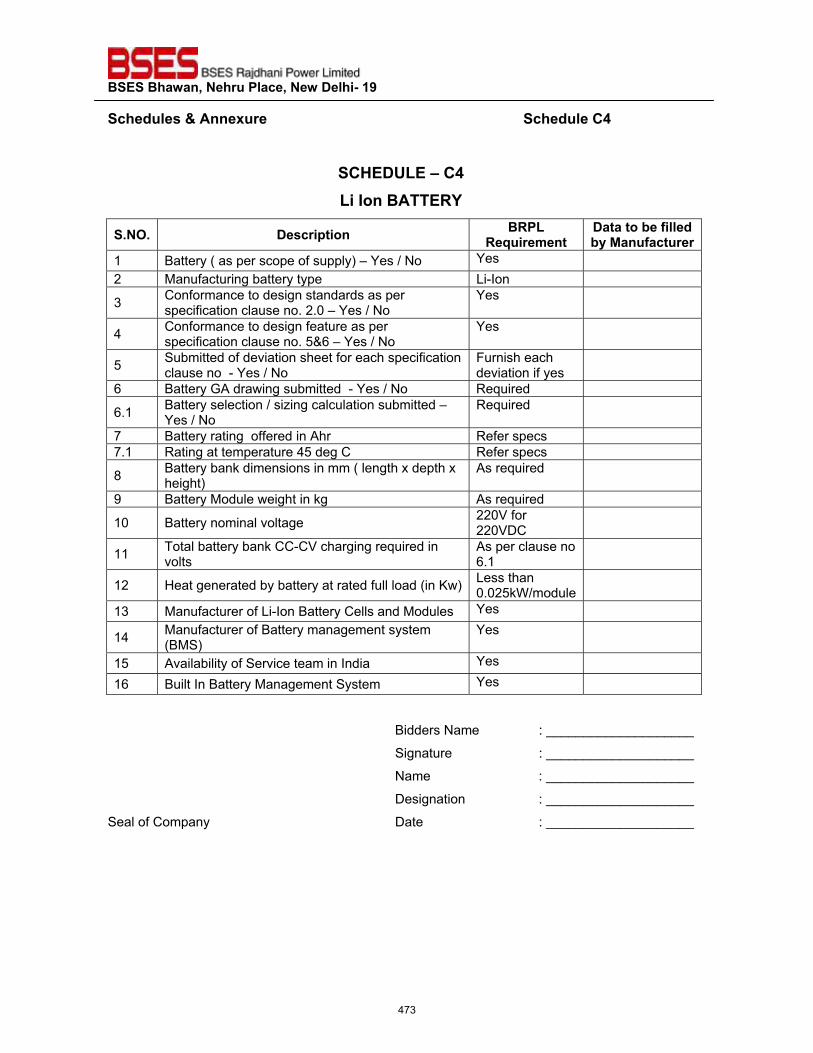
��������������� ����������������������
�����"�����'����� ��������������������������������������������������������������������"����?$��
�
�?@��QZ��\�?$��Z��^�������<��
�_��_� ���� ������ �<�Z�<�=�� �>���
����������������"����*������� �
1 Battery ( as per scope of supply) – Yes / No Yes 2 Manufacturing battery type Li-Ion
3 Conformance to design standards as per specification clause no. 2.0 – Yes / No
Yes
4 Conformance to design feature as per specification clause no. 5&6 – Yes / No
Yes
5 Submitted of deviation sheet for each specification clause no - Yes / No
Furnish each deviation if yes
6 Battery GA drawing submitted - Yes / No Required
6.1 Battery selection / sizing calculation submitted – Yes / No
Required
7 Battery rating offered in Ahr Refer specs 7.1 Rating at temperature 45 deg C Refer specs
8 Battery bank dimensions in mm ( length x depth x height)
As required
9 Battery Module weight in kg As required
10 Battery nominal voltage 220V for 220VDC
11 Total battery bank CC-CV charging required in volts
As per clause no 6.1
12 Heat generated by battery at rated full load (in Kw) Less than 0.025kW/module
13 Manufacturer of Li-Ion Battery Cells and Modules Yes
14 Manufacturer of Battery management system (BMS)
Yes
15 Availability of Service team in India Yes 16 Built In Battery Management System Yes
�Bidders Name : ____________________
Signature : ____________________
Name : ____________________
Designation : ____________________
Seal of Company Date : ____________________
473
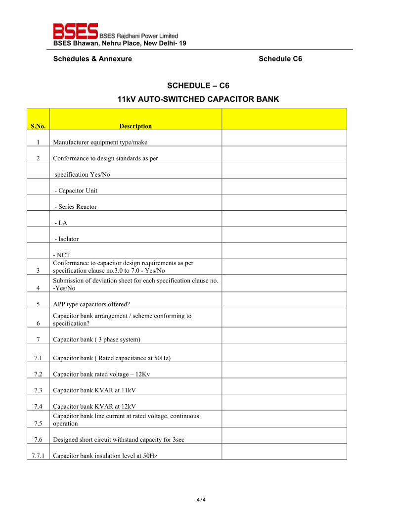
��������������� ����������������������
�����"�����'����� ��������������������������������������������������������������������"����?|��
�
�?@��QZ��\�?|���;~��Q�����^�?@���?���?^��<����}�
������ ������������ �
�� ������������ ���������������� �
�� ������������������������������������ �
�� ������������������� �
�� ��������������� �
�� ���������������� �
�� ���!"� �
�� ���#��$���� �
�� ����%� �
&�
����������������������������� ����������������
�����������$�������'&'(���)'(���������� �
*�
��+�������������,�������-���������-������������$�������'�
�������� �
.� "//��������������������0� �
1�
��������+������������������-����������������
����������0� �
)� ��������+����2�&��-���������3� �
)'�� ��������+����2����������������.(453� �
)'�� ��������+���������,�$����6���7,� �
)'&� ��������+����78"�������8� �
)'*� ��������+����78"�������8� �
)'.�
��������+����$�����������������,�$���9����������
��������� �
)'1� :���������-��������;�-���������������&��� �
)')'�� ��������+��������$�����$�,�$���.(45� �
474
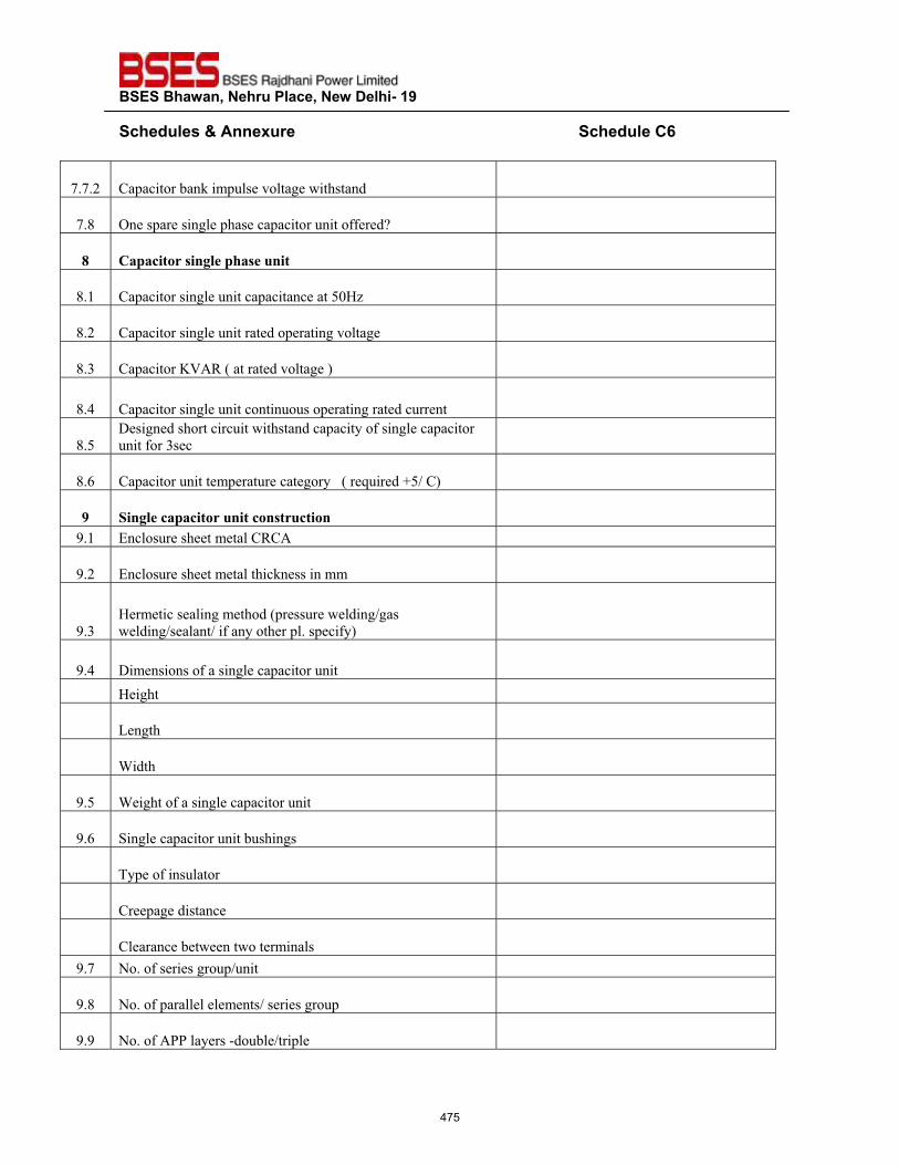
��������������� ����������������������
�����"�����'����� ��������������������������������������������������������������������"����?|��
)')'�� ��������+��������$���,�$����;�-����� �
)'<� =�������������$���-����������������������0� �
�� ��������������!���"����#���� �
<'�� ������������$����������������.(45� �
<'�� ������������$��������������������,�$���� �
<'&� ��������78"��2��������,�$����3� �
<'*� ������������$����������������������������������� �
<'.�
:���������-��������;�-������������������$���������
��������&��� �
<'1� �������������������������������2��� ������>.���3� �
$� ����!������������#����������#������ �
?'�� @�$�������-������$����"� �
?'�� @�$�������-������$�-������������� �
?'&�
4���������$������-���2���������;�$���������
;�$��������$������������-����$'�������3� �
?'*� :�������������������$������������� �
�� 4���-� �
�� !���-� �
�� A��-� �
?'.� A���-����������$������������� �
?'1� ����$�������������+��-����� �
�� %�����������$���� �
�� ����������������� �
�� �$�������+�;����;��������$�� �
?')� ��'��������������������� �
?'<� ��'��������$$�$��$���������������������
?'?� ��'����"//�$����������+$�����$���
475
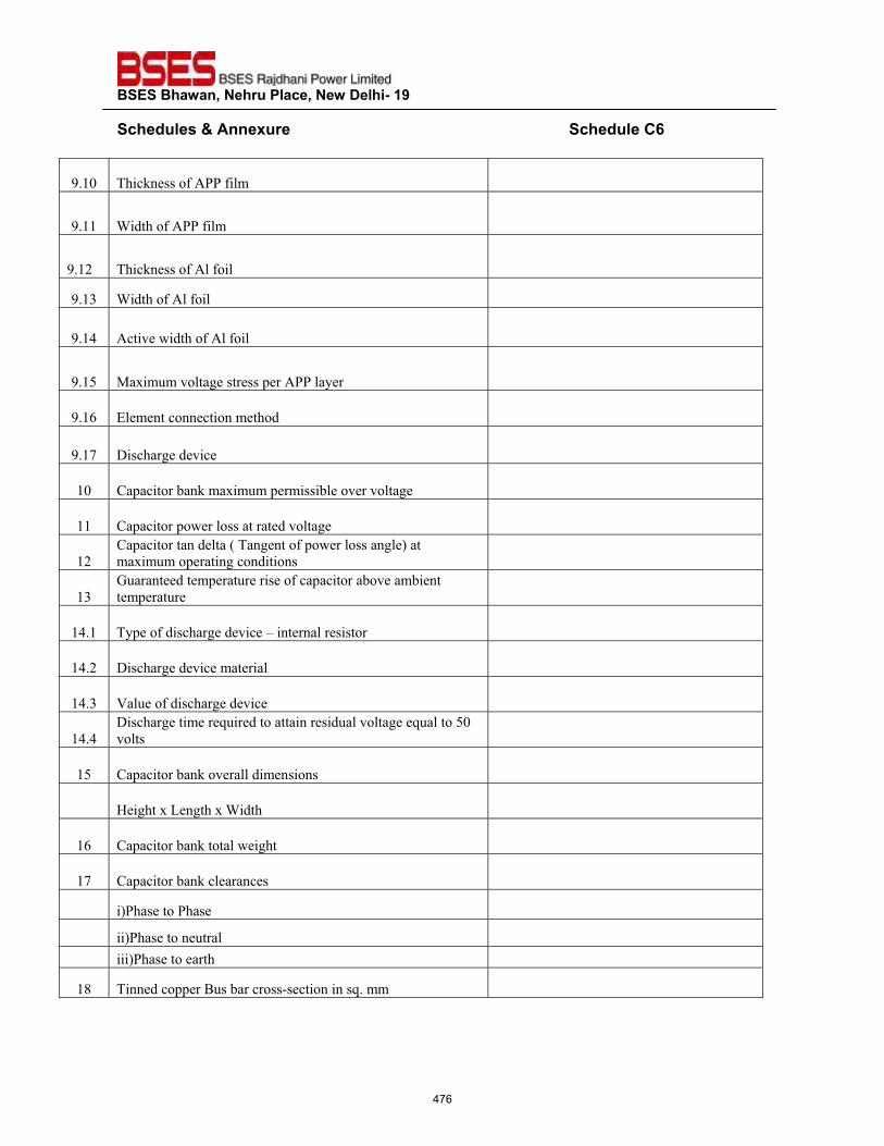
��������������� ����������������������
�����"�����'����� ��������������������������������������������������������������������"����?|��
?'�(� %-����������"//���$�� �
?'��� A��-����"//���$�� �
�����
?'��� %-����������"$����$� �
?'�&� A��-����"$����$� �
?'�*� "�,��;��-����"$����$� �
?'�.� ��B�����,�$��������������"//�$����� �
?'�1� @$���������������-��� �
?'�)� :��-�������,��� �
�(� ��������+������B�������������+$���,���,�$���� �
��� ����������;���$�����������,�$���� �
���
�������������$��2�%�����������;���$�������$�3���
��B����������������������� �
�&�
C�����������������������������������+�,����+����
���������� �
�*'�� %����������-�������,���6�������$��������� �
�*'�� :��-�������,���������$� �
�*'&� 8�$���������-�������,��� �
�*'*�
:��-����������� ��������������������$�,�$����� ��$���.(�
,�$�� �
�.� ��������+�����,���$$������������� �
�� 4���-�B�!���-�B�A��-� �
�1� ��������+������$�;���-�� �
�)� ��������+����$�������� �
�� �3/-������/-���� �
�� ��3/-�����������$� �
�� ���3/-���������-� �
�<� %������������D���+������������������ '���� �
476
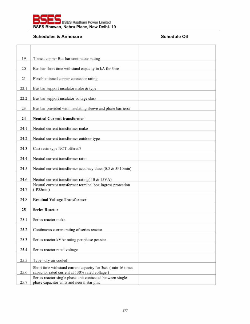
��������������� ����������������������
�����"�����'����� ��������������������������������������������������������������������"����?|��
�?� %������������D���+������������������ �
�(� D���+����-�������;�-���������������"�����&��� �
��� E$�B�+$��������������������������� �
��'�� D���+��������������$���������F����� �
��'�� D���+��������������$����,�$����$���� �
�&� D���+������,�����;�-�����$������$��,�������-����+�������0� �
%&� ��#���!��#�����������'��(��� �
�*'�� �����$����������������������� �
�*'�� �����$����������������������������� �
�*'&� ����������������%��������0� �
�*'*� �����$����������������������� �
�*'.� �����$������������������������$����2('.�F�./�(���3� �
�*'1� �����$�����������������������2��(�F��.8"3� �
�*')�
�����$������������������������$�+�B�����������������
2#/..���3� �
�*'<� ����)#�!���!�����*����'��(��� �
%+� ��������������� �
�.'�� ������������������ �
�.'�� �������������������������������������� �
�.'&� ��������������8"�������������-������������ �
�.'*� ������������������,�$���� �
�.'.� %����6����������$��� �
�.'1�
�-�������;�-���������������������&���2������1������
���������������������&(G������,�$����3� �
�.')�
�����������������$���-���������������+�;��������$��
�-�������������������������$��������� �
477
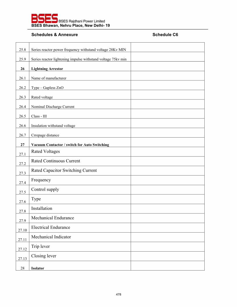
��������������� ����������������������
�����"�����'����� ��������������������������������������������������������������������"����?|��
�.'<� ���������������;������ �����;�-�����,�$�����<7,��#�� �
�.'?� �������������$��-����������$���;�-�����,�$����).�,����� �
%,� ���"��������������� �
�1'�� ������������������� �
�1'�� %����6�C��$����H�=�� �
�1'&� �����,�$���� �
�1'*� ������$�:��-������������ �
�1'.� �$������###� �
�1'1� #���$�����;�-�����,�$���� �
�1')� ���������������� �
%-�����##(�����������.��/���"�'����#����/���"���� �
�)'�� �����8�$������
�)'������������������������
�
�)'&���������������;�-�����������
�
�)'*�E�� �����
�
�)'.������$�����$��
�
�)'1�%����
�
�)'<�#���$$�����
�
�)'?���-����$�@��������
�
�)'�(�@$����$�@��������
�
�)'�����-����$�#�������
�
�)'���%����$�,����
�
�)'�&��$������$�,���
�
�<� ��!����� �
478
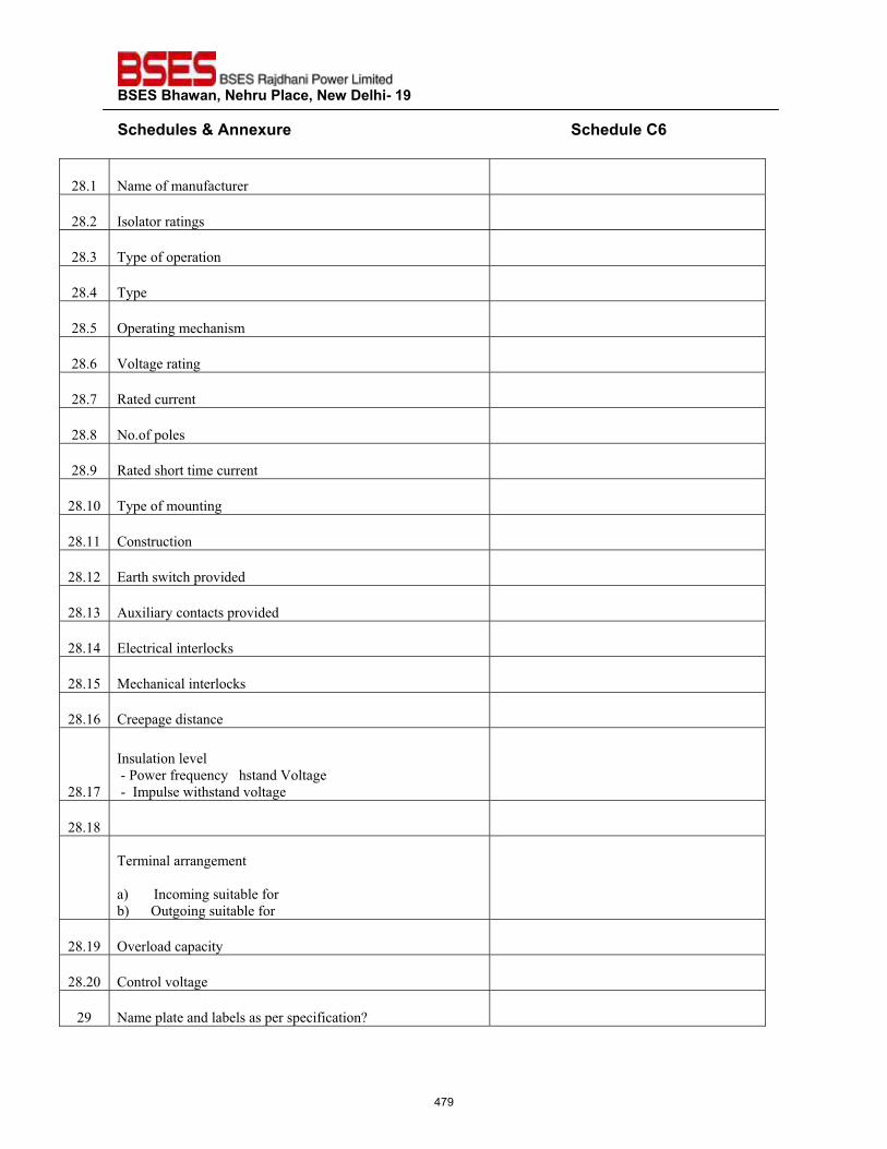
��������������� ����������������������
�����"�����'����� ��������������������������������������������������������������������"����?|��
�<'�� ������������������� �
�<'�� #��$����������� �
�<'&� %���������������� �
�<'*� %���� �
�<'.� =����������-������� �
�<'1� 8�$���������� �
�<')� ����������� �
�<'<� ��'�����$��� �
�<'?� ������-������������� �
�<'�(� %��������������� �
�<'��� ����������� �
�<'��� @��-��;�-����,����� �
�<'�&� "�B�$�������������,����� �
�<'�*� @$����$�����$���� �
�<'�.� ��-����$�����$���� �
�<'�1� ���������������� �
�<'�)�
#���$�����$�,�$������
���/�;������ �������-�����8�$������������������������������������������������
����#���$���;�-�����,�$���� �
�<'�<� �� �
��
%������$�������������
�
�3�������#�����������+$�������
+3������=�����������+$������ �
�<'�?� =,��$����������� �
�<'�(� �����$�,�$���� �
�?� ������$�������$�+�$�������������������0� �
479
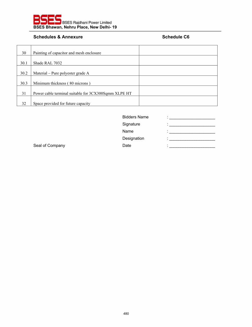
��������������� ����������������������
�����"�����'����� ��������������������������������������������������������������������"����?|��
&(� /������������������������-���$������ �
&('�� �-�����"!�)(&�� �
&('�� ������$�6�/������$������������"� �
&('&� ��������-�������2�<(��������3� �
&�� /�;����+$��������$�����+$������&�I&((� ���I!/@�4%�� �
&�� ��������,��������������������� �
�Bidders Name : ____________________
Signature : ____________________
Name : ____________________
Designation : ____________________
Seal of Company Date : ____________________
�
480
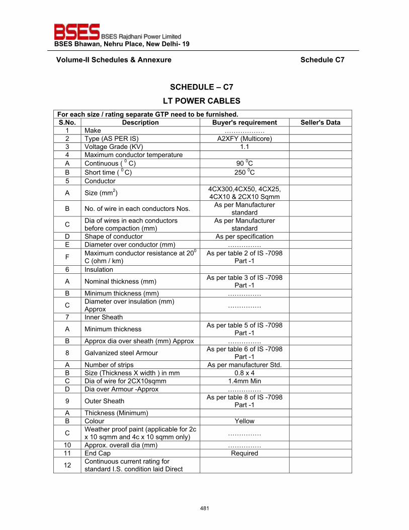
��������������� ����������������������
��~���>��^^�����"�����'����� ��������������������������������������������������������������������"����?%��
�
�?@��QZ��\�?%�Z������<�?��Z���
�� ������������� ��������� ����!�����"��������� ����"_��_��_� ���� ������� ���� ��� �=�� �>��� ����� ��������
1 Make ……………… 2 Type (AS PER IS) A2XFY (Multicore) 3 Voltage Grade (KV) 1.1 4 Maximum conductor temperature A Continuous ( 0 C) 90 0C B Short time ( 0 C) 250 0C 5 Conductor
A Size (mm2) 4CX300,4CX50, 4CX25, 4CX10 & 2CX10 Sqmm
B No. of wire in each conductors Nos. As per Manufacturer standard
C Dia of wires in each conductors before compaction (mm)
As per Manufacturer standard
D Shape of conductor As per specification E Diameter over conductor (mm) ……………
F Maximum conductor resistance at 200 C (ohm / km)
As per table 2 of IS -7098 Part -1
6 Insulation
A Nominal thickness (mm) As per table 3 of IS -7098 Part -1
B Minimum thickness (mm) ……………
C Diameter over insulation (mm) Approx ……………
7 Inner Sheath
A Minimum thickness As per table 5 of IS -7098 Part -1
B Approx dia over sheath (mm) Approx ……………
8 Galvanized steel Armour As per table 6 of IS -7098 Part -1
A Number of strips As per manufacturer Std. B Size (Thickness X width ) in mm 0.8 x 4 C Dia of wire for 2CX10sqmm 1.4mm Min D Dia over Armour -Approx ……………
9 Outer Sheath As per table 8 of IS -7098 Part -1
A Thickness (Minimum) B Colour Yellow
C Weather proof paint (applicable for 2c x 10 sqmm and 4c x 10 sqmm only) ……………
10 Approx. overall dia (mm) …………… 11 End Cap Required
12 Continuous current rating for standard I.S. condition laid Direct
481
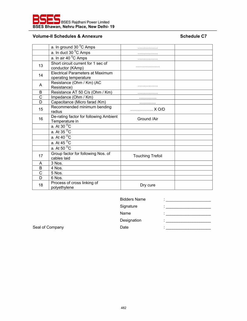
��������������� ����������������������
�~���>��^^�����"�����'����� ��������������������������������������������������������������������"����?%��
a. In ground 30 0C Amps …………… a. In duct 30 0C Amps …………… a. In air 40 0C Amps ……………
13 Short circuit current for 1 sec of conductor (KAmp) ………………
14 Electrical Parameters at Maximum operating temperature
A Resistance (Ohm / Km) (AC Resistance) ……………
B Resistance AT 50 C/s (Ohm / Km) …………… C Impedance (Ohm / Km) …………. D Capacitance (Micro farad /Km) …………
15 Recommended minimum bending radius …………….. X O/D
16 De-rating factor for following Ambient Temperature in Ground /Air
a. At 30 OC a. At 35 OC a. At 40 OC a. At 45 OC a. At 50 OC
17 Group factor for following Nos. of cables laid Touching Trefoil
A 3 Nos. B 4 Nos. C 5 Nos. D 6 Nos.
18 Process of cross linking of polyethylene Dry cure
Bidders Name : ____________________
Signature : ____________________
Name : ____________________
Designation : ____________________
Seal of Company Date : ____________________�
482
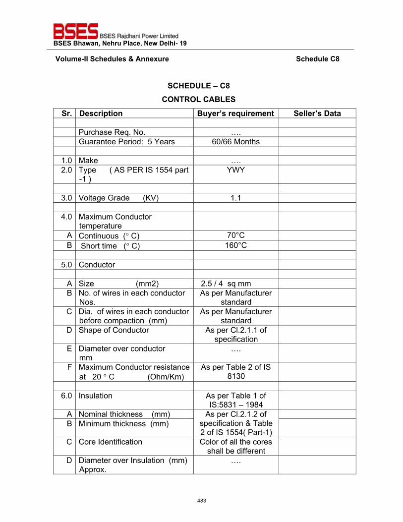
��������������� ����������������������
��~���>��^^�����"�����'����� ��������������������������������������������������������������������"����?���
�
�?@��QZ��\�?���?���<�Z�?��Z���
� _� ���� ������ ���� ��� �=�� �>��� ����� �������� � Purchase Req. No. …. � Guarantee Period: 5 Years 60/66 Months � �
1.0 Make …. �2.0 Type ( AS PER IS 1554 part
-1 ) YWY �
�3.0 Voltage Grade (KV) 1.1 �
�4.0 Maximum Conductor
temperature �
A Continuous (� C) 70°C �B Short time (� C) 160°C �
�5.0 Conductor �
�A Size (mm2) 2.5 / 4 sq mm �B No. of wires in each conductor
Nos. As per Manufacturer
standard �C Dia. of wires in each conductor
before compaction (mm) As per Manufacturer
standard �D Shape of Conductor As per Cl.2.1.1 of
specification �E Diameter over conductor
mm …. �
F Maximum Conductor resistance at 20 � C (Ohm/Km)
As per Table 2 of IS 8130 �
�6.0 Insulation As per Table 1 of
IS:5831 – 1984 �A Nominal thickness (mm) As per Cl.2.1.2 of
specification & Table 2 of IS 1554( Part-1)
�B Minimum thickness (mm) �C Core Identification Color of all the cores
shall be different �D Diameter over Insulation (mm)
Approx. …. �
483
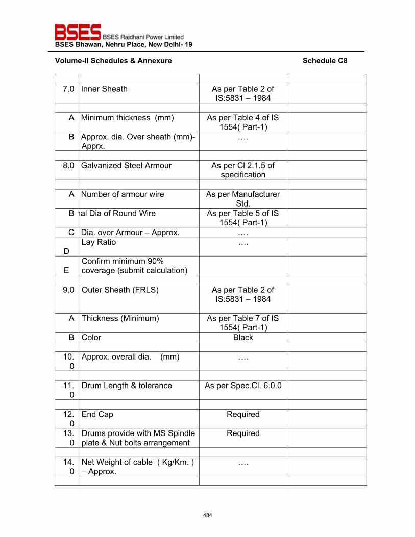
��������������� ����������������������
�~���>��^^�����"�����'����� ��������������������������������������������������������������������"����?���
�7.0 Inner Sheath As per Table 2 of
IS:5831 – 1984 � �
A Minimum thickness (mm) As per Table 4 of IS 1554( Part-1) �
B Approx. dia. Over sheath (mm)- Apprx.
…. � �
8.0 Galvanized Steel Armour As per Cl 2.1.5 of specification �
�A Number of armour wire As per Manufacturer
Std. �B nal Dia of Round Wire As per Table 5 of IS
1554( Part-1) �C Dia. over Armour – Approx. …. �
D
Lay Ratio …. � E
Confirm minimum 90% coverage (submit calculation)
� �
9.0 Outer Sheath (FRLS) As per Table 2 of IS:5831 – 1984
�
A Thickness (Minimum) As per Table 7 of IS 1554( Part-1) �
B Color Black � �
10.0
Approx. overall dia. (mm) …. � �
11.0
Drum Length & tolerance As per Spec.Cl. 6.0.0 � �
12.0
End Cap Required �13.
0 Drums provide with MS Spindle plate & Nut bolts arrangement
Required � �
14.0
Net Weight of cable ( Kg/Km. ) – Approx.
…. � �
484
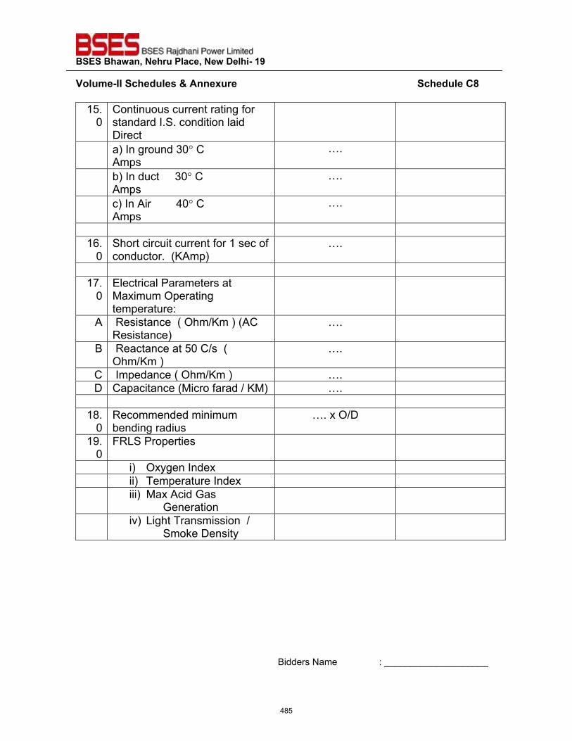
��������������� ����������������������
�~���>��^^�����"�����'����� ��������������������������������������������������������������������"����?���
15.0
Continuous current rating for standard I.S. condition laid Direct
�
a) In ground 30� C Amps
…. �
b) In duct 30� C Amps
…. �
c) In Air 40� C Amps
…. �
�16.
0 Short circuit current for 1 sec of conductor. (KAmp)
…. � �
17.0
Electrical Parameters at Maximum Operating temperature:
�
A Resistance ( Ohm/Km ) (AC Resistance)
…. �B Reactance at 50 C/s (
Ohm/Km ) …. �
C Impedance ( Ohm/Km ) …. �D Capacitance (Micro farad / KM) …. �
�18.
0 Recommended minimum bending radius
…. x O/D �19.
0 FRLS Properties �
i) Oxygen Index � ii) Temperature Index � iii) Max Acid Gas
Generation �
iv) Light Transmission / Smoke Density
�������
Bidders Name : ____________________
485

��������������� ����������������������
�~���>��^^�����"�����'����� ��������������������������������������������������������������������"����?��� Signature : ____________________
Name : ____________________
Designation : ____________________
Seal of Company Date : ____________________
�
486
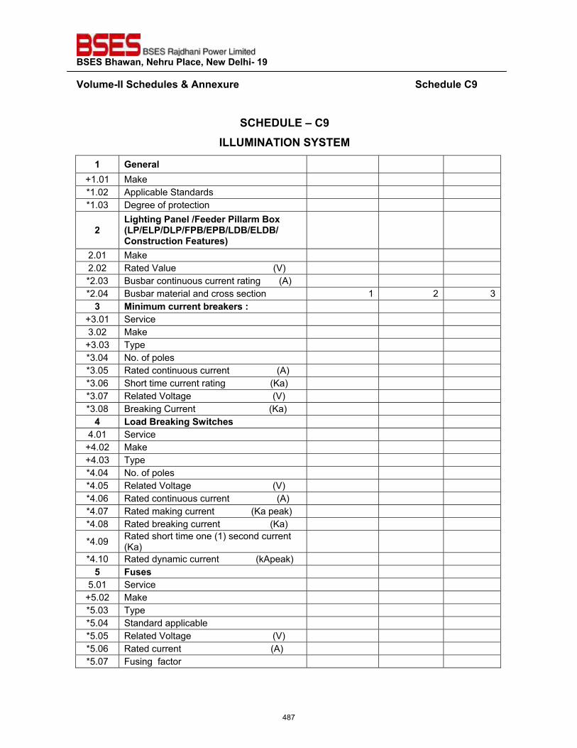
��������������� ����������������������
�~���>��^^�����"�����'����� ������������������������������������������������������������������"����?���
�
�?@��QZ��\�?���^ZZQ*^���^��������*�
�� !�� ��� +1.01 Make *1.02 Applicable Standards *1.03 Degree of protection
#�Z����������������"� ������ >������Z���Z���Z����������Z����Z����?��� ����������� ����
2.01 Make 2.02 Rated Value (V) *2.03 Busbar continuous current rating (A) *2.04 Busbar material and cross section 1 2 3
z� *��>�>��� ���� ��;� ��+� +3.01 Service 3.02 Make
+3.03 Type *3.04 No. of poles *3.05 Rated continuous current (A) *3.06 Short time current rating (Ka) *3.07 Related Voltage (V) *3.08 Breaking Current (Ka)
$� Z��"�� ��;������������ 4.01 Service
+4.02 Make +4.03 Type *4.04 No. of poles *4.05 Related Voltage (V) *4.06 Rated continuous current (A) *4.07 Rated making current (Ka peak) *4.08 Rated breaking current (Ka)
*4.09 Rated short time one (1) second current (Ka)
*4.10 Rated dynamic current (kApeak) {� ������
5.01 Service +5.02 Make *5.03 Type *5.04 Standard applicable *5.05 Related Voltage (V) *5.06 Rated current (A) *5.07 Fusing factor
487
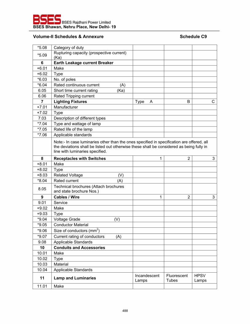
��������������� ����������������������
�~���>��^^�����"�����'����� ������������������������������������������������������������������"����?���
*5.08 Category of duty
*5.09 Rupturing capacity (prospective current) (Ka)
|� �� ���Z��;������ ���� ��;� � +6.01 Make +6.02 Type *6.03 No. of poles *6.04 Rated continuous current (A) 6.05 Short time current rating (Ka) 6.06 Rated Tripping current
%� Z������������ ��� Type A B C+7.01 Manufacturer +7.02 Type 7.03 Description of different types *7.04 Type and wattage of lamp *7.05 Rated life of the lamp *7.06 Applicable standards
Note:- In case luminaries other than the ones specified in specification are offered, all the deviations shall be listed out otherwise these shall be considered as being fully in line with luminaries specified.
�� <������������������������� 1 2 3+8.01 Make +8.02 Type +8.03 Related Voltage (V) *8.04 Rated current (A)
8.05 Technical brochures (Attach brochures and state brochure Nos.)
�� ?���������� �� 1 2 39.01 Service
+9.02 Make +9.03 Type *9.04 Voltage Grade (V) *9.05 Conductor Material *9.06 Size of conductors (mm2) *9.07 Current rating of conductors (A) 9.08 Applicable Standards �`� ?�"������"�������� ����
10.01 Make 10.02 Type 10.03 Material 10.04 Applicable Standards
��� Z�>���"�Z�>�� ���� Incandescent Lamps
Fluorescent Tubes
HPSV Lamps
11.01 Make
488
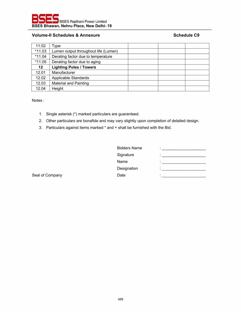
��������������� ����������������������
�~���>��^^�����"�����'����� ������������������������������������������������������������������"����?���
11.02 Type *11.03 Lumen output throughout life (Lumen) *11.04 Derating factor due to temperature *11.05 Derating factor due to aging
�#� Z������������������� �� 12.01 Manufacturer 12.02 Applicable Standards 12.03 Material and Painting 12.04 Height
Notes :
1. Single asterisk (*) marked particulars are guaranteed.
2. Other particulars are bonafide and may vary slightly upon completion of detailed design.
3. Particulars against items marked * and + shall be furnished with the Bid.
Bidders Name : ____________________
Signature : ____________________
Name : ____________________
Designation : ____________________
Seal of Company Date : ____________________
489
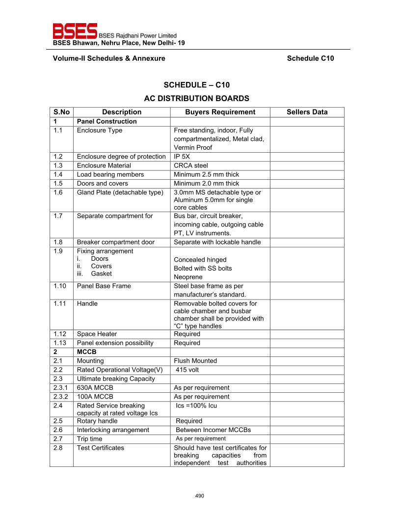
��������������� ����������������������
�~���>��^^�����"�����'����� ������������������������������������������������������������������"����?�`��
�
�?@��QZ��\�?�`��?��^��<^�Q�^������<���
�_��� ���� ������ ���� ��<�=�� �>��� ����� ��������� �����?��� ������ 1.1 Enclosure Type Free standing, indoor, Fully
compartmentalized, Metal clad, Vermin Proof
1.2 Enclosure degree of protection IP 5X 1.3 Enclosure Material CRCA steel 1.4 Load bearing members Minimum 2.5 mm thick 1.5 Doors and covers Minimum 2.0 mm thick 1.6 Gland Plate (detachable type) 3.0mm MS detachable type or
Aluminum 5.0mm for single core cables
1.7 Separate compartment for Bus bar, circuit breaker, incoming cable, outgoing cable PT, LV instruments.
1.8 Breaker compartment door Separate with lockable handle 1.9 Fixing arrangement
i. Doors ii. Covers iii. Gasket
Concealed hinged Bolted with SS bolts Neoprene
1.10 Panel Base Frame Steel base frame as per manufacturer’s standard.
1.11 Handle Removable bolted covers for cable chamber and busbar chamber shall be provided with “C” type handles
1.12 Space Heater Required 1.13 Panel extension possibility Required #� *??�� 2.1 Mounting Flush Mounted 2.2 Rated Operational Voltage(V) 415 volt 2.3 Ultimate breaking Capacity 2.3.1 630A MCCB As per requirement 2.3.2 100A MCCB As per requirement 2.4 Rated Service breaking
capacity at rated voltage Ics Ics =100% Icu
2.5 Rotary handle Required 2.6 Interlocking arrangement Between Incomer MCCBs 2.7 Trip time As per requirement 2.8 Test Certificates Should have test certificates for
breaking capacities from independent test authorities
490
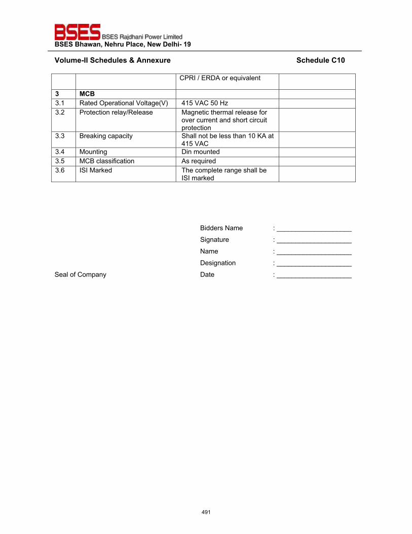
��������������� ����������������������
�~���>��^^�����"�����'����� ������������������������������������������������������������������"����?�`��
CPRI / ERDA or equivalent
z� *?�� 3.1 Rated Operational Voltage(V) 415 VAC 50 Hz 3.2 Protection relay/Release Magnetic thermal release for
over current and short circuit protection
3.3 Breaking capacity Shall not be less than 10 KA at 415 VAC
3.4 Mounting Din mounted 3.5 MCB classification As required 3.6 ISI Marked The complete range shall be
ISI marked
���
Bidders Name : ____________________
Signature : ____________________
Name : ____________________
Designation : ____________________
Seal of Company Date : ____________________
�
491
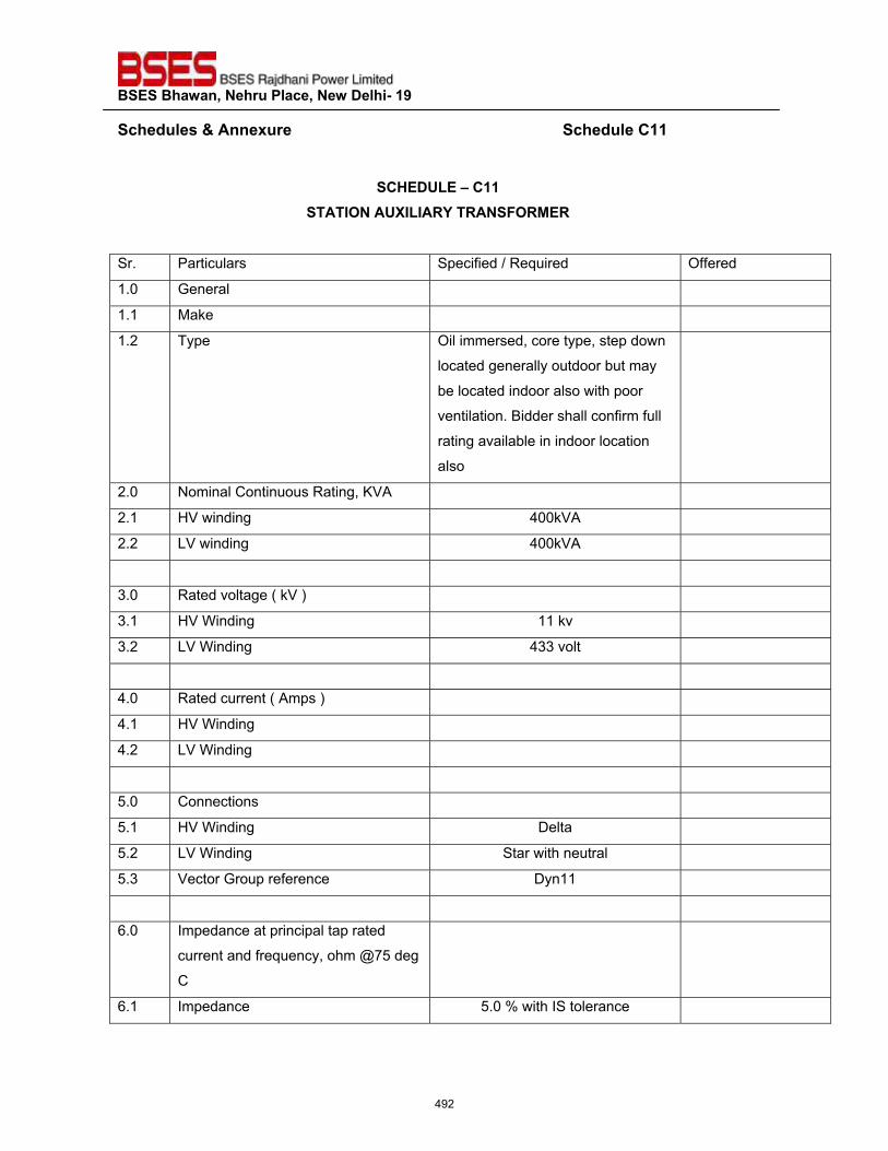
��������������� ����������������������
�����"�����'����� ������������������������������������������������������������������"����?����
��?@��QZ��\�?���
����^����Q�^Z^�<���<�����<*�<��
Sr. Particulars Specified / Required Offered
1.0 General
1.1 Make
1.2 Type Oil immersed, core type, step down
located generally outdoor but may
be located indoor also with poor
ventilation. Bidder shall confirm full
rating available in indoor location
also
2.0 Nominal Continuous Rating, KVA
2.1 HV winding 400kVA
2.2 LV winding 400kVA
3.0 Rated voltage ( kV )
3.1 HV Winding 11 kv
3.2 LV Winding 433 volt
4.0 Rated current ( Amps )
4.1 HV Winding
4.2 LV Winding
5.0 Connections
5.1 HV Winding Delta
5.2 LV Winding Star with neutral
5.3 Vector Group reference Dyn11
6.0 Impedance at principal tap rated
current and frequency, ohm @75 deg
C
6.1 Impedance 5.0 % with IS tolerance
492
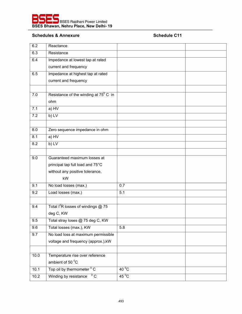
��������������� ����������������������
�����"�����'����� ������������������������������������������������������������������"����?����6.2 Reactance
6.3 Resistance
6.4 Impedance at lowest tap at rated
current and frequency
6.5 Impedance at highest tap at rated
current and frequency
7.0 Resistance of the winding at 750 C in
ohm
7.1 a) HV
7.2 b) LV
8.0 Zero sequence impedance in ohm
8.1 a) HV
8.2 b) LV
9.0 Guaranteed maximum losses at
principal tap full load and 75°C
without any positive tolerance,
kW
9.1 No load losses (max.) 0.7
9.2 Load losses (max.) 5.1
9.4 Total I2R losses of windings @ 75
deg C, KW
9.5 Total stray loses @ 75 deg C, KW
9.6 Total losses (max.), KW 5.8
9.7 No load loss at maximum permissible
voltage and frequency (approx.),kW
10.0 Temperature rise over reference
ambient of 50 0C
10.1 Top oil by thermometer 0 C 40 0C
10.2 Winding by resistance 0 C 45 0C
493
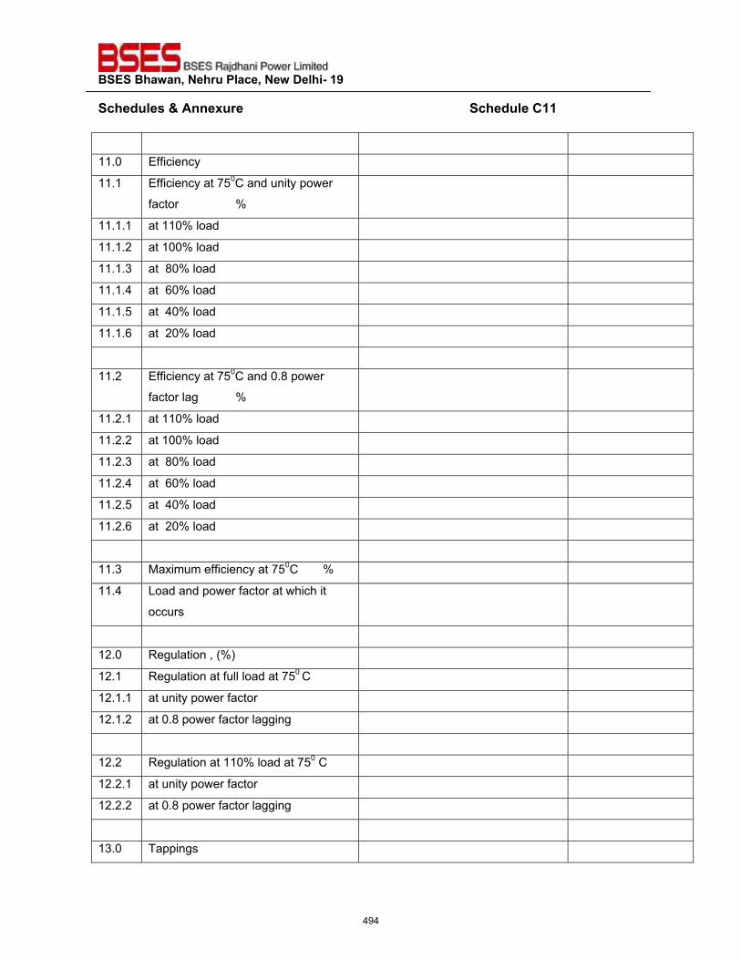
��������������� ����������������������
�����"�����'����� ������������������������������������������������������������������"����?����
11.0 Efficiency
11.1 Efficiency at 750C and unity power
factor %
11.1.1 at 110% load
11.1.2 at 100% load
11.1.3 at 80% load
11.1.4 at 60% load
11.1.5 at 40% load
11.1.6 at 20% load
11.2 Efficiency at 750C and 0.8 power
factor lag %
11.2.1 at 110% load
11.2.2 at 100% load
11.2.3 at 80% load
11.2.4 at 60% load
11.2.5 at 40% load
11.2.6 at 20% load
11.3 Maximum efficiency at 750C %
11.4 Load and power factor at which it
occurs
12.0 Regulation , (%)
12.1 Regulation at full load at 750 C
12.1.1 at unity power factor
12.1.2 at 0.8 power factor lagging
12.2 Regulation at 110% load at 750 C
12.2.1 at unity power factor
12.2.2 at 0.8 power factor lagging
13.0 Tappings
494
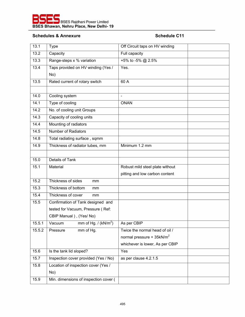
��������������� ����������������������
�����"�����'����� ������������������������������������������������������������������"����?����13.1 Type Off Circuit taps on HV winding
13.2 Capacity Full capacity
13.3 Range-steps x % variation +5% to -5% @ 2.5%
13.4 Taps provided on HV winding (Yes /
No)
Yes.
13.5 Rated current of rotary switch 60 A
14.0 Cooling system -
14.1 Type of cooling ONAN
14.2 No. of cooling unit Groups
14.3 Capacity of cooling units
14.4 Mounting of radiators
14.5 Number of Radiators
14.8 Total radiating surface , sqmm
14.9 Thickness of radiator tubes, mm Minimum 1.2 mm
15.0 Details of Tank
15.1 Material Robust mild steel plate without
pitting and low carbon content
15.2 Thickness of sides mm
15.3 Thickness of bottom mm
15.4 Thickness of cover mm
15.5 Confirmation of Tank designed and
tested for Vacuum, Pressure ( Ref:
CBIP Manual ) , (Yes/ No)
15.5.1 Vacuum mm of Hg. / (kN/m2) As per CBIP
15.5.2 Pressure mm of Hg. Twice the normal head of oil /
normal pressure + 35kN/m2
whichever is lower, As per CBIP
15.6 Is the tank lid sloped? Yes
15.7 Inspection cover provided (Yes / No) as per clause 4.2.1.5
15.8 Location of inspection cover (Yes /
No)
15.9 Min. dimensions of inspection cover (
495
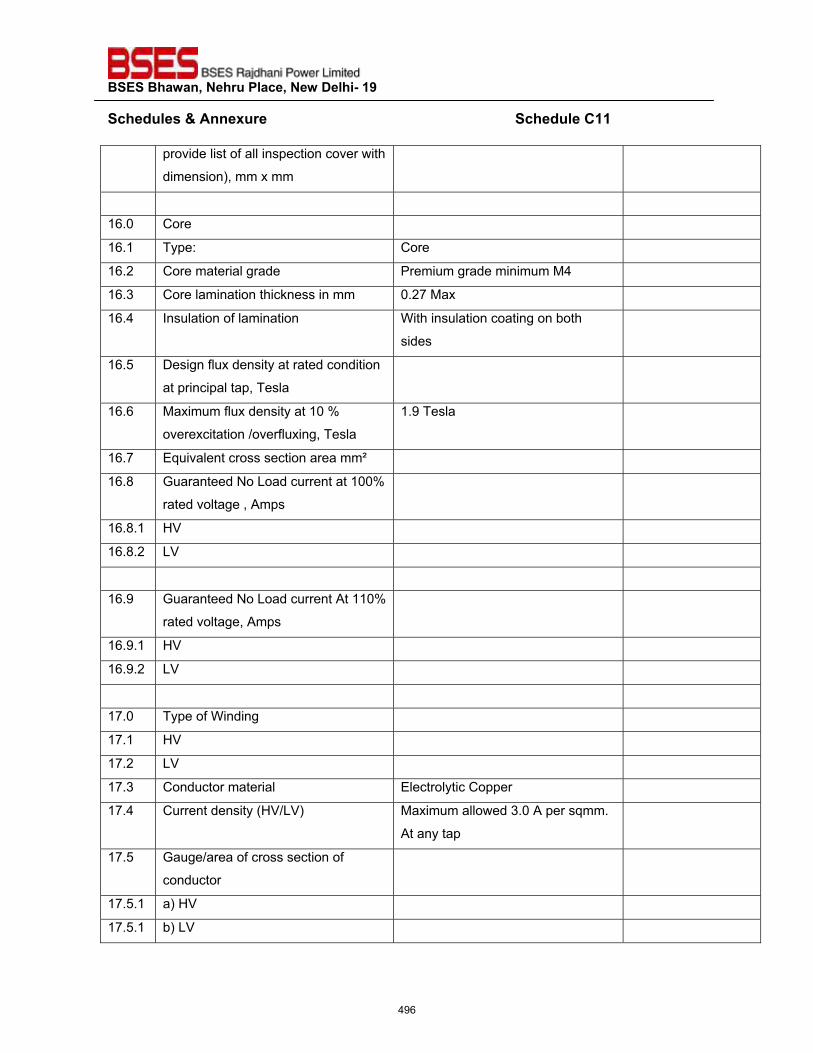
��������������� ����������������������
�����"�����'����� ������������������������������������������������������������������"����?����
provide list of all inspection cover with
dimension), mm x mm
16.0 Core
16.1 Type: Core
16.2 Core material grade Premium grade minimum M4
16.3 Core lamination thickness in mm 0.27 Max
16.4 Insulation of lamination With insulation coating on both
sides
16.5 Design flux density at rated condition
at principal tap, Tesla
16.6 Maximum flux density at 10 %
overexcitation /overfluxing, Tesla
1.9 Tesla
16.7 Equivalent cross section area mm²
16.8 Guaranteed No Load current at 100%
rated voltage , Amps
16.8.1 HV
16.8.2 LV
16.9 Guaranteed No Load current At 110%
rated voltage, Amps
16.9.1 HV
16.9.2 LV
17.0 Type of Winding
17.1 HV
17.2 LV
17.3 Conductor material Electrolytic Copper
17.4 Current density (HV/LV) Maximum allowed 3.0 A per sqmm.
At any tap
17.5 Gauge/area of cross section of
conductor
17.5.1 a) HV
17.5.1 b) LV
496
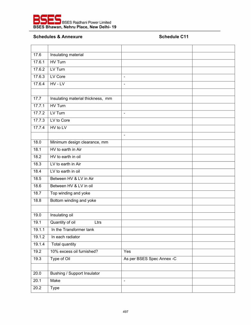
��������������� ����������������������
�����"�����'����� ������������������������������������������������������������������"����?����
17.6 Insulating material
17.6.1 HV Turn
17.6.2 LV Turn
17.6.3 LV Core -
17.6.4 HV - LV -
17.7 Insulating material thickness, mm
17.7.1 HV Turn
17.7.2 LV Turn -
17.7.3 LV to Core
17.7.4 HV to LV
-
18.0 Minimum design clearance, mm
18.1 HV to earth in Air
18.2 HV to earth in oil
18.3 LV to earth in Air
18.4 LV to earth in oil
18.5 Between HV & LV in Air
18.6 Between HV & LV in oil
18.7 Top winding and yoke
18.8 Bottom winding and yoke
19.0 Insulating oil
19.1 Quantity of oil Ltrs
19.1.1 In the Transformer tank
19.1.2 In each radiator
19.1.4 Total quantity
19.2 10% excess oil furnished? Yes
19.3 Type of Oil As per BSES Spec Annex -C
20.0 Bushing / Support Insulator
20.1 Make -
20.2 Type
497
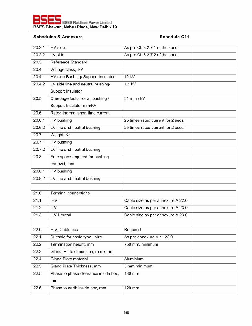
��������������� ����������������������
�����"�����'����� ������������������������������������������������������������������"����?����20.2.1 HV side As per Cl. 3.2.7.1 of the spec
20.2.2 LV side As per Cl. 3.2.7.2 of the spec
20.3 Reference Standard
20.4 Voltage class, kV
20.4.1 HV side Bushing/ Support Insulator 12 kV
20.4.2 LV side line and neutral bushing/
Support Insulator
1.1 kV
20.5 Creepage factor for all bushing /
Support Insulator mm/KV
31 mm / kV
20.6 Rated thermal short time current
20.6.1 HV bushing 25 times rated current for 2 secs.
20.6.2 LV line and neutral bushing 25 times rated current for 2 secs.
20.7 Weight, Kg
20.7.1 HV bushing
20.7.2 LV line and neutral bushing
20.8 Free space required for bushing
removal, mm
20.8.1 HV bushing
20.8.2 LV line and neutral bushing
21.0 Terminal connections
21.1 HV Cable size as per annexure A 22.0
21.2 LV Cable size as per annexure A 23.0
21.3 LV Neutral Cable size as per annexure A 23.0
22.0 H.V. Cable box Required
22.1 Suitable for cable type , size As per annexure A cl. 22.0
22.2 Termination height, mm 750 mm, minimum
22.3 Gland Plate dimension, mm x mm
22.4 Gland Plate material Aluminium
22.5 Gland Plate Thickness, mm 5 mm minimum
22.5 Phase to phase clearance inside box,
mm
180 mm
22.6 Phase to earth inside box, mm 120 mm
498
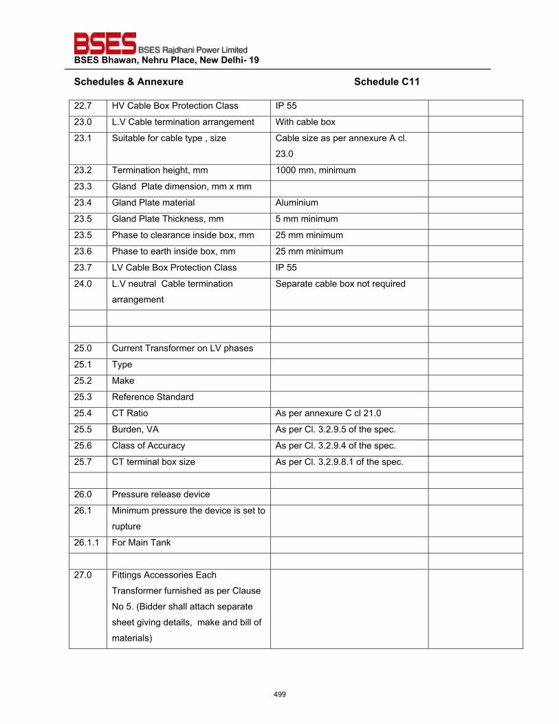
��������������� ����������������������
�����"�����'����� ������������������������������������������������������������������"����?����22.7 HV Cable Box Protection Class IP 55
23.0 L.V Cable termination arrangement With cable box
23.1 Suitable for cable type , size Cable size as per annexure A cl.
23.0
23.2 Termination height, mm 1000 mm, minimum
23.3 Gland Plate dimension, mm x mm
23.4 Gland Plate material Aluminium
23.5 Gland Plate Thickness, mm 5 mm minimum
23.5 Phase to clearance inside box, mm 25 mm minimum
23.6 Phase to earth inside box, mm 25 mm minimum
23.7 LV Cable Box Protection Class IP 55
24.0 L.V neutral Cable termination
arrangement
Separate cable box not required
25.0 Current Transformer on LV phases
25.1 Type
25.2 Make
25.3 Reference Standard
25.4 CT Ratio As per annexure C cl 21.0
25.5 Burden, VA As per Cl. 3.2.9.5 of the spec.
25.6 Class of Accuracy As per Cl. 3.2.9.4 of the spec.
25.7 CT terminal box size As per Cl. 3.2.9.8.1 of the spec.
26.0 Pressure release device
26.1 Minimum pressure the device is set to
rupture
26.1.1 For Main Tank
27.0 Fittings Accessories Each
Transformer furnished as per Clause
No 5. (Bidder shall attach separate
sheet giving details, make and bill of
materials)
499
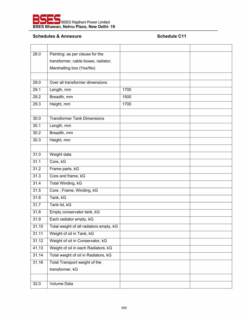
��������������� ����������������������
�����"�����'����� ������������������������������������������������������������������"����?����
28.0 Painting: as per clause for the
transformer, cable boxes, radiator,
Marshalling box (Yes/No)
29.0 Over all transformer dimensions
29.1 Length, mm 1700
29.2 Breadth, mm 1500
29.3 Height, mm 1700
30.0 Transformer Tank Dimensions
30.1 Length, mm
30.2 Breadth, mm
30.3 Height, mm
31.0 Weight data
31.1 Core, kG
31.2 Frame parts, kG
31.3 Core and frame, kG
31.4 Total Winding, kG
31.5 Core , Frame, Winding, kG
31.6 Tank, kG
31.7 Tank lid, kG
31.8 Empty conservator tank, kG
31.9 Each radiator empty, kG
31.10 Total weight of all radiators empty, kG
31.11 Weight of oil in Tank, kG
31.12 Weight of oil in Conservator, kG
41.13 Weight of oil in each Radiators, kG
31.14 Total weight of oil in Radiators, kG
31.16 Total Transport weight of the
transformer, kG
32.0 Volume Data
500
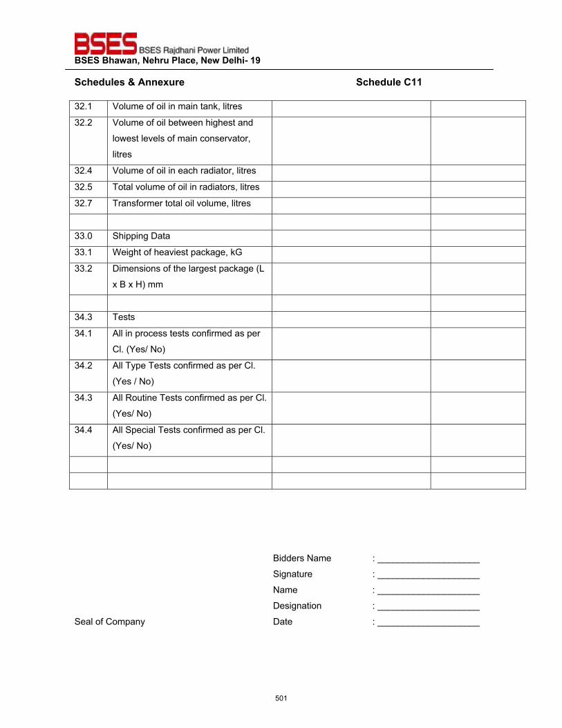
��������������� ����������������������
�����"�����'����� ������������������������������������������������������������������"����?����32.1 Volume of oil in main tank, litres
32.2 Volume of oil between highest and
lowest levels of main conservator,
litres
32.4 Volume of oil in each radiator, litres
32.5 Total volume of oil in radiators, litres
32.7 Transformer total oil volume, litres
33.0 Shipping Data
33.1 Weight of heaviest package, kG
33.2 Dimensions of the largest package (L
x B x H) mm
34.3 Tests
34.1 All in process tests confirmed as per
Cl. (Yes/ No)
34.2 All Type Tests confirmed as per Cl.
(Yes / No)
34.3 All Routine Tests confirmed as per Cl.
(Yes/ No)
34.4 All Special Tests confirmed as per Cl.
(Yes/ No)
�
�
�
�
�
�
Bidders Name : ____________________
Signature : ____________________
Name : ____________________
Designation : ____________________
Seal of Company Date : ____________________
�
501
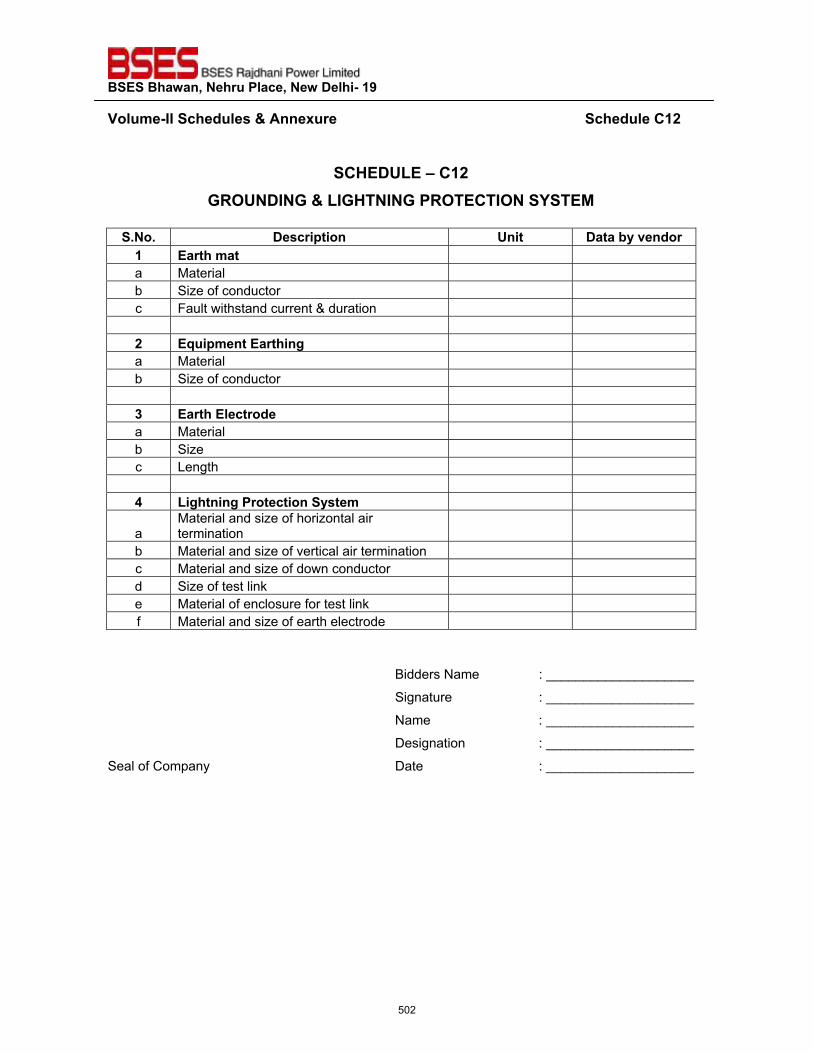
��������������� ����������������������
�~���>��^^�����"�����'����� ������������������������������������������������������������������"����?�#��
�
�?@��QZ��\�?�#�!<�Q��^�!�'�Z^!@��^�!��<���?�^��������*�
��_��_� ���� ������� Q��� ����������"� �
�� �� ���>��� a Material b Size of conductor c Fault withstand current & duration #� �=���>����� ����� a Material b Size of conductor z� �� �������� �"�� a Material b Size c Length $� Z�������� �������������>�
a Material and size of horizontal air termination
b Material and size of vertical air termination c Material and size of down conductor d Size of test link e Material of enclosure for test link f Material and size of earth electrode
��
Bidders Name : ____________________
Signature : ____________________
Name : ____________________
Designation : ____________________
Seal of Company Date : ____________________
�
502
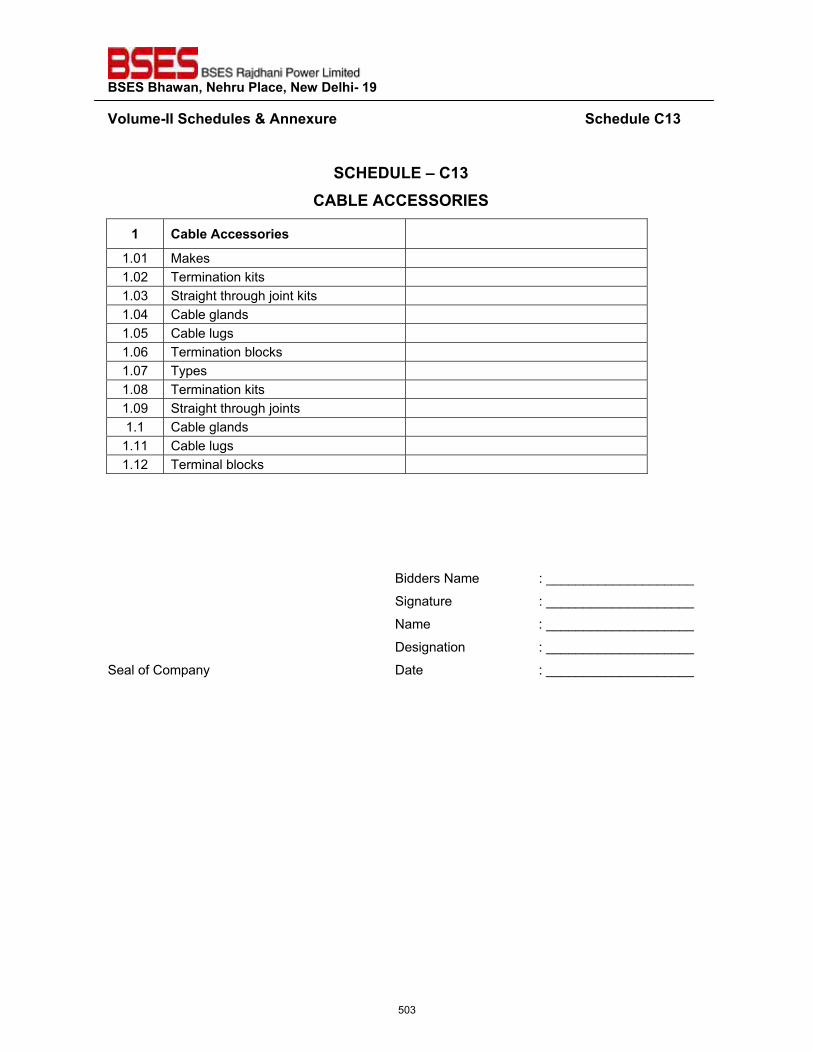
��������������� ����������������������
�~���>��^^�����"�����'����� ������������������������������������������������������������������"����?�z��
�
�?@��QZ��\�?�z��?��Z���??����<^���
�� ?������������ ����
1.01 Makes 1.02 Termination kits 1.03 Straight through joint kits 1.04 Cable glands 1.05 Cable lugs 1.06 Termination blocks 1.07 Types 1.08 Termination kits 1.09 Straight through joints 1.1 Cable glands 1.11 Cable lugs 1.12 Terminal blocks
�
Bidders Name : ____________________
Signature : ____________________
Name : ____________________
Designation : ____________________
Seal of Company Date : ____________________
503
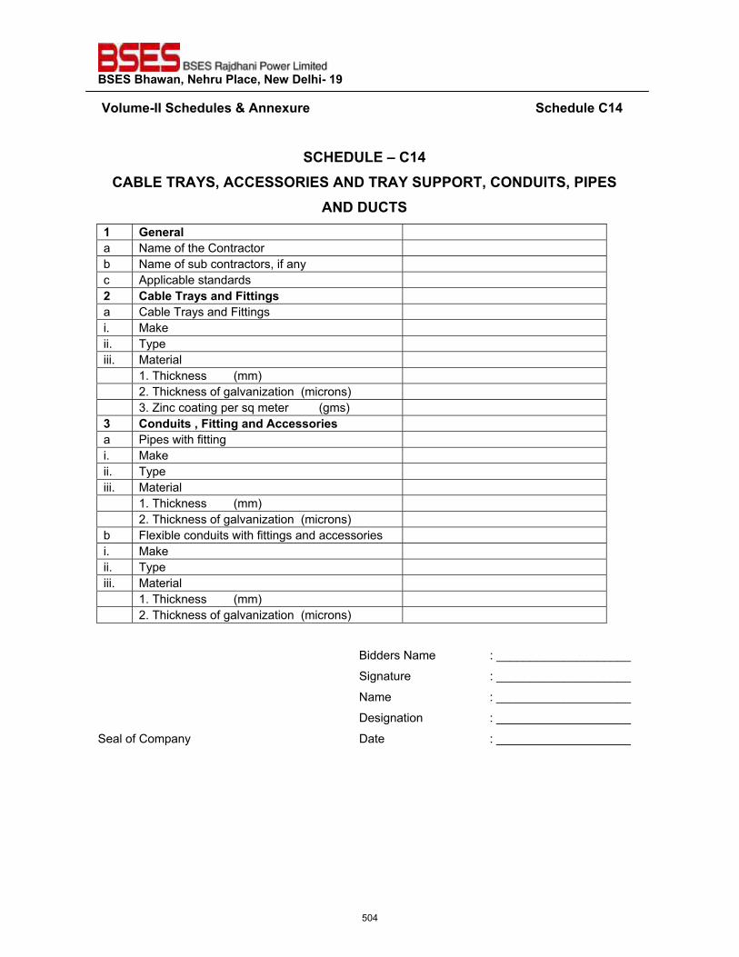
��������������� ����������������������
��~���>��^^�����"�����'����� ������������������������������������������������������������������"����?�$��
�
�?@��QZ��\�?�$�?��Z���<�����??����<^��������<����Q���<��?���Q^����^����
�����Q?����� !�� ��� a Name of the Contractor b Name of sub contractors, if any c Applicable standards #� ?������ �����"��������� a Cable Trays and Fittings i. Make ii. Type iii. Material 1. Thickness (mm) 2. Thickness of galvanization (microns) 3. Zinc coating per sq meter (gms) z� ?�"��������������"�������� ���� a Pipes with fitting i. Make ii. Type iii. Material 1. Thickness (mm) 2. Thickness of galvanization (microns) b Flexible conduits with fittings and accessories i. Make ii. Type iii. Material 1. Thickness (mm) 2. Thickness of galvanization (microns)
�Bidders Name : ____________________
Signature : ____________________
Name : ____________________
Designation : ____________________
Seal of Company Date : ____________________�
504
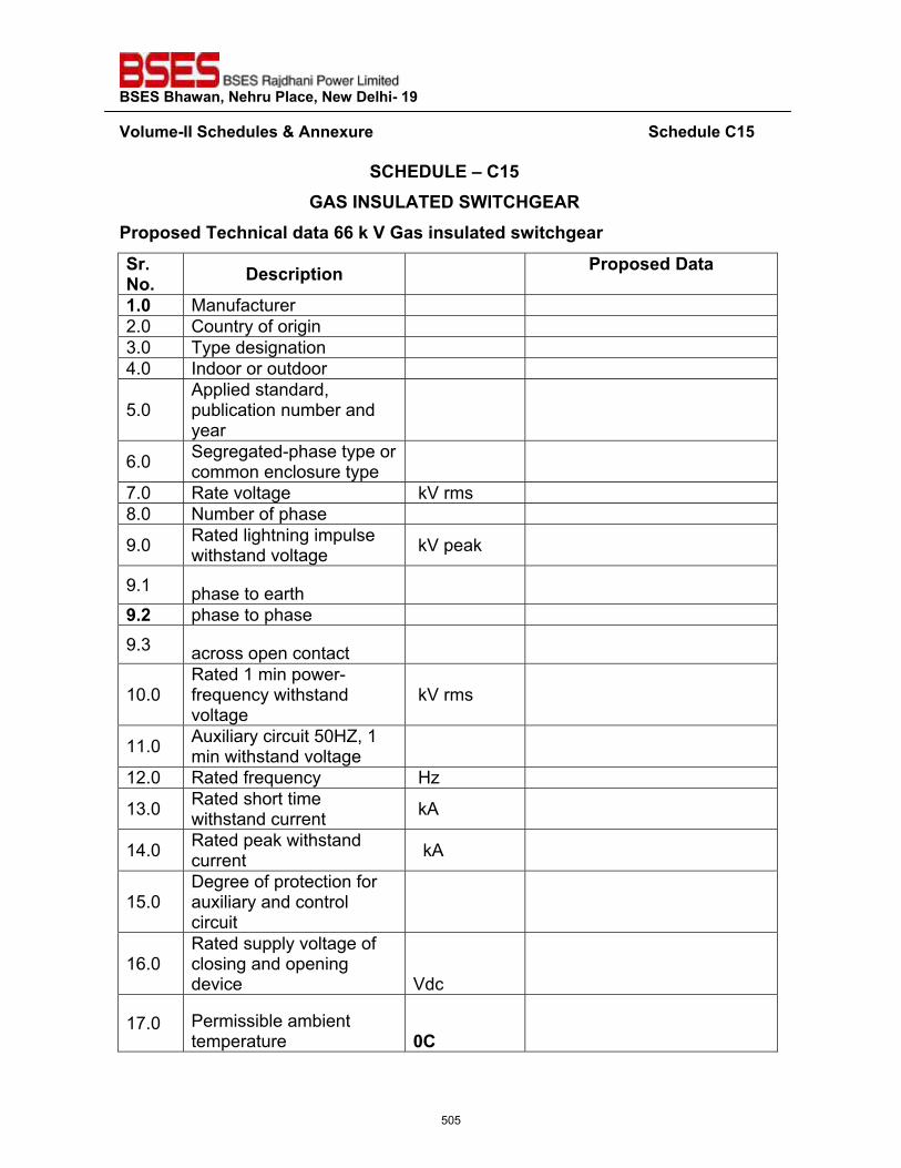
��������������� ����������������������
�~���>��^^�����"�����'����� ������������������������������������������������������������������"����?�{��
�?@��QZ��\�?�{��!���^��QZ�������^�?@!��<�
� �����"����������"����||�;�~�!����������"���������� �� _���_� ���� ������� � � �����"������
�_`� Manufacturer 2.0 Country of origin 3.0 Type designation 4.0 Indoor or outdoor
5.0 Applied standard, publication number and year
6.0 Segregated-phase type or common enclosure type
7.0 Rate voltage kV rms 8.0 Number of phase
9.0 Rated lightning impulse withstand voltage kV peak
9.1 phase to earth
�_#� phase to phase 9.3 across open contact
10.0 Rated 1 min power-frequency withstand voltage
kV rms
11.0 Auxiliary circuit 50HZ, 1 min withstand voltage
12.0 Rated frequency Hz
13.0 Rated short time withstand current kA
14.0 Rated peak withstand current kA
15.0 Degree of protection for auxiliary and control circuit
16.0 Rated supply voltage of closing and opening device Vdc
17.0 Permissible ambient temperature `?�
505
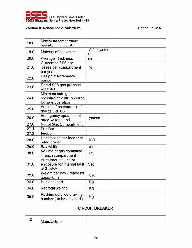
��������������� ����������������������
�~���>��^^������"�����'����� �����������������������������������������������������������������"����?�{��
�
18.0 Maximum temperature rise at..................A
19.0 Material of enclosure Al/alloy/steeI
20.0 Average Thickness mm
21.0 Guarantee SF6 gas losses per compartment per year
%
22.0 Design Maintenance period
23.0 Rated SF6 gas pressure at 20 `?
24.0 Minimum safe gas pressure at 20`?�required for safe operation
25.0 Setting of pressure relief device ( 20 `?)
26.0 Emergency operation at rated voltage and yes/no
27.0 No. of Gas Compartment 27.1 Bus Bar #%_#� ���"� �
28.0 Heat losses per feeder at rated power KW
29.0 Bay width mm
30.0 Volume of gas contained in each compartment M3
31.0 Burn through time of enclosure for internal fault of 31.5KA
Sec
32.0 Weight per bay ( ready for operation ) Sec
33.0 Heaviest part Kg 34.0 Net total weight Kg
35.0 Packing detailed drawing number ( to be attached ) Kg
?^<?Q^���<��}�<�
1.0 Manufacturer
506
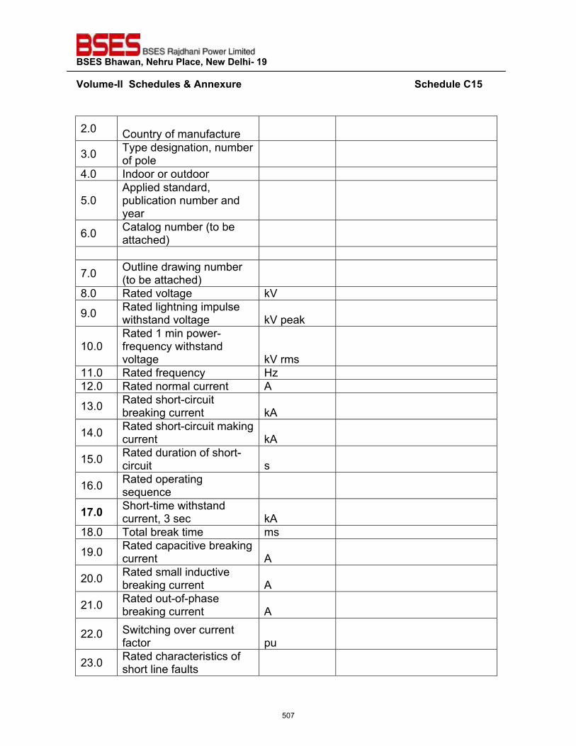
��������������� ����������������������
�~���>��^^������"�����'����� �����������������������������������������������������������������"����?�{��
�
2.0 Country of manufacture
3.0 Type designation, number of pole
4.0 Indoor or outdoor
5.0 Applied standard, publication number and year
6.0 Catalog number (to be attached)
7.0 Outline drawing number (to be attached)
8.0 Rated voltage kV
9.0 Rated lightning impulse withstand voltage kV peak
10.0 Rated 1 min power-frequency withstand voltage kV rms
11.0 Rated frequency Hz 12.0 Rated normal current A
13.0 Rated short-circuit breaking current kA
14.0 Rated short-circuit making current kA
15.0 Rated duration of short-circuit s
16.0 Rated operating sequence
�%_`� Short-time withstand current, 3 sec kA
18.0 Total break time ms
19.0 Rated capacitive breaking current A
20.0 Rated small inductive breaking current A
21.0 Rated out-of-phase breaking current A
22.0 Switching over current factor pu
23.0 Rated characteristics of short line faults
507
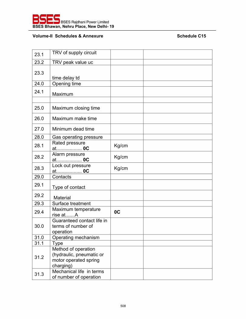
��������������� ����������������������
�~���>��^^������"�����'����� �����������������������������������������������������������������"����?�{��
�
23.1 TRV of supply circuit
23.2 TRV peak value uc
23.3 time delay td
24.0 Opening time 24.1 Maximum
25.0 Maximum closing time
26.0 Maximum make time
27.0 Minimum dead time
28.0 Gas operating pressure
28.1 Rated pressure at...................�`?� Kg/cm
28.2 Alarm pressure at...................�`?� Kg/cm
28.3 Lock out pressure at...................�`?� Kg/cm
29.0 Contacts 29.1 Type of contact
29.2 Material
29.3 Surface treatment
29.4 Maximum temperature rise at.......A `?
30.0 Guaranteed contact life in terms of number of operation
31.0 Operating mechanism 31.1 Type
31.2
Method of operation (hydraulic, pneumatic or motor operated spring charging)
31.3 Mechanical life in terms of number of operation
508
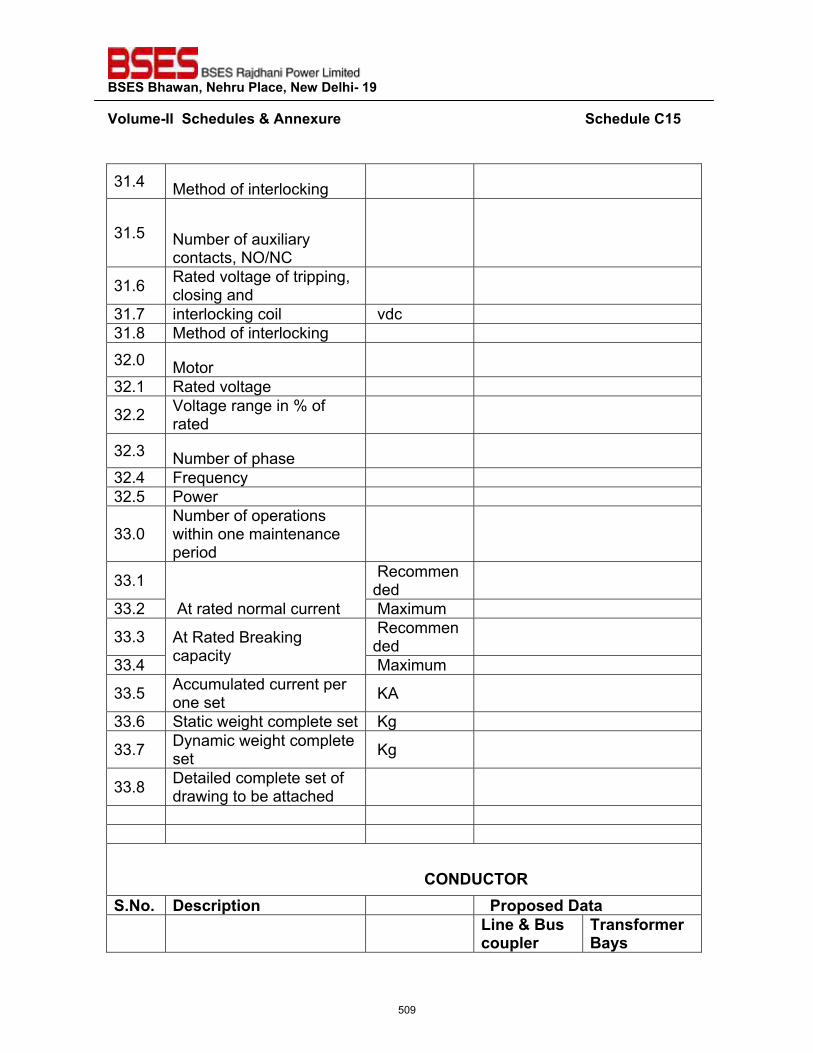
��������������� ����������������������
�~���>��^^������"�����'����� �����������������������������������������������������������������"����?�{��
�
31.4 Method of interlocking
31.5 Number of auxiliary contacts, NO/NC
31.6 Rated voltage of tripping, closing and
31.7 interlocking coil vdc 31.8 Method of interlocking 32.0 Motor
32.1 Rated voltage
32.2 Voltage range in % of rated
32.3 Number of phase
32.4 Frequency 32.5 Power
33.0 Number of operations within one maintenance period
33.1
At rated normal current
Recommended
33.2 Maximum
33.3 At Rated Breaking capacity
Recommended
33.4 Maximum
33.5 Accumulated current per one set KA
33.6 Static weight complete set Kg
33.7 Dynamic weight complete set Kg
33.8 Detailed complete set of drawing to be attached
���������������������������������������������������������������������?���Q?��<��_��_� ���� ������ �� ��� �����"������� � �� Z���'�����
������ �� ���� >� ������
509
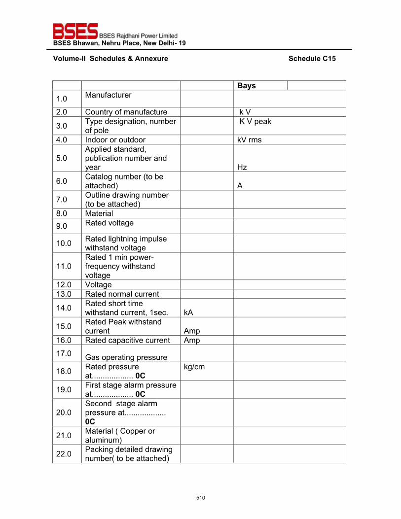
��������������� ����������������������
�~���>��^^������"�����'����� �����������������������������������������������������������������"����?�{��
�
�����1.0 Manufacturer
2.0 Country of manufacture k V
3.0 Type designation, number of pole
K V peak
4.0 Indoor or outdoor kV rms
5.0 Applied standard, publication number and year
Hz
6.0 Catalog number (to be attached)
A
7.0 Outline drawing number (to be attached)
8.0 Material 9.0 Rated voltage
10.0 Rated lightning impulse withstand voltage
11.0 Rated 1 min power-frequency withstand voltage
12.0 Voltage 13.0 Rated normal current
14.0 Rated short time withstand current, 1sec. kA
15.0 Rated Peak withstand current Amp
16.0 Rated capacitive current Amp 17.0 Gas operating pressure
18.0 Rated pressure at...................�`?
kg/cm
19.0 First stage alarm pressure at...................�`?
20.0 Second stage alarm pressure at...................�`?
21.0 Material ( Copper or aluminum)
22.0 Packing detailed drawing number( to be attached)
510
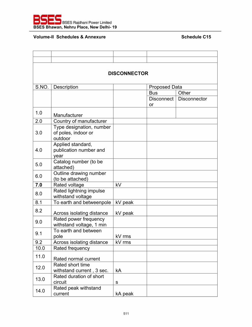
��������������� ����������������������
�~���>��^^������"�����'����� �����������������������������������������������������������������"����?�{��
�
������������������������������������������������������^�?����?��<�
S.NO. Description Proposed Data
Bus Other Disconnector
Disconnector
1.0 Manufacturer
2.0 Country of manufacturer
3.0 Type designation, number of poles, indoor or outdoor
4.0 Applied standard, publication number and year
5.0 Catalog number (to be attached)
6.0 Outline drawing number (to be attached)
%_`� Rated voltage kV
8.0 Rated lightning impulse withstand voltage
8.1 To earth and betweenpole kV peak 8.2 Across isolating distance kV peak
9.0 Rated power frequency withstand voltage, 1 min
9.1 To earth and between pole kV rms
9.2 Across isolating distance kV rms 10.0 Rated frequency 11.0 Rated normal current
12.0 Rated short time withstand current , 3 sec. kA
13.0 Rated duration of short circuit s
14.0 Rated peak withstand current kA peak
511
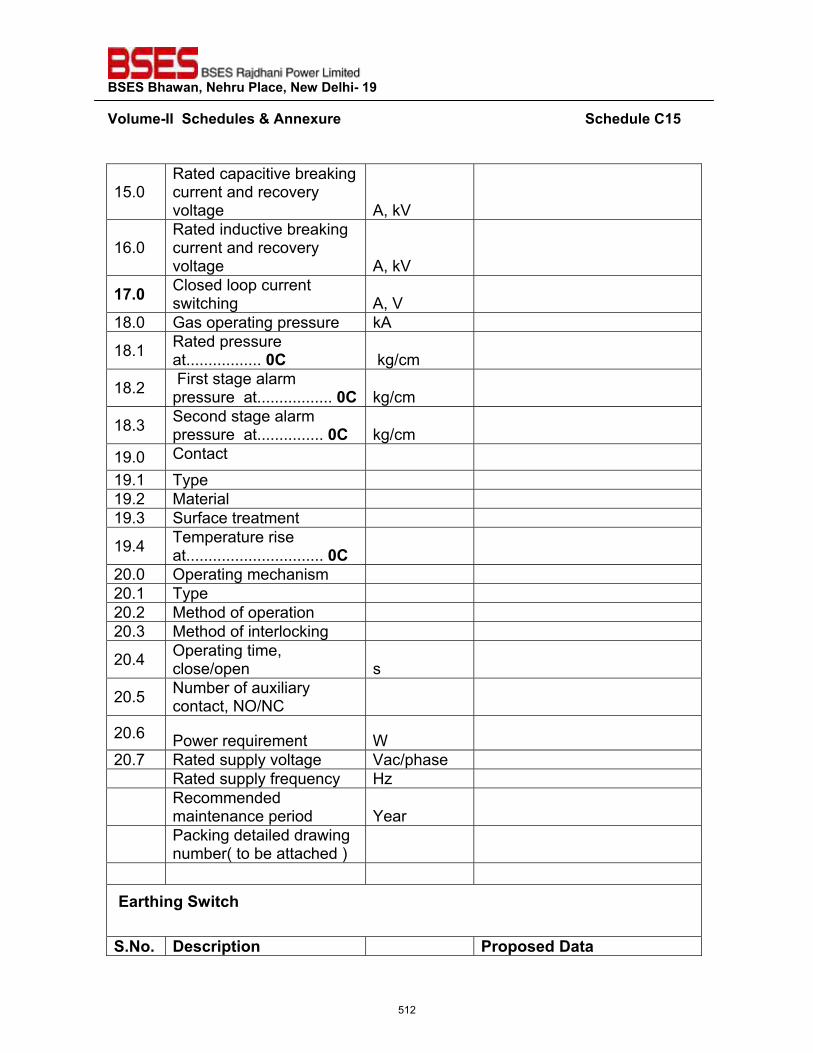
��������������� ����������������������
�~���>��^^������"�����'����� �����������������������������������������������������������������"����?�{��
�
15.0 Rated capacitive breaking current and recovery voltage A, kV
16.0 Rated inductive breaking current and recovery voltage A, kV
�%_`� Closed loop current switching A, V
18.0 Gas operating pressure kA
18.1 Rated pressure at.................�`? kg/cm
18.2 First stage alarm pressure at.................�`?� kg/cm
18.3 Second stage alarm pressure at...............�`?� kg/cm
19.0 Contact 19.1 Type 19.2 Material 19.3 Surface treatment
19.4 Temperature rise at............................... `?
20.0 Operating mechanism 20.1 Type 20.2 Method of operation 20.3 Method of interlocking
20.4 Operating time, close/open s
20.5 Number of auxiliary contact, NO/NC
20.6 Power requirement W
20.7 Rated supply voltage Vac/phase Rated supply frequency Hz
Recommended maintenance period Year
Packing detailed drawing number( to be attached )
�� ������������ �_��_� ���� ������ �� � �����"������
512
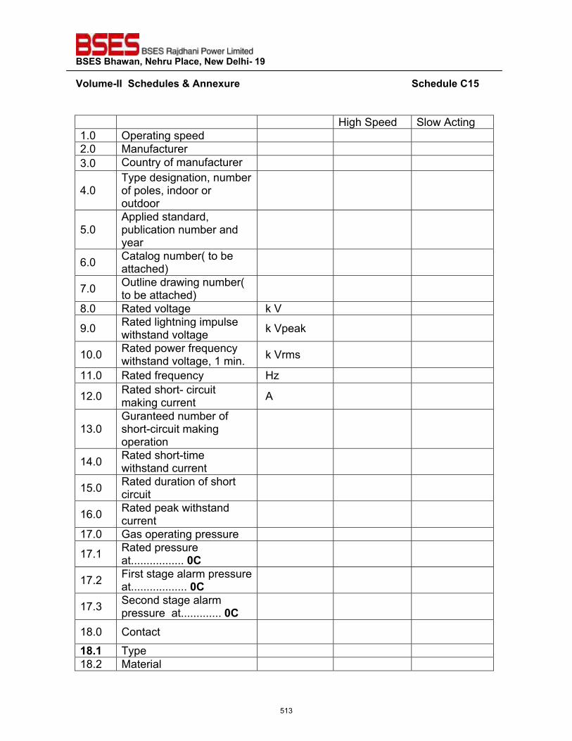
��������������� ����������������������
�~���>��^^������"�����'����� �����������������������������������������������������������������"����?�{��
�
High Speed Slow Acting 1.0 Operating speed 2.0 Manufacturer 3.0 Country of manufacturer
4.0 Type designation, number of poles, indoor or outdoor
5.0 Applied standard, publication number and year
6.0 Catalog number( to be attached)
7.0 Outline drawing number( to be attached)
8.0 Rated voltage k V
9.0 Rated lightning impulse withstand voltage k Vpeak
10.0 Rated power frequency withstand voltage, 1 min. k Vrms
11.0 Rated frequency Hz
12.0 Rated short- circuit making current A
13.0 Guranteed number of short-circuit making operation
14.0 Rated short-time withstand current
15.0 Rated duration of short circuit
16.0 Rated peak withstand current
17.0 Gas operating pressure
17.1 Rated pressure at.................�`?�
17.2 First stage alarm pressure at..................�`?�
17.3 Second stage alarm pressure at.............�`?�
18.0 Contact
��_�� Type 18.2 Material
513
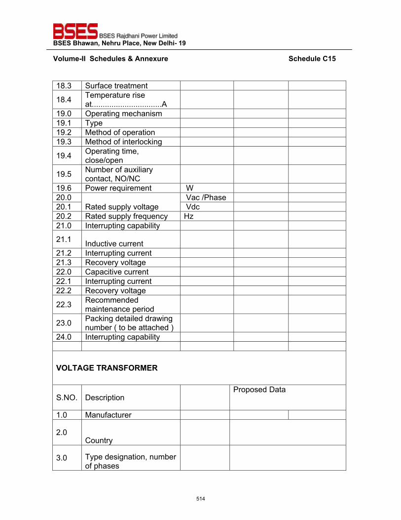
��������������� ����������������������
�~���>��^^������"�����'����� �����������������������������������������������������������������"����?�{��
�
18.3 Surface treatment
18.4 Temperature rise at................................A
19.0 Operating mechanism 19.1 Type 19.2 Method of operation 19.3 Method of interlocking
19.4 Operating time, close/open
19.5 Number of auxiliary contact, NO/NC
19.6 Power requirement W 20.0
Rated supply voltage Vac /Phase
20.1 Vdc 20.2 Rated supply frequency Hz 21.0 Interrupting capability
21.1 Inductive current
21.2 Interrupting current 21.3 Recovery voltage 22.0 Capacitive current 22.1 Interrupting current 22.2 Recovery voltage
22.3 Recommended maintenance period
23.0 Packing detailed drawing number ( to be attached )
24.0 Interrupting capability
~�Z��!���<�����<*�<�
S.NO. Description Proposed Data
1.0 Manufacturer
2.0 Country
3.0 Type designation, number of phases
514
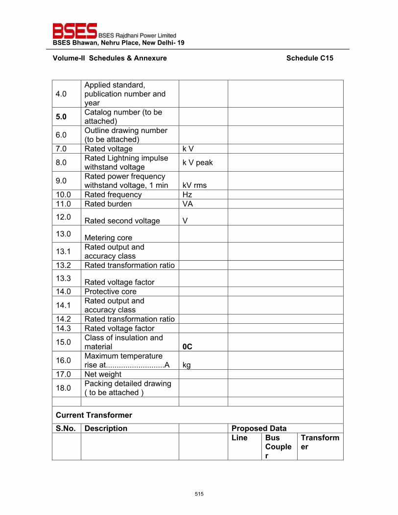
��������������� ����������������������
�~���>��^^������"�����'����� �����������������������������������������������������������������"����?�{��
�
4.0 Applied standard, publication number and year
{_`� Catalog number (to be attached)
6.0 Outline drawing number (to be attached)
7.0 Rated voltage k V
8.0 Rated Lightning impulse withstand voltage k V peak
9.0 Rated power frequency withstand voltage, 1 min kV rms
10.0 Rated frequency Hz 11.0 Rated burden VA 12.0 Rated second voltage V
13.0 Metering core
13.1 Rated output and accuracy class
13.2 Rated transformation ratio 13.3 Rated voltage factor
14.0 Protective core
14.1 Rated output and accuracy class
14.2 Rated transformation ratio 14.3 Rated voltage factor
15.0 Class of insulation and material `?�
16.0 Maximum temperature rise at...........................A kg
17.0 Net weight
18.0 Packing detailed drawing ( to be attached )
?� ���� ���� >� ��_��_� ���� ������ � �����"�������
Z��� ����
?����� �
� ���� >� �
515
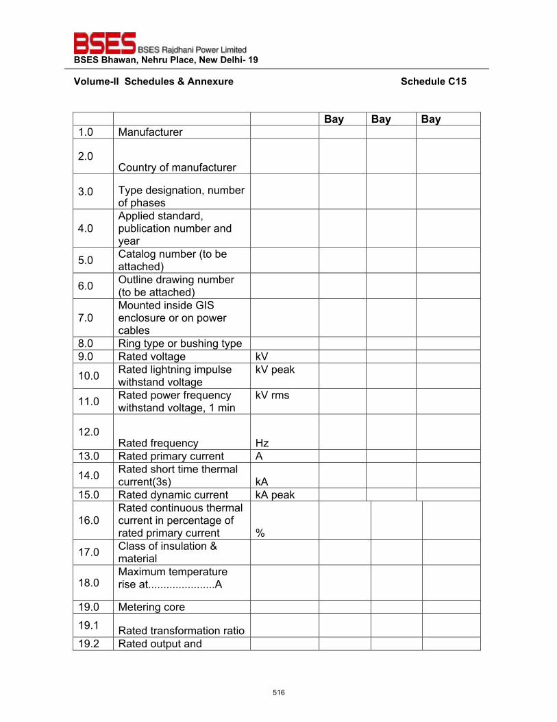
��������������� ����������������������
�~���>��^^������"�����'����� �����������������������������������������������������������������"����?�{��
�
���� ���� ����1.0 Manufacturer
2.0 Country of manufacturer
3.0 Type designation, number of phases
4.0 Applied standard, publication number and year
5.0 Catalog number (to be attached)
6.0 Outline drawing number (to be attached)
7.0 Mounted inside GIS enclosure or on power cables
8.0 Ring type or bushing type 9.0 Rated voltage kV
10.0 Rated lightning impulse withstand voltage
kV peak
11.0 Rated power frequency withstand voltage, 1 min
kV rms
12.0 Rated frequency Hz
13.0 Rated primary current A
14.0 Rated short time thermal current(3s) kA
15.0 Rated dynamic current kA peak
16.0 Rated continuous thermal current in percentage of rated primary current %
17.0 Class of insulation & material
18.0 Maximum temperature rise at......................A
19.0 Metering core 19.1 Rated transformation ratio
19.2 Rated output and
516
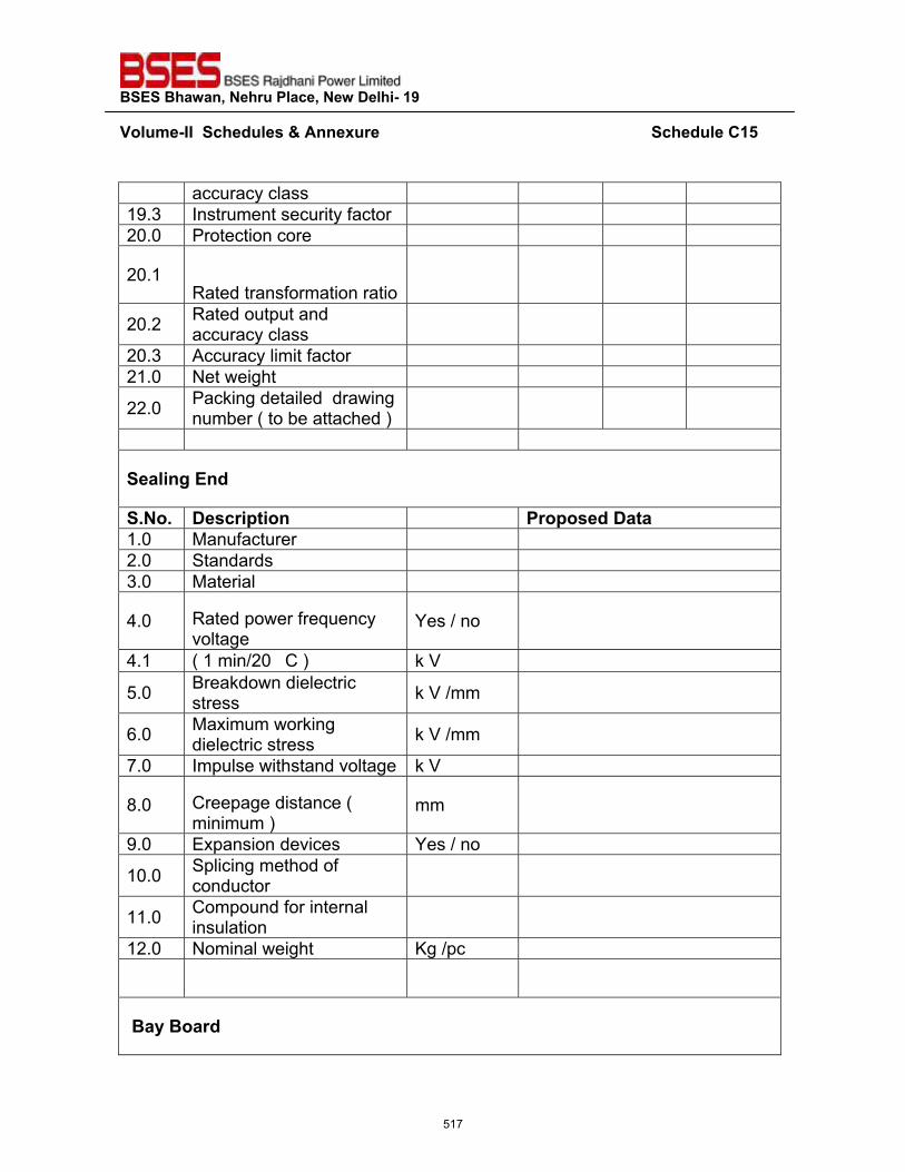
��������������� ����������������������
�~���>��^^������"�����'����� �����������������������������������������������������������������"����?�{��
�
accuracy class 19.3 Instrument security factor 20.0 Protection core
20.1 Rated transformation ratio
20.2 Rated output and accuracy class
20.3 Accuracy limit factor 21.0 Net weight
22.0 Packing detailed drawing number ( to be attached )
��������"
�_��_� ���� ������ � � �����"������1.0 Manufacturer 2.0 Standards 3.0 Material
4.0 Rated power frequency voltage
Yes / no
4.1 ( 1 min/20 C ) k V
5.0 Breakdown dielectric stress k V /mm
6.0 Maximum working dielectric stress k V /mm
7.0 Impulse withstand voltage k V
8.0 Creepage distance ( minimum )
mm
9.0 Expansion devices Yes / no
10.0 Splicing method of conductor
11.0 Compound for internal insulation
12.0 Nominal weight Kg /pc
������� "
517
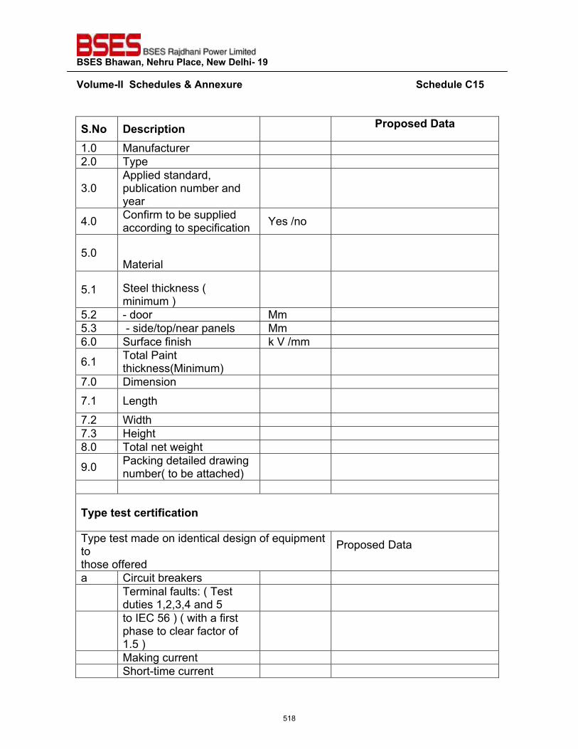
��������������� ����������������������
�~���>��^^������"�����'����� �����������������������������������������������������������������"����?�{��
�
�_��� ���� ������ �� � �����"������
1.0 Manufacturer 2.0 Type
3.0 Applied standard, publication number and year
4.0 Confirm to be supplied according to specification Yes /no
5.0 Material
5.1 Steel thickness ( minimum )
5.2 - door Mm 5.3 - side/top/near panels Mm 6.0 Surface finish k V /mm
6.1 Total Paint thickness(Minimum)
7.0 Dimension 7.1 Length
7.2 Width 7.3 Height 8.0 Total net weight
9.0 Packing detailed drawing number( to be attached)
������������ ����������
Type test made on identical design of equipment to those offered
Proposed Data
a Circuit breakers
Terminal faults: ( Test duties 1,2,3,4 and 5
to IEC 56 ) ( with a first phase to clear factor of 1.5 )
Making current Short-time current
518
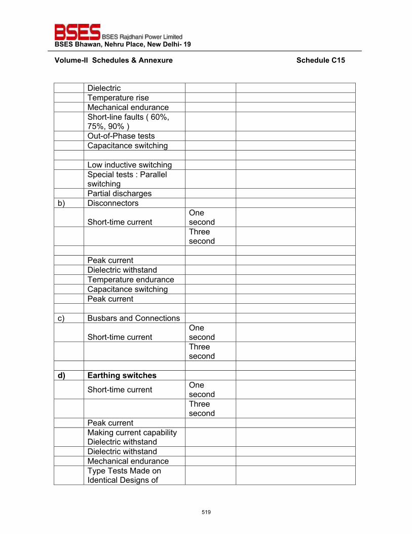
��������������� ����������������������
�~���>��^^������"�����'����� �����������������������������������������������������������������"����?�{��
�
Dielectric Temperature rise Mechanical endurance
Short-line faults ( 60%, 75%, 90% )
Out-of-Phase tests Capacitance switching Low inductive switching
Special tests : Parallel switching
Partial discharges b) Disconnectors
Short-time current One second
Three second
Peak current Dielectric withstand Temperature endurance Capacitance switching Peak current c) Busbars and Connections
Short-time current One second
Three second
"�� �� ��������������
Short-time current One second
Three second
Peak current
Making current capability Dielectric withstand
Dielectric withstand Mechanical endurance
� Type Tests Made on Identical Designs of
519
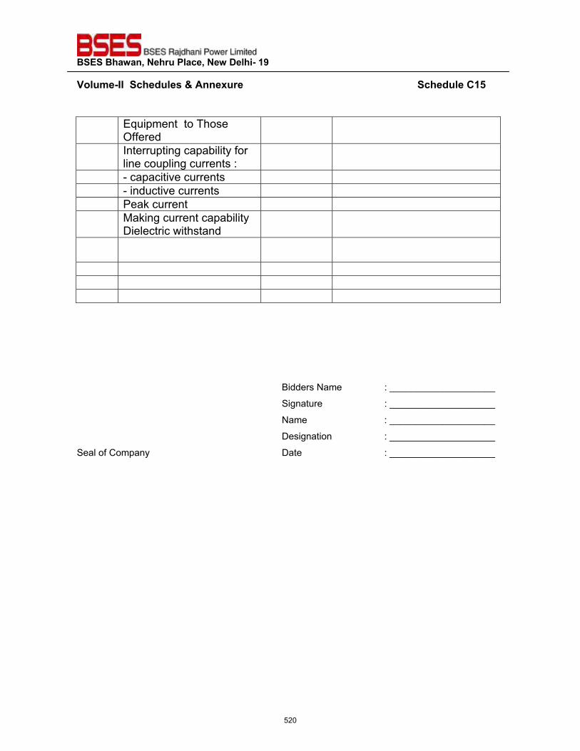
��������������� ����������������������
�~���>��^^������"�����'����� �����������������������������������������������������������������"����?�{��
�
Equipment to Those Offered
Interrupting capability for line coupling currents :
- capacitive currents - inductive currents Peak current
� Making current capability Dielectric withstand
Bidders Name : ____________________
Signature : ____________________
Name : ____________________
Designation : ____________________
Seal of Company Date : ____________________��
520
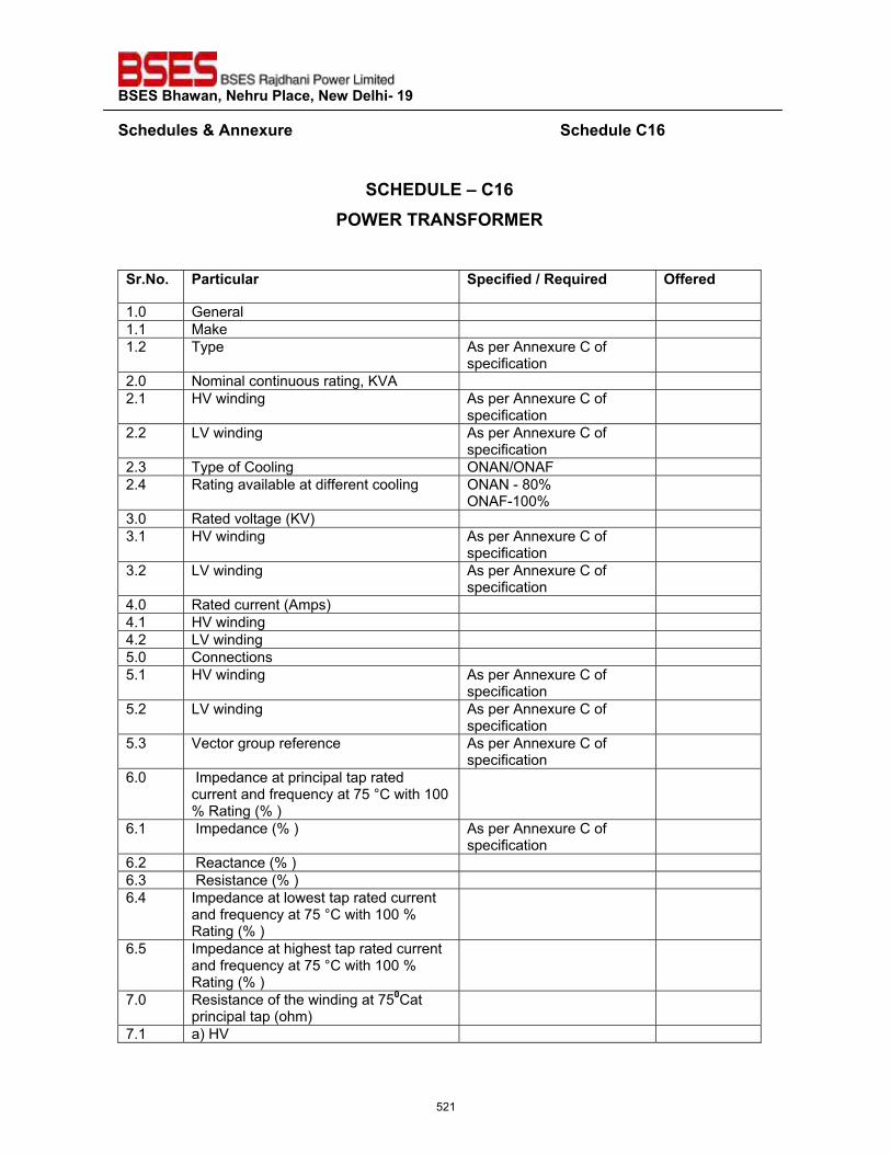
��������������� ����������������������
�����"�����'����� �����������������������������������������������������������������"����?�|��
�
�?@��QZ��\�?�|������<��<�����<*�<�
�� _��_� �� ������ � ��������"���<�=�� �"� ���� �"�
1.0 General 1.1 Make 1.2 Type As per Annexure C of
specification
2.0 Nominal continuous rating, KVA 2.1 HV winding As per Annexure C of
specification
2.2 LV winding As per Annexure C of specification
2.3 Type of Cooling ONAN/ONAF 2.4 Rating available at different cooling ONAN - 80%
ONAF-100%
3.0 Rated voltage (KV) 3.1 HV winding As per Annexure C of
specification
3.2 LV winding As per Annexure C of specification
4.0 Rated current (Amps) 4.1 HV winding 4.2 LV winding 5.0 Connections 5.1 HV winding As per Annexure C of
specification
5.2 LV winding As per Annexure C of specification
5.3 Vector group reference As per Annexure C of specification
6.0 Impedance at principal tap rated current and frequency at 75 °C with 100 % Rating (% )
6.1 Impedance (% ) As per Annexure C of specification
6.2 Reactance (% ) 6.3 Resistance (% ) 6.4 Impedance at lowest tap rated current
and frequency at 75 °C with 100 % Rating (% )
6.5 Impedance at highest tap rated current and frequency at 75 °C with 100 % Rating (% )
7.0 Resistance of the winding at 75`Cat principal tap (ohm)
7.1 a) HV
521
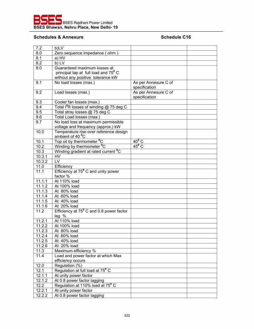
��������������� ����������������������
�����"�����'����� ������������������������������������������������������������������"����?�|��7.2 b)LV 8.0 Zero sequence impedance ( ohm ) 8.1 a) HV 8.2 b) LV 9.0 Guaranteed maximum losses at
principal tap at full load and 75` C without any positive tolerance kW
9.1 No load losses (max.) As per Annexure C of specification
9.2 Load losses (max.) As per Annexure C of specification
9.3 Cooler fan losses (max.) 9.4 Total I#R losses of winding @ 75 deg C 9.5 Total stray losses @ 75 deg C 9.6 Total Load losses (max.) 9.7 No load loss at maximum permissible
voltage and frequency (approx.) kW
10.0 Temperature rise over reference design ambient of 40 `C
10.1 Top oil by thermometer `C 40` C 10.2 Winding by thermometer `C 45` C 10.3 Winding gradient at rated current `C 10.3.1 HV 10.3.2 LV 11.0 Efficiency 11.1 Efficiency at 75` C and unity power
factor %
11.1.1 At 110% load 11.1.2 At 100% load 11.1.3 At 80% load 11.1.4 At 60% load 11.1.5 At 40% load 11.1.6 At 20% load 11.2 Efficiency at 75` C and 0.8 power factor
lag %
11.2.1 At 110% load 11.2.2 At 100% load 11.2.3 At 80% load 11.2.4 At 60% load 11.2.5 At 40% load 11.2.6 At 20% load 11.3 Maximum efficiency % 11.4 Load and power factor at which Max
efficiency occurs
12.0 Regulation (%) 12.1 Regulation at full load at 75` C 12.1.1 At unity power factor 12.1.2 At 0.8 power factor lagging 12.2 Regulation at 110% load at 75` C 12.2.1 At unity power factor 12.2.2 At 0.8 power factor lagging
522
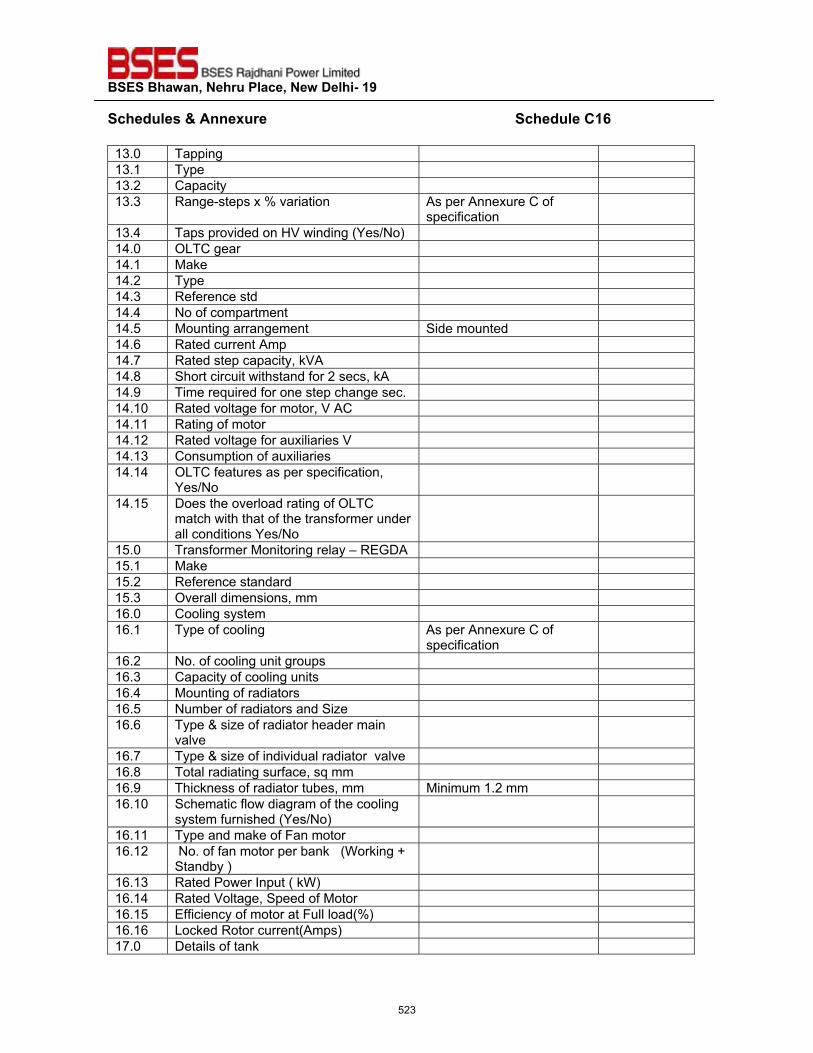
��������������� ����������������������
�����"�����'����� ������������������������������������������������������������������"����?�|��13.0 Tapping 13.1 Type 13.2 Capacity 13.3 Range-steps x % variation As per Annexure C of
specification
13.4 Taps provided on HV winding (Yes/No) 14.0 OLTC gear 14.1 Make 14.2 Type 14.3 Reference std 14.4 No of compartment 14.5 Mounting arrangement Side mounted 14.6 Rated current Amp 14.7 Rated step capacity, kVA 14.8 Short circuit withstand for 2 secs, kA 14.9 Time required for one step change sec. 14.10 Rated voltage for motor, V AC 14.11 Rating of motor 14.12 Rated voltage for auxiliaries V 14.13 Consumption of auxiliaries 14.14 OLTC features as per specification,
Yes/No
14.15 Does the overload rating of OLTC match with that of the transformer under all conditions Yes/No
15.0 Transformer Monitoring relay – REGDA 15.1 Make 15.2 Reference standard 15.3 Overall dimensions, mm 16.0 Cooling system 16.1 Type of cooling As per Annexure C of
specification
16.2 No. of cooling unit groups 16.3 Capacity of cooling units 16.4 Mounting of radiators 16.5 Number of radiators and Size 16.6 Type & size of radiator header main
valve
16.7 Type & size of individual radiator valve 16.8 Total radiating surface, sq mm 16.9 Thickness of radiator tubes, mm Minimum 1.2 mm 16.10 Schematic flow diagram of the cooling
system furnished (Yes/No)
16.11 Type and make of Fan motor 16.12 No. of fan motor per bank (Working +
Standby )
16.13 Rated Power Input ( kW) 16.14 Rated Voltage, Speed of Motor 16.15 Efficiency of motor at Full load(%) 16.16 Locked Rotor current(Amps) 17.0 Details of tank
523
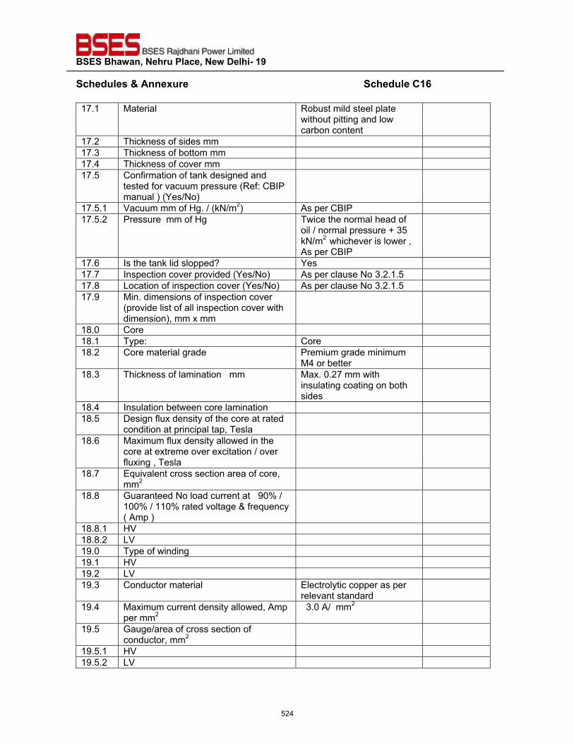
��������������� ����������������������
�����"�����'����� ������������������������������������������������������������������"����?�|��17.1 Material Robust mild steel plate
without pitting and low carbon content
17.2 Thickness of sides mm 17.3 Thickness of bottom mm 17.4 Thickness of cover mm 17.5 Confirmation of tank designed and
tested for vacuum pressure (Ref: CBIP manual ) (Yes/No)
17.5.1 Vacuum mm of Hg. / (kN/m2) As per CBIP 17.5.2 Pressure mm of Hg Twice the normal head of
oil / normal pressure + 35 kN/m2 whichever is lower , As per CBIP
17.6 Is the tank lid slopped? Yes 17.7 Inspection cover provided (Yes/No) As per clause No 3.2.1.5 17.8 Location of inspection cover (Yes/No) As per clause No 3.2.1.5 17.9 Min. dimensions of inspection cover
(provide list of all inspection cover with dimension), mm x mm
18.0 Core 18.1 Type: Core 18.2 Core material grade Premium grade minimum
M4 or better
18.3 Thickness of lamination mm Max. 0.27 mm with insulating coating on both sides
18.4 Insulation between core lamination 18.5 Design flux density of the core at rated
condition at principal tap, Tesla
18.6 Maximum flux density allowed in the core at extreme over excitation / over fluxing , Tesla
18.7 Equivalent cross section area of core, mm2
18.8 Guaranteed No load current at 90% / 100% / 110% rated voltage & frequency ( Amp )
18.8.1 HV 18.8.2 LV 19.0 Type of winding 19.1 HV 19.2 LV 19.3 Conductor material Electrolytic copper as per
relevant standard
19.4 Maximum current density allowed, Amp per mm2
3.0 A/ mm2
19.5 Gauge/area of cross section of conductor, mm2
19.5.1 HV 19.5.2 LV
524
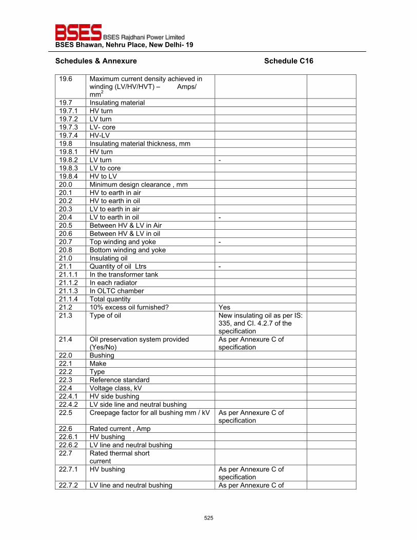
��������������� ����������������������
�����"�����'����� ������������������������������������������������������������������"����?�|��19.6 Maximum current density achieved in
winding (LV/HV/HVT) – Amps/ mm2
19.7 Insulating material 19.7.1 HV turn 19.7.2 LV turn 19.7.3 LV- core 19.7.4 HV-LV 19.8 Insulating material thickness, mm 19.8.1 HV turn 19.8.2 LV turn - 19.8.3 LV to core 19.8.4 HV to LV 20.0 Minimum design clearance , mm 20.1 HV to earth in air 20.2 HV to earth in oil 20.3 LV to earth in air 20.4 LV to earth in oil - 20.5 Between HV & LV in Air 20.6 Between HV & LV in oil 20.7 Top winding and yoke - 20.8 Bottom winding and yoke 21.0 Insulating oil 21.1 Quantity of oil Ltrs - 21.1.1 In the transformer tank 21.1.2 In each radiator 21.1.3 In OLTC chamber 21.1.4 Total quantity 21.2 10% excess oil furnished? Yes 21.3 Type of oil New insulating oil as per IS:
335, and CI. 4.2.7 of the specification
21.4 Oil preservation system provided (Yes/No)
As per Annexure C of specification
22.0 Bushing 22.1 Make 22.2 Type 22.3 Reference standard 22.4 Voltage class, kV 22.4.1 HV side bushing 22.4.2 LV side line and neutral bushing 22.5 Creepage factor for all bushing mm / kV As per Annexure C of
specification
22.6 Rated current , Amp 22.6.1 HV bushing 22.6.2 LV line and neutral bushing 22.7 Rated thermal short
current
22.7.1 HV bushing As per Annexure C of specification
22.7.2 LV line and neutral bushing As per Annexure C of
525
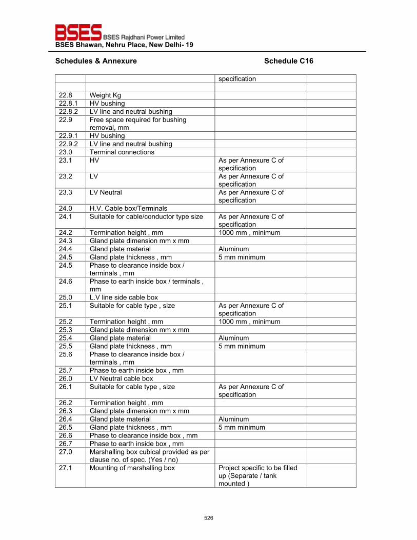
��������������� ����������������������
�����"�����'����� ������������������������������������������������������������������"����?�|��
specification 22.8 Weight Kg 22.8.1 HV bushing 22.8.2 LV line and neutral bushing 22.9 Free space required for bushing
removal, mm
22.9.1 HV bushing 22.9.2 LV line and neutral bushing 23.0 Terminal connections 23.1 HV As per Annexure C of
specification
23.2 LV As per Annexure C of specification
23.3 LV Neutral As per Annexure C of specification
24.0 H.V. Cable box/Terminals 24.1 Suitable for cable/conductor type size As per Annexure C of
specification
24.2 Termination height , mm 1000 mm , minimum 24.3 Gland plate dimension mm x mm 24.4 Gland plate material Aluminum 24.5 Gland plate thickness , mm 5 mm minimum 24.5 Phase to clearance inside box /
terminals , mm
24.6 Phase to earth inside box / terminals , mm
25.0 L.V line side cable box 25.1 Suitable for cable type , size As per Annexure C of
specification
25.2 Termination height , mm 1000 mm , minimum 25.3 Gland plate dimension mm x mm 25.4 Gland plate material Aluminum 25.5 Gland plate thickness , mm 5 mm minimum 25.6 Phase to clearance inside box /
terminals , mm
25.7 Phase to earth inside box , mm 26.0 LV Neutral cable box 26.1 Suitable for cable type , size As per Annexure C of
specification
26.2 Termination height , mm 26.3 Gland plate dimension mm x mm 26.4 Gland plate material Aluminum 26.5 Gland plate thickness , mm 5 mm minimum 26.6 Phase to clearance inside box , mm 26.7 Phase to earth inside box , mm 27.0 Marshalling box cubical provided as per
clause no. of spec. (Yes / no)
27.1 Mounting of marshalling box Project specific to be filled up (Separate / tank mounted )
526
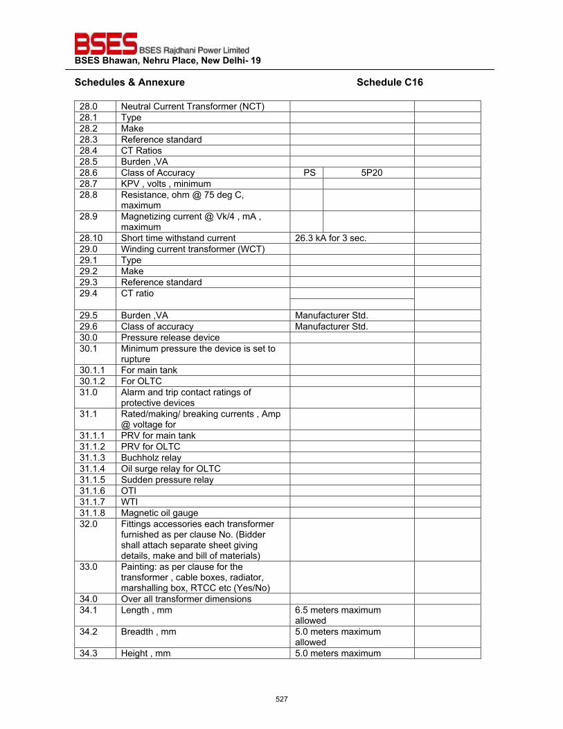
��������������� ����������������������
�����"�����'����� ������������������������������������������������������������������"����?�|��28.0 Neutral Current Transformer (NCT) 28.1 Type 28.2 Make 28.3 Reference standard 28.4 CT Ratios 28.5 Burden ,VA 28.6 Class of Accuracy PS 5P20 28.7 KPV , volts , minimum 28.8 Resistance, ohm @ 75 deg C,
maximum
28.9 Magnetizing current @ Vk/4 , mA , maximum
28.10 Short time withstand current 26.3 kA for 3 sec. 29.0 Winding current transformer (WCT) 29.1 Type 29.2 Make 29.3 Reference standard 29.4 CT ratio
29.5 Burden ,VA Manufacturer Std. 29.6 Class of accuracy Manufacturer Std. 30.0 Pressure release device 30.1 Minimum pressure the device is set to
rupture
30.1.1 For main tank 30.1.2 For OLTC 31.0 Alarm and trip contact ratings of
protective devices
31.1 Rated/making/ breaking currents , Amp @ voltage for
31.1.1 PRV for main tank 31.1.2 PRV for OLTC 31.1.3 Buchholz relay 31.1.4 Oil surge relay for OLTC 31.1.5 Sudden pressure relay 31.1.6 OTI 31.1.7 WTI 31.1.8 Magnetic oil gauge 32.0 Fittings accessories each transformer
furnished as per clause No. (Bidder shall attach separate sheet giving details, make and bill of materials)
33.0 Painting: as per clause for the transformer , cable boxes, radiator, marshalling box, RTCC etc (Yes/No)
34.0 Over all transformer dimensions 34.1 Length , mm 6.5 meters maximum
allowed
34.2 Breadth , mm 5.0 meters maximum allowed
34.3 Height , mm 5.0 meters maximum
527
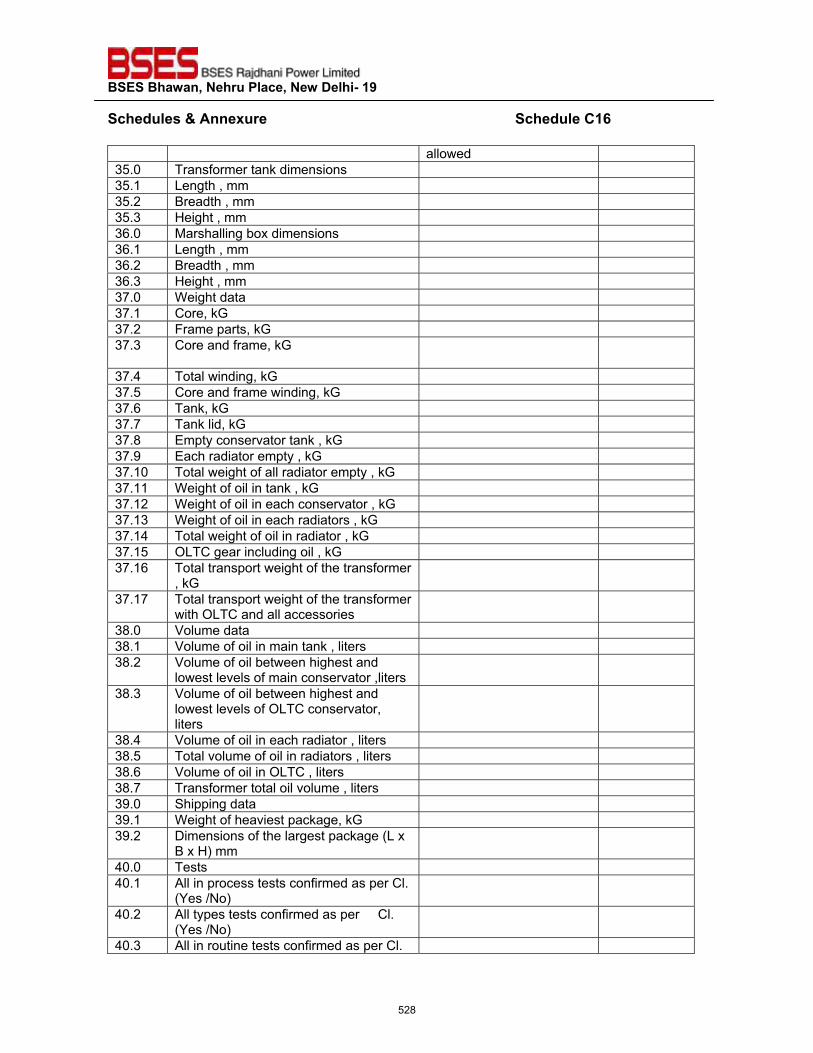
��������������� ����������������������
�����"�����'����� ������������������������������������������������������������������"����?�|��
allowed 35.0 Transformer tank dimensions 35.1 Length , mm 35.2 Breadth , mm 35.3 Height , mm 36.0 Marshalling box dimensions 36.1 Length , mm 36.2 Breadth , mm 36.3 Height , mm 37.0 Weight data 37.1 Core, kG 37.2 Frame parts, kG 37.3 Core and frame, kG
37.4 Total winding, kG 37.5 Core and frame winding, kG 37.6 Tank, kG 37.7 Tank lid, kG 37.8 Empty conservator tank , kG 37.9 Each radiator empty , kG 37.10 Total weight of all radiator empty , kG 37.11 Weight of oil in tank , kG 37.12 Weight of oil in each conservator , kG 37.13 Weight of oil in each radiators , kG 37.14 Total weight of oil in radiator , kG 37.15 OLTC gear including oil , kG 37.16 Total transport weight of the transformer
, kG
37.17 Total transport weight of the transformer with OLTC and all accessories
38.0 Volume data 38.1 Volume of oil in main tank , liters 38.2 Volume of oil between highest and
lowest levels of main conservator ,liters
38.3 Volume of oil between highest and lowest levels of OLTC conservator, liters
38.4 Volume of oil in each radiator , liters 38.5 Total volume of oil in radiators , liters 38.6 Volume of oil in OLTC , liters 38.7 Transformer total oil volume , liters 39.0 Shipping data 39.1 Weight of heaviest package, kG 39.2 Dimensions of the largest package (L x
B x H) mm
40.0 Tests 40.1 All in process tests confirmed as per Cl.
(Yes /No)
40.2 All types tests confirmed as per Cl. (Yes /No)
40.3 All in routine tests confirmed as per Cl.
528
��������������� ����������������������
�����"�����'����� ������������������������������������������������������������������"����?�|��
(Yes /No) 40.4 All in special tests confirmed as per Cl.
(Yes /No)
��
�Bidders Name : ____________________
Signature : ____________________
Name : ____________________
Designation : ____________________
Seal of Company Date : ____________________
529
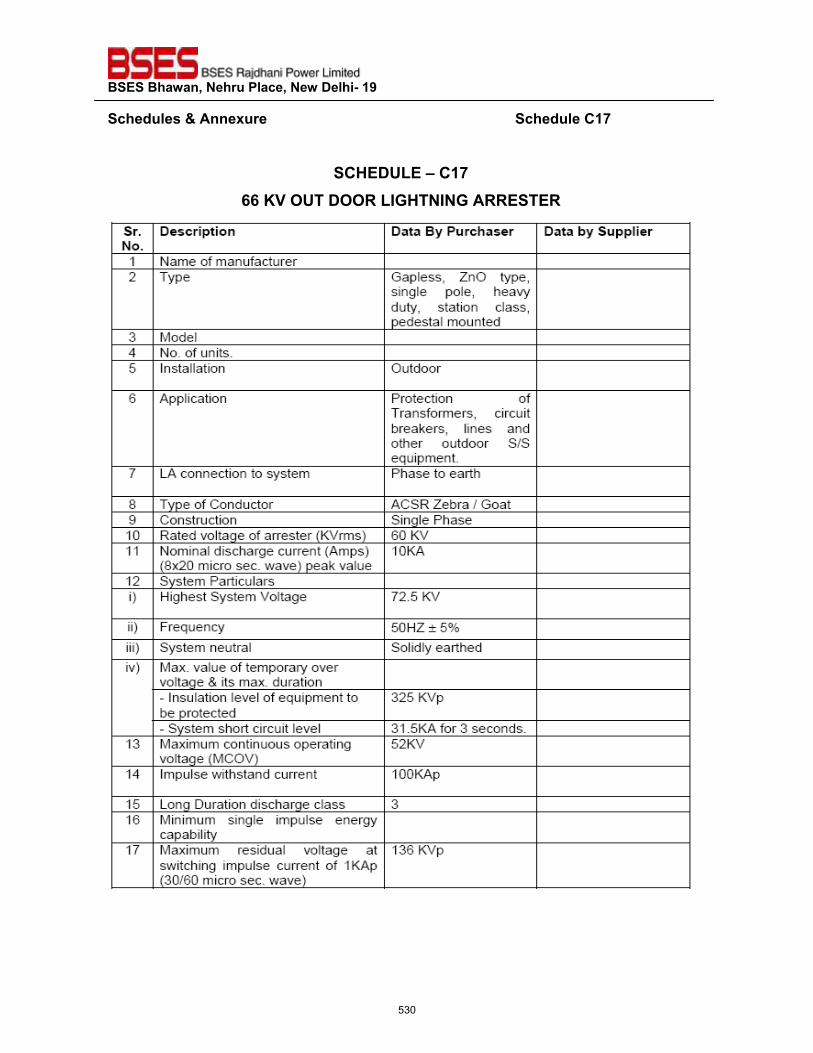
��������������� ����������������������
�����"�����'����� ������������������������������������������������������������������"����?�%��
�
�?@��QZ��\�?�%��||�}~��Q�����<�Z^!@��^�!��<<����<�
�
530
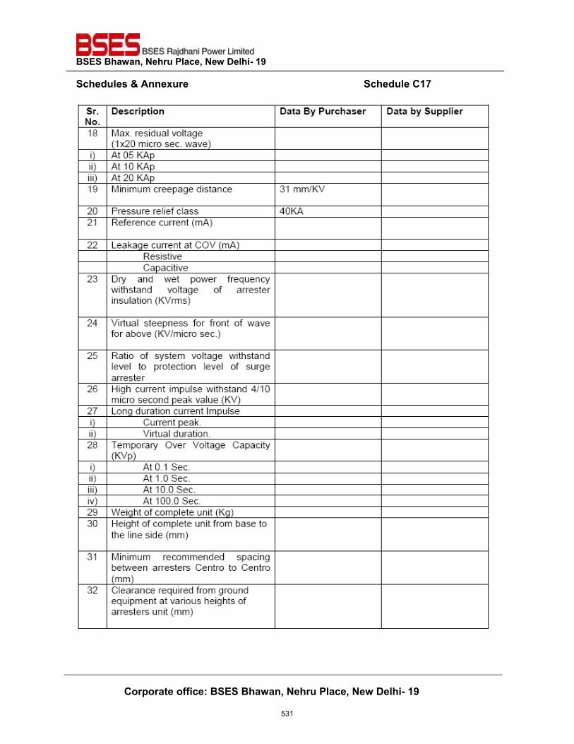
��������������� ����������������������
�����"�����'����� ������������������������������������������������������������������"����?�%��
��� � ?� �� ����������+��������������� ����������������������
�
�
531
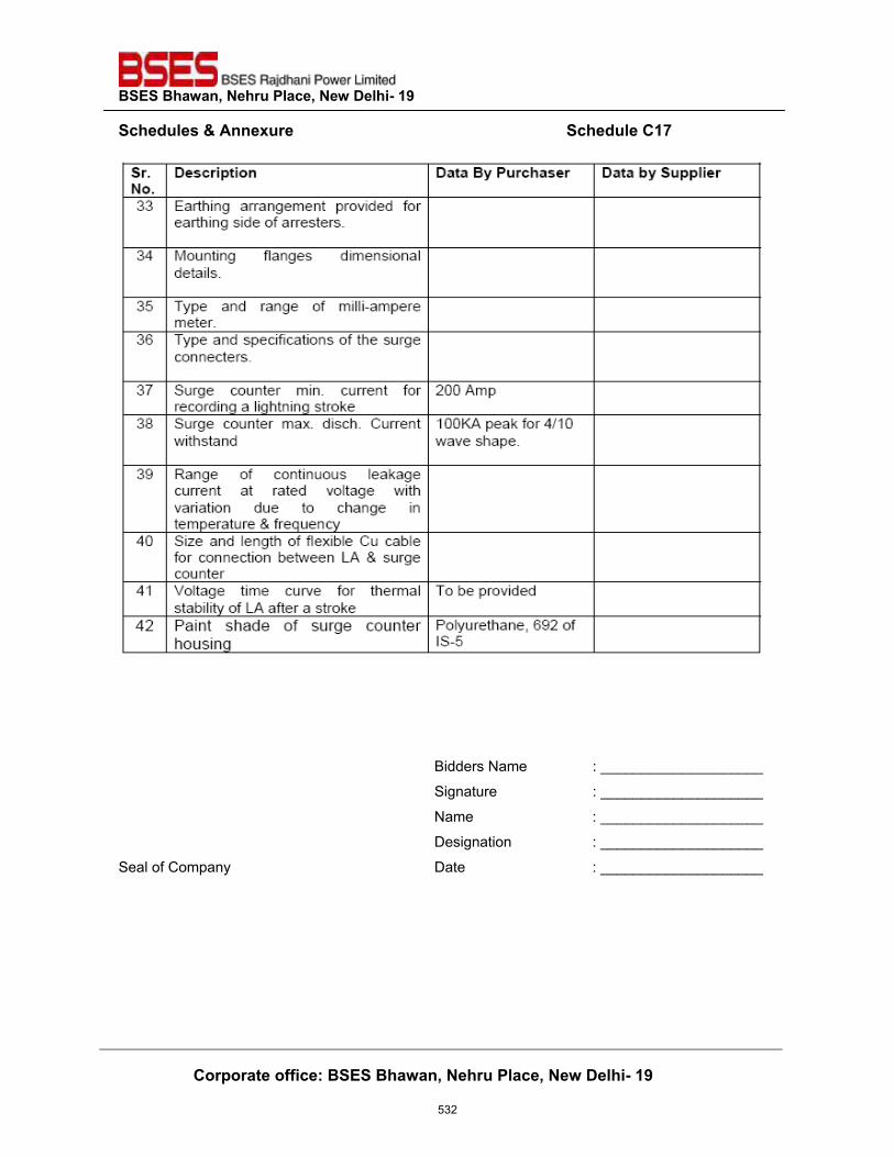
��������������� ����������������������
�����"�����'����� ������������������������������������������������������������������"����?�%��
��� � ?� �� ����������+��������������� ����������������������
�
����
Bidders Name : ____________________
Signature : ____________________
Name : ____________________
Designation : ____________________
Seal of Company Date : ____________________�
532
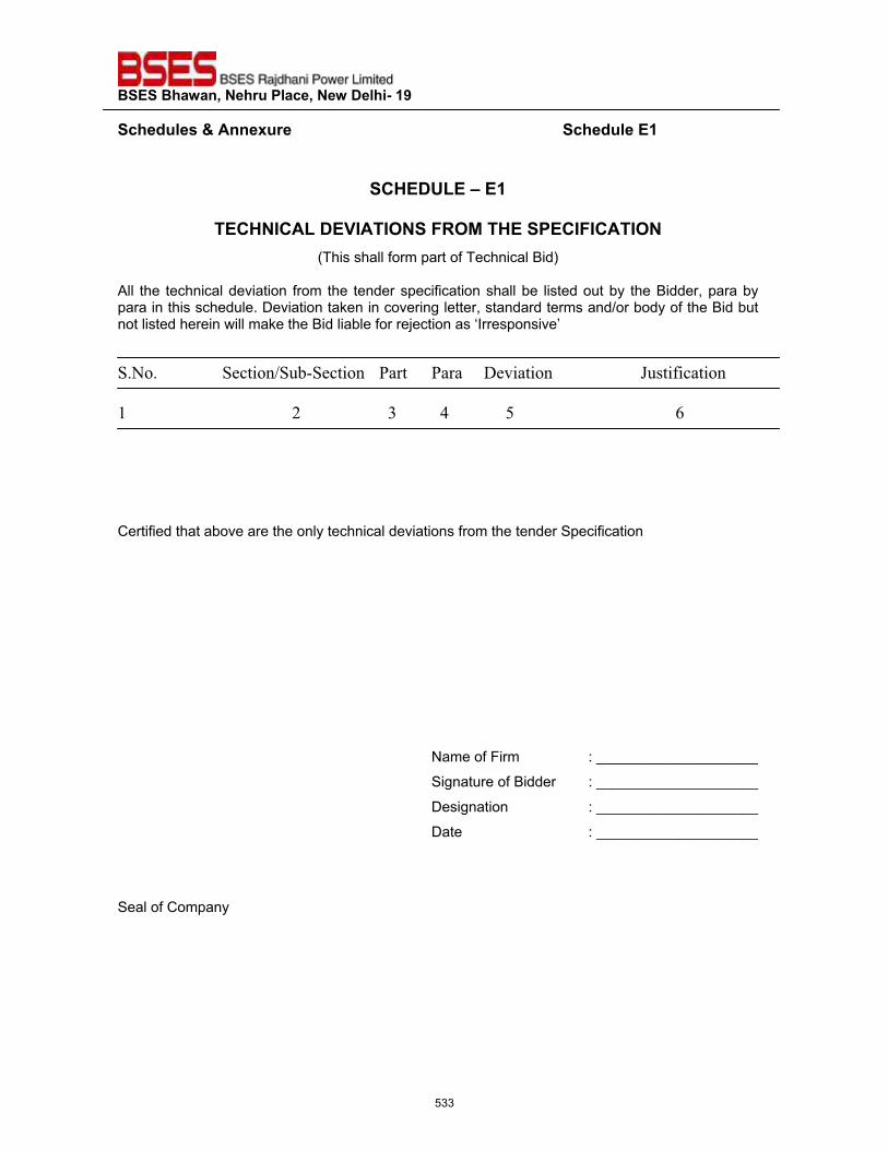
��������������� ����������������������
�����"�����'����� ������������������������������������������������������������������"��������
�
�?@��QZ��\�����
��?@�^?�Z���~^��^�����<�*��@�����?^�^?��^���(This shall form part of Technical Bid)
All the technical deviation from the tender specification shall be listed out by the Bidder, para by para in this schedule. Deviation taken in covering letter, standard terms and/or body of the Bid but not listed herein will make the Bid liable for rejection as ‘Irresponsive’ �
�'��'�� � ��������+������� /��� /���� :�,������ � J����������
�
�� � ������������������ � ��&� ��*� �����.� � � ��������1�
Certified that above are the only technical deviations from the tender Specification
Name of Firm : ____________________
Signature of Bidder : ____________________
Designation : ____________________
Date : ____________________
Seal of Company �
533
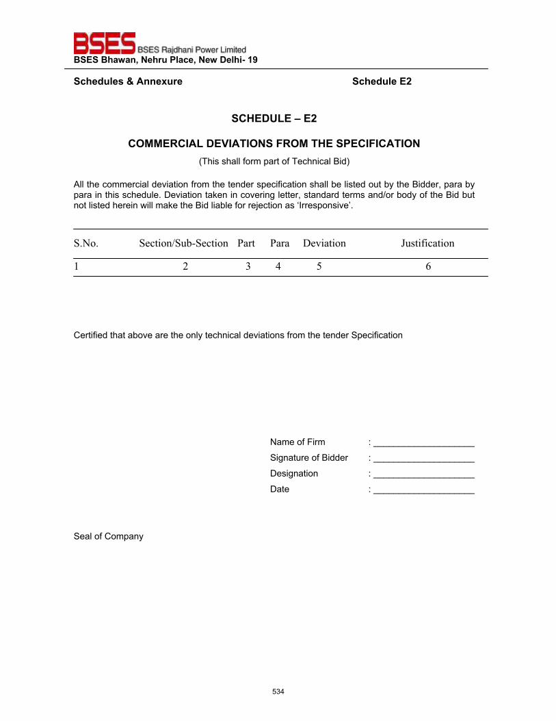
��������������� ����������������������
�����"�����'����� ������������������������������������������������������������������"�����#��
��?@��QZ��\��#�
�
?�**�<?^�Z���~^��^�����<�*��@�����?^�^?��^���(This shall form part of Technical Bid)
�All the commercial deviation from the tender specification shall be listed out by the Bidder, para by para in this schedule. Deviation taken in covering letter, standard terms and/or body of the Bid but not listed herein will make the Bid liable for rejection as ‘Irresponsive’.
�'��'�� � ��������+������� /��� /���� :�,������ � J��������� �� � ������������������ � ���&� ��*� �����.� � � ���������1�
Certified that above are the only technical deviations from the tender Specification
Name of Firm : ____________________
Signature of Bidder : ____________________
Designation : ____________________
Date : ____________________
Seal of Company
�
534
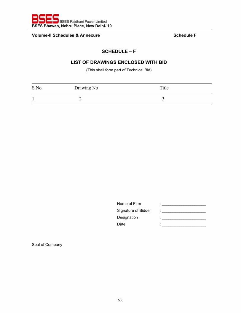
��������������� ����������������������
�~���>��^^�����"�����'����� ������������������������������������������������������������������"�������
�
�?@��QZ��\����
Z^�������<��^�!����?Z������^�@��^��(This shall form part of Technical Bid)
�
�'��'� � � :��;������� � � � � %�$��
�
�� � ������������������ � ��� � ���� ��������������&�
Name of Firm : ____________________
Signature of Bidder : ____________________
Designation : ____________________
Date : ____________________
Seal of Company �
535
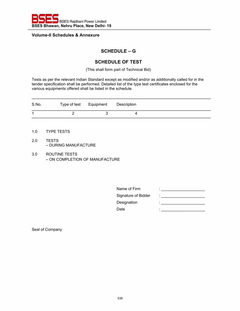
��������������� ����������������������
�~���>��^^�����"�����'����� ����������������������������������������������������������������
��?@��QZ��\�!�
�
�?@��QZ����������(This shall form part of Technical Bid)
�Tests as per the relevant Indian Standard except as modified and/or as additionally called for in the tender specification shall be performed. Detailed list of the type test certificates enclosed for the various equipments offered shall be listed in the schedule.
S.No. Type of test Equipment Description 1 2 3 4
1.0 TYPE TESTS
2.0 TESTS – DURING MANUFACTURE
3.0 ROUTINE TESTS – ON COMPLETION OF MANUFACTURE
Name of Firm : ____________________
Signature of Bidder : ____________________
Designation : ____________________
Date : ____________________
Seal of Company
�
536
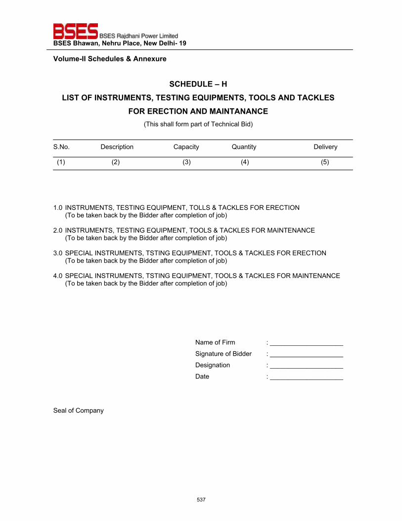
��������������� ����������������������
�~���>��^^�����"�����'����� �����������������������������������������������������������������
�?@��QZ��\�@��Z^������^���<Q*���������^�!���Q^�*��������Z��������?}Z���
��<��<�?�^�������*�^������?��(This shall form part of Technical Bid)
S.No. Description Capacity Quantity Delivery (1) (2) (3) (4) (5)
1.0 INSTRUMENTS, TESTING EQUIPMENT, TOLLS & TACKLES FOR ERECTION (To be taken back by the Bidder after completion of job)
2.0 INSTRUMENTS, TESTING EQUIPMENT, TOOLS & TACKLES FOR MAINTENANCE (To be taken back by the Bidder after completion of job)
3.0 SPECIAL INSTRUMENTS, TSTING EQUIPMENT, TOOLS & TACKLES FOR ERECTION (To be taken back by the Bidder after completion of job)
4.0 SPECIAL INSTRUMENTS, TSTING EQUIPMENT, TOOLS & TACKLES FOR MAINTENANCE�(To be taken back by the Bidder after completion of job)�
Name of Firm : ____________________
Signature of Bidder : ____________________
Designation : ____________________
Date : ____________________
Seal of Company
537
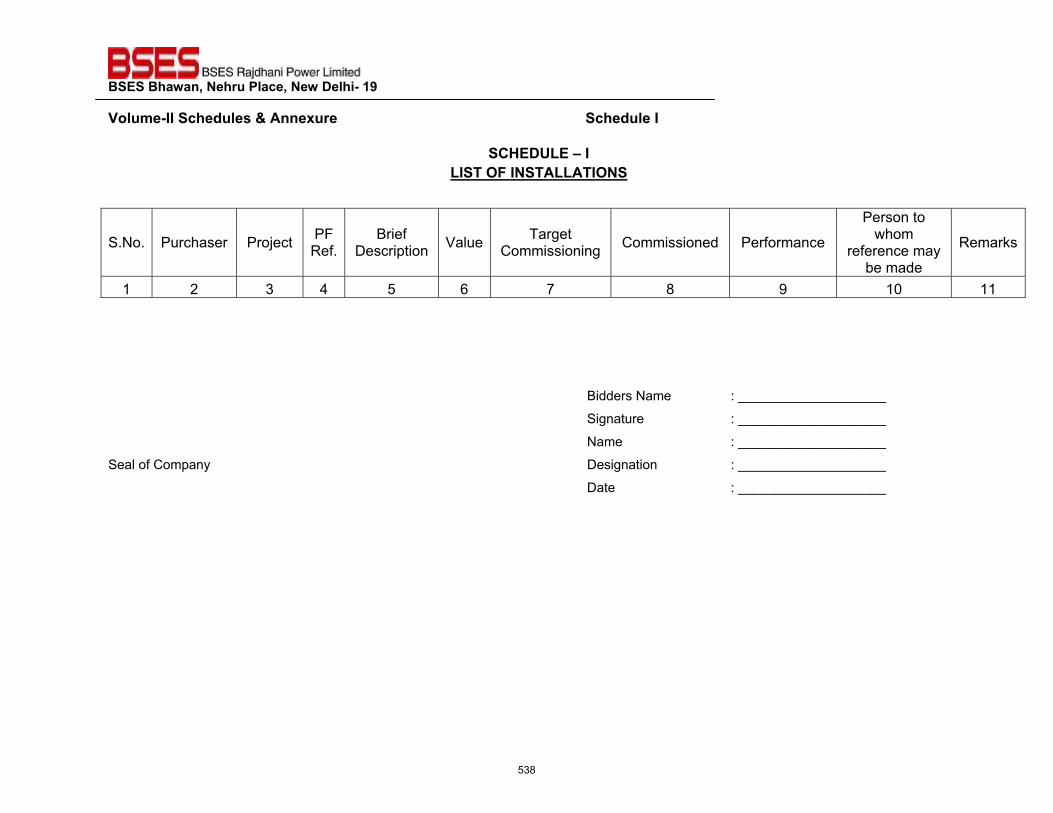
��������������� ����������������������
�~���>��^^�����"�����'����� ������������������������������������������������������������������"����^��
�?@��QZ��\�^�Z^������^����ZZ��^����
�
S.No. Purchaser Project PF Ref.
Brief Description Value Target
Commissioning Commissioned Performance
Person to whom
reference may be made
Remarks
1 2 3 4 5 6 7 8 9 10 11
Bidders Name : ____________________
Signature : ____________________
Name : ____________________
Seal of Company Designation : ____________________
Date : ____________________
538
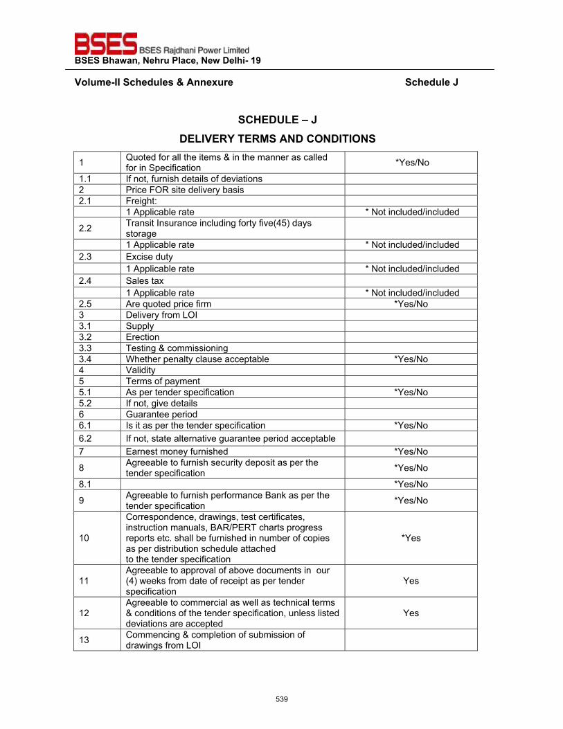
��������������� ����������������������
�~���>��^^�����"�����'����� ������������������������������������������������������������������"�������
�
�?@��QZ��\������Z^~�<����<*������?���^�^����
1 Quoted for all the items & in the manner as called for in Specification *Yes/No
1.1 If not, furnish details of deviations 2 Price FOR site delivery basis 2.1 Freight: 1 Applicable rate * Not included/included
2.2 Transit Insurance including forty five(45) days storage
1 Applicable rate * Not included/included 2.3 Excise duty 1 Applicable rate * Not included/included 2.4 Sales tax 1 Applicable rate * Not included/included 2.5 Are quoted price firm *Yes/No 3 Delivery from LOI 3.1 Supply 3.2 Erection 3.3 Testing & commissioning 3.4 Whether penalty clause acceptable *Yes/No 4 Validity 5 Terms of payment 5.1 As per tender specification *Yes/No 5.2 If not, give details 6 Guarantee period 6.1 Is it as per the tender specification *Yes/No 6.2 If not, state alternative guarantee period acceptable 7 Earnest money furnished *Yes/No
8 Agreeable to furnish security deposit as per the tender specification *Yes/No
8.1 *Yes/No
9 Agreeable to furnish performance Bank as per the tender specification *Yes/No
10
Correspondence, drawings, test certificates, instruction manuals, BAR/PERT charts progress reports etc. shall be furnished in number of copies as per distribution schedule attached to the tender specification
*Yes
11 Agreeable to approval of above documents in our (4) weeks from date of receipt as per tender specification
Yes
12 Agreeable to commercial as well as technical terms & conditions of the tender specification, unless listed deviations are accepted
Yes
13 Commencing & completion of submission of drawings from LOI
539
��������������� ����������������������
�~���>��^^�����"�����'����� ������������������������������������������������������������������"�������
�
�
Bidders Name : ____________________
Signature : ____________________
Name : ____________________
Designation : ____________________
Seal of Company Date : ____________________
540
��������������� ����������������������
�~���>��^^�����"�����'����� ������������������������������������������������������������������"����}��
�
�?@��QZ��\�}���?@��QZ�����<�?�**���������<���
��""� ����������� ������ ������� ���� ����� �"��������� �������������'�"����������������"� �"�����������"�����"_��
S.No. Description Quantity Unit Price Total Price
1 2 3 4 5
�
Bidders Name : ____________________
Signature : ____________________
Name : ____________________
Designation : ____________________
Seal of Company Date : ____________________
541
��������������� ����������������������
�~���>��^^�����"�����'����� ������������������������������������������������������������������"����Z��
�
�?@��QZ��\�Z����?Z�<��^���
(This shall form part of Technical Bid) I, ________________________ certify that all the typed data & information pertaining to the
subject tender specification are correct & are true representation of the equipment covered by our
formal Bid No_________________dated________________.
I hereby, certify that I am duly authorized representative of the Bidder whose name appears above
my signature.
Bidders Name : ____________________
Authorized Representative Signature : ____________________ Authorized Representative Name (Typed) : ____________________
Authorized Representative Designation : ____________________
Seal of Company Date : ____________________ Bidder’s Intent : The bidder hereby agrees to fully comply with the requirements
& intents of the subject tender specification for the price(s) indicated
Authorized Representative Signature : ____________________
542
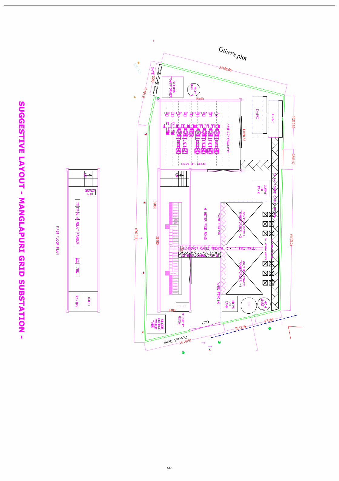
��,������:����
C��
10210.523859.97
26702.52
24196.66
12191.6
40973.36
15451.81
6083.72
5005.5
98.90
=-��K���$�
17400
6400
7000
7000
2000
600039860
26400
1546013460.63
TOILET
RWH
543
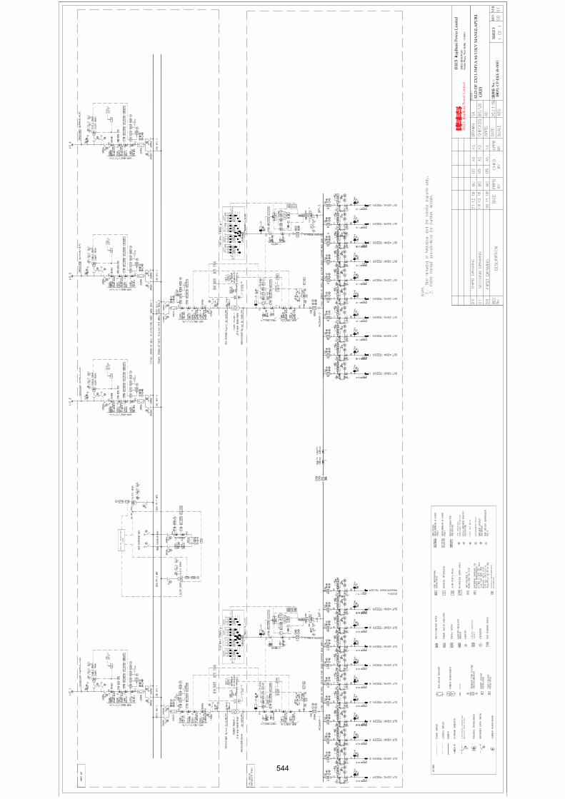
4RX1
CX1
000S
qmm
3Rx1
Cx10
00 S
qmm
544
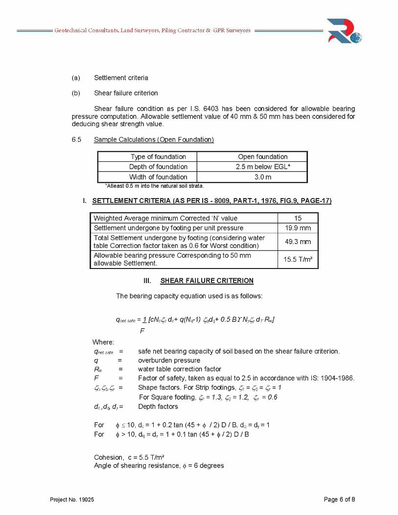
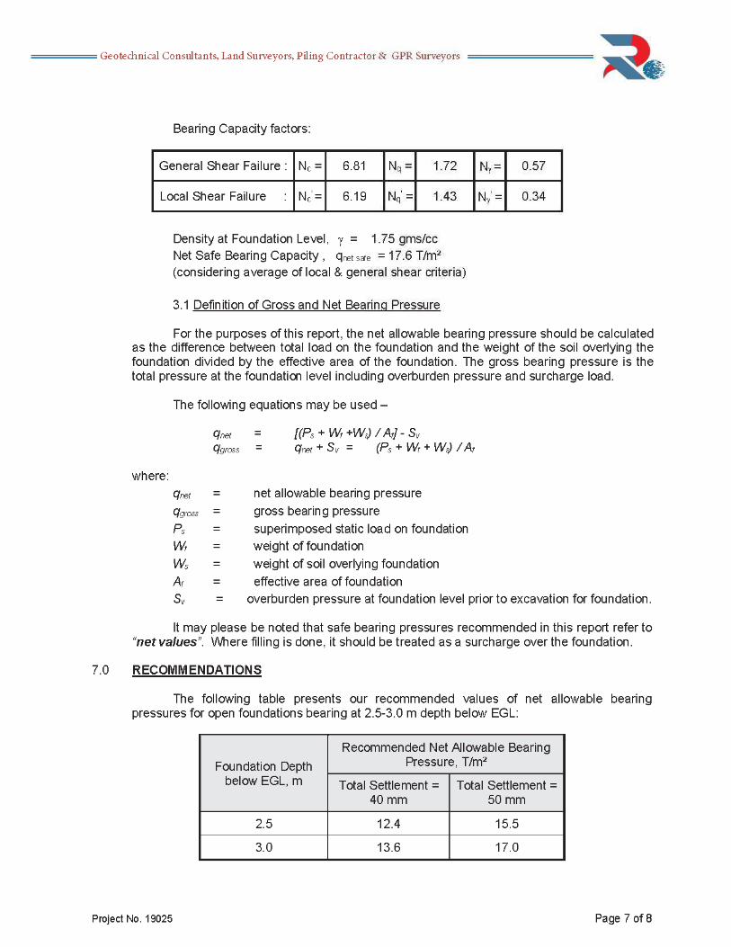
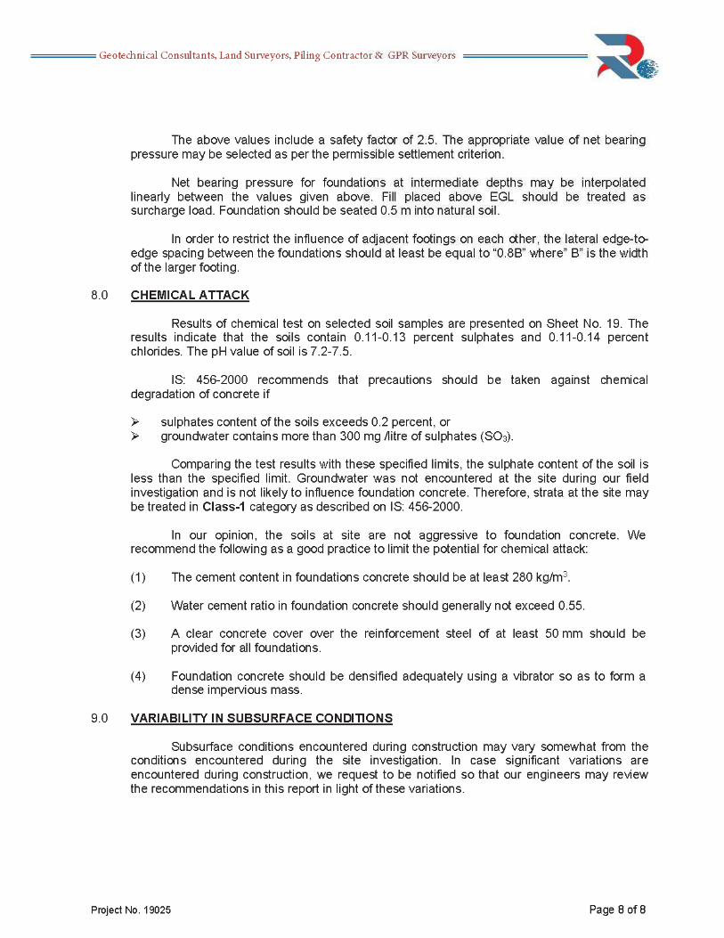
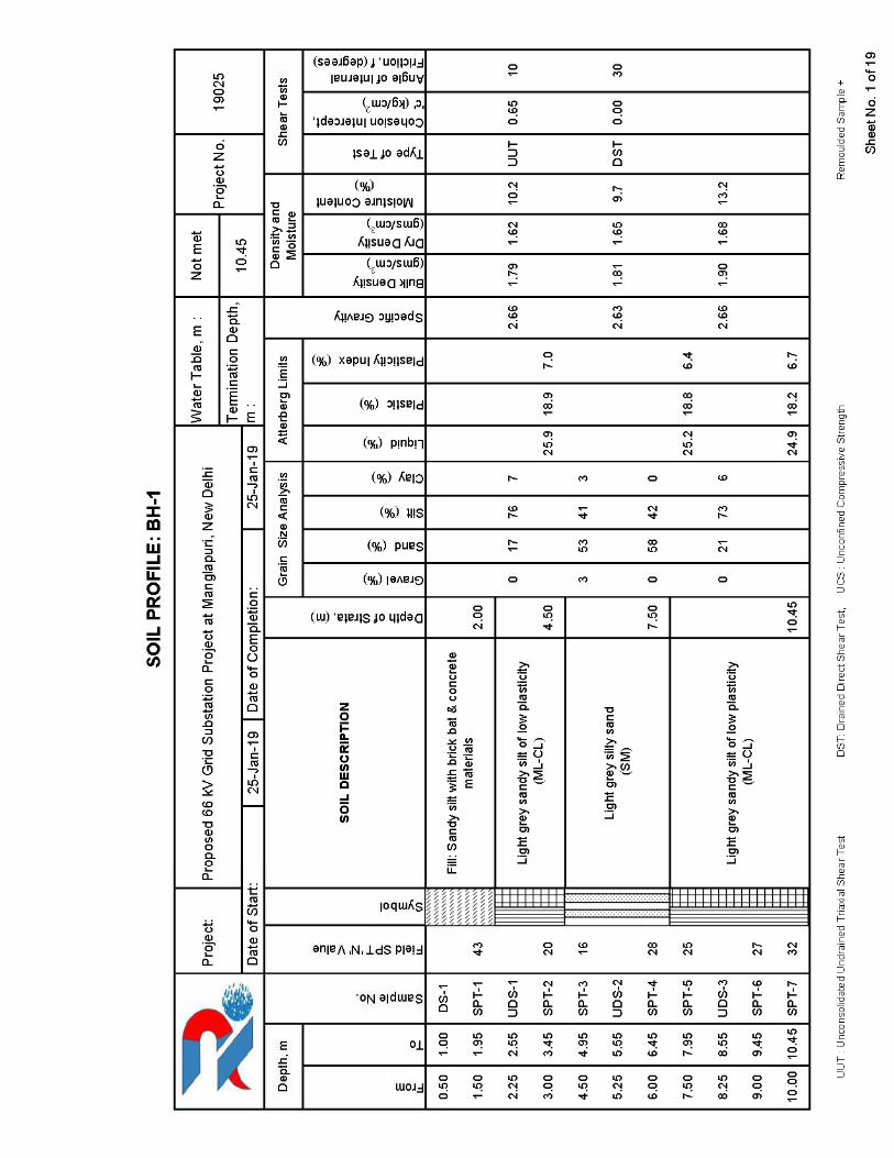
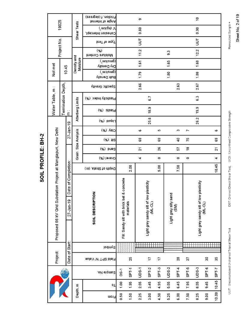

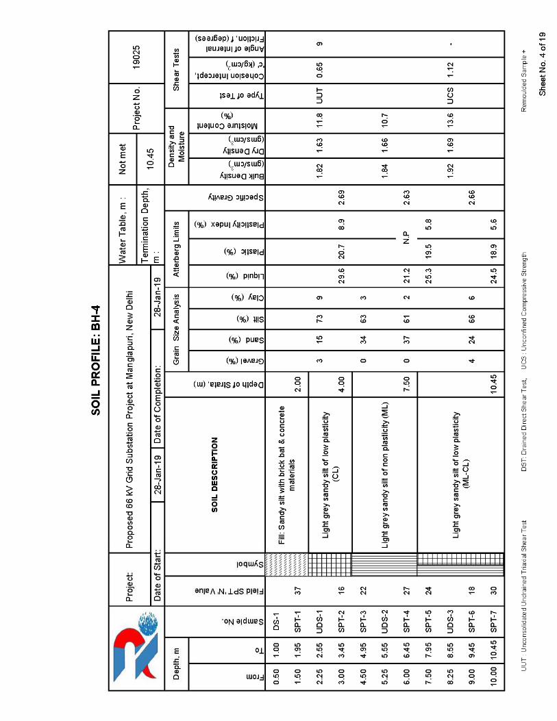
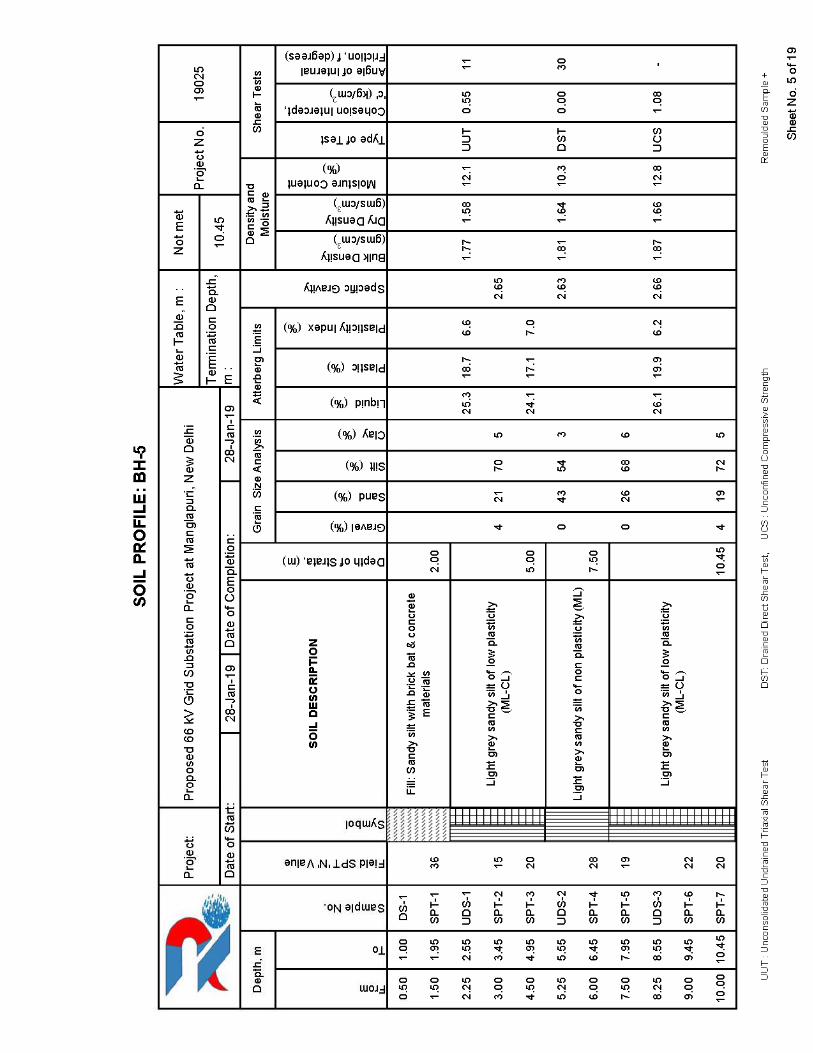
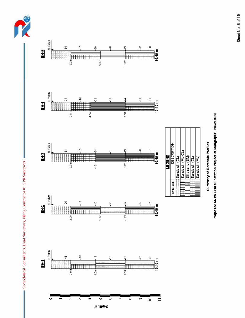
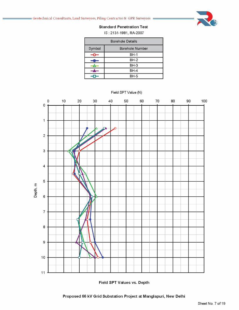
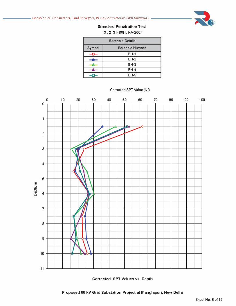
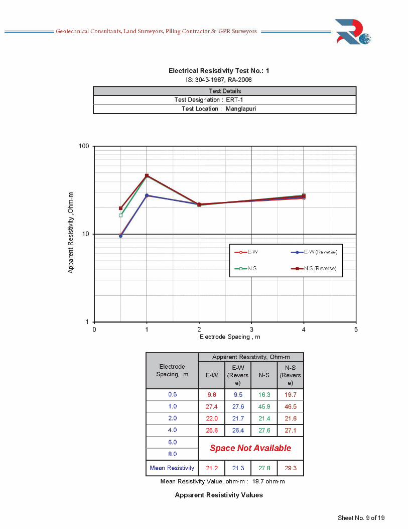
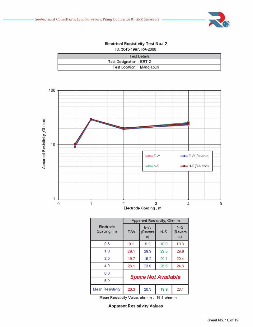
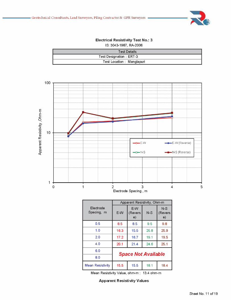
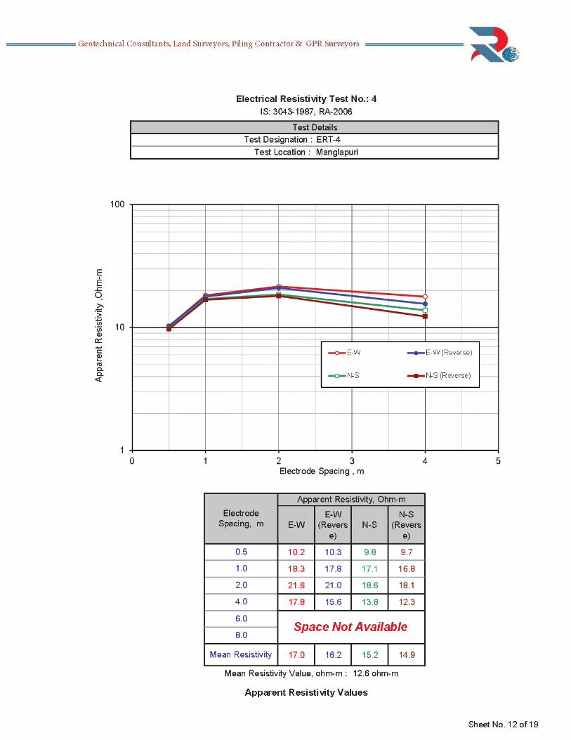

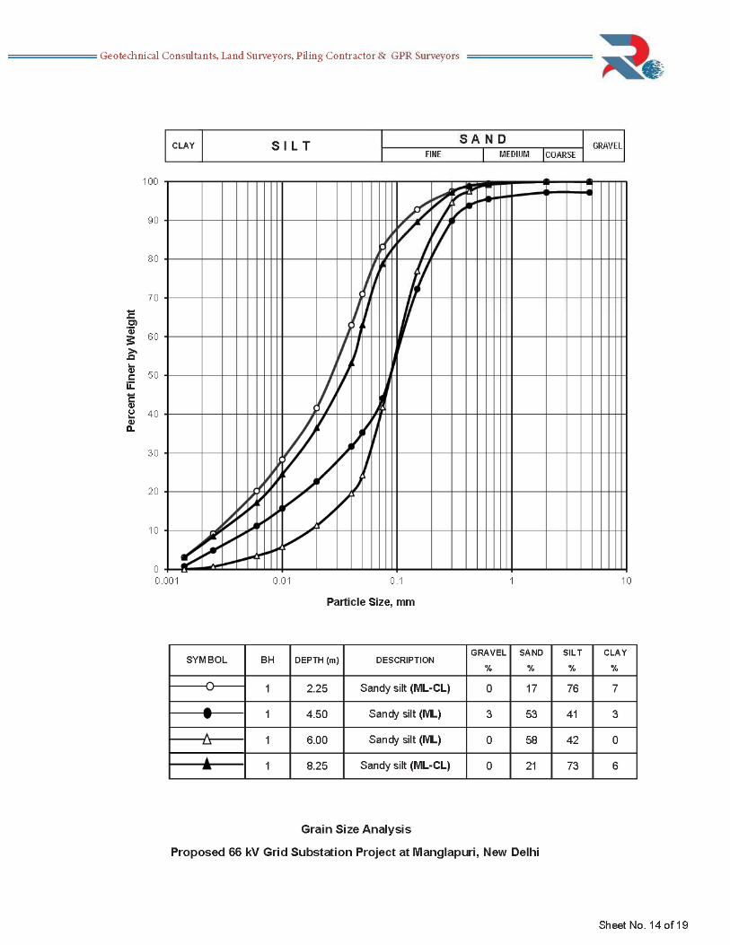
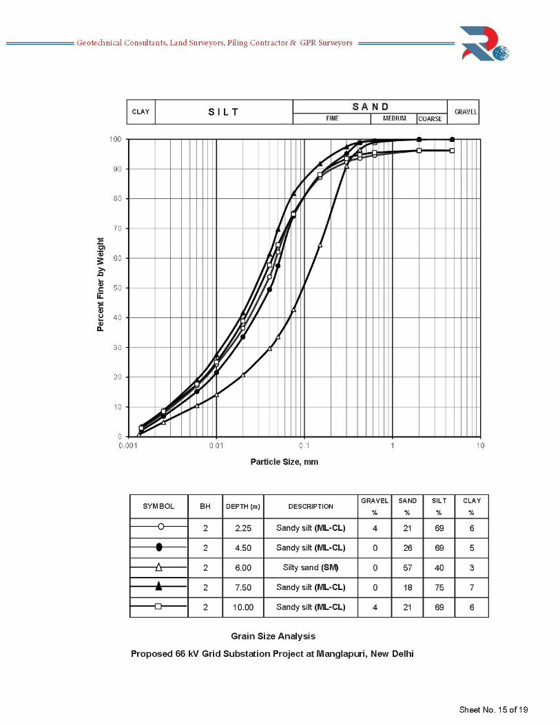
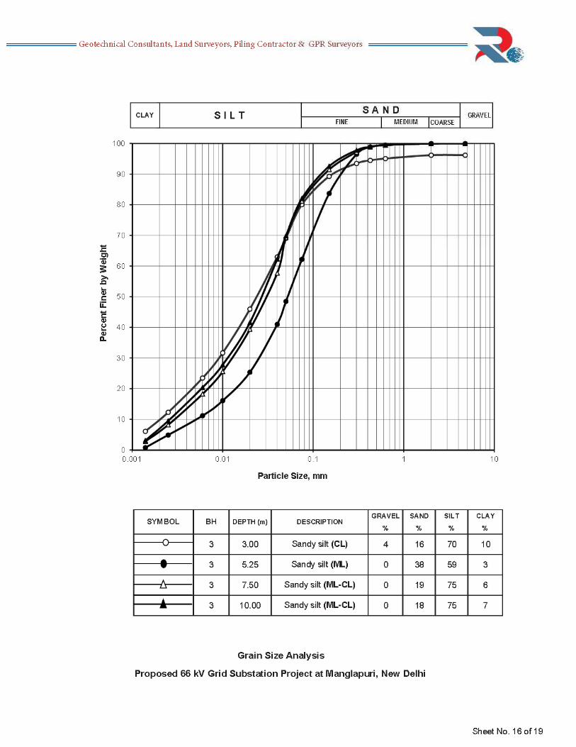
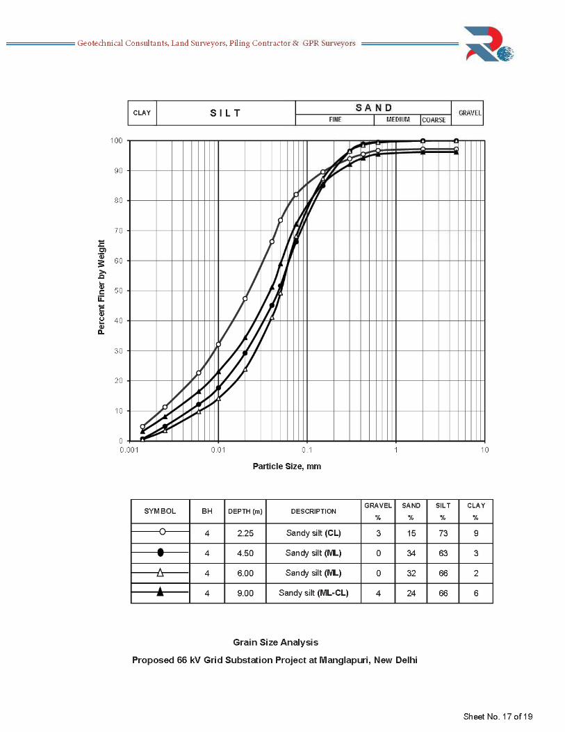
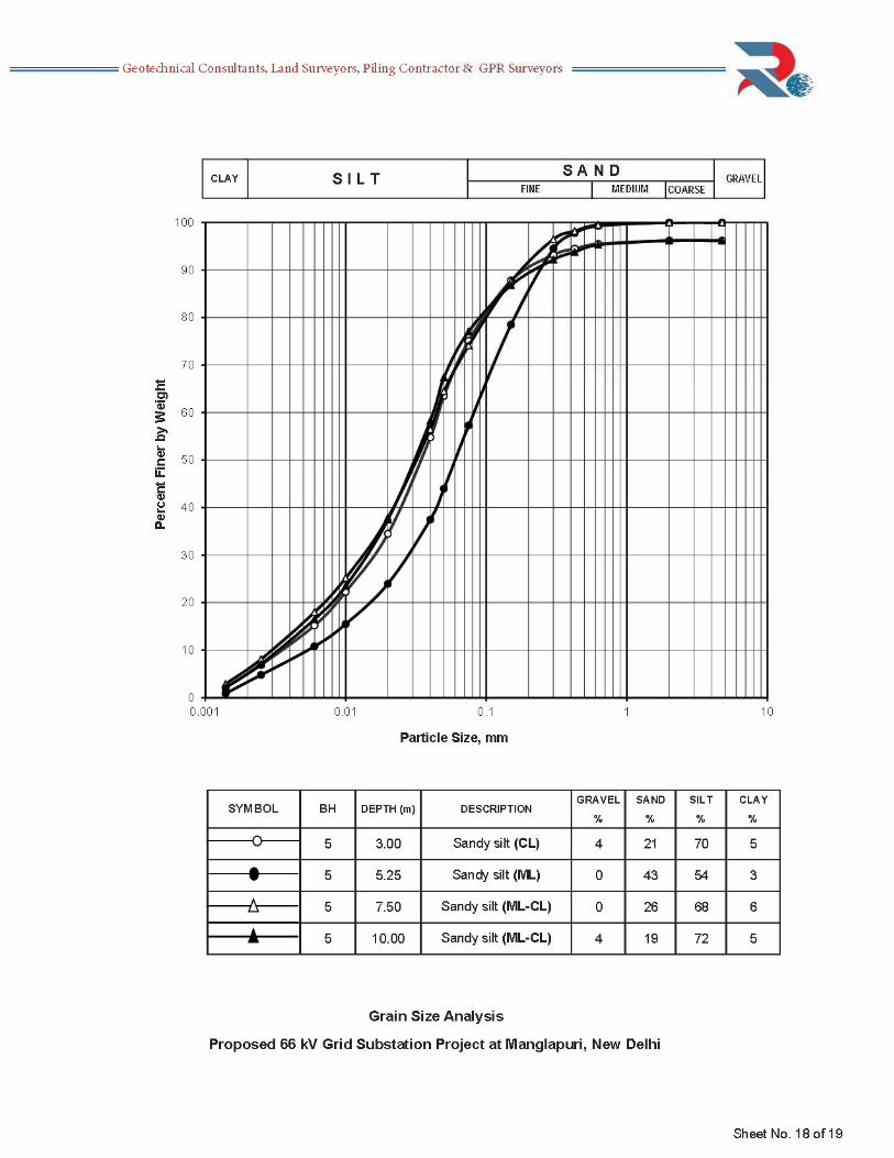
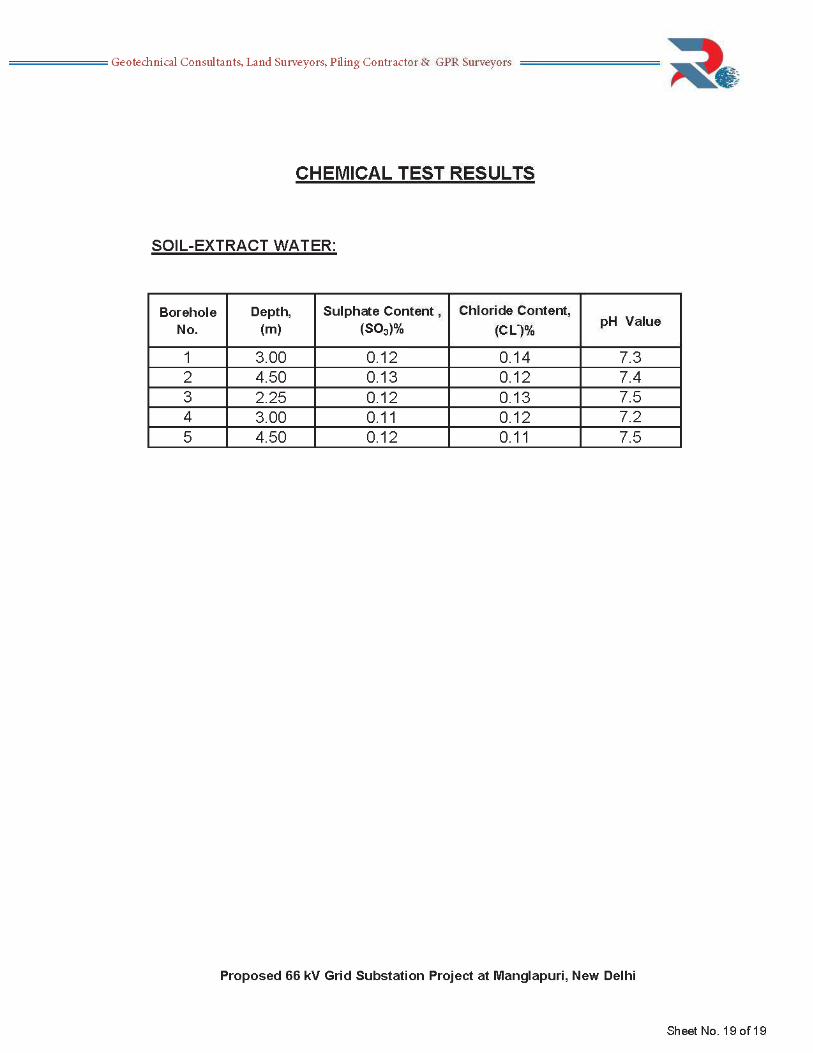
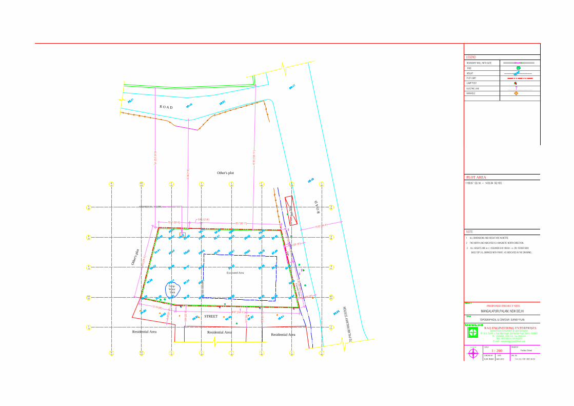
114 / C3 / TSP / REE /01/01
Pushkar Chilwal1 : 200
MAY 2019
CHECKED BY
G.R RAODATE DRG. NO.
SCALE DRAWN BYNORTH
W
S
E
E-mail:- [email protected]
91-D-3, Street -I, East Moti Bagh, Old Rohtak Road, Delhi -110007Ph : 23698806, 23691434, Fax-23691434
Geotechnical Consultants & Land Surveyors
PROPOSED PROJECT SITE
HEIGHT
PLOT LIMIT
Mob.-9811108174, 9310502435
MANGALAPURI,PALAM, NEW DELHI
PLOT AREA
TREE
BOUNDARY WALL WITH GATE
LEGEND
2 THE NORTH LINE INDICATED IS A MAGNETIC NORTH DIRECTION.
LAMP POST
MANHOLE
TOPOGRAPHICAL & CONTOUR SURVEY PLAN
NOTE
1 ALL DIMENSIONS AND HEIGHT ARE IN METRE.
1198.87 SQ. M. = 1433.84 SQ.YDS.
ELECTRIC LINE
3 ALL HEIGHTS ARE w.r.t. ASSUMED B.M 100.0m. i.e. ON FEDDER BOX
BASE TOP LVL.(MARKED WITH PAINT) AS INDICATED IN THE DRAWING.
TO P
ALAM
RAI
LWAY
STA
TION
Bus
Stop
R O
A D
STREET
R O A D
ASSUMED B.M=100.00M.
Residential Area Residential Area Residential Area
Other's plot
Covered Drain
Excavated Area
Gate
Temp. Water Tank
10.21 [33'-6"]3.86 [12'-8"]
26.7 [87'-7"]
24.2
[79'-
5"]
12.19 [40']
40.97 [134'-5"]
15.45 [50'-8"]
6.08 [20']
5.01 [16'-5"]
13.52 [44'-4"]
6.59
[21'
-7"]
6.84
[22'
-5"]
6.49
[21'-
4"]
6.04 [19'-10"]
6.36 [20'-10"]6.
77 [2
2'-2
"]
N/S0,0
N10
W10
N20
N30
N/S0,0
E10
S10
E20
E30
E40
E50
E60
N/S0,0
N10
N20
N30
S10
W10
N/S0,0
E10
E20
E30
E40
E50
E60
46.42 [152'-4"] 47.8
3 [1
56'-1
1"]
35.9
6 [1
18']
Oth
er's
plot
Related Documents