TENDER NO: WAP/ INFRA/NGP/KANHAN Page 1 of 64 TENDER DOCUMENT FOR “DEVELOPMENT OF INFRASTRUCTURE FOR LIFTING WATER FROM KANHAN RIVER AT VILLAGE ROHANA & CONVEYANCE TO WATER TREATMENT PLANT AT GODHANI & GOREWADA” TENDER NO: WAP/INFRA/NGP/KANHAN VOLUME 1: NOTICE INVITING TENDER Issued to M/s_______________________________________ _______________________________________ Telephone: +91- 0712 255 7798, Email: [email protected], Website: www.wapcos.co.in

Welcome message from author
This document is posted to help you gain knowledge. Please leave a comment to let me know what you think about it! Share it to your friends and learn new things together.
Transcript
TENDER NO: WAP/ INFRA/NGP/KANHAN
Page 1 of 64
TENDER DOCUMENT
FOR
“DEVELOPMENT OF INFRASTRUCTURE FOR LIFTING WATER FROM
KANHAN RIVER AT VILLAGE ROHANA & CONVEYANCE TO WATER
TREATMENT PLANT AT GODHANI & GOREWADA”
TENDER NO: WAP/INFRA/NGP/KANHAN
VOLUME 1: NOTICE INVITING TENDER
Issued to M/s_______________________________________ _______________________________________
Telephone: +91- 0712 255 7798, Email: [email protected], Website: www.wapcos.co.in

TENDER NO: WAP/ INFRA/NGP/KANHAN
Page 2 of 64
IMPORTANT DATES
Sr. No. Item Details 1. Name of work
Development of Infrastructure for lifting water from Kanhan River at village Rohana & conveyance to water treatment plant at Godhani & Gorewada
5. Period of downloading of bidding documents
11. Online opening of financial bid Shall be intimated to qualified bidders
12. Validity of Bid 180 days from the date of receiving of the bids.
13. Officer inviting Bids Chief, Civil/ Project Manager (Nagpur) Tele-fax: +91- 0712 255 7798
Chief, Civil (Infra), WAPCOS Ltd., C-14, 76-C, Sector-18, Institutional Area, Gurgaon-122015, Haryana or Chief, Civil/ PM (Nagpur), Plot 222, N Bazar Rd, opposite to Venus Book Centre, Dharampeth Extension, Gokulpeth, Nagpur, Maharashtra- 440010
10. Place of opening Bids WAPCOS Ltd., 76-C, Sector-18, Institutional Area, Gurgaon-122015, Haryana
7. Pre-bid Meeting 18.05.2022 at 3:00 PM at WAPCOS Ltd, Plot 222, N Bazar Rd, opposite to Venus Book Centre, Dharampeth Extension, Gokulpeth, Nagpur, Maharashtra 440010. However, the queries can be emailed to [email protected] before the pre- bid meeting and within 24 hrs after the pre- bid meeting.
6. Site Visit Bidders shall meet at WAPCOS office in Nagpur - Plot 222, N Bazar Rd, opposite to Venus Book Centre,
Dharampeth Extension, Gokulpeth, Nagpur,
Maharashtra 440010 on 17.05.2022 at 11:00 AM
(WAPCOS Contact person - Mr. Manoj Kumar
(Chief (Civil)/ Project Manager, Nagpur): 9861873709).
Bidder representative shall come along with an
authorization letter on behalf of bidder firm and
handover the same to WAPCOS representative.
2. Completion period for Construction 9 months including monsoon
3. Defect Liability Period 5 (Five) years
4. Date of issue of Notice inviting bid 11.05.2022 11.05.2022 to 31.05.2022 (up to 03:00 PM) Tender Documents can be downloaded from www.wapcos.co.in & https://etenders.gov.in/eprocure/app
8. Deadline for receiving bids 31.05.2022 (up to 03:00 PM)- Online & One Hard copy to below mentioned address:-
9. Date & time of opening Technical Bids 01-06-2022 (03:30 PM)
TENDER NO: WAP/ INFRA/NGP/KANHAN
Page 3 of 64
Email: [email protected] & [email protected]
14. Cost of Tender Document Rs. 10,000/- (in form of Demand Draft in favour of WAPCOS LIMITED payable at Gurugram)
Note: The Technical Bid submitted online only shall be used for evaluation purpose.
Financial Bid – Financial Bid has to be submitted online only.
15. Mode of Submission EMD – Rs. 62.36 Lacs (Refundable)
Technical Bid – Technical Bid must be uploaded online
and one hard copy to be submitted along with EMD,
Demand Draft and Solvency Certificate in original in
the office of the Chief, Civil (Infra), WAPCOS Ltd., C-14,
76-C, Sector-18, Institutional Area, Gurgaon-122015,
Haryana or Chief, Civil/ PM (Nagpur), Plot 222, N Bazar
Rd, opposite to Venus Book Centre, Dharampeth
Extension, Gokulpeth, Nagpur, Maharashtra- 440010
by 31.05.2022 (up to 3:00 pm).
TENDER NO: WAP/ INFRA/NGP/KANHAN
Page 4 of 64
TENDER DOCUMENT
FOR
“DEVELOPMENT OF INFRASTRUCTURE FOR LIFTING WATER FROM
KANHAN RIVER AT VILLAGE ROHANA & CONVEYANCE TO WATER
TREATMENT PLANT AT GODHANI & GOREWADA”
TENDER NO: WAP/INFRA/NGP/KANHAN
Section I- NIT
Telephone: +91- 0712 255 7798, Email: [email protected], Website: www.wapcos.co.in
TENDER NO: WAP/ INFRA/NGP/KANHAN
Page 5 of 64
Section I
NOTICE INVITING TENDER
TENDER NO: WAP/INFRA/NGP/KANHAN
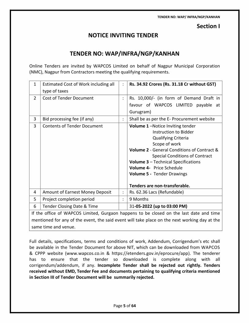
Online Tenders are invited by WAPCOS Limited on behalf of Nagpur Municipal Corporation (NMC), Nagpur from Contractors meeting the qualifying requirements.
1 Estimated Cost of Work including all
type of taxes
: Rs. 34.92 Crores (Rs. 31.18 Cr without GST)
2 Cost of Tender Document : Rs. 10,000/- (in form of Demand Draft in
favour of WAPCOS LIMITED payable at
Gurugram)
3 Bid processing fee (if any) : Shall be as per the E- Procurement website
3 Contents of Tender Document Volume 1 –Notice Inviting tender Instruction to Bidder Qualifying Criteria Scope of work Volume 2 - General Conditions of Contract &
Special Conditions of Contract Volume 3 – Technical Specifications Volume 4- Price Schedule Volume 5 - Tender Drawings Tenders are non-transferable.
If the office of WAPCOS Limited, Gurgaon happens to be closed on the last date and time
mentioned for any of the event, the said event will take place on the next working day at the
same time and venue.
Full details, specifications, terms and conditions of work, Addendum, Corrigendum’s etc shall be available in the Tender Document for above NIT, which can be downloaded from WAPCOS & CPPP website (www.wapcos.co.in & https://etenders.gov.in/eprocure/app). The tenderer has to ensure that the tender so downloaded is complete along with all corrigendum/addendum, if any. Incomplete Tender shall be rejected out rightly. Tenders received without EMD, Tender Fee and documents pertaining to qualifying criteria mentioned in Section III of Tender Document will be summarily rejected.
4 Amount of Earnest Money Deposit : Rs. 62.36 Lacs (Refundable)
5 Project completion period : 9 Months
6 Tender Closing Date & Time 31-05-2022 (up to 03:00 PM)

TENDER NO: WAP/ INFRA/NGP/KANHAN
Page 6 of 64
• Three similar completed works of order value each not less than
• Rs. 12.47 Crores
Or
• Two similar completed works of order value each not less than
• Rs. 15.60 Crores
Or
• One similar completed work of order value not less than
• Rs. 24.95 Crores
Here “Similar work” refers to Water Supply works with provision of Civil Works having
Construction of Intake well, Sump & Pump House, etc, laying of MS pipeline of minimum 1000
mm of 300 m length and E & M works like installation of pump sets in a pump house. Further,
for Automation/SCADA the bidder can execute this work on his own or can associate with some
other suitable firm/ agency. The bidder or the associated agency, as the case may be, Should
have installed and commissioned at least 1 SCADA/Automation project in Water Supply in any
Govt./Semi Govt./Corporation of Councils. The above experience can be met through especially
sub contractors or Bidder itself but MoU (Memorandums of Understanding) in this regard
should be submitted on Rs. 100 Stamp Paper. (Completion certificate needs to be enclosed).
The successful Tenderers shall have to comply with provision of contract labour (Regulation &
Abolition) Act, 1970 and rules appended there under if, applicable to him as applicable.
WAPCOS Limited reserves the right to accept or reject or cancel any or all tender (s) at any
stage if necessary without assigning any reason whatsoever.
The contractor should have a minimum average annual turnover of Rs. 15.60 Crores during
the last 3 years ending March 2021. Turnover Certificate for the last three years ending March
2022 shall be provided from a Registered Chartered Accountant mentioning the auditor’s UDIN.
The contractor should also have successfully completed similar projects during the last 7 years
ending previous day of last date of submission of tenders as prescribed below;
Technical and Financial Bid must be submitted online on CPPP Website (https://etenders.gov.in/eprocure/app) on or before 31.05.2022 up to 3:00 PM and Sealed Tender (Technical Bid along with Tender document fee in form of Demand Draft, original EMD and Solvency Certificate) will also be received physically at the Office of Chief, Civil (Infra), WAPCOS Ltd., C-14, 76-C, Sector-18, Institutional Area, Gurgaon-122015, Haryana or Chief, Civil/ PM (Nagpur), Plot 222, N Bazar Rd, opposite to Venus Book Centre, Dharampeth Extension, Gokulpeth, Nagpur, Maharashtra- 440010 by 31.05.2022 (up to 3:00 pm). The Financial bid of the technically qualified tenderers shall only be opened. Telex, Telegraphic or e-mail tenders will not be entertained.
TENDER NO: WAP/ INFRA/NGP/KANHAN
Page 7 of 64
The purpose of this NIT is to provide interested parties with information to assist the
preparation of their bid. While WAPCOS Limited has taken due care in the preparation of the
information contained herein, and believe it to be complete and accurate, neither it nor any of
its authorities or agencies nor any of its respective officers, employees, agents or advisors give
any warranty or make any representations, expressed or implied as to the completeness or
accuracy of the information contained in this document or any information which may be
provided in association with it.
Further, WAPCOS Limited does not claim that the information is exhaustive. Respondents to
this NIT are required to make their own inquiries/ surveys and will be required to confirm, in
writing, that they have done so and they did not rely solely on the information in NIT. WAPCOS
Limited is not responsible if no due diligence is performed by the Respondents.
WAPCOS Limited, reserves the right not to proceed with the Project at site or to change the
configuration of the Project, to alter the time-table reflected in this document or to change the
process or procedure to be applied. It also reserves the right to decline to discuss the Project
further with any respondent.
The Employer reserves the right, without being liable for any damages or obligation to inform
the bidder, to:
A) Amend the scope and value of contract to the bidder
B) Reject any or all the applications without assigning any reason.
No reimbursement of cost of any type or on any account will be paid to persons or entities
submitting their Bid.
1. IMPORTANT POINTS
1.1 Bidder shall be an Indian organization/entity.
1.2 Bidder must not have been blacklisted or deregistered by any government
agencies or public sector undertaking. If so the same shall be brought to the notice of
the Employer.
1.3 All Bidders are hereby cautioned that Bids containing any deviation or reservation
as described in Clauses of “Instructions to Bidders” shall be considered as non-
responsive and shall be summarily rejected.
TENDER NO: WAP/ INFRA/NGP/KANHAN
Page 8 of 64
1.4 WAPCOS Ltd. reserves the right to accept or reject any or all bids without assigning any
reasons. No Bidder shall have any cause of action or claim against WAPCOS Ltd. for
rejection of his Bid.
1.5 All designs and other information submitted in response to this NIT shall be the property
of WAPCOS Limited and it shall be free to use the concept of the same at its will.
1.6 GUIDELINES FOR JOINT VENTURE/ CONSORTIUM
Joint Venture/ Consortium is not allowed.
2. PREPARATION OF BID
2.1 Bidder’s responsibility
• The Bidder is solely responsible for the details of his Bid and the preparation
of Bids.
• The Bidder is expected to examine carefully all the contents of NIT document
which includes instructions, conditions, forms, terms, Employer’s Requirements
etc. and take them fully into account before submitting his offer. Bids, which
do not satisfy all the requirements, as detailed in these documents, are liable to
be rejected as being unresponsive.
• The Bidder shall be deemed to have inspected the Site and its
surroundings and taken into account all relevant factors pertaining to the Site, while
preparing and submitting the bid.
• WAPCOS will provide the Basic Details of the Project to the successful bidder.
2.2 Project Inspection and Site Visit
• Any Site information given in this NIT is for guidance only. The Bidder is advised to
visit and examine the Site of works and its surroundings at his/their cost and
obtain at his/their own responsibility, any information that may consider
necessary for preparing the Bid and entering into a Contract with the Employer,
including availability of electricity, water and drainage, where applicable.
• All Construction shall only be taken up after confirming the status of Land of the
Project. No Construction work shall be taken up on Private Land.
• WAPCOS Ltd. shall not be liable for such costs, regardless the outcome of the
selection process.
For and on behalf of WAPCOS LIMITED
TENDER NO: WAP/ INFRA/NGP/KANHAN
Page 9 of 64
TENDER DOCUMENT
FOR
“DEVELOPMENT OF INFRASTRUCTURE FOR LIFTING WATER FROM
KANHAN RIVER AT VILLAGE ROHANA & CONVEYANCE TO WATER
TREATMENT PLANT AT GODHANI & GOREWADA”
TENDER NO: WAP/INFRA/NGP/KANHAN
Section II- INSTRUCTIONS TO BIDDER
TENDER NO: WAP/ INFRA/NGP/KANHAN
Page 10 of 64
Telephone: +91- 0712 255 7798, Email: [email protected],
Website: www.wapcos.co.in
SECTION– II
INSTRUCTIONS TO BIDDER
1) Purpose:-
It is the purpose of these instructions to serve as a guide to Bidders for preparing offer for carrying out the Project.
2) In case of discrepancy between quoted rate and amount, rate shall prevail. The payment
will be made as per the actual work done and item wise measurement basis. Bidders are
advised to examine the available Cost Index/ Market Rate while framing their
estimate/rates.
3) a) Submission of a tender by a tenderer implies that he has read this notice and all other
Tender Documents and has made himself aware of the scope and the specifications,
Drawings of the work to be done and of conditions of contract and local conditions and
other factors having bearings on the execution of the work.
b) While all efforts have been made to avoid errors in the drafting of the tender
documents, the Bidder is advised to check the same carefully. No claim on account of
any errors detected in the tender documents shall be entertained.
c) WAPCOS Limited desires that the bidders, suppliers, and Sub-contractors under the
Project, observe the highest standard of ethics during the performance,
TENDER NO: WAP/ INFRA/NGP/KANHAN
Page 11 of 64
procurement and execution of such contracts. In pursuance of this requirement,
WAPCOS Limited:
Defines, for the purposes of this provision, the terms set forth below:
I) “Corrupt Practice” means the offering, giving, receiving, or soliciting, directly or
indirectly, anything of value to influence improperly the actions of another party;
II) “Fraudulent Practice” means any act of submission of forged documentation, or
omission, including a misrepresentation, that knowingly or recklessly misleads,
or attempts to mislead, a party to obtain a financial or other benefit or to avoid
an obligation, or to succeed in a competitive bidding process;
III) “Coercive Practice” means impairing or harming, or threatening to impair or
harm, directly or indirectly, any party or the property of the party to influence
improperly the actions of a party;
IV) “Collusive Practice” means an arrangement between two or more parties
designed to achieve an improper purpose, including influencing improperly the
actions of another party.
Will reject the award of Contract, even at a later stage, if it determines that the bidder
recommended/ selected for award/awarded has, directly or through an agent, engaged
in Corrupt, Fraudulent, Collusive, Or Coercive Practices in competing for the Contract;
Will sanction a party or its successors, including declaring ineligible, either indefinitely or
for a stated period of time, to participate in any further bidding/ procurement
proceedings under the Project, if it at any time determines that the party has, directly or
through an agent, engaged in Corrupt, Fraudulent, Collusive, Or Coercive Practices in
competing for, or in executing, the contract; and
Will sign an Integrity Pact, w.r.t the selected Tenderer.
Will have the right to require the bidders, or its suppliers, contractors and consultants to
permit WAPCOS Limited to inspect their accounts and records and other documents
relating to the bid submission and contract performance and to have them audited by
auditors appointed by WAPCOS Limited at the cost of the bidders.
The Bidder must obtain for himself on his own responsibility and at his own expenses all
the information which may be necessary for the purpose of making a bid and for
entering into a contract, must inspect the sites of the work, acquaint himself with all
local conditions, means of access to the work, nature of the work and all matters
pertaining thereto. WAPCOS Limited will in no case be responsible or liable for those
costs, regardless of the conduct or outcome of the bidding process.
TENDER NO: WAP/ INFRA/NGP/KANHAN
Page 12 of 64
d) Each page of the Tender documents should be stamped and signed by the person or
persons submitting the Tender in token of his/their having acquainted himself/
themselves and accepted the entire tender documents including various conditions
of contract. Any Bid with any of the Documents not so signed is liable to be
rejected at the discretion of WAPCOS Limited. The signatures shall be in blue ink.
e) The tender prepared by the Bidder and all correspondence and documents relating
to the tender exchanged between the Bidder and WAPCOS Limited shall be in the
English language.
f) The bidder shall attach the original authorization letter/power of Attorney as the
proof.
g) The contract shall be governed by General Conditions for Contract (GCC), Special
Conditions of Contract, Technical Specification (TS), addendum / clarification /
corrigendum etc. and all other relevant conditions on the tender documents.
h) The Bidders are expected to carefully examine all the contents of the tender
documents including instructions, conditions, terms, and specifications, if required,
from WAPCOS Limited and take them fully into account before submitting their
offer. Failure to comply with the requirements as detailed in these documents shall
be at the Bidder’s own risk. Bidders which are not responsive to the requirements of
the tender documents will be rejected.
i) All Bidders are hereby explicitly informed that conditional offers or offers with
deviations from the conditions of Contract, the bids not meeting the minimum
eligibility criteria, Technical Bids not accompanied with EMD of requisite amount in
acceptable format, Bids in altered/modified formats, or in deviation with any other
requirements stipulated in the tender documents are liable to be rejected.
j) The Bid submitted on behalf of a Firm shall be signed by all the Partners of the Firm
or by a Partner who has the necessary authority on behalf of the Firm to enter into
the proposed contract. Otherwise, the bid is liable to be rejected by the WAPCOS
Limited.
k) The bidders are expected to meet the minimum eligibility criteria as given in the
Section-III to participate in this tender. WAPCOS Limited will reject the Bids that do
not meet the minimum eligibility criteria as laid down, based on their submission
along with the tender documents, even after the bid opening process is concluded.
l) The bidders shall not tamper or modify any part of the tender documents in any
manner. In case in part of the bid is found to be tampered or modified at any stage,
the bids are liable to be rejected, the contract is liable to be terminated and the full
earnest deposit/retention money/performance guarantee will be forfeited and the
bidder will be liable to be banned from doing any business with WAPCOS Limited.
TENDER NO: WAP/ INFRA/NGP/KANHAN
Page 13 of 64
m) Incomplete Price bid shall be liable to be rejected, at the discretion of WAPCOS
Limited. The total bid price shall cover the entire scope of works covered in the
tender.
4) Procedure for submission of bid:
i) EMD Amount in the Form of Insurance Surety Bonds, Account Payee Demand Draft, Fixed Deposit Receipt, Banker's Cheque or Bank Guarantee having validity of minimum 6 months from any of the Commercial Banks to be submitted.
ii) Tender Document fee in form of DD payable at Gurugram to be submitted.
iii) The offer of the bidder may not be considered for further evaluation, if the EMD and
Tender fee is not submitted in the original form and manner as stated above and
their offer is liable to be rejected.
iv) The EMD of unsuccessful tenderer(s) will be returned to latest on or before the 30th
day after the award of Contract. The EMD submitted by the successful tenderer
shall be retained by WAPCOS Limited until the Performance Bank Guarantee (PBG)
is submitted. The successful Tenderer shall accept the LOI within 3 (Three) days
from receipt of the same, failing which then the details mentioned in EMD will be
forfeited and the award of work may be liable to be cancelled. In case tenderer
revokes, cancels, or varies his tender in any manner without the consent of WAPCOS
Limited, within this period, then the EMD will be forfeited.
v) Does not commence the work within the period as per LOI/Contract. In case the
LOI/Contract is silent in this regard then within 15 days after award of contract.
5) WAPCOS Limited reserves the right to reject any or all the bids or to cancel the Tender,
without assigning any reason(s) whatsoever.
6) The contents of the TECHNICAL BID and FINANCIAL BID are as mentioned below:
CONTENTS OF TECHNICAL BID
The Technical Bid, clearly labeled as “TECHNICAL BID”, has to be submitted. It shall
consist of information for responsiveness and other information about Bidders, as
required under Tender document.
a) Technical bid shall comprise the followings:
i. Proof of payment of Bid document fee, e-service fee and EMD in accordance with DNIT
conditions
ii. Bidder’s covering letter of offer.
iii. Signed & stamped NIT documents (comprising of total documents-all pages) including
documents related to Qualifying criteria as per SECTION-III of the Tender Document.
iv. “No Deviation Certificate” in prescribed format in Bidder’s Letter Head.
TENDER NO: WAP/ INFRA/NGP/KANHAN
Page 14 of 64
v. No information relating to financial terms of services should be included in the technical
bid. Bids are to be submitted to determine that the bidder has a full comprehension of
the tendered work. Where a bidder technical submittal is found non- compliant with the
requirement or work, it may be rejected. This process is to assure that only technical
acceptable bids are considered for the tendered work.
vi. Constitution & Legal Status along with attested copies of Deeds/Incorporation
Certificate, Articles and Memorandum of Association etc. as Applicable.
vii. Power of Attorney in original in favor of the person signing the tender.
viii. Details of Financial Status i.e. Original Solvency Certificate from the
Nationalised/Schedule Commercial Bank for a sum of at least Rs. 12.48 Crores. Solvency
Certificate shall be issued after the date of publishing of NIT and addressed to Tendering
Authority quoting the name of the work. Further, the certificate will carry Name,
Designation and Power of Attorney number of the bank official.
ix. Details of Contractor’s Bidding Capacity for a sum of at least Rs. 31.18 Crores.
x. The Construction agency should have liquid assets or availability of Credit facilities for
meeting the monthly fund requirement.
xi. Yearly sales Turnover and Audited Balance Sheet for Last 5 (Five) years ending on the
financial year 2020-21.
xii. The Bidder should not have incurred any loss (Profit after tax should be positive) in more
than two years during the last Five financial years ending on the financial year 2020-21.
xiii. Copy of P.F, ESI and GST Registration Certificate
xiv. PAN No. (With a copy)
xv. Name(s) of the Owner/Partners/Promoters and Directors of the firm / company.
xvi. Enlistment Certificate in PWD/NMC/NIT/MJP/CIDCO/MIDC/Other Govt Dept. in
appropriate class and bidders enlisted with CPWD, postal, telecom, Railways, MES,
Other state Government / Central Government under takings/ organizations in a class
making the bidder eligible to quote for work of value of this tender and meeting
eligibility criteria.
xvii. Information on litigation history, liquidated damages, disqualification etc. in
Tenderer’s Letter Head.
xviii. Details of similar type of work executed indicating value of works in each contract with
self-attested documentary evidence such as copy/copies of completion Certificate(s)
along-with LOI(s)/W.O(s) from respective Owner(s)/Client(s) mentioning name and
nature of work(s), date(s) of commencement and value(s) of the job(s) executed
during last Seven years.
xix. Programme of Works, a comprehensive Project implementation Program with list of
activities, timelines and milestones. A detailed overall activity chart indicating the
duration and timing of all major activities.
xx. ISO Certificate.
TENDER NO: WAP/ INFRA/NGP/KANHAN
Page 15 of 64
xxi. Signed Pre Integrity-Pact and Contract Agreements as per the format given in this
document.
CONTENTS OF FINANCIAL BID
The Financial Bid should be uploaded online only in the format prescribed. The rates
quoted for the contract shall be inclusive of all taxes. GST as applicable shall be
reimbursed by WAPCOS on submission of proof and Bill shall be accepted only after Bill is
uploaded at GST Portal.
Cost of Bidding
The Bidder shall bear all costs associated with the preparation and submission of the Bid
as well as costs associated for facilitating the evaluation. WAPCOS Limited shall in no case
be responsible or liable for these costs, regardless of the conduct or outcome of the
bidding process.
Language of Bid
The Bid and all related correspondence and documents relating to the Project shall be in
English language only. Supporting documents and printed literature furnished by the
Bidder may be in another language provided they are accompanied by an accurate English
translation which shall be certified by a qualified translator. Any material that is submitted
in a language other than English and which is not accompanied by an accurate English
translation will not be considered.
Currency of Bid
Bid prices shall be quoted in Indian Rupees.
Outermost cover:
Due date of submission shall be written on all the covers/envelopes of the bid without fail.
Bids received after the due date and time shall not be accepted. Telegraphic or Fax or E-
Mail offers shall not be accepted under any circumstances.
It shall be super scribed with offer for “Name of the Project”
(WAP/INFRA/NGP/KANHAN) and shall be addressed to “Chief, Civil (Infra.), Room No. C-
14, WAPCOS Limited 76-C, Sector-18, Institutional Area, Gurgaon - 122015 (Haryana)” or
“Chief, Civil/ PM (Nagpur), Plot 222, N Bazar Rd, opposite to Venus Book Centre,
Dharampeth Extension, Gokulpeth, Nagpur, Maharashtra- 440010” and should reach this
office as mentioned above on or before 31.05.2022 up to 3.00 P.M
TENDER NO: WAP/ INFRA/NGP/KANHAN
Page 16 of 64
7) Tender submitted by tenderer shall remain valid for acceptance for a period of 180 (One
Hundred and Eighty) days from the date set for submission of the tender. The tenderer
shall not be entitled within the said period of 180 (One Hundred and Eighty) days to
revoke or cancel or vary the tender given or any item thereof. In case tenderer revokes
or cancels or varies his tender in any manner without the consent of WAPCOS Limited,
within this period, then the EMD will be forfeited.
Price Bids of those Bidders who will be technically qualified for the subject job on the basis
of evaluation of technical bids, will be opened on specified date. The date & time to open
the price bid (Part-II) shall be intimated to the bidders and in such a case, one
representative of the bidder shall be allowed to attend. WAPCOS’s decision in this regard is
final & binding. The lowest Financial Bid so opened shall be awarded the work (L-1 Bidder).
Acceptance of WAPCOS LTD. is a prerequisite for consideration of Bidder’s offer for this
contract. Accordingly, Bidder(s) not acceptable to WAPCOS LTD. shall not be considered and
shall be rejected by WAPCOS Limited and no correspondence and claim etc. from the Bidder
in pursuant to the Tender shall be entertained by WAPCOS Limited under any circumstances
whatsoever
8) Special instructions to Bidders for e-Tendering
Digital Certificates
For integrity of data and authenticity/ non-repudiation of electronic records, and to be
compliant with IT Act 2000, it is necessary for each user to have a Digital Certificate (DC).
also referred to as Digital Signature Certificate (DSC), of Class 2 or above, issued by
a Certifying Authority (CA) licensed by Controller of Certifying Authorities (CCA) [refer
http://www.cca.gov.in].
Instructions for Online Bid Submission
The bidders are required to submit soft copies of their bids electronically on the CPP Portal, using valid Digital Signature Certificates. The instructions given below are meant to assist the bidders in registering on the CPP Portal, prepare their bids in accordance with the requirements and submitting their bids online on the CPP Portal.
More information useful for submitting online bids on the CPP Portal may be obtained at: https://etenders.gov.in/eprocure/app
REGISTRATION 1) Bidders are required to enroll on the e-Procurement module of the Central Public
Procurement Portal (URL: https://etenders.gov.in/eprocure/app) by clicking on the link “Online bidder Enrollment” on the CPP Portal which is free of charge.
TENDER NO: WAP/ INFRA/NGP/KANHAN
Page 17 of 64
2) As part of the enrolment process, the bidders will be required to choose a unique username and assign a password for their accounts.
3) Bidders are advised to register their valid email address and mobile numbers as part of the registration process. These would be used for any communication from the CPP Portal.
4) Upon enrolment, the bidders will be required to register their valid Digital Signature Certificate (Class III Certificates with signing key usage) issued by any Certifying Authority recognized by CCA India (e.g. Sify / nCode / eMudhra etc.), with their profile.
5) Only one valid DSC should be registered by a bidder. Please note that the bidders are responsible to ensure that they do not lend their DSC’s to others which may lead to misuse.
6) Bidder then logs in to the site through the secured log-in by entering their user ID / password and the password of the DSC / e-Token.
SEARCHING FOR TENDER DOCUMENTS 1) There are various search options built in the CPP Portal, to facilitate bidders to search
active tenders by several parameters. These parameters could include Tender ID, Organization Name, Location, Date, Value, etc. There is also an option of advanced search for tenders, wherein the bidders may combine a number of search parameters such as Organization Name, Form of Contract, Location, Date, Other keywords etc. to search for a tender published on the CPP Portal.
2) Once the bidders have selected the tenders they are interested in, they may download the required documents / tender schedules. These tenders can be moved to the respective ‘My Tenders’ folder. This would enable the CPP Portal to intimate the bidders through SMS / email in case there is any corrigendum issued to the tender document.
3) The bidder should make a note of the unique Tender ID assigned to each tender, in case they want to obtain any clarification / help from the Helpdesk.
PREPARATION OF BIDS 1) Bidder should take into account any corrigendum published on the tender document
before submitting their bids.
2) Please go through the tender advertisement and the tender document carefully to understand the documents required to be submitted as part of the bid. Please note the number of covers in which the bid documents have to be submitted, the number of documents - including the names and content of each of the document that need to be submitted. Any deviations from these may lead to rejection of the bid.
TENDER NO: WAP/ INFRA/NGP/KANHAN
Page 18 of 64
3) Bidder, in advance, should get ready the bid documents to be submitted as indicated in
the tender document / schedule and generally, they can be in PDF / XLS / RAR / DWF/JPG formats. Bid documents may be scanned with 100 dpi with black and white option which helps in reducing size of the scanned document.
4) To avoid the time and effort required in uploading the same set of standard documents which are required to be submitted as a part of every bid, a provision of uploading such standard documents (e.g. PAN card copy, annual reports, auditor certificates etc.) has been provided to the bidders. Bidders can use “My Space” or ‘’Other Important Documents’’ area available to them to upload such documents. These documents may be directly submitted from the “My Space” area while submitting a bid, and need not be uploaded again and again. This will lead to a reduction in the time required for bid submission process.
Note: My Documents space is only a repository given to the Bidders to ease the uploading process. If Bidder has uploaded his Documents in My Documents space, this does not automatically ensure these Documents being part of Technical Bid. SUBMISSION OF BIDS 1) Bidder should log into the site well in advance for bid submission so that they can
upload the bid in time i.e. on or before the bid submission time. Bidder will be responsible for any delay due to other issues.
2) The bidder has to digitally sign and upload the required bid documents one by one as indicated in the tender document.
3) Bidders are requested to note that they should necessarily submit their financial bids in
the format provided and no other format is acceptable. If the price bid has been given as a standard BoQ format with the tender document, then the same is to be downloaded and to be filled by all the bidders. Bidders are required to download the BoQ file, open it and complete the white coloured (unprotected) cells with their respective financial quotes and other details (such as name of the bidder). No other cells should be changed. Once the details have been completed, the bidder should save it and submit it online, without changing the filename. If the BoQ file is found to be modified by the bidder, the bid will be rejected.
4) The server time (which is displayed on the bidders’ dashboard) will be considered as
the standard time for referencing the deadlines for submission of the bids by the bidders, opening of bids etc. The bidders should follow this time during bid submission.
5) All the documents being submitted by the bidders would be encrypted using PKI
encryption techniques to ensure the secrecy of the data. The data entered cannot be viewed by unauthorized persons until the time of bid opening. The confidentiality of
TENDER NO: WAP/ INFRA/NGP/KANHAN
Page 19 of 64
the bids is maintained using the secured Socket Layer 128 bit encryption technology. Data storage encryption of sensitive fields is done. Any bid document that is uploaded to the server is subjected to symmetric encryption using a system generated symmetric key. Further this key is subjected to asymmetric encryption using buyers/bid opener’s public keys. Overall, the uploaded tender documents become readable only after the tender opening by the authorized bid openers.
6) The uploaded tender documents become readable only after the tender opening by the
authorized bid openers. 7) Upon the successful and timely submission of bids (i.e. after Clicking “Freeze Bid
Submission” in the portal), the portal will give a successful bid submission message & a bid summary will be displayed with the bid no. and the date & time of submission of the bid with all other relevant details.
8) The bid summary has to be printed and kept as an acknowledgement of the submission
of the bid. This acknowledgement may be used as an entry pass for any bid opening meetings.
ASSISTANCE TO BIDDERS 1) Any queries relating to the tender document and the terms and conditions contained
therein should be addressed to the Tender Inviting Authority for a tender or the relevant contact person indicated in the tender.
2) Any queries relating to the process of online bid submission or queries relating to CPP
Portal in general may be directed to the 24x7 CPP Portal Helpdesk
For any assistance regarding the Tender Document and/or term and conditions the
bidders may contact at WAPCOS:
WAPCOS Contact
Person
Manoj Kumar Chief (Civil)/ Project Manager ( Nagpur)
Telephone/ Mobile +91- 0712 255 7798
E-mail ID [email protected] & [email protected]
TENDER NO: WAP/ INFRA/NGP/KANHAN
Page 20 of 64
TENDER DOCUMENT
FOR
“DEVELOPMENT OF INFRASTRUCTURE FOR LIFTING WATER FROM
KANHAN RIVER AT VILLAGE ROHANA & CONVEYANCE TO WATER
TREATMENT PLANT AT GODHANI & GOREWADA”
TENDER NO: WAP/INFRA/NGP/KANHAN
Section III- QUALIFYING CRITERIA
Telephone: +91- 0712 255 7798, Email: [email protected], Website: www.wapcos.co.in
TENDER NO: WAP/ INFRA/NGP/KANHAN
Page 21 of 64
SECTION-III
QUALIFYING CRITERIA
Qualifying Criteria for participating in the Tender for “Name of the Project”
TENDER NO: WAP/INFRA/NGP/KANHAN
The Tenderer who wish to participate in the Tender shall fulfill the following Qualifying Criteria.
1) Qualifying Criteria for participation in Tender:-
Bids may be submitted by a contractor.
a) Technical Eligibility Requirements:
i) The contractor should have the expertise and experience to provide complete
solution for similar work.
b) The contractor should have a solvency of at least Rs. 12.48 Crores in order to fund
the project till the time the invoices get paid. Solvency Certificate shall be issued
after the date of publishing of NIT and addressed to Tendering Authority quoting the
name of the work. Further, the certificate will carry Name, Designation and Power of
Attorney number of the bank official.
c) The Bidder should not have incurred any loss (Profit after tax should be positive) in
more than two years during the last Five financial years ending on the financial year
2020-21.
d) The contractor should have minimum annual average turnover of Rs. 15.60 Crores
during the last 3 years. The bidder shall furnish a certified copy of audited financial
statements in support of the claim for last 5 financial year.
e) The contractor should also have successfully completed during last Seven years
ending previous day of last date of submission of tenders of minimum values
specified herein below:
• Three similar completed works of order value each not less than
• Rs. 12.47 Crores
Or
• Two similar completed works of order value each not less than
• Rs. 15.60 Crores
Or
• One similar completed work of order value not less than
• Rs. 24.95 Crores

TENDER NO: WAP/ INFRA/NGP/KANHAN
Page 22 of 64
f) To work out the present price level for value of completed/ Substantially Completed,
the previous year(s) values shall be multiplied by weight age factor@ of 7% per year.
g) In case previous experience of sole bidder or constituent of JV/ Consortium as a
member of JV /Consortium, experience weightage of work shall be fulfilled by the
Lead Member.
h) The works which have been completed and commissioned during the last seven
years, though may have commenced earlier, shall be considered for the
experience purposes. The period of 7 years shall be counted from end date of
submission of Bid.
i) Experience certificate issued by an officer not below the rank of Executive
Engineer or equivalent of The State Government/ Central Government or their
undertakings and autonomous bodies shall only be considered for the purpose of
experience of work.
j) The Bidder shall keep original certificates with him for verification and will
present, if required, at a short notice of 3 days to the department.
k) LOI / WO and relevant Completion certificate or any other documents to
substantiate the above nature as well as value of work.
l) Copy of PAN, PF and GST Registration Certificate to be submitted.
m) Pre Integrity Pact and Contract agreement mentioned in the Bid Formats shall be
signed and submitted with the bid.
Note for Clause 1 (e) above:
(Here “Similar work” refers to Water Supply works with provision of Civil Works having
Construction of Intake well, Sump & Pump House, etc, laying of MS pipeline of minimum
1000 mm of 300 m length and E & M works like installation of pump sets in a pump
house. Further, for Automation/SCADA the bidder can execute this work on his own or
can associate with some other suitable firm/ agency. The bidder or the associated
agency, as the case may be, Should have installed and commissioned at least 1
SCADA/Automation project in Water Supply in any Govt./Semi Govt./Corporation of
Councils. The above experience can be met through especially sub contractors or Bidder
itself but MoU (Memorandums of Understanding) in this regard should be submitted on
Rs. 100 Stamp Paper. (Completion certificate needs to be enclosed).
2) The company reserves the right to waive minor deviations if they do not materially
affect the capability of the Tenderer to perform the contract.
3) BID Capacity: The Bidder who interalia meet the minimum qualification criteria will be
qualified only if their available Bid Capacity is more than the Total Tendered Value. The
available Bid Capacity will be calculated as per following based on information
mentioned enclosed in the Bid Format for Bid Capacity.
Assessed available Bid Capacity =(A*N*2-B), Where

TENDER NO: WAP/ INFRA/NGP/KANHAN
Page 23 of 64
N= Number of years prescribed for completion of work for which Bid is invited
A= Maximum value of civil engineering works in respect of projects executed in any one
year during the last five years (updated to the price level of the year indicated in table
below under note) taking into account the completed as well as works in progress. The
Projects include turnkey project/item rate contract/ Construction works.
B = Value (updated to the price level of the year indicated in table below under note)
of existing commitments and on-going works to be completed during the period of
completion of the works for which BID is invited.
Note-1: The Statement showing the value of all existing commitments and ongoing
works as well as the stipulated period of completion remaining for each of the works
listed should be countersigned by the Client or its Engineer-in-charge not below the rank
of Executive Engineer or equivalent in respect of Projects or Concessionaire / Authorized
Signatory of SPV in respect of BOT Projects and verified by Statutory Auditor. The factor
for the year for up-dation to the price level is indicated below in Bid Formats.
For & on behalf of Tenderer

TENDER NO: WAP/ INFRA/NGP/KANHAN
Page 24 of 64
TENDER DOCUMENT
FOR
“DEVELOPMENT OF INFRASTRUCTURE FOR LIFTING WATER FROM
KANHAN RIVER AT VILLAGE ROHANA & CONVEYANCE TO WATER
TREATMENT PLANT AT GODHANI & GOREWADA”
TENDER NO: WAP/INFRA/NGP/KANHAN
Section IV- SCOPE OF WORK
Telephone: +91- 0712 255 7798, Email: [email protected], Website: www.wapcos.co.in
TENDER NO: WAP/ INFRA/NGP/KANHAN
Page 25 of 64
SECTION IV
CONDITIONS OF PARTICULAR APPLICATION
1) The instructions to the Bidders for submission of Tender are enclosed.
This Tender is being invited by WAPCOS Limited on behalf of Nagpur Municipal
Corporation, (NMC) Nagpur for executing a part of the work for the subject job as per
enclosed Scope of Work.
2) All terms & conditions namely General Conditions of Contract, Special Conditions of
Contract, Technical Specification, Corrigendum/Amendments/Clarification, if any
incorporated with this bidding document applicable to WAPCOS Limited shall also be
binding and construe as part of this tender document unless amended/altered or
clarified specifically here-in and such additional stipulation/clarification shall have an
overriding effect over Scope of work, General Conditions of Contract, Special Conditions
of Contract , Technical Specification, Corrigendum/Amendments/Clarification etc.
SCOPE OF WORK
PROJECT DESCRIPTION
The water supply needs of Nagpur city is being fulfilled from 2 major sources:-
I) Navegaon Khairy Reservoir, Constructed on Pench River at the downstream of Pench Hydel
Dam at Totla Doh, which collects the water after power generation through Tail race tunnel. This
Dam is located at 55 kms from Nagpur. Average 520 MLD water is being lifted from Navegaon
Khairy reservoir and transported to Mahadula head works (MHW) at Lonara through 27.5 km long
2300 mm diameter MS pipeline. Further the water is conveyed to WTPs at Gorewada and Godhani
through different size of pipe lines. After treatment the treated water is further conveyed to the
Master Balancing Reservoir at Seminary Hills for distribution.
II) Kanhan River, the right bank tributary of Wainganga river draining a large area lying south of
Satpura range in central India. Along its 275 km run through the Indian states of Maharashtra &
Madhya Pradesh, it receives its largest tributary Pench River, a major water source for the
metropolis of Nagpur. Another tributary connecting it at its right bank is Kolar river- the spill off
from Kolar Dam. Average 200 MLD water is being lifted from Kanhan River at the downstream of
confluence of tributaries Pench and Kolar to the WTPs located near Kamptee Cantonment area.
The treated water is further conveyed to city for distribution.
TENDER NO: WAP/ INFRA/NGP/KANHAN
Page 26 of 64
Due to very less precipitation in the catchment area of the storage reservoir constructed across
Pench River mainly Totla Doh and Navegaon Khairy and construction of Pench Diversion project at
Taluka Chaurai, Dist. Chhindwara at upstream side of Totla Doh Dam by Government of MP, very
less water is stored in these dams. As such NMC thought of exploring new sources of water to
compensate the less availability of water from these storage dams.
Raw water pipe line (gravity) from Navegaon Khairy reservoir crosses Kanhan River at village
Rohana at 18.5 km distance from Navegaon Khairy Dam. Kanhan River is having sufficient water
flow during June to January of every year. NMC now desires to lift 550 MLD water from Kanhan
River at this location and to convey it to Water Treatment Plant (WTP) at Godhni and Gorewada.
The Scope of work of project for Contractor includes, but not limited to
• Intake structure-cum-Raw Water Pumping station (RWPS) at intake location (302314.81 m
E, 2358702.75 m N) on river Kanhan to supply 550 MLD of raw water to water treatment
plant at Godhani and Gorewada with control arrangements including trash racks, piling
arrangement etc.
• RCC Pump House including tank reservoir, pumps and all civil works and pipe connections,
etc. Control arrangements viz Sluice gates Valves and connections to sump including gantry
arrangements etc.
• Automation works
• Raw water pumping main of diameter 2100 mm capable of transmitting 550 MLD of raw
water from pump house to existing conveyance system transmitting to Water Treatment
Plants at Godhani and Gorewada including manufacturing, in-lining, out coating,
transportation, earthwork excavation, lowering, laying, jointing, testing and commissioning
including specials, valves, thrust blocks, anchor blocks, valve chambers, refilling, providing
necessary ancillary and CD works including river crossing etc.
• Construction of approach road.
• Installation of Butterfly Valve 2300 mm on Existing Gravity Main & Surge Arrester Air Valve
on proposed pipeline.
• Handing over the project after commissioning in all aspects
• Defect Liability period for 5 years after handing over of project.
Notwithstanding the Employer has provided certain information, the scope of work shall
include obtaining necessary approvals during Construction Stage which are required for the
completion of the project. The bidder shall be responsible right through the entire duration
of the Project for execution of all works from the conception till commissioning and
handing over of the Project complete with all respects ready to use and shall remove all
defects, if any, developed during Defects Liability Period (DLP).

TENDER NO: WAP/ INFRA/NGP/KANHAN
Page 27 of 64
The Bidder shall visit the site and collect whatever information he may require before
submission of bid at their own cost.
The Contractor before proceeding with the work shall verify all surveys, Geotechnical
investigations, design and drawings. The Contractor shall provide detailed construction
drawings for approval before proceeding with the Construction work.
The Contractor shall submit monthly physical and financial progress report to the
Employer.
The Contractor shall ensure soundness of construction and defect free operation for a
period of 5 year after commissioning.
The responsibility of the Bidder shall include carrying out all the activities for the
completion of the Project which generally shall include the following and any additional
activities incidental to these:-
The Contractor shall be responsible for providing plant, equipment, materials and labour
for the provision of all necessary Permanent/Temporary Works, site installations and
services required for the realisation of the Works under this Contract.
The Contractor shall design, furnish, set-up, maintain and operate at the Site all
Permanent/Temporary Works, site installations and Contractor's Equipment for his own
use, or required by the Contractor, including camps, workshops, warehouses, storage
and assembly areas, all machinery, vehicles, scaffolding, equipment, water and power
supply, etc.
Permanent/Temporary Works and services provided and operated by a Contractor for
his own use as well as for that of the Employer shall conform to the applicable Indian
laws, regulations, standards, codes and sanitary requirements stipulated for such
purpose. In addition, they shall comply fully with all Indian laws and regulations relating
with environmental protection, mitigating measures for reducing environmental
impacts and remedial works on completion of the Works.
The design, construction, operation and maintenance of a Contractor's
Permanent/Temporary Works and services may be subject to inspection by the
Employer.
All plants, camp facilities, installations and services provided by a Contractor for his own
use as well as for that of the Employer's wherever applicable shall at all times remain his
property, except when otherwise specified hereinafter. Should, after the Completion of
Contract, the Contractor will transfer the developed amenities to Employer after
operation and maintenance in a good working condition.

TENDER NO: WAP/ INFRA/NGP/KANHAN
Page 28 of 64
Handing over of the Infrastructure in good working condition with all relevant
documents such as as-built drawings, physical & operational condition of the assets,
Project Completion Report, O&M manual, periodical reports along with soft copy to
employer.
The Permanent/Temporary site roads which a Contractor shall construct, and maintain
required for the various working areas, camps, and facilities and other
Permanent/Temporary works.
Any other facility and / or Infrastructure that may be required by the Contractor or
Employer shall be proposed by the Contractor along with detailed design / drawings for
the approval of Employer. All infrastructures existing prior to the award of work or
constructed by the Contractor shall be properly maintained in a good condition and may
be upgraded as per the requirements of Employer.
Provide 2 No. vehicle for inspection of works under the project for minimum contract
period of 9 months or execution period whichever is later including running charges
such as POL, driver, repairs etc. The model of the vehicle shall not be older than year
2020 & make of vehicle shall be either of dzire, Innova, etc.
Contractor shall furnish one contanised site office of size 20 ft *6 ft each fully air
conditioned with well-equipped furniture alongwith computer, printer, Almirah shall be
provided as per the direction of Engineer-In- Charge for entire construction period. All
the operating expenses, water, light, other charges shall be regardless as an inclusive
cost of contractors operating cost as part of contract price.
Within 14 days from the date of issue of the Letter of Acceptance, the Contractor shall
submit to the Employer updated layout drawings showing, at adequate scale, the
locations and arrangement of all his Permanent/Temporary Works and facilities. These
drawings shall be consistent with the plan submitted by the Contractor with his Tender,
as well as, with any amendments and additions subsequently agreed to by the Employer
and the Contractor; and shall include:
a) Camps for Contractor's employees,
b) Water supply, sewerage, sewage treatment and disposal, power supply
and illumination, telephone service, etc.
c) Permanent/Temporary road works, including public road diversions.
The Contractor shall forthwith comply with and duly execute any work comprised in such
WAPCOS Limited’s instructions, provided always that verbal instructions, directions and
explanations given to the Contractor or his representative upon the works by WAPCOS Limited
shall if involving a variation be confirmed in writing to the Contractor/s within seven days. No
works, for which rates are not specifically mentioned in the priced schedule or quantities, shall
be taken up without written permission of WAPCOS Limited. Rates of items not mentioned in
the priced Schedule of Quantities shall be fixed by WAPCOS Limited as provided in the
corresponding clauses of the tender document.
TENDER NO: WAP/ INFRA/NGP/KANHAN
Page 29 of 64
Regarding all factory made products for which ISI marked products are available, only products
bearing ISI marking shall be used in the work. Other products should be supplied as per the
brand name mentioned in the Technical Specifications and Special Conditions of Contract.
3) DEFINITIONS:
The following words and expressions shall have the meanings hereby assigned to them.
a) The “Owner” shall mean “Nagpur Municipal Corporation, (NMC) Nagpur” having
their office at Mahanagar Palika Marg, Near Vidhan Bhavan, Civil Lines, Nagpur,
Maharashtra 440001.
b) “Client/Employer” shall mean “WAPCOS Limited”, a Government of India
undertaking- Ministry of Jal Shakti for execution of the Project having their
Corporate office at 76-C, Sector-18, Institutional Area, Gurgaon-122015, Haryana,
India & include their successors & permitted assigns as well as their authorized
officer / representatives.
c) The “COMPANY” shall mean WAPCOS Limited having its Corporate office at 76-C,
Sector-18, Institutional Area, Gurgaon-122015 (Haryana) and include their
successors and permitted assigns as well as their authorized officers/
representatives.
d) The “Accepting Authority” shall mean the authority mentioned in the Instructions to
Bidders of the Tender Document.
e) The ‘ENGINEER – IN - CHARGE” shall mean Project Manager, Nagpur appointed by
WAPCOS Limited or his duly authorized representative who shall direct, supervise
and be in charge of the works for the purpose of this contract.
f) “TENDERER/BIDDER” shall mean the firm/party who quotes against this Notice
Inviting Tender.
g) “TENDERED VALUE” shall mean the sum accepted in this tender or the sum
calculated in accordance with the prices accepted in this tender or the contract rates
as payable to the Contractor by WAPCOS Limited for the entire execution and full
completion of work with respect to scope of work of Contractor.
h) The “Contractor/Successful Bidder” shall mean the firm or company whose bid has
been accepted by WAPCOS Limited and shall include legal representative or
successors or permitted assigns of such firm or company as the case may be.
i) The "Contract" shall mean the Notice Inviting Tender, the tender and acceptance
thereof and the formal agreements if any, executed between WAPCOS Limited and
the Contractor together with documents referred to therein including their
conditions with SECTION and any Special Conditions of Contract, the specifications,
designs, drawings etc. All these documents taken together shall be deemed to form
one contract and shall be complementary to one another.
TENDER NO: WAP/ INFRA/NGP/KANHAN
Page 30 of 64
j) "Contract Price" shall mean the sum accepted or the sum calculated in accordance
with the prices accepted in tender or the contract rates as payable to the Contractor
for the entire execution and full completion of work.
k) "Site" or "Work Site" shall mean the site of the contract works and shall include the
lands, buildings and other erection thereupon, or under, in or through which the
works are to be executed or carried out and any other lands or places provided by
WAPCOS Limited for the purpose of the contract.
l) Words imparting the singular only also include the plural and vice-versa when the
context requires. Words imparting persons include firms and Corporations and vice
versa where the context requires.
m) “Specification” shall mean all directions, various technical specifications, provisions
and requirement attached to this document/order, which pertain to the methods
and manner of performing the work according to the quantities and qualities thereof
as may be amplified or modified by the company during the performance of the
contract. It shall also include the latest edition including all agenda/corrigenda or
relevant Indian Standard Specifications & other relevant codes. In
agenda/corrigenda or relevant Indian Standard Specifications & other relevant
codes. In any dispute, the decision of the “Company” will be final.
n) “Consultant” shall mean any consultant nominated by the Company or by the
Company’s client.
o) The “Period of Liability” in relation to the contract means the specified period from
the date of Issue of completion certificate by the Company.
p) The “Appointing Authority” for the purpose of arbitration shall be the Chairman Cum
Managing Director of the Company or any other persons as designated by him.
q) The “Alteration/Variation Order” means an order given in writing by the Company to
affect additions/alteration to or deletions from the scope of work.
r) “Letter of Intent (LOI)” shall mean an intimation by a letter to tenderer that the
tender has been accepted in accordance with the provisions contained therein and
shall be issued by the Chairman Cum Managing Director of the Company or his
authorized representative.
4) PERFORMANCE GUARANTEE
1. The Successful Bidder shall within Ten (10) days of the acceptance of the LOI, execute a
Performance Bank Guarantee in form of Insurance Surety Bonds, Account Payee
Demand Draft, Fixed Deposit Receipt from a Commercial Bank, Bank Guarantee from a
Commercial Bank, for an amount equivalent to the 5% of the accepted Contract Value,
which shall be kept valid for a minimum period of Sixty days after Defect Liability Period
is over. The EMD of the successful Bidder shall be retained by WAPCOS Limited until the
PBG is submitted.
TENDER NO: WAP/ INFRA/NGP/KANHAN
Page 31 of 64
The Performance Bank Guarantee of the successful Bidder will be invoked and forfeited
if he fails to comply with any of the conditions of contract.
2. The Contractor shall from time to time at the request of the WAPCOS Limited suitably
extend the validity of Performance Bank Guarantee as may from time to time be
required by WAPCOS Limited, failing which, without prejudice to any other right or
remedy available to WAPCOS Limited, WAPCOS Limited shall be entitled to encash the
Bank Guarantee.

TENDER NO: WAP/ INFRA/NGP/KANHAN
Page 32 of 64
TENDER DOCUMENT
FOR
“DEVELOPMENT OF INFRASTRUCTURE FOR LIFTING WATER FROM
KANHAN RIVER AT VILLAGE ROHANA & CONVEYANCE TO WATER
TREATMENT PLANT AT GODHANI & GOREWADA”
TENDER NO: WAP/INFRA/NGP/KANHAN
BID FORMATS
(As applicable)
Telephone: +91- 0712 255 7798, Email: [email protected], Website: www.wapcos.co.in

TENDER NO: WAP/ INFRA/NGP/KANHAN
Page 33 of 64
FORMAT OF COVERING LETTER
[To be submitted in Bidder’s Letter Head]
To,
The Chief, Civil/ Project Manager (Nagpur)
WAPCOS LTD.
Plot 222, N Bazar Rd, opposite to Venus Book Centre,
Dharampeth Extension, Gokulpeth, Nagpur,
Maharashtra 440010
Subject: Name of the Project
TENDER NO: WAP/INFRA/NGP/KANHAN
Sir,
Having examined the details given in press notice and bids document for the above work, I/We
hereby submit the relevant information.
1. I/we hereby certify that all the statement made and information supplied in the enclosed
forms and accompanying statement is true and correct.
2. I/we have furnished all information and details necessary for eligibility and have no further
pertinent information to supply.
3. I/we submit the requisite certified solvency certificate and authorize the Chief, Civil/ Project
Manager (Nagpur), to approach the Bank issuing the solvency certificate to confirm the
correctness thereof. I/we also authorize Chief, Civil/ Project Manager (Nagpur) to approach
individuals, employers, forms and corporation to verify our competence and general
reputation.
4. I/we inform that our Bid is valid for 180 days from date of opening of tender.
5. I/we submit the following certificates in support of our suitability, technical knowledge and
capability for having successfully completed the following eligible similar works:
Name of Work Certificate form
TENDER NO: WAP/ INFRA/NGP/KANHAN
Page 34 of 64
Certificate:
It is to certify that the information given in the enclosed eligibility bid is correct. It is
also certified that I/we shall be liable to be debarred, disqualified/cancellation of
enlistment in case any information furnished by me/us found to be incorrect.
Enclosures:
Seal of bidder
Date of Submission:
Signature(s) of Bidder(s)
TENDER NO: WAP/ INFRA/NGP/KANHAN
Page 35 of 64
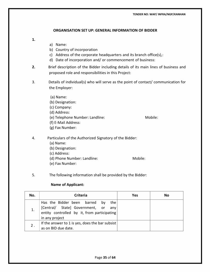
ORGANISATION SET UP: GENERAL INFORMATION OF BIDDER
1. a) Name: b) Country of incorporation c) Address of the corporate headquarters and its branch office(s),: d) Date of incorporation and/ or commencement of business:
2. Brief description of the Bidder including details of its main lines of business and
proposed role and responsibilities in this Project:
3. Details of individual(s) who will serve as the point of contact/ communication for
the Employer:
(a) Name: (b) Designation: (c) Company: (d) Address: (e) Telephone Number: Landline: Mobile: (f) E-Mail Address: (g) Fax Number:
4. Particulars of the Authorized Signatory of the Bidder: (a) Name: (b) Designation: (c) Address: (d) Phone Number: Landline: Mobile: (e) Fax Number:
5. The following information shall be provided by the Bidder: Name of Applicant:
No. Criteria Yes No
1.
Has the Bidder been barred by the [Central/ State] Government, or any entity controlled by it, from participating in any project
2 . If the answer to 1 is yes, does the bar subsist as on BID due date.
TENDER NO: WAP/ INFRA/NGP/KANHAN
Page 36 of 64
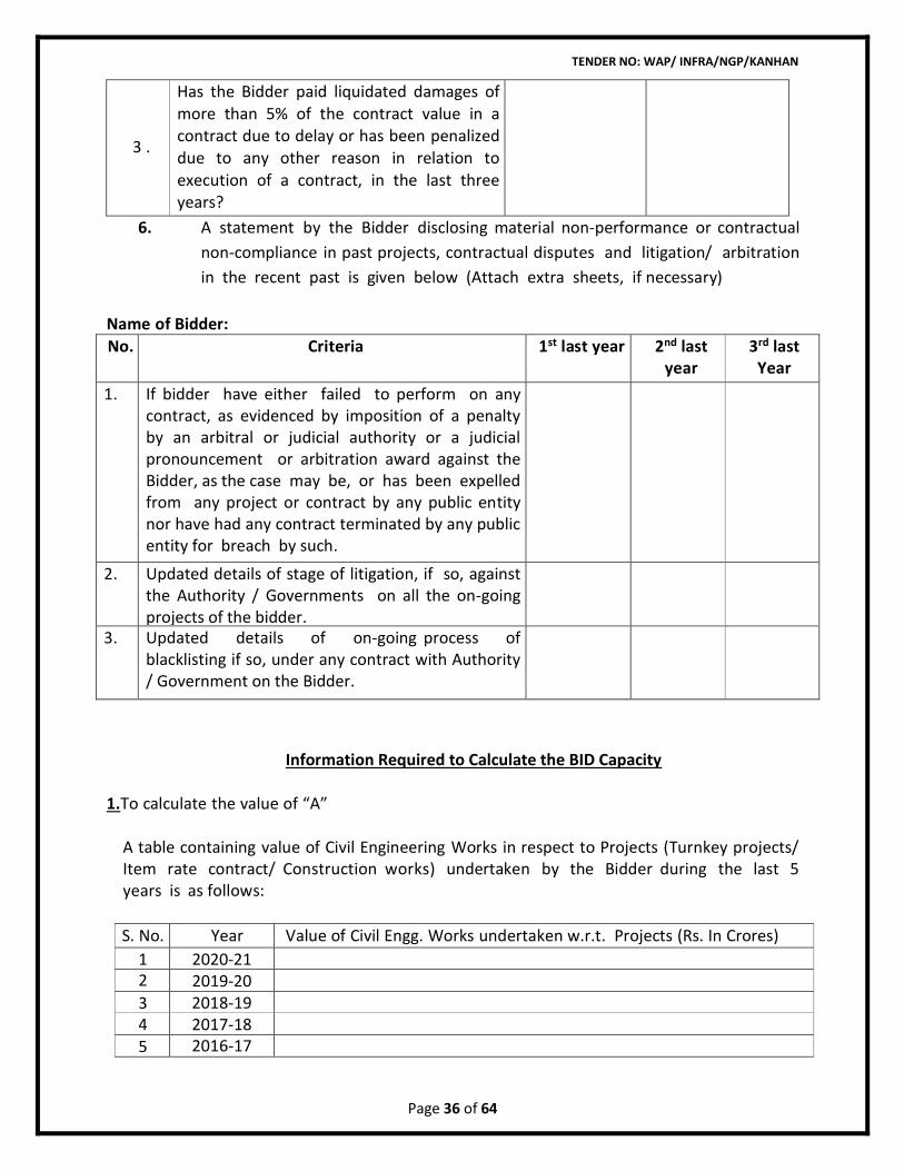
3 .
Has the Bidder paid liquidated damages of more than 5% of the contract value in a contract due to delay or has been penalized due to any other reason in relation to execution of a contract, in the last three years?
6. A statement by the Bidder disclosing material non-performance or contractual
non-compliance in past projects, contractual disputes and litigation/ arbitration
in the recent past is given below (Attach extra sheets, if necessary)
Name of Bidder:
No. Criteria 1st last year 2nd last year
3rd last Year
1. If bidder have either failed to perform on any contract, as evidenced by imposition of a penalty by an arbitral or judicial authority or a judicial pronouncement or arbitration award against the Bidder, as the case may be, or has been expelled from any project or contract by any public entity nor have had any contract terminated by any public entity for breach by such.
2. Updated details of stage of litigation, if so, against the Authority / Governments on all the on-going projects of the bidder.
3. Updated details of on-going process of blacklisting if so, under any contract with Authority / Government on the Bidder.
Information Required to Calculate the BID Capacity
1.To calculate the value of “A”
A table containing value of Civil Engineering Works in respect to Projects (Turnkey projects/ Item rate contract/ Construction works) undertaken by the Bidder during the last 5 years is as follows:
S. No. Year Value of Civil Engg. Works undertaken w.r.t. Projects (Rs. In Crores)
1 2020-21 2 2019-20 3 2018-19 4 2017-18 5 2016-17
TENDER NO: WAP/ INFRA/NGP/KANHAN
Page 37 of 64
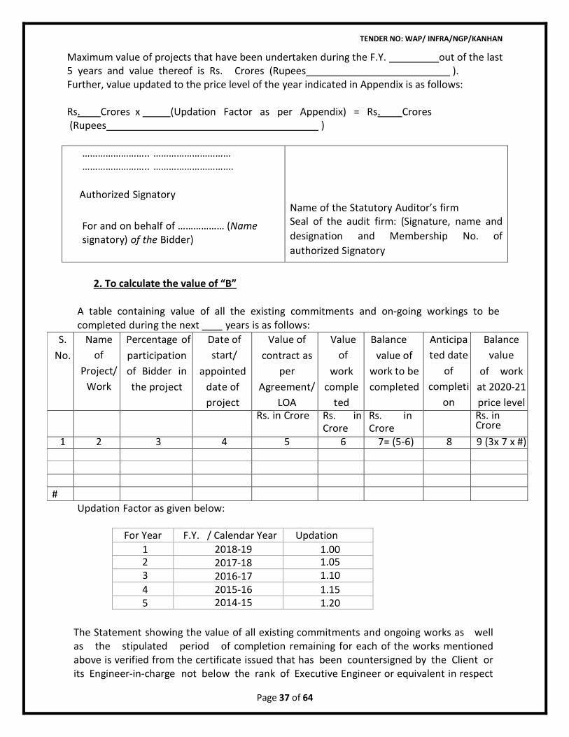
For Year F.Y. / Calendar Year Updation Factor 1 2018-19 1.00
2 2017-18 1.05 3 2016-17 1.10
4 2015-16 1.15 5 2014-15 1.20
Maximum value of projects that have been undertaken during the F.Y. out of the last 5 years and value thereof is Rs. Crores (Rupees ). Further, value updated to the price level of the year indicated in Appendix is as follows: Rs. Crores x (Updation Factor as per Appendix) = Rs. Crores (Rupees )
…………………….. ………………………… …………………….. ………………………….
Authorized Signatory
For and on behalf of ……………… (Name signatory) of the Bidder)
Name of the Statutory Auditor’s firm Seal of the audit firm: (Signature, name and
designation and Membership No. of
authorized Signatory
2. To calculate the value of “B”
A table containing value of all the existing commitments and on-going workings to be completed during the next years is as follows:
S.
No.
Name
of
Project/
Work
Percentage of
participation
of Bidder in
the project
Date of
start/
appointed
date of
project
Value of
contract as
per
Agreement/
LOA
Value
of
work
comple
ted
Balance
value of
work to be
completed
Anticipa
ted date
of
completi
on
Balance
value
of work
at 2020-21
price level
Rs. in Crore Rs. in Crore
Rs. in Crore
Rs. in Crore
1 2 3 4 5 6 7= (5-6) 8 9 (3x 7 x #) #
Updation Factor as given below:
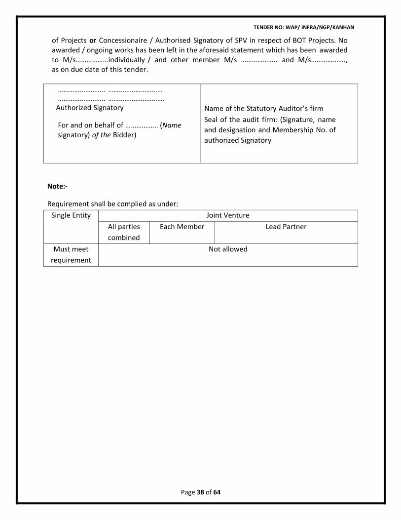
The Statement showing the value of all existing commitments and ongoing works as well as the stipulated period of completion remaining for each of the works mentioned above is verified from the certificate issued that has been countersigned by the Client or its Engineer-in-charge not below the rank of Executive Engineer or equivalent in respect
TENDER NO: WAP/ INFRA/NGP/KANHAN
Page 38 of 64
of Projects or Concessionaire / Authorised Signatory of SPV in respect of BOT Projects. No awarded / ongoing works has been left in the aforesaid statement which has been awarded to M/s………………individually / and other member M/s ……………….. and M/s………………., as on due date of this tender.
…………………….. ………………………… …………………….. ………………………….
Authorized Signatory
For and on behalf of ……………… (Name signatory) of the Bidder)
Name of the Statutory Auditor’s firm
Seal of the audit firm: (Signature, name
and designation and Membership No. of
authorized Signatory
Note:-
Requirement shall be complied as under:
Single Entity Joint Venture
All parties
combined
Each Member Lead Partner
Must meet
requirement
Not allowed
TENDER NO: WAP/ INFRA/NGP/KANHAN
Page 39 of 64
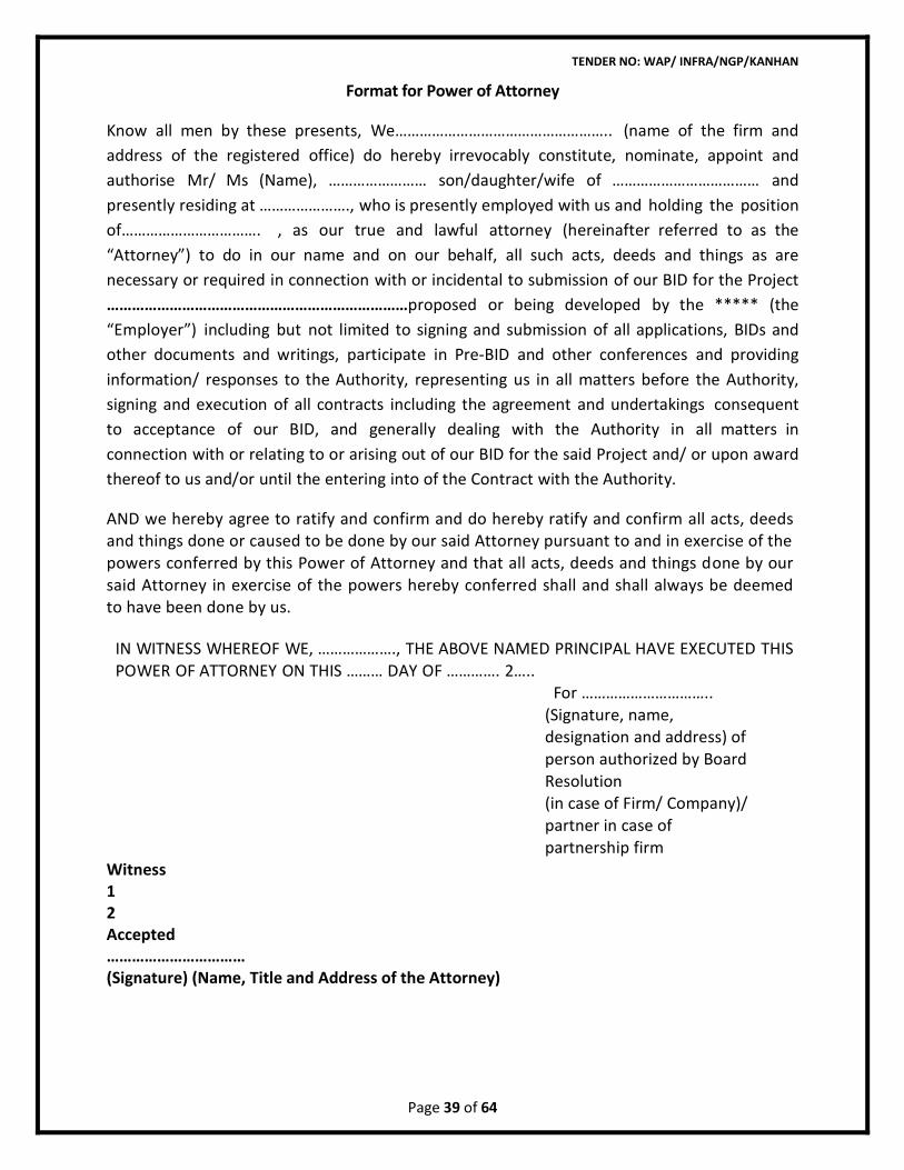
Format for Power of Attorney
Know all men by these presents, We…………………………………………….. (name of the firm and
address of the registered office) do hereby irrevocably constitute, nominate, appoint and
authorise Mr/ Ms (Name), …………………… son/daughter/wife of ……………………………… and
presently residing at …………………., who is presently employed with us and holding the position
of……………………………. , as our true and lawful attorney (hereinafter referred to as the
“Attorney”) to do in our name and on our behalf, all such acts, deeds and things as are
necessary or required in connection with or incidental to submission of our BID for the Project
………………………………………………………………proposed or being developed by the ***** (the
“Employer”) including but not limited to signing and submission of all applications, BIDs and
other documents and writings, participate in Pre-BID and other conferences and providing
information/ responses to the Authority, representing us in all matters before the Authority,
signing and execution of all contracts including the agreement and undertakings consequent
to acceptance of our BID, and generally dealing with the Authority in all matters in
connection with or relating to or arising out of our BID for the said Project and/ or upon award
thereof to us and/or until the entering into of the Contract with the Authority.
AND we hereby agree to ratify and confirm and do hereby ratify and confirm all acts, deeds and things done or caused to be done by our said Attorney pursuant to and in exercise of the powers conferred by this Power of Attorney and that all acts, deeds and things done by our said Attorney in exercise of the powers hereby conferred shall and shall always be deemed to have been done by us.
IN WITNESS WHEREOF WE, ………………., THE ABOVE NAMED PRINCIPAL HAVE EXECUTED THIS POWER OF ATTORNEY ON THIS ……… DAY OF …………. 2…..
For ………………………….. (Signature, name, designation and address) of person authorized by Board Resolution (in case of Firm/ Company)/ partner in case of partnership firm
Witness 1 2 Accepted …………………………… (Signature) (Name, Title and Address of the Attorney)
TENDER NO: WAP/ INFRA/NGP/KANHAN
Page 40 of 64
(Notarised) Person identified by me/
personally appeared before me
Attested/ Authenticated* (*Notary to specify as applicable) (Signature Name and Address of the Notary)
Seal of the Notary
Registration No. of the Notary Date:………………
TENDER NO: WAP/ INFRA/NGP/KANHAN
Page 41 of 64
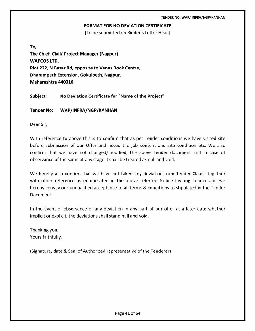
FORMAT FOR NO DEVIATION CERTIFICATE
[To be submitted on Bidder’s Letter Head]
To,
The Chief, Civil/ Project Manager (Nagpur)
WAPCOS LTD.
Plot 222, N Bazar Rd, opposite to Venus Book Centre,
Dharampeth Extension, Gokulpeth, Nagpur,
Maharashtra 440010
Subject: No Deviation Certificate for “Name of the Project”
Tender No: WAP/INFRA/NGP/KANHAN
Dear Sir,
With reference to above this is to confirm that as per Tender conditions we have visited site
before submission of our Offer and noted the job content and site condition etc. We also
confirm that we have not changed/modified, the above tender document and in case of
observance of the same at any stage it shall be treated as null and void.
We hereby also confirm that we have not taken any deviation from Tender Clause together
with other reference as enumerated in the above referred Notice Inviting Tender and we
hereby convey our unqualified acceptance to all terms & conditions as stipulated in the Tender
Document.
In the event of observance of any deviation in any part of our offer at a later date whether
implicit or explicit, the deviations shall stand null and void.
Thanking you,
Yours faithfully,
(Signature, date & Seal of Authorized representative of the Tenderer)
TENDER NO: WAP/ INFRA/NGP/KANHAN
Page 42 of 64
DECLARATION AGAINST CORRUPT OR FRAUDULENT PRACTICES
TO WHOM IT MAY CONCERN
I / We hereby declare that I / We and any of my / our affiliates have neither been involved, nor
have debarred by any Government/Multilateral funding agency for my / our involvement in any
corrupt or fraudulent practices in any of my /our contractual (Supply/Services)/ construction
activities.
I / We also confirm that if at any point of time, my / our involvement in any of my / our works
as corrupt or fraudulent is proved to be true, my / our proposals for the work under the
contract shall be treated as Non-Responsive.
Place:
Date:
Signature:
Name:
Seal
Form of EMD - Bank Guarantee
TENDER NO: WAP/ INFRA/NGP/KANHAN
Page 43 of 64
[The bank, as requested by the Contractor; shall fill in this form in accordance with the
instructions indicated]
Bank Guarantee No…………………….[insert guarantee reference number]
Date………………………….[insert date of issue of the guarantee]
WHEREAS, [name of Contractor](hereinafter called "the Applicant") has submitted his
Bid dated _ [date] or will submit his bid for [name of Bid] (hereinafter called "the Bid”)
under DNIT No- WAP/ INFRA./NGP/KANHAN (hereinafter called “the DNIT”)
KNOW ALL PEOPLE by these presents that We _________________[name of bank] of
__________________________[name of country] having our registered office at
_______________________ (hereinafter called "the Bank") are bound unto
___________________ [name of Employer] (hereinafter called "the Employer") in the sum of
________________________________for which payment well and truly to be made to the said
Employer the Bank binds itself, his successors and assigns by these presents.
SEALED with the Common Seal of the said Bank this_________________ day of __________20
THE CONDITIONS of this obligation are:
1) If after Bid opening the Applicant (a) withdraws his Bid during the period of Bid validity or
(b) does not accept the correction of the bid price pursuant to bid;
Or
2) If the Applicant having been notified of the acceptance of his proposal by the Employer
during the period of Bid validity:
a) fails or refuses to execute the Contract Agreement in accordance with the Instructions
to Contractor, if required; or
b) Fails or refuses to furnish the Performance Security, in accordance with the Instruction
to Contractor.
TENDER NO: WAP/ INFRA/NGP/KANHAN
Page 44 of 64
we undertake to pay to the Employer up to the above amount upon receipt of his first
written demand, without the Employer having to substantiate his demand, provided that in
his demand the Employer will note that the amount claimed by him is due to him owing to
the occurrence of one or any of the four conditions, specifying the occurred condition or
conditions.
This Guarantee will remain in force up to and including the date_____________________
after the deadline for submission of Bid as such deadline is stated in the DNIT or as it may
be extended by the Employer, notice of which extension(s) to the Bank is hereby waived.
DATE
SIGNATURE OF THE BANK
WITNESS
SEAL
[Signature, name, and address]
Note: All italicized text (including footnotes) is for use in preparing this form and shall be
deleted from the final product.
FORM OF ADVANCE PAYMENT GUARANTEE
TENDER NO: WAP/ INFRA/NGP/KANHAN
Page 45 of 64
M/s WAPCOS Limited,
76-C, Sector 18,
Gurgaon-122015.
In consideration of WAPCOS LTD. (hereinafter referred to as "the Employer") which expression
shall, unless repugnant to the context or meaning thereof include its successors, administrators
and assigns) having awarded to _______________________(Contractor’s name) with its
Registered /Head Office at __________________(hereinafter referred to as "the Contractor “
which expression shall unless repugnant to the context or meaning thereof, include its
successors, administrators, executors and assigns) a contract, by issue of Employer’s
Notification of Award No. ____________________dt. __________and the same having been
unequivocally accepted by the Contractor, resulting into a contract valued at
Rs._________(Rupees_____________________________________________________only) for
_______________ (hereinafter called “ the contract”) and the Employer having agreed to make
an advance payment to the Contractor for performance of the above Contract amounting to Rs.
_________________(Rupees ______________only) as an advance against bank guarantee to be
furnished by the Contractor.
We, __________________(name & address of bank) having its Head Office at
_____________(hereinafter referred to as "the Bank" which expression shall, unless repugnant
to the context or meaning thereof, include its successors, administrators, executors and
assigns) do hereby guarantee and undertake to pay the Employer immediately on demand any
or, all monies payable by the Contractor to the extent of Rs. ______________ (Rupees
________________only) as aforesaid at any time upto ___________without any demur,
reservation, contest , recourse or protest and/or without any reference to the Contractor.
Any such demand made by the Employer on the bank shall be conclusive and binding
notwithstanding any difference between the Employer and the Contractor or any dispute
pending before any Court, Tribunal, Arbitrator or any other authority. We agree that the
Guarantee herein contained shall be irrevocable and shall continue to be enforceable till the
Employer discharges this guarantee. We further agree that no change in the constitution of
the Bank or of the Employer shall affect this guarantee.
The Employer shall have the fullest liberty without affecting in any way the liability of
the Bank under this guarantee, from time to time, to vary the advance or to extend the time for
performance of the Contract by the Contractor. The Employer shall have the fullest liberty
without affecting this guarantee, to postpone from time to time the exercise of any powers
vested in them or of any right which they might have against the Contractor and to exercise the
same at any time in any manner, and either to enforce or to forbear to enforce any covenants,
contained or implied, in the Contract between the Employer and the Contractor or any other
TENDER NO: WAP/ INFRA/NGP/KANHAN
Page 46 of 64
course or remedy or security available to the Employer. The bank shall not be released of its
obligations under these presents by any exercise by the Employer of its liberty with reference
to the matters aforesaid or any of them or by reason of any other act or forbearance or other
acts of omission or commission on the part of the Employer or any other indulgence shown by
the Employer or by any other matter or thing whatsoever which under law would but for this
provision, have the effect of relieving the Bank.
The bank also agrees that the Employer at its option shall be entitled to enforce this
Guarantee against the Bank as a principal debtor, in the first instance without proceeding
against the Contractor and notwithstanding any security or other guarantee that the Employer
may have in relation to the Contractor's liabilities.
We The Said Bank do hereby declare that we have absolute and unconditional power to
issue this guarantee in your favour under the Memorandum and Articles of Association or such
other constitutional documents of the Bank and the undersigned have full power to execute
this guarantee under the Power of Attorney/ Post Approval Authorization
dated_____________________ of the bank granted to him / us by the Bank. We the said bank
do hereby declare and undertake that your claim under the guarantee shall not be affected by
any deficiency or other defect in the powers of the bank or its officials and the guarantee shall
be deemed to have been issued as if the bank and its officials have all the powers and
authorization to give this guarantee on behalf of the bank.
We the said bank does hereby certify the genuineness and appropriateness of the
Stamp paper and stamp value used for issuing the guarantee. We the said bank does hereby
declare and undertake that your claim under the guarantee shall not be affected by any
deficiency or other defect in the stamp paper or its stamp value.
We the said bank do hereby declare that our payments hereunder shall be made to you,
free and clear of and without and deduction, reduction on account of any reasons including any
and all present and future taxes, levies, charges of withholding whatsoever imposed or
collected with respect thereto.
Notwithstanding anything contained hereinabove our liability under this guarantee is limited to
Rs.______________(Rupees ________________only) and it shall remain in force upto and
including ________________and shall be extended from time to time for such period (not
exceeding one year), as may be desired by M/S _____________on whose behalf this bank
guarantee has been given.
Notwithstanding anything contained herein
TENDER NO: WAP/ INFRA/NGP/KANHAN
Page 47 of 64
ii) Our liability under this guarantee shall not exceed Rs.__________(Rupees
_______________________only);
iii) This bank guarantee shall be valid upto ________________ and
iv) our liability to make payment shall arise and we are liable to pay the guaranteed
amount or any part thereof under this guarantee, only and only if you serve upon us
a written claim or demand in terms of the guarantee on or before
___________(indicate a date twelve months after the validity of the guarantee).
Dated this ________day of _________at New Delhi.
WITNESS
_______________________ ________________________
(Signature) (Signature)
________________________ ________________________
(Name) (Name)
________________________ ________________________
(Official address) (Designation with bank stamp)
________________________ Attorney as Power of Attorney
(Signature) No.__________ dt._______
________________________
(Name)
________________________
TENDER NO: WAP/ INFRA/NGP/KANHAN
Page 48 of 64
FORM OF PERFORMANCE GUARANTEE
WAPCOS Limited,
76-C, Sector 18,
Gurgaon-122015.
In consideration of ____________________ (Employer’s name) (hereinafter referred to as
"the Employer") which expression shall, unless repugnant to the context or meaning thereof
include its successors, administrators and assigns) having awarded to _____________________
(Contractor’s name & address) (hereinafter referred to as "the Contractor “ which expression
shall unless repugnant to the context or meaning thereof, include its successors,
administrators, executors and assigns) a contract, by issue of Employer’s Notification of Award
No. _______________ dt. _____________ and the same having been unequivocally accepted
by the Contractor, resulting into a contract valued at Rs. _____________(Rupees
________________________only) for ________________(name of work) (hereinafter called “
the contract”) and the Contractor having agreed to provide a Contract Performance Guarantee
for the faithful performance of the entire contract equivalent to Rs. _____________ (Rupees
______________________only) (5% of the said value of the Contract to the Employer)
We, ____________________(name & address of bank) (hereinafter referred to as "the Bank"
which expression shall, unless repugnant to the context or meaning thereof, include its
successors, administrators, executors and assigns) do hereby guarantee and undertake to pay
the Employer, on demand any or, all monies payable by the Contractor to the extent of Rs.
_____________(Rupees __________________only) as aforesaid at any time upto
___________without any demur, reservation, contest , recourse or protest and/or without
any reference to the Contractor. Any such demand made by the Employer on the bank shall be
conclusive and binding notwithstanding any difference between the Employer and the
Contractor or any dispute pending before any Court, Tribunal, Arbitrator or any other authority.
The Bank undertakes not to revoke this guarantee during its currency without previous consent
of the Employer and further agrees that the guarantee herein contained shall continue to be
enforceable till the Employer discharges this guarantee.
We the said Bank further agree that the guarantee herein contained shall remain in full
force and effect during the period that would be taken for the performance of the said Contract
and that it shall continue to be enforceable till all the dues of the Employer under or by virtue
of the said contract have been fully paid and its claims satisfied or discharged or till the
Employer certifies that the terms and conditions of the said Contract have been fully and
properly carried out by the said Contractor and accordingly discharges the guarantee.

TENDER NO: WAP/ INFRA/NGP/KANHAN
Page 49 of 64
The Employer shall have the fullest liberty without affecting in any way the liability of
the Bank under this guarantee, from, time to time to extend the time for performance of the
Contract by the Contractor. The Employer shall have the fullest liberty without affecting this
guarantee, to postpone from time to time the exercise of any powers vested in them or of any
right which they might have against the Contractor and to exercise the same at any time in any
manner and either to enforce or to forbear to enforce any covenants, contained or implied, in
the Contract between the Employer and the Contractor or any other course or remedy or
security available to the Employer. The bank shall not be released of its obligations under these
presents by any exercise by the Employer of its liberty with reference to the matters aforesaid
or any of them or by reason of any other act or forbearance or other acts of omission or
commission on the part of the Employer or any other indulgence shown by the Employer or by
any other matter or thing whatsoever which under law would but for this provision, have the
effect of relieving the Bank. The guarantee shall not be affected by a change in the constitution
of the bank or of the employer.
The bank also agrees that the Employer at its option shall be entitled to enforce this
Guarantee against the Bank as a principal debtor, in the first instance, without proceeding
against the Contractor and notwithstanding any security or other guarantee that the Employer
may have in relation to the Contractor's liabilities.
We The Said Bank do hereby declare that we have absolute and unconditional power to
issue this guarantee in your favour under the Memorandum and Articles of Association or such
other constitutional documents of the Bank and the undersigned have full power to execute
this guarantee under the Power of Attorney/ Post Approval Authorization
dated_____________________ of the bank granted to him / us by the Bank. We the said bank
do hereby declare and undertake that your claim under the guarantee shall not be affected by
any deficiency or other defect in the powers of the bank or its officials and the guarantee shall
be deemed to have been issued as if the bank and its officials have all the powers and
authorization to give this guarantee on behalf of the bank.
We the said bank do hereby certify the genuineness and appropriateness of the Stamp
paper and stamp value used for issuing the guarantee. We the said bank do hereby declare and
undertake that your claim under the guarantee shall not be affected by any deficiency or other
defect in the stamp paper or its stamp value.
We the said bank do hereby declare that our payments hereunder shall be made to you,
free and clear of and without and deduction, reduction on account of any reasons including any
and all present and future taxes, levies, charges of withholding whatsoever imposed or
collected with respect thereto.
TENDER NO: WAP/ INFRA/NGP/KANHAN
Page 50 of 64
Notwithstanding anything contained hereinabove our liability under this guarantee is restricted
to Rs. _____________(Rupees ____________________ only) and it shall remain in force upto
and including _____________ and shall be extended from time to time for such period as may
be desired by M/S WAPCOS Limited on whose behalf this bank guarantee has been given.
Notwithstanding anything contained herein
i) Our liability under this guarantee shall not exceed Rs. _____________ (Rupees
_______________ only);
ii) This bank guarantee shall be valid upto _____________; and
iii) our liability to make payment shall arise and we are liable to pay the guaranteed
amount or any part thereof under this guarantee, only and only if you serve upon us
a written claim or demand in terms of the guarantee on or before
_________(indicate a date twelve months after validity of guarantee).
Dated this ________day of ________ at Place_____.
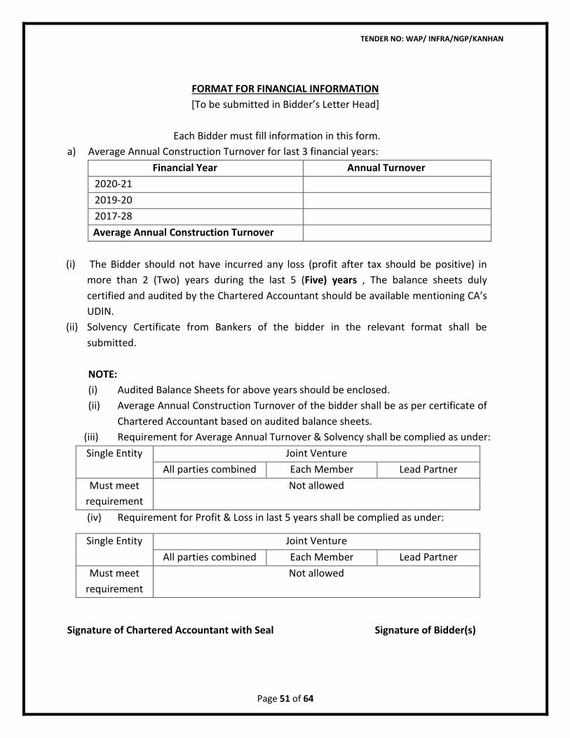
TENDER NO: WAP/ INFRA/NGP/KANHAN
Page 51 of 64
FORMAT FOR FINANCIAL INFORMATION
[To be submitted in Bidder’s Letter Head]
Each Bidder must fill information in this form.
a) Average Annual Construction Turnover for last 3 financial years:
Financial Year Annual Turnover
2020-21
2019-20
2017-28
Average Annual Construction Turnover
(i) The Bidder should not have incurred any loss (profit after tax should be positive) in
more than 2 (Two) years during the last 5 (Five) years , The balance sheets duly
certified and audited by the Chartered Accountant should be available mentioning CA’s
UDIN.
(ii) Solvency Certificate from Bankers of the bidder in the relevant format shall be
submitted.
NOTE:
(i) Audited Balance Sheets for above years should be enclosed.
(ii) Average Annual Construction Turnover of the bidder shall be as per certificate of
Chartered Accountant based on audited balance sheets.
(iii) Requirement for Average Annual Turnover & Solvency shall be complied as under:
Single Entity Joint Venture
All parties combined Each Member Lead Partner
Must meet
requirement
Not allowed
(iv) Requirement for Profit & Loss in last 5 years shall be complied as under:
Single Entity Joint Venture
All parties combined Each Member Lead Partner
Must meet
requirement
Not allowed
Signature of Chartered Accountant with Seal Signature of Bidder(s)
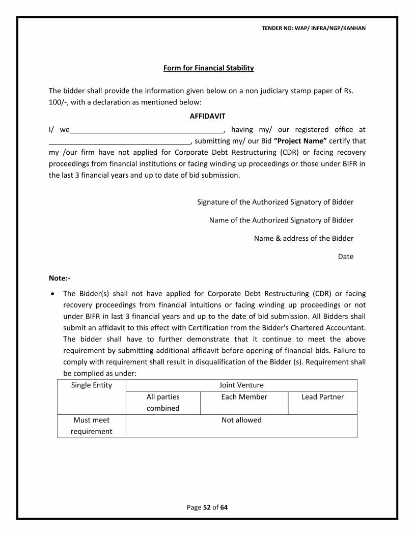
TENDER NO: WAP/ INFRA/NGP/KANHAN
Page 52 of 64
Form for Financial Stability
The bidder shall provide the information given below on a non judiciary stamp paper of Rs.
100/-, with a declaration as mentioned below:
AFFIDAVIT
I/ we______________________________________, having my/ our registered office at
___________________________________, submitting my/ our Bid “Project Name” certify that
my /our firm have not applied for Corporate Debt Restructuring (CDR) or facing recovery
proceedings from financial institutions or facing winding up proceedings or those under BIFR in
the last 3 financial years and up to date of bid submission.
Signature of the Authorized Signatory of Bidder
Name of the Authorized Signatory of Bidder
Name & address of the Bidder
Date
Note:-
• The Bidder(s) shall not have applied for Corporate Debt Restructuring (CDR) or facing
recovery proceedings from financial intuitions or facing winding up proceedings or not
under BIFR in last 3 financial years and up to the date of bid submission. All Bidders shall
submit an affidavit to this effect with Certification from the Bidder's Chartered Accountant.
The bidder shall have to further demonstrate that it continue to meet the above
requirement by submitting additional affidavit before opening of financial bids. Failure to
comply with requirement shall result in disqualification of the Bidder (s). Requirement shall
be complied as under:
Single Entity Joint Venture
All parties
combined
Each Member Lead Partner
Must meet
requirement
Not allowed
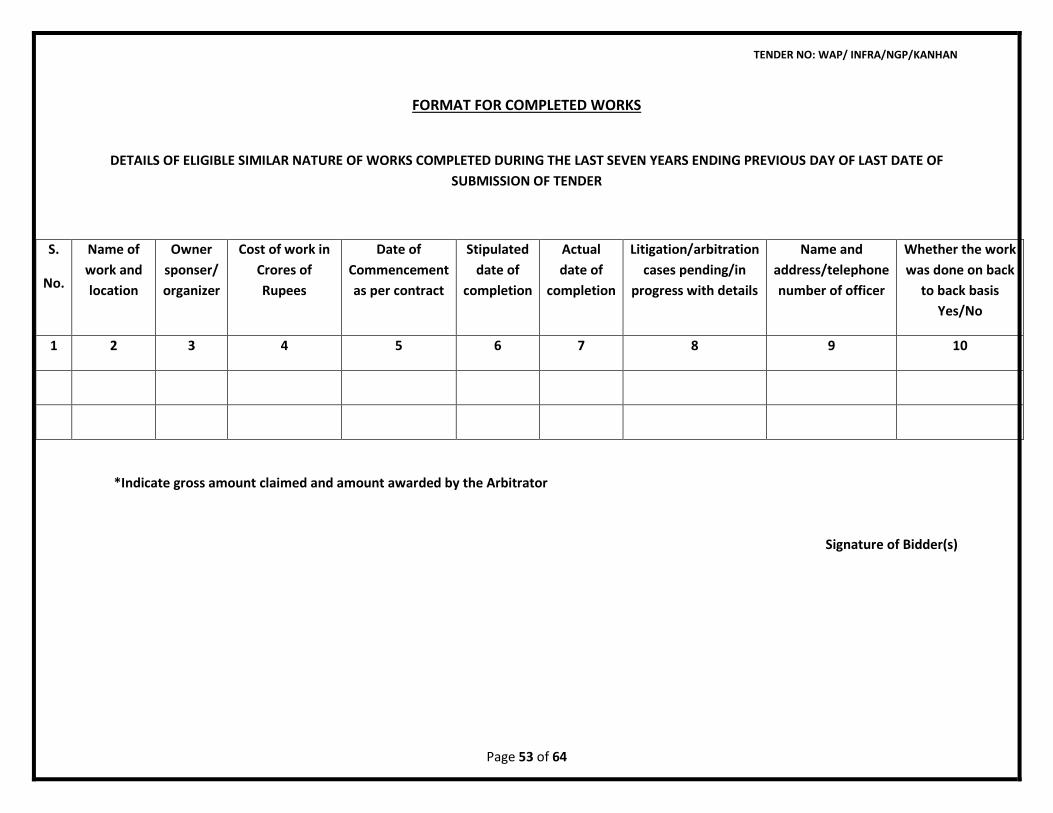
TENDER NO: WAP/ INFRA/NGP/KANHAN
Page 53 of 64
FORMAT FOR COMPLETED WORKS
DETAILS OF ELIGIBLE SIMILAR NATURE OF WORKS COMPLETED DURING THE LAST SEVEN YEARS ENDING PREVIOUS DAY OF LAST DATE OF
SUBMISSION OF TENDER
S.
No.
Name of
work and
location
Owner
sponser/
organizer
Cost of work in
Crores of
Rupees
Date of
Commencement
as per contract
Stipulated
date of
completion
Actual
date of
completion
Litigation/arbitration
cases pending/in
progress with details
Name and
address/telephone
number of officer
Whether the work
was done on back
to back basis
Yes/No
1 2 3 4 5 6 7 8 9 10
*Indicate gross amount claimed and amount awarded by the Arbitrator
Signature of Bidder(s)
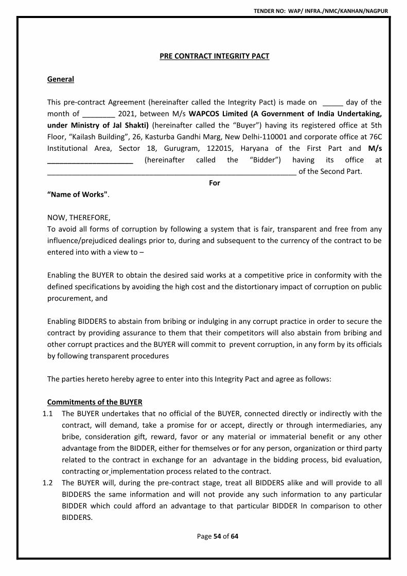
TENDER NO: WAP/ INFRA./NMC/KANHAN/NAGPUR
Page 54 of 64
PRE CONTRACT INTEGRITY PACT
General
This pre-contract Agreement (hereinafter called the Integrity Pact) is made on _____ day of the
month of ________ 2021, between M/s WAPCOS Limited (A Government of India Undertaking,
under Ministry of Jal Shakti) (hereinafter called the “Buyer”) having its registered office at 5th
Floor, “Kailash Building”, 26, Kasturba Gandhi Marg, New Delhi-110001 and corporate office at 76C
Institutional Area, Sector 18, Gurugram, 122015, Haryana of the First Part and M/s
_____________________ (hereinafter called the “Bidder”) having its office at
_____________________________________________________________ of the Second Part.
For
“Name of Works".
NOW, THEREFORE,
To avoid all forms of corruption by following a system that is fair, transparent and free from any
influence/prejudiced dealings prior to, during and subsequent to the currency of the contract to be
entered into with a view to –
Enabling the BUYER to obtain the desired said works at a competitive price in conformity with the
defined specifications by avoiding the high cost and the distortionary impact of corruption on public
procurement, and
Enabling BIDDERS to abstain from bribing or indulging in any corrupt practice in order to secure the
contract by providing assurance to them that their competitors will also abstain from bribing and
other corrupt practices and the BUYER will commit to prevent corruption, in any form by its officials
by following transparent procedures
The parties hereto hereby agree to enter into this Integrity Pact and agree as follows:
Commitments of the BUYER
1.1 The BUYER undertakes that no official of the BUYER, connected directly or indirectly with the
contract, will demand, take a promise for or accept, directly or through intermediaries, any
bribe, consideration gift, reward, favor or any material or immaterial benefit or any other
advantage from the BIDDER, either for themselves or for any person, organization or third party
related to the contract in exchange for an advantage in the bidding process, bid evaluation,
contracting or implementation process related to the contract.
1.2 The BUYER will, during the pre-contract stage, treat all BIDDERS alike and will provide to all
BIDDERS the same information and will not provide any such information to any particular
BIDDER which could afford an advantage to that particular BIDDER In comparison to other
BIDDERS.
TENDER NO: WAP/ INFRA./NMC/KANHAN/NAGPUR
Page 55 of 64
1.3 All the officials of the BUYER will report to the appropriate Government office any attempted or
completed breaches of the above commitments as well as any substantial suspicion of such a
breach.
2. In case any such preceding misconduct on the part of such official(s) is reported by the BIDDER
to the BUYER with full and verifiable facts and the same is prima facie found to be correct by
the BUYER, necessary disciplinary proceedings, or any other action as deemed fit, including
criminal proceedings may be initiated by the BUYER and such a person shall be debarred from
further dealings related to the contract process. In such a case while on enquiry is being
conducted by the BUYER the proceedings under the contract would not be stalled
Commitments of BIDDERS
3. The BIDDER commits itself to take all measures necessary to prevent corrupt practices, unfair
means and illegal activities during any stage of its bid or during any pre-contract or post-
contract stage in order to secure the contract or in furtherance to secure it and in particular
commit itself to the following:-
3.1 The BIDDER will not offer, directly or through intermediaries, and bribe gift, consideration,
reward, favor, any material or immaterial benefit or other advantage, commission, fees,
brokerage or inducement to any official of the BUYER, connected directly or indirectly with the
bidding process, or to any person, organization or third party related to the contract in
exchange for any advantage in the bidding, evaluation contracting and implementation of the
contract.
3.2 The BIDDER further undertake that it has not given offered or promised to give directly or
indirectly any bribe, gift, consideration, reward, favour any material or immaterial benefit or
other advantage, commission, fees, brokerage or inducement to any official of the BUYER or
otherwise in procuring the Contract or forbearing to do or having done any act in relation to the
obtaining or execution of the contract or any other contract with the Government for showing
or forbearing to show favour or disfavor to any person in relation to the contract or any other
contract with the Government.
3.3 BIDDERS shall disclose the name and address of agents and representatives and Indian BIDDERS
shall disclose their foreign principals or associates.
3.4 BIDDERS shall disclose the payments to be made by them to agents/brokers or any other
Intermediary, in connection with this bid/contract.
3.5 The BIDDER further confirms and declares to the BUYER that the BIDDER is the original
manufacturer/integrator/authorized government sponsored export entity of the defense stores
and has not engaged any individual or firm or company whether Indian or foreign to intercede,
facilitate or in any way to recommend to the BUYER or any of its functionaries, whether
officially or unofficially to the award of the contract to the BIDDER, nor has any amount been
paid, promised or intended to be paid to any such individual, firm or company in respect of any
such intercession facilitation or recommendation.
3.6 The BIDDER, either while presenting the bid or during pre-contract negotiations or before
signing the contract, shall disclose any payments he has made, is committed to or intends to
TENDER NO: WAP/ INFRA./NMC/KANHAN/NAGPUR
Page 56 of 64
make to officials of the BUYER or their family members, agents, brokers or any other
intermediaries in connection with the contract and the details of services agreed upon for such
payments.
3.7 The BIDDER will not collude with other parties interested in the contract to impair the
transparency, fairness and progress of the bidding process, bid evaluation contracting and
implementation of the contract.
3.8 The BIDDER will not accept any advantage in exchange for any corrupt practice, unfair means
and illegal activities.
3.9 The BIDDER shall not use improperly, for purposes of competition or personal gain, or pass on
to others, any information provided by the BUYER as part of the business relationship,
regarding plans, technical proposals and business details, including information contained in
any electronic data carrier. The Bidder also undertakes to exercise due and adequate care lest
any such information is divulged.
3.10 The BIDDER commits to refrain from giving any complaint directly or through any other manner
without supporting it with full and verifiable facts.
3.11 The bidder shall not instigate or cause to instigate any third person to commit any of the
actions mentioned above.
3.12 If the Bidder or any employees of the BIDDER or any person acting on behalf of the Bidder,
either directly or indirectly, is a relative of any of the officers of the BUYER, or alternatively, if
any relative of an officer of the BUYER has financial interest/stake in the BIDDER’S firm, the
same shall be disclosed by the BIDDER at the time of filling of tender.
• The term ‘relative’ for this purpose would be as defined in Section 6 of the Companies
Act 1956.
3.13 The BIDDER shall not lend to or borrow any money from or enter into any monetary dealings or
transactions, directly or indirectly with any employee of the BUYER.
4. Previous Transgression
4.1 The BIDDER declares that no previous transgression occurred in the last three years
immediately before signing of this Integrity Pact with any other company in any country in
respect of any corrupt practices envisaged hereunder or with any Public Sector Enterprise in
India or any Government Department in India that could justify BIDDER’s exclusion from the
tender process.
4.2 The bidder agrees that if it makes incorrect statement on this subject, BIDDER can be
disqualified from the tender process or the contract, if already awarded, can be terminated for
such reason.
5. Earnest Money (Security Deposit)
5.1 While submitting commercial bid, the BIDDER shall submit the EMD.
5.2 The EMD shall be valid upto a period of 6 months or the complete conclusion of the contractual
obligations to the complete satisfaction of both the BIDDER and the BUYER, including warranty
period, whichever is later.
TENDER NO: WAP/ INFRA./NMC/KANHAN/NAGPUR
Page 57 of 64
5.3 In case of the successful BIDDER a clause would also be incorporated in the Article pertaining to
Performance Bond in the Purchase Contract that the provisions of Sanctions for Violation shall
be applicable for forfeiture of Performance Bond in case of a decision by the BUYER to forfeit
the same without assigning any reason for imposing sanction for violation of this Pact.
6. Sanctions for Violations
6.1 Any breach of the aforesaid provisions by the BIDDER or any one employed by it or acting on its
behalf (whether with or without the knowledge of the BIDDER) shall entitle the BUYER to take
all or any one of the following actions wherever required:-
(i) To immediately call off the pre contract negotiations without assigning any reason or giving
any compensation to the BIDDER. However the proceedings with the other BIDDER(s)
would continue.
(ii) Performance Bond (after the contract is signed) shall stand forfeited either fully or partially,
as decided by the BUYER and the BUYER shall not be required to assign any reason
therefore
(iii) To immediately cancel the contract, if already signed, without giving any compensation to
the BIDDER
(iv) To recover all sums already paid by the BUYER, and in case of an Indian BIDDER with
interest thereon at 2% higher than the prevailing Prime Lending Rate of State Bank of India,
while in case of a BIDDER from a country other than India with interest thereon at 2%
higher than the LIBOR. If any outstanding payment is due to the BIDDER from the BUYER in
connection with any other contract for any other stores, such outstanding payment could
also be utilized to recover the aforesaid sum and interest.
(v) To encash the advance bank guarantee and performance bond/warranty bond, if furnished
by the BIDDER, in order to recover the payments, already made by the BUYER, along with
interest.
(vi) To cancel all or any other Contracts with the BIDDER, the BIDDER shall be liable to pay
compensation for any loss or damage to the BUYER resulting from such
cancellation/recession and the buyer shall be entitled to deduct the amount so payable
from money(s) due to the BIDDER.
(vii) To debar the BIDDER from participating in future bidding processes of the Government of
India for a minimum period of 5 years, which may be further extended at the discretion of
the BUYER.
(viii) To recover all sums paid in violation of this Pact by BIDDER(s) to any middleman or agent
or broker with a view to securing the contract.
(ix) In cases where irrevocable Letters of Credit have been received in respect of any contract
signed by the BUYER with the BIDDER, the same shall not be opened
(x) Forfeiture of Performance Bond in case of a decision by the BUYER to forfeit the same
without assigning any reason for imposing sanctions for violation of this Pact.
6.2 The BUYER will be entitled to take all or any of the actions mentioned at para 6.1(i) to (x) of this
Pact also on the Commission by the BIDDER or any one employed by it or acting on its behalf
(whether with or without the knowledge of the BIDDER), of an offence as defined in Chapter IX

TENDER NO: WAP/ INFRA./NMC/KANHAN/NAGPUR
Page 58 of 64
of the Indian Penal code 1860 or Prevention of Corruption Act, 1988 or any other statutes
enacted for prevention of Corruption Act, 1988 or any other statute enacted for prevention of
corruption.
6.3 The decision of the BUYER to the effect that a breach of the provisions of this Pact has been
committed by the BIDDER shall be final and conclusive on the BIDDER. However, the bidder can
approach the independent Monitor(s) appointed for the purposes of the pact.
7. Fall Clause
7.1 The BIDDER undertakes that it has not supplied/is not supplying similar product/systems or
subsystems at a price lower than that offered in the present bid in respect of any other
Ministry/Department of the Government of India or PSU and if it is found at any stage that
similar product/systems or subsystems was supplied by the BIDDER to any other
Ministry/Department of the Government of India or a PSU at a lower price, then that very price,
with due allowance for elapsed time, will be applicable to the present case and the difference
in the cost would be refunded by the BIDDER to the BUYER, if the contract has already been
concluded.
8. Independent Monitors
8.1 The BUYER has appointed Independent Monitors (hereinafter referred to as Monitors) for this
Pact in consultation with the Central Vigilance Commission (Names and Addresses of the
Monitors to be given).
8.2 The task of the Monitors shall be to review independently and objectively, whether and to what
extent the parties comply with the obligations under this Pact.
8.3 The Monitors shall not be subject to instructions by the representatives of the parties and
perform their functions neutrally and independently.
8.4 Both the parties accept that the Monitor have the right to access all the documents relating to
the project procurement, including minutes of meetings.
8.5 As soon as the Monitor notices, or has reason to believe, a violation of this Pact, he will so
inform the Authority designated by the BUYER.
8.6 The BIDDER(s) accepts that the Monitor has the right to access without restriction to all Project
documentation of the BUYER including that provided by the BIDDER. The BIDDER will also grant
the monitor, upon his request and demonstration of a valid interest, unrestricted and
unconditional access to his project documentation. The same is applicable to Subcontractors.
The Monitor shall be under contractual obligation to treat the information and documents of
the BIDDER/Subcontractor(s) with confidentiality.
8.7 The BUYER will provide to the Monitor sufficient information about all meetings among the
parties related to the Project provided such meetings could have an impact on the contractual
relations between the parties. The parties will offer to the Monitor the option to participate in
such meetings.
8.8 The Monitor will submit written report to the designated Authority of BUYER/Secretary in the
Department within 8 to 10 weeks from the date of reference or intimation to him by the BUYER
/ BIDDER and should the occasion arise, submit proposals for correcting problematic situations.
TENDER NO: WAP/ INFRA./NMC/KANHAN/NAGPUR
Page 59 of 64
9. Facilitation of Investigation
In case of any allegation of violation of any provisions of this Pact or payment of commission,
the BUYER or its agencies shall be entitled to examine all the documents including the Books of
Accounts of the BIDDER and the BIDDER shall provide necessary information and documents in
English and shall extend all possible help for the purpose of such examination.
10. Law and Place of Jurisdiction
This Pact is subject to Indian Law. The place of performance and exclusive jurisdiction shall be
Delhi High Court.
11. Other Legal Actions
The actions stipulated in this integrity Pact are without prejudice to any other legal action that
may follow in accordance with the provisions of the extant law in force relating to any civil or
criminal proceedings.
12. Validity
12.1 The validity of this integrity Pact shall be from date of its signing and extend upto 5 years or
the complete execution of the contract to the satisfaction of both the BUYER and the
BIDDER/Seller, including warranty period, whichever is later. In case BIDDER is unsuccessful
this Integrity Pact shall expire after six months from the date of the signing of the contract.
12.2 Should one or several provisions of this Pact turn out to be invalid, the remainder of this Pact
shall remain valid. In this case, the parties will strive to come to an agreement to their original
Intentions.
12.3 The parties hereby sign this Integrity Pact at _____________________ on
__________________.
BUYER BIDDER
M/s WAPCOS Limited M/s ____________________
(____________________) (______________)
___________________________ ________________
Witness Witness
1.______________________________ 1.______________________________
2. ______________________________ 2. ______________________________
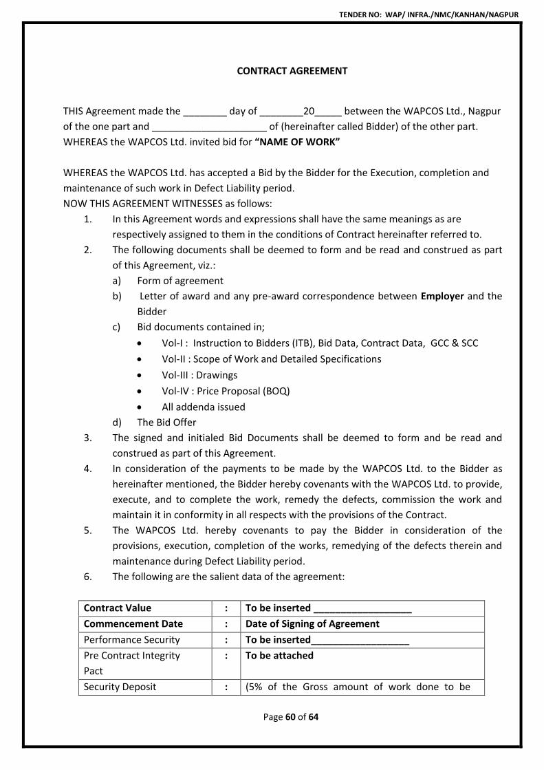
TENDER NO: WAP/ INFRA./NMC/KANHAN/NAGPUR
Page 60 of 64
CONTRACT AGREEMENT
THIS Agreement made the ________ day of ________20_____ between the WAPCOS Ltd., Nagpur
of the one part and _____________________ of (hereinafter called Bidder) of the other part.
WHEREAS the WAPCOS Ltd. invited bid for “NAME OF WORK”
WHEREAS the WAPCOS Ltd. has accepted a Bid by the Bidder for the Execution, completion and
maintenance of such work in Defect Liability period.
NOW THIS AGREEMENT WITNESSES as follows:
1. In this Agreement words and expressions shall have the same meanings as are
respectively assigned to them in the conditions of Contract hereinafter referred to.
2. The following documents shall be deemed to form and be read and construed as part
of this Agreement, viz.:
a) Form of agreement
b) Letter of award and any pre-award correspondence between Employer and the
Bidder
c) Bid documents contained in;
• Vol-I : Instruction to Bidders (ITB), Bid Data, Contract Data, GCC & SCC
• Vol-II : Scope of Work and Detailed Specifications
• Vol-III : Drawings
• Vol-IV : Price Proposal (BOQ)
• All addenda issued
d) The Bid Offer
3. The signed and initialed Bid Documents shall be deemed to form and be read and
construed as part of this Agreement.
4. In consideration of the payments to be made by the WAPCOS Ltd. to the Bidder as
hereinafter mentioned, the Bidder hereby covenants with the WAPCOS Ltd. to provide,
execute, and to complete the work, remedy the defects, commission the work and
maintain it in conformity in all respects with the provisions of the Contract.
5. The WAPCOS Ltd. hereby covenants to pay the Bidder in consideration of the
provisions, execution, completion of the works, remedying of the defects therein and
maintenance during Defect Liability period.
6. The following are the salient data of the agreement:
Contract Value : To be inserted __________________
Commencement Date : Date of Signing of Agreement
Performance Security : To be inserted__________________
Pre Contract Integrity
Pact
: To be attached
Security Deposit : (5% of the Gross amount of work done to be
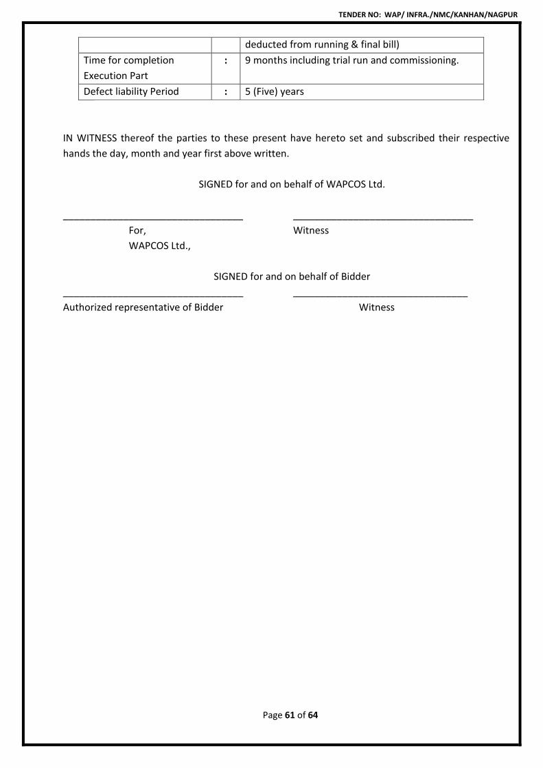
TENDER NO: WAP/ INFRA./NMC/KANHAN/NAGPUR
Page 61 of 64
deducted from running & final bill)
Time for completion
Execution Part
: 9 months including trial run and commissioning.
Defect liability Period : 5 (Five) years
IN WITNESS thereof the parties to these present have hereto set and subscribed their respective
hands the day, month and year first above written.
SIGNED for and on behalf of WAPCOS Ltd.
_________________________________ _________________________________
For, Witness
WAPCOS Ltd.,
SIGNED for and on behalf of Bidder
_________________________________ ________________________________
Authorized representative of Bidder Witness
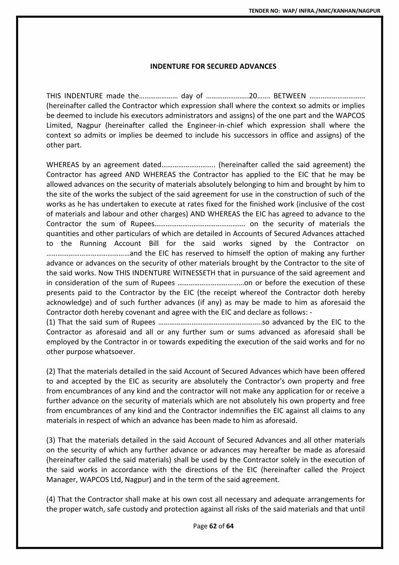
TENDER NO: WAP/ INFRA./NMC/KANHAN/NAGPUR
Page 62 of 64
INDENTURE FOR SECURED ADVANCES THIS INDENTURE made the………………… day of …………………..20……. BETWEEN ………………………… (hereinafter called the Contractor which expression shall where the context so admits or implies be deemed to include his executors administrators and assigns) of the one part and the WAPCOS Limited, Nagpur (hereinafter called the Engineer-in-chief which expression shall where the context so admits or implies be deemed to include his successors in office and assigns) of the other part. WHEREAS by an agreement dated……………………….. (hereinafter called the said agreement) the Contractor has agreed AND WHEREAS the Contractor has applied to the EIC that he may be allowed advances on the security of materials absolutely belonging to him and brought by him to the site of the works the subject of the said agreement for use in the construction of such of the works as he has undertaken to execute at rates fixed for the finished work (inclusive of the cost of materials and labour and other charges) AND WHEREAS the EIC has agreed to advance to the Contractor the sum of Rupees…………………………………………. on the security of materials the quantities and other particulars of which are detailed in Accounts of Secured Advances attached to the Running Account Bill for the said works signed by the Contractor on ………………………………………and the EIC has reserved to himself the option of making any further advance or advances on the security of other materials brought by the Contractor to the site of the said works. Now THIS INDENTURE WITNESSETH that in pursuance of the said agreement and in consideration of the sum of Rupees ………………………………on or before the execution of these presents paid to the Contractor by the EIC (the receipt whereof the Contractor doth hereby acknowledge) and of such further advances (if any) as may be made to him as aforesaid the Contractor doth hereby covenant and agree with the EIC and declare as follows: - (1) That the said sum of Rupees ………………………………………………..so advanced by the EIC to the Contractor as aforesaid and all or any further sum or sums advanced as aforesaid shall be employed by the Contractor in or towards expediting the execution of the said works and for no other purpose whatsoever. (2) That the materials detailed in the said Account of Secured Advances which have been offered to and accepted by the EIC as security are absolutely the Contractor's own property and free from encumbrances of any kind and the contractor will not make any application for or receive a further advance on the security of materials which are not absolutely his own property and free from encumbrances of any kind and the Contractor indemnifies the EIC against all claims to any materials in respect of which an advance has been made to him as aforesaid. (3) That the materials detailed in the said Account of Secured Advances and all other materials on the security of which any further advance or advances may hereafter be made as aforesaid (hereinafter called the said materials) shall be used by the Contractor solely in the execution of the said works in accordance with the directions of the EIC (hereinafter called the Project Manager, WAPCOS Ltd, Nagpur) and in the term of the said agreement. (4) That the Contractor shall make at his own cost all necessary and adequate arrangements for the proper watch, safe custody and protection against all risks of the said materials and that until
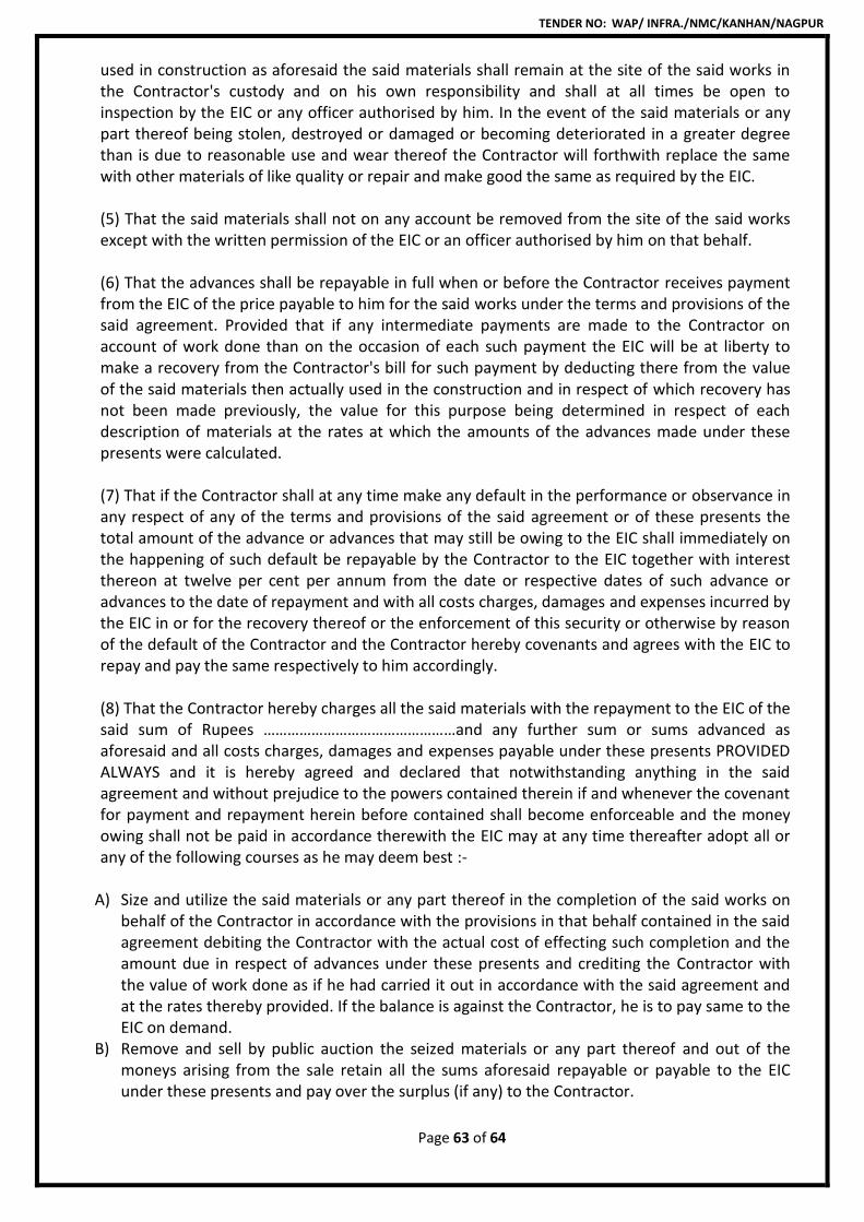
TENDER NO: WAP/ INFRA./NMC/KANHAN/NAGPUR
Page 63 of 64
used in construction as aforesaid the said materials shall remain at the site of the said works in the Contractor's custody and on his own responsibility and shall at all times be open to inspection by the EIC or any officer authorised by him. In the event of the said materials or any part thereof being stolen, destroyed or damaged or becoming deteriorated in a greater degree than is due to reasonable use and wear thereof the Contractor will forthwith replace the same with other materials of like quality or repair and make good the same as required by the EIC. (5) That the said materials shall not on any account be removed from the site of the said works except with the written permission of the EIC or an officer authorised by him on that behalf. (6) That the advances shall be repayable in full when or before the Contractor receives payment from the EIC of the price payable to him for the said works under the terms and provisions of the said agreement. Provided that if any intermediate payments are made to the Contractor on account of work done than on the occasion of each such payment the EIC will be at liberty to make a recovery from the Contractor's bill for such payment by deducting there from the value of the said materials then actually used in the construction and in respect of which recovery has not been made previously, the value for this purpose being determined in respect of each description of materials at the rates at which the amounts of the advances made under these presents were calculated. (7) That if the Contractor shall at any time make any default in the performance or observance in any respect of any of the terms and provisions of the said agreement or of these presents the total amount of the advance or advances that may still be owing to the EIC shall immediately on the happening of such default be repayable by the Contractor to the EIC together with interest thereon at twelve per cent per annum from the date or respective dates of such advance or advances to the date of repayment and with all costs charges, damages and expenses incurred by the EIC in or for the recovery thereof or the enforcement of this security or otherwise by reason of the default of the Contractor and the Contractor hereby covenants and agrees with the EIC to repay and pay the same respectively to him accordingly. (8) That the Contractor hereby charges all the said materials with the repayment to the EIC of the said sum of Rupees …………………………………………and any further sum or sums advanced as aforesaid and all costs charges, damages and expenses payable under these presents PROVIDED ALWAYS and it is hereby agreed and declared that notwithstanding anything in the said agreement and without prejudice to the powers contained therein if and whenever the covenant for payment and repayment herein before contained shall become enforceable and the money owing shall not be paid in accordance therewith the EIC may at any time thereafter adopt all or any of the following courses as he may deem best :-
A) Size and utilize the said materials or any part thereof in the completion of the said works on behalf of the Contractor in accordance with the provisions in that behalf contained in the said agreement debiting the Contractor with the actual cost of effecting such completion and the amount due in respect of advances under these presents and crediting the Contractor with the value of work done as if he had carried it out in accordance with the said agreement and at the rates thereby provided. If the balance is against the Contractor, he is to pay same to the EIC on demand.
B) Remove and sell by public auction the seized materials or any part thereof and out of the moneys arising from the sale retain all the sums aforesaid repayable or payable to the EIC under these presents and pay over the surplus (if any) to the Contractor.
TENDER NO: WAP/ INFRA./NMC/KANHAN/NAGPUR
Page 64 of 64
c) Deduct all or any part of the moneys owing out of the security deposit or any sum due to the Contractor under the said agreement. (9) That except in the event of such default on the part of the Contractor as aforesaid interest on the said advance shall not be payable. (10) That in the event of any conflict between the provisions of these presents and the said agreement the provisions of these presents shall prevail and in the event of any dispute or difference arising over the construction or effect of these presents the settlement of which has not been herein before expressly provided for the same shall be finally resolved as per provisions of clause 25 of the contract. In witness whereof the said ……………………and ………………………by the order and under the direction of the EIC have hereunto set their respective hands the day and year first above written. Signed, sealed and delivered by……………………….. the said contractor in the presence of Signature ……………………… Witness Name ………………………… ………………………….. Address ………………………. Signed by……………………….. by the order and direction of the EIC in the presence of Signature ……………………… Witness Name ………………………… ………………………….. Address ……………………….
TENDER NO: WAP/ INFRA./NGP/KANHAN
Page 1 of 133
TENDER DOCUMENT
FOR
“DEVELOPMENT OF INFRASTRUCTURE FOR LIFTING WATER FROM
KANHAN RIVER AT VILLAGE ROHANA & CONVEYANCE TO WATER
TREATMENT PLANT AT GODHANI & GOREWADA”
TENDER NO: WAP/INFRA/NGP/KANHAN
VOLUME -2
GENERAL CONDITIONS OF CONTRACT &
SPECIAL CONDITIONS OF CONTRACT
Issued to M/s_______________________________________ _______________________________________
Telephone: +91- 0712 255 7798, Email: [email protected], Website: www.wapcos.co.in
TENDER NO: WAP/ INFRA./NGP/KANHAN
Page 2 of 133
TENDER DOCUMENT
FOR
“DEVELOPMENT OF INFRASTRUCTURE FOR LIFTING WATER FROM
KANHAN RIVER AT VILLAGE ROHANA & CONVEYANCE TO WATER
TREATMENT PLANT AT GODHANI & GOREWADA”
TENDER NO: WAP/INFRA/NGP/KANHAN
1) GENERAL CONDITIONS OF CONTRACT : SECTION - V
2) SPECIAL CONDITIONS OF CONTRACT : SECTION– VI
______________________
For & On behalf of Tenderer
TENDER NO: WAP/ INFRA./NGP/KANHAN
Page 3 of 133
Table of Contents
GENERAL CONDITIONS OF CONTRACT ............................................................ 5
5.1 DEFINITIONS AND INTERPRETATIONS ............................................................................... 6
5.2 THE WAPCOS LIMITED REPRESENTATIVE ........................................................................ 25
5.3 COMMENCEMENT AND THE NOTICE TO PROCEED ......................................................... 27
5.4 THE PROJECT SITE ............................................................................................................ 28
5.5 CONDITION OF THE PROJECT SITE ................................................................................... 30
5.6 THE CONTRACTOR ........................................................................................................... 33
5.7 SUBCONTRACTORS .......................................................................................................... 41
5.8 SUFFICIENCY OF THE CONTRACT SUM ............................................................................ 46
5.9 COMMENCEMENT OF THE WORKS ................................................................................. 46
5.10 REVIEW MEETINGS .......................................................................................................... 51
5.11 HEALTH, SAFETY, SECURITY AND ENVIRONMENT ........................................................... 52
5.12 ELECTRICITY, WATER ........................................................................................................ 55
5.13 RELATED WORKS .............................................................................................................. 56
5.14 DELIVERY TO THE PROJECT SITE ...................................................................................... 60
5.15 CONTRACTOR’S EQUIPMENT AND OTHER PROVISIONS.................................................. 62
5.16 LABOUR AND CONTRACTOR’S PERSONNEL ..................................................................... 64
5.17 TESTING ........................................................................................................................... 70
5.18. TIME FOR COMPLETION, RATE OF PROGRESS AND ACCELERATION ............................... 73
5.19. EXTENSION OF TIME FOR COMPLETION .......................................................................... 73
5.20 LIQUIDATED DAMAGES.................................................................................................... 79
5.21 COMPLETION OF WORKS ................................................................................................. 80
5.22 RECTIFICATION OF DEFECTS AND MAINTENANCE OF THE PERMANENT WORKS ........... 82
5.23 CHANGES ......................................................................................................................... 85
5.24 INTELLECTUAL PROPERTY ................................................................................................ 91
5.25 INSURANCES .................................................................................................................... 94
5.26 PAYMENT ......................................................................................................................... 95
5.27 TAXES AND DUTIES ........................................................................................................ 101
5.28 CONTRACTOR’S COVENANTS ......................................................................................... 103
5.29 FORCE MAJEURE ............................................................................................................ 113
5.30 DISPUTE RESOLUTION PROCEDURE ............................................................................... 115
TENDER NO: WAP/ INFRA./NGP/KANHAN
Page 4 of 133
5.31 REPRESENTATIONS AND WARRANTIES, DISCLAIMER .................................................... 117
5.32 TERMINATION ................................................................................................................ 119
5.33. MISCELLANEOUS ............................................................................................................ 122
5.34 QUALITY CONTROL ........................................................................................................ 125
5.35 UNSATISFACTORY OR DELAYED COMPLETION OF WORK ............................................. 125
5.36 SUPERSTITION OF GENERAL CONDITIONS OF CONTRACT............................................. 125
SPECIAL CONDITIONS OF CONTRACT .......................................................... 126
TENDER NO: WAP/ INFRA./NGP/KANHAN
Page 5 of 133
“DEVELOPMENT OF INFRASTRUCTURE FOR LIFTING WATER FROM
KANHAN RIVER AT VILLAGE ROHANA & CONVEYANCE TO WATER
TREATMENT PLANT AT GODHANI & GOREWADA”
TENDER NO: WAP/ INFRA/NGP/KANHAN
SECTION– V
GENERAL CONDITIONS OF CONTRACT
TENDER NO: WAP/ INFRA./NGP/KANHAN
Page 6 of 133
SECTION– V
GENERAL CONDITIONS OF CONTRACT
5.1 DEFINITIONS AND INTERPRETATIONS
5.1.1 Definitions
In these Conditions of Contract (“Conditions”) the following words and expressions
shall, unless repugnant to the context or meaning thereof, has the meaning
hereinafter respectively ascribe to them:
“Additional Cost” means the additional capital expenditure and/or the additional
operating cost or additional taxes or all as the case may be, which the Contractor has
or would be required to incur and which has arisen as a result of Change of Scope of
work.
“Advance Payment” means a sum equal to the amount named in Special Conditions
of Contract and paid to the Contractor by WAPCOS Limited by way of a
mobilization/advance payment in accordance with Clause 5.26.11 [Advance
Payment].
“Advance Payment Guarantee” means any or all of the guarantees to be procured in
accordance with Clause 5.26.11 [Advance Payment].
“Affected Party” means a Party whose performance of its obligations under the
Contract is prevented, hindered or delayed in whole or in part by reason of Force
Majeure.
“Applicable Clearances” means any clearance, permit, authorisation, consent, license
(including without limitation, any import or export licenses), lease, ruling,
exemption, filing, agreements, or approval, required to be obtained and maintained
by WAPCOS Limited and/or the Contractor from time to time, in order to implement
the Project Facility and/or to design and Execute the Works in accordance with the
Contract.
“Applicable Laws” means all laws in force and effect as of the date hereof and which
may be promulgated or brought into force and effect hereinafter in India including
any revisions, amendments or re-enactments including without limitation rules,
regulations and notifications made there under and judgments, decrees, injunctions,
writs, orders and notifications issued by any court of record or any appropriate
authorities, as may be in force and effect during the subsistence of the Contract.
TENDER NO: WAP/ INFRA./NGP/KANHAN
Page 7 of 133
“Arbitration Act” means the Arbitration and Conciliation Act, 1996 and shall include
any amendment to or any re-enactment thereof as in force from time to time.
“As-built Documents” means all as-built documents and information of the
completed Project Facilities.
“Audit Period” shall have the meaning given under Clause 5.28.6 [Audit Rights].
“Background Information” means all and any materials, data, documents, drawings,
plans, surveys, reports or other information of whatsoever nature and howsoever
prepared/stored relating in any way to the Project Facility made available by
WAPCOS Limited and/or its agents in connection with the Contract and/or
discussions which preceded such negotiations and preparations, including all such
materials, data, documents, drawings, plans, agreements or other information
provided in connection with those processes.
“Business Day” means a day other than a Sunday or a public holiday on which banks
are open for domestic business in the city of New Delhi.
“Certificate of Payment” means the certificate referred to as such in Clause 5.26.3
[Certificate of Payment].
“Change” means any change to Technical Specifications and Drawings, which is
instructed or approved as a Change under Clause 5.23 [Changes].
“Change Notice” shall have the meaning ascribed to it in Clause 5.23.2.1(i)
[Procedure for Changes].
“Change Notice Response” shall have the meaning ascribed to it in Clause 5.23.2.2
[Procedure for Changes].
“Change Order” shall have the meaning ascribed to it in Clause 5.23.2.4 [Procedure
for Changes].
“Completion Certificate” has the meaning ascribed to it in Clause 5.21.2 [Application
for an issue of the Completion Certificate].
“Completion of the Works” means the achievement of the criteria set out in Clause
5.21.1[Completion of the Works] and “Complete” “Completed” “Completion” and

TENDER NO: WAP/ INFRA./NGP/KANHAN
Page 8 of 133
“Completing” shall be construed accordingly and as certified by the Completion
Certificate.
“Confidential Information” means the Contract and everything contained therein, all
documentation, data, particulars of the Works and/or the Project Facility and/or the
Project and technical or commercial information made by (or on behalf of) WAPCOS
Limited or obtained directly or indirectly from WAPCOS Limited or WAPCOS Limited
Representative by the Contractor or which is generated by the Contractor or any
subcontractor or any information or data that the Contractor receives or has access
to as a result of the Contract, other than information:
a. Which is generally available in the public domain other than by any
unauthorised actions or fault of the Contractor; or
b. which is in the possession of the Contractor with a right to disclose; or
c. Proprietary Information.
“Contract” means the Contract Agreement, these Conditions, Special Conditions of
Contract, Technical Specifications and Drawings, the Schedules, and the further
documents (if any) which are listed in the Contract Agreement and initialed by
WAPCOS Limited and the Contractor and includes any amendment thereto made in
accordance with the provisions hereof.
“Contract Agreement” means the agreement entered into or to be entered into by
the Parties and forming part of the Contract.
“Contract Price” means the Contract Sum subject to such additions thereto or
deductions there from as made in accordance with the Contract.
“Contract Sum” means the sum stated in Special Conditions of Contract and as
payable to the Contractor for the design and Execution of the Works in accordance
with the provisions of the Contract.
“Contractor” shall mean the person specified in the Contract Agreement as the
Contractor.
“Contractor's Documents” means those documents to be prepared by the Contractor
under the Contract including without limitation, such technical documents specified
in Technical Specifications and Drawings and such data, drawings, designs, design
information, detailed drawings and designs, descriptions, calculations, schedules,
specifications, plans, samples, patterns, models, mock-ups, computer software
drawings, inspection and test plans, manuals, programmers test data and all other
information and documents including all eye readable or computer or other machine
TENDER NO: WAP/ INFRA./NGP/KANHAN
Page 9 of 133
readable data relating to the design or Execution of the Works or otherwise to
performance of the Contract.
“Contractor’s Equipment” means all or any apparatus, machinery, equipment,
vehicles, materials, plant, tools and all other things required for the Execution of the
Works and the remedying of any defects to be provided by the Contractor but
Contractor's Equipment excludes Temporary Works, Equipment and any other things
intended to form or forming part of the Permanent Works.
“Contractor's Health, Safety, Security and Environmental Plan” means that plan
referred to in Clause 5.11.2 [Contractor's Health, Safety, Security and Environment
Plan].
“Contractor's Insurances” means the insurance policies to be purchased and
maintained in full by the Contractor, in respect of the risks set out in the contract.
“Date of Completion of the Works” means the date certified as such in the
Completion Certificate in accordance with Clause 5.21.3 [Completion of Works].
“Day work Schedule” means the day work schedule which is prepared and priced by
the Contractor in respect of the Works and included in Schedule B [Schedule of
Prices].
“Interest Rate” shall be the interest rate per annum set out in Special Conditions of
Contract.
“Defects Rectification Certificate” means the certificate to be issued in accordance
with Clause 5.22.2 [Defects Rectification Certificate].
“Defects Rectification Period” means the period stated in Special Conditions of
Contract.
“Delay Event” means any event set out at Clause 5.19.4 [Delay Events].
“Design Requirements” means the design requirement of the Project/Project Facility
set forth in the Technical Specifications and Drawings.
“Detailed Project Implementation Report” means the Detailed Project
Implementation Report prepared by consultants of WAPCOS Limited and setting out
the manner of procurement of the Works for the Project Facility and the completion
of the Project.

TENDER NO: WAP/ INFRA./NGP/KANHAN
Page 10 of 133
“Dispute” shall have the meaning ascribed thereto in Clause 5.30.1 [Amicable
Resolution and Mediation].
“Dispute Resolution Procedure” means the procedure for resolution of Disputes set
forth in Clause 5.30.1 [Dispute Resolution Procedure].
“Drawing or Drawings” means all of the drawings, designs, calculations and
documents pertaining to the Project in accordance with the Design Requirements.
“Effective Date” means the date of execution of the Contract by the Parties.
“Emergency” means any condition or situation that will or is likely to endanger safety
as per Good Industry Practice on or about the Project Site and/or the Permanent
Works including safety of users thereof or which poses or is likely to pose an
immediate threat of material damage to any part of the Project Site and/or the
Permanent Works.
“Employer” shall mean the WAPCOS Limited, a Government of India Undertaking-
Ministry of Water Resource or its successors or assigns.
“Encumbrance” means any encumbrance such as mortgage, charge, pledge, lien,
hypothecation, security interest, assignment, privilege or priority of any kind having
the effect of security or other such obligations and shall include without limitation
any designation of loss payees or beneficiaries or any similar arrangement under any
insurance policy pertaining to the Project Facility and/or the Works, physical
encumbrances and encroachments on the Project Site and/or the Permanent Works.
“Execution of the Works” means the construction, procurement and supply of
materials for construction, testing and completion of the Works and the correction
of defects in the Works and all works and things required to be undertaken pursuant
to the Contract and “Executed”, “Execute” and “Execution” shall be construed
accordingly.
“Execution Period” means the period beginning from the date of issue of the Notice
to proceed and ending on the Date of Completion of the Works.
“Final Design” means any design in accordance with which the Contractor may
proceed pursuant to Clause 5.6.3 [Contractor’s Documents] with the
commencement of the Execution of the relevant part of the Works.

TENDER NO: WAP/ INFRA./NGP/KANHAN
Page 11 of 133
“Final Request for Payment” shall have the meaning ascribed to it in Clause 5.26.5
[Final Payment].
“Force Majeure” shall have the meaning ascribed thereto in Clause 5.29 [Force
Majeure]
“Force Majeure Period” means, the period commencing from the date of occurrence
of a Force Majeure and ending on the date on which the Affected Party, acting in
accordance with the Good Industry Practice, resumes or should have resumed such
of its obligations the performance of which was excused in accordance with the
Contract.
“Gol” means the Government of India and includes any agency, authority (including
any regulatory authority) department, inspectorate, ministry or statutory person
(whether autonomous or not) under the control and direction of the Government of
India.
“Good Industry Practice” means the exercise of the highest degree of skill, diligence,
prudence and foresight in compliance with the undertakings and obligations under
the Contract which would be expected from a skilled and experienced person
engaged in the planning, design, execution, testing, implementation, operation and
maintenance or supervision or monitoring thereof or any of them of works of the
type, nature and scope similar to that of the Works.
“Goods” means Contractor's Equipment, Materials and Temporary Works, or any of
them as appropriate.
“Gross Certifiable Amount” has the meaning ascribed to it in Clause 5.26.3
[Certificates of Payment].
“Guarantee Period” shall have the meaning ascribed to it in Clause 5.6.5
[Contractor’s Guarantee] and which shall be specified in the Special Conditions of
Contract.
“Initial Programme” shall have the meaning ascribed to it at Clause 5.9.1 [The
Programme].
“Intellectual Property” means copyright, all rights conferred under statute, common
law or equity in relation to inventions (including patents), registered and
unregistered trademarks and service marks, registered and unregistered designs,
circuit layouts, confidential information, proprietary information and all other rights
resulting from intellectual activity in the industrial, scientific, literary or artistic fields.

TENDER NO: WAP/ INFRA./NGP/KANHAN
Page 12 of 133
“Key Personnel” shall have the meaning ascribed thereto in Clause 5.16.5.3 [Key
Personnel].
“Latent Defect” means any work or repair, amendment, reconstruction, rectification,
defect, imperfection or other fault which only becomes apparent to WAPCOS
Limited following the expiry of the Defects Rectification Period and which is due to
the use of materials or workmanship not in accordance with the Contract or the
neglect or failure of the Contractor to comply with any of its obligations, express or
implied, under the Contract.
“Latent Defects Rectification Period” means the period stated in the Special
Condition of Contract calculated from the date of issue of the Completion Certificate.
“Liquidated Damages” means those damages provided by Special Conditions of
Contract to be paid or allowed by the Contractor to WAPCOS Limited as
compensation for delay pursuant to Clause 5.20 [Liquidated Damages].
“Material Adverse Effect” means Material Adverse Effect on (a) the ability of
Contractor to exercise any of its rights or perform/discharge any of its
duties/obligations under and in accordance with the provisions of this Contract and
/or (b) the legality, validity, binding nature or enforceability of this Contract.
“Materials” shall mean all construction materials including but not limited to all
items required to be incorporated in the Works, for construction and completion of
the Works and set out in the Technical Specifications and Drawings.
“Master Plan” means the plan defining the layout of the Project Facility within the
Project Site and in conformity with the Detailed Project Implementation Report to be
prepared by WAPCOS Limited.
“Milestone Event” means the completion of a specific activity and shall include the
extent of progress of works (if any) as specified in the Special Conditions of Contract,
to be achieved, which reflects progress in the design and Execution of the Works or
the occurrence of an event in each case as identified as such in the Payment
Schedule.
“Notice to Proceed” means the notice to be issued by WAPCOS Limited to the
Contractor pursuant to Clause 5.3 [Commencement and Notice to Proceed].
TENDER NO: WAP/ INFRA./NGP/KANHAN
Page 13 of 133
“WAPCOS Limited Representative” means the person, company or firm appointed by
WAPCOS Limited to act as its representative and the Engineer In-Charge for the
purposes of the Contract and named as such as in Special Conditions of Contract or
such other person, company or firm so appointed from time to time by WAPCOS
Limited and notified in writing as such to the Contractor.
“PAFs” means Project Affected Families and “PAAs” means Project Affected Areas.
“Parties” means WAPCOS Limited and the Contractor and “Party” means any one of
those Parties.
“Payment Schedule” means the payment schedule described as such and set out at
Schedule C [Payment Schedule].
“Performance Guarantee” means the guarantee to be procured in accordance with
Clause 5.1.8 [Guarantees].
“Performance Standards” means such performance standards for the operation and
maintenance of the Project Facility as may be applicable pursuant to the Contract.
“Permanent Works” means the permanent works to be Executed (including without
limitation, all structures and all work intended to form a continuing function after
Completion) and any other work contractually required to be left at the Project Site
after Completion in accordance with the Contract.
“Price Breakdown” means the price breakdown of the elements of the Works
prepared by the Contractor for the purposes of the Contract and set out at Schedule
B [Schedule of Prices].
“Programme” shall have the meaning ascribed to it at Clause 5.9.1.5 [The
Programme].
“Project Facility” shall mean facility being one or more of the following facilities as
specified in the Special Conditions of Contract, being developed in accordance with
the Project and the Detailed Project Implementation Report and includes all its
buildings, equipment, facilities, software and systems and includes without
limitation, where the circumstances so require, any expansion thereof from time to
time and may include any new location to be separately mentioned in the Special
Conditions of Contract.
TENDER NO: WAP/ INFRA./NGP/KANHAN
Page 14 of 133
“Project Facility Insurance” means the insurance policies to be purchased and
maintained in force by WAPCOS Limited, in respect of risks set out in the contract.
“Project Manager” shall have the meaning ascribed thereto in Clause 5.16.5.3 (i)
[Key Personnel].
“Project Site” means that part of the site as indicated in the Special Conditions of
Contract, on, under and over which the Permanent Works are to be Executed and
any site to which any Contractor's Equipment, Materials and Temporary Works are
to be delivered and any other places as may be specified in the Contract as forming
part of the Project Site.
“Project Site Tests” means tests described as such in the Testing Plans.
“Proprietary Information” shall have the meaning ascribed thereto in Clause
5.1.62(b) [Proprietary Information].
“Punch List Items” means items of works of a minor or snagging nature which do not
affect beneficial occupation or use of the Works by WAPCOS Limited, or other users
and, where agreed with WAPCOS Limited, any other works which remain incomplete
at the Date of Completion of the Works.
“Quality Assurance Plan” means that plan referred to in Clause 5.9.3 [Quality
Assurance Plan].
“Related Works” means works other than the Works, performed or undertaken by
WAPCOS Limited or other contractors or suppliers of WAPCOS Limited or any
contractor employed in connection with the Project Facility and/or services related
thereto or by public or private utilities or by any Statutory Authority or other
authorities or by any Relevant Authority, either prior to, concurrently or sequentially
with the Works at, on, over or adjacent to the Project Site in connection with or
related to the Project Facility and which may be connected to, associated with,
ancillary to or otherwise related to or relevant to the Works.
“Related Works Contractor” means any person or persons undertaking Related
Works.
“Relevant Authority” includes the Government of India, Department of Customs and
Excise, the Ministry of Finance, the Department of Heavy Industry, Ministry of Heavy
Industries and Public Enterprises or any other subdivision or instrumentality thereof,
any local authority, or any authority empowered by the Applicable Laws.
TENDER NO: WAP/ INFRA./NGP/KANHAN
Page 15 of 133
“Request for Payment” means the request for payment issued by the Contractor in
accordance with Clause 5.26.2.2 [Contractor’s Application for Payment].
“Required Insurances” means collectively the Project Facility Insurances and the
Contractor Insurances.
“Retention Amount” means that part of the payment of the Contract Sum to be
retained by WAPCOS Limited in accordance with Clause 5.1.8 [Guarantees].
“Review Meeting” has the meaning ascribed to it at Clause 5.10.1 [Review
Meetings].
“Review Period” has the meaning ascribed to it in Clause 5.6.3.2 [Contractor's
Documents].
“Schedules” means Schedules attached to the Special Conditions of Contract.
“Schedule of Prices” means the schedule identified as such at Schedule B [Schedule
of Prices].
“Special Conditions of Contract” means the document titled Special Conditions of
Contract as included in the Contract, which are compliment to GCC in accordance
with the Contract. Such document specifies any special terms and conditions forming
part of this Contract and shall be read along with these Conditions when referring to
the Contract.
“Statutory Authority” means Government of India (GoI), or any central or state
government or governmental department, commission, board, body, bureau,
agency, authority or any companies owned by GoI, instrumentality, court or other
judicial or administrative body, central, state, or local body or any other authority
empowered by Applicable Laws, having jurisdiction over the Parties, the Project
Facility and/or Works and facilities or any portion thereof, or the performance of all
or any of the service or obligations of the Parties.
“Subcontractor” means a Subcontractor to whom a part of the Works has been
subcontracted or to whom the supply of any goods or materials or labour and
services for the Works has been subcontracted as permitted under Clause 5.7
[Subcontractors] and the permitted legal successors in title to such person, but not
any assignee of such person.

TENDER NO: WAP/ INFRA./NGP/KANHAN
Page 16 of 133
“Tax” means all forms of taxation, duties, fees, imposts and levies including (but
without limitation) income tax including withholding tax, value added tax, service
tax, works tax, octroi, entry tax, corporation profits tax, advance corporation tax,
capital gains tax, residential and property tax, labour cess, customs and other import
and export duties, excise duties, stamp duty, capital duty, social insurance, social
welfare or other similar contributions and other amounts corresponding thereto and
any interest, surcharge, penalty or fine in connection therewith which may be
payable worldwide by the Contractor, its Subcontractors and any of their employees,
and the words “Taxation” and “Taxes” shall be construed accordingly.
“Technical conditions of contract” means the document entitled Technical
Specifications and Drawings, as included in the Contract, and any additions and
modifications to such document in accordance with the Contract. Such document
specifies the purpose, scope, and /or design and specifications and /or other
technical criteria for the Works.
“Temporary Works” means all works required in or about the Execution of the Works
other than the Permanent Works and the Contractor’s Equipment.
“Termination Date” means the dates specified in the notice of Termination given by
either Party to the other Party, from which the Contract shall stand terminated, in
accordance with the Clause 5.32 of this Contract.
“Termination Notice” means the notice of Termination given by either Party to the
other Party, in accordance with Clause 5.32 of this Contract.
“Testing Plans” means those plans included in the Quality Assurance Plan and
referred to in Clause 5.17.1.2 [General] which set out the tests and inspections
required to be performed by the Contractor in accordance with the Technical
Specifications and Drawings and the means by which the Contractor intends to
conduct and satisfy such tests and inspections.
“Time for Completion” means the time for Completion of the Works as stated in
Special Conditions of Contract or such time as may be varied from time to time in
accordance with the Contract, calculated from the Date of issue of the Notice to
Proceed.
“Works” means the Permanent Works and the Temporary Works or any part
thereof.
TENDER NO: WAP/ INFRA./NGP/KANHAN
Page 17 of 133
5.1.2 Interpretation
In the Contract, unless the context otherwise requires or as otherwise expressly
stated:
Any reference to a statutory provision shall include such provision as is from time to
time modified or re-enacted or consolidated so far as such modification or re-
enactment or consolidation applies or is capable of applying to any transactions
entered into here under;
The words importing singular shall include plural and vice versa, and words denoting
natural persons shall include partnerships, firms, companies, corporations, joint
ventures, trusts, associations, organisations or other entities (whether or not having
a separate legal entity);
The headings are for convenience of reference only and shall not be used in, and
shall not affect, the construction or interpretation of this Contract;
The words “include” and “including” are to be construed without limitation;
Any reference to any period of time shall mean a reference to that according to
Indian Standard Time;
Any reference to day shall mean a reference to a calendar day;
Any reference to month shall mean a reference to a calendar month;
The Special Conditions of Contract, the Technical Specifications and Drawings and
Schedules form an integral part of the Contract and will be in full force and effect as
though they were expressly set out in the body of these Conditions. Terms defined in
the Special Conditions of Contract, Technical Specifications and Drawings and
Schedules shall have the same meaning throughout the Contract.
In case of any conflict between these Conditions and the Special Conditions of
Contract, the latter shall prevail;
Any reference at any time to any contract, deed, instrument, license or document of
any description shall be construed as reference to that contract, deed, instrument,
license or other document as amended, varied, supplemented, modified or
suspended at the time of such reference;
TENDER NO: WAP/ INFRA./NGP/KANHAN
Page 18 of 133
References to recitals, Clauses, sub-Clauses, clauses, or Schedules in the Contract
shall, except where the context otherwise requires, be deemed to be references to
recitals, Clauses, sub-Clauses, clauses and Schedules of or to this Contract;
Unless otherwise stated, any reference to any period commencing “from” a specified
day or date and “till” or “until” a specified day or date shall include both such days or
dates;
Definitions within Clauses have the meaning ascribed thereto.
The words “tender” shall be synonymous with the word “bid” and the words “tender
documents” with the words “bidding documents”.
5.1.3 Record of Measurements and Arithmetic conventions
The records of measurements such as measurement books, level books or any other
such records shall be under the custody of the WAPCOS Limited Representative and
the Engineer In-charge and he/his authorized representative shall make entries of
the measurements in the relevant records, conducted jointly by WAPCOS Limited
and the Contractor and the records are required to be signed by the both parties.
These measurement records shall be referred to by the contractor to prepare and
submit his request for payment.
All measurements and calculations shall be in metric system and the rounding off of
the contents/quantities to the requisite decimal place shall be done based on the
relevant IS codes.
5.1.4 Communications
Wherever these Conditions provide for any agreement, or the giving or issuing of any
consent, approval, authorization, notice, certificate, request, determination,
information or report (“communication”) from or by any Party or WAPCOS Limited
Representative such communication shall be valid and effectual only if:
i. in writing under the hands of a duly authorized representative of such Party or
WAPCOS Limited Representative, as the case may be and delivered by hand
(against receipt), sent by recognized courier, registered mail, or transmitted by
facsimile transmission; and
ii. Delivered, sent or transmitted to the address for the recipient's
communications as stated in Special Conditions of Contract.
TENDER NO: WAP/ INFRA./NGP/KANHAN
Page 19 of 133
All notices required to be given under the Contract and all communications,
documentation and proceedings which are in any way relevant to the Contract shall
be in the English language.
5.1.5 Background Information
WAPCOS Limited gives no warranty or undertaking as to the completeness, accuracy
or fitness for purpose of any of the Background Information or the various
documents that together comprise the Contract or for any representation or
statement contained therein. Neither WAPCOS Limited nor any of its agents or
servants shall be liable to the Contractor in contract, tort (including negligence or
breach of statutory duty) statute or otherwise as a result of:
i) any inaccuracy, omission, unfitness for purpose or inadequacy of any kind
whatsoever in the Background Information;
ii) any failure to make available to the Contractor any materials, documents,
drawings, plans or other information relating to the Works or the Project Facility;
iii) any ambiguities, discrepancies, inconsistencies, divergences, design or
construction
Impracticalities or omissions from, within, or between the documents which
comprise the Contract.
In this regard, the Contractor represents and warrants to WAPCOS Limited that:
i) it has conducted its own analysis and review of the Background Information and
that it has satisfied itself as to the accuracy, fitness for purpose and
completeness of all such Background Information; and
ii) it has thoroughly examined and discussed the Technical Specifications and
Drawings with WAPCOS Limited at length and has thoroughly examined the
documents comprising the Contract and is satisfied that there are no
ambiguities, discrepancies, inconsistencies, divergence, design or construction
impracticalities or omissions from, within and between such documents and that
such documents are accurate, complete, technically feasible and sufficient in all
respects for the purposes of the execution of the Works and that it has
consequently agreed to accept full responsibility for the designs and
specifications for the Works whether comprised in the Technical Specifications
and Drawings or the Contractor's bid; and
iii) after a complete and careful examination, it has made an independent
evaluation of the scope of the Works required and has determined and fully
acquainted itself with the nature and extent of the difficulties, the risks and
hazards, including without limitation the interfaces and its co-ordination
obligations relating to Related Works Contractors, that are likely to arise or may
be faced by it in or about of the performance of all its obligations in the Contract
TENDER NO: WAP/ INFRA./NGP/KANHAN
Page 20 of 133
and that the same have been taken into account in the programme, the Time for
Completion, the Contract Price and all other considerations as to time and cost.
The Contractor hereby acknowledges its responsibility in respect of all such
difficulties, risks and hazards and agrees that WAPCOS Limited shall not be liable
in respect of the same in any manner whatsoever to the Contractor whether in
contract, tort (including negligence or breach of statutory duty) or otherwise;
and
iv) that there is no ambiguity, discrepancy, inconsistency, divergence between the
Technical Specifications and Drawings, the Contractor's bid and the Project Site;
and
v) having carefully considered all aspects of the Works, including the designs,
specifications, scope of work, methodologies, programmes and cost plans and all
of the Background Information and having carried out all necessary checks,
investigations and enquiries of its own, the design and execution of the Works is
capable of being carried out and completed to the standards required by the
Contract by the Time For Completion at a cost not exceeding the Contract Price.
The Technical Specifications and Drawings shall remain in the sole custody of the
WAPCOS Limited Representative but two copies thereof shall be furnished to the
Contractor free of charge. The Contractor shall provide and make at its own expense
any further copies required by it. At the completion of the Contract the Contractor
shall return to the WAPCOS Limited Representative, the Technical Specifications and
Drawings provided under the Contract.
5.1.6 Confidentiality
The Contractor shall disclose to WAPCOS Limited any Confidential Information and
other information as WAPCOS Limited may reasonably require for verifying the
Contractor's compliance with the Contract. Further, the Contractor shall not, without
the previous written consent of WAPCOS Limited, use, copy, publish, disclose or
otherwise deal with, nor cause nor permit its Subcontractors or any persons for
whom it is contractually or otherwise responsible for, to use, copy, publish, disclose
or otherwise deal with any Confidential Information, otherwise than for the
performance of its obligations under the Contract.
Without limiting the generality of the foregoing:
i) the Contractor shall take all practicable steps to ensure that no photographs,
drawings or other image of the Project Site or of the Works or any part thereof or
any property of WAPCOS Limited or any physical or virtual model thereof, are
taken or made, except as may be expressly provided in the Technical
Specifications and Drawings or as may otherwise be directed or approved by the
WAPCOS Limited Representative;
TENDER NO: WAP/ INFRA./NGP/KANHAN
Page 21 of 133
ii) the Contractor shall not in regard to anything concerning the Works publish any
information, drawing or photograph and shall not give interviews to the press or
to any person associated with the news media or take part in radio or television
schedules except with the written consent of WAPCOS Limited Representative
and subject to such conditions as it may prescribe;
iii) if the Contractor receives enquiries from press, radio or television bodies or
representatives or other persons associated with the news media concerning the
Works or the Contract it shall refer them to WAPCOS Limited Representative;
iv) the Contractor shall not use any part of the Project Site for the purpose of any
advertisement, except by way of notice boards approved by the WAPCOS Limited
Representative as to their form, content, size, number and location; and
v) the Contractor shall use its best endeavors to procure that its servants and
agents and all Subcontractors, their servants and agents comply with this Clause
5.1.6 [Confidentiality].
(a) the Contractor shall neither disclose any Proprietary Information nor use
Proprietary Information other than on WAPCOS Limited behalf except as WAPCOS
Limited may otherwise authorize in writing. If disclosure to a third party is so
authorized, the Contractor shall enter into a confidentiality agreement with said
party containing the same terms and conditions with respect to use or disclosure of
Proprietary Information as set forth below. The provisions of this Clause 5.1.6
[Confidentiality] shall survive any termination of this Contract.
(b) “Proprietary Information”
As used in this Clause 5.1.6 [Confidentiality] “Proprietary Information” shall mean all
information which the Contractor, directly or indirectly, acquires from WAPCOS
Limited or its affiliates and subsidiaries or from the performance of the Works or any
other information concerning the technical and business activities and know-how of
WAPCOS Limited or its affiliates and subsidiaries, except information falling into any
of the following categories:
(1) information which, prior to the time of disclosure hereunder, is lawfully in
the public domain;
(2) information which, after disclosure hereunder, enters the public domain,
except where such entry is the result of Contractor's breach of this Contract;
(3) information, other than that obtained from third parties which, prior to
disclosure hereunder, was already lawfully in Contractor's possession either
without limitation on disclosure to others or which subsequently becomes
free of such limitation; and
(4) information obtained by Contractor from a third party who is lawfully in
possession of such information and not subject to a contractual or fiduciary
TENDER NO: WAP/ INFRA./NGP/KANHAN
Page 22 of 133
relationship to WAPCOS Limited or any of its affiliates or subsidiaries with
respect to said information.
The Contractor shall confirm that its Subcontractors do not use the name “WAPCOS
Limited” or any name which is likely to be confused with that name, or any image of
the proposed new Project Facility in any manner or for any purpose whatsoever and
shall not disclose to any third party the fact of the Contract, or any of the details
hereof or that the Contractor has agreed to undertake the obligations herein
referred to. The Contractor shall not use any device registered or used by WAPCOS
Limited whether alone or in a combination with the words “WAPCOS Limited “ and
shall not apply anywhere in the world for a trade mark or similar registration
including the words “WAPCOS Limited “ or any device used or registered by WAPCOS
Limited nor apply anywhere in the world for any trade mark or similar registration
that is deceptively similar to the words “WAPCOS Limited “ or any device used or
registered by WAPCOS Limited nor apply anywhere in the world for any trade mark
or similar registration which may cause confusion as to the ownership of such
trademarks or similar rights on the part of the public. The Contractor acknowledges
that damages alone would be an inadequate remedy for any breach of this Clause
[Confidentiality] and that WAPCOS Limited should, therefore, be entitled to
injunctive relief. The Contractor shall indemnify WAPCOS Limited in respect of any
and all loss, damage, costs, liabilities and expenses incurred in taking such action.
Notwithstanding the provisions of Clause 5.1.7 [Confidentiality], WAPCOS Limited
may in its absolute discretion allow or instruct the Contractor in writing to use
and/or permit named Subcontractors to use the name “WAPCOS Limited”, any
image of the Project Facility, the fact of its or their involvement in the Project, any
device registered or used by WAPCOS Limited whether alone or in combination with
the words “WAPCOS Limited” and/or any trademarks registered in the name of
WAPCOS Limited, for a consideration to be agreed and on the terms and for
purposes specified in an intellectual property license.
The Contractor shall reasonably assist WAPCOS Limited (including with the provision
of documentation, evidence and witnesses) with any action taken or to be taken by
WAPCOS Limited against any Subcontractor and/or agent of the Contractor for the
alleged wrongful use of the “WAPCOS Limited” name, or any name which is likely to
be confused with that name or any image of the Project Facility in any device
registered or used by WAPCOS Limited or the registration of any trademark.
5.1.7 WAPCOS Limited Representative’s Instructions
TENDER NO: WAP/ INFRA./NGP/KANHAN
Page 23 of 133
All instructions given by WAPCOS Limited Representative or by any person executing
delegated functions under Clause 5.2.2 [WAPCOS Limited Representative's authority
to delegate] will be issued in writing and in such form as will be advised to the
Contractor after the Effective Date. If an instruction is not so issued, the Contractor
shall immediately request in writing, a confirmation of the instruction. The
Contractor shall not carry out such instruction until WAPCOS Limited Representative
issues a written confirmation of the same, provided that if such confirmation is not
received in writing by the Contractor within [4 (four)] Business Days of issue of the
Contractor's request for confirmation, such instruction shall be deemed to have
been issued in writing and the Contractor shall carry out such an instruction.
Provided always that if in the event of an Emergency WAPCOS Limited
Representative considers it necessary to give an instruction orally, the Contractor
shall immediately comply with such instruction and shall confirm in writing such oral
instruction as soon as is possible under the circumstances.
The Contractor shall give adequate notice to WAPCOS Limited of other instructions
that may be required for the design and Execution of the Works in accordance with
the Contract.
Where the Contractor fails to comply with an instruction, WAPCOS Limited may
engage others to give effect to the instruction. All costs and charges incurred by
WAPCOS Limited in engaging others shall be paid by the Contractor to WAPCOS
Limited or may, without prejudice to any other method of recovery, be deducted by
WAPCOS Limited from any monies due to the Contractor or may be recovered as a
debt due and payable to WAPCOS Limited on demand.
5.1.8 Guarantees
The Contractor shall, within [10 (Ten] days of the date of acceptance of the Letter of
Acceptance, provide to WAPCOS Limited the Performance Bank Guarantee in form of
Insurance Surety Bonds, Account Payee Demand Draft, Fixed Deposit Receipt from a
Commercial Bank, Bank Guarantee from a Commercial Bank, for an amount
equivalent to the 5% of the accepted Contract Value with a branch at New Delhi, the
period of validity specified in Special Conditions of Contract and in the form
appearing in Form of PB Guarantee for the due observance and performance by the
Contractor of the Contract. The Contractor shall maintain the said Performance
Guarantee at its own expense, so that it shall remain in full force and effect until the
date set out in Special Conditions of Contract or until the issuance of the Defect
Rectification Certificate, whichever is later.] In the event of a net increase in the
Contract Sum due to the valuation of Changes equaling 10% or more of the Contract
Sum, the total value of the Performance Guarantee shall be increased
proportionately by the Contractor, if required by WAPCOS Limited. The cost of
TENDER NO: WAP/ INFRA./NGP/KANHAN
Page 24 of 133
obtaining (and increasing) the Performance Guarantee shall be at the expense of the
Contractor and shall be included in the Contract Sum.
If the Performance guarantee is or becomes invalid or unenforceable for any reason
whatsoever, or if such security is withdrawn or expires, the Contractor must
immediately notify WAPCOS Limited Representative and obtain within [7 (seven)]
days a replacement Performance Guarantee in the form appearing in Form of PB
Guarantees and which is acceptable to WAPCOS Limited in its absolute discretion.
The provision, maintenance and renewal by the Contractor of the Performance
Guarantee in accordance with this Clause 5.1.8 [Guarantees] shall be a condition
precedent to any payment by WAPCOS Limited to the Contractor under the
Contract.
If the Contractor shall fail to provide, maintain and renew the Performance
Guarantee in accordance with the Contract, then WAPCOS Limited may, without
prejudice to any other rights and remedies to which it may be entitled, by written
notice immediately terminate the Contractor's employment in accordance with
Clause 5.32.1 [Termination].
(i) In addition to any other rights contained in the Contract, WAPCOS Limited
shall be entitled to retain from each payment of the Contract Price an
amount (the Retention Amount) equal to the percentage of the Gross
Certifiable Amount, specified in the Special Conditions of Contract.
(ii) WAPCOS Limited shall certify to the Contractor, in case not explicitly
mentioned in the Special Conditions of Contract.
(a) 50% of the total Retention Amount held, in the Certificates of Payment to
be issued by WAPCOS Limited following Completion of the Works; and
(b) The balance of such Retention Amount (50%) as part of the Final Payment
or, if a Dispute arises under the Contract, after the final determination of the
Dispute, whichever occurs later. WAPCOS Limited may, in its absolute
discretion, on completion by the Contractor to the satisfaction of the
WAPCOS Limited Representative of any Punch List Items set out in the
Completion Certificate, pay to the Contractor a proportion of that retention
held, provided always that the Contractor shall not be able to dispute or in
any way challenge WAPCOS Limited determination of such proportion.
The WAPCOS Limited shall return the Performance Guarantee to the
Contractor after 60 days from the actual date of completion of Work or issue
of completion certificate whichever is later, from the WAPCOS Limited
representative.
TENDER NO: WAP/ INFRA./NGP/KANHAN
Page 25 of 133
5.1.9 Detailing
WAPCOS Limited Representative shall be entitled (but, save when expressly provided
to the contrary in the Contract, no obligation) to supply to the Contractor from time
to time, during the progress of the design and the Works, such further drawings,
specifications and instructions as the WAPCOS Limited Representative shall consider
necessary for the purpose of the proper and adequate design and Execution of the
Works. The Contractor shall carry out and be bound by the same but shall not be
entitled to any extension of time or further payment in relation thereto except as
provided by Clause 5.19 [Extension of Time for Completion] and Clause 5.23
[Change].
5.2 THE WAPCOS LIMITED REPRESENTATIVE
5.2.1 The WAPCOS Limited Representative's duties and authorities
The WAPCOS Limited Representative shall be appointed by and shall be responsible
to WAPCOS Limited and shall carry out the duties specified in, or necessarily implied
from the Contract and shall exercise the authority delegated to it by WAPCOS
Limited. The WAPCOS Limited representative shall also be the Engineer In-charge for
the contract, unless specified by WAPCOS Limited. Subject to the provisions of this
Clause 5.2.1 [The WAPCOS Limited Representative] and to any provision of the
Contract, which provides to the contrary, the Contractor shall take instructions,
notices, communications, decisions and approvals only from WAPCOS Limited
Representative.
The WAPCOS Limited Representative’s duties would include to watch and supervise
the Works and to test and examine any Goods to be used or workmanship employed
in connection with the Works. The WAPCOS Limited Representative shall have no
authority to amend the Contract, to release the Contractor of any of his duties,
liabilities or obligations under the Contract, nor, create estoppels against it or
WAPCOS Limited in respect thereof, or except as expressly provided hereunder or
elsewhere in the Contract, to order any Work involving delay or any extra payment
by WAPCOS Limited, nor to make any variation of or in the Works nor to waive any
right of WAPCOS Limited under the Contract. He shall have No authority to relieve
the Contractor of any of his obligations under the Contract.
The following shall be the authority of the WAPCOS Limited Representative, but not
limited to, with prior approval of WAPCOS Limited.
1) Issuing the Notice to Proceed or the order to commence any part of the works.
2) Approval of Sub-Contractor for any part of the Works.
TENDER NO: WAP/ INFRA./NGP/KANHAN
Page 26 of 133
3) Issuing the payment certificate and certifying additional cost under the
provisions of contract.
4) Awarding an extension of time.
5) Issuing notices to contractor with regard to day to day works.
6) Negotiating the rates on item rates under variation.
7) Issuing a Defects Liability Certificate.
8) Levy of Liquidated damages.
9) Executing the variation of quantities.
10) Change Notices and Change orders.
5.2.2 WAPCOS Limited Representative's authority to delegate
WAPCOS Limited Representative may from time to time delegate any of its functions
to assistants and may at any time revoke any such delegation. It shall notify the
Contractor of the names, duties and scope of authority of such assistants. WAPCOS
Limited Representative may not delegate any duty or authority, and such assistants
shall have no authority, to initiate any Change or to issue any certificates, notices,
instructions or decisions which may lead to any increase in the Contract Sum or any
extension of time. Any such Change Order, Change Notice, certificate, notice,
instruction or decision issued by an assistant of the WAPCOS Limited Representative
shall immediately be referred to the WAPCOS Limited Representative for
confirmation before the Contractor takes any action with regard thereto.
Any written communication between the Contractor and any assistant of WAPCOS
Limited Representative shall immediately and contemporaneously be copied by the
Contractor to WAPCOS Limited Representative.
Any examination, testing or similar act by any assistant of WAPCOS Limited
Representative, in accordance with its delegation, shall have effect as though it had
been an act of WAPCOS Limited Representative.
However, if the Contractor questions any communication of an assistant of WAPCOS
Limited Representative, the Contractor shall, not later than [7 (seven)] days after
receipt of such communication, refer the matter to WAPCOS Limited Representative,
who shall confirm, reverse or vary such communication.
5.2.3 Duration of powers and authorities
The powers and authorities vested in the WAPCOS Limited Representative and the
functions of any assistant of WAPCOS Limited Representative under the Contract
shall continue and be in force until the duties of WAPCOS Limited Representative set
out in the Contract have been fully discharged or, in the case of any assistant of
WAPCOS Limited Representative, until WAPCOS Limited Representative revokes or
TENDER NO: WAP/ INFRA./NGP/KANHAN
Page 27 of 133
removes the assistant's powers and authorities or until the period specified in the
delegation to it expires.
5.2.4 WAPCOS Limited protection
The Parties acknowledge and agree that provisions in the Contract to the effect that
matters or work to be done under the Contract shall be carried out with the consent,
non-objection or to the satisfaction of or be certified, determined, accepted,
confirmed or inspected by the WAPCOS Limited Representative are inserted as
protection to WAPCOS Limited and it is the sole responsibility of the Contractor to
ensure that the Works are designed and executed in all respects in accordance with
the Contractor's obligations under the Contract. The Contractor further
acknowledges and agrees that such provisions are additional to any other rights,
whether under the Contract or otherwise, which WAPCOS Limited may have for
breach of any obligation under the Contract by the Contractor and that no payment
by WAPCOS Limited nor any expression or implication of satisfaction or acceptance
nor any action, examination, comment, rejection, confirmation, certification,
determination, consent, non-objection, approval or notice by the WAPCOS Limited
Representative or failure to do the same shall restrict, debar, exclude or waive any
claims, rights or actions whatsoever by WAPCOS Limited for any breach of any such
obligation by the Contractor.
5.3 COMMENCEMENT AND THE NOTICE TO PROCEED
5.3.1 Condition Precedent
The Contract shall become legally binding and in force only upon:
The submission of the Performance Guarantee in accordance with Clause 5.1.8
[Guarantees];
Satisfaction of any other condition(s) precedent stated in the Special Conditions of
Contract;
Save for the provisions of this Clause 5.3.1 [Conditions Precedent], Clause 5.1.1
[Definitions and Interpretation], Clause 5.1.6 [Confidentiality], Clause 5.6.1.3(vi) [The
Contractor's general responsibilities], Clause 5.6.3 [Contractor's Documents], Clause
5.30 [Dispute Resolution Procedure] and Clause 5.33.3 [Governing Law and
Jurisdiction] which shall be effective, legally binding and in force immediately upon
the Effective Date.
The Notice to Proceed
After satisfaction of the conditions precedent set out in Clause 5.3.1 [Conditions
Precedent], the Contractor shall obtain a Notice to Proceed from WAPCOS Limited
prior to commencing the design and Execution of the Works.
TENDER NO: WAP/ INFRA./NGP/KANHAN
Page 28 of 133
WAPCOS Limited shall give the Contractor not less than [7 (seven)] days notice of the
date of issue of the Notice to Proceed or such other shorter period as may be
mutually agreed between the Parties.
Upon receipt of the Notice to Proceed, the Contractor shall proceed immediately to
design and Execute the Works.
5.3.2 Following the Notice to Proceed
Within [15 (Fifteen)] days or such other period as may be specified by the WAPCOS
Limited Representative, of the Notice to Proceed, the Contractor shall submit to
WAPCOS Limited Representative:
(i) in accordance with Clause 5.6.3 [Contractor's Documents]:
(a) the Quality Assurance Plan;
(b) the Contractor's Health, Safety, Security and Environment Plan;
(c) the Initial Programme and
(d) the Contractor’s Project Site Safety Plan
(e) the subcontract management plan
(f) the Designs
(g) The Contract Execution Plan
(ii) the following:
(a) evidence of full compliance of its insurance obligations in accordance with
Clause 25.4 [Evidence];
(b) evidence that the Contractor has made adequate arrangement for
mobilization at the Project Site.
It shall be a condition precedent to any payment under the Contract that the
Contractor is able, pursuant to Clause 5.6.3 [Contractor's Documents] to proceed on
the basis of the documents submitted pursuant to Clause 5.3.2 [Following the Notice
to Proceed].
5.4 THE PROJECT SITE
5.4.1 Access to and possession of the Project Site
Save insofar as the Contract may prescribe:
i) the extent of portions of the Project Site of which the Contractor is to be given
access from time to time; and
ii) order in which portions shall be made available to the Contractor;
WAPCOS Limited will, simultaneously with the Notice to Proceed, give to the
Contractor access to and possession of so much of the Project Site as may be
reasonably required by the Contractor to commence and proceed with the design (to
TENDER NO: WAP/ INFRA./NGP/KANHAN
Page 29 of 133
the extent required under the Contract) and Execution of the Works and to carry out
its obligations in accordance with the provisions of the Contract. WAPCOS Limited
will, from time to time as the design (to the extent required under the Contract) and
Execution of the Works proceeds, give to the Contractor access to and possession of
such further portions of the Project Site as may be reasonably required to enable the
Contractor to proceed with the design (to the extent required under the Contract)
and Execution of the Works in accordance with the Contract.
The Contractor shall not be entitled to uninterrupted access to or exclusive
possession of any part of the Project Site and without prejudice to any other
restriction contained in the Contract, the Contractor's rights of access to and
possession of any part of the Project Site shall in addition be subject to:
i. any rights of public passage or access existing over any part of the Project Site
from time to time;
ii. the right of WAPCOS Limited, the WAPCOS Limited Representative, the Related
Works Contractors, and representatives of any statutory authority, to have
access to:
(a) view the Works or any operations at the Project Site on reasonable notice;
and
(b) visit any site or workshop where Goods and Materials are being
manufactured, prepared or stored, on reasonable notice and during normal
working hours, for the purposes of general inspection and of attending any
test or investigation being carried out in respect of the same; and
(c) visit and use, and their staff and visitors may visit and use, any facilities
provided on the Project Site for their use; and
(d) the Project Site at any time in an Emergency as any of them (acting
reasonably) considers necessary in the circumstances;
(e) All material obtained from the site, during excavation works and other
construction works, shall be the property of WAPCOS/Government of
Maharashtra and shall be disposed off in concurrence with WAPCOS
Engineer in Charge.
Provided always that such persons shall comply with all relevant safety procedures.
The Contractor shall liaise with each of the Related Works Contractor(s) in relation to
when the various portions of the Project Site will be made available to the
Contractor. The Contractor shall keep the WAPCOS Limited Representative fully
informed as to all communications with such Related Works Contractors as
aforesaid. If the Contractor is likely to be delayed by reason of possession not being
made available, it shall give notice in writing to the WAPCOS Limited Representative
immediately.
5.4.2 Unauthorized persons
TENDER NO: WAP/ INFRA./NGP/KANHAN
Page 30 of 133
The Contractor shall be fully responsible for the presence on or around or for the
entry to the Project Site or for any other act, omission, default or interference
affecting the Project Site or the Execution of the Works, by or caused by any person
not authorised to be on the Project Site and any such act, omission, default or
interference shall not be a breach of the obligations of WAPCOS Limited to provide
access to the Project Site.
5.4.3 Rights of possession
The Contractor shall not part with or create any Encumbrance on the whole or any
part of the Project Site.
The Contractor shall not without the prior written consent of WAPCOS Limited use
the Project Site for any purpose other than for the purpose of the design (to the
extent required under the Contract) and Execution of the Works.
5.4.4 Additional access and facilities
The Contractor shall bear all costs and charges for any access required by it
additional to those provided by WAPCOS Limited. The Contractor shall provide at its
cost any additional facilities outside the Project Site as may be required by it for the
purposes of the Works and the performance of its obligations under the Contract,
provided that the Contractor shall obtain the prior written consent of the WAPCOS
Limited Representative. The Contractor shall allow access to and use of the Project
Site/ Project Facility for laying/installing telegraph lines, electric lines or for such
other public purposes as WAPCOS Limited or any Statutory Authority may specify.
5.5 CONDITION OF THE PROJECT SITE
5.5.1 Information from WAPCOS Limited
The Contractor acknowledges and agrees that any information and data on climatic,
hydrological, topographical and general conditions relating to the Project Site made
available to it by WAPCOS Limited has been done so for the convenience of the
Contractor and that the Contractor enters into the Contract based upon its own
investigations and determinations. Without prejudice to Clause 5.1.5 [Background
Information and the manner in which discrepancies are resolved], WAPCOS Limited
shall have no responsibility to the Contractor (whether in contract, tort, for breach of
statutory duty or howsoever other arising) for or in relation to such information and
data whether as to its accuracy, adequacy, sufficiency or completeness.
5.5.2 Contractor to inspect
Without prejudice to Clause 5.5.1 [Information from WAPCOS Limited] and without
limitation to any other provision of the Contract, the Contractor shall be deemed
prior to executing the Contract, to have and warrants that it has inspected to the full

TENDER NO: WAP/ INFRA./NGP/KANHAN
Page 31 of 133
extent necessary and examined to its satisfaction the Project Site and its
surroundings and where applicable, any existing structures or works on, over and
under the Project Site and is familiar with and has satisfied itself with the Project Site
Conditions including, without limitation:
o the nature of the climatic, hydrological, topographical, ecological, environmental
conditions at the Project Site (including without limitation all hazards and the
potential for any contamination of the Project Site or the sub-soil by any noxious
or hazardous substances) and the sub-soil and the general conditions of the
Project Site;
o the form and nature of the Project Site (including existing ground levels) and its
adequacy for the purposes of the design and Execution of the Works;
o the risk of injury or damage to property adjacent to the Project Site and to
occupiers and users of such property;
o the extent and nature of the design, work, plant and materials necessary for the
design and Execution of the Works;
o the means of communication with and access (including vehicular access) to and
from the Project Site, the accommodation it may require and the adequacy of
the rights of access set out in the Contract for those purposes (including the
nature and extent of any restrictions upon access or use of the Project Site);
o the possibility of interference by persons with access to or use of or possession
of the Project Site;
o the precautions and the times and methods of working necessary to prevent any
nuisance, whether public or private, being caused to any third parties on or
around the Project Site;
o the whereabouts of existing services and mains on or around the Project Site;
o conditions affecting shipping and transportation of Goods, plant, equipment and
Materials to, through and from the Project Site;
o the availability and quality of labour required for the Works;
o the availability of water and electrical power for the Works;
TENDER NO: WAP/ INFRA./NGP/KANHAN
Page 32 of 133
o the Applicable Laws and Applicable Clearances and local customs relating to the
Project Site and the Works; and
o the adequacy and suitability of any design or works carried out by other
contractors on or around the Project Site which design or works the Contractor
has taken over or will take over with the Project Site or with which the design
and/or the Execution of the Works is required to integrate.
5.5.3 Claims
No claim by the Contractor for additional payment or compensation or any extension
of time on the ground of any misunderstanding or misapprehension in respect of the
matters referred to in this Clause 5.5 [Condition of the Project Site] or on the ground
that incorrect or insufficient information was given to it by WAPCOS Limited,
WAPCOS Limited Representative or WAPCOS Limited advisors or consultants, any
Statutory Authority, nor shall the Contractor be relieved from any liability, risk or
obligation imposed on or undertaken by it under or in relation to the Contract on any
such ground or on the ground that it did not or could not foresee any matter which
may in fact affect or have affected the design and Execution of the Works.
Contractor shall, before initiating the construction works, check all levels,
dimensions and make proper markings on the site to assist the Engineers/ Architects
to visualize the proper locations of the built forms and road network. In case, due to
design or any other considerations, there are changes, then the Contractor shall
extend his full cooperation in site marking as per the revised instructions till all built
forms etc are satisfactorily located. This activity shall bear no extra cost.
5.5.4 Fossils and antiquities
The Contractor acknowledges that as between WAPCOS Limited and the Contractor
all fossils, antiquities, and other objects having artistic, religious, historic or
monetary value and human remains which may be found on or at the Project Site
(“fossils and antiquities”) are or shall be deemed to become the absolute property of
WAPCOS Limited.
Upon the discovery of any fossils and antiquities during the course of the Works, the
Contractor shall, at its own cost:
(i) immediately give notice to WAPCOS Limited and the WAPCOS Limited
Representative of such discovery;
(ii) take all steps not to disturb the item and, if necessary, cease any Works in so
far as the carrying out of such Works would endanger the item or prevent or
impede its excavation; and
TENDER NO: WAP/ INFRA./NGP/KANHAN
Page 33 of 133
(iii) take all steps reasonably necessary to preserve the item in the same position
and condition in which it was found and take all reasonably necessary
precautions to prevent its personnel or other persons from removing or
damaging any of these items.
Following receipt of a notice from the Contractor, WAPCOS Limited, through the
WAPCOS Limited Representative shall as soon as reasonably practicable issue an
instruction to the Contractor specifying what action WAPCOS Limited requires the
Contractor to take in relation to the discovery of the fossil or antiquity.
If instructed by the WAPCOS Limited Representative, the Contractor shall allow
representatives of WAPCOS Limited and/or any Statutory Authority to enter the
Project Site for the purposes of removal or disposal of such fossil or antiquity,
provided that such entry shall be subject to complying with all relevant safety
procedures.
The Contractor shall, at its own cost and without a right to any extension of time,
promptly and diligently comply with any instruction issued by the WAPCOS Limited
Representative under this Clause 5.5.4 [Fossils and antiquities].
5.5.5 Property in excavated material
All materials obtained from excavations or found on or under the Project Site or
under any additional se which the Contractor may be allowed to occupy, shall
remain the property of WAPCOS Limited and shall not be used in the Works or sold
or otherwise disposed of without the prior written consent of WAPCOS Limited
unless otherwise expressly provided for in the Technical Conditions of the Contract.
No excavations are to be made upon the Project Site beyond those shown on the
Contractor's Documents or described in the Technical Conditions of the Contract
without the prior written consent of the WAPCOS Limited Representative.
5.6 THE CONTRACTOR
5.6.1 The Contractor's general responsibilities
Subject to and in accordance with the terms and conditions of the Contract, the
Contractor shall to the satisfaction of WAPCOS Limited and WAPCOS Limited
Representative, design and Execute the Works and carry out its other obligations
under and/or in relation to the Contract and provide all personnel and labour,
including the supervision thereof, materials, offices, workshops, tools, machinery,
equipment and all other resources and things, whether of a temporary or permanent
nature, required in or for such design and Execution of the Works and for carrying
out such obligations.
TENDER NO: WAP/ INFRA./NGP/KANHAN
Page 34 of 133
The Contractor shall assume full responsibility for the design and Execution of the
Works in accordance with the Contract so as to meet the Time for Completion.
The Contractor shall at its own expense:
(i) take full responsibility for the adequacy, stability and safety of the Works and
of all on-site and off-site operations and construction, transportation, testing
and reliability and acceptance procedures;
(ii) organise the Project Site during the Execution Period with regard to safety
precautions, fire protection, security, transportation, delivery of Goods,
Materials, plant and equipment ,control of pollution and the maintenance of
competent personnel and labour and general site services;
(iii) do everything necessary (including the payment of all relevant fees) to acquire
and maintain all Applicable Clearances and which are not specified as
responsibility of WAPCOS Limited in Special Conditions of Contract. If
requested by WAPCOS Limited, the Contractor shall assist WAPCOS Limited in
obtaining in a timely and expeditious manner any Applicable Clearance which
WAPCOS Limited is required under the Contract to maintain;
(iv) take all reasonable steps, consistent with a good and experienced employer to
maintain harmony and good industrial relations among the personnel
employed in connection with the performance of its obligations under the
Contract;
(v) provide to WAPCOS Limited, WAPCOS Limited Representative and
representatives of any Relevant Authority and Statutory Authority such
assistance as they may reasonably require to carry out their respective duties
and functions;
(vi) at all times ensure that it has sufficient, suitable and qualified personnel at the
Project Site and in sufficient number to undertake the responsibilities imposed
upon the Contractor under the Contract and to provide full attention to the
design and Execution of the Works.
(vii) The contractor shall make all arrangements during site visits of VIPs,
dignitaries, officials from the Ministry of Jal Shakti or any other Ministries of
GoI or their Departments, WAPCOS officials to the Project Site during the
Contract Period.
(viii) The Contractor shall also make arrangements towards Foundation Stone Laying
Ceremony/Inauguration of the Project.
(ix) Contractor will also provide office space with working facilities like Computers,
Printers, Telephone, and Xerox etc. to the Personnel of WAPCOS & the officials
from Government of Maharashtra at the Project Site.
(x) The Construction agency should have liquid assets or availability of Credit
facilities letter of credit/ Certificate from banks/ Certificate from Chartered

TENDER NO: WAP/ INFRA./NGP/KANHAN
Page 35 of 133
Accountant for amount not less than the equivalent of the estimated cash flow
required per month during the construction period of the Project for meeting
the monthly fund requirement.
5.6.2 The Contractor’s representations and warranties
In addition to any other Clause contained in the Contract, the Parties agree that the
principal objective of the Contract is the timely completion of the Project Facility of
which the Works form an integral part. The Contractor warrants that it is fully
experienced in the planning, programming, design, procurement and supply, testing,
and execution and co-ordination of construction activities of facilities, complexity
and size of the Works and that it possesses the level of skill and expertise
commensurate with such experience, upon which skill and expertise WAPCOS
Limited is entirely reliant and the Contractor hereby represents and warrants to
WAPCOS Limited that:
Design
It has satisfied itself as to, and adopts and accepts full responsibility for any design of
the Works contained in and reflected by Technical Specifications and Drawings;
there has been exercised and will continue to be exercised in the design and
specifications for the Works all the skill, care and diligence to be expected of
professionals experienced in and possessing all the expertise necessary for the
design and specification of similar projects of the size, scope and complexity of the
Works;
the Works have been and will continue to be designed (to the extent required under
the Contract) and specified utilising state of the art systems, procedures and
technology, high quality goods, Materials and the high standards of workmanship
and fabrication consistent and in compliance with Technical Specifications and
Drawings;
the Contractor further warrants that upon the Date of Completion of the Works, the
Works will be in a condition which will enable WAPCOS Limited to meet those
Performance Standards which relate to the Works;
that it recognises that the process of producing, optimising, developing and finalising
the design of the Works will require the closest consultation, co-operation and co-
ordination between itself, WAPCOS Limited, the WAPCOS Limited Representative,
any Relevant Authority and the Related Works Contractors and that it has taken
account of the same in the Programme and the Contract Sum. The Contractor

TENDER NO: WAP/ INFRA./NGP/KANHAN
Page 36 of 133
further recognises that it will be necessary for the Parties to further develop and
agree to such methods and procedures to enable the same to be carried out;
that it is fully responsible for the integration of and for the full and complete co-
ordination of the design (to the extent required under the Contract) of the Works
with the Related Works and that:
(i) the Contract Sum is inclusive of the cost of the Contractor's compliance under
this Clause 5.6.2 [The Contractor's Representations and Warranties] and Clause
5.13 [Related Works];
and
(ii) the Contractor has programmed and will continue to programme the design
and Execution of the Works in such a way as to ensure its compliance with its
obligations in respect of Related Works as set out in Clause 5.13 [Related
Works].
Workmanship
The Works will be Executed and defects, remedied in accordance with Good Industry
Practice, using state of the art systems and technology and accepted professional
standards, codes of practice and regulations, and shall meet the intents and
objectives of the Contract and comply with all Applicable Laws and be in accordance
with Technical Specifications and Drawings and the functional and other
requirements of the Contract, whether expressed or reasonably to be inferred there
from;
The personnel to be employed by the Contractor in or about the Execution of the
Works will be properly skilled, competent and experienced having regard to the
nature and extent of the Works;
The Works and every part thereof will be complete in all parts, will be free from
defects in design, materials and workmanship and will be in conformity with
Technical Specifications and Drawings;
5.6.3 Contractor's Documents
The Contractor shall prepare all Contractor's Documents. The Contractor shall submit
to WAPCOS Limited Representative:
(i) within the time given in the Contract, or if no time is so specified then in
accordance with the Programme or as may be directed by WAPCOS Limited
Representative, those Contractor's Documents called for in the Contract or as
WAPCOS Limited Representative may require and in the numbers and format
TENDER NO: WAP/ INFRA./NGP/KANHAN
Page 37 of 133
required by the Contract or, if no such number and format is stated in the
Contract, as required by WAPCOS Limited Representative; and
(ii) during the progress of the Works such additional Contractor's Documents
within such times and in such numbers and format as WAPCOS Limited
Representative may reasonably require.
WAPCOS Limited Representative shall approve and comment on any Contractor's
Documents submitted in accordance with Clause 5.6.3 [Contractor's Documents]
within [21 (Twenty one)] Business Days after receipt of the Contractor's Document
(the “Review Period”). WAPCOS Limited Representative shall signify “No Comments”
or “comments made” or “resubmit” and return one copy of the Contractor's
Document to the Contractor. If WAPCOS Limited Representative fails to so do within
the Review Period, it shall be deemed that WAPCOS Limited Representative has
signified “No comments” and the Contractor may proceed as it deems appropriate to
comply with its obligations under the Contract.
The notes “No comments” or “comments made” will enable the Contractor to
proceed on the basis of the Contractor's Documents provided that in the latter case
the Contractor sufficiently addresses any comments made by WAPCOS Limited
Representative.
Where any Contractor's Document is marked “resubmit” the same shall be
amended, modified or prepared again, as the case may be, and resubmitted by the
Contractor and the procedure set out in this Clause 5.6.3 [Contractor's Documents]
shall apply to the re-submitted Contractor's Document.
No design or Execution of any part of the Works shall commence prior to the expiry
of the Review Period for those Contractor's Documents which are relevant to its
design and Execution except as may be expressly agreed in writing by WAPCOS
Limited Representative.
Notwithstanding any of the provisions of the Contract relating to Contractor's
Documents, the Contractor shall be fully responsible for:
(i) the adequacy of the Contractor's Documents in accordance with the Contract;
and
(ii) any failures of any Contractor's Documents whether to comply with the
Contract and/or to meet its obligations there under or otherwise and for any
ambiguities, failures, discrepancies, insufficiencies, lack of fitness for purpose,
errors, omissions, design or construction impracticalities in any such
Contractor's Documents howsoever such ambiguities, failures, discrepancies,

TENDER NO: WAP/ INFRA./NGP/KANHAN
Page 38 of 133
insufficiencies, lack of fitness for purpose, errors, omissions, design or
construction impracticalities may have arisen.
The Contractor shall at its own expense carry out any alterations or remedial work
necessitated by reason of any ambiguities, failures, discrepancies, insufficiencies,
lack of fitness for purpose, errors, omissions, design or construction impracticalities
in any Contractor's Documents and shall modify the Contractor's Documents
accordingly, or if the same be done by or on behalf of WAPCOS Limited, WAPCOS
Limited shall be entitled to recover from the Contractor all costs reasonably incurred
therein and may, without prejudice to any method of recovery, deduct the same
from any monies due or which may become due to the Contractor.
The WAPCOS Limited Representative shall not be obliged to comment upon any
Contractor's Documents without first satisfying itself that to the extent required,
such comment is issued with the consent, non objection or approval of a Statutory
Authority, if so required.
If the Contractor wishes to modify any Contractor's Document (including any design
contained in Contractor's Documents) which has previously been reviewed by the
WAPCOS Limited Representative, the Contractor shall immediately give notice to the
WAPCOS Limited Representative. Thereafter, the Contractor shall submit revised
documents to the WAPCOS Limited Representative in accordance with Clause 5.6.3
[Contractor's Documents].
Save as expressly provided in this Contract, the Contractor shall not seek to recover
from WAPCOS Limited any loss or claim which may arise from the adoption, use or
application by or on behalf of the Contractor or any other person for whom the
Contractor is responsible, of the design in any Contractor's Documents.
No review, comment, suggestion, approval on any other communication by the
WAPCOS Limited Representative made in accordance with the review procedure
specified in this Clause 5.6.3 [Contractor's Documents] or in any other system,
method or procedure subsequently agreed, shall in any way relieve the Contractor of
any of its obligations under the Contract.
In the case of any Contractor's Documents relating to the design of the Works, such
Contractor's Documents shall become part of the Final Design of the Works in
accordance with the following:
(i) when the Contractor submits the final submission for either the structural and
layout design or the finishes and aesthetics design of a specified area in the
Project Site, it shall notify the WAPCOS Limited Representative by issue of a
notice titled “Notice of Final Design of a Specified Area” accompanying such
TENDER NO: WAP/ INFRA./NGP/KANHAN
Page 39 of 133
Contractor's Document. Such notice shall identify the relevant specified area in
the Project Site, the date of submissions of all the Contractor's Documents
relating to either the structural and layout design or the finishes and aesthetics
design of such specified area in the Project Site and confirm that no further
structural and layout design or finishes and aesthetics design is to be undertaken
in respect of such specified area. Any Contractor's Document which has been
accompanied by a Notice of Final Design of a Specified Area in the Project Site
and which has reached a stage at which the WAPCOS Limited Representative can
confirm and signify in writing “no comment” or “comments made” in accordance
with Clause 5.6.3.2 [Contractor's Documents] will enable the Contractor to
proceed on the basis of each Contractor's Document in respect the of the
structural and layout design or finishes and aesthetics design (provided that in
the latter case the Contractor fully addresses any comments made by the
WAPCOS Limited Representative) and at which point such Contractor's
Documents will become part of the Final Design of the Works.
(ii) In the case of Contractor's Documents relating to the design of the Works, other
than the structural and layout design or the finishes and aesthetics design of a
specified area in the Project Site, and otherwise as may be directed by the
WAPCOS Limited Representative, such Contractor's Documents shall become
part of the Final Design of the Works when the WAPCOS Limited Representative
can confirm and signify in writing “no comment” or “comments made” in
accordance with Clause 5.6.3 [Contractor's Documents] provided that in the
latter case the Contractor fully addresses any comments made by the WAPCOS
Limited Representative.
5.6.4 Design Development
Notwithstanding any of the provisions of the Contract including those relating to the
instructions or approval, review of, or comment on any design documentation or any
Contractor's Document by WAPCOS Limited, the WAPCOS Limited Representative,
and/or any Relevant Authority:
(i) Void
(ii) it shall be a condition precedent to the Contractor’s entitlement to be paid or
reimbursed any amount in respect of work Executed or Materials or any part
thereof supplied under the Contract that the same shall have been Executed
or supplied in accordance with the Final Design of the Works;
(iii) the Contractor shall at all times during the design and Execution of the Works
keep itself informed and the WAPCOS Limited Representative duly appraised,
of any changes in Good Industry Practice, state of the art systems and
technology, codes of practice and regulations and of any design
developments or enhancements which occur or may become available during
TENDER NO: WAP/ INFRA./NGP/KANHAN
Page 40 of 133
the course of the design (to the extent required under the Contract) or
Execution of the Works and which relate to or could result in an
improvement of the Project Facility. The WAPCOS Limited Representative
may instruct the implementation of any such change, development or
enhancement and the Contractor shall immediately implement the same at
its own cost and without the right to any additional payment or any
extension of time;
(iv) at any time until the design of any part of the Works has become part of the
Final Design of the Works, the WAPCOS Limited Representative may give an
order in writing to the Contractor relating to the design of such part of the
Works (known as a “Design Order”). If in the opinion of the Contractor, any
Design Order is likely to prevent the Contractor from or in fulfilling any of its
obligations under the Contract in respect of the design or Execution of the
Works, either directly or indirectly, it shall notify the WAPCOS Limited
Representative thereof in writing as soon as practicable after receipt of the
Design Order from the WAPCOS Limited Representative, giving a full
statement of its reasons, and the WAPCOS Limited Representative shall
decide forthwith whether or not the same shall be carried out. The WAPCOS
Limited Representative may confirm the Design Order in writing and may
modify the said obligation to such an extent as it considers may by justified.
Until the WAPCOS Limited Representative so confirms the Design Order, it
shall be deemed not to have been given; and
(v) if such Design Order shall involve any work or supply which is contrary to the
Technical Specifications and Drawings and could not be inferred from the
Technical Specifications and Drawings then such Design Order shall be
treated as an instruction of the WAPCOS Limited Representative under
Clause 5.23.2.1(i) [Procedure for Changes], otherwise such Design Order shall
be actioned by the Contractor at its own cost with no entitlement to any
extension of time in respect thereof. Provided always that the onus of
proving that such work or supply is contrary to and could not be inferred
from the Technical Conditions of the Contract shall be on the Contractor.
5.6.5 Contractor's Guarantee
The Contractor shall guarantee each of the Systems for the respective periods and
commencing from the dates ascribed to each thereto under the Special Conditions of
Contract (“Guarantee Period”), to the intent that if during the period any defect,
inadequacy or unsuitability of design, manufacture, workmanship or materials or
failure to meet in any or all respects the requirements of the Contract shall arise or
become apparent in any part of the Works so guaranteed, written notice of such
defect, inadequacy or unsuitability, or failure to meet the requirements of the
Contract shall be given by the WAPCOS Limited Representative to the Contractor
TENDER NO: WAP/ INFRA./NGP/KANHAN
Page 41 of 133
who shall forthwith submit to the WAPCOS Limited Representative for its consent, its
written proposals for the remedying or replacement of the same at no cost to
WAPCOS Limited. Upon receipt of the written consent of the WAPCOS Limited
Representative to the Contractor's proposals or any amendments thereto the
Contractor shall forthwith, at a time or times convenient to WAPCOS Limited and the
WAPCOS Limited Representative, implement its proposals as accepted with all due
speed. If the contractor shall fail to submit its written proposals within a time
considered reasonable by the WAPCOS Limited Representative or if such proposals
are not, in the WAPCOS Limited Representative's opinion, satisfactory, WAPCOS
Limited may employ and pay other persons to carry out the necessary remedial work
or carry out such work itself and the Contractor shall be liable for all costs in
connection with such remedial work, which WAPCOS Limited may recover from the
Contractor as debt.
The Contractor shall at all times save harmless and indemnify WAPCOS Limited from
and against all claims, liabilities, expenses, costs and losses suffered or incurred by
WAPCOS Limited which may arise out of or in connection with any defect,
inadequacy or unsuitability of the design, manufacture, workmanship or materials or
failure to meet in any or all respects the requirements of the Contract or the
remedying thereof either by the Contractor, WAPCOS Limited, or by others
employed by WAPCOS Limited.
WAPCOS Limited rights under Clause 5.6.5 [Contractor's Guarantee] are without
prejudice to any other right which it may have whether at law or otherwise.
5.7 SUBCONTRACTORS
5.7.1 Subcontracting
The Contractor shall not subcontract any part of the Works without the prior
consent of WAPCOS Limited or the WAPCOS Limited Representative. Any such
consent shall not relieve the Contractor from any liability or obligation under the
Contract and the Contractor shall be responsible for the acts, defaults and neglects
of any Sub-Contractor, his agents, servants or workmen as fully as they were the
acts, defaults or neglects of the Contractor, his agents, servants or workmen.
Provided that the Contractor shall not be required to obtain such consent for:
(i) the provision of labour, or
(ii) the purchase of materials which are in accordance with the standards and
specifications specified in the Technical Specifications and Drawings, or
(iii) the subcontracting of any part of the Works for which the Sub-Contractor is
named in the Contract.
TENDER NO: WAP/ INFRA./NGP/KANHAN
Page 42 of 133
The Contractor shall, in order to obtain the prior written consent of WAPCOS
Limited, notify WAPCOS Limited in writing of all subcontracts to be awarded under
this Contract. Such notification shall not relieve the Contractor from any liability or
obligation under the Contract. Subcontracts must comply with all the provisions of
these Conditions of Contract. The Contractor shall promptly advise WAPCOS Limited
of the name of each Subcontractor which the Contractor intends to select to
subcontract any part of the Works, and shall furnish to WAPCOS Limited for approval
such information concerning such subcontract as is necessary to determine its
compliance with the Technical Specifications and Drawings and other requirements
of this Contract, including
(i) a description of such item of Materials or services being subcontracted,
(ii) a technical analysis of each subcontractor’s submission including the
technical specifications of the equipment, materials or services being
subcontracted,
(iii) the purchase order (excluding price).
The Contractor may subcontract any part of the Works but not subcontract the
whole of the Works under any circumstances. All Subcontractors shall be
appropriately licensed to perform the subcontracted work.
5.7.2 Subcontractor’s Warranty and Assignment of Sub- Contractor's' Obligations
As a condition to its consent to any Subcontractor, WAPCOS Limited requires that
the Contractor shall procure that any such subcontractor shall execute a warranty in
favour of WAPCOS Limited in the form to be provided by WAPCOS Limited under
Schedule E to the Special Conditions of Contract at the same time as it executes a
subcontract with the Contractor. The Contractor shall use all its best endeavours to
procure the execution of the warranty.
In respect of the work Executed, or Materials supplied by a Subcontractor, any
continuing obligation of a Subcontractor under the Subcontract extending for a
period exceeding that of the Defects Rectification Period, shall be disclosed to
WAPCOS Limited by the Contractor and be assignable to WAPCOS Limited or its
nominee. The Contractor shall ensure that the Subcontractor shall any time, assign
to WAPCOS Limited, at WAPCOS Limited request, such continuing obligation of a
Subcontract exceeding the Defects Rectification Period and the benefit of such
obligation for the un-expired duration thereof.
5.7.3 Responsibility
Subcontracting does not relieve the Contractor from any of its liabilities or
obligations under the Contract.
TENDER NO: WAP/ INFRA./NGP/KANHAN
Page 43 of 133
The Contractor shall be fully responsible for the acts, defaults, omissions and
neglects of any Subcontractor and their agents, employees, servants and workmen,
as fully as if they were the acts, defaults, omissions and neglects of the Contractor.
No consent to the appointment of any Subcontractor or to the terms of any
Subcontract by WAPCOS Limited or WAPCOS Limited Representative shall imply in
any way that a Subcontractor has been nominated by WAPCOS Limited, nor will it
diminish in any way the Contractor's responsibility and liability for the acts, defaults,
omissions and neglects of that Subcontractor
Without prejudice to the foregoing, the Contractor shall, on written notice from
WAPCOS Limited Representative, terminate the employment of any Subcontractor
whose acts or omissions, in the reasonable opinion of WAPCOS Limited
Representative, are putting or shall put, the Contractor in breach of its obligations
under the Contract and/or are causing or shall cause a Material Adverse Effect upon
the design (to the extent required under the Contract) and Execution of the Works.
Nothing contained in the Contract shall render WAPCOS Limited in any way liable to
any Subcontractor and the Contractor shall indemnify and keep indemnified
WAPCOS Limited against all and any liabilities to, and costs, claims and demands of
whatsoever nature by any Subcontractor.
5.7.4 Subcontract Terms
The Contractor shall procure that:
every Subcontractor has knowledge of those terms of the Contract (other than the
Contractor’s prices and rates) which are relevant to the Subcontractor and provisions
in the Contract relating to confidentiality and each Subcontract entered into by the
Contractor shall be let on such terms and conditions as are reasonably necessary for
the Contractor to ensure compliance with its obligations under the Contract insofar
as they relate to the subject matter of the Subcontract; included in each Subcontract
are, inter alia, terms expressly providing:
(i) for deemed knowledge of the terms of the Contract and of the Technical
Conditions of the Contract
(ii) that the Subcontractor shall observe, perform and comply with the terms and
conditions of the Contract (whether or not the Contract expressly requires the
Contractor to obtain the Subcontractor's compliance therewith) insofar as they
relate to the Subcontractor or that part of the Works (including, without limiting
the generality of the foregoing, any design, inspection, testing, insurance, quality
TENDER NO: WAP/ INFRA./NGP/KANHAN
Page 44 of 133
and assurance control, safety requirements or environmental regulations thereof
or relating thereto) and shall not commit any action or fail to perform any action
within the scope of its Subcontract which puts or shall put the Contractor in
breach of its obligations under the Contract or which causes or shall cause a
Material Adverse Effect upon the design (to the extent required under the
Contract) and Execution of the Works;
(iii) that the Subcontractor provides like warranties as given by the Contractor to
WAPCOS Limited;
(iv) that the Subcontractor provides like indemnities as given by the Contractor to
WAPCOS Limited;
(v) that to the extent the Subcontractor is to carry out any design, requiring the
Subcontractor to maintain professional indemnity insurance upon customary and
usual terms and conditions prevailing for the time in the insurance market and
with reputable insurers and with a limit of indemnity which is commensurate
with the design which the Subcontractor is to undertake for any one occurrence
or series of occurrences arising out of any one event in respect of any negligence,
omission or default in the design of the Subcontract;
(vi) that where the Subcontract includes the undertaking of fabrication work and
work of a similar nature, the Subcontractor warrants that it has reviewed the
drawings provided by the Contractor and that such drawings will be suitable for
the fabrication work proposed;
(vii) that the Contractor is able to fully comply with its obligations Clause 5.7.3
[Responsibility];
(viii) that WAPCOS Limited and the WAPCOS Limited Representative is able to
enter upon and remain in or about the site upon which the Subcontractor is
undertaking any subcontracted work;
(ix) the Subcontractor is able to provide to WAPCOS Limited rights to Intellectual
Property relevant to the Subcontract; and
(x) that upon Termination or repudiation or abandonment of the Contract by the
Contractor, if so directed by the WAPCOS Limited Representative, the
Subcontractor undertakes to provide to WAPCOS Limited all designs, documents,
materials and other things intended for incorporation in the Works.
TENDER NO: WAP/ INFRA./NGP/KANHAN
Page 45 of 133
5.7.5 Subcontract Management
The Contractor shall prepare and update a subcontract management plan regularly
throughout the duration of the Contract to reflect the latest position of the
Contractor's intentions and actions with regard to the subcontracting of the Works.
The Contractor shall within [15 (fifteen)] days of the Notice to Proceed, submit to the
WAPCOS Limited Representative in accordance with Clause 5.6.3 [Contractor's
Documents] a subcontract management plan which shall contain the following:
(i) a proposed procurement strategy comprising a list of the proposed
Subcontract packages and the contractual arrangements for each
Subcontract package;
(ii) a proposed procurement programme indicating the dates for tender
invitation, tender return and Subcontract award;
(iii) a list of proposed provisions to ensure the requirements of the Contract are
reflected in the Subcontracts;
(iv) details of the lines of communication between the Contractor and the
Subcontractors;
(v) details of planned briefing sessions and meetings with each Subcontractor
and regular meetings with the Subcontractors' senior off-site management to
review performance and take corrective actions;
(vi) a Subcontract interface schedule describing details at the interfaces between
individual Subcontractors and between Subcontractors and the Contractor to
ensure that there are no gaps with regard to the allocation of work and risk;
(vii) a management plan for any key elements of resources to be provided by the
Contractor to ensure an adequate and timely flow of resources to the
Subcontractors;
(viii) procedures for programme control, quality control, safety control and
environmental control;
(ix) a schedule of all Changes ordered by the WAPCOS Limited Representative
under the Contract showing the actions taken by the Contractor to ensure
proper implementation of Changes through the relevant Subcontractors;
TENDER NO: WAP/ INFRA./NGP/KANHAN
Page 46 of 133
(x) a plan providing a means for auditing Subcontractors' receipt of payments
from the Contractor and payment of wages by the Subcontractors to their
workmen; and
(xi) the Contractor's approach to resolving problems and difficulties between the
Contractor and individual Subcontractors and the Contractor's approach to
resolving problems and difficulties between the individual Subcontractors.
Within [14 (fourteen)] days after entering into a Subcontract, the Contractor shall
update and submit the subcontract management plan to the WAPCOS Limited
Representative.
5.7.6 Cancellation of Subcontracts
No subcontract shall bind or purport to bind WAPCOS Limited and the Contractor
shall ensure that each such subcontract shall contain provisions (a) permitting
assignment thereof to WAPCOS Limited upon WAPCOS Limited written request, and
(b) the right of the Contractor to unilaterally cancel all or a portion of such
subcontract which right will be exercised by Contractor if requested by WAPCOS
Limited.
5.8 SUFFICIENCY OF THE CONTRACT SUM
The Contractor shall be deemed to have satisfied itself before entering into the
Contract as to the correctness and sufficiency of the Contract Sum and of the rates
and prices specified, and have based the Contract Sum on the data, interpretations,
necessary information, inspections, examinations and satisfaction as to all relevant
matters. The Contract Sum will not be adjusted save as expressly provided in the
Contract, and includes any and all direct, indirect and ancillary charges and costs of
whatsoever nature, all profit, all license, royalty and other fees, and consumable
materials to be provided hereunder and Taxes, duties, tariffs, fees, penalties, levies,
insurance premiums, including all Contractor's equipment and licence fees and other
charges relating to or arising out of the Contract and the Execution of the Works
including its obligations in relation to the Related Works save as expressly provided
for in the Contract and in each case, all deductions and withholdings therefore.
5.9 COMMENCEMENT OF THE WORKS
5.9.1 The Programme
The Contractor and WAPCOS Limited hereby acknowledge and agree that the
expeditious preparation and implementation of a programme is of paramount
importance in ensuring the proper and effective monitoring and management of the
progress of the Works and the co-ordination of the same with any Related Works.
TENDER NO: WAP/ INFRA./NGP/KANHAN
Page 47 of 133
Accordingly, the Contractor agrees to co-operate fully with WAPCOS Limited in
adopting the procedure set out herein so as to ensure that the Programme is
submitted as specified in the clauses below.
The Contractor shall submit an Initial Programme to WAPCOS Limited Representative
within [fifteen (15)] days of the Notice to Proceed. The Initial Programme shall show
the order in which the Contractor proposes to carry out the Works in the first [90
(ninety)] days following the Notice to Proceed. The Initial Programme shall have
regard to, and be consistent with the Time for Completion. The Initial Programme
shall be maintained in a “rolling format” updated and submitted on a monthly basis.
Every quarter, the Initial Programme shall show progress for the [60 (sixty)] days
immediately prior to the data date and proposed works for the [90 (ninety) days]
following the data date (the “data date” being the date on which progress is updated
on the programme).
(i) The Contractor shall submit a further detailed programme within [15 (fifteen)]
days of the Notice to Proceed in addition to the programme submitted in
accordance with Clause 5.9.1.1 [The Programme]. The said programme shall be
submitted in accordance with Clause 5.6.3 [Contractor's Documents] and shall
incorporate the Initial Programme and shall be in a form acceptable to
WAPCOS Limited Representative. The said programme shall be compiled and
shall show or include, but not be limited to, the following:
(a) the Time for Completion of the Works;
(b) the order in which the Contractor intends to design and Execute the
Works;
(c) define in detail all of the Contractor’s work on the Project Site;
(d) the periods for submission of any Contractor's Documents to WAPCOS
Limited Representative in accordance with Clause 5.6.3 [Contractor's
Documents] together with the periods for comment to be given by
WAPCOS Limited or any third parties;
(e) the Contractor's proposals for complying with its obligations under the
Contract in relation to Related Works (including the incorporation within
the Programme, of the requirements of any person whose co-operation is
needed for the successful Completion of the Works);
(f) details of any Temporary Works which, in the Contractor's opinion, are
critical to the satisfactory Completion of the Works.
(g) the critical path(s) which shall be printed in colour unless otherwise
agreed with the WAPCOS Limited Representative; and
(h) a unique identification/reference number and revision status, indicating
clearly the changes incorporated therein.
TENDER NO: WAP/ INFRA./NGP/KANHAN
Page 48 of 133
(ii) Provided always that the programme submitted in accordance with Clause
5.9.1.3 (i) [The Programme] shall be compiled to satisfy, without limitation, the
following requirements:
(a) each activity shown on the programme shall be defined in periods no
longer than [30(thirty)] days duration;
(b) the programme shall clearly identify all Milestone Events; and
(c) the programme shall contain a sub-network relating to all Related Works
which shall clearly identify all interfacing activities and in particular those
activities requiring an interface and coordination with Related Works
Contractors.
(d) there shall be no artificial constraints on any dates and it should be
possible to clearly identify the logic links to these dates;
(e) the Contractor shall incorporate activity codes and/or a work breakdown
structure in the programme such that activities can be sorted and/or
filtered by any or all of the following:
(1) the whole of the Works;
(2) individual sections and interface areas;
(3) the various floor levels of the Works;
(4) the various areas within the Works as agreed with the WAPCOS
Limited Representative;
(5) the various areas within the Project Site and the project site of the
Related works Contractor;
(6) various disciplines, including, the design and installation of civil and
structural works, electrical and mechanical works (further broken
down into electrical, mechanical, plumbing and drainage and fire
stations) finishes (further broken down into screeding, flooring and
floor finishes, false ceilings, raised floors, painting and decoration)
and specialist systems;
(f) it shall be possible to clearly identify each phase of each activity or group
of related activities from the design, procurement, , execution and
testing stages.
(iii) The Contractor shall with the said detailed programme, submit a supporting method
statement and resource schedule, consistent with similar schedules submitted with
the Tender, which shall include a programme narrative giving a general description
of the methods which the Contractor intends to adopt in the Execution of the Works
and details and measures that the Contractor has adopted to ensure its obligations
under the Contract are fulfilled.

TENDER NO: WAP/ INFRA./NGP/KANHAN
Page 49 of 133
The Contractor and WAPCOS Limited shall ensure that the detailed programme
submitted in accordance with Clause 5.9.1.3 [The Programme] shall be achievable
and in compliance with the requirements of the Contract and that it shall permit
effective monitoring of progress.
The Programme shall be the detailed programme submitted in accordance with
Clause 5.9.1.3 [The Programme] (including any programme re-submitted by the
Contractor) and marked with “No Comments” or “comments made” in accordance
with Clause 5.6.3 [Contractor's Documents] provided, in the latter case, that the
comments are fully addressed by the Contractor.
The Contractor shall design (to the extent required under the Contract) and Execute
the Works regularly and diligently and in accordance with the Programme.
If, at any time, the WAPCOS Limited Representative gives notice to the Contractor
that the Programme fails (to the extent stated) to comply with the Contract or fails
to be consistent with actual progress of the Works and the Contractor's stated
intentions or will so fail, the Contractor shall submit to the WAPCOS Limited
Representative in accordance with Clause 5.6.3 [Contractor's Documents] a revised
Programme showing the modifications to the Programme as may be necessary to
reflect actual progress of the Works and so as to ensure Completion by the Time for
Completion and to take account of any extensions of time granted in accordance
with the Contract and any measures required to be taken by the Contractor to
expedite the Works. The Contractor shall with the revised Programme in addition
submit to the WAPCOS Limited Representative revisions to those documents
referred to at Clause 5.9.1.3 [The Programme].
Throughout the progress of the Works, the Contractor shall submit to the WAPCOS
Limited Representative monthly updates of the Programme and any documents,
which are included in or form part of the Programme.
Following the Notice to Proceed and throughout the progress of the Works, the
Contractor shall submit to WAPCOS Limited Representative in a format stipulated by
WAPCOS Limited Representative, a detailed monthly report on the progress of the
Works.
The Contractor hereby acknowledges and accepts that any programme, monthly
report, schedule and plan to be submitted by it in accordance with this Clause 5.9
[The Programme] shall not constitute a notice which it is required to give under any
provision of the Contract.

TENDER NO: WAP/ INFRA./NGP/KANHAN
Page 50 of 133
The WAPCOS Limited Representative's comment or failure to comment upon any
document submitted in accordance with this Clause 5.9.1 [The Programme] signifies
merely the understanding of the proposed order, sequence and method of working
and shall not:
(i) relieve the Contractor of any of its obligations under the Contract; nor
(ii) create any obligation or liability on the part of WAPCOS Limited; nor
(iii) establish the Programme or any programme as part of the Contract.
In addition to the reports required under this Clause 5.9.1 [The Programme] the
Contractor shall supply to the WAPCOS Limited Representative at such times as the
WAPCOS Limited Representative may direct during the progress of the Works such
further or special written particulars and information as are required by the WAPCOS
Limited Representative to enable proper and detailed progress records to be
maintained in respect of the Works.
Subject to the foregoing, unless expressly stipulated or described in the Contract, the
choice of methods of working, construction methods and Temporary Works,
programming the Works and deployment of the Contractor's Equipment and
employees on the Project Site shall be the sole responsibility of the Contractor.
5.9.2 “As built” drawings
The Contractor shall maintain a complete set of all Contractor's Documents used in
the design and Execution of the Works.
The Contractor shall at the times, periods and stages required by Technical
Specifications and Drawings or as directed by WAPCOS Limited Representative,
submit to WAPCOS Limited Representative in accordance with Clause 5.6.3
[Contractor's Documents] 2 (two) complete sets of the “as built” drawings of such
part of the Permanent Works in the form specified in Technical Specifications and
Drawings and other information in relation thereto as may be required by WAPCOS
Limited Representative.
5.9.3 Quality Assurance Plan
The Contractor shall, in a form and content acceptable to WAPCOS Limited
Representative, submit within [30(thirty)] days of the Notice to Proceed, a Quality
Assurance Plan to WAPCOS Limited Representative. The Quality Assurance Plan shall
incorporate the Testing Plans.

TENDER NO: WAP/ INFRA./NGP/KANHAN
Page 51 of 133
The Quality Assurance Plan shall be in accordance with Technical Specifications and
Drawings.
The Contractor shall from time to time as reasonably required by WAPCOS Limited
Representative, submit amendments, revisions, supplements of the Quality
Assurance Plan to WAPCOS Limited Representative in accordance with Clause 5.6.3
[Contractor's Documents].
The Contractor shall at its own cost provide all access, assistance and facilities to
enable WAPCOS Limited Representative to verify the implementation of the Quality
Assurance Plan, other than the costs associated with travelling, lodging and boarding
of WAPCOS Limited Representative or its assistant(s)/nominee(s).
5.10 REVIEW MEETINGS
Within the first week of every month from the issue of the Notice to Proceed during
the Execution Period or at such intervals as WAPCOS Limited Representative may
direct, the Contractor shall meet with WAPCOS Limited Representative and any of
the Relevant Authority and any Related Works Contractors and any of their
respective advisers as will be reasonably entitled to attend, to review the
development of the design and Execution of the Works (“Review Meetings”).
The WAPCOS Limited Representative shall, [7 (seven)] days prior to the date of a
Review Meeting circulate an agenda (as agreed with WAPCOS Limited
Representative) to all those attending and copies of any Contractor's Documents or
drawings, data or information of any kind to be presented at such meeting. All
Review Meetings shall be chaired by WAPCOS Limited Representative.
The Contractor shall take reasonable cognizance of any comments or objections
raised at any Review Meeting by WAPCOS Limited Representative, WAPCOS Limited,
any Relevant Authority, any Related Works Contractors and any of their respective
advisers.
Following each Review Meeting, WAPCOS Limited will prepare and circulate to those
attending any such meeting a report listing the Contractor's Documents or drawings,
data or information of any kind reviewed and a full minute with particular emphasis
on any other design information discussed, any comments made and agreements
reached.
Any comments or objections raised by the WAPCOS Limited Representative at any
Review Meeting shall be without prejudice to a review of any Contractor's

TENDER NO: WAP/ INFRA./NGP/KANHAN
Page 52 of 133
Documents by the WAPCOS Limited Representative in accordance with Clause 5.6.3
[Contractor's Documents].
5.11 HEALTH, SAFETY, SECURITY AND ENVIRONMENT
5.11.1 Importance of Safety
The Contractor is under a general obligation to place the highest importance on the
health, safety, security and environment aspects during the Execution of the Works.
The Contractor shall establish a Health, Safety, Security and Environment Plan.
The Contractor shall be responsible for all Health, Safety, Security and Environment
matters related to the Works and shall submit regular safety reports to WAPCOS
Limited Representative in accordance with the requirements of WAPCOS Limited
Representative under this Contract and all relevant Statutory Authorities and as
required by Applicable Laws.
5.11.2 Contractor's Health, Safety, Security and Environment Plan
The Contractor is under a general obligation to place the highest importance on
safety during the Execution of the Works. The Contractor shall establish a safety
programme to ensure that all activities required to undertake and to complete the
design and Execution of the Works in accordance with the Contract are carried out in
a safe manner and comply with Applicable Laws.
The Contractor shall submit regular safety reports to the WAPCOS Limited
Representative in accordance with the requirements of the WAPCOS Limited
Representative and all relevant Statutory Authorities and as required by Applicable
Laws.
The Contractor's Health, Safety, Security and Environment Plan shall specify in detail:
(i) the Contractor's approach to maintaining the safest possible work environment
and ensuring protection against accident and injury to workers and other
persons and protection of the Works, the Contractor's Equipment and other
property from damage, loss or destruction and shall further include any
requirements of the plan as set out in Technical Specifications and Drawings;
(ii) the methods and procedures to be employed by the Contractor to ensure
compliance with its obligations specified in Clause 5.11.3 [Environment
Compliances] and shall address all relevant aspects of the Execution of the Works
and the environmental management plan.
TENDER NO: WAP/ INFRA./NGP/KANHAN
Page 53 of 133
The Contractor shall from time to time as reasonably required by WAPCOS Limited
representative submit amendments, revisions, supplements of the Contractor's
Health, Safety, Security and Environment Plan to WAPCOS Limited The Contractor
shall from time to time as reasonably required by WAPCOS Limited Representative,
submit Representative in accordance with Clause 5.6.3 [Contractor's Documents].
The Contractor shall provide all access, assistance and facilities to enable WAPCOS
Limited Representative to carry out surveillance visits both on and off the Project
Site to verify that the Contractor's Health, Safety, Security and Environment Plan is
being implemented.
5.11.3 Environmental Compliance
The Contractor shall comply with all environmental requirements stipulated in
Technical Specifications and Drawings and with all Applicable Laws and regulations
having application to the Project Facility, including but not limited to standards for
noise and vibration levels and airborne and waterborne pollutants and the
environmental management plan.
Without prejudice to the foregoing the Contractor shall carry out the Works in a
manner:
(i) which prevents unreasonable silting and erosion or pollution of or unauthorized
discharges into any river, stream, waterway, drain, watercourse and in a manner
which will not have any adverse effect on the Project Facility; and
(ii) so as not to cause or knowingly permit contamination of any land, either on or
off any part of the Project Site, by any deliberate or accidental disposal,
including leakage or spillage of any effluent, pollutant, contaminant, flammable,
corrosive, radioactive or otherwise hazardous substance and waste.
In the event of the occurrence or suspected occurrence of an incident caused by the
Execution of the Works or otherwise by the Contractor which could give rise at any
time to any environmental damage or damage to the Works or the Project Facility,
the Contractor shall:
(i) immediately notify WAPCOS Limited Representative of such incident and shall
comply with any instruction of WAPCOS Limited Representative relating to the
incident;
(ii) take and complete promptly whatever action is required to prevent, mitigate
or remedy any such environmental damage including any actions required
under Applicable Laws in such situations; and
TENDER NO: WAP/ INFRA./NGP/KANHAN
Page 54 of 133
(iii) investigate the incident, and following such investigation, report to WAPCOS
Limited Representative the details of the incident and the results of such
incident.
The Contractor shall, promptly and diligently comply with any instruction issued by
WAPCOS Limited Representative under this Clause 5.11.3 [Environmental
Compliance].
5.11.4 Fencing, lighting and guarding
The Contractor shall consult with any relevant Statutory Authority and shall take all
reasonable and proper steps for protecting, securing, lighting and watching all places
on or about the Works and the Project Site which may be dangerous to any person
on the Project Site or to any member of the public and maintain at its own cost all
lights, guards, fencing and watching when and where necessary or required by
WAPCOS Limited Representative or by any relevant Statutory Authority for the
protection of the Works or for the safety and convenience of all persons on the
Project Site and members of the general public.
The Contractor shall take such measures in accordance with Technical Specifications
and Drawings and Good Industry Practice to prevent access onto the Project Site of
any persons or creatures not entitled to be there.
Major laws
Some of the major laws that are applicable as regards to Safety, Security and
Protection of the Environment and the Contractor shall abide are given below:
The Water (Prevention and Control of Pollution) Act. 1974
This provides for the prevention and control of water pollution and the maintaining
and restoring of wholesomeness of water. Pollution means such contamination of
water or such alteration of the physical, chemical or biological properties of water or
such discharge of any sewage or trade effluent or of any other liquid gaseous or sold
substance into water (whether directly or indirectly) as may, or is likely to create a
nuisance or render such water harmful or injurious to public health or safety, or to
domestic, commercial, industrial, agricultural or other legitimate uses or to the life
and health of animals or plants or of aquatic organisms.
The Air (Prevention and Control of Pollution) Act. 1981
This provides for prevention, control and abatement of air pollution ‘Air Pollution’
means the presence in the atmosphere of any ‘air pollutant’ which means any solid,
liquid or gaseous substance (including noise) present in the atmosphere in such
TENDER NO: WAP/ INFRA./NGP/KANHAN
Page 55 of 133
concentration as may be or tend to be injurious to human beings or other living
creatures or plants or property or environment.
The Environment (Protection) Act. 1986
This provides for the protection and improvement of environment and for matters
connected therewith and the prevention of hazards to human beings, other living
creatures, plants and property. ‘Environment’ includes water, air and land and the
inter-relationship which exists among and between water, air and land, and human
beings, other living creatures, plants, micro-organism and property.
The Public Liability Insurance Act. 1991
This provides for public liability insurance for the purpose of providing immediate
relief to the persons affected by accident occurring while handling hazardous
substances and for matters connected herewith or incidental thereto. Hazardous
substance means any substance or preparation which is defined as hazardous
substance under the Environment (Protection) Act 1986, and exceeding such
quantity as may be specified by notification by the Central Government.
5.12 ELECTRICITY, WATER
5.12.1 General arrangements
The Contractor shall be responsible for making all its arrangements, for and paying
all charges in connection with the supply and consumption of electricity and water
and the disposal of sewage and other waste as may be necessary for the design and
Execution of the Works including the construction, erection, testing and commission
of the Project Facility at a convenient point within the Project Site which enables the
Contractor to carry on its obligations under this Contract without any hindrance. The
Contractor shall be responsible for laying a distribution network according to the
Contractor’s requirement and shall bear any charges for the utilization of water and
electricity and also make standby arrangement for water & electricity to ensure un-
interrupted supply.
Connection of any part of the Permanent Works with utility services such as
electricity, water and sewerage services shall be made in accordance with Technical
Specifications and Drawings or as WAPCOS Limited Representative may reasonably
direct. Without prejudice to the generality of the foregoing and without prejudice to
its obligations under Clause 5.13 [Related Works] the Contractor shall during the
Execution Period:
(i) review with WAPCOS Limited Representative and the Related Works
Contractors and other Statutory Authorities the design of the power, water and
sewage, gas, telephone, optical fibers interconnections and the construction
TENDER NO: WAP/ INFRA./NGP/KANHAN
Page 56 of 133
schedule therefore and shall design, construct and commission such power,
water and sewage interconnections to achieve complete compatibility with the
design of the power and water interconnections and related equipment of the
Related Works Contractor; and
(ii) Liaise, co-ordinate and programme with the Related Works Contractor to avoid
delays in connecting the Permanent Works to the permanent power and water
connections and supply for the Project Facility.
(iii) liaise, co-ordinate and programme with the Related Works Contractor to avoid
delays in connecting the Permanent Works to the permanent power
connections and supply for the Project facility;
5.13 RELATED WORKS
5.13.1 Acknowledgement
The Contractor acknowledges that Related Works shall be performed and that it is of
paramount importance that the design and Execution of the Works are fully and
completely co-ordinated with the Related Works in view of their concurrent and
sequential nature and that such coordination is of the utmost importance to the
successful integration of the Works with the Related Works and to the timely
completion of the Project Facility. Without prejudice to the foregoing or to Clause
5.1.5
[Background Information and the manner in which discrepancies are resolved] the
Contractor warrants that it has conducted its own analysis and review of the
Background Information in respect of the design and execution of Related Works and
that it has satisfied itself that there are no ambiguities, discrepancies,
inconsistencies, divergence, design or construction impracticalities or omissions
from, with and between the same and the documents comprising the Contract.
5.13.2 Related Works' responsibilities
Accordingly, the Contractor shall at its own cost and expense, at all times and
otherwise in accordance with the reasonable requirements and directions of the
WAPCOS Limited Representative:
Take all reasonable steps to co-ordinate and to integrate the design and Execution of
the Works, including the work of Subcontractors, with the activities of the Related
Works Contractors, and in particular to liaise, consult and co-operate with all
authorised parties responsible for the Related Works including the preparation of
joint programmes, method statements, co-ordination drawings, specifications; and

TENDER NO: WAP/ INFRA./NGP/KANHAN
Page 57 of 133
Convene such co-ordination meetings as are necessary to plan, review and
determine co-ordinated activities for the management of interfaces between the
Works and the Related Works; and
Plan, programme, and schedule the Works so as to minimise any interference with
or hindrance to the Related Works; and
At all times refrain from carrying out any operation on the Project Site in a manner
which is likely to cause damage or inconvenience to the execution of the Related
Works; where such damage or inconvenience is the unavoidable consequence of
operations properly to be carried out on the Project Site, the Contractor shall not
carry out such operations without first giving reasonable advance notice in writing
thereof to the WAPCOS Limited Representative (with a copy to those responsible for
carrying out the Related Works reasonably likely to be affected thereby) with a view
to reaching an agreed procedure to prevent or minimise any such damage or
inconvenience; and
To take at all times every necessary step to protect the Related Works from
accidental damage caused by the Works; and
At all times co-operate with WAPCOS Limited and any Related Works Contractors so
as to promote and foster a coordinated and integrated approach to the Works and
the Related Works. The Contractor shall coordinate its activities with Related Works
Contractors so as to prevent, as far as possible, the performance of work by such
Related Works Contractors from impeding the performance of the Contractor or
unreasonably disturbing the free movement of traffic around, on or in the vicinity of
the Project Site; and
Comply with all obligations as to interfacing the Works with the Related Works as are
detailed in Technical Specifications and Drawings; and
Advise WAPCOS Limited and Related Works Contractors if it is anticipated that the
programme of any Related Works Contractor will prevent the Contractor from
designing and Executing the Works in accordance with the Contract and, if so, shall
make recommendations or suggestions as to how the programme of the Works may
be adjusted without affecting the Related Works, to enable the Contractor to meet
its obligations hereunder; and
Advise the Contractor if any plans, designs, specifications and drawings of the
Related Works Contractors supplied by WAPCOS Limited are in any way incompatible
or inconsistent with or otherwise detrimental to the Works. In the case of such
established incompatibility, inconsistency or detriment WAPCOS Limited shall supply

TENDER NO: WAP/ INFRA./NGP/KANHAN
Page 58 of 133
the Contractor with full details of the same and make appropriate recommendations
as to how the incompatibility, inconsistency or detriment may be remedied; and
Monitor the coordination and integration of the Works with the Related Works and
advise WAPCOS Limited in writing as and when it becomes apparent that the design
or Execution of the Works is likely to be the subject of delay and/or disruption and
recommend reasonable proposals to reduce or prevent such delay and/or
disruption.
5.13.3 Co-ordination meetings
Without prejudice to the Contractor's obligations under Clause 5.13.2 [Related
Works' responsibilities] the WAPCOS Limited Representative shall convene regular
co-ordination meetings with the Contractor and Related Works Contractors in order
to:
Plan, review and determine co-ordinated activities for the management of interfaces
between the Works and the Related Works, including those proposals of the
Contractor submitted pursuant to Clause 5.9.1 [The Programme]; and
Discuss and resolve conflicts in the order and sequence of the Works and Related
Works in order to effect reasonable co-ordination and integration of the Execution of
the Works with the execution of the Related Works; and
Advise the Contractor of further developments in respect of the Project Facility
including where appropriate, details of Related Works.
5.13.4 Allowances in the Contract Sum
The Contractor shall be deemed to have made adequate allowance in the Contract
Sum and in the Programme for compliance with its obligations under this Clause 5.13
[Related Works] and for any interference with the progress of the design (to the
extent required under the Contract) and Execution of the Works caused by Related
Works and for all expenses arising in relation to provision of access and co-operation
for the purposes of this Clause 5.13 [Related Works].
5.13.5 Failure to co-ordinate
In the event that the design (to the extent required under the Contract) and the
Execution of the Works and the design and execution of the Related Works are not
being co-ordinated and integrated to the reasonable satisfaction of WAPCOS
Limited, WAPCOS Limited may issue such instructions as are necessary including, but
not limited to:
TENDER NO: WAP/ INFRA./NGP/KANHAN
Page 59 of 133
Suspending the progress of the design or Execution of the Works or any part thereof;
and/or
Changing the Works including the omission of work from the Contract and its
execution by others.
For the avoidance of doubt, where WAPCOS Limited acting reasonably, determines
that an instruction under this Clause 5.13.5 [Failure to Co-ordinate] is required as a
result of a breach by the Contractor of its obligations under this Clause 5.13 [Related
Works] the Contractor shall not be entitled to any payment whatsoever in respect of
any such instruction or to any extension of time in respect thereof and the costs to
WAPCOS Limited of such instruction including the cost of any such suspension, or
removal and execution by others shall, without prejudice to WAPCOS Limited other
rights under the Contract, be deducted from the Contract Sum.
5.13.6 The WAPCOS Limited Representative's assistance
In the event that the design and Execution of the Works and the design (if any) and
execution of any Related Works are unable to be co-ordinated and integrated in
accordance with this Clause 5.13 [Related Works] as a result of circumstances
beyond the control of the Contractor, the Contractor may, along with the submission
of a report, request the WAPCOS Limited Representative:
(i) to issue within [10 (ten)] days of the Contractor's request, such instructions
as the WAPCOS Limited Representative may consider necessary to enable the
Contractor to comply with its obligations under this Clause 5.13 [Related
Works]; and/or
(ii) to use its reasonable endeavors to assist in procuring the removal of the
hindrance or impedance preventing the Contractor from complying with its
obligations under this Clause 5.13 [Related Works].
5.13.7 Contractor to bear costs
The Contractor shall bear all costs and expenses associated with any Change or
remedied work rendered necessary to the design (to the extent required under the
Contract) or Execution of the Works or the work of any Related Works Contractor as
a result of any failure on the Contractor's part to comply with the provisions of this
Clause 5.13 [Related Works]. Subject always to this Clause 5.13 [Related Works], if in
the opinion of WAPCOS Limited Representative any cost is or is likely to be incurred
as a result partially of a failure by the Contractor and partially as a result of a failure
by a Related Works Contractor, then in the event that the Contractor and the
Related Works Contractor are unable to agree on the apportionment of such costs
TENDER NO: WAP/ INFRA./NGP/KANHAN
Page 60 of 133
between them, the WAPCOS Limited Representative may instruct the Contractor to
make a Change or carry out any repair it deems necessary and, notwithstanding the
provisions of Clause 5.23 [Change] in valuing such Change or repair, it shall be
entitled to make what it, in its absolute discretion considers a fair reduction, in any
payment to the Contractor to reflect its assessment of the Contractor's responsibility
for the necessity to make such Change or repair as a result of the Contractor's failure
to comply with the requirements of this Clause 5.13 [Related Works].
5.13.8 Contractor's obligations
Without limiting its obligations under this Clause 5.13 [Related Works] or Clause 5.6
[The Contractor], the Contractor shall exercise due care and diligence in the design
and Execution of the Works where such design and Execution of the Works affects or
is likely to affect the Related Works and shall bear all costs, expenses, damages and
losses suffered by any Related Works Contractor as a result of its failure to comply
with such obligations.
5.13.9 Contractor's indemnities
The Contractor shall indemnify and keep indemnified WAPCOS Limited against all
claims, proceedings, damages, costs, losses, charges and expenses of any nature
whatsoever arising from the Contractor's failure to comply with its obligations under
this Clause 5.13 [Related Works].
5.13.10 Temporary Works
The Contractor shall be fully responsible for the cost of all delays to the Works or any
part where such delays have been occasioned to or in connection with Temporary
Works by the defaults or omissions of any Related Works Contractor and it shall not
be entitled to any extension of time or additional payment in respect thereof. Such
responsibility shall in no way be in derogation of the Contractor's other obligations
under this Clause 5.13 [Related Works].
5.14 DELIVERY TO THE PROJECT SITE
5.14.1 Delivery to the Project Site
The Contractor shall at its own risk and expense, be fully responsible for the proper
packing, marking, loading, transportation, customs clearance, delivery to the Project
Site, unloading and proper storage and security of all Contractor's Equipment,
Temporary Works and Materials required for the purposes of the Contract and for or
in connection with the Works and for making all arrangements in connection
therewith and for the reception thereof on the Project Site.
TENDER NO: WAP/ INFRA./NGP/KANHAN
Page 61 of 133
When marking any Contractor's Equipment, Temporary Works and Materials, the
Contractor shall be responsible for ensuring that all such equipment and any part
thereof and their transportation containers are properly marked and consigned.
5.14.2 Packing List
A packing list itemizing the contents of each case shall be enclosed in each package.
A copy of the packing list, together with dispatch details shall be provided forthwith
upon dispatch to the WAPCOS Limited Representative. The Contractor shall provide
all attendance, handling and transport up to and including off-loading into the
appropriate Project Site storage area.
5.14.3 Importation
The Contractor shall be responsible at its own cost for obtaining any Applicable
Clearances necessary for the export of Contractor's Equipment, Temporary Works
and Materials from the country of origin and any Applicable Clearances necessary for
their importation into India and the re-export from India of Contractor's Equipment
as may be the case.
5.14.4 Customs Clearance
WAPCOS Limited will use its reasonable endeavors in assisting the Contractor, where
required, in obtaining the customs clearance of any Contractor's Equipment,
Temporary Works and any Materials required for the Works.
5.14.5 Documents
Upon dispatch of each shipment of significant items of Materials and Contractor's
Equipment, the Contractor shall notify the WAPCOS Limited Representative by
facsimile or email of the description of the Materials and the Contractor's Equipment
and the point and means of the dispatch and the estimated time and point of
delivery at the Project Site and the Contractor shall furnish WAPCOS Limited with all
relevant transportation, insurance and testing documentation in respect of such
equipment, including without limitation:
• ocean bills of lading;
• commercial invoices;
• third party inspection reports;
• packing lists;
• insurance policy certificate;
• certificate of origin;
• inspection and test certificate;
• customs declaration details.
• The ocean bill of lading must be a full set of “clean on-board” bill of lading.
TENDER NO: WAP/ INFRA./NGP/KANHAN
Page 62 of 133
5.15 CONTRACTOR’S EQUIPMENT AND OTHER PROVISIONS
5.15.1 Contractor's Equipment and Temporary Works
All Contractor's Equipment and Temporary Works provided by the Contractor or its
Subcontractors shall, when brought on to the Project Site, be deemed to become the
property of WAPCOS Limited in the event of Termination of Works on account of
default of the Contractor and to be exclusively intended for the design and Execution
of the Works and the Contractor shall not remove the same or any part thereof,
except for the purpose of moving it from one part of the Project Site to another,
without the consent of the WAPCOS Limited Representative. Provided that such
consent shall not be required for vehicles engaged in transporting any staff, labour,
Contractor's Equipment and Temporary Works to or from the Project Site.
The Contractor shall upon written request by the WAPCOS Limited Representative
produce to the WAPCOS Limited Representative all documents evidencing title to or
the contractual basis of the Contractor's right to use any item of Contractor's
Equipment. In the event of failure to comply with such a request within [7(seven)]
days, without prejudice to any other rights or remedies available to WAPCOS
Limited, WAPCOS Limited may withhold any payments otherwise due to the
Contractor in accordance with the Contract.
5.15.2 WAPCOS Limited not liable for damage
WAPCOS Limited shall not at any time be liable for the loss of or damage to any of
the Contractor's Equipment and Temporary Works.
5.15.3 Conditions of hire of Contractor's Equipment
With a view to securing, in the event of Termination, the continued availability, for
the purpose of Executing the Works, of any hired Contractor's Equipment, the
Contractor shall not bring on to the Site any hired Contractor's Equipment unless
there is an agreement for the hire thereof (which agreement shall be deemed not to
include an agreement for hire purchase) which contains a provision that the owner
will, on request in writing made by WAPCOS Limited within [7 (seven)] days after the
Termination Date and on WAPCOS Limited undertaking to pay all hire charges in
respect thereof from such date, hire such Contractor's Equipment to WAPCOS
Limited on the same terms in all respects as the same was hired to the Contractor,
save that WAPCOS Limited shall be entitled to permit the use thereof by any other
contractor employed by it on occasion of the Contractor's termination.
The Contractor shall upon request made by the WAPCOS Limited Representative at
any time in relation to any item of hired Contractor's Equipment immediately notify
to the WAPCOS Limited Representative in writing the name and address of the
owner thereof and shall certify that the contract for the hire thereof contains a
TENDER NO: WAP/ INFRA./NGP/KANHAN
Page 63 of 133
provision in accordance with the requirements of Clause 5.15.3.1 [Conditions of hire
of Contractor's Equipment]. The Contractor shall also upon request as aforesaid give
a like notification (but without certification) in regard to any Contractor's Equipment
held under a contract of hire purchase thereof.
5.15.3.4 In the event of WAPCOS Limited entering into any agreement for the hire of
Contractor's Equipment pursuant to Clause 5.15.3.1 [Conditions of hire of
Contractor's Equipment] all sums properly paid by WAPCOS Limited under the
provisions of any such agreement and all costs incurred by it (including stamp duties)
in entering into such agreement shall be deemed to be part of the costs of Executing
the Works.
5.15.4 Hire purchase payments by WAPCOS Limited
WAPCOS Limited, shall in order to avoid seizure by the owner of any Contractor's
Equipment held under a contract of hire purchase thereof, be entitled to pay to such
owner the amount of any overdue installment or other sum payable under any
contract for hire purchase and in the event of its doing so any amount so paid by
WAPCOS Limited shall be a debt due from the Contractor to WAPCOS Limited and
may be deducted by WAPCOS Limited from any monies due or that may become due
to the Contractor under the Contract or may otherwise be recovered by WAPCOS
Limited from the Contractor.
5.15.5 Approval not implied
The operation of this Clause 5.15 [Contractor's Equipment and Temporary Works]
shall not be deemed to imply any approval by the WAPCOS Limited Representative
of the Contractor's Equipment and/or the Temporary Works or any part thereof, or
other matters referred to therein nor shall it prevent the WAPCOS Limited
Representative's right to order the removal of any such Contractor's Equipment
and/or Temporary Works or part thereof, at any time.
5.15.6 Incorporation of Clause into Subcontracts
The Contractor shall, where entering into any Key Subcontract or Major Subcontract
for the Execution of any part of the Works, incorporate in such Subcontract (by
reference or otherwise) the provisions of this Clause 5.15 [Contractor's Equipment
and Temporary Works] in relation to plant, equipment and Materials and tools and
Temporary Works brought on to the Project Site by the Subcontractor.
5.15.7 Re-vesting and removal of Contractor's Equipment
Upon removal of any Contractor's Equipment and Temporary Works which have
been deemed to become the property of WAPCOS Limited under Clause 5.15.1
[Contractor's Equipment and Temporary Works] with the WAPCOS Limited
TENDER NO: WAP/ INFRA./NGP/KANHAN
Page 64 of 133
Representative's consent, as aforesaid, the property therein shall be deemed to
revest in the Contractor and upon Completion of the Works the property in the
remainder of such Contractor's Equipment and Temporary Works as aforesaid shall,
subject to the termination provisions of the Contract, re-vest in the Contractor who
shall remove the same. If the Contractor shall fail to remove any Contractor's
Equipment or Temporary Works as aforesaid within such reasonable time after
Completion of the Works as may be allowed by the WAPCOS Limited Representative
or should fail to comply with its obligations under Clause 5.32.3 [Upon Termination],
WAPCOS Limited may:
sell any such Contractor's Equipment and Temporary Works; or
return any hired Contractor's Equipment at the Contractor's expense to the person,
firm or company from whom such Contractor's Equipment was hired by the
Contractor
and after deducting from any proceeds of sale the cost, charges and expenses of and
in connection with such sale and in connection with such return as aforesaid,
WAPCOS Limited shall, subject to any right of set-off, pay the balance (if any) to the
Contractor but to the extent that the proceeds of any sale or return are insufficient
to meet all such costs, charges and expenses the excess shall be a debt due from the
Contractor to WAPCOS Limited and shall be deductible or recoverable by WAPCOS
Limited accordingly as aforesaid.
5.16 LABOUR AND CONTRACTOR’S PERSONNEL
5.16.1 Labour Compliances
In the employment of labour for the Execution of the Works the Contractor shall
comply and shall require its Subcontractors to comply without limitation, with all
requirements of any Applicable Law relating to the employment of workmen or any
subsequent modification or re-enactment thereof including but not limited to,
matters relating to timely payment of wages and allowances, payment of minimum
wages, payment of overtime, grant of leave, payment of workmen's compensation,
working hours, safety, maternity benefits, holidays, framing of standing orders,
disciplinary action against employees, payment of provident fund contributions,
payment of gratuities and payment of bonuses.
The Contractor shall be responsible for making all arrangements for the payment,
feeding, housing, health, safety, sanitation and transport of all labour. The
Contractor shall be responsible for labour camps, preservation of peace, sanitary
arrangements, infectious diseases, medical facilities at site, use of intoxicants, age
limits of labour, observance of peace, etc.

TENDER NO: WAP/ INFRA./NGP/KANHAN
Page 65 of 133
Provision of labour camp
The Contractor, shall, at his own expense, make adequate arrangements for the
housing, supply of drinking water, canteen and provision of latrines and urinals, for
his staff and workmen employed on the Works, directly or through petty Contractors
or sub-Contractors and for temporary creche (Balmandir) where 50 or more women
are employed at a time. All camp sites shall be maintained in a clean and sanitary
condition, by the Contractor, at his own cost.
Compliance with Rules for Employment of Labour
The Contractor shall comply with all laws, bylaws, rules and regulations, for the time
being in force, pertaining to the employment of local or imported labour, and shall
take all necessary precautions to ensure and preserve the health and safety of all
staff, employed or the Works directly or through petty Contractors or Sub-
Contractors.
Preservation of Peace
The Contractor shall take requisite precautions, and use its best endeavors to
prevent any riotous or unlawful behavior by or amongst his workmen, and others,
employed on Works directly or through petty Contractors or assignees or
Subcontractors and for preservation of peace and protection of the inhabitants and
security of property in the neighborhood of Works. In the event of WAPCOS Limited
requiring the maintenance of a Special Police Force at or in the vicinity of the Project
Site, during the tenure of works, the expenses thereof shall be borne by the
Contractor and if paid by WAPCOS Limited, shall be recoverable from the Contractor.
Sanitary Arrangements
The Contractor shall obey all sanitary rules, and carry out at his cost all sanitary
measures that may from time to time be prescribed by the Local Medical Authority,
and permit inspection of all sanitary arrangements at all times by the WAPCOS
Limited Representative or the Medical staff of WAPCOS Limited and the staff of the
local municipal or other authorities concerned. Should the Contractor fail to make
adequate sanitary arrangements, these will be provided by WAPCOS Limited, and
the cost thereof recovered from the Contractor.
Outbreak of infectious Diseases:
The Contractor shall maintain the Labour Camp in a sanitary condition taking all
necessary precautions to detect the outbreak of infectious diseases. The Contractor
shall provide them with suitable prophylactics for the prevention of malaria,
gastroenteritis, typhoid and other water-borne diseases.
TENDER NO: WAP/ INFRA./NGP/KANHAN
Page 66 of 133
The Contractor shall remove from the Contractor’s camp such labour and their
families, who refuse protective inoculation and vaccination, when called upon to do
so by the WAPCOS Limited Representative or the WAPCOS Limited Representative’s
representative on the advice of medical authority. Should Cholera, Plague or any
other epidemic, contagious or infectious disease break out, the Contractor shall on
its own burn the Structures, beddings, clothes and other belongings of or used by
the infected persons, and promptly erect new Structures on healthy sites as required
by the WAPCOS Limited Representative, within the time specified by the WAPCOS
Limited Representative’s requisition, failing which the same may be done by
WAPCOS Limited and cost thereof recovered from the Contractor.
Medical Facilities at Site:
The Contractor shall, at its own cost, provide First Aid and medical facilities, at the
Project Site as may be prescribed by the WAPCOS Limited Representative, on advice
of Medical Authority in relation to the strength of the Contractor’s staff and
workmen employed on the Works, directly or through petty Contractors or Sub-
Contractors.
Use of Intoxicants:
The sale of ardent spirits or other intoxicating drugs or beverages upon the Works,
or in any of the buildings, encampments or tenements owned or occupied, by or
within the control of the Contractor or any of his employees employed on the Works
directly or through petty Contractors or sub-Contractors shall be forbidden, and the
Contractor shall exercise its influence and authority to secure strict compliance with
this condition. The Contractor shall also ensure that no labour or employee is
permitted to work at the Project Site in an intoxicated state or under the influence of
drugs
5.16.2 Contractor to indemnify
The Contractor shall indemnify WAPCOS Limited against any claim for legal action
arising out of the Applicable Laws due to the failure of non-compliance of the
provisions of the Applicable Laws which arise out of or in connection with the
employment of any labour for the Execution of the Works and penalty or any other
amount levied by the authorities from WAPCOS Limited, shall be recoverable form
the payments due to the Contractors or from the security deposit or both, as debt
due and payable on demand.
5.16.3 Engagement of Labour
The Contractor shall make its own arrangements for the engagement of all labour,
local and otherwise, skilled, semi-skilled and unskilled, as may be required for the
proper and timely Execution of the Works and shall use all diligence in arranging for

TENDER NO: WAP/ INFRA./NGP/KANHAN
Page 67 of 133
a sufficient and suitable supply of such labour but all such arrangements in India
shall be in accordance with the general local usage and subject to the Applicable
Laws.
5.16.4 Project Site records and returns
The Contractor shall maintain and keep at the Project Site wage books and time
sheets showing the wages paid to and time worked by all labour employed by the
Contractor and its Subcontractors in and about the Execution of the Works or any
part thereof and all records, forms, declarations, registers, notices, and copies of
filings made with labour authorities as are required to be maintained by the
Contractor pursuant to the Applicable Laws and the Contractor shall produce such
wages books, time sheets and records for inspection by WAPCOS Limited
Representative or any representative of a Statutory Authority.
5.16.5 Contractor’s Personnel
General
The Contractor shall at all times ensure that it has sufficient, suitable and qualified
personnel at the Project Site and in sufficient number to undertake the
responsibilities imposed upon the Contractor under the Contract and to provide full
attention to the design and Execution of the Works.
The Contractor's Project Organization Chart
The Contractor's Project Organisation Chart to be submitted by the Contractor to the
WAPCOS Limited Representative in accordance with Clause 5.3.3.1 [Following the
Notice to Proceed] shall show the proposed organisation to be established by the
Contractor for carrying out the Works and shall be consistent with the Contractor's
project organisation chart submitted with the Tender submission. The chart shall
evidence that the Contractor has the requisite organisation in place and that it has
designated and proposed suitable persons as Key Personnel, whose identities and
bio-data it shall include with the Contractor's Project Organisation Chart, to
supervise the design and Execution of the Works and to deal with WAPCOS Limited,
the WAPCOS Limited Representative and any Statutory Authority, as appropriate.
The Contractor shall promptly notify the WAPCOS Limited Representative of any
proposed revision or alteration of the Contractor's Project Organisation Chart, which
shall be submitted to the WAPCOS Limited Representative in accordance with Clause
5.6.3 [Contractor's Documents].
Key Personnel
The WAPCOS Limited Representative shall be entitled to interview any or all of the
persons designated and proposed as Key Personnel before deciding whether or not
TENDER NO: WAP/ INFRA./NGP/KANHAN
Page 68 of 133
to consent to their appointment. If WAPCOS Limited interviews any of the proposed
Key Personnel, WAPCOS Limited shall be deemed to consent to such Key Personnel if
it makes no objection within [3 (three)] days of the interview of the last proposed
person to be interviewed. If WAPCOS Limited objects to any of the proposed Key
Personnel within such 3 (three) day period, then the Contractor must nominate a
replacement or replacements, as applicable within [7 (seven)] days and this Clause
5.16.5.3.1 [Key Personnel] applies to such nomination.
The Key Personnel are to be engaged throughout the period of the Contract and
shall include one or more of the following positions as set out in the Special
Conditions of Contract:
(i) a representative who shall be resident in a location convenient to the Project
Site, to give its whole time to the superintendence of the Works, to be in full
charge thereof and who shall be empowered by the Contractor to act on the
Contractor's behalf in all matters in relation to the Contract. Such
representative shall be known as the "Project Manager";
(ii) on the Works at the Project Site, a sub-representative who shall give its
whole time to the superintendence of the same. Such representative shall be
known as the "Construction Superintendent";
(iii) a suitably qualified and experienced person to be known as the "Project Site
Safety Officer", to act as manager of the Contractor's Project Site Safety Plan
and be responsible for all safety matters related to the Works;
(iv) a suitably qualified and experienced person at the Project Site to be known as
the "Environmental Compliance Manager" to ensure the effective
implementation of the Contractor's Environmental Management Plan;
(v) a suitably qualified and experienced person to be known as the "Quality
Assurance Manager", to act as manager of the Quality Assurance Plan and be
responsible for all quality matters related to the Works; and
(vi) a suitably qualified and experienced person to be known as the "Design
Coordinator", to act as co-ordinator of the design.
Every Key Personnel shall:
(i) be empowered to receive and shall receive on behalf of the Contractor,
decisions, directions, orders and instructions given to it by the WAPCOS
Limited Representative;
(ii) be fluent in the English language;
(iii) be available to discuss, explain or make presentations on any part of the
Works for which it is responsible; and
(iv) be competent and authorised by the Contractor.
TENDER NO: WAP/ INFRA./NGP/KANHAN
Page 69 of 133
The Contractor may only remove or replace a member of the Key Personnel with the
prior written consent of WAPCOS Limited, provided that any substitute personnel
must be qualified for the duties of the position and there is an uninterrupted
transition between the Key Personnel and their replacement.
English speaking persons
The Contractor shall provide and shall, if so required by the WAPCOS Limited
Representative, procure that any Subcontractor shall provide competent and
authorised English speaking persons, approved by the WAPCOS Limited
Representative, on all parts of the Works (including premises where design is being
undertaken) where work is in progress, whose English shall be sufficiently fluent to
allow them to discuss and explain the technical aspects and design of the part of the
Works in question.
Technical Assistants
The Contractor and, where appropriate any Subcontractor shall provide and employ
in connection with the design and Execution of the Works only such engineers and
technical assistants as are skilled and experienced in their respective callings and
such engineers, managers, sub-representatives, foremen and leading hands as are
competent to give proper supervision to the work they are required to supervise.
All the Contractor's engineers and technical assistants and other personnel, who are
required to deal directly with the WAPCOS Limited Representative or any delegate or
assistant of the WAPCOS Limited Representative, or their respective senior staff
shall:
(i) not be transferred from the Works without the prior written approval of the
WAPCOS Limited Representative;
(ii) be named and listed, along with the Key Personnel, in the Contractor's
Project Organisation Chart; and
(iii) be fluent in the English language, and when appropriate in the WAPCOS
Limited Representative opinion, in the predominant language of the labour
force.
Removal of Contractor’s employees
The WAPCOS Limited Representative may object to and require the Contractor to
immediately remove from the Works at the Contractor's expense any person
employed by the Contractor or its Subcontractors in relation to the Works and such
person shall not be employed again upon the Works without the written permission
of the WAPCOS Limited Representative. Any person so removed from the Works
shall, unless the WAPCOS Limited Representative specifies otherwise, be replaced, at
the Contractor's expense as soon as possible by a competent substitute approved by
the WAPCOS Limited Representative.
TENDER NO: WAP/ INFRA./NGP/KANHAN
Page 70 of 133
5.16.5.6 Contractor to maintain discipline
The Contractor shall at all times be responsible for the discipline of its employees
and those of its Subcontractors and for ensuring that they perform their duties in a
safe, orderly and clean manner in accordance with the requirements of the WAPCOS
Limited Representative.
5.16.6 Subject to Clause 5.16.5.3.1, the contractor may bring in to the Country any
foreign personnel who are necessary for the execution of the Works to the extent
allowed by the applicable Laws. The Contractor shall ensure that these foreign
personnel are provided with the required residence visas and work permits. The
Employer will, if requested by the Contractor, use his best endeavours in a timely
and expeditious manner to assist the Contractor in obtaining any local, state,
national, or government permission required for bringing in the Contractor's
personnel.
The Contractor shall be responsible for the return of these foreign personnel to the
place where they were recruited or to their domicile. In the event of the death or
disability of any of the foreign personnel or members of their families during or in
connection with the Execution of Works, the Contractor shall be solely responsible
for making the appropriate arrangements for their return or burial and shall be
completely liable for any claims for compensation/ legal proceedings by such foreign
personnel or their family (as the case may be) in relation to such disability/ death
without any liability whatsoever to WAPCOS Limited or the WAPCOS Limited
Representative and the Contractor shall indemnify WAPCOS Limited in case WAPCOS
Limited is held liable under any Applicable Law and/ or any court order for such
burial/ return or claims of the foreign personnel or the family of such foreign
personnel.
5.17 TESTING
5.17.1 General
All materials and workmanship shall be of the respective kinds and standards
described in the Contract and in accordance with WAPCOS Limited Representative's
instructions and shall be subjected from time to time to such tests as provided for in
the Contract. The Contractor shall provide such assistance, instruments, machines,
consumables and artificial loads and labour and materials as are normally required
for examining, measuring and testing any work and the quality, weight or quantity of
any material used and shall supply samples of materials before incorporation in the
Works for testing as set out in the Testing Plans.
TENDER NO: WAP/ INFRA./NGP/KANHAN
Page 71 of 133
The Testing Plans being a part of the Quality Assurance Plan, shall be submitted to
WAPCOS Limited Representative in accordance with Clause 5.6.3 [Contractor's
Documents] at the times and in the manner stated in the Contract or as otherwise
directed by WAPCOS Limited Representative. Where the Contractor is able to
proceed on the basis of the Testing Plans submitted in accordance with Clause 5.6.3
[Contractor's Documents], all tests and factory inspections shall be conducted in
accordance with the said Testing Plans. In preparing the Testing Plans, the
Contractor shall define the tests which it is to perform in accordance with the tests
set out in this Clause 5.17 [Testing].
Notwithstanding Clause 5.17.1.2 [General], the WAPCOS Limited Representative
may, if it considers it appropriate or necessary, at any time change the requirements
for inspection and/or testing, in which event it shall so inform the Contractor in
writing and the Contractor shall forthwith give effect to such change, including
submitting any Testing Plans to the WAPCOS Limited Representative in accordance
with Clause 5.6.3 [Contractor's Documents] and the provisions of Clause 5.17.2
[Testing Costs] shall apply.
Any notice which must be given by the Contractor to WAPCOS Limited
Representative in accordance with the Contract with respect to the Contractor's
intention to carry out any test must include details of:
(i) the item to be tested;
(ii) the test to be performed; and
(iii) the proposed date and location of the test, provided always the Contractor
shall give notice of the date of any test in accordance with Technical
Specifications and Drawings or as otherwise directed by WAPCOS Limited
Representative.
WAPCOS Limited Representative or its nominee and any other person designated by
WAPCOS Limited may attend and witness any test.
The Contractor agrees that neither the execution of any test nor the issue of any test
certificate releases the contractor from any of its responsibilities, obligations, or
liabilities(including repair of replacement of any equipment or part of the works
damaged during the carrying out of any tests) under the Contract.
5.17.2 Testing Costs
The cost of making any test or factory inspection under the Contract shall be borne
by the Contractor if such test or inspection is intended by or provided for in the
Contract or should have reasonably been anticipated by the Contractor as likely to
TENDER NO: WAP/ INFRA./NGP/KANHAN
Page 72 of 133
be required. Any accommodation and travel costs incurred by WAPCOS Limited or its
agents in attending tests and factory inspections shall be borne by Contractor.
Save, as aforesaid, where any test is ordered by the WAPCOS Limited Representative
which is neither intended nor provided for by the Contract nor could reasonably
have been anticipated by the Contractor, then the cost of such test shall be borne by
the Contractor if the test shows any design, workmanship or materials not to be in
accordance with the Contract or the WAPCOS Limited Representative's instructions,
or if
the test was required as a result of any failure of the Contractor to comply with its
obligations under the Contract.
5.17.3 Project Site Tests
The Contractor must:
(i) Set up a Testing Laboratory at site equipped with the apparatus needed for
day to day testing of Construction materials during construction period as
directed by WAPCOS
(ii) not allow an item of Materials to be transported to the Project Site unless it
has successfully completed the Tests during Manufacture.
Within [7 (seven)] days of completion of any Project Site Tests, the Contractor must
give the WAPCOS Limited Representative a report of the test results in a form
approved by the WAPCOS Limited Representative.
The WAPCOS Limited Representative may, within [7 (seven)] days of receipt of a
report produced in accordance with Clause 5.17.3.2 [Project Site Tests], give the
Contractor a notice that it considers:
(i) such report is deficient in any way, and that it directs the Contractor to
correct and re-submit the report and the Contractor must re-submit the
report;
(ii) in its reasonable opinion, that the Contractor has failed the test; or
(iii) that the relevant test has been successfully performed.
If, in the reasonable opinion of the WAPCOS Limited Representative, the Works fail
any Project Site Test, the Contractor must:
(i) give the WAPCOS Limited Representative notice of the cause of the failure
and the remedial action to be taken;
(ii) remedy the cause of the failure; and
(iii) reschedule, re-perform and report on results of the test in accordance with
this Clause 5.17.3[Project Site Tests].
TENDER NO: WAP/ INFRA./NGP/KANHAN
Page 73 of 133
5.18. TIME FOR COMPLETION, RATE OF PROGRESS AND ACCELERATION
5.18.1 Time for Completion
The Contractor shall Complete the Works within the Time for Completion or such
other time as may be determined in accordance with Clause 5.19 [Extension of Time
for Completion].
5.18.2 Rate of progress
If for any reason, which does not entitle the Contractor to an extension of time, the
rate of progress of the design and Execution of the Works is at any time, in the
opinion of the WAPCOS Limited Representative, too slow to achieve Completion
within the Time for Completion, the WAPCOS Limited Representative shall so notify
the Contractor who shall thereupon take such steps as are necessary, subject to the
consent of the WAPCOS Limited Representative, to expedite progress so as to
complete the Works within the relevant Time for Completion. The Contractor shall
not be entitled to any additional payment or compensation for taking such steps. If
any steps, taken by the Contractor in meeting its obligations under this Clause 5.18.2
[Rate of progress], involve WAPCOS Limited in additional supervision costs, such
costs shall, after due consultation with the Contractor, be determined by the
WAPCOS Limited Representative and shall be recoverable from the Contractor by
WAPCOS Limited, and may be deducted by WAPCOS Limited from any monies due or
which may become due to the Contractor and the WAPCOS Limited Representative
shall notify the Contractor accordingly. Neither such notice given by WAPCOS
Limited pursuant to this Clause 5.18.2 [Rate of progress] nor WAPCOS Limited failure
to issue such notice shall relieve the Contractor from its obligations to achieve the
quality and rate of progress required by the Contract.
5.19. EXTENSION OF TIME FOR COMPLETION
5.19.1 Contractor’s notice of event likely to cause delay
The Contractor shall closely monitor the progress of the Works and shall give written
notice to WAPCOS Limited Representative, with a copy to WAPCOS Limited:
as soon as it can foresee any incident, circumstance and/or event of any nature
affecting or likely to affect the progress of the Works such that the Completion of
the Works will be or is likely to be delayed; or
should it have been unable to foresee such a incident, circumstance and/or event,
then as soon as it becomes aware of the commencement of the incident,
circumstance and/or event which has affected or is likely to affect the progress of
the Works such that Completion of the Works will be or is likely to be delayed.
TENDER NO: WAP/ INFRA./NGP/KANHAN
Page 74 of 133
5.19.2 Reasons for delay and extension of time
It shall be a condition precedent to any extension of time by WAPCOS Limited under
any provision of the Contract, that in respect of each and every incident,
circumstance or event identified in the notice given in accordance with Clause 5.19.1
[Contractor’s notice of event likely to cause delay] the Contractor shall, as soon as
possible after such notice but in any event not later than [30 (thirty)] days after such
notice or such longer period as WAPCOS Limited Representative may in its absolute
discretion determine, notify WAPCOS Limited Representative in writing of any
factors and the relevant Contract provision which it considers may entitle it to claim
an extension of time together with a statement, by reference to the Programme
where appropriate, providing:
full and detailed particulars of the expected effects of the delay;
the reasons why the delay has occurred or is likely to have occurred;
an explanation of any measures that the Contractor has adopted or proposes to
adopt to avoid or reduce or mitigate the consequences of the delay or impediment;
details of which of the Delay Events (if any) has caused the delay or impediment;
details of any adverse effect on the ability of the Contractor to meet Technical
specifications and Drawings and any other requirements under the Contract;
an estimate of the extent of the expected delay in Completion beyond the relevant
Time for Completion and any anticipated additional costs if any, as allowed under
the Contract, resulting from the delay.
details of the documents the Contractor proposes to prepare and maintain to
support any claim for an extension of time which must include a critical path
network and other documents as required by the WAPCOS Limited Representative in
order to demonstrate entitlement;
details as to the effect on the Programme;
details of the measures which it has discussed and agreed with its Subcontractors to
facilitate the reprogramming of the performance of their services as a consequence
of the delay;
TENDER NO: WAP/ INFRA./NGP/KANHAN
Page 75 of 133
further substantiation of any particulars and estimate aforesaid as the WAPCOS
Limited Representative may reasonably request;
reasons as to why in the Contractor's opinion, the Contractor is entitled to any
extension of time or compensation payment pursuant to any Project Document by
reason of any delay; and
confirmation that it is a notice pursuant to this Clause 5.19.2 [Reasons for delay and
extension of time].
5.19.3 Further particulars
The Contractor shall give such further written notices or supporting particulars for
any claim or any other notices which are required by WAPCOS Limited
Representative as may be reasonably necessary or as WAPCOS Limited
Representative may reasonably require for keeping up to date the particulars,
estimates and substantiation referred to in Clause 5.19.2 [Reasons for delay and
extension of time].
Without any admission of liability on the part of WAPCOS Limited WAPCOS Limited
Representative may, on receipt of a notice under Clause 5.19.2 [Reasons for delay
and extension of time] inspect such contemporary records of the Contractor and
may monitor the record-keeping and/or instruct the Contractor to maintain further
contemporary records. The Contractor shall permit WAPCOS Limited Representative
to inspect all records and shall supply it with copies thereof as and when WAPCOS
Limited Representative instructs.
Where a circumstance has a continuing effect or where the Contractor is at any time
unable to determine whether the effect of a circumstance will actually cause delay
to the Completion of the Works, a statement to that effect with reasons and interim
written particulars (including details of the likely consequences of the circumstance
on the progress of the design and Execution of the Works and an estimate of the
likelihood of and likely extent of the delay) must be submitted by the Contractor
within [30 (thirty)] days of the notice given in accordance with Clause 5.19.1
[Contractor's notice of event likely to cause delay]; the Contractor shall thereafter
submit to WAPCOS Limited Representative further interim written particulars at
intervals of not more than [30 (thirty)] days until the actual delay caused (if any) is
ascertainable, when it shall thereafter within [30 (thirty)] days submit to WAPCOS
Limited Representative full and detailed particulars of the cause and actual extent of
the delay in accordance with Clause 5.19.2 [Reasons for delay and extension of
time].
TENDER NO: WAP/ INFRA./NGP/KANHAN
Page 76 of 133
5.19.4 Delay Events
Subject to the other provisions of this Clause 5.19 [Extension of Time for
Completion], the Contractor will only be entitled to an extension of the Time for
Completion where a delay to the achievement of Completion is caused by:
the Contractor not being given access to the Project Site or any part thereof in
accordance with Clause 5.4 [The Project Site]; or
a Change instructed under Clause 5.23 [Changes] other than where such Change is
instructed as a consequence of any default or breach of the Contract by the
Contractor; or
any act, omission, default or breach by WAPCOS Limited; or
any act, omission, default or breach by a Related Works Contractor; or
a Force Majeure Event.
5.19.5 WAPCOS Limited Representative to determine extension
Subject always to proper compliance by the Contractor with the provisions of this
Clause 5.19 [Extension of Time for Completion], WAPCOS Limited Representative
shall determine any extension of the Time for Completion and shall notify WAPCOS
Limited and the Contractor accordingly.
5.19.6 Compliance
It shall be a condition precedent to the Contractor’s right to any extension of time
that it shall have complied fully and strictly with any of the provisions of this Clause
5.19 [Extension of Time for Completion] in respect thereof. For the avoidance of
doubt it is confirmed that this Clause 5.19.6 [Compliance] shall apply whether or not
any other provision of the Contract is expressly stated to be subject to this Clause
5.19 [Extension of Time for Completion].
Without prejudice to the generality of the foregoing:
(i) the Contractor shall constantly use its reasonable endeavours to prevent
and/or minimize delay in the progress of the Works, howsoever caused, and
to prevent Completion of the Works being delayed or further delayed beyond
the Time for Completion and the Contractor shall not be entitled to an
extension of time in respect of any cause of delay nor for any period of delay
which by the exercise of reasonable endeavours could be avoided or reduced
(to the extent that such could have been reduced). The onus of proving that
the Contractor has exercised all reasonable endeavours, and that despite
TENDER NO: WAP/ INFRA./NGP/KANHAN
Page 77 of 133
such endeavours, the delay could not be avoided or reduced, shall in all cases
rest with the Contractor;
(ii) the Contractor shall not under any circumstances be entitled to an extension
of time where the delay or likely delay is, or would be, attributable to the
default, breach, negligence, improper conduct or lack of endeavour of the
Contractor or any persons for whom it is contractually or otherwise
responsible for and further the Contractor shall not be entitled to an
extension of time where delay arises as a consequence of the termination of
a Subcontractor's employment by the Contractor.
(iii) if upon the request or claim by the Contractor for an extension of time for
alleged delay to the progress of the Works, the WAPCOS Limited
Representative is of the opinion that such delay was caused or materially
contributed to by any concurrent or interacting cause or causes of delay
which are not Delay Events, then in considering or revising any extension of
time in respect of that delay, the WAPCOS Limited Representative may treat
the said concurrent or interacting cause as the operative cause of the delay,
provided always that to the extent that the delay caused by a Delay Event
exceeds the period of delay which the WAPCOS Limited Representative under
this Clause 5.19 [Extension of Time for Completion] attributes to the
operative cause of delay, the Contractor shall be entitled to an extension of
time for that excess period;
(iv) the Contractor shall have kept and maintained such records (including those
referred to in the notices under this Clause 5.19 [Extension of Time for
Completion] as may be reasonably necessary to support any claim for an
extension of time it may subsequently wish to make;
(v) if there are two or more concurrent causes of delay and only one of those
concurrent causes is a delay which would entitle the Contractor to an
extension of time the Contractor is not entitled to an extension of time for
the period of that concurrence;
(vi) it is a further condition precedent to the Contractor's entitlement to an
extension of time that the critical path noted on the Programme is affected in
a manner which might reasonably be expected to result in a delay to the
Contractor achieving Completion by the Time for Completion; and
(vii) no relief shall be granted to an Affected Party to the extent that any failure or
delay in its performance would nevertheless have been experienced by the
Affected Party had an event of Force Majeure not occurred.
The Contractor shall after consultation with the WAPCOS Limited Representative
submit to the WAPCOS Limited Representative within [7 (seven)] days of the
consultation in accordance with Clause 5.6.3[Contractor's Documents] revisions to
the Programme which the Contractor considers necessary to enable it to meet any
TENDER NO: WAP/ INFRA./NGP/KANHAN
Page 78 of 133
extension of time fixed in accordance with this Clause 5.19.5 [WAPCOS Limited
Representative to determine extension] and the requirements of the WAPCOS
Limited Representative.
The WAPCOS Limited Representative shall not be obliged to take into account any
circumstances which are not notified to it in accordance with the periods referred to
in this Clause 5.19 [Extension of Time for Completion] but may upon the written
request of the Contractor extend the said periods if it considers the request for such
extension reasonable.
5.19A. PROCEDURE FOR CLAIMS
5.19A.1 Notice of claims
If the Contractor considers that it may have grounds to claim any additional payment
or any extension of time pursuant to any Clause of the Conditions or otherwise, it
shall in addition to compliance with any other procedure or obligation in relation
thereto, give notice to the WAPCOS Limited Representative, with a copy to WAPCOS
Limited, within fourteen [14 (fourteen)] days after the event giving rise to the claim
has first arisen. The notification shall include details of the clause under which the
claim is made, the circumstances in which the claim arises and details of the records
that the Contractor will maintain to substantiate the amount of its claim.
5.19A.2 Contemporary records
Upon the happening of the event referred to in Clause 5.19A.1 [Notice of claims], the
Contractor shall maintain such contemporary records (including those referred to in
its notice under Clause 5.19A.1 [Notice of claims]) as may reasonably be necessary to
support any claim it may subsequently wish to make. Without any admission of
liability on the part of WAPCOS Limited, the WAPCOS Limited Representative may,
on receipt of a notice under Clause 5.19A.1 [Notice of claims], inspect such
contemporary records and may instruct the Contractor to maintain any further
contemporary records as are reasonable and may be material to the claim of which
notice has been given. The Contractor shall permit the WAPCOS Limited
Representative to inspect all records maintained pursuant to this Clause 5.19A.2
[Contemporary records] and shall supply it with copies thereof as and when the
WAPCOS Limited Representative so instructs.
5.19A.3 Substantiation of claims
Within [28 (twenty eight)] days, or such lesser time as may be reasonably required
by the WAPCOS Limited Representative, of giving notice under Clause 5.19A.1
[Notice of claims], the Contractor shall send to the WAPCOS Limited Representative
an account giving detailed particulars of the amount claimed and the grounds upon
TENDER NO: WAP/ INFRA./NGP/KANHAN
Page 79 of 133
which the claim is based. Where the event giving rise to the claim has a continuing
effect, such account shall be considered to be an interim account and the Contractor
shall, at such intervals as the WAPCOS Limited Representative may reasonably
require, send further interim accounts detailing the aggregate amount of the claim
and any further grounds upon which it is based. In cases where interim accounts are
sent to the WAPCOS Limited Representative, the Contractor shall send a final
account within [28 (twenty-eight)] days of the end of the effects resulting from the
event. The Contractor shall, if required by the WAPCOS Limited Representative so to
do, copy to WAPCOS Limited all accounts sent to the WAPCOS Limited
Representative pursuant to this Clause 5.19A.3 [Substantiation of claims].
5.19A.4 Monthly particulars
In addition to its obligations under Clause 5.19A.1 [Notice of claims], Clause 5.19A.2
[Contemporary records] and Clause 5.19A.3 [Substantiation of claims] hereof, the
Contractor shall send to the WAPCOS Limited Representative by the 7th (seventh)
day of every month an account giving as full and detailed particulars as is possible, of
all claims for any additional payment compensation or any extension of time
(whether arising under the express provisions of this Contract or otherwise in
relation to the performance of the Contractor’s obligations thereunder) to which the
Contractor may consider itself entitled, including all Change Orders issued by the
WAPCOS Limited Representative which it has Executed during the preceding month.
In the event of the Contractor failing to comply with this Clause 5.19A.4 [Monthly
particulars], WAPCOS Limited shall not be bound to make any additional payment or
grant any extension of time to the Contractor in respect of any such claim or claims
and the Contractor shall conclusively be deemed to have waived such claim or
claims.
5.19A.5 Payment of claims
Subject to Clauses 5.19A.4 [Monthly particulars], the Contractor shall be entitled to
have included in any Certificate of Payment issued by the WAPCOS Limited
Representative pursuant to Clause 5.21.2 (i) [Certificates of Payment] such amount
in respect of any Change Order or any admissible claim as the WAPCOS Limited
Representative may consider due to the Contractor provided that the Contractor
shall have supplied sufficient particulars to enable the WAPCOS Limited
Representative to determine the amount due, if any, in respect of such Change
Order or claim. If such particulars are insufficient to substantiate the whole of the
claim in respect of such part of the claim as the particulars may substantiate to the
satisfaction of the WAPCOS Limited Representative.
5.20 LIQUIDATED DAMAGES
TENDER NO: WAP/ INFRA./NGP/KANHAN
Page 80 of 133
5.20.1 Liquidated Damages for delay
If the Contractor fails to Complete the Works in accordance with the Contract so that
the Date of Completion of the Works has not occurred within the Time for
Completion, then the Contractor shall pay or allow to WAPCOS Limited Liquidated
Damages for such default for every day which shall elapse between the Time for
Completion and the date stated in the Completion Certificate as being the Date of
Completion of the Works. Provided always that the aggregate liability of the
Contractor for Liquidated Damages under this Clause 5.20.1 [Liquidated Damages for
delay] shall not exceed the percentage of the Contract Sum as specified in Special
Conditions of Contract.
5.20.2 Payment of Liquidated Damages
On or before the first Business Day of any month following the Time for Completion
WAPCOS Limited shall notify the Contractor in writing of the amount of Liquidated
Damages that may have become due in the preceding month.
WAPCOS Limited may:
(i) deduct and retain the amount of any Liquidated Damages becoming due
under Clause 5.20.1 [Liquidated Damages for delay] from any sums due or
which become due to the Contractor; or
(ii) require the Contractor to pay such amount to WAPCOS Limited within [28
(twenty-eight)] days after receipt of the notice pursuant to Clause 5.20.2.1
[Payment of Liquidated Damages] notwithstanding any dispute between the
Parties as to the amount due or the liability to make payment of the same.
The payment of Liquidated Damages does not in any way relieve the Contractor from
any of its obligations to complete the Works or from any other obligations and
liabilities of the Contractor under the Contract.
For the avoidance of doubt and without prejudice to any continuing obligations of
the Contractor under the Contract or otherwise, the issue of any Completion
Certificate does not relieve the Contractor in respect of Liquidated Damages which
have accrued up to the date of such Completion Certificate, but which have not yet
been paid by the Contractor. Any Liquidity damage not recoverable from sum
available with the Employer shall be recoverable from Contractor as arrear of Land
Revenue.
5.21 COMPLETION OF WORKS
5.21.1 Completion of Works
TENDER NO: WAP/ INFRA./NGP/KANHAN
Page 81 of 133
The Date of Completion of the Works shall be the date upon which the following
criteria have been satisfied or waived in writing by WAPCOS Limited at its sole
discretion:
(i) the design and Execution of the Works, other than the performance of
obligations to be performed during the Defects Rectification Period, has been
completed in accordance with the Contract, save in respect of the Punch List
Items;
(ii) all outstanding work which WAPCOS Limited Representative requires to be
completed before issue of the Completion Certificate, has been satisfactorily
completed;
5.21.2 Application for an issue of the Completion Certificate
The Contractor shall make a written application to WAPCOS Limited Representative
with a copy to WAPCOS Limited for a Completion Certificate no later than [2 (two)]
Business Days of the satisfaction of the conditions stated in Clause 5.21.1
[Completion of the Works]. Such application shall accompanied by an undertaking to
finish any outstanding work in accordance with Clause 5.21.2.2 [Application for an
issue of the Completion Certificate]. The Works shall be deemed to be complete
when the Completion Certificate is issued by the WAPCOS Limited Representative in
accordance with the provisions hereof.
WAPCOS Limited Representative shall, within [7 (seven)] days after receiving the
Contractor's application in accordance with Clause 5.21.2.1 [Application for an issue
of the Completion Certificate] either:
(i) issue the Completion Certificate to the Contractor with a copy to WAPCOS
Limited and WAPCOS Limited stating the date upon which the Works
achieved Completion in accordance with Clause 5.21.1 [Date of Completion
of the Works] and specifying any outstanding work, if any, which the
Contractor is required to complete and the period or periods within which
such work is required to be completed, such work to include:
a) the Punch List Items;
b) any other outstanding work notified to the Contractor by WAPCOS Limited
Representative; or
(ii) in the event that the conditions set out in Clause 5.21.1 [Completion of the
Works] have not been satisfied, WAPCOS Limited Representative shall reject
the application giving its reasons, specifying:
a) the work required to be carried out by the Contractor to enable the
Completion Certificate to be issued; and
b) the period within which such work is required to be completed.
TENDER NO: WAP/ INFRA./NGP/KANHAN
Page 82 of 133
5.21.3 Completion of parts
If in accordance with the requirements of the WAPCOS Limited Representative, any
part of the Permanent Works has been completed, the WAPCOS Limited
Representative may in its absolute discretion issue to the Contractor a Completion
Certificate in respect of that part of the Permanent Works before Completion of the
whole of the Works as aforesaid and upon the issue of such certificate the
Contractor shall be deemed to have undertaken to complete any Punch List Items in
that part of the Permanent Works during the Defects Rectification Period.
No completion certificate issued in accordance with Clause 5.21.3 [Completion of
parts] shall be deemed to certify completion of any ground or surface requiring
reinstatement, unless such certificate shall expressly so state.
5.22 RECTIFICATION OF DEFECTS AND MAINTENANCE OF THE PERMANENT WORKS
5.22.1 Defects rectification by the Contractor
The WAPCOS Limited Representative shall have the right, but not the obligation, to
instruct the Contractor in writing to Execute all such work of repair, amendment,
reconstruction, rectification and make good defects, imperfections or other faults in
the Works and any part thereof, as the case may be, during the Defects Rectification
Period or within [14 (fourteen)] days after its expiration as a result of a inspection
made by or on behalf of the WAPCOS Limited Representative at any time or times
prior to its expiration. For the avoidance of doubt, the Contractor's obligations under
this Clause 5.22 [Rectification of defects and Maintenance of Permanent Works]
apply to any damage to any Related Works caused by the Contractor.
All such work instructed under Clause 5.22.1.1 [Defects rectification by the
Contractor] shall be carried out by the Contractor at its own expense if the necessity
thereof shall in the opinion of the WAPCOS Limited Representative be due to the use
of materials or workmanship not in accordance with the Contract or the neglect or
failure on the part of the Contractor to comply with any of its obligations, expressed
or implied, under the Contract.
The Contractor shall if required by the WAPCOS Limited Representative in writing
carry out such searches, or tests as may be necessary to determine the cause of any
defect, imperfection or fault. At all times during the Defects Rectification Period
WAPCOS Limited shall be fully entitled to Execute all work of repair, amendment,
reconstruction, rectification and make good defects, imperfections or other faults in
the Works and any part thereof, as the case may be, by its own workmen or by other
contractors and if the necessity thereof shall in the opinion of the WAPCOS Limited
Representative be due to the use of materials or workmanship not in accordance
TENDER NO: WAP/ INFRA./NGP/KANHAN
Page 83 of 133
with the Contract or the neglect or failure on the part of the Contractor to comply
with any obligations, expressed or implied under the Contract, WAPCOS Limited shall
be entitled to recover from the Contractor the cost thereof or may deduct the same
from any monies due or that become due to the Contractor.
If any defect, imperfection or other fault be such that, in the opinion of the WAPCOS
Limited Representative, it shall be impracticable or inconvenient to remedy the
same, the WAPCOS Limited Representative shall ascertain the diminution in the
value of the relevant part of the Works due to the existence of such defects,
imperfections or other faults and deduct the amount of such diminution from the
sum remaining to be paid to the Contractor in respect of such parts of the Works, or
failing such remainder it shall be recoverable as a debt due and payable to WAPCOS
Limited on demand.
5.22.2 Defects Rectification Certificate
The WAPCOS Limited Representative shall issue to the Contractor (with a copy to
WAPCOS Limited) the Defects Rectification Certificate for the Works as soon after
the expiration of the Defects Rectification Period as the Contractor shall, in the
WAPCOS Limited Representative’s opinion, have completed all its obligations
whether under Clause 5.22 [Rectification of defects and maintenance of the
Permanent Works] or otherwise, which relate to the Works or part thereof, as the
case may be, including any work redesigned or amended, replaced and renewed,
and shall state thereon the date when such obligations shall have in its opinion been
so completed.
5.22.3 Continuing Obligations
Notwithstanding the issue of the Defects Rectification Certificate the Contractor shall
remain liable for the fulfillment of any obligation incurred under the provisions of
the Contract prior to the issue of the Defects Rectification Certificate which remains
unperformed at the time such Defects Rectification Certificate is issued and, for the
purposes of determining the nature and extent of any such obligation, the Contract
shall be deemed to remain in force between the Parties.
5.22.4 Endemic Failures
Notwithstanding any other provisions of the Contract (including this Clause 5.22.4
[Endemic Failures]) if, during the course of Execution of the Works or in the 7 (seven)
year period immediately following the date of Completion of the Works WAPCOS
Limited forms the opinion that, because of the nature and frequency of the failures
of any part of the Works caused as a consequence of a breach of the Contractor's
obligations under the Contract, including, but not limited to, any component or
subassembly thereof, such part can properly be said to have failed endemically it
may so certify by notice in writing to the Contractor to that effect.
TENDER NO: WAP/ INFRA./NGP/KANHAN
Page 84 of 133
Should any part of the Works be certified under Clause 5.22.4.1 [Endemic Failures] to
be the subject of an endemic failure then the Contractor shall as soon as reasonably
practicable renew or alter or replace (including as necessary redesigning) all such or
parts throughout the Works whether or not such part had experienced failure, so as
to avoid any subsequent defect therein. The cost of such renewal, repair, alteration
or replacement (including any redesign) shall be borne by the Contractor together
with the cost of any work ancillary thereto. Before commencing any renewal,
alteration or replacement the Contractor shall submit to WAPCOS Limited for its
review, the Contractor's proposals for such renewal, alteration or replacement.
The renewals, repairs, alterations or replacements (including redesign) shall be
carried out and completed to the reasonable satisfaction of WAPCOS Limited and so
that the Works will meet the Contractor's obligations under the Contract. The
provisions of this Clause 5.22.4 [Endemic Failures] shall apply to all such renewals,
repairs, alterations and replacements as though the part of the Works in question,
together with any other part of the Works affected thereby had been the subject of
a Completion Certificate on the date the renewal, repair, alteration or replacement
was completed.
Any renewals, repairs, alterations or replacements under Clause 5.22.4 [Endemic
Failures] shall be without prejudice to the Contractor's other obligations under the
Contract including without limiting the generality thereof this Clause 5.22.4
[Endemic Failures]. Nothing contained in this Clause 5.22.4 [Endemic Failures] shall
prejudice any other rights or remedies WAPCOS Limited may have.
If the Contractor disagrees with WAPCOS Limited notification of evidence or failure
under Clause 5.22.4 [Endemic Failures], the Contractor shall nevertheless proceed to
effect the renewal, repair, alteration or replacement required and the Contractor's
rights in respect thereof shall be determined in accordance with Clause 5.32 [Dispute
Resolution Procedure].
5.22.5 Liability for Latent Defects
The Contractor shall be liable for the costs of rectification of any Latent Defect in
and/or damage caused to the Works as a result of such Latent Defect which is
notified to the Contractor and which may appear or occur during the Latent Defects
Rectification Period.
If any such Latent Defect in and/or such damage to the Works shall appear or occur,
the WAPCOS Limited Representative shall notify the Contractor immediately stating
the nature of the Latent Defect and/or damage. In the event that such Latent Defect
TENDER NO: WAP/ INFRA./NGP/KANHAN
Page 85 of 133
is a defect which does not affect the proper operation and maintenance of the
Project Facility WAPCOS Limited may, in its sole discretion, allow the Contractor a
reasonable period of time in which to rectify the Latent Defect. If the Contractor fails
to rectify any such Latent Defect and/or such damage within the period notified by
the WAPCOS Limited Representative WAPCOS Limited may, at the Contractor’s risk
and expense, rectify the Latent Defect and/or such damage or may employ another
contractor to carry out such rectification.
In the event that such Latent Defect is adversely affecting the operation and
maintenance of the Project Facility WAPCOS Limited may, in its sole discretion
employ and pay another contractor to carry out such rectification and recover the
cost of such rectification from the Contractor.
5.22.6 Maintenance Obligations
The Contractor shall take full responsibility for the maintenance and upholding of the
Permanent Works and the site offices (if any) used by the Contractor during the
Defects Rectification Period.
The Contractor shall ensure that its maintenance obligations are performed in such a
manner as will permit the proper performance by WAPCOS Limited in its operation
of the Project Facility and so as not to affect the activities of the Project Facility
users.
In the event the Contractor has failed to maintain and uphold the Permanent Works
during the Defects Rectification Period in accordance with the relevant provisions of
the Technical Specifications and Drawings and such failure has not been remedied
within [14 (fourteen)] days despite a written notice to that effect issued by the
WAPCOS Limited Representative, WAPCOS Limited may, without prejudice to any of
its rights and/or remedies under the Contract, be entitled to cause the maintenance
and upholding of the Permanent Works to be undertaken by others at the risk and
cost of the Contractor and WAPCOS Limited shall be entitled to recover from the
Contractor the cost thereof or may deduct the same from any monies due or that
become due to the Contractor.
5.23 CHANGES
5.23.1 General
The Contractor shall not carry out any Change except as directed by WAPCOS
Limited Representative and in accordance with this Clause 5.23 [Change].
TENDER NO: WAP/ INFRA./NGP/KANHAN
Page 86 of 133
The Contractor acknowledges and accepts that no Change shall in any way vitiate or
invalidate the Contract.
Subject to the terms of this Clause 5.23 [Change], the Contractor will be required to
perform any Change howsoever initiated.
5.23.2 Procedure for Changes
WAPCOS Limited Representative has the right to initiate a Change at any time by
either:
(i) instructing in writing a Change Order in which case the Contractor shall comply
with Clause 5.23.2.3 [Procedure for Changes];or
(ii) issuing a written notice proposing a Change (a “Change Notice”).
Within [14 (fourteen)] days of receipt of a Change Notice, the Contractor shall
provide to WAPCOS Limited Representative a written statement setting out detailed
particulars of any effect the proposed Change would have on the Works and Related
Works and/or on any other provisions of this Contract if the proposed Change is
effected (a “Change Notice Response”) including:
(i) the work and/or Goods required or no longer required as a consequence of
the Change;
(ii) an estimate of the increase or decrease in the Contract Price (which will
include any extra costs necessarily incurred (if any) by the Contractor for
delay or disruption as a consequence of a Change OR any change in the
contract price, resulting out of variation of agreed quantities);
(iii) any effect on the availability and/or cost of insurance;
(iv) any effect on the Programme, the Payment Schedule and the Time for
Completion;
(v) any proposed modifications to the Contract;
(vi) whether on account of the Change any Applicable Clearances will not be
obtainable without onerous conditions or within a reasonable period or any
existing Applicable Clearances will be revoked or adversely affected;
(vii) whether the Change would, if implemented, give rise to a breach of any
Applicable Law or be contrary to Good Industry Practice;
(viii) whether the Change is technically feasible on reasonable commercial terms;
(ix) where Clause 5.23.3.1(ii) [Contractor Changes] applies, a calculation of the
benefit the Contractor believes WAPCOS Limited will obtain, expressed in
financial terms; and
(x) any other information which WAPCOS Limited may reasonably request.
TENDER NO: WAP/ INFRA./NGP/KANHAN
Page 87 of 133
Following receipt of a Change Order, the Contractor must immediately implement
the Change subject to the following terms:
(i) the Contract Sum will, be amended in accordance with the principles to be
mutually agreed between WAPCOS Limited and the Contractor;
(ii) any extension of time will be determined in accordance with Clause 19
[Extension of Time for Completion] and WAPCOS Limited Representative is
entitled to take account of the Contractor's estimate (if any) set out in Clause
5.23.2.2 [Procedure for Changes] when determining such extension of time;
(iii) these Conditions (as amended from time to time) will apply to the Change as
though it formed part of the Works.
Following receipt of a Contractor's Change Notice Response, WAPCOS Limited
Representative may either:
(i) issue a written Change Order to the Contractor, on such terms and conditions
as WAPCOS Limited Representative may deem appropriate and the
Contractor shall implement the Change in accordance with Clause 5.23.2.3
[Procedure for Changes]; or
(ii) withdraw the Change Notice.
The Contractor shall not be entitled to any costs or extension of time as a result of
preparing a Change Notice Response.
If:
(i) the Contractor fails to comply with its obligation under Clause 5.23.2
[Procedure for Changes];
or
(ii) if the WAPCOS Limited Representative rejects the information provided by
the Contractor pursuant to Clause 5.23.2 [Procedure for Changes] (which the
WAPCOS Limited Representative is entitled to do in its absolute discretion);
WAPCOS Limited shall be entitled, following notification to the Contractor, to engage
a third party to perform the Change, in which case the Contractor shall cooperate
fully with any such third party or the WAPCOS Limited Representative may
nevertheless instruct a Change Order which the Contractor shall comply with and
Clause 5.23.2 [Procedure for Changes] shall apply.
Notwithstanding the provisions of Clause 5.23.2.2 [Procedure for Changes] and
Clause 5.23.2.5 [Procedure for Changes] the WAPCOS Limited Representative may
instruct a Change Order at any time, whether before or after receipt of the
Contractor's estimate under Clause 5.23.2 [Procedure for Changes] which the
Contractor shall comply with and Clause 5.23.2 [Procedure for Changes] shall apply.
TENDER NO: WAP/ INFRA./NGP/KANHAN
Page 88 of 133
5.23.3 Contractor's Changes
The Contractor may from time to time during its performance of the Contract
propose to WAPCOS Limited Representative any Change which the Contractor
considers:
(i) necessary for the proper design and Execution of the Works; or
(ii) which adopted will:
a) substantially reduce the cost of Executing, maintaining and operating the
Works or the Project; or
b) improve the efficiency or value to WAPCOS Limited of the Completed Works
(including a reduction in the life cycle costs associated with the Project); or
c) otherwise be of benefit financial or otherwise, to WAPCOS Limited and such
proposal must be in writing and shall be in the form of and contain such
information as required of a Change Notice Response referred to in Clause
5.23.2.2 [Procedure for Changes].
Where Clause 5.23.3.1(i) [Contractor's Changes] applies WAPCOS Limited
Representative may either:
(i) issue a written Change Order to the Contractor and the Contractor shall
implement the Change in accordance with Clause 5.23.2.2 [Procedure for
Changes]; or
(ii) reject the Change proposed by the Contractor.
The Contractor shall not be entitled to any costs or extension of time as a result of
preparing a proposal in accordance with Clause 5.23.3.1 [Contractor's Changes].
Where Clause 5.23.3.1 (ii) [Contractor's Changes] applies WAPCOS Limited
Representative may, at its sole discretion, accept or reject the Contractor's proposed
Change and failure by WAPCOS Limited Representative to respond within [14
(fourteen)] days shall be deemed to be a rejection. If WAPCOS Limited wishes to
implement a Change suggested by the Contractor, WAPCOS Limited shall be liable to
pay the Contractor a proportion identified in Special Conditions of Contract.
5.23.4 Omissions
The Contractor acknowledges that a Change may involve the omission of any part or
parts of the works up to 20% (twenty percent) of the total Contract Price and the
Contractor acknowledges and agrees that WAPCOS Limited may engage others to
carry out that part or parts so omitted.
TENDER NO: WAP/ INFRA./NGP/KANHAN
Page 89 of 133
In case of an omission of any part or parts of the Works being due to any reason
other than a failure of the Contractor to comply with the obligations under the
Contract, WAPCOS Limited and the Contractor shall mutually agree the reasonable
compensation payable to the Contractor on account of loss of profit and overheads
arising from the omission of any part or parts of the Works, provided that such
compensation agreed shall not exceed 10% (ten percent) of the part or parts of the
Works omitted. The value of the part or parts of the Works omitted shall be
determined in accordance with Clause 5.23.5.1 [Valuation of Changes].
The Contractor further acknowledges that any one or more omissions will not
constitute a basis to allege that WAPCOS Limited has repudiated the Contract, no
matter the extent or timing of such omission.
5.23.5 Valuation of Changes
The valuation of a Change to be paid by WAPCOS Limited to the Contractor, or by
the Contractor to WAPCOS Limited, as the case may be, shall be calculated as
follows:
(i) the Parties will endeavor to agree to the valuation; and
(ii) failing an agreement under Clause 5.23.5.1(i) [Valuation of Changes] within a
reasonable time (but no more than [28 (twenty-eight)] days after the WAPCOS
Limited Representative's direction in accordance with Clause 5.23.2.4(i)
[Procedure for Changes], WAPCOS Limited will determine the valuation,
subject to the following:
(a) in the event that the Change involves additional works, the increase to the
Contract Price will be no more than the estimate (if any) provided in
accordance with Clause 5.23.2.2 [Procedure for Changes]; and
(b) in the event that the Change involves the omission of part of the Works or
results in a saving to the Contractor, the reduction in the Contract Price will
be no less than the estimate (if any) provided in accordance with Clause
5.23.2.2 [Procedure for Changes];
The following valuation principles shall apply:
1. where the varied work is similar in character to and Executed under similar
conditions to work priced in the Price Breakdown, such work shall be valued at
the applicable rates and prices in the Special Conditions of Contract;
2. where the varied work is not of a similar character to or not Executed under
similar conditions to work priced in the price breakdown then the WAPCOS
Limited Representative shall establish a new rate for such work based upon the
rates or prices contained in the Special Conditions of Contract insofar as may
be reasonable making such allowances thereto by way of additional or
TENDER NO: WAP/ INFRA./NGP/KANHAN
Page 90 of 133
deductions as may be necessary to take account of any dissimilarity in the
character of the work or the conditions under which the work was Executed;
3. where work is omitted, the rates and prices in the Special Conditions of
Contract shall be used to value the work omitted provided that if part only of
an item of work is omitted then WAPCOS Limited Representative shall establish
a new rate or price by which to value the omitted work which shall be fair and
reasonable.
4. where the varied work cannot be properly valued in accordance with the
provisions of Clauses 5.23.5.1(ii) (1), (2) or 3 [Valuation of Changes] above, the
WAPCOS Limited Representative shall establish a new rate or price for such
work which shall be fair and reasonable.
The Contractor shall maintain all proper records relating to any Change Order
instructed and in addition the WAPCOS Limited Representative shall be entitled
within [14 (fourteen)] days after issuing a Change Order to instruct the Contractor as
to any records that the WAPCOS Limited Representative requires it to keep. The
Contractor shall keep such records at its own expense and submit them to the
WAPCOS Limited Representative as directed.
Without prejudice to Clause 5.23.2 [Procedure for Changes] the WAPCOS Limited
Representative may, in its absolute discretion, instruct a Change Order in
circumstances where, in its absolute discretion, the Contractor will fail to meet any
of its obligations under the Contract or where it is necessary on account of some
default or breach of the Contract by the Contractor or those for whom it is
responsible for, in which case the Contractor shall not be entitled to any extension of
time or any increase in the Contract Sum, and any adjustment to the Time for
Completion.
5.23.6 Day works
WAPCOS Limited Representative may if, in its opinion, it is necessary or desirable
order in writing that any additional or substituted work including any Provisional
Sum Works shall be executed on a day work basis. The Contractor shall then be paid
for such work in accordance with the day work Schedule. No variation of any day
work unit rate or price shall be considered for items in the day work Schedule,
notwithstanding the quantity of work performed under such schedule. The
Contractor shall furnish to WAPCOS Limited Representative such receipt or other
records as may be necessary to prove the amounts paid and before ordering
materials shall submit to WAPCOS Limited Representative quotations for the same
for its approval.
TENDER NO: WAP/ INFRA./NGP/KANHAN
Page 91 of 133
In respect of all work executed on a day work basis the Contractor shall during the
continuance of such work deliver each day to the WAPCOS Limited Representative
an exact list in duplicate of the names, occupation and time of all workmen
employed on such work and a statement also in duplicate showing the description
and quantity of all Materials and equipment used thereon or therefore. One copy of
each list and statement will if correct or when agreed be signed by the WAPCOS
Limited Representative and returned to the Contractor. At the end of each month
the Contractor shall deliver to the WAPCOS Limited Representative a priced
statement of the labour and material (except as aforesaid) used and the Contractor
shall not be entitled to any payment unless such lists and statements have been fully
and punctually rendered. Provided always that if the WAPCOS Limited
Representative shall consider that for any reason the sending of such list or
statement by the Contractor in accordance with the foregoing was impracticable it
shall nevertheless be entitled to authorize payment for such work either as daywork
(on being satisfied as to the time employed and Materials and equipment used on
such work) or at such value therefore as it shall consider fair and reasonable.
5.24 INTELLECTUAL PROPERTY
5.24.1 Intellectual Property
All Intellectual Property which is proprietary to WAPCOS Limited or the Contractor
shall be the exclusive property of WAPCOS Limited or the Contactor respectively, as
the case maybe.
It is agreed between the Parties that, subsequent to the date hereof, all and any
Intellectual Property developed by the Contractor and/or WAPCOS Limited either
jointly or severally in connection with the performance, execution and
implementation of the Works, shall at all times be and remain the sole and exclusive
property of WAPCOS Limited. The Parties however agree that if the Contractor
wishes to use for development of facilities owned by the Contractor/in house such
Intellectual Property (i.e. that having been jointly or severally developed by the
Contractor and/or WAPCOS Limited) for a period until the expiry of five (5) years
from the date of this Contract, then in such an event the Contractor shall be entitled
to use the said Intellectual Property without any cost/charge for use thereof.
However, where (i) the Contractor intends to use the said Intellectual Property
subsequent to the expiry of the period of five (5) years from the date of this
Contract; or (ii) the Contractor intends to use the said Intellectual Property right for
any third party at any time, then in such event, the Contractor shall be entitled to
use the said Intellectual Property right with the prior written approval of WAPCOS
TENDER NO: WAP/ INFRA./NGP/KANHAN
Page 92 of 133
Limited and on such commercial terms as may be mutually agreed to between the
Parties.
5.24.2 Unique Copyright
The Contractor hereby grants to WAPCOS Limited an option exercisable by notice
from WAPCOS Limited to the Contractor at any time and as often as required to take
an assignment from the Contractor with full title guarantee of all Intellectual
Property in any Contractor's Documents (and all modifications and amendments to
such Contractor's Documents), whether existing at the date of the Notice to Proceed
or coming, into existence in future and wherever in the world arising, relating to any
aspect of the Contractor’s design which in WAPCOS Limited reasonable opinion is
original or unique to or individually characteristic of the Project (“Unique Copyright”)
and no further fees shall be payable by WAPCOS Limited in respect of such
assignment.
To the extent that WAPCOS Limited becomes beneficial owner of any Unique
Copyright pursuant to this Clause 5.24.2 [Unique Copyright] WAPCOS Limited hereby
grants to the Contractor an irrevocable, royalty-free, nonexclusive license to use and
to reproduce such Unique Copyright for the purpose of performing the Contract
Obligations. Such license is granted on the basis that such Unique Copyright shall not
be used except for the purpose specified in this Clause.
5.24.3 Infringing Matter
The Contractor warrants and represents that:
(i) it has all rights and licences necessary to grant, assign and transfer to
WAPCOS Limited licences and assignments in accordance with this Clause
5.24.1 [Intellectual Property]; and
(ii) there is and will be no infringement of any Intellectual Property, in respect
of the rights licensed and transferred to WAPCOS Limited pursuant to
Clause 5.24.1. [Intellectual Property] or assigned otherwise used in
connection with the Works.
The Contractor shall indemnify and hold harmless WAPCOS Limited against all issues,
claims, damages, liabilities, costs and expenses (including legal costs) incurred by it in
respect of any breach of the warranty in Clause 5.24.3.1 [Infringing Matter]. The
Contractor shall ensure that in any appointment and/or Subcontract with any
Subcontractor, the Contractor obtains the right to license, assign and transfer in
accordance with Clause 5.24.1.2 [Intellectual Property] the Intellectual Property in all
or any Contractor's Documents and that such Subcontractor will enter into and
TENDER NO: WAP/ INFRA./NGP/KANHAN
Page 93 of 133
execute such documents in favour of WAPCOS Limited and/or the Contractor and/or
its Subcontractors to effect a valid license and/or assignment of such Intellectual
Property.
If either WAPCOS Limited or the Contractor is prevented from operating or using the
Works or any Intellectual Property or any part thereof (“Infringing Matter”), the
Contractor must at its own expense, in addition to its other obligations under the
Contract, take all steps necessary to procure for WAPCOS Limited the right to
operate or use the Infringing Matter for its intended purpose.
If the Contractor is unable to procure those rights referred to in Clause 5.24.3.3
[Infringing Matter] within such time as WAPCOS Limited directs, the Contractor must
promptly, and at its own expense, comply with any direction by WAPCOS Limited to
do one or more of the following:
(i) modify the Infringing Matter (but not so as to adversely affect its
functionality or fitness for the purpose for which it is intended);
(ii) replace the affected part of the Infringing Matter, so as to overcome the
infringement;
(iii) remove the affected part of the Infringing Matter and compensate WAPCOS
Limited for any cost, loss, expense or damage incurred by WAPCOS Limited;
(iv) acquire a license for WAPCOS Limited to use such Intellectual Property;
and any such direction is not a Change Order nor does it entitle the Contractor to
any extension of time or any additional payment.
The Contractor represents and warrants that except for amounts included in the
original Contract Sum, no royalties or other payments are due or payable by
WAPCOS Limited to the Contractor or any other person in respect of any Intellectual
Property or the use of or the grant of a right to use any Intellectual Property.
WAPCOS Limited shall be entitled to assign or transfer the license of the Intellectual
Property granted by the Contractor in accordance with Clause 5.24.1 [Intellectual
Property] to any person or persons engaged in connection with the design operation
and/or maintenance of the Works.
The Contractor's obligations under this Clause 5.24.1 [Intellectual Property] will not
cease on the completion, expiry or termination of the Contract or any other
discharge of the Contract.
TENDER NO: WAP/ INFRA./NGP/KANHAN
Page 94 of 133
As between the Parties, WAPCOS Limited shall retain the copyright and other
Intellectual Property in the Technical Conditions of the Contract and other
documents provided or made by (or on behalf of) WAPCOS Limited.
5.25 INSURANCES
5.25.1 Requirements
Before commencing execution of works, unless stated otherwise in the special
conditions of contract, it shall be obligatory for the contractor to obtain at his own
cost stipulated insurance cover under the following requirements:
a) Contractor’s all risk and Third Party Cover
Contractor is required to take All Risk & third party insurance cover from an
approved insurance company for insurance against any damage, injury or loss
which may occur to any person or property including that WAPCOS/owner/client,
arising out of the execution of the works or temporary works and of the project
as a whole. Wherever required by WAPCOS the contractor shall produce the
policy or the policies of Insurance and the receipt of payment of the current
premiums
b) Liability under the workmen’s compensation Act, 1923, Minimum Wages Act,
1948 and Contract Labour (Regulation and Abolition) Act, 1970.
c) Accidents to staff, Engineers, Supervisors and others who are not governed by
workmen’s compensation Act.
d) Damage to material, machinery and works due to fire theft etc.
e) Any other risk to be covered by insurance as may be specified by the employer in
the special conditions of contract.
5.25.2 Policy in Joint Names of Contractor and Employer
The policy referred to under sub-clause 5.25.1(a) above shall be obtained in the joint
names of the contractor and WAPCOS and shall inter-alia provide coverage against
the following, arising out of or in connection with execution of works, their
maintenance and performance of the contract.
a) Loss of life or injury involving public, employee of the contractor, or that of
employer and Engineer, labour etc.
b) Injury, loss or damage to the works or property belonging to public, government
bodies, local authorities, utility organizations, contractors, employer or others.
5.25.3 Currency of Policy
The policies shall remain in force throughout the period of execution of the works
and till the expiry of the maintenance period. The contractor shall, whenever called
upon, produce to the engineer or his representative the various insurance policies
obtained by him as also the rates of premia and the premia paid by him to ensure
TENDER NO: WAP/ INFRA./NGP/KANHAN
Page 95 of 133
that the polices indeed continue to be in force. If the contractor fails to effect or
keep in force or provide adequate cover in the insurance policies mentioned in the
sub clause 5.25.1 or any other insurance he might be required to effect under the
contract, then in such cases, the employer may effect and keep in force any such
insurance or further insurance and the cost and expenses incurred by him in this
regard shall be deductible from payments due to the contractor or from the
contractor’s performance security.
5.26 PAYMENT
5.26.1 Payment Schedule
The Payment Schedule includes a schedule setting out each Milestone Event to be
achieved in a month for the Works.
5.26.2 Contractor's Application for Payment
From the date of issue of the Notice to Proceed, on the 5th (fifth) Business Day of
any month, the Contractor may submit a Request for Payment, to WAPCOS Limited
Representative in respect of the preceding month.
Within each Request for Payment the Contractor shall show separately:
(i) the amounts which the Contractor claims to be payable as the cost of the
Works completed during that month; and
(ii) the cumulative amount of all prior payments made by WAPCOS Limited; and
(iii) any amounts to which the Contractor considers are due and payable to it in
accordance with the provisions of the Contract.
The Contractor's Request for Payment shall:
(i) be prepared on forms in the form and in a number advised by WAPCOS
Limited Representative; and
(ii) contain confirmation of the relevant Milestone Events which, in the opinion
of the Contractor have been achieved in that month which applies to each
such Milestone Event; and
(iii) be accompanied by:
(a) Copy of relevant records of measurement of works, jointly taken and
signed by both the parties;
(b) a status report describing in such detail as may reasonably request, the
percentage of any uncompleted Milestone Event for the month in
question and the work to be undertaken by the Contractor prior to the
next Request for Payment;
TENDER NO: WAP/ INFRA./NGP/KANHAN
Page 96 of 133
(c) certification by WAPCOS Limited Representative confirming that the
Milestone Events referred to in the Request for Payment have been
achieved.
(d) confirmation by the Contractor of any amounts due and owing from the
Contractor to WAPCOS Limited pursuant to the Contract;
(e) the Contractor's certification that the quality of all completed Works
accords with the requirements of the Contract;
(f) the Contractor's certification that each obligation, item of cost or expense
mentioned in that Request for Payment has not been the basis of any
previous payment.
(g) the Contractor's certification that it has reviewed all financial and budget
data contained in the Request for Payment;
(h) the Contractor's certification that the quality of all completed Works
accords with the requirements of the Contract;
(i) the Contractor's certification that each obligation, item of cost or expense
mentioned in that Request for Payment has not been the basis of any
previous payment; and
(j) the Contractor's certification that each Subcontractor who performed
part of the Works which was included in the immediately preceding
Certificates of Payment was paid all amounts then due to it for such
Works
(k) The Contractor providing evidence of the validity of the Contractor’s
Insurances.
(l) The Contractor acknowledges that under the present
Contract/Agreement, WAPCOS is only working as intermediary between
(Nagpur Municipal Corporation (NMC)) being Principal Employer/Client
and Contractor. Thus, the Contractor unconditionally acknowledges that
the payments under the present Contract/Agreement shall be made
proportionately by WAPCOS only on back to back basis i.e., after 21 days
subject to receipt of payment from (NMC) being Principal
Employer/Client. The Contractor also unconditionally agree that in the
event the payment or part thereof, under the present
Contract/Agreement is not received from (NMC) (Principal
Employer/Client), then WAPCOS &/or any of its Employee/Officer shall
not be responsible to pay any amount to Contractor. The said condition
shall supersede any and all other conditions of Contract/Agreement.
5.26.3 Certificates of Payment
Within [14 (fourteen)] Business Days of receipt of the Contractor's Request for
Payment under Clause 5.26.2 [Contractor's Application for Payment], WAPCOS
Limited and WAPCOS Limited Representative shall review such request and, shall
TENDER NO: WAP/ INFRA./NGP/KANHAN
Page 97 of 133
issue to the Contractor, a Certificate of Payment certifying what amounts WAPCOS
Limited shall pay. Each Certificate of Payment shall be for an amount which in the
opinion of WAPCOS Limited, is the basis of the Request for Payment and pursuant to
the Contract, is properly due to the Contractor (the “Gross Certifiable Amount”) less
(i) the cumulative amounts of payments previously certified as due to the
Contractor, (ii) any deduction on account of recovery of Advance Payment, and (iii)
Retention Amount.
In the event that the Contractor fails to achieve any Milestone Event specified in the
Payment Schedule, the Contractor shall not be entitled to the payment value
attributable to that Milestone Event until the relevant Milestone Event has been
achieved. When the relevant Milestone Event is achieved, the Contractor may
include the payment value attributable to the Milestone Event in the next Request
for Payment.
No sum shall be included in the Certificate of Payment in respect of Materials yet to
be incorporated into the Permanent Works unless the WAPCOS Limited
Representative is satisfied that:
(i) such Materials have been properly acquired and properly and not
prematurely delivered to the Project Site;
(ii) such Materials have been properly stored on the Project Site and fully
protected against loss, damage or deterioration;
(iii) the Contractor’s records of the requisitions, orders, receipts and use of any
Materials are kept in a form approved by the WAPCOS Limited
Representative, and such records are available for inspection by the WAPCOS
Limited Representative; and
(iv) The Contractor has submitted a proper statement of the cost of acquiring the
Materials together with such documents as may be required for evidencing
such cost.
Without prejudice to any other rights of WAPCOS Limited to withhold payment to
the Contractor, WAPCOS Limited may withhold from any payment due to the
Contractor such amount as WAPCOS Limited deems reasonably necessary or
appropriate:
(i) if in the opinion of the WAPCOS Limited Representative the progress of the
Works at the time of the Request for Payment is behind the progress of the
Works as set out in the Programme; and/or
(ii) to protect it from any losses, expenses, costs or liability because of any one
or more of the following reasons:
TENDER NO: WAP/ INFRA./NGP/KANHAN
Page 98 of 133
(a) defects and deficiencies in any Works, whether or not payment has
been made;
(b) unsatisfactory performance of the Contract;
(c) the filing of third party claims relating to the Works or any of its
commitment parts for which the Contractor is liable;
(d) the Contractor's failure to make payments to Subcontractors;
(e) failure by the Contractor to provide or procure replacement
Performance Security in accordance with the Contract;
(f) failure by the Contract to provide evidence of insurance coverage in
accordance with the Contract;
(g) reasonable evidence that Completion will not occur by the Time for
Completion;
(h) any overpayments made by WAPCOS Limited with respect to a previous
payment;
(i) failure by the Contractor to submit a properly updated monthly
Programme; and
(j) failure by the Contractor to provide satisfactory evidence that the costs
of all labour and Materials and other obligations arising out of the
Contract have been fully satisfied and discharged by the Contractor
and/or to otherwise fail to submit adequate supporting documentation
for any Request for Payment.
Any Provisional Sum Works shall only be executed in whole or part upon the
WAPCOS Limited Representative’s instruction. If the WAPCOS Limited
Representative issues no such instruction, the Provisional Sum Works shall not form
part of the Works and the Contractor shall not be entitled to payment for it. The
Contractor shall be deemed to have allowed the necessary time and resources to
enable design and Execution of the Provisional Sum Works in so far as the scope and
nature of the Provisional Sum Works was reasonably foreseeable.
The Contractor shall be entitled only to such amount in respect of the Provisional
Sum Works as the WAPCOS Limited Representative determines in accordance with
this Clause 5.26.3.6. The WAPCOS Limited Representative shall notify the Contractor
of any such determination. The WAPCOS Limited Representative shall have the
authority to issue instructions to the Contractor for every Provisional Sum Works for
which the Contractor shall be entitled to a part of the Provisional Sum as determined
by the WAPCOS Limited Representative.
The Contractor shall produce to the WAPCOS Limited Representative all quotations,
vouchers, invoices, accounts or receipts in connection with the expenditure in
respect of the Provisional Sum Works, except where the Provisional Sum Works is
TENDER NO: WAP/ INFRA./NGP/KANHAN
Page 99 of 133
valued in accordance with the item wise rates quoted by the Contractor in its bid
submitted to the Employer.
In respect of every Provisional Sum the WAPCOS Limited Representative shall have
authority to issue instructions for the execution of work or for the supply of goods,
materials, Plant Sums or services by the Contractor, in which case the Contractor
shall be entitled to an amount equal to the value thereof determined in accordance
with Clause 5.23.
5.26.4 Payment
WAPCOS Limited shall pay the amount certified in a Certificate of Payment less the
amount paid earlier in accordance with Clause 5.26.3.1 [Certificate of Payment], no
later than [15 (fifteen)] Business Days from the date of such Certificate of Payment.
5.26.5 Final Payment
Within [14 (fourteen)] Business Days after receipt of the Defects Rectification
Certificate, the Contractor must submit a final payment claim entitled “Final Request
for Payment”, which must include:
(i) statements for the Contract Sum, summarising and reconciling all previous
payments made by WAPCOS Limited and adjustments in the Contract Sum;
(ii) such other amounts as the Contractor considers to be due from WAPCOS
Limited under the Contract.
Within [28 (twenty eight)] days of the receipt of the Contractor’s Final Request for
Payment, WAPCOS Limited Representative shall review the statements for the
Contract Sum, submitted in accordance with Clause 5.26.5.1 [Final Payment] and
issue to the Contractor a Final Certificate of Payment certifying the payment which
WAPCOS Limited proposes to make which in the opinion of WAPCOS Limited, on the
basis of the Final Request for Payment and the Contract, is due to the Contractor less
any amount which WAPCOS Limited is entitled to withhold, return or set off
pursuant to the Contract (the “Final Payment”).
5.26.6 Disbursal of Final Payment
The Final Payment shall be paid to the Contractor within [45 (forty five)] Business
Days of the notice of the Final Payment.
If the Contractor owes amounts to WAPCOS Limited under the Contract which are
greater than the Final Payment, then such excess is a debt due and payable on
demand and may be deducted from any payments otherwise due from WAPCOS
Limited to the Contractor and WAPCOS Limited may also have recourse to the
Performance Guarantee and/or retention provided under the Contract.
TENDER NO: WAP/ INFRA./NGP/KANHAN
Page 100 of 133
5.26.7 Mode of Payment
All payments under the Contract shall be made in accordance with the method
stipulated in Special Conditions of Contract.
5.26.8 Corrections to Certificates of Payment
WAPCOS Limited Representative may in any Certificate of Payment make any
correction or modification that should properly be made in respect of any previous
Certificate.
5.26.9 Currency of Payment
The Contract Price and all payments to be made to the Contractor in respect thereof
shall be in the currency set out at Special Conditions of Contract.
5.26.10 WAPCOS Limited right to set off
WAPCOS Limited shall, notwithstanding any provision to the contrary included in the
Contract, be entitled to deduct from and set off against any amount due to the
Contractor under the Contract, any amount or amounts which the Contractor is
liable to pay to WAPCOS Limited under the Contract.
5.26.11 Advance Payment for Mobilisation of works.
The advance payment to the contractor for mobilisation of works shall be limited to
the percentage (%), as given in the special conditions of contract. The Contractor
shall, together with each Request for Payment containing an application for the
Advance Payment, provide to WAPCOS Limited an Advance Payment Guarantee
from a Scheduled Nationalised bank in India to which WAPCOS Limited has given its
prior approval in writing and in a sum 110% to the Advance Payment, in the form
appearing in Volume I Bid Formats. WAPCOS Limited shall pay the Advance Payment
within [7(seven)] days of the receipt of the Advance Payment Guarantee.
Provided always that the Contractor shall not be entitled to submit a Request for
Payment containing an application for the Advance Payment until it has
demonstrated to the satisfaction of WAPCOS Limited Representative that it has
mobilised at the Project Site, consistent with its obligations under the Contract and
has complied with its obligations under Clause 5.3.3 [Following the Notice to
Proceed].
The Contractor shall maintain each Advance Payment Guarantee so that they shall
remain in full force and effect until the expiry of [28 (twenty-eight)] days from the
date upon which the full amount of the Advance Payment shall have been repaid
after which no claim shall be made against the said guarantee. The cost of obtaining
TENDER NO: WAP/ INFRA./NGP/KANHAN
Page 101 of 133
Advance Payment Guarantee shall be at the expense of the Contractor and shall be
deemed to be included in the Contract Sum.
The Contractor agrees and acknowledges that following payment by WAPCOS
Limited of the Advance Payment and provided that if WAPCOS Limited is unable to
deduct the Advance Payment, including the interest as mentioned in the special
conditions of contract, WAPCOS Limited at its discretion shall be entitled to demand
the repayment of the whole or the remaining balance of the Advance Payment or to
deduct so much of the outstanding amount thereof from amounts due and payable
to the Contractor until the whole of the Advance Payment is repaid.
In addition to any other rights contained in the Contract, WAPCOS Limited shall be
entitled to recover the Advance Payment by making deductions from the Gross
Certifiable Amount, or to redeem the Advance payment Guarantee from the issuer
bank to recover the balance advance amount payable to WAPCOS Limited.
The advance payment shall be fully repayable to WAPCOS Limited by the contractor,
within a specific time, as mentioned in the special conditions of contract, counted
from the date of release of such payment. The repayment shall not be linked to the
certificate of payments and the same shall be dealt separately through A/c. Payee
cheque or demand draft as per the schedule given in the special conditions of
contract. The contractor shall submit a fund utilisation certificate, giving details of
expenditure of funds, spent towards the mobilisation of works, along with the last
re-payment schedule.
5.26.12 Effect of Payment
The making of any payment shall in no event constitute the acceptance of any Works
performed by Contractor pursuant to this Contract.
5.27 TAXES AND DUTIES
5.27.1 Contractor to pay Taxes
Unless specifically stated elsewhere in the Contract, the Contractor is solely liable for
payment of, and warrants that it will pay, or ensure the payment of:
all Taxes imposed and assessments made in relation to the Contractor's Equipment,
the Materials and the Works;
all contributions payable by any Applicable Law, award and pursuant to any contract
with all industrial or trade union or other association of employees or otherwise with
respect to or ascertained by reference to the wages, salaries or other compensation
TENDER NO: WAP/ INFRA./NGP/KANHAN
Page 102 of 133
paid to employees of the Contractor or its Subcontractors in respect of the Works,
including taxes or contributions for workers' compensation, unemployment or
sickness benefit, old age benefit, welfare funds, pensions and disability insurance;
the cost of all import or export licenses if required;
the cost of any port dues including (but not by way of limitation) wharfage dues,
storage, charges, quay rent, craneage, shipping dues, pilotage fees, anchorage,
berthage and mooring fees, quarantine dues, loading, porterage and overtime fees
for any Goods, Materials and equipment to be used in connection with the Execution
of the Works;
all charges and other expenses in connection with the landing and shipment of all
Goods and equipment and any part thereof, materials and other things of
whatsoever nature brought into or dispatched from India for the purposes of the
Contract; and
the Contractor indemnifies and keeps indemnified WAPCOS Limited against all
liability for payment of all of the above Taxes, assessments and contributions, duties,
costs and fees and all liability arising in respect of any non-payment.
5.27.2 Withholding Tax/Income Tax deducted at source
WAPCOS Limited shall be entitled to deduct in accordance with Applicable Law,
Income Tax or withholding tax or other deductions (as the case may be), from any
payments made to the Contractor, and the amount so deducted shall be deemed to
be a payment made to the Contractor. WAPCOS Limited shall provide a certificate
certifying the deduction so made.
5.27.3 Exemptions and Concessions
The benefit of any Tax exemption or concessional rate available when the Contractor
purchases Materials will be passed on to WAPCOS Limited through a reduction in the
Contract Sum.
5.27.4 General
The Contractor must provide sufficient information regarding the nature and cost of
the Works to enable all the relevant statutory obligations of WAPCOS Limited that
are dependent upon that information to be satisfied.
The Contractor shall fully indemnify, save harmless and defend WAPCOS Limited
including its officers, servants, agents and subsidiaries from and against any and all
loss and damages arising out of or with respect to failure of the Contractor (a) to
TENDER NO: WAP/ INFRA./NGP/KANHAN
Page 103 of 133
comply with Applicable Laws and Applicable Clearances and/or (b) to make
payments of Taxes relating to the Contractor's Subcontractors and representatives
income or other taxes required to be paid by the Contractor without reimbursement
hereunder and/or (c) to pay amounts due as a result of materials or services
furnished to the Contractor or any of its Subcontractors which are payable by the
Contractor or any of its Subcontractors or any other person employed or engaged by
the Contractor in connection with the Works.
5.27.5 Any other new taxes if levied during the contract period from state/central
government shall be reimbursed to the contractor on actual basis. However this shall
be Subject to approval of the Nagpur Municipal Corporation, Nagpur (NMC).
5.28 CONTRACTOR’S COVENANTS
5.28.1 Setting Out and Boreholes
The Contractor shall be responsible for:
(i) the true and proper setting-out of the Works and for the correctness of the
position, levels, dimensions and alignment of all parts of the Works; and
(ii) the provision of all necessary instruments, appliances and labour in
connection with the foregoing responsibilities.
If, at any time during the Execution of the Works, any error appears in the position,
levels, dimensions or alignment of any part of the Works, the Contractor, on being
required so to do by the WAPCOS Limited Representative, shall, at its own cost and
with no entitlement to any extension of time, rectify such error to the satisfaction of
the WAPCOS Limited Representative.
The checking of any setting-out or of any line or level by the WAPCOS Limited
Representative shall not in any way relieve the Contractor of its responsibility for the
accuracy thereof and the Contractor shall carefully protect and preserve all bench-
marks, sight-rails, pegs and other things used in setting-out the Works. Any
instruction given by the WAPCOS Limited Representative pursuant to this Clause
5.28.1 [Setting out and Bore Holes] shall not be deemed to be a Change Order and
the Contractor shall not be entitled to any extension of time or additional payment
in respect thereof.
Boreholes and exploratory excavations
If at any time during the Execution of the Works, the Contractor considers it
necessary or desirable to make boreholes or to carry out exploratory excavation or
investigations of the ground it shall apply to WAPCOS Limited Representative for
permission to do so, giving details of its reasons and proposed boring methods. Such
TENDER NO: WAP/ INFRA./NGP/KANHAN
Page 104 of 133
permission shall not be unreasonably refused or delayed by the WAPCOS Limited
Representative.
The Contractor shall observe such requirements in connection therewith as the
WAPCOS Limited Representative may impose as a condition of any permission it may
give and shall furnish to the WAPCOS Limited Representative full details of such
work, including borehole logs, and of any interpretation and conclusions which it, or
any Subcontractor undertaking such work on its behalf, makes or reaches based on
such information as may be obtained from such work. All such work shall be
undertaken at the expense of the Contractor and the Contractor shall be responsible
for such use as it may make of the results thereof. Any third party carrying out such
work shall be deemed for the purposes of the Contract to be a Subcontractor.
5.28.2 Urgent repairs
If, by reason of any accident or failure or an Emergency or other event occurring to,
in or in connection with the Works or any part thereof during the period of the
Contract, any remedial work or repair shall, in the opinion of WAPCOS Limited
Representative, be urgently necessary and the Contractor is unable or unwilling or
not available at once to do such work or repair, WAPCOS Limited may by its own or
other workmen do such work or repair as WAPCOS Limited Representative may
consider necessary. If the work or repair so done by WAPCOS Limited is work which,
in the opinion of the WAPCOS Limited Representative, the Contractor was liable to
do at its own expense under the Contract, all costs and charges properly incurred by
WAPCOS Limited in so doing shall within [14 (fourteen)] days from the date of
receipt of the claim be paid by the Contractor to WAPCOS Limited or may without
prejudice to any other method of recovery, be deducted by WAPCOS Limited from
any monies due or which may become due to the Contractor or may be recovered as
a debt.
5.28.3 Increased Monitoring and Right to Open Up
Increased monitoring
If, following any viewing, visit or inspection of the Project Site, it is discovered that
there are defects in the Works or that the Contractor has failed to comply with the
Technical Conditions of the Contract, the WAPCOS Limited Representative may
(without prejudice to any other right or remedy available to it) by notice to the
Contractor:
(i) specify the defect requiring rectification and the period for rectifying the
same which shall be within [7 (seven)] days of the date of the notice or such
other time as, in the opinion of the WAPCOS Limited Representative, is
reasonable. If the Contractor has been notified of a defect(s) in accordance
TENDER NO: WAP/ INFRA./NGP/KANHAN
Page 105 of 133
with this Clause 5.28.3 [Increased monitoring] and has failed to rectify it
within the relevant period the cost incurred by WAPCOS Limited in the
rectifying of the defect(s) as certified by the WAPCOS Limited Representative,
shall be paid by the Contractor to WAPCOS Limited or may, without prejudice
to any other method of recovery, be deducted by WAPCOS Limited from any
monies due to the Contractor or may be recovered as a debt due and payable
to WAPCOS Limited on demand;
(ii) require the Contractor to implement measures to avoid such defects re-
occurring;
(iii) require the Contractor to increase its quality assurance and quality control
resources; and
(iv) increase the level of the WAPCOS Limited Representative's monitoring of the
Contractor until such time as the Contractor shall have demonstrated to the
satisfaction of the WAPCOS Limited Representative that it is capable of
performing and will perform all its obligations under the Contract. The
WAPCOS Limited Representative may identify and instruct that work forming
or intended to form part of the Works shall not be covered up or put out of
view without the consent of the WAPCOS Limited Representative.
The Contractor shall give reasonable notice to the WAPCOS Limited Representative
before any such work is to be so covered up and shall afford the WAPCOS Limited
Representative the opportunity of inspection before the work is covered up.
Subject to the Clause 5.28.3 [Right to open up] the WAPCOS Limited Representative
shall have the right at any time to request the Contractor to open up and/or inspect
and test any part or parts of the Works and any Materials where the WAPCOS
Limited Representative reasonably believes that such part or parts of the Works is or
are defective and the Contractor shall comply with such request.
If, following the exercise by the WAPCOS Limited Representative of its right pursuant
to Clause 5.28.3 [Right to open up], the inspection shows that the relevant part or
parts of the Works or any Materials is or are defective, the Contractor shall rectify
and make good such defect(s) and any consequence of such rectification and/or
making good defect(s) shall be carried out by the Contractor at no cost to WAPCOS
Limited (including without limitation, any reinstatement) and the Contractor shall
not be entitled to any extension of time in relation to such rectification and making
good of the Works. If the inspection shows such part or parts of the Works or any
Materials is or are not defective, the WAPCOS Limited Representative shall, after due
consultation with the Contractor, determine the Contractor's costs in respect of
uncovering and reinstating the same, which shall be added to the Contract Sum,
unless the WAPCOS Limited Representative had reasonable grounds to believe that
such part or parts of the Works or any Materials were defective.
TENDER NO: WAP/ INFRA./NGP/KANHAN
Page 106 of 133
5.28.4 Improper work
The WAPCOS Limited Representative, without prejudice to the generality of its
powers, shall have the authority to issue instructions (which shall be effected by the
Contractor with all reasonable speed and at its sole expense without any right to an
extension of time) from time to time for:
the removal from the Project Site, within such time or times as may be specified in
the instruction, of any part of the Works which, in the opinion of the WAPCOS
Limited Representative, are not in accordance with the Contract;
the substitution of proper and suitable part of the Works;
the removal and proper re-Execution, notwithstanding any previous test thereof or
interim payment therefor, of any work which, in respect of any workmanship or
design by the Contractor is not, in the reasonable opinion of the WAPCOS Limited
Representative, in accordance with the Contract; and
such testing, as it may consider necessary or desirable following any instruction
issued pursuant to this Clause 5.28.4 [Improper work].
5.28.5 Suspension
The WAPCOS Limited Representative may suspend (i) progress or performance of all
or any part of the Works (ii) delivery of any Materials or any part thereof or
Contractor's Equipment which is ready for delivery to the Project Site by an order
(herein called a “Suspension Order”) issued to the Contractor in writing with a copy
to WAPCOS Limited where:
(i) it is necessary by reason of some act, default, omission or breach by the
Contractor (or those it is contractually responsible for) or a matter for which
it is responsible or by reason of some default or breach reasonably
anticipated by the WAPCOS Limited Representative; or
(ii) it is necessary for the proper Execution of the Works; or
(iii) it is necessary in accordance with Clause 5.13.5 [Failure to co-ordinate]; or
(iv) an unsafe condition or Emergency exists or is likely to result at the Works or
any part of the Project Site; or
(v) it is a necessary consequence of an action of any Statutory Authority.
A Suspension Order shall be final, conclusive and binding on the Contractor. On
receipt of a Suspension Order, the Contractor shall immediately suspend any
delivery or any part or all of the Works as the case may be, for such time and in such
manner as the WAPCOS Limited Representative may consider necessary and
TENDER NO: WAP/ INFRA./NGP/KANHAN
Page 107 of 133
immediately advise the WAPCOS Limited Representative of any aspects of the Works
which need to be continued to maintain the safety and security of the Works.
Following receipt of a Suspension Order the Contractor shall during any suspension,
properly protect and secure the Works and the Goods and shall not remove any
Goods from the Project Site without the prior consent of the WAPCOS Limited
Representative and the Contractor shall take all reasonable measures to minimize
the costs and losses of the suspension to WAPCOS Limited and the Contractor,
including meeting with the WAPCOS Limited Representative on a regular basis.
The Contractor shall, in a reasonable time, undertake any necessary action
instructed by the WAPCOS Limited Representative to remedy the circumstances that
led to the issue of a Suspension Notice and the Contractor shall notify the WAPCOS
Limited Representative immediately upon completing such action. The WAPCOS
Limited Representative shall within [7 (seven)] days of receipt of such notice either
instruct the Contractor to resume the Works or identify by means of a further
written notice the additional action which is required to be taken by the Contractor
before an instruction to resume can be given.
The WAPCOS Limited Representative may at any time instruct the Contractor to
resume the Works or such part of the Works that are the subject of a Suspension
Order, in which case the Contractor shall do so as soon as is reasonably practicable
and in any event within [20 (twenty)] days of such instruction. Upon resumption of
the Works, the Contractor shall immediately undertake an examination of the
affected parts of the Works and shall make good any deterioration or defect in or
loss of the Works, the Materials or any part thereof that may have occurred during
the suspension.
In the event that the WAPCOS Limited Representative issues a Suspension Order in
accordance with Clause 5.29.5.1 (i) to (iv) [Suspension] the Contractor shall not be
entitled to any addition to the Contract Sum or any extension of time. The
Contractor shall not be entitled to any addition to the Contract Sum or to any
extension of time where the necessity to issue such a Suspension Order was due in
any way to the act, default, omission or breach by the Contractor (or those it is
contractually responsible for) or a matter for which it is responsible or by reason of
some default or breach reasonably anticipated by the WAPCOS Limited
Representative.
5.28.6 Audit

TENDER NO: WAP/ INFRA./NGP/KANHAN
Page 108 of 133
It is an agreed term of the Contract that WAPCOS Limited reserves to itself the right
to carry out a pre payment audit of the Final Payment including all supporting
vouchers, abstracts, etc.
It is an agreed term of the Contract, that WAPCOS Limited reserves to itself or
through its nominee the right to carry out a post payment audit and / or technical
examination of the Works, and the Final Payment including all supporting vouchers,
abstracts, etc., and to make a claim on the Contractor for the refund of any excess
amount paid to the Contractor, if as a result of such examination, any overpayment
to the Contractor is discovered to have been made in respect of any Work done or
alleged to have been done by the Contractor, under the Contract. Such payments or
recoveries, however, shall not carry any interest.
Without prejudice to Clause 5.28.6 [Audit] and Clause 5.28.6 [Audit], the Contractor
shall maintain complete and accurate records in respect of the design and Execution
of the Works and in connection with the Contract and all transactions related
thereto during the Design and Execution Period and in accordance with the WAPCOS
Limited Representative instructions. The system of accounting to be employed by
Contractor shall be in accordance with WAPCOS Limited practices, and Contractor's
records and books of account referred to above and all supporting documents shall
be maintained in such a manner as to provide an audit trail and as to facilitate any
examination and audit thereof by WAPCOS Limited.
Any of the Contractor's records offices shall be maintained in accordance with the
Technical Specifications and Drawings and all such records contained therein shall be
maintained for at least [5 (five)] years after the issue of the Defects Rectification
Certificate (“Audit Period”). WAPCOS Limited and/or its duly authorised
representatives shall have, during the Audit Period, the right to audit, examine, and
make photocopies of all accounts, records, correspondence, manuals, drawings and
all other documents, including but not limited to all labour hours and costs, material
costs, subcontract costs, rental costs and other charges pertaining to the Contract to
verify the amounts and reliefs claimed and to verify compliance with the terms and
conditions hereof and with the Applicable Laws.
The Contractor shall make the accounts, records, correspondence, manuals and
drawings and all other documents referred to in Clause 5.28.6[Audit] available for
inspection on reasonable notice and during normal business hours to the WAPCOS
Limited Representative and any persons authorised by the WAPCOS Limited
Representative and shall furnish copies of the same, at WAPCOS Limited cost, if
called for.
TENDER NO: WAP/ INFRA./NGP/KANHAN
Page 109 of 133
(i) This Clause 5.28.6 [Audit] shall extend to transactions with third parties when
the transactions are deemed by WAPCOS Limited to relate, actually or
potentially, to performance under the Contract and compliance with
Applicable Laws.
(ii) To the extent the any accounts, records, correspondence, manuals and
drawings and all other documents referred to in this Clause 5.28.6 [Audit] are
to be created or maintained on a computer or other electronic storage
device, the Contractor shall comply with any reasonable request of the
WAPCOS Limited Representative from time to time relating to procedures for
the back-up and off-site storage of copies of such records.
(iii) Upon termination of the Contractor's employment for whatever reason
under the Contract, the Contractor shall make all such arrangements to
deliver the records referred to in the notice to WAPCOS Limited or its
nominee in as complete a form as required under the Contract at such time,
in such manner and at such location as the WAPCOS Limited Representative
shall reasonably specify.
5.28.7 Illegal gratification
Bribe, commission, gift or advantage: Any bribe, commission, gift or advantage
given or offered by the Contractor directly or through its partner, agent or any
officer or employee of WAPCOS Limited, or to any person / institution connected
with WAPCOS Limited, in relation to obtaining or the execution of this or any other
Contract with the WAPCOS Limited Representative or WAPCOS Limited, shall in
addition to any criminal liability which the Contractor may incur, subject the
Contractor to termination of the Contract and all other Contracts with WAPCOS
Limited, and liability for payment of any loss or damage to WAPCOS Limited,
resulting from such termination. WAPCOS Limited shall be entitled to deduct the
amounts so payable from any money / moneys due to the Contractor alone, or
jointly under the Contract or any other contract with WAPCOS Limited. The
Contractor shall not be due, nor shall be paid any compensation whatsoever for any
loss, alleged or actual, suffered by the Contractor when the Contract is so
terminated.
Monetary dealing of Contractor with employee of WAPCOS Limited or WAPCOS
Limited Representative: The Contractor shall not lend or borrow money from, or
enter into any monetary dealings or transactions directly or indirectly, with any
employee of WAPCOS Limited Representative or WAPCOS Limited, and if the
Contractor does so, WAPCOS Limited shall be entitled forth-with to terminate the
Contract and all other Contracts with WAPCOS Limited. The Contractor shall be liable
to pay compensation for any loss or damage to WAPCOS Limited resulting from such
TENDER NO: WAP/ INFRA./NGP/KANHAN
Page 110 of 133
termination and WAPCOS Limited shall be entitled to deduct the amounts so payable
from the money(s) due to the Contractor.
Settlement of dispute as to commission of such offence: If any question or dispute
as to the commission of any such offence arises under Sub-clauses (bribe,
commission, gift or advantage) and (monetary dealer of Contractor with employee of
WAPCOS Limited or WAPCOS Limited Representative), the same shall be settled by
WAPCOS Limited Representative, in such manner as the WAPCOS Limited
Representative shall consider fit and proper, and such decision shall be final and
binding.
5.28.8 Avoidance of Damage to Roads and Bridges
Contractor to prevent damage to roads and bridges
The Contractor shall use every reasonable means to prevent any of the highways,
railway or bridges communicating with or on the routes to the Project Site (including
access and link roads) from being damaged or injured by any traffic of the Contractor
or any of its Subcontractors. In particular the Contractor shall select routes, choose
and use vehicles and restrict and distribute loads so that any such extraordinary
traffic as will inevitably arise from the moving of plant and materials to and from the
Project Site shall be limited as far as reasonably possible and so that no damage or
injury may be occasioned to such highways, railways and bridges.
Should it be found necessary for the Contractor to move one or more loads of
Contractor's Equipment, machinery or pre-constructed units or part of units of works
over part of a highway railway or bridge, the moving whereof is likely to damage any
highway, railway or bridge unless special protection or strengthening is carried out,
then the Contractor shall before moving the load on to such highway, railway or
bridge give notice to the appropriate authority of the load to be moved and obtain
the required approval of the said authorities for its proposals for protecting or
strengthening the said highway, railway or bridge. The Contractor shall be
responsible for the cost and expenses of any necessary work for the protection or
strengthening the said highway, railway or bridge.
Transport of Materials and Contractor's Equipment
The Contractor shall indemnify and hold harmless WAPCOS Limited from and against
any claims, proceedings, damages, costs, charges or expenses in respect of damage
to any highway, railway, bridges or any other traffic facilities or route for vehicular
movement and/or persons that may be caused by the traffic of the Contractor or any
of its Subcontractors.
TENDER NO: WAP/ INFRA./NGP/KANHAN
Page 111 of 133
Access routes
The Contractor shall be deemed to have been satisfied as to the safety, suitability
and availability of access routes up to the Project Site. Without prejudice to the
generality of the foregoing:
WAPCOS Limited shall not be responsible for any claims which may arise from the
use or otherwise of any access route to, from and over the Project Site;
WAPCOS Limited does not guarantee the suitability or availability of particular access
routes and all costs due to non-suitability or non-availability, for the use required by
the Contractor, of access routes shall (as between the Parties) be borne by the
Contractor;
the Contractor shall provide such signs or directions along access routes to, from and
over the Project Site as required by the Technical Specifications and Drawings and
shall obtain any permission which may be required for the provision of such signs
and directions; and
without prejudice to its obligations under Clause 5.22.1 [Defects rectification by the
Contractor] the Contractor shall (as between the Parties) be responsible for the
maintenance of access routes over the Project Site until the Completion.
Road Diversions
Where it is necessary that operations required for the Execution of the Works or any
part thereof interfere with the use or occupation of or access to any public or private
roads or footpaths the Contractor shall, before it commences such operations, apply
for and obtain the written approval therefore from the relevant Statutory Authority
or the permission of the person affected, as the case may be, and shall observe all
the requirements that the same in order to be allowed to interfere with any public or
private roads or footpaths. The Contractor shall give the WAPCOS Limited
Representative prior notice of all operations referred to in this Clause 5.28.8.4 [Road
Diversions] and shall, as the same takes place, send copies to it of all correspondence
and inform it of all discussions relating to such operations and the work undertaken.
Contractor not to interfere
All operations necessary for the Execution of the Works or any part thereof shall, so
far as compliance with the requirements of the Contract permits, be carried on so as
not to interfere unnecessarily or improperly with any or with the convenience of the
public, or the access to, use and occupation of public or private roads or footpaths or
any properties (adjoining the Project Site or otherwise) whether in the possession of
WAPCOS Limited or of any other person.
TENDER NO: WAP/ INFRA./NGP/KANHAN
Page 112 of 133
Waterborne traffic
Where the nature of the Works is such as to require the use by the Contractor of
waterborne transport the forgoing provisions of this Clause 5.28.8 [Avoidance of
damages to roads and bridges] shall be construed as though "road" included a lock,
dock, sea wall or other structure related to a waterway and "vehicle" included craft,
and shall have effect accordingly.
5.28.9 Care of the Works, Liability for Accidents and Damage
Contractor to take full responsibility for care of the Works
The Contractor shall bear full risk in and take full responsibility for the care of the
Works (and, without limitation for the care of any works carried out on the Project
Site by other contractors) from the date of issue of the Notice to Proceed until [14
(fourteen)] days after the date of issue of the Completion Certificate, when such
responsibility for the care of the Works shall pass to WAPCOS Limited as instructed
to the Contractor by the WAPCOS Limited Representative.
Provided that the Contractor shall take full responsibility for (i) the care of any
outstanding Works for incorporation therein which it undertakes to finish during the
Defects Rectification Period until such outstanding Works have been completed
pursuant to the Contract and for (ii) the care of the Works or any part thereof which
may require repair or remedy during the Defects Rectification Period and Latent
Defects Rectification Period and for any part of the Works affected thereby, for the
period that such Works are under repair or remedy by the Contractor.
Responsibility to rectify loss or damage
If any loss or damage happens or occurs to the Works or any part thereof during the
period for which the Contractor is responsible for their care in accordance with
Clause 5.28.9 [Contractor to take full responsibility for care of the Works], the
Contractor shall rectify the loss or damage at the Contractor's risk and cost, so that
the Works conform in every respect with the provisions of the Contract and are to
the satisfaction of the WAPCOS Limited Representative.
For the avoidance of doubt and without limiting the Contractor's liability under the
remainder of the Contract, the Contractor shall also be liable for any loss or damage
to the Works:
(i) which occurs after the Completion Certificate for the Works has been issued and
which arose from a previous event for which the Contractor was liable.
TENDER NO: WAP/ INFRA./NGP/KANHAN
Page 113 of 133
(ii) occasioned by the Contractor in the course of any operations carried out by it for
the purpose of complying with any of its obligations under Clause 5.22 [Defects
Rectification Period].
Damage to persons and property
The Contractor indemnifies and keeps indemnified WAPCOS Limited against all
losses and claims for death, injuries or damage to any person or any property
whatsoever which may arise out of or in consequence of the design and Execution of
the Works and the remedying of any defects therein and against all claims demands,
proceedings, damages, costs, charges and expenses whatsoever in respect thereof or
in relation thereto.
5.28.10 Clearance of the Project Site
On completion of the Works, the Contractor shall clear away and remove from the
Project Site all equipments, surplus materials, rubbish and Temporary Works of
every kind and leave the whole of the Project Site and the Works clean and in a
workmanship condition, tidy and in an aesthetically pleasing appearance to the
satisfaction of WAPCOS Limited and the WAPCOS Limited Representative. The
Contractor shall, unless otherwise instructed in writing by WAPCOS Limited
Representative, remove all signs of temporary construction facilities such as such as
haul roads, work areas, structures, foundations of Temporary Works, stockpiles of
excess or waste materials and other vestiges of construction prior to the issue of the
Completion Certificate
5.29 FORCE MAJEURE
5.29.1 Force Majeure - Obligations of the Parties
“Force Majeure” shall mean any event beyond the control of WAPCOS Limited or of
the Contractor, as the case may be, and which is unavoidable notwithstanding the
reasonable care of the party affected, and which could not have been prevented by
exercise of reasonable skill and care and good industry practices and shall include,
without limitation, the following:
(i) War, hostilities, invasion, act of foreign enemy and civil war;
(ii) Rebellion, revolution, insurrection, mutiny, conspiracy, riot, civil commotion
and terrorist acts;
(iii) Strike, sabotage, unlawful lockout, epidemics, quarantine and plague;
(iv) Earthquake, fire, flood or cyclone, or other natural disaster.
As soon as reasonably practicable but no more than 48 (forty-eight) hours following
the date of commencement of any event of Force Majeure, an Affected Party shall
TENDER NO: WAP/ INFRA./NGP/KANHAN
Page 114 of 133
notify the other Party of the event of Force Majeure setting out, inter alia, the
following in reasonable detail:
the date of commencement of the event of Force Majeure;
the nature and extent of the event of Force Majeure;
the estimated Force Majeure Period,
reasonable proof of the nature of such delay or failure and its anticipated effect
upon the time for performance and the nature of and the extent to which,
performance of any of its obligations under the Contract is affected by the Force
Majeure.
the measures which the Affected Party has taken or proposes to take to
alleviate/mitigate the impact of the Force Majeure and to resume performance of
such of its obligations affected thereby.
any other relevant information concerning the Force Majeure and /or the rights and
obligations of the Parties under the Contract.
5.29.2 Meetings with WAPCOS Limited Representative
As soon as reasonably practicable and in any case within [5 (five)] days of notification
by the Affected Party in accordance with the preceding Clause 5.29.1 [Force Majeure
- Obligations of the Parties], the Parties shall along with WAPCOS Limited
Representative and others, meet and hold discussions and where necessary conduct
physical inspection and/or survey of the Works in order to:
assess the impact of the event of Force Majeure; and
to determine the likely duration of the Force Majeure Period; and
to formulate damage mitigation measures and steps to be undertaken by the Parties
for resumption of obligations the performance of which shall have been affected by
the underlying Force Majeure.
5.29.3 Reporting during the Force Majeure Period
The Affected Party shall during the Force Majeure Period provide to the other Party
and WAPCOS Limited Representative with regular (not less than weekly) reports
concerning the matters set out in Clause 5.29.2 [Meetings with WAPCOS Limited
Representative] in addition to any other information, details or document, which the
other Party or WAPCOS Limited Representative may reasonably require.
TENDER NO: WAP/ INFRA./NGP/KANHAN
Page 115 of 133
5.29.4 Performance obligations
If the Affected Party is rendered wholly or partially unable to perform any of its
obligations under the Contract because of an event of Force Majeure, it shall be
excused from performance of such obligations to the extent it is unable to perform
the same on account of such Force Majeure, provided that in case the Affected Party
is the Contractor, the Contractor shall be entitled to an extension of time under
Clause 5.19 [Extension of Time for Completion].
When the Affected Party is able to resume performance of its obligations under the
Contract, it shall give to the other Party written notice to that effect forthwith and
shall promptly resume performance of its obligations hereunder.
The Affected Party shall continue to perform such of its obligations which are not
affected by the event of Force Majeure and which are capable of being performed in
accordance with the Contract.
5.29.5 Liability for other losses, damages etc.
Save and except as expressly provided in this Clause 5.29.1 [Force Majeure] neither
Party hereto shall be liable in any manner whatsoever to the other Party in respect
of any loss, damage, cost, expense, claims, demands and proceedings relating to or
arising out of occurrence or existence of any event of Force Majeure.
5.29.6 Exceptions to Force Majeure
None of the following events shall be construed to relieve any Party of its obligations
hereunder by reason of Clause 5.29.1 [Force Majeure]:
(i) any changes in market conditions including without limitation changes that
affect the supply prices of the Goods;
(ii) commercial impracticability or hardship;
(iii) a Party’s lack of funds.
5.30 DISPUTE RESOLUTION PROCEDURE
5.30.1 Amicable Resolution and Mediation
Save where expressly stated to the contrary in the Contract, any dispute, difference
or controversy of whatever nature between the Parties, howsoever arising under,
out of or in relation to the Contract including disputes, if any, with regard to any
acts, decision or opinion of WAPCOS Limited Representative and so notified in
writing by either Party to the other (the “Dispute”) shall in the first instance be
TENDER NO: WAP/ INFRA./NGP/KANHAN
Page 116 of 133
attempted to be resolved amicably in accordance with the procedure set out in this
clause.
Either Party may require such Dispute to be referred to a person (not connected
with work directly) nominated by each Party, for amicable settlement. Upon such
reference, the two shall meet at the earliest mutual convenience and in any event
within [30 (thirty)] days of such reference to discuss and attempt to amicably
resolve the Dispute.
In the event that the Dispute in question is not resolved amicably within 30 (thirty)
days of such meeting between the Parties, either Party may refer the Dispute to
arbitration in accordance with [Arbitration Procedure].
5.30.2 Arbitration Procedure
"Any dispute, controversy or claim arising out of or relating to this Agreement or
the breach, termination or invalidity thereof, shall be settled through following
mechanism:
a) Firstly, the aggrieved party shall write a letter to the other party detailing its
grievances and calling upon the other party to amicably resolve the dispute by
convening a joint meeting. Accordingly, the parties as per their convenience shall
jointly convene the said meeting(s), where in minutes of the said meeting(s) shall
be prepared and countersigned by all the parties. It is mandatory to prepare
minutes of meeting(s) and to be countersigned by all the parties, irrespective of the
outcome of the said meeting(s).
b) In the event the parties are unable to reach on any settlement in the said
meeting(s), then the aggrieved party shall mandatory resort to pre-litigation
mediation mechanism with Delhi High Court Mediation Cell, New Delhi.
c) It is only upon failure of the pre-litigation mediation mechanism with Delhi High
Court Mediation Cell, then the aggrieved party shall resort to resolution of disputes
through arbitration of a Sole Arbitrator. The appointing authority of Sole Arbitrator
is CMD, WAPCOS Limited, to which neither of the parties have any objection nor
they shall ever object
d) Subject to the parties agreeing otherwise, the Arbitration proceedings shall be
conducted in accordance with the provisions of the Indian Arbitration and
Conciliation Act, 1996 (amended as on date).
e) It is also acknowledged and accepted that WAPCOS is only working as Intermediary
between the Associate/Sub-Consultant/Sub-Contractor and the Principal
Employer/Client, thus in the event, any dispute arises under the present agreement
and referred to Arbitration for adjudication, then subject to corresponding clause in
the Contract/ Agreement/Work Order/Arrangement between Principal
Employer/Client & WAPCOS, Principal Employer/Client shall also be made party to
TENDER NO: WAP/ INFRA./NGP/KANHAN
Page 117 of 133
the said Arbitration proceedings. Also, the award including costs if any passed
against WAPCOS and costs incurred in the proceedings shall be the sole
responsibility of Principal Employer/Client. The said clause if found inapplicable,
even then the other terms of the Arbitration Clause shall survive and shall be acted
upon.
f) The place/seat of arbitration shall be Delhi and any award whether interim or final,
shall be made, and shall be deemed for all purposes between the parties to be
made, in Delhi. The arbitral procedure shall be conducted in English language and
any award or awards shall be rendered in English. The procedural law of the
arbitration shall be Indian Law. The award of the arbitrator shall be final and
conclusive and binding upon the Parties.
g) The Contract and any dispute or claim arising out of or in connection with it or its
subject matter or formation (including non-contractual disputes or claims) shall be
governed by and construed in accordance with the laws of India and the Parties
submit to sole & exclusive jurisdiction of courts at Delhi."
h) The Parties agree that the decision or award resulting from arbitration shall be final
and binding upon the Parties and shall be enforceable in accordance with the
provisions of the Arbitration and Conciliation Act.
Pending the submission of and/or decision on a Dispute and until the arbitral award
is published, the Parties shall continue to perform their respective obligations under
the Contract without prejudice to a final adjustment in accordance with such award.
Save where expressly stated to the contrary in the Contract, any Dispute shall be
finally settled by arbitration under the Arbitration and Conciliation Act 1996 Act by
sole arbitrator to be appointed by CMD WAPCOS. The decision of sole arbitrator
shall be final & binding on both the parties
5.31 REPRESENTATIONS AND WARRANTIES, DISCLAIMER
5.31.1 Representations and Warranties of the Contractor
The Contractor represents and warrants to WAPCOS Limited that:
it is duly organised, validly existing and in good standing under the laws of [the
country of its incorporation] ;
it has full power and authority to execute, deliver and perform its obligations under
the Contract and to carry out the transactions contemplated hereby;
it has taken all necessary corporate and other action under Applicable Laws and its
constitutional documents to authorise the Execution, delivery and performance of
the Contract;

TENDER NO: WAP/ INFRA./NGP/KANHAN
Page 118 of 133
it has the financial standing and capacity to design and Execute the Works;
the Contract constitutes its legal, valid and binding obligation enforceable against it
in accordance with the terms hereof;
it is subject to the Applicable Laws with respect to the Contract and it hereby
expressly and irrevocably waives any immunity in any jurisdiction in respect thereof;
the execution, delivery and performance of this Contract will not conflict with, result
in the breach of, constitute a default under or accelerate performance required by
any of the terms of the Contractor's Memorandum and Articles of Association or any
Applicable Laws or any covenant, contract, understanding, decree or order to which
it is a party or by which it or any of its properties or assets are bound or affected;
there are no actions, suits, proceedings or investigations pending or to the
Contractor's knowledge threatened against it at law or in equity before any court or
before any other judicial, quasi judicial or other authority, the outcome of which may
result in a Material Adverse Effect upon the Works;
it has no knowledge of any violation or default with respect to any order, writ,
injunction or any decree of any court or any legally binding order of any Statutory
Authority which may result in a Material Adverse Effect upon the Works;
it has complied with all Applicable Laws and has not been subject to any fines,
penalties, injunctive relief or any other civil or criminal liabilities which in the
aggregate have or may have Material Adverse Effect upon the Works;
no representation or warranty by the Contractor contained herein or in any other
document furnished by it to WAPCOS Limited or to any Statutory Authority in
relation to Applicable Clearances contains or will contain any untrue statement of
material fact or omits or will omit to state a material fact necessary to make such
representation or warranty not misleading; and
no bribe or illegal gratification has been paid or will be paid in cash or kind by or on
behalf of the Contractor to any person to procure the Contract or any other benefit
under the Contract to procure other Contracts in relation to which the Contractor
may be a party in relation to the Project.
without prejudice to any express provision contained in the Contract, the Contractor
acknowledges that prior to the execution of the Contract, the Contractor has after a
TENDER NO: WAP/ INFRA./NGP/KANHAN
Page 119 of 133
complete and careful examination made an independent evaluation of the Project
Site, the Technical Specifications and Drawings and any information provided by or
on behalf of WAPCOS Limited and has made an inspection of the Project Site and has
determined to its satisfaction the nature and extent of risks and hazards as are likely
to arise or may be faced by the Contractor in the course of performance of its
obligations hereunder.
5.32 TERMINATION
5.32.1 Termination
Subject to the other provisions of the Contract, WAPCOS Limited shall have the right
to serve a notice of termination of the Contract on the Contractor and forthwith
terminate the Contract without prejudice to any of its other rights and remedies
against the Contractor and without being liable to pay any loss or compensation if:
(i) the Contractor fails to pay any amount due and payable under the Contract
within [21 (twenty one)] days of receipt of notice given by WAPCOS Limited
of such non-payment;
(ii) if any distress or execution is levied upon any of the assets of the Contractor;
(iii) at any time during the currency of the Contract there is a change in the
effective control of the Contractor as at the date of the Contract;
(iv) the Contractor fails to complete, test and commission the Contractor’s
Works/Project Facility within the Time for Completion or commits any other
violation/breach of the terms and conditions of the Contract which is not
rectified within [14 (fourteen)] days of the date of receipt of notice from
WAPCOS Limited in this regard.
(v) any of the following events occurs:
(a) the passing of a resolution by the shareholders of the Contractor for
the winding up of the Contractor;
(b) the appointment of a liquidator in a proceeding for the winding up of
the Contractor or the Contractor entering into a compromise with its
creditors; or
(c) the making by the court of an order winding up the Contractor,
(d) The Contractor either:
• Appoints a subcontractor without the prior approval of WAPCOS
Limited, or terminates any of the Subcontractor; or
• having terminated any of the Subcontracts with the consent of
WAPCOS Limited, appoints a replacement Sub-Contractor without
the prior approval of WAPCOS Limited.
(e) the Contractor without the consent of WAPCOS Limited assigns or
transfers all or any of its rights or obligations under the Contract;
TENDER NO: WAP/ INFRA./NGP/KANHAN
Page 120 of 133
(f) the Contractor repudiates the Contract or otherwise evidences an
intention not to be bound by the Contract; or
(g) the expropriation, confiscation or compulsory acquisition of the
Project Facility;
(h) as a result of Force Majeure, the Contractor is unable to proceed with
the Works for a period of [90(ninety)] consecutive days or [180(One
Hundred and Eighty)] days in a year (whichever is less);
(i) if the Contractor or any of its servants or agents commit or suffer to
be committed or omit or suffer to be omitted any act, deed, matter or
thing which in the opinion of WAPCOS Limited Representative whose
decision (without an obligation to give reasons therefor) in this regard
will be final, is prejudicial to the interests or reputation of WAPCOS
Limited.
(j) the Contractor offers, gives or promises any payment directly or
indirectly to any government, political party, or official thereof, or any
candidate for political office, or to WAPCOS Limited in order to
influence any substantive decision of, or induce any party or person to
use its influence to offset any substantive decision of any Relevant
Authority or Statutory Authority or WAPCOS Limited in regard to any
aspect of the Contract;
(k) the Contractor makes any warranty or representation in or in
accordance with the Contract which was materially incorrect when
made so as to materially affect WAPCOS Limited interests; or
(l) in the event that the Contractor’s liability for Liquidated Damages
reaches the cap on such damages as set out in Special Conditions of
Contract and the Completion Certificate for the whole of the Works
has not been issued; or
(m) fails to provide, maintain or renew and/or comply with its obligations
in relation to the Performance Security; or
(vi) the Contractor has, without valid reason and WAPCOS Limited consent, failed
to commence the Works promptly, or fails to progress the Works regularly
and/or diligently, or has suspended the progress of the Works for more than
[7 (seven) days;] or
(vii) the Contractor has failed to adhere to the Technical Specifications and
Drawings and in the reasonable estimation of the WAPCOS Limited
Representative, such failure is likely to mean that Completion of the Works is
likely to be delayed beyond the relevant Time for Completion; or
(viii) the Contractor's personnel is/are incompetent, have acted in a manner
prejudicial to WAPCOS Limited best interest or have failed to comply with
TENDER NO: WAP/ INFRA./NGP/KANHAN
Page 121 of 133
WAPCOS Limited health, safety, environment or other rules or regulations
and procedures; or
(ix) the Contractor has failed to achieve two Milestones consecutively.
5.32.2 Termination Procedure
A notice of termination given pursuant to this Clause 5.32 [Termination] (each a
“Preliminary Termination Notice”) shall specify in reasonable detail the
circumstances giving rise to the Preliminary Termination Notice. If, within [21
(twenty one)] days following the service by WAPCOS Limited of a Preliminary
Termination Notice, the Contractor pays all sums which are due and payable to
WAPCOS Limited or remedies the breach to the satisfaction of WAPCOS Limited
existing as at the date of the Preliminary Termination Notice then:-
(i) such Preliminary Termination Notice shall be revoked and all existing rights of
termination in favour of WAPCOS Limited under the Contract shall terminate
(but without prejudice to any rights of WAPCOS Limited in respect of any future
breach of the Contract); and
(ii) The Contractor shall continue to perform its obligations under the Contract in a
diligent and proper manner.
Within the period of [21 (twenty one)] days following the receipt of the Preliminary
Termination Notice by the Contractor and unless the Parties shall have otherwise
agreed or the circumstances giving rise to the Preliminary Termination Notice shall
have ceased to exist or shall have not been remedied, WAPCOS Limited may
terminate the Contract by giving written notice (a “Termination Notice”) to the
Contractor and the Contract shall terminate on the date mentioned in the
Termination Notice (“Termination Date”).
The termination of the Contract by WAPCOS Limited for reasons other than breach
can be made by a written notice to the Contractor and nothing herein will obligate
WAPCOS Limited to terminate the Contract or be liable for any exercising its right of
termination and WAPCOS Limited may pursue all remedies available in law instead of
termination.
5.32.3 Upon Termination
Upon Termination for any reason whatsoever, the Contractor shall to the extent
instructed by the WAPCOS Limited Representative:
(i) cease all further work as instructed by the WAPCOS Limited ‘s Representative
in the Termination Notice and the Contractor shall carry out works for the
sole purpose of securing, preserving and protecting that part of the Works
TENDER NO: WAP/ INFRA./NGP/KANHAN
Page 122 of 133
already Executed and any work required to leave the Project Site and the
Works in a clean and safe condition;
(ii) remove all the Contractor's Equipment and Temporary Works;
(iii) repatriate the Contractor's and Subcontractor's personnel from any part of
the Project Site and the Works;
(iv) deliver to WAPCOS Limited the Works Executed by the Contractor as at the
Termination Date;
(v) ensure that it and those it is contractually or otherwise responsible for,
vacate the Project Site;
(vi) deliver to WAPCOS Limited “as built drawings” showing all work carried out
since commencement of the Works; and
(vii) promptly and in an orderly manner deliver to WAPCOS Limited all documents
relating to the Works which are for the time being under the control of the
Contractor;
Without prejudice to Clause 5.32.3 [Upon Termination] upon Termination:
(i) WAPCOS Limited may enter the Project Site and the Works thereof and expel
the Contractor there from and WAPCOS Limited may complete the Works
itself or by employing any third party;
(ii) WAPCOS Limited may, to the exclusion of any right of the Contractor over the
same, take over and have free use, without payment to the Contractor, of
any Contractor's Equipment and Temporary Works of which have been
delivered to the Project Site for such period as the WAPCOS Limited
Representative considers necessary for the Execution of the Works, without
being responsible to the Contractor for fair wear and tear thereof and to the
exclusion of any right of the Contractor over the same.
(iii) WAPCOS Limited may at any time sell any of the said Contractor's Equipment,
Temporary Works and any unused materials and apply the proceeds of sale in
or towards for satisfaction of any sums due or which may become due to it
from the Contractor under the Contract; and
(iv) WAPCOS Limited shall have the power and authority to prohibit the
Contractor and any person claiming through or under the Contractor from
entering the Project Site.
5.33. MISCELLANEOUS
5.33.1 Assignment and Charges
Subject to Clauses 5.33.1 [Assignment and Charges], neither Party shall assign the
Contract or the rights, benefits and obligations hereunder save and except with prior
consent of the other Party.
TENDER NO: WAP/ INFRA./NGP/KANHAN
Page 123 of 133
The Contractor shall not create nor permit to subsist any Encumbrance over or
otherwise transfer or dispose of all or any of its rights and benefits under the
Contract except with prior consent in writing of WAPCOS Limited, which consent
shall not be unreasonably withheld.
5.33.2 Interest
An interest as specified in the SCC shall be charged to the contractor towards the
advance payment till such payment is fully recovered by WAPCOS Limited.
5.33.3 Governing Law and Jurisdiction
The Contract shall be governed by the laws of India. In respect of all matters arising
out of or relating to the Contract, the Courts at New Delhi, India.
5.33.4 Waiver
Waiver by either Party of any default by the other Party in the observance and
performance of any provision of or obligations under the Contract:
(i) shall not operate or be construed as a waiver of any other or subsequent
default hereof or of other provisions or obligations under the Contract;
(ii) shall not be effective unless it is in writing and executed by a duly authorised
representative of such Party; and
(iii) shall not affect the validity or enforceability of the Contract in any manner.
Neither the failure by either Party to insist on any occasion upon the performance of
the terms, conditions and provisions of the Contract or any obligation hereunder nor
time or other indulgence granted by a Party to the other Party shall be treated or
deemed as waiver/breach of any terms, conditions or provisions of the Contract.
5.33.5 Survival
Termination or expiry of the Contract (i) shall not relieve WAPCOS Limited or the
Contractor of any obligations already incurred hereunder which expressly or by
implication survives termination hereof, and (ii) except as otherwise provided in any
provision of the Contract expressly limiting the liability of either Party, shall not
relieve either Party of any obligations or liabilities for loss or damage to the other
Party arising out of or caused by acts or omissions of such Party prior to the
effectiveness of such termination or arising out of such termination.
5.33.6 Amendments
The Contract constitutes a complete and exclusive understanding of the terms of the
Contract between the Parties on the subject hereof and no amendment or
TENDER NO: WAP/ INFRA./NGP/KANHAN
Page 124 of 133
modification hereto shall be valid and effective unless agreed to by all the Parties
hereto and evidenced in writing.
5.33.7 Severability
If for any reason whatsoever any provision of the Contract is or becomes invalid,
illegal or unenforceable or is declared by any court of competent jurisdiction or any
other instrumentality to be invalid, illegal or unenforceable, the validity, legality or
enforceability of the remaining provisions shall not be affected in any manner, and
the Parties shall negotiate in good faith with a view to agreeing upon one or more
provisions which may be substituted for such invalid, unenforceable or illegal
provisions, as nearly as is practicable. Provided failure to agree upon any such
provisions shall not be subject to dispute resolution under this Contract or
otherwise.
5.33.8 No Partnership
Nothing contained in the Contract shall be construed or interpreted as constituting a
partnership between the Parties. Neither Party shall have any authority to bind the
other in any manner whatsoever. The Contract shall be construed to have been
entered on a principal to principal basis.
5.33.9 Exclusion of implied warranties
This Contract expressly excludes any warranty, condition or other undertaking
implied at law or by custom or otherwise arising out of any other agreement
between the Parties or any representation by any Party not contained in a binding
legal Contract executed by the Parties.
5.33.10 Entire Agreement
The Contract constitutes the entire agreement between the Parties and supersedes
all prior negotiations, commitments, representations, communications and
agreements relating to the Contract either oral or in writing except to the extent
they are expressly incorporated herein. The Contractor confirms that it has not relied
upon any representation inducing it to enter into the Contract (whether or not such
representation has been incorporated as a term of the Contract) and agrees to waive
any right which it might otherwise have to bring any action in respect of such
representation. The Contractor further confirms that there is not in existence at the
date of the Contract any collateral contract or warranty of which the Contractor is
the beneficiary which might impose upon WAPCOS Limited obligations which are in
addition to or vary the obligations expressly contained in the Contract and which
relate in any way to the subject matter of the Contract. The Contractor's only rights
arising out of, or in connection with, any act, matter or thing said, written or done,
or omitted to be said, written or done, by or on behalf of WAPCOS Limited (or any
TENDER NO: WAP/ INFRA./NGP/KANHAN
Page 125 of 133
agent, employee or subcontractor of WAPCOS Limited) in negotiations leading up to
the Contract or in the performance or purported performance of the Contract or
otherwise in relation to the Contract are the rights to enforce the express obligations
of WAPCOS Limited contained in the Contract and to bring an action for breach
thereof. Nothing in this Clause 5.34.10 [Entire Agreement] is intended to exclude
liability of the Contractor for fraud or fraudulent misrepresentation.
5.33.11 Liability and Indemnity
The Contractor shall indemnify, defend and hold WAPCOS Limited harmless against
any and all proceedings, actions and third party claims arising out of a breach by the
Contractor of any of its obligations under the Contract except to the extent that any
such claim has arisen due to breach by WAPCOS Limited of any of its obligations
under the Contract.
5.34 QUALITY CONTROL
The bidder must ensure that the works comply with the specification, method of
execution/ work, workmanship and quality standards specified in the latest IS Codes
(BIS Codes). Wherever IS Codes are not available, adopt CPWD norms.
Standard specification lest International standards, to the satisfaction of the
Employer. The bidder shall submit his quality plan in accordance with the above
along with the Tender. The quality of the project shall be monitored by the Employer
through the Engineer (WAPCOS Limited Employee/ firm or agency appointed by
WAPCOS) appointed by the employer for the purpose. The bidder shall comply with
suggestions/ instructions of the said agency in this regard.
5.35 UNSATISFACTORY OR DELAYED COMPLETION OF WORK
In the event of the unsatisfactory/ delayed completion of the contractor, WAPCOS
Limited shall have the right to get the work done from the market at the risk and
cost of the successful bidder.
5.36 SUPERSTITION OF GENERAL CONDITIONS OF CONTRACT
Any clause/s contained in this General Conditions of Contract shall be superseded
with the relevant clause/s in the Special Conditions of Contract.
TENDER NO: WAP/ INFRA./NGP/KANHAN
Page 126 of 133
“DEVELOPMENT OF INFRASTRUCTURE FOR LIFTING WATER FROM
KANHAN RIVER AT VILLAGE ROHANA & CONVEYANCE TO WATER
TREATMENT PLANT AT GODHANI & GOREWADA”
TENDER NO: WAP/ INFRA./NMC/KANHAN/NAGPUR
SECTION– VI
SPECIAL CONDITIONS OF CONTRACT
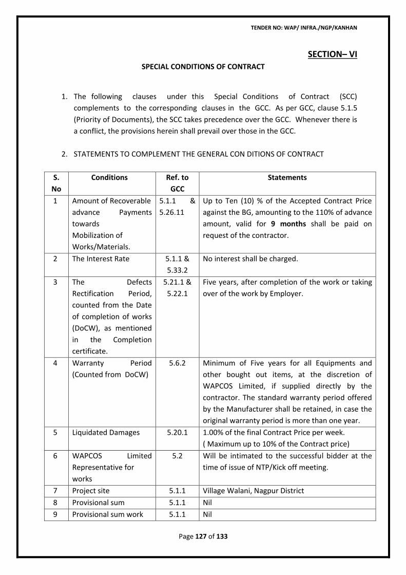
TENDER NO: WAP/ INFRA./NGP/KANHAN
Page 127 of 133
SECTION– VI
SPECIAL CONDITIONS OF CONTRACT
1. The following clauses under this Special Conditions of Contract (SCC)
complements to the corresponding clauses in the GCC. As per GCC, clause 5.1.5
(Priority of Documents), the SCC takes precedence over the GCC. Whenever there is
a conflict, the provisions herein shall prevail over those in the GCC.
2. STATEMENTS TO COMPLEMENT THE GENERAL CON DITIONS OF CONTRACT
S.
No
Conditions
Ref. to
GCC
Statements
1 Amount of Recoverable
advance Payments
towards
Mobilization of
Works/Materials.
5.1.1 &
5.26.11
Up to Ten (10) % of the Accepted Contract Price
against the BG, amounting to the 110% of advance
amount, valid for 9 months shall be paid on
request of the contractor.
2 The Interest Rate
5.1.1 &
5.33.2
No interest shall be charged.
3 The Defects
Rectification Period,
counted from the Date
of completion of works
(DoCW), as mentioned
in the Completion
certificate.
5.21.1 &
5.22.1
Five years, after completion of the work or taking
over of the work by Employer.
4 Warranty Period
(Counted from DoCW)
5.6.2 Minimum of Five years for all Equipments and
other bought out items, at the discretion of
WAPCOS Limited, if supplied directly by the
contractor. The standard warranty period offered
by the Manufacturer shall be retained, in case the
original warranty period is more than one year.
5 Liquidated Damages
5.20.1
1.00% of the final Contract Price per week.
( Maximum up to 10% of the Contract price)
6 WAPCOS Limited
Representative for
works
5.2 Will be intimated to the successful bidder at the
time of issue of NTP/Kick off meeting.
7 Project site 5.1.1 Village Walani, Nagpur District
8 Provisional sum 5.1.1 Nil
9 Provisional sum work 5.1.1 Nil
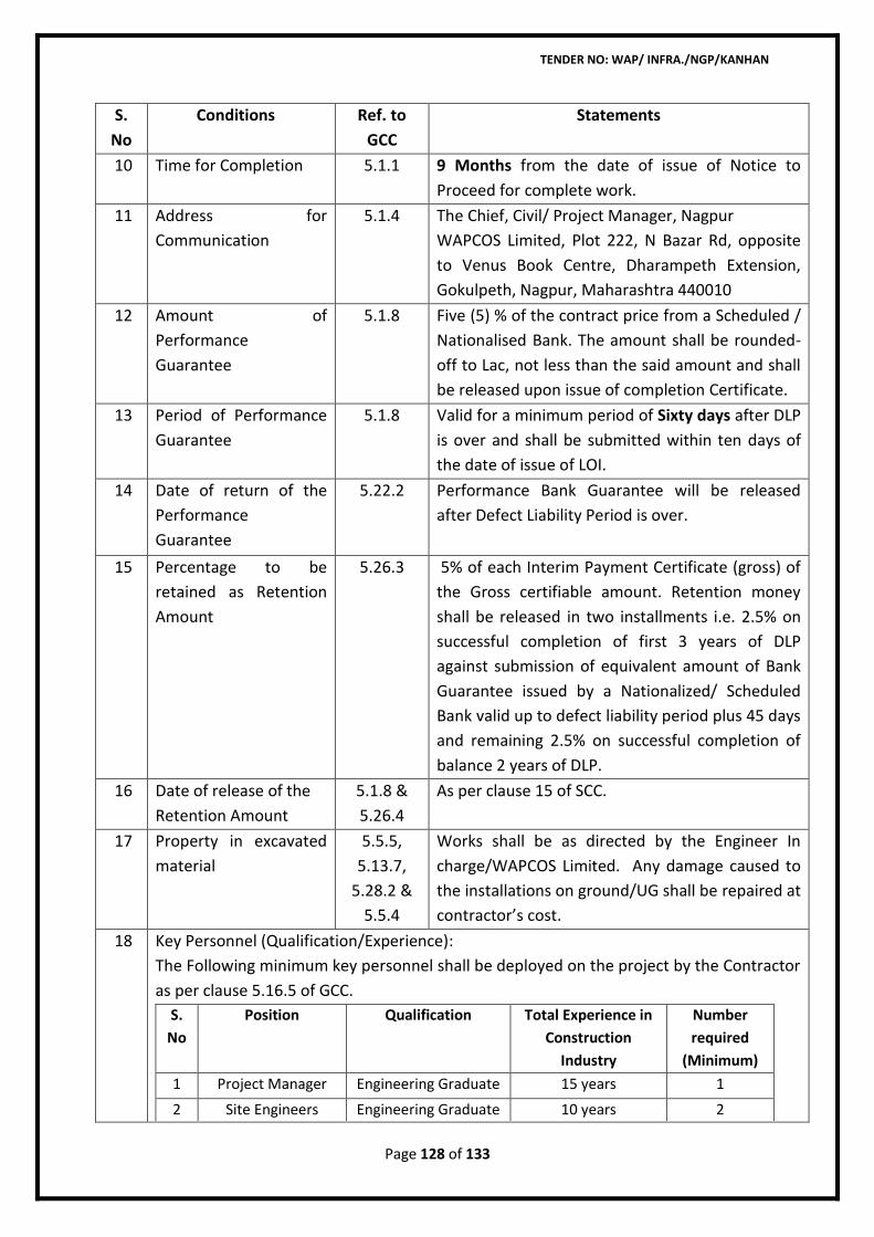
TENDER NO: WAP/ INFRA./NGP/KANHAN
Page 128 of 133
S.
No
Conditions
Ref. to
GCC
Statements
10 Time for Completion 5.1.1 9 Months from the date of issue of Notice to
Proceed for complete work.
11 Address for
Communication
5.1.4 The Chief, Civil/ Project Manager, Nagpur
WAPCOS Limited, Plot 222, N Bazar Rd, opposite
to Venus Book Centre, Dharampeth Extension,
Gokulpeth, Nagpur, Maharashtra 440010
12 Amount of
Performance
Guarantee
5.1.8 Five (5) % of the contract price from a Scheduled /
Nationalised Bank. The amount shall be rounded-
off to Lac, not less than the said amount and shall
be released upon issue of completion Certificate.
13 Period of Performance
Guarantee
5.1.8 Valid for a minimum period of Sixty days after DLP
is over and shall be submitted within ten days of
the date of issue of LOI.
14 Date of return of the
Performance
Guarantee
5.22.2 Performance Bank Guarantee will be released
after Defect Liability Period is over.
15 Percentage to be
retained as Retention
Amount
5.26.3 5% of each Interim Payment Certificate (gross) of
the Gross certifiable amount. Retention money
shall be released in two installments i.e. 2.5% on
successful completion of first 3 years of DLP
against submission of equivalent amount of Bank
Guarantee issued by a Nationalized/ Scheduled
Bank valid up to defect liability period plus 45 days
and remaining 2.5% on successful completion of
balance 2 years of DLP.
16 Date of release of the
Retention Amount
5.1.8 &
5.26.4
As per clause 15 of SCC.
17 Property in excavated
material
5.5.5,
5.13.7,
5.28.2 &
5.5.4
Works shall be as directed by the Engineer In
charge/WAPCOS Limited. Any damage caused to
the installations on ground/UG shall be repaired at
contractor’s cost.
18 Key Personnel (Qualification/Experience):
The Following minimum key personnel shall be deployed on the project by the Contractor
as per clause 5.16.5 of GCC.
S.
No
Position Qualification Total Experience in
Construction
Industry
Number
required
(Minimum)
1 Project Manager Engineering Graduate 15 years 1
2 Site Engineers Engineering Graduate 10 years 2
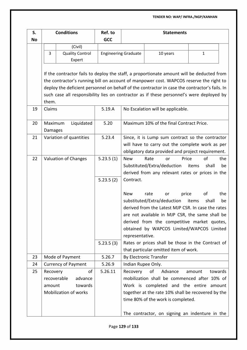
TENDER NO: WAP/ INFRA./NGP/KANHAN
Page 129 of 133
S.
No
Conditions
Ref. to
GCC
Statements
(Civil)
3 Quality Control
Expert
Engineering Graduate 10 years 1
If the contractor fails to deploy the staff, a proportionate amount will be deducted from
the contractor’s running bill on account of manpower cost. WAPCOS reserve the right to
deploy the deficient personnel on behalf of the contractor in case the contractor’s fails. In
such case all responsibility lies on contractor as if these personnel’s were deployed by
them.
19 Claims
5.19.A No Escalation will be applicable.
20 Maximum Liquidated
Damages
5.20 Maximum 10% of the final Contract Price.
21 Variation of quantities
5.23.4 Since, it is Lump sum contract so the contractor
will have to carry out the complete work as per
obligatory data provided and project requirement.
22 Valuation of Changes 5.23.5 (1)
New Rate or Price of the
Substituted/Extra/deduction items shall be
derived from any relevant rates or prices in the
Contract.
New rate or price of the
substituted/Extra/deduction items shall be
derived from the Latest MJP CSR. In case the rates
are not available in MJP CSR, the same shall be
derived from the competitive market quotes,
obtained by WAPCOS Limited/WAPCOS Limited
representative.
Rates or prices shall be those in the Contract of
that particular omitted item of work.
5.23.5 (2)
5.23.5 (3)
23 Mode of Payment 5.26.7 By Electronic Transfer
24 Currency of Payment 5.26.9 Indian Rupee Only.
25 Recovery of
recoverable advance
amount towards
Mobilization of works
5.26.11
Recovery of Advance amount towards
mobilization shall be commenced after 10% of
Work is completed and the entire amount
together at the rate 10% shall be recovered by the
time 80% of the work is completed.
The contractor, on signing an indenture in the
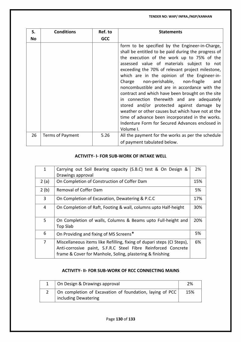
TENDER NO: WAP/ INFRA./NGP/KANHAN
Page 130 of 133
S.
No
Conditions
Ref. to
GCC
Statements
form to be specified by the Engineer-in-Charge, shall be entitled to be paid during the progress of the execution of the work up to 75% of the assessed value of materials subject to not exceeding the 70% of relevant project milestone, which are in the opinion of the Engineer-in- Charge non-perishable, non-fragile and noncombustible and are in accordance with the contract and which have been brought on the site in connection therewith and are adequately stored and/or protected against damage by weather or other causes but which have not at the time of advance been incorporated in the works. Indenture Form for Secured Advances enclosed in Volume I.
26 Terms of Payment 5.26 All the payment for the works as per the schedule
of payment tabulated below.
ACTIVITY- I- FOR SUB-WORK OF INTAKE WELL
1 Carrying out Soil Bearing capacity (S.B.C) test & On Design & Drawings approval
2%
2 (a) On Completion of Construction of Coffer Dam 15%
2 (b) Removal of Coffer Dam 5%
3 On Completion of Excavation, Dewatering & P.C.C 17%
4 On Completion of Raft, Footing & wall, columns upto Half-height 30%
5 On Completion of walls, Columns & Beams upto Full-height and Top Slab
20%
6 On Providing and fixing of MS Screens* 5%
7 Miscellaneous items like Refilling, fixing of dupari steps (CI Steps), Anti-corrosive paint, S.F.R.C Steel Fibre Reinforced Concrete frame & Cover for Manhole, Soling, plastering & finishing
6%
ACTIVITY- II- FOR SUB-WORK OF RCC CONNECTING MAINS
1 On Design & Drawings approval 2%
2 On completion of Excavation of foundation, laying of PCC including Dewatering
15%
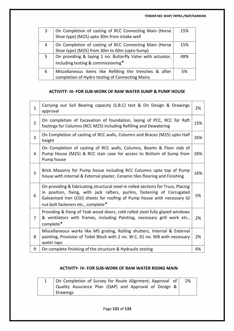
TENDER NO: WAP/ INFRA./NGP/KANHAN
Page 131 of 133
3 On Completion of casting of RCC Connecting Main (Horse Shoe type) (M25) upto 30m from intake well
15%
4 On Completion of casting of RCC Connecting Main (Horse Shoe type) (M25) from 30m to 60m (upto Sump)
15%
5 On providing & laying 1 no. Butterfly Valve with actuator,
Including testing & commissioning*
48%
6 Miscellaneous items like Refilling the trenches & after completion of Hydro testing of Connecting Mains
5%
ACTIVITY- III- FOR SUB-WORK OF RAW WATER SUMP & PUMP HOUSE
1 Carrying out Soil Bearing capacity (S.B.C) test & On Design & Drawings approval
2%
2 On completion of Excavation of foundation, laying of PCC, RCC for Raft footings for Columns (RCC M25) including Refilling and Dewatering
15%
3 On Completion of casting of RCC walls, Columns and Braces (M25) upto Half height
26%
4 On Completion of casting of RCC walls, Columns, Beams & Floor slab of Pump House (M25) & RCC stair case for access to Bottom of Sump from Pump house
26%
5 Brick Masonry for Pump house including RCC Columns upto top of Pump house with internal & External plaster, Ceramic tiles flooring and Finishing
16%
6
On providing & fabricating structural steel in rolled sections for Truss, Placing in position, fixing, with jack rafters, purlins, fastening of Corrugated Galvanised Iron (CGI) sheets for roofing of Pump house with necessary GI
nut bolt fasteners etc., complete*
5%
7
Providing & fixing of Teak wood doors, cold rolled steel fully glazed windows & ventilators with frames, including Painting, necessary grill work etc.,
complete*
2%
8 Miscellaneous works like MS grating, Rolling shutters, Internal & External painting, Provision of Toilet Block with 2 no. W.C, 01 no. WB with necessary water taps
2%
9 On complete finishing of the structure & Hydraulic testing 6%
ACTIVITY- IV- FOR SUB-WORK OF RAW WATER RISING MAIN
1 On Completion of Survey for Route Alignment, Approval of Quality Assurance Plan (QAP) and Approval of Design & Drawings
2%
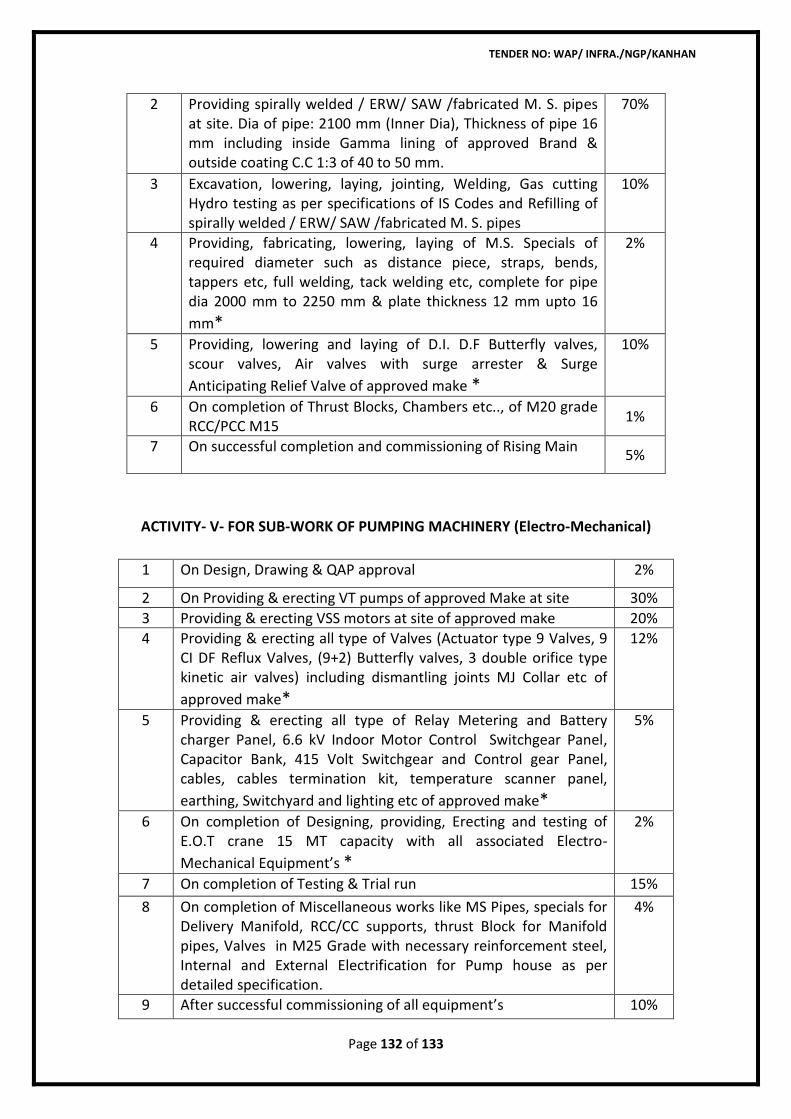
TENDER NO: WAP/ INFRA./NGP/KANHAN
Page 132 of 133
2 Providing spirally welded / ERW/ SAW /fabricated M. S. pipes at site. Dia of pipe: 2100 mm (Inner Dia), Thickness of pipe 16 mm including inside Gamma lining of approved Brand & outside coating C.C 1:3 of 40 to 50 mm.
70%
3 Excavation, lowering, laying, jointing, Welding, Gas cutting Hydro testing as per specifications of IS Codes and Refilling of spirally welded / ERW/ SAW /fabricated M. S. pipes
10%
4 Providing, fabricating, lowering, laying of M.S. Specials of required diameter such as distance piece, straps, bends, tappers etc, full welding, tack welding etc, complete for pipe dia 2000 mm to 2250 mm & plate thickness 12 mm upto 16
mm*
2%
5 Providing, lowering and laying of D.I. D.F Butterfly valves, scour valves, Air valves with surge arrester & Surge
Anticipating Relief Valve of approved make *
10%
6 On completion of Thrust Blocks, Chambers etc.., of M20 grade RCC/PCC M15
1%
7 On successful completion and commissioning of Rising Main 5%
ACTIVITY- V- FOR SUB-WORK OF PUMPING MACHINERY (Electro-Mechanical)
1 On Design, Drawing & QAP approval 2%
2 On Providing & erecting VT pumps of approved Make at site 30%
3 Providing & erecting VSS motors at site of approved make 20%
4 Providing & erecting all type of Valves (Actuator type 9 Valves, 9 CI DF Reflux Valves, (9+2) Butterfly valves, 3 double orifice type kinetic air valves) including dismantling joints MJ Collar etc of
approved make*
12%
5 Providing & erecting all type of Relay Metering and Battery charger Panel, 6.6 kV Indoor Motor Control Switchgear Panel, Capacitor Bank, 415 Volt Switchgear and Control gear Panel, cables, cables termination kit, temperature scanner panel,
earthing, Switchyard and lighting etc of approved make*
5%
6 On completion of Designing, providing, Erecting and testing of E.O.T crane 15 MT capacity with all associated Electro-
Mechanical Equipment’s *
2%
7 On completion of Testing & Trial run 15%
8 On completion of Miscellaneous works like MS Pipes, specials for Delivery Manifold, RCC/CC supports, thrust Block for Manifold pipes, Valves in M25 Grade with necessary reinforcement steel, Internal and External Electrification for Pump house as per detailed specification.
4%
9 After successful commissioning of all equipment’s 10%
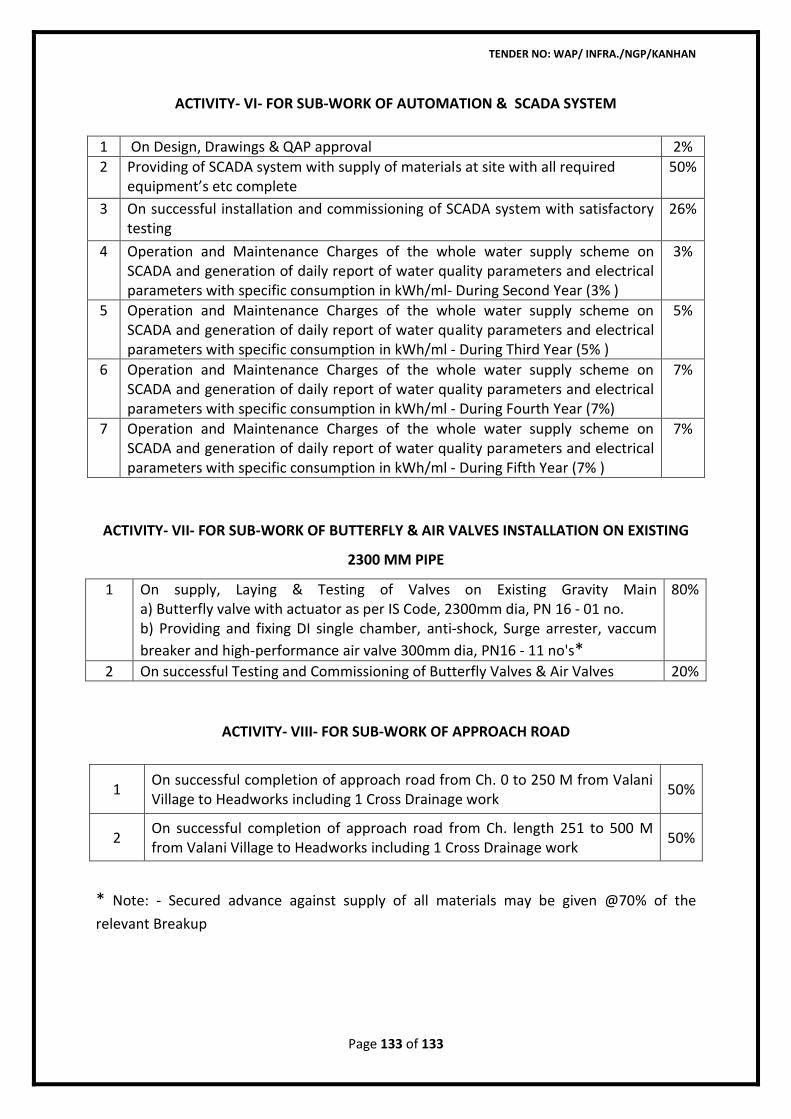
TENDER NO: WAP/ INFRA./NGP/KANHAN
Page 133 of 133
ACTIVITY- VI- FOR SUB-WORK OF AUTOMATION & SCADA SYSTEM
1 On Design, Drawings & QAP approval 2%
2 Providing of SCADA system with supply of materials at site with all required equipment’s etc complete
50%
3 On successful installation and commissioning of SCADA system with satisfactory testing
26%
4 Operation and Maintenance Charges of the whole water supply scheme on SCADA and generation of daily report of water quality parameters and electrical parameters with specific consumption in kWh/ml- During Second Year (3% )
3%
5 Operation and Maintenance Charges of the whole water supply scheme on SCADA and generation of daily report of water quality parameters and electrical parameters with specific consumption in kWh/ml - During Third Year (5% )
5%
6 Operation and Maintenance Charges of the whole water supply scheme on SCADA and generation of daily report of water quality parameters and electrical parameters with specific consumption in kWh/ml - During Fourth Year (7%)
7%
7 Operation and Maintenance Charges of the whole water supply scheme on SCADA and generation of daily report of water quality parameters and electrical parameters with specific consumption in kWh/ml - During Fifth Year (7% )
7%
ACTIVITY- VII- FOR SUB-WORK OF BUTTERFLY & AIR VALVES INSTALLATION ON EXISTING
2300 MM PIPE
1 On supply, Laying & Testing of Valves on Existing Gravity Main a) Butterfly valve with actuator as per IS Code, 2300mm dia, PN 16 - 01 no. b) Providing and fixing DI single chamber, anti-shock, Surge arrester, vaccum
breaker and high-performance air valve 300mm dia, PN16 - 11 no's*
80%
2 On successful Testing and Commissioning of Butterfly Valves & Air Valves 20%
ACTIVITY- VIII- FOR SUB-WORK OF APPROACH ROAD
1 On successful completion of approach road from Ch. 0 to 250 M from Valani Village to Headworks including 1 Cross Drainage work
50%
2 On successful completion of approach road from Ch. length 251 to 500 M from Valani Village to Headworks including 1 Cross Drainage work
50%
* Note: - Secured advance against supply of all materials may be given @70% of the
relevant Breakup
TENDER DOCUMENT
FOR
“DEVELOPMENT OF INFRASTRUCTURE FOR LIFTING WATER FROM
KANHAN RIVER AT VILLAGE ROHANA & CONVEYANCE TO WATER
TREATMENT PLANT AT GODHANI & GOREWADA”
TENDER NO: WAP/INFRA/NGP/KANHAN
VOLUME -3
Technical Specifications
Issued to M/s_______________________________________ _______________________________________
Telephone: +91- 0712 255 7798, Email: [email protected], Website: www.wapcos.co.in
Page 1 of 140
Summary of Contents
Volume – II
Part-A : Scope of Work
Part-B : General Specifications
Part-C : Technical Specifications
Page 2 of 140
System Description of the project
"Development of Infrastructure for lifting water from Kanhan river at village Rohana and
conveyance to Water Treatment plant at Godhani and Gorewada"
Chief, Civil/ Project Manager, WAPCOS Limited, Nagpur
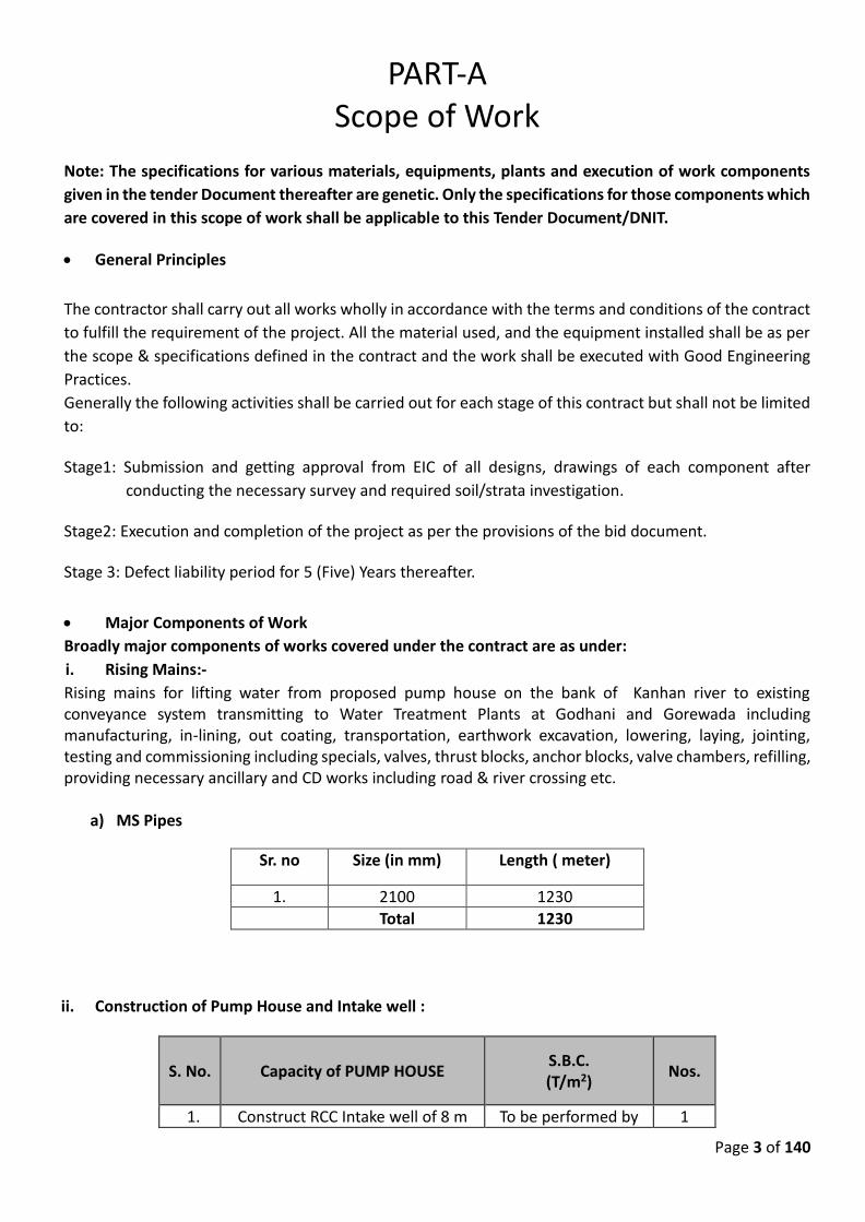
Page 3 of 140
PART-A Scope of Work
Note: The specifications for various materials, equipments, plants and execution of work components
given in the tender Document thereafter are genetic. Only the specifications for those components which
are covered in this scope of work shall be applicable to this Tender Document/DNIT.
• General Principles
The contractor shall carry out all works wholly in accordance with the terms and conditions of the contract
to fulfill the requirement of the project. All the material used, and the equipment installed shall be as per
the scope & specifications defined in the contract and the work shall be executed with Good Engineering
Practices.
Generally the following activities shall be carried out for each stage of this contract but shall not be limited
to:
Stage1: Submission and getting approval from EIC of all designs, drawings of each component after
conducting the necessary survey and required soil/strata investigation.
Stage2: Execution and completion of the project as per the provisions of the bid document.
Stage 3: Defect liability period for 5 (Five) Years thereafter.
• Major Components of Work
Broadly major components of works covered under the contract are as under:
i. Rising Mains:-
Rising mains for lifting water from proposed pump house on the bank of Kanhan river to existing conveyance system transmitting to Water Treatment Plants at Godhani and Gorewada including manufacturing, in-lining, out coating, transportation, earthwork excavation, lowering, laying, jointing, testing and commissioning including specials, valves, thrust blocks, anchor blocks, valve chambers, refilling, providing necessary ancillary and CD works including road & river crossing etc.
a) MS Pipes
Sr. no Size (in mm) Length ( meter)
1. 2100 1230
Total 1230
ii. Construction of Pump House and Intake well :
S. No. Capacity of PUMP HOUSE S.B.C. (T/m2)
Nos.
1. Construct RCC Intake well of 8 m To be performed by 1
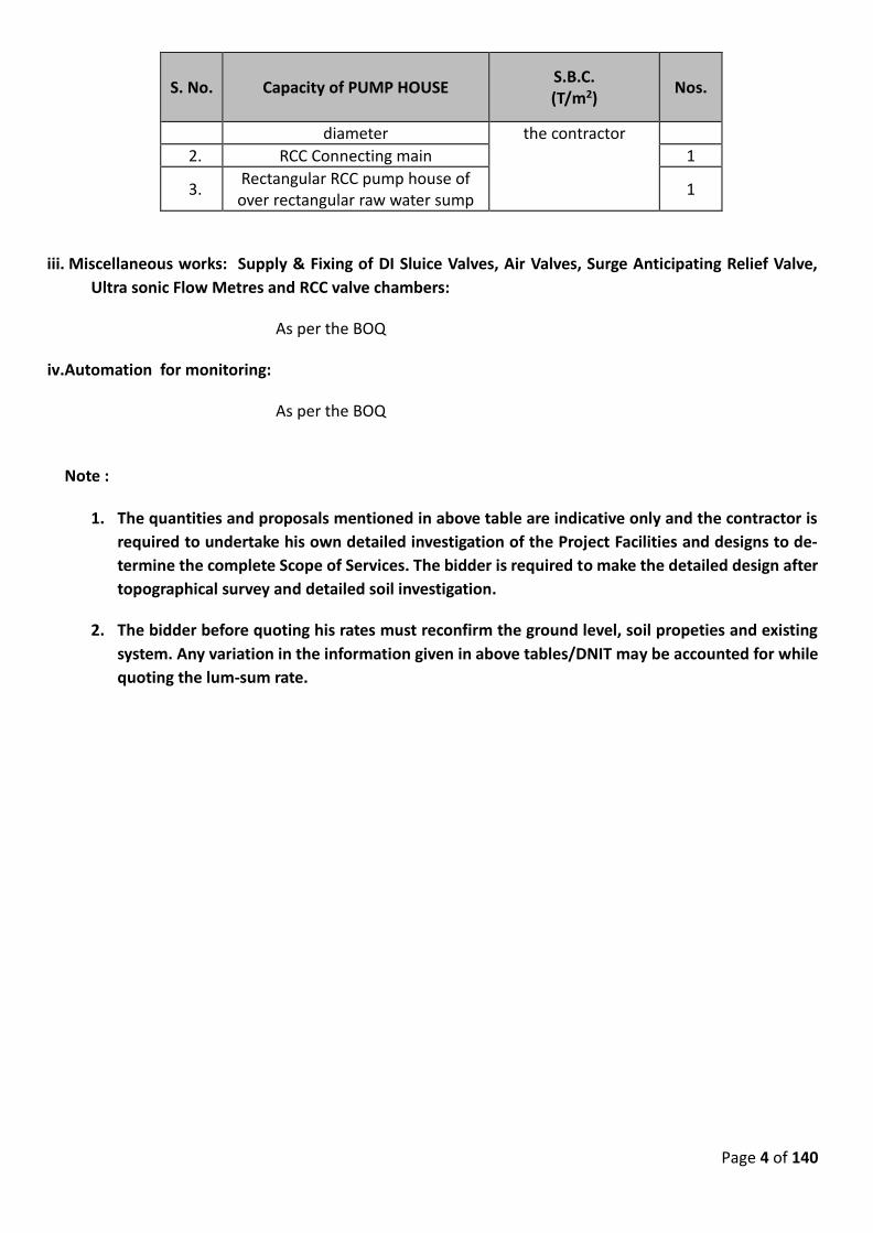
Page 4 of 140
S. No. Capacity of PUMP HOUSE S.B.C. (T/m2)
Nos.
diameter the contractor 2. RCC Connecting main 1
3. Rectangular RCC pump house of over rectangular raw water sump
1
iii. Miscellaneous works: Supply & Fixing of DI Sluice Valves, Air Valves, Surge Anticipating Relief Valve,
Ultra sonic Flow Metres and RCC valve chambers:
As per the BOQ
iv.Automation for monitoring:
As per the BOQ
Note :
1. The quantities and proposals mentioned in above table are indicative only and the contractor is
required to undertake his own detailed investigation of the Project Facilities and designs to de-
termine the complete Scope of Services. The bidder is required to make the detailed design after
topographical survey and detailed soil investigation.
2. The bidder before quoting his rates must reconfirm the ground level, soil propeties and existing
system. Any variation in the information given in above tables/DNIT may be accounted for while
quoting the lum-sum rate.
Page 5 of 140
PART-B GENERAL SPECIFICATION
GS-1
1. All the materials used in the work shall be of best quality and the material rejected shall be removed
from the site by the contractor within 36 hours in the presence of the Engineer in charge at his own
cost.
2. All other rules regarding workmen compensations etc will be binding on the contractor. Unwanted
persons shall be dispensed with if called upon by the Engineer in charge.
3. Other unforeseen items to be executed in course of work will have to be done by the contractor as
per specifications in P.W.D. Hand book volume I and II (Latest Edition) , relevant I.S. code of practice
and as per standard specifications book of latest edition.
4. The contractor shall be responsible and liable to pay for the damages caused by him to public
property etc.
5. All T and P, machinery shall be provided by the contractor. Non availability of the same shall not be
an excuse for application for extension of time limit.
6. Water of good quality for labour, construction, testing and such other purposes shall be provided by
the contractor without any claim for extra cost.
7. Materials belonging to contractor if not removed from site of works after completion of the work
within a period of 15 days shall be taken over by Nagpur Municipal Corporation at contractors risk
and cost and then shall be auctioned at the contractor’s risk and cost. The amount so recovered shall
be credited to contractor’s account after recovery of any dues or over payments etc.
8. The final bill and deposits will not be paid unless the site is cleared off all rubbish materials and
contractor’s stores etc from the site of the work.
9. The contractor will have to pay the royalties and municipal taxes, if charged by the Nagpur Municipal
Corporation Nagpur. The same will not be refunded.
10. Specifications given for relevant nature and type of work, for any particular item of the tender shall
also be applicable to the other item of work when similar work is repeated or carried out in part or
full although the item numbers may not have been mentioned especially against the particular
specifications.
11. The contractor shall be responsible for obtaining permission from Government local bodies, private
party for storing, stacking of materials required for execution of work.
12. Necessary sign board, danger flags, red lamps shall be provided by the contractor to avoid accidents.
Necessary guarding will also have to be provided.
13. Before entering any land, the contractor shall make independent enquiry regarding ownership of
land. Any action regarding trespassing will be at the risk of contractor.
14. Materials remaining unsold or unserviceable as per discretion of the department shall be confiscated,
destroyed or disposed off without any compensation to the contractor, who will be responsible for
all legal disputes at his own cost and consequences without reference to the department.
15. In case of legal disputes for materials brought and stored at site without permission of the Executive
Engineer, the contractor will be responsible for all such legal disputes at his own cost and
consequences without reference to the department.
Page 6 of 140
16. Provide 2 No. vehicle for inspection of works under the project for minimum contract period of 9
months or execution period whichever is later including running charges such as POL,driver,repairs
etc. The model of the vehicle shall not be older than year 2020 & make of vehicle shall be either of
dezire, Scorpio, Etios etc.
17. Contractor shall furnish one contanised site office of size 20 ft *6 ft each fully air conditioned with
well-equipped furniture alongwith computer, printer, Almirah shall be provided as per the direction
of Engineer-In- Charge for entire construction period. All the operating expenses, water, light, other
charges shall be regardless as an inclusive cost of contractors operating cost as part of contract price.
GS 2: SPECIFICATION OF WORK:
The work shall be carried out as per practice and procedure laid down in P.W.D. Hand book Volume
– I & II Latest Edition and Public Works Department’s standard specifications (Latest Publication of
Government of Maharashtra) with amendments from time to time and as per relevant I. S. code for
respective items of works, as directed by the Engineer in charge.
GS 3: MOTIVE POWER:
No electric power supply shall be provided by the department during construction and testing of
various structures under different sub-works. The contractor shall have to make his own
arrangement for the same at his own cost.
GS 4: FOUNDATION CONDITIONS AND PRESCRIBED BEARING CAPACITIES
The bearing capacities for the Pump house with sump and Intake well shall be taken on the basis of
actual strata met with the foundation levels & shall be got tested from reputed institution having
NABL accreditation, at contractor’s own cost and in the presence of Engineer-in-charge. Detailed
structural design shall be prepared by the contractor and got approved from the department.
GS 5: WATER TIGHTNESS TEST
All the water retaining and carrying structures will have to be tested for their water tightness by
filling them with water up to their designed F.S.L. Similarly the pipe line will have to be tested
hydraulically. Structures will be considered water tight when the reductions in filled up level is not
more than 6 mm in 48 hours with outer surface dry. As regards pipe line, these should be tested
for water tightness as per the specifications given in this bid document. The contractor will have to
give all such hydraulic tests by making his own arrangements for water supply, filling and disposing
off water after the test. He shall repeat this test if necessary until the above results are achieved
and certified by the Engineer-in-charge without any claim for extra cost. The contractor shall carry
out the rectification of the structures or pipe lines to achieve the above tests at his own cost. The
structures and pipe lines shall be kept filled with water upto F.S.L. after the above test are over at
his own cost.
GS 6: DISPOSAL OF EXCAVATED STUFF:
All materials obtained from any excavation carried out under this contract will be the property of
Nagpur Municipal Corporation Nagpur and the contractor shall not have any claim on it. It will not
be used by the contractor for any other purpose than the legitimate use on the work itself. Stuff
still remaining surplus shall be spreaded over the different site of work or disposed off as directed
Page 7 of 140
by the Engineer in charge without extra cost.
GS 7: SUBMISSION OF DETAILED DESIGNS & DRAWINGS AFTER ACCEPTANCE OF TENDER:
For the Intake well, Connecting Main, Pump house with sump work, the contractor shall submit
complete detailed designs and drawings within 1 month from the date of issue of work order for
approval of the department. Piecemeal submission of designs and drawings shall not be permitted
to commence the actual work at site unless detailed structural designs and working drawing are
approved by the department. If called upon, the contractor shall also submit within reasonable time
relevant books and other literature which have been referred to by him in working out the design
for civil, mechanical or electrical works involved in the construction. Such books and literature will
be returned to him. Reason of secrecy in regard to details of designs, materials, equipments etc
shall not be placed by the contractor in the name of ‘TRADE SECRET’ for not furnishing the requisite
details . The design got approved from Govt. Engineering College shall be subjected to modifications
if found necessary and such modification shall not violate the contract. The contractor shall be
responsible for the correctness and soundness of the designs submitted by him. The structure
design shall be as per recognized engineering practices and if any provisions, are found inadequate
or faulty, necessary modifications will have to be carried out by him at any stage up to the expiry of
guarantee period and no extra payment will be made on this account.
Five copies & one soft copy of all the approved designs and drawings shall be furnished by the
contractor to the department free of cost.
GS-8: REQUIREMENT OF STRENGTH OF CONCRETE
The contractor shall make field arrangements for testing of all materials for reinforced cement
concrete i.e. slump test, compression test etc. The concrete cube moulds as per IS 456:2000 of 15
x 15 x 15 cm size shall be kept during concreting operation. The cubes shall be prepared at site
during each concreting at work for compression test. The cubes shall be tested for strength at 7 and
28 days in Regional Testing Laboratory at Govt. Polytechnic/Engineering College / Vishveshvarayya
National Institute of Technology, Nagpur or at any approved NABL laboratory, by Engineer –In-
Charge. All The Testing Charges Shall Be Paid By Contractor. The entire responsibility of the testing
of materials will be borne by the contractor.
At least to 10% of prescribed Tests as per Central Public Works Department Manual/IS Codes
/BSI/Maharashtra Codes/ CPHEEO of construction materials shall be carried out from the outside
approved/NABL recognized Laboratory as may be approved by WAPCOS without any extra expend
ture to WAPCOS. The Contractor shall establish a field test laboratory on the site with latest equip-
ment’s for carrying out field tests of construction materials and will maintain proper records of all
the test results.
Mixing of concrete shall be done with automatic/semi automatic batch mixers.
a) The contractor will make his own arrangement for receiving all materials, tools, etc. required
for the work.
b) The material required for carrying out the work for which the tender is offered shall be
brought by the tenderer.
Page 8 of 140
c) The rates for all items are inclusive of all charges such as carting, lifting etc. No extra
payment for any lead and lifts will be paid for any item.
d) The contractor should not sublet any work without written permission of the Engineer-In-
Charge.
e) The conditions in the tender notice will be binding on the contractor and the Tender Notice
will form a part of agreement.
f) No extra charges for the carriage of water will be allowed.
GS-9: ORDINARY CONCRETE
1. The charges for preliminary design of concrete mix shall be entirely borne by the contractor.
2. For grades of concrete where cement is to be used by weightment, the cost of extra cement
required to make up under weight bags shall be borne by the contractor.
GS-10: REGULATORY PERMISSION:
All the regulatory permission like: Environmental Clearances, Forest Clearances, Land acquisition, Gas Pipe line crossing, Railway crossing or any relevant approval, which is to be required for exe-cution of the project, the same shall be arranged by the Employer. The contractor will assist the Employer in whole process of preparing the case for obtaining the necessary approval/permits to be required for execution of the project. Any payment or fees to be made to regulatory body for obtaining such permission, the same shall be made by the contractor.
It is also clarified here, that Employer will keep in force and effect such Applicable regulatory per-
missions in conformity with the Applicable Laws throughout the contract period.
Page 9 of 140
PART-C
TECHNICAL SPECIFICATIONS
1. PREPARATORY WORK
The proposals presented in this tender are based on the survey conducted by the department and
available details. However for verification of the data and the whole concept, the contractor shall
conduct his own survey and accordingly design the pipe lines. He shall submit the detailed calcula-
tions/design alongwith drawings for approval to EIC. No reduction in diameters of pipelines pro-
posed by the department shall be admissible. He will not be paid any extra amount for carrying out
survey and the detailed calculations/ design for verification. Cleaning cutting thorny shrubs bushes,
grass as directed with all lead and lift etc complete.
2. TOPOGRAPHICAL SURVEYS
The Contractor shall get the alignment of the proposed pipe line fixed further fix the location and
type of cross drainage works, pipe crossing structures, thrust blocks, anchor blocks, air valves, sluice
valves, butterfly valves, scour valves etc. and submit the same for the approval of the department.
3. SUBMISSIONS
The Contractor shall prepare and submit the following:
• Confirmation of department’s drawings and designs.
The following general criteria must be adhered to while planning about the alignment of the pipe-
line:
(i) The pipeline shall be laid below ground.
(ii) The pipeline must be laid in a regular slope with minimum possible bends. If laying of pipe
below ground is not possible to minimize close positions of bends, small stretches of pipeline
may be kept above road, if circumstances so permit.
(iii) The alignment shall be kept within the approved strip of land. The laying shall ensure minimum
damage to road side construction and plantation if any.
(iv) Wherever the pipeline is to cross the existing oil and natural gas or water pipelines, OFC and
telephone cables, etc the contractor shall take necessary precautions and he shall be liable to
all damages /claims / etc. on account of damages or accident caused due to damages of such
lines.
(v) The laying of pipes must not obstruct the flow of water in the natural drains. The pipe must
cross the drains either from below the scour levels or above the high flood levels. If crossed
above the bed level, appropriate structures at support and in between the nallah/drain/nal-
lah/river must be provided in the exposed section. The structure must be protected by suitably
Page 10 of 140
planned river training works. If laid below ground, it must have sufficient cover without change
in the existing grade of nallah/river/canal. The damaged portions of the embankment and the
bed must be restored in portions the pipeline is laid below canal bed levels with proper com-
paction and the canal bed and sides must be lined with CC lining at least 40 mm thick in at least
a length of 60 meters U/S and D/S portions.
(vi) Wherever the pipeline is laid with an embankment, the embankment must not create pound-
ing of water. If the conditions are unavoidable, suitable cross drainage works must be provided.
4. DESIGN OF PIPELINE
4.1 Detailed L-section
The design of pipeline as per departmental concept is available with the EIC. The contractor may
take these designs and check at his level and if satisfied, he must give his confirmation for doing
work as per department’s concept. If contractor feels to revise/change in the design of pipeline, he
shall produce detailed calculations in support of changes proposed for approval to EIC. However,
the contractor must compulsorily conduct survey in each section to re-confirm static level differ-
ences between two points and level of peaks, if any, to arrive at correct terminal pressure in the
pipe line.
4.2 Detailed Design
After required survey and investigation as per above, the pipe lines shall be designed as per the BIS
code and CPHEEO Manual.
5. EXCAVATION IN ALL SOFT AND HARD STRATA MATERIAL
5.0 GENERAL
The specifications contained in the standard specification volume IInd published by Public Works
and Housing Department, Govt. of Maharashtra, Chapter Bd.A shall apply. In addition to above,
following specifications shall also apply. In case of any discrepancy/variance between the two, the
below given specifications shall govern.
5.1 SITE CLEARANCE
The area to be excavated shall be cleared off. All trees , bushes and rubbish and other objectionable
materials removed shall be disposed off as directed by the Engineer-in-Charge. The cost of such
clearing and disposal shall be deemed to have been included in the rates accepted for different
items under excavation.
5.2 DEWATERING
No distinction shall be made as to whether the materials being excavated is dry, moist or wet. The
item of excavation also includes bailing out of water manually or pumps to keep the trenches
reasonable dry for all further works of lowering, laying, jointing and testing of the pipe line till the
completion of the work. Nothing extra shall be paid on this account.
Page 11 of 140
5.3 SHORING AND STRUTTING
The item includes all shoring and strutting that may be required. On no account the width of
trenches more than these mentioned hereinafter shall be measured. If excavation width, more
than the specified, is required for the purpose of keeping machinery, steeping due to loose material
or for any other reasons, the same shall be at the Contractors cost.
5.4 LIGHTING, BARRICADING AND GUARDING
The item of excavation also includes necessary caution lighting at night at suitable intervals (not
more than 15 meter) along the excavated trenches and at all crossings and barricading the
excavated portion by fencing so as to avoid the accident. Chowkidars shall be employed at places
where the trenches cross any traffic road to caution the vehicles and pedestrians etc. These
arrangements shall be maintained till completion of work and at the cost of the Contractor.
5.5 ALIGNMENT AND LEVELS
The excavation work shall be preceeded by a detailed survey along the alignment of the main to
obtain ground levels at every 100 meters or less distance. Temporary bench mark shall be
constructed along the alignment and shall be maintained till the completion of work. All labour and
materials required for the survey work of fixing bench marks etc. shall be provided by the Contractor
at his own cost. The Contractor shall be fully responsible for any mistake in survey . He should not
lay the pipes, unless the alignment is thoroughly checked by the Engineer-in-Charge or his
authorized representative who is empowered to sign the work order book in token of checking the
exact grade and level of the trenches excavation.
Excavation at random places shall not be measured by the Engineer - in - Charge. Any non-technical
practices during the excavation of the contracted work shall be viewed very seriously by the
department and a note to that effect will be recorded against the Contractor in his name.
5.6 DEPTH AND GRADES OF TRENCHES
The trenches shall be excavated to the required depth in all types of strata and on the lines as shown
on approved drawings or as directed by the Engineer-in-Charge. If not so, the payment for the item
will not be paid to the Contractor. The depth of excavation shall be checked by means of boning
rods of suitable lengths. Additional depths if required to be excavated for pipes, for sockets, collars,
specials, joints and for any other working facility shall not be measured and paid. The minimum
cover above the pipe shall be 0.90 m.
The Contractor shall notify the Engineer when the trenches are ready for bedding so that the
Engineer can inspect and record the depth. Only on explicit approval by Engineer, the bedding shall
be provided by the Contractor. If any public utility i.e. electrical cable, telephone cable, water
connections, sewer etc. damaged during work execution, then the same shall be rectified by
contractor at his own cost.
5.7 WIDTH OF TRENCHES
The maximum width of the trenches admissible for payment shall be as per the BIS code and
CPHEEO manual.
Page 12 of 140
In case the excavated width is less than the widths shown in the drawing, then the same shall be
recorded and paid for. Extra widths for pits at sockets, collars, specials, joints, construction and also
for working liabilities shall neither be measured nor paid for. However, excavation required for
providing and casting thrust blocks, encasing etc. will be measured and paid for under relevant item
of excavation. The pits for welding joints will also be paid under relevant item of excavation.
5.8 PRESSING AND CONSOLIDATING OF THE TRENCHES
The bed of the trenches shall be well rammed before laying of the murum or sand for bedding.
Hollows, if any, shall be filled with murum duly rammed and watered to required level and grade at
cost of the Contractor.
5.9 CLASSIFICATION OF MATERIAL IN TRENCHES
The exact classification of the strata met with during the excavation shall be done by the
representative of Engineer-in-Charge and accordingly measurement shall be recorded under
different items of excavation. In case of any dispute regarding classification of strata, the decision
of Engineer-in-Charge shall be final and binding. The strata classifications and its quantity shown
are indicative only. The Contractor therefore, shall carry out his own assessment regarding the
strata at different depth along the alignment, before submission of the tender.
5.10 EXCAVATION BY CHISELLING i.e. MECHANICAL MEANS
(in Hard Strata)
Excavation in hard strata shall be done by chiselling, wedging or line drilling as specified or by any
mechanical means as ordered by the Engineer. The excavation refers to excavation generally for
foundation, wet or dry, in hard rock by chiseling, wedging or line drilling and shall comply with the
specifications.
5.11 MODE OF MEASUREMENT AND PAYMENT
The excavation shall be measured in Cubic meters only. Dimensions shall be measured correct to
two decimal of meter and quantity shall be calculated to two places of Decimal of Cubic meters.
6. PLAIN/REINFORCED CEMENT CONCRETE
6.1 a) Proportions of concrete for types of work
i) M-10 – For leveling course and foundation of chairs and thrust blocks etc
ii) M-15 PCC for footing thrust blocks, anchor blocks, chairs and encasing of pipes etc.
iii) M-25 for Construction of Pump house with sump, Intake well, Connecting main, thrust blocks,
valve chamber etc.
b) General specifications of this work shall be as per standard specification of Public Works
Department, latest edition, for PCC Bd.-E1 to E-7 and for RCC Bd.F2 to F16.
c) Whenever concrete is to be laid in trenches, the trench shall be cleaned, and watered before
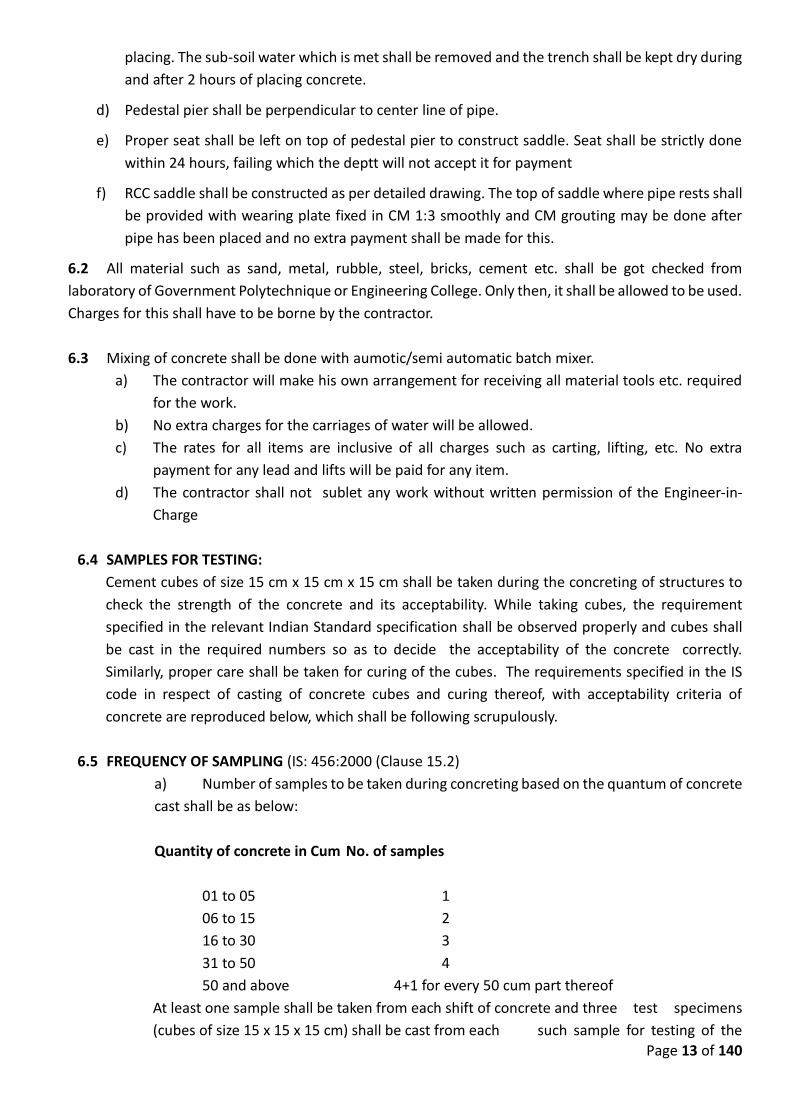
Page 13 of 140
placing. The sub-soil water which is met shall be removed and the trench shall be kept dry during
and after 2 hours of placing concrete.
d) Pedestal pier shall be perpendicular to center line of pipe.
e) Proper seat shall be left on top of pedestal pier to construct saddle. Seat shall be strictly done
within 24 hours, failing which the deptt will not accept it for payment
f) RCC saddle shall be constructed as per detailed drawing. The top of saddle where pipe rests shall
be provided with wearing plate fixed in CM 1:3 smoothly and CM grouting may be done after
pipe has been placed and no extra payment shall be made for this.
6.2 All material such as sand, metal, rubble, steel, bricks, cement etc. shall be got checked from
laboratory of Government Polytechnique or Engineering College. Only then, it shall be allowed to be used.
Charges for this shall have to be borne by the contractor.
6.3 Mixing of concrete shall be done with aumotic/semi automatic batch mixer.
a) The contractor will make his own arrangement for receiving all material tools etc. required
for the work.
b) No extra charges for the carriages of water will be allowed.
c) The rates for all items are inclusive of all charges such as carting, lifting, etc. No extra
payment for any lead and lifts will be paid for any item.
d) The contractor shall not sublet any work without written permission of the Engineer-in-
Charge
6.4 SAMPLES FOR TESTING:
Cement cubes of size 15 cm x 15 cm x 15 cm shall be taken during the concreting of structures to
check the strength of the concrete and its acceptability. While taking cubes, the requirement
specified in the relevant Indian Standard specification shall be observed properly and cubes shall
be cast in the required numbers so as to decide the acceptability of the concrete correctly.
Similarly, proper care shall be taken for curing of the cubes. The requirements specified in the IS
code in respect of casting of concrete cubes and curing thereof, with acceptability criteria of
concrete are reproduced below, which shall be following scrupulously.
6.5 FREQUENCY OF SAMPLING (IS: 456:2000 (Clause 15.2)
a) Number of samples to be taken during concreting based on the quantum of concrete
cast shall be as below:
Quantity of concrete in Cum No. of samples
01 to 05 1
06 to 15 2
16 to 30 3
31 to 50 4
50 and above 4+1 for every 50 cum part thereof
At least one sample shall be taken from each shift of concrete and three test specimens
(cubes of size 15 x 15 x 15 cm) shall be cast from each such sample for testing of the
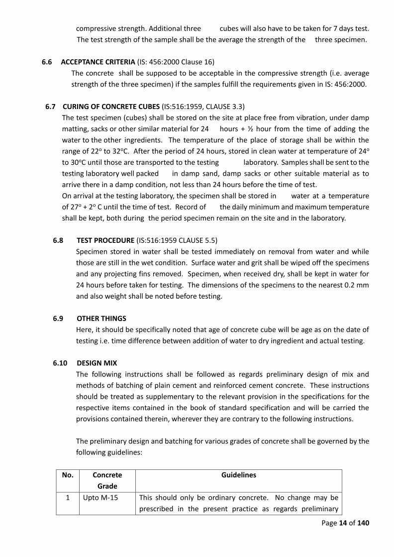
Page 14 of 140
compressive strength. Additional three cubes will also have to be taken for 7 days test.
The test strength of the sample shall be the average the strength of the three specimen.
6.6 ACCEPTANCE CRITERIA (IS: 456:2000 Clause 16)
The concrete shall be supposed to be acceptable in the compressive strength (i.e. average
strength of the three specimen) if the samples fulfill the requirements given in IS: 456:2000.
6.7 CURING OF CONCRETE CUBES (IS:516:1959, CLAUSE 3.3)
The test specimen (cubes) shall be stored on the site at place free from vibration, under damp
matting, sacks or other similar material for 24 hours + ½ hour from the time of adding the
water to the other ingredients. The temperature of the place of storage shall be within the
range of 22o to 32oC. After the period of 24 hours, stored in clean water at temperature of 24o
to 30oC until those are transported to the testing laboratory. Samples shall be sent to the
testing laboratory well packed in damp sand, damp sacks or other suitable material as to
arrive there in a damp condition, not less than 24 hours before the time of test.
On arrival at the testing laboratory, the specimen shall be stored in water at a temperature
of 27o + 2o C until the time of test. Record of the daily minimum and maximum temperature
shall be kept, both during the period specimen remain on the site and in the laboratory.
6.8 TEST PROCEDURE (IS:516:1959 CLAUSE 5.5)
Specimen stored in water shall be tested immediately on removal from water and while
those are still in the wet condition. Surface water and grit shall be wiped off the specimens
and any projecting fins removed. Specimen, when received dry, shall be kept in water for
24 hours before taken for testing. The dimensions of the specimens to the nearest 0.2 mm
and also weight shall be noted before testing.
6.9 OTHER THINGS
Here, it should be specifically noted that age of concrete cube will be age as on the date of
testing i.e. time difference between addition of water to dry ingredient and actual testing.
6.10 DESIGN MIX
The following instructions shall be followed as regards preliminary design of mix and
methods of batching of plain cement and reinforced cement concrete. These instructions
should be treated as supplementary to the relevant provision in the specifications for the
respective items contained in the book of standard specification and will be carried the
provisions contained therein, wherever they are contrary to the following instructions.
The preliminary design and batching for various grades of concrete shall be governed by the
following guidelines:
No. Concrete
Grade
Guidelines
1 Upto M-15 This should only be ordinary concrete. No change may be
prescribed in the present practice as regards preliminary
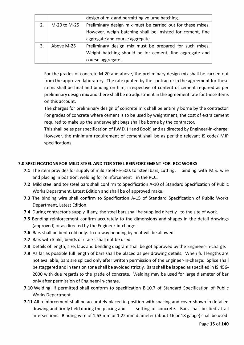
Page 15 of 140
design of mix and permitting volume batching.
2. M-20 to M-25 Preliminary design mix must be carried out for these mixes.
However, weigh batching shall be insisted for cement, fine
aggregate and course aggregate.
3. Above M-25 Preliminary design mix must be prepared for such mixes.
Weight batching should be for cement, fine aggregate and
course aggregate.
For the grades of concrete M-20 and above, the preliminary design mix shall be carried out
from the approved laboratory. The rate quoted by the contractor in the agreement for these
items shall be final and binding on him, irrespective of content of cement required as per
preliminary design mix and there shall be no adjustment in the agreement rate for these items
on this account.
The charges for preliminary design of concrete mix shall be entirely borne by the contractor.
For grades of concrete where cement is to be used by weightment, the cost of extra cement
required to make up the underweight bags shall be borne by the contractor.
This shall be as per specification of P.W.D. (Hand Book) and as directed by Engineer-in-charge.
However, the minimum requirement of cement shall be as per the relevant IS code/ MJP
specifications.
7.0 SPECIFICATIONS FOR MILD STEEL AND TOR STEEL REINFORCEMENT FOR RCC WORKS
7.1 The item provides for supply of mild steel Fe-500, tor steel bars, cutting, binding with M.S. wire
and placing in position, welding for reinforcement in the RCC.
7.2 Mild steel and tor steel bars shall confirm to Specification A-10 of Standard Specification of Public
Works Department, Latest Edition and shall be of approved make.
7.3 The binding wire shall confirm to Specification A-15 of Standard Specification of Public Works
Department, Latest Edition.
7.4 During contractor's supply, if any, the steel bars shall be supplied directly to the site of work.
7.5 Bending reinforcement confirm accurately to the dimensions and shapes in the detail drawings
(approved) or as directed by the Engineer-in-charge.
7.6 Bars shall be bent cold only. In no way bending by heat will be allowed.
7.7 Bars with kinks, bends or cracks shall not be used.
7.8 Details of length, size, laps and bending diagram shall be got approved by the Engineer-in-charge.
7.9 As far as possible full length of bars shall be placed as per drawing details. When full lengths are
not available, bars are spliced only after written permission of the Engineer-in-charge. Splice shall
be staggered and in tension zone shall be avoided strictly. Bars shall be lapped as specified in IS:456-
2000 with due regards to the grade of concrete. Welding may be used for large diameter of bar
only after permission of Engineer-in-charge.
7.10 Welding, if permitted shall conform to specification B.10.7 of Standard Specification of Public
Works Department.
7.11 All reinforcement shall be accurately placed in position with spacing and cover shown in detailed
drawing and firmly held during the placing and setting of concrete. Bars shall be tied at all
intersections. Binding wire of 1.63 mm or 1.22 mm diameter (about 16 or 18 gauge) shall be used.
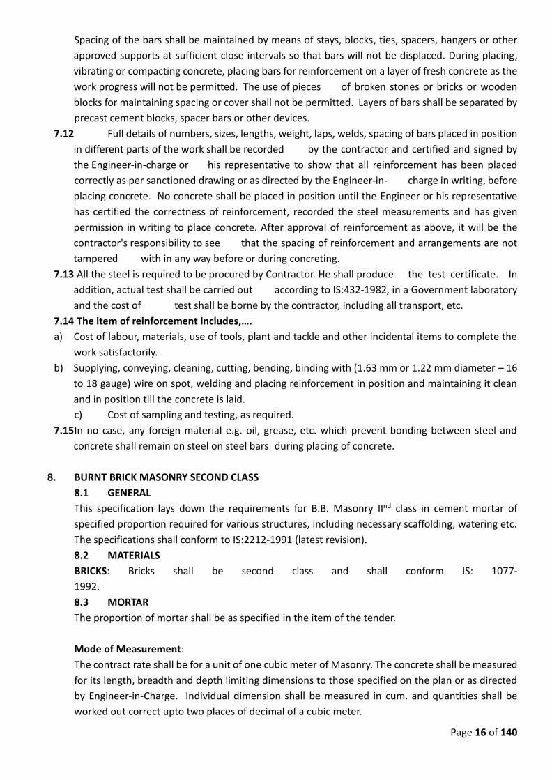
Page 16 of 140
Spacing of the bars shall be maintained by means of stays, blocks, ties, spacers, hangers or other
approved supports at sufficient close intervals so that bars will not be displaced. During placing,
vibrating or compacting concrete, placing bars for reinforcement on a layer of fresh concrete as the
work progress will not be permitted. The use of pieces of broken stones or bricks or wooden
blocks for maintaining spacing or cover shall not be permitted. Layers of bars shall be separated by
precast cement blocks, spacer bars or other devices.
7.12 Full details of numbers, sizes, lengths, weight, laps, welds, spacing of bars placed in position
in different parts of the work shall be recorded by the contractor and certified and signed by
the Engineer-in-charge or his representative to show that all reinforcement has been placed
correctly as per sanctioned drawing or as directed by the Engineer-in- charge in writing, before
placing concrete. No concrete shall be placed in position until the Engineer or his representative
has certified the correctness of reinforcement, recorded the steel measurements and has given
permission in writing to place concrete. After approval of reinforcement as above, it will be the
contractor's responsibility to see that the spacing of reinforcement and arrangements are not
tampered with in any way before or during concreting.
7.13 All the steel is required to be procured by Contractor. He shall produce the test certificate. In
addition, actual test shall be carried out according to IS:432-1982, in a Government laboratory
and the cost of test shall be borne by the contractor, including all transport, etc.
7.14 The item of reinforcement includes,….
a) Cost of labour, materials, use of tools, plant and tackle and other incidental items to complete the
work satisfactorily.
b) Supplying, conveying, cleaning, cutting, bending, binding with (1.63 mm or 1.22 mm diameter – 16
to 18 gauge) wire on spot, welding and placing reinforcement in position and maintaining it clean
and in position till the concrete is laid.
c) Cost of sampling and testing, as required.
7.15 In no case, any foreign material e.g. oil, grease, etc. which prevent bonding between steel and
concrete shall remain on steel on steel bars during placing of concrete.
8. BURNT BRICK MASONRY SECOND CLASS
8.1 GENERAL
This specification lays down the requirements for B.B. Masonry IInd class in cement mortar of
specified proportion required for various structures, including necessary scaffolding, watering etc.
The specifications shall conform to IS:2212-1991 (latest revision).
8.2 MATERIALS
BRICKS: Bricks shall be second class and shall conform IS: 1077-
1992.
8.3 MORTAR
The proportion of mortar shall be as specified in the item of the tender.
Mode of Measurement:
The contract rate shall be for a unit of one cubic meter of Masonry. The concrete shall be measured
for its length, breadth and depth limiting dimensions to those specified on the plan or as directed
by Engineer-in-Charge. Individual dimension shall be measured in cum. and quantities shall be
worked out correct upto two places of decimal of a cubic meter.
Page 17 of 140
8.4 CONSTRUCTION JOINTS:
Joints shall not exceed 12 mm (about ½") in thickness and shall be uniform throughout.
8.5 HALF BRICK MASONRY:
The half brick masonry shall be in cement mortar specified in the item but not weaker than 1:4.
Mode of measurement: Per Sqm
The half brick masonry shall be reinforced by 2 No. of 6 mm dia M.S. longitudinal bars or 2 No. of
hoop item strips of 25 x 1.6 mm size, at every third course properly bent and bound in vertical joints
of the brick work or to main walls as directed by the Engineer-in-charge. If continuous strip is not
available, strips shall be rivet jointed with a minimum overlap of 8 cm. All the bricks shall be laid
stretch wise breaking joint with the upper and lower courses. Fixtures, plugs, hold, fasts, frame
down, windows shall be based into brick work while laying only and at the correct levels and
positions. Holes of required size and stage shall be left in the brick work during laying for fixing
pipes or service lines, passage of water etc. After the pipeline work is completed, extra hollow left
around the hole shall be plugged with 1:3 cement mortar or 1:3:6 cement concrete. Hold fasts for
frames of doors and windows shall be accommodated in the joints of the brick while laying.
A set of mason's tools shall be maintained on work for each group of 3 masons or less for frequent
use and checking. The ends of walls shall be bonded into the side walls where necessary.
The joints shall be raked out to depth not less than the thickness of the joints.
This item shall include:
a) Providing and fixing mild steel reinforcement bars or hoop iron strips as mentioned above.
b) Leaving holes for fixtures or pipes and making them good after completion of the work.
c) Building in frames, hold fasts etc. and forming chassis and grooves.
Mode of measurement
The contract rate shall be for a unit of one Square meter and quantities shall be worked out correct
upto three places of decimal of a Sqmt...
9. CEMENT PLASTER WITH INTERNAL NEERU FINISH
9.1 GENERAL
This specification lays down the requirement of cement plaster to be applied to concrete or brick
masonry surface in cement mortar of specific proportion and thickness.
9.2 PREPARATION
For masonry, all joints in the frame work that is to be plastered shall be raked out to a depth not
less than the width of the joints or as directed by the Engineer-in-charge. The raking shall be done
taking care not to allow any chipping of masonry. In new work, the raking out shall be done while
the mortar in the joints in still green. Smooth surface of concrete or plaster etc. must be suitably
roughened to provide necessary bond for the plaster. All dirt, soot, oil paint or any other materials
that might interfere with satisfactory bond shall be removed and surface wetted before plastering
is started.
Page 18 of 140
9.2.1 General : The item shall comply with the following:
9.2.2 Finishing : When no finish is specified, the plastered surface shall be rubbed well to an even
plane with a wooden float for external surfaces and finished smooth with a steel trowel for internal
surfaces.
• When cement finish is specified, coat of pure Portland cement slurry 1.5 mm (1/16'')
thick shall be applied to the plastered surface while the second coat is still fresh. If
neeru finish is specified, then the surface shall be finished as per specification for
Item Bd.L-10.
• The thickness of the cement plaster shall be 12 mm excluding cement or neeru finish.
9.3 MATERIALS
Cement mortar shall be prepared from cement and and mixed in the proportion as specified for
RCC work. Sand shall be screened and washed if called upon to do so. Water proofing compound
of directed make in directed quantities shall be added where it is water proof plaster. Scaffolding
shall be prepared from sound materials and shall be provided, where ever situation demands for
facility of proper working.
9.4 GAUGES
Patch of plaster 15 x 15 cm shall be put on about 3 m apart as gauges to ensure even plastering in
one place.
9.5 FINISHING
In any continuous face of wall, finishing treatment of any type shall be carried out continuously and
day to day breaks made to coincide with architectural breaks in order to avoid unsightly junctions.
All mouldings shall be worked true to template and drawn neat, clean and level. All exposed angles,
junctions and openings shall be carefully finished.
9.6 WATERING
All pointing work shall be kept damp continuously for a period of 14 days. To prevent excessive
evaporation of the sunny and wind ward side of the building in hot dry weather, matting or gunny
bags may be hung over on the outside of the plaster in the beginning and kept moist. If the
contractor fails to water the work to the satisfaction of the Engineer-in-charge, the requisite labour,
materials and equipment to water the work properly shall be engaged departmentally at the cost
of the contractor.
9.7 Cost of all scaffolding etc. is included in the tender rate.
10. SAND FACED CEMENT PLASTER
10.1 GENERAL
The item shall comply with the following specifications:
Base Coat : The base coat plaster shall be of cement mortar 1:4. Water proofing compound of
approved make like Pudlo, Sika, Accorproof shall be added according to the maker’s instruction in
Bd.L 2 which a thickness of 15 mm for brick work and concrete surfaces and 20 mm for rubble
stone masonry. Keys shall be formed on the surface by thoroughly combing it with wavy horizontal
Page 19 of 140
lines about 12 mm apart and about 3 mm deep when the mortar is still plastic.
Sand Faced Treatment : The cement mortar of sand faced plaster shall have washed Kharsalia or
Kasaba or similar type of approved sand with slightly larger proportion of coarse material The
proportion of cement to sand shall be 1:4. The water is added gradually to make the mixture
homogeneous. The thickness of finishing coat shall not exceed 8 mm. After application, the surface
shall be finished with a wooden float lined with cork and tapped gently to retain a coarse surface
texture. When the finishing coat has hardened, the surface shall be kept moist continuously for 14
days.
The specification lays down the requirements of applying sand faced plaster in specified thickness
with cement mortar to concrete or masonry surface in specified coats. This shall conform to
specification for ordinary cement plaster where ever it is not irrelevant and in addition following
shall also be applicable.
Tools and accessories used in plastering work are thoroughly cleaned before plastering is done.
The programming of other building operations before during and after plastering shall be according
to the instructions contained in Clause 4 of IS:1661-1960 or its latest revision. The item shall be
executed as per Red book specification BdL-7 to 7.50 page No. 351)
Care shall be taken that other parts of work of adjacent work are not damaged while plastering.
The base coat plaster shall be of cement mortar of specified proportion 1:4 and thickness as
mentioned in the item or otherwise, it shall be of cement mortar 1:3 and thickness 15 mm to 20
mm. The base coat shall be laid in a similar manner as stipulated in. However, instead of finishing
the top surface smooth keys shall be formed on the surface thoroughly combined in with wavy
horizontal lines about 12 mm apart and about 3 mm deep when the mortar is still plastic. The base
coat shall be cured for suitable period as per relevant code.
11. DOORS, WINDOWS AND ROLLING SHUTTERS
The specifications for these works are as per Standard Specification, approved drawings and as
directed by Engineer-in-Charge.
12. PAINTING & WHITE WASH
This item is to be executed as per Standard Specification, approved drawings and as directed by
Engineer-in-Charge.
13. WATER PROOFCEMENT PAINTING
13.1 GENERAL
This specification lays down the requirement of applying cement based paint in specified coats to
concrete or masonry surface.
13.2 MATERIALS
Cement paint with a base of white Portland cement of approved manufacture, colour and shade
shall be used. Approved quality cement based paint shall be brought to site in original air tight
containers with seal intact.
Scaffolding wherever necessary shall be provided to the entire satisfaction of the Engineer-in-
Charge.
Page 20 of 140
13.3 PREPARATION
The surface to be painted shall be cleaned of all loose dust, and dirt paints and all cracks, holes and
surface defects shall be repaired with cement plaster cured and allowed to set hard. Before the
painting is commenced, the surface is wetted well and water is allowed to run off. Any grease, oil
paint, shall be removed by approved methods.
13.4 APPLICATION OF PAINT
Mixing of paint and procedure of painting shall be as specified by the manufacturer. When no
specifications are there then the following specifications shall generally apply:
The dry cement shall be thoroughly mixed with clean fresh water to produce paint of required
consistency (normally that of ordinary paints). The paint shall be kept stirred and used within one
hour of mixing. Hardened or damaged paint shall not be used. The paint shall be applied by brushes
in the manner specified by the manufacturer.
The number of coats shall be as per the specification. When more than one coat is to be given the
subsequent coats shall be applied after the preceding coat has thoroughly hardened, inspected and
approved.
13.5 CURING
Each application of paint shall be wetted at the end of the day with a fine water spray, depending
on climatic conditions. Wetting shall be done only after an interval of at least 6 to 8 hours after the
application. In dry weather, the painted surface shall be kept damp for at least two days and
protected from direct sun.
14. STEEL ROLLING SUTTERS
14.1 The specification lays down requirement of providing and fixing steel rolling shutter with
accessories i.e. locking arrangement , top hood cover and painting in three coats of synthetic enamel
paint of approved quality and shade
The specification for this work is as directed by Engineer-in-Charge.
14.2 MATERIALS
The rolling shutter shall conform to IS:6248:1979. Rolling shutter shall be supplied of specified type
with accessories. The size of the rolling shutter shall be as specified in the drawings. The shutter
shall be constructed with interlocking lathe sections formed from cold rolled steel strips not less than
0.9 mm thick and 80 mm wide for shutters upto 3.5 m width and not less than 1.25 mm thick and 80
mm wide for shutters 3.5 m width and above unless otherwise specified. Guide channels shall be of
mild steel deep channel section and or rolled pressed or built up (fabricated) jointless construction.
The thickness of sheet used shall not be less than 3.15 mm.
Head cover shall be made of M.S. sheet not less than 0.9 mm thick for shutters upto 3.5 m width. For
shutters having width 3.5 mm and above, the thickness of M.S. sheet for the hood cover shall not be
less than 1.25 mm.
The spring shall be of best quality and shall be manufactured from testedhigh tensile spring steel wire
or strip of adequate strength to balance the shutters in all positions. The spring pipe shaft etc. shall
be supported on strong M.S. or Malleable C.I. brackets. The brackets shall be fixed on or under the
lintel as specified with raw plugs and screws, bolts etc.
The rolling shutter shall be self rolling type upto 8 Sq.mt clear area without ball bearing and upto 12
Sqm. Clear area with ball bearing. If the rolling shutters are of larger size, then gear operated type
Page 21 of 140
shutters shall be used.
The locking arrangement shall be provided at the bottom of shutters at bottom ends. The shutters
shall be opened from outside.
The shutters shall be complete with door suspension shafts, locking arrangements, pulling hooks,
handles and other accessories.
14.3 WORKMANSHIP
Rolling shutters and top hood with all accessories shall be supplied of specified type and shall be got
approved before fixing by the Engineer-in-Charge. The fixing shall be done in true line and level. The
damaged work shall be made good to the level of original works. The fixing work shall be done to
the entire satisfaction of the Engineer-in-Charge. After the erection and fixing, the rolling shutters
with hood shall be painted with synthetic enamel paint in three coats. The paint shall be of approved
quality and shade.
14.4 The item shall include –
a) Providing and fixing the rolling shutters of specified size, material with all accessories,
locking arrangement and top hood cover.
b) Painting the same with approved synthetic enamel paint in three coats.
c) Redoing the damaged works
15. STRUCTURAL STEEL WORK (for pipe line etc.)
15.1 Requirements specified in this section will form a part of detailed specifications for items of
works falling under this category. Indian Standard shall apply as if included herein. Design of
structure shall be in compliance with Indian Standard (IS) viz. for Rivet IS:1148-1964, for bolts
IS:1148-1964 and for structural fabrication IS:800-1962, etc.
PRINCIPAL ITEMS
1) Structural steel members
2) Steel joints
3) Plates and connection
4) Steel chair assembly
5) Pipe supports and hangers for piping in all locations
6) Pipe railing
7) Ladders and stairs
8) Roof truss, rafters, purlins etc.
9) Misc. metal work for water supply and sewerage disposal
installations.
15.2 QUALITY ASSURANCE
Unless otherwise specified all work specified herein and shown on the drawings shall conform to
the applicable requirements of the following specifications and codes.
A) Fabrication and erection of structural steel shall be in accordance with IS:800-1962. (latest
edition)
B) WELDING INSPECTION
The contractor shall perform all structural field welding under continuous inspection of a
representative of the Engineer-in-Charge. Notice will be given at least 24 hours in advance of
Page 22 of 140
needed inspection.
15.3 SUB METALS
SHOP DRAWINGS
The contractor shall submit shop drawings for approval before fabrication of any of the work.
Complete fabrication details with material and specification list showing all welds, fabrication and
finish details and shop painting will be shown with the drawing. In approving shop drawings, the
deptt. does not assume responsibility for accuracy of the work relative to other components as
constructed.
15.4 SHOP FABRICATION
GENERAL
A) The maximum possible fabrication on structural steel work shall be manufactured off-site in
a fabrication shop.
B) Shop connections shall be welded or bolted, unless otherwise
indicated.
C) As far as possible, all works shall be fitted and assembled in shop ready for erection.
15.5 MEMBERS
A) All members shall be free from twists, kinks, buckness or open joints.
B) All members, holes and their spacing shall be so accurately made that when assembled the
parts shall come together and bolted without distortion.
C) Parts assembled with bolts shall be in close contact, except where separators are required
where unlike metals are in contact, to insulate as necessary to prevent corrosion.
D) Bolt holes will be provided to secure special items, if any, to structural members.
E) Bearing surface shall be planed to true beds. Abutting surface shall be closely fitted. Steel
requiring accurate alignment shall be provided with slotted holes and/or washers for
aligning the steel.
F) All materials shall be delivered in the order, in which they will be required so as to avoid all
delay in completion of the project.
15.6 WELDING
A) Welding in shop and field shall be done by qualified operators who have experience of
similar work. The standard for welders will be as required by IS:817-1966.
B) All steel before being fabricated shall be thoroughly wire brushed, cleaned of all scale and
rust and thoroughly straightened by approved methods that will not injure the materials
being worked on. Welding shall be continuous along the entire line of contact except where
tack or intermittent welding is permitted. Where exposed welds shall be cleaned of flux and
slag and ground smooth.
15.7 ERECTION
A) Erection shall include the installation and erection of all steel as called for in this section.
The contractor shall verify correctness before starting erection.
B) As erection progresses, the work shall be securely bolted up to take care of all dead-load,
Page 23 of 140
wind and erection stresses.
C) No final bolting or welding shall be done until each portion of the structure has been
properly aligned and plumbed.
D) Bolts shall be drawn up tight and threads set so that nuts cannot become loose.
E) DAMAGED MEMBERS
During erection, members which are bent, twisted or damaged shall be straightened or
replaced as directed. If heating is required in straightening, a heat method shall be used,
which will ensure uniform temperature throughout the entire member. Members which in
the opinion of the department are damaged to an extent impairing appearance, strength or
service ability, shall be removed and replaced with new members.
F) ANCHOR BOLTS AND ANCHORS
Anchor bolts and anchors shall be properly located and built into connection work. Bolts
and nuts shall be preset by the use of templates or such other methods as may be required
to locate the anchors and anchor bolts accurately. Embedded anchor bolts that are
submerged in process, water or pump room floors, or are in enclosed tanks or spaces
exposed to process gas or moisture shall be of stainless steel with nuts of same material. To
such stainless steel bolts, a non-oxidizing lubricant grease will be applied before bolting.
G) BEARING PLATES
Bearing plates shall be provided under beams and columns resting on walls or footings.
Bearing plates may be attached or loose and aligned on steel wedges or shims. After the
supported members have been plumbed and properly positioned and the anchor nuts
tightened, the entire bearing under the plate shall be dry packed solidly with bedding
mortar. Wedges and shims shall be cut off flush with edge of bearing plate and shall be left
in place.
H) SUBSTITUTIONS
Unless otherwise directed, the exact sections, shapes, thickness, sizes, weights and the
details of construction shown for the structural steel work shall be furnished. However the
contractor, because of his stock or shop practices, may suggest change if the net area of
section is not thereby reduced, if the section properties are at least equivalent and if the
overall dimensions are not exceeded. All substitutions or otherwise deviations from
drawings and/or specifications shall be specifically noted or 'clouded' on the shop drawing
submittals.
I) FLAME CUTTING
Flame cutting by the use of a gas cutting torch in the field for correcting fabrication errors
will not be permitted on any major member in the structural framing. The use of a flame
cutting torch will be permitted only on minor members, when the members are not under
stress, and only after the approval of the Engineer-in-Charge has been obtained.
J) STORAGE OF MATERIALS
Structural materials, either plain or fabricated shall be stored above ground upon platforms,
skids, or other supports. Materials shall be kept free from dirt, grease and other foreign
matter and shall be protected from corrosion.
K) TEST REPORTS
Page 24 of 140
Certified physical and chemical mill test reports for material used for major structural
members shall be furnished. All tests shall be performed in accordance with applicable
Indian Specification Standards.
15.8 MATERIALS AND WORKMANSHIP
A) STRUCTURAL STEEL AND MISCELLANEOUS METAL WORKS
i) GENERAL
This work shall include the furnishing and installation of all structural steel and
miscellaneous metal work and related work including grating and grating supports,
pipe hangers and supports, tanks, manhole steps, equipment guards, anchors and
other appurtenances and any other shown on the drawings or herein specified. All
materials shall be new, sound and of the best quality available.
ii) MATERIAL
Steel rolled sections, plates and bars shall conform to the latest editions of IS:226, 808,
1730, 1731, 1732 and 3954. Pipe used for columns or other structural purposes shall
conform to IS:1161-1968. Iron for castings shall conform to IS:210.
B) STEEL JOINTS
These shall be fabricated true to size and details shown on drawings in strict conformance
with requirements of reference standards.
C) COMMON BOLTS
Bolts and nuts shall conform to IS:1363-1967.
D) WELDING ELECTRODES
The electrodes shall conform to the requirements of IS:814, latest edition.
E) SHOP PAINTING
Structural steel not designated to be galvanized shall be shop coated, using priming coat of
red lead as specified in painting section, of these specifications. The portion of steel to be
embedded in concrete shall not be painted.
F) GALVANIZING
All metal work shown or specified to be galvanized shall be zinc coated, as per IS:2629-1966.
The zinc coating should be free from defects and shall have uniform thickness of coating.
Galvanizing coating marred or damaged during erection or fabrication shall be repaired by
any approved process as directed by the Engineer.
G) SHOP PAINTING
Before leaving the shop all steel not shown or specified to be galvanized shall be given one
coat of primer red lead. Final painting shall be in specified coats of approved brand of oil
Page 25 of 140
paint. The portion of steel to be embedded in concrete shall not be painted.
H) TEST REPORTS
Certified physical and chemical mill test reports for material used for major structural
members shall be furnished by the contractor.
I) SHOP DRAWINGS
Five sets of shop drawings shall be submitted to the Engineer, for approval before
fabrications of any of the work. In approving shop drawings, the Engineer does not assume
responsibility for accuracy of the work relative to other plant components, as constructed.
J) ANCHOR BOLTS
Anchor bolts shall be galvanized and shall be fabricated as shown or as specified by the
equipment manufacturer.
Suitable expansion bolts may be used in lieu of anchor bolts, at certain locations. It shall be
the responsibility of the contractor to request the substitution and obtain the Engineer's
approval, regarding type and location of expansion and bolts proposed to be used prior to
pouring concrete.
K) STEEL GRATING
Seat angles and anchors shall be of steel, grating and support shall be galvanized. Gratings
to be supplied and installed as detailed in the drawings.
L) MECHANICAL EQUIPMENT GUARDS
All rotating belts, pulleys and shafting shall be covered and guarded in conformity with
applicable safety requirements or as directed by the Engineer.
MODE OF MEASUREMENT:
This item will be calculated on Metric Tonne basis.
16. CHEQUERED PLATE
Plate shall be of regular quality carbon steel of the thickness as per the specification. The raised
lugs shall be diamond shaped and have an angled and opposed pattern.
17. G.I. HAND RAILING
The item shall be executed as specified in the tender item and as shown on drawing. The vertical
supports shall be properly fixed at base either in masonry or concrete by nuts and bolts duly
embedded in the form, right anchorage holes in the vertical support to pass G.I. piping in it or
welding to fix the G.I. pipes to support together with M.S. cleats etc. are included in this item. The
G.I. piping shall be provided along with required specials, fixtures, fastening, etc. and G.I. piping
shall be bent in circular or spiral railing pipes and shall be joined by G.I. collar or welded as per
necessity. Cost of all the materials which shall be procured by the Contractor, labor involved for
executing this item is included in tender item.
Page 26 of 140
The agency should provide G.I. pipe railing having 0.9 meter height consisting 50 x 50 x 6 mm thick
MS angles and vertical at 1.0 m c/c and additional post at every corner bends or curved point with
two horizontal rows of 25 mm G.I. pipe of medium class with 3 coats of oil paint approved colour
over one coat of anti corrosive paint including cost of labour, transport, materials etc. complete
18.0 DETAILED SPECIFICATIONS FOR PROVIDING, LAYING, CUTTING, JOINTING & TESTING OF PUMPING
MAINS PIPE LINES
18.1 General Standards
Except as otherwise specified in this technical specification, the Indian/International Standards and
Codes of Practice in their latest version shall be adhered to for the design, manufacturing, inspec-
tion, factory testing, packing, handling and transportation of product. The work of laying; jointing;
testing and commissioning shall also be as per the relevant Indian standards.
If any provision is prescribed in more than one Indian Standards, the specification more stringent
shall be used for the work.
The use of different types of pipe material in the contract shall be in accordance to the provisions
given in the “scope of work” and the principals defined therein. MS pipes have been proposed for
Rising/ Pumping mains whereas DI pipe is proposed wherever its required essentially. The following
specifications cover general provisions and requirements and are supplementary to the General
conditions of contract:
18.2 Providing Pipes & Specials
18.2.1 Ductile Iron pipes
Ductile pipes to be used in the contract shall be centrifugally cast (spun) Ductile Iron Lined pipes
suitable for Water and Sewage ISI Marked as per IS 8329: 2000 with internal cement mortar
lining.
Ductile Iron Specials such as bends, tees, tapers, tail pieces etc, shall be ISI Marked as per IS 9523:
1980. Unless in case of abnormal site conditions warranting use of MS specials, all specials on DI
pipe lone shall be of DI.
The fittings should preferably be manufactured by a manufacturer of the pipes. In case they are
not, it will be the responsibility of the manufacturer of the fittings to provide fitting which com-
mensurate with the supplied DI pipes. The special manufacturer will however be responsible for
the compatibility and quality of the products.
Supplies of rubber ring (EPDM/SBR) joint ISI Marked as per IS: 5382-1985 shall be done by the
Contractor and shall preferably take them from the approved vendor of the manufacturer of the
pipe.
18.2.1.1 Working Lengths and Tolerances
For all purposes, the lengths of the pipes provided shall be the length as defined in IS 8329 . The
pipes will be supplied in standard lengths as per the provisions in the standards (IS 8329 ), to which
the manufacturing confirms (IS 8329). The ends shall be suitably rounded and/or chamfered ends.
Any tolerance in the stipulated lengths will be as per the provision of the standards to which it has
been manufactured.
Page 27 of 140
The tolerance in diameter, thickness, ovality & permissible deviation from straight line shall be as
per the standards to which the pipe is manufactured (IS 8329 )
18.2.1.2 Standards for Rubber Gasket
Each pipe of the push on joint variety will also be supplied with a rubber EPDM gasket. The gaskets
will be ISI Marked as per IS 5382:1985. Material of rubber gaskets for push-on mechanical or
flanged joints shall be compatible with working pressure and temperature at which the water is to
be conveyed. Rubber gaskets for use with flanged joints shall conform to IS: 638. While conveying
potable water the gaskets should not deteriorate the quality of water and should not impart any
taste or foul odour.
The flanged joints shall confirm to the provisions of IS 8329 . The pipe supply will also include one
rubber gaskets for each flange.
18.2.1.3 Inspection and Testing:
The DI pipes supplied by the contractor shall be ISI Marked and will be subject to following tests as
per IS 8329 for acceptance:
a) Visual and dimensional check as per IS 8329
b) Mechanical Tests as per IS 8329
c) Review of online record of Hydrostatic Test as per IS 8329 of all pipes to be supplied.
d) Any other tests required as per the provisions to which the supplied pipe confirms i.e. (IS
8329)
e) The test reports for the rubber gaskets shall be as per acceptance tests of the IS 5382.
The sampling method for testing shall be as per the provisions of the standards to which they are
manufactured.
18.2.1.4 Marking
All pipes will be marked as per provisions of IS 8329 and subjected to the following minimum re-
quirements:
a) Manufacturer name/ stamp with last two digits of year of manufacturing
b) NMC
c) Nominal diameter
d) Class reference
e) Manufacturing standards to which the pipe confirms (IS 8329 ), and BIS certification mark.
f) Mark of the pre-dispatch inspecting authority
18.2.1.5 Lubricant for ductile iron pipes and specials
18.2.1.5.1 General
This section covers the requirements for lubricant for the assembly of Ductile Iron pipes and spe-
cials suitable for Tyton push-in rubber ring joints
18.2.1.5.2 Specifications
The lubricant has to have the following characteristics:
must have a paste like consistency and be ready for use
has to adhere to wet and dry surfaces of DI pipes and rubber rings
to be applied in hot and cold weather; ambient temperature 0 - 50 °C, temperature of ex-
posed pipes up to 70 °C
must be non toxic
must be water soluble
must not affect the properties of the drinking water carried in the pipes
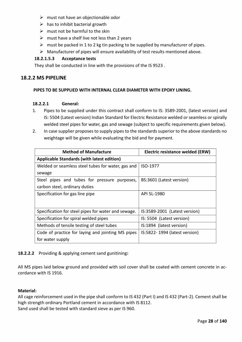
Page 28 of 140
must not have an objectionable odor
has to inhibit bacterial growth
must not be harmful to the skin
must have a shelf live not less than 2 years
must be packed in 1 to 2 kg tin packing to be supplied by manufacturer of pipes.
Manufacturer of pipes will ensure availability of test results mentioned above.
18.2.1.5.3 Acceptance tests
They shall be conducted in line with the provisions of the IS 9523 .
18.2.2 MS PIPELINE
PIPES TO BE SUPPLIED WITH INTERNAL CLEAR DIAMETER WITH EPOXY LINING.
18.2.2.1 General:
1. Pipes to be supplied under this contract shall conform to IS: 3589-2001, (latest version) and
IS: 5504 (Latest version) Indian Standard for Electric Resistance welded or seamless or spirally
welded steel pipes for water, gas and sewage (subject to specific requirements given below).
2. In case supplier proposes to supply pipes to the standards superior to the above standards no
weightage will be given while evaluating the bid and for payment.
Method of Manufacture Electric resistance welded (ERW)
Applicable Standards (with latest edition)
Welded or seamless steel tubes for water, gas and
sewage
ISO-1977
Steel pipes and tubes for pressure purposes,
carbon steel, ordinary duties
BS:3601 (Latest version)
Specification for gas line pipe API 5L-1980
Specification for steel pipes for water and sewage. IS:3589-2001 (Latest version)
Specification for spiral welded pipes IS: 5504 (Latest version)
Methods of tensile testing of steel tubes IS:1894 (latest version)
Code of practice for laying and jointing MS pipes
for water supply
IS:5822- 1994 (latest version)
18.2.2.2 Providing & applying cement sand gunitining:
All MS pipes laid below ground and provided with soil cover shall be coated with cement concrete in ac-cordance with IS 1916. Material: All cage reinforcement used in the pipe shall conform to IS 432 (Part I) and IS 432 (Part-2). Cement shall be high strength ordinary Portland cement in accordance with IS 8112. Sand used shall be tested with standard sieve as per IS 960.
Page 29 of 140
The aggregate used shall conform to IS 383. The maximum size of aggregate shall be one third of the thickness of concrete. Reinforcement :- The reinforcement of the coating of pipe sections may be spiral wire, wire fabric, or wire mesh (ribbon mesh). Reinforcement shall be free of oil, grease, and other contaminants that might reduce the adherence between the coating and reinforcement. Steel wire shall be of a minimum size of 3 mm. The wire shall conform to the requirements of IS:432 (Pt. 1) and IS 432 (Part-2). Reinforcement shall be 50 X 100 mm welded wire fabric. The wire shall conform to the requirements of IS:1566. Unless otherwise specified by the purchaser, wire fabric reinforcement may be either crimped or non-crimped. Cement mortar applied by mechanical placement or by the steam pneumatic process shall consist of not more than 3 parts sand to 1 part cement, by weight. The water in the mixture shall be carefully controlled so that the mortar will not run, sag, or segregate. The soluble chloride-ion content of the cement mortar mix shall not exceed 0.15 percent, expressed as a percentage of cement weight. Spiral wire :- Attachment of ends and splices in the wire shall be by welding or other suitable means ac-ceptable to the purchaser. Maximum spacing of the wire shall be 35 mm. The wires on 50 mm spacing on the 50 mm x 100 mm fabric shall extend circumferentially around the pipe. Wire mesh :- Attachment of ends and splices in the wire shall be by means approved by the purchaser. When 25 mm x 25 mm 8 mm the spiral lap shall be 35 mm and the applied lap 110 mm minimum. Thickness :-Cement mortar coating shall be uniform in thickness except in joints or other discontinuities in the pipe. Coating shall be 20 mm minimum thickness for all sizes of pipe up to unless otherwise specified by the purchaser. Application of Mortar Coating :- Mortar coating shall be applied by mechanical or pneumatic placement to the specified thickness in one or more continuous applications. Allowance shall be made for splices of reinforcing wire. If applied in more than one course, the interval between the first and last course shall be not more than 2 hours. The mortar shall be projected at high velocity against the exterior surfaces of the pipe or shall be applied by an equiv-alent method to produce a hard, tight adhering coating of the specified thickness. Defective Coating :-
i. Sand Pockets and Porous Spots :- If any sand pockets or porous spots occur, those shall be completely cut out and replaced by pneumatic placement or hand application of mortar in the proportion of 2 parts sand to 1 part cement, by weight.
ii. Coating Cracks :- Care shall be exercised to minimize the occurrence of cracks in the mortar coating. How-ever, hairline cracks need not be repaired. Repair procedures shall include the brushing or wiping of neat cement into the cracks, autogenous healing of the cracks by additional moist curing, the painting of the cracks with an epoxy coating, or a combination of these methods.
iii. Curing of Coating :-The mortar coating shall be cured by the moist or accelerated curing methods. A mem-brane material may be applied immediately following the coating application. The coating shall be kept continually moist by intermittent or continuous spraying for a period of at least four days. Moist curing may be used only if the minimum ambient temperature exceeds 50C continuously during the minimum required curing period.
iv. Accelerated Curing :- Accelerated curing of the pipe or special may begin immediately after completion of the coating operation or within 6 hours thereafter. The temperature of the pipe or special shall not exceed
Page 30 of 140
300C until the cement mortar coating has taken its initial set or until a period of 3 hours has elapsed, whichever occurs first. The relative humidity shall be not less than 85 percent at a temperature between 450C – 650C for at least 18 hours.
v. Membrane Curing :- Membrane curing shall consist of the complete encapsulation of the coating by ap-plication of material that will retain the moisture of the applied cement mortar coating. Applying Liquid epoxy lining to the interior surface of Rising Main Pipes as per Annex - B of IS 3589:2001, preferably by airless spray with one coat of Zinc rich epoxy primer (90% zink ,DFT 40 micron , coverage 9 Sqm / lit) and three coats of coal tar epoxy paint (DFT 120 X 3 micron coverage 5 Sqm/Lit/coat) including cleaning the surface to the satisfaction of Engineer in charge by sand blasting /chemical cleaning / scraping removing oil, grease, other foreign materials including all necessary material, labour with all leads and lifts etc. complete. (Qty. of sand 3cum/100sq.mtr.)
18.2.2.3 INSPECTION
Inspection of MS pipe
Inspection during manufacturing.
a) Identification of plate/strip material for manufacturing.
b) Qualification of welding process to be used for manufacturing of pipes.
c) Qualification of welders.
d) Dimensional check before start of welding to avoid rejection at a later stage.
e) Inspection of ready built pipes.
18.2.2.4 HYDRAULIC TESTING OF FABRICATED PIPES
The pipe length fabricated shall be as specified earlier above. The contractor shall provide all the required
machines and apparatus for testing all the pipes at the factory. The arrangements made by the contractor
for hydraulic testing of pipes shall be subject to the approval by the Engineer. The contractor shall paint
inside the serial number of pipe, the diameter and the plate thickness and letters NMC as well as the date
of the test etc. as directed by the Engineer. The pipes shall be inspected thoroughly before testing for any
apparent defect in welding and the contractor shall repair such defects by gousing and rewelding. Such
pipes will be laid only on approval of the Engineer-in-Charge. Necessary provisions for storage tank for
water for testing water pumping arrangements, if necessary and making available the required water shall
be made by the contractor. Hydraulic test shall be carried out under cover at the fabrication in the presence
of and to the satisfaction of the Engineer-in-Charge or his authorized representative.
Accurate pressure gauge of approved make shall be mounted on one end of the pipe to indicate the
pressure inside the pipe being tested. The Engineer at his discretion may accept untested pipes if the total
length of fabricated pipes of that particular dia. is less than 50 meters.
The pressure shall be applied gradually by approved means and shall be maintained at least for 10 minutes
or till inspection by EIL and Engineer-in-Charge during which time, the pipes be hammered throughout its
length with sharp blows with 1 kg. Hand hammer. The pipe shall stand the test without showing any sign
of weakness, leakage, oozing or sweating. If any leakage is observed, on approval of Engineer-in-Charge, it
shall be repaired by gousing and rewelding or as directed by him. No separate/additional payment shall be
made for dewatering, gousing, repairing and dewatering and the handling required to be done for such
pipes.
The M.S. pipes and specials to be provided by the contractor under this item includes 750 mm dia delivery piping with specials, dished ends and specials on 1500 mm dia common manifold in two rows , terminating
Page 31 of 140
25 mtr( Length is approx. and shall be carried put as per requirement) outside the raw pump house and connecting to main rising main. Installation outside the pump house shall be done without disturbing approach to the pump house.
Thickness of plates shall not be less than those stated below, nearest commercial thickness.
i) M.S. pipes and specials
a) 750 mm dia 12 mm
b) 1500 mm dia 12 mm thick
c) 2300 mm dia 12 mm thick
ii) Flanges of sizes 750 mm (I.D) & above 20 mm thick
iii) Dished end 1500 mm dia 25 mm thick
iv) Puddle flanges 25 mm thick
The pipes and specials shall be fabricated by welding conforming to IS: 3589, IS: 822 and IS: 823. The edge and surfaces shall be prepared for welding joint. The welded joint shall be designed to withstand test pressure of 25 Ks/Sq cm. The flanges shall be drilled as per IS: 1538.
18.3 Specifications for Laying and Jointing of Pumping Mains Pipe Lines
18.3.1 General
The contractor will inspect the route along which the pipe line is proposed to be laid. Efforts shall be made
by the contractor to keep the pipe alignment as straight as possible and to avoid damage of public and
private properties along the alignment. The alignment of pipe line and location of specials & chambers
may be changed at site in co-ordination and with prior approval of the Engineer- in- Charge. The final
alignment on which the pipeline shall be laid shall be marked in field and got approved from the Engineer-
in- Charge or his representative.
Wherever there is need for deviation, it should be done with the use of necessary specials or by deflection
in pipe joints (limited to 75% of permissible deflection as per relevant standards). The alignment as pro-
posed should be marked on ground with a line of white chalk and got approved from Engineer In-Charge.
The position of fittings, valves, shall be as per directions of engineer-in-charge.
Bench Marks are also required to be installed along the pipeline alignments. These shall be used for field
verification of grade to which the pipe is to be laid as per the approved L-section. The demarcation and
Bench Mark pillars installed by the department, if damaged or dislocated shall be reinstalled & repaired
without any cost.
18.3.2 Standards
Except otherwise specified in this technical specification, the Indian Standards and Codes of Practice in
their latest version, National Building code, PWD specification and Manual of water supply of GOI shall be
adhered to for the supply, handling, laying, installation, and site testing of all material and works.
18.3.3 Alignment and the L-Sections
Page 32 of 140
Pipes shall be laid along the alignment given by the department. The gradient in which the pipe alignment
is to be laid is based on the following principles:
On average, the change in slopes per km. length shall not be more than 10 in number.
The slopes provided shall be such that in existing ground level conditions, the maximum cover over the
laid pipe is neither more than 1.5 m nor less than 0.6 m. The average cover generally should not be less
than 0.9 meters.
18.3.4 Tools and equipment
The contractor has to provide required tools and equipment required for the timely, efficient and profes-
sional implementation of the work as specified in the time schedule given in the special conditions of the
contract. On demand he shall provide to the Engineer in Charge a detailed list of tools and equipment
available. If in the opinion of the Engineer in Charge the progress or the quality of the work cannot be
guaranteed by the available quantity and type of tools and equipment the contractor has to provide addi-
tional ones to the satisfaction of the Engineer in Charge.
The Contractor will always have a surveyor and leveling instrument on site. The contractor shall provide
ladder for inspection of works at the time of inspection for all the trenches of depth greater than 1.2 M.
18.4 Pipe Laying below Ground
18.4.1 General:
To protect persons from injury and to avoid damage to property, adequate barricades, construction
signs, torches, red lanterns and guards, as required and as specified above, shall be placed and
maintained during the progress of the work and until it is safe for traffic to use the roadways. All
materials and pipes which may serve as obstruction to traffic shall be enclosed by fences or barri-
cades and shall be protected by illuminating proper lights when the visibility is poor.
As far as possible, the pipe line shall be laid below existing services, like water pipes, cables, cable
ducts and drains but not below sewers, which are usually laid at greater depth. Where it is una-
voidable, pipe line should be suitably protected. A minimum clearance of 150 mm shall be provided
between the pipe line and such other services.
Trees, shrubbery fences, poles, and all other property and surface structures shall be protected.
Tree roots shall be cut within a distance of 50 cm from pipe joints in order to prevent roots from
entering them. Temporary support, adequate protection and maintenance of all underground and
surface structures, drains, sewers and other obstructions encountered in the progress of the work
shall be provided. The structures, which will be disturbed, shall be restored after completion of the
work.
Where water accumulates in any trench the Contractor shall maintain the trench free of water
during pipe laying.
During laying the pipe line, some time it may be necessary to cut the pipe as per the site condition
or to put in some special or valve or to have exact length of the section etc. The contractor at his
cost shall do this cutting . No claims for extra amount due to any particular type or individual length
Page 33 of 140
of cut pipes and specials being supplied or joints having been increased due to small lengths shall
be entertained.
The payment for this item shall be admissible on the basis of actually laid pipes at site including
length occupied by all types of specials and incidental small pipe pieces or other types.
No extra claims or compensation will be admitted for items of laying pipes etc.
If the lines are laid in separate detatched sections and not continuous length due to any of the
reasons such as non availability of specials or due to obstacles etc. then the contractor shall see
that no end of any pipe length is kept open even temporarily and that all open ends are immediately
covered up either by suitable blank flange or cap/plug or by means of a double layer gunny cloth
tied properly by means of mild steel wires and without any claim for extra cost or compensation.
The contractor shall take utmost precaution to see that no extraneous matters such as stones,
brick bats or animals such as rats, reptiles are allowed any access into the pipe line and in case of
their existence being detected in the pipe line, the contractor shall remove them by means of
rodding etc. to the complete satisfaction of the Engineer-in-Charge, without any claim for extra cost.
No extra cost will be allowed to fixing of specials and other accessories such as valves, washouts,
etc. unless provided for separately in the tender. Also no extra cost will be paid for cutting the pipes
and specials as and where required for negotiation of bend or fixing valve, branch tee or achieving
exact length of the line etc. The cutting operation shall be carried out preferably by means of
standard pipe cutter or hacksaw unless cutting by chisel and hammer is allowed by the Engineer-
in-charge. The end of pipe to be used for gasket joint shall be chamfered by means of file and made
perfectly true or like original chamfered.
The pipes will be cleaned in the whole length with special care of the spigot and sockets/other ends
on the inside/ outside to ensure that they are free from dirt and unwarranted projections.
Before the pipes and specials are lowered and laid in trenches, the contractor shall see that the
bedding is plane or the surface is brought to uniform grade and leveled and approved in advance
by the last 3 days by the Engineer-in-Charge or his representative.
The whole of the pipes shall be placed in position singly and shall be laid true to profile and direction
of slope indicated on longitudinal sections. The pipes shall be laid without deflection / or with per-
missible deflection as prescribed in the respective pipe material code between bends and/or be-
tween high and low points. The pipes shall rest continuously on the bottom of the trench. The pipes
should not rest on lumps of earth or on the joints.
The pipes, specials and valves shall be lowered by means of ropes, reckless or pulley as ordered
evenly and uniformly and shall be brought level with well consolidated hard murum or wooden
sleeper as ordered.
The pipes shall be laid in a complete straight line with center line ranged accurately by mean of
string stretched between marked centers and no deviation will be permissible without the permis-
sion of the Engineer-in-Charge.
18.4.2 Trench Excavation
The earthwork shall be carried out as specified above. The work of trench excavation should be
commensurate with laying and jointing of the pipeline. It should not be dug in advance for a length
Page 34 of 140
greater than 3 days ahead of work of laying and jointing of pipeline unless otherwise directed by
the Engineer-in-Charge. It is proposed to ensure the following:
1. Safety precautions have to be incorporated in the work process
2. Hindrances to the public have to be minimized
3. The trench shall not be allowed to erode
4. The trench must not be filled with water
5. The trench must not be refilled before laying of the pipes
6. The bed for the laying of the pipes has to be prepared according to the L-Section imme-
diately before laying of the pipes.
The trench excavation of pipe line shall be in accordance with relevant IS and /or as per the general
provisions given above. Pipe trenches shall be excavated to the lines and levels approved by the
Engineer in Charge. The width of the trench shall be as per BIS codes and CPHEEO manual. No
pipe shall be laid in a trench until the section of trench in which the pipe is to be laid has been
approved by the Engineer in Charge. The walls of the trench shall be cut to stable side slopes pref-
erably to a slope of ¼ : 1 or ½ : 1 depending on the nature of soil.
The bottom of the trench shall be trimmed and leveled to permit even bedding of the pipes. It
should be free from all extraneous matter which may damage the pipe or the pipe coating. Addi-
tional excavation shall be made at the joints of the pipes, so that the pipe is supported along its
entire length. All excavated material shall be stacked in such a distance from the trench edge that
it will not endanger the work or workmen and it will avoid obstructing footpaths, roads and drive
ways. Hydrants under pressure, surface boxes, fire or other utility controls shall be left unob-
structed and accessible during the construction work. Gutters shall be kept clear or other satisfac-
tory provisions made for street drainage, and natural water-courses shall not be obstructed.
Wherever necessary to prevent caving, trench excavations in soils such as sand, gravel and sandy
soil shall be adequately sheeted and braced. Where sheeting and bracing are used, the net trench
width after sheeting shall not be less than that specified above. The sides of the excavation shall
be adequately supported at all times and, except where described as permitted under the Contract,
shall be not battered.
The Engineer in Charge in co-operation with the Contractor shall decide about the sheeting/ bracing
of the trench according to the soil conditions in a particular stretch and taking into account the
safety requirements of the Contractor’s and Engineer- In- Charge’s staff. Generally, safety measures
against caving have to be provided for trenches with vertical walls if they are deeper than 2.0 m in
sandy or loose formations.
18.4.3 Bedding of the pipes
The trench bottom shall be even compact and smooth so as to provide a proper support for the
pipe over its entire length, and shall be free from stones, lumps, roots and other hard objects that
may injure the pipe or coating. Holes shall be dug in the trench bottom to accommodate sockets
so as to ensure continuous contact between the trench and the entire pipe barrel between socket
holes.
Page 35 of 140
Adequate soil/ murram cushion of minimum 15 cm depth shall be provided under the DI and MS
pipes, if the strata on which the pipes are laid, are rocky. In case of HDPE pipes, adequate soil/
murram cushion of minimum 15 cm depth shall be provided below, in haunches and minimum
15 cm above the pipes, if the strata on which the pipes are laid, are rocky.
The soil/ murram used for cushion should be free from stones, lumps and other hard objects that
may injure the pipes or their coating.
The murum bedding shall be of the full width of the trench. Murum bedding will be necessary in
rock formation, boulder formation but not in murum formation itself.
No brickbats or hard stone metal bigger than 20 mm gauge shall be allowed beneath the pipe line
directly in touch with the pipe.
18.4.4 Laying of pipes below ground
General:
Before pipes are jointed they shall be thoroughly cleaned of all earth lumps, stones, or any other
objects that may have entered the interior of the pipes, particularly the spigot end and the socket
including the groove for the rubber ring.
Pipes and the related specials shall be laid according to the instructions of the manufacturers and
using the tools recommended by them.
Cutting of pipes shall be reduced to a minimum required to conform with the drawings. Cutting has
to be made with suitable tools and according to the recommendations of the manufacturer. The
spigot end has to be chamfered again at the same angle as the original chamfered end. Cutting shall
be perpendicular to the centre line of the pipe. In case of ductile iron pipes the cut and chamfered
end shall be painted with two coats of epoxy paint. If there is no mark for the insertion depth on
the spigot end of the (cut) pipe it shall be marked again according to the instructions of the manu-
facturer.
Where the gradient of the bed slopes is more than 15 degrees, it may be necessary to anchor pipes
against their sliding downwards, by providing suitable gradient blocks and straps. Suitable cut off
walls shall also be provided in these sections to protect the trench soil to be washed out during
rains.
All specials like bends, tees etc. and appurtenances like sluice or butterfly valves etc. shall be laid
in synchronization with the pipes. The Contractor has to ensure that the specials and accessories
are ready in time to be installed together with the pipes. At the end of each working day and when-
ever work is interrupted for any period of time, the free ends of laid pipes shall be protected against
the entry of dirt or other foreign matter by means of approved plugs or end caps. End caps are
removed only just before laying and jointing
When pipe laying is not in progress, the open ends of installed pipe shall be closed by approved
means to prevent entrance of trench water and dirt into the line.
The pipe line laid should be absolutely straight unless planned otherwise. The accuracy of align-
ment should be tested before starting jointing and refilling with the help of stretching a string be-
tween two ends of the straight stretch of pipes to rectify possible small kinks in laying.
Page 36 of 140
The pipes shall be laid out properly along the proposed alignment in a manner that they do not
create any significant hindrance to the public and that they are not damaged.
Stringing of the pipes end to end along the working width should be done in such a manner that
the least interference is caused in the land crossed. Gaps should be left at intervals to permit the
passing of equipment across the working area. Pipes shall be laid out that they remain safe where
placed and that no damage can occur to the pipes and the coating until incorporated in the pipeline.
If necessary, pipes shall be wedged to prevent accidental movement. Precautions shall be made to
prevent soil, mud etc. entering the pipe.
Generally, the pipes shall be laid within two weeks from the date of their dispatch from the manu-
facturer.
The joint gaskets shall be kept in wooden boxes or their original packing and stored in cool condi-
tions and not exposed to direct sunlight. Gaskets must not be deformed. They shall be taken out
only shortly before they are needed.
18.4.5 JOINTING OF PIPES
All construction debris should be cleared from the inside of the pipe either before or just after a
joint is made. This is done by passing a pull-through in the pipe, or by hand, depending on the size
of the pipe. All persons should vacate any section of trench into which the pipe is being lowered.
All the jointing work shall be carried out by the contractor after giving written intimation in advance
at least for 4 days before jointing operation starts and laid pipes are approved for grade and cleaned
of all inside waste material such as mud etc. and in presence of Engineer-in-Charge or his
representative. Unless otherwise mentioned in the wording of the item in BOQ of the tender all
labour and materials required for jointing (depending upon the type of joint mentioned in item)
such as grease, oil, SBR quality rubber rings and gaskets, cement, sand, water, fire wood, nut-bolts,
washers, rubber packing, RCC collars, etc. shall be arranged and used by the contractor at his cost.
All the materials to be used for jointing should be first got approved from the Engineer-in-Charge
or his representative.
a) Jointing of D.I. pipes:
The two pipes shall be aligned properly in the pipe trench and the spigot end shall be pushed axially
into the socket either manually or with a suitable tool specially designed for the assembly of pipes
and as recommended by the manufacturer. The spigot has to be inserted up to the insertion mark
on the pipe spigot. After insertion, the correct position of the socket has to be tested with a feeler
blade.
Insertion of gaskets shall be done by proper application of a thin film of lubricant (Vegetable oil
only) to the butt seating inside the socket. The gasket shall be wiped clean, fixed and then the socket
with the bulb towards the back of the socket. The groove in the socket must be located on the
retaining board in the socket and retaining hole of the gasket firmly bedded in the seating.
Contractor shall ensure to the satisfaction of the Engineer-in-Charge that the gasket fits evenly
around the full circumference removing any bulges which would prevent the proper entry of the
spigot and for large diameter this operation should be assisted by forming a second loop in the
gasket opposite to the first and then pressing the loops flat one after the other.
The thin film of lubricant (Vegetable oil only) shall be applied to the inside surface of gasket which
Page 37 of 140
will be in contact with the entering spigot. A thin film of lubricant shall also be applied to the
outside surface of the entering spigot for a distance of 25 mm from spigot end. The pipeline to be
jointed should be supported centrally by the tackle used for laying and balance just clear of the
trench bottom. The spigot of the pipe must be aligned and entered carefully into the adjacent socket
until it makes contact with the gasket. Final assembly of the joint is completed from this position.
The spigot end of the entering pipe shall be compressed until it reaches the bottom of the socket.
If the assembly is not completed with reasonable force, the spigot end shall be removed and the
position of the gasket examined and then the assembly is refitted properly to the satisfaction of the
Sub-Divisional Officer. The work shall generally be carried out as per instructions given in
manufacturer's pamplets. All the tools and tackles required for jointing, such as rack and layer 3
mm dia, 5 m long wire rope with thimble, hook and rope adjuster should be procured by the
contractor at his own cost.
The item includes all other necessary materials including rings etc. and labour.
On gradients of 1:15 or steeper, precautions should be taken to ensure that the spigot of the pipe
being laid does not move into or out of the socket of the laid pipe during the jointing operations.
As soon as the joint assembly has been completed, the pipe should be held firmly while the trench
is back filled over the barrel of the pipe. Suitable transverse anchors shall be provided in sloping
reaches as defined herein after.
Where a pipeline crosses a watercourse, the design and method of construction should take into
account the characteristics of the watercourse to ascertain the nature of bed, scour levels, maxi-
mum velocities, high flood levels, seasonal variation, etc. which affect the design and laying of pipe-
line. The pipe shall be laid accordingly with adequate protection. The pipes in such cases shall be
laid below ground with anchor blocks of suitable size and design.
18.4.6 LAYING & JOINTING OF MS PIPELINE BELOW GROUND LEVEL:
18.4.6.1 GENERAL
Pipe laying shall be done as directed by Engineer, to the correct line and level. The Engineer, at his
discretion, may change the alignment and/or levels depending on the site conditions. The minimum
cover under roadway etc. where traffic is expected to over the pipeline shall be 120 cm as specified
in IS: 5822 (latest version). The minimum cover for pipeline along the major district road and State
Highway shall generally be 1.0 m, where traffic is not expected over the pipeline. Pipes and specials
to be laid underground shall be provided either with cement mortar gunitting, Coal tar wrapping or
cement concrete encasing as specified separately as per requirement. Care shall be taken to see
that while handling these pipes, the pipe and gunited portion is not damaged. The rate includes all
expenses on account of labour, machinery, material etc. required for complete process of lying. No
extra rate for any reason for this job will be admissible even if the process of lowering and laying of
these pipes requires additional labour, machinery, materials etc. from safety point of view.
18.4.6.2 LAYING PROCEDURE
The contractor shall lower the pipes of standard lengths. Short length pipes shall be lowered only if
found necessary and only after obtaining the permission of Engineer-in- Charge. The pipes shall be
lowered in the trench on prepared bedding as per the decision of Engineer-in-Charge. Pipes shall
not be laid on the open rock bottom as it may damage the pipe shell on account of point loads.
The alignment and levels shall be checked by the theodolite. Cutting of pipes shall not be allowed
for matching the sides of trenches excavated. While assembling the pipes , the ends shall be
Page 38 of 140
brought close enough to leave a uniform gap not exceeding 3 mm. Marginal cutting and grinding
shall be done if found necessary, for which no extra payment shall be made. There shall be no lateral
displacement between pipe faces to be jointed.
When the pipe is properly assembled and checked by Engineer-in-Charge for correct line and level,
it shall be firmly supported on wooden beams and wedges and then tack welded.
In the trenches where shoring is provided, care shall be taken to see that during lowering of pipes,
only required struts are removed at a time with additional precautions to keep the shoring in
position if necessary.
18.4.6.3 SPECIAL PRECAUTIONS FOR MAINTAINING CIRCULAR SHAPE OF PIPE
Special attention of the tenderer is drawn to the fact that the proposed pipeline is to be provided
with cement mortar lining. It is therefore very necessary that the circular shape of the pipes be
maintained till these pipes are mortar lined. The contractor shall provide adjustable steel struts of
the approved design for this purpose. Minimum three sets of struts shall be provided per pipe
length of 6 meter. These shall be retained till complete refilling is done and properly consolidated
or till concrete encasing is set. Any diametric variation beyond + 2% shall have to be rectified by the
contractor at his cost, which may include, removing the section of the pipeline and relaying it along
with all other ancillary operations. Providing required number of adjustable struts and all other
operations involved as above shall be deemed to have been included in the item of laying and no
separate payment on this account will be admissible.
18.4.6.4 MODE OF MEASUREMENT
The measurement for the payment of MS pipe shall be taken on running meter basis and paid on
running meter basis at the rate specified in BOQ.
18.4.6.5 JOINTING OF MS PIPE BY WELDING JOINTS
a) GENERAL:
Before aligning, assembling and welding, the pipe faces shall be cleared by scraping with wire
brushes or by any other method approved by the Engineer. Welding of pipes in field shall conform
to ISS:816-1969 (code of practice for use of metal arc welding for general construction in Mild
Steel). In case of variance, specifications hereunder shall have precedence.
Welder shall be qualified, experienced and approved by the Engineer-in-Charge to do the welding
at the locations. Welding shall not be allowed to be done by helpers. Contractor shall remove such
of the welders form the job whose work is not found to be satisfactory. The Engineer may ask
them to do test welding before approving their employment on the job.
The contractor shall keep record of the welding for each circumferential joint. It shall contain the
name of the Welder, Operator and Date of Completion of such run of internal and external
welding.
b) GOUSING AND CHIPPING:
MS Pipes of diameter larger than 1016 mm shall be welded with two number of runs from inside
and a sealing run from outside. External sealing run shall be done only after internal welding is
Page 39 of 140
completed. Before starting the external welding, the weld material in the joint shall be cleaned by
chipping out loose scales. Gousing shall be done before rectification of any defective welding
wherever necessary and as directed by the Engineer. Gousing or chipping shall not be paid for
separately and the rate for welding shall be deemed to include the cost of gousing & chipping.
c) ELECTRODES:
Welding electrodes to be used for welding in this contract shall conform to the Indian Standard
Specifications IS:814-2004 (Specification for covered electrodes for manual metal arc welding of
Mild Steel)
The contractor shall use standard electrodes depending on the thickness of the plates to be
welded and the type of joint. The contractor shall also use standard current and A.C. voltage
required for the machine as per manufacturer’s directions.
d) TYPES OF WELDED JOINTS:
The circumferential joints of the pipes shall be butt welded with required number of runs
externally and internally.
All fillet welds shall have a throat thickness not less than 0.7 times the thickness of the pipe to be
welded.
e) WELDING PROCEDURE:
All parts of pipes, specials, etc. having all loose scale, slag, rust, paint and any other foreign
material shall be removed with wire brush and left clean and dry. All scale and slag shall be
removed from each run of weld when that run is completed.
Openings in the form of manholes shall be made in the laid pipeline at suitable distance of access
for the work of cleaning, repairs etc. Such manholes, as far as possible shall be provided on sides
of the pipe line and cutting manholes at the crown shall be strictly avoided.
Patch Plates for plugging the above manholes shall be cut from a separate pipe of the same
diameter. Edges of the patch plate shall be properly shaped and shall be inserted in the opening
leaving a gap of 3 to 4 mm and tacked. Welding of patch plate shall be done in segments in a
proper sequence conforming to Indian Standard Specifications IS : 823
f) TESTING OF WELDED JOINTS :
Welded joints shall be tested in accordance with procedure laid down in Indian Standard
Specifications (IS : 3600, Part I –1985 of procedure for Testing Fusion welded joints and weld
metals in steel )
At least one test specimen shall be taken out for testing for every fifty field joints done. Test pieces
shall be taken out from the places pointed out by the Engineer. These shall be machined and tested
as early as possible. The shape of the test pieces removed for testing shall be such that it shall give
the specimen of the required dimensions with the weld in the middle of the specimen and at the
same time leave the holes in the pipe with rounded corner. This hole shall be patched with a plate
of suitable size cut from a separate pipe of same diameter. It must ensure good butt weld.
g) TENSILE TEST:
The test specimen taken perpendicularly across the weld shall be shaped in accordance with
Page 40 of 140
Indian Standard Specifications IS:223. The tension test specimen shall be machined. The
protruding welded portion from inside as well as outside shall be removed by machining before
the specimen is tested.
If the specimen shows defective machining or develops flaws not associated with welding, It shall
be discarded and another specimen substituted. The welded joint shall show a strength not less
than the minimum tensile strength for the plate in accordance with ISS:226
h) BEND TEST:
Bend Test specimen shall also be prepared in the same fashion as the tensile test specimen. The
specimen shall stand being bent cold 180o around a pin that has a diameter equal to 4.5 times the
plate thickness, without developing cracks. For this test, face representing inside of the pipe shall
be placed next to the pin.
i) TRE-PANNED PLUG :
Tre-Panned plugs shall be taken out from any welded portion as pointed out by the Engineer.
These plugs shall not show any defect in welding such as inclusion of slag, blow holes cavities,
etc. The plug shall be 12 mm in dia and shall be taken out by means of suitable electrically
operated holes. Such holes in the pipe shall either be filled back by inserting a steel stud
and welding around or threading the hole and providing suitable G.I. plug. This test shall
be done only if considered necessary by the Engineer.
j) PROCEDURE IN CASE OF FAILURE OF TEST SPECIMEN
If the test fails in either tensile or bend test or in both, two additional test specimens shall be taken
out from the section and shall be tested for tensile and bend tests. If any one of them fails,
extensive gousing and rewelding shall be done for the welded joints in that section to the full
satisfaction of the Engineer. However, if both the samples give satisfactory results, the joint form
which the original sample was taken and had failed shall be repaired to the satisfaction of the
Engineer by gousing and welding etc. at contractor’s cost. Welder who has done the welding of
the joint that has failed shall be solely held responsible for bad workmanship and failure. Since all
other factors like electrodes, current, arc voltage etc. are already controlled, negligence on the
part of the welder only is responsible for such failure. For such first failure, the welder shall be
warned and if the welded joint done by him fails for the second time, he shall be removed from
the job.
k) MEASUREMENT AND PAYMENT
Welding shall be paid in linear meter of welding done including the required number of runs. The
welding shall be paid for in the relevant item of welding butt joint or lap joint in respective items
in the Bill of Quantities and Rates. The rate shall include providing all labour, material and welding
machinery including all ancillary preparations and testing, repairing retesting, gousing etc.
complete in all positions and circumstances prevailing in site. No extra payment on any account
whatsoever may be admissible to contractor 10% of the amount under this item will be withheld
till the satisfactory hydraulic testing is given.
18.5 ANCHORING OF THE DI/MS PIPE LINES:
Page 41 of 140
Thrust blocks shall be provided at each bend, tee, taper, end piece to prevent undue movements of
the pipeline under pressure. They shall be constructed as per actual design and approval of Engineer
in Charge according to the highest pressure during operation or testing of the pipes, the safe bearing
pressure of the surrounding soil and the friction coefficient of the soil. Nominal steel shall be pro-
vided as per the provisions of CPHEEO manual and the construction of block shall be done in mini-
mum M20 grade of concrete.
18.6 HYDRAULIC TESTING OF DI/MS PIPELINE :
18.6.1 General:
After laying and jointing, the pipeline shall be tested for tightness of barrels and joints, and stability
of thrust blocks in sections approved by the Engineer in Charge. The length of the sections depends
on the topographical conditions. Preferably the pipeline stretches to be tested shall be between
two chambers (air valve, scour valve, bifurcation, and other chamber).
The contractor shall make all the arrangements for water required for testing, labour, pumps,
pressure gauge equipment etc. The contractor shall arrange for labour required for operating air
valves, scour valves etc. Any labour of department employed for the above activities of the test
other than supervision shall be charged to the contractor as per rules.
The Contractor shall fill the pipe and compensate the leakage during testing. The Contractor shall
provide and maintain all requisite facilities, instruments, etc. for the field testing of the pipelines.
The testing of the pipelines generally consists in three phases: preparation, pre-test/saturation and
test, immediately following the pre-test. Generally, the following steps are required which shall be
monitored and recorded in a test protocol if required:
1. Complete setting of the thrust blocks.
2. Partial backfilling and compaction to hold the pipes in position while leaving the joints ex-
posed for leakage control
3. Opening of all intermediate valves (if any)
4. Fixing the end pieces for tests and after temporarily anchoring them against the soil (not
against the preceding pipe stretch)
5. At the lower end with a precision pressure gauge and the connection to the pump for
establishing the test pressure
6. At the higher end with a valve for air outlet
7. If the pressure gauge cannot be installed at the lowest point of the pipeline, an allowance
in the test pressure to be read at the position of the gauge has to be made accordingly
8. Slowly filling the pipe from the lowest point(s).
9. The water for this purpose shall be reasonably clear and free of solids and suspended
matter
10. Complete removal of air through air valves along the line.
11. Closing all air valves and scour valves.
Page 42 of 140
12. Slowly raising the pressure to the test pressure while inspecting the thrust blocks and the
temporary anchoring.
13. Keeping the pipeline under pressure for the duration of the pre- test / saturation of the
lining by adding make-up water to main tain the pres sure at the desired test level.
Make up water to be arranged by Contractor himself at his own cost.
14. Start the test by maintaining the test pressure at the desired level by adding more make-
up water; record the water added and the pressure in intervals of 15 minutes at the
beginning and 30 minutes at the end of the test period.
15. Water used for testing should not be carelessly disposed off on land which would ultimately
find its way to trenches.
16. The field hydraulic testing pressures for pipelines & duration of test shall be as per relevant
codes.
18.6.2 HYDRAULIC TESTING OF DI PIPE LINE
The pipeline and valves should be tested hydraulically upto the required pressure as per IS
satisfactorily and all the leakages if any should be repaired at the time of hydraulic testing.
No section of the pipe work shall be accepted by the Engineer in Charge until all requirements of
the test have been obtained.
18.6.3 HYDRAULIC TESTING OF MS PIPE LINE
For MS pipes after erection at site and after the concrete anchor/ thrust blocks have been
constructed, the entire pipeline shall be subjected to a hydraulic test as follows, to the required
test pressure as per Clause 11 of IS: 5822.
When the field test pressure is less than 2/3 the works test pressures the period of test should be
at least 24 hours. The test pressure shall be gradually raised at a rate of 0.1 N/mm2 per minute.
If a drop in pressure occurs, the quantity of water added in order to reestablish the test pressure
should be carefully measured. This should not exceed 0.1 liter/ mm of pipe diameter per km of
pipeline per day for each 30 m head of pressure applied.
On completion of a satisfactory test any temporary anchor blocks shall be broken out and stop
ends removed. Backfilling of the pipeline trench shall be completed.
The working pressure shall be not less than designed value. Under this pressure, no leak or
sweating shall be visible at the welded joints. During the test, the pipe shall be struck sharp blows
with 1.5 kg hammer. Water shall not spout, ooze or sweat through any part. In case of any leak
observed anywhere in the field joints whether welded or bolted, the same shall be repaired
entirely at the contractor's cost which shall include repairs to welding and regunitting etc. The
repaired joint shall be subjected to retest. No section shall be accepted unless it is perfectly water
tight.
The entire cost of testing, retesting including cost of water taken together shall be paid under
relevant item or Bill of Quantities. The contractor shall make all the arrangements for all labour,
pumps, pressure gauge equipment etc. The gauges should be got tested if insisted by the Engineer-
Page 43 of 140
in-Charge. The contractor shall arrange for labour required for operating air valves, scour valves
etc. Any labour of department employed for the above activities of the test other than supervision
shall be charged to the contractor as per rules.
The hydraulic testing of the leading main will be carried out for entire length or part of it as
directed by Engineer-in-Charge. If any leakages are observed even during defects liability period
due to defective workmanship, the same shall be rectified immediately.
The charges of repairs if done departmentally will be recovered from the amount of retention
money. Repairs on live water mains are to be carried out immediately to avoid wastage of water
and other problems such as disruption of water supply and traffic etc. In view of this, it will be
very difficult to give prior intimation to concerned contractor. As such the cost of repairs, being
the expenditure, will be recovered from the contractor's retention money withheld in deposit
without giving any prior intimation. The contractor will not challenge or claim any extra for such
action on the part of the Department. Generally the contractor shall be required to test the pipe
line sections of 1 km using necessary equipment. However, if the Engineer-in-Charge directs, to
test full pipeline lengths in further suitable sections in the interest of the work, the tenderers will
have to carry out the test in such sections as directed by Engineer-in-Charge.
18.7 Failure to pass the test
All pipes or joints which are proved to be in any way defective shall be replaced or remade and re-
tested as often as may be necessary until a satisfactory test shall have been obtained. Any work
which fails or is proved by test to be unsatisfactory in any way shall be redone by the Contractor.
18.8 Pre-Commissioning & Commissioning Tests
After successful sectional testing & leakage test, Pre-Commissioning & commissioning tests shall
be performed when the work in the section is completed in all respect and the gaps / interconnec-
tions are made. These tests shall be performed as per the procedure and provisions given in
relavent IS codes.
15% payment of total subwork of pipe line work shall be withheld till hydraulic test is done & the
same shall be released only on giving satisfactory test.
18.9 PROVIDING AND SUPPLYING DI/CI SPECIALS
The items include providing ,supplying DI/CI S&S and Double flanged specials suitable for diameter
as required and including all material, labour charges with epoxy paint from inside and outside
including all taxes (Central & local) , inspection charges, transportation to stores/ sites & stacking
etc complete. The mode of measurement of payment shall be on weight ( Kg) basis.
Scope: The item cover supply of DI/CI double socket and flanged specials of various diameters
including conveyance of specials form manufacture's works to site stores, stacking them properly
and protecting till commissioning of work.
General: The specials shall confirm to relevant I.S code i.e. IS: 9523-2000 for DI fittings and IS:1538-
1994 with latest amendments for CI fittings with respect to material, coating, tests, tolerances etc.
Page 44 of 140
18.10 DISMANTLING JOINTS
The item includes Providing and fixing of Dismantling joints
All butterfly, sluice valves, Surge Anticipating Relief Valve, Ultra sonic Flow Metres, Bulk water meters or any other online valves etc. shall be installed between flanges with a flexible dismantling joint at one side. The joint must allow dismantling of the valve, meters etc. without causing stress to the joints of the attached pipes. The minimum clearance of the dismantling joint shall be five (5) cm. The pressure class of the dismantling joint shall be the same as that of the pipe. Drawings of the dismantling joint shall be submitted to the Engineer-in-Charge for approval. The Nuts and Bolts of the joint shall be galvanized. The joints shall be painted/coated as per specification given for exposed pipes.
Item to Include :
The item includes the supply of DI dismantling joint including all taxes, levies, transporting, loading,
unloading and stacking at work site. The necessary test certificate also shall be provided along with
the supply.
MODE OF MEASUREMENT
Diameter wise on No. basis.
18.11 DI/C.I. MECHANICAL JOINTS
Supply of DI/C.I. Mechanical Compression collar coupling (popularly known as Jiffy Collar Coupling)
suitable for D.I. pipes (as per IS:8329:2000) complete with sealing rubber gasket of SBR and MS Nut
bolts. The whole assembly should be mechanically and hydraulically tested to the provisions as laid
down in IS: 9523-2000 for DI collar coupling & IS: 1538-1993 for CI collar coupling and as directed
by Engineer-in-Charge.
Item to Include :
The item includes the supply of Mechanical joints including all taxes, levies, transporting, loading,
unloading and stacking at work site. The necessary test certificate also shall be provided along with
the supply.
MODE OF MEASUREMENT AND PAYMENT:
The item shall be measured as numbers of collar couplings for the specified diameter of pipe. The
measurement and payment shall be as per No.
18.12 PROVIDING AND SUPPLYING MS SPECIALS
GENERAL
All specials like distance pieces, straps, tapers, saddles, branches, tees etc. shall be generally
fabricated in the factory. Only small kinks or bends or saddles may be fabricated on site, care being
taken to see that the length of the fabricated fitting is at least equal to the diameter of the pipe to
which it is being fixed. Such fabrication of specials on site shall be done only on approval of the
Engineer and as his direction. As specified earlier, only kinks or bends shall be fabricated on site
by cutting the pipe faces and then welding shall be carried out as specified hereinafter and shall
be paid separately.
All specials shall necessarily be in steel and shall be laid in the same manner as specified in pipes
Page 45 of 140
section.
STRAPS
Whenever the pipe laying work proceeds from two ends and if gap between two faces is less than
30 cms., this gap shall be bridged by providing a strap. Strap shall also be provided during fixing of
expansion joints as has been specified earlier. Such strap shall be fabricated on site by cutting a
piece from the pipe. This piece shall be split longitudinal and stepped over the gap. A minimum
gap of 8 cm shall be kept on both the pipes to be connected and strap shall be welded with
required number of fillet welds from inside and outside. The gap between the ends of straps shall
be longitudinally butt welded.
DISTANCE PIECES
Distance piece shall be provided when the gap between the pipe faces to be jointed is more than
30 cms measured in the evening. Distance pieces shall be cut from the pipe pieces on site or can
be cut in factory. These will be measured and paid for laying as specials
TAPERS AND BENDS ETC.
These shall be fabricated in the factory and shall be welded on site as per requirements. Laying of
tapers shall be paid for laying as specials for the diameter in the larger size. Bends shall be
measured along the mean length and paid for in the respective items of Bill of Quantities.
MODE OF MEASUREMENT
The MS specials including all described above will be paid on weight basis in Kg. on supply, while
lowering, laying of specials will be paid as mentioned in BOQ. However, 10% of the amount of
lowering, laying will be withheld till satisfactory hydraulic testing of pipe line.
18.13 PROVIDING & FIXING SLUICE VALVES & BUTTERFLY VALVES, SURGE ANTICIPATING RELIEF
VALVE, AIR VALVES:
Butterfly Valve Details:- Body : Is2062 Gr.B. M.S. Disc : Is2062 Gr.B. M.S. Seat : Ss-304 Seal : EPDM Shaft : Aisi 410 Temperature : Up To 80°C End Connection : Double Flanged Valve Rating : Pn 10 Leakage : Class Vi End Connection : As Per Awwa C-207 Class “B” & “D” Flow : Uni Directional Electrical Actuator Details: Characteristic : On-Off Type With Integral Starter Power Supply : 415v Ac (±10%), 50hz (±5%) Housing & Cover : Aluminium Anodized Enclosure : Water Tight Ip 67 Ambient Temp : -10°C ~ 55°C Torque Switches : 2 X Spdt Limit Switches : 2 X Spdt
Page 46 of 140
Stall Protection : Current Trip Protection In Starter Unit Indicator : Continuous Position Indicator Manual Override : Hand Wheel Integral Starter Unit Details: Selector Switch : Open / Stop / Close. Selector Switch : Auto / Manual Or Local/Remote. Indicating Lamps : Open / Close / Error. Enclosure : Ip 67.
RPS-L&H -SURGE ANTICIPATING VALVE
Double flanged, Ductile Iron, Diaphragm controlled, Pilot operated, Surge Anticipating Relief Valve (RPS-
L & H), To be installed at the branch (Tee off) on the Rising main downstream side, open to atmosphere.
The Valve shall be with NC Solenoid and Surge anticipating panel with adjustable timer for valve closing
post surge relief. The valve shall be straight type and not Y type. Direct sealing diaphragm type valves
will not be accepted.
Body, Cover, Stem Cap : Ductile Iron ASTM A536 65/45/12
Stem, Seat Ring, Spring : AISI: 316 SS
Diaphragm, Seals, O Rings : EPDM/Buna N.
Stem Nut : Brass B16
External fasteners : SS: 304
Pilots : Precise, Repeatable Low maintenance.
Painting : NSF 61, Fusion Bonded Epoxy Coating safe for Drinking water.
Flange Drilling Std. : PN 16.
Tamper Proof, Ductile Iron, Single Chamber, Anti Shock, Surge Arrestor, Vacuum Breaker & Quartet
Function High Performance Air Valve
Standard Specifications
Size Range 50 mm to 600 mm – F/E
Design Feature
Single chamber 50 mm to 300 mm. Multi – port T type from 200
mm to 600mm. QUARTET Function. Positive and negative surge
Reliever.
Pressure Rating PN16
Flanged end IS :1538 OR Optional
Body materials D.I. to GGG – 50 / SGI – IS: 1865 / MS Fab. Epoxy Coated.
Page 47 of 140
Float, Sealing Arc,
Spring, Set Screw,
Exhaust Arc
Stainless steel AISI 304.
Orifice Seal EPDM
Fasteners Stainless steel / nickel plated ( optional Silicon infusion )
Special Features
• Quick Opening, full Port anti Vacuum (Vacuum Breaker )
Dampening (Energy Dissipation) of subsequent positive
Pressure waves by slow closing orifice. Anti Shock and
Cushioning.
• Releases entrained air to eliminate air pockets at system
high points.
• Tamper proof air vents.
• Adjustable Orifice setting for expelling air at a Controlled
Pressure and rate.
• Interchangeable Internals.
• Epoxy powder coated / painted inside & outside for protec-
tion from corrosion. Minimum 250 microns.
• In-Line easy maintenance.
Inspection and Tests
The following Inspection and Testing procedures shall be carried out for all the equipment as
applicable:
(a) Visual Inspection.
(b) Material Certificates for all the specified material shall be furnished.
(c) Welding Qualifications.
(d) Dimension Checking.
(e) Stage Inspections (in process inspection).
(f) Hydrostatic / Leak testing for all pressure parts, Pneumatic Leak Test wherever applicable.
(g) Operation check.
(h) Liquid penetrating tests or magnetic particle tests for all machined surfaces of pressure parts.
(i) Ultrasonic test for forging materials viz.,
(j) Plates of thickness 20mm and above for pressed / formed parts such as heads, etc.
(k) Plates, flanges and bars of thickness / diameter 40mm and above used for fabrication of pressure and load bearing members and rotating parts.
(l) Radiographic testing for all but welded parts, as per applicable codes.
(m) Hardness tests for all Hardened surfaces.
Requirement of shop tests for Valves are listed below:
(a) During testing there shall be no visible evidence of structural damage to any of the valve com-ponents.
Page 48 of 140
(b) Each valve operated actuator shall be shop-operated at least three times from the fully closed to the fully opened position, and the reverse, under no-flow condition, to demonstrate that com-plete assembly is workable.
The tests mentioned below shall be hold points and to be witnessed by a duty authorized
representative of the Employer:
The following tests shall be carried out for butterfly valves in line with IS 13095:
(a) Seat leakage test. Seat test shall be carried out in each direction and the valve shall be drop tight.
(b) Body hydrostatic test
(c) Disc strength test at body test pressure in each direction.
(d) Valve operation with and without actuator
The following tests shall be carried out for sluice valves in line with IS 14846:
(a) Seat leakage test
(b) Body hydrostatic test
(c) Valve operation
The material certificates, physical properties, heat treatments and shop test certificates of valve body, disc,
wedge and shaft shall be duly approved and certified by the manufacturer and these shall be subject to
review & approval by the Engineer.
Notwithstanding the above requirement for inspection and quality control, the following inspection and
quality control measures shall be carried out by manufacturer:
(a) Magnetic particle tests on body and disc/door.
(b) Dye penetration tests on metal seats.
(c) Ultrasonic tests on shafts.
(d) Overload Torque Test shall be carried out on the gear boxes of the valves. The test shall be carried out by applying 1.5 times the rated torque.
Painting
The Contractor shall be responsible for the cleaning, preparation for painting, and priming or otherwise
protecting of all parts at the place of manufacture prior to packing. Parts may be cleaned but surface
defects may not be filled in before testing at the manufacturer's works. Parts subject to hydraulic test
shall be tested before any surface treatment. After test, all surfaces shall be thoroughly cleaned and
dried out if necessary by washing with an approved de-watering fluid prior to surface treatment. Except
where the Specification provides to the contrary all painting materials shall be applied in strict
accordance with the paint manufacturer's instructions. Protective coatings and painting shall be in line
with the Standards for the particular type of valve.
19.0 REFILLING OF TRENCHES OF PIPELINE
After lowering, laying, jointing and welding of pipe line, site gunitting and concreting work, refilling of
trenches with available excavated stuff shall be done.
The available excavated stuff shall be laid in layers of 15 cm to 20 cm. Each layer shall be watered and
compacted before the upper layer is laid till the required level is reached. First 2 layers of 15 to 20 cms
shall be free from stones or chips or any harmful material, to protect the pipe from damage.
Only soil or soft murum shall be used for filling.
Page 49 of 140
Originally filling shall be done 30 to 40 cms above natural ground or road level.
Sinking below the road or ground level, if noticed till the completion of work, the contractor shall have
to make it level at his cost.
This item includes
a) Clearing useful excavated material of rubbish, breaking clods, stone, etc.
b) Transporting the useful excavated material upto 500 M and filling in layers, watering and
compacting.
c) All labour, equipment and other arrangements necessary for the satisfactory completion of
the item.
Mode of measurement and payment of the rate shall be for a unit of 1 Cum of compacted trench filling
with approved excavated material. The measurement shall be net for the compacted filing and no
deduction for shrinkage or voids shall be made. However, deduction for pipe volume will be made.
Depth of filling for measurement will be limited from natural ground level only. No payment will be
made for filling for 30 to 40 cms above natural ground level, if so insisted by the Engineer-in-charge.
Surplus excavated material is the property of NMC, Nagpur. So contractor is not empowered to sell this
excavated material to any other agency.
This disposal will not be considered for initial 50 m lead from edge of pipe line trenches and so will not
be paid for.
The material shall be conveyed by means of suitable devices/manner.
The material conveyed to the place of disposal shall either be stacked or spread as directed by Engineer-
in-charge or his representative.
The route opening and maintenance, payment of any royalties, compensation to land owners and for
any damage etc. during the process of conveyance/transportation shall be the entire responsibility of
the contractor.
10% amount will be withheld till satisfactory hydraulic testing of pipe line.
20.0 SPECIFICATION FOR HDD WORK
These details are common to any type of pipe. The specification for HDD work shall be followed as per
applicability of particular type of pipe.
Installation of MS pipe or HDPE pipe by HDD method
Item includes :- installation of MS pipe or HDPE pipe (PE 100) , PN 10 by Horizontal Directional Drilling
(HDD) method including preparation and setting up the plant and equipment, preparing new pipe work
material, installing new pipe work, hydro/ pneumatic testing and commissioning pipe work or making
the system ready for commissioning by HDD operation including, all related civil and mechanical work
like excavation, shoring/ strutting, drilling, stringing, reaming and pulling back the new pipe work on the
designed bore path alignment, proper disposal of drilling fluid all inclusive as per Ind STT:101-2007 code
of Practice for Horizontal Directional drilling Technique suiting Indian Conditions with up-to-date
amendment.
Description
This pipe installation method is called Horizontal Directional Drilling (HDD). This method is defined as
a steerable technique for the installation of pipes, conduits, and cables in an arc shape using a
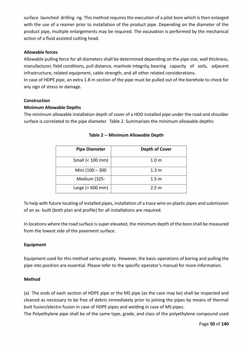
Page 50 of 140
surface launched drilling rig. This method requires the execution of a pilot bore which is then enlarged
with the use of a reamer prior to installation of the product pipe. Depending on the diameter of the
product pipe, multiple enlargements may be required. The excavation is performed by the mechanical
action of a fluid assisted cutting head.
Allowable forces
Allowable pulling force for all diameters shall be determined depending on the pipe size, wall thickness,
manufacturer, field conditions, pull distance, manhole integrity, bearing capacity of soils, adjacent
infrastructure, related equipment, cable strength, and all other related considerations.
In case of HDPE pipe, an extra 1.8 m section of the pipe must be pulled out of the borehole to check for
any sign of stress or damage.
Construction
Minimum Allowable Depths
The minimum allowable installation depth of cover of a HDD installed pipe under the road and shoulder
surface is correlated to the pipe diameter. Table 2. Summarizes the minimum allowable depths:
Table 2 -- Minimum Allowable Depth
Pipe Diameter Depth of Cover
Small (< 100 mm) 1.0 m
Mini (100 – 300
mm)
1.3 m
Medium (325-
600 mm)
1.5 m
Large (> 600 mm) 2.5 m
To help with future locating of installed pipes, installation of a trace wire on plastic pipes and submission
of an as- built (both plan and profile) for all installations are required.
In locations where the road surface is super elevated, the minimum depth of the bore shall be measured
from the lowest side of the pavement surface.
Equipment
Equipment used for this method varies greatly. However, the basic operations of boring and pulling the
pipe into position are essential. Please refer to the specific operator’s manual for more information.
Method
(a) The ends of each section of HDPE pipe or the MS pipe (as the case may be) shall be inspected and
cleaned as necessary to be free of debris immediately prior to joining the pipes by means of thermal
butt fusion/electro fusion in case of HDPE pipes and welding in case of MS pipes.
The Polyethylene pipe shall be of the same type, grade, and class of the polyethylene compound used
Page 51 of 140
in the process. This process provides joint weld strength equal to or greater than the tensile strength of
the pipe.
(b) The handling of the joined pipeline shall be in such a manner that the pipe is not damaged by
dragging it over sharp or jagged objects. Sections of the pipes with cuts and gouges exceeding 10 percent
of the pipe wall thickness or kinked sections shall be removed and the ends rejoined.
(c) Pipes shall be stored on level ground, free of sharp objects, which could damage the pipe. Stacking
of the polyethylene pipe shall be limited to a height that will not cause excessive deformation, bending,
or warping of the bottom layers of pipes under anticipated temperature condition.
(d) Sufficient space shall be allocated to fabricate and layout the product pipeline into one continuous
pipe length, thus enabling the pull back to be conducted during a single operation. If space
considerations are discovered that make this impossible, the permit applicant shall obtain specific
alternative instructions from the owner’s Engineer.
(e) Sufficient space is required on the rig side of the machine to safely set up and perform the operation.
(f) The drill path alignment shall be as straight as possible to minimize the frictional resistance during
pullback and maximize the length of the pipe that can be installed during a single pull.
(g) The radius of curvature is determined by the rig. The minimum radius of curvature of HDD path
should be 1,200 times the nominal diameter of the pipe to be installed.
(h) The required piping shall be assembled in a manner that does not obstruct adjacent roadways or
public activities. The HDD operator shall erect temporary fencing around the entry and exit pipe staging
areas.
(i) Several pre-reams may be employed to gradually enlarge the hole to the desired diameter and
reduce road surface heaving potential. No back ream diameter increase shall exceed 37.5 mm.
Furthermore, during the final pullback, the pull back rate shall not exceed 3 m per minute.
(j) The pipe shall be sealed at both ends with a cap or a plug to prevent water, drilling fluids and other
foreign materials from entering the pipe as it is being pulled back.
(k) Pipe rollers, skates or other protective devices shall be used to prevent damage to the pipe, eliminate
ground drag, reduce pulling force, and reduce the stress on the pipe and joints.
(l) The drilling fluid in the annular region outside of the pipe shall not be removed after installation, and
remain in place to provide support for the pipe and neighboring soil.
(m) Should the drilling operation be unsuccessful, the contractor shall ensure the backfill of any void(s)
with flow able fill.
(n) Entry penetration angles are limited by equipment capabilities. However, according to most HDD
Page 52 of 140
drilling rigs’ design, the best entry angle should be between 100 and 120.
(o) Exit angles should generally range from 50 (for large diameter steel pipelines) to 120. However, when
high exit angles are encountered or designed, the pipe must be supported in an elevated position during
the pull back operation to prohibit the pipe from bending, deforming, kinking, or even breaking.
Drilling Site
(a) Location
A minimum distance of 6 m, from the edge of the paved shoulder or curb to the face of any equipment,
and supplies, shall be maintained in areas posted at 50 kmph or less; otherwise, a minimum distance of
9 m shall be maintained.
(b) Protection
At discretion of owner’s Engineer/Inspector, traffic barriers shall be installed adjacent to machine site
locations according to the owner’s plans and current Standard Specifications for such Construction.
Temporary beam guardrail shall also be installed according to the current Standard Specifications for
Construction.
Fencing barriers shall be installed adjacent to equipment and supplies with suitable fencing and plastic
drums to prohibit pedestrian access to the work site. Equipment shall not be used as fencing to protect
access pits.
Overcut Allowance
The overcut diameter shall not exceed the outside diameter (OD) of the pipe by more than 37.5 mm, to
ensure excessive voids are not created resulting in post installation settlement.
Watertight Joints
Water tight pipe joints are required to ensure, the integrity of the road bed. Pipe shall be constructed
to prevent water leakage or earth infiltration throughout its entire length.
Drilling Fluids
(a) Drilling fluid shall be used during drilling and back reaming operations. Using water exclusively may
cause a collapse of the borehole while in unconsolidated soils, and may also cause soil swelling
while in clay soils. Either case may significantly impede the installation of the pipe.
(b) Excess drilling fluid shall be contained within a lined pit or containment pond, or trailer-mounted
portable tank, until removed from the site.
(c) All drilling fluids shall not enter the streets, manholes, sanitary and storm sewers, and other drainage
systems, including streams and rivers.
d) Any damage to any highway or non- highway facility caused by escaping drilling fluid, or the
directional drilling operation, shall be immediately restored by the HDD operator.
Pipe Locating and Tracking
(a) During construction, continuous monitoring and plotting of pilot drill progress shall be undertaken
to ensure compliance with the proposed installation alignment and allow for appropriate course
Page 53 of 140
corrections to be undertaken.
Monitoring shall be accomplished by manual plotting based on location and depth readings provided
by the locating/tracking system or by computer generated bore logs which map the bore path based on
information provided by the locating/tracking system. Readings or plot points shall be undertaken on
every drill rod.
(b) Pipe installed by the HDD method shall be located in plan as shown on the drawings, and shall be
no shallower than shown on the Drawings unless otherwise approved. The Contractor shall plot the
actual horizontal and vertical alignment of the pilot bore at intervals not exceeding 9 m. This “as built”
plan and profile shall be updated as the pilot bore is advanced. The HDD operator shall at all times
provide and maintain instrumentation that will accurately locate the pilot hole and measure drilling fluid
flow and pressure. The HDD operator shall grant the Engineer/ Inspector access to all data and readout
pertaining to the position of the bore head, the fluid pressures, and flows.
Settlement/Heaving Monitoring
(a) This method shall be performed in a manner that will minimize the movement of the ground in
front of, above, and surrounding the boring operation; and will minimize subsidence of the surface
above and in the vicinity of the boring.
(b) Potential settlement shall be monitored at each edge of right of way, each shoulder point, each
edge of pavement, the edge of each lane (or centerline for two lane roads), and otherwise at
15 m intervals along the pipe centerline.
(c) A survey shall be performed 1 day prior to initiating this operation at each required monitoring
location. A similar survey shall then be performed at each location, on a daily basis, until the
permitted activity has received a final inspection. This survey establishes the preexisting and post
construction conditions, and the amount of settlement. All survey readings shall be recorded to
the nearest one-hundredth (0.01) of a meter. Whenever possible, trenchless pipe installations
shall not be installed directly under a pavement crack. Digital photographs of the pavement
conditions shall also be taken prior and after the pipe installation.
(d) All operations shall stop immediately whenever monitored points indicate a vertical change in
elevation of 12 mm or more, or any surface disruption is observed. The Contractor shall then
immediately report the amount of settlement to the owner’s Engineer/ Inspector.
Ground Water Control
Dewatering is not an issue with this method of installing pipe.
Boring Failure
(a) Should anything prevents completion of this operation, the remainder of the pipe shall be
constructed by methods approved by the Engineer in charge.
(b) Abandonment of any component of the installation shall only be allowed as approved by the
owner’s Engineer in charge.
Contamination
When an area of contaminated ground is encountered, all operations shall stop immediately, and shall

Page 54 of 140
not proceed until approved by the Engineer in charge. Any slurry shall be tested for contamination
and disposed of in a manner, which meets locally applicable requirements.
Bulkhead
Pipe ends shall be temporarily sealed with a cap until the connection is made permanent, to prevent
water or earth infiltration.
Work Site Restoration
(a) Access pits and excavations shall be backfilled with suitable material, and in a method approved
by the Engineer in charge.
(b) The disturbed grass-surface area shall be top soiled, seeded, fertilized, mulched, and anchored
according the tender Specifications for construction. Slopes steeper than 1-on-3, shall be
sodded. If a final site restoration is not completed within 5 days after completion of the
operation, the installation of temporary soil erosion and sedimentation control measures shall
be required.
(c) Upon completion of the work, the contractor shall remove and properly dispose of all excess
materials and equipment from the work site.
(d) The permit, including the surety requirements, shall remain in effect for a minimum of one year
after completing the work to monitor for settlements of the pavement and/or slope.
21.0 TRENCHLESS CROSSING BY PUSHING METHOD
Crossing by Trench-less Method across National Highways/State Highways/Railway crossings/at
any other Specified Locations
All works for Road and Railway crossings by Trench less method i.e. by Pipe Ramming /Manual pipe
jacking shall be carried out as per specifications in this section mentioned below and for
details and specifications not included in this section shall be carried out as per “Standard contract
clauses for Trench less Contracts” and “Standard Guidelines for Trenchless contracts”, 2008.
Design & Submittals
Design
The Operator shall be responsible for the design of the pipes used for the trenchless method
including all joints, for the design of the thrust and reception pits including support and thrust wall
and for the design of the jacking system in general. His design will be reviewed by the Design Build
Operations Employers representative but this will not relieve him of his responsibility for the
adequacy of the design.
Submittals
In addition to the applicable requirement of this Specification, the following shall be submitted by
the Operator and approved by the Employers representative prior to commencement of any works;
1) Programme or work with resource and equipment allocation.
2) Design Calculations:
a) Pipes including jacking and frictional forces in the axial direction and earth, traffic and surcharge
loading in the vertical direction and the pipes resistance to these loads. Also allowable deflections
at joints to limit damage to the joint from eccentric loading under thrust and sealing limits,
b) Thrust and reception pits to resist external soil and water pressures and stresses resulting from
jacking machine. Drawings showing on plan and sections, the method of supporting excavations and
Page 55 of 140
equipment layout shall be included. All calculation shall be certified/ signed by a qualified Employers
representative.
Method Statement which shall include:
a) List of equipment and resources.
b) Detailed step by step procedure describing how work will be carried out including clear definition
of responsibilities and authority.
c) Support of existing services and adjacent structures.
d) Safety arrangement for compliance with safety requirements.
e) Locking pipe in position during insertion of next pipe.
f) Sealing thrust and reception pits during exiting and entering of pipe.
Site Investigation
After award of the Contract, the Operator shall be responsible for all necessary geotechnical
site investigations, including ground water level monitoring, which he considers necessary but as a
minimum at the proposed access pit locations, and central median. The Operator’s site
investigation programme shall be submitted to the Design Build Operations Employers
representative for review. The results of such investigations shall be submitted to the Design Build
Operations Employers representative and shall include recommendation for pipe laying, excavation
support and soil stabilization if required.
The Operator shall be responsible for obtaining existing utility structures information after
Conducting Ground Penetrating Radar Survey in a corridor of 4-6 meter width to detect buried
utilities like pipes, cables etc. in such corridor, Marking of the detected utilities on the map of corridor
with information of locations and depths to the top of various utilities detected. Work to be
conducted using 500MHz and 300MHz antenna for best possible resolution and penetration.
Utility Service structures
The Operator shall replace at his own cost towards damage of any utility service structures during
the excavation and rehabilitate if necessary at his own cost.
TRENCHLESS TECHNOLOGY FOR PIPE LAYING
For trenchless technology suitable guidelines/ codes from Indian society of Trenchless Technology
shall be followed.
SPECIAL CONDITIONS FOR PIPE RAMMING (PR)
Description
This method involves the forming of a bore from a drive pit, by driving a steel casing with an open
end using a percussive hammer or pushing device that serves as a casing for carrier (water
pipes). This process of horizontal ramming of steel pipe involves an open steel pipe string being
jacked dynamically with the aid of modified displacement hammer or a horizontal ram from
the starting shaft through the subsoil to the target shaft. The soil core entering the pipe is removed
continuously, at suitable intervals or after completion of jacking.
Materials
a) Pipe
Pipe used in this method includes an external casing pipe (also called jacking pipe) and may include
an interior carrier pipe.
b) Allowable Forces
Page 56 of 140
Considerable ramming / jacking forces may be required to install pipe using this method.
i) Casing pipe shall be obtained from manufacturer. Pipe shall be specifically designed and certified
for Horizontal auger boring by the pipe manufacturer.
ii) The allowable jacking strength capacity of casing pipe shall be capable of withstanding the
maximum jacking forces imposed by the operation. The specified allowable jacking capacity of the
casing pipe shall be 3 times greater than the maximum jacking forces imposed by jacking
operations as identified by theoretical calculations.
iii) Steel casing pipe shall have minimum yield strength of 35,000 psi.
Casing Pipe
a). Casing pipe shall be used within the entire roadbed influence area. The roadbed influence area is
defined as the subsurface area located under the road and shoulder surface, between each shoulder
point or back of curb; and continues transversely outward and downward from each shoulder point
or back of curb on a 1 on 1 slope
b). Casing pipe materials shall be steel.
c). Only new casing pipe shall be used.
d). Casing pipe shall normally be constructed without any longitudinal seams. However,
longitudinally welded casing pipe is allowed for 1.2 m or larger diameter pipes when a certified
welder performs all the welding.
e). Casing pipe shall have smooth interior and exterior walls to reduce jacking force and
prevent casing rotation.
f). The inside diameter (ID) of the casing pipe shall be at least 150 mm larger than the
largest out side diameter (OD) of the carrier pipe to allow the carrier pipe to be inserted or removed
subsequently without disturbing the casing or the roadbed.
g). Casing pipe shall be round. Steel casing pipe shall have roundness tolerance, so that the
difference between the major and minor outside diameters shall not exceed 1% of the specified
nominal outside diameter, or 6 mm, whichever is less.
h). Casing pipe shall have square and machine beveled ends. The pipe end maximum out –
of –square tolerance shall be 1 mm, (measured across the diameter).
i). Casing pipe shall be straight. The maximum allowable straightness deviation over any 3m length
ofsteel casing pipe is 3 mm.
j). Pipe shall be without any significant dimensional or surface deformities. All pipes shall be freeof
visible cracks, holes, foreign material, foreign inclusions, blisters, or other deleterious or
injurious faults or defects. Any section of the pipe with a gash, blister, abrasion, nick, scar, or other
deleterious fault greater in depth than ten percent (10%) of the wall thickness, shall not be used and
shall be immediately removed from the site.
k). Any of the following defects warrants pipe rejection:
i). Concentrated ridges, discoloration, excessive spot roughness, and pitting
ii) Insufficient or variable wall thickness
iii). Pipe damage from bending Crushing, stretching or other stress
iv). Pipe damage that impacts the pipe strength, the intended use, the internal diameter of the pipe
and internal roughness characteristics
v). Any other defect of manufacturing or handling.
l). Casing pipe shall be provided with inside two coats of food grade epoxy painting over one coat of
epoxy primer and outside two coats of anti-corrosive red oxide primer of approved quality.
Page 57 of 140
m) The casing pipe shall be tested for seepage test after completion.
Carrier Pipe
Carrier Pipe material is of either Ductile iron or MS. The carrier pipe shall be inserted into the casing
pipe in conjunction with the casing spacers.
The work includes, Supplying & Conveying of different diameters k-7/k-9 Class, Ductile Iron carrier
Pipes detailed in bill of quantities, confirming to IS 8329 with latest amendments and conveying to
work site lowering and placing horizontally into casing pipe with all necessary arrangements, true to
line and level and perfect linking at joints, testing and commissioning, including cement mortar lining
of thickness as per IS, loading and unloading at both destinations and cuts of pipes wherever
necessary including jointing of DI pipes and specials with rubber gaskets including cleaning the
socket and spigot ends with soap solution and applying soft soap to the spigot and socket ends before
insertion of rubber gaskets, jacking and fixing in perfect conditions including cost of soap solution,
soft soap, waste etc. and giving necessary hydraulic test to the required pressure as per ISS with all
lead and lifts including cost of jointing materials etc., complete (Operator will make his own
arrangements for procuring water for testing)
Supplying of different diameters S&S DI PIPES detailed in bill of quantities, with latest amendments
using Sulphate resistant cement, and conveying to worksite, rolling and lowering into trenches, laying
true to line and level including loading and unloading at both destinations and jointing of pipes &
specials including cost of specials including perfect linking of joints with jack to correct position
including cost of jointing materials ie., rubber rings with all lead and lifts as directed and giving
necessary hydraulic test as per ISS and testing & commissioning etc., complete. (Operator will make
his own arrangements for procuring water for testing)
Construction
Minimum Allowable Depth
The minimum allowable depth of pipe ramming (PR) installed pipe under the road and shoulder
surface should be usually twice the nominal diameter (OD) or 1 m or the minimum allowable depth
as per the project requirement, whichever is higher. In location where the road surface is super
elevated, the minimum depth of the bore shall be measured from the lowest side of the pavement
surface.
Equipment
Equipment used for this method shall have the basic operations of boring, removing tailings, and
jacking pipe.
Method
The starting shaft shall be excavated to accommodate the steel pipe sections to be jacked and the
ram. Steel support profiles shall be placed to direct the movement. If a long jacking is necessary
string fabrication shall be done at site.
Access Pits
a) Location
A minimum distance of 6 m, from the edge of the paved shoulder or curb to the face of any access
Page 58 of 140
pit, equipment, and supplies, shall be maintained in areas posted at 50 kmph or less; otherwise, a
minimum distance of 9 m shall be maintained.
b). Sheeting and Bracing
Sheeting and bracing shall be required whenever any part of the access pit excavation is located
within the road bed influence area. Steel sheet pilling shall be furnished and installed. An
additional earth retention structure shall be required above and below the bore hole on the drilling
face of all accesspits to prevent loss of material during construction.
c) Protection
i). At the discretion of Employers representative, and depending on the pit distance from theroad
embankment, traffic barriers may be required to be installed adjacent to access pit locations
according to the owner’s plans. If instructed, temporary beam guardrail shall also be installed
according to the current owner’s specifications.
ii). Fencing barriers shall be installed adjacent to access pits, open excavations, equipment and
supplies with suitable fencing and plastic drums to prohibit pedestrian access to the work site.
Equipment shall not be used as fencing to protect access pits.
iii). The Operator shall construct and operate safe access pits according to all applicable
regulatory requirements.
Overcut Allowance
Overcut is the annular space between the excavated hole and the outside diameter of the casing
pipe. No overcut shall be allowed in case of pipe Ramming.
Water tight Joints
Water tight pipe joints are required to ensure the integrity of the roadbed. Pipe shall be constructed
to prevent water leakage or earth infiltration throughout its entire length. A watertight specification
for each type of pipe material can be obtained through each pipe material industry. Necessary
reference must be made to the appropriate industry specification for more detailed information.
The carrier pipe and joints shall be protected from the possible adverse physical or chemical – effect
of grout. Compressible material shall be wrapped around pipe. The internal pipe shall be filled with
water to avoid floatation forces, hydration temperatures and to resist forces during grouting.
Thrust and Reception Pits
The dimensions of thrust and reception pits shall be limited to the minimum required to
construct the Works.
The pit bottom shall be sealed with concrete. Entry and exit sealing rings shall be provided.
The Operator shall determine the excavated dimensions of the drive and reception shafts as required
to suit the site conditions. Minimum shaft dimensions shall be used at all locations where utilities,
roads or trees exist adjacent to the required shaft locations.
The pits shall be completely dry prior to commencing and throughout Jacking works. Dealing
with groundwater where required shall be conducted in a slow manner. Standby facilities shall be
provided. The thrust wall shall be perpendicular to the proposed line of thrust. The thrust wall shall
be sufficient to accept repeatedly the maximum permitted thrust force without undue
movement. It will not be permissible to thrust directly off any permanent part of any shaft, chamber
or pumping station unless this is specifically designed to withstand the thrust reaction. Thrust wall
shall not be joined to the jacking rig base concrete.
Page 59 of 140
The maximum permissible thrust force.
i) 50% of the sum of the maximum forces recorded at the rigs used to construct the tail tunnel, or
ii) If the over break to the tail tunnel has been grouted up, 100% of the sum of the maximum forces
recorded at the rigs used to construct the tail tunnel.
Any tail tunnel which has been used as a reaction surface shall pass the specified water tightness test
at a time not less than 14 days after the load has been removed.
The design of thrust wall and any other associated Temporary Works shall be such as to prevent
damage to any part of the Permanent Works or any immediately adjacent service or structure.
Any void between the soil face used to provide a reaction to the thrust force and the thrust wall shall
be filled completely with grout.
The Operator shall take any measures necessary to prevent damage or deterioration of the soil
reaction face during the construction of the Temporary and Permanent Works from whatever
possible cause, such ingress of water, softening, corrosive soil or loss of fines from a granular soil.
Pipe Installation within Sleeves
Pipe sections shall be placed and joined individually within the sleeve or mounted on guide
rails or trolleys in such a manner as to transmit the pulling / pushing forces through the carriage and
not through pipe.
Thrust System
The rig shall distribute the thrust to the pipes via a thrust ring and packing. The jacks shall
apply the thrust to the thrust ring by means of a symmetrical distribution. Inter – jack stations shall
be used where frictional resistance or other causes would otherwise result in unacceptable thrust
forces. If used, spacer blocks shall be true and free form any distortions. All thrust rings shall be true
and free from any distortions and sufficiently stiff so as to transfer the load from the jacks uniformly
to the packing.
Other than at the shield, each group of jacks shall be interconnected to ensure that an evenly
distributed load is applied to the thrust ring. Each jack shall incorporate a load cell.
At the rig and at intermediate stations automatic thrust recording equipment monitoring load
cells incorporated in each jack is to be provided together with a pressure metering device. Other
continuous records including cutter torque, rate of progress, slurry progress, pitch, roll, slurry
slow, earth face pressure, etc. shall be provided. Copies of these records clearly stating the units
measured shall be submitted daily to the Design Build Operations Engineer
The thrust force shall not exceed the maximum permissible thrust force as determined by the
Operator, based on calculations submitted by the Operator and approved by Employers
representative and on consideration of the behavior of the pipe joint at the maximum permitted
angular deflection of 0.5 with the maximum permissible bearing stress in conjunction with the stress
/ strain relationship obtained from the packing compression tests.
Lubrication Holes
Where lubrication holes are required, these shall be threaded to enable plugs to be screwed into the
socket and withstand the external pressure. Non-return valves shall be fitted where opening a
hole would permit ground loss. Lubrication holes shall be plugged watertight on completion, lining
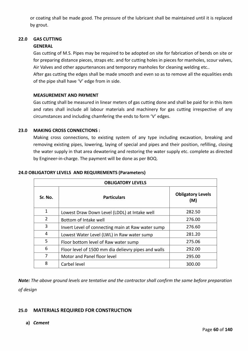
Page 60 of 140
or coating shall be made good. The pressure of the lubricant shall be maintained until it is replaced
by grout.
22.0 GAS CUTTING
GENERAL
Gas cutting of M.S. Pipes may be required to be adopted on site for fabrication of bends on site or
for preparing distance pieces, straps etc. and for cutting holes in pieces for manholes, scour valves,
Air Valves and other appurtenances and temporary manholes for cleaning welding etc..
After gas cutting the edges shall be made smooth and even so as to remove all the equalities ends
of the pipe shall have ‘V’ edge from in side.
MEASUREMENT AND PAYMENT
Gas cutting shall be measured in linear meters of gas cutting done and shall be paid for in this item
and rates shall include all labour materials and machinery for gas cutting irrespective of any
circumstances and including chamfering the ends to form ‘V’ edges.
23.0 MAKING CROSS CONNECTIONS :
Making cross connections, to existing system of any type including excavation, breaking and
removing existing pipes, lowering, laying of special and pipes and their position, refilling, closing
the water supply in that area dewatering and restoring the water supply etc. complete as directed
by Engineer-in-charge. The payment will be done as per BOQ.
24.0 OBLIGATORY LEVELS AND REQUIREMENTS (Parameters)
OBLIGATORY LEVELS
Sr. No. Particulars Obligatory Levels
(M)
1 Lowest Draw Down Level (LDDL) at Intake well 282.50
2 Bottom of Intake well 276.00
3 Invert Level of connecting main at Raw water sump 276.60
4 Lowest Water Level (LWL) in Raw water sump 281.20
5 Floor bottom level of Raw water sump 275.06
6 Floor level of 1500 mm dia delievry pipes and walls 292.00
7 Motor and Panel floor level 295.00
8 Carbel level 300.00
Note: The above ground levels are tentative and the contractor shall confirm the same before preparation
of design
25.0 MATERIALS REQUIRED FOR CONSTRUCTION
a) Cement

Page 61 of 140
OPC of 43 grade or higher in jute/polyethylene bags (weighing 50 Kg each) shall be used for all water
retaining Structures & for all works. Super plasticizer in the proportion of 0.5 % (0.25Kg/cement
bag) should be used.
b) Sand, coarse aggregate & Bricks
The building material to be used shall be as per the specifications given in this chapter. Sand, coarse
aggregate, crused stones & bricks of best quality will be insisted. Samples of these will have to be got
approved prior to use on work.
c) Reinforcement
Tor steel cold twisted of Fe 500 grade shall only be used as per design.
The Contractor shall have to procure the steel from open market .The steel procured by Contractor
shall be only tested one and the Contractor shall produce manufacturer's test certificate without
which it shall not be accepted. Further the Contractor shall arrange to get tested any sample from
steel brought at site by him in laboratory at his own cost and results should be submitted to the
deptt. Defective steel brought by Contractor shall be rejected and will not be allowed to be used.
Test certificate stating the chemical composition & characteristics of the product shall also be
produced.
At least three samples of each diameter shall be got tested from every 5 tons (MT) or part thereof.
Tested lots only will be permitted to be used.
d) Concrete
The PCC and RCC work shall be as per IS 456:2000. (OR LATEST REVISION) Automatic/semi automatic
batching plant shall be used for preparing concrete.
Vibrator shall be used to consolidate concrete while placing in position.
While concreting, representative samples in form of Test Cubes shall be taken by the deptt.
supervisor and shall be tested under his supervision. Charges of testing shall be borne by the
Contractor . Frequency of taking cubes(sampling, accepting criteria, standard deviation values,
carting of concrete cubes ,test procedure etc.) shall be followed by contractor as per IS:456.
e) Water Level Indicator Assembly
Water level indicator shall be provided for each reservoir to be constructed in this contract. Mercury
water level indicator with 15 mm dia. required GI pipes (medium duty), stop cocks (2 nos.),
necessary fixtures suitable for staging height upto 15 m and water depth up to 5 m to represent
depth of water in tank, etc. shall be provided and fixed by the Contractor as per direction of
Engineer-in-Charge. The indicator should be fixed to exterior face of column at about 1.5 m above
ground level at site or as per requirement of Engineer –in-charge.
f) Lightening Arrestor
Lightening arrestor conforming to IS and Indian Electricity Rules shall be provided. The lowermost
portion of tape for 2 metres above ground level and 2 meters below ground level shall be enclosed
by 50 mm GI pipe of 'M' class.
g) Pipe Railing at free end of Catwalk
Hand railing shall be provided along the stairs, around the platforms, balcony and landings and shall
consist of 25mm diameter medium B class GI pipes in two rows (one at the top and other at middle
level) and 0.9 m high vertical post 50x50x6 mm angle iron @ 1.0 m centre to centre (At least two
vertical angles are to be provided wherever distance is less) with all accessories like elbows, tees
Page 62 of 140
etc. including welding, threading and embedding in cement concrete floor. Railing shall be
protected against corrosion after welding. The pipe shall pass through hole in the vertical angle.
The railing and the posts shall be provided with two coats of oil paint of approved shade.
h) M.S. Ladder/stair
M.S. Staircase with one meter width shall be provided from landing platform to gallery and from
gallery to roof slab with intermediate platforms .The ladder should be fabricated from heavy angles,
steps & railing as directed by Engineer-in-charge.
i) S.S. Ladder in container
One heavy type S.S. Ladder of required length & design as approved by Department shall be
provided by the contractor for each ESR. This shall be for the access inside the tank .
j) Ventilators & Man Hole Cover
Two no. ventilators of adequate size and one CI square manhole cover of 600X600 mm size shall
be provided at top of the roof of the tank. The cover shall be connected to this frame by using two
nos. strung hinges. Locking arrangement shall be provided.
k) PVC water stops for construction joints in vertical wall
PVC Water stops shall be used as construction joints in vertical wall as per IS 3370 Part-I 1965.
Overlaps in sheets shall be 150 mm.
l) Plinth protection
Plinth protection works to be constructed around the Pump House as per approved design
drawings. It shall consist of laying lean concrete 100 mm thick in M10, over compacted soil & over
the lean concrete , 100 mm of M-20 concrete flooring shall be provided. Along this plinth protection
provision of 230 mm wide masonry toe wall in 1:5 over the base of lean concrete of M10 shall be
provided. Side slope of plinth protection shall be 1 in 50 outward & peripheral slope should be 1 in
500.
m) Puddle collars
Puddle collars shall be used for connecting the rising mains to the pump house. All puddles shall be
fixed during casting of the walls. All puddle collars shall be of C.I/D.I. The size of the puddle collars
shall be equal to the size of the outlet pipe.
n) Centering Work
Before starting the work, the Contractor should submit design of centering and its detailed drawing
for approval by deptt. This set of drawings shall be kept at site.
26.0 Specifications & Design Criteria for Pump House and Intake well with Contractor's own
Design:
26.1 General Note
a) The Contractor shall quote his offer for the complete work of constructing Pump House with
sump, RCC connecting main and Intake well to be carried out as per his own design based on
given data.
Page 63 of 140
The construction of Pump House with sump, RCC connecting main and Intake well shall be carried
out in accordance with the specifications and relevant BIS amended upto date and the manuals.
The general arrangement drawings of the piping system and other drawings like layout plan of site,
structural drawings and designs, working drawings, etc shall be submitted by the contractor for
approval of the department prior to start of work. In cases, where the specifications given below
are silent about any aspects in respect of any item, the work shall be carried out as per the relevant
IS code of practice in the latest version and as per sound engineering practice as decided by the
Engineer in Charge.
The design shall be got checked from the institutes like Government Engineering College. Remarks
shall be complied and scrutiny charges shall be borne by the Contractor.
b) Soil & Geo Technical Investigation
The SBC through an approved agency shall be got tested at foundation depth for Pump House with
sump, RCC connecting main and Intake well by the contractor before the design. The structure shall
be designed on the basis of actual SBC found on testing, for which no extra payment will be made
to contractor. The contractor shall carryout strata exploration mentioned above through a Govt.
Lab.
c) The Contractor shall submit the name, qualifications and experience of Design Engineer who has
prepared detailed RCC calculations or who will prepare design and drawings on acceptance of the
tender. The authorized representative of the designer will have to inspect and certify the works at
foundation level and every beam level.
d) The design Engineer has to prepare and submit a note on design methodology and construction
and drawings in two copies through the contractor. The note should indicate general description,
and salient features of the design.
26.2 Design Conditions for Pump House:
The Contractor shall quote with his own design with following conditions:
26.2.1 The structural design shall conform to the following standard specification & IS codes of practice
of (latest revisions or editions).
a) IS 456:2000
b) IS 3370 -Part I and IV
c) IS 875: 1987 Part I to Part IV
d) IS 1893: 2002/2016 (Part-I) criteria for earthquake resistant design of structures.
e) IS 1786-1985 Specifications for high strength deformed steel bars and wire for concrete
reinforcement.
(Tor steel of Fe-500 grade shall only be used.)
f) IS 13920:1993 -for ductile detailing,
g) B.S.I. publication S.P. 34 and S. P. 6 (S and T) 1987.
27.0 MS Screen
1) Size of Screen : 1.35 m x 1.5 m
2) Size of Frame Bar : 20 mm x 50 mm
Page 64 of 140
3) Size of Bar (Width) : 15 mm
4) Depth of Bar : 38 mm
5) Material : Mild Steel
6) Number of Screen : 7
7) Opening between the bars : 50 mm
8) Coating : Hot dip galvanization as per IS 4759: 1996. The average
Mass of coating shall be 610 grams/m2. The Zinc used for
galvanizing shall conform to grades specified in IS 13229:
1991
28.0 DETAILED SPECIFICATIONS FOR RAW WATER PUMPING MACHINERY AT WALANI GENERAL
This section outlines the specifications for Raw Water Vertical Turbine (VT) pumps self-water lubricated type to be installed in Raw water sump with pump house. The raw water from RL 276.00 is proposed to be pumped through rising main of MS pipe. The pumping station is designed to pump raw water with Seven no. of pumps operating in parallel. Two additional pump sets are proposed to be provided as stand-by. It will be responsibility of the contractor to arrange to match the flange drilling standard of pump, pipe and valves to be provided under scope of the contract and arrange suitable changes for successful installation and commissioning.
VERTICAL TURBINE (VT) PUMP (RAW WATER PUMPS) PUMP DUTY CONDITION
i) No. of pumps to be installed 9 Nos.
(7 No. Working + 2 No. Stand bye) ii) Individual pump discharge 909.39 lps
iii) Lowest suction level 281.20 m RL iv) Highest discharge level 337.75 m RL v) Static head 56.55 m
vi) Total discharge to be pumped 550 MLD.
vii) Duty head 58 m vii) Working head range 43 m to 64 m ix) Shut off head Not less than 71 m x) Pump efficiency at duty point preferably Not less than 85%
The pump shall be suitable for worst suction condition encountered. Necessary NPSH shall be submitted and minimum submergence required shall be stated. The system head curve and performance curve for all level conditions is to be enclosed with the tender documents by the tenderer for solo operation and parallel operation of seven pumps. The pump shall be suitable for satisfactory operation at the duty conditions; head range stipulated above includes solo operation and parallel operation up to seven pumps at a time under all water level conditions.
VT PUMP SETS (WATER LUBRICATED) The vertical turbine pump sets shall be self-water lubricated suitable for following conditions and specifications.
Page 65 of 140
i) Discharge (each pump) 909.39 lps
ii) Duty head 58 m
iii) Mode of operation Parallel operation of seven pumps to have combined discharge of 550 MLD at 58 m head. In case of single/ two/ three/ four/ five/six /seven pumps of parallel operation, motor should not be overloaded.
iv) Water quality Raw & turbid water
v) Head range 43 m to 64 m
vi) Shut off head 71 m minimum
The pump shall be of approved make as specified and shall conform to IS: 1710 and IS:5120 with latest modifications from time to time. Pump efficiency shall not be less than 85% at duty chart point under all circumstances. Constructional and design details of the set shall be as follows. a) VT Pumps (Cast Iron) Pump shall be self-water lubricated type. Number of stages shall not exceed Two. Speed 980 Rpm (Synchronous) b) Impeller Impellers shall be of Bronze /SS CF8M only conforming relevant standard. Impeller shall be statically and dynamically balanced. Balancing holes in impeller are acceptable. c) Wearing Ring It shall be of Bronze /SS 316 conforming to relevant standard and suitable grade and shall be of renewable type. It shall be held in place against rotation by screw in or locking with pin press fitted locked with pins. d) Pump Shaft Pump shaft shall be of SS 410 and diameter shall not be less than 80 mm diameter or nearest commercial size at the route of threads e) Line Shaft Line shaft and sleeve shall be in length of 1.5 m each and shall be of SS 410. The diameter of shaft shall not be less than 80 mm diameter or nearest commercial size at the route of threads. The coupling shall be of forged steel. Composite design of line shaft material and diameter and bearing centers shall ensure that the entire rotating assembly is brought from stand still to full speed without any vibration, whipping and shaft deflection and to ensure that first critical speed is not within 75% to 125% of full speed. f) Column Pipe Column pipe shall be of M.S./ERW fabricated, heavy duty, flanged type and of minimum 700 mm diameter, in length of 1.5 m each suitably designed to have total suspended length of column assembly of 18 m length (including bowl assembly and strainer and bell mouth) Thickness of column pipe shall not be less than 12 mm thick, individual column length more than 1.5 m shall not be accepted. Pipe shall be designed to accommodate guide bearing holders. Balance column pipe assembly shall be kept with owner.
Page 66 of 140
g) Line Shaft Bearing Thardon type bearing of suitable grade at 1.5 m spacing for total column assembly including C.I. spiders (bearing holders) shall be provided. h) Strainer Suction strainer shall be of flanged type heavy duty made from S.S. plate. Total area of perforation shall not be less than 250% of entrance area of bell mouth. Stainless steel hardware shall be provided. I) Suction Bell Mouth Entrance diameter of bell mouth shall be such that the suction velocity shall not exceed 1.5 m/sec. and shall be of Cast iron heavy duty. The shape and curvature of the bell mouth shall be designed to streamline the flow of bowl suction; the thickness of bell mouth shall not be less than 10 mm. j) Bowl Assembly The bowls of cast iron shall be capable of withstanding a hydrostatic pressure equal to twice the duty head or 1.5 times shutoff head whichever is greater. k) Discharge Head It is proposed to install discharge head and valves arrangement at RL 292.00. Agency has to design discharge head, delivery tee so that motor can be easily installed at RL 295.00. Discharge head shall be fully fabricated from M.S.10 mm thickness. It shall incorporate full diameter radial bend stuffing box with renewable bushing and tapping for pressure gauge. It shall be of robust construction and shall be designed to support entire loading of pump assembly, water column etc. and shall with stand all static, dynamic, torsion loads, hydraulic thrust imposed during operation from shut off to stipulated operating conditions and thrust due to change in direction of flow without any vibration. The discharge head shall be capable of withstanding hydrostatic pressure equal to twice the duty head or 1.50 times shut off head whichever is greater. The discharge head shall be properly installed supported to eliminate vibration at Floor RL. Entire load of pump and motor shall be on the floor RL. Provide the coating to inside of the discharge head. l) Thrust Bearing The thrust bearing shall be antifriction ball and roller bearing type. It shall be capable of withstanding entire weight of rotating parts of the pump assembly and maximum hydraulic thrust, encountered at stipulated operating conditions. The bearing shall also be suitable for all dynamic and static loads imposed during reverse rotation, Mitchell type thrust bearing will not be accepted. The bearing shall be designed for minimum rotating life of 40000 hours. Suitable bearing temperature sensor / detector shall be provided for connecting to scanner panel for high temperature alarm and higher temperature trip. m) Sole Plate Sole plate of M.S. not less than 35 mm thick machined from both the sides shall be provided. The size of sole plate shall cover entire pumps supporting girders (base frame).Suitable opening shall be provided at the center, considering diameter of bell mouth for bowl assembly and strainer. The sole plate shall be fixed with nut bolts on base frame of ISMB-350 x 140 mm and shall be machined. The sole plate shall be kept on girder and blue matched to the extent of at least 70% contact area If necessary, un-even surface shall be smoothened with polish paper, smooth file. The sole plate shall be perfectly leveled with straight edge and precision level. The sole plate shall have tapped holes to receive motor stool. The bottom of motor stool and top of sole plate
Page 67 of 140
shall be blue matched to have at least 60% contact area. If necessary uneven surface shall be smoothened with polish paper. n) Care shall have to be taken for motor stool considering pump installation levels. Agency has to design accordingly. Motor stool of robust construction and suitable height shall be designed to accommodate the thrust bearing and pump motor coupling. The line shaft of pump shall be coupled to the motor shaft through flexible coupling each halt of the flexible coupling shall be statically and dynamically balanced for transmission of power without vibration and shall be keyed to the respective shaft. The coupling shall be consisting of steel pin and rubber bush. Entire pump motor load will be taken at floor RL. o) The pump shall be driven by vertical solid shaft motor and shall be provided with non-reversible ratchet check nut flexible coupling etc. complete. p) Gleasering feed pressure gauge of 150 mm dia of approved make suitable to read up to 15 Kg/Sq.cm with controlling device siphoning tube etc. shall be provided and installed for each set. The pressure gauge shall be diaphragm type only. q) Special tools i.e. two pairs each of erection clamps for the column and line shaft as recommended by manufacturer, adjusting nut spanner shall be supplied. All bolt nut and washers shall be of stainless steel graded 410 and a certificate for the same shall be furnished along with supply.
TESTING All the pumps shall be subjected to factory test in presence of Municipal Engineer (M) or his representative and third party inspection agency approved for the purpose by MJP or appointed by corporation. field test in presence of Engineer-in-charge. The contractor shall arrange all required test equipment duly calibrated. Field performance test shall be witnessed by the Municipal Engineer concerned.
FACTORY TEST a) Review of raw material test certificate and quality control procedure. b) Hydrostatic Test Following item shall be tested at hydrostatic pressure equal to twice duty head or 1.5 times shut off head of bowl assembly whichever is higher as per IS:5120.
Bowl Assembly Discharge head Column pipes (20% of quantity)
c) Performance Test Performance test shall be carried out for all pumps. The test shall generally be carried out as per IS:9137 of acceptance test for pumps Class - C. The test shall be carried out at full speed full load at manufacture work. The test shall cover 6 points i.e.
i) Duty point ii) 2 points above duty point iii) 2 points below duty point iv) Shut off head v) Power consumption at all above points
The test at reduced speed will not be accepted. No negative tolerance for discharge will be accepted. d) Strip Inspection One of pump sets, after completion of its performance test and as
Page 68 of 140
selected by the Engineer or Inspector at random will be offered for strip inspection and dimensional checking. The manufacturers/contractor shall submit all required dimensional drawings. Minimum points as under shall be checked. i) Condition of all components particularly bushings, bearing, and wearing rings to examine un-
due rubbing, wear etc. ii) Hardness of cut less rubber bearing iii) Dynamic balancing of (a) impeller (b) flexible coupling, maximum un-balance shall not exceed
32 Gm/mm/Kg weight of impeller. iv) Finish for water passage in impeller and diffuser v) Clearance and tolerance between
a) wearing rings b) impeller shaft and bearings c) impeller shaft and key d) shaft and flexible coupling e) key and keyway on shaft at (d)
vi) Review of raw material test certificate and quality control procedure vii) Material test certificate to the various pump components shall be furnished.
FIELD PERFORMANCE TEST Field test shall be witnessed by two Engineer of the corporation not below the rank of Executive Engineer. The test shall be carried out as per IS:9137, Code of acceptance test of pump Class - C, in general and as stated below in particular. The purpose of field test is not to ensure whether pump performance as regards acceptance limit as per IS: 9137. The purpose is to ensure that the pump performance is generally acceptable or otherwise. Final acceptance shall be as per following criteria.
i) Verification of guarantee for H and Q specified in Clause 9.1.4 shall be based on following liberalized tolerances.
XH + 0.006 Xqv + 0.09
ii) As regards H.Q. Characteristics for acceptance, it shall be checked whether motor is not getting over loaded within specified head range.
a) Volumetric measurement shall be on basis of rise of level in BPT. In addition the contractor must install flow meter on the rising main to measure the discharge of each VT pump set as per direction of Engineer-in-charge.
b) The head shall be measured with calibrated pressure gauge of accuracy 1% or better. At least 3 pressure gauges shall be used calibrated from two different institutions with prior approval of the Engineer. The calibration shall be point and not more for percentage error.
The gauges shall be fitted at suitable place from the discharge nozzle. It may be noted that the stipulation that pressure gauge shall be installed at least two times diameter away from discharge nozzle and delivery valve be placed at least four times diameter away from discharge nozzle cannot be simulated at site condition and no allowance for this deficiency shall be considered. The decision of Engineer-in-Charge shall be final.
c) The input power to motor shall be measured with two Nos. class 0.5 accuracy single phase watt meters with suitable CTs, test lid and PTs provided in panel. The wattmeter, CTs and PTs shall be got calibrated from approved institutions. The calibration shall be for point to point and not mere for percentage error.
Page 69 of 140
d) The speed shall be measured by at least two numbers, noncontact tachometer with digital display and calibrated from two institutions, approved by the Engineer.
e) The field test shall be taken with entire head range in such a manner that it would cover at least six points (i.e. duty point, 2 above, 2 below and shut off). The guarantee for head and discharge shall be deemed to be fulfilled as per clause 9.4.1 of IS: 9137.
f) The field performance test at site is absolutely essential as above
(a) to (e).
Acceptable makes: As per list of approved make of MJP enclosed
SLUICE VALVE WITH ACTUATOR
750 mm dia. PN 10 rating gland les The entire assembly comprising valve actuator, reduction gear box and head stock shall be supplied by the approved valve manufacturer only and documentary proof for the same shall be submitted.
SLUICE VALVE (Glandless)
Providing, erecting and commissioning of 750 mm dia PN-10 Rating. Sluice Valves without by pass shall be provided in the delivery pipe of each pump. The sluice valves of cast iron body suitable for the PN-10 rating shall be provided and shall confirm to relevant IS. The sluice valves shall be double flange, water works pattern, inside screw, non-rising spindle type and shall be fitted with double faced gunmetal taper wedge made in one piece and having two machined facing rings securely fixed into machine recesses in the wedge. The guides and the lugs shall be provided to guide the wedge through its full travel and the lugs and guides shall be lined with bronze. The bronze liners provided on guides and lugs shall be secured by counter sunk screws or rivets of nonferrous metals. The clearances (radial and lugs axial) between the lugs and guides shall not exceed 2.5mm. All valves shall be provided on delivery side of pump.
A 750 mm dia PN 10 rating, Cast iron gland less sluice valve shall be provided on the delivery pipe of each pump. The valve shall be double flanged water works pattern inside screw with non-rising spindle. The valve shall generally conform to PN 10 rating of relevant international standard. The valve shall be suitable for operation with valve actuator mounted on valve body with reduction gear box and head stock. The materials of construction shall be as per relevant standard with stainless steel spindle of grade specified in standard. Thrust bearing shall be located in suitable housing above stuffing box and shall be oil/grease lubricated. Construction shall be such that ingress of water into bearing housing is totally prevented.
The valve shall be subjected to test at manufacturer’s works in the presence of the Third Party Engineer for seat and body test at the pressure stipulated Necessary C. C. Support shall be provided for the valve & the rating and entire operation with valve actuator simulating field installations.
MATERIALS OF CONSTRUCTIONS Body, bonnet cover and wedges Grey cast iron Stuffing box and gland. FG – 200 of IS-210 Spindle
Stainless steel IS:6603 Wedge and body rings, Leaded in bronze conforming to grade-2 of IS:318, Nuts and Bolts. As per IS: 1363, Wedge Nut High tensile brass conforming to Alloy 3 of IS: 320
Page 70 of 140
VALVE ACTUATOR
Electromechanical valve actuator shall be provided for sluice valve of individual pump delivery line the actuator shall be electrically operated. However features shall be incorporated to disengage electric motor and operate the actuators manually.
ACTUATORS
The actuator shall be designed to open and close with manual push button operation. The operating speed shall be designed for valve stroke of approximate 250 mm per minute during valve closing and opening operation. The enclosure shall be fully weatherproof it shall incorporate double ‘O’ sealing arrangement for protection of electrical component from moisture and dust at all time even when terminal covers are removed, mechanical indicator for sluice valve close and open should be provided on actuator. The actuator shall also incorporate hammer blow feature to open the valve.
MOTOR
The electric motor shall be 3 phase squirrel cage, Class-F insulated with a time rating of 10 minutes or twice the valve stroking time, whichever is longer. The HP of motor shall be with 50% extra margin.
DRIVE
The actuator gear box shall be of the totally closed oil lubricated type the arrangement shall be such that the gear case can be opened for inspection or disassembled without taking the valve out of the service.
The drive shall incorporate bottom entry drive bushing which shall be easily detachable and machined to fit on valve spindle.
MANUAL OPERATION
A hand wheel shall be provided at appropriate level for manual operation. The mechanism shall be such that the manual operation is possible only when motor is disengaged by means of lever.
LIMIT SWITCHES
Limit switches shall be provided for open and close torque and/or positions. Means shall be provided to prevent the open torque switch tripping during initial unseating hammer blow effect.
All required electrical and mechanical connections including power and control cables shall be provided and cost of all such items shall be deemed to be included in the quoted cost for valve and actuator.
Necessary support in CC block shall be provided underneath the valve. If required CC platform shall be provided to ensure that height of hand wheel is 1 m above the platform cost of CC support and platform shall be separately under relevant item in Schedule-B.
TESTING
The valve and actuator should be tested by the Third Party inspection agency with M.C. representative.
Page 71 of 140
The scope of third party inspection by the agency as under for all Sluice valves:
1. Review of raw material test certificate and quality control procedure.
2. Body and seat test
3. Test with operation of actuator and reduction gearbox fully assembled with valve opening and closing with synchronizing.
4. Checking wear travel.
For Valve Actuator: 1. Review of raw material test certificate and quality control procedure.
2. High voltage test
3. Insulation resistance test
4. Checking wiring diagram and circuit
Acceptable makes: As per list of approved make of MJP
NON-RETURN VALVES OF RATING PN 10
750 mm dia. Non Return valve generally conforming to relevant international standard shall be provided on the delivery pipe of each pump. The valve shall have free acting, quick opening, non-slam closure, and low head loss characteristics. The entire assembly shall be suitable for working pressure of 10 Kg/Sq cm and body test pressure of 15Kg/Sq cm construction materials shall be as per relevant standard. However, rubber faces shall not be offered.
Contractor will have to arrange third party inspection for valves from third party decided by MJP and submit inspection report at the time of delivery failing which no delivery is accepted
Approved make of Valves : As per MJP
Approved make of electrical actuators : As per MJP
The valves shall be of approved make and shall be tested at manufacturer’s works for seat and test and body test for test pressure in presence of the Third party inspection agency.
Necessary CC support shall be provided underneath the valves.
MATERIALS OF CONSTRUCTION Body, cover, door and door face disc. Grey cast iron confirming to grade Disc. FG –200 of IS-210 Hinges Cast steel to IS:1030 Hinges pins, door pins & door Stainless steel to IS:6603
Suspension pins Bearing bushes, body hinges and Gun metal conforming to grade 2 door faces of IS:318
TESTING
All the Reflux valves shall be subject to factory test in presence of authorized representative of WAPCOS.
Page 72 of 140
The scope of third-party inspection by the agency approved by MJP is as under a) Review of raw material test certificate and quality control procedure. b) Body test and seat test. All test certificates in triplicate shall be submitted along with supply of valves. Acceptable makes: As per approved mechanical list of MJP
BUTTERFLY VALVE BUTTERFLY VALVE, P.N.-10 (750 mm diameter for each pump). 750 mm diameter Butterfly valve shall be short wall body pattern conforming to IS 13095-1991 suitable for working pressure of 10 Kg/Sq.cm and body pressure 15Kg/Sq.cm. The manual actuator with suitable hand wheel shall be provided to operate the valve. The shaft shall be horizontal. The butterfly valve shall be installed on manifold as directed by Engineer-in-Charge. The valve seat of the disc shall be synthetic rubber and renewable without dismantling the valve. All fasteners shall be stainless steel. The casting shall conform by third party inspection agency. Necessary CC support shall be provided underneath the valve. TESTING All the valves shall be subject to factory test in presence of representative of WAPCOS. The scope of third-party inspection by the agency is as under a) Review of raw material test certificate and quality control procedure. b) Body and seat test. Acceptable makes: As per Mechanical approved list of MJP.
KINETIC AIR VALVE WITH ISOLATOR VALVE Double orifice kinetic type 200 mm diameter air valve of approved make by MJP shall be provided on 1500 mm diameter common manifold as shown in drawing as per direction of Engineer-in-Charge. The air valve shall be suitable for working pressure of 15 Kg/Sq.cm and isolating sluice valve designed for working pressure of 20 Kg/Sq cm shall be provided.
The air valve shall be mounted on 300 mm diameter branch hole with taper of size 300 x 200 mm and at least height of 300 mm. The air valve shall be of approved make by MJP only and shall be test at factory in presence of Third Party Inspection agency approved by MJP.
TESTING
The scope of third party inspection agency is as under:
a) Review of raw material test certificate and quality control procedure.
b) Body and seat test.
c) Operation test for functioning of small orifice and large orifice.
Acceptable makes: As per list of approved make of MJP enclosed
RCC AND PCC WORK FOR VALVES/ MANIFOLD /AIR VESSEL/ PIPE SUPPORTS. The work includes excavation in all types of strata, reinforcement as required, formwork concreting and curing etc. complete. Payment shall be on basis of concrete work. Excavation disposal of excavated stuff refilling, form work and curing etc. shall not be paid separately and deemed to be included in cost of RCC/PCC work.
The RCC platform at 13 m RL shall be cast with pile foundation using M-200
Page 73 of 140
cement concrete. The reinforcement details shall be furnished for approval. However, it will be responsibility of contractor to design the RCC platform taking in consideration site condition, earth quake proof design, taking into consideration actual load & thrusts of air vessel and loading unloading space requirement .The cost of approach road with bridge to the pump house and substation is not included in the scope of this item . The RCC design and drawing of the platform for air vessel shall be got approved from Corporation’ competent authority.
PCC support for valves and piping are separately included in the scope of works under this item.
RCC FOUNDATION a) The supports for valves and pipes, platform for valve operation shall be cast in M-200 concrete. The dimensions and spacing of block shall be submitted for prior approval.
Suitably designed and adequate numbers of concrete supports for pipe work and all sluice valves and non-return valves shall be provided minimum design criteria as under shall be adopted.
i) Span shall be such as to restrict deflection within 1/360 of span.
ii) Width of the support shall be equal to pipe diameter + 200 mm.
iii) Cradle thickness shall be 1/4th of pipe diameter but not less than300 mm.
iv) Minimum cradle depth shall be 1/4th of pipe diameter.
vi) Bearing angle shall be 120 o.
b) The free end and 500 mm dia common delivery line shall be suitably anchored to withstand and relieve pipe work and fasteners from stress due to thrust. The thrust block to common manifold free end, bend should be designed and got approved by the Department. Proper RCC chair blocks should be provided to common manifold.
c) There should be separate foundation block for all valves.
E.O.T. CRANE (15.00 MT CAPACITY 24 MTR SPAN) GENERAL
A 15.00 tonne safe working capacity and tested to 1.50 times working capacity electrically operated overhead travelling double girder crane with all accessories shall be provided of approved make. Functional requirement of the crane are as under:
i) To lift complete weight of the pump or motor from any point in the pump house the operation shall be electrical, lift of hoist rope should be 12 mtr. Minimum.
ii) The travel longitudinally along entire length not less than 30 mtr of the pump house including loading / unloading bay. Operation shall be electrical.
iii) To travel across entire 24 mtr. nominal pump by span Operation shall be Electrical.
The sub-work includes
a) Required length of ISMB and ISMC of adequate sections not less than ISMB 350 and ISMC 200 if square bar is used as track covering entire longitudinal travel and mounted on RCC corbel with necessary anchoring etc.
b) Required length of 50 mm x 50 mm square bars or 30 pounds/yard rail sections.
Page 74 of 140
c) Bridge girder mounted on track wheel and end carriages.
d) Motorized mechanisms (Hoist speed limit of 4 mtr. / minute)
e) Electric wire rope hoist suitable for 12 mtr, lift.
f) Trolley and hoist
g) Push button operated pendant with control cable to operate crane from floor level of pump house.
h) Control gear and switch gear including earthing.
i) Mercury/Sodium vapor lamps on crane girder or end carriages to illuminate area particularly while pump erection / dismantling.
j) Micro speed of crane say 0.40 mtr/Min. shall be provided in hoist.
k) Key operated pendent main switch for additional protection shall be provided.
l) Make of the motor shall be MJP approved make or may be different than approved make but suitable for crane duty.
m) Material of hook shall be forged steel / EN-9. Minimum capacities of crane ISMB square bars/rail section are stated above. It shall be the responsibility of the tenderer to design and provide higher capacities if the heaviest load of the equipment to be handled need so without any extra cost.
The crane shall generally conform to IS: 3177 and IS: 807.
BRIDGE, RAILS AND SUPPORTING RSJS
The bridge girder shall be designed to carry 15.00 ton load at any position during travel. The wheels of end carriage shall be machined and shall have flanged on both sides. The end carriage shall be driven by common shaft extending full span for longitudinal travel power to end carriage shall be through reduction gear box.
The rail shall be either square bars not less than 50 mm x 50 mm or equivalent rail section. The rail/square bars shall be secured on supporting ISMBs with all required fasteners’ and end stops to prevent over travel.
The ISMB sections shall be secured on the provided MS plate on RCC corbels.
TRAVELLING TROLLEY AND HOIST
The travelling trolley shall have single flanged 4 wheels and shall be mounted on bridge girder. Suitable sops shall be provided to prevent over travel of trolley. The hoist shall be mounted below travelling trolley.The joist shall incorporate swivel hook with ball and roller bearing.
REDUCTION GEAR BOX
The reduction gear boxes shall be of robust construction and for arduous duty. They shall be fully enclose with oil level markings for minimum and maximum levels. The bearing shall be bail and roller type and taper roller bearings shall be provided where thrust loads are to be sustained.
BRAKES AND CLUTCHES
Automatic electro-mechanical brake system shall be provided for joisting motion. The hoisting motion shall have limit switches to stop motion automatically at upper and lower limits. Electro-magnetic clutches or similar safety device shall be provided on all power transmission system to disengage the motor in case of over loading and obstruction.
Page 75 of 140
MOTOR
The electric motors shall be totally enclosed fan cooled with enclosure conforming to IP-55 or superior. They shall be squirrel cage induction 230 V/415 V A.C. supply with class-F insulation. The motor shall preferably be foot mounted and shall be designed for S.5 duty as per IS: 325.
SWITCH GEARS, CONTROL GEAR AND ELECTRICAL WORKS
A panel fabricated from mild steel sheet of 2.0 mm thickness and down shop leads shall be provided to meet the functional requirement of the crane. The essential features shall be as under:
1. Reception and distribution of power for Electric motorized operation.
2. Control gears for start and stop the motors with reversing contactor. 3. Operation of hoisting motion including reversing motion by means of suspended mobile pendant set for operation from pump floor level at RL 16 m 4. Limit switch for automatic stop of hoisting motion. 5. Earthing arrangement
6. L.T.cable as required
7. Holder and bulb fixture should be provided on trolley, so as to travel with trolley for required
illumination at work site.
8. EOT crane shall have optional alarm arrangement while travelling from one place to another
and during lifting and lowering of loads.
Material of Construction
Material of construction for components shall be stipulated below or superior.
1. Structural steel conforming to IS 808.
2. End carriage steel to IS:2061
3. Track and trolley wheel carbon steel casting IS:1030
4. Hooks steel to IS: 1875/Forged steel.
Testing
The crane shall be tested for 1.25 times working capacity for all 3 motions and for below mentioned
tests at manufacturer work in presence of the third party inspection agency. Site conditions
shall be simulated for deflection test. The scope of third party inspection of EOT crane by the agency
approved by MJP is as under.
a) Review of raw material test certificate and quality control procedure.
b) Operation test
c) Deflection test.
Acceptable makes: As per list of approved make of MJP enclosed
6.6 kV INDOOR SWITCHGEAR PANEL
Motor control switch gear panel and scanner panel
GENERAL :
A panel comprising 6.6 kV switch gear and control gears shall be designed for:
a) Reception of power from 7500 kVA transformers (1+ 1) and Voltage level 33/6.6 KV.
b) Distribution of power to Raw water pump motors.
c) Protection of the panel and motors from short circuit, earth fault, over
Page 76 of 140
current , under voltage, stalling and single phasing .
d) Indication for voltage, current and operating conditions of breakers, relay,
motor.
e) Annunciation.
f) Auto trip
g) Interlocking
COMPONENTS
The components shall be as per single line diagram and as specified below.
i) 2 Nos. 6.6 kV, 1250 A VCB for reception of power from from 2 x 7500 kVA Power Transformers.
ii) 1 No.6.6. kV VCB for bus coupling with interlocking facility.
iii) 10 Nos. 6.6 kV 400A Vacuum Contractor pannel for motor starting and control (which includes
one number spare) with HRC fuses for back up protection. (2 for Motor starting + 1 for capacitor + 1
spare)
iv) 6.6 kV Air insulated aluminium bus bars designed for 250 MVA fault level and short circuit current
not less than 325 KA and rated to carry not less than 1250 Amp. Continuous current.
6.6 kV INCOMING BREAKER
General
The breakers shall be Vacuum Circuit breaker for indoor installation. It shall be housed in metal clad enclosure. The enclosure shall be totally enclosed dust and vermin proof. The panel shall incorporate control protection and annunciation instruments/ features and detailed subsequently.
CONSTRUCTIONAL FEATURES.
The breaker shall be 3 pole operated through a common shaft, draw out type and provided with automatic closing shutters. It shall have separate compartments for breakers, bus bars, CT , PT meters cable box.
The breaker shall have constructional features as under.
i) The contact of suitable proven material and of shape to break current of 26.2 kA.
ii) 230 V AC motor with gang operated spring charging mechanism indication of spring state, position limit switches and all other accessories suitable for any number of closing and opening operation, so long as power is available to the motor and at least one closing and opening operation , in case of power failure.
iii) Crank for manual charging of spring .
iv) Required NO + NC contacts with minimum 2 Nos + 2NCs spare contacts.
v) Closing coils rated for 110 V DC and suitable for operation at 85% to 110% of rated voltage.
vi) Trip coil rated for 110 V DC and suitable for operation on 70 - 110% of rated voltage.
vii) Operating mechanism housed in weatherproof enclosure at accessible height. viii) Mechanical ON-OFF release. ix) Operation counter.
RATING
Minimum ratings of the breaker shall be as under : a) Rated voltage 6.6 KV
Page 77 of 140
b) Rated current 1250 A
c) Symmetrical breaking current ( RMS) 25 kA
d) Fault level 250 MVA
e) Short time rating 25kA for 1 second f) Peak making capacity 63kA
g) 1 minute power frequency withstand 20 kV voltage.
ACCESSORIES
The breakers shall incorporate following accessories 1. 3 Nos. CTs of ratio 300/5-5 with 20 VA burden and of class 10 P 10 for protection and class 1 for
metering.
2. 1 No. 3 phase PT 1100 V/110V 50 VA burden with fuse and test block.
3. 1 No. TP IDMTL relay having two over current elements with 50%, 200% range and one earth fault element with 20% to 80% range suitable for operation on 110 V DC
with range of 70-110% of rated voltage. A high set instantaneous element adjustable between 200 % to 800% shall be incorporated.
4. 1 No. 0-300 A Ammeter with selector switch.
5. 1 No. 0-7 KV voltmeter with selector switch .
6. 4 Nos. indicating lamps for ON, OFF, TRIP & circuit healthy .
7. 1 No. instantaneous under voltage relay resettable between 20 % to 80% of rated voltage . The relay shall be associated with time delay relay.
8. Cable termination from power cable and glands for control cable.
9. Arrangement of rectifier to obtain 110 V DC from PT for control circuits.
10. High speed tripping relay with hand reset contact.
6.6 kV BUS COUPER BREAKAR
The bus coupler breaker shall be generally conforming to specifications for incoming breaker, with all accessories in sub -cause for in coming VCB , except cable termination CTs and PTs.
6.6 kV MOTOR DUTY VACUUM CONTACTOR
Vacuum contactor shall be provided for direct -on-line starting, control and protection of the motor.Each of the 10 panels shall conform to the following .
6.6 kV VACUUM CONTACTOR PANEL
6.6 kV switchgear for motors shall comprises of isolating switch, motor duty HRC fuses and vacuum contactors housed in a metal clad, dust moisture and vermin proof enclosure. The vacuum contactor panel shall be complete with control, protection and annunciation instruments/ equipments . The arrangement of 6.6 KV vacuum contactor panels shall be generally as shown in the accompanying single line diagram.
CONSTRUCTIONAL FEATURE.
Vacuum contactor panel shall be built in single tier construction with a provision of isolation and
Page 78 of 140
motor duty HRC fuses of suitable capacity . Vertical section of the panel shall contain CTs, PTs bus bars etc. The isolators shall be off load type. The contact movements shall be through balance contact spring so as to provide consistency in operation at minimum contact pressure. The vacuum interrupter bottles shall be of ceramic material, having high degree of tensile compression and binding strength. The ceramic materials, having high degree of tensile compression and binding strength . The ceramic material shall also have high conductivity , softening point and breakdown voltage. The contact shall be made from special alloy or shall be filled with antis urge alloy. Vacuum contactors shall be mechanically interlocked with isolating switches to prevent the opening of isolator when the contactor is on. In case, however, isolator is open when the contactor is closed position, the contact shall open out before the isolator contacts are opened.
OPERATIONAL CONTROL
The vacuum contactor shall be employed for direct on line starting of the pump motor. The operating coils of the vacuum contactor shall be rated for 110 V DC supply without the need for resistors. The opening and closing speeds shall be obtained with minimum contact bounce by suitably balancing the spring pressure. The arcing period shall not exceed half cycle. Current shall be well within the limits. Necessary arrangement / device shall be provided to keep over voltage/ surge during making and breaking with limit. Required auxiliary contacts shall be fitted in the number of contactors with spare NO and NC contacts. The arrangement of bus bar instrument transformers, cable compartments, wiring and terminal blocks etc. shall be generally as described for 6.6 KV circuit breakers. Each Vacuum contractor panel shall comprise of following equipments / instruments.
i) 1No. 6.6 KV 400 Amps vacuum contractor suitable forAC 4 duty.
ii) 3 Nos. 300 Amp motor duty 6.6 kVHRC fuses, for back up protection.
iii) 3 Nos. 6.6 kV CTs of ratio 150/5/5 Amp for metering class 1.0 and 10 P 10 protection having 20 VA burden, and 3 Nos. 6.6 kV PTs having suitable burden for under voltage relay.
iv) 1No. Motor Protection Relay (MPR).
The MPR shall have following protections :
a) Thermal overload.
b) Loss of load / under power.
c) Excessive start / shall protection.
d) Number of starts limitation.
e) Negative sequence over current protection.
f) Reverse phase sequence detection.
g) Short circuit.
h) Under/ over voltage protection.
i) Residual over voltage protection.
j) Sensitive directional earth fault.
k) Wattmatic earth fault.
l) Compatible resistive temperature detector inputs PT-100 for motor winding and bearing.
The relay shall have the following control : - a) Programmable digital and relay outputs.
Page 79 of 140
b) Latching of the relay outputs.
c) Multiple setting groups.
The relay shall be capable of following measurements & records : - a) Comprehensive measurement values instantaneous & integrated.
b) Accuracy shall be less than 1% for direct measurement.
c) Magnitude, phase & true RMS values of the current & voltages.
d) Events, fault & disturbance records.
The relay shall have the following diagnostic modes : - a) Extensive fault diagnostics.
b) Breaker condition and state monitoring.
c) Test facilities.
The relay shall have 150/1 A dual CTs, Liquid Crystal Display with backlit, programmable LED indicators, Menu Text, Password Protection etc. The motor protection relay shall be installed on the front door panel for the instrument & relay section of the cubicle for all seven motor feeders. The front door shall be fabricated of the same material & thickness as existing one and shall be suitable for the installation in the existing cubicle. The indications and instruments shall be provided as per the Drawing. In addition to above following protection shall also be provided for the motor feeder : -
a) Motor Earth Fault Relay.
b) Capacitor Earth Fault Relay.
c) Timer for motor.
d) Auxiliary Relay for pump & motor bearing & motor winding temperature.
e) Hand Reset Lockout Relay.
f) Discharge Valve Timer Relay.
g) Trip Circuit Supervision Relay.
h) Remote ON/OFF switch.
i) Indication Lamps.
j) Ammeter.
The necessary tests for relays which are applicable as per the relevant standards shall be offered at manufacturer’s works. The motor capacitor value shall be improved as per manufacturer’s recommendations. The necessary required rating capacitor bank shall be connected and supplied, commissioned by the successful tenderer
ii) 1No. High speed tripping relay with hand reset contacts.
iii) 4Nos.Indicating lamps for ‘ON’, ‘OFF’ and ‘TRIP’ indication of the contactor. Trip circuit supervision indication shall be provided with push button for ‘ON DEMAND’.
iv) 1No. Ammeter range 0-020-300 with suppress scale along with 4 position ammeter to read each phase.
Page 80 of 140
v) 2 Nos.Indicating s lamps for motor space heater ‘ON & OFF’.
vi) Required Nos. of cable glands for control cables 2.5 Sq. mm and XLPE armoured cable of 3 core 70Sq. mm 6.6 kV grade.
vii) Indication for sluice valve ‘Close’ Operating’ and ‘full open’ shall be provided with ON and OFF push button for operating valve actuator, with interlocking and time delay arrangement.
viii) Suitably rated HRC fuses for capacitor bank.
xi) Sequential Start/ stop and interlocking of motors - Each VCB panel shall incorporate sequential start logic and control with required timer etc. to ensure the following.
xiii) 1No. Instantaneous under voltage relay with adjustable setting range of 20 to 80% and 110 V. The under voltage relay shall be associated with time delay relay, fix center
xiv) 10 Point temperature scanner on each vacuum contactor for indication and alarm in conjunction with 3 wire platinum RTD (100 ohms or so) embedded in stator winding suitable sensing unit in both bearings of motor as per detailed specifications elsewhere.
a) There should be time delay adjustable between 1 minute to 5minutes to ensure that there is set time delay between starting and stopping of all motors , so as to ensure sequential start and stop of motors.
b) Interlocking scheme should be provided to ensure the following -
On pressing start or stop push button the sluice valve closes first and motor should start or stop after sluice valve closure is fully achieved. On starting mode, the sluice valve should open after motor attains full speed.
Indication for sluice valve “close” “operating” and “full open” shall be provided with ON and OFF push button for operating valve actuator with interlocking and time delay arrangement. xv) Emergency push button shall be provided and erected near the motor duly wired to the main power.
PANEL CONSTRUCTION
The 10 panel , 6.6 KV control gear (VCB and Vacuum contractor) housed in totally enclosed sheet metal clad, vermin and dust proof cubicles, suitable for floor mounting and of equal height. The panel shall incorporate the following.
a) Triple pole single bus bars housed in enclosed compartment in horizontal formation.
b) Enclosed vertical bus bars serving the 6.6 kV motors.
c) Identical separate compartments for all panels for breakers contactors, instruments , bus bars CT. PT cable termination relays and annunciation and HT fuses for capacitor connection.
d) Interpanel barriers in the bus bars chambers shall be of epoxy. The panel shall be fabricated from M.S. sheet 2 mm thick, hinged door shall be provided at the front and rear with car type handles. Mechanical interlock, shall be provided to prevent opening of the front door in ‘ON’ position or alternative arrangement shall be provided to trip the supply in the event of opening of the front door. Cable entires and exits shall be from bottom. The indicating and operating devices shall be preferably at uniform levels and shall not be above 1600 mm from floor level. The panel frame work shall have minimum ISMC 100 base channel.
6.6kV BUS BARS.
The bus bars shall be of minimum rectangular section rated to carry 1250 A rated current continuously. All joints shall be silver plated . The bus bars shall be covered with heat resistant PVC sleeves with colour code and joint shall be epoxy shrouded. The bus bars shall be supported on durable nonhygroscope supports rigidly fixed to frame work.
Page 81 of 140
The clearance shall be as per relevant IS to limit the temperature rise to 550C over an ambient temperature of 480C.
PANEL CABLING AND TERMINATION
Power and control cabling shall be done entirely with PVC insulated copper cables of sizes designed in conformation with relevant IS and shall not be less than 2.5 Sq.mm.
The terminal blocks be one piece molded and screwed type. At least one spare terminal block shall be provided in each panel. Control cables shall be neatly run over PVC cable trays and shall be terminated in compression type terminated blocks . Identification codes as approved by the Engineer shall be used for cable terminations.
6.6 kV CT AND PT
The CT and PT for metering and protection shall be resin cast. Short time rating of the CT shall be 25 kA for 1 second . The PT shall be connected on both primary and secondary sides through current limiting type fuses. The PT shall be mounted on with draw able truck. For Alarm annunciation, interlocking , Earthing , painting , Label danger mark mat and inspection refer relevant specification .
ALARM ANNUCIATION
Audio - visual alarm annunciation shall be provided to indicate operation of the following.
i) Tripping of any of contactor .
ii) High motor winding temperature.
iii) High bearing temperature ( motor )
iv) Control supply failure.
A grouped alarm annunciation to wam for the condition shall be located at the top of the panel. Audible alarm accept push button, test push button, reset push button and on demand trip circuit healthy supervision push button shall be provided.
INTERLOCKING
i) Supply to space heaters of raw water pumps shall be on when motor is idle and ‘off’ when motor is running.
ii) Interlocking arrangement shall be provided for sequential operation of sluice valve and motor contactor to ensure that on pressing push button on vacuum contactor the sluice valve shall close first, the motor is started with time delay, brought to full speed and then sluice valve opens . Similarly while switching off the motor press button , the sluice valves is closed first and then motor stops .
INDICATORS
Indications as under shall be provided on front of the panel.
i) Sluice valve Closed Open Red Green operating Amber
ii) Each relay Energised Red De- energized
iii) Each motor Running Red Stopped Green
iv) Space heater (each motor) ON Red OFF Green
v) Bearing temperature High Red
vi) Winding temperature High Red
Page 82 of 140
EARTHING
Ground bus of section not less than 50 x 6 mm aluminium flat, extending throughout the length of panel shall be bolted to the frame work. Positive ear thing arrangement shall be provided inside each cubical to ensure that cubical tank is earthed in all position of the tank.
PAINTING
The panel shall be painted as under -Primer coat One coat of epoxy primer Intermediate coat Epoxy paint of shade approved by the Engineer. Final Coat. As above Surface preparation and finish of the paint shall be as specified.
LABELS AND DANGER MARK
i) Each compartment door shall have title label . The component/ control on each compartment shall have functional label.
ii) Each internal component and fuse shall have identification label with fuse current capacity where applicable.
All external labels shall be clear Perspex black is English. All internal labels shall be multilayered plastics. All labels shall be affixed with chrome plated nuts and bolts. Size of label shall be 50 mm x 25 mm minimum with height of letters as 5 mm. Compartment not interlocked to an isolator shall have an external danger marks as under. DANGER LIVE TERMINAL with flash mark and voltage in red letters on white background.
1 kV MAT
Electrical grade rubber mat 1000 mm wide extending 1 meter over full length of panel shall be provided. The requirement shall be applicable for all Electrical panel.
SCANNER PANEL DETAILS The Scanner panel shall be designed, provided erected for display of temperatures of windings and bearing of all H.T. motors and shall have 20 channels. The panel board shall be designed and fabricated by manufactures of VCB and / or H.T. panel manufactures. The panel board shall have same height as H.T. and L.T. panel and display windows at bottom and top shall be avoided to have access for observation , repairs and maintenance. The panel shall be tested at manufactures works. The details shall be furnished by the tendere to the panel manufacture under intimation to the Deptt. The technical literature , circuit diagram etc. shall also be furnished . One copy of the circuit diagram shall be pasted on the cover of panel for rectification. The item also include work of providing, laying and jointing required cables of suitable size whatsoever required for completion of job.
TESTING
The three Nos. indoor 6.6kV VCBs and eight Nos. Indoor 6.6 kV VCPs will be subjected to third party inspection for routine and type test from the agency approved by MJP as below.
For VCB and VCP i) Review of raw materials test certificate and quality control procedure. ii) Routine test iii) Checking components wiring diagram, control circuit and operation of panel. iv) I.R. Test v) H.V. test vi) Power frequency test vii) Faults simulation viii) Review of type test certificate of breakers. Scanner Panel a) Review of raw material test certificate and quality control procedure.
Page 83 of 140
b) Operation test for indication of temperature of bearing wiring, winding. c) Hooter test with respective setting of alarm and tripping circuit. d) Checking wiring diagram and control circuit. e) HV and IR Test. All 6.6 kV VCB and VCPs should be approved made by MJP.
750 KW 6.6KV MAIN MOTORS
Three phase squirrel cage induction motors shall be supplied as per IS 12615, IS- 325 & relevant energy efficient standard the technical requirement suitable to VT pump No.1 and also to meet following requirements and shall be suitable for the vertical flange mounting on pump stool and motor coupling half. Pump is being located on the lower side.
CONSTRUCTIONAL FEATURES
i) The motors shall be vertical solid spindle pointing downward and stool mounting type. The design shall be suitable for easy disassemble and reassemble. The enclosure shall be sturdy and shall permit easy removal of any part of motor for inspection and repairs. The motors shall be provided with eyebolts, lugs or other means to facilitate safe lifting.
ii) The rotor bars shall be of copper. The bars shall not be insulated in the slot portion between the iron core laminations and the bars.
vi) The motors shall be provided with class ‘F’ or better insulation. The winding shall be given vacuum impregnation treatment.
vii) The winding joints, end connections and terminals shall be braced to withstand short circuit current of 26.2 kA RMS (with 67 kA peak) for onesecond.
iv) The motors bearings shall be so constructed that the loss of lubricating fluid is kept to minimum and the greasing shall be possible without any dismantling operation. The bearings shall prevent dirt and water from getting into the motor. Bearing lubricant shall not find access to motor windings. The bearings shall permit running of the motor in either direction of rotation. Lubricants shall be selected for prolonged storage and normal use of the motors in tropical climate and shall contain corrosion and oxidation inhibitors. The bearings shall be designed for L-10 rating of 40,000 hour.
v) Phase segregated terminal boxes shall be of weatherproof construction designed for outdoor service to eliminate entry of dust and water. Gaskets of neoprene or approved quivalent material shall be provided at cover joints and between boxes and motor frame. The terminal box shall be suitable for installation of soft starter & bottom entry of cables. The terminals and other general arrangement shall be as per the relevant IS standard. This shall be substantially designed for the current carrying capacity and shall ensure ample phase to phase and phase to ground clearance. Cable glands shall be nickel plated brass. Double suitable for one 6.6 KV, 240 square mm, and Aluminium conductor, steel wire armored XLPE cable. The connectors between motor leads & cable shall be tinned brass. The orientation of phase segregating terminal box shall be on the left side looking from the front side of the motor. Total two number phase segregating terminal boxes are to be provided to each motor.
vi) Since the motor shall be supplied for VT pumps, utmost care shall be
taken adequately to keep vibrations and misalignments within satisfactory limits and conforming to BS 4675 Part - I, Class - III, Sub Class - B and should in no case exceed 2.8mm / sec. the TIR at shaft end shall be within 0.02 mm per meter. The surface finish of the motor shall be within 0.8 - micron root mean square. The rotor shall be dynamically balanced to VDI standard 2060 to Q-2.5 quality grade.
vii) Motor external parts shall be finished and painted to produce a neat and durable surface, which will prevent rusting and corrosion. The equipment shall be thoroughly degreased, all rust, sharp edges and scales removed and treated with one coat of primer and finished with two coats of enamel paint.
Page 84 of 140
viii) The motors shall be provided with two earthling pads. These pads shall be of non corroding metal welded or brazed at two locations on opposite sides. The size of the pads shall be 75 x 10 mm with two holes drilled at 40 mm. Centers, tapped and provided with suitable blots and washers. All the mechanical operations like bending, straightening, cutting etc. shall be carried out as per the site requirement. PERFORMANCE AND CHARACTERISTICS
i) Motors shall be occupied to 78.58 MLD capacity, vertical turbine type, raw water pumps.
ii) Motors shall be capable of giving rated output without reduction in expected life span when operated continuously under following supply condition :
a) Rated voltages of 6600 volts with ± 10.0% variation.
b) Rated frequency of 50 Hz with ± 2.5% variation.
c) Combined voltage and frequency variation ± 10.0%
d) Rated capacity –Not less than 750 kW
iii) Motors shall be suitable for full voltage direct on line starting with soft starter starting.
iv) Motors shall be capable of staring and accelerating the load with above method of starting without exceeding winding temperature rise when supply voltage is 80% of the rated voltage.
v) Motors shall be capable of satisfactory operation on full load at a supply voltage of the rated voltage for 5 minutes, commencing from hot condition.
vi) Motor shall be capable of developing the rated full load torque even if the supply voltage drops to 70% of the rated voltage. Such operation is envisaged for a period of one second. The pull out torque of the motor, to meet this requirement, shall be at least 205% of full load torque.
vii) Motors shall be designed to withstand 120% of rated speed for two minutes without any mechanical damage in either direction of rotation.
viii) The locked rotor current of the motors shall not exceed 600% of full load current (inclusive of tolerance as per standard).
ix) The locked rotor withstand time be more than the starting time at minimum permissible voltage mentioned in (IV) above, by at least 2 seconds.
x) The motor shall be designed for 45oC ambient temperature. The maximum allowable temperature rise is 60oC for measurement by thermometer method and 75oC for measurement by winding resistance method.
xi) Motor shall be suitable for S1 duty as per Indian Standards. The motors shall also be suitable for 3 equally spread starts per hour under supply conditions mentioned in Clauses (II) & (IV) above.
xii) The motors shall be capable of running continuously at break horse- power of minimum 20% in excess of that absorbed by the pump at the specified duty pump.
xiii) The efficiency of the motor shall be 96% in all conditions. (Without any negative tolerance as per standard).
ACCESSORIES
I) The motors shall be provided with anti-condensation heaters of adequate rating suitable for240 V 50 Hz AC supply. The space heater connections shall be brought out to suitable terminals in a separate terminal box for connection to supply cable. The space heaters shall be easily accessible & continuous rating type.
II) The motors shall have drain plugs so located that they will drain water, resulting from condensation or other
Page 85 of 140
cause from all pockets in the motor casing.
III) Six resistance type temperature detectors (PT-100) for the stator winding each having D.C. resistance of 100 ohms at 0oC embedded in the stator winding at locations where highest temperatures may be expected, shall be provided. The material of the RTDs (3 wire) shall be platinum. The leads of the RTDs shall be wired to separate terminal box mounted on motor.
IV) The motor bearings (top and bottom) shall be provided with dial type thermometers for local indication. The temperature sensors (RTD) shall also be provided and wired upto the terminal box mentioned in the item box (III) above.
V) Contacts / leads of all the accessories mentioned in III & IV above and those of the pump thrust bearing temperature as required shall be brought into one separate terminal box for external connections. This terminal box shall be mounted adjacent to motor terminal box. The terminal box shall be complete with internal wiring and provided with terminals for receiving power supply to various accessories (A.C. and of D.C.). the terminal shall be of suitable current rating.
VI) The tenderer shall provide 2 Nos. of M.S. earthing strips of size minimum 75 x 10 mm of required length and shall be suitably connected to the existing earthing grid.
VII) Core Balance Current Transformer 50/5A, Class 5P-20, 15 VA 2 Nos. -one each for motor and capacitor earth fault - shall be provided to the motor and the capacitor cables. The CBCT shall be suitable for rated size XPLE cable. The CBCTs shall be accommodated in the cubicle in cable chamber.
VIII) Shaft mounted cooling fan & CI / Al or MS & dynamically balanced.
MOTOR PROTECTION RELAY TO BE INCORPORATED IN INDIVIDUAL 6.6KV FEEDER OF EACH MOTOR
The motor protection relay shall be as per manufacturer’s recommendations and as per relevant standards and requirements as follows:
i) The numerical type motor protection relay shall be suitable for the newly supplied squirrel cage induction motors of 900 kW.
ii) The relay shall provide comprehensive protection for newly supplied squirrel cage motors with complete protection, measurements, control & monitoring for power system diagnostic and fault analysis.
TESTS
Stage wise and final inspection of the motor shall be offered in presence of Municipal Engineers at manufacturer’s works.
Motor shall be subjected to all type and routine tests as per relevant Indian Standard in the presence of Municipal Engineers at manufacturer’s works. Copies of test certificates of type and routine tests shall be furnished for approval. After installation & commissioning, the motors along with its accessories shall be monitored in a coupled condition with the pump at site to access the performance for a period of 7 days (seven days for each motor & accessories for its satisfactory running on full load).
TESTS, VIBRATIONS AND NOISE
All motors shall be offered for routine test and one motor shall be offered for type
test in presence of third party Engineer. The scope of third party inspection of all
6.6kV motors by the agency approved by MJP is as under.
i) Review of raw material test certificate and quality control procedure.
Page 86 of 140
ii) Routine test for all.
iii) Type test for one No. random motor including vibration and noise level.
The vibration level should be within permissible limit (IS: 12075) and noise level shall be 80db for which the certificate shall be submitted.
EMERGENCY STOP PUSH BUTTON STATION
Emergency stop push button station shall be provided and erected near motor with ISMC stand post and box duly wired to main panel, cost of item all be deemed to be included in quoted cost.
6.6 kV H. T. CAPACITORS
13.1 All pure water pump motors shall be provided with suitable capacitors and approved make for improving power factors to 0.98 lagging as normal duty condition. However, KVAR selected shall not exceed the magnetizing KVAR of the motor, even if corrected P.F. is less than 0.9, the lagging calculations shall be suitable for operation at rated voltage and shall be connected in respective power circuit of the motor.
The capacitor bank shall be complete with structure, connection each wise, discharge resistors etc. The capacitor shall be low loss polypropylene and craft paper insulated foiled type impregnated with chlorinated diphenyl or mineral oil.
The capacitor rating shall be subject to prior approval on furnishing letters from motor manufacturer stating magnetizing KVAR and uncorrected PF at rated power required by motor. Total 9 Nos. capacitor banks are to be provided and respectively connected to power circuits of 6.6kV motor control switchgear panel through suitably rated HRC fuses and circuit breakers.
6.6 kV Bus connector of each capacitor shall be totally enclosed type and provided with suitable rating CT and pedestal mounting ammeter with SS to measure Amp. rating of each capacitor individually.
TESTING
Capacitors should be tested by the third party inspection of capacitors by the agency.
a) Review of raw material test certificate and quality control procedure.
b) Routine test.
c) High voltage test.
d) Insulation resistance test.
The capacitor bank of 50 KVAR or above shall be subjected to above tests.
415 V L. T. CAPACITORS a) The capacitor shall be of approved make and suitable for operation at 440/400 V,3 phase, 50 Hz supply and variation in supply as per IS. The capacitor shall be mix di-electric/poly propylene low loss type. The capacitor shall be supplied in hermetically sealed unit each or same capacity with non inflammable and non oxidizing synthetic impregnate if used and shall be completely connected with switch fuse unit and earthing devices HRC fuses and self discharging resistance connected with common bus bar of adequate capacity. The capacitor shall be designed to withstand electro dynamic and thermal stresses caused by transit area current during switching. The capacitor ranks shall be of robust design and shall confirm to IS: 2834 kVAR. Rating shall be designed so as to have Pf of 0.95 and above as per MSEB’s Rule.
The capacitor bank shall be mounted on a base fabricated from 50 x 6mm channel shall be installed as per direction of Engineer-in-Charge.
Page 87 of 140
b) TESTING
Capacitors should be tested in factory in presence of third party inspection agency approved by MJP.
The score of third party inspection of capacitors by the agency approves by MJP is as under.
a) Review of raw material test certificate and quality control procedure.
b) Routine test.
c) High voltage test.
d) Insulation resistance test.
The capacitor bank of 50 KVAR or above shall be subjected to above tests.
L.T. PANEL
415 VOLT L.T. PANEL
The section specifies 415 V, LT Panel, 3 phase, 50 Hz switch board panel related equipment, control, metering, protection and indication. The general requirements of the system are described in the following clauses. One 415 V switch gear would receive power from the transformer in Raw Water pump house and would serve power to another switch gear to starter and driving motors. A dimensional drawing of the panel; showing position of switch gears, Ammeter, Voltmeter etc. shall be submitted before manufacturing, for approval.
CONSTRUCTION The control panel shall comprise of fully compartmentalized modular type cubicles suitable for floor mounting. The panel board shall be divided into distinct vertical sections each comprising of:
a) A completely metal enclosed bus bar compartment running horizontally.
b) Individual feeder modules arranged in multi-tier formation.
c) Enclosed vertical bus bars serving all motors in the vertical sections.
The panel shall be fabricated out of 50 x 50 mm angles and 16 SWG M.S. sheets at the bottom and rear and 14 SWG M.S. sheets in the front and top. The front and the rear sides shall be provided with hinged doors. Mechanical interlock shall be provided so that the front doors cannot be opened on ‘ON’ positions. Cable entry and exit to and from the panels board shall be from the bottom. The fabricated cubical shall form a totally enclosed, metal clad, dust and vermin proof enclosure. The indicating and operating switches shall not be mounted above 1.6 m from floor level.
The panel in cubical in shape and of size 2m x1.5 m x 0.5 m (height x width x length)
INTERNAL CABLING
The switch board shall be completely factory wired, ready for connecting to the equipment.
Power cabling shall be of suitable size not less than 2.5 mm, 2 PVC insulated, multistrand copper conductors of 1100 V grade. All cable connections shall be made using proper crimping sockets. Suitable size flanged type glands shall be provided for outgoing cables. Control cabling shall be done with PVC insulated multistrand copper conductors of size not less than 1.5 Sqmm of 600 V grade. The control wiring shall be concealed by taking through neatly arranged PVC cable trays and all cables shall be terminated in suitable compression type terminal blacks. The cable terminations shall be made in accordance with wiring diagrams, using identifying codes as approved by the Engineer.
All cable shall be arranged and marked in general compliance with IS:375.
EARTHING
A 50 x 6 mm G.I. earthing flat, running the length of control panels shall be provided. Metal frame of
Page 88 of 140
control switchboard shall have two separate and distinct earth connections of adequate size.
PAINTING The panel shall undergo chemical de-rusting and shall be effectively phosphatised as per IS:6005 and premiered. The panels shall be thoroughly rinsed with clean water after phosphatising, followed by final rinsing with dilute bicromate solutions and oven drying. The phosphate coating shall be sealed by the application of two coats of ready mixes, stoving type zinc chromate primer. Two coats of finishing synthetic enamel paint shall be applied, each coat followed by storing. The final finished thickness of paint film on steels shall not be less than 100 microns and shall not be more than 150 microns. The color for the finishing paints shall be approved by the Engineer. The finished painted appearance of panels shall present an aesthetically pleasing appearance free dust and un-even surface.
MISCELLANEOUS
Engraved PVC labels shall be provided on all incoming and out going compartments. The exact legend to be provided shall be as approved by the Engineer.
COMPONENT
The power receiving panel comprises of following equipments for receiving the power from transformers.
1. 630 Amp capacity ACB
(2 for reception of power from transformers & 1 as bus coupler) 3 No. 2. i)300 Amp MCCB 4 Nos
ii) 32 Amp SFU with HRC fuses 6 nos iii) 32 A SFU : 3no
3. Aluminium bus bar of minimum 630 Amp rating with insulator (minimum 2 meter in length) 1 Set
4. Volt meter with selector switch (O-5OOV)1 No. 5. Ammeter 0-100-300 Amp with suppressed scale with 2 Nos selector switch and CTs of proper ratio. 6. Indicating lamps 22 mm dia 1 Set 7. Rubber matting 11 KV grade 3 mm thick 20 Sq.m. 8. 63A RCCB (6 for DOL ,1 for EOT crane,1 for Int & Ext 9 Nos lighting,1 Spare) 9 Forward Reverse DOL Starter 6Nos 10 Iron work As required forcompletion of Job 11Caution board 3 Nos
12 Internal wiring Job
13 Name board for P/M details of size 2 Sqm 1 No.
630 A AIR CIRCUIT BREAKER Drawout Type
Three 630 Amp ACB shall be provided and fixed for reception of power supply. Two shall be used for reception of power from transformers and one as bus coupler. Standard accessories shall be provided as relevant IS. Shunt Release and ELR shall be provided for receiving reakers.
MOULDED CASE CIRCUIT BREAKER 300 AMP
The 440 volt Moulded case circuit breaker shall have the following features. Three 300 Amp MCCB shall be provided for distribution of power supply .One shall be used for capacitor, one for air compressor of air vessel & one shall be spare.
The continuous rating of MCCB shall be 300 Amp and shall have breaking capacity about 25 kA at 0.95 power factor. The final steady state operation temperature of the contacts when carrying rated current under continuous operation shall not excess the limit specified in relevant IS. The contacts shall
Page 89 of 140
be of silver alloy of high arc resistance and long electrical life quality. The operating mechanism shall be quick make quick break and trip free. The housing shall be made of heat resistant insulating material. Mechanical ON-OFF indication shall be provided. The MCCB shall be mounted in panel board.
The MCCB shall incorporate shunt release device. The overload protection shall have the setting range to meet the load requirement. All release should operate on common trip bar. The auxiliary contact block should be provided to facilitate visual ON-OFF indication. The MCCB shall be supplied with all standard accessories for functional requirement as per duty conditions, as per relevant standard.
BUS BAR
Bus bar shall be of electrolytic Aluminium to suit 630 Amp current rating and of withstanding the electro mechanical force due to short circuit. The neutral bus bars shall not be smaller than half cross section of main bus bars. The bus bars shall be housed in separate bus bar chamber and supported on unbreakable, non-hygroscopic supports, rigidly held to the framework. The bus bar shall have separate special screwed cover with ventilating louvers. The continuous rating of the bus bars shall not be less than 630 Amp. The temperature rise of the bus bars shall not exceed 55oC over an ambient temperature of 40oC. The bus bars shall be PVC insulated with colour code for phase identifications. The bus bars shall be easily accessible for inspection. The power distribution bus bars or cables shall be bolted clamp type. The parallel bus bar shall not be used for main bus bars or distribution.
The current density for auxiliary bus to connect out going switches or other switches shall be minimum 1 Amp per square mm or nearest commercial size whichever is on higher side for Aluminium bus and 2 Amp/Sq.mm for copper bus.
ISOLATING SWITCHES All isolating switches shall be double break type, quick break, load break type and have the rating to suit the load continuous on it. The ON-OFF position shall be clearly marked on the panel. The mechanical interlocking shall be provided so that the door opens only on off position of switch. The switch shall conform to IS:4047, IS:4237. H.R.C. FUSES H.R.C. cartridge fuses shall be of link type for power and control, nondeteriorating has adequate fault capacity, indication to show health and tripped conditions. Fuses shall conform to IS:2208. INDICATING LAMPS The indicating lamps of 22 mm dia shall be of filament bulbs type of 230 volts rating with series resistance for different voltages. The oil and dust proof, unbreakable suitably colored poly-carbonate lenses shall be used to improve appearance and illumination. SELECTOR SWITCH The selector switch shall be with three positions, unit designed for heavy duty application and handle of robust design. The required position shall be engraved on the front plate. AMMETER, VOLTMETER The meters shall meet following general requirements. i) Accuracy : Class 1 as per IS;1248 ii) Case : Steel iii) Cover : Metal iv) Window : Plastic v) Scale : Flat vi) Voltmeter - 0-500 V : 1 No. with S/S vii) Ammeter - 0-100-300 : 2 Nos. with suppressed scale with S/S and suitable CTS FORWARD REVERSE DOL STARTER: Six Nos Forward reverse type DOL Starter shall be provided for operation of valve actuators .The starter shall be associated with interlocking arrangement of pump starters including
Page 90 of 140
control wiring required for satisfactory operation of valves . RCCB: Nine Nos 4pole 63A RCCB shall be provided and installed. Six for power to DOL Starters, one for EOT crane power supply ,one for Int & Ext lighting and one as spare. RUBBER MATTING The 11 KV, 3 mm thick, 1 M width rubber matting of approved make shall be provided for panel boards and starters. (Total 2 Sqm matting required) FACTORY TESTING The scope of third party inspection agency approved by MJP is as under and as mentioned in QAP for the LT Panel . i) Review of raw material test certificate and quality control procedure. ii) HV test iii) IR test iv) Routine test v) Checking phase and earth clearance of bus bars. vi) Checking wiring diagram and contact circuit and operation of panels. vii) Fault simulation for testing protection relays except short circuit and earth fault.
CONTROL CABLES AND ACCESSORIES Control cables for DC supply circuits breakers, relays, indication, annunciation and protection.650/1100 V grade cable of adequate number of core of suitable size copper conductor PVC sheathed armoured shall be provided as required and approved by the Engineer and MSEB. All above cable or purpose of tendering are designated as control cables and includes all required cable not specifically stipulated. Complete electric diagram showing terminal block numbers, ferrule numbers and units with earthing point shall be submitted for prior approval before execution.
POWER CABLES AND ACCESSORIES
a) 33 kV AND 6.6 kV GRADE POWER CABLES 33 kV and 6.6 kV grade power cable shall be aluminium conductor XLPE insulated armoured cable earthed and of MJP approved make only. The cable shall be of size & rated to carry full load current at 0.90 P.F. continuously or to withstand short circuit current of 15 KA for 1 second duration but shall not be less than the size specified in subsequent clause.
1.1 kV POWER CABLE
Power cable used in 415 V system shall be of MJP approved make and shall be
1.1 kV grade 3.5 core single core or 3 core as applicable aluminium/copper conductor PVC
insulated PVC sheathed galvanized flat steel armoured type conforming to IS: 1554. As given in
cable schedule. Cable shall be of sizes rated to carry full load current continuous at 0.90 PF or to
withstand short circuit current of 35 KA for 1 second duration but shall not be less than size
specified in subsequent clause.
CABLE SCHECULE
The cable lengths stated in the schedule are estimated quantity and shall form the base for
comparison of the tender others. However for contract work quantity of the cables as actually
required shall be supplied at the tendered rates.
The sizes of the cables stated in the schedule are the minimum acceptable size
and shall form the base for comparison of tender offers. The tenderer may offer alternative sizes
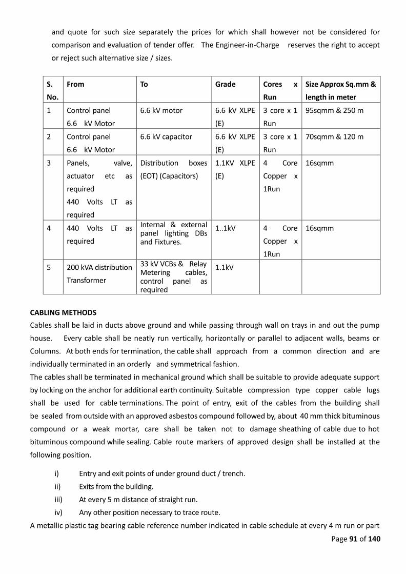
Page 91 of 140
and quote for such size separately the prices for which shall however not be considered for
comparison and evaluation of tender offer. The Engineer-in-Charge reserves the right to accept
or reject such alternative size / sizes.
S.
No.
From To Grade Cores x
Run
Size Approx Sq.mm &
length in meter
1 Control panel
6.6 kV Motor
6.6 kV motor 6.6 kV XLPE
(E)
3 core x 1
Run
95sqmm & 250 m
2 Control panel
6.6 kV Motor
6.6 kV capacitor 6.6 kV XLPE
(E)
3 core x 1
Run
70sqmm & 120 m
3 Panels, valve,
actuator etc as
required
440 Volts LT as
required
Distribution boxes
(EOT) (Capacitors)
1.1KV XLPE
(E)
4 Core
Copper x
1Run
16sqmm
4 440 Volts LT as
required
Internal & external panel lighting DBs and Fixtures.
1..1kV 4 Core
Copper x
1Run
16sqmm
5 200 kVA distribution
Transformer
33 kV VCBs & Relay Metering cables, control panel as required
1.1kV
CABLING METHODS
Cables shall be laid in ducts above ground and while passing through wall on trays in and out the pump
house. Every cable shall be neatly run vertically, horizontally or parallel to adjacent walls, beams or
Columns. At both ends for termination, the cable shall approach from a common direction and are
individually terminated in an orderly and symmetrical fashion.
The cables shall be terminated in mechanical ground which shall be suitable to provide adequate support
by locking on the anchor for additional earth continuity. Suitable compression type copper cable lugs
shall be used for cable terminations. The point of entry, exit of the cables from the building shall
be sealed from outside with an approved asbestos compound followed by, about 40 mm thick bituminous
compound or a weak mortar, care shall be taken not to damage sheathing of cable due to hot
bituminous compound while sealing. Cable route markers of approved design shall be installed at the
following position.
i) Entry and exit points of under ground duct / trench.
ii) Exits from the building.
iii) At every 5 m distance of straight run.
iv) Any other position necessary to trace route.
A metallic plastic tag bearing cable reference number indicated in cable schedule at every 4 m run or part
Page 92 of 140
thereof and at both ends shall be provided. For case of identification and route tracing. The schedule shall
be prepared by the contractor and submitted for approval.
The cable routing and laying shall be such that sharp bends and links are
avoided. The radius at bends for PVC insulated cables shall not be less than 15
D where D is overall diameter of the cable. Laying and termination of 11 kV and 6.6 kV grade cable shall
be as per manufacturer’s instructions. Such instructions shall be furnished to the Engineer-in-Charge.
Loops/extra length shall be provided in each cable run located suitably. The loop/extra length shall be
adequate for two straight through joints as and when such needs arises.
CABLE DUCT :
Following cables shall b e laid in cable ducts -
a) 33 kV 3 core 50 Sq. mm XLPE (E) cable from isolator / AB switch to all transformers.
b) From 7500 kVA transformer to 6.6 KV panel and 160 kVA Transformer to 415 V Panel.
The duct shall be designed and constructed in RCC of suitable size as required
as per I.E. rules, ISA 40 shall be inserted at 400 mm center to center to support
at 200 height above bottom and clamp the cable. The 1 core cables shall be laid
in trefoil formation. The cables shall be clamped at 1200 mm interval. The ducts shall be supported
by suitably designed rigid RCC column from HT sub-station to pump house. The cost of all this RCC
work is included in this item. Pre-cast covers shall be provided over the trench. The arrangements
shall be got approved prior to execution.
CABLE TRAYS :
The cable trays shall be used for indoor installation of cables and outdoor vertical runs on the
building. The trays shall be of mild steel pre-fabricated and perforated. The sheets shall be of
thickness not less than 2.0 mm shall be complete with approved. Tees fixing and shall be hot dip
galvanized. Bends and tees shall also be pre-fabricated with inside radius not less than 300 mm
or above (in case of large cables) and galvanized. All cuts on site shall be treated with cold
galvanizing process. Support brackets shall be provided at maximum of 1200 mm centers. Cable
trays from panel to motors shall be supported from underside of floor slab.
Cable shall be fixed on the trays at an interval of 1500 mm with suitably designed cable clamps.
The cables shall be supported at each 250 mm span particular care shall be exercised in laying
cable on vertically rising trays by providing adequate cable fixing at short intervals to ensure
that cable is not under any strain, load is property transmitted to clamp and cable is securely fixed.
Separate cable tray shall be used for power and control cables and also the cables operating
on different voltages.
33 kV and 6.6 kV TERMINATION KITS Termination method on pole structure, VCB, Vacuum contractor, motor for 6.6 kV and 33 kV cables
shall be as recommended by the manufacturer, with cable termination heat shrink type
Page 93 of 140
Kit/Compound etc. and any structural work required for its proper mounting connections including
lugs and glands.
The 11 kV cable shall be laid in suitable vertical G.I.Pipe with clamp while jointing to DP
structure.The termination kits shall be provided as per requirement.
TESTS FOR CABLES
The scope of third party inspection by an agency approved by MJP to as under;
a) Review of raw materials test certificate and quality control procedure,
b) Routine test,
c) Overload test,
d) Insulation Resistance test.
Above test are to be carried out
i) For H.T.cables of 95 Sq.mm size and above and if length required is 300 mtrs. and above.
ii) For L.T. cables of 300 Sq.mm size and above and if length required is 300 mt. and above.
For conditions other than (a) and (b) manufactured test certificate for routine test shall be furnished.
EARTHING ARRANGEMENT GENERAL
The Earthing arrangement for sub-station switch yard and indoor equipment shall be designed in conformity
with the I.E. rules 1956 and IS: 3043 and Rules/ Regulation/ Instructions of statutory authorities, as
applicable for the class of work under the contract. The arrangement specifications and quantity/size
stipulated hereunder are minimum requirements. It shall however, be the responsibility of the contractor
to design and provide the earthing arrangement as stated above without any extra cost.
EARTH ELECTRODE AND EARTH PITS
All earth electrodes shall be of 50 mm G. I. pipes, 3.0 length with a trough and cover. The electrodes
shall not be situated at a distance less than 1.5 m from building fencing structure and equipment
foundations. The earth pits shall confirm to the provisions in IS and shall be constructed in M-150
concrete. Required quantity of salt and charcoal shall be provided. Each earth pit shall have funnel
arrangement for watering, minimum requirements of each pits/ electrodes are as under.
Earthing for 6.6 kV system: 20 Nos
Earthing for 0.415 kV system: 10 Nos
Each earth electrode shall have disconnecting link to disconnect and measure resistance of earth
electrode. RCC chamber shall be provided with C.I. cover to each earth pit. RCC chamber’s top shall be
flushing to metal spreading level in switch yard.
A ring bus shall be formed in a pole yard and transformer yard to which individual earth electrode shall be
connected. Earth leads from equipment, structure etc. shall be connected separately to the ring bus.
Both ring buses shall be interconnected with two parallel earth leads at two opposite points on each
ring bus.
Page 94 of 140
EXTENT OF EARTH CONNECTIONS
Earth connections shall be given to metal frame work of Brakers, switches, operating handles,
lightening handles, and body cable box and glands, VCB body. Each unit shall have two separate and
distinct earth connections of adequate size.
EARTH LEADS
Minimum size of earth leads for earthing of equipment shall be as under.
Lightening arrestor, A.B. switches steel structure 50 x 6 mm
Transformer body, cable box, gland Galvanized M.S.
Fencing flat Transformer neutral
The earth leads run on the structure shall be severely bolted or clamped. Neutral earth leads shall
run on separate support without touching body of the transformer. The run and arrangement
of earth lead shall be neat and in parallel and at right angles formation with reference to general
layout of switch yard and equipment. The bend in flat shall be gradual to prevent mechanical
damage and 90o multiple bends if required in earth leads shall be located below ground level.
Inter connections of the earth continuity conductor and main/branch earth shall be bolted
ensuring reliable, permanent and good electrical connection and further brazed. Earth leads shall
be protected against mechanical damage and corrosion particularly at the point of connection.
EARTHIG FOR 6.6KV AND 415V SYSTEMS
The earthing shall be generally as specified above and as detailed
a) Minimum 20 earth pits for 6.6 KV kV system.
b) Minimum 10 Nos. earth pits for equipments and panel of 415V system.
c) There shall be separate and independent earthing system for 6.6KV, and 415V system and
isolated from each other.
d) Earth electrodes for 6.6KV, 33 kV and 415V system shall be 50 mm diameter G.I. and of
3m long.
e) Separate ring bus shall be formed for each system to which individual earth electrode of
the system shall be connected. Earth leads from equipment shall be connected
separately to the ring bus.
f) Two earth leads from each equipment shall be connected to ring bus
independently.
g) A disconnecting link shall be provided at each pit for disconnection and measuring earth
electrode resistance.
PUMP HOUSE ELECTRIFICATION AND SWITCH YARD LIGHTING
SWITCH YARD LIGHTING
Switch yard lighting to be provided erected and tested with 8 nos. street light fitting fixtures of
HSPV lamp 250 Watt on 8.5 M ISWP with lamp, pole fixture and bunch of suitable copper wire
on poles with G.I. pipes ‘B’ Grade 50mm dia. 2.5 Mt. long bracket complete duly clamped with

Page 95 of 140
suitable pole cap, pole base plate, required terminal box, G.I. pipe for cable run vertically to
pole terminal box and RCC plinth foundation complete. Pole to be painted by two coats of red
oxide and two coats of silver paint. Eight 250 W HSPV fittings on ISWP pole will be installed in HT
sub-station.
Location of poles in switch yard will be decided by Engineer-in-Charge. Pipe type earthing per pole
is included in this work.
Suitable size cable i.e. 4 core x 10 Sq mm to be provided for above lighting and power connection
to be taken from nearby switch room with required switch fuse unit. Payment for 4 core x 10 Sq
mm cable will be made for actual length at the rate mentioned against item of cable.
The cable to be laid underground as per standard specifications. Poles to be connected by
extra leads to nearby earth bus in an engineer manner.
PUMP HOUSE LIGHTING INTERNAL AND EXTERNAL
For pump house, office and switch room illumination and ventilation work following minimum
number of fixtures and accessories are to be provided.
Power supply to be taken from nearest L.T. panel in separate miniature circuit breaker panel.
Required number of power plugs shall be provided. Complete lighting drawing shall be got
approved from the department before starting the work. Industrial tube light fitting shall be
controlled from one control point, necessary single pole breaker and bunch of 4 rum copper
wire should be arranged from. 415 V 32A 8 way distribution board with RCCB + MCB is to be
provided and fixed along with required 6-32 A MCB.
The scope of work for internal and external electrification work will be as below:
Sr No Item Quantity
A] INDOOR 1] 1x36 W T 8 Industrial Tube light Fitting with 30 Nos
lamp
2] Exhaust Fan 400 mm size,230V AC ,1Phase 8 Nos
3] Ceiling Fan 1200 mm size ,230V AC,1Phase 4 Nos
4] 11 W CF Lamp (Solar) 2 Nos
5] Point Wiring in PVC Conduit 52 Nos
6] Half Point Wiring in PVC Conduit 10 Nos
7] Solar PV panel with inverter & battery one set (For 66W Load)
8] SPMCB Distribution board 10 way
Sr No Item Quantity
B] OUTDOOR
1] 250 HPSV Fitting with lamp & bracket 20 Nos
2] GI Pipe Poles 8.5 M with CC Foundation 14 Nos (6 with dual
fitting)
3] PVC Power Cable 2C X 4 Sqmm 200 Mtr
Page 96 of 140
4] PVC Main wire 2CX 2.5 Sqmm 100 Mtr
5] FRP Terminal box 14 Nos
6] 11W CFL street light fitting with wall bracket 4 Nos
7] Pipe earthing 4 Nos
Complete load should be equally distributed on each phase and maximum
number of circuits should be provided as per I.E. rules. (8 point per DPMCB)
The work of providing wall racess for exhaust fan fitting and providing G.I. sheet fabricated
cowl/louvers is included in this work.
Lighting circuit of solar fitting, inverter circuit and shall be separate with automatic changeover
whenever MSEDC supply goes off and comes on.
The above mentioned fixtures are to be suitably arranged for lighting and ventilation purpose
of main pump house and office room.
FIRST AID OUTFIT, SAFETY EQUIPMENT
The specifications for first aid outfits and fire extinguishers are as follows.
FIRST AID OUTFITS
Two boxes of first aid outfits shall be supplied and housed in sturdy box wall fixing type and the
contents of each box shall be as under.
a) Six small size sterilized un medicated dressings for injured fingers.
b) Three larger sterilized un medicated dressings for other injured parts.
c) Twelve adhesive wound dressings of an approved type and of assorted Sizes.
d) The triangular bandages of unbleached calico the longest side of which measures not less
than 1295 mm and which of the other sides not less than 914mm.
e) A sufficient supply of adhesive plaster.
f) A sufficient supply of absorbent cotton wool in approximately 14 gram packets.
g) A sufficient supply of approved type eye ointment in a container of an approved type and
size.
h) Two sterilized eye-pads in separate sealed packets.
i) Eye bath.
j) A rubber bandage or pressure bandage.
k) Five safety pins.
They shall be fixed in position directed by the Engineer together with a board giving advice of first
Aid treatment. Medical instruction shall be of large character in English.
FIRE EXTINGUISHERS
For fire extinguishers shall be supplied, each fire extinguisher shall be of the light alloy CO2 type (for
dealing with electric fires) of not less than 5 shall have an effective jet strength of at least 2m,
be suitable for operation in ambient temperature of 50o and subject to test pressure of not less
than 87 Kg/cm2 and complete with wall mounting bracket.
They shall be fixed in position directed by the Engineer together with a board giving instructions.
All operating instructions shall be of large characters in English on instruction charts.
Page 97 of 140
Four numbers of fire extinguishing sand filled, red coloured M.S. Buckets with suitable fabricated
stand shall be supplied and placed as directed by the Engineer.
TEST AND TRIAL OF PUMPING MACHINERY
Test and Trial after satisfactory field test carried out including Operation and maintenance of
pumping machinery after satisfactory completion, test and trial for 12 weeks (as described in
Schedule B).
The contractor shall carry out operation and maintenance of pump house and the works involved in
the scope of this tender.
The intention of carrying out operation and maintenance through contractor is to operate the
pumps as per the requirement of the department, impart training to the department staff in a
systematic manner so that the starting and stopping of pumps is done methodically, the records
are maintained, checks, routine maintenance which shall be as under.
1. Operation of all pumps, motors, valves and sub-station and supply water as per the
requirement of dept. 2. To maintain all records i.e. logbook, for operation and maintenance.
3. To monitor all parameters such as pressure, temperature, sub-station
equipments and for all other systems specified in the tender.
4. To carry out routine checks water level, operation of equipments, noise, vibrations and
shall maintain all corresponding records.
5. Carrying out preventive maintenance during above period such as lubrication, greasing, gland
cooling abnormal heating of panel, motor, etc. checking of loose connections de colorization
of cables, small and keep the instructions neat and clean dust free.
6. The pump house shall clean as far as possible from leakage water i.e.
checking and keeping the drainage arrangement clean and clear removing
waste, etc. 7. To give training to the operators or to the agency envisaged by the dept. for smooth O & M.
8. The contractor shall provide log books and all records as directed by the
dept. and shall hand over to the dept. and safety precautions for emergency
situations such as power failure, tripping restarting, abnormal leakages in
pump house short circuits sparking fire, etc.
9. The contractor shall prepare exhaustive O & M manual incorporating O & M
procedure for all the electrical and mechanical equipments of pumping station and
electrical sub-station. It shall provide information about recommended spares, name,
addresses, telephone Nos. and Fax Nos. and suppliers of plant and its spares. The preventive
maintenance schedule, circuit diagrams as built construction diagrams, duly dimensioned,
piping and valve diagrams etc. It shall be in -
i. Book Format : 4 Nos. ii. Pen drive form : 4 Nos.
The contractor shall not be relieved unless these manuals are provided.

Page 98 of 140
The contractor shall provide sundry material of good quality of recommended grease, oil
for lubrication, cotton waste gland, packing, rubber, packing kerosene and petrol for
genset of lighting, etc. as required. The tools supplied under the contract shall be allowed
to be used for O & M and shall be handed over in good working condition.
Normally the water would be supplied regularly after stabilizing the system with full trial and
testing and the requirement would be generated in stages.
The O & M therefore, shall be carried out on shift basis and No. of shifts specified in
the tender shall be completed and shall be certified by the Engineer-in-Charge.
The Contractor shall prepare user friendly software in standard database format for
registering, maintaining and updating database of pumping and operating details of WTP.
The software shall be able to transmit, receive the data through Modem to Head office.
29.0 AUTOMATION, PLC, SCADA & ACCESSORIES
General Requirements:
It is not intent to cover all detail engineering for equipment design, manufacture, installation, tests
and commissioning in this specification, but to cover the general and overall requirements to be
applied to the PLC based control system.
Any omissions in the specification shall not relieve the contractor from his obligation to provide a
system compatible with the intent of the specification. All components shall be of a proven and
reliable design and the highest possible uniformity and inter changeability of all parts shall be
reached. Contractor shall accept full system responsibility for all supplied hardware and software
and provide necessary training, supervision, and spares. They are fully responsible for Installation,
start up and commissioning assistance until successful handover to owner. All the Master PLCs and
Micro PLCs to be supplied for pumping station automation shall be from the same make. Contractor
shall take a precaution to select the same model of master PLCs, Micro PLCs, communication
switches, panels and accessories in case if the function is similar and repeated.
Each PLC system can work independently to guarantee the safety of each process system in case the
control network fails.
All technical services necessary to satisfy the various documentation and drawing requirements iden-
tified in this specification is included in a master drawing list.
The equipment, materials, and services to be furnished shall include, but not necessarily be limited
to, the following major items
a. Redundant Ethernet switches with built-in Fiber optic ports
b. Operator cum Engineering workstations (Server class machine)
c. All cable (communication cable, prefabricated cable etc…)
d. Network Cabinet for mounting Ethernet switches in Electronic Equipment room
Page 99 of 140
e. Required software
f. Other accessories as required by the system
g. Master PLC control panel
System Acceptability.
The system shall be designed and equipped to withstand, to the maximum extent possible, lightning
surge by atmospheric electrical disturbance without damage or disruption. The system architecture
shall accept new technology as it becomes available, and future system enhancements shall be com-
patible with the equipment supplied under this contract so that extensive hardware and software
retrofitting shall not be necessary.
The Contractor shall not propose or provide equipment from any manufacturer that is expected to
be superseded or outdated by a later generation of equipment prior to the commercial operation
date. The plant control system shall ensure maximum reliability during system operation, so that no
single component failure, shall affect the control and data acquisition functions of the system. All
equipment shall be new, unused, and of the highest quality available from the manufacturer.
The system shall be designed to detect failures by the use of continuously running diagnostic routines
and bring them to the operator's attention & provide hardware and software designs that react to
failures in a predictable and repeatable manner.
The programmable logic controller (PLC) shall be an embedded I/O design, with I/O expansion capa-
bility. A single chassis shall house CPU, memory, embedded I/O circuitry, communications and power
supply.
The PLC shall be designed to operate in an industrial environment with an ambient temperature of
0° to 55°C and with a relative humidity range of 5% to 95%, non-condensing. The PLC shall be de-
signed to operate in a free airflow environment (convection cooling only, no fans or other air moving
devices shall be required, however the control panel shall be provided with cooling fan along with
filter).
The PLC shall be designed and tested to operate in high electrical noise environments.
The system shall support up to 12 expansion modules (input/output, discrete or analog) for a total of
up to discrete I/O as designed by contractor. The expansion modules shall be front accessible. There
shall be a proper Isolation between all internal logic and external circuits. Each input and output
point shall have a visual indicator to display ON/OFF status. All users wiring to I/O modules shall be
through a heavy- duty terminal strip. Pressure-type screw terminals shall be used to provide fast,
secure wire connections.
System Timing:
The update rate, processing rate, and response time of all the data highway communications net-
work, wireless network and of the overall system shall be sufficient to maintain control over the plant
processes and equipment under all system operating conditions, including extreme upset conditions.
The system response timings shall be the time required for the exchange of command & status signals
in the complete control system network. The control system network includes Historian server, mas-
ter PLCs, work stations, panel mounted HMIs, switch gears, field instruments.
Page 100 of 140
At a minimum, the control system shall respond to operator commands and system changes as fol-
lows:
Time to completely generate a display shall not exceed 1 second.
The indication of any variable, on all displays including alarm displays, shall be updated within 1 sec-
ond of its value or status change.
The time to respond to any operator command shall not exceed 1 second.
The time to respond for Foreign device Interface (FDI) functions shall not exceed 1 second (response
time will not include the time required for the foreign device to respond to the control system; only
the actual bidirectional communication time shall be considered).
The bidder shall provide minimum of 20% spare capacity to accommodate any control and data ac-
quisition functions that may be added to the system during the start up phase of the project and
thereafter.
All equipment shall be designed for operation in plant areas with the environments defined in the
specification.
System Description:
Bidder shall provide complete and independent PLC based Control and Instrumentation system with
all accessories, auxiliaries and associated equipment and cables for the safe, efficient and reliable
operation of the following systems.
There shall be Master PLC control panel, workstation, communication switches & other accessories.
All the master PLCs shall be interfaced with Historian station on single mode, 8 core redundant optical
Fiber communication. The communication network shall be Star network with historian station as a
center of the network.
The location of Master PLCs shall be at Raw water System.
Programmable Logic Based Control System requirement
Master PLC Processor
The processor unit shall be capable of executing the following functions:-
a. Receiving binary and analog signals from the field and operator initiated commands from operator
Work Station (OWS)/ control panel.
b. Implementing all logic functions for control, protection, data storage, developing alarms and annun-
ciation of the equipment and systems.
c. Implementing modulating control function for certain application as specified elsewhere in the spec-
ification.
d. Issuing control commands.
e. Providing supervisory information for alarm, various types of displays, status information, trending,
historical storage of data etc.
f. Performing self-monitoring and diagnostic functions.
g. Interfacing with micro PLCs on wireless communication in Ring topology network. Interfacing with
other Master PLCs/Historian server on optical Fiber communication in star network. Interfacing with
Page 101 of 140
other programming devices on Ethernet/mod bus/RS 485 communication.
h. Interfacing with flow meters on wireless communication
i. The PLC controller shall provide all basic functions of binary gate operations, modulating controls,
storage, counting, timing, logging, transfer operations and comparison functions. The PLC shall have
expansion capability and shall provide Human-Machine Interface (HMI) functions, including display
processing, data acquisition and display, data storage, data history systems, alarm processing, event
recording, process reporting, control sequence configuration, integrated database management and
engineering maintenance utilities.
j. At no time, PLC processor shall utilize more than 70 % of it’s capacity during execution of the pro-
gram. CPU load calculation shall be provided by the manufacturer and manufacturer to provide the
method of test, which will be reviewed and then approved. The processor utilization shall be always
below that.
k. Bidder to provide the redundant power supply unit of suitable capacity specifically for PLC CPU pow-
ering. The power supply unit shall be separate from the PLC input/output card power supply unit. A
common bus of two power supply units shall be provided in the PLC control panel. In case of failure
of one of the power supply unit other power supply unit shall deliver power to the CPU power bus.
The changeover shall be bump less. Power supply failure indication to be provided on control panel.
l. PLC programming software for both types of PLC’s i.e. micro PLC’s & main PLC shall be preferably
same.
PLC Memory
a. Each PLC unit shall be provided with memories, the memory shall be field expandable & shall
have sufficient capacity to execute the complete system operation. Memory shall have a capa-
bility for at least 30% expansion in future.
b. Programmed operating sequences and criteria shall be stored in SD card.
c. In PLC controller, memory should exist as to where the sequence was aborted due to power
supply failure so that further operation from that point can restart after power supply restora-
tion. This restart after recovery of the power supply shall be through operator intervention so as
to enable verification of readiness of other related equipment. At no time, PLC memory shall
load more than 70 % of its capacity, the memory loading shall be always below that.
d. The operating system firmware shall be contained in non-volatile memory. An option shall be
possible to store both the user program and system firmware in a removable non-volatile
memory for back- up/restore purposes.
a. Input/ Output Modules
i. Input Output modules, shall be designed in the Control System for all type of field input signals
(4-20 mA, discrete contact inputs etc.) and outputs from the control system (discrete contact,
24/48 VDC output signals for energizing interface relays and 4-20 mA output etc.) are to be pro-
vided by the bidder.
ii. Electrical isolation of 1.5KV with optical couplers between the plant input/output and controller
shall be provided on the I/O cards. The isolation shall ensure that any unintentional voltage or
voltage spikes shall not damage the internal processing equipment.
Page 102 of 140
iii. The Input/output system shall facilitate modular expansion in fixed stages. The individual in-
put/output cards shall have LED indications on the module front panels for displaying individual
signal status.
iv. All input/output cards shall have quick disconnect terminations allowing for card replacement
without disconnection of external wiring and without switching of power supply.
v. The Bidder shall provide the minimum following monitoring features:
vi. Power supply monitoring.
vii. Contact bounce filtering.
viii. Optical isolation between input and output signals with the internal circuits. Isolation for exter-
nal impact on internal part of the system related with the I/O’s.
ix. In case of power supply failure or hardware fault, the critical outputs shall be automatically
switched to the fail-safe mode. The fail-safe mode shall be intimated to the bidder during de-
tailed engineering.
x. Output module shall be capable of switching ON/OFF inductive loads like solenoid valves, auxil-
iary relays, etc. without any extra hardware. However, bidder shall provide coupling relays with
two change over contact to interface with field devices & MCC/PCC for control and interlock
requirement. The required multiplication shall be done in PLC system.
b. Workstation
(i) A PC based Server cum Operator work station (OWS) cum engineering work Stations (OWS) shall
have 32 inch (minimum) flat panel LED displays (dual monitor) with TFT active matrix, a minimum
resolution of 1200 by 1600 pixels, minimum 400:1 contrast ratio, minimum dot/pixel pitch of
0.255 mm, and a minimum brightness of 250 cd/m2. Controls shall be provided on the front of
each monitor for contrast, brightness, horizontal/vertical position, and horizontal size.
(ii) Work station shall include the current state-of-the-art hardware platform (CD/DVD re writeable
drives, ports, processor/bus, RAM, etc.) All monitors shall be designed to minimize reflection and
glare from external light sources. The key boards shall be provided for control, monitoring and
programming function. One number A3 size color inkjet printer shall be provided along with op-
erator work station at each control station. The work station shall be server class machine. Con-
tractor shall provide all the necessary certificates/documents issued by server manufacturer.
(iii) The work station shall perform the functions of Server, Engineer work stations & operator work
station. The term Server/engineer work station refers to the work stations that have typically
been called Engineering Work Stations (EWS), but have the dual functionality of an EWS and
Server.
(iv) The work station shall be able to monitor, view, create, modify, debug, and document any control
or information display, program, database, or other function. Server shall be able to store & op-
erate on the required software’s for development and modification of control and data acquisi-
tion programs.
(v) The work station hardware shall meet system software requirements. System hardware and soft-
ware shall be latest. Server/Engineering station shall be able to call up related data stored in
their associated PLC.
(vi) The workstation shall be used for historical data storage and retrieval. work station shall consist
of monitor(s) as specified above, operator keyboard(s), pointing device(s), and supporting elec-
tronics (operator interface processors, display generators, data highway communications net-
work equipment, network accessories etc.).
Page 103 of 140
(vii) Work station shall have provision for event recording, trending and report generation. The work
station shall have option to reuse previous engineering work like options to import tags from PLC
and screens with tag from Local HMI stations dedicated for PLC.
(viii) The workstation shall perform control, monitoring and operation of all instruments/ drives in-
teracting with PLC based control system. The work station shall be possible to use as program-
ming station of the PLC also.
The work station shall basically perform the minimum following functions:
Provide point and click actions required for the operator to interact with the system, such as cursor
positioning, display selection, menu selection, menu item selection, Operator functions shall in-
clude local/ remote selection, A/M selection, open/ close operation, sequence auto, start/ stop
selection, ON/OFF, raise, lower, bypassing system, Select and execute process and equipment con-
trol functions.
a. Supervisory functions like Select any display to any monitor, and select display combinations of
process Control displays, trend displays, alarm displays, alarm summary, group displays, reports
and bar chart displays on any monitor. Select points and assign parameters for trend displays,
group displays, and bar Chart displays.
b. Runtime HMI software required to consolidate and present all relevant information in standard &
user configurable format, through which the plant operator shall be able to monitor and control
the plant operation.
c. Each work station shall include key lock and/or password protection to restrict access to critical
functions to be performed by authorized personnel only. These functions will be defined by the
owner during the design phase of the project.
d. Programming station shall have access to the processor of the control system for programming.
Programming shall be user friendly & shall not require special computer skills. Programming, self-
diagnostics, testing of sequence, simulation and sequence modification shall be possible on the
programming console.
e. Provision shall be made for erasing and duplicating the user program and long-term storage facil-
ities shall be provided with the help of EPROM from work station.
f. Manual intervention shall be possible at any stage of operation. Protection commands shall have
priority over manual commands and manual commands shall prevail over auto commands.
Printer
One number A3 size color laser inkjet printer with networking capability per main PLC at control
room shall be provided. It shall print out all alarm/trip conditions and event changes in plant status
along with date and time of occurrence. The least count of time for event recording shall not be more
than 100 milliseconds. The printer shall be able to print the trends, displays and graphs also.
Software
a. The bidder shall provide entire set of software required by the system for meeting the functional
and parametric requirements of the specification like implementation of control logic, operator
station displays / logs, storage & retrieval of program.
b. The software and programs shall include high level languages as far as possible. The bidder shall
provide sufficient documentation and program listing in view of making modifications in program

Page 104 of 140
at a later date.
c. All system related software including Real Time Operating System, File management software,
screen editor, database management software. On line diagnostics/debug software, peripheral
drivers’ software and latest versions of standard PC-based software and latest WINDOWS based
packages etc. and any other standard language offered shall be furnished as a minimum.
d. The software shall be password protected. The Bidder shall provide software locks and passwords
to buyer’s engineers nominated by the management authority at site for all operating & applica-
tion software so that buyer’s engineers can take backup of these software and shall be able to
perform modifications at site.
Programming Techniques
The programming format shall be IEC 61131-3 compliant ladder diagram (LD), function block dia-
gram (FBD), sequential function chart (SFC), and structured text (ST) languages. The Programmable
Automation Controller shall organize user applications as Tasks, which can be specified as contin-
uous, periodic, or event based.
Communication System
a. The PLC system shall be provided with necessary interface hardware, and software for dual
Fiber optic connectivity with other stations and Historian server. PLCs shall be provided with
necessary interface hardware, wireless modem, and software for wireless connectivity of mi-
cro PLCs with master PLCs. The PLC system shall be provided with necessary interface hard-
ware and software for communication with programming devices, energy meters, printers on
Ethernet/mod bus/RS 485 communication for two - way transfer of signals for the purpose of
information sharing.
b. The complete PLC network & Historian server shall be interfaced with MIDC internet network.
An enterprise network connectivity module (ENCM) on virtual private network (VPN) to be es-
tablished at plant side after fire wall on 4G network.
c. Historian server shall be provided with backup server named Data server at plant end. The data
server shall be updated periodically in line with main historian server. The fire wall provided
shall have proper De militarized zone (DMZ).
d. The communication system shall include a redundant System Bus with hot back-up and other
applicable bus systems like cubicle bus, local bus, I/O bus etc.
The Communication System inside the pump house shall have following minimum features:
a. Redundant communication controllers shall be provided to handle the communication be-
tween I/O Modules and PLCs and between PLCs and operator work station. During normal
operation 50% loading and during worst case only 70% loading of the communication
throughput shall be utilized.
b. The design shall be such as to minimize interruption of signals. It shall ensure that a single
failure anywhere in the media shall cause not more than a single message to be disrupted
and that message shall automatically be retransmitted. Any failure or physical removal of any
station/module connected to the system bus shall not result in loss of any communication
function to and from any other station/module.
Page 105 of 140
c. If the system bus requires a master bus controller philosophy, it shall employ redundant mas-
ter bus controller with automatic switchover facility.
d. The design and installation of the system bus shall take care of the environmental conditions
as applicable.
e. Data transmitting speed shall be sufficient to meet the responses of the system in terms of
displays, control etc. plus 25% spare capacity shall be available for future expansion.
f. Single mode 8 core Fiber optic cables shall be employed necessary applications. The bidder
shall furnish details regarding the communication system like communication protocol, bus
utilization calculations etc. for owner’s review and approval.
g. The Contractor shall furnish all necessary devices for establishing data communications sys-
tem. Ethernet switches with built in fiber optic ports, fiber-optic patch panels signal condi-
tioners, and prefabricated cables, with all necessary power distribution strips, power recep-
tacles/boxes, and other supporting electrical infrastructure
SCADA shall have following minimum features:
a. Share data and integrate seamlessly with other software and control devices. It shall have a
common service such as security, alarming and diagnostics. SCADA shall have capability of ac-
cessing tag information in the controller, eliminating the need to create HMI tags. A defining
feature of View shall have an ability to “directly reference” live information from any vendors
controllers
b. SCADA shall have a common address book of factory resources so that changes at one place of
the automation system shall updated automatically across the entire control system.
c. SCADA shall have an ability to provide a centralized security authority for all components in
the system. The Diagnostics shall make it easy to record information, warnings and errors gen-
erated by the system and users to a central location.
d. SCADA shall be able to configure the application from anywhere on the network and easily
make changes to a running system, with no need to copy graphics from a Server to Clients. It
shall have a Multi-user configuration capability. It shall provide an audit trail of operator and
alarm information in a centralized log database and shall have an ability of validating the user
access with private and Windows security options.
e. Provides the option of specifying a secondary, or redundant, server to take over in case the
primary server fails (native redundancy). Software shall have Decreases development time and
increases code consistency, and increases display consistency.
System Data Reporting Functions
The control system shall provide data reporting functions, all reports shall be made from stored
data so that once a report is initiated, it can be completed without interruption. The system shall
include major types of reports described below.
The system shall include a library of Contractor-configured report formats as specified in the fol-
lowing articles. Contractor-configured reports shall include all required headers, footers, subhead-
ings, column headings, and descriptive text.
Page 106 of 140
All reports and summaries shall be configured and tested by the Contractor prior to the factory
acceptance test. The system tools shall allow the user to assign run time properties to any report
format, such as specific point tag names, title, file name, execution time or event information, and
destination. For each report, the user shall be able to define whether that report is sent to a printer,
viewed on screen, or saved as a file with complete formatting information. Supported file types
shall include, as a minimum, comma-delimited ASCII, comma-separated variable (CSV), XML, Mi-
crosoft Excel spreadsheet, and HTML file.
Periodic Reports.
Periodic reports shall contain the current and averaged values of system variables collected during
the period. The reports shall be printed out automatically at designated times and on demand by
the operator.
Trend Reports.
Trend reports shall contain current and averaged values of system variables at predetermined in-
tervals. The reports shall be printed out automatically at designated times, on demand by the op-
erator, and automatically on the occurrence of a designated event.
Post-Trip Review Report.
The post-trip review report shall contain current values of system variables at predetermined inter-
vals before and after a plant or major equipment trip. The report shall be printed out on demand
by the operator.
Modulating (Continuous) Control Functions
The analog control loop control stations shall simulate conventional hand/auto stations, allowing
the operator to select a mode and to provide manual interface commands, and shall provide a dis-
play of all relevant variables associated with the control loops including the set point, the feedback
signal, the control signals, and the status of the loop.
The required modes of operation and operator controllable parameters shall be as follows:
Automatic Mode: This mode shall permit fully automatic operation of the system with no inter-
vention on the part of the operator except for the functions designated as operator adjustable,
such as set point adjustment and biasing of control signals.
Manual Mode: This mode shall permit manual "Raise" and "Lower" of system demand signals.
Operator interface for analog control loops shall also include one, two, three, and four vertical bar
indicating stations for indication of analog values. Each vertical bar on the station shall also display
a short description of that point, and the point's process value and engineering units. The multiple
measurement loop control stations shall allow the operator to select the multiple measurement
mode, and shall provide a vertical bar and analog value display for each of the analog inputs and
for the multiple measurement loop output. The station shall also display the multiple measurement
mode and quality of each analog value.
The pulse accumulator loop control stations shall allow the operator to reset and hold pulse accu-
mulation, and shall provide an analog value display of the accumulated total.
All operator interface command functions, except screen paging, shall be designed for two-step
operation. The operator shall be required to make one keyboard or touch screen action to select
Page 107 of 140
the function to be performed and a second keyboard or touch screen action to execute the func-
tion. For example, the operator must select the "Auto" button for a device and then execute the
auto function to prevent accidental touch screen or keyboard activation of control commands.
Discrete Control Functions:
The sequential OR discrete control functions shall be configured for the following applications,
which shall include, but not necessarily be limited to, the following:
a. Start/Stop of Raw water pump motors in sequential form
b. Open/Close/Stop of motor-operated valves
Alarm Functions
Analog Alarm Functions
The system shall perform comparison of limit functions on any or all analog points, as determined
during detailed design. The system shall allow the user to selectively activate or deactivate these
alarms. Each analog input variable, or calculation result, shall have an individual set of alarm limits.
These limits shall be either manually set, calculated as functions of other variables, or rates of
change with time. Violations of these limits shall initiate alarms and/or initiate execution of special
software programs.
Fiber- Optic Patch Panels.
The Contractor shall provide Fiber-optic patch panels and patch cords (patch cable) to connect
fiber-optic cables from PLC to PLC & plant Historian system. Patch panels shall be furnished with
connectors for all Fibers in multi- Fiber bundle cables, whether all individual Fibers are used or not.
Patch panel design and specification shall be the responsibility of the Contractor, and shall be re-
viewed with the owner for approval. Patch panels shall be mounted inside or outside the PLC net-
work cabinet located in respective building/control room where the PLC control panel is located.
Interconnecting Cables.
The Contractor shall provide all interconnecting cables, such as Ethernet (optical Fiber patch cable,
twisted pair) communication cable, cable required for internal cabinet/desk wiring, etc.…as re-
quired for connections between the various physically separated items in the scope of supply.
Fiber-optic cable using plug-in connectors shall be completely fabricated and tested by the Con-
tractor during the factory tests and shall be used to interconnect the system.
Control & Power Supply Scheme
a. For PLC system, redundant 24 V DC power supply shall be provided for PLC CPU power. The PLC
I/O shall be powered from separate powers supply unit. UPS is envisaged in the plant. 3-phase
redundant incomers to be provided by Purchaser at the input terminals of Power supply cabi-
nets.
b. For separately mounted I/O racks, separate power supplies shall be provided. Power supply mod-
ule shall be of sufficient capacity to supply all modules. In addition, 30 % spare capacity for future
shall be provided. All the drives shall be switched ON/OFF through 24V DC coupling relays to be
provided in HT/LT SWGR panels.
c. Power supply distribution from Bidder’s power supply cabinets shall be in the scope of Bidder.
The exact power supply scheme shall be as approved by Purchaser during detailed Engineering
stage.
Page 108 of 140
System Grounding.
The Contractor's electrical system or logic ground shall be designed for grounding to the station
ground mat at a single connection point. The system cabinets shall be equipped to accept the in-
sulated ground cables, which at this point will be isolated from the building ground. Any internal
component grounds or commons shall be connected to the system ground, which shall be kept
isolated from the building ground.
Any required electrical ground or common from components not mounted in the system cabinets
shall be brought to a terminal block connection within that component. This terminal block con-
nection shall be located with the other terminals within the component and shall be available for
connection through the shield of the field wiring to the system ground bus within the associated
system cabinet. Isolation between building ground and system ground shall be inherent in the com-
ponent design.
At least 600-volt isolation shall be provided between the electrical system or logic grounding bus
bar and cabinet or building ground for all system components.
Historian Server
General Requirements
It is not intent to cover all detail engineering for equipment design, manufacture, installation, tests
and commissioning in this specification, but to cover the general and overall requirements to be
applied to the Plant Historian, Data management, and Alarm management system.
Any omissions in the specification shall not relieve the contractor from his obligation to provide a
system compatible with the intent of the specification. All components shall be of a proven and
reliable design and the highest possible uniformity and inter changeability of all parts shall be
reached. Contractor shall accept full system responsibility for all supplied hardware and software
and provide necessary training, supervision, and spares. They are fully responsible for Installation,
startup and commissioning assistance until successful handover to owner.
The equipment, materials, and services to be furnished shall include, but not necessarily be limited
to, the following major items
a. Redundant Ethernet switches with built-in fiber optic ports
b. Network Cabinet for mounting Ethernet switches in Electronic Equipment room
c. Fiber optic patch panel as required
d. All cable (communication cable, prefabricated cable etc…)
e. Operator cum Engineering workstation
f. Network colour laser printer for Database & graphs
g. Operator control console (Desk), work station as specified in PLC specifications
h. Cable Termination Materials and accessories (Lugs, Glands, ferrules, Fittings, connectors (Ethernet,
fiber optic) etc.
i. Required software for database management, Alarm management, Historian, Enterprise data com-
munication network, clock synchronization, firewall and Gateway, internal LAN, OS
j. Other accessories as required by the system

Page 109 of 140
System Description
The optical fiber data highway integrates the total system and shall be configured with Redundant
Architecture for high reliability. The system shall be fully operational with one data highway out of
service and with no degradation in performance for components. Only the listed manufacturers
are recognized to maintaining the level of quality of workmanship required by the specification.
Master PLCs shall be provided with wireless modem.
A local control room shall be constructed in each section to install the Master PLCs for Raw water
and EHVT systems. The Filter house master PLCs shall be located in the centralized main control
room.
Historian and Data Acquisition systems
Data Acquisition System (DAS) software shall be loaded in the Engineering cum operator work sta-
tion associated with Master PLCs. The detailed quantity of tag numbers shall be discussed during
detailed engineering. Contractor shall define and declare the amount of memory space to be ac-
quired by the DAS in destination
DAS shall continuously process all relative important process point signals and status signals of
equipment of the unit to provide plant personnel with information to implement the safe and ef-
fective operation of the unit. Alarm whenever any abnormal condition of unit exists, so to increase
the availability of the unit.
The DAS shall send the real-time data to OPC server. The DAS can be a part of the individual SCADA
or a separate device which can interface PLC & OPC server.
Short- Term (Trend) Data Storage.
The historian shall have short-term data storage to allow data retrieval for recent and active trend
displays. The system shall be able to store and display the variables like I/O point and calculated
variables in the form of trend display, process control display, or report.
Long-Term (Historian) Data Storage.
The system shall be complete with hardware and software and able to store the long-term data in
the form of plant data and information on permanent storage media for later retrieval and use.
The historian shall utilize relational database technology to provide storage of plant information in a
format that is accessible to all SCADA applications as well as external databases and third-party
applications. A relational database management system (RDBMS) shall be included to allow data
access through standard Open Database Connectivity (ODBC) and Structured Query Language
(SQL). The retrieved data shall be accessible from all the normal system peripheral devices such as
operator work station monitors, and printers. The long-term data shall be available for use in trend
displays, process control displays, reports, and calculations. The data retrieval capability shall be
minimum of Five years.
The decision support model allows users to perform below main tasks
a. To analyze historic and current data such as flow & head.
i. Daily flow summaries
ii. Daily pressure summaries,
Page 110 of 140
iii. Daily summary statistics for special periods
iv. Maximum delivery value observed in the day
v. Minimum delivery value observed in the day
vi. Average of values observed in the day
vii. Calculated performance
viii. Electrical parameters
b. The widgets can be made personalized or can be made private to their login or public to all the
users.
30.0 UPS & Battery Charger General Requirement
The scope of this work includes sizing, design, supply, erection, cabling and commissioning of Un-
interruptable power supply (UPS).
UPS design: Design of UPS shall be based on electrical consumption, mounting arrangement,
interface requirement with control system, general requirement and specifications below.
Erection of UPS: Erection includes mounting of UPS at designated control room, laying of cable
from UPS to control system. UPS and battery charger can be provided as a single device.
Specifications of Uninterruptible Power Supply (UPS) System
The UPS system shall have following accessories:
• 2x100% parallel redundant chargers and inverters,
• 1x100% battery bank,
• Bypass line transformers and voltage stabilizer,
• other necessary protective devices and accessories
a. The kVA rating of UPS shall be minimum 1.5 KVA and include 10% spare capacity guaranteed
at 50 deg. C ambient. The UPS shall have an over load capacity of 125 % rated capacity for
10 minutes and 150 % rated capacity for 10 seconds. The inverter shall have sufficient I2t ca-
pability to clear fault in the maximum rated branch circuit. The sizing of UPS shall be based
on the power factor of the loads being fed subject to a maximum of 0.8.
b. Each of two sets of 2x100% redundant chargers shall be sized to meet the 100% UPS load
plus recharge the fully discharged battery within 8 hours.
c. The UPS battery shall have sufficient amp-hour capacity to supply 100% full load current of
UPS for 480 minutes. For this, the UPS capacity to be considered as the finally selected UPS
rating, irrespective of the actual load on UPS. A drop of 4V from battery station to the inverter
input shall be considered for design.
d. The UPS system design shall ensure that in case of failure of mains input power supply to one
of the chargers, the other charger whose mains input power supply is healthy, shall feed to
one or both the inverters.
Batteries
Page 111 of 140
The batteries shall be heavy duty Nickel-cadmium (Ni-cd) type only and shall be sized for 8 hour
of full load operation during non-availability of AC supply. The Ni-Cd batteries shall conform to
IS:10918. For sizing calculation, an aging factor of 0.8 and a temperature correction factor of
0.935 (based on temperature characteristics curve to be submitted by the contractor and at a
temperature of 4 deg. C). Capacity factor shall be taken into consideration, if applicable and am-
bient temperature shall be considered as the electrolytic temperature. The sizing of the battery
shall be as approved by consultant/owner during detailed engineering. However, contractor
shall consider a voltage drop of 4V from battery station to UPS, while sizing the battery.
CLOCK SYNCHRONIZATION SYSTEM
Automation of the water treatment plant includes master PLCs with their SCADA, historian sta-
tion, firewall gateway, Enterprise data network communication system.
The different instruments are distributed in different sections of the pump house for monitoring
and control. The distributed instruments network needs to bring in a same time zone in view of
reading the real time data from the network at real time stamping. The intent of this specifica-
tion is to design, supply erect, configure, communicate and commissioning of the GPS synchro-
nized timing system.
A GPS synchronized timing system receiver and it’s required accessories shall be designed sup-
plied & commissioned by the contractor. PLC based SCADA systems shall synchronize with the
system clock to within 0.001 second of a time signal received from a GPS synchronized timing
receiver. The system may also use Network Time Protocol (NTP), Simple Network Management
Protocol (SNMP), or TCP/IP. All, software, and cables shall be provided to support a fully func-
tional time synchronization system. The system shall be fully configured at the site by the Con-
tractor.
31.0 FIBER OPTIC CABLE
General Requirement The scope of this work includes sizing, design, supply, excavation of land, laying and commissioning of Fiber Optical Cable, cable network and accessories.
Fiber Optical Cable design: Design & selection of Fiber optical cable, design of patch panel, switches, and hardware and cable accessories. Conducting feasibility study at the site to finalize the fiber optical cable network layout to meet the data transfer speed at expected bandwidth. De-sign of cable support required for outdoor and indoor laid cable. Design shall meet the General requirement and specifications below.
Laying of the Fiber optical cable: Excavation of land as per the network designed path, Laying of Fiber optical cable, covering with 25 mm DWC conduit pipe throughout the cable length and half round RCC pipe for ground laying/road crossing area, backfilling of the land. Termination at each end of control system.
Commissioning: Commissioning of Fiber Optical Cable network includes establishing the commu-nication between end to end control systems. Establishing the data transfer between end to end control systems at appropriate speed on expected band width.
Page 112 of 140
Specifications: Fiber optical cable shall be 8 core, corrugated steel taped armored, fully water blocked with die-lectric central member for outdoor/indoor application so as to prevent any physical damage. The cable shall have multiple single-mode fibers as required by the communication system so as to avoid the usage of any repeaters. The core and cladding diameter shall be 9 +/- 1 micrometers and 125 +/- 1 micro- meters respectively. The outer sheath shall be Flame Retardant, UV resistant prop-erties and identified with the manufacturer’s name on it.
The cable core shall have suitable characteristics and strengthening for prevention of damage dur-ing pulling viz. Steel central member, loose buffer tube design, 4 fibers per buffer tube (mini-mum), Interstices and buffer tubes duly filled. The cable shall be suitable for a maximum tensile force of 2000 N during installation, and once installed, a tensile force of 1000 N minimum. The com-pressive strength of cable shall be 3000 N minimum. The operating temperature shall be –200 C to 700 C. All testing of the fiber optic cable being supplied shall be as per the relevant IEC, EIA and other international standards.
Contractor to ensure that minimum 50% cores shall be kept as spares in Fiber optical cables.
The network of Fiber optic cable developed in the plant shall conform to ISO 8802.3 100BASE-FX or 1000BASE- SX. The network shall be designed for maximum speed through the use of Gigabit (or faster) components where possible.
32.0 ELECTRO MAGNETIC FLOW METER
The scope of this work includes sizing, design, supply, erection and commissioning of Electromag-netic flow meter.
Transmitter design: Sizing & selection of Electromagnetic flow meters based on process data, process requirement, and general requirement and specification below.
Erection of EMF meter: Erection includes mounting of process isolation valve, erection of impulse piping, mounting of Electromagnetic flow meter’s support and rack, laying of electrical cable from
PLC to EMF meter, mounting of junction box, glanding, termination and interfacing of EMF meter
with control system.
Commissioning: Commissioning of transmitter includes, calibration checking, loop checking, test-ing of Electromagnetic flow meter from PLC and open / closed loop checking from sub control system & main control system.
Technical Specifications of Electromagnetic Flow Meter
a. Full bore bi-directional electromagnetic flow meters shall be designed, manufactured and cal-
ibrated to international standards. Meters shall also have actual Flow rate & Totalized value for effective water management purposes. The accuracy shall be +/- 0.5% of reading.
b. The contractor shall have full ISO 9000 series accreditation and fully traceable calibration methods to either of the two primary standard means of testing. These are mass (ISO 4185) or volume (ISO 8316). Testing by ISO 9104 strictly not acceptable. The contractors shall also have a testing facility in India or abroad so that methodology and procedures can be verified. Each meter shall be wet calibrated with 3-point calibration to verify performance in accordance with the specification & submit report for the same. The testing facility shall be duly accred-ited in accordance with ISO 17025 standards. Regarding testing facility ISO 17025 certification to be uploaded in Envelop no 1.
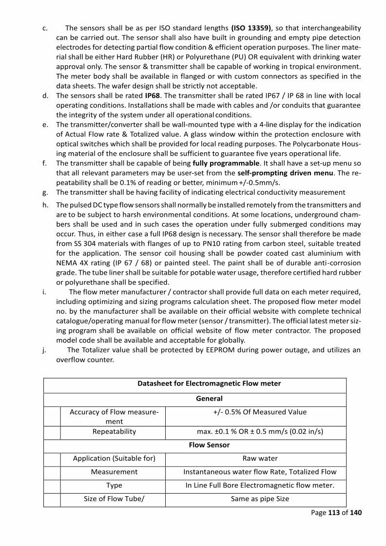
Page 113 of 140
c. The sensors shall be as per ISO standard lengths (ISO 13359), so that interchangeability can be carried out. The sensor shall also have built in grounding and empty pipe detection electrodes for detecting partial flow condition & efficient operation purposes. The liner mate-rial shall be either Hard Rubber (HR) or Polyurethane (PU) OR equivalent with drinking water approval only. The sensor & transmitter shall be capable of working in tropical environment. The meter body shall be available in flanged or with custom connectors as specified in the data sheets. The wafer design shall be strictly not acceptable.
d. The sensors shall be rated IP68. The transmitter shall be rated IP67 / IP 68 in line with local operating conditions. Installations shall be made with cables and /or conduits that guarantee the integrity of the system under all operational conditions.
e. The transmitter/converter shall be wall-mounted type with a 4-line display for the indication of Actual Flow rate & Totalized value. A glass window within the protection enclosure with optical switches which shall be provided for local reading purposes. The Polycarbonate Hous-ing material of the enclosure shall be sufficient to guarantee five years operational life.
f. The transmitter shall be capable of being fully programmable. It shall have a set-up menu so
that all relevant parameters may be user-set from the self-prompting driven menu. The re-peatability shall be 0.1% of reading or better, minimum +/-0.5mm/s.
g. The transmitter shall be having facility of indicating electrical conductivity measurement
h. The pulsed DC type flow sensors shall normally be installed remotely from the transmitters and are to be subject to harsh environmental conditions. At some locations, underground cham-bers shall be used and in such cases the operation under fully submerged conditions may occur. Thus, in either case a full IP68 design is necessary. The sensor shall therefore be made from SS 304 materials with flanges of up to PN10 rating from carbon steel, suitable treated for the application. The sensor coil housing shall be powder coated cast aluminium with NEMA 4X rating (IP 67 / 68) or painted steel. The paint shall be of durable anti-corrosion grade. The tube liner shall be suitable for potable water usage, therefore certified hard rubber
or polyurethane shall be specified. i. The flow meter manufacturer / contractor shall provide full data on each meter required,
including optimizing and sizing programs calculation sheet. The proposed flow meter model no. by the manufacturer shall be available on their official website with complete technical catalogue/operating manual for flow meter (sensor / transmitter). The official latest meter siz-ing program shall be available on official website of flow meter contractor. The proposed model code shall be available and acceptable for globally.
j. The Totalizer value shall be protected by EEPROM during power outage, and utilizes an
overflow counter.
Datasheet for Electromagnetic Flow meter
General
1 Accuracy of Flow measure-ment
+/- 0.5% Of Measured Value
2 Repeatability max. ±0.1 % OR ± 0.5 mm/s (0.02 in/s)
Flow Sensor
3 Application (Suitable for) Raw water
4 Measurement Instantaneous water flow Rate, Totalized Flow
5 Type In Line Full Bore Electromagnetic flow meter.
6 Size of Flow Tube/ Same as pipe Size
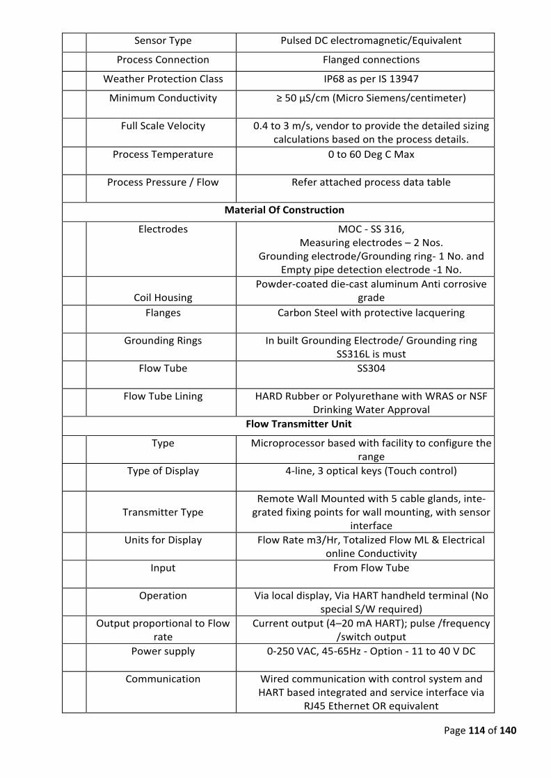
Page 114 of 140
7 Sensor Type Pulsed DC electromagnetic/Equivalent
8 Process Connection Flanged connections
9 Weather Protection Class IP68 as per IS 13947
10 Minimum Conductivity ≥ 50 μS/cm (Micro Siemens/centimeter)
11
Full Scale Velocity 0.4 to 3 m/s, vendor to provide the detailed sizing calculations based on the process details.
12
Process Temperature 0 to 60 Deg C Max
13 Process Pressure / Flow Refer attached process data table
Material Of Construction
14
Electrodes MOC - SS 316, Measuring electrodes – 2 Nos.
Grounding electrode/Grounding ring- 1 No. and Empty pipe detection electrode -1 No.
15
Coil Housing
Powder-coated die-cast aluminum Anti corrosive grade
16
Flanges Carbon Steel with protective lacquering
17
Grounding Rings In built Grounding Electrode/ Grounding ring SS316L is must
18
Flow Tube SS304
19
Flow Tube Lining HARD Rubber or Polyurethane with WRAS or NSF Drinking Water Approval
Flow Transmitter Unit
20
Type Microprocessor based with facility to configure the range
21
Type of Display 4-line, 3 optical keys (Touch control)
22
Transmitter Type
Remote Wall Mounted with 5 cable glands, inte-grated fixing points for wall mounting, with sensor
interface
23
Units for Display Flow Rate m3/Hr, Totalized Flow ML & Electrical online Conductivity
24
Input From Flow Tube
25
Operation Via local display, Via HART handheld terminal (No special S/W required)
26
Output proportional to Flow rate
Current output (4–20 mA HART); pulse /frequency /switch output
27
Power supply 0-250 VAC, 45-65Hz - Option - 11 to 40 V DC
28
Communication Wired communication with control system and HART based integrated and service interface via
RJ45 Ethernet OR equivalent
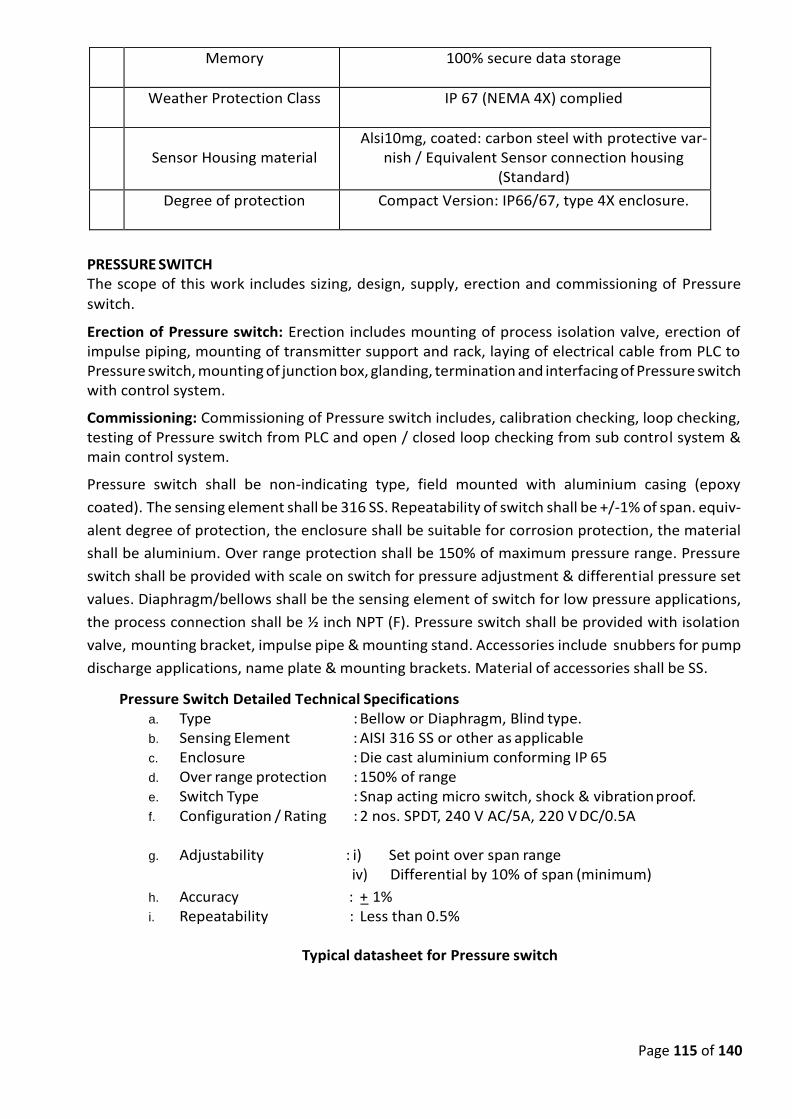
Page 115 of 140
29
Memory 100% secure data storage
30 Weather Protection Class IP 67 (NEMA 4X) complied
31
Sensor Housing material
Alsi10mg, coated: carbon steel with protective var-nish / Equivalent Sensor connection housing
(Standard)
32
Degree of protection Compact Version: IP66/67, type 4X enclosure.
PRESSURE SWITCH The scope of this work includes sizing, design, supply, erection and commissioning of Pressure
switch.
Erection of Pressure switch: Erection includes mounting of process isolation valve, erection of impulse piping, mounting of transmitter support and rack, laying of electrical cable from PLC to Pressure switch, mounting of junction box, glanding, termination and interfacing of Pressure switch with control system.
Commissioning: Commissioning of Pressure switch includes, calibration checking, loop checking, testing of Pressure switch from PLC and open / closed loop checking from sub control system & main control system.
Pressure switch shall be non-indicating type, field mounted with aluminium casing (epoxy
coated). The sensing element shall be 316 SS. Repeatability of switch shall be +/-1% of span. equiv-
alent degree of protection, the enclosure shall be suitable for corrosion protection, the material
shall be aluminium. Over range protection shall be 150% of maximum pressure range. Pressure
switch shall be provided with scale on switch for pressure adjustment & differential pressure set
values. Diaphragm/bellows shall be the sensing element of switch for low pressure applications,
the process connection shall be ½ inch NPT (F). Pressure switch shall be provided with isolation
valve, mounting bracket, impulse pipe & mounting stand. Accessories include snubbers for pump
discharge applications, name plate & mounting brackets. Material of accessories shall be SS.
Pressure Switch Detailed Technical Specifications a. Type : Bellow or Diaphragm, Blind type. b. Sensing Element : AISI 316 SS or other as applicable c. Enclosure : Die cast aluminium conforming IP 65 d. Over range protection : 150% of range e. Switch Type : Snap acting micro switch, shock & vibration proof. f. Configuration / Rating : 2 nos. SPDT, 240 V AC/5A, 220 V DC/0.5A g. Adjustability : i) Set point over span range
iv) Differential by 10% of span (minimum)
h. Accuracy : +_ 1% i. Repeatability : Less than 0.5%
Typical datasheet for Pressure switch
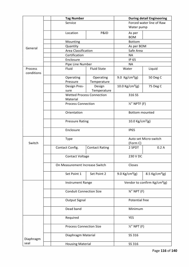
Page 116 of 140
General
1 Tag Number During detail Engineering
2 Service Forced water line of Raw Water pump
3 Location P&ID As per BOM
4 Mounting Bottom
5 Quantity As per BOM
6 Area Classification Safe Area
7 Certification NA
8 Enclosure IP 65
9 Pipe Line Number NA
Process conditions
10
Fluid Fluid State Water Liquid
11
Operating Pressure
Operating Temperature
9.0 Kg/cm²(g) 50 Deg C
12
Design Pres-sure
Design Temperature
10.0 Kg/cm²(g) 75 Deg C
16
Wetted Process Connection Material
316 SS
17
Process Connection ½” NPTF (F)
18
Orientation Bottom mounted
19
Pressure Rating 10.0 Kg/cm²(g)
20
Enclosure IP65
Switch
21
Type Auto set Micro-switch (Form C)
22
Contact Config. Contact Rating 2 SPDT 0.2 A
23
Contact Voltage 230 V DC
24
On Measurement Increase Switch Closes
25
Set Point 1 Set Point 2 9.0 Kg/cm²(g) 8.5 Kg/cm²(g)
26
Instrument Range Vendor to confirm Kg/cm²(g)
27
Conduit Connection Size ¾” NPT (F)
28
Output Signal Potential free
29
Dead band Minimum
Diaphragm seal
31
Required YES
32
Process Connection Size ½” NPT (F)
33
Diaphragm Material SS 316
3 Housing Material SS 316
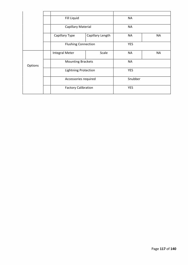
Page 117 of 140
4
35
Fill Liquid NA
36
Capillary Material NA
37
Capillary Type Capillary Length NA NA
38
Flushing Connection YES
Options
39
Integral Meter Scale NA NA
40
Mounting Brackets NA
41
Lightning Protection YES
42
Accessories required Snubber
43
Factory Calibration YES
Page 118 of 140
32.0 PRESSURE TRANSMITTER The scope of this work includes sizing, design, supply, erection and commissioning of transmitters.
Transmitter design: Sizing & selection of transmitter based on process data, process requirement, general requirement and specification below.
Erection of transmitter: Erection includes mounting of process isolation valve, erection of impulse piping, mounting of transmitter support and rack, laying of electrical cable from PLC to transmitter, mounting of junction box, glanding, termination and interfac-ing of transmitter with control system.
Commissioning: Commissioning of transmitter includes, calibration checking, loop checking, testing of transmitter from PLC and open / closed loop checking from sub control system & main control system.
Micro-processor based 2 wire transmitters shall have an impressed output signal of 4 - 20 mA corresponding to zero to full range input. A two-wire transmitter shall be used with accuracy of +/-0.1 % or better of span. Transmitter shall have external zero and span adjustment with self-diagnostics feature. Transmitter shall have temperature sensor for process compensation. The transmitters shall be of the SMART-type with HART protocol. The transmitter shall be indicating type & shall have LCD display with engineering units.
Turn Turndown Ratio of all the transmitter shall be 100:1 for pressure transmitters and 50:1 for very low-pressure applications. Load impedance shall be 600 ohm(min). The re-peatability shall be within a range of 0.1% of full span. Over Pressure of the transmitter shall be 150% or more of the Maximum Range of the pressure transmitter or maximum working pressure of Equipment/pipe line.
The output signal of all transmitters must be independent of the burden of the trans-mitter output circuit including cable resistance over a wide range.
All transmitters shall be suitable for field installation and shall have strong, moisture and dust proof cases of aluminium housing with epoxy coating suitable for IP 67 or equivalent degree of protection or better to be envisaged.
All wetted parts of the transmitters shall be SS316 or special material for corrosive applications. Accessories like snubbers for pump discharge applications and chemical diaphragm of 10 m PVC covered SS armored capillary for remote services shall be con-sidered. Diaphragm seals shall be of the flanged type, suitable for the same conditions as those for the transmitter. The material selection shall be according to the require-ments of the fluids to be measured. The seal shall be provided with a flushing connec-tion.
Transmitter shall be provided with Mounting bracket, mounting stand & nameplate. Material of accessories shall be SS or better.
Process connection shall be -1/2” NPT (F). 2 valve manifolds to be considered for abso-lute pressure, 3 valve manifolds for gauge pressure and 5 valve manifolds to be con-sidered for DP/level/flow measurements. Mounting bracket, mounting stand & name-plate to be envisaged. The material of accessories shall be SS or better.
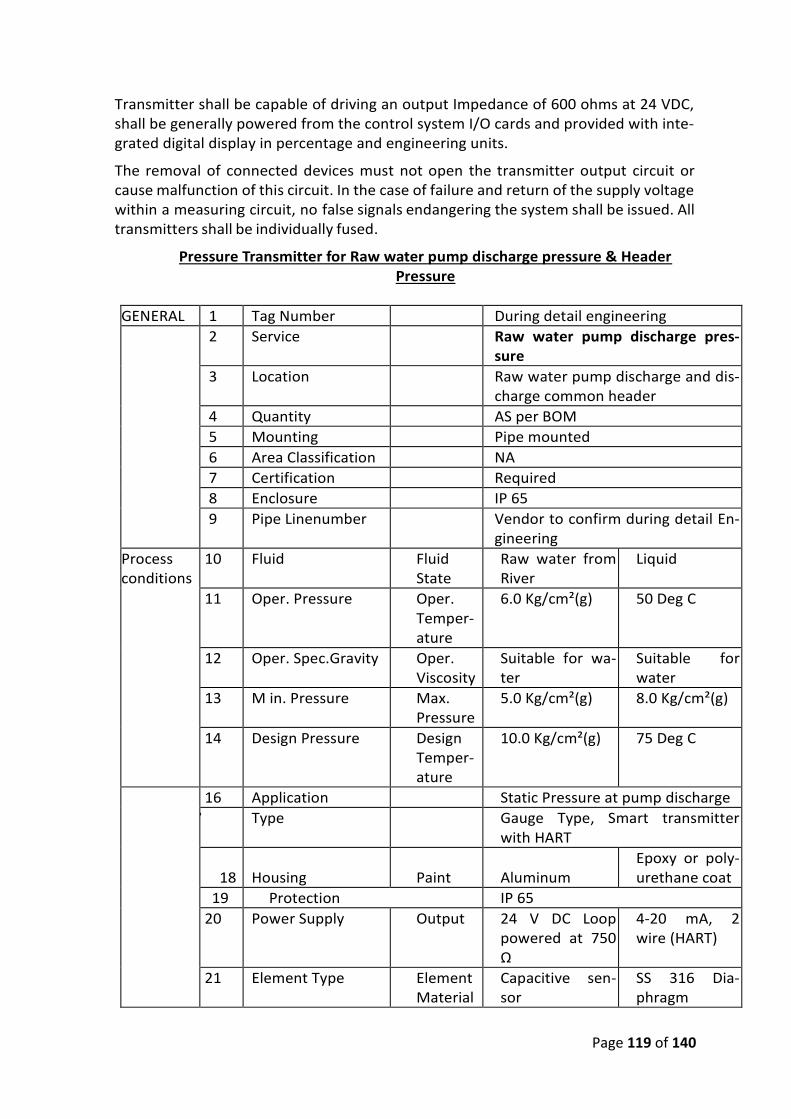
Page 119 of 140
Transmitter shall be capable of driving an output Impedance of 600 ohms at 24 VDC, shall be generally powered from the control system I/O cards and provided with inte-grated digital display in percentage and engineering units.
The removal of connected devices must not open the transmitter output circuit or cause malfunction of this circuit. In the case of failure and return of the supply voltage within a measuring circuit, no false signals endangering the system shall be issued. All transmitters shall be individually fused.
Pressure Transmitter for Raw water pump discharge pressure & Header Pressure
GENERAL 1 Tag Number During detail engineering
2 Service Raw water pump discharge pres-sure
3 Location Raw water pump discharge and dis-charge common header
4 Quantity AS per BOM
5 Mounting Pipe mounted
6 Area Classification NA
7 Certification Required
8 Enclosure IP 65
9 Pipe Linenumber Vendor to confirm during detail En-gineering
Process conditions
10 Fluid Fluid State
Raw water from River
Liquid
11 Oper. Pressure Oper. Temper-ature
6.0 Kg/cm²(g) 50 Deg C
12 Oper. Spec.Gravity Oper. Viscosity
Suitable for wa-ter
Suitable for water
13 M in. Pressure Max. Pressure
5.0 Kg/cm²(g) 8.0 Kg/cm²(g)
14 Design Pressure Design Temper-ature
10.0 Kg/cm²(g) 75 Deg C
16 Application Static Pressure at pump discharge
17 Type Gauge Type, Smart transmitter with HART
18
Housing
Paint
Aluminum
Epoxy or poly-urethane coat
19 Protection IP 65
20 Power Supply Output 24 V DC Loop powered at 750 Ω
4-20 mA, 2 wire (HART)
21 Element Type Element Material
Capacitive sen-sor
SS 316 Dia-phragm
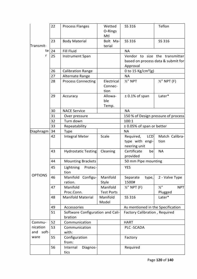
Page 120 of 140
Transmit-ter
22 Process Flanges Wetted O-Rings Mtl
SS 316 Teflon
23 Body Material Bolt Ma-terial
SS 316 SS 316
24 Fill Fluid NA
25 Instrument Span Vendor to size the transmitter based on process data & submit for Approval
26 Calibration Range 0 to 15 Kg/cm²(g)
27 Alternate Range NA
28 Process Connecting Electrical Connec-tion
½” NPT ½” NPT (F)
29 Accuracy Allowa-ble Temp.
± 0.1% of span Later*
30 NACE Service NA
31 Over pressure 150 % of Design pressure of process
32 Turn down 100:1
33 Repeatability ± 0.05% of span or better
Diaphragm 34 Type NA
OPTIONS
42 Integral Meter Scale Required, LCD type with engi-neering unit
Match Calibra-tion
43 Hydrostatic Testing Cleaning Certificate be provided
NA
44 Mounting Brackets 50 mm Pipe mounting
45 Lightning Protec-tion
YES
46 Manifold Configu-ration.
Manifold Style
Separate type, 1500#
2 - Valve Type
47 Manifold Proc.Conn.
Manifold Test Ports
½” NPT (F) ½” NPT Plugged
48 Manifold Material Manifold Model
SS 316 Later*
49 Accessories As mentioned in the Specification
51 Software Configuration and Cali-bration
Factory Calibration , Required
Commu-nication and soft-ware
52 Communication HART
53 Communication with:
PLC -SCADA
55 Configuration from:
Factory
56 Internal Diagnos-tics
Required
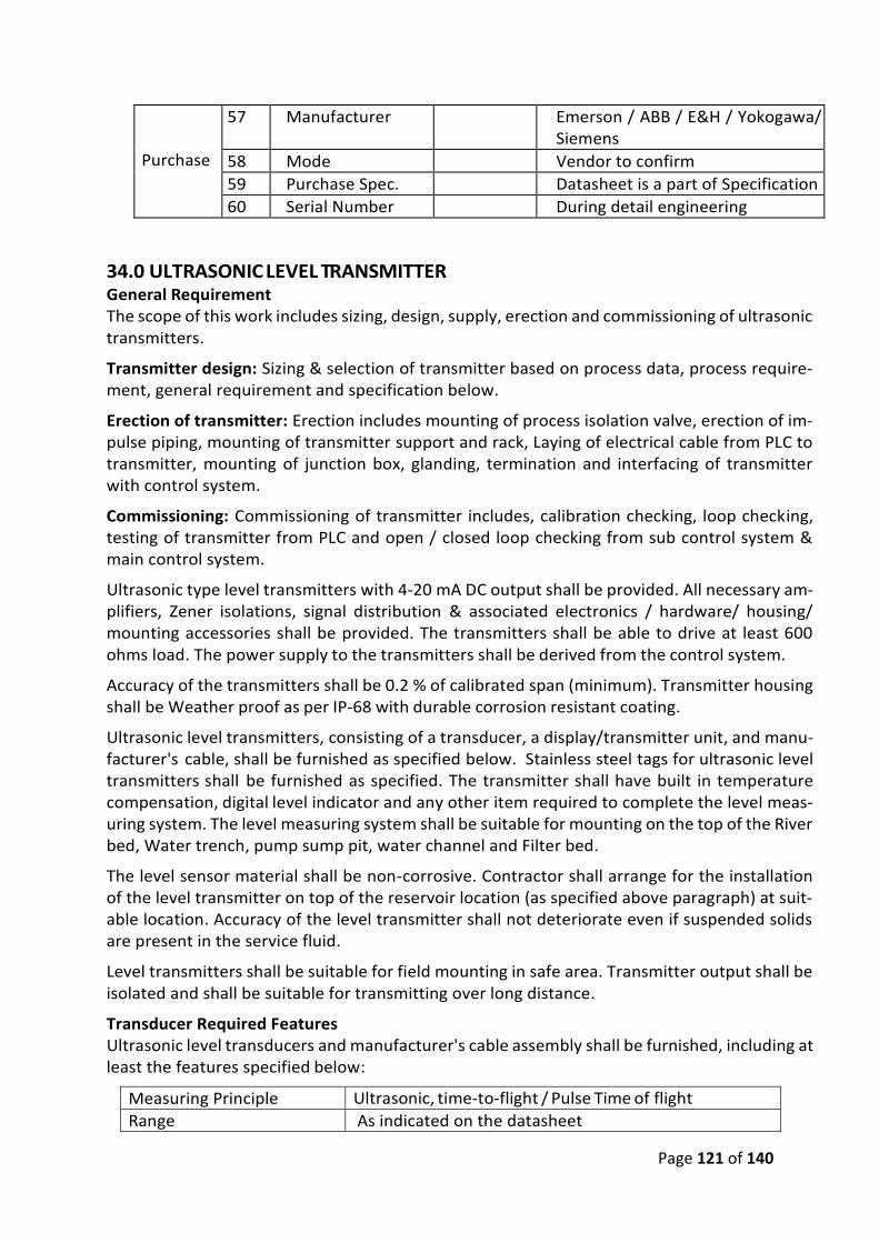
Page 121 of 140
Purchase
57 Manufacturer Emerson / ABB / E&H / Yokogawa/ Siemens
58 Mode Vendor to confirm
59 Purchase Spec. Datasheet is a part of Specification
60 Serial Number During detail engineering
34.0 ULTRASONIC LEVEL TRANSMITTER General Requirement The scope of this work includes sizing, design, supply, erection and commissioning of ultrasonic transmitters.
Transmitter design: Sizing & selection of transmitter based on process data, process require-ment, general requirement and specification below.
Erection of transmitter: Erection includes mounting of process isolation valve, erection of im-pulse piping, mounting of transmitter support and rack, Laying of electrical cable from PLC to transmitter, mounting of junction box, glanding, termination and interfacing of transmitter with control system.
Commissioning: Commissioning of transmitter includes, calibration checking, loop checking, testing of transmitter from PLC and open / closed loop checking from sub control system & main control system.
Ultrasonic type level transmitters with 4-20 mA DC output shall be provided. All necessary am-plifiers, Zener isolations, signal distribution & associated electronics / hardware/ housing/ mounting accessories shall be provided. The transmitters shall be able to drive at least 600 ohms load. The power supply to the transmitters shall be derived from the control system.
Accuracy of the transmitters shall be 0.2 % of calibrated span (minimum). Transmitter housing shall be Weather proof as per IP-68 with durable corrosion resistant coating.
Ultrasonic level transmitters, consisting of a transducer, a display/transmitter unit, and manu-facturer's cable, shall be furnished as specified below. Stainless steel tags for ultrasonic level transmitters shall be furnished as specified. The transmitter shall have built in temperature compensation, digital level indicator and any other item required to complete the level meas-uring system. The level measuring system shall be suitable for mounting on the top of the River bed, Water trench, pump sump pit, water channel and Filter bed.
The level sensor material shall be non-corrosive. Contractor shall arrange for the installation of the level transmitter on top of the reservoir location (as specified above paragraph) at suit-able location. Accuracy of the level transmitter shall not deteriorate even if suspended solids are present in the service fluid.
Level transmitters shall be suitable for field mounting in safe area. Transmitter output shall be isolated and shall be suitable for transmitting over long distance.
Transducer Required Features Ultrasonic level transducers and manufacturer's cable assembly shall be furnished, including at least the features specified below:
Measuring Principle Ultrasonic, time-to-flight / Pulse Time of flight
Range As indicated on the datasheet
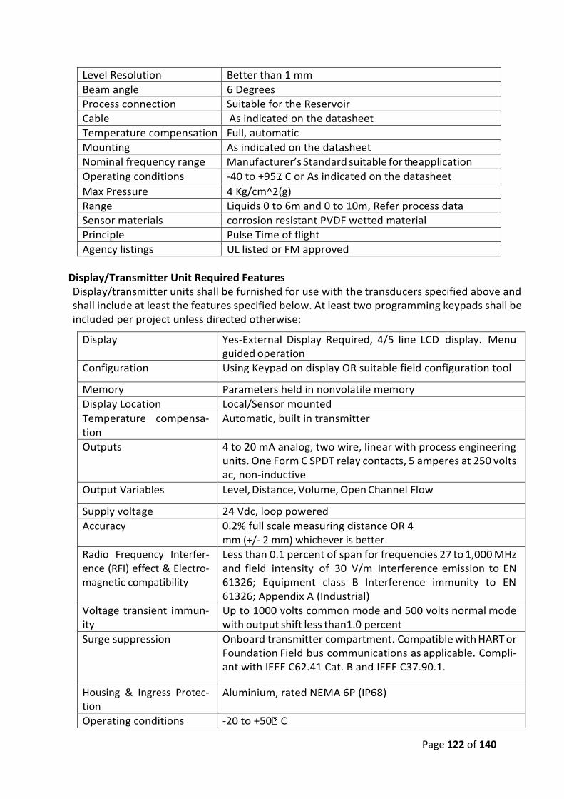
Page 122 of 140
Level Resolution Better than 1 mm
Beam angle 6 Degrees
Process connection Suitable for the Reservoir
Cable As indicated on the datasheet
Temperature compensation Full, automatic
Mounting As indicated on the datasheet
Nominal frequency range Manufacturer’s Standard suitable for the application
Operating conditions -40 to +95 C or As indicated on the datasheet
Max Pressure 4 Kg/cm^2(g)
Range Liquids 0 to 6m and 0 to 10m, Refer process data
Sensor materials corrosion resistant PVDF wetted material
Principle Pulse Time of flight
Agency listings UL listed or FM approved
Display/Transmitter Unit Required Features Display/transmitter units shall be furnished for use with the transducers specified above and shall include at least the features specified below. At least two programming keypads shall be included per project unless directed otherwise:
Display Yes-External Display Required, 4/5 line LCD display. Menu guided operation
Configuration Using Keypad on display OR suitable field configuration tool
Memory Parameters held in nonvolatile memory
Display Location Local/Sensor mounted
Temperature compensa-tion
Automatic, built in transmitter
Outputs 4 to 20 mA analog, two wire, linear with process engineering units. One Form C SPDT relay contacts, 5 amperes at 250 volts ac, non-inductive
Output Variables Level, Distance, Volume, Open Channel Flow
Supply voltage 24 Vdc, loop powered
Accuracy 0.2% full scale measuring distance OR 4 mm (+/- 2 mm) whichever is better
Radio Frequency Interfer-ence (RFI) effect & Electro-magnetic compatibility
Less than 0.1 percent of span for frequencies 27 to 1,000 MHz and field intensity of 30 V/m Interference emission to EN 61326; Equipment class B Interference immunity to EN 61326; Appendix A (Industrial)
Voltage transient immun-ity
Up to 1000 volts common mode and 500 volts normal mode with output shift less than1.0 percent
Surge suppression Onboard transmitter compartment. Compatible with HART or Foundation Field bus communications as applicable. Compli-ant with IEEE C62.41 Cat. B and IEEE C37.90.1.
Housing & Ingress Protec-tion
Aluminium, rated NEMA 6P (IP68)
Operating conditions -20 to +50 C
Page 123 of 140
Agency listings UL listed and FM approved
Hazardous area classifica-tion
Safe Area
VIBRATION TRANSMITTER AND VIBRATION MONITORING SYSTEM General requirement of Vibration Monitoring System
The specification is intended to cover the design, engineering, assembly, testing, delivery including packaging, erection, commissioning, site assembly, performance warranty & hand-ing over of ON LINE VIBRATION MONITORING SYSTEM complete with all materials and ac-cessories for efficient and trouble-free operation in water treatment plant.
The instrument / equipment / software shall conform to high standard of engineering, design and workmanship in all respects and shall be capable of performing satisfactorily in continu-ous commercial operation under the specified environmental condition.
Bearing vibrations can be measured for detailed health analysis& smooth functioning of ro-tary equipment like Raw water pump& Pure water pump.
The vibration monitoring system to be furnished on a system shall include vibration trans-ducers with low noise flexible cables in flexible conduit, terminated in local terminal boxes, necessary pre- amplifier/electronics/signal conditioning unit mounted in local weather proof boxes, Bar graph/LED/LCD indicating type vibration indicators, integrating units, along with mounting racks and cabinets. The provisions of fixing sensor should be made as per require-ment if not available. No extra payment will be made for this fixing work. Motors have provi-sions for RTD.
The vibration monitoring system shall include power supplies, interconnecting cabling, cali-bration equipment, and all other essential accessories. Microprocessor based vibration mon-itoring system shall compliance with API 670 – 1994 and BS : 4675 Part-2 standards.
One four channel vibration indicator shall be envisaged for two Raw pumps. Five vibration indicators shall be mounted in one control panel to include the vibration measurement of ten Raw water pumps.
There are nine nos. of raw water pumps. Minimum, two control panels, which include five vibration indicators each, shall be supplied by contractor.
Erection hardware required for monitoring of vibration at each point includes vibration pads. The vibration pad mounting shall be made of MS block of 30mmX30mm size suitable for weld-ing on to the bearing casing.
Bidder shall offer minimum four channel vibration monitors for each measurement equip-ment catering for drive end and non-drive end measurements. Offered vibration monitors shall be modular in construction, plug in type and suitable for rack mounting/panel mounting arrangement. Vibration indicator shall be four channel & provided with common Danger & Alert relay. Indicator shall have memory card facility available for data storage. Vibration indicator shall have vertical Bar graph/LED/LCD display and shall have 4-20 mA retransmis-sion facility for interfacing with plant central control unit. The display operation shall be pos-sible from the front panel of the display OR touch panel of the display on the front panel of the monitor.
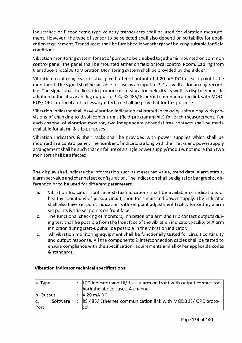
Page 124 of 140
Inductance or Piezoelectric type velocity transducers shall be used for vibration measure-ment. However, the type of sensor to be selected shall also depend on suitability for appli-cation requirement. Transducers shall be furnished in weatherproof housing suitable for field conditions.
Vibration monitoring system for set of pumps to be clubbed together & mounted on common control panel, the panel shall be mounted either on field or local control Room. Cabling from transducers local JB to Vibration Monitoring system shall be provided by the Bidder.
Vibration monitoring system shall give buffered output of 4-20 mA DC for each point to be monitored. The signal shall be suitable for use as an input to PLC as well as for analog record-ing. The signal shall be linear in proportion to vibration velocity as well as displacement. In addition to the above analog output to PLC, RS 485/ Ethernet communication link with MOD-BUS/ OPC protocol and necessary interface shall be provided for this purpose.
Vibration indicator shall have vibration indication calibrated in velocity units along with pro-visions of changing to displacement unit (field-programmable) for each measurement. For each channel of vibration monitor, two independent potential free contacts shall be made available for alarm & trip purposes.
Vibration indicators & their racks shall be provided with power supplies which shall be mounted in a control panel. The number of indicators along with their racks and power supply arrangement shall be such that on failure of a single power supply/module, not more than two monitors shall be affected.
The display shall indicate the information such as measured value, trend data, alarm status, alarm set value and channel set configuration. The indication shall be digital or bar graphs, dif-ferent color to be used for different parameters.
a. Vibration Indicator front face status indications shall be available or indications of healthy conditions of pickup circuit, monitor circuit and power supply. The indicator shall also have set point indication with set point adjustment facility for setting alarm set points & trip set points on front face.
b. The functional checking of monitors, inhibition of alarm and trip contact outputs dur-ing test shall be possible from the front face of the vibration indicator. Facility of Alarm inhibition during start-up shall be possible in the vibration indicator.
c. All vibration monitoring equipment shall be functionally tested for circuit continuity and output response. All the components & interconnection cables shall be tested to ensure compliance with the specification requirements and all other applicable codes & standards.
Vibration indicator technical specifications:
a. Type : LCD indicator and HI/HI-HI alarm on front with output contact for both the above cases. 4-channel
b. Output : 4-20 mA DC
c. Software Port
: RS 485/ Ethernet communication link with MODBUS/ OPC proto-col.
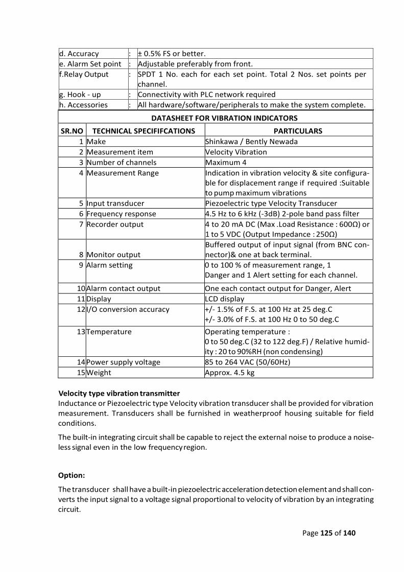
Page 125 of 140
d. Accuracy : ± 0.5% FS or better.
e. Alarm Set point : Adjustable preferably from front.
f.Relay Output : SPDT 1 No. each for each set point. Total 2 Nos. set points per channel.
g. Hook - up : Connectivity with PLC network required
h. Accessories : All hardware/software/peripherals to make the system complete.
DATASHEET FOR VIBRATION INDICATORS
SR.NO TECHNICAL SPECIFIFCATIONS PARTICULARS
1 Make Shinkawa / Bently Newada
2 Measurement item Velocity Vibration
3 Number of channels Maximum 4
4 Measurement Range Indication in vibration velocity & site configura-ble for displacement range if required :Suitable to pump maximum vibrations
5 Input transducer Piezoelectric type Velocity Transducer
6 Frequency response 4.5 Hz to 6 kHz (-3dB) 2-pole band pass filter
7 Recorder output 4 to 20 mA DC (Max .Load Resistance : 600Ω) or 1 to 5 VDC (Output Impedance : 250Ω)
8
Monitor output
Buffered output of input signal (from BNC con-nector)& one at back terminal.
9 Alarm setting 0 to 100 % of measurement range, 1 Danger and 1 Alert setting for each channel.
10 Alarm contact output One each contact output for Danger, Alert
11 Display LCD display
12 I/O conversion accuracy +/- 1.5% of F.S. at 100 Hz at 25 deg.C +/- 3.0% of F.S. at 100 Hz 0 to 50 deg.C
13 Temperature Operating temperature : 0 to 50 deg.C (32 to 122 deg.F) / Relative humid-ity : 20 to 90%RH (non condensing)
14 Power supply voltage 85 to 264 VAC (50/60Hz)
15 Weight Approx. 4.5 kg
Velocity type vibration transmitter
Inductance or Piezoelectric type Velocity vibration transducer shall be provided for vibration measurement. Transducers shall be furnished in weatherproof housing suitable for field conditions.
The built-in integrating circuit shall be capable to reject the external noise to produce a noise-less signal even in the low frequency region.
Option:
The transducer shall have a built-in piezoelectric acceleration detection element and shall con-verts the input signal to a voltage signal proportional to velocity of vibration by an integrating circuit.
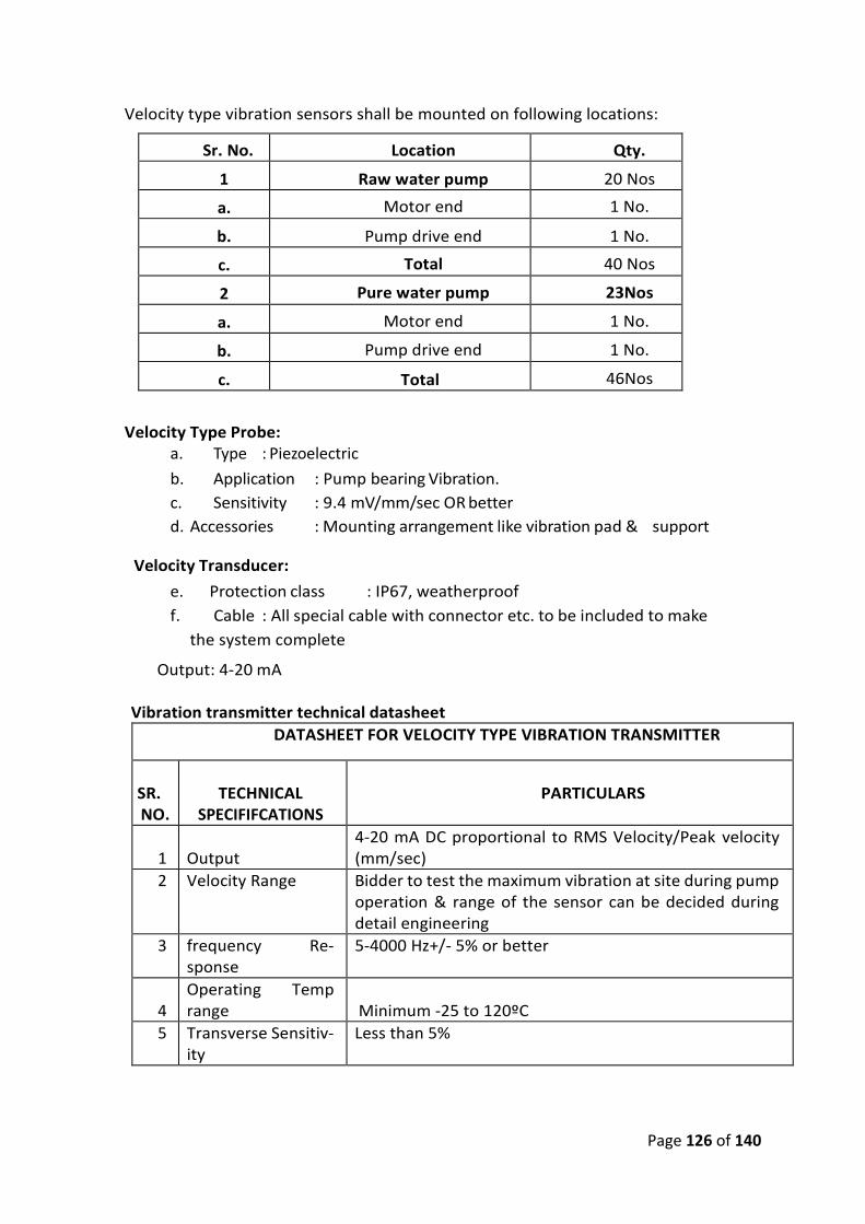
Page 126 of 140
Velocity type vibration sensors shall be mounted on following locations:
Sr. No. Location Qty.
1 Raw water pump 20 Nos
a. Motor end 1 No.
b. Pump drive end 1 No.
c. Total 40 Nos
2 Pure water pump 23Nos
a. Motor end 1 No.
b. Pump drive end 1 No.
c. Total 46Nos
Velocity Type Probe: a. Type : Piezoelectric
b. Application : Pump bearing Vibration.
c. Sensitivity : 9.4 mV/mm/sec OR better
d. Accessories : Mounting arrangement like vibration pad & support
Velocity Transducer:
e. Protection class : IP67, weatherproof
f. Cable : All special cable with connector etc. to be included to make
the system complete
Output: 4-20 mA
Vibration transmitter technical datasheet
DATASHEET FOR VELOCITY TYPE VIBRATION TRANSMITTER
SR. NO.
TECHNICAL
SPECIFIFCATIONS
PARTICULARS
1
Output
4-20 mA DC proportional to RMS Velocity/Peak velocity (mm/sec)
2 Velocity Range Bidder to test the maximum vibration at site during pump operation & range of the sensor can be decided during detail engineering
3 frequency Re-sponse
5-4000 Hz+/- 5% or better
4
Operating Temp range
Minimum -25 to 120ºC
5 Transverse Sensitiv-ity
Less than 5%
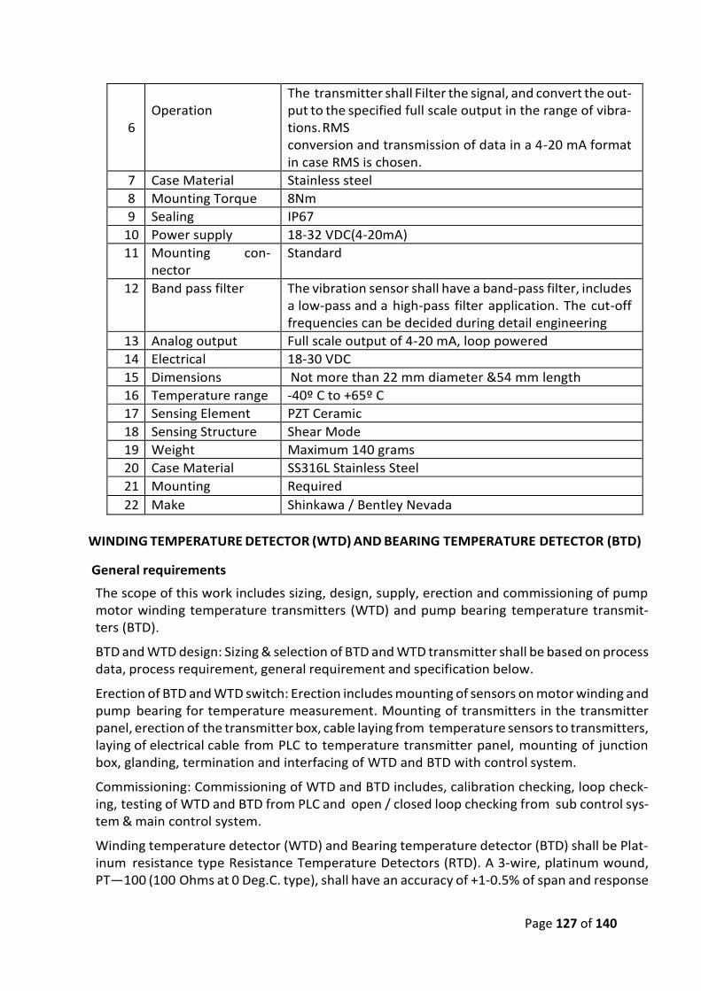
Page 127 of 140
6
Operation
The transmitter shall Filter the signal, and convert the out-put to the specified full scale output in the range of vibra-tions. RMS conversion and transmission of data in a 4-20 mA format in case RMS is chosen.
7 Case Material Stainless steel
8 Mounting Torque 8Nm
9 Sealing IP67
10 Power supply 18-32 VDC(4-20mA)
11 Mounting con-nector
Standard
12 Band pass filter The vibration sensor shall have a band-pass filter, includes a low-pass and a high-pass filter application. The cut-off frequencies can be decided during detail engineering
13 Analog output Full scale output of 4-20 mA, loop powered
14 Electrical 18-30 VDC
15 Dimensions Not more than 22 mm diameter &54 mm length
16 Temperature range -40º C to +65º C
17 Sensing Element PZT Ceramic
18 Sensing Structure Shear Mode
19 Weight Maximum 140 grams
20 Case Material SS316L Stainless Steel
21 Mounting Required
22 Make Shinkawa / Bentley Nevada
WINDING TEMPERATURE DETECTOR (WTD) AND BEARING TEMPERATURE DETECTOR (BTD)
General requirements
The scope of this work includes sizing, design, supply, erection and commissioning of pump motor winding temperature transmitters (WTD) and pump bearing temperature transmit-ters (BTD).
BTD and WTD design: Sizing & selection of BTD and WTD transmitter shall be based on process data, process requirement, general requirement and specification below.
Erection of BTD and WTD switch: Erection includes mounting of sensors on motor winding and pump bearing for temperature measurement. Mounting of transmitters in the transmitter panel, erection of the transmitter box, cable laying from temperature sensors to transmitters, laying of electrical cable from PLC to temperature transmitter panel, mounting of junction box, glanding, termination and interfacing of WTD and BTD with control system.
Commissioning: Commissioning of WTD and BTD includes, calibration checking, loop check-ing, testing of WTD and BTD from PLC and open / closed loop checking from sub control sys-tem & main control system.
Winding temperature detector (WTD) and Bearing temperature detector (BTD) shall be Plat-inum resistance type Resistance Temperature Detectors (RTD). A 3-wire, platinum wound, PT—100 (100 Ohms at 0 Deg.C. type), shall have an accuracy of +1-0.5% of span and response
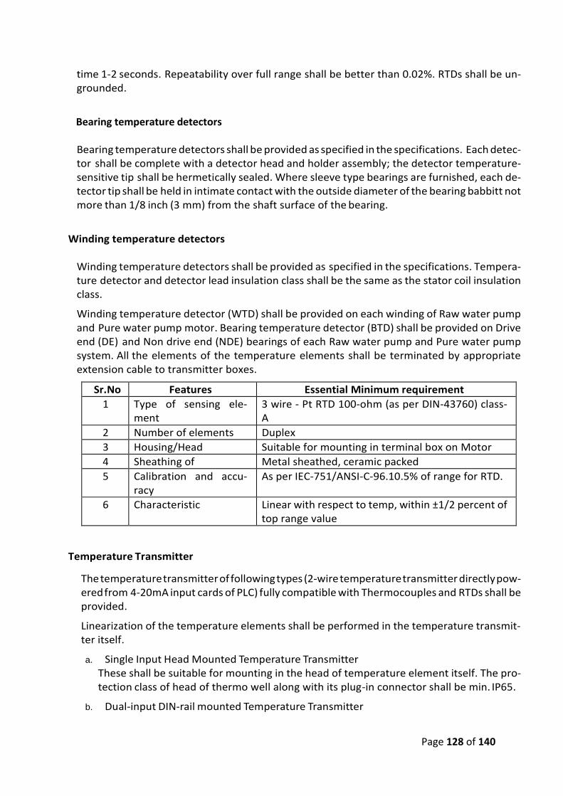
Page 128 of 140
time 1-2 seconds. Repeatability over full range shall be better than 0.02%. RTDs shall be un-grounded.
Bearing temperature detectors
Bearing temperature detectors shall be provided as specified in the specifications. Each detec-tor shall be complete with a detector head and holder assembly; the detector temperature-sensitive tip shall be hermetically sealed. Where sleeve type bearings are furnished, each de-tector tip shall be held in intimate contact with the outside diameter of the bearing babbitt not more than 1/8 inch (3 mm) from the shaft surface of the bearing.
Winding temperature detectors
Winding temperature detectors shall be provided as specified in the specifications. Tempera-ture detector and detector lead insulation class shall be the same as the stator coil insulation class.
Winding temperature detector (WTD) shall be provided on each winding of Raw water pump and Pure water pump motor. Bearing temperature detector (BTD) shall be provided on Drive end (DE) and Non drive end (NDE) bearings of each Raw water pump and Pure water pump system. All the elements of the temperature elements shall be terminated by appropriate extension cable to transmitter boxes.
Sr.No Features Essential Minimum requirement
1 Type of sensing ele-ment
3 wire - Pt RTD 100-ohm (as per DIN-43760) class-A
2 Number of elements Duplex
3 Housing/Head Suitable for mounting in terminal box on Motor
4 Sheathing of Metal sheathed, ceramic packed
5 Calibration and accu-racy
As per IEC-751/ANSI-C-96.10.5% of range for RTD.
6 Characteristic Linear with respect to temp, within ±1/2 percent of top range value
Temperature Transmitter
The temperature transmitter of following types (2-wire temperature transmitter directly pow-ered from 4-20mA input cards of PLC) fully compatible with Thermocouples and RTDs shall be provided.
Linearization of the temperature elements shall be performed in the temperature transmit-ter itself.
a. Single Input Head Mounted Temperature Transmitter These shall be suitable for mounting in the head of temperature element itself. The pro-tection class of head of thermo well along with its plug-in connector shall be min. IP65.
b. Dual-input DIN-rail mounted Temperature Transmitter
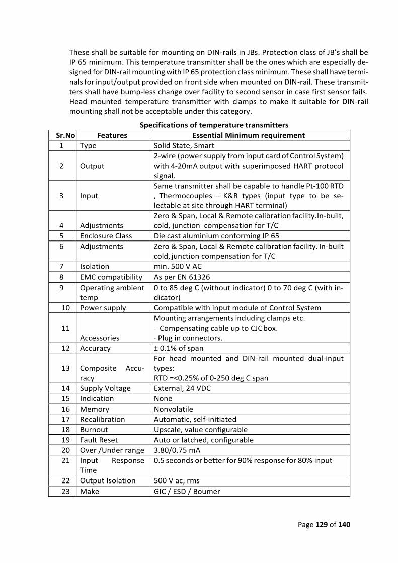
Page 129 of 140
These shall be suitable for mounting on DIN-rails in JBs. Protection class of JB’s shall be IP 65 minimum. This temperature transmitter shall be the ones which are especially de-signed for DIN-rail mounting with IP 65 protection class minimum. These shall have termi-nals for input/output provided on front side when mounted on DIN-rail. These transmit-ters shall have bump-less change over facility to second sensor in case first sensor fails. Head mounted temperature transmitter with clamps to make it suitable for DIN-rail mounting shall not be acceptable under this category.
Specifications of temperature transmitters
Sr.No Features Essential Minimum requirement
1 Type Solid State, Smart
2
Output
2-wire (power supply from input card of Control System) with 4-20mA output with superimposed HART protocol signal.
3
Input
Same transmitter shall be capable to handle Pt-100 RTD , Thermocouples – K&R types (input type to be se-lectable at site through HART terminal)
4
Adjustments
Zero & Span, Local & Remote calibration facility.In-built, cold, junction compensation for T/C
5 Enclosure Class Die cast aluminium conforming IP 65
6 Adjustments Zero & Span, Local & Remote calibration facility. In-built cold, junction compensation for T/C
7 Isolation min. 500 V AC
8 EMC compatibility As per EN 61326
9 Operating ambient temp
0 to 85 deg C (without indicator) 0 to 70 deg C (with in-dicator)
10 Power supply Compatible with input module of Control System
11
Accessories
Mounting arrangements including clamps etc. - Compensating cable up to CJC box. - Plug in connectors.
12 Accuracy ± 0.1% of span
13
Composite Accu-racy
For head mounted and DIN-rail mounted dual-input types: RTD =<0.25% of 0-250 deg C span
14 Supply Voltage External, 24 VDC
15 Indication None
16 Memory Nonvolatile
17 Recalibration Automatic, self-initiated
18 Burnout Upscale, value configurable
19 Fault Reset Auto or latched, configurable
20 Over /Under range 3.80/0.75 mA
21 Input Response Time
0.5 seconds or better for 90% response for 80% input
22 Output Isolation 500 V ac, rms
23 Make GIC / ESD / Boumer

Page 130 of 140
ENERGY METERS General Requirement The scope of this work includes sizing, design, supply, erection and commissioning of Energy me-ters, communication cable and software.
Energy meter design: Design & selection of Energy meters shall be based on electrical con-sumption, mounting arrangement, interface requirement with control system, general re-quirement and specifications below.
Erection of Energy meters: Erection includes mounting of energy meters on existing switchgear panel, wiring from CT and PT to energy meter. Laying of communication cable from energy meter to communication switches mounted in PLC based control panel. Mounting of junction box, glanding, termination and interfacing of energy meter with control system.
Commissioning: Commissioning of Energy meter includes, calibration checking, loop checking, testing of energy meter locally from switchgear panel, remotely from PLC based SCADA system and from Historian station.
System description:
Energy Audit shall be part of automation of water treatment plant. To accomplish this require-ment Digital energy meters shall be mounted on following switchgear panel, Incomer and out-going breakers, PCC, MCC.
• Raw water system – For each pump feeder, Incomer feeder, transformer feeder
• For each incomer, outgoing breaker and transformer feeder Energy meter falls under particular master PLC based control system section shall be interfaced on Ring topology/Daisy chain network with each other and this network finally shall be inter-faced with that particular master PLC. All the electrical parameters available in the energy me-ters shall be made available in the associated master PLC and SCADA.
These parameters shall be further made available in Historian server for database management, Alarm management and Energy Audit. Contractor shall design, supply, develop and program energy management software in the historian server. Contractor shall develop the commercial analysis of energy audit and represent it in the graphical, tabular and widget form for manage-ment reference.
Technical specifications: Energy meter shall have following minimum specifications but not limited to:
a. Selectable for system, 1 Ph, 3 Ph 3 W and 3 Ph 4 W. (The Input CT and PT shall be ratio programmable)
b. 21st Harmonics of voltages and currents (selectivity) c. Import and Export Energy measurement d. THD factors for currents and voltages e. Measurement of power network parameters in balanced & unbalanced systems f. Configured watt-hour meter for the selected harmonic g. Backlit LCD 4.5” screen, monochromatic with backlight h. Ingress protection: IP65 i. Digital transmission to the master system through the RS-485 interface (MODBUS) j. In-built Real-Time Clock (RTC)
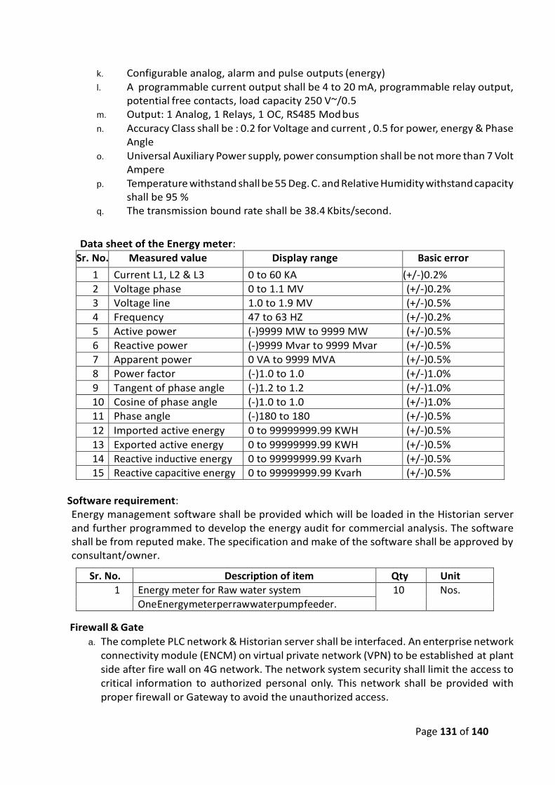
Page 131 of 140
k. Configurable analog, alarm and pulse outputs (energy) l. A programmable current output shall be 4 to 20 mA, programmable relay output,
potential free contacts, load capacity 250 V~/0.5 m. Output: 1 Analog, 1 Relays, 1 OC, RS485 Mod bus n. Accuracy Class shall be : 0.2 for Voltage and current , 0.5 for power, energy & Phase
Angle o. Universal Auxiliary Power supply, power consumption shall be not more than 7 Volt
Ampere p. Temperature withstand shall be 55 Deg. C. and Relative Humidity withstand capacity
shall be 95 % q. The transmission bound rate shall be 38.4 Kbits/second.
Data sheet of the Energy meter:
Sr. No. Measured value Display range Basic error
1 Current L1, L2 & L3 0 to 60 KA (+/-)0.2%
2 Voltage phase 0 to 1.1 MV (+/-)0.2%
3 Voltage line 1.0 to 1.9 MV (+/-)0.5%
4 Frequency 47 to 63 HZ (+/-)0.2%
5 Active power (-)9999 MW to 9999 MW (+/-)0.5%
6 Reactive power (-)9999 Mvar to 9999 Mvar (+/-)0.5%
7 Apparent power 0 VA to 9999 MVA (+/-)0.5%
8 Power factor (-)1.0 to 1.0 (+/-)1.0%
9 Tangent of phase angle (-)1.2 to 1.2 (+/-)1.0%
10 Cosine of phase angle (-)1.0 to 1.0 (+/-)1.0%
11 Phase angle (-)180 to 180 (+/-)0.5%
12 Imported active energy 0 to 99999999.99 KWH (+/-)0.5%
13 Exported active energy 0 to 99999999.99 KWH (+/-)0.5%
14 Reactive inductive energy 0 to 99999999.99 Kvarh (+/-)0.5%
15 Reactive capacitive energy 0 to 99999999.99 Kvarh (+/-)0.5%
Software requirement: Energy management software shall be provided which will be loaded in the Historian server and further programmed to develop the energy audit for commercial analysis. The software shall be from reputed make. The specification and make of the software shall be approved by consultant/owner.
Sr. No. Description of item Qty Unit
1 Energy meter for Raw water system 10 Nos.
One Energy meter per raw water pump feeder.
Firewall & Gate
a. The complete PLC network & Historian server shall be interfaced. An enterprise network connectivity module (ENCM) on virtual private network (VPN) to be established at plant side after fire wall on 4G network. The network system security shall limit the access to critical information to authorized personal only. This network shall be provided with proper firewall or Gateway to avoid the unauthorized access.
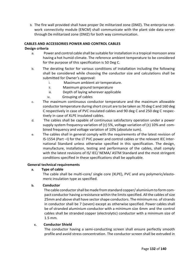
Page 132 of 140
b. The fire wall provided shall have proper De militarized zone (DMZ). The enterprise net-work connectivity module (ENCM) shall communicate with the plant side data server through De militarized zone (DMZ) for both way communication.
CABLES AND ACCESSORIES POWER AND CONTROL CABLES
Design criteria a. Power and control cable shall be suitable for installation in a tropical monsoon area
having a hot humid climate. The reference ambient temperature to be considered for the purpose of this specification is 50 Deg C.
b. The derating factor for various conditions of installation including the following shall be considered while choosing the conductor size and calculations shall be submitted for Owner’s approval:
i. Maximum ambient air temperature.
ii. Maximum ground temperature iii. Depth of laying wherever applicable
iv. Grouping of cables
c. The maximum continuous conductor temperature and the maximum allowable conductor temperature during short circuit are to be taken as 70 deg C and 160 deg C respectively in case of PVC insulated cables and 90 deg C and 250 deg C respec-tively in case of XLPE insulated cables.
d. The cables shall be capable of continuous satisfactory operation under a power supply system frequency variation of (±) 5%, voltage variation of (±) 10% and com-bined frequency and voltage variation of 10% (absolute sum).
e. The cables shall in general comply with the requirements of the latest revision of IS-1554 (Part –I) for the LT PVC power and control cables or the relevant IEC Inter-national Standard unless otherwise specified in this specification. The design, manufacture, installation, testing and performance of the cables, shall comply with the latest revisions of IS/ IEC/ NEMA/ ASTM Standard and the most stringent conditions specified in these specifications shall be applicable.
General technical requirements a. Type of cable
The cable shall be multi-core/ single core (XLPE), PVC and any polymeric/elasto-meric insulation type as specified.
b. Conductor The cable conductor shall be made from standard copper/ aluminium to form com-
pact conductor having a resistance within the limits specified. All the cables of size 25mm and above shall have sector shape conductors. The minimum no. of strands in conductor shall be 7 (seven) except as otherwise specified. Power cables shall be of stranded aluminium conductor with a minimum size 6mm and the control cables shall be stranded copper (electrolytic) conductor with a minimum size of 1.5 mm.
c. Conductor Shield The conductor having a semi-conducting screen shall ensure perfectly smooth profile and avoid stress concentration. The conductor screen shall be extruded in
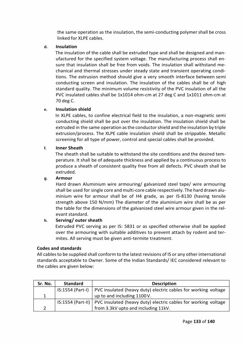
Page 133 of 140
the same operation as the insulation, the semi-conducting polymer shall be cross linked for XLPE cables.
d. Insulation The insulation of the cable shall be extruded type and shall be designed and man-ufactured for the specified system voltage. The manufacturing process shall en-sure that insulation shall be free from voids. The insulation shall withstand me-chanical and thermal stresses under steady state and transient operating condi-tions. The extrusion method should give a very smooth interface between semi conducting screen and insulation. The insulation of the cables shall be of high standard quality. The minimum volume resistivity of the PVC insulation of all the PVC insulated cables shall be 1x10¹⁴ ohm-cm at 27 deg C and 1x10¹¹ ohm-cm at 70 deg C.
e. Insulation shield
In XLPE cables, to confine electrical field to the insulation, a non-magnetic semi conducting shield shall be put over the insulation. The insulation shield shall be extruded in the same operation as the conductor shield and the insulation by triple extrusion/process. The XLPE cable insulation shield shall be strippable. Metallic screening for all type of power, control and special cables shall be provided.
f. Inner Sheath The sheath shall be suitable to withstand the site conditions and the desired tem-perature. It shall be of adequate thickness and applied by a continuous process to produce a sheath of consistent quality free from all defects. PVC sheath shall be extruded.
g. Armour Hard drawn Aluminium wire armouring/ galvanized steel tape/ wire armouring
shall be used for single core and multi-core cable respectively. The hard drawn alu-minium wire for armour shall be of H4 grade, as per IS-8130 (having tensile strength above 150 N/mm) The diameter of the aluminium wire shall be as per the table for the dimensions of the galvanized steel wire armour given in the rel-evant standard.
h. Serving/ outer sheath Extruded PVC serving as per IS: 5831 or as specified otherwise shall be applied over the armouring with suitable additives to prevent attach by rodent and ter-mites. All serving must be given anti-termite treatment.
Codes and standards All cables to be supplied shall conform to the latest revisions of IS or any other international standards acceptable to Owner. Some of the Indian Standards/ IEC considered relevant to the cables are given below:
Sr. No. Standard Description
1
IS:1554 (Part-I) PVC insulated (heavy duty) electric cables for working voltage up to and including 1100 V.
2
IS:1554 (Part-II) PVC insulated (heavy duty) electric cables for working voltage from 3.3kV upto and including 11kV.
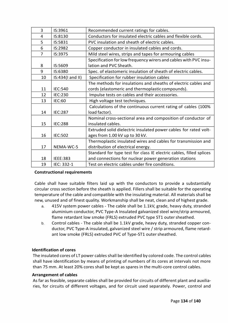
Page 134 of 140
3 IS:3961 Recommended current ratings for cables.
4 IS:8130 Conductors for insulated electric cables and flexible cords.
5 IS:5831 PVC insulation and sheath of electric cables.
6 IS:2982 Copper conductor in insulated cables and cords.
7 IS:3975 Mild steel wires, strips and tapes for armouring cables
8
IS:5609
Specification for low frequency wirers and cables with PVC insu-lation and PVC Sheath.
9 IS:6380 Spec. of elastomeric insulation of sheath of electric cables.
10 IS:434(I and II) Specification for rubber insulation cables
11
IEC:540
The methods for insulations and sheaths of electric cables and cords (elastomeric and thermoplastic compounds).
12 IEC:230 Impulse tests on cables and their accessories.
13 IEC:60 High voltage test techniques.
14
IEC:287
Calculations of the continuous current rating of cables (100% load factor).
15
IEC:288
Nominal cross-sectional area and composition of conductor of insulated cables.
16
IEC:502
Extruded solid dielectric insulated power cables for rated volt-ages from 1.00 kV up to 30 kV.
17
NEMA-WC-5
Thermoplastic insulated wires and cables for transmission and distribution of electrical energy.
18
IEEE:383
Standard for type test for class IE electric cables, filled splices and connections for nuclear power generation stations
19 IEC: 332-1 Test on electric cables under fire conditions.
Constructional requirements Cable shall have suitable filters laid up with the conductors to provide a substantially circular cross section before the sheath is applied. Fillers shall be suitable for the operating temperature of the cable and compatible with the insulating material. All materials shall be new, unused and of finest quality. Workmanship shall be neat, clean and of highest grade.
a. 415V system power cables - The cable shall be 1.1kV, grade, heavy duty, stranded aluminium conductor, PVC Type-A Insulated galvanized steel wire/strip armoured, flame retardant low smoke (FRLS) extruded PVC type ST1 outer sheathed.
b. Control cables - The cable shall be 1.1kV grade, heavy duty, stranded copper con-ductor, PVC Type-A insulated, galvanized steel wire / strip armoured, flame retard-ant low smoke (FRLS) extruded PVC of Type-ST1 outer sheathed.
Identification of cores The insulated cores of LT power cables shall be identified by colored code. The control cables shall have identification by means of printing of numbers of its cores at intervals not more than 75 mm. At least 20% cores shall be kept as spares in the multi-core control cables.
Arrangement of cables As far as feasible, separate cables shall be provided for circuits of different plant and auxilia-ries, for circuits of different voltages, and for circuit used separately. Power, control and
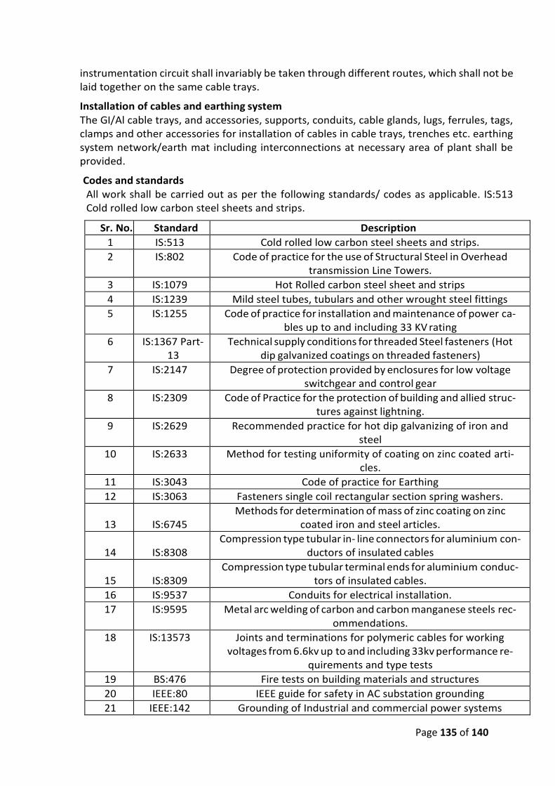
Page 135 of 140
instrumentation circuit shall invariably be taken through different routes, which shall not be laid together on the same cable trays.
Installation of cables and earthing system The GI/Al cable trays, and accessories, supports, conduits, cable glands, lugs, ferrules, tags, clamps and other accessories for installation of cables in cable trays, trenches etc. earthing system network/earth mat including interconnections at necessary area of plant shall be provided.
Codes and standards All work shall be carried out as per the following standards/ codes as applicable. IS:513 Cold rolled low carbon steel sheets and strips.
Sr. No. Standard Description
1 IS:513 Cold rolled low carbon steel sheets and strips.
2 IS:802 Code of practice for the use of Structural Steel in Overhead transmission Line Towers.
3 IS:1079 Hot Rolled carbon steel sheet and strips
4 IS:1239 Mild steel tubes, tubulars and other wrought steel fittings
5 IS:1255 Code of practice for installation and maintenance of power ca-bles up to and including 33 KV rating
6 IS:1367 Part-13
Technical supply conditions for threaded Steel fasteners (Hot dip galvanized coatings on threaded fasteners)
7 IS:2147 Degree of protection provided by enclosures for low voltage switchgear and control gear
8 IS:2309 Code of Practice for the protection of building and allied struc-tures against lightning.
9 IS:2629 Recommended practice for hot dip galvanizing of iron and steel
10 IS:2633 Method for testing uniformity of coating on zinc coated arti-cles.
11 IS:3043 Code of practice for Earthing
12 IS:3063 Fasteners single coil rectangular section spring washers.
13
IS:6745
Methods for determination of mass of zinc coating on zinc coated iron and steel articles.
14
IS:8308
Compression type tubular in- line connectors for aluminium con-ductors of insulated cables
15
IS:8309
Compression type tubular terminal ends for aluminium conduc-tors of insulated cables.
16 IS:9537 Conduits for electrical installation.
17 IS:9595 Metal arc welding of carbon and carbon manganese steels rec-ommendations.
18 IS:13573 Joints and terminations for polymeric cables for working voltages from 6.6kv up to and including 33kv performance re-
quirements and type tests
19 BS:476 Fire tests on building materials and structures
20 IEEE:80 IEEE guide for safety in AC substation grounding
21 IEEE:142 Grounding of Industrial and commercial power systems
Page 136 of 140
22 DIN 46267 Non tension proof compression joints for Aluminium conduc-tors.
23 DIN 46329 Cable lugs for compression connections, ring type, for Alumin-ium conductors
24 VDE 0278 Tests on cable terminate
25 BS:6121 Specification for mechanical Cable glands for elastomers and plastic insulated cables.
Cable trays, fittings and accessories
• GI Cable trays shall be ladder/perforated type as specified complete with matching fit-tings (like brackets, elbows, bends, reducers, tees, crosses, etc.) accessories (like side coupler plates, etc. and hardware (like bolts, nuts, washers, GI strap, hook etc.) as re-quired. Cable tray shall be ladder type for power and control cables and perforated for instrumentation cables.
• Cable trays, fittings and accessories shall be fabricated out of rolled mild steel sheets free from flaws such as laminations, rolling marks, pitting etc. These (including hard-ware) shall be hot dip galvanized as per relevant IS.
• Cable trays shall have standard width of 150 mm, 300 mm and 600 mm and standard lengths of 2.5 meter. Minimum thickness of mild steel sheets used for fabrication of cable trays and fittings shall be 2 mm. The thickness of side coupler plates shall be minimum 3 mm.
• Cable troughs shall be required for branching out few cables from main cable route. These shall be U-shaped, fabricated of mild steel sheets of minimum thickness 2 mm and shall be hot dip galvanized as per relevant IS. Troughs shall be standard width of 50 mm and 75 mm with depth of 25 mm.
• The size of the cable tray (150mm to 600mm width) depends on the size of the cables and routing of the trays. Bidder has to decide based on-site visit. The tray loading should not be more than 70% of tray capacity, none of cable will be laid over the cable. The cable cost includes cost of tray and no separate payment will be made for cable tray.
Support system for cable trays i Cable tray support system shall be pre-fabricated.
ii. Support system for cable trays shall essentially comprise of the two components i.e. main support channel and cantilever arms. The main support channel shall be of two types:
• Having provision of supporting cable trays on one side and • Having provision of supporting cable trays on both sides.
In general, the support system shall be as follows:
i. Cable supporting steel work for cable racks/cables shall comprise of various channel sections, cantilever arms, various brackets, clamps, floor plates, all hardwares such as lock washers, hexagon nuts, hexagon head bolt, support hooks, stud nuts, hexagon head screw, channel nut, channel nut with springs, fixing studs, etc.
ii. The system shall be designed such that it allows easy assembly at site by using bolting. All cable supporting steel work, hardwares fittings and accessories shall be prefabricated factory galvanized.
iii. The main support and cantilever arms shall be fixed at site using necessary brackets,
Page 137 of 140
clamps, fittings, bolts, nuts and other hardware etc. to form various arrangements re-quired to support the cable trays. Welding of the components shall not be allowed. However, welding of the bracket (to which the main support channel is bolted) to the overhead beams, structural steel, insert plates or reinforcement bars will be permitted. Any cutting or welding of the galvanized surface shall be brushed and red lead primer, oil primer and aluminium paint shall be applied.
iv. All steel components, accessories, fittings and hardware shall be hot dip galvanized after completing welding, cutting, drilling and other machining operation.
v. The main support channel and cantilever arms shall be fabricated out of minimum 2.5 thick rolled steel sheet conforming to IS.
vi. Cantilever arms of 300 mm, 600 mm and 750 mm in length are required. The arm portion shall be suitable for assembling the complete arm assembly on to component con-structed of standard channel section. The back plate shall allow sufficient clearance for fixing bolt to be tightened with tray in position.
Cable lugs/ ferrules
Cable lugs for power cables shall be Aluminium solder less crimping type conforming to IS:8309 suitable for aluminium compacted conductor cables. Cable lugs and ferrules for con-trol cables shall be tinned copper conforming to IS:8309. The cable lugs for control cables shall be provided with insulating sleeve and shall suit the type of terminals provided on the equip-ments.
Trefoil clamps Trefoil clamps for single core cables shall be pressure die cast aluminium or fiber glass or ny-lon and shall include necessary fixing accessories like G.I. nuts, bolts, washers, etc. Trefoil clamps shall have adequate mechanical strength to withstand the forces generated by the system short circuit current of 105kA peak.
Cable tray and support system installation • Cables shall run in cable trays mounted horizontally or vertically on cable tray support
system which in turn shall be supported from floor, ceiling, overhead structures, tres-tles, pipe racks, trenches or other building structures. All cable trays shall be in vertical configuration in boiler and ESP areas.
• Horizontally running cable trays shall be clamped by bolting to cantilever arms and ver-tically running cable trays shall be bolted to main support channel by suitable bracket/ clamps on both top and bottom side rails at an interval of 2000 mm. For vertical cable risers/shafts cable trays shall be supported at an interval of 1000mm. Fixing of cable trays to cantilever arms or main support channel by welding shall not be accepted.
• The cantilever arms shall be positioned on the main support channel with a minimum vertical spacing of 300 mm unless otherwise indicated in the relevant tray layout draw-ings
• All cable way sections shall have identification, designations as per cable way layout drawings and painted/stenciled at each end of cable way and where there is a branch connection to another cable way. Minimum height of letter shall be not less than 75 mm. For long lengths of trays, the identification shall be painted at every 10 meters. Risers shall additionally be painted/ stenciled with identification numbers at every
Page 138 of 140
floor.
• In certain cases it may be necessary to site fabricate portions of trays, supports and other non-standard bends where the normal prefabricated trays, supports and acces-sories may not be suitable. In such cases the Contractor shall fabricate at site suitable sections of trays, supports and accessories to make the installation complete for the specific purpose after obtaining Project Manager's prior approval, which shall be neat in appearance and shall match with the prefabricated sections in the dimensions. They shall be applied with one coat of red lead primer, one coat of oil primer followed by two finishing coats of aluminium paint.
• Junction boxes shall be mounted at a height of 1200mm above floor level or as
specified in the drawings or as decided by Project Manager and shall be adequately
supported/mounted on masonry wall by means of anchor fasteners/expandable bolts
or shall be mounted on an angle, plate or other structural supports fixed to floor, wall,
ceiling or equipment foundations.
Cable installation • Cable installation shall be carried out as per IS:1255 and other applicable standards.
Cable drums shall be unloaded, handled and stored in an approved manner on hard and well drained surface so that they may not sink. In no case shall be drum be stored flat i.e. with flange horizontal. Rolling of drums shall be avoided as far as possible. For short distances, the drums may be rolled provided they are rolled slowly and in proper direction as marked on the drum. In absence of any indication, the drums may be rolled in the same direction as it was rolled during taking up the cables. For un-reeling the cable, the drum shall be mounted on suitable jacks or on cable wheels and shall be rolled slowly so that cable comes out over the drum and not from below. All possible care shall be taken during unreeling and laying to avoid damage due to twist, kink or sharp bends. Cable ends shall be provided with sealed plastic caps to prevent damage and ingress of moisture.
• While laying cable, ground rollers shall be used at every 2 metre interval to avoid cable touching ground. The cables shall be pushed over the rollers by a gang of people po-sitioned in between the rollers. Cables shall not be pulled from the end without having intermediate pushing arrangements. Pulling tension shall not exceed the values recom-mended by cable manufacturer. Selection of cable drums for each run shall be so planned so as to avoid using straight through joints. Care should be taken while laying the cables so as to avoid damage to cables.
• Cables shall be laid on cable trays strictly in line with cable schedule furnished. • Power and control cables shall be laid on separate tiers. The laying of different voltage
grade cables shall be on different tiers according to the voltage grade of the cables. In horizontal tray stacks, 415 V power cables (1.1kV) shall be laid on topmost tier and ca-bles of subsequent lower voltage grades/control cables on lower tiers of trays. Single core cable in trefoil formation shall be laid with a distance of four times the diameter of cable between trefoil center lines and clamped at every two metre. All multi-core cables shall be laid in touching formation. Power and control cables shall be secured fixed to trays/ support with self-locking type nylon cable straps with deinterlocking facilities. For horizontal trays arrangements, multi-core power cables and control ca-bles shall be secured at every five-meter interval. For vertical tray arrangement, indi-vidual multi-core power cables and control cables shall be secured at every one meter
Page 139 of 140
by nylon cable strap. After completion of cable laying work in the particular vertical tray, all the control cables shall be tied to trays/ supports by aluminium strips at every five-meter interval and at every bend.
• Bending radii for cables shall be as per manufacturer’s recommendations and IS:1255. • Where cables cross roads/rail tracks, the cables shall be laid in hume pipe/ PVC pipe.
• Joints for less than 250 Meters run of cable shall not be permitted. • Control cable termination inside equipment enclosure shall have sufficient lengths so
that shifting of termination in terminal blocks can be done without requiring any splic-ing.
• The installation work shall be carried out in a neat workman like manner and areas of work shall be cleaned of all scraps, water, etc. after the completion of work in each area every day. RCC/ Steel trench covers shall be replaced after the installation work in a particular area is completed or when further work is not likely to be taken up for some time.
• Separation - At least 300mm clearance shall be provided between: - HT power and LT power cables,
- LT power and LT control/ instrumentation cables, • Segregation
Segregation means physical isolation to prevent fire jumping.
All cables associated with the unit shall be segregated from cables of other units.
Cable routes for one set of auxiliaries of same unit shall be segregated from the other set.
• Cable tags shall be provided on all cables at each end (just before entering the equip-ment
enclosure), on both sides of a wall or floor crossing, on each duct/conduit entry, and at every 20 meters in cable tray/trench runs. Cable tags shall also be provided inside the switchgear, motor control centres, control and relay panels etc. where a number of cables enter together through a gland plate. Cable tag shall be of rectangular shape for power cables and control cables. Cable tag shall be of 2 mm thick Aluminium with number punched on it and securely attached to the cable by not less than two turns of 20 SWG GI wire conforming to IS:280. Alternatively, cable tags made of nylon, cable marking ties of ‘TY-CAB’ or equivalent type with cable number heat stamped on the cable tags may also be provided.
• While crossing the floors, un-armoured cables shall be protected in conduits upto a height of 500 mm from floor level if not laid in tray.
Cable terminations and connections
• The termination and connection of cables shall be done strictly in accordance with cable termination kit manufacturer instructions, drawings etc. Cable jointer shall be qualified to carryout satisfactory cable jointing/ termination.
• Work shall include all clamps, fittings etc. and clamping, fitting, fixing, plumbing, sol-dering, drilling, cutting, taping, preparation of cable end, crimping of lug, insulated
Page 140 of 140
sleeving over control cable lugs, heat shrinking (where applicable), connecting to ca-ble terminal, shorting and grounding as required to complete the job.
• The equipment will be generally provided with undrilled gland plates for cables/ con-duit entry. The Contractor shall be responsible for punching of gland plates, painting and touching up. Holes shall not be made by gas cutting. The holes shall be true in shape. All cable entry points shall be sealed and made vermin and dust proof. Unused openings shall be effectively sealed by 2mm thick aluminium sheets.
• Control cable cores entering control panel/ switchgear/ MCCs etc. Shall be neatly bunched, clamped and tied with self-locking type nylon cable ties with de interlocking facility to keep them in position.
• The panels where a larger number of cables are to be terminated and cable identifica-tion may be difficult, each core ferrule shall include the complete cable number as per the drawings. The ferrules shall be indelible interlocking type and shall fit tightly on cores. Spare cores shall have similarly ferruled with a suffix letter ‘S’ along with cable numbers and coiled up after end sealing.
• All cable terminations shall be appropriately tightened to ensure secure and reliable connections.
Earthing system a. Earthing for all electrical and instrumentation system shall be in scope of and provided
by contractor only. Earthing system shall be in strict accordance with IS:3043 and In-dian Electricity Rules/ Acts. Earthing system shall be designed considering suitable cor-rosion allowance based on earthing conductor material and type of soil, for a service life of at least forty (40) years for maximum fault current or system fault current of 40kA whichever is higher for 1 second. The minimum rate of corrosion of earthing conductor shall be considered as 0.12mm per year while determining the conductor size.
b. The earth conductors shall be free from pitting, laminations, rust, scale and other electrical, mechanical defects. The material of the earthing conductors shall be as follows:
i. Conductors above ground level and - Galvanized steel in built up trenches ii. Conductors buried in earth - Mild steel iii. Earth electrodes - Mild steel rod
Note:
It is clarified that Makes and Specifications of various items shall be applicable in this tender which are in the approved list of MJP on and before last date of tender submission. However, if the makes/ specification of any item is not mentioned in the MJP, then the makes and specification would be applicable as per the approval of Engineer-in-Charge.
TENDER DOCUMENT
FOR
“DEVELOPMENT OF INFRASTRUCTURE FOR LIFTING WATER FROM KANHAN
RIVER AT VILLAGE ROHANA & CONVEYANCE TO WATER TREATMENT PLANT
AT GODHANI & GOREWADA”
TENDER NO: WAP/ INFRA./NGP/KANHAN/
VOLUME 4: PREAMBLE TO PRICE SCHEDULE & BILL OF QUANTITY
Issued to M/s_______________________________________ _______________________________________
Telephone: +91- 0712 255 7798, Email: [email protected], Website: www.wapcos.co.in
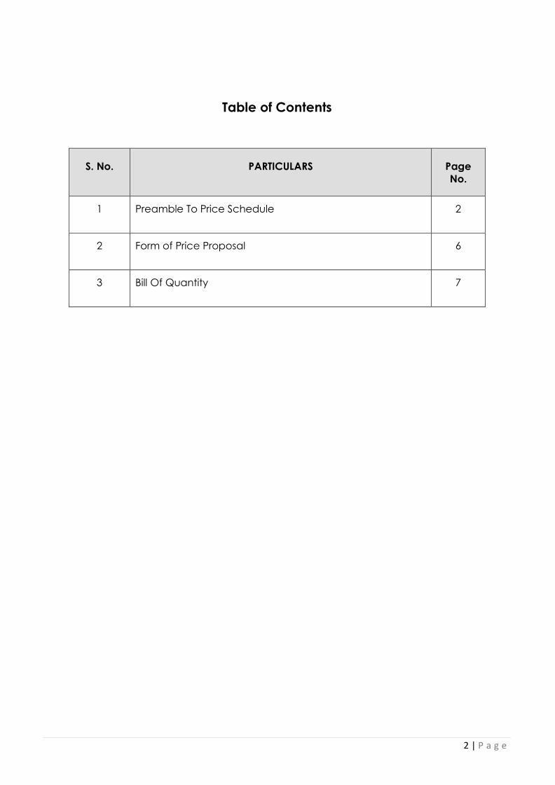
2 | P a g e
Table of Contents
S. No. PARTICULARS Page
No.
1 Preamble To Price Schedule 2
2 Form of Price Proposal 6
3 Bill Of Quantity 7
3 | P a g e
Preamble to Price Schedule
1.0 General
The nature of this contract is Lump sum Contract and the Bill of Quantities (BOQ) shall reflect this fact. BOQ shall be read and construed in conjunction with other Bid Documents. General directions and description of work and material given in the Technical Specification are not necessarily repeated in the Bill of Quantities. The Technical Specification forms an integral part of the Bill of Quantities. The Tenderer is obliged to check the number of the pages of the Bill of Quantities and should any be found missing or duplicated or the figures or writing indistinct, the Tenderer must notify the Employer/Engineer at once and have the matter rectified before the Tender is submitted. No liability whatsoever will be accepted in respect of any claim for errors in the Tenderer’s offer resulting from failure to comply with the afore-going. The Tenderer is deemed to have visited the site and fully acquainted himself as to the location and its surroundings and taken into account all relevant factors pertaining to the site and all the conditions which may affect the performance of the works.
The Tenderer is also deemed to have surveyed the actual condition of the site and made his own assessment of the type and extent of the works prior to submitting his offer.
2. QUANTITIES The contract is Lump sum type and the purpose is to Construction of circular Intake well, Horse shoe type Connecting main, Sump and Pump house pumping 550 MLD, 2100 mm MS pipeline of 1230 m length, Construction approach road, Providing and Erecting 9 no. VT pumps, Providing and Erecting of Sluice valves, air valves, Providing and Installing SCADA system along with Master PLC etc as mentioned in the Technical Specifications and BOQ. 3. MATERIALS All materials used are to be of the best new available and subject to the Employer/Engineer approval, and of durable nature, guaranteed, not liable to any base exchange and manufactured according to applicable IS Standards. Execution also is subject to approval of Employer/Engineer and shall be the best available common practice in engineering codes at the time of execution.
Items that contain materials or products of special make with names of manufacturers are to be taken as samples of what will be required. Subject to the Employer/Engineer approval, the Contractor may, at his discretion, offer similar products of other make if the equivalent quality of the specified materials is guaranteed. In this case, the Contractor shall submit a description and/or drawings showing all technical conditions, characteristics, make, type and address of Manufacturer … etc., of the materials offered as alternatives.
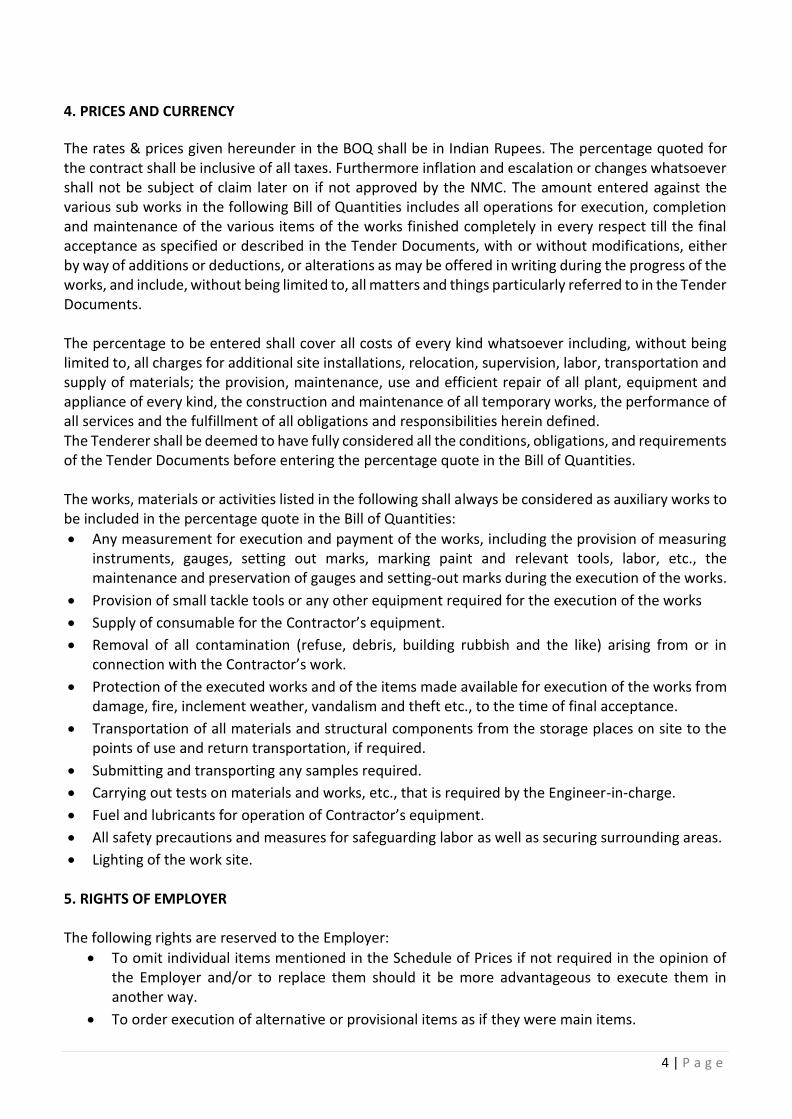
4 | P a g e
4. PRICES AND CURRENCY
The rates & prices given hereunder in the BOQ shall be in Indian Rupees. The percentage quoted for the contract shall be inclusive of all taxes. Furthermore inflation and escalation or changes whatsoever shall not be subject of claim later on if not approved by the NMC. The amount entered against the various sub works in the following Bill of Quantities includes all operations for execution, completion and maintenance of the various items of the works finished completely in every respect till the final acceptance as specified or described in the Tender Documents, with or without modifications, either by way of additions or deductions, or alterations as may be offered in writing during the progress of the works, and include, without being limited to, all matters and things particularly referred to in the Tender Documents. The percentage to be entered shall cover all costs of every kind whatsoever including, without being limited to, all charges for additional site installations, relocation, supervision, labor, transportation and supply of materials; the provision, maintenance, use and efficient repair of all plant, equipment and appliance of every kind, the construction and maintenance of all temporary works, the performance of all services and the fulfillment of all obligations and responsibilities herein defined. The Tenderer shall be deemed to have fully considered all the conditions, obligations, and requirements of the Tender Documents before entering the percentage quote in the Bill of Quantities. The works, materials or activities listed in the following shall always be considered as auxiliary works to be included in the percentage quote in the Bill of Quantities:
• Any measurement for execution and payment of the works, including the provision of measuring instruments, gauges, setting out marks, marking paint and relevant tools, labor, etc., the maintenance and preservation of gauges and setting-out marks during the execution of the works.
• Provision of small tackle tools or any other equipment required for the execution of the works
• Supply of consumable for the Contractor’s equipment.
• Removal of all contamination (refuse, debris, building rubbish and the like) arising from or in connection with the Contractor’s work.
• Protection of the executed works and of the items made available for execution of the works from damage, fire, inclement weather, vandalism and theft etc., to the time of final acceptance.
• Transportation of all materials and structural components from the storage places on site to the points of use and return transportation, if required.
• Submitting and transporting any samples required.
• Carrying out tests on materials and works, etc., that is required by the Engineer-in-charge.
• Fuel and lubricants for operation of Contractor’s equipment.
• All safety precautions and measures for safeguarding labor as well as securing surrounding areas.
• Lighting of the work site. 5. RIGHTS OF EMPLOYER The following rights are reserved to the Employer:
• To omit individual items mentioned in the Schedule of Prices if not required in the opinion of the Employer and/or to replace them should it be more advantageous to execute them in another way.
• To order execution of alternative or provisional items as if they were main items.
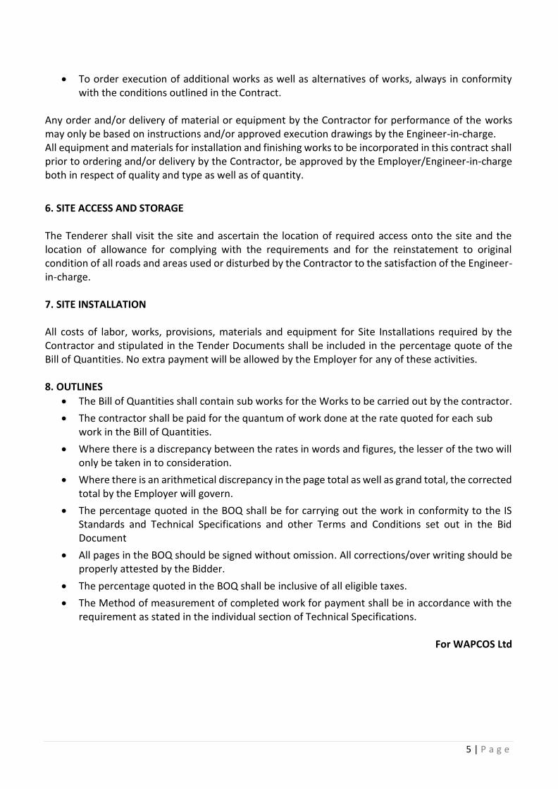
5 | P a g e
• To order execution of additional works as well as alternatives of works, always in conformity with the conditions outlined in the Contract.
Any order and/or delivery of material or equipment by the Contractor for performance of the works may only be based on instructions and/or approved execution drawings by the Engineer-in-charge. All equipment and materials for installation and finishing works to be incorporated in this contract shall prior to ordering and/or delivery by the Contractor, be approved by the Employer/Engineer-in-charge both in respect of quality and type as well as of quantity.
6. SITE ACCESS AND STORAGE The Tenderer shall visit the site and ascertain the location of required access onto the site and the location of allowance for complying with the requirements and for the reinstatement to original condition of all roads and areas used or disturbed by the Contractor to the satisfaction of the Engineer-in-charge. 7. SITE INSTALLATION All costs of labor, works, provisions, materials and equipment for Site Installations required by the Contractor and stipulated in the Tender Documents shall be included in the percentage quote of the Bill of Quantities. No extra payment will be allowed by the Employer for any of these activities. 8. OUTLINES
• The Bill of Quantities shall contain sub works for the Works to be carried out by the contractor.
• The contractor shall be paid for the quantum of work done at the rate quoted for each sub work in the Bill of Quantities.
• Where there is a discrepancy between the rates in words and figures, the lesser of the two will only be taken in to consideration.
• Where there is an arithmetical discrepancy in the page total as well as grand total, the corrected total by the Employer will govern.
• The percentage quoted in the BOQ shall be for carrying out the work in conformity to the IS Standards and Technical Specifications and other Terms and Conditions set out in the Bid Document
• All pages in the BOQ should be signed without omission. All corrections/over writing should be properly attested by the Bidder.
• The percentage quoted in the BOQ shall be inclusive of all eligible taxes.
• The Method of measurement of completed work for payment shall be in accordance with the requirement as stated in the individual section of Technical Specifications.
For WAPCOS Ltd

6 | P a g e
FORM OF PRICE PROPOSAL
The Chief, Civil/ Project Manager (Nagpur) WAPCOS LTD. Plot 222, N Bazar Rd, opposite to Venus Book Centre, Dharampeth Extension, Gokulpeth, Nagpur, Maharashtra 440010 Dear Sir,
SUB: “DEVELOPMENT OF INFRASTRUCTURE FOR LIFTING WATER FROM KANHAN RIVER AT VILLAGE
ROHANA & CONVEYANCE TO WATER TREATMENT PLANT AT GODHANI & GOREWADA”
I/We have examined the Conditions of Contract, Employer's Requirements, Addenda and the matters set out in the Schedules hereto. I/We have understood and checked these documents and have not found any errors in them. We accordingly offer to design, execute the entire work and commission the said works and remedy any defects, fit for purpose in conformity with these documents.
I/We hereby tender for the execution for the items of works specified in the BOQ as per time frame specified and as per rate mentioned in our price bid.
We confirm our agreement with the appointment of Arbitrator for Settlement of Disputes as per Clause 5.30 of Vol II General Condition of Contract.
We agree to abide by this Bid until 120 days and it shall remain binding upon us and maybe accepted at any time before that date.
If our bid is accepted, we will provide the specified performance deposit, commence the works as soon as reasonably possible after receiving the Employer's Representative's notice to commence, and complete the Works in accordance with the above-named documents within the time stated in the tender document.
Unless and until a formal Agreement is prepared and executed, this Bid, together with your written, acceptance thereof, shall constitute a binding contract between us.
We understand that you are not bound to accept the lowest or any bid you may receive.
Yours faithfully
(i) Signature of the representative of Company
(ii) Designation
(iii) Name of Company
(iv) Address _______________________________________________ _______________________________________________
Date _____________________________________
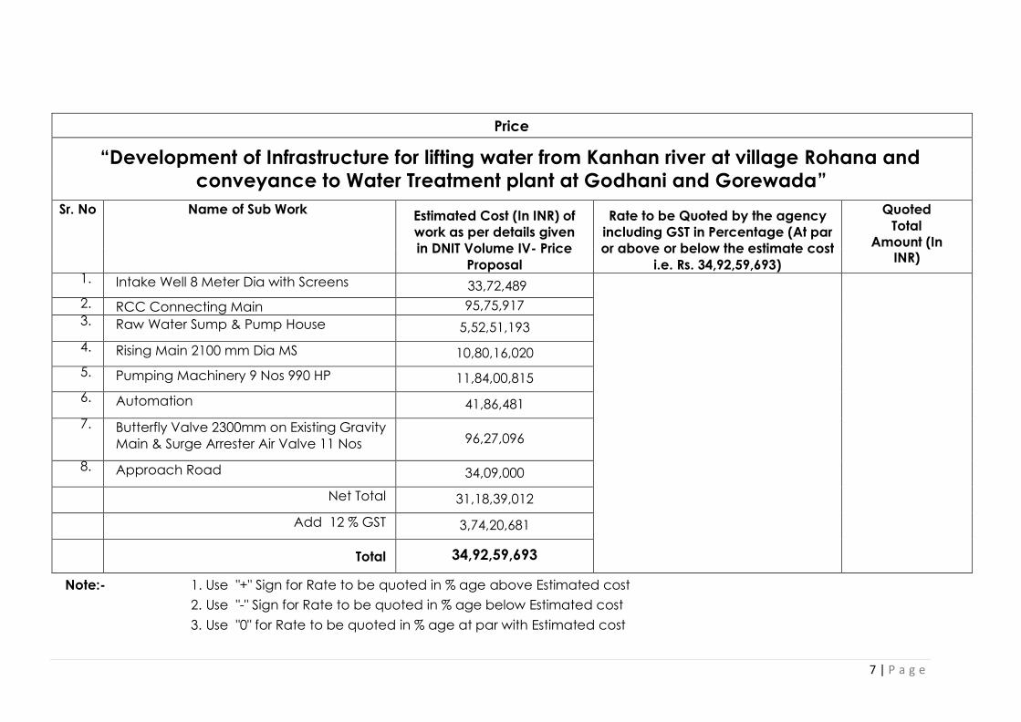
7 | P a g e
Price
Bid
“Development of Infrastructure for lifting water from Kanhan river at village Rohana and conveyance to Water Treatment plant at Godhani and Gorewada”
Sr. No Name of Sub Work
Estimated Cost (In INR) of
work as per details given
in DNIT Volume IV- Price
Proposal
Rate to be Quoted by the agency
including GST in Percentage (At par
or above or below the estimate cost
i.e. Rs. 34,92,59,693)
Quoted
Total
Amount (In INR)
1. Intake Well 8 Meter Dia with Screens 33,72,489
2. RCC Connecting Main 95,75,917 3. Raw Water Sump & Pump House 5,52,51,193
4. Rising Main 2100 mm Dia MS 10,80,16,020
5. Pumping Machinery 9 Nos 990 HP 11,84,00,815
6. Automation 41,86,481
7. Butterfly Valve 2300mm on Existing Gravity
Main & Surge Arrester Air Valve 11 Nos 96,27,096
8. Approach Road 34,09,000
Net Total 31,18,39,012
Add 12 % GST 3,74,20,681
Total 34,92,59,693
Note:- 1. Use "+" Sign for Rate to be quoted in % age above Estimated cost
2. Use "-" Sign for Rate to be quoted in % age below Estimated cost
3. Use "0" for Rate to be quoted in % age at par with Estimated cost

8 | P a g e
Yours faithfully
(i) Signature of the representative of Company
(ii) Designation
(iii) Name of Company
(iv) Address Date
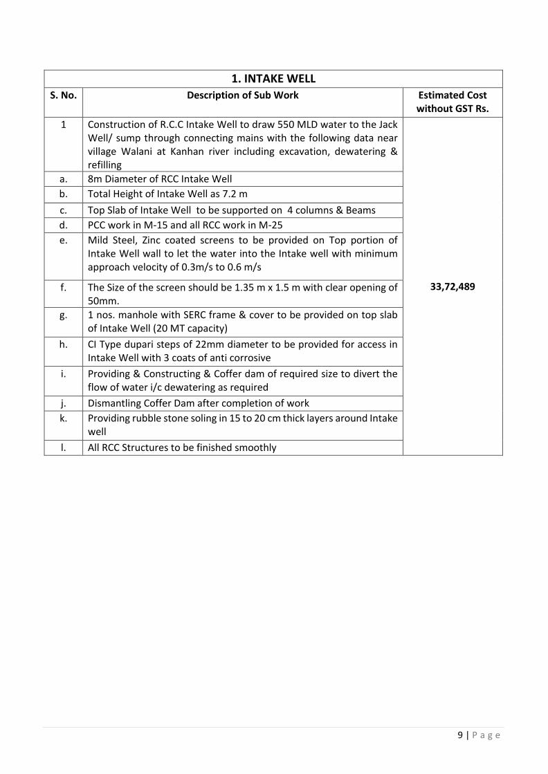
9 | P a g e
1. INTAKE WELL S. No. Description of Sub Work Estimated Cost
without GST Rs.
1 Construction of R.C.C Intake Well to draw 550 MLD water to the Jack Well/ sump through connecting mains with the following data near village Walani at Kanhan river including excavation, dewatering & refilling
33,72,489
a. 8m Diameter of RCC Intake Well
b. Total Height of Intake Well as 7.2 m
c. Top Slab of Intake Well to be supported on 4 columns & Beams
d. PCC work in M-15 and all RCC work in M-25
e. Mild Steel, Zinc coated screens to be provided on Top portion of Intake Well wall to let the water into the Intake well with minimum approach velocity of 0.3m/s to 0.6 m/s
f. The Size of the screen should be 1.35 m x 1.5 m with clear opening of 50mm.
g. 1 nos. manhole with SERC frame & cover to be provided on top slab of Intake Well (20 MT capacity)
h. CI Type dupari steps of 22mm diameter to be provided for access in Intake Well with 3 coats of anti corrosive
i. Providing & Constructing & Coffer dam of required size to divert the flow of water i/c dewatering as required
j. Dismantling Coffer Dam after completion of work
k. Providing rubble stone soling in 15 to 20 cm thick layers around Intake well
l. All RCC Structures to be finished smoothly
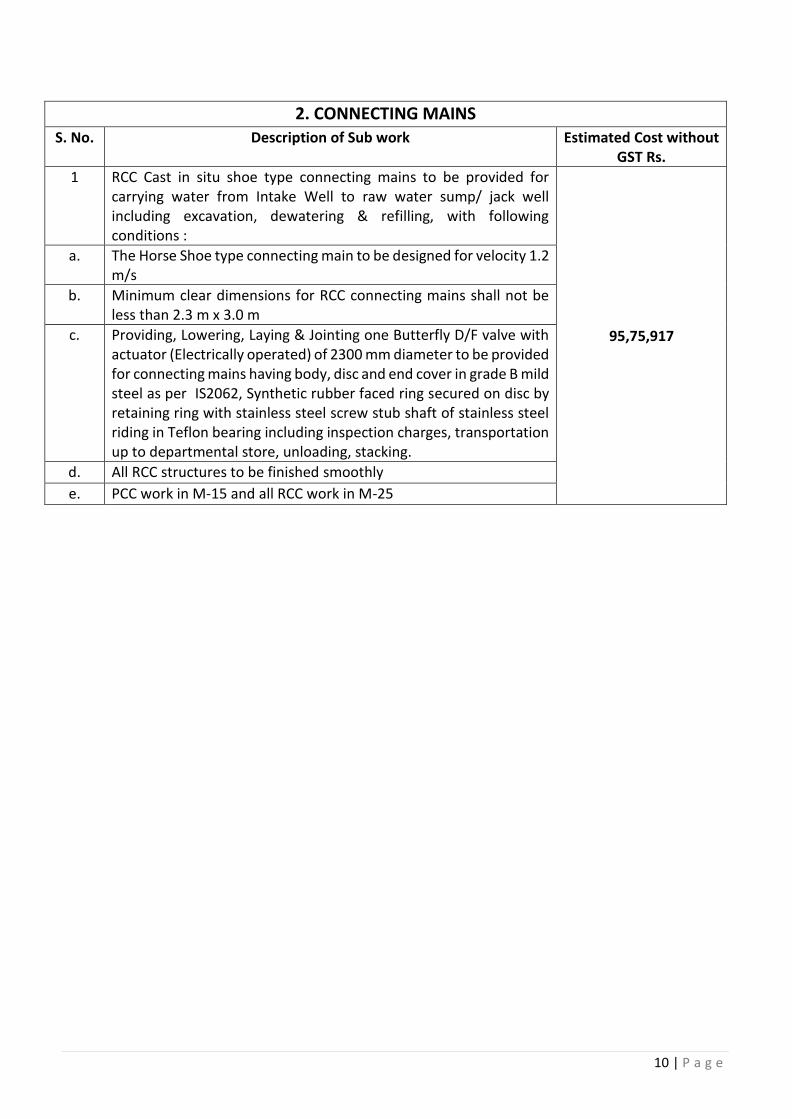
10 | P a g e
2. CONNECTING MAINS S. No. Description of Sub work Estimated Cost without
GST Rs.
1 RCC Cast in situ shoe type connecting mains to be provided for carrying water from Intake Well to raw water sump/ jack well including excavation, dewatering & refilling, with following conditions :
95,75,917
a. The Horse Shoe type connecting main to be designed for velocity 1.2 m/s
b. Minimum clear dimensions for RCC connecting mains shall not be less than 2.3 m x 3.0 m
c. Providing, Lowering, Laying & Jointing one Butterfly D/F valve with actuator (Electrically operated) of 2300 mm diameter to be provided for connecting mains having body, disc and end cover in grade B mild steel as per IS2062, Synthetic rubber faced ring secured on disc by retaining ring with stainless steel screw stub shaft of stainless steel riding in Teflon bearing including inspection charges, transportation up to departmental store, unloading, stacking.
d. All RCC structures to be finished smoothly
e. PCC work in M-15 and all RCC work in M-25
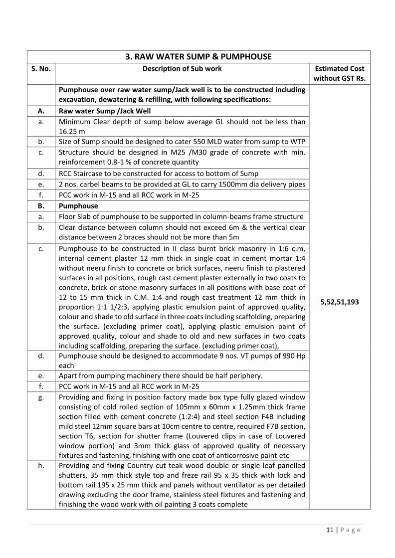
11 | P a g e
3. RAW WATER SUMP & PUMPHOUSE S. No. Description of Sub work Estimated Cost
without GST Rs.
Pumphouse over raw water sump/Jack well is to be constructed including excavation, dewatering & refilling, with following specifications:
5,52,51,193
A. Raw water Sump /Jack Well
a. Minimum Clear depth of sump below average GL should not be less than 16.25 m
b. Size of Sump should be designed to cater 550 MLD water from sump to WTP
c. Structure should be designed in M25 /M30 grade of concrete with min. reinforcement 0.8-1 % of concrete quantity
d. RCC Staircase to be constructed for access to bottom of Sump
e. 2 nos. carbel beams to be provided at GL to carry 1500mm dia delivery pipes
f. PCC work in M-15 and all RCC work in M-25
B. Pumphouse
a. Floor Slab of pumphouse to be supported in column-beams frame structure
b. Clear distance between column should not exceed 6m & the vertical clear distance between 2 braces should not be more than 5m
c. Pumphouse to be constructed in II class burnt brick masonry in 1:6 c.m, internal cement plaster 12 mm thick in single coat in cement mortar 1:4 without neeru finish to concrete or brick surfaces, neeru finish to plastered surfaces in all positions, rough cast cement plaster externally in two coats to concrete, brick or stone masonry surfaces in all positions with base coat of 12 to 15 mm thick in C.M. 1:4 and rough cast treatment 12 mm thick in proportion 1:1 1/2:3, applying plastic emulsion paint of approved quality, colour and shade to old surface in three coats including scaffolding, preparing the surface. (excluding primer coat), applying plastic emulsion paint of approved quality, colour and shade to old and new surfaces in two coats including scaffolding, preparing the surface. (excluding primer coat),
d. Pumphouse should be designed to accommodate 9 nos. VT pumps of 990 Hp each
e. Apart from pumping machinery there should be half periphery.
f. PCC work in M-15 and all RCC work in M-25
g. Providing and fixing in position factory made box type fully glazed window consisting of cold rolled section of 105mm x 60mm x 1.25mm thick frame section filled with cement concrete (1:2:4) and steel section F4B including mild steel 12mm square bars at 10cm centre to centre, required F7B section, section T6, section for shutter frame (Louvered clips in case of Louvered window portion) and 3mm thick glass of approved quality of necessary fixtures and fastening, finishing with one coat of anticorrosive paint etc
h. Providing and fixing Country cut teak wood double or single leaf panelled shutters, 35 mm thick style top and freze rail 95 x 35 thick with lock and bottom rail 195 x 25 mm thick and panels without ventilator as per detailed drawing excluding the door frame, stainless steel fixtures and fastening and finishing the wood work with oil painting 3 coats complete
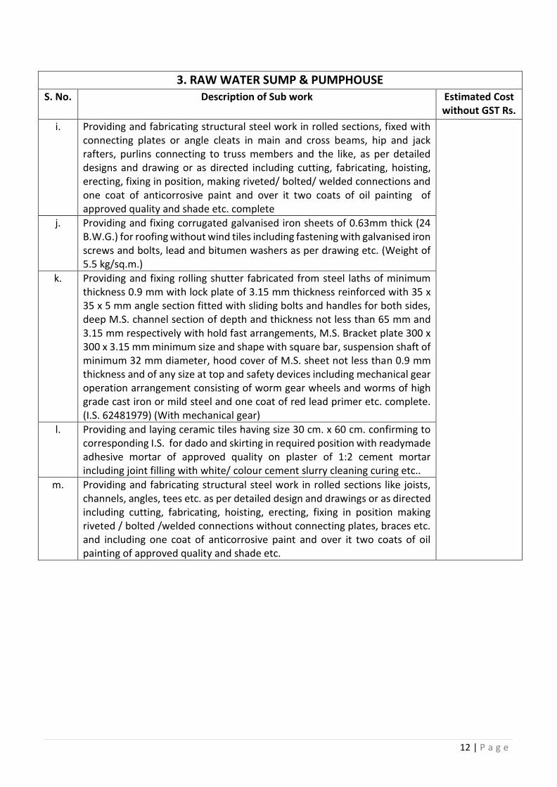
12 | P a g e
3. RAW WATER SUMP & PUMPHOUSE S. No. Description of Sub work Estimated Cost
without GST Rs.
i. Providing and fabricating structural steel work in rolled sections, fixed with connecting plates or angle cleats in main and cross beams, hip and jack rafters, purlins connecting to truss members and the like, as per detailed designs and drawing or as directed including cutting, fabricating, hoisting, erecting, fixing in position, making riveted/ bolted/ welded connections and one coat of anticorrosive paint and over it two coats of oil painting of approved quality and shade etc. complete
j. Providing and fixing corrugated galvanised iron sheets of 0.63mm thick (24 B.W.G.) for roofing without wind tiles including fastening with galvanised iron screws and bolts, lead and bitumen washers as per drawing etc. (Weight of 5.5 kg/sq.m.)
k. Providing and fixing rolling shutter fabricated from steel laths of minimum thickness 0.9 mm with lock plate of 3.15 mm thickness reinforced with 35 x 35 x 5 mm angle section fitted with sliding bolts and handles for both sides, deep M.S. channel section of depth and thickness not less than 65 mm and 3.15 mm respectively with hold fast arrangements, M.S. Bracket plate 300 x 300 x 3.15 mm minimum size and shape with square bar, suspension shaft of minimum 32 mm diameter, hood cover of M.S. sheet not less than 0.9 mm thickness and of any size at top and safety devices including mechanical gear operation arrangement consisting of worm gear wheels and worms of high grade cast iron or mild steel and one coat of red lead primer etc. complete. (I.S. 62481979) (With mechanical gear)
l. Providing and laying ceramic tiles having size 30 cm. x 60 cm. confirming to corresponding I.S. for dado and skirting in required position with readymade adhesive mortar of approved quality on plaster of 1:2 cement mortar including joint filling with white/ colour cement slurry cleaning curing etc..
m. Providing and fabricating structural steel work in rolled sections like joists, channels, angles, tees etc. as per detailed design and drawings or as directed including cutting, fabricating, hoisting, erecting, fixing in position making riveted / bolted /welded connections without connecting plates, braces etc. and including one coat of anticorrosive paint and over it two coats of oil painting of approved quality and shade etc.
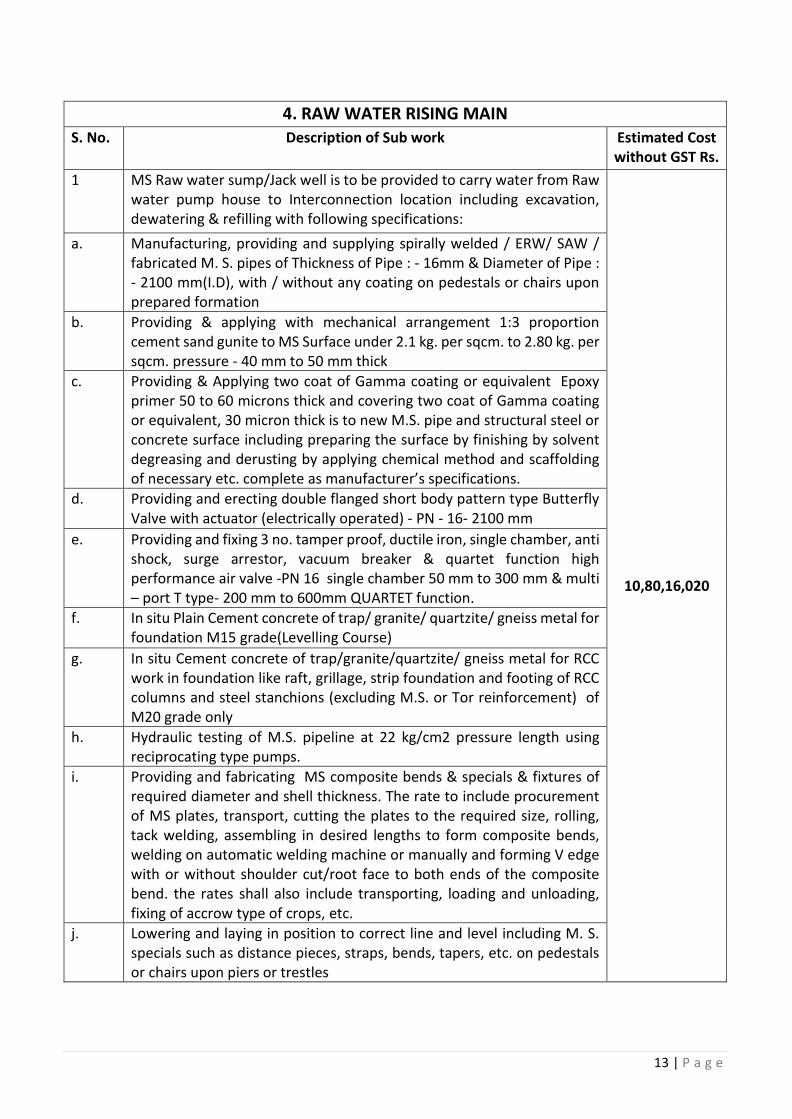
13 | P a g e
4. RAW WATER RISING MAIN S. No. Description of Sub work Estimated Cost
without GST Rs.
1 MS Raw water sump/Jack well is to be provided to carry water from Raw water pump house to Interconnection location including excavation, dewatering & refilling with following specifications:
10,80,16,020
a. Manufacturing, providing and supplying spirally welded / ERW/ SAW / fabricated M. S. pipes of Thickness of Pipe : - 16mm & Diameter of Pipe : - 2100 mm(I.D), with / without any coating on pedestals or chairs upon prepared formation
b. Providing & applying with mechanical arrangement 1:3 proportion cement sand gunite to MS Surface under 2.1 kg. per sqcm. to 2.80 kg. per sqcm. pressure - 40 mm to 50 mm thick
c. Providing & Applying two coat of Gamma coating or equivalent Epoxy primer 50 to 60 microns thick and covering two coat of Gamma coating or equivalent, 30 micron thick is to new M.S. pipe and structural steel or concrete surface including preparing the surface by finishing by solvent degreasing and derusting by applying chemical method and scaffolding of necessary etc. complete as manufacturer’s specifications.
d. Providing and erecting double flanged short body pattern type Butterfly Valve with actuator (electrically operated) - PN - 16- 2100 mm
e. Providing and fixing 3 no. tamper proof, ductile iron, single chamber, anti shock, surge arrestor, vacuum breaker & quartet function high performance air valve -PN 16 single chamber 50 mm to 300 mm & multi – port T type- 200 mm to 600mm QUARTET function.
f. In situ Plain Cement concrete of trap/ granite/ quartzite/ gneiss metal for foundation M15 grade(Levelling Course)
g. In situ Cement concrete of trap/granite/quartzite/ gneiss metal for RCC work in foundation like raft, grillage, strip foundation and footing of RCC columns and steel stanchions (excluding M.S. or Tor reinforcement) of M20 grade only
h. Hydraulic testing of M.S. pipeline at 22 kg/cm2 pressure length using reciprocating type pumps.
i. Providing and fabricating MS composite bends & specials & fixtures of required diameter and shell thickness. The rate to include procurement of MS plates, transport, cutting the plates to the required size, rolling, tack welding, assembling in desired lengths to form composite bends, welding on automatic welding machine or manually and forming V edge with or without shoulder cut/root face to both ends of the composite bend. the rates shall also include transporting, loading and unloading, fixing of accrow type of crops, etc.
j. Lowering and laying in position to correct line and level including M. S. specials such as distance pieces, straps, bends, tapers, etc. on pedestals or chairs upon piers or trestles
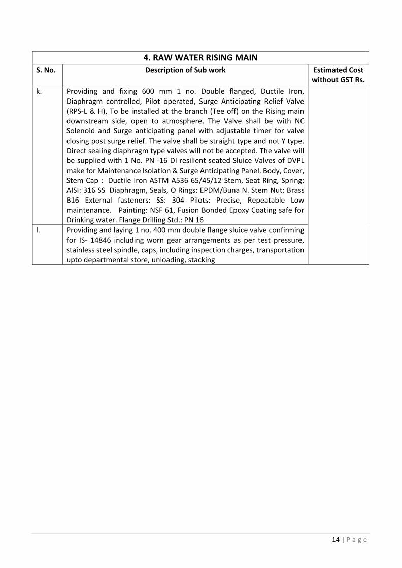
14 | P a g e
4. RAW WATER RISING MAIN S. No. Description of Sub work Estimated Cost
without GST Rs.
k. Providing and fixing 600 mm 1 no. Double flanged, Ductile Iron, Diaphragm controlled, Pilot operated, Surge Anticipating Relief Valve (RPS-L & H), To be installed at the branch (Tee off) on the Rising main downstream side, open to atmosphere. The Valve shall be with NC Solenoid and Surge anticipating panel with adjustable timer for valve closing post surge relief. The valve shall be straight type and not Y type. Direct sealing diaphragm type valves will not be accepted. The valve will be supplied with 1 No. PN -16 DI resilient seated Sluice Valves of DVPL make for Maintenance Isolation & Surge Anticipating Panel. Body, Cover, Stem Cap : Ductile Iron ASTM A536 65/45/12 Stem, Seat Ring, Spring: AISI: 316 SS Diaphragm, Seals, O Rings: EPDM/Buna N. Stem Nut: Brass B16 External fasteners: SS: 304 Pilots: Precise, Repeatable Low maintenance. Painting: NSF 61, Fusion Bonded Epoxy Coating safe for Drinking water. Flange Drilling Std.: PN 16
l. Providing and laying 1 no. 400 mm double flange sluice valve confirming for IS- 14846 including worn gear arrangements as per test pressure, stainless steel spindle, caps, including inspection charges, transportation upto departmental store, unloading, stacking
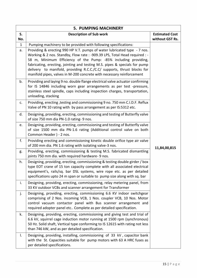
15 | P a g e
5. PUMPING MACHINERY S.
No. Description of Sub work Estimated Cost
without GST Rs.
1 Pumping machinery to be provided with following specifications:
11,84,00,815
a. Providing & erecting 990 HP V.T. pumps of water lubricated type - 7 nos. Working & 2 nos. Standby, Flow rate : -909.39 LPS, Total Head required : -58 m, Minimum Efficiency of the Pump: -85% including providing, fabricating, erecting, jointing and testing M.S. pipes & specials for pump delivery to manifold, providing R.C.C./C.C/ supports, thrust blocks for manifold pipes, valves in M-200 concrete with necessary reinforcement
b. Providing and laying 9 no. double flange electrical valve actuator confirming for IS 14846 including worn gear arrangements as per test -pressure, stainless steel spindle, caps including inspection charges, transportation, unloading, stacking
c. Providing, erecting ,testing and commissioning 9 no. 750 mm C.I.D.F. Reflux Valve of PN 10 rating with by pass arrangement as per IS:5312 etc.
d. Designing, providing, erecting, commissioning and testing of Butterfly valve of size 750 mm dia PN-1.0 rating- 9 nos.
e. Designing, providing, erecting, commissioning and testing of Butterfly valve of size 1500 mm dia PN-1.6 rating (Additional control valve on both Common Header ) - 2 nos.
f. Providing erecting and commissioning kinetic double orifice type air valve of 200 mm dia. PN 1.6 rating with isolating valve-3 nos.
g. Providing, erecting, commissioning & testing M.S. fabricated dismantling joints 750 mm dia. with required hardware- 9 nos.
h. Designing, providing, erecting, commissioning & testing double girder / box type EOT crane of 15 ton capacity complete with all associated electrical equipment’s, rails/sq. bar DSL systems, wire rope etc. as per detailed specifications upto 24 m span or suitable to pump size along with sq. bar
i. Designing, providing, erecting, commissioning, relay metering panel, from 33 KV outdoor VCBs and scanner arrangement for Transformer
j. Designing, providing, erecting, commissioning 6.6 KV indoor switchgear comprising of 2 Nos. incoming VCB, 1 Nos. coupler VCB, 10 Nos. Motor control vacuum contactor panel with Bus scanner arrangement and required adopter panel etc.. Complete as per detailed specification.
k. Designing, providing, erecting, commissioning and giving test and trial of 6.6 kV, squirrel cage induction motor running at 1500 rpm (synchronous) 50 Hz. Solid shaft, Vertical type conforming to IS 12615 with rating not less than 746 kW, and as per detailed specification.
l. Designing, providing, installing, commissioning of 33 kV , capacitor bank with the St. Capacities suitable for pump motors with 63 A HRC fuses as per detailed specifications.
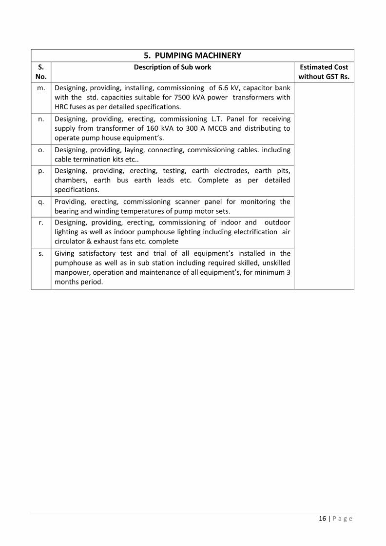
16 | P a g e
5. PUMPING MACHINERY S.
No. Description of Sub work Estimated Cost
without GST Rs.
m. Designing, providing, installing, commissioning of 6.6 kV, capacitor bank with the std. capacities suitable for 7500 kVA power transformers with HRC fuses as per detailed specifications.
n. Designing, providing, erecting, commissioning L.T. Panel for receiving supply from transformer of 160 kVA to 300 A MCCB and distributing to operate pump house equipment’s.
o. Designing, providing, laying, connecting, commissioning cables. including cable termination kits etc..
p. Designing, providing, erecting, testing, earth electrodes, earth pits, chambers, earth bus earth leads etc. Complete as per detailed specifications.
q. Providing, erecting, commissioning scanner panel for monitoring the bearing and winding temperatures of pump motor sets.
r. Designing, providing, erecting, commissioning of indoor and outdoor lighting as well as indoor pumphouse lighting including electrification air circulator & exhaust fans etc. complete
s. Giving satisfactory test and trial of all equipment’s installed in the pumphouse as well as in sub station including required skilled, unskilled manpower, operation and maintenance of all equipment’s, for minimum 3 months period.
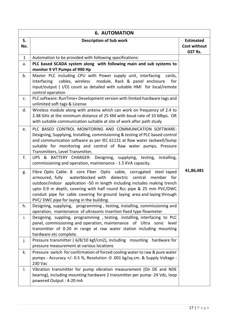
17 | P a g e
6. AUTOMATION
S. No.
Description of Sub work Estimated Cost without
GST Rs.
1 Automation to be provided with following specifications:
41,86,481
a. PLC based SCADA system along with following main and sub systems to monitor 9 VT Pumps of 990 Hp
b. Master PLC including CPU with Power supply unit, interfacing cards, interfacing cables, wireless module, Rack & panel enclosure for input/output ( I/O) count as detailed with suitable HMI for local/remote control operation
c. PLC software: RunTime+ Development version with limited hardware tags and unlimited soft tags & License
d. Wireless module along with antena which can work on frequency of 2.4 to 2.48 GHz at the minimum distance of 25 KM with boud rate of 10 Mbps. OR with suitable communication suitable at site of work after path study
e. PLC BASED CONTROL MONITORING AND COMMUNICATION SOFTWARE- Designing, Supplying, Installing, commissioning & testing of PLC based control and communication software as per IEC 61131 at Raw water Jackwell/Sump suitable for monitoring and control of Raw water pumps, Pressure Transmitters, Level Transmitter,
f. UPS & BATTERY CHARGER- Designing, supplying, testing, installing, commissioning and operation, maintenance - 1.5 KVA capacity.
g. Fibre Optic Cable- 8 core Fiber Optic cable, corrugated steel taped armoured, fully waterblocked with dielectric central member for outdoor/indoor application -50 m length including includes making trench upto 0.9 m depth, covering with half round Rcc pipe & 25 mm PVC/DWC conduit pipe for cable covering for ground laying area and laying through PVC/ DWC pipe for laying in the building.
h. Designing, supplying, programming , testing, installing, commissioning and operation, maintenance of ultrasonic Insertion fixed type flowmeter
i. Designing, suppling, programming , testing, installing, interfacing to PLC panel, commissioning and operation, maintenance of Ultra sonic level transmitter of 0-20 m range at raw water station including mounting hardware etc complete.
j. Pressure transmitter ( 6/8/10 kgf/cm2), including mounting hardware for pressure measurement at various locations
k. Pressure switch for confirmation of forced cooling water to raw & pure water pumps - Accuracy +/- 0.5 %, Resolution :0 .001 kg/sq.cm. & Supply Voltage : 230 Vac
l. Vibration transmitter for pump vibration measurement (On DE and NDE bearing), including mounting hardware 2 transmitter per pump- 24 Vdc, loop powered Output : 4-20 mA
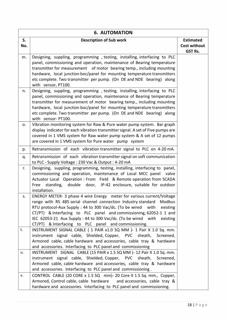
18 | P a g e
6. AUTOMATION
S. No.
Description of Sub work Estimated Cost without
GST Rs.
m. Designing, suppling, programming , testing, installing, interfacing to PLC panel, commissioning and operation, maintenance of Bearing temperature transmitter for measurement of motor bearing temp., including mounting hardware, local junction boc/panel for mounting temperature transmitters etc complete. Two transmitter per pump. (On DE and NDE bearing) along with sensor, PT100.
n. Designing, suppling, programming , testing, installing, interfacing to PLC panel, commissioning and operation, maintenance of Bearing temperature transmitter for measurement of motor bearing temp., including mounting hardware, local junction boc/panel for mounting temperature transmitters etc complete. Two transmitter per pump. (On DE and NDE bearing) along with sensor- PT100.
o. Vibration monitoring system for Raw & Pure water pump system. Bar graph display indicator for each vibration transmitter signal. A set of Five pumps are covered in 1 VMS system for Raw water pump system & A set of 12 pumps are covered in 1 VMS system for Pure water pump system
p. Retransmission of each vibration transmitter signal to PLC on 4-20 mA.
q. Retransmission of each vibration transmitter signal on soft communication to PLC - Supply Voltage : 230 Vac & Output : 4-20 mA
r. Designing, suppling, programming, testing, installing, interfacing to panel, commissioning and operation, maintenance of Local MCC panel valve Actuator Local Operation : From Field & Remote operation from SCADA Free standing, double door, IP-42 enclosure, suitable for outdoor installation.
s. ENERGY METER- 3 phase 4 wire Energy meter for various current/Voltage range with RS 485 serial channel connection Industry standard Modbus RTU protocol-Aux Supply : 44 to 300 Vac/dc. (To be wired with existing CT/PT) & Interfacing to PLC panel and commissioning, 62052-1 1 and IEC 62053-21 Aux Supply : 44 to 300 Vac/dc. (To be wired with existing CT/PT) & Interfacing to PLC panel and commissioning.
t. INSTRUMENT SIGNAL CABLE ( 1 PAIR x1.0 SQ MM )- 1 Pair X 1.0 Sq. mm. instrument signal cable, Shielded, Copper, PVC sheath, Screened, Armored cable, cable hardware and accessories, cable tray & hardware and accessories. Interfacing to PLC panel and commissioning
u. INSTRUMENT SIGNAL CABLE (15 PAIR x 1.5 SQ MM )- 12 Pair X 1.0 Sq. mm. instrument signal cable, Shielded, Copper, PVC sheath, Screened, Armored cable, cable hardware and accessories, cable tray & hardware and accessories. Interfacing to PLC panel and commissioning .
v. CONTROL CABLE (20 CORE x 1.5 SQ mm)- 20 Core X 1.5 Sq. mm., Copper, Armored, Control cable, cable hardware and accessories, cable tray & hardware and accessories. Interfacing to PLC panel and commissioning.
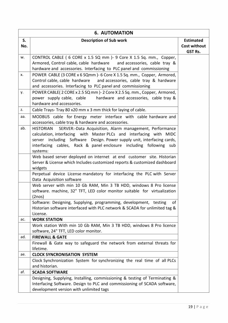
19 | P a g e
6. AUTOMATION
S. No.
Description of Sub work Estimated Cost without
GST Rs. w. CONTROL CABLE ( 6 CORE x 1.5 SQ mm )- 9 Core X 1.5 Sq. mm., Copper,
Armored, Control cable, cable hardware and accessories, cable tray & hardware and accessories. Interfacing to PLC panel and commissioning
x. POWER CABLE (3 CORE x 6 SQmm )- 6 Core X 1.5 Sq. mm., Copper, Armored, Control cable, cable hardware and accessories, cable tray & hardware and accessories. Interfacing to PLC panel and commissioning
y. POWER CABLE( 2 CORE x 2.5 SQ mm )- 2 Core X 2.5 Sq. mm., Copper, Armored, power supply cable, cable hardware and accessories, cable tray & hardware and accessories.
z. Cable Trays- Tray 80 x20 mm x 3 mm thick for laying of cable.
aa. MODBUS cable for Energy meter interface with cable hardware and accessories, cable tray & hardware and accessories.
ab. HISTORIAN SERVER:-Data Acquisition, Alarm management, Performance calculation, interfacing with Master PLCs and interfacing with MIDC server including Software Design. Power supply unit, interfacing cards, interfacing cables, Rack & panel enclosure including following sub systems:
Web based server deployed on internet at end customer site. Historian Server & License which Includes customized reports & customized dashboard widgets
Perpetual device License mandatory for interfacing the PLC with Server Data Acquisition software
Web server with min 10 Gb RAM, Min 3 TB HDD, windows 8 Pro license software. machine, 32" TFT, LED color monitor suitable for virtualization (2nos)
Software: Designing, Supplying, programming, development, testing of Historian software interfaced with PLC network & SCADA for unlimited tag & License.
ac. WORK STATION Work station With min 10 Gb RAM, Min 3 TB HDD, windows 8 Pro licence
software, 24" TFT, LED color monitor. ad. FIREWALL & GATE Firewall & Gate way to safeguard the network from external threats for
lifetime. ae. CLOCK SYNCRONISATION SYSTEM Clock Synchronization System for synchronizing the real time of all PLCs
and historian. af. SCADA SOFTWARE Designing, Supplying, Installing, commissioning & testing of Terminating &
Interfacing Software. Design to PLC and commissioning of SCADA software, development version with unlimited tags
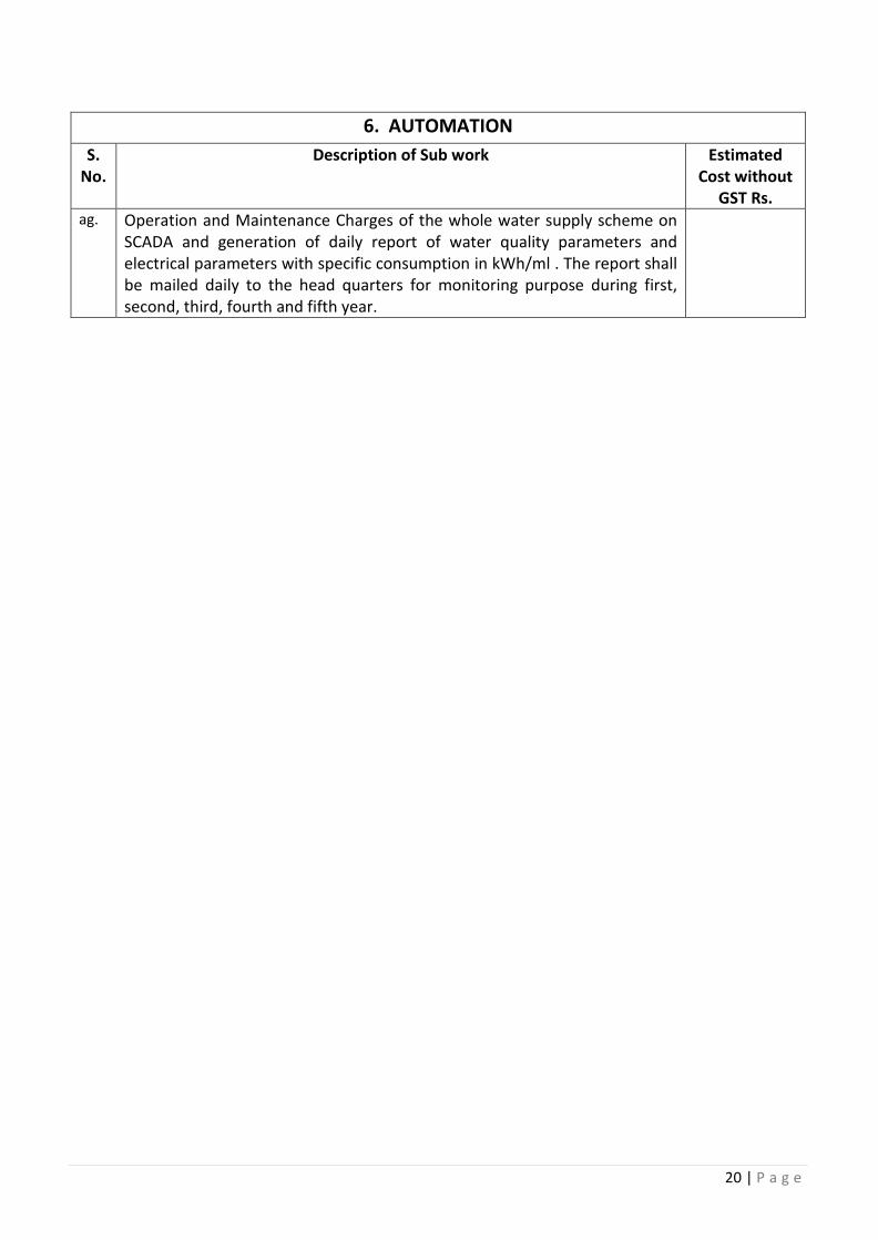
20 | P a g e
6. AUTOMATION
S. No.
Description of Sub work Estimated Cost without
GST Rs. ag. Operation and Maintenance Charges of the whole water supply scheme on
SCADA and generation of daily report of water quality parameters and electrical parameters with specific consumption in kWh/ml . The report shall be mailed daily to the head quarters for monitoring purpose during first, second, third, fourth and fifth year.
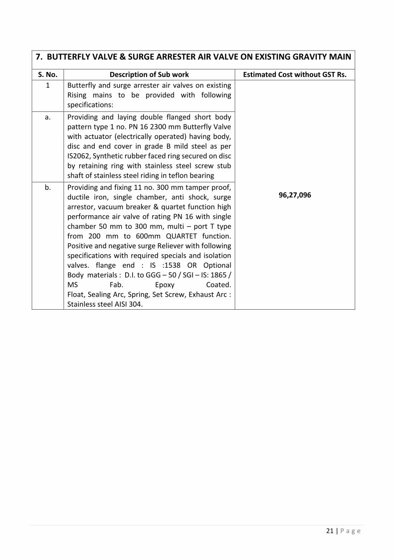
21 | P a g e
7. BUTTERFLY VALVE & SURGE ARRESTER AIR VALVE ON EXISTING GRAVITY MAIN
S. No. Description of Sub work Estimated Cost without GST Rs.
1 Butterfly and surge arrester air valves on existing Rising mains to be provided with following specifications:
96,27,096
a. Providing and laying double flanged short body pattern type 1 no. PN 16 2300 mm Butterfly Valve with actuator (electrically operated) having body, disc and end cover in grade B mild steel as per IS2062, Synthetic rubber faced ring secured on disc by retaining ring with stainless steel screw stub shaft of stainless steel riding in teflon bearing
b. Providing and fixing 11 no. 300 mm tamper proof, ductile iron, single chamber, anti shock, surge arrestor, vacuum breaker & quartet function high performance air valve of rating PN 16 with single chamber 50 mm to 300 mm, multi – port T type from 200 mm to 600mm QUARTET function. Positive and negative surge Reliever with following specifications with required specials and isolation valves. flange end : IS :1538 OR Optional Body materials : D.I. to GGG – 50 / SGI – IS: 1865 / MS Fab. Epoxy Coated. Float, Sealing Arc, Spring, Set Screw, Exhaust Arc : Stainless steel AISI 304.
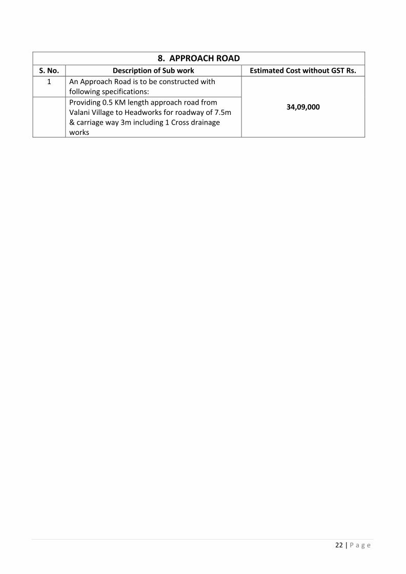
22 | P a g e
8. APPROACH ROAD S. No. Description of Sub work Estimated Cost without GST Rs.
1 An Approach Road is to be constructed with following specifications:
34,09,000 Providing 0.5 KM length approach road from
Valani Village to Headworks for roadway of 7.5m & carriage way 3m including 1 Cross drainage works
TENDER DOCUMENT
FOR
“DEVELOPMENT OF INFRASTRUCTURE FOR LIFTING WATER FROM KANHAN RIVER AT VILLAGE ROHANA & CONVEYANCE TO WATER
TREATMENT PLANT AT GODHANI & GOREWADA”
DRAWINGS
Issued to M/s_______________________________________ _______________________________________
TENDER NO: WAP/ INFRA./NGP/KANHAN
TENDER NO: WAP/ INFRA./NGP/KANHAN
Telephone: +91- 0712 255 7798, Email: [email protected], Website: www.wapcos.co.in
VOLUME - 5
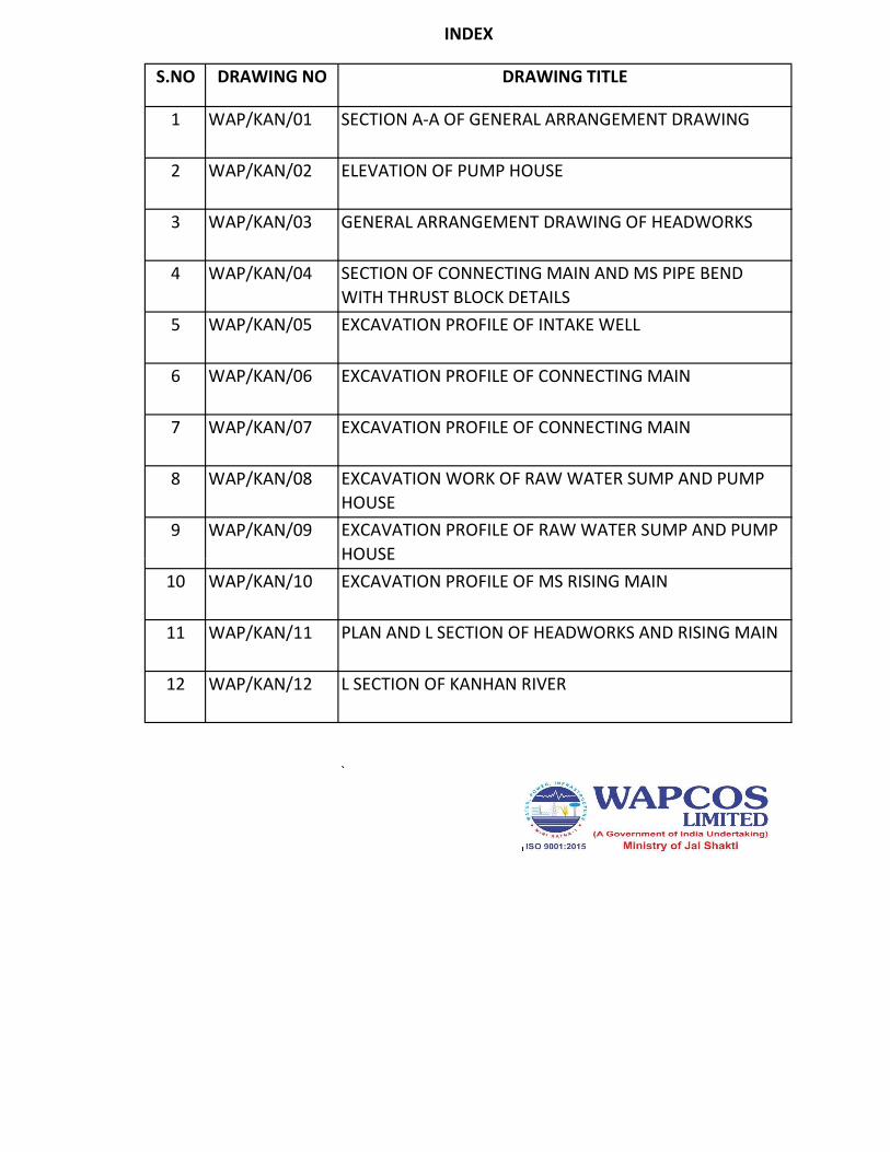
S.NO DRAWING NO DRAWING TITLE
1 WAP/KAN/01 SECTION A-A OF GENERAL ARRANGEMENT DRAWING
2 WAP/KAN/02 ELEVATION OF PUMP HOUSE
3 WAP/KAN/03 GENERAL ARRANGEMENT DRAWING OF HEADWORKS
4 WAP/KAN/04 SECTION OF CONNECTING MAIN AND MS PIPE BEND WITH THRUST BLOCK DETAILS
5 WAP/KAN/05 EXCAVATION PROFILE OF INTAKE WELL
6 WAP/KAN/06 EXCAVATION PROFILE OF CONNECTING MAIN
7 WAP/KAN/07 EXCAVATION PROFILE OF CONNECTING MAIN
8 WAP/KAN/08 EXCAVATION WORK OF RAW WATER SUMP AND PUMP HOUSE
9 WAP/KAN/09 EXCAVATION PROFILE OF RAW WATER SUMP AND PUMP HOUSE
INDEX
HOUSE 10 WAP/KAN/10 EXCAVATION PROFILE OF MS RISING MAIN
11 WAP/KAN/11 PLAN AND L SECTION OF HEADWORKS AND RISING MAIN
12 WAP/KAN/12 L SECTION OF KANHAN RIVER
`
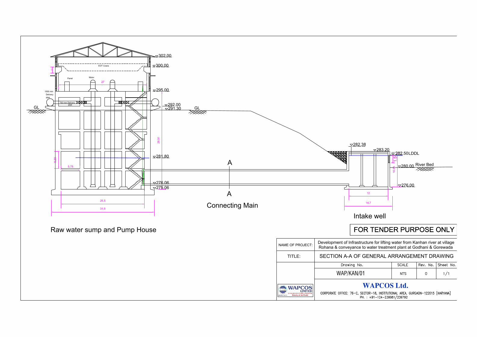
291.30
280.00
LDDL
295.00
281.80
292.00
302.00
276.06
GL
River Bed
283.20
276.00
282.38
282.50
275.06
12
29,91
5,78
5,23
25,5
31,5
10,56
14,7
Intake well
Connecting Main
Raw water sump and Pump House
27
1.5
1.25
Panel
Motor
EOT Crane
1500 mm
Delivery
pipe
750 mm Delivery
pipe
GL
300.00
WAPCOS Ltd.
NAME OF PROJECT:
Rohana & conveyance to water treatment plant at Godhani & Gorewada
SECTION A-A OF GENERAL ARRANGEMENT DRAWINGTITLE:
Development of Infrastructure for lifting water from Kanhan river at village
WAP/KAN/01
FOR TENDER PURPOSE ONLYFOR TENDER PURPOSE ONLY
A
A
AutoCAD SHX Text
Drawing No.
AutoCAD SHX Text
Rev. No.
AutoCAD SHX Text
Sheet No.
AutoCAD SHX Text
SCALE
AutoCAD SHX Text
CORPORATE OFFICE: 76-C, SECTOR-18, INSTITUTIONAL AREA, GURGAON-122015 [HARYANA]
AutoCAD SHX Text
PH. : +91-124-239981/239792
AutoCAD SHX Text
0
AutoCAD SHX Text
NTS
AutoCAD SHX Text
1/1
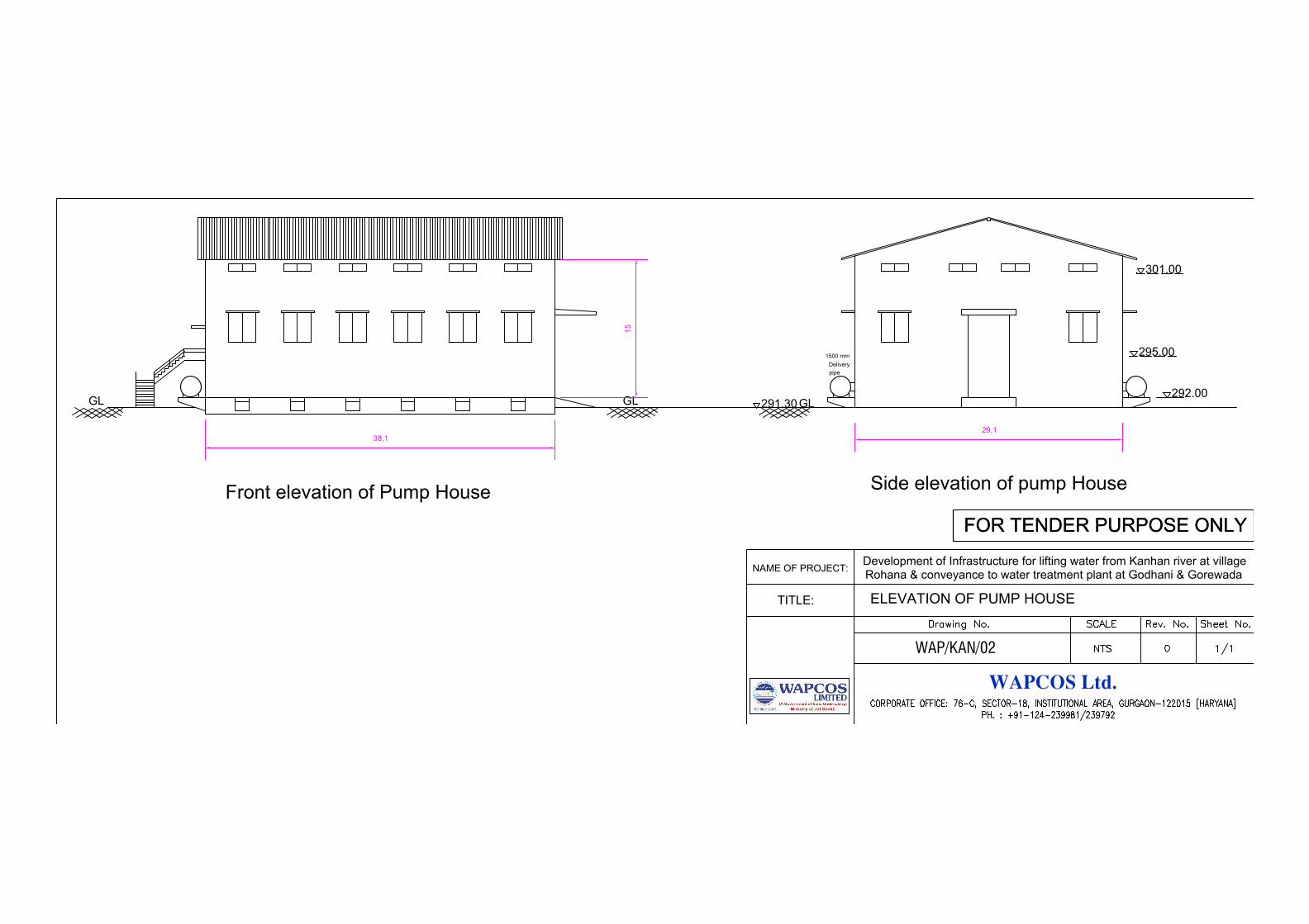
295.00
292.00
301.00
1500 mm
Delivery
pipe
GL
GL GL
15
38,1
29,1
Front elevation of Pump House
Side elevation of pump House
291.30
WAPCOS Ltd.
NAME OF PROJECT:
Rohana & conveyance to water treatment plant at Godhani & Gorewada
TITLE:
Development of Infrastructure for lifting water from Kanhan river at village
WAP/KAN/02
FOR TENDER PURPOSE ONLYFOR TENDER PURPOSE ONLY
ELEVATION OF PUMP HOUSE
AutoCAD SHX Text
Drawing No.
AutoCAD SHX Text
Rev. No.
AutoCAD SHX Text
Sheet No.
AutoCAD SHX Text
SCALE
AutoCAD SHX Text
CORPORATE OFFICE: 76-C, SECTOR-18, INSTITUTIONAL AREA, GURGAON-122015 [HARYANA]
AutoCAD SHX Text
PH. : +91-124-239981/239792
AutoCAD SHX Text
0
AutoCAD SHX Text
NTS
AutoCAD SHX Text
1/1
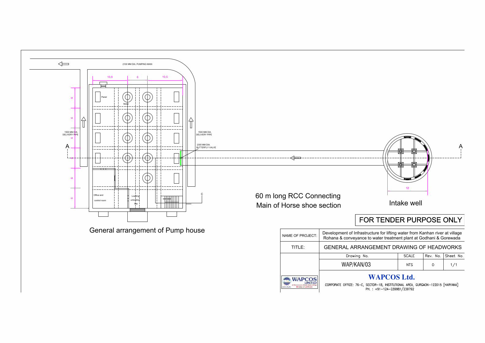
Intake well
610,5
10,5
66
66
66
General arrangement of Pump house
Office and
control room
Loading
unloading
bay
staircase
Panel
Motor
C
A
2100 MM DIA. PUMPING MAIN
1500 MM DIA.
DELIVERY PIPE
1500 MM DIA.
DELIVERY PIPE
A
60 m long RCC Connecting
2300 MM DIA.
BUTTERFLY VALVE
12
Main of Horse shoe section
WAPCOS Ltd.
NAME OF PROJECT:
Rohana & conveyance to water treatment plant at Godhani & Gorewada
TITLE:
Development of Infrastructure for lifting water from Kanhan river at village
WAP/KAN/03
FOR TENDER PURPOSE ONLYFOR TENDER PURPOSE ONLY
GENERAL ARRANGEMENT DRAWING OF HEADWORKS
AutoCAD SHX Text
Drawing No.
AutoCAD SHX Text
Rev. No.
AutoCAD SHX Text
Sheet No.
AutoCAD SHX Text
SCALE
AutoCAD SHX Text
CORPORATE OFFICE: 76-C, SECTOR-18, INSTITUTIONAL AREA, GURGAON-122015 [HARYANA]
AutoCAD SHX Text
PH. : +91-124-239981/239792
AutoCAD SHX Text
0
AutoCAD SHX Text
NTS
AutoCAD SHX Text
1/1
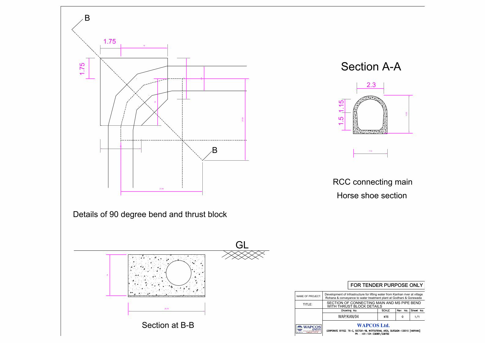
11,6
12
,9
5
1.1
51
.5
Horse shoe section
RCC connecting main
2.3
8,4
Details of 90 degree bend and thrust block
16
16
1.7
5
1.75
14
14
27
,8
9
27,89
B
B
Section at B-B
14
26,16
GL
WAPCOS Ltd.
NAME OF PROJECT:
Rohana & conveyance to water treatment plant at Godhani & Gorewada
TITLE:
Development of Infrastructure for lifting water from Kanhan river at village
WAP/KAN/04
FOR TENDER PURPOSE ONLYFOR TENDER PURPOSE ONLY
SECTION OF CONNECTING MAIN AND MS PIPE BEND
WITH THRUST BLOCK DETAILS
Section A-A
AutoCAD SHX Text
Drawing No.
AutoCAD SHX Text
Rev. No.
AutoCAD SHX Text
Sheet No.
AutoCAD SHX Text
SCALE
AutoCAD SHX Text
CORPORATE OFFICE: 76-C, SECTOR-18, INSTITUTIONAL AREA, GURGAON-122015 [HARYANA]
AutoCAD SHX Text
PH. : +91-124-239981/239792
AutoCAD SHX Text
0
AutoCAD SHX Text
NTS
AutoCAD SHX Text
1/1
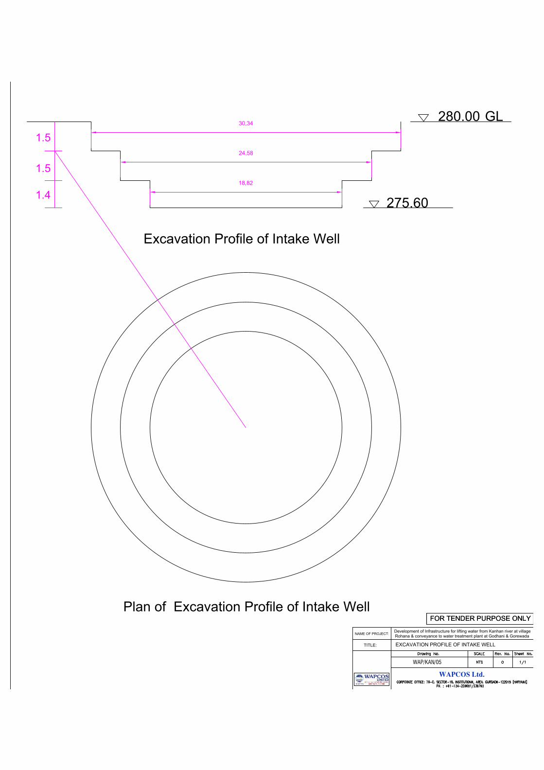
280.00
275.60
GL
1.5
1.5
1.4
Excavation Profile of Intake Well
24,58
30,34
18,82
Plan of Excavation Profile of Intake Well
WAPCOS Ltd.
NAME OF PROJECT:
Rohana & conveyance to water treatment plant at Godhani & Gorewada
TITLE:
Development of Infrastructure for lifting water from Kanhan river at village
WAP/KAN/05
FOR TENDER PURPOSE ONLYFOR TENDER PURPOSE ONLY
EXCAVATION PROFILE OF INTAKE WELL
AutoCAD SHX Text
Drawing No.
AutoCAD SHX Text
Rev. No.
AutoCAD SHX Text
Sheet No.
AutoCAD SHX Text
SCALE
AutoCAD SHX Text
CORPORATE OFFICE: 76-C, SECTOR-18, INSTITUTIONAL AREA, GURGAON-122015 [HARYANA]
AutoCAD SHX Text
PH. : +91-124-239981/239792
AutoCAD SHX Text
0
AutoCAD SHX Text
NTS
AutoCAD SHX Text
1/1
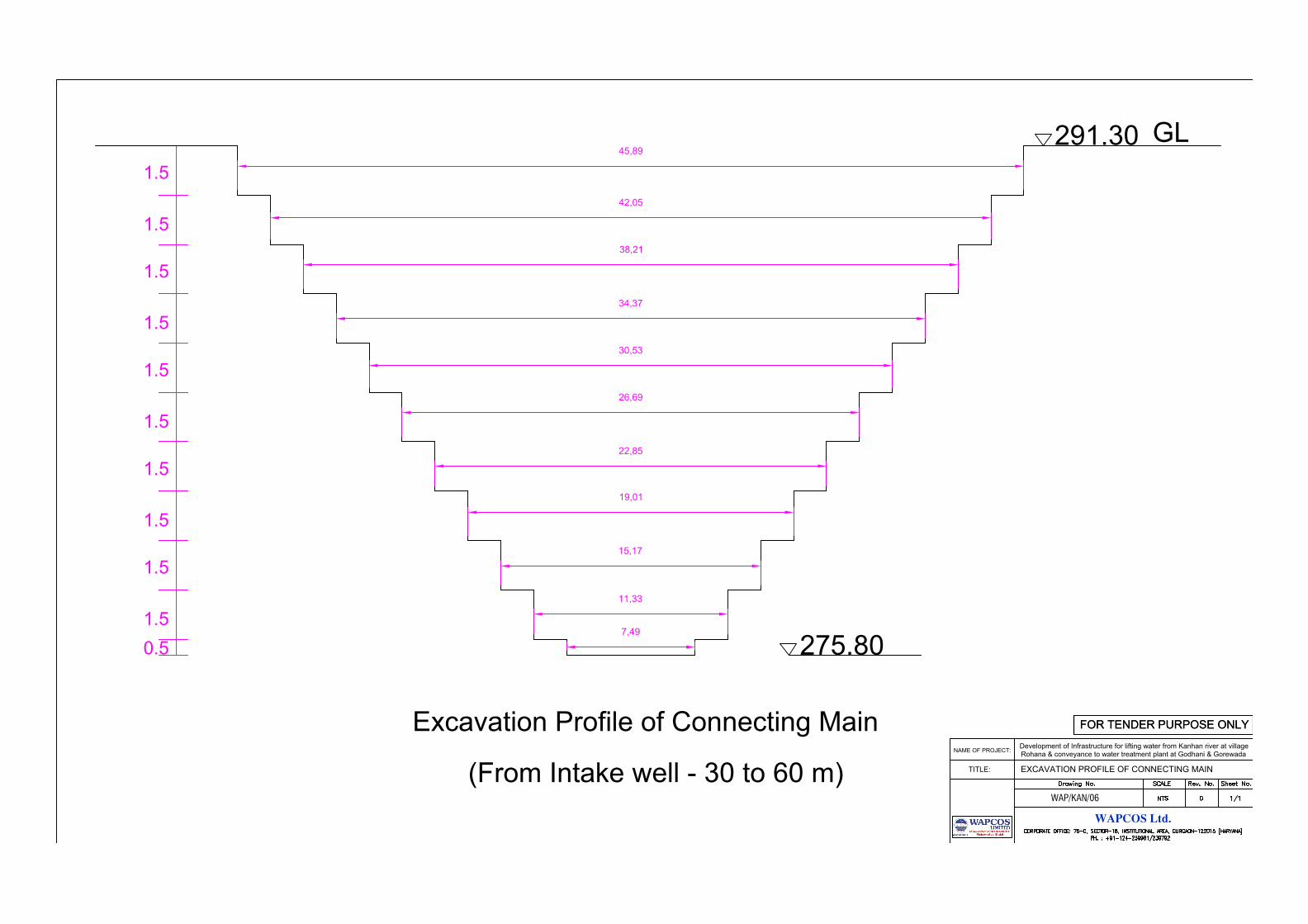
291.30
GL
1.5
1.5
1.5
1.5
1.5
1.5
1.5
1.5
1.5
1.5
0.5 275.80
Excavation Profile of Connecting Main
(From Intake well - 30 to 60 m)
7,49
11,33
15,17
19,01
22,85
26,69
30,53
34,37
38,21
42,05
45,89
WAPCOS Ltd.
NAME OF PROJECT:
Rohana & conveyance to water treatment plant at Godhani & Gorewada
TITLE:
Development of Infrastructure for lifting water from Kanhan river at village
WAP/KAN/06
FOR TENDER PURPOSE ONLYFOR TENDER PURPOSE ONLY
EXCAVATION PROFILE OF CONNECTING MAIN
AutoCAD SHX Text
Drawing No.
AutoCAD SHX Text
Rev. No.
AutoCAD SHX Text
Sheet No.
AutoCAD SHX Text
SCALE
AutoCAD SHX Text
CORPORATE OFFICE: 76-C, SECTOR-18, INSTITUTIONAL AREA, GURGAON-122015 [HARYANA]
AutoCAD SHX Text
PH. : +91-124-239981/239792
AutoCAD SHX Text
0
AutoCAD SHX Text
NTS
AutoCAD SHX Text
1/1
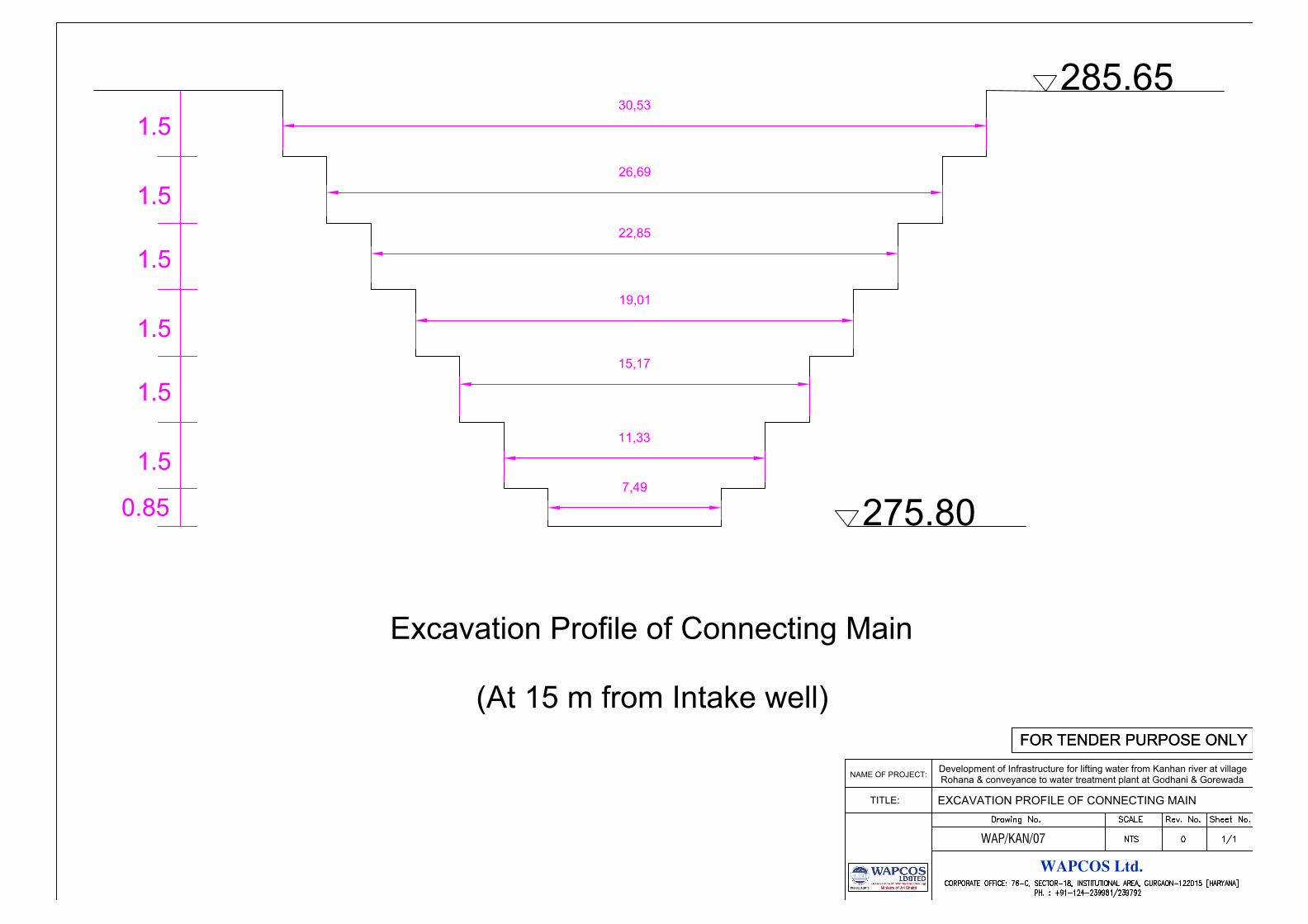
1.5
1.5
1.5
1.5
1.5
1.5
0.85
275.80
Excavation Profile of Connecting Main
(At 15 m from Intake well)
285.65
7,49
11,33
15,17
19,01
22,85
26,69
30,53
WAPCOS Ltd.
NAME OF PROJECT:
Rohana & conveyance to water treatment plant at Godhani & Gorewada
TITLE:
Development of Infrastructure for lifting water from Kanhan river at village
WAP/KAN/07
FOR TENDER PURPOSE ONLYFOR TENDER PURPOSE ONLY
EXCAVATION PROFILE OF CONNECTING MAIN
AutoCAD SHX Text
Drawing No.
AutoCAD SHX Text
Rev. No.
AutoCAD SHX Text
Sheet No.
AutoCAD SHX Text
SCALE
AutoCAD SHX Text
CORPORATE OFFICE: 76-C, SECTOR-18, INSTITUTIONAL AREA, GURGAON-122015 [HARYANA]
AutoCAD SHX Text
PH. : +91-124-239981/239792
AutoCAD SHX Text
0
AutoCAD SHX Text
NTS
AutoCAD SHX Text
1/1
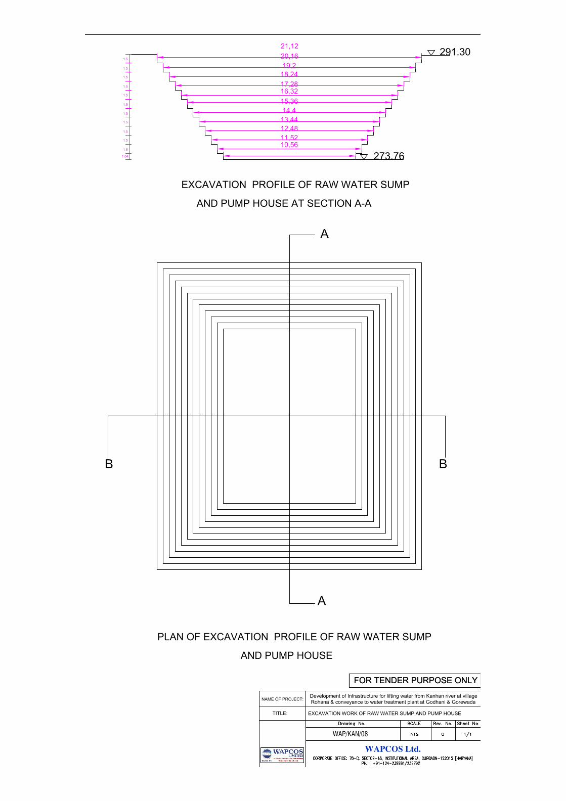
10,56
11,52
12,48
13,44
14,4
15,36
16,32
17,28
18,24
19,2
20,16
21,12
1.5
1.5
1.5
1.5
1.5
1.5
1.5
1.5
1.5
1.5
1.5
1.04
291.30
273.76
B
A
A
B
PLAN OF EXCAVATION PROFILE OF RAW WATER SUMP
AND PUMP HOUSE
EXCAVATION PROFILE OF RAW WATER SUMP
AND PUMP HOUSE AT SECTION A-A
WAPCOS Ltd.
NAME OF PROJECT:
Rohana & conveyance to water treatment plant at Godhani & Gorewada
TITLE:
Development of Infrastructure for lifting water from Kanhan river at village
WAP/KAN/08
FOR TENDER PURPOSE ONLYFOR TENDER PURPOSE ONLY
EXCAVATION WORK OF RAW WATER SUMP AND PUMP HOUSE
AutoCAD SHX Text
Drawing No.
AutoCAD SHX Text
Rev. No.
AutoCAD SHX Text
Sheet No.
AutoCAD SHX Text
SCALE
AutoCAD SHX Text
CORPORATE OFFICE: 76-C, SECTOR-18, INSTITUTIONAL AREA, GURGAON-122015 [HARYANA]
AutoCAD SHX Text
PH. : +91-124-239981/239792
AutoCAD SHX Text
0
AutoCAD SHX Text
NTS
AutoCAD SHX Text
1/1
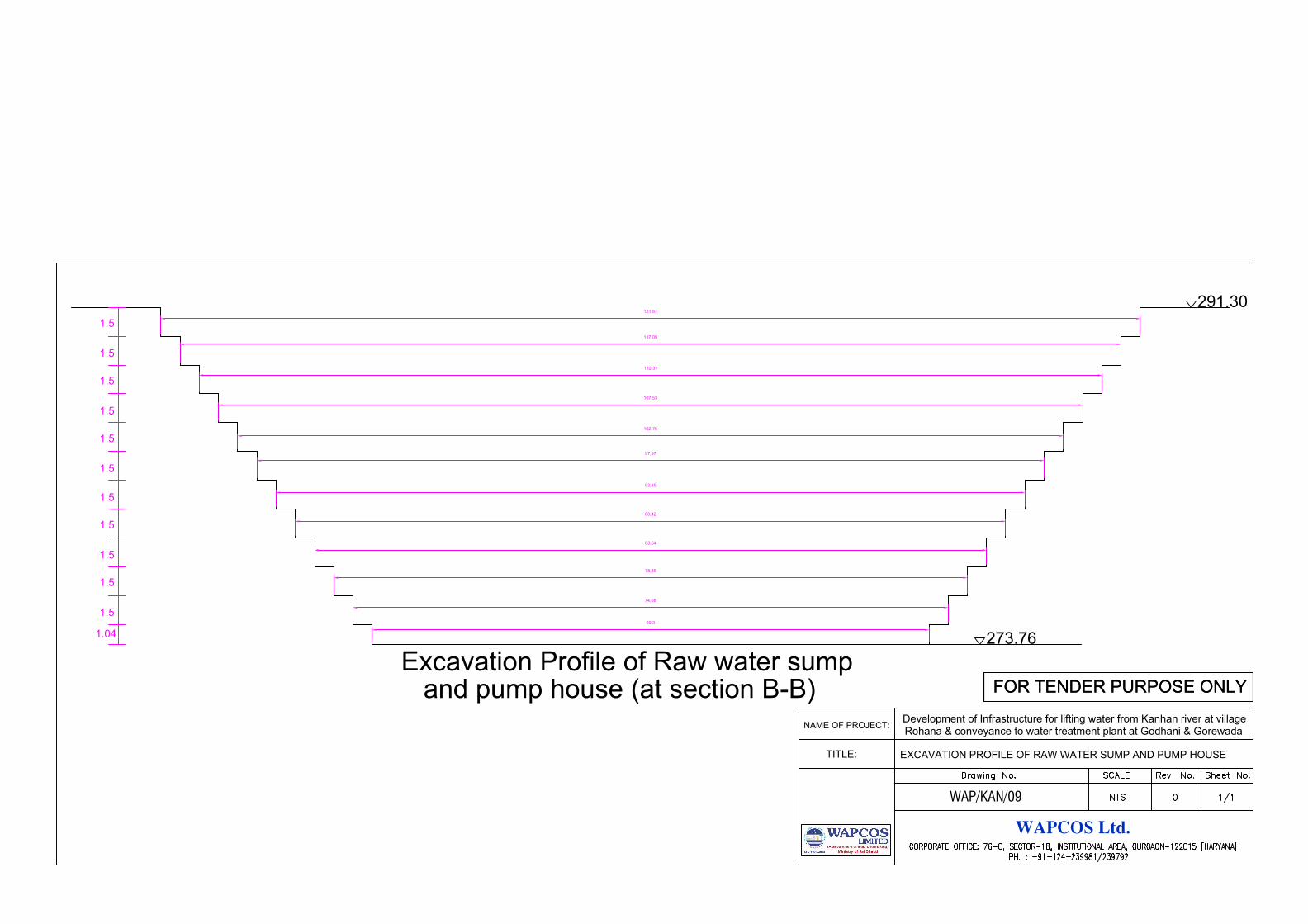
291.30
273.76
69,3
74,08
78,86
83,64
88,42
93,19
97,97
102,75
107,53
112,31
117,09
121,87
1.5
1.5
1.5
1.5
1.5
1.5
1.5
1.5
1.5
1.5
1.5
1.04
Excavation Profile of Raw water sump
and pump house (at section B-B)
WAPCOS Ltd.
NAME OF PROJECT:
Rohana & conveyance to water treatment plant at Godhani & Gorewada
TITLE:
Development of Infrastructure for lifting water from Kanhan river at village
WAP/KAN/09
FOR TENDER PURPOSE ONLYFOR TENDER PURPOSE ONLY
EXCAVATION PROFILE OF RAW WATER SUMP AND PUMP HOUSE
AutoCAD SHX Text
Drawing No.
AutoCAD SHX Text
Rev. No.
AutoCAD SHX Text
Sheet No.
AutoCAD SHX Text
SCALE
AutoCAD SHX Text
CORPORATE OFFICE: 76-C, SECTOR-18, INSTITUTIONAL AREA, GURGAON-122015 [HARYANA]
AutoCAD SHX Text
PH. : +91-124-239981/239792
AutoCAD SHX Text
0
AutoCAD SHX Text
NTS
AutoCAD SHX Text
1/1
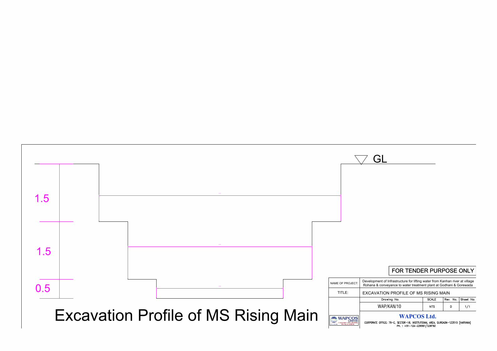
42,54
61,87
81,21
GL
1.5
1.5
0.5
Excavation Profile of MS Rising Main
WAPCOS Ltd.
NAME OF PROJECT:
Rohana & conveyance to water treatment plant at Godhani & Gorewada
TITLE:
Development of Infrastructure for lifting water from Kanhan river at village
WAP/KAN/10
FOR TENDER PURPOSE ONLYFOR TENDER PURPOSE ONLY
EXCAVATION PROFILE OF MS RISING MAIN
AutoCAD SHX Text
Drawing No.
AutoCAD SHX Text
Rev. No.
AutoCAD SHX Text
Sheet No.
AutoCAD SHX Text
SCALE
AutoCAD SHX Text
CORPORATE OFFICE: 76-C, SECTOR-18, INSTITUTIONAL AREA, GURGAON-122015 [HARYANA]
AutoCAD SHX Text
PH. : +91-124-239981/239792
AutoCAD SHX Text
0
AutoCAD SHX Text
NTS
AutoCAD SHX Text
1/1
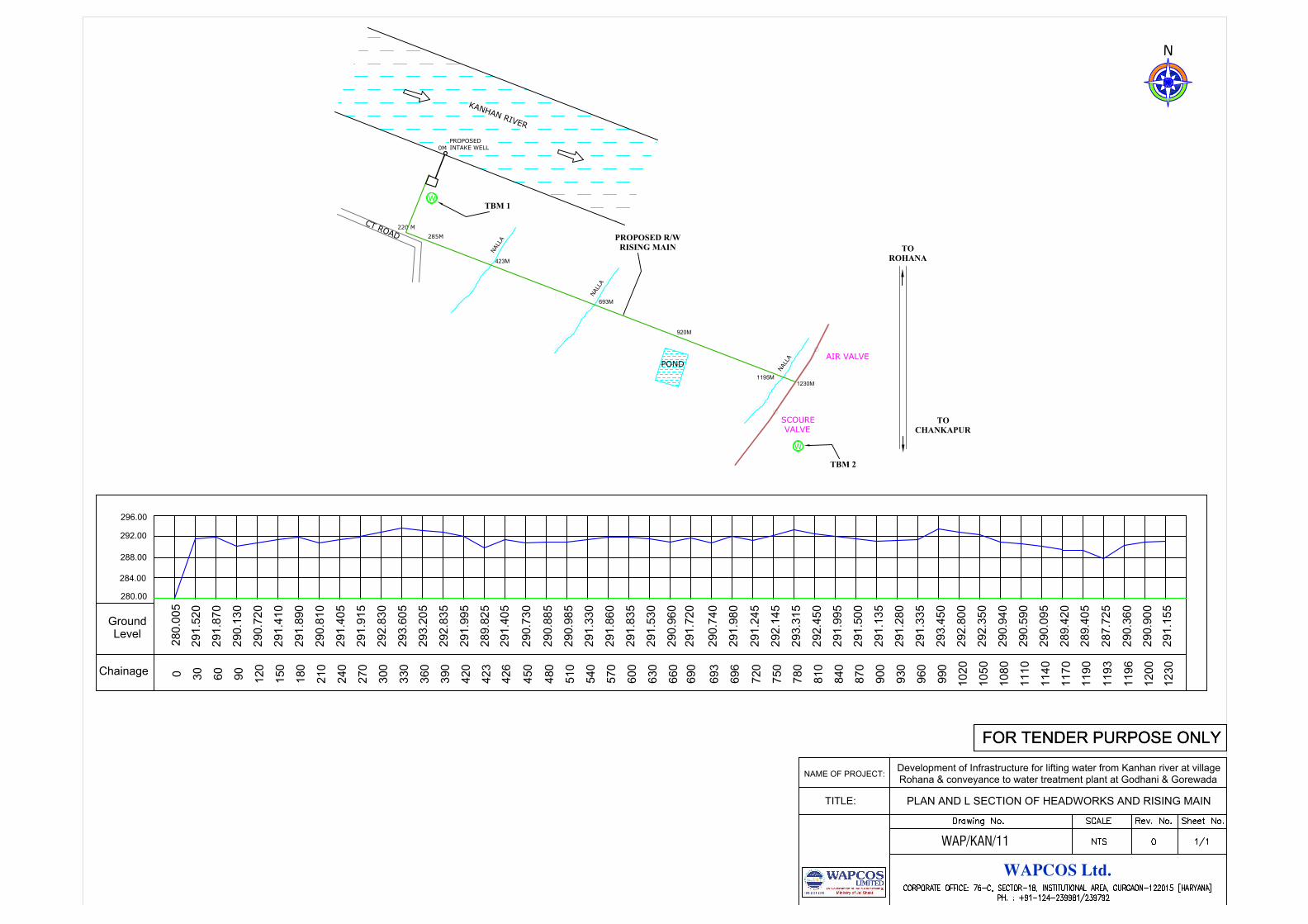
0
30
60
90
12
0
15
0
18
0
21
0
24
0
27
0
30
0
33
0
36
0
39
0
42
0
42
3
42
6
45
0
48
0
51
0
54
0
57
0
60
0
63
0
66
0
69
0
69
3
69
6
72
0
75
0
78
0
81
0
84
0
87
0
90
0
93
0
96
0
99
0
10
20
10
50
10
80
11
10
11
40
11
70
11
90
11
93
11
96
12
00
12
30
28
0.0
05
29
1.5
20
29
1.8
70
29
0.1
30
29
0.7
20
29
1.4
10
29
1.8
90
29
0.8
10
29
1.4
05
29
1.9
15
29
2.8
30
29
3.6
05
29
3.2
05
29
2.8
35
29
1.9
95
28
9.8
25
29
1.4
05
29
0.7
30
29
0.8
85
29
0.9
85
29
1.3
30
29
1.8
60
29
1.8
35
29
1.5
30
29
0.9
60
29
1.7
20
29
0.7
40
29
1.9
80
29
1.2
45
29
2.1
45
29
3.3
15
29
2.4
50
29
1.9
95
29
1.5
00
29
1.1
35
29
1.2
80
29
1.3
35
29
3.4
50
29
2.8
00
29
2.3
50
29
0.9
40
29
0.5
90
29
0.0
95
28
9.4
20
28
9.4
05
28
7.7
25
29
0.3
60
29
0.9
00
29
1.1
55
280.00
284.00
288.00
292.00
296.00
Ground
Chainage
Level
0M
220 M
285M
1230M
PROPOSED
INTAKE WELL
W
TBM 1
POND
AIR VALVE
SCOURE
VALVE
TBM 2
N
A
L
L
A
C
T
R
O
A
D
TOROHANA
TOCHANKAPUR
N
PROPOSED R/WRISING MAIN
N
A
L
L
A
423M
N
A
L
L
A
693M
1195M
W
920M
K
A
N
H
A
N
R
I
V
E
R
WAPCOS Ltd.
NAME OF PROJECT:
Rohana & conveyance to water treatment plant at Godhani & Gorewada
TITLE:
Development of Infrastructure for lifting water from Kanhan river at village
WAP/KAN/11
FOR TENDER PURPOSE ONLYFOR TENDER PURPOSE ONLY
PLAN AND L SECTION OF HEADWORKS AND RISING MAIN
AutoCAD SHX Text
Drawing No.
AutoCAD SHX Text
Rev. No.
AutoCAD SHX Text
Sheet No.
AutoCAD SHX Text
SCALE
AutoCAD SHX Text
CORPORATE OFFICE: 76-C, SECTOR-18, INSTITUTIONAL AREA, GURGAON-122015 [HARYANA]
AutoCAD SHX Text
PH. : +91-124-239981/239792
AutoCAD SHX Text
0
AutoCAD SHX Text
NTS
AutoCAD SHX Text
1/1
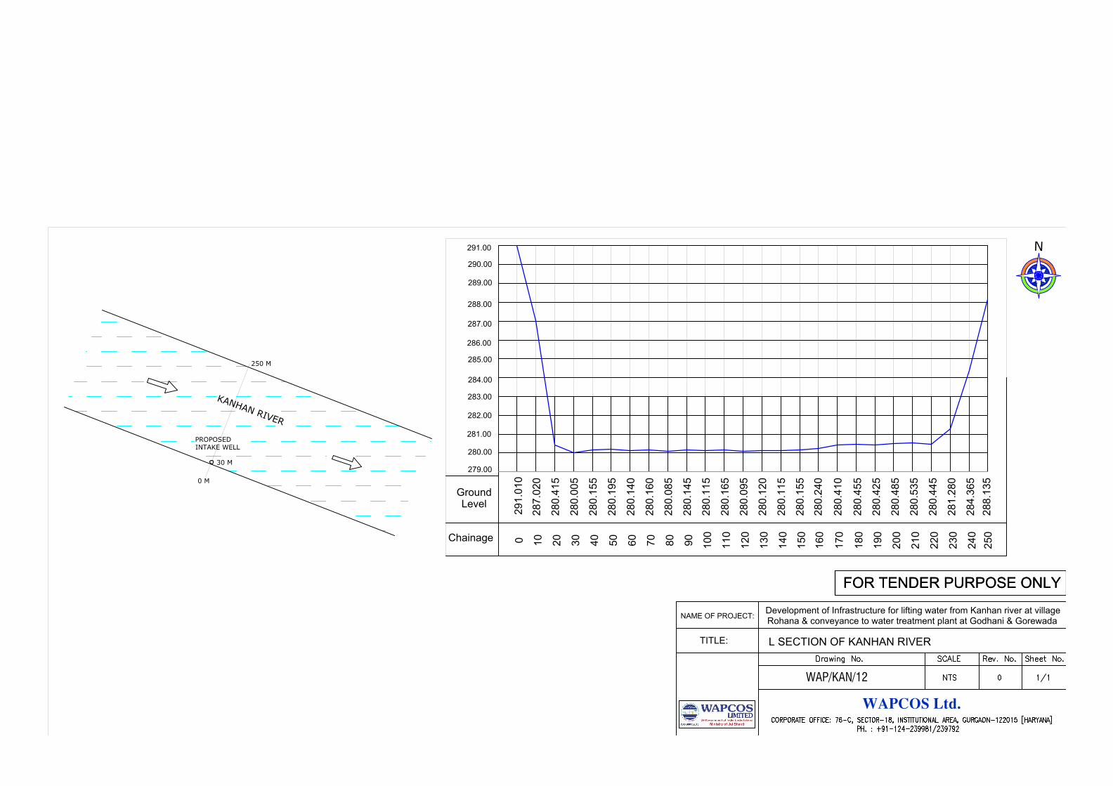
0
10
20
30
40
50
60
70
80
90
10
0
11
0
12
0
13
0
14
0
15
0
16
0
17
0
18
0
19
0
20
0
21
0
22
0
23
0
24
0
25
0
29
1.0
10
28
7.0
20
28
0.4
15
28
0.0
05
28
0.1
55
28
0.1
95
28
0.1
40
28
0.1
60
28
0.0
85
28
0.1
45
28
0.1
15
28
0.1
65
28
0.0
95
28
0.1
20
28
0.1
15
28
0.1
55
28
0.2
40
28
0.4
10
28
0.4
55
28
0.4
25
28
0.4
85
28
0.5
35
28
0.4
45
28
1.2
80
28
4.3
65
28
8.1
35
280.00
281.00
282.00
283.00
284.00
Ground
Chainage
Level
285.00
286.00
287.00
288.00
289.00
290.00
291.00
279.00
PROPOSED
INTAKE WELL
K
A
N
H
A
N
R
I
V
E
R
0 M
30 M
250 M
N
WAPCOS Ltd.
NAME OF PROJECT:
Rohana & conveyance to water treatment plant at Godhani & Gorewada
TITLE:
Development of Infrastructure for lifting water from Kanhan river at village
WAP/KAN/12
FOR TENDER PURPOSE ONLYFOR TENDER PURPOSE ONLY
L SECTION OF KANHAN RIVER
AutoCAD SHX Text
Drawing No.
AutoCAD SHX Text
Rev. No.
AutoCAD SHX Text
Sheet No.
AutoCAD SHX Text
SCALE
AutoCAD SHX Text
CORPORATE OFFICE: 76-C, SECTOR-18, INSTITUTIONAL AREA, GURGAON-122015 [HARYANA]
AutoCAD SHX Text
PH. : +91-124-239981/239792
AutoCAD SHX Text
0
AutoCAD SHX Text
NTS
AutoCAD SHX Text
1/1
Related Documents


