TENDER NO: WAP/INFRA/SIH-PURI TENDER DOCUMENT FOR CONSTRUCTION OF BALANCE WORKS OF SPORTS INDOOR HALL AT PURI, ODISHA TENDER NO: WAP/INFRA./SIH-PURI VOLUME 3: TECHNICAL SPECIFICATIONS Issued to M/s_______________________________________ _______________________________________ Tele-fax: +91-124-2397391, Email: [email protected], Website: www.wapcos.co.in

Welcome message from author
This document is posted to help you gain knowledge. Please leave a comment to let me know what you think about it! Share it to your friends and learn new things together.
Transcript
TENDER NO: WAP/INFRA/SIH-PURI
TENDER DOCUMENT
FOR
CONSTRUCTION OF BALANCE WORKS OF SPORTS INDOOR
HALL AT PURI, ODISHA
TENDER NO: WAP/INFRA./SIH-PURI
VOLUME 3: TECHNICAL SPECIFICATIONS
Issued to M/s_______________________________________ _______________________________________
Tele-fax: +91-124-2397391, Email: [email protected], Website: www.wapcos.co.in
TENDER NO: WAP/INFRA/SIH-PURI
CONSTRUCTION OF BALANCE WORKS OF SPORTS INDOOR HALL AT PURI, ODISHA
TENDER NO: WAP/INFRA./SIH-PURI
INDEX
S. No.
DESCRIPTION
PAGE NO.
1. GENERAL SPECIFICATIONS
3-10
2. TECHNICAL SPECIFICATIONS – CIVIL WORKS
11-142
3. TECHNICAL SPECIFICATIONS - ELECTRICAL WORK
511-583
4. TECHNICAL SPECIFICATIONS – PLUMBING & FIRE FIGHTING
WORKS
584-634
TENDER NO: WAP/INFRA/SIH-PURI
1.1 GENERAL
1.1.1 The work shall be carried out strictly in accordance with particular specifications and drawings.
The drawings, specifications BOQ etc. shall be taken complementary and also supplementary to
each other and shall form part this contract. Any work or material shown on drawings and not
specifically included in BOQ/specification or vice versa shall be executed and deemed to be included
in the scope of work.
1.1.2 In case there are no specifications for items shown on the drawings or where items are not
exhaustively described, the general specifications of CPWD shall be followed for which nothing
extra shall be paid. In case, no details are available even in CPWD specification, then decision of
employer is final & binding on the contractor.
1.1.3 The rates for all items of work unless clearly specified otherwise shall include cost of all labour,
materials and other inputs involved in the execution of the items.
1.1.4 The Contractor shall be responsible for furnishing all materials required for execution of the Works.
The Contractor shall submit the source and method of execution for the Employer’s review before any
execution. All materials used in the construction of permanent works required under this Contract
shall be of 1st class quality as specified herein and comply with the latest IS Codes or equivalent. The
material shall be tested before bringing it to the site.
1.1.5 This specification establishes and defines the requirements of various materials to be used in Civil
and Structural works. Whenever any reference to IS Codes is made, the same shall be taken as the
latest revision (with all amendments issued thereto) as on the date of submission of the Tender. Apart
from the IS Codes mentioned in particular in various clauses of this specification, all other relevant
codes related to specific job under consideration regarding quality, tests, testing and/or inspection
procedures shall be applicable. Reference to some of the codes in various clauses of this
specification does not limit or restrict the scope of applicability of other referred or relevant codes.
1.1.6 In case of any variation/contradiction between the provision of IS Codes and this specification, the
provision given in this specification shall be followed, unless the Employer agrees/consents to follow
IS codes or other proposal of the contractor as provided in the Contract.
1.1.7 All materials shall be of standard quality and shall be procured from renowned sources/manufacturers
approved by the/Employer. It shall be the responsibility of the contractor, to get all
materials/manufacturers approved by the Employer prior to procurement and placement of order.
1.1.8 Wherever brand is not mentioned, contractor shall take prior approval of brand complying with the
tender specifications however mentioning the brand considered in the Bid submission shall prevail if
specified earlier.
1.1.9 Whenever called for by the Employer, all tests of the materials as specified by the relevant IS Codes
shall be carried out by the Contractor in an approved laboratory and test reports duly authenticated by
the laboratory, shall be submitted to the Employer for his approval. If so desired by the Employer,
tests shall be conducted in the presence of the Employer or his authorized nominee.
1.1.10 Quality and acceptability of materials not covered under this specification shall be governed by the
relevant IS Codes. In case IS code is not available for the particular material, other codes e.g. B.S. or
DIN or API/ASTM etc. shall be considered. The decision of Employer in this regard shall be final and
binding on the Contractor.
1.1.11 Whenever asked for, the Contractor shall submit representative samples of materials to the
Employer for his inspection and approval. Approval of any samples does not necessarily exempt the
TENDER NO: WAP/INFRA/SIH-PURI
Contractor from submitting necessary test reports for the approved material, as per the
specification/relevant IS Codes.
1.1.12 The Contractor shall submit manufacturer’s test reports on quality and suitability of any material
procured from them and their recommendation on storage, application, workmanship etc. for the
intended use. Submission of manufacturer’s test reports does not restrict the Employer from asking
fresh test results from an approved laboratory of the actual material supplied from an approved
manufacturer/source at any stage of execution of work.
1.1.13 All costs relating to or arising out of the tests and submission of test reports and or samples to the
Employer for his approval till the date of issuance of Performance Certificate shall be borne by the
Contractor.
1.1.14 Materials for approval shall be separately stored and marked, as directed by the Employer and shall
not be used in the Works till these are approved.
1.1.15 All rejected materials shall be immediately removed from the site by the Contractor at his own cost.
1.2 GENERAL STANDARDS
The new facilities shall be completed to high standards of construction and specification. The facilities shall be technically and functionally suitable to meet the Employer's objectives:
i. The Architectural finishes shall be of such quality that will ensure better hygienic conditions.
ii. The architectural design takes into account the requirements of physically challenged persons
iii. All the material procured or to be used should be to the satisfaction of the Employerbefore being used for
the works intended to.
iv. All sanitary/ water supply fixture and fittings shall be of approved make confirming to IS specifications and
with ISI Marks.
v. All electrical system, fixtures, fittings etc. should confirm to CPWD specifications, latest IS code etc.
vi. The planning should include landscaping and horticulture to increase the comfort conditions. The
Contractor shall create parking, approach roads and other requirements for the building.
vii. Provision should be made for internal and external signages, display boards, in the required area.
1.3 UNACCEPTABLE MATERIALS AND PROCESSES
The materials and processes given below must not be used in the New Facilities or in connection with the New Facilities.
High alumina cement in structural elements
Calcium chloride as a concrete additive
Sea dredged aggregates or aggregates for use in reinforced concrete
Asbestos cement products; or asbestos in any other form including vermiculite containing asbestos
fibrous dust
Lead or any products containing lead for use in connection with drinking water
Materials which are generally composed of mineral fibres either man made or naturally occurring which
have a diameter of 3 microns or less and a length of 200 microns or less or which contain any fibres not
scaled or otherwise stabilised to ensure that fibre migration is prevented
Urea formaldehyde
Plastics for water storage and delivery that release toxic materials
Materials containing vinyl chloride unless risk form carcinogen is shown to be negligible.
Vermiculite containing asbestos fibrous dust
Cellulose fibre
TENDER NO: WAP/INFRA/SIH-PURI
Polyurethane foam or polyisocyanurate foam unless the risk is shown to be negligible
Plywood with glues, resins and surface treatments that produce irritant volatiles
Decorative finishes containing lead or asbestos
Materials containing chlorofluorocarbons (CFCs)
Paints and wood preservatives containing pentachlorophenois (PCPs) tributyl tin oxide (TBTO) or
Lindane
Any treatment of materials either before or after installation which give rise to toxic or hazardous
emissions or particles
Any other substances generally known at the time of use to be deleterious to health and safety or to the
durability of the works in the particular circumstances they are used
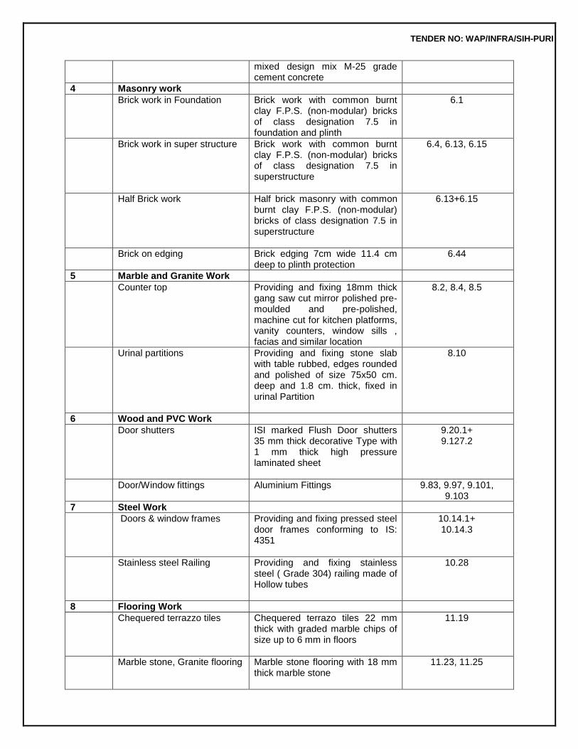
1.4 GENERAL SPECIFICATIONS
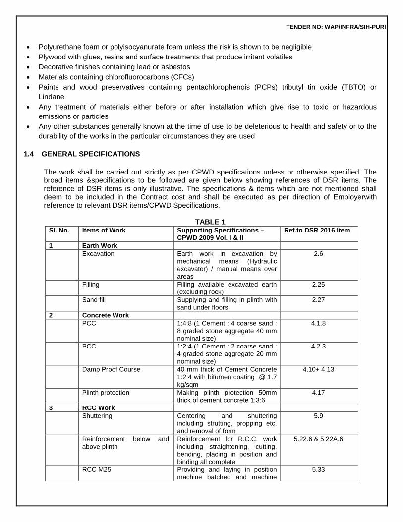
The work shall be carried out strictly as per CPWD specifications unless or otherwise specified. The broad items &specifications to be followed are given below showing references of DSR items. The reference of DSR items is only illustrative. The specifications & items which are not mentioned shall deem to be included in the Contract cost and shall be executed as per direction of Employerwith reference to relevant DSR items/CPWD Specifications.
TABLE 1
Sl. No. Items of Work Supporting Specifications – CPWD 2009 Vol. I & II
Ref.to DSR 2016 Item
1 Earth Work
Excavation Earth work in excavation by mechanical means (Hydraulic excavator) / manual means over areas
2.6
Filling Filling available excavated earth (excluding rock)
2.25
Sand fill Supplying and filling in plinth with sand under floors
2.27
2 Concrete Work
PCC 1:4:8 (1 Cement : 4 coarse sand : 8 graded stone aggregate 40 mm nominal size)
4.1.8
PCC 1:2:4 (1 Cement : 2 coarse sand : 4 graded stone aggregate 20 mm nominal size)
4.2.3
Damp Proof Course 40 mm thick of Cement Concrete 1:2:4 with bitumen coating @ 1.7 kg/sqm
4.10+ 4.13
Plinth protection Making plinth protection 50mm thick of cement concrete 1:3:6
4.17
3 RCC Work
Shuttering Centering and shuttering including strutting, propping etc. and removal of form
5.9
Reinforcement below and above plinth
Reinforcement for R.C.C. work including straightening, cutting, bending, placing in position and binding all complete
5.22.6 & 5.22A.6
RCC M25 Providing and laying in position machine batched and machine
5.33
TENDER NO: WAP/INFRA/SIH-PURI
mixed design mix M-25 grade cement concrete
4 Masonry work
Brick work in Foundation Brick work with common burnt clay F.P.S. (non-modular) bricks of class designation 7.5 in foundation and plinth
6.1
Brick work in super structure Brick work with common burnt clay F.P.S. (non-modular) bricks of class designation 7.5 in superstructure
6.4, 6.13, 6.15
Half Brick work Half brick masonry with common burnt clay F.P.S. (non-modular) bricks of class designation 7.5 in superstructure
6.13+6.15
Brick on edging Brick edging 7cm wide 11.4 cm deep to plinth protection
6.44
5 Marble and Granite Work
Counter top Providing and fixing 18mm thick gang saw cut mirror polished pre-moulded and pre-polished, machine cut for kitchen platforms, vanity counters, window sills , facias and similar location
8.2, 8.4, 8.5
Urinal partitions Providing and fixing stone slab with table rubbed, edges rounded and polished of size 75x50 cm. deep and 1.8 cm. thick, fixed in urinal Partition
8.10
6 Wood and PVC Work
Door shutters ISI marked Flush Door shutters 35 mm thick decorative Type with 1 mm thick high pressure laminated sheet
9.20.1+ 9.127.2
Door/Window fittings
Aluminium Fittings 9.83, 9.97, 9.101, 9.103
7 Steel Work
Doors & window frames Providing and fixing pressed steel door frames conforming to IS: 4351
10.14.1+ 10.14.3
Stainless steel Railing Providing and fixing stainless steel ( Grade 304) railing made of Hollow tubes
10.28
8 Flooring Work
Chequered terrazzo tiles Chequered terrazo tiles 22 mm thick with graded marble chips of size up to 6 mm in floors
11.19
Marble stone, Granite flooring Marble stone flooring with 18 mm thick marble stone
11.23, 11.25
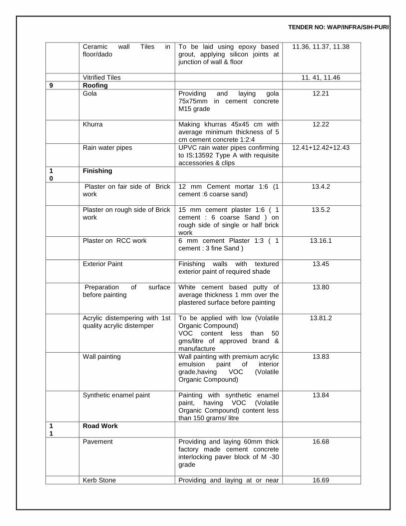
TENDER NO: WAP/INFRA/SIH-PURI
Ceramic wall Tiles in floor/dado
To be laid using epoxy based grout, applying silicon joints at junction of wall & floor
11.36, 11.37, 11.38
Vitrified Tiles 11. 41, 11.46
9 Roofing
Gola Providing and laying gola 75x75mm in cement concrete M15 grade
12.21
Khurra Making khurras 45x45 cm with average minimum thickness of 5 cm cement concrete 1:2:4
12.22
Rain water pipes UPVC rain water pipes confirming to IS:13592 Type A with requisite accessories & clips
12.41+12.42+12.43
10
Finishing
Plaster on fair side of Brick work
12 mm Cement mortar 1:6 (1 cement :6 coarse sand)
13.4.2
Plaster on rough side of Brick work
15 mm cement plaster 1:6 ( 1 cement : 6 coarse Sand ) on rough side of single or half brick work
13.5.2
Plaster on RCC work 6 mm cement Plaster 1:3 ( 1 cement : 3 fine Sand )
13.16.1
Exterior Paint Finishing walls with textured exterior paint of required shade
13.45
Preparation of surface before painting
White cement based putty of average thickness 1 mm over the plastered surface before painting
13.80
Acrylic distempering with 1st quality acrylic distemper
To be applied with low (Volatile Organic Compound) VOC content less than 50 gms/litre of approved brand & manufacture
13.81.2
Wall painting Wall painting with premium acrylic emulsion paint of interior grade,having VOC (Volatile Organic Compound)
13.83
Synthetic enamel paint Painting with synthetic enamel paint, having VOC (Volatile Organic Compound) content less than 150 grams/ litre
13.84
11
Road Work
Pavement Providing and laying 60mm thick factory made cement concrete interlocking paver block of M -30 grade
16.68
Kerb Stone Providing and laying at or near 16.69
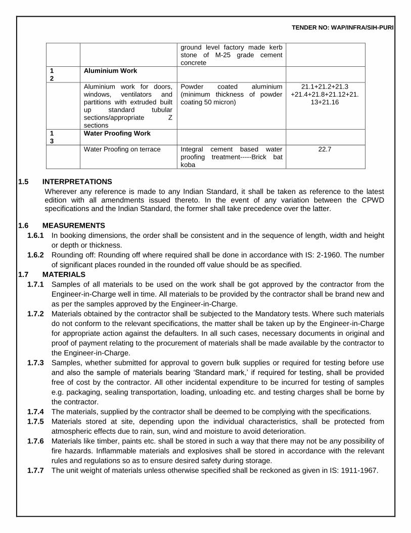
TENDER NO: WAP/INFRA/SIH-PURI
ground level factory made kerb stone of M-25 grade cement concrete
12
Aluminium Work
Aluminium work for doors, windows, ventilators and partitions with extruded built up standard tubular sections/appropriate Z sections
Powder coated aluminium (minimum thickness of powder coating 50 micron)
21.1+21.2+21.3 +21.4+21.8+21.12+21.
13+21.16
13
Water Proofing Work
Water Proofing on terrace Integral cement based water proofing treatment-----Brick bat koba
22.7
1.5 INTERPRETATIONS
Wherever any reference is made to any Indian Standard, it shall be taken as reference to the latest edition with all amendments issued thereto. In the event of any variation between the CPWD specifications and the Indian Standard, the former shall take precedence over the latter.
1.6 MEASUREMENTS
1.6.1 In booking dimensions, the order shall be consistent and in the sequence of length, width and height
or depth or thickness.
1.6.2 Rounding off: Rounding off where required shall be done in accordance with IS: 2-1960. The number
of significant places rounded in the rounded off value should be as specified.
1.7 MATERIALS
1.7.1 Samples of all materials to be used on the work shall be got approved by the contractor from the
Engineer-in-Charge well in time. All materials to be provided by the contractor shall be brand new and
as per the samples approved by the Engineer-in-Charge.
1.7.2 Materials obtained by the contractor shall be subjected to the Mandatory tests. Where such materials
do not conform to the relevant specifications, the matter shall be taken up by the Engineer-in-Charge
for appropriate action against the defaulters. In all such cases, necessary documents in original and
proof of payment relating to the procurement of materials shall be made available by the contractor to
the Engineer-in-Charge.
1.7.3 Samples, whether submitted for approval to govern bulk supplies or required for testing before use
and also the sample of materials bearing ‘Standard mark,’ if required for testing, shall be provided
free of cost by the contractor. All other incidental expenditure to be incurred for testing of samples
e.g. packaging, sealing transportation, loading, unloading etc. and testing charges shall be borne by
the contractor.
1.7.4 The materials, supplied by the contractor shall be deemed to be complying with the specifications.
1.7.5 Materials stored at site, depending upon the individual characteristics, shall be protected from
atmospheric effects due to rain, sun, wind and moisture to avoid deterioration.
1.7.6 Materials like timber, paints etc. shall be stored in such a way that there may not be any possibility of
fire hazards. Inflammable materials and explosives shall be stored in accordance with the relevant
rules and regulations so as to ensure desired safety during storage.
1.7.7 The unit weight of materials unless otherwise specified shall be reckoned as given in IS: 1911-1967.
TENDER NO: WAP/INFRA/SIH-PURI
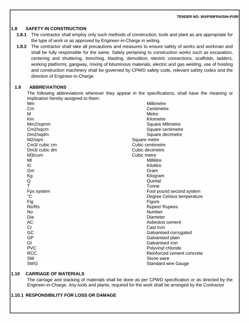
1.8 SAFETY IN CONSTRUCTION
1.8.1 The contractor shall employ only such methods of construction, tools and plant as are appropriate for
the type of work or as approved by Engineer-in-Charge in writing.
1.8.2 The contractor shall take all precautions and measures to ensure safety of works and workman and
shall be fully responsible for the same. Safety pertaining to construction works such as excavation,
centering and shuttering, trenching, blasting, demolition, electric connections, scaffolds, ladders,
working platforms, gangway, mixing of bituminous materials, electric and gas welding, use of hoisting
and construction machinery shall be governed by CPWD safety code, relevant safety codes and the
direction of Engineer-in-Charge
1.9 ABBREVIATIONS
The following abbreviations wherever they appear in the specifications, shall have the meaning or implication hereby assigned to them: Mm Millimetre Cm Centimetre M Metre Km Kilometre Mm2/sqmm Square Milimetre Cm2/sqcm Square centimetre Dm2/sqdm Square decimetre M2/sqm Square metre Cm3/ cubic cm Cubic centimetre Dm3/ cubic dm Cubic decimetre M3/cum Cubic metre Ml Millilitre Kl Kilolitre Gm Gram Kg Kilogram Q Quintal T Tonne Fps system Foot pound second system °C Degree Celsius temperature Fig Figure Re/Rs Rupee/ Rupees No Number Dia Diameter AC Asbestos cement CI Cast Iron GC Galvanised corrugated GP Galvanised plain GI Galvanised iron PVC Polyvinyl chloride RCC Reinforced cement concrete SW Stone ware SWG Standard wire Gauge
1.10 CARRIAGE OF MATERIALS
The carriage and stacking of materials shall be done as per CPWD specification or as directed by the Engineer-in-Charge. Any tools and plants, required for the work shall be arranged by the Contractor
1.10.1 RESPONSIBILITY FOR LOSS OR DAMAGE
TENDER NO: WAP/INFRA/SIH-PURI
Loading, carriage, unloading and stacking shall be done carefully to avoid loss or damage to the materials
1.11 LEAD
1.11.1 Route other than shortest practical route may be considered in cases of unavoidable circumstances
and as approved by Engineer-in-Charge along with reasons in writing.
1.11.2 Carriage by manual labour shall be reckoned in units of 50 metres or part thereof.
1.11.3 Carriage by animal and mechanical transport shall be reckoned in one km unit. Distances of 0.5 km or
more shall be taken as 1 km and distance of less than 0.5 km shall be ignored.
TENDER NO: WAP/INFRA/SIH-PURI
A.TECHNICAL SPECIFICATIONS - CIVIL WORKS
2.0 EARTH WORK 2.0 DEFINITIONS Deadmen or Tell Tales: Mounds of earth left undisturbed in pits dug out for borrowing earth Burjis:Shortpillarsofbrick/stonehavingtopsurfacefinishedwithcementplasterformarkingetc. Formation or Profile: Final shape of the ground after excavation or fillingup. Foulcondition:Filthyandunhygienicconditionswherephysicalmovementsarehamperedsuchassoil mixed with sewage or nightsoil.
Lead : All distances shall be measured over the shortest practical route and not necessarily the route actually taken. Route other than shortest practical route may be considered in cases of unavoidable circumstances and approved by Engineer-in-charge along with reasons in writing.
Carriage by manual labour shall be reckoned in units of 50 metres or part thereof.
Carriage by animal and mechanical transport shall be reckoned in one km. unit. Distances of 0.5 km. or more shall be taken as 1 km. and distance of less than 0.5 km. shall be ignored. However, when the total lead is less than 0.5 km., it will not be ignored but paid for separately in successive stages of 50 metressubjecttotheconditionthattherateworkedonthisbasisdoesnotexceedtherateforinitiallead of 1 km. by mechanical/animaltransport.
Lift: The vertical distance for removal with reference to the ground level. The excavation up to 1.5 metres depth below the ground level and depositing the excavated materials upto 1.5 metres abovethe groundlevelareincludedintherateofearthwork.Liftsinherentintheleadduetogroundslopeshallnot be paidfor.
Safety rules: Safety rules as laid down by the statutory authority and as provided in National Building Code (NBC) shall be followed.
2.1 CLASSIFICATION OF SOILS 2.1.0 Theearthworkshallbeclassifiedunderthefollowingcategoriesandmeasuredseparatelyforeach category:
(a) All kind of soils: Generally any strata, such as sand, gravel, loam, clay, mud, black
cotton moorum, shingle, river or nallah bed boulders, siding of roads, paths etc. and hard core, macadam surface of any description (water bound, grouted tarmac etc.), lime concrete mud concrete and their mixtures which for excavation yields to application of picks, showels, jumper, sacrifiers, ripper and other manual
TENDER NO: WAP/INFRA/SIH-PURI
diggingimplements.
(b) Ordinary rock: Generally any rock which can be excavated by splitting with crow bars or picks anddoesnotrequireblasting,wedgingorsimilarmeansforexcavationsuchaslimestone,sand stone,hardlaterite,hardconglomerateandun-reinforcedcementconcretebelowgroundlevel.
Ifrequiredlightblastingmayberesortedtoforlooseningthematerialsbutthiswillnotinanyway entitle the material to be classified as ‘Hardrock’.
(c) Hardrock:Generallyanyrockorboulderfortheexcavationofwhichblastingisrequiredsuchas
quartzite, granite, basalt, reinforced cement concrete (reinforcement to be cut through but not separated from concrete) below ground level and thelike.
(d) Hard rock (blasting prohibited): Hard rock requiring blasting as described under (c) but where the blasting is prohibited for any reason and excavation has to be carried out by chiseling, wedging, use of rock hammers and cutters or any other agreedmethod.
2.2 ANTIQUITIES AND USEFULMATERIALS 2.2.1 Any finds of archaeological interest such as relics of antiquity, coins, fossils or other articles of valueshallbedeliveredtotheEngineer-in-ChargeandshallbethepropertyoftheGovernment.
2.2.2 AnymaterialobtainedfromtheexcavationwhichintheopinionoftheEngineer-in-Chargeisuseful shall be stacked separately in regular stacks as directed by the Engineer-in-Charge and shall be the property of theGovernment.
2.3 PROTECTIONS 2.3.1 Excavation where directed by the Engineer-in-Charge shall be securely barricaded and provided with proper caution signs, conspicuously displayed during the day and properly illuminated with red lights and/or written using fluorescent reflective paint as directed by engineer in charge during the night to avoidaccident.
2.3.2 The Contractor shall take adequate protective measures to see that the excavation operations do not damage the adjoining structures or dislocate the services. Water supply pipes, sluice valve chambers, sewerage pipes, manholes, drainage pipes and chambers, communication cables, power supply cables etc. met within the course of excavation shall be properly supported and adequately protected, so that these services remain functional. However, if any service is damaged during excavation shall be restored in reasonabletime.
2.3.3 Excavation shall not be carried out below the foundation level of the adjacent buildings until underpinning, shoring etc. is done as per the directions of the Engineer-in-Charge for which payment shall be madeseparately.
TENDER NO: WAP/INFRA/SIH-PURI
2.3.4 Any damages done by the contractor to any existing work shall be made good by him at his own cost. Existing drains pipes, culverts, over head wires, water supply lines and similar services encountered during the course of execution shall be protected against damage by the contractor. The contractor shall not store material or otherwise occupy any part of the site in manner likely to hinder the operations of suchservices.
2.4 SITECLEARANCE 2.4.1 Before the earth work is started, the area coming under cutting and filling shall be cleared of shrubs,rankvegetation,grass,brushwood,treesandsaplingsofgirthupto30cmmeasuredataheight of one metre above ground level and rubbish removed up to a distance of 50 metres outside the periphery of the area under clearance. The roots of trees and saplings shall be removed to a depth of 60cm below ground level or 30 cm below formation level or 15 cm below sub grade level, whichever is lower, and the holes or hollows filled up with the earth, rammed andleveled.
2.4.2 The trees of girth above 30 cm measured at a height of one metre above ground shall be cut only after permission of the Engineer-in-Charge is obtained in writing. The roots of trees shall also be removed as specified in 2.4.1. payment for cutting such trees and removing the roots shall be made separately.
2.4.3 Existing structures and services such as old buildings, culverts, fencing, water supply pipe lines, sewers, power cables, communication cables, drainage pipes etc. within or adjacent to the area if required to be diverted/removed, shall be diverted/dismantled as per directions of the Engineer-in- Charge and payment for such diversion/dismantling works shall be madeseparately.
2.4.4 In case of archaeological monuments within or adjacent to the area, the contractor shall provide necessaryfencingalroundsuchmonumentsasperthedirectionsoftheEngineer-in-Chargeandprotect thesameproperlyduringexecutionofworks.Paymentforprovidingfencingshallbemadeseparately.
2.4.5 Lead of 50 m mentioned in the ‘Schedule Of Quantities’ is the average lead for the disposal of excavated earth within the site of work. The actual lead for the lead for the disposal of earth may be moreorlessthanthe50mforwhichnocostadjustmentshallbemadeintherates.
2.4.6 Disposal of Earth shall be disposed off at the specified location or as decided by the Engineer-in- Charge. The contractor has to take written permission about place of disposal of earth before the earth is disposed off, fromEngineer-in-Charge.
TENDER NO: WAP/INFRA/SIH-PURI
2.5 SETTING OUT AND MAKINGPROFILES 2.5.1 A masonry pillar to serve as a bench mark will be erected at a suitable point in the area, which is visible from the largest area. This bench mark shall be constructed as per Fig. 2.1 and connected with the standard bench mark as approved by the Engineer-in-Charge. Necessary profiles with strings stretched on pegs, bamboos or ‘Burjis’ shall be made to indicate the correct formation levels before the work is started. The contractor shall supply labour and material for constructing bench mark, setting out and making profiles and connecting bench mark with the standard bench mark at his own cost. The pegs, bamboos or ‘Burjis’ and the bench mark shall be maintained by the contractor at his own cost during the excavation to check theprofiles.
2.5.2 The ground levels shall be taken at 5 to 15 metres intervals (as directed by the Engineer-in- Charge) in uniformly sloping ground and at closer intervals where local mounds, pits or undulations are met with. The ground levels shall be recorded in field books and plotted on plans. The plans shall be drawn to a scale of 5 metres to one cm or any other suitable scale decided by the Engineer-in-Charge. Northdirectionlineandpositionofbenchmarkshallinvariablebeshownontheplans.Theseplansshall be signed by the contractor and the Engineer-in-Charge or their authorized representatives before the earthworkisstarted.Thelabourrequiredfortakinglevelsshallbesuppliedbythecontractorathisown cost.
2.6 BLASTING 2.6.0 Wherehardrockismetwithandblastingoperationsareconsiderednecessary,thecontractorshall obtaintheapprovaloftheEngineer-in-Chargeinwritingforresortingtoblastingoperation.
Note: In ordinary rock blasting operations shall not be generally adopted. However, the
contractor may resort to blasting with the permission of the Engineer-in-charge, but nothing extra shall be paid for such blasting operations.
Thecontractorshallobtainlicensefromthecompetentauthorityforundertakingblastingworka
swell asforobtainingandstoringtheexplosiveaspertheExplosiveAct,1884asamendeduptodateandthe Explosive Rules, 1983. The contractor shall purchase the explosives fuses, detonators, etc. only from a licensed dealer. The contractor shall be responsible for the safe transportation, storage and custody as per explosive rules and proper accounting of the explosive materials. Fuses and detonators shall be stored separately and away from the explosives. The Engineer-in-Charge or his authorized representative shall have the right to check the contractor’s store and account of explosives. The contractor shall provide necessary facilities forthis.
The contractor shall be responsible for any damage arising out of accident to workmen,
public or property due to storage, transportation and use of explosive during blasting operation.
2.6.1 Blasting operations shall be carried out under the supervision of a responsible
TENDER NO: WAP/INFRA/SIH-PURI
authorized agentof thecontractor(referredsubsequentlyasagentonly),duringspecifiedhoursasapprovedinwritingbytheEngineer-in-Charge.Theagentshallbeconversantwiththerulesofblasting.Incaseofblastingwith dynamite or any other high explosive, the position of all the bore holes to be drilled shall be marked in circleswithwhitepaint.Theseshallbeinspectedbythecontractor’sagent.Boreholesshallbeofasize that the cartridge can easily pass down. After the drilling operation, the agent shall inspect the holes to ensure that drilling has been done only at the marked locations and no extra hole has been drilled. The agent shall then prepare the necessary charge separately for each bore hole. The bore holes shall be thoroughlycleanedbeforeacartridgeisinserted.Onlycylindricalwoodentampingrodsshallbeusedfor tamping.Metalrodsorrodshavingpointedendsshallneverbeusedfortamping.Onecartridgeshallbe placed in the bore hole and gently pressed but not rammed down. Other cartridges shall then be added as may be required to make up the necessary charge for the bore hole. The top most cartridge shall be connected to the detonator which shall in turn be connected to the safety fuses of required length. All fuses shall be cut to the length required before being inserted into the holes. Joints in fuses shall be avoided.Wherejointsareunavoidableasemi-circularnitchshallbecutinonepieceoffuseabout2cm deep from the end and the end of other piece inserted into the nitch. The two pieces shall then be wrappedtogetherwithstring.Alljointsexposedtodampnessshallbewrappedwithrubbertape.
The maximum of eight bore holes shall be loaded and fired at one occasion. The charges shall be fired successively and not simultaneously. Immediately before firing, warning shall be given and the agent shall see that all persons have retired to a place of safety. The safety fuses of the charged holes shall be ignited in the presence of the agent, who shall see that all the fuses are properly ignited.
Careful count shall be kept by the agent and others of each blast as it explodes. In case all the charged bore holes have exploded, the agent shall inspect the site soon after the blast but in case of misfire the agent shall inspect the site after half an hour and mark red crosses (X) over the holes which have not exploded. During this interval of half an hour, nobody shall approach the misfired holes. No driller shall work near such bore until either of the following operations have been done by the agent for the misfired boreholes.
(a) The contractor’s agent shall very carefully (when the tamping is of damp clay) extract
the tamping with a wooden scraper and withdraw the fuse, primer and detonator. After this a fresh detonator, primer and fuse shall be placed in the misfired holes and fired,or
(b) Theholesshallbecleanedfor30cmoftampinganditsdirectionascertainedbyplacingastickin
the hole. Another hole shall then be drilled 15 cm away and parallel to it. This hole shall be chargedandfired.Themisfiredholesshallalsoexplodealongwiththenewone.
Beforeleavingthesiteofwork,theagentofoneshiftshallinformtheanotheragentrelievinghimf
TENDER NO: WAP/INFRA/SIH-PURI
or the next shift, of any case of misfire and each such location shall be jointly inspected and the action to be taken in the matter shall be explained to the relievingagent.
TheEngineer-in-Chargeshallalsobeinformedbytheagentofallcasesofmisfires,theircausesand steps taken in thatconnection.
2.6.2 GeneralPrecautions For the safety of persons red flags shall be prominently displayed around the area where blasting operations are to be carried out. All the workers at site, except those who actually ignite the fuse, shall withdraw to a safe distance of at least 200 metres from the blasting site. Audio warning by blowing whistle shall be given before igniting the fuse.
Blasting work shall be done under careful supervision and trained personnel shall be employed. Blastingshallnotbedonewithin200metresofanexistingstructure,unlessspecificallypermittedbythe Engineer-in-Charge inwriting. All procedures and safety precautions for the use of explosives drilling and loading of explosives drillingandloadingofexplosivesbeforeandaftershotfiringanddisposalofexplosivesshallbetakenby thecontractorasdetailedinIS4081,safetycodeforblastingandrelateddrillingoperation.
2.6.3 Precautions againstMisfire The safety fuse shall be cut in an oblique direction with a knife. All saw dust shall be cleared from inside of the detonator. This can be done by blowing down the detonator and tapping the open end. No tools shall be inserted into the detonator for this purpose.
If there is water present or if the bore hole is damp, the junction of the fuse and detonator shall be made water tight by means of tough grease or any other suitable material.
The detonator shall be inserted into the cartridge so that about one third of the copper tube is left exposedoutsidetheexplosive.Thesafetyfusejustabovethedetonatorshallbesecurelytiedinposition in the cartridge. Water proof fuse only shall be used in the damp bore hole or when water is present in the borehole.
If a misfire has been found to be due to defective fuse, detonator or dynamite, the entire consignment from which the fuse detonator or dynamite was taken shall be got inspected by the Engineer-in-Charge or his authorized representative before resuming the blasting or returning the consignment.
2.7 EXCAVATION IN ALL KINDS OFSOILS 2.7.1 All excavation operations manually or by mechanical means shall include excavation and ‘getting out’ the excavated materials. In case of excavation for trenches, basements, water tanks etc. ‘getting
TENDER NO: WAP/INFRA/SIH-PURI
out’shallincludethrowingtheexcavatedmaterialsatadistanceofatleastonemetreorhalfthedepthof excavation, whichever is more, clear off the edge of excavation. In all other cases ‘getting out’ shall include depositing the excavated materials as specified. The subsequent disposal of the excavated materialshallbeeitherstatedasaseparateitemorincludedwiththeitemsofexcavationstatinglead.
2.7.2 During the excavation the natural drainage of the area shall be maintained. Excavation shall be done from top to bottom. Undermining or undercutting shall not bedone.
2.7.3 In firm soils, the sides of the trenches shall be kept vertical upto a depth of 2 metres from the bottom. For greater depths, the excavation profiles shall be widened by allowing steps of 50 cms on either side after every 2 metres from the bottom. Alternatively, the excavation can be done so as to give slope of 1:4 (1 horizontal : 4 vertical). Where the soil is soft, loose or slushy, the width of steps shall be suitably increased or sides sloped or the soil shored up as directed by the Engineer-in- Charge. It shall be the responsibility of the contractor to take complete instructions in writing from the Engineer-in-Charge regarding the stepping , sloping or shoring to be done for excavation deeper than 2metres.
2.7.4 Theexcavationshallbedonetruetolevels,slope,shapeandpatternindicatedbytheEngineer-in- Charge. Only the excavation shown on the drawings with additional allowances for centering and shutteringorasrequiredbytheEngineer-in-Chargeshallbemeasuredandrecordedforpayment.
2.7.5 Incaseofexcavationforfoundationintrenchesoroverareas,thebedofexcavationshallbetothe correct level or slope and consolidated by watering and ramming. If the excavation for foundation is done to a depth greater than that shown in the drawings or as required by the Engineer-in-Charge, the excessdepthshallbemadegoodbythecontractorathisowncostwiththeconcreteofthemixusedfor levelling/ bed concrete for foundations. Soft/defective spots at the bed of the foundations shall be dug outandfilledwithconcrete(tobepaidseparately)asdirectedbytheEngineer-in-Charge.
2.7.6 While carrying out the excavation for drain work care shall be taken to cut the side and bottom to the required shape, slope and gradient. The surface shall then be properly dressed. If the excavation is done to a depth greater than that shown on the drawing or as required by the Engineer-in-Charge, the excessdepthshallbemadegoodbythecontractorathisowncostwithstiffclaypuddleatplaceswhere the drains are required to be pitched and with ordinary earth, properly watered and rammed, where the drains are not required to be pitched. In case the drain is required is to be pitched, the back filling with clay puddle, if required, shall be done simultaneously as the pitching work proceeds. The brick pitched stormwaterdrainsshouldbeavoidedasfaraspossibleinfilled-upareasandloosesoils.
2.7.7 Inallothercaseswheretheexcavationistakendeeperbythecontractor,itshallbebroughttothe required level by the contractor at his own cost by filling in with earth duly watered,
TENDER NO: WAP/INFRA/SIH-PURI
consolidated and rammed.
2.7.8 In case the excavation is done wider than that shown on the drawings or as required by the Engineer-in-Charge, additional filling wherever required on the account shall be done by the contractor at his owncost.
2.7.9 TheexcavationshallbedonemanuallyorbymechanicalmeansasdirectedbyEngineer-in-charge considering feasibility, urgency of work, availability of labour /mechanical equipments and other factors involved. Contractor shall ensure every safety measures for the workers. Neither any deduction willbe made nor any extra payment will be made on thisaccount.
2.8 EXCAVATION IN ORDINARY/HARDROCK 2.8.1 Allexcavationoperationsshallincludeexcavationand‘gettingout’theexcavatedmatter.Incaseof excavation for trenches, basements, water tanks etc. ‘getting out’ shall include throwing the excavated materialsatadistanceofatleastonemetreorhalfthedepthofexcavation,whicheverismore,clearoff the edge or excavation. In all other cases ‘getting out’ shall include depositing the excavated materials as specified. The subsequent disposal of the excavated material shall be either stated as a separate item or included with the item of excavation statinglead.
2.8.2 During the excavation, the natural drainage of the area shall be maintained. Excavation shall be done from top to bottom. Undermining or under cutting shall not bedone. 2.8.3 Wherehardrockismetwithandblastingoperationsareconsiderednecessary,thecontractorshall obtain the approval of the Engineer-in-Charge in writing for resorting to the blasting operations.Blasting operations shall be done as specified in para 2.6 and chiseling shall be done to obtain correct levels, slopes, shape and pattern of excavation as per the drawings or as required by the Engineer-in-Charge and nothing extra shall be payable forchiseling.
2.8.4 Where blasting operations are prohibited or are not practicable, excavation in hard rock shall be done bychiseling.
2.8.5 In ordinary rock excavation shall be carried out by crowbars, pick axes or pneumatic drills and blasting operation shall not be generally adopted. Where blasting operations are not prohibited and it is practicabletoresorttoblastingforexcavationinordinaryrock,contractormaydosowiththepermission of the Engineer-in-Charge in writing but nothing extra shall be paid for this blasting. Blasting shall be done as specified in para2.6.
2.8.6 If the excavation for foundations or drains is done to a depth greater than that shown in the drawings or as required by the Engineer-in-Charge. The excess depth shall be made good by the contractor at his own cost with the concrete of the mix used for levelling/ bed concrete for foundations. Soft/ defective spots at the bed of foundations shall be dug out and filled with concrete (to be paid separately) as directed by theEngineer-in-Charge.
TENDER NO: WAP/INFRA/SIH-PURI
2.8.7 Inallothercaseswheretheexcavationistakendeeperbythecontractor,itshallbebroughttothe required level by the contractor at his own cost by filling with earth duly watered, consolidated and rammed.
2.8.8 In case the excavation is done wider than that shown on the drawings or as required by the Engineer-in-Charge, filling wherever required on this account shall be done by the contractor at hisown cost.
2.8.9 Only the excavation shown on the drawings or as required by the Engineer-in-Charge shall be measured and recorded for payment except in case of hard rock, where blasting operations have been resorted to, excavation shall be measured to the actual levels, provided the Engineer-in-Charge is satisfied that the contractor has not gone deeper than what wasunavoidable.
2.8.10 The excavation shall be done manually or by mechanical means as desired by Engineer-in- Charge considering feasibility, urgency of work, availability of labour /mechanical equipments and other factors involved Contractor shall ensure every safety measures for the workers. Neither any deduction will be made nor any extra payment will be made on thisaccount.
2.9 EARTH WORK BY MECHANICALMEANS Earthworkbymechanicalmeansinvolvescarefulplanningkeepinginviewsiteconditionsi.e.typeof soil, nature of excavation, distances through which excavated soil is to be transported and working space available for employing these machines. The earth moving equipment should be accordingly selected.
The earth moving equipment consists of excavating and transporting equipment. Excavating equipments may be further classified as excavators and tractor based equipments.
2.9.1 Excavators
Excavators generally used at site are as follows: (i) Dipper–shovel:Itisusedforexcavatingagainstafaceorbankconsistingofopen-topbucketor
dipper with a bottom opening door, fixed to an arm or dipper stick which slides and pivots on the jib of the crane. It is suitable for excavating all clay chalk and friable materials and for handling rockandstone.However,itisnotsuitableforsurfaceexcavationforwhichaskimmerisused.
(ii) Backhoe : It is similar to face shovel except that the dipper stick pivots on the end of
the jib and the dipper or bucket works towards the chassis and normally has no bottom door but is emptied by swinging away from the chassis to invert the bucket. It may be designed to carry both afront –mounted bucket loading mechanism and a rear mounted backhoe. It is mainly used to excavate trenches and occasionally used for the excavation of open areas such as small basements.
TENDER NO: WAP/INFRA/SIH-PURI
Inthebackhoemodethebucketlifts,swingsanddischargesmaterialswhiletheundercarriageis stationary. When used in the ‘loader’ mode, the machine loads or excavated through forward motion of the machine, and lifts, transports and dischargesmaterials.
(iii) Skimmer : This arrangement is similar to the face shovel except that in this case the
bucket slides on rollers directly along the jib and thus has a more restricted movement. It is used for surface excavation and levelling in conjunction with transport to haul away the excavated material.
(iv) Dragline : It is usually fitted with a long slender boom or jib and the bucket, which in
operation faces towards the machine and has no door, is supported by cable only as on a crane. It works from the side of the excavation at normal ground level and is used for excavating large open excavations such as basements when the depth is beyond the limit of the boom of a backhoe. It is commonly used for open cast miningoperations.
(v) Clamshell:Itconsistsoftwohingedhalf-bucketsorjawspivotedtoaframewhichissuspended
by cable from a long jib of an excavation. The grab is used for deep excavations of limited area on all types of soil except rock. Crane and Grab is a variant of this type ofequipment.
2.9.2 Tractor–basedEquipment
It is a self–propelled crawler or wheeled machine used to exert a push or pull force through mounted equipment. It is designed either as attachments to normal tracked or wheeled tractors or as machines in which the earth moving attachments and the tractor are designed as a single integrated unit. A tractor, which is hydraulically operated, can be rigged as :
(i) Loaders : It is used for loading, light dozing, scraping and grabbing operations, lifting
and transporting the materials (loose earth, rubble, sand, gravel aggregate etc) at various sites through forward motion of themachine.
(ii) TractorShovel:Thisconsistsofatippingbucketatthefrontattachedbystrongpivotedarmsor
booms to the frame of the machine. It is used for stripping top soil, excavating against a face, bulldozing and for loading spoil or loose materials. It is similar to crawlerdipper-shovel.
(iii) Trench Digger : It operates on the same principle as a backhoe excavator except that
the bucket is controlled by hydraulic rams instead of cables andpulleys.
(iv) Scraper : Scrapers provide unique capability to excavate, load, haul and dump materials. Scrapers are available in various capacities by a number of manufacturers with options such as self – loading with elevators, twin engines or push-pull capability. They are cost effective where the haul distance is too long for bulldozers, yet too short for trucks. This distance typically
TENDER NO: WAP/INFRA/SIH-PURI
rangesfrom120mto1200m;however,theeconomicsshouldbeevaluatedforeachproject.
Scraper has an open bowl with a cutting edge positioned between the axles, which cuts, loads, transports, discharges and spreads through forward motion of the machine. Loading through forward motion of the machine can be assisted by a powered mechanism (elevator) fixed to the scraper bowl.
(v) Bulldozer and Angle-dozer : The most common equipment used for clearing and
levelling activities is a bulldozer. The terms bulldozer is used to define a tractor mounted with a dozing blade.
The bulldozer consists of a rectangular steel blade with renewable cutting edge set at right angles (capable of only tilting but not angling) to the direction of travel and attached by steel arms to the side frames of a crawler tractor. It may be used for excavating natural soil or for moving loose soil or debris, which is pushed forward as the tractor forces it ahead.
(vi) Angledozer is capable of both tilting andangling
2.9.3 TransportingEquipment
This implies horizontal movement primarily but it can involve some vertical movement too. (i) Dumpers : These are self-propelled wheeled machines, having an open body. It is
designed for thetransportofexcavatedmaterialsandconsistsofashallowtippinghopperorskipmountedon a wheeled chassis, such as, power barrow, dumper, multi-skip dumpers, high discharge dumpers, dump truck, etc. These can be rear dump, side dump or bottomdump.
Vibratory Roller : It is a single Drum Vibratory Roller for compaction of embankments, etc. The smooth drum version is for compaction of granular and mixed soil. The sheepsfoot Roller feet penetrate into the fill as a roller moves forward and cause compaction. The geometry of the foot may be sheep, club pyramid, cone or cylinder foot. Such rollers are employed for compaction (densification) of cohesive and semi-cohesive soils.
2.10 FILLING 2.10.1 The earth used for filling shall be free from all roots, grass, shrubs, rank vegetation, brushwood, tress, sapling andrubbish.
2.10.2 Filling with excavated earth shall be done in regular horizontal layers each not exceeding 20 cm in depth. All lumps and clods exceeding 8 cm in any direction shall be broken. Each layer shall be wateredandconsolidatedwithsteelrammeror½tonneroller.Wherespecified,everythirdandtopmust layer shall also be consolidated with power roller of minimum 8 tonnes. Wherever depth of filling
TENDER NO: WAP/INFRA/SIH-PURI
exceeds1.5metrevibratorypowerrollershallbeusedtoconsolidatethefilingunlessotherwisedirected by Engineer-in-charge. The top and sides of filling shall be neatly dressed. The contractor shall make goodallsubsidenceandshrinkageinearthfillings,embankments,traversesetc.duringexecutionandtill the completion of work unless otherwisespecified.
2.11 MEASUREMENTS 2.11.1 The length and breadth of excavation or filling shall be measured with a steel tape correct tothe nearest cm. The depth of cutting or height of filling shall be measured, correct to 5 mm, by recording levels before the start of the work and after the completion of the work. The cubical contents shall be worked out to the nearest two places of decimal in cubicmetres.
2.11.1.1 In case of open footings up to the depth of 1.5 metres, alround excavation of 30 cm. beyond the outer dimension of footing shall be measured for payment to make allowances for centering and shuttering. Any additional excavation beyond this limit shall be at the risk and cost of the contractor and shall not be measured forpayment.
2.11.1.2 Incaseofopenfootings/Raftsatadepthofmorethan1.5metre,alroundexcavationof75cm shall be measured for payment to make allowance for centering and shuttering. Additional excavation beyondthislimitshallbeattheriskandcostofthecontractorandshallnotbemeasuredforpayment.
2.11.2 In case the ground is fairly uniform and where the site is not required to be levelled, the Engineer-in-Charge may permit the measurements of depth of cutting or height of filling with steel tape, correcttothenearestcm.Incaseofborrowpits,diagonalridges,crossridgesordead-men,theposition of which shall be fixed by the Engineer-in-Charge, shall be left by the contractor to permit accurate measurements being taken with steel tape on the completion of the work Deduction of such ridges and dead men shall be made from the measurements unless the same are required to be removed later on and the earth so removed is utilized in the work. In the latter case nothing extra will be paid for their removal as subsequentoperation.
2.11.3 Where ordinary rock and hard rock is mixed. The measurement of the excavation shall be made as specified in 2.11.1 and 2.11.2 The two kinds of rock shall be stacked separately and measured in stacks. The net quantity of the two kinds of rocks shall be arrived at by applying deduction of 50% to allowforvoidsinstacks.Ifthesumofnetquantityoftwokindsofrocksexceedsthetotalquantityofthe excavated material, then the quantity for each type of rock shall be worked out from the total quantity in the ratio of net quantities in stack measurements of the two types of rocks. If in the opinion of the Engineering-in-chargestackingisnotfeasible,thequantityofordinaryandhardrockshallbeworkedout by means of cross-sectionalmeasurements.

TENDER NO: WAP/INFRA/SIH-PURI
2.11.4 Where soil, ordinary rock and hard rock are mixed, the measurements for the entire excavation shall be made as specified in 2.11.1 and 2.11.2 Excavated materials comprising hard rock and ordinary rockshallbestackedseparately,measured,andeachreducedby50%toallowforvoidstoarriveatthe quantity payable under hard rock and ordinary rock. The difference between the entire excavation and the sum of the quantities payable under hard rock and ordinary rock shall be paid for as excavation in ordinary soil or hard soil as the case may be.
2.11.5 Where it is not possible or convenient to measure the depth of cutting by recording levels as specified in 2.11.1 quantity of excavation shall be worked out from filling. The actual measurements of the fill shall be calculated by taking levels of the original ground before start of the work after site clearance and after compaction of the fill as specified and the quantity of earth work so computed shall be reduced by 10% in case of consolidated fills and by 5% in case the consolidation is done by heavy mechanical machinery to arrive at the net quantity of excavation for payment. No such deduction shall, however, be made in case of consolidation by heavy mechanical machinery at optimum moisture content,orwhentheconsolidatedfillingisinconfinedsituationssuchasunderfloors.
2.11.6. Recording Measurements for Earth LevellingWork
2.11.6.1 LevelBooks:Incaseoflevellingoperationsandearthwork,measurementsarerequiredtobe recorded in level books in addition to Measurement Books. The Level Books should be numbered, accounted for and handled like MeasurementBooks.
2.11.6.2 Preparatory Works: Before starting the earth work, following steps should be taken:
(1) Original ground levels should be recorded in the Level Book in the presence of the contractor orhisauthorizedrepresentative,andshouldbesignedbyhimandtheDepartmentOfficerwho records the levels. All the local mounds and depressions should be indicated clearly in the drawing and the field Level Book and should be checked by the Assistant Engineer/Executive Engineer before the levelling work isstarted.
(2) Asuitablebaselineshouldbefixedwithpermanentmasonrypillarsatdistancesnotexceeding 150 metres to provide a permanent reference line for facilitating check work. The base line (s) should be entered in the Level Book with co-ordinates. These baselines should be maintained till the final payment for the work has beenmade.
(3) Whilerecordingthelevels,itshouldbeensuredthatthecircuitisclosedbytakingfinallevelsof thestartingpointoranyotherpoint,theR.L.ofwhichwaspreviouslydetermined.
(4) Plans showing initial levels, location of bench marks and reduced levels, should be prepared and signed by both the parties and attached to the agreement before commencement of the work.
2.11.6.3 Test Check of theLevels
(1) The Assistant Engineer should exercise test check at least to the extent of 50%, and the Executive Engineer at least to the extent of 10% where the value of this item of work exceeds 10% of the tender acceptance power of the AssistantEngineer.
TENDER NO: WAP/INFRA/SIH-PURI
(2) The test check of the levels should be carried out independently by each officer, and the readings should be recorded in the prescribed Level Book in red ink against the old levels which should be neatly scored out wherever necessary. If the test check carried out reveals serious mistakesintheoriginallevels,theseshouldbetakenorre-takenandre-checked.
(3) The test check carried out by an officer should be as representative as possible for the entire workdone.
(4) On completion of work, the levels should again be recorded in the Level Book and the contractor’s signatures obtained. These levels should also be test checked by the Assistant Engineer/Executive Engineer to the same extent as indicated in (1) within one month of thedate ofcompletionoftheearthwork,andaccordingtotheprocedureaslaiddowninthecaseofinitial levels as indicatedabove.
(5) The formation levels as per final execution of the work should be compared with the proposed formation levels and the work got rectified within permissibletolerance.
2.11.6.4 Payment of LevelingWork
(1) Every fourth running bill and the final bill should be paid on the basis oflevels. (2) Intermediate payments can, however, be made on the basis of borrow pit
measurements. The Executive Engineer should take care that the quantities thus assessed are not in any case more than the actual workdone.
2.11.6.5 Large Scale LevelingWork
(1) Incaseoflargescalelevellingworkinvolvingbothcuttingandfilling,anaccuratesiteplanshould be prepared before the work is commenced. The portions requiring cutting and filling shall then be divided into squares and corresponding squares into filling, which are complementary to the squares in cutting given the samenumber.
(2) A table may be written upon the plan showing leads involved between the various complementary squares. This would form a lead chart for the work to bedone.
(3) Before the work of levelling is commenced, the lead chart shall be checked by the Assistant Engineer in the presence of the contractor or his authorized representative, and his signatures shall be obtained on the same. This should form an integral part of the contract and should be duly signed by both the integral parties before commencement of thework.
(4) The quantity payable for earthwork shall be lower of the quantity derived from cutting or filling. Thepaymentforleadshallbebasedonleadchartpreparedintheaforesaidmanner.
2.11.6.6 Import of Earth: In case of earth to be imported, the area from where the earth is to be imported, should be pre-determined wherever possible before the start of the work, and wherever feasible, the average lead should be worked out and stipulated in the tender. After this is determined, initial levels of the area to be filled should be recorded. The levels should be properly checked during the progress of work and oncompletion.
2.12 RATES 2.12.1 Rates for Earthwork shall include the following:
TENDER NO: WAP/INFRA/SIH-PURI
(a) Excavation and depositing excavated material asspecified. (b) Handing of antiquities and useful material as specified on2.2. (c) Protection as specified in2.3. (d) Site clearance as specified in2.4. (e) Setting out and making profiles as specified in2.5. (f) Forming (or leaving) dead – men or ‘Tell Tales’ in borrow pits and their removal after
measurements. (g) Bailing out or pumping of rain water fromexcavations. (h) Initial lead of 50 m and lift of 1.5m. (i) Blasting operations for hard rock as specified in2.6.
2.12.2 No deduction shall be made from the rate if in the opinion of the Engineer- in-charge, operations specified in 2.12.1 (b) to (h) are not required to be carried out on any account whatsoever.
2.13 SURFACE EXCAVATION 2.13.1 Excavations exceeding 1.5 m in width and 10 sqm. on plan but not exceeding 30 cm. in depth in all types of soils and rocks shall be described as surface excavation and shall be done as specified in 2.7 and 2.8.
2.13.1 Measurements
The length and breadth shall be measured with a steel tape correct to the nearest cm. and the area worked out to the nearest two places of decimal in square metres.
2.13.3 Rate shall be as specified in 2.12.
2.14. ROUGH EXCAVATION ANDFILLING 2.14.1 Excavation for earth from borrow pits, cutting hill side slopes etc. shall be described as rough excavation and shall be done as specified in 2.7, 2.8 and2.9.
2.14.2 Wherever filling is to be done, the earth from excavation shall be directly used for filling and no payment for double handling of earth shall be admissible. Filling of excavated earth shall be done as specified in 2.10. In case of hill side cutting, where the excavated materials is thrown down the hill slopes, payment for filling excavated earth shall not beadmissible.
2.14.3 Measurements shall be as specified in2.11.
2.14.4 Rates shall be as specified in2.12.
2.15 EXCAVATION OVER AREA (ALL KINDS OFSOIL) 2.15.1 This shall comprise:
(a) Excavationexceeding1.5minwidthand10sqmonplanandexceeding30cmindepth.
TENDER NO: WAP/INFRA/SIH-PURI
(b) Excavation for basements, water tanksetc. (c) Excavation in trenches exceeding 1.5 m in width and 10 sqm onplan.
2.15.2 Excavation shall be done as specified in2.7.
2.15.3 Measurements shall be as specified in2.11.
2.15.4 Rates shall be as specified in2.12.
2.16 EXCAVATION OVER AREA (ORDINARY/ HARDROCK) 2.16.1 This shall comprise:
(a) Excavationexceeding1.5minwidthand10sqmonplanandexceeding30cmindepth. (b) Excavation for basements, water tanksetc. (c) Excavation in trenches exceeding 1.5 m in width and 10 sqm onplan.
2.16.2 Excavation shall be done as specified in 2.8 and2.9.
2.16.3 Measurements shall be done as specified in2.11.
2.16.4 Rates shall be as specified in2.12.
2.17 EXCAVATIONINTRENCHESFORFOUNDATIONSANDDRAINS(ALLKINDSOFSOIL) 2.17.1 Thisshallcompriseexcavationnotexceeding1.5minwidthor10sqmonplanandtoanydepth in trenches (excluding trenches for pipes, cables, conduitsetc.)
2.17.2 Excavation shall be done as specified in2.7.
2.17.3 Measurements shall be as specified in2.11.
2.17.4 Rates shall be as specified in2.12.
2.18 EXCAVATIONINTRENCHESFORFOUNDATIONANDDRAINS(ORDINARY/HARDROCK) 2.18.1 Thisshallcompriseexcavationnotexceeding1.5minwidthor10sqm.Onplanandtoanydepth in trenches (excluding trenches for pipes, cables, conduitsetc.)
2.18.2 Excavation shall be done as specified in 2.8. and2.9.
2.18.3 Measurements shall be as specified in2.11.
2.18.4 Rates shall be as specified in2.12.
2.19 EXCAVATION IN TRENCHES FOR PIPES, CABLES ETC. ANDREFILLING 2.19.1 This shall comprise excavation not exceeding 1.5 mts in width or 10 sqm in plan and to any depthtrenchesforpipes.Cablesetc.andreturningtheexcavatedmaterialtofillthetrenchesafterpip
TENDER NO: WAP/INFRA/SIH-PURI
es, cables etc. are laid and their joints tested and passed and disposal of surplus excavated material upto 50 mlead.
2.19.2 Width ofTrench
(a) Upto one metre depth the authorized width of trench for excavation shall be arrived at by adding 25cmtotheexternaldiameterofpipe(notsocket/collar)cable,conduitetc.Whereapipeislaid on concrete bed/ cushioning layer, the authorized width shall be the external diameter of pipe (notsocket/collar)plus25cmorthewidthofconcretebed/cushioninglayerwhicheverismore.
(b) For depths exceeding one metre, an allowance of 5 cm per metre of depth for each side of the trench shall be added to the authorized width (that is external diameter of pipe plus 25 cm) for excavation. This allowance shall apply to the entire depth of the trench. In firm soils the sides of the trenches shall be kept vertical upto depth of 2 metres from the bottom. For depths greater than2metres,theexcavationprofilesshallbewidenedbyallowingstepsof50cmoneitherside after every two metres frombottom.
(c) Where more than one pipe, cable, conduit etc, are laid, the diameter shall be reckoned as the horizontaldistancefromoutsidetooutsideoftheoutermostpipes,cable,conduitetc.
(d) Where the soil is soft, loose or slushy, width of trench shall be suitably increased or side sloped or the soil shored up as directed by the Engineer-in-Charge. It shall be the responsibility of the contractor to take complete instructions in writing from the Engineer-in-Charge regarding increase in the width of trench. Sloping or shoring to be done for excavation in soft, loose or slushysoils.
2.19.3 Excavation : Shall be done as specified in 2.7, 2.8 and2.9.
2.19.4 Refilling
Fillingintrenchesshallbecommencedsoonafterthejointsofpipes,cables,conduitsetc.havebeen testedandpassed.Thespacealroundthepipes,cablesconduitsetc.shallbeclearedofalldebris,brick bats etc. Where the trenches are excavated in hard/ soft soil, the filling shall be done with earth on the side and top of pipes in layers not exceeding 20 cm in depth. Each layer shall be watered, rammed and consolidated. All clods and lumps of earth exceeding 8 cm in any direction shall be broken or removed before the excavated earth is used for filling. In case of excavation trenches in ordinary/ hard rock, the fillinguptoadepthof30cmabovethecrownofpipe,cable,conduitsetc.shallbedonewithfinematerial like earth, moorum or pulverized/ decomposed rock according to the availability at site. The remaining filling shall be done with boulders of size not exceeding 15cm mixed with fine material like decomposed rock, moorum or earth as available to fill up the voids, watered, rammed and consolidated in layers not exceeding 30cm. Excavated material containing deleterious material, salt peter earth etc. shall not be used for filling. Ramming shall be done with iron rammers where feasible and with blunt ends of crow barswhererammerscannotbeused.Specialcareshallbetakentoensurethatnodamageiscausedto
TENDER NO: WAP/INFRA/SIH-PURI
the pipes, Cables, Conduits etc. laid in thetrenches.
2.19.5 Measurements 2.19.5.1 Trenches for pipes, cables, conduits etc. shall be measured in running metre correct to the nearest cm in stages of 1.5 m depth and described separately asunder:
(a) Pipes, cables, conduits, etc. not exceeding 80 mmdia. (b) Pipes, cables, conduits etc. exceeding 80 mm dia but not exceeding 300mmdia. (c) Pipes, cables, conduits etc. exceeding 300 mmdia.
2.19.5.2 Where two or more categories of each work are involved due to different classification of soil within the same stage of trench depth or where the soil is soft loose or slushy requiring increase in the width of trench or sloping sides or shoring, trenches for pipes, cables, conduits, etc. shall be measured in cubic metres as specified in 2.10. Extra excavation, if any, on account of collar/ socket of pipes shall neither be measured nor paid forseparately.
2.19.6 Rates
The rate shall be as specified in 2.12 and shall also include the cost of refilling and all other operations described above.
2.20 PLANKING ANDSTRUTTING 2.20.1 When the depth of trench in soft/loose soil exceeds 2 metres, stepping, sloping and/ or planking and strutting of sides shall be done. In case of loose and slushy soils, the depths at which these precautions are to be taken, shall be determined by the Engineer-in-Charge according to the nature of soil.
Planking and strutting shall be ‘close’ or ‘open’ depending on the nature of soil and the depth of trench. The type of planking and strutting shall be determined by the Engineer-in-Charge. It shall bethe responsibilityofthecontractortotakeallnecessarystepstopreventthesidesoftrenchesfromcollapse. Engineer-in-Charge should take guidance from IS: 3764 for designing the shoring and strutting arrangements and specifying the profile ofexcavation.
2.20.2 Close Planking andStrutting
Close planking and strutting shall be done by completely covering the sides of the trench generally with short upright, members called ‘poling boards’. These shall be 250x38 mm in section or as directed by the Engineer-in-Charge.
Theboardsshallgenerallybeplacedinpositionverticallyinpairs.Oneboardsoneithersideofcutti
ng. Theseshallbekeptapartbyhorizontalwallingsofstrongwoodatamaximumspacingof1.2metrescross strutted with ballies, or as directed by Engineer-in-Charge. The length and diameter of the ballies strut shalldependuponthewidthofthetrench.TypicalsketchofclosetimberingisgiveninFig.2.2.
Wherethesoilisverysoftandloose,theboardsshallbeplacedhorizontallyagainstthesidesofthe
excavation and supported by vertical ‘wallings’ which shall be strutted to similar timber
TENDER NO: WAP/INFRA/SIH-PURI
pieces on the opposite face of the trench. The lowest boards supporting the sides shall be taken in the ground for a minimumdepthof75mm.Noportionoftheverticalsideofthetrenchshallremainexposed.
Thewithdrawalofthetimbermembersshallbedoneverycarefullytopreventcollapseofthetren
ch. It shall be started at one end and proceeded systematically to the other end. Concrete or masonry shall not be damaged while removing the planks. No claim shall be entertained for any timber which cannot be withdrawn and is lost or buried, unless required by the Engineer-in-Charge to be left permanently in position.
2.20.3 Open Planking andStrutting
In case of open planking and strutting, the entire surface of the side of the trench is not required to be covered. The vertical boards 250 mm wide & 38 mm thick, shall be spaced sufficiency apart toleave unsupported strips of 50 cm average width. The detailed arrangement, sizes of the timber and the distance apart shall be subject to the approval of the Engineer-in-Charge. In all other respect, specificationsforcloseplankingandstruttingshallapplytoopenplankingandstrutting.Typicalsketchof open planking and strutting is given in fig.2.2.
2.20.4 Measurements
The dimensions shall be measured correct to the nearest cm and the area of the face supported shall be worked out in square metres correct to two places of decimal.
2.20.4.1 Works shall be grouped according to thefollowing:
(a) Depth not exceeding 1.5m. (b) Depth exceeding 1.5m in stages of 1.5m.
2.20.4.2 Planking and strutting to the following shall be measuredseparately:
(a) Trenches. (b) Areas- The description shall include use and waste of rakingshores. (c) Shafts, walls, cesspits, manholes and thelike (d) Where tightly driven close but jointed sheeting is necessary as in case of running
sheeting is necessary as in case of running sand the item shall be measured separately and packing of cavities behind sheeting with suitable materials included with theitem.
(e) Plankingandstruttingrequiredtobeleftpermanentlyinpositionshallbemeasuredseparately.
2.20.5 Rates Rates shall include use and waste of all necessary timber work as mentioned above
including fixing and subsequent removal.
2.21 EXCAVATION IN WATER. MUD OR FOULPOSITION 2.21.1 All water that may accumulate in excavations during the progress of the work from springs, tidal or river seepage, broken water mains or drains (not due to the negligence of the contractor), and seepage from subsoil aquifer shall be bailed, pumped out or otherwise removed. The contractor shall take adequate measures for bailing and/or pumping out water
TENDER NO: WAP/INFRA/SIH-PURI
from excavations and/or pumping out water from excavations and construct diversion channels, bunds, sumps, coffer dams etc. as may be required. Pumping shall be done directly from the foundation trenches or from a sump out side the excavation in such a manner as to preclude the possibility of movement of water through any fresh concrete or masonry and washing away parts of concrete or mortar. During laying of concrete or masonry and for a period of at least 24 hours thereafter, pumping shall be done from a suitable sump separated from concrete or masonry by effectivemeans.
Capacity and number of pumps, location at which the pumps are to be installed, pumping
hours etc. shall be decided from time to time in consultation with the Engineer-in-Charge.
Pumping shall be done in such a way as not to cause damage to the work or adjoining property by subsidence etc. Disposal of water shall not cause inconvenience or nuisance in the area or cause damage to the property and structure nearby.
To prevent slipping of sides, planking and strutting may also be done with the approval of
the Engineer-in-Charge.
2.21.2 Classification The earth work for various classification of soil shall be categorised as under: (a) Work in or under water and/or liquid mud: Excavation, where water is met with from
any of thesourcesspecifiedin2.21.1shallfallinthiscategory.Steadywaterlevelinthetrialpitsbefore the commencement of bailing or pumping operations shall be the sub-soil water level in that area.
(b) Work in or under foul position: Excavation, where sewage, sewage gases or foul
conditions are met with from any source, shall fall in this category. Decision of the Engineer-in-Charge whether the work is in foul position or not shall befinal.
2.21.3 Measurements 2.21.3.1 The unit, namely, metre depth shall be the depth measured from the level of foul position/ sub- soil water level and upto the centre of gravity of the cross sectional area of excavation actually done in the conditions classified in 2.21.2. Metre depth shall be reckoned correct to 0.1 m, 0.05 m or more shall be taken as 0.1 m and less than 0.05 m ignored. The extra percentage rate is applicable in respect of eachitembutthemeasurementsshallbelimitedonlytothequantitiesofearthworkactuallyexecutedin the conditions classified in2.21.2.
2.21.3.2 In case earth work in or under foul position is also in or under water and/or liquid mud, extra paymentshallbeadmissibleonlyfortheearthworkactuallyexecutedinorunderfoulposition.
2.21.3.3 Pumpingorbailingoutwatermetwithinexcavationsfromthesourcesspecifiedin2.21.1where envisaged and specifically ordered in writing by the Engineer-in-Charge shall be measured
TENDER NO: WAP/INFRA/SIH-PURI
separately and paid. Quantity of water shall be recorded in kilolitres correct to two places of decimal. Thispayment shall be in addition to the payment under respective items of earthwork and shall be admissible only whenpumpingorbailingoutwaterhasbeenspecificallyorderedbytheEngineer-in-Chargeinwriting.
2.21.3.4 Planking and strutting or any other protection work done with the approval of the Engineer-in- Charge to keep the trenches dry and/or to save the foundations against damage by corrosion of rise in water levels shall be measured and paid forseparately.
2.21.3.5 Bailing or pumping out water, accumulated in excavation, due to rains is included under respective items of earthwork and is not to be paidseparately.
2.21.4 Rates
The rates for respective items described above shall include cost of all the operations as may be applicable.
2.22 EARTH WORK FOR MAJORWORKS 2.22.1 Excavation shall be undertaken to the width of the Basement/Retaining wall footing including necessarymarginsforconstructionoperationasperdrawingordirectedotherwise.Wherethenatureof soil or the depth of the trench and season of the year, do not permit vertical sides, the contractor at his own expense shall put up the necessary shoring, strutting and planking or cut slopes with or without steps, to a safer angle or both with due regard to the safety of personnel and works and to the satisfaction of the Engineer. Measurement of plan area of excavation for payment shall be permitted only. 2.22.2 All the major excavation shall be carried out by mechanical excavator. No extra payment shall be made forthat.
2.22.3 The contractor shall make at his own cost all necessary arrangements for maintaining water level,intheareawhereworksareunderexecutionlowenoughsoasnottocauseanyharmtothework shall be considered as inclusive of pumping out or bailing out water, if required, for which no extra payment shall be made. This will include water coming from any source, such as rains, accumulated rain water, floods, leakages from sewer and water mains, subsoil water table being high or due to any other cause whatsoever. The contractor shall make necessary provision of pumping, dredging bailing out water coming from all above sources and excavation and other works shall be kept free of water by providing suitable system approved by theEngineer-in-charge.
Sub-soil water table at work site is reported to be about approx. 6.5 m. below the general
ground level as observed in the month of April. The water level is likely to rise up to 1 to 2 m. during rainy season. In order to avoid possibility of basement floor of main building being getting uplifted/damaged due to water pressure, the contractor shall lower the ground water table below the proposed foundation level by boring tube wells all around the proposed

TENDER NO: WAP/INFRA/SIH-PURI
building using well point sinking method or anysuitable method as approved by Engineer-in-charge. Sub soil water table shall be maintained at least 50 cm. below the P.C.C. level during laying of P.C.C. water proofing treatment, laying of basement raft andbeamsincludingfillingofearth/sandunderthebasementfloor.Thewatertableshallnotbeallowed toriseabovebaseofraftleveluntilcompletionofouterretainingwallsincludingwaterproofingofvertical surface of walls and back filling along the walls upto ground level and until the structure attains such height to counter balance the uplift pressure. However, the contractor should inspect the site and make his own assessment about sub-soil water level likely to be encountered at the time of execution and quote his rates accordingly. Rate of all items are inclusive of pumping out or bailing out water, if required. Nothing extra on this account whatsoever shall be paid to him. The sequence of construction shall be got approved by theEngineer-in-charge.
2.22.4 The contractor shall take all necessary measures for the safety of traffic during construction and provide, erect and maintain such barricades including signs, markings, flags, lights and flagman, as necessary at either end of the excavation/embankment and at such intermediate points as directed by the Engineer-in-charge for the proper identification of construction area. He shall be responsible for all damages and accidents caused due to negligence on hispart.
2.22.5 The contractor shall provide suitable barricading with suitably painted single row of G.I. Sheets about 3’- 0” wide (90 cms.) nailed or bolted with wooden poles spaced 2 to 3 metre apart and eachpole1.6mto2mlong8cm.to10cm.dia.Thepoleswillbeembeddedinmobileironpedestalringssuitably framed for giving stable support as per direction of the Engineer-in-charge. All management (including watch and ward) of barricades shall be the full responsibility of the contractor. The barricades shall be removed only after completion of the work or part of the work. The contractor’s rate shall include all aboveitemsofworkandnothingextrashallbepaidtothecontractoroverandabovehisquotedrates.
2.23 FILLING IN TRENCHES, PLINTH, UNDER FLOORETC. 2.23.1 Earth
Normally excavated earth from same area shall be used for filling. Earth used for filling shall be free from shrubs, rank, vegetation, grass, brushwood, stone shingle and boulders (larger than 75mm in any direction), organic or any other foreign matter. Earth containing deleterious materials, salt peter earth etc. shall not be used for filling. All clods and lumps of earth exceeding 8 cm in any direction shall be broken or removed before the earth is used for filling.
2.23.2 Filling
The space around the foundations and drains in trenches shall be cleared of all debris, brick bats etc. The filling shall be done in layers not exceeding 20 cm in depth. Each layer shall be watered, rammedandconsolidated.Rammingshallbedonewithironrammerswherepossibleandwithblunt
TENDER NO: WAP/INFRA/SIH-PURI
end of crow bars where rammers cannot be used. Special care shall be taken to ensure that no damage is caused to the pipes, drains, masonry or concrete in the trenches. In case of filling under floor, the finishedleveloffillingshallbekepttotheslopeintendedtobegiventothefloor.
2.23.3 Measurements 2.23.3.1 Filling Side of Foundations: The cubical contents of bed concrete levelling course and masonry/concreteinfoundationsuptothegroundlevelshallbeworkedoutandthesamedeductedfrom the cubical contents of earthwork in excavation for foundations already measured under the respective item of earth work to arrive at the quantity for filling sides of foundation. The quantity shall becalculated correct to two places ofdecimal.
2.23.3.2 Filling in Plinth and under Floors: Depth of filling shall be the consolidated depth. The dimensions of filling shall be on the basis of pre-measurement correct to the nearest cm and cubical content worked out in cubic metres correct to two places ofdecimal.
2.23.4 Rates
The rates include cost of all the operations described above.
2.24 SAND FILLING INPLINTH 2.24.1 Sand
Sandshallbecleanandfreefromdustorganicandforeignmatteranditsgradingshallbewithinthe limits of grading zone IV or V specified in Section 3‘Mortars’.
2.24.2 Filling
Sandfillingshallbedoneinamannersimilartoearthfillinginplinthspecifiedin2.23.3.2.exceptthat consolidation shall be done by flooding with water. The surface of the consolidated sand filling shall be dressedtotherequiredlevelorslopeandshallnotbecoveredtilltheEngineer-in-Chargehasinspected and approved the sandfilling.
2.24.3 Measurements
Thelength,breadthanddepthofconsolidatedsandshallbemeasuredwithsteeltapecorrecttothe nearestcmandcubicalcontentsworkedoutincubicmetrescorrecttotwoplacesofdecimal.
2.24.4 Rates
The rates include the cost of material and labour involved in all the operations described above.
2.25 SURFACEDRESSING. 2.25.1 Surface dressing shall include cutting and filling upto a depth of 15 cm and clearing of shrubs, rank vegetation, grass, brushwood, trees and saplings of girth upto 30 cm measured at a height of one metreabovethegroundlevelandremovalofrubbishandotherexcavatedmaterialuptoadistanceof50 metresoutsidetheperipheryoftheareaundersurfacedressing.Highportionsofthegroundshallbec
TENDER NO: WAP/INFRA/SIH-PURI
ut down and hollows depression filled upto the required level with the excavated earth so as to give an even, neat and tidylook.
2.25.2 Measurements
Lengthandbreadthofthedressedgroundshallbemeasuredcorrecttothenearestcmandthearea worked out in square metres correct to two places ofdecimal.
2.25.3 Rates
The rates shall include cost of labour involved in all the operations described above.
2.26 JUNGLECLEARANCE 2.26.0 Jungleclearanceshallcompriseuprootingofrankvegetation,grass,brushwood,shrubs,stumps, treesandsaplingsofgirthupto30cmmeasuredataheightofonemetreabovethegroundlevel.Where only clearance of grass is involved it shall be measured and paid forseparately.
2.26.1 Uprooting ofVegetations
The roots of trees and saplings shall be removed to a depth of 60 cm below ground level or 30 cm below formation level or 15 cm below sub-grade level, whichever is lower. All holes or hollows formed due to removal of roots shall be filled up with earth rammed and levelled. Trees, shrubs, poles, fences, signs, monuments, pipe lines, cable etc., within or adjacent to the area which are not required to be disturbed during jungle clearance shall be properly protected by the contractor at his own cost and nothing extra shall be payable.
2.26.2 Stacking andDisposal
Allusefulmaterialsobtainedfromclearingandgrubbingoperationshallbestackedinthemanneras directedbytheEngineer-in-Charge.Trunksandbranchesoftreesshallbeclearedoflimbsandtopsand stacked neatly at places indicated by the Engineer-in-Charge. The materials shall be the property ofthe Government.AllunserviceablematerialswhichintheopinionoftheEngineer-in-Chargecannotbeused orauctionedshallberemoveduptoadistanceof50moutsidetheperipheryoftheareaunderclearance. It shall be ensured by the contractor that unserviceable materials are disposed off in such a manner that there is no likelihood of getting mixed up with the materials meant for construction.
2.26.3 Clearance ofGrass
Clearing and grubbing operation involving only the clearance of grass shall be measured and paid for separately and shall include removal of rubbish upto a distance of 50 m outside the periphery of the area under clearance.
2.26.4 Measurements
The length and breadth shall be measured correct to the nearest cm and area worked out in square metres correct to two places of decimal.
TENDER NO: WAP/INFRA/SIH-PURI
2.26.5 Rates The rate includes cost of all the operation described above.
Note: Jungle clearance and clearance of grass are not payable separately for the earth
work specified in 2.13 to 2.19.
2.27 FELLINGTREES 2.27.1 Felling
While clearing jungle, growth trees above 30 cm girth (measured at a height of one metre above ground level) to be cut, shall be approved by the Engineer-in-Charge and then marked at site. Felling trees shall include taking out roots upto 60 cm below ground level or 30 cm below formation level or 15 cm below sub-grade level, whichever is lower.
All excavation below general ground level arising out of the removal of trees, stumps etc.
shall be filled with suitable material in 20 cm layers and compacted thoroughly so that the surfaces at these points conform to the surrounding area. The trunks and branches of trees shall be cleared of limbs and tops and cut into suitable pieces as directed by the Engineer-in-Charge.
2.27.2 Stacking andDisposal
Wood, branches, twigs of trees and other useful material shall be the property of the Government. The serviceable materials shall be stacked in the manner as directed by the Engineer-in-Charge upto a lead of 50m.
All unserviceable material, which in the opinion of Engineer-in-Charge cannot be used or
auctioned shall be removed from the area and disposed off as per the directions of the Engineer-in-Charge. Care shall be taken to see that unsuitable waste materials are disposed off in such a manner that there is no likelihood of these getting mixed up with the materials meant for construction.
2.27.3 Measurements
Cutting of trees above 30 cm in girth (measured at a height of one metre above level) shall be measured in numbers according to the sizes given below:
(a) Beyond 30 cm girth, upto and including 60cmgirth. (b) Beyond 60 cm girth, upto and including 120 cmgirth. (c) Beyond 120 cm girth, upto and including 240 cmgirth. (d) Above 240 cmgirth.
2.27.4 Rate
The rate includes the cost involved in all the operations described above. The contract unit rate for cutting trees above 30 cm in girth shall include removal of stumps as well.
2.28 ANTI-TERMITETREATMENT 2.28.0 Sub-terranean termites are responsible for most of the termite damage in buildings. Typically,
TENDER NO: WAP/INFRA/SIH-PURI
theyformnestsorcoloniesunderground.Inthesoilneargroundlevelinastumporothersuitablepiece of timber in a conical or dome shaped mound. The termites find access to the super-structure of the building either through the timber buried in the ground or by means of mud shelter tubes constructed over unprotectedfoundations.
Termite control in existing as well as new building structures is very important as the
damage likely to be caused by the termites to wooden members of building and other household article like furniture, clothing, stationery etc. is considerable. Anti-termite treatment can be either during the time of construction i.e. pre-constructional chemical treatment or after the building has been constructed i.e. treatment for existing building.
Prevention of the termite from reaching the super-structure of the building and its
contents can be achieved by creating a chemical barrier between the ground, from where the termites come and other contents of the building which may form food for the termites. This is achieved by treating the soil beneath the building and around the foundation with a suitable insecticide.
2.28.1 Materials 2.28.1.0 Chemicals: Any one of the following chemicals in water emulsion to achieve the percentage concentration specified against each chemical shall beused:
(i) Chlorphriphos emulsifiable concentrate of20% (ii) Lindane emulsifiable concentrate of20%
Anti-termite treatment chemical is available in concentrated form in the market and
concentration is indicated on the sealed containers. To achieve the specified percentage of concentration, Chemical shouldbedilutedwithwaterinrequiredquantitybeforeitisused.Graduatedcontainersshallbeusedfor dilution of chemical with water in the required proportion to achieve the desired percentage of concentration.Forexample,todilutechemicalof20%concentration.19partsofwatershallbeaddedto one part of chemical for achieving 1%concentration.
Engineer-in-
Chargeshallprocurethechemicalofrequiredconcentrationinsealedoriginalcontainers directly from the reputed and authorized dealers, chemical shall be kept in the custody of the Engineer- in-Charge or his authorized representatives and issued for use to meet the day’s requirements. Empty containers after washing and concentrated chemical left unused at the end of the day’s work shall be returned to the Engineer-in-Charge or his authorizedrepresentative.
2.28.1.1 Measurements: Concentrated chemical in sealed containers shall be measured in litres. Chemicals of different types and concentration shall be measuredseparately.
2.28.1.2 Rate:TheRatefortheconcentratedchemicalshallincludethecostofmaterial,containersand all the operations involved in transportation and delivery at the placespecified.
TENDER NO: WAP/INFRA/SIH-PURI
2.28.2 SafetyPrecautions
Chemical used for anti-termite treatment are insecticides with a persistent action and are highly poisonous. This chemical can have an adverse effect upon health when absorbed through the skin, inhaled as vapours or spray mists or swallowed.
Thecontainershavingemulsifiableconcentratesshallbeclearlylabelledandkeptsecurelyclose
din stores so that children or pet cannot get at them. Storage and mixing of concentrates shall not be done nearanyfiresourceorflame.Personsusingthesechemicalshallbewarnedthatabsorptionthoughskin is the most likely source of accidental poisoning. Particular care shall be taken to prevent skin contact with concentrates and prolonged exposure to dilute emulsion shall also be avoided. After handling the concentratesordiluteemulsion.Workersshallwashthemselveswithsoapandwaterandwearclean
TENDER NO: WAP/INFRA/SIH-PURI
clothing, especially before eating. In the event of severe contamination, clothing shall be removed at once and the skin washed with soap and water. If chemical has splashed into the eyes, they shall be flushed with plenty of soap and water and immediate medical attention shall be sought.
Careshouldbetakenintheapplicationofchemicalstoseethattheyarenotallowedtocontaminat
e wells or springs which serve as source of drinkingwater.
2.28.3 Anti-Termite Treatment: ConstructionalMeasures The construction measures specified below should be adopted for protection against
subterranean termites originating both internally from within the plinth and externally from the area surrounding the building.
(i) Earth free from roots, dead leaves, or other organic matter shall be placed and compacted in successive horizontal layers of loose material not more than 200 mm thick. Dry brick shall be inserted at last 50 mm in brick masonry for providing apron floor around the periphery. [See Fig.2.3(i)]
(ii) Brick on edge masonry in cement mortar shall be laid on the plinth wall. Dry brick
shall be placed on the inner side of plinth wall for getting anticipated offset space for coarse sand and on the other side for installing anti-termite masonry groove. In the case of intermediate walls, dry bricks are placed on either side of the brick on edge masonry for getting offset space for coarse sand layer. [See Fig.2.3(ii)]
(iii) The dry brick for the anti-termite groove shall be taken out and dense cement
concrete 1:3:6 (1 cement : 3 sand : 6 coarse aggregate by volume) sub-floor carpet shall be laid casting the anti-termitegrooveinposition.Incaseofinternalpartitionwalls,thecementconcretesub-floor shall be laid on either side over the dry bricks to sufficient extent for getting staggered vertical joints over the joint of plinth wall and earth filling. [See Fig.2.3(iii)]
(iv) Superstructure masonry shall be raised over the dense cement concrete sub floor
carpet and over-head jobs completed. [See Fig.2.3)(iv)]
(v) Thedrybrickforcoarsesandlayershallberemovedandgradedsand(ofsize3to5mm)layer atleast100mmthickshallbecompactedovertheearthfillingandunderneaththepartiallylaid dense cement concrete sub-floor carpet [See Fig.2.3)(v)]
(vi) Densecementconcrete(1:3:6mix.)sub-
flooratleast75mmthickshallbelaidoverthesandfilling. Necessaryfinishmaybeprovidedtothecementconcretesub-floorcarpet.[SeeFig.2.3)(vi)]
(vii) Dry brick provided for apron floor shall be taken out and 600 mm wide formation of
earth in 1:30 slope shall be made. Over the formation, 75 mm thick lime concrete 1:3:6 (1 lime:3 sand: 6 coarse aggregate, by volume) shall be laid. [See Fig.2.3)(vii)]
TENDER NO: WAP/INFRA/SIH-PURI
(viii) Over the 75 mm thick like concrete bed at least 25 mm thick cement concrete topping 1:2:4 (1 cement: 2 sand: 4 fine aggregate, by volume) shall be laid and 12 mm thick cement plaster shall be applied on foundation and plinth. [See Fig.2.3)(viii)]
The final recommendations incorporating the constructional details given above (i to viii) are shown in Fig. 2.4.
2.28.4 Anti Termite Treatment : Treatment for Existing Building: Post ConstructionTreatment 2.28.4.1 Material
(i) Chemicals:AnyoneofthefollowingchemicalsconformingtorelevantIndianStandardsinwater emulsionmaybeusedforsoiltreatmentinordertoprotectabuildingfromtermiteattack.
Chemical with Percent Relevant Indian Standards Concentration by weight (Active ingredient)
Chlorpyrifos 20EC IS 8944 1.0
Lindane 20EC IS 632 1.0
These chemicals are available in concentrated form in the market and concentration isindicated on the sealed containers. To achieve the specified percentage of concentration, chemicals should be diluted with water in required quantity before it is used. Graduated containers shall be used for dilution of chemicals with water in the required proportion to achieve the desired percentage of concentration. For example, to dilute chemical of 20% concentration, 19 parts of water shall be added to one part of chemical for achieving 1% concentration. Oil or kerosene based solution of chlorpyrifos 20 EC or Lindane 20 EC, 1.0 percent (by weight) concentration is useful for treatment of wood. Engineer-in-charge shall procure the chemical of required concentration in sealed original containers directly from the reputed and authorized representative.ChemicalshallbekeptinthecustodyoftheEngineer-in-chargeorhisauthorized representatives and issued for use to meet the day’s requirements. Empty containers after washing and concentrated chemical left unused at the end of the day’s work shall be returnedto the Engineer-in-charge or his authorizedrepresentative.
(ii) Measurements : Concentrated chemical in sealed containers shall be measured in
litres. Chemicals of different types and concentration shall be measuredseparately.
(iii) Rate : The rate for the concentrated chemical shall include the cost of material, containers and alltheoperationsinvolvedintransportationanddeliveryattheplacespecified.
(iv) Safety Precautions: Chemical used for antitermite treatment are insecticides with a
persistent action and are highly poisonous. This chemical can have an adverse effect upon health when absorbed through the skin, inhaled as vapours or spray mists orswallowed.
TENDER NO: WAP/INFRA/SIH-PURI
Thecontainershavingemulsifiableconcentratesshallbeclearlylabeledandkeptsecurelyclosedin stores so that children or pet cannot get at them. Storage and mixing of concentrates shall not be done near any fire source or flame. Persons carrying out chemical soil treatments shouldfamiliarize themselves and exercise due care when handling the chemicals whether in concentrated or in diluted form. After handling the concentrates or dilute emulsion, worker shall wash themselves with soap and water and wear clean clothing especially before eating and smoking. In the event of severe contamination, clothing shall be removed at once and the skin washed with soap and water. If chemical has splashed into the eyes, they shall be flushed with plenty of soap and water and immediate medical attention shall besought.
The use of chemical shall be avoided where there is any risk of wells or other water
supplies becoming contaminated.
2.28.4.2 Treatment (i) Once the termites have an ingress into the building, they keep on multiplying and
destroy the wooden and cellulosic materials, and as such it becomes essential to take measuresfor protection against termites. Anti termite measures described below are necessary for the eradication and control of termites in existing building. To facilitate proper penetrations of chemical in to the surface to be treated, hand operated pressure pump shall be used. To have proper check for uniform penetration of chemical, graduated containers shall be used. Proper check should be kept so that the specified quantity of chemical is used for the required area during the operation. Chemical treatment for the eradication and control of sub-terranean termites in existing building shall be done as per IS 6313 (Part III). Treatment shall be got done only from the approved specialized agencies using the chemical procured directly by the Engineer-in-Charge from reputed and authorizeddealers.
(ii) Treatment along outside of foundations: The soil in contact with the external wall of
the building shall be treated with chemical emulsion at the rate of 7.5 litres per square metre of vertical surface of the sub-structure to a depth of 300 mm. To facilitate this treatment, a shallow channel shall be excavated along and close to the wall face. The chemical emulsion shall be directed towards the wall at 1.75 litres per running metre of the channel. Rodding with 12 mm diameter mild steel rods at 150 mm apart shall be done in the channel. If necessary, for uniform dispersal of the chemical to 300 mm depth from the ground level. The balance chemical of 0.5 litreperrunningmetreshallthenbeusedtotreatthebackfillearthasitisreturnedtothechannel directing the spray towards the wallsurface.
Ifthereisaconcreteormasonryapronaroundthebuilding,approximately12mmdiameterholes shallbedrilledascloseaspossibletotheplinthwallabout300mmapart,deepenoughtoreach the soil below and the chemical emulsion pumped into these holes to soak the soil below at the rate of 2.25 litres per linearmetre.
In soils which do not allow percolation of chemicals to desired depth, the uniform
TENDER NO: WAP/INFRA/SIH-PURI
disposal of the chemical to a depth of 300 mm shall be obtained by suitably modifying the mode of treatment depending on site condition.
In case of RCC foundations the soil (backfill) in contact with the column sides and plinth beams alongwithexternalperimeterofthebuildingshallbetreatedwithchemicalemulsionattherateof 7.5 litres/sqm. of the vertical surface of the structure. To facilitate this treatment, trenches shall beexcavatedequaltothewidthoftheshovelexposingthesidesofthecolumnandplinthbeams upto a depth of 300 mm or upto the bottom of the plinth beams, if this level is less than 300 mm. The chemical emulsion shall be sprayed on the backfill earth as it is returned into the trench directingthesprayagainsttheconcretesurfaceofthebeamorcolumnasthecasemaybe.
(iii) TreatmentofSoilunderFloors:Thepointswherethetermitesarelikelytoseekentrythrough
the floor are the cracks at the followinglocations: (a) At the junction of the floor and walls as result of shrinkage of theconcrete; (b) On the floor surface owing to constructiondefects; (c) At construction joints in a concrete floor, cracks in sections;and (d) Expansion joints in thefloor.
Chemicaltreatmentshallbeprovidedintheplinthareaofgroundfloorofthestructure,wherever suchcracksarenoticedbydrilling12mmholesatthejunctionoffloorandwallsalongthecracks on the floor and along the construction and expansion joints at the interval of 300 mm to reach the soil below. Chemical emulsion shall be squirted into these holes using a hand operated pressure pump to soak the soil below until refusal or upto a maximum of one litre per hole. The holesshallthenbesealedproperlywithcementmortar1:2(1cement:2coarsesand)finishedto match the existing floors. The cement mortar applied shall be cured for at least 10 days as per instruction ofEngineer-in-charge.
(iv) Treatment of Voids in Masonry : The movement of termites through the masonry wall
may be arrestedbydrillingholesinmasonrywallatplilnthlevelandsquirtingchemicalemulsionsintothe holestosoakthemasonry.Theholesshallbedrilledatanangleof45degreefrombothsidesof the plinth wall at 300 mm intervals and emulsion squirted through these holes to soak the masonry using a hand operated pump. This treatment shall also be extended to internal walls having foundations in the soil. Holes shall also be drilled at wall corners and where door and window frames are embedded in the masonry or floor at ground. Emulsion shall be squirted throughtheholestillrefusalortoamaximumofonelitreperhole.Careshallbetakentosealthe holes after thetreatment.
TENDER NO: WAP/INFRA/SIH-PURI
(v) Treatment at Points of Contact of Wood Work : The wood work which has already
been damaged beyond repairs by termites shall be replaced. The new timber shall be dipped or liberally brushed at least twice with chemical in oil or kerosene. All existing wood work in the building which is in contact with the floor or walls and which is infested by termites, shall be treated by spraying at the points of contacts with the adjoining masonry with the chemical emulsion by drilling 6 mm holes at a dowonward angle of about 45 degree at junction of wood work and masonry and squirting chemical emulsion into these holes till refusal or to a maximum of half a litre per hole. The treated holes shall then besealed.
Infestedwoodworkinchaukhats,shelves,joints,purlinsetc.,incontactwiththefloororthewalls shall be provided with protective treatment by drilling holes of about 3 mm diameter with a downward slant to the core of the wood work on the inconspicuous surface of the frame. These holes should be at least 150 mm centre to centre and should cover in entire frame work. Chemicals shall be liberally infused in these holes. If the wood is not protected by paint or varnish two coats of the chemicals shall be given on all the surfaces and crevices adjoining the masonry.
2.28.4.3 Measurements : All dimensions shall be measured correct to a cm. The measurements shall be made of the surface actually provided with anti termite treatment. Measurements shall be done separately for treatment of foundations, soils under floors, voids in masonry and wood work as detailed below:
(i) Treatment along outside of foundations : The measurements shall be made in running metres taking length along the plinth of thebuilding.
(ii) Treatment of soil under floors : The measurements shall be made in square metres, inside clear dimensions of rooms, verandah etc. shall betaken.
(iii) Treatment of voids in masonry : The measurements shall be made in running metres along the plinth of thebuilding.
(iv) Treatment of wood work : The measurements shall be made in running metres for chowkhats, joints, purlins, beamsetc.
2.28.4.4 Rates
Therateshallincludethecostoflabourandallotherinputs(exceptconcentratedchemical)involved inalltheoperationsdescribedaboveincludingdrilling,refillingandmakinggoodtheholes.
2.28.4.5 Treatment of ElectricalFixtures
If infestation in electrical fixture (like switch boxes in the wall) is noticed, covers of the switch boxes shall be removed and inside of such boxes shall be treated liberally with 5 per cent Malathion dusting powder. The covers of the switch boxes shall be refixed after dusting.
TENDER NO: WAP/INFRA/SIH-PURI
4.0 CONCRETE WORK
4.1. MATERIAL
Water, cement, fine aggregate or sand, surkhi, and fly ash shall be as specified in Chapter 3.0 – Mortar.
4.1.1 CoarseAggregate
4.1.1.1 General: Aggregate most of which is retained on 4.75 mm IS Sieve and contains only as much fine material as is permitted in IS 383 for various sizes and grading is known as coarse aggregate. Coarse aggregate shall be specified as stone aggregate, gravel or brick aggregate and it shall be obtained from approved/ authorizedsources.
(a) StoneAggregate:Itshallconsistofnaturallyoccurring(uncrushed,crushedorbroken)stones
.It shall be hard, strong, dense, durable and clean. It shall be free from veins, adherent coating, injurious amounts of disintegrated pieces, alkali, vegetable matter and other deleterious substances. It shall be roughly cubical in shape. Flaky and elongated pieces shall be avoided. It shall conform to IS 383 unless otherwisespecified.
(b) Gravel:Itshallconsistofnaturallyoccurring(uncrushed,crushedorbroken)riverbedshingle
or pit gravel. It shall be sound, hard and clean. It shall be free from flat particles of shale or similar laminated material, powdered clay, silt, loam, adherent coating, alkali, vegetable matter and other deleterious substances. Pit gravel shall be washed if it contains soil materials adhering to it. These shall conform to IS 383 unless otherwisespecified.
(c) Brick Aggregate: Brick aggregate shall be obtained by breaking well burnt or overburnt
dense brick/ brick bats. They shall be homogeneous in texture, roughly cubical in shape and clean. They shall be free from unburnt clay particles. Soluble salt, silt, adherent coating of soil, vegetable matter and other deleterious substances. Such aggregate should not contain more thanonepercentofsulphatesandshouldnotabsorbmorethan10%oftheirownmassofwater, when used in cement concrete. It shall conform to IS 306 unless otherwisespecified.
(d) Light weight aggregate such as sintered fly ash aggregate may also be used provided
the Engineer-in-Chargeissatisfiedwiththedataontheproportionofconcretemadewiththem.
4.1.1.2 Deleterious Material: Coarse aggregate shall not contain any deleterious material, such as pyrites,coal,lignite,mica,shaleorsimilarlaminatedmaterial,clay,alkali,softfragments,seashellsand organic impurities in such quantity as to affect the strength or durability of the concrete. Coarse aggregate to be used for reinforced cement concrete. Coarse aggregate to be used for reinforced
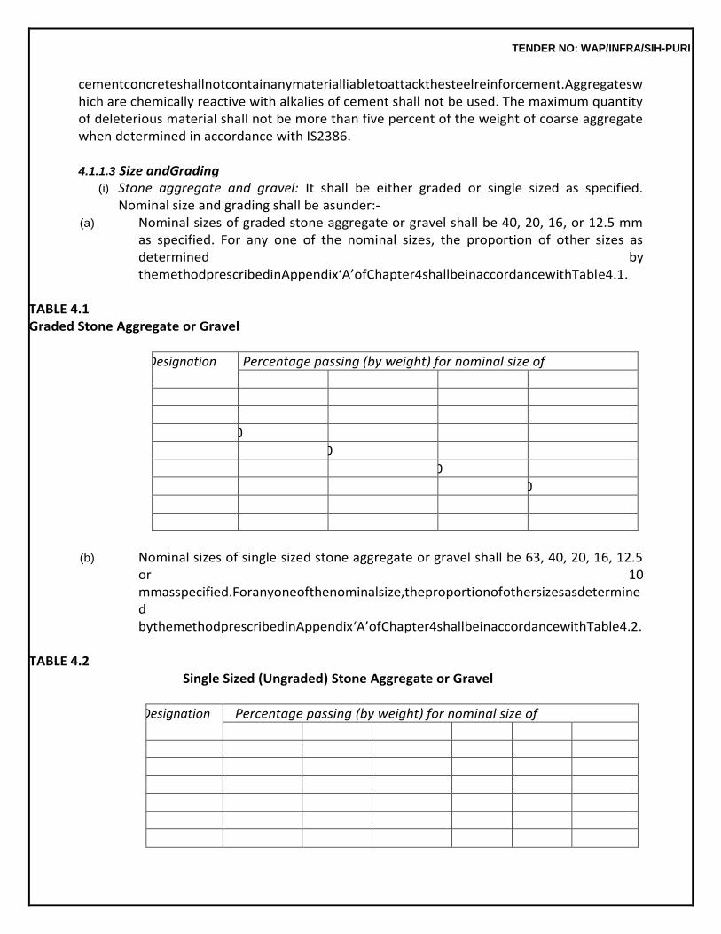
TENDER NO: WAP/INFRA/SIH-PURI
cementconcreteshallnotcontainanymaterialliabletoattackthesteelreinforcement.Aggregateswhich are chemically reactive with alkalies of cement shall not be used. The maximum quantity of deleterious material shall not be more than five percent of the weight of coarse aggregate when determined in accordance with IS2386.
4.1.1.3 Size andGrading
(i) Stone aggregate and gravel: It shall be either graded or single sized as specified. Nominal size and grading shall be asunder:-
(a) Nominal sizes of graded stone aggregate or gravel shall be 40, 20, 16, or 12.5 mm as specified. For any one of the nominal sizes, the proportion of other sizes as determined by themethodprescribedinAppendix‘A’ofChapter4shallbeinaccordancewithTable4.1.
TABLE 4.1 Graded Stone Aggregate or Gravel
IS Sieve Designation Percentage passing (by weight) for nominal size of
40 mm 20 mm 16 mm 12.5 mm
80 mm 100 - - -
63 mm - - - -
40 mm 95 to 100 100 - -
20 mm 30 to 70 95 to 100 100 100
16 mm - - 90 to 100 -
12.5 mm - - - 90 to 100
10 mm 10 to 35 25 to 55 30 to 70 40 to 85
4.75 mm 0 to 5 0 to 10 0 to 10 0 to 10
(b) Nominal sizes of single sized stone aggregate or gravel shall be 63, 40, 20, 16, 12.5
or 10 mmasspecified.Foranyoneofthenominalsize,theproportionofothersizesasdetermined bythemethodprescribedinAppendix‘A’ofChapter4shallbeinaccordancewithTable4.2.
TABLE 4.2
Single Sized (Ungraded) Stone Aggregate or Gravel
IS Sieve Designation Percentage passing (by weight) for nominal size of
63 mm 40 mm 20 mm 16 mm 12.5 mm 10 mm
80 mm 100 - - - - -
63 mm 85-100 100 - - - -
40 mm 0-30 85-100 100 - - -
20 mm 0- 5 0-20 85-100 100 - -
16 mm - - - 85-100 100 -
12.5 mm - - - - 85-100 100
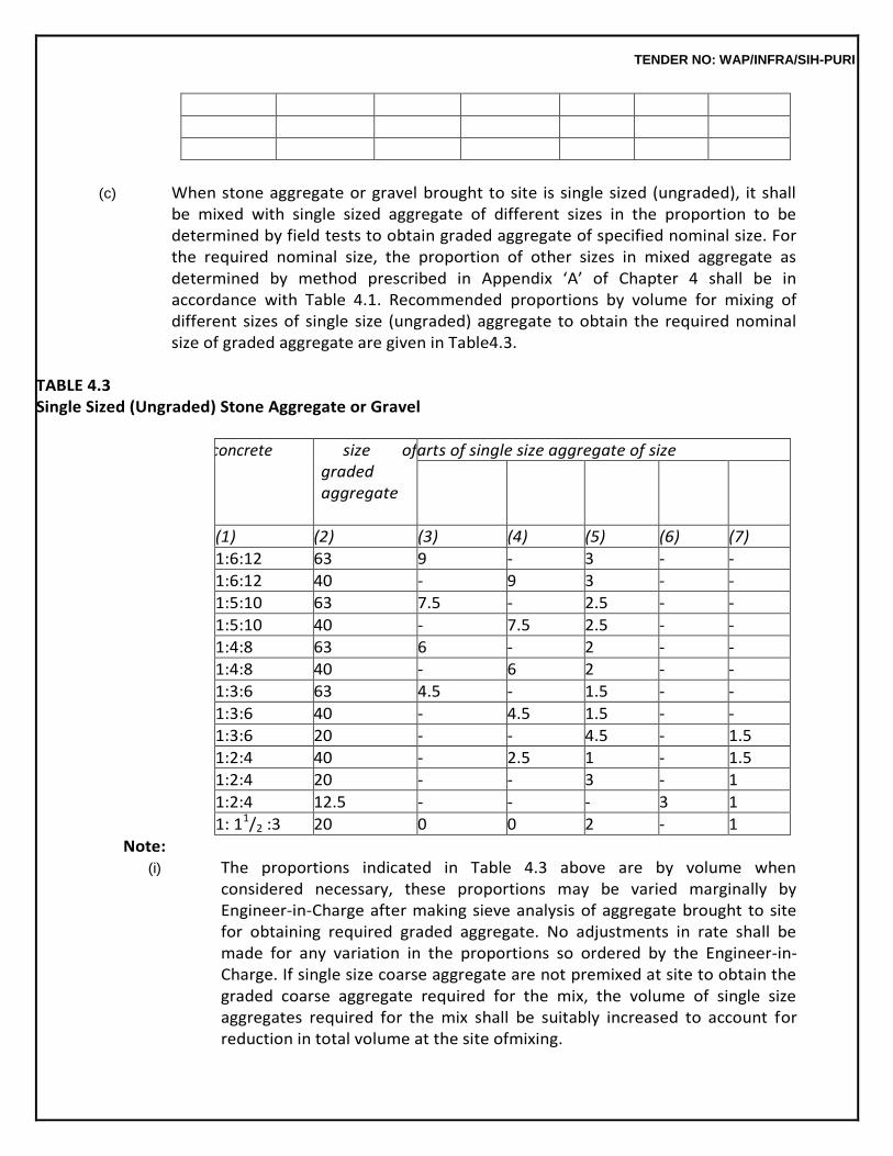
TENDER NO: WAP/INFRA/SIH-PURI
10 mm 0-5 0-5 0-20 0-30 0-45 85-100
4.75 mm - - 0-5 0-5 0-10 0-20
2.36 mm - - - - - 0-5
(c) When stone aggregate or gravel brought to site is single sized (ungraded), it shall
be mixed with single sized aggregate of different sizes in the proportion to be determined by field tests to obtain graded aggregate of specified nominal size. For the required nominal size, the proportion of other sizes in mixed aggregate as determined by method prescribed in Appendix ‘A’ of Chapter 4 shall be in accordance with Table 4.1. Recommended proportions by volume for mixing of different sizes of single size (ungraded) aggregate to obtain the required nominal size of graded aggregate are given in Table4.3.
TABLE 4.3 Single Sized (Ungraded) Stone Aggregate or Gravel
Cement concrete Nominal size of graded aggregate
required
Parts of single size aggregate of size
50 mm 40 mm 20 mm 12.5 mm 10 mm
(1) (2) (3) (4) (5) (6) (7)
1:6:12 63 9 - 3 - -
1:6:12 40 - 9 3 - -
1:5:10 63 7.5 - 2.5 - -
1:5:10 40 - 7.5 2.5 - -
1:4:8 63 6 - 2 - -
1:4:8 40 - 6 2 - -
1:3:6 63 4.5 - 1.5 - -
1:3:6 40 - 4.5 1.5 - -
1:3:6 20 - - 4.5 - 1.5
1:2:4 40 - 2.5 1 - 1.5
1:2:4 20 - - 3 - 1
1:2:4 12.5 - - - 3 1
1: 11/2 :3 20 0 0 2 - 1
Note: (i) The proportions indicated in Table 4.3 above are by volume when
considered necessary, these proportions may be varied marginally by Engineer-in-Charge after making sieve analysis of aggregate brought to site for obtaining required graded aggregate. No adjustments in rate shall be made for any variation in the proportions so ordered by the Engineer-in-Charge. If single size coarse aggregate are not premixed at site to obtain the graded coarse aggregate required for the mix, the volume of single size aggregates required for the mix shall be suitably increased to account for reduction in total volume at the site ofmixing.
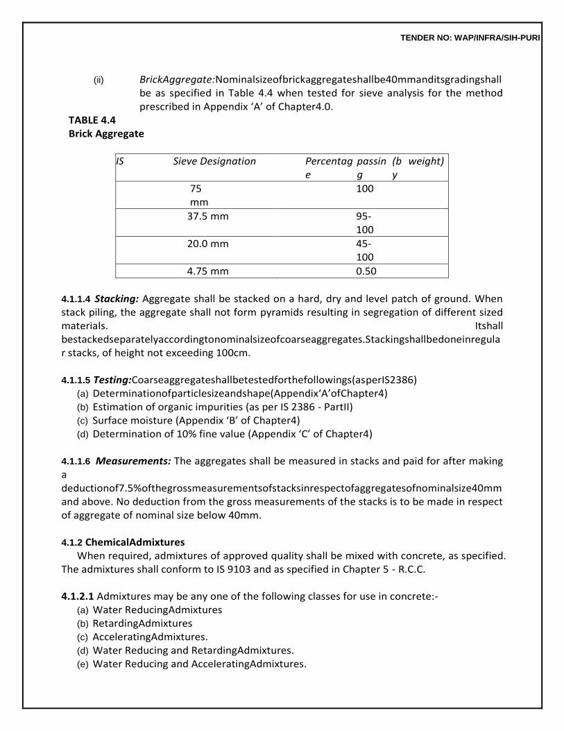
TENDER NO: WAP/INFRA/SIH-PURI
(ii) BrickAggregate:Nominalsizeofbrickaggregateshallbe40mmanditsgradingshall
be as specified in Table 4.4 when tested for sieve analysis for the method prescribed in Appendix ‘A’ of Chapter4.0.
TABLE 4.4 Brick Aggregate
IS Sieve Designation Percentage
passing
(by
weight)
75 mm
100
37.5 mm 95-100
20.0 mm 45-100
4.75 mm 0.50
4.1.1.4 Stacking: Aggregate shall be stacked on a hard, dry and level patch of ground. When stack piling, the aggregate shall not form pyramids resulting in segregation of different sized materials. Itshall bestackedseparatelyaccordingtonominalsizeofcoarseaggregates.Stackingshallbedoneinregular stacks, of height not exceeding 100cm.
4.1.1.5 Testing:Coarseaggregateshallbetestedforthefollowings(asperIS2386)
(a) Determinationofparticlesizeandshape(Appendix‘A’ofChapter4) (b) Estimation of organic impurities (as per IS 2386 - PartII) (c) Surface moisture (Appendix ‘B’ of Chapter4) (d) Determination of 10% fine value (Appendix ‘C’ of Chapter4)
4.1.1.6 Measurements: The aggregates shall be measured in stacks and paid for after making a deductionof7.5%ofthegrossmeasurementsofstacksinrespectofaggregatesofnominalsize40mm and above. No deduction from the gross measurements of the stacks is to be made in respect of aggregate of nominal size below 40mm.
4.1.2 ChemicalAdmixtures
When required, admixtures of approved quality shall be mixed with concrete, as specified. The admixtures shall conform to IS 9103 and as specified in Chapter 5 - R.C.C.
4.1.2.1 Admixtures may be any one of the following classes for use in concrete:-
(a) Water ReducingAdmixtures (b) RetardingAdmixtures (c) AcceleratingAdmixtures. (d) Water Reducing and RetardingAdmixtures. (e) Water Reducing and AcceleratingAdmixtures.
TENDER NO: WAP/INFRA/SIH-PURI
(f) Permeability Reducing (water proofing)Admixtures.
4.1.2.2 Liquid Admixtures: Admixtures introduced into the concrete as liquids generally fall into the followingcategories.
(a) Air Entraining. (b) WaterReducing. (c) Water ReducingRetarders. (d) Retarders. (e) Water ReducingAccelerators. (f) Accelerators.
4.1.2.3 Dosage of these admixtures may vary according to manufacturersspecification.
4.1.2.4 Two or more admixtures may not be compatible in the same solution. It is therefore mandatory that when two admixtures manufactured by the same manufacturers is being used simultaneously, the manufacturer shall certify their compatibility. In case the two or more admixtures are produces by different manufacturers, then, before their use in concrete, test shall be performed by the manufacturer to establish their compatibility, all such test reports shall be furnished to the Engineer-in-Charge for his approval before their use inconcrete.
4.1.2.5 Some admixture may be in the form of powder, particle or high concentration liquids which may requiremixingwithwaterpriortodosing.Undertheseconditionswaterinsolutionshallbeconsideredas partoftotalwatercontentinthebatchinordertomaintainthewater-cementratio.
4.1.2.6 Admixture manufacturer’s recommendation shall be carefully followed so as to ensure complete solutionoftheproductortoprepareastandardsolutionofuniformstrengthforeasieruse.
4.1.2.7 Certainadmixturesmaycontainsignificantamountsoffinelydividedinsolublematerialsoractive ingredients which may or may not be readily soluble. It is essential for such admixtures thatprecautions be taken to ensure that these constituents be kept in a state of uniform suspension before actual batching. When relatively small amounts of powered admixtures are to be used directly, these shall be pre-blended withcement.
4.1.2.8 Admixtures are sold under various trade names and may be in the form of liquids or powders. The proprietary name and the net quantity of content shall be clearly indicated in each package or container of admixtures. The admixtures shall be uniform within each batch and uniform between all batches.
4.1.2.9 No admixtures shall be accepted for use in concrete unless these are tested in accordance with IS 9103 and the test results are approved by theEngineer-in-Charge.
4.2. CEMENTCONCRETE 4.2.1 Grades of CementConcrete
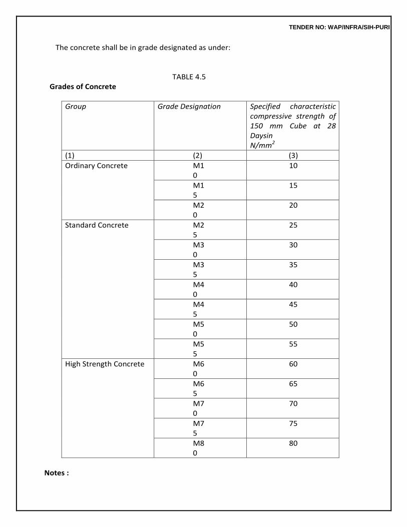
TENDER NO: WAP/INFRA/SIH-PURI
The concrete shall be in grade designated as under:
TABLE 4.5 Grades of Concrete
Group Grade Designation Specified characteristic compressive strength of 150 mm Cube at 28 Daysin N/mm2
(1) (2) (3)
Ordinary Concrete M10
10
M15
15
M20
20
Standard Concrete M25
25
M30
30
M35
35
M40
40
M45
45
M50
50
M55
55
High Strength Concrete M60
60
M65
65
M70
70
M75
75
M80
80
Notes :
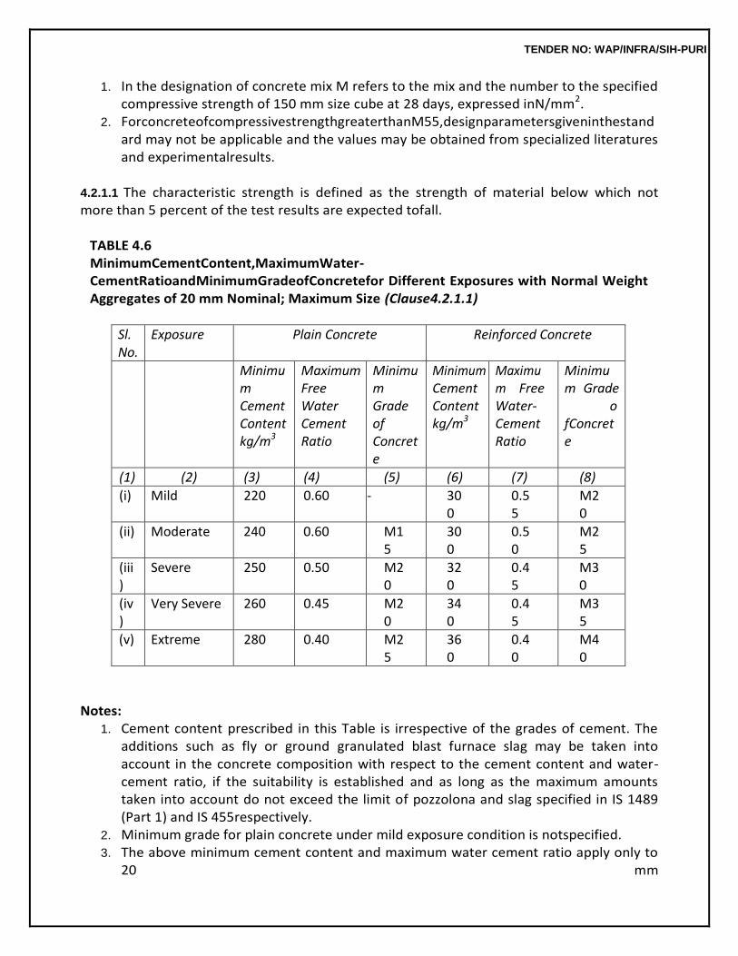
TENDER NO: WAP/INFRA/SIH-PURI
1. In the designation of concrete mix M refers to the mix and the number to the specified compressive strength of 150 mm size cube at 28 days, expressed inN/mm2.
2. ForconcreteofcompressivestrengthgreaterthanM55,designparametersgiveninthestandard may not be applicable and the values may be obtained from specialized literatures and experimentalresults.
4.2.1.1 The characteristic strength is defined as the strength of material below which not more than 5 percent of the test results are expected tofall.
TABLE 4.6 MinimumCementContent,MaximumWater-CementRatioandMinimumGradeofConcretefor Different Exposures with Normal Weight Aggregates of 20 mm Nominal; Maximum Size (Clause4.2.1.1)
Sl. No.
Exposure Plain Concrete Reinforced Concrete
Minimum Cement Content kg/m3
Maximum Free Water Cement Ratio
Minimum Grade of Concrete
Minimum Cement Content kg/m3
Maximum Free Water- Cement Ratio
Minimum Grade ofConcrete
(1) (2) (3) (4) (5) (6) (7) (8)
(i) Mild 220 0.60 - 300
0.55
M20
(ii) Moderate 240 0.60 M15
300
0.50
M25
(iii)
Severe 250 0.50 M20
320
0.45
M30
(iv)
Very Severe 260 0.45 M20
340
0.45
M35
(v) Extreme 280 0.40 M25
360
0.40
M40
Notes: 1. Cement content prescribed in this Table is irrespective of the grades of cement. The
additions such as fly or ground granulated blast furnace slag may be taken into account in the concrete composition with respect to the cement content and water-cement ratio, if the suitability is established and as long as the maximum amounts taken into account do not exceed the limit of pozzolona and slag specified in IS 1489 (Part 1) and IS 455respectively.
2. Minimum grade for plain concrete under mild exposure condition is notspecified. 3. The above minimum cement content and maximum water cement ratio apply only to
20 mm
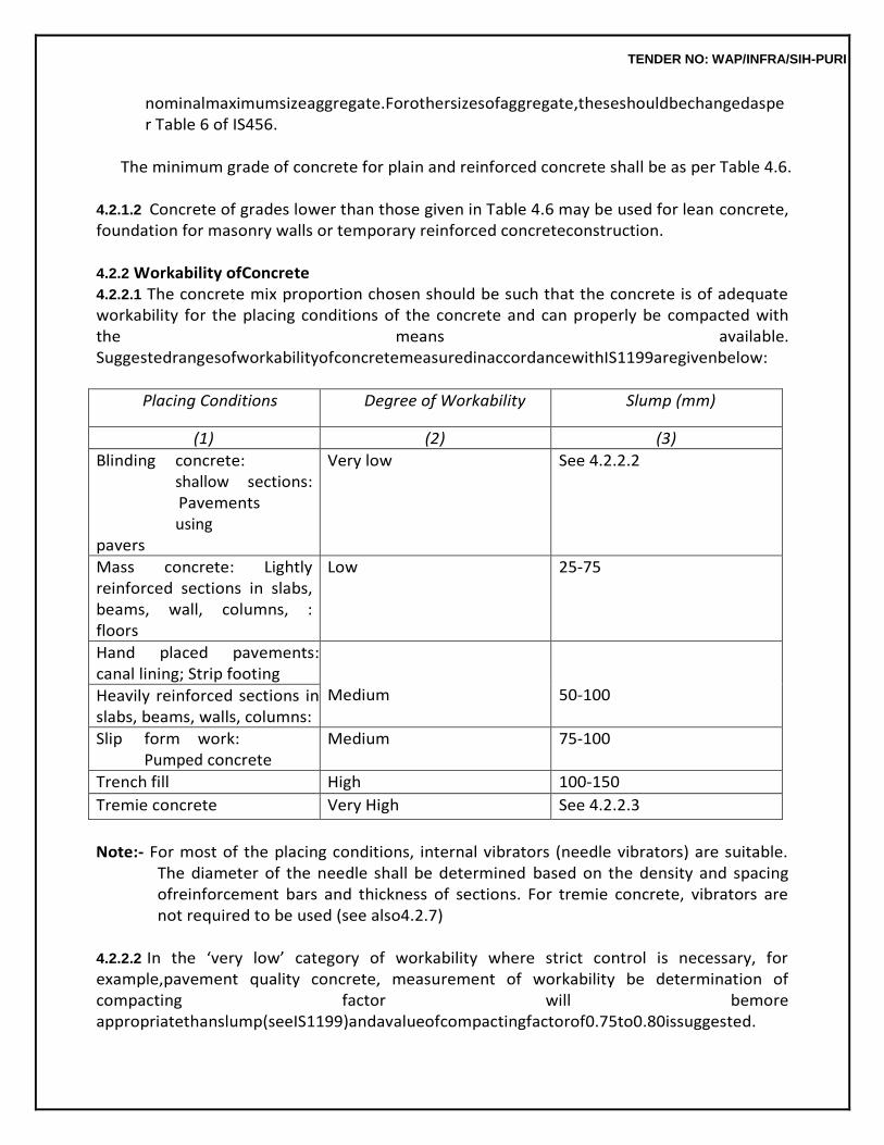
TENDER NO: WAP/INFRA/SIH-PURI
nominalmaximumsizeaggregate.Forothersizesofaggregate,theseshouldbechangedasper Table 6 of IS456.
The minimum grade of concrete for plain and reinforced concrete shall be as per Table 4.6.
4.2.1.2 Concrete of grades lower than those given in Table 4.6 may be used for lean concrete, foundation for masonry walls or temporary reinforced concreteconstruction.
4.2.2 Workability ofConcrete 4.2.2.1 The concrete mix proportion chosen should be such that the concrete is of adequate workability for the placing conditions of the concrete and can properly be compacted with the means available. SuggestedrangesofworkabilityofconcretemeasuredinaccordancewithIS1199aregivenbelow:
Placing Conditions Degree of Workability Slump (mm)
(1) (2) (3)
Blinding concrete: shallow sections: Pavements using pavers
Very low See 4.2.2.2
Mass concrete: Lightly reinforced sections in slabs, beams, wall, columns, : floors
Low 25-75
Hand placed pavements: canal lining; Strip footing
Medium
50-100 Heavily reinforced sections in
slabs, beams, walls, columns:
Slip form work: Pumped concrete
Medium 75-100
Trench fill High 100-150
Tremie concrete Very High See 4.2.2.3
Note:- For most of the placing conditions, internal vibrators (needle vibrators) are suitable.
The diameter of the needle shall be determined based on the density and spacing ofreinforcement bars and thickness of sections. For tremie concrete, vibrators are not required to be used (see also4.2.7)
4.2.2.2 In the ‘very low’ category of workability where strict control is necessary, for example,pavement quality concrete, measurement of workability be determination of compacting factor will bemore appropriatethanslump(seeIS1199)andavalueofcompactingfactorof0.75to0.80issuggested.
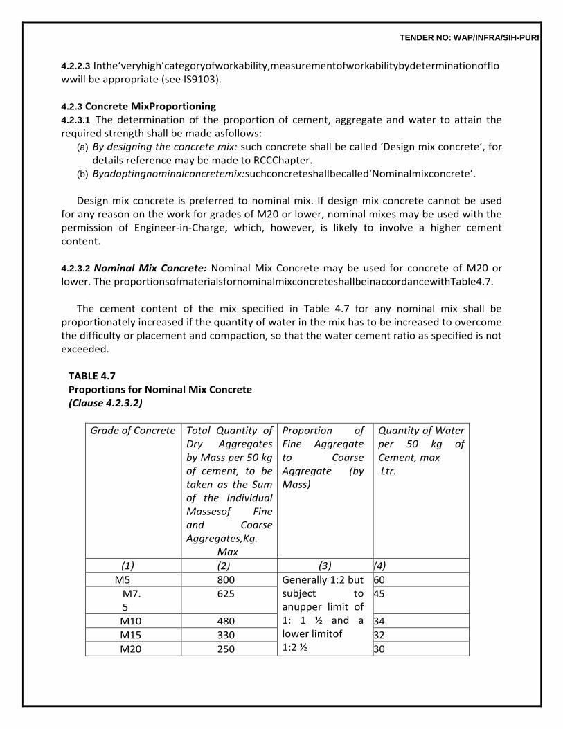
TENDER NO: WAP/INFRA/SIH-PURI
4.2.2.3 Inthe‘veryhigh’categoryofworkability,measurementofworkabilitybydeterminationofflowwill be appropriate (see IS9103).
4.2.3 Concrete MixProportioning 4.2.3.1 The determination of the proportion of cement, aggregate and water to attain the required strength shall be made asfollows:
(a) By designing the concrete mix: such concrete shall be called ‘Design mix concrete’, for details reference may be made to RCCChapter.
(b) Byadoptingnominalconcretemix:suchconcreteshallbecalled‘Nominalmixconcrete’.
Design mix concrete is preferred to nominal mix. If design mix concrete cannot be used for any reason on the work for grades of M20 or lower, nominal mixes may be used with the permission of Engineer-in-Charge, which, however, is likely to involve a higher cement content.
4.2.3.2 Nominal Mix Concrete: Nominal Mix Concrete may be used for concrete of M20 or lower. The proportionsofmaterialsfornominalmixconcreteshallbeinaccordancewithTable4.7.
The cement content of the mix specified in Table 4.7 for any nominal mix shall be
proportionately increased if the quantity of water in the mix has to be increased to overcome the difficulty or placement and compaction, so that the water cement ratio as specified is not exceeded.
TABLE 4.7 Proportions for Nominal Mix Concrete (Clause 4.2.3.2)
Grade of Concrete Total Quantity of Dry Aggregates by Mass per 50 kg of cement, to be taken as the Sum of the Individual Massesof Fine and Coarse Aggregates,Kg.
Max
Proportion of Fine Aggregate to Coarse Aggregate (by Mass)
Quantity of Water per 50 kg of Cement, max Ltr.
(1) (2) (3) (4)
M5 800 Generally 1:2 but subject to anupper limit of 1: 1 ½ and a lower limitof 1:2 ½
60
M7.5
625 45
M10 480 34
M15 330 32
M20 250 30
TENDER NO: WAP/INFRA/SIH-PURI
Note : - The proportion of the fine to coarse aggregate should be adjusted from upper limit progressively as the grading of fine aggregate becomes finer and the maximum size of coarse aggregate becomes larger. Graded coarse aggregate shall be used.
Note:- Quantity of water required from durability point of view may be less than the value given above.
Example
For an average grading of fine aggregate (that is, Zone II of Table 4 of IS 383), the proportionsshall be1:1½,1:2and1:2½formaximumsizeofaggregates10mm,20mmand40mmrespectively.
4.2.4 Batching
To avoid confusion and error in batching, consideration should be given to using the smallest practical number of different concrete mixed on any site or in any one plant. In batching concrete, the quantity of both cement and aggregate shall be determined by mass; admixture, if solid, by mass:liquidadmixture may however be measured in volume or mass: water shall be weighed or measured by volume in a calibrated tank (see also IS 4925).
Ready-mixedconcretesuppliedbyready-mixedconcreteplantshallbepreferred.Forlargeandmedium project sites the concrete shall be sourced from ready-mixed concrete plants or from on site or off site batching and mixing plants (see IS4926).
4.2.4.1 Except where it can be shown to the satisfaction of the Engineer-in-Charge that supply of properly graded aggregate of uniform quality can be maintained over a period of work, the grading aggregateshouldbecontrolledbyobtainingthecoarseaggregateindifferentsizesandblendingthemin the right proportions when required, the different sizes being stocked in separate stock-piles. The material should be stock-piled for several hours preferably a day before use. The grading of coarseand fine aggregate should be checked as frequently as possible, the frequency for a given job being determinedbytheEngineer-in-Chargetoensurethatthespecifiedgradingismaintained.
4.2.4.2 The accuracy of the measuring equipment shall be within + 2 percent of the quantity of cement being measured and within + 3 percent of the quantity of aggregate, admixtures and water being measured.
4.2.4.3 Proportion/Type and grading of aggregates shall be made by trial in such a way so as to obtain densestpossibleconcrete.Allingredientsoftheconcreteshouldbeusedbymassonly.
4.2.4.4 Volume batching may be allowed only where weigh-batching is not practicable and provided accurate used in concrete have earlier been established. Allowance for bilking shall be made in accordance with IS 2386 (Part 3). The mass volume relationship should be checked as frequently as necessary, the frequency for the given job being determined by Engineer-in-Charge to ensure that the specified grading ismaintained.
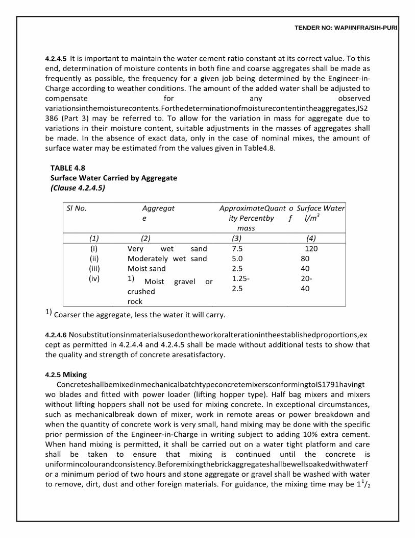
TENDER NO: WAP/INFRA/SIH-PURI
4.2.4.5 It is important to maintain the water cement ratio constant at its correct value. To this end, determination of moisture contents in both fine and coarse aggregates shall be made as frequently as possible, the frequency for a given job being determined by the Engineer-in-Charge according to weather conditions. The amount of the added water shall be adjusted to compensate for any observed variationsinthemoisturecontents.Forthedeterminationofmoisturecontentintheaggregates,IS2386 (Part 3) may be referred to. To allow for the variation in mass for aggregate due to variations in their moisture content, suitable adjustments in the masses of aggregates shall be made. In the absence of exact data, only in the case of nominal mixes, the amount of surface water may be estimated from the values given in Table4.8.
TABLE 4.8 Surface Water Carried by Aggregate (Clause 4.2.4.5)
Sl No. Aggregate
ApproximateQuantity Percentby
mass
of
Surface l/m3
Water
(1) (2) (3) (4)
(i) (ii) (iii) (iv)
Very wet sand Moderately wet sand Moist sand 1) Moist gravel or crushed rock
7.5 5.0 2.5 1.25-2.5
120 80 40 20-40
1) Coarser the aggregate, less the water it will carry.
4.2.4.6 Nosubstitutionsinmaterialsusedontheworkoralterationintheestablishedproportions,except as permitted in 4.2.4.4 and 4.2.4.5 shall be made without additional tests to show that the quality and strength of concrete aresatisfactory.
4.2.5 Mixing
ConcreteshallbemixedinmechanicalbatchtypeconcretemixersconformingtoIS1791havingtwo blades and fitted with power loader (lifting hopper type). Half bag mixers and mixers without lifting hoppers shall not be used for mixing concrete. In exceptional circumstances, such as mechanicalbreak down of mixer, work in remote areas or power breakdown and when the quantity of concrete work is very small, hand mixing may be done with the specific prior permission of the Engineer-in-Charge in writing subject to adding 10% extra cement. When hand mixing is permitted, it shall be carried out on a water tight platform and care shall be taken to ensure that mixing is continued until the concrete is uniformincolourandconsistency.Beforemixingthebrickaggregateshallbewellsoakedwithwaterfor a minimum period of two hours and stone aggregate or gravel shall be washed with water to remove, dirt, dust and other foreign materials. For guidance, the mixing time may be 11/2
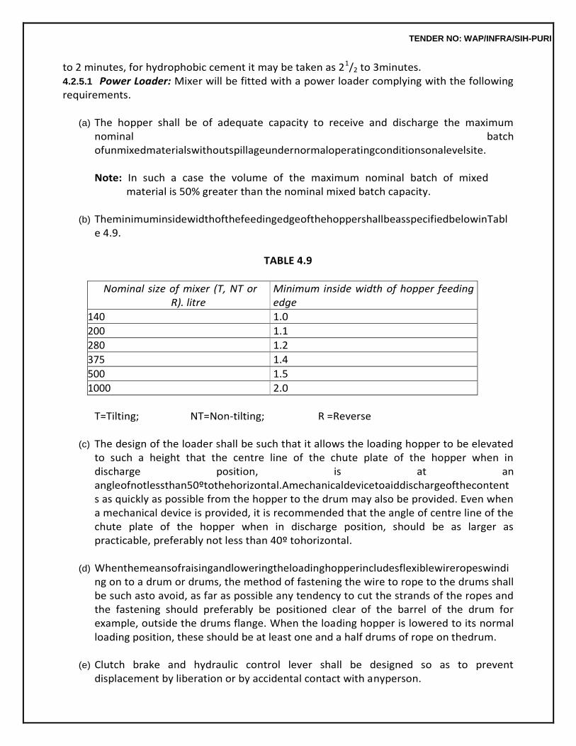
TENDER NO: WAP/INFRA/SIH-PURI
to 2 minutes, for hydrophobic cement it may be taken as 21/2 to 3minutes. 4.2.5.1 Power Loader: Mixer will be fitted with a power loader complying with the following requirements.
(a) The hopper shall be of adequate capacity to receive and discharge the maximum
nominal batch ofunmixedmaterialswithoutspillageundernormaloperatingconditionsonalevelsite.
Note: In such a case the volume of the maximum nominal batch of mixed
material is 50% greater than the nominal mixed batch capacity.
(b) TheminimuminsidewidthofthefeedingedgeofthehoppershallbeasspecifiedbelowinTable 4.9.
TABLE 4.9
Nominal size of mixer (T, NT or R). litre
Minimum inside width of hopper feeding edge
140 1.0
200 1.1
280 1.2
375 1.4
500 1.5
1000 2.0
T=Tilting; NT=Non-tilting; R =Reverse
(c) The design of the loader shall be such that it allows the loading hopper to be elevated
to such a height that the centre line of the chute plate of the hopper when in discharge position, is at an angleofnotlessthan50ºtothehorizontal.Amechanicaldevicetoaiddischargeofthecontents as quickly as possible from the hopper to the drum may also be provided. Even when a mechanical device is provided, it is recommended that the angle of centre line of the chute plate of the hopper when in discharge position, should be as larger as practicable, preferably not less than 40º tohorizontal.
(d) Whenthemeansofraisingandloweringtheloadinghopperincludesflexiblewireropeswindi
ng on to a drum or drums, the method of fastening the wire to rope to the drums shall be such asto avoid, as far as possible any tendency to cut the strands of the ropes and the fastening should preferably be positioned clear of the barrel of the drum for example, outside the drums flange. When the loading hopper is lowered to its normal loading position, these should be at least one and a half drums of rope on thedrum.
(e) Clutch brake and hydraulic control lever shall be designed so as to prevent
displacement by liberation or by accidental contact with anyperson.
TENDER NO: WAP/INFRA/SIH-PURI
(f) The clutch and brake control arrangements shall also be so designed that the operator
can control the falling speed of theloader.
(g) Safetydeviceshallbeprovidedtosecurethehopperinraisedpositionwhennotinuse.
4.2.5.2 Mixing Efficiency: The mixer shall be tested under normal working conditions in accordance with the method specified in IS 4643 with a view to check its ability to mix the ingredients to obtain concrete having uniformity within the prescribed limits. The uniformity of mixed concrete shall be evaluated by finding the percentage variation in quantity (mass in water) of cement, fine aggregate and coarse aggregate in a freshly mixed batch ofconcrete.
The percentage variation between the quantities of cement, fine aggregate and coarse
aggregates (as found by weighing in water) in the two halves of a batch and average of the two halve of the batch shall not be more than the following limits:
Cement 8% Fine aggregate 6% Coarse aggregate 5%
4.2.5.3 MachineMixing:Themixerdrumshallbeflushedcleanwithwater.Measuredquantityofcoarse aggregate shall be placed first in the hopper. This shall be followed with measured quantity of fine aggregate and then cement. In case fine aggregate is damp, half the required quantity of coarse aggregate shall be placed in the hopper, followed by fine aggregate and cement. Finally the balance quantity of coarse aggregate shall be fed in the hopper, & then the dry materials are slipped into the drum by raising the hopper. The dry material shall be mixed for atleast four turns of the drum. While the drum is rotating, water shall be added gradually to achieve the water cement ratio as specified or as required by the Engineer-in-Charge. After adding water, the mixing shall be continued until concrete of uniform colour, uniformly distributed material and consistency is obtained. Mixing shall be done for atleast two minutes after adding water. If there is segregation after unloading from the mixer, the concrete should beremixed.
The drum shall be emptied before recharging. When the mixer is closed down for the day
or at any time exceeding 20 minutes, the drum shall be flushed cleaned with water.
4.2.5.4 Hand Mixing: When hand mixing has been specifically permitted in exceptional circumstances by the Engineer-in-Charge in writing, subject to adding 10% extra cement, it shall be carried out on a smooth, clean and water tight platform of suitable size. Measured quantity of sand shall be spread evenly on the platform and the cement shall be dumped on the sand and distributed evenly. Sand and cement shall be mixed intimately with spade until mixture is of even colour throughout. Measured quantity of coarse aggregate shall be spread on top of cement sand mixture and mixing done by showlling and turning till the coarse aggregate gets evenly distributed the cement sand mixture. Three quarters of the total quantity of water required shall be added in a hollow made in the middle of the mixed pile
TENDER NO: WAP/INFRA/SIH-PURI
and the material is turned towards the middle of pile with spade. The whole mixture is turned slowly over and again and the remaining quantity of water is added gradually. The mixing shall be continued until concrete of uniform colour and consistency is obtained. The mixing platform shall be washed and cleaned at the end of theday.
4.2.5.5 Transportation and Handling:Concrete shall be transported from the mixer to the place of laying as rapidly as possible by methods which will prevent the segregation or loss of any of the ingredients and maintaining the requiredworkability.
TENDER NO: WAP/INFRA/SIH-PURI
Duringhotorcoldweather,concreteshallbetransportedindeepcontainers,othersuitablemethods to reduce the loss of water by evaporation in hot weather and heat loss in cold weather may also be adopted.
4.2.6 Placing
The concrete shall be deposited as nearly as practicable in its final position to avoid rehandling. It shall be laid gently (not thrown) and shall be thoroughly vibrated and compacted beforesetting commences and should not be subsequently disturbed. Method of placing shall be such as to preclude segregation. Care shall be taken to avoid displacement of reinforcement or movement of form workand damage due to rains. As a general guidance, the maximum free fall of concrete may be taken as 1.5 metre.
4.2.7 Compaction
Concrete shall be thoroughly compacted and fully worked around embedded fixtures and into corners of the form work. Compaction shall be done by mechanical vibrator of appropriate type till a denseconcreteisobtained.ThemechanicalvibratorsshallconformtoIS2505,IS2506,IS2514andIS 4656. To prevent segregation, over vibration shall beavoided.
Compaction shall be completed before the initial setting starts. For the items where
mechanical vibrators are not to be used, the contractor shall take permission of the Engineer-in-Charge in writing before the start of the work. After compaction the top surface shall be finished even and smooth with wooden trowel before the concrete begins to set.
4.2.8 ConstructionJoints
Concreting shall be carried out continuously upto construction joints. The position and arrangement of construction joints shall be as shown in the structural drawings or as directed by the Engineer-in- Charge. Number of such joints shall be kept minimum. Joints shall be kept as straight as possible. Construction joints should comply with IS 11817.
4.2.8.1 When the work has to be resumed on a surface which has hardened, such surface shall be roughened.Itshallthenbesweptcleanandthoroughlywetted.Forverticaljoints,neatcementslurry,of workable consistency by using 2 kgs of cement per sqm shall be applied on the surface before it is dry. Forhorizontaljoints,thesurfaceshallbecoveredwithalayerofmortarabout10-15mmthickcomposed of cement and sand in the same ratio as the cement and sand in concrete mix. This layer of cement slurryofmortarshallbefreshlymixedandappliedimmediatelybeforeplacingoftheconcrete.
4.2.8.2 Where the concrete has not fully hardened, all laitance shall be removed by scrubbing the wet surface with wire or bristle brushes, care being taken to avoid dislodgement of particles of coarse aggregate.Thesurfaceshallbethoroughlywettedandallfreewaterremoved.Thesurfaceshallthenbe coated with neat cement slurry @ 2 kgs of cement per sqm. On this surface, a layer of concrete not exceeding 150 mm in thickness shall first be placed and shall be well rammed
TENDER NO: WAP/INFRA/SIH-PURI
against old work particular attention being paid to corners and close spots; work, thereafter, shall proceed in the normal way.
4.2.9 Concreting under SpecialConditions 4.2.9.1 Work in Extreme Weather Conditions: During hot and cold weather, the concreting shall be done as per the procedure set out in IS 7861 (Part–I)-1975 and IS 7861 (Part II)-1981 respectively. Concreting shall not be done when the temperature falls below 4.5ºC. In cold weather, the concrete placed shall be protected against frost. During hot weather, it shall be ensured that the temperature of wet concrete does not exceed38ºC.
4.2.9.2 Under Water Concreting: Concrete shall not be deposited under water if it is practicable to de- watertheareaandplaceconcreteintheregularmanner.Whenitisnecessarytodepositconcreteunder water, the methods, equipment, materials and proportions of the mix to be used shall be submitted to and approved by the Engineer-in-Charge before the work isstarted.
Under-waterconcreteshouldhaveaslumprecommendedin4.2.2.Thewater-
cementratioshallnot exceed 0.6 and may need to be smaller, depending on the grade of concrete or the type of chemical attack. For aggregates of 40 mm maximum particle size, the cement content shall be atleast 350 kg/m3 ofconcrete.
4.2.9.3 ConcreteinSeaWater:Concreteinsea-waterorexposeddirectlyalongthesea-coastshallbe atleastM20GradeinthecaseofplainconcreteandM30incaseofreinforcedconcrete.Theuseofslag or pozzolana cement is advantageous under suchconditions.
(i) Special attention shall be given to the design of the mix to obtain the densest possible
concrete: slag, broken brick, soft lime stone, soft sandstone, or other porous or weak aggregates shall not beused.
(ii) As far as possible, preference shall be given to precast members unreinforced, well-
cured and hardened, without sharp corners, and having trowel-smooth finished surfaces free from crazing, cracks or other defect; plastering should beavoided.
(iii) No construction joints shall be allowed within 600 mm below low water-level or within
60 mm of the upper and lower planes of wave action. Where unusually severe conditions or abrasion are anticipated, such parts of the work shall be protected by bituminous or silico-fluoride coatings or stone facing bedded withbitumen.
(iv) In reinforced concrete structures, care shall be taken to protect the reinforcement
fromexposure to saline atmosphere during storage, fabrication and use. It may be achieved by treating the surface of reinforcement with cement wash or by suitablemethods.
4.2.10 Curing
TENDER NO: WAP/INFRA/SIH-PURI
Curing is the process of preventing loss of moisture from the concrete. The following methods shall be employed for effecting curing.
4.2.10.1 Moist Curing : Exposed surfaces of concrete shall be kept continuously in a damp or wet condition by ponding or by covering with a layer of sacking, canvas, Hessian or similar materials and kept constantly wet for at least 7 days from the date of placing concrete in case of ordinary Portland cement and at least 10 days where mineral admixtures or blended cements are used. The period of curingshallnotbelessthan10daysforconcreteexposedtodryandhotweatherconditions.Inthecase of concrete where mineral admixtures or blended cements are used, it is recommended that above minimum periods may be extended to 14days.
4.2.10.2 Membrane Curing : Approved curing compounds may be used in lieu of moist curing with the permission of the Engineer-in-Charge. Such compound shall be applied to all exposed surfaces of the concrete as soon as possible after the concrete has set. Impermeable membrane such as polythene sheet covering the concrete surface may also be used to provide effective barrier against the evaporation.
4.2.10.3 Freshly laid concrete shall be protected from rain by suitablecovering.
4.2.10.4 Over the foundation concrete, the masonry work may be started after 48 hours of its compaction but the curing of exposed surfaces of cement concrete shall be continued along with the masonry work for at east 7 days. And where cement concrete is used as base concrete for flooring, the flooring may be commenced before the curing period of base concrete is over but the curing of base concreteshallbecontinuedalongwithtoplayerofflooringforaminimumperiodof7days.
4.2.11 Testing ofConcrete
Testing of concrete shall be done as described in chapter of R.C.C.
4.2.12 FormWork Form work shall be as specified in R.C.C. chapter and shall be paid for separately unless
otherwise specified.
4.2.13 Finishes Plastering and special finishes other than those, obtained through form work shall be
specified and paid for separately unless otherwise specified.
4.2.14 Durability ofConcrete A durable concrete is one that performs satisfactorily in the working environment during
its anticipated exposure conditions during service. The materials and mix proportions shall be such as to maintain its intergrity and, if applicable, to protect reinforcement from corrosion.
The factors influencing durability include: (a) Theenvironment;
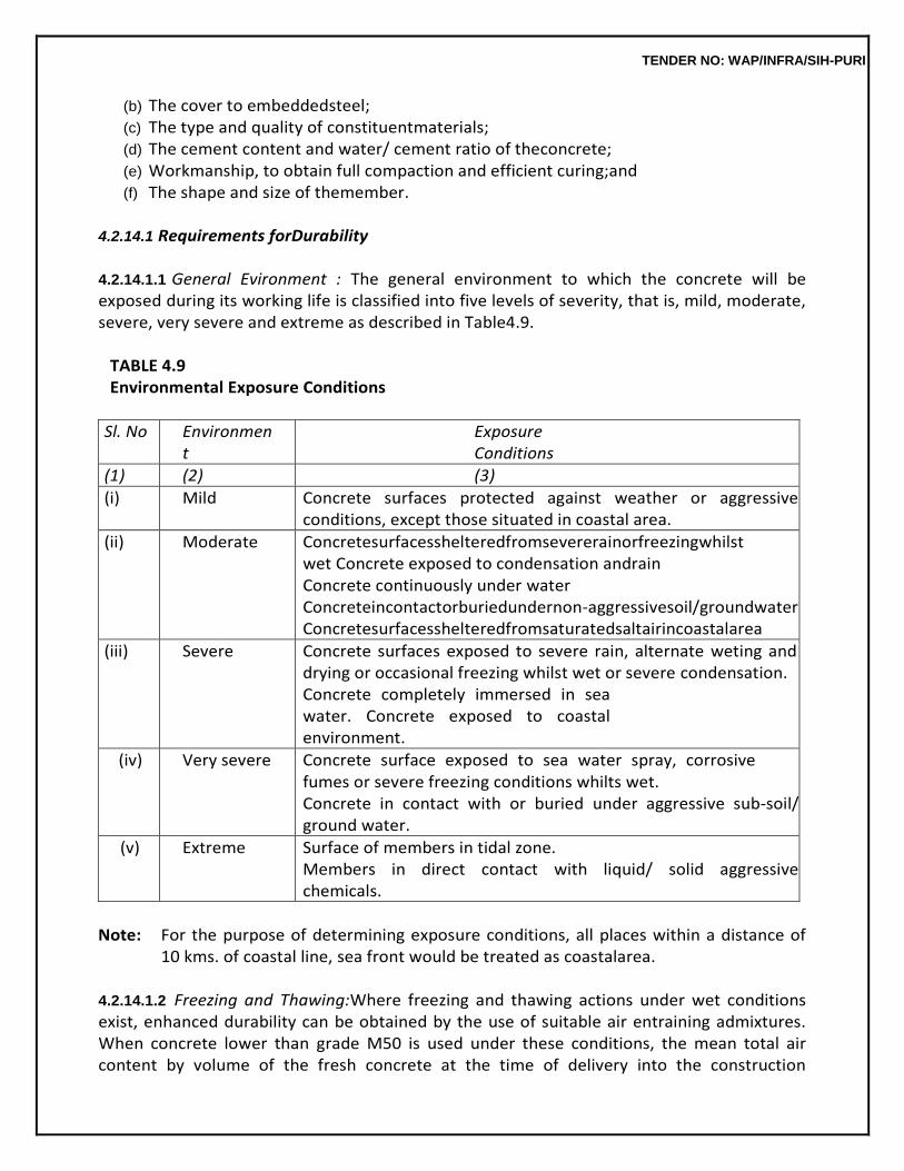
TENDER NO: WAP/INFRA/SIH-PURI
(b) The cover to embeddedsteel; (c) The type and quality of constituentmaterials; (d) The cement content and water/ cement ratio of theconcrete; (e) Workmanship, to obtain full compaction and efficient curing;and (f) The shape and size of themember.
4.2.14.1 Requirements forDurability
4.2.14.1.1 General Evironment : The general environment to which the concrete will be exposed during its working life is classified into five levels of severity, that is, mild, moderate, severe, very severe and extreme as described in Table4.9.
TABLE 4.9 Environmental Exposure Conditions
Sl. No Environment
Exposure Conditions
(1) (2) (3)
(i) Mild Concrete surfaces protected against weather or aggressive conditions, except those situated in coastal area.
(ii) Moderate Concretesurfacesshelteredfromsevererainorfreezingwhilstwet Concrete exposed to condensation andrain Concrete continuously under water Concreteincontactorburiedundernon-aggressivesoil/groundwater Concretesurfacesshelteredfromsaturatedsaltairincoastalarea
(iii) Severe Concrete surfaces exposed to severe rain, alternate weting and drying or occasional freezing whilst wet or severe condensation. Concrete completely immersed in sea water. Concrete exposed to coastal environment.
(iv) Very severe Concrete surface exposed to sea water spray, corrosive fumes or severe freezing conditions whilts wet. Concrete in contact with or buried under aggressive sub-soil/ ground water.
(v) Extreme Surface of members in tidal zone. Members in direct contact with liquid/ solid aggressive chemicals.
Note: For the purpose of determining exposure conditions, all places within a distance of
10 kms. of coastal line, sea front would be treated as coastalarea.
4.2.14.1.2 Freezing and Thawing:Where freezing and thawing actions under wet conditions exist, enhanced durability can be obtained by the use of suitable air entraining admixtures. When concrete lower than grade M50 is used under these conditions, the mean total air content by volume of the fresh concrete at the time of delivery into the construction
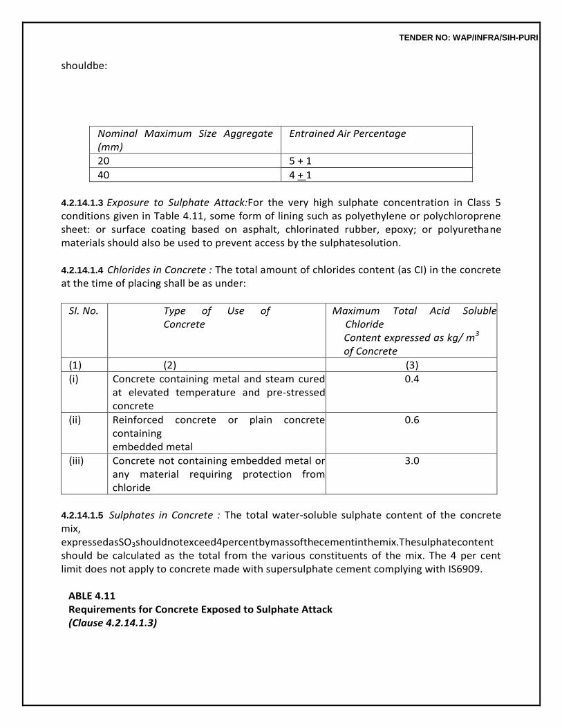
TENDER NO: WAP/INFRA/SIH-PURI
shouldbe:
Nominal Maximum Size Aggregate (mm)
Entrained Air Percentage
20 5 + 1
40 4 + 1
4.2.14.1.3 Exposure to Sulphate Attack:For the very high sulphate concentration in Class 5 conditions given in Table 4.11, some form of lining such as polyethylene or polychloroprene sheet: or surface coating based on asphalt, chlorinated rubber, epoxy; or polyurethane materials should also be used to prevent access by the sulphatesolution.
4.2.14.1.4 Chlorides in Concrete : The total amount of chlorides content (as CI) in the concrete at the time of placing shall be as under:
SI. No. Type of Use of Concrete
Maximum Total Acid Soluble Chloride Content expressed as kg/ m3 of Concrete
(1) (2) (3)
(i) Concrete containing metal and steam cured at elevated temperature and pre-stressed concrete
0.4
(ii) Reinforced concrete or plain concrete containing embedded metal
0.6
(iii) Concrete not containing embedded metal or any material requiring protection from chloride
3.0
4.2.14.1.5 Sulphates in Concrete : The total water-soluble sulphate content of the concrete mix, expressedasSO3shouldnotexceed4percentbymassofthecementinthemix.Thesulphatecontent should be calculated as the total from the various constituents of the mix. The 4 per cent limit does not apply to concrete made with supersulphate cement complying with IS6909.
ABLE 4.11 Requirements for Concrete Exposed to Sulphate Attack (Clause 4.2.14.1.3)
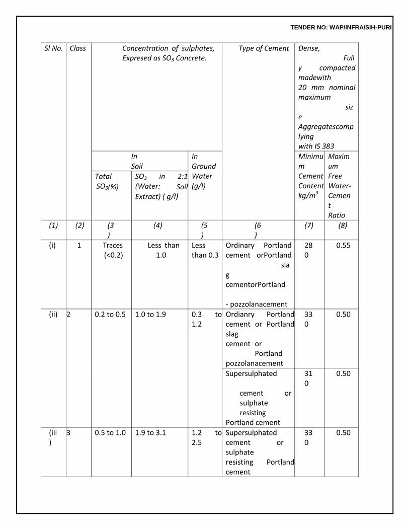
TENDER NO: WAP/INFRA/SIH-PURI
Sl No. Class Concentration of sulphates, Expresed as SO3 Concrete.
Type of Cement Dense, Fully compacted madewith 20 mm nominal maximum size Aggregatescomplying with IS 383
In Soil
In Ground Water (g/l)
Minimum Cement Content kg/m3
Maximum Free Water- Cement Ratio
Total SO3(%)
SO3 in 2:1 (Water: Soil Extract) ( g/l)
(1) (2) (3)
(4) (5)
(6)
(7) (8)
(i) 1 Traces (<0.2)
Less than 1.0
Less than 0.3
Ordinary Portland cement orPortland slag cementorPortland - pozzolanacement
280
0.55
(ii) 2 0.2 to 0.5 1.0 to 1.9 0.3 to 1.2
Ordianry Portland cement or Portland slag cement or Portland pozzolanacement
330
0.50
Supersulphated cement or sulphate resisting Portland cement
310
0.50
(iii)
3 0.5 to 1.0 1.9 to 3.1 1.2 to 2.5
Supersulphated cement or sulphate resisting Portland cement
330
0.50
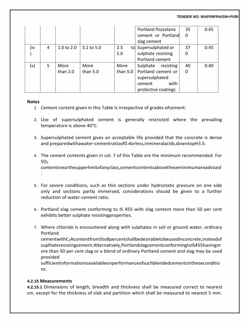
TENDER NO: WAP/INFRA/SIH-PURI
Portland Pozzolana cement or Portland slag cement
350
0.45
(iv)
4 1.0 to 2.0 3.1 to 5.0 2.5 to 5.0
Supersulphated or sulphate resisting Portland cement
370
0.45
(v) 5 More than 2.0
More than 5.0
More than 5.0
Sulphate resisting Portland cement or supersulphated cement with protective coatings
400
0.40
Notes
1. Cement content given in this Table is irrespective of grades ofcement.
2. Use of supersulphated cement is generally restricted where the prevailing temperature is above 40°C.
3. Supersulphated cement gives an acceptable life provided that the concrete is dense
and preparedwithawater-cementratioof0.4orless,inmineralacids,downtopH3.5.
4. The cement contents given in col. 7 of this Table are the minimum recommended. For SO3 contentsneartheupperlimitofanyclass,cementcontentsabovetheseminimumareadvised.
5. For severe conditions, such as thin sections under hydrostatic pressure on one side
only and sections partly immersed, considerations should be given to a further reduction of water-cement ratio.
6. Portland slag cement conforming to IS 455 with slag content more than 50 per cent
exhibits better sulphate resistingproperties.
7. Where chloride is encountered along with sulphates in soil or ground water, ordinary Portland cementwithC3Acontentfrom5to8percentshallbedesirabletobeusedinconcrete,insteadof suplhateresistingcement.Alternatively,PortlandslagcementconformingtoIS455havingmore than 50 per cent slag or a blend of ordinary Portland cement and slag may be used provided sufficientinformationisavailableonperformanceofsuchblendedcementsintheseconditions.
4.2.15 Measurements 4.2.15.1 Dimensions of length, breadth and thickness shall be measured correct to nearest cm. except for the thickness of slab and partition which shall be measured to nearest 5 mm.
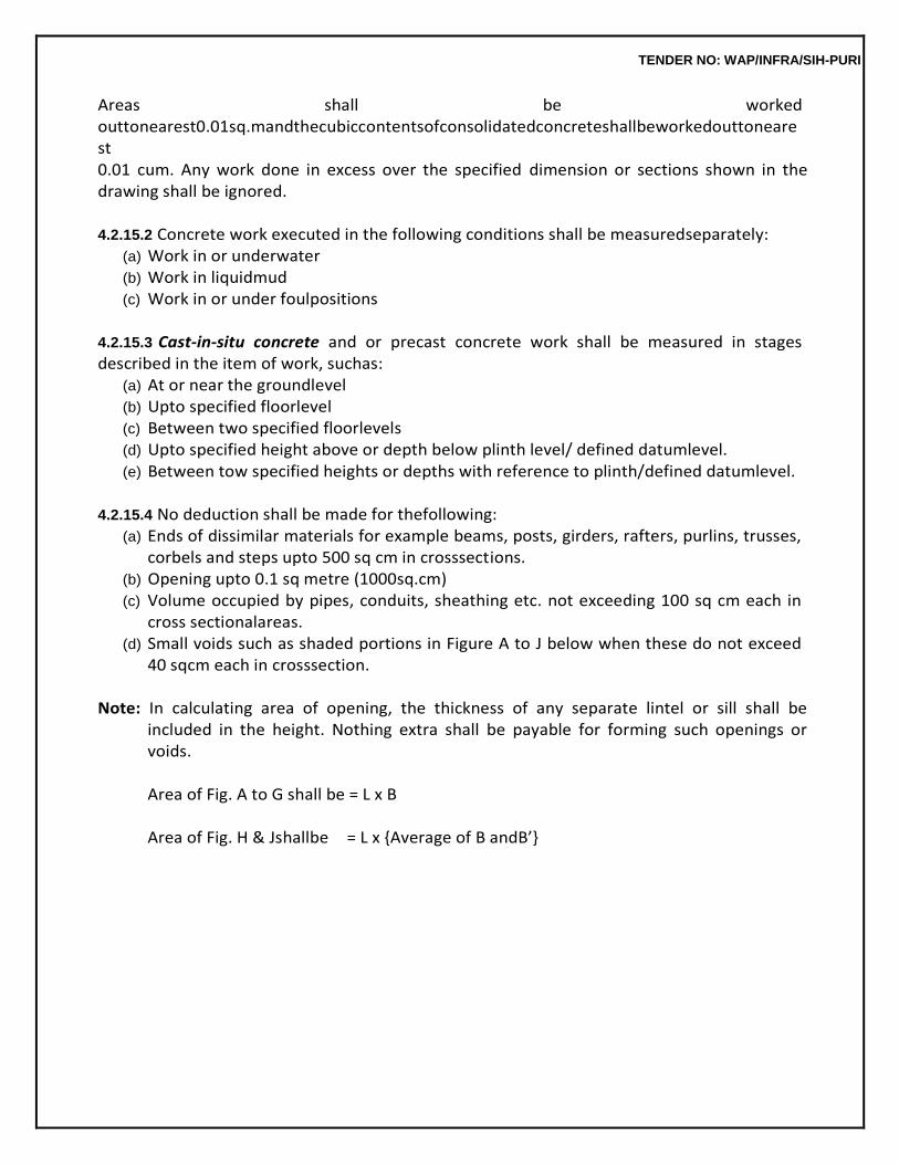
TENDER NO: WAP/INFRA/SIH-PURI
Areas shall be worked outtonearest0.01sq.mandthecubiccontentsofconsolidatedconcreteshallbeworkedouttonearest 0.01 cum. Any work done in excess over the specified dimension or sections shown in the drawing shall be ignored.
4.2.15.2 Concrete work executed in the following conditions shall be measuredseparately:
(a) Work in or underwater (b) Work in liquidmud (c) Work in or under foulpositions
4.2.15.3 Cast-in-situ concrete and or precast concrete work shall be measured in stages described in the item of work, suchas:
(a) At or near the groundlevel (b) Upto specified floorlevel (c) Between two specified floorlevels (d) Upto specified height above or depth below plinth level/ defined datumlevel. (e) Between tow specified heights or depths with reference to plinth/defined datumlevel.
4.2.15.4 No deduction shall be made for thefollowing:
(a) Ends of dissimilar materials for example beams, posts, girders, rafters, purlins, trusses, corbels and steps upto 500 sq cm in crosssections.
(b) Opening upto 0.1 sq metre (1000sq.cm) (c) Volume occupied by pipes, conduits, sheathing etc. not exceeding 100 sq cm each in
cross sectionalareas. (d) Small voids such as shaded portions in Figure A to J below when these do not exceed
40 sqcm each in crosssection.
Note: In calculating area of opening, the thickness of any separate lintel or sill shall be included in the height. Nothing extra shall be payable for forming such openings or voids.
Area of Fig. A to G shall be = L x B
Area of Fig. H & Jshallbe = L x {Average of B andB’}
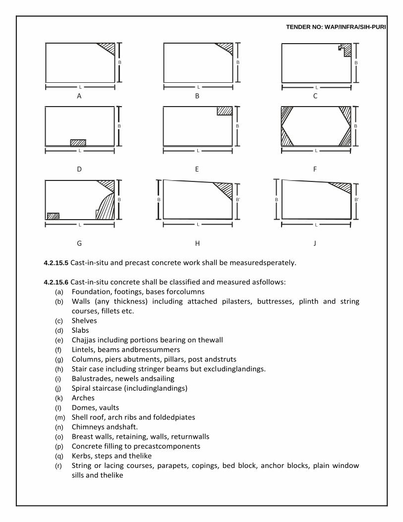
TENDER NO: WAP/INFRA/SIH-PURI
A B C
D E F
G H J
4.2.15.5 Cast-in-situ and precast concrete work shall be measuredsperately.
4.2.15.6 Cast-in-situ concrete shall be classified and measured asfollows:
(a) Foundation, footings, bases forcolumns (b) Walls (any thickness) including attached pilasters, buttresses, plinth and string
courses, fillets etc. (c) Shelves (d) Slabs (e) Chajjas including portions bearing on thewall (f) Lintels, beams andbressummers (g) Columns, piers abutments, pillars, post andstruts (h) Stair case including stringer beams but excludinglandings. (i) Balustrades, newels andsailing (j) Spiral staircase (includinglandings) (k) Arches (I) Domes, vaults (m) Shell roof, arch ribs and foldedpiates (n) Chimneys andshaft. (o) Breast walls, retaining, walls, returnwalls (p) Concrete filling to precastcomponents (q) Kerbs, steps and thelike (r) String or lacing courses, parapets, copings, bed block, anchor blocks, plain window
sills and thelike
B
L
B
L
B
L
B
L
B
L
B
L
B
L
B B'
L
B B'
L
TENDER NO: WAP/INFRA/SIH-PURI
(s) Cornices and moulded windowssills. (t) Louvers, fins,facia.
4.2.15.7 Precast cement concrete solid article shall be measured separately and shall include use of moulds,finishingthetopsurfacesevenandsmoothwithwoodentrowel,beforesettinginpositionincement mortar 1:2 (1 cement : 2 coarse sand). Plain and moulded work shall be measured separately and the work shall be classified and measured as under:
Classifications Method of measurement
(a) Wallpanels In square meters stating the thickness.
(b) String or lacing courses, coping,bed plates, plain windows sills, shelves, louvers, steps etc.
In cubic meters.
(c) Kerbs, edgings etc. In cubic metres.
(d) Solid blockwork In square metres stating the thickness or in cubic meters.
(e) Hollow blockwork In square metres stating the thickness or in cubic metres.
(f) Light weightpartitions In square thickness.
metres
stating
the partition’s
4.2.16 Rate
The rate is inclusive of the cost of labour and materials involved in all the operations described above.
4.3 CEMENT- FLY ASHCONCRETE 4.3.0 Fly ash concrete shall be prepared by mixing graded coarse aggregate of nominal size as specifiedwithfineaggregate,ordinaryPortlandcementandflyashinspecifiedproportionswithrequired quantityofwater.Therecommendedcompositionofcementflyashconcreteareasunder:
TABLE 4.12 Fly Ash Concrete Mixes
Composition (Dry Volume) Proportion (Dry Volume)
Compressive Strength at seven days
Lean Concrete (1:5:10)
28 kg/cm2 Cement (Ordinary Portland) 1.0
Fly ash 2.5
Sand 4.0
Stone aggregate 11.0
Lean Concrete (1:4:8)
TENDER NO: WAP/INFRA/SIH-PURI
Cement (Ordinary Portland) 1.0 37 kg/cm2
Fly ash 2.0
Sand 3.5
Stone aggregate 9.0
Note: No fly ash is to be added to Portland Puzzolona cement in any case which itself contains fly ash.
4.3.1 Proportioning
Proportioning shall be done by volume. Boxes of suitable size shall be used for measuring fly ash, sand and aggregate. The internal dimensions of the boxes shall be generally 35x25x40 cm. deep or as otherwiseapprovedbytheEngineer-in-charge.Theunitofmeasurementofcementshallbeabagof50 kg.andthisshallbetakenas0.035cum.Whilemeasuringtheaggregate,shaking,rammingorheaping shallnotbedone.Theproportioningofsandshallbeonthebasisofitsdryvolumeandincaseofdamp sand, allowances for bulkage shall be made as given in the chapter formortar.
4.3.2 Mixing shall be as specified in 4.2.5 except that the fly ash shall be placed in the hopper before cement in case of machinemixing.
4.3.3 Placing and compaction shall be as specified in 4.2.6 and4.2.7.
4.3.4 Curing shall be as specified in4.2.10.
4.3.5 Form work shall be as specified in4.2.12.
4.3.6 Measurements shall be as specified in4.2.15.
4.3.7 Rate
Rate shall include the cost of materials and labour involved in all the operations described above.
4.4 DAMP PROOFCOURSE 4.4.1 Cement ConcreteLayer
This shall consist of cement concrete of specified proportions and thickness. The surface of brick or stone masonry work shall be levelled and prepared before laying the cement concrete. Edge of damp proofcourseshallbestraight,evenandvertical.Sideshutteringshallconsistofsteelformsandshallbe strong and properly fixed so that it does not get disturbed during compaction and the mortar does not leak through. The concrete mix shall be of workable consistency and shall be tamped thoroughly to makeadensemass.Whenthesidesareremoved,thesurfaceshouldcomeoutsmoothwithouthoney- coming. Continuity shall be maintained while laying the cement concrete layer and laying shall be terminated only at the predetermined location where damp proof course is to be discontinued. There shall be no construction joints in the Damp ProofCourse.
4.4.2 Curing
TENDER NO: WAP/INFRA/SIH-PURI
Damp proof course shall be cured for at least seven days, after which it shall be allowed to dry.
4.4.3 Application of HotBitumen Where so directed, hot bitumen in specified quantity shall be applied over the dried up
surface of cement concrete, properly cleaned with brushes and finally with a piece of cloth soaked in kerosene oil. Bitumen of penetration A 90 or equivalent where used shall be heated to a temperature of 160º ± 5ºC. The hot bitumen shall be applied uniformly all over, so that no blank spaces are left anywhere. It will be paid for separately.
4.4.4 Water ProofingMaterials
Where so specified, water proofing material of approved quality shall be added to the concrete mixture in accordance with the manufacturer’s specification stating the quantity of water proofing material in litres or kg per 50 kg or cement and will be paid for separately.
4.4.5 Measurements
The length and breadth shall be measured correct to a cm and its area shall be calculated insquare metres correct to two places of decimal. The depth shall not be less than the specified thickness at any section.
4.4.6 Rate
The rate is inclusive of the cost of materials and labour involved in all the operations described aboveexceptfortheapplicationsofacoatofhotbitumenandadditionofwaterproofingmaterialswhich shall be paid for separately, unless otherwisespecified.
TENDER NO: WAP/INFRA/SIH-PURI
5.0 REINFORCED CEMENT CONCRETE WORK 5.0 GENERAL
Reinforcedcementconcreteworkmaybecast-in-situorPrecastasmaybedirectedbyEngineer-in- Charge according to the nature of work. Reinforced cement concrete work shall comprise of the followingwhichmaybepaidseparatelyorcollectivelyasperthedescriptionoftheitemofwork.
(a) Form work (Centering andShuttering)
(b) Reinforcement
(c) Concreting: (1– Cast-in-situ), (2 –Precast)
5.1 MATERIALS 5.1.1 Water, cement, fine and coarse aggregate shall be as specified under respective clauses of chapter 03 mortars and chapter 04 concrete work asapplicable.
5.1.2 Fly Ash admixed cement concrete (FACC) and fly ash Blended cements in Cement Concrete (PPCC) in RCCstructures.
5.1.2.0 Fly ash Blended Cements conforming to IS 1489 (Part I) may be used in RCC structures asper guidelines given below:
5.1.2.1 General
(i) IS 456- 2000 Code of Practice for Plain and Reinforced Concrete (as amended up to date) shall befollowedinregardtoConcreteMixProportionanditsproductionasunder: (a) The concrete mix design shall be done as “Design Mix Concrete” as prescribed in
clause-9 of IS 456 mentionedabove. (b) Concrete shall be manufactured in accordance with clause 10 of above mentioned
IS 456 covering quality assurance measures both technical and organizational, which shall also necessarily require a qualified Concrete Technologist to be available during manufacture of concrete for certification of quality ofconcrete.
(ii) MinimumM-
25gradeofconcreteshallbeusedinallstructuralelementsmadewithRCCbothin load bearing and framedstructure.
(iii) Themechanicalpropertiessuchasmodulusofelasticity,tensilestrength,creepandshrinkag
eof fly ash mixed concrete or concrete using fly ash blended cements (PPCs) are not likely to be significantlydifferentandtheirvaluesaretobetakensameasthoseusedforconcretemadewith OPC.
(iv) To control higher rate of carbonation in early ages of concrete both in fly ash admixed
TENDER NO: WAP/INFRA/SIH-PURI
as wellas PPC based concrete, water/binder ratio shall be kept as low as possible, which shall be closely monitored during concretemanufacture. If necessitated due to low water/binder ratio, required workability shall be achieved by use of chloride free chemical admixtures conforming to IS 9103. The compatibility of chemical admixturesandsuperplasticizerswitheachsetOPC,flyashand/orPPCreceivedfromdifferent sources shall be ensured bytrials.
(v) In environment subjected to aggressive chloride or sulphate attach in particular, use of
fly ash admixed or PPC based concrete is recommended. In cases, where structural concreteis exposedtoexcessivemagnesiumsulphate,flyashsubstitution/contentshallbelimitedto18%by weight. Special type of cement with low C3A content may also be alternatively used. Durability criteria like minimum binder content and maximum water /binder ratio also need to be given due consideration in suchenvironment.
(vi) Wet curing period shall be enhanced to a minimum of 10 days or its equivalent. In hot
& arid regions, the minimum curing period shall be 14 days or itsequivalent.
5.1.2.2 Use of Fly ash Admixed Cement Concrete (FACC) in RCCstructures There shall be no bar on use of FACC in RCC structures subject to following additional conditions. (i) Fly ash shall have its chemical characteristics and physical requirements etc.
conforming to IS 3812 (part I & II) and shall be dulycertified.
(ii) To ensure uniform blending of fly ash with cment in conformity with IS 456, a specific facility needs to be created at site with complete computerized automated process control to achieve design quality or with similar facility from Ready Mix Concrete (RMC)plants.
(iii) AsperIS1489(Part-I)maximum35%ofOPCbymassispermittedtobesubstitutedwithflyash
conforming to IS 3812 (Part –I) and same isreiterated.
(iv) Separate storage for dry fly ash shall be provided. Storage bins or silos shall be weather proof and permit a free flow and efficient discharge of fly ash. The filter or dust control system provided in the bins or silos shall be of sufficient size to allow delivery of fly ash maintained at specified pressure to prevent undue emission of fly ash dust, which may interfere weighing accuracy.
5.1.2.3 Use of Fly Ash Blended Cements in Cement Concrete (PPCC) in RCCStructures
(i) Subject to General Guidelines detailed out as above, PPC manufactured conforming to IS 1489 (Part-I) shall be treated at par with OPC for manufacture of Design Mix concrete for structural use inRCC.
(ii) Till the time, BIS makes it mandatory to print the %age of fly ash on each bag of
TENDER NO: WAP/INFRA/SIH-PURI
cement, the certificate from the PPC manufacture indicating the same shall be insisted upon before allowing use of such cements inworks.
(iii) WhileusingPPCforstructuralconcretework,nofurtheradmixingofflyashshallbepermitted.
5.1.3 Steel forReinforcement
5.1.3.1 The steel used for reinforcement shall be any of the following types: (a) Mild steel and medium tensile bars conforming to IS 432 (PartI)
(b) High strength deformed steel bars conforming to IS1786
(c) Hard drawn steel wire fabric conforming to IS1566
(d) Structural steel conforming to Grade A of IS2062
(e) Thermo-mechanically treated (TMT)Bars.
5.1.3.2 Elongation percent on gauge lengthis5.65 A where A is the cross sectional areas of
the test piece.
5.1.3.3 Mild steel is not recommended for the use in structures located in earthquake zone subjected to severe damage and for structures subjected to dynamic loading (other than wind loading) such as railway and highwaybridges.
5.1.3.4 Weldingofreinforcementbarscoveredinthisspecificationshallbedoneinaccordancewiththe requirements of IS2751.
Nominal mass/weight : The tolerance on mass/ weight for round and square bars shall be the percentage given in Table 5.1 of the mass/ weight calculated on the basis that the masses of the bar/ wire of nominal diameter and of density 7.85 kg/ cm3 or 0.00785 kg/mm3.
TABLE 5.1 Tolerance on Nominal Mass
Nominal size in mm Tolerance on the Nominal Mass per cent
Batch
Individual sample +
Individual sample for coil (x)
(a) Upto and including 10
+7 -8 +8
(b) Over 10, upto and including 16
+5 -6 +6
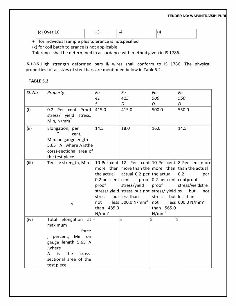
TENDER NO: WAP/INFRA/SIH-PURI
(c) Over 16 +3 -4 +4
+ for individual sample plus tolerance is notspecified (x) for coil batch tolerance is not applicable Tolerance shall be determined in accordance with method given in IS 1786.
5.1.3.5 High strength deformed bars & wires shall conform to IS 1786. The physical
properties for all sizes of steel bars are mentioned below in Table5.2.
TABLE 5.2
Sl. No Property Fe 415
Fe 415 D
Fe 500 D
Fe 550 D
(i) 0.2 Per cent Proof stress/ yield stress, Min, N/mm2
415.0 415.0 500.0 550.0
(ii) Elongation, per cent, Min. on gaugelength 5.65 A , where A isthe corss-sectional area of the test piece.
14.5 18.0 16.0 14.5
(iii) Tensile strength, Min 10 Per cent more than the actual 0.2 per cent proof stress/ yield stress but not less than 485.0 N/mm2
12 Per cent more than the actual 0.2 per cent proof stress/yield stress but not less than 500.0 N/mm2
10 Per cent more than the actual 0.2 per cent proof stress/ yield stress but not less than 565.0 N/mm2
8 Per cent more than the actual 0.2 per centproof stress/yieldstress but not lessthan 600.0 N/mm2
(iv) Total elongation at maximum force, percent, Min on
gauge length 5.65 A ,where A is the cross-sectional area of the test piece.
- 5 5 5
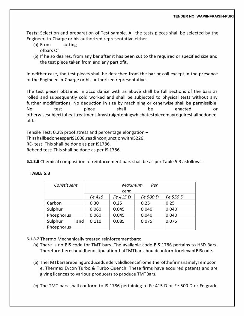
TENDER NO: WAP/INFRA/SIH-PURI
Tests: Selection and preparation of Test sample. All the tests pieces shall be selected by the Engineer- in-Charge or his authorized representative either-
(a) From cutting ofbars Or
(b) If he so desires, from any bar after it has been cut to the required or specified size and the test piece taken from and any part ofit.
In neither case, the test pieces shall be detached from the bar or coil except in the presence of the Engineer-in-Charge or his authorized representative.
The test pieces obtained in accordance with as above shall be full sections of the bars as rolled and subsequently cold worked and shall be subjected to physical tests without any further modifications. No deduction in size by machining or otherwise shall be permissible. No test piece shall be enacted or otherwisesubjecttoheattreatment.Anystraighteningwhichatestpiecemayrequireshallbedonecold.
Tensile Test: 0.2% proof stress and percentage elongation – ThisshallbedoneasperIS1608,readinconjunctionwithIS226. RE- test: This shall be done as per IS1786. Rebend test: This shall be done as per IS 1786.
5.1.3.6 Chemical composition of reinforcement bars shall be as per Table 5.3 asfollows:-
TABLE 5.3
Constituent Maximum Per cent
Fe 415 Fe 415 D Fe 500 D Fe 550 D
Carbon 0.30 0.25 0.25 0.25
Sulphur 0.060 0.045 0.040 0.040
Phosphorus 0.060 0.045 0.040 0.040
Sulphur and Phosphorus
0.110 0.085 0.075 0.075
5.1.3.7 Thermo Mechanically treated reinforcementbars:
(a) There is no BIS code for TMT bars. The available code BIS 1786 pertains to HSD Bars. ThereforethereshouldbenostipulationthatTMTbarsshouldconformtorelevantBIScode.
(b) TheTMTbarsarebeingproducedundervalidlicencefromeitherofthefirmsnamelyTempcor
e, Thermex Evcon Turbo & Turbo Quench. These firms have acquired patents and are giving licences to various producers to produce TMTBars.
(c) The TMT bars shall conform to IS 1786 pertaining to Fe 415 D or Fe 500 D or Fe grade
TENDER NO: WAP/INFRA/SIH-PURI
of steel asspecified.
(d) In design and construction of reinforced concrete building in seismic zone III and above, steel reinforcement of Grade Fe 415 D shall be used. However, high strength deformed steel bars, produced by thermomechanical treatment process of grade Fe 415, Fe 500 and Fe 550 having elongation more than 14.5. % and conform to other requirements of Fe 415 D, Fe 500 D and Fe 550 D respectively of IS 1786 may also be used for reinforcement. In future, latest provision of IS456andIS13920oranyotherrelevantcodeasmodifiedfromtimetotimeshallbeapplicable.
5.1.4 Stacking andStorage Steel for reinforcement shall be stored in such a way as to prevent distorting and
corrosion. Care shall be taken to protect the reinforcement from exposure to saline atmosphere during storage,fabricationanduse.Itmaybeachievedbytreatingthesurfaceofreinforcementwithcementwashorby suitable methods. Bars of different classifications, sizes and lengths shall be stored separately to facilitateissueinsuchsizesandlengthstocauseminimumwastageincuttingfromstandardlength.
5.1.5 Identification
Careshallalsobetakentoproperlyidentifythesebarsatsite.Thestaffshallbespeciallytrainedfor looking for identification marks on these bars given by the manufacturers which are generally given colour code. It will be advisable to see that only one type/grade of bars are brought to site and used in the project after conducting tests for eachlot.
5.2 FORM WORK (CENTRING &SHUTTERING)
5.2.1 FormWork
Form work shall include all temporary or permanent forms or moulds required for forming the concrete which is cast-in-situ, together with all temporary construction required for their support.
5.2.2 Design & Tolerance inConstruction
Form work shall be designed and constructed to the shapes, lines and dimensions shown on the drawings with the tolerance given below.
(a) Deviation from specified dimensionofcross +12mm section of columnsandbeams -6mm
(b) Deviation from dimensions offootings (i) DimensioninPlan (+ 50mm
( -12 mm (ii) Eccentricityinplan 0.02 times the width of the
footing inthedirectionofdeviationbutn
TENDER NO: WAP/INFRA/SIH-PURI
ot more than 50mm. (iii) Thickness + 0.05 times the specifiedthickness.
(Note- These tolerance apply to concrete dimensions only, and not to positioning of
vertical steel or dowels).
5.2.3 GeneralRequirement It shall be strong enough to withstand the dead and live loads and forces caused by
ramming and vibrationsofconcreteandotherincidentalloads,imposeduponitduringandaftercastingofconcrete.It shall be made sufficiently rigid by using adequate number of ties and braces, screw jacks or hardboard wedges where required shall be provided to make up any settlement in the form work either before or during the placing ofconcrete.
Form shall be so constructed as to be removable in sections in the desired sequence,
without damagingthesurfaceofconcreteordisturbingothersections,careshallbetakentoseethatnopieceis keyed into theconcrete.
5.2.3.1 Material for FormWork
(a) Propping and Centering : All propping and centering should be either of steel tubes with extension pieces or built up sections of rolledsteel.
5.2.3.2 (a) Centering/Staging : Staging should be as designed with required extension pieces
as approvedbyEngineer-in-Chargetoensureproperslopes,asperdesignforslabs/beamsetc. and as per levels as shown in drawing. All the staging to be either of Tubular steel structure with adequate bracings as approved or made of built up structural sections made form rolled structural steelsections.
(b) Incaseofstructureswithtwoormorefloors,theweightofconcrete,centeringandshutteri
ng ofanyupperfloorbeingcastshallbesuitablysupportedononefloorbelowthetopmostfloor already cast.
(c) Formworkandconcretingofupperfloorshallnotbedoneuntilconcreteoflowerfloorhass
et at least for 14days.
5.2.3.3 Shuttering: Shuttering used shall be of sufficient stiffness to avoid excessive deflection and joints shall be tightly butted to avoid leakage of slurry. If required, rubberized lining of material as approved by the Engineer-in-Charge shall be provided in the joints. Steel shuttering used or concreting should be sufficiently stiffened. The steel shuttering should also be properly repaired before use and properlycleanedtoavoidstains,honeycombing,seepageofslurrythroughjointsetc.
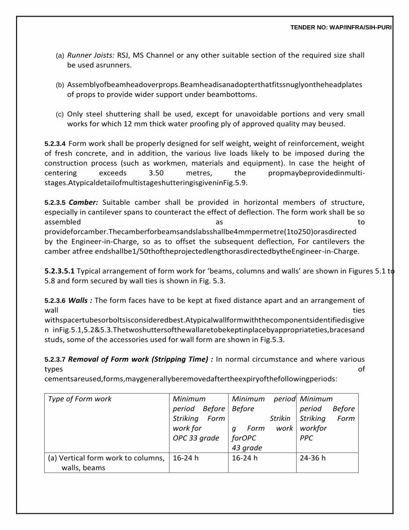
TENDER NO: WAP/INFRA/SIH-PURI
(a) Runner Joists: RSJ, MS Channel or any other suitable section of the required size shall be used asrunners.
(b) Assemblyofbeamheadoverprops.Beamheadisanadopterthatfitssnuglyontheheadplates
of props to provide wider support under beambottoms.
(c) Only steel shuttering shall be used, except for unavoidable portions and very small works for which 12 mm thick water proofing ply of approved quality may beused.
5.2.3.4 Form work shall be properly designed for self weight, weight of reinforcement, weight of fresh concrete, and in addition, the various live loads likely to be imposed during the construction process (such as workmen, materials and equipment). In case the height of centering exceeds 3.50 metres, the propmaybeprovidedinmulti-stages.AtypicaldetailofmultistageshutteringisgiveninFig.5.9.
5.2.3.5 Camber: Suitable camber shall be provided in horizontal members of structure, especially in cantilever spans to counteract the effect of deflection. The form work shall be so assembled as to provideforcamber.Thecamberforbeamsandslabsshallbe4mmpermetre(1to250)orasdirected by the Engineer-in-Charge, so as to offset the subsequent deflection, For cantilevers the camber atfree endshallbe1/50thoftheprojectedlengthorasdirectedbytheEngineer-in-Charge.
5.2.3.5.1 Typical arrangement of form work for ‘beams, columns and walls’ are shown in Figures 5.1 to 5.8 and form secured by wall ties is shown in Fig. 5.3.
5.2.3.6 Walls : The form faces have to be kept at fixed distance apart and an arrangement of wall ties withspacertubesorboltsisconsideredbest.Atypicalwallformwiththecomponentsidentifiedisgiven inFig.5.1,5.2&5.3.Thetwoshuttersofthewallaretobekeptinplacebyappropriateties,bracesand studs, some of the accessories used for wall form are shown in Fig.5.3.
5.2.3.7 Removal of Form work (Stripping Time) : In normal circumstance and where various types of cementsareused,forms,maygenerallyberemovedaftertheexpiryofthefollowingperiods:
Type of Form work Minimum period Before Striking Form work for OPC 33 grade
Minimum period Before Striking Form work forOPC 43 grade
Minimum period Before Striking Form workfor PPC
(a) Vertical form work to columns, walls, beams
16-24 h 16-24 h 24-36 h
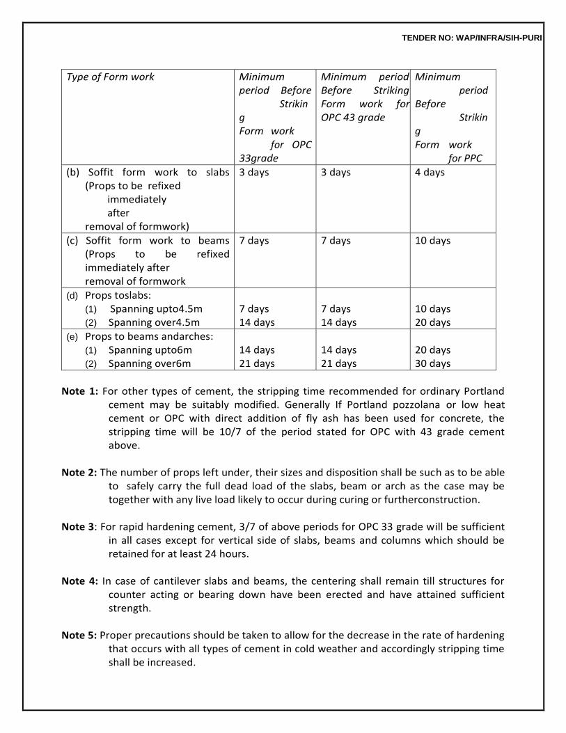
TENDER NO: WAP/INFRA/SIH-PURI
Type of Form work Minimum period Before Striking Form work for OPC 33grade
Minimum period Before Striking Form work for OPC 43 grade
Minimum period Before Striking Form work for PPC
(b) Soffit form work to slabs (Props to be refixed immediately after removal of formwork)
3 days 3 days 4 days
(c) Soffit form work to beams (Props to be refixed immediately after removal of formwork
7 days 7 days 10 days
(d) Props toslabs: (1) Spanning upto4.5m (2) Spanning over4.5m
7 days 14 days
7 days 14 days
10 days 20 days
(e) Props to beams andarches: (1) Spanning upto6m (2) Spanning over6m
14 days 21 days
14 days 21 days
20 days 30 days
Note 1: For other types of cement, the stripping time recommended for ordinary Portland
cement may be suitably modified. Generally If Portland pozzolana or low heat cement or OPC with direct addition of fly ash has been used for concrete, the stripping time will be 10/7 of the period stated for OPC with 43 grade cement above.
Note 2: The number of props left under, their sizes and disposition shall be such as to be able
to safely carry the full dead load of the slabs, beam or arch as the case may be together with any live load likely to occur during curing or furtherconstruction.
Note 3: For rapid hardening cement, 3/7 of above periods for OPC 33 grade will be sufficient
in all cases except for vertical side of slabs, beams and columns which should be retained for at least 24 hours.
Note 4: In case of cantilever slabs and beams, the centering shall remain till structures for
counter acting or bearing down have been erected and have attained sufficient strength.
Note 5: Proper precautions should be taken to allow for the decrease in the rate of hardening
that occurs with all types of cement in cold weather and accordingly stripping time shall be increased.
TENDER NO: WAP/INFRA/SIH-PURI
Note 6: Work damaged through premature or careless removal of forms shall be
reconstructed within 24 hrs.
5.2.4 SurfaceTreatment
5.2.4.1 Oiling the Surface : Shuttering gives much longer service life if the surfaces are coated with suitablemouldoilwhichactsbothasapartingagentandalsogivessurfaceprotections.
A typical mould oil is heavy mineral oil or purified cylinder oil containing not less than 5%
pentachlorophenol conforming to IS 716 well mixed to a viscosity of 70-80 centipoises.
After 3-4 uses and also in cases when shuttering has been stored for a long time, it should be recoated with mould oil before the next use.
TENDER NO: WAP/INFRA/SIH-PURI
The second categories of shuttering oils / leavening agents are Polymer based water soluble Compounds.Theyareavailableasconcentratesandwhenuseddilutedwithwaterintheratioof1:20or as per manufacturer specifications. The diluted solution is applied by brush applications on the shutteringbothofsteelaswellasplywood.Thesolutionisappliedaftereveryuse.
5.2.4.2 ThedesignofformworkshallconformtosoundEngineeringpracticesandrelevantIScodes.
5.2.5 Inspection of FormWork
The completed form work shall be inspected and approved by the Engineer-in-Charge before the reinforcement bars are placed in position.
Properformworkshouldbeadoptedforconcretingsoastoavoidhoneycombing,blowholes,gro
ut loss, stains or discoloration of concrete etc. Proper and accurate alignment and profile of finished concrete surface will be ensured by proper designing and erection of form work which will be approved byEngineer-in-Charge.
Shutteringsurfacebeforeconcretingshouldbefreefromanydefect/depositsandfullcleanedso
as to give perfectly straight smooth concrete surface. Shuttering surface should be therefore checked for any damage to its surface and excessive roughness beforeuse.
5.2.5.1 Erection of Form Work (Centering and shuttering): Following points shall be borne in mind while checking duringerection.
(a) Any member which is to remain in position after the general dismantling is done, should be clearlymarked.
(b) Material used should be checked to ensure that, wrong items/ rejects are notused.
(c) Ifthereareanyexcavationsnearbywhichmayinfluencethesafetyofformworks,correctivea
nd strengthening action must betaken.
(d) (i) The bearing soil must be sound and well prepared and the sole plates shall bear well on the ground.
(ii) Sole plates shall be properly seated on their bearing pads orsleepers. (iii) The bearing plates of steel props shall not bedistorted. (iv) The steel parts on the bearing members shall have adequate bearingareas.
(e) Safety measures to prevent impact of traffic, scour due to water etc. should be taken.
Adequate precautionary measures shall be taken to prevent accidental impactsetc.
(f) Bracing,strutsandtiesshallbeinstalledalongwiththeprogressofformworktoensurestrength andstabilityofformworkatintermediatestage.Steelsections(especiallydeepsections)shallbe adequately restrained against tilting, over turning and form work should be restrained against horizontal loads. All the securing devices and bracing shall
TENDER NO: WAP/INFRA/SIH-PURI
betightened.
(g) The stacked materials shall be placed as catered for, in thedesign.
(h) When adjustable steel props are used. Theyshould: 1. be undamaged and not visiblybent. 2. have the steel pins provided by the manufacturers foruse. 3. be restrained laterally near eachend. 4. have means for centralizing beams placed in theforkheads.
(i) Screw adjustment of adjustable props shall not be overextended.
(j) Double wedges shall be provided for adjustment of the form to the required position
wherever any settlement/ elastic shorting of props occurs. Wedges should be used only at the bottom end ofsingleprop.Wedgesshouldnotbetoosteepandoneofthepairshouldbetightened/clamped down after adjustment to preventshifting.
(k) No member shall be eccentric upon verticalmember.
(l) The number of nuts and bolts shall beadequate.
(m) All provisions of the design and/or drawings shall be compliedwith.
(n) Cantilever supports shall beadequate.
(o) Props shall be directly under one another in multistage constructionsas far as possible.
(p) Guy ropes or stays shall be tensionedproperly.
(q) There shall be adequate provision for the movements and operation of vibrators and
other construction plant andequipment.
(r) Required camber shall be provided over longspans.
(s) Supports shall be adequate, and in plumb within the specifiedtolerances.
5.2.6 Measurements
5.2.6.1 General : The form work shall include the following: (a) Splayed edges, notching, allowance for overlaps and passing at angles, sheathing
battens, strutting, bolting, nailing, wedging, easing, striking andremoval.
(b) All supports, struts, braces, wedges as well as mud sills, piles or other suitable arrangements to support the formwork.
TENDER NO: WAP/INFRA/SIH-PURI
(c) Bolts,wire,ties,clamps,spreaders,nailsoranyotheritemstoholdthesheathingtogether.
(d) Working scaffolds, ladders, gangways, and similaritems.
(e) Filleting to form stop chamfered edges of splayed external angles not exceeding 20mm
wide to beams, columns and thelike.
(f) Where required, the temporary openings provided in the forms for pouring concrete, inserting vibrators, and cleaning holes for removing rubbish from the interior of the sheathing before pouringconcrete.
(g) Dressing with oil to prevent adhesionand
(h) Raking or circularcutting
5.2.6.2 Classification of Measurements : Where it is stipulated that the form work shall be paid for separately, measurements shall be taken of the area of shuttering in contact with the concrete surface. Dimensions of the form work shall be measured correct to a cm. The measurements shall be taken separately for thefollowing.
(a) Foundations, footings, bases of columns etc. and for massconcrete (b) Walls(anythickness)includingattachedpilasters,buttresses,plinthandstringcoursesetc. (c) Suspended floors, roofs, landings, shelves and their supports andbalconies. (d) Lintels, beams, plinth beams, girders, bressummers andcantilevers. (e) Columns, pillars, piers, abutments posts andstruts. (f) Stairs (excluding landings) except spiralstaircase. (g) Spiral staircases (includinglandings). (h) Arches,Domes, vaults, shells roofs, arch ribs, curvilinear shaped foldedplates (i) Extra for arches, domes, vaults exceeding 6 m span other than curvilinearshaped (j) Chimneys andshafts. (k) Wellsteining. (l) Verticalandhorizontalfinsindividuallyorformingbox,louversandbands.faciasandeavesboard (m) Waffle or ribbedslabs. (n) Edges of slabs and breaks in floors and walls (to be measured in running metres where
below 200 mm in width orthickness). (o) Cornices andmouldings. (p) Small surfaces, such as cantilevers ends, brackets and ends of steps, caps and boxes to
pilasters and columns and thelike. (q) Chullah hoods, weather shades, chajjas, corbels etc. including edgesand (r) Elevated waterreservoirs.
5.2.6.3 Centering, and shuttering where exceeding 3.5 metre height in one floor shall be measured and paid forseparately.
5.2.6.4 Where it is not specifically stated in the description of the item that form work shall
TENDER NO: WAP/INFRA/SIH-PURI
be paid for separately,therateoftheRCCitemshallbedeemedtoincludethecostofformwork.
5.2.6.5 No deductions from the shuttering due to the openings/ obstructions shall be made if the areaof each openings/ obstructions does not exceed 0.4 square metre. Nothing extra shall be paid for forming suchopenings.
5.2.6.6 Formworkofelementsmeasuredundercategoriesofarches,archribs,domes,spiralstaircases, well steining, shell roofs, curvilinear folded plates & curvilinear eaves board, circular shafts & chimneys shall not qualify for extra rate for circularwork.
5.2.6.7 Extra for circular work shall be admissible for surfaces circular or curvilinear in plan or in elevation beyond the straight edge of supporting beam in respective mode of measurement. However, there may be many different types of such structures. In such cases, extra payment shall be made judiciouslyafterdeductingareaswhereshutteringforcircularformworkisnotinvolved.
5.2.7 Rate
The rate of the form work includes the cost of labour and materials required for all the operations described above.
5.3 REINFORCEMENTS 5.3.1 GeneralRequirements
Steel conforming to para 5.1.3 for reinforcement shall be clear and free from loose mill scales, dust, loose rust, coats of paints, oil or other coating which may destroy or reduce bond. It shall be stored in such a way as to avoid distortion and to prevent deterioration and corrosion. Prior to assembly of reinforcement on no account any oily substance shall be used for removing the rust.
5.3.1.1 AssemblyofReinforcement:Barsshallbebentcorrectlyandaccuratelytothesizeandshape as shown in the detailed drawing or as directed by Engineer-in-Charge. Preferably bars of full length shall be used. Necessary cutting and straightening is also included. Overlapping of bars,where necessary shall be done as directed by the Engineer-in-Charge. The overlapping bars shall not touch each other and these shall be kept apart with concrete between them by 25mm or 11/4 times the maximum size of the coarse aggregate whichever is greater. But where this is not possible, the overlapping bars shall be bound together at intervals not exceeding twice the dia. of such bars with two strandsannealedsteelwireof0.90mmto1.6mmtwistedtight.Theoverlaps/splicesshallbestaggered as per directions of the Engineer-in-Charge. But in no case the overlapping shall be provided in more than 50% of cross sectional area at onesection.
5.3.1.2 Bonds and Hooks Forming End Anchorages: Reinforcement shall be bent and fixed in accordance with procedure specified in IS 2502, code of practice of bending and fixing of bars for concretereinforcement.Thedetailsofbendsandhooksareshownbelowforguidance.
(a) U-Type Hook In case of mild steel plain bars standard U type hook shall be provided by bending ends
TENDER NO: WAP/INFRA/SIH-PURI
of rod into semicircular hooks having clear diameter equal to four times the diameter of the bar. Note: In case of work in seismic zone, the size of hooks at the end of the rod shall be
eight times the diameter of bar or as given in the structural drawings.
(b) Bends Bend forming anchorage to a M.S. plain bar shall be bent with and internal radius equal to two times the diameter of the bar with a minimum length beyond the bend equal to four times the diameter of the bar.
5.3.1.3 Anchoring Bars in Tension: Deformed bars may be used without end anchorages provided, development length equipment is satisfied. Hooks should normally be provided for plain bars intension. Development length of bars will be determined as per IS:456.
5.3.1.4 Anchoring Bars in Compression: The anchorage length of straight bar in compression shall be equal to the ‘Development length’ of bars in compression as specified in IS: 456. The projected length of hooks, bend and straight lengths beyond bend, if provided for a bar in compression, shall be considered for developmentlength.
5.3.1.5 Binders, stirrups, links etc. : In case of binders, stirrups, links etc. the straight portion beyond thecurveattheendshallbenotlessthaneighttimesandnominalsizeofbar.
5.3.2 Welding ofBars
Whereverfacilityforelectricarcweldingorgaspressureweldingisavailable,weldingofbarsshall be done in lieu of overlap. The location and type of welding shall be got approved by the Engineer-in- Charge. Welding shall be as per IS 2751 and9417.
5.3.3 Placing inPosition 5.3.3.1 Fabricatedreinforcementbarsshallbeplacedinpositionasshowninthedrawingsorasdirected by the Engineer-in-charge. The bars crossing one another shall be tied together at every intersection withtwostrandsofannealedsteelwire0.9to1.6mmthicknesstwistedtighttomaketheskeletonofthe steelworkrigidsothatthereinforcementdoesnotgetdisplacedduringdepositionofconcrete.
Tack welding in crossing bars shall also be permitted in lieu of binding with steel wire if
approved by Engineer-in-Charge.
5.3.3.2 The bars shall be kept in correct position by the followingmethods: (a) In case of beam and slab construction pre-cast cover blocks in cement mortar 1:2 (1
cement : 2 coarse sand) about 4x4 cm section and of thickness equal to the specified cover shall beplaced between the bars and shuttering, so as to secure and maintain the requisite cover of concrete overreinforcements.
(b) In case of cantilevered and doubly reinforced beams of slabs, the vertical distance between the horizontal bars shall be maintained by introducing chairs, spacers or support bars of steel at 1.0 mere or at shorter spacing to avoidsagging.
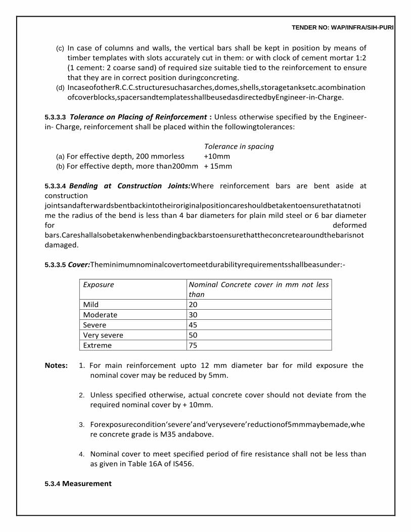
TENDER NO: WAP/INFRA/SIH-PURI
(c) In case of columns and walls, the vertical bars shall be kept in position by means of timber templates with slots accurately cut in them: or with clock of cement mortar 1:2 (1 cement: 2 coarse sand) of required size suitable tied to the reinforcement to ensure that they are in correct position duringconcreting.
(d) IncaseofotherR.C.C.structuresuchasarches,domes,shells,storagetanksetc.acombination ofcoverblocks,spacersandtemplatesshallbeusedasdirectedbyEngineer-in-Charge.
5.3.3.3 Tolerance on Placing of Reinforcement : Unless otherwise specified by the Engineer-in- Charge, reinforcement shall be placed within the followingtolerances:
Tolerance in spacing
(a) For effective depth, 200 mmorless +10mm (b) For effective depth, more than200mm + 15mm
5.3.3.4 Bending at Construction Joints:Where reinforcement bars are bent aside at construction jointsandafterwardsbentbackintotheiroriginalpositioncareshouldbetakentoensurethatatnotime the radius of the bend is less than 4 bar diameters for plain mild steel or 6 bar diameter for deformed bars.Careshallalsobetakenwhenbendingbackbarstoensurethattheconcretearoundthebarisnot damaged.
5.3.3.5 Cover:Theminimumnominalcovertomeetdurabilityrequirementsshallbeasunder:-
Exposure Nominal Concrete cover in mm not less than
Mild 20
Moderate 30
Severe 45
Very severe 50
Extreme 75
Notes: 1. For main reinforcement upto 12 mm diameter bar for mild exposure the
nominal cover may be reduced by 5mm.
2. Unless specified otherwise, actual concrete cover should not deviate from the required nominal cover by + 10mm.
3. Forexposurecondition‘severe’and‘verysevere’reductionof5mmmaybemade,whe
re concrete grade is M35 andabove.
4. Nominal cover to meet specified period of fire resistance shall not be less than as given in Table 16A of IS456.
5.3.4 Measurement
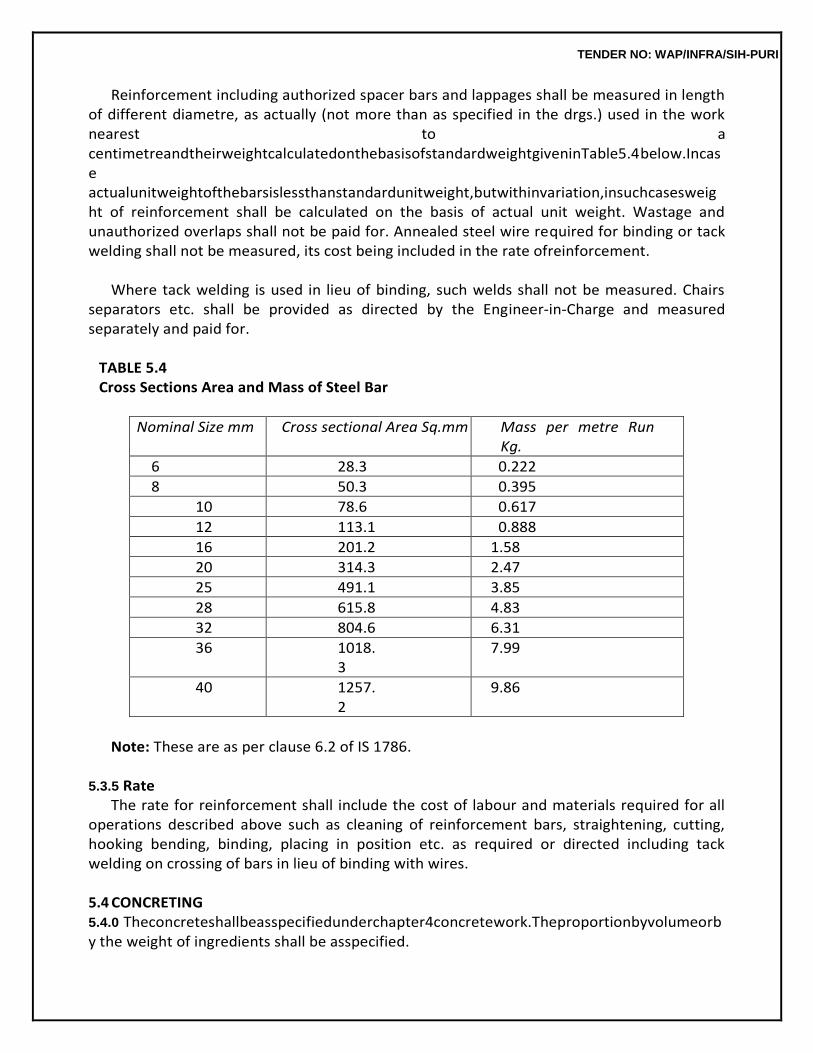
TENDER NO: WAP/INFRA/SIH-PURI
Reinforcement including authorized spacer bars and lappages shall be measured in length of different diametre, as actually (not more than as specified in the drgs.) used in the work nearest to a centimetreandtheirweightcalculatedonthebasisofstandardweightgiveninTable5.4below.Incase actualunitweightofthebarsislessthanstandardunitweight,butwithinvariation,insuchcasesweight of reinforcement shall be calculated on the basis of actual unit weight. Wastage and unauthorized overlaps shall not be paid for. Annealed steel wire required for binding or tack welding shall not be measured, its cost being included in the rate ofreinforcement.
Where tack welding is used in lieu of binding, such welds shall not be measured. Chairs
separators etc. shall be provided as directed by the Engineer-in-Charge and measured separately and paid for.
TABLE 5.4 Cross Sections Area and Mass of Steel Bar
Nominal Size mm Cross sectional Area Sq.mm Mass per metre Run Kg.
6 28.3 0.222
8 50.3 0.395
10 78.6 0.617
12 113.1 0.888
16 201.2 1.58
20 314.3 2.47
25 491.1 3.85
28 615.8 4.83
32 804.6 6.31
36 1018.3
7.99
40 1257.2
9.86
Note: These are as per clause 6.2 of IS 1786.
5.3.5 Rate
The rate for reinforcement shall include the cost of labour and materials required for all operations described above such as cleaning of reinforcement bars, straightening, cutting, hooking bending, binding, placing in position etc. as required or directed including tack welding on crossing of bars in lieu of binding with wires.
5.4 CONCRETING 5.4.0 Theconcreteshallbeasspecifiedunderchapter4concretework.Theproportionbyvolumeorby the weight of ingredients shall be asspecified.
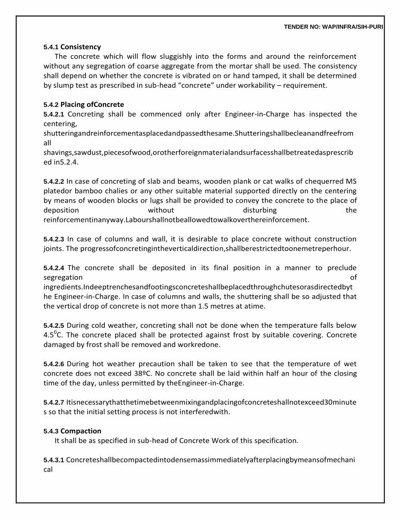
TENDER NO: WAP/INFRA/SIH-PURI
5.4.1 Consistency The concrete which will flow sluggishly into the forms and around the reinforcement
without any segregation of coarse aggregate from the mortar shall be used. The consistency shall depend on whether the concrete is vibrated on or hand tamped, it shall be determined by slump test as prescribed in sub-head “concrete” under workability – requirement.
5.4.2 Placing ofConcrete 5.4.2.1 Concreting shall be commenced only after Engineer-in-Charge has inspected the centering, shutteringandreinforcementasplacedandpassedthesame.Shutteringshallbecleanandfreefromall shavings,sawdust,piecesofwood,orotherforeignmaterialandsurfacesshallbetreatedasprescribed in5.2.4.
5.4.2.2 In case of concreting of slab and beams, wooden plank or cat walks of chequerred MS platedor bamboo chalies or any other suitable material supported directly on the centering by means of wooden blocks or lugs shall be provided to convey the concrete to the place of deposition without disturbing the reinforcementinanyway.Labourshallnotbeallowedtowalkoverthereinforcement.
5.4.2.3 In case of columns and wall, it is desirable to place concrete without construction joints. The progressofconcretingintheverticaldirection,shallberestrictedtoonemetreperhour.
5.4.2.4 The concrete shall be deposited in its final position in a manner to preclude segregation of ingredients.Indeeptrenchesandfootingsconcreteshallbeplacedthroughchutesorasdirectedbythe Engineer-in-Charge. In case of columns and walls, the shuttering shall be so adjusted that the vertical drop of concrete is not more than 1.5 metres at atime.
5.4.2.5 During cold weather, concreting shall not be done when the temperature falls below 4.50C. The concrete placed shall be protected against frost by suitable covering. Concrete damaged by frost shall be removed and workredone.
5.4.2.6 During hot weather precaution shall be taken to see that the temperature of wet concrete does not exceed 38ºC. No concrete shall be laid within half an hour of the closing time of the day, unless permitted by theEngineer-in-Charge.
5.4.2.7 Itisnecessarythatthetimebetweenmixingandplacingofconcreteshallnotexceed30minutes so that the initial setting process is not interferedwith.
5.4.3 Compaction
It shall be as specified in sub-head of Concrete Work of this specification.
5.4.3.1 Concreteshallbecompactedintodensemassimmediatelyafterplacingbymeansofmechanical
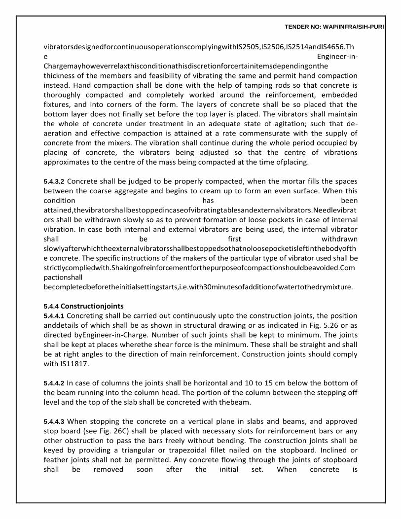
TENDER NO: WAP/INFRA/SIH-PURI
vibratorsdesignedforcontinuousoperationscomplyingwithIS2505,IS2506,IS2514andIS4656.The Engineer-in-Chargemayhoweverrelaxthisconditionathisdiscretionforcertainitemsdependingonthe thickness of the members and feasibility of vibrating the same and permit hand compaction instead. Hand compaction shall be done with the help of tamping rods so that concrete is thoroughly compacted and completely worked around the reinforcement, embedded fixtures, and into corners of the form. The layers of concrete shall be so placed that the bottom layer does not finally set before the top layer is placed. The vibrators shall maintain the whole of concrete under treatment in an adequate state of agitation; such that de-aeration and effective compaction is attained at a rate commensurate with the supply of concrete from the mixers. The vibration shall continue during the whole period occupied by placing of concrete, the vibrators being adjusted so that the centre of vibrations approximates to the centre of the mass being compacted at the time ofplacing.
5.4.3.2 Concrete shall be judged to be properly compacted, when the mortar fills the spaces between the coarse aggregate and begins to cream up to form an even surface. When this condition has been attained,thevibratorshallbestoppedincaseofvibratingtablesandexternalvibrators.Needlevibrators shall be withdrawn slowly so as to prevent formation of loose pockets in case of internal vibration. In case both internal and external vibrators are being used, the internal vibrator shall be first withdrawn slowlyafterwhichtheexternalvibratorsshallbestoppedsothatnoloosepocketisleftinthebodyofthe concrete. The specific instructions of the makers of the particular type of vibrator used shall be strictlycompliedwith.Shakingofreinforcementforthepurposeofcompactionshouldbeavoided.Compactionshall becompletedbeforetheinitialsettingstarts,i.e.with30minutesofadditionofwatertothedrymixture.
5.4.4 Constructionjoints 5.4.4.1 Concreting shall be carried out continuously upto the construction joints, the position anddetails of which shall be as shown in structural drawing or as indicated in Fig. 5.26 or as directed byEngineer-in-Charge. Number of such joints shall be kept to minimum. The joints shall be kept at places wherethe shear force is the minimum. These shall be straight and shall be at right angles to the direction of main reinforcement. Construction joints should comply with IS11817.
5.4.4.2 In case of columns the joints shall be horizontal and 10 to 15 cm below the bottom of the beam running into the column head. The portion of the column between the stepping off level and the top of the slab shall be concreted with thebeam.
5.4.4.3 When stopping the concrete on a vertical plane in slabs and beams, and approved stop board (see Fig. 26C) shall be placed with necessary slots for reinforcement bars or any other obstruction to pass the bars freely without bending. The construction joints shall be keyed by providing a triangular or trapezoidal fillet nailed on the stopboard. Inclined or feather joints shall not be permitted. Any concrete flowing through the joints of stopboard shall be removed soon after the initial set. When concrete is
TENDER NO: WAP/INFRA/SIH-PURI
stoppedonahorizontalplane,thesurfaceshallberoughenedandcleanedaftertheinitialset.
5.4.4.4 When the work has to be resumed, the joint shall be thoroughly cleaned with wire brush and loose particles removed. A coat of neat cement slurry at the rate of 2.75 kg of cement per square metre shall then be applied on the roughened surface before fresh concrete islaid.
5.4.5 ExpansionJoints Expansion joints shall be provided as shown in the structural drawings or as indicated in Fig. 5.10 to 5.25 or as directed by Engineer-in-Charge, for the purpose of general guidance. However it is recommended that structures exceeding 45 m in length shall be divided by one or more expansion joints. The filling of these joints with bitumen filler, bitumen felt or any such material and provision of copper plate, etc. shall be paid for separately in running metre. The measurement shall be taken two places of decimal stating the depth and width of joint.
5.4.6 Curing
After the concrete has begun to harden i.e. about 1 to 2 hours after its laying, it shall be protected from quick drying by covering with moist gunny bags, sand, canvass Hessian or any other material approved by the Engineer-in-Charge. After 24 hours of laying of concrete, the surface shall be cured by ponding with water for a minimum period of 7 days from the date of placing of concrete in case of OPC and at least 10 days where mineral admixtures or blended cements are used. The period of curingshall not be less than 10 days for concrete exposed to dry and hot weathercondition.
5.4.7 Finishing 5.4.7.1 In case of roof slabs the top surface shall be finished even and smooth with wooden trowel, beforetheconcretebeginstoset.Sprinklingofdrycementwhilefinishingshallnotberesortedto.
5.4.7.2 Immediatelyonremovalofforms,theR.C.C.workshallbeexaminedbytheEngineer-in-Charge, before any defects are madegood.
(a) Theworkthathassaggedorcontainshoneycombingtoanextentdetrimentaltostructuralsafety orarchitecturalconceptshallberejectedasgiveninpara5.4.9.4forvisualinspectiontest.
(b) Surface defects of minor nature may be accepted. On acceptance of such a work by
the Engineer-in-Charge, the same shall be rectified asfollows: 1. Surface defects which require repair when forms are removed, usually consist of
bulged due tomovementofforms,ridgesatformjoints,honey-combedareas,damageresultingfromthe stripping of forms and bolt holes, bulges and ridges are removed by careful chipping or tooling and the surface is then rubbed with a grinding stone. Honey-combed and other defective areas must be chipped out, the edges being cut as straight as possible and perpendicularly to the surface, or preferably slightly under cut to provide a key at the edgeof thepatch.
TENDER NO: WAP/INFRA/SIH-PURI
2. Shallow patches are first treated with a coat of thin grout composed of one part of cement and one part of fine sand and then filled with mortar similar to that used in the concrete. The mortar is placed in layers not more than 10mm thick and each layer is given a scratch finish to secure bond with the succeeding layer. The last layer is finished to match the surrounding concrete by floating, rubbing or tooling on formed surfaces by pressing the form material against the patch while the mortar is stillplastic.
3. Largeanddeeppatchesrequirefillingupwithconcreteheldinplacebyforms.Suchpatches are reinforced and carefully dowelled to the hardenedconcrete.
4. Holes left by bolts are filled with mortar carefully packed into places in small
amounts. The mortar is mixed as dry as possible, with just enough water so that it will be tightlycompacted when forced intoplace.
5. Tiered holes extending right through the concrete may be filled with mortar with a
pressure gun similar to the gun used for greasing motorcars.
6. Normally, patches appear darker than the surrounding concrete, possibly owing to the presenceontheirsurfaceoflesscementlaitance.Whereuniformsurfacecolourisimportant, this defect shall be remedied by adding 10 to 20 percent of white Portland cement to the patching mortar, the exact quantity being determined bytrial.
7. The same amount of care to cure the materials in the patches should be taken as
with the whole structure. Curing must be started as soon as possible, after the patch is finished to prevent early drying. Damp Hessian may be used but in some locations it may be difficult to holditinplace.Amembranecuringcompoundinthesecaseswillbemostconvenient.
(c) TheexposedsurfaceofR.C.C.workshallbeplasteredwithcementmortar1:3(1cement:3fine
sand) of thickness not exceeding 6 mm to give smooth and even surface true to line and form. Any RCC surface which remains permanently exposed to view in the completed structure, shall be considered exposed surfaced for the purpose of thisspecification.
Where such exposed surface exceeding 0.5 sqm in each location is not plastered with cement mortar1:3(1cement:3finesand)6mmthick,necessarydeductionshallbemadeforplastering notdone.
(d) The surface which is to receive plaster or where it is to be joined with brick masonry
wall, shall be properly roughened immediately after the shuttering is removed, taking care to remove the laitance completely without disturbing the concrete. The roughening shall be done by hacking. Before the surface is plastered, it shall be cleaned and wetted so as to give bond between concrete andplaster.
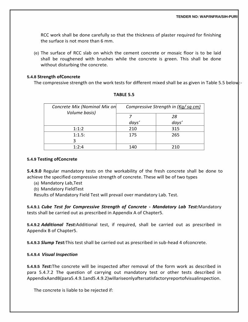
TENDER NO: WAP/INFRA/SIH-PURI
RCC work shall be done carefully so that the thickness of plaster required for finishing the surface is not more than 6 mm.
(e) The surface of RCC slab on which the cement concrete or mosaic floor is to be laid
shall be roughened with brushes while the concrete is green. This shall be done without disturbing the concrete.
5.4.8 Strength ofConcrete
The compressive strength on the work tests for different mixed shall be as given in Table 5.5 below:-
TABLE 5.5
Concrete Mix (Nominal Mix on Volume basis)
Compressive Strength in (Kg/ sq cm)
7 days’
28 days’
1:1:2 210 315
1:1.5:3
175 265
1:2:4 140 210
5.4.9 Testing ofConcrete
5.4.9.0 Regular mandatory tests on the workability of the fresh concrete shall be done to achieve the specified compressive strength of concrete. These will be of two types
(a) Mandatory Lab,Test (b) Mandatory FieldTest Results of Mandatory Field Test will prevail over mandatory Lab. Test.
5.4.9.1 Cube Test for Compressive Strength of Concrete - Mandatory Lab Test:Mandatory tests shall be carried out as prescribed in Appendix A of Chapter5.
5.4.9.2 Additional Test:Additional test, if required, shall be carried out as prescribed in Appendix B of Chapter5.
5.4.9.3 Slump Test:This test shall be carried out as prescribed in sub-head 4 ofconcrete.
5.4.9.4 Visual Inspection 5.4.9.5 Test:The concrete will be inspected after removal of the form work as described in para 5.4.7.2 The question of carrying out mandatory test or other tests described in AppendixAandB(para5.4.9.1and5.4.9.2)willariseonlyaftersatisfactoryreportofvisualinspection.
The concrete is liable to be rejected if:
TENDER NO: WAP/INFRA/SIH-PURI
(i) It is porous or honeycombed as per para 5.4.7.2(a). (ii) Its placing has been interrupted without providing a proper constructionjoint. (iii) The reinforcement has been displaced beyond tolerance specified or construction
tolerances have not beenmet.
However, the hardened concrete may be accepted after carrying out suitable remedial measures to the satisfaction of the Engineer-in-Charge at the risk and cost of the contractor.
5.4.10 Standard of Acceptance – for NominalMix
5.4.10.1 Mandatory Lab. Test:For concrete sampled and tested as prescribed in Appendix A of Chapter 5, the following requirement shallapply.
5.4.10.2 Outofsixsamplecubes,threecubesshallbetestedat7daysandremainingthreecubesat28 days.
5.4.10.3 7 days’Tests
Sampling: The average of the strength of three specimen shall be accepted as the compressive strengthoftheconcreteprovidedthevariationinstrengthofindividualspecimenisnotmorethan+15% of the average. Difference between the maximum and minimum strength should not exceed 30% of averagestrengthofthreespecimen.Ifthedifferencebetweenmaximumandminimumstrengthexceeds 30% of the average strength, then 28 days’ test shall have to be carriedout.
Strength: If the actual average strength of sample accepted in para ‘sampling’ above is
equal to or higher than specified strength upto +15% then strength of the concrete shall be considered in order.
Incasetheactualaveragestrengthofsampleacceptedintheaboveparaislowerthanthespecifie
d orhigherbymorethan15%then28days’testshallhavetobecarriedouttodeterminethecompressive strength of concretecubes.
5.4.10.4 28 days’Test
(a) The average of the strength of three specimen be accepted as the compressive strength of the concrete provided the strength of any individual cube shall neither be less than 70% nor higher than 130% of the specifiedstrength.
(b) If the actual average strength of accepted sample exceeds specified strength by more
than30% the Engineer-in-Charge, if he so desires, may further investigate the matter. However, if the strength of any individual cube exceeds more than 30% of specified strength, it will be restricted to 130% only for computation ofstrength.
(c) If the actual average strength of accepted sample is equal to or higher than specified

TENDER NO: WAP/INFRA/SIH-PURI
strength upto 30% then strength of the concrete shall be considered in order and the concrete shall be accepted at fullrates.
(d) Iftheactualaveragestrengthofacceptedsampleislessthanspecifiedstrengthbutnotlesstha
n 70% of the specified strength, the concrete may be accepted at reduced rate at the discretion of Engineer-in-Charge (see para5.4.13.2).
(e) If the actual average strength of accepted sample is less than 70% of specified
strength, the Engineer-in-Chargeshallrejectthedefectiveportionofworkrepresentedbysampleandnothing shallbepaidfortherejectedwork.Remedialmeasuresnecessarytoretainthestructureshallbe taken at the risk and cost of contractor. If, however the Engineer-in-Charge so desires, he may orderadditionaltests(SeeAppendixBofChapter5)tobecarriedouttoascertainifthestructure can be retained. All the charges in connection with these additional tests shall be borne by the contractor.
5.4.10.5 Acceptance Criteria of Field Test (Additional Test – NotMandatory)
(A) Preparation of Standard Test Cubes for calibration of Rebound Hammer atsite (a) In the beginning the standard test cubes of the specified mix shall be prepared by
field units before undertaking any concrete work in eachproject.
(b) Atleast18standardcubesnecessaryforformationofonespecimenofspecifiedmix,shallbe cast by site staff well in advance. From these 18 cubes any 3 cubes may be selected at random to be tested for crushing strength of 7 days. The crushing strength obtained should satisfy the specified strength for the mix as per specification or agreement. If the strength is satisfactorythentheremainingcubewillformthestandardsamplesforcalibrationofrebound hammer. In case of failure, the site staff should totally reject the samples and remove them also and then make another set of samples by fresh mixing or alternatively, out of the remaining 15 cubes, 3 cubes will be tested on 28 days. If the 28 days’ tests are found satisfactorythenremaining12cubeswillformthestandardsampleforcalibrationat28days’ strength otherwise all samples shall be rejected and whole procedure repeated to form a fresh specimen. All the results shall be recorded in aregister.
(c) No concreting will be allowed unless the standard specimen cubes areobtained.
The criteria for acceptance and calibration of hammer will be 28 days’ strength. The 7 days’ strength is only to facilitate the work to start.
No work (for the concrete cast between 8th and 28th day) shall be allowed to be paid unless 28 days’ cube strength is obtained. For the concrete cast between 8th and 28th day, the decision to make the payment may be taken by the Engineer-in-charge on the basis of existing
TENDER NO: WAP/INFRA/SIH-PURI
criteria. Concrete work will be rejected if 28 days’ strength falls short as per acceptance criteria. No further work will be allowed till the acceptable standard cubes are obtained.
(d) Frequency: it will be once in each quarter or as per the direction and discretion of
Engineer- in-Charge.Whenevertheacceptancecriteriaischangedorconcretemixortypeofcementis changed or Engineer-in-Charge feels it necessary for recorded reasons with the approval of theauthorityaccordingtotechnicalsanction,freshspecimenshallbeprepared.
(B) Calibration ofHammer
(a) Simultaneously, same three cubes to be tested on 28 days as referred in para A (b) above shallbeusedtocorrelatethecompressivestrengthoftheirconcretewithreboundnumberas per procedure described in para 5.2 of the IS 13311 (Part 2) “Indian standard for non- destructive testing of concrete Method of test by rebound hammer which is given below in para B (b). The average of values of the rebound number (minimum readings) obtained in respectofsamethreecubespassingon28days’worktestshallformthedatumreferencefor remaining cubes for the strength ofcubes.
(b) Theconcretecubesspecimensareheldinacompressiontestingmachineunderafixedloa
d, measurements of rebound hammer taken and then compressive strength determined as per IS 516. The fixed load required is of the order of 7 N/mm2 when the impact energy of the hammer is about 2.2NM.
If the specimen are wet cured, they should be removed from wet storage & kept in the laboratory atmosphere for about 24 hours before testing.
Only the vertical faces of the cubes as cast should be tested for rebound number. At least nine readings should be taken on each of the three vertical faces accessible in the compression testing machine when using rebound hammers. The points of impact in the specimen must not be nearer than 20 mm from the edge & should not be less than 20 mm from each other. The same points must not be impacted more than once.
(c) The rebound number of hammer will be determined on each of the remaining (18-
3-3=12) cubes.Wheneverthereboundnumberofhammerofanyindividualcubevariesbymorethan +25%formthedatumreadingsreferredtoinparaB(a)above,thatcubewillbeexcludedand willnotbeconsideredforstandardspecimencubesforcalibration.Itmustbeensuredthatat least8cubesoutof12thatis66.67%arewithinthepermissiblerangeofvariationofreboun
TENDER NO: WAP/INFRA/SIH-PURI
d number i.e. +25% or otherwise whole procedure shall have to be repeated andfresh specimenprepared.
These 8 cubes will form one standard sample in the beginning before commencement of work and shall be kept carefully for the visiting officers who will calibrate their hammers on these cubes.
(d) This calibration will be done by field staff with their hammer and then chart of
calibration giving the details of the average readings, date & month of casting, mix of the concrete etc. shall be prepared and signed by Engineer-in-Charge and will be duly preserved for future reference as and whenrequired.
(C) Preservation of Cubes atsite
StandardsamplecubescastshallbecarefullypreservedatsiteunderthesafecustodyofAE or his representative for making them available together with the charts, to the officers of QCTA/CTEoranyotherseniordepartmentalofficer,duringtheirinspectionofthework.Theywill calibrate their hammer on these cubes ifrequired.
(D) Testing atSite
(D-1) TestingEquipments
(D-2) Testing will be done generally by non-destructive methods like rebound hammers etc. Each field Division/ Sub Division/ Unit will purchase rebound hammers and keep them in working order at work site. The testing will be done only by hammers which are duly calibrated.
(D-3) The relative strength of actual field work will be tested with reference to
strength of these standard cubes and calibration charts of a hammer for determining the rebound number on the field work. The hammer will be used as per manufacturer’s guidelines at various locations chosen at random. The number of location/reading on each wall, beam or columnetc.shallnotbelessthan12.Allthereadingsshouldbewithinthe+25%rangeof valuesprescribedincalibrationchartnormally.However,readingindicatinggoodstrength will be when it is at per with calibrated value or between 100% & 125% and very good if morethan125%anyvaluebetween100%&75%ofcalibratedvalueshallbeconsidered satisfactory. Values from 75% to 50% shall be considered for payment at rates reduced on prorate basis. The concrete indicating rebound number less than 50% of calibrated value shall be rejected and not paidfor.
(E) Acceptance of Field Tests andStrength
If the relative strength of actual field work is found satisfactory considering the calibration charts with reference to the standard cube test kept at site, the representative work will be considered satisfactory. If the work is considered below
TENDER NO: WAP/INFRA/SIH-PURI
satisfactory, the same will be dealt as stated inpara D-3above.
(F) 7 days’ Strength in Rare Casesonly Normallycubecrushingstrengthon28days’testshallformthebasisofacceptance.Howeverin rare cases of time bound projects/ urgent repairs 7 days’ cube test strength criteria may be adoptedonsimilarlinesusing7days’standardtestcubesandcalibrationgraphs/curves/charts for 7 days’ in lieu of 28 days’ and testing work done at 7days’.
(G) Precautions
(G-1) The testing shall be done generally as per guidelines of manufacture of the apparatus and strictly in accordance with the procedure laid down in clause 6 of IS 13311 (Part 2): Indian Standard for Non-Destructive Testing of Concrete - Method of Test by Rebound Hammer.
(G-2) The rebound hammers are influenced by number of factor like type of cement
aggregate, surface conditions, moisture content, age of concrete & extent of calibration of concrete etc. hence care shall be taken to compare the cement, aggregate etc. and tested under the similar surface conditions having more or less same moisture content and age. However effect of age can be ignored for concrete between 3 days & 3 months old.
5.4.11 Measurements 5.4.11.1 Dimensions shall be measured nearest to a cm except for the thickness of slab which shall be measuredcorrectto0.5cm.Theareasshallbeworkedoutnearestto0.01Sq.mt.Thecubicalcontents shall be worked out to nearest 0.01 cubicmetre.
5.4.11.2 Reinforced cement concrete whether cast-in-situ or pre cast shall be classified and measured separately asfollows.
TENDER NO: WAP/INFRA/SIH-PURI
(a) Raft, footing, bases of columns and mass concrete etc. all work up to plinth level, column up to plinth level, plinthbeams.
(b) Wall (any thickness) including attached pilasters, buttresses plinth and string course, fillets, column, pillars, piers, abutments, post and strutsetc.
(c) Suspended floors, roofs, landings andbalconies. (d) Shelves (e) Chajjas (f) Lintel, beams andbressummers. (g) Columns, pillars, piers, abutments, posts andstruts. (h) Stair-cases including waist or waist less slab but excluding landing except in (i)below. (i) Spiral stair-case (includinglanding). (j) Arches, arch ribs, domes andvaults. (k) Chimneys andshafts. (l) Wellsteining. (m) Vertical and horizontal fins individually or forming box, louvers andfacias. (n) Kerbs, steps and thelike. (o) String courses, bands, coping, bed plates, anchor blocks, plain window sills and thelike. (p) Mouldings as in cornices, window sillsetc. (q) Shell, dome and foldedplates. (r) Extra for shuttering in circular work inplan.
5.4.11.3 Work under the following categories shall be measuredseparately.
(a) Rafts, footings, bases of columns etc. and massconcrete. (b) All other items upto floor twolevel. (c) From floor two level to floor three level and soon. (d) R.C.C. above roof level shall be measured along with R.C.C. Work in floor justbelow.
5.4.11.4 No deduction shall be made for thefollowing:
(a) Ends of dis-similar materials (e.g. Joists, beams, post, griders, rafter, purlins, trusses, corbels steps etc.) upto 500 sq cm incross-section.
(b) Opening upto 0.1.sqm.
Note:Incalculatingareaofopeningsupto0.1sqmthesizeofopeningshallincludethethickness of any separate lintels or sills. No extra labour for forming such openings or voids shall be paidfor.
(c) The volume occupied byreinforcement.
(d) The volume occupied by water pipes, conduits etc. not exceeding 25 sq cm each in
cross sectionalarea.Nothingextrashallbepaidforleavingandfinishingsuchcavitiesandholes.
5.4.11.5 Measurementshallbetakenbeforeanyrenderingisdoneinconcretemembers.Measurement willnotincluderendering.ThemeasurementofR.C.C.workbetweenvariousunitsshallberegulated
TENDER NO: WAP/INFRA/SIH-PURI
as below:
(a) Slabs shall be taken as running continuously through except when slab is monolithic with the beam. In that case it will be from the face to face of thebeam.
(b) Beams shall be measured from face to face of columns and shall be including
haunches, if any, between columns and beam. The depth of the beam shall be from the bottom of slab to the bottom of beam if beam and slab are not monolithic. In case of monolithic construction where slabs are integrally connected with beam, the depth of beam shall be from the top of the slab to the bottom ofbeam.
(c) The columns measurements shall be takenthrough.
(d) Chajjas along with its bearing on wall shall be measured in cubic metre nearest to two
places of decimal. When chajjas is combined with lintel, slab or beam, the projecting portion shall be measured as chajjas, built in bearing shall be measured as per item of lintel, slab or beam in which chajjabears.
(e) Wherethebandandlintelsareofthesameheightandthebandservesaslinteltheportionofth
e band to be measured as lintel shall be for clear length of opening plus twice the over all depthof band.
5.4.12 Tolerances
Subject to the condition that structural safety is not impaired and architectural concept does not hamper, the tolerances in dimensions of R.C.C. members shall be as specified in the drawings by the designer.Wheneverthesearenotspecified,thepermissibletoleranceshallbedecidedbytheEngineer- in-Charge after consultations with the Designer, ifnecessary.
When tolerances in dimensions are permitted, following procedure for measurement shall apply.
(a) If the actual dimension of R.C.C. members do not exceed or decrease the design
dimensions of themembersplusorminustolerancelimitspecifiedabove,thedesigndimensionsshallbetaken for the purpose ofmeasurement.
(b) If the actual dimensions exceed the design dimensions by more than the tolerance
limit, the design dimensions only shall be measured for the purpose ofpayment.
(c) If the actual dimensions decrease more than the tolerance limit specified, the actual dimensions oftheRCCmembersshallbetakenforthepurposeofmeasurementandpayment.
(d) For acceptance of RCC members whose dimensions are not exactly as per design
dimensions, the decision of Engineer-in-Charge shall be final. For the purpose of
TENDER NO: WAP/INFRA/SIH-PURI
payment, however, the clarification as given in para a, b & c above shallapply.
5.4.13 Rate
5.4.13.1 The rate included the cost of materials and labour involved in all the operations described above except for the cost of centring andshuttering.
5.4.13.2 Onthebasisofmandatorylabtests,incaseofactualaveragecompressivestrengthbeingless than specified strength but upto 70% of specified strength, the rate payable shall be in the same proportionasactualaveragecompressivestrengthbearstospecifiedcompressivestrength.
Example:
1. Average compressive strength in 80% of specified strength. Rate payable shall be 80% of agreementrate.
2. In case average compressive strength is less than 70% of the specified strength, the
work represented by the sample shall berejected.
3. However, on the basis of mandatory field tests, where they prevail, the rates of the work represented by samples showing actual compressive strength less than specified strength shall be worked out as per para 5.4.10.5 (D-3) above. In addition, Engineer-in-charge may order for additional tests (see Appendix ‘B’ of chapter 5) to be carried out at the cost of contractor to ascertain if the portion of structure where in concrete represented by the samples had been used, can be retained on the basis of these tests. Engineer-in-Charge may take furtherremedial measuredasnecessarytoretainthestructureattheriskandcostofthecontractor.
5.4.13.3 Where throating or plaster drip or moulding is not required to be provided in RCC chajjas, deductionfornotprovidingthroatingorplasterdripormouldingshallbemadefromtheitemofR.C.C.in chajjas. The measurement for deduction item shall be made in running metres correct to a cm of the edge ofchajja.
5.4.13.4 No extra payment for richer mix which projects into any member from another member during concreting of junctions of beams and columns etc. will be made except to the extent structurally considered necessary and when so indicated in the structural drawings. The payment for work done underitemsofdifferentmixedshallbelimitedstrictlytowhatisindicatedinthestructuraldrawings.
5.5 ENCASING ROLLED STEELSECTIONS
5.5.1 GeneralRequirements
Before concrete work is started, the Engineer-in-Charge shall check that all rolled steel sections to be encased, have been erected truly in position. The sections shall be unpainted and shall be wire brushed to remove the loose rust/ scales etc. Where so specified,
TENDER NO: WAP/INFRA/SIH-PURI
ungalvanised metal, having mesh or perforations large enough to permit the free passage of 12.5 mm nominal size aggregate through them shall be wrapped round the section to be encased and paid for separately.
5.5.2 Wrapping
5.5.2.1 Incaseofcolumns,thewrappingshallbearrangedasillustratedinFig.5.27topassthroughthe centre of the concrete covering. The wrapping of the entire length of the columns be carried out in stages and no stage shall cover more than 1.5 metre of height of columns. Successive wrappings shall be carried out only after the immediate adjacent wrapping has been encased in concrete. The surface and edges of the flanges of the steel columns shall have a concrete cover of not less than 50mm. The wrappings of the successive stages shall be tiedtogether.
5.5.2.2 Inthecaseofbeamsandgrillages,thewiremeshorexpandedmetalshallbewrappedroundthe lowerflangeofthebeamasillustratedinFig.5.28andthewrappingshallbesuspendedbywirehangers 5 mm diameter placed at about 1.2 metres centres. The surfaces and edges of the steel sections shall have a concrete cover of not less than 50mm. The wrapping shall pass through the centre of the concrete covering at the edges and soffits of theflanges.
5.5.3 Form Work shall be as prescribed in5.2.
5.5.4 Concreting
Concreteshallconsistofamixof1:2:4(1cement:2coarseand:4gradedstoneaggregateof12.5 mm nominal size) unless a richer mix is specified. The mix shall be poured solidly around the steel sections and around the wrapping by vibrating the concrete into position. Consistency of concrete, Placing of concrete and its compaction, curing, finishing and strength of concrete shall be as described in5.4.
5.5.5 Measurements
Thelengthshallbemeasuredcorrecttoonecmandotherdimensionscorrectof0.5cm.Thecement concrete shall be measured as per gross dimensions of the encasing exclusive of the thickness of plaster. No deduction shall be made for the volume of steel sections, expanded metal, mesh or any other reinforcement used therein. However, in case of boxed stanchions or girders, the boxed portion only shall bededucted.
Fabricreinforcementsuchasexpandedmetalshallbemeasuredseparatelyinsquaremetresstat
ing the mesh and size ofstrands.
The description shall include the bending of the fabric as necessary, Racking or circular cutting and waste shall be included in the description.
5.5.6 Rate
Therateshallincludethecostofmaterialsandlabourrequiredforalltheoperationsdescribedabove except the cost of fabric reinforcement. The cost of providing and erecting steel section
TENDER NO: WAP/INFRA/SIH-PURI
and wire hangers shall be paid forseparately.
5.6 PRECAST REINFORCEDCONCRETE 5.6.1 GeneralRequirements
Precast reinforced concrete units such as columns, fencing posts, door and window frames, lintels, chajjas,copings,sills,shelves,slabs,louversetc.shallbeofgradeofmixasspecifiedandcastinforms or moulds. The forms/ moulds shall be of fiber glass or of steel sections for better finish. Provision shall be made in the forms and moulds to accommodate fixing devices such as nibs, clips, hooks, bolts and forming of notches and holes. The contractor may precast the units on cement or steel platform which shall be adequately oiled provided the surface finish is of the same standard as obtained in form. Each unit shall be cast in oneoperation.
5.6.2 Concrete used for precasting the units should be well proportioned, mixed, placed and thoroughly compactedbyvibrationsortampingtogiveadenseconcretefreefromvoidsandhoneycombing.
5.6.3 Precastarticlesshallhaveadensesurfacefinishshowingnocoarseaggregateandshallhavenot cracks or crevices likely to assist in disintegration of concrete or rusting of steel or other defects that wouldinterferewiththeproperplacingoftheunits.Allangleoftheprecastunitswiththeexceptionofthe angles resulting from the splayed or chamfered faces shall be true right angles. The arises shall be cleanandsharpexceptthosespecifiedorshowntoberounded.Thewearingsurfaceshallbetruetothe lines.Onbeingfractured,theinterioroftheunitsshouldpresentacleanhomogeneousappearance.
5.6.4 The longitudinal reinforcement shall have a minimum cover of 12 mm or twice the diameter of the main bar, whichever is more, unless otherwise directed in respect of all items except fencing posts or electric posts where the minimum cover shall be 25mm.
5.6.5 Curing
Afterhavingbeencastinthemouldorformtheconcreteshallbeadequatelyprotectedduringsetting inthefirststagesofhardeningfromshocksandfromharmfuleffectsoffrost,sunshine,dryingwindsand cold. The concrete shall be cured at least for 7 days from the date ofcasting.
5.6.6 The precast articles shall be matured for 28 days before erection or being built in so that the concrete shall have sufficient strength to prevent damage to units when firsthandled.
5.6.7 Marking
Precastunitsshallbeclearlymarkedtoindicatethetopofmemberanditslocationandorientationin thestructure.
TENDER NO: WAP/INFRA/SIH-PURI
5.6.8 Precast units shall be stored, transported and placed in position in such as manner that they will not be overstressed ordamaged.
5.7 PRECAST CEMENT CONCRETEJALI 5.7.0 The jali shall be of cement concrete 1:2:4 (1 cement 2 coarse sand:4 stone aggregate 6 mm nominalsize)reinforcedwith1.6mmthickmildsteelwire,unlessotherwisespecified.
5.7.1 Fixing
The jali shall be set in position true to plumb and level before the joints sills and soffits of the openings are plastered. It shall then be properly grouted with cement mortar 1:3 (1 cement :3 coarse sand) and rechecked for levels. Finally the jambs, sills and soffits shall be plastered embedding the jali uniformly on all sides.
5.7.2 Measurements
The jali shall be measured for its gross superficial area. The length and breadth shall be measured correct to a cm. The thickness shall not be less than that specified.
5.7.3 Rate
The rate shall be inclusive of materials and labour involved in all the operations described above except plastering of jambs, sills and soffits, which will be paid for under relevant items of plastering.
5.8 DESIGNMIX 5.8.0 Definition
Design mix concrete is that concrete in which the design of mix i.e. the determination of proportions ofcement,aggregate&waterisarrivedastohavetargetmeanstrengthforspecifiedgradeofconcrete. The minimum mix of M25 shall be used in all structural elements in both load bearing & RCC framed construction.
5.8.1 Mix Design andProportioning 5.8.1.1 Mix proportions shall be designed to ensure that the workability of fresh concrete is suitable for conditions of handling and placing, so that after compaction it surrounds all reinforcement and completelyfillstheformwork.Whenconcreteishardened,itshallhavethestipulatedstrength,durability andimpermeability.
5.8.1.2 Determination of the proportions by weight of cement, aggregates and water shall be based on design of themix.
5.8.1.3 As a trial the manufacturer of concrete may prepare a preliminary mix according to provisionsof SP: 23. Reference may also be made to ACI 211.1-77 forguidance.
5.8.1.4 Mix design shall be tried and the mix proportions checked on the basis of tests conducted at a recognized laboratory approved by theEngineer-in-Charge.
TENDER NO: WAP/INFRA/SIH-PURI
.
5.8.1.5 Allconcreteproportionsforvariousgradesofconcreteshallbedesignedseparatelyandthemix proportions established keeping in view the workability for various structural elements, methods of placing andcompacting.
5.8.1.6 Before using an admixture in concrete, its performance shall be evaluated by comparing the properties of concrete with the admixture and concrete without any admixture. Chloride content of admixture should be declared by the manufacturer of admixture and shall be within limits stipulated by IS:9103.
5.8.2 Standard Deviation 5.8.2.1 Standard deviation calculations of test results based on tests conducted on the same mix design for a particular grade designation shall be done in accordance with IS 456.
5.8.3 AcceptanceCriteria 5.8.3.1 Compressive Strength : The concrete shall be deemed to comply with the strength requirements when both the following condition aremet:
(a) The mean strength determined from any group of four consecutive test results complies withthe appropriate limits in col 2 of Table5.6.
(b) Any individual test result complies with the appropriate limits in col. 3 of Table5.6.
5.8.3.2 Flexural Strength : When both the following conditions are met, the concrete complies with the specified flexuralstrength.
(a) The mean strength determined from any group of four consecutive test results exceeds the specified characteristic strength by at least 0.3N/mm2
(b) The strength determined from any test result is not less than the specified characteristicstrength/ 0.3 N/mm2.
5.8.3.3 Quantity of Concrete Represented by Strength Test Results : The quantity of concrete representedbyagroupoffourconsecutivetestresultsshallincludethebatchesfromwhichthefirstand last samples were taken together with all interveningbatches.
Fortheindividualtestresultrequirementsgivenincol3ofTable5.6orinitem(b)of5.8.3.2.Onlythe
particular batch from which the sample was taken shall be atrisk.
Where the mean rate of sampling is not specified the maximum quantity of concrete that four consecutive test results represent shall be limited to 60 m3. 5.8.3.4 If the concrete is deemed not to comply pursuant to 5.8.3 the structural adequacy of the parts affectedshallbeinvestigatedandanyconsequentialactionasneededshallbetaken.
5.8.3.5 Concrete of each grade shall be assessedseparately.
5.8.3.6 Concreteisliabletoberejectedifitisporousorhoney-combed,itsplacinghasbeeninterrupted without providing a proper construction joint, the
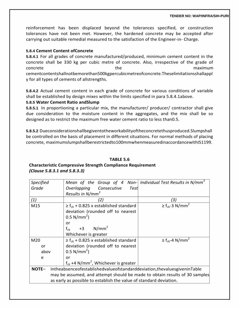
TENDER NO: WAP/INFRA/SIH-PURI
reinforcement has been displaced beyond the tolerances specified, or construction tolerances have not been met. However, the hardened concrete may be accepted after carrying out suitable remedial measured to the satisfaction of the Engineer-in- Charge.
5.8.4 Cement Content ofConcrete 5.8.4.1 For all grades of concrete manufactured/produced, minimum cement content in the concrete shall be 330 kg per cubic metre of concrete. Also, irrespective of the grade of concrete the maximum cementcontentshallnotbemorethan500kgpercubicmetreofconcrete.Theselimitationsshallapply for all types of cements of allstrengths.
5.8.4.2 Actual cement content in each grade of concrete for various conditions of variable shall be established by design mixes within the limits specified in para 5.8.4.1above. 5.8.5 Water Cement Ratio andSlump 5.8.5.1 In proportioning a particular mix, the manufacturer/ producer/ contractor shall give due consideration to the moisture content in the aggregates, and the mix shall be so designed as to restrict the maximum free water cement ratio to less than0.5.
5.8.5.2 Dueconsiderationshallbegiventotheworkabilityoftheconcretethusproduced.Slumpshallbe controlled on the basis of placement in different situations. For normal methods of placing concrete, maximumslumpshallberestrictedto100mmwhenmeasuredinaccordancewithIS1199.
TABLE 5.6 Characteristic Compressive Strength Compliance Requirement (Clause 5.8.3.1 and 5.8.3.3)
Specified Grade
Mean of the Group of 4 Non- Overlapping Consecutive Test Results in N/mm3
Individual Test Results in N/mm3
(1) (2) (3)
M15 ≥ fck + 0.825 x established standard deviation (rounded off to nearest 0.5 N/mm2) or fck +3 N/mm2 Whichever is greater
≥ fck-3 N/mm2
M20 or above
≥ fck + 0.825 x established standard deviation (rounded off to nearest 0.5 N/mm2) or fck +4 N/mm2, Whichever is greater
≥ fck-4 N/mm2
NOTE– Intheabsenceofestablishedvalueofstandarddeviation,thevaluesgiveninTable may be assumed, and attempt should be made to obtain results of 30 samples as early as possible to establish the value of standard deviation.
TENDER NO: WAP/INFRA/SIH-PURI
5.8.6 Approval of DesignMix 5.8.6.1 The producer/ manufacturer/ contractor of concrete shall submit details of each trial mix of each grade of concrete designed for various workability conditions to the Engineer-in-Charge for his comments and approval. Concrete of any particular design mix and grade shall be produced/ manufactured for works only on obtaining written approval of theEngineer-in-Charge.
5.8.6.2 For any change in quality/ quantity in the ingredients of a particular concrete, for which mix has been designed earlier and approved by the Engineer-in-Charge, the mix has to be redesigned and approval obtainedagain.
5.9 READY MIXED CONCRETE (as per IS4926) 5.9.1 Materials 5.9.1.1 Selection and Approval of Materials : Materials used should satisfy the requirements for the safety, structural performance durability and appearance of the finished structure, taking full account of the environment to which it will be subjected. The selection and use of materials shall be in accordance with IS 456. Materials used shall conform to the relevant Indian Standards applicable. Where materials are used which are not covered by the provisions of the relevant Indian Standard, there should be satisfactorydataontheirsuitabilityandassuranceofqualitycontrol.Recordsanddetailsofperformance of such materials should be maintained. Account should be taken of possible interactions and compatibility between IS 4926 and materials used. Also, prior permission of the purchaser shall be obtained before use of suchmaterials.
5.9.1.2 Cement:CementusedforconcreteshallbeinaccordancewiththerequirementsofIS456. . 5.9.1.3 Mineral Admixtures : Use of mineral admixtures shall be permitted in accordance with the provisions of IS456.
5.9.1.4 Aggregates:AggregatesusedforconcreteshallbeinaccordancewiththerequirementofIS 456. Unless otherwise agreed testing frequencies for aggregates in plant shall be as given IS 4926.
5.9.1.5 ChemicalAdmixtures
(i) Use of chemical admixtures shall be permitted in accordance, with the provisions of IS 456 and IS9103.
(ii) It shall be the responsibility of the producer to establish compatibility and suitability of
any admixturewiththeotheringredientsofthemixandthedeterminethedosagerequiredtogivethe desiredeffect.
(iii) Admixtures should be stored in a manner that prevents degradation of the product
and consumed within the time period indicated by the admixture supplier. Any vessel containing an
TENDER NO: WAP/INFRA/SIH-PURI
admixtureintheplantortakentositebytheproducershallbeclearlymarkedastoitscontent.
(iv) When offering or delivering a mix to a purchaser it should be indicated if such a mix contains an admixture or combination of admixtures or not. The admixtures may be identified generically and should be declared on the deliveryticket.
(v) The amount of admixture added to mix shall be recorded in the production record. In
special circumstances, if necessary, additional dose of admixture may be added at project site to regain theworkabilityofconcretewiththemutualagreementbetweentheproducerandthepurchaser.
5.9.1.6 Water : Water used shall be in accordance with the requirement of IS 456. Unless otherwise agreed, the testing frequencies for water shall be as given in AnnexA.
The use of re-cycled water is encouraged as long as concrete of satisfactory performance
can be produced and steps are taken to monitor the build up of chlorides in any recirculated water and thatany subsequentadjustmentstothemixdesignaremadetoensurethatanyoveralllimitonchloridecontents is satisfied. The addition of any recycled water shall be monitored and controlled to meet these requirements.
The total amount of water added to the mix shall be recorded in the production record.
The water content of concrete shall be regulated by controlling its workability or by measuring and adjusting the moisture contents of its constituent materials. The producer’s production staff and truck-mixer, drivers shall be made aware of the appropriate responses to variations in concrete consistency of a particular mix caused by normal variations in aggregate moisture content or grading.
5.9.2 GeneralRequirements
5.9.2.1 BasisofSupply:Ready-mixedconcreteshallbesuppliedhavingthequalityandthequantityin accordance with the requirement agreed with the purchaser or his agent. Notwithstanding this, the concrete supplied shall generally comply with requirements of IS456.
All concrete will be supplied and invoiced in terms of cubic metres (full or part) of
compacted fresh concrete. All proportioning is to be carried out by mass except water and admixture, which may be measured by volume.
5.9.2.2 Transport of Concrete : Ready-mixed concrete shall be transported from the mixer to thepoint ofplacingasrapidlyaspracticablebymethodsthatwillmaintaintherequiredworkabilityandwillprevent segregation, loss of any constituents or ingress of foreign matter or water. The concrete shall beplaced as soon as possible after delivery, as close as is practicable to its final position to avoid re-handling or
TENDER NO: WAP/INFRA/SIH-PURI
movingtheconcretehorizontallybyvibration.Ifrequiredbythepurchasertheproducercanutilizeadmixtures to slow down the rate of workability loss, however this does not remove the need for the purchaser to place the concrete as rapidly as possible. The purchaser should plan his arrangements so as to enable a full load of concrete to be discharged within 30 minutes of arrival on site.
Concrete shall be transported in a truck-mixer unless the purchaser agrees to the use of
non- agitating vehicles. When non-agitating vehicles are used, the mixed concrete shall be protected from gain or loss of water.
5.9.2.3 Time in Transport : The general requirement is that concrete shall be discharged from the truck-mixer within 2 h of the time of loading. However, a longer period may be permitted if retarding admixturesareusedorincoolhumidweatherorwhenchilledconcreteisproduced. Thetimeofloadingshallstartfromaddingthemixingwatertothedrymixofcementandaggregateorof adding the cement to the wet aggregate whichever isapplicable.
Ready-mixed concrete plant shall have test facilities at its premises to carry out routine
tests as per the requirement of the standard.
5.9.3 Sampling and Testing of Ready-MixedConcrete 5.9.3.1 Point and Time of Sampling : For the assessment of compliance of ready-mixed concrete, the point and time of sampling shall be at discharge from the producer’s delivery vehicle or from the mixer to the site or when delivered into the purchaser’s vehicle. It is critical that the sampling procedure and equipment used enables as representative a sample as possible to be taken of the quantity of concrete delivered (see AnnexA).
Thesamplingmaybecarriedoutjointlybythepurchaserandthesupplierwithitsfrequencymutu
ally agreedupon.However,itwillnotabsolvethesupplierofhisresponsibilityfromsupplyinginconcreteas pertherequirementgiveninthisstandardorotherwiseagreedtowheresopermittedinthestandard.
5.9.3.2 Workability : The test for acceptance is to be performed upon the producer’s delivery vehicle dischargeonsiteorupondischargeintothepurchaser’svehicle.lfdischargefromtheproducers’vehicle is delayed on site due to lack of preparedness on behalf of the purchaser then the responsibilitypasses to the purchaser after a delay of more than 30min.
Theworkabilityshallbewithinthefollowinglimitsonthespecifiedvalueasappropriate: Slump± 25 mm or 1/3 of the specified value, whichever isless. Compactingfactor : ± 0.03, where the specified value is 0.90 orgreater,
± 0.04, where the specified value is less than 0.90 but more than 0.80, ± 0.05, where the specified value is 0.80 or less.
TENDER NO: WAP/INFRA/SIH-PURI
Flow table test may be specified for concrete, for very high workability (see IS 9103) Acceptance criteria for spread (flow) are to be established between the supplier and the purchaser.
5.9.3.3 SpecifiedStrength
(i) Compliance shall be assessed against the requirements of IS 456 or other agreed Indian Standard. The purchaser may perform his sampling and testing or may enter into an arrangement with the producer to provide his testingrequirements.
(ii) Unless otherwise agreed between the parties involved, the minimum testing
frequency to be appliedbytheproducerintheabsenceofarecognizedready-mixed concreteindustry method of production control should be one sample for every 50 m3 of production or every 50 batches, whichever is the greater frequency. Three test specimens shall be made up for each sample for testing at 28 days (see also IS456).
In order to get a relatively quicker idea of the quality of concrete, optional test on beams for modulusofruptureat72±2horat7daysorcompressivestrength testat7daysmaybecarried out in addition to 28 days compressive strength test. For this purpose the value should be arrived at based on actual testing. In all cases 28 days compressive strength shall alone be the criteria for acceptance or rejection of theconcrete.
(iii) The purchaser shall inform the producer if his requirements for sampling and testing
are higher thanonesampleevery50m3or50batches,whicheveristhegreaterfrequency.
5.9.3.4 Additional Compliance Criteria : Any additional compliance criteria shall be declared to the producer by the purchaser prior to supply and shall be mutually agreed upon in terms of definition, tolerance frequency of assessment, method of test and significanceresult.
5.9.3.5 Non-Compliance : The action to be taken in case of non-compliance shall be declared and mutually agreedupon.
5.9.4 Information to be Supplied by thePurchaser 5.9.4.1 The purchaser shall provide to the producer the details of the concrete mix or mixes required by him and all pertinent information on the use of the concrete and the specified requirements. Prior to supply taking place, it is recommended that a meeting is held between the purchaser and the producer. Its objective to clarify operational matters such as notice to be given prior to delivery, delivery rate, the name of the purchasers authorized representative who will coordinate deliveries, any requirements for additional services such as pumping, on site testing or training,etc.
5.9.4.2 Designed Mixes : Where the purchaser specifies a designed mix to be supplied it is essential that all relevant information is conveyed to the producer. In order to assist in this, the format given in Annex B may be completed and forwarded to the producer at the time ofenquiry.
TENDER NO: WAP/INFRA/SIH-PURI
5.9.4.3 Prescribed Mixes : The concrete mix shall be specified by its constituent materials and the properties or quantities of those constituents to produce a concrete with the required performance. The assessment of the mix proportions shall form an essential part of the compliance requirements.The purchaser shall provide the producer with all pertinent information on the use of the concrete and the specified requirements. In order to assist in this, the format given in Annex B may be followed with suitable modifications as applicable to prescribedmixes.
5.9.5 Information to be Supplied by theProducer
When requested, the producer shall provide the purchaser with the following information before any concretes is supplied:
(a) Nature and source of each constituentmaterial,
(b) Source of supply ofcement,
(c) Proposed proportions or quantity of each constituent/ m3 of freshconcrete. (d) Generic type(s) of the main active constituent(s) in theadmixture;
(e) Whether or not the admixture contains chlorides and if so, the chloride content of the
admixture expressed as a percentage of chloride ion by mass ofadmixture; (f) Where more than one admixture is used, confirmation of their compatibilityand
(g) Initialandfinalsettingtimeofconcretewhenadmixtureisusedatadopteddosage(testedasp
er IS8142).
5.9.6 Production andDelivery 5.9.6.1 Materials Storage andHandling
(i) Cement : Separate storage for Different types and grades of cement shall be provided. Containers may be used to store cement of different types provided these are emptied before loading new cement. Bins or silos shall be weatherproof and permit free flow and efficient discharge of the cement. Each silo or compartment of a silo shall be completely separate and fitted with a filter or alternative method of dust control. Each filter or dust control system shall be of sufficient size to allow delivery of cement to be maintained at a specified pressure, and shall be properly maintained and prevent undue emission of cement dust and prevent interference withweighingaccuracybybuildupofpressure.Cementshallbestoredandstackedinbagsand shall be kept free from the possibility of any dampness or moisture coming in contact with them andwherecementcanbestoredandretrievedwithoutunduedamagetothebags.Thebagsare to be protected from becoming damp either from the ground or the weather. The cement is tobe used in the order it is delivered (see also IS4082). In case, the cement remains in storage for more than 3 months, the cement shall be retested before use and shall be rejected, if it fails to conform to any of the requirements given in the relevant Indian Standard.
TENDER NO: WAP/INFRA/SIH-PURI
(ii) Dry Pulverized Fuel Ash and Other Mineral Admixtures : Suitable separate arrangement
for storage of pulverized fuel ash, silica fume, metakeolin, rice husk ash, ground granulated blast furnaceslagsuchasforcement,shallbeprovided,intheplantsutilizingthesematerials.
(iii) Aggregates (Coarse and Fine) : Stockpiles shall be free draining and arranged to avoid
contamination and to prevent intermingling with adjustment material. Handling procedures for loading and unloading aggregates shall be such as to reduce segregation to a minimum. Provision shall be made for separate storage for each nominal size and type of aggregate and the method of loading of storage bins shall be such as to prevent intermingling of different sizes and types. Fine aggregates shall be stacked in a place where loss due to the effect of wind is minimum (see also IS 4082 and IS456).
(iv) Water : An adequate supply shall be provided and when stored on the plant such
storage facilities shall be designed to minimize the risk ofcontamination.
(v) Chemical Admixtures : Tanks or drums containing liquid admixtures shall be clearly labeled for identificationpurposesandstoredinsuchawaytoavoiddamage,contaminationortheeffectsof prolonged exposure to sunlight (if applicable). Agitation shall be provided for liquid admixture, which are not stablesolutions.
5.9.6.2 BatchingPlantsandBatchingEquipment:Hoppersforweighingcement,mineraladmixtures, aggregates and water and chemical admixture (if measured by mass) shall consist of suitablecontainer freely suspended from a scale or other suitable load-measuring device and equipped with a suitable discharging mechanism. The method of control of the loading mechanism shall be such that, as the quantity required in the weighing hopper is approached the material may be added at controllable rate and shut off precisely within the weighing tolerances specified in Annex C. The weighing hoppers for cement, mineral admixtures aggregate shall be capable of receiving their rated load, without the weighed material coming into contact with the loading mechanism. Where the rated capacity of a batching plant mixing cycle is less than 2.0 m3, additional precautions shall be taken to ensure that the correct number of batches are loaded into the truck mixer. The weighing hoppers shall be constructed so as to discharge efficiently and prevent the build up of materials. A tare adjustment, up to 10 percent of the nominal capacity of the weigh scale, shall be provided on the weighing mechanism so that the scale can be adjusted to zero at least once each day. Dust seals shall be provided on cement hoppers betweentheloadingmechanismandtheweighhopper,andshallbefittedsoastopreventtheemission of cement dust and not affect weighing accuracy. The hopper shall be vented to permit escape of air without emission of cementdust.
Vibrator or other attachment, where fitted, shall not affect the accuracy of weighing. There shall be sufficient protection to cement and aggregate weigh hoppers and weighing
TENDER NO: WAP/INFRA/SIH-PURI
mechanisms to prevent interference with weighing accuracy by weather conditions or external build-up of materials.
Where chemical admixture dispensers are used, they shall be capable of measurement
within the toleranceinannexCandcalibratedcontainerorweighscalesshallbeprovidedtochecktheaccuracyof measurement at least once amonth.
Where a continuous mixer with ribbon loading is used the batching procedure specified
by the manufacture of the plant shall be followed.
Each control on the batching console and weigh-dial or display shall be clearly labeled with its function and where concerned with the batching of materials, the materials type.
When more than one type or grade of cement is being used, the weighing device and
discharge screw or other parts of the transfer system shall be empty before changing from on type of cement to another.
When more than one type or grade of cement is being used, the weighing devised and
discharge screw or other parts of the transfer system shall be empty before changing from on type of cement to another.
When pulverized fuel ash and other mineral admixtures are batched through the cement
weigh system, the weighing device and discharge screw or other parts of the transfer system shall be empty when the weighing system has returned to zero reading or completed the batch.
Whereabackweighsystemisutilizedtoweighmaterialsasystemshallbeinplacesoastoprevent materials being loaded during the process ofweighing.
5.9.6.3 Measurement of Materials : Cement and mineral admixture materials shall be measured by mass in a hopper or compartment separate from those used for other materials and on a scale of appropriate sensitivity, measurement being taken from a zero reading. Aggregates shall be measured by mass, allowance being made for the free moisture content of the aggregates. The added water shall be measured by volume or by mass. Any liquid chemical admixture (or paste) shall be measured by volume or by mass and any solid admixture by mass. When weighing materials any build up in the hopper during the day must be tared out or allowed for in the batch weights. After measurement all materials shall be discharged into the mixer withoutloss.
The accuracy of the measuring equipment shall be within + 2 percent of the quantity of
cement and mineral admixtures being measured and within + 3 percent of the quantity of aggregate, chemical admixture and water being measured. The plant operator shall be provided with a clear display of the quantities of materials to be batched for each mix and batch size with information identifying thedisplay to be selected for each designed and prescribed mix to be produced. Analogue scale displays for the weighing of cement, mineral
TENDER NO: WAP/INFRA/SIH-PURI
admixtures, aggregates and water shall be readily discernable from the operating position. For digital readouts the numerals shall be readily discernable from the operating position.
Fully automatic production systems shall be fitted with control equipment to allow the
correct operation of the plant to be monitored during weighing and batching. Automatic control systems on batching plants shall not commence batching until all hoppers have been emptied and /or tared and the scales zeroed unless such systems are designed to take account of build up in their programming.
All scales shall be tested and calibrated as per Annex C.
5.9.6.4 Mixing
(i) WashingOutWater:Beforeloadingconcretematerialsormixedconcreteintoeitherastationary mixer or truck mixer any water retained in the mixing drum for washing out purposes shall be completelydischarged.
(ii) StationaryorCentralMixers:Stationarymixersshallnotbeloadedinexcessofthemanufacture
r’s rated capacity. The mixing time shall be measured from the time all the materials required for the batch, including water, are in the drum of the mixer. The mixing time shall not be less than thatrecommended by the manufacturer. Where a continuous mixing plant is used, the complete mixing timeshallbesufficienttoensurethattheconcreteisoftherequireduniformity.
(iii) Truck Mixers : When a truck mixer is used for the partial or complete mixing of
concrete, mixing shallbeconsideredtocommencefromthemomentwhenallthematerialsrequiredforthebatch, including water, are in the rotating drum of themixer.
Truck or agitators shall not be loaded in excess of the manufacturer’s rated capacity. In orderto produce a satisfactory mix, and where there is no data available to establish different periodand speed of revolutions, mixing shall continue for not less than 60 revolutions of the truck mixer drum at a rate of not less than 7 revolutions/min. All completely truck mixed concrete shall be visually inspected for uniformity prior to leaving theplant.
When a truck mixer or agitator is used for transporting concrete which has been mixed before leaving the plant, the concrete shall be agitated during transit and remixed at the site for at least 2 min so that the concrete is of the required uniformity.
Wherewaterisaddedtotheconcreteinthetruckmixerthroughthetruckmixerwatermeterand when such water is being accounted for in the total water within the mix, it shall be ensured that the truck mixer water meter is in operational condition and properly calibrated. Where a water meterisnotavailable,watermustbemeasuredinasuitablecontainerbeforebeingaddedtothe truckmixer.
TENDER NO: WAP/INFRA/SIH-PURI
(iv) Condition of Mixers : Stationary and truck mixers shall be maintained in an efficient
and clean conditionwithnoappreciablebuildupofhardenedconcreteorcementinthemixingdrum,onthe mixing blades, or on the loading hopper or dischargechutes.
5.9.6.5 Delivery Ticket : Immediately before discharging the concrete at the point of delivery, the producer or his representative shall provide the purchaser with a preprinted delivery ticket for each delivery of concrete on which is printed, stamped or written the minimum information detailed invoicing as per AnnexD.
5.9.7 QualityControl
Quality control of ready-mixed concrete may be divided into three components, forward control, immediate control and retrospectivecontrol.
5.9.7.1 Forward control : Forward control and consequent corrective action are essential aspects of quality control. Forward control includes thefollowing.
(i) Control of purchased materialQuality
(ii) Control of Materialsstorage
(iii) Mix design and mix designmodification
(iv) Transfer and Weighing Equipment : The producer shall be able to demonstrate that a documented calibration procedure is in place. The use of elector-mechanical weighing and metering systems, that is, load cells, flow meters, magmeters, etc, is preferable over purely mechanical system, that is, knife edge and leversystems.
(v) Plantmixerswherepresentandtruckmixersusedshallbeinanoperationalcondition.
5.9.7.2 Immediate Control : Immediate control is concerned with instant action to control the quality of theconcretebeingproducedorthatofdeliveriescloselyfollowing.Itincludestheproductioncontroland productcontrol.
(i) Production Control : The production of concrete at each plant shall be systematically
controlled. This is to ensure that all the concrete supplied shall be in accordance with these requirements andwiththespecificationsthathasformedthebasisoftheagreementbetweentheproducerand purchaser.
Each load of mixed concrete shall be inspected before dispatch and prior to discharge.
The workability of the concrete shall be controlled on a continuous basis during production and any corrective action necessary taken.
TENDER NO: WAP/INFRA/SIH-PURI
For each load, written, printed or graphical records shall be made of the mass of the materials batched, the estimated slump, the total amount of water added to the load, the delivery ticket number for that load, and the time the concrete was loaded into the truck.
Regularroutineinspectionsshallbecarriedoutontheconditionofplantandequipmentincluding deliveryvehicles.
(ii) Product Control : Concrete mixes shall be randomly sampled and tested for workability
and where appropriate, plastic density, temperature and air content. Where significant variations from target values are detected, corrective action shall betaken.
It is important to maintain the water cement ratio constant at its correct value. The amount of added water shall be adjusted to compensate for any observed variations in the moisture contents in the aggregates. Suitable adjustments should also be made in masses of the aggregates due to this variation (see IS 456). Any change in water content due to change in aggregate grading shall be taken care of by forward control by suitable modifications to mix design.
5.9.7.3 RetrospectiveControl:Retrospectivecontrolisconcernedwiththosefactorsthatinfluencethe control of production. Retrospective control may cover any property of materials or concrete, such as aggregate grading, slump, or air content, but is particularly associated with 28-day cube strength because by its very nature it is not property which can be measured ahead of, or at the time of, manufacture.
5.9.7.4 Mix Performance : The producer shall be responsible for ensuring that suitable control procedures are in place ensure thefollowing.
(i) DesignMixes:Aqualitycontrolsystemshallbeoperatedtocontrolthestrengthofdesignmixe
s to the levels required as per IS 456 and shall be based on random tests of mixes which formthe major proportion of production. The system shall include continuous analysis of results from cube tests to compare actual with target values together with procedures for modifying mix proportionstocorrectforobserveddifferences.Compressivestrengthtestingshallbecarriedout using a machine that meets the requirements of IS14858.
(ii) PrescribedMixes:Periodicandsystematicchecksshallbemadetoensurethatthecementitio
us material contents of prescribed mixes comply with their mixdescriptions.
5.9.7.5 Stock Control of Materials : The producer shall operate a materials stock control procedure to enable verification of total quantities used and to confirm that only approved materials have been received.
5.9.7.6 Complaints : The producer shall have a procedure in place to enable the diagnosis and
TENDER NO: WAP/INFRA/SIH-PURI
correction of faults identified fromcomplaints.
5.9.8 Order Processing A competent person to interpret the specified requirements and relate these to mix
design criteria shall systematically review specification and orders supplied by the purchaser. These shall be formally recorded together with any modification to the specification resulting from subsequent agreed documentationtoensurethattheplantoperatorisgiventhecorrectinstructionsforbatchingandmixing. When mixes or materials are offered as alternatives to requested mixes or where there is no specification supplied by the purchaser, orders whether received verbally or in writing, shall be agreed with the purchaser and the fact recorded. Alternatives to the mix description or compliance requirementsinthepurchaser’sspecificationshallbeclearlyidentifiedinthequotation.
5.9.9 Records
Records shall be maintained by the producer to provide confirmation of the quality and quantity and quantity of concrete produced. The records shall be retained for the purposes of these requirements for a period of at least one year. They shall cover the following aspect:
(a) Production anddelivery: (i) Batchinginstruction (ii) BatchingRecords, (iii) Delivery tickets,and (iv) Equipment calibration and plantmaintenance.
(b) Materials and productioncontrol:
(i) Concrete production and materials purchase, usage and stocks,and (ii) Certificatesortestresultsformaterials.
(c) ProductionqualityContol:Controltestresults.
5.10 PLACING CONCRETE BYPUMPING 5.10.1 General
Concrete conveyed by pressure through either rigid pipes or flexible hoses and discharged directly into the desired area is termed as pumped concrete.
Method of applying pressure to concrete is by pumps. Pumps to be used shall be either of
the two types as mentioned below:- (A) Piston typepumps (B) Squeeze pressure typepumps.
Compressed air pressure pumps shall not be used in the works.
5.10.2 PumpingEquipments 5.10.2.1 Piston Pumps : Piston pump to be used in the works shall consist of a receiving hopper for mixedconcrete,aninletvalve,anoutletvalve,andthepumpshallbeatwin-pistonpump.
TENDER NO: WAP/INFRA/SIH-PURI
The two pistons shall be so arranged that one piston retracts when the other is moving
forward and pushing concrete into the pipe line to maintain a reasonably steady flow of concrete. Single piston pumps shall not be acceptable.
Inlet and outlet valve shall be any one of the following types:- - Rotating plugtype - Sliding platetype - Guided plungertype - Swingtype - Flappertype - Or any combination of theabove. The pistons shall be mechanically driven using a crank or chain or hydraulically driven using
oil or water.
The receiving hopper shall have a minimum capacity of 1.0 cum and the hopper shall be fitted with remixing rotating blades capable of maintaining consistency and uniformity of concrete.
Theprimarypowerforpumpsmaybesuppliedbygasoline,diesel,orelectricmotors. Theprimarypowerunitandthepumpunitmaybetruck,trailerorskidmounted.
5.10.2.2 SqueezePressurePumps:Squeezepressurepumpsshallconsistofareceivinghopperfitted with re-mixing blades. Re-mixing blades shall be such that these can push the concrete into the flexible hose connected at the bottom of thehopper.
Theflexiblehoseshallpassthroughametaldrumaroundtheinsideperipheryofthedrumandcom
e out through the top part of thedrum.
The drum shall be maintained under a very high degree of a vacuum during operation. The drum shall be so fitted with hydraulically operation metal rollers., which when rotating, create a squeeze pressure on the flexible hose carrying concrete and forces the concrete out into the pipe line.
5.10.2.3 EffectiveRangeandDischargeofPumps:Effectiverangeofpumpstobeusedinthework shall be decided after studying the site conditions. However, the minimum horizontal range shall not be lessthan150metresandminimumverticalrangeshallnotbelessthan50metres.
Selectionofpumpsbasesondischargecapacityshallbedecidedafterstudyingtherequirementsf
or the project. Discharge capacity shall be worked out by the contractors and approval obtained from the Engineer-in-Charge. As a guide line figure the contractor may assume a discharge capacity of 15 cubic metre/hour/pump.
5.10.2.4 Pipe Lines : All concrete carrying pipe lines shall generally be rigid pipe lines. Flexible pipe lines may only be used at bend curves in lines or at discharge ends if required. Placements of flexible units shall be done judiciously and connected to the pipe lines only
TENDER NO: WAP/INFRA/SIH-PURI
when it meets the approval of the Engineer-in-Charge. (i) Rigid Line/ Hard Line/ Slick line : Such lines shall be made either of steel or plastic.
Aluminum alloy pipes shall not beused.
Minimum pipeline diameter shall be 100 millimeters and shall have normal maximum length of 3 metre in each section connected through couplers.
(ii) Flexible Pipe Line : Flexible lines shall be made out of rubber or spiral wound flexible
metal or plastic. The pipe shall again be such that they are in sections of 3 metre length each and connected through couplers. These pipes shall be such that they are interchangeable with rigid lines. While installing flexible units, care shall be taken that there are no links in the pipeline, whichisanormaltendencywiththesepipeshavingdiameter100mmandabove.
5.10.2.5 Couplers : Couplers to be used for connecting pipe line sections (either hard or flexible) shall haveadequatestrengthtowithstandstressesduetohandling,misalignments,poorsupporttopipelines etc.
Forhorizontalrunsofpipesandforverticalrunupto30metreheightthecouplersshallberatedfor
a minimum pressure of 35 kg/ cm square. Couplers used for rising runs between 30 metre and 50 metre heights shall have a minimum pressure rating of 50 kg/cm square. Couplers shall be designed to allow for replacement of any pipe section without displacing other sections. These shall provide for the full internal cross section. These shall provide for the full internal cross section with no constructions or service.Whichmaydisruptthesmoothflowofconcrete.Forpipelinesofsize150mmandabove,double toggedtypecouplerwithathickrubbergasketandsecondarywedge-take-upisrecommended.Typesof couplers that may be used shall be any of thefollowing:-
- Grooved endcoupler
- One piece extended lever swing typecouplers
- And full flow oil line typecouplers.
5.10.2.6 Other Accessories : Other accessories which shall be catered for, are asunder:-
(a) Backuppumpofrigidandflexiblepipesofvaryinglengthsofsimilarrating/specifications
(b) Curved sections of rigidpipes
(c) Swivel joints and rotarydistributors
(d) Pin and gate valves to prevent back flow in pipelines
TENDER NO: WAP/INFRA/SIH-PURI
(e) Switch valves to direct the flow into another pipeline
(f) Connection devices to fill forms from the bottomup
(g) Splints, rollers, and other devices for protection of conduit over rock concrete Reinforcing steel and form and to provide lifting and lashing points in the pipeline.
(h) Transitions for connecting different sizes of pipesections
(i) Air vents for downwardpumping.
(j) Clean outequipment.
For concreting of columns, walls and scattered small placement, recommendation is made
for special cranes or power controlled booms carrying pipe lines with a pendant type concrete delivery hose.
5.10.2.7 Lubricating of PipeLine
Before pumping concrete into the pipeline, the line shall be lubricated with a properly designed mortar/groutlubricant.Thisshallbeensuredbystartingthepumpingoperationwithaproperlydesigned mortar, or with a batch of regular concrete with the coarse aggregate omitted. The quantity of mortar required as lubricant is dependent on the smoothness and cleanliness of the pipelines. As a guide line, fora100mmdiameterpipelineof100metrelength,0.08cumto0.10cumofmortarshouldnormallybe adequate,butthisshallnotbetakenasspecified,andthecontractorshallestablishhisrequirements.
Thequantityofmortarthatcomesoutofthedeliveryendofthepipelineshallnotbeusedinplaceof
the concrete work. However, with the approval of Engineer-in-Charge, this mortar may be used as bedding mortar against construction joints. The rest of the mortar shall bewasted.
Lubrication shall be maintained as long as the pumping of concrete continues.
5.11 GUIDELINES FOR FIELDPRACTICE 5.11.1 GeneralPrecautions
(i) Properplanningofconcretesupply,pumplocations,linelayout,placingsequence and the entire pumping operation will result in savings of time andexpense.
(ii) The pump shall be placed as near the placement area as practicable. The surrounding
areaof the pump shall be free of obstructions to allow for movement of concrete delivery trucks. The surface must be strong enough to withstand the loaded trucks operating on it. If the surface is a suspendedslab,thetruckrouteshallbeadequatelysupportedinconsultationwiththeEngineer- in-Charge.
TENDER NO: WAP/INFRA/SIH-PURI
(iii) Pipe lines from the pump to the placing area shall be laid with minimum number of
bend. For large placement areas, alternate lines shall be installed for rapid connection when required. A flexiblepipeatthedischargeendwillpermitplacingoveralargeareadirectlywithoutre-handling of pipelines. The pipeline shall be firmlysupported.
(iv) If more than one size of pipe must be used, the smaller diameter pipe shall be placed
at the pump end and the larger diameter at the dischargeend.
(v) When pumping downwards, an air release valve shall be provided at the middle of the top bend to prevent vacuum or air buildup. Similarly, while pumping upwards, a no-return valve shall be provided near the pump to prevent the reverse flow ofconcrete.
(vi) Itisessentialthatdirectradio/telecommunicationbemaintainedbetweenthepumpoperat
orand the concrete placing crew. Good communication between the pump operator and the batching- plantisalsoessential.Theplacingrateshallbeestimatedbythepumpoperatorsothatconcrete can be ordered at an appropriate deliveryrate.
(vii) The pump shall be started for a check run and operated without concrete to ensure
that all movingpartsareinoperationproperly.Beforeplacingconcrete,thepumpshallberunwithsome grout/mortar for lubricating theline.
(viii) When concrete is received in the hopper, the pump shall be run slowly until the lines
are completely full and the concrete is steadily moving. A continuous pumping must be ensured, because, if the pump is stopped, concrete in the line may be difficult to moveagain.
(ix) When a delay occurs because of concrete delivery or some form repair works or for
any other reason, the pump shall be slowed down to maintain some movement of concrete in the pipe line. For longer delays, concrete in the receiving hopper shall be made to last as long as possiblebymovingtheconcreteinthelinesoccasionallywithintermittentstrokesofthepump.It issometimesessentialtorunareturnlinebacktothepumpsothatconcretecanbere-circulated during longdelays.
(x) If after a long delay, concrete cannot be moved in the line, it may be necessary to
clean out the entire line. However, quite often only a small section of pipe line may be plugged and requires cleaning. The pump operator who know such details as the length of line, age of concrete in the line etc., should be dependedupon to aid in deciding the appropriate section to be cleaned.
(xi) Whentheformisnearlyfull,andthereisenoughconcreteinthelinetocompletetheplacement, the pump shall be stopped and a “go devil” inserted at the appropriate time so that
TENDER NO: WAP/INFRA/SIH-PURI
concrete aheadofthego-devilshallbeforcedcompletionofthework.Thego-devilshallbeforcedthrough the pipeline to clean it out. Use of water pressure is a safer method. The go-devil shall be stopped at the discharge end to ensure that water does not spill on the placement area, if air pressure is used, extreme care shall be taken and the pressure must be carefully regulated. A trap shall be installed at the end of the line to prevent the go-devil being ejected as a dangerous projectile.Anairreleasevalveshallalsobeinstalledinthelinetopreventairpressurebuildup.
(xii) It is essential to clean the line after concrete placing operation is complete. Cleaning
shall be done in the reverse direction from the form work end to the pump-end where the concrete in the line can be dumped in bucket. After removal of all concrete, all pipe lines and other equipments shall be cleaned thoroughly and made ready for the nextuse.
5.11.2 Submittals
Alongwiththeirbidthecontractorsshallberequiredtosubmitthefollowinginformationregardingthe equipments proposed to be used bythem:-
(i) Type,number,capacity,range,mounting,natureofprimarypowerusedandtheoperatingweight of pump andmounting.
(ii) Manufacturer’sspecificationsforpipelinesgivingpressureratings,sizesandmaterialforstra
ight and curvedsections.
(iv) Manufacturer’s certificates.
5.11.3 Sampling and Testing(Materials)
5.11.3.1 Aggregates (i) Supplierofaggregatesshallfurnishthefollowinginformationbeforethematerialis
delivered to site:- - Precise location of source from where the material is to besupplied. - Trade group of principal rock type as per table 5.7 below: - Presence or reactiveminerals
TABLE5.7
(ii) Thesuppliershallalsofurnishreportsontestresultsgivingthefollowinginformationforapproval to Engineer-in-Charge before delivery of material atsite:- Specific gravity Bulk density Moisture content
Trade group name of
Aggregatestobeusedforconcrete
: Granite, Gabbro,
: Dolerite, Rhyolite, Basalt, Quartzite, Gneiss.
TENDER NO: WAP/INFRA/SIH-PURI
Absorption Value Aggregate crushing strength Aggregate impact value Abrasion value Flakiness index Elongation index Limits of deleterious substances in the aggregate Soundness of aggregate Potential reactivity of aggregates.
All tests shall be conducted in accordance with IS 2386 (Part-I to VIII).
(iii) Change in quality of aggregate as per trade group name shall not be acceptable in the
work. Change in source of aggregates shall also not be acceptable under normal circumstances,even if the aggregate belong to the same trade group. Engineer-in-Charge may with his discretion allow a change in the source. But, in that case, all test mentioned in para 5.8.9.1.2 above shall have to be repeated for the aggregates form the changed source and the test results submitted to Engineer-in-Charge for his approval before the delivery of material atsite.
(iv) In addition to above, the following tests have to be performed on representative
samples from every lot of aggregate after delivery at site. These test results are to be submitted to the Engineer-in-Charge for his approval. Acceptance criteria for aggregates shall be based on the resultsofthissetoftestsonly.IfintheopinionoftheEngineer-in-Charge,thetestresultsarenot with in permissible limits, the lot of aggregates from which the samples have been obtainedfor testing shall stand rejected and the material shall be removed from thesite.
Mandatory tests on Aggregates at site
Tests Nos. of test on each 50 cum of Material or partthereof
1. Specific gravity 3
2. Bulk density 3
3. Aggregate crushing strength 3
4. Limits of deleterious substances 3
5. Aggregate impact value 3
Mean value of the results from above test shall be taken as the representative value and the acceptancecriteriashallbebasedonthese.Alltestproceduresandcomputationsfortestresults shall be as per IS2386.
(v) All other tests in para iv being in compliance with requirements set in specifications, if
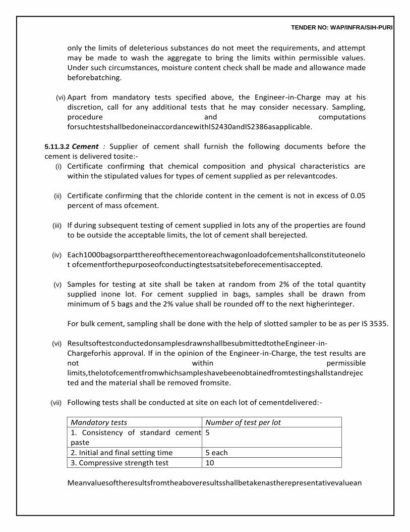
TENDER NO: WAP/INFRA/SIH-PURI
only the limits of deleterious substances do not meet the requirements, and attempt may be made to wash the aggregate to bring the limits within permissible values. Under such circumstances, moisture content check shall be made and allowance made beforebatching.
(vi) Apart from mandatory tests specified above, the Engineer-in-Charge may at his
discretion, call for any additional tests that he may consider necessary. Sampling, procedure and computations forsuchtestshallbedoneinaccordancewithIS2430andIS2386asapplicable.
5.11.3.2 Cement : Supplier of cement shall furnish the following documents before the cement is delivered tosite:-
(i) Certificate confirming that chemical composition and physical characteristics are within the stipulated values for types of cement supplied as per relevantcodes.
(ii) Certificate confirming that the chloride content in the cement is not in excess of 0.05
percent of mass ofcement.
(iii) If during subsequent testing of cement supplied in lots any of the properties are found to be outside the acceptable limits, the lot of cement shall berejected.
(iv) Each1000bagsorpartthereofthecementoreachwagonloadofcementshallconstituteonelot ofcementforthepurposeofconductingtestsatsitebeforecementisaccepted.
(v) Samples for testing at site shall be taken at random from 2% of the total quantity
supplied inone lot. For cement supplied in bags, samples shall be drawn from minimum of 5 bags and the 2% value shall be rounded off to the next higherinteger.
For bulk cement, sampling shall be done with the help of slotted sampler to be as per IS 3535.
(vi) ResultsoftestconductedonsamplesdrawnshallbesubmittedtotheEngineer-in-
Chargeforhis approval. If in the opinion of the Engineer-in-Charge, the test results are not within permissible limits,thelotofcementfromwhichsampleshavebeenobtainedfromtestingshallstandrejected and the material shall be removed fromsite.
(vii) Following tests shall be conducted at site on each lot of cementdelivered:-
Mandatory tests Number of test per lot
1. Consistency of standard cement paste
5
2. Initial and final setting time 5 each
3. Compressive strength test 10
Meanvaluesoftheresultsfromtheaboveresultsshallbetakenastherepresentativevaluean
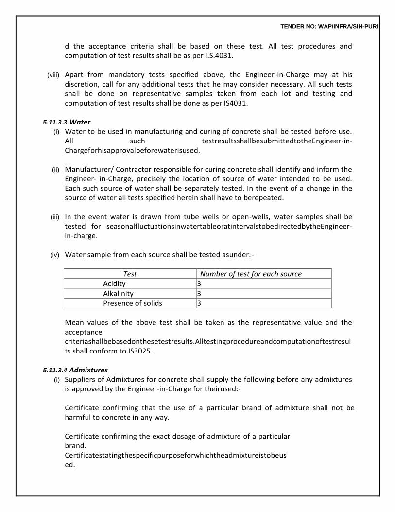
TENDER NO: WAP/INFRA/SIH-PURI
d the acceptance criteria shall be based on these test. All test procedures and computation of test results shall be as per I.S.4031.
(viii) Apart from mandatory tests specified above, the Engineer-in-Charge may at his
discretion, call for any additional tests that he may consider necessary. All such tests shall be done on representative samples taken from each lot and testing and computation of test results shall be done as per IS4031.
5.11.3.3 Water
(i) Water to be used in manufacturing and curing of concrete shall be tested before use. All such testresultsshallbesubmittedtotheEngineer-in-Chargeforhisapprovalbeforewaterisused.
(ii) Manufacturer/ Contractor responsible for curing concrete shall identify and inform the
Engineer- in-Charge, precisely the location of source of water intended to be used. Each such source of water shall be separately tested. In the event of a change in the source of water all tests specified herein shall have to berepeated.
(iii) In the event water is drawn from tube wells or open-wells, water samples shall be
tested for seasonalfluctuationsinwatertableoratintervalstobedirectedbytheEngineer-in-charge.
(iv) Water sample from each source shall be tested asunder:-
Test Number of test for each source
Acidity 3
Alkalinity 3
Presence of solids 3
Mean values of the above test shall be taken as the representative value and the acceptance criteriashallbebasedonthesetestresults.Alltestingprocedureandcomputationoftestresults shall conform to IS3025.
5.11.3.4 Admixtures
(i) Suppliers of Admixtures for concrete shall supply the following before any admixtures is approved by the Engineer-in-Charge for theirused:-
Certificate confirming that the use of a particular brand of admixture shall not be harmful to concrete in any way.
Certificate confirming the exact dosage of admixture of a particular brand. Certificatestatingthespecificpurposeforwhichtheadmixtureistobeused.
TENDER NO: WAP/INFRA/SIH-PURI
Special precautionary measures to be taken in the manufacturer of concrete when using the particular brand of admixture.
Certificate confirming that the admixture conforms to specifications of IS 9103 or to ASTM-C260, ASTM – C10, ASTM – C 595 or to ASTM- C 618.
(ii) Engineer-in-Charge at his discretion may require tests to be performed to reconfirm
the characteristic properties of any admixture. All such tests shall be done in accordance with IS: 9103.
(iii) All tests described in paras 5.4.8 to 5.4.10 above shall be done at the site laboratory or
at a laboratorytobeidentifiedbytheEngineer-in-Chargedependingonthetesttobeconducted.
(iv) All test shall be done in the presence of a representative nominated by the Engineer-
in-Charge and a representative of the concrete Manufacturer/ Contractor when tests are performed at the site laboratory. All observation and reports of test shall be jointly signed by the two representatives before the test results are submitted to theEngineer-in-Charge.
(v) Expenses for all materials used for testing, sampling procedures and testing including
preparing reports shall be borne by the concrete Manufacturer/Contractor.
(vi) Rate of concrete is inclusive of cost of admixtures. The contractor shall not be paid anything extra for admixtures required for achieving direct workability without any change in specified water cement ration for RCC/CCwork.
5.11.4 Sampling and Testing for Quality Control of FreshConcrete
Fresh concrete shall be tested for (a) Slump (b) Compacting Factor/Workability (c) Consistency (d) Weight per cubic metre, cement factor and aircontent
5.11.4.1 Slump
(i) For concrete totally mixed in a central plant, slump shall be checkedat:- (a) Immediately during loading oftrucks (b) Point of discharge from the deliverytruck (c) Final placementlocation (d) At placement location the slump measured shall conform to the design slump.
Manufacturer of concrete shall adjust for loss of slump in transit and establish the requirements of design mix. All slump measurements shall be done within a period of 20 minutes from the time cement is added to the mixer. Placement contractor shall transport concrete from truck discharge point to actual placement location within 10 minutes of delivery, before the final slump reading is taken at
TENDER NO: WAP/INFRA/SIH-PURI
placementlocation.
(ii) Forconcreteentirelymixedintransitorforshrinkmixconcrete,slumpreadingshallbetakenat:- (a) Point of discharge from deliverytrucks (b) Final placementlocation Inthiscasealso,theslumpmeasuredatthefinalplacementlocationshallconformtothedesign slump. The placement contractor shall be responsible for transporting concrete from delivery truck discharge point to final placement location within 10 minutes. However, in this case, the truckshalldischargetheconcretewithin1hourand30minutesfromthetimecementisaddedin the mixer and slump measured at point of discharge immediately on delivery. Manufacturer of concreteshallensurethat thefinalslumpmeasurementcorrespondstotheorderedslump.
(iii) For measuring concrete slump at point of discharge from delivery trucks, samples shall
betaken from concrete omitting the first and the last 15% of the load. For concrete delivery of placed by pumping, sampling shall be similar to those specified for deliverytrucks.
(iv) Slump measurements of ready mix concrete transported by buckets shall be at
locations specifiedinpara5.11.4.1withsamelimitsontime.Samplingfrombucketsshallbesuchthatthe buckets containing discharge from mixer for the last 15% areomitted.
(v) At placement locations, samples for checking slump shall be collected from every 20
cum of concrete or part thereof placed at location for each type toconcrete.
(vi) For all slump checks in the field at least two recordings shall be made and the average value taken as the recordedslump.
(vii) Slump checks for concrete in the laboratory shall be carried out as and when required
by the manufacturerofconcreteduringthemixdesignstageandduringtheprogressofworkforcontrol on fieldresults.
(viii) Slump readings shall only be a guideline for concrete consistency and shall not be
taken asthe acceptability criteria for concrete placed at location. All slump test shall be carried out in accordance with IS1199.
5.11.4.2 CompactingFactor
(i) For concrete whose ordered slump is 50 mm or less, compacting factor test shall be conducted atbothfieldandcentralbatchplantinadditiontoslumptestsmentionedabove.
(ii) Compacting factor check shall be done in field only at placement location, and shall
also be conducted at central batch plant if concrete is totally mixed inplant.
TENDER NO: WAP/INFRA/SIH-PURI
(iii) For this test, sampling shall be done as for slump measurements in field and within the
same frame as for slumptest.
(iv) Only one compaction factor test shall be conducted for every 20 cum of concrete or part thereof placedatlocationforeachtypeofconcrete.Sincethetestissensitive,everycareshallbetaken toconductthistesttotallyincompliancewithprocedurementionedinIS1199.
(v) Laboratory tests for determining compacting factor of concrete shall be done as per
manufacturer’srequirementsforestablishingandcontrollingthedesignmixofconcrete.
(vi) Compactingfactortestshallnotbetakenasanacceptancecriteriaandshallbetreatedonlyasa guideline to workability ofconcrete.
5.11.4.3 Consistency of Concrete : This test shall be performed only at the batching plant laboratory using a Vee-Bee Consist meter, for determining and predicting the slump of concrete. Number and frequency of these tests shall be based on requirements of the manufacturer of concrete. Care shall be taken in producing mix design of required characteristic strengths of concrete within limits of Vee-Bee- Degreesbetween1.6and4.5forconcretetransportedandplacedbynormalmethodandbetween 0.8 and 3.5 for concrete transported and placed by pumpingmethods.
5.11.4.4 Weight, Cement Factor and Air contents Test : Freshly mixed concrete for every type shall be tested in the batch plant laboratory for each batch of concrete produced to determine weight per cubic metre of freshly mixed concrete, cement factor in concrete and the air content of the concrete. Frequencyandnumberoftestshallbefinalizedbythemanufacturerofconcreteinconsultationwiththe Engineer-in-Chargeforhisrequirementofthemodeofmeasurementofconcreteproduced.
The Engineer-in-Charge may at his discretion require further tests over and above those
specified above in para 5.11.4.1 to be conducted on fresh concrete. The manufacturer and the placement contractor shall have to comply with all such requirements.
5.11.5 Sampling and Testing for Quality Control of HardenedConcrete
(i) Test on cube crushing strength of concrete in accordance and compliance with IS 456 and IS 516 shall done asunder:- (a) Sample of fresh concrete shall be taken from concrete at central batch plant mixer
while loading delivery trucks or other transport and also from concrete transported to placement location.
(b) Test on specimens made form samples collected at placement location shall be
considered as field test specimens and results therefrom shall be the criterion of concrete strength. Test in specimens made from samples at the batch plant shall only be taken as guidelines test. Onlyinthecaseofdoubtfulresult,theEngineer-in-
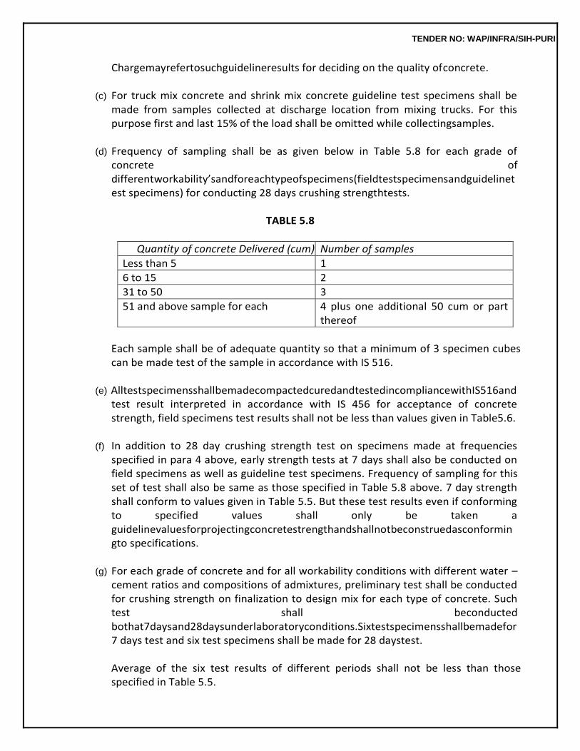
TENDER NO: WAP/INFRA/SIH-PURI
Chargemayrefertosuchguidelineresults for deciding on the quality ofconcrete.
(c) For truck mix concrete and shrink mix concrete guideline test specimens shall be made from samples collected at discharge location from mixing trucks. For this purpose first and last 15% of the load shall be omitted while collectingsamples.
(d) Frequency of sampling shall be as given below in Table 5.8 for each grade of
concrete of differentworkability’sandforeachtypeofspecimens(fieldtestspecimensandguidelinetest specimens) for conducting 28 days crushing strengthtests.
TABLE 5.8
Quantity of concrete Delivered (cum) Number of samples
Less than 5 1
6 to 15 2
31 to 50 3
51 and above sample for each 4 plus one additional 50 cum or part thereof
Each sample shall be of adequate quantity so that a minimum of 3 specimen cubes can be made test of the sample in accordance with IS 516.
(e) AlltestspecimensshallbemadecompactedcuredandtestedincompliancewithIS516and
test result interpreted in accordance with IS 456 for acceptance of concrete strength, field specimens test results shall not be less than values given in Table5.6.
(f) In addition to 28 day crushing strength test on specimens made at frequencies
specified in para 4 above, early strength tests at 7 days shall also be conducted on field specimens as well as guideline test specimens. Frequency of sampling for this set of test shall also be same as those specified in Table 5.8 above. 7 day strength shall conform to values given in Table 5.5. But these test results even if conforming to specified values shall only be taken a guidelinevaluesforprojectingconcretestrengthandshallnotbeconstruedasconformingto specifications.
(g) For each grade of concrete and for all workability conditions with different water –
cement ratios and compositions of admixtures, preliminary test shall be conducted for crushing strength on finalization to design mix for each type of concrete. Such test shall beconducted bothat7daysand28daysunderlaboratoryconditions.Sixtestspecimensshallbemadefor 7 days test and six test specimens shall be made for 28 daystest.
Average of the six test results of different periods shall not be less than those specified in Table 5.5.
TENDER NO: WAP/INFRA/SIH-PURI
(h) Crushing strengths on cubes shall also be conducted during the process of
finalization of concrete design mix. Frequency and number of such tests shall be as per Mix of requirements of concretemanufacturer.
(i) Alltestspecimensforconductingcrushingstrengthshallbeproperlylabeledforidentifica
tion indicating:- (i) Date of makingspecimen (ii) Grade ofconcrete (iii) Placement locationexact (iv) Purchasers ordernumber
(j) In addition to crushing strength test on concrete, the Engineer-in-Charge may call
for other tests on hardend concrete. The placement contractor and the manufacturer of concreteshall comply with all suchinstructions.
(ii) Non-destructiveTests
(a) When the 28 days crushing values on field specimens and/ or specimens and/or specimens made for guideline test fall short of specified values, or in case of doubtful placement of concrete, the Engineer-in-Charge shall call for non-destruction tests on the structure. Such tests may be any one or a combination of thefollowing:- Rebound hammertest Windsor Penetration Probetest Pulse velocity (sonic or Ultrasonic)test Coretest Loadtest
(b) Interpretation of rebound hammer, Windsor Probe and Pulse velocity test results
shall rest with theEngineer-in-Charge.
(c) Core test, if ordered by the Engineer-in-Charge, shall be done in accordance with IS 516. SamplesforsuchtestshallbetakenfromlocationstobeidentifiedbytheEngineer-in-Charge and such samples shall be collected in compliance withIS:1199.
(d) Iffeltnecessary,theEngineer-in-
Chargemayinstructloadtestingforanypartofthestructure based on doubtful concrete strengths. Such test shall be carried out as per details to be providedbytheEngineer-in-Chargeinconsultationwiththestructuralconsultants.
(e) The concrete manufacturer/ concrete placement contractor shall arrange for all
test to be conducted in accordance with these specifications, including all necessary tools, plants, equipmentandmaterial,andshallberesponsibleforconductingalltestathiscost.
TENDER NO: WAP/INFRA/SIH-PURI
(f) All test conducted at the filed laboratory shall be carried out by qualified technicians employed by the concrete manufacturer/ concrete placement contractor, in presence of authorized representative of the Engineer-in-Charge. All test reports and observationreports shall be jointly signed by the Engineer-in-Charge authorized representative and the technician conducting suchtest.
(g) Engineer-in-Charge shall alone decide where such tests are to be conducted. He
may instruct tests to be conducted at laboratories other than the field laboratory andsuch instructions shall be followed without claiming extra charges on thisaccount.
(h) The Concrete Manufacturer/ Placement contractor shall set up a laboratory at this
own expense which shall have facilities, for conducting all necessary field test on materials and field and laboratory test on concrete. The laboratory shall be staffed by the concrete Manufacturer/ Placement Contractor with qualified and experienced scientists and technicians.
TENDER NO: WAP/INFRA/SIH-PURI
6.0 BRICK WORK
6.0. TERMINOLOGY
Bond Thearrangementofthebricksinsuccessivecoursestotiethebrickworktogetherbothlongitudin
ally and transversely. The arrangement is usually designed to ensure that no vertical joint of one course is exactlyovertheoneinthenextcourseaboveorbelowit,andthereisgreatestpossibleamountoflap.
Bed Joint
Horizontal joint in brick work or masonry.
Closer Any portion of a brick used in constructing a wall, to close up the bond next to the end
brick of a course (See Fig. 6.3).
Coping or Weathering The cover applied over or the geometrical form given to a part of structure to enable it to
shed rain water.
Corbel A cantilever projecting from the face of a wall to form a bearing (see Fig. 6.1D)
Cornice
Horizontal or ornamental feature projecting from the face of a wall (see Fig. 6.1D)
Course A layer of bricks including bed mortar.
Cross joint
A joint other than a bed joint normal to the wall face.
Efflorescence A powdery incrustment of salts left by evaporation. This may be visible on the surface or
may be below surface. In the latter case, this is termed as crypto Efflorescence.
Header A brick laid with its length across the wall.
Indenting
The leaving recesses into which future work can be bonded. Jamb
The part of the wall at the side of an opening.
TENDER NO: WAP/INFRA/SIH-PURI
Joint A junction of bricks.
Jointing
The operation of finishing joints as the masonry work proceeds.
Pier A thickened section forming integral part of the wall placed at intervals along the wall
primarily to increase the stiffness of the wall or to carry a vertical concentrated load. The thickness of a pier is the over all thickness including the thickness of the wall, or when bonded into one leaf of a cavity wall the thickness obtained by treating this leaf as an independent wall (see Fig. (6.1A, 6.1B)). Pillar
Pillar means a detached masonry support. This can be rectangular, circular, elliptical etc. In case of rectangular pillar, the breadth shall not exceed three times the thickness and thickness itself shall not exceed more than thrice the length of brick (See Fig. 6.1C).
Quoin
An external corner in brick work, the term may also denote the brick used to form the quoin.
Scaffolding Atemporaryerectionoftimberorsteelworkusedintheconstruction,alteration,demolitionorre
pairs of a building to support or to attend of the hoisting or lowering of workmen, their tools and materials. Scaffoldings are of two types, namely single and double scaffoldings. Single scaffolding consists of a row of verticals connected to wall by horizontal supported on and tied to the structure. Double scaffolding consists of two rows of verticals secured or leashed together with horizontal and diagonal bracingsformingessentiallyastructureindependentofthebuilding.Itmayalsoconnecttothestructure at convenient points for the sake of betterstability.
Sill
A brick work forming the lower boundary of door or window opening (see Fig. 6.1D).
Spandrel The space between the haunches and the road decking of an arch.
Strecher
A brick laid with its length in the direction of the wall.
String course Ahorizontalcourseprojectingfromawallusuallyintroducedateveryfloorlevelorwindowsorbel
ow parapet for imparting architectural appearance to the structure and also keeping off the rain water. (see Fig.6.1D).
TENDER NO: WAP/INFRA/SIH-PURI
Templet A pattern of sheet metal used as a guide for setting out specific section and shape.
Toothing
Bricks left projecting in alternate courses to bond with future work.
Wall joint A joint parallel to the wall face.
6.1 BRICKS/BRICK TILES/BRICK BATS/MECHANIZED AUTOCLAVE FLY ASH LIMEBRICK
Bricks used in the masonry may be of the following type. (a) The Common Burnt Clay Bricks shall conform to IS:1077 and shall be hand moulded or
machine moulded. They shall be free from nodules of free lime, visible cracks, flaws warpage and organic matter, have a frog 100 mm in length 40 mm in width and 10 mm to 20 mm deepon one of its flat sides. Bricks made by extrusion process and brick tiles may not be provided with frogs. Each brick shall be marked (in the frog where provided) with the manufacturer’s identification mark orinitials.
(b) Fly Ash Lime Bricks (FALG Bricks) : The Fly Ash Lime Bricks (FALG Bricks) shall conform
to IS 12894. Visually the bricks shall be sound, compact and uniform in shape free from visible cracks, warpage, flaws and organic matter. The bricks shall be solid and with or without frog on one of its flatside.
Fly Ash: Fly ash shall conform to IS 3812.
Note: This item will be operated only for load bearing structure upto 2 storeys and for non-load bearing walls 23 cms thick for multi-storeyed building's.
Bottomashusedasreplacementofsandshallnothavemorethan12%lossonignitionwhentested. Sand: Deleterious materials, such as clay and silt in the sand shall preferably be less than 5%. Lime: Lime shall conform to class ‘C’ hydrated lime of IS712. Additives: Any suitable additive considered not detrimental to the durability of bricks may be used.
(c) Clay Fly Ash Bricks: The clay fly ash bricks shall conform to IS 13757. The bricks shall be
sound, compact and uniform in shape and colour. Bricks shall have smooth rectangular faces with sharp and square corners. The bricks shall be free from visible cracks, flaws, warpage, nodulesoffreelimeandorganicmatter,thebricksshallbehandormachinemoulded.Thebricks shallhavefrogof100mminlength40mmwidthand10to20mmdeepononeofitsflatsides.If made by extrusion process may not be provided with frogs. Fly Ash shall conform to grade I or grade II of IS3812.
(d) Calcium Silicate Bricks: The bricks shall conform to IS 4139. The Calcium silicate bricks
shall be sound, compact and uniform in shape. Bricks shall be free from visible cracks,
TENDER NO: WAP/INFRA/SIH-PURI
warpage, organic matter, large pebbles and nodules of free lime. Bricks shall be solid and with or without frog.Thebricksshallbemadeoffinelygroundedsandsiliceousrockandlime.Inadditionlimited quantityofflyashconformingtoIS3812maybeusedinthemix.Thesebricksarealsoknownas Fly Ash Sand Lime bricks in the constructionindustry.
(e) TileBrick:Thebricksof4cmheightshallbemouldedwithoutfrogs.Wheremodulartilesareno
t freely available in the market, the tile bricks of F.P.S. thickness 44 mm (1-3/4") shall be used unless otherwisespecified.
(f) Brick Bats: Brick bats shall be obtained from well burntbricks.
(g) Mechanized Autoclave Fly Ash Lime Brick: These bricks shall be machine moulded and
prepared in plant by appropriate proportion of fly ash and lime. The autoclave fly ash bricks shall conform to IS 12894. Visually, the bricks shall be sound, compact and uniform shape, free from visible cracks, warpage and organic matters. The brick shall be solid with or without frog, and of 100/80mminlength,40mmwidthand10to20mmdeeponeofitsflatsideasperIS12894.The brick shall have smooth rectangular faces with sharp corners and shall be uniform in shape and colour.FlyashshallconformtoIS3812andlimeshallconformtoclass‘C’hydratedlimeofIS712.
6.1.1 Dimensions
The brick may be modular or non-modular. Sizes for both types of bricks/tiles shall be as per Table 6.1.Whileuseofmodularbricks/tilesisrecommended,non-modular(FPS)bricks/tilescanalsobeused where so specified. Non-modular bricks/tiles of sizes other than the sizes mentioned in Table 6.1 may also be used wherespecified.
TABLE 6.1
Type of Bricks/ Tiles
Nominal Size mm
Actual Size mm
Modular Bricks 200 × 100 × 100 mm 190 × 90 × 90 mm
Modular tile bricks 200 × 100 × 40 mm 190 × 90 × 40 mm
Non-modular tile bricks
229 × 114 × 44 mm 225 × 111 × 44 mm
Non-modular bricks 229 × 114 × 70 mm 225 × 111 × 70 mm
6.1.2 Classification
Bricks/Brick tiles shall be classified on the basis of their minimum compressive strength as given below :
TABLE 6.2
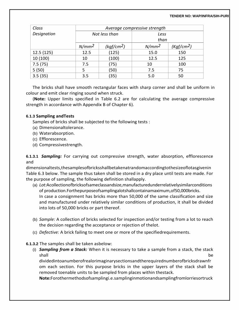
TENDER NO: WAP/INFRA/SIH-PURI
Class Designation
Average compressive strength
Not less than Less than
N/mm2 (kgf/cm2) N/mm2 (Kgf/cm2) 12.5 (125) 12.5 (125) 15.0 150 10 (100) 10 (100) 12.5 125 7.5 (75) 7.5 (75) 10 100 5 (50) 5 (50) 7.5 75 3.5 (35) 3.5 (35) 5.0 50
The bricks shall have smooth rectangular faces with sharp corner and shall be uniform in
colour and emit clear ringing sound when struck. (Note: Upper limits specified in Table 6.2 are for calculating the average compressive
strength in accordance with Appendix B of Chapter 6).
6.1.3 Sampling andTests Samples of bricks shall be subjected to the following tests : (a) Dimensionaltolerance. (b) Waterabsorption. (c) Efflorescence. (d) Compressivestrength.
6.1.3.1 Sampling: For carrying out compressive strength, water absorption, efflorescence and dimensionaltests,thesamplesofbricksshallbetakenatrandomaccordingtothesizeoflotasgivenin Table 6.3 below. The sample thus taken shall be stored in a dry place until tests are made. For the purpose of sampling, the following definition shallapply.
(a) Lot:Acollectionofbricksofsameclassandsize,manufacturedunderrelativelysimilarconditionsof production.Forthepurposeofsamplingalotshallcontainamaximum,of50,000bricks. In case a consignment has bricks more than 50,000 of the same classification and size and manufactured under relatively similar conditions of production, it shall be divided into lots of 50,000 bricks or part thereof.
(b) Sample: A collection of bricks selected for inspection and/or testing from a lot to reach
the decision regarding the acceptance or rejection of thelot.
(c) Defective: A brick failing to meet one or more of the specifiedrequirements.
6.1.3.2 The samples shall be taken asbelow: (i) Sampling from a Stack: When it is necessary to take a sample from a stack, the stack
shall be dividedintoanumberofrealorimaginarysectionsandtherequirednumberofbricksdrawnfrom each section. For this purpose bricks in the upper layers of the stack shall be removed toenable units to be sampled from places within thestack. Note:Forothermethodsofsamplingi.e.samplinginmotionandsamplingfromlorriesortruck
TENDER NO: WAP/INFRA/SIH-PURI
s, IS :5454 may bereferred.
Scale of sampling and criteria for conformity for visual and dimensional characteristics:— Visual characteristics: The bricks shall be selected and inspected for ascertaining their conformity to the requirements of the relevant specification.
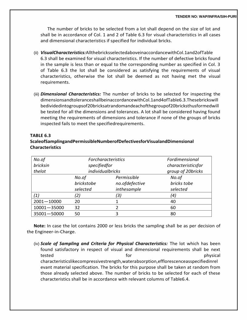
TENDER NO: WAP/INFRA/SIH-PURI
The number of bricks to be selected from a lot shall depend on the size of lot and shall be in accordance of Col. 1 and 2 of Table 6.3 for visual characteristics in all cases and dimensional characteristics if specified for individual bricks.
(ii) VisualCharacteristics:AllthebricksselectedaboveinaccordancewithCol.1and2ofTable
6.3 shall be examined for visual characteristics. If the number of defective bricks found in the sample is less than or equal to the corresponding number as specified in Col. 3 of Table 6.3 the lot shall be considered as satisfying the requirements of visual characteristics, otherwise the lot shall be deemed as not having met the visual requirements.
(iii) Dimensional Characteristics: The number of bricks to be selected for inspecting the
dimensionsandtoleranceshallbeinaccordancewithCol.1and4ofTable6.3.Thesebrickswill bedividedintogroupsof20bricksatrandomandeachofthegroupof20bricksthusformedwill be tested for all the dimensions and tolerances. A lot shall be considered having found meeting the requirements of dimensions and tolerance if none of the groups of bricks inspected fails to meet the specifiedrequirements.
TABLE 6.3 ScaleofSamplingandPermissibleNumberofDefectivesforVisualandDimensional Characteristics
No.of Forcharacteristics Fordimensional bricksin specifiedfor characteristicsfor thelot individualbricks group of 20bricks
No.of Permissible No.of brickstobe no.ofdefective bricks tobe selected inthesample selected
(1) (2) (3) (4)
2001—10000 20 1 40
10001—35000 32 2 60
35001—50000 50 3 80
Note: In case the lot contains 2000 or less bricks the sampling shall be as per decision of
the Engineer-in-Charge.
(iv) Scale of Sampling and Criteria for Physical Characteristics: The lot which has been found satisfactory in respect of visual and dimensional requirements shall be next tested for physical characteristicslikecompressivestrength,waterabsorption,efflorescenceasspecifiedinrelevant material specification. The bricks for this purpose shall be taken at random from those already selected above. The number of bricks to be selected for each of these characteristics shall be in accordance with relevant columns of Table6.4.
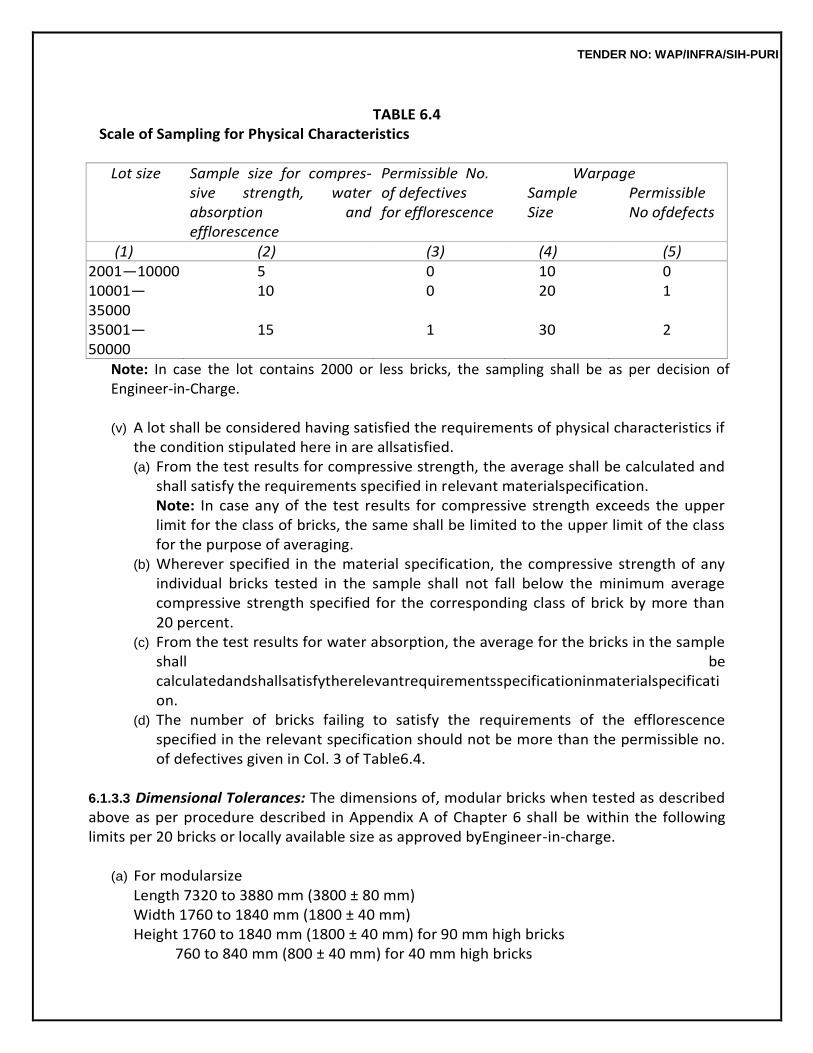
TENDER NO: WAP/INFRA/SIH-PURI
TABLE 6.4
Scale of Sampling for Physical Characteristics
Lot size Sample size for compres- sive strength, water absorption and efflorescence
Permissible No. of defectives for efflorescence
Warpage Sample Permissible Size No ofdefects
(1) (2) (3) (4) (5) 2001—10000 5 0 10 0 10001—35000
10 0 20 1
35001—50000
15 1 30 2
Note: In case the lot contains 2000 or less bricks, the sampling shall be as per decision of Engineer-in-Charge.
(v) A lot shall be considered having satisfied the requirements of physical characteristics if
the condition stipulated here in are allsatisfied. (a) From the test results for compressive strength, the average shall be calculated and
shall satisfy the requirements specified in relevant materialspecification. Note: In case any of the test results for compressive strength exceeds the upper limit for the class of bricks, the same shall be limited to the upper limit of the class for the purpose of averaging.
(b) Wherever specified in the material specification, the compressive strength of any individual bricks tested in the sample shall not fall below the minimum average compressive strength specified for the corresponding class of brick by more than 20 percent.
(c) From the test results for water absorption, the average for the bricks in the sample shall be calculatedandshallsatisfytherelevantrequirementsspecificationinmaterialspecification.
(d) The number of bricks failing to satisfy the requirements of the efflorescence specified in the relevant specification should not be more than the permissible no. of defectives given in Col. 3 of Table6.4.
6.1.3.3 Dimensional Tolerances: The dimensions of, modular bricks when tested as described above as per procedure described in Appendix A of Chapter 6 shall be within the following limits per 20 bricks or locally available size as approved byEngineer-in-charge.
(a) For modularsize
Length 7320 to 3880 mm (3800 ± 80 mm) Width 1760 to 1840 mm (1800 ± 40 mm) Height 1760 to 1840 mm (1800 ± 40 mm) for 90 mm high bricks
760 to 840 mm (800 ± 40 mm) for 40 mm high bricks
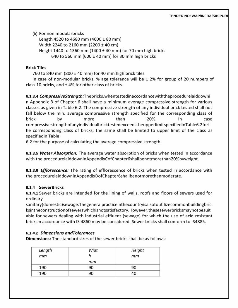
TENDER NO: WAP/INFRA/SIH-PURI
(b) For non modularbricks
Length 4520 to 4680 mm (4600 ± 80 mm) Width 2240 to 2160 mm (2200 ± 40 cm) Height 1440 to 1360 mm (1400 ± 40 mm) for 70 mm high bricks
640 to 560 mm (600 ± 40 mm) for 30 mm high bricks
Brick Tiles 760 to 840 mm (800 ± 40 mm) for 40 mm high brick tiles In case of non-modular bricks, % age tolerance will be ± 2% for group of 20 numbers of
class 10 bricks, and ± 4% for other class of bricks.
6.1.3.4 CompressiveStrength:Thebricks,whentestedinaccordancewiththeprocedurelaiddownin Appendix B of Chapter 6 shall have a minimum average compressive strength for various classes as given in Table 6.2. The compressive strength of any individual brick tested shall not fall below the min. average compressive strength specified for the corresponding class of brick by more than 20%. In case compressivestrengthofanyindividualbricktestedexceedstheupperlimitspecifiedinTable6.2forthe corresponding class of bricks, the same shall be limited to upper limit of the class as specifiedin Table 6.2 for the purpose of calculating the average compressive strength.
6.1.3.5 Water Absorption: The average water absorption of bricks when tested in accordance with the procedurelaiddowninAppendixCofChapter6shallbenotmorethan20%byweight.
6.1.3.6 Efflorescence: The rating of efflorescence of bricks when tested in accordance with the procedurelaiddowninAppendixDofChapter6shallbenotmorethanmoderate.
6.1.4 SewerBricks 6.1.4.1 Sewer bricks are intended for the lining of walls, roofs and floors of sewers used for ordinary sanitary(domestic)sewage.Thegeneralpracticeinthecountryisalsotoutilizecommonbuildingbricksintheconstructionofsewerswhichisnotsatisfactory.However,thesesewerbricksmaynotbesuitable for sewers dealing with industrial effluent (sewage) for which the use of acid resistant bricksin accordance with IS 4860 may be considered. Sewer bricks shall conform to IS4885.
6.1.4.2 Dimensions andTolerances Dimensions: The standard sizes of the sewer bricks shall be as follows:
Length mm
Width mm
Height mm
190 90 90
190 90 40
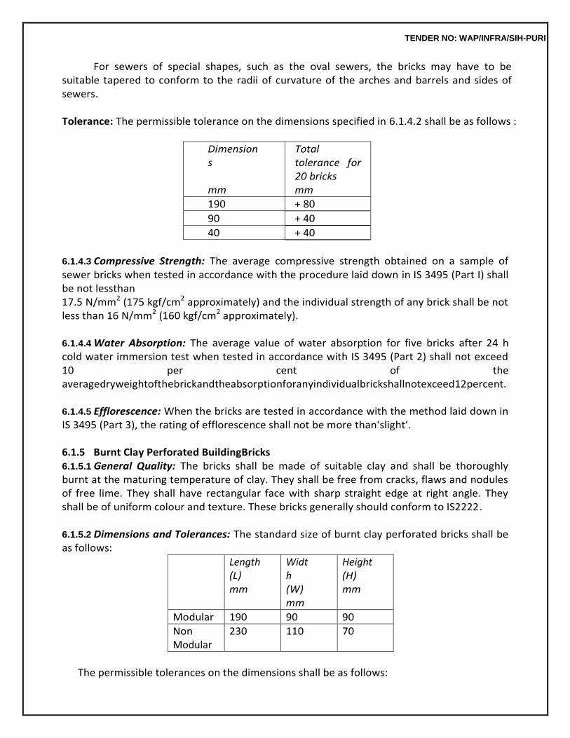
TENDER NO: WAP/INFRA/SIH-PURI
For sewers of special shapes, such as the oval sewers, the bricks may have to be suitable tapered to conform to the radii of curvature of the arches and barrels and sides of sewers.
Tolerance: The permissible tolerance on the dimensions specified in 6.1.4.2 shall be as follows :
Dimensions
mm
Total tolerance for 20 bricks mm
190 + 80
90 + 40
40 + 40
6.1.4.3 Compressive Strength: The average compressive strength obtained on a sample of sewer bricks when tested in accordance with the procedure laid down in IS 3495 (Part I) shall be not lessthan 17.5 N/mm2 (175 kgf/cm2 approximately) and the individual strength of any brick shall be not less than 16 N/mm2 (160 kgf/cm2 approximately).
6.1.4.4 Water Absorption: The average value of water absorption for five bricks after 24 h cold water immersion test when tested in accordance with IS 3495 (Part 2) shall not exceed 10 per cent of the averagedryweightofthebrickandtheabsorptionforanyindividualbrickshallnotexceed12percent.
6.1.4.5 Efflorescence: When the bricks are tested in accordance with the method laid down in IS 3495 (Part 3), the rating of efflorescence shall not be more than‘slight’.
6.1.5 Burnt Clay Perforated BuildingBricks 6.1.5.1 General Quality: The bricks shall be made of suitable clay and shall be thoroughly burnt at the maturing temperature of clay. They shall be free from cracks, flaws and nodules of free lime. They shall have rectangular face with sharp straight edge at right angle. They shall be of uniform colour and texture. These bricks generally should conform to IS2222.
6.1.5.2 Dimensions and Tolerances: The standard size of burnt clay perforated bricks shall be as follows:
Length (L) mm
Width (W) mm
Height (H) mm
Modular 190 90 90
Non Modular
230 110 70
The permissible tolerances on the dimensions shall be as follows:
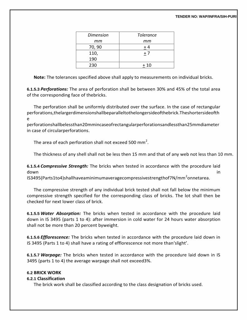
TENDER NO: WAP/INFRA/SIH-PURI
Dimension mm
Tolerance mm
70, 90 + 4
110, 190
+ 7
230 + 10
Note: The tolerances specified above shall apply to measurements on individual bricks.
6.1.5.3 Perforations: The area of perforation shall be between 30% and 45% of the total area of the corresponding face of thebricks.
The perforation shall be uniformly distributed over the surface. In the case of rectangular
perforations,thelargerdimensionshallbeparalleltothelongersideofthebrick.Theshortersideofthe perforationshallbelessthan20mmincaseofrectangularperforationsandlessthan25mmdiameterin case of circularperforations.
The area of each perforation shall not exceed 500 mm2.
The thickness of any shell shall not be less then 15 mm and that of any web not less than 10 mm.
6.1.5.4 Compressive Strength: The bricks when tested in accordance with the procedure laid down in IS3495(Parts1to4)shallhaveaminimumaveragecompressivestrengthof7N/mm2onnetarea.
The compressive strength of any individual brick tested shall not fall below the minimum
compressive strength specified for the corresponding class of bricks. The lot shall then be checked for next lower class of brick.
6.1.5.5 Water Absorption: The bricks when tested in accordance with the procedure laid down in IS 3495 (parts 1 to 4): after immersion in cold water for 24 hours water absorption shall not be more than 20 percent byweight.
6.1.5.6 Efflorescence: The bricks when tested in accordance with the procedure laid down in IS 3495 (Parts 1 to 4) shall have a rating of efflorescence not more than‘slight’.
6.1.5.7 Warpage: The bricks when tested in accordance with the procedure laid down in IS 3495 (parts 1 to 4) the average warpage shall not exceed3%.
6.2 BRICK WORK 6.2.1 Classification
The brick work shall be classified according to the class designation of bricks used.
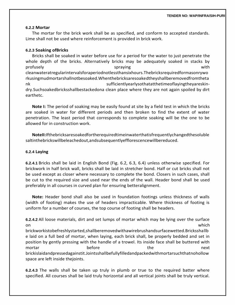
TENDER NO: WAP/INFRA/SIH-PURI
6.2.2 Mortar The mortar for the brick work shall be as specified, and conform to accepted standards.
Lime shall not be used where reinforcement is provided in brick work.
6.2.3 Soaking ofBricks Bricks shall be soaked in water before use for a period for the water to just penetrate the
whole depth of the bricks. Alternatively bricks may be adequately soaked in stacks by profusely spraying with cleanwateratregularintervalsforaperiodnotlessthansixhours.Thebricksrequiredformasonryworkusingmudmortarshallnotbesoaked.Whenthebricksaresoakedtheyshallberemovedfromthetank sufficientlyearlysothatatthetimeoflayingtheyareskin-dry.Suchsoakedbricksshallbestackedona clean place where they are not again spoiled by dirt earthetc.
Note I: The period of soaking may be easily found at site by a field test in which the bricks
are soaked in water for different periods and then broken to find the extent of water penetration. The least period that corresponds to complete soaking will be the one to be allowed for in construction work.
NoteII:Ifthebricksaresoakedfortherequiredtimeinwaterthatisfrequentlychangedthesoluble
saltinthebrickswillbeleachedout,andsubsequentlyefflorescencewillbereduced.
6.2.4 Laying
6.2.4.1 Bricks shall be laid in English Bond (Fig. 6.2, 6.3, 6.4) unless otherwise specified. For brickwork in half brick wall, bricks shall be laid in stretcher bond. Half or cut bricks shall not be used except as closer where necessary to complete the bond. Closers in such cases, shall be cut to the required size and used near the ends of the wall. Header bond shall be used preferably in all courses in curved plan for ensuring betteralignment.
Note: Header bond shall also be used in foundation footings unless thickness of walls
(width of footing) makes the use of headers impracticable. Where thickness of footing is uniform for a number of courses, the top course of footing shall be headers.
6.2.4.2 All loose materials, dirt and set lumps of mortar which may be lying over the surface on which brickworkistobefreshlystarted,shallberemovedwithawirebrushandsurfacewetted.Bricksshallbe laid on a full bed of mortar, when laying, each brick shall, be properly bedded and set in position by gently pressing with the handle of a trowel. Its inside face shall be buttered with mortar before the next brickislaidandpressedagainstit.Jointsshallbefullyfilledandpackedwithmortarsuchthatnohollow space are left inside thejoints.
6.2.4.3 The walls shall be taken up truly in plumb or true to the required batter where specified. All courses shall be laid truly horizontal and all vertical joints shall be truly vertical.
TENDER NO: WAP/INFRA/SIH-PURI
Vertical joints in the alternate course shall come directly one over the other. Quoin, Jambs and other angles shall be pro- perly plumbed as the work proceeds. Care shall be taken to keep the perpends properly aligned within following maximum permissible tolerances:
(a) Deviation from vertical within a storey shall not exceed 6 mm per 3 mheight. (b) Deviation in verticality in total height of any wall of building more than one storey in
height shall not exceed 12.5mm. (c) Deviation from position shown on plan of any brick work shall not exceed 12.5mm. (d) Relative displacement between load bearing wall in adjacent storeys intended to be
vertical alignments shall not exceed 6mm. (e) Asetoftoolscomprisingofwoodenstraightedge,masonicspiritlevels,square,1metrerulelin
e and plumb shall be kept on the site of work for every 3 masons for proper check during the progress ofwork.
6.2.4.4 All quoins shall be accurately constructed and the height of brick courses shall be kept uniform. This will be checked using graduated wooden straight edge or storey rod indicating height of each course including thickness of joints. The position of damp proof course, window sills, bottom of lintels, top of the wall etc. along the height of the wall shall be marked on the graduated straight edge orstorey rod. Acute and obtuse quoins shall be bonded, where practicable in the same way as square quoins. Obtusequoinsshallbeformedwithsquintshowingthreequartersbrickononefaceandquarterbrickon theother.
6.2.4.5 The brick work shall be built in uniformlayers.
No part of the wall during its construction shall rise more than one metre above the general construction level. Parts of wall left at different levels shall be raked back at an angle of 45 degrees or less with the horizontal. Toothing shall not be permitted as an alternative to raking back. For half brick partition to be keyed into main walls, indents shall be left in the main walls.
6.2.4.6 All pipe fittings and specials, spouts, hold fasts and other fixtures which are required to be built into the walls shall be embedded, as specified, in their correct position as the work proceeds unless otherwise directed by theEngineer-in-Charge.
6.2.4.7 Topcoursesofallplinths,parapets,stepsandtopofwallsbelowfloorandroofslabsshallbelaid with brick on edge, unless specified otherwise. Brick on edge laid in the top courses at corner of walls shallbeproperlyradiatedandkeyedintopositiontoformcut(maru)cornersasshowninFig6.4.Where brickscannotbecuttotherequiredshapetoformcut(maru)corners,cementconcrete1:2:4(1cement: 2 coarse sand : 4 graded stone aggregate 20 mm nominal size) equal to thickness of course shall be provided in lieu of cutbricks.
6.2.4.8 Bricks shall be laid with frog (where provided) up. However, when top course is exposed, bricks shall be laid with frog down. For the bricks to be laid with frog down, the frog shall be filled with mortar before placing the brick inposition.
TENDER NO: WAP/INFRA/SIH-PURI
6.2.4.9 Incaseofwallsonebrickthickandunder,onefaceshallbekeptevenandinproperplane,while the other face may be slightly rough. In case of walls more than one brick thick, both the faces shall be kept even and in properplane.
6.2.4.10 To facilitate taking service lines later without excessive cutting of completed work, sleeves (to be paid separately) shall be provided, where specified, while raising the brick work. Such sleeves in externalwallsshallbeslopeddownoutwardsoastoavoidpassageofwaterinside.
6.2.4.11 Top of the brickwork in coping and sills in external walls shall be slightly tilted. Where brick coping and sills are projecting beyond the face of the wall, drip course/throating (to be paid separately) shall be provided whereindicated.
6.2.4.12 Care shall be taken during construction that edges of jambs, sills and projections are not damaged in case of rain. New built work shall be covered with gunny bags or tarpoulin so as to prevent the mortar from being washed away. Damage, if any, shall be made good to the satisfaction of the Engineer-in-Charge.
6.2.4.13 Vertical reinforcement in the form of bars (MS or high strength deformed bars or thermo- mechanicallytreatedbarsasperdirectionofEngineer-in-Charge)),considerednecessaryatthecorners and junction of walls and jamb opening doors, windows etc. shall be encased with cement mortar not leaner than 1:4 (1 cement : 4 coarse sand), or cement concrete mix as specified. The reinforcement shallbesuitablytied,properlyembeddedinthefoundationandatrooflevel.Thedia.ofbarsshallnotbe less than 8 mm and concrete grade shall be minimum 1:3:6 (1 cement : 3 coarse sand : 6 graded stone aggregate 20 mm nominalsize).
6.2.4.14 In retaining walls and the like, where water is likely to accumulate, weep holes, 50 to 75 mm square shall be provided at 2 m vertically and horizontally unless otherwise specified. The lowest weep holeshallbeatabout30cmabovethegroundlevel.Allweepholesshallbesurroundedbyloosestones and shall have sufficient fall to drain out the waterquickly.
Note : Work of providing loose stone will be payable extra.
6.2.4.15 Workofcuttingchases,whereverrequiredtobemadeinthewallsforhousingG.I.pipe,CIpipe oranyotherfixturesshallbecarriedoutinvariouslocationsasperguidelinesgivenbelow:
(a) Cutting of chases in one brick thick and above load bearingwalls. (i) As far as possible services should be planned with the help of vertical chases.
Horizontal chases should beavoided. (ii) Thedepthsofverticalchasesandhorizontalchasesshallnotexceedone-thirdandone-
sixth of the thickness of the masonryrespectively. (iii) When narrow stretches of masonry (or short length of walls) such as between
doors and windows,cannotbeavoidedtheyshouldnotbepiercedwithopeningsforsoilpipesorwast
TENDER NO: WAP/INFRA/SIH-PURI
e pipes or timber joints, etc. Where there is a possibility of load concentration such narrow lengths of walls shall be checked for stresses and high strength bricks in mortar or concrete walls provided, ifrequired.
(iv) Horizontal chases when unavoidable should be located in the upper or lower one-third of height of storey and not more than three chases should be permitted in any stretch of a wall. No continuous horizontal chase shall exceed one metre in length. Where unavoidable, stressesintheaffectedareashouldbecheckedandkeptwithinthepermissiblelimits.
(v) Vertical chases should not be closer than 2 m in any stretch of a wall. These shall be kept awayfrombearingsofbeamsandlintels.Ifunavoidable,stressesintheaffectedareashould be checked and kept within permissiblelimits.
(vi) Masonry directly above a recess, if wider than 30 cm horizontal dimension) should be supported on lintel. Holes in masonry may be provided upto 30 cm width and 30 cm height without any lintel. In the case of circular holes in the masonry, no lintel need be provided for holes upto 40 cm indiameter.
(b) Cutting of chases in half brick load bearingwalls. No chase shall be permitted in half brick load bearing walls and as such no reccessed conduits and concealed pipes shall be provided with half brick thick load bearing walls.
(c) Cutting of chases in half brick non-load bearing wall: Servicesshouldbeplannedwiththehelpofverticalchases.Horizontalchaseshouldbeprovided only whenunavoidable.
6.2.5 Joints
The thickness of all types of joints including brick wall joints and cross joints shall be such that four course and three joints taken consecutively shall measure as follows:
(i) In case of modular bricks conforming to IS 1077 specification for common burnt clay buildings bricks, equal to 39cm.
(ii) In case of non-modular bricks, it shall be equal to 31cm.
Note : Specified thickness of joints shall be of 1 cm. Deviation from the specified thickness of all joints shall not exceed one-fifth of specified thickness.
6.2.5.1 Finishing of Joints: The face of brick work may be finished flush or by pointing. In flush finishingeitherthefacejointsofthemortarshallbeworkedoutwhilestillgreentogiveafinishedsurface flushwiththefaceofthebrickworkorthejointsshallbesquarelyrakedouttoadepthof1cmwhilethe mortarisstillgreenforsubsequentlyplastering.Thefacesofbrickworkshallbecleanedwithwirebrush soastoremoveanysplashesofmortarduringthecourseofraisingthebrickwork.Inpointing,thejoints shall be squarely raked out to a depth of 1.5 cm while the mortar is still green and raked joints shall be brushedtoremovedustandlooseparticlesandwellwetted,andshallbelaterrefilledwithmortartogive ruled finish. Some such finishes are ‘flush’, ‘weathered’, ruled,etc.
TENDER NO: WAP/INFRA/SIH-PURI
6.2.6 Curing
The brick work shall be constantly kept moist on all faces for a minimum period of seven days.Brick workdoneduringthedayshallbesuitablymarkedindicatingthedateonwhichtheworkisdonesoasto keep a watch on the curingperiod.
6.2.7 Scaffolding
Scaffolding shall be strong to withstand all dead, live and impact loads which are likely to come on them. Scaffolding shall be provided to allow easy approach to every part of the work.
6.2.7.1 Single Scaffolding: Where plastering, pointing or any other finishing has been indicated for brickwork,singlescaffoldingmaybeprovided,unlessotherwisespecified.Insinglescaffolding,oneend of the put-logs/pole shall rest in the hole provided in the header course of brick masonry. Not morethan one header for each put-log/pole shall be left out. Such holes shall not be allowed in the case of pillars, brick work less than one metre in length between the openings or near the skew backs of arches or immediately under or near the structural member supported by the walls. The holes for putlogs/poles shall be made good with brick work and wall finishing asspecified.
6.2.7.2 DoubleScaffolding:Wherethebrickworkortileworkistobeexposedandnottobefinishedwith plasteringetc.doublescaffoldinghavingtwoindependentsupports,clearofthework,shallbeprovided.
6.2.8 Measurements
6.2.8.1 Brick work shall be measured in cubic metres unless otherwise specified. Any extra work over the specified dimensions shall be ignored. Dimensions shall be measured correct to the nearest 0.01m i.e. 1 cm. Areas shall be calculated to the nearest 0.01 sq mtrs and the cubic contents shall be worked out to the nearest 0.01 cubic metres.
6.2.8.2 Brick work shall be measured separately in the followingstages:
(a) From foundation to floor one level (Plinthlevel) (b) Plinth (floor one) level to floor twolevel (c) Between two specified floor levels above floor twolevel Note : (i) Brick work in parapet walls, mumty, lift machine room and water tanks
constructed on the roof upto 1.2 m height above roof shall be measured together with the corresponding work of the floor next below.
6.2.8.3 Nodeductionsoradditionsshallbedoneandnoextrapaymentmadeforthefollowing:
Note : Where minimum area is defined for deduction of an opening, void or both, such
TENDER NO: WAP/INFRA/SIH-PURI
areas shall refer only to opening or void within the space measured. (a) Ends of dissimilar materials (that is, joists, beams, lintels, posts, girders, rafters,
purlins,trusses, corbels, steps, etc.); up to 0.1 m2 insection; (b) Opening up to 0.1 m2 in area (seeNote); (c) Wall plates, bed plates, and bearing of slabs, chajjas and the like, where thickness does
not exceed 10 cm and bearing does not extend over the full thickness ofwall; (d) Cement concrete blocks as for hold fasts and holding downbolts; (e) Iron fixtures, such as wall ties, pipes upto 300 mm diameter and hold fasts for doors
and windows;and (f) Chases of section not exceeding 50 cm ingirth. (g) Bearing portion of drip course, bearing of moulding andcornice.
Note : In calculating area of an opening, any separate lintel or sills shall be included with
the size of the opening but end portions of lintel shall be excluded. Extra width of rebated reveals, if any, shall also be excluded.
6.2.8.4 Walls half brick thick and less shall each be measured separately in square metres stating thickness.
6.2.8.5 Walls beyond half brick thickness shall be measured in multiples of half brick which shall be deemed to be inclusive of mortar joints. For the sizes of bricks specified in 6.1.1, half brick thickness shall mean 100 mm for modular and 115 mm for non-modularbricks.
Where fractions of half brick occur due to architectural or other reasons, measurement shall be as follows:
(a) upto 1/4th brick-actual measurementsand
(b) exceeding 1/4 brick-full halfbricks.
6.2.8.6 String courses, projecting pilasters, aprons, sills and other projections shall be fully described and measured separately in running metres stating dimensions of eachprojection.
6.2.8.7 Squareorrectangularpillarsshallbemeasuredseparatelyincubicmetresinmultipleofhalfbrick.
6.2.8.8 Circular pillars shall be measured separately in cubic metres as per actualdimensions.
6.2.8.9 Brick work curved on plan shall be measured like the brick work in straight walls and shall include all cutting and wastage of bricks, tapered vertical joints and use of extra mortar, if any. Brick workcurvedonplantoameanradiusnotexceedingsixmetresshallbemeasuredseparatelyandextra shallbepayableovertheratesforbrickworkinstraightwalls.Nothingextrashallbepayableifthemean radius of the brick work curved in plan exceeds sixmetres.
6.2.8.10 Tapered walls shall be measured net as walls and extra payment shall be allowed for making tapered surface for brick work inwalls.
TENDER NO: WAP/INFRA/SIH-PURI
6.2.8.11 Brick work with brick tiles shall be measured and paid forseparately.
6.2.9 Rate
Therateshallincludethecostofmaterialsandlabourrequiredforalltheoperationsdescribedabove except the vertical reinforcement and its encasement in cement mortar or cement concrete. The rate shall also include the following:
(a) Raking out joints or finishing joints flush as the workproceeds; (b) Preparing tops of existing walls and the like for raising further new brickwork. (c) Rough cutting and waste for forming gables, splays at eaves and thelike. (d) Leaving holes for pipes upto 150 mm dia. and encasing hold fastsetc. (e) Rough cutting and waste for brick work curved in plan and for backing to stone or
other types of facing. (f) Embedding in ends of beams, joists, slabs, lintels, sills, trussesetc. (g) Bedding wall plates, lintels, sills, roof tiles, corrugated sheets, etc. in or on walls if not
coveredin respective itemsand (h) Leavingchasesofsectionnotexceeding50cmingirthor350sqcmincross-section. (i) Brickonedgecourses,cutbrickcorners,splaysreveals,cavitywalls,brickworkscurvedonplan
to a mean radius exceeding sixmetres.
6.3 BRICK WORK IN ARCHES (FIG.6.5)
6.3.0 The detailed specifications for brick work mentioned in 6.2 shall apply, in so far as these are applicable. Arch work shall include masonry for both gauged as well as plain arches. In gauged arches, cut or moulded bricks shall be used. In plain arches, uncut bricks shall beused.
Brick forming skew-backs shall be dressed or cut so as to give proper radial bearing to the end voussiors. Defects in dressing of bricks shall not be covered by extravagant use of mortar, nor shall the use of chips or bats etc. be permitted.
The bricks of the spandrel wall at their junctions with the extrudes of the arch shall be cut
to fit the curvature of the arch.
6.3.1 CircularArches These shall be either (a) plain arches, and shall be built in half brick concentric rings with
break joints, or (b) gauged arches built with bricks cut or moulded to proper shape. The arch work shall be carried up from both ends simultaneously and keyed in the centre. The bricks shall be flush with mortar and well pressed into their positions so as to squeeze out a part of their mortar and leave the joints thin and compact. All joints shall be full of mortar and thickness of joints shall not be less than 5 mm nor more than 15 mm.
After the arch is completed, the haunches shall be loaded by filling up the spandrels upto
the crown level of the arch. Care shall be taken to load the haunches on two sides of the spandrels.
When the arch face is to be pointed (and not plastered), the face bricks shall be cut to
TENDER NO: WAP/INFRA/SIH-PURI
propershape or moulded, so as to have the joints not more than 5 mm thick. These shall be laid with radial joints to thefulldepthofthearch.Thevoussoirsshallbreakjointstothefulldepthofthearch.
6.3.2 FlatArches
These shall be gauged arches of brick cut or moulded to proper shape. The extrados shall be kept horizontal and the intrados shall be given slight camber of 1 in 100 of the span. The centre of the arch from which joints shall radiate, shall be determined by the point of the inter-section of the two lines drawn from the ends of the arch at the springing level and at 60° to horizontal.
In flat arches, bricks shall be laid with radial joints to the full depth of arch and voussoirs
breaking jointswitheachother.Thearchworkshallbecarriedupfrombothendssimultaneouslyandkeyedinthe centre. The thickness of the joints shall not exceed 5 mm. Flat arches may be used for the sake of appearance but for purpose of carrying loads of the wall above, these shall be used in conjunction with relieving arches, lintels placedbelow.
6.3.3 Centring andShuttering
ThecentringandshutteringforthearchshallbegotapprovedbytheEngineer-in-Chargebeforethe arch work is started. It shall be strong enough to bear the dead load of the arch and the live loads that are likely to come upon it during construction, without any appreciabledeflections.
The shuttering shall be tightened with hard wood wedged or sand boxes, so that the same
could be eased without jerks being transmitted to the arch. The sequence of easing the shuttering shall be got approved from the Engineer-in-Charge. The shuttering shall be struck within 48 hours of thecompletion of the arch but not before 24 hours. This shall be done after the spandrel has been filled in and thearch loaded.
6.3.4 Measurements
The length of the arch shall be measured as the mean of the extrados and intrados of the arch correct to a cm. The thickness of the arch shall be measured in multiples of the half brick.
The breadth in the direction of the thickness of wall shall be measured as specified. The cubical contents shall be calculated in cubic metre, correct to two places of decimal. For arches exceeding 6 m in spans extra payment shall be made on the actual area of the
soffit for additional cost of centring including all strutting, bolting, wedging, easing, striking and its removal.
6.3.5 Rate
The rate is inclusive of the cost of the materials and labour required for all the operations described above.
6.4 HALF BRICKWORK
TENDER NO: WAP/INFRA/SIH-PURI
Brick work in half brick walls shall be done in the same manner as described above in 6.2.4 except that the bricks shall be laid in stretcher bond. When the half brick work is to be reinforced, 2 Nos. M.S. barsof6mmdia.,shallbeembeddedineverythirdcourseasgivenintheitem(thediaofbarsshallnot exceed8mm).Theseshallbesecurelyanchoredattheirendwherethepartitionsend.Thefreeendsof the reinforcement shall be keyed into the mortar of the main brick work to which the half brick work is joined. The mortar used for reinforced brick work shall be rich dense cement mortarof mix 1:4 (1cement:4coarsesand).Limemortarshallnotbeused.Overlapsinreinforcement,ifanyshallnotbe less than 30cm.
The mortar interposed between the reinforcement bars and the brick shall not be less than 5 mm.
The mortar covering in the direction of joints shall not be less than 15 mm.
6.4.1 Measurements The length and height of the wall shall be measured correct to a cm. The area shall be
calculated in sq.m. where half brick wall is joined to the main walls of one brick or greater thickness and measurements for half brick wall shall be taken for its clear length from the face of the thicker wall.
6.4.2 Rate
Therateincludesthecostofthematerialsandlabourinvolvedinalltheoperationsdescribedabove except reinforcement which is to be paid forseparately.
6.5 BRICK TILE WORK
6.5.0 The work shall be done in the same manner as described in 6.2.4 except that brick tile shall be used instead of bricks. The measurement and rate shall be same as specified under 6.2. 6.6 HONEY COMB BRICKWORK
The honeycomb brick work shall be done with specified class of brick, laid in specified mortar. All joints and edges shall be struck flush to give an even surface.
The thickness of the brick honeycomb work shall be half-brick only, unless otherwise specified.
Openings shall be equal and alternate with half brick laid with a bearing of 2 cm on either side.
6.6.1 Measurements The length and height shall be measured correct to a cm. Area shall be calculated in
square metres correct to two places of decimal. Honeycomb openings shall not be deducted.
6.6.2 Rate The rate includes the cost of materials and labour involved in all the operations described above.
6.7 JOINING OLD BRICK WORK WITH NEW BRICKWORK
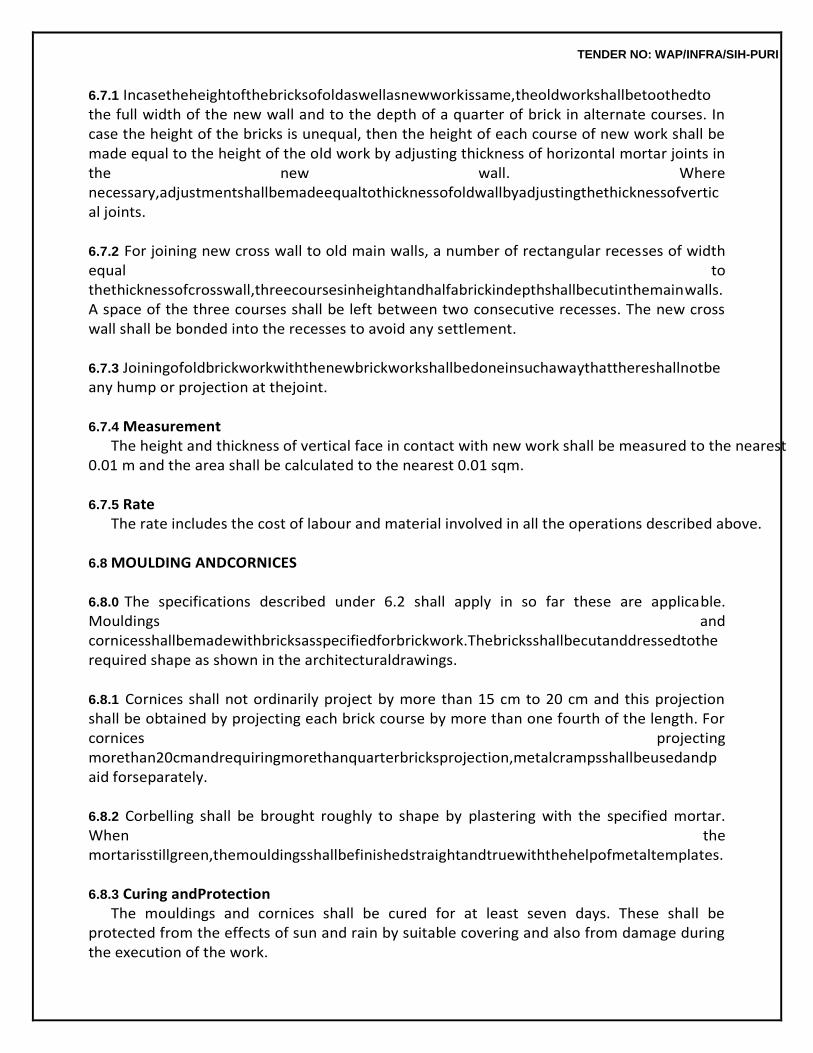
TENDER NO: WAP/INFRA/SIH-PURI
6.7.1 Incasetheheightofthebricksofoldaswellasnewworkissame,theoldworkshallbetoothedto the full width of the new wall and to the depth of a quarter of brick in alternate courses. In case the height of the bricks is unequal, then the height of each course of new work shall be made equal to the height of the old work by adjusting thickness of horizontal mortar joints in the new wall. Where necessary,adjustmentshallbemadeequaltothicknessofoldwallbyadjustingthethicknessofvertical joints.
6.7.2 For joining new cross wall to old main walls, a number of rectangular recesses of width equal to thethicknessofcrosswall,threecoursesinheightandhalfabrickindepthshallbecutinthemainwalls. A space of the three courses shall be left between two consecutive recesses. The new cross wall shall be bonded into the recesses to avoid any settlement.
6.7.3 Joiningofoldbrickworkwiththenewbrickworkshallbedoneinsuchawaythatthereshallnotbe any hump or projection at thejoint.
6.7.4 Measurement
The height and thickness of vertical face in contact with new work shall be measured to the nearest 0.01 m and the area shall be calculated to the nearest 0.01 sqm.
6.7.5 Rate
The rate includes the cost of labour and material involved in all the operations described above.
6.8 MOULDING ANDCORNICES
6.8.0 The specifications described under 6.2 shall apply in so far these are applicable. Mouldings and cornicesshallbemadewithbricksasspecifiedforbrickwork.Thebricksshallbecutanddressedtothe required shape as shown in the architecturaldrawings.
6.8.1 Cornices shall not ordinarily project by more than 15 cm to 20 cm and this projection shall be obtained by projecting each brick course by more than one fourth of the length. For cornices projecting morethan20cmandrequiringmorethanquarterbricksprojection,metalcrampsshallbeusedandpaid forseparately.
6.8.2 Corbelling shall be brought roughly to shape by plastering with the specified mortar. When the mortarisstillgreen,themouldingsshallbefinishedstraightandtruewiththehelpofmetaltemplates.
6.8.3 Curing andProtection
The mouldings and cornices shall be cured for at least seven days. These shall be protected from the effects of sun and rain by suitable covering and also from damage during the execution of the work.
TENDER NO: WAP/INFRA/SIH-PURI
6.8.4 Measurements
For the purpose of measurements, the sectional periphery of mouldings and cornices (excludingthe portionincontactwithwall)shallbemeasuredincentimetresandlengthinmetres(fig.below).Thegirth and length shall be measured correct to a cm. No deduction shall be made from the masonry of wall for the bearing of the moulding andcornices.
Note : 1 The sectional periphery curve ABCDEF.
2. Length FA shall not be measured.
6.8.5 Rate The rate includes the cost of materials and labour involved in all the operations described above.
6.9 BRICK WORK UNDER WATER OR FOULCONDITIONS
Brick Work under following conditions : (i) Work in or under water/or liquidmud; (ii) Work in or under foulpositions Shall be measured separately for payment of extra rate over and above the quantity
measured and paid under para 6.2.8.
6.10 EXPOSED BRICKWORK
6.10.1 FacingBricks The facing bricks made from suitable soils shall be free from cracks, flaws, nodules of free
lime warpage and organic matter. These shall be thoroughly burnt and shall have plane rectangular faces with parallel sides and sharp straight right angled edges. Facing bricks shall have uniform colour and even texture. Unless otherwise specified, facing bricks shall be machine moulded only. As far as possible, total requirement of facing bricks for a work shall be arranged from the same kiln. Bricks with chipped edges and broken corners shall not be used.
6.10.2 Dimensions andTolerances
TENDER NO: WAP/INFRA/SIH-PURI
The standard sizes of machine moulded facing bricks shall be as specified in 6.1.1.
6.10.2.1 The permissible tolerances shall be as under:
Dimension
mm
Tolerance (For Machine moulded bricks) mm
Length 190 or 225 + 3 Width 90 or 111 + 1.5 Thickness 40 or 44 + 1.5
Note: Tolerance and Dimensions for selected hand moulded bricks + 4 mm in length and +
3 mm in width and thickness).
6.10.3 Sampling As per Para 6.1.3 and 6.1.3.2.
6.10.4 PhysicalRequirements
Facing bricks shall be of class designation 75 unless otherwise specified. Average compressive strength shall not be less than 7.5 N/mm2, water absorption shall not exceed 20 per cent by weight and efflorescence rating shall be nil when tested in accordance with the procedure laid down and tolerance in dimensions shall be checked as per the procedure laid down in Appendix A-2.
Mortar, Soaking of Bricks and laying shall be as specified in Para 6.2.2, 6.2.3 and 6.2.4 respectively.
6.10.5 Joints in the exposed brick work shall be truly horizontal and vertical and kept uniform with the help of wooden or steel strips. The thickness of joints shall be as per6.2.5.
6.10.6 Curing and scaffolding shall be as specified in 6.2.6 and 6.2.7 to 6.2.7.2respectively.
6.10.7 Measurements
Exposed brick work in face using machine moulded bricks and selected hand moulded bricks shall be measured separately and the measurement shall be as specified in 6.2.8.
TENDER NO: WAP/INFRA/SIH-PURI
6.10.8 Rate The rates shall be as specified in 6.2.9 and shall also include the following : (a) Labour for selecting bricks and wastage of bricks where use of selected hand moulded
brick is specified. (b) Leaving uniform horizontal and vertical grooves of specified depth and providing
jointsof required thickness using wooden or steel strips as the workproceeds.
6.11 CAVITY WALL Itisawallcomprisingoftwoleaves,eachleafbeingbuiltofmasonryunitsandseparatedbyacavity
so as to provide an air space within the wall and tied together with metal ties or bonding units to ensure that two leaves act as one structural unit. The width of the cavity shall not be less than 50 mm and not more than 115 mm. Each leaf of the cavity wall shall not be less than 75 mm. The space between the leavesbeingeitherleftascavityorfilledwithnon-loadbearinginsulatingandwaterproofingmaterial.
6.11.1 Metal Ties
Thesemaybeofgalvanisediron,wroughtiron,gunmetal,brass,copper,stainlesssteeloranysuch corrosion resistant metal, made of flats 20 x 5 mm cranked or twisted at their mid point with ends split and fish tailed. The ties shall be built into horizontal bed joints during erection, placed sloping towards theexteriorsidetopreventwaterfromflowingalongitfromoutertoinnerleafside(FordetailsreferFig. 6.6 of Chapter 6).
6.11.2 BondingUnits
These shall be preferably precast R.C.C. units having cross-section as per Fig. No. 6.6.
Length of the Bonding units will be sum of thickness of both leaves plus width of cavity if the leaves are 75 mm or 115 mm. If the leaves are more than 115 mm thick, then the length of a unit will be 2 × 115 + width of cavity as shown in Fig. 6 of Chapter 6. Precast RCC units shall be provided with 2 no., 6 mm mild steel reinforcement bars tied with 2 no. 3 mm. dia. M.S. wire/hard drawn wire cross bars (As shown in Fig. 6 of Chapter 6) placed in the centre of units.
Cementconcreteusedinthebondingunitsshallnotbeleanerthan1:3:6(1cement:3coarsesand:
6 graded stone aggregate 20 mm nominalsize).
6.11.3 Spacing Metalties/bondingunitsshallbespacednotmorethan90cmaparthorizontallyand45cmvertical
ly and staggered in each course. Additional ties shall be used nearopenings.
6.11.4 Restrictions Cavitywallsshallnotnormallybebuiltmorethan7.5metresinheightand9metresinlength.Wher
e largelengthsandheightsaredesired,thewallshallbedividedintopanelswithstrengtheningmeasur
TENDER NO: WAP/INFRA/SIH-PURI
es such as pillars etc. Cavity shall be covered at the top with at least two courses of masonry unit and/or a coping overit.
Adoption of cavity walls is not recommended when heavy concentrated load from beam
etc. are to be supported by walls.
6.11.5 Measurements andRate (a) Brick work in cavity walls shall be included and measured with general brick work. The
width of the cavity shall not be measured. Skin of cavity wall, half brick thickness shall be measured as and paid as described in para 6.2.8 and6.4.
(b) The forming of the cavity shall be given in square metres stating the width of the cavity andshall include the metal ties/bonding unit specifying the numbers per squaremetre.
(c) Labour and material for closing cavities at the jambs, sills and heads of opening shall be as described and measured separately in runningmetres.
(d) The item shall include use of device for keeping cavity clear and forming the requisite weep and vent holes and nothing extra on this account shall bepayable.
6.12 GYPSUM PARTITIONPANELS
6.12.1 The material shall conform toIS:2849.
6.12.2 Dimensions As per the item nomenclature.
6.12.3 Laying
(i) Panelsarestoredinadryplaceandwatershouldnotcomeincontactwithpanelsduringorafter construction. If the panels get wet, they should be dried beforeuse.
(ii) The floor should be perfectly level before laying the first course. All panels must be properly aligned to the plumb. Successive layer of panels must be alternatively staggered so that vertical joints are not in the sameline.
(iii) The recommended quantity of Gypsum Bonding Plaster must be used for joints and filling the grooves made for conduits, pipelines, etc. Excess Bonding Plaster must be scooped and removed,sothatthejointsandtheplaceswherethegroovesarefilledinareflushandeven.
(iv) The walls should be dry and sanding done properly especially at joints before the primer is applied so that the surface is even and joints will not be visible after painting. Avoid chasingwith chisel and hammer. Use electrical saw or grooving tools for conduitingetc.
(v) Therecommendedspanofwallsismaximum6metersandmaximumheightis4.5meters. (vi) Gypsumpanelcaneasilybecutwithcoarsetoothhandsaw,electricjigsaw,etc.Thepanelscan
be cut, sawn, drilled, milled or dowelled on the job. For concealed piping and conduit, the depth of groove should not exceed 50 mm. Hammer and chisel techniques to form chases must be avoided.
(vii) Sanding:Thisapplicationistomakethesurfacelevelwithoutundulations.Tomakethegypsu
TENDER NO: WAP/INFRA/SIH-PURI
m wall surface level (in particular at joints, where there is excess bonding plaster), do sanding with sand paper at joints and other places, wherever you find uneven surface, otherwise joints willbe visible after painting. It is important to sand all jointsuniformly.
(viii) PrimerApplication:Thepurposeoftheprimeristogiveabetteradhesiontothepaintandalso toreduceconsumptionofpaintonthewall.Waterthinableprimersshallbeusedonly.
6.12.4 Measurements
The length and height shall be measured correct to a cm. Area shall be calculated in square meters correct to two place of decimal. No deduction shall be made for ducts, opening made from the standard size of panel.
6.12.5 Rate
The rate shall include the cost of materials and labour involved in all the operations described above.
6.13 BRICKEDGING
6.13.1 The edging shall be of bricks of class specified in the item. The specifications of bricks shall be asdescribedin6.1.Trenchesofrequireddepthandwidthshallfirstbemadealongtheedgeoftheplinth protection to receive the bricks for edging. The bed of trenches shall be compacted to a firm and even surface. The brick shall be laid true to line in cement mortar 1:4 (1 cement: 4 fine sand) with length parallelandbuttingtheplinthprotection.Thetopfaceofthebrickedgingshallbeinoneleveltoconform to the finished level of the plinth protection adjacent to the edging. After the concreting is done, no portion of the brick edging shall project above the adjacent concrete surface. Cement mortar shall conform to the specification described in chapter3.0.
6.13.2 Measurements
The brick edging shall be measured in running metere correct a cm.
6.13.3 Rate Rate shall include the cost of materials and labour involved in all operations.
TENDER NO: WAP/INFRA/SIH-PURI
8.0 MARBLE WORK 8.0 GENERAL
Marble shall be hard, sound, dense and homogeneous in texture with crystaline texture as far as possible. It shall generally be uniform in colour and free from stains, cracks, decay and weathering.
8.0.1 Marbles are metamorphic rocks capable of taking polish, formed from the re-crystalization of lime stones or dolomitic lime stones and are distinguished from lime stone by even visibly crystalined nature and nonflaggy stratification.
Note:Marbleisaproductofnaturehenceitisdifficulttoguaranteeuniformityofcolour,veiningoroth
er characteristics that may be represented in any sample submitted. A sample will indicate only an average of colour, veining and other general texture and specifiedfinish.
8.1 CLASSIFICATION
The marble blocks, slabs and tiles shall be classified broadly in the following two categories:
8.1.1 White Marble Raj Nagar (plain white) Marble:
It shall be plain white marble with coarse grains predominantly showing mica particles giving reflection in light.
8.1.2 ColouredMarble
(i) Plain BlackMarble Black marble sawn along veins locally known as ‘Peta Pasu sawing’ available at Bhainslana.
(ii) Black ZebraMarble (a) Bhainslana Black Zebra Marble: Black marble having grey or white veins available
at Bhainslana. (b) Kishangarh Black Zebra Marble: Black marble with grey and/or white veins
available at Kishangarh. (c) Abu Black Zebra Marble: Black marble having white patches and streaks available atAbu. (d) Narnaul Black Zebra Marbles: Black marble with thin white veins available atNarnaul. (e) Makrana Dhobi Doongri Zebra Marble: Greyish black marble with white flowery
pattern available at DhobiDoongri. (iii) GreenMarble
(a) Baroda Green Marble: Dark green marble with flowery pattern available atBaroda. (b) Abu Green Marble: Light green marble with green and/or brown streaks on white
ground available atAmbaji. (c) Falna Green Marble: Green marble with prominent yellowish pattern available atFalna. (d) Bundi Green Marble: Green marble with pinkish shades available at Umar,(Bundi).
(iv) GreyMarble (a) Kumari Grey Marble: Grey marble having light blue shades available atMakrana. (b) Bundi Grey Marble: Grey Marble with pink or green or black streaks available at
Umar (Bundi).
TENDER NO: WAP/INFRA/SIH-PURI
(v) BrownMarble (a) Bar Brown Marble/Brown Marble with light and dark brown shades available atBar. (b) Narnaul BrownMarble
Brown marble having teak wood shades available at Narnaul.
8.1.3 GraniteStone It shall be of any colour and size as directed by Engineer-in-Charge. Granite shall be plain
machine cut and mirror polished. The stone shall be smooth and of even surface without holes or pits.
8.2 SIZES ANDTOLERANCES
The size of marble blocks, slabs and tiles shall be as mentioned in Table 8.1.
TABLE 8.1 Sizes of Marble Blocks, Slabs and Tiles
Length Width Thickness
1. Blocks 30 to 250 30 to 100 30 to 90
2. Slabs 70 to 250 30 to 100 2 to 15
3. Tiles 10 to 60 10 to 60 0.8 to 2.4
Notes: (1) All dimensions are incentimetre. (2) The length and width, of the blocks shall be in multiple of 30cm. (3) Lengthandwidthofslabshallbeinmultipleof10cm.andthicknessinmultipleof1cm. (4) Tiles shall be square cut and linear dimensions in multiple of 10cm. (5) Only slabs and tiles shall be machine cut and factorymade. (6) For 8 mm thick tiles, special precautions will be required for fixing them like using
special adhesive as per manufacturer’s specifications. Such tiles are not suitable for outside veneering workexposedtorains/sunifusedinlargeareasincontinuousstretches.Fortilesofthickness20 mm and above cramps may be provided if approved byEngineer-in-Charge.
Tolerance
The following tolerances shall be allowed in the dimension of blocks, slabs and tiles: Tolerance
Blocks (a) Length + 2 percent (b) Width + 2 percent (c) Thickness + 2 percent
Slabs (a) Length + 2 percent (b) Width + 2 percent (c) Thickness + 3 percent
Tiles (a) Lineardimension + 3 percent
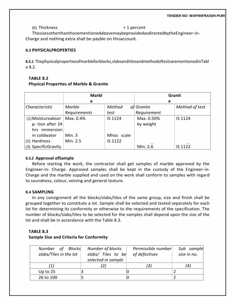
TENDER NO: WAP/INFRA/SIH-PURI
(b) Thickness + 1 percent ThesizesotherthanthosementionedabovemaybeprovidedasdirectedbytheEngineer-in-
Charge and nothing extra shall be payble on thisaccount.
8.3 PHYSICALPROPERTIES
8.3.1 Thephysicalpropertiesofmarbleforblocks,slabsandtilesandmethodoftestsarementionedinTable 8.2.
TABLE 8.2 Physical Properties of Marble & Granite
Marble
Granite
Characteristic Marble Requirements
Method of test
Granite Requirement
Method of test
(1) Moistureabsorp- tion after 24 hrs immersion in coldwater
(2) Hardness (3) SpecificGravity
Max. 0.4% Min. 3 Min. 2.5
IS 1124
Mhos scale IS 1122
Max. 0.50% by weight
Min. 2.6
IS 1124
IS 1122
8.3.2 Approval ofSample
Before starting the work, the contractor shall get samples of marble approved by the Engineer-in- Charge. Approved samples shall be kept in the custody of the Engineer-in-Charge and the marble supplied and used on the work shall conform to samples with regard to soundness, colour, veining and general texture.
8.4 SAMPLING
In any consignment all the blocks/slabs/tiles of the same group, size and finish shall be grouped together to constitute a lot. Sample shall be selected and tested separately for each lot for determining its conformity or otherwise to the requirements of the specification. The number of blocks/slabs/tiles to be selected for the samples shall depend upon the size of the lot and shall be in accordance with the Table 8.3.
TABLE 8.3 Sample Size and Criteria for Conformity
Number of Blocks slabs/Tiles in the lot
Number of blocks slabs/ Tiles to be selected in sample
Permissible number of defectives
Sub sample size in no.
(1) (2) (3) (4)
Up to 25 3 0 2
26 to 100 5 0 2
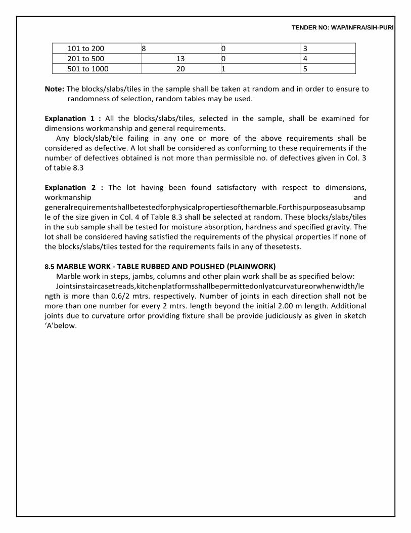
TENDER NO: WAP/INFRA/SIH-PURI
101 to 200 8 0 3
201 to 500 13 0 4
501 to 1000 20 1 5
Note: The blocks/slabs/tiles in the sample shall be taken at random and in order to ensure to
randomness of selection, random tables may be used.
Explanation 1 : All the blocks/slabs/tiles, selected in the sample, shall be examined for dimensions workmanship and general requirements.
Any block/slab/tile failing in any one or more of the above requirements shall be considered as defective. A lot shall be considered as conforming to these requirements if the number of defectives obtained is not more than permissible no. of defectives given in Col. 3 of table 8.3
Explanation 2 : The lot having been found satisfactory with respect to dimensions, workmanship and generalrequirementshallbetestedforphysicalpropertiesofthemarble.Forthispurposeasubsample of the size given in Col. 4 of Table 8.3 shall be selected at random. These blocks/slabs/tiles in the sub sample shall be tested for moisture absorption, hardness and specified gravity. The lot shall be considered having satisfied the requirements of the physical properties if none of the blocks/slabs/tiles tested for the requirements fails in any of thesetests.
8.5 MARBLE WORK - TABLE RUBBED AND POLISHED (PLAINWORK)
Marble work in steps, jambs, columns and other plain work shall be as specified below: Jointsinstaircasetreads,kitchenplatformsshallbepermittedonlyatcurvatureorwhenwidth/le
ngth is more than 0.6/2 mtrs. respectively. Number of joints in each direction shall not be more than one number for every 2 mtrs. length beyond the initial 2.00 m length. Additional joints due to curvature orfor providing fixture shall be provide judiciously as given in sketch ‘A’below.
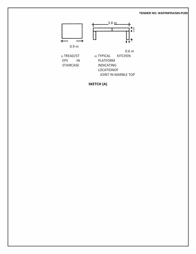
TENDER NO: WAP/INFRA/SIH-PURI
3.8 m
0.9 m
(I) TREAD/STEPS IN STAIRCASE
0.6 m (II) TYPICAL KITCHEN
PLATFORM INDICATING LOCATIONOF
JOINT IN MARBLE TOP
SKETCH (A)
1m
0
.6m
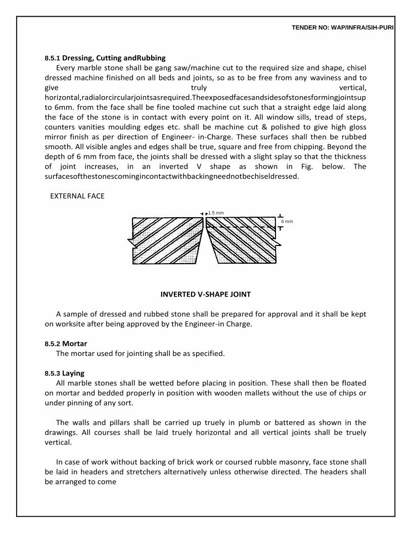
TENDER NO: WAP/INFRA/SIH-PURI
8.5.1 Dressing, Cutting andRubbing
Every marble stone shall be gang saw/machine cut to the required size and shape, chisel dressed machine finished on all beds and joints, so as to be free from any waviness and to give truly vertical, horizontal,radialorcircularjointsasrequired.Theexposedfacesandsidesofstonesformingjointsupto 6mm. from the face shall be fine tooled machine cut such that a straight edge laid along the face of the stone is in contact with every point on it. All window sills, tread of steps, counters vanities moulding edges etc. shall be machine cut & polished to give high gloss mirror finish as per direction of Engineer- in-Charge. These surfaces shall then be rubbed smooth. All visible angles and edges shall be true, square and free from chipping. Beyond the depth of 6 mm from face, the joints shall be dressed with a slight splay so that the thickness of joint increases, in an inverted V shape as shown in Fig. below. The surfacesofthestonescomingincontactwithbackingneednotbechiseldressed.
EXTERNAL FACE
INVERTED V-SHAPE JOINT
A sample of dressed and rubbed stone shall be prepared for approval and it shall be kept on worksite after being approved by the Engineer-in Charge.
8.5.2 Mortar
The mortar used for jointing shall be as specified.
8.5.3 Laying All marble stones shall be wetted before placing in position. These shall then be floated
on mortar and bedded properly in position with wooden mallets without the use of chips or under pinning of any sort.
The walls and pillars shall be carried up truely in plumb or battered as shown in the
drawings. All courses shall be laid truely horizontal and all vertical joints shall be truely vertical.
In case of work without backing of brick work or coursed rubble masonry, face stone shall
be laid in headers and stretchers alternatively unless otherwise directed. The headers shall be arranged to come
1.5 mm
6 mm
TENDER NO: WAP/INFRA/SIH-PURI
as nearly as possible in the middle of stretchers above and below. Stone shall be laid in regular courses of not less than 15 cm in height and all courses shall be of the same height unless otherwise specified.
For work facing with backing of brick work or coursed rubble masonry, face stone shall be
laid in alternate courses of header and stretchers unless otherwise directed. Face stone and bond stone courses shall have break joint on the face of atleast half the height of the standard course and thebond shall be carefully maintained through out. All the connected masonry in a structure shall be carried up nearly at one uniform level throughout but where breaks are unavoidable the joints shall be made in good long steps so as to prevent cracks developing between new and oldwork.
Whennecessaryjibcraneorothermechanicalappliancesshallbeusedtohoisttheheavypiecesof
stones and place these in to correct positions, care being taken that the corners of the stone are not damaged.Stoneshallbecoveredwithgunnybags,beforeputtingchainorropeispassedoverit,andit shall be handled carefully. No piece which has been damaged shall be used in work. The matching of grains shall be carried out as directed by theEngineer-in-Charge.
8.5.4 BondStone
Bond or through stones running right through the thickness of walls, shall be provided in walls upto 60 cm thick and in case of wall above 60 cm thickness a set of two or more bond stones overlapping each other by atleast 15 cm shall be provided in a line from face to back.
At least one bond stone or a set of bond stones shall be provided for every 0.5 sqm of the
wall surface. All bond stones shall be marked suitably as directed by the Engineer-in-Charge.
8.5.5 Joints Thedepthofjoints6mmfromthefaceshallbeuniformandasfineaspossiblebutshallbenotmore
than 1.5 mm thick on the exposed face. Beyond the depth of 6 mm from face, the thickness of joints shall increase in an inverted V shape so as to give good mortar bond between two stones. Theinverted portionofthejointsshallbefilledwithbeddingmortarandtheface6mmportionwithpointingmortar.
8.5.6 Curing
The work shall be kept constantly moist on all faces for a period of atleast seven days.
8.5.7 Finishing Afterthemarbleworkiscured,itshallberubbedwithcarborandumstoneofdifferentgradesno.6
0, 120 and 320 in succession or with electrical rubbing machines rubbed with carborandum items 0 to 6 nos.in succession, so as to give a plane true and highly smooth surface. It shall then be cleaned with a solution of oxalic acid, washed and finishedclean.
TENDER NO: WAP/INFRA/SIH-PURI
8.5.8 Protection Green work shall be protected from rain by suitable coverings. The work shall also be
suitably protected from damage during construction.
8.5.9 Scaffolding Double scaffolding having two sets of vertical supports shall be provided where necessary.
The supports shall be sound and strong, tied together by horizontal pieces over which the scaffolding plank shall be fixed.
8.5.10 Tolerances
As per para 8.2
Note: The above Para 8.5. also applies to the Ashlar masonry referred in Chapter No. 7.0 - Stone Work.
8.5.11 Measurements
For plain work: Measurements shall be taken correct to a cm in length and breadth and correct to 0.5 cm in thickness.
8.5.11.1 In the case of radially dressed or circular stone used in the work, the dimensions of the circumscribingrectangleofthedressedstone,shallbemeasuredcorrecttoacentimetreandthickness, correct to 0.5cm.
The cubical contents shall be calculated in cubic decimetre nearest to two places of decimal.
8.5.11.2 The marble work in arches and domes shall be measured as for plain work, but extra shall be allowed for such work over the rate for plainwork.
8.5.11.3 Sunkormouldedworkinmarbleshallbemeasuredbyvolumeasperplainmarbleworkorwork in arches or domes as the case may be on the basis of circumscribed rectangular block of the finished workbutextrashallbepaidforsuchworkovertherateforplainworkforworkinarchesanddomes.For thepurposeofextrapayment,volumeofeverystonesunkormouldedshallbeconsidered.
8.5.12 Rate
The rate includes the cost of materials and labour required for all the operations i/c cutting of recesses in wall cutting moulding corners edge rounding finishing & polishing as specified.
8.5.13 Use of Finished Marble Slabs andTiles
In case such finished tiles are used, these shall be measured and paid for separately.
8.6 WALL LINING/VENEERWORK
8.6.1 Unless and otherwise specified in the nomenclature of the item, the marble slabs used
TENDER NO: WAP/INFRA/SIH-PURI
for wall lining/veneer work shall be gang saw cut (polished & machine cut) and conform to dimensions given in Table 8.1above.
Back shall not be polished/ cut in order to ensure a good grip with the hearting of backing.
The cut slabs shall be of the thickness as specified with a tolerance permissible under para 8.2 above. The tolerance in wall lining when straight edge of 3 m length is placed should not be more than 2 mm.
8.6.2 Laying
The stone shall be wetted before laying. They shall then be fixed with mortar in position without the use of chips or under pinning of any sort. Care shall be taken to match the grains of veneer work as directed by the Engineer-in-Charge. For purpose of matching the grains, the marble slabs shall be selected judiciously having uniform pattern of veins/streaks. Preferably the slabs shall be those got out of the same block from the quarry. The area to be veneered shall be reproduced on the ground and the marble slabs laid in position and arranged in the manner to give the desired matching of grains. Any adjustment needed for achieving the best results shall be then carried out by replacing or interchanging theparticularslabs.Specialcareshallbetakentoachievethecontinuityofgrainsbetweenthetwoslabs one above the other along the horizontal joints. This shall then be got approved by the Engineer-in- Chargeandeachmarbleslabsnumberedproperlyandthesamenumbershallbemarkedonaseparate drawing as well as on the surface to be actually veneered, so as to ensure the fixing of the particular slabs in the correctlocation.
For the facing of the columns also the same procedure as mentioned above shall be followed.
8.6.2.1 Where so desired, the adjoining stones shall be secured to each other by means of copper pins 75 mm long and 6 mm diameter or asspecified.
TENDER NO: WAP/INFRA/SIH-PURI
8.6.2.2 The stones shall be secured to the backing by means of cramps. The material for cramps shall have high resistance to corrosion under conditions of dampness and against the chemical action of mortar or concrete in which cramps are usuallyembedded.
Cramps shall be of 25 × 6 mm and 30 cm long in case of backing of stone masonry walls
and brick masonrywallsthickerthan230mm.Incaseofbackingwithbrickmasonrywalls230mmorlessthickor RCC members cramps shall be of 25 × 6 mm and length as per requirement made out of gun metal or any other metal specified in para 8.6.2.6. Generally the outer length of cramp in half brick work backing shallbe115mmandinonebrickworkbackingitshallbe150mm.Typicalshape&detailsofcrampsfor such backing are as indicated in Fig. 8.2 for general guidance. This can be modified as directed by the Engineer-in-Chargeifso,requiredatsite.Crampsshallbespacednotmore60cmaparthorizontally.
Alternatively the stone may be secured to the backing by means of stone dowels 10 x 5 x
2.5 cm as per shape indicated in Fig. 8.1.
8.6.2.3 The adjoining stones shall be secured to each other by means of gun metal cramps or copper pins of the specified size. Cramps may be attached to its sides (see Fig. 8.3A, 8.3B) or top and bottom (See Fig. 8.3C, D, E, F) or sides, top and bottom (see Fig. 8.3G, 8.3H). The general arrangement of cramps required for fixing facing unit to the wall are illustrated in Fig 8.3. The actual number of cramps andtheirsections,however,shallbeasperrequirementsofdesigntocarrytheloads.
8.6.2.4 Where cramps are used to hold the unit in position only, the facings shall be provided with a continuous support on which the stones rest at the ground level and other storey levels, the support being in the form of projection from or recess into the concrete floor slab, or a beam between the columns or a metal angle attached to the floor slab or beams. These supports shall preferably be at verticalintervalsnotmorethan3.5mapartandalsoovertheheadsofallopenings.Suchsupportsshall alsobeprovidedwherethereistransitionfromthinfacingbelowtothickfacingsabove.
8.6.2.5 Alternativelycrampsmaybeusedtoholdtheunitsinpositionandinadditiontosupporttheunits thustransferringtheweightoftheunitstothebacking.Suchcrampsshouldbeproperlydesignedasper IS 4101 (Part1).
8.6.2.6 The cramps may be of copper alloyed with zinc, tin, nickel, lead or stainlesssteel.
8.6.2.7 The pins, cramps and dowels shall be laid in cement mortar 1:2 (1 cement : 2 fine sand) and their samples got approved by the Engineer-in-Charge and kept atsite.
8.6.3 Joints
All joints shall be full of mortar. Special care shall be taken to see that groundings for
TENDER NO: WAP/INFRA/SIH-PURI
veneer work arefullofmortar.Ifanyhollowgroundingsaredetectedbytappingthefacestones,theseshallbetaken out and relaid. The thickness of the face joints shall be uniform, straight and as fine as possible, not more than 1.5 mm and in the face joint, the top 6 mm depth shall be filled with mortar specified for the pointing.
8.6.4 Mortar
The mortar used for jointing slabs shall be as specified.
8.6.5 Curing, Finishing, Protection andScaffolding It shall be as specified under 8.5.6, 8.5.7, 8.5.8 and 8.5.9.
8.6.6 Measurements
The length and breadth shall be measured correct to a cm. In case of radially dressed or circular slabsusedinthework,thedimensionsofthecircumscribingrectanglesofthedressedstoneusedinthe work, shall be measured & paid for. The area shall be calculated in sqm nearest to two places of decimal.
Marble work in lining upto 4 cm thickness shall be paid by area under veneer work and
lining of greater thickness paid by volume under plain marble work.
8.6.7 Rate The rate includes the cost of materials and labour required for all the operations
described above exceptforthecostofprovidingandfixingofdowelandcrampswhichshallbepaidforseparately,unless otherwise stipulated in the item ofwork.
When factory made finished slabs and tiles are used, no further finishing as mentioned in
para8.5.7 shall be required nor anything extra shall bepayable.
8.7 MARBLE STONE FLOORING AND MARBLE STONE IN RISERS OF STEPS ANDSKIRTING Refer to relevant clause in subhead 11.0 of flooring of .
8.7.0 Marble Slab UrinalPartitions
The partitions shall be of marble slab embedded in the wall. The size and shape of the marbles slab shallbeasperdirectionofEngineer-in-Charge.Thefinishedthicknessshallbe18mm.Thespecifications formarble/granitestonework,ingeneral,shallbeasspecified.Themarblegranitestoneshallbecutinto slabsofrequiredthicknessandshallbeonepiece.(Fig.8.4).
8.7.1 Finishing
The partition of the slab to be embedded in the masonry shall be rough dressed. Dressing and rubbing of the exposed portion of the slab shall be as described. The dressed slab shall be of the

TENDER NO: WAP/INFRA/SIH-PURI
thicknessasspecifiedwithatoleranceof+1.5mm.TheslabshallbegotapprovedfromtheEngineer-in- Charge beforefixing.
8.7.2 Fixing shall be as specified except that the recess shall be 7.5 cm wide. Fixing shall be done by cutting chase with chase cutter/fine tools in a recess of 7.5 cm X 7.5 cm filled with cement concrete 1:2:4(1cement:2coarsesand:4gradedstoneaggregate6mmnominalsize).Fixingcanalsobedone byepoxygroutinachaseof2.0X7.5cmasperdirectionofEngineer-in-Charge.
8.7.3 Measurement shall be as per para8.6.6.
8.7.4 Rate shall include the cost of labour and materials involved in all the operations described above including the leaving/cutting of recess in the wall, moulding, curves, edge rounding, finishing and polishing asspecified.
TENDER NO: WAP/INFRA/SIH-PURI
9.0 WOOD WORK AND P.V.C. WORK
9.0 TERMINOLOGY
Ballies : Thin round poles usually without bark.
Beam:Astructuraltimbergenerallylonginproportiontoitswidthandthicknessandusedforsupporting load primarily by its internal resistance tobending.
Block Board : A Board having a core made up of strips of wood, each not exceeding 25 mm in width, laid separately or glued or otherwise joined to form a slab which is glued between two or more outer veneers with the direction of the grain of the core blocks running at right angles to that of the adjacent outer veneers.
Core : The inner layers of a composite wood product.
Cross Band : A general term indicating a transverse layer of veneer or veneers in composite wood products.
Decorative Veneers : Veneers having attractive appearance due to figure, colour, grain, lusture, etc.
Hard Wood : A conventional term used to denote the wood obtained from broad-leaved trees. It hasno relationship to the physical properties of hardness or strength. On account of the confusion this word might cause, its use isdiscouraged.
Freeze Rail : Horizontal member, mortised or otherwise secured to the stiles of a door, provided just below the freeze panel usually provided for decorative purposes in the uppermost portion of the door.
Joint : A prepared connection for joining adjacent pieces of wood, veneer, etc.
DovetailJoint:Ajointatthecorneroftwopiecesinsuchawaythatthenotchesmadetoonearefitted exactly into projections of corresponding size and shape made in the other. There are various kinds of dovetail joints for instance, lapped dovetail joint, wedge shaped dovetail joint, etc. joined in a waywhich willresistwithdrawalexceptinthedirectioninwhichitwasassembled(Fig.9.1C).
Mitred Joint : A joint, between two members at an angle which bisects the joining angle usually the joining faces are cut at 45° to form a right angle (Fig. 9.1B).
Mortise and Tenon Joint : A joint in which the reduced end (tenon) of one member fits into the corres- ponding slot (mortise) in another member (Fig. 9.1D).
Tongue and Groove Joint : A joint in which a tongue is provided on edge of one member to fit into a corresponding groove on the other (Fig. 9.1A).
TENDER NO: WAP/INFRA/SIH-PURI
Knot : Base of a branch or limb embedded in the tree which becomes visible when it is cut.
Diameter of a Knot : The maximum distance between two points farthest apart on the periphery of a round knot, on the face where it becomes visible. In the case of a spike or splay knot, the maximum width of the knot visible on the face on which it appears shall be taken as its diameter.
Muntin : Small horizontal or vertical dividing bars within basic framework of a window, or door sub- dividing and supporting the glass panes or panels of doors.
Particle Board : A board manufactured from particles of wood or other lignocellulose material, for example,flakes,granules,shavings,slivers,splinteragglomerated,formedandpressedtogetherbyuse of an organic binder together with one or more of the agents, such as heat, pressure, moisture and a catalyst.
Particle:Distinctparticleorfractionofwood,orotherlignocellulosematerialproducedmechanicallyfor use as the aggregate for making a particle board. This may be in the form of flake, granule, shaving, splinter andsliver.
Plywood : A board formed of three or more layers of veneers cemented or glued together, usually with the grain of adjacent veneers running at right angles to each other.
Rebate : A recess along the edge of a piece of timber to receive another piece or a door, sash or a frame.
Sapwood : The outer layers of the log, which in the growing tree contain living cells and feed material.
The sapwood is usually lighter in colour, and is readily attacked by insects and fungi.
Seasoning : A process involving the reduction of moisture content in timber under more or less controlled conditions towards or to an amount suitable for the purpose for which it is to be used.
Seasoned Timber : Timber whose moisture content has been reduced to the specified minimum, under more or less controlled processes of drying.
Structural Timber : Timber used in framing and load bearing structures or timber used or intended for use in buildings where strength is the primary consideration.
First Class Wood
Individualhardandsoundknotsshallnotbemorethan25mmindiameterandtheaggregateareaof all the knots shall not exceed one per cent of the area of thepiece.
TENDER NO: WAP/INFRA/SIH-PURI
Second Class Wood Individual hard and sound knot shall not be more than 40 mm in diameter and aggregate
of all the knots shall not exceed one and half per cent of the area of the piece. Wood shall be generally free from sapwood, but traces of sapwood may be allowed.
9.1 TIMBER
Timber is classified as under : (i) Teakwood (ii) Deodarwood (iii) Non-coniferous timbers other thanteak (iv) Coniferous timber other thandeodar.
The timber shall be free from decay, fungal growth, boxed heart, pitch pockets or streaks
on the exposed edges, splits and cracks. The timber shall be graded as first grade and second grade on the basis of the permissible defects in the timber as given in Appendix ‘A’ of Chapter 9.0. For both the grades, knots should be avoided over a specified limit.
9.1.1 Teak Wood (TectonaGrandis)
It is of outstanding merit in retention of shape and durability. The heart wood is one of the most naturallydurablewoodsoftheworld.Itusuallyremainsimmunetowhiteantattackandinsectattackfor very long periods. It is, however, not always immune from fungus attack (rot). Taken as a whole, good qualityteakisverydurable,itisrelativelyeasytosawandwork.Itcanbefurnishedtoafaresurfaceand takespolishwell.Itisgenerallyusedformakingfurnitureandallimportanttimberconstruction.
9.1.1.1 Superior Class Teak Wood such as Balarsha, Malabar and Dandeli:Individual hard and sound knot shall not be more than 12 mm in diameter and the aggregate area of all the knots shall not exceed one half per cent of the area of the piece. It shall be closegrained.
9.1.2 Deodar Wood (CedrusDeodars)
It is the strongest of the Indian conifers. Its weight and strength is 20% per cent less than teak. It is easy to saw and works to a smooth finish. It is not, however, a suitable wood for polish or paint work as the oil in the wood and especially near knots, always seeps through such finishes and discolours them.
It is used for house building, furniture and other construction work. It is also suitable for
beams, floors, boards, posts, window frames and light furniture etc.
9.1.3 Sal Wood (ShoeraRobusta) Salisabout30percentheavierthanteak,50percentharder,andabout20to30percentstronger.
In shock resistance it is about 45 per cent above teak. Its heart wood is a naturally durable wood, and usually remains immune to attack by white ants and fungi for a long period, while its sapwood is very perishable and should not be used. Well dried sal is not a really easy wood to saw and work. It is a
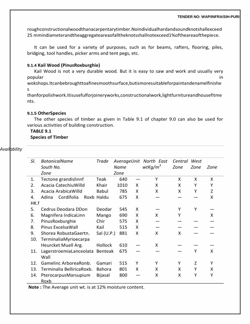
TENDER NO: WAP/INFRA/SIH-PURI
roughconstructionalwoodthanacarpentarytimber.Noindividualhardandsoundknotshallexceed25 mmindiameterandtheaggregateareaofalltheknotsshallnotexceed1%oftheareaofthepiece.
It can be used for a variety of purposes, such as for beams, rafters, flooring, piles,
bridging, tool handles, picker arms and tent pegs, etc.
9.1.4 Kail Wood (PinusRoxburghie) Kail Wood is not a very durable wood. But it is easy to saw and work and usually very
popular in wokshops.Itcanbebroughttoafinesmoothsurface,butismoresuitableforpaintandenamelfinishes thanforpolishwork.Itisusefulforjoineryworks,constructionalwork,lightfurnitureandhousefitments.
9.1.5 OtherSpecies
The other species of timber as given in Table 9.1 of chapter 9.0 can also be used for various activities of building construction.
TABLE 9.1 Species of Timber
Availability
Sl. BotanicalName Trade AverageUnit North East Central West South No. Name wtKg/m3 Zone Zone Zone Zone Zone 1. Tectone grandislinnf Teak 640 — Y X X X 2. Acacia CatechiuWilld Khair 1010 X X X Y Y 3. Acacia ArabicaWilld Babul 785 X X X Y Z 4. Adina Cordifolia Roxb HK.f
Haldu 675 X — — — X
5. Cedrus Deodara DDon Deodar 545 X — Y Y — 6. Magnifera IndicaLinn Mango 690 X X Y X 7. PinusRoxburghie Chir 575 X — — — — 8. Pinus ExcelsaWall Kail 515 X — — — — 9. Shorea RobustaGaertn. Sal (U.P.) 881 X X X — — 10. TerminaliaMyrioecarpa
Heurcket Muell Arg. Hollock 610 — X — — — 11. LagerstroemiaLanceolata Benteak 675 — — — Y X
Wall 12. Gamelinc ArboreaRonb. Gamari 515 Y Y Y Z Y 13. Terminalia BelliricaRoxb. Bahora 801 X X X Y X 14. PterocarpusMarsupium Bijasal 800 — X X Y Y
Roxb Note : The Average unit wt. is at 12% moisture content.
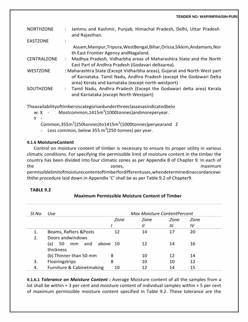
TENDER NO: WAP/INFRA/SIH-PURI
NORTHZONE : Jammu and Kashmir, Punjab, Himachal Pradesh, Delhi, Uttar Pradesh and Rajasthan.
EASTZONE : Assam,Manipur,Tripura,WestBengal,Bihar,Orissa,Sikkim,Andamans,North East Frontier Agency andNagaland.
CENTRALZONE : Madhya Pradesh, Vidharbha areas of Maharashtra State and the North East Part of Andhra Pradesh (Godavari deltaarea).
WESTZONE : Maharashtra State (Except Vidharbha areas), Gujarat and North West part of Karnataka. Tamil Nadu, Andhra Pradesh (except the Godawari Delta area) Kerala and karnataka (except north westport)
SOUTHZONE : Tamil Nadu, Andhra Pradesh (Except the Godawari delta area) Kerala and Karnataka (except North Westpart)
Theavailabilityoftimbersiscategorisedunderthreeclassesasindicatedbelo
w: X - Mostcommon,1415m3(1000tonnes)andmoreperyear. Y - Common,355m3(250tonnes)to1415m3(1000tonnes)peryearand Z - Less common, below 355 m3(250 tonnes) per year.
9.1.6 MoistureContent
Control on moisture content of timber is necessary to ensure its proper utility in various climatic conditions. For specifying the permissible limit of moisture content in the timber the country has been divided into four climatic zones as per Appendix B of Chapter 9. In each of the zones, maximum permissiblelimitofmoisturecontentoftimberfordifferentuses,whendeterminedinaccordancewiththe procedure laid down in Appendix ‘C’ shall be as per Table 9.2 of Chapter9.
TABLE 9.2
Maximum Permissible Moisture Content of Timber
Sl.No. Use Max Moisture ContentPercent
Zone Zone Zone Zone I II III IV
1. Beams, Rafters &Posts 12 14 17 20 2. Doors andwindows
(a) 50 mm and above thickness
10 12 14 16
(b) Thinner than 50 mm 8 10 12 14 3. Flooringstrips 8 10 10 12 4. Furniture & Cabinetmaking 10 12 14 15
9.1.6.1 Tolerance on Moisture Content : Average Moisture content of all the samples from a lot shall be within + 3 per cent and moisture content of individual samples within + 5 per cent of maximum permissible moisture content specified in Table 9.2. These tolerance are the
TENDER NO: WAP/INFRA/SIH-PURI
absolute values over the percentage moisture content for Sl. No. 1 & 2 of Table 9.2. No tolerance on moisture content is permitted for Sl. No. 3 & 4 of Table9.2.
9.1.7 Seasoning ofTimber
The process of drying timber under controlled conditions is called seasoning of timber. Timber shall beeitherairseasonedorkilnseasonedandinbothcasesmoisturecontentoftheseasonedtimbershall beasspecifiedinTable9.2ofChapter9unlessotherwisespecified,airseasonedtimbershallbeused. Kilnseasoningoftimber,wherespecified,shallbedoneasperIS1141inaplantapprovedbyEngineer- in-Charge.
9.1.8 Preservation ofTimber
Preservativetreatmentdoesnotimprovebasicpropertiesoftimberbutgivesvaryingdegreeofprotection againstdeteriorationduetoattacksbyfungi,termites,borersandmarineorganisms.Preservativetreatment, where specified, shall be done using Oil type, Organic solvent type or Water-soluble type preservative. Oiltype preservatives shall be used if the timber is not required to be polished or painted. Before preservative treatment, the timber shall be sawn and seasoned. All surfaces exposed after treatment, except due to planing, shall be thoroughly brushed with the preservation before jointing. Preservative treatment of timber shallbedoneasperIS401inaplantapprovedbytheEngineer-in-Charge.
9.2 PANELLINGMATERIAL
9.2.1 Timber
Timber panels shall be preferably made of timber of larger width. The minimum width and thickness of a panel shall be 150 mm and 15 mm respectively. When made from more than one piece, the pieces shall be joined with a continuous tongue and groove joint, glued together and reinforced with metal dowels. The grains of timber panels shall run along the longer dimensions of the panels. The panels shall be designed such that no single panel exceeds 0.5 square metre in area.
9.2.2 Plywood /PlywoodBoards
9.2.2.1 Plywood boards are formed by gluing and pressing three or more layers of veneers with the grainsofadjacentveneersrunningatrightanglestoeachother.Theveneersshallbeeitherrotarycutor sliced and shall be sufficiently smooth to permit an even spread of glue. Face veneers may be either decorative on both sides or one side commercial and the other decorative. Plywood shall be of BWP grade or BWR grade as per IS303.
9.2.2.2 Adhesive : Adhesive used for bonding BWP grade of plywood boards shall be BWP type synthetic resins conforming to IS 848.
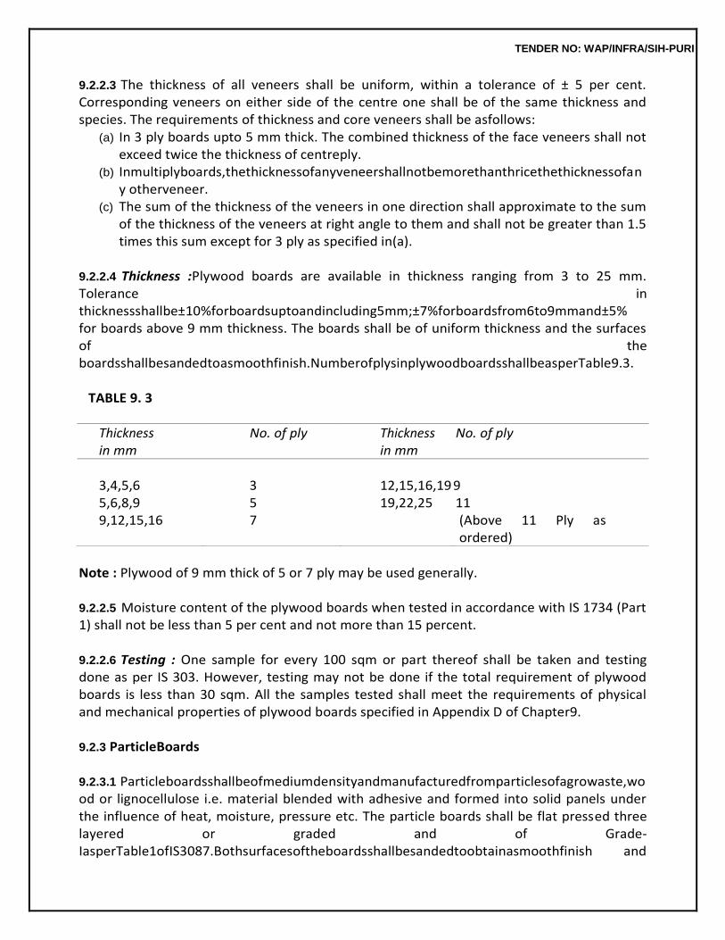
TENDER NO: WAP/INFRA/SIH-PURI
9.2.2.3 The thickness of all veneers shall be uniform, within a tolerance of ± 5 per cent. Corresponding veneers on either side of the centre one shall be of the same thickness and species. The requirements of thickness and core veneers shall be asfollows:
(a) In 3 ply boards upto 5 mm thick. The combined thickness of the face veneers shall not exceed twice the thickness of centreply.
(b) Inmultiplyboards,thethicknessofanyveneershallnotbemorethanthricethethicknessofany otherveneer.
(c) The sum of the thickness of the veneers in one direction shall approximate to the sum of the thickness of the veneers at right angle to them and shall not be greater than 1.5 times this sum except for 3 ply as specified in(a).
9.2.2.4 Thickness :Plywood boards are available in thickness ranging from 3 to 25 mm. Tolerance in thicknessshallbe±10%forboardsuptoandincluding5mm;±7%forboardsfrom6to9mmand±5% for boards above 9 mm thickness. The boards shall be of uniform thickness and the surfaces of the boardsshallbesandedtoasmoothfinish.NumberofplysinplywoodboardsshallbeasperTable9.3.
TABLE 9. 3
Thickness in mm
No. of ply Thickness in mm
No. of ply
3,4,5,6
3
12,15,16,19
9
5,6,8,9 5 19,22,25 11 9,12,15,16 7 (Above 11 Ply as
ordered)
Note : Plywood of 9 mm thick of 5 or 7 ply may be used generally.
9.2.2.5 Moisture content of the plywood boards when tested in accordance with IS 1734 (Part 1) shall not be less than 5 per cent and not more than 15 percent.
9.2.2.6 Testing : One sample for every 100 sqm or part thereof shall be taken and testing done as per IS 303. However, testing may not be done if the total requirement of plywood boards is less than 30 sqm. All the samples tested shall meet the requirements of physical and mechanical properties of plywood boards specified in Appendix D of Chapter9.
9.2.3 ParticleBoards
9.2.3.1 Particleboardsshallbeofmediumdensityandmanufacturedfromparticlesofagrowaste,wood or lignocellulose i.e. material blended with adhesive and formed into solid panels under the influence of heat, moisture, pressure etc. The particle boards shall be flat pressed three layered or graded and of Grade-IasperTable1ofIS3087.Bothsurfacesoftheboardsshallbesandedtoobtainasmoothfinish and
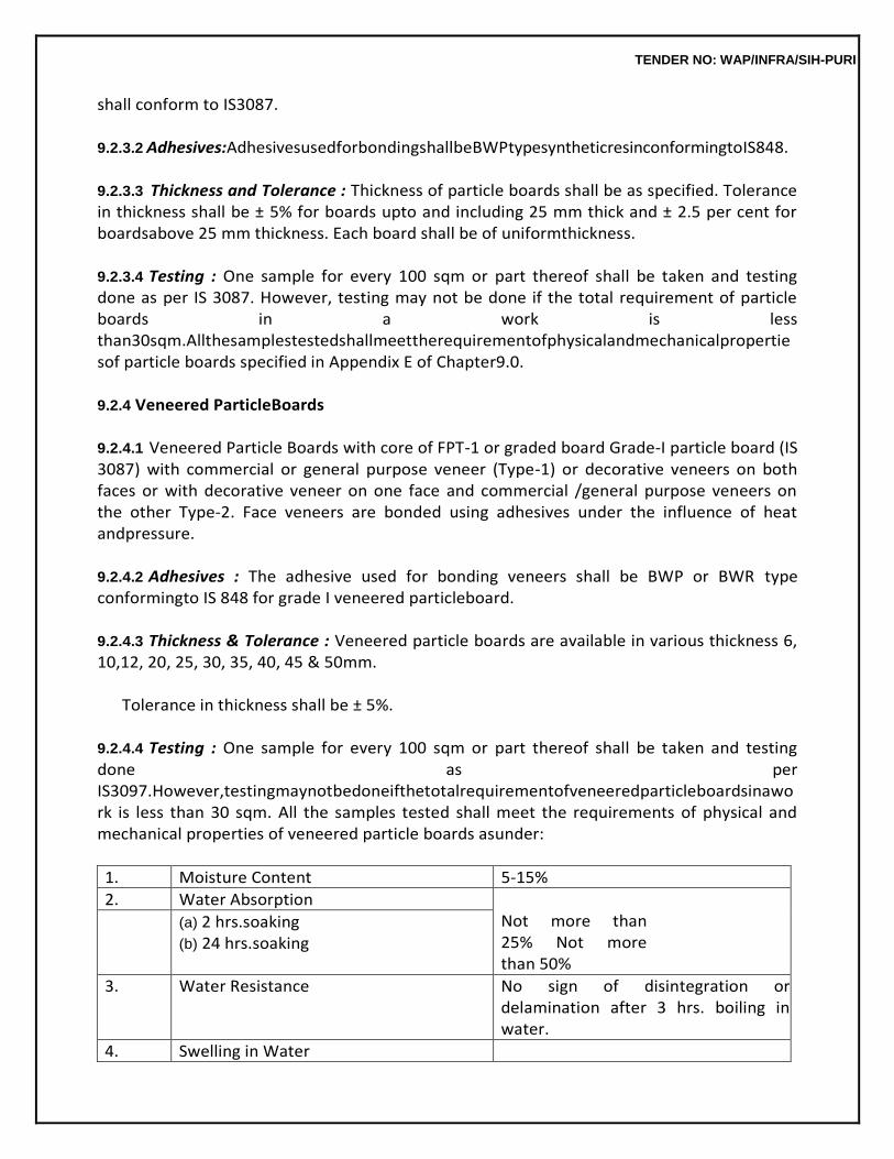
TENDER NO: WAP/INFRA/SIH-PURI
shall conform to IS3087.
9.2.3.2 Adhesives:AdhesivesusedforbondingshallbeBWPtypesyntheticresinconformingtoIS848.
9.2.3.3 Thickness and Tolerance : Thickness of particle boards shall be as specified. Tolerance in thickness shall be ± 5% for boards upto and including 25 mm thick and ± 2.5 per cent for boardsabove 25 mm thickness. Each board shall be of uniformthickness.
9.2.3.4 Testing : One sample for every 100 sqm or part thereof shall be taken and testing done as per IS 3087. However, testing may not be done if the total requirement of particle boards in a work is less than30sqm.Allthesamplestestedshallmeettherequirementofphysicalandmechanicalpropertiesof particle boards specified in Appendix E of Chapter9.0.
9.2.4 Veneered ParticleBoards
9.2.4.1 Veneered Particle Boards with core of FPT-1 or graded board Grade-I particle board (IS 3087) with commercial or general purpose veneer (Type-1) or decorative veneers on both faces or with decorative veneer on one face and commercial /general purpose veneers on the other Type-2. Face veneers are bonded using adhesives under the influence of heat andpressure.
9.2.4.2 Adhesives : The adhesive used for bonding veneers shall be BWP or BWR type conformingto IS 848 for grade I veneered particleboard.
9.2.4.3 Thickness & Tolerance : Veneered particle boards are available in various thickness 6, 10,12, 20, 25, 30, 35, 40, 45 & 50mm.
Tolerance in thickness shall be ± 5%.
9.2.4.4 Testing : One sample for every 100 sqm or part thereof shall be taken and testing done as per IS3097.However,testingmaynotbedoneifthetotalrequirementofveneeredparticleboardsinawork is less than 30 sqm. All the samples tested shall meet the requirements of physical and mechanical properties of veneered particle boards asunder:
1. Moisture Content 5-15%
2. Water Absorption Not more than 25% Not more than 50%
(a) 2 hrs.soaking (b) 24 hrs.soaking
3. Water Resistance No sign of disintegration or delamination after 3 hrs. boiling in water.
4. Swelling in Water
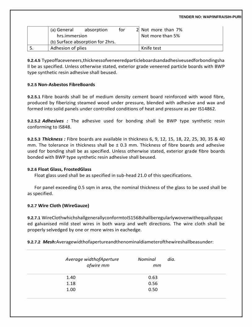
TENDER NO: WAP/INFRA/SIH-PURI
(a) General absorption for 2 hrs.immersion
(b) Surface absorption for 2hrs.
Not more than 7% Not more than 5%
5. Adhesion of plies Knife test
9.2.4.5 Typeoffaceveneers,thicknessofveneeredparticleboardsandadhesiveusedforbondingshall be as specified. Unless otherwise stated, exterior grade veneered particle boards with BWP type synthetic resin adhesive shall beused.
9.2.5 Non-Asbestos FibreBoards
9.2.5.1 Fibre boards shall be of medium density cement board reinforced with wood fibre, produced by fiberizing steamed wood under pressure, blended with adhesive and wax and formed into solid panels under controlled conditions of heat and pressure as per IS14862.
9.2.5.2 Adhesives : The adhesive used for bonding shall be BWP type synthetic resin conforming to IS848.
9.2.5.3 Thickness : Fibre boards are available in thickness 6, 9, 12, 15, 18, 22, 25, 30, 35 & 40 mm. The tolerance in thickness shall be ± 0.3 mm. Thickness of fibre boards and adhesive used for bonding shall be as specified. Unless otherwise stated, exterior grade fibre boards bonded with BWP type synthetic resin adhesive shall beused.
9.2.6 Float Glass, FrostedGlass
Float glass used shall be as specified in sub-head 21.0 of this specifications.
For panel exceeding 0.5 sqm in area, the nominal thickness of the glass to be used shall be as specified.
9.2.7 Wire Cloth (WireGauze)
9.2.7.1 WireClothwhichshallgenerallyconformtoIS1568shallberegularlywovenwithequallyspaced galvanised mild steel wires in both warp and weft directions. The wire cloth shall be properly selvedged by one or more wires in eachedge.
9.2.7.2 Mesh:Averagewidthofapertureandthenominaldiameterofthewireshallbeasunder:
Average widthofAperture Nominal dia.
ofwire mm mm
1.40 0.63 1.18 0.56 1.00 0.50
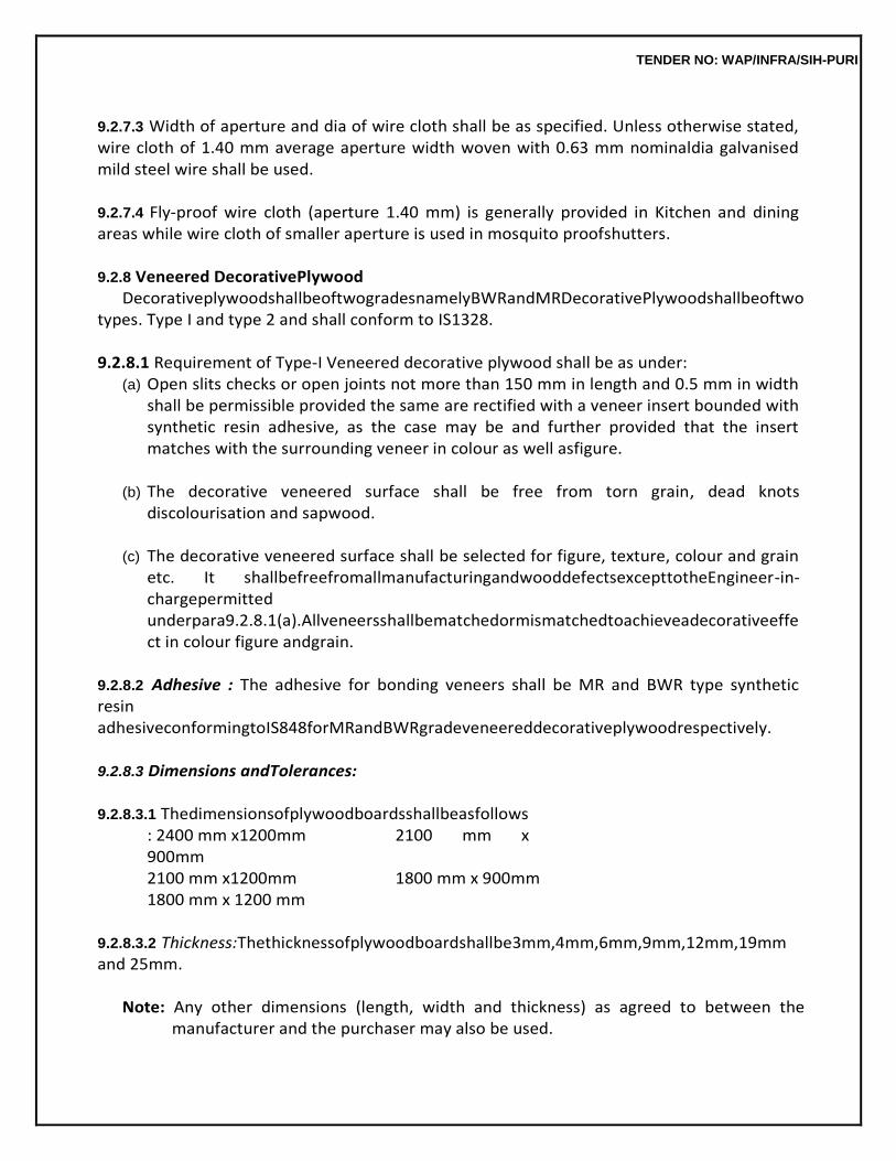
TENDER NO: WAP/INFRA/SIH-PURI
9.2.7.3 Width of aperture and dia of wire cloth shall be as specified. Unless otherwise stated, wire cloth of 1.40 mm average aperture width woven with 0.63 mm nominaldia galvanised mild steel wire shall be used.
9.2.7.4 Fly-proof wire cloth (aperture 1.40 mm) is generally provided in Kitchen and dining areas while wire cloth of smaller aperture is used in mosquito proofshutters.
9.2.8 Veneered DecorativePlywood
DecorativeplywoodshallbeoftwogradesnamelyBWRandMRDecorativePlywoodshallbeoftwo types. Type I and type 2 and shall conform to IS1328.
9.2.8.1 Requirement of Type-I Veneered decorative plywood shall be as under:
(a) Open slits checks or open joints not more than 150 mm in length and 0.5 mm in width shall be permissible provided the same are rectified with a veneer insert bounded with synthetic resin adhesive, as the case may be and further provided that the insert matches with the surrounding veneer in colour as well asfigure.
(b) The decorative veneered surface shall be free from torn grain, dead knots
discolourisation and sapwood.
(c) The decorative veneered surface shall be selected for figure, texture, colour and grain etc. It shallbefreefromallmanufacturingandwooddefectsexcepttotheEngineer-in-chargepermitted underpara9.2.8.1(a).Allveneersshallbematchedormismatchedtoachieveadecorativeeffect in colour figure andgrain.
9.2.8.2 Adhesive : The adhesive for bonding veneers shall be MR and BWR type synthetic resin adhesiveconformingtoIS848forMRandBWRgradeveneereddecorativeplywoodrespectively.
9.2.8.3 Dimensions andTolerances:
9.2.8.3.1 Thedimensionsofplywoodboardsshallbeasfollows
: 2400 mm x1200mm 2100 mm x 900mm 2100 mm x1200mm 1800 mm x 900mm 1800 mm x 1200 mm
9.2.8.3.2 Thickness:Thethicknessofplywoodboardshallbe3mm,4mm,6mm,9mm,12mm,19mm and 25mm.
Note: Any other dimensions (length, width and thickness) as agreed to between the
manufacturer and the purchaser may also be used.
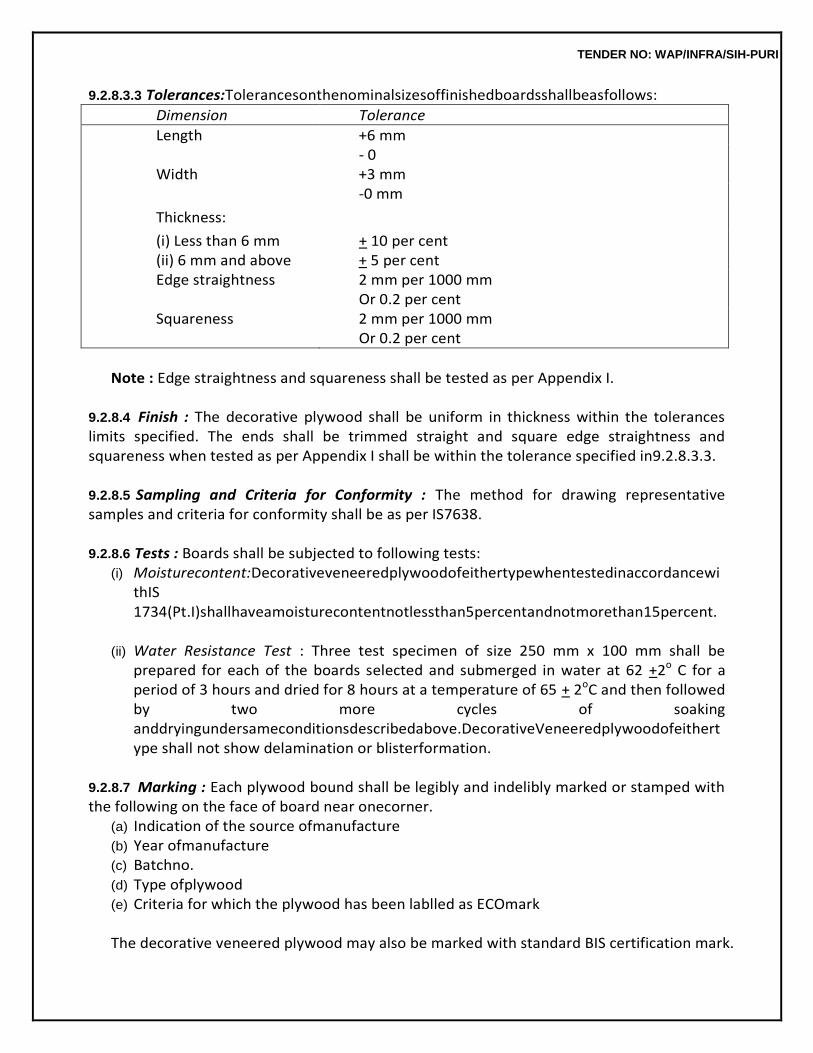
TENDER NO: WAP/INFRA/SIH-PURI
9.2.8.3.3 Tolerances:Tolerancesonthenominalsizesoffinishedboardsshallbeasfollows:
Dimension Tolerance
Length +6 mm - 0
Width +3 mm -0 mm
Thickness:
(i) Less than 6 mm + 10 per cent (ii) 6 mm and above + 5 per cent Edge straightness 2 mm per 1000 mm
Or 0.2 per cent Squareness 2 mm per 1000 mm
Or 0.2 per cent
Note : Edge straightness and squareness shall be tested as per Appendix I.
9.2.8.4 Finish : The decorative plywood shall be uniform in thickness within the tolerances limits specified. The ends shall be trimmed straight and square edge straightness and squareness when tested as per Appendix I shall be within the tolerance specified in9.2.8.3.3.
9.2.8.5 Sampling and Criteria for Conformity : The method for drawing representative samples and criteria for conformity shall be as per IS7638.
9.2.8.6 Tests : Boards shall be subjected to following tests:
(i) Moisturecontent:DecorativeveneeredplywoodofeithertypewhentestedinaccordancewithIS 1734(Pt.I)shallhaveamoisturecontentnotlessthan5percentandnotmorethan15percent.
(ii) Water Resistance Test : Three test specimen of size 250 mm x 100 mm shall be
prepared for each of the boards selected and submerged in water at 62 +2o C for a period of 3 hours and dried for 8 hours at a temperature of 65 + 2oC and then followed by two more cycles of soaking anddryingundersameconditionsdescribedabove.DecorativeVeneeredplywoodofeithertype shall not show delamination or blisterformation.
9.2.8.7 Marking : Each plywood bound shall be legibly and indelibly marked or stamped with the following on the face of board near onecorner.
(a) Indication of the source ofmanufacture (b) Year ofmanufacture (c) Batchno. (d) Type ofplywood (e) Criteria for which the plywood has been lablled as ECOmark
The decorative veneered plywood may also be marked with standard BIS certification mark.
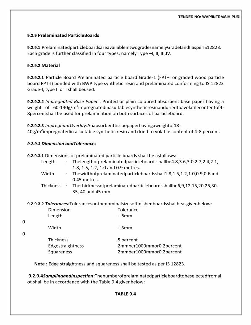
TENDER NO: WAP/INFRA/SIH-PURI
9.2.9 Prelaminated ParticleBoards
9.2.9.1 PrelaminatedparticleboardsareavailableintwogradesnamelyGradeIandIIasperIS12823. Each grade is further classified in four types; namely Type –I, II, III,IV.
9.2.9.2 Material
9.2.9.2.1 Particle Board Prelaminated particle board Grade-1 (FPT–I or graded wood particle board FPT-I) bonded with BWP type synthetic resin and prelaminated conforming to IS 12823 Grade-I, type II or I shall beused.
9.2.9.2.2 Impregnated Base Paper : Printed or plain coloured absorbent base paper having a weight of 60-140g/m2impregnatedinasuitablesyntheticresinanddriedtoavolatilecontentof4-8percentshall be used for prelamination on both surfaces of particleboard.
9.2.9.2.3 ImpregnantOverlay:Anabsorbenttissuepaperhavingaweightof18-40g/m2impregnatedin a suitable synthetic resin and dried to volatile content of 4-8 percent.
9.2.9.3 Dimension andTolerances
9.2.9.3.1 Dimensions of prelaminated particle boards shall be asfollows:
Length : Thelengthofprelaminatedparticleboardsshallbe4.8,3.6,3.0,2.7,2.4,2.1, 1.8, 1.5, 1.2, 1.0 and 0.9 metres.
Width : Thewidthofprelaminatedparticleboardsshall1.8,1.5,1.2,1.0,0.9,0.6and 0.45 metres.
Thickness : Thethicknessofprelaminatedparticleboardsshallbe6,9,12,15,20,25,30, 35, 40 and 45 mm.
9.2.9.3.2 Tolerances:Tolerancesonthenominalsizesoffinishedboardsshallbeasgivenbelow:
Dimension Tolerance Length + 6mm
- 0 Width + 3mm
- 0 Thickness 5 percent Edgestraightness 2mmper1000mmor0.2percent Squareness 2mmper1000mmor0.2percent
Note : Edge straightness and squareness shall be tested as per IS 12823.
9.2.9.4SamplingandInspection:Thenumberofprelaminatedparticleboardtobeselectedfromal
ot shall be in accordance with the Table 9.4 givenbelow:
TABLE 9.4
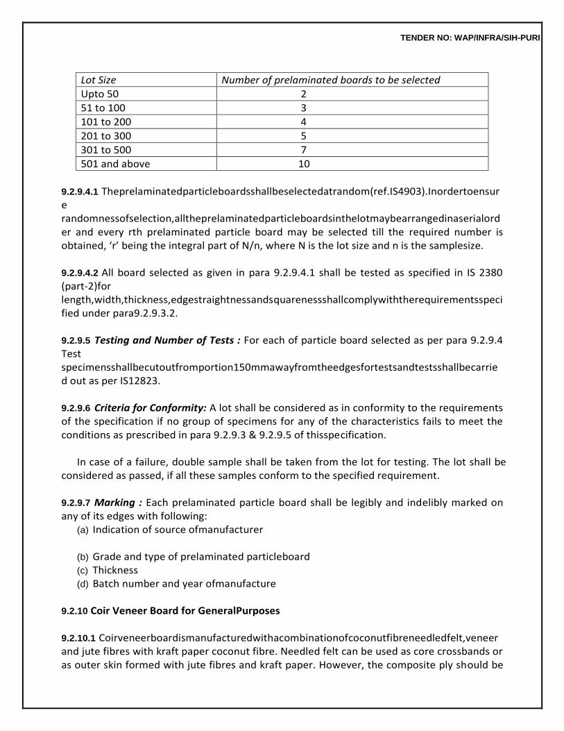
TENDER NO: WAP/INFRA/SIH-PURI
Lot Size Number of prelaminated boards to be selected
Upto 50 2
51 to 100 3
101 to 200 4
201 to 300 5
301 to 500 7
501 and above 10
9.2.9.4.1 Theprelaminatedparticleboardsshallbeselectedatrandom(ref.IS4903).Inordertoensure randomnessofselection,alltheprelaminatedparticleboardsinthelotmaybearrangedinaserialorder and every rth prelaminated particle board may be selected till the required number is obtained, ‘r’ being the integral part of N/n, where N is the lot size and n is the samplesize.
9.2.9.4.2 All board selected as given in para 9.2.9.4.1 shall be tested as specified in IS 2380 (part-2)for length,width,thickness,edgestraightnessandsquarenessshallcomplywiththerequirementsspecified under para9.2.9.3.2.
9.2.9.5 Testing and Number of Tests : For each of particle board selected as per para 9.2.9.4 Test specimensshallbecutoutfromportion150mmawayfromtheedgesfortestsandtestsshallbecarried out as per IS12823.
9.2.9.6 Criteria for Conformity: A lot shall be considered as in conformity to the requirements of the specification if no group of specimens for any of the characteristics fails to meet the conditions as prescribed in para 9.2.9.3 & 9.2.9.5 of thisspecification.
In case of a failure, double sample shall be taken from the lot for testing. The lot shall be
considered as passed, if all these samples conform to the specified requirement.
9.2.9.7 Marking : Each prelaminated particle board shall be legibly and indelibly marked on any of its edges with following:
(a) Indication of source ofmanufacturer
(b) Grade and type of prelaminated particleboard (c) Thickness (d) Batch number and year ofmanufacture
9.2.10 Coir Veneer Board for GeneralPurposes
9.2.10.1 Coirveneerboardismanufacturedwithacombinationofcoconutfibreneedledfelt,veneerand jute fibres with kraft paper coconut fibre. Needled felt can be used as core crossbands or as outer skin formed with jute fibres and kraft paper. However, the composite ply should be
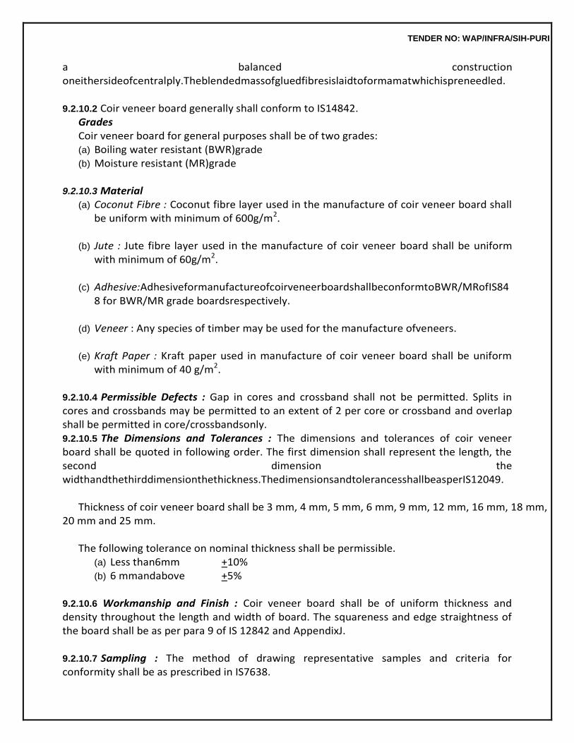
TENDER NO: WAP/INFRA/SIH-PURI
a balanced construction oneithersideofcentralply.Theblendedmassofgluedfibresislaidtoformamatwhichispreneedled.
9.2.10.2 Coir veneer board generally shall conform to IS14842.
Grades Coir veneer board for general purposes shall be of two grades: (a) Boiling water resistant (BWR)grade (b) Moisture resistant (MR)grade
9.2.10.3 Material
(a) Coconut Fibre : Coconut fibre layer used in the manufacture of coir veneer board shall be uniform with minimum of 600g/m2.
(b) Jute : Jute fibre layer used in the manufacture of coir veneer board shall be uniform
with minimum of 60g/m2.
(c) Adhesive:AdhesiveformanufactureofcoirveneerboardshallbeconformtoBWR/MRofIS848 for BWR/MR grade boardsrespectively.
(d) Veneer : Any species of timber may be used for the manufacture ofveneers.
(e) Kraft Paper : Kraft paper used in manufacture of coir veneer board shall be uniform
with minimum of 40 g/m2.
9.2.10.4 Permissible Defects : Gap in cores and crossband shall not be permitted. Splits in cores and crossbands may be permitted to an extent of 2 per core or crossband and overlap shall be permitted in core/crossbandsonly. 9.2.10.5 The Dimensions and Tolerances : The dimensions and tolerances of coir veneer board shall be quoted in following order. The first dimension shall represent the length, the second dimension the widthandthethirddimensionthethickness.ThedimensionsandtolerancesshallbeasperIS12049.
Thickness of coir veneer board shall be 3 mm, 4 mm, 5 mm, 6 mm, 9 mm, 12 mm, 16 mm, 18 mm,
20 mm and 25 mm.
The following tolerance on nominal thickness shall be permissible. (a) Less than6mm +10% (b) 6 mmandabove +5%
9.2.10.6 Workmanship and Finish : Coir veneer board shall be of uniform thickness and density throughout the length and width of board. The squareness and edge straightness of the board shall be as per para 9 of IS 12842 and AppendixJ.
9.2.10.7 Sampling : The method of drawing representative samples and criteria for conformity shall be as prescribed in IS7638.
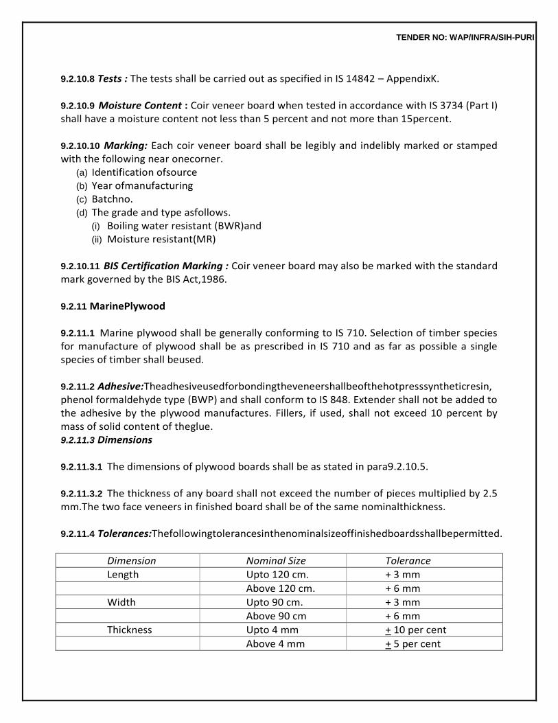
TENDER NO: WAP/INFRA/SIH-PURI
9.2.10.8 Tests : The tests shall be carried out as specified in IS 14842 – AppendixK.
9.2.10.9 Moisture Content : Coir veneer board when tested in accordance with IS 3734 (Part I) shall have a moisture content not less than 5 percent and not more than 15percent.
9.2.10.10 Marking: Each coir veneer board shall be legibly and indelibly marked or stamped with the following near onecorner.
(a) Identification ofsource (b) Year ofmanufacturing (c) Batchno. (d) The grade and type asfollows.
(i) Boiling water resistant (BWR)and (ii) Moisture resistant(MR)
9.2.10.11 BIS Certification Marking : Coir veneer board may also be marked with the standard mark governed by the BIS Act,1986.
9.2.11 MarinePlywood
9.2.11.1 Marine plywood shall be generally conforming to IS 710. Selection of timber species for manufacture of plywood shall be as prescribed in IS 710 and as far as possible a single species of timber shall beused.
9.2.11.2 Adhesive:Theadhesiveusedforbondingtheveneershallbeofthehotpresssyntheticresin, phenol formaldehyde type (BWP) and shall conform to IS 848. Extender shall not be added to the adhesive by the plywood manufactures. Fillers, if used, shall not exceed 10 percent by mass of solid content of theglue. 9.2.11.3 Dimensions
9.2.11.3.1 The dimensions of plywood boards shall be as stated in para9.2.10.5.
9.2.11.3.2 The thickness of any board shall not exceed the number of pieces multiplied by 2.5 mm.The two face veneers in finished board shall be of the same nominalthickness.
9.2.11.4 Tolerances:Thefollowingtolerancesinthenominalsizeoffinishedboardsshallbepermitted.
Dimension Nominal Size Tolerance
Length Upto 120 cm. + 3 mm
Above 120 cm. + 6 mm
Width Upto 90 cm. + 3 mm
Above 90 cm + 6 mm
Thickness Upto 4 mm + 10 per cent
Above 4 mm + 5 per cent
TENDER NO: WAP/INFRA/SIH-PURI
9.2.11.5 Sampling : The method of drawing representative samples and criteria for conformity shall be as prescribed in IS7638.
9.2.11.6 Tests : Test pieces cut from each of board as specified at para 9.2.11.5 shall be subjected to followingtests.
(a) Moisture content (b) Glue adhesive in drystate (c) Water resistancetest. (d) Tensilestrength (e) Mycologicaltest (f) Retension ofpreservative.
These tests shall be carried out as specified in IS 710.
9.2.11.7 Marking : Each plywood board shall be legibly and indelibly marked or stamped with following particularsalongwithsuchothermarksasthepurchasermaystipulateatthetimeofplacingorder.
(a) Manufacturer’s name, initials or recognized trade mark, ifany. (b) Year ofmanufacturing. (c) Abreviation indicating the species of timber used in each ply as indicated in col. 3 of
Table – 1 and 2 of IS710. (d) Batchnumber
9.2.11.8 BIS Certification Marking : The plywood board may also be marked with the standard mark, governed by the BISAct,1986.
9.2.11.9 Tender Sample, Inspection and Acceptance: Where samples are required to be tendered, three samples each not less than 90 x 60 mm in size shall be submitted by the supplier, and these samples,ifthetenderisacceptedshallconstitutethestandardasregardsthetypeoftimber,qualityand finish.
9.2.12 Fire RetardantPlywood
9.2.12.1 Fire retardant plywood shall generally conform to IS 5509. The plywood to be given fire retardant treatment shall conform to BWR grade of IS 303 to be able to stand pressure impregnation. Plywood for treatment shall be clean, free from oil or dirt patches on the surface and at a moisture content not exceeding 15 percent. In case of veneered decorative plywood care shall be taken that colour of the solution does not spoil to decorativesurface.
For Eco-mark the plywood shall conform to the requirements of Eco-mark specified in IS 303.
9.2.12.2 Fire Retardant Treatment : This shall be either pressure impregnation or soaking treatment as per IS5509.
TENDER NO: WAP/INFRA/SIH-PURI
9.2.12.3 Choice of Treatment : The choice of treatment may be left to the manufacturer of plywood as per fire resistant requirements prescribed in IS 5509. The purchaser should however, specify whether plywoodistobetreatedwithfireretardantsonlyorwithfireretardantsandpreservatives.
The recommended retention of fire retardant chemicals for different hazards like interior
or exterior use not subject to leaching by rain and water is of the order of 50 kg/m3.
9.2.12.4 Conditioning after Treatment : The plywood after treatment shall be conditioned to suitable equilibrium moisture content of not more than 20 percent.
9.2.12.5 DimensionandTolerancesshallconformtoIS2049.Thetoleranceofthicknessshallconform to IS303.
9.2.12.6 Sampling:Themethodofdrawingrepresentativesampleandthecriteriaofconformityshallbe as prescribed in IS7638.
9.2.12.7 TestSpecimenandNumberofTests:Fromeachoffireretardantplywoodselectedasabove para9.2.12.6,followingtestspecimensshallbecutfromportions150mmawayfromtheedgesfortests specified asunder:
(a) For Flammability : Six test specimens 125 mm x 125 mm in full thickness of material from each sample.
(b) For Flame Penetration : Three test specimens 125 mm x 125 mm in full thickness of material from eachsample.
(c) For Rate of Burning : Three test specimen 100 mm x 12.5 mm in full thickness of material from eachsample.
9.2.12.8 Test Requirements and OtherTests
(i) Moisture Content : Shall not exceed20%. (ii) Flammability : When tested as per IS 1734, time taken for second ignition shall not be
less than 30minutes. (iii) Flame Penetration : When tested as per IS 1734, time taken for flame penetration shall
not be less than 15 minutes for every 6 mmthickness. (iv) Rate of Burning : When tested as per IS 1734, the time taken to lose weight from 30
per cent to 70 per cent shall not be less than 20minutes.
9.2.12.9 Marking:Eachboardshallbelegiblyandindeliblymarkedneartheedgewiththefollowing: (a) Manufacturer’s name, his initials or his recognized trade mark, ifany. (b) Year ofmanufacture (c) Type oftreatment (d) Criteria for which the plywood has been labeled as ECOmark.
9.2.12.10 BIS Marking : Each board may also be marked with standard mark governed by the BIS Act, 1986.
TENDER NO: WAP/INFRA/SIH-PURI
9.2.13 Decorative Thermosetting Synthetic Resin Bonded LaminatedSheets
9.2.13.1 Scope : Decorative thermosetting synthetic resin bonded laminated sheets shall generally conform toIS2046.Thismaterialisintendedforinterioruseandisnotintendedforloadbearingapplications.
9.2.13.2 Terminology : For the purpose of this standard, the definition given under para 2 of IS 1998 shallapply.
9.2.13.3 Types : The material shall be of two typesnamely:-
(a) Type1-Havingonlyonesidebearingdecorativesurfacetheothersidebeingroughenedorgiven an appropriate treatment to promote adhesion to the base. This type shall generally be used, unless specifiedotherwise.
(b) Type 2- Having both sides bearing the decorative surface, the two sides may be
different in colour or pattern orboth.
9.2.13.4 Requirements (i) Appearance : The types of surface finish of decorative and reverse side, edge finish,
colour and pattern shall be as agreed to between the purchaser and the supplier. The sheets shall be reasonably free from localdeformation.
Note : Since sheets may vary slightly in colour and appearance, it is recommended that
sheets for any one scheme may be matched.
(ii) Flatness:Fornominalthickness1.5mm–whenasheetistestedforflatnessinaccordancewith the method given in Appendix –C of IS 2046, the height above the flat surface at the edge of full manufactured and trimmed width shall nowhere exceed 150mm.
(iii) Tolerance to nominal thickness : The departure from nominal thickness of sheet at any
point, shall not exceed the value givenbelow: NominalThickness Tolerance Upto1.5mm + 0.25mm
(iv) Straightnessofedgesofrectangularfinishedpanels,resistancetodryheat,resistancetoboili
ng water,resistancetostaining,grossbreakingstrength,packingandmarking,samplingandcriteria for conformity etc. shall be as per IS2046.
9.3 DOOR, WINDOW AND VENTILATORFRAMES
9.3.1 Timber for door, window and ventilators frames shall be as specified. Timber shall be sawn in the direction of the grains. All members of a frame shall be of the same species of timber and shall be straight without any warp or bow. Frames shall have smooth, well-planed
TENDER NO: WAP/INFRA/SIH-PURI
(wrought) surfaces exceptthe surfaces touching the walls, lintels, sill etc., which may be left clean sawn. Rebates, rounding or mouldingshallbedonebeforethemembersarejointedintoframes.Thedepthoftherebateforhousing theshuttersshallbe15mm,andthewidthoftherebatesshallbeequaltothethicknessoftheshutters. A tolerance of ± 2 mm shall be permitted in the specified finished dimensions of timber sections in frames.
9.3.2 Joints
TheJambpostsshallbethroughtenonedintothemortiseofthetransomstothefullthicknessofthe transoms and the thickness of the tenon shall be not less than 2.5 cm. The tenons shall closely fit into the mortise without any wedging or filling. The contact surface of tenon and mortise before putting together shall be glued with polyvinyl acetate dispersion based adhesive conforming to IS 4835 or adhesive conforming IS 851 and pinned with 10 mm dia hard wood dowels, or bamboo pins or star shaped metal pins. The joints shall be at right angles when checked from the inside surfaces of the respective members. The joints shall be pressed in position. Each assembled door frame shall be fitted with a temporary stretcher and a temporary diagonal brace on the rebatedfaces.
9.3.3 Fixing ofFrames
The frames shall be got approved by the Engineer-in-Charge before being painted, oiled or otherwise treated and before fixing in position. The surface of the frames abutting masonry or concrete and the portions of the frames embedded in floors shall be given a coating of coal tar. Frames shall be fixed to the abutting masonry or concrete with holdfasts or metallic fasteners as specified. After fixing, the jamb posts of the frames shall be plugged suitably and finished neat. Vertical members of the door frames shall be embedded in the floor for the full thickness of the floor finish and shall be suitably struttedandwedgedinordertopreventwarpingduringconstruction.Aminimumofthreeholdfastsshall be fixed on each side of door and window frames one at centre point and other two at 30 cm from the top and bottom of the frames. In case of window and ventilator frames of less than 1 m in height two hold fasts shall be fixed on each side at quarter point of the frames. Hold fasts and metallic fasteners shall be measured and paid forseparately.
9.3.4 Measurements
Wood work wrought, framed and fixed shall be measured for finished dimension without any allowanceforthewastageorfordimensionsbeyondspecifieddimension.However,incaseofmembers having mouldings, roundings or rebates and members of circular or varying sections, finished dimensions shall be taken as the sides of the smallest square or rectangle from which such a section can be cut. Length of each member shall be measured over all to the nearest cm so as to include projection for tenons. Width and thickness shall be measured to the nearest mm and the quantity shall be worked out in unit of upto three places ofdecimal.
9.3.5 Rate
The rate shall include the cost of material and labour involved in all the operations
TENDER NO: WAP/INFRA/SIH-PURI
described above except the hold fasts or metallic fasteners which will be paid for separately.
9.4 FALSE CEILING AND PARTITIONFRAMES This work shall be done as specified in 9.3 except that the scantlings need not be planed
unless otherwise specified.
9.5 TRUSSES
9.5.0 The work shall be carried out as per detailed drawings and as directed by the Engineer-in-Charge specified timber shall be used. Sawing shall be truly straight and square, and in the direction of the grains. The scantlings shall be accurately planed smooth to the full dimensions and rebate roundings and mouldings shown in the drawings, before the same are framed. Patching or plugging of any kind shall not be permitted. A tolerance of +3 mm and -2 mm shall be allowed in the finished cross sectional dimension.
9.5.1 Joints
Joints shall be simple, neat and strong. All mortise and tenon joints, mitred joints, scarfs etc. shallfit in fully and accurately without wedging or fillings. The joints shall be as per detailed drawings. Holes of correct sizes shall be drilled before inserting screws/bolts. Driving in screws with hammer is prohibited. Holes for bolts shall be of uniform diameter. The screws, bolts and nails shall be dipped in oil before using. The heads of nails and screws shall be sunk and puttied or dealt with as instructed by Engineer- in-Charge. The gauge and length of nails, screws and bolts shall be approved by the Engineer-in- Charge before using onworks.
9.5.2 Shaping Form andCutting
Thewoodsections,asspecifiedorrequired,shallbestraightened,cutsquareandtocorrectlengths. A fine accuracy shall be ensured in the fabrication of various member so that these can be assembled without being unduly packed, strained or forced into position and when built up, shall be true to shape and free from twist, kinks, buckles or openjoints.
9.5.3 Fabrication
Asperdrawing,afullsizetrussdiagramshallfirstbedrawnonalevelledplatform.Fromthisfullsize diagram, templates of all joints as for tenons, mortises, scarves etc. shall be made for use in the fabrication. The template shall be made to correspond to each member and plate holes for screws and bolts shall be marked accurately on them and drilled. The templates shall be laid on wooden members andtheholesforscrewingandboltingmarkedonthem.Theendsofthewoodenmembersshallalsobe marked for cutting. The base of columns and the position of anchor bolts shall be carefully set out. Before fabrication of the truss individual members shall be assembled together to ensure closeabutting orlappingofthesurfacesofthedifferentmembersandfittedclosetogetherasperdrawing.
9.5.4 Hoisting and Placing inPosition
The trusses shall be hoisted and placed in position carefully, without any damage to itself and other building work and injury to workman. The trusses shall be secured to walls by
TENDER NO: WAP/INFRA/SIH-PURI
means of holding down bolts or as directed by the Engineer-in-Charge. The necessary mechanical appliances such as lifting tackel,winchetc.forhoistingthetrussshallbeused.Thetrussesshallbestayedtemporarilytilltheyare permanentlysecuredinpositionandconnectedwitheachotherbymeansofpurlins.Holdingdownbolts cleatsusedforpurlinsandbottomplatesusedfortieandraftermembershallbepaidforseparately.
9.5.5 SurfaceTreatment
Wood work shall not be painted, oiled or otherwise treated before it has been approved by the Engineer-in-Charge.Allportionsoftimberbuiltintooragainstorclosetomasonryorconcreteorburried in ground shall be given two coats of boiling coal tar. All junctions of rafters, purlins, beams and wall plates shall be painted with approved woodprimer.
9.5.6 Measurements
Wood work shall be measured for finished dimensions. No allowance shall be made for dimensions suppliedbeyondthosespecified.Lengthofeachpieceshallbemeasuredoverallnearesttoacm,soas to include projections for tenons, scarves or mitres. Width and thickness shall be measured to the nearestmm.Cubicalcontentscanbeworkedoutinunitscubicmetersupto3placesofdecimalinwhole numbers.
9.5.7 Rate
The rate includes the cost of materials and labour involved in all the operations described above. Unless otherwise specified, iron fixtures such as bolts and nuts, M.S. steel plates, holding down bolts and staining, priming, painting or polishing of the work shall be paid for separately.
9.6 PANELLED GLAZED OR PANELLED AND GLAZED SHUTTERS (FIG.9.2)
9.6.0 Panelled or glazed shutters for doors, windows, ventilators and cupboards shall be constructed in the form of timber frame work of stiles and rails with panel inserts of timber, plywood, block board, veneered particle board, fibre board wire gauze or float glass. The shutters may be single or multipanelled, as shown in the drawings or as directed by the Engineer-in-Charge. Timber for frame work, material for panel inserts and thickness of shutters shall be as specified. All members of the shuttersshallbestraightwithoutanywarporbowandshallhavesmoothwellplanedfaceatrightangles to eachother.
Any warp or bow shall not exceed 1.5 mm for door shutter and 1 mm for window and
ventilator shutters The right angle for the shutter shall be checked by measuring the diagonals and the difference between the two diagonals should not be more than 3 mm. Generally panelled glazed or panelled and glazed shutter shall conform to IS 1003 (Pt. 1 & 2).
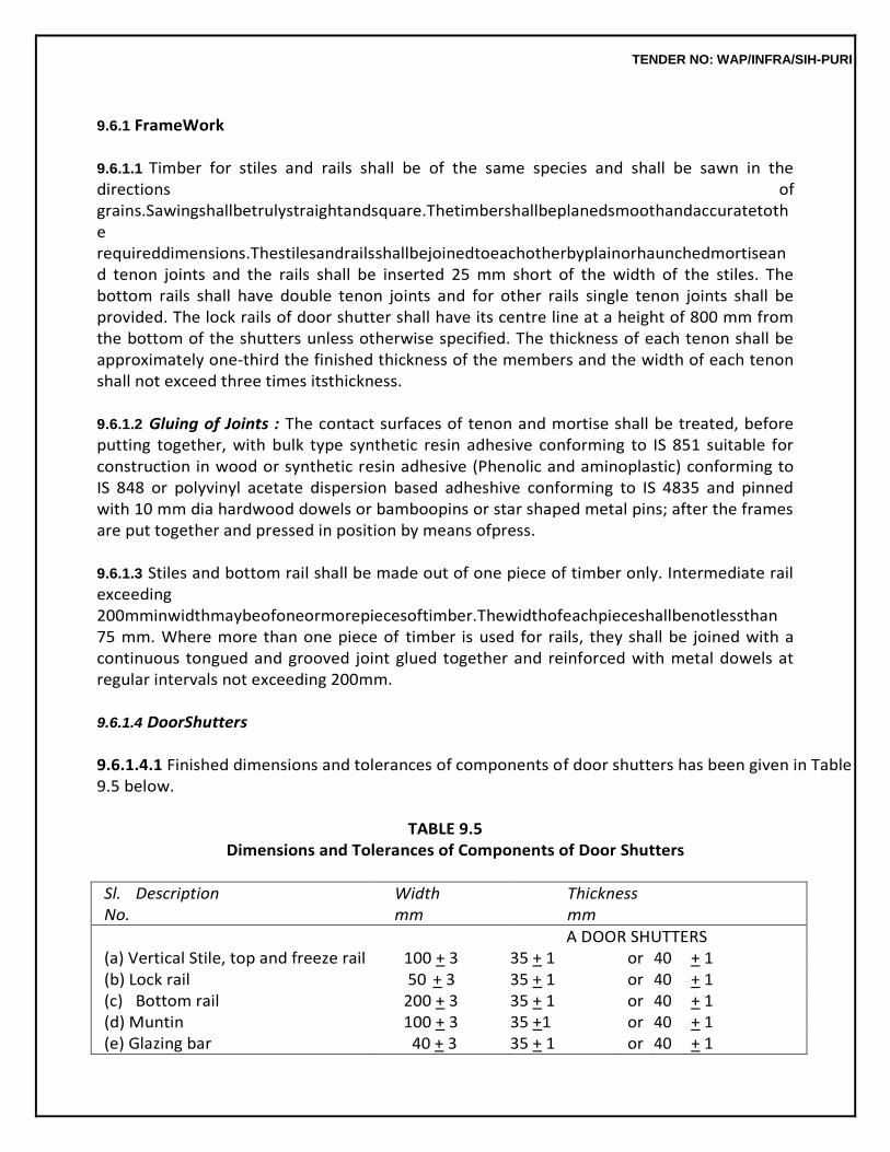
TENDER NO: WAP/INFRA/SIH-PURI
9.6.1 FrameWork
9.6.1.1 Timber for stiles and rails shall be of the same species and shall be sawn in the directions of grains.Sawingshallbetrulystraightandsquare.Thetimbershallbeplanedsmoothandaccuratetothe requireddimensions.Thestilesandrailsshallbejoinedtoeachotherbyplainorhaunchedmortiseand tenon joints and the rails shall be inserted 25 mm short of the width of the stiles. The bottom rails shall have double tenon joints and for other rails single tenon joints shall be provided. The lock rails of door shutter shall have its centre line at a height of 800 mm from the bottom of the shutters unless otherwise specified. The thickness of each tenon shall be approximately one-third the finished thickness of the members and the width of each tenon shall not exceed three times itsthickness.
9.6.1.2 Gluing of Joints : The contact surfaces of tenon and mortise shall be treated, before putting together, with bulk type synthetic resin adhesive conforming to IS 851 suitable for construction in wood or synthetic resin adhesive (Phenolic and aminoplastic) conforming to IS 848 or polyvinyl acetate dispersion based adheshive conforming to IS 4835 and pinned with 10 mm dia hardwood dowels or bamboopins or star shaped metal pins; after the frames are put together and pressed in position by means ofpress.
9.6.1.3 Stiles and bottom rail shall be made out of one piece of timber only. Intermediate rail exceeding 200mminwidthmaybeofoneormorepiecesoftimber.Thewidthofeachpieceshallbenotlessthan 75 mm. Where more than one piece of timber is used for rails, they shall be joined with a continuous tongued and grooved joint glued together and reinforced with metal dowels at regular intervals not exceeding 200mm.
9.6.1.4 DoorShutters
9.6.1.4.1 Finished dimensions and tolerances of components of door shutters has been given in Table 9.5 below.
TABLE 9.5
Dimensions and Tolerances of Components of Door Shutters
Sl. No.
Description Width mm
Thickness mm
A DOOR SHUTTERS (a) Vertical Stile, top and freeze rail 100 + 3 35 + 1 or 40 + 1 (b) Lock rail 50 + 3 35 + 1 or 40 + 1 (c) Bottom rail 200 + 3 35 + 1 or 40 + 1 (d) Muntin 100 + 3 35 +1 or 40 + 1 (e) Glazing bar 40 + 3 35 + 1 or 40 + 1
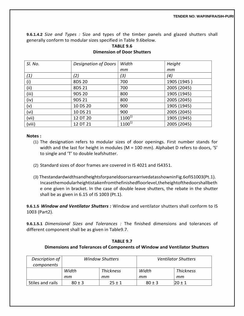
TENDER NO: WAP/INFRA/SIH-PURI
9.6.1.4.2 Size and Types : Size and types of the timber panels and glazed shutters shall generally conform to modular sizes specified in Table 9.6below.
TABLE 9.6 Dimension of Door Shutters
Sl. No. Designation of Doors Width mm
Height mm
(1) (2) (3) (4)
(i) 8DS 20 700 1905 (1945 )
(ii) 8DS 21 700 2005 (2045)
(iii) 9DS 20 800 1905 (1945)
(iv) 9DS 21 800 2005 (2045)
(v) 10 DS 20 900 1905 (1945)
(vi) 10 DS 21 900 2005 (2045)
(vii) 12 DT 20 11001) 1905 (1945)
(viii) 12 DT 21 11001) 2005 (2045)
Notes :
(1) The designation refers to modular sizes of door openings. First number stands for width and the last for height in modules (M = 100 mm). Alphabet D refers to doors, ‘S’ to single and ‘T’ to double leafshutter.
(2) Standard sizes of door frames are covered in IS 4021 and IS4351.
(3) ThestandardwidthsandheightsforpaneldoorsarearrivedatasshowninFig.6ofIS1003(Pt.1).
Incasethemodularheightistakenfromthefinishedfloorlevel,theheightofthedoorshallbethe one given in bracket. In the case of double leave shutters, the rebate in the shutter shall be as given in 6.15 of IS 1003 (Pt.1).
9.6.1.5 Window and Ventilator Shutters : Window and ventilator shutters shall conform to IS 1003 (Part2).
9.6.1.5.1 Dimensional Sizes and Tolerances : The finished dimensions and tolerances of different component shall be as given in Table9.7.
TABLE 9.7
Dimensions and Tolerances of Components of Window and Ventilator Shutters
Description of components
Window Shutters Ventilator Shutters
Width mm
Thickness mm
Width mm
Thickness mm
Stiles and rails 80 ± 3 25 ± 1 80 ± 3 20 ± 1
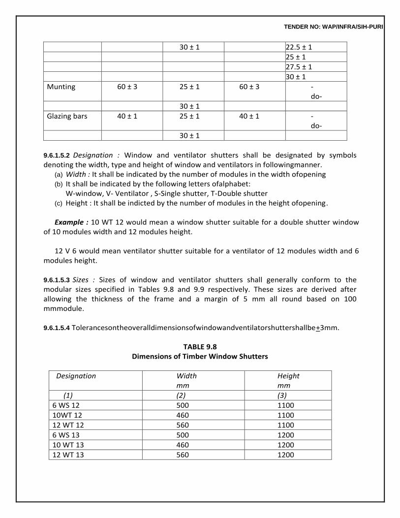
TENDER NO: WAP/INFRA/SIH-PURI
30 ± 1 22.5 ± 1
25 ± 1
27.5 ± 1
30 ± 1
Munting 60 ± 3 25 ± 1 60 ± 3 -do-
30 ± 1
Glazing bars 40 ± 1 25 ± 1 40 ± 1 -do-
30 ± 1
9.6.1.5.2 Designation : Window and ventilator shutters shall be designated by symbols denoting the width, type and height of window and ventilators in followingmanner.
(a) Width : It shall be indicated by the number of modules in the width ofopening (b) It shall be indicated by the following letters ofalphabet:
W-window, V- Ventilator , S-Single shutter, T-Double shutter (c) Height : It shall be indicted by the number of modules in the height ofopening.
Example : 10 WT 12 would mean a window shutter suitable for a double shutter window
of 10 modules width and 12 modules height.
12 V 6 would mean ventilator shutter suitable for a ventilator of 12 modules width and 6 modules height.
9.6.1.5.3 Sizes : Sizes of window and ventilator shutters shall generally conform to the modular sizes specified in Tables 9.8 and 9.9 respectively. These sizes are derived after allowing the thickness of the frame and a margin of 5 mm all round based on 100 mmmodule.
9.6.1.5.4 Tolerancesontheoveralldimensionsofwindowandventilatorshuttershallbe+3mm.
TABLE 9.8
Dimensions of Timber Window Shutters
Designation Width mm
Height mm
(1) (2) (3)
6 WS 12 500 1100
10WT 12 460 1100
12 WT 12 560 1100
6 WS 13 500 1200
10 WT 13 460 1200
12 WT 13 560 1200
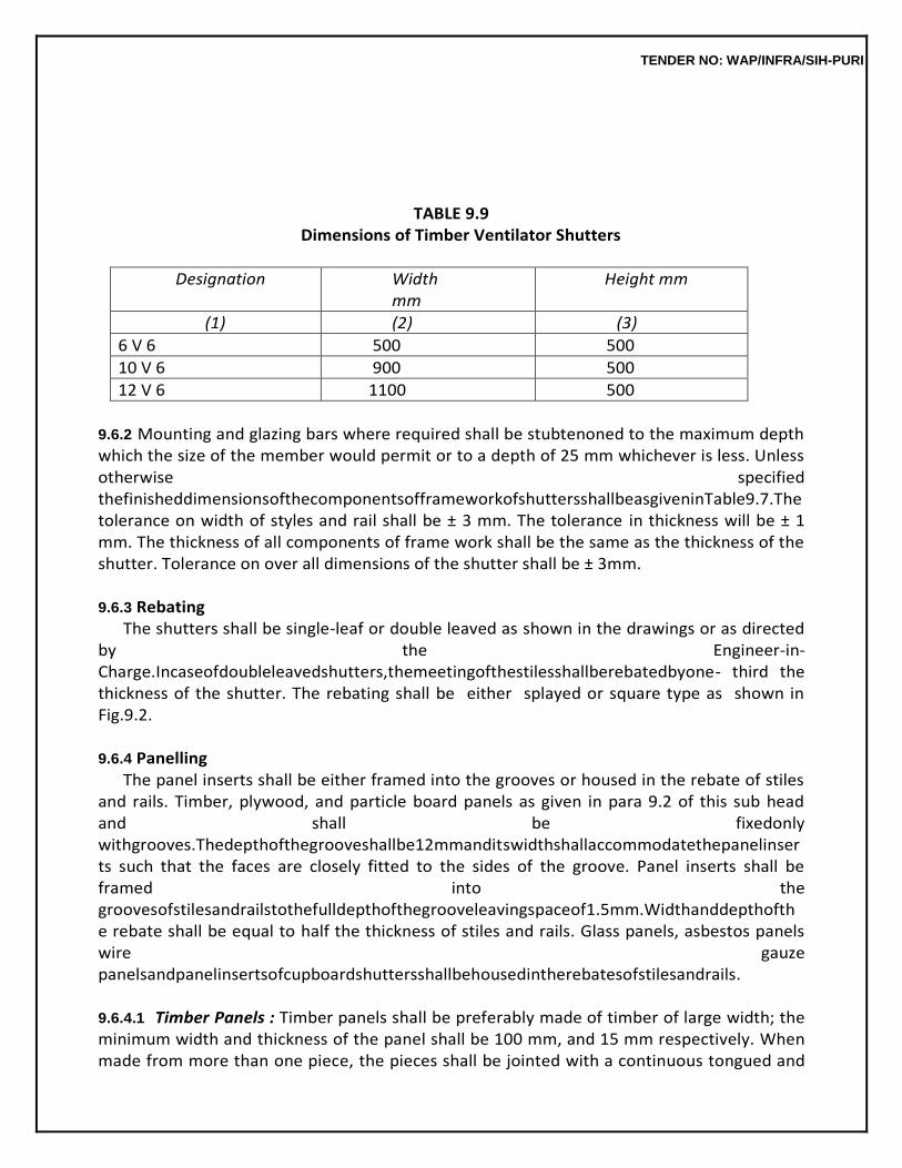
TENDER NO: WAP/INFRA/SIH-PURI
TABLE 9.9 Dimensions of Timber Ventilator Shutters
Designation Width mm
Height mm
(1) (2) (3)
6 V 6 500 500
10 V 6 900 500
12 V 6 1100 500
9.6.2 Mounting and glazing bars where required shall be stubtenoned to the maximum depth which the size of the member would permit or to a depth of 25 mm whichever is less. Unless otherwise specified thefinisheddimensionsofthecomponentsofframeworkofshuttersshallbeasgiveninTable9.7.The tolerance on width of styles and rail shall be ± 3 mm. The tolerance in thickness will be ± 1 mm. The thickness of all components of frame work shall be the same as the thickness of the shutter. Tolerance on over all dimensions of the shutter shall be ± 3mm.
9.6.3 Rebating
The shutters shall be single-leaf or double leaved as shown in the drawings or as directed by the Engineer-in-Charge.Incaseofdoubleleavedshutters,themeetingofthestilesshallberebatedbyone- third the thickness of the shutter. The rebating shall be either splayed or square type as shown in Fig.9.2.
9.6.4 Panelling
The panel inserts shall be either framed into the grooves or housed in the rebate of stiles and rails. Timber, plywood, and particle board panels as given in para 9.2 of this sub head and shall be fixedonly withgrooves.Thedepthofthegrooveshallbe12mmanditswidthshallaccommodatethepanelinserts such that the faces are closely fitted to the sides of the groove. Panel inserts shall be framed into the groovesofstilesandrailstothefulldepthofthegrooveleavingspaceof1.5mm.Widthanddepthofthe rebate shall be equal to half the thickness of stiles and rails. Glass panels, asbestos panels wire gauze panelsandpanelinsertsofcupboardshuttersshallbehousedintherebatesofstilesandrails.
9.6.4.1 Timber Panels : Timber panels shall be preferably made of timber of large width; the minimum width and thickness of the panel shall be 100 mm, and 15 mm respectively. When made from more than one piece, the pieces shall be jointed with a continuous tongued and
TENDER NO: WAP/INFRA/SIH-PURI
grooved joint glued together and reinforced with headless nails at regular intervals not exceeding 100 mm. Depth and thickness of such joint shall be equal to one-third of thickness of panel. The panels shall be designed such that no single panel exceeds 0.5 square metre in area. The grains of timber panels shall run along the longer dimensions of the panels. All panels shall be of the same species of timber unless otherwisespecified.
9.6.4.2 PlywoodPanels:PlywoodboardsusedforpanellingofshuttersshallbeBWPtypeorgradeas specified in 9.2.2. Each panels shall be a single piece of thickness, 9 mm for two or more panel constructionand12mmthicknessforsinglepanelconstructionunlessotherwisespecified.
9.6.4.3 Veneered Particle Board Panels : Veneered Particle board used for panelling of shutters shall be Exterior Grade bonded with BWP type synthetic resin adhesive as specified in 9.2.4.2. Each panel shall be a single piece of thickness 12 mm unless otherwisespecified.
9.6.4.4 Fibre Board Panels : Fibre board used for panelling of shutters shall be Exterior Gradebonded with BWP type synthetic resin adhesive Each fibre board panel shall be a single piece unlessotherwise specified. 9.6.4.5 Wire Gauze Panels: Wire Gauze used for panelling of shutters shall be woven with 0.63 mm dia galvanised mild steel wire to form average aperture size of 1.40 mm as specified in 9.2.7. Wire gauze shall be securely housed into the rebates of stiles and rails by giving right angles bend turned backandfixedbymeansofsuitablestaplesatintervalsof75mmandoverthiswoodenbeadingshallbe fixed.Thespacebetweentherebateandthebeadingshallbefixedwithputtytogiveaneatfinish.Each wire gauze panel shall be a single piece, and the panels shall be so designed that no single panels exceeds 0.5 sqm in area. However, care shall be taken to prevent sagging of wire gauge, of panel by providing and fixing 20 x 20 mm square or equivalent beading to the external face to the required patterns as decided by theEngineer-in-Charge.
9.6.4.6 Glass Panels : Glass panelling (Glazing) shall be done as specified in 9.2.6. Glazing in the shutters of doors, windows and ventilators of bath, WC and Lavatories shall be provided with frosted glass the weight of which shall be not less than 10 kg/sqm. Frosted glass panes shall be fixed with frosted face on the inside. Glass panels shall be fixed by providing a thin layer of putty conforming to IS419appliedbetweenglasspaneandallalongthelengthoftherebateandalsobetweenglasspanes and woodenbeading.
9.6.4.7 Putty can be prepared by mixing one part of white lead with three parts of finely powderedchalk and then adding boiled linseed oil to the mixture to form a stiff paste and adding varnish to the paste at the rate of 1 litre of varnish to 18 kg of paste. Fixing of glass panes without beading shall not be permitted. Glazing shall be done after the shutters have been primed and prepared for painting, so that wood may not draw oil out ofputty.
9.6.4.8 Finish:Panelsofshuttersshallbeflatandwellsandedtoasmoothandlevelsurface.
TENDER NO: WAP/INFRA/SIH-PURI
9.6.5 Beading Beadings in panelled shutter shall be provided where specified in architectural drawings
or directed by the Engineer-in-Charge. Each length of beading shall be single piece. Joints at the corners shall be mitred and exposed edges shall be rounded. Beading shall be fixed with headless nails at 75 mm intervals. For external shutters, the beading shall be fixed on the outside face.
9.6.6 Machine/Factory madeShutters
Machine made shutters, where specified, shall be procured from an approved factory. For machine made shutters, operations like sawing, planning, making tongue and tenons, cutting grooves, mortises and rebates, drilling holes and pressing of joints shall be done by suitable machines. Machines made shutters shall be brought to the site fully assembled but without any priming coat. Panel inserts ofsheet glass and wire gauze may, however, be fixed atsite.
9.6.7 Fixing ofShutters
Forsidehungshuttersofheightupto1.2m,eachleafshallbehungontwohingesatquarterpointsandfor shutterofheightmorethan1.2m,eachleafshallbehungonthreehingesoneatthecentreandtheothertwo at200mmfromthetopandbottomoftheshutters.Tophungandbottomhungshuttersshallbehungontwo hinges fixed at quarter points of top rail or bottom rail. Centre hung shutter shall be suspended on a suitable pivotinthecentreoftheframe.Sizeandtypeofhingesandpivotsshallbeasspecified.Flapofhingesshallbe neatlycountersunkintotherecessescuttotheexactdimensionsofflap.Screwsforfixingthehingesshallbe screwedinwithscrewdriverandnothammeredin.Unlessotherwisespecified,shuttersofheightmorethan 1.2 mm shall be hung on butt hinges of size 100 mm and for all other shutters of lesser height butt hinges of size75mmshallbeused.Forshutterofmorethan40mmthicknessbutthingesofsize125×90×4mmshall beused.Continuous(piano)hingesshallbeusedforfixingcup-boardshutterswherespecified.
9.6.8 Fittings
Fittings shall be provided as per schedule of fittings decided by Engineer-in-Charge. Appendix H gives for guidance the schedule of fittings and screws usually provided. Cost of providing and fixing shutter shall include cost of hinges and necessary screws for fixing the same. All other fittings shall be paid for separately. The fittings shall conform to specifications laid down in 9.15. Where the fittings are stipulatedtobesuppliedbythedepartmentfreeofcost,screwsforfixingthesefittingsshallbeprovided by contractor and nothing extra shall be paid for thesame.
9.6.9 Wooden Cleats andBlocks
Wooden cleats and blocks shall be fixed to doors and windows as directed by Engineer-in-Charge, as per size and shape approved by him. These are included in the cost of providing and fixing the shutters.
TENDER NO: WAP/INFRA/SIH-PURI
9.6.10 Measurements
Framework and panelling shall be measured separately.
9.6.10.1 FrameworkofShutters:Theoveralllengthandwidthoftheframeworkoftheshuttersshallbe measured nearest to a cm in fixed position (overlaps not to be measured in case of double leaved shutters) and the area calculated in square metres correct to two places of decimal. No deduction shall be made to form panel openings or louvers. No extra payments shall be made for shape, joints and labour involved in all operations describedabove.
9.6.10.2 For panelling of each type or for glazed panel length and width of opening for panels inserts or glazed panels shall be measured correct to a cm before fixing the beading and the area shall be calculatedtothenearest0.01sq.m.Theportionsofthepanelinsertsorglazedpanelinsidethegrooves or rebates shall not be measured forpayment.
9.6.11 Rate
Rate includes the cost of materials and labour involved in all the operations described above. The framework and panelling of each type or glazed panels shall be paid separately. The rate forframework includesthecostofbutthingesandnecessaryscrewsasspecifiedin9.6.7.However,extrashallbepaid forprovidingmouldedbeadingwherespecified.Nothingextrashallbepaidforplainbeadingasstatedin 9.6.5 when specified in drawing.
9.7 FLUSH DOOR SHUTTERS (Fig.9.3)
9.7.0 Flush door shutters shall have a solid core and may be of the decorative or non-decorative (Paintable type as per IS 2202 (Part I). Nominal thickness of shutters may be 25, 30 or 35 mm. Thickness and type of shutters shall be asspecified.
9.7.1 WidthandheightoftheshuttersshallbeasshowninthedrawingsorasindicatedbytheEngineer- in-Charge. All four edges of the shutters shall be square. The shutter shall be free from twist or warp in its plane. The moisture content in timbers used in the manufacture of flush door shutters shall be not more than 12 per cent when tested according to IS1708.
9.7.2 Core
The core of the flush door shutters shall be a block board having wooden strips held in a frame constructed of stiles and rails. Each stile and rail shall be a single piece without any joint. The width of the stiles and rails including lipping, where provided shall not be less than 45 mm and not more than 75 mm.Thewidthofeachwoodenstripshallnotexceed30mm.Stiles,railsandwoodenstripsformingthe coreofashuttershallbeofequalanduniformthickness.Woodenstripsshallbeparalleltothestiles.
TENDER NO: WAP/INFRA/SIH-PURI
End joints of the pieces of wooden strips of small lengths shall be staggered. In a shutter, stiles and railsshallbeofonespeciesoftimber.Woodenstripsshallalsobeofonespeciesonlybutitmayormay not be of the same species as that of the stiles and rails. Any species of timber may be used for core of flushdoor.However,anynon-coniferous(Hardwood)timbershallbeusedforstiles,railsandlipping.
9.7.3 FacePanel
The face panel shall be formed by gluing, by the hot-press process on both faces of the core, either plywood or cross-bands and face veneers. The thickness of the cross bands as such or in the plywood shallbebetween1.0mmand3.0mm.Thethicknessofthefaceveneersassuchorintheplywoodshall bebetween0.5mmand1.5mmforcommercialveneersandbetween0.4mmand1.0mmfordecorativeveneers,providedthatthecombinedthicknessofbothisnotlessthan2.2mm.Thedirection oftheveneersadjacenttothecoreshallbeatrightanglestothedirectionofthewoodenstrips.Finished faces shall be sanded to smooth even texture. Commercial face veneers shall conform to marine grade plywoodanddecorativefaceveneersshallconformtotypeIdecorativeplywoodinIS1328.
9.7.4 Lipping Lipping, where specified, shall be provided internally on all edges of the shutters. Lipping
shall be done with battens of first class hardwood or as specified of depth not less than 25 mm. For double leavedshutters,depthofthelippingatmeetingofstilesshallbenotlessthan35mm.Jointsshallnotbe permitted in thelipping.
9.7.5 Rebating
In the case of double leaves shutters the meeting of stiles shall be rebated by 8 mm to 10 mm. The rebatingshallbeeithersplayedorsquaretypeasshownindrawingwherelippingisprovided.Thedepth of lipping at the meeting of stiles shall not be less than 30mm.
9.7.6 Opening forGlazing
When required by the purchaser opening for glazing shall be provided and unless otherwise specified the opening for glazing shall be 250 mm in height and 150 mm or 200 mm in width unless directed otherwise. The bottom of the opening shall be at a height of 1.4 m from the bottom of the shutter. Opening for glazing shall be lipped internally with wooden batten of width not less than 25 mm. Opening for glazing shall be provided where specified or shown in the drawing.
9.7.7 VenetianOpening
Where specified the height of the venetian opening shall be 350 mm from the bottom of the shutter. The width of the opening shall be as directed but shall provide for a clear space of 75 mm between the edge of the door and venetian opening but in no case the opening
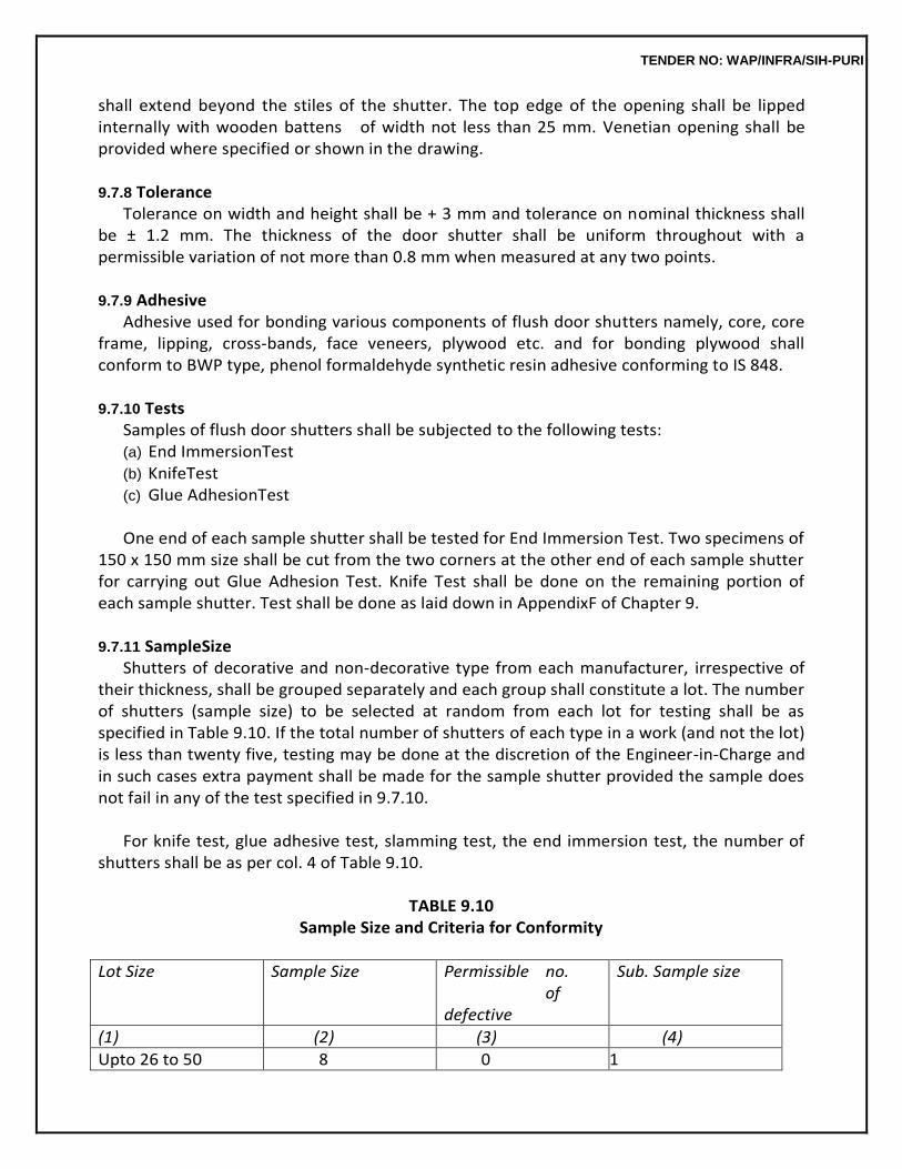
TENDER NO: WAP/INFRA/SIH-PURI
shall extend beyond the stiles of the shutter. The top edge of the opening shall be lipped internally with wooden battens of width not less than 25 mm. Venetian opening shall be provided where specified or shown in the drawing.
9.7.8 Tolerance
Tolerance on width and height shall be + 3 mm and tolerance on nominal thickness shall be ± 1.2 mm. The thickness of the door shutter shall be uniform throughout with a permissible variation of not more than 0.8 mm when measured at any two points.
9.7.9 Adhesive
Adhesive used for bonding various components of flush door shutters namely, core, core frame, lipping, cross-bands, face veneers, plywood etc. and for bonding plywood shall conform to BWP type, phenol formaldehyde synthetic resin adhesive conforming to IS 848.
9.7.10 Tests
Samples of flush door shutters shall be subjected to the following tests: (a) End ImmersionTest (b) KnifeTest (c) Glue AdhesionTest
One end of each sample shutter shall be tested for End Immersion Test. Two specimens of
150 x 150 mm size shall be cut from the two corners at the other end of each sample shutter for carrying out Glue Adhesion Test. Knife Test shall be done on the remaining portion of each sample shutter. Test shall be done as laid down in AppendixF of Chapter 9.
9.7.11 SampleSize
Shutters of decorative and non-decorative type from each manufacturer, irrespective of their thickness, shall be grouped separately and each group shall constitute a lot. The number of shutters (sample size) to be selected at random from each lot for testing shall be as specified in Table 9.10. If the total number of shutters of each type in a work (and not the lot) is less than twenty five, testing may be done at the discretion of the Engineer-in-Charge and in such cases extra payment shall be made for the sample shutter provided the sample does not fail in any of the test specified in 9.7.10.
For knife test, glue adhesive test, slamming test, the end immersion test, the number of
shutters shall be as per col. 4 of Table 9.10.
TABLE 9.10 Sample Size and Criteria for Conformity
Lot Size Sample Size Permissible no. of defective
Sub. Sample size
(1) (2) (3) (4)
Upto 26 to 50 8 0 1
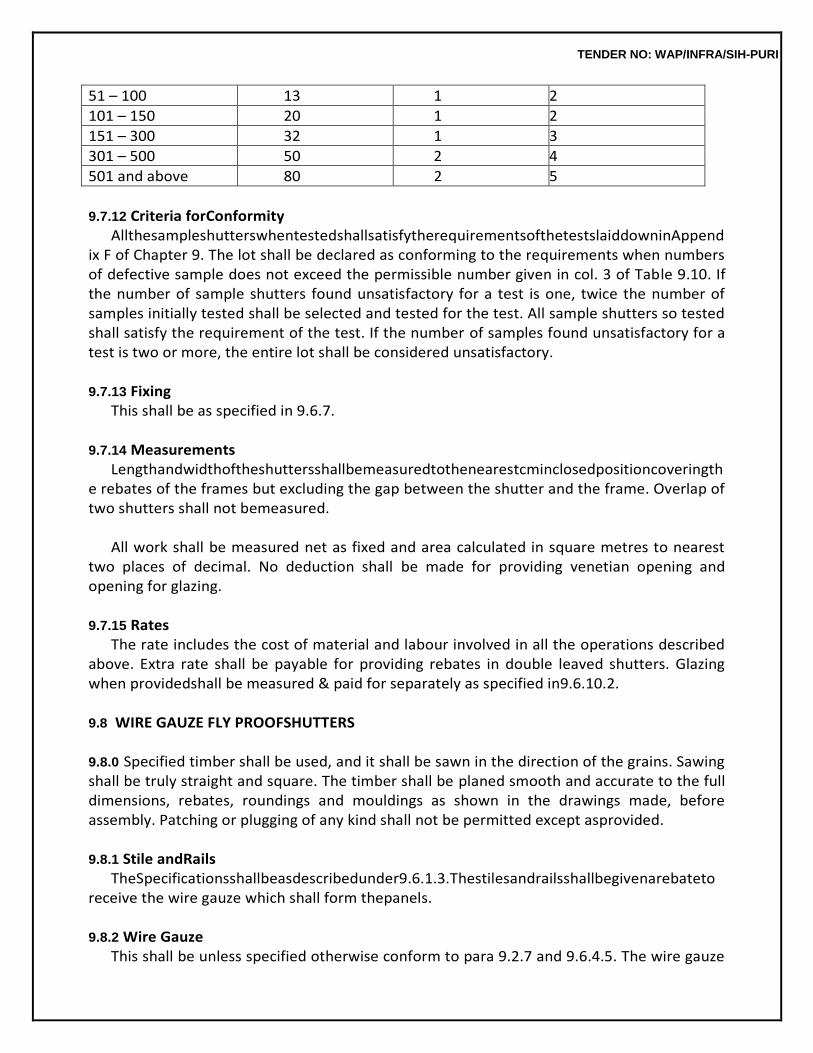
TENDER NO: WAP/INFRA/SIH-PURI
51 – 100 13 1 2
101 – 150 20 1 2
151 – 300 32 1 3
301 – 500 50 2 4
501 and above 80 2 5
9.7.12 Criteria forConformity
AllthesampleshutterswhentestedshallsatisfytherequirementsofthetestslaiddowninAppendix F of Chapter 9. The lot shall be declared as conforming to the requirements when numbers of defective sample does not exceed the permissible number given in col. 3 of Table 9.10. If the number of sample shutters found unsatisfactory for a test is one, twice the number of samples initially tested shall be selected and tested for the test. All sample shutters so tested shall satisfy the requirement of the test. If the number of samples found unsatisfactory for a test is two or more, the entire lot shall be considered unsatisfactory.
9.7.13 Fixing
This shall be as specified in 9.6.7.
9.7.14 Measurements Lengthandwidthoftheshuttersshallbemeasuredtothenearestcminclosedpositioncoveringth
e rebates of the frames but excluding the gap between the shutter and the frame. Overlap of two shutters shall not bemeasured.
All work shall be measured net as fixed and area calculated in square metres to nearest
two places of decimal. No deduction shall be made for providing venetian opening and opening for glazing.
9.7.15 Rates
The rate includes the cost of material and labour involved in all the operations described above. Extra rate shall be payable for providing rebates in double leaved shutters. Glazing when providedshall be measured & paid for separately as specified in9.6.10.2.
9.8 WIRE GAUZE FLY PROOFSHUTTERS
9.8.0 Specified timber shall be used, and it shall be sawn in the direction of the grains. Sawing shall be truly straight and square. The timber shall be planed smooth and accurate to the full dimensions, rebates, roundings and mouldings as shown in the drawings made, before assembly. Patching or plugging of any kind shall not be permitted except asprovided. 9.8.1 Stile andRails
TheSpecificationsshallbeasdescribedunder9.6.1.3.Thestilesandrailsshallbegivenarebateto receive the wire gauze which shall form thepanels.
9.8.2 Wire Gauze
This shall be unless specified otherwise conform to para 9.2.7 and 9.6.4.5. The wire gauze
TENDER NO: WAP/INFRA/SIH-PURI
shall be bent at right angles in the rebates of stiles and rails, turned back and fixed tight with blue tacks at about 75 mm centres, fixed alternately in the two faces of the rebates. Over this, wooden beading shall be fixed with brads or small screws at about 75 mm centres.
The space between the beading and rebates, where the wire gauze is bent, shall be neatly
finished with putty, so that the end of the wire gauze may not be visible.
9.8.3 Fixing Fittings, Wooden cleats, blocks and Measurement shall be as specified under9.6.
9.8.4 Rate Thisincludesthecostofmaterialsandlabourinvolvedinalltheoperationsdescribedabove,anda
s specified under9.6.
9.9 WALLLINING
9.9.0 Specified timber shall be used, and it shall be sawn in the direction of the grains. Sawing shall be truly straight and square. The timber shall be planed smooth and accurate to the full dimensions, rebates, roundings, and mouldings as shown in the drawings made, before assembly. Patchings or plugging of, any kind shall not be permitted except asprovided.
9.9.1 Grounds
Grounds shall be provided where so specified. These shall consist of first class hard wood plugs or the class of wood used for fabricating the frames, of trapezoidal shape having base of 50 × 50 mm and top 35 × 35 mm with depth of 5.0 cm and embedded in the wall with cement mortar 1:3 (1 cement : 3 fine sand) and batten of first class hard wood or as specified of size 50 × 25 mm or as specified, fixed over the plugs with 50 mm long wood screws. The plugs shall be spaced at 45 to 60 centimetres centre to centre, depending upon the nature of work. The battens shall be painted with priming coat, of approved wood primer before fixing.
9.9.2 Panelling
9.9.2.1 Material : This panelling shall be decorative or non-decorative (Paintable) type as per design and thickness specified by the Engineer-in-Charge, of 2nd class teak wood, FPT-1 or graded wood prelaminated particle board or as specified initem.
9.9.2.2 OrnamentalWork:Theornamentalwoodworkshallbepaintedonthebackwithprimingcoatof approved wood primer before fixing the same to the grounds with screws, which shall be sunk into the wood work and their tops covered with putty. The ornamental work shall be made true and accurate to the dimensions shown in the working drawings. The fixing shall be done true to lines and levels. The planks for wall lining shall be tongued and grooved, unless otherwisespecified.
9.9.2.3 Measurements:Lengthandbreadthshallbemeasuredcorrecttoacm.Wallpanellingsuchas teakwood panelling and block panelling, plain lining, and plain skirting each shall be measured separately in square metre nearest to two places of decimal. The moulded work
TENDER NO: WAP/INFRA/SIH-PURI
shall be measured in cm running metre i.e. in running metres stating the girth in cm. The sectional periphery (girth) of moulding excluding the portion in contact with wall shall be measured in cm correct to 5 mm and length in metre correct to acm.
Themeasurementsforgroundshallbetakenonthebasisofcubicalcontentsofbattensandpaidfor separately, unless otherwisespecified.
Where only plugs are required to be fixed for the ornamental work, the cost for the same
shall be deemedtobeincludedintherateofornamentalworkandnoseparatepaymentshallbemadeforplugs.
9.9.2.4 Rate : The rate includes the cost of materials and labour required for all the operationdescribed above.
9.10 SHELVES
9.10.0 Shelves and vertical partitions of cupboards shall be of timber planks fibre board, particle board, blockboardorveneeredparticleboardasspecified.Thicknessandtypeofplanksorboardsshallbeas specified. Each shelf shall be a single piece and vertical partitions between two consecutive shelves shall be without any joint. Exposed edges of boards having particle board core shall be sealed with 3 mm thick single piece teak wood strips of width equal to the thickness of board with headless pins. The arrangement of shelves and vertical partitions shall be as per drawings or as directed by the Engineer- in-Charge.
9.10.1 Fixing
Planks for shelves shall be planed on all faces and edges. In case of boards they shall be sawn to the required size truly straight and square. Timber battens 25 x 40 mm unless otherwise specified shall be planed smooth and fixed inside the cupboard with wooden plugs and screws. Shelves shall be fixed to the battens and vertical portions shall be held in position by fixing them to the battens and shelves using screws. Teakwood strips for edge sealing of the boards shall be planed smooth and fixed with headless nails. Tolerance in width shall be ± 1.5 mm and in thickness 1 mm.
9.10.2 Measurements
Length and width of shelves and vertical partitions shallbe measured correct to a cm. separately for eachtypeofboardstatingitsthickness.Areashallbecalculatedcorrectto0.01sqm.
9.10.3 Rate
It includes the cost of materials and labour required for all the operations described above.
9.11 TRELLIS (JAFFRI)WORK
9.11.0 Specifiedtimber/bambooshallbesawn/cutinthedirectionofthegrains.Sawing/cuttingshall
TENDER NO: WAP/INFRA/SIH-PURI
be truly straight and square. The timber / bamboo shall be planed smooth and accurate to the full dimensions, rebates, roundings, and mouldings as shown in the drawings made, before assembly. Patching or plugging of any kind shall not be permitted except asprovided.
9.11.1 Plain Trellis(Jaffri)
This shall consist of wooden strips or laths 35 x 10 mm section unless otherwise specified planed andnailedtogetherateveryalternatecrossing.Thestripsshallcrosseachotheratrightangleandshall be spaced 35 mm apart, so as to form 35 × 35 mm square opening or as shown in the drawing. These shall be fixed with nails to the frame. To cover the ends of strips, 50 × 12 mm beading shall be fixed to theframewithscrews.Thefinishedworkwithatoleranceof±1mmmaybeaccepted.
9.11.2 Measurements
Width and height of plain trellis work and trellis shutters shall be measured overall correct to a cm. The area shall be calculated in square metres nearest to two places of decimal.
9.11.3 Rate
It includes the cost of materials and labour required in all the operations described above.
9.12 PELMETS
9.12.0 Planks and curtain rods of specified timber shall be used, and it shall be sawn in the direction of thegrains.Sawingshallbetrulystraightandsquare.Thetimbershallbeplanedsmoothandaccurateto the full dimensions, rebates, roundings, and mouldings as shown in the drawings made, before assembly. Patching or plugging of any kind shall not bepermitted.
9.12.1 Sides, front and top of the pelmets shall be of 12 mm planks or boards of specified quality and widthunlessotherwisestated.Theseshallprojectfromthewallfaceby15cmorasspecified,andshall besecurelyfixedtowallswithwoodscrewsbymeansofwoodenplugsand10cmlong25×3mmM.S. flat bent in the form of angle or by any other device approved by the Engineer-in-Charge. The pelmets shall be provided with curtain rods and brackets or curtain rails with rollers, stop ends and brackets wooden,brassorchromiumplatedbrassasspecified.Intermediatewoodenbracketsshallbeprovided, if the front length of pelmet exceeds 1.5metres.
9.12.2 Measurements
The pelmets box shall be measured along the sides and front planking correct to a centimetre.
9.12.3 Rate The rate includes the cost of sides, front and top planking curtain rods with brackets or
curtain rails with rollers labour and materials required for all the operations described above.
TENDER NO: WAP/INFRA/SIH-PURI
9.13 HOLD FASTS
9.13.0 Theseshallbemadefrommildsteelflat40×5mmsizeconformingtoIS7196withoutanyburns ordents.5cmlengthofM.S.flatatoneendshallbebentatrightangleandonehole11mmdiashallbe made in it for fixing to wooden frame with 10 mm dia nut bolt. The bolt head shall be sunk into the woodenframe,10mmdeepandplugedwithwoodenplug.Attheotherend10cmlengthoftheholdfast flat shall be forked and bent of length as specified at right angle in opposite direction and embedded in cement concrete block of size 30 x 10 x 15 cm of mix 1:3:6 (1 cement : 3 coarse sand : 6 graded stone aggregate, 20 mm nominal size) or as specified (see Fig.9.4).
9.13.1 Measurements
Measurements for the hold fasts shall be in number.
9.13.2 Rate It includes the cost of labour and material involved in all the operations described above
including fixing bolt and cement concrete blocks.
9.14 EXPANDED METAL, HARD DRAWN STEEL WIRE FABRIC AND WIRE GAUZE IN WOODEN FRAMES
9.14.0 Expanded metal, hard drawn steel wire fabric or wire gauge or weld mesh as described in the item of work shall be fixed to the window frames on the outside or inside as per detailed drawings or as directed by the Engineer-in-Charge. These shall be free from rust and other defects.
Expanded Metal
This shall be in the form of rhombus with its opening diagonals 20 × 60 mm and strands 3.25 mm wide and 1.6 mm thick weighing 3.633 kg/m2 unless otherwise specified. Welded Steel Drawn Wire Fabric
This shall conform to IS 4948 and shall have rectangular mesh of 75 × 25 mm size with wires of diameter not less than 5 mm longitudinally and 3.15 mm transversely. Its weight shall be not less than7.75 kg/m2 unless otherwise specified.
Wire-Gauze
This shall be as per clause 9.2.7.
9.14.1 Fixing Expanded metal, hard drawn steel wire fabric and wire gauze shall be cut in one piece to
the sizeof the frame (out to out). Expanded metal and hard drawn steel wire fabric shall be fixed on to the frame withstaples,overwhichwoodenbeading60x20mmshallbefixedwithwoodscrews.
9.14.2 Measurements
TENDER NO: WAP/INFRA/SIH-PURI
The length and breadth shall be measured correct to a cm, the area from outside to outside of beading shall be calculated in square metre nearest to two places of decimal.
9.14.3 Rate
It includes the cost of labour and materials required for all the operations described above.
9.15 FITTINGS
9.15.0 Fitting shall be of mild steel brass, aluminium or as specified. Some mild steel fittings may have components of cast iron. These shall be well made, reasonably smooth, and free from sharp edgesand corners, flaws and other defects. Screw holes shall be counter sunk to suit the head of specified wood screws. These shall be of the following types according to the materialused.
(a) MildSteelFittings:Theseshallbebrightfinishblackstoneenamelledorcopperoxidised(blac
k finish), nickel chromium plated or asspecified.
(b) Brass Fittings : These shall be finished bright satin finish or nickel chromium plated or copper oxidised or asspecified.
(c) Aluminium Fittings : These shall be anodised to natural matt finish or dyed anodic
coating not less than grade AC 10 of IS1868.
The fittings generally used for different type of doors and windows are indicated in Appendix H attached. The fittings to be actually provided in a particular work shall, however, be decided by the Engineer-in-Charge.
Screws used for fittings shall be of the same metal, and finish as the fittings. However,
chromium plated brass screws or stainless steel screws shall be used for fixing aluminium fittings. These shall be of the size as indicated in respective figures.
Fittings shall be fixed in proper position as shown in the drawings or as directed by the
Engineer-in- Charge.Theseshallbetrulyverticalorhorizontalasthecasemaybe.Screwsshallbedrivenhomewith screw driver and not hammered in. Recesses shall be cut to the exact size and depth for the counter sunking ofhinges.
9.15.1 Butt Hinges (Fig.9.5A)
These shall be of the following types according to the material used. (a) Mild steel butt hinges(Medium). (b) Cast brass butt hinges light/ordinary orheavy. (c) Extruded aluminium alloy butthinges.
9.15.1.1 MildSteel(Medium)(Fig.9.5A):TheseshallbemediumtypemanufacturedfromM.S.sheet. These shall be well made and shall be free from flaws and defects of all kinds. All hinges
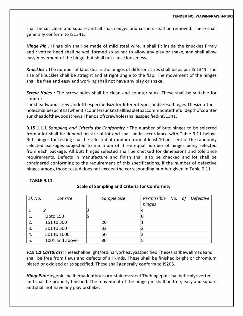
TENDER NO: WAP/INFRA/SIH-PURI
shall be cut clean and square and all sharp edges and corners shall be removed. These shall generally conform to IS1341. Hinge Pin : Hinge pin shall be made of mild steel wire. It shall fit inside the knuckles firmly and rivetted head shall be well formed so as not to allow any play or shake, and shall allow easy movement of the hinge, but shall not cause looseness.
Knuckles : The number of knuckles in the hinges of different sizes shall be as per IS 1341. The size of knuckles shall be straight and at right angle to the flap. The movement of the hinges shall be free and easy and working shall not have any play or shake.
Screw Holes : The screw holes shall be clean and counter sunk. These shall be suitable for counter sunkheadwoodscrewsandofthespecifiedsizefordifferenttypes,andsizesofhinges.Thesizeofthe holesshallbesuchthatwhenitiscountersunkitshallbeabletoaccommodatethefulldepthofcounter sunkheadofthewoodscrews.Thenos.ofscrewholesshallasspecifiedinIS1341.
9.15.1.1.1 Sampling and Criteria for Conformity : The number of butt hinges to be selected from a lot shall be depend on size of lot and shall be in accordance with Table 9.11 below. Butt hinges for testing shall be selected at random from at least 10 per cent of the randomly selected packages subjected to minimum of three equal number of hinges being selected from each package. All butt hinges selected shall be checked for dimensions and tolerance requirements. Defects in manufacture and finish shall also be checked and lot shall be considered conforming to the requirement of this specifications, if the number of defective hinges among those tested does not exceed the corresponding number given in Table 9.11.
TABLE 9.11
Scale of Sampling and Criteria for Conformity
Sl. No. Lot size Sample Size Permissible No. of Defective hinges
1 2 3 4
1. Upto 150 5 0
2. 151 to 300 20 1
3. 301 to 500 32 2
4. 501 to 1000 50 3
5. 1001 and above 80 5
9.15.1.2 CastBrass:Theseshallbelight/ordinaryorheavyasspecified.Theseshallbewellmadeand shall be free from flaws and defects of all kinds. These shall be finished bright or chromium plated or oxidised or as specified. These shall generally conform to IS205.
HingePin:Hingepinshallbemadeofbrassorofstainlesssteel.Thehingepinsshallbefirmlyrivetted and shall be properly finished. The movement of the hinge pin shall be free, easy and square and shall not have any play orshake.
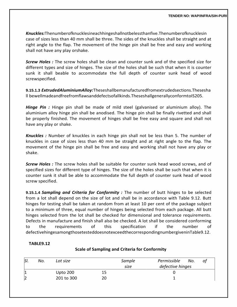
TENDER NO: WAP/INFRA/SIH-PURI
Knuckles:Thenumberofknucklesineachhingeshallnotbelessthanfive.Thenumberofknucklesin case of sizes less than 40 mm shall be three. The sides of the knuckles shall be straight and at right angle to the flap. The movement of the hinge pin shall be free and easy and working shall not have any play orshake.
Screw Holes : The screw holes shall be clean and counter sunk and of the specified size for different types and size of hinges. The size of the holes shall be such that when it is counter sunk it shall beable to accommodate the full depth of counter sunk head of wood screwspecified.
9.15.1.3 ExtrudedAluminiumAlloy:Theseshallbemanufacturedfromextrudedsections.Theseshall bewellmadeandfreefromflawsanddefectsofallkinds.TheseshallgenerallyconformtoIS205. Hinge Pin : Hinge pin shall be made of mild steel (galvanised or aluminium alloy). The aluminium alloy hinge pin shall be anodised. The hinge pin shall be finally rivetted and shall be properly finished. The movement of hinges shall be free easy and square and shall not have any play or shake.
Knuckles : Number of knuckles in each hinge pin shall not be less than 5. The number of knuckles in case of sizes less than 40 mm be straight and at right angle to the flap. The movement of the hinge pin shall be free and easy and working shall not have any play or shake.
Screw Holes : The screw holes shall be suitable for counter sunk head wood screws, and of specified sizes for different type of hinges. The size of the holes shall be such that when it is counter sunk it shall be able to accommodate the full depth of counter sunk head of wood screw specified.
9.15.1.4 Sampling and Criteria for Conformity : The number of butt hinges to be selected from a lot shall depend on the size of lot and shall be in accordance with Table 9.12. Butt hinges for testing shall be taken at random from at least 10 per cent of the package subject to a minimum of three, equal number of hinges being selected from each package. All butt hinges selected from the lot shall be checked for dimensional and tolerance requirements. Defects in manufacture and finish shall also be checked. A lot shall be considered conforming to the requirements of this specification if the number of defectivehingesamongthosetesteddoesnotexceedthecorrespondingnumbergiveninTable9.12.
TABLE9.12
Scale of Sampling and Criteria for Conformity
Sl. No. Lot size Sample size
Permissible No. of defective hinges
1 Upto 200 15 0 2 201 to 300 20 1
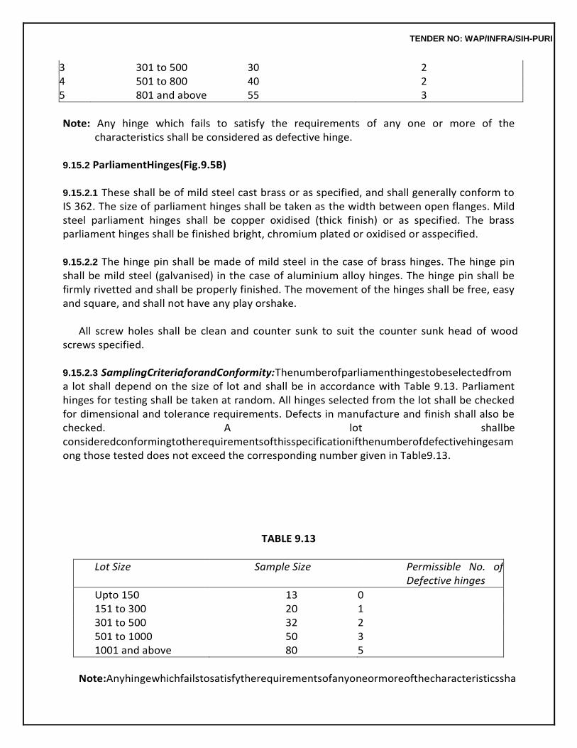
TENDER NO: WAP/INFRA/SIH-PURI
3 301 to 500 30 2 4 501 to 800 40 2 5 801 and above 55 3
Note: Any hinge which fails to satisfy the requirements of any one or more of the
characteristics shall be considered as defective hinge.
9.15.2 ParliamentHinges(Fig.9.5B)
9.15.2.1 These shall be of mild steel cast brass or as specified, and shall generally conform to IS 362. The size of parliament hinges shall be taken as the width between open flanges. Mild steel parliament hinges shall be copper oxidised (thick finish) or as specified. The brass parliament hinges shall be finished bright, chromium plated or oxidised or asspecified.
9.15.2.2 The hinge pin shall be made of mild steel in the case of brass hinges. The hinge pin shall be mild steel (galvanised) in the case of aluminium alloy hinges. The hinge pin shall be firmly rivetted and shall be properly finished. The movement of the hinges shall be free, easy and square, and shall not have any play orshake.
All screw holes shall be clean and counter sunk to suit the counter sunk head of wood
screws specified.
9.15.2.3 SamplingCriteriaforandConformity:Thenumberofparliamenthingestobeselectedfrom a lot shall depend on the size of lot and shall be in accordance with Table 9.13. Parliament hinges for testing shall be taken at random. All hinges selected from the lot shall be checked for dimensional and tolerance requirements. Defects in manufacture and finish shall also be checked. A lot shallbe consideredconformingtotherequirementsofthisspecificationifthenumberofdefectivehingesamong those tested does not exceed the corresponding number given in Table9.13.
TABLE 9.13
Lot Size Sample Size Permissible No. of Defective hinges
Upto 150 13 0 151 to 300 20 1 301 to 500 32 2 501 to 1000 50 3 1001 and above 80 5
Note:Anyhingewhichfailstosatisfytherequirementsofanyoneormoreofthecharacteristicssha
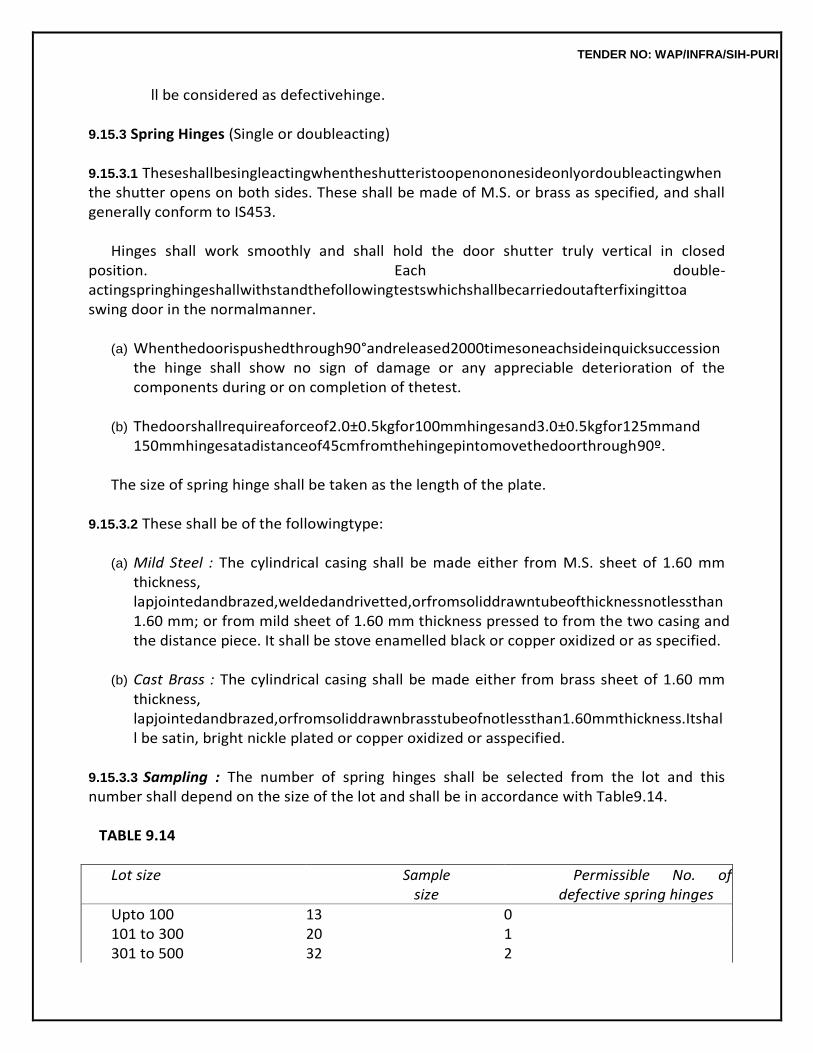
TENDER NO: WAP/INFRA/SIH-PURI
ll be considered as defectivehinge.
9.15.3 Spring Hinges (Single or doubleacting)
9.15.3.1 Theseshallbesingleactingwhentheshutteristoopenononesideonlyordoubleactingwhen the shutter opens on both sides. These shall be made of M.S. or brass as specified, and shall generally conform to IS453.
Hinges shall work smoothly and shall hold the door shutter truly vertical in closed
position. Each double-actingspringhingeshallwithstandthefollowingtestswhichshallbecarriedoutafterfixingittoa swing door in the normalmanner.
(a) Whenthedoorispushedthrough90°andreleased2000timesoneachsideinquicksuccession
the hinge shall show no sign of damage or any appreciable deterioration of the components during or on completion of thetest.
(b) Thedoorshallrequireaforceof2.0±0.5kgfor100mmhingesand3.0±0.5kgfor125mmand
150mmhingesatadistanceof45cmfromthehingepintomovethedoorthrough90º.
The size of spring hinge shall be taken as the length of the plate.
9.15.3.2 These shall be of the followingtype:
(a) Mild Steel : The cylindrical casing shall be made either from M.S. sheet of 1.60 mm thickness, lapjointedandbrazed,weldedandrivetted,orfromsoliddrawntubeofthicknessnotlessthan 1.60 mm; or from mild sheet of 1.60 mm thickness pressed to from the two casing and the distance piece. It shall be stove enamelled black or copper oxidized or as specified.
(b) Cast Brass : The cylindrical casing shall be made either from brass sheet of 1.60 mm
thickness, lapjointedandbrazed,orfromsoliddrawnbrasstubeofnotlessthan1.60mmthickness.Itshall be satin, bright nickle plated or copper oxidized or asspecified.
9.15.3.3 Sampling : The number of spring hinges shall be selected from the lot and this number shall depend on the size of the lot and shall be in accordance with Table9.14.
TABLE 9.14
Lot size Sample size
Permissible No. of defective spring hinges
Upto 100 13 0 101 to 300 20 1 301 to 500 32 2
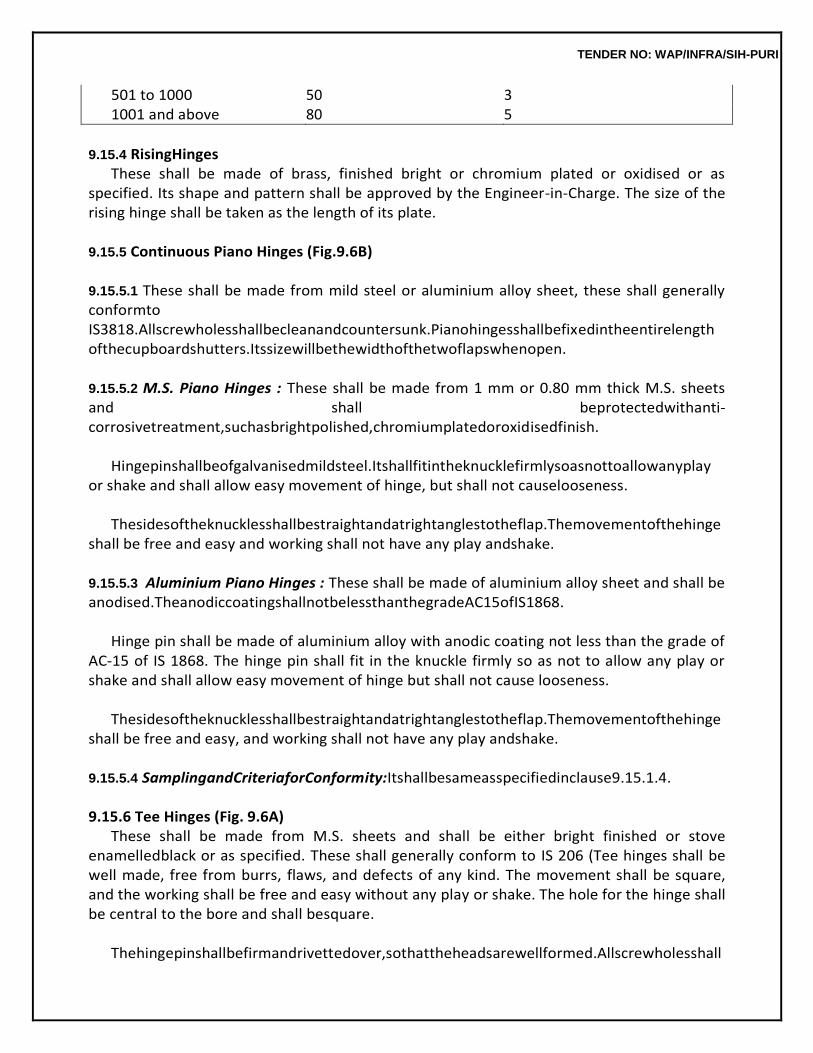
TENDER NO: WAP/INFRA/SIH-PURI
501 to 1000 50 3 1001 and above 80 5
9.15.4 RisingHinges
These shall be made of brass, finished bright or chromium plated or oxidised or as specified. Its shape and pattern shall be approved by the Engineer-in-Charge. The size of the rising hinge shall be taken as the length of its plate.
9.15.5 Continuous Piano Hinges (Fig.9.6B)
9.15.5.1 These shall be made from mild steel or aluminium alloy sheet, these shall generally conformto IS3818.Allscrewholesshallbecleanandcountersunk.Pianohingesshallbefixedintheentirelength ofthecupboardshutters.Itssizewillbethewidthofthetwoflapswhenopen.
9.15.5.2 M.S. Piano Hinges : These shall be made from 1 mm or 0.80 mm thick M.S. sheets and shall beprotectedwithanti-corrosivetreatment,suchasbrightpolished,chromiumplatedoroxidisedfinish.
Hingepinshallbeofgalvanisedmildsteel.Itshallfitintheknucklefirmlysoasnottoallowanyplay
or shake and shall allow easy movement of hinge, but shall not causelooseness.
Thesidesoftheknucklesshallbestraightandatrightanglestotheflap.Themovementofthehinge shall be free and easy and working shall not have any play andshake.
9.15.5.3 Aluminium Piano Hinges : These shall be made of aluminium alloy sheet and shall be anodised.TheanodiccoatingshallnotbelessthanthegradeAC15ofIS1868.
Hinge pin shall be made of aluminium alloy with anodic coating not less than the grade of
AC-15 of IS 1868. The hinge pin shall fit in the knuckle firmly so as not to allow any play or shake and shall allow easy movement of hinge but shall not cause looseness.
Thesidesoftheknucklesshallbestraightandatrightanglestotheflap.Themovementofthehinge
shall be free and easy, and working shall not have any play andshake.
9.15.5.4 SamplingandCriteriaforConformity:Itshallbesameasspecifiedinclause9.15.1.4.
9.15.6 Tee Hinges (Fig. 9.6A) These shall be made from M.S. sheets and shall be either bright finished or stove
enamelledblack or as specified. These shall generally conform to IS 206 (Tee hinges shall be well made, free from burrs, flaws, and defects of any kind. The movement shall be square, and the working shall be free and easy without any play or shake. The hole for the hinge shall be central to the bore and shall besquare.
Thehingepinshallbefirmandrivettedover,sothattheheadsarewellformed.Allscrewholesshall
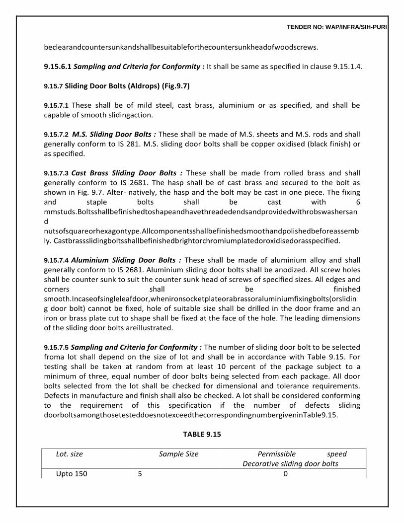
TENDER NO: WAP/INFRA/SIH-PURI
beclearandcountersunkandshallbesuitableforthecountersunkheadofwoodscrews.
9.15.6.1 Sampling and Criteria for Conformity : It shall be same as specified in clause 9.15.1.4.
9.15.7 Sliding Door Bolts (Aldrops) (Fig.9.7)
9.15.7.1 These shall be of mild steel, cast brass, aluminium or as specified, and shall be capable of smooth slidingaction.
9.15.7.2 M.S. Sliding Door Bolts : These shall be made of M.S. sheets and M.S. rods and shall generally conform to IS 281. M.S. sliding door bolts shall be copper oxidised (black finish) or as specified.
9.15.7.3 Cast Brass Sliding Door Bolts : These shall be made from rolled brass and shall generally conform to IS 2681. The hasp shall be of cast brass and secured to the bolt as shown in Fig. 9.7. Alter- natively, the hasp and the bolt may be cast in one piece. The fixing and staple bolts shall be cast with 6 mmstuds.Boltsshallbefinishedtoshapeandhavethreadedendsandprovidedwithrobswashersand nutsofsquareorhexagontype.Allcomponentsshallbefinishedsmoothandpolishedbeforeassembly. Castbrassslidingboltsshallbefinishedbrightorchromiumplatedoroxidisedorasspecified.
9.15.7.4 Aluminium Sliding Door Bolts : These shall be made of aluminium alloy and shall generally conform to IS 2681. Aluminium sliding door bolts shall be anodized. All screw holes shall be counter sunk to suit the counter sunk head of screws of specified sizes. All edges and corners shall be finished smooth.Incaseofsingleleafdoor,whenironsocketplateorabrassoraluminiumfixingbolts(orsliding door bolt) cannot be fixed, hole of suitable size shall be drilled in the door frame and an iron or brass plate cut to shape shall be fixed at the face of the hole. The leading dimensions of the sliding door bolts areillustrated.
9.15.7.5 Sampling and Criteria for Conformity : The number of sliding door bolt to be selected froma lot shall depend on the size of lot and shall be in accordance with Table 9.15. For testing shall be taken at random from at least 10 percent of the package subject to a minimum of three, equal number of door bolts being selected from each package. All door bolts selected from the lot shall be checked for dimensional and tolerance requirements. Defects in manufacture and finish shall also be checked. A lot shall be considered conforming to the requirement of this specification if the number of defects sliding doorboltsamongthosetesteddoesnotexceedthecorrespondingnumbergiveninTable9.15.
TABLE 9.15
Lot. size Sample Size Permissible speed Decorative sliding door bolts
Upto 150 5 0
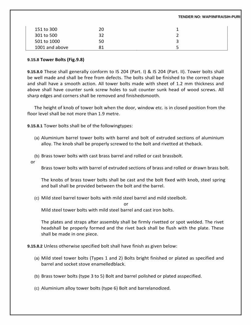
TENDER NO: WAP/INFRA/SIH-PURI
151 to 300 20 1 301 to 500 32 2 501 to 1000 50 3 1001 and above 81 5
9.15.8 Tower Bolts (Fig.9.8)
9.15.8.0 These shall generally conform to IS 204 (Part. I) & IS 204 (Part. II). Tower bolts shall be well made and shall be free from defects. The bolts shall be finished to the correct shape and shall have a smooth action. All tower bolts made with sheet of 1.2 mm thickness and above shall have counter sunk screw holes to suit counter sunk head of wood screws. All sharp edges and corners shall be removed and finishedsmooth.
The height of knob of tower bolt when the door, window etc. is in closed position from the
floor level shall be not more than 1.9 metre.
9.15.8.1 Tower bolts shall be of the followingtypes:
(a) Aluminium barrel tower bolts with barrel and bolt of extruded sections of aluminium alloy. The knob shall be properly screwed to the bolt and rivetted at theback.
(b) Brass tower bolts with cast brass barrel and rolled or cast brassbolt.
or Brass tower bolts with barrel of extruded sections of brass and rolled or drawn brass bolt.
The knobs of brass tower bolts shall be cast and the bolt fixed with knob, steel spring and ball shall be provided between the bolt and the barrel.
(c) Mild steel barrel tower bolts with mild steel barrel and mild steelbolt.
or Mild steel tower bolts with mild steel barrel and cast iron bolts.
The plates and straps after assembly shall be firmly rivetted or spot welded. The rivet headshall be properly formed and the rivet back shall be flush with the plate. These shall be made in one piece.
9.15.8.2 Unless otherwise specified bolt shall have finish as given below:
(a) Mild steel tower bolts (Types 1 and 2) Bolts bright finished or plated as specified and
barrel and socket stove enamelledblack.
(b) Brass tower bolts (type 3 to 5) Bolt and barrel polished or plated asspecified.
(c) Aluminium alloy tower bolts (type 6) Bolt and barrelanodized.
TENDER NO: WAP/INFRA/SIH-PURI
The anodic film may be either transparent or dyed as specified. The quality of anodized finish shall not be less than grade AC-10 of IS 1868.
9.15.8.3 SamplingandCriteriaforConformity:Itshallbesameasspecifiedinclause9.15.1.4.
9.15.9 M.S. Locking Bolt with Holes for PadLocks
9.15.9.1 This shall conform to IS7534.
9.15.9.2 This shall be of mild steel polished bright or copper oxidised batch electrogalvanised or stove enamelled. In case of stove enamelled locking bolts, the bolt may be finishedbright.
9.15.10 Pull Bolt Locks (Fig.9.9)
9.15.10.1 These shall be of M.S. cast brass or aluminium as specified. M.S. pull bolt locks shall be copper oxidized (black finish) or asspecified.
9.15.10.2 Brass pull bolt locks shall be finished bright, chromium plated or oxidised as specified. Aluminiumpullboltlocksshallbeanodisedandtheanodiccoatingshallnotbelessthangrade.A.C.10 of IS 1868. The bolt shall be 10 mm in diameter and the fixing plate 3 mm thick. The stop block shall be screwedtothefixingplatebyasmallballandspringoverwhichtheboltshallslide.
9.15.10.3 The fixing plate shall have four holes for fixing it to the door leaf, two of which shall be square toreceive6mmdia.boltswithroundheads,theremainingtwoshallreceivemachinescrewedwithlock nuts. The receiving plate shall be of the same width and thickness as the fixing plate and shall have 3 counter sunkholes.
Where the bolt slides into wooden members, like the chowkhat, which have a rebate, the
receiving plate shall also be correspondingly shaped so as to fit into the rebate. The screws and bolts shall have thesamefinishasthemainbolt.Theleadingdimensionsofpullboltlocksaregiveninthedrawing.The denominating size of the pull bolt locks shall be length of the fixing plate between guides plus the thickness of theguides.
9.15.11 Door Latch
9.15.11.1 This shall be of mild steel, cast brass, or as specified and shall be capable of smooth sliding action.Incase,ofmildsteellatch,itshallbecopperoxidized(blackfinish)orasspecifiedandincaseof brass,itshallbefinishedbright,chromiumplatedoroxidizedorasspecified.Thesizeofdoorlatchshall be taken as the length of thelatch.
TENDER NO: WAP/INFRA/SIH-PURI
9.15.12 Indicating Bolt(Vacant/Engaged) These shall be of cast brass finished bright chromium plated, or oxidized or as specified.
The shape and pattern shall be approved by the Engineer-in-Charge.
9.15.13 Mortice Lock and Latch (Fig.9.10)
9.15.13.0 This should generally conform to IS2209.
9.15.13.1 Thesizeofthemorticelockshallbedenotedbythelengthofthebodytowardsthefaceandit shall be 65 mm, 75 mm and 100 mm as specified. The measured length shall not vary more than 3 mm from the lengthspecified.
9.15.13.2 Non-interchangeableKeys:Testingofnon-interchangeablekeysshallbeasperIS2209.
9.15.13.3 The clear depth of the body shall not be more than 15 mm. The fore end shall be firmly fitted to the body suitably by counter sunk head screw. The latch bolt shall be of specified material and of sectionnotlessthan12x16mmforallsizesoflocks.Ifmadeoftwopiececonstructionbothpartsshall berivetted.Ordinarylevermechanismwithnotlessthantwoleversshallbeprovided.Falseleversshall not be used. Lever shall be fitted with one spring of phosphor bronze or steel wire and shall withstand the tests as provided in IS2209.
9.15.13.4 Locking bolts, spring and strike plate shall conform to IS2209.
9.15.13.5 Handles : These shall conform to IS4992.
9.15.13.6 Keys : Each lock shall be provided with twokeys.
9.15.13.7 Sampling,CriteriaforConformity:Itshallbethesameasspecifiedinclause9.15.1.4.
9.15.13.8 Tests:ThefinallyassembledlocksshallbetestedasprescribedinAppendix‘G’ofChapter9.
9.15.14 Mortice Latch (with LockingBolt)
9.15.14.1 These are generally used in doors of bath rooms, WC’s and privaterooms.
9.15.14.2 Mortice latch shall, in respect of shape, design and mechanism of the latch and its components parts, generally conform to IS 5930. The material used for the different component partsof the latch shall comply with Tables 1 and 2 of IS 5930, unless otherwisespecified.
9.15.14.3 The size of the latch shall be denoted by the length of the body towards the face and shall be 65mm,75mmor100mmasspecified.Thedepthofthebodyshallnotbemorethan15mm.
TENDER NO: WAP/INFRA/SIH-PURI
9.15.14.4 Thelatchshallbeofsize10×18mmofshapeasshowninFig.1ofIS5930.Thelockingbolt shall be of section not less than 8 x 25 mm for all size of locks. The mechanism of the latch bolt, its spring, striking plate etc. shall be as described in IS5930.
9.15.14.5 The handles provided shall conform to IS4992.
9.15.14.6 Sampling, criteria for conformity shall be same as per clause9.15.1.4.
9.15.15 Mortice Lock and Latch(Rebated)
9.15.15.1 Theseareslightlydifferentfrommorticelockdescribedin9.15.14andaredesignedforusein double leaved doors. These should generally conform to IS6607.
9.15.15.2 Handles, Keys, Sampling, Criteria for Conformity and Test : These shall be same as specified in clause9.15.14.
9.15.16 Mortice Night Latch (Fig.9.11)
9.15.16.1 This is a mortice lock having a single spring bolt withdrawn from the outside by using the key and from inside by turning the knob and with an arrangement whereby the lock can be prevented from beingopenedbyitskeyfromoutsidewhilethenightlatchisusedfrominsidetheroom.
9.15.16.2 This should generally conform to IS3847.
9.15.16.3 It shall be cast or sheet brass, cast or sheet aluminium alloy or Mild steel as specified and of best quality of approved make. These shall be bright finished or copper oxidised (black) finish as specified. Nominal size of the latch shall be denoted by the length of the face over the body in milli- metres.Theseshallhavenotlessthantwolevers.False(Dummy)leversshallnotbeallowed.
9.15.16.4 Keys : Each latch shall be provided with two keys which should work smoothly and without any appreciable friction in thelock.
9.15.17 Cupboard or WardrobeLock
ThisshouldgenerallyconformtoIS729.Thesizeofthecupboardlockshallbe40,50,65&75mm. This shall be made of cast brass and shall be of the best make of approved quality. These shall be finished bright or chromium plated or oxidised or as specified. The size of the lock shall be denoted by the length of the face across the body inmm.
Theselocksshallbefittedwithfour,fiveorsixleversasspecified.False(dummy)leversshallnotbe
used.
9.15.18 KickingPlates
TENDER NO: WAP/INFRA/SIH-PURI
9.15.18.1 This shall be of brass (finished bright or chromium plated or oxidised) bronze, stainless steel, aluminium or as specified. Aluminium kicking plates shall be anodised and the anodic coating shall not be less than grade AC-10 of IS 1868. It shall be made from a plate of minimum thickness 3.0 mm & 1.5 mm in case of stainless steel. Shape of the plate shall be as specified. This shall have bevelled or straightedgesandshallbefixedbymeansofcountersunkorroundedscrewsofthesamematerialand finishasthatoftheplate.Theshapeandpatternshallbeaccordingtothedrawingsandasapprovedby theEngineer-in-Charge.
9.15.19 Door Handles (Doors and Windows) (Fig.9.12)
9.15.19.1 TheseshouldgenerallyconformtoIS208.Thedoorhandlesshallbewellmadeandfreefrom defects. These shall be finished correct to shape and dimensions. All edges and corners shall be removed and finished smooth so as to facilitate easy handling. Cast handle shall be free from casting defects. Where the grip portion of the handle is joined with the base piece by mechanical means, the arrangement shall be such that the assembled handle shall have adequate strength comparable to that of integrally cast typehandles.
9.15.19.2 Door handles shall be of the following types according to the materialused:
(a) Cast or Sheet Aluminium Alloy Handles : These shall be of aluminium of specified size, and of shape and pattern as approved by the Engineer-in-Charge. The size of the handle shall be determined by the inside grip of the handle. Door handles shall be of 100 mm size and window handles of 75 mm size unless, otherwise specified. These shall be fixed with 25 mm long wood screws of designationNo.6. Aluminium handles, shall be anodized and the anodic coating shall not be less than grade AC 15 -IS 1868asspecified.Thefinishcanbebrightnatural,mattorsatinordyedasspecified. (b) CastBrassHandles:Theseshallbeofcastbrassofspecifiedsizeandoftheshapeandpatternas approvedbytheEngineer-in-Charge.Thesizeofthehandleshallbedeterminedbytheinsidegripofthe handle. Door handles shall be of 100 mm size and window handles of 75 mm size, unless otherwise specified. These shall be fixed with 25 mm long wood screws of designation No 6. Brass handles shall befinishedbrightsatinornickelchromiumplatedorcopperoxidisedorasspecified.
(c) Mild Steel Handles : These shall be of mild steel sheet, pressed into oval section. The size of the handles will be determined by the inside grip of the handle. Door handles shall be 10 mm size and window handles of 75 mm size unless otherwise specified. These shall be fixed with 25 mm long wood screws of designation No. 6., Iron handles shall be copper oxidised (black finish) or stove enamelled black or asspecified.
9.15.19.3 Sampling and Criteria for Conformity : The number of handles to be selected from a lot shall depend on the size of lot and shall be in accordance with Table 9.16. Handles for testing shall be selected at random for at least 10 percent of packages. Subject to a minimum 3, equal number of door handles being selected from each such package. All door handles
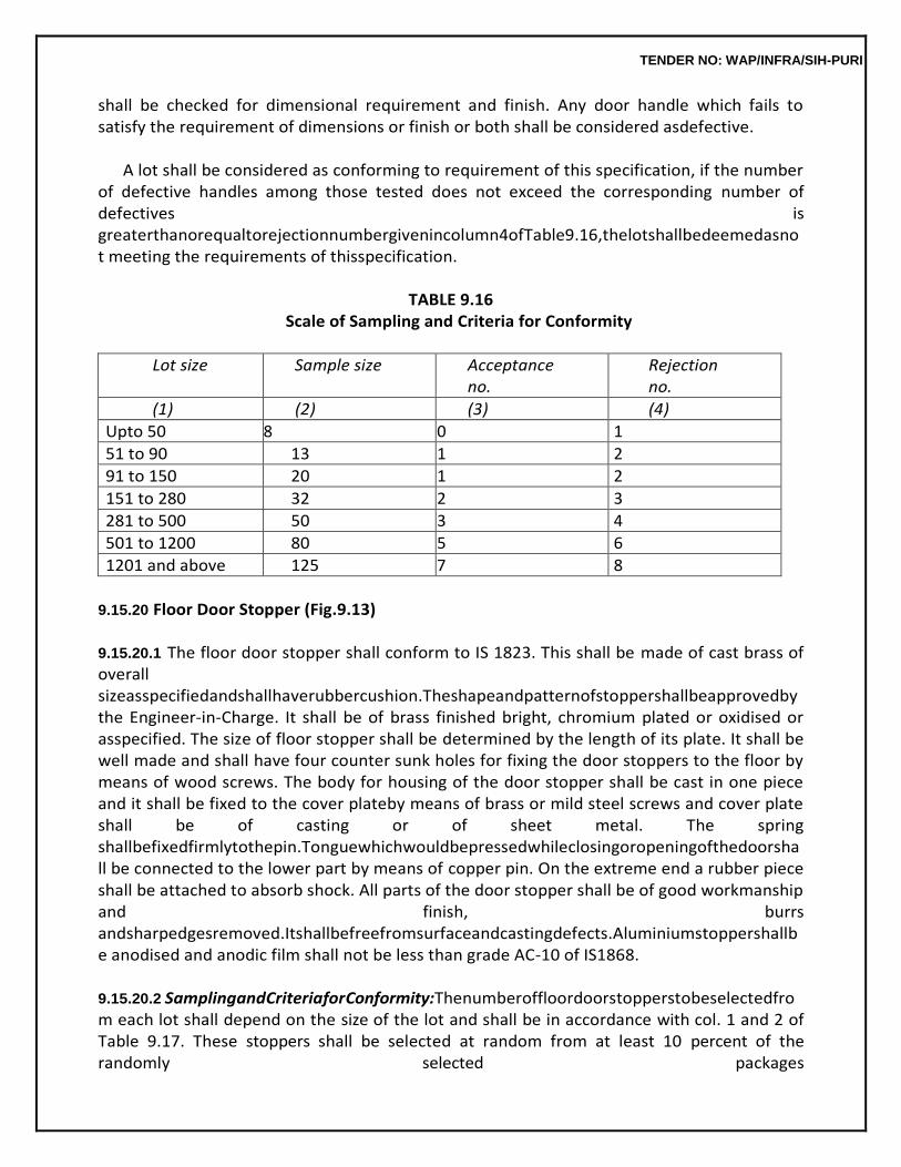
TENDER NO: WAP/INFRA/SIH-PURI
shall be checked for dimensional requirement and finish. Any door handle which fails to satisfy the requirement of dimensions or finish or both shall be considered asdefective.
A lot shall be considered as conforming to requirement of this specification, if the number
of defective handles among those tested does not exceed the corresponding number of defectives is greaterthanorequaltorejectionnumbergivenincolumn4ofTable9.16,thelotshallbedeemedasnot meeting the requirements of thisspecification.
TABLE 9.16
Scale of Sampling and Criteria for Conformity
Lot size Sample size Acceptance no.
Rejection no.
(1) (2) (3) (4)
Upto 50 8 0 1
51 to 90 13 1 2
91 to 150 20 1 2
151 to 280 32 2 3
281 to 500 50 3 4
501 to 1200 80 5 6
1201 and above 125 7 8
9.15.20 Floor Door Stopper (Fig.9.13)
9.15.20.1 The floor door stopper shall conform to IS 1823. This shall be made of cast brass of overall sizeasspecifiedandshallhaverubbercushion.Theshapeandpatternofstoppershallbeapprovedby the Engineer-in-Charge. It shall be of brass finished bright, chromium plated or oxidised or asspecified. The size of floor stopper shall be determined by the length of its plate. It shall be well made and shall have four counter sunk holes for fixing the door stoppers to the floor by means of wood screws. The body for housing of the door stopper shall be cast in one piece and it shall be fixed to the cover plateby means of brass or mild steel screws and cover plate shall be of casting or of sheet metal. The spring shallbefixedfirmlytothepin.Tonguewhichwouldbepressedwhileclosingoropeningofthedoorshall be connected to the lower part by means of copper pin. On the extreme end a rubber piece shall be attached to absorb shock. All parts of the door stopper shall be of good workmanship and finish, burrs andsharpedgesremoved.Itshallbefreefromsurfaceandcastingdefects.Aluminiumstoppershallbe anodised and anodic film shall not be less than grade AC-10 of IS1868.
9.15.20.2 SamplingandCriteriaforConformity:Thenumberoffloordoorstopperstobeselectedfrom each lot shall depend on the size of the lot and shall be in accordance with col. 1 and 2 of Table 9.17. These stoppers shall be selected at random from at least 10 percent of the randomly selected packages
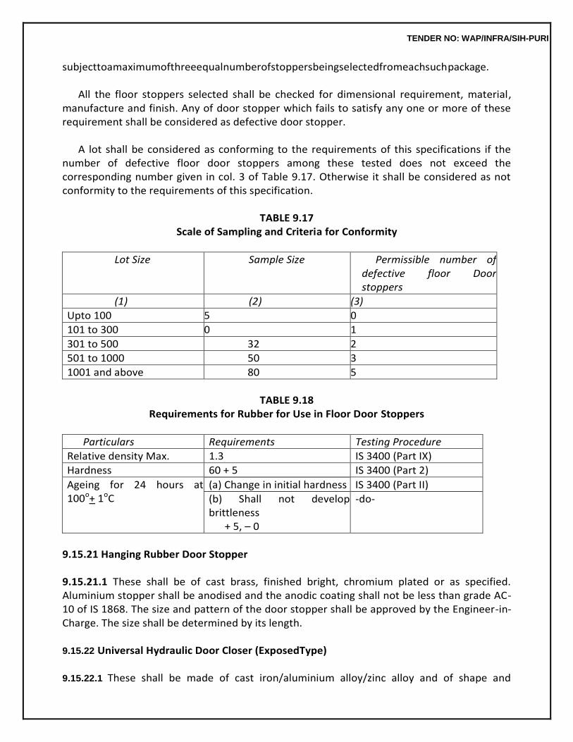
TENDER NO: WAP/INFRA/SIH-PURI
subjecttoamaximumofthreeequalnumberofstoppersbeingselectedfromeachsuchpackage.
All the floor stoppers selected shall be checked for dimensional requirement, material, manufacture and finish. Any of door stopper which fails to satisfy any one or more of these requirement shall be considered as defective door stopper.
A lot shall be considered as conforming to the requirements of this specifications if the
number of defective floor door stoppers among these tested does not exceed the corresponding number given in col. 3 of Table 9.17. Otherwise it shall be considered as not conformity to the requirements of this specification.
TABLE 9.17
Scale of Sampling and Criteria for Conformity
Lot Size Sample Size Permissible number of defective floor Door stoppers
(1) (2) (3)
Upto 100 5 0
101 to 300 0 1
301 to 500 32 2
501 to 1000 50 3
1001 and above 80 5
TABLE 9.18
Requirements for Rubber for Use in Floor Door Stoppers
Particulars Requirements Testing Procedure
Relative density Max. 1.3 IS 3400 (Part IX)
Hardness 60 + 5 IS 3400 (Part 2)
Ageing for 24 hours at 100o+ 1oC
(a) Change in initial hardness IS 3400 (Part II)
(b) Shall not develop brittleness
+ 5, – 0
-do-
9.15.21 Hanging Rubber Door Stopper
9.15.21.1 These shall be of cast brass, finished bright, chromium plated or as specified. Aluminium stopper shall be anodised and the anodic coating shall not be less than grade AC-10 of IS 1868. The size and pattern of the door stopper shall be approved by the Engineer-in-Charge. The size shall be determined by its length.
9.15.22 Universal Hydraulic Door Closer (ExposedType)
9.15.22.1 These shall be made of cast iron/aluminium alloy/zinc alloy and of shape and
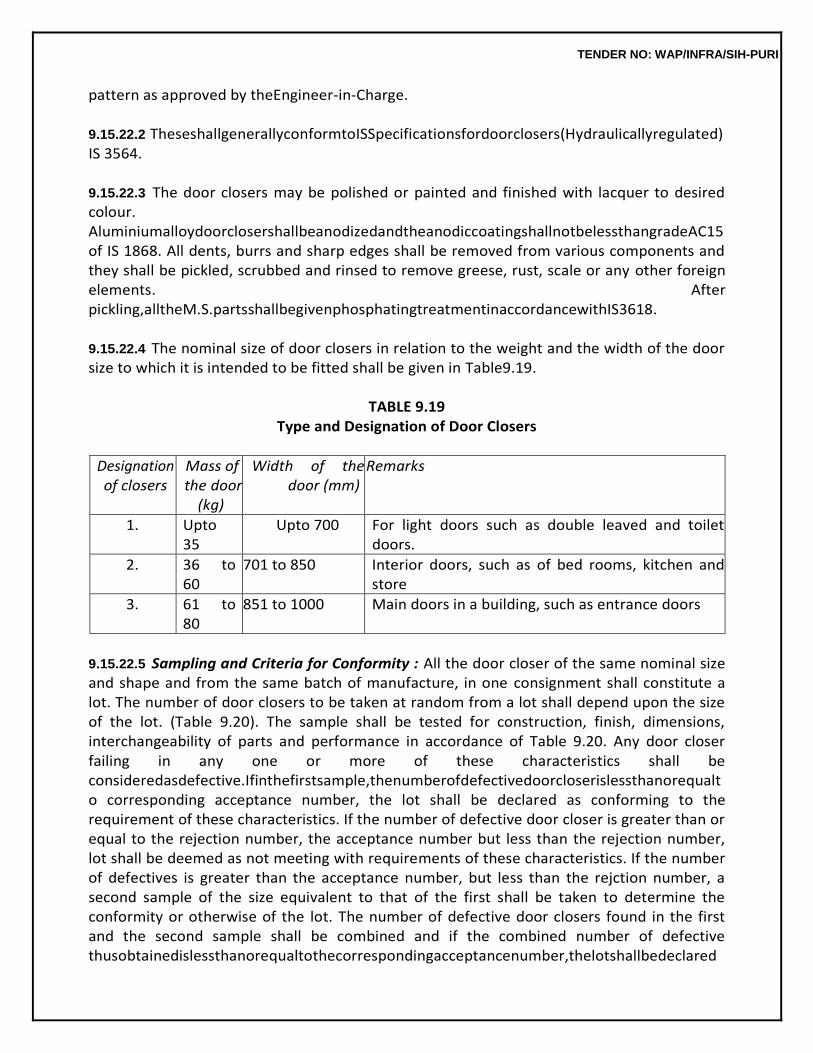
TENDER NO: WAP/INFRA/SIH-PURI
pattern as approved by theEngineer-in-Charge.
9.15.22.2 TheseshallgenerallyconformtoISSpecificationsfordoorclosers(Hydraulicallyregulated)IS 3564.
9.15.22.3 The door closers may be polished or painted and finished with lacquer to desired colour. AluminiumalloydoorclosershallbeanodizedandtheanodiccoatingshallnotbelessthangradeAC15 of IS 1868. All dents, burrs and sharp edges shall be removed from various components and they shall be pickled, scrubbed and rinsed to remove greese, rust, scale or any other foreign elements. After pickling,alltheM.S.partsshallbegivenphosphatingtreatmentinaccordancewithIS3618.
9.15.22.4 The nominal size of door closers in relation to the weight and the width of the door size to which it is intended to be fitted shall be given in Table9.19.
TABLE 9.19
Type and Designation of Door Closers
Designation of closers
Mass of the door
(kg)
Width of the door (mm)
Remarks
1. Upto 35
Upto 700 For light doors such as double leaved and toilet doors.
2. 36 to 60
701 to 850 Interior doors, such as of bed rooms, kitchen and store
3. 61 to 80
851 to 1000 Main doors in a building, such as entrance doors
9.15.22.5 Sampling and Criteria for Conformity : All the door closer of the same nominal size and shape and from the same batch of manufacture, in one consignment shall constitute a lot. The number of door closers to be taken at random from a lot shall depend upon the size of the lot. (Table 9.20). The sample shall be tested for construction, finish, dimensions, interchangeability of parts and performance in accordance of Table 9.20. Any door closer failing in any one or more of these characteristics shall be consideredasdefective.Ifinthefirstsample,thenumberofdefectivedoorcloserislessthanorequalto corresponding acceptance number, the lot shall be declared as conforming to the requirement of these characteristics. If the number of defective door closer is greater than or equal to the rejection number, the acceptance number but less than the rejection number, lot shall be deemed as not meeting with requirements of these characteristics. If the number of defectives is greater than the acceptance number, but less than the rejction number, a second sample of the size equivalent to that of the first shall be taken to determine the conformity or otherwise of the lot. The number of defective door closers found in the first and the second sample shall be combined and if the combined number of defective thusobtainedislessthanorequaltothecorrespondingacceptancenumber,thelotshallbedeclared
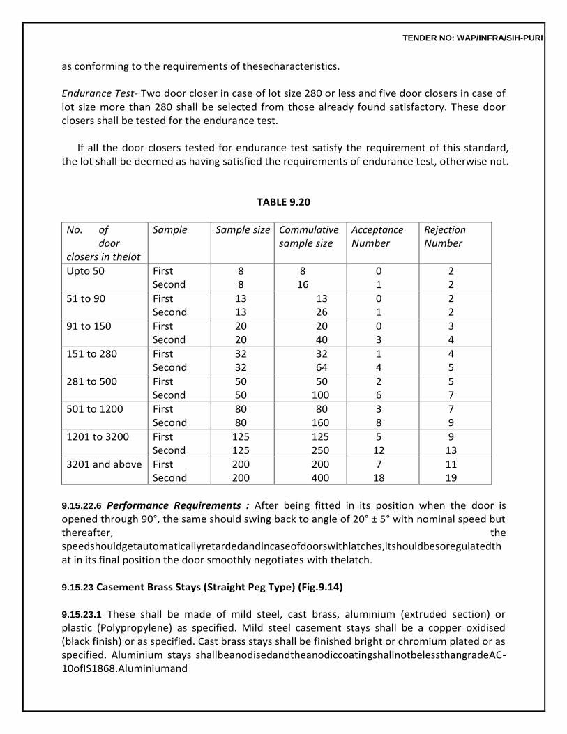
TENDER NO: WAP/INFRA/SIH-PURI
as conforming to the requirements of thesecharacteristics.
Endurance Test- Two door closer in case of lot size 280 or less and five door closers in case of lot size more than 280 shall be selected from those already found satisfactory. These door closers shall be tested for the endurance test.
If all the door closers tested for endurance test satisfy the requirement of this standard,
the lot shall be deemed as having satisfied the requirements of endurance test, otherwise not.
TABLE 9.20
No. of door closers in thelot
Sample Sample size Commulative sample size
Acceptance Number
Rejection Number
Upto 50 First Second
8 8
8 16
0 1
2 2
51 to 90 First Second
13 13
13 26
0 1
2 2
91 to 150 First Second
20 20
20 40
0 3
3 4
151 to 280 First Second
32 32
32 64
1 4
4 5
281 to 500 First Second
50 50
50 100
2 6
5 7
501 to 1200 First Second
80 80
80 160
3 8
7 9
1201 to 3200 First Second
125 125
125 250
5 12
9 13
3201 and above First Second
200 200
200 400
7 18
11 19
9.15.22.6 Performance Requirements : After being fitted in its position when the door is opened through 90°, the same should swing back to angle of 20° ± 5° with nominal speed but thereafter, the speedshouldgetautomaticallyretardedandincaseofdoorswithlatches,itshouldbesoregulatedthat in its final position the door smoothly negotiates with thelatch.
9.15.23 Casement Brass Stays (Straight Peg Type) (Fig.9.14)
9.15.23.1 These shall be made of mild steel, cast brass, aluminium (extruded section) or plastic (Polypropylene) as specified. Mild steel casement stays shall be a copper oxidised (black finish) or as specified. Cast brass stays shall be finished bright or chromium plated or as specified. Aluminium stays shallbeanodisedandtheanodiccoatingshallnotbelessthangradeAC-10ofIS1868.Aluminiumand
TENDER NO: WAP/INFRA/SIH-PURI
M.S. stays shall be made from channel section. The stays shall not weigh less than that indicated below:
200mm 0.24 kgeach 250mm 0.28 kgeach 300mm 0.33 kgeach
9.15.23.2 The shape and pattern of the stays shall be approved by the Engineer-in-Charge. The size of stays shall be determined by its length as shown in the plate. The plastic (Polypropylene) stays shall conform to IS6318.
9.15.24 Quadrant Stays 300mm
Theseshallbemadeofcastbrassandfinishedbrightorchromiumplatedorasspecified.Theshape andpatternshallbeapprovedbytheEngineer-in-Charge.Itshallnotweighlessthan0.20kgeach.
9.15.25 Hasp and Staple Safety Type (Fig.9.15)
9.15.25.1 This shall be made of mild steel, cast brass or aluminium as specified. This shall generally conform to IS 363. M.S. Hasp and staples shall be finished black enamelled, or copper oxidised (black finish)orasspecified.Brasshaspandstaplesshallbefinishedbrightchromiumplatedoroxidisedoras specified. Aluminium hasp and staples shall be anodized and the anodic coating shall not be less than grade AC 15 of IS1868.
9.15.25.2 M.S. hasp and staples shall be manufactured from M.S. sheet and brass hasp and staples by casting and Aluminium hasp and staples shall be made from dye section. The hinge pin which in all casesshallbeofmildsteel,shallbefirmanditsrivettedheadswellformed.Themovementofhaspshall be free, easy and square and shall not have any play orshake.
The hasp shall fit, in the staple correctly. The size shall be determined by the length of the
bigger of the hasp.
9.15.25.3 The staple except in the case of cast one, shall be rivetted properly to its plate. The ends of the hinge pin for the safety type hasp shall be rivetted and properly finished. All screw holes shall be cleanandcountersunktosuitcountersunkwoodscrew.Alledgesandcornersshallberounded.
9.15.26 P.T.M.T (Polytetra Methyline Tetraphthalate)Fittings
9.15.26.0 PTMT (Polytetra Methylene Tetraphthalate) is an engineering plastic (raw material imported) and have following physicalproperties:-
(i) TensileStrength : 500Kg/cm² (ii) CompressiveStrength : 900 Kg/cm² (iii) RockwellhardnessL-scale : 75 (iv) Workingtemperature : -45º to120ºC.
TENDER NO: WAP/INFRA/SIH-PURI
(v) EValue : 85000Kg/cm² (vi) Density : 1.3gm/cc (vii) ImpactStrength : NoBreak P.T.M.T. fitting shall be in different colours like White, Green, Blue, Derby Brown,
Mushroom, Black, Gold, Silver & Broonze or any colours agreed by the manufactures and purchaser.
P.T.M.T. fittings are suitable for internal doors shutters kitchen, bath w.c. & cabinet etc.
These shall not be used in external door and where security is concern.
Screws used for fittings shall be counter sunk cross head of chromium plated brass or stainless steel. Sizes of screws shall be of same size as used in case non ferrous material door/window fittings. 9.15.26.1 P.T.M.T. Butt Hinges : These shall of the material as mentioned in para 9.15.26.0 above. Theseshallbeofrequiredcolour/shadeceramiclook,glassysmoothsurface.Theseshallbeofrequired size andthickness.
9.15.26.1.1 Hinge Pin: Hinge pin shall be made of 5.5 mm dia stainless steel. It shall fit inside the knuckles firmly and riveted head (head covered with same material as of hinge) shall be well formed so as not to allow any play or shake and shall allow easy movement of the hinge, but shall not cause looseness.
9.15.26.1.2 Knuckles : The number of the knuckles in hinges shall be as per IS 1341. The shape of knucklesshallbestraightandrightangletoflap.Themovementofthehingeshallbefreeandeasyand working shall not have any play orshake.
9.15.26.1.3 Screw Holes : The screw holes shall be clean and counter sunk. These shall be suitable for counter sunk head cross head wood screws and of the specified sizes for different type and sizes of hinges.Thesizeoftheholesshallbesuchthatwhenitcountersunkitshallbeabletoaccommodatethe full depth of counter sunk ofscrews.
9.15.26.2P.T.M.T.DoorHandles:Thedoorhandlesshallbeofmaterialasmentionedinpara 9.15.26.0 above moulded to required shape and size. The size & thickness etc. of the handle shall be determined by the inside grip of the handle. These shall be moulded as solid sections. The body of the handle shall not be hollow. Door handles shall be 100 mm size and window handles of 75 mm size unless, otherwise specified. These shall be fixed with 25 mm long wood. (Cross head) screws of designation No. 6.
9.15.26.3 PTMT Tower Bolt : The tower bolt shall be generally barrel type of material as mentioned in para 9.15.26.0 moulded to required shape and size. Size (length, dia, length of rod, number of holes) shall generally confirm to IS 204 PI & P-II. The rod shall be solid. If it in
TENDER NO: WAP/INFRA/SIH-PURI
hollow it shall be provided with stainless steel rod of required dia. for its strength protective coat of wood primer, polish or varnish.
9.16 LAMINATED VENEER LUMBER(LVL)
9.16.1 Laminated Veneer Lumber door frames and shutters shall conform to IS14616.
9.16.2 Material
9.16.2.1 Laminated Veneer Lumber(LVL)
(a) Laminated Veneer Lumber is made of rubber wood silver oak, eucalyptus, Poplars, acacias etc. veneers glued together having grains of all the veneers in one direction under high temperature and pressure to develop high Modulus of Repture & Modulus of elasticity. Veneers for LVL shall be of thickness between 1.5 to 2.5mm.
(b) Veneers shall be free from knot holes, decayed knots except pin knots, unfilled splits
wider than 3 mm, concentrated borer holes, shakes, objectionable decay or termite attack, except that for thefaceveneersnoneofthesedefectsnorcrossgrainexceeding1in10shallbepermitted.The nominal thickness of all the veneers used shall be identical and uniform within a tolerance of + 5 percent.
(c) Adhesives:OnlyBWPgradeadhesiveconformingtoIS848shallbeusedformakingLVL.
(d) Preservatives : Veneers used for LVL shall be given suitable perservative treatment
before lamination, with a preservative that is compatible with the adhesive to be used. Only fixed type of water soluble preservatives, CCA or CCB, or non-leachable, solvent soluble preservatives as per IS 401 shall be used for treating the veneers. Retentions of preservatives shall be as per IS 401 depending upon the proposed enduse.
All the Veneers shall be given preservative treatment by one of the water soluble fixed
type treatment,CopperChrome-BoronComposition.(CCB)asperIS401.ThetreatedVeneersshallthenbe dried having moisture content less than 6%. The Veneers shall be glued together, by keeping all the grains in one direction, with BWP grade synthetic resin adhesive conforming to IS 848. The Veneers havingmoisturecontentlessthan6%soglued,shallbepressedinhotpressathightemperatureof140 degreeCto180degreeC.andpressure1.4to1.8MPa.ThenetabsorptionofpreservativeinLVLwhen tested as per IS 2753 shall not be less than 8.0 kg/m3 Veneers shall be scarf jointed only length wise and not in the direction of width with EWP type synthetic resin adhesive. However, the length of individual Veneer shall not be less than 600mm.
9.16.3 MoistureContent
Theaveragemoisturecontentofthreetestspecimens,whendeterminedinaccordancewithIS1734 (Part 1) shall be between 5 to15%.
TENDER NO: WAP/INFRA/SIH-PURI
9.16.4 Tests
9.16.4.1 The tests as per Table-1 of IS 14616 shall be carried out by the manufacturer on the LVL (Laminated Veneer Lumber) sections on eachbatch.
9.16.4.2 The manufacturer shall get the tests done on at least three samples of each batch by the standardmethodoftesttoensurequalityandperformanceofthematerialasperpara8.2ofIS14616.
9.16.4.3 Themanufacturershallprovideacertificatewiththedeliverychallanindicatingthatthematerial conformstoIS14616alongwiththecopyofthetestreportoftherelevantbatch.
9.16.5 Laminated Veneer Lumber (LVL) Door Shutters (Fig.9.16)
9.16.5.1 This specification lays down requirements regarding types, sizes, material, construction, workmanship and finish, performance evaluation, sampling, measurements, rates and testing of Laminated Veneer Lumber (LVL) door shutter for use in domestic buildings, offices, schools, hospitals etc.Thisspecificationdoesnotcoverlargesizedoorshuttersforindustrialandspecialbuildingssuchas workshops, garages, godownsetc.
9.16.5.2 The material of each lot shall be supported by a certificate to thateffect:
Each lot of LVL materials shall be accompanied by the test reports. Fabricator shall take up
manufacturing of shutters only if provisions of clause 9.16.4 are fulfilled; failing which, shutters so manufactured are liable for rejection.
9.16.5.3 PanellingMaterials
9.16.5.3.1 Plain Particle Board: Plain particle boards used for panels shall be FPT-1 conforming to IS 3087 and shall have been bonded with BWP type of synthetic resin adhesive as per IS 848. (Ref. para9.2.3)
9.16.5.3.2 Pre-laminated Particle Board: Pre-laminated particle boards used for panels shall conform to IS 12823. The plain particle boards used in pre-laminated particle boards shall be as per para 9.2.11 above.
9.16.5.3.3 Medium Density Fibre Board: Medium density fibre board used for panels shall conform to exteriorgradeasperIS12406madefromagro-forestproductsoragriculturalwastesornaturalfibers.
9.16.5.3.4 Pre-laminated Medium Density Fibre Board: Pre-lamination in pre-laminated mediumdensity fiberboardshallconformtotherequirementssuchasAbrasionResistance,ResistancetoSteam,Crack
TENDER NO: WAP/INFRA/SIH-PURI
Resistance,ResistancetoCigaretteBurnandResistancetoStainasspecifiedinIS12823.Themedium densityfibreboardusedinpre-laminatedmediumdensityfibreboardshallbeasperpara9.6.11above.
9.16.5.3.5 Glass: Glass for glazing shall conform to IS 2835 or IS 2553. The use of other types of glass, such as frosted glass, wired glass and coloured glass may also be specified by the Engineer-in- Charge. (Ref.para9.2.8).
9.16.5.3.6 WireGauze:WiregauzeshallgenerallyconformtoIS1568andshallberegularlywovenwith equally spaced galvanized mild steel wires of 0.63 mm nominal diameter in both warp and weft directions to form aperture of average width 1.40 mm. (Ref para9.2.9)
9.16.6 Construction andWorkmanship
9.16.6.1 Laminated Veneer Lumber (LVL) panelled, glazed and panelled and glazed shutter shall be constructed in the form of LVL framework of stiles and rails with panel inserts conforming to para 9.16.5 above of plain or perlaminated particle board, plain or prelaminated medium density fibre board, wire gauze or glass. The panels shall be fixed by either providing grooves in stiles and rails and beading as specified. The stiles, top rails, lock rails and bottom rails shall be jointed to each other by mortice and tenonjoints(SeeFig.9.16A).Railshavingwidthof150mmormoreshallhaveplaindoubletenonjointsas shown in Fig. 9.16B. Other rails shall have single tenon joints. The bottom lock and top rails shall be inserted25+3mmshortofthewidthofstilestoformastubmortice&tenonjoint.Afterassemblingshutter complete with panels, Bamboo pins of 6 mm dia shall be fitted on each tenon &mortice joint by drilling suitable size of holes (2 pins per joint for rail width upto 150 mm and 3 pins for rails of greater width). All thefouredgesofshuttershallbebeadedwith12mmthickrubberwood/plantationwoodlipping(SeeFig. 9.16).Lippingshallbeseasonedandchemicallytreatedasperclause9.16.4.Lippingontopandbottom railsshallbeofonepieceandlippingonstilesmaybeintwopieces.Alllippingsshallbegluedtoshutter withwaterresistingglue(Syntheticrubberpassedadhesive)attherateof0.15kg/m2.
9.16.6.2 All members of the shutters shall be straight, smooth and with well planed faces at rightangles to each other. Any warp or bow shall not exceed 1.5 mm. The right angle for the shutters shall be checked by measuring the two diagonals from one extreme corner to the opposite one and the difference between the two diagonals shall not be more than 3mm.
9.16.6.3 Beading:Allthepanelsexceptglassandwiregauzeshallbefixedwithgrooves(seeFig.9.16C) but additional beading may be provided either on one side or on both the sides, if so specified. In so far as glass and wire gauze panels are concerned, beading shall be provided without grooves. In such a case where beading is provided without the grooves, the beading shall be only on one side, the other sidebeingsupportedbyrebatefromstiles.Thebeadingshallhaveasizenotlessthan15mmx10mm.
TENDER NO: WAP/INFRA/SIH-PURI
It can be fixed by suitable headless nailing or screwing. The beading shall be of plantation timber section, preservative chemically treated of fixed type as per IS401-1982.
9.16.6.4 Stiles, top rails, bottom rails and lock rails of shutters shall each be made in one piece of LVL, only.
Mullions and glazing bars shall be stubtenoned to the maximum depth which the size of
the member would permit or to a depth of 25 mm, whichever is less.
Two common methods for jointing of panels with stiles/rails are shown in Fig. 9.16C. The minimum depth of grooves of stiles and rails shall be 12 mm for all types of panelling. The panels shall beframed into grooves to the full depth of groove leaving an air space of 1.5 mm and the faces shall be closely fitted to the sides of thegroove.
LVL Shutters shall be manufactured in factories under controlled conditions.
9.16.7 Panelling
9.16.7.1 Plain and Prelaminated Particle Board Paneling: The panels shall be made of one piece of plain or prelaminated particle board of thickness 12 mm ormore.
9.16.7.2 Wire Guaze Panelling : Wire guaze panel shall be so designed that no single panel shall exceed 0.5 sqm. inarea.
9.16.8 Rebating
Incaseofdoubleleavedshutters,themeetingofthestilesshallberebatedeithersplayedorsquare type as shown in Fig. 9.16 D as per clause 6.12 of IS 1003(part-1).
9.16.9 Gluing ofJoints
Thecontactsurfacesoftenonandmorticeshallbetreatedbeforeputtingtogetherasperclause6.13 ofIS1003(Part-I).Allthetenonandmorticejointsshouldbegluedtogetherandpinnedtofullthickness of the door with Bamboopins.
9.16.10 Dimensions, Sizes andTolerances
9.16.10.1 Dimensions of Components and Tolerances: The finished dimensions and tolerances of the different components of door shutter shall be as per para 9.6.1.4.1.
Tolerances: Tolerance on the size of door shutter shall be + 3 mm and in thickness + 1.2 mm.
9.16.11 Locations of Fittings andAccessories
9.16.11.1 Each door shutter shall be fixed to the frame with four hinges, unless otherwise specified by the Engineer-in-Charge, of the typespecified.
TENDER NO: WAP/INFRA/SIH-PURI
The lock rail of door shutters, where provided, shall be so placed that its centre line is at a
height 850+5 mm from the bottom of the shutter. Hinges and other fixtures shall be fixed to shutter with full threaded steel screws after coating the screws with adhesive such as fevicol etc. For fixing of hinges, holesof3.5mmdiameterand52mmlengthshallbeboredandNo.10fullthreadedparallelshanksteel screws, 50 mm long, coated with adhesive shall be used. In no circumstances screws shallbe hammered intoboard.
9.16.11.2 Cleats and blocks made of LVL wood shall be fixed to door shutter, if required, by the user as per size and shape approved. Pull bolt or sliding door bolt etc. shall be provided in the door shutter at a height of 850 mm from bottom of shutter. These shall be fixed to shutter as per method of fixing described in9.16.11.
For rescrewing, a plastic sleeve of appropriate diameter shall be inserted into the hole
and then fixing with full threaded screws shall be done. Fittings other than hinges shall be provided as per schedule of fittings decided by the user. The fittings shall conform to specifications as described in clause 9.15.
Panelledshuttermaybeprovidedwithlouversofvisionpanelsasspecified.Wheresuchaprovisio
n ismade,theposition,sizesandshapeoflouverorvisionpanelopeningshallbeasspecified.
9.16.12 Finish All the four edges of the shutter shall be square. The shutter shall be free from twist or
warp in its plane. Panels of the door shutters shall be flat and well sanded to a smooth and level surface. All the surfaces shall be delivered without protective coat of wood primer polish or varnish.
9.16.13 Glazing
9.16.13.1Glazingintheshuttersofdoorandwindowshallbeaspersubhead21.0Inspecifyingsizesof theopeningsorpanelsofglass,thefirstdimensionshallbewidth.Theglassshallbeembeddedinputty and secured to the rebate by the wooden beading of suitable size andshape.
9.16.14 Tests
9.16.14.1 Routine Tests: The following test shall be carried out by the fabricator on shutters during the processoffabricationinthefactory’slaboratorytobedevelopedforthisspecificpurposebeforedispatch ofshutters.
TABLE 9.21
Sl.No. Name of Test Acceptability Criteria
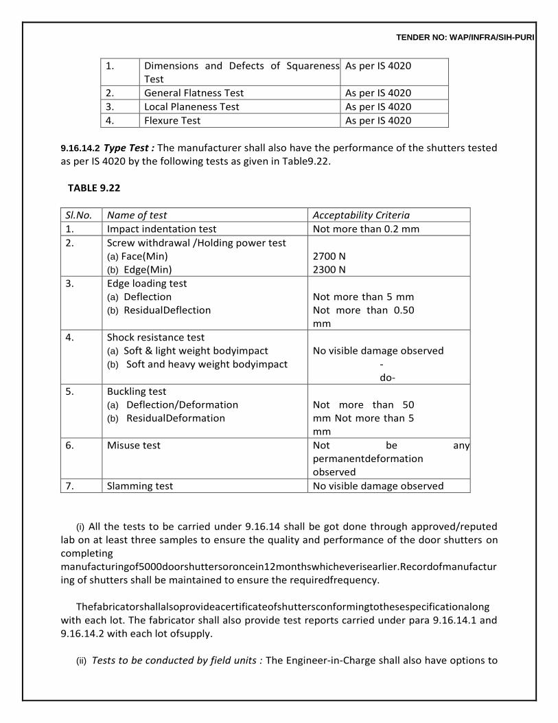
TENDER NO: WAP/INFRA/SIH-PURI
1. Dimensions and Defects of Squareness Test
As per IS 4020
2. General Flatness Test As per IS 4020
3. Local Planeness Test As per IS 4020
4. Flexure Test As per IS 4020
9.16.14.2 Type Test : The manufacturer shall also have the performance of the shutters tested as per IS 4020 by the following tests as given in Table9.22.
TABLE 9.22
Sl.No. Name of test Acceptability Criteria
1. Impact indentation test Not more than 0.2 mm
2. Screw withdrawal /Holding power test (a) Face(Min) (b) Edge(Min)
2700 N 2300 N
3. Edge loading test (a) Deflection (b) ResidualDeflection
Not more than 5 mm Not more than 0.50 mm
4. Shock resistance test (a) Soft & light weight bodyimpact (b) Soft and heavy weight bodyimpact
No visible damage observed
-do-
5. Buckling test (a) Deflection/Deformation (b) ResidualDeformation
Not more than 50 mm Not more than 5 mm
6. Misuse test Not be any permanentdeformation observed
7. Slamming test No visible damage observed
(i) All the tests to be carried under 9.16.14 shall be got done through approved/reputed lab on at least three samples to ensure the quality and performance of the door shutters on completing manufacturingof5000doorshuttersoroncein12monthswhicheverisearlier.Recordofmanufacturing of shutters shall be maintained to ensure the requiredfrequency.
Thefabricatorshallalsoprovideacertificateofshuttersconformingtothesespecificationalong
with each lot. The fabricator shall also provide test reports carried under para 9.16.14.1 and 9.16.14.2 with each lot ofsupply.
(ii) Tests to be conducted by field units : The Engineer-in-Charge shall also have options to
TENDER NO: WAP/INFRA/SIH-PURI
get any orallothertestcoveredin9.16.14doneathisowncost.Iftheshutterfailstosatisfythetest,costwillbe borne by the supplier and consignment shall berejected.
9.16.15 Measurement
Length and width of the shutter shall be measured to the nearest centimetre in closed position covering the rebates of the frames but excluding the gap between the shutter and the frame. Overlapof the two shutters shall not be measured. All work shall be measured net as fixed and area calculated in square metres to nearest two places of decimal. No deduction shall be made to form panel opening, louver Venetian opening and opening for glazing. No extra payment shall be made for shape, jointsand labour involved in operations describedabove.
9.16.16 Rates
The rate includes the cost of material and labour involved in all the operations described above. Extra rate shall be payable for providing rebates in double leaf shutters. Fittings described in 9.16.11.2 shall be payable extra. Nothing extra shall be payable for complying with the provisions described in 9.16.14.1&9.16.14.2.Costoftestsasdescribedin9.16.14.2shallbebornebyDeptt.iftestreportsare found satisfactory. Rate shall include cost of material and labour involved in providing plain beading. Extra shall be paid for providing moulded/plain beading on panels wherespecified.
9.17 PARTITIONS
9.17.1 Materials
(i) Gypsum Board conforming to IS 2095(Pt.-I) (ii) Non asbestos multi-purpose cement board conforming to IS14862 (iii) Tapered edge calcium silicateboard
Tapered Edge Calcium Silicate Board are manufactured from Siliceous and Calcareous
materials reinforced with fibers. The boards are made in a laminar process and then autoclaved to give a stable crystalline structure. It is lightweight and can be fixed to either side of timber, aluminum or lightweight galvanized metal sections. The partitions are non-load bearing and can easily be assembled at site.
9.17.2 Installation
The G.I. frame and board partitions shall be fixed as per nomenclature of the item and directions of Engineer-in-Charge. (Fig. 9.17).
9.17.3 Jointing &Finishing
Joints of the boards are finished with specially formulated Jointing compound and fibre tape to provideseamlessfinish.Boardsurfacecanbedecoratedwithanytypeofpaint,wallpaper,woodveneer &hardlaminates.Servicesshouldbeincorporatedbeforecommencementofboardfixing.
TENDER NO: WAP/INFRA/SIH-PURI
9.17.4 Fitting andFixtures Itiseasyandsimpletoattachdifferentfittingstowallpanellingboards.Inclinednailscanbefixedto
the boards itself for light materials. For heavier materials the fastening should be centered on internal stud work or steel or wood frame behind the boards, fixed before boarding. Services should be incorporated before commencement of boardfixing.
9.17.5 Tolerance
Tolerance in dimensions shall be + 5 mm.
9.17.6 Measurements
9.17.6.1 Length and breadth of superficial area of the finished work shall be measured correct to a cm. Area shall be calculated in square meter correct to two places of decimal. No deduction will be made of openingsofareasupto0.40sqmnorshallextrapaymentbemadeeitherforanyextramaterialorlabour involved in forming suchopenings.
9.17.6.2 Foropeningsexceeding0.40sqm.inarea,deductioninmeasurementsshallbemadebutextra willbepayableforanyextramaterialorlabourinvolvedinmakingsuchopenings.
9.17.7 Rate
The rate shall include the cost of all materials and labour involved in all the operations described above including all scaffolding, staging etc.
9.18 UPVC- DOORFRAMES
9.18.0 Material
Polyvinyl chloride Resin suspension grade is the basic raw material for forming PVC compound. PVC resin then is mixed with chemicals like Calcium, Stearate, Hydrocarbon Wax, Titanium Dioxide, Calcium Carbonate, Acrylic processing aids. Further, additives like impact modifiers, pigments, epoxy plasticizer, UV stabilizer, lubricants, chemical blowing agent etc. are added. The purpose of adding the chemicals and additives is to impart cellular structure, strength, surface finish, colour and resistance to fading by light rays. These chemicals are mixed in the desired proportion and shall be used in the formulation of PVC material and for free and smooth extrusion of PVC profiles.
9.18.1 UPVC DoorFrame
UPVC door frame shall be made of PVC material conforming to IS 10151. The door frame shall be madefromextrudedUPVCsectionhavingoveralldimensionsof48x40mmor42x50mmhavingwall thickness of 2.0 mm + 0.2 mm. Corners of the door frame to be jointed by M.S. galvanized brackets. Joints mitred and plastic welded. The hinge side vertical outer frames shall be reinforced bygalvanized M.S. Tube of size 19 x 19 mm of wall thickness 1 mm + 0.1 mm and a tie rod shall be provided at the bottom of the frame. The frame shall be fabricated in factory as per nomenclature of
TENDER NO: WAP/INFRA/SIH-PURI
the item and directions of Engineer-in-Charge. (Fig. 9.18).
9.18.2 Fixing ofFrames The frames are to be fixed in prepared openings in the walls. All civil work and tiling
should be completed before the fixing of the frames. The frames are to be fixed directly on the plastered wall. In case tiling is to be done in the place the frames are to be fitted, a 50 mm strip should be left untiled at thelocationwheretheframesaretobefitted.Theframesareerectedinthepreparedopeningsuchthat the vertical members of the door frame are embedded 50 mm in the floor. The frame shall be fittedtruly in plumb. A minimum of three anchor bolts or screws of size 65/100 shall be used to fix each vertical member. One bolt shall be fixed at 200 mm from the top member and one bolt shall be fixed at 200 mm fromthefloor.Thethirdanchorboltshallbefixedinthecenter.Thetophorizontalmembershallbefixed usingtwo65/100sizeanchorboltsorscrewsatadistanceof200mmfromboththecorners.
9.18.3 Measurements
The outer length of the vertical and horizontal members of UPVC door frame shall be measured in running metres including embedded length in floor corrected upto a cm.
9.18.4 Rate
Therateincludesthecostofthematerialsandlabourinvolvedinalltheoperationsdescribedabove. The cost of anchor bolts or screws for joining the frame is included in the rate. Any other hardware, which may be required, shall be paid forseparately.
9.19 PVC DOORSHUTTERS
The shutters shall be fabricated at factory as per nomenclature of the item and directions of Engineer-in-Charge. Shutter shall be made of PVC material conforming to IS 10151.
9.19.1 24 mm thick PVC Door Shutter (Fig.9.19)
9.19.2 30 mm Thick PVC Door Shutters (Fig.9.20)
9.19.3 Sampling and Criteria forConformity
9.19.3.1 GeneralPrecautions
9.19.3.1.1 The test specimens shall not have been exposed to a temperature below 40oC for 24 hours immediately preceding the test and shall be free from all visible moisture. The specimen shall be inspected and any specimen with visible flaws shall bediscarded.
9.19.3.1.2 Ifanytestspecimenfailsbecauseofmechanicalreason,suchasfailureoftestingequipment or improper specimen preparation, it shall be discarded and another specimentaken.
9.19.3.2 Sampling
TENDER NO: WAP/INFRA/SIH-PURI
9.19.3.2.1 Sampling criteria for conformity shall be in accordance with IS 4020 (Part–I)
9.19.3.2.2 Lot in any consignment of shutters shall be of the same grade and type and manufactured undersimilarconditionsofproductionwhichshallbegroupedtogethertoformalot.
9.19.3.2.3 The number of shutters to be selected at random from a lot shall depend upon its size and shall be in accordance with Col. 1 and Col. 2 of Table9.23.
TABLE 9.23
No. of Sample and Criteria for Conformity
Sl. No. Sample size Permissible No. of Defects
(1) (2) (3)
26 to 50 8 1
51 to 100 13 1
101 to 150 20 1
151 to 300 32 1
301 to 500 50 2
501 and above 80 2
Note : For lot size 25 or less, number of samples to be taken for testing shall be as agreed
to between the manufacturer & Engineer-in-Charge.
Number of Tests : The samples selected as in column 2 of Table 9.23 shall be as agreed to between the manufacturer & Engineer-in-Charge.
9.19.3.2.4 Criteria for Conformity : The lot shall be considered conforming to the requirements if the numberofsamplesfailingtosatisfytherequirementsofcharacteristicsdoesnotexceedthepermissible number mentioned in col.3.
TENDER NO: WAP/INFRA/SIH-PURI
9.19.4 Test
9.19.4.1 The door shutters shall be subjected to the following tests in accordance with IS 4020 (Part 1 to16).
(a) DimensionandSquarenessTest:DoorshutterswhentestedinaccordancewithIS4020(Part2)
thedimensionsofnominalwidthandheightwillbewithinalimitof+5mm.Thedoorshuttershall notdeviatebymorethan1mmonalengthof500mm.Thethicknessofthedoorshuttershallbe uniform throughout with the permissible variation of not more than 0.8 mm between any two points.Thenominalthicknessoftheshuttershallbewithinalimitof+1.5mm.
(b) General Flatness Test : Door shutter, when tested in accordance with IS 4020 (Part 3)
the twist, cupping and warping shall not exceed 6mm.
(c) LocalPlanenessTest:Doorshutters,whentestedinaccordancewithIS4020(Part4),thedepth of deviation measured at any point shall not be more than 0.5mm.
(d) Impact Indentation Test : Door shutters, when tested in accordance with IS 4020 (Part
5), shall have no defects such as cracking, tearing or delamination and the depth of indentation shall not be more than 0.2mm.
(e) Edge Loading Test : Door shutters, when tested in accordance with IS 4020 (Part 7) the
deflection of the edge at the maximum load shall not be more than 5 mm. On removal of the loads, the residual deflection shall not be more than 0.5 mm, failing which the test may be repeated on the other edge in the reverse direction. Also there shall be no lateral buckling by more than 2 mm during loaded condition and no residual lateral buckling after removal of the load.
(f) Shock Resistance Test : Door shutters, when tested in accordance with 2.1 of IS 4020
(Part 8) , thereshallbenovisibledamageinanypartofthedooraftertwentyfiveblowsoneachend.
(g) Buckling Test : Door shutters, when tested in accordance with IS 4020 (Part 9), shall
not show any deterioration and any residual deformation more than 5 mm after 15 min. of unloading and the initial deflection also shall not be more than 50mm.
(h) SlammingTest:Doorshutters,whentestedinaccordancewith2.1ofIS4020(Part10),shallnot
have any damage in any part of the door at the end of successiveimpacts.
Doorshutters,whentestedinaccordancewith3.1ofIS4020(Part10),shallnothaveanyvisible damage in part of the door at the end of 100 successiveimpacts.
(i) MisuseTest:Doorshutters,whentestedinaccordancewithIS4020(Part11),thereshallnotbe
any permanent deformation of the fixing or any other part of the door set in hindering
TENDER NO: WAP/INFRA/SIH-PURI
its normal working after thetest.
(j) Screw Holding Test : Door shutters, when tested in accordance with IS 4020- Part 16, the load shall not be less than 1000N.
(k) End Immersion Test : Door shutters, when tested in accordance with IS 4020- Part 13,
the shutter shall not show anydelamination.
(l) KnifeTest:Doorshutter,whentestedinaccordancewithIS4020–Part14,thegradingshallbe standard &excellent.
(m) Glue Adhesion Test : Door shutters shall be tested in accordance with IS 4020 – Part
15. There should be nodelamination.
9.19.5 Fixing ofShutters PVC door shutter shall be side hung on three bolt hinges of size 100 mm, one at the
centre and the other two at 200 mm from the top and bottom of the shutter. The flat of the hinges shall be neatly counter sunk in to the recesses cut out to the exact dimensions of the hinge flap. The door shall be drilled on the thickness to fit hinges. Screws for fixing the hinges shall be screwed in with screwdrivers and not hammered. The length of the screws should be 8 mm/30 mm. The hinges used should be of stainless steel.
9.19.6 Tolerance
The tolerance on the width and the height of the door shall be + 5 mm and the tolerance on the nominal thickness of the door shall be + 2 mm.
9.19.7 Fittings
Fittings shall be provided as per schedule of fittings decided by Engineer-in-Charge. In moisture prone areas M.S. fittings and screws should not be used. Hardware such as handles, tower bolt, stopper, buffer etc. should be directly screwed (not pre-drilled) and fitted on the door.
9.19.8 Measurements
Lengthandwidthoftheshuttersshallbemeasuredtothenearestcminclosedpositioncoveringthe rebatesoftheframesbutexcludingthegapbetweentheshutterandtheframe.Areaiscalculatedtothe nearest 0.01sqm.
9.19.9 Rate
The specified rate include the cost of the door shutter and labour involved in fixing of the shutter. Fittings & fixtures on the door shutter except hinges & screws shall be paid extra as provided.
9.20 PVC DOORFRAME
Solid PVC door frame and shutter shall be as per para 9.19.
TENDER NO: WAP/INFRA/SIH-PURI
9.20.1 SolidPVCDoorFramesconsistingofsection50x47mmshallbefabricatedfrom5mmPVCsheet having density of 600 kg./cum. The sheet used may be in plain colour, printed design or prelam veneer shadeasapprovedbytheEngineer-in-Charge.Theweightperrunningmetreofthedoorframeincluding reinforcement should be a minimum of 1.5 kg./sq. mtr. The depth of the rebate of door frame shall be 10 mm. Frames shall have smooth surface, without any warping or bending in any member. All the parts of thedoorframearetobejoinedtoeachotherusingsolventadhesiveconformingtoIS14182.Atolerance of+3mmshallbepermittedinthespecifieddimensionofPVCsectioninthedoorframes.(Fig.9.21)
The solid PVC door frames shall be fabricated in factory as per nomenclature of the item
and directions of the Engineer-in-charge.
9.20.2 Fixing ofFrames As per clause 9.18.2.
9.20.3 Measurements
As per clause 9.18.3.
9.20.4 Rate As per clause 9.18.4.
9.21 PANEL PVC DOORSHUTTER
9.21.1 Panel PVC Shutters are factory made shutter and shall be brought to site fully assembled. The Solid Panel PVC Door shall be fabricated from 5 mm PVC sheet. The sheets used may be in plain colour, printed design or prelam veneer shade as approved by the Engineer-in-Charge. The shutters shall be fabricated at factory as per nomenclature of the item and directions of the Engineer-in-charge.
(a) 30 mm thick panel PVC door shutters (Figure9.22).
9.21.2 Sampling and Criteria forConformity As per clause 9.19.3.
9.21.3 Tests
As per clause 9.19.4 except para (k), (l) & (m).
9.21.4 Fixing ofShutters As per clause 9.19.5. In addition, it may be ensured that while fixing hinges the screws pass
through the two opposites surfaces of the M.S. reinforcement.
9.21.5 Tolerance As per clause 9.19.6.
9.21.6 Fittings
As per clause 9.19.7.
TENDER NO: WAP/INFRA/SIH-PURI
9.21.7 Measurements
As per clause 9.19.8.
9.21.8 Rate As per clause 9.19.9.
9.22 FIBRE GLASS REINFORCED PLASTIC (FRP) DOOR FRAMES
9.22.0 Door Frames shall be three legged of cross section 90 mm x 45 mm having single rebate of size 32 mm x 15 mm to receive shutter of 30 mm thickness. The frame shall be made of laminate of thicknessof2mmandshallbefilledwithwoodenblocksofexteriorgradeMDForseasonedandtreated hardwoodinsidethelaminateinallthethreelegsoftheframe.Theframetobemouldedbyeitherhand lay up or resin transfer moulding process. The process shall consist of laying gelcoat at 1000 gms./m2 and laid over with layer of FRP Mat (CSM mat) gelcoat and FRP (CSM Mat) are defined in IS 14856. The CSM mat shall be bonded with Isophatholic resin in the ratio not less than 1:2 (One part of Mat to twopartsofIsopathlicresinandfillers&additives)byweight.Theedgeshallbesealedwithgelcoatand FRP mat to obtain smooth finish. Sufficient roving shall be laid in the corner to have smooth curvewhile laying the CSM mat. (Fig.9.23).
9.22.1 FRP door shall be manufcturred as per specifications laid down in IS 14856, nomenclature of items & direction ofEngineer-in-Charge.
9.22.2 Tolerance
Tolerance of size of frame to be + 2 mm and on size of rebate to be + 1 mm.
9.22.3 Finish Thesurfaceofthemouldedframeshallbefreefromanyvisibledefectssuchassmallpores,crazing
, blistering,wrinkling,impurities,defectiveimpregration,colourblotsandaggregatedefects,asmentioned inIS14856.Scatteredpinholesdulyrepairedandfinishedbyapplyingresinandnotnoticeableshallbe acceptable. Frame laminate shall be flat and shall have smooth and level surface. Laminate shall be finished in colour & shade as approved byEngineer-in-Charge.
9.22.4 Fixing ofFrame
As per clause 9.18.2.
9.22.5 Measurement As per clause 9.18.3.
9.22.6 Rate
TENDER NO: WAP/INFRA/SIH-PURI
As per clause 9.18.4.
9.23 FIBRE GLASS REINFORCED PLASTIC (F.R.P.)SHUTTERS
9.23.1 F.R.P. Shutters shall be manufactured conforming to the specifications as per IS 14856 and nomenclature of item & direction of Engineer-in-Charge. (Fig. 9.24A &9.24B).
9.23.2 Blocks of any seasoned hardwood of bulk density not less than 450 kg./m3 at 12 per cent moisture content or any other material of sufficient thickness and length shall be provided inside the shutteratsuitableplacetoholdfittingsandfixturessuchasaldrops,towerbolt,handle,slidingdoorbolt, morticelocketc.Blocksforhingesshallbeprovidedatthreelocations,unlessotherwisespecifiedbythe purchaser.Oneatthecentreandothertwoat200mmfromthetopandthebottomoftheshutter.Blocks shall be provided at predetermined places in the shutter so as to fix hinges mortice locks, tower bolts, aldrops,doorclosures,etc.Thefinishedsurfaceshallbebuffedandpolishedwithwax.
9.23.3 Location of Fittings andAccessories
Thelockrailofdoorshuttersshallbesoplacedthatiscentrelineisataheight850+5mmfromthe bottom of the shutter. Door shutter shall be fixed to the frame with three hinges, unless otherwise specifiedbythepurchaser,ofthetypespecified.Theselocationsshallbe,oneatcentreandothertwoat 200 mm from the top and the bottom of the shutter, where blocks have already been provided and suitable indication by depressing the profile has been made. Screws for fixing the hinges shall be screwed in with screwdrivers & not hammered. The length of screw should be 8/30 mm. The hinges used shall be stainless steel oraluminum.
9.23.4 Sampling & Criteria for Conformity Shall be as per clause9.19.3.
9.23.5 Finish
As per clause 9.22.3.
9.23.6 Tests As per para 9.19.4 except clause (j), (k), (l) & (m).
9.23.7 Fixing ofShutter
As per clause 9.19.5.
9.23.8 Tolerance As per clause 9.19.6.
9.23.9 Measurement
As per clause 9.19.8.
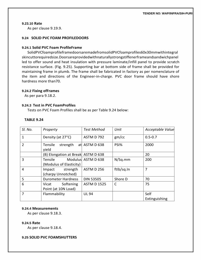
TENDER NO: WAP/INFRA/SIH-PURI
9.23.10 Rate As per clause 9.19.9.
9.24 SOLID PVC FOAM PROFILEDOORS
9.24.1 Solid PVC Foam ProfileFrame
SolidPVCfoamprofileframedoorsaremadefromsolidPVCfoamprofiles60x30mmwithintegral skincuttorequiredsize.Doorsareprovidedwithnaturallystrongstiffenerframeandsandwichpanelled to offer sound and heat insulation with pressure laminate/infill panel to provide scratch resistance surface. (Fig. 9.25). Supporting bar at bottom side of frame shall be provided for maintaining frame in plumb. The frame shall be fabricated in factory as per nomenclature of the item and directions of the Engineer-in-charge. PVC door frame should have shore hardness more than70.
9.24.2 Fixing ofFrames
As per para 9.18.2.
9.24.3 Test in PVC FoamProfiles Tests on PVC Foam Profiles shall be as per Table 9.24 below:
TABLE 9.24
Sl. No. Property Test Method Unit Acceptable Value
1 Density (at 27°C) ASTM D 792 gm/cc 0.5-0.7
2 Tensile strength at yield
ASTM D 638 PSI% 2000
(B) Elongation at Break ASTM D 638 20
3 Tensile Modulus (Modulus of Elasticity)
ASTM D 638 N/Sq.mm 200
4 Impact strength (charpy Unnotched)
ASTM D 256 ftIb/sq.In 7
5 Durometer Hardness DIN 53505 Shore D 70
6 Vicat Softening Point (at 10N Load)
ASTM D 1525 C 75
7 Flammability UL 94 Self Extinguishing
9.24.4 Measurements
As per clause 9.18.3.
9.24.5 Rate As per clause 9.18.4.
9.25 SOLID PVC FOAMSHUTTERS
TENDER NO: WAP/INFRA/SIH-PURI
Solid PVC foam shutters are made from solid PVC foam profiles with integral skin. Doors are provided with naturally strong stiffener frame and sandwich panelled to offer sound and heat insulation with pressure laminate/infill panel provides scratch resistance surface. Door shutters can be nailed, screwed, drilled, glued, sawn lapped or welded just like wood and characterized by excellent screw holding strength (200 kgf.).
9.25.1 28 mm Thick DoorShutters
Profile is cut in required length to make vertical & horizontal stile. Mitered cut joint are made using solvent based PVC adhesive & epoxy solvent. GI ‘C’ stiffner 39 x 19 x 19 or 40 x 20 x 19g. M.S. Pipe is fixed in the grooves made in frame. Telescopic polymeric corners are provided at corners for better rigidity.Infillpanel3mmthickHPLsheetisfixedwithcskscrewsofrequiredsizetotheprofileframeas specified. Mirror image of shutter frame is joined using solvent based PVC adhesive as well as csktype sheet metal screws of required size at four corners at top & bottom. Additional bonding strength is providedbyusingsiliconesealantepoxysealantatjoints.LockrailisprovidedbyusingPVCprofile&‘C’ typeGIstiffener40x10inthegroove&fixedwithadhesivetoframe&infill.Decorativecornermoulding is fixed to impart elegant look. (Fig.9.26)
The fabrication shall be done in factory as per nomenclature of the item and directions of
Engineer- in-Charge.
9.25.2 Sampling and Criteria forconformity As per clause 9.19.3.
9.25.3 Tests
As per clause 9.19.4.
9.25.4 Fixing ofShutters As per clause 9.19.5.
9.25.5 Tolerance
As per clause 9.19.6.
9.25.6 Fittings As per clause 9.19.7.
9.24.7 Measurements
As per clause 9.19.8.
9.24.8 Rate As per clause 9.19.9.
9.26 FACTORY MADE FIBRE GLASS REINFORCED PLASTICCHAJJA
TENDER NO: WAP/INFRA/SIH-PURI
9.26.1 F.R.P. chajja shall be 4 mm thick of required colour/size, design and drawing as approved. The chaja shall have smooth gradual slope curvature for easy drainage of water & shall be factory manufactured as per nomenclature of item & directions of Engineer-in-Charge. (Fig.9.27).
9.26.2 Material
(1) Glass Fibre (chopped strand mat) shall be as per IS11551 (2) Unsaturated Polyester Resin shall be as per IS6746 (3) Surface Burning Characteristics of Building Material – ASTM E84-77a (4) Unsaturated Polyester Resin Gel coat shall be as per IS6746 (5) Curing Agents – Cobalt Napthanate andMEKP (6) Test of products – IS14425 (7) Glass Fiber Roving – IS11320
The F.R.P. chajja laminate shall be water and chemical resistant and shall have very high
transit strength to weight ratio and high modulus of elasticity, good textile processing and excellent fiber reinforcement properties. The laminate shall have low coefficient of thermal expansion and a high thermalconductivityandhighdielectricconstants.TheF.R.P.laminateshallbediversionallystable,shall have moisture and corrosionresistance.
9.26.3 Tolerance
Tolerance of + 10 mm in overall size of FRP chajja is permissible.
9.26.4 Finish The F.R.P. laminate to be finished with polyurathene based or equivalent paint as final
coat or gloss or mat followed by clear lacquer coat to get the shine of required shade.
9.26.5 Tests Frequency of tests as per direction of Engineer-in-Charge & tests to be conducted as per
para 9.19.4.
9.26.6 Measurement andRate The width and length to be measured in centimetres and area to be calculated as square
metre correct upto two places of decimal. The rate includes cost of all the materials,labour scaffolding, fittings &fixinguptoallheightsetc.involvedinoperationsdescribedabove,butexcludesthecostofpaint.
9.27 WALL PANELLING (Fig.9.28)
All specification same as per clauses 9.17.1 to 9.17.7.
TENDER NO: WAP/INFRA/SIH-PURI
10.0 STEEL WORK 10.0 DEFINITIONS/ TERMINOLOGY Bead
A single run of weld metal deposited on surface.
Butt Weld A weld in which the weld metal lies substantially within the extension of the planes arc the surfaces
on the parts joined.
Crater A depression left in weld metal where the arc was broken or the flame was removed.
End Crater
A crater at the end of a weld or at the end of a joint.
Fillet Weld A weld of approximately triangular cross-section joining two surfaces approximately at the
right angles to each other in a lap joint, tee joint or corner joint. It is of two types: (1) Continuous (2) Intermittent.
Fusion Welding
Any welding process in which the weld is made between metals in a state of fusion without hammering or pressure.
Non- fusion Welding
Atermappliedtothedeposition,bytheOxy-Acetyleneprocessoffillermetalonparentmetalwithout fusion of thelatter.
Oxy-Acetylene Pressure Welding
Pressure welding in which any Oxy-Acetylene flame is used to make the surface to be united plastic. No filler metal is used.
Run
The metal deposited during one passage of the electrode or blow pipe in the making of a joint.
Throat thickness See Fig. 10.1.
Weld
A union between two pieces of metal at faces rendered plastic or liquid by heat or pressure, or both, Filler metal may be used to effect the union.
10.1 MATERIALS
TENDER NO: WAP/INFRA/SIH-PURI
Micro-Alloying Elements Elements such as niobium, boron, vanadium and titanium added singly or in combination
to obtain higher strength to weight ratio and better toughness, formability and weldability as compared to unalloyed steel of similar strength level.
Weldability
A metallic substance is considered to be weldable by a given process and for the given purpose, when metallic continuity to a stated degree can be obtained by welding using a suitable procedure, so that the joints comply with the requirements specified in regard to both their local properties and their influence on the construction of which they form a part.
Controlled Rolling
A hot rolling process in which the temperature of the steel and its reduction ratio are controlled, particularly during the final rolling passes, in order to achieve fine grain micro structure and optimum mechanical properties.
Normalizing Rolling
Ahotrollingprocessinwhichthefinalrollingpassesarecarriedoutatasuitablehighertemperature, followed by cooling in natural air to a temperature below the transformation temperature, in order to produce a structure, analogous to that obtained by a separate normalizing treatment of hot rolled product.
10.1.1 Steel 10.1.1.1 Supply of Material : General requirements relating to supply of structural steel shall conform to IS8910.
10.1.1.2 Grades : There shall be nine grades of steel as given in Tables 10.1 and 10.2. While placing theorderthesteelshouldbedesignatedby‘Designation’(SeeTable10.1and10.2).
10.1.1.3 Manufacture:Theprocessesusedinthesteelmakingandfurtherhotrollingintosteelplates, strips, sections, flats, bars, etc., are left to the discretion of the manufacturer/supplier. If required, secondary refining may follow steel making, as also normalizing rolling/controlled rolling during manufacturing of sections or as per the agreement between the purchaser and the manufacturer/ supplier.
10.1.1.4 Freedom fromDefects
10.1.1.4.1 All finished materials shall be well and cleanly rolled to the dimensions, sections and massesspecified.Thefinishedmaterialshallbereasonablyfreefromsurfaceflaws;laminations;rough/ jagged and imperfect edges and all other harmfuldefects.
10.1.1.4.2 Minor surface defects may be removed by the manufacturer/supplier by grinding provided the thickness is not reduced locally by more than 4 percent below the minimum specified thickness. Reduction in thickness by grinding greater than 4 percent but not
TENDER NO: WAP/INFRA/SIH-PURI
exceeding 7 percent may be made subject to mutual agreement between the purchaser andmanufacturer/supplier.
10.1.1.4.3 Subjecttoagreementwiththepurchaser,surfacedefectswhichcannotbedealtwithasin 10.1.1.4.2 may be repaired by chipping or grinding followed by welding and inspection by a mutually agreed procedure such that:
(a) Aftercompleteremovalofthedefectsandbeforewelding,thethicknessoftheitemisnottobe reduced by more than 20 percent at anyplace.
(b) Welding is carried out by procedure APPROVED by competent authority with approved electrodesandtheweldingisgroundsmoothtothecorrectnominalthickness;and
(c) Subsequenttothefinishgrinding,theitemmayberequiredtobenormalizedorotherwiseheat- treated at the purchaser’sdiscretion.
10.1.1.4.4 Welding as mentioned in 10.1.1.4.3 is not permissible for grade designation E 250 material.
10.1.1.5 Chemical Composition : Ladle Analysis the ladle analysis of the steel, when carried out by the method specified in the relevant part of IS 228 or any other established instrumental /chemical method, shall be as given in Table 10.1. In case of dispute, the procedure given in IS 228 and its relevant parts shall be the referee method and where test methods are not specified shall be as agreed to between the purchaser and the manufacturer/supplier.
10.1.2 Rivets
Rivets shall be made from rivet bars of mild steel as per IS 1148.
10.1.3 Bolts These are of two types namely turned and fitted bolts and black bolts. Turned & fitted
bolts are turned to exact diameter in automatic lathe. For these bolts, whether reamed or drilled bolts, the same unit stresses are allowed as for rivets. In case of black bolts which are not finished to exact sizes, a lower working stress other than for turned bolts is adopted. They shall conform to IS 1367 – Technical supply conditions for threaded steel fasteners.
10.1.4 Electrodes
The electrodes required for metal arc welding shall be covered electrodes and shall conform to IS814.
10.2 STEEL WORK IN SINGLE SECTION FIXED INDEPENDENTLY WITH CONNECTINGPLATE
10.2.0 The steel work in single section of R.S. joists, flats, Tees Angles fixed independently with or without connecting plate, is described in theseclauses.
10.2.1 Fabrication
Thesteelsectionsasspecifiedshallbestraightenedandcutsquaretocorrectlengthsandmeasured
TENDER NO: WAP/INFRA/SIH-PURI
withasteeltape.Thecutendsexposedtoviewshallbefinishedsmooth.Notwopiecesshallbewelded or otherwise jointed to make up the required length ofmember.
All straightening and shaping to form, shall be done by pressure. Bending or cutting shall
be carried out in such a manner as not to impair the strength of the metal. 10.2.2 Painting
All surfaces which are to be painted, oiled or otherwise treated shall be dry and thoroughly cleaned to remove all loose scale and loose rust. Surfaces not in contact but inaccessible after shop assembly, shallreceivethefullspecifiedprotectivetreatmentbeforeassembly.Thisdoesnotapplytotheinteriorof sealed hollow sections. Part to be encased in concrete shall not be painted or oiled. A priming coat of approved steel primer such as Red Oxide/Zinc Chromate primer conforming to IS 2074 shall beapplied beforeanymemberofsteelstructureareplacedinpositionortakenoutofworkshop.
10.2.3 Erection
Steel work shall be hoisted and placed in position carefully without any damage to itself and other building work and injury to workmen. Where necessary mechanical appliances such as lifting tackle winch etc. shall be used. The suitability and capacity of all plant and equipment used for erection shall be upto the satisfaction of the Engineer-in-charge.
10.2.4 Measurements
The work as fixed in place shall be measured in running metres correct to a millimetre and weights calculated on the basis of standard tables correct to the nearest kilogram. The standard weight of steel sections shall conform to IS 808 with tolerance in sizes as per IS 1852. Tolerance in weight is given in Table 10.3. Steel sections shall be acceptable within tolerance limits. Payment for steel sections shall be made as per actual weight within tolerances. Sections having weight on higher side thanpermissibletolerance, may be acceptable but payment shall be made on the basis of standard weight only. Steel sections having weight variations lower side than permissible variation shall not be acceptable.
Unlessotherwisespecified,weightofcleats,brackets,packingpieces,bolts,nuts,washers,dista
nce pieces,separaters,diaphgramgussets(takingoverallsquaredimension)fishplates,etc.shallbeadded to the weight of respective items. In riveted work allowance is to be made for weight of rivet heads. Unlessotherwisespecifiedanadditionof2.5%oftheweightofstructureshallbemadeforshopandsite rivet heads in riveted steelstructures.
Nodeductionshallbemadeforrivet/orboltholes(excludingholesforanchororholdingdownbolts). Deductionincaseofrivetorboltholeshallhoweverbemadeifitsareaexceeds0.02sqm. The weight of steel sheets, plates and strips shall be taken from relevant Indian standards based on
7.85 Kg/m2 for every millimetre sheet thickness. For rolled sections, steel rods and steel strips, weight given in relevant Indian Standards shall be used.
TENDER NO: WAP/INFRA/SIH-PURI
10.2.5 Rate Rate includes the cost of labour and materials required for all the operations described above.
10.3 STEEL WORK IN BUILT UP SECTIONS (RIVETED ANDBOLTED)
Thesteelworkinbuiltupsection(Rivetedandbolted)suchastrusses,framedworketc.isspecified in thisclause.
10.3.1 LayingOut
A figure of the steel structure to be fabricated shall be drawn on a level platform to full scale. This may be done in full or in parts, as shown on drawings or as directed by the Engineer-in-Charge. Steel tape shall be used for measurements.
10.3.2 Fabrication
Fabrication shall generally be done as specified in IS 800. In major works or where so specified, shop drawings giving complete information for the fabrication of the component parts of the structure including the location, type, size, length and details or rivets, bolts or welds, shall be prepared in advance of the actual fabrication and approved by the Engineer-in-charge. The drawings shall indicate theshopandfieldrivets,boltsandwelds.Thesteelmembersshallbedistinctlymarkedorstenciledwith paint with the identification marks as given in the shopdrawings.
Great accuracy shall be observed in the fabrication of various members, so that these can
be assembledwithoutbeingundulypacked,strainedorforcedintopositionandwhenbuiltup,shallbetrue and free from twist, kinks, buckles or openjoints.
Woodenormetalsheettemplatesshallbemadetocorrespondtoeachmember,andpositionofri
vet holesshallbemarkedaccuratelyonthemandholesdrilled.Thetemplatesshallthenbelaidonthesteel members, and holes for riveting and bolting marked on them. The ends of the steel members shall also bemarkedforcuttingasperrequireddimensions.Thebaseofsteelcolumnsandthepositionsofanchor bolts shall be carefully set out at the requiredlocation.
10.3.2.1 The steel section shall be straight or to be straightened or flattened by pressure unless requiredtobeofcurvilinearformandshallfreefromtwists.Theseshallbecutsquareeitherbyshearing or sawing to correct length and measured by steel tape. No tow pieces shall be welded or joined to make up for the required length ofmember.
10.3.2.2 Making Holes : Holes through more than one thickness of materials for members, such as compound stanchion and girder flanges shall, where possible, be drilled after the membersareassembled and tightly clamped or bolted together. Punching may be permitted before assembly, providedtheholesarepunched3mmlessindiameterthantherequiredsizeandreamedafterassem

TENDER NO: WAP/INFRA/SIH-PURI
bly tothefulldiameter.Thethicknessofmaterialpunchedshallbenotgreaterthan16mm.
Rivet Holes The diameter for rivets and black bolts holes shall be taken as the nominal diameter of a
rivet/black bolts plus 1.5 mm for rivets/ bolts of nominal diameter less than or equal to 25 mm” and 2.0 mm for rivets of nominal diameter exceeding 25 mm, unless specified otherwise. Holes for turned and fitted boltsshallbedrilledorreamedlargeby0.2to8mmdependinguponthedia.ofbolts.
Holes shall have their axis perpendicular to the surface bored through. The drilling or
reaming shall be free from burrs, and the holes shall be clean and accurate. Holes for rivets and bolts shall not be formed by gas cutting process.
Holes for counter sunk bolts shall be made in such a manner that their heads sit flush with the surface after fixing.
10.3.2.3 Assembly:Beforemakingholesinindividualmembers,forfabricationandsteelworkintended to be riveted or bolted together shall be assembled and clamped properly and tightly so as to ensure closeabutting,orlappingofthesurfacesofthedifferentmembers.Allstiffenersshallbefixed(orplaced) tightlybothattopandbottomwithoutbeingdrawnorcaulked.Theabuttingjointsshallbecutordressed true and straight, and fitted closetogether.
Webplatesofgirders,whichhavenocoverflangeplates,shallhavetheirendsflushwiththetopsof
angles unless otherwise required. The web plate when spliced, shall have clearance of not more than 5mm. The erection clearance of cleated ends of members connecting steel to steel shall preferably be not greater than 1.5 mm. The erection clearance at the ends of beams without web cleats shall not be more than 3 mm at each end but where for practical reasons, greater clearance is necessary, seating designed suitably shall beprovided.
Column splices and butt joints of struts and compression members requiring contact for
stress transmissionshallbeaccurately,machinedandclosebuttedoverthewholesection.Incolumncapsand bases, the ends of shafts together with the attached gussets, angles, channels etc. after riveting together shall be accurately machined so that the parts connected, butt against each other over the entiresurfacesofcontact.Connectinganglesorchannelsshallbefabricatedandplacedinpositionwith great accuracy so that they are not unduly reduced in thickness bymachining.
The ends of all bearing stiffeners shall be machined or grounded to fit tightly both at top and bottom.
10.3.2.4 Riveting : Rivets shall be used, where slip under load has to beavoided.
Preliminaries before Rivetings:- Members to be riveted shall have all parts firmly placed and held together before and during riveting, and special care shall be taken in this respect for all
TENDER NO: WAP/INFRA/SIH-PURI
single riveted connections. For multiple riveted connections, a service bolt shall be provided in every third or fourth hole.
Process of Riveting
The riveting shall be carried out by using machines of the steady pressure type. However, where such facilities are not available hand riveting may be permitted by the Engineer-in-charge. The rivets shall be heated red hot, care being taken to control the temperature of heating so as not to burn the steel.Rivetsofdiameterlessthan10mmmaybedrivencold.Rivetsshallbefinishedneatwithheadsfull andofequalsize.Theheadsshallbecentralonshanksandshallgriptheassembledmembersfirmly.
TENDER NO: WAP/INFRA/SIH-PURI
Allloose,burnt,orbadlyformedrivetswitheccentricordeficientheadsshallbecutoutandreplaced.In cutting out rivets, care shall be taken so as not to injure the assembled members. Caulking and recapping shall not bepermitted.
For testing rivets, a hammer weighing approx. 0.25 kg shall be used and both heads of the
rivet (Specially the machine head) shall be tapped. When so tested, the rivets shall not give a hollow sound and a jar where so specified, other tests shall be carried out to ensure the soundness of rivets.
All rivets heads shall be painted with approved steel primer paint within a week of their fixing.
10.3.2.5 Bolting:Thenominallengthoftheboltshallbethedistancefromtheundersideoftheheadto the further end of the shank. The nominal diameter of the bolt shall be the diameter at the shank above the screwed threads. Bolts, nuts and washers shall be thoroughly cleaned and dipped in double boiled linseed oil, before use. All bolts heads and nuts shall be hexagonal unless specified otherwise. The screwedthreadsshallconformtoIS1363andthethreadedsurfaceshallnotbetapered.Theboltsshall be of such length as to project at least two clear threads beyond the nuts when fixed in position, and theseshallfitintheholeswithoutanyshake.Thenutsshallfitinthethreadedendsofboltsproperly.
Wherenecessary,washersshallbetaperedorotherwisesuitablyshapedtogivetheheadsandnu
ts ofboltsasatisfactorybearing.Thethreadedportionofeachboltshallprojectthroughthenutatleasttwo thread. In all cases where the full bearing area of the bolt is to be developed, the bolt shall be provided withawasherofsufficientthicknessunderthenutstoavoidanythreadedportionoftheboltbeingwithin the thickness of the parts boltedtogether.
Where there is a risk of the nuts being removed or becoming loose due to vibrations or
reversal of stresses, these shall be secured from slackening by the use of lock nut, spring washers as directed by the Engineer-in-charge.
10.3.3 Erection
10.3.3.0 Steel members shall be hoisted and erected in position carefully, without any damage to itself, otherstructuresandequipmentandinjurytoworkmen.Themethodofhoistinganderectionproposedto be adopted by the contractor shall be got approved from the Engineer-in-charge in advance. The contractorhowevershallbefullyresponsiblefortheworkbeingcarriedoutinasafeandpropermanner without unduly stressing the various members and proper equipment such as derricks, lifting tackles, winches, ropes etc. shall beused.
10.3.3.1 The work of erection may be done in suitable units as may be directed by the
TENDER NO: WAP/INFRA/SIH-PURI
Engineer-in- charge.Fabricatedmembersshallbeliftedatsuchpointssoastoavoiddeformationorexcessivestress in members. The structure or part of it placed in position shall be secured against over-turning or collapse by suitablemeans.
Duringexecution,thesteelmembersshallbesecurelyboltedorotherwisefastenedwhennecess
ary temporarily braced to provide for all loads including those due to erection equipments and its operation tobecarriedsafelybystructureduringerection.Thesteelmembersshallbeplacedinproperpositionas per approved drawing, final riveting or permanent bolting shall be done only after proper alignment has been checked andconfirmed.
10.3.3.2 Trusses shall be lifted only at nodes. The trusses above 10 m in span shall not be lifted by slingingattwomidpointsofrafters,whichshallbetemporarybracedbyawoodenmemberofasuitable section. After the trusses are placed in position, purlins and wind bracings shall be fixed as soon as possible.
The end of the truss which faces the prevailing winds shall be fixed with holding down bolts, andthe other end kept free to move. In case of trusses of spans upto 10m the free end of the truss shall be laid on lead sheet or steel plate as per design, and the holes for holding down bolts shall be made in the formofoblongslotssoastopermitthefreemovementsofthetrussend.Forlargerspansthetrussshall be provided with proper bearing as perdesign.
10.3.3.3 Columns and stanchions shall be erected truly vertical with the necessary cross bracing etc. and the base shall be properly fixed with the foundation concrete by means of anchor bolts etc. as per drawing.
10.3.3.4 Anchor bolts to be placed in the concrete foundation should be held in position with a wooden template. At the time of concreting anchor bolt locations shall be provided with suitable timber mould or pipe sleeve to allow for adjustment which shall be removed after initial setting of concrete. The spaces left around anchor bolts shall be linked to a stopping channel in the concrete leading to the side of the pedestal and on the underside of the base plate to allow the spaces being grouted up after the base plate is fixed in the position along with the column footing. Grouting shall be of cement mortar 1:3 (1 cement: 3 coarse sand) or asspecified.
10.3.3.5 Bedding of Column, Stanchions etc.:- Bedding shall not be carried out until the steel work has been finally levelled, plumbed and connected together. The stanchion shall be supported on steel wedges and adjusted to make the column plumb. For multistoreyed buildings, the bedding shall not be done until sufficient number of bottom lengths of stanchions have been properly lined, levelled and plumbed and sufficient floor beams are fixed in position. The base plates shall be wedged clear of the bases by M.S. wedges and adjusted where necessary to plumb the columns. The gaps under the base
TENDER NO: WAP/INFRA/SIH-PURI
platemaybemadeupto25mmwhichshallbepressuregroutedwithcementgrouts.
With small columns, if permitted by the Engineer-in-charge, the column base shall be floated on a thick cement grout on the concrete pedestal. The anchor bolt holes in the base plate may be made about 10 to 15 mm larger than the bolts. In such cases suitable washers shall be provided.
10.3.4 Painting
Before the members of the steel structure are placed in position or taken out of the workshop these shall be painted as specified in 10.2.2.
10.3.5 Measurements
The work as fixed in position shall be measured in running metres correct to a millimeter and their weight calculated on the basis of standard tables correct to the nearest kilogram.
ThestandardweightofsteelsectionsshallconformtoIS808withtoleranceinsizesasperIS1852.
Tolerenace in weight is given in Table 10.3. Steel sections shall be acceptable within tolerance limits. Paymentforsteelsectionsshallbemadeasperactualweightwithintolerances.Sectionshavingweight onhighersidethanpermissibletolerance,maybeacceptablebutpaymentshallbemadeonthebasisof standard weight only. Steel sections having weight variations lower than permissible variation shall not beacceptable.
Unlessotherwisespecified.Weightofcleats,brackets,packingpieces,boltsnuts,washers,dista
nce pieces,separatorsdiaphragmgussets(takingoverallsquaredimensions)fishplatesetc.shallbeadded totheweightofrespectiveitems.Nodeductionsshallbemadeforskewcuts.Inrivetedwork,allowance istobemadeforweightofrivetheads.Unlessotherwisespecifiedandadditionof2.5%oftheweightof structure shall be made for shop and site rivet heads in riveted steel structures. No deduction shall be madeforrivet/orboltholes(excludingholesforanchororholdingdownbolts).Deductionincaseofrivet or bolt hole shall, however, be made if its area exceeds 0.02m2.
The weight of steel sheet and strips shall be taken from relevant Indian Standards based on 7.85 kg/m2foreverymillimetersheetthickness.Forrolledsections,steelrodsandsteelstrips,weightgivenin relevant Indian Standards shall beused.
10.3.6 Rate
The rate shall include the cost of all materials and labour involved in all the operation described above.
TENDER NO: WAP/INFRA/SIH-PURI
10.4 STEEL WORK IN BUILT UP SECTION(WELDED)
10.4.0 The steel work in built up sections (welded) such as in trusses, form work etc. is specified in this clause.
10.4.1 Layingout
It shall be as specified in 10.3.1.
10.4.2 Fabrication
10.4.2.1 Straightening, shaping to form, cutting and assembling, shall be as per 10.3.2 as far as applicable, except that the words “riveted or bolted” shall be read as “welded” and holes shall only be used for the bolts used for temporary fastening as shown indrawings. 10.4.2.2 Welding : Welding shall generally be done by electric arc process as per IS 816 and IS 823. Theelectricarcmethodisusuallyadoptedandiseconomical.Whereelectricityforpublicisnotavailable generators shall be arranged by the contractor at his own cost unless otherwise specified. Gas welding shallonlybyresortedtousingoxyacetyleneflamewithspecificapprovaloftheEngineer-in-charge.Gas welding shall not be permitted for structural steel work Gas welding required heating of the members to be welded along with the welding rod and is likely to create temperature stresses in the welded members. Precautions shall therefore be taken to avoid distortion of the members due to these temperaturestresses.
The work shall be done as shown in the shop drawings which should clearly indicate
various details of the joint to be welded, type of welds, shop and site welds as well as the types of electrodes to be used. Symbol for welding on plans and shops drawings shall be according to IS 813.
As far as possible every efforts shall be made to limit the welding that must be done after
the structure is erected so as to avoid the improper welding that is likely to be done due to heights and difficult positions on scaffolding etc. apart from the aspect of economy. The maximum dia of electrodes for welding work shall be as per IS 814. Joint surfaces which are to be welded together shall be free from loose mill scale, rust, paint, grease or other foreign matter, which adversely affect the quality of weld and workmanship.
10.4.2.3 Precautions:Alloperationconnectedwithweldingandcuttingequipmentshallconformtothe safety requirements given in IS 818 for safety requirements and Health provision in Electric and gas welding and cuttingoperations.
10.4.2.4 Operation, Workmanship and process of Welding is described in AppendixB,
10.4.2.5 Inspection and testing of welds shall be as per IS822.
10.4.2.6 Assembly : Before welding is commenced, the members to be welded shall first be
TENDER NO: WAP/INFRA/SIH-PURI
brought together and firmly clamped or tack welded to be held in position. This temporary connection has to be strongenoughtoholdthepartsaccuratelyinplacewithoutanydisturbance.Tackweldslocatedinplaceswherefinalweldswillbemadelatershallconformtothefinalweldinqualityandshallbecleaned off slag before final weld ismade.
10.4.2.7 Erection:Thespecificationshallbeasdescribedin10.3.3exceptthatwhileerectingawelded structureadequatemeansshallbeemployedfortemporaryfasteningthememberstogetherandbracing the frame work until the joints are welded. Such means shall consists of applying of erection bolts, tack welding or other positive devices imparting sufficient strength and stiffness to resist all temporary loads andlateralforcesincludingwind.Owingtothesmallnumberofboltsordinarilyemployedforjointswhich are to be welded, the temporary support of heavy girders carrying columns shall be specially attended. Different members which shall be fillet welded, shall be brought into as close contact as possible. The gap due to faulty workmanship or incorrect fit if any shall not exceed. 1.5 mm if gap exceeds 1.5 mm or more occurs locally the size of fillet weld shall be increased at such position by an amount equal to the width of thegap.
10.4.2.8 Painting : Before the member of the steel structures are placed in position or taken out of the workshop these shall be painted as specified in para10.2.2.
10.4.3 Measurements
The mode of measurements shall be the same as specified in 10.2.4 except that weight of welding material shall not be added in the weight of members for payment and nothing extra shall be paid for making and filling holes for temporary fastening of members during erection before welding.
10.4.4 Rate
The rate shall include the cost of all labour and materials involved in all the operations described above.
10.5 COLLAPSIBLE STEELGATES
10.5.0 Theseshallbeofapprovedmanufactureandshallbefabricatedfromthemildsteelsections.
10.5.1 Thegatesshallconsistofdoubleorsinglecollapsiblegatedependingonthesizeoftheopening. These shall consist of vertical double channels each 20 x 10 x 2 mm. at 10 cm. centre to centre braced withflatirondiagonals20x5mmandtopandbottomrailsofT-iron40x40x6mm@3.5kg/mwith40 mm dia. ball bearings in every fourth double channel, unless otherwise specified. Wherever collapsible gate is not provided within the opening and fixed along the outer wall surface, T- iron at the top may be replaced by flat iron 40 x 10mm.
Thecollapsiblegateshallbeprovidedwithnecessaryboltsandnuts,lockingarrangement,stoppe
rs andhandles.Anyspecialfittingslikespring,catchesandlocks,shallbesospecifiedinthedescriptiono
TENDER NO: WAP/INFRA/SIH-PURI
f item where so required. The gate shall open and close smoothly andeasily.
10.5.2 Fixing T- iron rails shall be fixed to the floor and to the Lintel at top by means of anchor bolts
embedded in cement concrete of floor and lintel. The anchor bolts shall be placed approximately at 45 cm centres alternatively in the two flanges of the T- iron. The bottom runner (T- iron) shall be embedded in thefloor and proper groove shall be formed along the runner for the purpose. The collapsible shutter shall be fixed at sides by fixing the end double channel with T-iron rails and also by hold- fasts bolted to the end doublechannelandfixedinmasonryofthesidewallsontheotherside.Incasethecollapsibleshutteris not required to reach the lintel, beam or slab level, a Tee-section suitably designed may be fixed at the top, embedded in masonry and provided with necessary clamps and roller arrangement at the top. All theadjoiningworkdamagedinfixingofgateshallbemadegoodtomatchtheexistingwork,withoutany extracost.
10.5.3 Painting
All the members of the collapsible gate including T-iron shall be thoroughly cleaned off rust, scales, dust etc. and given a priming coat of approved steel primer conforming to IS 2074 before fixing them in position.
10.5.4 Measurements
Theheightandbreadthshallbemeasuredcorrecttoacm.Theheightofthegateshallbemeasured as the length of the double channels and breadth from outside to outside of the end fixed double channels in open position, of the gate. The area shall be calculated in square metres, correct to two places ofdecimal.
10.5.5 Rate
The rate shall include the cost of materials and labour involved in all the operations described above.
10.6 M.S. SHEET SLIDINGSHUTTER
10.6.0 These shall be manufactured as per drawings and specification. These shall be fabricated from mild steel sheets.
10.6.1 Theshuttersshallbedoubleorsingleleafshutterasspecified.Theshuttersshallbefabricatedof specified size of M.S. angle iron frame diagonally braced with the same size of M.S. angle riveted / welded together with 3mm gusset plate at junction to form a rigid frame. M.S. sheet of 1 mm thickness or as specified shall be fixed to the frame with rivets/welds as approved by the Engineer-in-charge. These shall also be provided with top and bottom guide rails of specified size angles or T- irons and 25 mm diameter pulley or with 25 mm diameter ball bearing at the bottom and guide block with steel pulleys at the top. The shutters shall also be provided with locking arrangement, handles, stoppers,and holdfasts, other fittings as specified in the description of theitem.
TENDER NO: WAP/INFRA/SIH-PURI
Theguiderailsshallbesufficientlylongandcontinuedalongthewallonbothendssothatthesliding shutters can rest against the walls, giving full opening when sorequired.
10.6.2 Fixing
Theguiderailsshallbefixedtothefloorbymeansofanchorboltsembeddedinthecementconcrete floor. The steel section at the top shall be suitably supported from the walls. Two channel sections shall besuitablefixedverticallybelowtheextremeclampsinthewallandfloortoavoidtheshutterfromgoing out of the supports at top and bottom. A suitable clamping arrangement will be provided at either endof the opening to avoid the shutters from rolling back into theopening.
All the adjoining work damaged in fixing shall be made good to match the existing work.
10.6.3 Painting
All members of the sliding shutters including fittings shall be thoroughly cleaned of rust, scales,dust etc. and given a priming coat of approved steel primer i.e. Red oxide zinc chrome primer conforming to IS 2074 before fixing them inposition. 10.6.4 Measurements
Theheightandwidthshallbemeasuredcorrecttoacmanditsareaforpaymentshallbecalculated in square metres correct to two places of decimal. The height of the shutter shall be measured from outside to outside of the guide rail and width out side to out side of the shutter including the vertical position channels in sides, when shutterclosed.
10.6.5 Rate
The rate shall include the cost of materials and labour involved in all the operation described above.
It also includes the cost of the full length of guide rails.
10.7 M.S. SHEETSHUTTERS
10.7.0 These shall be manufactured as per drawing and specification. These shall be fabricated from mild steel sheets and angleiron.
10.7.1 The doors shall be provided as double leaf shutters unless otherwise specified . The shutters [email protected]/metreandtwodiagonalbracesof the same section as shown in Fig. 3 unless otherwise specified. The frame shall be riveted and/ or welded at the junctions. Wherever riveting shall be done 3.15 mm (10 G) thick gusset plate shall be provided at the junction. M.S. sheet of 1 mm thickness or as specified, shall be fixed to the frame with rivets or welds as approved by theEngineer-in-charge.
Alternatively the diagonal bracing may be replaced by one horizontal and two cross flats
30 x 6 mm as shown in Fig. 10.3 unless otherwise specified.
The outer frame shall be provided with cleats made of section 40 x 10 mm and bent in the
TENDER NO: WAP/INFRA/SIH-PURI
shape of angle cleats with one arm 150 mm long and the other arm 50 mm long and fixed to the angle ironframe ofthedoorwithtwo12mmdiaboltsandnuts.Fordoorsupto2.40mheight,twoanglescleatsperdoor shall beprovided.
The cleat shall have a vertical leg of 150 mm which shall be fixed with frame and
horizontal leg of about 50 mm which shall be provided with a hole of 24 mm dia and fixed in the projected pin of the pin clamp.
10.7.2 Fittings andFixtures
The shutters shall be fixed to the wall masonry with four pin clamps (pintles) where the height of the shutter is upto 2.4 m. Each pin clamp shall consist of 50 x 6 mm flat iron 45 cm long bent and forked at one end and provided with 20 mm diameter M.S. pin on the other. The pin shall be firmly riveted or welded to the pin clamp, the other end of which shall be embedded in masonry by means of cement concreteblock40x23x20cmof1:3:6mix(1cement:3coarsesand:6gradedstoneaggregate20mm nominal size). It shall be so placed that bottom pin shall face upwards and “top pin downward”in order that the gate may not be removed by lifting overpins.
One hook with eye 45 cm long of 10 mm diameter shall be provided for each shutter to keep it fixed in open position. The hook shall be fixed in wall masonry with wooden block and the eye shall be fixed on 6 mm thick M.S. plate as staple and fixed in the shutter frame with rivet or weld.
A cement concrete block 15 x 10 x 20 cm in 1:2:4 (1 cement:2 coarse sand:4 grades stone
aggregate of 20 mm nominal size) mix shall be embedded in the floor or at junction of two shutters so that door shutter open only on the outside and not on the inside.
The shutters shall also be provided with locking arrangement and two handles of the
shape and pattern as approved by the Engineer-in-charge.
10.7.3 Painting All the members of the door including angle iron shall be thoroughly cleaned off rust,
scales, dust etc. and given a priming coat of approved steel primer i.e. Red Oxide/ Zinc chrome primer confirming to IS 2074 before fixing them in position.
10.7.4 Measurements
The width and height of shutters shall be measured to the nearest cm. The area shall be calculated in square metre correct to two places of decimal.
10.7.5 Rate
The rate shall include the cost of materials and labour involved in all the operation describedabove. Nothingextrashallbepaidforcementconcreteblockorwoodenblocksnoranythingdeductedforthese from the measurement of the masonrywall.
TENDER NO: WAP/INFRA/SIH-PURI
10.8 ROLLINGSHUTTERS
10.8.1 RollingshuttersshallconformtoIS6248.Theseshallincludenecessarylockingarrangementand handles etc. These shall be suitable for fixing in the position as specified i.e. outside or inside on or below lintel or between jambs of the opening. The door shall be either push and pull type or operated with mechanical device supplied by the firm. Shutters upto 10 sq. metre shall be of push and pull type and shutters with an area of over 10 sq. metre shall generally be provided with reduction gear operated bymechanicaldevicewithchainorhandle,ifbearingsarespecifiedforeachofoperation,theseshallbe paid forseparately.
10.8.1.1 Shutter:Theshutterbebuiltupofinterlockinglathsectionformedfromcoldrolledsteelstrips. The thickness of the sheets from which the lath sections have been rolled shall be not less than 0.90 mm for the shutters upto 3.5 m width. Shutters above 9 metres width should be divided in 2 parts with provision of one middle fixed or movable guide channel or supported from the back side to resist wind pressure. The lath section shall be rolled so as to have interlocking curls at both edges and a deep corrugation at the centre with a bridge depth of not less than 12 mm to provide sufficient curtain of stiffnessforresistingmanualpressuresandnormalwindpressure.Eachlathsectionshallbecontinuous single piece without any welded joint. When interlocked, the lath sections shall have a distance of 75 mm rolling centers. Each alternate lath section shall be fitted with malleable cast iron or mild steel clips securelyrivetedateitherends,thuslockinginthelathsectionatbothendspreventinglateralmovement oftheindividuallathsections.Theclipsshallbesodesignedastofitthecontourofthelathsections.
10.8.1.2 Spring : The spring shall be of coiled type. The spring shall be manufactured from high tensile spring steel wire or strips of adequate strength conforming to IS 4454- Part I.
10.8.1.3 Roller and Brackets : The suspension shaft of the roller shall be made of steel pipe conforming to heavy duty as per IS 1161. For shutter upto 6 metre width and height not exceeding 5 metre, steel pipes of 50 mm nominal bore shall be used. The shaft shall be supported on mild steel bracketsofsize375x375x3.15mmforshuttersuptoaclearheightof3.5metre.Thesizeofmildsteel brackets shall be 500 x 500 x 10 mm for shutters of clear height above 3.5 m and upto 6.5 m. The suspension shaft clamped to the brackets shall be fitted with rotatable cast iron pulleys to which the shutterisattached.Thepulleysandpipeshaftshallconnectedbymeansofpretensionedhelicalsprings to counter balance the weight of the shutter and to keep the shutter in equilibrium in any partly open position.
10.8.1.4 When the width of the opening is greater than 3.5 mtr. The cast iron pulleys shall be interconnected with a cage formed out of mild steel flats of at least 32 x 6 mm and mild steel dummy rings made of similar flats to distribute the torque uniformly. Self aligning two row ball bearing with
TENDER NO: WAP/INFRA/SIH-PURI
specialcastironcasingsshallbeprovidedattheextremepulleyandcagingringsshallhaveaminimum spacingof15mmandatleast4numberflatsrunningthroughoutlengthofrollershallbeprovided.
10.8.1.5 In case of shutters of large opening with mechanical device for opening the shutter the roller shall be fitted with a purion wheel at one end which in contact with a worm fitted to the bracket plate, caging and pulley with two ball bearing shall beprovided.
10.8.1.6 Guide Channel : The width of guide channel shall be 25 mm the minimum depth of guide channels shall be asfollows:
Clear width of shutters Depth of guide channel
Upto 3.5 m 65 mm
3.5 m upto 8 m 75 mm
8 m and above 100 mm
10.8.1.7 The gap between the two legs of the guide channels shall be sufficient to allow the free movementoftheshutterandatthesametimecloseenoughtopreventrattlingoftheshutterduetowind.
10.8.1.8 Each guide channel shall be provided with a minimum of three fixing cleats or supports for attachmenttothewallorcolumnbymeansofboltsorscrews.Thespacingofcleatsshallnotexceed 0.75 m. Alternatively, the guide channels may also be provided with suitable dowels, hooks or pins for embedding in the walls.
10.8.1.9 The guide channels shall be attached to the jambs, plumb and true either in the overlapping fashion or embedded in grooves, depending on the method offixing.
10.8.1.10 Cover : Top cover shall be of mild steel sheets not less than 0.90 mm thick and stiffenedwith angle or flat stiffeners at top and bottom edges to retainshape.
10.8.1.11 Lockplateswithslidingbolts,handlesandanchoringrodsshallbeasperIS6248.
10.8.2 Fixing
The arrangement for fixing in different situations in the opening shall be as per IS 6248.
10.8.2.1 Brackets shall be fixed on the lintel or under the lintel as specified with rawl. Plugs and screws bolts etc. The shaft along with the spring shall then be fixed on thebrackets.
10.8.2.2 The lath portion (shutter) shall be laid on ground and the side guide channels shall be bound with ropes etc. The shutter shall then be placed in position and top fixed with pipe shaft with bolts and nuts.Thesideguidechannelsandcoverframesshallthenbefixedtothewallsthroughtheplatewelde
TENDER NO: WAP/INFRA/SIH-PURI
d to the guides. These plates and bracket shall be fixed by means of steel screws bolts, and rawl plugs concealed in plaster to make their location invisible. Fixing shall be done accurately in a workmen like manner that the operation of the shutter is easy andsmooth.
10.8.3 Measurements
Clear width and clear height of the opening for rolling shutter shall be measured correct to a mm. The clear distance between the two jambs of the opening shall be clear width and the clear distance between the sill and the soffit (bottom of lintel) of the opening shall be the clear height.
The area shall be calculated in square metres correct to two places of decimal.
10.8.4 Rate
Therateshallincludethecostofmaterialsandlabourinvolvedinalltheoperationsdescribedabove including cost of top cover and spring except ball bearing and mechanical device of chain and crank operation, which shall be paid forseparately.
10.9 ROLLING GRILLS –SHUTTERS
10.9.0 Rollinggrillshutterismeanttoprovidevisibilityorventilationorboth,thedegreeofprotectionand safety is less as compared to a rolling shutter. The situations where a certain amount of ventilation combined with safety is required rolling shutter-cum-grill may be provided in which the rolling shutter may have a rolling grill portion either at the top or at the bottom or at both places. In addition, therolling grillportionmayalsobeprovidedinthemiddleoftheshutter.Thetotalheightofthegrillportioninallthe segments of rolling shutter-cum-grill shall not exceed 1.0 m and the height of the grill portion in any individual segment shall not be more than 0.5m.
10.9.1 Rolling grills shutters are similar in design, construction and operation to rolling shutters and all the provisions of Para 10.8 shall be applicable to rolling grills shuters except in respect of the shutter portion, and shall conform to IS6248.
10.9.2 Shutters
Rollinggrillshutterandtherollinggrillportionoftherollingshutter-cum-grillshallbefabricatedwith8 mm diameter mild steel round bars. Straight bars and bars bent to the required profile are placed alternativelyandheldinpositionwith20mmwideand5mmthickmildsteelflatlinks.Straightbarsshall be spaced not exceeding 150 mm centre to centre and the bars bent to required profile shall be placed symmetrically between two consecutive straight bars. Unless otherwise specified or directed by the Engineer-in-charge,barsplacedalternativelywithstraightbarsshallbebenttoformacorrugatedprofile suchthatthepitchofthecorrugationis100to120mmandthedepthofcorrugationis80to100mm.all the bent bars shall have uniform profile. Straight bar along with the adjoining bent bars on it both sides shall be held in position by passing the bars through holes in the links. Each link shall have three holes
TENDER NO: WAP/INFRA/SIH-PURI
andthelengthofthelinksshallbesuchthatthedistancefromthecentreoftheholetothenearestedge oftheflatisnotlessthanthediameterofthehole.Thecornerofthelinksshallberounded.Alllinksshall be of uniform size and shape. The spacing of the links measured along the straight bar shall be the same as centre to centre distance between two consecutive crests/ troughs of the bars bent to the requiredprofile.Eachbarandlinkshallbecontinuoussinglepiecewithoutanyjoint.
10.9.3 Measurement &Rate
Themeasurementandrateshallbeasspecifiedin10.8.3and10.8.4respectively.IncaseofRolling Shutter-cum-Grill, where the area of the grill portion is half or less than half the area of opening, it shall be measured and paid as rolling shutter and where the area of grill portion is more than half the area of opening, it shall be measured and paid as rollinggrill.
10.10 STEEL DOORS, WINDOWS, VENTILATORS AND COMPOSITE UNITS (Fig.10.4)
Hot rolled steel sections for fabrication of steel doors, windows, ventilators and fixed lights shall conform to IS 7452. Shapes weights and designations of hot rolled sections shall be as per IS 7452. Appendix ’D’ indicates the purpose or the situation where the sections are normally used. Tolerance in thickness of the sections shall be + 0.2 mm. The fabricated steel doors, windows, ventilators and compositeunitsshallconfirmtoIS1038withup-to-dateamendmentsandshallbeISmarked(IS1038).
10.10.1 The steel doors and windows shall be according to the specified sizes and design. The size of doorsandwindowsshallbecalculated,soastoallow1.25cmclearanceonallthefoursidesofopening to allow for easy fitting of doors windows and ventilators into opening. The actual sizes of doors, windowsandventilatorsshallnotvarybymorethan+1.5mmfromthosegiveninthedrawing.
10.10.2 Fabrication
10.10.2.1.1 Frames : Both the fixed and openable frames shall be made of sections which have been cut to length and mitred. The corner of fixed and openable frames shall be welded to form a solid fused welded joint conforming the requirements given below. All frames shall be square and flat. The process of welding adopted shall be flush but welding or can be any other process as agreed to between the supplierandthepurchaserwhichshallfulfiltherequirementsgiveninclause6.1.1ofIS1038,metalarc welding or any other suitable method. The section for glazing shall be tennoned and riveted into the frames and where they intersect the vertical tie shall be broached and horizontal tee threads through it, and the intersection closed by hydraulicpressure.
10.10.2.1.2 Requirements of WeldedJoints
(i) Visual Inspection Test: When two opposite corners of the frame are cut, paint removed and inspected, the joint shall conform to thefollowing:- (a) Welds should have been made all along the place of meeting the members and
tack welding shall not bepermitted. (b) Welds should have been properly groundedand
TENDER NO: WAP/INFRA/SIH-PURI
(c) Complete cross section of the corner shall be checked up to see that the jointis completely solid and there are no cavitiesvisible.
(ii) Micro and Macro Examinations: From the two opposite corners obtained for visual test, the flanges of the sections shall be cut with the help of a saw. The cut surface of the remaining portions shall be polished, etched and examined. The polished and etched faces of the weld andthebasemetalshallbefreefromcracksandcavityandreasonablyfreefromundercutting overlaps, gross porosity and entrappedslag.
(iii) Fillet Weld Test: The fillet weld in the remaining portion of the joint shall be fractured by hammering.Thefracturedsurfacesshallbefreefromslaginclusionporosity,crackpenetration defects and fusiondefects.
10.10.2.2 Doors : The hinges shall be of 50 mm projecting type, Non projecting type hinges may also be used, if approved by Engineer-in-Charge. The hinge pin shall be of electro-galvanized steel or aluminum alloy of suitable thickness and size. Door handles shall be approved by the Engineer-in- Charge.Asuitablelatchlockfordooropenablebothfrominsideandoutsideshallbeprovided.
In the case of double doors, the first closing leaf shall be the left hand leaf locking at the
door from the push side. The first closing shutter shall have a concealed steel bolt at top and bottom. The bolts shall be so constructed as not to work loose or drop by its own weight.
Single and double leaf shutter door may be provided with a three way bolting device.
Where the device is provided in the case of double leaf shutters, concealed brass or steel bolts shall not be provided.
10.10.2.3Windows
(a) For fixed windows, the frames shall be fabricated as per10.10.2.1.1. (b) Side hungwindows.
For fixing steel hinges, slots shall be cut in the fixed frame and hinges inserted inside and
weldedto the frame at the back. The hinges shall be of projecting type with thickness not less than 3.15 mm and length not less than 65 mm and width not more than 25 mm. Non projecting type hinges may also be allowedifapprovedbytheEngineer-in-Charge.Thediameterofhingepinsshallnotbelessthan6mm. Thehingepinandwashershallbeofgalvanizedsteeloraluminumalloyofsuitablethickness.
Forfixinghingestoinsideframe,themethoddescribedabovemaybeadoptedbuttheweldshallb
e cleaned, or the holes made in the inside frame and hingeriveted.
The handle of side hung shutters shall be pressed brass, cast brass, aluminium or steel protected against rusting and shall be mounted on a steel plate. Thickness of handle shall not be less than 3 mm in case of steel or brass and 3.5 mm in case of aluminium. The handle plate shall be welded, screwed
TENDER NO: WAP/INFRA/SIH-PURI
and/orrevittedtotheopeningframeinsuchamannerthatitshouldbefixedbeforetheshutterisglazed and should not be easily removable afterglazing.
The handle shall have a two point nose which shall engage with a brass or aluminium alloy
striking plateonthefixedframeinaslightlyopenedpositionaswellasclosedposition.Thebossofhandleshall incorporateafrictiondevicetopreventthehandlefromdroppingunderitsownweightandtheassembly shallbesodesignedthattherotationofthehandlemaynotcauseittounscrewfromthepin.
The height of the handle plate in each type of standards windows will be as specified,
otherwise it shall be at a height of 3/8 of the height of shutter, from its bottom. The strike plate shall be so designed and fixed in such a position in relation to the handle that with the later bearing against its stop, there shall be adequately tight fit between the casement and outer frames.
In case where no friction type hinges are provided, the windows shall be fitted with peg
stays which shallbeeitherofblackoxidisedsteel,pressedorcastbrassorasspecified,300mmlongorasspecified with steel peg and locking brackets. The pegs stay shall have three holes to open the side hung casementinthreedifferentangles.Thepegstayshallbeofminimumthickness2mmincaseofbrassor aluminium and 1.25 mm in case of steel. Where specified friction hinges shall be provided. Side hung shutters fitted with friction hinges shall not be provided with a pegstay.
Ifspecified,sidehungshuttersmaybefittedwithaninternalremovableflyproofscreenina1.25m
m thick sheet steel frame to the outer frame of the shutter by brass turn buckles at the jambs, and brass studsatthesilltoallowthescreenbeingreadilyremoved.Thewindowswithremovableflyproofscreen shall be fitted with a through – the screen level operator at the sill level to permit the operation of the shutter through an angle of 90° without having to remove the fly proof screen. The lever shall permit keeping the shutter open in minimum three differentpositions.
10.10.2.4 Ventilators
(a) Top HungVentilators The steel butt hinges for top hung ventilators shall be riveted to the fixed frame or welded to it at the back after cutting a slot in it. Hinges to the opening frame shall be riveted or welded. Tophungventilatorsshallbeprovidedwithapegstaywiththreeholeswhichwhenclosedshall be held tightly by the locking bracket. The locking bracket shall either be fitted to the fixed frames or to thewindow.
(b) Centre HungVentilators
Central hung ventilators shall be hung on two pairs of brass or aluminium cup pivots as specified, riveted to the inner and outer frames of ventilators to permit the ventilator shutter to
TENDER NO: WAP/INFRA/SIH-PURI
swingtoangleofapprox85°.Theopeningportionoftheventilatorsshallbesobalancedthatit remains open at any desired angle under normal weatherconditions.
10.10.2.4.1 AblackoxidisedsteelspringcatchapprovedbytheEngineer-in-Chargeshallbefittedinthe centre of the top of the centre hung ventilator, for the operation of ventilators. The spring catch shall be secured to the frame with M.S. screws and shall close into a mild steel or malleable iron catch plate riveted, screwed or welded to the outside of the outer window framebar.
10.10.2.4.2 A black oxidised cord pulley wheel in galvanized mild steel brackets shall be fitted at sill of the centre hung window with mild steel screws or alternatively welded together with mild steel or malleable iron cord-eye riveted or welded to the bottom inner frame bar of the window in a position corresponding to that ofpulley.
Removable fly-proof screen may be provided as specified in 10.10.2.3 (b). This shall be
fitted with a through – the screen operator to enable operating and keeping the shutter open in minimum three different positions.
10.10.2.5 Composite Units : Composite Units consist of a combination of two or more units of doors, windows and ventilators etc. as the case may be. The different units shall be coupled by using coupling sections K-11B or K-12B (Ref. Appendix D) as the case maybe.
Wherever the ventilators, windows and doors shall be coupled with a coupling sections,
mastic cement shall be applied between the junction to make the joint water tight.
10.10.3 Glazing
10.10.3.1 Specifications described in para 9.6.4.6 shall apply. The glass panes shall have square corners and straight edges. The glass panes shall be so cut that it fits slightly loose in the frames. In doors, windows and clerestory windows of bath, WC and lavatories frosted glass panes shall be used which shall weight not less than 10.00kg/m2.
10.10.3.2 Glazing shall be provided on the outside of the frame unless otherwise specified. Putty of approved make conforming to IS 419 shall be used for fixing glass panes. Putty shall be applied betweenglasspanesandglazingbars.Puttyshallthenbeappliedovertheglasspane,whichshallstop 2 to 3 mm from the sight line of the back rebate to enable the painting to be done upto the sight line to seal the edge of the putty to the glass. The oozed out putty shall be cleaned and from putty cut to straight line. Quantity of putty shall not be less than 185 gm/ metre of glass perimetre. Putty shall be painted within 2 to 3 weeks, after glazing is fixed to avoid itscracking.
Note: Putty may be prepared by mixing one part of white lead with three parts of finely
powdered chalk and then adding boiled linseed oil to the mixture to form a stiff paste and adding varnish to the paste at the rate of 1 litre of varnish to the 18 kg paste.
TENDER NO: WAP/INFRA/SIH-PURI
10.10.3.3 Four glazing clips may be provided per glass pane for a size larger than 30 cm x 60 cm for all types, where the glass panes size exceed 80 cm x 200 cm, 6 glazing clips shall be used. In case of doors, windows and ventilators without horizontal glazing bars, the glazing clips may be spaced according to the slots, in the vertical members provided the spacing does not exceed 30 cm otherwise the spacing shall be 30cm.
Note: Where large size glass panes are required to be used or where the door or window is
located in heavilyexposedsituation,holesforglazingclipshavetobedrilledpriortofabricationandcannot bedoneatanylaterstages.Useofglazingclipsshallbespecifiedwhileplacingtheorder.
10.10.3.4 Where specially stipulated, fixing of glass panes may be done with metal or wooden beading instead of mere putty. Where beading are proposed to be used, the manufacturers shall be intimated in advancetodrillholesforhardscrews.Usuallybeadsshallbefixedwithscrewsspacednotmorethan10 cm from each corner and the intermediate not more than 20 cm apart. When glass panes are fixed with woodenormetalbeadinghavingmitredjoints,athinlayerofputtyshallbeappliedbetweenglasspanes and sash bars and also between glass panes and the beading. Size of M.S. beading shall be 10 x 10 mmboxsectionmanufacturedfrom1.6mmthicksheetunlessotherwisespecifiedintheitem.
Where metal beading is specified, extra payment shall be made on this account.
10.10.4 Finishing
All steel surfaces shall be thoroughly cleaned of rust, scale and dirt. Where so specified. The steel surface shall be treated for rust proofing by the hot dip, zinc spray or electro galvanizing process. A priming coat of approved steel primer i.e. red oxide/ zinc chromate perimer conforming to IS 2074 shall be given. The fabricated steel door, windows, ventilators and composite units shall be inspected in the factory and approved by the Engineer-in-charge before priming coat is applied.
Finalfinishingcoatshallbegiventothedoors,windowsandventilatorsaftertheyareerectedandfi
xed infinalposition.Therateshallbeexclusiveoffinalfinishingcoatsbutshallincludetheprimingcoat.
10.10.5 Fixing
10.10.5.1 Steel, doors and windows shall be so stacked as to keep them in true shape withoutdamage. Doors, windows and ventilators shall be fixed as describedbelow. 10.10.5.2 Opening may be flush or rebated as shown in the drawing. The opening may have rendered finishora“fairfaced”finish(i.e.withoutrenderingasincaseofmarbleorstonefacing).Whereopenings are flush and with a rendered finish a clearance of 1.25 cm shall be provided between the steel frame and opening (See Fig. 10.6). In case of external masonry finish “fair faced” and
TENDER NO: WAP/INFRA/SIH-PURI
with rebated jambs, a minimum1.25cmclearancebetweenframeandopeningshallprovided(SeeFig.10.6)openinginsteel workshallbesodesignedthattheouterflangeofthedoor,windows,orventilatorframesectionoverlaps the steel surface by 10 mm (see Fig.10.6)
Note : The sizes of Indian Standard doors, windows and ventilators, are designed for modular opening
1.25 cm larger all round than the doors, windows etc. This gap of 1.25 cm is for the purpose of fixing of doors, windows etc. In masonry opening, the gap is filled up with mastic cement and plaster after the door or windows is fixed in position. In the case of steel or timber modular opening, extra steel or timber fillets will be necessary to cover this gap of 1.25 cm.
10.10.5.3 Fixing in MasonryOpenings
(a) Fixing withLugs (i) Doors, windows and ventilators unit, shall not be “built in” as the work
proceeds but opening shall be left out and frames fitted afterwards so that the minimum specified clearance between opening and unit frame is left alround. The size of the opening shall firstbecheckedandclearedofobstruction,ifany.Thepositionoftheunitandfixingholes shallbemarkedonthejamb.Necessaryholesshallbemadeinthemasonryandlugsnot less than 10 cm long 15 x 3 mm size M.S flat fixed in cement concrete blocks 15 x 10 x 10 cm size of 1:3:6 mix (1 cement : 3 coarse sand:6 graded stone aggregate 20mm nominalsize).Theframesofunitsshallbesetintheopeningbyusingwoodenwedgesat the jamb, head and sill, (wedges shall preferably be placed near the points where a glazing bar meets the frames and be plumbed inposition).
(ii) After,theframeshallbefixedwiththelugswith20mmlongand6.3mmdia.G.I.counter
sunk machine screws and nuts. In case of flush opening which are rendered smooth, wedges shall be removed and gap between unit and the jambs shall be filled with cement mortar (Fig.10.6)
(iii) In case of flush jamb with external “fair faced” finish the gap between the
opening and frame shall be filled with mastic from inside till it oozed out on eternal face. The oozing mastic shall be cleaned and flush pointed. The internal gap shall be filled with mastic to about 1/3rd depth the rest with cement mortar (Fig.10.6).
(iv) In case of rebated jambs and jambs finished “fair faced” externally, the mastic
shall be freely applied to the inside channel of frame, jamb and sill, so as to ensure a watertight joint. After the units is firmly fixed in position surplus mastic shall be cleaned and flush pointed, as shown in Fig.10.6.
TENDER NO: WAP/INFRA/SIH-PURI
(b) Fixing with Screws and Plugs: In R. C. C. work where lugs cannot be embedded due to reinforcement bars etc. rawl plugs or other approved metallic fasteners may be fixed in proper position and frame fixed to them with 60 mm galvanized cross recessed head wood screws of designation 10.
10.10.5.4 Fixing in Wood Work Opening : Opening in wood work are normally rebated and approved masticorrubberliningsshallbeappliedtojambs,sillandchannelbeforefixinginposition,theframeshall be set in opening using wooden wedges as specified in 10.10.5.3 and fixed to the opening with 60 mm galvanized wood screws of designation 10. Extra timber fillets of hard wood to match the adjoining work shallalsobeprovidedaroundtheframetoclosetheextragapbetweenopeningandframe(Fig.10.6).
10.10.5.5 FixinginSteelWorkOpening:Beforeplacingtheunitframeinpositionapprovedmasticshall be applied as specified in 10.10.5.3 (a) (iv) and a mild steel or hard wood fillet shall be provided around the frametoclosetheextragapbetweenopeningandframe.Theunitshallthenbefixedtotheopeningwithfixing clipsorwithnutsandboltsasshowninthedrawingsorasdirectedbytheEngineer-in-Charge(Fig.10.6)
10.10.5.6 Fixing of Composite Units : The fixing procedure for composite units shall generally be as described under 10.10.5.1 to 10.10.5.5 exceptthat:
Where large units shall be formed by coupling individual units together (with coupling
sections), the mullions and transom shall be bedded in mastic to ensure water tightness. Mastic shall be applied liberally to the channels of the outside frame section before assembly and after coupling. All oozing out mastic shall be cut out neatly.
10.10.6 Precautions
Care shall be taken that steel doors and windows etc. are not deformed/ damaged during subsequent constructions. Particular care shall be taken that scaffolding do not rest on the steel door window frames or glazing bars.
Allfittingsandhinges(projectinghinges)shallbeprotected,preferablywithalkathenesheetssot
hat these may not be damaged during execution ofwork.
10.10.7 Measurement The weight of finished section door/windows of different sizes, inclusive of all fixed /welded fittings
i.e. hinges pivots, lugs, brackets striking plates etc,. shall be worked out before fixing of windows (exclusive of weight of glass panes, glazing clips, putty etc.). Sectional weight of steel members only shallbemeasuredwithoutweightofglasspanesetc.Anyloosefittingssuchascasementstays/fastners etc. shall be enumerated and paid forseparately.
10.10.8 Rate
Rate shall include the cost of materials and labour involved in all the operations described
TENDER NO: WAP/INFRA/SIH-PURI
above excluding two coats of painting but including cost of glazing and priming including the cost of projecting hinges in case of side hung doors/windows, plain hinges in case of top/ bottom hung windows / ventilators and pivots for centre hung windows/ ventilators.
Metal beading and other fittings such as peg stay and casement window fasteners etc.
shall be enumerated and paid for separately.
10.11 T-IRON DOORS, WINDOWS AND VENTILATORSFRAMES. 10.11.0 T-iron doors, windows and ventilators frames shall be manufactured from uniform mild steel Tee section. The steel shall be of the grade as provided in 10.1.1 The frames shall be got fabricated in approved workshop as approved by the ChiefEngineer.
10.11.1 The sizes of doors, windows and ventilator frames shall be as per drawing or as decided bythe Engineer-in-Charge. MS tie bar of 10 mm dia shall be welded at bottom of the frame. The size ofdoors, window and ventilators shall be calculated so as to allow 12.5 mm clearance on all sides to allow an easyfittingsinopening.Theactualsizeofdoors,windowsandventilatorshallnotvarybymorethan+2 mm than those shown in thedrawings.
The size of T section used for manufacture of doors, windows and ventilators shall not be
less than those specified in IS 1038 (see Fig. 10.5) unless otherwise directed by the Engineer-in-charge.
10.11.2 Fabrications
The frame shall be constructed in section which has been cut to length and mitred. The corners of the frames shall be butt welded to form a true and right angle. All frames shall be square and flat meeting the requirements stated under para 10.10.2.1.1.
The T Sections shall be mitre joined and continuously butt welded all along. The
requirement of welded joints shall be as specified under para 10.10.2.1.2.
10.11.3 Fittings Requisite number of holes shall be made in the frame for fixing of fitting. Detailed
arrangement of fixing fittings shall be as shown in Fig. 10.7. All fitting shall be fillet welded to T iron frame all along the periphery of contact.
Butt hinges shall be fixed to the frame as below: (i) MSflatofsize100mmx25mmx6mmwillbeweldedwithfilletweldallalongtheperipheryof
contact on the rear side of the web of T iron to receive the hinges. Requisite number of holes shallbemadeinTironframeandMSflatforfixingofhingeswithcountersunksteelscrewsas shown in Fig.10.7.
(ii) AnalternatemethodoffixingbutthingescanbeadoptedbyfilletweldingthehingetotheTiron frame on three sided. No welding shall be done along the hinge pin to allow free movement of butt hinges as shown in Fig.10.7.
TENDER NO: WAP/INFRA/SIH-PURI
10.11.4 FixingProcedure
Fixing procedure for T iron doors, windows and ventilator frames in masonry opening shall be as described in 10.10.5. Fixing arrangements of shutters to such frames is shown in Fig. 10.5.
10.11.5 Measurements
T-irondoorwindowsandventilatorframesshallbemeasuredinrunningmetre,alongthecentreline of the frame correct to a 1mm and weight calculated on the basis of standard tables. No deduction or extra payment shall be made for making holes and making arrangement for fixing fittings including packing wherever necessary. No deduction will be made for not providing tie bars in case of windows andventilators.
10.11.6 Rate
The rate includes cost of materials and labour involved in all the operation described above. It shall include the necessary butt hinges and screws for fixing the same with frame or as specified. But it does not include the cost of other door, window and ventilator fittings.
10.12 PRESSED STEEL DOOR FRAMES (Fig.10.8) 10.12.1 Materials
Steel door frames shall be manufactured from commercial mild steel sheet of specified thickness, conforming to IS 2062 and 4351.
Steel door frames with or without fan light shall be made in the profiles indicated in Fig.
10.8 which may be manufactured to suit doors of either type opening inwards or outwards as directed by the Engineer-in-Charge.
10.12.2 Construction
Each door frame shall consist of hinge jamb, lock jamb, head and if required angle threshold (see Fig. 10.8.) These shall be welded or rigidly fixed together by mechanical means. Where no angle threshold is required, temporary base tie shall be screwed to the feet of frames in order to form a rigid unit. Where so specified base ties shall be of pressed mild steel 1.25 mm thick adjustable to suit floor thickness of 35 or 40 mm and removable , or alternatively, threshold of mild steel angle of section 50 x 25 mm, minimum shall be provided for external doors frames.
10.12.3 Fabrication
The pressed steel door frames shall be got fabricated in an approved workshop as approved by the Chief Engineer.
10.12.3.1 Fixing Lugs (Fig. 10.8) : There shall be three adjustable lugs with split end tail to each jamb without fan light, and four for jamb with fanlight.
The head of the fixing lug shall be of one of the following lengths:
TENDER NO: WAP/INFRA/SIH-PURI
(a) 98 mm long for use with profileA (b) 120mmlongforusewithprofileB (c) 160mmlongforusewithprofileC
The head shall be made from flat steel strip 25 mm wide and not less than 1.60 mm thick
The tail of the lugs shall be 200mm long and shall be made of steel strip not less than 40
mm wide and not less than 1 mm thick.
10.12.3.2 Hinges(Fig.10.8):100mmmildsteelbutthingesshallbeused.Fordoorframes80cmwide and under, three hinges shall be rigidly fixed to one jamb and for door frames above 80 cm wide, four hingesshallrigidlyfixedtoonejamb,ifitissingleshutter,wheretheheightofdoorshutterexceeds2.15 metres,oneadditionalhingeshallbeprovidedforevery0.5morpartthereoftheadditionalheight.
In all cases the hinges shall be so fixed that the distance from the inside of the head
rebate to the top of the upper hinge is 20 cm and the distance from the bottom of the door frame to the bottom of the bottom hinge is also kept about 200 mm. The middle hinges shall be at equal distances from lowerand upperhingesorasagreedtobetweenthepurchaserandthesupplier.Hingesshallbemadeofsteel2.5 mm thick with zinc coated removable pin of 6 mm diameter. The space between the two leaves of the hinge when closed shall be 3 mm and the leaf that is not welded to the frame shall have four counter sunk holes to take No. 10 cross recessed head woodscrews.
10.12.3.3 Mortar Guards : Mortar guards of thickness of main frame sheet shall be provided in accordance to provisions of IS 4351 and as instructed by Engineer-in-charge shall be provided. These shall be welded to the frame at the head of the frame for double shutter doors to make provision for bolts. These shall also be provided to the frame behind the hinges, mortice locks and latches, slots, aldrop and sliding /towerbolts.
10.12.3.4 Lock – Strike Plate : There shall be an adjustable lock- strike plate of steel complete with mortar guard to make provision for locks or latches complying with the relevant Indian Standards. (IS4351)Lock-strikeplatesshallbeofgalvanizedmildsteelandfixedat95cmfromtheheadoftheframe.
10.12.3.5 Shock Absorbers : For side hung door there shall not be less than three buffers or rubber or othersuitablematerialinsertedinholesintherebate.oneshallbelocatedatthecentreofthelockjamb and the other two shall be at 30 cm. from top and bottom of the frame. For double leaf shutter door,two buffers shall beprovided.
10.12.4 Finishing
The surface of door frame shall be thoroughly cleaned, free of rust, mill-scale dirt oil etc. either by mechanical means, for example sand or shot blasting or by chemical means such as picking. After
TENDER NO: WAP/INFRA/SIH-PURI
pretreatmentofthesurfaceonecoatofapprovedprimeri.e.redoxidezincchromeprimerconformingto IS 2074. Two coats of paints as directed by the Engineer-in-charge shall be applied to the exposed surface.
10.12.5 Fixing
Frames shall be fixed up right in plumb and plane. To avoid sag or bow in width during fixing or during construction phase, temporary struts across the width preventing sides bulging inwards may be provided. Wall shall be built solid on each side and grouted at each course to ensure solid contact with frame leaving no voids behind the frame.
Three lugs shall be provided on each jamb with spacing not more than 75 cm. The
temporary struts should not be removed till the masonry behind the frame is set. In case screwed base tie is provided, this should be left in position till the flooring is laid when it can be removed.
After pretreatment of the surface, one coat of steel primer and two coats, of paint, as
directed by Engineer-in-charge shall be applied to the exposed surface.
10.12.6 Measurements The length shall be measured in running metre correct to a cm along the centre line of the frames.
10.12.7 Rate
The rate shall include the cost of labour and material involved in all the operation described above including one coat of approved steel primer but excluding two coats of paint.
10.13 TUBULAR / HOLLOW SECTIONTRUSSES
10.13.1 Structural SteelTube
These shall be of: 1. Hot finished welded (HFW) type,or 2. Hot finished seamless (HFS) type,or 3. Electric resistance or induction butt welded (ERW), having carbon content less than
0.03 percent, yield stress of 21.5 kg/mm2 (YST 210)type.
Conforming to the requirement of IS 1161. The steel tubes when analysed in accordance with the method specified in IS 228 shall show not more than 0.06 percent sulphur, and not more than 0.06 per cent phosphorous.
Tubesshallbedesignatedbytheirnominalbore.Theseshallbelight,mediumorheavyasspecified
depending upon the wall thickness. The standard size and weights of tubes are listed in Appendix C. Hollow sections shall be as per IS4923.
Tubes shall be clean finished and reasonably free from scale. They shall be free from
cracks, surface flaws, laminations and other defects. The ends shall be cut clean and square
TENDER NO: WAP/INFRA/SIH-PURI
with axis of tube, unless otherwise specified.
10.13.2 Minimum Thickness ofMetals Wallthicknessoftubesusedforconstructionexposedtoweathershallbenotlessthan4mmandf
or construction not exposed to weather it shall be not less than 3.2 mm where structures are not readily accessible for maintenance, the minimum thickness shall be 5mm.
10.13.3 Fabrication
10.13.3.1 The component parts of the structure shall be assembled in such a manner that they are neither twisted nor otherwise damaged and be so prepared that the specified cambers, if any, are, maintained. The tubular steel work shall be painted with one coat of approved steel primer after fabrication. All fabrication and welding is to be done in an approved workshop. The joint details shall be generally as per S.P-38 of B.I.Spublication.
10.13.3.2 Straightening : All material before being assembled shall be straightened, if necessary, unless required to be of curvilinear form and shall be free fromtwist.
10.13.3.3 Bolting : Washers shall be specially shaped where necessary, or other means, used to give the nuts and the heads of bolts a satisfactorybearing.
In all cases, where the full area of the bolts is to be developed, the threaded portion of
the bolt shall not be within the thickness of the parts bolted together and washers of appropriate thickness shall be provided to allow the nuts to be completely tightened.
10.13.3.4 Welding : Where welding is adopted, it shall be as per IS816.
10.13.3.5 Caps and Bases for Columns : The ends of all the tubes, for columns transmitting loads through the ends, should be true and square to the axis of the tubes and should be provided with a cap orbaseaccuratelyfittedtotheendofthetubeandscrewed,weldedorshrunkon.Thecaporbaseplate should be true and square to the axis of thecolumn.
10.13.3.6 Sealing of Tubes : When the end of a tube is not automatically sealed by virtue of its connection be welding to another member the end shall be properly and completely sealed. Before sealing, the inside of the tubes should be dry and free from loosescale.
10.13.3.7 Flatened Ends : In tubular construction the ends of tubes may be flattened or otherwise formed to provide for welded. Riveted or bolted connections provide that the methods adopted for such flattening do not injure the material. The change of sections shall begradual.
10.13.4 Hoisting andErection
Tubular trusses shall be hoisted and erected in position carefully, without damage to themselves, other structure, equipment and injury to workman.
TENDER NO: WAP/INFRA/SIH-PURI
The method of hoisting and erection proposed to be adopted shall be got approved from
the Engineer-in-charge.Thecontractorshallhoweverbefullyresponsible,fortheworkbeingcarriedoutina safe and proper manner without unduly stressing the various members. Proper equipment such as derricks, lifting tackles, winches, ropes etc. shall beused.
10.13.5 Measurements
The work as fixed in place shall be measured in running metres correct to a centimeter on their weights calculated on the basis of standard tables correct to the nearest kilogram unless otherwise specified.
Weightofcleats,brackets,packingpiecesboltsnuts,washersdistancepiecesseparatorsdiaphar
am gussests (taking overall square dimensions) fish plates, etc. shall be added to the weight of respective items unless otherwise specified. No deduction shall be made for skewcuts.
10.13.6 Rate
Therateshallincludethecostoflabourandmaterialsinvolvedinalltheoperationsdescribedabove including application of one coat of approved steel primer, i.e. red oxide zinc chrome primer conforming to IS2074.
10.14 FAN CLAMPS (Fig.10.9) 10.14.1 The fan clamps shall be of the followingtypes:
(a) Fan clamp to be fixed during the laying of R.C.C. slab, shall be of type I, as shown in (Fig. 10.9) This shall be made of 16 mm M.S. bar bent to shape with its ends hooked. The overall heightoftheclampsshallbemadetosuitthedepthofslab. .
(b) FanclampsforbeamsshallbeoftypeIIasshownin(Fig.10.9).Itshallbesimilartofanclamp, typeI,exceptthatitsheightshallbegreaterdependingonthedepthofthebeamrib.
(c) In case low ceiling heights, circular cast iron box for ceiling fan clamp shall be fixed during the layingofR.C.C.slabandshallbeasshownin(Fig.10.9).Thesizeofcastironboxshallbe140 mm internal dia with 73 mm height, the thickness of cast iron rim shall be 4.5 mm bottom and top lid shall be of 1.5 mm thick M.S. sheet, with its top surface hacked so as to ensure proper bonding with the concrete. The lids shall be screwed into the cast iron box by means of 3.3 mm dia round head screws one each at the corners. The box can be of M.S. sheet, the thickness of side walls can be reduced to 3 mm without effecting inner dia of the box. The fan clamp shall be made of 12mm dia M.S. bar bent to shape with its ends bent as per drawing.
10.14.2 Fixing
Holes for inserting the fan clamps in the positions shown in the drawing or as instructed by the Engineer-in-charge shall be made in the shuttering after the latter has been fixed in position. After steel reinforcementistied,fanclampsshallbefixedwiththeirloopstrulyverticalandatthecorrectdepthfr
TENDER NO: WAP/INFRA/SIH-PURI
om the under-side of the slab or beam. The hooked arms and the loop shall be tied to the reinforcement, eitherdirectlyorthroughcutpiecesofM.S.barswithannealedsteelwire1.6mmor1.00mmthick.The clamp shall neither be disturbed out of position during concreting nor shall they be bent out of shape when shuttering of slabs or beams isremoved.
The exposed portion of loops of the clamps shall be given two or more coats of paint,
including priming coat, of approved steel primer as ordered by the Engineer-in-charge.
10.14.3 Measurements Clamps of type I and 3 shall be counted in numbers. Fan clamps type II, shall be counted
and paid for under fan clamps type I, but they shall in addition be paid for their extra height as determined by the depth of the beam.
10.14.4 Rate
The rate per fan clamps shall include the cost of labour and materials involved in all the operations described above. In the case of type I and 3 clamps, the rate shall apply irrespective of the thickness of the slabs.
10.15 M.S. HOLLOW RECTANGULAR DOOR FRAMES (l-TYPESECTION)
10.15.1 Materials
Steel door frames shall be manufactured from commercial mild steel sheet of 1.60 mm thickness, conforming to IS 2062 and 4351.
Steel door frames shall be made in the profiles as per drawings and/or as directed by the
Engineer- in-charge.
10.15.2 Construction Each door frame shall consist of hinge jamb, lock jamb, head and if required angle
threshold.These shall be welded or rigidly fixed together by mechanical means. Where no angle threshold is required, temporary base tie shall be screwed to the feet of frames in order to form a rigid unit. Where so specified base ties shall be pressed mild steel 1.60 mm thick adjustable to suit floor thickness of 35 or 40 mm and removable, or alternatively, threshold of mild steel angle of section 50 x 25 mm, minimum shall be provided for external doorsframes.
10.15.3 Fabrication
The M.S hollow rectangular steel door frames shall be got fabricated in an approved workshop as approved by the Chief Engineer.
10.15.3.1 Fixing Lugs : There shall be three adjustable lugs with split end tail to each jamb.
The head of the fixing lug shall be 120 mm long and made up flat steel strip 25 mm wide and
1.60 mm thick.
TENDER NO: WAP/INFRA/SIH-PURI
10.15.3.2 Hinges 100 mm mild steel butt hinges shall be used. Floor door frames 80 cm wide and under, three hinges shall be rigidly fixed to one jamb and for frames of door above 80 cm wide, four higes shall be rigidly fixed to one jamb, if it is single shutter. Where the height of door shutter exceeds 2.15 metres, one additional hinge shall be provided for every 0.5 m or part thereof of the additional height.
Inallcasesthehingesshallbesofixedthatthedistancefromtheinsideoftheheadrebatetothetop
of the upper hinge is 20 cm and the distance from the bottom of the door frame to the bottom of the bottom hinge is also kept about 200 mm. The middle hinges shall be at equal distance from lower and upperhingesorasagreedtobetweenthepurchaserandthesupplier.Hingesshallbemadeofsteel2.5 mm thick with zinc coated removable pin of 6 mm diameter. The space between the two leaves of the hinge when closed shall be 3 mm and the leaf that is not welded to the frame shall have four counter sunk holes to take Number-10 cross recessed head woodscrews.
10.15.3.3 Aldrops,SlidingBoltsandTowerBolts:Provisionsshallbemadeforaldrops,slidingbolts and tower bolts in the frames as per the positions given by the purchaser. Necessary mortar guards/metallic or nylon bushes shall be provided inside the frames for aldrops, sliding bolts and tower bolts.
10.15.3.4 Lock Strike Plate : Provision shall be made to fix lock stricke plates of mortise locks or latches, complying with the relevant Indian Standards. A slot suitable for lock stricke plate shall be pierced into the rebate of the frame and necessary fixing arrangement and mortar guard from theinside of the frame shall beprovided.
10.15.3.5 Shock Absorbers : For side-hung door there shall be not less than three buffers of rubber or other suitable material inserted in holes in the rebate and one shall be located at the centre of the lock jamb of frame and other two shall be 300 mm from top and bottom of the frame. For double leaf doors two buffers shall beprovided.
10.15.4 Finishing
The surface of door frame shall be thoroughly cleaned, free of rust, mill –scale dirt, oil etc. either by mechanical means, for example sand or shot blasting or by chemical means such as picking. After pretreatmentofthesurfaceonecoatofapprovedprimeri.e.redoxidezincchromeprimerconformingto IS 2074. Two coats of paints as directed by the Engineer-in-Charge shall be applied to the exposed surface.
10.15.5 Fixing
Frames shall be fixed up right in plumb and plane. To avoid sag or bow in width during fixing or during construction phase, temporary struts across the width preventing sides bulging inwards may be provided. Wall shall be built solid on each side and grouted at each course to ensure solid contact with frame leaving no voids behind the frame.
TENDER NO: WAP/INFRA/SIH-PURI
Three lugs shall be provided on each jamb with spacing not more than 75 cm the
temporary struts should not be removed till the masonry behind the frame is set. In case screwed base tie is provided, this should be left in position till the flooring is laid when it can be removed.
After pretreatment of the surface one coat of steel primer and two coats, of paint, as
directed by Engineer-in-charge shall be applied to the exposed surface.
10.15.6 Measurements The length shall be measured in running metre correct to a cm. along the centre line of the frames.
10.15.7 Rate
The rate shall include the cost of labour and material involved in all the operation described above including one coat of approved steel primer but excluding two coats of paint.
10.16 FACTORY MADE GLAZED STEEL DOORS, WINDOWS AND VENTILATORS
10.16.0 Specifications for this item to be same as for standard steel glazed doors, windows and ventilators as mentioned in para 10.10, except that Doors, windows and ventilators to be manufactured in a workshop, approved by the Chief engineer. Also owner of the workshop shall have a valid ISI license for manufacture of doors, windows and ventilators.
10.17 STEEL WORK WELDED IN BUILT-UP SECTIONS USING STRUCTURALSTEEL
(A) In Stringers, Treads, Landing etc. of Stair cases including use of Chequred Plate wherever required
(B) In Grating, Frames, Guard Bar, Ladder, Railings, Brackete, Gates and similarwork.
10.17.1 General specifications for these items to be same as for steel work welded in built-up sections as mentioned in para 10.4 except that steel used for fabrication of these items to be of type used for structuraluse/purposes.
10.17.2 Steel members used for fabricating these items to be designed structurally to withstanding the all loads to be carried out by the members during erection, fixing and functional use in designed life. Work to be executed as per structuraldrawings.
10.18 STEEL WORK WELDED IN BUILT-UP SECTIONS FOR HAND RAIL USING M.S. TUBULAR/ERW TUBULAR PIPES AND G.I. PIPES
10.18.1 General specifications to be same as for steel work welded in built-up section as mentioned in para 10.4.
10.18.2.1 Hot finished welded (HFW) Hot finished seamless (HFS) and electric resistance welded tube shall conform to IS1161.
TENDER NO: WAP/INFRA/SIH-PURI
10.18.2.2 G.I. pipes used for Hand rail to be conforming to IS 1239-Part I for medium grade. GI pipesto be screwed and socketed type and of required nominalbore.
10.18.2.3 Galvanising of GI pipes shall conform to IS4736.
10.18.2.4 All screwed tubes and socket of GI pipes shall have pipe threads conforming to the requirements of IS554.
10.18.2.5 The fittings for GI pipes to be conforming to IS 1239(Part-II).
10.8.3 Measurement of Hand Rail of M.S. Tubular/E.R.W TubularPipes
The work as fixed in place shall be measured in running metres correct to a centimeter and their weights calculated on the basis of standard tables correct to the nearest kilogram or actual weight whichever is less unless otherwise specified.
TENDER NO: WAP/INFRA/SIH-PURI
11.0 FLOORING 11.1 BRICK ON EDGEFLOORING
11.1.1 Bricks
Bricks of Specified class designations shall be used. These shall conform to the specifications described in Subhead 6.0. Broken bricks shall not be used in flooring except for closing the line. The bricks shall be laid on edge.
11.1.2 Mortar
The mortar used shall be as specified (in case of dry bricks flooring fine sand shall be filled in the joints).
11.1.3 BaseConcrete
11.1.3.1 Flooringshallbelaidonbaseconcretewheresoprovided.Thebaseconcreteshallbeprovided with the slope required for the flooring. Floors in verandah, courtyard kitchens, baths shall have slope ranging from 1 : 36 to 1 : 48 depending upon locations as decided by the Engineer-in-Charge. Floors in water closet portion shall have slope of 1 : 30 or as decided by the Engineer-in-Charge to drain off washingwater.Plinthmasonryoff-setshallbedepressedsoastoallowthebaseconcretetorestonit.
11.1.3.2 Ifthebaseisofleancementconcrete,theflooringshallcommencewithin48hoursofthelaying of base, failing which, the surface of base shall be roughened with steel wire brushes without disturbing the concrete. Before laying the flooring the base shall be wetted and smeared with a coat of cement slurry at 2 kg of cement spread over an area of one sqm so as to get a good bond between sub-grade andflooring.
11.1.3.3 Where base concrete is not provided, the earth below shall be properly sloped, watered, rammed and consolidated. Before laying the flooring, it shall bemoistened.
11.1.4 Soaking ofBricks
Bricks required for flooring shall be perfectly soaked in stacks before use, by profusely spraying clean water at regular intervals for a period of not less than six hours so as to keep them wet to the satisfaction of the Engineer-in-Charge. (In case the joints are to be filled with sand, the bricks need not be soaked).
11.1.5 Laying
11.1.5.1 The bricks shall be laid on the edge, diagonal herring bone bond, or other pattern as specified or directed by theEngineer-in-Charge.
11.1.5.2 Bricks shall be laid on edge on 12 mm thick mortar of specified ratio bed and each brick shall be properly bedded and set home by gentle tapping with trowel handle or wooden mallet. Its insideface shallbebutteredwithmortar,beforethenextbrickislaidandpressedagainstit.
TENDER NO: WAP/INFRA/SIH-PURI
11.1.5.3 On completion of a portion of flooring, the vertical joints shall be fully filled from the top with mortar. During laying, the surface of the flooring shall be frequently checked with a straight edge of lengthatleast2m,soastoobtainatrueplainsurfacewiththerequiredslope.
11.1.6 Joints
Bricksshallbesolaidthatalljointsarefullofmortar.Thethicknessofjointsshallnotexceed1.0cm for brick work with bricks of any class designation. All face joints shall be raked to a minimum depth of 15 mm by raking tool during the progress of work when the mortar is still green so as to provide proper key for the plaster or pointing to be done. Where plastering or pointing is not required to be done, the joints shall be struck flush and finished at the time of laying. The face of brick work shall be cleaned on thesamedayonwhichbrickworkisdoneandallmortardroppingsremovedpromptly.
11.1.7 Curing
Brick work shall be protected from rain by suitable covering when the mortar is green. Brick work in cement mortar, shall be kept constantly moist on all faces for a minimum period of seven days. Brick work carried out shall be suitably marked indicating the date on which the work is done so as to keep a watch on the curing period.
11.1.8 Measurements
Lengthandbreadthoftheflooringshallbemeasuredcorrecttoacmandareashallbecalculatedin square metres correct to two places of decimal. Length and breadth shall be measured before laying skirting, dado or wall plaster. No deduction shall be made nor extra paid for voids not exceeding 0.20 sqm. Deduction for ends of dissimilar materials or other articles embedded shall not be made for areas not exceeding 0.10sqm.
Brickflooringwhenlaidindiagonalherringbonebondorotherpatternasspecifiedordirectedbyt
he Engineer-in-Charge shall be measuredseparately.
11.1.9 Rate The rate shall include the cost of all materials and labour involved in all the operations
described above,includingapplicationofcementslurryonbaseconcreteorRCCslabandcleaningofbase.Base concrete shall be paid forseparately.
11.1.10 Dry BrickFlooring
All provisions of para’s 11.1.1 to 11.1.8 will be applicable except that bricks need not be soaked. Bricks will be laid on a bed of 12 mm thick mud mortar laid to required slope. The joints shall be as thin as possible and not exceeding 5 mm which will be filled with fine sand. No curing is to be done.
11.1.10.1 Rate: The rate shall include the cost of all materials and labour involved in all the operations described above.
TENDER NO: WAP/INFRA/SIH-PURI
11.2 CEMENT CONCRETEFLOORING
11.2.1 CementConcrete Cement concrete of specified mix grade shall be used and it shall generally conform to the
specifications described under sub head 4.0 .
11.2.2 BaseConcrete
11.2.2.1 Flooringshallbelaidonbaseconcretewheresoprovided.Thebaseconcreteshallbeprovided with the slopes required for the flooring. Flooring in verandah, Courtyard, kitchens & baths shall have slope ranging from 1 : 48 to 1 : 60 depending upon location and as decided by the Engineer-in-Charge. Floors in water closet portion shall have slope of 1:30 or as decided by the Engineer-in-Charge to drain off washing water. Further, necessary drop in flooring in bath, WC, kitchen near floor traps rangingfrom 6 mm to 10 mm will also be provided to avoid spread of water. Necessary margin to accommodate this drop shall be made in base concrete. Plinth masonry off set shall be depressed so as to allow the base concrete to rest onit.
11.2.2.2 Theflooringshallbecommencedpreferablywithin48hoursofthelayingofbaseconcrete.The surface of the base shall be roughened with steel wire brushes without disturbing theconcrete. Immediately before laying the flooring, the base shall be wetted and a coat of cement slurry @ 2 kg of cementspreadoveranareaofonesqmsoastogetagoodbondbetweenthebaseandconcretefloor.
11.2.2.3 If the cement concrete flooring is to be laid directly on the RCC slab, the top surface of RCC slab shall be cleaned and the laitance shall be removed and a coat of cement slurry @ 2 kg of cement spreadoveranareaofonesqmsoastogetagoodbondbetweenthebaseandconcretefloor.
11.2.3 Thickness
The thickness of floor shall be as specified in the description of the item.
11.2.4 Laying
11.2.4.1 Panels:Flooringofspecifiedthicknessshallbelaidinthepatternincludingtheborderasgiven inthedrawingsorasdirectedbytheEngineer-in-Charge.Theborderpanelsshallnotexceed450mmin width and the joints in the border shall be in line with panel joints. The panels shall be of uniform size and no dimension of a panel shall exceed 2 m and the area of a panel shall not be more than 2 sqm. The joints of borders at corners shall be mitred for provision ofstrips.
11.2.4.2 Laying of Flooring with Strips : Normally cement concrete flooring shall be laid in one operationusingglass/aluminium/PVC/brassstrips/stainlesssteelstripsoranyotherstripsasrequiredas per drawing or instructions of the Engineer-in-Charge, at the junction of two panels.
TENDER NO: WAP/INFRA/SIH-PURI
This method ensures uniformity in colour of all the panels and straightness at the junction of the panels. 4 mm thick glass strips or 2 mm PVC strips or 2 mm aluminium or brass strips shall be fixed with their tops at proper level, giving required slopes. Use of glass and metallic strips shall be avoided in areas exposed to sun. Cost of providing and fixing strips shall be paid forseparately.
Concreting : Cement concrete shall be placed in the panels and be levelled with the help of straight edge and trowel and beaten with thapy or mason’s trowel. The blows shall be fairly heavy in the beginning but as consolidation takes place, light rapid strokes shall be given. Beating shall cease as soon as the surface is found covered with a thin layer of cream of mortar. The evenness of the surface shall be tested with straight edge. Surface of flooring be true to required slopes. While laying concrete, care shall be taken to see that the strips are not damaged/disturbed by the labourers. The tops of strips shall be visible clearly after finishing with cement slurry.
11.2.4.3 Laying of Flooring without Strips : Laying of cement concrete flooring in alternate panels may be allowed by the Engineer-in-Charge in case strips are not to beprovided.
Shuttering:Thepanelsshallbeboundedbyangleironorflats.Theangleiron/flatshallhavethesame depth as the concrete flooring. These shall be fixed in position, with their top at proper level giving requiredslopes.Thesurfaceoftheangleironorflats,tocomeincontactwithconcreteshallbesmeared with soap solution or non-sticking oil (Form oil or raw linseed oil) before concreting. The flooring shall butt against the unplastered masonrywall.
Concreting:Theconcretingshallbedoneinthemannerdescribedunder11.2.4.2.Theangleiron/flats used for shuttering, shall be removed on the next day of the laying of cement concrete. The ends thus exposedshallberepaired,ifdamagedwithcementmortar1:2(1cement:2coarsesand)andallowed to set for minimum period of 24 hours. The alternate panels shall then be cleaned of dust, mortar, droppings etc. and concrete laid. While laying concrete, care shall be taken to see that the edges of the previously laid panels are not damaged and fresh mortar is not splashed over them. The jointsbetween the panels should come out as fine straightlines.
11.2.5 Finishing
11.2.5.1 The finishing of the surface shall follow immediately after the cessation of beating. Thesurface shall be left for some time, till moisture disappears from it or surplus water can be mopped up. Use of dry cement or cement and sand mixture stiffening the concrete to absorb excessive moisture shall not be permitted. Excessive trowelling shall beavoided.
11.2.5.2 Fresh cement shall be mixed with water to form a thick slurry and spreaded @ 2 kg of cement overanareaofonesqmofflooringwhiletheflooringconcreteisstillgreen.Thecementslurryshallthen be properly processed and finishedsmooth.
TENDER NO: WAP/INFRA/SIH-PURI
11.2.5.3 The edges of sunk floors shall be finished and rounded with cement mortar 1:2 (1 cement : 2 coarse sand) and finished with a floating coat of neatcement.
11.2.5.4 Thejunctionsoffloorwithwallplaster,dadoorskirtingshallberoundedoffwheresospecified.
11.2.5.5 The men engaged on finishing operations shall be provided with raised wooden platform to sit on so as to prevent damage to newwork. 11.2.6 Curing
Thecuringshallbedoneforaminimumperiodoftendays.Curingshallnotbecommenceduntilthe top layer has hardened. Covering with empty gunnies bag shall be avoided as the colour of the flooring is likely to be bleached due to the remanents of cement dust from thebags.
11.2.7 Precautions
Flooring in lavatories and bath room shall be laid only after fixing of water closet and squatting pans and floor traps. Traps shall be plugged while laying the floors and opened after the floors are cured and cleaned. Any damage done to W.C.’s squatting pans and floor traps during the execution of work shall be made good.
During cold weather, concreting shall not be done when the temperature falls below 4°C.
The concrete placed shall be protected against frost by suitable covering. Concrete damaged by frost shall be removed and work redone. During hot weather, precautions shall be taken to see that the temperature of wet concrete does not exceed 38° C. No concreting shall be laid within half an hour of theclosingtimeoftheday,unlesspermittedbytheEngineer-in-Charge.Tofacilitateroundingofjunction of skirting, dado and floor, the skirting/dado shall be laid along with the border or adjacent panels of floor.
11.2.8 Measurement
Lengthandbreadthshallbemeasuredbeforelayingskirting,dadoorwallplaster.Nodeductionshall bemadenorextrapaidforvoidsnotexceeding0.20sqm.Deductionsforendsofdissimilarmaterialsor other articles embedded shall not be made for areas not exceeding 0.10sqm.
The flooring done either with strips (in one operation) or without strips (in alternate
panels) shall be treated as same and measured together.
11.2.9 Rate The rate shall include the cost of all materials and labour involved in all the operations
described aboveincludingapplicationofcementslurryonRCCslaboronbaseconcreteincludingrougheningand cleaning the surface but excluding the cost of strips which shall be paid separately under relevant item. Nosingofstepswhereprovidedshallbepaidforseparatelyinrunningmetre.Nothingextrashallbepaid for laying the floor at different levels in the same room or courtyard and rounding off edges of sunk floors. In case the flooring is laid in alternate panels, nothing extra shall be paid towards the cost of shuttering used for thispurpose.
TENDER NO: WAP/INFRA/SIH-PURI
11.3 CEMENT CONCRETE FLOORING WITH METALLIC HARDENERTOPPING
11.3.0 Wherever floors are required to withstand heavy wear and tear, use of floor hardener shall be avoided as far as possible by using richer mixes of concrete, unless the use of a metallic hardner is justifiedonthebasisofcost.Wheremetallichardenertoppingisused,itshallbe12mmthick.
11.3.1 Metallic HardeningCompound
The compound shall be of approved quality consisting of uniformally graded iron particles, free from non-ferrous metal particles, oil, grease sand, soluble alkaline compounds. Where so directed by the Engineer-in-Charge it shall be tested as described in Appendix A.
11.3.2 BaseConcrete
It shall be as specified in 11.2.2.
11.3.3 UnderLayer Cement concrete flooring of specified thickness and mix (mentioned in item for under
layer) shallbe laid as under layer (11.2.1 and 11.2.4). The top surface shall be roughened with brushes while the concrete is still green and the forms/strips shall be kept projecting up 12 mm over the concrete surface, to receive the metallic hardening compoundtopping.
11.3.4 Topping
This shall consist of 12 mm thick layer of mix 1:2 (1 cement : 2 stone aggregate 6 mm nominalsize) by volume or as otherwise specified with which metallic hardening compound is mixed in the ratio of 1 : 4 (1 metallic concrete hardener : 4 cement) by weight. Metallic hardener shall be dry mixed thoroughly with cement on a clean dry pacca platform. This dry mixture shall be mixed with stone aggregate 6 mm nominalsizeorasotherwisespecifiedintheratioof1:2(1cement:2stoneaggregate)andwellturned over.Justenoughwatershallthenbeaddedtothisdrymixasrequiredforfloorconcrete.
The mixture so obtained shall be laid in 12 mm thickness, on cement concrete floor within
2 to 4 hoursofitslaying.Thetoppingshallbelaidtruetoprovideauniformandevensurface.Itshallbefirmly pressed into the bottom concrete so as to have good bond with it. After the initial set has started, the surface shall be finished smooth and true to slope with steelfloats.
The junction of floor with wall plaster, dado or skirting and finishing operations shall be
dealt with as described in 11.2.5.
Themenengagedonfinishingoperationsshallbeprovidedwithraisedwoodenplatformtositon,so as to prevent damage to newwork.
11.3.5 The specifications for curing, precautions to be taken, ‘Measurements’ and ‘Rates’ shall be as specified in11.2.
TENDER NO: WAP/INFRA/SIH-PURI
11.4 CEMENT PLASTER IN RISERS OF STEPS, SKIRTING,DADO
11.4.0 Plaster at the bottom of wall not exceeding 30 cm in height above the floor shall be classified as skirting. It shall be flush with wall plaster or projecting out uniformly by 6 mm from the wall plaster, as specified. The work shall be preferably carried out simultaneously with the laying of floor. It’s corners and junctions with floor shall be finished neatly asspecified.
11.4.1 Thickness
Thethicknessoftheplasterspecifiedshallbemeasuredexclusiveofthethicknessofkeyi.e.groovesor open joints in brick work. The average thickness shall not be less than the specified thickness. The average thickness should be regulated at the time of plastering by keeping suitable thickness of the gauges. Extra thicknessrequiredinroundingofcornersatjunctionsofwallshallbeignored.
11.4.2 Preparation of WallSurface
Thejointsshallberakedouttoadepthofatleast15mminmasonrywalls.Incaseofconcretewalls, the surfaces shall be roughened by hacking. The surface shall be cleaned thoroughly, washed with water and kept wet before skirting iscommenced.
11.4.3 Application
Skirting with specified mortar and to specifed thickness shall be laid immediately after the surface is prepared. It shall be laid along with the border or adjacent panels of floor. The joints in skirting shall be kept true and straight in continuation of the line of joints in borders or adjacent panels. The skirting shall be finished smooth with top truly horizontal and joints truly vertical except where otherwise indicated.
11.4.4 Finishing
Thefinishingofsurfaceshallbedonesimultaneouslywiththebordersortheadjacentpanelsoffloor. The cement to be applied in the form of slurry for smooth finishing shall be at the rate of 2 kg of cement per litre of water applied over an area of 1sqm.
Where skirting is flush with plaster, a groove 10 mm wide and upto 5 mm deep shall be
provided in plaster at the junction of skirting with plaster.
11.4.5 Curing Curingshallbecommencedonthenextdayofplasteringwhentheplasterhashardenedsufficient
ly and shall be continued for a minimum period of 7days.
11.4.6 Measurement Length and height shall be measured correct to a cm and its area shall be calculated in
sqm correct to two places of decimals for a specified the thickness. Length shall be measured as the finished length of skirting. Height shall be measured from the finished level of floor correct to 5 mm.
TENDER NO: WAP/INFRA/SIH-PURI
11.4.7 Rate Rate shall include the cost of all materials and labour involved in all the operations described above.
11.5 CEMENT CONCRETE PAVEMENT IN COURTYARD AND TERRACEETC.
11.5.1 Specifications described in 11.2.1, 11.2.2.1, 11.2.3, 11.2.4, 11.2.6 and 11.2.7 shall hold good as far as applicable except that:
(i) The panels shall be of uniform size and no dimension of a panel shall exceed 1.25 m and the areaofpanelshouldnotexceed1.25sqmforthethicknessofpanelsupto50mm.
(ii) Concreting shall be done in alternate panels only and no glass/asbestos strips shall be provided.
11.5.2 Finishing
Thefinishingofthesurfaceshallfollowimmediatelyafterthecessationofbeating.Thesurfaceshall beleftforsome-time,tillmoisturedisappearsfromitorsurpluswatercanbemoppedup.
Use of dry cement or cement and sand mix on the surface to stiffen the concrete or to
absorb excessive moisture shall not be permitted. Excessive trowelling shall be avoided. When the surface becomes fairly stiff, it shall be finished rough with wooden floats or where so specified chequered uniformly by pressing a piece of expanded metal of approved size.
11.5.3 Measurements
Same as 11.2.8 except that the volume will be calculated in cum nearest to two decimal places.
11.5.4 Rate The rate shall include the cost of all materials and labour involved in all the operations
described aboveexceptthebaseconcretebelowflooringwhichshallbepaidforseparately.Chequeringtopattern shall be paid for separately unless otherwisespecified.
11.6 TERRAZO (MARBLE CHIPS) FLOORING LAID INSITU
11.6.1 UnderLayer
Cement concrete of specified mix shall be used and the specifications given under sub head 4.0 shallapply.Thepanelsshallbeofuniformsize,notexceeding2sqminareaor2minlengthforinsidesituations. In exposed situations, the length of any side of the panel shall not be more than 1.25 metre. Cementslurry @ 2.00 kg per sqm shall be applied before laying of under layer over the base cement concrete/RCC base.
11.6.2 Fixing ofStrips
4 mm thick glass strips or 2 mm thick PVC strips/aluminium strips/brass strips / stainless steel strips/copper strips unless otherwise specified shall be fixed with their top at proper level to required slope. Strips of stone or marble or of any other material of specified
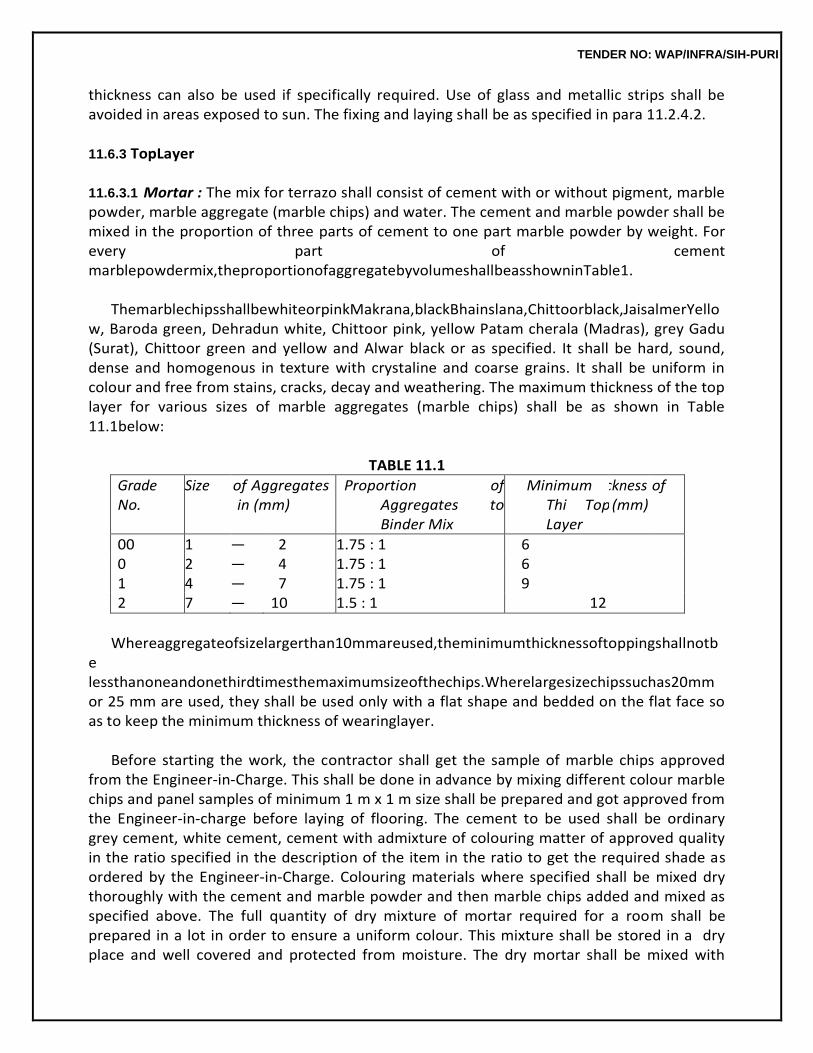
TENDER NO: WAP/INFRA/SIH-PURI
thickness can also be used if specifically required. Use of glass and metallic strips shall be avoided in areas exposed to sun. The fixing and laying shall be as specified in para 11.2.4.2.
11.6.3 TopLayer
11.6.3.1 Mortar : The mix for terrazo shall consist of cement with or without pigment, marble powder, marble aggregate (marble chips) and water. The cement and marble powder shall be mixed in the proportion of three parts of cement to one part marble powder by weight. For every part of cement marblepowdermix,theproportionofaggregatebyvolumeshallbeasshowninTable1.
ThemarblechipsshallbewhiteorpinkMakrana,blackBhainslana,Chittoorblack,JaisalmerYello
w, Baroda green, Dehradun white, Chittoor pink, yellow Patam cherala (Madras), grey Gadu (Surat), Chittoor green and yellow and Alwar black or as specified. It shall be hard, sound, dense and homogenous in texture with crystaline and coarse grains. It shall be uniform in colour and free from stains, cracks, decay and weathering. The maximum thickness of the top layer for various sizes of marble aggregates (marble chips) shall be as shown in Table 11.1below:
TABLE 11.1
Grade No.
Size of Aggregates in (mm)
Proportion of Aggregates to Binder Mix
Minimum Thi Top Layer
ckness (mm)
of
00 1 — 2 1.75 : 1 6 0 2 — 4 1.75 : 1 6 1 4 — 7 1.75 : 1 9 2 7 — 10 1.5 : 1 12
Whereaggregateofsizelargerthan10mmareused,theminimumthicknessoftoppingshallnotb
e lessthanoneandonethirdtimesthemaximumsizeofthechips.Wherelargesizechipssuchas20mm or 25 mm are used, they shall be used only with a flat shape and bedded on the flat face so as to keep the minimum thickness of wearinglayer.
Before starting the work, the contractor shall get the sample of marble chips approved
from the Engineer-in-Charge. This shall be done in advance by mixing different colour marble chips and panel samples of minimum 1 m x 1 m size shall be prepared and got approved from the Engineer-in-charge before laying of flooring. The cement to be used shall be ordinary grey cement, white cement, cement with admixture of colouring matter of approved quality in the ratio specified in the description of the item in the ratio to get the required shade as ordered by the Engineer-in-Charge. Colouring materials where specified shall be mixed dry thoroughly with the cement and marble powder and then marble chips added and mixed as specified above. The full quantity of dry mixture of mortar required for a room shall be prepared in a lot in order to ensure a uniform colour. This mixture shall be stored in a dry place and well covered and protected from moisture. The dry mortar shall be mixed with
TENDER NO: WAP/INFRA/SIH-PURI
water in the usual way as and when required. The mixed mortar shall be homogenous and stiff and contain just sufficient water to make itworkable.
The terrazo topping shall be laid while the under layer is still plastic, but has hardened
sufficiently to prevent cement from rising to the surface. This is normally achieved between 18 to 24 hours after the underlayerhasbeenlaid.Acementslurrypreferablyofthesamecolourasthetoppingshallbebrushed on the surface immediately before laying is commenced. It shall be laid to a uniform thickness slightly more than that specified in order to get the specified finished thickness after rubbing. The surface ofthe toplayershallbetrowelledover,pressedandbroughttruetorequiredlevelbyastraightedgeandsteel floats in such a manner that the maximum amount of marble chips come up and are spread uniformly over thesurface.
TENDER NO: WAP/INFRA/SIH-PURI
11.6.3.2 Curing, Polishing and Finishing : The surface shall be left dry for air-curing for a duration of 12 to 18 hours depending on atmospheric temperature conditions. It shall then be cured by allowing water to stand in pools over it for a priod of not less than 4days.
The grinding and polishing may be commenced not before 2 days from the time of
completion of laying for manual grinding and not before 7 days for maching grinding. For polishing by machines, the surface shall be watered and ground evenly with machine fitted with special rapid cutting grit blocks (carborundum stone) of coarse grade (No. 60) till the marble chips are evenly exposed and the floor is smooth. After the first grinding, the surface shall be thoroughly washed to remove all grinding mud and covered with a grout of cement and colouring matter in same mix and proportion as the topping inorder to fill any pin holes that appear. The surface shall be allowed to dry for 24 hours and wet cured for 4 days and then rubbed with machine fitted with fine grit blocks (No. 120). Curing shall be done by ponding of water between panels formed with fine sand. The surface is cleaned and repaired as before andallowedtocureagainfor3to5days.Finallythethirdgrindingshallbedonewithmachinefittedwith mere fine grade grit blocks (No. 320) to get even and smooth surface without pin holes. The finished surface should show the marble chips evenlyexposed.
Where use of machine for polishing is not feasible or possible, rubbing and polishing shall
be done by hand, in the same manner as specified for machine polishing except that carborundum stone of coarse grade (No. 60) shall be used for the 1st rubbing, stone of medium grade (No. 80) for second rubbing and stone of fine grade (No. 120) for final rubbing polishing.
Afterthefinalpolisheitherbymachineorbyhand,oxalicacidshallbedustedoverthesurface@33
gm per square metre sprinkled with water and rubbed hard with a nemdah block (Pad of Woolen rags). Thefollowingday,thefloorshallbewipedwithamoistraganddriedwithasoftclothandfinishedclean.
Curing shall be done by suitable means such as laying moist sawdust or ponding water.
11.6.4 Precautions
Flooring in lavatories and bathrooms shall be laid after fixing of water closet and squatting pansand floor traps. Traps shall be plugged, while laying the floors and opened after the floors are cured and cleaned.AnydamagedonetoWC’ssquattingpansandfloortrapsduringtheexecutionofworkshallbe madegood.
During cold weather, concreting shall not be done when the temperature falls below 4°C.
The concrete placed shall be protected against frost by suitable coverings. Concrete damaged by frost shall be removed and work redone. During hot weather, precautions shall be taken to see that the temperatureofwetconcretedoesnotexceed38°C.Noconcretingshallbelaidwithinhalfanhourofth
TENDER NO: WAP/INFRA/SIH-PURI
e closing time of the day, unless permitted by theEngineer-in-Charge.
11.6.5 Measurements
11.6.5.1 Length and breadth shall be measured correct to a cm before laying skirting, dado or wall plaster. The area as laid shall be calculated in sqm correct to two decimalplaces.
The thickness of the under layer shall be measured correct to a cm. The thickness of top
layer shall not be less than that specified.
Nodeductionshallbemade,norextrapaidforvoidsnotexceeding0.20squaremetre.Deductionfor ends of dissimilar materials or other articles embedded shall not be made for areas not exceeding 0.10 square metre. Nothing extra shall be paid for laying the floor at different levels in the same room or courtyard.
11.6.5.2 Terrazo (Marble Chips) flooring laid as floor borders, margins and similar bands upto 30 cm widthandonstaircasetreadsshallbemeasuredundertheitemofterrazoflooringbutextrashallbepaidforsuchwork.Thisextrainthecaseofstaircasetreadsshallincludethecostofformingthenosingalso. However, moulded nosing shall be paid for staircase treads etc. extra in running metres except where otherwise stated, returned moulded ends and angles to mouldings shall be included in the description. Extra shall also be paid for laying flooring in narrow bands not exceeding 7.5 cm in width and such bands shall be measured in running metres for thispurpose.
11.6.5.3 Dividing strips inserted in terrazo to form bays, patterns shall be described stating the mate- rials, its width and thickness and measured in runningmetres.
11.6.5.4 Special surface finishes to treads, risers and the ends of concrete steps and the like shall be measuredseparatelyandgiveninsquaremetresandshallincludeformwork,ifrequired.
11.6.6 Rate
The rate shall include the cost of all materials and labour involved in all the operations described above including cleaning of surface of RCC slab or base concrete and application of cement slurry but shallnotincludethecostofbaseconcreteandcostofprovidingandfixingstripsofglassoraluminiumor of any other material used for making panels, which shall be paid forseparately.
11.7 TERRAZO (MARBLE CHIPS) SKIRTING INSITU
11.7.1 UnderCoat
The under coat of skirting shall be of cement plaster of the thickness and mix described in the item. Specifications given under 11.4.0, 11.4.1 and 11.4.2 shall apply. As regards application, the work shall be carried out in the manner described in para 11.4.3 except that the under coat shall be finishedrough with a scratching tool to form a key for the topcoat.
TENDER NO: WAP/INFRA/SIH-PURI
11.7.2 TopCoat
The specifications as in para 11.6.3 shall hold good as far as applicable and shall include cutting to line and fair finish to top edges of terrazo and polishing.
11.7.3 Thickness
The thickness of the bottom and top coats shall be as specified. The total thickness of skirting specified is of the total thickness of plaster including top coat as measured from the unplastered face of the masonry. Average thickness of the under coat shall not be less than 6 mm and minimum thickness over any portion of the surface shall not be less than 4 mm. The thickness of top coat shall not be less than the thickness specified.
11.7.4 Measurements
Length and height shall be measured correct to a cm and its area shall be calculated in sqm correct to two places of decimal. Length shall be measured as finished length of skirting. Height shall be measuredfromthefinishedleveloffloorcorrectto5mmwheretheheightofskirtingdoesnotexceed30 cm and when the height exceeds 30 cm it shall be measured correct to acm.
11.7.5 Rates
The rate shall include the cost of all materials and labour involved in all the operations described above.
11.8 WAX POLISHING
11.8.1 Application, Polishing andPrecautions
Waxpolishshallbeofapprovedbrandandmanufactureandinsealedcontainers.Itshallbeapplied in uniform layer to the dry surface of thefloor/skirting.
11.8.2 When the layer of the wax is stiffened and surface of floor is saturated with the polish, polishing shall be resorted with machine fitted with bobs (pad of rags) and shall be done until shades of all chips have appeared and glossy surface isobtained.
11.8.3 The fresh polished floor surface shall be spreaded with dry saw dust to a thickness of about 12 mm uniformly. After the surplus wax has been soaked from the floor surface the saw dust shall be removed.
11.8.4 Measurements
Lengthandbreadthshallbemeasuredcorrecttoacmanditsareashallbecalculatedinsqmcorrect to two places ofdecimal.
11.8.5 Rates
The rate shall include the cost of all materials and labour involved in all the operations described above.
TENDER NO: WAP/INFRA/SIH-PURI
11.9 CRAZY MARBLE FLOORING (Fig.11.1)
11.9.1 BaseConcrete Crazy marble stone flooring shall be laid on cement concrete base. The base concrete
shall be provided with slope required for the flooring in verandahs and courtyards to drain off washing and rain water. The surface of base shall be roughened with steel wire brushes, without disturbing the concrete, wetted and smeared with a floating cost of cement slurry at 2 kg of cement spread over an area of one sqm so as to get a good bond between base and flooring.
Before laying the flooring on RCC slabs, the laitance shall be removed, the surface of slab
hacked andacoatofcementslurryatrateof2kgofcementspreadoveranareaofonesqmshallbeappliedso as to get a good bond between RCC slab andfloor.
11.9.2 UnderLayer
The under layer of crazy marble flooring shall be of cement concrete of thickness 25 mm or as specified. The mix shall normally be 1:2:4 (1 cement : 2 coarse sand : 4 graded stone aggregate 12.5 mm nominal size) by volume unless otherwise specified. It shall conform to the specifications given under para 4.2 of sub-head ‘Cement Concrete’.
11.9.3 TopLayer
The mix of crazy marble stone flooring shall consist of white cement with or without pigment,marble powder, marble chips of 00 Nos. and marble stone pieces and water. The marble stone pieces shall be hard, sound, dense and homogenous in texture with crystaline and coarse grains. It shall be uniform in colour and free from stains, cracks, decay and weathering. Before starting the work the contractor shall get the sample of marble stone approved by the Engineer-in-Charge. The marble stone pieces shall be of sizes as approved by the Engineer-in-Charge but the thickness shall be according to the overall thickness specified which could be achieved when laid over the under layer as specified. Thus for 50 mm thick floor, the thickness of marble pieces will be 25 mm while for 40 mm thick floor, the thickness will be 15mm.
The white cement and marble powder shall be mixed in proportion of three parts of
cement and one part of marble powder by weight, and the proportion of marble chips to binder mix by volume shall be 7 parts of marble chips to 4 parts of binder mix. The marble chips shall be as specified. It shall be hard, sound, dense and homogeneous in texture. It shall be uniform in colour and free from stains, cracks decay and weathering.
11.9.4 Laying
A coat of cement slurry at the rate of 2 kg of cement per sqm of area shall be spread and then the marble stone pieces shall be set by hand in such a manner that the top surface of all the set marble stones shall be true to the required level and slopes. After fixing the stones, the cement marble chips mixture shall be filled in between the gaps of laid marble stone pieces. The filled surface then shall be trowelled over, pressed and brought to the level of the
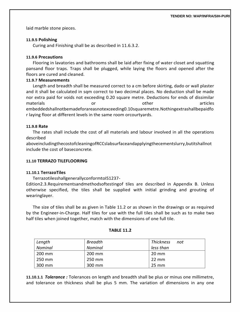
TENDER NO: WAP/INFRA/SIH-PURI
laid marble stone pieces.
11.9.5 Polishing Curing and Finishing shall be as described in 11.6.3.2.
11.9.6 Precautions
Flooring in lavatories and bathrooms shall be laid after fixing of water closet and squatting pansand floor traps. Traps shall be plugged, while laying the floors and opened after the floors are cured and cleaned. 11.9.7 Measurements
Length and breadth shall be measured correct to a cm before skirting, dado or wall plaster and it shall be calculated in sqm correct to two decimal places. No deduction shall be made nor extra paid for voids not exceeding 0.20 square metre. Deductions for ends of dissimilar materials or other articles embeddedshallnotbemadeforareasnotexceeding0.10squaremetre.Nothingextrashallbepaidfor laying floor at different levels in the same room orcourtyards.
11.9.8 Rate
The rates shall include the cost of all materials and labour involved in all the operations described aboveincludingthecostofcleaningofRCCslabsurfaceandapplyingthecementslurry,butitshallnot include the cost of baseconcrete.
11.10 TERRAZO TILEFLOORING
11.10.1 TerrazoTiles
TerrazotilesshallgenerallyconformtoIS1237-Edition2.3.Requirementsandmethodsoftestingof tiles are described in Appendix B. Unless otherwise specified, the tiles shall be supplied with initial grinding and grouting of wearinglayer.
The size of tiles shall be as given in Table 11.2 or as shown in the drawings or as required
by the Engineer-in-Charge. Half tiles for use with the full tiles shall be such as to make two half tiles when joined together, match with the dimensions of one full tile.
TABLE 11.2
Length Nominal
Breadth Nominal
Thickness not less than
200 mm 250 mm 300 mm
200 mm 250 mm 300 mm
20 mm 22 mm 25 mm
11.10.1.1 Tolerance : Tolerances on length and breadth shall be plus or minus one millimetre, and tolerance on thickness shall be plus 5 mm. The variation of dimensions in any one
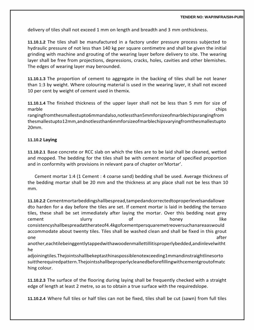
TENDER NO: WAP/INFRA/SIH-PURI
delivery of tiles shall not exceed 1 mm on length and breadth and 3 mm onthickness.
11.10.1.2 The tiles shall be manufactured in a factory under pressure process subjected to hydraulic pressure of not less than 140 kg per square centimetre and shall be given the initial grinding with machine and grouting of the wearing layer before delivery to site. The wearing layer shall be free from projections, depressions, cracks, holes, cavities and other blemishes. The edges of wearing layer may berounded.
11.10.1.3 The proportion of cement to aggregate in the backing of tiles shall be not leaner than 1:3 by weight. Where colouring material is used in the wearing layer, it shall not exceed 10 per cent by weight of cement used in themix.
11.10.1.4 The finished thickness of the upper layer shall not be less than 5 mm for size of marble chips rangingfromthesmallestupto6mmandalso,notlessthan5mmforsizeofmarblechipsrangingfrom thesmallestupto12mm,andnotlessthan6mmforsizeofmarblechipsvaryingfromthesmallestupto 20mm.
11.10.2 Laying
11.10.2.1 Base concrete or RCC slab on which the tiles are to be laid shall be cleaned, wetted and mopped. The bedding for the tiles shall be with cement mortar of specified proportion and in conformity with provisions in relevant para of chapter on‘Mortar’.
Cement mortar 1:4 (1 Cement : 4 coarse sand) bedding shall be used. Average thickness of
the bedding mortar shall be 20 mm and the thickness at any place shall not be less than 10 mm.
11.10.2.2 Cementmortarbeddingshallbespread,tampedandcorrectedtoproperlevelsandallowedto harden for a day before the tiles are set. If cement mortar is laid in bedding the terrazo tiles, these shall be set immediately after laying the mortar. Over this bedding neat grey cement slurry of honey like consistencyshallbespreadattherateof4.4kgofcementpersquaremetreoversuchanareaaswould accommodate about twenty tiles. Tiles shall be washed clean and shall be fixed in this grout one after another,eachtilebeinggentlytappedwithawoodenmallettillitisproperlybedded,andinlevelwiththe adjoiningtiles.Thejointsshallbekeptasthinaspossiblenotexceeding1mmandinstraightlinesorto suittherequiredpattern.Thejointsshallbeproperlycleanedbeforefillingwithcementgroutofmatching colour.
11.10.2.3 The surface of the flooring during laying shall be frequently checked with a straight edge of length at least 2 metre, so as to obtain a true surface with the requiredslope.
11.10.2.4 Where full tiles or half tiles can not be fixed, tiles shall be cut (sawn) from full tiles
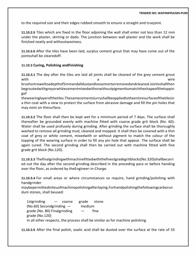
TENDER NO: WAP/INFRA/SIH-PURI
to the required size and their edges rubbed smooth to ensure a straight and truejoint.
11.10.2.5 Tiles which are fixed in the floor adjoining the wall shall enter not less than 12 mm under the plaster, skirting or dado. The junction between wall plaster and tile work shall be finished neatly and withoutwaviness.
11.10.2.6 After the tiles have been laid, surplus cement grout that may have come out of the jointsshall be clearedoff.
11.10.3 Curing, Polishing andFinishing
11.10.3.1 The day after the tiles are laid all joints shall be cleaned of the grey cement grout with a wire brushortroweltoadepthof5mmandalldustandloosemortarremovedandcleaned.Jointsshallthen begroutedwithgreyorwhitecementmixedwithorwithoutpigmenttomatchtheshapeofthetoppingof thewearinglayerofthetiles.Thesamecementslurryshallbeappliedtotheentiresurfaceofthetilesin a thin coat with a view to protect the surface from abrasive damage and fill the pin holes that may exist on thesurface.
11.10.3.2 The floor shall then be kept wet for a minimum period of 7 days. The surface shall thereafter be grounded evenly with machine fitted with coarse grade grit block (No. 60). Water shall be used profusely during grinding. After grinding the surface shall be thoroughly washed to remove all grinding mud, cleaned and mopped. It shall then be covered with a thin coat of grey or white cement, mixedwith or without pigment to match the colour of the topping of the wearing surface in order to fill any pin hole that appear. The surface shall be again cured. The second grinding shall then be carried out with machine fitted with fine grade grit block (No.120).
11.10.3.3 Thefinalgrindingwithmachinefittedwiththefinestgradegritblocks(No.320)shallbecarried out the day after the second grinding described in the preceding para or before handing over the floor, as ordered by theEngineer-in-Charge.
11.10.3.4 For small areas or where circumstances so require, hand grinding/polishing with handgrinder maybepermittedinlieuofmachinepolishingafterlaying.Forhandpolishingthefollowingcarborundum stones, shall beused:
1stgrinding — coarse grade stone (No.60) Secondgrinding — medium grade (No. 80) Finalgrinding — fine grade (No.120) In all other respects, the process shall be similar as for machine polishing.
11.10.3.5 After the final polish, oxalic acid shall be dusted over the surface at the rate of 33
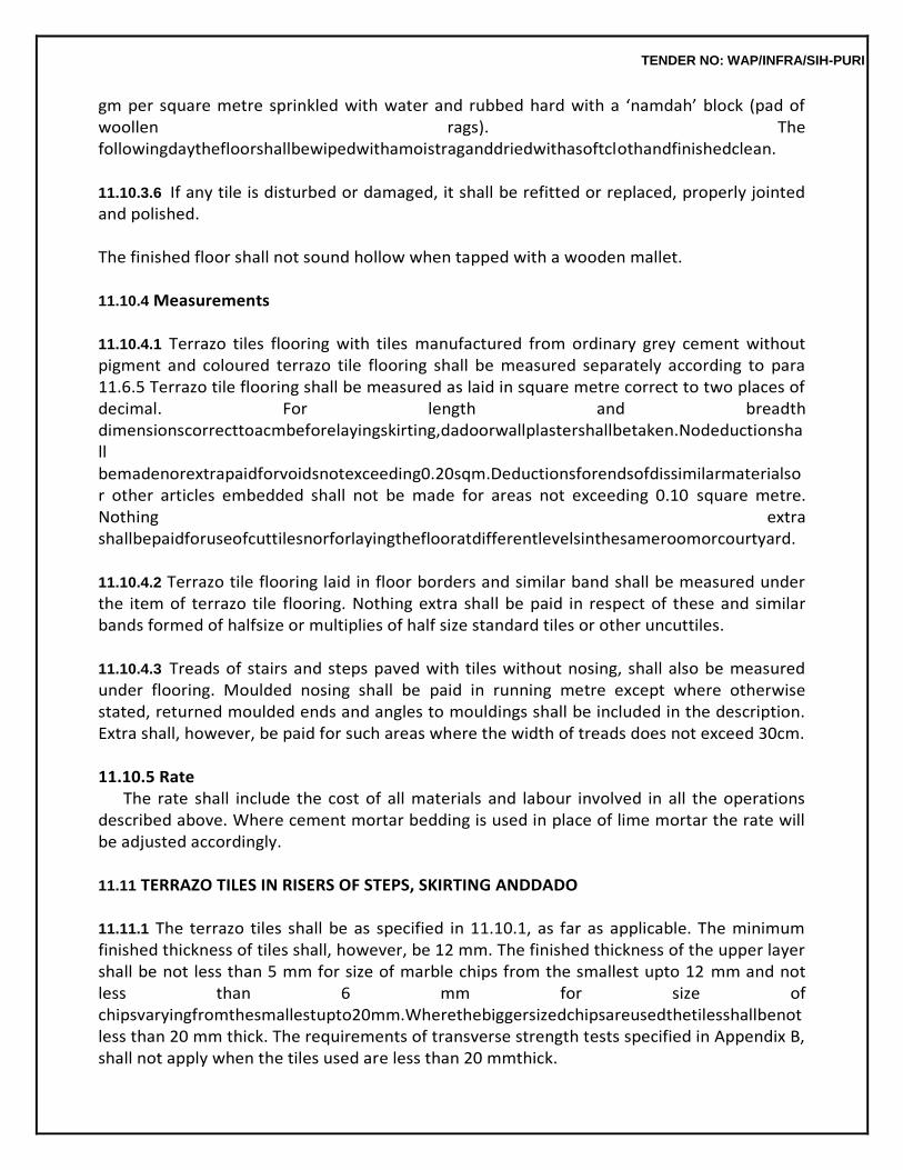
TENDER NO: WAP/INFRA/SIH-PURI
gm per square metre sprinkled with water and rubbed hard with a ‘namdah’ block (pad of woollen rags). The followingdaythefloorshallbewipedwithamoistraganddriedwithasoftclothandfinishedclean.
11.10.3.6 If any tile is disturbed or damaged, it shall be refitted or replaced, properly jointed and polished.
The finished floor shall not sound hollow when tapped with a wooden mallet.
11.10.4 Measurements
11.10.4.1 Terrazo tiles flooring with tiles manufactured from ordinary grey cement without pigment and coloured terrazo tile flooring shall be measured separately according to para 11.6.5 Terrazo tile flooring shall be measured as laid in square metre correct to two places of decimal. For length and breadth dimensionscorrecttoacmbeforelayingskirting,dadoorwallplastershallbetaken.Nodeductionshall bemadenorextrapaidforvoidsnotexceeding0.20sqm.Deductionsforendsofdissimilarmaterialsor other articles embedded shall not be made for areas not exceeding 0.10 square metre. Nothing extra shallbepaidforuseofcuttilesnorforlayingtheflooratdifferentlevelsinthesameroomorcourtyard.
11.10.4.2 Terrazo tile flooring laid in floor borders and similar band shall be measured under the item of terrazo tile flooring. Nothing extra shall be paid in respect of these and similar bands formed of halfsize or multiplies of half size standard tiles or other uncuttiles.
11.10.4.3 Treads of stairs and steps paved with tiles without nosing, shall also be measured under flooring. Moulded nosing shall be paid in running metre except where otherwise stated, returned moulded ends and angles to mouldings shall be included in the description. Extra shall, however, be paid for such areas where the width of treads does not exceed 30cm.
11.10.5 Rate
The rate shall include the cost of all materials and labour involved in all the operations described above. Where cement mortar bedding is used in place of lime mortar the rate will be adjusted accordingly.
11.11 TERRAZO TILES IN RISERS OF STEPS, SKIRTING ANDDADO
11.11.1 The terrazo tiles shall be as specified in 11.10.1, as far as applicable. The minimum finished thickness of tiles shall, however, be 12 mm. The finished thickness of the upper layer shall be not less than 5 mm for size of marble chips from the smallest upto 12 mm and not less than 6 mm for size of chipsvaryingfromthesmallestupto20mm.Wherethebiggersizedchipsareusedthetilesshallbenot less than 20 mm thick. The requirements of transverse strength tests specified in Appendix B, shall not apply when the tiles used are less than 20 mmthick.
TENDER NO: WAP/INFRA/SIH-PURI
11.11.2 Preparation ofSurface
The specification for this shall be same as specified in 11.4.2.
11.11.3 Laying 12 mm thick plaster of cement mortar 1:3 (1 cement : 3 coarse sand) or mix as specified,
shall then be applied and allowed to harden. The plaster shall then be roughened with wire brushes or by scratching diagonal lines 2 mm deep at approximately 7.5 cm centres both ways. The back of tilesshall be buttered with a coat of grey cement slurry and edges with grey or white cement slurry with orwithout pigments to match the shade of tiles, and set in the bedding mortar. These shall be tamped and corrected to proper planes and lines. The tiles shall be set in the required pattern and butt jointed. The joints shall be as fine as possible. Top of skirting or dado shall be truly horizontal with projection from finishwallsurfacenotmorethantilethicknessandjointstrulyverticalexceptwhereotherwiseindicated.
The risers of steps, skirting or dado shall rest on the top of the tread or flooring. Where
full size tiles cannot be fixed, the tiles shall be cut (sawn) to the required size and their edges rubbed smooth.
12.11.1 Curing, Polishing andFinishing
The specifications as in 11.10.3 shall hold good as far as applicable. Polishing shall be done only with hand.
12.11.2 Measurements
The thickness of the skirting shall be as stated. Length shall be measured along the finished face of riser, skirting or dado correct to a cm. Height shall be measured from the finished level of tread or floor to the top (the underside of tread in the case of steps). This shall be measured correct to 5 mm in case ofrisersandskirting(notexceeding30cminheight).Incaseofheightsmorethan30cm,asinthecase of dado and on walls, the height shall be measured correct to a cm and such work shall be paid for separately.Theareashallbecalculatedinsquaremetre,correcttotwoplacesofdecimal.
Where the height of risers, skirting or dado does not admit of full size or other finished
size tiles and the tiles are to be cut (sawn), nothing extra shall be paid for the same.
12.11.3 Rate The rate shall include the cost of all materials and labour involved in all the operations
described above.
Nothingextrashallbepayableforuseofcut(sawn)tilestosuitthesizeofrisers,skirting,portionsof dadoetc.
11.12 CHEQUERED TILEFLOORING
TENDER NO: WAP/INFRA/SIH-PURI
11.12.1 ChequeredTiles The tiles shall be of nominal sizes such as 20 × 20 cm, 25 × 25 cm and 30 × 30 cm or of
standard sizes with equal sides. The size of tiles to be used shall be as shown in drawings or as required by the Engineer-in-Charge. The centre to centre distance of chequers shall not be less than 2.5 cm and not more than 5 cm.
Theoverallthicknessofthetilesshallnotbelessthan30mm.Thegroovesinthechequersshallbe
uniformandstraight.Thedepthofthegroovesshallnotbelessthan3mm.Thechequeredtilesshallbe cement tiles, or terrazo tiles as specified in the description of the item. The thickness of the upperlayer, measured from the top of the chequers shall not be less than 6mm.
The terrazo tiles shall be given the first grinding with machine before delivery to site.
The tiles shall conform to the specifications for plain cement concrete or terrazo tiles in
respect of method of manufacture and the mix of the backing and wearing layers.
11.12.2 Laying, curing, Polishing and Finishing shall be as specified in 11.10.2 and 11.10.3 except that thepolishingofthetilesandthechequergrooves,afterlaying,maybedonebyhand.Specialcareshall be taken to polish the grooves in such a manner as to get a uniform section and that their finish shall match with the finish of flat portion of the tiles. Cement concrete tiles normally do not require polishing but where polishing is required the same shall be done as describedabove.
11.12.3 Measurement and Rate: Shall be as specified in 11.10.4 and11.10.5. 11.13 CHEQUERED TILES IN STAIR TREADS (FIG.11.2)
11.13.1 ChequeredTiles
The specifications for tiles shall be as specified in 11.12.1 except in the following respects :
(1) The length of the tiles including nosing shall be asspecified.
(2) The nosing edge of the tile shall berounded.
(3) The minimum thickness of the tile shall be 30mm.
(4) The front portion of the tile for a minimum length of 75 mm from and including the nosing shall have grooves running parallel to the nosing and at centres not exceeding 25 mm. Beyond that the tiles shall have the normal chequerpattern.
(5) The nosing shall also have the same wearing layer as thetop.
11.13.2 Preparation of Surface andLaying
11.13.2.1 RCC or brick work in treads on which the tiles are to be laid shall be cleaned wetted
TENDER NO: WAP/INFRA/SIH-PURI
and mopped.Thebeddingfortilesshallbewithcementmortar1:4(1cement:4coarsesand)orofspecified mix. The minimum thickness of bedding mortar at any place shall be 10 mm. Bedding mortar shall be spread, tamped and corrected to proper levels. After laying bedding mortar, neat grey cement slurry of honey like consistency shall be spread over the mortar at the rate of 4.4 kg of cement per square metre over each tread. Tiles shall be washed cleaned and shall be fixed in this grout butting one at another. Each tile being gently tapped with a wooden mallet till it is properly bedded, and is in level and line with the adjoining tiles. The joints shall be kept as thin as possible and in straight lines. The surface shall be checked with a straight edge during laying to obtain a truesurface.
11.13.2.2 The square end of the tile shall, as far as possible butt against the riser face of the concrete orbricktreadandinanycaseshallbeembeddedunderthesidewallplaster,skirtingordadoandunder the riser tile or other finish to a depth of not less than 10mm.
11.13.2.3 Where full size tiles cannot be fixed, these shall be cut (sawn) to the required size (along the groove of the chequers where the cut edge is exposed) and used. The cut in the case of embedded edges will be neat and true while the cut in the case of exposed edges shall in addition be rubbed smooth to ensure a straight and truejoints.
11.13.2.4 After the tiles have been laid surplus cement grout shall be cleanedoff.
11.13.3 Curing, Polishing andFinishing
The specifications shall be as described in 11.10.3 except that polishing of the treads nosing and chequered grooves, after laying, may be done by hand in the same manner as specified under terrazo tileflooring.Specialcareshallbetakentopolishthenosingandthegroovesinsuchamannerastoget a uniform, section for the grooves and the nosing and their finish shall match with the finish of the flat portion of thetiles.
11.13.4 Measurements
Chequred tiles on stair treads shall be measured in square metre correct to two places of decimal. Length shall be measured correct to a cm before laying skirting, dado or wall plaster. Width shall be measured correct to a cm from the outer edge of the nosing, as laid, before providing the riser. In the case of the edge tiles of the landing and wide steps, width shall be measured upto the near edge of the chequered stair tread tiles. Deductions for ends of dissimilar materials or other articles embedded shall not be made for areas not exceeding 0.10 square metre.
11.13.5 Rate
The rate shall include the cost of all materials and labour involved in all the operations described above.
Nothing extra shall be payable for cutting the tiles to suit the size of treads and also for nosing.
TENDER NO: WAP/INFRA/SIH-PURI
11.14 ACID OR ALKALI RESISTANTTILES
11.14.0 Manufacture andFinish
The tiles shall be of vitreous ware and free from deleterious substances. The iron oxide content allowable in the raw material shall not exceed two percent. The tiles shall be vitrified at the temperature of 11000C and above and shall be kept unglazed. The finished, tile, when fractured shall appear fine grained in texture, dense and homogenous. The tiles shall be sound, true to shope, flat and free from flows and manufacturing defects affecting their utility.
The tiles shall be conforming to IS 4457. The tiles to be tested for water absorption,
compressive strength, acid resistance as per IS 4457. Sampling procedure for acceptance tests and criteria for conformity to be as per IS 4457. The tiles shall be of required colour.
11.14.1 Dimensions andTolerances
Ceramic unglazed vitreous acid-resistant tiles shall be made in three sizes namely 98.5 X 98.5 mm, 148.5X148.5mmand198.5X198.5mm.Theyshallbeavailableinthefollowingthickness:35,30,25, 20 and 15 mm. The depth of the grooves on the under side of the tile shall not exceed 3 mm.Tolerance on length, breadth and thickness of tiles shall be + 2percent.
11.14.2 Shape
The tiles shall be square shaped. Half tiles rectangular in shape shall also be available. Half tilesfor use with full tiles shall have dimensions which shall be such as to make two half tiles, when joined together,matchwiththedimensionoffulltile.Theshapeoftilesotherthansquareshallbeasagreedto betweenthepurchaserandthemanufacturer.TilesshallbecheckedforsquarenessandwarpasperIS 4457.
11.14.3 PerformanceRequirements
The tiles when tested in accordance with method given in IS 4457, shall conform to be requirement specified in the code (IS 4457).
11.14.4 Loss inAbrasion
The maximum percentage of loss in abrasion of the ceramic unglazed vitreous acid resistant tiles determined in accordance with the procedure laid down in IS 1237, shall be as mentioned in IS 4457.
11.14.5 Marking
Tiles shall be legibly marked on the back with the name of the manufacturer or his trade mark. Manufacturer’s batch number and year of manufacture.
Each tile may also be marked with the ISI certification mark.
TENDER NO: WAP/INFRA/SIH-PURI
11.14.6 Preparation of Surface andLaying Preparationofsurfaceandlayingtobeaccordingtopara11.15.4,exceptthecementusedtobeaci
d and or alkali resistant cement and cement mortar to be used to be acid and or Alkali resistant mortar. Thickness of bedding of mortar for flooring to be 10 mm or specified on the item and for dado/skirtingto be 12 mm or specified onitem.
11.14.7 Pointing andFinishing
As per para 11.15.5, except that cement used for pointing to be acid and or alkali resistant cement.
11.14.8 Measurements As per para 11.15.6.
11.14.9 Rate
The rate for flooring shall include the cost of all materials and labor in volved in all the operations described above. For tiles of sizes upto 0.16 Sqm, unless otherwise specified in the description of the item. Nothing extra shall be paid for the use of cost (Sawn) tiles in the work.
11.15 PRESSED CERAMIC TILEFLOORING
11.15.1 Pressed CeramicTiles
The tiles shall be of approved make and shall generally conform to IS 15622. They shall be flat,and truetoshapeandfreefromblisterscrazing,chips,welts,crawlingorotherimperfectionsdetractingfrom their appearance. The tiles shall be tested as per IS13630.
Classification and Characteristics of pressed ceramic tiles shall be as per IS 13712.
The tiles shall be square or rectangular of nominal size. Table 1,3,5, and 7 of IS 15622 give
the modular preferred sizes and table 2,4,6 and 8 give the most common non modular sizes. Thickness shall be specified by the manufacturer. It includes the profiles on the visible face and on the rear side. Manufacturer/supplierandpartyshallchoosetheworksizeoftilesinordertoallowanominaljointwidth upto 2mm for unrectified floor tiles and upto 1mm for rectified floor tiles. The joint in case of spacer lug tile shall be as per spacer. The tiles shall conform to table10 of IS 15622 with water absorption 3 to 6% (GroupBII).
The top surface of the tiles shall be glazed. Glaze shall be either glossy or matt as
specified. The underside of the tiles shall not have glaze on more than 5% of the area in order that the tile mayadhere properly to the base. The edges of the tiles shall be preferably free from glaze. However, any glaze if unavoidable,shallbepermissibleononlyupto50percentofthesurfaceareaoftheedges.
11.15.2 ColouredTiles
Only the glaze shall be coloured as specified. The sizes and specifications shall be the
TENDER NO: WAP/INFRA/SIH-PURI
same as for the white glazed tiles.
11.15.3 DecorativeTiles The type and size of the decorative tiles shall be as follows :
(i) Decorated white back groundtiles
The size of these tiles shall be as per IS 15622.
(ii) Decorated and having colouredback-ground The sizes of the tiles shall be as per IS 15622.
11.15.4 Preparation of Surface andLaying
11.15.4.1 Base concrete or the RCC slab on which the tiles are to be laid shall be cleaned, wetted and mopped. The bedding for the tile shall be with cement mortar 1:4 (1 cement : 4 coarse sand) or as specified. The average thickness of the bedding shall be 20 mm or as specified while the thickness under any portion of the tiles shall not be less than 10mm.
11.15.4.2 Mortar shall be spread, tamped and corrected to proper levels and allowed to harden sufficiently to offer a fairly rigid cushion for the tiles to be set and to enable the mason to place wooden plank across and squat onit.
11.15.4.3 Overthismortarbeddingneatgreycementslurryofhoneylikeconsistencyshallbespreadat the rate of 3.3 kg of cement per square metre over an area upto one square metre. Tiles shall be soaked in water washed clean and shall be fixed in this grout one after another, each tile gently being tappedwithawoodenmallettillitisproperlybeddedandinlevelwiththeadjoiningtiles.Thejointsshall be kept as thin as possible and in straight lines or to suit the requiredpattern.
11.15.4.4 The surface of the flooring during laying shall be frequently checked with a straight edgeabout 2 m long, so as to obtain a true surface with the required slope. In bath, toilet W.C. kitchen and balcony/verandah flooring, suitable tile drop or as shown in drawing will be given in addition to required slope to avoid spread of water. Further tile drop will also be provided near floor trap.
11.15.4.5 Where full size tiles cannot be fixed these shall be cut (sawn) to the required size, and their edge rubbed smooth to ensure straight and truejoints.
Tileswhicharefixedintheflooradjoiningthewallshallenternotlessthan10mmundertheplaster,
skirting ordado.
11.15.4.6 After tiles have been laid surplus cement slurry shall be cleanedoff.
11.15.5 Pointing andFinishing The joints shall be cleaned off the grey cement slurry with wire/coir brush or trowel to a
TENDER NO: WAP/INFRA/SIH-PURI
depth of 2 mmto3mmandalldustandloosemortarremoved.Jointsshallthenbeflushpointedwithwhitecement added with pigment if required to match the colour of tiles. Where spacer lug tiles are provided, the half the depth of joint shall be filled with polysulphide or as specified on top with under filling with cement grout without the lugs remaining exposed. The floor shall then be kept wet for 7 days. After curing, the surface shall be washed and finished clean. The finished floor shall not sound hollow when tapped with a woodenmallet.
11.15.6 Measurements
Lengthandbreadthshallbemeasuredcorrecttoacmbeforelayingskirting,dadoorwallplasterand the area calculated in square metre correct to two places of decimal. Where coves are used at the junctions,thelengthandbreadthshallbemeasuredbetweentheloweredgesofthecoves.
No deduction shall be made nor extra paid for voids not exceeding 0.20 square metre.
Deductions for ends of dissimilar materials or other articles embedded shall not be made for areas not exceeding 0.10 square metre.
Areas, where glazed tiles or different types of decorative tiles are used will be measured separately.
11.15.7 Rate
The rate for flooring shall include the cost of all materials and labour involved in all the operations described above, For tiles of sizes upto 0.16 sqm. unless otherwise specified in the description of the item. Nothing extra shall be paid for the use of cut (sawn) tiles in the work.
Extraoverandabovethenormalrateforwhitetilesshallbepaidwherecolouredoranyothertype
of decorative tiles have beenused.
11.16 PRESSED CERAMIC TILE FLOORING (VITRIFIED TILEFLOORING)
11.16.1 Operationsasdescribedin11.15.1to11.15.6shallbefollowedexceptthetilesshallconformto Table12ofIS15622(TileswithwaterabsorptionEflooring shall not be more than1mm.
11.16.2 Rate
The rate for flooring shall include the cost of all materials and labour involved in all the operations described above. Nothing extra shall be paid for the use of cut (sawn) tiles in the work.
11.17 FIXINGOFTILEFLOORINGWITHCEMENTBASEDHIGHPOLYMERMODIFIEDQUICKSET ADHESIVE (WATERBASED)
11.17.1 Whentileflooringistobelaidovertheexistingflooringwithoutdismantlingoldflooringitcanbe
TENDER NO: WAP/INFRA/SIH-PURI
laidwithadhesive.Theoldflooringshallbethoroughlycleanedandcheckedforundulations,ifanyshall be rectified with cement mortar 1:3 (1 cement: 3 coarse sand). Old cement concrete surface shall be hacked and cleaned off to have proper bond with the oldsurface.
11.17.2 High polymer modified quick set tile adhesive (conforming to IS 15477) shall be thoroughly mixed with water and a paste of zero slump shall be prepared so that it can be used with in 1.5 to 2 hours. It shall be spread over an area not more than one sqm at one time. Average thickness of adhesiveshallbe3mmTheadhesivesospreadedshallbecombedusingsuitabletrowel.Tilesshallbe pressed firmly in to the position with slight twisting action checking it simultaneously to ensure good contact gently being tapped with wooden mallet till it is properly backed with adjoining tiles. The tiles shallbefixedwithin20minutesofapplicationofadhesive.Thesurplusadhesivefromthejoints,surface of the tiles shall be immediatelycleaned.
11.17.3 Thesurfaceoftheflooringshallbefrequentlycheckedduringlayingwithstraightedgeofabove 2m long so as to attain a true surface with requiredslope.
11.17.4 Where spacer lugs tiles are provided these shall be filled with grout with lugs remaining exposed.
11.17.5 Where full size tile can not be fixed these shall be cut (sawn) to the required size and edges rubbed smooth to ensure straight and true joints. Tiles which are fixed in floor adjoining to wall shall enter not less than 10 mm under plaster, skirting ordado.
11.17.6 Finishing:para11.15.5shallapply.
11.17.7 Measurements: para 11.15.6 shallapply.
11.17.8 Rate
Provisions of para 11.15.7 and 11.16.2 shall apply.
11.18 PRESSED CERAMIC TILES IN SKIRTING AND DADO
11.18.1 The tiles shall be of approved make and shall generally conform to IS 15622. The tiles shall be pressedceramiccoveredbyaglazethoroughlymaturedandfittedtothebody.Thetilesshallbesound, truetoshape,flatandfreefromflawsandothermanufacturingdefectsaffectingtheirutility.
The top surface of the tiles shall be glazed. The underside of the tiles shall not have glaze
on more than5%oftheareainorderthatthetilemayadhereproperlytothebase.Theedgesofthetilesshallbe free from glaze, however, any glaze if unavoidable shall be permissible on only upto 50 per cent of the surface area ofedges.
TENDER NO: WAP/INFRA/SIH-PURI
The glaze shall be free from welts, chips, craze, specks, crawlings or other imperfections detracting fromtheappearancewhenviewedfromadistanceofonemetre.Theglazeshallbeeitherglossyormatt asspecified.Theglazeshallbewhiteincolourexceptinthecaseofcolouredtileswhencoloursshallbe specified by the Engineer-in-Charge. There may be more than one colour on atile.
11.18.1 (a) Dimensions andTolerances
Glazed pressed cramic tiles shall be made square or rectangular in sizes Table 1, 3, 5 & 7 of IS 15622givethemodularsizesandtable2,4,6&8ofIS15622givesthesizesofnonmodulartiles.The tilesshallconformtoIS15622fordimensionaltolerance,physicalandchemicalproperties.
Halftilesforuseasfulltilesshallhavedimensionswhichshallbesuchastomakethehalftileswhen
jointedtogether(with1mmjoint)matchwithdimensionsoffulltiles.Tilesmaybemanufacturedinsizes other than those specified.above.
The thickness of the tiles shall be 5 mm or 6 mm or as specified.
The dimensions of fittings associated with the glazed tiles namely cover base, round edge
tile, angles corner cups, ridge and legs, cronices and capping beads shall be of the shape and dimensions as required and the thickness of fittings shall be the same as the thickness of tiles given above.
11.18.2 Preparation ofSurfaces
The joints shall be raked out to a depth of at least 15 mm in masonry walls.
Incaseofconcretewalls,thesurfaceshallbehackedandroughenedwithwirebrushes.Thesurface shallbecleanedthoroughly,washedwithwaterandkeptwetbeforeskirtingiscommenced.
11.18.3 Laying
12 mm thick plaster of cement mortar 1:3 (1 cement : 3 coarse sand) mix of as specified shall be applied and allowed to harden. The plaster shall be roughened with wire brushes or by scratching diagonal at closedintervals.
The tiles should be soaked in water, washed clean, and a coat of cement slurry applied
liberally at the back of tiles and set in the bedding mortar. The tiles shall be tamped and corrected to proper plane and lines. The tiles shall be set in the required pattern and jointed. The joints shall be as fine as possible. Top of skirting or dado shall be truly horizontal and joints truly vertical except whereotherwise indicated. Odd size/cut size of tile shall be adjusted at bottom to take care of slope of the flooring. Skirtinganddadoshallrestonthetopoftheflooring.Wherefullsizetilescannotbefixedtheseshallbe cut (sawn) to the required size and their edges rubbed smooth. Skirting /dado shall not project from the finished“surfaceofwall”bymorethanthetilethickness,undulationsifanyshallbeadjustedinwall.
TENDER NO: WAP/INFRA/SIH-PURI
11.18.4 Curing andFinishing
The joints shall be cleaned off the grey cement grout with wire/coir brush or trowel to a depth of 2 mmto3mmandalldustandloosemortarremoved.Jointsshallthenbeflushpointedwithwhitecement addedwithpigmentsifrequiredtomatchthecolouroftiles.Theworkshallthenbekeptwetfor7days.
After curing, the surface shall be washed and finished clean. The finished work shall not
sound hollow when tapped with a wooden mallet.
11.18.5 Measurements Length shall be measured correct to a cm. Height shall be measured correct to a cm in the
case of dadoand5mminthecaseofriserandskirting.Theareashallbecalculatedinsquaremetre,correctto two places of decimal. Length and height shall be measured along the finished face of the skirting or dado including curves where specials such as coves, internal and external angles and beads are used. Where cornices are used the area of dado shall be measured excluding the cornices. Nothing extra will be paid for cutting (sawn) the tiles tosizes.
Areaswherecolouredtilesordifferenttypesofdecorativetilesareusedwillbemeasuredseparat
ely to be paid extra over and above the normal rate for whitetiles.
11.18.6 Rates The rate shall include the cost of all material and labour involved in all the operations
described above, for tiles of sizes upto 0.14 sqm. unless otherwise specified in the description of the item. The specials such as coves, internal and external angles and beading shall be measured and paid for separately. The rate shall not include cost of cornices which shall be measured and paid for in running meters separately.
11.19 MARBLE STONEFLOORING
11.19.1 MarbleStone
It shall be as specified in sub head 8.0.
11.19.2 Dressing ofSlabs Every stone shall be cut to the required size and shape, fine chisel dressed on all sides to
the full depth so that a straight edge laid along the side of the stone shall be fully in contact with it. The top surface shall also be fine chisel dressed to remove all waviness. In case machine cut slabs are used, fine chiesel dressing of machine cut surface need not be done provided a straight edge laid any where along the machine cut surfaces is in contact with every point on it. The sides and top surface of slabs shall be machine rubbed or table rubbed with coarse sand before paving. All angles and edges of the marble slabs shall be true, square and free from chippings and the surface shall be true and plane.
TENDER NO: WAP/INFRA/SIH-PURI
The thickness of the slabs shall be 18, 30 or 40 mm as specified in the description of the item. Tolerance of + 3% shall be allowed for the thickness. In respect of length and breadth of slabs a tolerance of + 2% shall be allowed.
11.19.3 Laying
11.19.3.1 Base concrete or the RCC slab on which the slabs are to be laid shall be cleaned, wettedand mopped. The bedding for the slabs shall be with cement mortar 1:4 (1 cement : 4 coarse sand) or as given in the description of theitem.
11.19.3.2 Theaveragethicknessofthebeddingmortarundertheslabshallbe20mmandthethickness at any place under the slab shall be not less than 12mm.
11.19.3.3 The slabs shall be laid in the followingmanner:
Mortar of the specified mix shall be spread under the area of each slab, roughly to the
average thickness specified in the item. The slab shall be washed clean before laying. It shall be laid on top, pressed, tapped with wooden mallet and brought to level with the adjoining slabs. It shall be lifted and laid aside. The top surface of the mortar shall then be corrected by adding fresh mortar at hollows. The mortar is allowed to harden a bit and cement slurry of honey like consistency shall be spread over the same at the rate of 4.4 kg of cement per sqm. The edges of the slab already paved shall be buttered with grey or white cement with or without admixture of pigment to match the shade of the marble slabs as given in the description of the item.
Theslabtobepavedshallthenbeloweredgentlybackinpositionandtappedwithwoodenmallett
ill it is properly bedded in level with and close to the adjoining slabs with as fine a joint as possible. Subsequent slabs shall be laid in the same manner. After each slab has been laid, surplus cement on the surface of the slabs shall be cleaned off. The flooring shall be cured for a minimum period of seven days. The surface of the flooring as laid shall be true to levels, and, slopes as instructed by the Engineer-in-Charge. Joint thickness shall not be more than 1mm.
Due care shall be taken to match the grains of slabs which shall be selected judiciously
having uniform pattern of Veins/streaks or as directed by the Engineer-in-Charge.
11.19.3.4 TheslabsshallbematchedasshownindrawingsorasinstructedbytheEngineer-in-Charge.
11.19.3.5 Slabs which are fixed in the floor adjoining the wall shall enter not less than 12 mm under the plaster skirting or dado. The junction between wall plaster and floor shall be finished neatly and without waviness.
11.19.3.6 Marble slabs flooring shall also be laid in combination with other stones and/or in simple regular pattern/design as described in item of work and/ordrawing. 11.19.4 Polishing andFinishing
TENDER NO: WAP/INFRA/SIH-PURI
Slight unevenness at the meeting edges of slabs shall then be removed by fine chiselling and finished in the same manner as specified in 11.10.3 except that cement slurry with or without pigments shall not be applied on the surface before each polishing.
11.19.5 Measurements
Marblestoneflooringwithdifferentkindofmarbleshallbemeasuredseparatelyandinsquaremetre correct to two places of decimal. Length and breadth shall be measured correct to a cm before laying skirting, dado or wall plaster. No deduction shall be made nor extra paid for voids not exceeding 0.20 square metre. Deductions for ends of dissimilar materials or other articles embedded shall not be made for areas not exceeding 0.10 square metre. Nothing extra shall be paid for laying the floor at different levels in the same room. Steps and treads of stairs paved with marble stone slabs shall also be measured under the item of Marble Stone flooring. Extra shall, however, be paid for such areas where the width of treads does not exceed 30 cm. Nosing for treads shall be measured in running metre and paid for extra. The width of treads shall be measured from the outer edge of the nosing, as laid, before providing theriser.
11.19.6 Rate
The rate shall include the cost of all materials and labour involved in all the operations described above. However, extra shall be paid for making special type of pattern/design/flowers as per drawings. No deductions shall be made in rate even if flooring is done without any pattern/design.
11.20 MARBLE STONE IN RISERS OF STEPS ANDSKIRTING
11.20.1 Marble Stone Slabs and Dressing of Slabs shall be as specified in 11.19.1 and 11.19.2 except that the thickness of slabs shall be 18 mm. A tolerance of + 3% mm shall be allowed, unless otherwise specified in the description of theitem.
11.20.2 Preparation ofSurface
It shall be as specified in 11.18.2 where necessary, the wall surface shall be cut uniformly to the requisite depth so that the skirting face shall have the projection from the finished face of wall asshown in drawings or as required by the Engineer-in-Charge. In no case the skirting should project by more than thickness ofstone.
11.20.3 Laying
The risers of steps and skirting shall be in grey or white cement admixed with or without pigment to matchtheshadeofthestone,asspecifiedinthedescriptionoftheitem,withthelineoftheslabatsuch adistancefromthewallthattheaveragewidthofthegapshallbe12mmandatnoplacethewidthshall be less than 10 mm, if necessary, the slabs shall be held in position by temporary M.S. hooks fixed into the wall at suitable intervals. The skirting or riser face shall be checked for plane and plumb and corrected.Thejointsshallthusbelefttohardenthentherearoftheskirtingorriserslabshallbepacked with cement mortar 1:3 (1 cement : 3 coarse sand) or other mix as specified in the

TENDER NO: WAP/INFRA/SIH-PURI
description of the item.Thefixinghooksshallberemovedafterthemortarfillingthegaphasacquiredsufficientstrength.
TENDER NO: WAP/INFRA/SIH-PURI
The joints shall be as fine as possible but not more than 1 mm. The top line of skirting and risers shall be truly horizontal and joints truly vertical, except where otherwise indicated.
TherisersandskirtingslabshallbematchedasshownindrawingsorasinstructedbytheEngineer-
in-Charge.
11.20.4 Curing, Polishing andFinishing It shall be as specified in 11.11.4 as far as applicable, except that cement slurry with or
without pigmentshallnotbeappliedonthesurfaceandpolishingshallbedoneonlywithhand.Thefaceandtop of skirting shall bepolished.
11.20.5 Measurements
Length shall be measured along the finished face of riser or skirting, correct to a cm. Height shallbe measuredfromthefinishedleveloftreadorfloor,tothetop(theundersideoftread,inthecaseofsteps) correctto0.5cm.Theareasshallbecalculatedinsquaremetrecorrecttotwoplacesofdecimal.
Dado and lining of pillars etc. shall be measured as ‘Marble work in wall lining. If the
thickness is upto25mmoras“MarbleWork”inJambs,walls,columnsandotherplainwork’ifthethicknessismore.
11.20.6 Rate
The rate shall include the cost of all materials and labour involved in all the operations described above.
11.21 KOTA STONEFLOORING
11.21.1 Kota StoneSlabs
The slabs shall be of selected quality, hard, sound, dense and homogeneous in texture free from cracks,decay,weatheringandflaws.Theyshallbehandormachinecuttotherequisitethickness.They shallbeofthecolourindicatedinthedrawingsorasinstructedbytheEngineer-in-Charge.
The slabs shall have the top (exposed) face polished before being brought to site, unless
otherwise specified. The slabs shall conform to the size required. Before starting the work the contractor shall get the samples of slabs approved by the Engineer-in-Charge.
11.21.2 Dressing
Everyslabshallbecuttotherequiredsizeandshapeandfinechiseldressedonthesidestothefull depth so that a straight edge laid along the side of the stone shall be in full contact with it. The sides (edges) shall be table rubbed with coarse sand or machine rubbed before paving. All angles and edges oftheslabsshallbetrue,squareandfreefromchippingsandthesurfaceshallbetrueandplane.

TENDER NO: WAP/INFRA/SIH-PURI
The thickness of the slab after it is dressed shall be 20, 25, 30 or 40 mm as specified in the
description of the item. Tolerance of ±2 mm shall be allowed for the thickness. In respect of length and breadth of slabs Tolerance of ± 5 mm for hand cut slabs and ± 2 mm for machine cut slabs shall be allowed.
11.21.3 Preparation of Surface andLaying
The specification shall be as described in 11.19.3 except that the edges of the slabs to be jointed shall be buttered with grey cement, with admixture of pigment to match the shade of the slab. The thickness of the joints should be minimum as possible. In any location, it shall not exceed 1 mm.
11.21.4 Polishing andFinishing
The specifications shall be as described in 11.19.3 except that (a) first polishing with coarse grade carborundum stone shall not be done, (b) cement slurry with or without pigment shall not be applied on the surface before polishing.
11.21.5 Measurements andRates
These shall be as described in paras 11.19.5 and 11.19.6.
11.22 KOTA STONE IN RISERS OF STEPS, SKIRTING ANDDADO
11.22.1 Kota Stone Slabs and Dressing shall be as specified in 11.21.1 and 11.21.2 except that the thickness of the slabs shall be 25 mm or as specified in the description of the item. The slabs may beof uniform size ifrequired.
11.22.2 Preparation of surface shall be as specified in11.20.2.
11.22.3 Laying shall be as specified in 11.20.3 except that the joints of the slabs shall be set in grey cement mixed with pigment to match the shade of theslabs.
11.22.4 Curing, Polishing and Finishing shall be as specified in 11.20.4 except that first polishing with coarse grade carborundum stone shall not bedone.
11.22.5 Measurements
Length shall be measured along the finished face of riser, skirting or dado correct to a cm. Height shallbemeasuredfromthefinishedleveloftreadoffloortothetop(theundersideoftreadinthecaseof steps).Thisshallbemeasuredcorrecttoamminthecaseofrisersofstepsandskirtingandcorrecttoa cminthecaseofdado.Theareashallbecalculatedinsquaremetrecorrecttotwoplacesofdecimal.
Lining of pillars etc. shall also be measured under this item.
11.22.6 Rate
The rate shall include the cost of all materials and labour involved in all the operations
TENDER NO: WAP/INFRA/SIH-PURI
described above.
11.23 RED OR WHITE FINE DRESSED SAND STONEFLOORING
11.23.1 StoneSlabs The slabs shall be red or white as specified in the description of the item. The stone slabs
shall be hard, sound, durable and tough, free from cracks, decay and weathering. In case of red sand stone, white patches or streaks shall not be allowed. However, scattered spots upto 10 mm diameter will be permitted. Before starting the work the contractor shall get samples of slabs approved by the Engineer- in-Charge.
Theslabsshallbehandormachinecuttotherequisitethicknessalongplanesparalleltothenatura
l bed of stone and should be of uniform size ifrequired.
11.23.2 Dressing ofSlabs Every slab shall be cut to the required size and shape and chisel dressed on all sides to a
minimum depth of 20 mm. The top and the joints shall be fine tooled so that straight edge laid along the face is fully in contact with it. In case machine cut stones are used, chisel dressing and fine tooling of machine cutsurfaceneednotbedoneprovidedastraightedgelaidanywherealongthemachinecutsurfaceisin contact with every point onit.
The thickness of the slabs after dressing shall be 40 mm or as specified in the description
of item with a permissible tolerance of ± 2 mm.
11.23.3 Laying
11.23.3.1 Base concrete on which the slabs are to be laid shall be cleaned, wetted and mopped. The bedding for the slabs shall be with cement mortar 1:5 (1 cement : 5 coarse sand) or as given in the description of theitem.
11.23.3.2 The average thickness of the bedding mortar under the slabs shall be 20 mm and the thickness at any place under the slabs shall not be less than 12mm.
11.23.3.3 The slab shall be laid in the followingmanner:
Mortar of specified mix shall be spreaded under each slab. The slab shall be washed clean
before laying. It shall then be laid on top, pressed and larried, so that all hollows underneath get filled and surplusmortarworksupthroughthejoints.Thetopshallbetappedwithawoodenmalletandbroughtto level and close to the adjoining slabs, with thickness of joint not exceeding 5 mm. Subsequent slabs shall be laid in the same manner. After laying each slab surplus mortar on the surface of slabs shall be cleaned off and joints finishedflush.
11.23.3.4 In case pointing with other mortar mix is specified, the joint shall be left raked out
TENDER NO: WAP/INFRA/SIH-PURI
uniformly and to a depth of not less than 12 mm when the mortar is still green. The pointing shall be cured for a minimum period of 7 days. The surface of the flooring as laid shall be true to levels and slopes as instructed by theEngineer-in-Charge.
11.23.3.5 Slabs which are fixed in the floor adjoining the wall shall enter not less than 12 mm under the plaster, skirting or dado. The junction between wall plaster skirting and floor shall be finished neatlyand withoutwaviness. 11.23.3.6 The finished floor shall not sound hollow when tapped with woodenmallet.
11.23.4 Finishing
Incaseofchiseldressedstoneflooringslightunevenness,ifanyexistingbetweentheedgesofslabs at joints shall then be removed by chiselling in aslant.
11.23.5 Measurements
These shall be as specified in para 11.19.5.
11.23.6 Rate The rate shall include the cost of all materials and labour involved in all the operations
described above.Wherepointingistobedone,thiswillbepaidextraunlessspecificallyincludedinthedescription of theitem.
11.24 RED OR WHITE FINE DRESSED AND RUBBED SAND STONEFLOORING
11.24.1 Stone Slabs shall be as specified in11.23.1.
11.24.2 Dressing
The specifications for dressing the top surface and the sides shall be as described in 11.23.2. In addition the dressed top and sides shall be table rubbed with coarse grade carborundum stone before paving, to obtain a perfectly true and smooth surface free from chisel marks.
The thickness of the slabs after dressing shall be as specified with a permissible tolerance
of ± 2 mm.
11.24.3 Laying The slabs shall be laid with 3 mm thick or 5 mm thick joints as specified in the description of the item.
Where the joints are to be limited to 3 mm thickness, the slabs shall be laid as specified in
11.19.3 except that the bedding mortar shall be as specified in 11.23.3 and sides of the slabs to be jointed shall be buttered with cement mortar 1:2 (1 cement : 2 stone dust) admixed with pigment to match the shade of the slab.
Where the slabs are to be laid with 5 mm thick joints, the specifications for laying shall be
as described in 11.23.3.
TENDER NO: WAP/INFRA/SIH-PURI
11.24.4 Finishing shall be as specified in 11.23.4 except that chisel marks and unevenness shall be removed by rubbing with coarse grade carborundumstone.
11.24.5 Measurement and Rate shall be as specified in 11.23.5 and11.23.6.
11.25 WOODENFLOORING
11.25.0 Seasoning andPreservation
All timber used for timber floors shall be thoroughly seasoned in accordance with IS 1141. After seasoning the timber shall be treated with preservative in accordance with IS 401. Seasoning and preservative treatment shall be paid for separately unless otherwise specifically included in the description of the item of flooring.
11.25.1 SupportingJoists
Main beams and joists of the class of wood sections specified in the description of the item for beams and joists, or as instructed by the Engineer-in-Charge shall be fixed in position to dead levels. The width of the joints shall not be less than 50 mm. The arrangement and spacing of beams joists etc. shall be as per design furnished.
11.25.2 Boards
It shall be of the class of timber and thickness specified in the description of the item. The timber shall be as specified in para 9.1. Only selected boards of uniform width shall be used. Unlessotherwise specifiedorshowninthedrawings,thewidthofboardsselectedshallnotbelessthan100mmnormore than 150 mm. The same width of boards shall not be maintained throughout except where the width of the room is not an exact multiple of the boards. In the latter case, the difference shall be equally adjusted between the two end boards (adjacent to walls). The length of the boards shall not exceed 3 metre anywhere. Ordinarily, the minimum length of boards shall be such that the boards shall rest at least on three supports, except where otherwise required by the pattern specified in the drawings or as directed by theEngineer-in-Charge.
The boards shall be planed true on the top face only unless otherwise specified in the
description of the item. Where the bottom face is exposed and it is also required to be planed, then such planing shall be paid for extra.
Unless otherwise described in the item, the longitudinal joints of planks shall be tongued
and groovedtoaminimumdepthof12mmwhiletheheadingjointsshallbeofthesquarebutttypeandshall occuroverthecentrelineofthesupportingjoists.Headingjoistsinadjacentboardsshallbeplacedover the samejoists.
11.25.3 IronScrews
Iron screws shall be of the slotted counter sunk head type, of length not less than the
TENDER NO: WAP/INFRA/SIH-PURI
thickness of planks plus 25 mm, subject to a minimum of 40 mm, and of designation No. 9 conforming to IS 451.
11.25.4 Fixing
The joists on which the planks shall be fixed shall be checked and corrected to levels. The end boardsshallbeaccuratelyfixedwiththesidesparallelandclosetothewalls.Eachadjoiningboardshall becarefullyjointedandshallbetightenedinpositionandscrewed.Forfixingtheboardstothejoists,two screwsshallbeusedateachendoftheboardsandonescrewateachoftheintermediatejoistsinazig zagmanner.Thescrewsshallbecountersunkandscrewholesfilledwithapprovedstopping.
The junction between timber flooring and adjacent flooring shall be formed by inserting a
metal strip (brass or aluminium) at the junction. The metal strip shall be fixed to the end of the planks by screws. The strips shall be paid for extra.
The flooring shall be truly level and plane. The joints shall be truly parallel and or
perpendicular to the walls, unless otherwise specified.
The floor shall be planed in both directions and made perfectly even, true and smooth.
Note : No wood of any kind shall be placed within 60 cm of any fire place or flue. Provision shall be made for ventilation in the space below the floor in case of ground floor and between floor andtopofceilinginthecaseofupperfloors.Sucharrangementsshallbepaidforseparately.
11.25.5 Finishing
The surface of the floor shall be bees waxed or finished otherwise as directed by the Engineer-in- Charge. The lower face shall be painted or treated with wood preservative as directed. The finishing shall be paid for separately unless specifically included in description of the flooring item.
11.25.6 Measurements
Length and breadth of superficial area of the finished work shall be measured correct to a cm. The area shall be calculated in square metre correct to two places of decimal. No deduction shall be made nor extra paid for voids not exceeding 0.20 square metre. Deductions for ends of dissimilar materials or other articles embedded shall not be made for areas not exceeding 0.10 square metre.
11.25.7 Rate
The rate shall include the cost of the labour and materials involved in all the operations described above, with the exceptions noted in the relevant sub-paras.
TENDER NO: WAP/INFRA/SIH-PURI
11.26 WOOD BLOCKFLOORING
11.26.1 WoodBlocks Thewoodblocksshallbeoftheclassoftimberspecifiedinthedescriptionoftheitemandshallbein
accordance with the .general specifications for ‘Wood Work’ given under para 9.1. The size of blocks shallbeasshowninthedrawings.Thelongitudinaledgesoftheblocksshallbedovetailedgroovednear the bottom. The blocks shall be truly rectangular in shape with clean sharp edges and true faces. The top and sides shall be planed true. The thickness of the blocks shall be 38 mm unless otherwise specified. The timber used for making the blocks shall be thoroughly seasoned in accordance with IS 1141.Afterseasoning,thetimbershallbetreatedwithpreservativesinaccordancewithIS401.
11.26.2 BaseConcrete
The specifications shall be same as in 11.2.2.
11.26.3 LevellingConcrete Thelevellinglayerofconcreteshallbeofcementconcrete1:2:4(1cement:2coarsesand:4stone
aggregate10mmnominalsize)byvolumeunlessotherwisedescribedintheitem.Itsthicknessshallbe 25mm.Cementconcreteshallbeplacedinpositionandlevelledupwiththehelpofastraightedgeand trowel. It shall then be beaten with wooden ‘Thappy’ or a mason’s trowel till the cream comes up. The surface shall be finished with a wooden float to give a sand paper finish, plane and true to level. The finished level of the concrete shall be lower than the proposed finished level of the flooring by the specified thickness of the wooden blocks plus a minimum of 1.5 mm. The levelling layer shall be cured for a weak and then allowed to dry thoroughly, before paving with woodblocks.
11.26.4 Laying
The wood blocks shall be first laid ‘dry’ to the margin and pattern shown in the drawings or as directed by the Engineer-in-Charge. The blocks shall fit closely and sides and end shall be correctedby furtherplaningifnecessarytogetclosedandevenjoints.Aftertheblockshavebeenfittedandmatched theyshallberemovedandstackedinsuchawayastofacilitatetheirrepavinginthesameorder.
The surface of the levelling course shall be thoroughly cleaned and a small area of the
surfaceshall be coated with a thin layer of a hot bitumen such as blown type petroleum bitumen grade 85/25 of IS 702 or other equivalents, applied at a temperature of not less than 180° C and at the rate of 2.45 kgper square metre. The wood blocks shall then be taken in turn serially and be dipped in the same hot bitumen for about half their depth so as to coat thoroughly the bottom and part of the sides and quickly set and pressed into place to required patterns, on the previously coated concrete surface so that the dovetailed grooves at the edges of the blocks get filled up with bitumen. The joints of the work shall be very thin andfine.
TENDER NO: WAP/INFRA/SIH-PURI
When all the blocks shall have been set in position, the surface shall be cleaned of any bitumen droppings and planed or machined level and smooth.
The floor shall then be given a final smooth finish by rubbing down with sand paper.
Note: No wood of any kind shall be placed within 60 cm of any fire place or flue.
11.26.5 Finishing
The floor shall be Bees waxed or polished with ready made wax polish or given any other finish as required.
11.26.6 Measurements
Length and breadth of superficial areas of the finished work shall be measured correct to a cm. The area shall be calculated in square metre correct to two places of decimal. No deduction shall be made nor extra paid for voids not exceeding 0.20 square metre. Deductions for ends of dissimilar materials or other articles embedded shall not be made for areas not exceeding 0.10 square metre.
11.26.7 Rate
The rate shall include the cost of all labour and materials involved in all the operations described above but shall not include the cost of base concrete bees waxing or other finishing unless otherwise specifically described in the item.

TENDER NO: WAP/INFRA/SIH-PURI
TENDER NO: WAP/INFRA/SIH-PURI
12 ROOFING 12.0 TERMINOLOGY 12.0.1 Accessories
Purpose made fittings, such as apron flashing pieces, barge boards, bottom glazing flashing,corner piece (corner flashing), eaves filler pieces, expansion joints, hip capping, hip tile or cap, ridge capping, ridge finials, roof lights, ventilators, with which the roof isfurnished.
12.0.2 Eaves
The lower edge of the inclined roof.
12.0.3 Finial A decorative fitting used at the Junction of ridges and hips to form a water proof covering
and at the top of conical, pyramidal, or dome roofs.
12.0.4 Flashing A strip of impervious material, usually metal used to exclude water from the junction
between a roof covering and another part of the structure.
12.0.5 Gable Part of wall above the general eaves level at tie end of ridged or partially hipped roof.
12.0.6 Gutter
Any form of roof water channel.
12.0.7 Hip The outer angle (more than 180 degree) formed by the inclined ridge between two
intersecting roof slopes.
12.0.8 Pitch
12.0.8.1 The angle of inclination with the horizontal of the rafters or substructure surface on which the roof coverings arelaid.
12.0.8.2 Inpatentglazing,theangleatwhichtheplaneofastretchofglazingisinclinedtothehorizontal.
12.0.9 PitchedRoof
A roof the pitch of which is greater than 10 degree to the horizontal.
12.0.10 Ridge The horizontal inter-section at the apex of the two rising roof surfaces inclined in opposite directions.
12.0.11 Valley
The re-entrant angle formed by the inter-section of two inclined roof surfaces.
12.0.12 Verge
TENDER NO: WAP/INFRA/SIH-PURI
Free edge of a roof surface ending at a gable.
12.1 CORRUGATED GALVANISED STEEL SHEETROOFING
12.1.1 C.G.S.Sheets These shall be of the thickness specified in the description of the item and shall conform
to IS 277. The sheets shall be of 275 grade of coating (See Appendix-A) unless otherwise specified in the description of item.
The sheets shall be free from cracks, split edges, twists, surface flaws etc. They shall be
clean, bright and smooth. The galvanising shall be non-injured and in perfect condition. The sheets shall not show signs of rust or white powdry deposits on the surface. The corrugations shall be uniform in depth and pitch and parallel with the side.
12.1.2 Purlins
Purlins of the specified material or M.S. rolled sections of requisite size shall be fixed over the principal rafters. These shall not be spaced at more than the following distances. (Table 12.1)
TABLE 12.1
Thickness of
C.G.S. sheet Maximumspacing
of
purlins
1.00 mm 0.80 mm 0.63 mm
2.00 metre 1.80 metre 1.60 metre
The top surfaces of the purlins shall be uniform and plane. They shall be painted before fixing on top.
Embedded portions of wooden purlins shall be coal tarred with two coats.
12.1.3 Slope Roof shall not be pitched at a flatter slope than 1 vertical to 5 horizontal. The normal pitch
adopted shall usually be 1 vertical to 3 horizontal.
12.1.4 Laying andFixing
12.1.4.1 The sheets shall be laid and fixed in the manner described below, unless otherwise shown in the working drawings or directed by theEngineer-in-Charge.
12.1.4.2 The sheets shall be laid on the purlins to a true plane, with the lines of corrugations parallel or normaltothesidesoftheareatobecoveredunlessotherwiserequiredasinspecialshapedroofs.
TENDER NO: WAP/INFRA/SIH-PURI
12.1.4.3 The sheets shall be laid with a minimum lap of 15 cm at the ends and 2 ridges of corrugations ateachside.Theaboveminimumendlapof15cmshallapplytoslopesof1verticalto2horizontaland steeper slopes. For flatter slopes the minimum permissible end lap shall be 20 cm. The minimum lap of sheetswithridge,hipandvalleyshallbe20cmmeasuredatrightanglestothelineoftheridge,hipand valley respectively. These sheets shall be cut to suit the dimensions or shapes of the roof, either along theirlengthortheirwidthorinaslantacrosstheirlinesofcorrugationsathipsandvalleys.Theyshallbe cut carefully with a straight edge chisel to give a smooth and straightfinish.
12.1.4.4 LappinginC.G.S.sheetsshallbepaintedwithacoatofapprovedsteelprimerandtwocoatsof paintingwithapprovedpaintsuitableforG.S.sheet,beforethesheetsarefixedinplace.
12.1.4.5 Sheets shall not generally be fixed into gables and parapets. They shall be bent up along their side edges close to the wall and the junction shall be protected by suitable flashing or by a projecting drip course, the later to cover the junction by at least 7.5cm.
12.1.4.6 The laying operation shall include all scaffolding workinvolved.
12.1.4.7 Sheets shall be fixed to the purlins or other roof members such as hip or valley rafters etc.with galvanised J or L hook bolts and nuts, 8 mm diameter, with bitumen and G.I. limpet washers or with a limpet washer filled with white lead as directed by the Engineer-in-Charge. While J hooks are used for fixing sheets on angle iron purlins, and L hooks are used for fixing the sheet to R.S. joists, timber or precastconcretepurlins.Thelengthofthehookboltshallbevariedtosuittheparticularrequirements.
The bolts shall be sufficiently long so that after fixing they project above the top of the nuts by not less than 10 mm. The grip of J or L hook bolt on the side of the purlin shall not be less than 25 mm. There shallbeaminimumofthreehookboltsplacedattheridgesofcorrugationsineachsheetoneverypurlin andtheirspacingshallnotexceed30cm.Coachscrewsshallnotbeusedforfixingsheetstopurlins.
12.1.4.8 The galvanised coating on J or L hooks, and bolts shall be continuous and free from defects such as blisters, flux stains, drops, excessive projections or other imperfections which would impair serviceability.
ThegalvanisedcoatingshouldconformtoIS1367(Pt.XIII)Themassofcoatingpersquaremeterof
the surface shall be asunder:
Mass and Equivalent Thickness of Coating
TENDER NO: WAP/INFRA/SIH-PURI
Minimum (g/m2)
Mass Average Thickness (µm)
Minimum Mass (g/m2)
Individual Thickness (µm)
375 54 300 43
12.1.4.9 Where slopes of roofs are less than 21.5 degrees (1 vertical to 2.5 horizontal) sheets shall be joined together at the side laps by galvanised iron bolts and nuts 25 × 6 mm size, each bolt provided with a bitumen and a G.I. limpet washer or a G.I. limpet washer filled with white lead. As the overlap at the sides extends to two corrugations, these bolts shall be placed zig-zag over the two overlapping corrugations, so that the ends of the overlapping sheets shall be drawn tightly to each other. The spacingoftheseseamboltsshallnotexceed60cmalongeachofthestaggeredrows.Holesforallbolts shall be drilled and not punched in the ridges of the corrugations from the underside, while the sheets are on theground.
12.1.5 Wind Tie
Wind ties shall be of 40 x 6 mm flat iron section or of other size as specified. These shall be fixed at the eaves of the sheets. The fixing shall be done with the same hook bolts which secure the sheets to the purlins. The ties shall be paid for separately unless described in the item of roofing.
12.1.6 Finish
The roof when completed shall be true to lines, and slopes and shall be leak proof.
12.1.7 Measurements
12.1.7.1 The length and breadth shall be measured correct to a cm. Area shall be worked out in sqm correct to two places ofdecimal.
12.1.7.2 The superficial area of roof covering shall be measured on the flat without allowance for laps and corrugations. Portion of roof covering overlapping the ridge or hip etc. shall be included in the measurements of theroof.
12.1.7.3 Roof with curved sheets shall be measured and paid for separately. Measurements shall be taken on the flat and notgirthed.
12.1.7.4 No deduction in measurement shall be made for opening upto 0.4 sqm and nothing extra shall be allowed for forming such openings. For any opening exceeding 0.4 sqm in area, deduction in measurementsforthefullopeningshallbemadeandinsuchcasesthelabourinvolvedinmakingthese openings shall be paid for separately. Cutting across corrugation shall be measured on the flat and not girthed. No additions shall be made for laps cutthrough.
12.1.8 Rate
Therateshallincludethecostofallthematerialsandlabourinvolvedinalltheoperationsdescribe
TENDER NO: WAP/INFRA/SIH-PURI
d aboveincludingacoatofapprovedsteelprimerandtwocoatsofapprovedsteelpaintonoverlappingof C.G.S. sheets. This includes the cost of roof sheets, galvanised iron J or L hooks, bolts and nuts, galvanised iron seam bolts and nuts, bituminous and galvanised iron limpet washers etc.
12.2 RIDGESANDHIPSOFPLAINGALVANISEDSTEELSHEETS
12.2.1 Ridges andHips
RidgesandhipsofC.G.S.roofshallbecoveredwithridgeandhipsectionsofplainG.S.sheetwitha minimum lap of 20 cm on either side over the C.G.S. sheets. The end laps of the ridges and hips and betweenridgesandhipsshallalsobenotlessthan20cm.Theridgesandhipsshallbeof60cmoverall width plain G.S. sheet, 0.6 mm or 0.8 mm thick as given in the description of the item and shall be properly bent inshape.
12.2.2 Fixing
12.2.2.1 Ridges shall be fixed to the purlins below with the same 8 mm dia G.I. hook bolts and nutsand bitumen and G.I. limpet washers which fix the sheets to thepurlins.
12.2.2.2 Similarly, hips shall be fixed to the roof members below such as purlins, hip and valley rafters with the same 8 mm dia G.I. hook bolts and nuts and bitumen and G.I. limpet washers which fix the sheets to those roof members. At least one of the fixing bolts shall pass through the end laps of ridges andhips,oneitherside.Ifthisisnotpossibleextrahookboltsshallbeprovided.
12.2.2.3 The end laps of ridges and hips shall be joined together with C.G.S sheet by galvanised iron seam bolts 25 x 6 mm size each with a bitumen and G.I. washer or white lead as directed by the Engineer-in-Charge. There shall be at least two such bolts in each endlap.
12.2.2.4 Surface of C.G.I. sheets of ridge and hip sections and the roofing sheets which overlap each other shall be painted with a coat of approved primer and two coats of approved paint suitable for painting G.S. Sheets before they are fixed inplace.
12.2.3 Finish
The edges of the ridges and hips shall be straight from end to end and their surfaces should be planeandparalleltothegeneralplaneoftheroof.Theridgesandhipsshallfitinsquarelyonthesheets.
12.2.4 Measurement
Themeasurementsshallbetakenforthefinishedworkinlengthalongthecentrelineofridgeorhip, as the case may be, correct to a cm. The laps in ridges and hips and between ridges and hips shall not bemeasured.
TENDER NO: WAP/INFRA/SIH-PURI
12.2.5 Rate The rate shall include the cost of all labour and materials specified above, including
painting, costof seam bolts and any extra G.I. hook bolts, nuts and washers,required.
12.3 VALLEY AND FLASHING OF PLAIN GALVANISED STEELSHEETS
12.3.1 Valley andFlashing Valleyshallbe90cmwideoverallplainG.S.sheet1.6mmthickorothersizeasspecifiedintheitem
bent to shape and fixed. They shall lap with the C.G.S. sheets not less than 25 cm width on other side. The end laps of valley shall also be not less than 25cm.
TENDER NO: WAP/INFRA/SIH-PURI
Valley sheets shall be laid over 25 mm thick wooden boarding if so required.
Flashing shall be of plain G.S. sheet of 40 cm overall width 1.25 mm thick or 1.00 mm thick as specifiedintheitembendtoshapeandfixed.Theyshalllapnotlessthan15cmovertheroofingsheets. The end laps between flashing pieces shall not be less than 25cm.
12.3.2 Laying andFixing
Flashing and valley sheets shall be fixed to the roof members below, such as purlins and valley rafters with the same 8 mm dia G.I. hook bolts and nuts and bitumen and G.I. limpet washers which fix the sheets to those roof members.
At least one of the fixing bolts shall pass through the end laps of the valley pieces on other
side. If this is not possible extra hook bolts shall be provided. The free end of flashing shall be fixed at least 5cminsidemasonarywiththemortarofmix1:3(1cement:3coarsesand).ReferFig.12.3.
12.3.3 Surface of G.S. sheets under overlaps shall be painted with a coat of approved primer and two coats of approved paint suitable for painting G.S.sheets.
12.3.4 Finish
The edges of valley and flashing should be straight from end to end. The surfaces should be true and without bulges and depressions.
12.3.5 Measurements
The length of the valleys and flashing shall be measured for the finished work correct to a cm. The lapsalongthelengthofthevalleyorflashingpieces,includingtheportionembeddedinmasonary,shall not bemeasured.
12.3.6 Rates
Therateforvalleys,shallbeforallthelabourandmaterialsspecifiedabove,includingpainting,cost ofseamboltsandthecostofrequisiteG.I.hookbolts,nutsandwashersrequiredoverandabovethose neededforconnectingtheroofsheetstotheroofmembers.Therateforvalleysshallexcludethecostof boarding underneath which shall be paid for separately. The rate for flashing shall be for all the labour andmaterialsspecifiedabove,andshallincludethecostofpaintingandmortarforfixinginwall.
12.4 GUTTERS MADE OF PLAIN GALVANISED STEEL SHEETS (FIG.12.2)
12.4.1 Gutters
Gutter shall be fabricated from plain G.S. Sheets of thickness as specified in the item.
Eaves gutters shall be of the shape and section specified in the description of the item.
TENDER NO: WAP/INFRA/SIH-PURI
The overall width of the sheet referred to therein shall mean the peripheral width of the gutter including therounded edges.Thelongitudinaledgesshallbeturnedbacktotheextentof12mmandbeatentoformarounded edge. The ends of the sheets at junctions of pieces shall be hooked into each other and beaten flush to avoidleakage. 12.4.2 Slope
Gutter shall be laid with a minimum slope of 1 in 120.
12.4.3 Laying andFixing
12.4.3.1 Gutter shall be supported on and fixed to M.S. flat iron brackets bent to shape and fixed to the requisite slope. The maximum spacing of brackets shall be 1.20metres.
12.4.3.2 Where these brackets are to be fixed to the sides of rafters, they shall be of 40 × 3 mm section bend to shape and fixed rigidly to the sides of rafters with 3 Nos. 10 mm dia bolts, nuts and washers. The brackets shall overlap the rafter not less than 30 cm and the connecting bolts shall be at 12 cm centres.
12.4.3.3 Where the brackets are to be fixed to the purlins, the brackets shall consist of 50 × 3 mm M.S. flat iron bent to shape with one end turned at right angle and fixed to the purlin face with 2 Nos. of 10 mmdiaboltsnutsandwashers.Thebracketwillbestiffenedbyprovisionof50×3mm.M.S.flatwhose over hung portion bent to right angle shape with its longer leg connected to the bracket with 2 Nos. 6 mmdiaM.S.bolts,nutsandwashersanditsshorterlegfixedtofaceofpurlinwith1No.10mmdia,bolt, nut and washer. The over hang of the vertical portion of the bracket from the face of the purlin shall not exceed22.5cmwiththisarrangement.Thespacingofthebracketsshallnotexceed1.20metres.
12.4.3.4 The gutter shall be fixed to the brackets with 2 Nos. G.I. bolts and nuts 6 mm dia, each fitted with a pair of G.I. and bitumen washers. The connecting bolts shall be above the water line of the gutters.
12.4.3.5 For connection to down take pipes, a proper drop end or funnel shaped connecting piece shall be made out of G.S. sheet of the same thickness as the gutter and riverted to the gutter, the other end tailing into the socket of the rain-water pipe. Wherever necessary stop ends, angles etc., should be provided.
12.4.4 Finish
The gutters when fixed shall be true to line and slope and shall be leakproof.
12.4.5 Measurements Measurementsshallbetakenforthefinishedworkalongthecentrelineofthetopwidthofthegutt
er connection to a cm. The hooked lap portion in the junctions and gutter lengths shall not be measured. Thenumberofbracketswhicharefixedtopurlinswithstiffenerflatsshouldbemeasured.
TENDER NO: WAP/INFRA/SIH-PURI
12.4.6 Rate
Therateshallincludethecostofalllabourandmaterialsspecifiedabove,includingallspecialssuch as angles, junctions, drop ends or funnel shaped connecting pieces, stop ends etc., flat iron brackets andboltsandnutsrequiredforfixingthelattertotheroofmembers.Bracketsof50×3mmflatsfixedto purlins with stiffener flats will be paidextra.
12.5 NON-ASBESTOS HIGH IMPACT POLY PROPYLENE REINFORCED CEMENT CORRUGATED SHEET ROOFING (FIG. 12.4)
12.5.1 Non-Asbestos High Impact Poly Propylene Reinforcement Cement Corrugated Sheets
The sheets shall be of the approved quality and shall conform to IS 14871. The sheets shall be free from cracks, chipped edges or corners and other damages.
12.5.1 (a) General Composition of Sheets
The product shall be composed essentially of an inorganic hydraulic binder (see Note) or a calcium silicate binder formed by the chemical reaction of a silicate binder formed by the chemical reaction of a siliceous (includes ground silica, pulverized fuel ash and amorphous silica) and calcareous material reinforcedbyorganicfibresand/orinorganicsyntheticfibres.Pozzolanicmaterialsprocessaids,fillersand pigments which are compatible with the fibre reinforced cement may be added. The inorganic hydraulic binder shall be either 33 grade ordinary Portland cement conforming to IS 269 or 43 grade ordinary Portland cementconformingtoIS8112or53gradeordinaryPortlandcementconformingtoIS12269or Portlandpozzolana(flyashbased)cementconformingtoIS1489.(Part1)orPortlandpozzolanacement(calcined clay based) conforming to IS 1489 (Part 2) or rapid hardening cement conforming to IS 8041 or Portland slag cement conforming to IS 455. Fly ash used shall be conforming to IS 3812.
Note : In case of Portland pozzolana cement and Portland slag cement, addition of pozzolanic
materials and slag shall not be permitted.
12.5.1 (b) Classification – Sheets may be classified according to thickness as under:
Type A - The thickness of the sheets shall be approximately constant throughout the width of profile.
Type B - The thickness of the sheets shall vary regularly between the valley and the crown for corrugated sheets or between the lower part and the upper part of ribs for asymmetrical section sheets, in the same cross-section.
The sheets shall be categorized based on height of corrugations, ‘h’ and minimum thickness ‘e’ as under:
Category and Class (Minimum Breaking Load N/m)
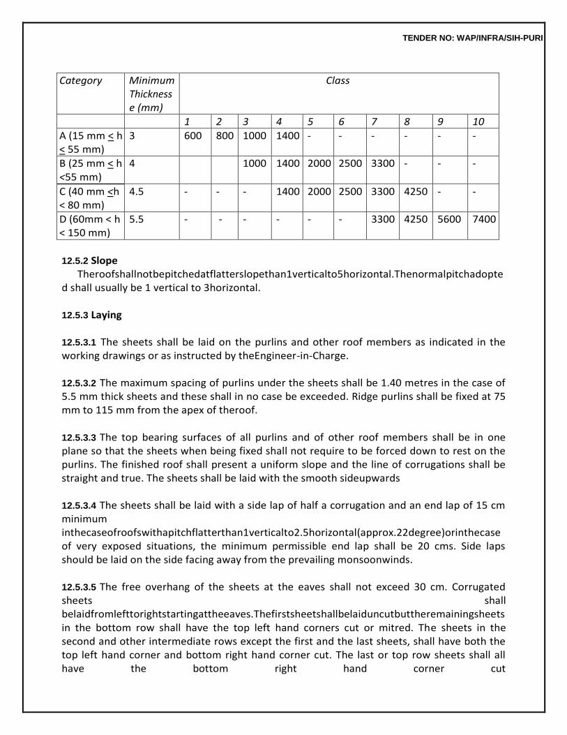
TENDER NO: WAP/INFRA/SIH-PURI
Category Minimum Thickness e (mm)
Class
1 2 3 4 5 6 7 8 9 10
A (15 mm < h < 55 mm)
3 600 800 1000 1400 - - - - - -
B (25 mm < h <55 mm)
4 1000 1400 2000 2500 3300 - - -
C (40 mm <h < 80 mm)
4.5 - - - 1400 2000 2500 3300 4250 - -
D (60mm < h < 150 mm)
5.5 - - - - - - 3300 4250 5600 7400
12.5.2 Slope
Theroofshallnotbepitchedatflatterslopethan1verticalto5horizontal.Thenormalpitchadopted shall usually be 1 vertical to 3horizontal.
12.5.3 Laying
12.5.3.1 The sheets shall be laid on the purlins and other roof members as indicated in the working drawings or as instructed by theEngineer-in-Charge.
12.5.3.2 The maximum spacing of purlins under the sheets shall be 1.40 metres in the case of 5.5 mm thick sheets and these shall in no case be exceeded. Ridge purlins shall be fixed at 75 mm to 115 mm from the apex of theroof.
12.5.3.3 The top bearing surfaces of all purlins and of other roof members shall be in one plane so that the sheets when being fixed shall not require to be forced down to rest on the purlins. The finished roof shall present a uniform slope and the line of corrugations shall be straight and true. The sheets shall be laid with the smooth sideupwards
12.5.3.4 The sheets shall be laid with a side lap of half a corrugation and an end lap of 15 cm minimum inthecaseofroofswithapitchflatterthan1verticalto2.5horizontal(approx.22degree)orinthecase of very exposed situations, the minimum permissible end lap shall be 20 cms. Side laps should be laid on the side facing away from the prevailing monsoonwinds.
12.5.3.5 The free overhang of the sheets at the eaves shall not exceed 30 cm. Corrugated sheets shall belaidfromlefttorightstartingattheeaves.Thefirstsheetshallbelaiduncutbuttheremainingsheets in the bottom row shall have the top left hand corners cut or mitred. The sheets in the second and other intermediate rows except the first and the last sheets, shall have both the top left hand corner and bottom right hand corner cut. The last or top row sheets shall all have the bottom right hand corner cut
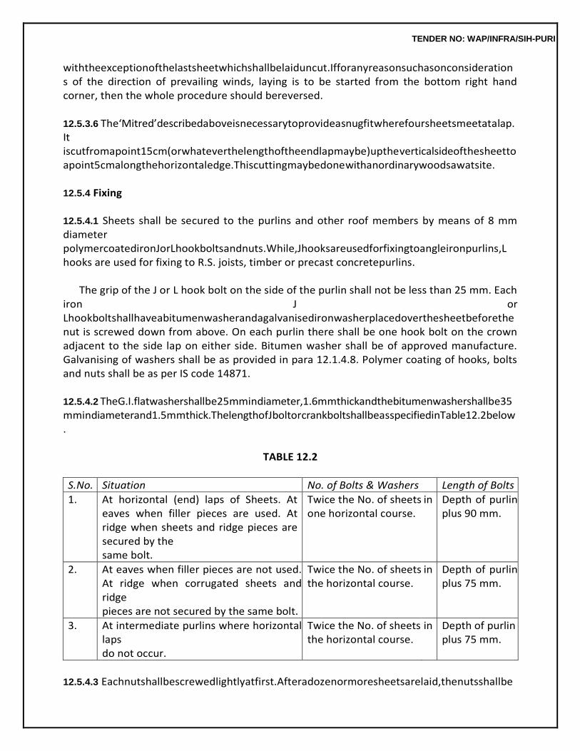
TENDER NO: WAP/INFRA/SIH-PURI
withtheexceptionofthelastsheetwhichshallbelaiduncut.Ifforanyreasonsuchasonconsiderations of the direction of prevailing winds, laying is to be started from the bottom right hand corner, then the whole procedure should bereversed.
12.5.3.6 The‘Mitred’describedaboveisnecessarytoprovideasnugfitwherefoursheetsmeetatalap.It iscutfromapoint15cm(orwhateverthelengthoftheendlapmaybe)uptheverticalsideofthesheetto apoint5cmalongthehorizontaledge.Thiscuttingmaybedonewithanordinarywoodsawatsite.
12.5.4 Fixing
12.5.4.1 Sheets shall be secured to the purlins and other roof members by means of 8 mm diameter polymercoatedironJorLhookboltsandnuts.While,Jhooksareusedforfixingtoangleironpurlins,L hooks are used for fixing to R.S. joists, timber or precast concretepurlins.
The grip of the J or L hook bolt on the side of the purlin shall not be less than 25 mm. Each
iron J or Lhookboltshallhaveabitumenwasherandagalvanisedironwasherplacedoverthesheetbeforethe nut is screwed down from above. On each purlin there shall be one hook bolt on the crown adjacent to the side lap on either side. Bitumen washer shall be of approved manufacture. Galvanising of washers shall be as provided in para 12.1.4.8. Polymer coating of hooks, bolts and nuts shall be as per IS code 14871.
12.5.4.2 TheG.I.flatwashershallbe25mmindiameter,1.6mmthickandthebitumenwashershallbe35 mmindiameterand1.5mmthick.ThelengthofJboltorcrankboltshallbeasspecifiedinTable12.2below.
TABLE 12.2
S.No. Situation No. of Bolts & Washers Length of Bolts
1. At horizontal (end) laps of Sheets. At eaves when filler pieces are used. At ridge when sheets and ridge pieces are secured by the same bolt.
Twice the No. of sheets one horizontal course.
in Depth of purlin plus 90 mm.
2. At eaves when filler pieces are not used. At ridge when corrugated sheets and ridge pieces are not secured by the same bolt.
Twice the No. of sheets the horizontal course.
in Depth of purlin plus 75 mm.
3. At intermediate purlins where horizontal laps do not occur.
Twice the No. of sheets the horizontal course.
in Depth of purlin plus 75 mm.
12.5.4.3 Eachnutshallbescrewedlightlyatfirst.Afteradozenormoresheetsarelaid,thenutsshallbe
TENDER NO: WAP/INFRA/SIH-PURI
tightened to ensure a leak proofjoint.
12.5.4.4. Holes for hook bolts etc. shall be drilled and not punched, always through the crown of the corrugation and not in valleys, in locations to suit the purlins while the sheets are on the roof in their correctposition.Thediameterofholesshallbe2mmmorethanthediameterofthefixingbolts.Nohole shall be nearer than 40 mm to any edge of a sheet or anyaccessory.
12.5.4.5 Roof ladders or planks shall always be used when laying and fixing the sheets, to avoid damage to the sheets, and to provide security to the workmen.
12.5.5 Wind Ties
Windtiesmaybeprovidedwherethesituationjustifytheirprovision.Theseshallbeof40×6mmflat iron section or of other size as specified. These shall be fixed at the eave ends of the sheets. The fixing shallbedonewiththesamehookboltswhichsecurethesheetstothepurlins.Windtiesshallbepaidfor separately unless described as included in the items of the roofwork.
12.5.6 Finish
The completed roof shall present a neat and uniform appearance and be leakproof.
12.5.7 Measurements
12.5.7.1 Length and breadth shall be measured correct to a cm and its area shall be calculated in square metres correct to two places ofdecimal.
12.5.7.2 The superficial area of roof coverings shall be measured on the flat without allowance for laps and corrugations. Portions of roof covering overlapping the ridge or hips etc. shall be included in the measurements of theroof.
12.5.7.3 Roof with curved sheets shall be measured and paid for separately. Measurements shall be taken on the flat and not girthed. The breadth of the roof shall be measured along the rest of thecurved sheets.
12.5.7.4 No deductions in measurements shall be made for opening upto 0.4 sqm and nothing extra shall be allowed for forming such opening. For any opening exceeding 0.4 sqm in area, deduction in measurementsforthefullopeningshallbemadeandinsuchcasesthelabourinvolvedinmakingthese openings shall be paid for separately. Cutting across corrugation shall be measured on the flat and not girthed.
12.5.8 Rate
Therateshallincludethecostofallthematerialsandlabourinvolvedinalltheoperationsdescribed above except otherwise stated. This includes the cost of roof sheets, polymer coated or L hook, bolts and nuts, bituminous and galvanised ironwashers.
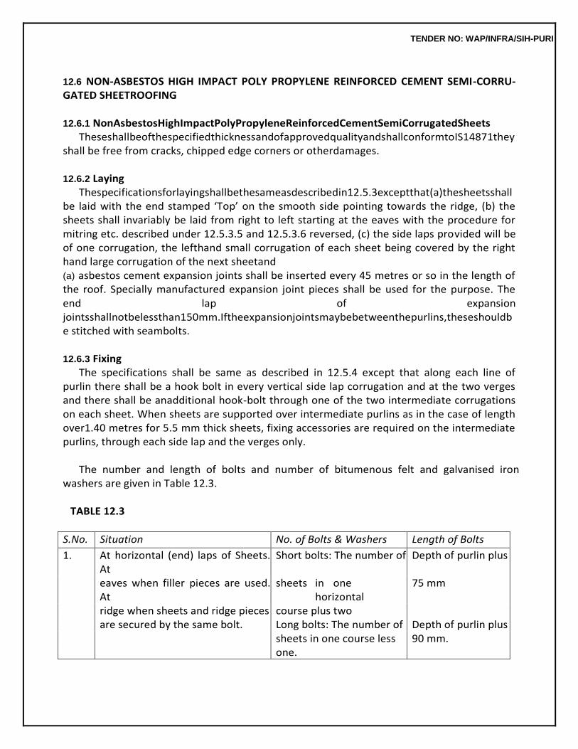
TENDER NO: WAP/INFRA/SIH-PURI
12.6 NON-ASBESTOS HIGH IMPACT POLY PROPYLENE REINFORCED CEMENT SEMI-CORRU- GATED SHEETROOFING
12.6.1 NonAsbestosHighImpactPolyPropyleneReinforcedCementSemiCorrugatedSheets
TheseshallbeofthespecifiedthicknessandofapprovedqualityandshallconformtoIS14871they shall be free from cracks, chipped edge corners or otherdamages.
12.6.2 Laying
Thespecificationsforlayingshallbethesameasdescribedin12.5.3exceptthat(a)thesheetsshall be laid with the end stamped ‘Top’ on the smooth side pointing towards the ridge, (b) the sheets shall invariably be laid from right to left starting at the eaves with the procedure for mitring etc. described under 12.5.3.5 and 12.5.3.6 reversed, (c) the side laps provided will be of one corrugation, the lefthand small corrugation of each sheet being covered by the right hand large corrugation of the next sheetand (a) asbestos cement expansion joints shall be inserted every 45 metres or so in the length of the roof. Specially manufactured expansion joint pieces shall be used for the purpose. The end lap of expansion jointsshallnotbelessthan150mm.Iftheexpansionjointsmaybebetweenthepurlins,theseshouldbe stitched with seambolts.
12.6.3 Fixing
The specifications shall be same as described in 12.5.4 except that along each line of purlin there shall be a hook bolt in every vertical side lap corrugation and at the two verges and there shall be anadditional hook-bolt through one of the two intermediate corrugations on each sheet. When sheets are supported over intermediate purlins as in the case of length over1.40 metres for 5.5 mm thick sheets, fixing accessories are required on the intermediate purlins, through each side lap and the verges only.
The number and length of bolts and number of bitumenous felt and galvanised iron
washers are given in Table 12.3.
TABLE 12.3
S.No. Situation No. of Bolts & Washers Length of Bolts
1. At horizontal (end) laps of Sheets. At
Short bolts: The number of Depth of purlin plus
eaves when filler pieces are used. At
sheets in one horizontal
75 mm
ridge when sheets and ridge pieces course plus two are secured by the same bolt. Long bolts: The number of Depth of purlin plus sheets in one course less 90 mm. one.
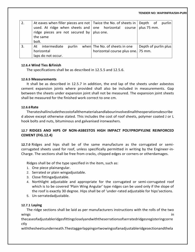
TENDER NO: WAP/INFRA/SIH-PURI
2. At eaves when filler pieces are not used. At ridge when sheets and ridge pieces are not secured by the same bolt.
Twice the No. of sheets in one horizontal course plus one.
Depth of purlin plus 75 mm.
3. At intermediate purlin when horizontal laps do not occur.
The No. of sheets in one horizontal course plus one.
Depth of purlin plus 75 mm.
12.6.4 Wind Ties &Finish
The specifications shall be as described in 12.5.5 and 12.5.6.
12.6.5 Measurements It shall be as described in 12.5.7 in addition, the end lap of the sheets under asbestos
cement expansion joints where provided shall also be included in measurements. Gap between the sheets under expansion joint shall not be measured. The expansion joint sheets shall be measured for the finished work correct to one cm.
12.6.6 Rate
Therateshallincludethecostofallthematerialsandlabourinvolvedinalltheoperationsdescribed above except otherwise stated. This includes the cost of roof sheets, polymer coated J or L hook bolts and nuts, bituminous and galvanised ironwashers.
12.7 RIDGES AND HIPS OF NON-ASBESTOS HIGH IMPACT POLYPROPYLENE REINFORCED CEMENT (FIG.12.4)
12.7.0 Ridges and hips shall be of the same manufacture as the corrugated or semi-corrugated sheets used for roof, unless specifically permitted in writing by the Engineer-in-Charge. The sections shall be free from cracks, chipped edges or corners or otherdamages.
Ridges shall be of the type specified in the item, such as: 1. One piece plainangular. 2. Serrated or plain wingadjustable. 3. Close fittingadjustable. 4. Northlight adjustable and appropriate for the corrugated or semi-corrugated roof
which is to be covered ‘Plain Wing Angular’ type ridges can be used only if the slope of the roof is exactly 30 degree. Hips shall be of ‘under-rated adjustable for hips’sections.
5. Un-serratedadjustable.
12.7.1 Laying The ridge sections shall be laid as per manufacturers instructions with the rolls of the two
wings in thecaseofadjustableridgesfittingcloselyandwiththeserrationsofserratedridgesregisteringcorrectly withthesheetsunderneath.Thestaggerlappingortwowingsofanadjustableridgesectionandthela
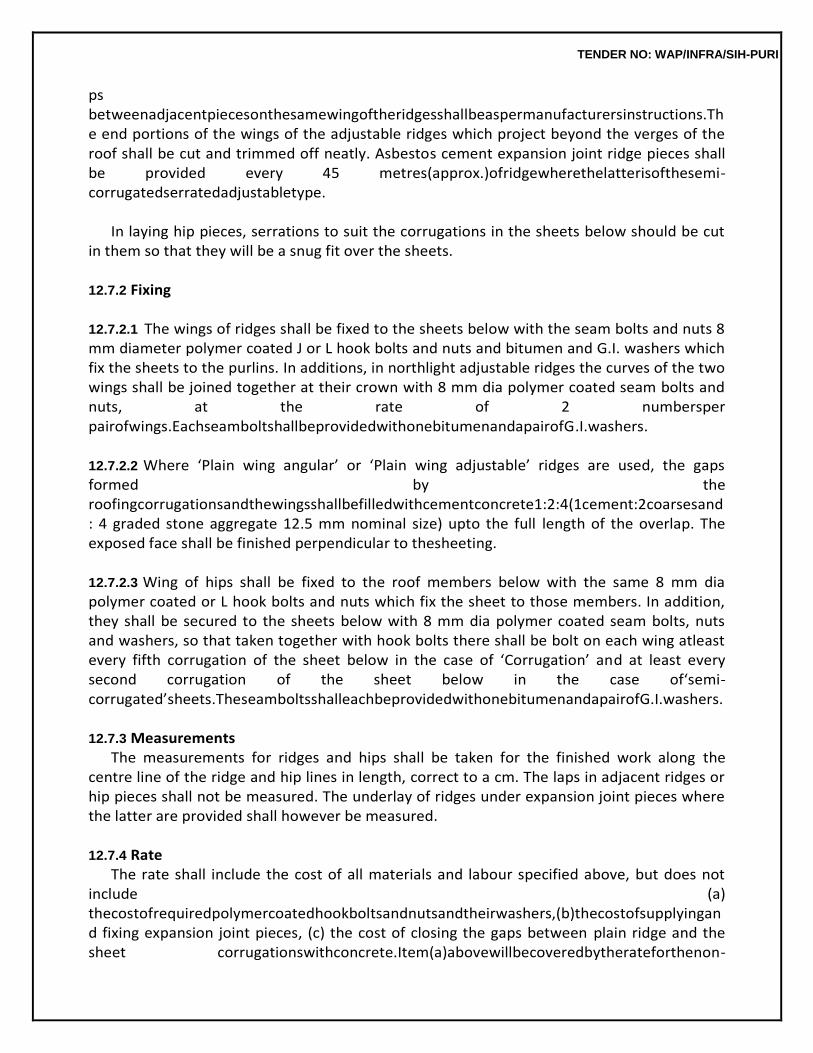
TENDER NO: WAP/INFRA/SIH-PURI
ps betweenadjacentpiecesonthesamewingoftheridgesshallbeaspermanufacturersinstructions.The end portions of the wings of the adjustable ridges which project beyond the verges of the roof shall be cut and trimmed off neatly. Asbestos cement expansion joint ridge pieces shall be provided every 45 metres(approx.)ofridgewherethelatterisofthesemi-corrugatedserratedadjustabletype.
In laying hip pieces, serrations to suit the corrugations in the sheets below should be cut
in them so that they will be a snug fit over the sheets.
12.7.2 Fixing
12.7.2.1 The wings of ridges shall be fixed to the sheets below with the seam bolts and nuts 8 mm diameter polymer coated J or L hook bolts and nuts and bitumen and G.I. washers which fix the sheets to the purlins. In additions, in northlight adjustable ridges the curves of the two wings shall be joined together at their crown with 8 mm dia polymer coated seam bolts and nuts, at the rate of 2 numbersper pairofwings.EachseamboltshallbeprovidedwithonebitumenandapairofG.I.washers.
12.7.2.2 Where ‘Plain wing angular’ or ‘Plain wing adjustable’ ridges are used, the gaps formed by the roofingcorrugationsandthewingsshallbefilledwithcementconcrete1:2:4(1cement:2coarsesand: 4 graded stone aggregate 12.5 mm nominal size) upto the full length of the overlap. The exposed face shall be finished perpendicular to thesheeting.
12.7.2.3 Wing of hips shall be fixed to the roof members below with the same 8 mm dia polymer coated or L hook bolts and nuts which fix the sheet to those members. In addition, they shall be secured to the sheets below with 8 mm dia polymer coated seam bolts, nuts and washers, so that taken together with hook bolts there shall be bolt on each wing atleast every fifth corrugation of the sheet below in the case of ‘Corrugation’ and at least every second corrugation of the sheet below in the case of‘semi- corrugated’sheets.TheseamboltsshalleachbeprovidedwithonebitumenandapairofG.I.washers.
12.7.3 Measurements
The measurements for ridges and hips shall be taken for the finished work along the centre line of the ridge and hip lines in length, correct to a cm. The laps in adjacent ridges or hip pieces shall not be measured. The underlay of ridges under expansion joint pieces where the latter are provided shall however be measured.
12.7.4 Rate
The rate shall include the cost of all materials and labour specified above, but does not include (a) thecostofrequiredpolymercoatedhookboltsandnutsandtheirwashers,(b)thecostofsupplyingand fixing expansion joint pieces, (c) the cost of closing the gaps between plain ridge and the sheet corrugationswithconcrete.Item(a)abovewillbecoveredbytherateforthenon-
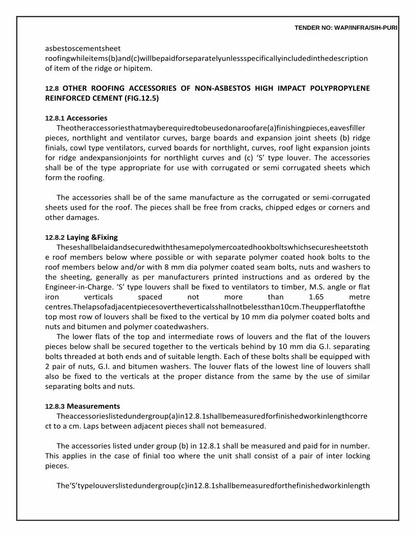
TENDER NO: WAP/INFRA/SIH-PURI
asbestoscementsheet roofingwhileitems(b)and(c)willbepaidforseparatelyunlessspecificallyincludedinthedescriptionof item of the ridge or hipitem.
12.8 OTHER ROOFING ACCESSORIES OF NON-ASBESTOS HIGH IMPACT POLYPROPYLENE REINFORCED CEMENT (FIG.12.5)
12.8.1 Accessories
Theotheraccessoriesthatmayberequiredtobeusedonaroofare(a)finishingpieces,eavesfiller pieces, northlight and ventilator curves, barge boards and expansion joint sheets (b) ridge finials, cowl type ventilators, curved boards for northlight, curves, roof light expansion joints for ridge andexpansionjoints for northlight curves and (c) ‘S’ type louver. The accessories shall be of the type appropriate for use with corrugated or semi corrugated sheets which form the roofing.
The accessories shall be of the same manufacture as the corrugated or semi-corrugated
sheets used for the roof. The pieces shall be free from cracks, chipped edges or corners and other damages.
12.8.2 Laying &Fixing
Theseshallbelaidandsecuredwiththesamepolymercoatedhookboltswhichsecuresheetstothe roof members below where possible or with separate polymer coated hook bolts to the roof members below and/or with 8 mm dia polymer coated seam bolts, nuts and washers to the sheeting, generally as per manufacturers printed instructions and as ordered by the Engineer-in-Charge. ‘S’ type louvers shall be fixed to ventilators to timber, M.S. angle or flat iron verticals spaced not more than 1.65 metre centres.Thelapsofadjacentpiecesovertheverticalsshallnotbelessthan10cm.Theupperflatofthe top most row of louvers shall be fixed to the vertical by 10 mm dia polymer coated bolts and nuts and bitumen and polymer coatedwashers.
The lower flats of the top and intermediate rows of louvers and the flat of the louvers pieces below shall be secured together to the verticals behind by 10 mm dia G.I. separating bolts threaded at both ends and of suitable length. Each of these bolts shall be equipped with 2 pair of nuts, G.I. and bitumen washers. The louver flats of the lowest line of louvers shall also be fixed to the verticals at the proper distance from the same by the use of similar separating bolts and nuts.
12.8.3 Measurements
Theaccessorieslistedundergroup(a)in12.8.1shallbemeasuredforfinishedworkinlengthcorrect to a cm. Laps between adjacent pieces shall not bemeasured.
The accessories listed under group (b) in 12.8.1 shall be measured and paid for in number.
This applies in the case of finial too where the unit shall consist of a pair of inter locking pieces.
The‘S’typelouverslistedundergroup(c)in12.8.1shallbemeasuredforthefinishedworkinlength
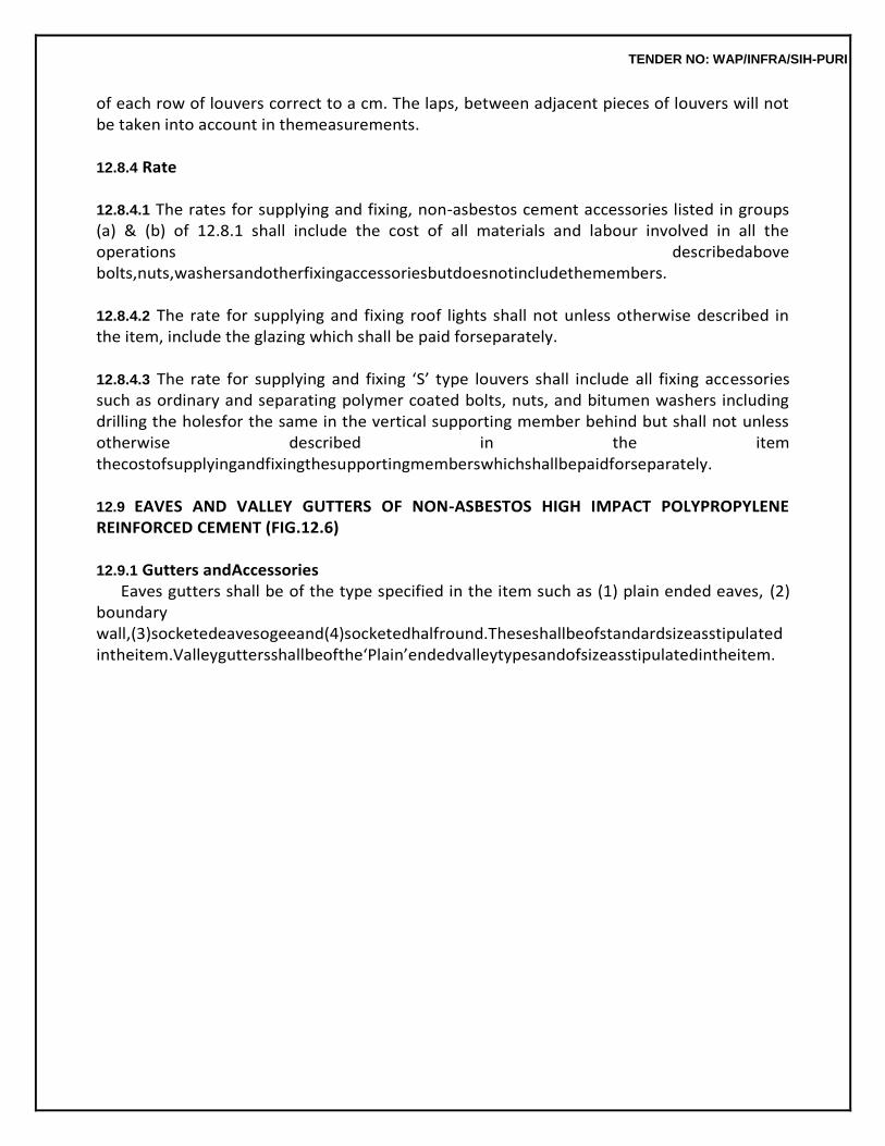
TENDER NO: WAP/INFRA/SIH-PURI
of each row of louvers correct to a cm. The laps, between adjacent pieces of louvers will not be taken into account in themeasurements.
12.8.4 Rate
12.8.4.1 The rates for supplying and fixing, non-asbestos cement accessories listed in groups (a) & (b) of 12.8.1 shall include the cost of all materials and labour involved in all the operations describedabove bolts,nuts,washersandotherfixingaccessoriesbutdoesnotincludethemembers.
12.8.4.2 The rate for supplying and fixing roof lights shall not unless otherwise described in the item, include the glazing which shall be paid forseparately.
12.8.4.3 The rate for supplying and fixing ‘S’ type louvers shall include all fixing accessories such as ordinary and separating polymer coated bolts, nuts, and bitumen washers including drilling the holesfor the same in the vertical supporting member behind but shall not unless otherwise described in the item thecostofsupplyingandfixingthesupportingmemberswhichshallbepaidforseparately.
12.9 EAVES AND VALLEY GUTTERS OF NON-ASBESTOS HIGH IMPACT POLYPROPYLENE REINFORCED CEMENT (FIG.12.6)
12.9.1 Gutters andAccessories
Eaves gutters shall be of the type specified in the item such as (1) plain ended eaves, (2) boundary wall,(3)socketedeavesogeeand(4)socketedhalfround.Theseshallbeofstandardsizeasstipulated intheitem.Valleyguttersshallbeofthe‘Plain’endedvalleytypesandofsizeasstipulatedintheitem.
TENDER NO: WAP/INFRA/SIH-PURI
These shall be of approved manufacture, approved by the Engineer-in-Charge. The gutter sections and their accessories such as drop ends, stop ends, nozzles, angles and union clips shall be free from cracks, chipped edges or corners and other damages.
12.9.2 Laying andFixing
12.9.2.1 Gutters shall be laid with a minimum slope of 1 in 120, which should be increased where possible. Gutters shall be true to line and slope and shall be laid with the requisite accessories such as dropends,stopends,nozzles,anglesandunionclipsasshownintheworkingdrawingorasorderedby theEngineer-in-Charge.
12.9.2.2 The size of outlet of drop ends and nozzles shall be of the same size as the size of the rain water pipes into which they shall be discharging thewater.
12.9.2.3 Gutters and their accessories shall be supported by M.S. flat iron bracket. Where these brackets are to be fixed to the sides of rafters, they shall be of 40 x 3 mm section bent to shape and fixed rigidly to the sides of the rafter with 3 Nos. 10 mm diameter bolts, nuts and washers. Thebrackets shalloverlaptherafternotlessthan30cmandtheconnectingboltsshallbe11.5cmcentres.
12.9.2.4 Wherethebracketsaretobefixedtothepurlinstheyshallconsistof50×3mmM.S.flatironbent to shape with one end turned at a right angle, and fixed to the purlin face with a 10 mm dia bolt, nut and washer.Theperpendicularoverhangportionof50×3mmbracketshallbestiffenedbyanother50×3mm flat, bent to right angle shape with its lower leg connected to the bracket with 2 Nos. 6 mm dia M.S. bolts,nuts and washers and its shorter leg fixed to face of purlin with one number 10 mm dia bolt, nuts and washers. The overhang of the vertical portion of the flat iron bracket from the face of the purlin shall not exceed by 22.5 cm with thisarrangement.
12.9.2.5 The requisite slope in the gutters shall be given in the line of the bracket. The brackets shallbe placed at not more than 90 cmcentres.
12.9.2.6 The gutters shall be fixed to the brackets with 2 Nos. 8 mm dia polymer coated seam boltsand nuts, each bolt and nut being equipped with a pair of bitumen and polymer coated washers. These connecting bolts shall be above the water line of thegutters.
12.9.2.7 Spigot and socket ends of gutters of ‘socketed eaves ornamental’ or ‘socketed half round’ type andtheiraccessoriesshallbeconnectedtogetherattheirlapswithonerowof8mmdiapolymercoated bolts and nuts, each bolt and nut being provided with a pair of bitumen and a pair of polymer coated washers. The gap between the socket and spigot shall be packed with approved plastic roofing compound, flanked on both sides with 6 mm dia non-asbestos rope. The connecting polymer coated boltsarethentightenedsothatthelappedjointsbecomeleakproof.Theouterfacesofthepackedno
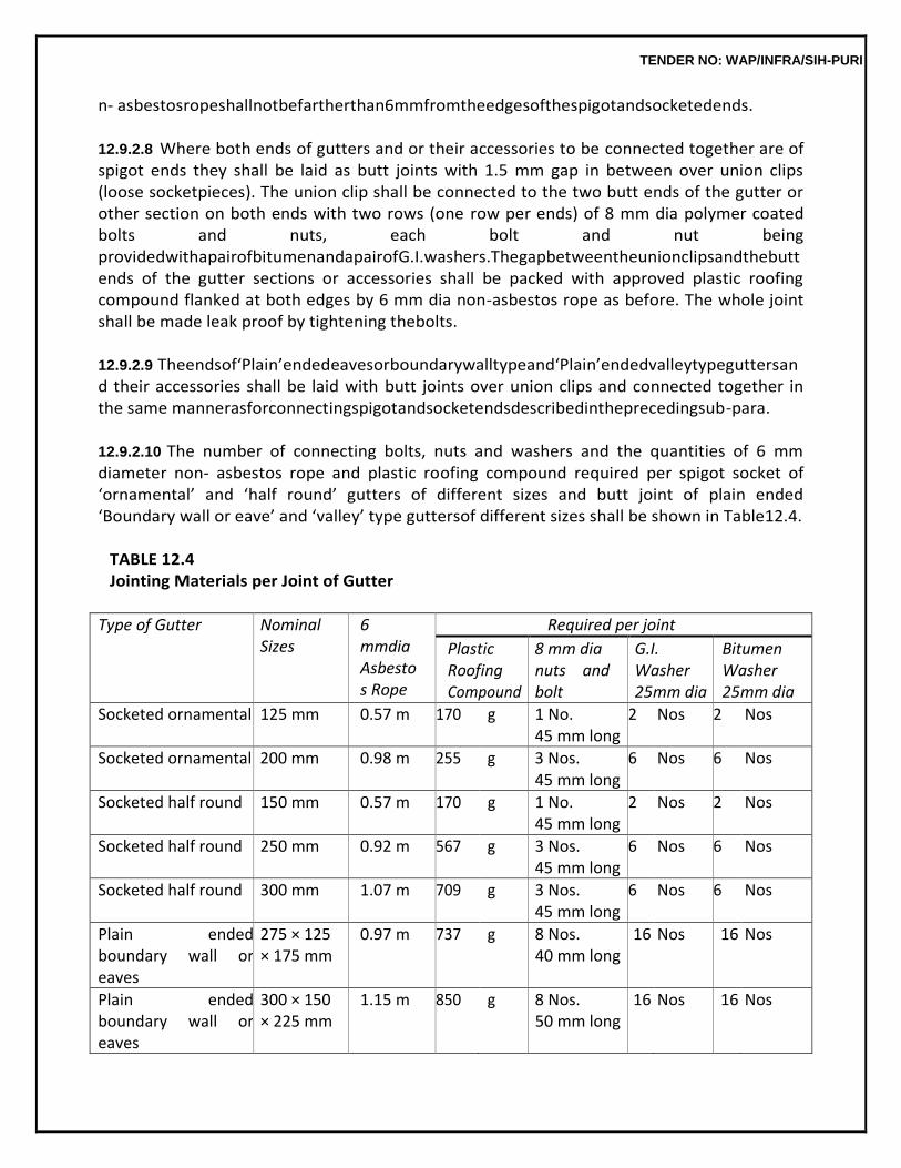
TENDER NO: WAP/INFRA/SIH-PURI
n- asbestosropeshallnotbefartherthan6mmfromtheedgesofthespigotandsocketedends.
12.9.2.8 Where both ends of gutters and or their accessories to be connected together are of spigot ends they shall be laid as butt joints with 1.5 mm gap in between over union clips (loose socketpieces). The union clip shall be connected to the two butt ends of the gutter or other section on both ends with two rows (one row per ends) of 8 mm dia polymer coated bolts and nuts, each bolt and nut being providedwithapairofbitumenandapairofG.I.washers.Thegapbetweentheunionclipsandthebutt ends of the gutter sections or accessories shall be packed with approved plastic roofing compound flanked at both edges by 6 mm dia non-asbestos rope as before. The whole joint shall be made leak proof by tightening thebolts.
12.9.2.9 Theendsof‘Plain’endedeavesorboundarywalltypeand‘Plain’endedvalleytypeguttersand their accessories shall be laid with butt joints over union clips and connected together in the same mannerasforconnectingspigotandsocketendsdescribedintheprecedingsub-para.
12.9.2.10 The number of connecting bolts, nuts and washers and the quantities of 6 mm diameter non- asbestos rope and plastic roofing compound required per spigot socket of ‘ornamental’ and ‘half round’ gutters of different sizes and butt joint of plain ended ‘Boundary wall or eave’ and ‘valley’ type guttersof different sizes shall be shown in Table12.4.
TABLE 12.4 Jointing Materials per Joint of Gutter
Type of Gutter Nominal Sizes
6 mmdia Asbestos Rope
Required per joint
Plastic Roofing Compound
8 mm dia nuts and bolt
G.I. Washer 25mm dia
Bitumen Washer 25mm dia
Socketed ornamental 125 mm 0.57 m 170 g 1 No. 45 mm long
2 Nos 2 Nos
Socketed ornamental 200 mm 0.98 m 255 g 3 Nos. 45 mm long
6 Nos 6 Nos
Socketed half round 150 mm 0.57 m 170 g 1 No. 45 mm long
2 Nos 2 Nos
Socketed half round 250 mm 0.92 m 567 g 3 Nos. 45 mm long
6 Nos 6 Nos
Socketed half round 300 mm 1.07 m 709 g 3 Nos. 45 mm long
6 Nos 6 Nos
Plain ended boundary wall or eaves
275 × 125 × 175 mm
0.97 m 737 g 8 Nos. 40 mm long
16 Nos 16 Nos
Plain ended boundary wall or eaves
300 × 150 × 225 mm
1.15 m 850 g 8 Nos. 50 mm long
16 Nos 16 Nos
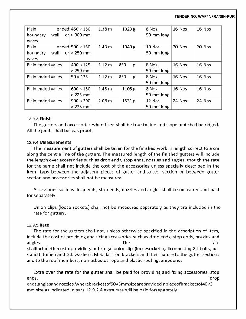
TENDER NO: WAP/INFRA/SIH-PURI
Plain ended boundary wall or eaves
450 × 150 × 300 mm
1.38 m 1020 g 8 Nos. 50 mm long
16 Nos 16 Nos
Plain ended boundary wall or eaves
500 × 150 × 250 mm
1.43 m 1049 g 10 Nos. 50 mm long
20 Nos 20 Nos
Plain ended valley 400 × 125 × 250 mm
1.12 m 850 g 8 Nos. 50 mm long
16 Nos 16 Nos
Plain ended valley 50 × 125 1.12 m 850 g 8 Nos. 50 mm long
16 Nos 16 Nos
Plain ended valley 600 × 150 × 225 mm
1.48 m 1105 g 8 Nos. 50 mm long
16 Nos 16 Nos
Plain ended valley 900 × 200 × 225 mm
2.08 m 1531 g 12 Nos. 50 mm long
24 Nos 24 Nos
12.9.3 Finish
The gutters and accessories when fixed shall be true to line and slope and shall be ridged. All the joints shall be leak proof.
12.9.4 Measurements
The measurement of gutters shall be taken for the finished work in length correct to a cm along the centre line of the gutters. The measured length of the finished gutters will include the length over accessories such as drop ends, stop ends, nozzles and angles, though the rate for the same shall not include the cost of the accessories unless specially described in the item. Laps between the adjacent pieces of gutter and gutter section or between gutter section and accessories shall not be measured.
Accessories such as drop ends, stop ends, nozzles and angles shall be measured and paid
for separately.
Union clips (loose sockets) shall not be measured separately as they are included in the rate for gutters.
12.9.5 Rate
The rate for the gutters shall not, unless otherwise specified in the description of item, include the cost of providing and fixing accessories such as drop ends, stop ends, nozzles and angles. The rate shallincludethecostofprovidingandfixingallunionclips(loosesockets),allconnectingG.I.bolts,nuts and bitumen and G.I. washers, M.S. flat iron brackets and their fixture to the gutter sections and to the roof members, non-asbestos rope and plastic roofingcompound.
Extra over the rate for the gutter shall be paid for providing and fixing accessories, stop
ends, drop ends,anglesandnozzles.Wherebracketsof50×3mmsizeareprovidedinplaceofbracketsof40×3 mm size as indicated in para 12.9.2.4 extra rate will be paid forseparately.
TENDER NO: WAP/INFRA/SIH-PURI
12.10 PAINTING OF ROOF SLAB WITH HOTBITUMEN 12.10.1 Preparing theSurface
The surface shall be painted only when it is thoroughly dry. The surface to be painted shall be cleaned with wire brushes and cotton or gunny cloth. All loose materials and scales shall be removed and the surface shall be further cleaned with a piece of cloth lightly soaked in kerosene oil.
12.10.2 Painting withBitumen
12.10.2.1 Thecontractorshallbringthebitumentositeinitsoriginalpackingandshallopenanduseitin the presence of the Engineer-in-Charge or his authorised representative. The containers shall not be removed from the site until the painting job is completed and the Engineer-in-Charge has satisfied himself regarding the quantity of bitumen actually used and has given his permission to remove the empty containers.
12.10.2.2 The surface prepared and treated shall be painted uniformly with bitumen of approved quality such as residual type petroleum bitumen of penetration 80/100, hot cut back bitumen or equivalent as per specifications of the manufacturer. The coat of bitumen shall be continued 15 cm along the vertical surfacesjoiningtheroof.Incaseofparapetwallsitshallbecontinueduptothedripcourses.
12.10.2.3 Residualtypepetroleumbitumenofpenetration80/100shallbeheatedtoatemperatureofnot less than 180 degree C and not more than 190 degree C and shall be applied on the roof surface atnot lessthan180degreeC.Similarly,hotcutbackbitumenshallbeheatedtoatemperatureofnotlessthan 165 degree C and not more than 170 degree C and shall be applied on the surface at not less than 165 degreeC.
12.10.2.4 Careshallbetakentoseethatnoblankpatchesareleft.Thequantityofbitumentobeapplied per10squaremetresofroofsurfaceshallbe17kg,unlessotherwisestipulatedinthedescriptionofthe item. It shall be carefully regulated so that the application is uniform at the stipulated rate of 17 Kg. per 10 squaremetres.
12.10.3 SpreadingSand
Immediately after painting, dry, clean sharp coarse sand at the rate of 60 cubic decimeter per 10 sqm. shall be evenly spread and levelled over the surface when the bitumen is still hot.
12.10.4 Measurements
The superficial area of the surface painted shall be measured in square metres. No deduction in measurements shall be made for unpainted areas of roof slab occupied by chimney stacks, roof lights etc. of areas, each upto 40 sq. decimetre. The measurements of length and breadth shall be taken correct to a cm.
TENDER NO: WAP/INFRA/SIH-PURI
12.10.5 Rate
The rate shall include the cost of all materials and labour involved in all the operations described above.
TENDER NO: WAP/INFRA/SIH-PURI
12.11 MUD PHUSKA TERRACING WITH BRICK TILEPAVING
12.11.1 MudPhuska For mud phuska, selected soil which should be a good quality earth suitable for making
bricks not containing excessive clay or sand, free from stones, kankar, vegetable matter and other foreign matter, shall be collected and stacked at site. The soil shall not be collected from a locality infested with white ants. Before laying on the roof, the soil shall be made damp by adding water about 12 hours earlier. It shall be turned over with phawaras so as to break clods and to pulverise the same. Quantity of water to be added to the soil shall be carefully regulated so that the soil shall have optimum moisture content at thetimeoflayingandcompactionontheroof.Thesoilshallbelaidontherooftorequisitethicknessand slope, well compacted with wooden rammers and thappies, to obtain an even surface to correct slope. Average thickness of soil after compaction shall be as specified for theitem.
Note: A practical way of determining the moisture content of soil suitable for giving good
compaction is that the soil should contain that much quantity of moisture, which when a handful of soil is moulded with hand to the shape of a ball, it shall just retain its form. If the soil on moulding cannot retain its shape of a ball, moisture content is inadequate. On the other hand, if the ball can be plastically deformed on pressing with hand, the moisture content is on the high side.
12.11.2 MudPlaster
After laying the mud phuska, the surface shall be given a coat of mud plaster 25 mm thick and the plaster shall be allowed to dry and crack.
The mud plaster shall be prepared from the same soil as for mud phuska. The dry soil shall
be reduced to fine powder and mixed with water in a pit, adding fibrous reinforcing materials such as choppedstraw(Bhusa)inproportionof35kgpercumofsoil.Themixtureshallbeallowedtomaturefor a period of not less than 7 days. During this period it shall be worked over with feet and spades (Phawaras) at intervals so as to get pugged into a homogeneous mass free from lumps and clods. The mud mortar shall be puddled again very thoroughly just beforeuse.
The consistency of mud mortar shall be checked by taking it on a trowel and observing
how it slides off the face of trowel. The mortar shall readily slide off the trowel and should not be so wet as to part on tolargedropsbeforefalling.AlternativelyslumptestmaybeperformedinaccordancewithIS1199.The slump should be about 70mm.
12.11.3 GobriLeaping
After the mud plaster has dried, the surface should be given a coat of gobri leaping so as to completely fill any crack that may have formed in the mud plaster. Mortar for gobri leaping shall be prepared by mixing equal quantities of fresh gobar and finely sieved clay and adding sufficient water to form a thin paste. The quantity of gobar used in gobri leaping shall not be less than 0.03 cum per 100 sqm of plaster area. Five percent of cut back bitumen by
TENDER NO: WAP/INFRA/SIH-PURI
mass of dry clay may be added to improve upon the water proofing qualities.
12.11.4 Laying of BricksTile After the gobri leaping has dried, brick tiles shall be laid using the minimum amount of
plain mud mortar (without bhusa) as bedding so as to obtain correct slope and even surface of tile floors. Care shall be exercised to see that mud mortar does not rise into the vertical joints of the tiles more than 12 mm.Thebricktilesshallbeeitherflattilebricksofclassdesignation100ormachinemouldedtilebricks ofclassdesignation125conformingtoIS2690(PrtI)asperthenomenclatureoftheitem.Thetilesshall belaidsuchthatthethicknessofjointsshallnotbelessthan6mmandmorethan12mminwidth.After thetilesarewellsetandbeddingmortarhasdried,jointsofthetilesshallbegroutedwithcementmortar ofmix1:3(1cement:3finesand)suchthatallthejointsoftilesarecompletelyfilledwithmortarandthejoints should be finished neat. Cement used for the mortar shall be mixed with 2% of integral water proofing compound which should conform to IS 2645.
12.11.5 Curing
Assoonascementgroutingobtainsinitialset,thesurfaceofthebricktilefloorshallbecoveredwith wet gunny bags, hessian cloth or wet sand to prevent quick drying. After 8-12 hours, the brick tile floor shallbecuredbyfrequentsprinklingofwateronthesurfaceforaperiodof7days.Aftercuringhasbeen done, the surface shall be sweptclean.
The tile surface as completed shall be even and true to slopes of 1 in 48 or as specified
and should be leak proof.
Note: When surplus earth of a suitable quality exists at the site of work, the contractor shall be allowed to use the same free of cost for laying the mud terracing, mud plaster and gobri leaping on the top. The Engineer-in-Charge shall be the final authority to decide whether the earth obtained from excavation is surplus to the requirements at site and is suitable for mud phuska work.
12.11.6 Measurements
Length and breadth shall be measured correct to a cm. The measurements shall be taken for the finished work, (mud phuska terracing of stipulated thickness with mud plaster, gobri leaping and tile paving and grouting) over the tiled surface, in superficial area.
No deductions in measurements shall be made for either openings or recesses for
chimney stacks, roof lights or khurras, of area upto 0.40 sqm. No extra shall be paid either for any extra materials or labour involved in forming such openings, recesses etc. For areas exceeding 0.40 sqm deductions will be made in the measurements for the full opening but extra shall be paid for any extra labour, materials etc. in forming such openings.
For plus or minus deviation from the average thickness stipulated for the mud phuska in
the item,
TENDER NO: WAP/INFRA/SIH-PURI
paymentswillbeadjustedintherateadmissibletothecontractorfortherelevantscheduleitemprovided that such deviations were authorised by the Engineer-in-Charge inwriting.
12.11.7 Rate
The rate shall include the cost of all materials and labour involved in all the operations described above.
12.12 PAVING OVER MUMTY ROOFS WITH BRICKSTILE
12.12.0 The roofs shall be paved with bricks tile laid flat and grouted with cementmortar.
12.12.1 BricksTile
These shall conform to the specifications detailed in subhead 6.0 of brick work
12.12.2 CementMortar The cement mortar shall be of 1:3 mix (1 cement : 3 fine sand) unless otherwise specified
in the description of the item and shall conform to the specifications described in subhead 3.0 of Mortars.
12.12.3 Preparing theSurfaces
The surface shall be hacked, roughened and cleaned of all dust and other foreign matter. It shall then be wetted before applying the mortar.
12.12.4 Paving andGrouting
Cement mortar shall be spread in 12 mm layer over the surface evenly to required slope. Brick tiles whichhadbeensoakedasinbrickworkinwaterforatleastanhourbeforehandshallthenbelaidopenjointed and flat on the mortar and lightly pressed, and set to plane surface true to slopes etc. using a trowelandwoodenstraightedge.Thebricktilesshallbelaidwiththeirjointsnotmorethan10mmwide. They shall be laid with their longitudinal lines of joints truly parallel and horizontal and at right angles to the sloping edges of theroof.
Transversejointsinalternaterowsshouldcomedirectlyinlinewithoneanother.Transversejoint
sin adjacent courses shall not have distance by less than 5 cm. As soon as the paving is done, the open joints shall be grouted with cement mortar 1:3 (1cement : 3 fine sand). Cement used for groutingmortar shall be mixed with 2% (by unit of cement) water proofing compound conforming to IS 2645. Care shall betakentoseethatnojointsareleftunfilledorinadequatelyfilled.Thejointsshallbefinishedflushwith the bricksurface.
12.12.5 Curing
The tile paving shall be cured for at least 7 days during which period it shall be suitably protected from damage.
TENDER NO: WAP/INFRA/SIH-PURI
12.12.6 Measurements Lengthandbreadthshallbemeasuredcorrecttoacm.Measurementsshallbetakenforthefinish
ed work in superficial areacovered.
No deduction in measurement shall be made for either openings or recesses for chimney stacks, roof lights, or for khurras, for areas upto 0.40 sqm nor extra shall be paid for forming such openings.
Forsimilarareasexceeding0.40sqmdeductionshallbemadeinmeasurementsforallopeningsb
ut nothing extra shall be paid for forming suchopenings.
12.12.7 Rate The rate shall include the cost of all materials and labour involved in all the operations
described above.
12.13 CEMENT CONCRETE GOLA (FIG.12.7)
12.13.1 CementConcrete The specifications for concrete shall be the same as described in subhead 4.0 of concrete work.
12.13.2 Gola
A chase of 75 mm wide and 75 mm deep shall be cut in the parapet wall just above the junction of mud phuska or lime concrete with parapet wall and it shall be filled with cement concrete 1:2:4 (1 cement : 2 coarse sand : 4 stone aggregate 10 mm and down gauge) the external face finish with a slope of 1 : 0.75 and the exposed surface of the gola shall be plastered with cement mortar 1 : 3 (1 cement : 3 finesand).
Expansionjointatevery3.5to4.5metresshallbeprovidedandfilledwithbitumenfiller.Thebitum
en filler shall be prepared by mixing bitumen, cement and coarse sand in the ratio of 80 : 1 : 0.25 (80 kg of hot bitumen : 1 kg of cement and 0.25 cum of coarsesand).
12.13.3 Curing
The finished surface shall be cured for at least 7 days.
12.13.4 Measurements Thelengthofthefinishedgolashallbemeasuredatitsjunctionwiththewallfacecorrecttoacm.No
deduction shall be made in measurements for gaps for wateroutlets.
12.13.5 Rate The rate shall include the cost of all materials and labour involved in all the operations
described above including the cost of bitumen filler in expansion joint. The rate includes for all turnings and roundings at all the corners and risers.
12.14 KHURRAS (FIG.12.7)
TENDER NO: WAP/INFRA/SIH-PURI
12.14.0 The khurras shall be constructed before the brick masonry work in parapet wall is taken up and it shall be of size 45 cm x 45 cm unless otherwise specified in the description of the item and shall be made of cement concrete 1:2:4 mix (1 cement : 2 coarse sand : 4 graded stone aggregate 20 mm nominal size) or other mix as stipulated in the description of theitem.
12.14.1 Laying
12.14.1.1 APVCsheetofsize1mx1mx400micron(alternatively,aluminiumfoilof32SWG)shallbe laid under the khurra and then cement concrete shall be laid over it to average thickness of 50 mm with itstopsurfacelowerthanthelevelofadjoiningroofsurfacebynotlessthan50mm.
12.14.1.2 Theconcreteshallbelaidtoasizegreaterthanthestipulatedsizeofthekhurrainsuchaway that the adjoining terracing shall overlap the concrete on its three edges by not less than 7.5 cm. The concretewillslopeuniformlyfromtheedgestotheoutlet,theslopebeingasmuchaspossibleandinno caselessthan20mmcementconcreteattheoutlet.Theconcreteshallbecontinuedatthesameslope throughthewidthofthewallintotheoutletopeningtoensureawatertightjoint.
12.14.1.3 The khurras and the sides of the outlet shall then be rendered with 12 mm coat of cement plaster 1:3 mix (1 cement : 3 coarse sand) or other mix as stipulated in the description of the item. This shall be done when the concrete is still green and shall be finished. The sides of the khurras and sides of the outlet opening shall be well rounded. The size of the finished outlet opening shall be 10 cm wide and by 20 cm high or as directed by theEngineer-in-Charge.
12.14.1.4 In cases where rain water is to be disposed off through rain water pipes, iron grating shall be provided at the outlet as a safeguard against choking, if so directed by the Engineer-in-Charge. Iron gratings, shall be of overall size 20 × 25 cm. with an outer frame of 15 × 3 mm M.S. flat to which 4Nos M.S. bars of 10 mm dia shall be welded in a vertical direction keeping equal clear spacing of 2.5 cm. or as directed by the Engineer in Charge.
12.14.2 Measurements
Khurras shall be counted in numbers.
12.14.3 Rate Therateisforeachcompletedkhurraofthespecifiedsizeandisinclusiveofthecostofallmaterials
and labour in forming the khurras and outlet opening as described above, except for iron gratingswhich shall be paid forseparately.
12.15 RED OR WHITE SAND STONEROOFING
12.15.1 Sand StoneSlabs
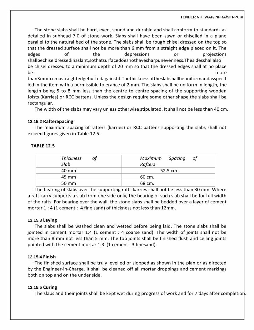
TENDER NO: WAP/INFRA/SIH-PURI
The stone slabs shall be hard, even, sound and durable and shall conform to standards as detailed in subhead 7.0 of stone work. Slabs shall have been sawn or chiselled in a plane parallel to the natural bed of the stone. The slabs shall be rough chisel dressed on the top so that the dressed surface shall not be more than 6 mm from a straight edge placed on it. The edges of the depressions or projections shallbechiseldressedinaslant,sothatsurfacedoesnothavesharpunevenness.Thesidesshallalso be chisel dressed to a minimum depth of 20 mm so that the dressed edges shall at no place be more than3mmfromastraightedgebuttedagainstit.Thethicknessoftheslabshallbeuniformandasspecified in the item with a permissible tolerance of 2 mm. The slabs shall be uniform in length, the length being 5 to 8 mm less than the centre to centre spacing of the supporting wooden Joists (Karries) or RCC battens. Unless the design require some other shape the slabs shall be rectangular.
The width of the slabs may vary unless otherwise stipulated. It shall not be less than 40 cm.
12.15.2 RafterSpacing The maximum spacing of rafters (karries) or RCC battens supporting the slabs shall not
exceed figures given in Table 12.5.
TABLE 12.5
Thickness of Slab
Maximum Spacing of Rafters
40 mm 52.5 cm.
45 mm 60 cm.
50 mm 68 cm.
The bearing of slabs over the supporting rafts karries shall not be less than 30 mm. Where a raft karry supports a slab from one side only, the bearing of such slab shall be for full width of the rafts. For bearing over the wall, the stone slabs shall be bedded over a layer of cement mortar 1 : 4 (1 cement : 4 fine sand) of thickness not less than 12mm.
12.15.3 Laying
The slabs shall be washed clean and wetted before being laid. The stone slabs shall be jointed in cement mortar 1:4 (1 cement : 4 coarse sand). The width of joints shall not be more than 8 mm not less than 5 mm. The top joints shall be finished flush and ceiling joints pointed with the cement mortar 1:3 (1 cement : 3 finesand).
12.15.4 Finish
The finished surface shall be truly levelled or slopped as shown in the plan or as directed by the Engineer-in-Charge. It shall be cleaned off all mortar droppings and cement markings both on top and on the under side.
12.15.5 Curing
The slabs and their joints shall be kept wet during progress of work and for 7 days after completion.
TENDER NO: WAP/INFRA/SIH-PURI
12.15.6 Measurements Length and width of finished stone slab work including bearing shall be measured correct to a cm.
The area shall be calculated in sqm correct up to two places of decimal.
No deduction in area shall be made for openings in roof slab for chimney, stacks, roof lights etc. of area upto 40 square decimetre nor any extra shall be paid for extra labour, materials etc. involved in cutting and wastage, in forming such openings. For openings exceeding 40 sq. decimeter in area, deduction shall be made in measurements for the full opening but extra shall be paid for extra labour, material etc. required in forming such openings.
12.15.7 Rate
The rate shall include the cost of all materials and labour involved in all the operations described above.
12.16 WOODENCEILING
12.16.1 Boards
12.16.1.1 Boardsshallbeoftheclassoftimberandoffinishedthicknessasspecifiedinthedescriptionof theitemandshallbeinaccordancewiththegeneralspecificationsforwoodwork.Onlyselectedboardsofuniform width shall be used. Unless otherwise specified in the description of the item or shown in the drawings, the width of boards selected for use shall not be less than 100 mm nor more than 150 mm.
12.16.1.2 Thespecificwidthofboardsonceselectedwithinthesetwolimitsshallbemaintainedthrough- out and shall not be varied except in the first and last lines of boards adjustment to the two walls,where remaining odd width shall be adjacent equally on both sides. The maximum length of the board in the finishedworkshallbe180cm.Theminimumlengthofboardinthefinishedworkshallbesuchthatitwill span at least two spacings of the supporting frame work except where shorter lengths are unavoidable, depending on the arrangements of the lines of heading joints which shall be carried out to the pattern ordered by theEngineer-in-Charge.
The boards shall be plained true on the exposed side.
12.16.1.3 Unless stipulated otherwise in the description of the item, the longitudinal joints of the boards shall be tongued and grooved, while the heading joints shall be of the square butt type and shall occur under the centre line of the supporting joint. Heading joints in adjacent boards shall not be placed over thesamejoists,thoseinalternateboardsbeingarrangedinthesameline,exceptwherethejointsareto be concealed byheadings.
12.16.2 Frame
Timber frame of the class of timber and section specified in the description of the item or asordered by the Engineer-in-Charge shall be provided. The width of the frame scantling shall
TENDER NO: WAP/INFRA/SIH-PURI
not be less than 50 mm. The arrangements and spacing of the frame scantling shall be as per design furnished. The frame shall be given two coats of approved preservative paint before the boarding is screwed. The frameand paintsthereofshallbepaidforseparatelyunlessspecificallyincludedinthedescriptionoftheitem.M.S. anglesorothersectionsshallbeusedforsuspendingtheframeandpaidforseparately.
The bottom surface of the frame shall be checked and corrected to true plans and slopes.
12.16.3 Mild SteelScrews
ScrewsshallbegotapprovedfromtheEngineer-in-Chargebeforefixing.Theyshallbeoftheslotted counter sunk head type of length not less than the thickness of the board plus 20 mm. The designation numbershallnotbelessthan9forscrewsoflength40to50mmandshallnotbelessthan6forscrews of length 25 to 35mm.
12.16.4 Fixing
The outer lines of boards shall be accurately fixed, parallel and close to the wall. Each subsequent plank shall be carefully jointed up. The boards shall be fixed to the frame scantling above with two screws at each of frame and one at every intermediate joist. The screws shall be counter sunk and the screw holes filled with putty or sloping out wax.
The unexposed faces of planks shall be painted with wood preservative before fixing.
12.16.5 Finishing
The exposed side of the boards shall be truely level and plane. The joints shall be truely parallel and/or perpendicular to the walls.
Beadingsshallthenbefixedtotheceiling,tothesizeandpatternrequired.Theseshallbemeasure
d andpaidforseparatelyunlessspecificallyincludedinthedescriptionoftheceilingitem.
12.16.6 Measurements Length and breadth shall be measured correct to a cm. Areas shall be worked out to
nearest 0.01 sqm. The superficial area of the finished work ceiling shall be measured in square metres.
No deduction in measurements shall be made for openings of areas upto 40 square
decimetre. Nothingextrashallbepayableeitherforanyextramaterialorlabourinvolvedinformingsuchopenings. Foropeningsexceeding0.40sqminarea,deductionsinmeasurementsforthefullopeningwillbemade and in such case any labour involved in making these openings shall be paid for separately in running metres.
Woodenceilingofboardingsfixedtocurvesurfacesinnarrowwidthsshallbemeasuredandpaidf
or separately and shall include making the joints to propersplay.
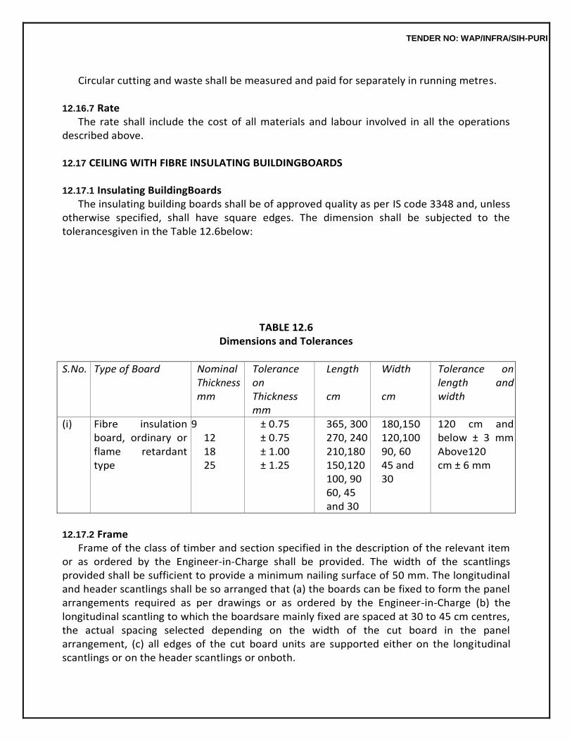
TENDER NO: WAP/INFRA/SIH-PURI
Circular cutting and waste shall be measured and paid for separately in running metres.
12.16.7 Rate
The rate shall include the cost of all materials and labour involved in all the operations described above.
12.17 CEILING WITH FIBRE INSULATING BUILDINGBOARDS
12.17.1 Insulating BuildingBoards
The insulating building boards shall be of approved quality as per IS code 3348 and, unless otherwise specified, shall have square edges. The dimension shall be subjected to the tolerancesgiven in the Table 12.6below:
TABLE 12.6 Dimensions and Tolerances
S.No. Type of Board Nominal Thickness mm
Tolerance on Thickness mm
Length
cm
Width
cm
Tolerance on length and width
(i) Fibre insulation board, ordinary or flame retardant type
9 12 18 25
± 0.75 ± 0.75 ± 1.00 ± 1.25
365, 300 270, 240 210,180 150,120 100, 90 60, 45 and 30
180,150 120,100 90, 60 45 and 30
120 cm and below ± 3 mm Above120 cm ± 6 mm
12.17.2 Frame
Frame of the class of timber and section specified in the description of the relevant item or as ordered by the Engineer-in-Charge shall be provided. The width of the scantlings provided shall be sufficient to provide a minimum nailing surface of 50 mm. The longitudinal and header scantlings shall be so arranged that (a) the boards can be fixed to form the panel arrangements required as per drawings or as ordered by the Engineer-in-Charge (b) the longitudinal scantling to which the boardsare mainly fixed are spaced at 30 to 45 cm centres, the actual spacing selected depending on the width of the cut board in the panel arrangement, (c) all edges of the cut board units are supported either on the longitudinal scantlings or on the header scantlings or onboth.
TENDER NO: WAP/INFRA/SIH-PURI
The frame shall be given two coats of approved preservative paint (to be paid for separately) before the board is nailed on. M.S. angles or other sections shall be used for suspending the frame and will be paid for separately.
Wherethejointsintheboardaretobecoveredwithbeadingstheframesshouldallow3to6mmfor
space betweenboards.
The frame and painting thereof shall be paid for separately unless specifically included in the description of the ceiling item.
The bottom surface of the frame shall be checked and corrected to true planes and slopes.
12.17.3 Nails ThesheetsshallbefixedtotheframescantlingwithG.I.headlessnails2.24mmdiawhenthejoints
are to be left exposed. Where the joints will be covered with beadings, the sheets are to be fixed to the framesscantlingswithG.I.feltheaded(clout)nails2.5mmdia.Thelengthofthenailsshallgenerallybe equaltothicknessofsheetplus25mmsothattheirgripontheframingmemberswillnotbelessthan25 mm.
12.17.4 Fixing
Theboardsshallbelaidwithlengthsparalleltoalljointscenteredovertheframingmembers.Where joints are to be covered, the boards may be spaced 3 to 6 mm apart as described in the respective manufacturers’ specifications. Where joints are to be left exposed the sheets shall be butt laid with their edges abutting in moderate contact, but without having to force them into place. The boards shall be supported and held tight to the frame with timber pieces the later being moved outwards as the nailing proceeds.Theboardsarefirstnailedtotheintermediateframingmemberproceedingfromthecentreof the board outwards, the edges being nailedlast.
Where the joints are to be left exposed, the outer rows of nails are placed at 10 cm centres and about12mmfromtheedgeofthesheet.Intherowsinthemiddleofthesheets,thenailsareplaced20 cm apart. The nails should be counter sunk in the under side of board with a suitable punch. Care shall betakenindrivingthenailssothatthesheetsarenotmarkedbyhammerblows.
Where the joints are to be covered with beadings, felt headed (clout) nails shall be used instead of nails without head. The spacing of the nails in the interior rows in boards shall be the same as in the precedingpara.Intheouterrowsatedgestobecoveredbybeadings,thenailswillbespacedat20cm centres in each row with the nails staggered. The beadings will then be fixed over the sheets with screws at 20 cm centres in each row with the screws in the two rows staggered and passing through beading, sheet and framing so that ultimately the spacing of the fixing (nails and screws takentogether) ineachrowwillbeat10cmcentressofarasthesheetsandframesareconcerned.
12.17.5 Finishing
The exposed side of the board shall be truely level and plane without any local bulges or
TENDER NO: WAP/INFRA/SIH-PURI
sags. The joints shall be truely parallel and/or perpendicular to the walls. The width of joints shall be uniform. Care shall be taken to see that the uniformity of colour of the sheets is not spoilt during the fixing operations.
Where the joints are required to be covered, beadings of size, pattern and material as approved by Engineer-in-charge be fixed with screws. These shall, however, be measured and paid for separately, unless specifically included in the description of the ceiling item.
The ceiling shall be treated with distemper or painting if so required but such surface treatment will be paid for separately, unless specifically included in the description of the ceiling item.
12.17.6 Measurements andRate
These shall be the same as described in 12.16.6 and 12.16.7.
12.18 PARTICLE BOARD /MULTIPURPOSE CEMENT BOARDCEILING
12.18.1 Boards
12.18.1.1 Particle Board : Particle board flat pressed 3 layers medium density shall be graded particle boardgrade-1conformingtoIS3087ofspecifiedthickness.Thespecificationsforparticleboardshallbe same as in sub head 9.0 of wood work and PVCwork.
TENDER NO: WAP/INFRA/SIH-PURI
12.18.1.2 Multipurpose Cement Board : (High Pressure Steam cured). This shall be conforming to IS 14862 and of thickness specified in theitem.
12.18.2 Frame
The specifications as described in 12.17.2 shall apply except that the maximum spacing of the longitudinal scantlings shall be 40 cm centres. The specifications for cutting and chamfering etc. will be same as in 12.17.2.
12.18.3 Nails
The specifications shall be the same as in 12.17.3.
12.18.4 Fixing The specifications as in 12.17.4 shall apply.
12.18.5 Finishing
The specifications as in 12.17.5 shall apply except that normally no surface treatment like painting, varnishing, etc. is necessary.
12.18.6 Measurements andRate
These shall be the same as under 12.17.6.
12.19 PLAIN/SEMI PERFORATED PARTICLE BOARD TILESCEILING
12.19.1 Frame The frame work shall consist of anodized aluminium T sections for main runners /cross
runners of size specified in the item with anodic coating of 15 micron and perimeter wall angle of anodized aluminium section of size specified by the Engineer-in-charge with anodic coating of 15 micron fixed to the wall with M.S. screws 50 mm long and PVC raw plugs. The frame work shall be executed in a manner so as to form a grid of 600 mm x 600 mm as specified in the item. The frame work shall be suspended from ceiling by level adjusting hangers made of 6 mm dia. M.S. rods fixed to slab by means ofMSceilingcleats.Theceilingcleatsshallbefixedtotheslabbymeansofmechanicaldashfasteners 6 mm dia and 50 mm long. MS hangers and ceiling cleats shall be painted with a coat of yellow zinc chromate primer and two coats of synthetic enamelpaint.
12.19.2 CeilingTiles
Ceiling tiles shall be of 12 mm plain/semi perforated or with design BWP type phenol formaldehyde syntheticresinbondedparticleboardconformingtoIS3087ofrequiredsize.Tilesshallbefinishedwith acoatofaluminiumprimeronbothsideandedgesandtwocoatsofsyntheticenamelpaintofapproved quality and shade on exposed faces of thetiles.
12.19.3 Fixing of CeilingTiles
The ceiling tiles shall be placed over the aluminium frame and fixed to the frame with help
TENDER NO: WAP/INFRA/SIH-PURI
of 25mm long CP brass screws with minimum 2 screws on each side of the grid. The CP brass screws shall be counter sunk star headscrews.
12.19.4 Measurements
Length&breadthofthefinishedceilingshallbemeasuredcorrecttoacentimetre.Theareashallbe calculated in square metre correct to two decimal places. No deduction shall be made for making openings for electrical, air conditioning, fire fighting fixtures nor shall extra payment be made either for extra materials or labour involved in making suchopenings.
12.19.5 Rate
The rate shall include the cost of all the materials and labour involved in all the operation described above including scaffolding etc. Aluminium frame work mentioned in para 12.19.1 will be paid for separately unless otherwise stipulated in the description of the items.
12.20 TRANSLUSCENT WHITE ACRYLIC PLASTIC (PMMA) SHEETCEILING
12.20.1 Frame
It shall be as para 12.19.1
12.20.2 CeilingTiles These shall be made of tanslucent white acrylic plastic sheet conforming to IS 14753 of
thickness specified in the item.
12.20.3 , 12.20.4, 12.20.5 Fixing, Measurements &Rate Same as per paras 12.19.3, 12.19.4, 12.19.5 respectively.
12.21 PLASTER OF PARIS (GYPSUM ANHYDROUS) CEILING OVER WOODENSTRIPS
12.21.1 Frame
The frame work shall be of the specified wood. In case of sloping roofs, wooden battens of suitable section (depending upon the span and load to be carried) shall be firmly fixed as main supports, to the undersideofthetiebeamsofthetrussesatrequiredspacingbymeansofboltsandnutsofpropersize. Incaseofflatroofs,thebattensshallbesecurelyfixedtothewallsandpillarsbyholdingdownboltsand shall be fastened to the slabs above with iron straps of suitable sections and encroached therein.Cross battens of 50 x 40 mm sections at 40 cm centres or so, shall then be fixed at right angles to the main battens. The frame work shall be treated with approved wooden preservative before fixing. The underside of the frame work shall be true to planes andslopes.
The frame work for ceiling shall be paid for separately unless specifically included in the
description of the ceiling item.
12.21.2 WoodenStrips Wooden strips of size 25 x 6 mm of first class kailwood, (unless otherwise stipulates
TENDER NO: WAP/INFRA/SIH-PURI
specifically in thedescriptionoftheitem)shallbefixedtothecrossbattens,intheparallelrowswithgapsof10mmin between adjacent rows, by means of felt headed (clout) nails. The strips shall be fixed butt jointed and not overlapped. The joints shall be staggered. The minimum length of strips to be used shall be 1.5 m depending upon the length of stripsrequired. 12.21.3 Rabbit WireMesh
Rabbit Wire mesh shall then be fixed to the underside of wooden strips and their junctions with the battens with nails at pitch of 15 to 20 cm as ordered by the Engineer-in-Charge. The rabbit wire mesh shall be straight, tight and perfectly true to planes and slopes and without any sagging and shall be slightly below the underside of the laths to allow the plaster to encase the metal round.
12.21.4 Plaster ofParis
The plaster of Paris shall be of the calcium-sulphate semi-hydrate variety.
Its fineness shall be such that when sieved through a sieve of IS sieve designation 3.35 mm for 5 minutes the residue left on it after drying shall be not more than 1% by weight. It shall not be too quick setting. Initial setting time shall not be less than 13 minutes. The average compressive strength of material determined by testing 5 cm cubes after removal from moulds, after 24 hours and drying in an oven at 40 degree C till weight of the cubes is constant, shall not be less than 84 kg per square metre.
12.21.5 Applications
The material will be mixed with water to a workable consistency. Plaster of Paris shall be applied to the underside of the laths over the rabbit wire mesh in suitable sized panels and finished to a smooth surfacebysteeltrowels.Theplastershallbeappliedinsuchamannerthatitfullyfillsthegapsbetween thelathsandthethicknessoverthelathsisasspecifiedinthedescriptionoftheitem.Thejointsshallbe finished flush to make the ceiling in one piece. The finished surface shall be smooth and true to plane, slopes or curves asrequired.
12.21.6 Measurements
12.21.6.1 Lengthandbreadthofsuperficialareaofthefinishedworkshallbemeasuredcorrecttoacm. Area shall be calculated in square metre correct to two places of decimal. No deduction will be made to openings of areas upto 40 square decimetre nor shall extra payment be made either for any extra material or labour involved in forming suchopenings.
12.21.6.2 For openings exceeding 40 square decimetre in area, deduction in measurements shall be madebutextrapaymentwillbemadeforanyextramaterialorlabourinvolvedinmakingsuchopenings.
12.21.6.3 Curved surfaces shall be measured and paid for separately from flat surfaces. The work shall
TENDER NO: WAP/INFRA/SIH-PURI
bedeemedtocompriseofflatsurfacesonlyunlessspecificallystatedotherwiseinthedescriptionofthe item.
12.21.6.4 Any sunk or raised mouldings in the plaster shall be measured and paid for separately, deductions being made from plastering on ceiling only if the width exceeds 15 cm. Ceiling at a height greaterthan5metresshallbesodescribedandmeasuredseparatelystatingtheheight.
12.21.7 Rate The rate shall include the cost of all materials and labour involved in all the operations
described above including all scaffolding, staging etc. The frame work mentioned in para 12.21.1 supporting the ceiling will be paid for separately unless otherwise stipulated in the description of the item.
The rate does not include for any raised or sunk mouldings or for any patterned finishing
of the surface which will be measured and paid for extra over the plaster work.
12.22 RAIN WATERSPOUTS
12.22.0 The sectional area of rain water spouts provided shall be generally at the rate of 1 square cm per 70 to 80 square decimetre of roof area drained. However in locations subject to excessive and high intensities of rainfalls, the area of spouts provided may be suitably increased to suit local conditions.No spout shall be less than 80 mm in diameter. The spacing of spouts shall be arranged to suit theposition of openings in thewall.
12.22.1 Stone WareSpouts
The spouts shall be 100 mm in diameters and 60 cm long.
12.22.1.1 The stone ware pipe shall be perfectly sound, free from fine cracks, imperfections of glazing etc. They must be straight cylindrical and of standard nominal diameter and length and depth of socket as given in IS 651. Full length of pipes shall be used on the work. They must be thoroughly salt glazed inside and outside shall generally conform to IS651.
12.22.1.2 Fixing:Theseshallbeprovidedatthemouthsofkhurrasandshallbefixedincementmortar 1:3 (1 cement : 3 coarse sand) with the socket embedded in the masonry and the spigot endprojectingoutside. The masonry alround the pipe and socket shall be thoroughly wetted and the holes shall be givenacoatofcementmortaralround.TheS.W.pipeshallthenbeinsertedandfixedwithasurroundof mortar. In case the hole has become much larger than the size of the pipe, cement concrete 1:2:4 (1 cement: 2 coarse sand: 4 graded stone aggregate 12.5 mm nominal size) shall be used to fill in the annular space. The spouts shall slope downward at the rate of 1 in 6. The projection outside the wall shall be uniform and not less than 40 cm. The entrance into the pipe shall be smoothly rounded tomeet the internal bore of the pipe to facilitate easy flow. Care shall be taken to ensure that the vertical plane through the centre line of the spouts is
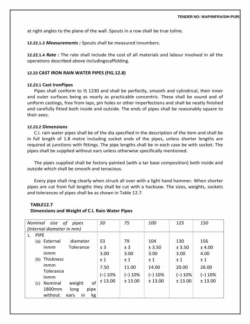
TENDER NO: WAP/INFRA/SIH-PURI
at right angles to the plane of the wall. Spouts in a row shall be true toline.
12.22.1.3 Measurements : Spouts shall be measured innumbers.
12.22.1.4 Rate : The rate shall include the cost of all materials and labour involved in all the operations described above includingscaffolding.
12.23 CAST IRON RAIN WATER PIPES (FIG.12.8)
12.23.1 Cast IronPipes
Pipes shall conform to IS 1230 and shall be perfectly, smooth and cylindrical, their inner and outer surfaces being as nearly as practicable concentric. These shall be sound and of uniform castings, free from laps, pin holes or other imperfections and shall be neatly finished and carefully fitted both inside and outside. The ends of pipes shall be reasonably square to their axes.
12.23.2 Dimensions
C.I. rain water pipes shall be of the dia specified in the description of the item and shall be in full length of 1.8 metre including socket ends of the pipes, unless shorter lengths are required at junctions with fittings. The pipe lengths shall be in each case be with socket. The pipes shall be supplied without ears unless otherwise specifically mentioned.
The pipes supplied shall be factory painted (with a tar base composition) both inside and
outside which shall be smooth and tenacious.
Every pipe shall ring clearly when struck all over with a light hand hammer. When shorter pipes are cut from full lengths they shall be cut with a hacksaw. The sizes, weights, sockets and tolerances of pipes shall be as shown in Table 12.7.
TABLE12.7 Dimensions and Weight of C.I. Rain Water Pipes
Nominal size of pipes (Internal diameter in mm)
50 75 100 125 150
1. PIPE (a) External diameter
inmm Tolerance inmm
(b) Thickness inmm Tolerance inmm
(c) Nominal weight of 1800mm long pipe without ears in kg
53
79
104
130
156
± 3 ± 3 ± 3.50 ± 3.50 ± 4.00
3.00 3.00 3.00 3.00 4.00
± 1 ± 1 ± 1 ± 1 ± 1
7.50 11.00 14.00 20.00 26.00
(–) 10% (–) 10% (–) 10% (–) 10% (–) 10%
± 13.00 ± 13.00 ± 13.00 ± 13.00 ± 13.00
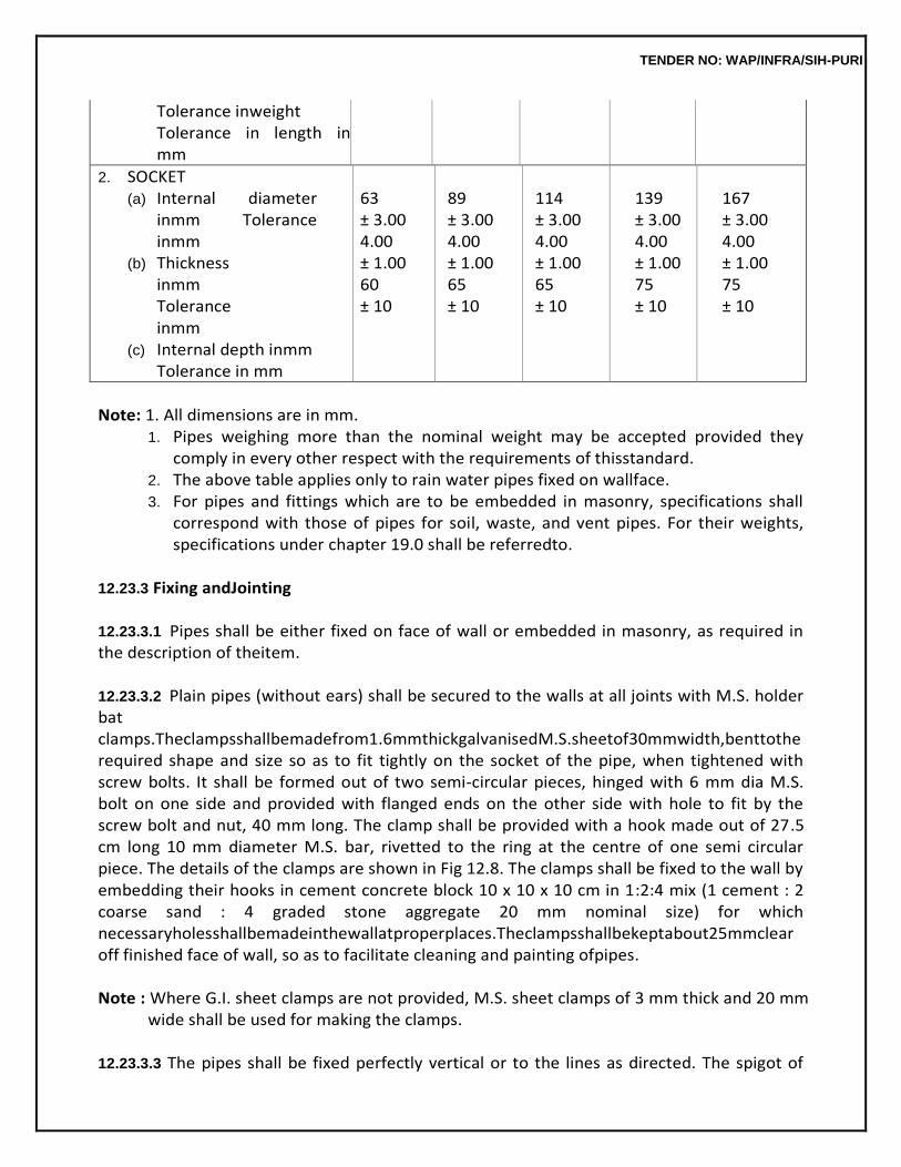
TENDER NO: WAP/INFRA/SIH-PURI
Tolerance inweight Tolerance in length in mm
2. SOCKET (a) Internal diameter
inmm Tolerance inmm
(b) Thickness inmm Tolerance inmm
(c) Internal depth inmm Tolerance in mm
63 ± 3.00 4.00 ± 1.00 60 ± 10
89 ± 3.00 4.00 ± 1.00 65 ± 10
114 ± 3.00 4.00 ± 1.00 65 ± 10
139 ± 3.00 4.00 ± 1.00 75 ± 10
167 ± 3.00 4.00 ± 1.00 75 ± 10
Note: 1. All dimensions are in mm.
1. Pipes weighing more than the nominal weight may be accepted provided they comply in every other respect with the requirements of thisstandard.
2. The above table applies only to rain water pipes fixed on wallface. 3. For pipes and fittings which are to be embedded in masonry, specifications shall
correspond with those of pipes for soil, waste, and vent pipes. For their weights, specifications under chapter 19.0 shall be referredto.
12.23.3 Fixing andJointing
12.23.3.1 Pipes shall be either fixed on face of wall or embedded in masonry, as required in the description of theitem.
12.23.3.2 Plain pipes (without ears) shall be secured to the walls at all joints with M.S. holder bat clamps.Theclampsshallbemadefrom1.6mmthickgalvanisedM.S.sheetof30mmwidth,benttothe required shape and size so as to fit tightly on the socket of the pipe, when tightened with screw bolts. It shall be formed out of two semi-circular pieces, hinged with 6 mm dia M.S. bolt on one side and provided with flanged ends on the other side with hole to fit by the screw bolt and nut, 40 mm long. The clamp shall be provided with a hook made out of 27.5 cm long 10 mm diameter M.S. bar, rivetted to the ring at the centre of one semi circular piece. The details of the clamps are shown in Fig 12.8. The clamps shall be fixed to the wall by embedding their hooks in cement concrete block 10 x 10 x 10 cm in 1:2:4 mix (1 cement : 2 coarse sand : 4 graded stone aggregate 20 mm nominal size) for which necessaryholesshallbemadeinthewallatproperplaces.Theclampsshallbekeptabout25mmclear off finished face of wall, so as to facilitate cleaning and painting ofpipes.
Note : Where G.I. sheet clamps are not provided, M.S. sheet clamps of 3 mm thick and 20 mm
wide shall be used for making the clamps.
12.23.3.3 The pipes shall be fixed perfectly vertical or to the lines as directed. The spigot of
TENDER NO: WAP/INFRA/SIH-PURI
the upper pipeshallbeproperlyfittedinthesocketofthelowerpipesuchthatthereisauniformannularspacefor fillingwiththejointingmaterial.Theannularspacebetweenthesocketandthespigotshallbefilledwith a few turns of spun yarn soaked in neat cement slurry. These shall be pressed home by means of caulking tool. More skins of yarn shall be wrapped if necessary and shall be rammed home. The joint shall then be filled with stiff cement mortar 1:2 (1 cement : 2 fine sand) well pressed with caulking tool and finished smooth at top at an angle of 45 degree sloping up. The joints shall be kept wet for not less than7daysbytyingapieceofgunnybag,fourfold,tothepipeandkeepingitmoistconstantly.
12.23.3.4 Where pipes are to be embedded in masonry, these shall be fixed in masonry work as it proceeds. In such cases care shall be taken to keep the pipes absolutely vertical or to the line as directed by the Engineer-in-Charge. The pipe shall have a surrounding of 12 mm minimum thickness of mortar at every portion of the external surface. The mortar shall be of the same mix as is used in the masonry.Thejointshallbecaulkedwithleadassoonasthenextlengthofpipeisplacedinposition.
TENDER NO: WAP/INFRA/SIH-PURI
The open end (socket end) of the pipe shall be kept closed till the next length is fitted and jointed, to prevent any brick bats or concrete or pieces of wood falling in and choking the pipe.
Thedepthofleadfromthelipofsocketshallbe25mmminimum.Incaseof100mmdia.75mmand
50mmpipes,thequantityofleadrequiredperjointshallbe1.00kg,0.66kgand0.50kgrespectivelyfor purpose of reckoning theoreticalConsumption.
In order to ensure that required quantity of lead is poured into the joint and to control
wastage of lead, at the beginning, three or four samples shall be made and the quantum of lead per joint approved by the Engineer-in-Charge.
The actual consumption of lead should be within ± 5% of the approved sample job subject
to the provisionthatavariationof±20%shallbeallowedoverthetheoreticalquantityofleadduetodimensional tolerancesallowedasperIndianStandards.Thisvariationincludesallowancesofwastagealso.
12.23.3.5 Thespigotendshallbutttheshoulderofthesocketandleavenogapinbetween.Theannular space between the socket and the spigot will be first well packed in with spun yarn leaving 25 mm from thelipofthesocketforthelead.Thejointshallthenbeleadcaulkedasdescribedindetailunderjointing of S.C.I soil, waste and ventpipes.
12.24 CAST IRON ACCESSORIES FOR RAIN WATER PIPES (FIG.12.8)
12.24.1 C.I.Fittings
C.I. accessories such as bends of various degrees, heads, offsets of different projections, branches and shoes shall conform to IS 1230.
Bends shall be of the nearest standard degree as actually required at site. Heads shall be
of the flat or corner type as required. Offsets shall be of the projection as stipulated in the description of the item. Branchesshallbesingleordoubleasdescribedintheitemandshallbeoftheneareststandarddegree asactuallyrequired.Standardshoesshallbeofoverallverticallength,180mmfor75mmdia.,205mm for 100 mm dia and 275 mm for 150 dia sized pipe from top of socket to lowest tip of shoe. Shoes of longer lengths if used shall be in lengths 300 mm, 375 mm, 450 mm, or 600 mm from top of socket to lowest tip of shoe of as actually required atsite.
12.24.2 Dimensions
The fittings shall be of the diameter specified in the description of the item.
The thickness of the fittings and details of spigots and sockets shall be same as those of the corresponding size of straight pipes. The fittings shall be supplied without ears unless otherwise specifically mentioned in the item. The fittings shall be factory painted with a tar basis composition both inside and outside which shall be smooth and tenacious. Every
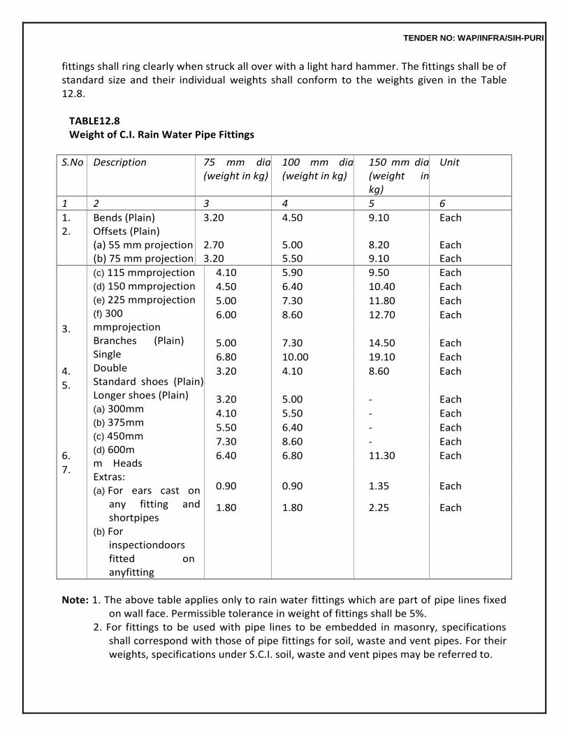
TENDER NO: WAP/INFRA/SIH-PURI
fittings shall ring clearly when struck all over with a light hard hammer. The fittings shall be of standard size and their individual weights shall conform to the weights given in the Table 12.8.
TABLE12.8 Weight of C.I. Rain Water Pipe Fittings
S.No Description 75 mm dia (weight in kg)
100 mm dia (weight in kg)
150 mm dia (weight in kg)
Unit
1 2 3 4 5 6
1. Bends (Plain) 3.20 4.50 9.10 Each 2. Offsets (Plain)
(a) 55 mm projection 2.70 5.00 8.20 Each (b) 75 mm projection 3.20 5.50 9.10 Each
(c) 115 mmprojection (d) 150 mmprojection (e) 225 mmprojection (f) 300 mmprojection Branches (Plain) Single Double Standard shoes (Plain) Longer shoes (Plain) (a) 300mm (b) 375mm (c) 450mm (d) 600mm Heads Extras: (a) For ears cast on
any fitting and shortpipes
(b) For inspectiondoors fitted on anyfitting
4.10 5.90 9.50 Each
4.50 6.40 10.40 Each
5.00 7.30 11.80 Each
6.00 8.60 12.70 Each
3.
5.00 7.30 14.50 Each
6.80 10.00 19.10 Each
4. 3.20 4.10 8.60 Each
5.
3.20 5.00 - Each
4.10 5.50 - Each
5.50 6.40 - Each
7.30 8.60 - Each
6. 6.40 6.80 11.30 Each
7.
0.90 0.90 1.35 Each
1.80 1.80 2.25 Each
Note: 1. The above table applies only to rain water fittings which are part of pipe lines fixed
on wall face. Permissible tolerance in weight of fittings shall be 5%. 2. For fittings to be used with pipe lines to be embedded in masonry, specifications
shall correspond with those of pipe fittings for soil, waste and vent pipes. For their weights, specifications under S.C.I. soil, waste and vent pipes may be referred to.
TENDER NO: WAP/INFRA/SIH-PURI
12.24.3 Fixing and jointing shall be as specified in12.23.3.
12.24.4 Measurements The fittings shall be measured by numbers. Where longer shoes are used in lieu of
standard shoes specified in the description of the item, they shall be measured as standard shoes of 180 mm, 205 mm and275mmfor75mmdia,100mmdiaand150mmdiarespectivelyinnumberandtheextralengthsof the shoes shall be measured and paid for under the corresponding size ofpipes.
12.24.5 Rate
The rate shall include in the case of fittings fixed on the face of wall, the cost of all materials and labour involved in all the operations described above including jointing but excluding the supply and fixing the M.S. holder bat clamps in walls and the anchoring concrete. Unless otherwise specified in the description of the item, the rate shall apply for fittings without access doors. In the case of fittings forming part of a rain water pipe line embedded in masonry, the rate shall be for supplying and embedding the fittings in masonry but shall not include for the jointing and lead caulking which shall be paid for separately.
12.25 THERMAL INSULATION FORROOFING
12.25.1 With CellularConcrete
12.25.1.1 Types and Grades: Cellular concrete is a light weight concrete formed by producing gas or air bubbles in cement slurry or a cement sand slurry. Cellular concrete shall conform to IS 6598 and shall be of following two types depending on the manner ofmanufacture.
(i) TypeI:Highpressuresteamcured(auto-claved)materialsintheformofprecastblocks. (ii) Type II: Materials cured under natural conditions (that is under ambient pressure and
temperature) by water. The material may be either cast in situ or may be in the form of precast blocks.
Grades-Eachofthesetwotypesofthematerialshallhavethreegrades,namely: Grade A - Light weight cellularconcrete; Grade B - Medium weight cellular concrete and; Grade C - Heavy weight cellular concrete.
12.25.1.2 Materials
(a) Aggregate:Avarietyofsilliciousfines,suchasgroundquartssandshale,flyashandgranulated slag may be used in the manufacture of cellularconcrete.
(b) Water and binder shallconform to para 3.1.1 and 3.1.2 of . (c) Gassing Agents: Organic foaming agents based on resin soap, glue, surface active
agents, or fine aluminium powder, zinc, dust, calcium carbide, calcium by pocheride etc. may be used for gassing theconcrete.
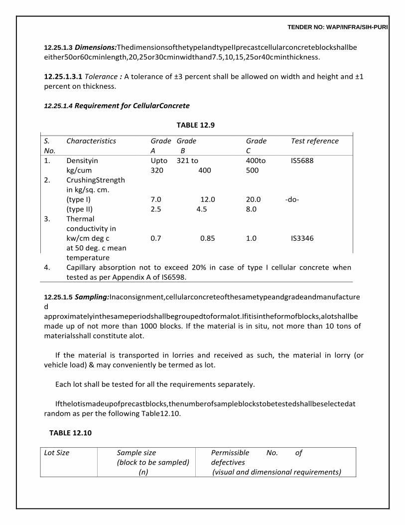
TENDER NO: WAP/INFRA/SIH-PURI
12.25.1.3 Dimensions:ThedimensionsofthetypeIandtypeIIprecastcellularconcreteblockshallbe either50or60cminlength,20,25or30cminwidthand7.5,10,15,25or40cminthickness.
12.25.1.3.1 Tolerance : A tolerance of ±3 percent shall be allowed on width and height and ±1 percent on thickness.
12.25.1.4 Requirement for CellularConcrete
TABLE 12.9
S. Characteristics Grade Grade Grade Test reference No. A B C 1. Densityin Upto 321 to 400to IS5688
kg/cum 320 400 500 2. CrushingStrength
in kg/sq. cm. (type I) 7.0 12.0 20.0 -do- (type II) 2.5 4.5 8.0
3. Thermal conductivity in kw/cm deg c 0.7 0.85 1.0 IS3346 at 50 deg. c mean temperature
4. Capillary absorption not to exceed 20% in case of type I cellular concrete when tested as per Appendix A of IS6598.
12.25.1.5 Sampling:Inaconsignment,cellularconcreteofthesametypeandgradeandmanufactured approximatelyinthesameperiodshallbegroupedtoformalot.Ifitisintheformofblocks,alotshallbe made up of not more than 1000 blocks. If the material is in situ, not more than 10 tons of materialsshall constitute alot.
If the material is transported in lorries and received as such, the material in lorry (or
vehicle load) & may conveniently be termed as lot.
Each lot shall be tested for all the requirements separately.
Ifthelotismadeupofprecastblocks,thenumberofsampleblockstobetestedshallbeselectedat random as per the following Table12.10.
TABLE 12.10
Lot Size Sample size (block to be sampled)
(n)
Permissible No. of defectives (visual and dimensional requirements)
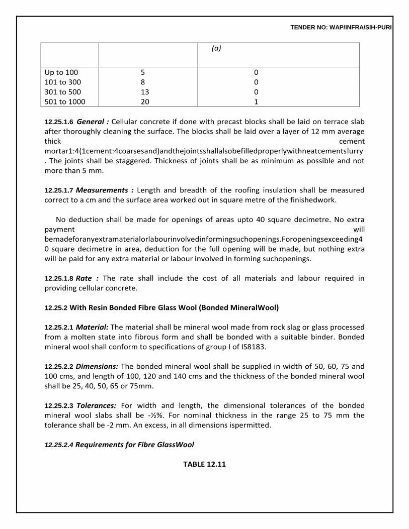
TENDER NO: WAP/INFRA/SIH-PURI
(a)
Up to 100 5 0 101 to 300 8 0 301 to 500 13 0 501 to 1000 20 1
12.25.1.6 General : Cellular concrete if done with precast blocks shall be laid on terrace slab after thoroughly cleaning the surface. The blocks shall be laid over a layer of 12 mm average thick cement mortar1:4(1cement:4coarsesand)andthejointsshallalsobefilledproperlywithneatcementslurry. The joints shall be staggered. Thickness of joints shall be as minimum as possible and not more than 5 mm.
12.25.1.7 Measurements : Length and breadth of the roofing insulation shall be measured correct to a cm and the surface area worked out in square metre of the finishedwork.
No deduction shall be made for openings of areas upto 40 square decimetre. No extra
payment will bemadeforanyextramaterialorlabourinvolvedinformingsuchopenings.Foropeningsexceeding40 square decimetre in area, deduction for the full opening will be made, but nothing extra will be paid for any extra material or labour involved in forming suchopenings.
12.25.1.8 Rate : The rate shall include the cost of all materials and labour required in providing cellular concrete.
12.25.2 With Resin Bonded Fibre Glass Wool (Bonded MineralWool)
12.25.2.1 Material: The material shall be mineral wool made from rock slag or glass processed from a molten state into fibrous form and shall be bonded with a suitable binder. Bonded mineral wool shall conform to specifications of group I of IS8183.
12.25.2.2 Dimensions: The bonded mineral wool shall be supplied in width of 50, 60, 75 and 100 cms, and length of 100, 120 and 140 cms and the thickness of the bonded mineral wool shall be 25, 40, 50, 65 or 75mm.
12.25.2.3 Tolerances: For width and length, the dimensional tolerances of the bonded mineral wool slabs shall be -½%. For nominal thickness in the range 25 to 75 mm the tolerance shall be -2 mm. An excess, in all dimensions ispermitted.
12.25.2.4 Requirements for Fibre GlassWool
TABLE 12.11
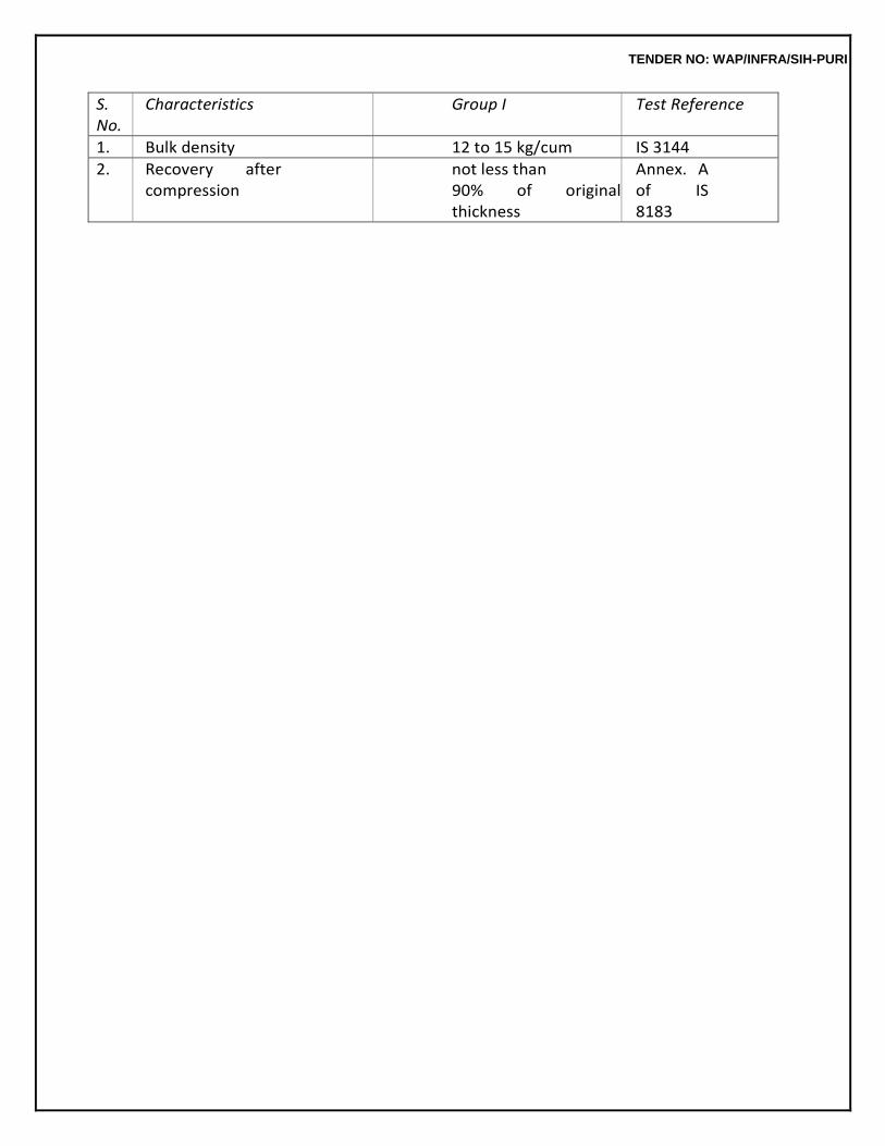
TENDER NO: WAP/INFRA/SIH-PURI
S. No.
Characteristics Group I Test Reference
1. Bulk density 12 to 15 kg/cum IS 3144
2. Recovery after compression
not less than 90% of original thickness
Annex. A of IS 8183
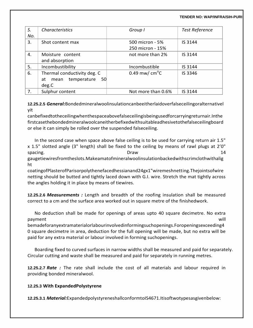
TENDER NO: WAP/INFRA/SIH-PURI
S. No.
Characteristics Group I Test Reference
3. Shot content max 500 micron - 5% 250 micron - 15%
IS 3144
4. Moisture content and absorption
not more than 2% IS 3144
5. Incombustibility Incombustible IS 3144
6. Thermal conductivity deg. C at mean temperature 50 deg.C
0.49 mw/ cmoC IS 3346
7. Sulphur content Not more than 0.6% IS 3144
12.25.2.5 General:Bondedmineralwoolinsulationcanbeeitherlaidoverfalseceilingoralternativelyit canbefixedtotheceilingwhenthespaceabovefalseceilingisbeingusedforcarryingreturnair.Inthe firstcasethebondedmineralwoolcaneitherbefixedwithsuitableadhesivetothefalseceilingboardor else it can simply be rolled over the suspended falseceiling.
In the second case when space above false ceiling is to be used for carrying return air 1.5"
x 1.5" slotted angle (3" length) shall be fixed to the ceiling by means of rawl plugs at 2’0" spacing. Draw 14 gaugetiewiresfromtheslots.Makeamatofmineralwoolinsulationbackedwithscrimclothwithalight coatingofPlasterofParisorpolythenefacedhessianand24gx1"wiremeshnetting.Thejointsofwire netting should be butted and tightly laced down with G.I. wire. Stretch the mat tightly across the angles holding it in place by means of tiewires.
12.25.2.6 Measurements : Length and breadth of the roofing insulation shall be measured correct to a cm and the surface area worked out in square metre of the finishedwork.
No deduction shall be made for openings of areas upto 40 square decimetre. No extra
payment will bemadeforanyextramaterialorlabourinvolvedinformingsuchopenings.Foropeningsexceeding40 square decimetre in area, deduction for the full opening will be made, but no extra will be paid for any extra material or labour involved in forming suchopenings.
Boarding fixed to curved surfaces in narrow widths shall be measured and paid for separately.
Circular cutting and waste shall be measured and paid for separately in running metres.
12.25.2.7 Rate : The rate shall include the cost of all materials and labour required in providing bonded mineralwool.
12.25.3 With ExpandedPolystyrene
12.25.3.1 Material:ExpandedpolystyreneshallconformtoIS4671.Itisoftwotypesasgivenbelow:
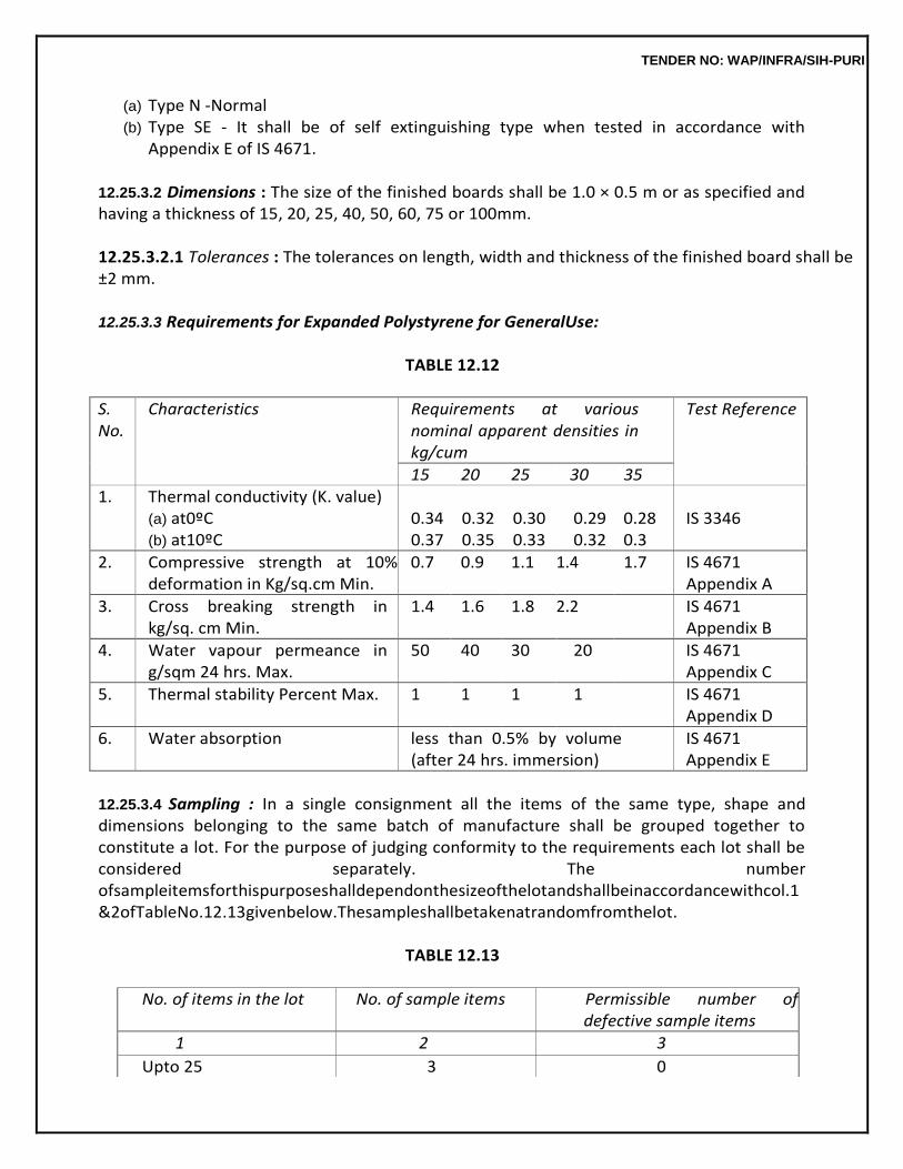
TENDER NO: WAP/INFRA/SIH-PURI
(a) Type N -Normal (b) Type SE - It shall be of self extinguishing type when tested in accordance with
Appendix E of IS 4671.
12.25.3.2 Dimensions : The size of the finished boards shall be 1.0 × 0.5 m or as specified and having a thickness of 15, 20, 25, 40, 50, 60, 75 or 100mm.
12.25.3.2.1 Tolerances : The tolerances on length, width and thickness of the finished board shall be ±2 mm. 12.25.3.3 Requirements for Expanded Polystyrene for GeneralUse:
TABLE 12.12
S. No.
Characteristics Requirements at various nominal apparent densities in kg/cum
Test Reference
15 20 25 30 35 1. Thermal conductivity (K. value)
(a) at0ºC (b) at10ºC
0.34 0.37
0.32 0.35
0.30 0.33
0.29 0.32
0.28 0.3
IS 3346
2. Compressive strength at 10% deformation in Kg/sq.cm Min.
0.7 0.9 1.1 1.4 1.7 IS 4671 Appendix A
3. Cross breaking strength in kg/sq. cm Min.
1.4 1.6 1.8 2.2 IS 4671 Appendix B
4. Water vapour permeance in g/sqm 24 hrs. Max.
50 40 30 20 IS 4671 Appendix C
5. Thermal stability Percent Max. 1 1 1 1 IS 4671 Appendix D
6. Water absorption less than 0.5% by volume (after 24 hrs. immersion)
IS 4671 Appendix E
12.25.3.4 Sampling : In a single consignment all the items of the same type, shape and dimensions belonging to the same batch of manufacture shall be grouped together to constitute a lot. For the purpose of judging conformity to the requirements each lot shall be considered separately. The number ofsampleitemsforthispurposeshalldependonthesizeofthelotandshallbeinaccordancewithcol.1 &2ofTableNo.12.13givenbelow.Thesampleshallbetakenatrandomfromthelot.
TABLE 12.13
No. of items in the lot No. of sample items Permissible number of
defective sample items
1 2 3
Upto 25 3 0
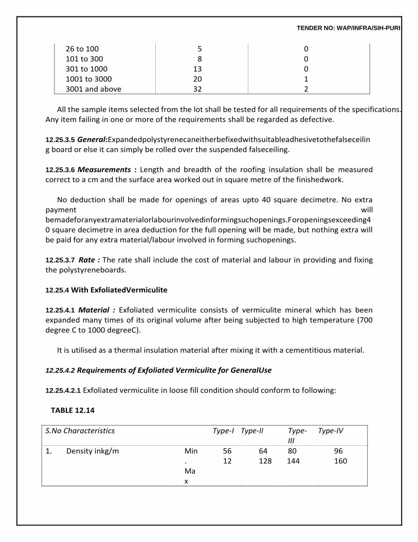
TENDER NO: WAP/INFRA/SIH-PURI
26 to 100 5 0 101 to 300 8 0 301 to 1000 13 0 1001 to 3000 20 1 3001 and above 32 2
All the sample items selected from the lot shall be tested for all requirements of the specifications.
Any item failing in one or more of the requirements shall be regarded as defective.
12.25.3.5 General:Expandedpolystyrenecaneitherbefixedwithsuitableadhesivetothefalseceiling board or else it can simply be rolled over the suspended falseceiling.
12.25.3.6 Measurements : Length and breadth of the roofing insulation shall be measured correct to a cm and the surface area worked out in square metre of the finishedwork.
No deduction shall be made for openings of areas upto 40 square decimetre. No extra
payment will bemadeforanyextramaterialorlabourinvolvedinformingsuchopenings.Foropeningsexceeding40 square decimetre in area deduction for the full opening will be made, but nothing extra will be paid for any extra material/labour involved in forming suchopenings.
12.25.3.7 Rate : The rate shall include the cost of material and labour in providing and fixing the polystyreneboards.
12.25.4 With ExfoliatedVermiculite
12.25.4.1 Material : Exfoliated vermiculite consists of vermiculite mineral which has been expanded many times of its original volume after being subjected to high temperature (700 degree C to 1000 degreeC).
It is utilised as a thermal insulation material after mixing it with a cementitious material.
12.25.4.2 Requirements of Exfoliated Vermiculite for GeneralUse
12.25.4.2.1 Exfoliated vermiculite in loose fill condition should conform to following:
TABLE 12.14
S.No Characteristics Type-I Type-II Type-III
Type-IV
1. Density inkg/m Min. Max
56 12
64 128
80 144
96 160
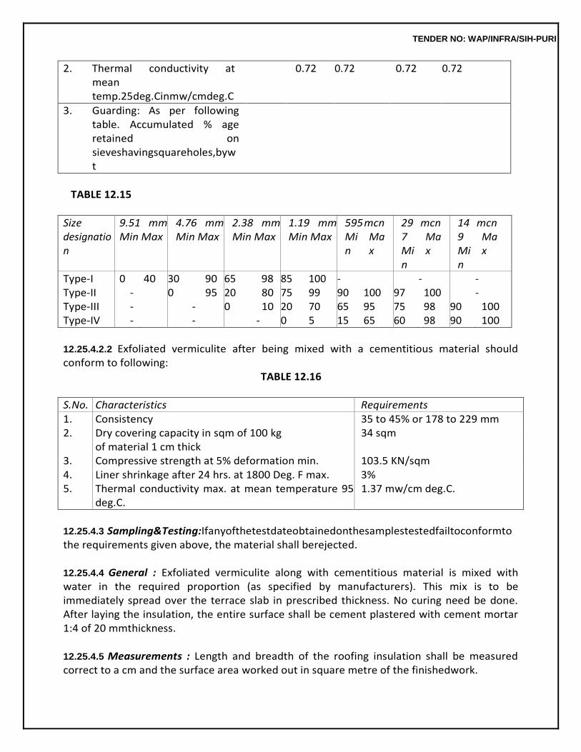
TENDER NO: WAP/INFRA/SIH-PURI
2. Thermal conductivity at mean temp.25deg.Cinmw/cmdeg.C
0.72 0.72 0.72 0.72
3. Guarding: As per following table. Accumulated % age retained on sieveshavingsquareholes,bywt
TABLE 12.15
Size designation
9.51 mm Min Max
4.76 mm Min Max
2.38 mm Min Max
1.19 mm Min Max
595 Min
mcn Max
297 Min
mcn Max
149 Min
mcn Max
Type-I 0 40 30 90 65 98 85 100 - - - Type-II - 0 95 20 80 75 99 90 100 97 100 - Type-III - - 0 10 20 70 65 95 75 98 90 100 Type-IV - - - 0 5 15 65 60 98 90 100
12.25.4.2.2 Exfoliated vermiculite after being mixed with a cementitious material should conform to following:
TABLE 12.16
S.No. Characteristics Requirements 1. Consistency 35 to 45% or 178 to 229 mm 2. Dry covering capacity in sqm of 100 kg 34 sqm
of material 1 cm thick 3. Compressive strength at 5% deformation min. 103.5 KN/sqm 4. Liner shrinkage after 24 hrs. at 1800 Deg. F max. 3% 5. Thermal conductivity max. at mean temperature 95
deg.C. 1.37 mw/cm deg.C.
12.25.4.3 Sampling&Testing:Ifanyofthetestdateobtainedonthesamplestestedfailtoconformto the requirements given above, the material shall berejected.
12.25.4.4 General : Exfoliated vermiculite along with cementitious material is mixed with water in the required proportion (as specified by manufacturers). This mix is to be immediately spread over the terrace slab in prescribed thickness. No curing need be done. After laying the insulation, the entire surface shall be cement plastered with cement mortar 1:4 of 20 mmthickness.
12.25.4.5 Measurements : Length and breadth of the roofing insulation shall be measured correct to a cm and the surface area worked out in square metre of the finishedwork.
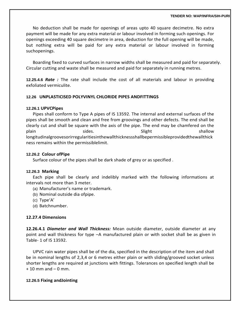
TENDER NO: WAP/INFRA/SIH-PURI
No deduction shall be made for openings of areas upto 40 square decimetre. No extra payment will be made for any extra material or labour involved in forming such openings. For openings exceeding 40 square decimetre in area, deduction for the full opening will be made, but nothing extra will be paid for any extra material or labour involved in forming suchopenings.
Boarding fixed to curved surfaces in narrow widths shall be measured and paid for separately.
Circular cutting and waste shall be measured and paid for separately in running metres.
12.25.4.6 Rate : The rate shall include the cost of all materials and labour in providing exfoliated vermiculite.
12.26 UNPLASTICISED POLYVINYL CHLORIDE PIPES ANDFITTINGS
12.26.1 UPVCPipes
Pipes shall conform to Type A pipes of IS 13592. The internal and external surfaces of the pipes shall be smooth and clean and free from groovings and other defects. The end shall be clearly cut and shall be square with the axis of the pipe. The end may be chamfered on the plain sides. Slight shallow longitudinalgroovesorirregularitiesinthewallthicknessshallbepermissibleprovidedthewallthickness remains within the permissiblelimit.
12.26.2 Colour ofPipe
Surface colour of the pipes shall be dark shade of grey or as specified .
12.26.3 Marking Each pipe shall be clearly and indelibly marked with the following informations at
intervals not more than 3 meter. (a) Manufacturer’s name or trademark. (b) Nominal outside dia ofpipe. (c) Type‘A’ (d) Batchnumber.
12.27.4 Dimensions
12.26.4.1 Diameter and Wall Thickness: Mean outside diameter, outside diameter at any point and wall thickness for type –A manufactured plain or with socket shall be as given in Table- 1 of IS 13592.
UPVC rain water pipes shall be of the dia, specified in the description of the item and shall
be in nominal lengths of 2,3,4 or 6 metres either plain or with sliding/grooved socket unless shorter lengths are required at junctions with fittings. Tolerances on specified length shall be + 10 mm and – 0 mm.
12.26.5 Fixing andJointing
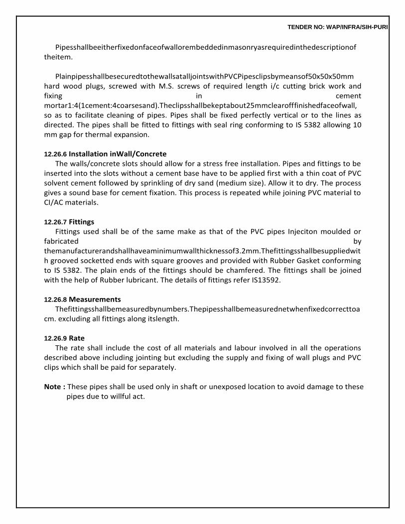
TENDER NO: WAP/INFRA/SIH-PURI
Pipesshallbeeitherfixedonfaceofwallorembeddedinmasonryasrequiredinthedescriptionof theitem.
PlainpipesshallbesecuredtothewallsatalljointswithPVCPipesclipsbymeansof50x50x50mm
hard wood plugs, screwed with M.S. screws of required length i/c cutting brick work and fixing in cement mortar1:4(1cement:4coarsesand).Theclipsshallbekeptabout25mmclearofffinishedfaceofwall, so as to facilitate cleaning of pipes. Pipes shall be fixed perfectly vertical or to the lines as directed. The pipes shall be fitted to fittings with seal ring conforming to IS 5382 allowing 10 mm gap for thermal expansion.
12.26.6 Installation inWall/Concrete
The walls/concrete slots should allow for a stress free installation. Pipes and fittings to be inserted into the slots without a cement base have to be applied first with a thin coat of PVC solvent cement followed by sprinkling of dry sand (medium size). Allow it to dry. The process gives a sound base for cement fixation. This process is repeated while joining PVC material to CI/AC materials.
12.26.7 Fittings
Fittings used shall be of the same make as that of the PVC pipes Injeciton moulded or fabricated by themanufacturerandshallhaveaminimumwallthicknessof3.2mm.Thefittingsshallbesuppliedwith grooved socketted ends with square grooves and provided with Rubber Gasket conforming to IS 5382. The plain ends of the fittings should be chamfered. The fittings shall be joined with the help of Rubber lubricant. The details of fittings refer IS13592.
12.26.8 Measurements
Thefittingsshallbemeasuredbynumbers.Thepipesshallbemeasurednetwhenfixedcorrecttoa cm. excluding all fittings along itslength.
12.26.9 Rate
The rate shall include the cost of all materials and labour involved in all the operations described above including jointing but excluding the supply and fixing of wall plugs and PVC clips which shall be paid for separately.
Note : These pipes shall be used only in shaft or unexposed location to avoid damage to these
pipes due to willful act.
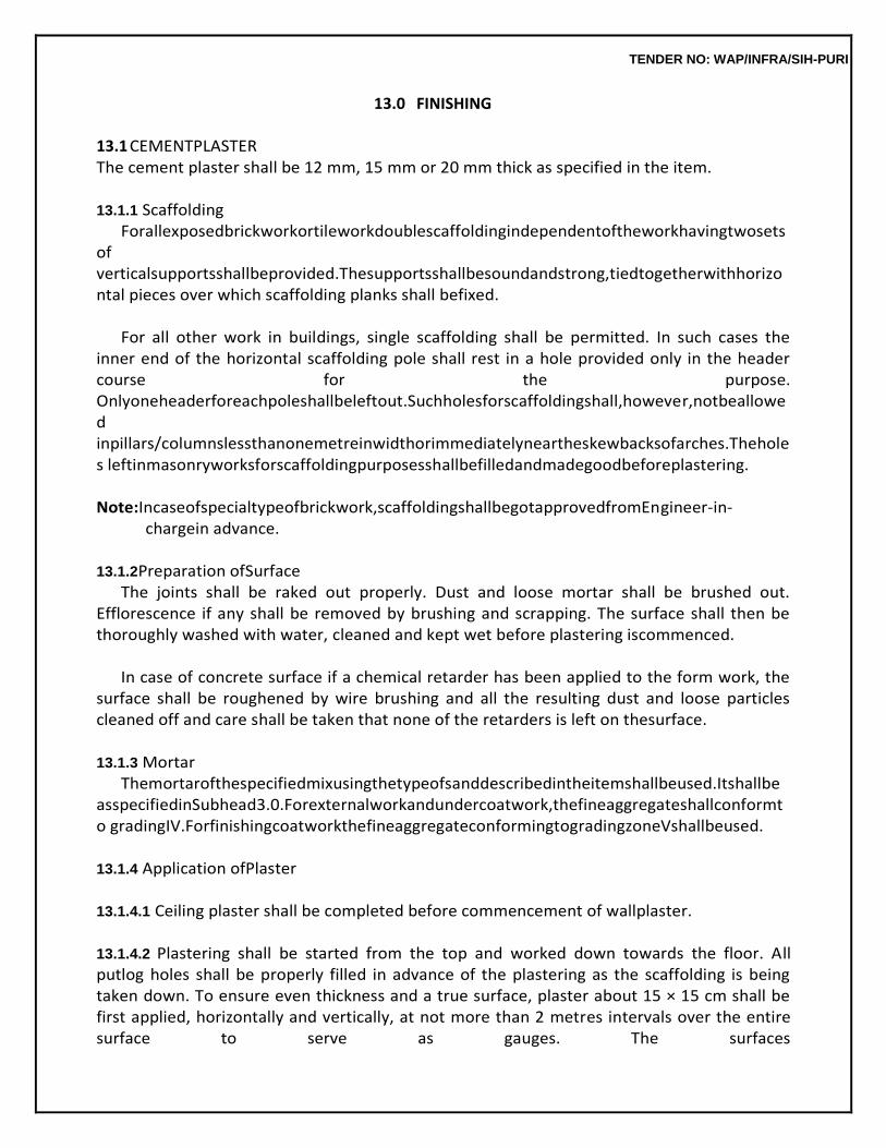
TENDER NO: WAP/INFRA/SIH-PURI
13.0 FINISHING
13.1 CEMENTPLASTER The cement plaster shall be 12 mm, 15 mm or 20 mm thick as specified in the item.
13.1.1 Scaffolding
Forallexposedbrickworkortileworkdoublescaffoldingindependentoftheworkhavingtwosetsof verticalsupportsshallbeprovided.Thesupportsshallbesoundandstrong,tiedtogetherwithhorizontal pieces over which scaffolding planks shall befixed.
For all other work in buildings, single scaffolding shall be permitted. In such cases the
inner end of the horizontal scaffolding pole shall rest in a hole provided only in the header course for the purpose. Onlyoneheaderforeachpoleshallbeleftout.Suchholesforscaffoldingshall,however,notbeallowed inpillars/columnslessthanonemetreinwidthorimmediatelyneartheskewbacksofarches.Theholes leftinmasonryworksforscaffoldingpurposesshallbefilledandmadegoodbeforeplastering.
Note:Incaseofspecialtypeofbrickwork,scaffoldingshallbegotapprovedfromEngineer-in-
chargein advance.
13.1.2 Preparation ofSurface The joints shall be raked out properly. Dust and loose mortar shall be brushed out.
Efflorescence if any shall be removed by brushing and scrapping. The surface shall then be thoroughly washed with water, cleaned and kept wet before plastering iscommenced.
In case of concrete surface if a chemical retarder has been applied to the form work, the
surface shall be roughened by wire brushing and all the resulting dust and loose particles cleaned off and care shall be taken that none of the retarders is left on thesurface.
13.1.3 Mortar
Themortarofthespecifiedmixusingthetypeofsanddescribedintheitemshallbeused.Itshallbe asspecifiedinSubhead3.0.Forexternalworkandundercoatwork,thefineaggregateshallconformto gradingIV.ForfinishingcoatworkthefineaggregateconformingtogradingzoneVshallbeused.
13.1.4 Application ofPlaster
13.1.4.1 Ceiling plaster shall be completed before commencement of wallplaster.
13.1.4.2 Plastering shall be started from the top and worked down towards the floor. All putlog holes shall be properly filled in advance of the plastering as the scaffolding is being taken down. To ensure even thickness and a true surface, plaster about 15 × 15 cm shall be first applied, horizontally and vertically, at not more than 2 metres intervals over the entire surface to serve as gauges. The surfaces
TENDER NO: WAP/INFRA/SIH-PURI
ofthesegaugedareasshallbetrulyintheplaneofthefinishedplastersurface.Themortarshallthenbe laidonthewall,betweenthegaugeswithtrowel.Themortarshallbeappliedinauniformsurfaceslightly more than the specified thickness. This shall be brought to a true surface, by working a woodenstraight edge reaching across the gauges, with small upward and side ways movements at a time. Finally the surface shall be finished off true with trowel or wooden float according as a smooth or a sandy granular texture is required. Excessive troweling or over working the float shallbe avoided.
13.1.4.3 Allcorners,arrises,anglesandjunctionsshallbetrulyverticalorhorizontalasthecasemaybe and shall be carefully finished. Rounding or chamfering corners, arrises, provision of grooves at junctions etc. where required shall be done without any extra payment. Such rounding, chamfering or groovingshallbecarriedoutwithpropertemplatesorbattenstothesizesrequired.
13.1.4.4 When suspending work at the end of the day, the plaster shall be left, cut clean to line both horizontally and vertically. When recommencing the plastering, the edge of the old work shall be scrapped cleaned and wetted with cement slurry before plaster is applied to the adjacent areas, to enable the two to properly join together. Plastering work shall be closed at the end of the day on the body of wall and not nearer than 15 cm to any corners or arrises. It shall not be closed on the body of the features such as plasters, bands and cornices, nor at the corners of arrises. Horizontal joints in plaster work shall not also occur on parapet tops and copings as these invariably lead to leakages. The plasteringandfinishingshallbecompletedwithinhalfanhourofaddingwatertothedrymortar.
No portion of the surface shall be left out initially to be patched up later on. The
plastering and finishing shall be completed within half an hour of adding water to the dry mortar.
13.1.5 Thickness
Where the thickness required as per description of the item is 20 mm the average thickness of the plaster shall not be less than 20 mm whether the wall treated is of brick or stone. In the case of brick work, the minimum thickness over any portion of the surface shall be not less than 15 mm while incase ofstoneworktheminimumthicknessoverthebushingsshallbenotlessthan12mm.
13.1.6 Curing
Curing shall be started as soon as the plaster has hardened sufficiently not to be damaged when watered.
The plaster shall be kept wet for a period of at least 7 days. During this period, it shall be
suitably protected from all damages at the contractor’s expense by such means as the Engineer-in-Charge may approve. The dates on which the plastering is done shall be legibly marked on the various sections plastered so that curing for the specified period thereafter can be watched.
13.1.7 Finish
TENDER NO: WAP/INFRA/SIH-PURI
Theplastershallbefinishedtoatrueandplumbsurfaceandtotheproperdegreeofsmoothnessas required. The work shall be tested frequently as the work proceeds with a true straight edge not less than2.5mlongandwithplumbbobs.Allhorizontallinesandsurfacesshallbetestedwithalevelandall jambs and corners with a plumb bob as the workproceeds.
13.1.8 Precaution
Any cracks which appear in the surface and all portions which sound hollow when tapped, or are found to be soft or otherwise defective, shall be cut out in rectangular shape and redone as directed by the Engineer-in-Charge.
(i) When ceiling plaster is done, it shall be finished to chamfered edge at an angle at its junction with a suitable tool when plaster is being done. Similarly when the wall plaster is being done, it shall be kept separate from the ceiling plaster by a thin straight groove not deeper than 6 mm drawn with any suitable method with the wall while the plaster isgreen.
(ii) Topreventsurfacecracksappearingbetweenjunctionsofcolumn/beamandwalls,150mmwide chicken wire mesh should be fixed with U nails 150 mm centre to centre before plastering the junction. The plastering of walls and beam/column in one vertical plane should be carried out in one go. For providing and fixing chicken wire mesh with U nails payment shall be made separately.
13.1.9 Measurements
13.1.9.1 Length and breadth shall be measured correct to a cm and its area shall be calculated in square metres correct to two places ofdecimal.
13.1.9.2 Thickness of the plaster shall be exclusive of the thickness of the key i.e. grooves, or open joints in brickwork. 13.1.9.3 Themeasurementofwallplastershallbetakenbetweenthewallsorpartitions(thedimensions before the plaster shall be taken) for the length and from the top of the floor or skirting to the ceiling for the height. Depth of coves or cornices if any shall bededucted.
13.1.9.4 The following shall be measured separately from wallplaster.
(a) Plaster bands 30 cm wide andunder (b) Cornice beadings and architraves or architraves moulded wholly inplaster. (c) Circular work not exceeding 6 m inradius.
13.1.9.5 Plaster over masonry pilasters will be measured and paid for as plasteronly.
13.1.9.6 A coefficient of 1.63 shall be adopted for the measurement of one side plastering on honey comb work having 6 x 10 cm.opening.
13.1.9.7 Moulded cornices andcoves.
(a) Length shall be measured at the centre of thegirth. (b) Moulded cornices and coves shall be given in square metres the area being arrived at
TENDER NO: WAP/INFRA/SIH-PURI
by multiplying length by thegirth. (c) Flat or weathered top to cornices when exceeding 15 cm in width shall not be included
in the girth but measured with the general plasterwork. (d) Cornices which are curved in their length shall be measuredseparately.
13.1.9.8 Exterior plastering at a height greater than 10 m from average ground level shall be measured separatelyineachstoreyheight.Patchplastering(inrepairs)shallbemeasuredasplasteringnewwork, wherethepatchexceed2.5sqm.extrapaymentbeingmadeforpreparingoldwall,suchasdismantling old plaster, raking out the joints and cleaning the surface. Where the patch does not exceed 2.5 sqm in areaitshallbemeasuredundertheappropriateitemundersubhead‘RepairstoBuildings.’
13.1.9.9 Deductions in measurements, for opening etc. will be regulated asfollows:
(a) Nodeductionwillbemadeforopeningsorendsofjoists,beams,posts,girders,stepsetc.upto 0.5 sqm in area and no additions shall be made either, for the jambs, soffits and sills of such openings. The above procedure will apply to both faces of wall.
(b) Deduction for opening exceeding 0.5 sqm but not exceeding 3 sqm each shall be made
for reveals, jambs, soffits sills, sills, etc. of theseopenings. (i) When both faces of walls are plastered with same plaster, deductions shall be
made for one faceonly.
(ii) Whentwofacesofwallsareplasteredwithdifferenttypesofplasterorifonefaceisplastered and other is pointed or one face is plastered and other is unplastered, deduction shall be made from the plaster or pointing on the side of the frame for the doors, windows etc. on which width of reveals is less than that on the other side but no deduction shall be made on the otherside.
Where width of reveals on both faces of wall are equal, deduction of 50% of area of opening on each face shall be made from area of plaster and/or pointing as the case may be.
(iii) For opening having door frame equal to or projecting beyond thickness of wall,
fulldeduction for opening shall be made from each plastered face ofwall.
(c) For opening exceeding 3 sqm in area, deduction will be made in the measurements for the full opening of the wall treatment on both faces, while at the same time, jambs, sills and soffits will be measured forpayment.
In measuring jambs, sills and soffits, deduction shall not be made for the area in contact
with the frame of doors, windows etc.
13.1.10 Rate The rate shall include the cost of all labour and materials involved in all the operations
TENDER NO: WAP/INFRA/SIH-PURI
described above.
13.2 CEMENT PLASTER WITH A FLOATING COAT OF NEATCEMENT
13.2.0 The cement plaster shall be 12, 15 or 20 mm thick, finished with a floating coat of neat cement, as described in theitem.
13.2.1 Specifications for this item of work shall be same as described in 13.1 except for the additional floating coat which shall be carried out asbelow.
Whentheplasterhasbeenbroughttoatruesurfacewiththewoodenstraightedge(clause13.1.4.
2) it shall be uniformly treated over its entire area with a paste of neat cement and rubbed smooth, so that the whole surface is covered with neat cement coating. The quantity of cement applied for floating coat shall be 1 kg per sqm. Smooth finishing shall be completed with trowel immediately and in no caselater than half an hour of adding water to the plaster mix. The rest of the specifications described in 13.1.4 shallapply.
13.3 18 MM CEMENT PLASTER (TWO COATWORK)
13.3.1 Thespecificationforscaffoldingandpreparationofsurfaceshallbeasdescribedin13.1
13.3.2 Mortar
The mix and type of fine aggregate specified in the description of the item shall be used for the respective coats. Generally the mix of the finishing coat shall not be richer than the under coat unless otherwise described in item.
Generally coarse sand shall be used for the under coat and fine sand for the finishing coat,
unless otherwise specified for external work and under coat work, the fine aggregate shall conform to grading zone IV. For finishing coat work the fine aggregate conforming to grading zone V shall be used.
13.3.3 Application
13.3.3.1 The plaster shall be applied in two coats i.e. 12 mm under coat and then 6 mm finishing coat and shall have an average total thickness of not less than 18mm.
13.3.3.2 12 mm Under Coat : This shall be applied as specified in 13.1.4 except that when the plaster has been brought to a true surface a wooden straight edge and the surface shall be left rough and furrowed 2 mm deep with a scratching tool diagonally both ways, to form key for the finishing coat. The surface shall be kept wet till the finishing coat isapplied.
13.3.3.3 6 mm Finishing Coat : The finishing coat shall be applied after the under coat has sufficiently setbutnotdriedandinanycasewithin48hoursandfinishedinthemannerspecifiedin13.1.4.
TENDER NO: WAP/INFRA/SIH-PURI
13.3.4 Specifications for Curing, Finishing, Precautions, Measurements and Rate shall be as described under13.1.
13.4 6 MM CEMENT PLASTER ON CEMENT CONCRETE AND REINFORCED CEMENT CONCRETEWORK
13.4.1 Scaffolding
Stage scaffolding shall be provided for the work. This shall be independent of the walls.
TENDER NO: WAP/INFRA/SIH-PURI
13.4.2 Preparation ofSurface Projecting burrs of mortar formed due to the gaps at joints in shuttering shall be
removed. The surfaceshallbescrubbedcleanwithwirebrushes.Inadditionconcretesurfacestobeplasteredshallbe pock marked with a pointed tool, at spacings of not more than 5 cm. Centres, the pock being made not less than 3 mm deep. This is to ensure a proper key for the plaster. The mortar shall be washed offand surface,cleanedoffalloil,greaseetc.andwellwettedbeforetheplasterisapplied.
13.4.3 Mortars
Mortarofthespecifiedmixusingthetypesofsanddescribedintheitemshallbeused.Itshallbeas specified in3.2.
13.4.4 Application
To ensure even thickness and a true surface, gauges of plaster 15 x 15 cm. shall be first applied at not more than 1.5 m intervals in both directions to serve as guides for the plastering. Surface of these gaugedareasshallbetrulyintheplaneofthefinishedplastersurface.Theplastershallbethenapplied in a uniform surface to a thickness slightly more than the specified thickness and shall then be brought to true and even surface by working a wooden straight edge reaching across the gauges. Finally the surface shall be finished true with a trowel or with wooden float to give a smooth or sandy granular texture as required. Excess troweling or over working of the floats shall be avoided. The plastering and finishing shallbe completed within half an hour of adding water to the dry mortar.
Plasteringofceilingshallnotbecommenceduntiltheslababovehasbeenfinishedandcentringha
s beenremoved.Inthecaseofceilingofroofslabs,plastershallnotbecommenceduntiltheterracework has been completed. These precautions are necessary in order that the ceiling plaster is not disturbed by the vibrations set up in the aboveoperations.
13.4.5 Finish
Theplastershallbefinishedtoatrueandplumbsurfaceandtotheproperdegreeofsmoothnessas required. The work shall be tested frequently as the work proceeds with a true straight edge not less than2.5mlongandwithplumbbobs.Allhorizontallinesandsurfacesshallbetestedwithalevelandall jambs and corners with a plumb bob as the workproceeds.
13.4.6 Thickness
The average thickness of plaster shall not be less than 6 mm. The minimum thickness over any portion of the surface shall not be less than 5 mm.
13.4.7 Curing
The specifications shall be as detailed in 13.1.6.
TENDER NO: WAP/INFRA/SIH-PURI
13.4.8 Precautions The specifications shall be as detailed in 13.1.8.
13.4.9 Measurements
13.4.9.1 Length and breadth shall be measured correct a cm. and its area shall be calculated in sqm. correct to two places of decimal. Dimensions before plastering shall betaken.
13.4.9.2 Thickness of plaster shall be exclusive of the thickness of the key i.e. depth or rock marks and hacking.
13.4.9.3 Plastering on ceiling at height greater than 5 m above the corresponding floor level shall be so describedandshallbemeasuredseparatelystatingtheheightinstagesof1morpartthereof.
13.4.9.4 Plastering on the sides and soffits of the projected beams of ceiling at a height greater than 5 m abovethecorrespondingfloorlevelshallbemeasuredandaddedtothequantitymeasuredunder13.4.9.3.
13.4.9.5 Plastering on spherical and groined ceiling and circular work not exceeding 6 m in radius,shall be measured and paid forseparately.
13.4.9.6 Flowingsoffits(viz.portionunderspiralstaircaseetc.)shallbemeasuredandpaidforseparately.
13.4.9.7 Ribs and mouldings on ceiling shall be measured as for cornices, deductions being made from the plastering on ceiling in case the width of the moulding exceed 15cm.
13.4.9.8 The mode of measurement of exterior plastering and patch plastering (in repairs) shall be as laid down in13.1.9.8
13.4.9.9 Deduction shall not be made for openings or for ends of columns, or columns caps of 0.5 sqm eachinareaandunder.Noadditionswillbemadeeitherfortheplasteringofthesidesofsuchopenings. For openings etc. of areas exceeding 0.5 sqm deduction will be made for the full opening but the sides of such openings shall be measured forpayment.
13.4.10 Rate
The rate shall include the cost of all labour and materials involved in all the operations described above.
13.5 6 MM CEMENT PLASTER FOR SLABBEARING
13.5.0 Cement plaster shall be 6 mm thick finished with a floating coat of neat cement and thick coat of lime wash on top of walls for bearing ofslabs.
TENDER NO: WAP/INFRA/SIH-PURI
13.5.1 Application
The plaster shall be applied over the cleaned and wetted surface of the wall. When the plaster has been brought to a true surface with the wooden straight edge (Clause 13.1.4) it shall be uniformly treatedoveritsentireareawithapasteofneatcementandrubbedsmooth,sothatthewholesurfaceis covered with neat cement coating. The quantity of cement applied for floating coat shall be 1 kg per sqm.Smoothfinishingshallbecompletedwithtrowelimmediatelyandinnocaselaterthanhalfanhour ofaddingwatertotheplastermix.Therestofthespecificationsdescribedin13.1.4shallapply.
13.5.2 Limewash
This shall be applied in a thick coat after curing the plaster for three days.
13.5.3 Measurements Length and breadth shall be measured correct to a cm and area worked out in sqm correct
to two places of decimal.
13.5.4 Rate The rate shall include the cost of all labour and materials involved in all the operations described above.
13.6 NEAT CEMENTPUNNING
13.6.1 The specifications given for floating coat described in 13.2.1 shallapply.
13.6.2 Specification for scaffolding and curing shall be as described in 13.1.1 and 13.1.6. respectively. SpecificationsforFinishandPrecautionsshallbeasdescribedin13.1.7.and13.1.8. 13.6.3 Measurements
13.6.3.1 The measurements for cement punning shall be taken over the finished work. The length and breadth shall be measured correct to a cm. The area shall be calculated in sqm correct to two places of decimal.
13.6.3.2 PunningoverPlasteronbands,skirting,coping,cornices,dripcourses,stringcoursesetc.shall not be measured separately but only as wall surfaces. In these cases the measurements shall be taken girthed over the abovefeatures.
13.6.3.3 Punning over plaster on circular work also, of any radius shall be measured only as wall surfaces, and notseparately.
13.6.3.4 Cement punning in patch repairs irrespective of the size of the patch shall be measured as new work, and in this case the rate shall include for cutting the patch to rectangular shape before lime punning.
TENDER NO: WAP/INFRA/SIH-PURI
13.6.3.5 Deductionsinmeasurementsforopeningsshallberegulatedgenerallyasdescribedin13.1.9.9.
13.6.4 Rate
The rate shall include the cost of all labour and materials involved in all the operations described above.
13.7 ROUGH CASTPLASTER
13.7.0 Roughcastfinishcomprisesofamixtureofsandandgravelinspecifiedproportionsdashedover a freshly plasteredsurface.
13.7.1 Scaffolding
Scaffolding shall be done as specified in 13.1.1.
13.7.2 Preparation ofSurface The joints shall be raked out, dust and loose mortar, shall be brushed out. The surface shall
be thoroughly washed with water, cleaned and kept wet before plastering is commenced.
13.7.3 Mortar Mortar of specified mix using the type of sand described in the item shall be used, where
coarse sand is to be used, the fineness modulus of the sand shall not be less than 2.5 mm.
13.7.4 Application
13.7.4.1 The plaster base over which rough cast finish is to be applied shall consist of two coats, under layer 12 mm thick and top layer 10mm.
13.7.4.2 12 mm Under Layer : This shall be applied in the same manner as specified in para 13.1.3 under 18 mm cement plaster except that the finishing, after the mortar has been brought to a level with the wooden straight edge, shall be done with wooden floatonly.
13.7.4.3 Top Layer : The top layer shall be applied a day or two after the under layer has taken initial set. The latter shall not be allowed to dry out, before the top layer is laid on. The mortar used for applying top layer shall be sufficiently plastic and of rich mix 1 : 3 (1 cement : 3 fine sand) or as otherwisespecifiedsothatthemixofsandandgravelgetswellpitchedwiththeplastersurface.Inorder to make the base plastic, about 10% of finely grouted hydrated lime by volume of cement, shall be added when preparing mortar for the toplayer.
13.7.5 Finish
Itshallbeensuredthatthebasesurfacewhichistoreceiveroughcastmixtureisinplasticstate.The roughcastmixtureshallconsistofsandorgravelorcrushedstoneofuniformcolourfrom2.36mmto 12.5mmorasspecifiedandintheproportionsasspecifiedaccuratelytotheeffectrequired.Themixture shall be wetted and shall be dashed on the plaster base in plastic state by hand scoop so
TENDER NO: WAP/INFRA/SIH-PURI
that the mix get well pitched into the plaster base. The mix shall again be dashed over the vacant spaces if any so thatthesurfacerepresentsahomogeneoussurfacesofsandmixedwithgravel.Asampleofroughcast plaster shall be got approved by theEngineer-in-Charge.
13.7.6 Specification for other details like precautions, measurement and rate shall be as described under 13.1.
13.8 PEBBLE DASH FINISH (IN SITUWORK)
13.8.1 The specification shall be the same as for rough cast plaster, except that the washed pebble or crushed stone graded from 12.5 mm to 6.3 mm or as specified shall be dashed over the plaster base and the vacant spaces if any shall be filled in by pressing pebbles or crushed stone as specified by hand, so that the finished surface represents a homogeneoussurface.
13.8.2 Specification for scaffolding, preparation of surface, Mortar, Measurements and Rate shall be as described under13.7.
13.9 PLAIN BANDS OF CEMENTMORTAR
13.9.0 ‘Plain band’ is a plaster strip of uniform width not exceeding 30 cm and of uniform thickness, provided for decorative or other purpose flush with, sunk below or projecting beyond, the wall plaster. A flush band is one where due to the difference in mix or shade of the mortar, the band is executed as a separate and distinct operation from the wallplaster.
13.9.1 Thickness
The thickness of a raised band is the thickness of the projection beyond the plane of the wall plaster.
In the case of a flush or a sunk band, the thickness will be the thickness of the plaster measured from the untreated wall surface.
13.9.2 Preparation of Surfaces andApplication
13.9.2.1 In the case of flush or sunk bands the joints shall be raked out properly. Dust and loose mortar shall be brushed out. Efflorescence if any shall be removed by brushing the scraping. The surface shall thenbethoroughlywashedwithwater,cleanedandkeptwetbeforeplasteringiscommenced.
In case of concrete surface if a chemical retarder has been applied to the form work, the
surface shall be roughened by wire brushing and all the resulting dust and loose particles cleaned off and care shall be taken that none of the retarders is left on the surface.
13.9.2.2 In case of raised band, the surface shall be prepared as specified in 13.1.4. The surface of the wall plaster behind the band shall be left rough and furrowed 2 mm deep with a scratching tool,
TENDER NO: WAP/INFRA/SIH-PURI
diagonallybothwaystoformkeyfortheband.Noreductionintheratefortheabovebackingwallplaster shall, however, be made for not finishing the samesmooth.
13.9.3 Mortar
Mortar of the mix and type of sand specified in the description of the item shall be used.
13.9.4 Finish The bands shall be finished exactly to the size as shown in the drawings. The horizontal or
vertical lines of bands shall be truly parallel and straight and the surfaces shall be finished truly plane and smooth. The lines and surfaces shall be checked with fine threads for straightness, level and accuracy.
13.9.5 Scaffolding, Curing and Precaution shall be as described under13.1.
13.9.6 Measurements
Length will be measured in running metres correct to a cm. The length shall be taken along the finished face. The width shall not be measured by girth. For width of band 30 cm or below, the width shall be measured in cm correct to 5 mm. The quantity shall be calculated in metre-cm units.
13.9.7 Rate
The rate shall include the cost of all labour and materials involved in all the operations described above.Nothingextrashallbepaidformitres,stopsnorforbandsoncurvedsurfacesofwhateverradius, they may be. The rate is also inclusive of all rounding or chamfering at corners, arrisers, providing grooves at junctionsetc.
13.10 MOULDED BANDS OF CEMENT MORTAR (SINGLE COATWORK)
13.10.0 Moulded band is a plaster strip of uniform width but with varying thickness across its section formed over wall plaster for decorative purposes. The sectional periphery of the band is formed by a combination of straight lines or of curves or of straight lines andcurves.
13.10.1 Thickness
The higher thickness stipulated in the description of the item shall refer to the upper limiting thickness of the moulding at its most projected portion, measured from the wall plaster.
13.10.2 Preparation of Surface, Mortar, Scaffolding, Curing and Precautions shall be as specifiedunder 13.9.
13.10.3 Application andFinish
Proper templates conforming accurately to the sectional periphery of the moulded band shall be got approved, before use. The finished band shall be true to the template at all sections. The lines of the band shall be truly parallel and straight and surfaces smoothly
TENDER NO: WAP/INFRA/SIH-PURI
finished.
13.10.4 Measurements The width of the band 30 cm or below shall be measured in cm correct to 5 mm and shall
be measuredalongthesectionalperipheryofthemouldedband,fromwallplasterfacetowallplasterface. Thelengthshallbemeasured,inrunningmetrescorrecttoacm.Itshallbetakenalongthefinishedface ofthebandatthecentreofitsgirth.Thequantityshouldbecalculatedinmetre-cmunits.
13.10.5 Rate
The rate shall include the cost of all labour and materials involved in all the operations described above.Nothingextrashallbepaidformitres,stopsnorforbandsoncurvedsurfacesofwhateverradius, theymaybe.Therateisalsoinclusiveofallroundingorchamferingatcorners,arrisersetc.
13.11 MOULDED BANDS OF CEMENT MORTAR (TWO COATWORK)
13.11.0 Moulded band is a plaster strip of uniform width but with varying thickness across its section formed over wall plaster for decorative purposes. The sectional periphery of the band is formed by a combination of straight lines or of curves or of straight lines andcurves. 13.11.1 Thickness
The higher thickness stipulated for the under coat in the description of the item shall refer to the upperlimiting thickness of the under coat of the moulding at its most projected portion from the wall plaster.
The thickness stipulated for the finishing coat is the uniform thickness of the finished
peripheral surface of the moulded band from the under coat.
13.11.2 Mortar Theundercoatshallconsistofcementmortar1:5(1cement:5coarsesand)andthetopcoatshall
beofcementmortar1:4(1cement:4finesand)unlessotherwisespecifiedinthedescriptionofitem.
13.11.3 Application andFinish Proper templates conforming to the sectional periphery of the moulded band as at the
stages of the under coat and the finished final coat shall be made and got approved and used at the proper stages in executing the bands to true and accurate profile. The lines of the bands as finally completed shall be truly parallel and straight and the surfaces smoothly finished.
13.11.4 Allotherdetailsshallbeasspecifiedunder13.10.
13.12 CEMENTWATERPROOFINGCOMPOUND
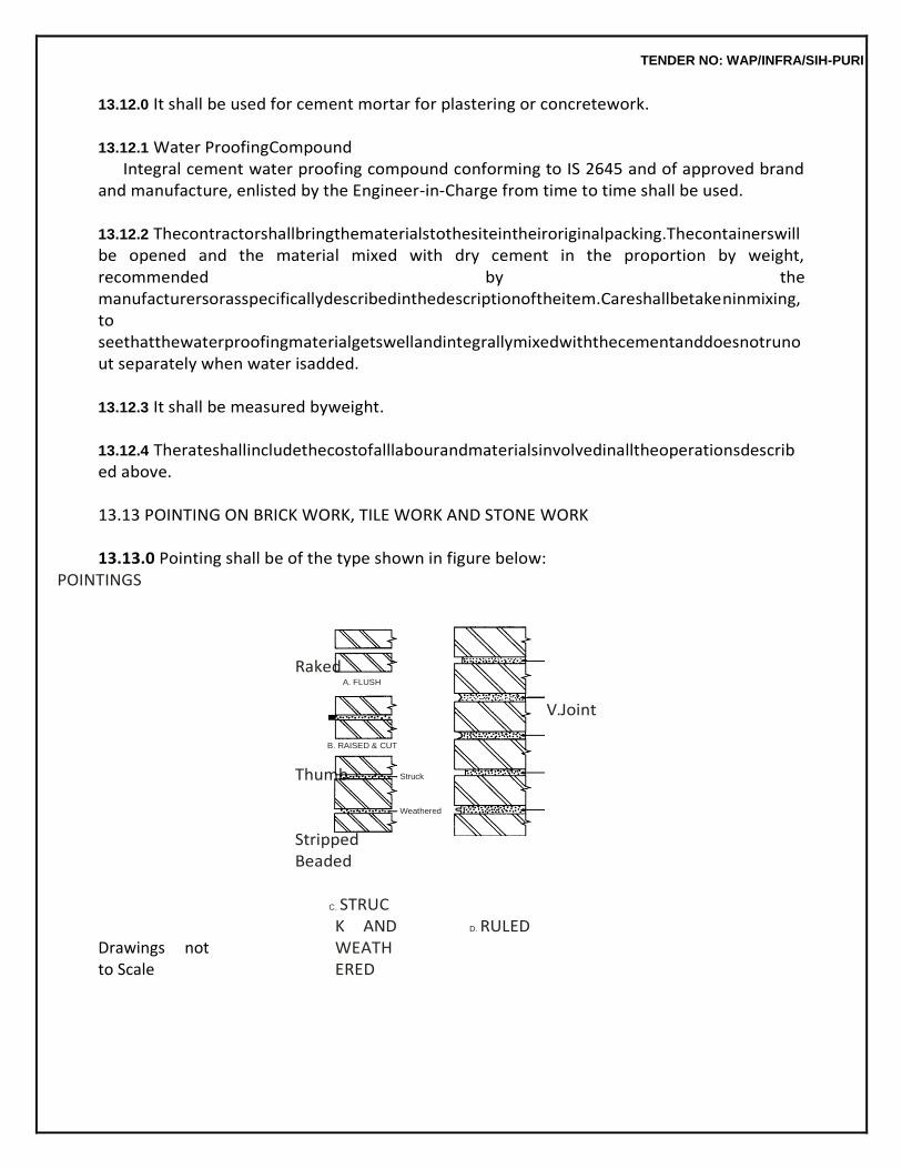
TENDER NO: WAP/INFRA/SIH-PURI
13.12.0 It shall be used for cement mortar for plastering or concretework.
13.12.1 Water ProofingCompound Integral cement water proofing compound conforming to IS 2645 and of approved brand
and manufacture, enlisted by the Engineer-in-Charge from time to time shall be used.
13.12.2 Thecontractorshallbringthematerialstothesiteintheiroriginalpacking.Thecontainerswillbe opened and the material mixed with dry cement in the proportion by weight, recommended by the manufacturersorasspecificallydescribedinthedescriptionoftheitem.Careshallbetakeninmixing,to seethatthewaterproofingmaterialgetswellandintegrallymixedwiththecementanddoesnotrunout separately when water isadded.
13.12.3 It shall be measured byweight.
13.12.4 Therateshallincludethecostofalllabourandmaterialsinvolvedinalltheoperationsdescribed above.
13.13 POINTING ON BRICK WORK, TILE WORK AND STONE WORK
13.13.0 Pointing shall be of the type shown in figure below:
POINTINGS
Raked
V.Joint
Thumb
Stripped Beaded
Drawings not to Scale
C. STRUCK AND WEATHERED
D. RULED
A. FLUSH
B. RAISED & CUT
Struck
Weathered
TENDER NO: WAP/INFRA/SIH-PURI
13.13.1 Scaffolding
Forallexposedbrickwork,tileworkorstoneworkindependentdoublescaffoldinghavingtwosetsof verticalsupportsshallbeprovided.Thesupportsshallbesoundandstrongtiedtogetherwithhorizontal pieces over which scaffolding planks shall befixed.
For all other work in building, single scaffolding shall be permitted. In such cases, the
inner end of the horizontal scaffolding pole shall rest in a hole provided only in the header course for the purpose. Onlyoneheaderforeachpoleshallbeleftout.Suchholesforscaffoldingshall,however,notbeallowed inpillars/columnslessthanonemetreinwidth,orimmediatelyneartheskewbacksofarches.Theholes leftinmasonryworksforscaffoldingpurposesshallbefilledandmadegoodbeforeplastering.
Note : In case of special type of work, scaffolding shall be got approved from Engineer-in-
Charge in advance.
13.13.2 Preparation ofsurface The joints shall be raked out properly. Dust and loose mortar shall be brushed out.
Efflorescence if any shall be removed by brushing and scraping. The surface shall then be thoroughly washed with water, cleaned and kept wet before pointing is commenced.
In case of concrete surface if a chemical retarder has been applied to the form work, the
surface shall be roughened by wire brushing and all the resulting dust and loose particles cleaned off and care shall be taken that none of the retarders is left on the surface.
The joints shall be raked to such a depth that the minimum depth of the new mortar
measured from eitherthesunksurfaceofthefinishedpointingorfromtheedgeofthebrickshallnotbelessthan12mm.
13.13.3 Mortar
Mortar of specified mix shall be used. It shall be as specified under Chapter 3.0.
13.13.4 Application andFinishing
13.13.4.1 The mortar shall be pressed into the raked out joints, with a pointing trowel, either flush, sunk or raised, according to the type of pointing required. The mortar shall not spread over the corner,edges or surface of the masonry. The pointing shall then be finished with the proper tool, in the manner describedbelow:
13.13.4.2 FlushPointing:Themortarshallbepressedintothejointsandshallbefinishedoffflushand levelwiththeedgesofthebricks,tilesorstonessoastogiveasmoothappearance.Theedgesshallbe neatly trimmed with a trowel and straightedge.
TENDER NO: WAP/INFRA/SIH-PURI
13.13.4.3 Ruled Pointing : The joints shall be initially formed as for flush pointing and then while the mortar is still green, a groove of shape and size as shown in drawings or as instructed, shall be formed byrunningaformingtool,straightalongthecentrelineofthejoints.Thisoperationshallbecontinuedtill a smooth and hard surface is obtained. The vertical joints shall also be finished in a similar way. The vertical lines shall make true right angles at their junctions with the horizontal lines and shall not project beyond thesame.
13.13.4.4 Cut or Weather Struck Pointing : The mortar shall first be pressed into the joints. The topof the horizontal joints shall then be neatly pressed back about 3 mm or as directed, with the pointing tool so that the joints are sloping from top tobottom.
Theverticaljointsshallberuledpointed.Thejunctionsofverticaljointswiththehorizontaljointss
hall be at true rightangles.
13.13.4.5 Raised and Cut Pointing : Raised and cut pointing shall project from the wall facing with its edges cut parallel so as to have a uniformly raised band about 6 mm raised and width 10 mm more as directed.
13.13.4.6 The superfluous mortar shall then be cut off from the edges of the lines and the surface ofthe masonryshallalsobecleanedoffallmortar.Thefinishshallbesuchthatthepointingistotheexactsize and shape required and the edges are straight, neat andclean.
13.13.5 Curing
Thepointingshallbekeptwetforsevendays.Duringthisperioditshallbesuitablyprotectedfromall damages.
The pointing lines shall be truly horizontal and vertical except where the joints are
slanting as in rubble random masonry. Lines of joints from different directions should meet neatly at the junctions instead of crossing beyond.
13.13.6 Measurements
13.13.6.1 Length and breadth shall be measured correct to a cm and its area shall be calculated in square metres upto two places ofdecimal.
13.13.6.2 The various types of pointing for example, struck, keyed, flush, tuck, etc. shall each be measuredseparately.
13.13.6.3 Pointing on different types of walls, floors, roofs etc. shall each be measured separately. The type and material of the surface to be pointed shall bedescribed.
13.13.6.4 Pointing in a single detached joint as for flashing shall be given in runningmetres.
TENDER NO: WAP/INFRA/SIH-PURI
13.13.6.5 Forjambs,soffits,sillsetc.foropeningnotexceeding0.5sqmeachinarea,endsofjoists,beams, posts, girders, steps etc. not exceeding 0.5 sqm each in area and opening not exceeding 3 sqm each deductionsandadditionsshallbemadeinthefollowingway,incaseofpointingonexternalfaceonly.
(a) Nodeductionshallbemadeforendsofjoists,beams,postsetc.andopeningsnotexceeding0.5 sqmeach,andnoadditionshallbemadeforreveals,jambs,soffits,sills,etc.oftheseopenings.
(b) Deductions for openings exceeding 0.5 sqm but not exceeding 3 sqm each shall be made as followsandnoadditionsshallbemadeforreveals,jambs,soffits,sills,etc.fortheseopenings.
(c) When both the faces of the wall are pointed with the same pointing deduction shall be made for one faceonly.
(d) Whentwofacesofwallarepointedwithdifferentpointingsorifonefaceisplasteredandotheris pointed or plastered, deduction shall be made from the plaster or pointing on the side of frames for doors, windows, etc. on which the width of the reveal is less than that on the other side, but no deduction shall be made from the otherside.
(e) Where width of reveals on both faces of wall are equal, deduction of 50% of area of opening on eachfaceshallbemadefromareaofpointingorplasterasthecasemaybe.
(f) For opening having door frame equal to or projecting beyond thickness of wall, full deduction for opening shall be made from each pointed face ofwall.
13.13.6.6 In case of openings of area above 3 sqm each, deduction shall be made for the openings,but jambs, soffits and sills shall bemeasured.
13.13.6.7 The following shall be measuredseparately.
(a) Raking out joints for old work only shall be measured and given in squaremetres. (b) Raking out joints of old work built in mud mortar, lime mortar and cement mortar shall
each be measuredseparately. (c) Rakingoutjointsofdifferenttypesofoldwalls,floorsetc.shalleachbemeasuredseparately. (d) Rakingsingledetachedjointsasforflashingoldworkshallbegiveninrunningmetres.
13.13.7 Rate
The rate shall include the cost of all materials and labour involved in all the operations described above.
13.14 WHITE WASHING WITHLIME
13.14.1 Scaffolding
13.14.1.1 Wherever scaffolding is necessary, it shall be erected on double supports tied together by horizontal pieces, over which scaffolding planks shall be fixed. No ballies, bamboos or planks shall rest on or touch the surface which is being whitewashed.
13.14.1.2 For all exposed brick work or tile work, double scaffolding having two sets of vertical
TENDER NO: WAP/INFRA/SIH-PURI
supports shall be provided. The supports shall be sound and strong, tied together with horizontal pieces over which scaffolding planks shall befixed.
Note : In case of special type of brick work, scaffolding shall be got approved from Engineer-
in-Charge in advance.
13.14.1.3 Whereladdersareused,piecesofoldgunnybagsshallbetiedontheirtopstoavoiddamage or scratches towalls.
13.14.1.4 For white washing the ceiling, proper stage scaffolding shall beerected.
13.14.2 Preparation ofSurface
Before new work is white washed, the surface shall be thoroughly brushed free from mortar droppings an foreign matter.
In case of old work, all loose particles and scales shall be scrapped off and holes in plaster
as well as patches of less than 50 cm area shall be filled up with mortar of the same mix. Where so specifically orderedbytheEngineer-in-Charge,theentiresurfaceofoldwhitewashshallbethoroughlyremovedby scrapping and this shall be paid for separately. Where efflorescence is observed the deposits may be brushed clean and washed. The surface shall then be allowed to dry for atleast 48 hours before white washing isdone.
13.14.3 Preparation of LimeWash
13.14.3.1 The lime wash shall be prepared from fresh stone white lime (Narnaul or Dehradun quality). The lime shall be thoroughly slaked on the spot, mixed and stirred with sufficient water to make a thin cream. This shall be allowed to stand for a period of 24 hours and then shall be screened through a clean coarse cloth. 40 gm of gum dissolved in hot water, shall be added to each 10 cubic dicimetre of thecream.Theapproximatequantityofwatertobeaddedinmakingthecreamwillbe5litresofwaterto one kg oflime.
13.14.3.2 Indigo(Neel)upto3gmperkgoflimedissolvedinwater,shallthenbeaddedandstirredwell. Watershallthenbeaddedattherateofabout5litresperkg.oflimetoproduceamilkysolution.
13.14.4 Application
13.14.4.1 The white wash shall be applied with moonj brushes to the specified number of coats. The operationforeachcoatshallconsistofastrokeofthebrushgivenfromthetopdownwards,anotherfrom the bottom upwards over the first stroke, and similarly one stroke horizontally from the right and another from the left before it dries.
13.14.4.2 Each coat shall be allowed to dry before the next one is applied. Further each coat
TENDER NO: WAP/INFRA/SIH-PURI
shall be inspectedandapprovedbytheEngineer-in-Chargebeforethesubsequentcoatisapplied.Noportionof the surface shall be left out initially to be patched up lateron.
13.14.4.3 For new work, three or more coats shall be applied till the surface presents a smooth and uniform finish through which the plaster does not show. The finished dry surface shall not show any signsofcrackingandpeelingnorshallitcomeoffreadilyonthehandwhenrubbed.
13.14.4.4 Foroldwork,afterthesurfacehasbeenpreparedasdescribedinpara13.14.2acoatofwhite wash shall be applied over the patches and repairs. Then a single coat or two or more coats of white wash as stipulated in the description of the item shall be applied over the entire surface. The white washed surface should present a uniform finish through which the plaster patches do not appear. The washing on ceiling should be done prior to that onwalls.
Note : In case of Hessian ceiling, on no account, lime shall be used as it rots cloth and hessian.
13.14.5 ProtectiveMeasures
Doors, windows, floors, articles of furniture etc. and such other parts of the building not to be white washed, shall be protected from being splashed upon. Splashings and droppings, if any shall be removed by the contractor at his own cost and the surfaces cleaned. Damages if any to furniture or fittings and fixtures shall be recoverable from the contractor.
13.14.6 Measurements 13.14.6.1 Length and breadth shall be measured correct to a cm. and area shall be calculated in sqm correct to two places ofdecimals.
13.14.6.2 MeasurementsforJambs,SoffitsandFillsetc.foropeningsshallbeasdescribedin13.1.9.
13.14.6.3 Corrugated surfaces shall be measured flat as fixed and the area so measured shall be increased by the following percentages to allow for the girthedarea.
Corrugated non-asbestoscementsheet 20% Semi corrugated non-asbestoscementsheet 10%
13.14.6.4 Cornices and other such wall or ceiling features, shall be measured along the girth and included in themeasurements.
13.14.6.5 The number of coats of each treatment shall be stated. The item shall include removing nails, making good holes, cracks, patches etc. not exceeding 50 sq. cm. each with material similar in composition to the surface to beprepared.
TENDER NO: WAP/INFRA/SIH-PURI
13.14.6.6 Work on old treated surfaces shall be measured separately and sodescribed.
13.14.7 Rate The rate shall include all material and labour involved in all the operations described above.
13.15 SATNA LIME WASHING
13.15.0 Satna lime wash shall be used as a base coat where so specified. The specifications for ‘white washingwithlime’shallapplyexceptthatSatnaorKatniqualitylimeshallbeusedinplaceofNarnaulorDehradun quality lime and the wash will be mixed to a thicker consistency. The other details and specifications described in 13.14 will apply in toto. 13.16 WHITE WASHING WITHWHITING
13.16.1 Preparation ofMix
Whiting (ground white chalk) shall be dissolved in sufficient quantity of warm water and thoroughly stirred to form a thin slurry which shall then be screened through a clean coarse cloth. Two kg of gum and 0.4 kg of copper sulphate dissolved separately in hot water shall be added for every cum of the slurry which shall then be diluted with water to the consistency of milk so as to make a wash ready for use.
13.16.2 Other specifications described in 13.14 shall apply in this casealso.
13.17 COLOUR WASHING
13.17.1 The mineral colours, not affected by lime, shall be added to white wash. Indigo (Neel) shall however, not be added. No colour wash shall be done until a sample of the colour wash of the required tint or shade has been got approved from the Engineer-in-Charge. The colour shall be of even tint or shade over the whole surface. If it is blotchy or otherwise badly applied, it shall be redone by the contractor.
For new work, the priming coat shall be of white wash with lime or with whiting as
specified in the description of the item. Two or more coats, shall then be applied on the entire surface till it represents a smooth and uniform finish.
Foroldwork,afterthesurfacehasbeenpreparedasdescribedin13.14.2acoatofcolourwashshall
be applied over the patches and repairs. Then a single coat, or two or more coats of colour wash, as stipulated in the description of the item shall be applied over the entire surface. The colour washed surface shall present a uniformfinish.
The finished dry surface shall not be powdery and shall not readily come off on the hand when rubbed.
13.17.2 Other specifications as described under13.14.
TENDER NO: WAP/INFRA/SIH-PURI
13.18 DRYDISTEMPERING
13.18.1 Materials Dry distemper of required colour (IS 427) and of approved brand and manufacture shall
be used. The shade shall be got approved from the Engineer-in-Charge before application of the distemper. The dry distemper colour as required shall be stirred slowly in clean water using 6 decilitres (0.6 litre) of waterperkgofdistemperorasspecifiedbythemakers.Warmwatershallpreferablybeused.Itshallbe allowed to stand for at least 30 minutes (or if practicable over night) before use. The mixture shall be well stirred before and during use to maintain an evenconsistency.
Distemper shall not be mixed in larger quantity than is actually required for one day’s work.
13.18.2 Preparation ofSurface
13.18.2.1 Before new work is distempered, the surface shall be thoroughly brushed free from mortar droppings and other foreign matter and sand paperedsmooth.
13.18.2.2 Newplasteredsurfacesshallbeallowedtodrycompletely,beforeapplying,distemper.
13.18.2.3 In the case of old work, all loose pieces and scales shall be removed by sand papering. The surface shall be cleaned of all grease, dirt,etc.
13.18.2.4 Pitting in plaster shall be made good with plaster of paris mixed with the colour to be used. The surface shall then be rubbed down again with a fine grade sand paper and made smooth. A coatof thedistempershallbeappliedoverthepatches.Thepatchedsurfaceshallbeallowedtodrythoroughly before the regular coat of distemper isapplied.
13.18.3 PrimingCoat
Aprimingcoatofwhiting(see13.16)shallbeappliedoverthepreparedsurfaceincaseofnewwork, if so stipulated in the description of the item. No white washing coat shall be used as a priming coat for distemper.
The treated surface be allowed to dry before distemper coat is given.
13.18.4 Application
13.18.4.1 Inthecaseofnewwork,thetreatmentshallconsistofaprimingcoatofwhiting(Asper13.16) followedbytheapplicationoftwoormorecoatsofdistempertillthesurfaceshowsanevencolour.
13.18.4.2 For old work, the surface prepared as described in para 13.14 shall be applied one or more coats of distemper till the surface attains an evencolour.
13.18.4.3 The application of each coat shall be asfollows:
TENDER NO: WAP/INFRA/SIH-PURI
The entire surface shall be coated with the mixture uniformly, with proper distemper
brushes (ordinarywhitewashbrushedshallnotbeallowed)inhorizontalstrokesfollowedimmediatelybyvertical ones which together shall constitute onecoat.
13.18.4.4 The subsequent coats shall be applied only after the previous coat hasdried.
13.18.4.5 The finished surface shall be even and uniform and shall show no brushmarks.
13.18.4.6 Enough distemper shall be mixed to finish one room at a time. The application of a coat in each room shall be finished in one operation and no work shall be started in any room, which cannotbe completed the sameday.
13.18.4.7 After each day’s work, the brushes shall be washed in hot water and hung down to dry. Old brushes which are dirty or caked with distemper shall not beused.
13.18.5 The specifications in respect of scaffolding, protective measures, measurements and rate shall be as described under 13.14.
13.19 OIL EMULSION (OIL BOUND) WASHABLEDISTEMPERING
13.19.1 Materials
Oil emulsion (Oil Bound) washable distemper (IS 428) of approved brand and manufacture shall be used. The primer where used as on new work shall be cement primer or distemper primer as described in the item. These shall be of the same manufacture as distemper. The distemper shall be diluted with water or any other prescribed thinner in a manner recommended by the manufacturer. Only sufficient quantity of distemper required for day’s work shall be prepared.
Thedistemperandprimershallbebroughtbythecontractorinsealedtinsinsufficientquantitiesa
ta timetosufficeforafortnight’swork,andthesameshallbekeptinthejointcustodyofthecontractorandthe Engineer-in-Charge. The empty tins shall not be removed from the site of work, till this item of work has been completed and passed by the Engineer-in-Charge.
13.19.2 Preparation of theSurface
13.19.2.1 For new work the surface shall be thoroughly cleaned of dust, old white or colour wash by washing and scrubbing. The surface shall then be allowed to dry for at least 48 hours. It shall then be sand papered to give a smooth and even surface. Any unevenness shall be made good by applying putty, made of plaster of paris mixed with water on the entire surface including filling up the undulations and then sand papering the same after it isdry.
13.19.2.2 In the case of old work, all loose pieces and scales shall be removed by sand
TENDER NO: WAP/INFRA/SIH-PURI
papering. The surface shall be cleaned of all grease, dirtetc.
Pitting in plaster shall be made good with plaster of paris mixed with the colour to be used. The surface shall then be rubbed down again with a fine grade sand paper and made smooth. A coat of the distemper shall be applied over the patches. The patched surface shall be allowed to dry thoroughly before the regular coat of distemper is applied.
13.19.3 Application
13.19.3.1 PrimingCoat:Theprimingcoatshallbewithdistemperprimerorcementprimer,asrequired inthedescriptionoftheitem.Theapplicationofthedistemperprimershallbeasdescribedin13.18.4.
Note : If the wall surface plaster has not dried completely, cement primer shall be applied
before distempering the walls. But if distempering is done after the wall surface is dried completely, distemper primer shall be applied.
Oil bound distemper is not recommended to be applied, within six months of the completion of wall plaster. However, newly plastered surfaces if required to be distempered before a period of six months shall be given a coat of alkali resistant priming Paint conforming to IS 109 and allowed to dry for atleast 48 hours before distempering iscommenced.
Foroldworknoprimercoatisnecessary.
13.19.3.2 DistemperCoat:Fornewwork,aftertheprimercoathasdriedforatleast48hours,thesurface shallbelightlysandpaperedtomakeitsmoothforreceivingthedistemper,takingcarenottoruboutthe priming coat. All loose particles shall be dusted off after rubbing. One coat of distemper properly diluted with thinner (water or other liquid as stipulated by the manufacturer) shall be applied with brushes in horizontalstrokesfollowedimmediatelybyverticaloneswhichtogetherconstitutesonecoat.
The subsequent coats shall be applied in the same way. Two or more coats of distemper
as are found necessary shall be applied over the primer coat to obtain an even shade.
A time interval of at least 24 hours shall be allowed between successive coats to permit proper drying of the preceding coat.
Foroldworkthedistempershallbeappliedoverthepreparedsurfaceinthesamemannerasinne
w work. One or more coats of distemper as are found necessary shall be applied to obtain an even and uniform shade.15 cm double bristled distemper brushes shall be used. After each days work, brushes shall be tho- roughly washed in hot water with soap solution and hung down to dry. Old brushes which are dirty and caked with distemper shall not be used on the work.
TENDER NO: WAP/INFRA/SIH-PURI
13.19.4 Thespecificationsinrespectofscaffolding,protectivemeasuresandmeasurementsshallbeas described under13.14.
13.19.5 Rate
The rate shall include the cost of all labour and materials involved in all the above operations (including priming coat) described above.
13.20 CEMENT PRIMERCOAT
13.20.0 Cementprimercoatisusedasabasecoatonwallfinishofcement,limeorlimecementplaster or on non-asbestos cement surfaces before oil emulsion distemper Paints are applied on them. The cement primer is composed of a medium and pigment which are resistant to the alkalies present in the cement, lime or lime cement in wall finish and provides a barrier for the protection of subsequent coats of oil emulsion distemperPaints.
Primer coat shall be preferably applied by brushing and not by spraying. Hurried priming
shall be avoided particularly on absorbent surfaces. New plaster patches in old work should also be treatedwith cement primer before applying oil emulsion Paintsetc. 13.20.1 Preparation of theSurface
Thesurfaceshallbethoroughlycleanedofdust,oldwhiteorcolourwashbywashingandscrubbing. The surface shall then be allowed to dry for at least 48 hours. It shall then be sand papered to give a smooth and even surface. Any uneveness shall be made good by applying putty, made of plaster of paris mixed with water on the entire surface including filling up the undulations and then sand papering the same after it isdry.
13.20.2 Application
The cement primer shall be applied with a brush on the clean dry and smooth surface. Horizontal strokes shall be given first and vertical strokes shall be applied immediately afterwards. This entire operation will constitute one coat. The surface shall be finished as uniformly as possible leaving no brush marks. It shall be allowed to dry for at least 48 hours, before oil emulsion Paint is applied.
13.20.3 The Specifications in respect of scaffolding, protective measures, measurements and rate shall be as described under13.1.4.
13.21 CEMENTPAINT
13.21.1 Material
The cement Paint shall be (conforming to IS 5410) of approved brand and manufacture.
The cement Paint shall be brought to the site of work by the contractor in its original containers is sealedcondition.Thematerialshallbebroughtinatatimeinadequatequantitiestosufficeforthewhole work or at least a fortnight’s work. The materials shall be kept in the joint custody of the Contractor and theEngineer-in-
TENDER NO: WAP/INFRA/SIH-PURI
Charge.Theemptycontainersshallnotberemovedfromthesiteofworktilltherelevant itemoftheworkhasbeencompletedandpermissionobtainedfromtheEngineer-in-Charge.
13.21.2 Preparation ofSurface
For New Work, the surface shall be thoroughly cleaned of all mortar dropping, dirt dust, algae, grease and other foreign matter by brushing and washing. Pitting in plaster shall be made good and a coat of water proof cement Paint shall be applied over patches after wetting them thoroughly.
13.21.3 Preparation ofMix
Cement Paint shall be mixed in such quantities as can be used up within an hour of its mixing as otherwise the mixture will set and thicken, affecting flow and finish. Cement Paint shall be mixed with water in two stages. The first stage shall comprise of 2 parts of cement Paint and one part of water stirred thoroughly and allowed to stand for 5 minutes. Care shall be taken to add the cement Paint graduallytothewaterandnotviceversa.Thesecondstageshallcompriseofaddingfurtheronepartof water to the mix and stirring thoroughly to obtain a liquid of workable and uniform consistency. In all cases the manufacturer’s instructions shall be followedmeticulously.
The lids of cement Paint drums shall be kept tightly closed when not in use, as by
exposure to atmosphere the cement Paint rapidly becomes air set due to its hygroscopic qualities.
In case of cement Paint brought in gunny bags, once the bag is opened, the contents
should be consumed in full on the day of its opening. If the same is not likely to be consumed in full, the balance quantity should be transferred and preserved in an airtight container to avoid its exposure to atmosphere.
13.21.4 Application
13.21.4.1 The solution shall be applied on the clean and wetted surface with brushes or spraying machine.Thesolutionshallbekeptwellstirredduringtheperiodofapplication.Itshallbeappliedonthe surface which is on the shady side of the building so that the direct heat of the sun on the surface is avoided. The method of application of cement Paint shall be as per manufacturer’s specification. The completed surface shall be watered after the day’swork.
13.21.4.2 The second coat shall be applied after the first coat has been set for at least 24 hours.Before applicationofthesecondorsubsequentcoats,thesurfaceofthepreviouscoatshallnotbewetted.
13.21.4.3 For new work, the surface shall be treated with three or more coats of water proof cement Paint as found necessary to get a uniformshade.
13.21.4.4 For old work, the treatment shall be with one or more coats as found necessary to
TENDER NO: WAP/INFRA/SIH-PURI
get a uniform shade.
13.21.5 Precaution Water proof cement Paint shall not be applied on surfaces already treated with white
wash, colour wash, distemper dry or oil bound, varnishes, Paints etc. It shall not be applied on gypsums, wood and metal surfaces.
If water proofing cement is required to be applied on existing surface, previously treated
with white wash, colour wash etc., the surface shall be thoroughly cleaned by scrapping off all the white wash, colour wash etc. completely. Thereafter, a coat of cement primer shall be applied followed by two or more coat of water proof cement.
13.21.6 The specifications in respect of scaffolding, protective measures, measurements and rate shall be as described under 13.14. The coefficient for cement Paint on RCC Jalli shall be the same as providedinSl.No.7ofTable1underpara13.23.6.4forpaintingtrellisforJaffriwork.
13.22 EXTERIOR PAINTING ONWALL
13.22.1 Material
The paint shall be (Texured exterior paint/Acrylic smooth exterior paint/premium acrylic smooth exterior paint) of approved brand and manufacture.
This paint shall be brought to the site of work by the contractor in its original containers in
sealed condition. The material shall be brought in at a time in adequate quantities to suffice for the whole work or at least a fornight’s work. The materials shall be kept in the joint custody of the contractor and theEngineer-in-Charge. The empty containers shall not be removed from the site of work till the relevant item of work has been completed and permission obtained from the Engineer-in-Charge.
13.22.2 Preparation ofSurface
Fornewwork,thesurfaceshallbethoroughlycleanedoffallmortardropping,dirtdust,algae,fungus or moth, grease and other foreign matter of brushing and washing, pitting in plaster shall make good, surface imperfections such as cracks, holes etc. should be repaired using white cement. The prepared surface shall have received the approval of the Engineer in charge after inspection before painting is commenced.
13.22.3 Application
Base coat of water proofing cement paint
13.22.3.1 All specifications in respect of base coat of water proofing cement paint shall be as described under13.21.
13.22.3.2 Before pouring into smaller containers for use, the paint shall be stirred thoroughly in its container, when applying also the paint shall be continuously stirred in the smaller containers so that its consistency is kept uniform. Dilution ratio of paint with potable water
TENDER NO: WAP/INFRA/SIH-PURI
can be altered takinginto consideration the nature of surface climate and as per recommended dilution given by manufacturer. In all cases, the manufacturer’s instructions & directions of the Engineer-in-charge shall be followed meticulously.
The lids of paint drums shall be kept tightly closed when not in use as by exposure to
atmosphere the paint may thicken and also be kept safe from dust.
13.22.3.3 Paint shall be applied with a brush on the cleaned and smooth surface. Horizontal strokes shall be given, First and vertical strokes shall be applied immediately afterwards. This entire operation willconstituteonecoat.Thesurfaceshallbefinishedasuniformlyaspossibleleavingnobrushmarks.
13.22.4 The specifications in respect of scaffolding, protective measures, measurements and rate shall be as described under13.14.
13.23 PAINTING
13.23.1 Materials
Paints, oils, varnishes etc. of approved brand and manufacture shall be used. Only ready mixed Paint (Exterior grade) as received from the manufacturer without any admixture shall be used.
If for any reason, thinning is necessary in case of ready mixed Paint, the brand of thinner recommended by the manufacturer or as instructed by the Engineer-in-Charge shall be used.
ApprovedPaints,oilorvarnishesshallbebroughttothesiteofworkbythecontractorintheirorigi
nal containersinsealedcondition.Thematerialshallbebroughtinatatimeinadequatequantitiestosuffice for the whole work or at least a fortnight’s work. The materials shall be kept in the joint custody of the contractor and the Engineer-in-Charge. The empties shall not be removed from the site of work, till the relevantitemofworkhasbeencompletedandpermissionobtainedfromtheEngineer-in-Charge.
13.23.2 CommencingWork
Painting shall not be started until the Engineer-in-Charge has inspected the items of work to be painted, satisfied himself about their proper quality and given his approval to commence the painting work. Painting of external surface should not be done in adverse weather condition like hail storm and dust storm.
Painting, except the priming coat, shall generally be taken in hand after practically
finishing all other building work.
The rooms should be thoroughly swept out and the entire building cleaned up, at least one day in advance of the Paint work being started.
13.23.3 Preparation ofSurface
TENDER NO: WAP/INFRA/SIH-PURI
Thesurfaceshallbethoroughlycleanedanddustedoff.Allrust,dirt,scales,smokesplashes,mortar droppingsandgreaseshallbethoroughlyremovedbeforepaintingisstarted.Thepreparedsurfaceshall havereceivedtheapprovaloftheEngineer-in-Chargeafterinspection,beforepaintingiscommenced.
13.23.4 Application
13.23.4.1 Before pouring into smaller containers for use, the Paint shall be stirred thoroughly in its containers, when applying also, the Paint shall be continuously stirred in the smaller containers so that its consistency is keptuniform.
13.23.4.2 The painting shall be laid on evenly and smoothly by means of crossing and laying off, the latter in the direction of the grains of wood. The crossing and laying off consists of covering the area overwithPaint,brushingthesurfacehardforthefirsttimeoverandthenbrushingalternatelyinopposite direction, two or three times and then finally brushing lightly in a direction at right angles to the same.In thisprocess,nobrushmarksshallbeleftafterthelayingoffisfinished.Thefullprocessofcrossingand laying off will constitute onecoat.
13.23.4.3 Where so stipulated, the painting shall be done by spraying. Spray machine used may be (a) high pressure (small air aperture) type, or (b) a low pressure (large air gap) type, depending on the nature and location of work to be carried out. Skilled and experienced workmen shall be employed for thisclassofwork.Paintsusedshallbebroughttotherequisiteconsistencybyaddingasuitablethinner. 13.23.4.4 Spraying should be done only when dry condition prevails. Each coat shall be allowed to dry outthoroughlyandrubbedsmoothbeforethenextcoatisapplied.Thisshouldbefacilitatedbythorough ventilation. Each coat except the last coat, shall be lightly rubbed down with sand paper or fine pumice stone and cleaned off dust before the next coat islaid.
13.23.4.5 NoleftoverPaintshallbeputbackintothestocktins.Whennotinuse,thecontainersshallbe kept properlyclosed.
13.23.4.6 No hair marks from the brush or clogging of Paint puddles in the corners of panels, angles of mouldings etc. shall be left on thework.
13.23.4.7 Inpaintingdoorsandwindows,theputtyroundtheglasspanesmustalsobepaintedbutcare must be taken to see that no Paint stains etc. are left on the glass. Tops of shutters and surfaces in similarhiddenlocationsshallnotbeleftoutinpainting.However,bottomedgeoftheshutterswherethe painting is not practically possible, need not be done nor any deduction on this account will be donebut
TENDER NO: WAP/INFRA/SIH-PURI
twocoatsofprimerofapprovedmakeshallbedoneonthebottomedgebeforefixingtheshutters.
13.23.4.8 On painting steel work, special care shall be taken while painting over bolts, nuts, rivets overlapsetc.
13.23.4.9 The additional specifications for primer and other coats of Paints shall be as according to the detailed specifications under the respectiveheadings.
13.23.5 Brushes andContainers
After work, the brushes shall be completely cleaned of Paint and linseed oil by rinsing with turpentine. A brushinwhichPainthasdriedupisruinedandshallonnoaccountbeusedforpaintingwork.Thecontainers whennotinuse, shallbekeptclosedandfreefromairsothatPaintdoesnotthickenandalso shallbekeptsafefromdust.WhenthePainthasbeenused,thecontainersshallbewashedwithturpentineandwipeddry withsoftcleancloth,sothattheyareclean,andcanbeusedagain.
13.23.6 Measurements
13.23.6.1 The length and breadth shall be measured correct to a cm. The area shall be calculated in sqm (correct to two places of decimal), except otherwisestated.
13.23.6.2 Small articles not exceeding 10 sq. decimetre (0.1 sqm) of painted surfaces where not in conjunction with similar painted work shall beenumerated.
13.23.6.3 Painting upto 10 cm in width or in girth and not in conjunction with similar painted work shall be given in running metres and shall include cutting to line where sorequired.
Note : Components of trusses, compound girders, stanchions, lattices and similar work shall,
however, be given in sq. metres irrespective of the size or girth of members. Priming coat of painting shall be included in the work of fabrication.
13.23.6.4 In measuring painting, varnishing, oiling etc. of joinery and steel work etc. The coefficients as indicatedinfollowingtablesshallbeusedtoobtaintheareapayable.Thecoefficientsshallbeappliedto the areas measured flat and notgirthed.
TABLE 13.1 Equivalent Plain Areas of Uneven Surface
S. Description No.
of
work How measured Multiplying coefficients
1 2 3 4
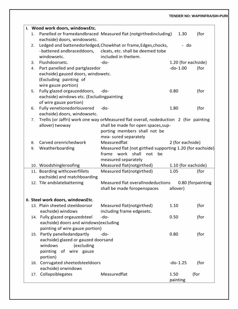
TENDER NO: WAP/INFRA/SIH-PURI
I. Wood work doors, windowsEtc. 1. Panelled or framedandbraced Measured flat (notgirthedincluding) 1.30 (for
eachside) doors, windowsetc. 2. Ledged and battenedorledged, Chowkhat or frame,Edges,chocks, - do
- battened andbraceddoors, cleats, etc. shall be deemed tobe windowsetc. included in theitem.
3. Flushdoorsetc. -do- 1.20 (for eachside) 4. Part panelled and partglazedor -do- 1.00 (for
eachside) gauzed doors, windowetc. (Excluding painting of wire gauze portion)
5. Fully glazed orgauzeddoors, -do- 0.80 (for eachside) windows etc. (Excludingpainting of wire gauze portion)
6. Fully venetionedorlouvered -do- 1.80 (for eachside) doors, windowsetc.
7. Trellis (or Jaffri) work one way orMeasured flat overall, nodeduction 2 (for painting allover) twoway shall be made for open spaces,sup-
porting members shall not be mea- sured separately
8. Carved orenrichedwork Measuredflat 2 (for eachside) 9. Weatherboarding Measured flat (not girthed supporting 1.20 (for eachside)
frame work shall not be measured separately
10. Woodshingleroofing Measured flat(notgirthed) 1.10 (for eachside)
11. Boarding withcoverfillets Measured flat(notgirthed) 1.05 (for eachside) and matchboarding
12. Tile andslatebattening Measured flat overallnodeductions 0.80 (forpainting shall be made foropenspaces allover)
II. Steel work doors, windowsEtc.
13. Plain sheeted steeldoorsor Measured flat(notgirthed) 1.10 (for eachside) windows including frame edgesetc.
14. Fully glazed orgauzedsteel -do- 0.50 (for eachside) doors and windows(excluding painting of wire gauze portion)
15. Partly panelledandpartly -do- 0.80 (for eachside) glazed or gauzed doorsand windows (excluding painting of wire gauze portion)
16. Corrugated sheetedsteeldoors -do- 1.25 (for eachside) orwindows
17. Collapsiblegates Measuredflat 1.50 (for painting
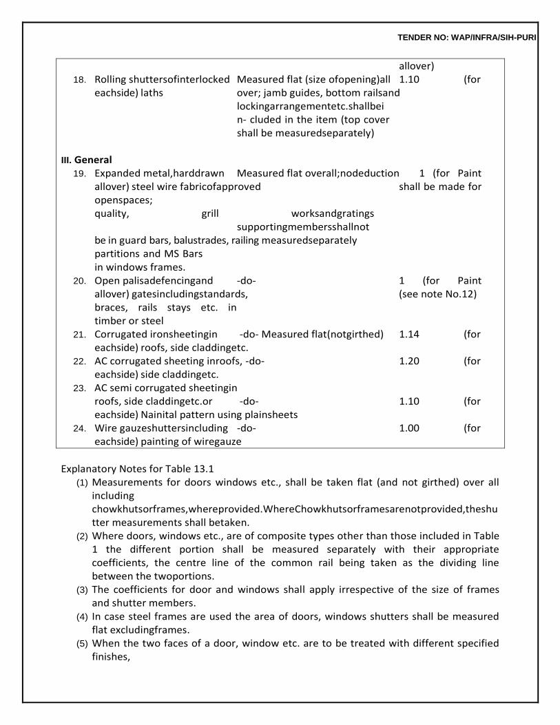
TENDER NO: WAP/INFRA/SIH-PURI
allover) 18. Rolling shuttersofinterlocked Measured flat (size ofopening)all 1.10 (for
eachside) laths over; jamb guides, bottom railsand lockingarrangementetc.shallbein- cluded in the item (top cover shall be measuredseparately)
III. General
19. Expanded metal,harddrawn Measured flat overall;nodeduction 1 (for Paint allover) steel wire fabricofapproved shall be made for openspaces; quality, grill worksandgratings supportingmembersshallnotbe in guard bars, balustrades, railing measuredseparately partitions and MS Bars in windows frames.
20. Open palisadefencingand -do- 1 (for Paint allover) gatesincludingstandards, (see note No.12) braces, rails stays etc. in timber or steel
21. Corrugated ironsheetingin -do- Measured flat(notgirthed) 1.14 (for eachside) roofs, side claddingetc.
22. AC corrugated sheeting inroofs, -do- 1.20 (for eachside) side claddingetc.
23. AC semi corrugated sheetingin roofs, side claddingetc.or -do- 1.10 (for eachside) Nainital pattern using plainsheets
24. Wire gauzeshuttersincluding -do- 1.00 (for eachside) painting of wiregauze
Explanatory Notes for Table 13.1
(1) Measurements for doors windows etc., shall be taken flat (and not girthed) over all including chowkhutsorframes,whereprovided.WhereChowkhutsorframesarenotprovided,theshutter measurements shall betaken.
(2) Where doors, windows etc., are of composite types other than those included in Table 1 the different portion shall be measured separately with their appropriate coefficients, the centre line of the common rail being taken as the dividing line between the twoportions.
(3) The coefficients for door and windows shall apply irrespective of the size of frames and shutter members.
(4) In case steel frames are used the area of doors, windows shutters shall be measured flat excludingframes.
(5) When the two faces of a door, window etc. are to be treated with different specified finishes,
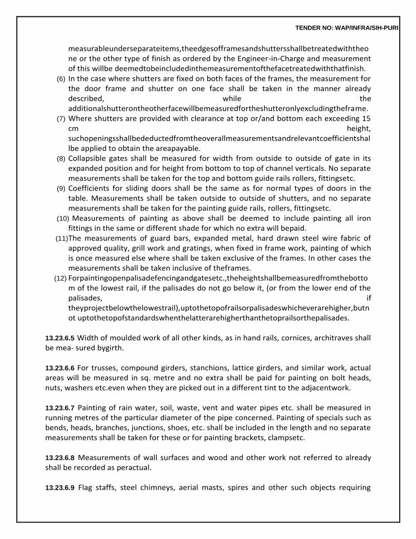
TENDER NO: WAP/INFRA/SIH-PURI
measurableunderseparateitems,theedgesofframesandshuttersshallbetreatedwiththeone or the other type of finish as ordered by the Engineer-in-Charge and measurement of this willbe deemedtobeincludedinthemeasurementofthefacetreatedwiththatfinish.
(6) In the case where shutters are fixed on both faces of the frames, the measurement for the door frame and shutter on one face shall be taken in the manner already described, while the additionalshutterontheotherfacewillbemeasuredfortheshutteronlyexcludingtheframe.
(7) Where shutters are provided with clearance at top or/and bottom each exceeding 15 cm height, suchopeningsshallbedeductedfromtheoverallmeasurementsandrelevantcoefficientshallbe applied to obtain the areapayable.
(8) Collapsible gates shall be measured for width from outside to outside of gate in its expanded position and for height from bottom to top of channel verticals. No separate measurements shall be taken for the top and bottom guide rails rollers, fittingsetc.
(9) Coefficients for sliding doors shall be the same as for normal types of doors in the table. Measurements shall be taken outside to outside of shutters, and no separate measurements shall be taken for the painting guide rails, rollers, fittingsetc.
(10) Measurements of painting as above shall be deemed to include painting all iron fittings in the same or different shade for which no extra will bepaid.
(11) The measurements of guard bars, expanded metal, hard drawn steel wire fabric of approved quality, grill work and gratings, when fixed in frame work, painting of which is once measured else where shall be taken exclusive of the frames. In other cases the measurements shall be taken inclusive of theframes.
(12) Forpaintingopenpalisadefencingandgatesetc.,theheightshallbemeasuredfromthebottom of the lowest rail, if the palisades do not go below it, (or from the lower end of the palisades, if theyprojectbelowthelowestrail),uptothetopofrailsorpalisadeswhicheverarehigher,butnot uptothetopofstandardswhenthelatterarehigherthanthetoprailsorthepalisades.
13.23.6.5 Width of moulded work of all other kinds, as in hand rails, cornices, architraves shall be mea- sured bygirth.
13.23.6.6 For trusses, compound girders, stanchions, lattice girders, and similar work, actual areas will be measured in sq. metre and no extra shall be paid for painting on bolt heads, nuts, washers etc.even when they are picked out in a different tint to the adjacentwork.
13.23.6.7 Painting of rain water, soil, waste, vent and water pipes etc. shall be measured in running metres of the particular diameter of the pipe concerned. Painting of specials such as bends, heads, branches, junctions, shoes, etc. shall be included in the length and no separate measurements shall be taken for these or for painting brackets, clampsetc.
13.23.6.8 Measurements of wall surfaces and wood and other work not referred to already shall be recorded as peractual.
13.23.6.9 Flag staffs, steel chimneys, aerial masts, spires and other such objects requiring
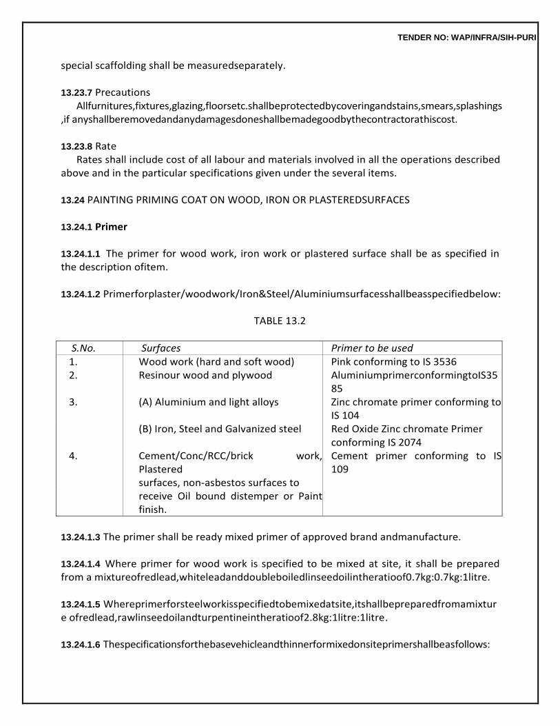
TENDER NO: WAP/INFRA/SIH-PURI
special scaffolding shall be measuredseparately.
13.23.7 Precautions Allfurnitures,fixtures,glazing,floorsetc.shallbeprotectedbycoveringandstains,smears,splashings
,if anyshallberemovedandanydamagesdoneshallbemadegoodbythecontractorathiscost.
13.23.8 Rate Rates shall include cost of all labour and materials involved in all the operations described
above and in the particular specifications given under the several items.
13.24 PAINTING PRIMING COAT ON WOOD, IRON OR PLASTEREDSURFACES
13.24.1 Primer
13.24.1.1 The primer for wood work, iron work or plastered surface shall be as specified in the description ofitem.
13.24.1.2 Primerforplaster/woodwork/Iron&Steel/Aluminiumsurfacesshallbeasspecifiedbelow:
TABLE 13.2
S.No. Surfaces Primer to be used 1. Wood work (hard and soft wood) Pink conforming to IS 3536 2. Resinour wood and plywood AluminiumprimerconformingtoIS35
85 3. (A) Aluminium and light alloys Zinc chromate primer conforming to
IS 104 (B) Iron, Steel and Galvanized steel Red Oxide Zinc chromate Primer conforming IS 2074
4. Cement/Conc/RCC/brick work, Plastered
Cement primer conforming to IS 109
surfaces, non-asbestos surfaces to receive Oil bound distemper or Paint
finish.
13.24.1.3 The primer shall be ready mixed primer of approved brand andmanufacture.
13.24.1.4 Where primer for wood work is specified to be mixed at site, it shall be prepared from a mixtureofredlead,whiteleadanddoubleboiledlinseedoilintheratioof0.7kg:0.7kg:1litre.
13.24.1.5 Whereprimerforsteelworkisspecifiedtobemixedatsite,itshallbepreparedfromamixture ofredlead,rawlinseedoilandturpentineintheratioof2.8kg:1litre:1litre.
13.24.1.6 Thespecificationsforthebasevehicleandthinnerformixedonsiteprimershallbeasfollows:
TENDER NO: WAP/INFRA/SIH-PURI
(a) White Lead : The White lead shall be pure and free from adulterants like barium sulphate and whiting. It shall conform to IS103.
(b) Red Lead : This shall be in powder form and shall be pure and free from adulterants
like brick dust etc. It shall conform to IS102.
(c) RawLinseedOil:Rawlinseedoilshallbelightlyviscousbutclearandofyellowishcolourwithlight browntinge.Itsspecificgravityatatemperatureof30degreeCshallbebetween0.923and0.928.
Note : The oil shall be mellow and sweet to the taste with very little smell. The oil shall
be of sufficiently matured quality. Oil turbid or thick, with acid and bitter taste and rancid odour and which remains sticky for a considerable time shall be rejected. The oil shall conform in all respects to IS 75. The oil shall be of approved brand and manufacture.
(d) Double Boiled Linseed Oil : This shall be more viscous than the raw oil, have a deeper
colour andspecificgravitybetween0.931and0.945atatemperatureof30degreeC.Itshalldrywitha glossy surface. It shall conform in all respects to IS 77. The oil shall be of approved brand and manufacture.
Turpentine : Mineral turpentine i.e. petroleum distillate which has the same rate of evaporation as vegetable turpentine (distillate product of oleeresin of conifers) shall be used. It shall have no grease or other residue when allowed to evaporate. It shall conform to IS 533.
13.24.1.7 All the above materials shall be of approved manufacture and brought to site in their original packing in sealedcondition.
13.24.2 Preparation ofSurface
13.24.2.1 WoodenSurface:Thewoodworktobepaintedshallbedryandfreefrommoisture.
The surface shall be thoroughly cleaned. All unevenness shall be rubbed down smooth with sand paper and shall be well dusted. Knots, if any shall be covered with preparation of red lead made by grinding red lead in water and mixing with strong glue sized and used hot. Appropriate filler material conforming to IS 345 with same shade as Paint shall be used where specified. The surface treated for knotting shall be dry before Paint is applied. After obtaining approval of Engineer-in-Charge for wood work,theprimingcoatshallbeappliedbeforethewoodworkisfixedinposition.Aftertheprimingcoatis applied, the holes and indentation on the surface shall be stopped with glazier’s putty or wood putty. Stopping shall not be done before the priming coat is applied as the wood will absorb the oil in stopping and the latter is therefore liable tocrack.
TENDER NO: WAP/INFRA/SIH-PURI
13.24.2.2 Iron & Steel Surface : All rust and scales shall be removed by scrapping or by brushing with steel wire brushes. Hard skin of oxide formed on the surface of wrought iron during rolling which becomes loose by rusting, shall beremoved.
All dust and dirt shall be thoroughly wiped away from the surface.
If the surface is wet, it shall be dried before priming coat is undertaken.
13.24.2.3 Plastered Surface : The surface shall ordinarily not be painted until it has dried completely. Trial patches of primer shall be laid at intervals and where drying is satisfactory, painting shall then be takeninhand.Beforeprimerisapplied,holesandundulations,shallbefilledupwithplasterofparisand rubbedsmooth.
13.24.3 Application
The primer shall be applied with brushes, worked well into the surface and spread even and smooth. The painting shall be done by crossing and laying off as described in 13.22.3.3.
13.24.4 Treatment on Steel for AggressiveEnvironment
13.24.4.1 A second coat of ready mixed red oxide zinc chromate primer may be applied where consi- dered necessary in aggressive environment such as near Industrial Establishment and Coastal regions wherethesteelmembersarepronetocorrosion.Thesecondcoat(whichshallbepaidforseparately)is to be applied after placing the member in position and just before applying Paint. The second coat of primer is not necessary in case of painting with synthetic enamel Paint as it is applied over an under coat of ordinaryPaint.
13.24.4.2 Thespecificationsdescribedunder13.33shallholdgoodsofarastheyareapplicable.
13.25 PAINTING SYNTHETIC ENAMEL PAINT OVER G.S.SHEETS
13.25.0 Syntheticenamel
Paint,suitableforpaintingoverG.S.sheets,ofapprovedbrandandmanufactureandoftherequired shade shall be used. New or weathered G.S. sheets shall be painted with a priming coat of one coat of redoxide zinc chromate Paint. Primer shall be applied before fixing sheets inplace.
13.25.1 Preparation ofSurface
13.25.1.1 Painting New Surface : The painting of new G.S. sheets shall not usually be done till the sheets have weathered for about a year. When new sheets are to be painted before they have weatheredtheyshallbetreatedwithamordantsolutionpreparedbymixing38gmofcopperacetateina litre of soft water or 13 gm hydrochloric acid in a solution of 13 gm each of copper
TENDER NO: WAP/INFRA/SIH-PURI
chloride, copper nitrate and ammonium chloride dissolved in a litre of soft water. This quantity of solution is sufficient for about 235 sqm. to 280 sqm of area and is applied for ensuring proper adhesion of Paint. The painting with the mordant solution will be paid forseparately.
Before painting on new or weathered G.S. sheets, rust patches shall be completely
cleaned with coarse emery paper and brush. All grease marks shall also be removed and the surface washed and dried and rusted surface shall be touched with synthetic enamel paint of approved brand, manufacturer and shade.
13.25.1.2 Painting Old Surface: If the old Paint is firm and sound, it shall be cleaned of grease,smoke etc.Thesurfaceshallthenberubbeddownwithsandpaperanddusted.Rustypatchesshallbecleaned up and touched with synthetic enamelpaint.
If the old Paint is blistered and flaked, it shall be completely removed as described in
13.41. Such removal shall be paid for separately and painting shall be treated as on new work.
13.25.2 Application
Thenumberofcoatstobeappliedshallbeasinthedescriptionofitem.InthecaseofC.G.S.sheets, the crowns of the corrugations shall be painted first and when these get dried the general coat shall be giventoensureuniformfinishovertheentiresurfacewithoutthecrownsshowingsignsofthinning.
The second or additional coats shall be applied when the previous coat has dried.
13.25.3 The specifications described in 13.23 shall hold good so far as they areapplicable.
13.26 PAINTING CAST IRON RAIN WATER, SOIL, WASTE AND VENT PIPES ANDFITTINGS
13.26.1 The primer shall be prepared on site or shall be of approved brand and manufacture as specified in theitem.
Paint shall be anti-corrosive bitumastic Paint, aluminium Paint or other type of Paint as
specified in the description of the item.
13.26.2 Painting NewSurface
13.26.2.1 Preparation of Surface : The surface shall be prepared for priming coat as described in 13.24.2.2.
13.26.2.2 Application : The number of coat of painting over the priming coat shall be as stipulated in thedescriptionoftheitem.TheapplicationofPaintoverprimingcoatshallbecarriedoutasspecifiedi
TENDER NO: WAP/INFRA/SIH-PURI
n 13.25.
13.26.2.3 Measurements : Measurements will be taken over the finished line of pipe including specials etc. in running metres, correct to acm.
Pipes of different diameters of bore shall be measured and paid for separately.
Specials and fittings such as holder bat clamps, plugs etc. will not be measured separately.
13.26.2.4 Rate : The rate shall include the cost of all materials and labour involved in all the operations described above, including painting of all specials andfittings.
13.26.2.5 Specifications described in 13.22 shall hold good as far as they areapplicable.
13.26.3 Painting on OldSurface
13.26.3.1 The surface shall be prepared as specified in13.25.1.2.
13.26.3.2 The specifications for application shall be as described in13.22.3.
13.26.3.3 Measurements, rate and other details shall be as specified in13.26.2.3.
13.27 PAINTING WITH WOODPRESERVATIVE
13.27.1 Oil type wood preservative of specified quality and approved make, conforming to IS 218 shall be used. Generally, it shall be creosote oil type-I or anthraceneoil.
13.27.2 Painting on NewSurface
13.27.2.1 Preparation of Surface : Painting shall be done only when the surface is perfectly dry to permit of good absorption. All dirt, dust or other foreign matter shall be removed from the surface to be painted. All roughness shall be sand papered andcleaned.
13.27.2.2 Application : The preservative shall be applied liberally with a stout brush and not daubed with rags or cotton waste. It shall be applied with a pencil brush at the joints of the wood work. The first coat shall be allowed at least 24 hours to soak in before the second (the final) coat is applied. The second coat shall be applied in the same manner as the first coat. The excess of preservative which does not soak into the wood shall be wiped off with a clean dry piece ofcloth.
13.27.2.3 Thespecificationsdescribedin13.23shallholdgoodinsofarastheyareapplicable.
13.27.3 Painting on Old Surface
The work shall be done in the same manner as on new surface except that only one coat shall be done.
TENDER NO: WAP/INFRA/SIH-PURI
13.28 COAL TARRING
13.28.1 Coal tar of approved manufacture conforming to IS 290 shall be used. The tar, to every litre of which 200 gm of unslaked lime has been added, shall be heated till it begins to boil. It must then be taken off the fire and kerosene oil added to it slowly at the rate of one part of kerosene oil to six ormore partsbyvolumeandstirredthoroughly.Theadditionoflimeisforpreventingthetarfromrunning.
13.28.2 Coal Tarring NewSurface
13.28.2.1 PreparationofSurface:Thisshallbedoneasspecifiedin13.24.2exceptthatsandpaperingis notnecessary.Whereironworkistobepainteditshallbefreefromscalesandrustbeforepainting.
13.28.2.2 Application : The mixture shall be applied as hot as possible with a brush. The second coat shallbeappliedonlyafterthefirstcoathasthoroughlydriedup.Wherepossible,thearticletobetarred, shall be dipped in the hot mixture for better results. The quantity of tar to be used for the first or second coat shall be not less than 0.16 and 0.12 litre per sqm respectively. Thinning with kerosene oil shall be suitably done to ensurethis.
13.28.2.3 Thespecificationsdescribedin13.23shallholdgoodinallotherrespects,sofarastheyareapplicable.
13.28.3 Coal Tarring old Surface
The work shall be done in the same manner as specified in 13.28.2 except that only one coat using 0.12 litre per sqm. area shall be done.
13.29 SPRAY PAINTING WITH FLAT WALL PAINT ON NEWSURFACE
13.29.0 Theworkshallincludeaprimingcoatof‘DistemperingPrimer’or‘CementPrimer’asspecifiedin the description of the item. Flat wall Paint shall normally be applied on walls 12 months after their completion, in which case Distemper primer will suffice. If the walls are to be painted earlier, the primer coat shall consist of cementprimer.
13.29.1 The primer and the flat wall Paint shall be of approved brand and manufacture and of the requiredshade.
13.29.2 The surface shall be prepared as described in13.20.1.
13.29.3 Application
13.29.3.1 Primer Coat : The specified primer shall be painted or sprayed over the surface in an even and uniformlayer.
13.29.3.2 PaintingCoats:Whenthesurfaceisdry,thespraypaintingwiththewallPaintinuniformand even layers will be done to the required number of coats. Each coat shall be allowed to dry
TENDER NO: WAP/INFRA/SIH-PURI
overnight andlightlyrubbedwithveryfinegradeofsandpaperandlooseparticlesbrushedoffbeforethenextcoat is sprayed.
Spraying should be done only when dry condition prevails. During spraying the spray gun
shall be held perpendicular to the surface to be coated and shall be passed over the surface in a uniform sweeping motion.Differentairpressuresandfanadjustmentshallbetriedsoastoobtainthebestapplication.TheAir pressureshallnotbekepttoohighasotherwisethePaintwillfogupandwillbewasted.
At the end of the job, the spray gun shall be cleaned thoroughly so as to be free from dirt.
Incorrect adjustments shall be set right, as otherwise they will result in variable spray patterns, runs, sags and uneven coats.
If after the final coat of wall Paints, the surface obtained is not upto the mark, further one
or more coats as required shall be given after rubbing down the surface and dusting off all loose particles to obtain a smooth and even finish.
If the primer or wall Paint gets thickened during the application, it shall be thinned
suitably with the thinner recommended by the manufacture.
Adequateventilationshallbeprovidedtodispersesprayfumes.Fitmentsandfloorshallbeprotected from thespray.
13.29.4 The specifications described in 13.23 shall hold good for all other details as far as applicable.
13.30 SPRAY PAINTING WITH FLAT PAINT ON OLDSURFACE
13.30.0 Where the old Paint is in sound condition, renewal shall be carried out as described below, otherwise the old Paint shall be completely stripped and spray painting shall be carried out as over new work. Such removal shall be paid forseparately.
13.30.1 TheflatwallPaintshallbeofapprovedbrandandmanufactureandofrequiredshade.
13.30.2 Preparation ofSurface
Thesurfaceshallbewashedtoremovedustanddirt.Amilddetergentsolutionlikesoapwatershall be used for washing and the surface shall also be rubbed down lightly with abrasive paper when dry. Any patches appearing on the surface shall first be touched up with a coat of Paint. These shall be allowed to dry and then rubbed downlightly.
13.30.3 Application
The Paint shall then be applied with spraying machine in uniform and even layer. A second coat shall be appliedifconsiderednecessarybytheEngineer-in-Chargebutonlyafterthefirstcoatiscompletedryandhard.
TENDER NO: WAP/INFRA/SIH-PURI
Spraying should be done only when dry condition prevails. During spraying the spray gun shall be heldperpendiculartothesurfacetobecoatedandshallbepassedoverthesurfaceinuniformsweeping motion.Differentairpressuresandfanadjustmentshallbetriedsoastoobtainthebestapplication.The Air pressure shall not be kept too high as otherwise the Paint will fog up and will be wasted. At the end of the job, the spray gun shall be cleaned thoroughly so as to be free from dirt. Incorrect adjustments shallbesetright,asotherwisetheyresultinvariablespraypatterns,runs,sagsandunevencoats.
13.30.4 The specifications described in 13.22 shall hold good for all other details, as far as they are applicable.
13.31 WALL PAINTING WITH PLASTIC EMULSIONPAINT
13.31.0 TheplasticemulsionPaintisnotsuitableforapplicationonexternal,woodandironsurfaceand surfaces which are liable to heavy condensation. These Paints are to be used on internal surfaces except wooden andsteel.
13.31.1 Plastic Emulsion Paint as per IS 5411 of approved brand and manufacture and of the required shade shall beused.
13.31.2 Painting on NewSurface
13.31.2.1 The wall surface shall be prepared as specified in13.23.3.
13.31.2.2 Application:Thenumberofcoatsshallbeasstipulatedintheitem.ThePaintwillbeapplied in the usual manner with brush, spray or roller. The Paint dries by evaporation of the water content and as soon as the water has evaporated the film gets hard and the next coat can be applied. The time of dryingvariesfromonehouronabsorbentsurfacesto2to3hoursonnon-absorbentsurfaces.
Thethinningofemulsionistobedonewithwaterandnotwithturpentine.Thinningwithwaterwill
be particularly required for the under coat which is applied on the absorbent surface. The quantity of water to be added shall be as per manufacturer’sinstructions.
The surface on finishing shall present a flat velvety smooth finish. If necessary more coats
will be applied till the surface presents a uniform appearance.
13.31.2.3 Precautions (a) OldbrushesiftheyaretobeusedwithemulsionPaints,shouldbecompletelydriedofturpenti
ne or oil Paints by washing in warm soapwater. Brushes should be quickly washed in water immediately after use and kept immersed in water during break periods to prevent the Paint from hardening on the brush.
(b) In the preparation of wall for plastic emulsion painting, no oil base putties shall be
TENDER NO: WAP/INFRA/SIH-PURI
used in filling cracks, holesetc. (c) Splashes on floors etc. shall be cleaned out without delay as they will be difficult to
removeafter hardening. (d) Washing of surfaces treated with emulsion Paints shall not be done within 3 to 4
weeks of application.
13.31.2.4 Other details shall be as specified in 13.23 as far as they areapplicable. 13.31.3 Painting on OldSurface
13.31.3.1 Preparation of Surface : This shall be done, generally as specified in 13.24.2.1 except that the surface before application of Paint shall be flattened well to get the proper flat velvety finish after painting.
13.31.3.2 Application : The number of coats to be applied shall be as in description ofitem.
The application shall be as specified in 13.31.2.2 except that thinning with water shall not
normally be required.
13.31.3.3 Other details shall be as specified in 13.23 as far asapplicable.
13.32 PAINTING WITH SYNTHETIC ENAMELPAINT
13.32.1 Synthetic Enamel Paint (conforming to IS 2933) of approved brand and manufacture and of the required colour shall be used for the top coat and an undercoat of ordinary Paint of shade to match the topcoatasrecommendedbythesamemanufacturerasfarthetopcoatshallbeused.
13.32.2 Painting on NewSurface
13.32.2.1 Preparation of surface shall be as specified in 13.24.2 as the case maybe.
13.32.2.2 Application:Thenumberofcoatsincludingtheundercoatshallbeasstipulatedintheitem.
(a) Under Coat : One coat of the specified ordinary Paint of shade suited to the shade of
the top coat, shall be applied and allowed to dry overnight. It shall be rubbed next day with the finest grade of wet abrasive paper to ensure a smooth and even surface, free from brush marks and all loose particles dustedoff.
(b) Top Coat : Top coats of synthetic enamel Paint of desired shade shall be applied after
the undercoat is thoroughly dry. Additional finishing coats shall be applied if found necessary to ensure properly uniform glossysurface.
13.32.2.3 Other details shall be as specified in 13.22 as far as they areapplicable.
13.32.3 Painting on OldSurface
TENDER NO: WAP/INFRA/SIH-PURI
13.32.3.1 Preparation of Surface : Where the existing Paint is firm and sound it shall be cleaned of grease,smokeetc.andrubbedwithsandpapertoremovealllooseparticlesdustedoff.Allpatchesand cracks shall then be treated with stopping and filler prepared with the specified Paint. The surface shall again be rubbed and made smooth anduniform.
If the old paint is blistered and flaked it will be necessary to completely remove the same
as described in para 13.41. Such removal shall be paid for separately and the painting shall be treated as on new surface.
13.32.3.2 Painting : The number of coats as stipulated in the item shall be applied with synthetic enamel Paint. Each coat shall be allowed to dry and rubbed down smooth with very fine wet abrasive paper, to get an even glossy surface. If however, the surface is not satisfactory additional coats as required shall be applied to get correctfinish.
13.32.3.3 Other details shall be specified in 13.22 as far as they areapplicable.
13.33 PAINTING WITH ALUMINIUMPAINT
13.33.1 Aluminium Paint shall be (conforming to IS 2339) of approved brand and manufacture. The Paint comes in compact dual container with the paste and the mediumseparately.
The two shall be mixed together to proper consistency before use.
13.33.2 Preparation ofSurface
13.33.2.1 Steel Work (New Surfaces) : All rust and scales shall be removed by scraping or brushing withsteelwirebrushesandthensmoothenedwithsandpaper.Thesurfaceshallbethoroughlycleaned ofdust.
13.33.2.2 C.G.S.Sheets(NewSurfaces):Thepreparationofsurfaceshallbeasspecifiedin13.25.1.1.
13.33.2.3 Steel Work or C.G.S. sheets (Old Surfaces): The specifications shall be as described in 13.25.1.2.
13.33.3 Application
Thenumberofcoatstobeappliedshallbeasgivenintheitem.Eachcoatshallbeallowedtodryfor 24 hours and lightly rubbed down with fine grade sand paper and dusted off before the next coat is applied. The finished surface shall present an even and uniformappearance.
As aluminium paste is likely to settle in the container, care shall be taken to frequently stir
the Paint during used. Also the Paint shall be applied and laid off quickly, as surface is
TENDER NO: WAP/INFRA/SIH-PURI
otherwise not easily finished.
13.33.4 Other details shall be as specified in 13.23 as far as they areapplicable.
13.34 PAINTING WITH ACID PROOFPAINT
13.34.1 AcidproofPaintofapprovedbrandandmanufactureandoftherequiredshadeshallbeused.
13.34.2 Preparation of surface and application shall be as specified under 13.32 for new/old surface as the case maybe.
13.34.3 Other details shall be as specified in 13.23 as far as they areapplicable.
13.35 PAINTING WITH ANTI-CORROSIVE BITUMASTICPAINT
13.35.1 Ready mixed Paint (conforming to IS 158) shall be of approved brand and manufacture. It shall be black, lead free, acid-alkali-heat-waterresistant.
13.35.2 Preparation of surface and application shall be as specified in 13.32 for painting on new or old surfaces as the case maybe.
The drying time between consecutive coats, however, shall be not less than 3 hours.
13.35.3 Other details shall be as specified in 13.23 as far asapplicable.
13.36 FLOORPAINTING
13.36.1 FloorPaintofapprovedbrandandmanufactureandoftherequiredcolourshallbeused.
13.36.2 Preparation ofSurface
All dirt, grease shall be removed from the floor by wiping with rags, soaked in turpentine and scraping where necessary and then washing with warm water, containing caustic soda or washing soda in solution. The floor should then be rinsed thoroughly with water and dried. Cracks and holes shall then be filled with specified filler as recommended by the manufacturer and rubbed smooth.
It should be noted that the painting with floor paints shall not be done over concrete
surfaces less than two years old.
Old surface shall be prepared as specified in 13.32.3.1
13.36.3 Application The number of coats as in the description of the item shall be applied. Each coat shall be
allowedto dryfornotlessthan24hoursbeforethenextcoatisapplied.Theflooringshouldnotbebroughtintous
TENDER NO: WAP/INFRA/SIH-PURI
e for a week after final coat so that the painted surface can thoroughlyharden.
13.36.4 Measurement Measurements shall be as per actual length and breadth being measured correct to a cm.
The details given under 13.23.6 shall hold good as far as applicable.
13.36.5 Other details shall be as specified in 13.23 as far asapplicable.
13.37 VARNISHING
13.37.0 Ordinarycopalvarnishorsuperiorqualitysprayvarnishshallbeused.Theworkincludessizing of transparent woodfiller. 13.37.1 Varnish (conforming to IS 347 for the finishing and undercoats shall be of the approved manufacturer.
13.37.2 Varnishing on NewSurfaces
13.37.2.1 Preparation of Surface : New wood work to be varnished shall have been finished smooth with a carpenter’s plane. Knots shall be cut to a slight depth. Cracks and holes shall be cleanedof dust. The knots, cracks etc. shall then be filled in with wood putty made asfollows:
On a piece of wood say 20 x 15 cm face and on the side where cross grains appear, a small
quantity of glue size shall be poured and the surface scraped with the edge of a fine carpenter’s chisel. Very fine wood powder shall be mixed with the glue and the stiff paste thus formed shall be used for the filling.
Thefillingswhendryshallberubbeddownwithacarpenter’sfileandthentheentiresurfaceshallb
e rubbeddownperfectlysmoothwithmediumgrainedandfinesandpapersandwipedwithdrycleancloth so that it presents uniform appearance. In no case shall sand papers be rubbed across the grains, asin this case even the finest marks will be visible when the varnishing isapplied.
13.37.2.2 Sizing or Transparent Wood Filler Coat : The surface shall then be treated with either glue sizing or with transparent wood filler coat as stipulated in the description ofitem.
(a) Sizing : When sizing is stipulated, an application of thin clean size shall be applied hot
on the surface. When dry, the surface shall be rubbed down smooth with sand paper and cleaned. It shallthen be given another application of glue size nearly cold. The sized wood work shall again be rubbed down smoothly with fine sand paper and cleaned. The surface shall be perfectly dry and all dust shall be removednotonlyfromthesurfacebutalsofromtheedgesandjointsbeforevarnishingiscommenced.If thewoodworkistobestained,thestainingcolourshallbemixedwiththesecondcoatofthesizewhich must be applied evenly and quickly keeping the colour on theflow.
TENDER NO: WAP/INFRA/SIH-PURI
Any joining up with work already dry will show badly. The object of application of the glue
size is to seal the pores in wood to prevent absorption of the oil in the varnish.
Glue sizing is inadvisable on floors, table tops and other horizontal surfaces likely to carry wet household untensils which are likely to disturb the size coatings and thus expose bare wood.
Where glue sizing is omitted to be done the rate for the work shall be suitably reduced.
(b) Transparent Wood Filler Coat : Where instead of glue sizing, transparent wood filler
application is stipulated in the item, then the surface prepared as described in 13.37.2.1 shall be given as applicationofthefillerwithbrushorraginsuchawaythatthefillerfillsupalltheporesandindentations and levels up the surface. It shall be allowed to dry for 24 hours. Then it shall be cut and rubbed with emery paper so that the surface of the wood is laid bare, with the filler only in the pores and crevices of thewood.
13.37.2.3 Application of Varnish : The number of coats to be applied shall be as stipulated in thedes- cription of theitem.
The undercoat shall be with a flatting varnish. This dries hard and brittle and when cut
and rubbed down to produce a smooth surface enhances the gloss of the finishing varnish. The top coat shall be given with stipulated brand of finishing varnish.
The varnish shall be applied liberally with a full brush and spread evenly with short light
strokes to avoid frothing. If the work is vertical the varnish shall be crossed and recrossed and then laid off, latter being finished on the upstrokes so that varnish, as it sets, flows down and eliminates brush marks, the above process will constitute one coat. If the surface is horizontal, varnish shall be worked in every direction, with light quick strokes and finish in one definite direction so that it will set without showing brushmarks,inhandlingandapplyingvarnishcareshouldbetakentoavoidformingfrothorairbubbles. Brushes and containers shall be kept scrupulouslyclean.
Rubbing down and flatting the surface shall be done after each coat except the final coat
with fine sand paper.
The work shall be allowed to dry away from droughts and damp air. The finished surface shall then present a uniform appearance and fine glossy surface free from streaks, blister etc.
Any varnish left over in the small container shall not be poured back into the stock tin, as
it will render the latter unfit for use.
Special fine haired varnishing brushes shall be used and not ordinary Paint brushes. Brushes shall be well worn and perfectly clean.
TENDER NO: WAP/INFRA/SIH-PURI
13.37.2.4 Other details shall be as specified in 13.23 as far as they areapplicable.
13.37.3 Varnishing on OldSurface
13.37.3.1 Preparation of Surface : If the old varnished surface is firm and sound it shall be cleaned of greaseanddirtwithturpentineandthenrubbedwithwetsandpaperuntilthesurfaceiscleanandsmooth. Itshallbedriedandwipedcleanwithasoftcloth.Knots,holesandcracksshallbestoppedasspecifiedin 13.37.2.1. The entire surface shall then be rubbed down smooth with sand paper and wiped clean.
If the old varnished surface is peeled or cracked then it will be necessary to remove the
entire varnish as described in para 13.41 and such removal shall be paid for separately outside the rate for varnishing. Further the varnishing itself will have to be done like new work and will be paid for as such.
13.37.3.2 Application : The specification shall be same as described in 13.37.2.3 as far as applicable exceptthatthecoatstobeappliedwillbewiththestipulatedqualityofvarnishforfinishingcoat.
13.37.3.3 Other details shall be as specified in 13.23 as far as they areapplicable.
13.38 FRENCH SPIRITPOLISHING
13.38.1 Pure shellac conforming to IS 16 varying from pale orange to lemon yellow colour, free from resin or dirt shall be dissolved in methylated spirit at the rate of 140 gm of shellac to 1 litre of spirit. Suitablepigmentshallbeaddedtogettherequiredshade.ReadymadepolishconformingtoIS348can also beused.
13.38.2 Polishing NewSurface
13.38.2.1 PreparationofSurface:Thesurfaceshallbecleaned.Allunevennessshallberubbeddown smooth with sand paper and well dusted. Knots if visible shall be covered with a preparation of red lead and glue size laid on while hot. Holes and indentations on the surface shall be stopped with glazier’s putty. The surface shall then be given a coat of wood filler made by mixing whiting (ground chalk) in methylated spirit at the rate of 1.5 Kg of whiting per litre of spirit. The surface shall again be rubbed down perfectly smooth with glass paper and wipedclean.
13.38.2.2 Application:Thenumberofcoatsofpolishtobeappliedshallbeasdescribedintheitem.
A pad of woolen cloth covered by a fine cloth shall be used to apply the polish. The pad
shall be moistened with the polish and rubbed hard on the wood, in a series of overlapping
TENDER NO: WAP/INFRA/SIH-PURI
circles applying the mixture sparingly but uniformly over the entire area to give an even level surface. A trace of linseed oil on the face of the pad facilitates this operation. The surface shall be allowed to dry and the remaining coats applied in the same way. To finish off, the pad shall be covered with a fresh piece of clean fine cotton cloth slightly damped with methylated spirit and rubbed lightly and quickly with circular motions. The finished surface shall have a uniform texture and high gloss.
13.38.2.3 Measurements, Rate and other details shall be as specified in 13.23 as far as they are applicable.
13.38.3 Polishing OldSurface
13.38.3.1 Preparation of Surface : If the old polished surface is not much soiled it shall be cleaned of grease and dirt by rubbing with turpentine and then rubbed with fine sandpaper.
If the old polished surface is much soiled then it will be necessary to remove the entire
polish as described in 13.41 and such removal shall be paid for separately outside the rate of polishing. Further the polishing itself will have to do done like new work and will be paid for as such.
TENDER NO: WAP/INFRA/SIH-PURI
13.38.3.2 Application:Thespecificationsshallbesameasdescribedin13.38.2.2asfarasapplicable.
13.38.3.3 Measurements, Rate and other details shall be as specified in 13.23 as far as they are applicable.
13.39 BEES WAXING OR POLISHING WITH READY MADE WAX POLISH
13.39.1 The polishing shall be done with bees waxing prepared locally or with ready made wax polish of approved brand and manufacture, as stipulated in the description of item.
Where bees waxing is to be prepared locally, the following specifications for the same shall apply. Purebeeswaxfreefromparaffinorstearineadulterantsshallbeused.Itsspecificgravityshallbe
0.965to0.969andmeltingpointshallbe63degreeC.Thepolishshallbepreparedfromamixtureof bees wax, linseed oil, turpentine and varnish in the ratio of 2 : 1.5 : 1 : 0.5 by weight.
The bees wax and boiled linseed oil shall be heated over a slow fire. When the wax is
completely dissolved the mixture shall be cooled till it is just warm and turpentine and varnish added to it in the required proportions and the entire mixture shall be well stirred.
13.39.2 Waxing New Surface
13.39.2.1 Preparation of Surface : Preparation of surface shall be as described in 13.37.2.1 with the exception that knotting, holes and cracks shall be stopped with a mixture of fine saw dust formed of the wood being treated, beaten up with sufficient bees wax to give itcohesion.
13.39.2.2 Application:Thepolishshallbeappliedevenlywithacleansoftpadofcottonclothinsucha waythatthesurfaceiscompletelyandfullycovered.Thesurfaceisthenrubbedcontinuouslyforhalfan hour.
When the surface is quite dry, a second coat shall be applied in the same manner and
rubbed continuously for one hour or until the surface is dry.
The final coat shall then be applied and rubbed for two hours (more if necessary) until the surface has assumed a uniform gloss and is dry, showing no sign of stickiness.
The final polish depends, largely on the amount of rubbing which should be continuous
and with uniform pressure with frequent changes in the direction.
13.39.2.3 Other details shall be as specified in 13.23 as far as they areapplicable.
13.39.3 Waxing OldSurfaces
13.39.3.1 Preparation of Surface : The wood work shall be cleaned of all smoke and grease by washingwithlimewater.Thesurfaceshallthenbewashedwithsoapandcompletelydried.Thenitsh
TENDER NO: WAP/INFRA/SIH-PURI
all be prepared smooth as specified in13.37.2.1. 13.39.3.2 Application : The polish shall be applied in the manner specified in 13.39.2.2. In this case oneortwocoatsshallbeappliedasnecessarytogetuniformgloss,insteadofthreecoatsinthecaseof newwork.
13.39.3.3 Other details shall be as specified in 13.22 as far as they areapplicable.
13.40 LETTERING WITHPAINT
13.40.1 Black, Japan Paint (conforming to IS 341) or ready mixed Paint as ordered by the Engineer-in- Charge shall be used. The Paint shall be of approved brand and manufacture. Ordinary ready mixed Paint shall be of the shade required by theEngineer-in-Charge.
13.40.2 Lettering on NewSurface
13.40.2.1 Application : The letters and figures shall be to the heights and width as ordered by the Engineer-in-Charge.Theseshallbestenciledordrawninpencilandgotapprovedbeforepainting.They shall be of uniform size and finished neatly. The edges shall be straight or in pleasant smooth curves. ThethicknessoftheletteringshallbeasapprovedbytheEngineer-in-Charge.Letteringshallbevertical or slanting asrequired.
Two or more coats of Paint shall be applied till uniform colour and glossy finish are obtained.
13.40.2.2 Measurements:Measurementsshallbetakenintermsoflettercm(themeasurementrelates totheverticalheightofthelettering).Theletterheightsshallbemeasuredcorrecttoacm.
Dots, dashes, punctuations and other similar marks or lines shall not be measured for payment.
In Devanagari Script Dots & Matras occurring with the letters shall not be measured. Half
lettershall bemeasuredasfullletter.TheheightoflettersshallbemeasuredexcludingtheMatrasprojectingabove the heading and matras below theletters.
13.40.2.3 Rate : Rate shall include the cost of all labour and materials involved in the operations described above. The rate per cm height of letter shall hold good irrespective of the width of the letters or figures or the thickness of thelettering.
The same rate will apply irrespective of whether black Japan or ready mixed Paint of any
shade as required is used.
13.40.3 Relettering on OldSurface
13.40.3.1 Painting shall be done over the existing letters and shall accurately follow their lines
TENDER NO: WAP/INFRA/SIH-PURI
and curves.
One or more coat of Paints shall be applied till a uniform colour and glossy finish is obtained.
13.40.3.2 Measurements and Rate shall be as specified under13.40.2.
13.41 REMOVING OLDPAINT
13.41.1 With Patent PaintRemover
13.41.1.1 Patent Paint removers shall consist of volatile organic liquids thickened with waxes and other ingredients to retard the evaporation of the liquid and to enable a substantial layer of remover to be applied to the surface. The Paint remover shall be of a brand and manufacture approved by the Engineer-in-Charge. It shall be free from alkaline matter and non-caustic so that it can be handled by workmen without injury. It shall be of non inflammable quality as far aspossible.
13.41.1.2 Application : Paint remover shall be used where burning off with blow lamp is not suitable. ThePaintremovershallbeappliedliberallywithabrushandallowedtoremainonthesurfaceforaperiod depending on the particular brand of remover used and on the thickness of the Paint coating to be removed. When the Paint film lifts and wrinkles under the action of the remover it shall be stripped withasharpinstrument.Ifthefilmisnotthoroughlyremovedasecondcoatofremovermaybeappliedif necessary over such patches and then the film thoroughlyscrapped.
After the surface has been stripped, it shall be washed down with mineral turpentine to
remove all traces of paraffin wax, which forms one of the ingredients of patent Paint remover and which if left in place will prevent the Paint from drying.
The cleaned surface shall be suitably prepared for application of Paint or other finish.
13.41.1.3 Precautions : Where the Paint remover used is of the inflammable type, suitable precaution against risk of fire shall betaken.
Neighbouringpaintedsurfaceswhicharenottobetreatedshouldbeproperlyprotectedfromcon
tact with Paintremover.
13.41.1.4 Preparation of Surface : The surface shall then be prepared asdescribed in 13.24.2.
13.41.1.5 Measurements : Specification for 13.23.6 shall holdgood.
13.41.1.6 Rate : Rate shall include the cost of all labour and materials involved in all operations describedabove.
TENDER NO: WAP/INFRA/SIH-PURI
13.41.1.7 Other details shall be as specified 13.23 as far aspossible.
13.41.2 With Caustic SodaSolution
13.41.2.1 Application : Caustic soda dissolved with 48 times its volume of water shall be applied tothe old Paint with a brush and when the Paint film lifts and wrinkles it shall be thoroughly scrapped of in the same way as described in 13.41.1.2. After the surface has been stripped thoroughly, it shall be rinsed withseveralchancesofcleanwatertoremovealltracesofalkali,whichifallowedtoremainareliableto spoil the new Paint applied over it. A little acetic acid or vinegar added to the final change of rinsing water helps to neutralize any remainingalkali.
13.41.2.2 Precautions:Causticsodaasitsnameimpliesisacorrosiveliquidandcareshouldbetaken to see that no liquid spills over the skin orclothing.
13.41.2.3 Preparation of Surface, Measurements, Rate and other details shall be as specified under 13.41.1.
13.41.3 With BlowLamp
13.41.3.1 The Paint shall be removed either with a blow lamp or with an airacetylene equipment. The flame shall be allowed to play upon the Paint just enough to soften it without charring either the Paintor thebackground.ThesoftenedPaintshallthenberemovedwithastrippingknifefollowingtheflameasit is moved up thesurface.
Burning off shall begin at the bottom of the vertical surface and shall proceed upwards.
13.41.3.2 Precautions : Removal with blow lamp shall not be done on narrow or carved under cut surfaces or where there is risk of damage to neighbouring materials such as panes in glazed windows.
13.41.3.3 Preparation of surface, Measurements, Rate and other details shall be as described under 13.41.1.
Neighbouringpaintedsurfaceswhicharenottobetreatedshouldbeproperlyprotectedfromco
ntact with Paintremover.
13.42 WASHED STONE GRITPLASTER
13.42.1 Scaffolding shall be as specified in13.1.1.
13.42.2 Preparation of surface shall be as specified in 13.1.2 and13.4.2.
13.42.3 Materials
TENDER NO: WAP/INFRA/SIH-PURI
13.42.3.1 Stone chippings obtained by crushing hard stone shall be free of dust and deleterious material.10mmnominalsizestonechippings,wherespecified,shallpass100%through12.5mmsieve and fully retained on 6.3 mm sieve. Stone chippings shall be thoroughly washed with water and sieved beforeuse.
13.42.3.2 Mortar : Cement mortar for under coat and cement mortar to be mixed with stone chippings for top coat shall be as specified in3.5. 13.42.4 Application ofPlaster
13.42.4.1 12 mm Under Coat : Under coat of cement mortar 1:4 (1 cement : 4 coarse sand) shall be applied as specified in 13.1.3 except that the finishing, after the mortar has been brought to level with the wooden straight edge, shall be done with wooden float only. The surface shall be furtherroughened by furrowing with a scratching tool. Furrowing shall be done diagonally both ways and shall be about 2 mm deep to provide a key for the top coat. The scratched lines shall not be more than 10 cm apart.The surface shall be kept wet till top coat isapplied.
13.42.4.2 15 mm Top Coat : Top coat comprising cement mortar and stone chippings shall have an overall proportion of 1:0.5:2 (1 cement : 0.5 coarse sand : 2 stone chippings 10 mm nominal size) or as specified. The top coat shall be applied a day or two after the under coat has taken the initial set. The surface of the under coat shall be cleaned and a coat of cement slurry at 2 kg of cement per sqm shall beappliedbeforetheapplicationofcoat.Thetopcoatshallbeappliedinuniformthicknessontheunder coat after the application of slurry and sufficiently pressed with wooden float for proper bonding withthe under coat. Vacant space, if any shall be filled with the specifiedmix.
13.42.5 Finish
The top coat of plaster shall be finished to a true and plumb surface. The surface shall be tested frequently as the work proceeds with a true straight edge not less than 2.5 m long and with plumb bobs. All horizontal lines and surfaces shall be tested with a level and all jambs and corners with a plumb bob as the work proceeds. All the corners angles and junctions shall be truly vertical or horizontal as the case may be. Rounding or chamfering of corners junctions etc. Where required shall be true totemplate.
Finishedsurfaceofthetopcoatafterthemixhastakentheinitialset,shallbescrubbedandwashed
with suitable brushes and plain water. Scrubbing and washing shall continue till the stone chippings are sufficiently exposed. Stone chippings which may come out while scrubbing shall be replaced using the specifiedmortarmix.AsampleofthewashedstonegritplastershallbegotapprovedfromtheEngineer- in-Charge.
13.42.6 Grooves
Grooves of size 15 mm x 15 mm or as specified shall be provided as shown on the drawing

TENDER NO: WAP/INFRA/SIH-PURI
or as required by the Engineer-in-Charge. Tapered wooden battens to match the size and shape of the grooves shall be fixed on the under coat with nails before the application of the top coat and these shall beremovedcarefullysothattheedgesofthepanelsoftopcoatarenotdamaged.Damage,ifany,shall be made good by thecontractor.
13.42.7 Curing
Curing shall be started 24 hours after finishing the plaster. The plaster shall be kept wet for a period of seven days. During this period, it shall be suitably protected from all damages at the contractor’s expense by such means as the Engineer-in-Charge may approve.
13.42.8 Measurements 13.42.8.1 Length and breadth shall be measured correct to the nearest cm and the area shall be calculated in sqm correct to two places ofdecimal.
13.42.8.2 Measurements shall be taken for the work actually done with deductions for all openings and addition for all jambs soffits and sills. However, no deduction is to be made for the grooves provided as specified in13.42.6.
13.42.8.3 Washed stone grit plaster on circular surfaces not exceeding 6 m in radius and on external surfaces at a height greater than 10 m shall be measuredseparately.
13.42.9 Rates
The rates shall include the cost of all labour and materials involved in all the operations described above except for providing grooves. The length of grooves shall be measured in running metres and paid for separately.
13.43 GYPSUM LIGHT WEIGHTPLASTER
13.43.1 Scaffolding shall be as specified in13.11.
13.43.2 Preparation of surface shall be as specified in 13.1.2 and13.4.2.
13.43.3 Materials
13.43.3.1 Premixedlightweightplastersessentiallyconsistofretardedhemihydrategypsumplasterand light weight aggregate which are characterized by low density, high thermal insulation and sound absorption properties. Other additions may be incorporated to impart desired properties. The physical and chemical requirements shall conform to IS 2547 (Pt.II).
13.43.3.2 The minimum recommended water-premixed plaster ratio is 1:2 as per standard practice or as recommended by themanufacturers.
13.43.4 Application of Plaster
TENDER NO: WAP/INFRA/SIH-PURI
13.43.4.1 Application of plaster shall be as specified in 13.1.4.1 to 13.1.4.4.
13.43.5 Thickness Where the thickness required, as per description of the item is 12 mm, the average
thickness of the plaster shall not be less than 12 mm whether wall treated is of brick/block/RCC work.
13.43.6 Finish
The plaster shall be finished as specified in 13.1.7.
13.43.7 Measurement Measurement of plaster shall be as specified in 13.1.9.1 to 13.1.9.9.
13.43.8 Rate
Rate shall include the cost of all labour & material involved in all the operations described above.
TENDER NO: WAP/INFRA/SIH-PURI
15.0 DISMANTLING AND DEMOLISHING
15.0 TERMINOLOGY (i) Dismantling: The term ‘Dismantling’ implies carefully separating the parts without
damage and removing. This may consist of dismantling one or more parts of the building as specified or shown on thedrawings.
(ii) Demolition : The term ‘Demolition’ implies breaking up. This shall consist of demolishing whole orpartofworkincludingallrelevantitemsasspecifiedorshownonthedrawings.
15.1 GENERAL
This chapter relates to buildings only.
15.1.1 Precautions
15.1.1.1 All materials obtained from dismantling or demolition shall be the property of the Government unless otherwise specified and shall be kept in safe custody until they are handed over to theEngineer- in-Charge/ authorizedrepresentative.
15.1.1.2 Thedemolitionshallalwaysbewellplannedbeforehandandshallgenerallybedoneinreverse order of the one in which the structure was constructed. The operations shall be got approved from the Engineer-in-Charge before starting thework.
Due care shall be taken to maintain the safety measures prescribed in IS 4130.
15.1.1.3 Necessarypropping,shoringandorunderpinningshallbeprovidedtoensurethesafetyofthe adjoining work or property before dismantling and demolishing is taken up and the work shall becarried out in such a way that no damage is caused to the adjoining work or property. Wherever specified, temporaryenclosuresorpartitionsandnecessaryscaffoldingwithsuitabledoublescaffoldingandproper cloth covering shall also be provided, as directed by theEngineer-in-Charge.
TENDER NO: WAP/INFRA/SIH-PURI
15.1.1.4 Necessary precautions shall be taken to keep noise and dust nuisance to the minimum. All work needs to be done under the direction of Engineer-in-Charge. Helmets, goggle, safety belts etc. should be used whenever required and as directed by theEngineer-in-Charge.
The demolition work shall be proceeded with in such a way that it causes the least damage
and nuisance to the adjoining building and the public.
15.1.1.5 Dismantlingshallbedoneinasystematicmanner.Allmaterialswhicharelikelytobedamagedby dropping from a height or by demolishing roofs, masonry etc. shall be carefully removed first.Chisels and cuters may be used carefully as directed. The dismantled articles shall be removed manually or otherwise, loweredtotheground(andnotthrown)andthenproperlystackedasdirectedbytheEngineer-in-Charge.
15.1.1.6 Where existing fixing is done by nails, screws, bolts, rivets, etc., dismantling shall be done by taking out the fixing with proper tools and not by tearing or rippingoff.
15.1.1.7 Anyserviceablematerial,obtainedduringdismantlingordemolition,shallbeseparatedoutand stacked properly as directed by the Engineer-in-Charge within a lead of 50 metres. All unserviceable materials, rubbish etc. shall be disposed off as directed by theEngineer-in-Charge.
15.1.1.8 The contractor shall maintain/disconnect existing services, whether temporary or permanent, where required by theEngineer-in-Charge.
15.1.1.9 Nodemolitionworkshouldbecarriedoutatnightespeciallywhenthebuildingorstructuretobe demolished is in an inhabitedarea.
15.1.1.10 Screens shall be placed where necessary to prevent injuries due to fallingpieces.
15.1.1.11 Water may be used to reduce dust while tearing down plaster from brickwork.
15.1.1.12 Safetybeltsshallbeusedbylabourerswhileworkingathigherleveltopreventfallingfromthe structure.
15.1.1.13 First-aid equipment shall be got available at all demolition works of anymagnitude.
15.2 RECOMMENDATIONSFORDEMOLITIONOFCERTAINSPECIALTYPESANDELEMENTSOF STRUCTURES
15.2.1 RoofTrusses
If a building has a pitched roof, the roof structure should be removed to wall plate level by hand
TENDER NO: WAP/INFRA/SIH-PURI
method.Sufficientpurlinsandbracingshouldberetainedtoensurestabilityoftheremainingrooftrusses while each individual truss is removedprogressively.
15.2.1.1 Temporary bracing should be added, where necessary, to maintain stability. The end frame opposite to the end where dismantling is commenced, or a convenient intermediate frame should be independently and securely guyed in both directions before workstarts.
15.2.1.2 On no account should the bottom tie of roof trusses be cut until the principal rafters are prevented from making outwardmovement.
15.2.3 Heavy FloorBeams
Heavy bulks of timber and steel beams should be supported before cutting at the extremities and should then be lowered to a safe working place.
15.2.4 JackArches
Where tie rods are present between main supporting beams, these should not be cut until after the arch orseriesofarchesinthefloorhavebeenremoved.Particularcareshouldbeexercisedandfullexamination of this type of structure undertaken before demolition is commenced (see Fig. 15.1). The floor should be demolishedinstripsparalleltothespanofthearch.rings(atrightanglestothemainfloorbeams).
15.2.5 BrickArches
15.2.5.1 Expert advice should be obtained and at all stages of the demolition, the closest supervision should be given by persons fully experienced and conversant in the type of work to ensure that the structure is stable at alltimes.
15.2.5.2 Asmuchdeadloadaspossiblemayberemovedprovideditdoesnotinterferewiththestability ofthemainarchringsbutitshouldbenotedthattheload-carryingcapacityofmanyoldarchesrelieson the filling between the spandrels. On no account should the restraining influence of the abutments be removedbeforethedeadloadofthesprandrelfillandthearchringsareremoved.
15.2.5.3 The normal sequence of demolition is as shown in Fig. 15.2-A,namely:
(a) Remove spandrel in filling down to the springingline, (b) Remove the arch. ringsand (c) Remove theabutment.
15.2.5.4 Special temporary support shall be provided in the case of skewbridges.
15.2.5.5 Asinglespanarch.canbedemolishedbyhandbycuttingnarrowsegmentsprogressivelyfrom eachspringingparalleltothespanofthearchuntilthewidthofthearchhasbeenreducedtoaminimum which can then be collapsed (see Fig.15.2B).
TENDER NO: WAP/INFRA/SIH-PURI
15.2.5.6 Where it is impossible to allow debris to fall to the ground below, centering designed to carry the load should be erected and the arch demolished progressively. The design of the centering should make appropriate allowance forimpact.
15.2.5.7 Where deliberate collapse is feasible the crown may be broken by the demolition ball method working progressively from edges to the centre (see Fig.15.2C).
15.2.5.8 Collapse of the structure can be effected in one action by the use of explosives. Charges should be inserted into boreholes drilled in both arch and abutments. This method is the most effective for demolition of tallviaducts.
15.2.5.9 In multi-span arches before individual spans are removed, lateral restraint should be provided at the springing level. Demolition may then proceed as for a single span, care being taken to demolish the spandrels down to the springing line as the work proceeds (see Fig. 15.2D). Where explosives are useditispreferabletoensurethecollapseofthewholestructureinoneoperationtoobviatethechance of leaving unstable portionsstanding.
15.2.6 Cantilevers (Not part of a FramedStructure)
A cantilever type of construction depends for its stability on the super imposed structure. Canopies, cornices,staircasesandbalconiesshouldbedemolishedorsupportedbeforethetailingdownloadisremoved.
15.2.7 In-situ ReinforcedConcrete
15.2.7.1 Before commencing demolition, the nature and condition of the concrete, the condition and positionofreinforcement,andthepossibilityoflackofcontinuityofreinforcementshouldbeascertained.
15.2.7.2 Attentionshouldbepaidtotheprinciplesofthestructuraldesigntodeterminewhichpartsofthe structure depend on each other to maintain overallstability.
15.2.7.3 Demolition should be commenced by removing partitions and external non-loadbearing cladding.Itshouldbenotedthatinsomebuildingstheframemayrelyonthepanelwallsforstability.
15.2.7.4 Whereharddemolitionmethodsaretobeused,thefollowingproceduresshouldbeused.
(a) Reinforced ConcreteBeams For beams, a supporting rope should be attached to the beam. Then the concrete should be removed from both ends by pneumatic drill and the reinforcement exposed. The reinforcement should then be cut in such a way as to allow the beam to be lowered under control to the floor (see Fig. 15.3A).
TENDER NO: WAP/INFRA/SIH-PURI
(b) Reinforced ConcreteColumns For columns, the reinforcement should be exposed at the base after restraining wire guy ropes have been placed round the member at the top. The reinforcement should then be cut in such a way as to allow the column to be pulled down to the floor under control. (see Fig. 15.3B for sequence of operations).
(c) Reinforced ConcreteWalls Reinforced concrete walls should be cut into strips and demolished as for columns (Fig. 15.3C).
15.3 MEASUREMENTS
15.3.1 Allworkshallbemeasurednetinthedecimalsystem,asfixedinitsplace,subjecttothefollowing limits, unless otherwise statedhereinafter.
(a) Dimensions shall be measured correct to acm. (b) Areas shall be worked out in sqm correct to two places ofdecimal. (c) Cubical contents shall be worked out to the nearest 0.01cum.
15.3.2 Parts of work required to be dismantled and those required to be demolished shall be measured separately.
15.3.3 Measurementsofallworkexcepthiddenworkshallbetakenbeforedemolitionordismantlingand no allowance for increase in bulk shall beallowed.
15.3.4 Specifications for deduction for voids, openings etc. shall be on the same basis as that adopted for new construction of thework.
15.3.5 Work executed in the following conditions shall be measuredseparately.
(a) Work in or under water and/or liquidmud (b) Work in or under foulposition.
15.3.6 Roofs
(i) Roof coverings generally including battens boarding, mats, bamboo jaffari or other subsidiary supports shall be measured in square metres except lead sheet roof covering which shall be measured in quintals (15.2.3) and stone slab roof covering which shall be measured in cubic metres.
(ii) Ridges, hips and valleys shall be girthed and included with the roof area. Corrugated or semi corrugated surfaces shall be measured flat and notgirthed.
(iii) Mud phuska on roofs shall be measured in cubicmetres. (iv) Lead sheets in roofs shall be measured in quintals and hips, valleys, flashings, lining to
gutter etc. shall be included in thisweight. (v) R.B. or R.C.C. roofs shall be measured as specified in15.3.11. (vi) Supporting members, such as rafters, purlins, beams joists, trusses etc. of wood shall
be measured in cubic metres and steel or iron sections, inquintals.
15.3.7 Ceiling (i) The stripping of ceilings shall be measured in squaremetres.
TENDER NO: WAP/INFRA/SIH-PURI
(ii) Dismantling of supporting joists, beams, etc. shall be measured in cubic metres or in quintals as specified in15.3.6(vi).
(iii) Height above floor level, if it exceeds 3.5 m shall be paid forseparately.
15.3.8 Flooring andPavings Dismantling of floors (except concrete and brick floors) shall be measured in square
metres. Supports such as joints, beams etc. if any shall be measured as per 15.3.6(vi). Concrete and bricks paving shall be measured as per 15.3.9.
15.3.9 Concrete and Brick Roofs and SuspendedFloors
Demolition of floors and roofs of concrete or brick shall be measured in cubic metres. Beams cantilevers or other subsidiary supports of similar materials, shall be included in the item. In measuring thickness of roofs provide with water proofing treatments with bitumen felts, the thickness of water proofing treatment shall be ignored.
15.3.10 Walls andPiers
(i) Taking down walls and independent piers or columns of brick, stone or concrete shall be measured,incubicmetres.Allcopings,corbels,cornicesandotherprojectionsshallbeincluded with the wallmeasurements.
(ii) In measuring thickness of plastered walls, the thickness of plaster shall beignored. (iii) Ashlar face stones, dressed stone work, pre-cast concrete articles, etc. if required to
be taken down intact shall be so stated and measured separately in cubicmetres. (iv) Cleaning bricks stacking for measurements including all extra handling and removal
and disposingofftherubbishasstatedshallbeenumeratedinthousandofcleanedbricks.
(v) Cleaningstoneobtainedfromdemolished/dismantlingstonemasonryofanydescriptionincluding ashlar facing dressed stone work, stone slabs or flagging and pre-cast concrete blocksincluding all extra handling and disposing off the rubbish as stated shall be measured in cubic metres of cleaned stone.
(vi) Honeycombworksorcavitywallsofbricksstoneorconcreteshallbemeasuredassolid.
15.3.11 Reinforced Concrete and BrickWork Reinforced concrete structures and reinforced brick roofs and walls shall be measured in
cubic metres and if reinforcement is required to be salvaged, it shall be so stated.
Where reinforcement is required to be separated, scraped and cleaned, the work shall be measured separately in quintal of salvaged steel.
15.3.12 Partitions, Trellis Worketc.
Partitions or light walls, of lath and plaster, trellis work, expanded metal, thin concrete or terracota slabsandothersimilarmaterialsincludingframeworkifanyshallbemeasuredinsquaremetresstating the over allthickness.
TENDER NO: WAP/INFRA/SIH-PURI
15.3.13 WoodWork All wood work including karries average 40 sq cm or over in section, shall be measured in
cubic metres, while that under 40 sq cm in section, in running metres. Ballies shall be measured in running metres.
Boardingincludingwoodenchajjasandsunshadesalongwithsupportsshallbemeasuredinsquar
e metres in itsplane.
15.3.14 Steel and IronWork (i) All steel and iron work shall be measured in quintals. The weight shall be computed
from standard tables unless the actual weight can readily bedetermined. (ii) Riveted work, where rivets are required to be cut, shall be measuredseparately. (iii) Marking of structural steel required to be re-erected shall be measuredseparately. (iv) In framed steel items, the weight or any covering material or filling such as iron sheets
and expanded metal shall be included in the weight of the main article unless such covering is not ordered to be taken outseparately.
15.3.15 Doors andWindows
Dismantling of doors, windows, clerestory windows, ventilators etc. (wood or metal) whether done separately or along with removal of wall by making recess in the wall shall be enumerated. Those exceeding 3 sqm each in area shall be measured separately. The item shall include removal of chowkhats architraves, holdfasts and other attachments.
If only shutters are to be taken out it shall be measured separately.
15.3.16 Pipes and SewerLines
(i) Water pipe lines including rain water pipes with clamps and specials, sewer lines (salt glazed ware or concrete) etc. shall be described by their diameter and length measured in running metres inclusive ofjoints.
(ii) If the joints, special and fittings etc. are required to be separated, it shall be so stated and enumerated.
(iii) Pucca drains shall be measured under relevantitems. (iv) Valve cistern, public fountain platform, fire hydrants, etc. shall beenumerated. (v) Manholes and inspection chambers shall be enumerated stating the size and depth of
manhole/inspectionchamber.Theyshallbeclassifiedintodifferentgroupsdependinguponthedepth, in unit of half and one metre depth. The depth of the manhole shall be the distance between the top of manhole cover and invert level of the drain.
(vi) Ventilating shafts, gully traps, flushing cisterns and other appurtenant items of work shall be enumerated.
15.3.17 Posts orStruts
Posts or struts (wood, steel or RCC) section including taking out embedded portion shall be measured in running metres.
15.3.18 Fencing WireMesh
TENDER NO: WAP/INFRA/SIH-PURI
Wire mesh fencing of any type with frame shall be measured in square metres.
15.3.19 Glazing Taking out any portion of serviceable glass except polished plate, from old sashes,
skylights, etc. (any thickness, weight or size) raking out old putty, etc. shall be measured in square metres.
Irregular circular panes shall be measured as rectangle or square enveloping the same.
The width and height being measured correct to the nearest 0.5 cm.
15.3.20 RoadWork (i) Different types of road surfaces shall be measured separately. (ii.) Road surfaces metalling or soling (base) shall be measured in square metres. (iii) Concrete paving shall be measured as in 15.3.8 or 15.3.9 as the case may be.
15.4RATES
The rate shall include the cost of all labour involved and tools used in demolishing and dismantling including scaffolding. The rate shall also include the charges for separating out and stacking the serviceable material properly and disposing off unserviceable material within a distance of 50 metres.
The rate shall also include for temporary shoring for the safety of portions not required to
be pulled down, or of adjoining property, and providing temporary enclosures or partitions, where considered necessary.
21.0 ALUMINIUM WORK 21.1 TERMINOLOGY Bar
Any solid section, other than round, with at least one dimension of 10 mm or more.
Rod Any round solid section with a diameter of 10 mm or greater.
Extruded Round Tube
A circular hollow extrusion of uniform wall thickness not subjected to cold drawing.
Hollow Section An extruded shape other than round tube, the cross section of which completely encloses
a void or voids and which is not subject to cold drawing.
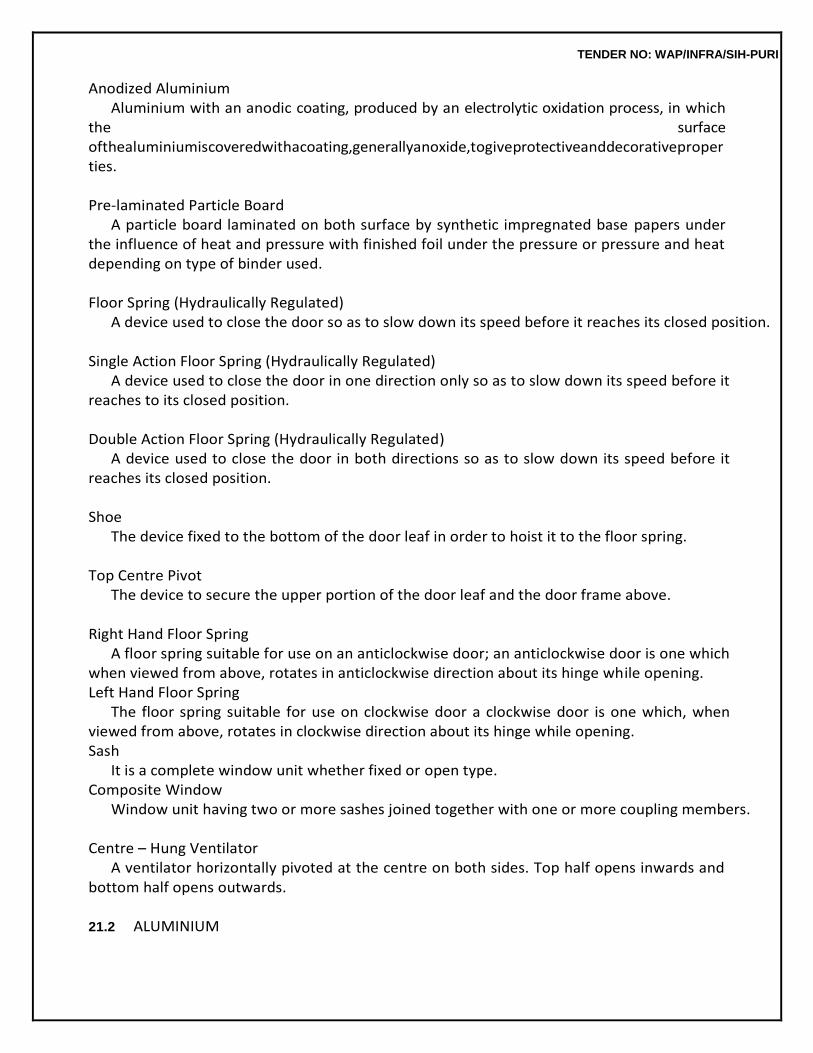
TENDER NO: WAP/INFRA/SIH-PURI
Anodized Aluminium Aluminium with an anodic coating, produced by an electrolytic oxidation process, in which
the surface ofthealuminiumiscoveredwithacoating,generallyanoxide,togiveprotectiveanddecorativeproperties.
Pre-laminated Particle Board
A particle board laminated on both surface by synthetic impregnated base papers under the influence of heat and pressure with finished foil under the pressure or pressure and heat depending on type of binder used.
Floor Spring (Hydraulically Regulated)
A device used to close the door so as to slow down its speed before it reaches its closed position.
Single Action Floor Spring (Hydraulically Regulated) A device used to close the door in one direction only so as to slow down its speed before it
reaches to its closed position.
Double Action Floor Spring (Hydraulically Regulated) A device used to close the door in both directions so as to slow down its speed before it
reaches its closed position.
Shoe The device fixed to the bottom of the door leaf in order to hoist it to the floor spring.
Top Centre Pivot
The device to secure the upper portion of the door leaf and the door frame above.
Right Hand Floor Spring A floor spring suitable for use on an anticlockwise door; an anticlockwise door is one which
when viewed from above, rotates in anticlockwise direction about its hinge while opening. Left Hand Floor Spring
The floor spring suitable for use on clockwise door a clockwise door is one which, when viewed from above, rotates in clockwise direction about its hinge while opening. Sash
It is a complete window unit whether fixed or open type. Composite Window
Window unit having two or more sashes joined together with one or more coupling members.
Centre – Hung Ventilator A ventilator horizontally pivoted at the centre on both sides. Top half opens inwards and
bottom half opens outwards.
21.2 ALUMINIUM
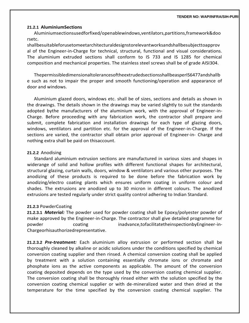
TENDER NO: WAP/INFRA/SIH-PURI
21.2.1 AluminiumSections Aluminiumsectionsusedforfixed/openablewindows,ventilators,partitions,framework&doo
rsetc. shallbesuitableforusetomeetarchitecturaldesignstorelevantworksandshallbesubjecttoapproval of the Engineer-in-Charge for technical, structural, functional and visual considerations. The aluminium extruded sections shall conform to IS 733 and IS 1285 for chemical composition and mechanical properties. The stainless steel screws shall be of grade AISI304.
ThepermissibledimensionaltolerancesoftheextrudedsectionsshallbeasperIS6477andshallb
e such as not to impair the proper and smooth functioning/operation and appearance of door and windows.
Aluminium glazed doors, windows etc. shall be of sizes, sections and details as shown in
the drawings. The details shown in the drawings may be varied slightly to suit the standards adopted bythe manufacturers of the aluminium work, with the approval of Engineer-in-Charge. Before proceeding with any fabrication work, the contractor shall prepare and submit, complete fabrication and installation drawings for each type of glazing doors, windows, ventilators and partition etc. for the approval of the Engineer-in-Charge. If the sections are varied, the contractor shall obtain prior approval of Engineer-in- Charge and nothing extra shall be paid on thisaccount.
21.2.2 Anodising
Standard aluminium extrusion sections are manufactured in various sizes and shapes in widerange of solid and hollow profiles with different functional shapes for architectural, structural glazing, curtain walls, doors, window & ventilators and various other purposes. The anodizing of these products is required to be done before the fabrication work by anodizing/electro coating plants which ensures uniform coating in uniform colour and shades. The extrusions are anodized up to 30 micron in different colours. The anodized extrusions are tested regularly under strict quality control adhering to Indian Standard.
21.2.3 PowderCoating 21.2.3.1 Material: The powder used for powder coating shall be Epoxy/polyester powder of make approved by the Engineer-in-Charge. The contractor shall give detailed programme for powder coating inadvance,tofacilitatetheinspectionbyEngineer-in-Chargeorhisauthorizedrepresentative.
21.2.3.2 Pre-treatment: Each aluminium alloy extrusion or performed section shall be thoroughly cleaned by alkaline or acidic solutions under the conditions specified by chemical conversion coating supplier and then rinsed. A chemical conversion coating shall be applied by treatment with a solution containing essentially chromate ions or chromate and phosphate ions as the active components as applicable. The amount of the conversion coating deposited depends on the type used by the conversion coating chemical supplier. The conversion coating shall be thoroughly rinsed either with the solution specified by the conversion coating chemical supplier or with de-mineralized water and then dried at the temperature for the time specified by the conversion coating chemical supplier. The
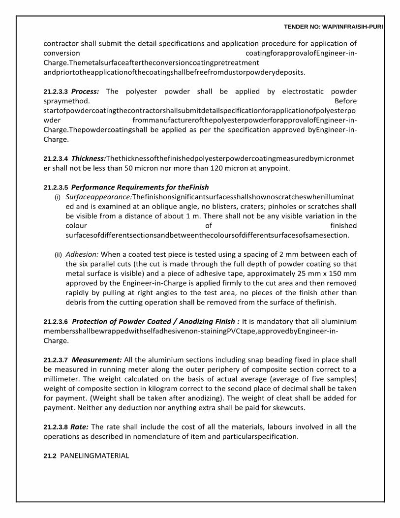
TENDER NO: WAP/INFRA/SIH-PURI
contractor shall submit the detail specifications and application procedure for application of conversion coatingforapprovalofEngineer-in-Charge.Themetalsurfaceaftertheconversioncoatingpretreatment andpriortotheapplicationofthecoatingshallbefreefromdustorpowderydeposits.
21.2.3.3 Process: The polyester powder shall be applied by electrostatic powder spraymethod. Before startofpowdercoatingthecontractorshallsubmitdetailspecificationforapplicationofpolyesterpowder frommanufacturerofthepolyesterpowderforapprovalofEngineer-in-Charge.Thepowdercoatingshall be applied as per the specification approved byEngineer-in-Charge.
21.2.3.4 Thickness:Thethicknessofthefinishedpolyesterpowdercoatingmeasuredbymicronmeter shall not be less than 50 micron nor more than 120 micron at anypoint.
21.2.3.5 Performance Requirements for theFinish
(i) Surfaceappearance:Thefinishonsignificantsurfacesshallshownoscratcheswhenilluminated and is examined at an oblique angle, no blisters, craters; pinholes or scratches shall be visible from a distance of about 1 m. There shall not be any visible variation in the colour of finished surfacesofdifferentsectionsandbetweenthecoloursofdifferentsurfacesofsamesection.
(ii) Adhesion: When a coated test piece is tested using a spacing of 2 mm between each of
the six parallel cuts (the cut is made through the full depth of powder coating so that metal surface is visible) and a piece of adhesive tape, approximately 25 mm x 150 mm approved by the Engineer-in-Charge is applied firmly to the cut area and then removed rapidly by pulling at right angles to the test area, no pieces of the finish other than debris from the cutting operation shall be removed from the surface of thefinish.
21.2.3.6 Protection of Powder Coated / Anodizing Finish : It is mandatory that all aluminium membersshallbewrappedwithselfadhesivenon-stainingPVCtape,approvedbyEngineer-in-Charge.
21.2.3.7 Measurement: All the aluminium sections including snap beading fixed in place shall be measured in running meter along the outer periphery of composite section correct to a millimeter. The weight calculated on the basis of actual average (average of five samples) weight of composite section in kilogram correct to the second place of decimal shall be taken for payment. (Weight shall be taken after anodizing). The weight of cleat shall be added for payment. Neither any deduction nor anything extra shall be paid for skewcuts.
21.2.3.8 Rate: The rate shall include the cost of all the materials, labours involved in all the operations as described in nomenclature of item and particularspecification.
21.2 PANELINGMATERIAL
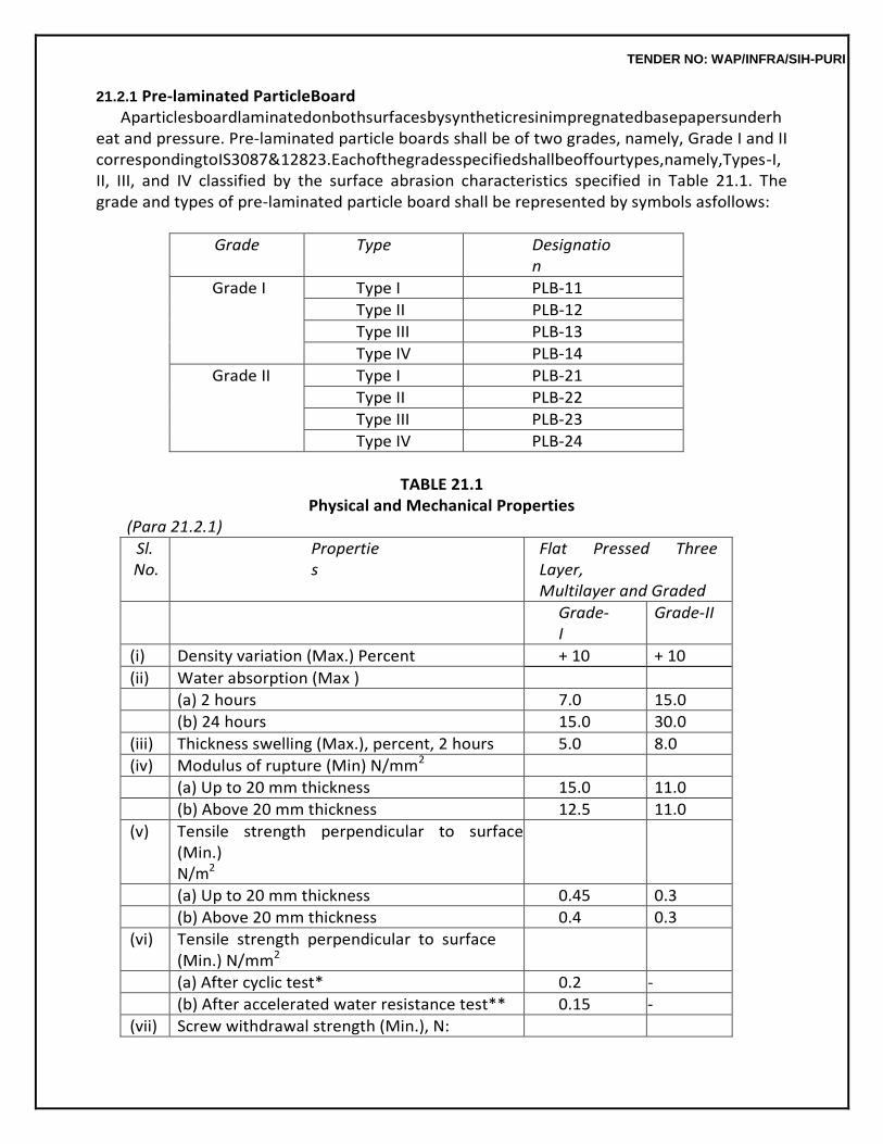
TENDER NO: WAP/INFRA/SIH-PURI
21.2.1 Pre-laminated ParticleBoard Aparticlesboardlaminatedonbothsurfacesbysyntheticresinimpregnatedbasepapersunderh
eat and pressure. Pre-laminated particle boards shall be of two grades, namely, Grade I and II correspondingtoIS3087&12823.Eachofthegradesspecifiedshallbeoffourtypes,namely,Types-I, II, III, and IV classified by the surface abrasion characteristics specified in Table 21.1. The grade and types of pre-laminated particle board shall be represented by symbols asfollows:
Grade Type Designation
Grade I Type I PLB-11
Type II PLB-12
Type III PLB-13
Type IV PLB-14
Grade II Type I PLB-21
Type II PLB-22
Type III PLB-23
Type IV PLB-24
TABLE 21.1
Physical and Mechanical Properties (Para 21.2.1)
Sl. No.
Properties
Flat Pressed Three Layer, Multilayer and Graded
Grade-I
Grade-II
(i) Density variation (Max.) Percent + 10 + 10
(ii) Water absorption (Max )
(a) 2 hours 7.0 15.0
(b) 24 hours 15.0 30.0
(iii) Thickness swelling (Max.), percent, 2 hours 5.0 8.0
(iv) Modulus of rupture (Min) N/mm2
(a) Up to 20 mm thickness 15.0 11.0
(b) Above 20 mm thickness 12.5 11.0
(v) Tensile strength perpendicular to surface (Min.) N/m2
(a) Up to 20 mm thickness 0.45 0.3
(b) Above 20 mm thickness 0.4 0.3
(vi) Tensile strength perpendicular to surface (Min.) N/mm2
(a) After cyclic test* 0.2 -
(b) After accelerated water resistance test** 0.15 -
(vii) Screw withdrawal strength (Min.), N:
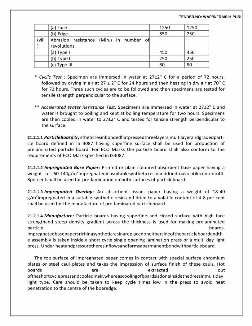
TENDER NO: WAP/INFRA/SIH-PURI
(a) Face 1250 1250
(b) Edge 850 750
(viii)
Abrasion resistance (Min.) in number of revolutions
(a) Type I 450 450
(b) Type II 250 250
(c) Type III 80 80
* Cyclic Test : Specimen are immersed in water at 27±2o C for a period of 72 hours,
followed by drying in air at 27 ± 2o C for 24 hours and then heating in dry air at 70o C for 72 hours. Three such cycles are to be followed and then specimens are tested for tensile strength perpendicular to the surface.
** Accelerated Water Resistance Test: Specimens are immersed in water at 27±2o C and
water is brought to boiling and kept at boiling temperature for two hours. Specimens are then cooled in water to 27±2o C and tested for tensile strength perpendicular to the surface.
21.2.1.1 ParticleBoard:Syntheticresinbondedflatpressedthreelayers,multilayerandgradedparticle board defined in IS 3087 having superfine surface shall be used for production of prelaminated particle board. For ECO Marks the particle board shall also conform to the requirements of ECO Mark specified in IS3087.
21.2.1.2 Impregnated Base Paper: Printed or plain coloured absorbent base paper having a weight of 60-140g/m2impregnatedinasuitablesyntheticresinanddriedtoavolatilecontentof4-8percentshall be used for pre-lamination on both surfaces of particleboard.
21.2.1.3 Impregnated Overlay: An absorbent tissue, paper having a weight of 18-40 g/m2impregnated in a suitable synthetic resin and dried to a volatile content of 4-8 per cent shall be used for the manufacture of pre-laminated particleboard.
21.2.1.4 Manufacture: Particle boards having superfine and closed surface with high face strengthand steep density gradient across the thickness is used for making prelaminated particle boards. Impregnatedbasepapersrichinasyntheticresinareplacedoneithersideoftheparticleboardandthe assembly is taken inside a short cycle single opening lamination press or a multi day light press. Under heatandpressuretheresinflowsandformsapermanentbondwithparticleboard.
The top surface of impregnated paper comes in contact with special surface chromium
plates or steel caul plates and takes the impression of surface finish of these cauls. Hot boards are extracted out oftheshortcyclepressandcooledinair,whereascoolingofboardsisdoneinsidethedressinmultiday light type. Care should be taken to keep cycle times low in the press to avoid heat penetration to the centre of the boaredge.
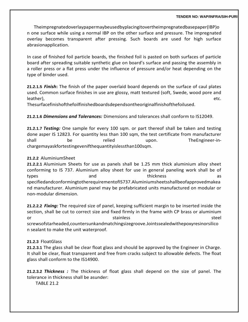
TENDER NO: WAP/INFRA/SIH-PURI
Theimpregnatedoverlaypapermaybeusedbyplacingitovertheimpregnatedbasepaper(IBP)on one surface while using a normal IBP on the other surface and pressure. The impregnated overlay becomes transparent after pressing. Such boards are used for high surface abrasionapplication.
In case of finished foil particle boards, the finished foil is pasted on both surfaces of particle board after spreading suitable synthetic glue on board’s surface and passing the assembly in a roller press or a flat press under the influence of pressure and/or heat depending on the type of binder used.
21.2.1.5 Finish: The finish of the paper overlaid board depends on the surface of caul plates used. Common surface finishes in use are glossy, matt textured (soft, Swede, wood pore and leather), etc. Thesurfacefinishofthefoilfinishedboardsdependsontheoriginalfinishofthefoilused.
21.2.1.6 Dimensions and Tolerances: Dimensions and tolerances shall conform to IS12049.
21.2.1.7 Testing: One sample for every 100 sqm. or part thereof shall be taken and testing done asper IS 12823. For quantity less than 100 sqm, the test certificate from manufacturer shall be relied upon. TheEngineer-in-chargemayaskfortestingevenifthequantityislessthan100sqm.
21.2.2 AluminiumSheet 21.2.2.1 Aluminium Sheets for use as panels shall be 1.25 mm thick aluminium alloy sheet conforming to IS 737. Aluminium alloy sheet for use in general paneling work shall be of types and thickness as specifiedandconformingtotherequirementofIS737.Aluminiumsheetsshallbeofapprovedmakeand manufacturer. Aluminium panel may be prefabricated units manufactured on modular or non-modular dimension.
21.2.2.2 Fixing: The required size of panel, keeping sufficient margin to be inserted inside the section, shall be cut to correct size and fixed firmly in the frame with CP brass or aluminium or stainless steel screwsofstarheaded,countersunkandmatchingsizegroove.Jointssealedwithepoxyresinorsilicon sealant to make the unit waterproof.
21.2.3 FloatGlass 21.2.3.1 The glass shall be clear float glass and should be approved by the Engineer in Charge. It shall be clear, float transparent and free from cracks subject to allowable defects. The float glass shall conform to the IS14900.
21.2.3.2 Thickness : The thickness of float glass shall depend on the size of panel. The tolerance in thickness shall be asunder:
TABLE 21.2
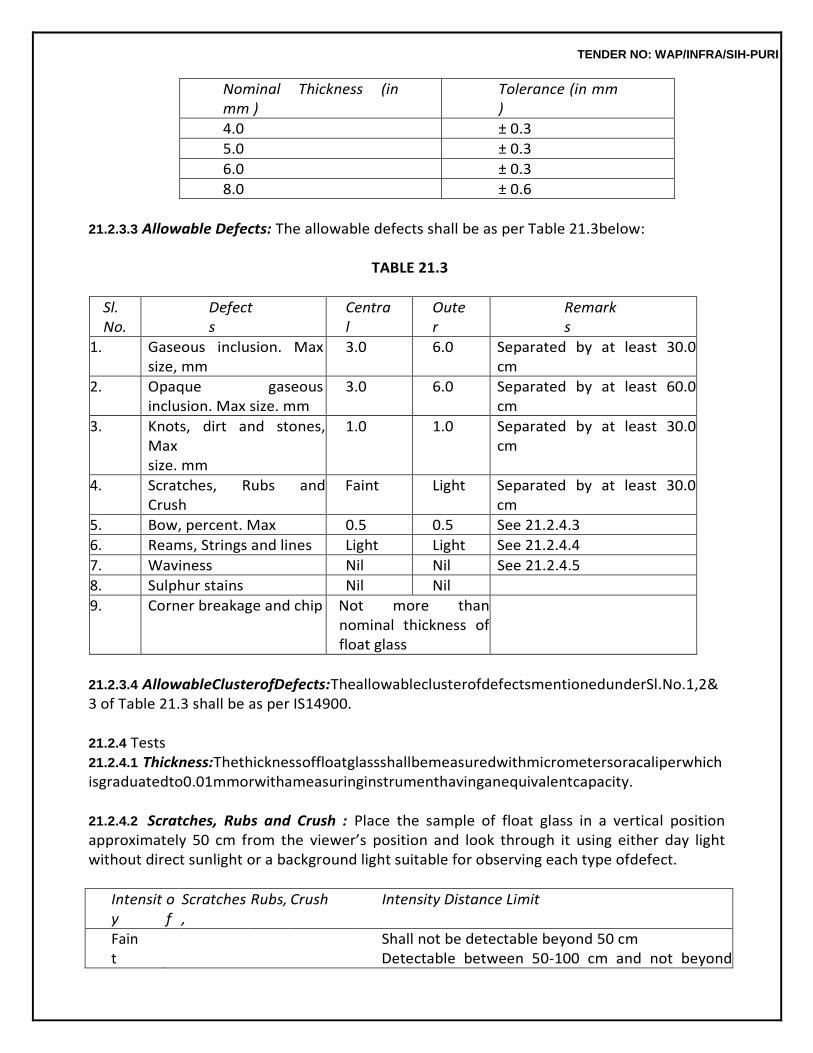
TENDER NO: WAP/INFRA/SIH-PURI
Nominal Thickness (in mm )
Tolerance (in mm )
4.0 ± 0.3
5.0 ± 0.3
6.0 ± 0.3
8.0 ± 0.6
21.2.3.3 Allowable Defects: The allowable defects shall be as per Table 21.3below:
TABLE 21.3
Sl. No.
Defects
Central
Outer
Remarks
1. Gaseous inclusion. Max size, mm
3.0 6.0 Separated by at least 30.0 cm
2. Opaque gaseous inclusion. Max size. mm
3.0 6.0 Separated by at least 60.0 cm
3. Knots, dirt and stones, Max size. mm
1.0 1.0 Separated by at least 30.0 cm
4. Scratches, Rubs and Crush
Faint Light Separated by at least 30.0 cm
5. Bow, percent. Max 0.5 0.5 See 21.2.4.3
6. Reams, Strings and lines Light Light See 21.2.4.4
7. Waviness Nil Nil See 21.2.4.5
8. Sulphur stains Nil Nil
9. Corner breakage and chip Not more than nominal thickness of float glass
21.2.3.4 AllowableClusterofDefects:TheallowableclusterofdefectsmentionedunderSl.No.1,2& 3 of Table 21.3 shall be as per IS14900.
21.2.4 Tests 21.2.4.1 Thickness:Thethicknessoffloatglassshallbemeasuredwithmicrometersoracaliperwhich isgraduatedto0.01mmorwithameasuringinstrumenthavinganequivalentcapacity.
21.2.4.2 Scratches, Rubs and Crush : Place the sample of float glass in a vertical position approximately 50 cm from the viewer’s position and look through it using either day light without direct sunlight or a background light suitable for observing each type ofdefect.
Intensity
of
Scratches,
Rubs, Crush Intensity Distance Limit
Faint
Shall not be detectable beyond 50 cm Detectable between 50-100 cm and not beyond
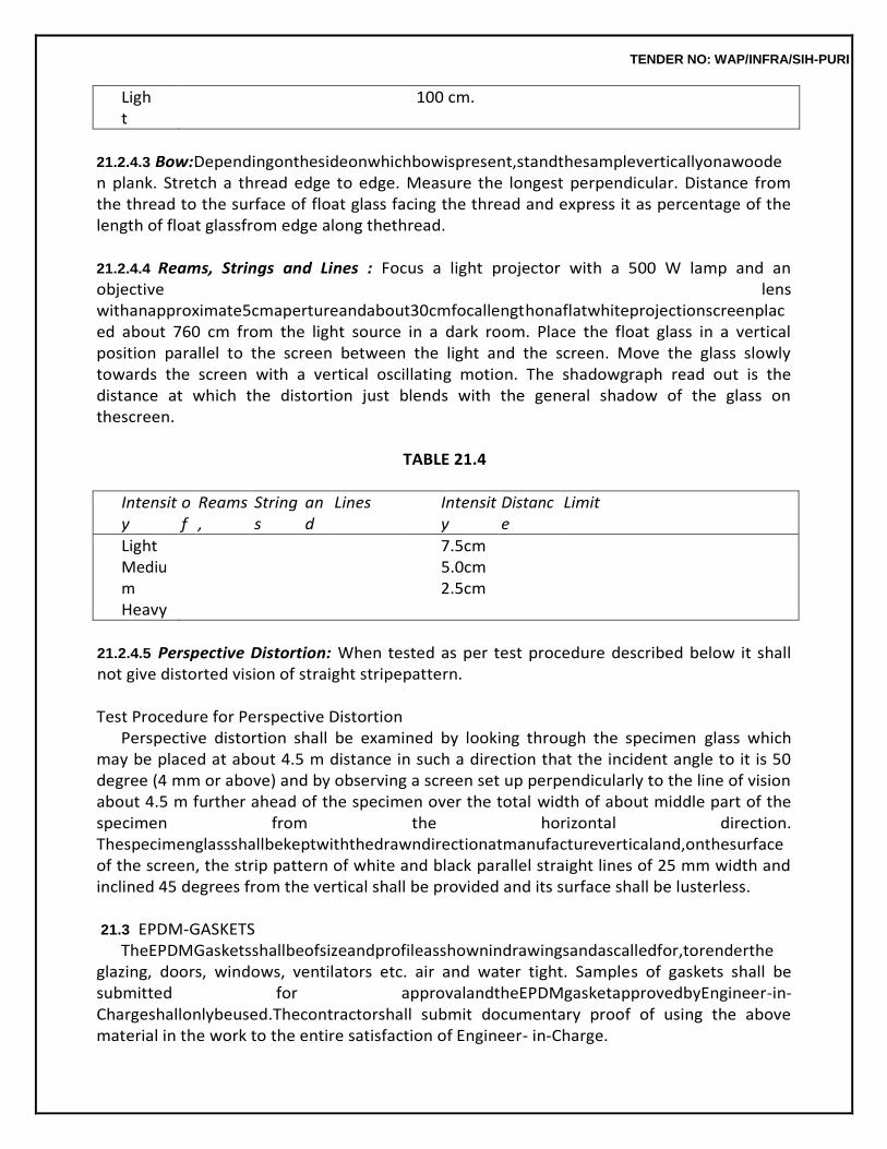
TENDER NO: WAP/INFRA/SIH-PURI
Light
100 cm.
21.2.4.3 Bow:Dependingonthesideonwhichbowispresent,standthesampleverticallyonawooden plank. Stretch a thread edge to edge. Measure the longest perpendicular. Distance from the thread to the surface of float glass facing the thread and express it as percentage of the length of float glassfrom edge along thethread.
21.2.4.4 Reams, Strings and Lines : Focus a light projector with a 500 W lamp and an objective lens withanapproximate5cmapertureandabout30cmfocallengthonaflatwhiteprojectionscreenplaced about 760 cm from the light source in a dark room. Place the float glass in a vertical position parallel to the screen between the light and the screen. Move the glass slowly towards the screen with a vertical oscillating motion. The shadowgraph read out is the distance at which the distortion just blends with the general shadow of the glass on thescreen.
TABLE 21.4
Intensity
of
Reams,
Strings
and
Lines Intensity
Distance
Limit
Light Medium Heavy
7.5cm 5.0cm 2.5cm
21.2.4.5 Perspective Distortion: When tested as per test procedure described below it shall not give distorted vision of straight stripepattern.
Test Procedure for Perspective Distortion
Perspective distortion shall be examined by looking through the specimen glass which may be placed at about 4.5 m distance in such a direction that the incident angle to it is 50 degree (4 mm or above) and by observing a screen set up perpendicularly to the line of vision about 4.5 m further ahead of the specimen over the total width of about middle part of the specimen from the horizontal direction. Thespecimenglassshallbekeptwiththedrawndirectionatmanufactureverticaland,onthesurfaceof the screen, the strip pattern of white and black parallel straight lines of 25 mm width and inclined 45 degrees from the vertical shall be provided and its surface shall be lusterless.
21.3 EPDM-GASKETS
TheEPDMGasketsshallbeofsizeandprofileasshownindrawingsandascalledfor,torenderthe glazing, doors, windows, ventilators etc. air and water tight. Samples of gaskets shall be submitted for approvalandtheEPDMgasketapprovedbyEngineer-in-Chargeshallonlybeused.Thecontractorshall submit documentary proof of using the above material in the work to the entire satisfaction of Engineer- in-Charge.
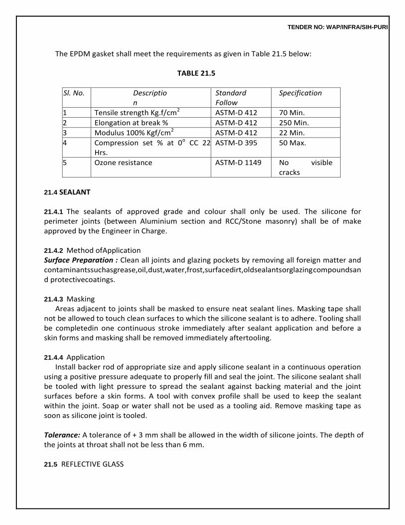
TENDER NO: WAP/INFRA/SIH-PURI
The EPDM gasket shall meet the requirements as given in Table 21.5 below:
TABLE 21.5
Sl. No. Description
Standard Follow
Specification
1 Tensile strength Kg.f/cm2 ASTM-D 412 70 Min.
2 Elongation at break % ASTM-D 412 250 Min.
3 Modulus 100% Kgf/cm2 ASTM-D 412 22 Min.
4 Compression set % at 0o CC 22 Hrs.
ASTM-D 395 50 Max.
5 Ozone resistance ASTM-D 1149 No visible cracks
21.4 SEALANT
21.4.1 The sealants of approved grade and colour shall only be used. The silicone for perimeter joints (between Aluminium section and RCC/Stone masonry) shall be of make approved by the Engineer in Charge.
21.4.2 Method ofApplication Surface Preparation : Clean all joints and glazing pockets by removing all foreign matter and contaminantssuchasgrease,oil,dust,water,frost,surfacedirt,oldsealantsorglazingcompoundsand protectivecoatings.
21.4.3 Masking
Areas adjacent to joints shall be masked to ensure neat sealant lines. Masking tape shall not be allowed to touch clean surfaces to which the silicone sealant is to adhere. Tooling shall be completedin one continuous stroke immediately after sealant application and before a skin forms and masking shall be removed immediately aftertooling.
21.4.4 Application
Install backer rod of appropriate size and apply silicone sealant in a continuous operation using a positive pressure adequate to properly fill and seal the joint. The silicone sealant shall be tooled with light pressure to spread the sealant against backing material and the joint surfaces before a skin forms. A tool with convex profile shall be used to keep the sealant within the joint. Soap or water shall not be used as a tooling aid. Remove masking tape as soon as silicone joint is tooled.
Tolerance: A tolerance of + 3 mm shall be allowed in the width of silicone joints. The depth of the joints at throat shall not be less than 6 mm.
21.5 REFLECTIVE GLASS
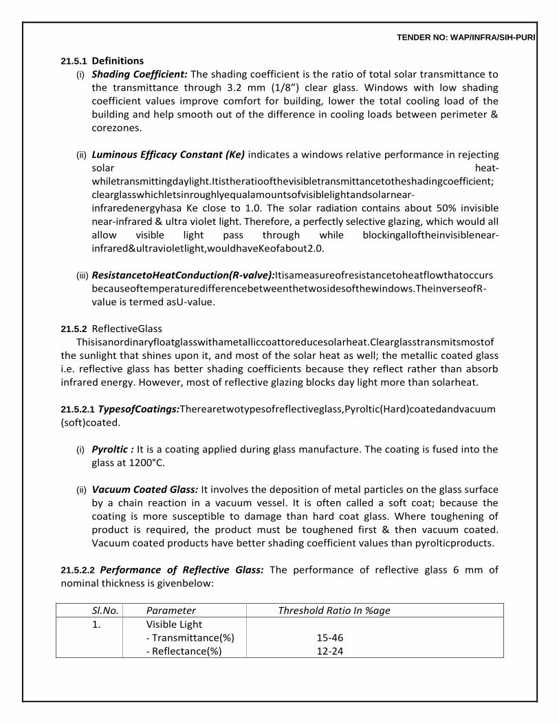
TENDER NO: WAP/INFRA/SIH-PURI
21.5.1 Definitions (i) Shading Coefficient: The shading coefficient is the ratio of total solar transmittance to
the transmittance through 3.2 mm (1/8”) clear glass. Windows with low shading coefficient values improve comfort for building, lower the total cooling load of the building and help smooth out of the difference in cooling loads between perimeter & corezones.
(ii) Luminous Efficacy Constant (Ke) indicates a windows relative performance in rejecting
solar heat-whiletransmittingdaylight.Itistheratioofthevisibletransmittancetotheshadingcoefficient; clearglasswhichletsinroughlyequalamountsofvisiblelightandsolarnear-infraredenergyhasa Ke close to 1.0. The solar radiation contains about 50% invisible near-infrared & ultra violet light. Therefore, a perfectly selective glazing, which would all allow visible light pass through while blockingalloftheinvisiblenear-infrared&ultravioletlight,wouldhaveKeofabout2.0.
(iii) ResistancetoHeatConduction(R-valve):Itisameasureofresistancetoheatflowthatoccurs
becauseoftemperaturedifferencebetweenthetwosidesofthewindows.TheinverseofR-value is termed asU-value.
21.5.2 ReflectiveGlass
Thisisanordinaryfloatglasswithametalliccoattoreducesolarheat.Clearglasstransmitsmostof the sunlight that shines upon it, and most of the solar heat as well; the metallic coated glass i.e. reflective glass has better shading coefficients because they reflect rather than absorb infrared energy. However, most of reflective glazing blocks day light more than solarheat.
21.5.2.1 TypesofCoatings:Therearetwotypesofreflectiveglass,Pyroltic(Hard)coatedandvacuum (soft)coated.
(i) Pyroltic : It is a coating applied during glass manufacture. The coating is fused into the
glass at 1200°C.
(ii) Vacuum Coated Glass: It involves the deposition of metal particles on the glass surface by a chain reaction in a vacuum vessel. It is often called a soft coat; because the coating is more susceptible to damage than hard coat glass. Where toughening of product is required, the product must be toughened first & then vacuum coated. Vacuum coated products have better shading coefficient values than pyrolticproducts.
21.5.2.2 Performance of Reflective Glass: The performance of reflective glass 6 mm of nominal thickness is givenbelow:
Sl.No. Parameter Threshold Ratio In %age
1. Visible Light - Transmittance(%) - Reflectance(%)
15-46 12-24
TENDER NO: WAP/INFRA/SIH-PURI
2. Total Solar Energy: - Transmittance(%) - Reflectance(%)
16-24 8-12
3. Ultra Violet Rays: - Transmittance (%)
2-10
4. U-Value - Summer - Winter
0.58 0.45
5. Shading Coefficient 0.25-0.35
21.5.2.3 Testing: The reflective glass shall be tested for thefollowings:
(i) Physical/Field Test: In a true reflective glass, when a pointed pencil is placed, then tip of pencil (physical) & image shouldcoincide.
(ii) Lab. Test: In the lab, the reflective glass shall be tested for the parameter specified in
21.5.2.2 above.
21.5.2.4 Fixing of glass shall be done asspecified.
21.6 DOOR, WINDOW, VENTILATOR AND PARTITIONFRAMES
21.6.1 FrameWork First of all the shop drawings for each type of doors/windows/ventilators etc. shall be
prepared by using suitable sections based on architectural drawings, adequate to meet the requirement/ specifications and by taking into consideration varying profiles of aluminium sections being extruded by approved manufacturers. The shop drawings shall show full size sections of glazed doors, windows, ventilators etc. The shop drawings shall also show the details of fittings and joints. Before start of the work, all the shop drawings shall be got approved from the Engineer-in-Charge.
Actualmeasurementofopeningsleftatsitefordifferenttypeofdoor/windowetc.shallbetaken.
The fabrication of the individual door/windows/ventilators etc. shall be done as per the actual sizes of the opening left at site. The frames shall be truly rectangular and flat with regular shape corners fabricated totruerightangles.Theframesshallbefabricatedoutofsectionwhichhavebeencuttolength,mitered and jointed mechanically using appropriate machines. Mitered joints shall be corner crimped or fixed with self tapping stainless steel screws using extruded aluminium cleats of required length and profile. Allaluminiumworkshallprovideforreplacingdamaged/brokenglasspaneswithouthavingtoremoveor damage any member of exterior finishingmaterial.
21.6.2 Fixing ofFrames
The holes in concrete/masonry/wood/any other members for fixing anchor bolts/fasteners/screws shallbedrilledwithanappropriateelectricdrill.Windows/doors/ventilatorsetc.shallbeplacedinco
TENDER NO: WAP/INFRA/SIH-PURI
rrect final position in the opening and fixed to Sal wood backing using stainless steel screws of star headed, counter sunk and matching size groove. of required size at spacing not more than 250 mm c/c or dash fastener. All joints shall be sealed with approved siliconesealants.
In the case of composite windows and doors, the different units are to be assembled first.
The assembled composite units shall be checked for line, level and plumb before final fixing is done. Engineer-in-Chargeinhissolediscretionmayallowtheunitstobeassembledintheirfinallocationifthe situation so warrants. Snap beadings and EPDM gasket shall be fixed as per the detail shown in the shopdrawings.
Where aluminium comes into contact with stone masonry, brick work, concrete, plaster
or dissimilar metal, it shall be coated with an approved insulation lacquer, paint or plastic tape to ensure that electrochemical corrosion is avoided. Insulation material shall be trimmed off to a clean flush line on completion.
The contractor shall be responsible for the doors, windows etc. being set straight, plumb,
level and for their satisfactory operation after fixing is complete.
21.6.3 Measurements Allthealuminiumsectionsincludingsnapbeadingsfixedinplaceshallbemeasuredinrunningmet
er along the outer periphery of composite section correct to a millimeter. The weight calculated on the basis ofactualaverage(averageoffivesamples)weightofcompositesectioninkilogramcorrecttothesecond place of decimal shall be taken for payment (weight shall be taken after anodizing). The weight of cleat shallbeaddedforpayment.Neitheranydeductionnoranythingextrashallbepaidforskewcuts.
21.6.4 Rate
The rate shall include the cost of all the materials, labour involved in all the operations as described in nomenclature of item and particular specification.
21.7 DOOR, WINDOWS AND VENTILATORSHUTTERS
Material,fabricationanddimensionsofaluminiumdoors,windowsandventilatorsmanufacturedfrom extruded aluminium alloy sections of standard sizes and designs complete with fittings, ready for being fixed into the building shall be as per IS1948.
21.7.1 Terminology
The components of doors, windows and ventilators shall be defined as in Figure 21.1 below.
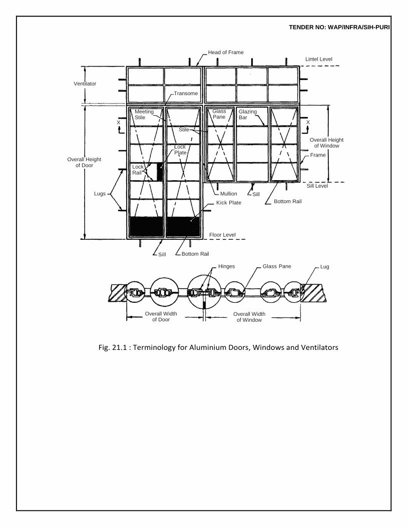
TENDER NO: WAP/INFRA/SIH-PURI
Fig. 21.1 : Terminology for Aluminium Doors, Windows and Ventilators
Head of Frame
Lintel Level
Ventilator
Transome
Overall Height of Door
Meeting Stile
X
Lock Rail
Stile
Lock Plate
Glass Pane
Glazing Bar
X
Overall Height of Window
Frame
Lugs
Mullion Sill
Kick Plate
Bottom Rail
Sill Level
Floor Level
Sill Bottom Rail
Overall Width of Door
Hinges Glass Pane Lug
Overall Width
of Window
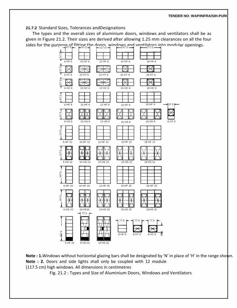
TENDER NO: WAP/INFRA/SIH-PURI
21.7.2 Standard Sizes, Tolerances andDesignations The types and the overall sizes of aluminium doors, windows and ventilators shall be as
given in Figure 21.2. Their sizes are derived after allowing 1.25 mm clearances on all the four sides for the purpose of fitting the doors, windows and ventilators into modular openings.
Note : 1.Windows without horizontal glazing bars shall be designated by 'N' in place of 'H' in the range shown. Note : 2. Doors and side lights shall only be coupled with 12 module (117.5 cm) high windows. All dimensions in centimetres
Fig. 21.2 : Types and Size of Aluminium Doors, Windows and Ventilators
57.5 97.5 117.5 147.5 177.5
6 HF 6 10 HF 6 12 HF 6 15 HF 6 18 HF 6
6 HT 6 10 HT 6 12 HT 6 15 HT 6 18 HT 6
6 HC 6 10 HC 6 12 HC 6 15 HC 6 18 HC 6
6 HF 9 10 HF 9 12 HF 9 15 HF 9 18 HF 9 57.5
6 HS 9 10 HS 9 12 HS 9 15 HS 9 18 HS 9 6 HT 9
6 HF 12 10 HF 12 12 HF 12 15 HF 12 18 HF 12
6 HS 12 10 HS 12 12 HS 12 15 HS 12 18 HS 12
6 HF 15 10 HF 15 12 HF 15 15 HF 15 18 HF 15
6 HS 15 10 HS15
77.5
12 HS 15 15 HS 15 18 HS 15
77.5 77.5 77.5
8 HF 6 8 HT 6 8 HC 6
6 HF 21 8 HS 21 12 HS 21
147.5
147.5
117.5
117.5
8
7.5
8
7.5
5
7.5
5
7.5
5
7.5
207.5
57.5
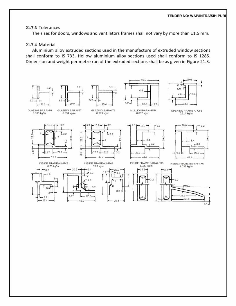
TENDER NO: WAP/INFRA/SIH-PURI
21.7.3 Tolerances The sizes for doors, windows and ventilators frames shall not vary by more than ±1.5 mm.
21.7.4 Material
Aluminium alloy extruded sections used in the manufacture of extruded window sections shall conform to IS 733. Hollow aluminium alloy sections used shall conform to IS 1285. Dimension and weight per metre run of the extruded sections shall be as given in Figure 21.3.
GLAZING BAR AI-T6
0.306 kg/m GLAZING BAR AI-T7
0.334 kg/m GLAZING BAR AI-T8
0.363 kg/m MULLION BAR AI-F4B
0.837 kg/m OPENING FRAME AI-CF6
0.614 kg/m
15.9 3.2
9.5
15.9 3.2
9.5 19.0 3.2
28.6
3.2
2 R
3.2
2
R
R 3.2
2 2
R
8.4
3.2
8.4
3.2
12.7 22.2
44.4
12.7 22.2
44.4
3.2
22.2
44.4
9.5 22.2
44.4
INSIDE FRAME AI-HFX5
0.73 kg/m
INSIDE FRAME AI-HFX6
0.73 kg/m
INSIDE FRAME BAR AI-FX5
1.033 kg/m
INSIDE FRAME BAR AI-FX6
1.033 kg/m
3.2
4.8
20.6 6.4
3.2 3.2 22.2
4.8
15.9 15.9
8 4.8
R R
3.2 R
3.2
R 3.2 120°
2
3.2
25.4
R 3.2 R
3.2
3.6 22.2 R R
42.9 25.4
38.1
50.8
6.4
TENDER NO: WAP/INFRA/SIH-PURI
Note 1 : All radii R = 1.6mm Note2:Theweightsofsectionspermetrelengthasindicatedarenominal. All dimensions inmillimeters
Fig. 21.3 : Extruded Aluminium Sections for Doors, Windows and Ventilators
21.7.5 GlassPanes Glasspanesshallweighatleast7.5kg/m2andshallbefreefromflaws,specksorbubbles.Allpanes
shall have properly squared corners and straight edges. The sizes of glass panes for use in doors, windows and ventilators shall be as given in Table21.6.
21.7.6 Screws
Screws threads of machine screws used in the fabrication of aluminium doors, windows and ventilators shall conform to IS 1362.
TABLE 21.6
Glass Sizes (Clearance Allowed) (Clause 21.7.5)
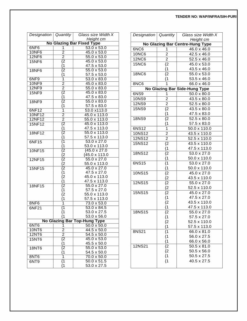
TENDER NO: WAP/INFRA/SIH-PURI
Designation Quantity Glass size Width Height cm
X
No Glazing Bar Fixed Type 6NF6 1 53.0 x 53.0 10NF6 2 45.0 x 53.0 12NF6 2 55.0 x 53.0
15NF6 {2 45.0 x 53.0 {1 47.5 x 53.0
18NF6 {2 55.0 x 53.0 {1 57.5 x 53.0
6NF9 1 53.0 x 83.0 10NF9 2 45.0 x 83.0 12NF9 2 55.0 x 83.0
15NF9 {2 45.0 x 83.0 {1 47.5 x 83.0
18NF9 {2 55.0 x 83.0 {1 57.5 x 83.0
6NF12 1 53.0 x113.0 10NF12 2 45.0 x 113.0 12NF12 2 55.0 x 113.0
15NF12 {2 45.0 x 113.0 {1 47.5 x 113.0
18NF12 {2 55.0 x 113.0 {1 57.5 x 113.0
6NF15 {1 53.0 x 27.0 {1 53.0 x 113.0
10NF15 {2 {45.0 x 27.0 {2 {45.0 x 113.0
12NF15 {2 55.0 x 27.0 {2 55.0 x 113.0
15NF15 {2 45.0 x 27.0 {1 47.5 x 27.0
{2 45.0 x 113.0 {1 47.5 x 113.0
18NF15 {2 55.0 x 27.0 {1 57.5 x 27.0
{2 55.0 x 113.0 {1 57.5 x 113.0 8NF6 1 73.0 x 53.0
6NF21 {1 53.0 x 84.5 {1 53.0 x 27.5
{1 53.0 x 56.0 No Glazing Bar Top-Hung Type
6NT6 1 50.0 x 50.0 10NT6 2 44.5 x 50.0 12NT6 2 54.5 x 50.0
15NT6 {2 45.0 x 53.0 {1 45.5 x 50.0
18NT6 {2 55.0 x 53.0 {1 54.5 x 50.0
8NT6 1 70.0 x 50.0
6NT9 {1 50.0 x 51.5 {1 53.0 x 27.5
Designation Quantity Glass size Width Height cm
X
No Glazing Bar Centre-Hung Type
6NC6 1 46.0 x 46.0
10NC6 2 42.5 x 46.0
12NC6 2 52.5 x 46.0
15NC6 {2 45.0 x 53.0 {1 43.5 x 46.0
18NC6 {2 55.0 x 53.0 {1 53.5 x 46.0
8NC6 1 66.0 x 46.0
No Glazing Bar Side-Hung Type
6NS9 1 50.0 x 80.0
10NS9 2 43.5 x 80.0
12NS9 2 52.5 x 80.0
15NS9 {2 43.5 x 80.0 {1 47.5 x 83.0
18NS9 {2 52.5 x 80.0 {1 57.5 x 83.0
6NS12 1 50.0 x 110.0
10NS12 2 43.5 x 110.0
12NS12 2 52.5 x 110.0
15NS12 {2 43.5 x 110.0 {1 47.5 x 113.0
18NS12 {2 53.0 x 27.0 {1 50.0 x 110.0
6NS15 {1 53.0 x 27.0 {1 50.0 x 110.0
10NS15 {2 45.0 x 27.0 {2 43.5 x 110.0
12NS15 {2 55.0 x 27.0 {2 52.5 x 110.0
15NS15 {2 45.0 x 27.0 {1 47.5 x 27.0 {2 43.5 x 110.0 {1 47.5 x 113.0
18NS15 {2 55.0 x 27.0 {1 57.5 x 27.0 {2 52.5 x 110.0 {1 57.5 x 113.0
8NS21 {1 66.0 x 81.0 {1 56.0 x 27.5 {1 66.0 x 56.0
12NS21 {2 50.5 x 81.0 {2 50.5 x 56.0 {1 50.5 x 27.5
{1 40.5 x 27.5
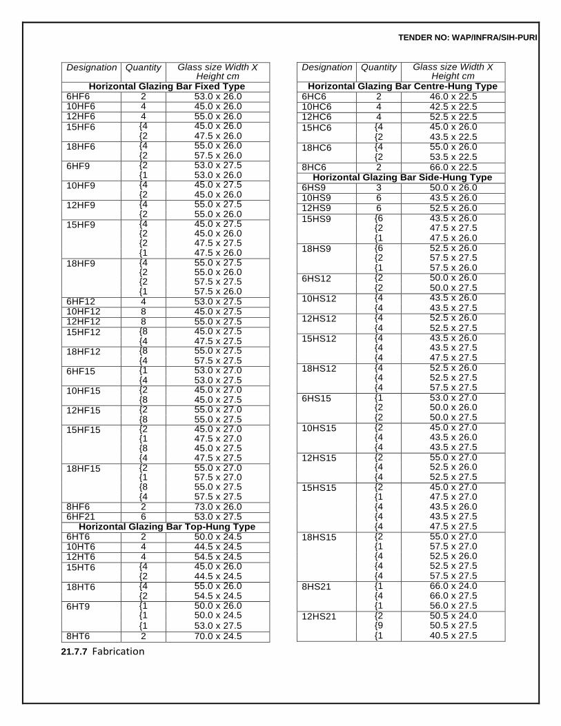
TENDER NO: WAP/INFRA/SIH-PURI
21.7.7 Fabrication
Designation Quantity Glass size Width Height cm
X
Horizontal Glazing Bar Centre-Hung Type 6HC6 2 46.0 x 22.5 10HC6 4 42.5 x 22.5 12HC6 4 52.5 x 22.5
15HC6 {4 45.0 x 26.0 {2 43.5 x 22.5
18HC6 {4 55.0 x 26.0 {2 53.5 x 22.5
8HC6 2 66.0 x 22.5 Horizontal Glazing Bar Side-Hung Type
6HS9 3 50.0 x 26.0 10HS9 6 43.5 x 26.0 12HS9 6 52.5 x 26.0
15HS9 {6 43.5 x 26.0 {2 47.5 x 27.5
{1 47.5 x 26.0
18HS9 {6 52.5 x 26.0 {2 57.5 x 27.5
{1 57.5 x 26.0
6HS12 {2 50.0 x 26.0 {2 50.0 x 27.5
10HS12 {4 43.5 x 26.0 {4 43.5 x 27.5
12HS12 {4 52.5 x 26.0 {4 52.5 x 27.5
15HS12 {4 43.5 x 26.0 {4 43.5 x 27.5
{4 47.5 x 27.5
18HS12 {4 52.5 x 26.0 {4 52.5 x 27.5
{4 57.5 x 27.5
6HS15 {1 53.0 x 27.0 {2 50.0 x 26.0
{2 50.0 x 27.5
10HS15 {2 45.0 x 27.0 {4 43.5 x 26.0
{4 43.5 x 27.5
12HS15 {2 55.0 x 27.0 {4 52.5 x 26.0
{4 52.5 x 27.5
15HS15 {2 45.0 x 27.0 {1 47.5 x 27.0
{4 43.5 x 26.0 {4 43.5 x 27.5 {4 47.5 x 27.5
18HS15 {2 55.0 x 27.0 {1 57.5 x 27.0
{4 52.5 x 26.0 {4 52.5 x 27.5 {4 57.5 x 27.5
8HS21 {1 66.0 x 24.0 {4 66.0 x 27.5
{1 56.0 x 27.5
12HS21 {2 50.5 x 24.0 {9 50.5 x 27.5
{1 40.5 x 27.5
Designation Quantity Glass size Width Height cm
X
Horizontal Glazing Bar Fixed Type 6HF6 2 53.0 x 26.0 10HF6 4 45.0 x 26.0 12HF6 4 55.0 x 26.0 15HF6 {4 45.0 x 26.0
{2 47.5 x 26.0 18HF6 {4 55.0 x 26.0
{2 57.5 x 26.0 6HF9 {2 53.0 x 27.5
{1 53.0 x 26.0 10HF9 {4 45.0 x 27.5
{2 45.0 x 26.0 12HF9 {4 55.0 x 27.5
{2 55.0 x 26.0 15HF9 {4 45.0 x 27.5
{2 45.0 x 26.0 {2 47.5 x 27.5 {1 47.5 x 26.0
18HF9 {4 55.0 x 27.5 {2 55.0 x 26.0
{2 57.5 x 27.5 {1 57.5 x 26.0 6HF12 4 53.0 x 27.5 10HF12 8 45.0 x 27.5 12HF12 8 55.0 x 27.5 15HF12 {8 45.0 x 27.5
{4 47.5 x 27.5 18HF12 {8 55.0 x 27.5
{4 57.5 x 27.5 6HF15 {1 53.0 x 27.0
{4 53.0 x 27.5 10HF15 {2 45.0 x 27.0
{8 45.0 x 27.5
12HF15 {2 55.0 x 27.0 {8 55.0 x 27.5
15HF15 {2 45.0 x 27.0 {1 47.5 x 27.0
{8 45.0 x 27.5 {4 47.5 x 27.5
18HF15 {2 55.0 x 27.0 {1 57.5 x 27.0
{8 55.0 x 27.5 {4 57.5 x 27.5 8HF6 2 73.0 x 26.0 6HF21 6 53.0 x 27.5
Horizontal Glazing Bar Top-Hung Type 6HT6 2 50.0 x 24.5 10HT6 4 44.5 x 24.5 12HT6 4 54.5 x 24.5 15HT6 {4 45.0 x 26.0
{2 44.5 x 24.5
18HT6 {4 55.0 x 26.0 {2 54.5 x 24.5
6HT9 {1 50.0 x 26.0 {1 50.0 x 24.5
{1 53.0 x 27.5 8HT6 2 70.0 x 24.5
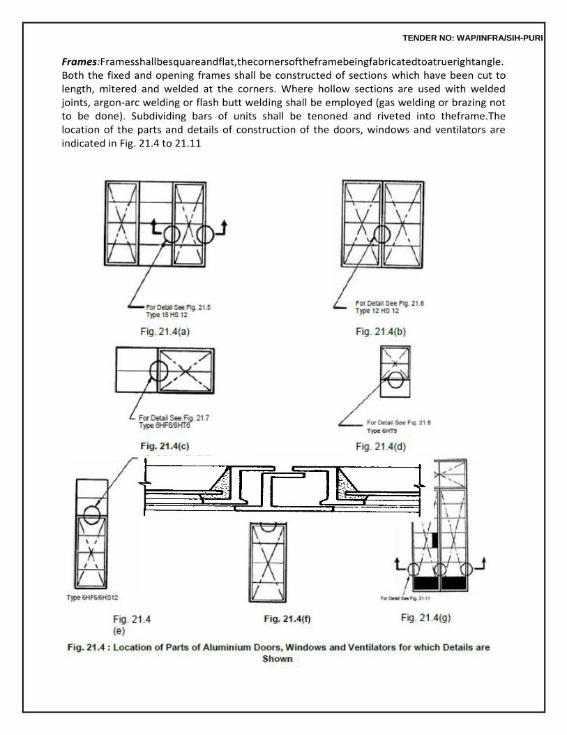
TENDER NO: WAP/INFRA/SIH-PURI
Frames:Framesshallbesquareandflat,thecornersoftheframebeingfabricatedtoatruerightangle. Both the fixed and opening frames shall be constructed of sections which have been cut to length, mitered and welded at the corners. Where hollow sections are used with welded joints, argon-arc welding or flash butt welding shall be employed (gas welding or brazing not to be done). Subdividing bars of units shall be tenoned and riveted into theframe.The location of the parts and details of construction of the doors, windows and ventilators are indicated in Fig. 21.4 to 21.11
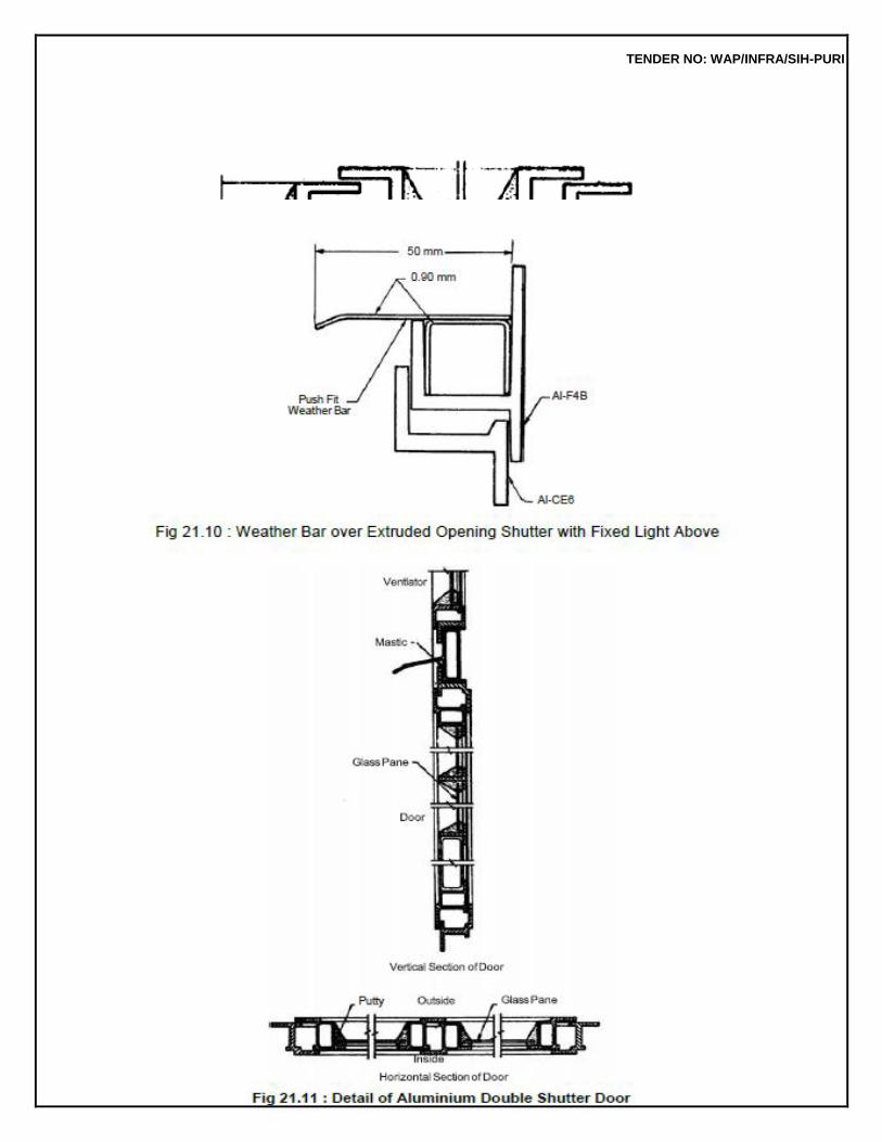
TENDER NO: WAP/INFRA/SIH-PURI
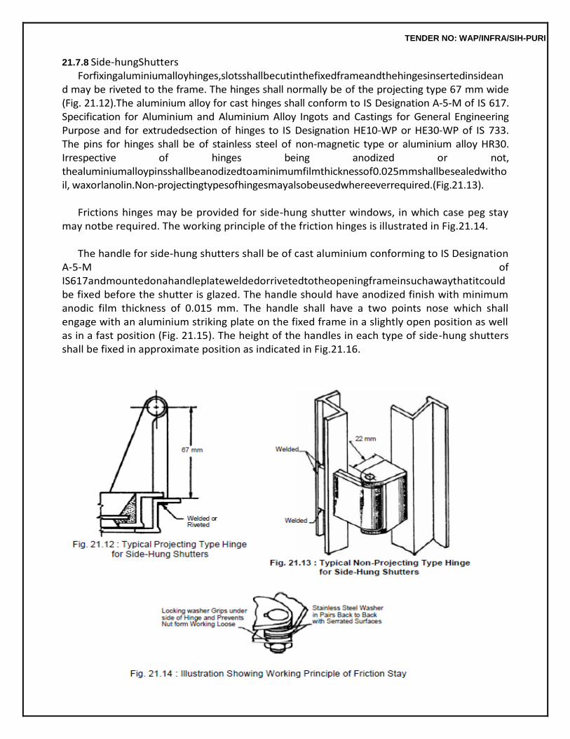
TENDER NO: WAP/INFRA/SIH-PURI
21.7.8 Side-hungShutters Forfixingaluminiumalloyhinges,slotsshallbecutinthefixedframeandthehingesinsertedinsidean
d may be riveted to the frame. The hinges shall normally be of the projecting type 67 mm wide (Fig. 21.12).The aluminium alloy for cast hinges shall conform to IS Designation A-5-M of IS 617. Specification for Aluminium and Aluminium Alloy Ingots and Castings for General Engineering Purpose and for extrudedsection of hinges to IS Designation HE10-WP or HE30-WP of IS 733. The pins for hinges shall be of stainless steel of non-magnetic type or aluminium alloy HR30. Irrespective of hinges being anodized or not, thealuminiumalloypinsshallbeanodizedtoaminimumfilmthicknessof0.025mmshallbesealedwithoil, waxorlanolin.Non-projectingtypesofhingesmayalsobeusedwhereeverrequired.(Fig.21.13).
Frictions hinges may be provided for side-hung shutter windows, in which case peg stay
may notbe required. The working principle of the friction hinges is illustrated in Fig.21.14.
The handle for side-hung shutters shall be of cast aluminium conforming to IS Designation A-5-M of IS617andmountedonahandleplateweldedorrivetedtotheopeningframeinsuchawaythatitcould be fixed before the shutter is glazed. The handle should have anodized finish with minimum anodic film thickness of 0.015 mm. The handle shall have a two points nose which shall engage with an aluminium striking plate on the fixed frame in a slightly open position as well as in a fast position (Fig. 21.15). The height of the handles in each type of side-hung shutters shall be fixed in approximate position as indicated in Fig.21.16.
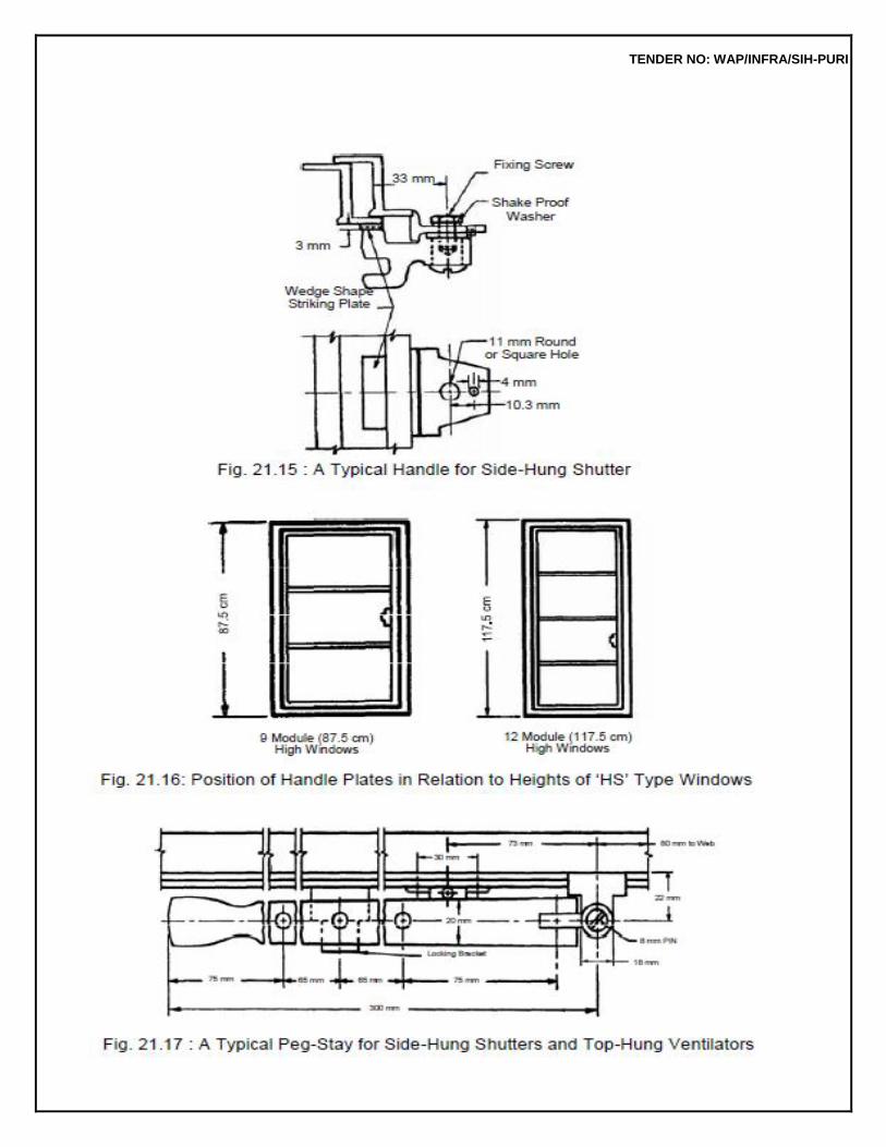
TENDER NO: WAP/INFRA/SIH-PURI
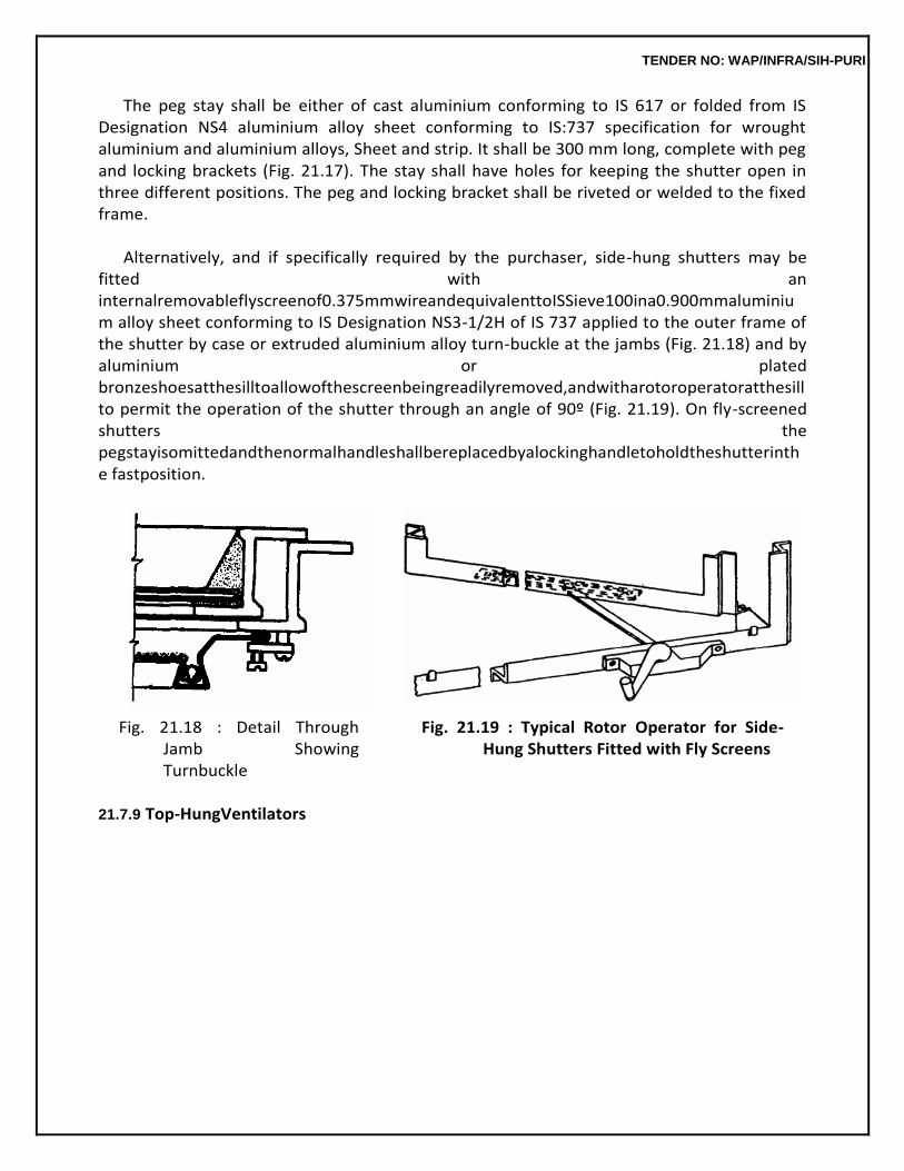
TENDER NO: WAP/INFRA/SIH-PURI
The peg stay shall be either of cast aluminium conforming to IS 617 or folded from IS Designation NS4 aluminium alloy sheet conforming to IS:737 specification for wrought aluminium and aluminium alloys, Sheet and strip. It shall be 300 mm long, complete with peg and locking brackets (Fig. 21.17). The stay shall have holes for keeping the shutter open in three different positions. The peg and locking bracket shall be riveted or welded to the fixed frame.
Alternatively, and if specifically required by the purchaser, side-hung shutters may be
fitted with an internalremovableflyscreenof0.375mmwireandequivalenttoISSieve100ina0.900mmaluminium alloy sheet conforming to IS Designation NS3-1/2H of IS 737 applied to the outer frame of the shutter by case or extruded aluminium alloy turn-buckle at the jambs (Fig. 21.18) and by aluminium or plated bronzeshoesatthesilltoallowofthescreenbeingreadilyremoved,andwitharotoroperatoratthesill to permit the operation of the shutter through an angle of 90º (Fig. 21.19). On fly-screened shutters the pegstayisomittedandthenormalhandleshallbereplacedbyalockinghandletoholdtheshutterinthe fastposition.
Fig. 21.18 : Detail Through
Jamb Showing Turnbuckle
21.7.9 Top-HungVentilators
Fig. 21.19 : Typical Rotor Operator for Side-Hung Shutters Fitted with Fly Screens
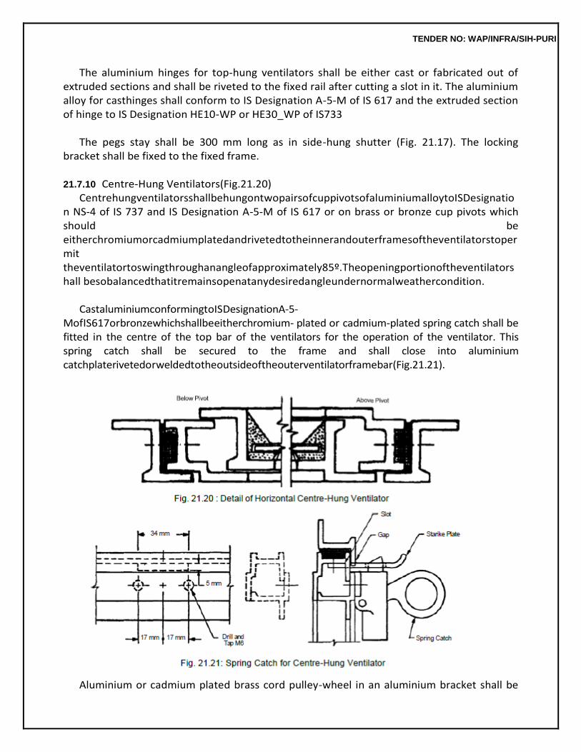
TENDER NO: WAP/INFRA/SIH-PURI
The aluminium hinges for top-hung ventilators shall be either cast or fabricated out of extruded sections and shall be riveted to the fixed rail after cutting a slot in it. The aluminium alloy for casthinges shall conform to IS Designation A-5-M of IS 617 and the extruded section of hinge to IS Designation HE10-WP or HE30_WP of IS733
The pegs stay shall be 300 mm long as in side-hung shutter (Fig. 21.17). The locking
bracket shall be fixed to the fixed frame.
21.7.10 Centre-Hung Ventilators(Fig.21.20) CentrehungventilatorsshallbehungontwopairsofcuppivotsofaluminiumalloytoISDesignatio
n NS-4 of IS 737 and IS Designation A-5-M of IS 617 or on brass or bronze cup pivots which should be eitherchromiumorcadmiumplatedandrivetedtotheinnerandouterframesoftheventilatorstopermit theventilatortoswingthroughanangleofapproximately85º.Theopeningportionoftheventilatorshall besobalancedthatitremainsopenatanydesiredangleundernormalweathercondition.
CastaluminiumconformingtoISDesignationA-5-
MofIS617orbronzewhichshallbeeitherchromium- plated or cadmium-plated spring catch shall be fitted in the centre of the top bar of the ventilators for the operation of the ventilator. This spring catch shall be secured to the frame and shall close into aluminium catchplaterivetedorweldedtotheoutsideoftheouterventilatorframebar(Fig.21.21).
Aluminium or cadmium plated brass cord pulley-wheel in an aluminium bracket shall be
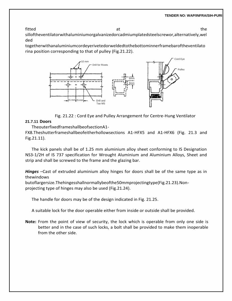
TENDER NO: WAP/INFRA/SIH-PURI
fitted at the silloftheventilatorwithaluminiumorgalvanizedorcadmiumplatedsteelscrewor,alternatively,welded togetherwithanaluminiumcordeyerivetedorweldedtothebottominnerframebaroftheventilatorina position corresponding to that of pulley (Fig.21.22).
Fig. 21.22 : Cord Eye and Pulley Arrangement for Centre-Hung Ventilator
21.7.11 Doors TheouterfixedframeshallbeofsectionA1-
FX8.Theshutterframeshallbeofeitherhollowsections A1-HFX5 and A1-HFX6 (Fig. 21.3 and Fig.21.11).
The kick panels shall be of 1.25 mm aluminium alloy sheet conforming to IS Designation
NS3-1/2H of IS 737 specification for Wrought Aluminium and Aluminium Alloys, Sheet and strip and shall be screwed to the frame and the glazing bar.
Hinges –Cast of extruded aluminium alloy hinges for doors shall be of the same type as in thewindows butoflargersize.Thehingesshallnormallybeofthe50mmprojectingtype(Fig.21.23).Non-projecting type of hinges may also be used (Fig.21.24).
The handle for doors may be of the design indicated in Fig. 21.25.
A suitable lock for the door operable either from inside or outside shall be provided.
Note: From the point of view of security, the lock which is operable from only one side is
better and in the case of such locks, a bolt shall be provided to make them inoperable from the other side.
Cord Eye 10 mm
Drill for Rivets
Pulley
6mm
8mm
15 mm 15 mm Drill and Tap MS
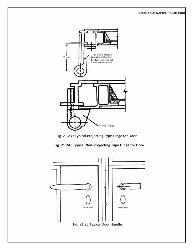
TENDER NO: WAP/INFRA/SIH-PURI
Fig. 21.23 : Typical Projecting Type Hinge for Door
Fig. 21.24 : Typical Non-Projecting Type Hinge for Door
Fig. 21.25 Typical Door Handle
Outside View Inside View
50 mm Projecting Hinges
(Welded orRiveted)
to allow Door toFold Backagainstthewall
Plain Hinge
TENDER NO: WAP/INFRA/SIH-PURI
In double shutter doors the first closing shutter shall have a concealed aluminium alloy
bolt at top and bottom (Fig. 21.26). It shall be so constructed as not to work loose or drop by its own weight.
Singleanddoubleshutterdoorsmaybeprovidedwithathree-
wayboltingdevice(Fig.21.27).Where thisisprovidedinthecaseofdoubleshutterdoor,concealedaluminiumboltsmaynotbeprovided.
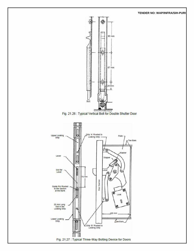
TENDER NO: WAP/INFRA/SIH-PURI
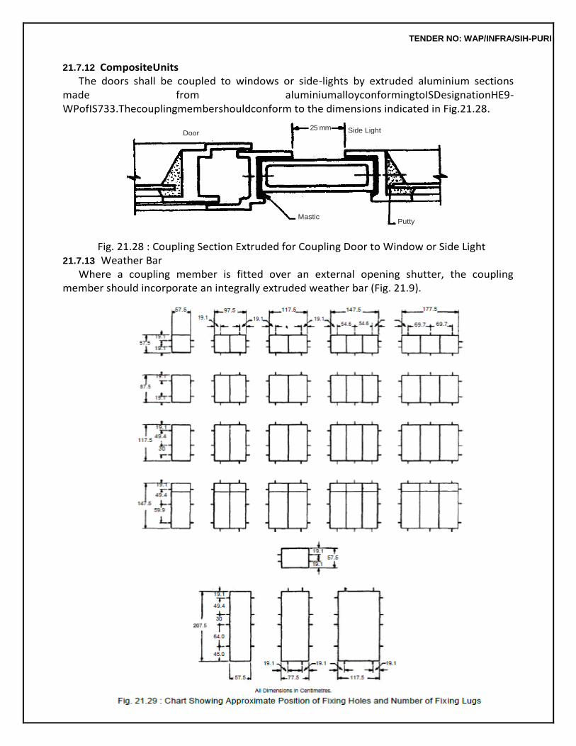
TENDER NO: WAP/INFRA/SIH-PURI
21.7.12 CompositeUnits The doors shall be coupled to windows or side-lights by extruded aluminium sections
made from aluminiumalloyconformingtoISDesignationHE9-WPofIS733.Thecouplingmembershouldconform to the dimensions indicated in Fig.21.28.
Fig. 21.28 : Coupling Section Extruded for Coupling Door to Window or Side Light
21.7.13 Weather Bar Where a coupling member is fitted over an external opening shutter, the coupling
member should incorporate an integrally extruded weather bar (Fig. 21.9).
Door 25 mm Side Light
Mastic Putty
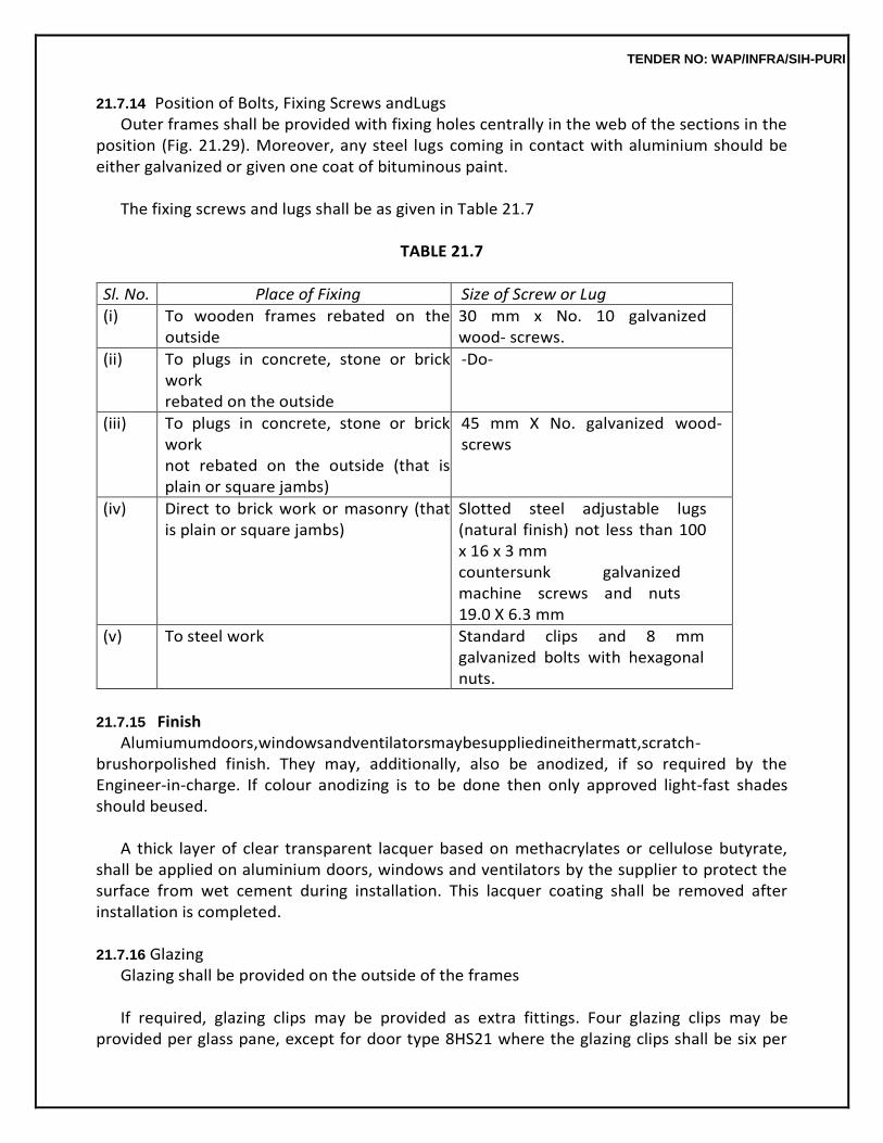
TENDER NO: WAP/INFRA/SIH-PURI
21.7.14 Position of Bolts, Fixing Screws andLugs Outer frames shall be provided with fixing holes centrally in the web of the sections in the
position (Fig. 21.29). Moreover, any steel lugs coming in contact with aluminium should be either galvanized or given one coat of bituminous paint.
The fixing screws and lugs shall be as given in Table 21.7
TABLE 21.7
Sl. No. Place of Fixing Size of Screw or Lug
(i) To wooden frames rebated on the outside
30 mm x No. 10 galvanized wood- screws.
(ii) To plugs in concrete, stone or brick work rebated on the outside
-Do-
(iii) To plugs in concrete, stone or brick work not rebated on the outside (that is plain or square jambs)
45 mm X No. galvanized wood-screws
(iv) Direct to brick work or masonry (that is plain or square jambs)
Slotted steel adjustable lugs (natural finish) not less than 100 x 16 x 3 mm countersunk galvanized machine screws and nuts 19.0 X 6.3 mm
(v) To steel work Standard clips and 8 mm galvanized bolts with hexagonal nuts.
21.7.15 Finish
Alumiumumdoors,windowsandventilatorsmaybesuppliedineithermatt,scratch-brushorpolished finish. They may, additionally, also be anodized, if so required by the Engineer-in-charge. If colour anodizing is to be done then only approved light-fast shades should beused.
A thick layer of clear transparent lacquer based on methacrylates or cellulose butyrate,
shall be applied on aluminium doors, windows and ventilators by the supplier to protect the surface from wet cement during installation. This lacquer coating shall be removed after installation is completed.
21.7.16 Glazing
Glazing shall be provided on the outside of the frames
If required, glazing clips may be provided as extra fittings. Four glazing clips may be provided per glass pane, except for door type 8HS21 where the glazing clips shall be six per
TENDER NO: WAP/INFRA/SIH-PURI
glass pane. In case of doors, windows and ventilators without horizontal glazing bars the glazing clips shall be spaced according to the slots in the vertical members, otherwise the spacing shall be 30 cm.
Note: Glazing clips are not usually provided for normal size glass panes. Where large size
glass panes are required to be used or where the door or the window is located in heavily exposed situation, holes for glazing clips have to be drilled prior to fabrication and cannot be done at any later stage. Use of glazing clips, where necessary, shall be specified while placing the order.
21.7.17 Packing
All doors, windows and ventilators shall be dispatched with the opening parts suitably secured to preserve alignment when fixing and glazing.
Fixinglugs,couplingfittingsandallhardwareshallbedispatchedseparately. Composite windows shall be dispatcheduncoupled.
21.7.18 Marking Alldoors,windowsandventilatorsshallbesuitablymarkedontheframeswithamarkidentifyingt
he manufacturer and thetype.
The units may also be marked with the BIS Certification Mark.
21.8 FITTINGS
21.8.1 Stainless Steel FrictionStay ThestainlesssteelfrictionstaysofmakeapprovedbytheEngineer-in-Chargeshallbeused.TheSS
frictionstaysshallbeofgradeAISI-304andofsizesspecifiedinnomenclatureofitem.
21.8.2 LockableHandles ThelockablehandleshallbeofmakeapprovedbytheEngineer-in-
Chargeandofrequiredcolourto match the colour of powder coated /anodized aluminium windowsections.
21.8.3 Hydraulic FloorSpring
The hydraulic floor spring shall be heavy duty double action floor spring of make approved by the Engineer-in-Charge suitable for door leaf of weight minimum 100 kg. The top cover plate shall be of stainlesssteel,flushingwithfloorfinishlevel.Thecontractorshallcutthefloorproperlywithstonecutting machine to exact size & shape. The spindle of suitable length to accommodate the floor finish shall be used. The contractor shall give the guarantee duly supported by the company for proper functioning of floor spring at least for 10years.
21.8.4 TubularHandle
The tubular handle bar shall be aluminium polyester powder coated minimum 50 micron to required colour/anodized AC 15. Outer dia of tube shall be 32 mm, tube thickness 3.0 mm
TENDER NO: WAP/INFRA/SIH-PURI
and centre to centre length 2115 mm + 5 mm.
21.8.5 Measurement Refer Para 21.6.3.
21.8.6 Rate
Refer Para 21.6.4.
21.9 LOUVERS Aluminium extruded sections (anodized or power coated) are used for providing Louvers
in aluminium door, window & partition for ventilation.
21.9.1 Fabrication Refer Para 21.6.1.
21.9.2 Measurements
Refer Para 21.6.3.
21.9.3 Rate Refer Para 21.6.4.
21.10 HERMETICALLY SEALEDUNIT
Insulating glass shall be a double glazed unit comprising two sheets of float glass panes separated by a spacer, hermetically sealed using primary and secondary sealants. The design of insulating glass system shall consist of:
(a) Hollow SpacerBar The hollow aluminium spacer bar shall be of required size and shape and shall be colour anodized. The spacer bar shall have two lines of perforations in the inner surface.
(b) Desiccant
The desiccant shall be Neftomol 3 A Chemetall or equivalent.
The desiccant filled in the aluminium spacer bar shall be synthesized crystalline compounds of Aluminium Hydroxide, Caustic Soda and Sodium Silicate which absorbs water molecules. The desiccant shall be of 3 A size (A means Angstrom). The quantity of desiccant used shall not be less than 35 gm/m length of spacer bar. Filled spacer bar frame shall not be stored for more than 6 hours before assembly and sealing of the unit to ensure proper functioning of the desiccant. The contractor shall submit documentary proof of using the above material in the work.
(c) PrimarySealant
The primary sealant shall be single component approved by the Engineer in Charge, thermo plastic solvent free sealing compound based on polysosutylene. The sealant surface shall be free from cavities, depression and other defects. The contractor shall
TENDER NO: WAP/INFRA/SIH-PURI
submit documentary proof of using the above material in this work.
(d) SecondarySealant The secondary sealant in double glazed unit shall be silicone sealant approved by the Engineer in Charge. The contractor shall submit documentary proof of using the above material in this worktotheentiresatisfactionofEngineer-in-Charge.Beforeapplicationofsilicone/polysulphide, thesurfacemustbecleanedandfreefromoil,grease,dustandotherloosematter.Thesurfaces shall be cleaned with alcohol or other suitable solvents. Detergent or soap shall not be used to clean the surfaces. The polysulphide shall be mixed and applied mechanically using automatic mixing machine in the manner approved byEngineer-in-Charge.
Measurement
The height and width of double glazed/single glazed unit (the area of glass unit outside the snap beadingshallonlybemeasured)asfixedinplaceshallbemeasuredcorrecttoonecentimeterandarea calculated in sqm. correct to second place of decimal shall be taken forpayment.
Rate
Therateshallincludethecostofallthematerials,laboursinvolvedinalltheoperationsasdescribed in nomenclature of item and particularspecification.
21.11 BRASSLOCK This should generally conform to IS-2209. The size of the lock shall be denoted by the length of the bodytowardsthefaceanditshallbe100mm.themeasuredlengthshallnotvarymorethan3mmfrom thespecifiedlength.Ordinarylevermechanismwithnotlessthan2leversshallbeprovided.Falselever shall not be used. Lever shall be fitted with one spring of phosphor-bronze or steel wire and shall withstand the test as provided in IS-2209. Locking-bolt spring and strike plate shall conform to IS 2209. Two keys shall be provided with eachlock
TENDER NO: WAP/INFRA/SIH-PURI
22.0 WATER PROOFING TREATMENT
22.0 TERMINOLOGY
Water Bars
Water bars are preformed strips of impermeable materials which are embedded in the concrete during construction.
Low Partition Walls
Parapet walls of height less than 45 cm.
Expansion Joints Joints provided in the structure to allow for thermal expansion/construction.
Blended Cement
Cement mixed with water proofing compound in liquid or powder form.
22.1 INTEGRAL CEMENT BASED TREATMENT FOR WATER PROOFING ON HORIZONTAL SURFACE OF UNDER-GROUND STRUCTURE AT ALLDEPTH
22.1.1 Water Proofing of Horizontal Internal Surfaces of Under-ground Structure (Fig. 22.1) (i) Preparation ofSurface
The Water Proofing Treatment over the lean concrete/levelling course surface should adhere to the surfacefirmly,thesurfaceoflevellingcourseshouldberoughenedproperlywhentheconcreteisstill green. In case the surface is not made rough before the concrete is set, the work of water proofing shouldnotbeexecutedtillproperkeyisprovidedforthebaselayerofCementMortar1:3.
(ii) Blending Cement/Water with Water ProofingCompound
The required quantity of cement bags to be used for a particular portion of work should be emptied onadryplatform.WaterproofingcompoundbearingISImarkandconformingtoIS2645shouldthen be mixed properly with the cement. The quantity of water proofing compound to be mixed shouldbe as prescribed by the manufacturer but not exceeding 3% by weight of cement. The quantity of cement and water proofing compound thus mixed should be thoroughly blended and the blended cement should again be packed inbags.
TENDER NO: WAP/INFRA/SIH-PURI
For the water proofing compound in liquid form, the blending is to be done with
water. This can bedonebytakingthejustrequiredquantityofwatertobemixedintheparticularbatchofdrycement mortar.
The required quantity of water thus collected per batch of dry cement mortar to be
prepared should be mixed with liquid water proofing compound from sealed tins with ISI mark. The waterthus mixed with water proofing compound shall be thoroughly stirred so that the water is blended with water proofing compoundproperly.
(iii) Rough Kota Stone 22 to 25 mmThick
The stone slabs to be used for this item shall be in thickness of 22 mm to 25 mm. Larger size of stone slabs i.e. 550 mm x 550 mm or 550 mm x 850 mm shall be used to minimise the number of joints.
General requirement of Kota stone shall be as laid down in CPWD Specifications of
Kota Stone flooring.
(iv) Preparation of CementSlurry Cement slurry shall be prepared by using 2.2 kg of blended cement per sqm. area.
Each time only that much quantity shall be prepared which can be covered on the surface and the surface in turnwouldbecoveredwith25mmthickcementmortarbasewithinhalfanhour.Slurrypreparedand remained unused for more than half an hour shall be totallyrejected.
(v) Preparation of CementMortar
Cementmortar1:3(1blendedcement:3coarsesand)shallbepreparedwithcement/waterduly blended as explained in clause 22.1.1 (ii). Only that much quantity of cement mortar which can be consumed within half an hour, shall be prepared. Any cement mortar that is prepared and remains unusedformorethanhalfanhourshallnotbeusedintheworkandshallberejected.
(vi) Laying Water ProofingCourse
Before laying the base course of cement mortar 1:3, the lean concrete surface shall be cleaned neatlywithwater.Cementslurrypreparedasperclause22.1.1(ii),shallbeappliedonlyonthearea oftheconcretesurface,thatcanbecoveredwiththecementmortar(1:3)basecoursewithinhalfan hour.Thecementslurryshouldcovereveryspotofthesurfaceandnoplaceshallremainuncovered. Justaftertheapplicationofcementslurryonthesurface,thecementmortarpreparedasperclause 22.1.1 (v) should be used for laying the base course. Base Course should be laid to a perfect level with wooden/aluminium straight edge of at least 2 mtrs. long. The top
TENDER NO: WAP/INFRA/SIH-PURI
surface of cement mortar shouldbefinishedneatlyandlaterscratchedwhengreenwithasuitableinstrumentbeforethebase coursedriesandgetshardthatisjustbeforethebasecoursetakesupinitialset.
When the 25 mm thick base course is just getting set the cement slurry prepared as per clause
22.1.1 (iv)shouldbespreadoverthebasecourseuptotheareathatshallbecoveredwithjusttwoto three stone slabs. The cement slurry shall be spread in such a way that the area of base course to be covered immediately shall be covered with slurry without any gap or dry spots. Immediately on applying cement slurry on the base course the Rough Kota Stone slab shall be laid over the base course and pressed gently so that the air gap can be removed. The slurry applied on the surface which gets spread when the stone slab is pressed shall get accumulated in the joints of adjacent stone slabs and if any gap still remains between the stone slabs the same should also be filled with additional quantity of cement slurry. For laying the stone slabs in perfect level, two stone slabs at adjacent concerns/ends shall be fixed firmly to the required level and a string stretched over thetwo slabs, the intermediate slabs shall then be set to the level of thestring.
After filling all the joints of the Rough Kota stone Slabs with cement slurry the area of
stone slab shallbelaidwithcementmortar1:3.Thesurfaceofstoneslabsshallbecleanedandlightlywatered. Cementmortar1:3preparedasperclause22.1.1(iv)shallbeusedforlayingthiscourse.Forlaying this course 25 mm high wooden strips shall be used and the top surface shall be finished smooth without using additional cement orslurry.
After laying 3rd course and before the mortar layer takes the initial set, Stone
aggregate of 10 mm to 12 mm nominal size shall be uniformly spread and lightly pressed into the finished surface@ 8cudm./sqm.Theaggregatesshallnotbeembeddedtotallyinsidethemortarandshallbevisibleon the topsurface.
In cases where slope is to be provided for the water proofing layer, grading with
additional cement concrete/cement mortar shall be provided and then the water proofing layer shall be laid on the graded surface. Extra payment shall however be made for the grading course.
(vii) Curing
Immediately after completing the fourth layer, arrangements shall be made for the top RCC slab as quickly as possible and in the mean time till the top slab is casted the water proofing treatment shallbekeptwetcontinuously.Incasetheconcretingofslabgetsdelayedformorethan2weeksthe curing can be stopped after 14days.
(viii) Measurement
Length and breadth shall be measured along the finished surface correct to a cm and
TENDER NO: WAP/INFRA/SIH-PURI
the area shall be worked out to nearest 0.01 sqm.
(ix) Rate The rate shall include the cost of all labour & materials involved in all the operations
described above. The cost of grading with cement concrete / cement mortar shall be paid for separately.
22.1.2 Water Proofing of Internal Horizontal Surfaces of Under-ground Structure (Fig.22.2)
Same as in 22.1.1 above except that water proofing courses will be laid on R.C.C. Slab.
22.2 INTEGRALCEMENTBASEDWATERPROOFINGTREATMENTONTHEVERTICALSURFACE OF UNDER GROUND STRUCTURES (FIG.22.3)
(i) Preparing theSurface
The surface of the structure to be treated shall be roughed either by raking of joints in case of brick/ stone masonry or by hacking the cement concrete surface with a specifically made hacking tooljustafterremovingshuttering.Alternately,thesurfaceshouldberoughenedbyprovidingspatter dash key as explained under clause 22.1.1 (i). While doing water proofing to vertical faces from inside, it shall be ensured that water proofing treatment of floor slab is not damaged. Preferably, water proofing of verticalsurface shall be done before that of horizontal surface.
(ii) Blending Cement/Water with Water ProofingCompound
Same as under clause 22.1.1(ii).
(iii) Rough Kota StoneSlab Same as explained under clause 22.1.1(iii).
(iv) Preparation of CementSlurry
Same as explained under clause 22.1.1(iv).
(v) Preparation of CementMortar Same as explained under clause 22.1.1(v).
(vi) Laying Water ProofingCourse
Sameasexplainedunderclause22.1.1(vi).Furtherroughkotastonearenotsufficientlyroughto remain in vertical position held by cement slurry. Therefore, the grip for the stone slab has to be increasedandthiscanbedonebyplanting12mmto15mmnominalsizestoneaggregatefixedwith araldite on surface of each sand stoneslab.
(vii) Curing
Sameasexplainedunderclause22.1.1(vii).Furthertillthewaterproofingworkonverticalfaceis in progress, the water proofing work done on floor slab shall be kept wet for a
TENDER NO: WAP/INFRA/SIH-PURI
minimum period of14 days. Immediately after completion of water proofing on vertical faces of side walls, the water tank shall be gradually filled with water fortesting.
(viii) Measurement
Same as explained under clause 22.1.1(viii).
(ix) Rate Same as explained under clause 22.1.1(ix).
22.3 WATER PROOFING TREATMENT TO VERTICAL AND HORIZONTAL SURFACE OF DEPRESSED PORTION OF WC, KITCHEN AND THELIKE
22.3.1 Before the Water ProofingTreatment
Before the water proofing treatment, the internal plaster of ceiling and walls of WC block leaving the portion for dado/skirting should be completed. Grooving / chasing for doing the concealed work ofGI/CI pipes/Electrical conduits should be completed. Cleaning the depressed/sunken portion of WC of all debris,extramortarstickingtotheverticalandhorizontalsurfaceetc.Necessaryholesfor‘P’trap/Nhani trap/Water escape pipe etc should becompleted.
22.3.2 Preparing Surface and Fixing Pipes andFittings
Before the water proofing treatment work, proper key in the concrete surface should be provided. The depressed/sunken portion should be hacked by a hacking tool, after the concrete slab is cast and when this concrete is still green.
The vertical surfaces of the depressed /sunken portion should be hacked with a hacking
tool just after the shuttering is removed.
In case of old work, the water proofing treatment on such surfaces shall be permitted after making proper spatter dash key.
Fixing the ‘P’ trap in position and all other pipes work including the water escape pipe
shall be fixed properly and the holes should be plugged carefully before taking up the water proofing work.
22.3.3 1stCourse
Cement duly blended with water proofing compound as explained in clause 22.1 shall be used for preparing the cement slurry.
The consistency of the slurry should be such that 4.4 kg. of blended cement with water
proofing compound is used per sq. metre area of surface to be treated. The slurry should be started from the vertical faces towards the bottom of the floor as shown in Fig. 22.4. Particular care should be taken to see that the slurry is applied to corners without leaving any gap.
TENDER NO: WAP/INFRA/SIH-PURI
22.3.4 2ndCourse Immediately on applying the blended cement slurry on the surface to be treated cement
plaster 20 mm thick in CM 1:3 (1 blended cement: 3 coarse sand) shall be applied both on vertical and horizontal surfaces taking particular care to complete the entire depressed/ sunken portion of WC within a day so that the plaster can be done without any joint. Junctions shall be properly rounded. The surfaces of the plaster shall be left rough but finished in one plain and cured for a week.
On completion of the curing period both horizontal and vertical surfaces shall be cleaned
properly and gently and allowed to dry.
22.3.5 3rdCourse Onlyafterthesurfaceiscompletelydriedtheblownorresidualbitumenshallbeapplied@1.7kg.o
f bitumen per sqmarea.
22.3.6 4thCourse PVC sheet 400 micron thick shall be spread evenly without any kink immediately, so that
the PVC sheet sticks to the surface firmly. PVC sheet shall be continued to be laid over the main slab upto 100 mm.
Overlapping of PVC sheet should be done with a minimum overlap of 100 mm, duly
pasting the overlapped sheet with an application of bitumen @ 1.7 kg./ sqm.
Theprojectionsofpipesand‘P’trapoutletetc.insidethedepressed/sunkenportionofWCshallalso be cladded with water proofing treatment layer upto a height of 150 mm, using a coat of bitumen with PVC sheetcomplete.
The surfaces of depressed/sunken portion of WC shall not be left without covering with
specified filling material and base concrete, otherwise the PVC sheet layer may be tampered by the labour working in the vicinity.
Fixing up of WC pan, filling specified material and the top base concrete should be done
as earlyas possible and the top horizontal layer of water proofing may be taken up later i.e. just before laying the floortiles.
22.3.7 Measurement
Length and breadth shall be measured along the finished surface correct to a cm. and area shall be worked out to nearest 0.01 sqm. No payment however shall be made for the 100 mm overlap of PVC Sheet over the roof slab.
22.3.8 Rate
The rate shall include the cost of labour and materials involved in all the operations described above.
22.4 PROVIDING WATERSTOPS
TENDER NO: WAP/INFRA/SIH-PURI
22.4.1 Water stops conforming to IS 12200 for construction/expansion joints should be fabrication from a plastic compound, the basic resin of which shall be polyvinyl chloride. The compound shall contain additional resin/ plasticizer inhibitors or other materials such that when the materials is compounded it shall meet the requirement given in IS15058.
22.4.2 Type of Joints for which Water Bars areProvided
Thewaterbarsareprovidedonlyforthemovementofjointsinawaterretainingstructure. Different types of movement joints are as describedbelow:
CompleteContractionJoint:Thisisamovementjointwithdeliberatediscontinuitybothinconcreteas wellasthereinforcementbutnoinitialgapismaintainedbetweentheconcreteoneithersideofthejoint. This joint is intended to accommodate the contraction of theconcrete.
Partial Contraction Joint: This is a movement joint with deliberate discontinuity in concrete but no water bar is provided and no discontinuity is provided in steel. No initial gap is maintained between the concrete on either side of joint.
Expansion Joint: This is also a movement joint with complete discontinuity in both reinforcement and concrete. It is intended to accommodate either expansion or contraction of the structure.
In general such joint requires the provision of an initial gap between the adjoining parts of
the structure which accommodates expansion or contraction of the structure.
22.4.3 Types and Performance of WaterBars Waterbarsareperformedstripsofimpermeablematerialwhichareembeddedintheconcreted
uring construction so as to span across the joints and provide a permanent water tight seal during the whole range of jointmovement.
ThemostusualformofwaterbarsarestripwithalongitudinalcorrugationasshowninFig.22.5. Another form of water bar of metallic type is Z shapedstrip. Water bars of copper, sheet lead, natural or synthetic rubber and plastic such as polyvinyl
chloride (PVC) are also used. These bars comprise of central longitudinal hollow tube with thin walls and stiff wings of about 150 mm width.
Outofthemetalsavailablecopperismostsuitableasregardsductility,resistancetocorrosioninai
r, water and concrete. However, it may be attacked by some wastes. If sheet lead is used it should be insulated from concrete by a good coat of bituminous or suitable composition. Natural synthetic rubber andplasticshaveveryconsiderableadvantageinhandling,splicingandinmakingintersections.
Galvanized iron sheets may also be used with the specific permission of the Engineer-in-
charge provided the liquid stored or the atmosphere around the liquid retaining structure is not excessively corrosive i.e. sewage.
TENDER NO: WAP/INFRA/SIH-PURI
The strip water bars described as above, while placing in position has to be passed through theend shutter of the first placed concrete with the result the shuttering at this point should be perfectly water tight otherwise cement slurry may escape from the concrete being laid and will ultimately weaken the structure.Thereforetoavoidtheaboveproblemonecanprefermouldedtypeofwaterbar.
The design of the moulded water bar with several projections need to be passed through
the end shutter while placing the same in position. Another main advantage of this water bar is that since it occupies bigger proportion of the thickness of the joint it would lengthen the shortest alternative water path through the concrete.
22.4.4 It is important to ensure proper compaction of concrete around the water bar. Proper cover toall the reinforcement shall be maintained. Sometimes to increase the bond the holes are provided in the copper water bars but in the long run it proves to be disadvantageous as it shortens the path of water through concrete. Water bars should be placed at the centre of the wall or if it is to be provided away from the centre its distance from either face of the wall shall not be less than half of the width of water bar or as specified/directed by theEngineer-in-charge.
22.4.5 Covers Plates forJoint
Sometimes joint cover plates have to be used for expansion joints mainly to avoid the risk of a fault in the water bar which is embedded. The plates to be used should be either copper or sheet lead. In case the copper plates are to be used, it should be clamped to the concrete face on each side of the joint. To ensure water tightness suitable gasket shall be used. Joint cover plates of sheet lead are also used and fixed on the joints. In this case the edges may return into grooves formed in the concrete and can be made completely water tight by lead caulking. Faces of the concrete to which sheet lead is tobe fixed should be painted with bituminous or other suitable composition and the lead sheet should be similarly coated beforefixing.
22.4.6 Spacing ofJoints
InReinforcedConcretefloorsmovementjointsshouldbespacedatnotmorethan7.5mapartintwo directions at right angles. The wall and floor joints should occur at the base of the wall in which case corresponding vertical joint is notimportant.
In concrete walls, the vertical movement joints should normally be placed at a maximum spacing of
0.75 m in reinforced walls. The maximum length desirable between vertical movement joints will depend upon the tensile strength of the walls and may be increased by suitable reinforcements.
Amongst the movement joints in floors and walls as mentioned above, expansion joint
should be normallybeprovidedatspacingofnotmorethan30mbetweensuccessiveexpansionjointsorbetween theendofthestructureandthenextexpansionjoint,allotherjointsbeingofthecontractiontype.
TENDER NO: WAP/INFRA/SIH-PURI
In case of expansion joints the filling of these with bitumen filler, bitumen felt or any such material etc. shall be paid for separately in running metre. The measurement shall be taken upto two places of decimal stating the depth and width of joint.
In case joint cover plates either of copper or sheet lead with ancillaries are provided,
these shall be measured and paid for separately.
22.4.7 Measurement Length shall be measured correct to a cm and net quantities shall be calculated upto two
places of decimal.
Each category of water stops/bar such as PVC, copper specifying width, thickness shall be measured and paid for separately.
22.4.8 Rate
The rate shall include all labour and materials in all the operations described above.
22.5 WATER PROOFING TREATMENT IN SUNKEN PORTION OF WCs, BATHROOMSETC.
22.5.1 Preliminaries to beAttended The preliminaries shall be attended as described in clause 22.3.1.
22.5.2 Preparing Surface, Fixing Pipes andFittings
In this case, unlike as described in clause 22.3.2, no hacking of surface need be made, but only extra mortar sticking to the surface should be removed and the surface should be cleaned thoroughly. Fixing ‘P’ trap etc. shall be done as described in Clause 22.3.2.
22.5.3 Providing and Laying of Slurry for FirstLayer
The consistency of the slurry should be such as to cover the desired area by using 0.488 kg of blended cement per sqm of area.
On deciding the correct quantity of water required per sqm. area the required quantity of
slurry should be prepared which can be applied over the desired surface within half an hour of mixing with 0.488 kg. of grey cement + 0.253 kg. water proofing compound as per manufacturer specifications + x litres of water per sqm. area and the required quantity of slurry thus prepared should only be used for first application.
The first layer shall be applied with painting brushes over the specified and dampened
area carefully including the corners, holes on the surfaces and joints of pipes in concrete etc. and the application should continue at least upto 150 mm height of fixtures of pipes from the surface. The surface on application shall be air cured for 4 hours.
22.5.4 Providing and Laying of Slurry for SecondLayer
Thequantityofslurryrequiredforsecondapplicationtobecoveredwithinanhourofmixingshallb
TENDER NO: WAP/INFRA/SIH-PURI
e preparedwith0.242kg.cement+0.126kg.waterproofingcompound+ylitresofwaterpersqm.area andtherequiredquantityofslurrythuspreparedshouldonlybeusedforsecondapplication.
The application of 2nd layer of slurry is same as for first layer as detailed in clause 22.5.3.
Theappliedsurfaceshallbeallowedtoaircurefor4hoursandthereafterwatercuringshallbedon
e for full 48hours.
In case no further work as described above is to be taken up immediately on completion of water proofing treatment due to any reason it is recommended to protect the treated portion with cement plaster 1:4 as a protective layer for which separate payment shall be made to the contractor.
22.5.5 Measurement
Length and breadth shall be measured along the finished surface correct to a cm and area shall be worked out to nearest 0.01 sqm.
22.5.6 Rate
The rate shall include the cost of all labour and materials involved in all the operations described above. The cost of plastering shall be measured and paid for separately.
22.6 WATER PROOFING TREATMENT ON ROOFSLABS
22.6.1 Before taking up the water proofing work the construction of parapet walls, including finishing shouldbecompleted.Similarly,theancillaryitemslikehaunches,khurras,groovestotackthefibrecloth layer,fixingupofalldowntakepipes,waterpipesandelectricconduitsetc.shouldbecompletedandno such work should be allowed on the area to be treated during the progress of water proofing treatment or evenlater.
22.6.2 Preparing Surface
Thereisnonecessityofhackingthesurfacebutthesurfacetobetreatedshallbecleanedincluding removing the mortar dropping from thesurface.
22.6.3 Providing and Laying of CementSlurry
The procedure to prepare and apply the cement slurry shall be same as detailed in clause 22.5.3 except that over projected pipes etc. slurry shall be applied just upto 100 mm height instead of 150 mm height.Theslurryshallbeapplieduptoaheightof300mmonparapetwallsandinthegroovewherethe fibre glass cloth is to betucked.
22.6.4 Providing and Laying of Fibre Glass Cloth (2ndLayer)
The fibre glass cloth shall be of approved brand and shall be thin, flexible uniformly bonded mat composed of chemically resistant borosilicate glass fibre distributed in random
TENDER NO: WAP/INFRA/SIH-PURI
open porous structure bonded together with a thermosetting resin.
Immediatelyonapplyingtheslurryonasufficientlyworkableareaasdetailedaboveinclause22.6.3 when the slurry applied is still green the fibre glass as specified shall be spread evenly on the surface without any kink and pressed in such a way that no air spaces exist. The fibre glass cloth shall betaken uptoaheightof30cmonparapetwallsandtuckedinthegroovespeciallypreparedatthatheight.
Aminimumoverlapof100mmwidthshallbeprovidedwhenthefibreclothhastobejoined.Thejoinin
g of 100 mm overlap shall be done with the same slurry used for the application on surface as first layer. The fibreclothshallalsobeextendeduptoaheightof100mmoverpipesprojectingfromthesurface.
22.6.5 Providing and Laying of Cement Slurry for ThirdLayer
Thequantityofwaterrequiredtoprepareslurrywhichcancoveronesqm.areaofthesurfacetobe treatedshallbecalculatedasdescribedinclause22.5.3andconsiderthisquantityassayxlitres/sqm.
On deciding the correct quantity of water required, the slurry shall be prepared by mixing
1.289 kg/m2 of grey cement + 0.67 kg./sqm. of Water Proofing Compound +1.289 kg./sqm. of coarse sand +x litresofwater.Slurryshallbepreparedfortheareatobecoveredwithin½anhourofmixing.
Theconsistencyoftheslurryshallbesuchthatinoneapplicationwithabrush1.5mmthicknessof
slurry can be coated on the fibre glass clothsurface.
Thisslurryshallbeappliedevenlyontheentiresurfacecoveredwithfibreglassclothsothatalayer of 1.50 mm thickness of slurry isformed.
The application of slurry shall be continued over the 300 mm portion of parapet wall and
also the portion tucked in the groove on top.
TENDER NO: WAP/INFRA/SIH-PURI
The entire surface shall be allowed for air curing for 4 hours and later the surface shall be cured with clean water for 7 days.
Oncompletionofcuringthegrooveswherethefibreglassclothistuckedshallbeclosedneatlywit
h cementmortarmixedwithwaterproofingcompoundandtherepairedsurfaceshouldbecuredbyclean water for 7days.
Fourth and final layer of brick tiling if required shall be laid and paid for separately.
22.6.6 Measurement
Length and breadth shall be measured along the finished surface correct to a cm and area shall be worked out to nearest 0.01 sqm. Overlaps and tucking in a flashing grooves shall not be measured. No deductionsshallbemadeforopeningsorrecessorchimneystack,rooflightsorKhurrasofareaupto 0.40sqm,noranythingextrashallbepaidforformingsuchopenings,recessetc.Forareaexceeding 0.40 sqm. deduction will be made in the measurement for the full opening and nothing extra shall be paid for making such opening.
22.6.7 Rate
The rate shall include the cost of labour and material involved in all the operations describedabove, however the cost of brick layer with cement mortar shall be paid forseparately.
22.7 INTEGRALCEMENTBASEDWATERPROOFINGTREATMENTWITHBRICKBATCOBA(Fig. 22.6)
22.7.1 Before taking up the work the preliminaries to be attended shall be exactly same as describedin clause22.6.1.
22.7.2 Preparing theSurface
The surface of the slab should be roughened by scrapping when the slab concrete is still green, however,thesurfaceneednotbehacked.Incasetheslabisalreadycastandsurfacefairlyfinished,the sameshallbecleanedneatlyofallmortardroppings,loosematerialsetcwithbrooms/cloth.
22.7.3 Providing and Laying of Slurry under BaseCoat
The quantity of water required to prepare the slurry with 2.75 kg. of blended cement to be painted over an area of 1 sqm. shall be calculated exactly as described in clause 22.5.3.
Dependingupontheareaofsurfacethathastobecovered,therequiredquantityofslurryshouldb
e prepared using 2.75 kg. blended cement + water per sqm. area to be covered, taking particular care to see that only that much quantity of slurry shall be prepared which can be used within half an hour of preparation i.e. before the initial setting time ofcement.
The prepared slurry shall be applied over the dampened surface with brushes very
TENDER NO: WAP/INFRA/SIH-PURI
carefully, including the joints between the floor slab and the parapet wall, holes on the surfaces, joints of pipes, masonry/concrete etc.
The application of the slurry should continue upto a height of 300 mm on the parapet wall
and also the groove as shown in Fig. 22.6. The slurry should also be applied upto a height of 150 mm over pipe projections etc.
22.7.4 Laying Base Coat 20 mmthick
Immediatelyaftertheapplicationofslurryandwhentheapplicationisstillgreen,20mmthickcement plasterasbasecoatwithcementmortar1:5(1blendedcement:5coarsesand)shallbeevenlyapplied overtheconcretesurfacetakingparticularcaretoseethatallthecornersandjointsareproperlypacked andtheapplicationofthebasecoatshallbecontinueduptoaheightof300mmovertheparapetwall.
22.7.5 Laying Brick BatCoba
Brick bat of size 25 mm to 115 mm out of well burnt bricks shall be used for the purpose of brick batcoba.
The brick bats shall be properly dampened for six hours before laying.
Brickbatsshallbelaidtorequiredslope/gradientoverthebasecoatofmortarleaving15-
25mmgap betweentwobats.Cementmortar1:5(1blendedcement:5coarsesand)shallbepouredoverthebrick batsandjointsfilledproperly.Undernocircumstancesdrybrickbatsshouldbelaidoverthebasecoat.
The haunches/gola at the junction of parapet wall and the roof shall be formed only with
brick bat coba as shown in Fig. 22.6.
Incasethebrickbatcobaislaidonthebasecoatimmediatelyoninitialsettherewillbenonecessity of applying cement slurry over the base coat before laying the brick bat coba. However, if the brick bat coba is to be laid on the subsequent day, cement slurry prepared as described in clause 22.7.3 shallbe appliedoverthetopsurfaceofthebasecoat,thenonlythebrickbatcobashallbelaid.
22.7.6 Application of Slurry over Brick BatCoba
After two days of curing of brick bat coba cement slurry prepared as per clause 22.7.3 shall be applied on the surface of brick bat coba The application of slurry shall be the same as described in clause 22.5.3 which should cover the haunches/gola, and the remaining small portion of parapet wall and also inside the groove as shown in the figure.
22.7.7 Laying Finishing Layer (ProtectiveCoat)
Immediatelyonapplyingthecementslurryoverthesurfaceofthebrickbatcobaandwhentheslurry applied is still green, the fibre glass cloth as specified in clause 22.6.4 shall be spread
TENDER NO: WAP/INFRA/SIH-PURI
evenly on the surface without any kink & pressed to see that no air spaces exist. The fibre glass cloth shall be taken up to a height of 300 mm on parapet walls & tucked in the groove specially prepared at that height. 20 mm thick layer of cement plaster, without leaving any joints shall be applied with cement mortar 1:4 (1 blended cement: 4 coarse sand) over the entire fibre glass cloth including the haunches/gola andthe small portion on the parapet wall. The groove in the parapet wall over the haunches shall also be filled neatly packing the mortar firmly in thegroove.
The surface of the finishing layer (protective coat) shall be neatly finished with cement
slurry prepared as per clause 22.7.3. The finished surface shall be allowed to dry for a while and then pattern of 300 mm x 300 mm groove, 8 mm deep shall be made over the entire surface.
22.7.8 Curing and Testing theTreatment
The entire surface thus treated shall be flooded with water by making kiaries with weak cement mortar, for a minimum period of two weeks.
22.7.9 Measurement
The measurement shall be taken along the finished surface of treatment including the rounded and tapered portion at junction of parapet wall. Length and breadth shall be measured correct to a cm and areashallbeworkedouttonearest0.01sqm.Nodeductioninmeasurementshallbemadeforopenings orrecessesorchimneystacks,rooflightsorkhurrasofareaupto0.40sqm.,noranythingextrashallbe paidformakingsuchopenings,recessesetc.Forareasexceeding0.40sqm.,deductionwillbemadein themeasurementsforthefullopeningsandnothingextrashallbepaidformakingsuchopenings.
22.7.10 Rate
The rate shall include the cost of all labour and materials involved in all the operations described above.
22.8 WATER PROOFING TREATMENT WITH BITUMENFELT 22.8.0 Water proofing treatment with self finished felt shall be four courses or six courses as described in the item. Four course water proofing treatment with self finished felt is a normal duty treatment suitable for buildings where the cost of roof treatment is required to berestricted.
Six course water proofing treatment with self finished felt is a heavy duty treatment
suitable for important structures.
22.8.1 Materials
22.8.1.1 Self finished felt (Appendix A and B) shall conform to the type and grade given in the description of the item. This shall be one of the followingtypes:
(i) Type 3 grade 1 hessian base felt conforming in all respects to IS1322.
TENDER NO: WAP/INFRA/SIH-PURI
(ii) Type 2 grade 1 fibre base bitumen felt conforming to IS1322. (iii) Type 2 grade 2 glass fibre base felt conforming in all respects to IS7193.
22.8.1.2 BondingMaterials:ThisshallconsistofblowntypepetroleumbitumenconformingtoIS702or residual petroleum bitumen conforming to IS 73. The bonding material shall be so selected as to withstandthelocalconditionoftemperatureandgradientsatisfactorily.Thepenetrationofbitumenused shallnotexceed40inanycase.Suitableresidualtypepetroleumbitumenofpenetration30/40(ISgrade S-35), residual type petroleum bitumen with higher penetration and low softening point and suitable blowntypepetroleumbitumenofISgrade85/25or90/15ofapprovedqualityshallbeused.
Where proprietary brands of bonding materials are proposed to be used they shall
conform in all respects to the specifications in the preceding paras.
1st course kg/sqm
3rd course kg/sqm
5th course kg/sqm
I. Four course treatment: 1.45 1.45 —
II. Six course treatment: (a) Withtype3grade1hessianbaseself
finished bitumenfelt.
1.45 1.20 1.45
(b) With felts other than type 3 grade 1 hessian base.
1.45 1.20 1.70
22.8.1.3 Stone Grit and Pea-sized Gravel: Stone grit shall be 6 mm and down size. Where pea-sized gravelisuseditshallbehard,roundandfreefromdust,dirtetc.Thestonegritorpea-sizedgravelshall not be spread over vertical and sloping faces of flashings and at drain mouths. At these places the surface shall be painted with two coats of bituminoussolution.
The quantity of stone grit or pea-sized gravel required for the final course of four or six
course treatment with hessian base self finished bitumen felt type 3 grade 1 shall be 6 cubic decimeter/ sqm.
22.8.2 Preparation ofSurface
22.8.2.1 The surface to be treated shall have a minimum slope of 1 in 120. This grading shall becarried out with cement concrete or cement plaster with coarse sand, as per direction of Engineer-in-charge, to theaveragethicknessrequiredandfinishedsmooth.Suchgradingshallbepaidforseparately.
22.8.2.2 Junctionsbetweentheroofandverticalfacesofparapetwalls,chimneysetc.shallbecasedby running triangular fillets 7.5 x 7.5 cm size, in cement concrete. At the drain mouths, the fillets shall be suitably cut back and rounded off for easy application of water proofing treatment and easy flow of water. Cement concrete where used shall be 1:2:4 mix (1 cement:
TENDER NO: WAP/INFRA/SIH-PURI
2 coarse sand : 4 graded stone aggregate 20 mm nominal size). The provision of fillets shall be deemed to be covered by the item of water proofing and shall not be measured or paid forseparately. 22.8.2.3 Inexistingroofwheregolaanddripcourseareprovidedatthejunctionofroofandverticalface of parapet wall, chimney stacks etc., these shall be dressed suitably and finished smooth so as to ensure an easy and gradual turning of the flashing. Any dismantlement or forming and finishing smooth thejunctionforformingthebaseoftheflashingshallnotbemeasuredorpaidforseparatelyandshallbe deemedtoformpartofthepreparationofthesurfaceinthewaterproofingtreatment.
22.8.2.4 While the grading of roof surface is being done, it shall be ensured that the outlet drain pipe have been fixed and mouth at the entrance have been eased and rounded off properly for easy flow of water.
22.8.2.5 When any pipe passes through the roof to be treated, angular fillet of shape shown in Fig.22.7 shall be built around it for the water proofing treatment to be taken over it. These fillets shall not be measured or paid forseparately.
22.8.2.6 For carrying over and tucking in the water proofing felts into the parapet walls, chimney stacks etc. a horizontal groove 6.5 cm deep, 7.5 cm wide section with its lower edge at not less than 15 cm above the graded roof surface shall be left on the inner face of the same during construction ifpossible. Whensuchgroovehasnotbeenleft,thesameshallbecutoutneatlyandthebaseatrearofthegroove shall be finished smooth with cement plaster 1:4 (1 cement: 4 coarse sand). Such cutting of the groove anditsfinishingsmoothshallbedeemedtobepartofthewaterproofingitemandshallnotbemeasured or paid for separately. No deduction shall be made either for not making the groove or when the later has already been left in the masonry by the constructionagency.
22.8.2.7 Tucking in the water proofing felt will be required where the parapet wall exceeds 45 cm in the height from the graded surface. Where the height is 45 cm or less, no groove will be required as the waterproofingtreatmentwillbecarriedoverthetopoftheparapetwalltoitsfullthickness.Inthecaseof low dividing walls of height 30 cm or less, outlets therein shall be cut open for full height and thebottom andsidesshallberenderedsmoothandcornersroundedandsuchtreatmentshallnotbemeasuredand paid forseparately.
22.8.2.8 Where expansion joints are left in the slab, the provision of dwarf walls and/or RCC slabs for covering them and finishing the surface smooth shall be the responsibility of the construction agency, whichhadlaidtheroofslabandwillnotbeincludedtheoperationofwaterproofing.
22.8.2.9 The graded surface of the roof and concrete fillets and the faces of walls shall be
TENDER NO: WAP/INFRA/SIH-PURI
thoroughly cleaned with wire brushes and all loose scales etc. removed. The surface shall then be dusted off. Any crack in the roof shall be cut to ‘V’ section, cleaned and filled up flush with cement mortar slurry 1:4 (1 cement: 4 coarse sand) or blown type petroleum bitumen of IS grade 85/25, or approved quality conformingtoIS702.Suchcleaningofthesurfaceortreatingthecracksshallnotbepaidforseparately.
22.8.3 PrimingCoat
Where so specified, or required by the Engineer-in-Charge for example under slightly damp conditions a priming coat consisting of a bitumen primer conforming to IS 3384 should be applied with brush on the roof and wall surface at 0.24 litres per sqm to assist adhesion of the bonding material (i.e. bitumen).
Such application of primer shall be paid for separately, unless specifically included in the
water proofing item.
22.8.4 Underlay Where a floating treatment of water proofing with self finished bitumen felt is required
i.e. where water proofing treatment is required to be isolated from the roof structure, a layer of bitumen saturated felt (underlay) shall be spread over the roof surface and tucked into the flashing groove. No bonding material shall be used below the underlay in order to keep the underlay free of the structure. Theadjoining strips of the underlay shall overlap to a minimum of 7.5 cm at sides and 10 cm at ends. The overlaps shall be sealed with the same bonding material as used for the self finished felt treatment. Unless specifically included in the water proofing item, the underlay treatment shall be paid for separately.
Theunderlayshallbeoftype1saturatedfeltconformingtoIS1322inallrespectsandhavingatotal
minimum weight of the finished bitumen felt in dry condition with mica dusting powder @ 6.8 kg per 10 sqm.Therollshallnotbedamagedorcrackonbeingunrolledonafairlysmoothandflatsurface.
22.8.5 Treatment
22.8.5.1 The water proofing shall consist of a four or six course treatment, as given in the description of the item, each layer of bonding materials, self finished bitumen felt or stone grit or pea sized gravel being counted as acourse.
22.8.5.2 The choice of a four or six course treatment will depend on the climatic condition, the importanceofthebuilding,thedurabilityrequired,costandotherrelevantconsiderations.
22.8.5.3 A four course treatment shall consist of the followinglayers:
(a) Initial layer of bonding material applied hot at specified weight per unitarea. (b) 2ndlayerofselffinishedbitumenfeltconformingtothetypeandgradegiveninthedescription
of theitem. (c) Third layer of bondingmaterial.
TENDER NO: WAP/INFRA/SIH-PURI
(d) Finallayerofstonegritofpeasizedgravelspreadatspecifiedvolumeofmaterialperunitarea.
22.8.5.4 In a six course treatment, the first, second and third layer shall be of the same as in the four course treatment. The fourth and fifth layer shall consist of self finished felt and bonding material respectively. The sixth layer shall consist of stone grit or pea sizedgravel.
22.8.5.5 The primer or underlay where required to be provided shall not count against the number of coursesspecified.
22.8.6 Laying
22.8.6.1 Bitumen bonding material of required grade shall be heated to the working temperature specified for the particular grade by the bitumen manufacturers and conveyed to the roof in buckets or pouring canes in weighedquantities.
Suitable working temperature for different grades of bitumen are as under: (i) Blown type petroleum bitumen of IS grade 85/25 or 90/15 - 180 degreeC. (ii) Residualtypepetroleumbitumenofpenetration30/40-180degreeto190degreeC(ISgradeS-35).
22.8.6.2 Drain outlets shall be given a four or six course treatment as specified for the roof in the description of the item in the manner specified for the flat roof surface. Water proofing treatment shall be carried into the drain pipe or outlets by at least 10 cm. The water proofing treatment laid on the roof surfaceshalloverlaptheupperedgeofthewaterproofingtreatmentinthedrainoutletsbyatleast10cm.
22.8.6.3 The self finished felt shall be cut to the required length, brushed clean of dusting material and laid out flat on the roof to eliminate curls and subsequent stretching. The felt shall normally be laid in lengthatrightanglestothedirectionoftheslopeandlayingshallbecommencedatthelowestleveland worked upto crest. The felt shall not be laid in single piece of very long lengths as they are likely to shrink; 6 to 8 m are suitable lengths. The roof surface shall be cleaned and dried before the felt treatment is begun. Each length of felt shall be laid in position and rolled up for a distance of half its length. The hot bonding material shall be poured on the roof across the full width of the rolled felt asthe latter is steadily rolled out and pressed down. The pouring shall be so regulated that the correctweightofbondingmaterialperunitareaisspreaduniformlyoverthesurface.Excessbondingmaterialthatgets squeezed out at the ends shall be levelled up as laying proceeds. When the first half of the strip of felt has been bonded to the roof, the other half shall be rolled up and then unrolled on the hot bonding material in the same way. Subsequent strips shall also be laid in the same manner. Each strip shall overlap the preceeding one by at least 7.5 cm at the longitudinal edges and 10 cm at the ends. All overlaps shall be firmly bonded with hot bitumen. Streaks and trailings of bitumen near edges of laps shallbelevelledbyheatingtheoverlapwithablowlampandlevellingdownunevenness.
The third layer of bonding material in the four course treatment shall be carried out in a
TENDER NO: WAP/INFRA/SIH-PURI
similar manner after the flashing has been completed.
22.8.6.4 In a six course treatment the third and fourth layers of bonding material and self finished felt shallbelaidinthemanneralreadydescribed,takingcarethatlapsinthefeltarestaggeredfromthosein the second layer. The fifth layer of bonding material shall be carried out after the flashing is done (See Fig.22.7).
22.8.6.5 HighParapetWalls,ChimneyStacksetc.:Feltsshallbelaidasflashingswhereverjunctions ofverticalandhorizontalsurfacesoccur.Longitudinallapsshallbe10cm.Thelowerlayerofflashingfelt in a six course treatment shall overlap the roof water proofing by not less than 20 cm while the upper layer shall overlap the roofing felt by 10 cm. The minimum overlap of the flashing felt in four course specification over the roofing felt shall be 10cm.
Theflashingshallconsistofthesamefourorsixcoursetreatmentasfortheroofexceptthatthefina
l course of stone grit or pea-sized gravel shall be replaced by an application of bituminous solution of approved quality in two coats on the vertical and sloping faces only, of the flashing. The overlap along the length of flashing shall stagger with those in the second layer of flashing felt (in a six course treatment and with the joints in the rooffelt).
The upper edge of the flashing felt shall be well tucked into the flashing grooves in the
parapet, chimney stacks etc. to a depth of not less than 6.5 cm. Corresponding applications of bonding material shall also be made. The flashing treatment shall be firmly held in place in the grooves with wood edges at intervals and the grooves shall be filled up with cement mortar 1:4 (1 cement: 4 coarse sand) or cement concrete 1:2:4 (1 cement : 2 coarse sand : 4 graded stone aggregate 6 mm nominal size) and surface finished smooth with the rest of the wall. The cement work shall be cured for 7 days. When dry, theexposedplasterjointsofgroovesshallbepaintedwithbitumenandtwocoatsofbituminoussolution shall be applied on the vertical and sloping surface of flashing (see Fig.22.7).
After the top flashing felt layer has been fixed, the penultimate layer of bonding material
shall be appliedovertheroofingfeltandthehorizontaloverlapsandverticalandslopingsurfacesoftheflashings at the specified rate. Stone grit or pea sized gravel shall then be spread uniformly over the hot bonding material on the horizontal roof surface at the specified quantity per unit area and pressed into it with a woodenroller.
22.8.6.6 Low Parapet Walls: Where parapet walls are of height 45 cm or less, bitumen felt flashings shall be provided in the same manner as for flashings in the case of high parapet walls except that the upper edge shall be carried upto the full height of the wall and taken right across the top of the parapet anddownontheexternalverticalfacestoaminimumdistanceof5cm(seeFig.22.7).
22.8.6.7 Low Dividing Walls: Where low dividing walls or inverted beams are met with, the same shall be covered with a four or six layer treatment as for the main roof, the latter
TENDER NO: WAP/INFRA/SIH-PURI
bearing carried down both sides of the wall and overlapping the roofing treatment as in the case of flashing of high parapet walls (see Fig.22.7).
Drain outlets where formed in the low dividing walls, shall be given water proofing
treatment of the same number of courses as specified for the flat roof surface. The bottom and sides shall be so treated that all overlaps are in the direction of flow of drainage.
22.8.6.8 Expansion Joints: Where the expansion joints are provided in the slabs, the joints and their cover slabs shall be suitably treated with water proofing. A typical sketch of an expansion joint with the RCC slabs on either side of the joint turned vertically up and covered with precast RCC cover slabs as given in Fig. 22.7. The cover slabs shall cover the vertical turned up dwarf walls by not less than 7.5cm andareprovidedwiththroatingsontheirundersidealongtheirlength.Thewaterproofingtreatmentshall be taken up the sloping junction fillets and the vertical faces of the walls to the underside of the cover slabs. The cover slabs are given the water proofing treatment like the roof slabs, after the cross joints between adjacent cover slabs are first sealed with 15 cm width of roofing felt struck to them with bitumen. The water proofing treatment shall be carried down the sides of the cover slabs to their full thickness.Careshallbetakentoseethatoverlapsifanyintheroofingoverthecoverslabsstaggerwith the joints between coverslabs.
The formation of the expansion joints and provision of cover slabs shall be the
responsibility of the constructionagency.Theformationofthejunctionfilletsandthewaterproofingtreatmentofthejointand cover slabs shall be carried out by the water proofing agency. No extra shall be paid for the junction fillersorforthesealingofthecrossjointsinthecoverslabwith15cmwidthofbitumenstrips.
22.8.6.9 Pipes:Whereverticalpipeoutletsaremetwith7.5x7.5cmfilletsoflimeorcementconcreteof the type and section shown in Fig. 22.7 shall be provided and flashing of four or six course treatment, same as for the roofing treatment shall belaid.
The upper edge of the flashing shall be laid sloping down forward and butted against the
pipe and annular depression so formed shall be filled with hot bitumen. A circular metal collar in the shape of an invertedtruncatedconeshallbefixedonthepipetothrowofftherainwaterclearoftheflashingandthis shall be paid forseparately.
22.8.6.10 Terrace:Whereroofsurfacesareexpectedtobeusedprecastcementconcretetilesor40mm thick cement concrete shall be laid on the water proofing treatment. In such cases, the final course of stone grit or pea sized gravel shall not be laid in the water proofing treatment. Suitable adjustment in the rates will be effected for not providing the stone grit or pea sized gravel layer. Cement concrete in situ flooring shall be laid in panel not exceeding 0.4 square metres each. Precast tiles or in situ concrete flooringwherelaidshallbepaidforseparatelyunlessincludedinthedescriptionofthewaterproofingi

TENDER NO: WAP/INFRA/SIH-PURI
tem.
22.8.7 Measurements
22.8.7.1 Length and breadth shall be measured correct to a cm. The area shall be calculated in square metres correct to two places ofdecimal.
22.8.7.2 Measurements shall be taken over the entire exposed area of roofing and flashing treatment includingflashingoverlowparapetwalls,lowdividingwallsandexpansionjointsandatpipeprojections etc. Overlaps and tucking into flashing grooves shall not bemeasured.
22.8.7.3 Verticalandslopingsurfacesofwaterproofingtreatmentshallalsobemeasuredunderthefour or six course treatment as the case may be, irrespective of the fact that the final course of grit or pea sized gravel is replaced by bitumenprimer.
22.8.7.4 Primer or saturated felt underlay, where provided, shall also be measured in the same manner as the water proofing treatment and paid for separately. No deduction in measurements shall be made for either openings or recesses for chimney stacks, roof lights and the like, for areas upto 40 square decimetre (0.4 sqm) nor anything shall be paid for forming suchopenings.
For similar areas exceeding 40 sq. decimetre deductions will be made in measurements
for full opening and nothing extra shall be paid for forming such openings.
22.8.8 Rate The rate shall include the cost of all labour and materials involved in all the operations
described above and the particular specifications given under the different items, with the corrections noted in the relevant sub-paras.
22.9 GRADING ROOF WITH CEMENT CONCRETE1:2:4
22.9.1 Materials
Cement,coarsesandandgradedstoneaggregate20mmnominalsize,shallbeusedasspecifiedin theitem.
The specifications for the materials and method of preparation of concrete shall conform
in general to the specification described in sub-head 4.0 of CPWD Specifications.
22.9.1.1 Laying: Before laying cement concrete for grading, the level markings to the required slope/gradient shall be made only with cement concrete on the surface of the slab at suitable spacing with the help of string and steel tape (Measuring tape) so that the mason can lay the concrete to the required thickness, slope / gradient easily in between the two levelmarkings.
TENDER NO: WAP/INFRA/SIH-PURI
On getting the level marking approved by the Site Engineer the surface should be
sprinkled with thick cement slurry and the concrete should be laid carefully, without throwing from height, in predetermined strips.
The concrete should be consolidated by specially made wooden tamping. After the
tamping is done thesurfaceshouldbefinishedtorequiredslope/gradientwithwoodentrowelswithoutleavinganyspots of loose aggregatesetc.
The mixed cement concrete must be laid in position, within half an hour of its mixing. In
case any quantity of concrete remains unused for more than half an hour the same should be rejected and removed from the site.
22.9.1.2 Finishing:Theslopeoffinishedterraceshallnotbemorethan1in120unlessasteeperslope is desired by theEngineer-in-Charge.
The minimum thickness of the concrete at its junction with Khurra or parapets shall be 5
cm. The concrete shall be rounded at the junction of roof slab and parapet. It is desirable to provide a haunch/gola/filler at the junction of the parapet wall and the roof slab as shown in Fig. 22.8.
The finished concrete surface shall present a smooth surface with correct slopes and
uniform rounding. The concrete should be free from cracks. Excess trowelling shall be avoided.
22.9.1.3 Thickness: Average thickness shall be as per clause 22.9.1.2 as shown in Fig.22.8.
22.9.1.4 Curing:Curingshallbedoneeitherbyspreadingstraw/Hessianclothoverthegradedsurface, keepingthesamewetforfull10daysorfloodingthegradedareawithwaterbymakingkiarieswithweak cement mortar, for 10 days. Occasional curing by simply spraying water now and then shall not be permitted under anycircumstances.
22.9.1.5 Measurement:Lengthandbreadthshallbemeasuredcorrecttoacm.Areashallbeworkedoutto nearest0.01sqm.andthecubicalcontentsshallbeworkedouttonearest0.001cum.
No deduction shall be made for either opening or recesses for chimney stacks, roof lights etc., Khurraforareaupto0.1sqm.Nothingextrashallbepaideitherforanyextramaterialorlabourinvolved in forming such opening or recess or in rounding the concrete function of roof with parapet walls, chimney stack, khurraetc.
22.9.1.6 Rate:Therateshallincludethecostofallthematerialsandlabourinvolvedinalltheoperations describedabove.
TENDER NO: WAP/INFRA/SIH-PURI
22.10 GRADING ROOF WITH CEMENTMORTAR
22.10.1 Materials
Cementandcoarsesandshallbeasspecifiedintheitemofworkorasdescribedinsub-head3.0of CPWDSpecifications.
22.10.1.1 CementMortar:Cementmortar1:3(1cement:3coarsesand)/1:4(1cement:4coarsesand) specified in the item of work shall conform to the specification described in sub-head 3.0 of CPWD Specifications.
22.10.1.2 Preparation of the Surface: The surface shall be cleaned properly with brooms bruch, cloth to remove all dirts, dust, mortardroppings.
22.10.1.3 Laying: Same as described in clause 22.9.1.1, except that cement mortar shall be tamped with wooden and steel trowels and surface finished with steeltrowel.
22.10.1.4 Finishing
(i) The slope of finished surface shall not be more than 1 in 120 unless a steeper slope is specified in the item ofwork.
(ii) The finished surface of the grading shall present a smooth surface with correct slopes and uniform roundings wherever they are provided. The mortar surface shall be free of cracks. Excess trowelling shall beavoided.
22.10.1.5 Thickness: The minimum thickness of cement mortar grading at the junction with khurra or parapet wall shall be 20 mm. The cement mortar shall be rounded at the junction of roof slab and parapet. It is desirable to provide a haunch/gola/filler at the junction of parapet wall and the roof slab. Themaximumthicknessthatshallbeadoptedforgradingwithcementmortarshallbe50mm.Itisnotat alldesirabletolaythecementmortargradingforgreaterthicknessandinthatcaseitisadvisedtogoin forgradingwithCementConcrete.TheaveragethicknessshallbeasshowninFig.22.9and22.10.
22.10.1.6 Curing: Curing for the grading with cement mortar shall be done exactly as described in clause22.9.1.4.
22.10.1.7 Measurement: Same as specified in clause22.9.1.5.
22.10.1.8 Rate: The rate shall include the cost of all the labour and material involved in all the operations describedabove.
22.11 WATER PROOFING TREATMENT WITH APP (ATACTIC POLYPROPYLENE POLYMERIC) MEMBRANE
Water proofing treatment of roofs with APP modified polymeric membrane shall be either five course, seven course as specified in the item. In selecting the combinations of
TENDER NO: WAP/INFRA/SIH-PURI
layers of APP membrane, consideration shall be given to the type and construction of buildings, climate and atmospheric conditions and the degree of permanence required. Five course treatment is a normal treatment suitable to moderate rainfall conditions (less than 50 cm.) and seven course treatment is suitable for heavy rainfall (50 cm and above). Seven course treatment with APP modified polymeric membrane2.00mmthickandweight3.00kg./sqm.tosuitableforveryheavyconditionsofrainfall(more than 150cm.).
22.11.1 Materials
22.11.1.1 The bitumen primer shall conform to the requirements laid down in IS3384.
22.11.1.2 APP Modified Membrane: It is a polymeric water proofing membrane manufactured to high standards. It is five layered APP modified polymeric membrane with centre core as 20 micron HMHDPE/100 micron HMHDPE High Molecular High Density Polythylene Film, is the heart of the membrane and protects against water and moisture. The centre core is sandwiched on both sides by high quality polymeric mix with properties of high softening point, high heat resistance and cold resistively to make it ideal for all water proofing treatment. The polymeric mix is protected on both sides with20micronHMHDPEfilm.Themembraneisavailableinvariablethicknessandweights.Usualwidth is 1.0m.
Important physical and chemical parameter of the membrane shall be as given in Table
22.1 for guidance.
TABLE 22.1
Centre Core Film Thickness Weight
20 micron HMHPDE 20 micron HMHPDE 1.5 mm 2.25 kg/ sqm.
100 micron HMHPDE 20 micron HMHPDE 2.00 mm 3.00 kg./ sqm.
Where proprietary brands Atactic Polyproplene modified polymeric membrane is
proposed to be used by the contractor, they shall conform in all respect to the specification in the preceding paras and manufactured by a company of repute.
22.11.1.3 Bonding Material: This shall consist of blown type bitumen conforming to IS 702 or residual bitumen85/25conformingtoIS73heatedtothecorrectworkingtemperatureof180°C.Thepenetration of the bitumen shall not be more than 40 when tested in accordance with IS 1203, unless otherwise specified each coat of bonding material shall be of blown type bitumen of grade 85/25 heated to a workingtemperatureof180degreeCandapplied@1.20kg.persquaremetreofthesurfacearea.
22.11.1.4 Surface Finish: Surface finish shall be with brick tiles of class designation 100 grouted with cement mortar 1:3 (1 cement : 3 fine sand ) with 2% integral water proofing
TENDER NO: WAP/INFRA/SIH-PURI
compound by weight of cement over a 12 mm thick layer of cement mortar 1:3 (1 cement: 3 fine sand) and finished neat, as shown in Fig. 22.11. Surface finish shall be measured and paid forseparately.
22.11.1.5 Preparation of Surface: The surface to be treated shall have a minimum slope of 1 to 120. This grading shall be carried out with cement concrete or cement plaster with coarse sand, as desired, totheaveragethicknessrequiredandfinishedsmooth.Suchgradingshallbepaidforseparately.
Junctions between the roof and vertical faces of parapet walls, chimneys etc. shall be
chased by running triangular fillets 7.5 x 7.5 cm. size, cement concrete. At the drain mouths, the fillets shall be suitably cut back and rounded off for easy application of water proofing treatment and easy flow of water.Cementconcretewhereshallbe1:2:4mix(1Cement:2Coarsesand:4Gradedstoneaggregate 20 mm. Nominal size). The provision of fillets shall be deemed to be covered by the item of water proofing and shall not be measured or paid forseparately.
In existing roof where gola and drip course are provided at the junction of roof and
vertical face of parapetwall,chimneystacks,etc.Theseshallbedressedsuitablyandfinishedsmoothsoastoensure an easy and gradual turning of the flashing. Any dismantlement or forming and finishing smooth the junction for forming the base of the flashing shall not be measured or paid for separately and shall be deemed to form part of the preparation of thesurface.
While the grading of roof surface is being done, it shall be ensured that the outlet drain
pipe have been fixed and mouth at the entrance have been eased and rounded off properly for easy flow ofwater. Whenanypipepassesthroughtherooftobetreated,angularfilletofshapeshowninFig.22.11shallbe built around it for the water proofing treatment to be taken over it. These fillets shall not be measuredor paid for separately. For carrying over and tucking in the water proofing felts into the parapet walls, chimneys stacks etc. a horizontal groove 6.5 cm. deep, 7.5 cm. wide section with its lower edge at not less than 15 cm. above the graded roof surface shall be left on the inner face of the same; during construction if possible. When such groove has not been left, the same shall be cut out neatly and the base at rear of the groove shall be finished smooth with cement plaster 1:4 (1 cement: 4 coarse sand). Such cutting of the groove and its finishing smooth shall be part of the water proofing or paid for separately. No deduction shall be made either for not making the groove or when the latter has already been left in the masonry by the construction agency. Tucking in the water proofing felt will be required where the parapet wall exceeds 45 cm. in the height from the graded surface. Where the height is 45 cm. or less, no groove will be required as the water proofing treatment will be carried over the top ofthe parapetwalltoitsfullthickness.Inthecaseoflowdividingwallsofheight30cm.orless,outletstherein shallbecutopenforfullheightandthebottomandsidesshallberenderedsmoothandcornersrounded andsuchtreatmentshallnotbemeasuredandpaidforseparately.Whereexpansionjointsareleftint
TENDER NO: WAP/INFRA/SIH-PURI
he slab the provision of dwarf walls and/or RCC slabs for covering them and finishing the surface smooth shall be the responsibility of the construction agency, which had laid the roof slab and will not be included in the operation of water proofing. The graded surface of the roof and concrete fillets and the faces of walls shall be thoroughly cleaned with wire brushed and all loose scales etc. removed. The surface shall then be dusted off. Any crack in the roof shall be cut to V section, cleaned and filled up flush with cement mortar slurry 1:4 (1 cement : 4 coarse sand) or blown type petroleum bitumen of IS grade 85/25, or approved quality conforming to IS 702. Such cleaning of the surface or treating the cracks shall not be paid forseparately.
22.11.1.6 Treatment: The water treatment shall be of five or seven course asspecified.
Insevencoursetreatment,thefirstfourcoursesshallbethesameasforfivecoursetreatment.Th
e fifth course shall be a layer of APP modified polymeric membrane. The sixth course shall be a coat of bondingmaterialandthetopmostseventhcourseshallbeofspecifiedsurfacefinish.
22.11.1.7 Laying
(a) Firstcourseshallbeacoatofbitumenprimer@0.40kgpersqmtfollowedbysubsequentcourse as per treatmentrequired.
(b) Drain outlets shall be given a four or six course treatment as specified for the roof in
the description of the item in the manner specified for the flat roof surface. Water proofing treatment shall be carried into the drain pipe or outlets by at least 10 cm. The water proofing treatmentlaid on the roof surface shall overlap the upper edge of the water proofing treatment in the drain outlets by at least 10cm.
(c) The APP modified polymeric membrane shall be cut to the required length, brushed
clean of dusting material and laid out flat on the roof to eliminate curls and subsequent stretching. The membrane shall normally be laid in length in the direction of the slope and laying shall be commencedatthelowestlevelandworkeduptocrest.Themembraneshallnotbelaidinsingle piece of very long lengths as they are likely to shrink; 6 to 8 m are suitable lengths. The roof surface shall be cleaned and dry before starting the membrane treatment. Each length of membraneshallbelaidinpositionandrolledupforadistanceofhalfitslength.Thehotbonding material shall be poured on the roof across the full width of the rolled membrane as the latter is steadilyrolledoutandpresseddown.Thepouringshallbesoregulatedthatthecorrectweightof bondingmaterialperunitareaisspreaduniformlyoverthesurface.Excessbondingmaterialthat gets squeezed out at the ends shall be levelled up as laying proceeds. When the first half of the stripoffelthasbeenbondedtotheroof,theotherhalfshallberolledupandthenunrolledonthe hot bonding material in the same way. Subsequent strips shall also be laid in the samemanner.
TENDER NO: WAP/INFRA/SIH-PURI
Each strip shall overlap the preceding one by at least 7.5 cm. at the longitudinal edges and 10 cm. at the ends. All overlaps shall be firmly bonded with a blow lamp and levelling down unevenness.Thefourthlayerofbondingmaterialinthefivecoursetreatmentshallbecarriedout in a similar manner after the flashing has beencompleted.
(d) In a seven course treatment the fifth layers of membrane shall be laid in the manner
already described, taking care that laps in the membrane are staggered from those in the earlier layer. Thesixthlayerofbondingmaterialshallbecarriedoutaftertheflashingisdone(SeeFig.22.23).
(e) HighParapetWalls,ChimneyStacksetc.:Membraneshallbelaidasflashingwhereverjunctio
ns of vertical and horizontal surfaces occur. Longitudinal laps shall be 10 cm. The lower layer of flashing membrane in a six course treatment shall overlap the roof water proofing by not less than20cm.whiletheupperlayershalloverlaptheroofingfeltby10cm.Theminimumoverlapof theflashingmembraneinfivecoursetreatmentovertheroofingmembraneshallbe10cm.
The flashing shall consist of the same five or seven course treatment as for the roof
except thatthefinalcourseshallbereplacedbyanapplicationof12mmthickcementplaster1:3onthe vertical and sloping faces only, of the flashing as shown in Fig 22.10. The overlap along the length of flashing shall stagger with those in the second layer of flashing membrane (in a seven course treatment and with the joints in the roofmembrane).
The upper edge of the finishing membrane shall be well tucked into the flashing
grooves in the parapet, chimney stacks etc. to a depth of not less than 6.5 cm. Corresponding applications ofbondingmaterialshallalsobemade.Theflashingtreatmentshallbefirmlyheldinplaceinthe grooves with wood edges at intervals and the grooves shall be filled up with cement mortar 1:4 (1 cement: 4 coarse sand) or cement concrete 1:2:4 (1 cement: 2 coarse sand : 4 graded stone aggregate6mmnominalsize)andsurfacefinishedsmoothwiththerestofthewall.Thecement work shall be cured for 7 days. When dry, the exposed plaster joints of grooves shall be painted with bitumen and two coats of bituminous solution shall be applied on the vertical and sloping surface of flashing (see Fig.22.11).
After the top flashing membrane layer has been fixed, the penultimate layer of
bonding materialshallbeappliedovertheroofingmembraneandthehorizontaloverlapsandverticaland sloping surfaces of the flashing at the specifiedrate.
(f) Low Parapet Walls: Where parapet walls are of height 45 cm. or less, membrane
flashings shall
TENDER NO: WAP/INFRA/SIH-PURI
beprovidedinthesamemannerasforflashingsinthecaseofhighparapetwallsexceptthatthe upper edge shall be carried upto the full height of the wall and taken right across the top of the parapetanddownontheexternalverticalfacestoaminimumdistanceof5cm.(seeFig22.18).
(g) Low Dividing Walls: Where low dividing walls or inverted beams are met with, the
same shall be covered with a four or six layer treatment as for the main roof, the latter bearing carried down both sides of the wall and overlapping the roofing treatment as in the case of flashing of high parapet walls (see Fig.22.7).
Drain outlets where formed in the low dividing walls, shall be given water proofing
treatment of the same number of courses as specified for the flat roof surface. The bottom and sides shall be so treated that all overlaps are in the direction of flow of drainage.
(h) ExpansionJoints:Wheretheexpansionjointsareprovidedintheslabs,thejointsandtheircov
er slabs shall be suitably treated with water proofing. A typical sketch of an expansion joint withthe RCCslabsoneithersideofthejointturnedverticallyupanddwarfwallsbynotlessthan7.5cm. and are provided with throatings on their underside along their length. The water proofing treatment shall be taken up the sloping junction fillets and the vertical faces of the walls to the underside of the cover slabs. The cover slabs are given the water proofing treatment liketheroofs slabs, after the cross joints between adjacent cover slabs are first sealed with 15 cm width of roofing felt struck to them with bitumen. The water proofing treatment shall be carried down the sides of the cover slabs to their full thickness. Care shall be taken to see that overlaps if any in the roofing over the cover slabs stagger with the joints between cover slabs.
The formation of the expansion joints and provision of the cover slabs shall be the
responsibility of the construction agency. The formation of the junction fillets and the water proofing treatment of the joint and cover slabs shall be carried out by the water proofingagency. Nothingagencyextrashallbepaidforthesealingofthecrossjointsinthecoverslabwith15cm. width of bitumenstrips.
(i) Pipes: Where vertical pipe outlets are met with, 7.5 x 7.5 cm fillets of lime or cement
concrete of the type and section shown in Fig. 22.7 shall be provided and flashing of four or six course treatment, same as for the roofing treatment shall belaid.
Theupperedgeoftheflashingshallbelaidslopingdownforwardandbuttedagainstthepip
e and annular depression so formed shall be filled with hot bitumen. A circular metal collar in the shape of an inverted truncated cone shall be fixed on the pipe to throw off the rain water clearof the flashing and this shall be paid forseparately.
22.11.1.8 Measurement: Length and breadth shall be measured correct to a cm. The area
TENDER NO: WAP/INFRA/SIH-PURI
shall be calculated in square metres correct to two places of decimal. Measurements shall be taken over the entire exposed area of roofing and flashing treatment including flashing over low parapet walls, low dividing walls and expansion joints and at pipe projections etc. Overlaps and tucking into flashing grooves shall not be measured. Vertical and sloping surfaces of water proofing treatment shall also be measured under the five or seven course treatment as the case may be, irrespective of the fact that the final course is replaced by bitumen primer. No deduction in measurements shall be made for either openings or recesses for chimney stacks, roof lights and the like, for areas upto 0.4 sqm nor anything shall be paid for forming such openings. For areas exceeding 0.40 sqm deduction will be made in measurementsforfullopeningandnothingextrashallbepaidforformingsuchopenings.
22.11.1.9 Rate: The rate shall include the cost of all labour and materials involved in all the operations described above. The top most layer shall be paid forseparately.
22.12 FIVE LAYERED WATER PROOFING TREATMENT WITH ATACTIC POLYPROPYLENE POLYMER MODIFIED PREFABRICATEDMEMBRANE
22.12.1 Atactic Polypropylene Polymer modified prefabricated five layer water proofing membraneshall beofthicknessasspecified.Inselectingthicknessofmembranedueconsiderationshallbegiventothe type and construction of building, climate and atmospheric condition and permanence required. Five layered treatment 2.00 mm thick with glass fibre is with a normal duly treatment suitable for pitched roofs. Five layered 3.00 mm thick with glass fibre matt treatment is suitable for moderate condition of rainfall (50 to 150 mm) and fine layered 3.00 mm thick with non-woven polyester matt treatment is suitable for heavy condition ofrainfall.
22.12.1.1 Materials
Bitumen primer for bitumen membrane shall have density at 25°C in the range of 0.87 - 0.89 kg./litre and viscosity of 70-160 CPS primer shall be applied @ of 0.40 litre/sqm.
22.12.1.2 AtacticPolypropylenePolymerModifiedPrefabricatedMembrane:Itisapolymericwater proofing membrane. This shall be one of the followingtypes:
(i) 2 mm thick with glass fibrematt. (ii) 3 mm thick glass fibrematt. (iii) 3 mm thick with non-woven polyestermatt.
It is prefabricated five layered black finish water proofing membrane comprising of centre core of
50 gsm. Glass fibre matt/170 gsm nonwoven polyester matt sandwiched on both sides by APP polymer modified bitumen which is protected on both sides by 20 micron thermofusible polyethylene sheet. Composite thickness of the membrane including all five layers shall be 2/3 mm with glass fibre matt and 3 mm with non woven polyester matt. It is available in 1 m width and variablelengths.
Physical and chemical parameters of the membrane shall be as given in Table 22.2.
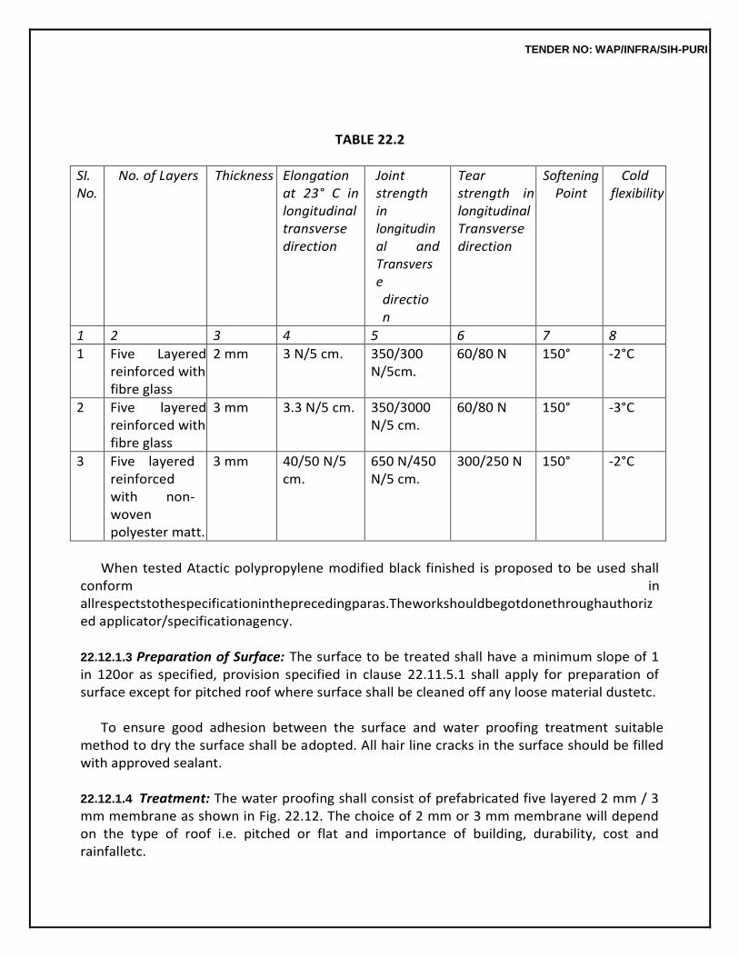
TENDER NO: WAP/INFRA/SIH-PURI
TABLE 22.2
SI. No.
No. of Layers Thickness Elongation at 23° C in longitudinal transverse direction
Joint strength in longitudinal and Transverse direction
Tear strength in longitudinal Transverse direction
Softening Point
Cold flexibility
1 2 3 4 5 6 7 8
1 Five Layered reinforced with fibre glass
2 mm 3 N/5 cm. 350/300 N/5cm.
60/80 N 150° -2°C
2 Five layered reinforced with fibre glass
3 mm 3.3 N/5 cm. 350/3000 N/5 cm.
60/80 N 150° -3°C
3 Five layered reinforced with non-woven polyester matt.
3 mm 40/50 N/5 cm.
650 N/450 N/5 cm.
300/250 N 150° -2°C
When tested Atactic polypropylene modified black finished is proposed to be used shall
conform in allrespectstothespecificationintheprecedingparas.Theworkshouldbegotdonethroughauthorized applicator/specificationagency.
22.12.1.3 Preparation of Surface: The surface to be treated shall have a minimum slope of 1 in 120or as specified, provision specified in clause 22.11.5.1 shall apply for preparation of surface except for pitched roof where surface shall be cleaned off any loose material dustetc.
To ensure good adhesion between the surface and water proofing treatment suitable
method to dry the surface shall be adopted. All hair line cracks in the surface should be filled with approved sealant.
22.12.1.4 Treatment: The water proofing shall consist of prefabricated five layered 2 mm / 3 mm membrane as shown in Fig. 22.12. The choice of 2 mm or 3 mm membrane will depend on the type of roof i.e. pitched or flat and importance of building, durability, cost and rainfalletc.
TENDER NO: WAP/INFRA/SIH-PURI
22.12.1.5 Laying: Bitumen primer @ 0.40 lts/sqm shall be applied to the prepared roof, drain and all other surfaces where polymer modified membrane is to be laid. The five layered water proofing membrane shall be laid using Butane torch and sealing all joints and preparing the surface complete. Drain outlets shall be given same treatment as specified for the roof in the description of the item in the mannerspecifiedfortheflatroofsurface.Waterproofingtreatmentshallbecarriedintothedrainpipeor outlets by at least 10 cm. The water proofing treatment laid on the roof surface shall overlap the upper edge of the water proofing treatment in the drain outsets by at least 10cm.
The APP polymer modified prefabricated water proofing membrane shall be cut to the
required length. Water proofing membrane shall normally be laid in length in the direction of the slope and laying shall be commenced at the lowest level and worked upto crest. APP water proofing membrane shall be laid in 6 to 8 m lengths. The roof surface shall be cleaned and bitumen primer shall be applied in the correct quantity, over this specified water proofing membrane shall be laid with butane torch after allowing 24 hours for primer to dry. Each strip shall overlap the preceding one by at least 10 cm. at the longitudinal edges and 15 cm. at the ends. All overlaps shall be firmly bonded with bitumen primer and levelled by heating the overlap with butane torch.
If the roof is accessible the treatment is protected by brick tiles laid over 12 mm thick
cementmortar ofspecifiedgradebeddingandjointssealedwithcementmortarofwhichshallbemeasuredandpaidfor separately.
APP water proofing membrane shall be laid as flashing wherever junction of vertical and
horizontal surfaces occur. Longitudinal laps shall be 10 cm. The upper edge of flashing membrane shall be well tucked into the flashing grooves in the parapets, chimney stack etc. to a depth of not less than 6.5 cm; correspondingapplicationsofprimercoatshallalsobemade.Theflashingtreatmentshallbefirmlyheld inthegroovesanditshallbesealedwiththeapprovedsealantafterterminatingthemembrane.
Where parapet walls are of height 45 cm or less AP water proofing membrane flashing
shall be provided in the same manner as for splashing in the core of high parapet walls except that upper edge shallbecarriedoutthefullheightofthewallandtakenrightacrossthetopoftheparapetanddownon the external vertical faces to a minimum distance of 5cm.
Where low dividing walls or inverted beams are met with, the same treatment shall be
provided as for the main roof, the lateral bearing carried down both sides of the wall and overlapping the roof treatment.
Drain outlets where formed in the low dividing walls, shall be given water proofing
treatment same as for the main roof.
TENDER NO: WAP/INFRA/SIH-PURI
Where the expansion joints are provided in the slabs, the joints and their cover slabs shall be suitably treated with water proofing treatment. A typical sketch of an expansion joint with the RCCslabs on either side of the joint turned vertically up and covered with precise RCC cover slabs as given in Fig. 22.7. The cover slabs shall cover the vertical turned up dwarf walls by not less than 7.5 cm andare provided with throatings on their underside along their length. The water proofing treatment shall be taken up the slopping junction fillets and the vertical faces of the walls to the underside of the cover slabs are given the water proofing treatment like the roof slabs, after the cross joints between adjacent cover slabs are first sealed with 15 cm. width of roofing felt struck to them with bitumen. The water proofingtreatmentshallbecarrieddownthesidesofthecoverslabstotheirfullthickness.Careshallbe takentoseethatoverlapsifanyintheroofingoverthecoverslabsstaggerwiththejointsbetweencover slabs.
The formation of the expansion joints and provision of cover slabs shall be the
responsibility of construction agency. The formation of the junctions fillets and the water proofing treatment of the joint andcoverslabsshallbecarriedoutbythewaterproofingagency.Noextrashallbepaidforthejunction filletsorforthesealingofthecrossjointsinthecoverslabwith15cm.widthofbitumenstrips.
22.12.1.6 Measurements: Length and breadth shall be measured correct to a cm. The area shall be calculated in square metres correct to two places ofdecimal.
Measurementshallbetakenovertheentireexposedareaofroofingandflashingtreatmentinclu
ding flashing over low parapet walls, low dividing walls and expansion joints at pipe projections etc. overlaps and tucking into flashing grooves shall not bemeasured.
No deduction in measurements shall be made for either openings or recesses for chimney stacks, roof lights and the like, for areas upto 40 square decimeter (0.4. sqm.) nor any thing shall be paid for forming such openings. For areas exceeding 0.40 sqm. deductions will be made in measurements for full opening and nothing extra shall be paid for forming such openings.
22.12.1.7 Rate: The rates shall include the cost of all labour and materials involved in all theoperations describedabove. 22.13 EXTRA FOR COVERING OF APP MODIFIED PREFABRICATED MEMBRANE WITH GEOTEXTILE 22.13.1 If the water proofing treatment of flat roof has been done with APP modified five layered membrane and the roof is accessible, a separation layer on top of membrane should be laid before any protected treatment is done. Brick tiles in cement mortar or 25 mm thick cement concrete 1:2:4 shall be laid as final layer as shown in Fig.22.12.
TENDER NO: WAP/INFRA/SIH-PURI
Geotextile 120 gm. Non woven 100% polyester of thickness 1.0 to 1.25 mm manufactured by a company of repute shall be used. Geotextile of the specified thickness is bonded to the water proofing membrane with intermittent touch by heating the membrane by Butane torch as per manufacturing recommendations. 22.13.2 Measurements: Length and breadth shall be measured correct to two places of decimal, measurement shall be taken over the entire exposed area ofroofing. Rate: The rate shall include the cost of all labour and material involved in all the operation described above. Final layer of brick tiles or 25 mm thick cement concrete shall be measured and paid forseparately.
TENDER NO: WAP/INFRA/SIH-PURI
14 - MR ITEMS ITEM NO. - 14.1 DRY STONE CLADDING 14.1.1.1 Material Stone shall be of the type as specified in the item. It shall be hard, sound durable and tough free from cracks, decay and weathering and defects like cavities cracks, flaws, holes, veins, patches of soft or loose materials etc. Thickness of stone shall be as specified Stone shall be cut with the gang saw to the required size and shape on all beds and joints so as to free from any waviness and to give truly vertical horizontal surface as required. The exposed face and sides of stones forming joints shall be such that the straight edge laid along the face of the stone is in contact with every point on it. All the visible angle and edges shall be square and free from chipping. The dressed stone shall be of the thickness specified with permissible tolerance of + 2 mm.Before starting the work, the contractor shall get the samples of stone approved by Engineer-Incharge. Approved sample shall be kept in custody of Engineer-in-Charge and stones supplied and used on the work shall conform to sample with regard to soundness, colour, veining and general texture. The stone shall be cut by gang saw into slabs of required thickness along the places parallel to the natural bed. When necessary double scaffolding for fixing the stone at greater heights, jib crane or other mechanical appliances shall be used to hoist the heavy pieces of stone and placed them into correct positions. Care shall have to be taken that corners of the stone are not damaged. Stone shall be covered with gunny bags before tying chain or rope is passed over and it shall be handled carefully. No pieces which has been damaged shall be used that work 14.1.1.2Stacking and Storing Stone slabs are thin and brittle and should never be stacked flat across timber supports. They should therefore, be stacked on edge on timber or like runners. Packing pieces inserted between the slabs may be rope or timber. Slabs shall be well covered with plastic sheeting to protect them from any possible staining. 14.1.1.3Double scaffolding having two sets of vertical supports shall be provided. The supports shall be sound and strong, tied together with horizontal pieces over which scaffolding planks shall be fixed. 14.1.1.4Fixing The size & shape of the cramps shall be as per drawing and as per directions of Engineer-in-charge. The samples of steel cramps should be approved in advance before starting the stone cladding work. The cramp shall be attached to top and bottom of the stone. The cramps shall have inbuilt adjustment for vertical and horizontal alignment. The cramps used to hold support and transfer the load of stone unit to the supporting structured steel shall be designed by the manufacturer and approval of the same shall be obtained from the Engineer-in-Charge. The minimum number of clamps required shall be as per requirement of design to carry the load of individual stone slabs. The cramps shall be spaced not more than 60 cm horizontally and vertically along the stone side for insertion of pins / bolt attached with the steel cramps. Adequate cutting in stone shall be made with precision instrument to hold the cramps pins at the joints.
TENDER NO: WAP/INFRA/SIH-PURI
Stone shall be secured with clamps with high quality workmanship. The walls shall be carried up truly plumb. All the courses shall be laid truly horizontal and all the vertical joints truly vertical. The sequence of execution for cladding work shall be approved by the Engineer-in-Charge. Jointing: Joints horizontal and vertical shall be filled with weather sealant of make as approved by Engineer-in-charge with the help of pouring gun for filling the sealant. Before filling the joint with sealant, masking tape are required to be fixed on stones surface on both edges of joints of the stones, so that sealant may not spoil the surface of the stone. When all the joints are filled and sealant has dried, the masking tape may be removed. Protection: Work shall be protected from rain by suitable covering. The work shall also be suitably protected from damage and rain during construction. Measurement: The length and breadth shall be measured correct to a cm. The area shall be calculated in square metre correct to two places of decimal. Any opening of area 0.01 sqm. or less shall not be deducted. Rate: The rate includes the cost of materials and labour involved in all operations described above including cost of support scaffolding staging, sealant, pouring guns but excluding the cost of steel cramps drilling holes / making recesses in stones which shall be paid for separately. 14.1.2.1 STRUCTURAL STEEL FRAME WORK FOR DRY STONE CLADDING Specification for structural frame work for dry stone cladding are same specifications as for steel work in built up sections (welded or bolted). 14.1.2.2Fixing of Frame The properly designed structural frame for withstanding the weight of stone slab are fixed/supported on wall surface with the help of M.S. brackets/lugs of angle iron/flat etc. which is welded at each junctions of member of frame and also embedded in cement concrete block 1:2:4 (1 cement: 2 coarse sand: 4 graded stone aggregate 20 mm nominal size) of size 300 x 230 x 300 mm. The concrete block can be made by cutting the hole of size as mentioned in brick wall and filling the hole with cement concrete including provision of necessary centring/shuttering for holding of concrete. The frame can also be supported on RCC surface with the help of approved expansion hold fastener by drilling the holes in RCC surface. Steel cramps are either welded or bolted to the frame (by making necessary holes in frame work) for holding of stone. 14.1.2.3Measurement The mode of measurement shall be the same, as specified for steel work in built up section except that the weight of welding material shall not be added in weight of members for payment and nothing extra shall be paid for making holes for temporary fastening of members during erection before welding, which also includes cost of cement concrete block, centring and shuttering and making holes in walls, but excluding the cost of expansion fastener, steel clamps which shall be paid for separately.
TENDER NO: WAP/INFRA/SIH-PURI
14.1.3.1 Rate The rate shall include the cost of all labour and material involved in all the operation described above. 14.1.4.1 ADJUSTABLE STAINLESS STEEL CRAMPSThe cramps shall be stainless steel of make approved by the Engineer-in-charge. 14.1.4.2 The weight of the stainless steel clamp (including weight of nut and washer) shall not be less than 260 gms. 14.1.4.3 Necessary holes at suitable locations are to be done on steel frame work for dry stone cladding to be fixed. 14.1.4.4 Necessary recessed are required to be done in stone slab which is required to be supported by clamps. 14.1.4.5 The one end of steel clamp is fixed on frame with nut and bolt and other end is inserted into recesses/hole for fixing the dry cladding stone on frame. 14.1.4.6 The rate includes cost of materials and other operations mentioned as above. Specification for surface maounted door closer :- 14.2.1 These shall be made of cast iron/aluminium alloy/zinc alloy and of shape and pattern as approved by theEngineer-in-Charge. 14.2.2 These shall generally conform to IS Specifications for door closers (Hydraulically regulated) IS 3564. 14.2.3 The door closers may be polished or painted and finished with lacquer to desired colour. Aluminium alloy door closer shall be anodized and the anodic coating shall not be less than grade AC15 of IS 1868. All dents, burrs and sharp edges shall be removed from various components and they shall be pickled, scrubbed and rinsed to remove greese, rust, scale or any other foreign elements. After pickling, all the M.S. parts shall be given phosphating treatment in accordance with IS3618. 14.2.4 The nominal size of door closers in relation to the weight and the width of the door size to which it is intended to be fitted shall be given in Table9.19.
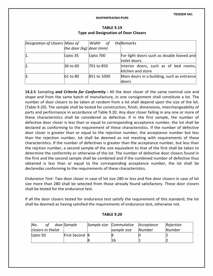
TENDER NO: WAP/INFRA/SIH-PURI
TABLE 9.19 Type and Designation of Door Closers
Designation of closers Mass of the door (kg)
Width of the door (mm)
Remarks
1. Upto 35 Upto 700 For light doors such as double leaved and toilet doors.
2. 36 to 60 701 to 850 Interior doors, such as of bed rooms, kitchen and store
3. 61 to 80 851 to 1000 Main doors in a building, such as entrance doors
14.2.5 Sampling and Criteria for Conformity : All the door closer of the same nominal size and shape and from the same batch of manufacture, in one consignment shall constitute a lot. The number of door closers to be taken at random from a lot shall depend upon the size of the lot. (Table 9.20). The sample shall be tested for construction, finish, dimensions, interchangeability of parts and performance in accordance of Table 9.20. Any door closer failing in any one or more of these characteristics shall be considered as defective. If in the first sample, the number of defective door closer is less than or equal to corresponding acceptance number, the lot shall be declared as conforming to the requirement of these characteristics. If the number of defective door closer is greater than or equal to the rejection number, the acceptance number but less than the rejection number, lot shall be deemed as not meeting with requirements of these characteristics. If the number of defectives is greater than the acceptance number, but less than the rejction number, a second sample of the size equivalent to that of the first shall be taken to determine the conformity or otherwise of the lot. The number of defective door closers found in the first and the second sample shall be combined and if the combined number of defective thus obtained is less than or equal to the corresponding acceptance number, the lot shall be declaredas conforming to the requirements of these characteristics. Endurance Test- Two door closer in case of lot size 280 or less and five door closers in case of lot size more than 280 shall be selected from those already found satisfactory. These door closers shall be tested for the endurance test. If all the door closers tested for endurance test satisfy the requirement of this standard, the lot shall be deemed as having satisfied the requirements of endurance test, otherwise not.
TABLE 9.20
No. of door closers in thelot
Sample Sample size Commulative sample size
Acceptance Number
Rejection Number
Upto 50 First Second 8 8
8 16
0 1
2 2
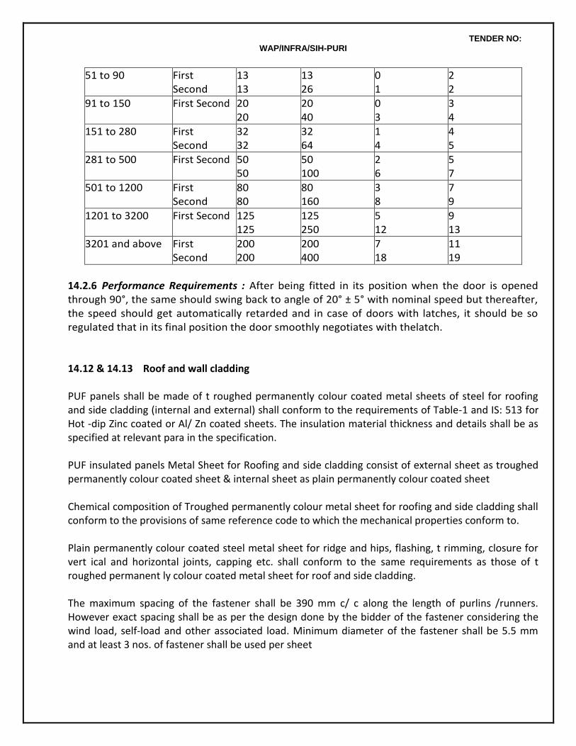
TENDER NO: WAP/INFRA/SIH-PURI
51 to 90 First Second
13 13
13 26
0 1
2 2
91 to 150 First Second 20 20
20 40
0 3
3 4
151 to 280 First Second
32 32
32 64
1 4
4 5
281 to 500 First Second 50 50
50 100
2 6
5 7
501 to 1200 First Second
80 80
80 160
3 8
7 9
1201 to 3200 First Second 125 125
125 250
5 12
9 13
3201 and above First Second
200 200
200 400
7 18
11 19
14.2.6 Performance Requirements : After being fitted in its position when the door is opened through 90°, the same should swing back to angle of 20° ± 5° with nominal speed but thereafter, the speed should get automatically retarded and in case of doors with latches, it should be so regulated that in its final position the door smoothly negotiates with thelatch. 14.12 & 14.13 Roof and wall cladding PUF panels shall be made of t roughed permanently colour coated metal sheets of steel for roofing and side cladding (internal and external) shall conform to the requirements of Table-1 and IS: 513 for Hot -dip Zinc coated or Al/ Zn coated sheets. The insulation material thickness and details shall be as specified at relevant para in the specification. PUF insulated panels Metal Sheet for Roofing and side cladding consist of external sheet as troughed permanently colour coated sheet & internal sheet as plain permanently colour coated sheet Chemical composition of Troughed permanently colour metal sheet for roofing and side cladding shall conform to the provisions of same reference code to which the mechanical properties conform to. Plain permanently colour coated steel metal sheet for ridge and hips, flashing, t rimming, closure for vert ical and horizontal joints, capping etc. shall conform to the same requirements as those of t roughed permanent ly colour coated metal sheet for roof and side cladding. The maximum spacing of the fastener shall be 390 mm c/ c along the length of purlins /runners. However exact spacing shall be as per the design done by the bidder of the fastener considering the wind load, self-load and other associated load. Minimum diameter of the fastener shall be 5.5 mm and at least 3 nos. of fastener shall be used per sheet

TENDER NO: WAP/INFRA/SIH-PURI
Fillers blocks as a t rough filler shall be used to seal cavit ies formed between the profiled sheet and the support or flashing. The fillers blocks shall be manufactured from black synthetic rubber or any other material approved by engineer. Roof Insulation & Type:
Both metal sheets shall have an under insulation of minimum 80 mm thick PUF with density 40 +/ - kg/m3 and thermal conductivity 0.019-2.2 W/ (m.K) at 10°C with gutters and down take pipes along with Flashing & Top cap of required size and colour complete with all necessary hardware complete. Roof shall be projected at -least 300 mm from the wall. Stiffening ribs / subtle fluting for effective water shedding and special male/ female ends with full return legs on side laps for purlin support and ant i-capillary flute in side lap. Both upper and lower sheets shall be separated through spacers and fastened through zinc/ zinc-t in coated self-drilling screws. The fastener size shall be calculated as per the design or manufacturers recommendations. Bidder may also alternatively make the PEB roofing with composite slab (RCC slab with permanent formwork). The composite slab scheme, design and drawings shall be subject to approval from BHEL/NTPC before start of work. .. All voids of external and internal metalled walls shall have an under insulat ion of minimum 60 mm thick PUF with density 40 +/ - kg/m3 and thermal conductivity 0.019-2.2 W/ (m.K) at 10°C with proper supports etc. as approved. Both the walls should be separated by spacers system made up of cold formed steel bars and fastened through zinc / zinc-t in coated self-drilling screws. The external wall of Inverter room / security room facing the transformer area shall be as per IS: 1646 - Code of practice for fire safety of buildings (general): electrical installations.
TECHNICAL SPECIFICATIONSFOR STRUCTURAL GLAZING SCOPE OF WORKS The scope of works under this contract includes Design, Supply, Installation, Protection, Guarantees, Testing and Maintenance up to Defects Liability Period for the Structural Glazing, Curtain Walling, Structurally Glazed Windows, Aluminium Cladding, Doors, Windows, Canopy, Louvers, structural steel supporting system etc. The work under this section includes all Labour, materials, equipment and services as required for the complete design, engineering, testing, fabrication, assembly, delivery, anchorage, installation, protection and waterproofing of the aluminium curtain wall / structural glazing system, cladding, aluminium doors, aluminium windows & louvres and all in accordance with the true intent and
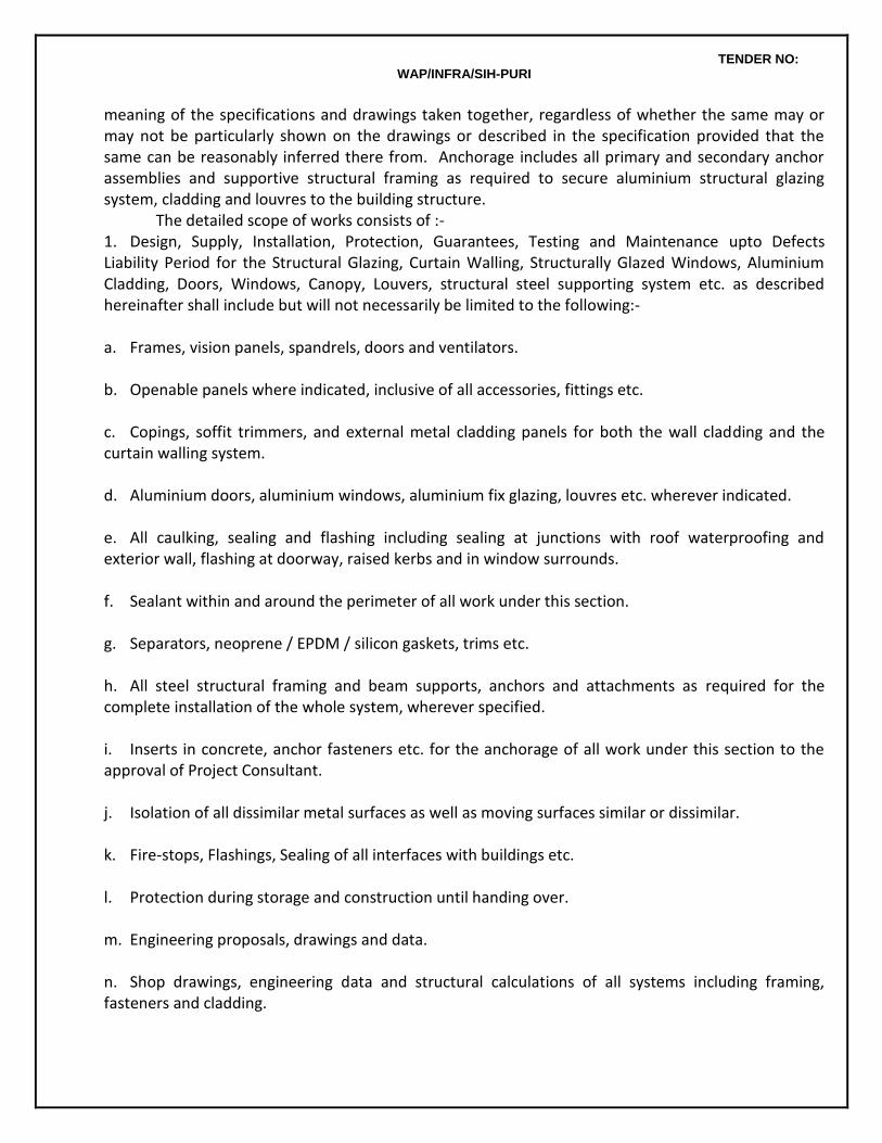
TENDER NO: WAP/INFRA/SIH-PURI
meaning of the specifications and drawings taken together, regardless of whether the same may or may not be particularly shown on the drawings or described in the specification provided that the same can be reasonably inferred there from. Anchorage includes all primary and secondary anchor assemblies and supportive structural framing as required to secure aluminium structural glazing system, cladding and louvres to the building structure.
The detailed scope of works consists of :- 1. Design, Supply, Installation, Protection, Guarantees, Testing and Maintenance upto Defects Liability Period for the Structural Glazing, Curtain Walling, Structurally Glazed Windows, Aluminium Cladding, Doors, Windows, Canopy, Louvers, structural steel supporting system etc. as described hereinafter shall include but will not necessarily be limited to the following:- a. Frames, vision panels, spandrels, doors and ventilators. b. Openable panels where indicated, inclusive of all accessories, fittings etc. c. Copings, soffit trimmers, and external metal cladding panels for both the wall cladding and the curtain walling system. d. Aluminium doors, aluminium windows, aluminium fix glazing, louvres etc. wherever indicated. e. All caulking, sealing and flashing including sealing at junctions with roof waterproofing and exterior wall, flashing at doorway, raised kerbs and in window surrounds. f. Sealant within and around the perimeter of all work under this section. g. Separators, neoprene / EPDM / silicon gaskets, trims etc. h. All steel structural framing and beam supports, anchors and attachments as required for the complete installation of the whole system, wherever specified. i. Inserts in concrete, anchor fasteners etc. for the anchorage of all work under this section to the approval of Project Consultant. j. Isolation of all dissimilar metal surfaces as well as moving surfaces similar or dissimilar. k. Fire-stops, Flashings, Sealing of all interfaces with buildings etc. l. Protection during storage and construction until handing over. m. Engineering proposals, drawings and data. n. Shop drawings, engineering data and structural calculations of all systems including framing, fasteners and cladding.

TENDER NO: WAP/INFRA/SIH-PURI
o. Scheduling and monitoring of the work. p. All samples, mock-ups and test units. q. Co-ordination with work of Civil Works and other agencies / contractors employed on site. r. All final exterior and interior cleaning of the aluminium structural glazing system, cladding, doors louvres and window etc. s. Hoisting, staging, scaffolding and temporary services. t. Specified tests, inclusive of necessary reports. u. Maintenance manuals. v. Design and Performance guarantees. w. Periodic inspection, supervision and advice by Contractor’s Senior Personnel of the System Principal as well as guarantee in approved Proforma for the quality and performance of works. x. Construction monitoring for regular quality control and technical inspection to ensure the work conforms to the shop drawing details (including any modification made during testing) and acceptable standards of quality.
2. REFERENCES AND STANDARDS
2.1 The provisions not restricted to the latest Standards listed below and mentioned in subsequent Para’s. ANSI Z97.1.84 Safety Glazing materials used in Buildings ASTM C 1036-90 Specification for float glass ASTM C 1048-90 Specification for Heat treated Float Glass ASTM E 774 –88 Specification for sealed Insulating Glass Units ASTM C 1172- 91 Specification for Laminated Architectural Glass ASTM C 864 – 90 Specification for compression Seal Gaskets ASTM C 1115-89 Specification for Silicon Rubber Gaskets ASTM C 920-87 Specification for Sealants ASTM C 509-90 Specification for sealing material CPSC 16 CFR 1201 Specification for Safety of glass GTA Specification No. 89-1-6
Specification for environment durability for heat strengthened Spandrel Glass with Applied pacifiers.
BSCP 118 Structural use of Aluminium ASTM E 283 Air Infiltration test
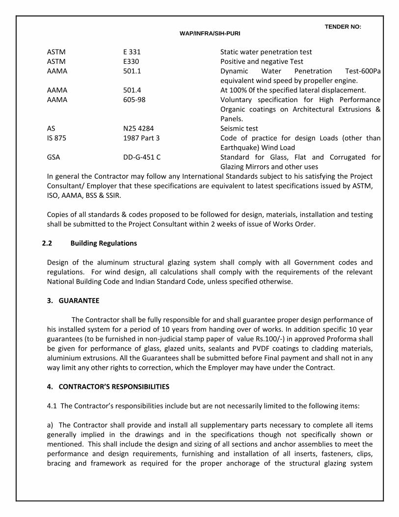
TENDER NO: WAP/INFRA/SIH-PURI
ASTM E 331 Static water penetration test ASTM E330 Positive and negative Test AAMA 501.1 Dynamic Water Penetration Test-600Pa
equivalent wind speed by propeller engine. AAMA AAMA
501.4 605-98
At 100% 0f the specified lateral displacement. Voluntary specification for High Performance Organic coatings on Architectural Extrusions & Panels.
AS N25 4284 Seismic test IS 875 GSA
1987 Part 3 DD-G-451 C
Code of practice for design Loads (other than Earthquake) Wind Load Standard for Glass, Flat and Corrugated for Glazing Mirrors and other uses
In general the Contractor may follow any International Standards subject to his satisfying the Project Consultant/ Employer that these specifications are equivalent to latest specifications issued by ASTM, ISO, AAMA, BSS & SSIR. Copies of all standards & codes proposed to be followed for design, materials, installation and testing shall be submitted to the Project Consultant within 2 weeks of issue of Works Order.
2.2 Building Regulations Design of the aluminum structural glazing system shall comply with all Government codes and regulations. For wind design, all calculations shall comply with the requirements of the relevant National Building Code and Indian Standard Code, unless specified otherwise. 3. GUARANTEE
The Contractor shall be fully responsible for and shall guarantee proper design performance of his installed system for a period of 10 years from handing over of works. In addition specific 10 year guarantees (to be furnished in non-judicial stamp paper of value Rs.100/-) in approved Proforma shall be given for performance of glass, glazed units, sealants and PVDF coatings to cladding materials, aluminium extrusions. All the Guarantees shall be submitted before Final payment and shall not in any way limit any other rights to correction, which the Employer may have under the Contract. 4. CONTRACTOR’S RESPONSIBILITIES 4.1 The Contractor’s responsibilities include but are not necessarily limited to the following items: a) The Contractor shall provide and install all supplementary parts necessary to complete all items generally implied in the drawings and in the specifications though not specifically shown or mentioned. This shall include the design and sizing of all sections and anchor assemblies to meet the performance and design requirements, furnishing and installation of all inserts, fasteners, clips, bracing and framework as required for the proper anchorage of the structural glazing system
TENDER NO: WAP/INFRA/SIH-PURI
elements to the structure, unless otherwise noted or specified to be furnished / installed by another contractor. Alternate anchorage proposals will be considered, if, in the opinion of the Project Consultant the general design and intent of the drawings and specifications are maintained. The Contractor’s system therefore must perform satisfactorily as a whole. b) Design Responsibility: Drawings and specifications indicate the required basic dimensions, profiles and performance criteria. The Contractor shall have the option of modification and addition of details provided the visual concept and performance requirements are fulfilled. Proposed modifications shall be clearly shown on shop drawings as “Design Modifications” and acceptance of the same will not relieve the Contractor from sole responsibility for performance of the aluminium structural glazing system and cladding. The Contractor shall be solely and fully responsible for due performance of his installation based on his own design and details. c) In-plant and job site inspection: The Contractor shall allow the Employer, Project Consultant / PMC or their authorised agent full access to plants, shops and assembly points to view and inspect the processes and methods employed in the fabrication, assembly and finishing of the aluminium structural glazing system and cladding for this project. The Project Consultant / PMC will have the right to reject any and all aluminium structural curtain wall / structural glazing system and cladding components and assemblies during assembly and erection if the workmanship and intent are not in strict conformity with the approved shop drawings, structural calculations, documentation, certifications, samples and mock-up. d) Glass, sealants and other items or materials procured by purchase shall be back to back guaranteed by the manufacturer. 5. SHOP DRAWINGS 5.1 The contractor shall prepare necessary shop drawings based on the preliminary drawings and two (2) copies of all shop drawings shall be submitted to the Project Consultant for review and approval. The Project Consultant’s review of all shop drawings will be limited to their conformity to the design concept & specifications. Project Consultant’s approval of the shop drawings will not relieve the contractor from any of the responsibilities and requirements as stated drawings and all other related submissions, documentation, certifications, samples and the mock-up for that work have been reviewed and approved by the Project Consultant. On approval of the drawings by Project Consultant, the Contractor shall submit six (6) copies of all drawings to PMC for release to execution / site. 5.2 Shop drawings shall incorporate scaled and dimensioned plans, elevations, sections and full size details for all work in this section. Shop drawings shall indicate the desired dimensional profiles and modules, function, design and
TENDER NO: WAP/INFRA/SIH-PURI
performance standards and, in general, delineate the scope of work. The contractor shall verify and co-ordinate these items with all applicable and/or related trades, contract drawings and specifications. Since the dimensions and modular references shown on the drawings are for specific and/or typical detail, the shop drawings shall include a full complete layout of all modular and referenced dimensions for all the aluminium structural glazing, cladding, doors, windows and louvres and their related elements. All dimensions / modules, etc., shall be field checked as required. The full size details shall show and specify all metal sections, types of finishes; areas to be sealed and sealant materials; gaskets; direction and magnitude of thermal expansion; direction and magnitude of all applicable construction including fasteners and welds; all anchorage assemblies and components; the fabrication and erection tolerances for the work and applicable related works adjoining, attached to or in some way related to the work covered by these specifications. The location of all static and dynamic anchor assemblies, the direction of thermal and other applicable building movements, co-ordination with concrete works and the sequence of installation shall be designated on the applicable plans, elevations and / or sections. All details shall be subject to Project Consultant’s approval. 5.3 Shop drawings shall indicate the desired profiles, dimensions, details of metal finish and in general delineate the scope of the work. Profile adjustments in the interest of economy, fabrication, erection, weather-ability or ability to satisfy the performance requirements may be made only with the written approval of the Project Consultant, provided that the general design and intent of the drawings and specifications are maintained. 5.4 Shop drawings to be vetted by the Principal of the Structural Glazing & Cladding System. Six (6) copies each of all final approved shop drawings shall be submitted to Project Consultant / PMC. 6. STRUCTURAL CALCULATIONS 6.1 The Contractor shall guarantee that his design will ensure the structural safety and integrity of the curtain wall, cladding and glass panels against all natural forces, superimposed loads, environment and consequent movements. For that purpose the contractor shall employ a competent design engineer to design his systems and components. During the design stage, the Contractor shall interact actively with the Project Consultant concerning all aspects of design and shall obtain all the information from them concerning the structure, probable deflections and other building movements etc. The Contractor shall take full account of all possible building movements as well as the movements of his curtain wall and cladding systems in his design. The Contractor shall submit his detailed structural calculations for the systems and each of their components and shall guarantee that his design will ensure the structural safety and integrity of the curtain wall, cladding and glass panels against all natural forces, superimposed loads, environment and consequent movements. The structure and functional design must be vetted and approved by the Principals of the curtain wall system. The Contractor shall obtain the Project Consultant's approval to his design calculations and to the provisions made in his design for all the building movements, and shall be responsible for the correctness of the fixing and interaction of the curtain wall with the structure so as to ensure that all the movements envisaged between the structure and the curtain wall area are fully taken care of.
TENDER NO: WAP/INFRA/SIH-PURI
The Contractor shall be responsible for the workmanship of fabrication and installation and shall indemnify the Employer against all claims due to defects or non-performance during the specified 10 year Guarantee period. The provisions of this clause shall not in any way limit the Employer’s rights under other clauses of the Contract. 7. DOCUMENTATION AND CERTIFICATION 7.1 Glass and Glazing Documentation: The applicable glass manufacturer(s) shall submit written certification for Project Consultant’s review and approval stating that all glass and glazing requirements as detailed and specified on the shop drawings have been reviewed and approved for use relative to their specific application and / or design parameters, compatibility to adjacent materials and in conformity with all requirements as detailed and specified in the Contract Documents. Certification shall further state that the proposed glass and glazing materials are most appropriately suited for the use or uses intended and recommended for the specific use or the selection of the glass and the glazing materials including, but not limited to, gaskets, setting blocks, sealant, the design and dimensional parameters of the glass pockets and the compatibility of materials. Test Certificate from approved laboratories for U-values and shading factor claimed by the Manufacturer shall be submitted. 7.2 Sealants Documents: All sealant applications must be clearly designated on the applicable shop drawing details and referenced to a master sealant schedule specifying materials, special instructions and application procedures. The applicable sealant manufacturer(s) shall submit in writing that all sealant requirements as detailed and specified on the shop drawings have been reviewed and approved for use relative to their specific application and / or design intent, compatibility to adjacent materials and in conformity with all the requirements as detailed and specified in the contract documents. The manufacturer’s certification shall specify the optimum life expectancy, in years, for the proposed sealant materials as detailed and specified on the shop drawings and/or master sealant schedule and shall further state that the proposed materials are most appropriately suited for the use or uses intended and recommended for the specific use or uses. 7.3 Quality Control Documentation: In-plant and job site quality control procedures shall be documented in writing for Project Consultant’s review and approval to ensure the design integrity and performance of the as-built product. Documentation shall include schedule, details, isometric and/or schematic explanatory sketches cross-references to the shop drawings, data sheets, etc., all as required to intelligently witness and assess methods and materials; and to ensure that both the fabrication and installation are in accord with the contract documents. The Employer / Project Consultant / PMC shall, if required, be given free access to the plant to inspect
TENDER NO: WAP/INFRA/SIH-PURI
fabrication procedures. No fabrication or assembly of job site materials shall commence until the first production unit is inspected and approved by Project Consultant / PMC. a) The in-plant quality control procedures shall include but not necessarily be limited to the following items:
Fabrication : Tolerances, Joinery, Sleeves, etc.
Finish Match : Approved finish controls required for matching the exposed surfaces.
Assembly : Welds, fastener, sealants, gaskets, separators, glazing etc.
Protection : Handling, protection, shipping etc.
b) The job site quality control procedures shall include, but not necessarily be limited to the following items:
Anchorage : Lines, grades and related building tolerances
Installation : Tolerances, finish, match, joinery, sleeves, flashing, welds, fasteners, sealants, etc.
Sealing : As recommended by the applicable sealant manufacturer(s)
Protection & Cleaning : As recommended by the applicable sealant manufacturer(s)
8. SAMPLES AND MANUALS: 8.1 The following samples of actual job site materials together with detailed technical data / catalogues shall be submitted in duplicate, unless otherwise noted, and in the sizes noted, for Project Consultant’s review and approval. Any omission of an item, or items, which require the Contractor’s compliance with these documents, does not relieve him from such responsibility. (a) Aluminium sheet panel: Each type and thickness; 600 x 600 mm of the specified thickness. (b) Aluminium extrusions; one only of each section; 300 mm long of specified thickness. (c) Glass; Each type and kind, 300 x 250 mm of specified thickness and including frame. (d) Glazing gaskets, tapes, separators, glass setting blocks, etc. each section or unit, 300 mm long or unit. (e) Fasteners and connections devices: Each type and size.
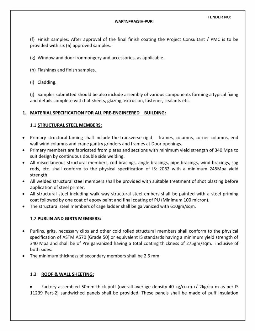
TENDER NO: WAP/INFRA/SIH-PURI
(f) Finish samples: After approval of the final finish coating the Project Consultant / PMC is to be provided with six (6) approved samples. (g) Window and door ironmongery and accessories, as applicable. (h) Flashings and finish samples. (i) Cladding. (j) Samples submitted should be also include assembly of various components forming a typical fixing and details complete with flat sheets, glazing, extrusion, fastener, sealants etc.
1. MATERIAL SPECIFICATION FOR ALL PRE-ENGINEERED BUILDING: 1.1 STRUCTURAL STEEL MEMBERS:
Primary structural faming shall include the transverse rigid frames, columns, corner columns, end wall wind columns and crane gantry grinders and frames at Door openings.
Primary members are fabricated from plates and sections with minimum yield strength of 340 Mpa to suit design by continuous double side welding.
All miscellaneous structural members, rod bracings, angle bracings, pipe bracings, wind bracings, sag rods, etc. shall conform to the physical specification of IS: 2062 with a minimum 245Mpa yield strength.
All welded structural steel members shall be provided with suitable treatment of shot blasting before application of steel primer.
All structural steel including walk way structural steel embers shall be painted with a steel priming coat followed by one coat of epoxy paint and final coating of PU (Minimum 100 micron).
The structural steel members of cage ladder shall be galvanized with 610gm/sqm. 1.2 PURLIN AND GIRTS MEMBERS:
Purlins, grits, necessary clips and other cold rolled structural members shall conform to the physical specification of ASTM A570 (Grade 50) or equivalent IS standards having a minimum yield strength of 340 Mpa and shall be of Pre galvanized having a total coating thickness of 275gm/sqm. inclusive of both sides.
The minimum thickness of secondary members shall be 2.5 mm. 1.3 ROOF & WALL SHEETING:
Factory assembled 50mm thick puff (overall average density 40 kg/cu.m.+/-2kg/cu m as per IS 11239 Part-2) sandwiched panels shall be provided. These panels shall be made of puff insulation
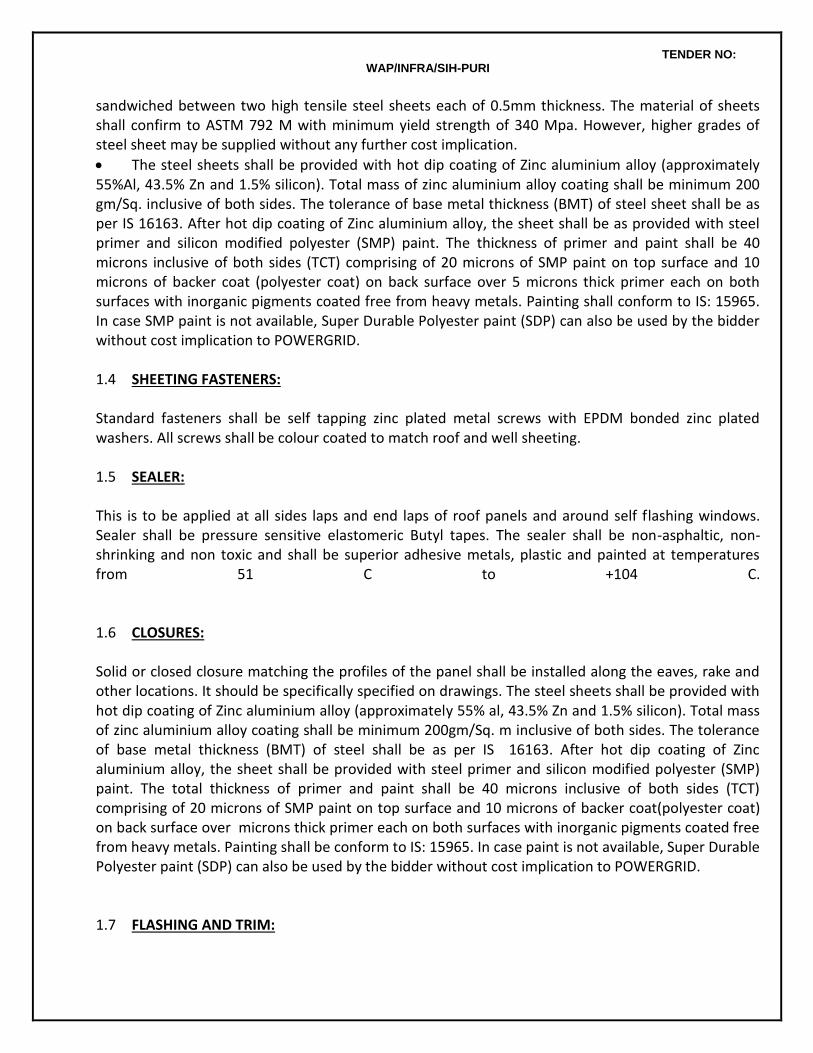
TENDER NO: WAP/INFRA/SIH-PURI
sandwiched between two high tensile steel sheets each of 0.5mm thickness. The material of sheets shall confirm to ASTM 792 M with minimum yield strength of 340 Mpa. However, higher grades of steel sheet may be supplied without any further cost implication.
The steel sheets shall be provided with hot dip coating of Zinc aluminium alloy (approximately 55%Al, 43.5% Zn and 1.5% silicon). Total mass of zinc aluminium alloy coating shall be minimum 200 gm/Sq. inclusive of both sides. The tolerance of base metal thickness (BMT) of steel sheet shall be as per IS 16163. After hot dip coating of Zinc aluminium alloy, the sheet shall be as provided with steel primer and silicon modified polyester (SMP) paint. The thickness of primer and paint shall be 40 microns inclusive of both sides (TCT) comprising of 20 microns of SMP paint on top surface and 10 microns of backer coat (polyester coat) on back surface over 5 microns thick primer each on both surfaces with inorganic pigments coated free from heavy metals. Painting shall conform to IS: 15965. In case SMP paint is not available, Super Durable Polyester paint (SDP) can also be used by the bidder without cost implication to POWERGRID. 1.4 SHEETING FASTENERS: Standard fasteners shall be self tapping zinc plated metal screws with EPDM bonded zinc plated washers. All screws shall be colour coated to match roof and well sheeting. 1.5 SEALER: This is to be applied at all sides laps and end laps of roof panels and around self flashing windows. Sealer shall be pressure sensitive elastomeric Butyl tapes. The sealer shall be non-asphaltic, non-shrinking and non toxic and shall be superior adhesive metals, plastic and painted at temperatures from 51 C to +104 C. 1.6 CLOSURES: Solid or closed closure matching the profiles of the panel shall be installed along the eaves, rake and other locations. It should be specifically specified on drawings. The steel sheets shall be provided with hot dip coating of Zinc aluminium alloy (approximately 55% al, 43.5% Zn and 1.5% silicon). Total mass of zinc aluminium alloy coating shall be minimum 200gm/Sq. m inclusive of both sides. The tolerance of base metal thickness (BMT) of steel shall be as per IS 16163. After hot dip coating of Zinc aluminium alloy, the sheet shall be provided with steel primer and silicon modified polyester (SMP) paint. The total thickness of primer and paint shall be 40 microns inclusive of both sides (TCT) comprising of 20 microns of SMP paint on top surface and 10 microns of backer coat(polyester coat) on back surface over microns thick primer each on both surfaces with inorganic pigments coated free from heavy metals. Painting shall be conform to IS: 15965. In case paint is not available, Super Durable Polyester paint (SDP) can also be used by the bidder without cost implication to POWERGRID. 1.7 FLASHING AND TRIM:

TENDER NO: WAP/INFRA/SIH-PURI
Flashing and/or trim shall be furnished at the rake, corners, eaves, and framed openings and wherever necessary to provide weather tightness and finished appearance. Colour shall be matching with the colour wall. The steel sheets shall be provided with hot dip coating of Zinc aluminium alloy (approximately 55% Al, 43.5% Zn, and 1.5% silicon). Total mass of zinc aluminium alloy coating shall be minimum 200 gm/sq.m inclusive of both sides. The tolerance of base metal thickness (BMT) of steel sheet shall be as per IS 16163. After hot dip coating of Zinc aluminium alloy, the sheet shall be provided with steel primer and silicon modified polyester (SMP) paint. The total thickness of primer and paint shall be 40 microns inclusive of both sides (TCT) comprising of 20 microns of SMP on top
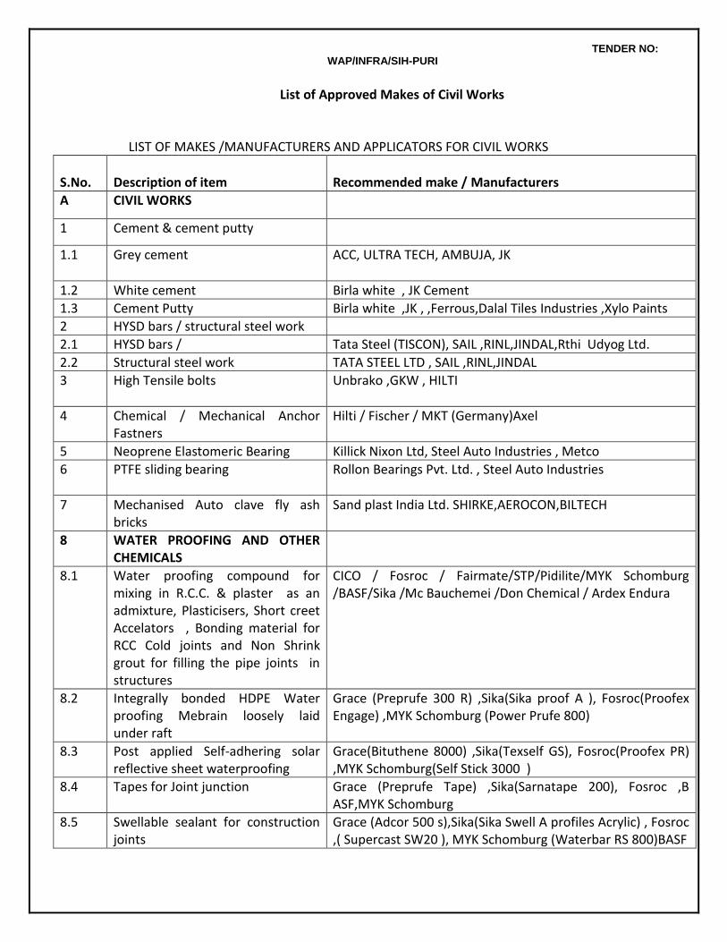
TENDER NO: WAP/INFRA/SIH-PURI
List of Approved Makes of Civil Works
LIST OF MAKES /MANUFACTURERS AND APPLICATORS FOR CIVIL WORKS
S.No.
Description of item
Recommended make / Manufacturers
A CIVIL WORKS
1 Cement & cement putty
1.1 Grey cement
ACC, ULTRA TECH, AMBUJA, JK
1.2 White cement Birla white , JK Cement
1.3 Cement Putty Birla white ,JK , ,Ferrous,Dalal Tiles Industries ,Xylo Paints
2 HYSD bars / structural steel work
2.1 HYSD bars / Tata Steel (TISCON), SAIL ,RINL,JINDAL,Rthi Udyog Ltd.
2.2 Structural steel work TATA STEEL LTD , SAIL ,RINL,JINDAL
3 High Tensile bolts Unbrako ,GKW , HILTI
4 Chemical / Mechanical Anchor Fastners
Hilti / Fischer / MKT (Germany)Axel
5 Neoprene Elastomeric Bearing Killick Nixon Ltd, Steel Auto Industries , Metco
6 PTFE sliding bearing Rollon Bearings Pvt. Ltd. , Steel Auto Industries
7 Mechanised Auto clave fly ash bricks
Sand plast India Ltd. SHIRKE,AEROCON,BILTECH
8 WATER PROOFING AND OTHER CHEMICALS
8.1 Water proofing compound for mixing in R.C.C. & plaster as an admixture, Plasticisers, Short creet Accelators , Bonding material for RCC Cold joints and Non Shrink grout for filling the pipe joints in structures
CICO / Fosroc / Fairmate/STP/Pidilite/MYK Schomburg /BASF/Sika /Mc Bauchemei /Don Chemical / Ardex Endura
8.2 Integrally bonded HDPE Water proofing Mebrain loosely laid under raft
Grace (Preprufe 300 R) ,Sika(Sika proof A ), Fosroc(Proofex Engage) ,MYK Schomburg (Power Prufe 800)
8.3 Post applied Self-adhering solar reflective sheet waterproofing
Grace(Bituthene 8000) ,Sika(Texself GS), Fosroc(Proofex PR) ,MYK Schomburg(Self Stick 3000 )
8.4 Tapes for Joint junction Grace (Preprufe Tape) ,Sika(Sarnatape 200), Fosroc ,B ASF,MYK Schomburg
8.5 Swellable sealant for construction joints
Grace (Adcor 500 s),Sika(Sika Swell A profiles Acrylic) , Fosroc ,( Supercast SW20 ), MYK Schomburg (Waterbar RS 800)BASF
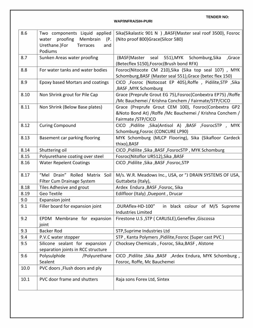
TENDER NO: WAP/INFRA/SIH-PURI
8.6
Two components Liquid applied water proofing Membrain (P. Urethane.)For Terraces and Podiums
Sika(Sikalastic 901 N ) ,BASF(Master seal roof 3500), Fosroc (Nito proof 800)Grace(Silcor 580)
8.7 Sunken Areas water proofing (BASF(Master seal 551),MYK Schomburg,Sika ,Grace (Betecflex S150),Fosroc(Brush bond RFX)
8.8 For water tanks and water bodies Fosroc(Nitocote CM 210),Sika (Sika top seal 107) , MYK Schomburg,BASF (Master seal 551),Grace (betec flex 150)
8.9 Epoxy based Mortars and coatings CICO ,Fosroc (Notocoat EP 405),Roffe , Pidilite,STP ,Sika ,BASF ,MYK Schomburg
8.10 Non Shrink grout for Pile Cap Grace (Preprufe Grout EG 75),Fosroc(Conbextra EP75) /Roffe /Mc Bauchemei / Krishna Conchem / Fairmate/STP/CICO
8.11 Non Shrink (Below Base plates) Grace (Preprufe Grout CEM 100), Fosroc(Conbextra GP2 &Noto Bond At) /Roffe /Mc Bauchemei / Krishna Conchem / Fairmate /STP/CICO
8.12 Curing Compound CICO ,Pidilite ,Sika(Antisol A) ,BASF ,FosrocSTP , MYK Schomburg,Fosroc (CONCURE LP90)
8.13 Basement car parking flooring MYK Schomburg (MLCP Flooring), Sika (Sikafloor Cardeck thixo),BASF
8.14 Shuttering oil CICO ,Pidilite ,Sika ,BASF ,FosrocSTP , MYK Schomburg
8.15 Polyurethane coating over steel Fosroc(Nitoflor UR512),Sika ,BASF
8.16
Water Repelent Coatings CICO ,Pidilite ,Sika ,BASF ,Fosroc,STP
8.17 “Mel Drain” Rolled Matrix Soil Filter Cum Drainage System
M/s. W.R. Meadows Inc., USA, or “J DRAIN SYSTEMS OF USA, Guttabeta (Italy),
8.18 Tiles Adhesive and grout Ardex Endura ,BASF ,Fosroc, Sika
8.19 Geo Textile Edilfloor (Italy) ,Duepont , Drucar
9.0 Expansion joint
9.1 Filler board for expansion joint .DURAflex-HD-100” in black colour of M/S Supreme Industries Limited
9.2 EPDM Membrane for expansion joint
Firestone U.S ,STP ( CARLISLE),Geneflex ,Giscossa
9.3 Backer Rod STP,Suprime Industries Ltd
9.4 P.V.C water stopper STP , Kanta Polymers ,Pidilite,Fosroc (Super cast PVC )
9.5 Silicone sealant for expansion / separation joints in RCC structure
Chocksey Chemicals , Fosroc, Sika,BASF , Alstone
9.6 Polysulphide /Polyurethane Sealent
CICO ,Pidilite ,Sika ,BASF ,Ardex Endura, MYK Schomburg , Fosroc, Roffe, Mc Bauchemei
10.0 PVC doors ,Flush doors and ply
10.1 PVC door frame and shutters Raja sons Forex Ltd, Sintex
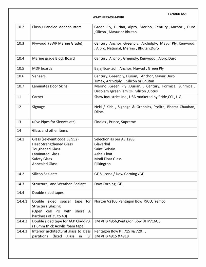
TENDER NO: WAP/INFRA/SIH-PURI
10.2 Flush / Paneled door shutters Green Ply, Durian, Alpro, Merino, Century ,Anchor , Duro ,Silicon , Mayur or Bhutan
10.3 Plywood (BWP Marine Grade) Century, Anchor, Greenply, Archidply, Mayur Ply, Kenwood, , Alpro, National, Merino , Bhutan,Duro
10.4 Marine grade Block Board Century, Anchor, Greenply, Kenwood, ,Alpro,Duro
10.5 MDF boards Bajaj Eco-tech, Anchor, Nuwud , Green Ply
10.6 Veneers
Century, Greenply, Durian, Anchor, Mayur,Duro Timex, Archidply , Silicon or Bhutan
10.7 Laminates Door Skins Merino ,Green Ply .Durian, , Century, Formica, Sunmica , Decolam /green lam OR Silicon ,Optus
11 Carpet Shaw Industries Inc., USA marketed by Pride,CCI , L.G.
12 Signage Neki / Kich , Signage & Graphics, Prolite, Bharat Chauhan, Dline.
13 uPvc Pipes for Sleeves etc) Finolex , Prince, Supreme
14 Glass and other items
14.1 Glass (relevant code BS 952) Heat Strengthened Glass Toughened Glass Laminated Glass Safety Glass Annealed Glass
Selection as per AS 1288 Glaverbal Saint Gobain Ashai Float Modi Float Glass Pilkington
14.2 Silicon Sealants GE Silicone / Dow Corning /GE
14.3 Structural and Weather Sealant Dow Corning, GE
14.4 Double sided tapes
14.4.1 Double sided spacer tape for Structural glazing (Open cell PU with shore A hardness of 35 to 40)
Norton V2100,Pentagon Bow 790U,Tremco
14.4.2
Double sided tape for ACP Cladding (1.6mm thick Acrylic foam tape)
3M VHB 4956,Pentagon Bow UHP716GS
14.4.3 Interior architectural glass to glass partitions (fixed glass in ‘u’
Pentagon Bow PT 715T& 720T , 3M VHB 4915 &4918
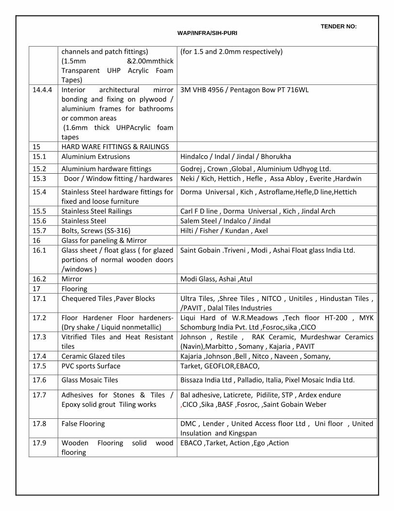
TENDER NO: WAP/INFRA/SIH-PURI
channels and patch fittings) (1.5mm &2.00mmthick Transparent UHP Acrylic Foam Tapes)
(for 1.5 and 2.0mm respectively)
14.4.4 Interior architectural mirror bonding and fixing on plywood / aluminium frames for bathrooms or common areas (1.6mm thick UHPAcrylic foam tapes
3M VHB 4956 / Pentagon Bow PT 716WL
15 HARD WARE FITTINGS & RAILINGS
15.1 Aluminium Extrusions Hindalco / Indal / Jindal / Bhorukha
15.2 Aluminium hardware fittings Godrej , Crown ,Global , Aluminium Udhyog Ltd.
15.3 Door / Window fitting / hardwares Neki / Kich, Hettich , Hefle , Assa Abloy , Everite ,Hardwin
15.4 Stainless Steel hardware fittings for fixed and loose furniture
Dorma Universal , Kich , Astroflame,Hefle,D line,Hettich
15.5 Stainless Steel Railings Carl F D line , Dorma Universal , Kich , Jindal Arch
15.6 Stainless Steel Salem Steel / Indalco / Jindal
15.7 Bolts, Screws (SS-316) Hilti / Fisher / Kundan , Axel
16 Glass for paneling & Mirror
16.1 Glass sheet / float glass ( for glazed portions of normal wooden doors /windows )
Saint Gobain .Triveni , Modi , Ashai Float glass India Ltd.
16.2 Mirror Modi Glass, Ashai ,Atul
17 Flooring
17.1 Chequered Tiles ,Paver Blocks Ultra Tiles, ,Shree Tiles , NITCO , Unitiles , Hindustan Tiles , /PAVIT , Dalal Tiles Industries
17.2 Floor Hardener Floor hardeners- (Dry shake / Liquid nonmetallic)
Liqui Hard of W.R.Meadows ,Tech floor HT-200 , MYK Schomburg India Pvt. Ltd ,Fosroc,sika ,CICO
17.3 Vitrified Tiles and Heat Resistant tiles
Johnson , Restile , RAK Ceramic, Murdeshwar Ceramics (Navin),Marbitto , Somany , Kajaria , PAVIT
17.4 Ceramic Glazed tiles Kajaria ,Johnson ,Bell , Nitco , Naveen , Somany,
17.5 PVC sports Surface Tarket, GEOFLOR,EBACO,
17.6 Glass Mosaic Tiles Bissaza India Ltd , Palladio, Italia, Pixel Mosaic India Ltd.
17.7 Adhesives for Stones & Tiles / Epoxy solid grout Tiling works
Bal adhesive, Laticrete, Pidilite, STP , Ardex endure ,CICO ,Sika ,BASF ,Fosroc, ,Saint Gobain Weber
17.8 False Flooring DMC , Lender , United Access floor Ltd , Uni floor , United Insulation and Kingspan
17.9 Wooden Flooring solid wood flooring
EBACO ,Tarket, Action ,Ego ,Action
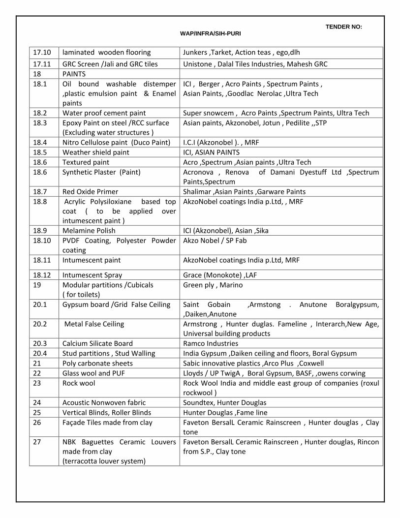
TENDER NO: WAP/INFRA/SIH-PURI
17.10 laminated wooden flooring Junkers ,Tarket, Action teas , ego,dlh
17.11 GRC Screen /Jali and GRC tiles Unistone , Dalal Tiles Industries, Mahesh GRC
18 PAINTS
18.1 Oil bound washable distemper ,plastic emulsion paint & Enamel paints
ICI , Berger , Acro Paints , Spectrum Paints , Asian Paints, ,Goodlac Nerolac ,Ultra Tech
18.2 Water proof cement paint Super snowcem , Acro Paints ,Spectrum Paints, Ultra Tech
18.3 Epoxy Paint on steel /RCC surface (Excluding water structures )
Asian paints, Akzonobel, Jotun , Pedilite ,,STP
18.4 Nitro Cellulose paint (Duco Paint) I.C.I (Akzonobel ). , MRF
18.5 Weather shield paint ICI, ASIAN PAINTS
18.6 Textured paint Acro ,Spectrum ,Asian paints ,Ultra Tech
18.6 Synthetic Plaster (Paint) Acronova , Renova of Damani Dyestuff Ltd ,Spectrum Paints,Spectrum
18.7 Red Oxide Primer Shalimar ,Asian Paints ,Garware Paints
18.8 Acrylic Polysiloxiane based top coat ( to be applied over intumescent paint )
AkzoNobel coatings India p.Ltd, , MRF
18.9 Melamine Polish ICI (Akzonobel), Asian ,Sika
18.10 PVDF Coating, Polyester Powder coating
Akzo Nobel / SP Fab
18.11 Intumescent paint AkzoNobel coatings India p.Ltd, MRF
18.12 Intumescent Spray Grace (Monokote) ,LAF
19 Modular partitions /Cubicals ( for toilets)
Green ply , Marino
20.1 Gypsum board /Grid False Ceiling Saint Gobain ,Armstong . Anutone Boralgypsum, ,Daiken,Anutone
20.2 Metal False Ceiling Armstrong , Hunter duglas. Fameline , Interarch,New Age, Universal building products
20.3 Calcium Silicate Board Ramco Industries
20.4 Stud partitions , Stud Walling India Gypsum ,Daiken ceiling and floors, Boral Gypsum
21 Poly carbonate sheets Sabic innovative plastics ,Arco Plus ,Coxwell
22 Glass wool and PUF Lloyds / UP TwigA , Boral Gypsum, BASF, ,owens corwing
23 Rock wool Rock Wool India and middle east group of companies (roxul rockwool )
24 Acoustic Nonwoven fabric Soundtex, Hunter Douglas
25 Vertical Blinds, Roller Blinds Hunter Douglas ,Fame line
26 Façade Tiles made from clay Faveton BersalL Ceramic Rainscreen , Hunter douglas , Clay tone
27
NBK Baguettes Ceramic Louvers made from clay (terracotta louver system)
Faveton BersalL Ceramic Rainscreen , Hunter douglas, Rincon from S.P., Clay tone
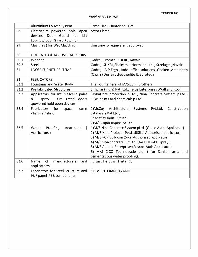
TENDER NO: WAP/INFRA/SIH-PURI
Aluminium Louver System Fame Line , Hunter douglas
28 Electrically powered hold open devices Door Guard for Lift Lobbies/ door Guard Retainer
Astro Flame
29
Clay tiles ( for Wet Cladding ) Unistone or equivalent approved
30 FIRE RATED & ACOUSTICAL DOORS
30.1 Wooden Godrej, Promat , SUKRI , Navair
30.2 Steel Godrej, SUKRI ,Shakyimat Hormann Ltd. , Steelage ,Navair
31 LOOSE FURNITURE ITEME Godrej , B.P.Ergo , Indo office solutions ,Geeken ,Amardeep (Chairs) Durian , ,Featherlite & Eurotech
32 FEBRICATORS
32.1 Fountains and Water Body The Fountainers of M/SK.S.R. Brothers
32.2 Pre fabricated Structures Shilpkar (India) Pvt. Ltd., Tejus Enterprises ,Wall and Roof
32.3 Applicators for Intumescent paint & spray , fire rated doors ,powered hold open devices
Global fire protection p.Ltd , Nina Concrete System p.Ltd , Sukri paints and chemicals p.Ltd.
32.4 Fabricators for space frame /Tensile Fabric
1)McCoy Architectural Systems Pvt.Ltd, Construction catalysers Pvt.Ltd , Shadeflex India Pvt.Ltd. 2)M/S Sujan Impex Pvt.Ltd
32.5 Water Proofing treatment ( Applicators )
1)M/S Nina Concrete System pLtd (Grace Auth. Applicator) 2) M/S Nine Projects Pvt.Ltd(Sika Authorised applicator) 3) M/S RCP Buildcon (Sika Authorised applicator 4) M/S Viva concrete Pvt.Ltd ((for PUF &PU Spray ) 5) M/S Atlanta Enterprises(Fosroc Auth.Applicator) 6) M/S CICO Technotrade Ltd. ( for Sunken area and cementatious water proofing).
32.6 Name of manufacturers and applicatotrs
. Bizar , Herculis ,Tristar CS
32.7 Fabricators for steel structure and PUF panel ,PEB components
KIRBY, INTERARCH,ZAMIL
TENDER NO: WAP/INFRA/SIH-PURI
B. TECHNICAL SPECIFICATIONS FOR ELECTRICAL WORK
CHAPTER 1 : WIRING 1 GENERAL
Technical Specifications in this section cover the Internal Wiring Installations comprising of
Wiring for lights and convenience socket outlets etc. in concealed/surface conduit/raceways.
Wiring for telephone outlets.
Wiring for fire detection system
Sub main wiring. 2 STANDARDS AND CODES
The following Indian Standard Specifications and Codes of Practice will apply to the equipment and the work covered by the scope of this contract. In addition the relevant clauses of the Indian Electricity Act 1910 and Indian Electricity Rules 1956 as amended up to date shall also apply. Wherever appropriate Indian Standards are not available, relevant British and/or IEC Standards shall be applicable. BIS certified equipment shall be used as a part of the Contract in line with Government regulations. Necessary test certificates in support of the certification shall be submitted prior to supply of the equipment. It is to be noted that updated and current Standards shall be applicable irrespective of those listed below.
660/1100 V grade PVC insulated wires. IS 694 : 1990 Rigid steel conduits for electrical wiring. IS 9537 : Part I 1980 IS 9537 : Part II 1981 Accessories for rigid steel conduits IS 3837 : 1990 Flexible steel conduits for electrical wiring IS 3480 : 1990 Switch socket outlets IS 4615 : 1990 Switches for domestic and similar purposes IS 3854 : 1997
Boxes for the enclosure of electrical accessories IS 5133 : Parts I & II 1969
Code of practice for personal hazard fire safety of buildings IS 1644: 1998 Code of practice for electrical installation fire safety of buildings IS1646 : 1997 Code of practice for electrical wiring installations IS 732 : 1989
TENDER NO: WAP/INFRA/SIH-PURI
3 CONDUITS/ RACEWAYS 3.1 PVC Conduits
PVC conduits shall be high impact, rigid, FRLS PVC, heavy-duty type and shall comply with relevant Indian Standards.
Conduits up to 32mm dia shall be 2mm thick and above that shall be 2.5mm thick.
Plain conduits shall be joined by slip type of couplers with approved sealing cement. All conduit entries to outlet boxes are to be made with adaptors female thread and screwed male bushes. Conduit fittings and accessories such as inspection boxes, draw boxes and junction boxes shall be of heavy duty rigid PVC installed in such a manner that they can remain accessible for existing wires or for the installation of the additional wires. Fan hook box shall be of M.S. Inspection boxes shall be covered with suitable covers.
Conduit runs shall be so arranged that the cables connected to separate main circuits shall be enclosed in separate conduits and that all lead and return wires of each circuit shall be run with the same circuit.
PVC conduits shall be smooth in bore, true in size and all ends where conduits are cut shall be made carefully smooth. Sharp edges shall be trimmed. All joints between lengths of conduits or between conduits and fittings and boxes shall be held firmly together and glued properly. All joints shall be fully water tight. All jointing of PVC conduits shall be by means of adhesive jointing.
3.2 PVC Raceways
Wiring for power convenience socket outlets over work tables in laboratories shall be carried out in 100 mm x 50m PVC raceways in surface on wall just above the laboratory table top as directed by Engineer in charge. The raceway shall be fabricated from superior quality engineering plastics and shall be complete with all standard accessories like couplers, end caps, bends, tees and mounting frames suitable for fixing modular wiring accessories. The raceway and accessories shall be as described in the Schedule of Quantities. Wiring up to the raceway shall be brought in MS conduit and approved adapter box to connect the conduit to the raceway shall be provided. Combined 6/16 amp modular switch socket outlets shall be provided on the raceway at modular intervals or as indicated in layout drawings. Each 6/16 amp outlet shall be wired to a separate circuit. Individual circuits in the raceway shall be bunched separately. Installation of the raceway wiring system shall be carried out as per manufacturers recommendations.
3.3 Laying & Fixing of Conduits
Conduits shall be installed so as to avoid steam and hot water pipes. Conduits for LV systems shall be at least 150mm away from the electrical conduits. Conduits concealed in the ceiling slab shall run parallel to walls and beams and conduit concealed in the walls shall be vertical or horizontal. The chase in the walls required for the recessed conduit system shall be neatly made and shall be of ample dimensions to permit the conduits to be fixed in the manner desired. Conduits in chase shall be held by steel clamps of approved design. The chase shall be filled up neatly after erection of conduits and brought to the original finish of the wall with cement plaster/cement concrete. The spacing between each clamp shall be 60 cm center to center. Surface conduits shall be fixed by means of spacer bar saddles at intervals of not more than 500 mm from both sides of fittings/accessories. The saddles shall be of 3mm x 19mm galvanized M.S. flat
TENDER NO: WAP/INFRA/SIH-PURI
properly treated, primed and painted securely fixed to support by means of nuts & bolts / raw plugs and brass machine screws. Where conduits cross expansion joints in the buildings, adequate expansion fittings shall be used to take care of any relative movement. Separate conduits shall be laid for the following systems: a) Normal light, Fan and 6 A socket outlets. b) Power points. c) TV outlets. d) PA system. e) Telephone points f) Fire alarm system g) CCTV System h) Emergency Lighting
Contractor shall submit the conduting layout to PMC / Owners for approval before start of work. While laying conduting, care should be taken that water, mortar and dirt etc. do not enter the conduits and boxes. Conduting system should be such that it shall facilitate easy drawing of new wires/additional wires at any stage. All junction boxes/pull boxes/ draw boxes shall be completely accessible for inspection, maintenance or for future expansion. While drawing of wires, care shall be taken to avoid damage to the wire insulation. All joints in the wiring shall be made only at switches, distribution boards, socket outlets, lighting outlets and switch boxes only. No joint shall be made in conduits and junction boxes.
3.4 Bends
Large right angle bends (more than 75 mm radius) or non right angle bends in conduit runs shall be made by means of conduits bending machines carefully so as not to cause any crack in the conduit. Small right angle bends in conduits runs can be made by standard conduit accessories (solid/inspection bends/elbows) no run of conduits shall have more than four right angle bends from outlet to outlet. Bends in multi runs of conduits shall be parallel to each other and neat in appearance, maintaining the same distance as between straight runs of conduits.
3.5 Conduit Accessories. 3.5.1 Standard accessories
Heavy duty black enamel painted standard conduit fittings and accessories like standard/extra-deep circular boxes, looping in boxes, junction boxes, normal/ inspection bends, solid/inspection elbows, solid/inspection tees, couplers, nipples, saddles, check nuts, earth clips, ball socket joints etc. shall be of superior quality and of approved makes. Heavy duty covers screwed with approved quality screws shall be used. Superior quality screwed PVC bushes shall be used Samples of all conduits fittings and accessories shall be got approved by Owners/Architects before use.
3.5.2 Fabricated accessories
TENDER NO: WAP/INFRA/SIH-PURI
Where ever required, outlet/junction boxes of required sizes shall be fabricated from 1.6 mm thick MS sheets excepting ceiling fan outlet boxes which shall be fabricated from minimum 2 mm thick sheets. The outlet boxes shall be of approved quality, finish and manufacture. Suitable means of fixing connectors etc., if required, shall be provided in the boxes. The boxes shall be protected from rust by zinc phosphate primer process. Boxes shall be finished with minimum 2 coats of enamel paint of approved colour. A screwed brass stud shall be provided in all boxes as earthing terminal.
3.5.2.1 Outlet Boxes For Light Fittings.
These shall be minimum 75mm x 75mm x 50mm deep and provided with required number of threaded collars for conduit entry. For ceiling mounted florescent fittings, the boxes shall be provided 300 mm off centre for a 1200 mm fitting and 150 mm off centre for a 600 mm fitting so that the wiring is taken directly to the down rod. 3 mm thick Perspex/hylam sheet cover of matching colour shall be provided.
3.5.2.2 Outlet Boxes For Ceiling
Outlet boxes for ceiling fans shall be fabricated from minimum 2 mm thick MS sheet steel. The boxes shall be hexagonal in shape of minimum 100 mm depth and 60 mm sides. Each box shall be provided with a recessed fan hook in the form of one 'U' shaped 15 mm dia rod welded to the box and securely tied to the top reinforcement of the concrete slab for a length of minimum 150 mm on either side. 3 mm thick Perspex/xylem sheet cover of matching colour shall be provided.
3.5.3 Boxes For Modular Wiring Accessories 3.5.3.1 Switch Boxes - Modular Type
Switch boxes suitable to house modular type switches of required ratings, and fan regulators as required shall be provided. In case the number of switches in one box is not tallying with that available in standard manufacture, the box accommodating the next higher number of switches shall be provided without any extra cost. In case fan regulator/regulators is /are to be provided at a later dated, suitable provision for accommodating such regulators shall be made in the switch boxes and blank off covers shall be provided without any extra cost.
Switch boxes shall be so designed that accessories are mounted on a grid plate with tapped holes for brass machine screws leaving ample space at the back and on the sides for accommodating conductors, check-nuts and screwed bushes at conduit entries etc... The grid plates and M.S. boxes shall be fitted with a brass earth terminal. Boxes shall be attached to conduits by means of check-nuts on either sides of their walls. Moulded front covers made from high impact resistant, flame retardant and ultra violet stabilized engineering plastics shall be fixed by means of counter sunk chromium plated brass machine screws. No timber shall be used for any supports. Switch boxes shall be located with bottom at 1200 mm above floor level unless otherwise indicated.
3.5.3.2 Modular Type Boxes For Socket/ Telephone/Call Bell Outlets
Outlet boxes shall be suitable for housing modular type switched socket outlets/ telephone outlets/ buzzers and any other outlet as required. These shall be so designed that accessories are mounted on a grid plate with tapped holes for brass machine screws leaving ample space at the back and on the sides for accommodating conductors, check nuts and screwed bushes at conduit entries etc. The grid plates and M.S. boxes shall be fitted with a brass earth terminal. These shall be attached to conduits by means of check nuts on either sides of their walls. Moulded front covers made from high impact resistant, flame retardant and ultra violet stabilized engineering plastics shall be used to mount the outlets and
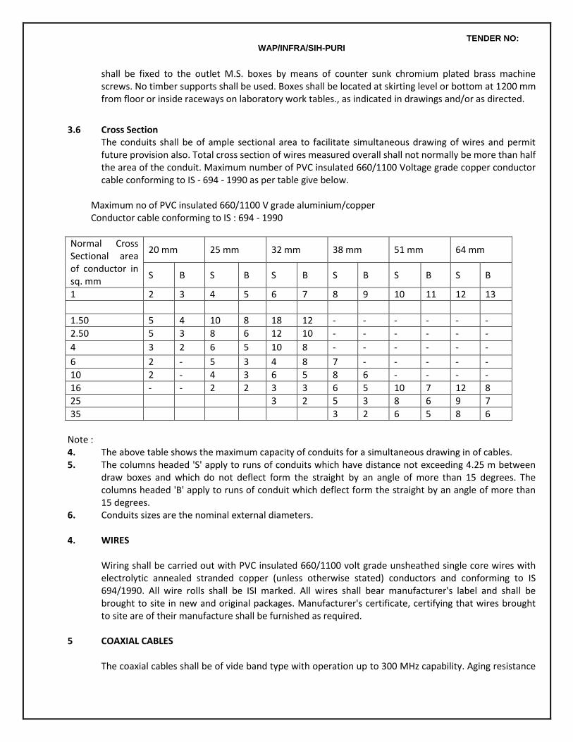
TENDER NO: WAP/INFRA/SIH-PURI
shall be fixed to the outlet M.S. boxes by means of counter sunk chromium plated brass machine screws. No timber supports shall be used. Boxes shall be located at skirting level or bottom at 1200 mm from floor or inside raceways on laboratory work tables., as indicated in drawings and/or as directed.
3.6 Cross Section
The conduits shall be of ample sectional area to facilitate simultaneous drawing of wires and permit future provision also. Total cross section of wires measured overall shall not normally be more than half the area of the conduit. Maximum number of PVC insulated 660/1100 Voltage grade copper conductor cable conforming to IS - 694 - 1990 as per table give below.
Maximum no of PVC insulated 660/1100 V grade aluminium/copper Conductor cable conforming to IS : 694 - 1990
Normal Cross Sectional area of conductor in sq. mm
20 mm 25 mm 32 mm 38 mm 51 mm 64 mm
S B S B S B S B S B S B
1 2 3 4 5 6 7 8 9 10 11 12 13
1.50 5 4 10 8 18 12 - - - - - -
2.50 5 3 8 6 12 10 - - - - - -
4 3 2 6 5 10 8 - - - - - -
6 2 - 5 3 4 8 7 - - - - -
10 2 - 4 3 6 5 8 6 - - - -
16 - - 2 2 3 3 6 5 10 7 12 8
25 3 2 5 3 8 6 9 7
35 3 2 6 5 8 6
Note : 4. The above table shows the maximum capacity of conduits for a simultaneous drawing in of cables. 5. The columns headed 'S' apply to runs of conduits which have distance not exceeding 4.25 m between
draw boxes and which do not deflect form the straight by an angle of more than 15 degrees. The columns headed 'B' apply to runs of conduit which deflect form the straight by an angle of more than 15 degrees.
6. Conduits sizes are the nominal external diameters. 4. WIRES
Wiring shall be carried out with PVC insulated 660/1100 volt grade unsheathed single core wires with electrolytic annealed stranded copper (unless otherwise stated) conductors and conforming to IS 694/1990. All wire rolls shall be ISI marked. All wires shall bear manufacturer's label and shall be brought to site in new and original packages. Manufacturer's certificate, certifying that wires brought to site are of their manufacture shall be furnished as required.
5 COAXIAL CABLES
The coaxial cables shall be of vide band type with operation up to 300 MHz capability. Aging resistance
TENDER NO: WAP/INFRA/SIH-PURI
shall comply with DIM 472.52 part 2 i.e maximum 5% increase in attenuation at 200 MHz measured by artificial aging (14 days at 80o C) cables shall meet all exceed following specifications
Center core Dia 0.8 mm Dielectric Dia 4.8 mm Dielectric PE Outer Conductor Dia 5.4 mm Outer Dia 7.0 mm Bending radius more than 30 mm Impedance 75 ohms D.C Resistance 50 ohms/KM Screening factor more than 50 Attenuation 50 MHz 6.5 100 MHz 9 200 MHz 13 300 MHz 16
6 LAYING OF CONDUITS
Conduits shall be laid either recessed in walls and ceilings or on surface on walls and ceilings or partly recessed and partly on surface, as required.
Same rate shall apply for recessed and surface conduting in this contract.
Stranded copper conductor insulated wire of size as per schedule of quantities shall be provided in entire conduting for loop earthing.
GI wire of suitable size to serve as a fish wire shall be left in all conduit runs to facilitate drawing of wires after completion of conduting.
6.1 Recessed Conduting
Conduits recessed in concrete members shall be laid before casting, in the upper portion of slabs or otherwise as may be instructed, so as to embedded the entire run of conduits and ceiling outlet boxes with a cover of minimum 12 mm concrete. Conduits shall be adequately tied to the reinforcement to prevent displacement during casting at intervals of maximum 1 meter. No reinforcement bars shall be cut to fix the conduits. Suitable flexible joints shall be provided at all locations where conduits cross expansion joints in the building. Conduits recessed in brick work shall be laid in chases to be cut by electrical Contractor in brick work before plastering. The chases shall be cut by a chase cutting electric machine. The chases shall be of sufficient width to accommodate the required number of conduits and of sufficient depth to permit full thickness of plaster over conduits. The conduits shall be secured in the chase by means of heavy duty pressed steel clamps screwed to MS flat strip saddles at intervals of maximum 1 meter. The chases shall then be filled with cement and coarse sand mortar (1:3) and properly cured by watering. Entire recessed conduit work in concrete members and in brick work shall be carried out in close coordination with progress of civil works. Conduits in concrete members shall be laid before casting and conduits in brick work shall be laid before plastering. Should it become necessary to embed conduits in already cast concrete members, suitable chase shall be cut in concrete for the purpose. For minimizing this cutting, conduits of lesser diameter than 25 mm and outlet boxes of lesser depth than
TENDER NO: WAP/INFRA/SIH-PURI
50 mm could be used by the Contractor for such extensions only after obtaining specific approval from Architects/Owners. For embedding conduits in finished and plastered brick work, the chase would have to be made in the finished brick work. After fixing conduit in chases, chases shall be made good in most workmanlike manner to match with the original finish. Cutting chases in finished concrete or finished plastered brick work for recessing conduits and outlet boxes etc shall be done by the Contractors without any extra cost.
6.2 Surface Conduting
Wherever so desired, conduit shall be laid in surface over finished concrete and/or plastered brickwork. Suitable spacer saddles of approved make and finish shall be fixed to the finished structural surface along the conduit route at intervals not exceeding 600 mm. Holes in concrete or brick work for fixing the saddles shall be made neatly by electric drills using masonry drill bits. Conduits shall be fixed on the saddles by means of good quality heavy duty MS clamps screwed to the saddles by counter sunk screws. Neat appearance and good workmanship of surface conduting work is of particular importance. The entire conduit work shall be in absolute line and plumb.
6.3 Fixing of conduit fittings and accessories
For concealed conduting work, the fittings and accessories shall be completely embedded in walls/ceilings leaving top surface flush with finished wall/ceiling surface in a workman like manner. Loop earthing wire shall be connected to a screwed earth stead inside outlet boxes to make an effective contact with the metal body.
6.4 Painting and Colour coding of conduits
Before laying, conduits shall be painted specially at such places where paint has been damaged due to vice or wrench grip or any other reason. If so specified, surface conduits shall be provided with 20 mm wide and 100 mm long colour coding strips as below
Use Code colour Low voltage Grey Fire alarm Red Telephone Black PA system Brown Earthing system Green Control system lighting Purple
6.5 Protection of Conduits
To safeguard against filling up with mortar/plaster etc. all the outlet and switch boxes shall be provided with temporary covers and plugs which shall be replaced by sheet/plate covers as required. All screwed and socketed joints shall be made fully water tight with white lead paste.
6.6 Cleaning of Conduit Runs
The entire conduit system including outlets and boxes shall be thoroughly cleaned after completion of erection and before drawing in of cables.
TENDER NO: WAP/INFRA/SIH-PURI
6.7 Protection Against Dampness All outlets in conduit system shall be properly drain and ventilated to minimize chances of condensation/sweating.
6.8 Expansion Joints
When crossing through expansion joints in buildings, the conduit sections across the joint shall be through approved quality heavy duty metal flexible conduits of the same size as the rigid conduit.
6.9 Loop Earthing
Loop earthing shall be provided by means of insulated stranded copper conductor wires of sizes as per Schedule of Quantity laid along with wiring inside conduits for all wiring outlets and sub-mains. Earthing terminals shall be provided inside all switch boxes, outlet boxes and draw boxes etc.
7 LAYING AND DRAWING OF WIRES 7.1 Bunching of Wires
Wires carrying current shall be so bunched in conduits that the outgoing and return wires are drawn into the same conduit. Wires originating from two different phases shall not be run in the same conduit.
7.2 Drawing of Wires
The drawing of wires shall be done with due regard to the following precautions:-
No wire shall be drawn into any conduit, until all work of any nature, that may cause injury to wire is completed. Burrs in cut conduits shall be smoothen before erection of conduits. Care shall be taken in pulling the wires so that no damage occurs to the insulation of the wire. Approved type bushes shall be provided at conduit terminations.
Before the wires are drawn into the conduits, conduits shall be thoroughly cleaned of moisture, dust, dirt or any other obstruction by forcing compressed air through the conduits if necessary..
While drawing insulated wires into the conduits, care shall be taken to avoid scratches and kinks which cause breakage of conductors.
There shall be no sharp bends.
The Contractor shall, after wiring is completed, provide a blank metal/sun mica plate on all switch / outlet / junction boxes for security and to ensure that wires are not stolen till switches / outlets etc.. are fixed at no extra cost the contractor shall be responsible to ensure that wires and loop earthing conductors are not broken and stolen. In the event of the wire been partly / fully stolen , the contractor shall replace the entire wiring along with loop earthing at no extra cost to the Owners. No joint of any nature whatsoever shall be permitted in wiring and loop earthing .
7.3 Termination /Jointing of Wires
TENDER NO: WAP/INFRA/SIH-PURI
Sub-circuit wiring shall be carried out in looping system. Joints shall be made only at distribution board terminals, switches/buzzers and at ceiling roses/connectors/lamp holders terminals for lights/fans/socket outlets. No joints shall be made inside conduits or junction/draw/inspection boxes.
Switches controlling lights, fans or socket outlets shall be connected in the phase wire of the final sub circuit only. Switches shall never be connected in the neutral wire.
Wiring conductors shall be continuous from outlet to outlet. Joints where unavoidable, due to any special reason shall be made by approved connectors. Specific prior permission from Architect/Owners in writing shall be obtained before making such joint.
Insulation shall be shaved off for a length of 15 mm at the end of wire like sharpening of a pencil and it shall not be removed by cutting it square or wringing.
Strands of wires shall not be cut for connecting terminals. All strands of wires shall be twisted round at the end before connection..
Conductors having nominal cross sectional area exceeding 4 sq. mm shall always be provided with crimping sockets.
At all bolted terminals, brass flat washer of large area and approved steel spring washers shall be used.
Brass nuts and bolts shall be used for all connections.
The pressure applied to tighten terminal screws shall be just adequate, neither too much nor too less.
Switches controlling lights, fans, socket outlets etc. shall be connected to the phase wire of circuits only.
Only certified valid license holder wiremen shall be employed to do wiring / jointing work. 7.4 Load Balancing
Balancing of circuits in three phase installation shall be planned before the commencement of wiring and shall be strictly adhered to.
7.5 Colour Code of Conductors
Colour code shall be maintained for the entire wiring installation - red, yellow, blue for three phases, black for neutral and green for earth.
8. MEASUREMENT AND PAYMENT OF WIRING
Wiring for lights, fans, convenience socket outlets and telephone outlets etc. shall be measured and paid for on POINT BASIS as itemized schedule of quantities and as elaborated as below unless otherwise stated.
TENDER NO: WAP/INFRA/SIH-PURI
8.1 Primary and Secondary light point wiring In respect of group control of lights (more than one light controlled by one switch or MCB), wiring up to the first light in the group shall be measured and paid for as a primary light point. Wiring for other lights looped in one group for switch controlled as also MCB controlled lights shall be measured and paid for as secondary light points. Primary light points for switch controlled lights shall include the cost of control switch whereas primary light points controlled by MCBs shall not include the switch cost. The cost of MCB controlling such lights shall not be included in the primary light point rate since the MCB shall be paid for in the item of DB. The point wiring basis shall assume average wiring length and average conduting length per point based on parameters stipulated in para 8.2 below. The average wiring length and average conducting length forming the basis of point wiring payment, shall take the electrical layouts of the entire project into consideration. Tenderers are advised to seek clarifications, if they so desire, on this aspect before submitting their tenders. No claim for extra payment on account of electrical layouts in part or whole of the project requiring larger average wiring and conduting length per point, whether specifically shown in tender drawings or not, shall be entertained after the award of contract.
8.2 Parameters: Wiring shall be carried out as per following parameters in recessed/ surface conduit system.
Only looping system of wiring shall be adopted throughout. No joints excepting at wiring terminals shall be permitted.
All accessories shall be flush type unless otherwise stated.
For estimation of load, following loads per point shall be assumed.
Light points 100 Watts.
6 amps socket outlet points 100 Watts. Fan points 60 Watts. Exhaust fan points 300 Watts or as specified. 16 amp socket outlet points 1000 Watts.
Lights, fans and 6 amp socket outlets may be wired on a common final such circuit. Such circuit shall not normally have more than a total of ten lights, fans or socket outlets or a load of 800 watts whichever is lesser.
Power circuits shall normally have maximum one 16 amps socket outlet unless otherwise stated. Separate circuit shall be run for each geyser, kitchen equipment, window air conditioners and similar appliances.
Wiring rates shall include painting of conduits and other accessories as required.
Wiring rates shall include cleaning of dust, splashes of colour wash or paint from all fixtures, fans, fittings etc. at the time of taking over of the installation.
Wiring rates shall include blanking of outlet boxes to prevent damage/pilferage of wires as elaborated in Para 7.2.
8.3 Definitions 8.3.1 Wiring for Lights
TENDER NO: WAP/INFRA/SIH-PURI
Primary Light Points : Wiring for primary light points, as defined in para 8.1 above, shall commence at the Distribution Board terminals and shall terminate at the ceiling rose/connector in ceiling box/lamp holder via the control switch (for switch controlled lights). Rates for primary light point wiring shall be deemed to be inclusive of the cost of entire material and labour require for completion of primary light point thus defined including : .
Recessed / surface conduting system with all accessories, junction/draw/inspection boxes, bushes, check nuts etc. complete as required,
Wiring with stranded copper conductor PVC insulated 660/1000 volt grade wires including terminations etc. complete as required.
Control switch with switch box and cover plate of specified type including fixing screws, earth terminal etc. complete as required. Cost of this switch is applicable only for switch controlled points. This cost shall not be applicable for DB controlled points.
Loop earthing with insulated copper wires.
Secondary Light points : Secondary light points, as defined in para 8.1 above, shall cover the cost of interconnection wiring between group controlled light fittings and shall be deemed to be inclusive of the cost of entire materials and labour required for completion of the secondary light point thus defined including
Recessed / surface conduting system with all accessories, junction/draw/inspection boxes, bushes, check nuts etc. complete as required,
Wiring with stranded copper conductor PVC insulated 660/1000 volt grade wires including terminations etc. complete as required.
Loop earthing with insulated copper wires. 8.3.2 Wiring for Ceiling Fans
Wiring for ceiling fan points shall be same as for primary light points and shall, in addition, include ceiling outlet box with recessed fan hooks and provision in the switch box for mounting the fan regulator.
8.3.3 Wiring for Exhaust Fans
Wiring for exhaust fan points shall be same as for primary light points and shall in addition include the cost of providing a 3/5 pin 6 amp socket outlet near the fan and a 6 amp control switch at convenient location near the room entry.
8.3.4 Wiring for Call Bell Points
Wiring for call bell points shall be the same as for primary light points and shall in addition include the cost of a call bell/buzzer of approved type and make in the required location and a call bell in lieu of the control switch at a convenient location as required.
8.3.5 Wiring for Telephone Outlets
TENDER NO: WAP/INFRA/SIH-PURI
Wiring for telephone outlets points shall include the entire wiring and conduting from the telephone tag block to the telephone outlet including the telephone outlet complete as required and as itemized in the Schedule of Quantities
8.3.6 Wiring for Convenience Socket Outlets
3/5 pin 6 amps and 3/6 pin 16 amps single phase switched convenience socket outlets shall be provided in the building as indicated in the layout drawings. In addition, combined 3 pin 6 / 16 amps socket outlets at modular intervals in special PVC raceway over the work tables in laboratories shall be provided. Wherever required, 20/32/50 amps single phase and 32/50 amps 3 phase outlets shall also be provided. Wiring for 3/5 pin 6 amps convenience socket outlets Point wiring for 3/5 pin 6 amps socket outlets (in locations other than over the laboratory work tables) on point wiring basis shall be the same as primary light point defined in para 8.3.1 and shall in addition include 3/5 pin 6 amp socket outlet with 6 amp control switch in MS box with cover. Including loop earthing of the third pin complete as required as itemized in scheduled of quantities. Wiring for 3/6 pin 16 amps convenience socket outlets Point wiring for 3/6 pin 16 amps socket outlets (in locations other than over the laboratory work tables) on point wiring basis shall be the same as primary light point defined in para 8.3.1 and shall in addition include 3/6 pin 16 amp socket outlet with 16 amp control switch in MS box with cover. Including loop earthing of the third pin complete as required as itemized in scheduled of quantities. Wiring for combined 3 pin 6/16 amps socket outlets in laboratories Wiring for 3 pin 6/16 amp combined socket outlets in existing PVC raceways (provided over laboratory work tables) on point wiring basis shall include the cost of wiring from DB terminals to the outlets along with loop earrthing of the earth pin and the switched combination 6/16 amp outlet with 16 amp control switch housed in the existing raceway, as indicated in layout drawings and as itemized in schedule of quantities. PVC raceway/conduit required for this wiring shall be paid extra as itemized in the schedule of quantities. Wiring for special socket outlets In addition to the above, special convenience outlets of 20/32/50 amps single phase and 32/50 amps three phase, required in few locations as indicated in the layout drawings, shall be paid for on linear basis as itemized in schedule of quantities. Outlets only shall be paid separately in numbers as per actuals. Wiring along with loop earthing shall be paid separately on running meter basis and conduting /PVC raceway shall be paid separately on running meter basis.
9. ROUTINE AND COMPLETION TESTS 9.1 Installation Completion Tests At the completion of the work, the entire installation shall be subject to the following tests:
1. Wiring continuity test 2. Insulation resistance test 3. Earth continuity test 4. Earth resistivity test
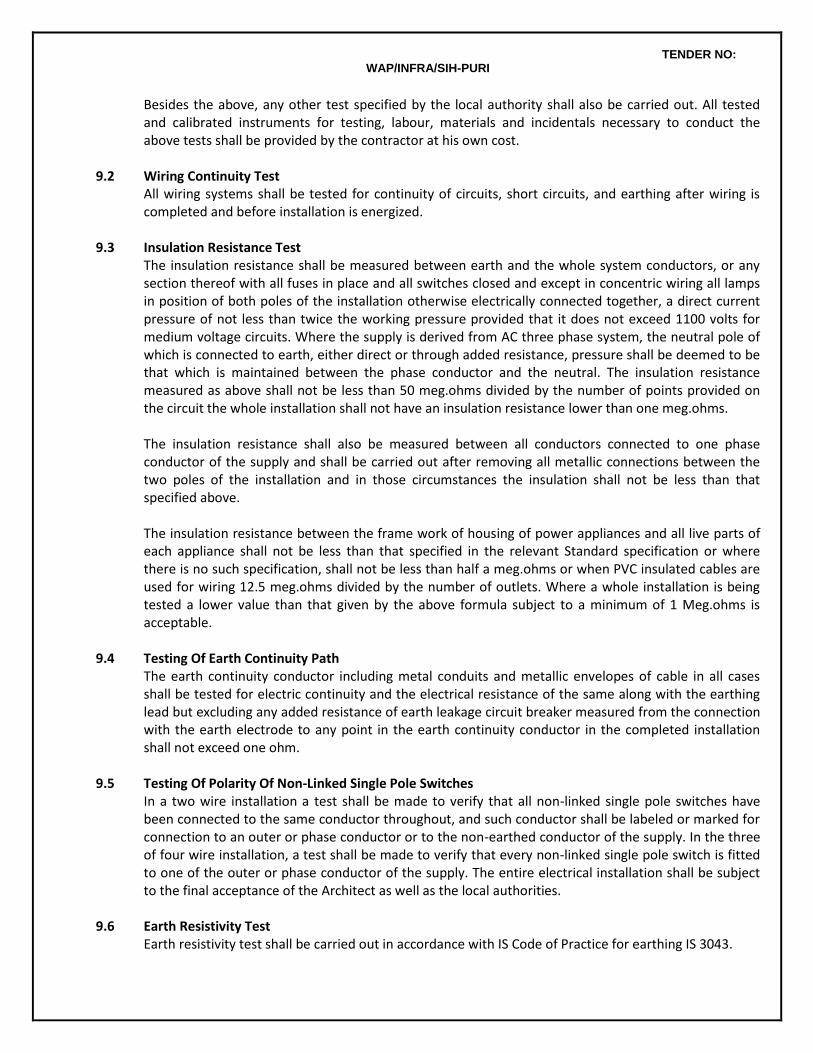
TENDER NO: WAP/INFRA/SIH-PURI
Besides the above, any other test specified by the local authority shall also be carried out. All tested and calibrated instruments for testing, labour, materials and incidentals necessary to conduct the above tests shall be provided by the contractor at his own cost.
9.2 Wiring Continuity Test
All wiring systems shall be tested for continuity of circuits, short circuits, and earthing after wiring is completed and before installation is energized.
9.3 Insulation Resistance Test
The insulation resistance shall be measured between earth and the whole system conductors, or any section thereof with all fuses in place and all switches closed and except in concentric wiring all lamps in position of both poles of the installation otherwise electrically connected together, a direct current pressure of not less than twice the working pressure provided that it does not exceed 1100 volts for medium voltage circuits. Where the supply is derived from AC three phase system, the neutral pole of which is connected to earth, either direct or through added resistance, pressure shall be deemed to be that which is maintained between the phase conductor and the neutral. The insulation resistance measured as above shall not be less than 50 meg.ohms divided by the number of points provided on the circuit the whole installation shall not have an insulation resistance lower than one meg.ohms. The insulation resistance shall also be measured between all conductors connected to one phase conductor of the supply and shall be carried out after removing all metallic connections between the two poles of the installation and in those circumstances the insulation shall not be less than that specified above. The insulation resistance between the frame work of housing of power appliances and all live parts of each appliance shall not be less than that specified in the relevant Standard specification or where there is no such specification, shall not be less than half a meg.ohms or when PVC insulated cables are used for wiring 12.5 meg.ohms divided by the number of outlets. Where a whole installation is being tested a lower value than that given by the above formula subject to a minimum of 1 Meg.ohms is acceptable.
9.4 Testing Of Earth Continuity Path
The earth continuity conductor including metal conduits and metallic envelopes of cable in all cases shall be tested for electric continuity and the electrical resistance of the same along with the earthing lead but excluding any added resistance of earth leakage circuit breaker measured from the connection with the earth electrode to any point in the earth continuity conductor in the completed installation shall not exceed one ohm.
9.5 Testing Of Polarity Of Non-Linked Single Pole Switches
In a two wire installation a test shall be made to verify that all non-linked single pole switches have been connected to the same conductor throughout, and such conductor shall be labeled or marked for connection to an outer or phase conductor or to the non-earthed conductor of the supply. In the three of four wire installation, a test shall be made to verify that every non-linked single pole switch is fitted to one of the outer or phase conductor of the supply. The entire electrical installation shall be subject to the final acceptance of the Architect as well as the local authorities.
9.6 Earth Resistivity Test
Earth resistivity test shall be carried out in accordance with IS Code of Practice for earthing IS 3043.
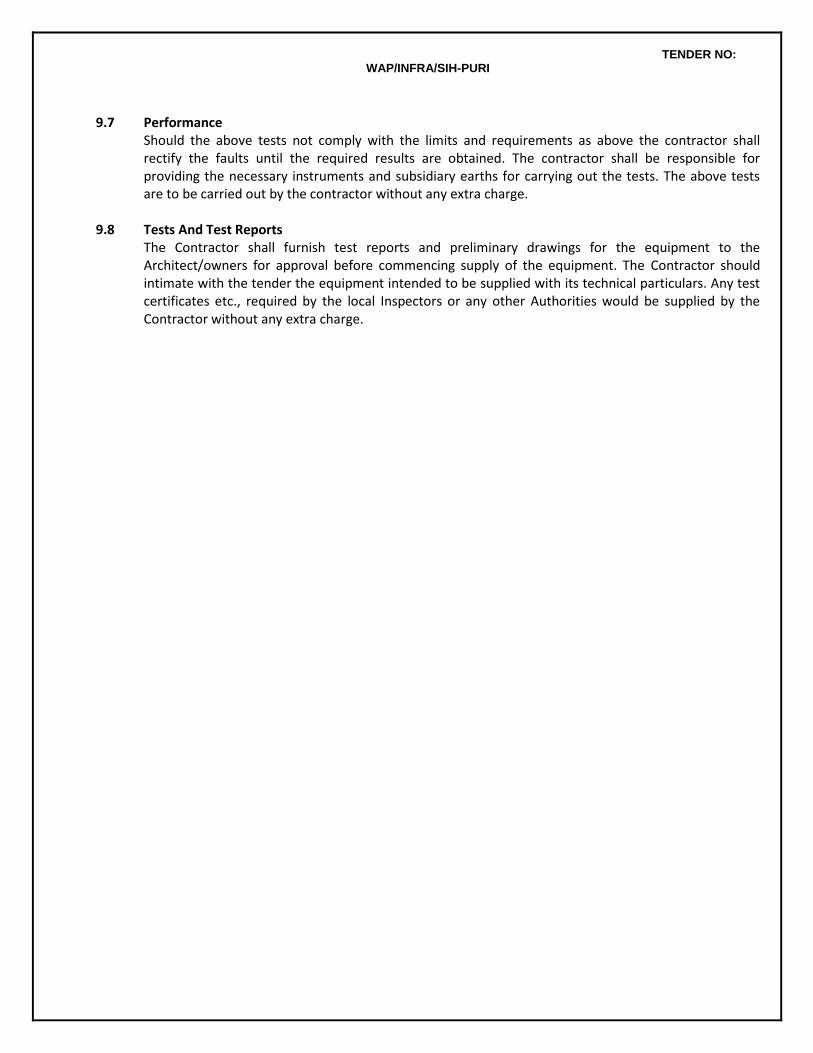
TENDER NO: WAP/INFRA/SIH-PURI
9.7 Performance
Should the above tests not comply with the limits and requirements as above the contractor shall rectify the faults until the required results are obtained. The contractor shall be responsible for providing the necessary instruments and subsidiary earths for carrying out the tests. The above tests are to be carried out by the contractor without any extra charge.
9.8 Tests And Test Reports
The Contractor shall furnish test reports and preliminary drawings for the equipment to the Architect/owners for approval before commencing supply of the equipment. The Contractor should intimate with the tender the equipment intended to be supplied with its technical particulars. Any test certificates etc., required by the local Inspectors or any other Authorities would be supplied by the Contractor without any extra charge.
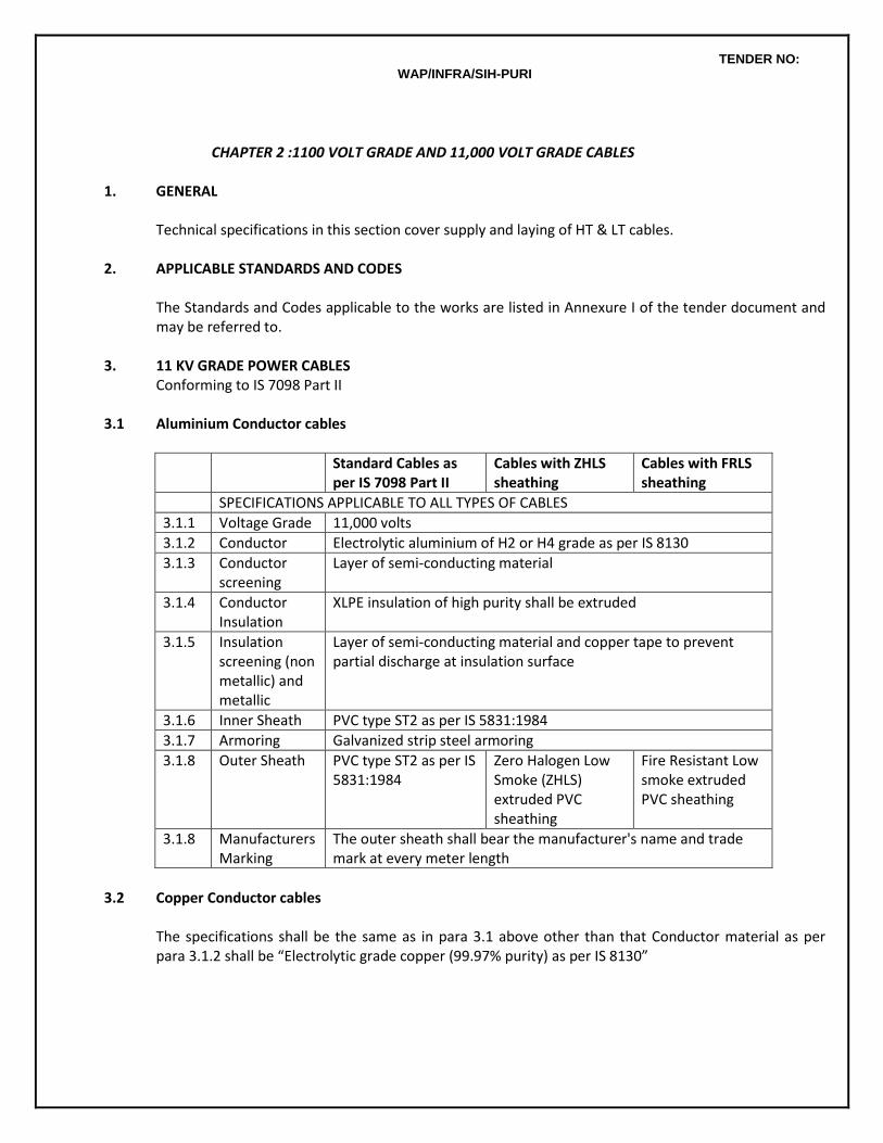
TENDER NO: WAP/INFRA/SIH-PURI
CHAPTER 2 :1100 VOLT GRADE AND 11,000 VOLT GRADE CABLES 1. GENERAL Technical specifications in this section cover supply and laying of HT & LT cables. 2. APPLICABLE STANDARDS AND CODES
The Standards and Codes applicable to the works are listed in Annexure I of the tender document and may be referred to.
3. 11 KV GRADE POWER CABLES Conforming to IS 7098 Part II 3.1 Aluminium Conductor cables
Standard Cables as per IS 7098 Part II
Cables with ZHLS sheathing
Cables with FRLS sheathing
SPECIFICATIONS APPLICABLE TO ALL TYPES OF CABLES
3.1.1 Voltage Grade 11,000 volts
3.1.2 Conductor Electrolytic aluminium of H2 or H4 grade as per IS 8130
3.1.3 Conductor screening
Layer of semi-conducting material
3.1.4 Conductor Insulation
XLPE insulation of high purity shall be extruded
3.1.5 Insulation screening (non metallic) and metallic
Layer of semi-conducting material and copper tape to prevent partial discharge at insulation surface
3.1.6 Inner Sheath PVC type ST2 as per IS 5831:1984
3.1.7 Armoring Galvanized strip steel armoring
3.1.8 Outer Sheath PVC type ST2 as per IS 5831:1984
Zero Halogen Low Smoke (ZHLS) extruded PVC sheathing
Fire Resistant Low smoke extruded PVC sheathing
3.1.8
Manufacturers Marking
The outer sheath shall bear the manufacturer's name and trade mark at every meter length
3.2 Copper Conductor cables
The specifications shall be the same as in para 3.1 above other than that Conductor material as per para 3.1.2 shall be “Electrolytic grade copper (99.97% purity) as per IS 8130”
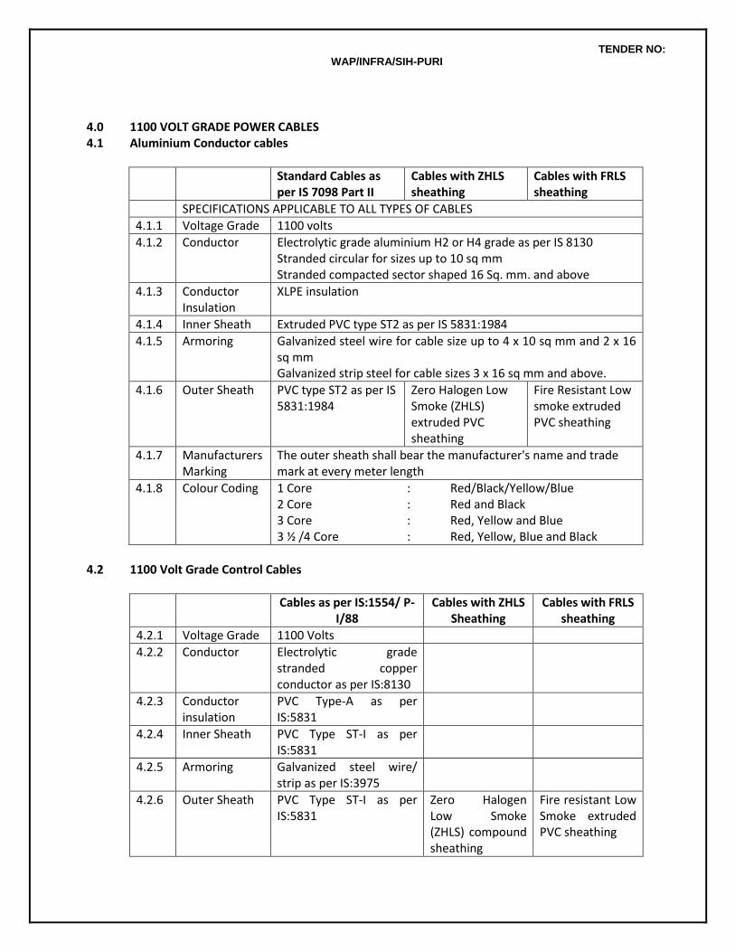
TENDER NO: WAP/INFRA/SIH-PURI
4.0 1100 VOLT GRADE POWER CABLES 4.1 Aluminium Conductor cables
Standard Cables as per IS 7098 Part II
Cables with ZHLS sheathing
Cables with FRLS sheathing
SPECIFICATIONS APPLICABLE TO ALL TYPES OF CABLES
4.1.1 Voltage Grade 1100 volts
4.1.2 Conductor Electrolytic grade aluminium H2 or H4 grade as per IS 8130 Stranded circular for sizes up to 10 sq mm Stranded compacted sector shaped 16 Sq. mm. and above
4.1.3 Conductor Insulation
XLPE insulation
4.1.4 Inner Sheath Extruded PVC type ST2 as per IS 5831:1984
4.1.5 Armoring Galvanized steel wire for cable size up to 4 x 10 sq mm and 2 x 16 sq mm Galvanized strip steel for cable sizes 3 x 16 sq mm and above.
4.1.6 Outer Sheath PVC type ST2 as per IS 5831:1984
Zero Halogen Low Smoke (ZHLS) extruded PVC sheathing
Fire Resistant Low smoke extruded PVC sheathing
4.1.7
Manufacturers Marking
The outer sheath shall bear the manufacturer's name and trade mark at every meter length
4.1.8 Colour Coding 1 Core : Red/Black/Yellow/Blue 2 Core : Red and Black 3 Core : Red, Yellow and Blue 3 ½ /4 Core : Red, Yellow, Blue and Black
4.2 1100 Volt Grade Control Cables
Cables as per IS:1554/ P-I/88
Cables with ZHLS Sheathing
Cables with FRLS sheathing
4.2.1 Voltage Grade 1100 Volts
4.2.2 Conductor Electrolytic grade stranded copper conductor as per IS:8130
4.2.3 Conductor insulation
PVC Type-A as per IS:5831
4.2.4 Inner Sheath PVC Type ST-I as per IS:5831
4.2.5 Armoring Galvanized steel wire/ strip as per IS:3975
4.2.6 Outer Sheath PVC Type ST-I as per IS:5831
Zero Halogen Low Smoke (ZHLS) compound sheathing
Fire resistant Low Smoke extruded PVC sheathing
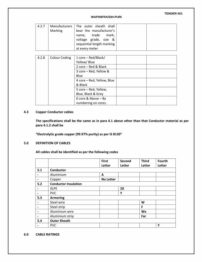
TENDER NO: WAP/INFRA/SIH-PURI
4.2.7 Manufacturers Marking
The outer sheath shall bear the manufacturer’s name, trade mark, voltage grade, size & sequential length marking at every meter
4.2.8 Colour Coding 1 core – Red/Black/ Yellow/ Blue
2 core – Red & Black
3 core – Red, Yellow & Blue
4 core – Red, Yellow, Blue & Black
5 core – Red, Yellow, Blue, Black & Grey
6 core & Above – By numbering on cores.
4.3 Copper Conductor cables
The specifications shall be the same as in para 4.1 above other than that Conductor material as per para 4.1.2 shall be “Electrolytic grade copper (99.97% purity) as per IS 8130”
5.0 DEFINITION OF CABLES
All cables shall be identified as per the following codes
First Letter
Second Letter
Third Letter
Fourth Letter
5.1 Conductor
- Aluminium A
- Copper No Letter
5.2 Conductor Insulation
- XLPE 2X
- PVC Y
5.3 Armoring
- Steel wire W
- Steel strip F
- Aluminium wire We
- Aluminium strip Far
5.4 Outer Sheath
- PVC Y
6.0 CABLE RATINGS
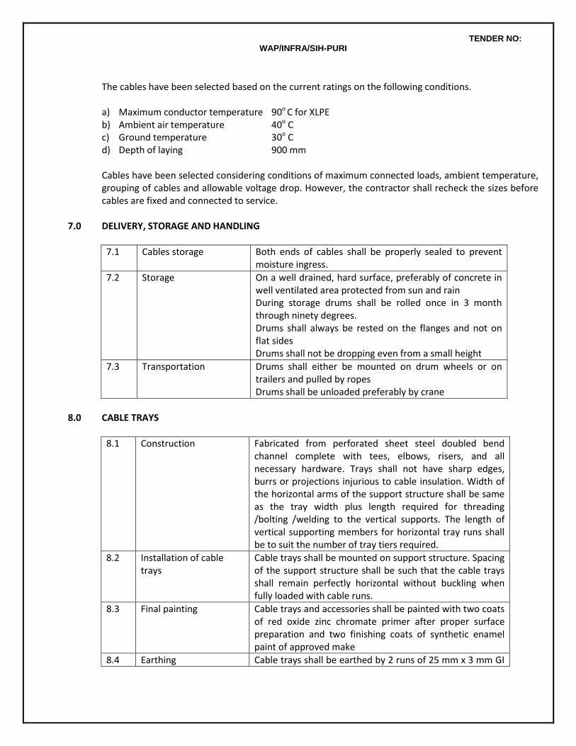
TENDER NO: WAP/INFRA/SIH-PURI
The cables have been selected based on the current ratings on the following conditions.
a) Maximum conductor temperature 90o C for XLPE b) Ambient air temperature 40o C c) Ground temperature 30o C d) Depth of laying 900 mm Cables have been selected considering conditions of maximum connected loads, ambient temperature, grouping of cables and allowable voltage drop. However, the contractor shall recheck the sizes before cables are fixed and connected to service.
7.0 DELIVERY, STORAGE AND HANDLING
7.1
Cables storage Both ends of cables shall be properly sealed to prevent moisture ingress.
7.2 Storage On a well drained, hard surface, preferably of concrete in well ventilated area protected from sun and rain During storage drums shall be rolled once in 3 month through ninety degrees. Drums shall always be rested on the flanges and not on flat sides Drums shall not be dropping even from a small height
7.3 Transportation Drums shall either be mounted on drum wheels or on trailers and pulled by ropes Drums shall be unloaded preferably by crane
8.0 CABLE TRAYS
8.1 Construction Fabricated from perforated sheet steel doubled bend channel complete with tees, elbows, risers, and all necessary hardware. Trays shall not have sharp edges, burrs or projections injurious to cable insulation. Width of the horizontal arms of the support structure shall be same as the tray width plus length required for threading /bolting /welding to the vertical supports. The length of vertical supporting members for horizontal tray runs shall be to suit the number of tray tiers required.
8.2 Installation of cable trays
Cable trays shall be mounted on support structure. Spacing of the support structure shall be such that the cable trays shall remain perfectly horizontal without buckling when fully loaded with cable runs.
8.3 Final painting Cable trays and accessories shall be painted with two coats of red oxide zinc chromate primer after proper surface preparation and two finishing coats of synthetic enamel paint of approved make
8.4 Earthing Cable trays shall be earthed by 2 runs of 25 mm x 3 mm GI
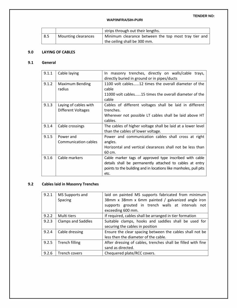
TENDER NO: WAP/INFRA/SIH-PURI
strips through out their lengths.
8.5 Mounting clearances Minimum clearance between the top most tray tier and the ceiling shall be 300 mm.
9.0 LAYING OF CABLES
9.1 General
9.1.1 Cable laying In masonry trenches, directly on walls/cable trays, directly buried in ground or in pipes/ducts
9.1.2 Maximum Bending radius
1100 volt cables……12 times the overall diameter of the cable 11000 volt cables..….15 times the overall diameter of the cable
9.1.3 Laying of cables with Different Voltages
Cables of different voltages shall be laid in different trenches. Wherever not possible LT cables shall be laid above HT cables.
9.1.4 Cable crossings The cables of higher voltage shall be laid at a lower level than the cables of lower voltage.
9.1.5 Power and Communication cables
Power and communication cables shall cross at right angles. Horizontal and vertical clearances shall not be less than 60 cm.
9.1.6 Cable markers Cable marker tags of approved type inscribed with cable details shall be permanently attached to cables at entry points to the building and in locations like manholes, pull pits etc.
9.2 Cables laid in Masonry Trenches
9.2.1 MS Supports and Spacing
laid on painted MS supports fabricated from minimum 38mm x 38mm x 6mm painted / galvanized angle iron supports grouted in trench walls at intervals not exceeding 600 mm.
9.2.2 Multi tiers If required, cables shall be arranged in tier formation
9.2.3 Clamps and Saddles Suitable clamps, hooks and saddles shall be used for securing the cables in position
9.2.4 Cable dressing Ensure the clear spacing between the cables shall not be less then the diameter of the cable.
9.2.5 Trench filling After dressing of cables, trenches shall be filled with fine sand as directed.
9.2.6 Trench covers Chequered plate/RCC covers.
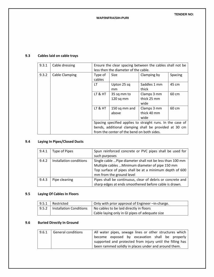
TENDER NO: WAP/INFRA/SIH-PURI
9.3 Cables laid on cable trays
9.3.1 Cable dressing Ensure the clear spacing between the cables shall not be less then the diameter of the cable.
9.3.2 Cable Clamping Type of cables
Size Clamping by Spacing
LT Upton 25 sq mm
Saddles 1 mm thick
45 cm
LT & HT 35 sq mm to 120 sq mm
Clamps 3 mm thick 25 mm wide
60 cm
LT & HT 150 sq mm and above
Clamps 3 mm thick 40 mm wide
60 cm
Spacing specified applies to straight runs. In the case of bends, additional clamping shall be provided at 30 cm from the center of the bend on both sides.
9.4 Laying In Pipes/Closed Ducts
9.4.1 Type of Pipes Spun reinforced concrete or PVC pipes shall be used for such purposes
9.4.2 Installation conditions Single cable …Pipe diameter shall not be less than 100 mm Multiple cables …Minimum diameter of pipe 150 mm Top surface of pipes shall be at a minimum depth of 600 mm from the ground level
9.4.3 Pipe cleaning Pipes shall be continuous, clear of debris or concrete and sharp edges at ends smoothened before cable is drawn.
9.5 Laying Of Cables In Floors
9.5.1 Restricted Only with prior approval of Engineer –in-charge.
9.5.2 Installation Conditions No cables to be laid directly in floors Cable laying only in GI pipes of adequate size
9.6 Buried Directly In Ground
9.6.1 General conditions All water pipes, sewage lines or other structures which become exposed by excavation shall be properly supported and protected from injury until the filling has been rammed solidly in places under and around them.
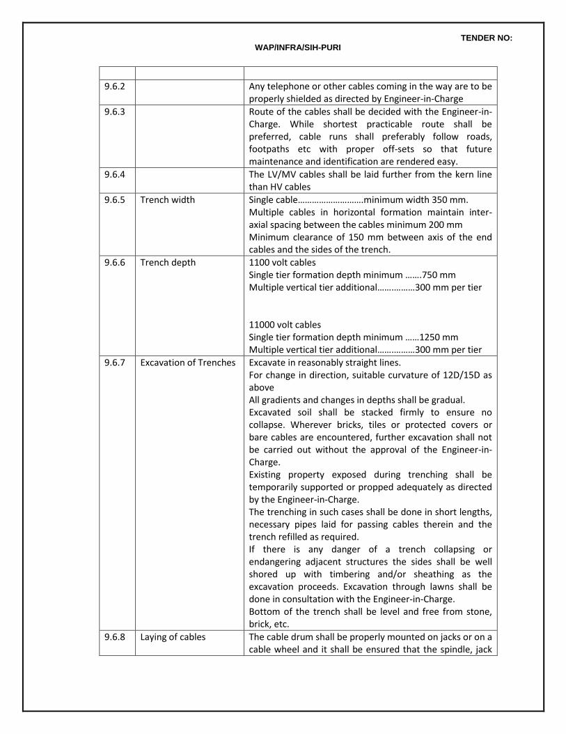
TENDER NO: WAP/INFRA/SIH-PURI
9.6.2 Any telephone or other cables coming in the way are to be properly shielded as directed by Engineer-in-Charge
9.6.3 Route of the cables shall be decided with the Engineer-in-Charge. While shortest practicable route shall be preferred, cable runs shall preferably follow roads, footpaths etc with proper off-sets so that future maintenance and identification are rendered easy.
9.6.4 The LV/MV cables shall be laid further from the kern line than HV cables
9.6.5 Trench width Single cable……………………….minimum width 350 mm. Multiple cables in horizontal formation maintain inter-axial spacing between the cables minimum 200 mm Minimum clearance of 150 mm between axis of the end cables and the sides of the trench.
9.6.6 Trench depth 1100 volt cables Single tier formation depth minimum …….750 mm Multiple vertical tier additional…….………300 mm per tier 11000 volt cables Single tier formation depth minimum ……1250 mm Multiple vertical tier additional…….………300 mm per tier
9.6.7 Excavation of Trenches Excavate in reasonably straight lines. For change in direction, suitable curvature of 12D/15D as above All gradients and changes in depths shall be gradual. Excavated soil shall be stacked firmly to ensure no collapse. Wherever bricks, tiles or protected covers or bare cables are encountered, further excavation shall not be carried out without the approval of the Engineer-in-Charge. Existing property exposed during trenching shall be temporarily supported or propped adequately as directed by the Engineer-in-Charge. The trenching in such cases shall be done in short lengths, necessary pipes laid for passing cables therein and the trench refilled as required. If there is any danger of a trench collapsing or endangering adjacent structures the sides shall be well shored up with timbering and/or sheathing as the excavation proceeds. Excavation through lawns shall be done in consultation with the Engineer-in-Charge. Bottom of the trench shall be level and free from stone, brick, etc.
9.6.8 Laying of cables The cable drum shall be properly mounted on jacks or on a cable wheel and it shall be ensured that the spindle, jack
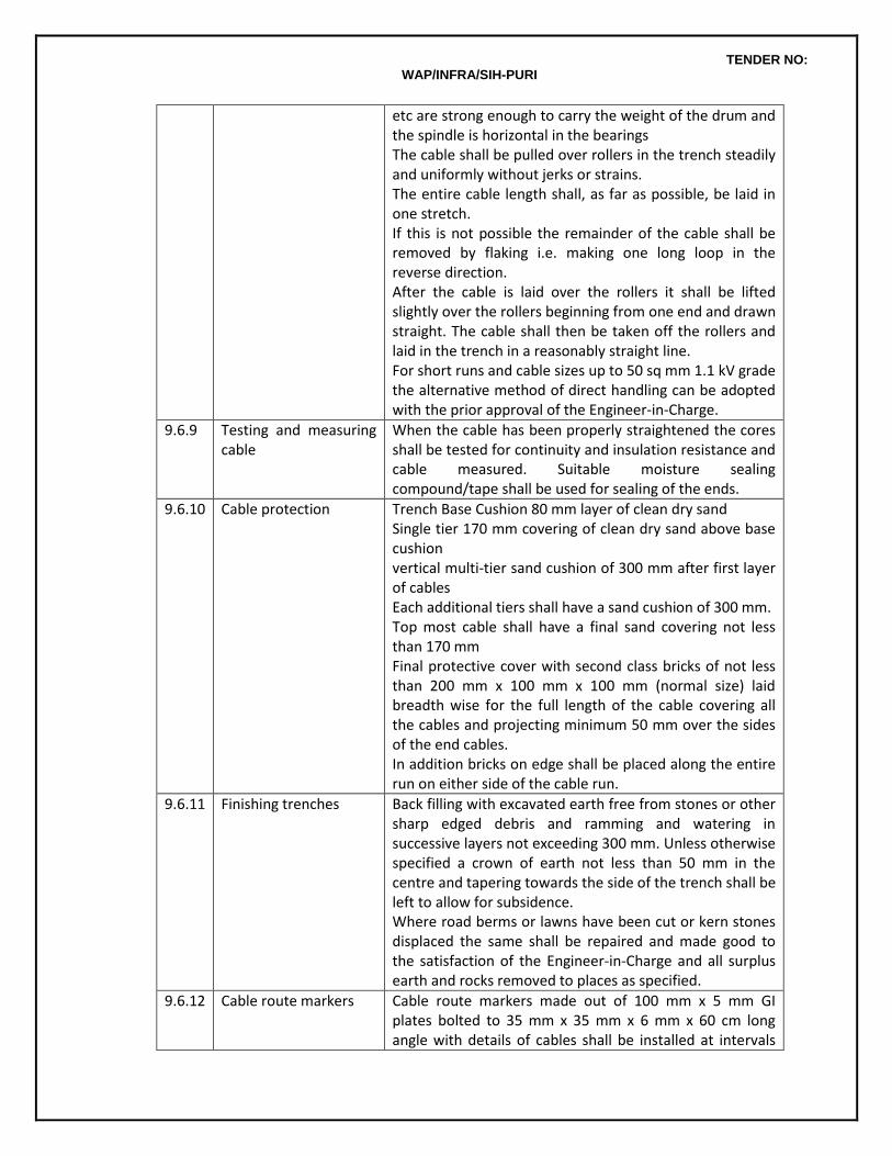
TENDER NO: WAP/INFRA/SIH-PURI
etc are strong enough to carry the weight of the drum and the spindle is horizontal in the bearings The cable shall be pulled over rollers in the trench steadily and uniformly without jerks or strains. The entire cable length shall, as far as possible, be laid in one stretch. If this is not possible the remainder of the cable shall be removed by flaking i.e. making one long loop in the reverse direction. After the cable is laid over the rollers it shall be lifted slightly over the rollers beginning from one end and drawn straight. The cable shall then be taken off the rollers and laid in the trench in a reasonably straight line. For short runs and cable sizes up to 50 sq mm 1.1 kV grade the alternative method of direct handling can be adopted with the prior approval of the Engineer-in-Charge.
9.6.9 Testing and measuring cable
When the cable has been properly straightened the cores shall be tested for continuity and insulation resistance and cable measured. Suitable moisture sealing compound/tape shall be used for sealing of the ends.
9.6.10 Cable protection Trench Base Cushion 80 mm layer of clean dry sand Single tier 170 mm covering of clean dry sand above base cushion vertical multi-tier sand cushion of 300 mm after first layer of cables Each additional tiers shall have a sand cushion of 300 mm. Top most cable shall have a final sand covering not less than 170 mm Final protective cover with second class bricks of not less than 200 mm x 100 mm x 100 mm (normal size) laid breadth wise for the full length of the cable covering all the cables and projecting minimum 50 mm over the sides of the end cables. In addition bricks on edge shall be placed along the entire run on either side of the cable run.
9.6.11 Finishing trenches Back filling with excavated earth free from stones or other sharp edged debris and ramming and watering in successive layers not exceeding 300 mm. Unless otherwise specified a crown of earth not less than 50 mm in the centre and tapering towards the side of the trench shall be left to allow for subsidence. Where road berms or lawns have been cut or kern stones displaced the same shall be repaired and made good to the satisfaction of the Engineer-in-Charge and all surplus earth and rocks removed to places as specified.
9.6.12 Cable route markers Cable route markers made out of 100 mm x 5 mm GI plates bolted to 35 mm x 35 mm x 6 mm x 60 cm long angle with details of cables shall be installed at intervals
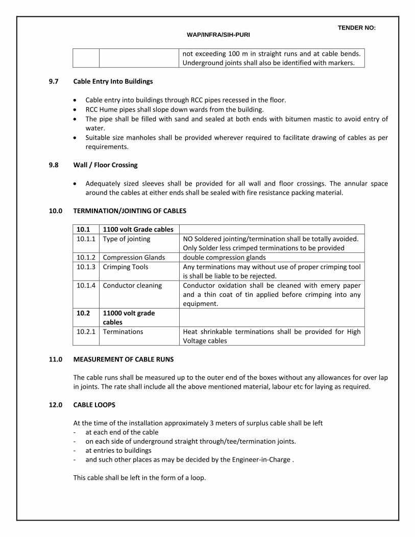
TENDER NO: WAP/INFRA/SIH-PURI
not exceeding 100 m in straight runs and at cable bends. Underground joints shall also be identified with markers.
9.7 Cable Entry Into Buildings
Cable entry into buildings through RCC pipes recessed in the floor.
RCC Hume pipes shall slope down wards from the building.
The pipe shall be filled with sand and sealed at both ends with bitumen mastic to avoid entry of water.
Suitable size manholes shall be provided wherever required to facilitate drawing of cables as per requirements.
9.8 Wall / Floor Crossing
Adequately sized sleeves shall be provided for all wall and floor crossings. The annular space around the cables at either ends shall be sealed with fire resistance packing material.
10.0 TERMINATION/JOINTING OF CABLES
10.1 1100 volt Grade cables
10.1.1 Type of jointing NO Soldered jointing/termination shall be totally avoided. Only Solder less crimped terminations to be provided
10.1.2 Compression Glands double compression glands
10.1.3 Crimping Tools Any terminations may without use of proper crimping tool is shall be liable to be rejected.
10.1.4 Conductor cleaning Conductor oxidation shall be cleaned with emery paper and a thin coat of tin applied before crimping into any equipment.
10.2 11000 volt grade cables
10.2.1 Terminations Heat shrinkable terminations shall be provided for High Voltage cables
11.0 MEASUREMENT OF CABLE RUNS
The cable runs shall be measured up to the outer end of the boxes without any allowances for over lap in joints. The rate shall include all the above mentioned material, labour etc for laying as required.
12.0 CABLE LOOPS At the time of the installation approximately 3 meters of surplus cable shall be left
- at each end of the cable - on each side of underground straight through/tee/termination joints. - at entries to buildings - and such other places as may be decided by the Engineer-in-Charge .
This cable shall be left in the form of a loop.
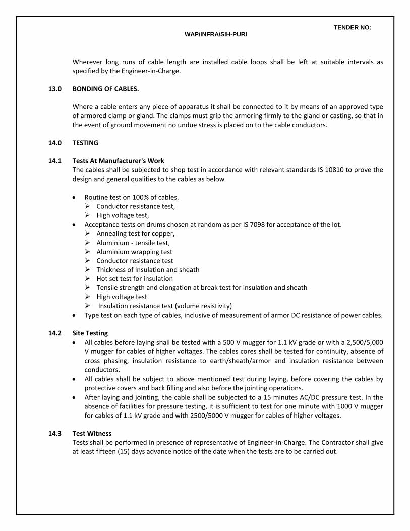
TENDER NO: WAP/INFRA/SIH-PURI
Wherever long runs of cable length are installed cable loops shall be left at suitable intervals as specified by the Engineer-in-Charge.
13.0 BONDING OF CABLES.
Where a cable enters any piece of apparatus it shall be connected to it by means of an approved type of armored clamp or gland. The clamps must grip the armoring firmly to the gland or casting, so that in the event of ground movement no undue stress is placed on to the cable conductors.
14.0 TESTING 14.1 Tests At Manufacturer's Work
The cables shall be subjected to shop test in accordance with relevant standards IS 10810 to prove the design and general qualities to the cables as below
Routine test on 100% of cables. Conductor resistance test, High voltage test,
Acceptance tests on drums chosen at random as per IS 7098 for acceptance of the lot. Annealing test for copper, Aluminium - tensile test, Aluminium wrapping test Conductor resistance test Thickness of insulation and sheath Hot set test for insulation Tensile strength and elongation at break test for insulation and sheath High voltage test Insulation resistance test (volume resistivity)
Type test on each type of cables, inclusive of measurement of armor DC resistance of power cables. 14.2 Site Testing
All cables before laying shall be tested with a 500 V mugger for 1.1 kV grade or with a 2,500/5,000 V mugger for cables of higher voltages. The cables cores shall be tested for continuity, absence of cross phasing, insulation resistance to earth/sheath/armor and insulation resistance between conductors.
All cables shall be subject to above mentioned test during laying, before covering the cables by protective covers and back filling and also before the jointing operations.
After laying and jointing, the cable shall be subjected to a 15 minutes AC/DC pressure test. In the absence of facilities for pressure testing, it is sufficient to test for one minute with 1000 V mugger for cables of 1.1 kV grade and with 2500/5000 V mugger for cables of higher voltages.
14.3 Test Witness
Tests shall be performed in presence of representative of Engineer-in-Charge. The Contractor shall give at least fifteen (15) days advance notice of the date when the tests are to be carried out.
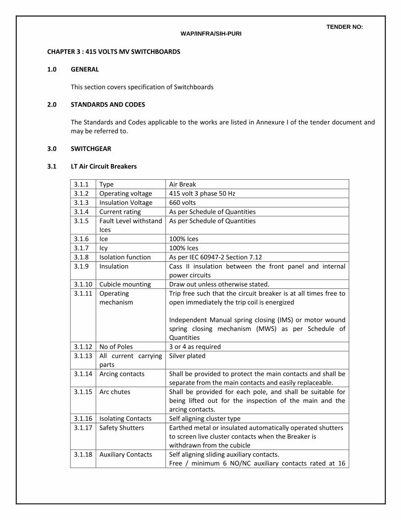
TENDER NO: WAP/INFRA/SIH-PURI
CHAPTER 3 : 415 VOLTS MV SWITCHBOARDS 1.0 GENERAL
This section covers specification of Switchboards
2.0 STANDARDS AND CODES
The Standards and Codes applicable to the works are listed in Annexure I of the tender document and may be referred to.
3.0 SWITCHGEAR 3.1 LT Air Circuit Breakers
3.1.1 Type Air Break
3.1.2 Operating voltage 415 volt 3 phase 50 Hz
3.1.3 Insulation Voltage 660 volts
3.1.4 Current rating As per Schedule of Quantities
3.1.5 Fault Level withstand Ices
As per Schedule of Quantities
3.1.6 Ice 100% Ices
3.1.7 Icy 100% Ices
3.1.8 Isolation function As per IEC 60947-2 Section 7.12
3.1.9 Insulation Cass II insulation between the front panel and internal power circuits
3.1.10 Cubicle mounting Draw out unless otherwise stated.
3.1.11 Operating mechanism
Trip free such that the circuit breaker is at all times free to open immediately the trip coil is energized Independent Manual spring closing (IMS) or motor wound spring closing mechanism (MWS) as per Schedule of Quantities
3.1.12 No of Poles 3 or 4 as required
3.1.13 All current carrying parts
Silver plated
3.1.14 Arcing contacts Shall be provided to protect the main contacts and shall be separate from the main contacts and easily replaceable.
3.1.15 Arc chutes Shall be provided for each pole, and shall be suitable for being lifted out for the inspection of the main and the arcing contacts.
3.1.16 Isolating Contacts Self aligning cluster type
3.1.17 Safety Shutters Earthed metal or insulated automatically operated shutters to screen live cluster contacts when the Breaker is withdrawn from the cubicle
3.1.18 Auxiliary Contacts Self aligning sliding auxiliary contacts. Free / minimum 6 NO/NC auxiliary contacts rated at 16
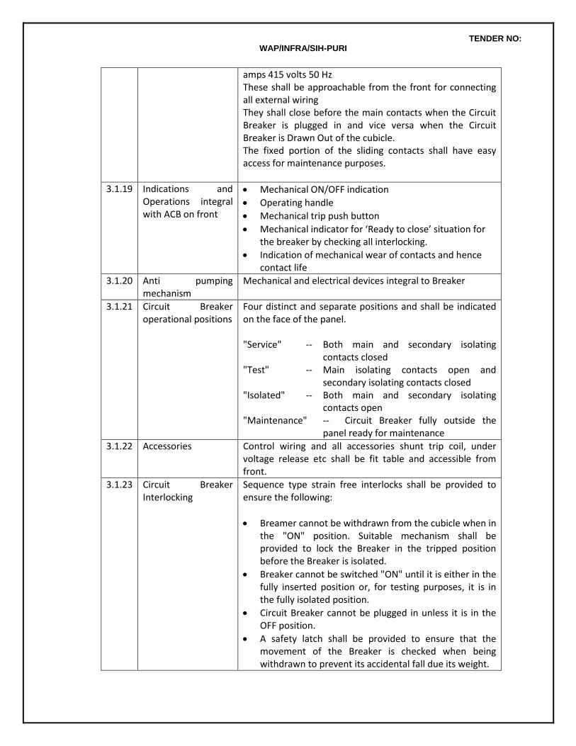
TENDER NO: WAP/INFRA/SIH-PURI
amps 415 volts 50 Hz These shall be approachable from the front for connecting all external wiring They shall close before the main contacts when the Circuit Breaker is plugged in and vice versa when the Circuit Breaker is Drawn Out of the cubicle. The fixed portion of the sliding contacts shall have easy access for maintenance purposes.
3.1.19 Indications and Operations integral with ACB on front
Mechanical ON/OFF indication
Operating handle
Mechanical trip push button
Mechanical indicator for ‘Ready to close’ situation for the breaker by checking all interlocking.
Indication of mechanical wear of contacts and hence contact life
3.1.20 Anti pumping mechanism
Mechanical and electrical devices integral to Breaker
3.1.21 Circuit Breaker operational positions
Four distinct and separate positions and shall be indicated on the face of the panel. "Service" -- Both main and secondary isolating
contacts closed "Test" -- Main isolating contacts open and
secondary isolating contacts closed "Isolated" -- Both main and secondary isolating
contacts open "Maintenance" -- Circuit Breaker fully outside the
panel ready for maintenance
3.1.22 Accessories Control wiring and all accessories shunt trip coil, under voltage release etc shall be fit table and accessible from front.
3.1.23 Circuit Breaker Interlocking
Sequence type strain free interlocks shall be provided to ensure the following:
Breamer cannot be withdrawn from the cubicle when in the "ON" position. Suitable mechanism shall be provided to lock the Breaker in the tripped position before the Breaker is isolated.
Breaker cannot be switched "ON" until it is either in the fully inserted position or, for testing purposes, it is in the fully isolated position.
Circuit Breaker cannot be plugged in unless it is in the OFF position.
A safety latch shall be provided to ensure that the movement of the Breaker is checked when being withdrawn to prevent its accidental fall due its weight.
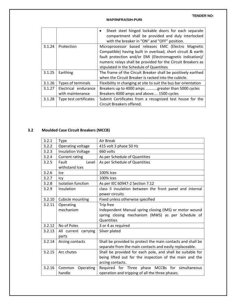
TENDER NO: WAP/INFRA/SIH-PURI
Sheet steel hinged lockable doors for each separate compartment shall be provided and duly interlocked with the breaker in "ON" and "OFF" position.
3.1.24 Protection Microprocessor based releases EMC (Electro Magnetic Compatible) having built in overload, short circuit & earth fault protection and/or EMI (Electromagnetic indication)/ numeric relays shall be provided for the Circuit Breakers as stipulated in the Schedule of Quantities
3.1.25 Earthing The frame of the Circuit Breaker shall be positively earthed when the Circuit Breaker is racked into the cubicle.
3.1.26 Types of terminals Flexibility in changing at site to suit the bus bar orientation
3.1.27 Electrical endurance with maintenance
Breakers up to 4000 amps …………greater than 5000 cycles Breakers 4000 amps and above.... 1500 cycles
3.1.28 Type test certificates Submit Certificates from a recognized test house for the Circuit Breakers offered.
3.2 Moulded Case Circuit Breakers (MCCB)
3.2.1 Type Air Break
3.2.2 Operating voltage 415 volt 3 phase 50 Hz
3.2.3 Insulation Voltage 660 volts
3.2.4 Current rating As per Schedule of Quantities
3.2.5 Fault Level withstand Ices
As per Schedule of Quantities
3.2.6 Ice 100% Ices
3.2.7 Icy 100% Ices
3.2.8 Isolation function As per IEC 60947-2 Section 7.12
3.2.9 Insulation class II insulation between the front panel and internal power circuits
3.2.10 Cubicle mounting Fixed unless otherwise specified
3.2.11 Operating mechanism
Trip free Independent Manual spring closing (IMS) or motor wound spring closing mechanism (MWS) as per Schedule of Quantities
3.2.12 No of Poles 3 or 4 as required
3.2.13 All current carrying parts
Silver plated
3.2.14 Arcing contacts Shall be provided to protect the main contacts and shall be separate from the main contacts and easily replaceable.
3.2.15 Arc chutes Shall be provided for each pole, and shall be suitable for being lifted out for the inspection of the main and the arcing contacts.
3.2.16 Common Operating handle
Required for Three phase MCCBs for simultaneous operation and tripping of all the three phases.
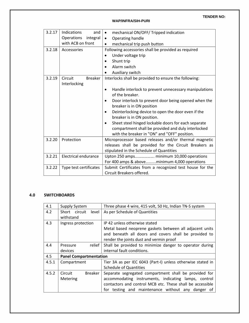
TENDER NO: WAP/INFRA/SIH-PURI
3.2.17 Indications and Operations integral with ACB on front
mechanical ON/OFF/ Tripped indication
Operating handle
mechanical trip push button
3.2.18 Accessories Following accessories shall be provided as required
Under voltage trip
Shunt trip
Alarm switch
Auxiliary switch
3.2.19 Circuit Breaker Interlocking
Interlocks shall be provided to ensure the following:
Handle interlock to prevent unnecessary manipulations of the breaker.
Door interlock to prevent door being opened when the breaker is in ON position
Deinterlocking device to open the door even if the breaker is in ON position.
Sheet steel hinged lockable doors for each separate compartment shall be provided and duly interlocked with the breaker in "ON" and "OFF" position.
3.2.20 Protection Microprocessor based releases and/or thermal magnetic releases shall be provided for the Circuit Breakers as stipulated in the Schedule of Quantities
3.2.21 Electrical endurance Upton 250 amps………………. minimum 10,000 operations For 400 amps & above……….minimum 4,000 operations
3.2.22 Type test certificates Submit Certificates from a recognized test house for the Circuit Breakers offered.
4.0 SWITCHBOARDS
4.1 Supply System Three phase 4 wire, 415 volt, 50 Hz, Indian TN-S system
4.2 Short circuit level withstand
As per Schedule of Quantities
4.3 Ingress protection IP 42 unless otherwise stated Metal based neoprene gaskets between all adjacent units and beneath all doors and covers shall be provided to render the joints dust and vermin proof
4.4 Pressure relief devices
Shall be provided to minimize danger to operator during internal fault conditions.
4.5 Panel Compartmentation
4.5.1 Compartment Tier 3A as per IEC 6043 (Part-I) unless otherwise stated in Schedule of Quantities
4.5.2 Circuit Breaker Metering
Separate segregated compartment shall be provided for accommodating instruments, indicating lamps, control contactors and control MCB etc. These shall be accessible for testing and maintenance without any danger of
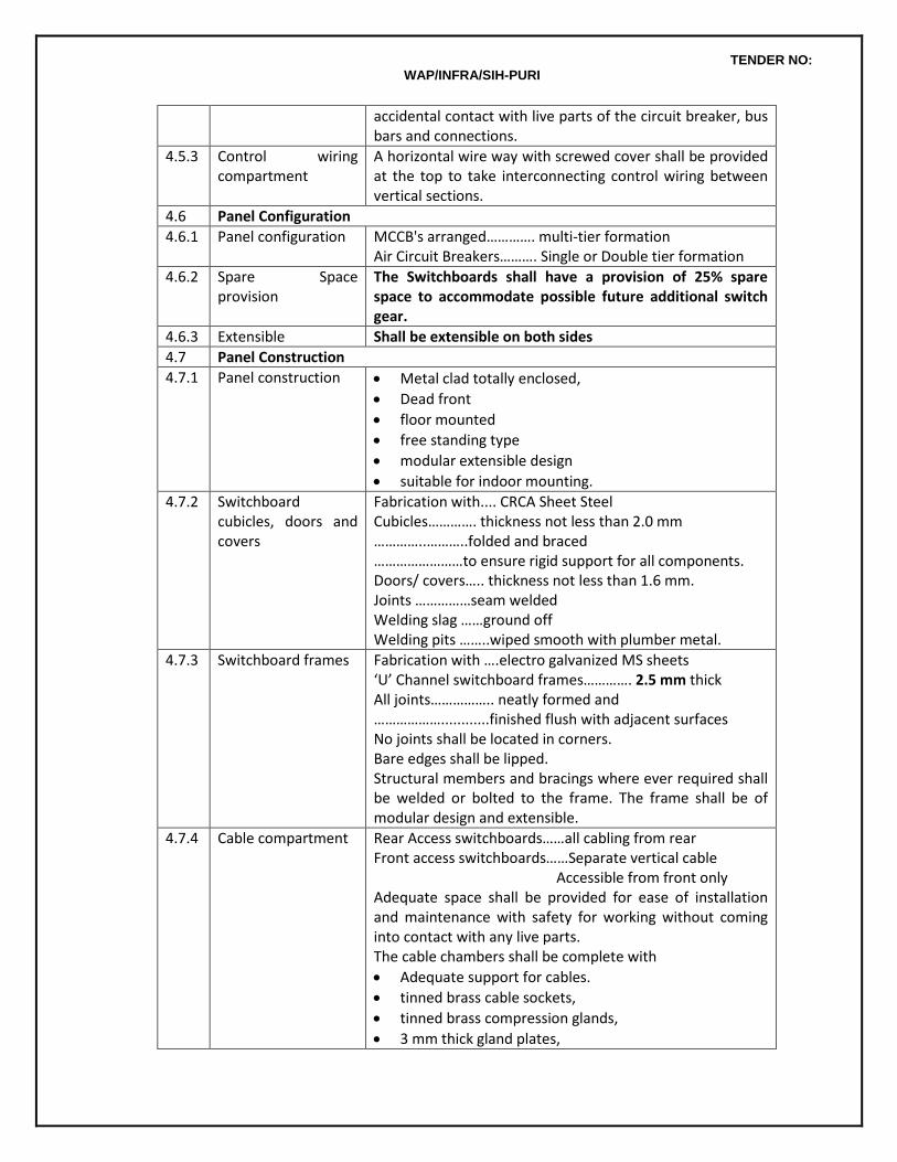
TENDER NO: WAP/INFRA/SIH-PURI
accidental contact with live parts of the circuit breaker, bus bars and connections.
4.5.3 Control wiring compartment
A horizontal wire way with screwed cover shall be provided at the top to take interconnecting control wiring between vertical sections.
4.6 Panel Configuration
4.6.1 Panel configuration MCCB's arranged…………. multi-tier formation Air Circuit Breakers………. Single or Double tier formation
4.6.2 Spare Space provision
The Switchboards shall have a provision of 25% spare space to accommodate possible future additional switch gear.
4.6.3 Extensible Shall be extensible on both sides
4.7 Panel Construction
4.7.1 Panel construction Metal clad totally enclosed,
Dead front
floor mounted
free standing type
modular extensible design
suitable for indoor mounting.
4.7.2 Switchboard cubicles, doors and covers
Fabrication with.... CRCA Sheet Steel Cubicles…………. thickness not less than 2.0 mm …………..………..folded and braced ……………………to ensure rigid support for all components. Doors/ covers….. thickness not less than 1.6 mm. Joints ……………seam welded Welding slag ……ground off Welding pits ……..wiped smooth with plumber metal.
4.7.3 Switchboard frames Fabrication with ….electro galvanized MS sheets ‘U’ Channel switchboard frames…………. 2.5 mm thick All joints…………….. neatly formed and ………………............finished flush with adjacent surfaces No joints shall be located in corners. Bare edges shall be lipped. Structural members and bracings where ever required shall be welded or bolted to the frame. The frame shall be of modular design and extensible.
4.7.4 Cable compartment Rear Access switchboards……all cabling from rear Front access switchboards……Separate vertical cable Accessible from front only Adequate space shall be provided for ease of installation and maintenance with safety for working without coming into contact with any live parts. The cable chambers shall be complete with
Adequate support for cables.
tinned brass cable sockets,
tinned brass compression glands,
3 mm thick gland plates,
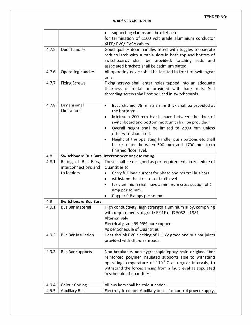
TENDER NO: WAP/INFRA/SIH-PURI
supporting clamps and brackets etc for termination of 1100 volt grade aluminium conductor XLPE/ PVC/ PVCA cables.
4.7.5 Door handles Good quality door handles fitted with toggles to operate rods to latch with suitable slots in both top and bottom of switchboards shall be provided. Latching rods and associated brackets shall be cadmium plated.
4.7.6 Operating handles All operating device shall be located in front of switchgear only.
4.7.7 Fixing Screws Fixing screws shall enter holes tapped into an adequate thickness of metal or provided with hank nuts. Self threading screws shall not be used in switchboards.
4.7.8 Dimensional Limitations
Base channel 75 mm x 5 mm thick shall be provided at the bottohm.
Minimum 200 mm blank space between the floor of switchboard and bottom most unit shall be provided.
Overall height shall be limited to 2300 mm unless otherwise stipulated.
Height of the operating handle, push buttons etc shall be restricted between 300 mm and 1700 mm from finished floor level.
4.8 Switchboard Bus Bars, Interconnections etc rating
4.8.1 Rating of Bus Bars, interconnections and to feeders
These shall be designed as per requirements in Schedule of Quantities to
Carry full load current for phase and neutral bus bars
withstand the stresses of fault level
for aluminium shall have a minimum cross section of 1 amp per sq.mm.
Copper 0.6 amps per sq mm
4.9 Switchboard Bus Bars
4.9.1 Bus Bar material High conductivity, high strength aluminium alloy, complying with requirements of grade E 91E of IS 5082 – 1981 Alternatively Electrical grade 99.99% pure copper As per Schedule of Quantities
4.9.2 Bus Bar Insulation Heat shrunk PVC sleeking of 1.1 kV grade and bus bar joints provided with clip-on shrouds.
4.9.3 Bus Bar supports Non-breakable, non-hygroscopic epoxy resin or glass fiber reinforced polymer insulated supports able to withstand operating temperature of 110O C at regular intervals, to withstand the forces arising from a fault level as stipulated in schedule of quantities.
4.9.4 Colour Coding All bus bars shall be colour coded.
4.9.5 Auxiliary Bus Electrolytic copper Auxiliary buses for control power supply,
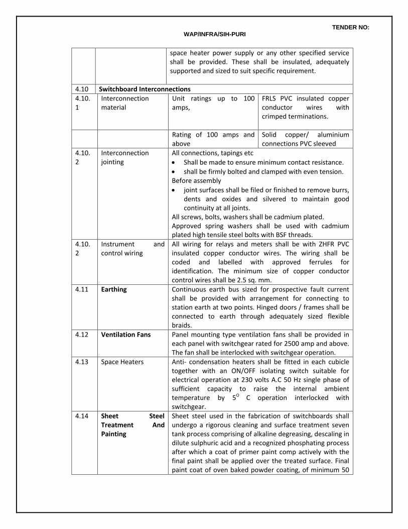
TENDER NO: WAP/INFRA/SIH-PURI
space heater power supply or any other specified service shall be provided. These shall be insulated, adequately supported and sized to suit specific requirement.
4.10 Switchboard Interconnections
4.10.1
Interconnection material
Unit ratings up to 100 amps,
FRLS PVC insulated copper conductor wires with crimped terminations.
Rating of 100 amps and above
Solid copper/ aluminium connections PVC sleeved
4.10.2
Interconnection jointing
All connections, tapings etc
Shall be made to ensure minimum contact resistance.
shall be firmly bolted and clamped with even tension. Before assembly
joint surfaces shall be filed or finished to remove burrs, dents and oxides and silvered to maintain good continuity at all joints.
All screws, bolts, washers shall be cadmium plated. Approved spring washers shall be used with cadmium plated high tensile steel bolts with BSF threads.
4.10.2
Instrument and control wiring
All wiring for relays and meters shall be with ZHFR PVC insulated copper conductor wires. The wiring shall be coded and labelled with approved ferrules for identification. The minimum size of copper conductor control wires shall be 2.5 sq. mm.
4.11 Earthing
Continuous earth bus sized for prospective fault current shall be provided with arrangement for connecting to station earth at two points. Hinged doors / frames shall be connected to earth through adequately sized flexible braids.
4.12 Ventilation Fans
Panel mounting type ventilation fans shall be provided in each panel with switchgear rated for 2500 amp and above. The fan shall be interlocked with switchgear operation.
4.13 Space Heaters Anti- condensation heaters shall be fitted in each cubicle together with an ON/OFF isolating switch suitable for electrical operation at 230 volts A.C 50 Hz single phase of sufficient capacity to raise the internal ambient temperature by 5O C operation interlocked with switchgear.
4.14 Sheet Steel Treatment And Painting
Sheet steel used in the fabrication of switchboards shall undergo a rigorous cleaning and surface treatment seven tank process comprising of alkaline degreasing, descaling in dilute sulphuric acid and a recognized phosphating process after which a coat of primer paint comp actively with the final paint shall be applied over the treated surface. Final paint coat of oven baked powder coating, of minimum 50
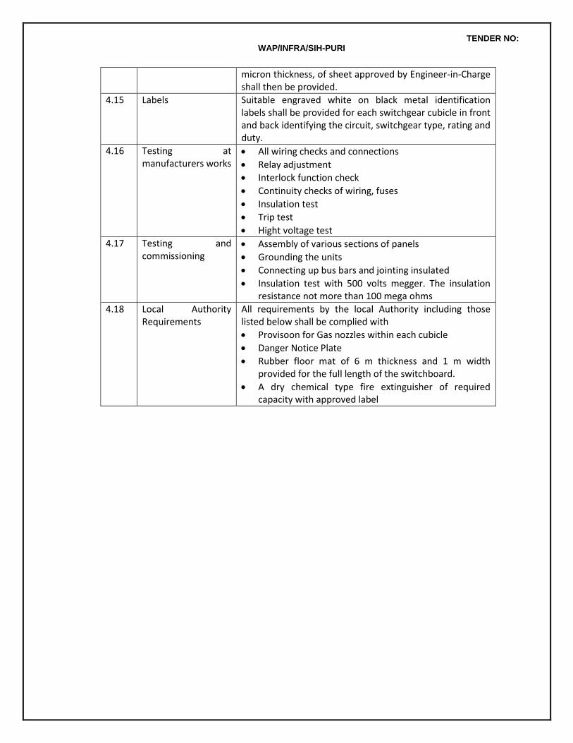
TENDER NO: WAP/INFRA/SIH-PURI
micron thickness, of sheet approved by Engineer-in-Charge shall then be provided.
4.15 Labels Suitable engraved white on black metal identification labels shall be provided for each switchgear cubicle in front and back identifying the circuit, switchgear type, rating and duty.
4.16 Testing at manufacturers works
All wiring checks and connections
Relay adjustment
Interlock function check
Continuity checks of wiring, fuses
Insulation test
Trip test
Hight voltage test 4.17 Testing and
commissioning Assembly of various sections of panels
Grounding the units
Connecting up bus bars and jointing insulated
Insulation test with 500 volts megger. The insulation resistance not more than 100 mega ohms
4.18 Local Authority Requirements
All requirements by the local Authority including those listed below shall be complied with
Provisoon for Gas nozzles within each cubicle
Danger Notice Plate
Rubber floor mat of 6 m thickness and 1 m width provided for the full length of the switchboard.
A dry chemical type fire extinguisher of required capacity with approved label
TENDER NO: WAP/INFRA/SIH-PURI
CHAPTER 4 : 11 kV SWITCHBOARDS 1. GENERAL
The technical specifications cover the equipment to be supplied for a 11 kV (12 kV basic insulation level) Switchboards suitable for 11 kV 3 phase earthed system (transformer neutral solidly earthed). 50 HZ AC supply with a fault level of 350 MVA at 11kV. The equipment shall be suitable for continuous operation in the stipulated ambient conditions.
2. STANDARDS AND CODES
Updated and current Indian Standard Specifications and Codes of Practice will apply to the equipment and the work covered by the scope of this contract. In addition the relevant clauses of the Indian Electricity Act 2003, Indian Electricity Rules 1956, National Building Code 1994, National Electric Code 1985, Code of Practice for Fire Safety of Building (general): General Principal and Fire Grading – IS 1641 - 1988 as amended up to date shall also apply. Wherever appropriate Indian Standards are not available, relevant British and/or IEC Standards shall be applicable. 11000 volt Circuit Breaker IS 13118; 1991 Metal Enclosed Switchgear and Controlgear for voltages above 1000 volts IS 3427 : 1969 Electrical Relays for Power System Protection IS 3231 : 1986 Voltage Transformers IS 3156: 1978 Current Transformers IS 2705 : 1981 Rubber Mats for Electrical Works IS 5424 : 1983 Danger Notice Plate IS 2551 : 1982 AC isolators and earthing switches IEC 129 AC metal enclosed Switchgear IEC 298 HT AC contactors
TENDER NO: WAP/INFRA/SIH-PURI
IEC 470
3. 11000 VOLT CIRCUIT BREAKERS & Switchboard Panels
11 kV Circuit Breaker / Switchboard shall be suitable for insulation voltage of 12kv rms and for operation at 11000 volt 3 phase 50 Hz supply system with a short circuit withstand of 350 MVA at 11,000 volts and a corresponding short time rating of 18.5 kA for 1 second unless otherwise stated. The equipment shall have one minute power frequency withstand voltage 28 kv rms and impulse withstand voltage of 75 kv peak. The Circuit breaker/ switchboard shall be suitable for transformer neutral being solidly earthed.
Circuit breakers shall be triple pole single throw SF6/Vacuum type.
Proper device to monitor gas pressure shall be provided in SF6 breakers. The device shall be two position type for alarm and isolation in the event of loss of pressure. Breakers shall be able to break rated load current under complete loss of pressure.
Vacuum circuit breakers shall be provided with suitable surge protection devices to restrict rate of rise of restriping voltage.
Circuit breakers of identical rating shall be completely interchangeable.
Circuit breakers shall be provided with protective relays, meters, indicating instruments with associated current and potential transformers as per schedule of quantities and schematic drawing.
Circuit breakers shall be provided with motor wound spring charged trip free mechanism with anti pumping feature and shunt trip. In addition facility for manual charging of spring shall also be available. One open-close-open operation of the breaker shall be possible after loss of supply to the motor.
Each breaker shall be provided with:
Shrouded manual emergency trip push button,
ON/OFF indication,
Operation counter
Spring charged/discharged indicator.
The following minimum interlocks shall be provided for: Breaker cannot be racked from one position to the other in close position. Breaker cannot operated in any intermediate position.
TENDER NO: WAP/INFRA/SIH-PURI
Breaker cannot be opened or closed with compartment fro m door open With selector switch in “local” position breaker can only be operated in “test” position. For
operation in “service” position, control must be from “remote”
The following minimum indication lamps shall be provided in the front of the cubicle. Lamps shall be clustered LED type and trip circuit supervision scheme shall be of continuous supervision type. Breaker Open/ Closed/Tripped. SF6 pressure low. Spring charged trip circuit healthy Control supply healthy. .
After meeting all necessary control and indication requirements 2 nose NO and 2 nose NC auxiliary contacts of the breaker shall be made available for the Owner, wired up to terminal block.
Circuit breakers shall be housed in flush front, metal clad, truck mounted, draw out type truck and shall be fully interlocked. The truck that carries the Circuit Breaker shall be of rigid fabricated construction. Each Circuit Breaker shall be housed in a separate compartment enclosed on all sides. Each withdraw able truck shall have its own Circuit Breaker. The draw out mechanism shall be so designed and constructed as to permit smooth withdrawal and insertion. The movement shall be free of jerks, easy to operate and positive.
All current carrying parts in the Circuit Breaker shall be silver plated.
Circuit breaker operating mechanism shall provide 2distinct and separate positions of the circuit breakers on the cradle
Service Test
4. 11 KV SWITCHBOARD
Switchboard shall be totally enclosed, metal clad, cubicle pattern, floor mounting, extensible on both sides and suitable for indoor use. The Switchboard ( Form 3A ) assembly shall form a continuous dead front line up of free standing vertical cubical. Each cubical shall have lockable hinged door and removable bolted back cover. Each cubical shall be provided with lifting arrangement.
Switchboard shall be totally enclosed and completely dust and vermin proof with IP 4X protection. Neoprene gaskets between all adjacent units and beneath all covers shall be provided to render the joints dust and vermin proof. All doors and covers shall also be fully casketed.
Sheet steel barriers shall be provided between

TENDER NO: WAP/INFRA/SIH-PURI
Instrument Panel and Potential Transformer Instrument Panel and Current Transformers Bulbar chamber and Circuit Breaker compartments
The switchboard bus bars shall be made of high strength, high conductivity aluminium alloy with maximum temperature rise limited to thermal limits of connected equipment, via cables etc.. Bus bar chamber shall be provided with inter panel barriers with epoxy cast seal off bushings
All spare contacts of breaker, relays switches etc shall be wired up to terminal blocks. Wiring shall be done with flexible, 1100 volts grade PVC insulated cables minimum size 1.5mm2 for all potential circuits and 2.5 mm2 for CT circuits. Each wire shall be identified at both ends with permanently marked ferrules. All wire termination’s shall be made with crimped connectors having insulating sleeves. Not more than 2 wires shall be connected to any terminal. Spare terminals equal to at least 20% of active terminals shall be provided in each terminal block. Terminals will also need to be segregated circuit wise and voltage wise
Switchboards shall be suitable for cable entry from top or bottom as specified. Power and control cabling shall be completely segregated. Suitable space for termination/maintenance shall be provided in the cable compartment. Suitable working space between gland plate and power cable box shall be provided for and also for mounting core balance CTs if required. Gland plates shall be of non magnetic material for single core cables.
A ground bus rated for same short circuit level as the system shall be provided along the full length of the switchgear. Ground bus shall be of GI and bolted studs should be provided at each end of the switchboard to permit connection of flat/cable. All instrument transformer neutrals shall be connected to the ground bus thro ugh removable links. All removable/hinged doors and covers shall be grounded by flexible stranded connectors.
5. TEST AT MANUFACTURERS WORKS
Copies of type tests and of routine tests carried out at manufacturer’s works shall be furnished along with the delivery of the switchboards. Architects/Owners reserves the right to get the switchboard inspected by their representative at manufacturer’s works prior to dispatch to site to witness the routine tests, for which purpose the contractor shall provide the necessary facilities and also give due notice.
6. TESTS AT SITE
Pre-commissioning tests as per manufacturers recommendations shall be carried out on the switchboard a site after installation including but not restricted to the following.
Physical checking of the switchboard including checking for damage or cracks in components, bolt tightness, gasket ting etc.
Checking of vacuum bottles to ensure leak tightness
Insulation testing of Bus bar supports by 2.5 kV mugger
TENDER NO: WAP/INFRA/SIH-PURI
Insulation testing of Control wiring by 1.1 kV mugger.
Testing of relays and CTs with secondary injection kit.
Checking of breaker operation.
Checking of earth continuity.
High potential test / Pressure testing
TENDER NO: WAP/INFRA/SIH-PURI
CHAPTER 5 : RELAYS, CTs, PTs, METERS, INDICATING LAMPS ETC. 1.0 GENERAL
This section covers specifications for Protection and Control Relays for breakers, Instrument Transformers, Measuring Instruments, Push Buttons, Indicating Lamps etc. required in LT and HT switchboards.
2.0 STANDARDS AND CODES
Updated and current Indian Standard Specifications and Codes of Practice will apply to the equipment and the work covered by the scope of this contract. In addition the relevant clauses of the Indian Electricity Act 1910, Indian Electricity Rules 1956, National Building Code 1994, National Electric Code 1985, Code of Practice for Fire Safety of Building (general) :General Principal and Fire Grading – IS 1641 as amended up to date shall also apply. Wherever appropriate Indian Standards are not available, relevant British and/or IEC Standards shall be applicable. Application guide for Current Transformers IS 4201 : Application guide for Voltage Transformers IS 4140 : Application guide for Relays IS 3842 : Electromagnetic Relays IS 5051 :
3.0 PROTECTION AND CONTROL RELAYS
The Circuit Breaker shall have protection and control relays as specified in the bill of quantities. Relays shall be approved types complying to relevant ISS and having approved characteristic. Relays shall be flush mounted in dust proof cases. Relays shall be arranged so that adjustments, testing and replacement can be affected with minimum of time and labour. Incase of C.T. operated thermal overload and magnetic instantaneous short circuit release. The overload releases shall be such that each phase can be individually set depending on the phase unbalanced currents. The releases shall have inverse time current characteristics and the magnetic release shall be time delayed with a minimum setting of 25 ms varying up to 300 ms for discrimination without effecting the breaking current capacity of the ACB.
4.0 CURRENT TRANSFORMERS Separate sets of CTs shall be provided for metering and protection. C/Ts shall confirm to IS 2705 (part -
I, II and III) in all respects. All C/Ts used for medium voltage application shall be rated for 1 kV. C/Ts shall have rated primary current, rated burden and class of accuracy as specified in Bill of Quantities/drawings. Rated secondary current shall be 5A unless otherwise stated. Minimum acceptable class for measurement shall be class 0.5 to 1 and for protection class SP 10. C/Ts shall be capable of withstanding magnetic and thermal stresses due to short circuit faults of 31 MVA on medium voltage. Terminals of C/Ts shall be paired permanently for easy identification of poles. C/Ts shall be provided with earthing terminals for earthing chassis, frame work and fixed part of metal casing (if any). Each C/T shall be provided with rating plate indicating :
TENDER NO: WAP/INFRA/SIH-PURI
Name and make
Serial number
Transformation ratio
Rated burden
Rated voltage
Accuracy class CTs shall be mounded such that they are easily accessible for inspection, maintenance and
replacement. Wiring for CT shall be with copper conductor FRLS PVC insulated wires with proper termination works and wiring shall be bunched with cable straps and fixed to the panel structure in a neat manner.
5.0 POTENTIAL TRANSFORMER PTs shall confirm to IS 3156 (Part-I, II and III) in all respects. 6.0 MEASURING INSTRUMENTS Direct reading electrical instruments shall conform to IS 1248 or in all respects. Accuracy of direct
reading shall be 1.0 of voltmeter and 1.5 for ammeters. Other instruments shall have accuracy of 1.5. Meters shall be suitable for continuous operation between -10o C and +500C. Meters shall be flush mounting and shall be enclosed in dust tight housing. The housing shall be of steel or phenolic mould. Design and manufacture of meters shall ensure prevention of fogging of instrument glass. Pointer shall be black in colour and shall have Zero position adjustment device operable from out side. Direction of deflection shall be from left to right. Suitable selector switches shall be provided for ammeters and volt meters used in three phase system. The rating type and quantity of meters, instruments and protective device shall be as per Bill of Quantities /drawings
6.1 Ammeters Ammeters shall be of moving iron type. Moving part assembly shall be with jewel bearings. Jewel
bearings shall be mounted on a spring to prevent damage to pivot due to vibrations and shocks. Ammeters shall be manufacture and calibrated as per IS 1248
Ammeters shall normally be suitable for 5 A secondary of current transformers. Ammeters shall be capable of carrying substantial over loads during fault conditions. 6.2 Voltmeters Voltmeters shall be moving iron type range of 3 phase 415 volt voltmeters shall be 0-500. Volt meters
shall be provided with protection fuse. 6.3 Watt meter
TENDER NO: WAP/INFRA/SIH-PURI
Wattmeter shall be of 3 phase electro dynamic type and shall be provided with a maximum demand indicator if required.
6.4 Power factor meters 3 phase power factor meters shall be of electro dynamic type with current and potential coils suitable
for operation with current and potential transformers provided in the panel. Scale shall be calibrated for 50% lag - 100% - 50% readings. Phase angle accuracy shall be +40.
6.5 Energy and reactive power meters Trajectory meters shall be two element, integrating type, KWH, KVA, KVARH meters. Meters shall
confirm to IEC 170 in all respects. Energy meters, KVA, and KVARH meters shall be provided with integrating registers. The registers shall be able to record energy conception of 500 hours corresponding to maximum current at rated voltage and unity power factor. Meters shall be suitable for operation with current and potential transformers available in the panel.
7.0 INDICATING LAMPS
Neon type indicating lamps shall be provided for indication of phases and Breaker position as required in the bill of quantities. Lamps shall be easily removed and replaced from the front of the panel by manual means not requiring the use of extractors.
8.0 PUSH BUTTONS Push buttons shall be of non hygroscopic material, non-swelling and fitted to avoid any possibility of sticking. Contacts shall be of adequate strength and have a positive whipping action when in operation
TENDER NO: WAP/INFRA/SIH-PURI
CHAPTER 6 : BATTERY AND BATTERY CHARGER 1.0 GENERAL
This section covers specifications for lead acid batteries and float cum boost battery chargers. DC is considered as unearthed system.
2.0 STANDARDS AND CODES
Updated and current Indian Standard Specifications and Codes of Practice will apply to the equipment and the work covered by the scope of this contract. In addition the relevant clauses of the Indian Electricity Act 2003, Indian Electricity Rules 1956, National Building Code 1994, National Electric Code 1985, Code of Practice for Fire Safety of Building (general) :General Principal and Fire Grading – IS 1641 as amended up to date shall also apply. Wherever appropriate Indian Standards are not available, relevant British and/or IEC Standards shall be applicable. Electrical vocabulary secondary cells and batteries IS 1885 Lead Acid SMF VRLA Batteries JIS C8702 Water for storage batteries IS 1069 Sulfuric Acid for storage batteries IS 266 General requirements for tests for lead acid storage batteries IS 8320 Rubber and Plastic containers for batteries IS 1146 Synthetic Separators IS 6071 High performance planet cells BS 6290 (Part II) IE recommendations for sizing of large lead acid storage batteries IEEE 485 Design and installation of storage batteries IEEE 484 Stationary lead acid batteries IEC – 896 (Part I)
3.0 BATTERY
The battery shall be sealed maintenance free / valve regulated led acid (SMF/VRLA) battery. The batteries shall be manufactured using “absorbent glass matt” technology in which the electrolyte is in absorb condition, held within the pores of the glass matt separator. The separator is packed tightly between the positive and negative plates. “Led Calcium Tin Alloy” shall be used in the plate grid structure to eliminate harmful effect of early gassing. The container and the lid of the battery shall be of high grade polypropylene. The vent plugs shall be provided with self resealing relief valves. The battery shall be rated for minimum 100 AH at 30 volt DC unearthed system. The battery sizing calculation to be carried out by vendor during detailed engineering stage and to be submitted to Electrical consultant for verification and approval.
4.0 BATTERY CHARGERS 4.1 General
The battery charger shall be float cum boost type, thermistors controlled. The charger shall have selector switch for auto float – boost/manual, float /manual boost mode of operation. during auto float
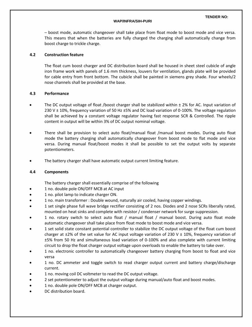
TENDER NO: WAP/INFRA/SIH-PURI
– boost mode, automatic changeover shall take place from float mode to boost mode and vice versa. This means that when the batteries are fully charged the charging shall automatically change from boost charge to trickle charge.
4.2 Construction feature
The float cum boost charger and DC distribution board shall be housed in sheet steel cubicle of angle iron frame work with panels of 1.6 mm thickness, louvers for ventilation, glands plate will be provided for cable entry from front bottom. The cubicle shall be painted in siemens grey shade. Four wheels/2 nose channels shall be provided at the base.
4.3 Performance
The DC output voltage of float /boost charger shall be stabilized within ± 2% for AC. Input variation of 230 V ± 10%, frequency variation of 50 Hz ±5% and DC load variation of 0-100%. The voltage regulation shall be achieved by a constant voltage regulator having fast response SCR & Controlled. The ripple content in output will be within 3% of DC output nominal voltage.
There shall be provision to select auto float/manual float /manual boost modes. During auto float mode the battery charging shall automatically changeover from boost mode to flat mode and vice versa. During manual float/boost modes it shall be possible to set the output volts by separate potentiometers.
The battery charger shall have automatic output current limiting feature. 4.4 Components The battery charger shall essentially comprise of the following
1 no. double pole ON/OFF MCB at AC input
1 no. pilot lamp to indicate charger ON.
1 no. main transformer : Double wound, naturally air cooled, having copper windings.
1 set single phase full wave bridge rectifier consisting of 2 nos. Diodes and 2 nose SCRs liberally rated, mounted on heat sinks and complete with resistor / condenser network for surge suppression.
1 no. rotary switch to select auto float / manual float / manual boost. During auto float mode automatic changeover shall take place from float mode to boost mode and vice versa.
1 set solid state constant potential controller to stabilize the DC output voltage of the float cum boost charger at ±2% of the set value for AC input voltage variation of 230 V ± 10%, frequency variation of ±5% from 50 Hz and simultaneous load variation of 0-100% and also complete with current limiting circuit to drop the float charger output voltage upon overloads to enable the battery to take over.
1 no. electronic controller to automatically changeover battery charging from boost to float and vice versa
1 no. DC ammeter and toggle switch to read charger output current and battery charge/discharge current.
1 no. moving coil DC voltmeter to read the DC output voltage.
2 set potentiometer to adjust the output voltage during manual/auto float and boost modes.
1 no. double pole ON/OFF MCB at charger output.
DC distribution board.
TENDER NO: WAP/INFRA/SIH-PURI
Alarm annunciation Visual and audible alarm with manual accept/ reset facility shall be provided for the following - AC mains fail - Charger fail - Load / output over volt
Potential free contact for BMS connectivity for maintaining battery status.

TENDER NO: WAP/INFRA/SIH-PURI
CHAPTER 7 : EARTHING 1.0 GENERAL This section covers specifications for earthing systems comprising of earth electrodes, earth leads and
loop earthing conductors. 2.0 STANDARDS
The Standards and Codes applicable to the works are listed in Annexure I of the tender document and may be referred to.
3.0 EARTHING NETWORK
3.1 EARTH NETWORK PARAMETERS
3.1.1 General Guidelines
All the non-current carrying metal parts of electrical installations including metal conduits, turnings, cable armour, switchboards, DB’s, light fittings and all other non current carrying parts made of metal shall be bonded together and connected by means of specified earthing conductors to an efficient earthing system.
3.1.2 Earthing Material
The earthing system shall be constructed from bare or insulated GI, Aluminium or Copper as specified in the Schedule of Quantities.
3.1.3 Ecarts vis-à-vis phases
All three phase equipment shall have two separate and independent distinct body earths and single phase equipment shall have a single body earth.
3.2 EARTH ELECTRODES
3.2.1 Guidelines for earth electrodes location
Minimum distances
Any electrode and building structure shall be 1.5 m.
Two adjacent electrodes shall be 2 m.
As far as possible earth connections shall be visible for inspections
Drawing showing the main earth connection and earth electrodes be prepared for each installation.
Electrodes shall be located in accessible locations and not under entrances, pavements and roads.
3.2.2 Plate Earth Electrodes
3.2.2.1 Material Copper or GI as per Schedule of Quantities
3.2.2.2 Plate size Plate size shall be based on fault level as per IS 3043 but shall be minimum Copper………Minimum 600 mm x 600 mm x 3 mm thick GI…………….Minimum 600 mm x 600 mm x 6 mm thick
3.2.2.3 Earth Pit Plate electrode shall be buried in ground with its face vertical depth from GL to top plate 3 m
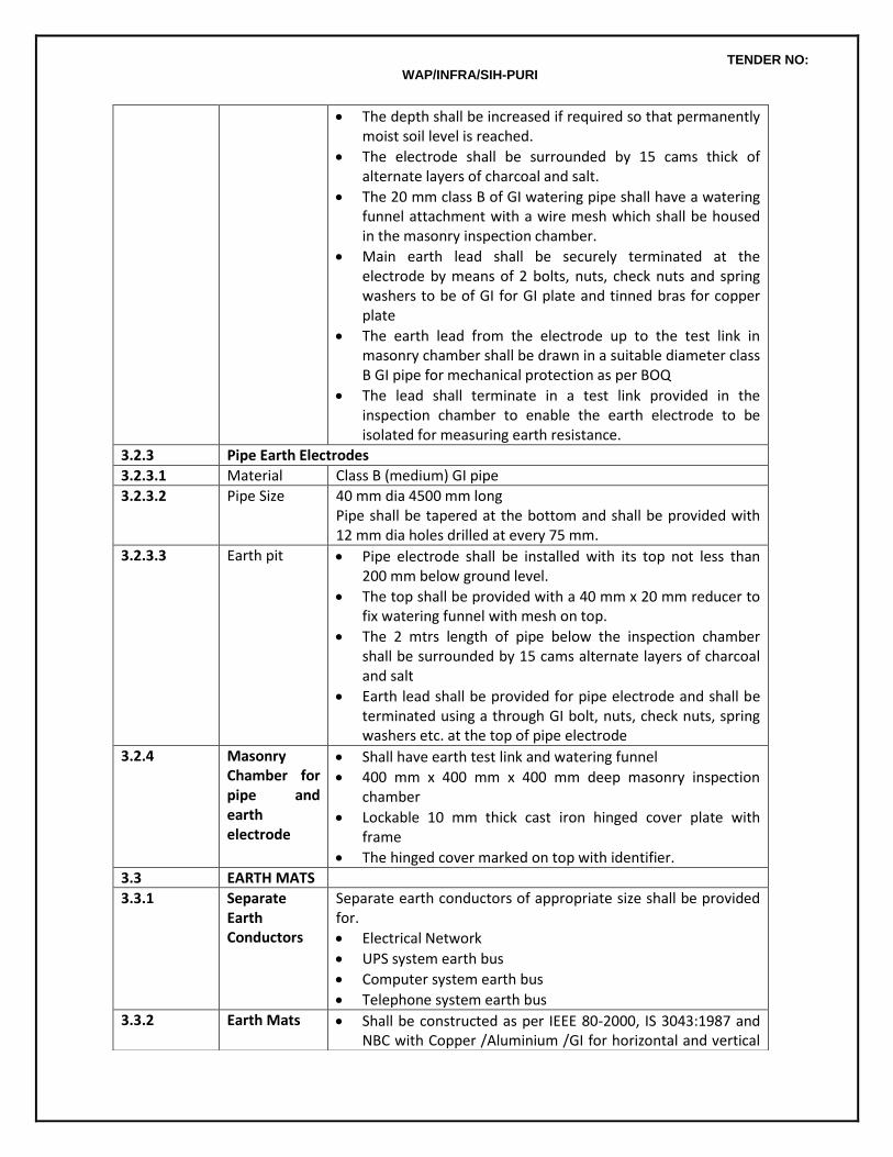
TENDER NO: WAP/INFRA/SIH-PURI
The depth shall be increased if required so that permanently moist soil level is reached.
The electrode shall be surrounded by 15 cams thick of alternate layers of charcoal and salt.
The 20 mm class B of GI watering pipe shall have a watering funnel attachment with a wire mesh which shall be housed in the masonry inspection chamber.
Main earth lead shall be securely terminated at the electrode by means of 2 bolts, nuts, check nuts and spring washers to be of GI for GI plate and tinned bras for copper plate
The earth lead from the electrode up to the test link in masonry chamber shall be drawn in a suitable diameter class B GI pipe for mechanical protection as per BOQ
The lead shall terminate in a test link provided in the inspection chamber to enable the earth electrode to be isolated for measuring earth resistance.
3.2.3 Pipe Earth Electrodes
3.2.3.1 Material Class B (medium) GI pipe
3.2.3.2 Pipe Size 40 mm dia 4500 mm long Pipe shall be tapered at the bottom and shall be provided with 12 mm dia holes drilled at every 75 mm.
3.2.3.3 Earth pit Pipe electrode shall be installed with its top not less than 200 mm below ground level.
The top shall be provided with a 40 mm x 20 mm reducer to fix watering funnel with mesh on top.
The 2 mtrs length of pipe below the inspection chamber shall be surrounded by 15 cams alternate layers of charcoal and salt
Earth lead shall be provided for pipe electrode and shall be terminated using a through GI bolt, nuts, check nuts, spring washers etc. at the top of pipe electrode
3.2.4 Masonry Chamber for pipe and earth electrode
Shall have earth test link and watering funnel
400 mm x 400 mm x 400 mm deep masonry inspection chamber
Lockable 10 mm thick cast iron hinged cover plate with frame
The hinged cover marked on top with identifier.
3.3 EARTH MATS
3.3.1 Separate Earth Conductors
Separate earth conductors of appropriate size shall be provided for.
Electrical Network
UPS system earth bus
Computer system earth bus
Telephone system earth bus
3.3.2 Earth Mats Shall be constructed as per IEEE 80-2000, IS 3043:1987 and NBC with Copper /Aluminium /GI for horizontal and vertical
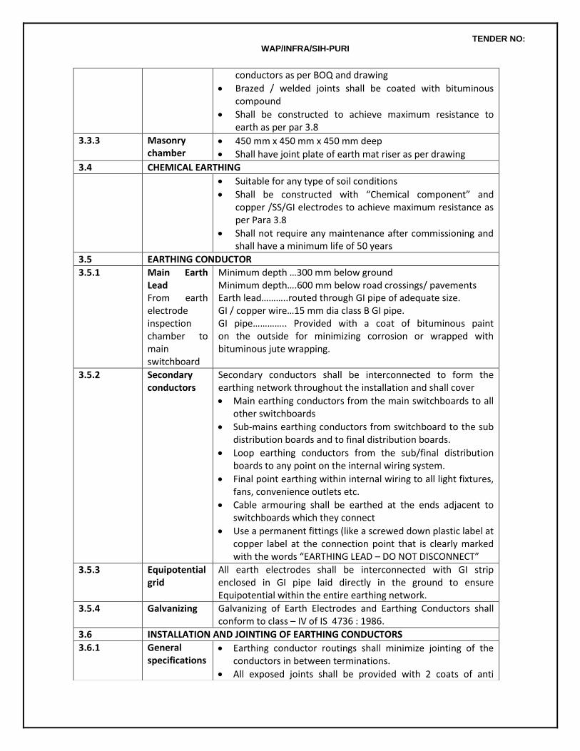
TENDER NO: WAP/INFRA/SIH-PURI
conductors as per BOQ and drawing
Brazed / welded joints shall be coated with bituminous compound
Shall be constructed to achieve maximum resistance to earth as per par 3.8
3.3.3 Masonry chamber
450 mm x 450 mm x 450 mm deep
Shall have joint plate of earth mat riser as per drawing
3.4 CHEMICAL EARTHING
Suitable for any type of soil conditions
Shall be constructed with “Chemical component” and copper /SS/GI electrodes to achieve maximum resistance as per Para 3.8
Shall not require any maintenance after commissioning and shall have a minimum life of 50 years
3.5 EARTHING CONDUCTOR
3.5.1 Main Earth Lead From earth electrode inspection chamber to main switchboard
Minimum depth …300 mm below ground Minimum depth….600 mm below road crossings/ pavements Earth lead………..routed through GI pipe of adequate size. GI / copper wire…15 mm dia class B GI pipe. GI pipe………….. Provided with a coat of bituminous paint on the outside for minimizing corrosion or wrapped with bituminous jute wrapping.
3.5.2 Secondary conductors
Secondary conductors shall be interconnected to form the earthing network throughout the installation and shall cover
Main earthing conductors from the main switchboards to all other switchboards
Sub-mains earthing conductors from switchboard to the sub distribution boards and to final distribution boards.
Loop earthing conductors from the sub/final distribution boards to any point on the internal wiring system.
Final point earthing within internal wiring to all light fixtures, fans, convenience outlets etc.
Cable armouring shall be earthed at the ends adjacent to switchboards which they connect
Use a permanent fittings (like a screwed down plastic label at copper label at the connection point that is clearly marked with the words “EARTHING LEAD – DO NOT DISCONNECT”
3.5.3 Equipotential grid
All earth electrodes shall be interconnected with GI strip enclosed in GI pipe laid directly in the ground to ensure Equipotential within the entire earthing network.
3.5.4 Galvanizing
Galvanizing of Earth Electrodes and Earthing Conductors shall conform to class – IV of IS 4736 : 1986.
3.6 INSTALLATION AND JOINTING OF EARTHING CONDUCTORS
3.6.1 General specifications
Earthing conductor routings shall minimize jointing of the conductors in between terminations.
All exposed joints shall be provided with 2 coats of anti
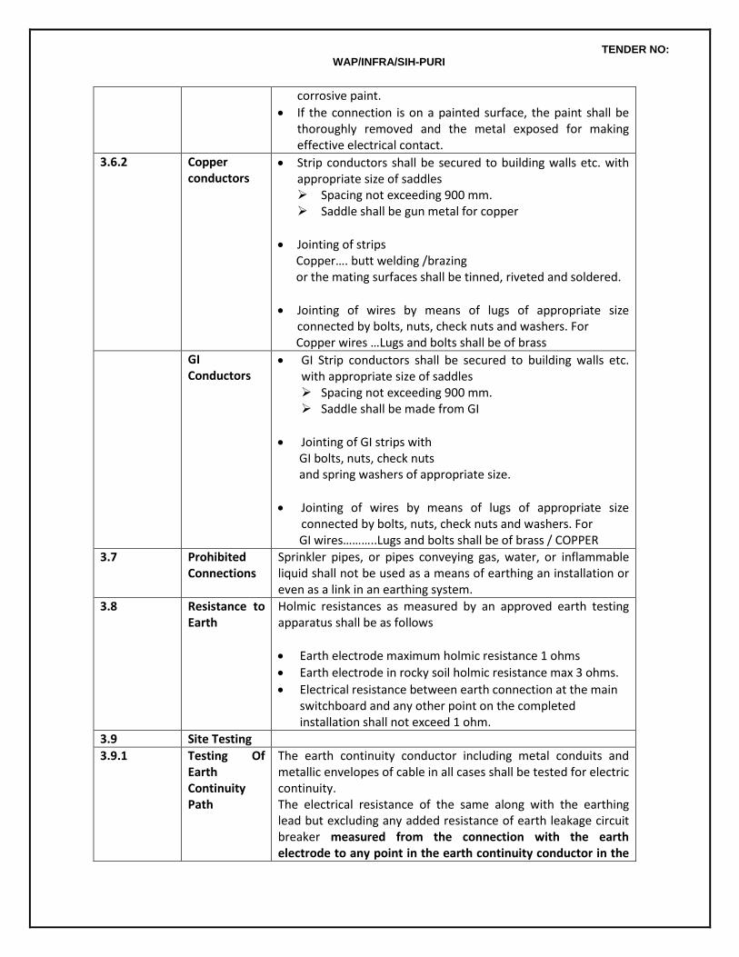
TENDER NO: WAP/INFRA/SIH-PURI
corrosive paint.
If the connection is on a painted surface, the paint shall be thoroughly removed and the metal exposed for making effective electrical contact.
3.6.2 Copper conductors
Strip conductors shall be secured to building walls etc. with appropriate size of saddles Spacing not exceeding 900 mm. Saddle shall be gun metal for copper
Jointing of strips Copper…. butt welding /brazing or the mating surfaces shall be tinned, riveted and soldered.
Jointing of wires by means of lugs of appropriate size connected by bolts, nuts, check nuts and washers. For
Copper wires …Lugs and bolts shall be of brass
GI Conductors
GI Strip conductors shall be secured to building walls etc. with appropriate size of saddles Spacing not exceeding 900 mm. Saddle shall be made from GI
Jointing of GI strips with GI bolts, nuts, check nuts and spring washers of appropriate size.
Jointing of wires by means of lugs of appropriate size connected by bolts, nuts, check nuts and washers. For
GI wires………..Lugs and bolts shall be of brass / COPPER
3.7 Prohibited Connections
Sprinkler pipes, or pipes conveying gas, water, or inflammable liquid shall not be used as a means of earthing an installation or even as a link in an earthing system.
3.8 Resistance to Earth
Holmic resistances as measured by an approved earth testing apparatus shall be as follows
Earth electrode maximum holmic resistance 1 ohms
Earth electrode in rocky soil holmic resistance max 3 ohms.
Electrical resistance between earth connection at the main switchboard and any other point on the completed installation shall not exceed 1 ohm.
3.9 Site Testing
3.9.1 Testing Of Earth Continuity Path
The earth continuity conductor including metal conduits and metallic envelopes of cable in all cases shall be tested for electric continuity. The electrical resistance of the same along with the earthing lead but excluding any added resistance of earth leakage circuit breaker measured from the connection with the earth electrode to any point in the earth continuity conductor in the

TENDER NO: WAP/INFRA/SIH-PURI
completed installation shall not exceed one ohm.
3.9.2 Earth Resistivity Test
Earth resistivity test shall be carried out in accordance with IS Code of Practice for earthing IS 3043.
TENDER NO: WAP/INFRA/SIH-PURI
CHAPTER 9 : DIESEL GENERATOR SETS 1. GENERAL
Work covered by this contract shall include design, manufacture, supply, transportation, delivery, installation, testing and commissioning of automatic start direct coupled Diesel Generator Sets and shall include but not limited to the following.
Diesel engine with alternator mounted on a rigid fabricated steel base frame with resilient antivibration mountings.
Water cooling system including cooling towers, pumps, piping and controls.
Exhaust piping with Residential type Silencer.
Electric starting equipment including batteries and battery chargers.
Fuel supply system including bulk oil storage and automatically operated fuel transmission system.
Statutory approvals including permission from Electric Supply Authority for operation of DG sets, approval from Electricity Board/company, clearance from Electrical Inspector, approval from Pollution Control Board and necessary approvals from Department of Explosive for bulk oil storage.
2. STANDARDS
The equipment offered shall conform to the latest revision of relevant Indian or British Standard (BSS.) and Codes together with the requirements of the Local Supply Authority and Department of Explosive etc. Tenderers shall clearly state the standards to which the equipment they are offering conform.
3. ENGINE AND ACCESSORIES 3.1 Engine
The engine shall have the following characteristics:
Type - Suitable for generating set application, turbo charged, multi-cylinder, solid injection, cold starting.
Cycle - Four stroke. Speed - 1,500 r.p.m. Speed Variation - Within 2% for operation between 10% and 100% Method of Starting - Battery Net site output - This shall be the continuous rating under the ambient conditions given in
Clause 3.3 of SCC and as per Bill of quantities. The engine rating shall be stated in the tender in accordance with the latest revision of relevant I.S. or B.S. Adequate precautions shall be taken to safeguard the sets against low lubricating oil pressure, high water temperature, over speed and over current.
3.2 Fuel Consumption
The engine shall be suitable for satisfactory operation on H.S.D. as locally available. The tenderers shall
TENDER NO: WAP/INFRA/SIH-PURI
declare the guaranteed fuel consumption in liters per BHP/hr, in accordance with relevant I.S. or B.S. at 1/2, 3/4 and full load under the maximum output after de-rating to ambient conditions.. Such guaranteed fuel consumption is also to be expressed in liters per gross / net kWh output from the alternator (after supplying the requirements of auxiliaries) at 1/2, 3/4 and full load and at 0.8 and unity power factors. If guaranteed fuel consumption is exceeded, the Contractor shall make such amendments or alterations as are necessary to bring the consumption to within the guaranteed figures. Tolerance of + 5% as defined in BSS-649-1958 shall be allowed.
3.3 Lubricating Oil Consumption
The tenderers shall state the guaranteed lubricating oil consumption in liters per hour. 3.4 Governing
The governor shall be of electronic type with governing class A direct. 3.5 Mounting And Foundations
The engine and direct coupled alternator shall be rigidly secured to a common rigid base frame fabricated from MS sections. The DG set shall be placed on the RCC Floor with antivibration mountings having required quality steel springs for control vibration. The antivibration mountings shall be of GERB make.
The design of mounting arrangements with antivibration mountings shall be as recommended by the DG manufacturers and shall be such that no vibrations are transmitted to the structure.
The tenderer shall confirm the type and design of mountings provided and the vibration isolation efficiency in the tender.
3.6 Exhaust Piping
The engine shall be fitted with a residential type silencer (design approved by manufacturer) to reduce the noise level. Silencer outlet shall be connected to exhaust piping carried to the top of the building through shafts provided for the purpose. Exhaust piping shall be fabricated from class 'B' MS pipes and relevant IS Code above 150 mm dia pipe of size suitable to limit back pressure to within permissible limit as required by engine manufacturer. Tenderer shall submit design calculation in support of the back pressure being within limits along with the tender. The exhaust piping system shall be tested for leakages after installation by means of a smoke test. The entire length of exhaust piping shall be inspected for any visual indication of smoke leaking out during the smoke test. It is important to ensure that the surface temperature of the exhaust piping does not exceed 50oC. For this purpose, the entire length of exhaust piping shall be insulated with minimum 75 mm thick layer of LRB rock wool (150 kg /m3 density covered with 26 SWG aluminium sheet cladding. Flanged joints in the exhaust piping shall be covered with removable insulation at suitable intervals for permitting access to the joint if and when required. Exhaust piping shall be connected to the engine by means of flexible section or an expansion joint and
TENDER NO: WAP/INFRA/SIH-PURI
shall also be graded to a drain pocket inside the building. The pocket shall be fitted with a drain cock.
3.7 Air Filters The engine air intake shall be fitted with a substantial air cleaner of oil bath/ paper element type. The filter shall be suitable for operation under dusty conditions.
3.8 Crank Case Breather
The crankcase breather outlet of the engine shall be fitted with a filter cap capable of preventing entry of dust.
3.9 Fuel And Lubricating Oil Filters
Filter for fuel and lubricating oil systems shall be of simplex type. Lubricating oil filters shall be of an efficient full flow type of ample capacity and suitable for use with detergent oils. They shall be capable of removing all foreign matter above a particle size of 5 microns.
3.10 Tools
Two sets of standard tools kit for maintenance shall be provided by Contractor. Tenderer shall submit a list of the tools along with the tender.
3.11 Lubricating Oil System
The engine shall be of the totally enclosed type and fitted with a positive pressure system of lubrication to all working parts. Lubricating oil shall be circulated in the engine by an engine driven pump. There shall be no moving part requiring lubrication by hand prior to the starting of the engine or while in operation.
3.12 Safety Controls
Low Lubricating Oil Pressure Pressure sensors shall be fitted such that in the event of a fall in the lub oil pressure, an alarm and indication shall be actuated. In addition, the engine shall be automatically shut down in the event of lub oil pressure dropping to a predetermined low value. High Water Temperature An alarm shall be given if the close loop engine jacket cooling water temperature exceeds safe limits stipulated by the engine manufacturer due to any reason (including low level of water in secondary cooling system cooling tower). The engine shall be shut down when a pre-determined set water temperature is reached. Over Speed Speed control shall be so arranged that a 12-1/2% increase over normal rated speed shall cut off fuel supply, thus stopping the engine. Overload Protection The engine shall be adequately protected against operating under overload conditions. The requirements shall be met by the provision of a fixed overload limit stop on the fuel pump rack control rod to prevent the set being subject o to a load exceeding the site rating plus 10%. Excess Starting Time
TENDER NO: WAP/INFRA/SIH-PURI
The starting circuit for the automatic mains failure diesel generator sets shall be arranged to attempt up to three starting cycles, each not exceeding 10 seconds duration with a similar OFF period between each cycle. If the set fails to start upon completion of the third attempt the starting circuit shall be locked out until it is restored manually. An alarm shall be given and "Set failed to start" indication given on the panel. Provision shall also be made to avoid re-engagement of the starter pinion until after the engine has come to rest. Failure of the starter motor to disengage shall close down or lock out the engine. Fuel Level Protection A level sensor shall be provided in the day fuel tanks to give visual and audible alarms if the level in the tank falls to below 1/4 full.
3.13 General
The DG sets shall be complete with all equipments, visual and audible alarms, indications and controls required for fully reliable and safe operation of the DG sets whether specifically stated in these specifications or not. It is essential that the operation of all protection equipments be completely reliable in all respects.
Whenever the engine is shut down due to overspeed, low lubricating oil pressure, high water temperature or excess starting time, the circuit breaker shall also be tripped and the starting systems of the engine shall be locked out until the respective protective relay is reset.
3.14 Accessories, Instruments and Safety Controls for Engine
Accessories, instruments and safety controls to be provided with the engine shall be (but not limited to) as below. All accessories shall be of design compatible with the design and /or operation of the engine.
a. Accessories:
Flywheel to suit flexible coupling. Flexible coupling with guard. Air cleaner oil bath/paper element type. Corrosion resistor. Heat exchanger. Governor - electronic. Fuel filter Lub. oil filter. Heavy duty batteries with leads and battery charger with battery stands. Stainless Steel Bellows Flexible coupling Exhaust silencer residential type Interconnection wiring, cabling and piping as required Set of standard tools Anti-vibration mounting pads.
TENDER NO: WAP/INFRA/SIH-PURI
b. Instruments and Gauges: Lub. oil pressure gauge. Water temperature gauge. Battery charging ammeter. Hour meter (mechanical) to show total engine hours run 10,000 hr capacity R.P.M. indicator of the tachometer type. Starting switch with key Lamp indicator for charging alternator Push button for starting Safety control indication lamp
c. Safety controls for Low lub oil pressure High water temperature Over speed
Low fuel level in buffer tank Low water level sensor in cooling towers
3.15 Alternator
The Alternator shall have the following characteristics Type - Drip Proof Screen protected for power generation Speed - 1500 R.P.M. Net Site Output - Rated continuous at ambient conditions and as per Bill of quantities. Voltage Regulation - Within 0.5% of the rated voltage Overload - More than 10% of the nominal for 1 hour every 12 hours without exceeding
permissible temperature rise. Harmonics - Maximum 1% between phase and neutral and total maximum 3%
Excitation
The alternator shall be of brushless type and shall be a permanent, self regulated magnet generator. The exciter unit shall be mounted on the control panel or on the alternator assembly.
Construction
A screen protected drip proof type, alternator directly coupled to the Diesel Engine by a flexible coupling shall be provided. The combined engine alternator unit shall be mounted on a common rigid fabricated base frame. The alternator shall have its windings star connected with the neutral connection brought out to a separate terminal. The alternator shall fully comply with the latest Standard BS 2613 and BS 269 in respect of winding insulation and fast response to maintain steady voltage.
Temperature Rise
The maximum temperature rises of the various components of the alternator shall not exceed those permitted under I.S. with full output and under the ambient temperature conditions specified in Clause 3 above. Rating And Regulation The alternator shall be continuously rated to deliver the rated output at 0.8 P.F. lagging, on a 3 phase 4
TENDER NO: WAP/INFRA/SIH-PURI
wire 415 volts 50 cycle system. The alternator shall be of the self regulated and self excited type brushless. The alternator shall be provided with a static excitation system and the voltage regulation from no load to rated load shall be within 0.5% of rated voltage. Alternator Insulation The alternator should have class H insulation suitable to withstand tropical conditions.
7. DG CONTROL AND OPERATION
Operation of DG sets shal be monitored and controlled by Programable Logic controller (PLC) based Logic Panel provided by Owners on the Main LT Panel of the System. DG contractor shall coordinate this aspects with the electrical contractor appointed by the Owner.
5. WATER COOLING SYSTEM
The engine shall be provided with a heat exchanger for closed loop primary cooling water circuit circulated by an engine driven pump for jacket cooling of the engine. The secondary water cooling circuit of the heat exchanger shall be cooled through a cooling tower by monoblock centrifugal pumps. Soft water (commercial zero hardness) shall be used for initial fill and make up water for secondary cooling circuit and for initial fill of primary cooling circuit. In addition, the primary closed loop cooling circuit shall be dosed with corrosion inhibiters recommended by the engine manufacturer to minimize engine jacket corrosion/scaling. All equipment of the cooling system (heat exchanger, pumps, cooling tower) shall be of specifications and design recommended by the engine manufacturer for reliable and trouble free operation. Tenderers shall provide design data in support of equipment selection along with the tender.
5.1 Pumps
Construction Monoblock or horozontal split casing pumps as per Bill of quantities shall be as per IS:1520-1660, IS:9079, IS:325 and shall be of the following construction unless otherwise specified:
Casing Cast Iron Impeller Bronze Shaft High Tensile steel Bearings Heavy duty Ball/Roller Bearings. Base Frame Fabricated MS Flanges Conforming to ISS 1536/1960 Packing Mechanical seal Speed 1500 RPM Drive Motor TEFC
Drive motor ratings, if shown, are tentative and tenderers shall select their motors at least 15% in excess of the maximum BHP of the pump plus transmission losses if any. Motors shall be supplied with matching starters unless otherwise stated. Pumps and motors shall be mounted on a single base frame and directly driven through flexible coupling in case of horizontal split casing pumps.
TENDER NO: WAP/INFRA/SIH-PURI
Accessories And Fittings Following accessories shall be provided with each pump inaddition to standard accessories : a) Coupling guard for horizontal split casing pumps. b) Lubrication fittings c) Test and/or air vent cocks. Following fittings shall be provided with each pump inaddition to standard fittings : a) Suction and discharge shut off valves and discharge check valves b) Suction and discharge pressure gauges not less than 100mm dia and of the appropriate rating with
bras gauge cocks etc. c) 25mm GI gland drain to drain channel Installation Pump sets shall be mounted on a common rigid fame and shall be installed on inertia block/vibration isolators, as per manufacturers recommendations. All items including, foundation bolts, vibration isolators etc. required for proper installation shall be provided by the contractor. Pump-sets shall preferably be factory aligned, wherever necessary, site alignment shall be done by competent persons. Before the foundation bolts are grouted and the couplings are bolted, the bed plate levels and alignment results shall be submitted to the Project Manager. Testing Tenderers shall submit the performance curves of pumps supplied by them. They shall also check the capacity and total head requirements of each pump to match his own piping and equipment layout. On completion of the entire installation, pumps shall be tested, wherever possible, for their discharge, head, flow rate & BHP. Where it is not possible at least the discharge, head and BHP (as measured on the input side) shall be field tested. Test results shall correspond to the performance curves. Painting After complete installation and testing, pumps, accessories and fittings shall be given two coats of approved finishing paint. Quantity of water Minimum water flow at engine shall be 1300 lits per minute.
5.2 Cooling Tower
Cooling tower shall be suitable for outdoor installation. Cooling tower shall be vertical, induced / forced draft, counter /cross flow type in fibre glass reinforcement /plastic construction, complete with fan, motor, surface and spray section, eliminators, bird screen and steel supports. The colour of the cooling tower shall be as approved by Consultant /Owner.
Capacity : The cooling tower capacities shall be compatible with DG sets. Cooling load , Flow rate, inlet water and out let water temperature, Max inlet temp, make up water qty, and WBT etc to be specified.
Side casing : Casing shall be made of FRP having smooth surface for minimum resistance to air flow. It shall have

TENDER NO: WAP/INFRA/SIH-PURI
sufficient structural strength to withstand high wind velocities and vibration. The casing shall be installed within the fibre glass reinforced basin. The tower supporting structure shall be made out of hot dip galvanized tubular frame.
Cold water basin : Cold water basin shall be of fibre glass reinforced sump of sufficient depth on which cooling tower super structure shall be supported. Basin fittings shall include but not restricted to the following: i. Bottom outlet. ii. Screened suction assembly fixed to the casing. iii. Drain at under side of suction side sheet. iv. Overflow fixed to inside of casing side sheet. v. Ball type automatic make-up water valve. vi. Sensor for low level alarm.
Distribution system : Warm water distribution system shall comprise of header and branch arms system or open pan gravity flow system.
Fillings : Fillings shall be made of corrosion proof material (PVC) and rigid film in modular packs and arranged in square/rectangular form. These shall be arranged in such a manner as to ensure negligible resistance to air flow and to eliminate back water spots and prevent fouling through scales that may form. In order to reduce carry-over losses through entertainment of moisture drops in air stream, high efficiency PVC tubular drift eliminator shall also be provided.
Mechanical equipment : Fan shall be of efficient axial flow propeller type design with adjustable pitch blades and light-weight rotor fitted with multiple aerofoil blades. The entire fan assembly shall be statically and dynamically balanced. Fan shall be direct driven motor suitable for operation on 415+/-10% volts, 3 phase, 50 cycles AC supply of approved make, totally enclosed, fan-cooled, weather proof construction, designed and selected to operate in humid air stream. Fan shall be protected by fan guard and shall be easily accessible for inspection and maintenance. A service ladder shall also be provided for greater convenience. The mechanical equipment assembly shall be adequately supported on a rugged steel base welded to tubular support assuring vibration free operation. Fan guard shall be provided to prevent birds from nesting during idling periods.
The cooling tower shall be procured of the colour, strictly in accordance with written approval of Project Manager.
5.3. Piping Piping Materials
Unless otherwise specified, pipes shall be medium class MS (black steel) as per IS 1239 (Class B) suitable for welded joints.. Wherever so specified, class B GI pipes with screwed joints could be used for pipes up to 50 mm dia.. MS/GI pipes shall be of makes as per approved list. Pipes shall be given one primary coat of rust inhibiting paint before being installed.
TENDER NO: WAP/INFRA/SIH-PURI
Fittings shall be new and from approved manufacturers, Fittings shall be of pressure ratings suitable for the piping system. Flanges shall confirm to ISS. Supply of flanges shall include bolts, nuts, washers, gaskets etc., as required. All equipment and valve connections shall be through welded flanges. Gate valves and check valves shall conform to IS:780/1969. Gate valves shall have non-rising spindles unless otherwise specified. Valves up to 40 mm dia.. shall have gun metal body and valves of more than 40 mm dia.. cast iron body unless otherwise specified. Valves shall be suitable for test pressures as per piping system requirements and as per ISS. Butterfly valves shall conform to BS:5155, MSS SP 67 & API 609. The valves shall be suitable for flow in either direction and seal in both directions. The valve shall be of integral moulded design. Strainers shall be Y type or Pot type as per Bill of quantities and /or as required with CI or fabricated steel bodies. Strainers shall have removable bronze screen with 3mm perforations. All strainers shall be provided with equal size isolating valves so that the strainer may be cleaned without draining the system. Pressure gauge shall be not less than 100 mm dia dial and of appropriate range and be complete with shut off gauge cocks etc.. and shall be duly calibrated before installation. Pressure gauges shall be provided at the following locations: a) Suction and discharge of pumps. b) Inlet and outlet of heat exchangers. Care shall be taken to protect pressure gauges during pressure testing.
Thermometers shall be either 100 mm dia dial or direct reading industrial type of appropriate range duly calibrated before installation. Thermometers shall be installed in separable wells. Thermometers shall be provided at the following locations:
Dial type thermometers on supply and return of heat exchangers. Piping Installation
The Contractor, on award of work, shall prepare detailed working drawings showing the piping route, typical sections, location and detail of fittings, valves, strainers and instruments. The planing of piping system shall take existing wall and ceiling openings, if any, into consideration. Piping layout shall take due care for expansion and contraction in pipes. Piping shall be installed only after through cleaning. Pipes shall be cut square. Proper edge preparation with 'V' grooves shall be done and edges grinded before welding. Sufficient gap shall be maintained. Electrodes of approved makes only shall be used for welding and tacking. Pipes shall be supported from floor /wall mounted or ceiling suspended supports at an intervel of maximum 2 mtrs unless otherwise states/approved. Supports shall be designed to withstand the weight of pipes, fittings and fluid in motion. Pipe supports shall be of steel, adjustable for height and primer coated with rust preventive paint and finish coated with 2coats of enamel paint of approved
TENDER NO: WAP/INFRA/SIH-PURI
colour. Where pipes and clamps are of dissimilar material, a gasket shall be provided in between. Pipe hangers shall be fixed on walls and ceilings by means of dash fastners. Vertical risers shall be parallel to walls and column lines and shall be straight and plumb. Risers passing from floor to floor shall be supported at each floor by clamps or collars attached to pipe and with a 12mm thick ribbed rubber pad or any other approved resilient material. Where pipes pass through the terrace floor, suitable curbing shall be provided to prevent water leakage. Risers shall also have a suitable concrete pipe support at the lowest point. Pipe sleeves of 50mm or larger diameter shall be provided wherever pipes pass through wall and the annular space filled with felt and finished with retaining rings. Insulated piping shall be supported in such a manner as not to put undue pressure on the insulation. Piping shall be pitched towards drain points. Drain outlets shall be provided at all low points in the piping system with 25 mm dia pipe (for up to 300 mm dia water pipe) with gate valves of equal size with rising spindels . Drain outlets shall be connected through equal size GI pipe to the nearest drain or floor waste. All piping buried directly in ground shall be provided with a coat of primer paint after surface preparation over which rust preventing tape (Pipekote 4 mm) shall be wrapped.
Testing
Entire piping system after installation shall be flushed with clean water to ensure thorough inside cleaning of the system. All piping shall be tested to hydrostatic test pressure of at least one and a half times the maximum operating pressure, but not less than 7 Kg/Sq cm for a period of not less than 24 hours. All leaks and defects in joints revealed during the testing shall be rectified to the satisfaction of the Project Manager . Piping required subsequent to the above pressure test shall be retested in the same manner. Systems may be tested in sections and such sections shall be securely capped. The Project Manager shall be notified well in advance by the contractor of his intention to test a section of piping and all testing shall be witnessed by the Project Manager or his authorised representative. The Contractor shall make sure that proper noiseless circulation of fluid is achieved through all coils and other heat exchange equipment in the system concerned. If proper circulation is not achieved due to air bound connections, the Contractor shall rectify the defective connections. He shall bear all the expenses for carrying out the above rectifications including the tarring-up and re-finishing of floors, walls etc. as required. No insulation shall be applied to piping until the completion of the pressure testing to the satisfaction of the Project Manager . The Contractor shall provide all materials, tools, equipment, instruments, services and labour required to perform the test, and shall ensure that the plant room and other areas are cleaned up and spill over water is removed. And also ensure that there is no flooding of water.
TENDER NO: WAP/INFRA/SIH-PURI
After the piping has been installed, tested and run for at least ten days of eight hours each, the piping shall be given two finish coats, 3 mils each of approved color and shade.
6. FUEL OIL SYSTEM Diesel oil shall be stored in 2 nose 20 kL capacity underground bulk oil tanks provided with facilities for oil tanker delivering oil and pumping of the oil for transferring it to the DG room. Fuel transfer pumps with flame proof motors shall pump the diesel oil into buffer tank provided at ceiling level of DG room. The buffer tank shall be provided with low and high level electronic sensors to actuate the automatic operation of the fuel transfer pump. The oil from buffer tank shall be transferred to the day fuel tanks of individual DG sets by gravity flow. The entire installation shall be as per the requirements of the Department of Explosives. Approval of shop drawing of the entire installation shall be obtained from the Department of Explosives by the Contractor before commencement of work. Clearance of the installation for use by Owners shall also be obtained by the Contractor from Department of Explosives after completion of work.
6.1 Bulk Fuel Storage Tanks.
Construction The Bulk Fuel Storage Tanks shall be suitable for storing HSD. The tanks shall conform to IS 10987 - 1992 and shall be suitable for underground installation. Tanks shall have dished ends and shall be fabricated from 6 mm thick boiler quality plates conforming to IS 2002 - 1982. Tanks shall be designed for a pressure of 10 kg / cm2 when full of water. Tanks shall be fabricated by welding. Welding procedure and qualification of welders shall be as specified in IS 9595-1980 and IS 817-1966. Cylindrical shell be of full penetration butt belt welded construction End plates shall be attached to the shell by double fillet welds. The fabrication drawings to be submitted for Owner/Consultant approval. The tanks shall be water pressure tested to 1.5 times the design pressure and shall be held for 24 hours for no leaks.
Accessories The tanks shall be provided with all standard accessories, nozzles and appurtenances as indicated below. a. Lifting lugs - 2 nose per tank b. Earthing bosses - 2 nose per tank c. 600 mm dia manhole with hinged cover, with gasket seals, lockable cover and provided with a
removable access ladder to go into the tank d. 80NB fill pipe running down to within 100 mm of the tank bottom and with end chamfered at 45
Deg. e. Suction connection suitable for 50 NB suction pipe f. Dip connection with brass screwed cover and fitted with internal perforated pipe running down
to within 100 mm of the tank bottom. A calibrated 12 mm square brass dip rod shall be provided.
g. Properly supported 4 m high vent pipe shall be provided. Open end shall be covered with 2 layers of non rusting metal wire gauge having minimum 11 meshes per linear centimeter. The vent pipe shall be prevented from rain by a suitable hood or with down ward bends.
h. Spare appurtenance for 40 NB pipe suitably closed with solid flange
TENDER NO: WAP/INFRA/SIH-PURI
i. Flame arresters to be installed as per the requirement
Shop Testing The workmanship and finish of fabrication shall be of superior quality and shall be subject to close inspection by manufacturer's inspector and also, if so desired by Project Manager. All welds shall be visually inspected. DP test shall be carried out for all the weld joints. If so desired by Project Manager, Radiographic tests shall be done on pipe joints. Tanks shall be subjected to hydraulic test at a pressure of 1.5 times design pressure and checked for leaks. All gauges, templates, required for inspection and testing at works shall be provided by supplier.
Shop Painting All external surfaces of tank shall be protected against corrosion by asphalt doping. Asphalt doping shall be carried out after final testing of the tanks only especially in respect of portions having welded joint. The outer surfaces of the tank, turnbuckle, anchor bolts, manhole cover, nozzles, saddles etc. shall be thoroughly cleaned by scrapping by wired brushes and sand papers to bare metal. All mill scales dirt shall be completely removed. The surface thus prepared shall be treated with two coats of "tankmastic" or equivalent primer, each quote being applied uniformly with a spreading of around 11 to 13 mtrs per liter after the first coat is thoroughly dry. After the application of primer coat, two coats of hot 30 / 40 grade bitumen shall be applied as per manufacturer's recommendation resulting in an overall coating thickness of 3.2 mm. The bitumen shall be heated as required for easy and uniform application. Finished appearance shall be of a rough cast plaster obtained by dabbing.
Internal surface of the tank shall be cleaned to remove all rust and foreign matters like grease, dirt etc. before dispatch.
6.2 Fuel Transfer Pump The fuel transfer pump for transfer of oil from bulk oil tank to buffer tank in DG room (automatic in operation) shall be a positive displacement flame proof construction pump of rotary gear type, of rating as per bill of quantities. The drive motor shall be of flame proof construction. The pump panel shall also be of flame proof construction with IP-54 ingress protection.
6.3. Pipes And Pipe Fittings The MS pipes shall be of minimum class B (Medium gauge) type. Makes of pipes and pipe fittings shall be as stipulated in the list of approved makes and as approved by Project Managers.
6.4. Daily Service Fuel Tank Day fuel tanks of 990 litres capacity. The tank shall be fabricated from not less than 14 SWG M.S. Sheet. A removable cover of ample size with lock shall be provided to permit access to the tank interior. The tank shall be provided with all required appurtenances like inlet and outlet connections, drain connection, overflow connection etc. Fuel level indicator with low and high level visual shall be provided. The day tanks shall be floor/wall supported on steel support 300 mm above FFL. Buffer tanks shall be wall mounted at ceiling level. Buffer tank shall also be provided with automatic level sensors as per BOQ for automatic operation of fuel transfer pumps.
7. ENGINE AUXILIARIES AND WIRING
TENDER NO: WAP/INFRA/SIH-PURI
All engine auxiliaries shall be checked and tested for proper operation. Wiring between the engine auxiliaries and the DG control logic panel shall be provided with copper conductor PVC insulated 1100 V grade armored cables. Loop earthing as required shall be provided.
8. STARTING BATTERY AND BATTERY CHARGER
8.1 24 Volt DC Batteries
24 volt batteries for each set shall comprise of standard lead acid stationary batteries consisting of required cell of each 2 volts to have 180 AH/360 AH capacity a one hour rate of discharge to attain voltage of 1.85 volt per cell to 2 volts supplied complete with inter cell connectors and acid level indicating floats. Battery cells shall conform to IS 1651 with up to date amendments. The battery bank shall be provided with the following accessories.
a) Battery stand b) Set of connectors with ends take off suitable for connections. c) Cell insulator and stand insulators d) Spring type hydrometer e) Thermometer with specific gravity correction scale f) Cell testing voltmeter g) Set of tools consisting of spanners, rubber syringe, acid resisting funnel and acid resisting tube of 2
litres capacity – one set
The batteries shall be supplied duly filled, charged and acidic filled. 8.2 Battery Charging Equipment (Trickle and Boost Charging)
Battery trickle and boos charge of suitable capacity intended to operate on single phase 230 volts, so cycles supply system and suitable for charging current. The battery boost charger shall be provided with the following accessories.
a) AC and DC “ON” and “OFF” switches with HRC fuses b) Indicating lamps for indicating mains “ON” and battery charging c) Ballast to give charging d) Single phase double wound (copper conductor ) impregnated natural air cooled mains transformer for
rectifier stack. e) Rotary switch to give step control. f) Single phase full wave bridge connected silicon rectifier stack g) Moving coil ammeter to indicated charging current h) Moving coil voltmeter with a selector switch to measure the battery/charger voltage. i) Silicon blocking diodes connected to a suitable tap to maintain continuity of DC supply. j) AC and DC contactors of suitable rating as required.
All the components for battery charger shall be adequately rated and housed in a well ventilated sheet steel cubicle with input and output terminals. Proper cable glands shall be provided for incoming and outgoing cables. Battery charger shall form part of DG Protection and PLC panel.
9. RADIO INTERFERENCE
All equipment provided under this specification shall be so designed that it will not cause interference
TENDER NO: WAP/INFRA/SIH-PURI
with radio equipment. In the event of the inherent characteristics of the equipment being such that radio interference is possible, efficient devices to nullify the same shall be provided. Suppressers shall be as per the relevant I.S./B.S. Standards.
10. ACOUSTIC TREATMENT
The walls and ceiling of DG room shall be lined with acoustic treatment for minimizing transmission of sound outside the DG room. The acoustic treatment shall comprise of the following. 600 mm x 600 mm grid frame work to be fixed on walls and ceilings by means of rawl plugs or dash fastners. The frame work shall be made from 50 mm x 50 mm channels fabricated from 18 guage GI sheets. 100 mm thick glass wool slabs of density not less that 48 kg / m 2 or approved equivalent material shall be fixed tightly on the GI channel frame work with joints well butted together. Glass wool insulation to be covered with a thin (28 guage) perforated aluminium sheet, perforations providing minimum 20% open area. Joints of the cover sheet shall be over lapped. The cover shall be screwed to the GI channel by suitable screws in an approved manner. The CPCB norms shall be as per notification dated 9th July, 2002 New Delhi issued by Ministry of Environment and forest.
11. PRE-COMMISSIONING CHECKS All standards checks including the ones elaborated in the specifications to ensure that the installation of the DG sets and associated systems has been carried out satisfactorily shall be done on completion of installation. These shall include.
DG sets – Checking of piping interconnections – Checking electrical interconnections – Checking of insulation resistance – Checking of earthing – Checking of instruments and controls. – Checking of alignment – Checking of vibration transmission to building a structure. – Checking of expansion joints.
Cooling water system – Checking of piping interconnections – Checking electrical interconnections – Checking of insulation resistance – Checking of earthing – Pressure testing of piping
Exhaust system – Checking of silencer operation
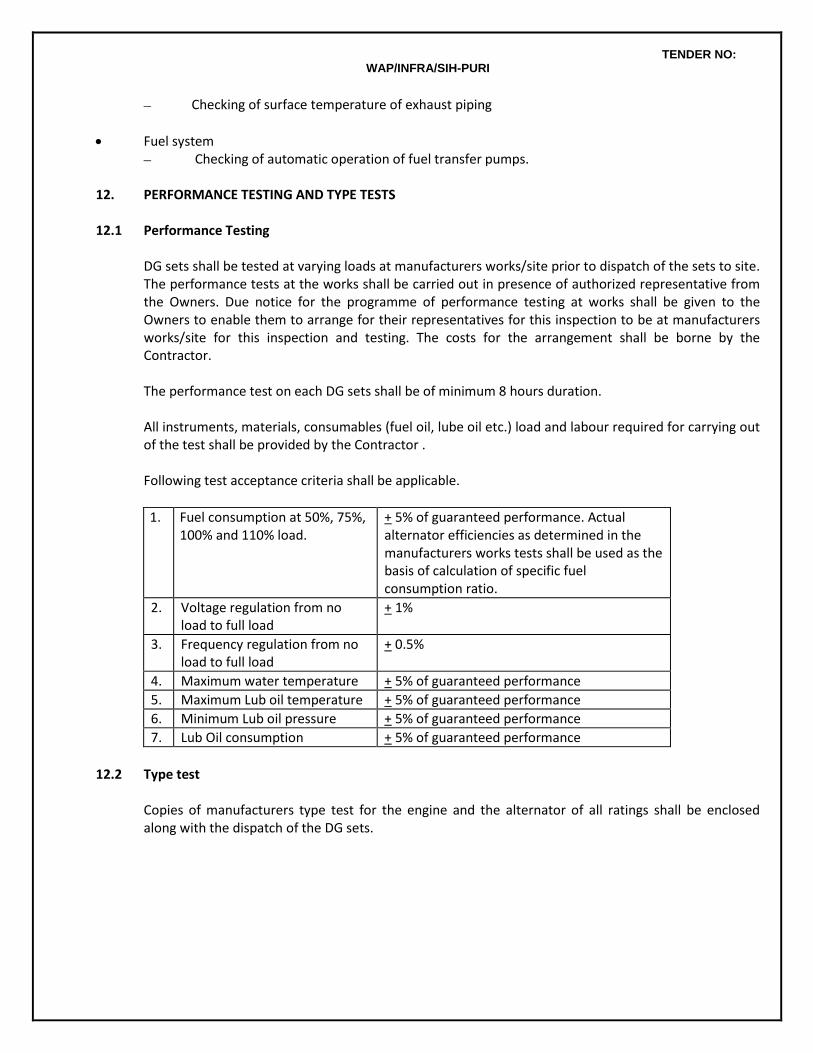
TENDER NO: WAP/INFRA/SIH-PURI
– Checking of surface temperature of exhaust piping
Fuel system – Checking of automatic operation of fuel transfer pumps.
12. PERFORMANCE TESTING AND TYPE TESTS 12.1 Performance Testing
DG sets shall be tested at varying loads at manufacturers works/site prior to dispatch of the sets to site. The performance tests at the works shall be carried out in presence of authorized representative from the Owners. Due notice for the programme of performance testing at works shall be given to the Owners to enable them to arrange for their representatives for this inspection to be at manufacturers works/site for this inspection and testing. The costs for the arrangement shall be borne by the Contractor. The performance test on each DG sets shall be of minimum 8 hours duration.
All instruments, materials, consumables (fuel oil, lube oil etc.) load and labour required for carrying out of the test shall be provided by the Contractor . Following test acceptance criteria shall be applicable.
1. Fuel consumption at 50%, 75%, 100% and 110% load.
+ 5% of guaranteed performance. Actual alternator efficiencies as determined in the manufacturers works tests shall be used as the basis of calculation of specific fuel consumption ratio.
2. Voltage regulation from no load to full load
+ 1%
3. Frequency regulation from no load to full load
+ 0.5%
4. Maximum water temperature + 5% of guaranteed performance
5. Maximum Lub oil temperature + 5% of guaranteed performance
6. Minimum Lub oil pressure + 5% of guaranteed performance
7. Lub Oil consumption + 5% of guaranteed performance
12.2 Type test
Copies of manufacturers type test for the engine and the alternator of all ratings shall be enclosed along with the dispatch of the DG sets.
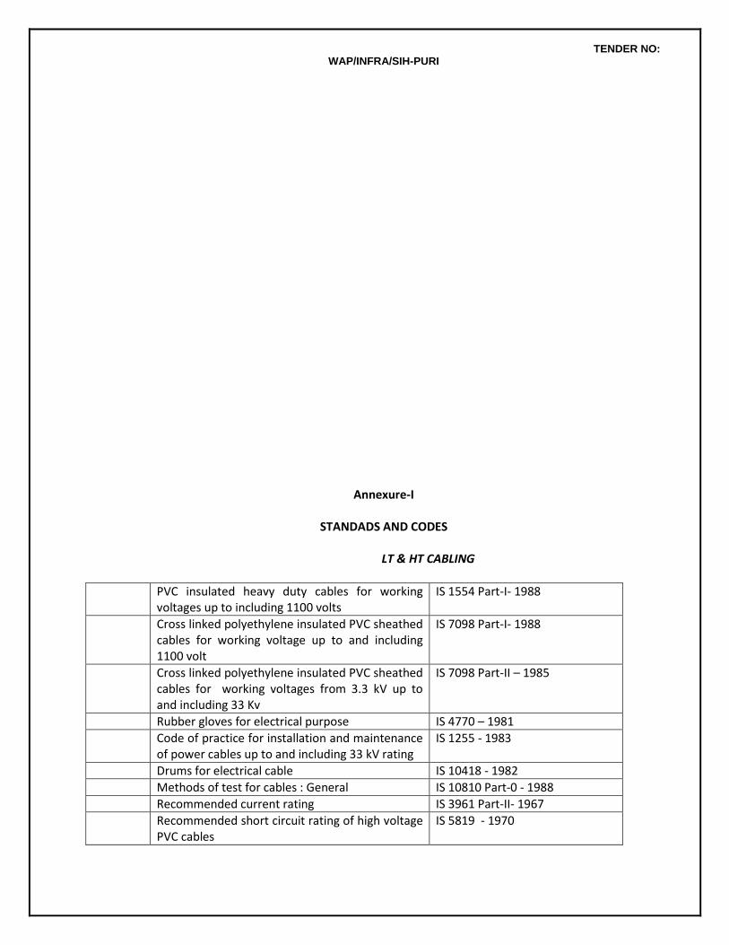
TENDER NO: WAP/INFRA/SIH-PURI
Annexure-I
STANDADS AND CODES LT & HT CABLING
PVC insulated heavy duty cables for working voltages up to including 1100 volts
IS 1554 Part-I- 1988
Cross linked polyethylene insulated PVC sheathed cables for working voltage up to and including 1100 volt
IS 7098 Part-I- 1988
Cross linked polyethylene insulated PVC sheathed cables for working voltages from 3.3 kV up to and including 33 Kv
IS 7098 Part-II – 1985
Rubber gloves for electrical purpose IS 4770 – 1981
Code of practice for installation and maintenance of power cables up to and including 33 kV rating
IS 1255 - 1983
Drums for electrical cable IS 10418 - 1982
Methods of test for cables : General IS 10810 Part-0 - 1988
Recommended current rating IS 3961 Part-II- 1967
Recommended short circuit rating of high voltage PVC cables
IS 5819 - 1970
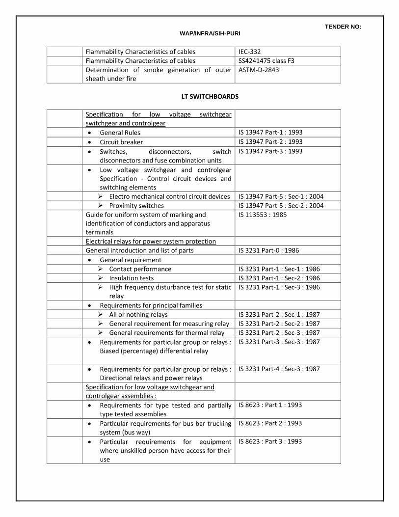
TENDER NO: WAP/INFRA/SIH-PURI
Flammability Characteristics of cables IEC-332
Flammability Characteristics of cables SS4241475 class F3
Determination of smoke generation of outer sheath under fire
ASTM-D-2843`
LT SWITCHBOARDS
Specification for low voltage switchgear switchgear and controlgear
General Rules IS 13947 Part-1 : 1993
Circuit breaker IS 13947 Part-2 : 1993
Switches, disconnectors, switch disconnectors and fuse combination units
IS 13947 Part-3 : 1993
Low voltage switchgear and controlgear Specification - Control circuit devices and switching elements
Electro mechanical control circuit devices IS 13947 Part-5 : Sec-1 : 2004
Proximity switches IS 13947 Part-5 : Sec-2 : 2004
Guide for uniform system of marking and identification of conductors and apparatus terminals
IS 113553 : 1985
Electrical relays for power system protection
General introduction and list of parts IS 3231 Part-0 : 1986
General requirement
Contact performance IS 3231 Part-1 : Sec-1 : 1986
Insulation tests IS 3231 Part-1 : Sec-2 : 1986
High frequency disturbance test for static relay
IS 3231 Part-1 : Sec-3 : 1986
Requirements for principal families
All or nothing relays IS 3231 Part-2 : Sec-1 : 1987
General requirement for measuring relay IS 3231 Part-2 : Sec-2 : 1987
General requirements for thermal relay IS 3231 Part-2 : Sec-3 : 1987
Requirements for particular group or relays : Biased (percentage) differential relay
IS 3231 Part-3 : Sec-3 : 1987
Requirements for particular group or relays : Directional relays and power relays
IS 3231 Part-4 : Sec-3 : 1987
Specification for low voltage switchgear and controlgear assemblies :
Requirements for type tested and partially type tested assemblies
IS 8623 : Part 1 : 1993
Particular requirements for bus bar trucking system (bus way)
IS 8623 : Part 2 : 1993
Particular requirements for equipment where unskilled person have access for their use
IS 8623 : Part 3 : 1993
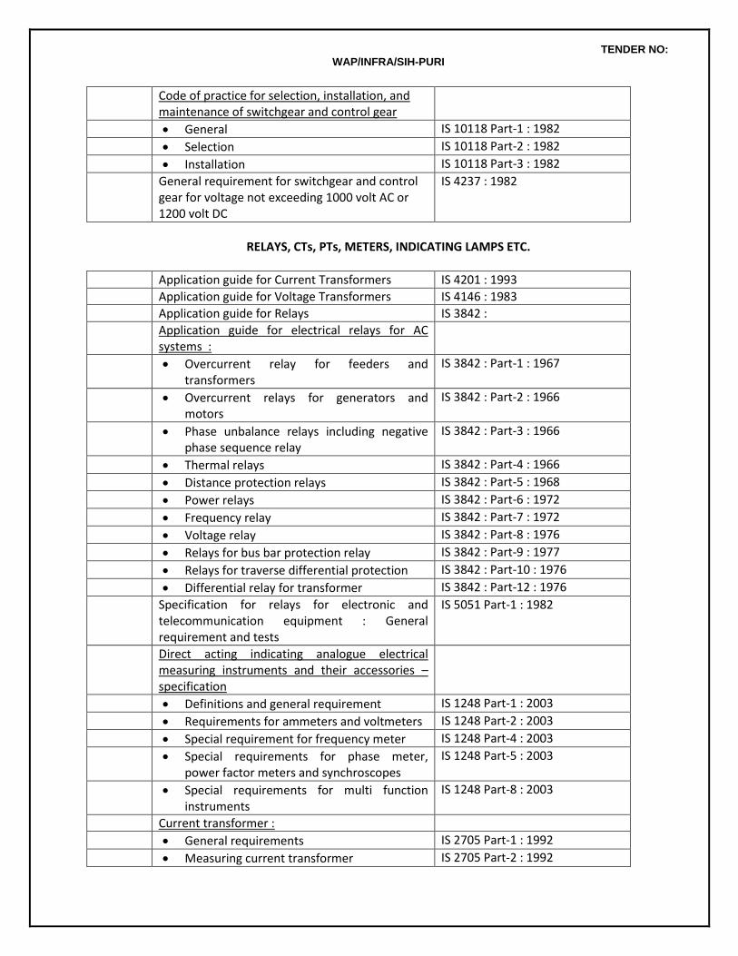
TENDER NO: WAP/INFRA/SIH-PURI
Code of practice for selection, installation, and maintenance of switchgear and control gear
General IS 10118 Part-1 : 1982
Selection IS 10118 Part-2 : 1982
Installation IS 10118 Part-3 : 1982
General requirement for switchgear and control gear for voltage not exceeding 1000 volt AC or 1200 volt DC
IS 4237 : 1982
RELAYS, CTs, PTs, METERS, INDICATING LAMPS ETC.
Application guide for Current Transformers IS 4201 : 1993
Application guide for Voltage Transformers IS 4146 : 1983
Application guide for Relays IS 3842 :
Application guide for electrical relays for AC systems :
Overcurrent relay for feeders and transformers
IS 3842 : Part-1 : 1967
Overcurrent relays for generators and motors
IS 3842 : Part-2 : 1966
Phase unbalance relays including negative phase sequence relay
IS 3842 : Part-3 : 1966
Thermal relays IS 3842 : Part-4 : 1966
Distance protection relays IS 3842 : Part-5 : 1968
Power relays IS 3842 : Part-6 : 1972
Frequency relay IS 3842 : Part-7 : 1972
Voltage relay IS 3842 : Part-8 : 1976
Relays for bus bar protection relay IS 3842 : Part-9 : 1977
Relays for traverse differential protection IS 3842 : Part-10 : 1976
Differential relay for transformer IS 3842 : Part-12 : 1976
Specification for relays for electronic and telecommunication equipment : General requirement and tests
IS 5051 Part-1 : 1982
Direct acting indicating analogue electrical measuring instruments and their accessories – specification
Definitions and general requirement IS 1248 Part-1 : 2003
Requirements for ammeters and voltmeters IS 1248 Part-2 : 2003
Special requirement for frequency meter IS 1248 Part-4 : 2003
Special requirements for phase meter, power factor meters and synchroscopes
IS 1248 Part-5 : 2003
Special requirements for multi function instruments
IS 1248 Part-8 : 2003
Current transformer :
General requirements IS 2705 Part-1 : 1992
Measuring current transformer IS 2705 Part-2 : 1992
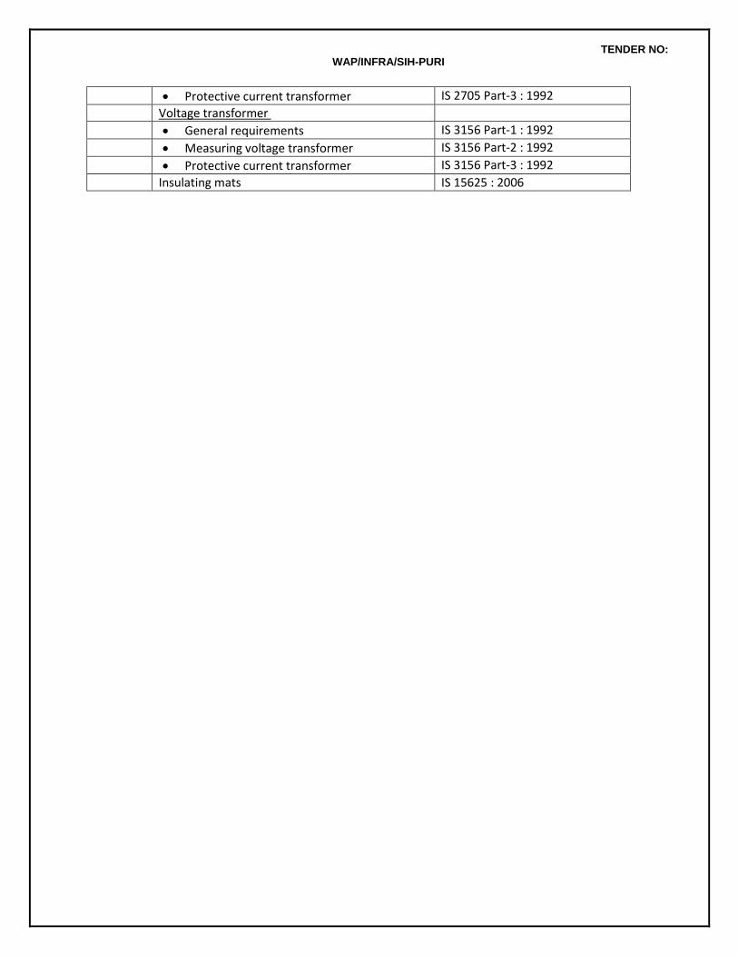
TENDER NO: WAP/INFRA/SIH-PURI
Protective current transformer IS 2705 Part-3 : 1992
Voltage transformer
General requirements IS 3156 Part-1 : 1992
Measuring voltage transformer IS 3156 Part-2 : 1992
Protective current transformer IS 3156 Part-3 : 1992
Insulating mats IS 15625 : 2006
TENDER NO: WAP/INFRA/SIH-PURI
SPECIAL INSTRUCTIONS TO TENDERER 1. GENERAL
Rates quoted shall be for work to be carried out at all heights and levels as required at site. No extra payment on this account shall be admissible.
2 WIRING
Rates quoted for Point Wiring items shall be based on average wiring and average conduting length in all areas of the project. irrespective of their being shown in tender drawings or not. No extra claim on this account shall be admissible.
Cost of circuit wiring (wiring from DB terminal to the first switch in any sub circuit) is included in the scope of Point Wiring item. Circuit wiring shall not be paid extra.
Rate quoted for Point Wiring for ceiling fan points shall also include the cost of providing fan hook cum outlet box in the ceiling. The switchbox shall have space provision for electronic fan regulator.
Same rate shall be payable for wiring in surface conduting system or recessed conduting system
Recessed conduting work shall be carried out in close co-ordination with progress of civil works Conduting system in slabs shall be laid on shuttering before concrete is poured. Chases in brick work shall be made prior to plastering. Cutting of concrete or plaster for conduit laying shall not be permitted.
Wiring colour code – Red, Yellow, Blue for three Phases, Black for Neutral and Green for Earth – shall be maintained for entire wiring except on UPS
UPS wiring colour code – Red/white, Yellow/white, Blue/white for three Phases, white for Neutral and Green/yellow for Earth shall be maintained for wiring on UPS system.
All wiring accessories (switches, socket outlets, bell pushes etc..), shall be as per approved make, type and colour. Sample of each type shall be got approved by Architect/Owners before use on work.
Socket outlets on UPS and on normal supply shall be designated and labeled as “UPS” and “Raw Power” in a manner specifically got approved from Architects/ Owners
Rates for wiring of IP 56/metalclad 20/32 amps single/three phase socket outlets shall include the cost of matching plugs also.
3 SUB-MAINS AND MAINS.
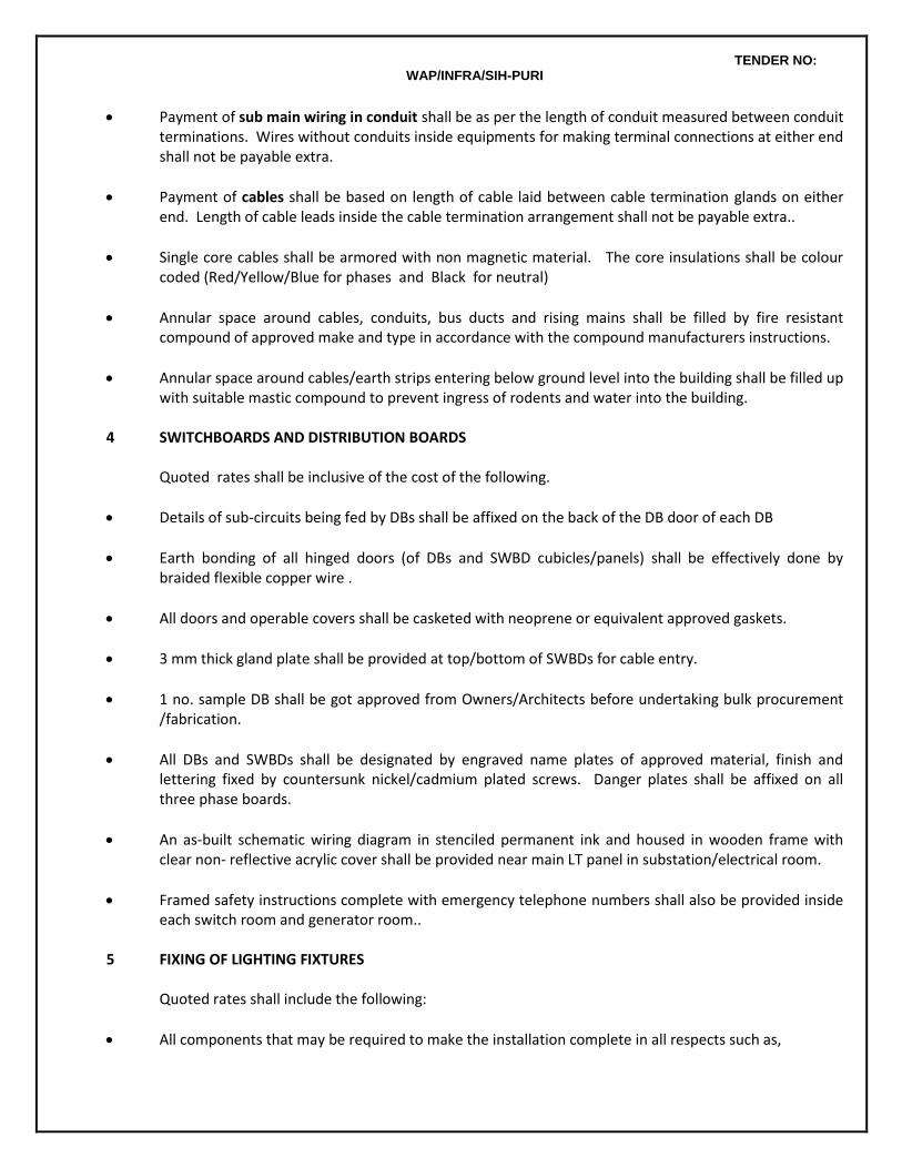
TENDER NO: WAP/INFRA/SIH-PURI
Payment of sub main wiring in conduit shall be as per the length of conduit measured between conduit terminations. Wires without conduits inside equipments for making terminal connections at either end shall not be payable extra.
Payment of cables shall be based on length of cable laid between cable termination glands on either end. Length of cable leads inside the cable termination arrangement shall not be payable extra..
Single core cables shall be armored with non magnetic material. The core insulations shall be colour coded (Red/Yellow/Blue for phases and Black for neutral)
Annular space around cables, conduits, bus ducts and rising mains shall be filled by fire resistant compound of approved make and type in accordance with the compound manufacturers instructions.
Annular space around cables/earth strips entering below ground level into the building shall be filled up with suitable mastic compound to prevent ingress of rodents and water into the building.
4 SWITCHBOARDS AND DISTRIBUTION BOARDS
Quoted rates shall be inclusive of the cost of the following.
Details of sub-circuits being fed by DBs shall be affixed on the back of the DB door of each DB
Earth bonding of all hinged doors (of DBs and SWBD cubicles/panels) shall be effectively done by braided flexible copper wire .
All doors and operable covers shall be casketed with neoprene or equivalent approved gaskets.
3 mm thick gland plate shall be provided at top/bottom of SWBDs for cable entry.
1 no. sample DB shall be got approved from Owners/Architects before undertaking bulk procurement /fabrication.
All DBs and SWBDs shall be designated by engraved name plates of approved material, finish and lettering fixed by countersunk nickel/cadmium plated screws. Danger plates shall be affixed on all three phase boards.
An as-built schematic wiring diagram in stenciled permanent ink and housed in wooden frame with clear non- reflective acrylic cover shall be provided near main LT panel in substation/electrical room.
Framed safety instructions complete with emergency telephone numbers shall also be provided inside each switch room and generator room..
5 FIXING OF LIGHTING FIXTURES Quoted rates shall include the following:
All components that may be required to make the installation complete in all respects such as,
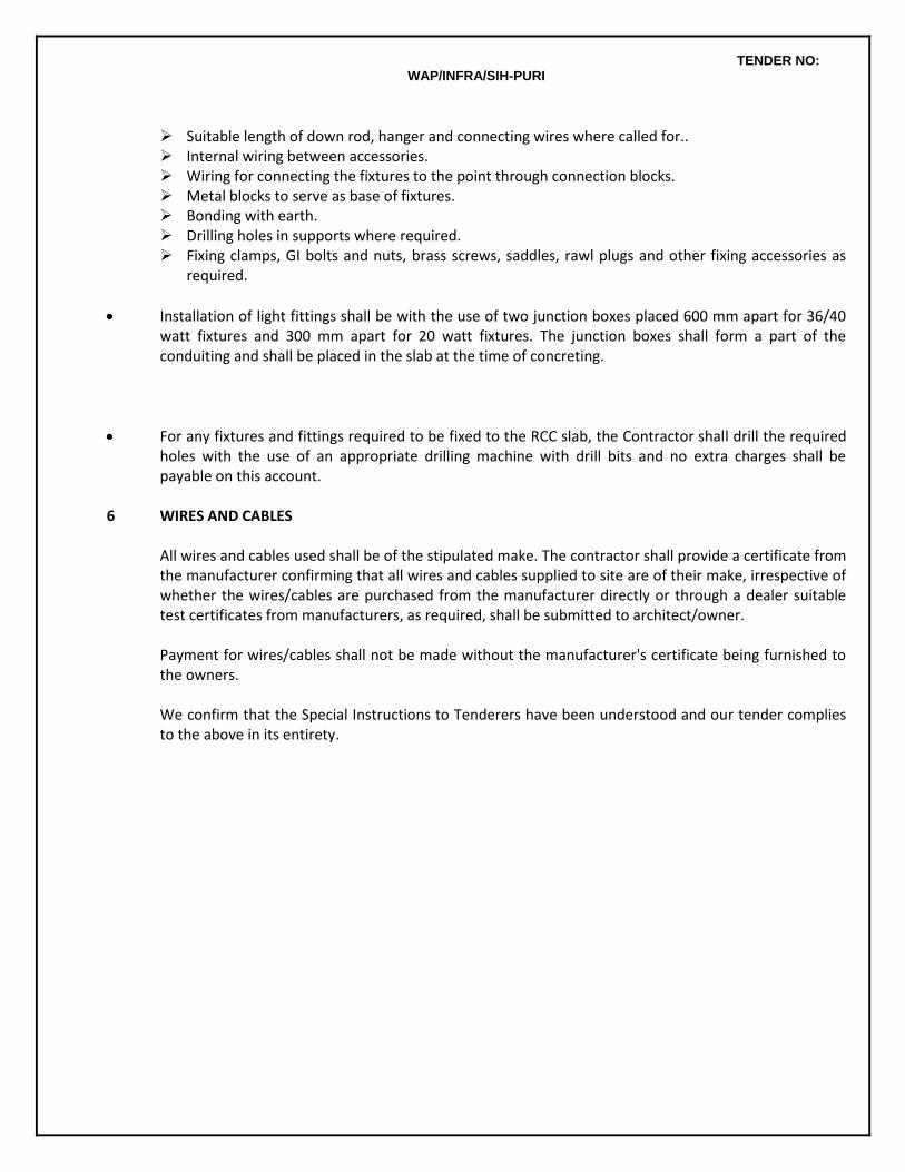
TENDER NO: WAP/INFRA/SIH-PURI
Suitable length of down rod, hanger and connecting wires where called for.. Internal wiring between accessories. Wiring for connecting the fixtures to the point through connection blocks. Metal blocks to serve as base of fixtures. Bonding with earth. Drilling holes in supports where required. Fixing clamps, GI bolts and nuts, brass screws, saddles, rawl plugs and other fixing accessories as
required.
Installation of light fittings shall be with the use of two junction boxes placed 600 mm apart for 36/40 watt fixtures and 300 mm apart for 20 watt fixtures. The junction boxes shall form a part of the conduiting and shall be placed in the slab at the time of concreting.
For any fixtures and fittings required to be fixed to the RCC slab, the Contractor shall drill the required holes with the use of an appropriate drilling machine with drill bits and no extra charges shall be payable on this account.
6 WIRES AND CABLES All wires and cables used shall be of the stipulated make. The contractor shall provide a certificate from
the manufacturer confirming that all wires and cables supplied to site are of their make, irrespective of whether the wires/cables are purchased from the manufacturer directly or through a dealer suitable test certificates from manufacturers, as required, shall be submitted to architect/owner.
Payment for wires/cables shall not be made without the manufacturer's certificate being furnished to
the owners. We confirm that the Special Instructions to Tenderers have been understood and our tender complies
to the above in its entirety.
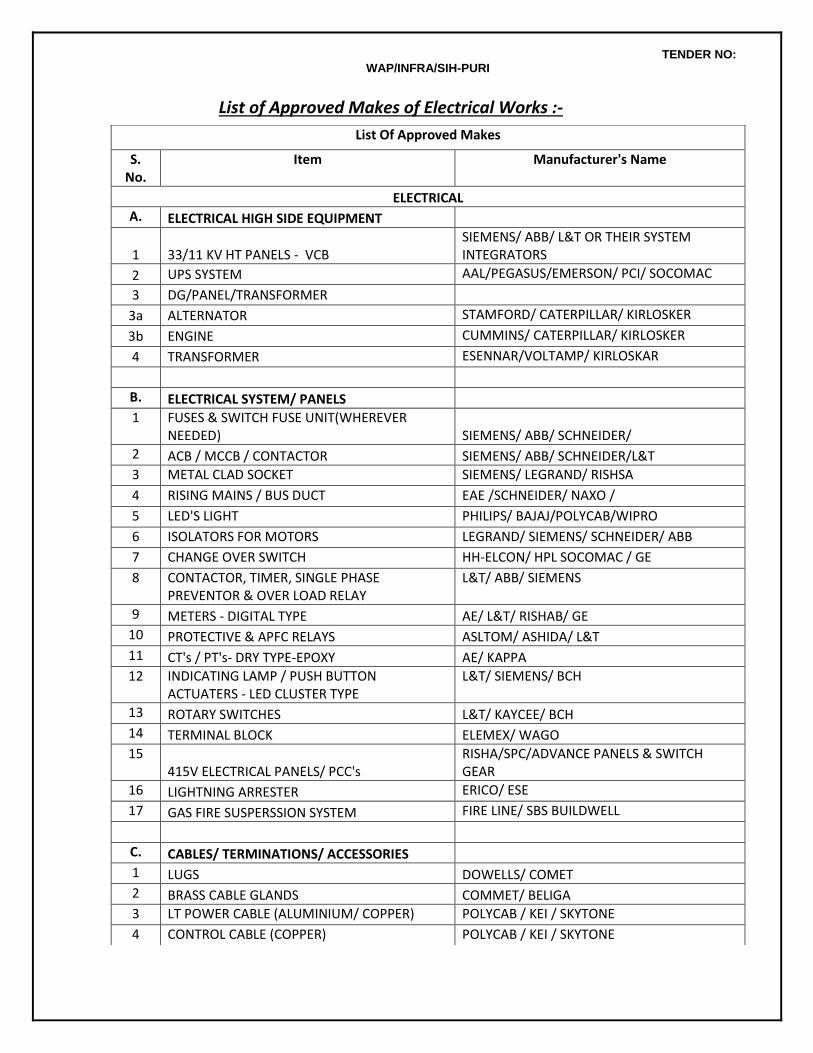
TENDER NO: WAP/INFRA/SIH-PURI
List of Approved Makes of Electrical Works :-
List Of Approved Makes
S. No.
Item Manufacturer's Name
ELECTRICAL
A. ELECTRICAL HIGH SIDE EQUIPMENT
1 33/11 KV HT PANELS - VCB SIEMENS/ ABB/ L&T OR THEIR SYSTEM INTEGRATORS
2 UPS SYSTEM AAL/PEGASUS/EMERSON/ PCI/ SOCOMAC
3 DG/PANEL/TRANSFORMER
3a ALTERNATOR STAMFORD/ CATERPILLAR/ KIRLOSKER
3b ENGINE CUMMINS/ CATERPILLAR/ KIRLOSKER
4 TRANSFORMER ESENNAR/VOLTAMP/ KIRLOSKAR
B. ELECTRICAL SYSTEM/ PANELS
1 FUSES & SWITCH FUSE UNIT(WHEREVER NEEDED) SIEMENS/ ABB/ SCHNEIDER/
2 ACB / MCCB / CONTACTOR SIEMENS/ ABB/ SCHNEIDER/L&T
3 METAL CLAD SOCKET SIEMENS/ LEGRAND/ RISHSA
4 RISING MAINS / BUS DUCT EAE /SCHNEIDER/ NAXO /
5 LED'S LIGHT PHILIPS/ BAJAJ/POLYCAB/WIPRO
6 ISOLATORS FOR MOTORS LEGRAND/ SIEMENS/ SCHNEIDER/ ABB
7 CHANGE OVER SWITCH HH-ELCON/ HPL SOCOMAC / GE
8 CONTACTOR, TIMER, SINGLE PHASE PREVENTOR & OVER LOAD RELAY
L&T/ ABB/ SIEMENS
9 METERS - DIGITAL TYPE AE/ L&T/ RISHAB/ GE
10 PROTECTIVE & APFC RELAYS ASLTOM/ ASHIDA/ L&T
11 CT's / PT's- DRY TYPE-EPOXY AE/ KAPPA
12 INDICATING LAMP / PUSH BUTTON ACTUATERS - LED CLUSTER TYPE
L&T/ SIEMENS/ BCH
13 ROTARY SWITCHES L&T/ KAYCEE/ BCH
14 TERMINAL BLOCK ELEMEX/ WAGO
15 415V ELECTRICAL PANELS/ PCC's
RISHA/SPC/ADVANCE PANELS & SWITCH GEAR
16 LIGHTNING ARRESTER ERICO/ ESE
17 GAS FIRE SUSPERSSION SYSTEM FIRE LINE/ SBS BUILDWELL
C. CABLES/ TERMINATIONS/ ACCESSORIES
1 LUGS DOWELLS/ COMET
2 BRASS CABLE GLANDS COMMET/ BELIGA
3 LT POWER CABLE (ALUMINIUM/ COPPER) POLYCAB / KEI / SKYTONE
4 CONTROL CABLE (COPPER) POLYCAB / KEI / SKYTONE

TENDER NO: WAP/INFRA/SIH-PURI
5 33/11 KV HT XLPE CABLE POLYCAB / KEI / SKYTONE
6 H.T. CABLE END TERMINATION BIRLA 3 M/ REYCHEM/ FRONTEC
D. CONDUITING & WIRING ACCESSORIES
1 MS CONDUIT / GI CONDUIT (ISI MARKED) BEC/ AKG
2 PVC CONDUIT (ISI MARKED) BEC/ AKG
3 PVC INSULATED COPPER CONDUCTOR FRLS WIRE
POLYCAB / BATRA HENLAY/RR KABLE/
4 PLATE TYPE - SWITCHES / SOCKETS / TV & TELEPHONE SOCKETS AND ALL OTHER WIRING ACCESSORIES
LEGRAND/ ANCHOR-ROMA
5 ACCESSORIES FOR METALIC / GI CONDUIT ( ISI MARKED )
SHRMA STEEL CORPORATION / PRAKASH ENGINEERING WORKS / SUPER SALES CORPORATION
6 PVC INSULATION TAPE STEEL GRIP/ ANCHOR
7 PHENOL LAMINATED SHEET HYLUM/ FORMICA
8 RACEWAYS & CABLE TRAY MEM/INDEANA
9 TERMINATIONS WIRE NUTS
E. LIGHTING DBs & MCBs
1 MCB,10KA LEGRAND/ SIEMENS/ ABB / INDO ASIAN
2 DISTRIBUTION BOARD LEGRAND/ SIEMENS/ ABB / INDO ASIAN
3 ELCB / ELMCB / RCCB LEGRAND/ SIEMENS/ ABB / INDO ASIAN
F. LIGHTING FIXTURES & FANS
1 BULK HEAD FITTINGS BAJAJ/POLYCAB/PHILIPS/WIPRO/ CROMPTON
2 EXHAUST FANS / CEILING FAN / WALL MOUNTED FAN
HAVELLS/BAJAJ/POLYCAB/ CROMPTON
3 LIGHTING FIXTURES PHILIPS/WIPRO/SYLVANIA/REGENT- TO BE APPROVED BY ARCHITECS
4 LIGHTING CONTROL SYSTEM BAJAJ/POLYCAB/PHILIPS/WIPRO/ CROMPTON
G. ELV- TELEPHONE/ CCTV/ DOOR ACCESS/ FIRE ALARM/ PUBLIC ADDRESS & MISC. SYSTEMS
1 SMOKE DETECTORS NOTIFIER/ HONEYWELL(XLS)/ SIEMENS
2 HEAT DETECTORS NOTIFIER/ HONEYWELL(XLS)/ SIEMENS
3 MANUAL CALL BOX NOTIFIER/ HONEYWELL(XLS)/ SIEMENS
4 HOOTER/ SOUNDER NOTIFIER/ HONEYWELL(XLS)/ SIEMENS
5 RESPONSE INDICATOR NOTIFIER/ HONEYWELL(XLS)/ SIEMENS
6 FIRE PANEL NOTIFIER/ HONEYWELL(XLS)/ SIEMENS
7 PA AMPLIFIER BOSE/ PHILIPS/ AHUJA
8 PA SPEAKERS BOSE/ PHILIPS/ AHUJA
9 LINE MATCHING TRANSFORMER BOSE/ PHILIPS/ AHUJA
10 GOOSE NECK MIKE BOSE/ PHILIPS/ AHUJA
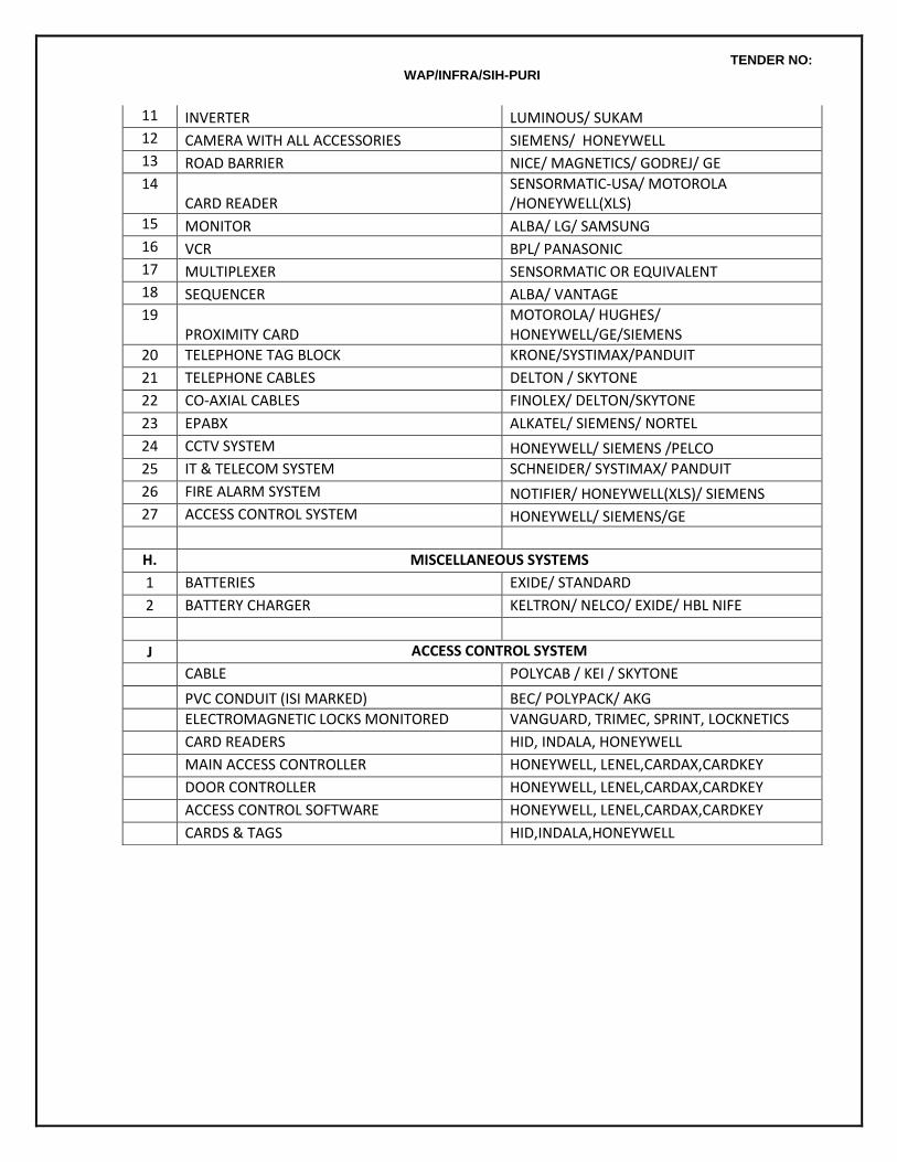
TENDER NO: WAP/INFRA/SIH-PURI
11 INVERTER LUMINOUS/ SUKAM
12 CAMERA WITH ALL ACCESSORIES SIEMENS/ HONEYWELL
13 ROAD BARRIER NICE/ MAGNETICS/ GODREJ/ GE
14 CARD READER
SENSORMATIC-USA/ MOTOROLA /HONEYWELL(XLS)
15 MONITOR ALBA/ LG/ SAMSUNG
16 VCR BPL/ PANASONIC
17 MULTIPLEXER SENSORMATIC OR EQUIVALENT
18 SEQUENCER ALBA/ VANTAGE
19 PROXIMITY CARD
MOTOROLA/ HUGHES/ HONEYWELL/GE/SIEMENS
20 TELEPHONE TAG BLOCK KRONE/SYSTIMAX/PANDUIT
21 TELEPHONE CABLES DELTON / SKYTONE
22 CO-AXIAL CABLES FINOLEX/ DELTON/SKYTONE
23 EPABX ALKATEL/ SIEMENS/ NORTEL
24 CCTV SYSTEM HONEYWELL/ SIEMENS /PELCO
25 IT & TELECOM SYSTEM SCHNEIDER/ SYSTIMAX/ PANDUIT
26 FIRE ALARM SYSTEM NOTIFIER/ HONEYWELL(XLS)/ SIEMENS
27 ACCESS CONTROL SYSTEM HONEYWELL/ SIEMENS/GE
H. MISCELLANEOUS SYSTEMS
1 BATTERIES EXIDE/ STANDARD
2 BATTERY CHARGER KELTRON/ NELCO/ EXIDE/ HBL NIFE
J ACCESS CONTROL SYSTEM
CABLE POLYCAB / KEI / SKYTONE
PVC CONDUIT (ISI MARKED) BEC/ POLYPACK/ AKG
ELECTROMAGNETIC LOCKS MONITORED VANGUARD, TRIMEC, SPRINT, LOCKNETICS
CARD READERS HID, INDALA, HONEYWELL
MAIN ACCESS CONTROLLER HONEYWELL, LENEL,CARDAX,CARDKEY
DOOR CONTROLLER HONEYWELL, LENEL,CARDAX,CARDKEY
ACCESS CONTROL SOFTWARE HONEYWELL, LENEL,CARDAX,CARDKEY
CARDS & TAGS HID,INDALA,HONEYWELL

TENDER NO: WAP/INFRA/SIH-PURI
C.TECHNICAL SPECIFICATIONS - PLUMBING & FIRE FIGHTING WORKS
SECTION - 01 :: BASIS OF DESIGN
1. BASIS OF DESIGN
The Plumbing, Sanitary, Drainage & Fire Protection System for the project is designed keeping in view the following:
1.1 Requirement of adequate and equal pressure availability of cold & Hot water lines in Toilets, Pantry/Kitchen etc.
1.2 Adequate storage of water in under ground raw + treated domestic water tanks.
1.3 Provision of fire fighting appurtenance such as fire hydrants, hose reel, and portable extinguishers.
1.4 Levels of roads / pavements and other services in the area.
1.5 Landscape layout.
The execution of works and materials used shall be as per the latest relevant I.S. specifications. The extension of work shall in stick compliance to the Environmental Clearance granted by MoEF, Govt. of India & NOC issued by Fire Department. Wherever reference has been made to Indian Standard or any other specifications, the same shall mean to refer to the latest specification irrespective of any particular edition of such specification being mentioned in the specifications below or Schedule of Quantities.
2. CONCEPT OF THE SYSTEM
The following services are envisaged for the complex:
2.1 Water Treatment System for meeting the domestic water quality requirement with chemical parameters in acceptable limits as per SP:35(S & T) 1987 which is considered safe for human consumption, and other standards such as IS 10392 for boiler feed water quality.
2.2 Domestic (Cold) & Hot water supply through Gravity System.
2.3 Sewage and Sullage collection system based on IS: 1742 and applicable standards for domestic drainage.
2.4 Sewer connection to municipal sewer main.
2.5 Storm / Rain water drainage system from various levels of the building and disposal rain water harvesting pit & is overflow to available municipal storm water disposal.
2.6 Fire Fighting system for the Complex comprising of Hydrant, Hose Reels and portable fire extinguishers.
3. WATER STORAGE & DISTRIBUTION SYSTEM
3.1 Water Requirement
The water requirement for the project is proposed to be based on the provisions of IS:1172 and prevalent practice. The estimated requirement of water per day for the Complex is based on the number of users and other services.
3.2 Source of Water
TENDER NO: WAP/INFRA/SIH-PURI
It is expected that part of the daily domestic water requirement for the Complex shall be through Municipal mains supply.
3.3 Water Storage
The static storage for Fire Protection is at present sized for 100 KL.
3.4 Water Quality
Disinfected Water: It is proposed to provide localized water purifier units for water consumption points for direct consumption in Pantry.
3.5 Water Distribution
Domestic water supply to toilets will be provided through gravity.
3.6 Appurtenant
Following components shall be included in the water supply system for efficient functioning:
i). Pressure Gauge.
ii). Isolation valve for toilet /pantry/ kitchen
4. SEWAGE, SULLAGE AND STORM WATER
The soil and waste shall be carried down in separate independently vented pipes. Two pipe drainage systems shall be adopted as per NBC (Part-IX).
4.1 Design Limitations
The system is designed considering the following:
1. High thrust developed at soil & water pipe connections.
2. Termination of vent cowl at terrace level.
3. Provision of adequate slope for horizontal header pipes for achieving self-cleaning velocity in the pipes.
4. Provision of cleanout plug.
5. WORKMANSHIP
The workmanship shall be best of its kind and shall conform to the specifications, as below or Indian Standard Specifications in every respect or latest trade practices and shall be subject to approval of the Owner’s Site Representative. All materials and/or Workmanship which in the opinion of the Owner’s Site Representative / Architect / Consultant is defective or unsuitable shall be removed immediately from the site and shall be substituted with proper materials and/or workmanship forthwith.
6. MATERIALS All materials shall be best of their kind and shall conform to the latest Indian Standards. All materials shall be of approved quality as per samples and origins approved by the Owner’s Site Representative / Architect / Consultants. As and when required by the Owner’s Site Representative / Consultant, the contractor shall arrange to test the materials and/or portions of works at his own cost to prove their soundness and efficiency. If after tests any materials, work or portions or work are found defective or unsound by the Owner’s Site Representative / Consultant, the contractor shall remove the defective material from the site, pull down and re-execute the works at his own cost to the satisfaction of the Owner’s Site Representative / Consultant. To prove that the materials used are as specified the contractor shall furnish the Owner’s Site Representative with original vouchers on demand.
TENDER NO: WAP/INFRA/SIH-PURI
SECTION - 02 :: SANITARY FIXTURES & FITTINGS
1. SCOPE
The scope of this section consists of but is not necessarily limited to supply, installation, testing and commissioning of following items:
a. Sanitary appliances and fixtures for toilets.
b. Chromium plated brass fittings
c. Stainless steel sink
d. Hand driers, drinking water fountains etc.
Whether specifically mentioned or not the Contractor shall provide for all appliances and fixtures all fixing devices, nuts, bolts, screws, hangers as required. All exposed pipes within toilets and near appliances/fixtures shall be of chromium plated brass or copper unless otherwise specified.
2. GENERAL REQUIREMENT
Sanitary appliances and fixtures for toilets, chromium plated brass fittings, stainless steel sink, bathroom accessories like toilet paper holder etc as listed in the relevant items in the Schedule of Quantities shall be procured by the contractor. The rates shall be inclusive of accessories (in such case) required for installation. All appliances, fixtures and fittings shall be provided with all such accessories as are required to complete the item in working condition whether specifically mentioned or not in the Schedule of Quantities, specifications, drawings. Accessories shall include proper fixing arrangements, brackets, nuts, bolts, washers, screws and required connection pieces. The sanitary fixtures and fittings shall be installed at the correct assigned position as shown on the drawings and as directed by the Architect / Owner’s Site Representative and shall fully meet with the aesthetic and symmetrical requirements as demanded by the Architect / Interior Designer All fixtures and accessories shall be fixed in accordance with a set pattern matching the tiles or interior finish as per Architect requirements. Wherever necessary, the fittings shall be centered to dimensions and pattern as called for. Fixing screws shall be half round head chromium plated (CP) brass screws, with CP brass washers unless otherwise specified. Fixtures shall be installed by skilled workman with appropriate tools according to the best trade practice. All appliances , fittings and fixtures shall be fixed in a neat workmanlike manner true to level and to heights shown on the drawings and in accordance with the manufacturers recommendations. Care shall be taken to fix all inlet and outlet pipes at correct positions. Faulty locations shall be made good and any damage to the finished floor, tiling, plaster, paint, insulation or terrace shall be made good by the Contractor at his own cost. Fixtures shall be mounted rigid, plumb and true to alignment. All materials shall be rust proofed; materials in direct or indirect contact shall be compatible to prevent electrolytic or chemical (bimetallic) corrosion. Wall flanges shall be provided on all walls, floors, columns etc. wherever supply and disposal pipes pierce through them. These wall caps shall be or chromium plated brass fittings and the receiving pipes and shall be large enough to cover the punctures properly. Sanitary appliances, subject to the type of appliance and specific requirements, shall be fixed in accordance with the relevant standards and the following:
i. Contractor shall, during the entire period of installation and afterwards protect the appliances by providing suitable cover or any other protection so as to absolutely prevent any damage to the appliances until handing over (The original protective wrapping shall be left in position for as long as possible)
ii. The appliances shall be placed in correct position or marked out in order that pipe work can be fixed or partially fixed first.
iii. The appliance shall be fixed in a manner such that it will facilitate subsequent removal if necessary.
iv. The appliance shall be securely fixed. Manufacturer's brackets and fixing methods shall be used
TENDER NO: WAP/INFRA/SIH-PURI
wherever possible. Compatible rust-proofed fixings shall be used. Fixing shall be done in a manner that minimizes noise transmission.
v. Appliances shall not be bedded (e.g. WC pans, pedestal units) in thick strong mortar that could crack the unit (e.g. ceramic unit)
vi. Pipe connections shall be made with demountable unions. Pipe work shall not be fixed in a manner that it supports or partially supports and appliance.
vii. Appliances shall be fixed true to level firmly fixed to anchor or supports provided by the manufacturer and additional anchors or supports where necessary.
Sizes of sanitary fixtures given in the Specifications or in the Schedule of Quantities are for identification with reference to the catalogues of make considered. Dimensions of similar models of other makes may very within + 10% and the same shall be provided and no claim for extra payment shall be entertained NOR shall any payment be deducted on this account. The contractor shall fix all plumbing fittings such as water faucets, shower fittings, mixing valves etc. in accordance with manufacturer’s instructions and connect to piping system. The contractor shall supply all fixing materials such as screws, rawl plugs, unions, collars, compression fittings etc., as required. Joints / gaps between all sanitary appliances / fixtures and the floor / walls shall be caulked with an approved mildew resistant sealant, having antifungal properties, of colour and shade to match that of the appliances / fixture and the floor / wall to the extent possible.
2.1 Water Closet
Water Closet shall be wash down or symphonic wash down type floor or wall mounted set, as shown in the drawings, designed for low volume flushing from 3-6 litres of water, flushed by means of a porcelain flushing cistern or an exposed or concealed type (as detailed in the drawings or as directed by the Owner’s Site Representative). Flush pipe / bend shall be connected to the WC by means of a suitable rubber adaptor. Wall hung WC shall be supported by CI floor mounted chair which shall be fixed in a manner as approved by the Owners Site Representative. Each WC set shall be provided with approved quality of seat, rubber buffers and chromium plated hinges. Seat shall be so fixed that it remains absolutely stationary in vertical position without falling down on the WC. Each WC shall be provided with 110 mm dia (OD) PVC Pan connector connecting the ceramic outlet of WC to pipe.
2.2 Urinals
Urinals shall be lipped type half stall with glazed vitreous China of size as called for in the Bill of Quantities. Half stall urinals shall be provided with 15mm dia CP spreader, 32mm dia CP domical waste and CP cast brass bottle trap with pipe and wall flange and shall be fixed to wall by CI brackets, CI wall clips and CP brass screws as recommended by manufacturer complete as directed by the Owner’s Site Representative. Flushing for urinals shall be by means of no hand operation, infrared electric flush valve with complete kit of plumbing, electrical and electronic items, infrared photo cells, solenoid valve transformer and electrical connection. The automatic flush sensor plate shall be flush and press fitted and be of high quality mirror polish finish. Each urinal shall be provided with one flush valve unit. Flush pipes shall be concealed in wall chase but with chromium plated bends at inlet and outlet.
Urinal Partitions
Urinal partitions shall be white glazed vitreous china of size specified in the Schedule of Quantities.
Porcelain partitions shall be fixed at proper heights with CP brass bolts, anchor fasteners and MS clips as recommended by the manufacturer and directed by the Owner’s Site Representative.
2.3 Cisterns
TENDER NO: WAP/INFRA/SIH-PURI
Low level flushing cistern (exposed or concealed) shall be provided for WC in specified toilets. Contractor shall install cistern in accordance to the manufacturer’s specification to the satisfaction of the Owner Site Representative.
2.4 Wash Basin
Wash basins shall be white glazed vitreous china of size, shape and type specified in the Schedule of Quantities. Each basin shall be provided with painted MS angle or CI brackets and clips and the basin securely fixed to wall/counter slab. Placing of basins over the brackets without secure fixing shall not be accepted. The MS angle shall be provided with two coats of red oxide primer and two coats of synthetic enamel paint of make , brand and colour as approved by the Owner’s Site Representative. The cost of fixing the basin shall be inclusive of supply and installation of brackets as described above.Each basin shall be provided with 32mm dia CP waste with overflow, CP waste as specified in the Schedule of Quantities. Each basin shall be provided with hot and cold water mixing fitting or as specified in the Schedule of Quantities.
2.5 Sinks
Sinks shall be stainless steel or any other material as specified in the Schedule of Quantities. Each sink shall be provided with painted MS or CI brackets and clips and securely fixed. Counter top sinks shall be fixed with suitable painted angle iron brackets or clips as recommended by the manufacturer. Each sink shall be provided with 40mm dia CP waste and rubber plug with CP brass chain as given in the Schedule of Quantities. The MS angle shall be provided with two coats of red oxide primer and two coats of synthetic enamel paint of make, brand and colour as approved by the Owner’s site representative. Sanitary fittings for sinks shall be deck mounted or wall mounted CP swivel faucets with or without hot and cold water mixing fittings as specified in the Schedule of Quantities. Installation of fittings shall be measured and paid for separately.
2.6 Toilet Paper Holder
Toilet paper holder shall be white glazed vitreous china or chrome plated of size, shape and type specified in the Schedule of Quantities.Porcelain toilet paper holder shall be fixed in walls and set in cement mortar 1:2 (1 cement: 2 coarse sand) and fixed in relation to the tiling work.The latter (chrome) shall be fixed by means of screws/capping having finish similar to the toilet paper holder in wall/temper partitions with raw l plugs or nylon sleeves. When fixed on timber partition, it shall be fixed on a solid wooden base member provided by the Owner’s Site Representative.
2.7 Towel Rail
Towel rail shall be chromium plated brass or of stainless steel or powder coated brass of size, shape and type specified in the Schedule of Quantities. Towel rail shall be fixed with screws/capping having finish similar to the towel rail in wall with rawl plugs or nylon sleeves and shall include cutting and making good as required or directed by the Owner’s Site Representative.
2.8 Janitor's Sink
Janitor's sink shall be stainless steel, single bowl type of size as called for in the Schedule of Quantities, provided with painted R.S. or CI brackets and clips and securely fixed. Each sink shall be provided with 40mm dia CP waste. Fixing shall be as directed by the Owner’s Site Representative.The supply fittings for Janitor's sink shall be wall mounted type of size as mentioned in Schedule of Quantities.
TENDER NO: WAP/INFRA/SIH-PURI
2.9 Drinking Water Fountain
Drinking water fountain shall be well mounting type made of vitreous china, stainless steel or any other material as given in the Schedule of Quantities.The drinking water fountain shall be with anti-squirt bubble less, self closing valve type with automatic volume regulator. The drinking water fountain shall be provided with an anti-splash back and integral strainer with 32mm or 40mm cast brass trap.
2.10 Liquid Soap Dispenser
Liquid Soap Dispenser shall be wall/counter mounted suitable for dispensing liquid soaps, lotions, detergents. The cover shall lock to body with concealed locking arrangement, opened only be key provided. Liquid soap dispenser body and shank shall be of high impact resistance material. The piston and spout shall be stainless steel with 1 litre capacity polyethylene container. The valve shall operate with less than 2.27 Kg (5 lbs) of force.
3. TOILETS FOR THE DISABLED
Where specified, in washroom facilities designed to accommodate physically disabled, accessories shall be provided as directed by the Owner’s Site Representative. Stainless steel garb brass of required size suitable for concealed or exposed mounting and opened non-slip gripping surface shall be provided in all washroom. The flushing cistern/valve shall be provided with chromium plated long handles.
4. MOCKUP AND TRIAL ASSEMBLY
The installation of the Sanitary fixtures and fittings shall be as per the shop drawings approved by the Architect/Consultant.The contractor shall have to assemble at least one set of each type of sanitary fixtures and fittings in order to determine precisely the required supply and disposal connections. Relevant instructions from manufacturers shall be followed as applicable. This trial assembly shall be developed to determine the location of puncture holes, holding devices etc. which will be required for final installation of all sanitary fixtures and fittings. The above assembly shall be subject to final approval by the Architect / Interior Designer. The fixtures in the trial assembly can be re-used for final installation without any additional payments for fixing or dismantling of the fixtures.
5. SUPPORTING AND FIXING DEVICES
The contractor shall provide all the necessary supporting and fixing devices to install the sanitary fixtures and fittings securely in position. The fixing devices shall be rigidly anchored into the building structure. The devices shall be rust resistant and shall be so fixed that they do not present an unsightly appearance in the final assembly. Where the location demands, the Architect may instruct the contractor to provide chromium plated or other similarly finished fixing devices. In such circumstances the contractor shall arrange to supply the fixing devices and shall be installed complete with appropriate vibration isolating pads, washers and gaskets.
6. FINAL INSTALLATION
The contractor shall install all sanitary fixtures and fittings in their final position in accordance with approved trial assemblies and as shown on drawings. The installation shall be complete with all supply and waste connections. The connection between building and piping system and the sanitary fixtures shall be through proper unions and flanges to facilitate removal/replacement of sanitary fixtures without disturbing the built in piping system. All unions and flanges shall match in appearance with other exposed fittings.Fixtures shall be mounted rigid, plumb and to alignment. The outlets of water closet pans and similar appliances shall be examined to ensure that outlet ends are butting on the receiving pipes before making the joints. It shall be ensured that the receiving pipes are clear of obstruction. When fixtures are
TENDER NO: WAP/INFRA/SIH-PURI
being mounted, attention shall be paid to the possibility of movement and settlement by other causes. Overflows shall be made to ensure that necessary anchoring devices have been provided for supporting water closets, wash basins, sinks and other appliances.
7. PROTECTION AGAINST DAMAGE
The contractor shall take every precaution to protect all sanitary fixtures against damage, misuse, cracking, staining, breakage and pilferage by providing proper wrapping and locking arrangement till the completion of the installation. At the time of handing over, the contractor shall clean, disinfect and polish all the fixtures and fittings. Any fixtures and fittings found damaged, cracked chipped stained or scratched shall be removed and new fixtures and fittings free from defects shall be installed at his own cost to complete the work.
8. MEASUREMENT
8.1 Rate for fixing only of sanitary fixtures accessories, CP fittings shall etc. include all items, and operations stated in the respective specifications and bill of quantities and nothing extra is payable.
8.2 Rates for all items under specifications para above shall be inclusive of cutting holes and chases and making good the same, CP screws, nuts, bolts and any fixing arrangements required and recommended by manufacturers, testing and commissioning and making good to the satisfaction of the Owner’s Site Representative.
9. TESTING
All appliances, fixtures and fittings shall be tested before and after installation. Water seals of all appliances shall be tested. The contractor shall block the ends of waste and ventilation pipes and shall conduct an air test.
SECTION - 03 :: WATER SUPPLY (COLD)
1. SCOPE
The scope of this section comprises the supply, installation, testing and commissioning of piping network for water supply for internal & external services as follows:
a Bore well / Municipal / Tanker Water supply.
b. Drinking Water Supply.
c. External water supply to cater for Horticulture .
d. Connection to various mechanical equipments to be supplied and installed by the other specialist contractors.
The Contractor shall make all necessary application and arrangements for his work to be inspected by the Local Authorities.The Contractor shall be solely responsible for obtaining the Authorities approval of his works prior to the handing over of the complete water supply / distribution installation to the Owner.
2. PIPING MATERIALS
The piping system shall consist of CPVC SDR 11.0 piping from 15 mm to 50 mm & Schedule 40 from 65 mm to 150 mm for cold water supply & schedule 80 from 65 mm to 150 mm for hot water supply.The piping system shall also consist of heavy class galvanized iron pipes and fittings conforming to IS:1239. The sizes and makes is specified in the Schedule of Quantities. For any internal works, the CPVC pipes and fittings shall be embedded in the wall chase or run on the floor/ceiling unless otherwise specified. No unsightly exposed runs shall be permitted.
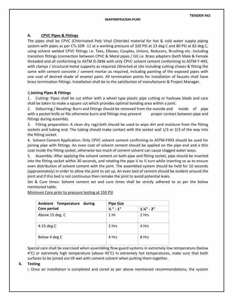
TENDER NO: WAP/INFRA/SIH-PURI
A. CPVC Pipes & Fittings
The pipes shall be CPVC (Chlorinated Poly Vinyl Chloride) material for hot & cold water supply piping system with pipes as per CTs SDR -11 at a working pressure of 320 PSI at 23 deg C and 80 PSI at 82 deg.C, using solvent welded CPVC fittings i.e. Tees, Elbows, Couples, Unions, Reducers, Brushing etc. including transition fittings (connection between CPVC & Metal pipes / GI) i.e. Brass adapters (both Male & Female threaded and all conforming to ASTM D-2846 with only CPVC solvent cement conforming to ASTM F-493, with clamps / structural metal supports as required /directed at site including cutting chases & fitting the same with cement concrete / cement mortar as required, including painting of the exposed pipes with one coat of desired shade of enamel paint. All termination points for installation of faucets shall have brass termination fittings. Installation shall be to the satisfaction of manufacturer & Project Manager.
i).Joining Pipes & Fittings
1. Cutting: Pipes shall be cut either with a wheel type plastic pipe cutting or hacksaw blade and care shall be taken to make a square cut which provides optimal bonding area within a joint.
2. Deburring / Beveling: Burrs and fittings should be removed from the outside and inside of pipe with a pocket knife or file otherwise burrs and fittings may prevent proper contact between pipe and fittings during assembly.
3. Fitting preparation: A clean dry rag/cloth should be used to wipe dirt and moisture from the fitting sockets and tubing end. The tubing should make contact with the socket wall 1/3 or 2/3 of the way into the fitting socket.
4. Solvent Cement Application: Only CPVC solvent cement confirming to ASTM-F493 should be used for joining pipe with fittings. An even coat of solvent cement should be applied on the pipe end and a thin coat inside the fitting socket, otherwise too much of cement solvent can cause clogged water ways.
5. Assembly: After applying the solvent cement on both pipe and fitting socket, pipe should be inserted into the fitting socket within 30 seconds, and rotating the pipe ¼ to ½ turn while inserting so as to ensure even distribution of solvent cement with the joint. The assembled system should be held for 10 seconds (approximately) in order to allow the joint to set up. An even bed of cement should be evident around the joint and if this bed is not continuous then remake the joint to avoid potential leaks.
Set & Cure times: Solvent cement set and cure times shall be strictly adhered to as per the below mentioned table.
Minimum Core prior to pressure testing at 150 PSI
Ambient Temperature during Core period
Pipe Size
½ " - 1" 1.¼" - 2"
Above 15 deg. C 1 Hr 2 Hrs
4-15 deg.C 2 Hrs 4 Hrs
Below 4 deg C 4 Hrs 8 Hrs
Special care shall be exercised when assembling flow guard systems in extremely low temperature (below 4°C) or extremely high temperature (above 45°C) In extremely hot temperatures, make sure that both surfaces to be joined are till wet with cement solvent when putting them together.
6. Testing
i. Once an installation is completed and cored as per above mentioned recommendations, the system
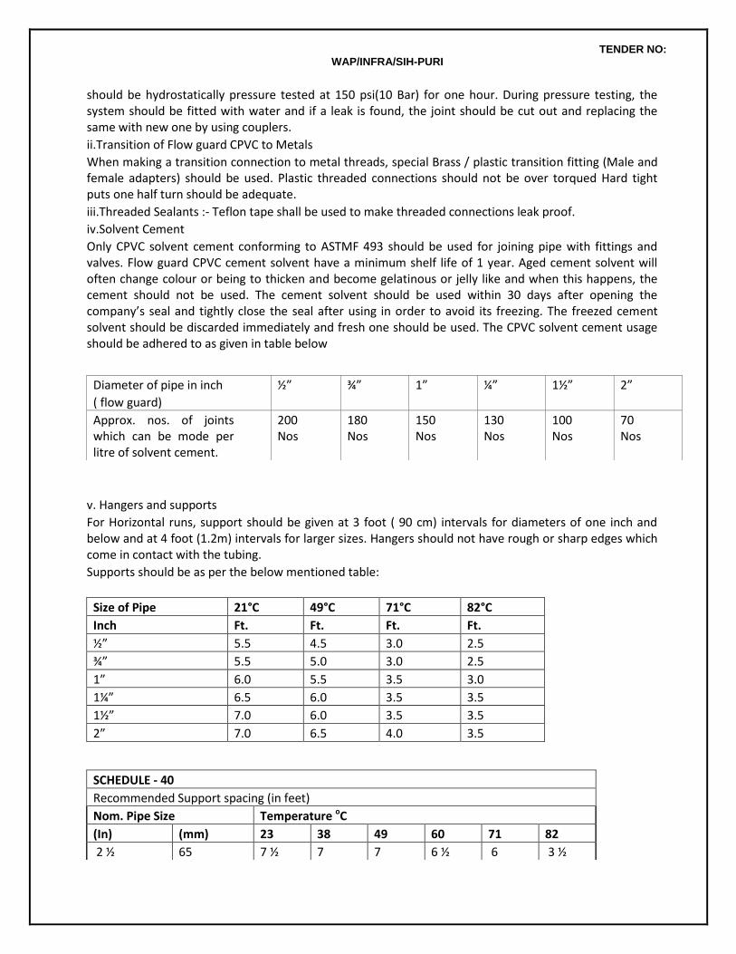
TENDER NO: WAP/INFRA/SIH-PURI
should be hydrostatically pressure tested at 150 psi(10 Bar) for one hour. During pressure testing, the system should be fitted with water and if a leak is found, the joint should be cut out and replacing the same with new one by using couplers.
ii.Transition of Flow guard CPVC to Metals
When making a transition connection to metal threads, special Brass / plastic transition fitting (Male and female adapters) should be used. Plastic threaded connections should not be over torqued Hard tight puts one half turn should be adequate.
iii.Threaded Sealants :- Teflon tape shall be used to make threaded connections leak proof.
iv.Solvent Cement
Only CPVC solvent cement conforming to ASTMF 493 should be used for joining pipe with fittings and valves. Flow guard CPVC cement solvent have a minimum shelf life of 1 year. Aged cement solvent will often change colour or being to thicken and become gelatinous or jelly like and when this happens, the cement should not be used. The cement solvent should be used within 30 days after opening the company’s seal and tightly close the seal after using in order to avoid its freezing. The freezed cement solvent should be discarded immediately and fresh one should be used. The CPVC solvent cement usage should be adhered to as given in table below
v. Hangers and supports
For Horizontal runs, support should be given at 3 foot ( 90 cm) intervals for diameters of one inch and below and at 4 foot (1.2m) intervals for larger sizes. Hangers should not have rough or sharp edges which come in contact with the tubing.
Supports should be as per the below mentioned table:
Size of Pipe 21°C 49°C 71°C 82°C
Inch Ft. Ft. Ft. Ft.
½” 5.5 4.5 3.0 2.5
¾” 5.5 5.0 3.0 2.5
1” 6.0 5.5 3.5 3.0
1¼” 6.5 6.0 3.5 3.5
1½” 7.0 6.0 3.5 3.5
2” 7.0 6.5 4.0 3.5
Diameter of pipe in inch
( flow guard)
½” ¾” 1” ¼” 1½” 2”
Approx. nos. of joints which can be mode per litre of solvent cement.
200 Nos
180 Nos
150 Nos
130 Nos
100 Nos
70 Nos
SCHEDULE - 40
Recommended Support spacing (in feet)
Nom. Pipe Size Temperature oC
(In) (mm) 23 38 49 60 71 82
2 ½ 65 7 ½ 7 7 6 ½ 6 3 ½
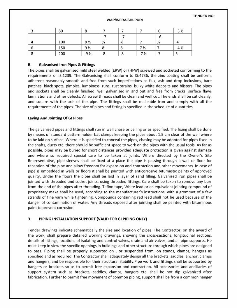
TENDER NO: WAP/INFRA/SIH-PURI
B. Galvanised Iron Pipes & Fittings
The pipes shall be galvanised mild steel welded (ERW) or (HFW) screwed and socketed conforming to the requirements of IS:1239. The Galvanising shall conform to IS:4736, the zinc coating shall be uniform, adherent reasonably smooth and free from such imperfections as flux, ash and drop inclusions, bare patches, black spots, pimples, lumpiness, runs, rust strains, bulky white deposits and blisters. The pipes and sockets shall be cleanly finished, well galvanised in and out and free from cracks, surface flaws laminations and other defects. All screw threads shall be clean and well cut. The ends shall be cut cleanly, and square with the axis of the pipe. The fittings shall be malleable iron and comply with all the requirements of the pipes. The size of pipes and fitting is specified in the schedule of quantities.
Laying And Jointing Of GI Pipes
The galvanised pipes and fittings shall run in wall chase or ceiling or as specified. The fixing shall be done by means of standard pattern holder bat clamps keeping the pipes about 1.5 cm clear of the wall where to be laid on surface. Where it is specified to conceal the pipes, chasing may be adopted for pipes fixed in the shafts, ducts etc. there should be sufficient space to work on the pipes with the usual tools. As far as possible, pipes may be buried for short distances provided adequate protection is given against damage and where so required special care to be taken at joints. Where directed by the Owner’s Site Representative, pipe sleeves shall be fixed at a place the pipe is passing through a wall or floor for reception of the pipe and allow freedom for expansion and contraction and other movements. In case of pipe is embedded in walls or floors it shall be painted with anticorrosive bitumastic paints of approved quality. Under the floors the pipes shall be laid in layer of sand filling. Galvanised iron pipes shall be jointed with threaded and socket joints, using threaded fittings. Care shall be taken to remove any burr from the end of the pipes after threading. Teflon tape, White lead or an equivalent jointing compound of proprietary make shall be used, according to the manufacturer’s instructions, with a grommet of a few strands of fine yarn while tightening. Compounds containing red lead shall not be used because of the danger of contamination of water. Any threads exposed after jointing shall be painted with bituminous paint to prevent corrosion.
3. PIPING INSTALLATION SUPPORT (VALID FOR GI PIPING ONLY)
Tender drawings indicate schematically the size and location of pipes. The Contractor, on the award of the work, shall prepare detailed working drawings, showing the cross-sections, longitudinal sections, details of fittings, locations of isolating and control valves, drain and air valves, and all pipe supports. He must keep in view the specific openings in buildings and other structure through which pipes are designed to pass. Piping shall be properly supported on , or suspended from, on stands, clamps, hangers as specified and as required. The Contractor shall adequately design all the brackets, saddles, anchor, clamps and hangers, and be responsible for their structural stability.Pipe work and fittings shall be supported by hangers or brackets so as to permit free expansion and contraction. All accessories and ancillaries of support system such as brackets, saddles, clamps, hangers etc. shall be hot dip galvanized after fabrication. Further to permit free movement of common piping, support shall be from a common hanger
3 80 8 7 7 7 6 3 ½
4 100 8 ½ 7 ½
7 ½ 7
6 ½ 4
6 150 9 ½ 8 8 7 ½ 7 4 ½
8 200 9 ½ 8 8 7 ½ 7 5
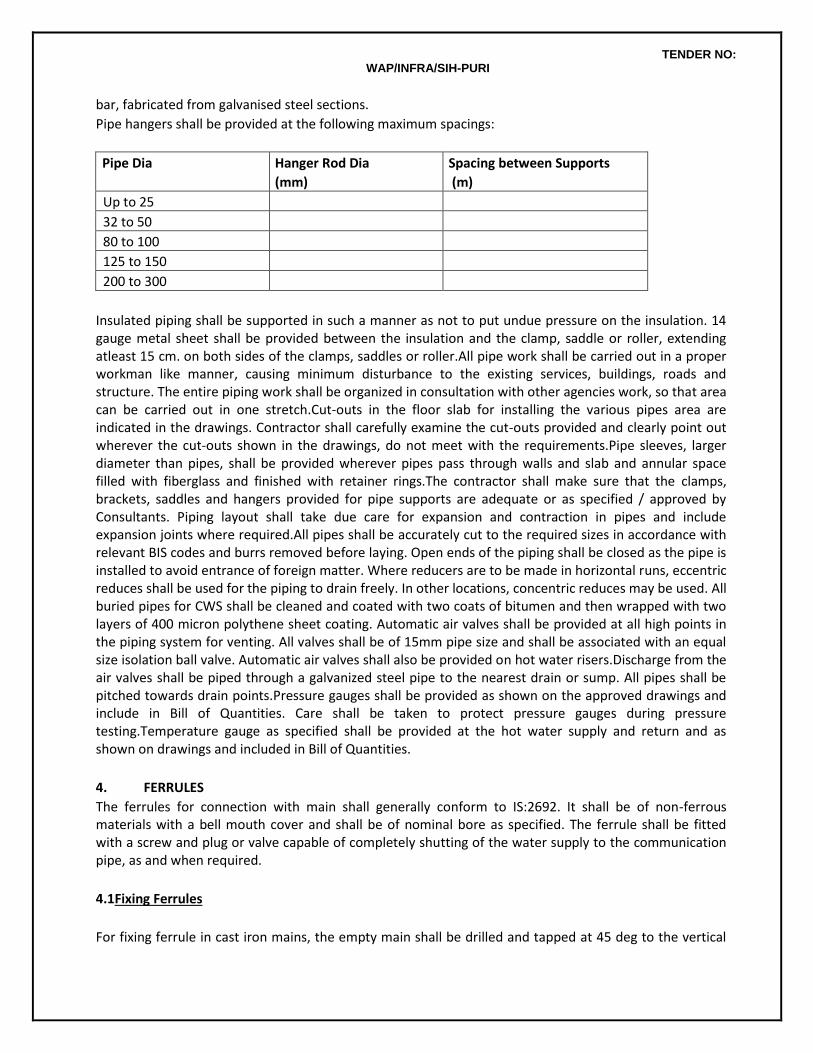
TENDER NO: WAP/INFRA/SIH-PURI
bar, fabricated from galvanised steel sections.
Pipe hangers shall be provided at the following maximum spacings:
Pipe Dia
(mm)
Hanger Rod Dia
(mm)
Spacing between Supports
(m)
Up to 25 6 2
32 to 50 10 2.7
80 to 100 12 2.7
125 to 150 16 3.6
200 to 300 19 5.3
Insulated piping shall be supported in such a manner as not to put undue pressure on the insulation. 14 gauge metal sheet shall be provided between the insulation and the clamp, saddle or roller, extending atleast 15 cm. on both sides of the clamps, saddles or roller.All pipe work shall be carried out in a proper workman like manner, causing minimum disturbance to the existing services, buildings, roads and structure. The entire piping work shall be organized in consultation with other agencies work, so that area can be carried out in one stretch.Cut-outs in the floor slab for installing the various pipes area are indicated in the drawings. Contractor shall carefully examine the cut-outs provided and clearly point out wherever the cut-outs shown in the drawings, do not meet with the requirements.Pipe sleeves, larger diameter than pipes, shall be provided wherever pipes pass through walls and slab and annular space filled with fiberglass and finished with retainer rings.The contractor shall make sure that the clamps, brackets, saddles and hangers provided for pipe supports are adequate or as specified / approved by Consultants. Piping layout shall take due care for expansion and contraction in pipes and include expansion joints where required.All pipes shall be accurately cut to the required sizes in accordance with relevant BIS codes and burrs removed before laying. Open ends of the piping shall be closed as the pipe is installed to avoid entrance of foreign matter. Where reducers are to be made in horizontal runs, eccentric reduces shall be used for the piping to drain freely. In other locations, concentric reduces may be used. All buried pipes for CWS shall be cleaned and coated with two coats of bitumen and then wrapped with two layers of 400 micron polythene sheet coating. Automatic air valves shall be provided at all high points in the piping system for venting. All valves shall be of 15mm pipe size and shall be associated with an equal size isolation ball valve. Automatic air valves shall also be provided on hot water risers.Discharge from the air valves shall be piped through a galvanized steel pipe to the nearest drain or sump. All pipes shall be pitched towards drain points.Pressure gauges shall be provided as shown on the approved drawings and include in Bill of Quantities. Care shall be taken to protect pressure gauges during pressure testing.Temperature gauge as specified shall be provided at the hot water supply and return and as shown on drawings and included in Bill of Quantities.
4. FERRULES
The ferrules for connection with main shall generally conform to IS:2692. It shall be of non-ferrous materials with a bell mouth cover and shall be of nominal bore as specified. The ferrule shall be fitted with a screw and plug or valve capable of completely shutting of the water supply to the communication pipe, as and when required.
4.1Fixing Ferrules
For fixing ferrule in cast iron mains, the empty main shall be drilled and tapped at 45 deg to the vertical
TENDER NO: WAP/INFRA/SIH-PURI
and the ferrule screwed in. The ferrule must be so fitted that no portion of the shank shall be left projecting within the main into which it is fitted.
5. WATER METERS
Water meters of approved make and design shall be supplied for installation at locations as shown. The water meters shall meet with the approval of local supply authorities. Suitable valves and chambers or wall meter box to house the meters shall also the be provided along with the meters.The meters shall conform to Indian Standard IS:779 and IS:2373. Calibration certificate shall be obtained and submitted for each water meter. Provision shall also be made to lock the water meter. The provision shall be such that the lock is conveniently operated from the top. Where the provision is designed for use in conjunction with padlocks, the hole provided for padlocks shall be a diameter not less than 4mm.
5.1Installation Of Water Meter And Stop Cock
The G.I. lines shall be cut to the required lengths at the position where the meter and stop cock are required to be fixed. Suitable fittings shall be attached to the pipes. The meter and stop cock shall be fixed in a position by means of connecting pipes, jam nut and socket etc. The stop cock shall be fixed near the inlet of the water meter. The paper disc inserted in the ripples of the meter shall be removed. And the meter installed exactly horizontal or vertical in the flow line in the direction shown by the arrow cast on the body of the meter. Care shall be taken that the factory seal of the meter is not disturbed. Wherever the meter shall be fixed to a newly fitted pipe line, the pipe line shall have to be completely washed before fitting the meter.
6. TESTING
The Contractor shall notify the Architect three days in advance of any test so that the Architect can witness the tests if he so wishes.All water supply system shall be tested to hydrostatic pressure test of at least one and a half (1.5) times the maximum pressure but not less than 10Kg/Sq.cm for a period of not less than 8 hours. All leaks and defects in joints revealed during the testing shall be rectified and got approved at site by retest. Piping required subsequent to the above pressure test shall be retested in the same manner. System may be tested in sections and such sections shall be entirely retested on completion.The Contractor shall make sure that proper noiseless circulation of fluid is achieved through the entire piping network of the system concerned. In case of improper circulation, the contractor shall rectify the defective connections. He shall bear all expenses for carrying out the above rectifications including the tearing up and refinishing of floors and walls as required. In addition to the sectional testing carried out during the construction, contractor shall test the entire installation after connections to the overhead tanks or pumping system or mains. He shall rectify all leakages and shall replace all defective materials in the system. Any damage done due to carelessness, open or burst pipes or failure of fittings, to the building, furniture and fixtures shall be made good by the contractor during the defects liability period without any cost.After commissioning of the water supply system, contractor shall test each valve by closing and opening it a number of times to observe if it is working efficiently. Valves which do not effectively operate shall be replaced by new ones at no extra cost and the same shall be tested as above.A test register shall be maintained and all entries shall be signed and dated by Contractor(s) and Owner’s site representative.
7. DISINFECTION OF PIPING SYSTEM AND STORAGE TANKS
Before commissioning the water supply system, the contractor shall arrange to disinfect the entire system as described in the succeeding paragraph.The water storage tanks and pipes shall first be filled with water and thoroughly flushed out. The storage tanks shall then be filled with water again and disinfecting chemical containing chlorine added gradually while tanks are being filled to ensure thorough mixing.
TENDER NO: WAP/INFRA/SIH-PURI
Sufficient chemical shall be used to give water a dose of 50 parts of chlorine to one million parts of water. If ordinary bleaching powder is used, the proportions will be 150 gm of power to 1000 liters of water. The power shall be mixed with water in the storage tank. If a proprietary brand of chemical is used, the proportions shall be specified by the manufacturer. When the storage tanks is full, the supply shall be stopped and all the taps on the distributing pipes are opened successively working progressively away from the storage tank. Each tap shall be closed when the water discharged begins to smell of chlorine. The storage tank shall then be filled up with water from supply pipe and added with more disinfecting chemical in the recommended proportions. The storage tank and pipe shall then remain charged at least for three hours. Finally the tank and pipes shall be thoroughly flushed out before any water is used for domestic purpose. The pipe work shall be thoroughly flushed before supply is restored.
8. STERILIZATION OF MAIN
After the pipe work has been tested and approved, but before it is coupled, it shall be sterilized with a solution of chloride of lime.
9. CUTTING CHASES IN MASONARY WALLS
Cold water distribution pipes to fixtures and equipment exposed to view in the bathrooms, kitchens, and sanitary compartments shall be chased into walls or floors or placed in wall cavities. The Contractor shall be responsible for cutting all notches, chases, and recesses in walls and floors and only a diamond cutter shall be used. The maximum size of conduit or pipe permitted to be concealed in floor slabs shall be 32 mm diameter unless otherwise approved by the Architect. The chases upto 7.5 x 7.5 cm shall be made in the walls for housing GI pipes etc. These shall be provided in correct positions as shown in the drawings or directed by the Architects. Chases shall be made by chiselling out the masonry to proper line and depth. After the pipes etc are fixed in chases, the chases shall be filled with cement mortar 1:2:4 or as may be specified, and made flush with the masonr surface. The concrete surface shall be roughened with wire brush to provide a key for plastering. Where pipes pass through beams or structural walls, subject to the approval of the Structural Consulting Engineer, the Contractor shall ensure that sizes and locations of openings required are formed in when the relevant beams or walls are cast.
10. VALVES
All valves (gate, globe, check, safety) shall be of gun metal suitable for the particular service as specified. All valves shall be of the particular duty and design as specified. Valves shall either be of screwed type or flanged type, as specified, with suitable flanges and non-corrosive bolts and gaskets. Tail pieces as required shall be supplied along with valves. Gate, globe and check valves shall conform to Indian Standard IS:776 and non-return valves and swing check type reflux to IS:5312. Sluice valves, where specified shall be flanged sluice valves of cast iron body. The spindle, valve seat and wedge nuts shall be gunmetal. They shall generally have non-rising spindle and shall be of the particular duty and design as specified. The valves shall be supplied with suitable flanges, non-corrosive bolts and asbestos fibre gaskets. Sluice valves shall conform to Indian standard IS:780 and IS:2906. Ball valves with floats to be fixed in storage tanks shall consist of cast brass lever arm having copper balls (26 SWG) screwed to the arm integrally. The copper ball shall have bronze welded seams. The closing/opening mechanism incorporating the piston and cylinder shall be non-corrosive metal and include washers. The size and construction of ball valves and float shall be suitable for desired working pressure operating the supply system. Where called for brass valves shall be supplied with brass hexagonal back nuts to secure them to the tanks and a socket to connect to supply pipe.
Globe valves on Hot-water line shall be union bonnet with stem/disc and body seat ring of SS. Suitable for temperature upto 80° C.
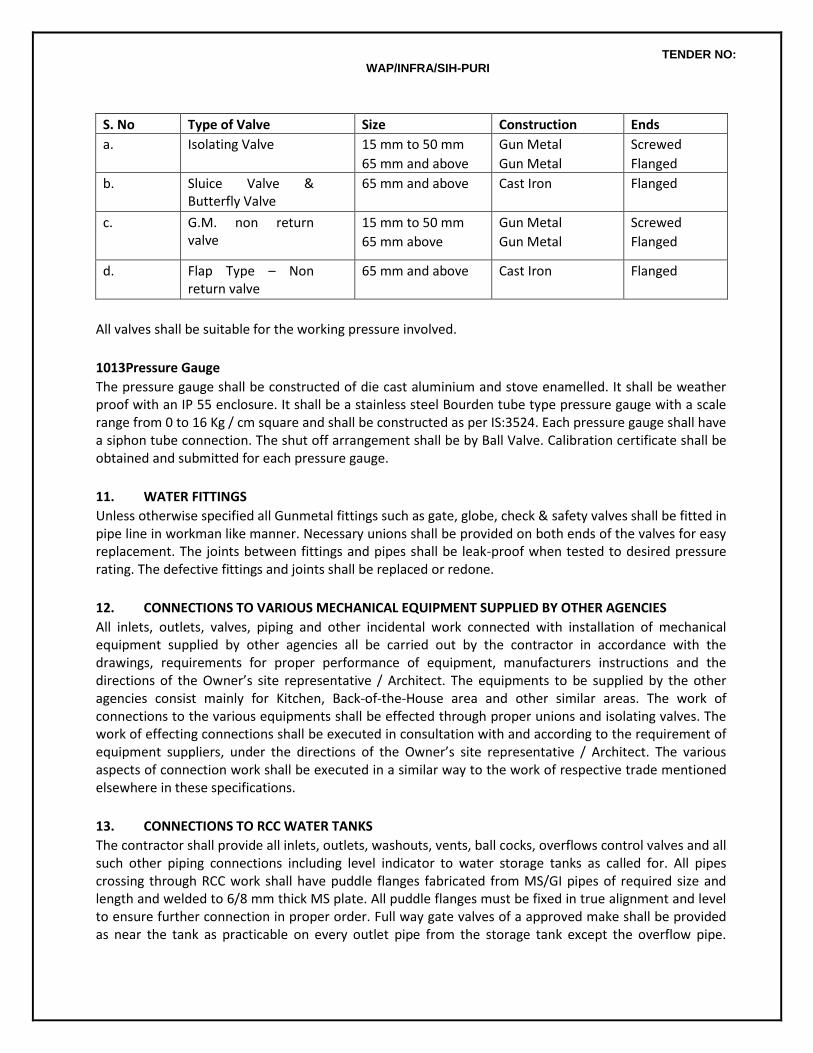
TENDER NO: WAP/INFRA/SIH-PURI
S. No Type of Valve Size Construction Ends
a. Isolating Valve 15 mm to 50 mm
65 mm and above
Gun Metal
Gun Metal
Screwed
Flanged
b. Sluice Valve & Butterfly Valve
65 mm and above Cast Iron Flanged
c. G.M. non return valve
15 mm to 50 mm
65 mm above
Gun Metal
Gun Metal
Screwed
Flanged
d. Flap Type – Non return valve
65 mm and above Cast Iron Flanged
All valves shall be suitable for the working pressure involved.
1013Pressure Gauge
The pressure gauge shall be constructed of die cast aluminium and stove enamelled. It shall be weather proof with an IP 55 enclosure. It shall be a stainless steel Bourden tube type pressure gauge with a scale range from 0 to 16 Kg / cm square and shall be constructed as per IS:3524. Each pressure gauge shall have a siphon tube connection. The shut off arrangement shall be by Ball Valve. Calibration certificate shall be obtained and submitted for each pressure gauge.
11. WATER FITTINGS
Unless otherwise specified all Gunmetal fittings such as gate, globe, check & safety valves shall be fitted in pipe line in workman like manner. Necessary unions shall be provided on both ends of the valves for easy replacement. The joints between fittings and pipes shall be leak-proof when tested to desired pressure rating. The defective fittings and joints shall be replaced or redone.
12. CONNECTIONS TO VARIOUS MECHANICAL EQUIPMENT SUPPLIED BY OTHER AGENCIES
All inlets, outlets, valves, piping and other incidental work connected with installation of mechanical equipment supplied by other agencies all be carried out by the contractor in accordance with the drawings, requirements for proper performance of equipment, manufacturers instructions and the directions of the Owner’s site representative / Architect. The equipments to be supplied by the other agencies consist mainly for Kitchen, Back-of-the-House area and other similar areas. The work of connections to the various equipments shall be effected through proper unions and isolating valves. The work of effecting connections shall be executed in consultation with and according to the requirement of equipment suppliers, under the directions of the Owner’s site representative / Architect. The various aspects of connection work shall be executed in a similar way to the work of respective trade mentioned elsewhere in these specifications.
13. CONNECTIONS TO RCC WATER TANKS
The contractor shall provide all inlets, outlets, washouts, vents, ball cocks, overflows control valves and all such other piping connections including level indicator to water storage tanks as called for. All pipes crossing through RCC work shall have puddle flanges fabricated from MS/GI pipes of required size and length and welded to 6/8 mm thick MS plate. All puddle flanges must be fixed in true alignment and level to ensure further connection in proper order. Full way gate valves of a approved make shall be provided as near the tank as practicable on every outlet pipe from the storage tank except the overflow pipe.
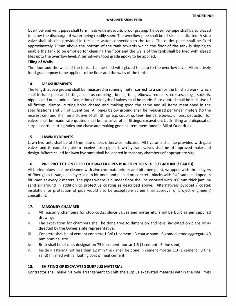
TENDER NO: WAP/INFRA/SIH-PURI
Overflow and vent pipes shall terminate with mosquito proof grating.The overflow pipe shall be so placed to allow the discharge of water being readily seen. The overflow pipe shall be of size as indicated. A stop valve shall also be provided in the inlet water connection to the tank. The outlet pipes shall be fixed approximately 75mm above the bottom of the tank towards which the floor of the tank is sloping to enable the tank to be emptied for cleaning.The floor and the walls of the tank shall be tiled with glazed tiles upto the overflow level. Alternatively food grade epoxy to be applied.
Tiling of Walls
The floor and the walls of the tanks shall be tiled with glazed tiles up to the overflow level. Alternatively food grade epoxy to be applied to the floor and the walls of the tanks.
14. MEASUREMENTS
The length above ground shall be measured in running meter correct to a cm for the finished work, which shall include pipe and fittings such as coupling , bends, tees, elbows, reducers, crosses, plugs, sockets, nipples and nuts, unions. Deductions for length of valves shall be made. Rate quoted shall be inclusive of all fittings, clamps, cutting holes chased and making good the same and all items mentioned in the specifications and Bill of Quantities. All pipes below ground shall be measured per linear meters (to the nearest cm) and shall be inclusive of all fittings e.g. coupling, tees, bends, elbows, unions, deduction for valves shall be made rate quoted shall be inclusive of all fittings, excavation, back filling and disposal of surplus earth, cutting holes and chase and making good all item mentioned in Bill of Quantities.
15. LAWN HYDRANTS
Lawn hydrants shall be of 25mm size unless otherwise indicated. All hydrants shall be provided with gate valves and threaded nipple to receive hose pipes. Lawn hydrant valves shall be of approved make and design. Where called for lawn hydrants shall be located in masonry chambers of appropriate size.
16. PIPE PROTECTION (FOR COLD WATER PIPES BURIED IN TRENCHES / GROUND / EARTH)
All buried pipes shall be cleaned with zinc chromate primer and bitumen paint, wrapped with three layers of fiber glass tissue, each layer laid in bitumen and placed on concrete blocks with PUF saddles dipped in bitumen at every 2 meters. The pipes where laid under floor shall be encased with 100 mm thick jamuna sand all around in addition to protective coating as described above. Alternatively pypcoat / coatek insulation for protection of pipe would also be acceptable as per final approval of project engineer / consultant.
17. MASONRY CHAMBER
i. All masonry chambers for stop cocks, sluice valves and meter etc. shall be built as per supplied drawings.
ii. The excavation for chambers shall be done true to dimension and level indicated on plans or as directed by the Owner’s site representative.
iii. Concrete shall be of cement concrete 1:3:6 (1 cement : 3 coarse sand : 6 graded stone aggregate 40 mm nominal size.
iv. Brick shall be of class designation 75 in cement mortar 1:5 (1 cement : 5 fine sand)
v. Inside Plastering not less than 12 mm thick shall be done in cement mortar 1:3 (1 cement : 3 fine sand) finished with a floating coat of neat cement.
18. SHIFTING OF EXCAVATED SURPLUS MATERIAL
Contractor shall make his own arrangement to shift the surplus excavated material within the site limits
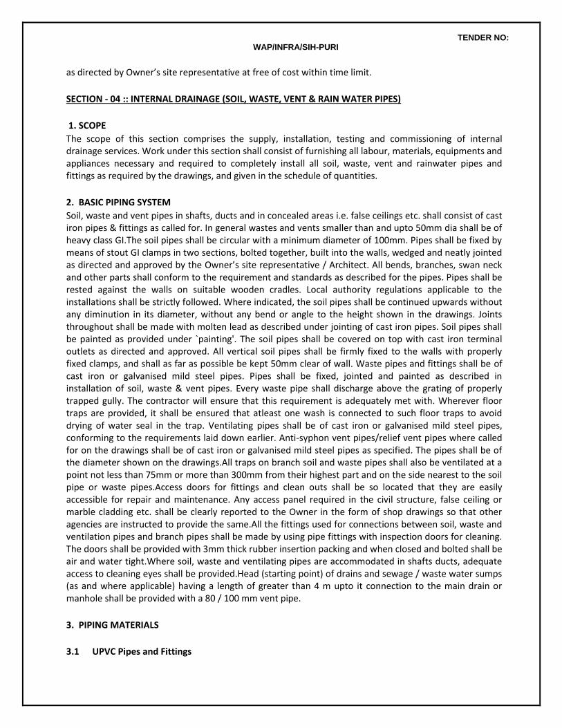
TENDER NO: WAP/INFRA/SIH-PURI
as directed by Owner’s site representative at free of cost within time limit.
SECTION - 04 :: INTERNAL DRAINAGE (SOIL, WASTE, VENT & RAIN WATER PIPES)
1. SCOPE
The scope of this section comprises the supply, installation, testing and commissioning of internal drainage services. Work under this section shall consist of furnishing all labour, materials, equipments and appliances necessary and required to completely install all soil, waste, vent and rainwater pipes and fittings as required by the drawings, and given in the schedule of quantities.
2. BASIC PIPING SYSTEM
Soil, waste and vent pipes in shafts, ducts and in concealed areas i.e. false ceilings etc. shall consist of cast iron pipes & fittings as called for. In general wastes and vents smaller than and upto 50mm dia shall be of heavy class GI.The soil pipes shall be circular with a minimum diameter of 100mm. Pipes shall be fixed by means of stout GI clamps in two sections, bolted together, built into the walls, wedged and neatly jointed as directed and approved by the Owner’s site representative / Architect. All bends, branches, swan neck and other parts shall conform to the requirement and standards as described for the pipes. Pipes shall be rested against the walls on suitable wooden cradles. Local authority regulations applicable to the installations shall be strictly followed. Where indicated, the soil pipes shall be continued upwards without any diminution in its diameter, without any bend or angle to the height shown in the drawings. Joints throughout shall be made with molten lead as described under jointing of cast iron pipes. Soil pipes shall be painted as provided under `painting'. The soil pipes shall be covered on top with cast iron terminal outlets as directed and approved. All vertical soil pipes shall be firmly fixed to the walls with properly fixed clamps, and shall as far as possible be kept 50mm clear of wall. Waste pipes and fittings shall be of cast iron or galvanised mild steel pipes. Pipes shall be fixed, jointed and painted as described in installation of soil, waste & vent pipes. Every waste pipe shall discharge above the grating of properly trapped gully. The contractor will ensure that this requirement is adequately met with. Wherever floor traps are provided, it shall be ensured that atleast one wash is connected to such floor traps to avoid drying of water seal in the trap. Ventilating pipes shall be of cast iron or galvanised mild steel pipes, conforming to the requirements laid down earlier. Anti-syphon vent pipes/relief vent pipes where called for on the drawings shall be of cast iron or galvanised mild steel pipes as specified. The pipes shall be of the diameter shown on the drawings.All traps on branch soil and waste pipes shall also be ventilated at a point not less than 75mm or more than 300mm from their highest part and on the side nearest to the soil pipe or waste pipes.Access doors for fittings and clean outs shall be so located that they are easily accessible for repair and maintenance. Any access panel required in the civil structure, false ceiling or marble cladding etc. shall be clearly reported to the Owner in the form of shop drawings so that other agencies are instructed to provide the same.All the fittings used for connections between soil, waste and ventilation pipes and branch pipes shall be made by using pipe fittings with inspection doors for cleaning. The doors shall be provided with 3mm thick rubber insertion packing and when closed and bolted shall be air and water tight.Where soil, waste and ventilating pipes are accommodated in shafts ducts, adequate access to cleaning eyes shall be provided.Head (starting point) of drains and sewage / waste water sumps (as and where applicable) having a length of greater than 4 m upto it connection to the main drain or manhole shall be provided with a 80 / 100 mm vent pipe.
3. PIPING MATERIALS
3.1 UPVC Pipes and Fittings
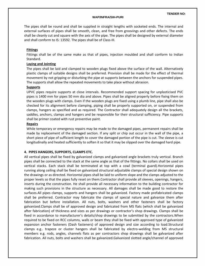
TENDER NO: WAP/INFRA/SIH-PURI
The pipes shall be round and shall be supplied in straight lengths with socketed ends. The internal and external surfaces of pipes shall be smooth, clean, and free from groovings and other defects. The ends shall be cleanly cut and square with the axis of the pipe. The pipes shall be designed by external diameter and shall conform to IS: 13592. The pipes shall be of Class-III.
Fittings
Fittings shall be of the same make as that of pipes, injection moulded and shall conform to Indian Standard.
Laying and Jointing
The pipes shall be laid and clamped to wooden plugs fixed above the surface of the wall. Alternatively plastic clamps of suitable designs shall be preferred. Provision shall be made for the effect of thermal movement by not gripping or disturbing the pipe at supports between the anchors for suspended pipes. The supports shall allow the repeated movements to take place without abrasion.
Supports
UPVC pipes require supports at close intervals. Recommended support spacing for unplasticised PVC pipes is 1400 mm for pipes 50 mm dia and above. Pipes shall be aligned properly before fixing them on the wooden plugs with clamps. Even if the wooden plugs are fixed using a plumb line, pipe shall also be checked for its alignment before clamping, piping shall be properly supported on, or suspended from clamps, hangers as specified and as required. The Contractor shall adequately design all the brackets, saddles, anchors, clamps and hangers and be responsible for their structural sufficiency. Pipe supports shall be primer coated with rust preventive paint.
Repairs
While temporary or emergency repairs may be made to the damaged pipes, permanent repairs shall be made by replacement of the damaged section. If any split or chip out occur in the wall of the pipe, a short piece of pipe of sufficient length to cover the damaged portion of the pipe is cut. The sleeve is cut longitudinally and heated sufficiently to soften it so that it may be slipped over the damaged hard pipe.
4. PIPES HANGERS, SUPPORTS, CLAMPS ETC.
All vertical pipes shall be fixed by galvanized clamps and galvanized angle brackets truly vertical. Branch pipes shall be connected to the stack at the same angle as that of the fittings. No collars shall be used on vertical stacks. Each stack shall be terminated at top with a cowl (terminal guard).Horizontal pipes running along ceiling shall be fixed on galvanized structural adjustable clamps of special design shown on the drawings or as directed. Horizontal pipes shall be laid to uniform slope and the clamps adjusted to the proper levels so that the pipes fully reset on them.Contractor shall provide all sleeves, openings, hangers, inserts during the construction. He shall provide all necessary information to the building contractor for making such provisions in the structure as necessary. All damages shall be made good to restore the surfaces.All pipes clamps, supports and hangers shall be galvanized. Factory made prefabricated clamps shall be preferred. Contractor may fabricate the clamps of special nature and galvanize them after fabrication but before installation. All nuts, bolts, washers and other fasteners shall be factory galvanized.Clamps shall be of approved design and fabricated from MS flats (which shall be galvanized after fabrication) of thickness and sizes as per drawings or contractor’s shop drawings. Clamps shall be fixed in accordance to manufacturer’s details/shop drawings to be submitted by the contractors.When required to be fixed on RCC columns, walls or beam they shall be fixed with approved type of galvanized expansion anchor fasteners (Dash fasteners) of approved design and size according to load.Structural clamps e.g.. trapeze or cluster hangers shall be fabricated by electro-welding from MS structural members e.g. rods, angles, channels flats as per contractors shop drawings shall be galvanized after fabrication. All nuts, bolts and washers shall be galvanized.Galvanized slotted angle/channel of approved
TENDER NO: WAP/INFRA/SIH-PURI
sizes supports on walls shall be provided wherever shown on shop drawings. Angles/channels shall be fixed to brick walls with bolts embedded in cement concrete blocks and to RCC walls with anchor fasteners mentioned above. The spacing of support bolts on support members fixed horizontally shall not exceed 1 m.
5. INSTALLATION OF SOIL, WASTE & VENT PIPES
Soil, waste & vent pipes in shafts under the floors / suspended below slab shall consist of cast iron pipes as described earlier. Waste pipes from bottle trap to floor/urinal traps for wash basin, urinal and sink shall be GI pipes and fittings.All Horizontal pipes running below the slab and along the ceiling, shall be fixed on structural adjustable clamps, sturdy hangers of the design as called for in the drawings. The pipes shall be laid in uniform slope and proper levels. All vertical pipes shall be truly vertical fixed by means of stout clamps in two sections, bolted together, built into the walls, wedged and neatly jointed. The branch pipes shall be connected to the stack at the same angle as that of fittings. All connections between soil, waste and ventilating pipes and branch pipes shall be made by using pipe fittings with inspection doors for cleaning. Pipes shall be fixed in a manner as to provide easy accessibility for repair and maintenance and shall not cause obstruction in shafts. Where the horizontal run off the pipe is long or where the pipes cross over building expansion joints etc. suitable allowance shall be provided for any movements in the pipes by means of expansion joint etc. such that any such movement does not damage the installation in any way.All cast iron pipes and fittings shall be jointed with drip seal / Best Quality pig lead free from impurities confirming to IS 27.Before jointing, the interior of the socket and exterior of the spigots shall be thoroughly cleaned and dried. The spigot end shall be inserted into the socket right up to the back of the socket and carefully centered by two or three laps of threaded spun yarn, twisted into ropes of uniform thickness, well caulked into the back of the socket. No piece of yarn shall be shorter than the circumference of the pipe. The jointed pipe line shall be at required levels and alignment. The reminder of the socket is left for the lead caulking. Where the gasket has been tightly held, a jointing ring shall be placed round the barrel against the face of the socket. Molten Lead shall be poured to the remainder of the socket. The depth of the lead joints for the cast iron pipes shall be 45mm for the pipes upto 100mm dia and 50mm for the pipes beyond 100mm dia respectively. The joint shall not be covered till the pipe line has been tested under pressure. Rest of pipe line shall be covered so as to prevent the expansion and contraction due to variation in temperature.
Rainwater Pipes
All open terraces shall be drained by rain water down takes.Rainwater down takes are separate and independent of the soil and waste system and will discharge into the underground storm water drainage system of the complex.Rainwater in open courtyards shall be collected in catch basins and connected to the Storm Water Drains.Any dry weather flow from waste appliances, e.g. AHU’s pump rooms, waste water sumps shall connected to sewers after traps and not in the storm water drainage systems.
Balcony / Planter drainage
Wherever required, all balconies, terraces, planters and other frontal landscape areas will be drained by vertical down takes or other type of drainage system shown on the drawings and directed by the Project Manager.
6. TRAPS
6.1Floor Traps
Floor traps where specified shall be siphon type full before P or S type iron having a minimum 50 mm deep seal. The trap and waste pipes when buried below ground shall be set and encased in cement concrete blocks firmly supported on firm ground or when installed on a sunken RCC structural slab. The blocks shall be in 1:2:4 mix (1 cement : 2 coarse sand : 4 stone aggregate 20 mm nominal size).Contractor
TENDER NO: WAP/INFRA/SIH-PURI
shall provide all necessary shuttering and centering for the blocks. Size of the block shall be 30 x 30 cms of the required depth.
6.2 Floor Trap Inlet /Hopper
Bath room traps and connection shall ensure free and silent flow of discharging water. Where Floor trap inlet and the traps shall be set in cement concrete blocks where burried in floors without extra charge.waste connection to each floor trap shall be through multi connector fitting.
6.3 Floor Trap Grating
Floor and urinal traps shall be provided with 100 – 150 mm square or round stainless steel gratings, with frame and rim of approved design and shape or as specified in the schedule of quantities approved by the Owner’s site representative.
6.4 Cleanout Plugs
Floor Clean Out Plug
Clean out plug for soil, waste or rain water pipes laid under floors shall be provided near pipe junctions bends, tees, “Y” and on straight runs at such intervals as required as per site conditions. Cleanout plugs shall terminate flush with the floor level.
Cleanout on Drainage Pipes
Cleanout plugs shall be provided on head of each drain and in between at locations indicated on plans or directed by Owner’s site representative. Cleanout plugs shall be of size matching the full bore of the pipe but not exceeding 150 mm dia CO plugs on drains of greater diameters shall be 150 mm dia. Fixed with a suitable reducing adapter.Floor cleanout plugs shall be cast brass.Cleanouts provided at ceiling level pipe shall be fixed to a end cap.
7. PIPE SLEEVES
Pipe sleeves, next larger diameter than pipes shall be provided wherever pipes pass through walls & slabs and annular space filled with fiberglass & finished with retainer rings. All pipes shall be accurately cut to the required sizes in accordance with relevant BIS codes and burrs removed before laying. Open ends of the pipe shall be closed as the pipe is installed to avoid entrance of foreign matter.
8. PIPE PROTECTION
Soil and waste pipes under floor in sunken slabs and in wall chases (when cut specially for the pipe) shall be encased in cement concrete 1:2:4 mix (1 cement : 2 coarse sand : 4 stone aggregate of 12 mm size) 10 cm bed and around. When pipes are running well above the structural slabs, the encased pipes shall be supported with suitable cement concrete pillars of required height and size at intervals directed by the Project Manager.
9. CUTTING AND MAKING GOOD
Pipes shall be fixed and tested as building proceeds. The contractor shall provide all necessary holes, cutouts and chases in structural members as building work proceeds. Wherever holes are cut or left originally they shall be made good with cement concrete 1:2:4 (1 cement : 2 coarse sand : 4 stone aggregate 20 mm nominal size) or cement mortar 1:2 (1 cement : 2 coarse sand). Cured and the surface restored to original condition.
11. TESTING
Testing shall be done in accordance with IS: Entire drainage system shall be tested for water tightness and smoke tightness during and after completion of the installation. No portion of the system shall remain untested. Contractor must have adequate number of expandable rubber bellow plugs, manometers, smoke testing machines, pipe and fitting work tests,All materials obtained and used on site must have manufacturer’s hydraulic test certificate for each batch of materials used on the site.Before use at site all pipes shall be tested by filling up with water for at least 15 minutes. After filling, pipes shall be for blow holes and cracks. All defective pipes shall be rejected and removed from the site within 48 hours. Soil and
TENDER NO: WAP/INFRA/SIH-PURI
waste pipes shall be tested in sections after installation, by filling up the stack with water. All openings and connections shall be suitably plugged as approved by the Project Manager. The total head in the stack shall be 4.5 m at the highest point of the section under test. The period of test shall be minimum for 15 minutes or as directed by the Project Manager. If any leakage is visible, the defective part of the work shall be cut out and made good. After the installation is fully complete, it should be tested by flushing the toilets, running atleast 20% of all taps simultaneously and ensuring that the entire system is self draining, has no leakages, blockages etc. rectify and replace where required.A test register shall be maintained and all entries shall be signed and dated by the Contractor and the Project Manager or his representative.All pipes in wall chase or meant to be encased or burried shall be hydro tested before the chase in plastered or the pipe encased or burried.
SECTION – 05 :: EXTERNAL DRAINAGE (SEWAGE & STORM WATER DISPOSAL)
1. SCOPE
The scope of this section comprises the supply, installation, testing and commissioning of external drainage & sewage disposal services.
1.1 General Scheme
The contractor shall install a drainage system to effectively collect; drain and dispose all soil and waste water from various parts of the buildings, appurtenances and equipment. The piping system shall finally terminate and discharge into the municipal sewer manhole. The piping work mainly consists of laying of pipes. All piping shall be installed at depth greater than 50 cm below finished ground level. The disposal system shall include construction of gully traps, manholes, intercepting chambers as indicated. The piping system shall be vented suitably at the starting point of all branch drains, main drains, the highest/lowest point of drain and at intervals as shown. All ventilating arrangements shall be unobstructive and concealed. The work shall be executed strictly in accordance with IS: 1742. The sewage system shall be subject to smoke test for its soundness as directed by the Project Manager. Wherever the sewerage pipes run above water supply lines, same shall be completely encased in cement concrete 1:4:8 all round with the prior approval of the Project Manager.
Without restricting to the generality of the foregoing, the drainage system shall inter-alia include:
a. Sewer lines including earth work for excavation, disposal, back filling and compaction, pipe lines, manholes, drop connections and connections to the municipal sewer.
b. Storm water drainage, earth works for excavation, disposal, backfilling and compaction, pipe lines, manholes, catch basins and connections to the rain water harvesting tank/ existing municipal storm water drain or connected as indicated by the Project Manager.
General Requirements
All materials shall be new and of quality conforming to specifications and subject to the approval of the Owner’s site representative. Wherever particular makes are mentioned, the choice of selection shall remain with the Architect / Consultant / Owner’s site representative. Drainage lines and open drains shall be laid to the required gradients and profiles.All drainage work shall be done in accordance with the local municipal bye-laws.Contractor shall obtain necessary approval and permission for the drainage system from the municipal or any other competent authority.Location of all manholes, etc shall be got confirmed by the Project Manager before the actual execution of work at site. As far as possible, no drains or sewers shall be laid in the middle of road unless otherwise specifically shown on the drawings or directed by the Project Manager in writing.All materials shall be rust proofed; materials in direct or indirect contact shall be compatible to prevent electrolytic or chemical (bimetallic) corrosion.
TENDER NO: WAP/INFRA/SIH-PURI
2. TRENCHING FOR PIPES AND DRAINS
2.1 General
All the material shall be new of best quality conforming to specifications and subject to the approval of the Architects. Drainage lines shall be laid to the required gradients and profiles. All drainage work shall be done in accordance with the local municipal by-laws. Contractor shall obtain necessary approval and permission for the drainage system from the municipal or any other competent authority. Location of all manholes, catch basins etc. shall be finalized and shown in approved shop drawings before the actual execution of work at site. All work shall be executed as directed by the Project Manager.
2.2 Alignment & Grade
The sewer and storm water drainage pipes shall be carefully laid to levels and gradients shown in the plans and sections but subject to modifications as shall be ordered by the Architects from time to time to meet the requirements of the works. Great care shall be taken to prevent sand etc. from entering the pipes. The pipes between two manholes shall be laid truly in straight lines without vertical or horizontal undulations. The body of the pipes shall rest on an even bed in the trench for its length and places shall be excavated to receive collar for the purpose of jointing. No deviations from the lines, depths of cuttings or gradients as called for on the drawings shall be permitted without the written approval of the Architect. All pipes shall be laid at least 60cms below the finished ground level or as called for on the drawings.
2.3 Setting out Trenches
The contractor shall set out all trenches, manholes, chambers and such other works to true grades and alignments as called for. He shall provide the necessary instruments for setting out and verification for the same. All trenches shall be laid to true grade and in straight lines and as shown on the drawings. The trenches shall be laid to proper levels by the assistance of boning rods and sight rails which shall be fixed at intervals not exceeding 10 meters or as directed by the Project Manager.
2.4 Trench Excavation
The trenches for the pipes shall be excavated with bottoms formed to level and gradients as shown on the drawings or as directed by the Project Manager. In soft and filled in ground, the Project Manager may require the trenches to be excavated to a greater depth than the shown on the drawings and to fill up such additional excavation with concrete (1:4:8) consolidated to bring the excavation to the required levels as shown on the drawings. All excavations shall be properly protected where necessary by suitable timbering, piling and sheeting as approved by the Project Manager. All timbering and sheeting when withdrawn shall be done gradually to avoid falls. All cavities be adequately filled and consolidated. No blasting shall be allowed without prior approval in writing from the Architect. It shall be carried out under thorough and competent supervision, with the written permission of the appropriate authorities taking full precautions connected with the blasting operations. All excavated earth shall be kept clear of the trenches to a distance equal to 75 cms.
2.5 Timbering of Sewer and Trenches
The Contractor shall at all times support efficiently and effectively the sides of all the trenches and other excavations by suitable timbering, piling and sheeting and they shall be close timbered in loose or sandy starta and below the surface of the sub soil water level.All timbering, sheeting and piling with their wallings and supports shall be of adequate dimensions and strength and fully braced and strutted so that no risk of collapse or subsidence of the walls of the trench shall take place.The Contractor shall be held responsible and shall be accountable for the sufficiency of all timbering, bracings, sheeting and piling used and also for, all damage to persons and property resulting from improper quality strength placing, maintaining or removing of the same.
2.6 Shoring of Buildings
The Contractor shall shore up all buildings, walls and other structures, the stability of which is liable to be
TENDER NO: WAP/INFRA/SIH-PURI
endangered by the execution of the work and shall be fully responsible for all damages to persons or property resulting from any accident.
2.7 Obstruction Road
The contractor shall not occupy or obstruct by his operation more than one half of the width of any road or street and sufficient space shall then be left for public and private transit. He shall remove the materials excavated and bring them back again when the trench is required to be refilled. The contractor shall obtain the consent of the Project Manager in writing before closing any road to vehicular traffic and the foot walks must be clear at all times.
2.8 Protection of Pipes etc
All pipes, water mains, cables etc. met in the course of excavation shall be carefully protected and supported. Care shall be taken not to disturb the cables, the removal of which shall be arranged by the contractor with the written consent from the Project Manager.
2.9 Trench Back Filling
Refilling of the trenches shall not be commenced until the length of pipes therein has been tested and approved. All timbering which may be withdrawn safely shall be removed as filling proceeds. Where the pipes are unprotected by concrete hunching, selected fine material shall be carefully hand-packed around the lower half of the pipes so as to buttress them to the sides of the trench.The refilling shall then be continued to 150mm over the top of the pipe using selected fine hand packed material, watered and rammed on both sides of the pipes with a wooden hammer. The process of filling and tamping shall proceed evenly in layers not exceeding 150mm thickness, each layer being watered and consolidated so as to maintain an equal pressure on both sides of the pipe line. In gardens and fields the top solid and turf if any, shall be carefully replaced.
2.10 Contractor to restore settlement and Damages
The contractor shall at his own costs and expenses, make good promptly during the whole period for the works in hand if any settlement occurs in the surfaces of roads, beams, footpaths, gardens, open spaces etc. in the public or private areas caused by his trenches or by his other excavations and he shall be liable for any accident caused thereby. He shall also, at his own expense and charges, repair (and make good) any damage done to building and other property. If in the opinion of the Project Manager he fails to make good such works with all practicable dispatch, the Project Manager shall be at his liberty to get the work done by other means and the expenses thereof shall be paid by the contractor or deducted from any money that may be or become due to him or recovered from him by any other manner according to the laws of land. The contractor shall at his own costs and charges provide places for disposal of all surplus materials not required to be used on the works. As each trench is refilled, surplus soil shall be immediately removed, the surface shall be properly restored and roadways and sides shall be left clear.
2.11 Removal of Water from Sewer, Trench etc.
The contractor shall at all times during the progress of work keep the excavations free from water which shall be disposed by him in a manner as will neither cause injury to the public health nor to the public or private property nor to the work completed or in progress nor to the surface of any road or streets, nor cause any interference with the use of the same by the public. If any excavation is carried out at any point or points to a greater width of the specified cross section of the sewer with its cover, the full width of the trench shall be filled with concrete by the contractor at his own expense and charges to the requirements of the Project Manager.
2.12 Removal of Filth
All night soil, filth or any other offensive mater met with during the execution of the works, shall not be deposited on the surface of any street or where it is likely to be a nuisance or passed into any sewer or drain but shall be immediately, after it is taken out of any trench, sewer or cess pool, put into the carts and removed to a suitable place to be provided by the Contractor.
TENDER NO: WAP/INFRA/SIH-PURI
2.13 Width of Trench
The Project Manager shall have power by giving an order in writing to the Contractor to increase the maximum width/depth for excavation and backfilling in trenches for various classes of sewer, manholes and other works in certain length to be specifically laid down by him, where on account of bad ground on other unusual conditions, he considers that such increased width/depths are necessary in view of the site conditions.
3. PIPING MATERIAL
3.1 RCC pipes
All pipes shall be centrifugally spun RCC pipes NP2. Pipes shall be true and straight with uniform bore throughout. Cracked, warped pipes shall not be used on the work. All pipes shall be tested by the manufacturer and the Contractor shall produce, prior to use on site, a certificate to that effect from the manufacturer. The pipes shall be with or without reinforcement as required and of the class as specified. These shall conform to IS:458-1971. All pipes shall be true to shape, straight, perfectly sound and free from cracks and flaws. The external and internal surface of the pipes shall be smooth and hard. The pipes shall be free from defects resulting from imperfect grading of the aggregate mixing or moulding.
Laying
RCC spun pipes shall be laid on cement concrete bed of cradles as specified and shown on the detailed drawings. The cradles may be precast and sufficiently cured to prevent cracks and breakage in handling. The invert of the cradles shall be left 12 mm below the invert level of the pipe and properly placed on the soil to prevent any disturbance. The pipe shall then be placed on `the bed concrete or cradles and set for the line and gradient by means of sight rails and boning rods, etc. Cradles or concrete bed may be omitted, if directed by the Project Manager.
Jointing
Semi flexible type collar joint. Hemp rope soaked in neat cement wash shall be passed round the joint and inserted in it by means of caulking tool. More skein of yarn shall be added and rammed home. Cement mortar with one part of cement and two part of sand and with minimum water content but on no account soft or sloppy, shall be carefully inserted, punched and caulked into the collar and more cement mortar added until the space of the collar has been filled completely with tightly caulked mortar. Provision of rubber sealing ring in the collar joint shall also be made. The joint shall then be finished off neatly outside the socket at an angle of 45 deg.
Curing:The joint shall be cured for at least seven days. Refilling at joints will be permitted only on satisfactory completion of curing period.
Cement Concrete for Pipe Supports:
a. Unless otherwise directed by the Project Manager cement concrete for bed, all round or in haunches shall be as follows:
upto 1.5 m depth upto 3 m depth
Stoneware pipes buried in open ground (No sub soil water) All round (1:3:6) In Haunches (1:3:6)
RCC or SW in sub soil water All round (1:3:6) In Haunches (1:3:6)
PVC / HDPE pipe All round (1:4:8) In Haunches (1:3:6)
All pipes under building All round (1:2:4) All round (1:2:4)
TENDER NO: WAP/INFRA/SIH-PURI
b. Pipes may be supported on brick masonry or precast RCC or in situ cradles. Cradles shall be as shown on the drawings.
c. Pipes in loose soil or above ground shall be supported on brick or stone masonry pillars as shown on the drawings.
Measurement:
a. Excavation: Measurement for excavation of pipes trenches shall be made per linear meter.
b. Trenches shall be measurement between outside walls of manholes at top and the depth shall be the average depth between the two ends to the nearest cm. The rate quoted shall be for a depth upto 1.5 metre or as given in the Bill of Quantities.
c. Payment for trenches more than 1.5 m in depth shall be made for extra depth as given in the Bill of Quantities and above the rate for depth upto 1.5 m.
d. RCC pipes shall be measured for length of the pipe line per linear meter.
i. Length between manholes shall be recorded from inside of one manhole or inside of other manhole.
ii. Length between gully trap and manhole shall be recorded between socket of pipe near gully trap and inside of manhole.
3.2 UPVC Pipes and Fittings
The pipes shall be round and shall be supplied in straight lengths with socketed ends. The internal and external surfaces of pipes shall be smooth, clean, free from groovings and other defects. The ends shall be cleanly cut and square with the axis of the pipe. The pipes shall be designed by external diameter.
Fittings
Fittings shall be of the same make as that of pipes, injection moulded and shall conform to Indian Standard.
Laying in Trenches
UPVC pipes shall be laid on cement concrete bed of width 300mm over the outside diameter of pipe, and 100 mm thickness. Fine sand shall be carefully filled around the lower half of the pipes so as to buttress them to the sides of the trench. The filling shall then be continued to 150mm over the top of the pipe using fine sand, watered and rammed on both sides of the pipes. The process of filling and ramming with fine hand picked material shall proceed evenly in layers not exceeding 150mm thickness, each layer being watered and consolidated so as to maintain an equal pressure on both sides of the pipe line.
S.W. Gully Trap
Gully trap shall be stoneware conforming to IS:651. These shall be sound and free from visible defects such as fire cracks, or hair cracks. The glaze of the traps shall be free from cracks. They shall give a sharp clear note when struck with light hammer. There shall be no broken blisters. Each gully trap shall have one CI grating of square size corresponding to the dimensions of inlet of gully trap. It will also have a water tight CI cover with frame inside dimensions 300 x 300mm the cover weighing not less than 4.5 kg and the frame not less than 2.7kg. The grating cover and frame shall be of good casting and shall have truly square machined seating faces.
Fixing of S.W. Gully Trap
The excavation for gully traps shall be done true to dimensions and levels as indicated on plans or as directed by the Project Manager /Consultant / Architect. The gully traps shall be fixed on cement concrete foundation 65cm square and not less than 10cm thick. The mix for the concrete will be 1:4:8. The jointing of gully outlet to the branch drain shall be done similar to the jointing of S.W. Pipes described earlier. After fixing and testing gully and branch drain, a brick work of specified class in cement mortar 1:5 shall be built with a half brick masonry work round the gully trap from the top of the bed concrete upto ground
TENDER NO: WAP/INFRA/SIH-PURI
level. The space between the chamber and trap shall be filled in with cement concrete 1:3:6. The upper portion of the chamber i.e. above the top level of the trap shall be plastered inside the cement mortar 1:3 finish with a floating coat of neat cement. The corners and bottom of the chamber shall be rounded off so as to slope towards the grating. CI cover with frame 300 x 300 mm (minimum inside) shall then be fixed on the top of the brick masonry with cement concrete 1:2:4 and rendered smooth. The finished top cover shall be so as to prevent the surface water from entering the gully trap.
Measurements
Gully traps shall be measured by the number and rate which shall include all excavation, foundation, concrete, brick masonry, cement plaster inside and outside, C I grating and sealed cover and frame.
4. CONSTRUCTION OF MANHOLE
Where manholes are to be constructed, the excavation, filling back and ramming, disposal of surplus earth, preparation of bottom and sides etc. shall be carried out as described earlier under trench excavation. Manhole shall be sized and depths as called for in the drawings and Bill of Quantities.The manhole shall be built on a base concrete 1:4:8 of 150mm thickness for manholes upto 1500mm depth and 250mm thickness for manholes from 1500 to 2500mm depth and 300mm thickness manholes of depth greater than 2500mm. Reinforcement as shown shall be provided in the base slabs. The walls shall be of brick work of thickness as shown in drawings built in cement mortar 1:5. The joints of brick work shall be raked and plastered internally in cement mortar 1:3 (at least 12 mm thick) and finish with a coat of neat cement, external plaster shall be rough plaster in 1:3, PCC benching & semi circular channels of the same diameter as the pipes shall be provided and finished with neat cement coating. Above the horizontal diameter, the sides of channel shall be extended vertically to the same level as the crown of the outgoing pipe and the top edge shall be suitably rounded off. The branch channels shall also be similarly constructed with respect to the benching but at their junction with the main channel an appropriate fall suitably rounded off in the direction of flow in the main channel shall be given. All manholes / sumps shall be provided with poly propylene coated steel reinforced foot rest. The polypropylene shall confirm to ASTM D-4101 specification, injection moulded around 12 mm dia IS-1786 grade FE-415 steel reinforcing bar. These rungs shall be set at 30cms interval in two vertical runs at 380mm apart horizontally. The top rung shall be 450mm below the manhole cover. Unless otherwise mentioned, manholes shall be constructed to the requirements of Indian Standard IS:4111 (Part I). All manholes shall be constructed so as to be water tight under test. All angles shall be rounded to a 75mm radius with cement plaster 20mm thick. The benching at the side shall be carried out in such a manner so as to provide no lodgment for any splashing in case of accidental flooding. Manhole cover with frame shall be of cast iron of an approved make. The covers and frame shall generally be double seal as specified in the Bill of Quantities.
4.1 Measurements
Manhole shall be measured in numbers as indicated in the Bill of Quantity. The depth of manhole shall be measured from invert of channel to the top of manhole cover. Manhole with depth greater than specified under the main item shall be paid for under `Extra Depth’ and shall include all items as given for manholes depth will be measured to the nearest cm. Depth of the manholes shall be measured from top of the manhole cover to bottom of channel. The following are inclusive in the cost of manhole viz;
i. Bed concrete
ii. Brick work.
iii. Plastering (inside & outside)
iv. R C C top slab, benching and channeling including drop connections.
v. Supply and fix foot rests.
vi. Keeping holes and embedding pipes for all the connections.
vii. Excavation, refilling, necessary de-watering and disposing off surplus soil to a places as directed by
TENDER NO: WAP/INFRA/SIH-PURI
Project Manager.
viii. Curing.
ix. Cost of angle frame and embedding the frame in concrete bed.
x. Testing.
xi. De-watering of chambers.
4.2 Drop Connection
Drop connection shall be provided between branch sewer and main sewer in the main sewer itself in steep ground when the difference in invert level of two exceeds 60 cms of the required sizes. Drop connections from gully traps to main sewer in rectangular shall be made inside the manholes and shall have CI special types door bend on to top and heel rest bend at bottom connected by a CI pipe. The pipe shall be supported by holder bat clamps at 180 cms intervals with atleast one clamp for each drop connection. All joints shall be lead caulked joints 25mm deep.Drop connections from branch sewer to main sewer shall be made outside the manhole wall with CI / CI class LA pipe, connection, vertical pipe and bend at the bottoms. The top of the tee shall be finished upto the surface level and provided with a CI hinges type frame and cover 30cms x 30cms. The connection and tee upto the surface chamber of the tee. Drop connection made from vertical stacks directly into manholes shall not be considered as drop connections.
4.3 Making Connections
Contractor shall connect the new sewer line to the existing manhole by cutting the walls benching and restoring them to the original condition. A new channel shall be cut in the benching of the existing manhole for the new connection. Contractor shall remove all sewage and water if encountered in making the connection without additional cost.
5. TESTING
All rights of the sewer and drain shall be carefully tested for water tightness by means of water pressure maintained for not less than 30 minutes. Testing shall be carried out from manhole to manhole. All pipes shall be subject to a test pressure of 1.5 meter head of water. The test pressure will however, not exceed 6 meters head at any point. The pipes shall be plugged preferably with standard design plugs or with rubber plugs on both sides, the upper end shall, however, be connected to a pipe for filling with water and getting the required head poured at one time.
Sewer lines shall be tested for straightness by:
i. Inserting a smooth ball 12 mm less than the internal diameter of the pipe. In the absence of obstructions such as yarn or mortar projecting at the joints the ball shall roll down the invert of the pipe and emerge at the lower end.
ii. Means of a mirror at one end a lamp at the other end. If the pipe is straight the full circle of light will be seen otherwise obstructions or deviations will be apparent.
iii. The contractor shall give a smoke test to the drain and sewer at his own expense and charges, if directed by the Owner’s site representative.
iv. A test register shall be maintained which shall be signed and dated by contractor and Owner’s site representative.
SECTION - 06 :: PUMPS & EQUIPMENT
4.4 Sump Pump
4.4.1 Submersible
These shall be fully submersible with a fully submersible motor. The pumps shall be provided with an automatic level controller and all interconnecting power and control cabling which shall cause the pumps to operate when the water level in the sump rises to a preset level and stop when the preset low level is
TENDER NO: WAP/INFRA/SIH-PURI
reached.Pumps for drainage shall be single stage, single entry.Pump shall be C.I. casing and C.I. two vane open type with a dynamically balanced impeller connected to a common shaft of the motor. The vane for sewage pump will be open type, while for drainage pump, etc. it will be of semi open type. The MOC of the sump shall be in accordance to schedule of quantity.Stuffing box shall be provided with mechanical seals.Each pump shall be provided with a suitably rated induction motor suitable for 415 volts, 3 phase, 50 Hz A.C. power supply. Each pump shall be provided with in built liquid level controller for operating the pump between predetermined levels.The pumping set shall be for stationary application and shall be provided with pump connector unit. The delivery pipe shall be joined to the pump through a rubber diaphragm, and bend and guide pipe for easy installation. Pump shall be provided with all accessories and devices necessary and required for the pump to make it a complete working system.Sump pump shall be complete with level controllers, power and control switch gear, Auto/off/Manual switches, pumps priority selections and control and power cabling upto motor and controller/probes etc. (Including earthing). Level control shall be such that one pump starts on required level, 2nd pump cuts in at high level and alarms is given at extra high level. All level controllers shall be provided with remote level indications.
4.4.2 Motor Design
The pump motor shall be a squirrel cage induction, housed in air filled water-tight enclosure. Oil filled motors are not acceptable. The stator windings shall be Class "F" insulation (155 degree C or 311 degree F) for general usage and class `H' insulation (180 degree C or 317-8 grade 2) for submersible type.The stator shall be heat shrunk fitted into the enclosure and shall not use bolts, pins or other fasteners that penetrate through the stator enclosure. The starter shall be equipped with a thermal switch embedded in series in the coils of the stator windings to protect the stator from wheel.The motors shall be designed for continuous running duty type at 415 volts, 3 phase, 50 Hz power supply and capable of sustaining a minimum of 20 starts/stops per hour.Between stator housing and pump, a tandem seal arrangement will be provided with an oil barrier. Both seals run in oil, allowing dry running without seal damage. Both seals shall be of the rubber bellows or metallic bellow type with positive drive between shaft and rotating seal face.
5. PUMP INDICATOR
The following audible and visible indication shall be provided at the pump local control panels as applicable: a. Red "overflow level" indicator with buzzer for the associated water tanks; b. Amber "extra high water level" indicator for the associated water tank; c. Amber "high water level" indicator; d. Amber "low water level" indicator; e. Red "pump trip" indicator for each pump; f. Green "pump on" indicator for each pump; g. "Pump electrical supply healthy" indicator for each pump; h. Amber "remote/local" status indicator.
SECTION - 7 :: FIRE PROTECTION SYSTEM
1. SCOPE
The scope of this section consists of but is not necessarily limited to supply, installation, testing and commissioning of the fire protection system. The philosophy of the system is as follows :
a. The Fire Suppression System shall comprise the Fire Hydrants System, Hand Appliances.
b. Water from the underground RCC Fire Water Storage Tank of 100 cum capacity, shall be supplied for the uses listed below.
i. Fire Hydrant System (Pressurised) both for the external hydrants, the internal landing valves and the hose reels at landings.
TENDER NO: WAP/INFRA/SIH-PURI
c. The Hydrant System, under normal conditions, shall be lowest pressurized by means of the electric motor driven Jockey Pump.
d. The Hydrant System shall be provided with two pump sets, one of which will be diesel engine driven and the other electric motor driven.
e. The starting and stopping of the Jockey pump shall be automatic based on the pressure switches at preset low and high pressure.
f. The electric motor driven Hydrant Pump starts automatically at a preset pressure by means of a pressure switch. As soon as the Hydrant Pump starts, the Jockey Pump Stops. If for any reason the electric motor driven Hydrant Pump does not start at the preset pressure or is unable to maintain the pressure, the diesel engine driven Hydrant Pump starts at the preset pressure.
g. The Hydrant Pump, whether electric motor driven or the diesel engine driven shall be stopped only manually.
h. Contractor shall ensure Hydro Testing for the complete system.
i. The Contractor shall obtain the necessary approval of the drawings and the schemes from the local authority as called for. The contractor shall also take care of any other requirement so that insurance cover can be obtained, if required at minimum premium at a later date.
j. The contractor shall design and after approval of Project Manager display near each staircase landing at floor levels, a glass covered framed floor plan clearly showing the locations of all landing valves, hose reels, hand appliances, as well as the DO’s and DON’T’s for the personnel and the exit direction in case of an emergency. The dimensions of the floor plan, its scale, lettering size, colour scheme etc shall be as directed by the Project Manager.
2. PIPE WORK
2.1 General Requirements
All materials shall be of the best quality conforming to the specifications and subject to the approval of the Consultants.Pipes shall be fixed in a manner as to provide easy accessibility for repair and maintenance and shall not cause obstruction in shafts, passages etc.Pipes shall be securely fixed to walls and ceilings by suitable clamps and supports (galvanised after fabrication ) at intervals specified. Only approved type of anchor fasteners shall be used for RCC slabs and walls / floors etc.Valves and other appurtenances shall be so located that they are easily accessible for operations, repairs and maintenance.Pipes and fittings shall be fixed truly vertical, horizontal or in slopes as required in a neat workman like manner.Pipe accessories such as gauges, meters, control devices, etc. shall have the same working pressure rating as the associated pipe work. All pipe work shall be free from burrs, rust and scale and shall be cleaned before installation. All personnel engaged on welding operations must possess a certificate of competence issued by an acceptable / recognized authority.
2.2 Piping
Pipes of following types are to be used:
Mild steel black pipes as per IS:1239 heavy grade(for pipes of sizes 150 mm N.B. and below) suitably lagged on the outside to prevent soil corrosion. M.S. pipes buried below ground shall also be suitably be lagged with 2 layers of 400 micron polythene sheet over 2 coats of bitumen. Steel pipelines upto 150 mm dia shall be as per IS: 1239, Part-II (heavy grade) while pipelines above 150 mm dia shall be as per I.S.:3589. All pipe clamps and supports shall be fabricated from MS steel sections and shall be factory galvanised before use at site. Welding of galvanised clamps and supports shall not be permitted. Pipes shall be hung by means of expandable anchor fastener of approved make and design. The hangers and clamps shall be fastened by means of galvanised nuts and bolts. The size/diameter of the anchor fastener and the clamps shall be suitable to carry the weight of water filled pipe and dead load normally encountered.Hangers and supports shall be thoroughly galvanised after fabrication. The selection and design of the hanger & support shall be capable of carrying the sum of all concurrently acting loads. They
TENDER NO: WAP/INFRA/SIH-PURI
shall be designed to provide the required supporting effects and allow pipeline movements as necessary. All guides, anchor braces, dampener, expansion joint and structural steel to be attached to the building/structure trenches etc. shall be provided. Hangers and components for all piping shall be approved by the Consultants.The piping system shall be tested for leakages at 2 times the operating pressure or 1.5 time shut-off pressure, which ever is highest including testing for water hammer effects.Flanged joints shall be used for connections for vessels, equipment, flanged valves and also on two straight lengths of pipelines of strategic points to facilitate erection and subsequent maintenance work.For pipes under ground installation the pipes shall be buried at least one meter below ground level and shall have 230 mm x 230 mm masonry or concrete supports at least 300 mm high at 3m intervals. Masonry work to have plain cement concrete foundation (1 cement: 4 coarse sand : 8 stone aggregate) of size 380x380x75 thick resting on firm soil. Mains below ground level shall be supported at regular intervals not exceeding 3.0 metres and shall be laid at least 2.0 metre away from the building.
2.3 Piping Installation & Support
Tender drawings indicate schematically the size and location of pipes. The Contractor, on the award of the work, shall prepare detailed working drawings, showing the cross-sections, longitudinal sections, details of fittings, locations of isolating and control valves, drain and air valves, and all pipe supports. He must keep in view the specific openings in buildings and other structure through which pipes are designed to pass.Piping shall be properly supported on , or suspended from , on stands, clamps, hangers as specified and as required. The Contractor shall adequately design all the brackets, saddles, anchor, clamps and hangers, and be responsible for their structural stability.Pipe work and fittings shall be supported by hangers or brackets so as to permit free expansion and contraction. Risers shall be supported at each floor with Galvanised steel clamps. To permit free movement of common piping support shall be from a common hanger bar fabricated from Galvanised steel sections.
Pipe hangers shall be provided at the following maximum spacings:
Pipe Dia
(mm)
Hanger Rod Dia
(mm)
Spacing between Supports
(m)
Up to 25 6 2
32 to 50 6 2.5
65 to 80 8 2.5
80 to 100 10 2.5
125 to 150 10 3.0
200 to 300 12 3.5
The end of the steel rods shall be threaded and not welded to the threaded bolt. All pipe work shall be carried out in a proper workman like manner, causing minimum disturbance to the existing services, buildings, roads and structure. The entire piping work shall be organized in consultation with other agencies work, so that area can be carried out in one stretch.Cut-outs in the floor slab for installing the various pipes area are indicated in the drawings. Contractor shall carefully examine the cut-outs provided and clearly point out wherever the cut-outs shown in the drawings, do not meet with the requirements.Pipe sleeves, larger diameter than pipes, shall be provided wherever pipes pass through walls and slab and annular space filled with fibreglass and finished with retainer rings.The contractor shall make sure that the clamps, brackets, saddles and hangers provided for pipe supports are adequate or as specified / approved by Consultants. Piping layout shall take due care for expansion and contraction in pipes and include expansion joints where required.All pipes shall be accurately cut to the required sizes in accordance with relevant BIS codes and burrs removed before laying. Open ends of the piping shall be
TENDER NO: WAP/INFRA/SIH-PURI
closed as the pipe is installed to avoid entrance of foreign matter. Where reducers are to be made in horizontal runs, eccentric reduces shall be used for the piping to drain freely. In other locations, concentric reduces may be used.Automatic air valves shall be provided at all high points in the piping system for venting. All valves shall be of 15mm pipe size and shall be associated with an equal size gate valves. Automatic air valves shall be provided on all risers.Discharge from the air valves shall be piped through a pipe to the nearest drain or sump. All pipes shall be pitched towards drain points.Pressure gauges shall be provided as shown on the approved drawings. Care shall be taken to protect pressure gauges during pressure testing.
2.4 Pipe Fittings
Pipe fittings mean tees, elbows, couplings, unions, flanges, reducers etc and all such connecting devices that are needed to complete the piping work in its totality.Ductile Iron / Cast Iron / Forged steel screwed type fitting shall be used for pipes of 50 mm dia & below. Fabricated fittings shall not be permitted for pipes diameters 50mm and below. Fabricated fittings used on pipe size 65 mm & above shall be fabricated , welded in workshops. They shall be inspected by Project Manager before dispatch from the workshop.Cutting by gas or electrical welding shall not be permitted.
2.5 Procedure for Pypkote Application
a. Surface Preparation - The pipe surface shall be cleaned by a wire brush.
b. Application of Primer - Pypkote primer is to be applied on pipes immediately after cleaning. This is to prevent any further accumulation of rust on the pipe. This is a cold applied primer and is applied by brush.
c. Application of Pypkote 4 mm Tape - After the primer is applied on the pipe, it is allowed to dry for about 30 min. till it becomes touch dry. Before adhering the tape to the pipe, it is advisable to gently heat the primer coated pipe by a run of LPG torch. Remove the bottom polyethylene from the tape & then heat bottom surface of the tape by LPG torch or any heat source & start wrapping the tape to the pipe by heating the primer coated pipe & by removing the bottom polyethylene from the tape before wrapping better adhesion between the tape & pipe is obtained. Overlaps are maintained with a minimum of 12.5 mm.
d. Tape coating of weld joints - The tape is applied over the weld joints after the necessary welding & testing methods of the joints is completed. The procedure for application of tape shall be the same as bare pipe procedure. Overlaps on each side of the weld joints shall be 50 mm.
e. A final coat of White wash with water based cement paint is done immediately over the entire coated pipe.
2.6 Jointing
2.6.1 Welded Joints
Joints between MS pipes and fittings shall be made with the pipes and fittings having “V” groove and welded with electrical resistance welding in an approved manner. But welding without “V” groove shall not be permitted.All joints in the pipe line with screwed fittings shall be seal welded after testing and the weld plus the adjoining portion shall be given two coats of zinc rich primer.
2.6.2 Flanged joints ( 65 mm dia and above)
Flanged joints with flanges conforming to IS: 6392 shall be provided on
i. Straight runs at intervals not exceeding 25-30m on pipe lines of 50 mm dia and above and as directed by the Project Manager.
j. For jointing all types of valves, appurtenances, pumps, connections with other type of pipes, to water tanks and other places necessary and as required for good engineering practice and as shown/noted on the drawings.
k. Flanges shall be with GI bolts and nuts and 3mm insertion gasket of natural rubber conforming to IS: 11149.
TENDER NO: WAP/INFRA/SIH-PURI
2.6.3 Unions (upto 50 mm dia)
Approved type of dismountable unions shall be provided on pipe lines of 40 mm dia and smaller dia, in locations similar to those specified for flanges.
3. AIR VESSEL
The air vessel shall be provided to compensate for slight loss of pressure in the system and to provide an air cushion for counter-acting pressure, surges, whenever the pumping sets come into operation. Air vessel shall conform to IS:3844. It shall be normally half full of water, when the system is in normal operation. Air vessel shall be fabricated with 8 mm thick M.S. plate with dished ends and suitable supporting legs. It shall be provided with one 100 mm dia flanged connection from pump, one 25 mm drain with valve, one water level gauge and 25 mm sockets for pressure switches. The air vessel shall be tested to pressure for 12 hours at 2 times the operating pressure or 1.5 times the shut-off.
4. AIR CUSHION TANK
Every wet riser shall be provided with an air cushion tank at its top most point. The air cushion shall be provided with an automatic air release cock, 25 mm dia drain pipe, drain valve and shut off valve.
5. FIRE BRIGADE CONNECTION
The storage tank shall be provided with a 150 mm fire brigade pumping connection to discharge at least 2275 litres / minute into it. This connection shall not be taken directly into the side of the storage tank, but arranged to discharge not less than 150 mm above the top edge of the tank such that the water flow can be seen. The connection shall be fitted with stop valve in a position approved by the Project Manager. An overflow connection discharging to a drain point shall be provided from the storage tank.The fire brigade connection shall be fitted with four numbers of 63mm instantaneous inlets in a glass fronted wall box at a suitable position at street level, so located as to make the inlets accessible from the outside of the building. The size of the wall box shall be adequate to allow hose to be connected to the inlets, even if the door cannot be opened and the glass has to be broken. Each box shall have fall of 25mm towards the front at its base and shall be glassed with wired glass with ”FIRE BRIGADE INLET” painted on the inner face of the glass in 50 mm size block letter. Each such box shall be provided with a steel hammer with chain for breaking the glass. In addition to the emergency fire brigade connection to the storage tank, a 150mm common connection shall be taken from the four 63mm instantaneous inlets direct to hydrant main so that the fire brigade may pump to the hydrants in the even of the hydrant pumps being out of commission. The connection shall be fitted with a sluice valve and reflux valve. Location of these valve shall be as per the approval of the Project Manager.Two way collecting head with two numbers 63 mm instantaneous type inlets shall be connected to the sprinkler header. All other details shall be as described above.
6. SYSTEM DRAINAGE
The system shall be provided with suitable drainage arrangement with drain valves complete with all accessories.
7. VALVE CHAMBERS
Provision of suitable brick masonry chambers in cement mortar 1:5 (1 cement : 5 coarse sand) on cement concrete foundations 150 mm thick 1:5:10 mix (1 cement:5 fine sand : 10 graded stone aggregate 20 mm nominal size ) with 15 mm thick cement plaster inside and outside finished with a plaster inside and outside finished with a floated coat of neat cement inside with cast iron surface box approved by fire brigade including excavation, back-filling complete shall be made.
8. VALVES
8.1 Sluice Valves
Sluice valves shall be double flanged valves with cast iron body. The spindle, wall seat and wedge nuts shall be of bronze. They shall generally have non-rising spindle and shall be of the particular duty and
TENDER NO: WAP/INFRA/SIH-PURI
design called for. The valves shall be supplied with suitable flanges, non- corrosive bolts and asbestos fibre gaskets. Sluice valves shall conform to Indian Standard IS : 780-1969 and IS : 2906 .
8.2 Butterfly Valve
The butterfly valve shall be suitable for waterworks and rated for 300 P.S.I The body shall be of cast iron to IS:210 in circular shape and of high strength to take the water pressure . The disc shall be heavy duty cast iron with anti corrosive epoxy or nickel coating. The valve seat shall be of high grade elastomer or nitrile rubber. The valve is closed position shall have complete contact between the seat and the disc throughout the perimeter. The elastomer rubber shall have a long life and shall not give away on continuous applied water pressure . The shaft shall be EN 8 grade carbon steel. The valve shall be fitted between two flanges on either side of pipe flanges. The valve edge rubber shall be projected outside such that they are wedged within the pipe flanges to prevent leakages.
8.3 Ball Valve
The ball valve shall be made forged brass and suitable for test pressure of pipe line. The valve shall be internally threaded to receive pipe connections. The ball shall be made from brass and machined to perfect round shape and subsequently chrome plated. The seat of the valve body-bonnet gasket and gland packing shall be of Teflon. The handle shall be provided with PVC jacket. The handle shall also indicate the direction of ‘open’ and ‘closed’ situations. The gap between the ball and the teflon packing shall be sealed to prevent water seeping. The handle shall also be provided with a lug to keep the movement of the ball valve within 90°. The lever shall be operated smoothly and without application of any unnecessary force.
8.4 Gun Metal Valves
Gun metal Valves shall be used for smaller dia pipes, and for threaded connections. The Valves shall bear certification as per IS: 778 The body and bonnet shall be of gun metal to IS:318. The stem gland and gland nut shall be of forged brass to IS: 6912. The hand wheel shall be of cast iron to IS:210. The Hand wheel shall be of high quality finish to avoid hand abrasions. Movement shall also be easy. The spindle shall be non rising type.
8.5 Non-Return Valve
Non-Return valves shall be cast iron double flanged with cast iron body and gunmetal internal parts conforming to IS: 5312.
8.6 Pressure Relief Valve
Each System shall be provided with a Pressure Relief Valves. The Valve shall be spring actuated and set to operate as per field requirement. The Valve shall be constructed of bronze and provided with an open discharge orifice for releasing the water. The Valve shall be open lift type.
9. PRESSURE SWITCH
The pressure switches shall be employed for starting and shutting down operation of pumps automatically, dictated by line pressure. The Pressure Switch shall be diaphragm type. The housing shall be die cast aluminium, with SS 316 movement, pressure element and socket. The set pressure shall be adjustable.The Switch shall be suitable for consistent and repeated operations without change in values. It shall be provided with IP:55 water and environment protection.
10. PRESSURE GAUGE
Pressure gauge shall be provided near all individual connections of the hydrant system with isolation valves and near each flow switch assembly of the sprinkler system. Pressure gauge shall be 50 mm dia gunmetal bourdon type with gunmetal isolation ball valve, tapping and connecting pipe and nipple. The gauge shall be installed at appropriate height for easy readability.
11. PAINTING
All Hydrant and Sprinkler pipes shall be painted with post office red colour paint. All M S pipes shall first be cleaned thoroughly before application of primer coat. After application of primer coat two coats of
TENDER NO: WAP/INFRA/SIH-PURI
enamel paint shall be applied. Each coat shall be given minimum 24 hours drying time. No thinners shall be used. Wherever required all pipe headers shall be worded indicating the direction of the pipe and its purpose such as "TO RISER NO.1" etc.Painting shall be expertly applied, the paint shall not over run on surfaces not requiring painting such as walls, surfaces etc. Nuts and bolts shall be painted black, while valves shall be painted blue.
12. EXCAVATION
Excavation for pipe lines shall be in open trenches to levels and grades shown on the drawings or as required at site. Pipe lines shall be burried with a minimum cover of 1 meter or as shown on drawings.Wherever required Contractor shall support all trenches or adjoining structures with adequate timber supports, shoring and strutting.On completion of testing in the presence of the Project Manager and pipe protection, trenches shall be backfilled in 150 mm layers and consolidated.Contractor shall dispose off all surplus earth as directed by the Project Manager.
13. FIRE HYDRANTS
13.1 Internal Hydrants
a. Contractor shall provide on each landing and other locations as shown on the drawings double headed SS landing valve with 80 mm dia inlet as per IS:5290, with shut off valves having cast iron wheels as shown on the drawings. Landing valve shall have flanged inlet and instantaneous type outlets as shown on the drawings.
b. Instantaneous outlets for fire hydrants shall be standard pattern and suitable for fire hoses.
c. Contractor shall provide for each internal fire hydrant station two numbers each of 63 mm dia. 15 m long rainforced rubber lined hose pipes with male and female instantaneous type coupling machine would with GI wire (hose to IS:636 type 2 and couplings to IS:903 with IS certification), fire hose reel,branch pipe with nozzle to IS:903. This shall be measured and paid for separately.
d. Contractor shall provide standard fire hose reels of 20mm dia high pressure rubber hose 36 m long with gunmetal nozzle, all mounted on a circular hose reel of heavy duty mild steel construction having cast iron brackets. Hose reel shall be connected directly to the wet riser with an isolating valve. Hose reel shall conform to IS:884 and shall be mounted vertically . This shall be measured and paid for separately.
e. Each internal hydrant hose cabinet shall be provided with a drain in the bottom plate. The drain point shall be lead away to the nearest general drain.
f. Each internal hydrant hose cabinet containing items as above shall also be provided with a nozzle spanner and a Fireman’s Axe. The cabinet shall be recessed in the wall as directed. This shall be measured and paid for separately.
g. Each hose cabinet shall be conspicuously painted with the letters “FIRE HOSE”.
13.2 Hose Reel
Hosereel shall conform to IS : 884, heavy duty, 20 mm dia length shall be 36 metre long fitted with gun metal chromium plated nozzle, mild steel pressed reel drum which can swing upto 170 degree with wall brackets of cast iron finished with red and black enamel complete.
13.3 Fire Hose
All hose pipes shall be of 63 mm diameter RRL, conforming to IS : 636 . The hose shall be provided with copper alloy delivery coupling. The hose shall be capable of withstanding a bursting pressure of 22 Kg/Sq.cm without undue leakage or sweating. Hose shall be provided with instantaneous spring-lock, type couplings.
13.4 Branch Pipe, Nozzle
Branch pipes shall be of with loaded tin bronze ring at the discharge and to receive the nozzle and
TENDER NO: WAP/INFRA/SIH-PURI
provided at the other with a leaded tin bronze ring to fit into the instantaneous coupling. Nozzle shall be of spray type of diameter of not less than 16 mm and not more than 25 mm. Nozzle shall be of loaded tin bronze branch pipe and nozzle shall be of instantaneous pattern conforming to Indian Standard - 903.
13.5 Hose Cabinet
Hose cabinet shall be provided for all internal and external fire hydrants. Hose cabinets shall be fabricated from MS of fully welded construction with hinged double front door partially glazed (4 mm glass panel) with locking arrangement, stove enamelled fire red paint (shade No. 536 of IS:5) with “FIRE HOSE” written on it prominently (size as given in the schedule of quantities). Cabinet surfaces in contact with the walls shall not be powder coated but instead given two coats of anti-corrosive bitumastic paint.
13.6 Internal Hose Cabinet
Hose cabinet shall be of glass fronted with hinged door & lock. The cabinet shall be made of aluminium sheet and spray painted to shade No. 536 of IS:5. The hose cabinet shall be of size to accommodate the following:
i. Landing Valves (Single headed)
ii. Hose pipe
iii. Hose reel (36.5 mtr.)
iv. Branch pipes, nozzles (1 sets)
v. Fire man's axe and hand appliances
13.7 External Hose Cabinet
The hose cabinet shall be of size to accommodate the following:
i. Single headed yard hydrant valve
ii. Hose pipe (2 length of 15 m)
iii. Branch pipes, nozzles (1 set)
iv. Fire man's axe
14. HAND HELD FIRE EXTINGUISHERS
14.1 Hand Appliances
14.1.1 Scope
Work under this section shall consist of furnishing all labour, materials, appliances and equipment necessary and required to install fire extinguishing hand appliances as per relevant specification of various authorities.
Without restricting to the generality of the foregoing, the work shall consists of the following:
Installation of fully charged and tested fire extinguishing hand appliances of A B C powder type as required and specified in the drawings and schedule of rates.
14.2 General Requirements
Hand appliances shall be installed in easily accessible locations with the brackets fixed to the wall by suitable anchor fasteners. Each appliance shall be provided with an inspection card indicating the date of inspection, testing, change of charge and other relevant data. All appliances shall be fixed in a true workmanlike manner truly vertical and at correct locations. Distribution / installation of fire extinguisher to be in accordance to IS:2190.
14.3 Measurement
Fire extinguishers shall be counted in numbers and include installation of all necessary items required as given in the specifications.
14.4 ABC Type Dry Powder Extinguisher
The Extinguisher shall be filled with ABC grade 40, Mono Ammonium Phosphate 40% from any approved manufacturer. The capacity of the extinguisher when filled with Dry Chemical Powder (First filling) as per IS 4308, Part II, shall be 5 Kg +/-2% or 10 Kg +/- 3%.The distribution of fire extinguishers to be as per IS
TENDER NO: WAP/INFRA/SIH-PURI
2190 – 1992. It shall be operated upright, with a squeeze grip valve to control discharge. The plunger neck shall have a safety clip, fitted with a pin, to prevent accidental discharge. It shall be pressurised with Dry Nitrogen, as expellant. The Nitrogen to be charged at a pressure of 15 Kg/cm2Body shall be of mild steel conforming to relevant IS Standards. The neck ring shall be also mild steel and welded to the body. The discharge valve body, shall be forged brass or leaded bronze, while the spindle, spring and siphon tube shall be of brass. The nozzle shall be of brass, while the hose shall be braided nylon. The body shall be cylindrical in shape, with the dish and dome welded to it. Sufficient space for Nitrogen gas shall be provided inside the body, above the powder filling.The Neck Ring shall be externally threaded - the threading portion being 1.6 cm. The filler opening in the neck ring shall not less than 50 mm. Discharge nozzle shall be screwed to the hose. The design of the nozzle shall meet the performance requirement, so as to discharge at least 85% of contents upto a throw of 4 mtrs, continuously, at least for 15 seconds. The hose, forming part of discharge nozzle, shall be 500 mm long, with 10 mm dia internally for 5 Kg capacity and 12 mm for 10 Kg capacity. It shall have a pressure gauge fitted to the valve assembly or the cylinder to indicate pressure available inside. The extinguisher shall be treated with anti-corrosive paint, and it shall be labelled with words ABC 2.5 cm long, within a triangle of 5 cm on each face. The extinguisher body and valve assembly shall withstand internal pressure of 30 Kg/cm2 for a minimum period of 2 minutes. The pressure gauge shall be imported and suited for the purpose.
14.5 Water Type Extinguisher (Gas Pressure Type)
The Extinguishing medium shall be primarily water stored under normal pressure, the discharge being affected by release of Carbon Dioxide Gas from a 120 gms cylinder. The capacity of Extinguisher, when filled upto the indicated level, shall be 9 ltr +/- 5%The skin thickness of the Cylinder shall be minimum 4.0 mm, fabricated from Mild Steel sheet, welded as required, with dish and dome, being of same thickness, and of size not exceeding the diameter of body. The diameter of body to be not less than 150 mm and not exceeding 200 mm. The neck shall be externally threaded upto a minimum depth of 16 mm, and leaded tin bronze.The cap shall be of leaded tin bronze, and screwed on the body upto a minimum of 1.6 cm depth, with parallel screw thread to match the neck ring. The siphon tube to be of brass or G.I. and the strainer of Brass. The cartridge holder, knob, discharge fittings and plunger to be of Brass/Leaded tin bronze, and plunger of stainless steel, spring of stainless steel. The cap to have handle fixed to it. The discharge hose shall be braided nylon, of 10 mm dia and 600 mm long, with a nozzle of brass fitted at end. The extinguisher shall be treated for anti-corrosion internally and externally, and externally painted with Fire Red paint. The paint shall be stove enamelled/powder coated. The cartridge shall be as per IS, and have 60 gm net carbon dioxide gas for expelling. The extinguisher, body and cap shall be treated to an internal hydraulic pressure of 25 Kg/cm2. It shall have external marking with letter A, of 2.5 cm height, in block letters within a triangle of 5 cm each side. The extinguisher shall be upright in operation, with the body placed on ground and discharge tube with nozzle held in one hand to give a throw of not less than 6 mtr, and continue so for atleast 60 secs. The extinguisher body shall be clearly marked with ISI stamp (IS 940).
14.6 Carbon Dioxide Extinguisher
The Carbon Dioxide Extinguisher shall be as per IS: 2878 The body shall be constructed of seamless tube conforming to IS: 7285 and having a convex dome and flat base. Its dia shall be maximum 140 mm, and the overall height shall not exceed 720 mm.The discharge mechanism shall be through a control valve conforming to IS: 3224. The internal syphon tube shall be of copper aluminium conforming to relevant specifications. Hose Pipe shall be high pressure braided Rubber hose with a minimum burst pressure of 140 Kg/cm2 and shall be approximately 1.0 meter in length having internal dia of 10 mm. The discharge horn shall be of high quality unbreakable plastic with gradually expanding shape, to convert liquid carbon dioxide into gas form. The hand grip of Discharge horn shall be insulated with Rubber of appropriate thickness.The gas shall be conforming to IS: 307 and shall be stored at about 85 Kg/cm2. The expansion
TENDER NO: WAP/INFRA/SIH-PURI
ratio between stored liquid carbon dioxide to expanded gas shall be 1:9 times and the total discharge time (effective) shall be minimum 10 secs and maximum 25 secs.
The extinguisher shall fulfill the following test pressures:
Cylinder: 236 Kg/cm2
Control Valve: 125 Kg/cm2
Burst Pressure of Hose: 140 Kg/cm2 minimum
It shall be an Upright type. The cylinder, including the control valve and high pressure Discharge Hose must comply with relevant Statutory Regulations, and be approved by Chief Controller of Explosives, Nagpur and also bear IS marking.The Extinguisher including components shall be IS marked.
15. FIRE PUMPS AND ALLIED EQUIPMENTS
15.1 Scope
Work under this section shall consist of furnishing all labour, materials, equipment and appliances necessary and required to completely install electrically operated and diesel driven pumps and as required by drawings and specified hereinafter or given in the schedule of rates.
a. Electrically operated pumps with motors and diesel engine driven pumps with diesel engine, common base plates, coupling, coupling guard and accessories.
b. Automatic starting system with all accessories, wiring and connections and pressure switches.
c. Motor control centre.
d. Annunciation system with all accessories wiring and connections.
e. Pressure gauges with isolation valves and piping, bleed and block valves.
f. Suction strainers and accessories.
g. Vibration eliminator pads and foundation bolts.
h. Leak-off drain shall be led to the nearest floor drain.
15.2 General Requirements
Pumps shall be installed true to levels on suitable concrete foundations. Base plate shall be firmly fixed by properly grouted foundation bolts.Pumps and motors shall be truly aligned by suitably instruments. Record of such alignment shall be furnished to the Project Manager.All pump connections shall be standard flanged type with number of bolts as per relevant standard requirement for the working pressure. Companion flanges shall be provided with the pumps.Manufacturers’ instructions regarding installation, connections and commissioning shall be strictly followed.Contractor shall provide necessary test certificates, type test certificates, performance curves and NPSH curves of the pumps from the manufacturer when called for. The contractor shall provide facilities to the Project Manager & Consultant for inspection of equipment during manufacturing and also to witness various tests at the manufacturer’s works without any cost to the Project Manager or Consultant. Seismic isolation and clamping for each pump and flexible connection on the suction as well as the discharge side shall be provided.The contractor shall submit with this tender a list of recommended spare parts for three years of normal operation and quote the prices for the same as a separate submittal / annexure.
15.3 Electric Fire Pump
General
The electric fire pump shall be suitable for automatic operation complete with necessary electric motor and automatic starting gear, suitable for operation on 415 volts, 3 phase, 50 Hz. A.C. system. Both the motor and the pump shall be assembled on a common base plate, fabricated M.S. channel type or cast iron type.
TENDER NO: WAP/INFRA/SIH-PURI
Drive
The pump shall be direct driven by means of a flexible coupling. Coupling guard shall also be provided.
15.4 Fire Pump
The fire pump shall be horizontally mounted multistage centrifugal type. It shall have a capacity to deliver 2850 lpm as specified, and developing adequate head so as to ensure a minimum pressure of 3.5 Kg/Sq.cm at the highest and the farthest outlet. The pump shall be capable of giving a discharge of not less than 150 per cent of the rated discharge, at a head of not less than 65 per cent of the rated head. The shut off head shall be within 120 per cent of the rated head. The pump casing shall be of cast iron to grade FG 200 to IS: 210 and parts like impeller, shaft sleeve, wearing ring etc. shall be of non-corrosive metal like bronze/brass/gun metal. The shaft shall be of stainless steel. Provision of mechanical seal shall also be made. Bearings of the pump shall be effectively sealed to prevent loss of lubricant or entry of dust or water. The pump shall be provided with a plate indicating the suction lift, delivery head, discharge, speed and number of stages. The pump casing shall be designed to withstand 1.5 times the working pressure.Provision of Jockey Pump shall be made. The pump shall be vertical SS type and of detail as in schedule of quantity. Contractor shall verify that the capacity of the Jockey pump shall not be less than 3% (Minimum 180 LPM) and not more than 10% of the installed pump capacity.
Motor
The motor shall be squirrel cage A.C. induction type suitable for operation on 415 volts 3 phase 50 Hz. system. The motor shall be totally enclosed fan cooled type conforming to protection clause IP 55. The class of insulation shall be F. The synchronous speed shall be 1500 RPM as specified. The motor shall be rated for continuous duty and shall have a horse power rating necessary to drive the pump at 150 per cent of its rated discharge with at least 65 per cent rated head. The motor shall conform to I.S.325-1978.
Motor Starter
The motor starter shall be as per detail in MCC. The unit shall include suitable current transformer and ammeter of suitable range on one line to indicate the current. The starter shall not incorporate under voltage, no voltage trip overload or SPP. The starter assembly shall be suitably integrated in the power and control panel for the wet riser system &sprinkler system.
15.5 Diesel Fire Pump
General
The diesel pump set shall be suitable for automatic operation complete with necessary automatic starting gear, for starting on wet battery system and shall be complete with all accessories. Both engine and pump shall be assembled on a common base plate.
Drive
The pump shall be only direct driven by means of a flexible coupling. Coupling guard shall also be provided. The speed shall be 1500 RPM as specified.
Fire Pump
The fire pump shall be horizontally mounted centrifugal multi stage. It shall have a capacity to deliver as specified, and developing adequate head so as to ensure a minimum pressure of 3.5 Kg/Sq.cm at the highest and the farthest outlet. The pump shall be multi stage as specified. The pump shall be capable of giving a discharge of not less than 150% of the rated discharge at a head of not less than 65% of the rated head. The shut off head shall be within 120% of the rated head. The pump casing shall be of cast iron to grade FG 200 to IS 210 and parts like impeller, shaft sleeves, wearing-ring etc. shall be of non-corrosive metal like bronze/brass/gun metal. The shaft shall be stainless steel. Provision of mechanical seal shall also be made. The pump casing shall be designed to withstand 1.5 times the working pressure. Bearing of pump shall be effectively sealed to prevent loss of lubricant or entry of dust or water.
Diesel Engine
TENDER NO: WAP/INFRA/SIH-PURI
Engine Rating - The engine shall be cold starting type without the necessity of preliminary heating of the engine cylinders or combustion chamber (for example, by wicks, cartridge, heater, plugs etc.). The engine shall be multi cylinder/vertical 4 stroke cycle, aircooled, diesel engine, developing suitable HP at the operating speed specified to drive the fire pump. Continuous capacity available for the load shall be exclusive of the power requirement of auxiliaries of the diesel engine, and the after correction for altitude, ambient temperature and humidity for the specified environmental conditions. This shall be at least 20% greater than the maximum HP required to drive the pump at its duty point. It shall also be capable of driving the pump at 150% of the rated discharge at 65% of rated head. The engine shall be capable of continuous non-stop operation for 8 hours and major overhaul shall not be required before 3000 hours of operation. The engine shall have 10% overload capacity for one hour in any period of 12 hours continuous run. The engine shall accept full load within 15 seconds from the receipt of signal to start. The diesel engine shall conform to BS 649/IS 1601/IS 10002, all amended up to date.
a. Engine Accessories - The engine shall be complete with the following accessories:-
Fly wheel dynamically balanced.
Direct coupling for pump and coupling guard.
Corrosion Resistor.
Air cleaner.
Fuel service tank support, and fuel oil filter with necessary pipe work.
Elect. starting battery (2X24 v).
Exhaust silencer with necessary pipe work.
Governor.
Instrument panel housing all the gauges, including Tachometer, hour meter and starting switch with key (for manual starting). Necessary safety controls.
b. Fuel System - The fuel shall be gravity fed from the engine fuel tank to the engine driven fuel pump. The engine fuel tank shall be mounted either over or adjacent to the engine itself or suitably wall mounted on bracket. The fuel filter shall be suitably located to permit easy servicing. All fuel tubing to the engine shall be with copper, with flexible hose connections where required. Plastic tubing shall not be permitted. The fuel tank shall be of welded steel construction (3 mm. thick) and of capacity sufficient to allow the engine to run on full load for at least 8 hours. The tank shall be complete with necessary wall mounted supports, level indicator (protected against mechanical injury) inlet, outlet, overflow connections and drain plug and piping to the engine fuel tank. The outlet shall be so located as to avoid entry of any sediments into the fuel line to the engine. As semi rotary hand pump for filling the daily service tank together with hose pipe 5 mtr. long with a foot valve etc. shall also form part of the scope of supply.
c. Lubricating Oil System- Forced feed Lub. Oil system shall be employed for positive lubrication. Necessary Lub. oil filters shall be provided, located suitably for convenient servicing.
d. Starting System- The starting system shall comprise necessary batteries (2x24v), 24 volts starter motor of adequate capacity and axle type gear to match with the toothed ring on the fly wheel. Bi metallic relay protection to protect starting motor from excessively long cranking runs suitably integrated with engine protection system shall be included within the scope of the work. The capacity of the battery shall be suitable for meeting the needs of the starting system. The battery capacity shall be adequate for 10 consecutive starts without recharging with cold engine under full compression. The scope shall cover all cabling, terminals, initial charging etc.
e. Exhaust System - The exhaust system shall be complete with silencer suitable for outdoor installation and silencer piping including bends and accessories needed for a run of 20 metre from the engine manifold.(Adjustment rates for extra lengths shall also be given). The total back pressure shall not exceed the engine manufacture's recommendation. The exhaust piping shall be suitably supported.
TENDER NO: WAP/INFRA/SIH-PURI
f. Engine shut down mechanism- This shall be auto/ manually operated and shall return automatically to the starting position after use.
g. Governing System- The engine shall be provided with an adjustable governor to control the engine speed within 5% of its rated speed under all conditions of load up to full load. The governor shall be set to maintain rated pump speed at maximum pump load.
h. Engine Instrumentation- Engine instrumentation shall include the following:-
i) Lub. oil pressure gauge.
ii) Lub. oil temperature gauge.
iii)Water pressure gauge.
iv)Water temperature gauge.
v) Tachometer.
vi) Hour meter.
The instrumentation panel shall be suitably resident mounted on the engine.
Engine Protection Devices- Following engine protection and automatic shut down facilities shall be provided:-
i) Low lub.oil pressure.
ii) High cooling water temp.
iii) High lub.oil temperature.
iv) Over speed shut down.
i. Pipe Work - All pipe lines with fittings and accessories required shall be provided for fuel oil, lub.oil and exhaust systems, copper piping of adequate sizes, shall be used for Lub.oil and fuel oil. M.S. piping will be permitted for exhaust.
j. Anti Vibration Mounting- Suitable vibration mounting duly approved by Project Manager shall be employed for mounting the unit so as to minimise transmission of vibration to the structure. The isolation efficiency achievable shall be clearly indicated.
k. Battery Charger-Necessary float and boost charger shall be incorporated in the control section of the power and control panel, to keep the battery in trim condition. Voltmeter to indicate the state of charge of the batteries shall be provided.
15.6 Pump Sets Assembly
On the main fire sprinkler and hydrant headers near pump sets a 150 mm dia by-pass valve located in an accessible location shall be provided along with a rate of flow rota meter calibrated in 1 pm and able to read 200% of the rated pump capacity. The delivery shall be connected to the fire tank. Each and every pump set assembly shall be provided with suction valve (only for positive suction head), discharge valve, non-return valve and 150 mm dia Bourdon type pressure gauge with isolation valve.
15.7 Flexible Connectors
On all suction and delivery lines double flanged reinforced neoprene flexible pipe connectors shall be provided. Connectors should be suitable for maximum working pressure of each pipe line on which it is mounted and tested to a test pressure of 1:5 time the operating pressure. Length of the connector shall be as per manufacturers standard.
15.8 Interlocking
The following inter-locking between the two main fire pumps (i.e. wet riser pump), the jockey pump and the diesel engine driven pump.Only one category of pumps will work at a time i.e. either jockey pump or main fire pumps or diesel driven pump.
15.9 Annunciation Panel
One solid state electronic annunciation panel, fully wired with visual display and audible alarm unit shall be provided to indicate :
TENDER NO: WAP/INFRA/SIH-PURI
a. Flow condition in any flow switch indicating the area of distress and fire alarm.
b. Starting and stopping of each hydrant pump.
c. Starting and stopping of each jockey pump.
d. Starting and stopping of each sprinkler pump.
e. Failure of Hydrant / Sprinkler pump to start.
f. High level in fire water storage tank compartment.
g. Low level in fire water storage tank compartment.
h. Low level in HSD day tank of the fire pump.
The panel shall be factory fabricated, wired and tested. All details shall be submitted with the tender.
The annunciation panel shall be located in the security office / reception on the ground floor or as instructed by the Project Manager.
15.10 Vibration Isolation
The pumpset shall be mounted on rolled steel channels and 150 mm thick inertia block spring and ribbed neoprene vibration isolation mounting shall support the inertia block onto a 100 mm thick concrete plinths. The spring mountings shall have a maximum deflection of15 mm. Reference shall be made to the section on “Nose and Vibration” for further technical requirements.
SECTION - 16 :: ELECTRICAL INSTALLATION
1. SCOPE
The scope of this section comprises of fabrication, supply, erection, testing and commissioning of Motor Control Centre (MCC), wiring and earthing of all air-conditioning equipment, components and accessories.
2. GENERAL
Work shall be carried out in accordance with the accompanying specifications and shall comply with the latest relevant Indian Standards and Electricity Rules and Regulations. All motor control centres shall be CPRI approved and shall be suitable for operation on 3 phase/single phase 415/230 volts, 50 cycles power supply system.
3. CONSTRUCTIONAL FEATURES
The Motor Control Centre (MCC) electrical panels shall be sheet steel cabinet for indoor installation, dead front, floor mounting/wall mounting type and shall be 3b construction. The control panel shall be totally enclosed, completely dust and vermin proof and shall be with hinged doors with Neoprene gasket. Control panel shall be suitable for the climatic conditions as specified in Specifications. Steel sheets used in the construction of Control panel shall be 2 mm thick and shall be folded and braced as necessary to provide a rigid support for all components. Joints of any kind in sheet metal shall be seam welded, all welding, slag shall be rounded off and welding pits wiped smooth with plumber metal. The general construction shall confirm to relevant BIS Codes. All panels and covers shall be properly fitted and square with the frame, and holes in the panel correctly positioned. Fixing screws shall enter into holes tapped into an adequate thickness of metal or provided with wing nuts. Self threading screws shall not be used in the construction of Control panels. A base channel of 75 mm x 40 mm x 5 mm thick shall be provided at the bottom for floor mounted panels. Minimum clearance of 275 mm shall be provided between the floor of control panel and the lowest unit. The control panel shall be of adequate size with a provision of 25% spare space to accommodate possible future breakers. Breakers shall be arranged in multi-tier. Knockout holes of appropriate size and number shall be provided in the Motor Control Centre in conformity with the location of cable/conduit connections. Removable sheet steel plates shall be provided at the top to make holes for additional cable entry at site if required. Every cabinet shall be provided with Trifoliate or engraved metal name plates. All panels shall be provided with circuit diagram mounted on inside of door shutter protected with Hylam sheet. All live accessible connections shall be shrouded and shall be finger
TENDER NO: WAP/INFRA/SIH-PURI
touch proof and minimum clearance between phase and earth shall be 20 mm and phase to phase shall be 25 mm.
4. WIRING SYSTEM
All L T power cabling between MCC and motors shall be carried out with 1100 volts grade PVC insulated, overall PVC sheathed aluminium conductor armoured cables, Cables shall be sized by applying proper derating factor. All control wiring shall be carried out by using PVC insulated copper conductor wires in conduits. Minimum size of control wiring shall be 1.5 sq mm. Minimum size of conductor for power wiring shall be 4 sq. mm 1100 volts grade PVC insulated copper conductor wires in conduit.
5. CIRCUIT COMPARTMENT
Each circuit breaker, contactor and relay shall be housed in a separate compartment and shall have steel sheets on top and bottom of compartment. Sheet steel hinged lockable door shall be duly interlocked with the breaker in the “ON” position. Safety interlocks shall be provided to prevent the breaker from being drawn-out when the breaker is in ‘ON’ position. The door shall not form an integral part of the draw-out portion of the panel. Sheet steel barriers shall be provided between the tiers in a vertical section.
6. INSTRUMENT ACCOMMODATION
Adequate space shall be provided for accommodating instruments, indicating lamps, control contactors and control MCBs. These shall be accessible for testing and maintenance without any danger of accidental contact with live parts of the circuit breaker and bus bar `ON’ lamps shall be provided on all outgoing feeders.
7. BUS BAR CONNECTIONS
Bus bar and interconnections shall be of high conductivity electrolytic aluminium complying with requirement of grade E91E of IS:5082-1981 and shall be of rectangular cross section suitable for carrying the rated full load current and short circuit current without overheating of phase and neutral bus bar and shall be extendable on either side. Bus bar and interconnections shall be insulated with heat shrinkable sleeve and shall be colour coded and shall be supported on glass fiber reinforced thermosetting plastic insulated supports at regular intervals to withstand the force arising from in case of short circuit in the system. All bus bar shall be provided in a separate chamber and all connections shall be done by bolting. Additional cross sectional area shall be added to the bus bar to compensate for the holes. All connections between bus bar and breaker shall be through solid aluminium strips of proper size to carry full rated current as per approved for construction shop drawing and insulated with insulating sleeves. Bus bar shall be rated for current density of 1.0 amps/mm2 cross section area.
8. TEMPERATURE - RISE LIMIT
Unless otherwise specified, in the case of external surface of enclosures of bus bar trunking system which shall be accessible but do not need to be touched during normal operation, an increase in the temperature rise limits of 25° C above ambient temperature shall be permissible for metal surface and of 15° C above ambient temperature for insulating surfaces as per relevant IS Codes.
9. CABLE COMPARTMENTS
Cable compartment of adequate size shall be provided in the control panel for easy clamping of all incoming and outgoing cables entering from the top/bottom. Adequate supports shall be provided in cable compartment to support cables as per approved for construction shop drawing.
10. MOULDED CASE CIRCUIT BREAKER (MCCB)
All MCCB’s shall be motor duty and Current Limiting type, and comprise of Quick Make - break switching mechanism, preferably Double Break Contact system, arc extinguishing device and the tripping unit shall be contained in a compact, high strength, heat resistant, flame retardant, insulating moulded case with high withstand capability against thermal and mechanical stresses. All MCCB’s shall be capable of defined Variable overload adjustment. All MCCB’s rated 200 Amps and above shall have adjustable Magnetic
TENDER NO: WAP/INFRA/SIH-PURI
short circuit pick up. The trip command shall override all other commands. MCCB shall employ maintenance free double break contact system to minimise the let thru’ energies and capable of achieving discrimination up to full short circuit capacity of downstream MCCB. The manufacturer shall provide both discrimination tables and let thru energy curves. The breaking capacity of MCCB’s shall be asked for in the schedule of quantities. The breaking capacities specified will be ICU=ICS i.e type-2. Co-ordination as per relevant IS and IEC Codes. The MCCB’s shall be provided with rotary handle operating mechanism. The handle position shall give positive indication of ‘ON’, ‘OFF’ or ‘Tripped’ thus qualifying to Disconnection as per the IS/IEC indicating the true position of all the contacts. In case of 4 pole MCCB the neutral shall be defined and capable of offering protection.
11. MINIATURE CIRCUIT BREAKER (MCB)
Miniature Circuit Breaker shall comply with relevant IS Codes and shall be quick make and break type for 230/415 VAC 50 Hz application with magnetic thermal release for over current and short circuit protection. The breaking capacity shall not be less than 10 KA at 415 VAC. MCBs shall be DIN mounted. The MCB shall be Current Limiting type (Class-3). MCBs shall be classified (B,C,D ref IS standard) as per their Tripping Characteristic curves defined by the manufacturer. The MCB shall have the minimum power loss (Watts) per pole defined as per the IS/IEC and the manufacturer shall publish the values. The housing shall be heat resistant and having a high impact strength. The terminals shall be protected against finger contact to IP20 Degree of protection. All DP, TP and TPN miniature circuit breakers shall have a common trip bar independent to the external operating handle.
12. PAINTING
All sheet steel work shall undergo a process of degreasing, pickling in acid, cold rinsing, phosphating, passivating (seven tank processing) and then painted with electrostatic paint (Powder coating). The shade of colour of panel inside/outside shall be as per relevant BIS code.
13. LABELS
Engraved PVC labels shall be provided on all incoming and outgoing feeder. Circuit diagram showing the arrangements of the circuit inside the control panel shall be pasted on inside of the panel door and covered with transparent plastic sheet.
14. METERS
i. All voltmeters and indicating lamps shall be through MCB’s.
ii. Meters and indicating instruments shall be plug type.
iii. All CT’s connection for meters shall be through Test Terminal Block (TTB).
iv. CT ratio and burdens shall be as specified on the Single line diagram.
15. CURRENT TRANSFORMERS
Current transformers shall be provided for Control panels carrying current in excess of 60 amps. All phase shall be provided with current transformers of suitable VA burden with 5 amps secondaries for operation of associated metering. The CTs shall confirm to relevant Indian Standards. The design and construction shall be dry type, epoxy resin cast robust to withstand thermal and dynamic stresses during short circuits. Secondary terminals of CTs shall be brought out suitable to a terminal block which shall be easily accessible for testing and terminal connections. The protection CTs shall be of accuracy class 5P10 and measurement CTs shall be of accuracy class I.
16. SELECTOR SWITCH
Where called for, selector switches of rated capacity shall be provided in control panels, to give the choice of operating equipment in selective mode.
17. STARTERS
Each motor shall be provided with a starter of suitable rating. Starters shall be in accordance with relevant IS Codes. All Star Delta and ATS Starters shall be fully automatic.
TENDER NO: WAP/INFRA/SIH-PURI
18. CONTACTOR
Contactor shall be built into a high strength thermoplastic body and shall be provided with an arc shield for quick arc extinguishing. Silver alloy tips shall be provided to ensure a high degree of reliability and endurance under continuous operation. The magnet system shall consist of laminated yoke and armature to ensure clean operation without hum or chatter. Starters contactors shall have 3 main and 2 Nos. NO / NC auxiliary contacts and shall be air break type suitable for making and breaking contact at minimum power factor of 0.35. For design consideration of contactors the starting current of connected motor shall be assumed to be 6 times the full load current of the motor in case of direct-on-line starters and 3 times the full load current of the motor in case of Star Delta and Reduced Voltage Starters. The insulation for contactor coils shall be of Class “E”.
Coil shall be tape wound vacuum impregnated and shall be housed in a thermostatic bobbin, suitable for tropical conditions and shall withstand voltage fluctuations. Coil shall be suitable for 220/415±10% volts AC, 50 cycles AC supply.
19. THERMAL OVERLOAD RELAY
Thermal over load relay shall have built in phase failure sensitive tripping mechanism to prevent against single phasing as well as on overloading. The relay shall operate on the differential system of protection to safeguard against three phase overload, single phasing and unbalanced voltage conditions. Auto-manual conversion facility shall be provided to convert from auto-reset mode to manual-reset mode and vice-versa at site. Ambient temperature compensation shall be provided for variation in ambient temperature from -5° C to +55°C. All overload relays shall be of three element, positive acting ambient temperature compensated time lagged thermal over load relays with adjustable setting. Relays shall be directly connected for motors upto 35 HP capacity. C.T. operated relays shall be provided for motors above 35 HP capacity. Heater circuit contactors may not be provided with overload relays.
20. TIME DELAY RELAYS
Time delay relays shall be adjustable type with time delay adjustment from 0-180 seconds and shall have one set of auxiliary contacts for indicating lamp connection.
21. INDICATING LAMP AND METERING
All meters and indicating lamps shall be in accordance with IS:1248 and IS-1258. The meters shall be flush mounted type. The indicating lamp shall be of low wattage . Each MCC and control panel shall be provided with voltmeter 0-500 volts with three way and off selector switch, CT operated ammeter of suitable range with three nos. CTS of suitable ratio with three way and off selector switch, phase indicating lamps, and other indicating lamps as called for. Each phase indicating lamp shall be backed up with 5 MCB. Other indicating lamps shall be backed up with fuses as called for in Schedule of Quantities.
22. TOGGLE SWITCH
Toggle switches, where called for in Schedule of Quantities, shall be in conformity with relevant IS Codes and shall be of 5 amps rating.
23. PUSH BUTTON STATIONS
Push button stations shall be provided for manual starting and stopping of motors / equipment Green and Red colour push buttons shall be provided for ‘Starting’ and ‘Stopping’ operations. ‘Start’ or ‘Stop’ indicating flaps shall be provided for push buttons. Push Buttons shall be suitable for panel mounting and accessible from front without opening door, Lock lever shall be provided for ‘Stop’ push buttons. The push button contacts shall be suitable for 6 amps current capacity.
24. CONDUITS
Conduits and Accessories shall conform to relevant Indian Standards. Wall thickness shall be 16 gauge upto 32 mm dia and 14 gauge above 32 mm dia conduit. Screwed G.I. Conduits shall be used. Joints between conduits and accessories shall be securely made, to ensure earth continuity. All conduit accessories shall be threaded type only. All raw metal shall be painted with bitumastic paint. Only
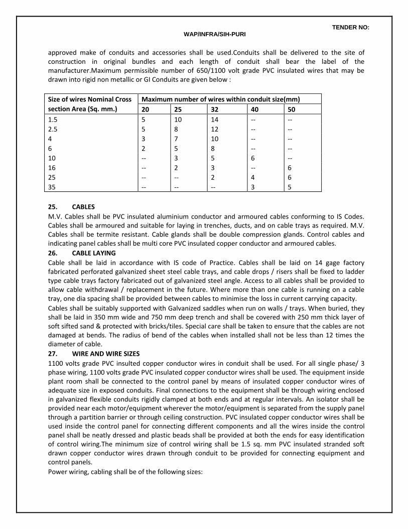
TENDER NO: WAP/INFRA/SIH-PURI
approved make of conduits and accessories shall be used.Conduits shall be delivered to the site of construction in original bundles and each length of conduit shall bear the label of the manufacturer.Maximum permissible number of 650/1100 volt grade PVC insulated wires that may be drawn into rigid non metallic or GI Conduits are given below :
Size of wires Nominal Cross
section Area (Sq. mm.)
Maximum number of wires within conduit size(mm)
20 25 32 40 50
1.5 5 10 14 -- --
2.5 5 8 12 -- --
4 3 7 10 -- --
6 2 5 8 -- --
10 -- 3 5 6 --
16 -- 2 3 -- 6
25 -- -- 2 4 6
35 -- -- -- 3 5
25. CABLES
M.V. Cables shall be PVC insulated aluminium conductor and armoured cables conforming to IS Codes. Cables shall be armoured and suitable for laying in trenches, ducts, and on cable trays as required. M.V. Cables shall be termite resistant. Cable glands shall be double compression glands. Control cables and indicating panel cables shall be multi core PVC insulated copper conductor and armoured cables.
26. CABLE LAYING
Cable shall be laid in accordance with IS code of Practice. Cables shall be laid on 14 gage factory fabricated perforated galvanized sheet steel cable trays, and cable drops / risers shall be fixed to ladder type cable trays factory fabricated out of galvanized steel angle. Access to all cables shall be provided to allow cable withdrawal / replacement in the future. Where more than one cable is running on a cable tray, one dia spacing shall be provided between cables to minimise the loss in current carrying capacity.
Cables shall be suitably supported with Galvanized saddles when run on walls / trays. When buried, they shall be laid in 350 mm wide and 750 mm deep trench and shall be covered with 250 mm thick layer of soft sifted sand & protected with bricks/tiles. Special care shall be taken to ensure that the cables are not damaged at bends. The radius of bend of the cables when installed shall not be less than 12 times the diameter of cable.
27. WIRE AND WIRE SIZES
1100 volts grade PVC insulted copper conductor wires in conduit shall be used. For all single phase/ 3 phase wiring, 1100 volts grade PVC insulated copper conductor wires shall be used. The equipment inside plant room shall be connected to the control panel by means of insulated copper conductor wires of adequate size in exposed conduits. Final connections to the equipment shall be through wiring enclosed in galvanized flexible conduits rigidly clamped at both ends and at regular intervals. An isolator shall be provided near each motor/equipment wherever the motor/equipment is separated from the supply panel through a partition barrier or through ceiling construction. PVC insulated copper conductor wires shall be used inside the control panel for connecting different components and all the wires inside the control panel shall be neatly dressed and plastic beads shall be provided at both the ends for easy identification of control wiring.The minimum size of control wiring shall be 1.5 sq. mm PVC insulated stranded soft drawn copper conductor wires drawn through conduit to be provided for connecting equipment and control panels.
Power wiring, cabling shall be of the following sizes:
TENDER NO: WAP/INFRA/SIH-PURI
1. Upto 5 HP motors/ 5 KW heaters 3 x 4 sq. mm copper conductor wires.
2. From 6 HP to 10 HP motors/ 3 x 6 sq. mm copper conductor wires
KW to 7.5 KW heaters
3. From 12.5 HP to 15 HP wires 2 Nos. 3 x 6 sq. mm copper conductor wires
4. From 20 HP to 25 HP motors 2 Nos. 3 x 10 sq. mm copper conductor wires
5. From 30 HP to 35 HP motors 2 nos.3x 16 sq.mm aluminium conductor armoured cable.
6. From 40 HP to 50 HP motors 2 Nos. 3x25 sq.mm aluminium conductor armoured cable.
7. From 60 HP to 75 HP motors 1 No. 3 x 70 sq. mm aluminium conductor armoured cable.
8. 100 HP motors conductor 1 No. 3 x 150 sq. mm. aluminium armoured cable
9. 200 HP motor conductor 2 No. 3 x 150 sq. mm. aluminium armoured cable.
All the switches, contactors, push button stations, indicating lamps shall be distinctly marked with a small description of the service installed. The following capacity contactors and overload relays shall be provided for different capacity motors or as per manufacturer’s recommendation.
28. EARTHING
Earthing shall be provided in accordance with relevant BIS Codes and shall be copper strips /wires .The main panel shall be connected to main earthing system of the power supply. All single phase metal clad switches and control panels be earthed with minimum 3 mm diameter copper conductor wire. All 3 phase motors and equipment shall be earthed with 2 numbers distinct and independent copper wires / tapes as follows:
i. Motor upto and inclu 2 No. 3 mm dia copper
10 HP rating. wires.
ii. Motor 12.5 HP to 40 HP capacity 2 No. 4 mm dia copper wires
iii. Motor 50 to 75 HP capacity. 2 No. 6 mm dia copper
All switches shall be earthed with two numbers distinct and independent copper wires’ tapes as follows:
i. 3 phase switches 2 No. 3 mm dia copper
and control panels upto wires.
60 amps rating.
ii. 3 phase switches, and 2 No. 4 mm dia copper
control panels 63 amps to wires.
100 amps rating.
iii. 3 phase switches and control 2 No. 6 mm dia copper
panels 125 amps to wires.
200 amps rating.
iv. 3 phase switches, control 2 No. 3 mm x 25 mm
panels, bus ducts, above copper tapes.
200 amps rating.
The earthing connections shall be tapped off from the main earthing of electrical installation. The overlapping in earthing strips at joints where required shall be minimum 75 mm. These straight joints
TENDER NO: WAP/INFRA/SIH-PURI
shall be riveted with brass rivets & brazed in approved manner. Sweated lugs of adequate capacity and size shall be used for all termination of wires. Lugs shall be bolted to the equipment body to be earthed after the metal body is cleaned of paint and other oily substance, and properly tinned.
29. DRAWINGS
Shop drawings for control panels and for wiring of equipment showing the route of conduit & cable shall be submitted by the contractor for approval of Architect/Consultant before starting the fabrication of panel and starting the work. On completion, four sets of complete “As-installed” drawings incorporating all details like, conduits routes, number of wires in conduit, location of panels, switches, junction/pull boxes and cables route etc. shall be furnished by the Contractor.
30. TESTING
Before commissioning of the equipment, the entire electrical installation shall be tested in accordance with relevant BIS codes and test report furnished by a qualified and authorised person. The entire electrical installation shall be gotten approved by Electrical Inspector and a certificate from Electrical Inspector shall be submitted. All tests shall be carried out in the presence of Project Manager. Testing of the panels shall be as per relevant BIS Codes :
31. PAINTING
All sheet steel work shall undergo a process of degreasing, thorough cleaning, and painting with a high corrosion resistant primer. All panels shall then be baked in an oven. The finishing treatment shall be by application of powder coating of approved shade.
32 MEASUREMENT OF ELECTRICAL CONTROL PANELS
Panels shall be counted as number of units. Quoted rates shall include as lumpsum (NOT measurable lengths) for all internal wiring, power wiring and earthing connections from the control panel to the starter and to the motor, control wiring for interlocking, power and control wiring for automatic and safety controls, and control wiring for remote start/stop as well as indication as per the specifications. The quoted rate of panel shall also include all accessories, switchgear, contactors, indicating meters and lights as per the Specifications and Schedule of Quantities.
33.RUBBER MAT
Rubber mat shall be provided in front to cover the full length of all panels. Where back space is provided for working from the rear of the panel, rubber mat shall also be provided to cover the full length of panel.
SECTION - 10 :: COMMISSIONING & GUARANTEE
1. SCOPE OF WORK
Work under this section shall be executed without any additional cost. The rates quoted in this tender shall be inclusive of the works given in this section.Contractor shall provide all tools, equipment, metering and testing devices required for the purpose.On award of work, Contractor shall submit a detailed proposal giving methods of testing and gauging the performance of the equipment to be supplied and installed under this contract.All tests shall be made in the presence of the Architect or his representative or any inspecting authority. At least five working days notice in writing shall be given to the inspecting parties before performing any test.Water flow rates of all equipment and in pipe lines through valves shall be adjusted to design conditions. Complete results of adjustments shall be recorded and submitted.Contractor shall ensure proper balancing of the hydraulic system and for the pipes / valves installed in his scope of work by regulating the flow rates in the pipe line by valve operation. The contractor shall also provide permanent Tee connection (with plug) in water supply lines for ease of installing pressure gauge, temperature gauge & rota meters. Contractor shall also supply all required pressure gauge, temperature gauge & rotameter for system commissioning and balancing. The balancing shall be to the satisfaction of Consultant / Project Manager.Three copies of all test results shall be
TENDER NO: WAP/INFRA/SIH-PURI
submitted to the Engineer in A4 size sheet paper within two weeks after completion of the tests.
2. PRECOMMISSIONNIG
On completion of the installation of all pumps, piping, valves, pipe connections, insulation etc. the Contractor shall proceed as follows:
a. Prior to start-up and hydraulic testing, the Contractor shall clean the entire installation including all fitments and pipe work and the like after installation and keep them in a new condition. All pumping systems shall be flushed and drained at least once through to get rid of contaminating materials. All pipes shall be rodded to ensure clearance of debris, cleaning and flushing shall be carried out in sections as the installation becomes completed.
b. All strainers shall be inspected and cleaned out or replaced.
c. When the entire systems are reasonably clean, a pre-treatment chemical shall be introduced and circulated for at least 8 hours. Warning signs shall be provided at all outlets during pre-treatment. The pre-treatment chemical shall:
· Remove oil, grease and foreign residue from the pipe work and fittings;
· Pre-condition the metal surfaces to resist reaction with water or air.
d· Establish an initial protective film;
· After pre-treatment, the system shall be drained and refilled with fresh water and left until the system is put into operation.
· Details and procedures of the pre-treatment shall be submitted to the Architect for approval.
e. Check all clamps, supports and hangers provided for the pipes.Check all the equipment, piping and valves coming under hot water system and operate each and every valve on the system to see if the valves are functioning properly. Thereafter conduct & hydro test of the system as for (b) above.
f. Fill up pipes with water and apply hydrostatic pressure to the system as given in the relevant section of the specification. If any leakage is found, rectify the same and retest the pipes.
Fire Protection System
a. Check all hydrant valves by opening and closing : any valve found to be open shall be closed.
b. Check all the piping under hydro test.
c. Check that all suction and delivery connections are properly made for all pump sets.
d. Check rotation of each motor after decoupling and correct the same if required.
e. Test run each pump set.
f. All pump sets shall be run continuously for 8 hours (if required with temporary piping back to the tank).
Commissioning and Testing
a. Pressurise the fire hydrant system by running the jockey pump and after it attains the shutoff pressure of the pump , then
b. Open bypass valve and allow the pressure to drop in the system. Check that the jockey pump cuts-in and cuts-out at the preset pressure. If necessary adjust the pressure switch for the jockey pump. Close by-pass valve.
c. Open hydrant valve and allow the water to below into the fire water tank in order to avoid wastage of water. The main fire pump shall cut-in at the preset pressure and shall not cutout automatically on reaching the normal line pressure. The main fire pump shall stop only by manual push button. However the jockey pump shall cut-out as soon as the main pump starts,
d. Switch off the main fire pump and test check the diesel engine driven pump in the same manner as the electrically driven pump,
TENDER NO: WAP/INFRA/SIH-PURI
e. When the fire pumps have been checked for satisfactory working on automatic controls, open fire hydrant valves simultaneously and allow the hose pipes to discharge water into the fire tank to avoid wastage.
f. Check each landing valve, male and female couplings and branch pipes, for compatibility with each other. Any fitting which is found to be incompatible and do not fit into the other properly shall be replace by the Contractor. Each landing valve shall also be checked by opening and closing under pressure.
g. Check all annunciations by simulating the alarm conditions at site.
3. STATUTORY AUTHORITIES' TESTS AND INSPECTIONS
As and when notified in writing or instructed by the Architect, the Contractor shall submit shop drawing and attend all tests and inspections carried out by Local Fire Authorities, Water Authority and other Statutory Authorities, and shall forthwith execute free of charge any rectification work ordered by the Architect as a result of such tests and inspections where these indicate non-compliance with Statutory Regulations. Some of these tests may take place after the issue of Practical Completion of the Main Contract and the Contractor shall make all allowances in this respect. The Contractor shall be responsible for the submission of all necessary forms and shop drawings to the Statutory Authorities which shall conform in layout to the latest architectural plans submitted to and kept by these Authorities. The submission shall comply with the requirements set forth in the current Codes of Practice and circular letters of the Statutory Authorities. The shop drawings to be submitted shall be forwarded to the Architect for checking before submission.
The Contractor shall allow for at least two submissions of complete sets of shop drawings to the Authorities, one to be made within six months after the award of the Contract but not less than six weeks before the inspection. The Architect may at his discretion instruct the Contractor for additional submissions to the Local Authorities whenever necessary. The Contractor shall notify the Architect at least seven days in advance of his application for local Authority tests and inspections. On receipt of a confirmed date for test and inspection the Contractor shall inform the Architect without delay.
4. FINAL ACCEPTANCE TESTS
Following commissioning and inspection of the entire installation, and prior to issue of the Completion Certificate, the Contractor shall carry out final acceptance tests in accordance with a programme to be agreed with the Architect.Should the results of the acceptance tests show that plant, systems and/or equipment fail to perform to the efficiencies or other performance figures as given in this Specification, the Contractor shall adjust, modify and if necessary replace the equipment without further payment in order that the required performance is obtained.Where acceptance tests are required by the relevant Authorities having jurisdiction, these tests shall be carried out by the Contractor prior to the issue of Completion Certificate to the acceptance of the Authorities.
5. REJECTION OF INSTALLATION / PLANT
Any item of plant or system or component which fails to comply with the requirements of this Specification in any respect whatsoever at any stage of manufacture, test, erection or on completion at site may be rejected by the Architect either in whole or in part as he considers necessary/appropriate. Adjustment and/or modification work as required by the Architect so as to comply with the Authority's requirements and the intent of the Specification shall be carried out by the Contractor at his own expense and to the satisfaction of the Authority/Architect. After works have been accepted, the Contractor may be required to carry out assist in carrying out additional performance tests as reasonably required by the Architect/Employer.
TENDER NO: WAP/INFRA/SIH-PURI
6. WARRANTY AND HANDOVER
The Contractor shall warrant that all plant, materials and equipment supplied and all workmanship performed by him to be free from defects of whatsoever nature before handover to the Owner.
7. HANDING OVER OF DOCUMENTS
All testing and commissioning shall be done by the Contractor to the entire satisfaction of the Owner’s site representative and all testing and commissioning documents shall be handed over to the Owner’s site representative.The Contractor shall also hand over all maintenance and operation manuals, all certificates and all other documentation as per the terms of the contract to the Owner’s site representative.
8. PIPE COLOUR CODE
S.No. Pipe Lines Ground / Base Colour
First
Colour Band
Second
Colour Band
1. Cooling Water Sea Green French Blue
2. Drinking Water (All cold water lines after filter)
Sea Green French Blue Single Red
3. Treated Water (Soft Water) Sea Green Light Orange
4. Domestic Hot Wate Sea Green Light Grey
5. Drainage (Storm Water) Black
6. Drainage (Sewage Water) Brown
7. Fire System Post Office Red
BORE WELL, PUMPS & FITTING AND PUMPHOUSE
1 No. of Bore well shall be executed by the contractors as detailed in the description of items inside
the Campus as per the availability of water. The Contractor shall take necessary approvals/ clearances
from the concerned authorities at his own cost if required. The statutory fees deposited towards the
above works shall be reimbursable to the Contractor subject to the submission of original receipt of the
deposited fees from the department and no extra amount shall be paid to the Contractor. It is also
mentioned that during the estimation depth of bore well was considered as 90 m. According Contractor
shall execute the work minimum up to 90 m depth or as per the direction of Engineer-in- Charge. The
supply of required capacity of pumps, fittings and pump house at the location of bore hole is in the scope
of Contractor under.

TENDER NO: WAP/INFRA/SIH-PURI
List of Approved Makes of Fire Fighting Works:-
S. No.
Details of Materials / Equipments Manufacturer's Name
1 G.I./M.S pipes. Jindal Hissar/Tata/Prakash
2 G.I. pipes fittings. Unik/Kirti/Zoloto
3 Valves Kartar/C& R/Zoloto
4 `Y' strainer Emerald Enterprises / Zoloto/ Kartar
5 Level Controller & Indicator (Water)
Technika / Minilec/Advance Auto
6 Paints Asian Paints/Berger/Shalimar
7 Pressure Gauge H Guru/Fiebig
8 Flexible Rubber Expansion Joint Kanwal Easyflex, Resistoflex
9 Pumps Kirloskar/Mather & Platt
10 Fire Fighting Equipments Minimax/Safeguard/Getech/Newage
11 Welding Rods Advani/Victor
12 GI Hangers Chilly/GMGR
13 Rubber hose pipe Deep Jyoti/Superex/approved IS marked
List of Approved Makes of PHE Works:-
S. No. Details of Materials / Equipments Manufacturer's Name
1 Vitreous China Sanitaryware Parryware/Hindware/Kohlar
2 C.P. Brass fittings Jaquar/Gem/Parko
3 Cast iron pipes & fittings, Manhole covers and frames. NECO/RIF/SKF
4 G.I. pipes. Jindal Hissar/Tata/Prakash
5 G.I. pipes fittings. Unik/Kirti/Zoloto
6 R.C.C pipe K.K. / App. Equivalent ISI marked
7 Stoneware pipes, Gully traps Perfect potteries, Jabalpur / Approved equivalent ISI marked
8 Valves Kartar/C& R/Zoloto
9 Paints Asian Paints /Berger/ Shalimar Paints
10 Water treatment equipments Ion Exchange/Thermax/Fontus.
11 Pumps Kirloskar/ITT/Grundfoss
12 Level Controller & Indicator (Water)
Technika / Minilec/Advance Auto
13 PVC Pipes Supreme / Prince/Polypack
14 Urinal Sensor UTEC/AOS System/Jaquar
15 Geyser Venus/Racold/AO Smith
16 Sink Neelkanth/Kobra/Parryware
17 Water purifier Acquaguard/Kent/Fontus
18 Water tanks Sintex/Polycon/Frontier
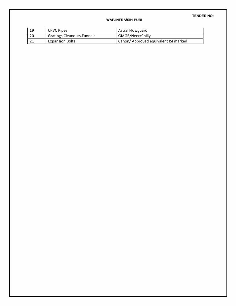
TENDER NO: WAP/INFRA/SIH-PURI
19 CPVC Pipes Astral Flowguard
20 Gratings,Cleanouts,Funnels GMGR/Neer/Chilly
21 Expansion Bolts Canon/ Approved equivalent ISI marked
Related Documents