Templatized Model Transformations: Enabling Reuse in Model Transformations Amogh Kavimandan and Aniruddha Gokhale Dept. of EECS, Vanderbilt University, Nashville, TN, USA {amoghk,gokhale}@dre.vanderbilt.edu Abstract. Model transformations are a key element of model-based software de- velopment processes. Despite their importance, contemporary model transforma- tion tools have limited or no support for reuse, particularly, when model trans- formations are applied in the context of development of a family of application variants, such as product lines. This forces developers to reinvent the transfor- mation rules thereby adversely impacting their productivity and increasing main- tenance costs. This paper presents MTS (Model transformation Templatization and Specialization), which overcomes these limitations by enabling developers to write reusable, templatized model transformations. MTS defines two higher order transformations to capture the variability and specialize the transforma- tions across variants of an application family. MTS can be realized within ex- isting model transformation tools without requiring any modifications to them. The results from applying our approach to two representative case studies indi- cate reduction in development effort of upto 90% when compared with the non- templatized approach. 1 Introduction Model transformations are key to the success of model-based software development. They are used to define progressive refinements of application models from abstract, high-level views into low-level, detailed views that are used by the execution platform for different purposes, such as application configuration, deployment, code synthesis, or even transforming them into other representations suitable for analysis tools that check various properties, such as correctness or deadlock free behavior. Model transformations have been applied in significantly diverse use cases as in (a) middleware quality of service (QoS) configuration [1], which involves automatically mapping the application-specified QoS requirements onto the correct QoS configuration options for the middleware platform, or (b) synthesizing dialogs for communication endpoints (i.e., hardware devices/software applications for communications, such as cellphone, instant messenger (IM), pager) in enterprise workflows for rapid decision making. A noticeable trait in the model transformations used in the context of multiple sce- narios of a given use case is the significant commonality in the transformations across variants of that use case. For example, in the QoS configuration use case, it is observed that many generated middleware configurations are same across a class of applications

Welcome message from author
This document is posted to help you gain knowledge. Please leave a comment to let me know what you think about it! Share it to your friends and learn new things together.
Transcript

Templatized Model Transformations: Enabling Reuse inModel Transformations
Amogh Kavimandan and Aniruddha Gokhale
Dept. of EECS, Vanderbilt University, Nashville, TN, USA{amoghk,gokhale}@dre.vanderbilt.edu
Abstract. Model transformations are a key element of model-based software de-velopment processes. Despite their importance, contemporary model transforma-tion tools have limited or no support for reuse, particularly, when model trans-formations are applied in the context of development of a family of applicationvariants, such as product lines. This forces developers to reinvent the transfor-mation rules thereby adversely impacting their productivity and increasing main-tenance costs. This paper presents MTS (Model transformation Templatizationand Specialization), which overcomes these limitations by enabling developersto write reusable, templatized model transformations. MTS defines two higherorder transformations to capture the variability and specialize the transforma-tions across variants of an application family. MTS can be realized within ex-isting model transformation tools without requiring any modifications to them.The results from applying our approach to two representative case studies indi-cate reduction in development effort of upto 90% when compared with the non-templatized approach.
1 Introduction
Model transformations are key to the success of model-based software development.They are used to define progressive refinements of application models from abstract,high-level views into low-level, detailed views that are used by the execution platformfor different purposes, such as application configuration, deployment, code synthesis, oreven transforming them into other representations suitable for analysis tools that checkvarious properties, such as correctness or deadlock free behavior.
Model transformations have been applied in significantly diverse use cases as in (a)middleware quality of service (QoS) configuration [1], which involves automaticallymapping the application-specified QoS requirements onto the correct QoS configurationoptions for the middleware platform, or (b) synthesizing dialogs for communicationendpoints (i.e., hardware devices/software applications for communications, such ascellphone, instant messenger (IM), pager) in enterprise workflows for rapid decisionmaking.
A noticeable trait in the model transformations used in the context of multiple sce-narios of a given use case is the significant commonality in the transformations acrossvariants of that use case. For example, in the QoS configuration use case, it is observedthat many generated middleware configurations are same across a class of applications
that are related to each other due to similarities in their QoS requirements and the imple-mentation platform. Similarly, in the dialog use case, despite differences in the commu-nication endpoints, a number of dialog properties remain common. These observationslead us to seek solutions for reuse in model transformations.
Our study of the current state-of-the-art in model transformations illustrates thatdespite the strong evidence of recurring patterns in the transformations, contemporarymodel transformation tools and techniques [2–6] lack support for reusability, modu-larization and extensibility of model transformation rules and algorithms. These short-comings force the transformation developers to reinvent the transformation steps andthe translation logic leading to significant code duplication in the transformations, andincreased efforts in code maintenance and evolution activities.
Recent research efforts [7–9] have demonstrated progress in applying model trans-formations in the context of families of applications or product lines. However, theseefforts do not as yet address the following open research questions:
a. How can the commonalities in the transformation process be factored out such thatthey can be reused by the entire application family?
b. How can the variabilities be decoupled from the model transformation rules, whilemaximizing the flexibility of the transformation process?
c. How can the model transformation for an application family be extended with newvariants, however, with minimally invasive changes to the transformation rules?
d. How can all these capabilities be achieved with none or minimal changes to con-temporary model transformation tools and techniques?
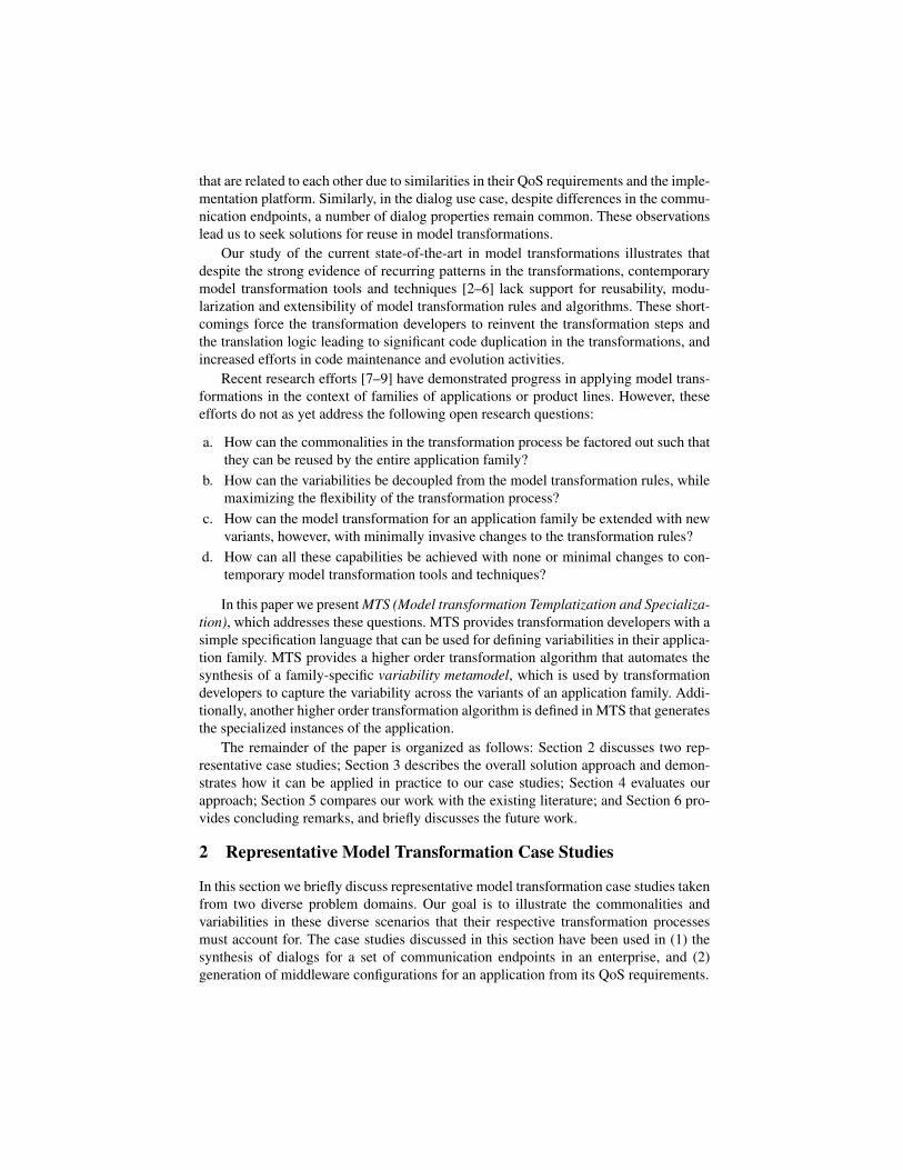
In this paper we present MTS (Model transformation Templatization and Specializa-tion), which addresses these questions. MTS provides transformation developers with asimple specification language that can be used for defining variabilities in their applica-tion family. MTS provides a higher order transformation algorithm that automates thesynthesis of a family-specific variability metamodel, which is used by transformationdevelopers to capture the variability across the variants of an application family. Addi-tionally, another higher order transformation algorithm is defined in MTS that generatesthe specialized instances of the application.
The remainder of the paper is organized as follows: Section 2 discusses two rep-resentative case studies; Section 3 describes the overall solution approach and demon-strates how it can be applied in practice to our case studies; Section 4 evaluates ourapproach; Section 5 compares our work with the existing literature; and Section 6 pro-vides concluding remarks, and briefly discusses the future work.
2 Representative Model Transformation Case Studies
In this section we briefly discuss representative model transformation case studies takenfrom two diverse problem domains. Our goal is to illustrate the commonalities andvariabilities in these diverse scenarios that their respective transformation processesmust account for. The case studies discussed in this section have been used in (1) thesynthesis of dialogs for a set of communication endpoints in an enterprise, and (2)generation of middleware configurations for an application from its QoS requirements.

2.1 Communication Dialog Creation for an Insurance EnterpriseOur first case study deals with the creation of dialogs for a set of communication end-points from workflow decision points in an insurance company. As part of their oper-ation, modern enterprise workflows set up communications between decision makers(i.e., employees) in an enterprise, and publish(collect) important information to(from)these decision makers. Since the employees in an enterprise may potentially be usingseveral endpoints (i.e., devices), an important consideration in delivering informationcontent from the workflows to the employees is the customization of communicationdialogs for individual endpoints, which is done using model transformations.
Figure 1a shows the communication dialog metamodel used in our case study. Wehave simplified the communication dialog by restricting the communications pertain-ing to a customer claim in the insurance company. The model transformation processin this case study is concerned with generating a dialog tailored to the properties of thecommunication end point. The transformation process is endogenous [10] in that boththe source and target model elements belong to the same dialog metamodel. The trans-formation process must account for the following requirements: (1) the dialogs for allthe endpoints contain, at the very least, the topic_info, and invitation_infoattributes; (2) the Call, Documentation, and Response model objects may bepresent in some but not all endpoints; and (3) the response to a communication dialogmay be YES, NO, or may contain advanced options such as suggest_alternate oramend_invitation.
Dialog
-topic_info : string-topic_detail : string
Topic
-info : stringInvitation_brief
-url : string-brief_text : string
Documentation
-user_response : bool-suggest_alternate : Employee = NULL-amend_invitation : Amend
Response
-detail_invitation_info : string-meeting_date : Date-meeting_time : Time
Invitation_detail
Invitation
-day : long-month : long-year : long
Date
-hour : long-minute : long
Time-change_date : Date-change_time : Time-change_modality : ENDPOINT
Amend
-name : string-eid : long
Employee
1
1
1
1
11
1
1
-number : longCall
1
1
(a) Generic communication dialog
Source metamodel
Target metamodel
RealTimeConfiguration
-cmd_line_options : string-service_conf : string
EnvironmentConf -low_range : long-high_range : long
BandedConnections
-stacksize : long-allow_borrowing : bool-allow_buffering : bool-max_buffered_requests : long-max_buffer_size : long
ThreadPool-static_threads : int-lane_priority : int-dynamic_threads : int
Lane-priority_model : Policy-default_priority : long
PriorityModelPolicy
+SERVER_DECLARED+CLIENT_PROPAGATED
«enumeration»Policy
1
0..*10..1
10..1
1
0..*
1
0..1
1..*
-configuredBy 1 1
-honors 1
-fixed_priority_service_execution : bool-multi_service_levels : bool
RTRequirement
(b) Middleware QoS configuration
Fig. 1: Simplified metamodels for representative use cases.
2.2 Middleware QoS Configuration for Component-based Applications
Our second case study is an exogenous transformation that translates component-basedapplication QoS requirements into the underlying middleware platform-specific QoSconfiguration options. Figure 1b shows the UML representation of both the source andthe target metamodels used in the QoS configuration case study. As shown, the sourcemetamodel contains the following Booleans for server components: (1) fixed_pr-iority_service_execution that indicates whether the component changes thepriority of client service invocations; and (2) multi_service_levels to indicatewhether the component provides multiple service levels to its clients. The output meta-model models the real-time CORBA [11] configurations.

Transformations for middleware QoS configuration are applicable across a num-ber of application domains. The individual configurations generated using the modeltransformation should be easily customizable for slight variations in these domains.Thus, the case study has the following requirements for the generated middlewareQoS configurations: (1) the PriorityModelPolicy object along with its attributesare transformed from fixed_priority_service_execution source attribute;(2) Lane object and its attributes are transformed from multi_service_levelssource attribute. The Lane object cardinality and the exact values of its attributes how-ever, can change; and (3) the cardinality of BandedConnections, the values of allthe attributes of ThreadPool except stacksize are assigned statically, however,they may vary for different application domains.
3 Model Transformation TemplatizationSection 1 argued for reusable and flexible model transformations so that they can be ef-fectively used in software development for application families including product lines.This section describes our solution approach called MTS. MTS is similar in conceptto C++ class templates and Java generics. Unlike C++ templates where specializationis based on the presence (or absence) of certain characteristics of the parameterizedtype, however, MTS is applicable more widely to developing generalized transforma-tion rules.
Legend
Transformation developers analyze their
application family; the variability results are input using constraint notation to
the (templatized) model transformation
1
MTS Higher order transformation used to automatically generate VMM
from model transformation2
Transformation developers create
a specialization repository for their application family
3
A combination of model transformation and a VMM model
synthesizes application family instances
4
Templatized Model Transformation
G G’
G G’ G G’ G G’
G G’
G G’
G G’
Subsystems in appln. familyApplication family
Variability Metamodel
Publisher Subscriber-publishes
*
-consumes
*
-nesting : Type-scheme : Granularity-nestingLevel : int
GroupFilter11
Publisher Subscriber-publishes
*
-consumes
*
-ecfiltering : ECFilteringTypeEventChannel
1
1 SubscriberOptions1 1
-filter : ECFilteringTypeFilter
1
1
1
0..*
InputPattern OutputPattern
1 1
11 1 11
1
1
1
1
1
1
1
1
1
Specialization Repository
Variable
Com
ponent
Variable
Com
ponent
Variable
Com
ponent
Variable
Com
ponent
Variable
Com
ponent
Fig. 2: MTS Approach to Reusable Model Transformations
The overall MTS approach is shown in Figure 2. It consists of the following steps,which are also marked in the figure:1. Identifying the variabilities: In this step, transformation developers analyze theirapplication family to identify variabilities across the variants. As shown in Step 1, thesevariabilities are input to the model transformation in terms of a simple constraint no-tation specification (see Section 3.1). This step decouples the transformation algorithmfrom its variabilities that can change in instance-specific manner, and is similar to defin-ing template functions in C++ that outline the pattern of the function code.2. Generating variability metamodel: In this step, developers use a higher order trans-formation (i.e., those model transformations that work on meta-metamodels to translatesource metamodel(s) to target metamodel(s)) defined in MTS to automatically generatethe variability metamodel (VMM) for their application family (see Section 3.2).

3. Synthesizing specialization repository: Next, developers create VMM models, whereeach VMM model corresponds to a family member. Subsequently in Step 3, the vari-abilities identified in Step 1 are instantiated for every family member. A collection ofall the VMM models in an application family is termed as a specialization repository ofthat family (see Section 3.3).4. Specializing the application instances: Finally, as shown in Step 4, developers useanother higher order transformation defined in MTS to create application variants (seeSection 3.4). This step is similar to instantiation of a C++ template where the compilergenerates type-specific code based on the type of the argument passed.
We have used the Generic Modeling Environment (GME) [12] as the modeling en-vironment for MTS. GME provides a general-purpose editing engine, and a separatemodel-view-controller GUI. GME is metaprogrammable in that the same environmentused to define modeling languages is also used to build models, which are instancesof the metamodels. For defining transformation rules we have used the Graph Rewrit-ing And Transformation (GReAT) [6] language. GReAT is developed using GME andcan be used to define model transformation rules using its visual modeling language. Ituses domain-specific modeling languages (DSMLs) as its source and target languages.Transformation developers model the transformation rules in terms of patterns compris-ing modeling elements of the source and target modeling languages. The GReAT Exe-cution Engine (GR-engine) subsequently executes these transformation rules to gener-ate the target models.
3.1 Identifying the Variabilities
In an application family, the commonalities constitute the invariants of that family i.e.,the characteristics that are unique and that do not change across the set of members ofthe application family. Thus, in essence, the general idea in using MTS for developingtemplatized transformations is that all the common features of an application familyget transformed directly from the input specification as family instance-independenttransformation rules. Variabilities on the other hand, constitute family member idiosyn-crasies i.e., characteristics that constitute the dissimilarities between members of theapplication family. Therefore, they must be dissociated from the transformation rules toallow independent evolution of the transformation and its variabilities. Our discussionbelow focuses on how this is achieved in MTS.
Transformation developers carry out scope, commonality and variability (SCV) [13]analysis of their application family as a precursor to this first step. The developers theninput the results from SCV analysis to the model transformation in terms of constraintspecifications. The following two categories of variabilities can be specified using ourconstraint notation specification:(a) Structural variabilities, where the basic building blocks i.e., model elements, ortheir cardinalities in every family member model are different. Thus, the variation infamily member models emanates from dissimilarities in their structural composition.(b) Qualitative variabilities, where the family member models may share model el-ements, but the data values of their attributes are different. The term quality here isstrictly used in terms of the specification of a model as a whole, which is an aggregateof data values of all its attributes.

Table 1: SCV analysis results for case studies in Section 2.Properties/Attributes
Family Commonalities VariabilitiesVariant Structural Qualitative
Insurance Enterprise
invitation_detail, meeting_date,Cell phone/Office phone meeting_time, user_response,
– topic_detail, claim_id, customer_name,customer_id, claim_date
invitation_info,Pager topic_info Call –
user_response, suggest_alternate,Instant Messenger Documentation invitation_detail, meeting_date, meeting_time,
topic_detail, claim_id, customer_name,scustomer_id, claim_date, amend_invitation
QoS Configuration
Config_1 allow_borrowing, allow_buffering,Lane max_buffd_reqs., max_buff_size,
PriorityModelPolicy,
Config_2 EnvironmentConf, Lane, allow_borrowing, allow_buffering,stacksize BandedConnections max_buffd_reqs., max_buff_size,
Config_3 Lane, allow_borrowing, allow_buffering,BandedConnections max_buffd_reqs., max_buff_size,
Table 1 shows the results of the SCV analysis for the two case studies presented inSection 2. For example, in the dialog case study, we show profiles for three endpoints,where a profile is denoted by properties required to create a dialog for an endpoint. Ittabulates the common and variable properties for each of these endpoints. These dialogproperties themselves may be either be model object attributes (e.g., suggest_al-ternate and invitation_detail attributes), or the model objects themselves(e.g., Call and Documentation objects).
MTS defines a constraint specification notation that is used by developers after theSCV analysis to capture the variabilities in their transformations. MTS requires devel-opers to insert the constraint specifications as special comments inside the Attrib-uteMapping model element in GReAT. This element allows assignment of the at-tributes of matched objects in a transformation rule using C++ code. This constraintspecification is opaque to the GReAT interpretation logic (for reading source and targetmetamodels of the transformation) and does not affect its GR-engine execution.
Figure 3a shows a snippet of the constraint specification in MTS for the variabili-ties in Table 1 for the Dialog case study. As shown, Call and Documentation arespecified in Structural block to indicate that they may be present in the dialog pro-files of some endpoints. The Qualitative block on the other hand, captures thosemodel objects that are present across all the endpoints, but whose attributes may havedifferent values for every endpoint. Thus, from Table 1, even though the Responseelement is present in both the cell phone and the IM, the suggest_alternate andamend_invitation attributes are not applicable and are omitted for the cell phone(because of limited capabilities of the endpoint). For a IM endpoint, however, these at-tributes can be used in its dialog and are available. A similar variability exists for theattributes of the Invitation element for the office phone and pager endpoints.

Untitled
Structural { Call Documentation}Qualitative { Response:user_response Response:suggest_alternate Response:amend_invitation Invitation:invitation_info Invitation:invitation_detail Invitation:meeting_date Invitation:meeting_time}
Page 1
(a) Insurance enterprise case study
Untitled
Structural { BandedConnection }Qualitative { RTRequirement:multi_service_levels:: Lane:static_threads, Lane:dynamic_threads, Lane:lane_priority ThreadPool:max_buffer_size ThreadPool:max_buffered_requests ThreadPool:allow_buffering ThreadPool:allow_borrowing}
Page 1
(b) QoS configuration case study
Fig. 3: Example constraint notation specification.
Similarly, Figure 3b shows an excerpt from the constraint specification for the vari-abilities in Table 1 for the QoS configuration case study. As shown, there is an asso-ciation between multi_service_levels attribute of RTRequirement sourceobject, and attributes of Lane target object to indicate that the values of the later aredependent on that of the former, and that the values themselves can vary for differentconfigurations. The above specification can thus be exemplified be the following: forLane attribute set {static_threads, dynamic_threads, lane_priority},config_1 in Table 1 can have data values {10, 20, 50}, while config_2 can havedata values {5, 2, 15} to realize the requirement that server component should supportmultiple levels for its clients’ service invocations.
3.2 Generating Variability Metamodel from Constraint SpecificationAfter the SCV analysis has been performed and the variabilities in the application fam-ily have been specified in the model transformation as discussed in Section 3.1, the nextstep is generating the VMM for that family. The goal behind generating VMM is tomodularize the variabilities and decouple them from the model transformation rules. Inthis section we explain the higher order transformation for generating the VMM.
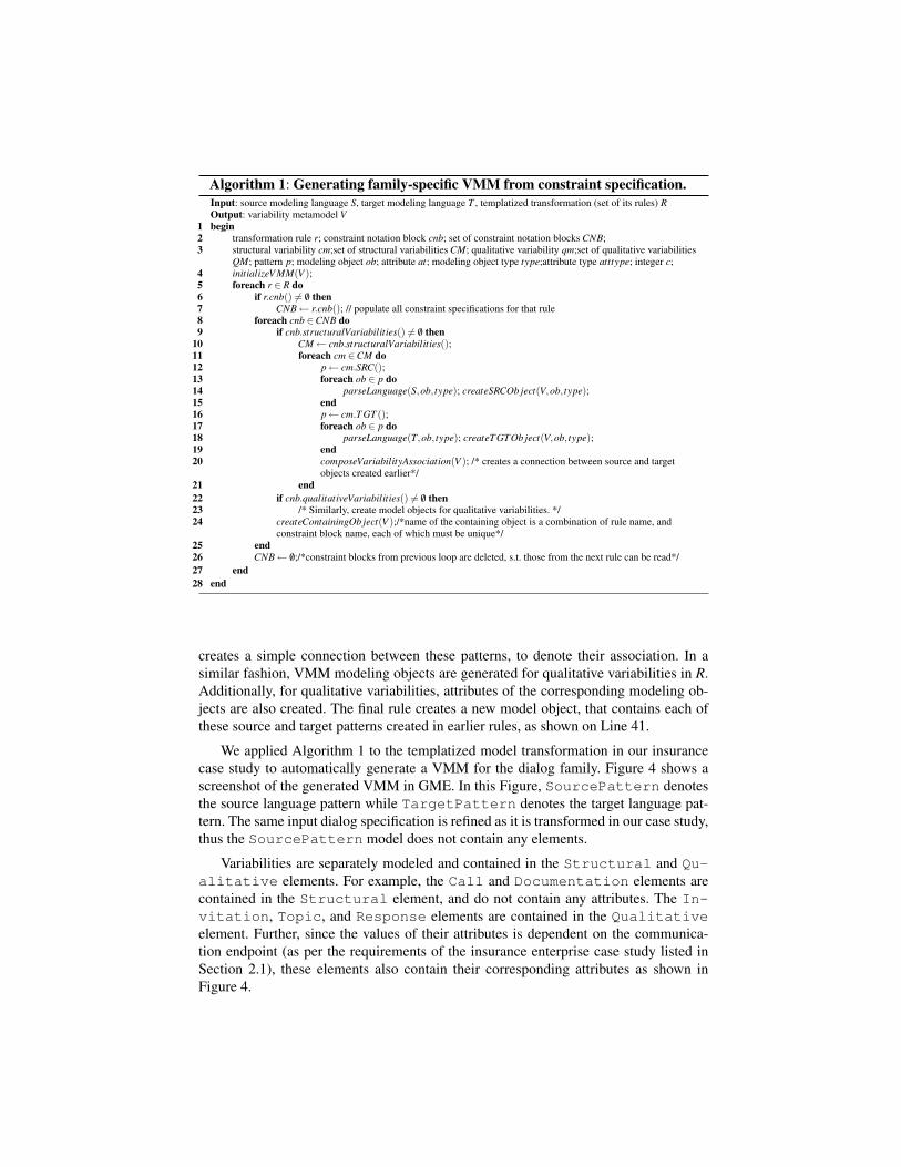
The higher order transformation operates on GME and GReAT metamodels, thetemplatized transformation itself, and source and target DSMLs (of the templatizedtransformation). Algorithm 1 shows the translation rules in this higher order transfor-mation and it works as follows: Recall from Section 3.1 that the structural variabilityis concerned only with capturing the (source and target) model objects (or their cardi-nalities) used in composition of family variants. As such, for every structural variabilityblock, the algorithm creates the corresponding model objects in VMM. The qualitativevariability, on the other hand, captures the dissimilarities in values of model object at-tributes. Therefore, for these variabilities, the algorithm creates model objects and theirattributes as well.
The function initializeV MM(V ) on Line 4 creates a new VMM, V , and initializes itsinternal variables. This is necessary so that in the following rules the syntax and seman-tics of V can be defined in GME. Lines 12 and 16 in the Algorithm read the source andtarget patterns that correspond to every structural variability in the templatized transfor-mation R. Next, the types of each modeling object, for both source and target patternsread in the previous rule is deduced by parsing the respective modeling languages asshown in Lines 14 and 18. This type information is used to create appropriate modelingobjects corresponding to the specified source and target patterns. Once the source andtarget patterns are created in VMM, the function composeVariabilityAssociation(V )
Algorithm 1: Generating family-specific VMM from constraint specification.Input: source modeling language S, target modeling language T , templatized transformation (set of its rules) ROutput: variability metamodel Vbegin1
transformation rule r; constraint notation block cnb; set of constraint notation blocks CNB;2structural variability cm;set of structural variabilities CM; qualitative variability qm;set of qualitative variabilities3QM; pattern p; modeling object ob; attribute at; modeling object type type;attribute type atttype; integer c;initializeV MM(V );4foreach r ∈ R do5
if r.cnb() 6= /0 then6CNB← r.cnb(); // populate all constraint specifications for that rule7
foreach cnb ∈CNB do8if cnb.structuralVariabilities() 6= /0 then9
CM← cnb.structuralVariabilities();10foreach cm ∈CM do11
p← cm.SRC();12foreach ob ∈ p do13
parseLanguage(S,ob, type); createSRCOb ject(V,ob, type);14end15p← cm.T GT ();16foreach ob ∈ p do17
parseLanguage(T,ob, type); createT GTOb ject(V,ob, type);18end19composeVariabilityAssociation(V ); /* creates a connection between source and target20objects created earlier*/
end21if cnb.qualitativeVariabilities() 6= /0 then22
/* Similarly, create model objects for qualitative variabilities. */23createContainingOb ject(V );/*name of the containing object is a combination of rule name, and24constraint block name, each of which must be unique*/
end25CNB← /0;/*constraint blocks from previous loop are deleted, s.t. those from the next rule can be read*/26
end27end28
creates a simple connection between these patterns, to denote their association. In asimilar fashion, VMM modeling objects are generated for qualitative variabilities in R.Additionally, for qualitative variabilities, attributes of the corresponding modeling ob-jects are also created. The final rule creates a new model object, that contains each ofthese source and target patterns created in earlier rules, as shown on Line 41.
We applied Algorithm 1 to the templatized model transformation in our insurancecase study to automatically generate a VMM for the dialog family. Figure 4 shows ascreenshot of the generated VMM in GME. In this Figure, SourcePattern denotesthe source language pattern while TargetPattern denotes the target language pat-tern. The same input dialog specification is refined as it is transformed in our case study,thus the SourcePattern model does not contain any elements.
Variabilities are separately modeled and contained in the Structural and Qu-alitative elements. For example, the Call and Documentation elements arecontained in the Structural element, and do not contain any attributes. The In-vitation, Topic, and Response elements are contained in the Qualitativeelement. Further, since the values of their attributes is dependent on the communica-tion endpoint (as per the requirements of the insurance enterprise case study listed inSection 2.1), these elements also contain their corresponding attributes as shown inFigure 4.

Attributes can be modified in VMM
models as opposed to transformation rules
Structural elements generated without
attributes
Fig. 4: Generated VMM for communication dialog family using the Algorithm 1.
3.3 Synthesizing Specialization RepositoryIn this step, transformation developers use the generated VMM to create VMM mod-els, where each VMM model corresponds to a family member (or more appropriately,variabilities of a family member). The aggregate of all the VMM models collectivelycontain variabilities of all the family members.
For example, for insurance enterprise case study, the specialization repository con-tains a distinct VMM model for every type of endpoint supported. Similarly, the QoSconfiguration case study has as many VMM models as the number of separate configu-rations it contains.
3.4 Specializing the Application InstancesFinally the VMM models generated in Step III must be used in conjunction with the(original) templatized model transformation to create specialized instances of the ap-plication family. In this section, we explain the higher order transformation used to(1) read the input VMM model corresponding to a member of the application family,and (2) add temporary objects at the appropriate rules in the templatized transforma-tion to insert the instantiated variability of a family member (corresponding to the cur-rent VMM model). Algorithm 2 shows the translation rules in this transformation. Asshown, Lines 4–6 in Algorithm 2 create a new model transformation instance R′1 fromthe input templatized transformation R, read the containing model objects in VMM V ,and for every model object ob search the corresponding rule in the transformation R′.This rule denotes the location where the variabilities contained in ob were specified inSection 3.1. At this time, once rule r is known, the constraint block is deleted fromthis rule in function deleteCNB(r). The function createTempOb ject(tmp,r) creates a
1 For creating application family instances, it is not necessary to create a new instance R′, and isonly created in Algorithm 2 to avoid modification of the original templatized transformation Ritself.

temporary object tmp inside this rule. For every Structural variability in the sourcepattern in ob, object references are read from V , and created in tmp and in addition,their cardinalities are assigned in Lines 7–9. Similarly, attributes in VMM that captureQualitative variabilities are read from V , and created and assigned values in tmpin Line 10. The same rule is also repeated for all target patterns in ob in Lines 12–15.
Algorithm 2: Specializing model transformation from the VMM model.Input: variability metamodel V , templatized transformation ROutput: specialized instance of input templatized transformation R′
begin1transformation rule r; set of model objects OB,IO; pattern p; modeling object ob,io,tmp; attribute at;2modeling object type type;attribute type atttype;3R′← R; OB← containingModelOb ject(V );4foreach ob ∈ OB do5
r← searchRule(R′,ob jName(ob)); createTempOb ject(tmp,r); deleteCNB(r);6IO← parseSRCPattern(ob);7foreach io ∈ IO do8
createOb jectRe f s(io, tmp); assignCardinalities(io, tmp);9createAttribs(io, tmp); assignValues(io, tmp);10
end11IO← parseT GT Pattern(ob);12foreach io ∈ IO do13
createOb jectRe f s(io, tmp); assignCardinalities(io, tmp);14createAttribs(io, tmp); assignValues(io, tmp);15
end16end17
end18
We applied Algorithm 2 to our QoS configuration case study. One of the rules inthis case study assigns specific data values to the attributes of Lane (target) elementdepending on whether or not the multi_service_levels (source) element valueis set to TRUE. Further, as identified earlier in Section 3.1, there is a qualitative vari-ability involving these two elements. The same variability is also given in Figure 5 forreference. The attributes in tempObject are assigned values from the values of thecorresponding attribute in the VMM model. Similarly, for the structural variability, themodel object references are also created by parsing and reading the VMM model.
Thus, the rule service_levels_attribute_mapping (and in effect, themodel transformation itself) need not change, when some of these data values/modelobject cardinalities have to be altered. This is because the modifications can now bedone simply by modifying the appropriate VMM model.4 Evaluating MTS for Managing Model Transformation
VariabilitiesIn this section we evaluate the capabilities of MTS in managing the variabilities in thecontext of our case studies from Section 2. First, we measure the performance overheadof our approach in terms of the time complexity of each of its higher order transfor-mations. Next, we discuss the reduction in development effort with the use of MTS interms of the time required to execute the model transformations.
Our prototype implementation of MTS is part of the CoSMIC2 tool suite. For all ofour experiments below, we used CoSMIC version 0.5.7. In addition, we have used GME
2 http://www.dre.vanderbilt.edu/cosmic/

/*Qualitative{ RTRequirement: multi_service_levels:: Lane:static_threads, Lane:dynamic_threads, Lane.lane_priority } */
bool multi = tempObject.multi_service_levels (); int static tempObject.static_threads (); int dyna = tempObject.dynamic_threads (); int prio tempObject.lane_priority (); if (multi == RTRequirement. multi_service_levels ()) { Lane.static_threads () = static; Lane.dynamic_threads () = dyna; Lane.lane_priority () = prio; }
Temporary object created by Algorithm 2; attributes/model objects contained correspond to the constraint
specification in this rule
Source and target attributes are read (and assigned) from the
attributes of tempObject that are read from VMM model. Thus, the
rule need not change for changing values of attributes
Fig. 5: Specialization of a QoS configuration rule using MTS.
version 6.11.9 and GReAT version 1.6.0 software packages which are necessary forusing MTS, and specifying various DSMLs and transformations. All the experimentswere run on a Windows XP SP2 workstation with a 2.66 GHz Intel Xeon dual processor,2 GB physical memory.
4.1 Reduction in Development Effort using MTSRecall from Section 3 that, in order to create target model from the source model us-ing GReAT, the developers need to execute the GR-engine that in turn executes all thetranslation rules of that model transformation. More specifically, GR-engine executioninvolves the following steps: (1) executing the master interpreter that generates thenecessary intermediate files containing all the rules in the current transformation, (2)compile these intermediate files, if not done already, and (3) run the generated exe-cutable. Steps 1 and 2 must be executed each time the model transformation is modified(i.e., its rules are modified). Table 2 shows the time taken for each of these steps for ourtwo case studies3.
Table 2: Time taken in executing the twomodel transformations in GReAT.
Case Master GR-engineStudy Interpreter Compile & execute Execute
InsuranceEnterprise 16 sec. 64 sec. 8 sec.
QoSConfiguration 16 sec. 104 sec. 12 sec.
Obviously, without the use of MTS,Steps 1 and 2 have to be re-executed eachtime a new type of family instance (e.g.,addition of a new communication end-point in insurance enterprise case study)has to be supported by the model trans-formations. Additionally, even for a sin-gle family instance, modifying a particu-lar mapping (e.g., changing the values of Lane attributes, for a particular multi_se-rvice_levels value in QoS configuration case study), requires the re-execution ofthe first two steps above.
Using MTS, on the other hand, the first two steps have to be executed only oncewhen the model transformation is being executed for the first time. Since all the instance-
3 Even with the use of MTS for the development of a model transformation, since the sourceand target DSMLs do not change, approximately the same number of rules are required. Thus,the time required for each of the steps in Table 2 is the same even with the use of MTS.

specific customizations/changes are done in the corresponding VMM model, the devel-opers only need to execute Step 3 after each change to produce output of the trans-formation (i.e., a new family instance). For our two case studies, as shown in Table 2,using MTS leads to savings of upto 90% in the time taken for a single transformationrun, over non-templatized approach.
Rather than re-executing the same model transformation each time for a new familyinstance, the transformation developers can potentially develop and maintain a modeltransformation per single(subset of) family instance(s). Assuming a total of I family in-stances, and Rn average number of rules per instance, this approach will require main-tenance of I ∗Rn rules. With the use of MTS, assuming that the average number of rulesdo not change, the total number of rules to be maintained reduces by a fraction of I−1
I .4.2 Performance Overhead of using MTSThe rationale behind these experiments was to quantify the overhead placed by the useof MTS and observe how the Algorithms 1 and 2 perform when the number of structuraland qualitative variabilities are changed. The performance overhead was calculated interms of the time taken by each of these algorithms when used in the context of eachof the two case studies. In all we identified (a maximum of) fifteen variabilities for in-surance enterprise case study, and eleven variabilities for QoS configuration case study.The performance overhead was measured, increasing the variabilities in each case studyfrom a minimum value of two to the maximum values above. Table 3b shows the dis-tribution of variabilities across the qualitative and structural dimensions. Additionally,the size of both the metamodels is also given in Table 3a.
Table 3: Details of the representative case studies.(a) The size of the metamodels.
Metamodel # of # of # ofmodeling elmts. attribs. conns.
InsuranceEnterpriseSRC/TRGT 8 14 0
QoSConfiguration
SRC 3 2 2TRGT 8 14 4
(b) Distribution of variabilities.Data Point Insurance Enterprise QoS Configuration
Qualitative Structural Qualitative Structural1 2 0 2 02 2 2 4 03 3 4 5 04 3 6 5 25 5 6 6 36 6 7 8 37 6 9 n.a. n.a.
Figure 6 shows the overhead involved in using MTS to generate VMM (Step 1), andspecialize the transformation (Step 4). In general, the algorithms take slightly more timefor QoS configuration than the insurance enterprise, for the same number of variabili-ties, which is attributed to the larger size of the combined size of the source and targetmetamodels of the former. For the maximum number of variabilities, identified by thehighest data points in either plots, Algorithm 1 took 26 and 27 seconds for case studiesin Section 2.1 and Section 2.2, respectively. Algorithm 2, on the other hand, took 24seconds, for both the case studies. Algorithm 1 was observed to be generally more sen-sitive to the variations in structural variabilities, when the qualitative variabilities werekept constant (e.g., data points 1-2, 3-4, and 6-7 in Table 3b).
For a variation of {Q=4, S=9} in insurance enterprise case study where Q and Sdenote the total variation in qualitative and structural variabilities, respectively, the time

0
5
10
15
20
25
30
0 5 10 15 20
Tim
e (s
econ
ds)
# of variabilities
1
2
34
5 6
7
Algorithm 1Algorithm 2
(a) Insurance enterprise case study
0
5
10
15
20
25
30
0 2 4 6 8 10 12 14
Tim
e (s
econ
ds)
# of variabilities
1
23
4
5
6
Algorithm 1Algorithm 2
(b) QoS configuration case study
Fig. 6: Overhead in using MTS for the development of templatized transforma-tions. The Y axis denotes the time taken by Algorithms 1 and 2.
complexity of Algorithm 1 increased by 350% from an initial value of 6 seconds, whilethat of Algorithm 2 increased by 380% from an initial value of 5 seconds. For QoSconfiguration case study, with a total variation of {Q=6, S=3}, the increase was∼136%and ∼300%, for Algorithms 1 and 2, respectively.
Note that, while using MTS for the development of a single application family,each of these algorithms have to be applied only once (i.e., once for generating VMM,and once for creating temporary objects in the model transformation). Thus, the costof using MTS is amortized over the total number of transformation runs, during thedevelopment cycle of that application family.
5 Related WorkThe model driven architecture (MDA) development process is centered around defin-ing application platform-independent models and applying (typed, and attribute aug-mented) transformations to these models to obtain application platform-specific models.In the context of MDA, requirements and challenges in generating specialized trans-formations from generic transformations are discussed in [14]. Asset variation pointsdiscussed in [15] deal with expressing variability in models of product lines [16]. Avariation point is identified by several characteristics (e.g. point reference, and context,use and rationale of the variation point) that uniquely identify that point in the productlines. These asset variation points capture variation rules of implementation compo-nents of a product-line member.
Existing model transformation tools [2–4] support some form of higher order trans-formations. PROGRES and ATL allow specification of type parameters while VIATRAallows development of meta-transformations i.e., higher order transformations that canmanipulate transformation rules and hence model transformations. Unlike MTS how-ever, these tools do not provide mechanisms for separation of variabilities from modeltransformations to facilitate automated development of application families.
Reflective model driven engineering (MDE) approach [17] proposes a two dimen-sional MDA process by expressing model transformations in a tool- or platform-indepe-ndent way and transforming this expression into actual tool- or platform-specific modeltransformation expressions. There is return on investment (ROI) associated with devel-oping and maintaining mappings from platform-independent transformations to platform-specific transformations in terms of reuse, composition, customization, maintenance

etc. The authors argue that the ROI for a two-dimensional MDA process is greater thanconventional one dimensional MDA.
Although reflective MDE focuses on having durable transformation expressions thatnaturally facilitate technological evolution and development of tool-agnostic transfor-mation projects, mappings still have to be evolved with change in platform-specifictechnologies. MTS on the other hand, is concerned with managing and evolving modeltransformation variability in systems developed using an MDA process.
An aspect-oriented approach to managing transformation variability is discussedin [7, 8] that relies on capturing variability in terms of models and code generators.Another approach is model weaving [18], which is used in the composition of separatemodels that together define the system as a whole. Aspect models allow specifyingvariability that is weaved into a base model to form an instance of a product-line.
In essence, using the aspect-oriented approach requires developers to learn a newmodeling language for creating aspect models for their product-line. In contrast, MTSgenerates VMM from variability specification in the templatized transformation to au-tomate the entire process. The population of VMM models itself, as shown in Section 3,does not involve learning an entirely new language since all its modeling objects are partof a source (or target) modeling language of the transformation.
6 ConclusionsThis paper presented MTS (Model transformation Templatization and Specialization),which is an enabling technology for contemporary model transformation tools to sup-port reusable model transformations. Existing model transformation tools lack supportfor reusable transformations which force developers to reinvent transformation rules.MTS overcomes these limitations while requiring no change to contemporary tools.MTS defines templatized transformations to factor out the commonalities, and uses thenotion of a generated variability metamodel to capture the variabilities in the transfor-mation process across variants of an application family. MTS defines two novel higherorder transformations to specialize the transformations for different variants. The con-tributions of MTS are important since it enhances developer productivity and effective-ness of model-based software development for application families. Our results fromapplying MTS to two diverse set of application families (for the given number of struc-tural and qualitative variabilities) indicate upto a 90% reduction in execution time, whencompared with the non-templatized approach.
In the future we are interested in studying the usability of the constraint specificationlanguage, and the higher order transformations in MTS. As such, several user studieshave been planned to measure the quality value of our toolchain. Additionally, we havealso planned on extending and applying MTS to scenarios where a single source DSMLmust be mapped to multiple target DSMLs.References
1. Kavimandan, A., Gokhale, A.: Automated Middleware QoS Configuration Techniques us-ing Model Transformations. In: Proceedings of the 14th IEEE Real-Time and EmbeddedTechnology and Applications Symposium (RTAS 2008), St. Louis, MO, USA (April 2008)93–102
2. Schürr, A., Winter, A.J., Zündorf, A.: Progres: Language and environment. In Ehrig, H., En-gels, G., Kreowski, H., Rozenberg, G., eds.: Handbook on Graph Grammars and Computing

by Graph Transformation: Applications, Languages, and Tools, World Scientific PublishingCompany (1999) 487–550
3. G. Csertán and G. Huszerl and I. Majzik and Z. Pap and A. Pataricza and D. Varró: VIATRA:Visual Automated Transformations for Formal Verification and Validation of UML Models.In: Proceedings of 17th IEEE International Conference on Automated Software Engineering,Edinburgh, UK, IEEE (2002) 267–270
4. Bézivin, J., Dupé, G., Jouault, F., Pitette, G., Rougui, J.E.: First Experiments with the ATLModel Transformation Language: Transforming XSLT into XQuery. In: Companion of the18th Annual ACM SIGPLAN Conference on Object-Oriented Programming, Systems, Lan-guages, and Applications, OOPSLA 2003, ACM (2003)
5. Gabriele Taentzer: AGG: A Graph Transformation Environment for Modeling and Valida-tion of Software. In: International Workshop on Application of Graph Transformations withIndustrial Relevance (AGTIVE 2003), Charlottesville, VA (September 2003) 446–453
6. Karsai, G., Agrawal, A., Shi, F., Sprinkle, J.: On the Use of Graph Transformations in theFormal Specification of Computer-Based Systems. In: Proceedings of IEEE TC-ECBS andIFIP10.1 Joint Workshop on Formal Specifications of Computer-Based Systems, Huntsville,AL, IEEE (April 2003)
7. Voelter, M., Groher, I.: Product Line Implementation using Aspect-Oriented and Model-Driven Software Development. In: Proceedings of the 11th Annual Software Product LineConference (SPLC), Kyoto, Japan (September 2007)
8. Voelter, M., Groher, I.: Handling Variability in Model Transformations and Generators. In:Companion to the Annual ACM SIGPLAN Conference on Object-Oriented Programming,Systems, Languages, and Applications (OOPSLA 2007), Montréal, Canada, ACM (October2007)
9. Frédéric Thomas, Jérôme Delatour, F.T., Gérard, S.: Toward a Framework for ExplicitPlatform-Based Transformations. In: Proceedings of the 11th IEEE International Sympo-sium on Object-oriented Real-time distributed Computing (ISORC 2008), Orlando, FL, USA(May 2008)
10. Mens, T., Gorp, P.V., Varro, D., Karsai, G.: Applying a Model Transformation Taxonomyto Graph Transformation Technology. In: Lecture Notes in Computer Science: Proceedingsof the International Workshop on Graph and Model Transformation (GraMoT’05). Volume152., Tallinn, Estonia, Springer-Verlag (September 2006) 143–159
11. Object Management Group: Real-time CORBA Specification. 1.2 edn. (January 2005)12. Ledeczi, A., Bakay, A., Maroti, M., Volgysei, P., Nordstrom, G., Sprinkle, J., Karsai, G.:
Composing Domain-Specific Design Environments. IEEE Computer (November 2001) 44–51
13. Coplien, J., Hoffman, D., Weiss, D.: Commonality and Variability in Software Engineering.IEEE Software 15(6) (November/December 1998)
14. Kovse, J.: Generic Model-to-Model Transformations in MDA: Why and How? In: Proceed-ing of 1st OOPSLA Workshop on Generative Techniques in the context of Model DrivenArchitecture. (November 2002)
15. Salicki, S., Farcet, N.: Expression and usage of the variability in the software product lines.In: Proceeding of The 4th International Workshop on Software Product-Family Engineering.Volume 2290 of Lecture Notes in Computer Science., Springer (2002) 304–318
16. Clements, P., Northrop, L.: Software Product Lines: Practices and Patterns. Addison-Wesley,Boston (2002)
17. Bézivin, J., Farcet, N., Jézéquel, J.M., Langlois, B., Pollet, D.: Reflective Model DrivenEngineering. In: Proceeding of The 5th International Conference on Unified Modeling Lan-guage, Modeling Languages and Applications. (October 2003) 175–189
18. Gray, J., Bapty, T., Neema, S.: Handling Crosscutting Constraints in Domain-Specific Mod-eling. Communications of the ACM (October 2001) 87–93
Related Documents


