Template-based autonomous navigation and obstacle avoidance in urban environments Jefferson R. Souza, Daniel O. Sales, Patrick Y. Shinzato, Fernando S. Osório and Denis F. Wolf Mobile Robotics Laboratory, University of São Paulo (USP) Av. Trabalhador São-Carlense, 400 - P.O. Box 668 - 13.560-970, São Carlos, Brazil {jrsouza, dsales, shinzato, fosorio, denis}@icmc.usp.br http://www.lrm.icmc.usp.br/ ABSTRACT Autonomous navigation is a fundamental task in mobile robotics. In the last years, several approaches have been addressing the autonomous navigation in outdoor environ- ments. Lately it has also been extended to robotic vehi- cles in urban environments. This paper presents a vehi- cle control system capable of learning behaviors based on examples from human driver and analyzing different levels of memory of the templates, which are an important capa- bility to autonomous vehicle drive. Our approach is based on image processing, template matching classification, finite state machine, and template memory. The proposed sys- tem allows training an image segmentation algorithm and a neural networks to work with levels of memory of the tem- plates in order to identify navigable and non-navigable re- gions. As an output, it generates the steering control and speed for the Intelligent Robotic Car for Autonomous Na- vigation (CaRINA). Several experimental tests have been carried out under different environmental conditions to eva- luate the proposed techniques. Categories and Subject Descriptors I.2.9 [Artificial Intelligence:Robotics]: Autonomous Vehi- cles. General Terms Algorithms, Performance, Design, Experimentation. Keywords Robotic Vehicles Navigation, Obstacles Avoidance, Tem- plate Matching, FSM and Urban Environments. 1. INTRODUCTION Human driver errors are a major cause of accidents on ro- ads. Frequently people get injured or even die due to road traffic accidents (RTA). Also, bad road and weather condi- tions increase the risk of RTA. Autonomous vehicles could Figure 1: CaRINA test platform. provide safer conditions in roads for individual or collective use. They also could increase efficiency in freight transpor- tation and provide some degree of independence to people unable to drive. Research in mobile robotics has reached significant progress in the last 10 years. Part of them focus on autonomous navigation, which is a fundamental task in the area [19]. Lately, several works have been improving on navigation in outdoor environments. Competitions like DARPA Challen- ges [6] and ELROB [3] have been pushing the state of the art in autonomous vehicle control. The most relevant results obtained in such competitions combine information obtained from a large number of com- plex sensors. Some approaches use five (or more) laser range finders, video cameras, radar, differential GPS, and inertial measurement units [6], [12]. Although there are several in- teresting applications for such technology, the cost of such systems is very high, which is certainly prohibitive to com- mercial applications. In this paper we propose a vision-based navigation appro- ach for urban environments, based on a low cost platform.

Welcome message from author
This document is posted to help you gain knowledge. Please leave a comment to let me know what you think about it! Share it to your friends and learn new things together.
Transcript
Template-based autonomous navigation and obstacleavoidance in urban environments
Jefferson R. Souza, Daniel O. Sales, Patrick Y. Shinzato,Fernando S. Osório and Denis F. Wolf
Mobile Robotics Laboratory, University of São Paulo (USP)Av. Trabalhador São-Carlense, 400 - P.O. Box 668 - 13.560-970, São Carlos, Brazil
{jrsouza, dsales, shinzato, fosorio, denis}@icmc.usp.brhttp://www.lrm.icmc.usp.br/
ABSTRACTAutonomous navigation is a fundamental task in mobilerobotics. In the last years, several approaches have beenaddressing the autonomous navigation in outdoor environ-ments. Lately it has also been extended to robotic vehi-cles in urban environments. This paper presents a vehi-cle control system capable of learning behaviors based onexamples from human driver and analyzing different levelsof memory of the templates, which are an important capa-bility to autonomous vehicle drive. Our approach is basedon image processing, template matching classification, finitestate machine, and template memory. The proposed sys-tem allows training an image segmentation algorithm and aneural networks to work with levels of memory of the tem-plates in order to identify navigable and non-navigable re-gions. As an output, it generates the steering control andspeed for the Intelligent Robotic Car for Autonomous Na-vigation (CaRINA). Several experimental tests have beencarried out under different environmental conditions to eva-luate the proposed techniques.
Categories and Subject DescriptorsI.2.9 [Artificial Intelligence:Robotics]: Autonomous Vehi-cles.
General TermsAlgorithms, Performance, Design, Experimentation.
KeywordsRobotic Vehicles Navigation, Obstacles Avoidance, Tem-plate Matching, FSM and Urban Environments.
1. INTRODUCTIONHuman driver errors are a major cause of accidents on ro-ads. Frequently people get injured or even die due to roadtraffic accidents (RTA). Also, bad road and weather condi-tions increase the risk of RTA. Autonomous vehicles could
Figure 1: CaRINA test platform.
provide safer conditions in roads for individual or collectiveuse. They also could increase efficiency in freight transpor-tation and provide some degree of independence to peopleunable to drive.
Research in mobile robotics has reached significant progressin the last 10 years. Part of them focus on autonomousnavigation, which is a fundamental task in the area [19].Lately, several works have been improving on navigation inoutdoor environments. Competitions like DARPA Challen-ges [6] and ELROB [3] have been pushing the state of theart in autonomous vehicle control.
The most relevant results obtained in such competitionscombine information obtained from a large number of com-plex sensors. Some approaches use five (or more) laser rangefinders, video cameras, radar, differential GPS, and inertialmeasurement units [6], [12]. Although there are several in-teresting applications for such technology, the cost of suchsystems is very high, which is certainly prohibitive to com-mercial applications.
In this paper we propose a vision-based navigation appro-ach for urban environments, based on a low cost platform.
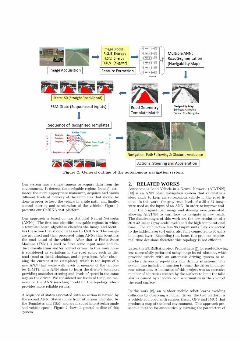
Figure 2: General outline of the autonomous navigation system.
Our system uses a single camera to acquire data from theenvironment. It detects the navigable regions (roads), esti-mates the more appropriate maneuver, acquires and trainsdifferent levels of memory of the templates that should bedone in order to keep the vehicle in a safe path, and finally,control steering and acceleration of the vehicle. Figure 1presents our CaRINA test platform.
Our approach is based on two Artificial Neural Networks(ANNs). The first one identifies navigable regions in whicha template-based algorithm classifies the image and identi-fies the action that should be taken by CaRINA. The imagesare acquired and then processed using ANNs that identifiesthe road ahead of the vehicle. After that, a Finite StateMachine (FSM) is used to filter some input noise and re-duce classification and/or control errors. In this work noiseis considered as variations in the road color, such as dirtroad (mud or dust), shadows, and depressions. After obtai-ning the current state (template), which is the input of anew ANN that works with levels of memory of the templa-tes (LMT). This ANN aims to learn the driver’s behavior,providing smoother steering and levels of speed in the sameway as the driver. We considered six levels of template me-mory on the ANN searching to obtain the topology whichprovides more reliable results.
A sequence of states associated with an action is learned bythe second ANN. States comes from situations identified bythe Templates and FSM, and are mapped into steering angleand vehicle speed. Figure 2 shows a general outline of thissystem.
2. RELATED WORKSAutonomous Land Vehicle in a Neural Network (ALVINN)[13] is an ANN based navigation system that calculates asteer angle to keep an autonomous vehicle in the road li-mits. In this work, the gray-scale levels of a 30 x 32 imagewere used as the input of an ANN. In order to improve trai-ning, the original road image and steering were generated,allowing ALVINN to learn how to navigate in new roads.The disadvantages of this work are the low resolution of a30 x 32 image (gray-scale levels) and the high computationaltime. The architecture has 960 input units fully connectedto the hidden layer to 4 units, also fully connected to 30 unitsin output layer. Regarding that issue, this problem requiresreal time decisions therefore this topology is not efficient.
Later, the EUREKA project Prometheus [7] for road-followingwas successfully performed using image based solutions, whichprovided trucks with an automatic driving system to re-produce drivers in repetitious long driving situations. Thesystem also included a function to warn the driver in dange-rous situations. A limitation of this project was an excessivenumber of heuristics created by the authors to limit the falsealarms caused by shadows or discontinuities in the color ofthe road surface.
In the work [8], an outdoor mobile robot learns avoidingcollisions by observing a human driver, the test platform isa vehicle equipped with sensors (laser, GPS and IMU) thatproduce a map of the local environment. This approach pre-sents a method for automatically learning the parameters of
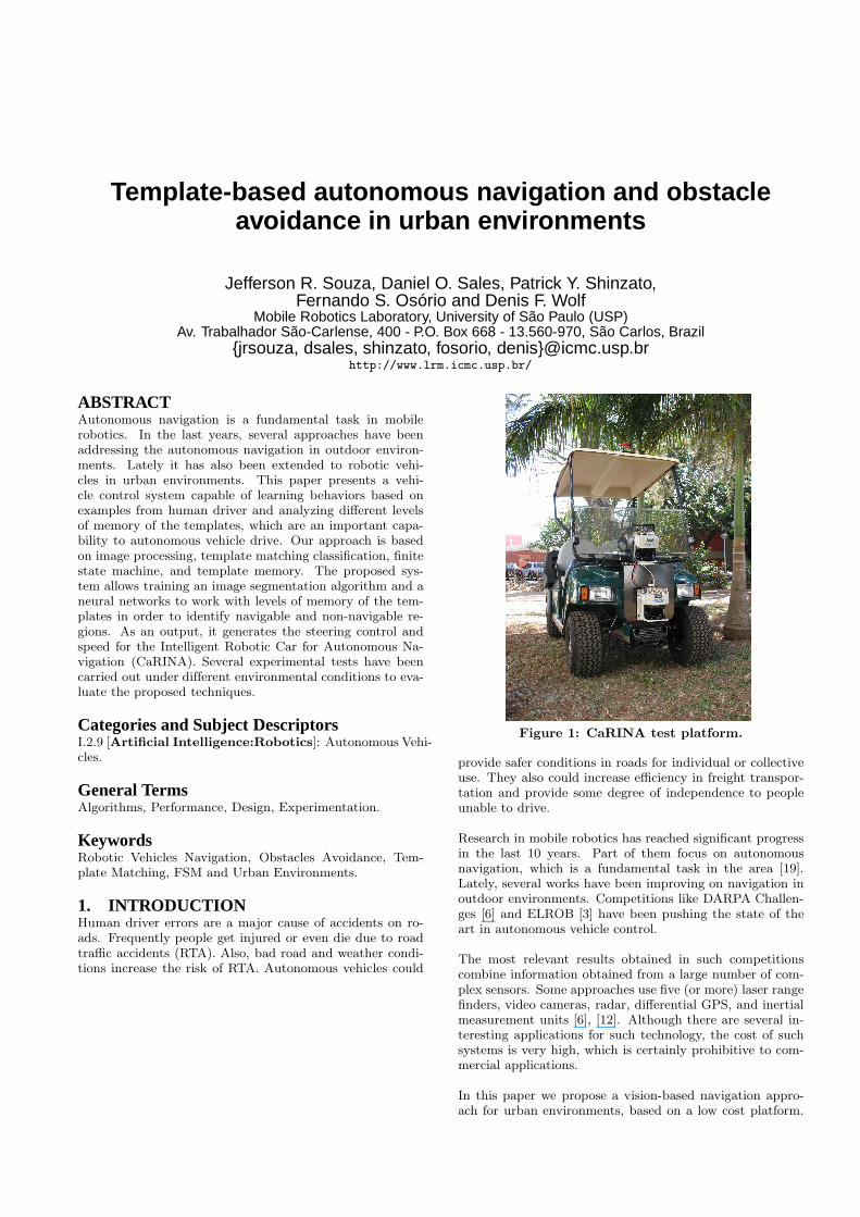
(a) (b) (c) (d)
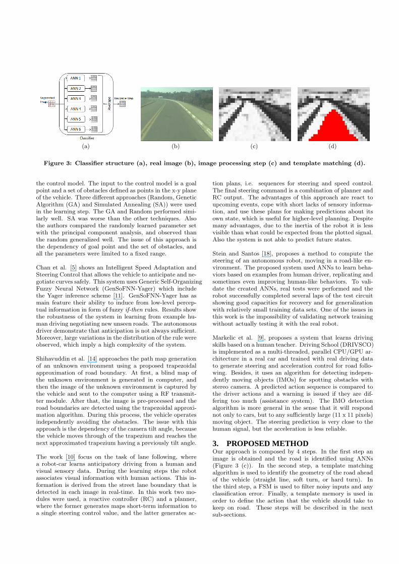
Figure 3: Classifier structure (a), real image (b), image processing step (c) and template matching (d).
the control model. The input to the control model is a goalpoint and a set of obstacles defined as points in the x-y planeof the vehicle. Three different approaches (Random, GeneticAlgorithm (GA) and Simulated Annealing (SA)) were usedin the learning step. The GA and Random performed simi-larly well. SA was worse than the other techniques. Alsothe authors compared the randomly learned parameter setwith the principal component analysis, and observed thanthe random generalized well. The issue of this approach isthe dependency of goal point and the set of obstacles, andall the parameters were limited to a fixed range.
Chan et al. [5] shows an Intelligent Speed Adaptation andSteering Control that allows the vehicle to anticipate and ne-gotiate curves safely. This system uses Generic Self-OrganizingFuzzy Neural Network (GenSoFNN-Yager) which includethe Yager inference scheme [11]. GenSoFNN-Yager has asmain feature their ability to induce from low-level percep-tual information in form of fuzzy if-then rules. Results showthe robustness of the system in learning from example hu-man driving negotiating new unseen roads. The autonomousdriver demonstrate that anticipation is not always sufficient.Moreover, large variations in the distribution of the rule wereobserved, which imply a high complexity of the system.
Shihavuddin et al. [14] approaches the path map generationof an unknown environment using a proposed trapezoidalapproximation of road boundary. At first, a blind map ofthe unknown environment is generated in computer, andthen the image of the unknown environment is captured bythe vehicle and sent to the computer using a RF transmit-ter module. After that, the image is pre-processed and theroad boundaries are detected using the trapezoidal approxi-mation algorithm. During this process, the vehicle operatesindependently avoiding the obstacles. The issue with thisapproach is the dependency of the camera tilt angle, becausethe vehicle moves through of the trapezium and reaches thenext approximated trapezium having a previously tilt angle.
The work [10] focus on the task of lane following, wherea robot-car learns anticipatory driving from a human andvisual sensory data. During the learning steps the robotassociates visual information with human actions. This in-formation is derived from the street lane boundary that isdetected in each image in real-time. In this work two mo-dules were used, a reactive controller (RC) and a planner,where the former generates maps short-term information toa single steering control value, and the latter generates ac-
tion plans, i.e. sequences for steering and speed control.The final steering command is a combination of planner andRC output. The advantages of this approach are react toupcoming events, cope with short lacks of sensory informa-tion, and use these plans for making predictions about itsown state, which is useful for higher-level planning. Despitemany advantages, due to the inertia of the robot it is lessvisible than what could be expected from the plotted signal.Also the system is not able to predict future states.
Stein and Santos [18], proposes a method to compute thesteering of an autonomous robot, moving in a road-like en-vironment. The proposed system used ANNs to learn beha-viors based on examples from human driver, replicating andsometimes even improving human-like behaviors. To vali-date the created ANNs, real tests were performed and therobot successfully completed several laps of the test circuitshowing good capacities for recovery and for generalizationwith relatively small training data sets. One of the issues inthis work is the impossibility of validating network trainingwithout actually testing it with the real robot.
Markelic et al. [9], proposes a system that learns drivingskills based on a human teacher. Driving School (DRIVSCO)is implemented as a multi-threaded, parallel CPU/GPU ar-chitecture in a real car and trained with real driving datato generate steering and acceleration control for road follo-wing. Besides, it uses an algorithm for detecting indepen-dently moving objects (IMOs) for spotting obstacles withstereo camera. A predicted action sequence is compared tothe driver actions and a warning is issued if they are dif-fering too much (assistance system). The IMO detectionalgorithm is more general in the sense that it will respondnot only to cars, but to any sufficiently large (11 x 11 pixels)moving object. The steering prediction is very close to thehuman signal, but the acceleration is less reliable.
3. PROPOSED METHODOur approach is composed by 4 steps. In the first step animage is obtained and the road is identified using ANNs(Figure 3 (c)). In the second step, a template matchingalgorithm is used to identify the geometry of the road aheadof the vehicle (straight line, soft turn, or hard turn). Inthe third step, a FSM is used to filter noisy inputs and anyclassification error. Finally, a template memory is used inorder to define the action that the vehicle should take tokeep on road. These steps will be described in the nextsub-sections.
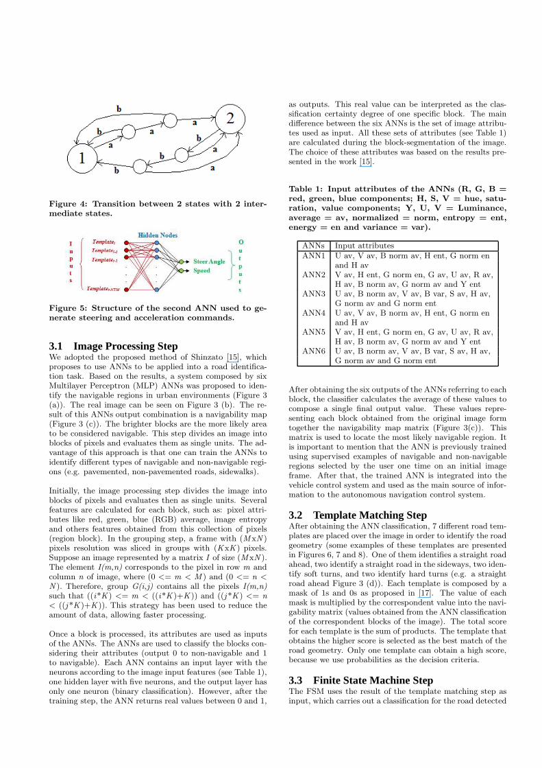
Figure 4: Transition between 2 states with 2 inter-mediate states.
Figure 5: Structure of the second ANN used to ge-nerate steering and acceleration commands.
3.1 Image Processing StepWe adopted the proposed method of Shinzato [15], whichproposes to use ANNs to be applied into a road identifica-tion task. Based on the results, a system composed by sixMultilayer Perceptron (MLP) ANNs was proposed to iden-tify the navigable regions in urban environments (Figure 3(a)). The real image can be seen on Figure 3 (b). The re-sult of this ANNs output combination is a navigability map(Figure 3 (c)). The brighter blocks are the more likely areato be considered navigable. This step divides an image intoblocks of pixels and evaluates them as single units. The ad-vantage of this approach is that one can train the ANNs toidentify different types of navigable and non-navigable regi-ons (e.g. pavemented, non-pavemented roads, sidewalks).
Initially, the image processing step divides the image intoblocks of pixels and evaluates then as single units. Severalfeatures are calculated for each block, such as: pixel attri-butes like red, green, blue (RGB) average, image entropyand others features obtained from this collection of pixels(region block). In the grouping step, a frame with (M xN )pixels resolution was sliced in groups with (KxK ) pixels.Suppose an image represented by a matrix I of size (M xN ).The element I(m,n) corresponds to the pixel in row m andcolumn n of image, where (0 <= m < M ) and (0 <= n <
N ). Therefore, group G(i,j) contains all the pixels I(m,n)such that ((i*K ) <= m < ((i*K )+K )) and ((j *K ) <= n< ((j *K )+K )). This strategy has been used to reduce theamount of data, allowing faster processing.
Once a block is processed, its attributes are used as inputsof the ANNs. The ANNs are used to classify the blocks con-sidering their attributes (output 0 to non-navigable and 1to navigable). Each ANN contains an input layer with theneurons according to the image input features (see Table 1),one hidden layer with five neurons, and the output layer hasonly one neuron (binary classification). However, after thetraining step, the ANN returns real values between 0 and 1,
as outputs. This real value can be interpreted as the clas-sification certainty degree of one specific block. The maindifference between the six ANNs is the set of image attribu-tes used as input. All these sets of attributes (see Table 1)are calculated during the block-segmentation of the image.The choice of these attributes was based on the results pre-sented in the work [15].
Table 1: Input attributes of the ANNs (R, G, B =red, green, blue components; H, S, V = hue, satu-ration, value components; Y, U, V = Luminance,average = av, normalized = norm, entropy = ent,energy = en and variance = var).
ANNs Input attributesANN1 U av, V av, B norm av, H ent, G norm en
and H avANN2 V av, H ent, G norm en, G av, U av, R av,
H av, B norm av, G norm av and Y entANN3 U av, B norm av, V av, B var, S av, H av,
G norm av and G norm entANN4 U av, V av, B norm av, H ent, G norm en
and H avANN5 V av, H ent, G norm en, G av, U av, R av,
H av, B norm av, G norm av and Y entANN6 U av, B norm av, V av, B var, S av, H av,
G norm av and G norm ent
After obtaining the six outputs of the ANNs referring to eachblock, the classifier calculates the average of these values tocompose a single final output value. These values repre-senting each block obtained from the original image formtogether the navigability map matrix (Figure 3(c)). Thismatrix is used to locate the most likely navigable region. Itis important to mention that the ANN is previously trainedusing supervised examples of navigable and non-navigableregions selected by the user one time on an initial imageframe. After that, the trained ANN is integrated into thevehicle control system and used as the main source of infor-mation to the autonomous navigation control system.
3.2 Template Matching StepAfter obtaining the ANN classification, 7 different road tem-plates are placed over the image in order to identify the roadgeometry (some examples of these templates are presentedin Figures 6, 7 and 8). One of them identifies a straight roadahead, two identify a straight road in the sideways, two iden-tify soft turns, and two identify hard turns (e.g. a straightroad ahead Figure 3 (d)). Each template is composed by amask of 1s and 0s as proposed in [17]. The value of eachmask is multiplied by the correspondent value into the navi-gability matrix (values obtained from the ANN classificationof the correspondent blocks of the image). The total scorefor each template is the sum of products. The template thatobtains the higher score is selected as the best match of theroad geometry. Only one template can obtain a high score,because we use probabilities as the decision criteria.
3.3 Finite State Machine StepThe FSM uses the result of the template matching step asinput, which carries out a classification for the road detected
in each captured frame. This classification is defined by thetemplate which best fits the matrix and its position. Thedeveloped FSM is composed by 5 states (straight road, softturns left and right, and hard turns left and right) as shownon Table 2.
Table 2: States of the FSM used for the experimen-tal tests.
States Associated ActionSR Keep steering wheel at center positionSLT Smoothly turn the steering wheel to leftSRT Smoothly turn the steering wheel to rightLT Fully turn the steering wheel to leftRT Fully turn the steering wheel to right
Figure 4 presents a partial scheme of the developed FSM.Transition ’a’ represents classification of an input as a tran-sition in direction of State 2, and ’b’ classification as a tran-sition in direction of State 1. Figure 4 represents a statechange of state 1 to state 2. For example, ’a’ represents astraight road state and ’b’ soft turns left. To change the statein the FSM there must happen three consecutive equal sta-tes. In this work, we use the FSM with only 2 intermediatetransitions between the states and have produced reasonableresults. Detailed information can be seen in [17].
The full FSM was designed with 5 states, which is obvi-ously more complex to represent, but the partial schemepresented in Figure 4 still remains representative of the fullFSM scheme. A transition between the current states toany other state occurs only after detecting a sequence of ’n+ 1’ identical inputs leading to the new state, where ’n’ isthe established number of intermediate states. The numberof intermediate states varies according to the noise level inthe images and navigability matrix representing the road,and also depends of the frame rate. In a system based on ahigh image acquisition frame rate, more misclassified inputscould be generated per time unit, so more intermediate sta-tes can be needed to discard some of these bad/noisy inputs.Environments with low level of input noise are associated toa smaller number of intermediate states.
3.4 Template Memory StepAfter obtaining the current state (template) by FSM, thiscurrent template is used as input in the template memorystep. In this step, the levels of memory of the templa-tes are stored in a queue, as {Templatet, Templatet−1,Templatet−2, ..., Templatet−NTM}. In this work, the Templatetrepresents the current template, Templatet−1 the previoustemplate, Templatet−2 one template before the previous.This is done successively, until the number of template me-mory (NTM) is reached, where t represents the time.
In this step, a second ANN is used differently of the ANNsused in the image processing step. The basic network struc-ture (Figure 5) used is a feed-forward MLP, the activa-tion function of the hidden neurons is the sigmoid func-tion and the ANN learning is the resilient backpropagation(RPROP). The inputs are represented by templates memoryand the outputs are the steer angle and speed.
4. EXPERIMENTAL RESULTSThe experiments were performed using CaRINA (Figure 1),an electric vehicle capable of autonomous navigation in aurban road, equipped with a VIDERE DSG video camera, aROBOTEQ AX2580 motor controller for steering control,an ARDUINO DUEMILANOVE is a microcontroller bo-ard used for vehicle speed control and a GARMIN 18X-5HzGPS. The GPS was used only to register the log of the vehi-cle trajectories, and it was not used as input of the system.The image acquisition resolution was set to (320 x 240) pi-xels. The ANNs of the image processing step were executedusing Fast Artificial Neural Network (FANN) [1], which is afree open source library which implements MLP ANNs in C,and the ANN in the template memory step was used Stutt-gart Neural Network Simulator (SNNS) [2], which is also asoftware simulator for ANNs. For the development of theimage acquisition, image processing and template matchingalgorithm, we used the OpenCV [4] library.
The results are divided into three scenarios. The first oneshows an urban area without obstacles using only the stee-ring control without template memory. The second scenarioshows an urban area with obstacles (e.g. people, traffic co-nes) using the steering and speed control without templatememory. The third scenario shows an urban area withoutobstacles, but uses the supervised learning (vehicle controlsystem capable of learn behaviors based on examples obtai-ned from human driver).
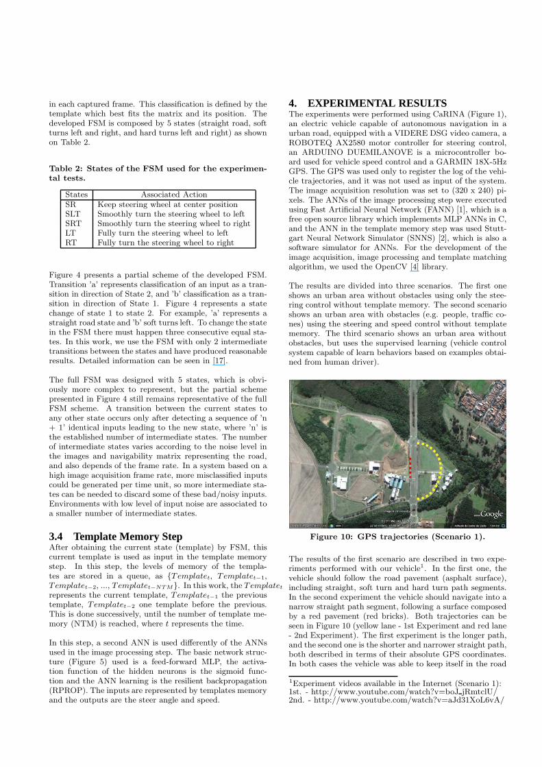
Figure 10: GPS trajectories (Scenario 1).
The results of the first scenario are described in two expe-riments performed with our vehicle1. In the first one, thevehicle should follow the road pavement (asphalt surface),including straight, soft turn and hard turn path segments.In the second experiment the vehicle should navigate into anarrow straight path segment, following a surface composedby a red pavement (red bricks). Both trajectories can beseen in Figure 10 (yellow lane - 1st Experiment and red lane- 2nd Experiment). The first experiment is the longer path,and the second one is the shorter and narrower straight path,both described in terms of their absolute GPS coordinates.In both cases the vehicle was able to keep itself in the road
1Experiment videos available in the Internet (Scenario 1):1st. - http://www.youtube.com/watch?v=boJ jRmtclU/2nd. - http://www.youtube.com/watch?v=aJd31XoL6vA/
(a) (b) (c) (d) (e)
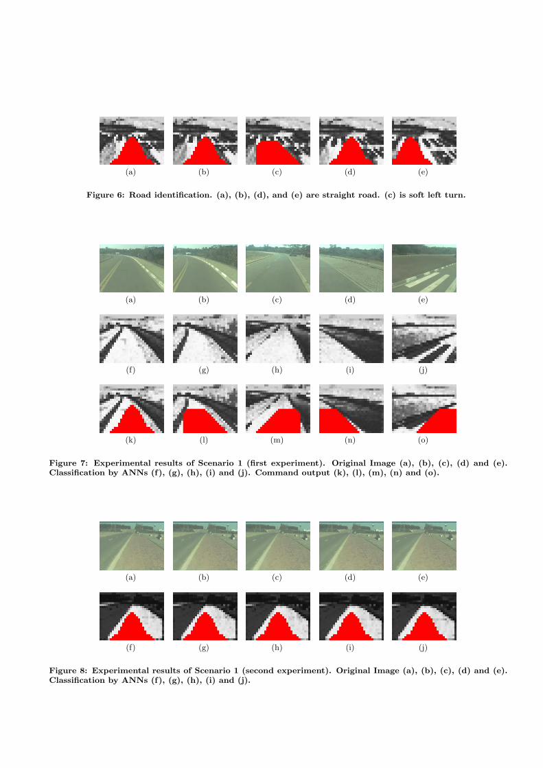
Figure 6: Road identification. (a), (b), (d), and (e) are straight road. (c) is soft left turn.
(a) (b) (c) (d) (e)
(f) (g) (h) (i) (j)
(k) (l) (m) (n) (o)
Figure 7: Experimental results of Scenario 1 (first experiment). Original Image (a), (b), (c), (d) and (e).Classification by ANNs (f), (g), (h), (i) and (j). Command output (k), (l), (m), (n) and (o).
(a) (b) (c) (d) (e)
(f) (g) (h) (i) (j)
Figure 8: Experimental results of Scenario 1 (second experiment). Original Image (a), (b), (c), (d) and (e).Classification by ANNs (f), (g), (h), (i) and (j).
(a) (b) (c) (d) (e)
(f) (g) (h) (i) (j)
(k) (l) (m) (n) (o)
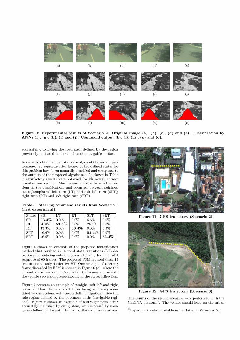
Figure 9: Experimental results of Scenario 2. Original Image (a), (b), (c), (d) and (e). Classification byANNs (f), (g), (h), (i) and (j). Command output (k), (l), (m), (n) and (o).
successfully, following the road path defined by the regionpreviously indicated and trained as the navigable surface.
In order to obtain a quantitative analysis of the system per-formance, 30 representative frames of the defined states forthis problem have been manually classified and compared tothe outputs of the proposed algorithms. As shown in Table3, satisfactory results were obtained (67.4% overall correctclassification result). Most errors are due to small varia-tions in the classification, and occurred between neighborstates/templates: left turn (LT) and soft left turn (SLT);right turn (RT) and soft right turn (SRT).
Table 3: Steering command results from Scenario 1(first experiment).
States SR LT RT SLT SRTSR 93.4% 0.0% 0.0% 6.6% 0.0%LT 20.0% 53.4% 0.0% 26.6% 0.0%RT 13.3% 0.0% 83.4% 0.0% 3.3%SLT 46.6% 0.0% 0.0% 53.4% 0.0%SRT 46.6% 0.0% 0.0% 0.0% 53.4%
Figure 6 shows an example of the proposed identificationmethod that resulted in 15 total state transitions (ST) de-tections (considering only the present frame), during a totalsequence of 60 frames. The proposed FSM reduced these 15transitions to only 4 effective ST. One example of a wrongframe discarded by FSM is showed in Figure 6 (c), where thecurrent state was kept. Even when traversing a crosswalkthe vehicle successfully keep moving in the correct direction.
Figure 7 presents an example of straight, soft left and rightturns, and hard left and right turns being accurately iden-tified by our system, with successfully navigation inside thesafe region defined by the pavement paths (navigable regi-ons). Figure 8 shows an example of a straight path beingaccurately identified by our system, with successfully navi-gation following the path defined by the red bricks surface.
Figure 11: GPS trajectory (Scenario 2).
Figure 12: GPS trajectory (Scenario 3).
The results of the second scenario were performed with theCaRINA platform2. The vehicle should keep on the urban
2Experiment video available in the Internet (Scenario 2):
road, spotting of obstacles (e.g. people, traffic cones), inclu-ding straight, soft turn and hard turn path segments. TheGPS trajectories using the vehicle can be seen in Figure 11.
Figure 9 shows in details the experiment of scenario 2, in-cluding an example of straight, soft left and right turns,and hard left and right turns being identified by our system,performing successfully the navigation inside the safe regiondefined by the urban path and the obstacles avoidance (Fi-gure 9 (a), (b) and (c)).
The results of the third scenario also were performed withthe CaRINA platform [16]. The vehicle should keep on theurban environment (road), replicating the human behaviorbased on examples from human driver. The GPS trajectorycan be seen in Figure 12.
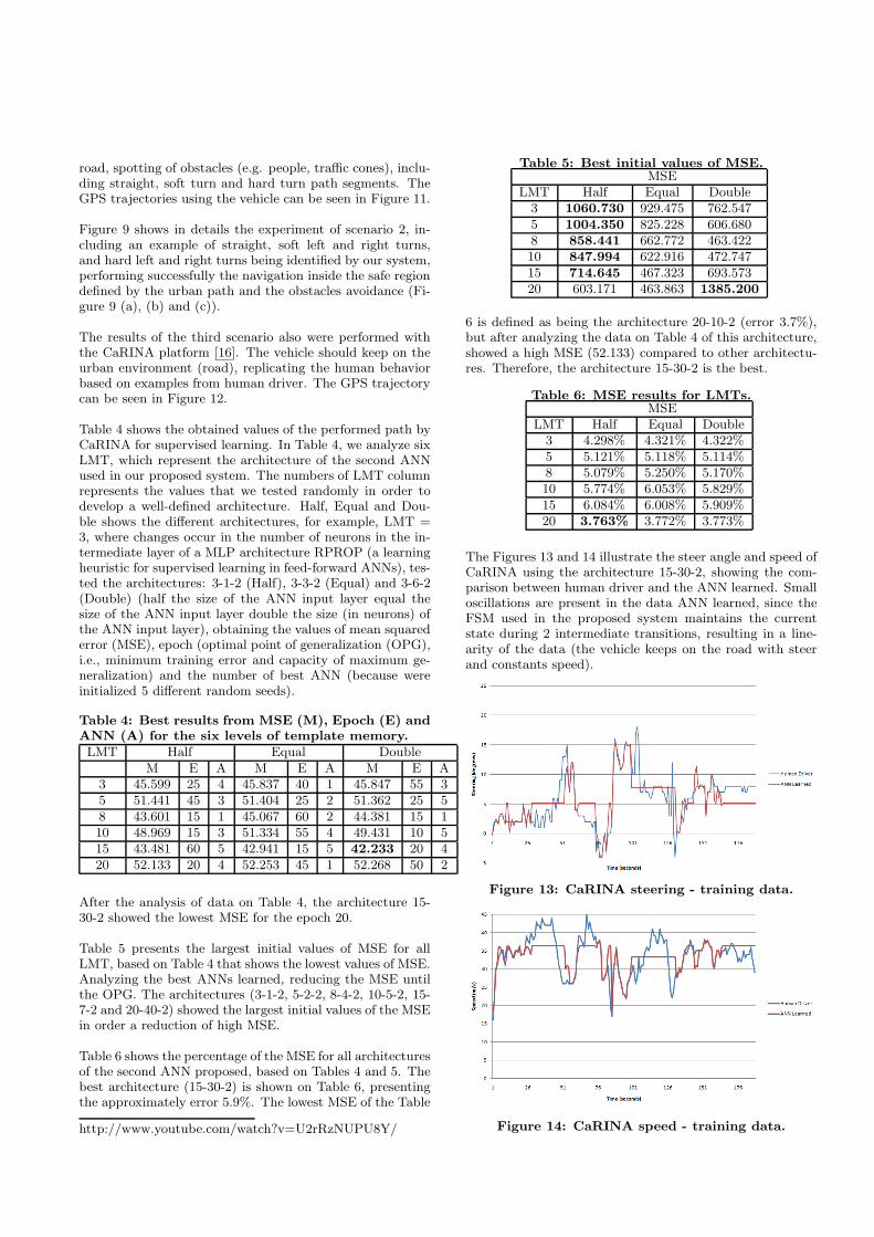
Table 4 shows the obtained values of the performed path byCaRINA for supervised learning. In Table 4, we analyze sixLMT, which represent the architecture of the second ANNused in our proposed system. The numbers of LMT columnrepresents the values that we tested randomly in order todevelop a well-defined architecture. Half, Equal and Dou-ble shows the different architectures, for example, LMT =3, where changes occur in the number of neurons in the in-termediate layer of a MLP architecture RPROP (a learningheuristic for supervised learning in feed-forward ANNs), tes-ted the architectures: 3-1-2 (Half), 3-3-2 (Equal) and 3-6-2(Double) (half the size of the ANN input layer equal thesize of the ANN input layer double the size (in neurons) ofthe ANN input layer), obtaining the values of mean squarederror (MSE), epoch (optimal point of generalization (OPG),i.e., minimum training error and capacity of maximum ge-neralization) and the number of best ANN (because wereinitialized 5 different random seeds).
Table 4: Best results from MSE (M), Epoch (E) andANN (A) for the six levels of template memory.LMT Half Equal Double
M E A M E A M E A3 45.599 25 4 45.837 40 1 45.847 55 35 51.441 45 3 51.404 25 2 51.362 25 58 43.601 15 1 45.067 60 2 44.381 15 110 48.969 15 3 51.334 55 4 49.431 10 515 43.481 60 5 42.941 15 5 42.233 20 420 52.133 20 4 52.253 45 1 52.268 50 2
After the analysis of data on Table 4, the architecture 15-30-2 showed the lowest MSE for the epoch 20.
Table 5 presents the largest initial values of MSE for allLMT, based on Table 4 that shows the lowest values of MSE.Analyzing the best ANNs learned, reducing the MSE untilthe OPG. The architectures (3-1-2, 5-2-2, 8-4-2, 10-5-2, 15-7-2 and 20-40-2) showed the largest initial values of the MSEin order a reduction of high MSE.
Table 6 shows the percentage of the MSE for all architecturesof the second ANN proposed, based on Tables 4 and 5. Thebest architecture (15-30-2) is shown on Table 6, presentingthe approximately error 5.9%. The lowest MSE of the Table
http://www.youtube.com/watch?v=U2rRzNUPU8Y/
Table 5: Best initial values of MSE.MSE
LMT Half Equal Double3 1060.730 929.475 762.5475 1004.350 825.228 606.6808 858.441 662.772 463.42210 847.994 622.916 472.74715 714.645 467.323 693.57320 603.171 463.863 1385.200
6 is defined as being the architecture 20-10-2 (error 3.7%),but after analyzing the data on Table 4 of this architecture,showed a high MSE (52.133) compared to other architectu-res. Therefore, the architecture 15-30-2 is the best.
Table 6: MSE results for LMTs.MSE
LMT Half Equal Double3 4.298% 4.321% 4.322%5 5.121% 5.118% 5.114%8 5.079% 5.250% 5.170%10 5.774% 6.053% 5.829%15 6.084% 6.008% 5.909%20 3.763% 3.772% 3.773%
The Figures 13 and 14 illustrate the steer angle and speed ofCaRINA using the architecture 15-30-2, showing the com-parison between human driver and the ANN learned. Smalloscillations are present in the data ANN learned, since theFSM used in the proposed system maintains the currentstate during 2 intermediate transitions, resulting in a line-arity of the data (the vehicle keeps on the road with steerand constants speed).
Figure 13: CaRINA steering - training data.
Figure 14: CaRINA speed - training data.
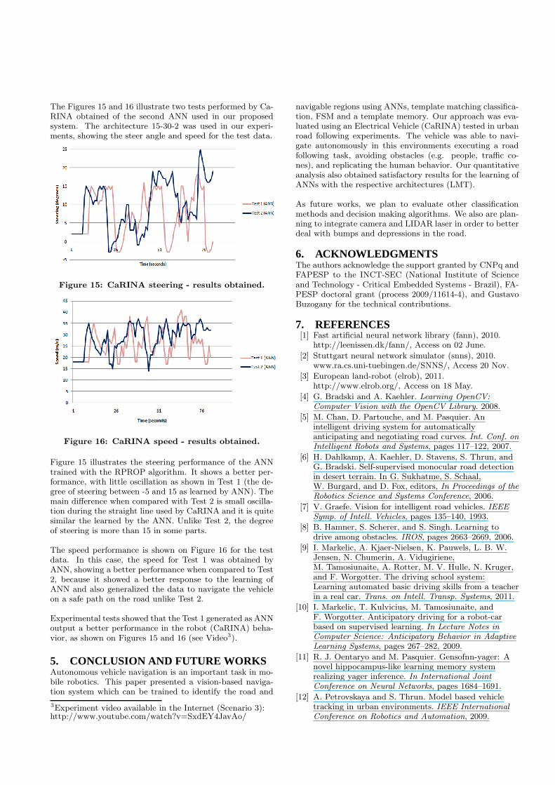
The Figures 15 and 16 illustrate two tests performed by Ca-RINA obtained of the second ANN used in our proposedsystem. The architecture 15-30-2 was used in our experi-ments, showing the steer angle and speed for the test data.
Figure 15: CaRINA steering - results obtained.
Figure 16: CaRINA speed - results obtained.
Figure 15 illustrates the steering performance of the ANNtrained with the RPROP algorithm. It shows a better per-formance, with little oscillation as shown in Test 1 (the de-gree of steering between -5 and 15 as learned by ANN). Themain difference when compared with Test 2 is small oscilla-tion during the straight line used by CaRINA and it is quitesimilar the learned by the ANN. Unlike Test 2, the degreeof steering is more than 15 in some parts.
The speed performance is shown on Figure 16 for the testdata. In this case, the speed for Test 1 was obtained byANN, showing a better performance when compared to Test2, because it showed a better response to the learning ofANN and also generalized the data to navigate the vehicleon a safe path on the road unlike Test 2.
Experimental tests showed that the Test 1 generated as ANNoutput a better performance in the robot (CaRINA) beha-vior, as shown on Figures 15 and 16 (see Video3).
5. CONCLUSION AND FUTURE WORKSAutonomous vehicle navigation is an important task in mo-bile robotics. This paper presented a vision-based naviga-tion system which can be trained to identify the road and
3Experiment video available in the Internet (Scenario 3):http://www.youtube.com/watch?v=SxdEY4JavAo/
navigable regions using ANNs, template matching classifica-tion, FSM and a template memory. Our approach was eva-luated using an Electrical Vehicle (CaRINA) tested in urbanroad following experiments. The vehicle was able to navi-gate autonomously in this environments executing a roadfollowing task, avoiding obstacles (e.g. people, traffic co-nes), and replicating the human behavior. Our quantitativeanalysis also obtained satisfactory results for the learning ofANNs with the respective architectures (LMT).
As future works, we plan to evaluate other classificationmethods and decision making algorithms. We also are plan-ning to integrate camera and LIDAR laser in order to betterdeal with bumps and depressions in the road.
6. ACKNOWLEDGMENTSThe authors acknowledge the support granted by CNPq andFAPESP to the INCT-SEC (National Institute of Scienceand Technology - Critical Embedded Systems - Brazil), FA-PESP doctoral grant (process 2009/11614-4), and GustavoBuzogany for the technical contributions.
7. REFERENCES[1] Fast artificial neural network library (fann), 2010.
http://leenissen.dk/fann/, Access on 02 June.
[2] Stuttgart neural network simulator (snns), 2010.www.ra.cs.uni-tuebingen.de/SNNS/, Access 20 Nov.
[3] European land-robot (elrob), 2011.http://www.elrob.org/, Access on 18 May.
[4] G. Bradski and A. Kaehler. Learning OpenCV:Computer Vision with the OpenCV Library. 2008.
[5] M. Chan, D. Partouche, and M. Pasquier. Anintelligent driving system for automaticallyanticipating and negotiating road curves. Int. Conf. onIntelligent Robots and Systems, pages 117–122, 2007.
[6] H. Dahlkamp, A. Kaehler, D. Stavens, S. Thrun, andG. Bradski. Self-supervised monocular road detectionin desert terrain. In G. Sukhatme, S. Schaal,W. Burgard, and D. Fox, editors, In Proceedings of theRobotics Science and Systems Conference, 2006.
[7] V. Graefe. Vision for intelligent road vehicles. IEEESymp. of Intell. Vehicles, pages 135–140, 1993.
[8] B. Hamner, S. Scherer, and S. Singh. Learning todrive among obstacles. IROS, pages 2663–2669, 2006.
[9] I. Markelic, A. Kjaer-Nielsen, K. Pauwels, L. B. W.Jensen, N. Chumerin, A. Vidugiriene,M. Tamosiunaite, A. Rotter, M. V. Hulle, N. Kruger,and F. Worgotter. The driving school system:Learning automated basic driving skills from a teacherin a real car. Trans. on Intell. Transp. Systems, 2011.
[10] I. Markelic, T. Kulvicius, M. Tamosiunaite, andF. Worgotter. Anticipatory driving for a robot-carbased on supervised learning. In Lecture Notes inComputer Science: Anticipatory Behavior in AdaptiveLearning Systems, pages 267–282, 2009.
[11] R. J. Oentaryo and M. Pasquier. Gensofnn-yager: Anovel hippocampus-like learning memory systemrealizing yager inference. In International JointConference on Neural Networks, pages 1684–1691.
[12] A. Petrovskaya and S. Thrun. Model based vehicletracking in urban environments. IEEE InternationalConference on Robotics and Automation, 2009.
[13] D. A. Pomerleau. ALVINN: An Autonomous LandVehicle In a Neural Network. Advances In NeuralInformation Processing Systems, 1989.
[14] A. S. M. Shihavuddin, K. Ahmed, M. S. Munir, andK. R. Ahmed. Road boundary detection by a remotevehicle using radon transform for path map generationof an unknown area. Int. Journal of Computer Scienceand Network Security, 8(8):64–69, 2008.
[15] P. Y. Shinzato and D. F. Wolf. A road followingapproach using artificial neural networkscombinations. Journal of Intelligent and RoboticSystems, 62(3):527–546, 2010.
[16] J. R. Souza, G. Pessin, P. Y. Shinzato, F. S. Osorio,and D. F. Wolf. Vision-based autonomous navigationusing neural networks and templates in urbanenvironments. First Brazilian Conference on CriticalEmbedded Systems (I CBSEC), pages 55–60, 2011.
[17] J. R. Souza, D. O. Sales, P. Y. Shinzato, F. S. Osorio,and D. F. Wolf. Template-based autonomousnavigation in urban environments. In 26th ACMSymp. on Applied Computing, pages 1376–1381, 2011.
[18] P. S. Stein and V. Santos. Visual guidance of anautonomous robot using machine learning. 7th IFACSymposium on Intelligent Autonomous Vehicles, 2010.
[19] S. Thrun, M. Montemerlo, H. Dahlkamp, D. Stavens,A. Aron, J. Diebel, P. Fong, J. Gale, M. Halpenny,G. Hoffmann, K. Lau, C. Oakley, M. Palatucci,V. Pratt, P. Stang, S. Strohband, C. Dupont, L. E.Jendrossek, C. Koelen, C. Markey, C. Rummel, J. VanNiekerk, E. Jensen, P. Alessandrini, G. Bradski,B. Davies, S. Ettinger, A. Kaehler, A. Nefian, andP. Mahoney. Stanley, the robot that won the darpagrand challenge. Journal of Field Robotics, 2006.
Related Documents