Temperature impact on the performance of galloping-based piezoaeroelastic energy harvesters This article has been downloaded from IOPscience. Please scroll down to see the full text article. 2013 Smart Mater. Struct. 22 055026 (http://iopscience.iop.org/0964-1726/22/5/055026) Download details: IP Address: 204.111.161.206 The article was downloaded on 12/04/2013 at 13:54 Please note that terms and conditions apply. View the table of contents for this issue, or go to the journal homepage for more Home Search Collections Journals About Contact us My IOPscience

Welcome message from author
This document is posted to help you gain knowledge. Please leave a comment to let me know what you think about it! Share it to your friends and learn new things together.
Transcript

Temperature impact on the performance of galloping-based piezoaeroelastic energy
harvesters
This article has been downloaded from IOPscience. Please scroll down to see the full text article.
2013 Smart Mater. Struct. 22 055026
(http://iopscience.iop.org/0964-1726/22/5/055026)
Download details:
IP Address: 204.111.161.206
The article was downloaded on 12/04/2013 at 13:54
Please note that terms and conditions apply.
View the table of contents for this issue, or go to the journal homepage for more
Home Search Collections Journals About Contact us My IOPscience

IOP PUBLISHING SMART MATERIALS AND STRUCTURES
Smart Mater. Struct. 22 (2013) 055026 (14pp) doi:10.1088/0964-1726/22/5/055026
Temperature impact on the performanceof galloping-based piezoaeroelastic energyharvestersAbdessattar Abdelkefi, Zhimiao Yan and Muhammad R Hajj
Department of Engineering Science and Mechanics, MC 0219, Virginia Tech, Blacksburg, VA 24061,USA
E-mail: [email protected]
Received 12 January 2013, in final form 28 February 2013Published 12 April 2013Online at stacks.iop.org/SMS/22/055026
AbstractThe effects of ambient temperature on the level of harvesting energy from gallopingoscillations of a bluff body are investigated. A nonlinear-distributed-parameter model isdeveloped to determine variations in the onset speed of galloping and the level of the harvestedpower when the ambient temperature is varied. The considered harvester consists of a bimorphpiezoelectric cantilever beam with a prismatic-structure tip mass. A modal analysis isperformed to derive the exact mode shapes and natural frequencies of the beam–structuresystem and their dependence on temperature variations. The quasi-steady representation isused to model the aerodynamic loads. The linear analysis shows that the temperature and theelectrical load resistance affect the onset speed of galloping significantly. The nonlinearanalysis shows that temperature variation affects the level of the harvested power.
(Some figures may appear in colour only in the online journal)
1. Introduction
Piezoelectric transduction-based energy harvesting systemshave received significant attention as viable long-term powersources that can be effectively placed in small volumes andused to harvest energy over a wide range of frequencies.These harvesters have been proposed to operate self-powered devices including microelectromechanical systemsor actuators [1–3], health monitoring, and wireless sensors [4,5], or to replace small batteries that have a finite life spanor would require hard and expensive maintenance [6–8].However, several structural and environmental factors canaffect the performance of these harvesters. One of thesefactors that can change the response of a piezoelectricenergy harvester is the ambient temperature. This is dueto the fact that temperature variations affect the propertiesof piezoelectric materials [9–12]. Rhimi and Lajnef [13]studied the effects of the temperature on the response of apiezoelectric energy harvester subjected to direct excitations.They determined that variations in the temperature ofa specific piezoelectric material (PZT-5H) affected the
frequency of the harvester and, consequently, the level of theharvested power.
There has also been recent interest in the conceptof harvesting energy from aeroelastic or flow-inducedvibrations [14–21]. In these studies, one or two piezoceramiclayers bonded by electrodes that generate an alternatingvoltage output are used to convert flow-induced vibrationsto electrical power. Another aeroelastic phenomenon thathas shown promise for harvesting energy is the gallopingof prismatic structures. Sirohi and Mahadik [22] proposedharvesting energy from transverse galloping of a structurethat had an equilateral triangle section. Surface-bondedpiezoelectric sheets attached to two beams connected to thestructure were used to harvest power. Their device generatedmore than 50 mW at a wind speed of 11.6 mph, a powerlevel that is sufficient to supply most of the commerciallyavailable wireless sensors. Abdelkefi et al [23] derived anonlinear distributed-parameter model for galloping-basedpiezoaeroelastic energy harvesters. They validated theirnumerical results with the experimental measurements ofSirohi and Mahadik [22]. Abdelkefi et al [24, 25] investigatedthe effects of the Reynolds number and section geometry
10964-1726/13/055026+14$33.00 c© 2013 IOP Publishing Ltd Printed in the UK & the USA

Smart Mater. Struct. 22 (2013) 055026 A Abdelkefi et al
Figure 1. A schematic of the piezoaeroelastic energy harvester.
on the level of harvested power. Their results showed thecombined effects of the electrical (load resistance) andmechanical (damping and frequency) components on theharvester’s response. Noting that the ambient temperatureimpacts the piezoelectric material properties, one wouldcertainly expect it to add to the combination of parametersthat affect the harvester’s response.
In this work, the impact of the temperature on theperformance of a galloping-based piezoaeroelastic energyharvester is investigated. To this end, we consider a bimorphpiezoelectric (PZT-5H) cantilever beam with a prismatic-structure tip mass. We develop a nonlinear distributed-parameter model that is capable of predicting the levelof harvested power that can be generated from gallopingoscillations for different temperatures, wind speeds, and loadresistances. The developed electromechanical model whichtakes into account the impact of the temperature on thesystem’s response is discussed in section 2. The quasi-steadyapproximation is used to model the aerodynamic loads.The background and justification for using this model arediscussed in section 3. In section 4, linear and nonlinearanalyses of the system are performed to investigate theeffects of the temperature and electrical load resistance onthe onset of galloping, harvested power, voltage output, andtip displacement amplitude. A summary and conclusions arepresented in section 5.
2. System modeling and reduced-order model
2.1. Governing equations
The energy harvester shown in figure 1 consists of apiezoelectric bimorph cantilever beam with a prismaticstructure attached to its free end. This structure undergoesgalloping in the transverse direction when subjected to anincoming flow. The cantilever beam is composed of aluminumand two piezoelectric layers (PZT-5H). The piezoelectricsheets are bonded by two in-plane electrodes of negligiblethickness connected in parallel with opposite polarity to aload resistance R. The geometric and material properties ofthe harvester are presented in table 1.
The Euler–Bernoulli beam assumptions are used tomodel the multilayered cantilever beam. Based on theseassumptions, the transverse vibration, v(x; t), of the cantileverbeam is described by
∂2M(x, t)
∂x2 + ca∂v(x, t)
∂t+ m
∂2v(x, t)
∂t2
= Ftipδ(x− L)−Mtipdδ(x− L)
dx(1)
Table 1. The physical and geometric properties of the cantileverbeam and the tip body.
Es Aluminum Young’smodulus (GN m−2)
70
ρs Aluminum density (kg m−3) 2700ρp PZT-5H density (kg m−3) 7900L Length of the beam (mm) 90b1 Width of the aluminum layer (mm) 38b2 Width of the piezoelectric layer (mm) 36.2hs Aluminum layer thickness (mm) 0.635hp Piezoelectric layer thickness (mm) 0.267Mt Tip mass (g) 65Lstruc Length of the tip body (mm) 235bstruc Width of the tip body (mm) 30
where δ(x) is the Dirac delta function, Ftip and Mtip are,respectively, the galloping aerodynamic force and momentat the tip of the beam that are caused by the oscillation ofthe structure, L is the length of the beam, ca is the viscousair damping coefficient, m is the mass of the beam per unitlength, and M(x; t) is the internal moment. This moment iscomposed of three components. The first is the resistance to
bending and is given by EI ∂2v(x,t)∂x2 . The second is due to the
strain rate damping effect and is represented by csI∂3v(x,t)∂x2∂t
.The third component is the contribution of the piezoelectricsheets which are connected in parallel. This contribution isrepresented by (H(x) − H(x − L))ϑpV(t) where H(x) is theHeaviside step function, V(t) is the generated voltage, and ϑpis the piezoelectric coupling term [26]. This term is given by
ϑp = −e31b2(hp + hs) (2)
where e31 is the piezoelectric stress coefficient, b2 is the widthof the piezoelectric layer and hs and hp are the thicknesses ofthe aluminum and piezoelectric layers, respectively.
Substituting for the moment M(x; t) its three componentsin equation (1), the equation of motion of the electromechan-ical system is rewritten as
YI∂4v(x, t)
∂x4 + csI∂5v(x, t)
∂x4∂t+ ca
∂v(x, t)
∂t
+ m∂2v(x, t)
∂t2+
(dδ(x)
dx−
dδ(x− L)
dx
)ϑpV(t)
= Ftipδ(x− L)−Mtipdδ(x− L)
dx. (3)
In this equation, the stiffness EI and mass of the beam per unit
length m are given by EI = 112 b1Esh3
s+23 b2Ep[(hp+
hs2 )
3−
h3s
8 ]
and m = b1ρshs + 2b2ρphp where Es and Ep are the Young’smoduli of the aluminum and piezoelectric layers, respectively,and ρs and ρp are the respective densities of these layers.
To complete the problem formulation, we relate themechanical and electrical variables by using the Gausslaw [27]
ddt
∫D · n dA =
ddt
∫D2 dA =
V
R(4)
where D is the electric displacement vector and n is the normalvector to the plane of the beam. The electric displacement
2

Smart Mater. Struct. 22 (2013) 055026 A Abdelkefi et al
component D2 is given by the following relation [26]:
D2 = e31ε11(x, t)+ εs33E2 (5)
where ε11 is the axial strain component in the aluminumand piezoelectric layers and is given by ε11(x, y, t) =
−y ∂2v(x,t)∂2x2 , εs
33 is the permittivity component at constant strain.Substituting (5) into (4), we obtain the equation governing thestrain–voltage relation,
− e31(hp + hs)b2
∫ L
0
∂3v(x, t)
∂t∂x2 dx−2εs
33b2L
hp
dV(t)
dt=
V(t)
R.
(6)
2.2. Eigenvalue problem analysis
To perform the linear and nonlinear analyses, we firstdiscretize the system using the Galerkin procedure whichrequires the exact mode shapes of the structure. To determinethe mode shapes of the considered system, we drop thedamping, forcing, and polarization from equation (3), andlet v(x, t) = φ(x)eiωt. The resulting eigenvalue problem isgiven by
EIφiv− mω2φ = 0 (7)
with the following boundary conditions:
φ(0) = 0 φ′(0) = 0 (8)
EIφ′′(L)− ω2MtLcφ(L)− ω2Itφ′(L) = 0 (9)
EIφ′′′(L)+ ω2MtLcφ′(L)+ ω2Mtφ(L) = 0 (10)
where It is the rotary inertia of the tip structure Mt and Lc ishalf of the length of the tip mass. The general expression ofthe mode shapes is written as
φ(x) = A sinβx+ B cosβx+ C sinhβx+ D coshβx (11)
where β and ω are related by ω = β2√
EIm .
To obtain the relation between the different coefficients in(11), we normalize the eigenfunctions and use the followingorthogonality conditions:∫ L
0φs(x)mφr(x) dx+ φs(L)Mtφr(L)+ φs′(L)Itφ
′r(L)
+ φs(L)MtItφ′r(L)+ φ
′r(L)Itφ
′s(L) = δrs (12)∫ L
0φ′′s (x)EIφ′′r (x) dx = δrsω
2r (13)
where s and r are used to represent the vibration modes andδrs is the Kronecker delta, defined as unity when s is equal tor and zero otherwise.
Using the Galerkin discretization, we express thetransverse displacement, v(x, t), in the following form:
v(x, t) =∞∑
i=1
φi(x)qi(t) (14)
where qi(t) are the modal coordinates and φi(x) are themode shapes of the cantilever beam with the prismatic tip
structure. Substituting equation (14) into equations (3) and (6)and considering the first mode only, we obtain the followingcoupled equations of motions:
q(t)+ 2ξωq(t)+ ω2q(t)+ θpV(t) = f (t) (15)
V(t)
R+ CpV(t)− θpq(t) = 0 (16)
where ξ is the mechanical damping coefficient, f (t) is thegalloping force of the first mode which is expressed asf (t) = φ(L)Ftip + φ′(L)Mtip, ω is the fundamental naturalfrequency of the structure, and the coefficients θp and Cpare the piezoelectric coupling term and the capacitance ofthe harvester which are given by θp = φ
′(L)ϑp and Cp =2εs
33b2Lhp
.
2.3. Temperature effects on the piezoelectric material(PZT-5H) properties
Inspecting the governing equations of the harvester (equa-tions (3) and (6)), we note that these equations dependon the properties of the piezoelectric material (Ep, e31, andεs
33). It has been demonstrated in the literature [10] thatthe temperature can significantly affect the properties of thepiezoelectric material. The plotted curves in figure 2 show theeffects of the temperature on the piezoelectric and dielectricconstants and Young’s modulus of the PZT-5H. The red pointsrepresent the values measured by Hooker [10] and the solidlines are fitted polynomials to be considered in our subsequentanalysis. Figure 2(a) shows that the temperature affects thepiezoelectric constant d31 = e31/Ep significantly. In fact,an increase of about 200% in the piezoelectric constant isobtained when the temperature is varied from −70 to 120 ◦C.For the dielectric constant, εT
33/ε0, where ε0 is the permittivityof free space and εT
33 = εs33 + d2
31Ep is the permittivitycomponent at constant stress, an increase in the operatingtemperature from −70 to 120 ◦C causes a significant increaseof about 300%, as shown in figure 2(b). The variation of thePZT-5H Young’s modulus as a function of the temperatureis plotted in figure 2(c). A decrease of about 30% is obtainedwhen the temperature is increased from−20 to 50 ◦C. Clearly,the properties of the PZT-5H are strong functions of theoperating temperature.
Noting that the structural natural frequency of theharvester, ω, depends on the Young’s modulus through the
relation ω = β2√
EIm , where EI = 1
12 b1Esh3s +
23 b2Ep[(hp +
hs2 )
3−
h3s
8 ], and that varying the temperatures causes variationsin the value of Ep, it is clear that the structural naturalfrequency depends on the temperature. Figure 3(a) shows thevariation of the structural natural frequency as a functionof the temperature. The plots show that increasing thetemperature from −20 to 50 ◦C causes the natural frequencyto decrease by about 15%. This is expected because theYoung’s modulus, Ep, is reduced when the temperature isincreased, as shown in figure 2(c). The variations of thepiezoelectric constant and dielectric constant, as shown infigures 2(a) and (b), result in variations in the capacitance,
3

Smart Mater. Struct. 22 (2013) 055026 A Abdelkefi et al
Figure 2. Variations of the PZT-5H properties as a function of the temperature based on the experimental data of Hooker [10] (red points):(a) piezoelectric constant, (b) dielectric constant, and (c) Young’s modulus. The solid lines represent the considered fitting in the numericalanalysis.
Cp, and piezoelectric coupling, θp. In fact, the capacitance is
directly related to εs33 by the relation Cp =
2εs33b2Lhp
and thepiezoelectric coupling coefficient is expressed as a functionof e31 by θp = −e31b2(hp + hs)φ
′(L). The variations ofthe capacitance and piezoelectric coupling coefficients asfunctions of the temperature are plotted in figures 3(b) and (c),respectively. The plot in figure 3(b) shows that increasing thetemperature from −20 to 50 ◦C causes the capacitance of thepiezoelectric material to increase by about 78%. This is dueto the increase in the permittivity at constant strain εs
33. Onthe other hand, there is an optimum value of the temperatureat which the piezoelectric coupling is maximized, as shownin figure 3(c). This coupling increases when the temperatureis increased from −20 ◦C to almost 0 ◦C and then decreasesas the temperature is raised from 0 to 50 ◦C. Because ofthe significant impact of the temperature on the piezoelectriccoupling, the capacitance of the piezoelectric material, andthe natural frequency of the harvester, one would expect theharvester’s response to be strongly dependent on the operatingtemperature.
3. Aerodynamic load representation
The aerodynamic loads are modeled by using the quasi-steadyapproximation [28, 29]. In fact, in the transverse gallopingphenomenon, the characteristic time scale of the oscillations,which is approximately equal to 2π
ω, is, in general, much larger
than the characteristic time scale of the flow motion, which isof the order of bstruc
U where bstruc is the width of the bluff bodyat the tip. Because the length of the tip mass is large, there aretwo different components in the aerodynamic loads, namelythe galloping force and the galloping moment. These loadsare directly related to the lift and drag forces FL and FD by
Ftip = −
∫ Lstruc
0(FL cosα + FD sinα) ds
Mtip = −
∫ Lstruc
0s(FL cosα + FD sinα) ds
(17)
where Lstruc is the length of the tip structure, s is the lengthcoordinate along the tip structure, and the lift force FL and the
4

Smart Mater. Struct. 22 (2013) 055026 A Abdelkefi et al
Figure 3. Variations of the (a) structural natural frequency, (b) capacitance of the piezoelectric material, and (c) piezoelectric coupling asfunctions of the temperature.
drag force FD per unit length are given by
FL =12ρairU
2bstrucCL FD =12ρairU
2bstrucCD (18)
where ρair is the density of air, bstruc is the width of thetip structure, and U is the incoming wind speed. Here, CL
and CD are, respectively, the lift and drag coefficients. Theseaerodynamic coefficients depend on the angle of attack, α, aswell as the Reynolds number. For the considered system, the
angle of attack is expressed as α = tan−1(v(L,t)+sv′(L,t)
U ).
To simplify the analysis, we consider the totalaerodynamic force per unit length, Fy, applied to the prismaticstructure in the direction normal to the incoming flow. Thistotal force is directly related to the lift and drag forces and isgiven by
Fy =12ρairU
2bstrucCy
= −12ρairU
2bstruc[CL cos(α)+ CD sin(α)] (19)
where Cy is the total aerodynamic force coefficient in thedirection normal to the incoming flow.
Following Barrero-Gil et al [29], the total aerodynamicforce coefficient can be expressed by a polynomial function
of tan(α) in the form
Cy = a1 tanα + a3(tanα)3 (20)
where a1 and a3 are empirical coefficients obtained bypolynomial fitting of Cy versus tan(α). The Den Hartogstability criterion [30] states that a section of a prismaticstructure on a flexible support is susceptible to galloping whenthe linear coefficient a1 is positive. In fact, galloping is aself-excited response, which is initiated when the damping ofthe system changes from positive to negative. The nonlinearcoefficient a3 is always negative because Cy always has amaximum value, which decreases as a function of the angleof attack. Both the linear and nonlinear coefficients dependon the geometry of the cross-section and the aspect ratioof the prismatic structure. To investigate the effects of thetemperature on the onset speed of galloping, we consider twodifferent isosceles cross-section geometries, namely isoscelestriangles with δ = 30◦ and 53◦. Barrero-Gil et al [29] giveempirical values of both of a1 and a3, as presented in table 2.These values are used in the rest of the analysis. Based on theabove derivation and assumptions, the aerodynamic loads areexpressed as
5

Smart Mater. Struct. 22 (2013) 055026 A Abdelkefi et al
Ftip =12ρairU
2bstruc
∫ Lstruc
0a1
(v(L, t)+ sv′(L, t)
U
)
+ a3
(v(L, t)+ sv′(L, t)
U
)3
ds
Mtip =12ρairU
2bstruc
∫ Lstruc
0s
(a1
(v(L, t)+ sv′(L, t)
U
)
+ a3
(v(L, t)+ sv′(L, t)
U
)3)ds.
(21)
Using the Galerkin discretization in equation (21), thecombined term for the aerodynamic force and moment isrewritten as
f (t) =12ρairU
2bstruc
∫ Lstruc
0k1
(q
U
)+ k3
(q
U
)3
ds (22)
where k1 and k3 are given by
k1 = a1
(φ2(L)Lstruc + φ(L)φ
′(L)L2struc +
13φ′2(L)L2
struc
)k3 = a3
(φ(L)
∫ Lstruc
0(φ(L)+ sφ′(L))3 ds
+ φ′(L)∫ Lstruc
0 s(φ(L)+ sφ′(L))3 ds).
(23)
It was demonstrated in section 2.2 that the eigenfunctionsof the system are independent of the temperature variationsand that only the natural frequency is changed. Consequently,the global galloping force is independent of the temperature.
4. Results and discussion
To analyze the representative model, the governing equationsof the galloping-based piezoaeroelastic energy harvester arerewritten using the following state variables:
X =
X1
X2
X3
=q
q
V
. (24)
The equations of motion are then written as
X1 = X2 (25)
X2 = −
(2ξω −
ρUbstrucLstruck1
2
)X2 − ω
2X1 − θpX3
+ρbstrucLstruck3
2UX3
2 (26)
X3 = −1
RCX3 +
θp
CpX2. (27)
These equations have the form
X = BX+ C(X,X,X) (28)
Table 2. Estimates of the linear and nonlinear coefficients fordifferent cross-section geometries.
Cross-section a1 a3
Isosceles triangle(δ = 30◦) [31, 29]
2.9 −6.2
Isosceles triangle(δ = 53◦) [32, 29]
1.9 −6.7
where
B =
0 1 0
−ω2−
(2ξω −
ρUbstrucLstruck1
2
)−χ
0χ
Cp−
1RCp
and C(X,X,X) is a cubic vector of the state variables which
is given by CT= [0,
ρbstrucLstruck3
2UX3
2, 0].
4.1. Linear analysis: temperature effects on the onset speedof galloping
The effects of the temperature and electrical load resistanceon the onset speed of galloping are determined from a linearanalysis. The matrix B includes all parameters that affect thelinear part of the system. In this matrix, three variables aredependent on the temperature. These are the structural naturalfrequency, ω, the capacitance of the piezoelectric material,Cp, and the piezoelectric coupling, θp. B(U) has a set of threeeigenvalues λi, i = 1, 2, 3, which vary with the temperature.The first two eigenvalues are similar to those of a puregalloping problem in the absence of the piezoelectricity effect.The third eigenvalue, λ3, is a result of the electromechanicalcoupling and is always real and negative, as in the caseof piezoelectric systems subjected to base or aeroelasticexcitations [33–35, 17]. The first two eigenvalues are complexconjugates (λ2 = λ1). The real part of these eigenvaluesrepresents the electromechanical damping coefficient and thepositive imaginary part corresponds to the global frequencyof the coupled system. Because λ3 is always real and negative,the stability of the trivial solution depends only on the real partof the first two eigenvalues. The solution of the linear part isasymptotically stable if the real part of λ1 is negative. On theother hand, if the real part of λ1 is positive, the solution of thelinearized system is unstable. The speed, Ug, for which thereal part of λ1 is zero corresponds to the onset of instabilityor galloping. Because Real (dλ1/dU) is nonzero at Ug, theinstability or bifurcation is a Hopf bifurcation.
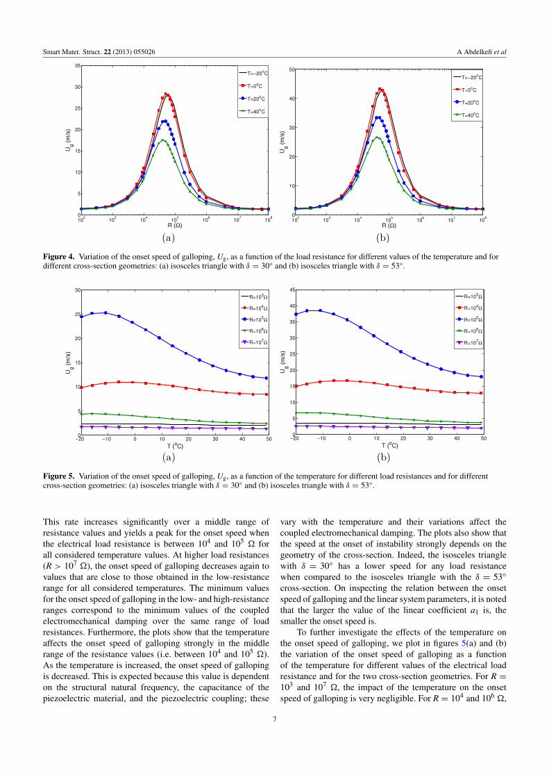
Figures 4(a) and (b) show the variation of the onset speedof galloping with the electrical load resistance for the twoconsidered cross-section geometries and for different valuesof the temperature when using the physical and geometricproperties described in table 1. The plots show that the loadresistance affects the onset speed of galloping significantly forboth considered configurations and for different temperaturevalues. In the lower range (R < 103 �) and for differentvalues of the temperature, the rate of variation is negligible.
6
Smart Mater. Struct. 22 (2013) 055026 A Abdelkefi et al
Figure 4. Variation of the onset speed of galloping, Ug, as a function of the load resistance for different values of the temperature and fordifferent cross-section geometries: (a) isosceles triangle with δ = 30◦ and (b) isosceles triangle with δ = 53◦.
Figure 5. Variation of the onset speed of galloping, Ug, as a function of the temperature for different load resistances and for differentcross-section geometries: (a) isosceles triangle with δ = 30◦ and (b) isosceles triangle with δ = 53◦.
This rate increases significantly over a middle range ofresistance values and yields a peak for the onset speed whenthe electrical load resistance is between 104 and 105 � forall considered temperature values. At higher load resistances(R > 107 �), the onset speed of galloping decreases again tovalues that are close to those obtained in the low-resistancerange for all considered temperatures. The minimum valuesfor the onset speed of galloping in the low- and high-resistanceranges correspond to the minimum values of the coupledelectromechanical damping over the same range of loadresistances. Furthermore, the plots show that the temperatureaffects the onset speed of galloping strongly in the middlerange of the resistance values (i.e. between 104 and 105 �).As the temperature is increased, the onset speed of gallopingis decreased. This is expected because this value is dependenton the structural natural frequency, the capacitance of thepiezoelectric material, and the piezoelectric coupling; these
vary with the temperature and their variations affect thecoupled electromechanical damping. The plots also show thatthe speed at the onset of instability strongly depends on thegeometry of the cross-section. Indeed, the isosceles trianglewith δ = 30◦ has a lower speed for any load resistancewhen compared to the isosceles triangle with the δ = 53◦
cross-section. On inspecting the relation between the onsetspeed of galloping and the linear system parameters, it is notedthat the larger the value of the linear coefficient a1 is, thesmaller the onset speed is.
To further investigate the effects of the temperature onthe onset speed of galloping, we plot in figures 5(a) and (b)the variation of the onset speed of galloping as a functionof the temperature for different values of the electrical loadresistance and for the two cross-section geometries. For R =103 and 107 �, the impact of the temperature on the onsetspeed of galloping is very negligible. For R = 104 and 106 �,
7

Smart Mater. Struct. 22 (2013) 055026 A Abdelkefi et al
Figure 6. Bifurcation diagrams of the tip displacement for different values of the temperature and electrical load resistance: (a) R = 103 �,(b) R = 104 �, (c) R = 105 �, and (d) R = 106 �.
varying the temperature affects the onset speed of gallopingsignificantly. In fact, at higher temperatures, the onset speedof galloping decreases when the temperature is increased. ForR = 105 �, the onset speed of galloping changes significantlywhen the temperature is varied. At low temperature values,the onset speed is very high, with a maximum value near T ≈−15 ◦C. At higher temperature values, it decreases drastically.This significant variation in the onset speed of gallopingwhen varying the temperature is due to the dependence of thepiezoelectric properties on the temperature and their effects onthe coupled electromechanical damping. As we note the sametendency for the two cross-section geometries considered, wewill consider only the isosceles triangle with δ = 30◦ in therest of this work.
4.2. Nonlinear analysis: temperature impact on theperformance of the harvester
To investigate the impact of the temperature, electricalload resistance, and wind speed on the performance of
the harvester, we perform a full nonlinear analysis of thegoverning equations. The bifurcation diagrams of the tipdisplacement of the bluff body for different temperaturesand when the electrical load resistance is set equal to103 �, 104 �, 105 �, and 106 � are shown in figures 6(a)–(d),respectively. On inspecting these curves, we find that the loadresistance affects the onset speed of galloping strongly, asdemonstrated by the linear analysis performed in section 4.1.The onset speed of galloping is always lower at highertemperature values for all considered load resistances. Theimpact of the temperature on the onset speed is very negligiblefor R = 103 �, as shown in figure 6(a). For R = 105 �, theonset speed changes significantly when the temperature valueis varied, as shown in figure 6(c). The displacement values arezero for T =−20 and 0 ◦C for wind speeds less than 20 m s−1.This is expected because the onset speeds of galloping forthese two temperatures are larger than 20 m s−1 for a loadresistance of 105 �, as shown in figure 5(a). Additionally,the maximum displacement values are observed when T =40 ◦C for all considered load resistances. This is explained
8

Smart Mater. Struct. 22 (2013) 055026 A Abdelkefi et al
Figure 7. Bifurcation diagrams of the generated voltage for different values of the temperature and electrical load resistance:(a) R = 103 �, (b) R = 104 �, (c) R = 105 �, and (d) R = 106 �.
by the low values of the electromechanical damping at thistemperature.
Figure 7 shows the impact of the temperature on thevoltage output for different values of the load resistance whenvarying the wind speed. For R = 103 �, a higher value of thegenerated voltage is obtained when the temperature is 0 ◦C,as shown in figure 7(a). Furthermore, there is an intersectionpoint between the different curves of the generated voltagewhen varying the temperature for R = 103, 104, and 106 �,as shown in figures 7(a), (b), and (d). The wind speedcorresponding to this intersection point is closer to the onsetspeed of galloping when the impact of the temperature onthe onset speed is less pronounced. For R = 103 �, theintersection point is very close to the onset of instability. ForR = 104 �, the intersection point is significantly higher thanthe onset speed. Beyond this intersection point, the generatedvoltage, for the cases where the onset speed of galloping isrelatively larger, becomes more important. This result is veryclear in figures 7(a) and (d).
The plotted curves in figure 8 show the bifurcationdiagrams of the harvested power for different temperatures
and load resistances. The lowest values of the harvested powerare obtained at T = 40◦C for R = 103 and 106 �, as shownin figures 8(a) and (d), respectively. It is important to note thatthese minimum values in the harvested power are associatedwith maximum values of the tip displacement, as shown infigures 6(a) and (d), The highest values of harvested powerare obtained in cases where the onset speeds of galloping arehigher. These maximum values of the harvested power areassociated with minimum values of the tip displacement, asshown in figures 6(a) and (d), for R = 104 and 105 �. All ofthese results show the significant impact of the temperature onthe response of the harvester.
To further elucidate the effects of the temperature on thesystem’s outputs, we plot in figures 9 and 10 the variation ofthe tip displacement, generated voltage, and harvested poweras functions of the temperature for different load resistancesand for two distinct values of the wind speed, namely 5 and15 m s−1. For U = 5 m s−1, figures 9(a)–(c) show that nopower can be generated for electrical load resistance values of104 or 105 �. For R = 103 � and U = 5 m s−1, increase
9

Smart Mater. Struct. 22 (2013) 055026 A Abdelkefi et al
Figure 8. Bifurcation diagrams of the harvested power for different values of the temperature and electrical load resistance: (a) R = 103 �,(b) R = 104 �, (c) R = 105 �, and (d) R = 106 �.
of the temperature is accompanied by a slight increase inthe tip displacement, as shown in figure 9(a), and a slightdecrease in the harvested power, as shown in figure 9(c). ForR = 106 � and U = 5 m s−1, the tip displacement increasesas the temperature is increased. This is explained by thelow electromechanical damping terms at these temperatures.Figure 9(c) shows that increasing the temperature also causesan increase in the harvested power level.
At U = 15 m s−1, figure 10(a) shows that increaseof the temperature is accompanied by an increase in thedisplacement for the considered load resistances. This is dueto the low electromechanical damping at the high temperaturevalues. On the other hand, the generated voltage and harvestedpower show different tendencies when using different loadresistances. Because the intersection wind speed values whenthe load resistances are set equal to 103 and 106 � aresmaller than this wind speed (15 m s−1), the variations of thegenerated voltage and harvested power with the temperature,as shown in figures 10(b) and (c), have similar tendenciesto the variation of the onset speed of galloping with the
temperature. These results show that maximum levels ofharvested power are accompanied by minimum values of tipdisplacement when varying the temperature, and vice versa.For a load resistance of 104 �, there is a minimum valuein the tip displacement when the temperature is between −5and 0 ◦C, as shown in figure 10(a). This range of temperaturecorresponds to a higher onset speed of galloping, as shownin figure 5(a). Because the intersection wind speed valueis larger than the considered speed, the curves of the tipdisplacement, generated voltage, and harvested power havethe same tendency when varying the temperature, as shownin figures 10(a)–(c). For R = 105 �, the harvester does notproduce any power at temperatures lower than 26 ◦C. This isexpected because the onset speed of galloping is larger than15 m s−1 in this range of temperatures, as shown in figure 5(a).In addition, increase of the temperature is associated with anincrease in all of the system’s outputs.
To further investigate the effects of the electrical loadresistance on the system outputs for different values of thetemperature, we present in figures 11, 12 and 13 the variation
10

Smart Mater. Struct. 22 (2013) 055026 A Abdelkefi et al
Figure 9. Variation of the (a) tip displacement, (b) generated voltage, and (c) harvested power as a function of the temperature for differentload resistances and when U = 5 m s−1.
of the tip displacement, generated voltage, and harvestedpower, respectively, with the electrical load resistance forfour values of the temperature and two distinct wind speeds,namely U = 5 m s−1 and U = 15 m s−1. On inspectingfigures 11(a), 12(a), and 13(a), it is noted that for U =5 m s−1 there is a range of load resistance where nooscillations (zero-tip displacement) are observed. This rangeof load resistance depends on the temperature. This isexpected because the onset speed of galloping in this regionof load resistance is larger than U = 5 m s−1. Thesezero-displacement values can be explained by the maximumvalue of the electromechanical damping in this region ofelectrical load resistance. When the wind speed is increasedto U = 15 m s−1, as shown in figures 11(b), 12(b), and 13(b),we find that the range of zero-tip displacement is decreasedprogressively for all considered temperature values. For allconsidered temperature values, for low (R < 103 �) andhigh (R > 107 �) load resistance values, the variation of thedisplacement with the electrical load resistance is negligiblefor both wind speeds, as shown in figures 11(a) and (b).
Figures 12(a) and (b) show the variation of the generatedvoltage with the load resistance for different temperaturevalues. It is noted that, for low and high values of theload resistance, increase of the electrical load resistance isassociated with an increase in the generated voltage forall considered temperature values and for both consideredwind speeds. Moreover, the generated voltage stabilizes for aspecific value of the electrical load resistance, which is around107 � when U = 5 m s−1 and 106 � when U = 15 m s−1.As mentioned above, for a specific range of load resistance,only at high temperature (T = 40 ◦C) can the system harvestenergy. Furthermore, the level of generated voltage is higherat lower temperatures.
The plots in figure 13 show the variation of the harvestedpower with the load resistance for different values of thetemperature and for two distinct wind speeds. The plotsshow that there are optimum values of the load resistancefor which more energy can be harvested and these optimumvalues depend on the temperature and the wind speedconsidered. Similarly to the variation of the tip displacementand generated voltage with the load resistance, the harvested
11

Smart Mater. Struct. 22 (2013) 055026 A Abdelkefi et al
Figure 10. Variation of the (a) tip displacement, (b) generated voltage, and (c) harvested power as a function of the temperature fordifferent load resistances and when U = 15 m s−1.
Figure 11. Variation of the tip displacement as a function of the electrical load resistance when (a) U = 5 m s−1 and (b) U = 15 m s−1 andfor different temperature values.
power is almost zero over a specific range of load resistancethat is temperature-dependent. Moreover, the region of loadresistance over which the harvested power is maximum
matches the region of load resistance over which thedisplacement is minimum, and vice versa, for all consideredtemperature values and for both wind speeds. These results
12

Smart Mater. Struct. 22 (2013) 055026 A Abdelkefi et al
Figure 12. Variation of the generated voltage as a function of the electrical load resistance when (a) U = 5 m s−1 and (b) U = 15 m s−1
and for different temperature values.
Figure 13. Variation of the harvested power as a function of the electrical load resistance when (a) U = 5 m s−1 and (b) U = 15 m s−1 andfor different temperature values.
show that at higher temperature values, energy harvesting canbe performed at lower wind speeds. In the low-temperaturerange, the level of harvested power can be maximized but thiswill be achieved only at higher wind speeds.
5. Conclusions
The impact of the temperature on the properties of PZT-5Hpiezoelectric material and on the onset speed of gallopingand the level of harvested power of a galloping-basedpiezoaeroelastic energy harvester was investigated. Theharvester consisted of a bimorph piezoelectric cantilever beamwith a prismatic-structure tip mass. A nonlinear-distributed-parameter model was used to perform the analysis. Thequasi-steady approximation was used to model the gallopingforce and moment. Linear and nonlinear analyses wereperformed to investigate the effects of the temperature and
electrical load resistance on the onset of instability and thesystem’s response. The results showed that the system’sresponse is strongly affected by temperature variation. Itwas determined that the effects of varying the operatingtemperature are more significant at specific load resistancesand wind speeds. At higher temperature values, energycan be harvested at lower wind speeds and for differentload resistances. On the other hand, at relatively higherwind speeds, more energy can be generated at lowertemperatures. The maximum levels of harvested power arealways associated with minimum displacements. These resultsshow a complex relation between the harvested power and tipdisplacement on one hand and the wind speed, load resistance,and temperature on the other hand. This complex relationnecessitates the development of representative models andcoupled analysis as performed here.
13

Smart Mater. Struct. 22 (2013) 055026 A Abdelkefi et al
References
[1] Muralt P 2000 Ferroelectric thin films for micro-sensors andactuators: a review J. Micromech. Microeng. 10 136–46
[2] Gurav S P, Kasyap A, Sheplak M, Cattafesta L, Haftka R T,Goosen J F L and Van Keulen F 2004 Uncertainty-baseddesign optimization of a micro piezoelectric compositeenergy reclamation device 10th AIAA/ISSSMOMultidisciplinary Analysis and Optimization Conferencepp 3559–70
[3] Zhou W, Liao W H and Li W J 2005 Analysis design of aself-powered piezoelectric micro-accelerometer Proc. SPIE5763 233–40
[4] Inman D J and Grisso B L 2006 Towards autonomous sensingProc. SPIE 61740 61740T
[5] Roundy S and Wright P K 2005 A piezoelectricvibration-based generator for wireless electronics J. Intell,Mater. Struct. 16 809–23
[6] Capel I D, Dorrell H M, Spencer E P and Davis M W 2003The amelioration of the suffering associated with spinalcord injury with subperception transcranial electricalstimulation Spinal Cord 41 109–17
[7] Priya S, Popa D and Lewis F 2006 Energy efficient mobilewireless sensor networks Proc. ASME Int. MechanicalEngineering Congr. Exposition (Chicago, IL)
[8] Magoteaux K C, Sanders B and Sodano A H 2008Investigation of energy harvesting small unmanned airvehicle Proc. SPIE 6928 692823
[9] Omote K and Ohigashi H 1996 Temperature dependence ofshear piezoelectric properties of poly (vinylidene fuoride)studied by piezoelectric resonance method J. Appl. Phys.35 1818–23
[10] Hooker M W 1998 Propreties of PZT-based piezoelectricceramics between −150 and 250 ◦C NASA Contract ReportReport No NASA/CR-1998-208708
[11] Park G, Kabeya K, Cudney H H and Inman D J 1998Removing effects of temperature changes frompiezoelectric impedance-based qualitative healthmonitoring Proc. SPIE 3330 103
[12] Birman V and Suhir E 2006 Effect of temperature ofvibrations of physically nonlinear piezoelectric rods Int.Workshop on Thermal Investigation of ICs and Systems(Belgirate, Maggiore, Sept. 2005) pp 180–90
[13] Rhimi M and Lajnef N 2012 Passive temperaturecompensation in piezoelectric vibrators using shapememory alloy-induced axial loading J. Intell. Mater. Syst.Struct. 23 1759–70
[14] Bryant M and Garcia E 2009 Energy harvesting: a key towireless sensor nodes Proc. SPIE 7493 74931W
[15] Erturk A, Vieira W G R, De Marqui C and Inman D J 2010 Onthe energy harvesting potential of piezoaeroelastic systemsAppl. Phys. Lett. 96 184103
[16] De Marqui C, Erturk A and Inman D J 2010 Piezoaeroelasticmodeling and analysis of a generator wing with continuousand segmented electrodes J. Intell. Mater. Syst. Struct.21 983–93
[17] Abdelkefi A, Nayfeh A H and Hajj M R 2012 Modeling andanalysis of piezoaeroelastic energy harvesters NonlinearDyn. 67 925–39
[18] Abdelkefi A, Nayfeh A H and Hajj M R 2012 Design ofpiezoaeroelastic energy harvesters Nonlinear Dyn.68 519–30
[19] Abdelkefi A, Nayfeh A H and Hajj M R 2012 Enhancement ofpower harvesting from piezoaeroelastic systems NonlinearDyn. 68 531–41
[20] Abdelkefi A, Hajj M R and Nayfeh A H 2012 Sensitivityanalysis of piezoaeroelastic energy harvesters J. Intell.Mater. Syst. Struct. 23 1523–31
[21] Abdelkefi A, Hajj M R and Nayfeh A H 2012 Phenomena andmodeling of piezoelectric energy harvesting from freelyoscillating cylinders Nonlinear Dyn. 70 1377–88
[22] Sirohi J and Mahadik R 2011 Piezoelectric wind energyharvester for low-power sensors J. Intell. Mater. Syst.Struct. 23 1523–31
[23] Abdelkefi A, Yan Z and Hajj M R 2013 Modeling andnonlinear analysis of piezoelectric energy harvesting fromtransverse galloping Smart Mater. Struct. 22 025016
[24] Abdelkefi A, Hajj M R and Nayfeh A H 2012 Powerharvesting from transverse galloping of square cylinderNonlinear Dyn. 70 1377–88
[25] Abdelkefi A, Hajj M R and Nayfeh A H 2013 Piezoelectricenergy harvesting from transverse galloping of bluff bodiesSmart Mater. Struct. 22 015014
[26] Erturk A and Inman D J 2009 An experimentally validatedbimorph cantilever model for piezoelectric energyharvesting from base excitations Smart Mater. Struct.18 025009
[27] IEEE 1987 Standard on Piezoelectricity[28] Naudascher E and Rockwell D 1994 Flow-Induced Vibrations,
An Engineering Guide (New York: Dover)[29] Barrero-Gil A, Alonso G and Sanz-Andres A 2010 Energy
harvesting from transverse galloping J. Sound Vib.329 2873–83
[30] Den Hartog J P 1956 Mechanical Vibrations (New York:McGraw-Hill)
[31] Alonso G, Meseguer J and Prez-Grande I 2007 Gallopingstabilities of two-dimensional triangular cross-sectionalbodies: a systematic approach J. Wind Eng. Indust.Aerodyn. 95 928–40
[32] Luo S C, Chew Y T, Lee T S and Yazdani M G 1998 Stabilityto translational galloping vibration of cylinders at differentmean angles of attack J. Sound Vib. 215 1183–94
[33] Abdelkefi A, Najar F, Nayfeh A H and Ben Ayed S 2011An energy harvester using piezoelectric cantilever beamsundergoing coupled bending-torsion vibrations SmartMater. Struct. 20 115007
[34] Abdelkefi A, Nayfeh A H and Hajj M R 2012 Global nonlineardistributed-parameter model of parametrically excitedpiezoelectric energy harvesters Nonlinear Dyn. 67 1147–60
[35] Abdelkefi A, Nayfeh A H and Hajj M R 2012 Effects ofnonlinear piezoelectric coupling on energy harvesters underdirect excitation Nonlinear Dyn. 67 1221–32
14
Related Documents