Litho in U.S.A. 4/02 #6312 Lifting Capacities Telescopic Boom Rough Terrain Crane RTC–80100 100–ton (91 metric tons) Series II Boom and Fly Capacities for this machine are listed by the following sections. Fully Extended Outriggers S Working Range Diagram S 24,000 lbs (10 886 kg) of Counterweight S 40’ to 95’ (12.19 – 28.96 m) Main Boom Capacities, “A–max1” Mode S 40’ to 122.5’ (12.19 – 37.34 m) Main Boom Capacities, “A–max2” Mode S 40’ to 150’ (12.19 – 45.72 m) Main Boom Capacities, “Standard” Mode S 31’ to 85’ (9.45 – 25.90 m) Fly Capacities, “Standard” Mode On Tires S With Outrigger Boxes S Stationary – Over Rear, Stationary – 360_, Creep and 2.5 mph S 24,000 lbs (10 886 kg) of Counterweight S 40’ to 95’ (12.19 – 28.96 m) “A–max1” Boom Mode S 40’ to 122.5’ (12.19 – 37.34 m) Main Boom Capacities, “A–max2” Mode S 40’ to 120’ (12.19 – 36.58 m) Main Boom Capacities, “Standard” Mode Link–Belt CAUTION: This material is supplied for reference use only. Operator must refer to in–cab Crane Rating Manual to determine allowable machine lifting capacities and operating procedures.

Welcome message from author
This document is posted to help you gain knowledge. Please leave a comment to let me know what you think about it! Share it to your friends and learn new things together.
Transcript

Litho in U.S.A. 4/02 #6312
�������������� Telescopic Boom Rough Terrain Crane
RTC–80100 100–ton (91 metric tons)Series II
Boom and Fly Capacities for this machine are listed by the following sections.
Fully Extended Outriggers� Working Range Diagram� 24,000 lbs (10 886 kg) of Counterweight� 40’ to 95’ (12.19 – 28.96 m) Main Boom Capacities, “A–max1” Mode� 40’ to 122.5’ (12.19 – 37.34 m) Main Boom Capacities, “A–max2” Mode� 40’ to 150’ (12.19 – 45.72 m) Main Boom Capacities, “Standard” Mode� 31’ to 85’ (9.45 – 25.90 m) Fly Capacities, “Standard” Mode
On Tires� With Outrigger Boxes� Stationary – Over Rear, Stationary – 360�, Creep and 2.5 mph� 24,000 lbs (10 886 kg) of Counterweight� 40’ to 95’ (12.19 – 28.96 m) “A–max1” Boom Mode� 40’ to 122.5’ (12.19 – 37.34 m) Main Boom Capacities, “A–max2” Mode� 40’ to 120’ (12.19 – 36.58 m) Main Boom Capacities, “Standard” Mode
Link–Belt
CAUTION: This material is supplied for reference use only. Operator mustrefer to in–cab Crane Rating Manual to determine allowable machine liftingcapacities and operating procedures.

����RTC–80100 Series II
�������READ AND UNDERSTAND THE OPERATOR’S AND SAFETY MANUALS AND THE FOLLOWING IN-STRUCTIONS AND RATED LIFTING CAPACITIES BEFORE OPERATING CRANE. OPERATIONWHICH DOES NOT FOLLOW THESE INSTRUCTIONS MAY RESULT IN AN ACCIDENT
OPERATING INSTRUCTIONSGENERAL:1. Rated lifting capacities in pounds as shown on lift
charts pertain to this crane as originally manufacturedand normally equipped. Modifications to the crane oruse of optional equipment other than that specifiedcan result in a reduction of capacity.
2. Construction equipment can be dangerous ifimproperly operated or maintained. Operation andmaintenance of this crane must be in compliance withthe information in the Operator’s, Parts, and SafetyManuals supplied with this crane. If these manualsare missing, order replacements through thedistributor.
3. The operator and other personnel associated with thiscrane shall read and fully understand the latestapplicable American National Standards ASME B30.5safety standards for cranes.
4. The rated lifting capacities are based on cranestanding level on firm supporting surface.
SET UP:1. The crane shall be leveled on a firm supporting
surface. Depending on the nature of the supportingsurface, it may be necessary to have structuralsupports under the outrigger pontoons or tires tospread the load to a larger bearing surface.
2. When making lifts on outriggers, all tires must be freeof supporting surface. All outrigger beams must beextended to the same length; fully retracted,intermediate extended, or fully extended.
3. The tires must be inflated to 102 psi for all travel andwhen making lifts on tires.
4. For required parts of line, see Wire Rope Capacityand Winch Performance.
5. Before setting up the crane, refer to Allowable CraneConfiguration and rated lifting capacities to determineallowable crane configurations.
OPERATION:1. Rated lifting capacities at rated radii shall not be
exceeded. Do not tip the crane to determine allowableloads.
2. Rated lifting capacities shall be reduced for repetitivelift applications. For concrete bucket operation, weightof bucket and load shall not exceed 80% of ratedload.
For duty cycle operation, such as loading andunloading, maximum allowable load shall not exceed70% of rated load. For clamshell and magnetoperation, weight of bucket, or magnet, and load shallnot exceed 70% of rated load. Lifts with fly erectedare prohibited for clamshell and magnet operation.
3. Rated lifting capacities shown on fully extendedoutriggers do not exceed 85% of the tipping loads.Rated lifting capacities shown on intermediateextended or fully retracted outriggers are determinedby the formula, rated load = (tipping load – 0.1 X loadfactor) / 1.25. Rated lifting capacities shown on tiresdo not exceed 75% of the tipping loads. Tippingloads are determined by SAE crane stability test codeJ–765.
4. Rated lifting capacities in the shaded areas are basedon structural strength or hydraulic limitations and havebeen tested to meet minimum requirements of SAEJ–1063 cantilevered boom crane structures–methodof test. Rated lifting capacities in the non–shadedareas are based on stability ratings.
5. Rated lifting capacities include the weight of hookball/block, slings, bucket, magnet, and auxiliary liftingdevices. Their weights must be subtracted from thelisted rated capacity to obtain the net load that can belifted. Rated lifting capacities include the deduct foreither fly stowed on the base of the boom. Fordeducts of any fly erected, but not used, see CapacityDeductions.
6. Rated lifting capacities are based on freely suspendedloads. No attempt shall be made to move a loadhorizontally on the ground in any direction.
7. Rated lifting capacities are for lift crane service only.8. Do not operate at radii or boom lengths (minimum or
maximum) where capacities are not listed. At thesepositions, the crane can tip or cause boom failure.
9. The maximum loads that can be telescoped are notdefinable because of variation in loadings and cranemaintenance, but it is permissible to attempt retractionand extension within the limits of the applicable loadrating chart.
10. For main boom capacities when either boom length orradius or both are between values listed, proceed asfollows:a. For boom lengths not listed, use rating for next longer
boom length or next shorter boom length, whicheveris smaller.
b. For load radii not listed, use rating for next larger ra-dius.

���� RTC–80100 Series II
11. The user shall operate at reduced ratings to allow foradverse job conditions, such as: soft or unevenground, out of level conditions, wind, side loads,pendulum action, jerking or sudden stopping of loads,hazardous conditions, experience of personnel,traveling with loads, electrical wires, etc. Side load onboom or fly is dangerous and shall be avoided.
12. For cold weather operation rated capacities should bereduced by the following rule: a 1% reduction in ratedcapacity should be taken for each 1�F below 0�F.Example: if the temperature is –10�F a 10%reduction in rated capacities should be taken, at–40�F a 40% reduction.
13. When making lifts with auxiliary lifting sheave, theeffective length of the boom increases by 2 feet.
14. The power sections of the boom, for the selectedboom mode, must be extended or retracted equally.
15. The least stable rated working area depends on theconfiguration of the crane set up.
16. Rated lifting capacities are based on correct reeving.Deduction must be made for excessive reeving. Anyreeving over minimum required is consideredexcessive and must be accounted for when makinglifts. Use Working Range Diagram to estimate theextra feet of rope then deduct 1.5 lb for each extrafoot of wire rope before attempting to lift a load.
17. The loaded boom angle combined with the boomlength give only an approximation of the operatingradius. The boom angle, before loading, should begreater to account for deflection. For main boomcapacities, the loaded boom angle is for referenceonly. For fly capacities, the load radius is for referenceonly.
18. For fly capacities with main boom length between 120ft. and 150 ft., the rated loads are determined by theboom angle using the 150 ft. boom and fly chart. Forangles not shown use the next lower boom angle todetermine the rated capacity.
19. For fly capacities with main boom length less than 120ft. the rated loads are determined by the boom angleonly using the 120 ft. boom and fly chart. For anglesnot shown, use the next lower boom angle todetermine the rated capacity.
20. The 40 ft. boom length structural capacities are basedon boom fully retracted. If the boom is not fullyretracted, do not exceed capacities shown for the 50ft. boom length.
21. Rated lifting capacities on tires depend on tirecapacity, condition of tires, and tire air pressure. Ontire capacities require lifting from main boom headonly on a smooth and level surface. Pick and carryoperations are restricted to speed of 2.5 mph andcreep. The boom must be centered over the rear ofthe crane with two–position travel swing lock engagedand the load must be restrained from swinging. Liftswith any fly erected on tires are prohibited.
DEFINITIONS:1. Load Radius: Horizontal distance from a projection of
the axis of rotation to the supporting surface, beforeloading, to the center of the vertical hoist line or tacklewith load applied.
2. Loaded Boom Angle: � ° The angle between theboom base section and horizontal with freelysuspended load at the rated radius.
3. Working Area: Area measured in a circular arc aboutthe center line of rotation as shown on the WorkingArea Diagram.
4. Freely Suspended Load: Load hanging free with nodirect external force applied except by the hoist line.
5. Side Load: Horizontal side force applied to the liftedload either on the ground or in the air.
6. No Load Stability Limit: The radius or boom anglebeyond which it is not permitted to position the boombecause the crane can overturn without any load onthe hook.
7. Load Factor: Load applied at the boom tip whichgives the same moment effect as the boom mass.
8. Creep: Crane movement limited to 200 ft. in a 30minute period and not to exceed 1 mph maximumspeed.

����RTC–80100 Series II
BOOM MODES
Boom Mode “Amax1”
Boom Mode “Amax2”
Inner and center sections telescope simultaneously.
Center, outer, and tip sections telescope simultaneously.
Boom Mode “Standard” Inner, center, outer, and tip sections telescope simultaneously.
Base
400000502.52.52.52.5605.05.05.05.0707.57.57.57.58010.010.010.010.09012.512.512.512.510015.015.015.015.011017.517.517.517.512020.020.020.020.013022.522.522.522.514025.025.025.025.015027.527.527.527.5
InnerCenterOuterTip
40000503.33606.667010.008013.339016.6610020.0011023.33
122.527.50
BaseCenterOuterTip
3.336.6610.0013.3316.6620.0023.3327.50
3.336.6610.0013.3316.6620.0023.3327.50
400505.06010.07015.08020.09025.09527.5
BaseInnerCenter
05.010.015.020.025.027.5
Boom Length (Ft.)Telescope Length (Ft.)
Boom Length (Ft.)Telescope Length (Ft.)
Boom Length (Ft.)Telescope Length (Ft.)
ALLOWABLE CRANE CONFIGURATION
��� ���� � � �� ��� ��� ���
0 lbs. – 40’–80’ – – – – –
ON TIRES 12,000 lbs. 40’–95’ 40’–122.5’ 40’–120’ – – – –
24,000 lbs. 40’–95’ 40’–122.5’ 40’–120’ – – – –
0 lbs. – 40’–100’ – – – – –
RETRACTED 12,000 lbs. 40’–95’ 40’–122.5’ 40’–120’ – – – –RETRACTED24,000 lbs. 40’–95’ 40’–122.5’ 40’–120’ – – – –
0 lbs. – – – –
INTERMEDIATE 12,000 lbs. 40’–95’ 40’–122.5’ 40’–150’ – – – –INTERMEDIATE24,000 lbs.
40’–95’ 40’–122.5’ 40’–150’40’–150’ – – –
0 lbs. – – – –
FULL 12,000 lbs. 40’–95’ 40’–122.5’ 40’–150’ 40’–150’ 40’–150’ – –FULL24,000 lbs.
40’–95’ 40’–122.5’ 40’–150’40’–150’

���� RTC–80100 Series II
WIND SPEED RESTRICTIONS
If The Wind Speed Exceeds: Rated Lifted Capacities MustBe Reduced By At Least:
20 MPH 40%
30 MPH 70%
40 MPH Crane operation must be shutdown and theboom retracted and lowered to horizontal.
� Additional reductions are required for loads with large wind sail area.
� These restrictions are based on crane on fully extended outriggers. Additional reductions are required for other configurations.
� During high winds, the operator shall add 10� to all minimum boom angles due to no load stability and shall not boom down below that angle.
WINCH PERFORMANCEWinch Line Pulls
Wire Rope Two Speed WinchDrum Rope Capacity (ft.)
Wire RopeLayer Low Speed High Speed
Available lb* Available lb Layer Total
1 21,022 9,474 125 125
2 18,968 8,549 138 263
3 17,280 7,788 152 415
4 15,868 7,151 165 580
5 14,669 6,611 179 759
6 13,639 6,147 192 951
* Maximum lifting capacity: Type RB Rope = 17,520 Type ZB Rope = 20,920
WIRE ROPE CAPACITYMaximum Lifting Capacities Based On Wire Rope Strength
7/8” 7/8”Parts of Line
Type RB Type ZBNotes
1 17,520 20,920 Capacities shown are in pounds
2 35,040 41,840 and working loads must not ex-ceed the ratings on the capacity
3 52,560 67,760ceed the ratings on the capacitycharts in the Crane Rating
4 70,080 83,680Manual.
5 87,600 104,600Capacity deducts for auxiliarylifting devices do not apply for
6 105,120 125,520lifting devices do not apply forwire rope strength capacities.
7 122,640 146,440Study Operator’s Manual forwire rope inspection procedures
8 140,160 167,360wire rope inspection proceduresand single part of line applica-
9 157,680 188,280tions.
10 175,200 209,200
11 192,720 230,120
12 210,240 251,040
LBCE DESCRIPTION
TYPE RB 18 X 19 Rotation Resistant – Compacted Strand – HighStrength, Preformed, Right Regular Lay
TYPE ZB 36 X 7 Rotation Resistant – Extra Improved Plow Steel –Right Regular Lay
HYDRAULIC CIRCUIT PRESSURE SETTINGSFunction Pressure (psi)
Front and Rear Winch (Non–Adjustable) 4,130 – 4,350
Propel (Non–Adjustable) 6,090 – 6,310
Outrigger/Counterweight Removal (Option) 3,000
Boom Hoist/Telescope Retract 4,400
Telescope/Extend 3,000
Swing/Steering 3,000
Pilot Control 500
Charge Circuit 350
Park Brake 350
CAPACITY DEDUCTIONSLoad Handling Equipment Weight (lb)
80 Ton Quick Reeve 5 Sheave Hook Block (See Hook BlockFor Actual Weight) 1,410
100 Ton Quick Reeve 6 Sheave Hook Block (See HookBlock For Actual Weight) 1,750
12 Ton Hook Ball (See Hook Ball For Actual Weight) 720
Auxiliary Lifting Devices Weight (lb)
Auxiliary Head Attached 100
Lifting From Main Boom With:
31 Ft. Or 55 Ft. Fly Stowed On Boom Base (See OperationNote 4) 0
31 Ft. Offset Fly Erected But Not Used 4,600
55 Ft. Offset Fly Erected But Not Used 7,500
70 Ft. Offset Fly Erected But Not Used PROHIBITED
85 Ft. Offset Fly Erected But Not Used PROHIBITED
Lifting From 31 Ft. Offset Fly With:
24 Ft. Fly Tip Erected But Not Used PROHIBITED
24 Ft. Fly Tip Stowed On 31 Ft. Offset Fly PROHIBITED
Note: Capacity deductions are for Link–Belt supplied equipment only.
WORKING AREAS
Note: These Lines Determine The Limiting Position OfAny Load For Operation Within Working Areas Indicated.
RTC On Tires
Boom CenteredOver Front
Center OfRotation
Front WheelTrack 360�
Chart
See Note
OverFront
Boom
Center OfRotation
Longitudinal of RTC Boom
360�Chart
See Note
OverFront
OverSide
OverSide
RTC On Outriggers
See Note
See Note
OverRear
Longitudinal of RTC
OutriggerPontoon
Rear WheelTrack
See Note
OverRear
See Note
Boom CenteredOver Rear
CL
CL
CL
CL
CLCL
CL

����RTC–80100 Series II
������������������ ���!�"�#
Do Not Lower The Boom Below The Minimum Boom Angle For No Load Stability As Shown In TheLift Charts For The Boom Lengths Given. Loss Of Stability Will Occur Causing A Tipping Condition.
�������
Note: Boom and fly geometry shown are for unloaded condition and crane standing level on firm supportingsurface. Boom deflection, subsequent radius, and boom angle change must be accounted for when applyingload to hook.
10
20
30
40
50
60
80
90
100
110
120
��������
70
130
140
20�
30�
40�
50�
60�
70�
10�
150
160
100 FT. BOOM
90 FT. BOOM
80 FT. BOOM
70 FT. BOOM
95 FT. MODE “Amax1”
50 FT. BOOM
80� MAX.BOOM ANGLE
2� Offset
160150
140130
120110
10090
8070
6050
4030
2010
40 FT. BOOM
L�
170
180
45�Offset
25�Offset
5’ 4”9’ 1”
5’ 4”
10’ 7”
170
190
200
210
220
230
240
250
180190
200210
220230
60 FT. BOOM
110 FT. BOOM
120 FT. BOOM122.5 FT. MODE “Amax2”130 FT. BOOM
140 FT. BOOM
150 FT. MODE “STD”
31 FT. FLY+150 FT. BOOM
55 FT. FLY+150 FT. BOOM85 FT. FLY+120 FT. BOOM
70 FT. FLY+150 FT. BOOM
85 FT. FLY+150 FT. BOOM
$%�!������!�#�"&��!���'����!(�������!���������������
WORKING RANGE DIAGRAM

���� RTC–80100 Series II
Rated Lifting CapacitiesIn Pounds
Boom Mode “Amax1”Full 24,000# Counterweight
Load 40 Ft. 50 Ft.Radius
�� ��Radius
�� ° Front �� ° Front(Ft) � 360° Front � 360° Front
10 68.0 200,000 200,000 72.5 104,100 104,100
12 64.5 182,500 183,100 70.0 104,100 104,100
15 59.5 158,300 158,800 66.5 104,100 104,100
20 50.0 122,200 122,200 60.0 104,100 104,100
25 39.0 94,900 94,900 52.5 94,400 94,400
30 21.5 76,600 76,600 44.5 76,100 76,100
35 34.0 61,200 61,900
40 19.0 47,300 47,900
45
50
55
60
Min.Bm. 0 50,700 50,700 0 38,000 38,000
Ang./Cap. (31.5) (41.5)
Load 60 Ft. 70 Ft.Load
�� ��Radius
�� ° Front �� ° Front(Ft) � 360° Front � 360° Front
10 76.0 102,500 102,500 78.5 101,500 101,500
12 74.0 102,500 102,500 76.5 101,500 101,500
15 71.0 102,500 102,500 74.0 101,500 101,500
20 66.0 102,500 102,500 70.0 95,200 95,200
25 60.0 93,900 93,900 65.5 81,100 81,100
30 54.0 75,800 75,800 60.5 70,300 70,300
35 47.5 60,400 61,200 55.5 59,900 60,600
40 40.0 46,900 47,500 50.0 46,400 47,000
45 31.0 37,500 38,000 44.0 37,100 37,600
50 17.0 30,500 31,000 37.0 30,300 30,700
55 28.5 25,100 25,500
60 15.5 20,900 21,200
Min.Bm. 0 28,800 28,900 0 19,800 20,100
Ang./Cap. (51.5) (61.5)
Load 80 Ft. 90 Ft.LoadRadius
�� ��Radius
�� ° Front �� ° Front(Ft) � 360° Front � 360° Front
12 79.0 100,100 100,100
15 76.5 88,800 88,800 78.5 81,900 81,900
20 73.0 74,300 74,300 75.5 69,900 69,900
25 69.0 63,500 63,500 72.0 59,800 59,800
30 65.0 55,000 55,000 68.5 51,700 51,700
35 61.0 48,200 48,200 65.0 45,300 45,300
40 56.5 42,800 42,800 61.5 40,100 40,100
45 52.0 36,700 37,200 57.5 35,600 35,600
50 47.0 30,000 30,400 53.5 29,700 30,200
55 41.0 24,800 25,200 49.0 24,600 24,900
60 34.5 20,700 21,100 44.0 20,500 20,800
65 27.0 17,400 17,700 39.0 17,300 17,500
70 14.5 14,700 14,900 33.0 14,600 14,900
75 25.5 12,200 12,500
80 14.0 10,300 10,500
Min.Bm. 0 13,900 14,200 0 9,700 9,900
Ang./Cap. (71.5) (81.5)
Load 95 Ft.LoadRadius
��Radius
�� °(Ft) � 360° Front
12
15
20 76.5 61,800 61,800
25 73.5 57,400 57,400
30 70.0 49,700 49,700
35 67.0 43,500 43,500
40 63.5 38,400 38,400
45 60.0 34,200 34,200
50 56.0 29,600 30,100
55 52.0 24,500 24,800
60 47.5 20,400 20,700
65 43.0 17,200 17,400
70 38.0 14,500 14,800
75 32.0 12,200 12,500
80 25.0 10,200 10,500
Min.Bm. 0 8,000 8,300
Ang./Cap. (86.5)
( ) Reference Radius For Minimum Boom Angle Capacities (Shown In Parenthesis) Are In Feet.
��Loaded Boom Angle In Degrees.

����RTC–80100 Series II
Boom Mode “Amax2”Full
Rated Lifting CapacitiesIn Pounds
24,000# Counterweight
Load 40 Ft. 50 Ft.LoadRadius
�� ��Radius
�� ° Front �� ° Front(Ft) � 360° Front � 360° Front
10 68.0 200,000 200,000 72.5 52,000 52,000
12 64.5 182,500 183,100 70.0 52,000 52,000
15 59.5 158,300 158,800 66.5 52,000 52,000
20 50.0 122,200 122,200 60.0 52,000 52,000
25 39.0 94,900 94,900 52.5 52,000 52,000
30 21.5 76,600 76,600 44.0 52,000 52,000
35 34.0 52,000 52,000
40 19.0 49,800 50,400
45
50
55
60
Min.Bm. 0 50,700 50,700 0 33,300 33,300
Ang./Cap. (31.5) (41.5)
Load 60 Ft. 70 Ft.LoadRadius
�� ��Radius
�� ° Front �� ° Front(Ft) � 360° Front � 360° Front
10 75.5 52,000 52,000 78.0 52,000 52,000
12 74.0 52,000 52,000 76.5 52,000 52,000
15 71.0 52,000 52,000 74.0 52,000 52,000
20 65.5 52,000 52,000 70.0 52,000 52,000
25 60.0 52,000 52,000 65.5 52,000 52,000
30 54.0 52,000 52,000 60.5 52,000 52,000
35 47.5 52,000 52,000 55.5 52,000 52,000
40 40.0 51,000 51,600 50.0 51,700 52,000
45 31.0 41,400 41,900 44.0 42,000 42,500
50 17.0 34,300 34,700 37.0 35,000 35,400
55 28.5 29,600 30,000
60 15.5 25,300 25,700
Min.Bm. 0 23,800 23,800 0 18,200 18,200
Ang./Cap. (51.5) (61.5)
Load 80.0 Ft. 90.0 Ft.LoadRadius
�� ��Radius
�� ° Front �� ° Front(Ft) � 360° Front � 360° Front
12 78.0 53,200 53,200
15 76.5 53,200 53,200 78.0 54,500 54,500
20 73.0 53,200 53,200 75.0 54,500 54,500
25 69.0 53,200 53,200 71.5 54,500 54,500
30 65.0 53,200 53,200 68.5 54,500 54,500
35 61.0 53,200 53,200 65.0 50,300 50,300
40 56.5 52,100 52,600 61.0 45,500 45,500
45 51.5 42,400 42,900 57.0 41,400 41,400
50 46.5 35,400 35,800 53.0 35,700 36,100
55 41.0 30,100 30,500 48.5 30,400 30,800
60 34.5 25,800 26,200 44.0 26,100 26,500
65 26.5 22,400 22,700 38.5 22,700 23,000
70 14.5 19,500 19,800 32.5 19,900 20,200
75 25.0 17,500 17,700
80 14.0 15,500 15,700
85
90
Min.Bm. 0 14,200 14,200 0 11,300 11,300
Ang./Cap. (71.5) (81.5)
Load 100 Ft.LoadRadius
��Radius
�� ° Front(Ft) � 360° Front
12
15 79.5 56,000 56,000
20 77.0 56,000 56,000
25 74.0 53,700 53,700
30 71.0 47,500 47,500
35 68.0 42,400 42,400
40 64.5 38,300 38,300
45 61.5 34,800 34,800
50 58.0 31,800 31,800
55 54.5 29,300 29,300
60 50.5 26,400 26,700
65 46.5 22,900 23,200
70 42.0 20,100 20,400
75 37.0 17,700 18,000
80 31.0 15,800 16,000
85 24.0 14,000 14,300
90 13.5 12,500 12,700
Min.Bm. 0 9,100 9,100
Ang./Cap. (91.5)
Load 110 Ft. 122.5 Ft.LoadRadius
�� ��Radius
�� ° Front �� ° Front(Ft) � 360° Front � 360° Front
20 78.5 55,300 55,300
25 76.0 49,100 49,100 77.5 37,800 37,800
30 73.0 43,500 43,500 75.5 37,800 37,800
35 70.5 38,900 38,900 73.0 35,300 35,300
40 67.5 35,100 35,100 70.5 31,900 31,900
45 64.5 31,900 31,900 68.0 29,000 29,000
50 61.5 29,100 29,100 65.5 26,500 26,500
55 58.5 26,700 26,700 62.5 24,300 24,300
60 55.5 24,700 24,700 60.0 22,400 22,400
65 52.0 22,800 22,800 57.0 20,700 20,700
70 48.0 20,300 20,500 54.0 19,200 19,200
75 44.5 17,900 18,100 51.0 17,800 17,800
80 40.0 16,000 16,200 47.5 16,200 16,400
85 35.5 14,200 14,500 44.0 14,400 14,600
90 30.0 12,700 12,900 40.5 12,900 13,100
95 23.0 11,400 11,600 36.0 11,600 11,800
100 13.0 10,200 10,400 31.5 10,400 10,600
105 25.5 9,300 9,500
110 18.0 8,400 8,500
Min.Bm 0 7,400 7,400 0 5,800 5,800
Ang/Cap (101.5) (114.0)

���� RTC–80100 Series II
Boom Mode “Std”Full
Rated Lifting CapacitiesIn Pounds
24,000# Counterweight
Load 40 Ft. 50 Ft.LoadRadius
�� ��Radius
�� ° Front �� ° Front(Ft) � 360° Front � 360° Front
10 68.0 200,000 200,000 72.5 52,000 52,000
12 64.5 182,500 183,100 70.0 52,000 52,000
15 59.5 158,300 158,800 66.5 52,000 52,000
20 50.0 122,200 122,200 59.5 52,000 52,000
25 39.0 94,900 94,900 52.5 52,000 52,000
30 21.5 76,600 76,600 44.0 52,000 52,000
35 34.0 52,000 52,000
40 19.0 49,000 49,600
45
50
55
60
Min.Bm. 0 50,700 50,700 0 34,200 34,200Min.Bm.Ang./Cap. (31.5) (41.5)
Load 60 Ft. 70 Ft.LoadRadius
�� ��Radius
�� ° Front �� ° Front(Ft) � 360° Front � 360° Front
10 75.5 52,000 52,000 78.0 52,000 52,000
12 73.5 52,000 52,000 76.0 52,000 52,000
15 70.5 52,000 52,000 73.5 52,000 52,000
20 65.5 52,000 52,000 69.5 52,000 52,000
25 60.0 52,000 52,000 65.0 52,000 52,000
30 54.0 52,000 52,000 60.5 52,000 52,000
35 47.5 52,000 52,000 55.5 52,000 52,000
40 40.0 49,600 50,200 50.0 49,900 50,500
45 31.0 40,000 40,600 43.5 40,300 40,800
50 17.0 33,000 33,400 37.0 33,400 33,900
55 28.5 28,100 28,500
60 15.5 23,800 24,200
Min.Bm. 0 24,700 24,700 0 18,900 18,900Min.Bm.Ang./Cap. (51.5) (61.5)
Load 80 Ft. 90 Ft.Radius
�� ° �� °(Ft) �� 360° Front �� 360° Front
12 78.0 52,500 52,500
15 76.0 52,500 52,500 78.0 53,500 53,500
20 72.5 52,500 52,500 75.0 53,500 53,500
25 68.5 52,500 52,500 71.5 53,500 53,500
30 65.0 52,500 52,500 68.5 53,500 53,500
35 61.0 52,500 52,500 65.0 53,500 53,500
40 56.5 50,000 50,600 61.0 50,200 50,800
45 51.5 40,500 41,000 57.0 40,600 41,100
50 46.5 33,600 34,000 53.0 33,700 34,200
55 41.0 28,300 28,700 48.5 28,400 28,800
60 34.5 24,100 24,400 44.0 24,200 24,600
65 26.5 20,700 21,000 38.5 20,800 21,100
70 14.5 17,900 18,100 32.5 18,000 18,300
75 25.0 15,700 16,000
80 13.5 13,700 14,000
85
90
95
100
Min.Bm. 0 14,600 14,600 0 11,500 11,500Min.Bm.Ang./Cap. (71.5) (81.5)
Load 100 Ft. 110 Ft.Radius
�� ° �� °(Ft) �� 360° Front �� 360° Front
12
15 79.5 54,000 54,000
20 77.0 54,000 54,000 78.5 56,000 56,000
25 74.0 54,000 54,000 76.5 56,000 56,000
30 71.5 54,000 54,000 73.5 53,500 53,500
35 68.0 54,000 54,000 70.5 47,400 47,400
40 65.0 48,900 48,900 68.0 42,400 42,400
45 61.5 40,700 41,200 65.0 38,100 38,100
50 58.0 33,800 34,200 62.0 33,900 34,300
55 54.0 28,500 28,900 58.5 28,500 28,900
60 50.0 24,300 24,600 55.0 24,300 24,700
65 46.0 20,900 21,200 51.5 21,000 21,300
70 41.5 18,100 18,400 48.0 18,200 18,500
75 36.5 15,900 16,200 44.0 16,000 16,200
80 31.0 13,900 14,100 40.0 14,000 14,200
85 24.0 12,100 12,400 35.0 12,300 12,500
90 13.0 10,600 10,800 29.5 10,700 11,000
95 23.0 9,400 9,600
100 12.5 8,200 8,400
Min.Bm. 0 9,100 9,100 0 7,200 7,200Min.Bm.Ang./Cap. (91.5) (101.5)
Load 120 Ft. 130 Ft.Radius
�� ° �� °(Ft) �� 360° Front �� 360° Front
25 78.0 53,200 53,200
30 75.5 46,700 46,700 77.0 46,100 46,100
35 73.0 41,400 41,400 75.0 40,800 40,800
40 70.0 37,000 37,000 72.5 36,400 36,400
45 67.5 33,300 33,300 70.0 32,800 32,800
50 65.0 30,100 30,100 67.5 29,600 29,600
55 62.0 27,300 27,300 65.0 26,900 26,900
60 59.0 24,400 24,700 62.5 24,400 24,500
65 56.0 21,000 21,300 60.0 21,000 21,300
70 53.0 18,200 18,500 57.0 18,200 18,500
75 49.5 16,000 16,300 54.0 16,100 16,300
80 46.0 14,000 14,300 51.0 14,100 14,300
85 42.5 12,300 12,500 48.0 12,300 12,600
90 38.5 10,800 11,000 44.5 10,800 11,100
95 34.0 9,500 9,700 41.0 9,500 9,700
100 28.5 8,300 8,500 37.0 8,400 8,600
105 22.5 7,300 7,500 33.0 7,300 7,500
110 12.5 6,300 6,500 28.0 6,400 6,600
115 21.5 5,600 5,700
120 12.0 4,800 5,000
125
130
135
140
Min.Bm. 0 5,700 5,700 0 4,500 4,500Min.Bm.Ang./Cap. (111.5) (121.5)

�����RTC–80100 Series II
Boom Mode “Std”Full
Rated Lifting CapacitiesIn Pounds
24,000# Counterweight
Load 140 Ft. 150 Ft.Radius
�� ° �� °(Ft) �� 360° Front �� 360° Front
25
30 78.0 32,000 32,000 79.0 30,000 30,000
35 76.5 32,000 32,000 77.5 30,000 30,000
40 74.5 32,000 32,000 75.5 30,000 30,000
45 72.0 31,500 31,500 74.0 30,000 30,000
50 70.0 28,500 28,500 72.0 27,500 27,500
55 67.5 25,900 25,900 70.0 25,000 25,000
60 65.5 23,600 23,600 68.0 22,700 22,700
65 63.0 21,000 21,300 65.5 20,800 20,800
70 60.5 18,200 18,500 63.0 18,200 18,500
75 57.5 16,100 16,300 61.0 16,100 16,400
80 55.0 14,100 14,300 58.5 14,100 14,300
85 52.0 12,400 12,600 56.0 12,400 12,600
90 49.5 10,900 11,100 53.5 10,900 11,100
95 46.5 9,600 9,800 50.5 9,600 9,800
100 43.0 8,400 8,600 48.0 8,400 8,600
105 39.5 7,400 7,500 45.0 7,400 7,600
110 36.0 6,400 6,600 42.0 6,500 6,600
115 32.0 5,600 5,800 38.5 5,600 5,800
120 27.0 4,800 5,000 35.0 4,900 5,000
125 21.0 4,100 4,300 31.0 4,200 4,300
130 12.0 3,500 3,700 26.5 3,500 3,700
135 20.5 3,000 3,100
140 12.0 2,400 2,600
Min.Bm. 0 3,400 3,500 0 2,300 2,400Min.Bm.Ang./Cap. (131.5) (141.5)
( ) Reference Radius For Minimum Boom Angle Capacities (Shown In Parenthesis) Are In Feet.
� �Loaded Boom Angle In Degrees.

����� RTC–80100 Series II
Boom Mode “Std”Full
Rated Lifting CapacitiesIn Pounds
24,000# Counterweight
31 Ft. Offset Fly
120 Ft. Main Boom
2� Offset
45� Offset
25�Offset
Load 2� Offset 25� Offset 45� OffsetRadius
(Ft.) �� 360� �� 360� �� 360�
30 78.5 28,100
35 76.5 26,700
40 75.0 25,400 78.5 16,900
45 73.0 24,200 77.0 16,400
50 71.0 23,100 75.0 16,000 78.0 13,600
55 69.0 20,300 73.0 15,500 76.0 13,400
60 67.0 19,600 71.0 15,200 74.0 13,300
65 65.0 18,900 69.0 14,800 72.0 13,100
70 63.0 18,200 67.0 14,500 69.5 13,000
75 60.5 17,100 64.5 14,200 67.5 12,800
80 58.0 15,300 62.5 13,900 65.0 12,700
85 55.5 13,500 60.0 13,700 62.5 12,500
90 53.0 12,000 58.0 13,100 60.0 12,400
95 50.5 10,700 55.0 11,600 57.5 12,100
100 48.0 9,500 52.0 10,300 54.5 10,800
105 45.0 8,500 49.5 9,200 51.5 9,500
110 42.0 7,500 46.0 8,200 48.0 8,400
115 38.5 6,700 43.0 7,200 44.5 7,400
120 35.0 5,900 39.0 6,400
125 31.5 5,200 35.0 5,600
130 27.0 4,600 30.5 4,900
135 21.5 4,000 25.0 4,200
140 14.0 3,500
Min.Bm. 0 2,200 0 2,400 0 2,600
Ang./Cap
55 Ft. Offset Fly
120 Ft. Main Boom
2� Offset
45� Offset
25�Offset
Load 2� Offset 25� Offset 45� OffsetRadius
(Ft.) �� 360� �� 360� �� 360�
35 78.5 14,200
40 77.0 13,700
45 75.5 13,200
50 74.0 12,800
55 72.5 12,300 79.0 9,500
60 71.0 11,900 77.5 9,200
65 69.0 11,500 76.0 9,000
70 67.5 11,100 74.0 8,700 79.0 7,000
75 65.5 10,800 72.5 8,400 77.0 6,900
80 64.0 10,400 70.5 8,200 75.0 6,700
85 62.0 10,100 68.5 7,900 73.0 6,600
90 60.5 9,800 67.0 7,700 71.0 6,500
95 58.5 9,500 65.0 7,500 69.0 6,400
100 56.5 9,300 63.0 7,300 67.0 6,300
105 54.5 9,000 61.0 7,100 64.5 6,200
110 52.5 8,500 58.5 6,900 62.5 6,200
115 50.0 7,700 56.5 6,800 60.0 6,100
120 47.5 6,900 54.0 6,600 57.5 6,100
125 45.0 6,200 51.5 6,500 54.5 6,000
130 42.5 5,500 49.0 6,400 52.0 6,000
135 39.5 4,900 46.0 5,700 48.5 6,000
140 36.5 4,400 43.0 5,000 45.0 5,200
145 33.5 3,900 39.5 4,400
150 30.0 3,400 35.5 3,900
155 26.0 3,000 31.0 3,300
160 21.0 2,600 25.0 2,800
165 13.0 2,200
Min.Bm. 0 1,100 0 1,200 0 1,500
Ang./Cap
� °
Loaded Boom Angle In Degrees.
*This capacity based on maximum obtainable boom angle.

�����RTC–80100 Series II
Boom Mode “Std”Full
Rated Lifting CapacitiesIn Pounds
24,000# Counterweight
70 Ft. Offset Fly
120 Ft. Main Boom
2� Offset
45� Offset
25�Offset
Load 2� Offset 25� Offset 45� OffsetRadius
(Ft.) �� 360� �� 360� �� 360�
40 78.5 11,600
45 77.5 11,100
50 76.0 10,600
55 74.5 10,100
60 73.0 9,600
65 71.5 9,200 79.5 6,400
70 70.0 8,800 77.5 6,100
75 68.5 8,400 76.0 5,900
80 66.5 8,100 74.5 5,700
85 65.0 7,700 73.0 5,500 78.5 4,500
90 63.5 7,300 71.0 5,400 77.0 4,400
95 62.0 7,000 69.5 5,200 75.0 4,300
100 60.0 6,700 67.5 5,100 73.0 4,300
105 58.5 6,400 66.0 4,900 71.0 4,200
110 56.5 6,200 64.0 4,800 69.5 4,100
115 54.5 5,900 62.0 4,700 67.0 4,100
120 52.5 5,700 60.5 4,600 65.0 4,000
125 50.5 5,500 58.0 4,500 63.0 4,000
130 48.5 5,300 56.0 4,400 60.5 4,000
135 46.5 5,100 54.0 4,300 58.0 4,000
140 44.0 4,600 51.5 4,200 55.5 4,000
145 41.5 4,100 49.0 4,100 52.5 4,000
150 39.0 3,600 46.5 4,100 49.5 4,000
155 36.0 3,200 43.5 3,900 46.0 4,000
160 33.0 2,800 40.0 3,400
165 30.0 2,400 36.5 2,900
170 26.0 2,000 32.0 2,400
175 21.5 1,700 26.0 1,900
180 14.0 1,400
Min.Bm. 0 200 0 400 0 700
Ang./Cap
85 Ft. Offset Fly
120 Ft. Main Boom
2� Offset
45� Offset
25�Offset
Load 2� Offset 25� Offset 45� OffsetRadius
(Ft.) �� 360� �� 360� �� 360�
45 78.5 8,300
50 77.0 7,800
55 76.0 7,400
60 74.5 7,000
65 73.0 6,600
70 71.5 6,200
75 70.5 5,800 79.5 3,800
80 69.0 5,500 78.0 3,700
85 67.5 5,200 76.5 3,500
90 66.0 5,000 75.0 3,400
95 64.5 4,700 73.5 3,300
100 63.0 4,500 72.0 3,100 78.5 2,500
105 61.5 4,300 70.5 3,000 77.0 2,400
110 60.0 4,100 68.5 2,900 75.0 2,400
115 58.0 3,900 67.0 2,800 73.5 2,300
120 56.5 3,700 65.5 2,800 71.5 2,300
125 55.0 3,500 63.5 2,700 69.5 2,300
130 53.0 3,400 62.0 2,600 67.5 2,200
135 51.0 3,300 60.0 2,500 65.5 2,200
140 49.5 3,100 58.0 2,500 63.5 2,200
145 47.5 3,000 56.0 2,400 61.0 2,200
150 45.5 2,900 54.0 2,400 59.0 2,200
155 43.0 2,800 51.5 2,300 56.0 2,200
160 41.0 2,700 49.5 2,300 53.5 2,200
165 38.5 2,500 47.0 2,300 50.0 2,200
170 36.0 2,200 44.0 2,200 46.5 2,200
175 33.0 1,800 41.0 2,200
180 30.0 1,500 37.5 2,000
185 26.5 1,200 33.0 1,600
Do Not Lower 85 Ft. Offset Fly In Working Position Below 25.5�Main Boom Angle Unless Main Boom Length Is 119 Ft. Or Less,Since Loss Of Stability Will Occur Causing A Tipping Condition.
WARNING
� °
Loaded Boom Angle In Degrees.
*This capacity based on maximum obtainable boom angle.

����� RTC–80100 Series II
Boom Mode “Std”Full
Rated Lifting CapacitiesIn Pounds
24,000# Counterweight
31 Ft. Offset Fly
150 Ft. Main Boom
2� Offset
45� Offset
25�Offset
Load 2� Offset 25� Offset 45� OffsetRadius
(Ft.) �� 360� �� 360� �� 360�
35 79.5 15,000
40 78.0 15,000
45 76.5 15,000
50 75.5 15,000 79.0 14,700
55 74.0 15,000 77.5 14,500
60 72.5 15,000 76.0 14,200 78.5 12,700
65 71.0 15,000 74.5 14,000 77.0 12,500
70 69.5 15,000 73.0 13,800 75.5 12,400
75 68.0 15,000 71.5 13,600 73.5 12,300
80 66.0 14,500 70.0 13,400 72.0 12,200
85 64.0 13,100 68.0 13,200 70.5 12,100
90 62.0 11,600 66.5 12,800 68.5 12,000
95 60.0 10,200 64.0 11,300 66.5 11,900
100 58.0 9,100 62.0 10,100 64.5 10,700
105 56.0 8,000 60.0 8,900 62.0 9,500
110 54.0 7,100 57.5 7,900 60.0 8,400
115 51.5 6,200 55.5 7,000 57.5 7,400
120 49.0 5,500 53.0 6,200 55.0 6,500
125 47.0 4,800 50.5 5,400 52.5 5,700
130 44.5 4,100 48.0 4,700 49.5 4,900
135 42.0 3,600 45.5 4,100 46.5 4,300
140 39.0 3,000 42.5 3,500
145 36.0 2,500 39.5 2,900
150 33.0 2,100 36.5 2,400
155 29.5 1,700 32.5 1,900
160 25.5 1,300 28.5 1,500
Do Not Lower 31 Ft. Offset Fly In Working Position Below 21.5�Main Boom Angle Unless Main Boom Length Is 144 Ft. Or Less,Since Loss Of Stability Will Occur Causing A Tipping Condition.
WARNING
55 Ft. Offset Fly
150 Ft. Main Boom
2� Offset
45� Offset
25�Offset
Load 2� Offset 25� Offset 45� OffsetRadius
(Ft.) �� 360� �� 360� �� 360�
45 78.5 10,100
50 77.5 10,100
55 76.0 10,100
60 75.0 10,100
65 73.5 10,000 79.5 8,200
70 72.5 9,800 78.0 8,100
75 71.0 9,600 76.5 7,900
80 70.0 9,500 75.5 7,800 79.5 6,600
85 68.5 9,300 74.0 7,700 78.0 6,500
90 67.0 9,100 72.5 7,600 76.5 6,400
95 65.5 8,900 71.0 7,400 74.5 6,300
100 64.0 8,800 69.5 7,200 73.0 6,200
105 62.5 8,600 68.0 7,100 71.5 6,100
110 61.0 7,900 66.5 6,900 70.0 6,100
115 59.0 7,000 65.0 6,800 68.0 6,000
120 57.0 6,200 63.0 6,700 66.5 5,900
125 55.0 5,500 61.5 6,500 64.5 5,900
130 53.5 4,900 59.5 6,000 62.5 5,900
135 51.5 4,300 57.5 5,300 60.5 5,900
140 49.0 3,700 55.0 4,700 58.5 5,200
145 47.0 3,200 53.0 4,100 56.0 4,500
150 45.0 2,800 50.5 3,500 53.5 3,900
155 42.5 2,300 48.0 3,000 50.5 3,300
160 40.5 1,900 45.5 2,600 47.5 2,800
165 38.0 1,600 43.0 2,100 44.5 2,300
170 40.0 1,700
175 37.0 1,300
Do Not Lower 55 Ft. Offset Fly In Working Position Below 35�Main Boom Angle Unless Main Boom Length Is 135 Ft. Or Less,Since Loss Of Stability Will Occur Causing A Tipping Condition.
WARNING
� °
Loaded Boom Angle In Degrees.
*This capacity based on maximum obtainable boom angle.

�����RTC–80100 Series II
Boom Mode “Std”Full
Rated Lifting CapacitiesIn Pounds
24,000# Counterweight
70 Ft. Offset Fly
150 Ft. Main Boom
2� Offset
45� Offset
25�Offset
Load 2� Offset 25� Offset 45� OffsetRadius
(Ft.) �� 360� �� 360� �� 360�
45 80.0* 9,300
50 79.0 9,100
55 78.0 8,900
60 76.5 8,600
65 75.5 8,400
70 74.5 8,100
75 73.0 7,900
80 72.0 7,700 78.5 5,500
85 70.5 7,400 77.0 5,400
90 69.5 7,200 76.0 5,200
95 68.0 6,900 74.5 5,100 79.5 4,200
100 66.5 6,700 73.0 5,000 78.0 4,200
105 65.5 6,500 71.5 4,900 76.5 4,100
110 64.0 6,300 70.5 4,700 75.0 4,000
115 62.5 6,100 69.0 4,600 73.5 4,000
120 61.0 5,900 67.5 4,600 72.0 4,000
125 59.5 5,700 66.0 4,500 70.0 3,900
130 57.5 5,100 64.5 4,400 68.5 3,900
135 56.0 4,500 63.0 4,300 67.0 3,900
140 54.0 3,900 61.0 4,200 65.0 3,800
145 52.5 3,400 59.5 4,200 63.5 3,800
150 50.5 2,900 57.5 4,000 61.5 3,800
155 48.5 2,500 55.5 3,500 59.5 3,800
160 46.5 2,100 53.5 3,000 57.0 3,500
165 44.5 1,700 51.0 2,500 54.5 2,900
170 49.0 2,100 51.5 2,400
175 46.5 1,700 49.0 1,900
180 44.0 1,300 46.0 1,500
Do Not Lower 70 Ft. Offset Fly In Working Position Below 42.5°Main Boom Angle Unless Main Boom Length Is 127 Ft. Or Less,Since Loss Of Stability Will Occur Causing A Tipping Condition.
WARNING
85 Ft. Offset Fly
150 Ft. Main Boom
2� Offset
45� Offset
25�Offset
Load 2� Offset 25� Offset 45� OffsetRadius
(Ft.) �� 360� �� 360� �� 360�
50 80.0* 6,800
55 79.0 6,500
60 78.0 6,300
65 76.5 6,000
70 75.5 5,800
75 74.5 5,500
80 73.5 5,300
85 72.0 5,100
90 71.0 4,900 78.5 3,300
95 70.0 4,700 77.5 3,200
100 68.5 4,500 76.5 3,100
105 67.5 4,300 75.0 3,000
110 66.0 4,100 74.0 2,900 79.5 2,300
115 65.0 4,000 72.5 2,800 78.0 2,300
120 63.5 3,800 71.0 2,700 77.0 2,200
125 62.0 3,700 70.0 2,700 75.5 2,200
130 61.0 3,500 68.5 2,600 74.0 2,200
135 59.5 3,400 67.0 2,500 72.5 2,100
140 58.0 3,300 65.5 2,500 71.0 2,100
145 56.5 3,200 64.0 2,400 69.0 2,100
150 55.0 3,000 62.5 2,400 67.5 2,100
155 53.5 2,600 61.0 2,300 66.0 2,100
160 51.5 2,200 59.5 2,300 64.0 2,100
165 50.0 1,800 58.0 2,200 62.0 2,100
170 56.0 2,200 60.0 2,100
175 54.0 1,900 58.0 2,100
180 52.0 1,600 55.5 1,900
185 50.0 1,300 53.0 1,500
190 50.5 1,200
Do Not Lower 85 Ft. Offset Fly In Working Position Below 48.5°Main Boom Angle Unless Main Boom Length Is 119 Ft. Or Less,Since Loss Of Stability Will Occur Causing A Tipping Condition.
WARNING
� °
Loaded Boom Angle In Degrees.
*This capacity based on maximum obtainable boom angle.

����� RTC–80100 Series II
Rated Lifting Capacities InPoundsStationary – RearBetween Tire Tracks Boom Mode “Amax1”24,000# Counterweight
With Outrigger Boxes
On Tires–Rear
Load 40 Ft. 50 Ft.Radius
�� ��(Ft) �� Rear �� Rear
10 67.5 92,000
12 64.5 73,200 70.0 61,800
15 59.5 62,300 66.5 61,800
20 50.0 49,500 59.5 49,100
25 38.5 37,600 52.5 37,200
30 21.5 27,100 44.0 26,800
35 34.0 20,000
40 18.5 15,200
45
50
55
60
Min.Bm. 0 24,700 0 13,900
Ang./Cap. (31.5) (41.5)
Load 60 Ft. 70 Ft.Radius
�� ��(Ft) �� Rear �� Rear
10
12
15 70.5 36,800
20 65.5 36,800 69.5 26,200
25 60.0 36,800 65.0 26,200
30 54.0 26,600 60.0 26,200
35 47.0 19,700 55.0 19,600
40 40.0 15,000 49.5 14,900
45 30.5 11,500 43.5 11,300
50 16.5 8,700 36.5 8,600
55 28.0 6,400
60 15.5 4,600
Min.Bm. 0 8,000 0 4,100
Ang./Cap. (51.5) (61.5)
Load 80 Ft. 90 Ft. 95 Ft.LoadRadius
�� �� ��Radius
�� Rear �� Rear �� Rear(Ft) � Rear � Rear � Rear
30 64.5 25,900 68.0 19,100 69.5 14,500
35 60.0 19,300 64.0 19,100 66.0 14,500
40 56.0 14,700 60.5 14,500 62.5 14,500
45 51.0 11,200 56.5 11,100 58.5 11,000
50 46.0 8,500 52.5 8,400 55.0 8,300
55 40.5 6,300 48.0 6,200 51.0 6,200
60 34.0 4,600 43.5 4,500 47.0 4,400
65 26.5 3,100 38.0 3,000 42.0 3,000
MinBm 19.5 35.0 39.5
Ang./Cap (68.3) (67.6) (67.5)
( ) Reference Radius For Minimum Boom Angle Capacities (Shown In Parenthesis) Are In Feet.

�����RTC–80100 Series II
Rated Lifting Capacities InPoundsStationary – RearBetween Tire Tracks 24,000# Counterweight
With Outrigger Boxes
On Tires–Rear Boom Mode “Amax2”
Load 40 Ft. 50 Ft.Radius
�� ��(Ft) �� Rear �� Rear
10 67.5 92,000
12 64.5 73,200 70.0 52,000
15 59.5 62,300 66.5 52,000
20 50.0 49,500 59.5 50,700
25 38.5 37,600 52.5 39,400
30 21.5 27,100 44.0 28,800
35 34.0 21,800
40 18.5 17,000
45
50
55
60
Min.Bm. 0 24,700 0 15,800
Ang./Cap. (31.5) (41.5)
Load 60 Ft. 70 Ft.Radius
�� ��(Ft) �� Rear �� Rear
10
12
15 70.5 40,300
20 65.5 40,300 69.5 35,000
25 59.5 40,300 64.5 35,000
30 53.5 29,800 60.0 30,300
35 47.0 22,800 55.0 23,400
40 39.5 17,900 49.5 18,500
45 30.5 14,300 43.5 14,900
50 16.5 11,500 36.5 12,100
55 28.0 9,900
60 15.0 8,100
Min.Bm. 0 10,800 0 7,600
Ang./Cap. (51.5) (61.5)
Load 80 Ft. 90 Ft. 100 Ft.LoadRadius
�� �� ��Radius
�� Rear �� Rear �� Rear(Ft) � Rear � Rear � Rear
30 64.5 30,700 67.5 24,100 70.5 19,400
35 60.0 23,800 64.0 24,100 67.0 19,400
40 55.5 19,000 60.5 19,200 64.0 19,400
45 51.0 15,400 56.5 15,700 60.5 15,900
50 46.0 12,600 52.5 12,900 57.0 13,200
55 40.5 10,300 48.0 10,700 53.5 10,900
60 34.0 8,500 43.0 8,800 49.5 9,100
65 26.0 7,000 38.0 7,300 45.5 7,600
70 14.0 5,700 32.0 6,100 41.0 6,300
75 24.5 5,000 36.0 5,200
80 13.5 4,000 30.5 4,300
85 23.5 3,400
90 12.5 2,700
Min.Bm. 0 5,400 0 3,800 0 2,600
Ang/Cap. (71.5) (81.5) (91.5)
Load 110 Ft. 122.5 Ft.Radius
�� ��(Ft) �� Rear �� Rear
35 70.0 16,100
40 67.0 16,100 69.5 13,500
45 64.0 16,100 67.0 13,500
50 60.5 13,300 64.5 13,500
55 57.5 11,100 61.5 11,200
60 54.0 9,300 59.0 9,500
65 51.0 7,800 56.0 8,000
70 47.0 6,500 53.0 6,700
75 43.5 5,400 49.5 5,600
80 39.0 4,400 46.5 4,600
85 34.5 3,600 43.0 3,800
90 29.0 2,900 39.0 3,100
95 22.5 2,300 35.0 2,400
100 12.0 1,700 30.0 1,900
Min.Bm. 0 1,600 25.0
Ang/Cap. (101.5) (104.4)
( ) Reference Radius For Minimum Boom Angle Capacities (Shown In Parenthesis) Are In Feet.

����� RTC–80100 Series II
Rated Lifting Capacities InPoundsStationary – RearBetween Tire Tracks 24,000# Counterweight
With Outrigger Boxes
On Tires–Rear Boom Mode “Std”
Load 40 Ft. 50 Ft.Radius
�� ��(Ft) �� Rear �� Rear
10 67.5 92,000
12 64.5 73,200 70.0 52,000
15 59.5 62,300 66.5 52,000
20 50.0 49,500 59.5 50,200
25 38.5 37,600 52.5 38,600
30 21.5 27,100 44.0 28,100
35 34.0 21,200
40 18.5 16,400
45
50
55
60
Min.Bm. 0 24,700 0 15,100
Ang./Cap. (31.5) (41.5)
Load 60 Ft. 70 Ft.Radius
�� ��(Ft) �� Rear �� Rear
10
12
15 70.5 39,100
20 65.5 39,100 69.5 28,900
25 59.5 39,100 64.5 28,900
30 53.5 28,700 60.0 28,900
35 47.0 21,700 55.0 22,100
40 39.5 17,000 49.5 17,300
45 30.5 13,300 43.5 13,700
50 16.5 10,500 36.5 10,900
55 28.0 8,700
60 15.0 6,900
Min.Bm. 0 9,800 0 6,400
Ang./Cap. (51.5) (61.5)
Load 80 Ft. 90 Ft. 100 Ft.LoadRadius
�� �� ��Radius
�� Rear �� Rear �� Rear(Ft) � Rear � Rear � Rear
30 64.5 29,100 67.5 22,300 70.5 17,600
35 60.0 22,300 64.0 22,300 67.0 17,600
40 55.5 17,500 60.0 17,600 64.0 17,600
45 51.0 14,000 56.5 14,200 60.5 14,200
50 46.0 11,200 52.0 11,400 57.0 11,500
55 40.5 9,000 48.0 9,200 53.5 9,300
60 34.0 7,200 43.0 7,300 49.5 7,500
65 26.0 5,700 38.0 5,900 45.5 6,000
70 14.0 4,400 32.0 4,600 41.0 4,700
75 24.5 3,500 36.0 3,700
80 13.0 2,600 30.5 2,700
85 23.5 1,900
Min.Bm. 0 4,100 0 2,400 21.5
Ang/Cap (71.5) (81.5) (86.1)
Load 110 Ft. 120 Ft.Radius
�� ��(Ft) �� Rear �� Rear
35 69.5 14,300
40 66.5 14,300 69.0 11,600
45 63.5 14,300 66.5 11,600
50 60.5 11,600 63.5 11,600
55 57.5 9,400 61.0 9,400
60 54.0 7,600 58.0 7,700
65 50.5 6,100 55.0 6,200
70 47.0 4,800 52.0 4,900
75 43.0 3,800 48.5 3,800
80 39.0 2,800 45.0 2,900
85 34.5 2,000 41.5 2,100
Min.Bm. 32.5 39.0
Ang./Cap. (86.6) (87.6)
( ) Reference Radius For Minimum Boom Angle Capacities (Shown In Parenthesis) Are In Feet.

�����RTC–80100 Series II
Rated Lifting Capacities InPounds. Between Tire TracksPick & Carry – Creep Boom Mode “Amax1”24,000# Counterweight
With Outrigger Boxes
On Tires–Creep
Load 40 Ft. 50 Ft.Radius
�� ��(Ft) �� Rear �� Rear
10 67.5 90,600
12 64.5 73,200 70.0 43,700
15 59.5 62,300 66.5 43,700
20 50.0 44,200 59.5 43,700
25 38.5 30,000 52.0 29,600
30 21.5 21,400 44.0 21,200
35 34.0 15,600
40 18.5 11,500
45
50
55
60
Min.Bm. 0 19,400 0 10,500
Ang./Cap. (31.5) (41.5)
Load 60 Ft. 70 Ft.Radius
�� ��(Ft) �� Rear �� Rear
10
12
15 70.5 29,300
20 65.5 29,300 69.5 20,700
25 59.5 29,300 64.5 20,700
30 53.5 20,900 60.0 20,700
35 47.0 15,400 55.0 15,200
40 39.5 11,400 49.5 11,300
45 30.5 8,400 43.5 8,300
50 16.5 6,000 36.5 5,900
55 28.0 4,100
60 15.5 2,600
Min.Bm. 0 5,400 10.5
Ang./Cap. (51.5) (60.9)
Load 80 Ft. 90 Ft. 95 Ft.LoadRadius
�� �� ��Radius
�� Rear �� Rear �� Rear(Ft) � Rear � Rear � Rear
30 64.5 20,400 67.5 14,900 69.0 10,900
35 60.0 15,100 64.0 14,900 65.5 10,900
40 55.5 11,100 60.5 11,000 62.0 10,900
45 51.0 8,200 56.5 8,000 58.5 8,000
50 46.0 5,800 52.5 5,700 55.0 5,700
55 40.5 4,000 48.0 3,900 51.0 3,900
60 34.0 2,500 43.5 2,400
Min.Bm. 33.0 42.5 0 46.5 0
Ang./Cap (60.5) (60.2) (60.0)
( ) Reference Radius For Minimum Boom Angle Capacities (Shown In Parenthesis) Are In Feet.

����� RTC–80100 Series II
Rated Lifting Capacities InPounds. Between Tire TracksPick & Carry – Creep 24,000# Counterweight
With Outrigger Boxes
On Tires–Creep Boom Mode “Amax2”
Load 40 Ft. 50 Ft.Radius
�� ��(Ft) �� Rear �� Rear
10 67.5 90,600
12 64.5 73,200 70.0 52,000
15 59.5 62,300 66.5 52,000
20 50.0 44,200 59.5 45,900
25 38.5 30,000 52.0 31,600
30 21.5 21,400 44.0 23,000
35 34.0 17,400
40 18.5 13,300
45
50
55
60
Min.Bm. 0 19,400 0 12,200
Ang./Cap. (31.5) (41.5)
Load 60 Ft. 70 Ft.Radius
�� ��(Ft) �� Rear �� Rear
10
12
15 70.5 32,600
20 65.5 32,600 69.5 26,500
25 59.5 32,600 64.5 26,500
30 53.5 24,000 60.0 24,600
35 47.0 18,200 55.0 18,900
40 39.5 14,200 49.5 14,900
45 30.5 11,200 43.5 11,800
50 16.5 8,800 36.5 9,400
55 28.0 7,500
60 15.0 5,900
Min.Bm. 0 8,200 0 5,500
Ang./Cap. (51.5) (61.5)
Load 80 Ft. 90 Ft. 100.Ft.Radius
�� �� ��(Ft) �� Rear �� Rear �� Rear
30 64.0 25,000 67.5 19,500 70.5 15,800
35 60.0 19,300 64.0 19,500 67.0 15,800
40 55.5 15,300 60.0 15,600 63.5 15,800
45 51.0 12,200 56.5 12,600 60.5 12,800
50 46.0 9,800 52.0 10,200 57.0 10,400
55 40.5 7,900 48.0 8,200 53.0 8,500
60 34.0 6,300 43.0 6,700 49.5 6,900
65 26.0 5,100 38.0 5,400 45.5 5,600
70 14.0 4,000 32.0 4,300 41.0 4,500
75 24.5 3,300 36.0 3,600
80 13.0 2,500 30.5 2,700
85 23.5 2,000
Min.Bm. 0 3,700 0 2,300 15.5
Ang/Cap. (71.5) (81.5) (89.0)
Load 110 Ft. 122.5 Ft.Radius
�� ��(Ft) �� Rear �� Rear
35 69.5 12,900
40 66.5 12,900 69.5 10,700
45 63.5 12,900 67.0 10,700
50 60.5 10,600 64.0 10,700
55 57.5 8,700 61.5 8,800
60 54.0 7,100 58.5 7,300
65 50.5 5,800 55.5 6,000
70 47.0 4,700 52.5 4,900
75 43.0 3,700 49.5 3,900
80 39.0 2,900 46.0 3,100
85 34.5 2,200 42.5 2,400
90 29.0 1,600 39.0 1,800
Min.Bm. 28.0 36.5
Ang./Cap. (90.7) (92.6)
( ) Reference Radius For Minimum Boom Angle Capacities (Shown In Parenthesis) Are In Feet.

�����RTC–80100 Series II
Rated Lifting Capacities InPounds. Between Tire TracksPick & Carry – Creep 24,000# Counterweight
With Outrigger Boxes
On Tires–CreepBoom Mode “Std”
Load 40 Ft. 50 Ft.Radius
�°
�°(Ft) � Rear � Rear
10 67.5 90,600
12 64.5 73,200 70.0 52,000
15 59.5 62,300 66.5 52,000
20 50.0 44,200 59.5 45,100
25 38.5 30,000 52.0 30,900
30 21.5 21,400 44.0 22,400
35 34.0 16,800
40 18.5 12,700
45
50
55
60
Min.Bm. 0 19,400 0 11,600
Ang./Cap. (31.5) (41.5)
Load 60 Ft. 70 Ft.Radius
�°
�°(Ft) � Rear � Rear
10
12
15 70.5 31,500
20 65.5 31,500 69.5 23,300
25 59.5 31,500 64.5 23,300
30 53.5 22,900 60.0 23,300
35 47.0 17,300 54.5 17,600
40 39.5 13,300 49.5 13,600
45 30.5 10,200 43.5 10,600
50 16.5 7,800 36.5 8,200
55 28.0 6,300
60 15.0 4,800
Min.Bm. 0 7,200 0 4,400
Ang./Cap. (51.5) (61.5)
Load 80 Ft. 90 Ft. 100 Ft.LoadRadius
�°
�°
�°Radius
�° Rear �
° Rear �° Rear(Ft) � Rear � Rear � Rear
30 64.0 23,400 67.5 17,900 70.0 14,100
35 60.0 17,800 64.0 17,900 67.0 14,100
40 55.5 13,900 60.0 14,000 63.5 14,100
45 51.0 10,800 56.0 11,000 60.5 11,100
50 46.0 8,500 52.0 8,600 57.0 8,800
55 40.5 6,600 48.0 6,800 53.0 6,900
60 34.0 5,000 43.0 5,200 49.5 5,300
65 26.0 3,700 38.0 3,900 45.0 4,100
70 14.0 2,700 32.0 2,800 41.0 3,000
75 24.5 1,900 36.0 2,000
Min.Bm. 0 2,400 23.5 34.5
Ang./Cap (71.5) (75.4) (76.3)
Load 110 Ft. 120 Ft.Radius
�°
�°(Ft) � Rear � Rear
35 69.5 11,200
40 66.5 11,200 69.0 8,900
45 63.5 11,200 66.0 8,900
50 60.5 8,900 63.5 8,900
55 57.5 7,000 60.5 7,100
60 54.0 5,400 57.5 5,500
65 50.5 4,200 54.5 4,200
70 47.0 3,100 51.5 3,100
75 43.0 2,100 48.5 2,200
Min.Bm. 41.5 46.5 0
Ang./Cap. (76.8) (77.3)
( ) Reference Radius For Minimum Boom Angle Capacities (Shown In Parenthesis) Are In Feet.
����� RTC–80100 Series II
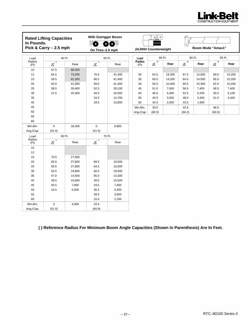
Rated Lifting CapacitiesIn Pounds. Pick & Carry – 2.5 mph 24,000# Counterweight
With Outrigger Boxes
On Tires–2.5 mphBoom Mode “Amax1”
Load 40 Ft. 50 Ft.Radius
�°
�°(Ft) � Rear � Rear
10 67.5 88,300
12 64.5 73,200 70.0 41,400
15 59.5 62,300 66.5 41,400
20 50.0 41,900 59.5 41,400
25 38.5 28,400 52.0 28,100
30 21.5 20,300 44.0 20,000
35 34.0 14,700
40 18.5 10,800
45
50
55
60
Min.Bm. 0 18,400 0 9,800
Ang./Cap. (31.5) (41.5)
Load 60 Ft. 70 Ft.Radius
�°
�°(Ft) � Rear � Rear
10
12
15 70.5 27,800
20 65.5 27,800 69.5 19,500
25 59.5 27,800 64.5 19,500
30 53.5 19,800 60.0 19,500
35 47.0 14,500 55.0 14,300
40 39.5 10,600 49.5 10,500
45 30.5 7,800 43.5 7,600
50 16.5 5,500 36.5 5,400
55 28.0 3,600
60 15.5 2,100
Min.Bm. 0 4,900 10.5
Ang./Cap. (51.5) (60.9)
Load 80 Ft. 90 Ft. 95 Ft.LoadRadius
�°
�°
�°Radius
�° Rear �
° Rear �° Rear(Ft) � Rear � Rear � Rear
30 64.5 19,300 67.5 14,000 69.0 10,200
35 60.0 14,200 64.0 14,000 65.5 10,200
40 55.5 10,400 60.5 10,300 62.0 10,200
45 51.0 7,500 56.5 7,400 58.5 7,400
50 46.0 5,300 52.5 5,200 55.0 5,100
55 40.5 3,500 48.0 3,400 51.0 3,400
60 34.0 2,000 43.5 1,900
Min.Bm. 33.0 42.5 46.5
Ang./Cap (60.5) (60.2) (60.0)
( ) Reference Radius For Minimum Boom Angle Capacities (Shown In Parenthesis) Are In Feet.

�����RTC–80100 Series II
Rated Lifting CapacitiesIn Pounds. Pick & Carry – 2.5 mph 24,000# Counterweight
With Outrigger Boxes
On Tires–2.5 mph Boom Mode “Amax2”
Load 40 Ft. 50 Ft.Radius
�°
�°(Ft) � Rear � Rear
10 67.5 88,300
12 64.5 73,200 70.0 52,000
15 59.5 62,300 66.5 52,000
20 50.0 41,900 59.5 43,600
25 38.5 28,400 52.0 30,000
30 21.5 20,300 44.0 21,800
35 34.0 16,400
40 18.5 12,500
45
50
55
60
Min.Bm. 0 18,400 0 11,500
Ang./Cap. (31.5) (41.5)
Load 60 Ft. 70 Ft.Radius
�°
�°(Ft) � Rear � Rear
10
12
15 70.5 31,000
20 65.5 31,000 69.5 25,000
25 59.5 31,000 64.5 25,000
30 53.5 22,800 60.0 23,400
35 47.0 17,400 55.0 17,900
40 39.5 13,500 49.5 14,100
45 30.5 10,500 43.5 11,100
50 16.5 8,200 36.5 8,800
55 28.0 7,000
60 15.0 5,500
Min.Bm. 0 7,600 0 5,100
Ang./Cap. (51.5) (61.5)
Load 80 Ft. 90 Ft. 100 Ft.LoadRadius
�°
�°
�°Radius
�° Rear �
° Rear �° Rear(Ft) � Rear � Rear � Rear
30 64.0 23,800 67.5 18,600 70.0 15,000
35 60.0 18,400 64.0 18,600 67.0 15,000
40 55.5 14,500 60.0 14,900 63.5 15,000
45 51.0 11,600 56.5 11,900 60.5 12,100
50 46.0 9,200 52.0 9,600 57.0 9,800
55 40.5 7,400 48.0 7,700 53.0 8,000
60 34.0 5,900 43.0 6,200 49.5 6,400
65 26.0 4,600 38.0 4,900 45.5 5,200
70 14.0 3,600 32.0 3,900 41.0 4,100
75 24.5 3,000 36.0 3,200
80 13.0 2,200 30.5 2,400
85 23.5 1,700
Min.Bm. 0 3,300 0 2,000 15.5
Ang./Cap (71.5) (81.5) (89.0)
Load 110.0 Ft. 122.5 Ft.Radius
�°
�°(Ft) � Rear � Rear
35 69.5 12,300
40 66.5 12,300 69.5 10,200
45 63.5 12,300 67.0 10,200
50 60.5 10,000 64.0 10,200
55 57.5 8,200 61.5 8,300
60 54.0 6,600 58.5 6,800
65 50.5 5,400 55.5 5,600
70 47.0 4,300 52.5 4,500
75 43.0 3,400 49.5 3,600
80 39.0 2,600 46.0 2,800
85 34.0 1,900 42.5 2,100
90 29.0 1300 39.0 1,500
Min.Bm. 28.0 36.5
Ang./Cap. (90.7) (92.6)
( ) Reference Radius For Minimum Boom Angle Capacities (Shown In Parenthesis) Are In Feet.

����� RTC–80100 Series II
24,000# Counterweight
With Outrigger Boxes
On Tires–2.5 mphBoom Mode “Std”
Rated Lifting CapacitiesIn Pounds. Pick & Carry – 2.5 mph
Load 40 Ft. 50 Ft.Radius
�°(Ft) � Rear Rear
10 67.5 88,300
12 64.5 73,200 70.0 52,000
15 59.5 62,300 66.5 52,000
20 50.0 41,900 59.5 42,800
25 38.5 28,400 52.0 29,400
30 21.5 20,300 44.0 21,200
35 34.0 15,800
40 18.5 11,900
45
50
55
60
Min.Bm. 0 18,400 0 10,900
Ang./Cap. (31.5) (41.5)
Load 60 Ft. 70 Ft.Radius
�°
�°(Ft) � Rear � Rear
10
12
15 70.5 29,900
20 65.5 29,900 69.0 22,100
25 59.5 29,900 64.5 22,100
30 53.5 21,800 60.0 22,100
35 47.0 16,400 54.5 16,800
40 39.5 12,500 49.5 12,900
45 30.5 9,600 43.5 9,900
50 16.5 7,300 36.5 7,600
55 28.0 5,800
60 15.0 4,300
Min.Bm. 0 6,700 0 3,900
Ang./Cap. (51.5) (61.5)
Load 80 Ft. 90 Ft. 100 Ft.LoadRadius
�°
�°
�°Radius
�° Rear �
° Rear �° Rear(Ft) � Rear � Rear � Rear
30 64.0 22,200 67.5 22,300 70.0 22,400
35 60.0 17,000 64.0 17,100 67.0 17,200
40 55.5 13,100 60.0 13,300 63.5 13,400
45 51.0 10,200 56.0 10,400 60.5 10,500
50 46.0 7,900 52.0 8,100 57.0 8,200
55 40.5 6,100 48.0 6,200 53.0 6,400
60 34.0 4,600 43.0 4,800 49.5 4,900
65 26.0 3,300 38.0 3,500 45.0 3,600
70 14.0 2,300 32.0 2,500 41.0 2,600
75 24.5 1,600 36.0 1,700
Min.Bm. 0 2,000 23.5 34.5
Ang./Cap (71.5) (75.4) (76.3)
Load 110 Ft. 120 Ft.Radius
�°
�°(Ft) � Rear � Rear
35 69.5 17,200
40 66.5 13,400 69.0 13,500
45 63.5 10,500 66.0 10,600
50 60.5 8,300 63.5 8,300
55 57.5 6,500 60.5 6,600
60 54.0 5,000 57.5 5,100
65 50.5 3,700 54.5 3,800
70 47.0 2,700 51.5 2,800
75 43.0 1,800 48.5 1,900
Min.Bm. 41.5 46.5
Ang./Cap. (76.8) (77.3)
( ) Reference Radius For Minimum Boom Angle Capacities (Shown In Parenthesis) Are In Feet.

�����RTC–80100 Series II
Rated Lifting CapacitiesIn Pounds. On Tires –Stationary – 360� 24,000# Counterweight
With Outrigger Boxes
On Tires–360�Boom Mode “Amax1”
40.Ft. 50 Ft.Load Radius
�° ° �
° °(Ft) � 360° � 360°
25 38.5 19,700
30 21.5 13,700 44.0 13,500
35 34.0 9,400
40 18.5 6,400
45
50
Min.Bm. 0 12,300 0 5,600
Ang./Cap. (31.5) (41.5)
Do Not Raise Boom Above 47° Boom Angle. Loss Of Back-ward Stability Will Occur Causing a Tipping Condition.
�������
60 Ft. 70 Ft.Load Radius
�° ° �
° °(Ft) � 360° � 360°
25
30
35 47.0 9,200
40 39.5 6,300
45 30.5 4,000 43.5 3,900
50 16.5 2,200 36.5 2,100
Min.Bm. 0 1,700 32.5
Ang./Cap. (51.5) (52.4)
Do Not Raise Boom Above 47° Boom Angle. Loss Of Back-ward Stability Will Occur Causing a Tipping Condition.
�������
( ) Reference Radius For Minimum Boom Angle Capacities (Shown In Parenthesis) Are In Feet.

����� RTC–80100 Series II
Rated Lifting CapacitiesIn Pounds. On Tires –Stationary – 360� 24,000# Counterweight
With Outrigger Boxes
On Tires–360� Boom Mode “Amax2”
Load 40 Ft. 50 Ft. 60 Ft.Radius
�° ° �
° ° �° °(Ft) � 360° � 360° � 360°
25 38.5 19,700
30 21.5 13,700 44.0 15,200
35 34.0 11,100 47.0 12,000
40 18.5 8,100 39.5 9,000
45 30.5 6,700
50 16.5 4,900
Min.Bm. 0 12,300 0 7,300 0 4,400
Ang./Cap.
(31.5) (41.5) (51.5)
Do Not Raise Boom Above 47° Boom Angle. Loss Of Back-ward Stability Will Occur Causing a Tipping Condition.
�������
Load 70 Ft. 80 Ft.Radius
�° ° �
° °(Ft) � 360° � 360°
40
45 43.5 7,300
50 36.5 5,400 46.0 5,900
55 28.0 4,000 40.5 4,400
60 15.0 2,800 34.0 3,200
65 26.0 2,200
70 14.0 1,400
Min.Bm. 0 2,500 0 1,100
Ang./Cap. (61.5) (71.5)
Do Not Raise Boom Above 47° Boom Angle. Loss Of Back-ward Stability Will Occur Causing a Tipping Condition.
�������
( ) Reference Radius For Minimum Boom Angle Capacities (Shown In Parenthesis) Are In Feet.

�����RTC–80100 Series II
Rated Lifting CapacitiesIn Pounds. On Tires –Stationary – 360� 24,000# Counterweight
With Outrigger Boxes
On Tires–360�Boom Mode “Std”
Load 40 Ft. 50 Ft. 60 Ft.Radius
�° ° �
° ° �° °(Ft) � 360° � 360° � 360°
25 38.5 19,700
30 21.5 13,700 44.0 14,600
35 34.0 10,500 47.0 11,000
40 18.5 7,500 39.5 8,100
45 30.5 5,800
50 16.5 4,000
Min.Bm. 0 12,300 0 6,700 0 3,500
Ang./Cap (31.5) (41.5) (51.5)
Do Not Raise Boom Above 47° Boom Angle. Loss Of Back-ward Stability Will Occur Causing a Tipping Condition.
�������
Load 70 Ft. 80 Ft.Radius
�° ° �
° °(Ft) � 360° � 360°
45 43.5 6,100
50 36.5 4,300 46.0 4,600
55 28.0 2,900 40.5 3,100
60 15.0 1,700 34.0 1,900
Min.Bm. 0 1,400 27.5Ang./Cap. (61.5) (64.1)
Do Not Raise Boom Above 47° Boom Angle. Loss Of Back-ward Stability Will Occur Causing a Tipping Condition.
�������
( ) Reference Radius For Minimum Boom Angle Capacities (Shown In Parenthesis) Are In Feet.

����� RTC–80100 Series II
This Page Intentionally Blank

�����RTC–80100 Series II
Link–Belt Construction Equipment Company Lexington, Kentucky www.linkbelt.com� Link–Belt is a registered trademark. Copyright 2002. All rights reserved. We are constantly improving our products and therefore reserve the right to change designs and specifications.
Related Documents