Copyright 2016 by Robert Stengel. All rights reserved. For educational use only. http://www.princeton.edu/~stengel/MAE342.html Telemetry, Command, Data Processing & Handling Space System Design, MAE 342, Princeton University Robert Stengel • System definition • Computer architecture • Components • Data coding • Fault tolerance and reliability • Hardware and software testing 1 A Typical Space/Ground Information System Wertz and Larson 2

Welcome message from author
This document is posted to help you gain knowledge. Please leave a comment to let me know what you think about it! Share it to your friends and learn new things together.
Transcript

Copyright 2016 by Robert Stengel. All rights reserved. For educational use only.http://www.princeton.edu/~stengel/MAE342.html
Telemetry, Command, Data Processing & Handling
Space System Design, MAE 342, Princeton University!Robert Stengel
•! System definition•! Computer architecture•! Components•! Data coding•! Fault tolerance and
reliability•! Hardware and software
testing
1
A Typical Space/Ground Information System
Wertz and Larson 2

GOES Telemetry and Command Sub-System
3
Defining the System•! Identify the spacecraft bus and payload operational modes•! Allocate top-level requirements for the computer system•! Define sub-system interfaces•! Specify baseline computer system
–! Define computer system s operational modes and states–! Functionally partition and allocate computational requirements to
•! spacecraft sub-systems, hardware, or software•! ground station
–! Analyze data flow–! Evaluate candidate architectures–! Select basic architecture–! Develop baseline system configuration
•! Do we need a new computing system, or can we use an old system that is already certified?
Wertz and Larson 4

Wertz and Larson5
Defining the System
Requirements Definition•! What must the system do?•! Why must it be done?•! How do we achieve the design goal?•! What are the alternatives?•! What sub-systems perform specified functions?•! Are all functions technically feasible?•! How can the system be tested to show that it
satisfies requirements?
Wertz and Larson 6

Telecommand Waveforms
7
•! NRZ-L (Non-Return-to-Zero, Level)
–! A signifies ‘1’–! B signifies ‘0’
•! SP-L (Split-Phase, Level)–! ‘1’ signified by A during 1st
half, B during the 2nd half–! ‘0’ signified by B during 1st
half , A during 2nd half•! NRZ-M (Non-Return-to-Zero,
Mark)–! Level change from A to B or
B to A signifies ‘1’–! No level change signifies ‘0’
Pulse Code Modulation (PCM)
Fortescue
Classification of Telemetry Data
8Fortescue
•! Housekeeping data–! Temperatures, pressures, voltages, currents, …
•! Attitude and acceleration data–! Sun sensors, star sensors, gyros, accelerometers, …
•! Payload data–! Mission dependent–! Wide range of data rates, bandwidth, criticality, …
https://en.wikipedia.org/wiki/Spectrogram
Frequency Analysis Waterfall

Digital vs. Analog Modulation
PCM: pulse-code modulationFM: frequency modulationAM: amplitude modulation
•! Analog–! Amplitude modulation
conserves bandwidth–! Frequency modulation
spreads information bandwidth over larger RF bandwidth
•! Digital–! Pulse-code modulation
(particularly phase-shift keying) uses RF power most efficiently
9Pisacane
Link Budget for a Digital Data Link
Eb
No
=
PtLlGtLsLaGr
kTsR
Pt = transmitter powerLl = transmitter-to-antenna line loss
Gt = transmit antenna gainLs = space loss
La = transmission path lossGr = receiver antenna gaink = Boltzmann's constant
Ts = system noise temperature
Eb
No
= SNBWR
Link budget design goal is to achieve satisfactory Eb/No by choice of link parameters
… in decibels?
10Fortescue
Pisacane

Bit Error Rate vs. Eb/No
•! Goal is to achieve lowest bit error rate (BER) with lowest Eb/No
•! Implementation losses increase required Eb/No
•! Link margin is the difference between the minimum and actual Eb/No
•! BER can be reduced by error-correcting codes–! Number of bits
transmitted is increased–! Additional check bits
allow errors to be detected and corrected
11Pisacane
Performance of Coding/Decoding Methods
12
Pisacane
Pe = Bit Error Rate (BER)BPSK = Binary phase-shift keying
Coding gain is net S/N improvement provided by adding check bits

Telemetry List and Data Format
•! For each item–! Signal ID, data type, required accuracy,
sampling rate•! PCM message format
–! e.g. Eight frames, each with 64 8-bit words–! Fixed synchronization code–! Frame ID channel
•! Specification of data channels–! Housekeeping, “prime”, commutation
13Fortescue
Telemetry Data Encoding•! Analog data
–! Filtering–! A/D–! Multiplexer, sub-multiplexer
•! Digital bi-level data–! On-off
•! Digital serial data–! Word length–! PCM mode
14Fortescue

Multiplexing•! Analog Modulation
–! AM, FM, PM, SSB (single sideband), …•! Circuit Mode (circuit mode)
–! TDM, FDM, Polarization, …•! Statistical Multiplexing (variable bandwidth)
–! Packet switching, Dynamic TDMA, Spread Spectrum, …
15https://en.wikipedia.org/wiki/Multiplexing
Data Formatting
16
Packet Telemetry Data Flow
•! Application Process Layer
•! System Management Layer
•! Packetization Layer•! Segmentation
Layer•! Transfer Layer•! Coding Layer•! Physical Layer
Fortescue

Parity and Error Detection•! n-bit word = (n - 1) bits of data plus a parity bit
(e.g., ASCII 8-bit word for 7-bit code)•! Parity bit is computed (XOR gates) so that the
number of ones in the word is even (or odd)•! Word is transmitted•! Error in one bit of the word is detected if the
number of ones is not even (or odd)A wants to transmit: 1001A computes parity bit value: 1^0^0^1 = 0A adds parity bit and sends: 10010B receives: 10010B computes overall parity: 1^0^0^1^0 = 0B reports correct transmission after observing expected even result.
•! If error is detected, B requests re-transmission from A•! Error-correcting codes as in telemetry (convolution
and block codes, memory refreshing, redundancy)
Wikipedia
17Fortescue
Error-Control Coding•! Typical BER: 1:105
•! Division by a polynomial–! e.g., x16 + x12 + x5 + 1–! Send 16-bit remainder
•! Ground station–! Divide by same polynomial–! If 16-bit remainder not the same, re-send
•! Forward error correction–! Various codes, e.g., …
18Fortescue
http://www.ccs.neu.edu/home/rraj/Courses/6710/S10/Lectures/Coding.pdf

Telecommand User Interface•! Low-level on-off commands•! High-level on-off commands•! Proportional commands•! Telecommand standards
19Fortescue
Memory Load Command Frame Structure
20Fortescue
ASW: Address and Synchronization Word

Communications Techniques & Protocols
21
•! Ranging•! Advanced Orbiting Systems•! Proximity Links•! Protocols
–! Store-and-forward networking–! Continuous file delivery–! Negative automatic report queuing–! Proxy transfer facilities–! Graceful suspend/resume–! Garbage clearance–! File manipulation
Fortescue
On-Board Data Handling and Processing
22Fortescue
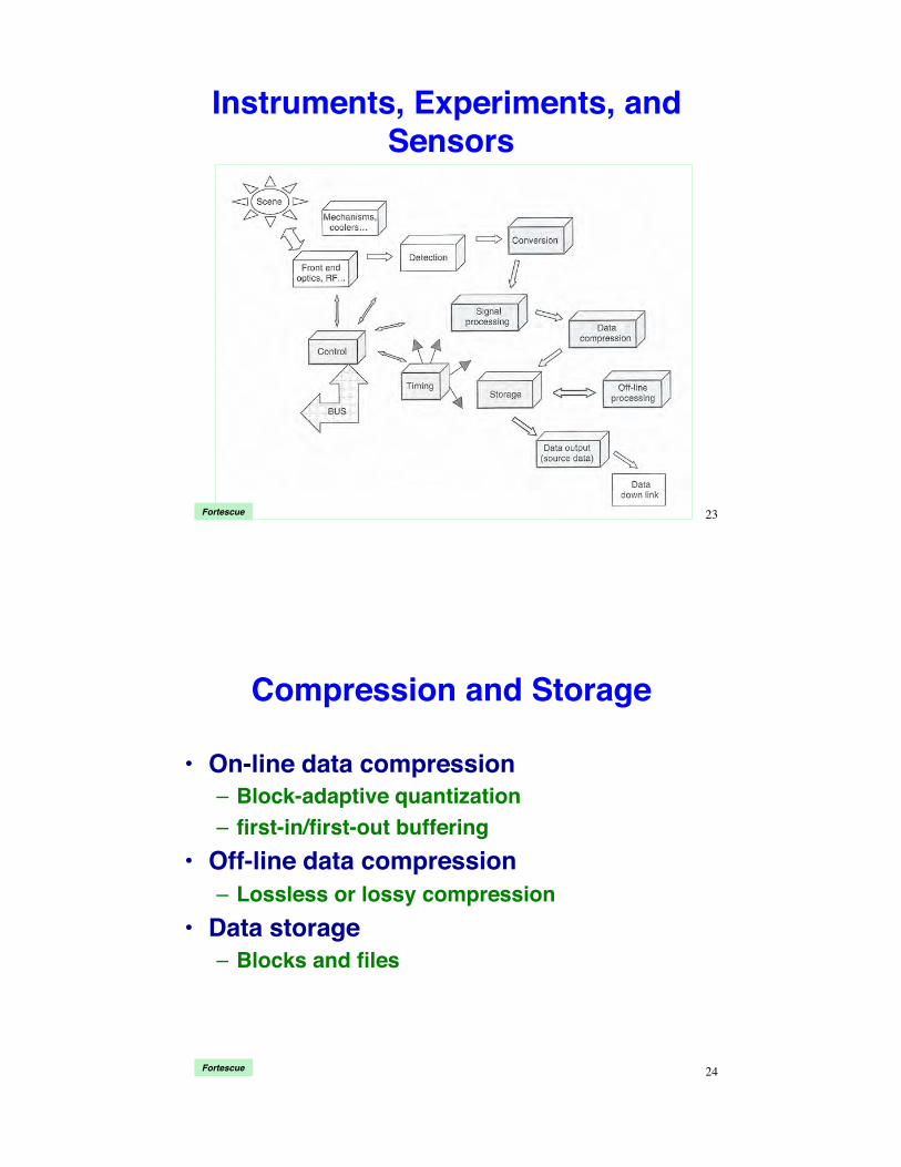
Instruments, Experiments, and Sensors
23Fortescue
Compression and Storage
•! On-line data compression–! Block-adaptive quantization–! first-in/first-out buffering
•! Off-line data compression–! Lossless or lossy compression
•! Data storage–! Blocks and files
24Fortescue

Data Downlinks•! Data-handling function RF transmit chain
–! Data routing–! Buffering–! Formatting–! Carrier modulation–! Amplification–! Transmission
•! Modulation techniques–! QPSK–! Amplification–! Link layer–! Link availability
25Fortescue
Electronics Technology•! Radiation hardness•! Single-event upsets•! CMOS latch-up•! Parity•! Error detection and
correction•! Triple modular
redundancy•! Multiple execution•! Fault roll-back
–! repeat the function if error is sensed
Pisacane
•! Fault roll-forward–! correct the error and move
on•! Watchdog timers
–! detect unusual execution time for program function
–! force a restart if faul is detected
•! Improper sequence detection
•! Hardware vs. software errors
26Fortescue

Radiation Hardness and Single-Event Upsets
•! Radiation degrades semiconductor devices•! Ionization due to Gamma rays may trap charges in
devices, altering their function–! Can produce a single-event upset
•! Random and age-related failures must be anticipated–! Shielding–! Radiation-hardened dielectrics
•! Single-event upset (SEU)–! Radiation flips a bit in data or instruction
•! CMOS latch-up–! Large transient current flow may destroy the device–! Build in a circuit breaker that shuts off current before damage
is donePisacane 27
Triple Modular Redundancy: Hardware
•! Parallel hardware implementation for fault tolerance–! Each sensor, computer, or actuator is replicated three times–! Multiple execution–! Voting logic compares the three versions of each output and
chooses the version •! transmitted by two (or all three),•! middle value, or•! average value
–! Cost and maintenance implications
28Fortescue

Triple Modular Redundancy: Software
•! Software implementation for serial data transmission–! Each word is transmitted three times–! Voting logic compares the three versions and chooses
the version transmitted by two (or all three)–! Serial data transfer rate is slowed by a factor of three
29Fortescue
ReliabilityProbability of Success during
Period of Operation
R(t) =1! P(t)
R(t) : Probability of successP(t) : Probability of failure
30Fortescue

Reliability Assessment•! Tools for reliability assessment: Testing
–! Levels of test: development, qualification, acceptance, function
–! Destructive physical analysis•! Tools for reliability assessment: Analysis
–! Statistical distributions–! Statistics, regression, and inference–! Fault trees and reliability prediction–! Confidence level or interval
31Fortescue
Reliability of a Single String
Reliability of a string of components = product of individual reliabilities
R1!n (t) = R1R2 ...Rn
32Fortescue

Reliability of Parallel (Redundant) Components
Probability of failure of parallel components = product of individual
probabilities
R(t) =1! P(t)
R13(t) =1! P13(t) =1! P1(t)P2(t)P3(t)
P13(t) = P1(t)P2 (t)P3(t)
33Fortescue
Reliability of a Switched Redundant System
Reliability of the switch must be
considered
Rsystem (t) = R1(t) 1! 1! R2 (t)[ ] 1! RS (t)R2' (t)[ ]{ }R3(t)= R1(t) 1! P2 (t)PS2' (t){ }R3(t)
34Fortescue

Reliability of a String of Parallel Components
Binomial coefficient nx
!"#
$%&= n!x! n ' x( )!
Rsystem (t) =nx
!"#
$%&Rx 1' R( )n'x
x=r
n
(
35Fortescue
r = # of elements in a parallel component that must survive for operation
Reliability of Parallel Strings
P1n (t) = P1(t)P2 (t)…Pn (t)R(t) = 1! P(t)
R1n (t) = 1! P1n (t) = 1! P1(t)P2 (t)…Pn (t)
36Fortescue

Spacecraft Computers
•! Spacecraft computing hardware; analogous to Macs and PCs, but–! Must be ultra-reliable–! A few generations behind the state-of-the-art
•! Memory•! Input/output•! Fault tolerance•! Special-purpose peripherals
Pisacane 37
Hardware, Software, and Documentation
38Wertz and Larson

Computer System State Diagram
System states must be consistent with allocated requirements and with spacecraft s and ground station s
concepts of operation ( conops )Wertz and Larson 39
Computer System
Functional Partitioning
Wertz and Larson 40
•! Group functions–! Similarity–! Complexity–! Processing type–! Urgency–! Timing and throughput–! External interface–! Data storage req’t–! Human participation–! Flight safety
•! Space/ground tradeoffs–! Autonomy–! Time criticality–! Downlink bandwidth–! Uplink bandwidth
•! Hardware/software tradeoffs
–! Special-purpose h/w–! Algorithmic complexity

Computer Architecture
41Wertz and Larson
•! Central processor–! Point-to-point interfaces,
central processor and devices
–! Dedicated wiring and software
•! Bus–! Processors and devices
communicate via a bus–! Protocol software for
transmission control–! Standard interfaces
•! Ring–! Established arbitration
(e.g., token-passing) for bus control
•! Instruction set–! Assembly language–! Higher-order language
Computer Resource Estimation•! Defining processing tasks
–! Software requirements specification–! Interface requirements specification–! Principal classes
•! Control systems•! System management•! Mission data management•! Operating system
–! Utilities–! Built-in test
•! Estimating software size and throughput–! Processor instruction sets–! Processor clock speeds–! Historical data for similar processing tasks–! Preliminary coding of example tasks
Wertz and Larson 42

Development Phase Issues•! Hardware selection
–! Performance, cost, availability, vendor competition
•! Developmental environment–! Software languages, tools for coding,
compiling, and testing–! Host/target machines
•! Development costs–! Mission life cycle
•! Development tools and methodologies–! Specification and analysis aids–! Design aids–! Traceability analysis–! Documentation aids
Wertz and Larson
Typical Life-Cycle Cost Distribution
43
Wertz and Larson 44
Computer System Integration and Test

Computer Memory•! Read-only memory (ROM)
–! Non-volatile–! Non-alterable–! Store critical programs–! EAROM, EEROM, EEPROM
•! Flash memory (special EEPROM)•! Random-access memory
–! Volatile•! Special-purpose memory
–! Multi-port–! Cache–! Multiply-accumulate
•! Disk–! Magnetic–! CD, DVD
Pisacane45
a! a + b " c( )
Computer Input/Output•! Ports
–! Data transfer between processor and bus•! Serial I/O ports•! Parallel I/O ports•! I/O-mapped ports•! Memory-mapped ports
•! Direct memory access–! Sub-systems access memory without going through the
processor for large blocks of data or high data rate•! Multi-port memory
–! Simultaneous data access by two or more devices•! Interrupts
–! May be generated by a timer or an event, changing processor function
–! Synchronize activity of multiple processors–! Context switching and storage
•! Timers•! Bus interface
Pisacane46

Special-Purpose Peripherals (Signal-Processing Hardware)
Data acquisition
47
Special-Purpose Peripherals (Signal-Processing Hardware)
•! Logarithmic and data compression–! Rounding, filtering, coding, channel capacity,
probability, incremental values, ...•! Frequency domain transformation
–! Time domain -> frequency domain–! Fourier transform, inverse transform , wavelets
•! Power/energy spectrum accumulation•! Image processing•! Digital/analog conversion
48

Apollo GNC Software Testing and Verification
•! Major areas of testing–! Computational accuracy–! Proper logical sequences
•! Testing program–! Comprehensive test plans–! Specific initial conditions and operating sequences–! Performance of tests–! Comparison with prior simulations, evaluation, and re-testing
•! Levels of testing–! 1: Specifications coded in higher-order language for non-flight hardware
(e.g., PCs)–! 2: Digital simulation of flight code–! 3: Verification of complete programs or routines on laboratory flight
hardware–! 4: Verification of program compatibility in mission scenarios–! 5: Repeat 3 and 4 with flight hardware to be used for actual mission–! 6: Prediction of mission performance using non-flight computers and
laboratory flight hardware49
Apollo GNC Software Specification Control
•! Guidance System Operations Plan (GSOP)–! NASA-approved specifications document for mission software–! Changes must be approved by NASA Software Control Board
•! Change control procedures–! Program Change Request (NASA) or Notice (MIT)–! Anomaly reports–! Program and operational notes
•! Software control meetings–! Biweekly internal meetings–! Joint development plan meetings–! First Article Configuration Inspection–! Customer Acceptance Readiness Review–! Flight Software Readiness Review
50

Apollo GNC Software Documentation and Mission Support
•! Documentation generation and review–! GSOP: 1: Prelaunch 2: Data links 3: Digital autopilots 4:
Operational modes 5: Guidance equations 6: Control data–! Functional description document: H/W-S/W interfaces, flowcharts of
procedures–! Computer listing of flight code–! Independently generated program flowchart–! Users Guide to AGC–! NASA program documents: Apollo Operations Handbook, Flight
Plans and Mission Rules, various procedural documents•! Mission support
–! Pre-flight briefings to the crew–! Personnel in Mission Control and at MIT during mission
51
Apollo Guidance Computer
•! Parallel processor•! 16-bit word length (14 bits + sign +
parity)•! Memory cycle time: 11.7 µµsec•! Add time: 23.4 µµsec•! Multiply time: 46.8 µµsec•! Divide time: 81.9 µµsec
•! There were NO computer hardware failures during Apollo flights 52
•! Memory (ceramic magnetic cores)–! 36,864 words (ROM)–! 2,048 words (RAM)
•! 34 normal instructions•! Identical computers in CSM and LM•! Different software (with many
identical subroutines)•! 70 lb, 55 w

Some Flight Computer Variations
53Pervasive use of VMEbus in
spacecraft computers
RAD750 Single Board Computer
54
Produced From 2001 to PresentDesigned by IBMManufacturer BAEMax. CPU clock rate
110 MHz to 200 MHz Min. feature size 250 nm to 150 nmInstruction set PowerPC v.1.1Microarchitecture PowerPC 750Cores 1Application Radiation hardened
•! Mars Curiosity Rover, Mars/Lunar Reconnaissance Orbiters, Deep Impact, …

RAD5545 Single Board Computer
55
Designed by IBM, FreescaleManufacturer BAESpeeds 5200 MIPS, 3700MFLOPSMin. feature size 45 nmInstruction set Power ISA, v 2.06Microarchitecture PowerPC e5500, VPX backplaneCores 4Application Radiation hardened
Fault Tolerance Requirements for Overall System
•! Failure at a single point should not cause failure of entire system
•! It should be possible to isolate the effects of a single component failure
•! It should be possible to contain individual failures to prevent failure propagation
•! Reversionary modes should be available ( fail-safe design)–! backup software–! backup hardware
56

Next Time:!Ground Segment!
57
SSuupppplleemmeennttaall MMaatteerriiaall
58

Astronaut Interface With the AGC
•! Computer Display Unit or Display/Keyboard
•! Sentence–! Subject and predicate–! Subject is implied
•! Astronaut, or•! GNC system
–! Sentence describes action to be taken employing or involving the object
•! Predicate–! Verb = Action–! Noun = Variable or Program
See http://apollo.spaceborn.dk/dsky-sim.html
And http://www.ibiblio.org/apollo/ for simulation59
Verbs and Nouns in Apollo Guidance
Computer Program•! Verbs (Actions)
–! Display–! Enter–! Monitor–! Write–! Terminate–! Start–! Change–! Align–! Lock–! Set–! Return–! Test–! Calculate–! Update
•! Selected Nouns (Variables)
–! Checklist–! Self-test ON/OFF–! Star number–! Failure register
code–! Event time–! Inertial velocity–! Altitude–! Latitude–! Miss distance–! Delta time of burn–! Velocity to be
gained
•! Selected Programs (CM)
–! AGC Idling–! Gyro Compassing–! LET Abort–! Landmark Tracking–! Ground Track
Determination–! Return to Earth–! SPS Minimum
Impulse–! CSM/IMU Align–! Final Phase–! First Abort Burn
60

A Little AGC Digital Autopilot Code
61
Space Shuttle Quintuply Redundant Flight
Control Computers
•! Five identical IBM AP-101 computers–! Magnetic core memory later upgraded to
semiconductor memory–! Primary system: 4 parallel computers with
identical coding and complex redundancy management software
–! Backup system: 5th computer with independent coding of the same functions
–! Concern for generic software failures–! HAL/S programming language
62

Space Shuttle Quintuply Redundant Flight Control Computers
Norman, Proc. IEEE, 198763
Norman, Proc. IEEE, 1987 64
IBM AP-101 Input/Output Processor
and Central Processing Unit
Related Documents