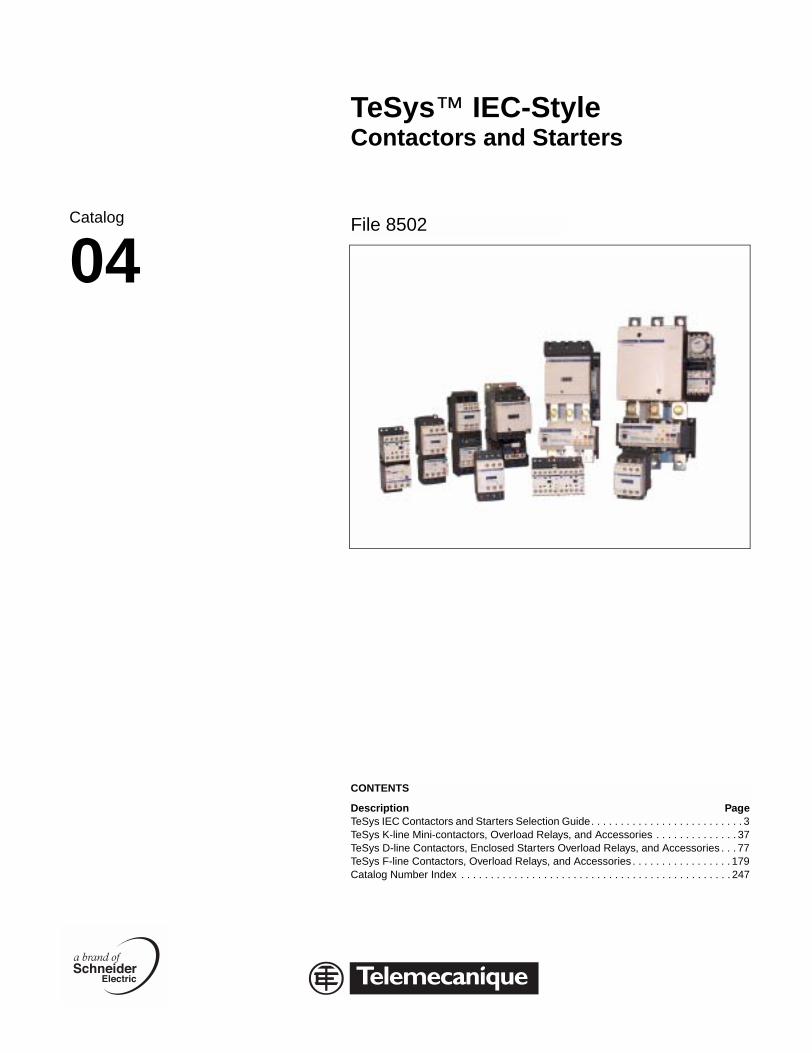
TeSys™ IEC-Style Contactors and Starters File 8502 CONTENTS Description Page TeSys IEC Contactors and Starters Selection Guide . . . . . . . . . . . . . . . . . . . . . . . . . . 3 TeSys K-line Mini-contactors, Overload Relays, and Accessories . . . . . . . . . . . . . . 37 TeSys D-line Contactors, Enclosed Starters Overload Relays, and Accessories. . . 77 TeSys F-line Contactors, Overload Relays, and Accessories . . . . . . . . . . . . . . . . . 179 Catalog Number Index . . . . . . . . . . . . . . . . . . . . . . . . . . . . . . . . . . . . . . . . . . . . . . 247 Catalog 04

Welcome message from author
This document is posted to help you gain knowledge. Please leave a comment to let me know what you think about it! Share it to your friends and learn new things together.
Transcript
TeSys™ IEC-StyleContactors and Starters
File 8502
CONTENTS
Description PageTeSys IEC Contactors and Starters Selection Guide. . . . . . . . . . . . . . . . . . . . . . . . . . 3TeSys K-line Mini-contactors, Overload Relays, and Accessories . . . . . . . . . . . . . . 37TeSys D-line Contactors, Enclosed Starters Overload Relays, and Accessories . . . 77TeSys F-line Contactors, Overload Relays, and Accessories . . . . . . . . . . . . . . . . . 179Catalog Number Index . . . . . . . . . . . . . . . . . . . . . . . . . . . . . . . . . . . . . . . . . . . . . . 247
Catalog
04

Catalog
04
TeSys™ IEC-StyleContactors and StartersSelection Guide
File 8502
CONTENTS
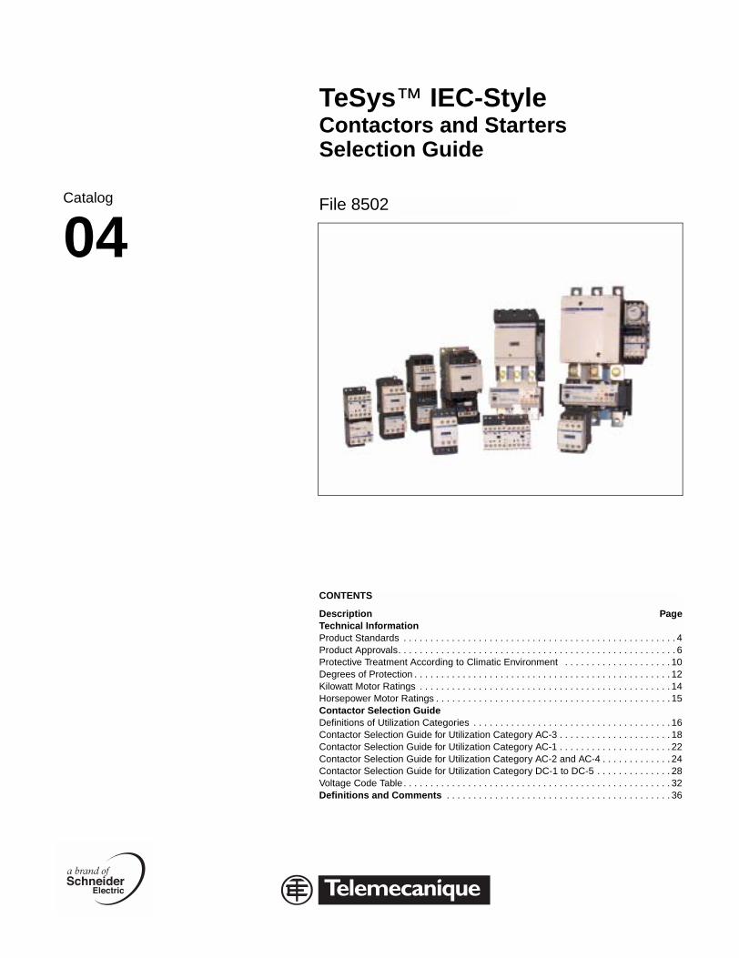
Description PageTechnical InformationProduct Standards . . . . . . . . . . . . . . . . . . . . . . . . . . . . . . . . . . . . . . . . . . . . . . . . . . . 4Product Approvals. . . . . . . . . . . . . . . . . . . . . . . . . . . . . . . . . . . . . . . . . . . . . . . . . . . . 6Protective Treatment According to Climatic Environment . . . . . . . . . . . . . . . . . . . . 10Degrees of Protection . . . . . . . . . . . . . . . . . . . . . . . . . . . . . . . . . . . . . . . . . . . . . . . . 12Kilowatt Motor Ratings . . . . . . . . . . . . . . . . . . . . . . . . . . . . . . . . . . . . . . . . . . . . . . . 14Horsepower Motor Ratings . . . . . . . . . . . . . . . . . . . . . . . . . . . . . . . . . . . . . . . . . . . . 15Contactor Selection GuideDefinitions of Utilization Categories . . . . . . . . . . . . . . . . . . . . . . . . . . . . . . . . . . . . . 16Contactor Selection Guide for Utilization Category AC-3 . . . . . . . . . . . . . . . . . . . . . 18Contactor Selection Guide for Utilization Category AC-1 . . . . . . . . . . . . . . . . . . . . . 22Contactor Selection Guide for Utilization Category AC-2 and AC-4 . . . . . . . . . . . . . 24Contactor Selection Guide for Utilization Category DC-1 to DC-5 . . . . . . . . . . . . . . 28Voltage Code Table . . . . . . . . . . . . . . . . . . . . . . . . . . . . . . . . . . . . . . . . . . . . . . . . . . 32Definitions and Comments . . . . . . . . . . . . . . . . . . . . . . . . . . . . . . . . . . . . . . . . . . 36
Selection Guide
TeSys™ IEC-Style Contactors and Starters Selection GuideTechnical Information: Product Standards
© 2001-2004 Schneider E4
Technical Information: Product Standards
Conformity to Standards
The Telemecanique D-Line, F-line, and K-line contactors, overload relays and accessories satisfy most national, European, and international standards for promoting worldwide product acceptance. These product standards precisely define the performance of the designated products (such as IEC 60947 for low voltage equipment).
When used correctly, as designated by the manufacturer and in accordance with the regulations and rules of the art, these products will allow assembled equipment, machine systems or installations to conform to their appropriate standards (for example: IEC 60204, relating to electrical equipment used on industrial machines).
Telemecanique is able to provide proof of conformity of its production, in accordance with the standards selected by ourselves, due to our quality assurance system. On request, and depending on the situation, Telemecanique can provide the following:
• A declaration of conformity.
• A certificate of conformity (ASEFA/LOVAG).
• An approval certificate or agreement, in the countries where this procedure is required or for particular specifications, such as those existing in the merchant marine.
European EN Standards
This is a group of technical specifications established in conjunction with, and approval of, the relative bodies within the various CENELEC member countries (EEC and EFTA). Arrived at by the principal of consensus, the European standards are the result of a majority vote. Such adopted standards are then integrated into the national collection of standards, and contradictory national standards are withdrawn.The European standards are now incorporated within the French standards and carry the prefix NF EN. Under the “Technical Union of Electricity” (UTE), the French version of the corresponding European standard carries a double notation: European reference (NF EN …) and classification (C …).
In addition, the standard NF EN 60947-4-1 relating to motor contactors and starters, effectively constitutes the French version of the European standard EN 60947-4-1 and carries the UTE classification C 63-110. This standard is identical to the British standard BS EN 60947-4-1 and the German standard DIN VDE 0660 Teil 102. Whenever reasonably practical, European standards reflect international standards (IEC).
For automation system components and distribution equipment, Telemecanique supplements the requirements of the French NF standards with those necessary for all other major industrial countries.
European Directives
The opening of the European market assumes a harmonization of the regulations pertaining to each member country of the European Community. The purpose of the European Directive is the elimination of obstacles hindering the free circulation of goods within the European Community, and its application applies to each member country.
Member countries are obliged to transcribe each Directive into their national legislation and to simultaneously withdraw any contradictory regulation. The Directives, in particular those of a technical content concerning us here, only establish the objectives to be obtained and are referred to as “essential requirements.”
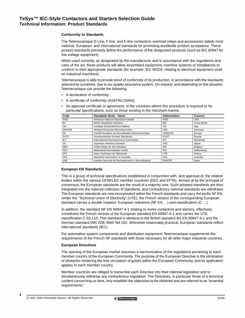
Code Standards Body - Name Abbreviation CountryANSI American National Standards Institute ANSI USABS British Standards Institution BSI Great BritainCEI Comitato Electtrotechnico Italiano CEI ItalyDIN/VDE Verband Deutscher Electrotechniker VDE GermanyEN Comité Européen de Normalisation Electrotechnique CENELEC EuropeGOST Gosudarstvenne Komitet Standartov GOST RussiaIEC International Electrotechnical Commission IEC WorldwideJIS Japanese Industrial Standard JISC JapanNBN Institut Belge de Normalisation IBN BelgiumNEN Nederlands Normalisatie Institut NNI NetherlandsNFC Union Technique de l'Electricité UTE FranceSAA Standards Association of Australia SAA AustraliaUNE Instituto Nacional de Racionalizacion y Normalizacion IRANOR Spain
lectric All Rights Reserved 01/04
TeSys™ IEC-Style Contactors and Starters Selection GuideTechnical Information: Product Standards
01/04
The manufacturer is obliged to ensure that all measures are taken to provide conformity to the regulations of the particular Directive applicable to his product. As a general rule, the manufacturer certifies conformity to the essential requirements of the Directive(s) for the product by affixing a CE marking. The CE marking will be affixed to Telemecanique products progressively throughout the transition period, as defined by the French and European regulations.
Significance of the CE marking:
• The CE marking is affixed to a product to signify that the manufacturer certifies that the product conforms to the relevant European Directive(s) and is obligatory for a product, subject to one or more of the European Directives, before it can be freely distributed within the European Community.
• The CE marking is intended solely for national market control authorities.
• The CE marking must not be confused with a conformity marking.
For electrical equipment, only conformity to standards signifies that the product is suitable for its designated function, and only the guarantee of an established manufacturer can provide a high level of quality assurance. For Telemecanique labelled products, one or several Directives are liable to be applied, in particular:
• The Low Voltage Directive 73/23/EEC amended by the Directive 93/68/EEC: the CE marking relating to this Directive could not be affixed before 1 January 1995 but was obligatory as of January 1, 1997.
• The Electromagnetic Compatibility Directive 89/336/EEC, amended by the Directives 92/31/EEC and 93/68/EEC: the CE marking on products covered by this Directive is obligatory from 1 January 1996.
ASEFA-LOVAG Certification
The function of ASEFA (Association des Stations d'Essais Française d'Appareils électriques — Association of French Testing Stations for Low Voltage Industrial Electrical Equipment) is to carry out tests for conformity to standards and to issue certificates and test reports. ASEFA laboratories are authorized by the National Testing Network (RNE).
ASEFA is now effectively a member of the European accord group LOVAG (Low Voltage Agreement Group). This means that any certificates issued by LOVAG/ASEFA are recognized by all the authorities forming the membership of the group and carry the same validity as those issued by any of the member authorities.
Quality Labels
When components can be used in domestic and similar applications, it is sometimes necessary to obtain a “quality label,” which is a form of certification of conformity.
Approvals
In some countries, the approval of certain electrical equipment is required by law. In this case, an approval certificate is issued by the official test authority. Each approved component must bear the relevant quality label when this is mandatory.
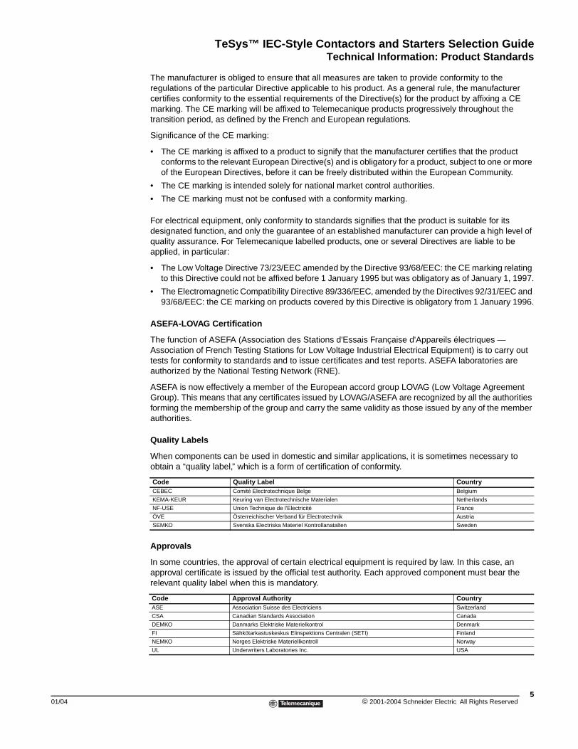
Code Quality Label CountryCEBEC Comité Electrotechnique Belge Belgium
KEMA-KEUR Keuring van Electrotechnische Materialen Netherlands
NF-USE Union Technique de l'Electricité France
ÖVE Österreichischer Verband für Electrotechnik Austria
SEMKO Svenska Electriska Materiel Kontrollanatalten Sweden
Code Approval Authority CountryASE Association Suisse des Electriciens Switzerland
CSA Canadian Standards Association Canada
DEMKO Danmarks Elektriske Materielkontrol Denmark
FI Sähkötarkastuskeskus Elinspektions Centralen (SETI) Finland
NEMKO Norges Elektriske Materiellkontroll Norway
UL Underwriters Laboratories Inc. USA
5© 2001-2004 Schneider Electric All Rights Reserved
TeSys™ IEC-Style Contactors and Starters Selection GuideTechnical Information: Product Approvals
© 2001-2004 Schneider E6
Level of Approval Symbo
“Recognized”
“Listed”
Code ClassifBV Bureau V
DNV Det Nors
GL Germani
LROS Lloyd's R
NKK Nippon K
RINA Registro
RRS Register
Existing and Pending A
Standard VersionX: ApprovedO: Approval pending
Special Version+: ApprovedØ: Approval pending
Approv
ASE
Switzerland
AB1BB, AB1BC X
AB1BD X
AB1DV X
AB1FU X
AB1FV X
AB1NE, AB1SE X
AB1SV
AB1TP X
AB1TR X
AB1VV X
AB3RV
ABA6, ABE6R
ABR1, ABR2
ABS1
ABS2
AK2BA01 X
AK2BA162U
AK2SB X
AK3JB4 (CMD) X
AK3JB8 (CMD) X
Technical Information: Product Approvals
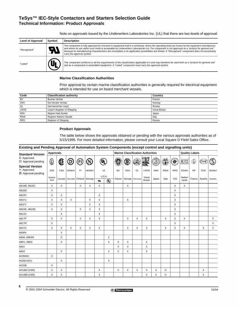
Note on approvals issued by the Underwriters Laboratories Inc. (UL) that there are two levels of approval:
Marine Classification Authorities
Prior approval by certain marine classification authorities is generally required for electrical equipment which is intended for use on board merchant vessels.
Product Approvals
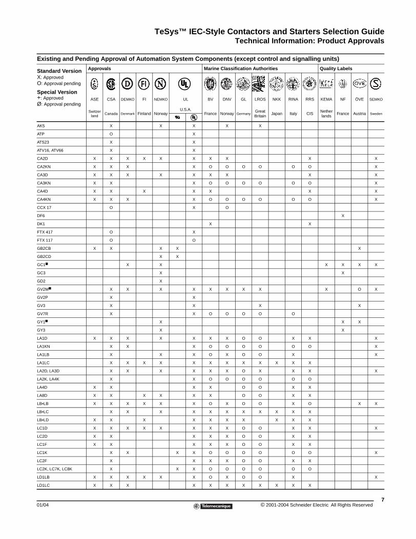
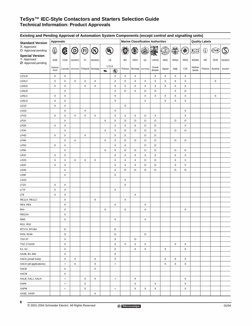
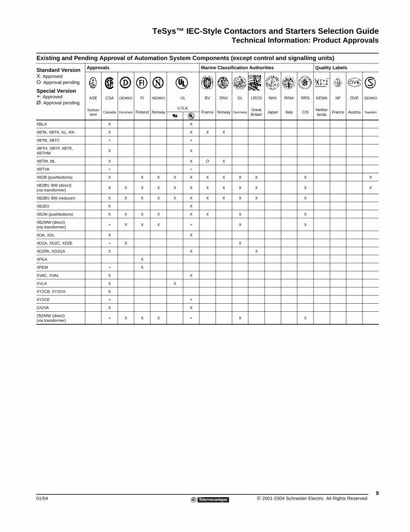
The table below shows the approvals obtained or pending with the various approvals authorities as of 5/15/1995. For more detailed information, please consult your Local Square D Field Sales Office.
l Description
The component is fully approved for inclusion in equipment built in a workshop, where the operating limits are known by the equipment manufacturer, and where its use within such limits is acceptable by Underwriters Laboratories Inc.The component is not approved as a “product for general use” because its manufacturing characteristics are incomplete or its application possibilities are limited. A “Recognized” component does not necessarily carry the approval symbol.
The component conforms to all the requirements of the classification applicable to it and may therefore be used both as a “product for general use” and as a component in assembled equipment. A “Listed” component must carry the approval symbol.
ication authority Countryeritas France
ke Veritas Norway
scher Lloyd Russia
egister of Shipping Great Britain
aiji Kyokaï Japan
Italiano Navale Italy
of Shipping Russia
pproval of Automation System Components (except control and signalling units)
als Marine Classification Authorities Quality Labels
CSA DEMKO FI NEMKO UL BV DNV GL LROS NKK RINA RRS KEMA NF ÖVE SEMKO
Canada Denmark Finland NorwayU.S.A.
France Norway GermanyGreat Britain
Japan Italy CISNetherlands
France Austria Sweden
X X X X X X X
X
X X X
X X X X X X
X X X X
X X X X X
X X X
X X X X X X X X X X X
X X
X X X X X X X X X X X X X
X
O X
X X X X X
X X X
X X X X X
X X
X X X X X X X O X
X X X X O X
lectric All Rights Reserved 01/04
TeSys™ IEC-Style Contactors and Starters Selection GuideTechnical Information: Product Approvals
01/04
AK5
ATP
ATS23
ATV16, ATV66
CA2D X
CA2KN X
CA3D X
CA3KN X
CA4D X
CA4KN X
CCX 17
DF6
DK1
FTX 417
FTX 117
GB2CB X
GB2CD
GC1
GC3
GD2
GV2M
GV2P
GV3
GV7R
GY1
GY3
LA1D X
LA1KN
LA1LB
LA1LC
LA2D, LA3D
LA2K, LA4K
LA4D X
LA8D X
LB•LB X
LB•LC
LB•LD X
LC1D X
LC2D X
LC1F X
LC1K
LC2F
LC2K, LC7K, LC8K
LD1LB X
LD1LC X
Existing and Pending A
Standard VersionX: ApprovedO: Approval pending
Special Version+: ApprovedØ: Approval pending
Approv
ASE
Switzerland
X X X X X
O X
X X
X X
X X X X X X X X X
X X X O O O O O O X
X X X X X X X X
X X O O O O O O X
X X X X X X
X X X O O O O O O X
O X O
X
X X
O X
O O
X X X X
X X
X X X X X X
X X
X
X X X X X X X X X O X
X X
X X X X
X X O O O O O
X X X
X X
X X X X X X O O X X X
X X X O O O O O O X
X X X O X O O X X
X X X X X X X X X X X X
X X X X X X O X X X X
X X O O O O O O
X X X O O X X
X X X X X O O X X
X X X X X O X O O X O X X
X X X X X X X X X X X
X X X X X X X X X
X X X X X X X O O X X X
X X X X O O X X
X X X X O O X X
X X X X O O O O O O X
X X X X O O X X
X X X O O O O O O
X X X X X O X O O X X
X X X X X X X X X X
pproval of Automation System Components (except control and signalling units)
als Marine Classification Authorities Quality Labels
CSA DEMKO FI NEMKO UL BV DNV GL LROS NKK RINA RRS KEMA NF ÖVE SEMKO
Canada Denmark Finland NorwayU.S.A.
France Norway GermanyGreat Britain
Japan Italy CISNetherlands
France Austria Sweden
7© 2001-2004 Schneider Electric All Rights Reserved
TeSys™ IEC-Style Contactors and Starters Selection GuideTechnical Information: Product Approvals
© 2001-2004 Schneider E8
LD1LD X
LD4LC X
LD4LD X
LD5LB
LD5LC X
LD5LD X
LE1D X
LN1D
LP1D X
LP1K
LP2D X
LP2K
LP4D X
LP4K
LP5D X
LP5K
LR1F X
LR2D X
LR2F X
LR2K
LR9F
LS1D
LT2S X
LT7F X
LT8 X
RE1LA, RE1LC
RE4, RE5
RH•
RM1XA
RM3
RS1, RS2
RTV74, RTV84
RXN, RUW
TSX 07
TSX 1710/20
K1, K2
XA2B, BV, BW
XACA (small hoist)
XACA (all applications)
XACB
XACM
XALB, XALJ, XALN
XAPA
XAPM
XASE, XASP
Existing and Pending A
Standard VersionX: ApprovedO: Approval pending
Special Version+: ApprovedØ: Approval pending
Approv
ASE
Switzerland
X X X X X X X X
X X X X X X X X X X X X X
X X X X X X X X X X X
X X O X O O X O
X X X X X X X X
X X X X X X
X X
X X X X
X X X X X X X O X X
X X X O O O O O O
X X X X O O X
X X X O O O O O O
X X X X O O
X X X X O O O O O O
X X X O O
X X X O O O O O O
X X X X X X X X
X X X X X X X O O X X
X X X X O O X X
X X O O O O O O
X X
X
X X
X X
X X
X X X
X X X
X X X X X
X
X X X
O O
O O O
X X O
X X X X X X X
X X X X X X
X X
X X X X X X X
+ X X + X X X
X X
X
+ X X + X X
+ X X X X
+ X + X X X X
X
pproval of Automation System Components (except control and signalling units)
als Marine Classification Authorities Quality Labels
CSA DEMKO FI NEMKO UL BV DNV GL LROS NKK RINA RRS KEMA NF ÖVE SEMKO
Canada Denmark Finland NorwayU.S.A.
France Norway GermanyGreat Britain
Japan Italy CISNetherlands
France Austria Sweden
lectric All Rights Reserved 01/04
TeSys™ IEC-Style Contactors and Starters Selection GuideTechnical Information: Product Approvals
01/04
XBLA
XBTA, XBTK, KL, KN
XBTB, XBTC
XBTH, XBTP, XBTE, XBTHM
XBTM, ML
XBTVA
XB2B (pushbuttons)
XB2BV, BW (direct) (via transformer)
XB2BV, BW (reducer)
XB2EV
XB2M (pushbuttons)
XB2MW (direct) (via transformer)
XDA, XDL
XD2A, XD2C, XD2E
XD2PA, XD2GA
XPEA
XPEM
XVAC, XVAL
XVLA
XY2CB, XY2CH
XY2CE
ZA2VA
ZB2MW (direct) (via transformer)
Existing and Pending A
Standard VersionX: ApprovedO: Approval pending
Special Version+: ApprovedØ: Approval pending
Approv
ASE
Switzerland
X X
X X X X
+ +
X X
X X O X
+ +
X X X X X X X X X X X
X X X X X X X X X X X X
X X X X X X X X X X X
X X
X X X X X X X X
+ X X X + X X
X X
+ X X
X X X
X
+ X
X X
X X
X
+ +
X X
+ X X X + X X
pproval of Automation System Components (except control and signalling units)
als Marine Classification Authorities Quality Labels
CSA DEMKO FI NEMKO UL BV DNV GL LROS NKK RINA RRS KEMA NF ÖVE SEMKO
Canada Denmark Finland NorwayU.S.A.
France Norway GermanyGreat Britain
Japan Italy CISNetherlands
France Austria Sweden
9© 2001-2004 Schneider Electric All Rights Reserved
TeSys™ IEC-Style Contactors and Starters Selection GuideTechnical Information: Protective Treatment / Climatic Environment
© 2001-2004 Schneider E10
Technical Information: Protective Treatment According to Climatic Environment
Depending on the climatic and environmental conditions in which the equipment is placed, Telemecanique can offer specially adapted products to meet your requirements.
In order to make the correct choice of protective finish, two points should be remembered:
• The prevailing climate of the country is never the only criterion.
• Only the atmosphere in the immediate vicinity of the equipment should be considered.
“TC” Treatment for All Climates
“TC” is the standard treatment for Telemecanique equipment and is suitable for the vast majority of applications. It is the equivalent of treatments described as “Klimafest,” “Climateproof,” “Total Tropicalization,” or “Super Tropicalization,” and meets the following requirements:
• Publication UTE C 63-100 (method l), successive cycles of humid heat at + 40 °C (104 °F) and 95% relative humidity.
• DIN 50016 — Variations of ambient conditions within a climatic chamber:+ 23 °C (73 °F) and 83% relative humidity,+ 40 °C (104 °F) and 92% relative humidity.
It also meets the requirements of the marine classification authority BV-LROS-GL-DNV-RINA.
Characteristics
• Steel components are usually treated with zinc chromate and, when they have a mechanical function, they may also be painted.
• Insulating materials are selected for their high electrical, dielectric and mechanical characteristics.
• Metal enclosures have a stoved paint finish, applied over a primary phosphate protective coat, or are galvanized (for example, some prefabricated busbar trunking components).
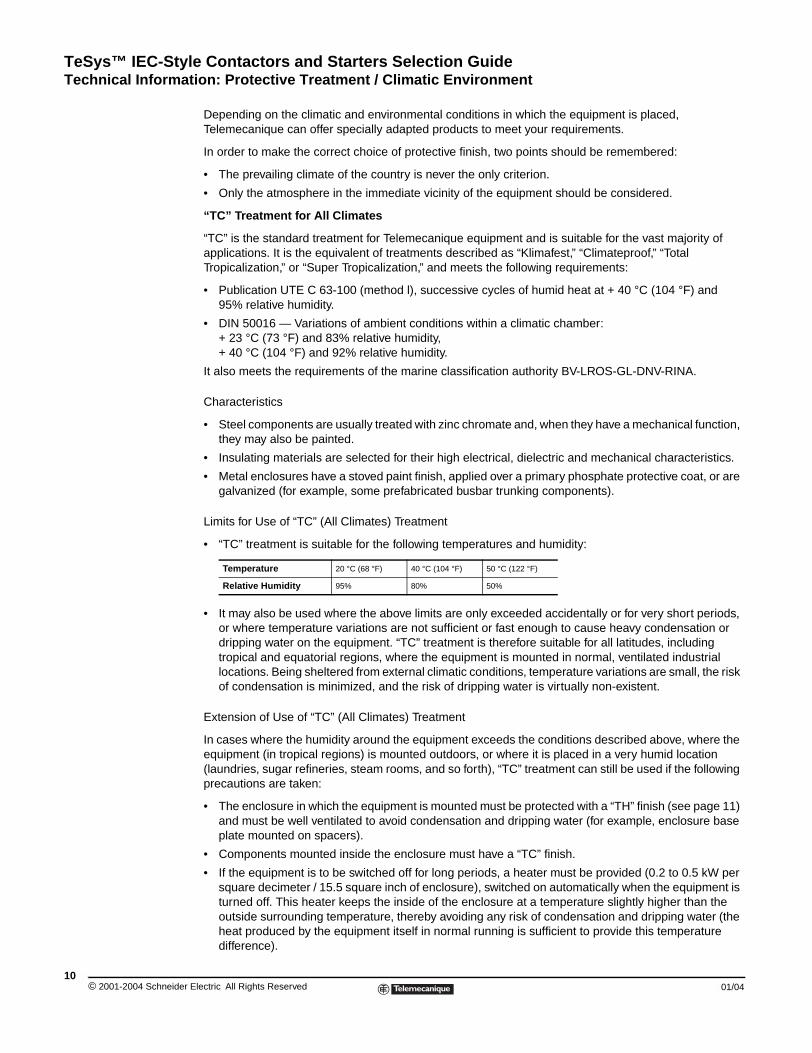
Limits for Use of “TC” (All Climates) Treatment
• “TC” treatment is suitable for the following temperatures and humidity:
• It may also be used where the above limits are only exceeded accidentally or for very short periods, or where temperature variations are not sufficient or fast enough to cause heavy condensation or dripping water on the equipment. “TC” treatment is therefore suitable for all latitudes, including tropical and equatorial regions, where the equipment is mounted in normal, ventilated industrial locations. Being sheltered from external climatic conditions, temperature variations are small, the risk of condensation is minimized, and the risk of dripping water is virtually non-existent.
Extension of Use of “TC” (All Climates) Treatment
In cases where the humidity around the equipment exceeds the conditions described above, where the equipment (in tropical regions) is mounted outdoors, or where it is placed in a very humid location (laundries, sugar refineries, steam rooms, and so forth), “TC” treatment can still be used if the following precautions are taken:
• The enclosure in which the equipment is mounted must be protected with a “TH” finish (see page 11) and must be well ventilated to avoid condensation and dripping water (for example, enclosure base plate mounted on spacers).
• Components mounted inside the enclosure must have a “TC” finish.
• If the equipment is to be switched off for long periods, a heater must be provided (0.2 to 0.5 kW per square decimeter / 15.5 square inch of enclosure), switched on automatically when the equipment is turned off. This heater keeps the inside of the enclosure at a temperature slightly higher than the outside surrounding temperature, thereby avoiding any risk of condensation and dripping water (the heat produced by the equipment itself in normal running is sufficient to provide this temperature difference).
Temperature 20 °C (68 °F) 40 °C (104 °F) 50 °C (122 °F)
Relative Humidity 95% 80% 50%
lectric All Rights Reserved 01/04
TeSys™ IEC-Style Contactors and Starters Selection GuideTechnical Information: Protective Treatment / Climatic Environment
01/04
• For pilot devices, the use of “TC” treatment can be extended to outdoor use provided the enclosure is made of light alloys, zinc alloys, or plastic material. In this case, it is essential to ensure that the degree of protection against penetration of liquids and solid objects is suitable for the applications involved.
“TH” Treatment for Hot and Humid Environments
This treatment is for hot and humid atmospheres where installations are subject to condensation, dripping water, and the risk of fungi.
Plastic insulating components are also resistant to attacks from insects such as termites and cockroaches. These properties have led to this treatment being described as “Tropical Finish,” but this does not mean that all equipment installed in tropical and equatorial regions must have undergone “TH” treatment. On the other hand, certain operating conditions in temperate climates may well require the use of “TH”-treated equipment (see the Limits for Use of “TC” Treatment section on page 10).
The following are special characteristics of “TH” treatment:
• All insulating components are made of materials which are either resistant to fungi or treated with a fungicide, having increased resistance to creepage (Standards IEC 112, NF C 26-220, DIN 5348).
• Metal enclosures receive a top-coat of baked, fungicidal paint, applied over a rust inhibiting undercoat. Components with “TH” treatment may be subject to a surcharge (a large number of Telemecanique products are “TH” treated as standard and are, therefore, not subject to a price surcharge). Please consult our local representatives or agents.
Special Precautions for Electronic Equipment
Electronic products always meet the requirements of “TC” treatment. A number of them are “TH”-treated as standard.
Some electronic products (for example, programmable controllers, flush-mountable controllers CCX, and flush-mountable operator terminals XBT) necessitate the use of an enclosure providing a degree of protection to at least IP 54 (as defined by the standards IEC 60664 and NF C 20 040) for use in industrial applications or in environmental conditions requiring a “TH” treatment.
These electronic products, including flush-mountable products, must have a degree of protection to at least IP 20 (either provided by the enclosure itself or following installation) for restricted access locations where the degree of pollution does not exceed 2 (a test booth not containing machinery or other dust producing activities, for example).
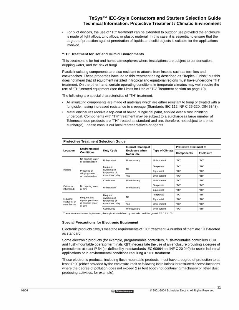
Protective Treatment Selection Guide
LocationEnvironmental Conditions
Duty CycleInternal Heating of Enclosure when Not in Use
Type of ClimateProtective Treatment of
Components Enclosure
Indoors
No dripping water or condensation
Unimportant Unnecessary Unimportant “TC” “TC”
Presence of dripping wateror condensation
Frequentswitching offfor periods ofmore than 1 day
NoTemperate “TC” “TH”
Equatorial “TH” “TH”
Yes Unimportant “TC” “TH”
Continuous Unnecessary Unimportant “TC” “TH”
Outdoors(sheltered)
No dripping wateror dew
Unimportant UnnecessaryTemperate “TC” “TC”
Equatorial “TH” “TH”
Exposedoutdoors, ornear the sea
Frequent andregular presenceof dripping wateror dew
Frequentswitching offfor periods ofmore than 1 day
NoTemperate “TC” “TH”
Equatorial “TH” “TH”
Yes Unimportant “TC” “TH”
Continuous Unnecessary Unimportant “TC” “TH”
These treatments cover, in particular, the applications defined by methods I and II of guide UTE C 63-100.
11© 2001-2004 Schneider Electric All Rights Reserved
TeSys™ IEC-Style Contactors and Starters Selection GuideTechnical Information: Degrees of Protection
© 2001-2004 Schneider E12
IEC 60529 ClassificatioFirst Characteristic Numeral
Corresponds to protection of the eqpenetration of solid objects and protedirect contact with live parts.
0
1
2
3
4
5
6
Technical Information: Degrees of Protection
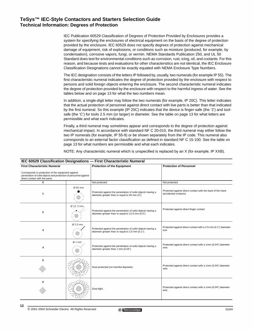
IEC Publication 60529 Classification of Degrees of Protection Provided by Enclosures provides a system for specifying the enclosures of electrical equipment on the basis of the degree of protection provided by the enclosure. IEC 60529 does not specify degrees of protection against mechanical damage of equipment, risk of explosions, or conditions such as moisture (produced, for example, by condensation), corrosive vapors, fungi, or vermin. NEMA Standards Publication 250, and UL 50 Standard does test for environmental conditions such as corrosion, rust, icing, oil, and coolants. For this reason, and because tests and evaluations for other characteristics are not identical, the IEC Enclosure Classification Designations cannot be exactly equated with NEMA Enclosure Type Numbers.
The IEC designation consists of the letters IP followed by, usually, two numerals (for example IP 55). The first characteristic numeral indicates the degree of protection provided by the enclosure with respect to persons and solid foreign objects entering the enclosure. The second characteristic numeral indicates the degree of protection provided by the enclosure with respect to the harmful ingress of water. See the tables below and on page 13 for what the two numbers mean.
In addition, a single-digit letter may follow the two numerals (for example, IP 20C). This letter indicates that the actual protection of personnel against direct contact with live parts is better than that indicated by the first numeral. So this example (IP 20C) indicates that the device is finger-safe (the ‘2’) and tool-safe (the ‘C’) for tools 2.5 mm (or larger) in diameter. See the table on page 13 for what letters are permissible and what each indicates.
Finally, a third numeral may sometimes appear and corresponds to the degree of protection against mechanical impact. In accordance with standard NF C 20-010, the third numeral may either follow the two IP numerals (for example, IP 55-9) or be shown separately from the IP code. This numeral also corresponds to an external factor classification as defined in standard NF C 15-100. See the table on page 13 for what numbers are permissible and what each indicates.
NOTE: Any characteristic numeral which is unspecified is replaced by an X (for example, IP XXB).
n Designations — First Characteristic Numeral
uipment against ction of personnel against
Protection of the Equipment Protection of Personnel
Not protected Not protected
Protected against the penetration of solid objects having a diameter greater than or equal to 50 mm (2”).
Protected against direct contact with the back of the hand (accidental contacts).
Protected against the penetration of solid objects having a diameter greater than or equal to 12.5 mm (0.5”).
Protected against direct finger contact.
Protected against the penetration of solid objects having a diameter greater than or equal to 2.5 mm (0.1”).
Protected against direct contact with a 2.5-mm (0.1”) diameter tool.
Protected against the penetration of solid objects having a diameter greater than 1 mm (0.04”).
Protected against direct contact with a 1mm (0.04”) diameter wire.
Dust-protected (no harmful deposits).Protected against direct contact with a 1mm (0.04”) diameter wire.
Dust-tight.Protected against direct contact with a 1mm (0.04”) diameter wire.
Ø 50 mm
Ø 12. 5 mm
Ø 2,5 mm
Ø 1 mm
lectric All Rights Reserved 01/04
TeSys™ IEC-Style Contactors and Starters Selection GuideTechnical Information: Degrees of Protection
01/04
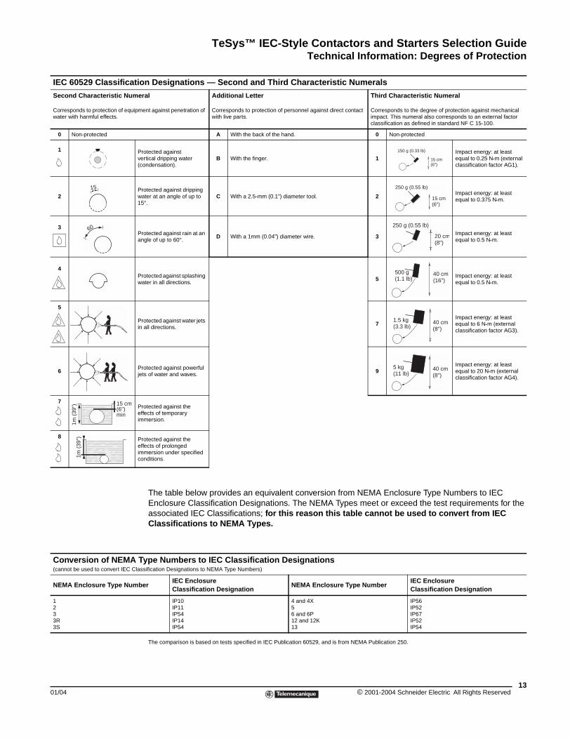
IEC 60529 Classificatio
Second Characteristic Nume
Corresponds to protection of equipmwater with harmful effects.
0 Non-protected
1 Pv(c
2Pw1
3Pa
4Pw
5
Pin
6 Pje
7Peim
8 Peimc
Conversion of NEMA T(cannot be used to convert IEC Cla
NEMA Enclosure Type Numb
1 2 3 3R 3S
15
60
1m (
39") 15 cm
(6")min
1m
(39
")
The table below provides an equivalent conversion from NEMA Enclosure Type Numbers to IEC Enclosure Classification Designations. The NEMA Types meet or exceed the test requirements for the associated IEC Classifications; for this reason this table cannot be used to convert from IEC Classifications to NEMA Types.
The comparison is based on tests specified in IEC Publication 60529, and is from NEMA Publication 250.
n Designations — Second and Third Characteristic Numerals
ral
ent against penetration of
Additional Letter
Corresponds to protection of personnel against direct contact with live parts.
Third Characteristic Numeral
Corresponds to the degree of protection against mechanical impact. This numeral also corresponds to an external factor classification as defined in standard NF C 15-100.
A With the back of the hand. 0 Non-protected
rotected against ertical dripping water ondensation).
B With the finger. 1Impact energy: at least equal to 0.25 N•m (external classification factor AG1).
rotected against dripping ater at an angle of up to 5°.
C With a 2.5-mm (0.1”) diameter tool. 2 Impact energy: at least equal to 0.375 N•m.
rotected against rain at an ngle of up to 60°.
D With a 1mm (0.04”) diameter wire. 3 Impact energy: at least equal to 0.5 N•m.
rotected against splashing ater in all directions.
5 Impact energy: at least equal to 0.5 N•m.
rotected against water jets all directions.
7Impact energy: at least equal to 6 N•m (external classification factor AG3).
rotected against powerful ts of water and waves.
9Impact energy: at least equal to 20 N•m (external classification factor AG4).
rotected against the ffects of temporary mersion.
rotected against the ffects of prolonged mersion under specified
onditions.
ype Numbers to IEC Classification Designations ssification Designations to NEMA Type Numbers)
er IEC Enclosure Classification Designation
NEMA Enclosure Type Number IEC Enclosure Classification Designation
IP10 IP11 IP54 IP14 IP54
4 and 4X 5 6 and 6P 12 and 12K 13
IP56 IP52 IP67 IP52 IP54
150 g (0.33 lb)
15 cm(6")
250 g (0.55 lb)
15 cm(6")
250 g (0.55 lb)
20 cm(8")
500 g(1.1 lb)
40 cm(16")
1.5 kg(3.3 lb)
40 cm(8")
5 kg(11 lb)
40 cm(8")
13© 2001-2004 Schneider Electric All Rights Reserved
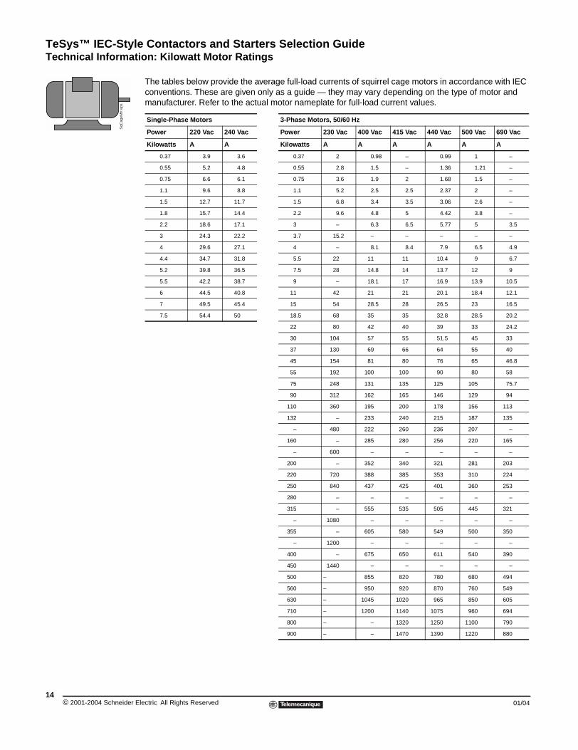
TeSys™ IEC-Style Contactors and Starters Selection GuideTechnical Information: Kilowatt Motor Ratings
© 2001-2004 Schneider E14
SqC
ageM
tr.e
ps
Technical Information: Kilowatt Motor Ratings
The tables below provide the average full-load currents of squirrel cage motors in accordance with IEC conventions. These are given only as a guide — they may vary depending on the type of motor and manufacturer. Refer to the actual motor nameplate for full-load current values.
Single-Phase Motors 3-Phase Motors, 50/60 Hz
Power 220 Vac 240 Vac Power 230 Vac 400 Vac 415 Vac 440 Vac 500 Vac 690 Vac
Kilowatts A A Kilowatts A A A A A A
0.37 3.9 3.6 0.37 2 0.98 – 0.99 1 –
0.55 5.2 4.8 0.55 2.8 1.5 – 1.36 1.21 –
0.75 6.6 6.1 0.75 3.6 1.9 2 1.68 1.5 –
1.1 9.6 8.8 1.1 5.2 2.5 2.5 2.37 2 –
1.5 12.7 11.7 1.5 6.8 3.4 3.5 3.06 2.6 –
1.8 15.7 14.4 2.2 9.6 4.8 5 4.42 3.8 –
2.2 18.6 17.1 3 – 6.3 6.5 5.77 5 3.5
3 24.3 22.2 3.7 15.2 – – – – –
4 29.6 27.1 4 – 8.1 8.4 7.9 6.5 4.9
4.4 34.7 31.8 5.5 22 11 11 10.4 9 6.7
5.2 39.8 36.5 7.5 28 14.8 14 13.7 12 9
5.5 42.2 38.7 9 – 18.1 17 16.9 13.9 10.5
6 44.5 40.8 11 42 21 21 20.1 18.4 12.1
7 49.5 45.4 15 54 28.5 28 26.5 23 16.5
7.5 54.4 50 18.5 68 35 35 32.8 28.5 20.2
22 80 42 40 39 33 24.2
30 104 57 55 51.5 45 33
37 130 69 66 64 55 40
45 154 81 80 76 65 46.8
55 192 100 100 90 80 58
75 248 131 135 125 105 75.7
90 312 162 165 146 129 94
110 360 195 200 178 156 113
132 – 233 240 215 187 135
– 480 222 260 236 207 –
160 – 285 280 256 220 165
– 600 – – – – –
200 – 352 340 321 281 203
220 720 388 385 353 310 224
250 840 437 425 401 360 253
280 – – – – – –
315 – 555 535 505 445 321
– 1080 – – – – –
355 – 605 580 549 500 350
– 1200 – – – – –
400 – 675 650 611 540 390
450 1440 – – – – –
500 – 855 820 780 680 494
560 – 950 920 870 760 549
630 – 1045 1020 965 850 605
710 – 1200 1140 1075 960 694
800 – – 1320 1250 1100 790
900 – – 1470 1390 1220 880
lectric All Rights Reserved 01/04
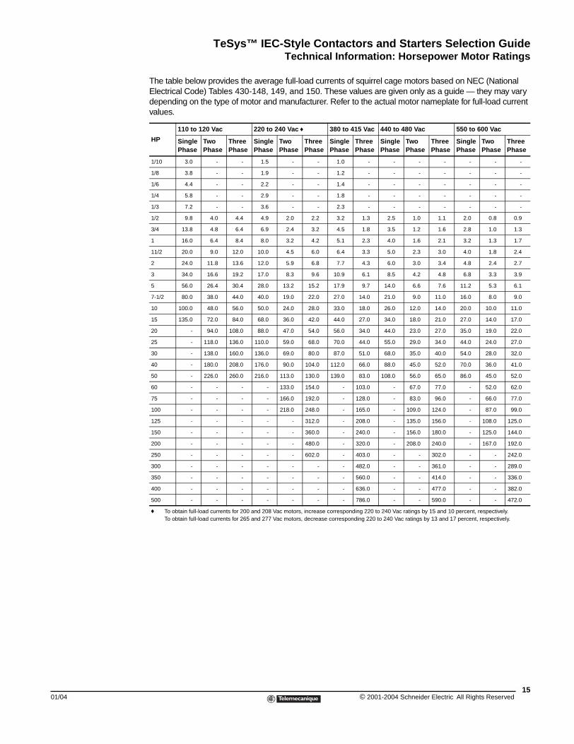
TeSys™ IEC-Style Contactors and Starters Selection GuideTechnical Information: Horsepower Motor Ratings
01/04
Technical Information: Horsepower Motor Ratings
The table below provides the average full-load currents of squirrel cage motors based on NEC (National Electrical Code) Tables 430-148, 149, and 150. These values are given only as a guide — they may vary depending on the type of motor and manufacturer. Refer to the actual motor nameplate for full-load current values.
HP
110 to 120 Vac 220 to 240 Vac f 380 to 415 Vac 440 to 480 Vac 550 to 600 Vac
Single Phase
Two Phase
Three Phase
Single Phase
Two Phase
Three Phase
Single Phase
Three Phase
Single Phase
Two Phase
Three Phase
Single Phase
Two Phase
Three Phase
1/10 3.0 - - 1.5 - - 1.0 - - - - - - -
1/8 3.8 - - 1.9 - - 1.2 - - - - - - -
1/6 4.4 - - 2.2 - - 1.4 - - - - - - -
1/4 5.8 - - 2.9 - - 1.8 - - - - - - -
1/3 7.2 - - 3.6 - - 2.3 - - - - - - -
1/2 9.8 4.0 4.4 4.9 2.0 2.2 3.2 1.3 2.5 1.0 1.1 2.0 0.8 0.9
3/4 13.8 4.8 6.4 6.9 2.4 3.2 4.5 1.8 3.5 1.2 1.6 2.8 1.0 1.3
1 16.0 6.4 8.4 8.0 3.2 4.2 5.1 2.3 4.0 1.6 2.1 3.2 1.3 1.7
11/2 20.0 9.0 12.0 10.0 4.5 6.0 6.4 3.3 5.0 2.3 3.0 4.0 1.8 2.4
2 24.0 11.8 13.6 12.0 5.9 6.8 7.7 4.3 6.0 3.0 3.4 4.8 2.4 2.7
3 34.0 16.6 19.2 17.0 8.3 9.6 10.9 6.1 8.5 4.2 4.8 6.8 3.3 3.9
5 56.0 26.4 30.4 28.0 13.2 15.2 17.9 9.7 14.0 6.6 7.6 11.2 5.3 6.1
7-1/2 80.0 38.0 44.0 40.0 19.0 22.0 27.0 14.0 21.0 9.0 11.0 16.0 8.0 9.0
10 100.0 48.0 56.0 50.0 24.0 28.0 33.0 18.0 26.0 12.0 14.0 20.0 10.0 11.0
15 135.0 72.0 84.0 68.0 36.0 42.0 44.0 27.0 34.0 18.0 21.0 27.0 14.0 17.0
20 - 94.0 108.0 88.0 47.0 54.0 56.0 34.0 44.0 23.0 27.0 35.0 19.0 22.0
25 - 118.0 136.0 110.0 59.0 68.0 70.0 44.0 55.0 29.0 34.0 44.0 24.0 27.0
30 - 138.0 160.0 136.0 69.0 80.0 87.0 51.0 68.0 35.0 40.0 54.0 28.0 32.0
40 - 180.0 208.0 176.0 90.0 104.0 112.0 66.0 88.0 45.0 52.0 70.0 36.0 41.0
50 - 226.0 260.0 216.0 113.0 130.0 139.0 83.0 108.0 56.0 65.0 86.0 45.0 52.0
60 - - - - 133.0 154.0 - 103.0 - 67.0 77.0 - 52.0 62.0
75 - - - - 166.0 192.0 - 128.0 - 83.0 96.0 - 66.0 77.0
100 - - - - 218.0 248.0 - 165.0 - 109.0 124.0 - 87.0 99.0
125 - - - - - 312.0 - 208.0 - 135.0 156.0 - 108.0 125.0
150 - - - - - 360.0 - 240.0 - 156.0 180.0 - 125.0 144.0
200 - - - - - 480.0 - 320.0 - 208.0 240.0 - 167.0 192.0
250 - - - - - 602.0 - 403.0 - - 302.0 - - 242.0
300 - - - - - - - 482.0 - - 361.0 - - 289.0
350 - - - - - - - 560.0 - - 414.0 - - 336.0
400 - - - - - - - 636.0 - - 477.0 - - 382.0
500 - - - - - - - 786.0 - - 590.0 - - 472.0
f To obtain full-load currents for 200 and 208 Vac motors, increase corresponding 220 to 240 Vac ratings by 15 and 10 percent, respectively. To obtain full-load currents for 265 and 277 Vac motors, decrease corresponding 220 to 240 Vac ratings by 13 and 17 percent, respectively.
15© 2001-2004 Schneider Electric All Rights Reserved
TeSys™ IEC-Style Contactors and Starters Selection GuideDefinitions of Utilization Categories
© 2001-2004 Schneider E16
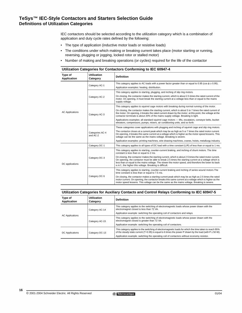
Definitions of Utilization Categories
IEC contactors should be selected according to the utilization category which is a combination of application and duty cycle rates defined by the following:
• The type of application (inductive motor loads or resistive loads)
• The conditions under which making or breaking current takes place (motor starting or running, reversing, plugging or jogging, locked rotor or stalled motor)
• Number of making and breaking operations (or cycles) required for the life of the contactor
Utilization Categories for Contactors Conforming to IEC 60947-4
Type of Application
Utilization Category
Definition
AC Applications
Category AC-1This category applies to AC loads with a power factor greater than or equal to 0.95 (cos ϕ ≥ 0.95).
Application examples: heating, distribution.
Category AC-2
This category applies to starting, plugging, and inching of slip ring motors.
On closing, the contactor makes the starting current, which is about 2.5 times the rated current of the motor. On opening, it must break the starting current at a voltage less than or equal to the mains supply voltage.
Category AC-3
This category applies to squirrel cage motors with breaking during normal running of the motor.
On closing, the contactor makes the starting current, which is about 5 to 7 times the rated current of the motor. On opening, it breaks the rated current drawn by the motor; at this point, the voltage at the contactor terminals is about 20% of the mains supply voltage. Breaking is light.
Applications examples: all standard squirrel cage motors — lifts, escalators, conveyor belts, bucket elevators, compressors, pumps, mixers, air conditioning units, and so forth.
Categories AC-4 and AC-2
These categories cover applications with plugging and inching of squirrel cage and slip ring motors.
The contactor closes at a current peak which may be as high as 5 or 7 times the rated motor current. On opening, it breaks this same current at a voltage which is higher as the motor speed lessens. This voltage can be the same as the mains voltage. Breaking is severe.
Application examples: printing machines, wire drawing machines, cranes, hoists, metallurgy industry.
DC applications
Category DC-1 This category applies to all types of DC load with a time constant (L/R) of less than or equal to 1 ms.
Category DC-3
This category applies to starting, counter-current braking, and inching of shunt motors. The time constant is less than or equal to 2 ms.
On closing, the contactor makes the starting current, which is about 2.5 times the rated motor current. On opening, the contactor must be able to break 2.5 times the starting current at a voltage which is less than or equal to the mains voltage. The slower the motor speed, and therefore the lower its back e.m.f., the higher this voltage. Breaking is difficult.
Category DC-5
This category applies to starting, counter-current braking and inching of series wound motors.The time constant is less than or equal to 7.5 ms.
On closing, the contactor makes a starting current peak which may be as high as 2.5 times the rated motor current. On opening, the contactor breaks this same current at a voltage which is higher as the motor speed lessens. This voltage can be the same as the mains voltage. Breaking is severe.
Utilization Categories for Auxiliary Contacts and Control Relays Conforming to IEC 60947-5
Type of Application
Utilization Category
Definition
AC Applications
Category AC-14This category applies to the switching of electromagnetic loads whose power drawn with the electromagnet closed is less than 72 VA.
Application example: switching the operating coil of contactors and relays.
Category AC-15This category applies to the switching of electromagnetic loads whose power drawn with the electromagnet closed is greater than 72 VA.
Application example: switching the operating coil of contactors.
DC Applications Category DC-13This category applies to the switching of electromagnetic loads for which the time taken to reach 95% of the steady state current (T=0.95) is equal to 6 times the power P drawn by the load (with P ≤ 50 W).
Application example: switching the operating coil of contactors without economy resistor.
lectric All Rights Reserved 01/04
TeSys™ IEC-Style Contactors and Starters Selection GuideDefinitions of Utilization Categories
01/04
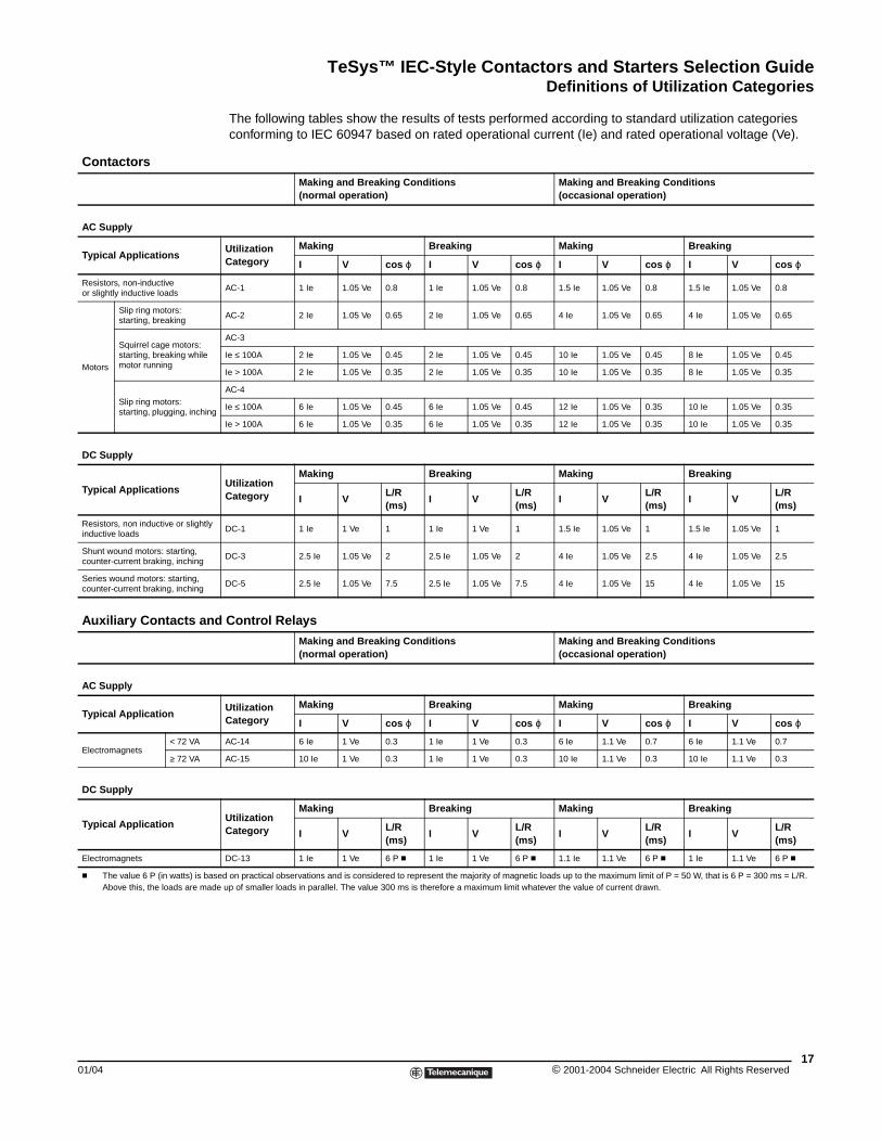
Contactors
AC Supply
Typical Applications
Resistors, non-inductive or slightly inductive loads
Motors
Slip ring motors: starting, breaking
Squirrel cage motors: starting, breaking while motor running
Slip ring motors: starting, plugging, inching
DC Supply
Typical Applications
Resistors, non inductive or slightly inductive loads
Shunt wound motors: starting, counter-current braking, inching
Series wound motors: starting, counter-current braking, inching
Auxiliary Contacts and
AC Supply
Typical Application
Electromagnets< 72 VA
≥ 72 VA
DC Supply
Typical Application
Electromagnets
c The value 6 P (in watts) is basAbove this, the loads are mad
The following tables show the results of tests performed according to standard utilization categories conforming to IEC 60947 based on rated operational current (Ie) and rated operational voltage (Ve).
Making and Breaking Conditions(normal operation)
Making and Breaking Conditions(occasional operation)
Utilization Category
Making Breaking Making Breaking
I V cos ϕ I V cos ϕ I V cos ϕ I V cos ϕ
AC-1 1 Ie 1.05 Ve 0.8 1 Ie 1.05 Ve 0.8 1.5 Ie 1.05 Ve 0.8 1.5 Ie 1.05 Ve 0.8
AC-2 2 Ie 1.05 Ve 0.65 2 Ie 1.05 Ve 0.65 4 Ie 1.05 Ve 0.65 4 Ie 1.05 Ve 0.65
AC-3
Ie ≤ 100A 2 Ie 1.05 Ve 0.45 2 Ie 1.05 Ve 0.45 10 Ie 1.05 Ve 0.45 8 Ie 1.05 Ve 0.45
Ie > 100A 2 Ie 1.05 Ve 0.35 2 Ie 1.05 Ve 0.35 10 Ie 1.05 Ve 0.35 8 Ie 1.05 Ve 0.35
AC-4
Ie ≤ 100A 6 Ie 1.05 Ve 0.45 6 Ie 1.05 Ve 0.45 12 Ie 1.05 Ve 0.35 10 Ie 1.05 Ve 0.35
Ie > 100A 6 Ie 1.05 Ve 0.35 6 Ie 1.05 Ve 0.35 12 Ie 1.05 Ve 0.35 10 Ie 1.05 Ve 0.35
Utilization Category
Making Breaking Making Breaking
I VL/R (ms)
I VL/R (ms)
I VL/R (ms)
I VL/R (ms)
DC-1 1 Ie 1 Ve 1 1 Ie 1 Ve 1 1.5 Ie 1.05 Ve 1 1.5 Ie 1.05 Ve 1
DC-3 2.5 Ie 1.05 Ve 2 2.5 Ie 1.05 Ve 2 4 Ie 1.05 Ve 2.5 4 Ie 1.05 Ve 2.5
DC-5 2.5 Ie 1.05 Ve 7.5 2.5 Ie 1.05 Ve 7.5 4 Ie 1.05 Ve 15 4 Ie 1.05 Ve 15
Control Relays
Making and Breaking Conditions(normal operation)
Making and Breaking Conditions(occasional operation)
Utilization Category
Making Breaking Making Breaking
I V cos ϕ I V cos ϕ I V cos ϕ I V cos ϕ
AC-14 6 Ie 1 Ve 0.3 1 Ie 1 Ve 0.3 6 Ie 1.1 Ve 0.7 6 Ie 1.1 Ve 0.7
AC-15 10 Ie 1 Ve 0.3 1 Ie 1 Ve 0.3 10 Ie 1.1 Ve 0.3 10 Ie 1.1 Ve 0.3
Utilization Category
Making Breaking Making Breaking
I VL/R (ms)
I VL/R (ms)
I VL/R (ms)
I VL/R (ms)
DC-13 1 Ie 1 Ve 6 P c 1 Ie 1 Ve 6 P c 1.1 Ie 1.1 Ve 6 P c 1 Ie 1.1 Ve 6 P c
ed on practical observations and is considered to represent the majority of magnetic loads up to the maximum limit of P = 50 W, that is 6 P = 300 ms = L/R. e up of smaller loads in parallel. The value 300 ms is therefore a maximum limit whatever the value of current drawn.
17© 2001-2004 Schneider Electric All Rights Reserved
TeSys™ IEC-Style Contactors and Starters Selection GuideContactor Selection for Utilization Category AC-3
© 2001-2004 Schneider E18
Contactor Selection for Utilization Category AC-3
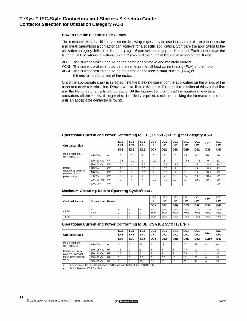
How to Use the Electrical Life Curves
The contactor electrical life curves on the following pages may be used to estimate the number of make and break operations a contactor can achieve for a specific application. Compare the application to the utilization category definitions listed on page 16 and select the appropriate chart. Each chart shows the Number of Operations in Millions on the Y axis and the Current Broken in Amps on the X axis.
AC-1 The current broken should be the same as the make and maintain current.AC-3 The current broken should be the same as the full load current rating (FLA) of the motor.AC-4 The current broken should be the same as the locked rotor current (LRA) or
6 times full-load current of the motor.
Once the appropriate chart is selected, find the breaking current of the application on the X axis of the chart and draw a vertical line. Draw a vertical line at this point. Find the intersection of this vertical line and the life curve of a particular contactor. At the intersection point read the number of electrical operations off the Y axis. If longer electrical life is required, continue checking the intersection points until an acceptable contactor is found.
Operational Current and Power Conforming to IEC (θ ≤ 55°C [131 °F]) for Category AC-3
Contactor SizeLC1LP1
LC1LC1
LC1LP1
LC1LP1
LC1LP1
LC1LP1
LC1LP1
LC1LP1
LC1LC1LP1
K06 K09 K12 D09 D12 D18 D25 D32 D38 D40Max. operationalcurrent (AC-3)
≤ 440 Vac A 6 9 12 9 12 18 25 32 38 40
Rated operational power P(standard motor power ratings)
220/240 Vac kW 1.5 2.2 3 2.2 3 4 5.5 7.5 9 11
380/400 Vac kW 2.2 4 5.5 4 5.5 7.5 11 15 18.5 18.5
415 Vac kW 2.2 4 5.5 4 5.5 9 11 15 18.5 22
440 Vac kW 3 4 5.5 4 5.5 9 11 15 18.5 22
500 Vac kW 3 4 4 5.5 7.5 10 15 18.5 18.5 22
660/690 Vac kW 3 4 4 5.5 7.5 10 15 18.5 18.5 30
1000 Vac kW – – – – – – – – – 22
Maximum Operating Rate in Operating Cycles/Hour f
On-load Factor Operational PowerLC1LP1
LC1LP1
LC1LP1
LC1LP1
LC1LP1
LC1LC1LP1
D09 D12 D18 D25 D32 D38 D40
≤ 85%P – – – 1200 1200 1200 1200 1000 1000 1000
0.5 P – – – 3000 3000 2500 2500 2500 2500 2500
≤ 25% P – – – 1800 1800 1800 1800 1200 1200 1200
Operational Current and Power Conforming to UL, CSA (θ ≤ 55°C [131 °F])
Contactor SizeLC1LP1
LC1LP1
LC1LP1
LC1LP1
LC1LP1
LC1LP1
LC1LP1
LC1LP1
LC1LC1LP1
K06 K09 K12 D09 D12 D18 D25 D32 D38k D40Max. operationalcurrent (AC-3)
≤ 440 Vac A 6 9 12 9 12 18 25 32 – 40
Rated operationalpower P (standard motor power ratings) 60 Hz
200/208 Vac HP 1.5 2 3 2 3 5 7.5 10 – 10
230/240 Vac HP 1.5 3 3 2 3 5 7.5 10 – 10
460/480 Vac HP 3 5 7.5 5 7.5 10 15 20 – 30
575/600 Vac HP 3 5 10 7.5 10 15 20 30 – 30
f Depending on the operational power and the on-load factor (θ ≤ 55 °C [131 °F]). k Not UL Listed or CSA Certified.
lectric All Rights Reserved 01/04
TeSys™ IEC-Style Contactors and Starters Selection GuideContactor Selection for Utilization Category AC-3
01/04
Where: E = EstimaAC3 = NumbAC4 = NumbP = Propo
Example: A LC1D12 co
AC-3 breakinAC-4 breakin
E = 2,250,00
Operational Current an
Contactor Size
Max. operationalcurrent (AC-3)
≤ 440 Vac
Rated operational power P(standard motor power ratings)
220/240 Vac
380/400 Vac
415 Vac
440 Vac
500 Vac
660/690 Vac
1000 Vac
Maximum Operating Ra
On-load FactorOperational Power
≤ 85%P
0.5 P
≤ 25% P
Operational Current an
Contactor Size
Max. operationalcurrent (AC-3)
≤ 440 Vac
Rated operationalpower P (standard motor power ratings) 60 Hz
200/208 Vac
230/240 Vac
460/480 Vac
575/600 Vac
f Depending on the operational pk Not UL Listed or CSA Certified
In many applications there is a mixture of AC3 and AC4 duty. For these applications the electrical life of a particular contactor can be estimated by using the following formula:
ted electrical life for mixed duty applicationer of electrical operations taken from the 100% AC3 Duty Life Curveer of electrical operations taken for the 100% AC4 Duty Life Curvertion of AC-4 operations to total operations for the application, expressed as a percentage.
ntactor for a motor load of 7.5 HP at 460 Vac, 11 A, 15% AC4 duty.
g current is 11 Amps From chart: AC3 = 2,250,000 operationsg current is 66 Amps (approximate inrush) From chart: AC4 = 90,000 operations
0/[1 – (15/100) + (15/100) x (2,250,000 / 90,000)] = 489,130 operations for approximate electrical life
d Power Conforming to IEC (θ ≤ 55°C [131 °F]) for Category AC-3 LC1LP1
LC1LP1
LC1LP1
LC1 LC1 LC1 LC1 LC1 LC1 LC1 LC1 LC1 LC1 LC1 LC1
D50 D65 D80 D95 D115 D150 F185 F225 F265 F330 F400 F500 F630 F780 F800
A 50 65 80 95 115 150 185 225 265 330 400 500 630 780 800
kW 15 18.5 22 25 30 40 55 63 75 100 110 147 200 220 250
kW 22 30 37 45 55 75 90 110 132 160 200 250 335 400 450
kW 25 37 45 45 59 80 100 110 140 180 220 280 375 425 450
kW 30 37 45 45 59 80 100 110 140 200 250 295 400 425 450
kW 30 37 55 55 75 90 110 129 160 200 257 355 400 450 450
kW 33 37 45 45 80 100 110 129 160 220 280 335 450 475 475
kW 30 37 45 45 75 90 100 100 147 160 185 335 450 450 450
te in Operating Cycles/Hour fLC1LP1
LC1LP1
LC1LP1
LC1 LC1 LC1 LC1 LC1 LC1 LC1 LC1 LC1 LC1 LC1 LC1
D50 D65 D80 D95 D115 D150 F185 F225 F265 F330 F400 F500 F630 F780 F8001000 1000 750 750 750 750 750 750 750 750 500 500 500 500 500
2500 2500 2000 2000 2000 1200 2000 2000 2000 2000 1200 1200 1200 1200 600
1200 1200 1200 1200 1200 1200 1200 1200 1200 1200 1200 1200 1200 600 600
d Power Conforming to UL, CSA (θ ≤ 55°C [131 °F])LC1LP1
LC1LP1
LC1LP1
LC1 LC1 LC1 LC1 LC1 LC1 LC1 LC1 LC1 LC1 LC1 LC1
D50 D65 D80 D95 k D115 D150 F185 F225 k F265 F330 F400 F500 F630 F780 F800
A 50 65 80 – 115 150 185 – 265 330 400 500 630 780 800
HP 15 20 30 – 30 40 50 – 60 75 100 150 – – 350
HP 15 20 30 – 40 50 60 – 75 100 125 200 300 450 400
HP 40 50 60 – 75 100 125 – 150 200 250 400 600 900 900
HP 40 50 60 – 100 125 150 – 200 250 300 500 800 900 900
ower and the on-load factor (θ ≤ 55 °C [131 °F]). .
E AC3
1 P100--------- –
P100--------- AC3
AC4-----------×
+
--------------------------------------------------------------=
19© 2001-2004 Schneider Electric All Rights Reserved
TeSys™ IEC-Style Contactors and Starters Selection GuideContactor Selection for Utilization Category AC-3
© 2001-2004 Schneider E20
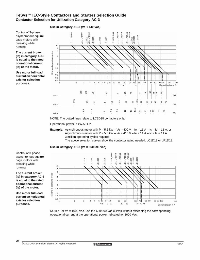
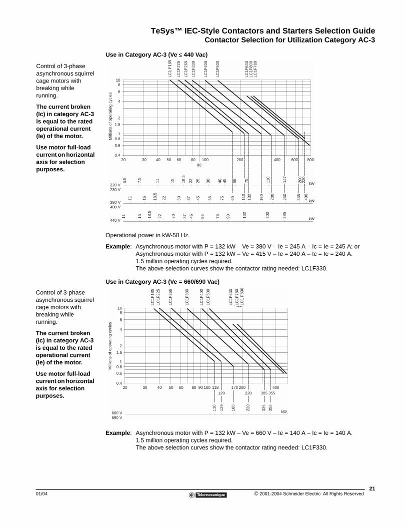
Control of 3-phase asynchronous squirrel cage motors with breaking while running.
The current broken (Ic) in category AC-3 is equal to the rated operational current (Ie) of the motor.
Use motor full-load current on horizontal axis for selection purposes.
Control of 3-phase asynchronous squirrel cage motors with breaking while running.
The current broken (Ic) in category AC-3 is equal to the rated operational current (Ie) of the motor.
Use motor full-load current on horizontal axis for selection purposes.
Use in Category AC-3 (Ve ≤ 440 Vac)
NOTE: The dotted lines relate to LC1D38 contactors only.
Operational power in kW-50 Hz.
Example: Asynchronous motor with P = 5.5 kW – Ve = 400 V – Ie = 11 A – Ic = Ie = 11 A; or Asynchronous motor with P = 5.5 kW – Ve = 415 V – Ie = 11 A – Ic = Ie = 11 A.3 million operating cycles required.The above selection curves show the contactor rating needed: LC1D18 or LP1D18.
Use in Category AC-3 (Ve = 660/690 Vac)
NOTE: For Ve = 1000 Vac, use the 660/690 Vac curves without exceeding the corresponding operational current at the operational power indicated for 1000 Vac.
21 3 4 5 6 7 8 9 10 12 15
18
20 302532
38 50 65 80 11595 1500.5 0.6
0.81
1.5
2
4
6
810
LC1D
09
LC1,
LP
1K09
LC1,
LP
1K06
LC1D
12
LC1,
LP
1K12
LC1D
18
LC1D
25
LC1D
32, D
38
LC1,
LP
1D40
LC1,
LP
1D50
LC1,
LP
1D65
LC1,
LP
1D80
LC1D
95LC
1D11
5
LC1
D15
0
2000.
55
0.75
1.5
2.2
4
4
5.5
7.5
11 15 18.5
22 25 30
230 V
400 V
0.75
1.5
2.2
4 5.5
7.5
11 15 18.5
22 30 37
kW
1.5
2.2
5.5
7.5
11 15 18.5
22 37 45 55 7530
440 V kW
kW
45 55 75
Mill
ions
of o
pera
ting
cycl
es
Current broken in A
0.6
0.81
1.5
2
3
4
6
810
LC1D
09
LC1D
12
LC1D
18
LC1D
25
LC1D
25, D
32
LC1,
LP
1D40
LC1,
LP
1D50
LC1,
LP
1D65
LC1,
LP
1D80
LC1D
95LC
1D11
5
LC1D
150
2001 2 3 4 5 6 7 896.6
1011
1517
2022 35
33 4042 48
50 60 9080 100
Mill
ions
of o
pera
ting
cycl
es
Current broken in A
lectric All Rights Reserved 01/04
TeSys™ IEC-Style Contactors and Starters Selection GuideContactor Selection for Utilization Category AC-3
01/04
Control of 3-phase asynchronous squirrel cage motors with breaking while running.
The current broken (Ic) in category AC-3 is equal to the rated operational current (Ie) of the motor.
Use motor full-load current on horizontal axis for selection purposes.
Control of 3-phase asynchronous squirrel cage motors with breaking while running.
The current broken (Ic) in category AC-3 is equal to the rated operational current (Ie) of the motor.
Use motor full-load current on horizontal axis for selection purposes.
Use in Category AC-3 (Ve ≤ 440 Vac)
Operational power in kW-50 Hz.
Example: Asynchronous motor with P = 132 kW – Ve = 380 V – Ie = 245 A – Ic = Ie = 245 A; or Asynchronous motor with P = 132 kW – Ve = 415 V – Ie = 240 A – Ic = Ie = 240 A.1.5 million operating cycles required.The above selection curves show the contactor rating needed: LC1F330.
Use in Category AC-3 (Ve = 660/690 Vac)
Example: Asynchronous motor with P = 132 kW – Ve = 660 V – Ie = 140 A – Ic = Ie = 140 A.1.5 million operating cycles required.The above selection curves show the contactor rating needed: LC1F330.
20 30 40 50 60 8090
100 400 800200 6000.4
0.81
1.5
2
4
6
810
5.5
7.5
11 15 18.5
22 25 30 40 55 110
11 15 18.5
22 30 37 45 55 75 90 110
132
160
200
250
335
400
11 15 18.5
22 30 37 45 55 75 90 132
200
285
45 75 200
220
147
220 V230 V
kW
kW
kW
380 V400 V
440 V
LC1
F18
5
LC1F
225
LC1F
265
LC1F
330
LC1F
400
LC1F
500
LC1F
780
LC1F
630
LC1F
800
0.6
Mill
ions
of o
pera
ting
cycl
es
0.6
0.81
1.5
2
4
6
810
20 30 40 50 60 80 90 100 400200118129
170220 305 355
LC1F
185
LC1F
225
LC1F
265
LC1F
330
LC1F
400
LC1F
500
LC1F
780
LC1
F80
0
LC1F
630
0.4
kW110
160
355
335
129
220
660 V690 V
Mill
ions
of o
pera
ting
cycl
es
21© 2001-2004 Schneider Electric All Rights Reserved
TeSys™ IEC-Style Contactors and Starters Selection GuideContactor Selection for Utilization Category AC-1
© 2001-2004 Schneider E22
Control of resistive circuits (powerfactor ≥ 0.95).
The current broken (Ic) in category AC-1 is equal to the current (Ie) normally drawn by the load.
Use motor full-load current on horizontal axis for selection purposes.
Contactor Selection for Utilization Category AC-1
Use in Category AC-1 (Ve ≤ 440 Vac)
Example: Ve = 220 V – Ie = 50 A (θ ≤ 40 °C) – Ic = Ie = 50 A.2 million operating cycles required.The above selection curves show the contactor rating needed: LC1D50 or LP1D50.
Maximum Operational Current (Open-mounted Device)
Contactor Size
LC1LC1
LC1LP1
LC1LP1
LC1LP1
LC1LP1
LC1LP1
LC1LP1
LC1LC1LP1
K09 K12 D09 D12 D18 D25 D32 D38 D40
Maximum operating rateoperating cycles/hour
600 600 600 600 600 600 600 600 600
Cabling to IEC 60947-1
cable c.s.a mm2 (AWG)4 (#12) 4 (#12) 4 (#12) 4 (#12) 6 (#10) 6 (#10) 10 (#8) 10 (#8) 16 (#6)
bar c.s.a. mm– – – – – – – – –
Operational current in A, in AC-1 according to the ambient temperature to IEC 60947-1
≤ 40 °C (104 °F) A 20 20 25 25 32 40 50 50 60
≤ 55 °C (131 °F) A 20 20 25 25 32 40 50 50 60
≤ 70 °C (158 °F) A (to Vc) f f 17 17 22 28 35 35 42
Maximum operational power ≤ 55°C
220/230 Vac kW 8 8 9 9 11 14 18 18 21
240 Vac kW 8 8 9 9 12 15 19 19 23
380/400 Vac kW 14 14 15 15 20 25 31 31 37
415 Vac kW 14 14 17 17 21 27 34 34 41
440 Vac kW 15 15 18 18 23 29 36 36 43
500 Vac kW 17 17 20 20 23 33 41 41 49
660/690 Vac kW 22 22 27 27 34 43 54 54 65
1000 Vac kW – – – – – – – – 70
f Please consult our local representatives or agents.
Increase in operation current by paralleling of poles: Apply the following multiplying factors to the current or power values given above. The factors take into account the often unbalanced current distribution between poles:
2 poles in parallel: K = 1.63 poles in parallel: K = 2.254 poles in parallel: K = 2.8
1 2 3 4 6 8 10 20 25 32 100 125 200 250 40040 50 60 80
8
10
6
4
21.5
10.8
0.6
0.4
0.2
0.1
LC1,
LP
1K09
LC1,
LP
1K12
LC1,
LP
1D09
LC1,
LP
1D12
LC1,
LP
1D18
LC1,
LP
1D25
LC1,
LP
1D32
, LC
1D38
LC1,
LP
1D40
LC1,
LP
1D50
LC1,
LP
1D65
LC1,
LP
1D80
LC1D
95
LC1D
115
LC1D
150
Mill
ions
of o
pera
ting
cycl
es
Current broken in A
lectric All Rights Reserved 01/04
TeSys™ IEC-Style Contactors and Starters Selection GuideContactor Selection for Utilization Category AC-1
01/04
Maximum Operational
Contactor Size
Maximum operating rateoperating cycles/hour
Cabling to IEC 60947-1
cable c.s.a
Number of Bars
bar c.s.a.
Operational current in A, in AC-1 according to the ambient temperature to IEC 60947-1
≤ 40 °C (104 °F)
≤ 55 °C (131 °F)
≤ 70 °C (158 °F)
Maximum operational power ≤ 55°C (131°F)
220/230 Vac
240 Vac
380/400 Vac
415 Vac
440 Vac
500 Vac
660/690 Vac
1000 Vac
Increase in operation current by pThe factors take into account the oft
2 poles in parallel: K = 1.6
Use in Category AC-1
Control of resistive circuits (powerfactor ≥ 0.95).
The current broken (Ic) in category AC-1 is equal to the current (Ie) normally drawn by the load.
Use motor full-load current on horizontal axis for selection purposes.
NOTE: The dotted lines relate to LC1F225 contactors only.
Example: Ve = 220 V – Ie = 500 A (θ ≤ 40 °C) – Ic = Ie = 500 A.2 million operating cycles required.The above selection curves show the contactor rating needed: LC1 F780.
Current (Open-mounted Device)LC1LP1
LC1LP1
LC1LP1
LC1 LC1 LC1 LC1 LC1 LC1 LC1 LC1 LC1 LC1 LC1 LC1
D50 D65 D80 D95D115
D150
F185 F225 F265 F330 F400 F500 F630 F780 F800
600 600 600 600 600 600 600 600 600 600 600 600 600 600 600
mm2
(AWG)25 (#4)
25 (#4)
50 (#0)
50 (#0)
120 (250 MCM)
120 (250 MCM)
150 (300 MCM)
185 (350 MCM)
185 (350 MCM)
240 (500 MCM)
– – – – –
– – – – – – – – – – 2 2 2 2 2
mm – – – – – – – – – – 30 x 5 40 x 5 60 x 5 100 x 5 60 x 5
inches – – – – – – – – – – 1.18 x 0.2 1.57 x 0.2 2.36 x 0.2 4.0 x 0.2 2.36 x 0.2
A 80 80 125 125 250 250 275 315 350 400 500 700 1000 1600 1000
A 80 80 125 125 200 200 275 280 300 360 430 580 850 1350 850
A (to Vc) 56 56 80 80 160 160 180 200 250 290 340 500 700 1100 700
kW 29 29 45 45 80 80 90 100 120 145 170 240 350 550 350
kW 31 31 49 49 83 83 95 110 125 160 180 255 370 570 370
kW 50 50 78 78 135 135 165 175 210 250 300 430 600 950 600
kW 54 54 85 85 140 140 170 185 220 260 310 445 630 1000 630
kW 58 58 90 90 150 150 180 200 230 290 330 470 670 1050 670
kW 65 65 102 102 170 170 200 220 270 320 380 660 750 1200 750
kW 86 86 135 135 235 235 280 300 370 400 530 740 1000 1650 1000
kW 85 100 120 120 345 345 410 450 540 640 760 950 1500 2400 1500
aralleling of poles: Apply the following multiplying factors to the current or power values given above. en unbalanced current distribution between poles:
3 poles in parallel: K = 2.254 poles in parallel:K = 2.8
(Ve ≤ 440 Vac)
810
6
4
2
10.8
0.6
0.4
0.2
0.1
Mill
ions
of o
pera
ting
cycl
es
20 40 50 60 80 100 200 250
275 500
600
700
800 1000 1600300
315
350
400 Current broken in A
LC1F
185,
F22
5
LC1F
265
LC1F
330
LC1F
400
LC1F
500
LC1F
630
LC1F
800
LC1F
780
23© 2001-2004 Schneider Electric All Rights Reserved
TeSys™ IEC-Style Contactors and Starters Selection GuideContactor Selection for Utilization Categories AC-2 and AC-4
© 2001-2004 Schneider E24
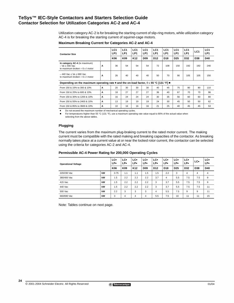
Contactor Selection for Utilization Categories AC-2 and AC-4
Utilization category AC-2 is for breaking the starting current of slip-ring motors, while utilization category AC-4 is for breaking the starting current of squirrel-cage motors.
Plugging
The current varies from the maximum plug-braking current to the rated motor current. The making current must be compatible with the rated making and breaking capacities of the contactor. As breaking normally takes place at a current value at or near the locked rotor current, the contactor can be selected using the criteria for categories AC-2 and AC-4.
Note: Tables continue on next page.
Maximum Breaking Current for Categories AC-2 and AC-4
Contactor Size
LC1LP1
LC1LP1
LC1LP1
LC1LP1
LC1LP1
LC1LP1
LC1LP1
LC1LP1
LC1LC1LP1
K06 K09 K12 D09 D12 D18 D25 D32 D38 D40
In category AC-4 (Ie maximum)– Ve ≤ 440 VacIe maximum broken = 6 x I motor
A 36 54 54 54 72 108 150 192 192 240
– 440 Vac ≤ Ve ≤ 690 VacIe maximum broken = 6 x I motor
A 26 40 40 40 50 70 90 105 105 150
Depending on the maximum operating rate f and the on-load factor, θ ≤ 55 °C [131 °F] c
From 150 & 15% to 300 & 10% A 20 30 30 30 40 45 75 80 80 110
From 150 & 20% to 600 & 10% A 18 27 27 27 36 40 67 70 70 96
From 150 & 30% to 1200 & 10% A 16 24 24 24 30 35 56 60 60 80
From 150 & 55% to 2400 & 10% A 13 19 19 19 24 30 45 50 50 62
From 150 & 85% to 3600 & 10% A 10 16 16 16 21 25 40 45 45 53
f Do not exceed the maximum number of mechanical operating cycles.c For temperatures higher than 55 °C (131 °F), use a maximum operating rate value equal to 80% of the actual value when
selecting from the above tables.
Permissible AC-4 Power Rating for 200,000 Operating Cycles
Operational Voltage
LC•LP•
LC•LP•
LC•LP•
LC•LP•
LC•LP•
LC•LP•
LC•LP•
LC•LP• LC• LC•
LP•K06 K09 K12 D09 D12 D18 D25 D32 D38 D40
220/230 Vac kW 0.75 1.1 1.1 1.5 1.5 2.2 3 4 4 4
380/400 Vac kW 1.5 2.2 2.2 2.2 3.7 4 5.5 7.5 7.5 9
415 Vac kW 1.5 2.2 2.2 2.2 3 3.7 5.5 7.5 7.5 9
440 Vac kW 1.5 2.2 2.2 2.2 3 3.7 5.5 7.5 7.5 11
500 Vac kW 2.2 3 3 3 4 5.5 7.5 9 9 11
660/690 Vac kW 3 4 4 4 5.5 7.5 10 11 11 15
lectric All Rights Reserved 01/04
TeSys™ IEC-Style Contactors and Starters Selection GuideContactor Selection for Utilization Categories AC-2 and AC-4
01/04
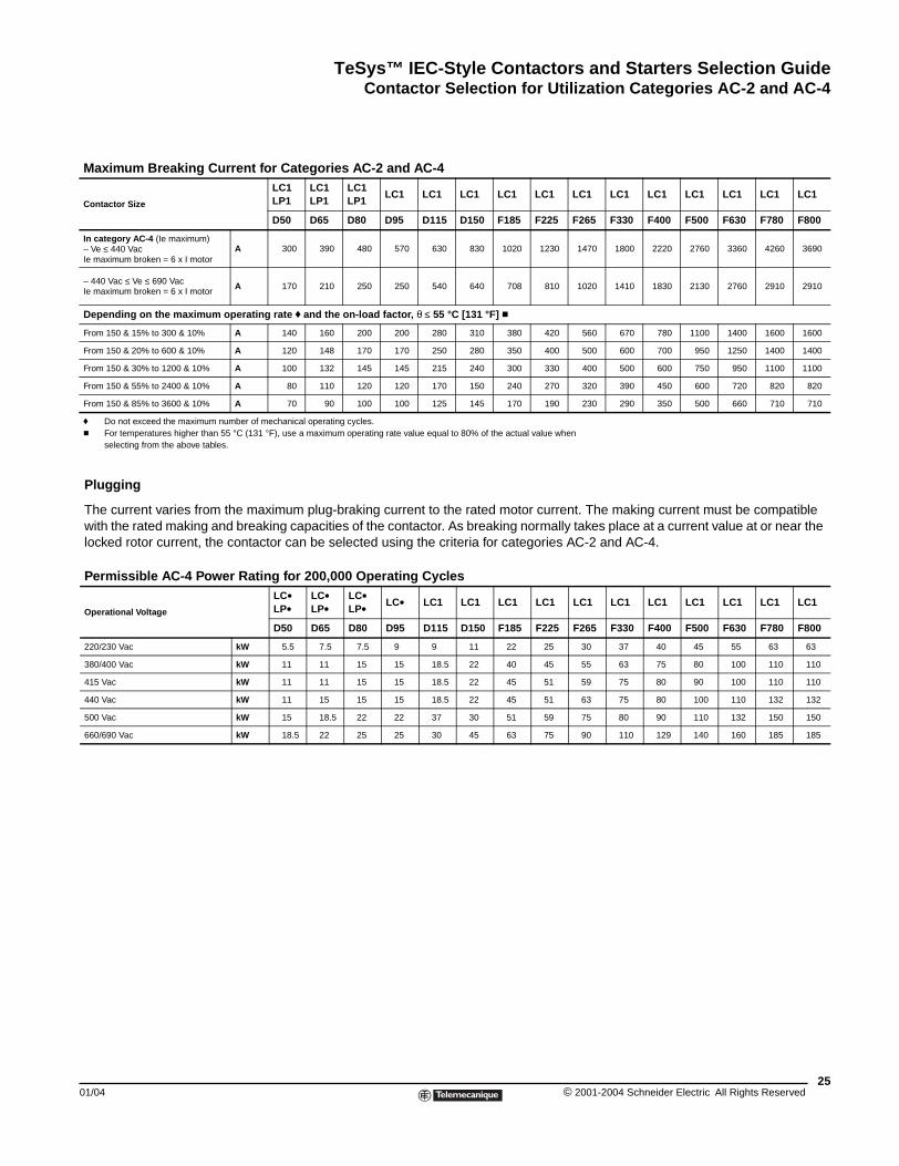
Maximum Breaking Cu
Contactor Size
In category AC-4 (Ie maximum)– Ve ≤ 440 VacIe maximum broken = 6 x I motor
– 440 Vac ≤ Ve ≤ 690 VacIe maximum broken = 6 x I motor
Depending on the maximum
From 150 & 15% to 300 & 10%
From 150 & 20% to 600 & 10%
From 150 & 30% to 1200 & 10%
From 150 & 55% to 2400 & 10%
From 150 & 85% to 3600 & 10%
f Do not exceed the maximum nc For temperatures higher than 5
selecting from the above table
Plugging
The current varies from with the rated making anlocked rotor current, the
Permissible AC-4 Pow
Operational Voltage
220/230 Vac
380/400 Vac
415 Vac
440 Vac
500 Vac
660/690 Vac
rrent for Categories AC-2 and AC-4 LC1LP1
LC1LP1
LC1LP1
LC1 LC1 LC1 LC1 LC1 LC1 LC1 LC1 LC1 LC1 LC1 LC1
D50 D65 D80 D95 D115 D150 F185 F225 F265 F330 F400 F500 F630 F780 F800
A 300 390 480 570 630 830 1020 1230 1470 1800 2220 2760 3360 4260 3690
A 170 210 250 250 540 640 708 810 1020 1410 1830 2130 2760 2910 2910
operating rate f and the on-load factor, θ ≤ 55 °C [131 °F] c
A 140 160 200 200 280 310 380 420 560 670 780 1100 1400 1600 1600
A 120 148 170 170 250 280 350 400 500 600 700 950 1250 1400 1400
A 100 132 145 145 215 240 300 330 400 500 600 750 950 1100 1100
A 80 110 120 120 170 150 240 270 320 390 450 600 720 820 820
A 70 90 100 100 125 145 170 190 230 290 350 500 660 710 710
umber of mechanical operating cycles.5 °C (131 °F), use a maximum operating rate value equal to 80% of the actual value when
s.
the maximum plug-braking current to the rated motor current. The making current must be compatible d breaking capacities of the contactor. As breaking normally takes place at a current value at or near the contactor can be selected using the criteria for categories AC-2 and AC-4.
er Rating for 200,000 Operating CyclesLC•LP•
LC•LP•
LC•LP• LC• LC1 LC1 LC1 LC1 LC1 LC1 LC1 LC1 LC1 LC1 LC1
D50 D65 D80 D95 D115 D150 F185 F225 F265 F330 F400 F500 F630 F780 F800
kW 5.5 7.5 7.5 9 9 11 22 25 30 37 40 45 55 63 63
kW 11 11 15 15 18.5 22 40 45 55 63 75 80 100 110 110
kW 11 11 15 15 18.5 22 45 51 59 75 80 90 100 110 110
kW 11 15 15 15 18.5 22 45 51 63 75 80 100 110 132 132
kW 15 18.5 22 22 37 30 51 59 75 80 90 110 132 150 150
kW 18.5 22 25 25 30 45 63 75 90 110 129 140 160 185 185
25© 2001-2004 Schneider Electric All Rights Reserved
TeSys™ IEC-Style Contactors and Starters Selection GuideContactor Selection for Utilization Categories AC-2 and AC-4
© 2001-2004 Schneider E26
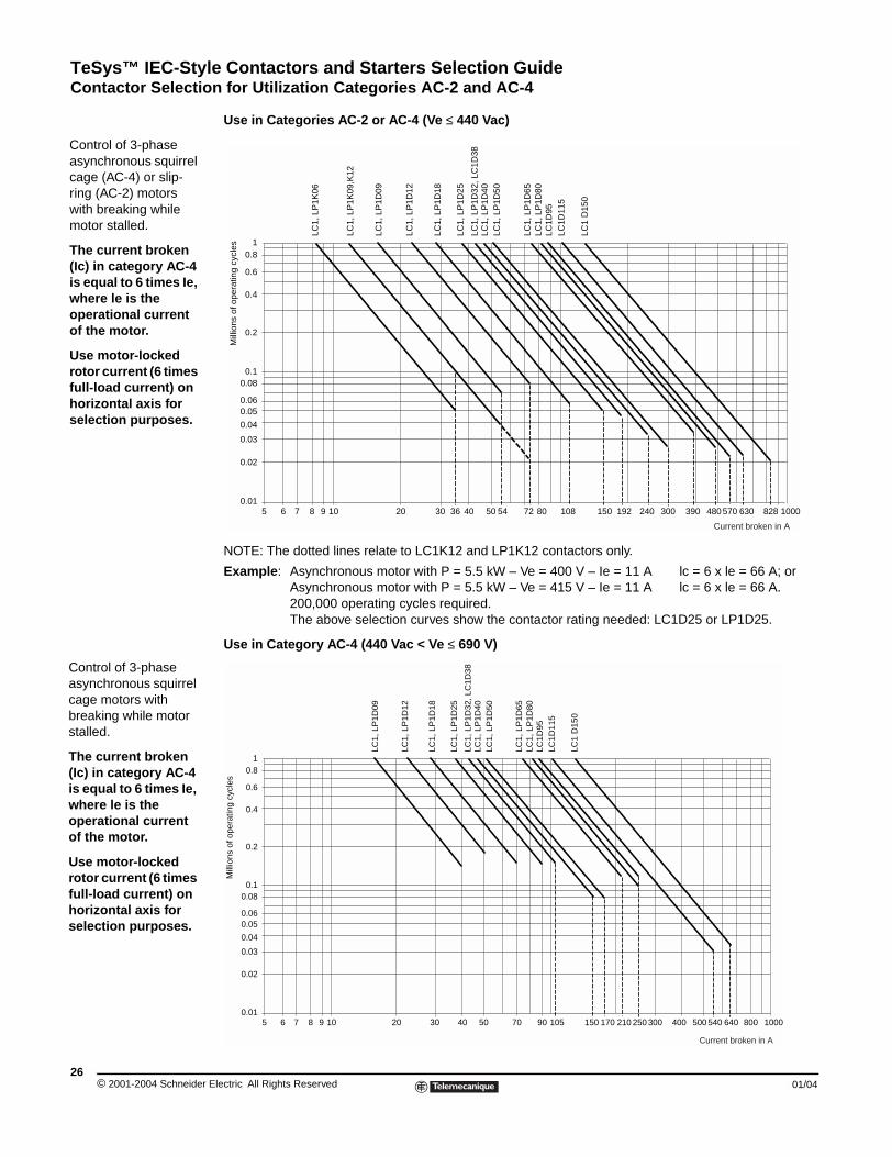
Control of 3-phase asynchronous squirrel cage (AC-4) or slip-ring (AC-2) motors with breaking while motor stalled.
The current broken (Ic) in category AC-4 is equal to 6 times Ie, where le is the operational current of the motor.
Use motor-locked rotor current (6 times full-load current) on horizontal axis for selection purposes.
Control of 3-phase asynchronous squirrel cage motors with breaking while motor stalled.
The current broken (Ic) in category AC-4 is equal to 6 times Ie, where le is the operational current of the motor.
Use motor-locked rotor current (6 times full-load current) on horizontal axis for selection purposes.
Use in Categories AC-2 or AC-4 (Ve ≤ 440 Vac)
NOTE: The dotted lines relate to LC1K12 and LP1K12 contactors only.
Example: Asynchronous motor with P = 5.5 kW – Ve = 400 V – Ie = 11 A lc = 6 x le = 66 A; orAsynchronous motor with P = 5.5 kW – Ve = 415 V – Ie = 11 A lc = 6 x le = 66 A.200,000 operating cycles required.The above selection curves show the contactor rating needed: LC1D25 or LP1D25.
Use in Category AC-4 (440 Vac < Ve ≤ 690 V)
5 6 7 8 9 10 20 30 36 40 50 54 8072 108 150 192 240 300 390 480 630 828 10005700.01
0.02
0.03
0.04
0.060.05
0.080.1
0.2
0.4
0.6
0.81
LC1,
LP
1D09
LC1,
LP
1D12
LC1,
LP
1D18
LC1,
LP
1D25
LC1,
LP
1D32
, LC
1D38
LC1,
LP
1D40
LC1,
LP
1D50
LC1,
LP
1D65
LC1,
LP
1D80
LC1D
95LC
1D11
5
LC1
D15
0
LC1,
LP
1K09
,K12
LC1,
LP
1K06
Mill
ions
of o
pera
ting
cycl
es
Current broken in A
5 6 7 8 9 10 20 30 40 50 9070 105 150 170 210 250 300 400 500 640 800 10005400.01
0.02
0.03
0.04
0.060.05
0.080.1
0.2
0.4
0.6
0.81
LC1,
LP
1D09
LC1,
LP
1D12
LC1,
LP
1D18
LC1,
LP
1D25
LC1,
LP
1D32
, LC
1D38
LC1,
LP
1D40
LC1,
LP
1D50
LC1,
LP
1D65
LC1,
LP
1D80
LC1D
95LC
1D11
5
LC1
D15
0
Mill
ions
of o
pera
ting
cycl
es
Current broken in A
lectric All Rights Reserved 01/04
TeSys™ IEC-Style Contactors and Starters Selection GuideContactor Selection for Utilization Categories AC-2 and AC-4
01/04
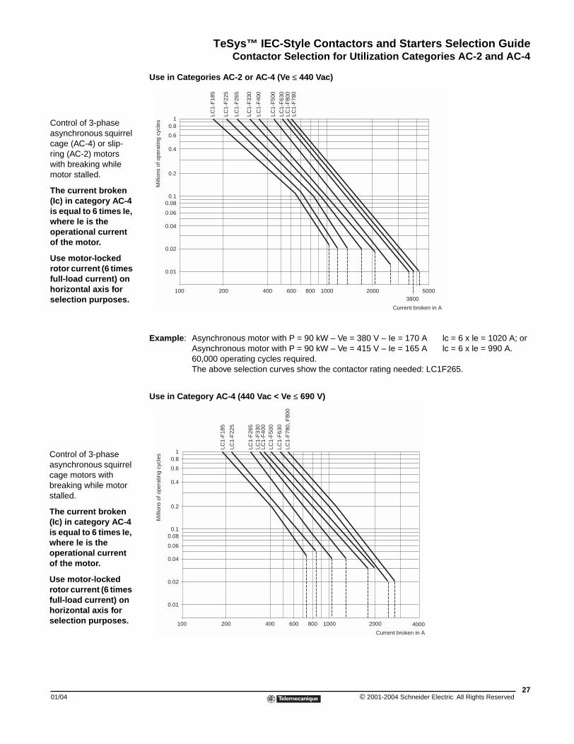
Control of 3-phase asynchronous squirrel cage (AC-4) or slip-ring (AC-2) motors with breaking while motor stalled.
The current broken (Ic) in category AC-4 is equal to 6 times Ie, where le is the operational current of the motor.
Use motor-locked rotor current (6 times full-load current) on horizontal axis for selection purposes.
Control of 3-phase asynchronous squirrel cage motors with breaking while motor stalled.
The current broken (Ic) in category AC-4 is equal to 6 times Ie, where le is the operational current of the motor.
Use motor-locked rotor current (6 times full-load current) on horizontal axis for selection purposes.
Use in Categories AC-2 or AC-4 (Ve ≤ 440 Vac)
Example: Asynchronous motor with P = 90 kW – Ve = 380 V – Ie = 170 A lc = 6 x le = 1020 A; orAsynchronous motor with P = 90 kW – Ve = 415 V – Ie = 165 A lc = 6 x le = 990 A.60,000 operating cycles required.The above selection curves show the contactor rating needed: LC1F265.
Use in Category AC-4 (440 Vac < Ve ≤ 690 V)
100 200 400 600 800 1000 20003800
5000
10.8
0.6
0.4
0.2
0.10.08
0.06
0.04
0.02
0.01
LC1-
F18
5
LC1-
F22
5
LC1-
F26
5
LC1-
F33
0
LC1-
F40
0
LC1-
F50
0
LC1-
F63
0LC
1-F
800
LC1-
F78
0
Current broken in A
Mill
ions
of o
pera
ting
cycl
es
100 200 400 600 800 1000 2000 4000
10.8
0.6
0.4
0.2
0.10.08
0.06
0.04
0.02
0.01
LC1-
F18
5
LC1-
F22
5
LC1-
F26
5LC
1-F
330
LC1-
F40
0LC
1-F
500
LC1-
F63
0LC
1-F
780,
F80
0
Current broken in A
Mill
ions
of o
pera
ting
cycl
es
27© 2001-2004 Schneider Electric All Rights Reserved
TeSys™ IEC-Style Contactors and Starters Selection GuideContactor Selection for Utilization Categories DC-1 to DC-5
© 2001-2004 Schneider E28
– +
– +
– +
– +
Contactor Selection for Utilization Categories DC-1 to DC-5
Continued on next page.
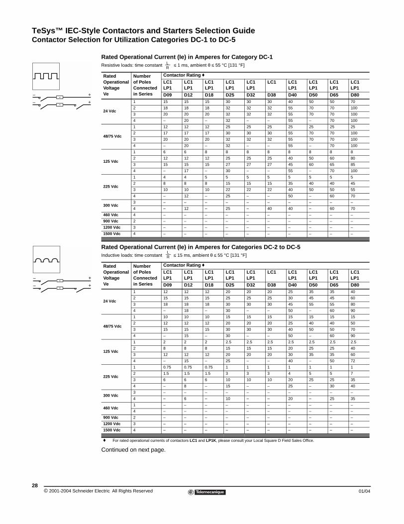
Rated Operational Current (Ie) in Amperes for Category DC-1Resistive loads: time constant ≤ 1 ms, ambient θ ≤ 55 °C [131 °F]
RatedOperationalVoltageVe
Number of PolesConnectedin Series
Contactor Rating f
LC1LP1
LC1LP1
LC1LP1
LC1LP1
LC1LP1
LC1 LC1LP1
LC1LP1
LC1LP1
LC1LP1
D09 D12 D18 D25 D32 D38 D40 D50 D65 D80
24 Vdc
1 15 15 15 30 30 30 40 50 50 70
2 18 18 18 32 32 32 55 70 70 100
3 20 20 20 32 32 32 55 70 70 100
4 – 20 – 32 – – 55 – 70 100
48/75 Vdc
1 12 12 12 25 25 25 25 25 25 25
2 17 17 17 30 30 30 55 70 70 100
3 20 20 20 32 32 32 55 70 70 100
4 – 20 – 32 – – 55 – 70 100
125 Vdc
1 6 6 8 8 8 8 8 8 8 8
2 12 12 12 25 25 25 40 50 60 80
3 15 15 15 27 27 27 45 60 65 85
4 – 17 – 30 – – 55 – 70 100
225 Vdc
1 4 4 5 5 5 5 5 5 5 5
2 8 8 8 15 15 15 35 40 40 45
3 10 10 10 22 22 22 40 50 50 55
4 – 12 – 25 – – 50 – 60 70
300 Vdc3 – – – – – – – – – –
4 – 12 – 25 – 40 40 – 60 70
460 Vdc 4 – – – – – – – – – –
900 Vdc 2 – – – – – – – – – –
1200 Vdc 3 – – – – – – – – – –
1500 Vdc 4 – – – – – – – – – –
Rated Operational Current (Ie) in Amperes for Categories DC-2 to DC-5Inductive loads: time constant ≤ 15 ms, ambient θ ≤ 55 °C [131 °F]
RatedOperationalVoltageVe
Number of PolesConnectedin Series
Contactor Rating f
LC1LP1
LC1LP1
LC1LP1
LC1LP1
LC1LP1
LC1 LC1LP1
LC1LP1
LC1LP1
LC1LP1
D09 D12 D18 D25 D32 D38 D40 D50 D65 D80
24 Vdc
1 12 12 12 20 20 20 25 35 35 40
2 15 15 15 25 25 25 30 45 45 60
3 18 18 18 30 30 30 45 55 55 80
4 – 18 – 30 – – 50 – 60 90
48/75 Vdc
1 10 10 10 15 15 15 15 15 15 15
2 12 12 12 20 20 20 25 40 40 50
3 15 15 15 30 30 30 40 50 50 70
4 – 15 – 30 – – 50 – 60 90
125 Vdc
1 2 2 2 2.5 2.5 2.5 2.5 2.5 2.5 2.5
2 8 8 8 15 15 15 20 25 25 40
3 12 12 12 20 20 20 30 35 35 60
4 – 15 – 25 – – 40 – 50 72
225 Vdc
1 0.75 0.75 0.75 1 1 1 1 1 1 1
2 1.5 1.5 1.5 3 3 3 4 5 5 7
3 6 6 6 10 10 10 20 25 25 35
4 – 8 – 15 – – 25 – 30 40
300 Vdc3 – – – – – – – – – –
4 – 6 – 10 – – 20 – 25 35
460 Vdc1 – – – – – – – – – –
4 – – – – – – – – – –
900 Vdc 2 – – – – – – – – – –
1200 Vdc 3 – – – – – – – – – –
1500 Vdc 4 – – – – – – – – – –
f For rated operational currents of contactors LC1 and LP1K, please consult your Local Square D Field Sales Office.
LR
LR
lectric All Rights Reserved 01/04
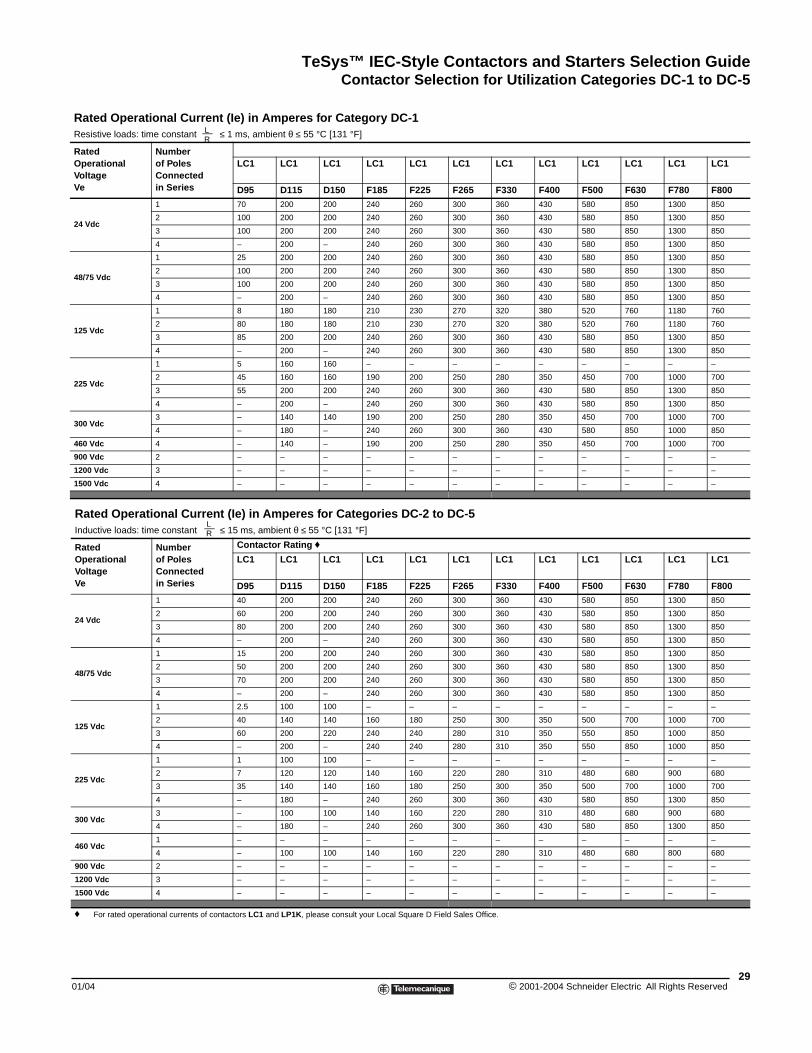
TeSys™ IEC-Style Contactors and Starters Selection GuideContactor Selection for Utilization Categories DC-1 to DC-5
01/04
Rated Operational CurResistive loads: time constant
RatedOperationalVoltageVe
Number of PolesConnectedin Series
24 Vdc
1
2
3
4
48/75 Vdc
1
2
3
4
125 Vdc
1
2
3
4
225 Vdc
1
2
3
4
300 Vdc3
4
460 Vdc 4
900 Vdc 2
1200 Vdc 3
1500 Vdc 4
Rated Operational CurInductive loads: time constant
RatedOperationalVoltageVe
Number of PolesConnectedin Series
24 Vdc
1
2
3
4
48/75 Vdc
1
2
3
4
125 Vdc
1
2
3
4
225 Vdc
1
2
3
4
300 Vdc3
4
460 Vdc1
4
900 Vdc 2
1200 Vdc 3
1500 Vdc 4
f For rated operational currents
rent (Ie) in Amperes for Category DC-1 ≤ 1 ms, ambient θ ≤ 55 °C [131 °F]
LC1 LC1 LC1 LC1 LC1 LC1 LC1 LC1 LC1 LC1 LC1 LC1
D95 D115 D150 F185 F225 F265 F330 F400 F500 F630 F780 F800
70 200 200 240 260 300 360 430 580 850 1300 850
100 200 200 240 260 300 360 430 580 850 1300 850
100 200 200 240 260 300 360 430 580 850 1300 850
– 200 – 240 260 300 360 430 580 850 1300 850
25 200 200 240 260 300 360 430 580 850 1300 850
100 200 200 240 260 300 360 430 580 850 1300 850
100 200 200 240 260 300 360 430 580 850 1300 850
– 200 – 240 260 300 360 430 580 850 1300 850
8 180 180 210 230 270 320 380 520 760 1180 760
80 180 180 210 230 270 320 380 520 760 1180 760
85 200 200 240 260 300 360 430 580 850 1300 850
– 200 – 240 260 300 360 430 580 850 1300 850
5 160 160 – – – – – – – – –
45 160 160 190 200 250 280 350 450 700 1000 700
55 200 200 240 260 300 360 430 580 850 1300 850
– 200 – 240 260 300 360 430 580 850 1300 850
– 140 140 190 200 250 280 350 450 700 1000 700
– 180 – 240 260 300 360 430 580 850 1000 850
– 140 – 190 200 250 280 350 450 700 1000 700
– – – – – – – – – – – –
– – – – – – – – – – – –
– – – – – – – – – – – –
rent (Ie) in Amperes for Categories DC-2 to DC-5 ≤ 15 ms, ambient θ ≤ 55 °C [131 °F]
Contactor Rating f
LC1 LC1 LC1 LC1 LC1 LC1 LC1 LC1 LC1 LC1 LC1 LC1
D95 D115 D150 F185 F225 F265 F330 F400 F500 F630 F780 F80040 200 200 240 260 300 360 430 580 850 1300 850
60 200 200 240 260 300 360 430 580 850 1300 850
80 200 200 240 260 300 360 430 580 850 1300 850
– 200 – 240 260 300 360 430 580 850 1300 850
15 200 200 240 260 300 360 430 580 850 1300 850
50 200 200 240 260 300 360 430 580 850 1300 850
70 200 200 240 260 300 360 430 580 850 1300 850
– 200 – 240 260 300 360 430 580 850 1300 850
2.5 100 100 – – – – – – – – –
40 140 140 160 180 250 300 350 500 700 1000 700
60 200 220 240 240 280 310 350 550 850 1000 850
– 200 – 240 240 280 310 350 550 850 1000 850
1 100 100 – – – – – – – – –
7 120 120 140 160 220 280 310 480 680 900 680
35 140 140 160 180 250 300 350 500 700 1000 700
– 180 – 240 260 300 360 430 580 850 1300 850
– 100 100 140 160 220 280 310 480 680 900 680
– 180 – 240 260 300 360 430 580 850 1300 850
– – – – – – – – – – – –
– 100 100 140 160 220 280 310 480 680 800 680
– – – – – – – – – – – –
– – – – – – – – – – – –
– – – – – – – – – – – –
of contactors LC1 and LP1K, please consult your Local Square D Field Sales Office.
LR
LR
29© 2001-2004 Schneider Electric All Rights Reserved
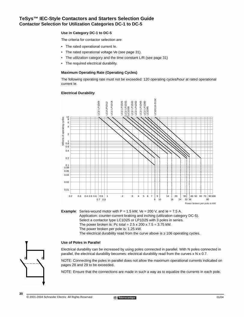
TeSys™ IEC-Style Contactors and Starters Selection GuideContactor Selection for Utilization Categories DC-1 to DC-5
© 2001-2004 Schneider E30
Use in Category DC-1 to DC-5
The criteria for contactor selection are:
• The rated operational current Ie.
• The rated operational voltage Ve (see page 31).
• The utilization category and the time constant L/R (see page 31)
• The required electrical durability.
Maximum Operating Rate (Operating Cycles)
The following operating rate must not be exceeded: 120 operating cycles/hour at rated operational current Ie.
Electrical Durability
Example: Series-wound motor with P = 1.5 kW, Ve = 200 V, and Ie = 7.5 A.Application: counter-current braking and inching (utilization category DC-5).Select a contactor type LC1D25 or LP1D25 with 3 poles in series.The power broken is: Pc total = 2.5 x 200 x 7.5 = 3.75 kW.The power broken per pole is: 1.25 kW.The electrical durability read from the curve above is ≥ 106 operating cycles.
Use of Poles in Parallel
Electrical durability can be increased by using poles connected in parallel. With N poles connected in parallel, the electrical durability becomes: electrical durability read from the curves x N x 0.7.
NOTE: Connecting the poles in parallel does not allow the maximum operational currents indicated on pages 28 and 29 to be exceeded.
NOTE: Ensure that the connections are made in such a way as to equalize the currents in each pole.
0.01
0.02
0.04
0.060.08
1
2
4
68
10
0.1
0.2
0.4
0.60.8
0.2 0.3 0.4 0.5 0.60.7
10.80.9
2 3 4 5 6 7 98 10 16
14 20 3024 32 36
40 50 60 70 9080
100
LC1/
LP
1D09
LC1/
LP1D
12
LC1/
LP
1D18
LC1/
LP
1D25
LC1/
LP
1D32
.LC
1D38
LC1/
LP
1D40
LC1/
LP
1D50
LC1/
LP
1D65
LC1/
LP
1D80
LC1D
95
LC1D
115
/D15
0
Mill
ions
of o
pera
ting
cycl
es
Power broken per pole in kW
lectric All Rights Reserved 01/04
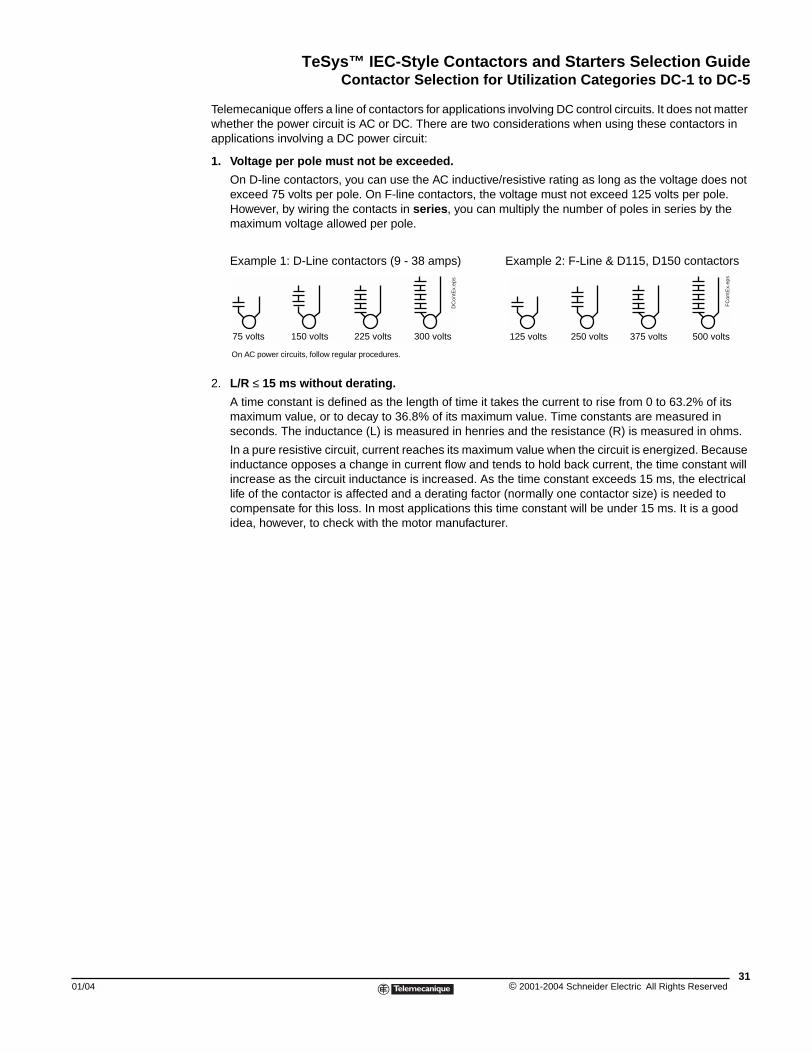
TeSys™ IEC-Style Contactors and Starters Selection GuideContactor Selection for Utilization Categories DC-1 to DC-5
01/04
Telemecanique offers a line of contactors for applications involving DC control circuits. It does not matter whether the power circuit is AC or DC. There are two considerations when using these contactors in applications involving a DC power circuit:
1. Voltage per pole must not be exceeded.
On D-line contactors, you can use the AC inductive/resistive rating as long as the voltage does not exceed 75 volts per pole. On F-line contactors, the voltage must not exceed 125 volts per pole. However, by wiring the contacts in series, you can multiply the number of poles in series by the maximum voltage allowed per pole.
Example 1: D-Line contactors (9 - 38 amps) Example 2: F-Line & D115, D150 contactors
2. L/R ≤ 15 ms without derating.
A time constant is defined as the length of time it takes the current to rise from 0 to 63.2% of its maximum value, or to decay to 36.8% of its maximum value. Time constants are measured in seconds. The inductance (L) is measured in henries and the resistance (R) is measured in ohms.
In a pure resistive circuit, current reaches its maximum value when the circuit is energized. Because inductance opposes a change in current flow and tends to hold back current, the time constant will increase as the circuit inductance is increased. As the time constant exceeds 15 ms, the electrical life of the contactor is affected and a derating factor (normally one contactor size) is needed to compensate for this loss. In most applications this time constant will be under 15 ms. It is a good idea, however, to check with the motor manufacturer.
75 volts 150 volts 225 volts 300 volts
DC
ontE
x.ep
s
125 volts 250 volts 375 volts 500 volts
FC
ontE
x.ep
s
On AC power circuits, follow regular procedures.
31© 2001-2004 Schneider Electric All Rights Reserved
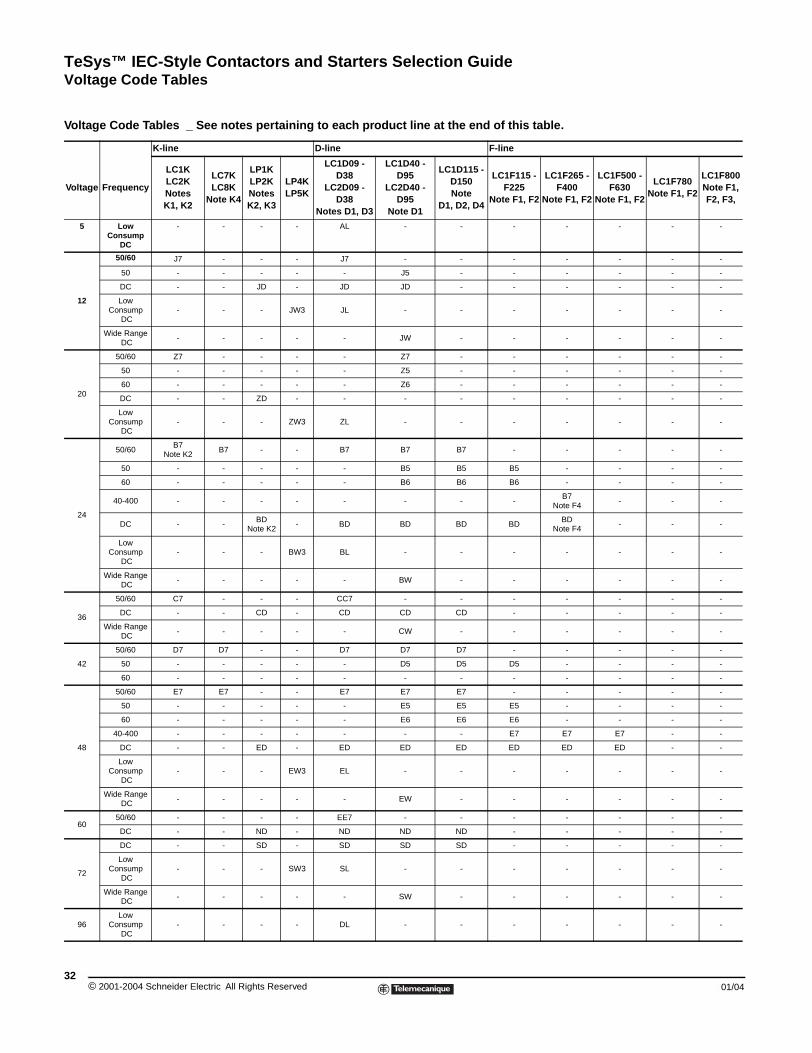
TeSys™ IEC-Style Contactors and Starters Selection GuideVoltage Code Tables
Voltage Code Table
Voltage Code Tables _ See notes pertaining to each product line at the end of this table.
K-line D-line F-line
Voltage Frequency
LC1KLC2KNotesK1, K2
LC7KLC8K
Note K4
LP1KLP2K Notes K2, K3
LP4KLP5K
LC1D09 - D38
LC2D09 - D38
Notes D1, D3
LC1D40 - D95
LC2D40 - D95
Note D1
LC1D115 - D150 Note
D1, D2, D4
LC1F115 - F225
Note F1, F2
LC1F265 - F400
Note F1, F2
LC1F500 - F630
Note F1, F2
LC1F780 Note F1, F2
LC1F800 Note F1, F2, F3,
5 Low Consump
DC
- - - - AL - - - - - - -
12
50/60 J7 - - - J7 - - - - - - -
50 - - - - - J5 - - - - - -
DC - - JD - JD JD - - - - - -
Low Consump
DC- - - JW3 JL - - - - - - -
Wide Range DC
- - - - - JW - - - - - -
20
50/60 Z7 - - - - Z7 - - - - - -
50 - - - - - Z5 - - - - - -
60 - - - - - Z6 - - - - - -
DC - - ZD - - - - - - - - -
Low Consump
DC- - - ZW3 ZL - - - - - - -
24
50/60B7
Note K2B7 - - B7 B7 B7 - - - - -
50 - - - - - B5 B5 B5 - - - -
60 - - - - - B6 B6 B6 - - - -
40-400 - - - - - - - -B7
Note F4- - -
DC - -BD
Note K2- BD BD BD BD
BDNote F4
- - -
Low Consump
DC- - - BW3 BL - - - - - - -
Wide Range DC
- - - - - BW - - - - - -
36
50/60 C7 - - - CC7 - - - - - - -
DC - - CD - CD CD CD - - - - -
Wide Range DC
- - - - - CW - - - - - -
42
50/60 D7 D7 - - D7 D7 D7 - - - - -
50 - - - - - D5 D5 D5 - - - -
60 - - - - - - - - - - - -
48
50/60 E7 E7 - - E7 E7 E7 - - - - -
50 - - - - - E5 E5 E5 - - - -
60 - - - - - E6 E6 E6 - - - -
40-400 - - - - - - - E7 E7 E7 - -
DC - - ED - ED ED ED ED ED ED - -
Low Consump
DC- - - EW3 EL - - - - - - -
Wide Range DC
- - - - - EW - - - - - -
6050/60 - - - - EE7 - - - - - - -
DC - - ND - ND ND ND - - - - -
72
DC - - SD - SD SD SD - - - - -
Low Consump
DC- - - SW3 SL - - - - - - -
Wide Range DC
- - - - - SW - - - - - -
96Low
Consump DC
- - - - DL - - - - - - -
© 2001-2004 Schneider Electric All Rights Reserved32
01/04
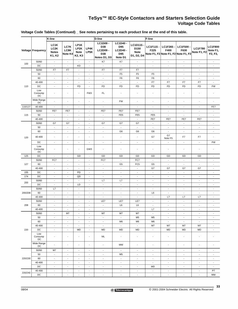
TeSys™ IEC-Style Contactors and Starters Selection GuideVoltage Code Tables
Voltage Frequency
LC1KLC2KNotesK1, K2
LC7KLC8K
Note K4
LP1KLP2K Note
K2, K3
LP4KLP5K
LC1D09 - D38
LC2D09 - D38
Notes D1, D3
LC1D40 - D95
LC2D40 - D95
Note D1
LC1D115 - D150 Note
D1, D2, D4
LC1F115 - F225
Note F1, F2
LC1F265 - F400
Note F1, F2
LC1F500 - F630
Note F1, F2
LC1F780 Note F1, F2
LC1F800 Note F1, F2, F3,
10050/60 - - - - K7 K7 - - - - - -
DC - - KD - - - - - - - - -
110
50/60 F7 F7 - - F7 F7 F7 - - - - -
50 - - - - - F5 F5 F5 - - - -
60 - - - - - F6 F6 F6 - - - -
40-400 - - - - - - - F7 F7 F7 F7 -
DC - - FD - FD FD FD FD FD FD FD FW
Low Consump
DC- - - FW3 FL - - - - - - -
Wide Range DC
- - - - - FW - - - - - -
110/127 40-400 - - - - - - - - - - - FE7
115
50/60 FE7 FE7 - - FE7 FE7 FE7 - - - - -
50 - - - - - FE5 FE5 FE5 - - - -
40-400 - - - - - - - FE7 FE7 FE7 FE7 -
120
50/60 G7 G7 - - G7 G7 G7 - - - - -
50 - - - - - - - - - - - -
60 - - - - - G6 G6 G6 - - - -
40-400 - - - - - - - G7G7
Note F5F7 F7 -
DC - - - - - - - - - - - FW
Low Consump
DC- - - GW3 - - - - - - - -
125 DC - - GD - GD GD GD GD GD GD GD -
127
50/60 FC7 - - - FC7 - FC7 - - - - -
60 - - - - - G5 FC5 G5 - - - -
40-400 - - - - - - - G7 G7 G7 G7 -
155 DC - - PD - - - - - - - - -
174 DC - - QD - - - - - - - - -
20050/60 - - - - L7 L7 - - - - - -
DC - - LD - - - - - - - - -
200/208
50/60 L7 - - - - - - - - - - -
60 - - - - - - - L6 - - - -
40-400 - - - - - - - - L7 L7 L7 -
208
50/60 - - - - LE7 LE7 LE7 - - - - -
60 - - - - - L6 L6 - - - - -
40-400 - - - - - - - L7 - - - -
220
50/60 - M7 - - M7 M7 M7 - - - - -
50 - - - - - - M5 M5 - - - -
60 - - - - - M6 M6 M6 - - - -
40-400 - - - - - - - M7 M7 M7 M7 -
DC - - MD - MD MD MD - MD MD MD -
Low Consump
DC- - - - ML - - - - - - -
Wide Range DC
- - - - - MW - - - - - -
220/230
50/60 M7 - - - - - - - - - - -
50 - - - - - M5 - - - - - -
60 - - - - - - - - - - - -
40-400 - - - - - - - - - - - -
DC - - - - - - - MD - - - -
220/24040-400 - - - - - - - - - - - P7
DC - - - - - - - - - - - MW
Voltage Code Tables (Continued) _ See notes pertaining to each product line at the end of this table.
K-line D-line F-line
3308/04 © 2001-2004 Schneider Electric All Rights Reserved
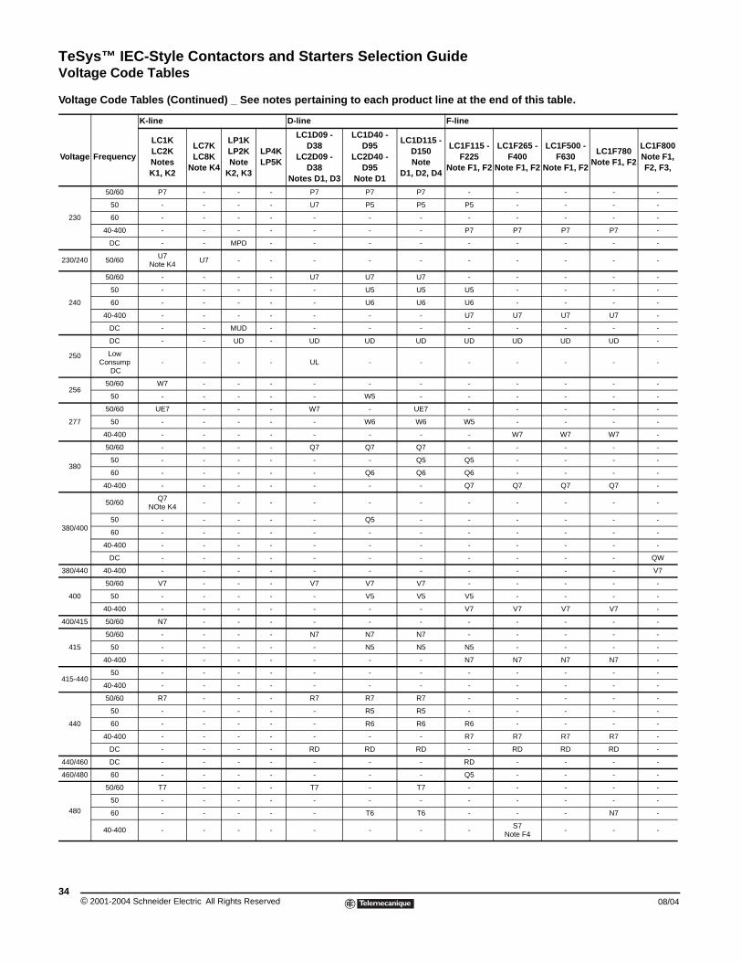
TeSys™ IEC-Style Contactors and Starters Selection GuideVoltage Code Tables
Voltage Frequency
LC1KLC2KNotesK1, K2
LC7KLC8K
Note K4
LP1KLP2K Note
K2, K3
LP4KLP5K
LC1D09 - D38
LC2D09 - D38
Notes D1, D3
LC1D40 - D95
LC2D40 - D95
Note D1
LC1D115 - D150 Note
D1, D2, D4
LC1F115 - F225
Note F1, F2
LC1F265 - F400
Note F1, F2
LC1F500 - F630
Note F1, F2
LC1F780 Note F1, F2
LC1F800 Note F1, F2, F3,
230
50/60 P7 - - - P7 P7 P7 - - - - -
50 - - - - U7 P5 P5 P5 - - - -
60 - - - - - - - - - - - -
40-400 - - - - - - - P7 P7 P7 P7 -
DC - - MPD - - - - - - - - -
230/240 50/60U7
Note K4U7 - - - - - - - - - -
240
50/60 - - - - U7 U7 U7 - - - - -
50 - - - - - U5 U5 U5 - - - -
60 - - - - - U6 U6 U6 - - - -
40-400 - - - - - - - U7 U7 U7 U7 -
DC - - MUD - - - - - - - - -
250
DC - - UD - UD UD UD UD UD UD UD -
Low Consump
DC- - - - UL - - - - - - -
25650/60 W7 - - - - - - - - - - -
50 - - - - - W5 - - - - - -
277
50/60 UE7 - - - W7 - UE7 - - - - -
50 - - - - - W6 W6 W5 - - - -
40-400 - - - - - - - - W7 W7 W7 -
380
50/60 - - - - Q7 Q7 Q7 - - - - -
50 - - - - - - Q5 Q5 - - - -
60 - - - - - Q6 Q6 Q6 - - - -
40-400 - - - - - - - Q7 Q7 Q7 Q7 -
380/400
50/60Q7
NOte K4- - - - - - - - - - -
50 - - - - - Q5 - - - - - -
60 - - - - - - - - - - - -
40-400 - - - - - - - - - - - -
DC - - - - - - - - - - - QW
380/440 40-400 - - - - - - - - - - - V7
400
50/60 V7 - - - V7 V7 V7 - - - - -
50 - - - - - V5 V5 V5 - - - -
40-400 - - - - - - - V7 V7 V7 V7 -
400/415 50/60 N7 - - - - - - - - - - -
415
50/60 - - - - N7 N7 N7 - - - - -
50 - - - - - N5 N5 N5 - - - -
40-400 - - - - - - - N7 N7 N7 N7 -
415-44050 - - - - - - - - - - - -
40-400 - - - - - - - - - - - -
440
50/60 R7 - - - R7 R7 R7 - - - - -
50 - - - - - R5 R5 - - - - -
60 - - - - - R6 R6 R6 - - - -
40-400 - - - - - - - R7 R7 R7 R7 -
DC - - - - RD RD RD - RD RD RD -
440/460 DC - - - - - - - RD - - - -
460/480 60 - - - - - - - Q5 - - - -
480
50/60 T7 - - - T7 - T7 - - - - -
50 - - - - - - - - - - - -
60 - - - - - T6 T6 - - - N7 -
40-400 - - - - - - - -S7
Note F4- - -
Voltage Code Tables (Continued) _ See notes pertaining to each product line at the end of this table.
K-line D-line F-line
© 2001-2004 Schneider Electric All Rights Reserved34
08/04
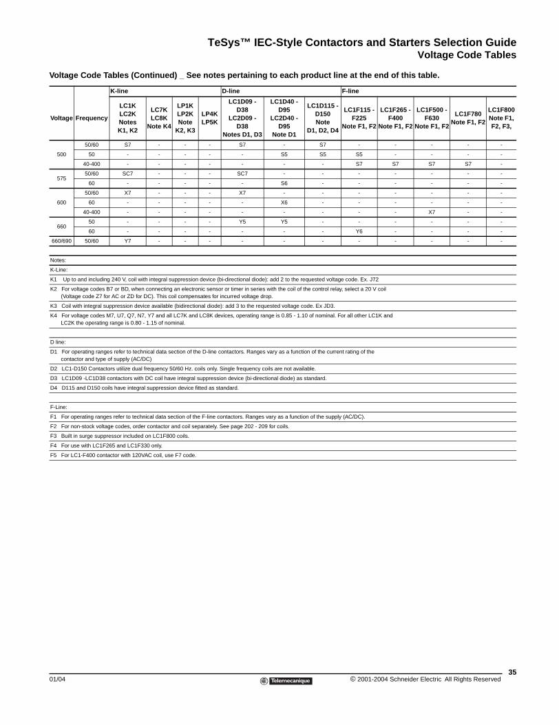
TeSys™ IEC-Style Contactors and Starters Selection GuideVoltage Code Tables
Voltage Frequency
LC1KLC2KNotesK1, K2
LC7KLC8K
Note K4
LP1KLP2K Note
K2, K3
LP4KLP5K
LC1D09 - D38
LC2D09 - D38
Notes D1, D3
LC1D40 - D95
LC2D40 - D95
Note D1
LC1D115 - D150 Note
D1, D2, D4
LC1F115 - F225
Note F1, F2
LC1F265 - F400
Note F1, F2
LC1F500 - F630
Note F1, F2
LC1F780 Note F1, F2
LC1F800 Note F1, F2, F3,
500
50/60 S7 - - - S7 - S7 - - - - -
50 - - - - - S5 S5 S5 - - - -
40-400 - - - - - - - S7 S7 S7 S7 -
57550/60 SC7 - - - SC7 - - - - - - -
60 - - - - - S6 - - - - - -
600
50/60 X7 - - - X7 - - - - - - -
60 - - - - - X6 - - - - - -
40-400 - - - - - - - - - X7 - -
66050 - - - - Y5 Y5 - - - - - -
60 - - - - - - - Y6 - - - -
660/690 50/60 Y7 - - - - - - - - - - -
Notes:
K-Line:
K1 Up to and including 240 V, coil with integral suppression device (bi-directional diode): add 2 to the requested voltage code. Ex. J72
K2 For voltage codes B7 or BD, when connecting an electronic sensor or timer in series with the coil of the control relay, select a 20 V coil (Voltage code Z7 for AC or ZD for DC). This coil compensates for incurred voltage drop.
K3 Coil with integral suppression device available (bidirectional diode): add 3 to the requested voltage code. Ex JD3.
K4 For voltage codes M7, U7, Q7, N7, Y7 and all LC7K and LC8K devices, operating range is 0.85 - 1.10 of nominal. For all other LC1K and LC2K the operating range is 0.80 - 1.15 of nominal.
D line:
D1 For operating ranges refer to technical data section of the D-line contactors. Ranges vary as a function of the current rating of the contactor and type of supply (AC/DC)
D2 LC1-D150 Contactors utilize dual frequency 50/60 Hz. coils only. Single frequency coils are not available.
D3 LC1D09 -LC1D38 contactors with DC coil have integral suppression device (bi-directional diode) as standard.
D4 D115 and D150 coils have integral suppression device fitted as standard.
F-Line:
F1 For operating ranges refer to technical data section of the F-line contactors. Ranges vary as a function of the supply (AC/DC).
F2 For non-stock voltage codes, order contactor and coil separately. See page 202 - 209 for coils.
F3 Built in surge suppressor included on LC1F800 coils.
F4 For use with LC1F265 and LC1F330 only.
F5 For LC1-F400 contactor with 120VAC coil, use F7 code.
Voltage Code Tables (Continued) _ See notes pertaining to each product line at the end of this table.
K-line D-line F-line
3501/04 © 2001-2004 Schneider Electric All Rights Reserved
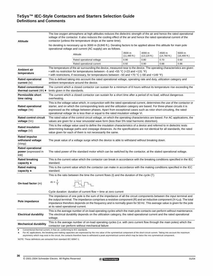
TeSys™ IEC-Style Contactors and Starters Selection GuideDefinitions and Comments
© 2001-2004 Schneider E36
Altitude
Tvoco
Nop
Ambient air temperature
T• •
Rated operational current (Ie)
Tam
Rated conventional thermal current (Ith) f
Tlim
Permissible short time rating
Tov
Rated operational voltage (Ve)
Tstexop
Rated control circuit voltage (Vc)
Tva
Rated insulation voltage (Vi)
Tdeva
Rated impulse withstand voltage (Vimp)
T
Rated operational power (expressed in kW)
T
Rated breaking capacity q
Tst
Rated making capacity q
Tst
On-load factor (m)
T
C
Pole impedance
Tthimat
Electrical durabilityTTvo
Mechanical durabilityTco
f Conventional thermal current, q For AC applications, the break
asymmetry which may exist in
NOTE: These definitions are extrac
Definitions and Comments
he low oxygen atmosphere at high altitudes reduces the dielectric strength of the air and hence the rated operational ltage of the contactor. It also reduces the cooling effect of the air and hence the rated operational current of the ntactor (unless the temperature drops at the same time).
o derating is necessary up to 3000 m (9,840 ft.). Derating factors to be applied above this altitude for main pole erational voltage and current (AC supply) are as follows.
Altitude 3500 m(11,480 ft.)
4000 m(13,120 ft.)
4500 m(14,760 ft.)
5000 m(16,400 ft.)
Rated operational voltage 0.90 0.80 0.70 0.60
Rated operational current 0.92 0.90 0.88 0.86
he temperature of the air surrounding the device, measured near to the device. The operating characteristics are given:with no restriction for temperatures between –5 and +55 °C (+23 and +131 °F)with restrictions, if necessary, for temperatures between –50 and +70 °C (–58 and +149 °F)
his is defined taking into account the rated operational voltage, operating rate and duty, utilization category and bient temperature around the device.
he current which a closed contactor can sustain for a minimum of 8 hours without its temperature rise exceeding the its given in the standards.
he current which a closed contactor can sustain for a short time after a period of no load, without dangerous erheating.
his is the voltage value which, in conjunction with the rated operational current, determines the use of the contactor or arter, and on which the corresponding tests and the utilization category are based. For three-phase circuits it is pressed as the voltage between phases. Apart from exceptional cases such as rotor short-circuiting, the rated erational voltage Ve is less than or equal to the rated insulation voltage Vi.
he rated value of the control circuit voltage, on which the operating characteristics are based. For AC applications, the lues are given for a near sinusoidal wave form (less than 5% total harmonic distortion).
his is the voltage value used to define the insulation characteristics of a device and referred to in dielectric tests termining leakage paths and creepage distances. As the specifications are not identical for all standards, the rated lue given for each of them is not necessarily the same.
he peak value of a voltage surge which the device is able to withstand without breaking down.
he rated power of the standard motor which can be switched by the contactor, at the stated operational voltage.
his is the current value which the contactor can break in accordance with the breaking conditions specified in the IEC andard.
his is the current value which the contactor can make in accordance with the making conditions specified in the IEC andard.
his is the ratio between the time the current flows (t) and the duration of the cycle (T)
ycle duration: duration of current flow + time at zero current
he impedance of one pole is the sum of the impedance of all the circuit components between the input terminal and e output terminal. The impedance comprises a resistive component (R) and an inductive component (X=Lω). The total pedance therefore depends on the frequency and is normally given for 50 Hz. This average value is given for the pole its rated operational current.
his is the average number of on-load operating cycles which the main pole contacts can perform without maintenance. he electrical durability depends on the utilization category, the rated operational current and the rated operational ltage.
his is the average number of on-load operating cycles (i.e. with zero current flow through the main poles) which the ntactor can perform without mechanical failure
in free air, conforming to IEC standards.ing and making capacities are expressed by the rms value of the symmetrical component of the short-circuit current. Taking into account the maximum the circuit, the contacts therefore have to withstand a peak asymmetrical current which may be twice the rms symmetrical component.
ted from standard IEC 60947-1.
tm =T
t
T
lectric All Rights Reserved 01/04
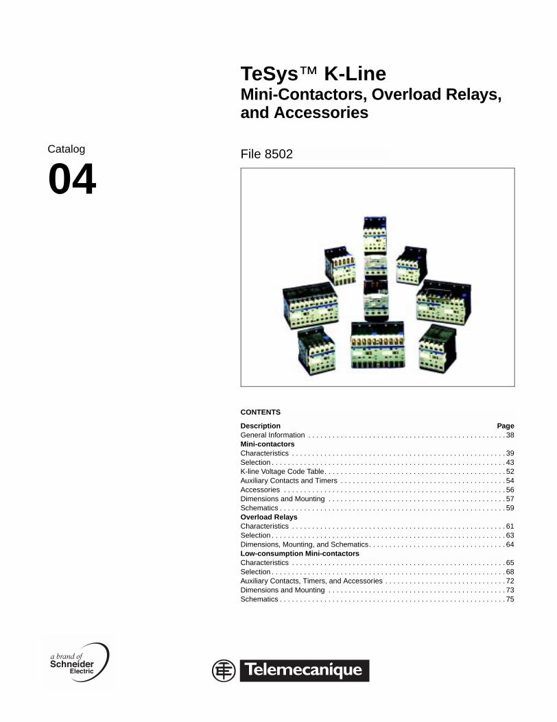
Catalog
04
TeSys™ K-Line Mini-Contactors, Overload Relays, and Accessories
File 8502
CONTENTS
Description PageGeneral Information . . . . . . . . . . . . . . . . . . . . . . . . . . . . . . . . . . . . . . . . . . . . . . . . . 38Mini-contactorsCharacteristics . . . . . . . . . . . . . . . . . . . . . . . . . . . . . . . . . . . . . . . . . . . . . . . . . . . . . 39Selection . . . . . . . . . . . . . . . . . . . . . . . . . . . . . . . . . . . . . . . . . . . . . . . . . . . . . . . . . . 43K-line Voltage Code Table. . . . . . . . . . . . . . . . . . . . . . . . . . . . . . . . . . . . . . . . . . . . . 52Auxiliary Contacts and Timers . . . . . . . . . . . . . . . . . . . . . . . . . . . . . . . . . . . . . . . . . 54Accessories . . . . . . . . . . . . . . . . . . . . . . . . . . . . . . . . . . . . . . . . . . . . . . . . . . . . . . . 56Dimensions and Mounting . . . . . . . . . . . . . . . . . . . . . . . . . . . . . . . . . . . . . . . . . . . . 57Schematics . . . . . . . . . . . . . . . . . . . . . . . . . . . . . . . . . . . . . . . . . . . . . . . . . . . . . . . . 59Overload RelaysCharacteristics . . . . . . . . . . . . . . . . . . . . . . . . . . . . . . . . . . . . . . . . . . . . . . . . . . . . . 61Selection . . . . . . . . . . . . . . . . . . . . . . . . . . . . . . . . . . . . . . . . . . . . . . . . . . . . . . . . . . 63Dimensions, Mounting, and Schematics. . . . . . . . . . . . . . . . . . . . . . . . . . . . . . . . . . 64Low-consumption Mini-contactorsCharacteristics . . . . . . . . . . . . . . . . . . . . . . . . . . . . . . . . . . . . . . . . . . . . . . . . . . . . . 65Selection . . . . . . . . . . . . . . . . . . . . . . . . . . . . . . . . . . . . . . . . . . . . . . . . . . . . . . . . . . 68Auxiliary Contacts, Timers, and Accessories . . . . . . . . . . . . . . . . . . . . . . . . . . . . . . 72Dimensions and Mounting . . . . . . . . . . . . . . . . . . . . . . . . . . . . . . . . . . . . . . . . . . . . 73Schematics . . . . . . . . . . . . . . . . . . . . . . . . . . . . . . . . . . . . . . . . . . . . . . . . . . . . . . . . 75
K-Line
TeSys™ K-line Mini-Contactors and StartersGeneral Information
© 2001-2004 Schneider E38
General Information
K-line Mini-contactors, and Overload Relays are ideal for general-duty applications where small size and reliability are key concerns. They feature:
• Three contactor ratings for the USA market:
— K06 rated for 3 HP motors at 480 Vac or 600 Vac.
— K09 rated for 5 HP motors at 480 Vac or 600 Vac.
— K12 rated for 7.5 HP motors at 480 Vac or 10 HP at 600 Vac.
• Space savings — the special magnet and armature structure allow for a DC coil-operated device with the same physical size and panel footprint of the AC coil version.
• IP20-rated touch-safe terminals with both North American and International terminal markings
• Mountable on 35mm DIN rail or panel mount with screws
• Available in 3-pole contactor versions with built-in auxiliary contact for holding circuit or 4-pole contactor versions.
• Easily-installed accessories.
— 2-pole or 4-pole instantaneous auxiliary contact blocks with screw clamp, slip-on, or spring terminals.
— Transient voltage surge suppressors.
— Electronic 1 to 30 second on-delay timers.
• Four wiring methods to reduce installation time:
— Captive screw terminals for use with either Phillips or slotted head screwdrivers.
— Slip-on terminals for quick installation of single 1/4" or double 1/8" tabs.
— Terminal pins for soldering the contactor directly to a printed circuit board.
— Spring terminals for extreme-vibration applications.
• Control circuit flexibility
All versions of the K-line mini-contactors are available with an AC, DC, or low-consumption DC operating coil. The low-consumption DC coil operating device can be energized by a low level DC signal from a computer or PLC and includes built-in transient suppression and LED “On” indicator.
• Bimetallic overload relays
The K-line Class 10 bimetallic overload relays are ambient-compensated and include single-phase sensitivity for phase unbalance and phase loss protection. Standard features include isolated N.C. trip contact and N.O. alarm contact, manual or automatic reset function, tamper resistant window for full load current settings, and Test trip button. Five pins connect to the contactor load side terminals — three for the power circuit and two for the control circuit — which eliminate customer wiring for the 3-wire control holding circuit.
lectric All Rights Reserved 01/04
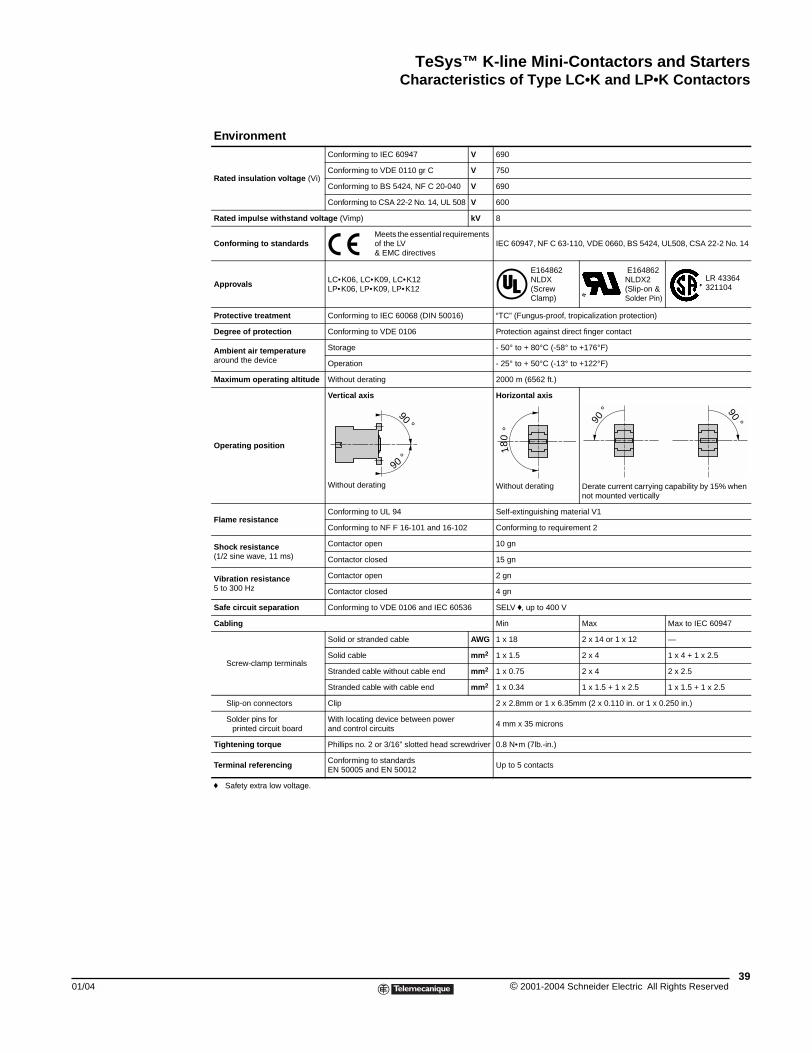
TeSys™ K-line Mini-Contactors and StartersCharacteristics of Type LC•K and LP•K Contactors
01/04
Characteristics of Type LC\bK and LP\bK Contactors
Environment
Rated insulation voltage (Vi)
Conforming to IEC 60947 V 690
Conforming to VDE 0110 gr C V 750
Conforming to BS 5424, NF C 20-040 V 690
Conforming to CSA 22-2 No. 14, UL 508 V 600
Rated impulse withstand voltage (Vimp) kV 8
Conforming to standardsMeets the essential requirements of the LV & EMC directives
IEC 60947, NF C 63-110, VDE 0660, BS 5424, UL508, CSA 22-2 No. 14
Approvals LC•K06, LC•K09, LC•K12LP•K06, LP•K09, LP•K12
E164862NLDX(Screw Clamp)
E164862NLDX2(Slip-on & Solder Pin)
LR 43364 321104
Protective treatment Conforming to IEC 60068 (DIN 50016) “TC” (Fungus-proof, tropicalization protection)
Degree of protection Conforming to VDE 0106 Protection against direct finger contact
Ambient air temperaturearound the device
Storage - 50° to + 80°C (-58° to +176°F)
Operation - 25° to + 50°C (-13° to +122°F)
Maximum operating altitude Without derating 2000 m (6562 ft.)
Operating position
Vertical axis
Without derating
Horizontal axis
Without derating Derate current carrying capability by 15% when not mounted vertically
Flame resistanceConforming to UL 94 Self-extinguishing material V1
Conforming to NF F 16-101 and 16-102 Conforming to requirement 2
Shock resistance(1/2 sine wave, 11 ms)
Contactor open 10 gn
Contactor closed 15 gn
Vibration resistance5 to 300 Hz
Contactor open 2 gn
Contactor closed 4 gn
Safe circuit separation Conforming to VDE 0106 and IEC 60536 SELV f, up to 400 V
Cabling Min Max Max to IEC 60947
Screw-clamp terminals
Solid or stranded cable AWG 1 x 18 2 x 14 or 1 x 12 —
Solid cable mm2 1 x 1.5 2 x 4 1 x 4 + 1 x 2.5
Stranded cable without cable end mm2 1 x 0.75 2 x 4 2 x 2.5
Stranded cable with cable end mm2 1 x 0.34 1 x 1.5 + 1 x 2.5 1 x 1.5 + 1 x 2.5
Slip-on connectors Clip 2 x 2.8mm or 1 x 6.35mm (2 x 0.110 in. or 1 x 0.250 in.)
Solder pins for printed circuit board
With locating device between power and control circuits
4 mm x 35 microns
Tightening torque Phillips no. 2 or 3/16” slotted head screwdriver 0.8 N•m (7lb.-in.)
Terminal referencing Conforming to standards EN 50005 and EN 50012
Up to 5 contacts
f Safety extra low voltage.
90 °
90 °
180
°
90 ° 90 °
39© 2001-2004 Schneider Electric All Rights Reserved
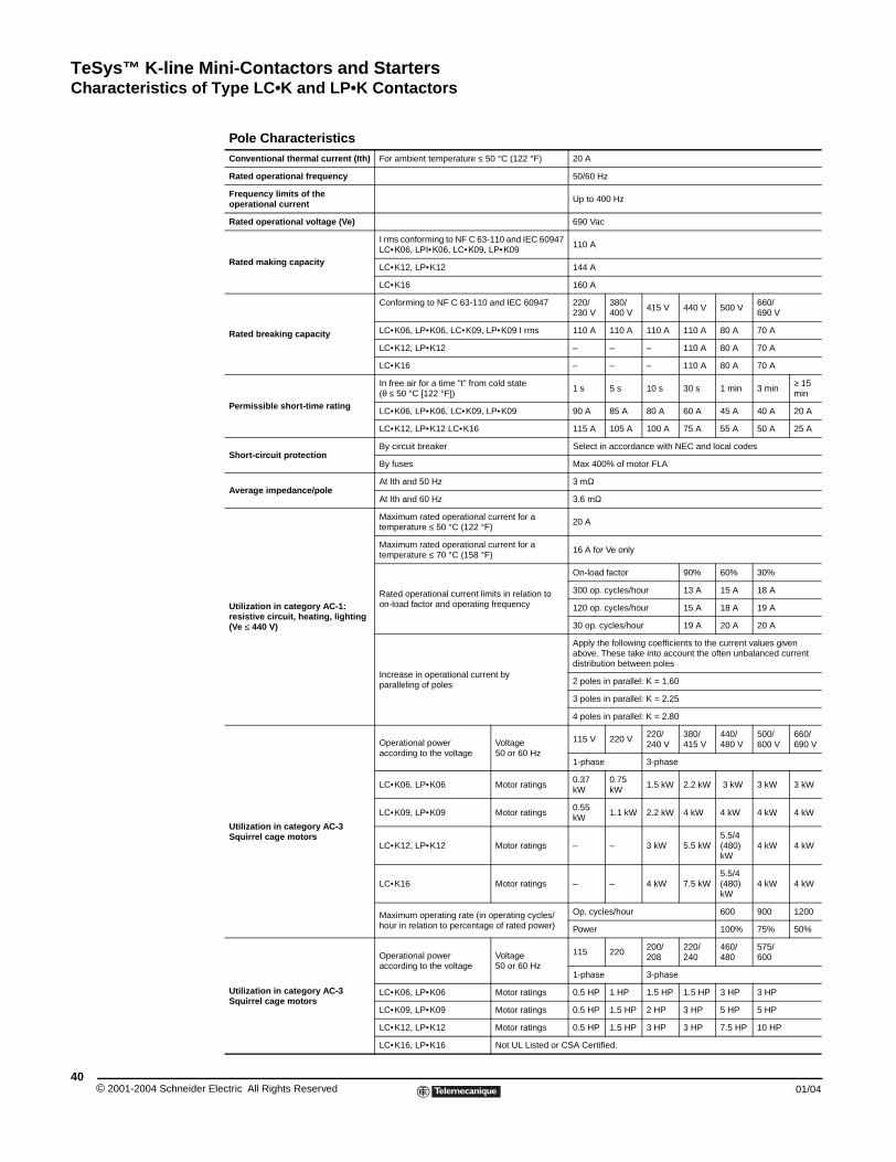
TeSys™ K-line Mini-Contactors and StartersCharacteristics of Type LC•K and LP•K Contactors
© 2001-2004 Schneider E40
Pole CharacteristicsConventional thermal current (Ith) For ambient temperature ≤ 50 °C (122 °F) 20 A
Rated operational frequency 50/60 Hz
Frequency limits of the operational current Up to 400 Hz
Rated operational voltage (Ve) 690 Vac
Rated making capacity
I rms conforming to NF C 63-110 and IEC 60947LC•K06, LPI•K06, LC•K09, LP•K09
110 A
LC•K12, LP•K12 144 A
LC•K16 160 A
Rated breaking capacity
Conforming to NF C 63-110 and IEC 60947 220/230 V
380/ 400 V
415 V 440 V 500 V660/ 690 V
LC•K06, LP•K06, LC•K09, LP•K09 I rms 110 A 110 A 110 A 110 A 80 A 70 A
LC•K12, LP•K12 – – – 110 A 80 A 70 A
LC•K16 – – – 110 A 80 A 70 A
Permissible short-time rating
In free air for a time "t” from cold state (θ ≤ 50 °C [122 °F])
1 s 5 s 10 s 30 s 1 min 3 min≥ 15 min
LC•K06, LP•K06, LC•K09, LP•K09 90 A 85 A 80 A 60 A 45 A 40 A 20 A
LC•K12, LP•K12 LC•K16 115 A 105 A 100 A 75 A 55 A 50 A 25 A
Short-circuit protectionBy circuit breaker Select in accordance with NEC and local codes
By fuses Max 400% of motor FLA
Average impedance/poleAt Ith and 50 Hz 3 mΩ
At Ith and 60 Hz 3.6 mΩ
Utilization in category AC-1: resistive circuit, heating, lighting (Ve ≤ 440 V)
Maximum rated operational current for a temperature ≤ 50 °C (122 °F)
20 A
Maximum rated operational current for a temperature ≤ 70 °C (158 °F)
16 A for Ve only
Rated operational current limits in relation to on-load factor and operating frequency
On-load factor 90% 60% 30%
300 op. cycles/hour 13 A 15 A 18 A
120 op. cycles/hour 15 A 18 A 19 A
30 op. cycles/hour 19 A 20 A 20 A
Increase in operational current by paralleling of poles
Apply the following coefficients to the current values given above. These take into account the often unbalanced current distribution between poles
2 poles in parallel: K = 1.60
3 poles in parallel: K = 2.25
4 poles in parallel: K = 2.80
Utilization in category AC-3Squirrel cage motors
Operational poweraccording to the voltage
Voltage50 or 60 Hz
115 V 220 V220/ 240 V
380/415 V
440/480 V
500/600 V
660/ 690 V
1-phase 3-phase
LC•K06, LP•K06 Motor ratings0.37 kW
0.75 kW
1.5 kW 2.2 kW 3 kW 3 kW 3 kW
LC•K09, LP•K09 Motor ratings0.55 kW
1.1 kW 2.2 kW 4 kW 4 kW 4 kW 4 kW
LC•K12, LP•K12 Motor ratings – – 3 kW 5.5 kW5.5/4(480) kW
4 kW 4 kW
LC•K16 Motor ratings – – 4 kW 7.5 kW5.5/4(480) kW
4 kW 4 kW
Maximum operating rate (in operating cycles/hour in relation to percentage of rated power)
Op. cycles/hour 600 900 1200
Power 100% 75% 50%
Utilization in category AC-3Squirrel cage motors
Operational poweraccording to the voltage
Voltage50 or 60 Hz
115 220200/ 208
220/240
460/480
575/600
1-phase 3-phase
LC•K06, LP•K06 Motor ratings 0.5 HP 1 HP 1.5 HP 1.5 HP 3 HP 3 HP
LC•K09, LP•K09 Motor ratings 0.5 HP 1.5 HP 2 HP 3 HP 5 HP 5 HP
LC•K12, LP•K12 Motor ratings 0.5 HP 1.5 HP 3 HP 3 HP 7.5 HP 10 HP
LC•K16, LP•K16 Not UL Listed or CSA Certified.
lectric All Rights Reserved 01/04
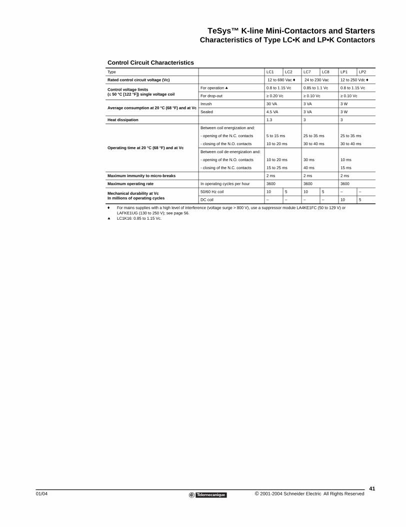
TeSys™ K-line Mini-Contactors and StartersCharacteristics of Type LC•K and LP•K Contactors
01/04
Control Circuit CharacteristicsType LC1 LC2 LC7 LC8 LP1 LP2
Rated control circuit voltage (Vc) 12 to 690 Vac f 24 to 230 Vac 12 to 250 Vdc f
Control voltage limits (≤ 50 °C [122 °F]) single voltage coil
For operation q 0.8 to 1.15 Vc 0.85 to 1.1 Vc 0.8 to 1.15 Vc
For drop-out ≥ 0.20 Vc ≥ 0.10 Vc ≥ 0.10 Vc
Average consumption at 20 °C (68 °F) and at VcInrush 30 VA 3 VA 3 W
Sealed 4.5 VA 3 VA 3 W
Heat dissipation 1.3 3 3
Operating time at 20 °C (68 °F) and at Vc
Between coil energization and:
- opening of the N.C. contacts 5 to 15 ms 25 to 35 ms 25 to 35 ms
- closing of the N.O. contacts 10 to 20 ms 30 to 40 ms 30 to 40 ms
Between coil de-energization and:
- opening of the N.O. contacts 10 to 20 ms 30 ms 10 ms
- closing of the N.C. contacts 15 to 25 ms 40 ms 15 ms
Maximum immunity to micro-breaks 2 ms 2 ms 2 ms
Maximum operating rate In operating cycles per hour 3600 3600 3600
Mechanical durability at Vc In millions of operating cycles
50/60 Hz coil 10 5 10 5 – –
DC coil – – – – 10 5
f For mains supplies with a high level of interference (voltage surge > 800 V), use a suppressor module LA4KE1FC (50 to 129 V) or LAFKE1UG (130 to 250 V); see page 56.
q LC1K16: 0.85 to 1.15 Vc.
41© 2001-2004 Schneider Electric All Rights Reserved
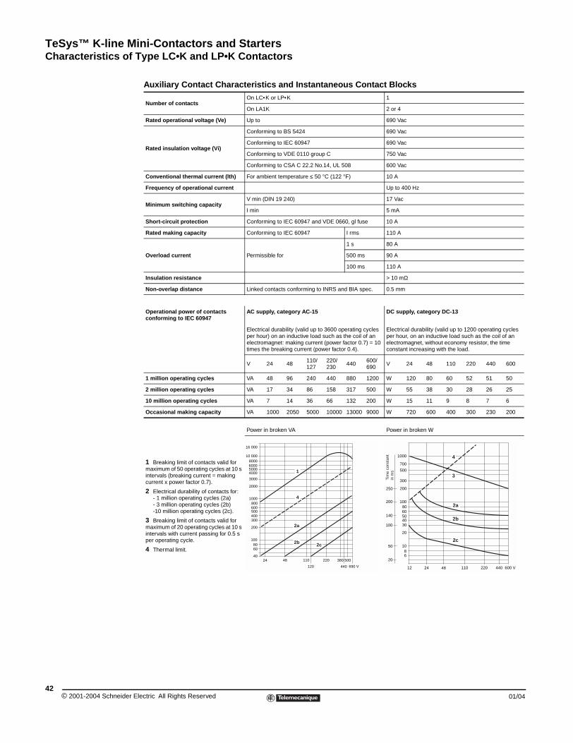
TeSys™ K-line Mini-Contactors and StartersCharacteristics of Type LC•K and LP•K Contactors
© 2001-2004 Schneider E42
Auxiliary Contact Characteristics and Instantaneous Contact Blocks
Number of contactsOn LC•K or LP•K 1
On LA1K 2 or 4
Rated operational voltage (Ve) Up to 690 Vac
Rated insulation voltage (Vi)
Conforming to BS 5424 690 Vac
Conforming to IEC 60947 690 Vac
Conforming to VDE 0110 group C 750 Vac
Conforming to CSA C 22.2 No.14, UL 508 600 Vac
Conventional thermal current (lth) For ambient temperature ≤ 50 °C (122 °F) 10 A
Frequency of operational current Up to 400 Hz
Minimum switching capacityV min (DIN 19 240) 17 Vac
I min 5 mA
Short-circuit protection Conforming to IEC 60947 and VDE 0660, gl fuse 10 A
Rated making capacity Conforming to IEC 60947 I rms 110 A
Overload current Permissible for
1 s 80 A
500 ms 90 A
100 ms 110 A
Insulation resistance > 10 mΩ
Non-overlap distance Linked contacts conforming to INRS and BIA spec. 0.5 mm
Operational power of contactsconforming to IEC 60947
AC supply, category AC-15 DC supply, category DC-13
Electrical durability (valid up to 3600 operating cycles per hour) on an inductive load such as the coil of an electromagnet: making current (power factor 0.7) = 10 times the breaking current (power factor 0.4).
Electrical durability (valid up to 1200 operating cycles per hour, on an inductive load such as the coil of an electromagnet, without economy resistor, the time constant increasing with the load.
V 24 48110/127
220/230
440600/690
V 24 48 110 220 440 600
1 million operating cycles VA 48 96 240 440 880 1200 W 120 80 60 52 51 50
2 million operating cycles VA 17 34 86 158 317 500 W 55 38 30 28 26 25
10 million operating cycles VA 7 14 36 66 132 200 W 15 11 9 8 7 6
Occasional making capacity VA 1000 2050 5000 10000 13000 9000 W 720 600 400 300 230 200
1 Breaking limit of contacts valid for maximum of 50 operating cycles at 10 s intervals (breaking current = making current x power factor 0.7).
2 Electrical durability of contacts for:- 1 million operating cycles (2a)- 3 million operating cycles (2b)-10 million operating cycles (2c).
3 Breaking limit of contacts valid for maximum of 20 operating cycles at 10 s intervals with current passing for 0.5 s per operating cycle.
4 Thermal limit.
Power in broken VA Power in broken W
10 000
5000
3000
2000
1000800600500400300
200
1008060
24 48 110 220
440 690 V120
380 50040
16 000
80006000
4000
2c2b
4
1
2a
1000
700
500
300
200
1008060504030
20
1086
12 24 48 110 220 440 600 V
250
200
140
100
50
20
2c
2b
2a
3
4
Tim
e co
nsta
ntin
ms
lectric All Rights Reserved 01/04
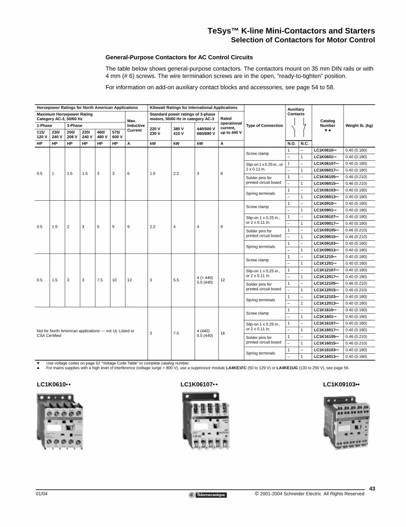
TeSys™ K-line Mini-Contactors and StartersSelection of Contactors for Motor Control
01/04
Horsepower Ratings for North Am
Maximum Horsepower RatingCategory AC-3, 50/60 Hz
1-Phase 3-Phase
115/120 V
230/240 V
200/208 V
220/240 V
4648
HP HP HP HP H
0.5 1 1.5 1.5 3
0.5 1.5 2 3 5
0.5 1.5 3 3 7.
Not for North American applicationsCSA Certified
p Use voltage codes on page 52q For mains supplies with a high
LC1K0610••
Selection of Contactors for Motor Control
General-Purpose Contactors for AC Control Circuits
The table below shows general-purpose contactors. The contactors mount on 35 mm DIN rails or with 4 mm (# 6) screws. The wire termination screws are in the open, “ready-to-tighten” position.
For information on add-on auxiliary contact blocks and accessories, see page 54 to 58.
erican Applications Kilowatt Ratings for International Applications
Type of Connection
Auxiliary Contacts
CatalogNumber
p qWeight lb. (kg)
Max. Inductive Current
Standard power ratings of 3-phase motors, 50/60 Hz in category AC-3 Rated
operational current,up to 440 V
220 V230 V
380 V415 V
440/500 V660/690 V0/
0 V575/600 V
P HP A kW kW kW A N.O. N.C.
3 6 1.5 2.2 3 6
Screw clamp1 – LC1K0610•• 0.40 (0.180)
– 1 LC1K0601•• 0.40 (0.180)
Slip-on 1 x 0.25 in., or 2 x 0.11 in.
1 – LC1K06107•• 0.40 (0.180)
– 1 LC1K06017•• 0.40 (0.180)
Solder pins for printed circuit board
1 – LC1K06105•• 0.46 (0.210)
– 1 LC1K06015•• 0.46 (0.210)
Spring terminals1 – LC1K06103•• 0.40 (0.180)
– 1 LC1K06013•• 0.40 (0.180)
5 9 2.2 4 4 9
Screw clamp1 – LC1K0910•• 0.40 (0.180)
– 1 LC1K0901•• 0.40 (0.180)
Slip-on 1 x 0.25 in., or 2 x 0.11 in.
1 – LC1K09107•• 0.40 (0.180)
– 1 LC1K09017•• 0.40 (0.180)
Solder pins for printed circuit board
1 – LC1K09105•• 0.46 (0.210)
– 1 LC1K09015•• 0.46 (0.210)
Spring terminals1 – LC1K09103•• 0.40 (0.180)
– 1 LC1K09013•• 0.40 (0.180)
5 10 12 3 5.54 (> 440)5.5 (440)
12
Screw clamp1 – LC1K1210•• 0.40 (0.180)
– 1 LC1K1201•• 0.40 (0.180)
Slip-on 1 x 0.25 in., or 2 x 0.11 in.
1 – LC1K12107•• 0.40 (0.180)
– 1 LC1K12017•• 0.40 (0.180)
Solder pins for printed circuit board
1 – LC1K12105•• 0.46 (0.210)
– 1 LC1K12015•• 0.46 (0.210)
Spring terminals1 – LC1K12103•• 0.40 (0.180)
– 1 LC1K12013•• 0.40 (0.180)
— not UL Listed or 3 7.5
4 (440)5.5 (440)
16
Screw clamp1 – LC1K1610•• 0.40 (0.180)
– 1 LC1K1601•• 0.40 (0.180)
Slip-on 1 x 0.25 in., or 2 x 0.11 in.
1 – LC1K16107•• 0.40 (0.180)
– 1 LC1K16017•• 0.40 (0.180)
Solder pins for printed circuit board
1 – LC1K16105•• 0.46 (0.210)
– 1 LC1K16015•• 0.46 (0.210)
Spring terminals1 – LC1K16103•• 0.40 (0.180)
– 1 LC1K16013•• 0.40 (0.180)
“Voltage Code Table” to complete catalog number.level of interference (voltage surge > 800 V), use a suppressor module LA4KE1FC (50 to 129 V) or LA4KE1UG (130 to 250 V), see page 56.
LC1K06107•• LC1K09103••
43© 2001-2004 Schneider Electric All Rights Reserved
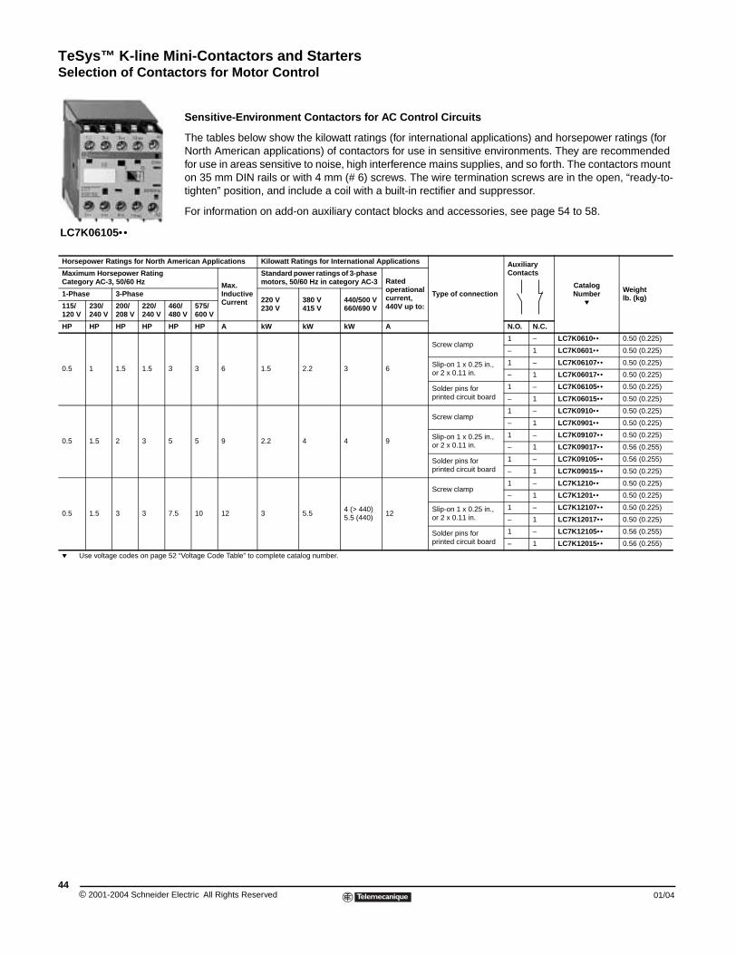
TeSys™ K-line Mini-Contactors and StartersSelection of Contactors for Motor Control
© 2001-2004 Schneider E44
Horsepower Ratings for North Am
Maximum Horsepower RatingCategory AC-3, 50/60 Hz
1-Phase 3-Phase
115/120 V
230/240 V
200/208 V
220/240 V
4648
HP HP HP HP H
0.5 1 1.5 1.5 3
0.5 1.5 2 3 5
0.5 1.5 3 3 7.
p Use voltage codes on page 52
LC7K06105••
Sensitive-Environment Contactors for AC Control Circuits
The tables below show the kilowatt ratings (for international applications) and horsepower ratings (for North American applications) of contactors for use in sensitive environments. They are recommended for use in areas sensitive to noise, high interference mains supplies, and so forth. The contactors mount on 35 mm DIN rails or with 4 mm (# 6) screws. The wire termination screws are in the open, “ready-to-tighten” position, and include a coil with a built-in rectifier and suppressor.
For information on add-on auxiliary contact blocks and accessories, see page 54 to 58.
erican Applications Kilowatt Ratings for International Applications
Type of connection
Auxiliary Contacts
CatalogNumber
p
Weight lb. (kg)
Max. Inductive Current
Standard power ratings of 3-phase motors, 50/60 Hz in category AC-3 Rated
operational current,440V up to:
220 V230 V
380 V415 V
440/500 V660/690 V0/
0 V575/600 V
P HP A kW kW kW A N.O. N.C.
3 6 1.5 2.2 3 6
Screw clamp1 – LC7K0610•• 0.50 (0.225)
– 1 LC7K0601•• 0.50 (0.225)
Slip-on 1 x 0.25 in., or 2 x 0.11 in.
1 – LC7K06107•• 0.50 (0.225)
– 1 LC7K06017•• 0.50 (0.225)
Solder pins for printed circuit board
1 – LC7K06105•• 0.50 (0.225)
– 1 LC7K06015•• 0.50 (0.225)
5 9 2.2 4 4 9
Screw clamp1 – LC7K0910•• 0.50 (0.225)
– 1 LC7K0901•• 0.50 (0.225)
Slip-on 1 x 0.25 in., or 2 x 0.11 in.
1 – LC7K09107•• 0.50 (0.225)
– 1 LC7K09017•• 0.56 (0.255)
Solder pins for printed circuit board
1 – LC7K09105•• 0.56 (0.255)
– 1 LC7K09015•• 0.50 (0.225)
5 10 12 3 5.54 (> 440)5.5 (440)
12
Screw clamp1 – LC7K1210•• 0.50 (0.225)
– 1 LC7K1201•• 0.50 (0.225)
Slip-on 1 x 0.25 in., or 2 x 0.11 in.
1 – LC7K12107•• 0.50 (0.225)
– 1 LC7K12017•• 0.50 (0.225)
Solder pins for printed circuit board
1 – LC7K12105•• 0.56 (0.255)
– 1 LC7K12015•• 0.56 (0.255)
“Voltage Code Table” to complete catalog number.
lectric All Rights Reserved 01/04
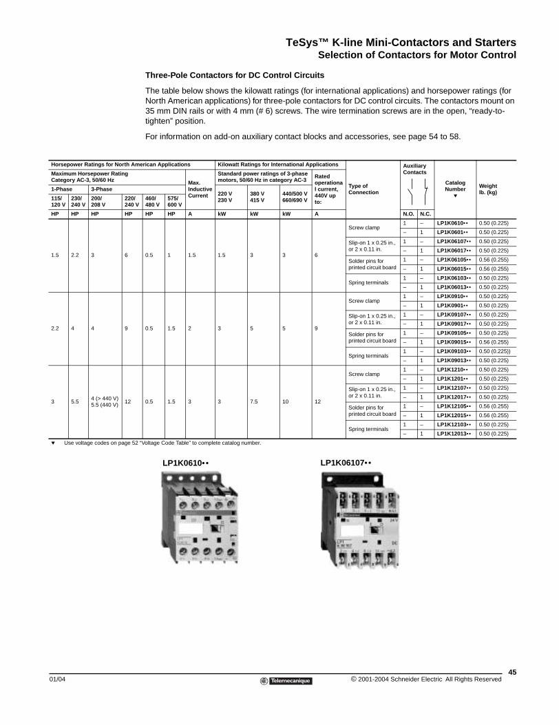
TeSys™ K-line Mini-Contactors and StartersSelection of Contactors for Motor Control
01/04
Horsepower Ratings for North Am
Maximum Horsepower RatingCategory AC-3, 50/60 Hz
1-Phase 3-Phase
115/120 V
230/240 V
200/208 V
220/240 V
HP HP HP HP
1.5 2.2 3 6
2.2 4 4 9
3 5.54 (> 440 V)5.5 (440 V)
12
p Use voltage codes on page 52
Three-Pole Contactors for DC Control Circuits
The table below shows the kilowatt ratings (for international applications) and horsepower ratings (for North American applications) for three-pole contactors for DC control circuits. The contactors mount on 35 mm DIN rails or with 4 mm (# 6) screws. The wire termination screws are in the open, “ready-to-tighten” position.
For information on add-on auxiliary contact blocks and accessories, see page 54 to 58.
erican Applications Kilowatt Ratings for International Applications
Type of Connection
Auxiliary Contacts
CatalogNumber
p
Weight lb. (kg)
Max. Inductive Current
Standard power ratings of 3-phase motors, 50/60 Hz in category AC-3
Rated operational current,440V up to:
220 V230 V
380 V415 V
440/500 V660/690 V460/
480 V575/600 V
HP HP A kW kW kW A N.O. N.C.
0.5 1 1.5 1.5 3 3 6
Screw clamp1 – LP1K0610•• 0.50 (0.225)
– 1 LP1K0601•• 0.50 (0.225)
Slip-on 1 x 0.25 in.,or 2 x 0.11 in.
1 – LP1K06107•• 0.50 (0.225)
– 1 LP1K06017•• 0.50 (0.225)
Solder pins for printed circuit board
1 – LP1K06105•• 0.56 (0.255)
– 1 LP1K06015•• 0.56 (0.255)
Spring terminals1 – LP1K06103•• 0.50 (0.225)
– 1 LP1K06013•• 0.50 (0.225)
0.5 1.5 2 3 5 5 9
Screw clamp1 – LP1K0910•• 0.50 (0.225)
– 1 LP1K0901•• 0.50 (0.225)
Slip-on 1 x 0.25 in.,or 2 x 0.11 in.
1 – LP1K09107•• 0.50 (0.225)
– 1 LP1K09017•• 0.50 (0.225)
Solder pins for printed circuit board
1 – LP1K09105•• 0.50 (0.225)
– 1 LP1K09015•• 0.56 (0.255)
Spring terminals1 – LP1K09103•• 0.50 (0.225))
– 1 LP1K09013•• 0.50 (0.225)
0.5 1.5 3 3 7.5 10 12
Screw clamp1 – LP1K1210•• 0.50 (0.225)
– 1 LP1K1201•• 0.50 (0.225)
Slip-on 1 x 0.25 in.,or 2 x 0.11 in.
1 – LP1K12107•• 0.50 (0.225)
– 1 LP1K12017•• 0.50 (0.225)
Solder pins for printed circuit board
1 – LP1K12105•• 0.56 (0.255)
– 1 LP1K12015•• 0.56 (0.255)
Spring terminals1 – LP1K12103•• 0.50 (0.225)
– 1 LP1K12013•• 0.50 (0.225)
“Voltage Code Table” to complete catalog number.
LP1K0610•• LP1K06107••
45© 2001-2004 Schneider Electric All Rights Reserved
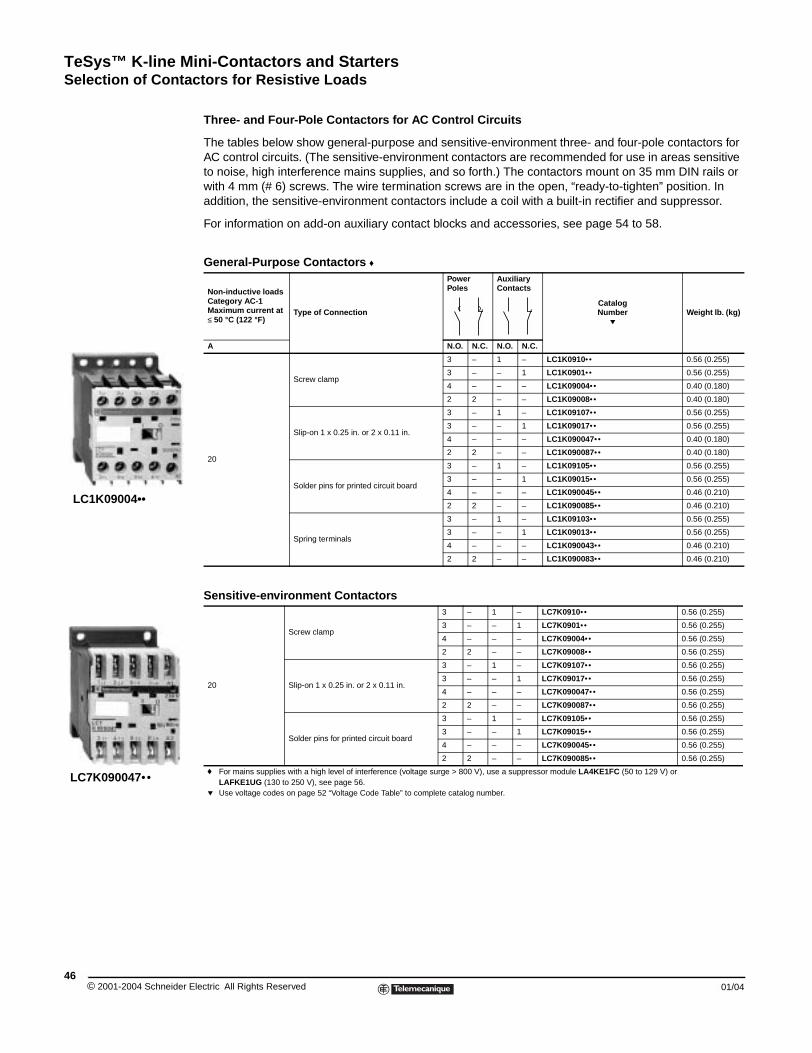
TeSys™ K-line Mini-Contactors and StartersSelection of Contactors for Resistive Loads
© 2001-2004 Schneider E46
LC7K090047••
LC1K09004••
Selection of Contactors for Resistive Loads
Three- and Four-Pole Contactors for AC Control Circuits
The tables below show general-purpose and sensitive-environment three- and four-pole contactors for AC control circuits. (The sensitive-environment contactors are recommended for use in areas sensitive to noise, high interference mains supplies, and so forth.) The contactors mount on 35 mm DIN rails or with 4 mm (# 6) screws. The wire termination screws are in the open, “ready-to-tighten” position. In addition, the sensitive-environment contactors include a coil with a built-in rectifier and suppressor.
For information on add-on auxiliary contact blocks and accessories, see page 54 to 58.
General-Purpose Contactors f
Non-inductive loads Category AC-1 Maximum current at ≤ 50 °C (122 °F)
Type of Connection
Power Poles
Auxiliary Contacts
CatalogNumber
pWeight lb. (kg)
A N.O. N.C. N.O. N.C.
20
Screw clamp
3 – 1 – LC1K0910•• 0.56 (0.255)
3 – – 1 LC1K0901•• 0.56 (0.255)
4 – – – LC1K09004•• 0.40 (0.180)
2 2 – – LC1K09008•• 0.40 (0.180)
Slip-on 1 x 0.25 in. or 2 x 0.11 in.
3 – 1 – LC1K09107•• 0.56 (0.255)
3 – – 1 LC1K09017•• 0.56 (0.255)
4 – – – LC1K090047•• 0.40 (0.180)
2 2 – – LC1K090087•• 0.40 (0.180)
Solder pins for printed circuit board
3 – 1 – LC1K09105•• 0.56 (0.255)
3 – – 1 LC1K09015•• 0.56 (0.255)
4 – – – LC1K090045•• 0.46 (0.210)
2 2 – – LC1K090085•• 0.46 (0.210)
Spring terminals
3 – 1 – LC1K09103•• 0.56 (0.255)
3 – – 1 LC1K09013•• 0.56 (0.255)
4 – – – LC1K090043•• 0.46 (0.210)
2 2 – – LC1K090083•• 0.46 (0.210)
Sensitive-environment Contactors
20
Screw clamp
3 – 1 – LC7K0910•• 0.56 (0.255)
3 – – 1 LC7K0901•• 0.56 (0.255)
4 – – – LC7K09004•• 0.56 (0.255)
2 2 – – LC7K09008•• 0.56 (0.255)
Slip-on 1 x 0.25 in. or 2 x 0.11 in.
3 – 1 – LC7K09107•• 0.56 (0.255)
3 – – 1 LC7K09017•• 0.56 (0.255)
4 – – – LC7K090047•• 0.56 (0.255)
2 2 – – LC7K090087•• 0.56 (0.255)
Solder pins for printed circuit board
3 – 1 – LC7K09105•• 0.56 (0.255)
3 – – 1 LC7K09015•• 0.56 (0.255)
4 – – – LC7K090045•• 0.56 (0.255)
2 2 – – LC7K090085•• 0.56 (0.255)
f For mains supplies with a high level of interference (voltage surge > 800 V), use a suppressor module LA4KE1FC (50 to 129 V) or LAFKE1UG (130 to 250 V), see page 56.
p Use voltage codes on page 52 “Voltage Code Table” to complete catalog number.
lectric All Rights Reserved 01/04
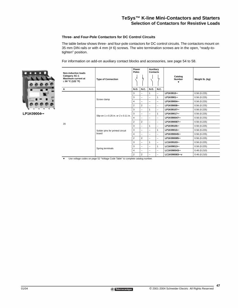
TeSys™ K-line Mini-Contactors and StartersSelection of Contactors for Resistive Loads
01/04
LP1K09004••
Three- and Four-Pole Contactors for DC Control Circuits
The table below shows three- and four-pole contactors for DC control circuits. The contactors mount on 35 mm DIN rails or with 4 mm (# 6) screws. The wire termination screws are in the open, “ready-to-tighten” position.
For information on add-on auxiliary contact blocks and accessories, see page 54 to 58.
Non-inductive loads Category AC-1Maximum current at ≤ 50 °C (122 °F)
Type of Connection
Power Poles
Auxiliary Contacts
CatalogNumber
pWeight lb. (kg)
A N.O. N.C. N.O. N.C.
20
Screw clamp
3 – 1 – LP1K0910•• 0.56 (0.225)
3 – – 1 LP1K0901•• 0.56 (0.225)
4 – – – LP1K09004•• 0.56 (0.225)
2 2 – – LP1K09008•• 0.56 (0.225)
Slip-on 1 x 0.25 in. or 2 x 0.11 in.
3 – 1 – LP1K09107•• 0.56 (0.225)
3 – – 1 LP1K09017•• 0.56 (0.225)
4 – – – LP1K090047•• 0.56 (0.225)
2 2 – – LP1K090087•• 0.56 (0.225)
Solder pins for printed circuit board
3 – 1 – LP1K09105•• 0.56 (0.225)
3 – – 1 LP1K09015•• 0.56 (0.225)
4 – – – LP1K090045•• 0.56 (0.225)
2 2 – – LP1K090085•• 0.56 (0.225)
Spring terminals
3 – 1 – LC1K09103•• 0.56 (0.225)
3 – – 1 LC1K09013•• 0.56 (0.225)
4 – – – LC1K090043•• 0.46 (0.210)
2 2 – – LC1K090083•• v 0.46 (0.210)
p Use voltage codes on page 52 “Voltage Code Table” to complete catalog number.
47© 2001-2004 Schneider Electric All Rights Reserved
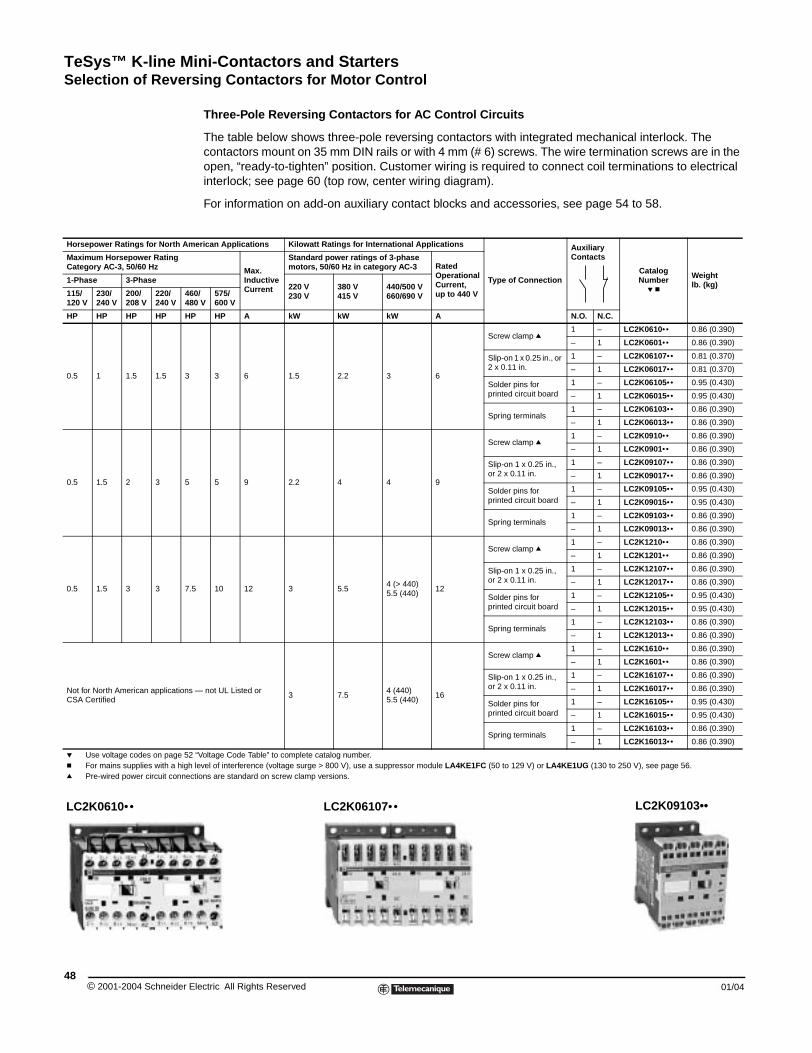
TeSys™ K-line Mini-Contactors and StartersSelection of Reversing Contactors for Motor Control
© 2001-2004 Schneider E48
Horsepower Ratings for North Am
Maximum Horsepower RatingCategory AC-3, 50/60 Hz
1-Phase 3-Phase
115/120 V
230/240 V
200/208 V
220/240 V
4648
HP HP HP HP HP
0.5 1 1.5 1.5 3
0.5 1.5 2 3 5
0.5 1.5 3 3 7.
Not for North American applicationsCSA Certified
p Use voltage codes on page 52c For mains supplies with a highq Pre-wired power circuit connec
LC2K0610••
Selection of Reversing Contactors for Motor Control
Three-Pole Reversing Contactors for AC Control Circuits
The table below shows three-pole reversing contactors with integrated mechanical interlock. The contactors mount on 35 mm DIN rails or with 4 mm (# 6) screws. The wire termination screws are in the open, “ready-to-tighten” position. Customer wiring is required to connect coil terminations to electrical interlock; see page 60 (top row, center wiring diagram).
For information on add-on auxiliary contact blocks and accessories, see page 54 to 58.
erican Applications Kilowatt Ratings for International Applications
Type of Connection
Auxiliary Contacts
CatalogNumber
p c
Weightlb. (kg)
Max. Inductive Current
Standard power ratings of 3-phase motors, 50/60 Hz in category AC-3 Rated
Operational Current,up to 440 V
220 V230 V
380 V415 V
440/500 V660/690 V0/
0 V575/600 V
HP A kW kW kW A N.O. N.C.
3 6 1.5 2.2 3 6
Screw clamp q1 – LC2K0610•• 0.86 (0.390)
– 1 LC2K0601•• 0.86 (0.390)
Slip-on 1 x 0.25 in., or 2 x 0.11 in.
1 – LC2K06107•• 0.81 (0.370)
– 1 LC2K06017•• 0.81 (0.370)
Solder pins for printed circuit board
1 – LC2K06105•• 0.95 (0.430)
– 1 LC2K06015•• 0.95 (0.430)
Spring terminals1 – LC2K06103•• 0.86 (0.390)
– 1 LC2K06013•• 0.86 (0.390)
5 9 2.2 4 4 9
Screw clamp q1 – LC2K0910•• 0.86 (0.390)
– 1 LC2K0901•• 0.86 (0.390)
Slip-on 1 x 0.25 in., or 2 x 0.11 in.
1 – LC2K09107•• 0.86 (0.390)
– 1 LC2K09017•• 0.86 (0.390)
Solder pins for printed circuit board
1 – LC2K09105•• 0.95 (0.430)
– 1 LC2K09015•• 0.95 (0.430)
Spring terminals1 – LC2K09103•• 0.86 (0.390)
– 1 LC2K09013•• 0.86 (0.390)
5 10 12 3 5.54 (> 440)5.5 (440)
12
Screw clamp q1 – LC2K1210•• 0.86 (0.390)
– 1 LC2K1201•• 0.86 (0.390)
Slip-on 1 x 0.25 in., or 2 x 0.11 in.
1 – LC2K12107•• 0.86 (0.390)
– 1 LC2K12017•• 0.86 (0.390)
Solder pins for printed circuit board
1 – LC2K12105•• 0.95 (0.430)
– 1 LC2K12015•• 0.95 (0.430)
Spring terminals1 – LC2K12103•• 0.86 (0.390)
– 1 LC2K12013•• 0.86 (0.390)
— not UL Listed or 3 7.5
4 (440)5.5 (440)
16
Screw clamp q1 – LC2K1610•• 0.86 (0.390)
– 1 LC2K1601•• 0.86 (0.390)
Slip-on 1 x 0.25 in., or 2 x 0.11 in.
1 – LC2K16107•• 0.86 (0.390)
– 1 LC2K16017•• 0.86 (0.390)
Solder pins for printed circuit board
1 – LC2K16105•• 0.95 (0.430)
– 1 LC2K16015•• 0.95 (0.430)
Spring terminals1 – LC2K16103•• 0.86 (0.390)
– 1 LC2K16013•• 0.86 (0.390)
“Voltage Code Table” to complete catalog number. level of interference (voltage surge > 800 V), use a suppressor module LA4KE1FC (50 to 129 V) or LA4KE1UG (130 to 250 V), see page 56.tions are standard on screw clamp versions.
LC2K06107•• LC2K09103••
lectric All Rights Reserved 01/04
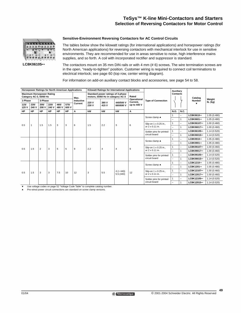
TeSys™ K-line Mini-Contactors and StartersSelection of Reversing Contactors for Motor Control
01/04
Horsepower Ratings for North Am
Maximum Horsepower RatingCategory AC-3, 50/60 Hz
1-Phase 3-Phase
115/120 V
230/240 V
200/208 V
220/240 V
4648
HP HP HP HP HP
0.5 1 1.5 1.5 3
0.5 1.5 2 3 5
0.5 1.5 3 3 7.5
p Use voltage codes on page 52 q Pre-wired power circuit connec
LC8K06105••
Sensitive-Environment Reversing Contactors for AC Control Circuits
The tables below show the kilowatt ratings (for international applications) and horsepower ratings (for North American applications) for reversing contactors with mechanical interlock for use in sensitive environments. They are recommended for use in areas sensitive to noise, high interference mains supplies, and so forth. A coil with incorporated rectifier and suppressor is standard.
The contactors mount on 35 mm DIN rails or with 4 mm (# 6) screws. The wire termination screws are in the open, “ready-to-tighten” position. Customer wiring is required to connect coil terminations to electrical interlock; see page 60 (top row, center wiring diagram).
For information on add-on auxiliary contact blocks and accessories, see page 54 to 58.
erican Applications Kilowatt Ratings for International Applications
Type of Connection
Auxiliary Contacts
CatalogNumber
p
Weightlb. (kg)
Max. Inductive Current
Standard power ratings of 3-phase motors, 50/60 Hz in category AC-3 Rated
Operational Current,up to 440 V
220 V230 V
380 V415 V
440/500 V660/690 V0/
0 V575/600 V
HP A kW kW kW A N.O. N.C.
3 6 1.5 2.2 3 6
Screw clamp q1 – LC8K0610•• 1.05 (0.480)
– 1 LC8K0601•• 1.05 (0.480)
Slip-on 1 x 0.25 in., or 2 x 0.11 in.
1 – LC8K06107•• 1.00 (0.460)
– 1 LC8K06017•• 1.00 (0.460)
Solder pins for printed circuit board
1 – LC8K06105•• 1.14 (0.520)
– 1 LC8K06015•• 1.14 (0.520)
5 9 2.2 4 4 9
Screw clamp q1 – LC8K0910•• 1.05 (0.480)
– 1 LC8K0901•• 1.05 (0.480)
Slip-on 1 x 0.25 in., or 2 x 0.11 in.
1 – LC8K09107•• 1.00 (0.460)
– 1 LC8K09017•• 1.00 (0.460)
Solder pins for printed circuit board
1 – LC8K09105•• 1.14 (0.520)
– 1 LC8K09015•• 1.14 (0.520)
10 12 3 5.54 (> 440)5.5 (440)
12
Screw clamp q1 – LC8K1210•• 1.05 (0.480)
– 1 LC8K1201•• 1.05 (0.480)
Slip-on 1 x 0.25 in., or 2 x 0.11 in.
1 – LC8K12107•• 1.00 (0.460)
– 1 LC8K12017•• 1.00 (0.460)
Solder pins for printed circuit board
1 – LC8K12105•• 1.14 (0.520)
– 1 LC8K12015•• 1.14 (0.520)
“Voltage Code Table” to complete catalog number.tions are standard on screw clamp versions.
49© 2001-2004 Schneider Electric All Rights Reserved
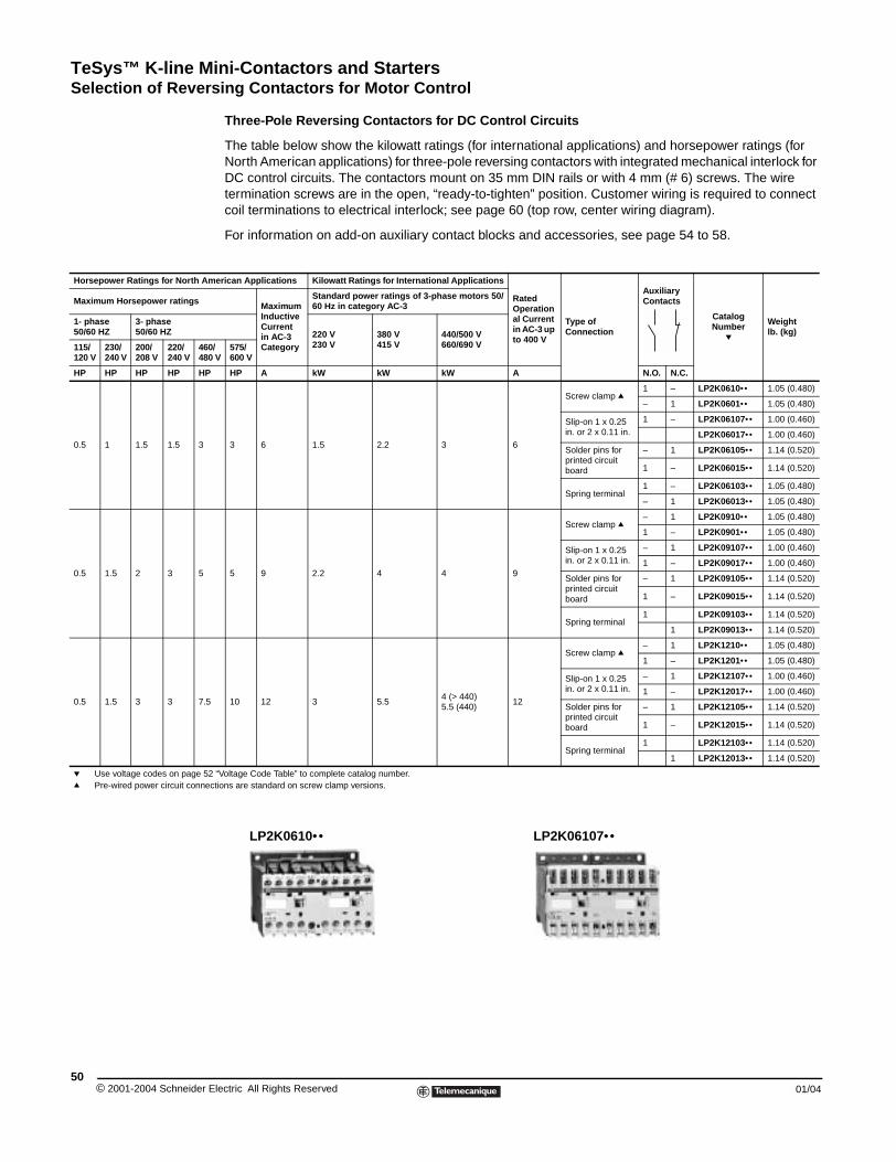
TeSys™ K-line Mini-Contactors and StartersSelection of Reversing Contactors for Motor Control
© 2001-2004 Schneider E50
Horsepower Ratings for North Am
Maximum Horsepower ratings
1- phase50/60 HZ
3- phase50/60 HZ
115/120 V
230/240 V
200/208 V
220/240 V
460480
HP HP HP HP HP
0.5 1 1.5 1.5 3
0.5 1.5 2 3 5
0.5 1.5 3 3 7.5
p Use voltage codes on page 52q Pre-wired power circuit connec
Three-Pole Reversing Contactors for DC Control Circuits
The table below show the kilowatt ratings (for international applications) and horsepower ratings (for North American applications) for three-pole reversing contactors with integrated mechanical interlock for DC control circuits. The contactors mount on 35 mm DIN rails or with 4 mm (# 6) screws. The wire termination screws are in the open, “ready-to-tighten” position. Customer wiring is required to connect coil terminations to electrical interlock; see page 60 (top row, center wiring diagram).
For information on add-on auxiliary contact blocks and accessories, see page 54 to 58.
erican Applications Kilowatt Ratings for International Applications
Rated Operational Current in AC-3 up to 400 V
Type of Connection
Auxiliary Contacts
CatalogNumber
p
Weightlb. (kg)
MaximumInductive Current in AC-3 Category
Standard power ratings of 3-phase motors 50/60 Hz in category AC-3
220 V230 V
380 V 415 V
440/500 V660/690 V/
V575/600 V
HP A kW kW kW A N.O. N.C.
3 6 1.5 2.2 3 6
Screw clamp q1 – LP2K0610•• 1.05 (0.480)
– 1 LP2K0601•• 1.05 (0.480)
Slip-on 1 x 0.25 in. or 2 x 0.11 in.
1 – LP2K06107•• 1.00 (0.460)
LP2K06017•• 1.00 (0.460)
Solder pins for printed circuit board
– 1 LP2K06105•• 1.14 (0.520)
1 – LP2K06015•• 1.14 (0.520)
Spring terminal1 – LP2K06103•• 1.05 (0.480)
– 1 LP2K06013•• 1.05 (0.480)
5 9 2.2 4 4 9
Screw clamp q– 1 LP2K0910•• 1.05 (0.480)
1 – LP2K0901•• 1.05 (0.480)
Slip-on 1 x 0.25 in. or 2 x 0.11 in.
– 1 LP2K09107•• 1.00 (0.460)
1 – LP2K09017•• 1.00 (0.460)
Solder pins for printed circuit board
– 1 LP2K09105•• 1.14 (0.520)
1 – LP2K09015•• 1.14 (0.520)
Spring terminal1 LP2K09103•• 1.14 (0.520)
1 LP2K09013•• 1.14 (0.520)
10 12 3 5.54 (> 440)5.5 (440)
12
Screw clamp q– 1 LP2K1210•• 1.05 (0.480)
1 – LP2K1201•• 1.05 (0.480)
Slip-on 1 x 0.25 in. or 2 x 0.11 in.
– 1 LP2K12107•• 1.00 (0.460)
1 – LP2K12017•• 1.00 (0.460)
Solder pins for printed circuit board
– 1 LP2K12105•• 1.14 (0.520)
1 – LP2K12015•• 1.14 (0.520)
Spring terminal1 LP2K12103•• 1.14 (0.520)
1 LP2K12013•• 1.14 (0.520)
“Voltage Code Table” to complete catalog number.tions are standard on screw clamp versions.
LP2K06107••LP2K0610••
lectric All Rights Reserved 01/04
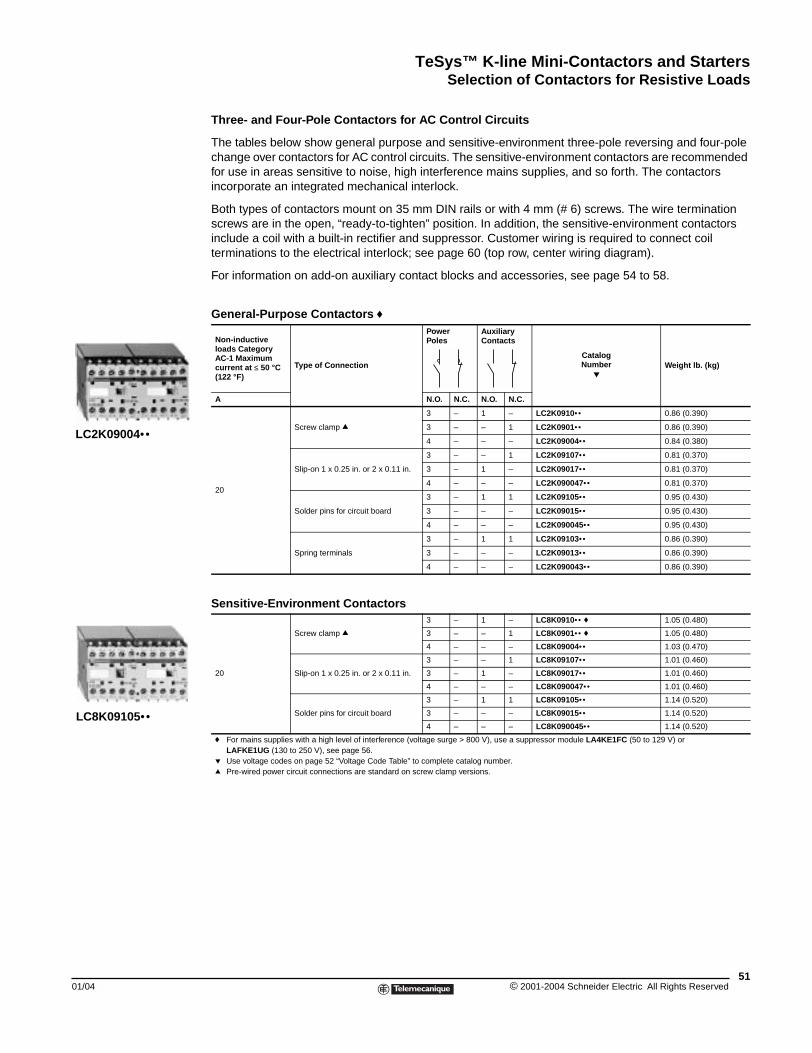
TeSys™ K-line Mini-Contactors and StartersSelection of Contactors for Resistive Loads
01/04
LC2K09004••
LC8K09105••
Selection of Reversing Contactors for Resistive Loads
Three- and Four-Pole Contactors for AC Control Circuits
The tables below show general purpose and sensitive-environment three-pole reversing and four-pole change over contactors for AC control circuits. The sensitive-environment contactors are recommended for use in areas sensitive to noise, high interference mains supplies, and so forth. The contactors incorporate an integrated mechanical interlock.
Both types of contactors mount on 35 mm DIN rails or with 4 mm (# 6) screws. The wire termination screws are in the open, “ready-to-tighten” position. In addition, the sensitive-environment contactors include a coil with a built-in rectifier and suppressor. Customer wiring is required to connect coil terminations to the electrical interlock; see page 60 (top row, center wiring diagram).
For information on add-on auxiliary contact blocks and accessories, see page 54 to 58.
General-Purpose Contactors f
Non-inductive loads Category AC-1 Maximum current at ≤ 50 °C (122 °F)
Type of Connection
Power Poles
Auxiliary Contacts
CatalogNumber
pWeight lb. (kg)
A N.O. N.C. N.O. N.C.
20
Screw clamp q
3 – 1 – LC2K0910•• 0.86 (0.390)
3 – – 1 LC2K0901•• 0.86 (0.390)
4 – – – LC2K09004•• 0.84 (0.380)
Slip-on 1 x 0.25 in. or 2 x 0.11 in.
3 – – 1 LC2K09107•• 0.81 (0.370)
3 – 1 – LC2K09017•• 0.81 (0.370)
4 – – – LC2K090047•• 0.81 (0.370)
Solder pins for circuit board
3 – 1 1 LC2K09105•• 0.95 (0.430)
3 – – – LC2K09015•• 0.95 (0.430)
4 – – – LC2K090045•• 0.95 (0.430)
Spring terminals
3 – 1 1 LC2K09103•• 0.86 (0.390)
3 – – – LC2K09013•• 0.86 (0.390)
4 – – – LC2K090043•• 0.86 (0.390)
Sensitive-Environment Contactors
20
Screw clamp q3 – 1 – LC8K0910•• f 1.05 (0.480)
3 – – 1 LC8K0901•• f 1.05 (0.480)
4 – – – LC8K09004•• 1.03 (0.470)
Slip-on 1 x 0.25 in. or 2 x 0.11 in.
3 – – 1 LC8K09107•• 1.01 (0.460)
3 – 1 – LC8K09017•• 1.01 (0.460)
4 – – – LC8K090047•• 1.01 (0.460)
Solder pins for circuit board
3 – 1 1 LC8K09105•• 1.14 (0.520)
3 – – – LC8K09015•• 1.14 (0.520)
4 – – – LC8K090045•• 1.14 (0.520)
f For mains supplies with a high level of interference (voltage surge > 800 V), use a suppressor module LA4KE1FC (50 to 129 V) or LAFKE1UG (130 to 250 V), see page 56.
p Use voltage codes on page 52 “Voltage Code Table” to complete catalog number.q Pre-wired power circuit connections are standard on screw clamp versions.
51© 2001-2004 Schneider Electric All Rights Reserved
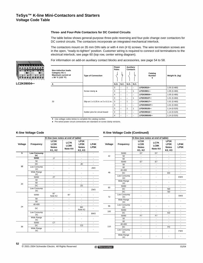
TeSys™ K-line Mini-Contactors and StartersVoltage Code Table
© 2001-2004 Schneider E52
LC2K09004••
Voltage Code Table
Three- and Four-Pole Contactors for DC Control Circuits
The table below shows general-purpose three-pole reversing and four-pole change over contactors for DC control circuits. The contactors incorporate an integrated mechanical interlock.
The contactors mount on 35 mm DIN rails or with 4 mm (# 6) screws. The wire termination screws are in the open, “ready-to-tighten” position. Customer wiring is required to connect coil terminations to the electrical interlock; see page 60 (top row, center wiring diagram).
For information on add-on auxiliary contact blocks and accessories, see page 54 to 58.
Non-inductive loads Category AC-1Maximum current at ≤ 50 °C (122 °F)
Type of Connection
Power Poles
Auxiliary Contacts
CatalogNumber
pWeight lb. (kg)
A N.O. N.C. N.O. N.C.
20
Screw clamp q
3 – 1 – LP2K0910•• 1.05 (0.480)
3 – – 1 LP2K0901•• 1.05 (0.480)
4 – – – LP2K09004•• 1.05 (0.480)
Slip-on 1 x 0.25 in. or 2 x 0.11 in.
3 – – 1 LP2K09107•• 1.01 (0.460)
3 – 1 – LP2K09017•• 1.01 (0.460)
4 – – – LP2K090047•• 1.01 (0.460)
Solder pins for circuit board
3 – 1 1 LP2K09105•• 1.14 (0.520)
3 – – – LP2K09015•• 1.14 (0.520)
4 – – – LP2K090045•• 1.14 (0.520)
p Use voltage codes below to complete the catalog number. q Pre-wired power circuit connections are standard on screw clamp versions.
K-line Voltage Code Table
K-line Voltage Code
Voltage Frequency
K-line (see notes at end of table)LC1KLC2KNotesK1, K2
LC7KLC8K
Note K4
LP1KLP2K NotesK2, K3
LP4KLP5K
5 Low ConsumpDC
- - - -
12
50/60 J7 - - -50 - - - -DC - - JD -
Low Consump DC
- - - JW3
Wide Range DC
- - - -
20
50/60 Z7 - - -50 - - - -60 - - - -DC - - ZD -
Low Consump DC
- - - ZW3
24
50/60B7
Note K2B7 - -
50 - - - -60 - - - -
40-400 - - - -
DC - -BD
Note K2-
Low Consump DC
- - - BW3
Wide Range DC
- - - -
36
50/60 C7 - - -DC - - CD -
Wide Range DC
- - - -
lectric All Rights Reserved
4250/60 D7 D7 - -
50 - - - -60 - - - -
48
50/60 E7 E7 - -50 - - - -60 - - - -
40-400 - - - -DC - - ED -
Low Consump DC
- - - EW3
Wide Range DC
- - - -
6050/60 - - - -DC - - ND -
72
DC - - SD -Low Consump
DC- - - SW3
Wide Range DC
- - - -
96Low Consump
DC- - - -
10050/60 - - - -DC - - KD -
110
50/60 F7 F7 - -50 - - - -60 - - - -
40-400 - - - -DC - - FD -
Low Consump DC
- - - FW3
Wide Range DC
- - - -
K-line Voltage Code (Continued)
Voltage Frequency
K-line (see notes at end of table)LC1KLC2KNotesK1, K2
LC7KLC8K
Note K4
LP1KLP2K NotesK2, K3
LP4KLP5K
01/04
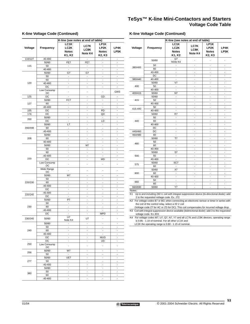
TeSys™ K-line Mini-Contactors and StartersVoltage Code Table
110/127 40-400 - - - -
11550/60 FE7 FE7 - -
50 - - - -40-400 - - - -
120
50/60 G7 G7 - -50 - - - -60 - - - -
40-400 - - - -DC - - - -
Low Consump DC
- - - GW3
125 DC - - GD -
12750/60 FC7 - - -
60 - - - -40-400 - - - -
155 DC - - PD -174 DC - - QD -
20050/60 - - - -DC - - LD -
200/20850/60 L7 - - -
60 - - - -40-400 - - - -
20850/60 - - - -
60 - - - -40-400 - - - -
220
50/60 - M7 - -50 - - - -60 - - - -
40-400 - - - -DC - - MD -
Low Consump DC
- - - -
Wide Range DC
- - - -
220/230
50/60 M7 - - -50 - - - -60 - - - -
40-400 - - - -DC - - - -
220/24040-400 - - - -
DC - - - -
230
50/60 P7 - - -50 - - - -60 - - - -
40-400 - - - -DC - - MPD -
230/240 50/60U7
Note K4U7 - -
240
50/60 - - - -50 - - - -60 - - - -
40-400 - - - -DC - - MUD -
250DC - - UD -
Low Consump DC
- - - -
25650/60 W7 - - -
50 - - - -
27750/60 UE7 - - -
50 - - - -40-400 - - - -
380
50/60 - - - -50 - - - -60 - - - -
40-400 - - - -
K-line Voltage Code (Continued)
Voltage Frequency
K-line (see notes at end of table)LC1KLC2KNotesK1, K2
LC7KLC8K
Note K4
LP1KLP2K NotesK2, K3
LP4KLP5K
01/04
380/400
50/60Q7
NOte K4- - -
50 - - - -60 - - - -
40-400 - - - -DC - - - -
380/440 40-400 - - - -
40050/60 V7 - - -
50 - - - -40-400 - - - -
400/415 50/60 N7 - - -
41550/60 - - - -
50 - - - -40-400 - - - -
415-44050 - - - -
40-400 - - - -
440
50/60 R7 - - -50 - - - -60 - - - -
40-400 - - - -DC - - - -
440/460 DC - - - -460/480 60 - - - -
480
50/60 T7 - - -50 - - - -60 - - - -
40-400 - - - -
50050/60 S7 - - -
50 - - - -40-400 - - - -
57550/60 SC7 - - -
60 - - - -
60050/60 X7 - - -
60 - - - -40-400 - - - -
66050 - - - -60 - - - -
660/690 50/60 Y7 - - -Notes:K1 Up to and including 240 V, coil with integral suppression device (bi-directional diode): add
2 to the requested voltage code. Ex. J72K2 For voltage codes B7 or BD, when connecting an electronic sensor or timer in series with
the coil of the control relay, select a 20 V coil (Voltage code Z7 for AC or ZD for DC). This coil compensates for incurred voltage drop.K3 Coil with integral suppression device available (bidirectional diode): add 3 to the requested
voltage code. Ex JD3.K4 For voltage codes M7, U7, Q7, N7, Y7 and all LC7K and LC8K devices, operating range
is 0.85 - 1.10 of nominal. For all other LC1K and LC2K the operating range is 0.80 - 1.15 of nominal.
K-line Voltage Code (Continued)
Voltage Frequency
K-line (see notes at end of table)LC1KLC2KNotesK1, K2
LC7KLC8K
Note K4
LP1KLP2K NotesK2, K3
LP4KLP5K
53© 2001-2004 Schneider Electric All Rights Reserved
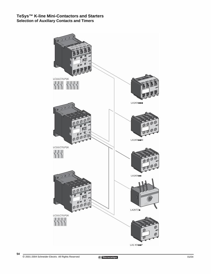
TeSys™ K-line Mini-Contactors and StartersSelection of Auxiliary Contacts and Timers
© 2001-2004 Schneider E54
Selection of Auxiliary Contacts and Timers
XX
LC1/LC7/LP1K
LC1/LC7/LP1K
LA1 KN P
LC1/LC7/LP1K
LA1KN M
LA1KN
LA1KN
LA2KT2
lectric All Rights Reserved 01/04
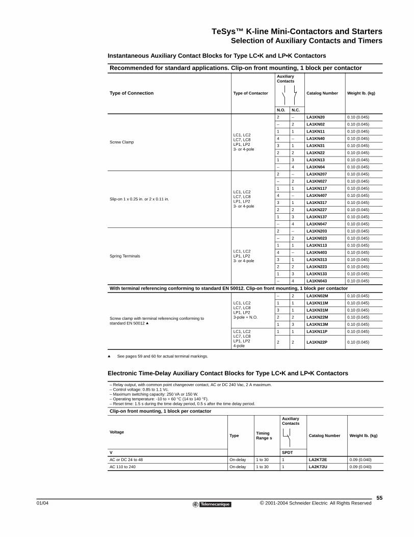
TeSys™ K-line Mini-Contactors and StartersSelection of Auxiliary Contacts and Timers
01/04
Instantaneous Auxiliary Contact Blocks for Type LC•K and LP•K Contactors
q See pages 59 and 60 for actual terminal markings.
Electronic Time-Delay Auxiliary Contact Blocks for Type LC•K and LP•K Contactors
Recommended for standard applications. Clip-on front mounting, 1 block per contactor
Type of Connection Type of Contactor
Auxiliary Contacts
Catalog Number Weight lb. (kg)
N.O. N.C.
Screw Clamp
LC1, LC2LC7, LC8LP1, LP23- or 4-pole
2 – LA1KN20 0.10 (0.045)
– 2 LA1KN02 0.10 (0.045)
1 1 LA1KN11 0.10 (0.045)
4 – LA1KN40 0.10 (0.045)
3 1 LA1KN31 0.10 (0.045)
2 2 LA1KN22 0.10 (0.045)
1 3 LA1KN13 0.10 (0.045)
– 4 LA1KN04 0.10 (0.045)
Slip-on 1 x 0.25 in. or 2 x 0.11 in.
LC1, LC2LC7, LC8LP1, LP23- or 4-pole
2 – LA1KN207 0.10 (0.045)
– 2 LA1KN027 0.10 (0.045)
1 1 LA1KN117 0.10 (0.045)
4 – LA1KN407 0.10 (0.045)
3 1 LA1KN317 0.10 (0.045)
2 2 LA1KN227 0.10 (0.045)
1 3 LA1KN137 0.10 (0.045)
– 4 LA1KN047 0.10 (0.045)
Spring TerminalsLC1, LC2LP1, LP23- or 4-pole
2 – LA1KN203 0.10 (0.045)
– 2 LA1KN023 0.10 (0.045)
1 1 LA1KN113 0.10 (0.045)
4 – LA1KN403 0.10 (0.045)
3 1 LA1KN313 0.10 (0.045)
2 2 LA1KN223 0.10 (0.045)
1 3 LA1KN133 0.10 (0.045)
– 4 LA1KN043 0.10 (0.045)
With terminal referencing conforming to standard EN 50012. Clip-on front mounting, 1 block per contactor
Screw clamp with terminal referencing conforming to standard EN 50012 q
LC1, LC2LC7, LC8LP1, LP23-pole + N.O.
– 2 LA1KN02M 0.10 (0.045)
1 1 LA1KN11M 0.10 (0.045)
3 1 LA1KN31M 0.10 (0.045)
2 2 LA1KN22M 0.10 (0.045)
1 3 LA1KN13M 0.10 (0.045)
LC1, LC2LC7, LC8LP1, LP24-pole
1 1 LA1KN11P 0.10 (0.045)
2 2 LA1KN22P 0.10 (0.045)
– Relay output, with common point changeover contact, AC or DC 240 Vac, 2 A maximum.– Control voltage: 0.85 to 1.1 Vc.– Maximum switching capacity: 250 VA or 150 W.– Operating temperature: -10 to + 60 °C (14 to 140 °F).– Reset time: 1.5 s during the time delay period, 0.5 s after the time delay period.
Clip-on front mounting, 1 block per contactor
VoltageType Timing
Range s
Auxiliary Contacts
Catalog Number Weight lb. (kg)
V SPDT
AC or DC 24 to 48 On-delay 1 to 30 1 LA2KT2E 0.09 (0.040)
AC 110 to 240 On-delay 1 to 30 1 LA2KT2U 0.09 (0.040)
55© 2001-2004 Schneider Electric All Rights Reserved
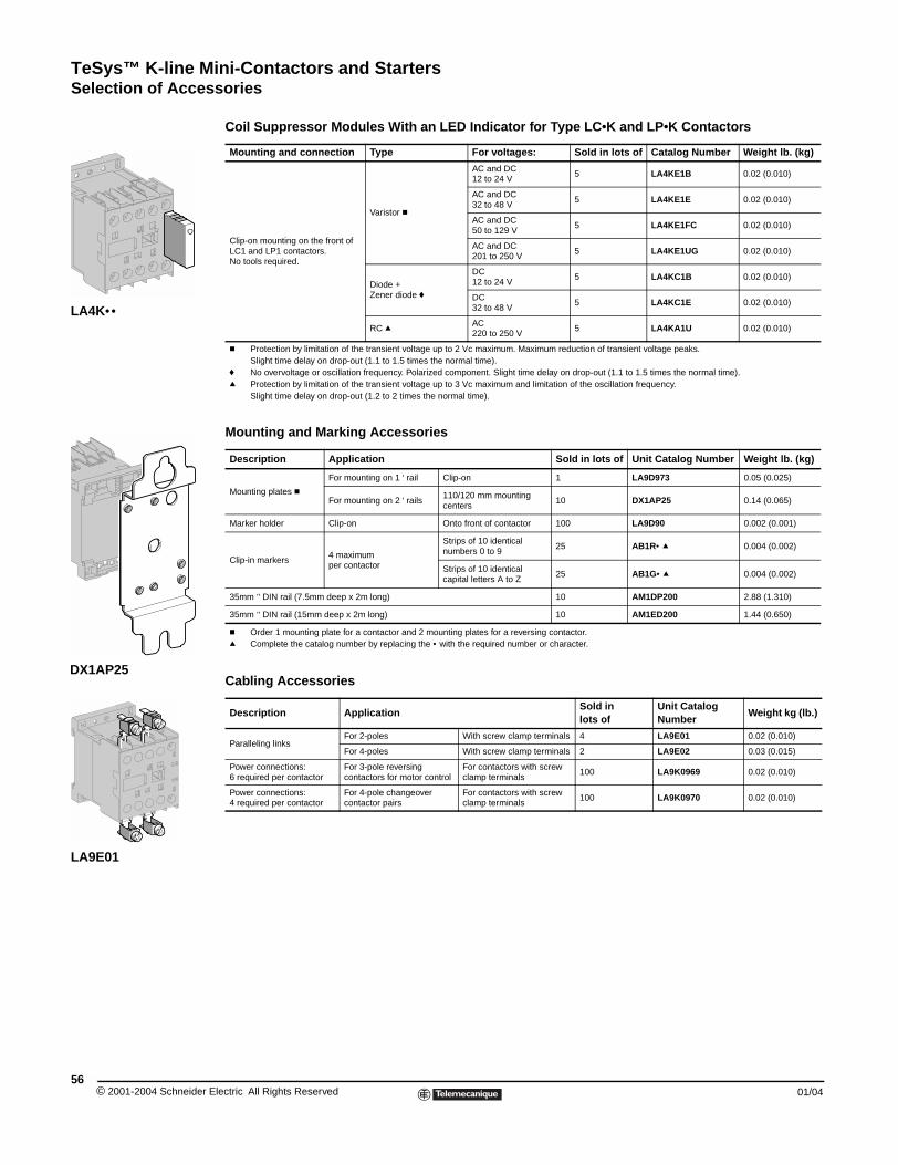
TeSys™ K-line Mini-Contactors and StartersSelection of Accessories
© 2001-2004 Schneider E56
LA4K••
DX1AP25
LA9E01
Selection of Accessories
Coil Suppressor Modules With an LED Indicator for Type LC•K and LP•K Contactors
Mounting and Marking Accessories
Cabling Accessories
Mounting and connection Type For voltages: Sold in lots of Catalog Number Weight lb. (kg)
Clip-on mounting on the front of LC1 and LP1 contactors.No tools required.
Varistor c
AC and DC12 to 24 V
5 LA4KE1B 0.02 (0.010)
AC and DC32 to 48 V
5 LA4KE1E 0.02 (0.010)
AC and DC50 to 129 V
5 LA4KE1FC 0.02 (0.010)
AC and DC201 to 250 V
5 LA4KE1UG 0.02 (0.010)
Diode +Zener diode f
DC12 to 24 V
5 LA4KC1B 0.02 (0.010)
DC32 to 48 V
5 LA4KC1E 0.02 (0.010)
RC q AC220 to 250 V
5 LA4KA1U 0.02 (0.010)
c Protection by limitation of the transient voltage up to 2 Vc maximum. Maximum reduction of transient voltage peaks. Slight time delay on drop-out (1.1 to 1.5 times the normal time).
f No overvoltage or oscillation frequency. Polarized component. Slight time delay on drop-out (1.1 to 1.5 times the normal time).q Protection by limitation of the transient voltage up to 3 Vc maximum and limitation of the oscillation frequency.
Slight time delay on drop-out (1.2 to 2 times the normal time).
Description Application Sold in lots of Unit Catalog Number Weight lb. (kg)
Mounting plates c
For mounting on 1 ' rail Clip-on 1 LA9D973 0.05 (0.025)
For mounting on 2 ' rails110/120 mm mounting centers
10 DX1AP25 0.14 (0.065)
Marker holder Clip-on Onto front of contactor 100 LA9D90 0.002 (0.001)
Clip-in markers4 maximumper contactor
Strips of 10 identical numbers 0 to 9
25 AB1R• q 0.004 (0.002)
Strips of 10 identical capital letters A to Z
25 AB1G• q 0.004 (0.002)
35mm " DIN rail (7.5mm deep x 2m long) 10 AM1DP200 2.88 (1.310)
35mm " DIN rail (15mm deep x 2m long) 10 AM1ED200 1.44 (0.650)
c Order 1 mounting plate for a contactor and 2 mounting plates for a reversing contactor.q Complete the catalog number by replacing the • with the required number or character.
Description ApplicationSold in lots of
Unit Catalog Number
Weight kg (lb.)
Paralleling linksFor 2-poles With screw clamp terminals 4 LA9E01 0.02 (0.010)
For 4-poles With screw clamp terminals 2 LA9E02 0.03 (0.015)
Power connections:6 required per contactor
For 3-pole reversing contactors for motor control
For contactors with screw clamp terminals
100 LA9K0969 0.02 (0.010)
Power connections:4 required per contactor
For 4-pole changeover contactor pairs
For contactors with screw clamp terminals
100 LA9K0970 0.02 (0.010)
lectric All Rights Reserved 01/04
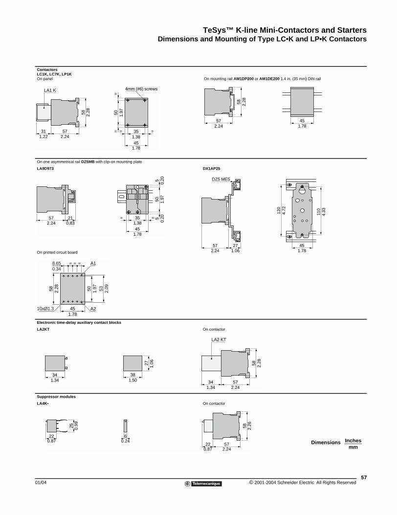
TeSys™ K-line Mini-Contactors and StartersDimensions and Mounting of Type LC•K and LP•K Contactors
01/04
Contactors LC1K, LC7K, LP1K On panel
On one asymmetrical rail DZ5MB w
LA9D973
On printed circuit board
Electronic time-delay auxiliary co
LA2KT
Suppressor modules
LA4K•
57312.241.22
LA1 K
58 2.28
572.24
210.83
50 1.97
451.78
58 2.28
8.650.34
= = =
10xØ1.3
A1
A2
1.3434
25 0.99
220.87
Dimensions and Mounting of Type LC\bK and LP\bK Contactors
XXX
On mounting rail AM1DP200 or AM1DE200 1.4 in. (35 mm) DIN rail
ith clip-on mounting plate
DX1AP25
ntact blocks
On contactor
On contactor
50 1.97
==
351.3845
1.78
= =
4mm (#6) screws
57
58 2.28
452.24 1.78
45
35
1.78
1.38= =
505
51.
970.
200.
20
110
4.33
451.78
120
4.72
572.24
271.06
DZ5 ME5
53 2.09
381.50
27 1.06
57342.241.34
LA2 KT
58 2.28
60.24
572.24
220.87
58 2.26
Inchesmm
Dimensions
57© 2001-2004 Schneider Electric All Rights Reserved
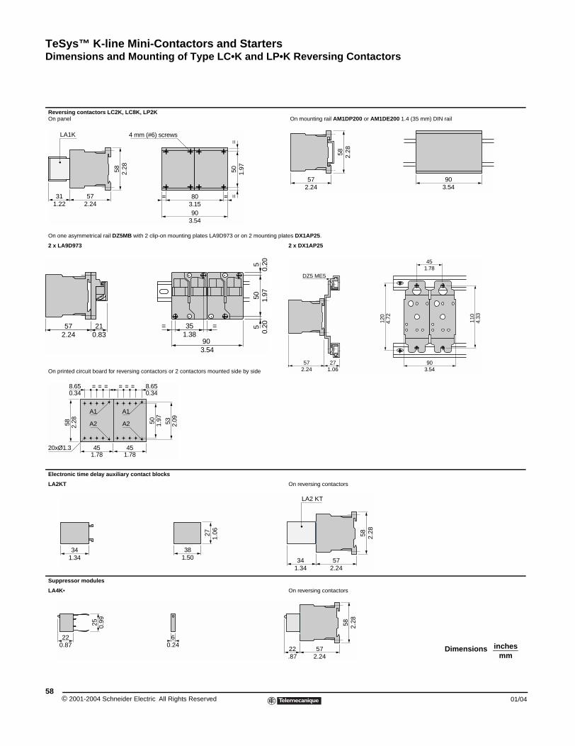
TeSys™ K-line Mini-Contactors and StartersDimensions and Mounting of Type LC•K and LP•K Reversing Contactors
© 2001-2004 Schneider E58
Reversing contactors LC2K, LC8On panel
On one asymmetrical rail DZ5MB w
2 x LA9D973
On printed circuit board for reversin
Electronic time delay auxiliary co
LA2KT
Suppressor modules
LA4K•
572.24
311.22
LA1K
58 2.28
4 m
57 212.24 0.83
45
58
8.65 = = =
20xØ1.3
A1
A2
451.78
0.34
1.78
===
2.28
A1
A2
1.3434
25 0.99
220.87
Dimensions and Mounting of Type LCkK and LPkK Reversing Contactors
K, LP2K On mounting rail AM1DP200 or AM1DE200 1.4 (35 mm) DIN rail
ith 2 clip-on mounting plates LA9D973 or on 2 mounting plates DX1AP25.
2 x DX1AP25
g contactors or 2 contactors mounted side by side
ntact blocks
On reversing contactors
On reversing contactors
50 1.97
==
903.54
803.15
m (#6) screws
==
57
58 2.28
902.24 3.54
90
35= =
505
51.
970.
200.
20
3.54
1.38
57 272.24 1.06
DZ5 ME5
903.54
110
120
4.33
4.72
451.78
50
8.650.34
531.97
2.09
381.50
27 1.06
57342.241.34
LA2 KT
58 2.28
60.24
57222.24.87
58 2.28
inchesmm
Dimensions
lectric All Rights Reserved 01/04
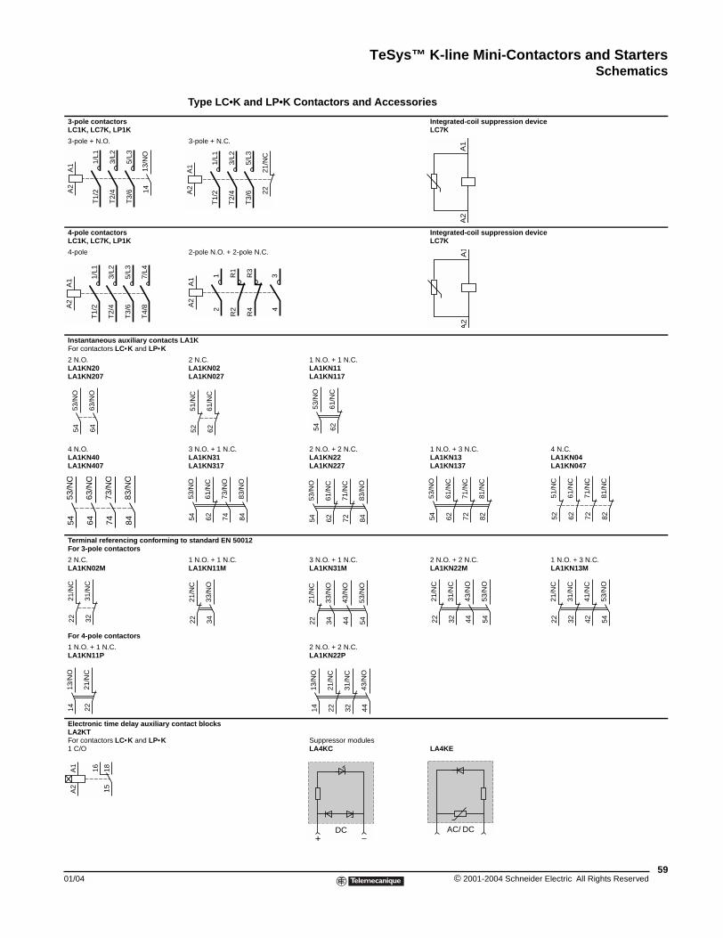
TeSys™ K-line Mini-Contactors and StartersSchematics
01/04
3-pole contactorsLC1K, LC7K, LP1K
3-pole + N.O.
4-pole contactorsLC1K, LC7K, LP1K
4-pole
Instantaneous auxiliary contactsFor contactors LC•K and LP•K
2 N.O. LA1KN20LA1KN207
4 N.O. LA1KN40LA1KN407
Terminal referencing conformingFor 3-pole contactors
2 N.C. LA1KN02M
For 4-pole contactors
1 N.O. + 1 N.C.LA1KN11P
Electronic time delay auxiliary coLA2KTFor contactors LC•K and LP•K1 C/O
13/N
O14
A1
A2
1/L1
T1/
2
3/L2
T2/
4
5/L3
T3/
6
A1
A2
1/L1
T1/
2
3/L2
T2/
4
5/L3
T3/
6
7/L4
T4/
8
53/N
O54
63/N
O64
54 64 74
53/N
O
63/N
O
73/N
O
83/N
O84
31/N
C32
21/N
C22
21/N
C22
13/N
O14
A1
A2
1815
16
SchematicsType LC•K and LP•K Contactors and Accessories
Integrated-coil suppression deviceLC7K
3-pole + N.C.
Integrated-coil suppression device LC7K
2-pole N.O. + 2-pole N.C.
LA1K
2 N.C. LA1KN02LA1KN027
1 N.O. + 1 N.C.LA1KN11LA1KN117
3 N.O. + 1 N.C. LA1KN31LA1KN317
2 N.O. + 2 N.C. LA1KN22LA1KN227
1 N.O. + 3 N.C. LA1KN13LA1KN137
4 N.C.LA1KN04LA1KN047
to standard EN 50012
1 N.O. + 1 N.C.LA1KN11M
3 N.O. + 1 N.C. LA1KN31M
2 N.O. + 2 N.C. LA1KN22M
1 N.O. + 3 N.C.LA1KN13M
2 N.O. + 2 N.C.LA1KN22P
ntact blocks
Suppressor modulesLA4KC LA4KE
A1
A2
2221
/NC
A1
A2
1/L1
T1/
2
3/L2
T2/
4
5/L3
T3/
6
A1
A2
R1
R2
A1
A2
12
34
R3
R4
61/N
C62
51/N
C52
61/N
C62
53/N
O54
53/N
O54
61/N
C62
73/N
O74
83/N
O84
53/N
O54
61/N
C62
71/N
C72
83/N
O84 54 62 72 82
53/N
O
61/N
C
71/N
C
81/N
C
51/N
C52
61/N
C62
71/N
C72
81/N
C82
22 34
21/N
C
33/N
O
33/N
O34
21/N
C22
43/N
O44
53/N
O54
21/N
C22
43/N
O44
53/N
O54
31/N
C32
21/N
C22
53/N
O54
31/N
C32
41/N
C42
22
13/N
O14
21/N
C
31/N
C32
43/N
O44
+ −DC AC/ DC
59© 2001-2004 Schneider Electric All Rights Reserved
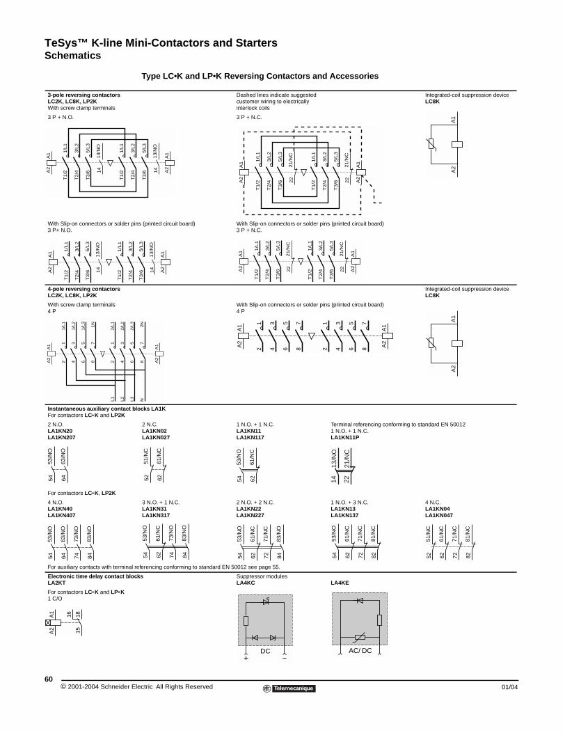
TeSys™ K-line Mini-Contactors and StartersSchematics
© 2001-2004 Schneider E60
3-pole reversing contactorsLC2K, LC8K, LP2KWith screw clamp terminals
3 P + N.O.
With Slip-on connectors or solder p3 P+ N.O.
4-pole reversing contactors LC2K, LC8K, LP2K
With screw clamp terminals4 P
Instantaneous auxiliary contact bFor contactors LC•K and LP2K
2 N.O. LA1KN20LA1KN207
For contactors LC•K, LP2K
4 N.O. LA1KN40LA1KN407
For auxiliary contacts with terminal
Electronic time delay contact bloLA2KT
For contactors LC•K and LP•K1 C/O
13/N
O14
A1
A2
1/L1
T1/
2
3/L2
T2/
4
5/L3
T3/
6
1/L1
T1/
2
13/N
O14
A1
A2
1/L
1T
1/2
3/L
2T
2/4
5/L
3T
3/6
1/L
1T
1/2
3/L
2T
2/4
A1
A2
12
34
56
12
34
1/L
1
1/L
2
1/L
3
2/L
1
2/L
2
L1
L2
78
1N
53/N
O54
63/N
O64
54 64 74
53/N
O
63/N
O
73/N
O
83/N
O84
A1
A2
1815
16
Type LC•K and LP•K Reversing Contactors and Accessories
Dashed lines indicate suggested customer wiring to electrically interlock coils
Integrated-coil suppression deviceLC8K
3 P + N.C.
ins (printed circuit board) With Slip-on connectors or solder pins (printed circuit board)3 P + N.C.
Integrated-coil suppression deviceLC8K
With Slip-on connectors or solder pins (printed circuit board)4 P
locks LA1K
2 N.C. LA1KN02LA1KN027
1 N.O. + 1 N.C.LA1KN11LA1KN117
Terminal referencing conforming to standard EN 500121 N.O. + 1 N.C.LA1KN11P
3 N.O. + 1 N.C. LA1KN31LA1KN317
2 N.O. + 2 N.C. LA1KN22LA1KN227
1 N.O. + 3 N.C. LA1KN13LA1KN137
4 N.C.LA1KN04LA1KN047
referencing conforming to standard EN 50012 see page 55.
cks Suppressor modulesLA4KC LA4KE
A1
A2
13/N
O14
A1
A2
3/L2
T2/
4
5/L3
T3/
6
21/N
C22
A1
A2
1/L
1T
1/2
3/L
2T
2/4
5/L
3T
3/6
21/N
C22
A1
A2
1/L
1T
1/2
3/L
2T
2/4
5/L
3T
3/6
13/N
O14
A1
A2
5/L
3T
3/6
21
/NC
22
A1
A2
1/L
1T
1/2
3/L
2T
2/4
5/L
3T
3/6
21
/NC
22
A1
A2
1/L
1T
1/2
3/L
2T
2/4
5/L
3T
3/6
A1
A2
A1
A2
56
2/L
3L
3
78
2N
N
A1
A2
12
34
56
A1
A2
12
34
78
78
56
1413
/NO
2221
/NC
61/N
C62
51/N
C52
61/N
C62
53/N
O54
62 74
53/N
O54
61/N
C
73/N
O
83/N
O84
53/N
O54
61/N
C62
71/N
C72
83/N
O84 54 62 72 82
53/N
O
61/N
C
71/N
C
81/N
C
51/N
C52
61/N
C62
71/N
C72
81/N
C82
+ −DC AC/ DC
lectric All Rights Reserved 01/04
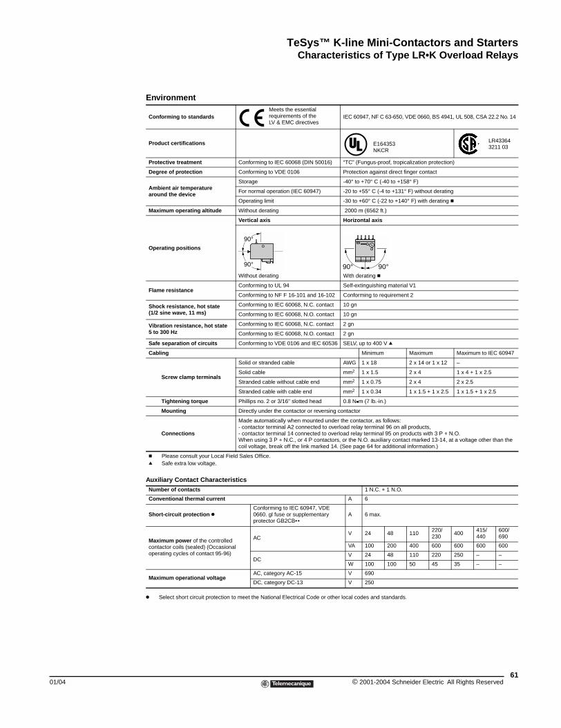
TeSys™ K-line Mini-Contactors and StartersCharacteristics of Type LR•K Overload Relays
01/04
Characteristics of Type LR\bK Overload Relays
k Select short circuit protection to meet the National Electrical Code or other local codes and standards.
Environment
Conforming to standardsMeets the essential requirements of the LV & EMC directives
IEC 60947, NF C 63-650, VDE 0660, BS 4941, UL 508, CSA 22.2 No. 14
Product certifications E164353 NKCR
LR43364 3211 03
Protective treatment Conforming to IEC 60068 (DIN 50016) “TC” (Fungus-proof, tropicalization protection)
Degree of protection Conforming to VDE 0106 Protection against direct finger contact
Ambient air temperature around the device
Storage -40° to +70° C (-40 to +158° F)
For normal operation (IEC 60947) -20 to +55° C (-4 to +131° F) without derating
Operating limit -30 to +60° C (-22 to +140° F) with derating c
Maximum operating altitude Without derating 2000 m (6562 ft.)
Operating positions
Vertical axis Horizontal axis
Without derating With derating c
Flame resistanceConforming to UL 94 Self-extinguishing material V1
Conforming to NF F 16-101 and 16-102 Conforming to requirement 2
Shock resistance, hot state (1/2 sine wave, 11 ms)
Conforming to IEC 60068, N.C. contact 10 gn
Conforming to IEC 60068, N.O. contact 10 gn
Vibration resistance, hot state5 to 300 Hz
Conforming to IEC 60068, N.C. contact 2 gn
Conforming to IEC 60068, N.O. contact 2 gn
Safe separation of circuits Conforming to VDE 0106 and IEC 60536 SELV, up to 400 V q
Cabling Minimum Maximum Maximum to IEC 60947
Screw clamp terminals
Solid or stranded cable AWG 1 x 18 2 x 14 or 1 x 12 –
Solid cable mm2 1 x 1.5 2 x 4 1 x 4 + 1 x 2.5
Stranded cable without cable end mm2 1 x 0.75 2 x 4 2 x 2.5
Stranded cable with cable end mm2 1 x 0.34 1 x 1.5 + 1 x 2.5 1 x 1.5 + 1 x 2.5
Tightening torque Phillips no. 2 or 3/16" slotted head 0.8 Nkm (7 lb.-in.)
Mounting Directly under the contactor or reversing contactor
Connections
Made automatically when mounted under the contactor, as follows:- contactor terminal A2 connected to overload relay terminal 96 on all products,- contactor terminal 14 connected to overload relay terminal 95 on products with 3 P + N.O. When using 3 P + N.C., or 4 P contactors, or the N.O. auxiliary contact marked 13-14, at a voltage other than the coil voltage, break off the link marked 14. (See page 64 for additional information.)
c Please consult your Local Field Sales Office.q Safe extra low voltage.
Auxiliary Contact CharacteristicsNumber of contacts 1 N.C. + 1 N.O.
Conventional thermal current A 6
Short-circuit protection kConforming to IEC 60947, VDE 0660. gl fuse or supplementary protector GB2CB••
A 6 max.
Maximum power of the controlled contactor coils (sealed) (Occasional operating cycles of contact 95-96)
AC V 24 48 110
220/230
400 415/440
600/690
VA 100 200 400 600 600 600 600
DCV 24 48 110 220 250 – –
W 100 100 50 45 35 – –
Maximum operational voltageAC, category AC-15 V 690
DC, category DC-13 V 250
90°
90° 90°90°
61© 2001-2004 Schneider Electric All Rights Reserved
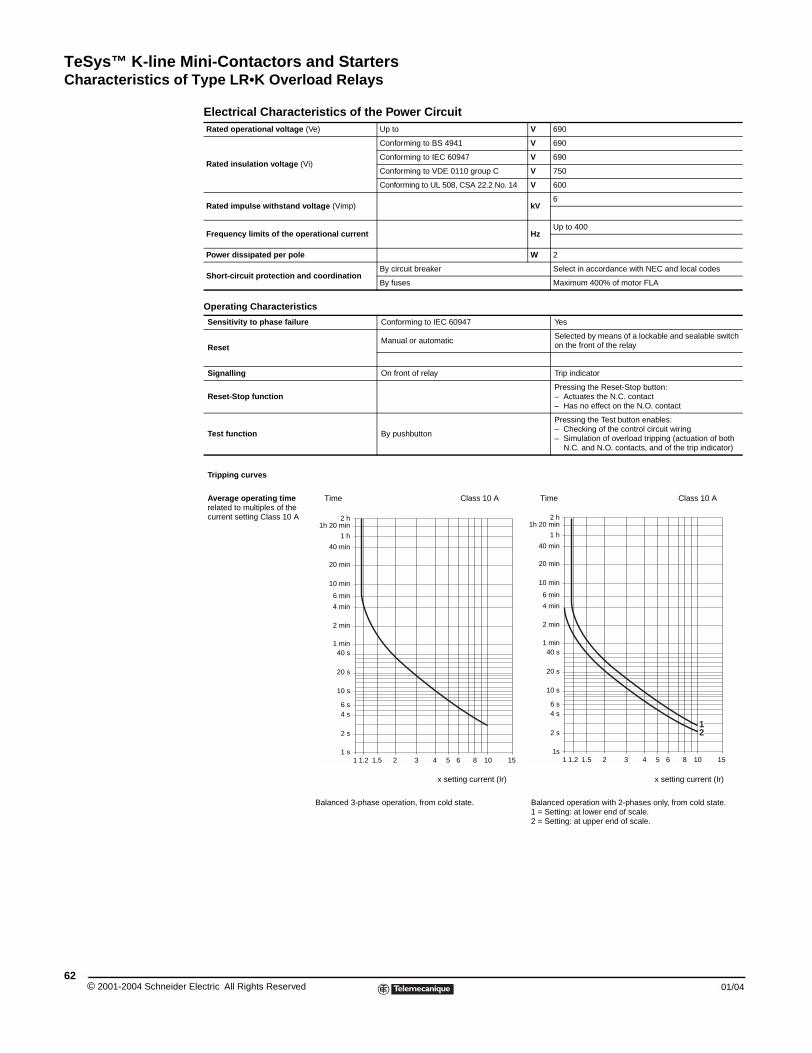
TeSys™ K-line Mini-Contactors and StartersCharacteristics of Type LR•K Overload Relays
© 2001-2004 Schneider E62
Electrical Characteristics of the Power CircuitRated operational voltage (Ve) Up to V 690
Rated insulation voltage (Vi)
Conforming to BS 4941 V 690
Conforming to IEC 60947 V 690
Conforming to VDE 0110 group C V 750
Conforming to UL 508, CSA 22.2 No. 14 V 600
Rated impulse withstand voltage (Vimp) kV6
Frequency limits of the operational current Hz Up to 400
Power dissipated per pole W 2
Short-circuit protection and coordinationBy circuit breaker Select in accordance with NEC and local codes
By fuses Maximum 400% of motor FLA
Operating Characteristics
Sensitivity to phase failure Conforming to IEC 60947 Yes
ResetManual or automatic
Selected by means of a lockable and sealable switchon the front of the relay
Signalling On front of relay Trip indicator
Reset-Stop functionPressing the Reset-Stop button:– Actuates the N.C. contact– Has no effect on the N.O. contact
Test function By pushbutton
Pressing the Test button enables:– Checking of the control circuit wiring– Simulation of overload tripping (actuation of both
N.C. and N.O. contacts, and of the trip indicator)
Tripping curves
Average operating time related to multiples of the current setting Class 10 A
Time Class 10 A Time Class 10 A
x setting current (Ir) x setting current (Ir)
Balanced 3-phase operation, from cold state. Balanced operation with 2-phases only, from cold state.1 = Setting: at lower end of scale.2 = Setting: at upper end of scale.
2 h 1h 20 min
1 h
40 min
20 min
10 min
6 min
4 min
2 min
1 min40 s
20 s
10 s
6 s4 s
2 s
1 s1 1.2 1.5 2 3 4 5 6 8 10 15
2 h1h 20 min
1 h
40 min
20 min
10 min
6 min
4 min
2 min
1 min40 s
20 s
10 s
6 s4 s
2 s
1s1 1.2 1.5 2 3 4 5 6 8 10 15
12
lectric All Rights Reserved 01/04
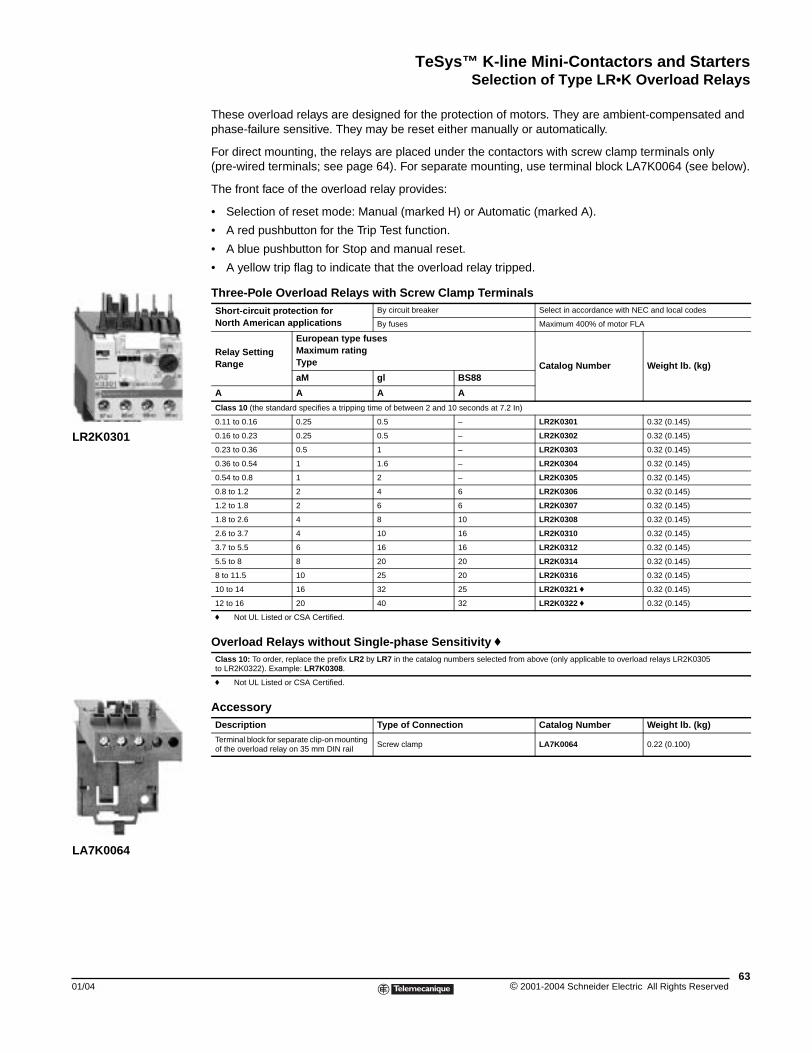
TeSys™ K-line Mini-Contactors and StartersSelection of Type LR•K Overload Relays
01/04
LR2K0301
LA7K0064
Selection of Type LR\bK Overload Relays
These overload relays are designed for the protection of motors. They are ambient-compensated and phase-failure sensitive. They may be reset either manually or automatically.
For direct mounting, the relays are placed under the contactors with screw clamp terminals only (pre-wired terminals; see page 64). For separate mounting, use terminal block LA7K0064 (see below).
The front face of the overload relay provides:
• Selection of reset mode: Manual (marked H) or Automatic (marked A).
• A red pushbutton for the Trip Test function.
• A blue pushbutton for Stop and manual reset.
• A yellow trip flag to indicate that the overload relay tripped.
Three-Pole Overload Relays with Screw Clamp TerminalsShort-circuit protection for North American applications
By circuit breaker Select in accordance with NEC and local codes
By fuses Maximum 400% of motor FLA
Relay Setting Range
European type fusesMaximum ratingType Catalog Number Weight lb. (kg)aM gl BS88
A A A A
Class 10 (the standard specifies a tripping time of between 2 and 10 seconds at 7.2 In)
0.11 to 0.16 0.25 0.5 – LR2K0301 0.32 (0.145)
0.16 to 0.23 0.25 0.5 – LR2K0302 0.32 (0.145)
0.23 to 0.36 0.5 1 – LR2K0303 0.32 (0.145)
0.36 to 0.54 1 1.6 – LR2K0304 0.32 (0.145)
0.54 to 0.8 1 2 – LR2K0305 0.32 (0.145)
0.8 to 1.2 2 4 6 LR2K0306 0.32 (0.145)
1.2 to 1.8 2 6 6 LR2K0307 0.32 (0.145)
1.8 to 2.6 4 8 10 LR2K0308 0.32 (0.145)
2.6 to 3.7 4 10 16 LR2K0310 0.32 (0.145)
3.7 to 5.5 6 16 16 LR2K0312 0.32 (0.145)
5.5 to 8 8 20 20 LR2K0314 0.32 (0.145)
8 to 11.5 10 25 20 LR2K0316 0.32 (0.145)
10 to 14 16 32 25 LR2K0321 f 0.32 (0.145)
12 to 16 20 40 32 LR2K0322 f 0.32 (0.145)
f Not UL Listed or CSA Certified.
Overload Relays without Single-phase Sensitivity fClass 10: To order, replace the prefix LR2 by LR7 in the catalog numbers selected from above (only applicable to overload relays LR2K0305 to LR2K0322). Example: LR7K0308.
f Not UL Listed or CSA Certified.
AccessoryDescription Type of Connection Catalog Number Weight lb. (kg)
Terminal block for separate clip-on mounting of the overload relay on 35 mm DIN rail
Screw clamp LA7K0064 0.22 (0.100)
63© 2001-2004 Schneider Electric All Rights Reserved
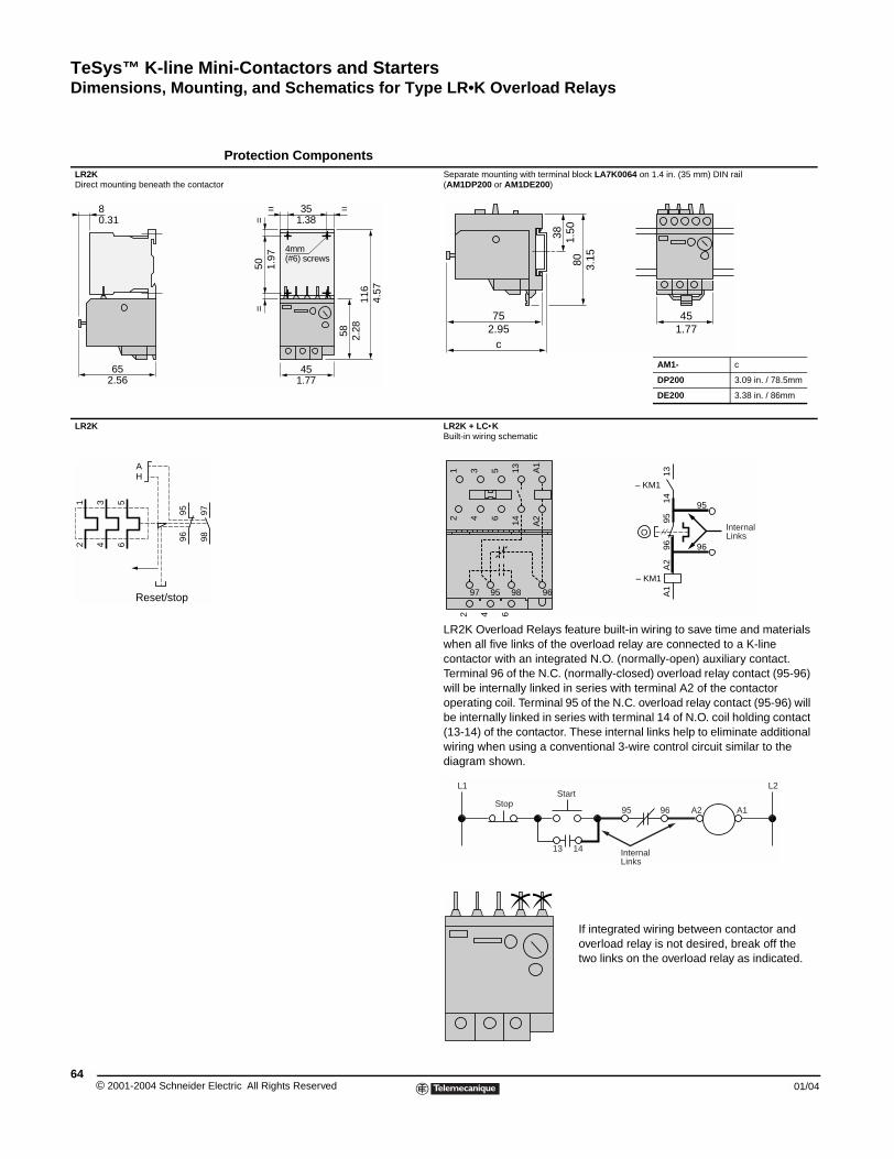
TeSys™ K-line Mini-Contactors and StartersDimensions, Mounting, and Schematics for Type LR•K Overload Relays
© 2001-2004 Schneider E64
LR2KDirect mounting beneath the contac
LR2K
65
8
2.56
0.31
1 3 5
2 4 6
9798
9596
AH
Reset/stop
Dimensions, Mounting, and Schematics for Type LR\bK Overload Relays
Protection Components
tor Separate mounting with terminal block LA7K0064 on 1.4 in. (35 mm) DIN rail (AM1DP200 or AM1DE200)
AM1- c
DP200 3.09 in. / 78.5mm
DE200 3.38 in. / 86mm
LR2K + LC•KBuilt-in wiring schematic
LR2K Overload Relays feature built-in wiring to save time and materials when all five links of the overload relay are connected to a K-line contactor with an integrated N.O. (normally-open) auxiliary contact. Terminal 96 of the N.C. (normally-closed) overload relay contact (95-96) will be internally linked in series with terminal A2 of the contactor operating coil. Terminal 95 of the N.C. overload relay contact (95-96) will be internally linked in series with terminal 14 of N.O. coil holding contact (13-14) of the contactor. These internal links help to eliminate additional wiring when using a conventional 3-wire control circuit similar to the diagram shown.
If integrated wiring between contactor and overload relay is not desired, break off the two links on the overload relay as indicated.
==
35= =
4mm (#6) screws
45
1.38
1.77
58
50
116
2.28
1.97
4.57
38
801.
50
3.15
2.95 1.7775
c
45
Internal Links
1 3 5 13 A1
2 4 6 14 A2
2 4 6
97 95 98 96
– KM1
A2
A1
9695
1314
– KM1
O
95
96
StopStart
L1
13 14
95 96 A2 A1
L2
InternalLinks
lectric All Rights Reserved 01/04
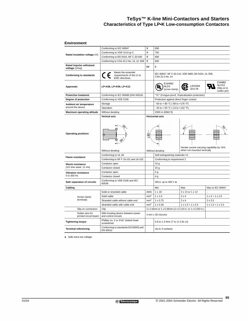
TeSys™ K-line Mini-Contactors and StartersCharacteristics of Type LP•K Low-consumption Contactors
01/04
Characteristics of Type LP\bK Low-consumption Contactors
q Safe extra low voltage.
Environment
Rated insulation voltage (Vi)
Conforming to IEC 60947 V 690
Conforming to VDE 0110 gr C V 750
Conforming to BS 5424, NF C 20-040 V 690
Conforming to CSA 22.2 No. 14, UL 508 V 600
Rated impulse withstand voltage (Vimp)
kV 8
Conforming to standardsMeets the essential requirements of the LV & EMC directives
IEC 60947, NF C 63-110, VDE 0660, BS 5424, UL 508, CSA 22.2 No. 14
Approvals LP•K06, LP•K09, LP•K12E164862NLDX (screw clamp)
LR433643211 04
E164862NLDX2(Slip-on & solder pin)
Protective treatment Conforming to IEC 60068 (DIN 50016) “TC” (Fungus-proof, Tropicalization protection)
Degree of protection Conforming to VDE 0106 Protection against direct finger contact
Ambient air temperature around the device
Storage - 50 to + 80 °C (-58 to +176 °F)
Operation - 25 to + 50 °C (-13 to +122 °F)
Maximum operating altitude Without derating 2000 m (6562 ft)
Operating positions
Vertical axis Horizontal axis
Without derating Without deratingDerate current carrying capability by 15% when not mounted vertically
Flame resistanceConforming to UL 94 Self-extinguishing materials V1
Conforming to NF F 16-101 and 16-102 Conforming to requirement 2
Shock resistance (1/2 sine wave, 11 ms)
Contactor open 10 g
Contactor closed 15 g
Vibration resistance5 to 300 Hz
Contactor open 2 g
Contactor closed 4 g
Safe separation of circuits Conforming to VDE 0106 and IEC 60536
SELV, up to 400 V q
Cabling Min Max Max to IEC 60947
Screw clamp terminals
Solid or stranded cable AWG 1 x 18 2 x 14 or 1 x 12 -
Solid cable mm2 1 x 1.5 2 x 4 1 x 4 + 1 x 2.5
Stranded cable without cable end mm2 1 x 0.75 2 x 4 2 x 2.5
Stranded cable with cable end mm2 1 x 0.34 1 x 1.5 + 1 x 2.5 1 x 1.5 + 1 x 2.5
Slip-on connectors Clip 2 x 2.8mm or 1 x 6.35mm (2 x 0.110 in. or 1 x 0.250 in.)
Solder pins for printed circuit board
With locating device between power and control circuits
4 mm x 35 microns
Tightening torque Phillips no. 2 or 3/16" slotted head screwdriver
0.8 to 1.3 N•m (7 to 11.5 lb.-in)
Terminal referencing Conforming to standards EN 50005 and EN 50012
Up to 3 contacts
90 °
90 ° 180
°
90 ° 90 °
65© 2001-2004 Schneider Electric All Rights Reserved
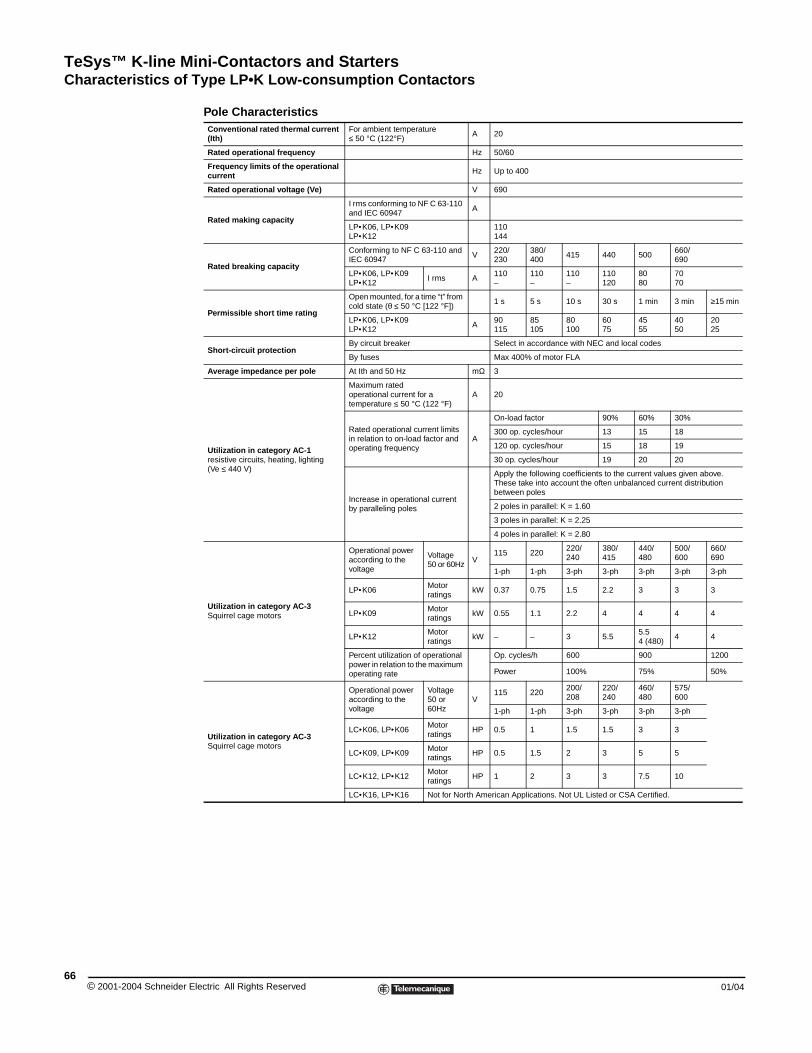
TeSys™ K-line Mini-Contactors and StartersCharacteristics of Type LP•K Low-consumption Contactors
© 2001-2004 Schneider E66
Pole CharacteristicsConventional rated thermal current (Ith)
For ambient temperature ≤ 50 °C (122°F)
A 20
Rated operational frequency Hz 50/60
Frequency limits of the operational current Hz Up to 400
Rated operational voltage (Ve) V 690
Rated making capacity
I rms conforming to NF C 63-110 and IEC 60947
A
LP•K06, LP•K09 LP•K12
110144
Rated breaking capacity
Conforming to NF C 63-110 and IEC 60947
V220/230
380/400
415 440 500660/690
LP•K06, LP•K09 LP•K12
I rms A110–
110–
110–
110120
8080
7070
Permissible short time rating
Open mounted, for a time “t” from cold state (θ ≤ 50 °C [122 °F])
1 s 5 s 10 s 30 s 1 min 3 min ≥15 min
LP•K06, LP•K09 LP•K12
A90115
85105
80100
6075
4555
4050
2025
Short-circuit protectionBy circuit breaker Select in accordance with NEC and local codes
By fuses Max 400% of motor FLA
Average impedance per pole At Ith and 50 Hz mΩ 3
Utilization in category AC-1 resistive circuits, heating, lighting(Ve ≤ 440 V)
Maximum rated operational current for a temperature ≤ 50 °C (122 °F)
A 20
Rated operational current limits in relation to on-load factor and operating frequency
A
On-load factor 90% 60% 30%
300 op. cycles/hour 13 15 18
120 op. cycles/hour 15 18 19
30 op. cycles/hour 19 20 20
Increase in operational current by paralleling poles
Apply the following coefficients to the current values given above. These take into account the often unbalanced current distribution between poles
2 poles in parallel: K = 1.60
3 poles in parallel: K = 2.25
4 poles in parallel: K = 2.80
Utilization in category AC-3Squirrel cage motors
Operational poweraccording to the voltage
Voltage50 or 60Hz
V115 220
220/240
380/415
440/480
500/600
660/690
1-ph 1-ph 3-ph 3-ph 3-ph 3-ph 3-ph
LP•K06Motorratings
kW 0.37 0.75 1.5 2.2 3 3 3
LP•K09Motor ratings
kW 0.55 1.1 2.2 4 4 4 4
LP•K12Motor ratings
kW – – 3 5.55.54 (480)
4 4
Percent utilization of operational power in relation to the maximum operating rate
Op. cycles/h 600 900 1200
Power 100% 75% 50%
Utilization in category AC-3Squirrel cage motors
Operational poweraccording to the voltage
Voltage50 or 60Hz
V115 220
200/ 208
220/240
460/480
575/600
1-ph 1-ph 3-ph 3-ph 3-ph 3-ph
LC•K06, LP•K06Motor ratings
HP 0.5 1 1.5 1.5 3 3
LC•K09, LP•K09Motor ratings
HP 0.5 1.5 2 3 5 5
LC•K12, LP•K12Motor ratings
HP 1 2 3 3 7.5 10
LC•K16, LP•K16 Not for North American Applications. Not UL Listed or CSA Certified.
lectric All Rights Reserved 01/04
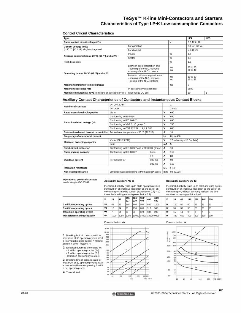
TeSys™ K-line Mini-Contactors and StartersCharacteristics of Type LP•K Low-consumption Contactors
01/04
Control Circuit CharacteristicsType LP4 LP5
Rated control circuit voltage (Vc) V DC 12 to 72
Control voltage limits(≤ 50 °C [122 °F]) single-voltage coil
For operation 0.7 to 1.30 Vc
For drop-out ≥ 0.10 Vc
Average consumption at 20 °C (68 °F) and at VcInrush W 1.8
Sealed W 1.8
Heat dissipation W 1.8
Operating time at 20 °C (68 °F) and at Vc
Between coil energization and:- opening of the N.C. contacts- closing of the N.O. contacts
msms
25 to 3530 to 40
Between coil de-energization and:- opening of the N.O. contacts- closing of the N.C. contacts
msms
10 to 2015 to 25
Maximum immunity to micro breaks ms 2
Maximum operating rate In operating cycles per hour 3600
Mechanical durability at Vc In millions of operating cycles Wide range DC coil 30 5
Auxiliary Contact Characteristics of Contactors and Instantaneous Contact Blocks
Number of contactsOn LP4, LP5K 1
On LA1K 2 max.
Rated operational voltage (Ve) Up to V 690
Rated insulation voltage (Vi)
Conforming to BS 5424 V 690
Conforming to IEC 60947 V 690
Conforming to VDE 0110 group C V 750
Conforming to CSA 22.2 No. 14, UL 508 V 600
Conventional rated thermal current (lth) For ambient temperature ≤ 50 °C (122 °F) A 10
Frequency of operational current Hz Up to 400
Minimum switching capacityV min (DIN 19 240) V 17 (reliability <10-8 at 24V)
I min mA 5
Short-circuit protection Conforming to IEC 60947 and VDE 0660, gl fuse A 10
Rated making capacity Conforming to IEC 60947 I rms A 110
Overload current Permissible for
1 s A 80
500 ms A 90
100 ms A 110
Insulation resistance MΩ > 10
Non-overlap distance Linked contacts conforming to INRS and BIA specs. mm 0.5 (0.02")
Operational power of contacts conforming to IEC 60947
AC supply, category AC-15 DC supply, category DC-13
Electrical durability (valid up to 3600 operating cycles per hour) on an inductive load such as the coil of an electromagnet: making current (power factor 0.7) = 10 times the breaking current (power factor 0.4).
Electrical durability (valid up to 1200 operating cycles per hour) on an inductive load such as the coil of an electromagnet, without economy resistor, the time constant increasing with the load.
V 24 48 110/127
220/230
380/400 400 600/
690 V 24 48 110 220 440 600
1 million operating cycles VA 48 96 240 440 800 880 1200 W 120 80 60 52 51 50
3 million operating cycles VA 17 34 86 158 288 317 500 W 55 38 30 28 26 25
10 million operating cycles VA 7 14 36 66 120 132 200 W 15 11 9 8 7 6
Occasional making capacity VA 1000 2050 5000 10000 14000 13000 9000 W 720 600 400 300 230 200
1 Breaking limit of contacts valid for maximum of 50 operating cycles at 10 s intervals (breaking current = making current x power factor 0.7).
2 Electrical durability of contacts for:- 1 million operating cycles (2a)- 3 million operating cycles (2b)-10 million operating cycles (2c).
3 Breaking limit of contacts valid for maximum of 20 operating cycles at 10 s intervals with current passing for 0.5 s per operating cycle.
4 Thermal limit.
Power in broken VA Power in broken W
10 000
5000
3000
2000
1000800600500400300
200
1008060
24 48 110 220
440 690 V120
380 50040
16 000
80006000
4000
2c2b
4
1
2a
1000
700
500
300
200
1008060504030
20
1086
12 24 48 110 220 440 600 V
250
200
140
100
50
20
2c
2b
2a
3
4
Tim
e co
nsta
ntin
ms
67© 2001-2004 Schneider Electric All Rights Reserved
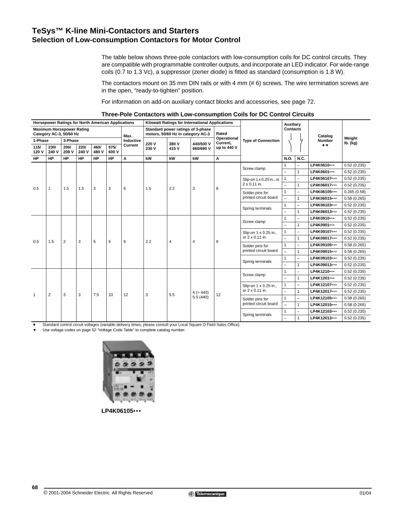
TeSys™ K-line Mini-Contactors and StartersSelection of Low-consumption Contactors for Motor Control
© 2001-2004 Schneider E68
Horsepower Ratings for North Am
Maximum Horsepower RatingCategory AC-3, 50/60 Hz
1-Phase 3-Phase
115/120 V
230/240 V
200/208 V
220/240 V
44
HP HP HP HP H
0.5 1 1.5 1.5 3
0.5 1.5 2 3 5
1 2 3 3 7
f Standard control circuit voltagep Use voltage codes on page 52
Selection of Low-consumption Contactors for Motor Control
The table below shows three-pole contactors with low-consumption coils for DC control circuits. They are compatible with programmable controller outputs, and incorporate an LED indicator. For wide-range coils (0.7 to 1.3 Vc), a suppressor (zener diode) is fitted as standard (consumption is 1.8 W).
The contactors mount on 35 mm DIN rails or with 4 mm (# 6) screws. The wire termination screws are in the open, “ready-to-tighten” position.
For information on add-on auxiliary contact blocks and accessories, see page 72.
Three-Pole Contactors with Low-consumption Coils for DC Control Circuitserican Applications Kilowatt Ratings for International Applications
Type of Connection
Auxiliary Contacts
CatalogNumber
f p
Weightlb. (kg)
Max. Inductive Current
Standard power ratings of 3-phase motors, 50/60 Hz in category AC-3 Rated
Operational Current,up to 440 V
220 V230 V
380 V415 V
440/500 V660/690 V60/
80 V575/600 V
P HP A kW kW kW A N.O. N.C.
3 6 1.5 2.2 3 6
Screw clamp1 – LP4K0610••• 0.52 (0.235)
– 1 LP4K0601••• 0.52 (0.235)
Slip-on 1 x 0.25 in., or 2 x 0.11 in.
1 – LP4K06107••• 0.52 (0.235)
– 1 LP4K06017••• 0.52 (0.235)
Solder pins for printed circuit board
1 – LP4K06105••• 0.265 (0.58)
– 1 LP4K06015••• 0.58 (0.265)
Spring terminals1 – LP4K06103••• 0.52 (0.235)
– 1 LP4K06013••• 0.52 (0.235)
5 9 2.2 4 4 9
Screw clamp1 – LP4K0910••• 0.52 (0.235)
– 1 LP4K0901••• 0.52 (0.235)
Slip-on 1 x 0.25 in., or 2 x 0.11 in.
1 – LP4K09107••• 0.52 (0.235)
– 1 LP4K09017••• 0.52 (0.235)
Solder pins for printed circuit board
1 – LP4K09105••• 0.58 (0.265)
– 1 LP4K09015••• 0.58 (0.265)
Spring terminals1 – LP4K09103••• 0.52 (0.235)
– 1 LP4K09013••• 0.52 (0.235)
.5 10 12 3 5.54 (> 440)5.5 (440)
12
Screw clamp1 – LP4K1210••• 0.52 (0.235)
– 1 LP4K1201••• 0.52 (0.235)
Slip-on 1 x 0.25 in., or 2 x 0.11 in.
1 – LP4K12107••• 0.52 (0.235)
– 1 LP4K12017••• 0.52 (0.235)
Solder pins for printed circuit board
1 – LP4K12105••• 0.58 (0.265)
– 1 LP4K12015••• 0.58 (0.265)
Spring terminals1 – LP4K12103••• 0.52 (0.235)
– 1 LP4K12013••• 0.52 (0.235)
s (variable delivery times, please consult your Local Square D Field Sales Office). “Voltage Code Table” to complete catalog number.
LP4K06105•••
lectric All Rights Reserved 01/04
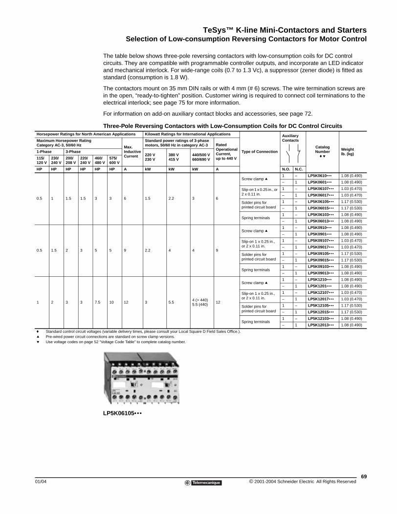
TeSys™ K-line Mini-Contactors and StartersSelection of Low-consumption Reversing Contactors for Motor Control
01/04
Horsepower Ratings for North Am
Maximum Horsepower RatingCategory AC-3, 50/60 Hz
1-Phase 3-Phase
115/120 V
230/240 V
200/208 V
220/240 V
4648
HP HP HP HP H
0.5 1 1.5 1.5 3
0.5 1.5 2 3 5
1 2 3 3 7.
f Standard control circuit voltageq Pre-wired power circuit connecp Use voltage codes on page 52
Selection of Low-consumption Reversing Contactors for Motor Control
The table below shows three-pole reversing contactors with low-consumption coils for DC control circuits. They are compatible with programmable controller outputs, and incorporate an LED indicator and mechanical interlock. For wide-range coils (0.7 to 1.3 Vc), a suppressor (zener diode) is fitted as standard (consumption is 1.8 W).
The contactors mount on 35 mm DIN rails or with 4 mm (# 6) screws. The wire termination screws are in the open, “ready-to-tighten” position. Customer wiring is required to connect coil terminations to the electrical interlock; see page 75 for more information.
For information on add-on auxiliary contact blocks and accessories, see page 72.
Three-Pole Reversing Contactors with Low-Consumption Coils for DC Control Circuitserican Applications Kilowatt Ratings for International Applications
Type of Connection
Auxiliary Contacts
CatalogNumber
f p
Weightlb. (kg)
Max. Inductive Current
Standard power ratings of 3-phase motors, 50/60 Hz in category AC-3 Rated
Operational Current,up to 440 V
220 V230 V
380 V415 V
440/500 V660/690 V0/
0 V575/600 V
P HP A kW kW kW A N.O. N.C.
3 6 1.5 2.2 3 6
Screw clamp q1 – LP5K0610••• 1.08 (0.490)
– 1 LP5K0601••• 1.08 (0.490)
Slip-on 1 x 0.25 in., or 2 x 0.11 in.
1 – LP5K06107••• 1.03 (0.470)
– 1 LP5K06017••• 1.03 (0.470)
Solder pins for printed circuit board
1 – LP5K06105••• 1.17 (0.530)
– 1 LP5K06015••• 1.17 (0.530)
Spring terminals1 – LP5K06103••• 1.08 (0.490)
– 1 LP5K06013••• 1.08 (0.490)
5 9 2.2 4 4 9
Screw clamp q1 – LP5K0910••• 1.08 (0.490)
– 1 LP5K0901••• 1.08 (0.490)
Slip-on 1 x 0.25 in., or 2 x 0.11 in.
1 – LP5K09107••• 1.03 (0.470)
– 1 LP5K09017••• 1.03 (0.470)
Solder pins for printed circuit board
1 – LP5K09105••• 1.17 (0.530)
– 1 LP5K09015••• 1.17 (0.530)
Spring terminals1 – LP5K09103••• 1.08 (0.490)
– 1 LP5K09013••• 1.08 (0.490)
5 10 12 3 5.54 (> 440)5.5 (440)
12
Screw clamp q1 – LP5K1210••• 1.08 (0.490)
– 1 LP5K1201••• 1.08 (0.490)
Slip-on 1 x 0.25 in., or 2 x 0.11 in.
1 – LP5K12107••• 1.03 (0.470)
– 1 LP5K12017••• 1.03 (0.470)
Solder pins for printed circuit board
1 – LP5K12105••• 1.17 (0.530)
– 1 LP5K12015••• 1.17 (0.530)
Spring terminals1 – LP5K12103••• 1.08 (0.490)
– 1 LP5K12013••• 1.08 (0.490)
s (variable delivery times, please consult your Local Square D Field Sales Office.).tions are standard on screw clamp versions. “Voltage Code Table” to complete catalog number.
LP5K06105•••
69© 2001-2004 Schneider Electric All Rights Reserved
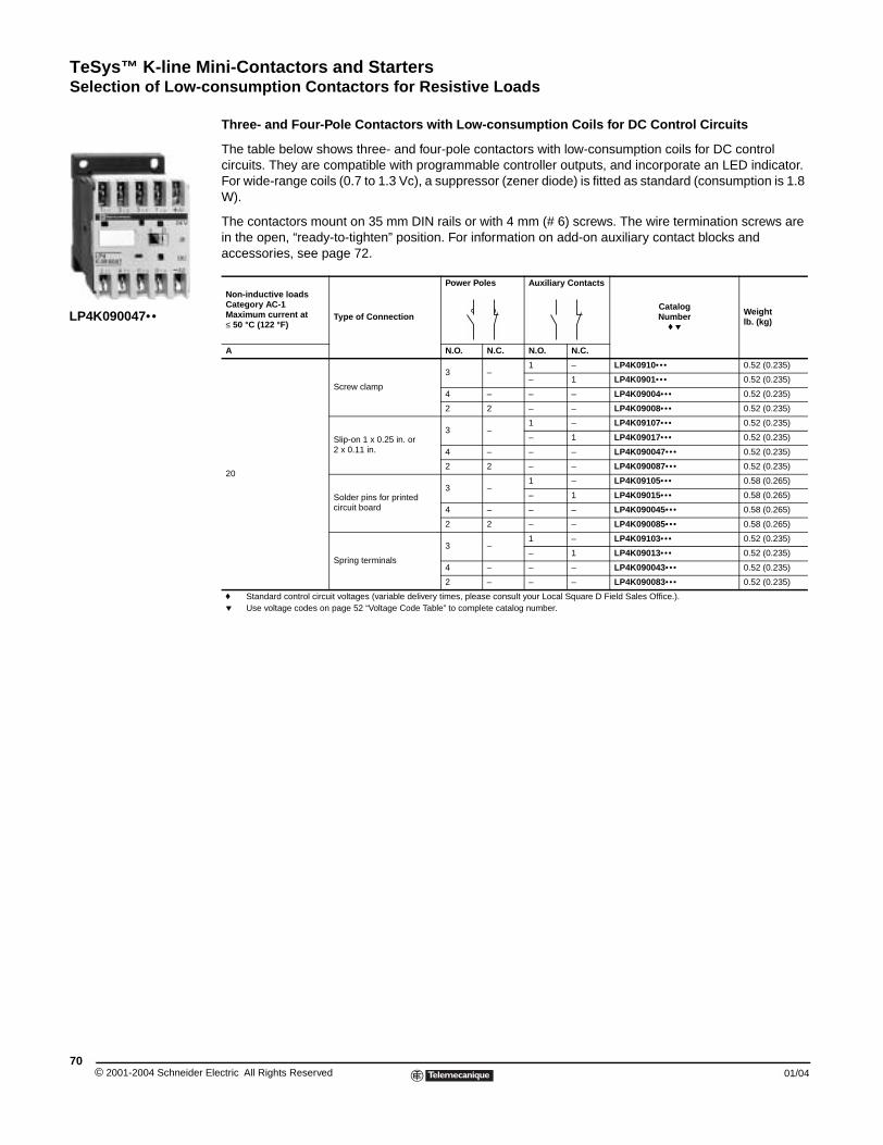
TeSys™ K-line Mini-Contactors and StartersSelection of Low-consumption Contactors for Resistive Loads
© 2001-2004 Schneider E70
LP4K090047••
Selection of Low-consumption Contactors for Resistive Loads
Three- and Four-Pole Contactors with Low-consumption Coils for DC Control Circuits
The table below shows three- and four-pole contactors with low-consumption coils for DC control circuits. They are compatible with programmable controller outputs, and incorporate an LED indicator. For wide-range coils (0.7 to 1.3 Vc), a suppressor (zener diode) is fitted as standard (consumption is 1.8 W).
The contactors mount on 35 mm DIN rails or with 4 mm (# 6) screws. The wire termination screws are in the open, “ready-to-tighten” position. For information on add-on auxiliary contact blocks and accessories, see page 72.
Non-inductive loads Category AC-1 Maximum current at ≤ 50 °C (122 °F)
Type of Connection
Power Poles Auxiliary Contacts
CatalogNumber
f p
Weightlb. (kg)
A N.O. N.C. N.O. N.C.
20
Screw clamp
3 –1 – LP4K0910••• 0.52 (0.235)
– 1 LP4K0901••• 0.52 (0.235)
4 – – – LP4K09004••• 0.52 (0.235)
2 2 – – LP4K09008••• 0.52 (0.235)
Slip-on 1 x 0.25 in. or2 x 0.11 in.
3 –1 – LP4K09107••• 0.52 (0.235)
– 1 LP4K09017••• 0.52 (0.235)
4 – – – LP4K090047••• 0.52 (0.235)
2 2 – – LP4K090087••• 0.52 (0.235)
Solder pins for printed circuit board
3 –1 – LP4K09105••• 0.58 (0.265)
– 1 LP4K09015••• 0.58 (0.265)
4 – – – LP4K090045••• 0.58 (0.265)
2 2 – – LP4K090085••• 0.58 (0.265)
Spring terminals
3 –1 – LP4K09103••• 0.52 (0.235)
– 1 LP4K09013••• 0.52 (0.235)
4 – – – LP4K090043••• 0.52 (0.235)
2 – – – LP4K090083••• 0.52 (0.235)
f Standard control circuit voltages (variable delivery times, please consult your Local Square D Field Sales Office.).p Use voltage codes on page 52 “Voltage Code Table” to complete catalog number.
lectric All Rights Reserved 01/04
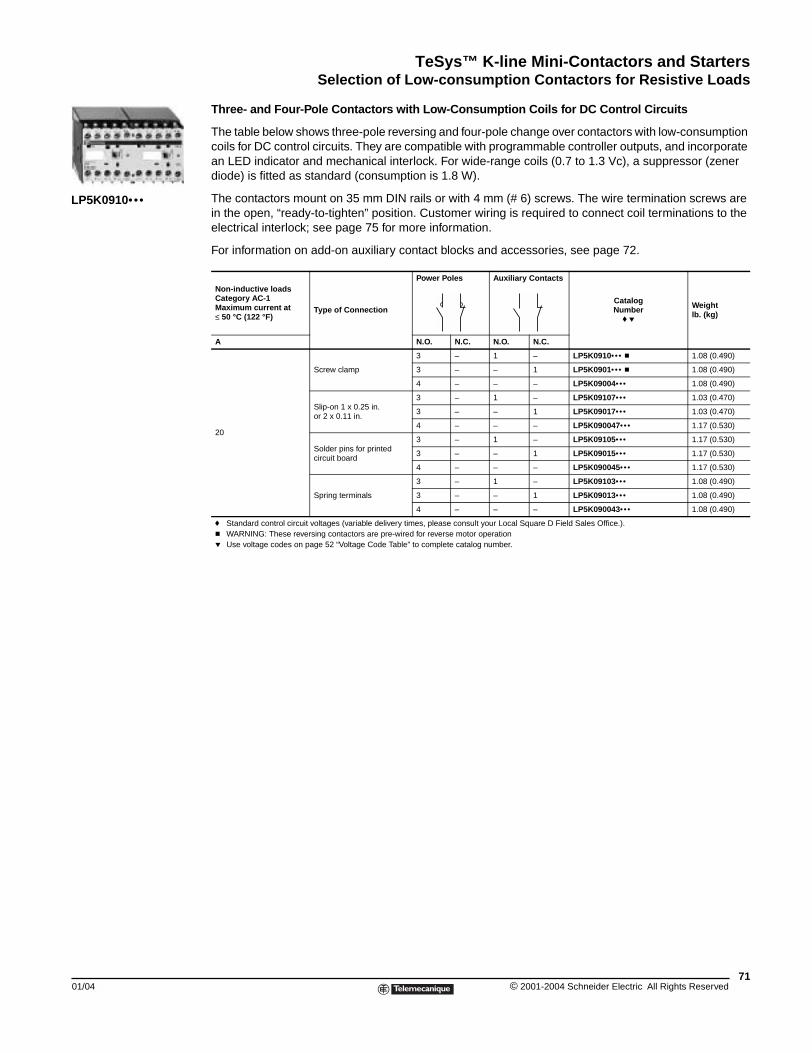
TeSys™ K-line Mini-Contactors and StartersSelection of Low-consumption Contactors for Resistive Loads
01/04
LP5K0910•••
Three- and Four-Pole Contactors with Low-Consumption Coils for DC Control Circuits
The table below shows three-pole reversing and four-pole change over contactors with low-consumption coils for DC control circuits. They are compatible with programmable controller outputs, and incorporate an LED indicator and mechanical interlock. For wide-range coils (0.7 to 1.3 Vc), a suppressor (zener diode) is fitted as standard (consumption is 1.8 W).
The contactors mount on 35 mm DIN rails or with 4 mm (# 6) screws. The wire termination screws are in the open, “ready-to-tighten” position. Customer wiring is required to connect coil terminations to the electrical interlock; see page 75 for more information.
For information on add-on auxiliary contact blocks and accessories, see page 72.
Non-inductive loads Category AC-1 Maximum current at ≤ 50 °C (122 °F)
Type of Connection
Power Poles Auxiliary Contacts
CatalogNumber
f p
Weightlb. (kg)
A N.O. N.C. N.O. N.C.
20
Screw clamp
3 – 1 – LP5K0910••• c 1.08 (0.490)
3 – – 1 LP5K0901••• c 1.08 (0.490)
4 – – – LP5K09004••• 1.08 (0.490)
Slip-on 1 x 0.25 in.or 2 x 0.11 in.
3 – 1 – LP5K09107••• 1.03 (0.470)
3 – – 1 LP5K09017••• 1.03 (0.470)
4 – – – LP5K090047••• 1.17 (0.530)
Solder pins for printed circuit board
3 – 1 – LP5K09105••• 1.17 (0.530)
3 – – 1 LP5K09015••• 1.17 (0.530)
4 – – – LP5K090045••• 1.17 (0.530)
Spring terminals
3 – 1 – LP5K09103••• 1.08 (0.490)
3 – – 1 LP5K09013••• 1.08 (0.490)
4 – – – LP5K090043••• 1.08 (0.490)
f Standard control circuit voltages (variable delivery times, please consult your Local Square D Field Sales Office.).c WARNING: These reversing contactors are pre-wired for reverse motor operationp Use voltage codes on page 52 “Voltage Code Table” to complete catalog number.
71© 2001-2004 Schneider Electric All Rights Reserved
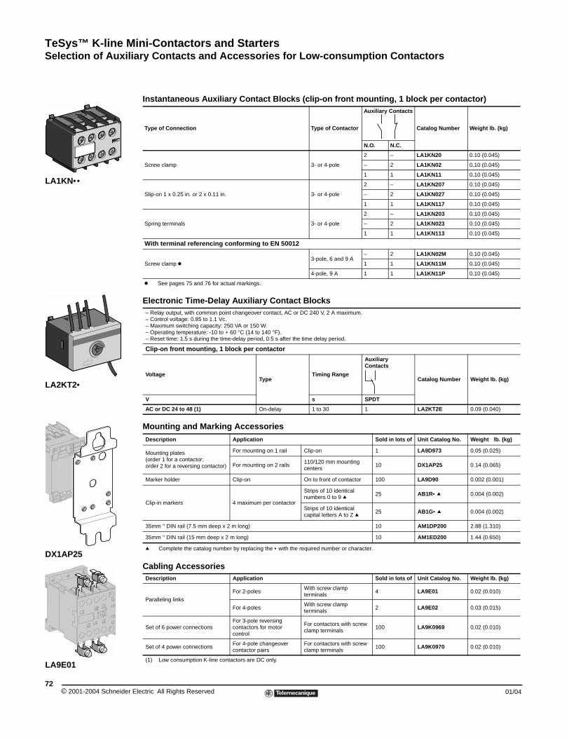
TeSys™ K-line Mini-Contactors and StartersSelection of Auxiliary Contacts and Accessories for Low-consumption Contactors
© 2001-2004 Schneider E72
LA1KN••
LA2KT2•
DX1AP25
LA9E01
Selection of Auxiliary Contacts and Accessories for Low-consumption Contactors
Instantaneous Auxiliary Contact Blocks (clip-on front mounting, 1 block per contactor)
Type of Connection Type of Contactor
Auxiliary Contacts
Catalog Number Weight lb. (kg)
N.O. N.C.
Screw clamp 3- or 4-pole
2 – LA1KN20 0.10 (0.045)
– 2 LA1KN02 0.10 (0.045)
1 1 LA1KN11 0.10 (0.045)
Slip-on 1 x 0.25 in. or 2 x 0.11 in. 3- or 4-pole
2 – LA1KN207 0.10 (0.045)
– 2 LA1KN027 0.10 (0.045)
1 1 LA1KN117 0.10 (0.045)
Spring terminals 3- or 4-pole
2 – LA1KN203 0.10 (0.045)
– 2 LA1KN023 0.10 (0.045)
1 1 LA1KN113 0.10 (0.045)
With terminal referencing conforming to EN 50012
Screw clamp k3-pole, 6 and 9 A
– 2 LA1KN02M 0.10 (0.045)
1 1 LA1KN11M 0.10 (0.045)
4-pole, 9 A 1 1 LA1KN11P 0.10 (0.045)
k See pages 75 and 76 for actual markings.
Electronic Time-Delay Auxiliary Contact Blocks– Relay output, with common point changeover contact, AC or DC 240 V, 2 A maximum.– Control voltage: 0.85 to 1.1 Vc.– Maximum switching capacity: 250 VA or 150 W.– Operating temperature: -10 to + 60 °C (14 to 140 °F).– Reset time: 1.5 s during the time-delay period, 0.5 s after the time delay period.
Clip-on front mounting, 1 block per contactor
VoltageType
Timing Range
Auxiliary Contacts
Catalog Number Weight lb. (kg)
V s SPDT
AC or DC 24 to 48 (1) On-delay 1 to 30 1 LA2KT2E 0.09 (0.040)
Mounting and Marking AccessoriesDescription Application Sold in lots of Unit Catalog No. Weight lb. (kg)
Mounting plates(order 1 for a contactor; order 2 for a reversing contactor)
For mounting on 1 rail Clip-on 1 LA9D973 0.05 (0.025)
For mounting on 2 rails110/120 mm mounting centers
10 DX1AP25 0.14 (0.065)
Marker holder Clip-on On to front of contactor 100 LA9D90 0.002 (0.001)
Clip-in markers 4 maximum per contactor
Strips of 10 identical numbers 0 to 9 q 25 AB1R• q 0.004 (0.002)
Strips of 10 identical capital letters A to Z q 25 AB1G• q 0.004 (0.002)
35mm " DIN rail (7.5 mm deep x 2 m long) 10 AM1DP200 2.88 (1.310)
35mm " DIN rail (15 mm deep x 2 m long) 10 AM1ED200 1.44 (0.650)
q Complete the catalog number by replacing the • with the required number or character.
Cabling AccessoriesDescription Application Sold in lots of Unit Catalog No. Weight lb. (kg)
Paralleling links
For 2-polesWith screw clamp terminals
4 LA9E01 0.02 (0.010)
For 4-polesWith screw clamp terminals
2 LA9E02 0.03 (0.015)
Set of 6 power connectionsFor 3-pole reversing contactors for motor control
For contactors with screw clamp terminals
100 LA9K0969 0.02 (0.010)
Set of 4 power connectionsFor 4-pole changeover contactor pairs
For contactors with screw clamp terminals
100 LA9K0970 0.02 (0.010)
(1) Low consumption K-line contactors are DC only.
lectric All Rights Reserved 01/04
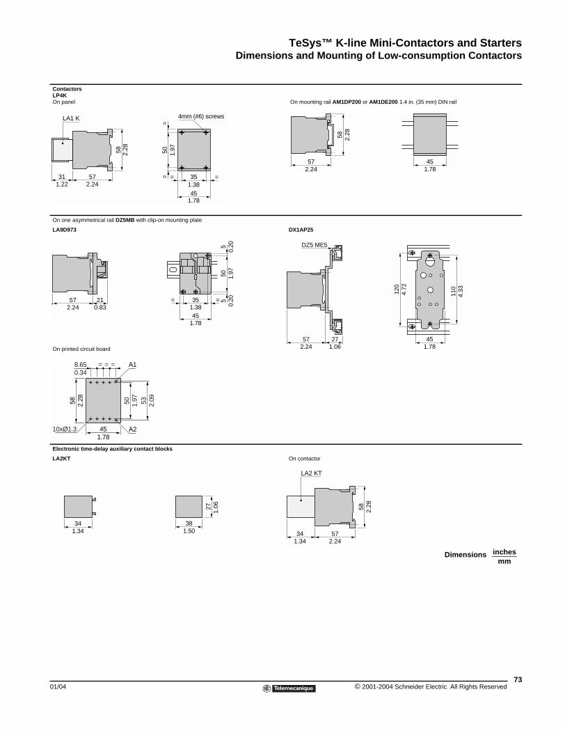
TeSys™ K-line Mini-Contactors and StartersDimensions and Mounting of Low-consumption Contactors
01/04
Contactors LP4K On panel
On one asymmetrical rail DZ5MB w
LA9D973
On printed circuit board
Electronic time-delay auxiliary co
LA2KT
57312.241.22
LA1 K58 2.28
572.24
210.83
50 1.97
451.78
58 2.28
8.650.34
= = =
10xØ1.3
A1
A2
1.3434
Dimensions and Mounting of Low-consumption Contactorsxxxxx
On mounting rail AM1DP200 or AM1DE200 1.4 in. (35 mm) DIN rail
ith clip-on mounting plate
DX1AP25
ntact blocks
On contactor
50 1.97
==
351.3845
1.78
= =
4mm (#6) screws
57
58 2.28
452.24 1.78
45
35
1.78
1.38= =
505
51.
970.
200.
20
110
4.33
451.78
120
4.72
572.24
271.06
DZ5 ME5
53 2.09
381.50
27 1.06
57342.241.34
LA2 KT
58 2.28
inchesmm
Dimensions
73© 2001-2004 Schneider Electric All Rights Reserved
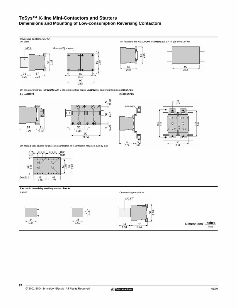
TeSys™ K-line Mini-Contactors and StartersDimensions and Mounting of Low-consumption Reversing Contactors
© 2001-2004 Schneider E74
Reversing contactors LP5K On panel
On one asymmetrical rail DZ5MB w
2 x LA9D973
On printed circuit board for reversin
Electronic time-delay auxiliary co
LA2KT
572.24
311.22
LA1K58 2.28
4 m
57 212.24 0.83
45
58
8.65 = = =
20xØ1.3
A1
A2
451.78
0.34
1.78
===
2.28
A1
A2
1.3434
On mounting rail AM1DP200 or AM1DE200 1.4 in. (35 mm) DIN rail
ith 2 clip-on mounting plates LA9D973 or on 2 mounting plates DX1AP25.
2 x DX1AP25
g contactors or 2 contactors mounted side by side
ntact blocks
On reversing contactors
50 1.97
==
903.54
803.15
m (#6) screws
==
57
58 2.28
902.24 3.54
90
35= =
505
51.
970.
200.
20
3.54
1.38
57 272.24 1.06
DZ5 ME5
903.54
110
120
4.33
4.72
451.78
50
8.650.34
531.97
2.09
381.50
27 1.06
57342.241.34
LA2 KT
58 2.28
inchesmm
Dimensions
lectric All Rights Reserved 01/04
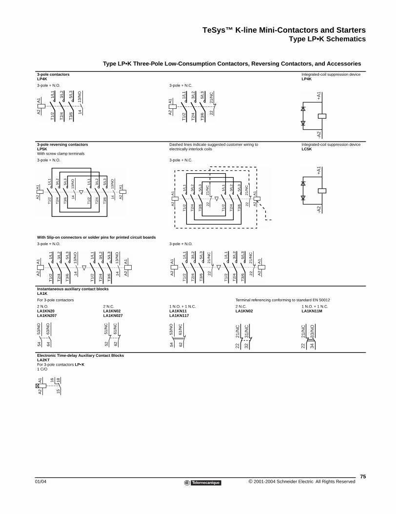
TeSys™ K-line Mini-Contactors and StartersType LP•K Schematics
01/04
3-pole contactorsLP4K
3-pole + N.O.
3-pole reversing contactorsLP5KWith screw clamp terminals
3-pole + N.O.
With Slip-on connectors or solde
3-pole + N.O.
Instantaneous auxiliary contact bLA1K
For 3-pole contactors
2 N.O. LA1KN20LA1KN207
Electronic Time-delay Auxiliary CLA2KTFor 3-pole contactors LP•K1 C/O
13/N
O14
A1
A2
1/L1
T1/
2
3/L2
T2/
4
5/L3
T3/
613
/NO
14
A1
A2
1/L1
T1/
2
3/L2
T2/
4
5/L3
T3/
6
1/L1
T1/
2
13/N
O14
A1
A2
1/L
1T
1/2
3/L
2T
2/4
5/L
3T
3/6
1/L
1T
1/2
53/N
O54
63/N
O64
A1
A2
1815
16
Type LP\bK SchematicsType LP•K Three-Pole Low-Consumption Contactors, Reversing Contactors, and Accessories
Integrated-coil suppression deviceLP4K
3-pole + N.C.
Dashed lines indicate suggested customer wiring to electrically interlock coils
Integrated-coil suppression deviceLC5K
3-pole + N.C.
r pins for printed circuit boards
3-pole + N.O.
locks
Terminal referencing conforming to standard EN 50012
2 N.C. LA1KN02LA1KN027
1 N.O. + 1 N.C.LA1KN11LA1KN117
2 N.C. LA1KN02
1 N.O. + 1 N.C.LA1KN11M
ontact Blocks
2221
/NC
A1
A2
1/L1
T1/
2
3/L2
T2/
4
5/L3
T3/
6
-A2
+A
1
13/N
O14
A1
A2
3/L2
T2/
4
5/L3
T3/
6
21/N
C22
A1
A2
1/L
1T
1/2
3/L
2T
2/4
5/L
3T
3/6
21/N
C22
A1
A2
1/L
1T
1/2
3/L
2T
2/4
5/L
3T
3/6
-A2
+A
1
13/N
O14
A1
A2
3/L
2T
2/4
5/L
3T
3/6
21
/NC
22
A1
A2
1/L
1T
1/2
3/L
2T
2/4
5/L
3T
3/6
21
/NC
22
A1
A2
1/L
1T
1/2
3/L
2T
2/4
5/L
3T
3/6
61/N
C62
51/N
C52
61/N
C62
53/N
O54 22
21/N
C
3231
/NC
2221
/NC
3433
/NO
75© 2001-2004 Schneider Electric All Rights Reserved
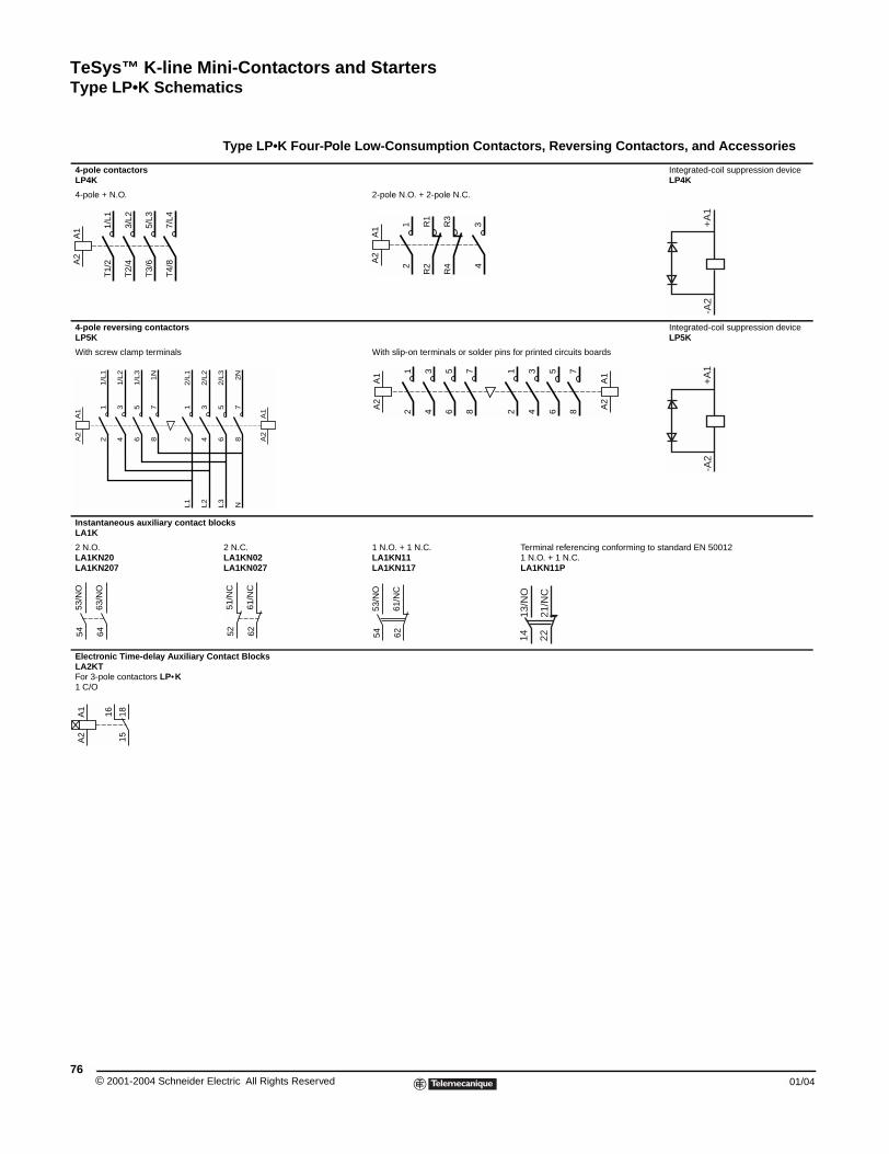
TeSys™ K-line Mini-Contactors and StartersType LP•K Schematics
© 2001-2004 Schneider E76
4-pole contactorsLP4K
4-pole + N.O.
4-pole reversing contactorsLP5K
With screw clamp terminals
Instantaneous auxiliary contact bLA1K
2 N.O. LA1KN20LA1KN207
Electronic Time-delay Auxiliary CLA2KTFor 3-pole contactors LP•K1 C/O
A1
A2
1/L1
T1/
2
3/L2
T2/
4
5/L3
T3/
6
7/L4
T4/
8
A1
A2
12
34
56
12
34
1/L
1
1/L
2
1/L
3
2/L
1
2/L
2
L1
L2
78
1N
53/N
O54
63/N
O64
A1
A2
1815
16
Type LP•K Four-Pole Low-Consumption Contactors, Reversing Contactors, and Accessories
Integrated-coil suppression deviceLP4K
2-pole N.O. + 2-pole N.C.
Integrated-coil suppression deviceLP5K
With slip-on terminals or solder pins for printed circuits boards
locks
2 N.C. LA1KN02LA1KN027
1 N.O. + 1 N.C.LA1KN11LA1KN117
Terminal referencing conforming to standard EN 500121 N.O. + 1 N.C. LA1KN11P
ontact Blocks
R1
R2
A1
A2
12
34
R3
R4
-A2
+A
1
A1
A2
56
2/L
3L3
78
2N
N
A1
A2
12
34
56
A1
A2
12
34
78
78
56
-A2
+A
1
61/N
C62
51/N
C52
61/N
C62
53/N
O54 14
13/N
O
2221
/NC
lectric All Rights Reserved 01/04
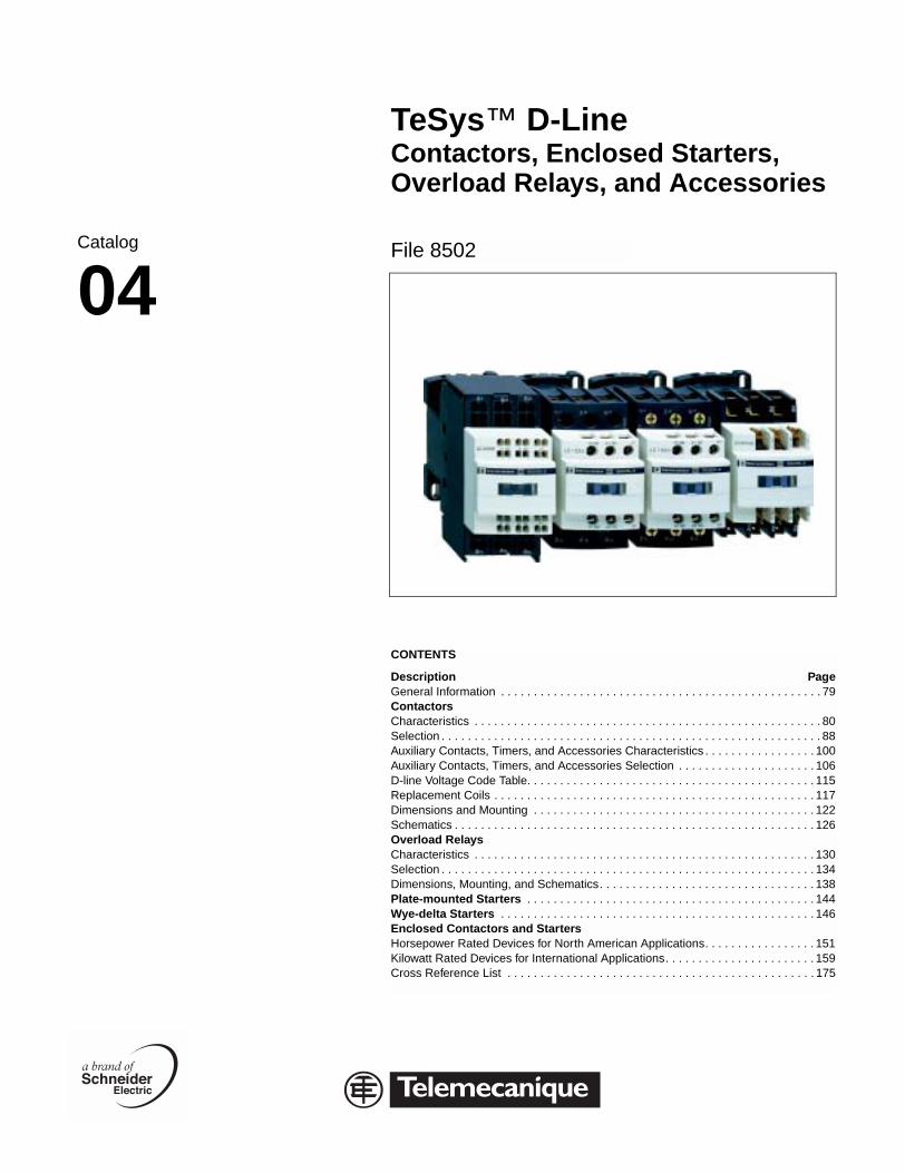
Catalog
04
TeSys™ D-LineContactors, Enclosed Starters,Overload Relays, and Accessories
File 8502
CONTENTS
Description PageGeneral Information . . . . . . . . . . . . . . . . . . . . . . . . . . . . . . . . . . . . . . . . . . . . . . . . . 79ContactorsCharacteristics . . . . . . . . . . . . . . . . . . . . . . . . . . . . . . . . . . . . . . . . . . . . . . . . . . . . . 80Selection . . . . . . . . . . . . . . . . . . . . . . . . . . . . . . . . . . . . . . . . . . . . . . . . . . . . . . . . . . 88Auxiliary Contacts, Timers, and Accessories . . . . . . . . . . . . . . . . . . . . . . . . . . . . . 100Selection . . . . . . . . . . . . . . . . . . . . . . . . . . . . . . . . . . . . . . . . . . . . . . . . . . . . . . . . . 106Replacement Coils . . . . . . . . . . . . . . . . . . . . . . . . . . . . . . . . . . . . . . . . . . . . . . . . . 117Dimensions and Mounting . . . . . . . . . . . . . . . . . . . . . . . . . . . . . . . . . . . . . . . . . . . 122Schematics . . . . . . . . . . . . . . . . . . . . . . . . . . . . . . . . . . . . . . . . . . . . . . . . . . . . . . . 126Overload RelaysCharacteristics . . . . . . . . . . . . . . . . . . . . . . . . . . . . . . . . . . . . . . . . . . . . . . . . . . . . 130Selection . . . . . . . . . . . . . . . . . . . . . . . . . . . . . . . . . . . . . . . . . . . . . . . . . . . . . . . . . 134Dimensions, Mounting, and Schematics. . . . . . . . . . . . . . . . . . . . . . . . . . . . . . . . . 138Plate-mounted Starters . . . . . . . . . . . . . . . . . . . . . . . . . . . . . . . . . . . . . . . . . . . . 144Wye-delta Starters . . . . . . . . . . . . . . . . . . . . . . . . . . . . . . . . . . . . . . . . . . . . . . . . 146Enclosed Contactors and StartersHorsepower Rated Devices for North American Applications. . . . . . . . . . . . . . . . . 151Kilowatt Rated Devices for International Applications. . . . . . . . . . . . . . . . . . . . . . . 159
CONTENTS
Description PageGeneral Information . . . . . . . . . . . . . . . . . . . . . . . . . . . . . . . . . . . . . . . . . . . . . . . . . 79ContactorsCharacteristics . . . . . . . . . . . . . . . . . . . . . . . . . . . . . . . . . . . . . . . . . . . . . . . . . . . . . 80Selection . . . . . . . . . . . . . . . . . . . . . . . . . . . . . . . . . . . . . . . . . . . . . . . . . . . . . . . . . . 88Auxiliary Contacts, Timers, and Accessories Characteristics . . . . . . . . . . . . . . . . . 100Auxiliary Contacts, Timers, and Accessories Selection . . . . . . . . . . . . . . . . . . . . . 106D-line Voltage Code Table. . . . . . . . . . . . . . . . . . . . . . . . . . . . . . . . . . . . . . . . . . . . 115Replacement Coils . . . . . . . . . . . . . . . . . . . . . . . . . . . . . . . . . . . . . . . . . . . . . . . . . 117Dimensions and Mounting . . . . . . . . . . . . . . . . . . . . . . . . . . . . . . . . . . . . . . . . . . . 122Schematics . . . . . . . . . . . . . . . . . . . . . . . . . . . . . . . . . . . . . . . . . . . . . . . . . . . . . . . 126Overload RelaysCharacteristics . . . . . . . . . . . . . . . . . . . . . . . . . . . . . . . . . . . . . . . . . . . . . . . . . . . . 130Selection . . . . . . . . . . . . . . . . . . . . . . . . . . . . . . . . . . . . . . . . . . . . . . . . . . . . . . . . . 134Dimensions, Mounting, and Schematics. . . . . . . . . . . . . . . . . . . . . . . . . . . . . . . . . 138Plate-mounted Starters . . . . . . . . . . . . . . . . . . . . . . . . . . . . . . . . . . . . . . . . . . . . 144Wye-delta Starters . . . . . . . . . . . . . . . . . . . . . . . . . . . . . . . . . . . . . . . . . . . . . . . . 146Enclosed Contactors and StartersHorsepower Rated Devices for North American Applications. . . . . . . . . . . . . . . . . 151Kilowatt Rated Devices for International Applications. . . . . . . . . . . . . . . . . . . . . . . 159Cross Reference List . . . . . . . . . . . . . . . . . . . . . . . . . . . . . . . . . . . . . . . . . . . . . . . 175
D-Line

© 2001-2004 Schneider E78
lectric All Rights Reserved 01/04
TeSys™ D-Line Contactors and StartersGeneral Information
01/04
General Information
The D-line contactors and overload relays are the largest selling line of contactors and starters in the world. They offer high reliability with long mechanical and electrical life and the most complete line of accessories in the industry.
Contactor Ratings
• D-line contactors and overload relays are available in 11 contactor ratings for the USA market for inductive motor applications up to 150 full-load amps and resistive loads up to 200 A. They offer motor control and overload protection for motors rated up to 100 hp at 480 Vac or 125 hp at 600 Vac.
• 3-pole and 4-pole contactor versions available.
• All contactors include built-in auxiliary contacts.
• All screw connections have IP20 rated touch-safe terminals with both North American and International terminal markings.
• D-line contactors can be panel mounted with screws or DIN rail mounted.
Easily Installed Accessories
• Auxiliary contact blocks with serrated wiping action
• Front mount dust tight auxiliary contact blocks
• Pneumatic time delay blocks
• Transient voltage surge suppressors
• Interface modules and electronic timers
• Mechanical latching blocks
Control Circuit Flexibility
The D-line contactors are available with ac or dc operating coils. Several devices utilize a low- consumption dc coil with built-in transient suppression for operation with a low-level dc signal from a computer or PLC without need for an interposing relay.
Overload Relays
Class 10 or Class 20 bimetallic overload relays are available up to 140 A. They are bimetallic ambient compensated and are available with or without single-phase sensitivity for phase unbalance and phase loss protection. New solid state overload relays are available for 90 to 150 A applications. Both bimetallic and solid-state overload relays include the following features:
• Isolated N.C. trip contact and N.O. alarm contacts.
• Manual or Automatic reset function (bi-metallic versions only).
• Tamper-resistant window for FLA settings.
• Test trip button.
79© 2001-2004 Schneider Electric All Rights Reserved
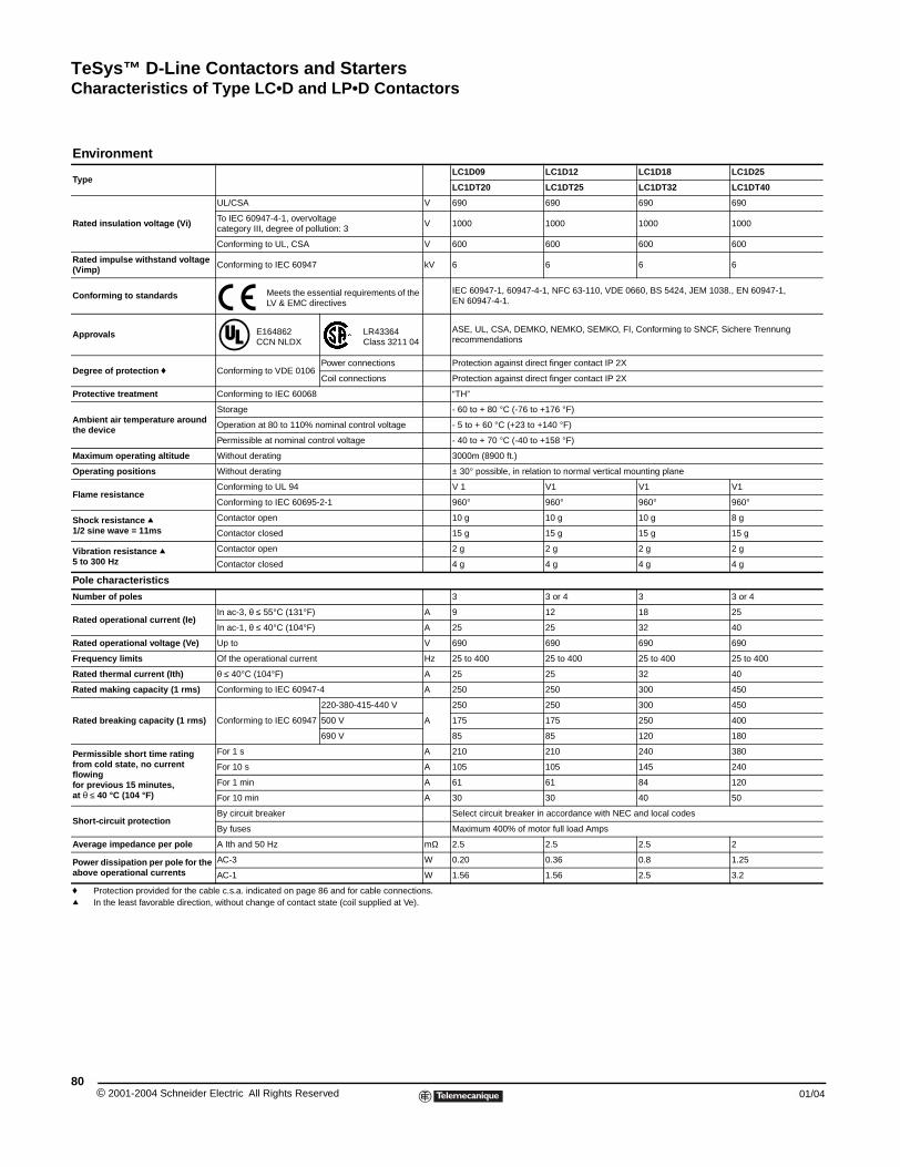
TeSys™ D-Line Contactors and StartersCharacteristics of Type LC•D and LP•D Contactors
© 2001-2004 Schneider E80
Environment
Type
Rated insulation voltage (Vi)
Rated impulse withstand voltage (Vimp)
Conforming to standards
Approvals
Degree of protection f
Protective treatment
Ambient air temperature around the device
Maximum operating altitude
Operating positions
Flame resistance
Shock resistance q1/2 sine wave = 11ms
Vibration resistance q 5 to 300 Hz
Pole characteristics
Number of poles
Rated operational current (Ie)
Rated operational voltage (Ve)
Frequency limits
Rated thermal current (Ith)
Rated making capacity (1 rms)
Rated breaking capacity (1 rms)
Permissible short time rating from cold state, no current flowing for previous 15 minutes, at θ ≤ 40 °C (104 °F)
Short-circuit protection
Average impedance per pole
Power dissipation per pole for the above operational currents
f Protection provided for the cabq In the least favorable direction,
Characteristics of Type LC\bD and LP\bD Contactors
LC1D09 LC1D12 LC1D18 LC1D25
LC1DT20 LC1DT25 LC1DT32 LC1DT40
UL/CSA V 690 690 690 690
To IEC 60947-4-1, overvoltage category III, degree of pollution: 3
V 1000 1000 1000 1000
Conforming to UL, CSA V 600 600 600 600
Conforming to IEC 60947 kV 6 6 6 6
Meets the essential requirements of the LV & EMC directives
IEC 60947-1, 60947-4-1, NFC 63-110, VDE 0660, BS 5424, JEM 1038., EN 60947-1, EN 60947-4-1.
E164862 CCN NLDX
LR43364 Class 3211 04
ASE, UL, CSA, DEMKO, NEMKO, SEMKO, FI, Conforming to SNCF, Sichere Trennung recommendations
Conforming to VDE 0106Power connections Protection against direct finger contact IP 2X
Coil connections Protection against direct finger contact IP 2X
Conforming to IEC 60068 “TH”
Storage - 60 to + 80 °C (-76 to +176 °F)
Operation at 80 to 110% nominal control voltage - 5 to + 60 °C (+23 to +140 °F)
Permissible at nominal control voltage - 40 to + 70 °C (-40 to +158 °F)
Without derating 3000m (8900 ft.)
Without derating ± 30° possible, in relation to normal vertical mounting plane
Conforming to UL 94 V 1 V1 V1 V1
Conforming to IEC 60695-2-1 960° 960° 960° 960°
Contactor open 10 g 10 g 10 g 8 g
Contactor closed 15 g 15 g 15 g 15 g
Contactor open 2 g 2 g 2 g 2 g
Contactor closed 4 g 4 g 4 g 4 g
3 3 or 4 3 3 or 4
In ac-3, θ ≤ 55°C (131°F) A 9 12 18 25
In ac-1, θ ≤ 40°C (104°F) A 25 25 32 40
Up to V 690 690 690 690
Of the operational current Hz 25 to 400 25 to 400 25 to 400 25 to 400
θ ≤ 40°C (104°F) A 25 25 32 40
Conforming to IEC 60947-4 A 250 250 300 450
Conforming to IEC 60947
220-380-415-440 V
A
250 250 300 450
500 V 175 175 250 400
690 V 85 85 120 180
For 1 s A 210 210 240 380
For 10 s A 105 105 145 240
For 1 min A 61 61 84 120
For 10 min A 30 30 40 50
By circuit breaker Select circuit breaker in accordance with NEC and local codes
By fuses Maximum 400% of motor full load Amps
A Ith and 50 Hz mΩ 2.5 2.5 2.5 2
AC-3 W 0.20 0.36 0.8 1.25
AC-1 W 1.56 1.56 2.5 3.2
le c.s.a. indicated on page 86 and for cable connections. without change of contact state (coil supplied at Ve).
lectric All Rights Reserved 01/04
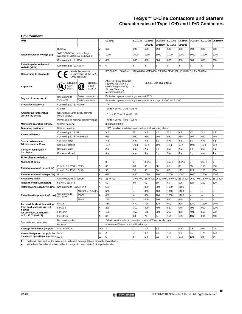
TeSys™ D-Line Contactors and StartersCharacteristics of Type LC•D and LP•D Contactors
01/04
EnvironmentType
Rated insulation voltage (Vi)
UL
Toca
Co
Rated impulse withstand voltage (Vimp) Co
Conforming to standards
Approvals
Degree of protection f CoVD
Protective treatment Co
Ambient air temperature around the device
Sto
Opco
Pe
Maximum operating altitude Wi
Operating positions Wi
Flame resistanceCo
Co
Shock resistance q1/2 sine wave = 11ms
Co
Co
Vibration resistance q 5 to 300 Hz
Co
Co
Pole characteristics
Number of poles
Rated operational current (Ie)In
In
Rated operational voltage (Ve) Up
Frequency limits Of
Rated thermal current (Ith) θ ≤
Rated making capacity (1 rms) Co
Rated breaking capacity (1 rms) CoIEC
Permissible short time rating from cold state, no current flowing for previous 15 minutes, at θ ≤ 40 °C (104 °F)
Fo
Fo
Fo
Fo
Short-circuit protectionBy
By
Average impedance per pole A I
Power dissipation per pole for the above operational currents
AC
AC
f Protection provided for the cableq In the least favorable direction, w
LC1D32 LC1D38 LC1D40 LC1D50 LC1D65 LC1D80 LC1D95 LC1D115 LC1D150
LP1D40 LP1D50 LP1D65 LP1D80
/CSA V 690 690 690 690 690 690 690 690 690
IEC 60947-4-1, overvoltage tegory III, degree of pollution: 3
V 1000 1000 1000 1000 1000 1000 1000 1000 1000
nforming to UL, CSA V 600 600 600 600 600 600 600 600 600
nforming to IEC 60947 kV 6 6 8 8 8 8 8 8 8
Meets the essential requirements of the LV & EMC directives
IEC 60947-1, 60947-4-1, NFC 63-110, VDE 0660, BS 5424, JEM 1038., EN 60947-1, EN 60947-4-1.
E164862 CCN NLDX
LR43364 Class 3211 04
ASE, UL, CSA, DEMKO, NEMKO, SEMKO, FI, Conforming to SNCF, Sichere Trennung recommendations
-
UL 508, CSA C22.2 No.14
nforming to E 0106
Power connections Protection against direct finger contact IP 2X
Coil connections Protection against direct finger contact IP 2X except LP1D40 to LP1D80
nforming to IEC 60068 “TH”
rage - 60 to + 80 °C (-76 to +176 °F)
eration at 80 to 110% nominal ntrol voltage
- 5 to + 55 °C (+23 to +131 °F)
rmissible at nominal control voltage - 40 to + 70 °C (-40 to +158 °F)
thout derating 3000m (8900 ft.)
thout derating ± 30° possible, in relation to normal vertical mounting plane
nforming to UL 94 V 1 V 1 V 1 V 1 V 1 V 1 V 1 V 1 V 1
nforming to IEC 60695-2-1 960° 960° 960° 960° 960° 960° 960° 960° 960°
ntactor open 8 g 8 g 8 g 8 g 8 g 8 g 8 g 6 g 6 g
ntactor closed 15 g 10 g 10 g 10 g 10 g 10 g 10 g 15 g 15 g
ntactor open 2 g 2 g 2 g 2 g 2 g 2 g 2 g 2 g 2 g
ntactor closed 4 g 4 g 3 g 3 g 3 g 3 g 3 g 4 g 4 g
3 3 3 or 4 3 3 or 4 3 or 4 3 3 or 4 3
ac-3, θ ≤ 55°C (131°F) A 32 38 40 50 65 80 95 115 150
ac-1, θ ≤ 40°C (104°F) A 50 50 60 80 80 125 125 200 200
to V 690 690 1000 1000 1000 1000 1000 1000 1000
the operational current Hz 25 to 400 25 to 400 25 to 400 25 to 400 25 to 400 25 to 400 25 to 400 25 to 400 25 to 400
40°C (104°F) A 50 50 60 80 80 125 125 200 200
nforming to IEC 60947-4 A 550 – 800 900 1000 1100 – – –
nforming to 60947
220-380-415-440 V
A
550 – 800 900 1000 1100 – – –
500 V 450 – 800 900 1000 1100 – – –
690 V 180 – 400 400 630 640 – – –
r 1 s A 430 430 720 810 900 990 1100 1100 1400
r 10 s A 260 310 320 400 520 640 800 950 1200
r 1 min A 138 150 165 208 260 320 400 550 580
r 10 min A 60 60 72 84 110 135 135 250 250
circuit breaker Select circuit breaker in accordance with NEC and local codes
fuses Maximum 400% of motor full load Amps
th and 50 Hz mΩ 2 2 1.5 1.5 1 0.8 0.8 0.6 0.6
-3 W 2 2 2.4 3.7 4.2 5.1 7.2 7.9 13.5
-1 W 5 5 5.4 9.6 6.4 12.5 12.5 24 24
c.s.a. indicated on page 86 and for cable connections. ithout change of contact state (coil supplied at Ve).
81© 2001-2004 Schneider Electric All Rights Reserved

TeSys™ D-Line Contactors and StartersCharacteristics of Type LC•D and LP•D Contactors
© 2001-2004 Schneider E82
Control Circuit Charac
Type
Rated control circuit voltage (Vc)
Control voltage limits (θ ≤ 55 °C [131 °F])
Average consumptionat 20 °C (68 °F) and at Vc
Heat dissipation
Operating time
Mechanical durability in millions ooperating cycles
Maximum operating rate at ambietemperature ≤ 55 °C (131 °F)
c The closing time “C” is measurq The opening time “O” is measu
teristics
LC1D09 LC1D12 LC1D18 LC1D25 LC1D32 LC1D38
LC1DT20 LC1DT25 LC1DT32 LC1DT40
50 or 60 Hz V 21 to 660 21 to 660
50 or 60 Hz coils Operational 0.8 to 1.1 Vac 0.8 to 1.1 Vac
Drop-out 0.3 to 0.6 Vac 0.3 to 0.6 Vac
50/60 Hz coils Operational 0.85 to 1.1 Vac at 60 Hz 0.85 to 1.1 Vac at 60 Hz
Drop-out 0.3 to 0.6 Vac 0.3 to 0.6 Vac
50 Hz ac
Inrush
50 Hz coil VA – – – – – –
Cos ϕ 0.75 0.75 0.75 0.75 0.75 0.75
50/60 Hz coil VA 70 70 70 70 70 70
Sealed
50 Hz coil VA – – – – – –
Cos ϕ 0.3 0.3 0.3 0.3 0.3 0.3
50/60 Hz coil VA 7 7 7 7 7 7
60 Hz ac
Inrush
60 Hz coil VA – – – – – –
Cos ϕ 0.75 0.75 0.75 0.75 0.75 0.75
50/60 Hz coil VA 70 70 70 100 70 70
Sealed
60 Hz coil VA – – – – – –
Cos ϕ 0.3 0.3 0.3 0.3 0.3 0.3
50/60 Hz coil VA 7.5 7.5 7.5 7.5 7.5 7.5
50/60 Hz W 2 to 3 2 to 3 2 to 3 2.5 to 3.5 2 to 3 2 to 3
Closing “C” c ms 12 to 22 12 to 22 12 to 22 15 to 24 12 to 22 12 to 22
Opening “O” q ms 4 to 19 4 to 19 4 to 19 5 to 19 4 to 19 4 to 19
f 50 or 60 Hz coil – – – – – –
50/60 Hz coil at 50 Hz 15 15 15 15 15 15
nt In operating cycles per hour 3600 3600 3600 3600 3600 3600
ed from the moment the coil supply is switched on to initial contact of the main poles.red from the moment the coil supply is switched off to the moment the mains poles separate.
lectric All Rights Reserved 01/04
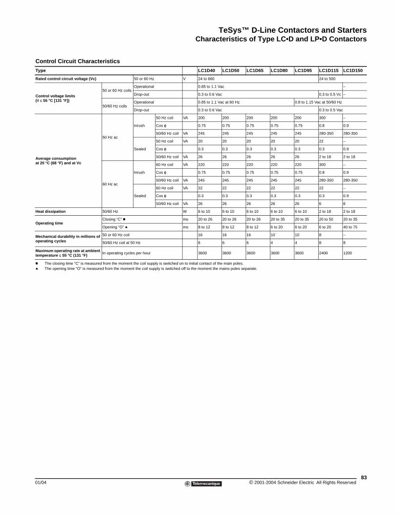
TeSys™ D-Line Contactors and StartersCharacteristics of Type LC•D and LP•D Contactors
01/04
Control Circuit Charac
Type
Rated control circuit voltage (Vc)
Control voltage limits (θ ≤ 55 °C [131 °F])
Average consumptionat 20 °C (68 °F) and at Vc
Heat dissipation
Operating time
Mechanical durability in millions ooperating cycles
Maximum operating rate at ambientemperature ≤ 55 °C (131 °F)
c The closing time “C” is measurq The opening time “O” is measu
teristics
LC1D40 LC1D50 LC1D65 LC1D80 LC1D95 LC1D115 LC1D150
50 or 60 Hz V 24 to 660 24 to 500
50 or 60 Hz coils Operational 0.85 to 1.1 Vac –
Drop-out 0.3 to 0.6 Vac 0.3 to 0.5 Vc –
50/60 Hz coils Operational 0.85 to 1.1 Vac at 60 Hz 0.8 to 1.15 Vac at 50/60 Hz
Drop-out 0.3 to 0.6 Vac 0.3 to 0.5 Vac
50 Hz ac
Inrush
50 Hz coil VA 200 200 200 200 200 300 –
Cos ϕ 0.75 0.75 0.75 0.75 0.75 0.8 0.9
50/60 Hz coil VA 245 245 245 245 245 280-350 280-350
Sealed
50 Hz coil VA 20 20 20 20 20 22 –
Cos ϕ 0.3 0.3 0.3 0.3 0.3 0.3 0.9
50/60 Hz coil VA 26 26 26 26 26 2 to 18 2 to 18
60 Hz ac
Inrush
60 Hz coil VA 220 220 220 220 220 300 –
Cos ϕ 0.75 0.75 0.75 0.75 0.75 0.8 0.9
50/60 Hz coil VA 245 245 245 245 245 280-350 280-350
Sealed
60 Hz coil VA 22 22 22 22 22 22 –
Cos ϕ 0.3 0.3 0.3 0.3 0.3 0.3 0.9
50/60 Hz coil VA 26 26 26 26 26 6 6
50/60 Hz W 6 to 10 6 to 10 6 to 10 6 to 10 6 to 10 2 to 18 2 to 18
Closing “C” c ms 20 to 26 20 to 26 20 to 26 20 to 35 20 to 35 20 to 50 20 to 35
Opening “O” q ms 8 to 12 8 to 12 8 to 12 6 to 20 6 to 20 6 to 20 40 to 75
f 50 or 60 Hz coil 16 16 16 10 10 8 –
50/60 Hz coil at 50 Hz 6 6 6 4 4 8 8
t In operating cycles per hour 3600 3600 3600 3600 3600 2400 1200
ed from the moment the coil supply is switched on to initial contact of the main poles.red from the moment the coil supply is switched off to the moment the mains poles separate.
83© 2001-2004 Schneider Electric All Rights Reserved
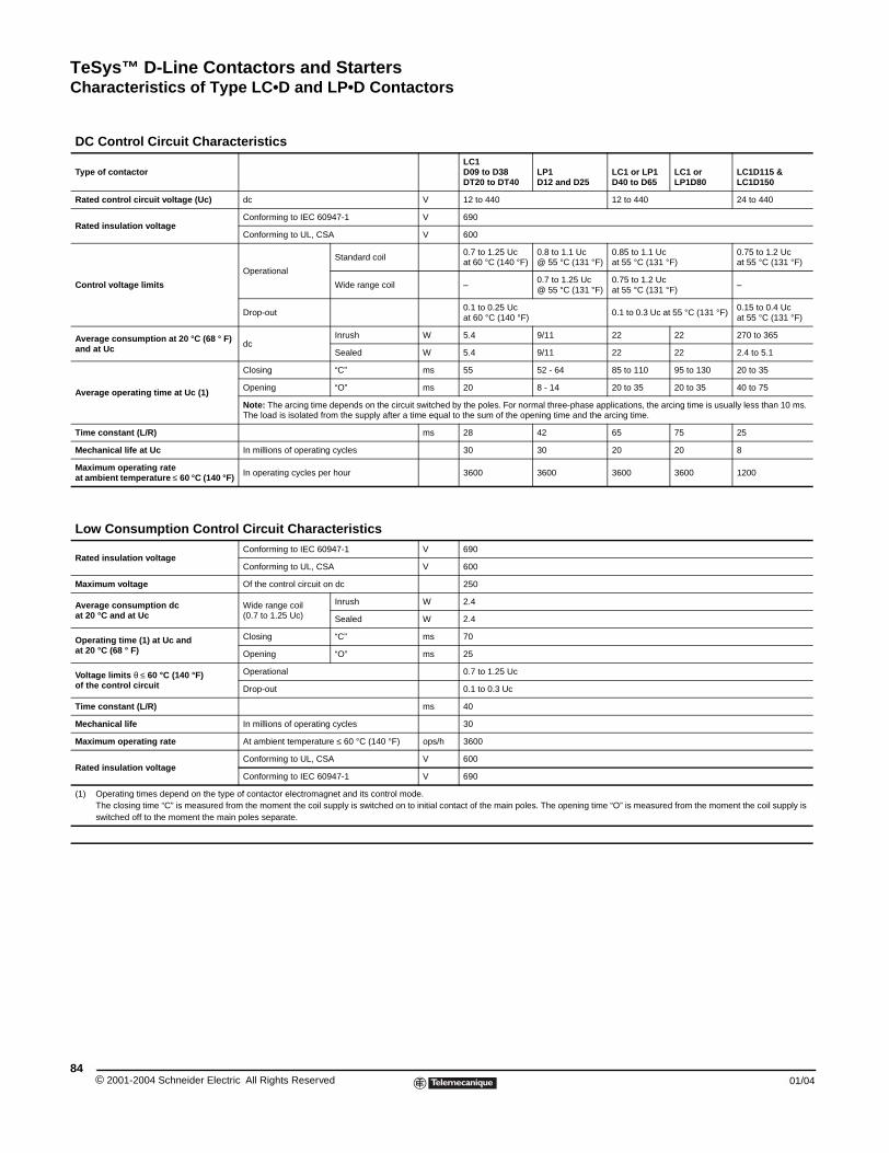
TeSys™ D-Line Contactors and StartersCharacteristics of Type LC•D and LP•D Contactors
© 2001-2004 Schneider E84
DC Control Circuit Ch
Type of contactor
Rated control circuit voltage (Uc)
Rated insulation voltage
Control voltage limits
Average consumption at 20 °C (6and at Uc
Average operating time at Uc (1)
Time constant (L/R)
Mechanical life at Uc
Maximum operating rateat ambient temperature ≤ 60 °C (1
Low Consumption Co
Rated insulation voltage
Maximum voltage
Average consumption dcat 20 °C and at Uc
Operating time (1) at Uc and at 20 °C (68 ° F)
Voltage limits θ ≤ 60 °C (140 °F)of the control circuit
Time constant (L/R)
Mechanical life
Maximum operating rate
Rated insulation voltage
(1) Operating times depend on thThe closing time “C” is measuswitched off to the moment the
aracteristicsLC1D09 to D38DT20 to DT40
LP1D12 and D25
LC1 or LP1D40 to D65
LC1 orLP1D80
LC1D115 &LC1D150
dc V 12 to 440 12 to 440 24 to 440
Conforming to IEC 60947-1 V 690
Conforming to UL, CSA V 600
Operational
Standard coil0.7 to 1.25 Ucat 60 °C (140 °F)
0.8 to 1.1 Uc@ 55 °C (131 °F)
0.85 to 1.1 Uc at 55 °C (131 °F)
0.75 to 1.2 Ucat 55 °C (131 °F)
Wide range coil –0.7 to 1.25 Uc@ 55 °C (131 °F)
0.75 to 1.2 Uc at 55 °C (131 °F)
–
Drop-out0.1 to 0.25 Ucat 60 °C (140 °F)
0.1 to 0.3 Uc at 55 °C (131 °F)0.15 to 0.4 Ucat 55 °C (131 °F)
8 ° F) dc
Inrush W 5.4 9/11 22 22 270 to 365
Sealed W 5.4 9/11 22 22 2.4 to 5.1
Closing “C” ms 55 52 - 64 85 to 110 95 to 130 20 to 35
Opening “O” ms 20 8 - 14 20 to 35 20 to 35 40 to 75
Note: The arcing time depends on the circuit switched by the poles. For normal three-phase applications, the arcing time is usually less than 10 ms. The load is isolated from the supply after a time equal to the sum of the opening time and the arcing time.
ms 28 42 65 75 25
In millions of operating cycles 30 30 20 20 8
40 °F) In operating cycles per hour 3600 3600 3600 3600 1200
ntrol Circuit CharacteristicsConforming to IEC 60947-1 V 690
Conforming to UL, CSA V 600
Of the control circuit on dc 250
Wide range coil(0.7 to 1.25 Uc)
Inrush W 2.4
Sealed W 2.4
Closing “C” ms 70
Opening “O” ms 25
Operational 0.7 to 1.25 Uc
Drop-out 0.1 to 0.3 Uc
ms 40
In millions of operating cycles 30
At ambient temperature ≤ 60 °C (140 °F) ops/h 3600
Conforming to UL, CSA V 600
Conforming to IEC 60947-1 V 690
e type of contactor electromagnet and its control mode. red from the moment the coil supply is switched on to initial contact of the main poles. The opening time “O” is measured from the moment the coil supply is main poles separate.
lectric All Rights Reserved 01/04
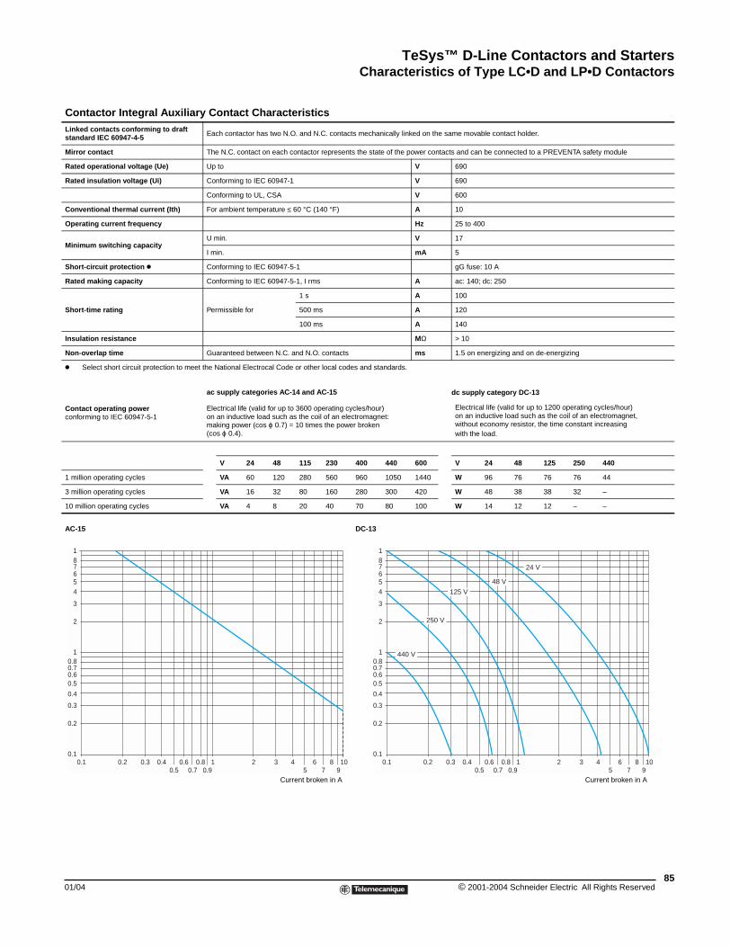
TeSys™ D-Line Contactors and StartersCharacteristics of Type LC•D and LP•D Contactors
01/04
Contactor Integral AuxLinked contacts conforming to drastandard IEC 60947-4-5
Mirror contact
Rated operational voltage (Ue)
Rated insulation voltage (Ui)
Conventional thermal current (Ith)
Operating current frequency
Minimum switching capacity
Short-circuit protection k
Rated making capacity
Short-time rating
Insulation resistance
Non-overlap time
k Select short circuit protection to
Contact operating powerconforming to IEC 60947-5-1
1 million operating cycles
3 million operating cycles
10 million operating cycles
AC-15
0.1 0.2 0.3 0.40.5
00.1
0.2
0.3
0.4
0.60.5
0.80.7
7
1
2
3
54
6
81
iliary Contact Characteristicsft
Each contactor has two N.O. and N.C. contacts mechanically linked on the same movable contact holder.
The N.C. contact on each contactor represents the state of the power contacts and can be connected to a PREVENTA safety module
Up to V 690
Conforming to IEC 60947-1 V 690
Conforming to UL, CSA V 600
For ambient temperature ≤ 60 °C (140 °F) A 10
Hz 25 to 400
U min. V 17
I min. mA 5
Conforming to IEC 60947-5-1 gG fuse: 10 A
Conforming to IEC 60947-5-1, I rms A ac: 140; dc: 250
Permissible for
1 s A 100
500 ms A 120
100 ms A 140
MΩ > 10
Guaranteed between N.C. and N.O. contacts ms 1.5 on energizing and on de-energizing
meet the National Electrocal Code or other local codes and standards.
ac supply categories AC-14 and AC-15 dc supply category DC-13
Electrical life (valid for up to 3600 operating cycles/hour)on an inductive load such as the coil of an electromagnet:making power (cos ϕ 0.7) = 10 times the power broken(cos ϕ 0.4).
Electrical life (valid for up to 1200 operating cycles/hour)on an inductive load such as the coil of an electromagnet,without economy resistor, the time constant increasingwith the load.
V 24 48 115 230 400 440 600 V 24 48 125 250 440
VA 60 120 280 560 960 1050 1440 W 96 76 76 76 44
VA 16 32 80 160 280 300 420 W 48 38 38 32 –
VA 4 8 20 40 70 80 100 W 14 12 12 – –
Current broken in A
DC-13
Current broken in A
.60.7
0.80.9
1 2 3 45
67
8910 0.1 0.2 0.3 0.4
0.50.6
0.70.8
0.91 2 3 4
56
78
910
0.1
0.2
0.3
0.4
0.60.5
0.80.7
7
1
2
3
54
6
81
440 V
48 V
250 V
125 V
24 V
85© 2001-2004 Schneider Electric All Rights Reserved
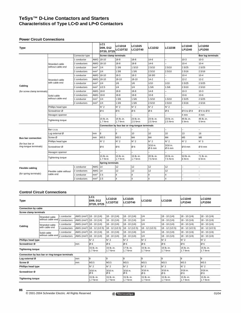
TeSys™ D-Line Contactors and StartersCharacteristics of Type LC•D and LP•D Contactors
© 2001-2004 Schneider E86
Power Circuit Connect
Type
Cabling
(for screw clamp terminals)
Strandedwithout c
Strandedwith cabl
Solid cabwithout c
Phillips h
Screwdr
Hexagon
Tightenin
Bus bar connection
(for bus bar or ring-tongue terminals)
Bar c.s.a
Lug exte
Screw Ø
Phillips h
Screwdr
Hexagon
Tightenin
Flexible cabling
(for spring terminals)Flexible cable en
Control Circuit Connec
Type
Connection by cable
Screw clamp terminals
Cabling
Stranded cable without cable end
Stranded cable with cable end
Solid cable without cable end
Phillips head type
Screwdriver Ø
Tightening torque
Connection by bus bar or ring-ton
Lug external Ø
Screw Ø
Phillips head type
Screwdriver Ø
Tightening torque
ionsLC1D09, D12DT20, DT25
LC1D18LC1DT32
LC1D25LC1DT40
LC1D32 LC1D38LC1D40LP1D40
LC1D50LP1D50
Connector type Screw clamp terminals Box lug terminals
cable able end
1 conductor AWG 18-10 18-8 18-8 14-6 – 10-3 10-3
2 conductors AWG 18-10 18-8 18-8 14-6 – 10-4 10-4
1 conductor mm2 1/4 1.5/6 1.5/10 2.5/10 2.5/10 2.5/25 2.5/25
2 conductors mm2 1/4 1.5/6 1.5/6 2.5/10 2.5/10 2.5/16 2.5/16
cable e end
1 conductor AWG 18-10 18-3 18-3 18-3/0 – 10-4 10-4
2 conductors AWG 18-10 18-10 18-10 14-2 – 12-2 12-2
1 conductor mm2 1/4 1/6 1/6 1/10 1/10 2.5/25 2.5/25
2 conductors mm2 1/2.5 1/4 1/4 1.5/6 1.5/6 2.5/10 2.5/10
le able end
1 conductor AWG 18-8 18-8 18-8 14-8 – 10-3 10-3
2 conductors AWG 18-8 18-8 18-8 10-8 – 10-6 10-6
1 conductor mm2 1/4 1.5/6 1.5/6 1.5/10 1.5/10 2.5/25 2.5/25
2 conductors mm2 1/4 1.5/6 1.5/6 2.5/10 2.5/10 2.5/16 2.5/16
ead type N° 2 N° 2 N° 2 N° 2 N° 2 – –
iver Ø Ø 6 Ø 6 Ø 6 Ø 6 Ø 6 Ø 6 to Ø 8 Ø 6 to Ø 8
spanner – – – – – 4 mm 4 mm
g torque15 lb.-in. 1.7 N•m
15 lb.-in. 1.7 N•m
23 lb.-in. 2.5 N•m
23 lb.-in. 2.5 N•m
23 lb.-in.2.5 N•m
45 lb.-in. 5 N•m
45 lb.-in. 5 N•m
Connection by bus bar or ring-tongue terminals
. – – – – – – –
rnal Ø mm 8 8 10 10 10 13 16
mm M3.5 M3.5 M4 M4 M4 M5 M6
ead type N° 2 N° 2 N° 2 N° 2 N° 2 N° 2 N° 3
iver Ø Ø 6 Ø 6 Ø 63/16 in.Ø 6 mm
3/16 in.Ø 6 mm
Ø 8 mm Ø 8 mm
spanner – – – – – – –
g torque15 lb.-in. 1.7 N•m
15 lb.-in. 1.7 N•m
15 lb.-in. 1.7 N•m
20 lb.-in. 7.5 N•m
20 lb.-in. 7.5 N•m
53 lb.-in.6 N•m
71 lb.-in.6 N•m
Spring terminals
cable without d
1 conductor AWG 14 12 12 12 12 – –
2 conductors AWG 14 12 12 12 12 – –
1 conductor mm2 2.5 4 4 4 4 – –
2 conductors mm2 2.5 4 4 4 4 – –
tionsLC1D09, D12DT20, DT25
LC1D18LC1DT32
LC1D25LC1DT40
LC1D32 LC1D38LC1D40LP1D40
LC1D50LP1D50
1 conductor AWG (mm2) 18 - 10 (1/4) 18 - 10 (1/4) 18 - 10 (1/4) 1/4 18 - 10 (1/4) 18 - 10 (1/4) 18 - 10 (1/4)
2 conductors AWG (mm2) 18 - 10 (1/4) 18 - 10 (1/4) 18 - 10 (1/4) 1/4 18 - 10 (1/4) 18 - 10 (1/4) 18 - 10 (1/4)
1 conductor AWG (mm2) 18 - 10 (1/4) 18 - 10 (1/4) 18 - 10 (1/4) 1/4 18 - 10 (1/4) 18 - 10 (1/4) 18 - 10 (1/4)
2 conductors AWG (mm2) 18 - 12 (1/2.5) 18 - 12 (1/2.5) 18 - 12 (1/2.5) 18 - 12 (1/2.5) 18 - 12 (1/2.5) 18 - 12 (1/2.5) 18 - 12 (1/2.5)
1 conductor AWG (mm2) 18 - 10 (1/4) 18 - 10 (1/4) 18 - 10 (1/4) 1/4 18 - 10 (1/4) 18 - 10 (1/4) 18 - 10 (1/4)
2 conductors AWG (mm2) 18 - 10 (1/4) 18 - 10 (1/4) 18 - 10 (1/4) 1/4 18 - 10 (1/4) 18 - 10 (1/4) 18 - 10 (1/4)
N° 2 N° 2 N° 2 N° 2 N° 2 N° 2 N° 2
mm Ø 6 Ø 6 Ø 6 Ø 6 Ø 6 Ø 6 Ø 6
15 lb.-in. 1.7 N•m
15 lb.-in. 1.7 N•m
17 lb.-in. 1.7 N•m
15 lb.-in. 1.7 N•m
15 lb.-in. 1.7 N•m
15 lb.-in. 1.7 N•m
15 lb.-in. 1.7 N•m
gue terminals
mm 8 8 8 8 8 8 8
mm M3.5 M3.5 M3.5 M3.5 M3.5 M3.5 M3.5
N° 2 N° 2 N° 2 N° 2 N° 2 N° 2 N° 2
3/16 in. Ø 6
3/16 in. Ø 6
3/16 in. Ø 6
3/16 in. Ø 6
3/16 in. Ø 6
3/16 in. Ø 6
3/16 in. Ø 6
15 lb.-in. 1.7 N•m
15 lb.-in. 1.7 N•m
15 lb.-in. 1.7 N•m
15 lb.-in. 1.7 N•m
15 lb.-in. 1.7 N•m
15 lb.-in. 1.7 N•m
15 lb.-in. 1.7 N•m
lectric All Rights Reserved 01/04
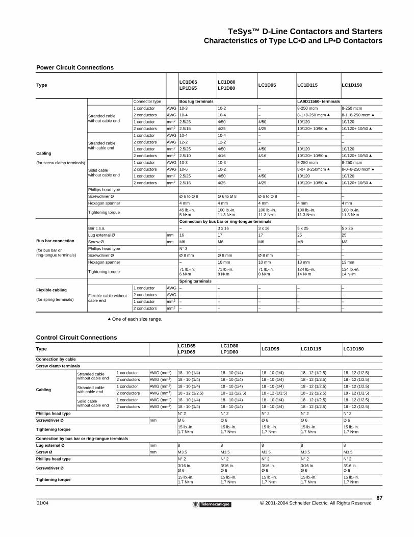
TeSys™ D-Line Contactors and StartersCharacteristics of Type LC•D and LP•D Contactors
01/04
Power Circuit Connecti
Type
Cabling
(for screw clamp terminals)
Strandewithout
Strandewith cab
Solid cawithout
Phillips
Screwdr
Hexago
Tighten
Bus bar connection
(for bus bar or ring-tongue terminals)
Bar c.s.
Lug exte
Screw Ø
Phillips
Screwdr
Hexago
Tighten
Flexible cabling
(for spring terminals)Flexiblecable en
Control Circuit Connec
Type
Connection by cable
Screw clamp terminals
Cabling
Stranded cablwithout cable
Stranded cablwith cable end
Solid cable without cable
Phillips head type
Screwdriver Ø
Tightening torque
Connection by bus bar or ring-tong
Lug external Ø
Screw Ø
Phillips head type
Screwdriver Ø
Tightening torque
q One of each size range.
ons
LC1D65LP1D65
LC1D80LP1D80
LC1D95 LC1D115 LC1D150
Connector type Box lug terminals LA9D11560• terminals
d cable cable end
1 conductor AWG 10-3 10-2 – 8-250 mcm 8-250 mcm
2 conductors AWG 10-4 10-4 – 8-1+8-250 mcm q 8-1+8-250 mcm q
1 conductor mm2 2.5/25 4/50 4/50 10/120 10/120
2 conductors mm2 2.5/16 4/25 4/25 10/120+ 10/50 q 10/120+ 10/50 q
d cable le end
1 conductor AWG 10-4 10-4 – – –
2 conductors AWG 12-2 12-2 – – –
1 conductor mm2 2.5/25 4/50 4/50 10/120 10/120
2 conductors mm2 2.5/10 4/16 4/16 10/120+ 10/50 q 10/120+ 10/50 q
ble cable end
1 conductor AWG 10-3 10-3 – 8-250 mcm 8-250 mcm
2 conductors AWG 10-6 10-2 – 8-0+ 8-250mcm q 8-0+8-250 mcm q
1 conductor mm2 2.5/25 4/50 4/50 10/120 10/120
2 conductors mm2 2.5/16 4/25 4/25 10/120+ 10/50 q 10/120+ 10/50 q
head type – – – – –
iver Ø Ø 6 to Ø 8 Ø 6 to Ø 8 Ø 6 to Ø 8 – –
n spanner 4 mm 4 mm 4 mm 4 mm 4 mm
ing torque45 lb.-in. 5 N•m
100 lb.-in. 11.3 N•m
100 lb.-in.11.3 N•m
100 lb.-in. 11.3 N•m
100 lb.-in. 11.3 N•m
Connection by bus bar or ring-tongue terminals
a. – 3 x 16 3 x 16 5 x 25 5 x 25
rnal Ø mm 16 17 17 25 25
mm M6 M6 M6 M8 M8
head type N° 3 – – – –
iver Ø Ø 8 mm Ø 8 mm Ø 8 mm – –
n spanner – 10 mm 10 mm 13 mm 13 mm
ing torque71 lb.-in.6 N•m
71 lb.-in.8 N•m
71 lb.-in.8 N•m
124 lb.-in.14 N•m
124 lb.-in.14 N•m
Spring terminals
cable without d
1 conductor AWG – – – – –
2 conductors AWG – – – – –
1 conductor mm2 – – – – –
2 conductors mm2 – – – – –
tionsLC1D65LP1D65
LC1D80LP1D80
LC1D95 LC1D115 LC1D150
e end
1 conductor AWG (mm2) 18 - 10 (1/4) 18 - 10 (1/4) 18 - 10 (1/4) 18 - 12 (1/2.5) 18 - 12 (1/2.5)
2 conductors AWG (mm2) 18 - 10 (1/4) 18 - 10 (1/4) 18 - 10 (1/4) 18 - 12 (1/2.5) 18 - 12 (1/2.5)
e 1 conductor AWG (mm2) 18 - 10 (1/4) 18 - 10 (1/4) 18 - 10 (1/4) 18 - 12 (1/2.5) 18 - 12 (1/2.5)
2 conductors AWG (mm2) 18 - 12 (1/2.5) 18 - 12 (1/2.5) 18 - 12 (1/2.5) 18 - 12 (1/2.5) 18 - 12 (1/2.5)
end1 conductor AWG (mm2) 18 - 10 (1/4) 18 - 10 (1/4) 18 - 10 (1/4) 18 - 12 (1/2.5) 18 - 12 (1/2.5)
2 conductors AWG (mm2) 18 - 10 (1/4) 18 - 10 (1/4) 18 - 10 (1/4) 18 - 12 (1/2.5) 18 - 12 (1/2.5)
N° 2 N° 2 N° 2 N° 2 N° 2
mm Ø 6 Ø 6 Ø 6 Ø 6 Ø 6
15 lb.-in. 1.7 N•m
15 lb.-in. 1.7 N•m
15 lb.-in. 1.7 N•m
15 lb.-in. 1.7 N•m
15 lb.-in. 1.7 N•m
ue terminals
mm 8 8 8 8 8
mm M3.5 M3.5 M3.5 M3.5 M3.5
N° 2 N° 2 N° 2 N° 2 N° 2
3/16 in. Ø 6
3/16 in. Ø 6
3/16 in. Ø 6
3/16 in. Ø 6
3/16 in. Ø 6
15 lb.-in. 1.7 N•m
15 lb.-in. 1.7 N•m
15 lb.-in. 1.7 N•m
15 lb.-in. 1.7 N•m
15 lb.-in. 1.7 N•m
87© 2001-2004 Schneider Electric All Rights Reserved
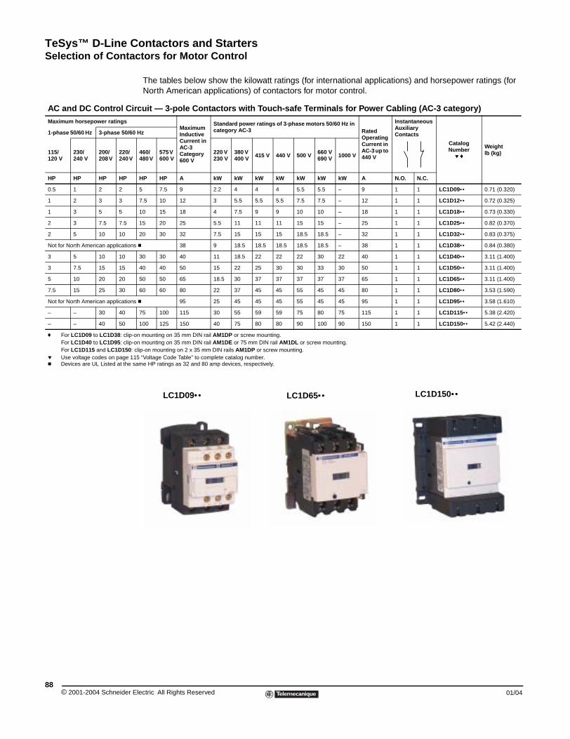
TeSys™ D-Line Contactors and StartersSelection of Contactors for Motor Control
© 2001-2004 Schneider E88
AC and DC Control CirMaximum horsepower ratings
1-phase 50/60 Hz 3-phase 50/60
115/120 V
230/240 V
200/208 V
220/240 V
HP HP HP HP
0.5 1 2 2
1 2 3 3
1 3 5 5
2 3 7.5 7.5
2 5 10 10
Not for North American applications
3 5 10 10
3 7.5 15 15
5 10 20 20
7.5 15 25 30
Not for North American applications
– – 30 40
– – 40 50
f For LC1D09 to LC1D38: clip-oFor LC1D40 to LC1D95: clip-oFor LC1D115 and LC1D150: c
p Use voltage codes on page 11c Devices are UL Listed at the s
Selection of Contactors for Motor Control
The tables below show the kilowatt ratings (for international applications) and horsepower ratings (for North American applications) of contactors for motor control.
cuit — 3-pole Contactors with Touch-safe Terminals for Power Cabling (AC-3 category)
Maximum Inductive Current in AC-3 Category 600 V
Standard power ratings of 3-phase motors 50/60 Hz in category AC-3 Rated
Operating Current in AC-3 up to 440 V
Instantaneous Auxiliary Contacts
Catalog Number
p f
Weight lb (kg)
Hz
460/480 V
575 V 600 V
220 V 230 V
380 V 400 V 415 V 440 V 500 V 660 V
690 V 1000 V
HP HP A kW kW kW kW kW kW kW A N.O. N.C.
5 7.5 9 2.2 4 4 4 5.5 5.5 – 9 1 1 LC1D09•• 0.71 (0.320)
7.5 10 12 3 5.5 5.5 5.5 7.5 7.5 – 12 1 1 LC1D12•• 0.72 (0.325)
10 15 18 4 7.5 9 9 10 10 – 18 1 1 LC1D18•• 0.73 (0.330)
15 20 25 5.5 11 11 11 15 15 – 25 1 1 LC1D25•• 0.82 (0.370)
20 30 32 7.5 15 15 15 18.5 18.5 – 32 1 1 LC1D32•• 0.83 (0.375)
c 38 9 18.5 18.5 18.5 18.5 18.5 – 38 1 1 LC1D38•• 0.84 (0.380)
30 30 40 11 18.5 22 22 22 30 22 40 1 1 LC1D40•• 3.11 (1.400)
40 40 50 15 22 25 30 30 33 30 50 1 1 LC1D50•• 3.11 (1.400)
50 50 65 18.5 30 37 37 37 37 37 65 1 1 LC1D65•• 3.11 (1.400)
60 60 80 22 37 45 45 55 45 45 80 1 1 LC1D80•• 3.53 (1.590)
c 95 25 45 45 45 55 45 45 95 1 1 LC1D95•• 3.58 (1.610)
75 100 115 30 55 59 59 75 80 75 115 1 1 LC1D115•• 5.38 (2.420)
100 125 150 40 75 80 80 90 100 90 150 1 1 LC1D150•• 5.42 (2.440)
n mounting on 35 mm DIN rail AM1DP or screw mounting. n mounting on 35 mm DIN rail AM1DE or 75 mm DIN rail AM1DL or screw mounting. lip-on mounting on 2 x 35 mm DIN rails AM1DP or screw mounting.5 “Voltage Code Table” to complete catalog number.ame HP ratings as 32 and 80 amp devices, respectively.
LC1D09•• LC1D65•• LC1D150••
lectric All Rights Reserved 01/04
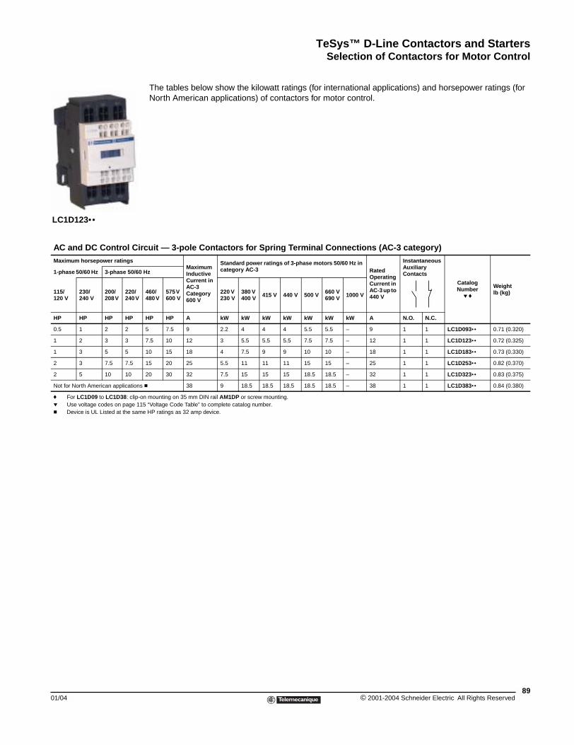
TeSys™ D-Line Contactors and StartersSelection of Contactors for Motor Control
01/04
AC and DC Control CirMaximum horsepower ratings
1-phase 50/60 Hz 3-phase 50/60
115/120 V
230/240 V
200/208 V
220/240 V
HP HP HP HP
0.5 1 2 2
1 2 3 3
1 3 5 5
2 3 7.5 7.5
2 5 10 10
Not for North American applications
f For LC1D09 to LC1D38: clip-op Use voltage codes on page 11c Device is UL Listed at the sam
LC1D123••
The tables below show the kilowatt ratings (for international applications) and horsepower ratings (for North American applications) of contactors for motor control.
cuit — 3-pole Contactors for Spring Terminal Connections (AC-3 category)
Maximum Inductive Current in AC-3 Category 600 V
Standard power ratings of 3-phase motors 50/60 Hz in category AC-3 Rated
Operating Current in AC-3 up to 440 V
Instantaneous Auxiliary Contacts
Catalog Number
p f
Weight lb (kg)
Hz
460/480 V
575 V 600 V
220 V 230 V
380 V 400 V 415 V 440 V 500 V 660 V
690 V 1000 V
HP HP A kW kW kW kW kW kW kW A N.O. N.C.
5 7.5 9 2.2 4 4 4 5.5 5.5 – 9 1 1 LC1D093•• 0.71 (0.320)
7.5 10 12 3 5.5 5.5 5.5 7.5 7.5 – 12 1 1 LC1D123•• 0.72 (0.325)
10 15 18 4 7.5 9 9 10 10 – 18 1 1 LC1D183•• 0.73 (0.330)
15 20 25 5.5 11 11 11 15 15 – 25 1 1 LC1D253•• 0.82 (0.370)
20 30 32 7.5 15 15 15 18.5 18.5 – 32 1 1 LC1D323•• 0.83 (0.375)
c 38 9 18.5 18.5 18.5 18.5 18.5 – 38 1 1 LC1D383•• 0.84 (0.380)
n mounting on 35 mm DIN rail AM1DP or screw mounting. 5 “Voltage Code Table” to complete catalog number.e HP ratings as 32 amp device.
89© 2001-2004 Schneider Electric All Rights Reserved
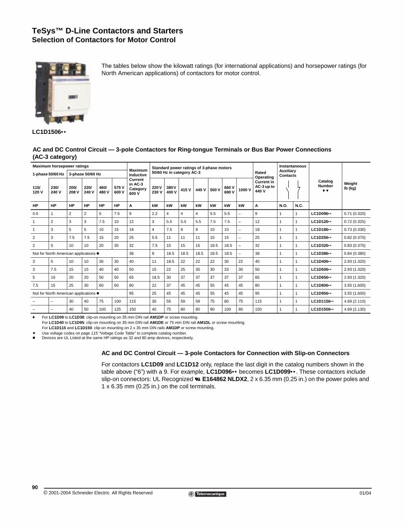
TeSys™ D-Line Contactors and StartersSelection of Contactors for Motor Control
© 2001-2004 Schneider E90
AC and DC Control Cir(AC-3 category)Maximum horsepower ratings
1-phase 50/60 Hz 3-phase 50/60
115/120 V
230/240 V
200/208 V
220/240 V
HP HP HP HP
0.5 1 2 2
1 2 3 3
1 3 5 5
2 3 7.5 7.5
2 5 10 10
Not for North American applications
3 5 10 10
3 7.5 15 15
5 10 20 20
7.5 15 25 30
Not for North American applications
– – 30 40
– – 40 50
f For LC1D09 to LC1D38: clip-oFor LC1D40 to LC1D95: clip-oFor LC1D115 and LC1D150: c
p Use voltage codes on page 11c Devices are UL Listed at the sa
LC1D1506••
The tables below show the kilowatt ratings (for international applications) and horsepower ratings (for North American applications) of contactors for motor control.
AC and DC Control Circuit — 3-pole Contactors for Connection with Slip-on Connectors
For contactors LC1D09 and LC1D12 only, replace the last digit in the catalog numbers shown in the table above (“6”) with a 9. For example, LC1D096•• becomes LC1D099•• . These contactors include slip-on connectors: UL Recognized E164862 NLDX2, 2 x 6.35 mm (0.25 in.) on the power poles and 1 x 6.35 mm (0.25 in.) on the coil terminals.
cuit — 3-pole Contactors for Ring-tongue Terminals or Bus Bar Power Connections
Maximum Inductive Current in AC-3 Category 600 V
Standard power ratings of 3-phase motors 50/60 Hz in category AC-3 Rated
Operating Current in AC-3 up to 440 V
Instantaneous Auxiliary Contacts
CatalogNumber
f p
Weight lb (kg)
Hz
460/480 V
575 V 600 V
220 V 230 V
380 V 400 V 415 V 440 V 500 V 660 V
690 V 1000 V
HP HP A kW kW kW kW kW kW kW A N.O. N.C.
5 7.5 9 2.2 4 4 4 5.5 5.5 – 9 1 1 LC1D096•• 0.71 (0.320)
7.5 10 12 3 5.5 5.5 5.5 7.5 7.5 – 12 1 1 LC1D126•• 0.72 (0.325)
10 15 18 4 7.5 9 9 10 10 – 18 1 1 LC1D186•• 0.73 (0.330)
15 20 25 5.5 11 11 11 15 15 – 25 1 1 LC1D256•• 0.82 (0.370)
20 30 32 7.5 15 15 15 18.5 18.5 – 32 1 1 LC1D326•• 0.83 (0.375)
c 38 9 18.5 18.5 18.5 18.5 18.5 – 38 1 1 LC1D386•• 0.84 (0.380)
30 30 40 11 18.5 22 22 22 30 22 40 1 1 LC1D406•• 2.93 (1.320)
40 40 50 15 22 25 30 30 33 30 50 1 1 LC1D506•• 2.93 (1.320)
50 50 65 18.5 30 37 37 37 37 37 65 1 1 LC1D656•• 2.93 (1.320)
60 60 80 22 37 45 45 55 45 45 80 1 1 LC1D806•• 3.55 (1.600)
c 95 25 45 45 45 55 45 45 95 1 1 LC1D956•• 3.55 (1.600)
75 100 115 30 55 59 59 75 80 75 115 1 1 LC1D1156•• 4.69 (2.110)
100 125 150 40 75 80 80 90 100 90 150 1 1 LC1D1506•• 4.69 (2.130)
n mounting on 35 mm DIN rail AM1DP or screw mounting. n mounting on 35 mm DIN rail AM1DE or 75 mm DIN rail AM1DL or screw mounting. lip-on mounting on 2 x 35 mm DIN rails AM1DP or screw mounting.5 “Voltage Code Table” to complete catalog number.me HP ratings as 32 and 80 amp devices, respectively.
lectric All Rights Reserved 01/04
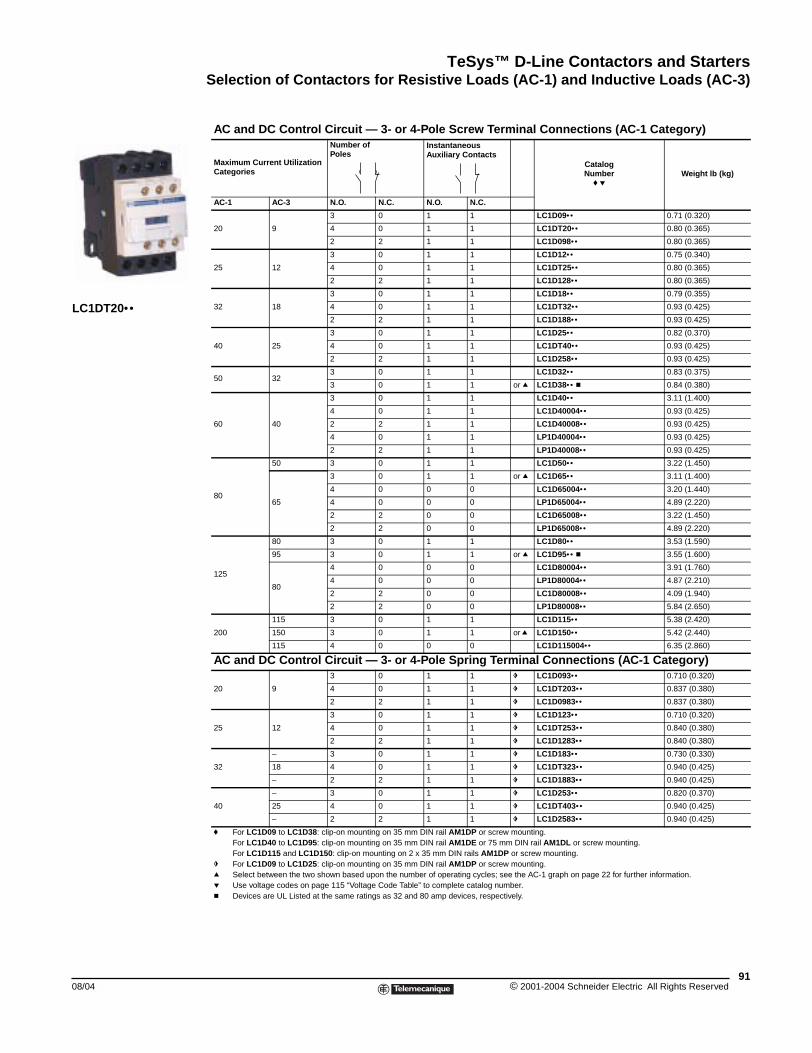
TeSys™ D-Line Contactors and StartersSelection of Contactors for Resistive Loads (AC-1) and Inductive Loads (AC-3)
08/04
LC1DT20••
Selection of Contactors for Resistive Loads
AC and DC Control Circuit — 3- or 4-Pole Screw Terminal Connections (AC-1 Category)
Maximum Current Utilization Categories
Number of Poles
Instantaneous Auxiliary Contacts
CatalogNumber
f pWeight lb (kg)
AC-1 AC-3 N.O. N.C. N.O. N.C.
20 9
3 0 1 1 LC1D09•• 0.71 (0.320)
4 0 1 1 LC1DT20•• 0.80 (0.365)
2 2 1 1 LC1D098•• 0.80 (0.365)
25 12
3 0 1 1 LC1D12•• 0.75 (0.340)
4 0 1 1 LC1DT25•• 0.80 (0.365)
2 2 1 1 LC1D128•• 0.80 (0.365)
32 18
3 0 1 1 LC1D18•• 0.79 (0.355)
4 0 1 1 LC1DT32•• 0.93 (0.425)
2 2 1 1 LC1D188•• 0.93 (0.425)
40 25
3 0 1 1 LC1D25•• 0.82 (0.370)
4 0 1 1 LC1DT40•• 0.93 (0.425)
2 2 1 1 LC1D258•• 0.93 (0.425)
50 323 0 1 1 LC1D32•• 0.83 (0.375)
3 0 1 1 or q LC1D38•• c 0.84 (0.380)
60 40
3 0 1 1 LC1D40•• 3.11 (1.400)
4 0 1 1 LC1D40004•• 0.93 (0.425)
2 2 1 1 LC1D40008•• 0.93 (0.425)
4 0 1 1 LP1D40004•• 0.93 (0.425)
2 2 1 1 LP1D40008•• 0.93 (0.425)
80
50 3 0 1 1 LC1D50•• 3.22 (1.450)
65
3 0 1 1 or q LC1D65•• 3.11 (1.400)
4 0 0 0 LC1D65004•• 3.20 (1.440)
4 0 0 0 LP1D65004•• 4.89 (2.220)
2 2 0 0 LC1D65008•• 3.22 (1.450)
2 2 0 0 LP1D65008•• 4.89 (2.220)
125
80 3 0 1 1 LC1D80•• 3.53 (1.590)
95 3 0 1 1 or q LC1D95•• c 3.55 (1.600)
80
4 0 0 0 LC1D80004•• 3.91 (1.760)
4 0 0 0 LP1D80004•• 4.87 (2.210)
2 2 0 0 LC1D80008•• 4.09 (1.940)
2 2 0 0 LP1D80008•• 5.84 (2.650)
200
115 3 0 1 1 LC1D115•• 5.38 (2.420)
150 3 0 1 1 or q LC1D150•• 5.42 (2.440)
115 4 0 0 0 LC1D115004•• 6.35 (2.860)
AC and DC Control Circuit — 3- or 4-Pole Spring Terminal Connections (AC-1 Category)
20 9
3 0 1 1 g LC1D093•• 0.710 (0.320)
4 0 1 1 g LC1DT203•• 0.837 (0.380)
2 2 1 1 g LC1D0983•• 0.837 (0.380)
25 12
3 0 1 1 g LC1D123•• 0.710 (0.320)
4 0 1 1 g LC1DT253•• 0.840 (0.380)
2 2 1 1 g LC1D1283•• 0.840 (0.380)
32
– 3 0 1 1 g LC1D183•• 0.730 (0.330)
18 4 0 1 1 g LC1DT323•• 0.940 (0.425)
– 2 2 1 1 g LC1D1883•• 0.940 (0.425)
40
– 3 0 1 1 g LC1D253•• 0.820 (0.370)
25 4 0 1 1 g LC1DT403•• 0.940 (0.425)
– 2 2 1 1 g LC1D2583•• 0.940 (0.425)
f For LC1D09 to LC1D38: clip-on mounting on 35 mm DIN rail AM1DP or screw mounting. For LC1D40 to LC1D95: clip-on mounting on 35 mm DIN rail AM1DE or 75 mm DIN rail AM1DL or screw mounting. For LC1D115 and LC1D150: clip-on mounting on 2 x 35 mm DIN rails AM1DP or screw mounting.
g For LC1D09 to LC1D25: clip-on mounting on 35 mm DIN rail AM1DP or screw mounting. q Select between the two shown based upon the number of operating cycles; see the AC-1 graph on page 22 for further information.p Use voltage codes on page 115 “Voltage Code Table” to complete catalog number.c Devices are UL Listed at the same ratings as 32 and 80 amp devices, respectively.
91© 2001-2004 Schneider Electric All Rights Reserved
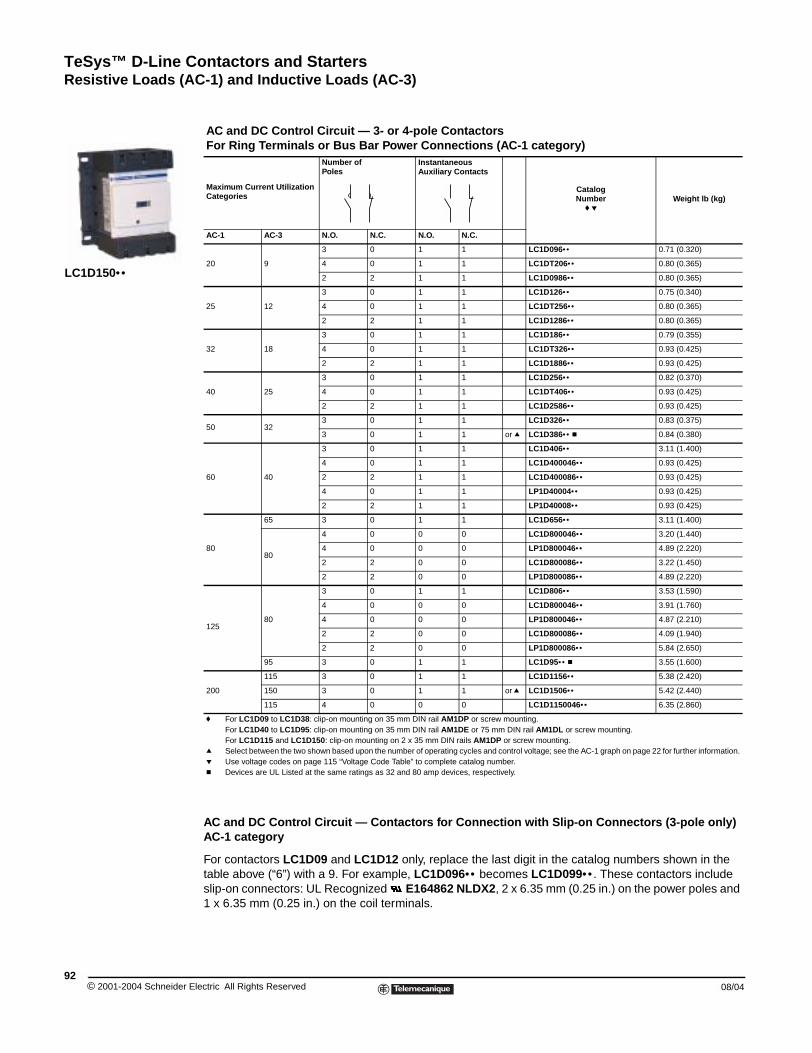
TeSys™ D-Line Contactors and StartersResistive Loads (AC-1) and Inductive Loads (AC-3)
© 2001-2004 Schneider E92
LC1D150••
Resistive Loads
AC and DC Control Circuit — Contactors for Connection with Slip-on Connectors (3-pole only)AC-1 category
For contactors LC1D09 and LC1D12 only, replace the last digit in the catalog numbers shown in the table above (“6”) with a 9. For example, LC1D096•• becomes LC1D099•• . These contactors include slip-on connectors: UL Recognized E164862 NLDX2, 2 x 6.35 mm (0.25 in.) on the power poles and 1 x 6.35 mm (0.25 in.) on the coil terminals.
AC and DC Control Circuit — 3- or 4-pole ContactorsFor Ring Terminals or Bus Bar Power Connections (AC-1 category)
Maximum Current Utilization Categories
Number of Poles
Instantaneous Auxiliary Contacts
CatalogNumber
f pWeight lb (kg)
AC-1 AC-3 N.O. N.C. N.O. N.C.
20 9
3 0 1 1 LC1D096•• 0.71 (0.320)
4 0 1 1 LC1DT206•• 0.80 (0.365)
2 2 1 1 LC1D0986•• 0.80 (0.365)
25 12
3 0 1 1 LC1D126•• 0.75 (0.340)
4 0 1 1 LC1DT256•• 0.80 (0.365)
2 2 1 1 LC1D1286•• 0.80 (0.365)
32 18
3 0 1 1 LC1D186•• 0.79 (0.355)
4 0 1 1 LC1DT326•• 0.93 (0.425)
2 2 1 1 LC1D1886•• 0.93 (0.425)
40 25
3 0 1 1 LC1D256•• 0.82 (0.370)
4 0 1 1 LC1DT406•• 0.93 (0.425)
2 2 1 1 LC1D2586•• 0.93 (0.425)
50 323 0 1 1 LC1D326•• 0.83 (0.375)
3 0 1 1 or q LC1D386•• c 0.84 (0.380)
60 40
3 0 1 1 LC1D406•• 3.11 (1.400)
4 0 1 1 LC1D400046•• 0.93 (0.425)
2 2 1 1 LC1D400086•• 0.93 (0.425)
4 0 1 1 LP1D40004•• 0.93 (0.425)
2 2 1 1 LP1D40008•• 0.93 (0.425)
80
65 3 0 1 1 LC1D656•• 3.11 (1.400)
80
4 0 0 0 LC1D800046•• 3.20 (1.440)
4 0 0 0 LP1D800046•• 4.89 (2.220)
2 2 0 0 LC1D800086•• 3.22 (1.450)
2 2 0 0 LP1D800086•• 4.89 (2.220)
12580
3 0 1 1 LC1D806•• 3.53 (1.590)
4 0 0 0 LC1D800046•• 3.91 (1.760)
4 0 0 0 LP1D800046•• 4.87 (2.210)
2 2 0 0 LC1D800086•• 4.09 (1.940)
2 2 0 0 LP1D800086•• 5.84 (2.650)
95 3 0 1 1 LC1D95•• c 3.55 (1.600)
200
115 3 0 1 1 LC1D1156•• 5.38 (2.420)
150 3 0 1 1 or q LC1D1506•• 5.42 (2.440)
115 4 0 0 0 LC1D1150046•• 6.35 (2.860)
f For LC1D09 to LC1D38: clip-on mounting on 35 mm DIN rail AM1DP or screw mounting. For LC1D40 to LC1D95: clip-on mounting on 35 mm DIN rail AM1DE or 75 mm DIN rail AM1DL or screw mounting. For LC1D115 and LC1D150: clip-on mounting on 2 x 35 mm DIN rails AM1DP or screw mounting.
q Select between the two shown based upon the number of operating cycles and control voltage; see the AC-1 graph on page 22 for further information.p Use voltage codes on page 115 “Voltage Code Table” to complete catalog number.c Devices are UL Listed at the same ratings as 32 and 80 amp devices, respectively.
lectric All Rights Reserved 08/04
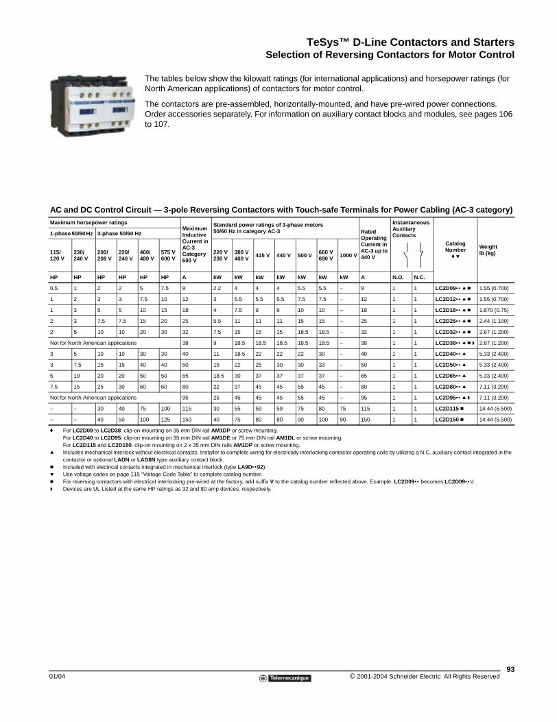
TeSys™ D-Line Contactors and StartersSelection of Reversing Contactors for Motor Control
01/04
AC and DC Control CircMaximum horsepower ratings
1-phase 50/60 Hz 3-phase 50/60 H
115/120 V
230/240 V
200/208 V
220/240 V
HP HP HP HP
0.5 1 2 2
1 2 3 3
1 3 5 5
2 3 7.5 7.5
2 5 10 10
Not for North American applications
3 5 10 10
3 7.5 15 15
5 10 20 20
7.5 15 25 30
Not for North American applications
– – 30 40
– – 40 50
f For LC2D09 to LC2D38: clip-oFor LC2D40 to LC2D95: clip-oFor LC2D115 and LC2D150: c
q Includes mechanical interlock wcontactor or optional LADN or
c Included with electrical contactp Use voltage codes on page 115k For reversing contactors with ew Devices are UL Listed at the sa
Selection of Reversing Contactors for Motor Control
The tables below show the kilowatt ratings (for international applications) and horsepower ratings (for North American applications) of contactors for motor control.
The contactors are pre-assembled, horizontally-mounted, and have pre-wired power connections. Order accessories separately. For information on auxiliary contact blocks and modules, see pages 106 to 107.
uit — 3-pole Reversing Contactors with Touch-safe Terminals for Power Cabling (AC-3 category)
Maximum Inductive Current in AC-3 Category 600 V
Standard power ratings of 3-phase motors50/60 Hz in category AC-3 Rated
Operating Current in AC-3 up to 440 V
Instantaneous Auxiliary Contacts
CatalogNumber
f p
Weight lb (kg)
z
460/480 V
575 V 600 V
220 V230 V
380 V400 V 415 V 440 V 500 V 660 V
690 V 1000 V
HP HP A kW kW kW kW kW kW kW A N.O. N.C.
5 7.5 9 2.2 4 4 4 5.5 5.5 – 9 1 1 LC2D09•• q k 1.55 (0.700)
7.5 10 12 3 5.5 5.5 5.5 7.5 7.5 – 12 1 1 LC2D12•• q k 1.55 (0.700)
10 15 18 4 7.5 9 9 10 10 – 18 1 1 LC2D18•• q k 1.670 (0.75)
15 20 25 5.5 11 11 11 15 15 – 25 1 1 LC2D25•• q k 2.44 (1.100)
20 30 32 7.5 15 15 15 18.5 18.5 – 32 1 1 LC2D32•• q k 2.67 (1.200)
38 9 18.5 18.5 18.5 18.5 18.5 – 38 1 1 LC2D38•• q k w 2.67 (1.200)
30 30 40 11 18.5 22 22 22 30 – 40 1 1 LC2D40•• q 5.33 (2.400)
40 40 50 15 22 25 30 30 33 – 50 1 1 LC2D50•• q 5.33 (2.400)
50 50 65 18.5 30 37 37 37 37 – 65 1 1 LC2D65•• q 5.33 (2.400)
60 60 80 22 37 45 45 55 45 – 80 1 1 LC2D80•• q 7.11 (3.200)
95 25 45 45 45 55 45 – 95 1 1 LC2D95•• q w 7.11 (3.200)
75 100 115 30 55 59 59 75 80 75 115 1 1 LC2D115 c 14.44 (6.500)
100 125 150 40 75 80 80 90 100 90 150 1 1 LC2D150 c 14.44 (6.500)
n mounting on 35 mm DIN rail AM1DP or screw mounting. n mounting on 35 mm DIN rail AM1DE or 75 mm DIN rail AM1DL or screw mounting. lip-on mounting on 2 x 35 mm DIN rails AM1DP or screw mounting.ithout electrical contacts. Installer to complete wiring for electrically interlocking contactor operating coils by utilizing a N.C. auxiliary contact integrated in the
LAD8N type auxiliary contact block.s integrated in mechanical interlock (type LA9D•• 02). “Voltage Code Table” to complete catalog number.
lectrical interlocking pre-wired at the factory, add suffix V to the catalog number reflected above. Example: LC2D09•• becomes LC2D09•• V.me HP ratings as 32 and 80 amp devices, respectively.
93© 2001-2004 Schneider Electric All Rights Reserved
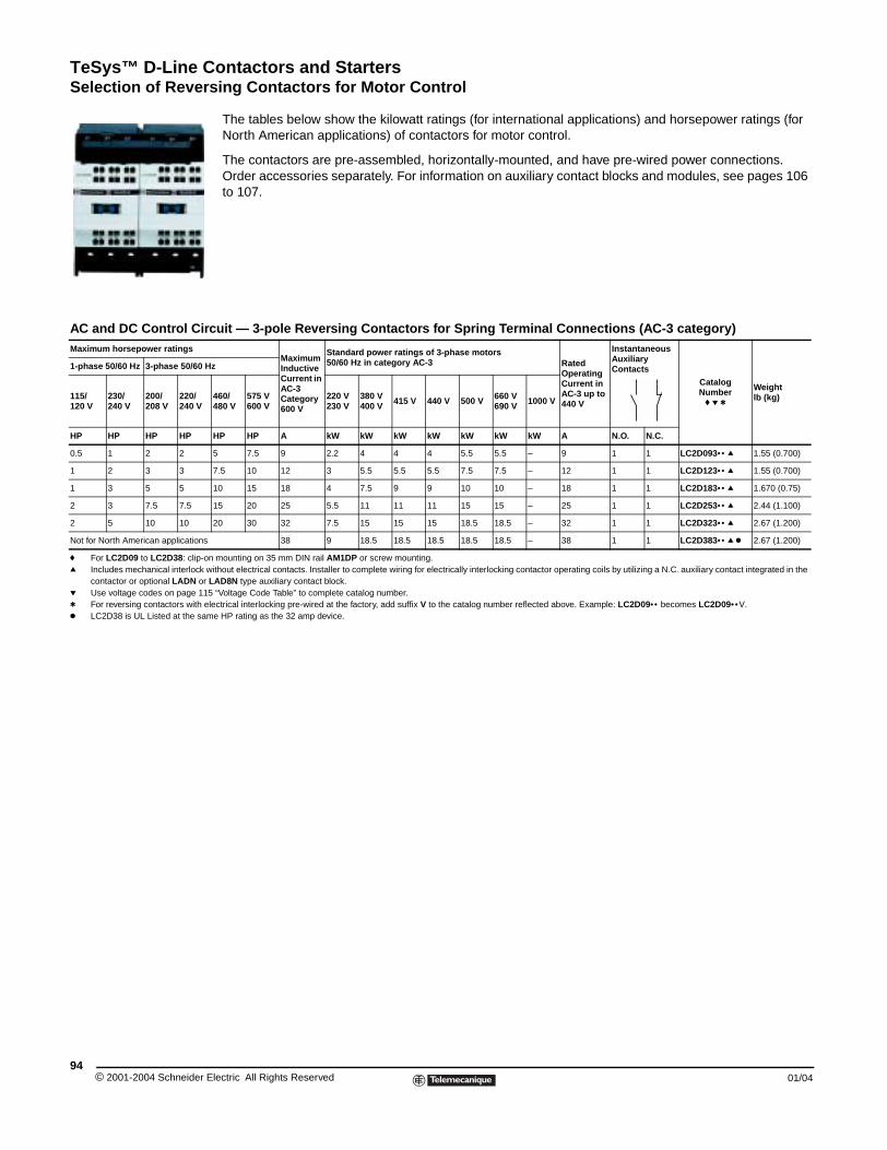
TeSys™ D-Line Contactors and StartersSelection of Reversing Contactors for Motor Control
© 2001-2004 Schneider E94
AC and DC Control CircMaximum horsepower ratings
1-phase 50/60 Hz 3-phase 50/60 H
115/120 V
230/240 V
200/208 V
220/240 V
HP HP HP HP
0.5 1 2 2
1 2 3 3
1 3 5 5
2 3 7.5 7.5
2 5 10 10
Not for North American applications
f For LC2D09 to LC2D38: clip-onq Includes mechanical interlock w
contactor or optional LADN or Lp Use voltage codes on page 115t For reversing contactors with elk LC2D38 is UL Listed at the sam
The tables below show the kilowatt ratings (for international applications) and horsepower ratings (for North American applications) of contactors for motor control.
The contactors are pre-assembled, horizontally-mounted, and have pre-wired power connections. Order accessories separately. For information on auxiliary contact blocks and modules, see pages 106 to 107.
uit — 3-pole Reversing Contactors for Spring Terminal Connections (AC-3 category)
Maximum Inductive Current in AC-3 Category 600 V
Standard power ratings of 3-phase motors50/60 Hz in category AC-3 Rated
Operating Current in AC-3 up to 440 V
Instantaneous Auxiliary Contacts
CatalogNumber
f p t
Weight lb (kg)
z
460/480 V
575 V 600 V
220 V230 V
380 V400 V 415 V 440 V 500 V 660 V
690 V 1000 V
HP HP A kW kW kW kW kW kW kW A N.O. N.C.
5 7.5 9 2.2 4 4 4 5.5 5.5 – 9 1 1 LC2D093•• q 1.55 (0.700)
7.5 10 12 3 5.5 5.5 5.5 7.5 7.5 – 12 1 1 LC2D123•• q 1.55 (0.700)
10 15 18 4 7.5 9 9 10 10 – 18 1 1 LC2D183•• q 1.670 (0.75)
15 20 25 5.5 11 11 11 15 15 – 25 1 1 LC2D253•• q 2.44 (1.100)
20 30 32 7.5 15 15 15 18.5 18.5 – 32 1 1 LC2D323•• q 2.67 (1.200)
38 9 18.5 18.5 18.5 18.5 18.5 – 38 1 1 LC2D383•• q k 2.67 (1.200)
mounting on 35 mm DIN rail AM1DP or screw mounting. ithout electrical contacts. Installer to complete wiring for electrically interlocking contactor operating coils by utilizing a N.C. auxiliary contact integrated in the AD8N type auxiliary contact block. “Voltage Code Table” to complete catalog number.ectrical interlocking pre-wired at the factory, add suffix V to the catalog number reflected above. Example: LC2D09•• becomes LC2D09•• V.e HP rating as the 32 amp device.
lectric All Rights Reserved 01/04
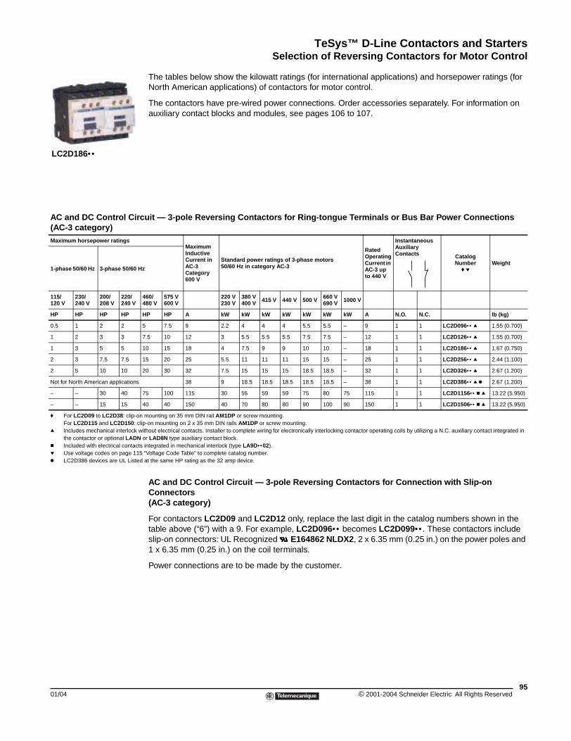
TeSys™ D-Line Contactors and StartersSelection of Reversing Contactors for Motor Control
01/04
AC and DC Control Circ(AC-3 category)Maximum horsepower ratings
1-phase 50/60 Hz 3-phase 50/60 H
115/120 V
230/240 V
200/208 V
220/240 V
HP HP HP HP
0.5 1 2 2
1 2 3 3
1 3 5 5
2 3 7.5 7.5
2 5 10 10
Not for North American applications
– – 30 40
– – 15 15
f For LC2D09 to LC2D38: clip-onFor LC2D115 and LC2D150: cl
q Includes mechanical interlock wthe contactor or optional LADN
c Included with electrical contactsp Use voltage codes on page 115k LC2D386 devices are UL Listed
LC2D186••
The tables below show the kilowatt ratings (for international applications) and horsepower ratings (for North American applications) of contactors for motor control.
The contactors have pre-wired power connections. Order accessories separately. For information on auxiliary contact blocks and modules, see pages 106 to 107.
AC and DC Control Circuit — 3-pole Reversing Contactors for Connection with Slip-on Connectors(AC-3 category)
For contactors LC2D09 and LC2D12 only, replace the last digit in the catalog numbers shown in the table above (“6”) with a 9. For example, LC2D096•• becomes LC2D099•• . These contactors include slip-on connectors: UL Recognized E164862 NLDX2, 2 x 6.35 mm (0.25 in.) on the power poles and 1 x 6.35 mm (0.25 in.) on the coil terminals.
Power connections are to be made by the customer.
uit — 3-pole Reversing Contactors for Ring-tongue Terminals or Bus Bar Power Connections
Maximum Inductive Current in AC-3 Category 600 V
Standard power ratings of 3-phase motors50/60 Hz in category AC-3
Rated Operating Current in AC-3 up to 440 V
Instantaneous Auxiliary Contacts Catalog
Numberf p
Weight z
460/480 V
575 V 600 V
220 V230 V
380 V400 V 415 V 440 V 500 V 660 V
690 V 1000 V
HP HP A kW kW kW kW kW kW kW A N.O. N.C. lb (kg)
5 7.5 9 2.2 4 4 4 5.5 5.5 – 9 1 1 LC2D096•• q 1.55 (0.700)
7.5 10 12 3 5.5 5.5 5.5 7.5 7.5 – 12 1 1 LC2D126•• q 1.55 (0.700)
10 15 18 4 7.5 9 9 10 10 – 18 1 1 LC2D186•• q 1.67 (0.750)
15 20 25 5.5 11 11 11 15 15 – 25 1 1 LC2D256•• q 2.44 (1.100)
20 30 32 7.5 15 15 15 18.5 18.5 – 32 1 1 LC2D326•• q 2.67 (1.200)
38 9 18.5 18.5 18.5 18.5 18.5 – 38 1 1 LC2D386•• q k 2.67 (1.200)
75 100 115 30 55 59 59 75 80 75 115 1 1 LC2D1156•• c q 13.22 (5.950)
40 40 150 40 70 80 80 90 100 90 150 1 1 LC2D1506•• c q 13.22 (5.950)
mounting on 35 mm DIN rail AM1DP or screw mounting. ip-on mounting on 2 x 35 mm DIN rails AM1DP or screw mounting.ithout electrical contacts. Installer to complete wiring for electronically interlocking contactor operating coils by utilizing a N.C. auxiliary contact integrated in or LAD8N type auxiliary contact block. integrated in mechanical interlock (type LA9D•• 02). “Voltage Code Table” to complete catalog number. at the same HP rating as the 32 amp device.
95© 2001-2004 Schneider Electric All Rights Reserved
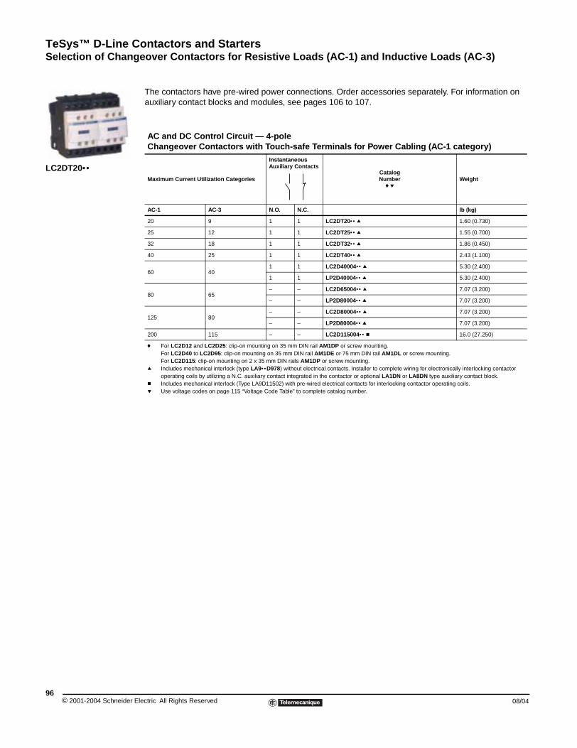
TeSys™ D-Line Contactors and StartersSelection of Changeover Contactors for Resistive Loads (AC-1) and Inductive Loads (AC-3)
© 2001-2004 Schneider E96
LC2DT20••
Selection of Changeover Contactors for Resistive Loads
The contactors have pre-wired power connections. Order accessories separately. For information on auxiliary contact blocks and modules, see pages 106 to 107.
AC and DC Control Circuit — 4-pole Changeover Contactors with Touch-safe Terminals for Power Cabling (AC-1 category)
Maximum Current Utilization Categories
Instantaneous Auxiliary Contacts
CatalogNumber
f pWeight
AC-1 AC-3 N.O. N.C. lb (kg)
20 9 1 1 LC2DT20•• q 1.60 (0.730)
25 12 1 1 LC2DT25•• q 1.55 (0.700)
32 18 1 1 LC2DT32•• q 1.86 (0.450)
40 25 1 1 LC2DT40•• q 2.43 (1.100)
60 401 1 LC2D40004•• q 5.30 (2.400)
1 1 LP2D40004•• q 5.30 (2.400)
80 65– – LC2D65004•• q 7.07 (3.200)
– – LP2D80004•• q 7.07 (3.200)
125 80– – LC2D80004•• q 7.07 (3.200)
– – LP2D80004•• q 7.07 (3.200)
200 115 – – LC2D115004•• c 16.0 (27.250)
f For LC2D12 and LC2D25: clip-on mounting on 35 mm DIN rail AM1DP or screw mounting. For LC2D40 to LC2D95: clip-on mounting on 35 mm DIN rail AM1DE or 75 mm DIN rail AM1DL or screw mounting. For LC2D115: clip-on mounting on 2 x 35 mm DIN rails AM1DP or screw mounting.
q Includes mechanical interlock (type LA9•• D978) without electrical contacts. Installer to complete wiring for electronically interlocking contactor operating coils by utilizing a N.C. auxiliary contact integrated in the contactor or optional LA1DN or LA8DN type auxiliary contact block.
c Includes mechanical interlock (Type LA9D11502) with pre-wired electrical contacts for interlocking contactor operating coils.p Use voltage codes on page 115 “Voltage Code Table” to complete catalog number.
lectric All Rights Reserved 08/04
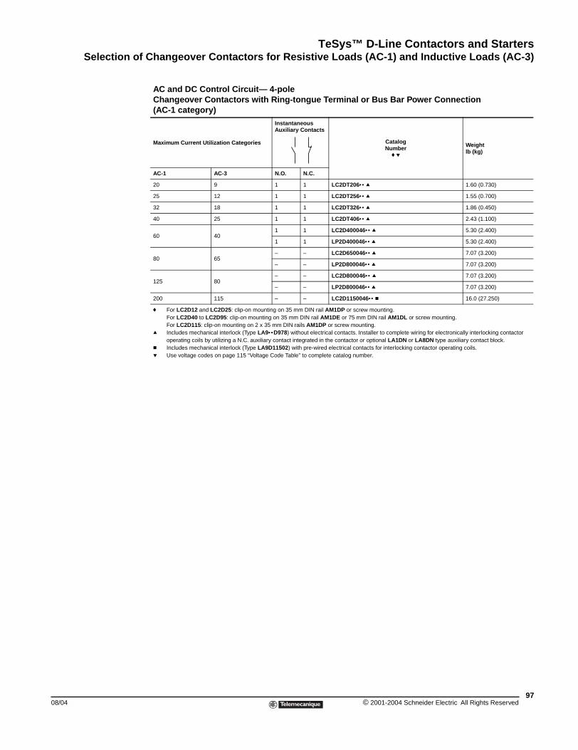
TeSys™ D-Line Contactors and StartersSelection of Changeover Contactors for Resistive Loads (AC-1) and Inductive Loads (AC-3)
08/04
AC and DC Control Circuit— 4-poleChangeover Contactors with Ring-tongue Terminal or Bus Bar Power Connection(AC-1 category)
Maximum Current Utilization Categories
Instantaneous Auxiliary Contacts
CatalogNumber
f p
Weight lb (kg)
AC-1 AC-3 N.O. N.C.
20 9 1 1 LC2DT206•• q 1.60 (0.730)
25 12 1 1 LC2DT256•• q 1.55 (0.700)
32 18 1 1 LC2DT326•• q 1.86 (0.450)
40 25 1 1 LC2DT406•• q 2.43 (1.100)
60 401 1 LC2D400046•• q 5.30 (2.400)
1 1 LP2D400046•• q 5.30 (2.400)
80 65– – LC2D650046•• q 7.07 (3.200)
– – LP2D800046•• q 7.07 (3.200)
125 80– – LC2D800046•• q 7.07 (3.200)
– – LP2D800046•• q 7.07 (3.200)
200 115 – – LC2D1150046•• c 16.0 (27.250)
f For LC2D12 and LC2D25: clip-on mounting on 35 mm DIN rail AM1DP or screw mounting. For LC2D40 to LC2D95: clip-on mounting on 35 mm DIN rail AM1DE or 75 mm DIN rail AM1DL or screw mounting. For LC2D115: clip-on mounting on 2 x 35 mm DIN rails AM1DP or screw mounting.
q Includes mechanical interlock (Type LA9•• D978) without electrical contacts. Installer to complete wiring for electronically interlocking contactor operating coils by utilizing a N.C. auxiliary contact integrated in the contactor or optional LA1DN or LA8DN type auxiliary contact block.
c Includes mechanical interlock (Type LA9D11502) with pre-wired electrical contacts for interlocking contactor operating coils.p Use voltage codes on page 115 “Voltage Code Table” to complete catalog number.
97© 2001-2004 Schneider Electric All Rights Reserved
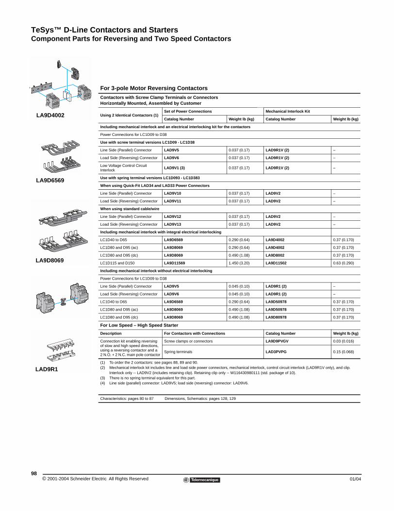
TeSys™ D-Line Contactors and StartersComponent Parts for Reversing and Two Speed Contactors
© 2001-2004 Schneider E98
LA9D4002
LA9D6569
LA9D8069
LAD9R1
Component Parts for Reversing and Two Speed Contactors
For 3-pole Motor Reversing Contactors
Contactors with Screw Clamp Terminals or ConnectorsHorizontally Mounted, Assembled by Customer
Using 2 Identical Contactors (1)Set of Power Connections Mechanical Interlock Kit
Catalog Number Weight lb (kg) Catalog Number Weight lb (kg)
Including mechanical interlock and an electrical interlocking kit for the contactors
Power Connections for LC1D09 to D38
Use with screw terminal versions LC1D09 - LC1D38
Line Side (Parallel) Connector LAD9V5 0.037 (0.17) LAD9R1V (2) –
Load Side (Reversing) Connector LAD9V6 0.037 (0.17) LAD9R1V (2) –
Low Voltage Control Circuit Interlock
LAD9V1 (3) 0.037 (0.17) LAD9R1V (2) –
Use with spring terminal versions LC1D093 - LC1D383
When using Quick-Fit LAD34 and LAD33 Power Connectors
Line Side (Parallel) Connector LAD9V10 0.037 (0.17) LAD9V2 –
Load Side (Reversing) Connector LAD9V11 0.037 (0.17) LAD9V2 –
When using standard cable/wire
Line Side (Parallel) Connector LAD9V12 0.037 (0.17) LAD9V2 –
Load Side (Reversing) Connector LAD9V13 0.037 (0.17) LAD9V2 –
Including mechanical interlock with integral electrical interlocking
LC1D40 to D65 LA9D6569 0.290 (0.64) LA9D4002 0.37 (0.170)
LC1D80 and D95 (ac) LA9D8069 0.290 (0.64) LA9D4002 0.37 (0.170)
LC1D80 and D95 (dc) LA9D8069 0.490 (1.08) LA9D8002 0.37 (0.170)
LC1D115 and D150 LA9D11569 1.450 (3.20) LA9D11502 0.63 (0.290)
Including mechanical interlock without electrical interlocking
Power Connections for LC1D09 to D38
Line Side (Parallel) Connector LAD9V5 0.045 (0.10) LAD9R1 (2) –
Load Side (Reversing) Connector LAD9V6 0.045 (0.10) LAD9R1 (2) –
LC1D40 to D65 LA9D6569 0.290 (0.64) LA9D50978 0.37 (0.170)
LC1D80 and D95 (ac) LA9D8069 0.490 (1.08) LA9D50978 0.37 (0.170)
LC1D80 and D95 (dc) LA9D8069 0.490 (1.08) LA9D80978 0.37 (0.170)
For Low Speed – High Speed Starter
Description For Contactors with Connections Catalog Number Weight lb (kg)
Connection kit enabling reversing of slow and high speed directions, using a reversing contactor and a2 N.O. + 2 N.C. main pole contactor
Screw clamps or connectors LA9D9PVGV 0.03 (0.016)
Spring terminals LAD3PVPG 0.15 (0.068)
(1) To order the 2 contactors: see pages 88, 89 and 90.(2) Mechanical interlock kit includes line and load side power connectors, mechanical interlock, control circuit interlock (LAD9R1V only), and clip.
Interlock only -- LAD9V2 (includes retaining clip). Retaining clip only -- W116430980111 (std. package of 10).(3) There is no spring terminal equivalent for this part.(4) Line side (parallel) connector: LAD9V5; load side (reversing) connector: LAD9V6.
Characteristics: pages 80 to 87 Dimensions, Schematics: pages 128, 129
lectric All Rights Reserved 01/04
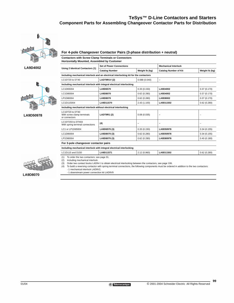
TeSys™ D-Line Contactors and StartersComponent Parts for Assembling Changeover Contactor Parts for Distribution
01/04
LA9D4002
LA9D50978
LA9D8070
Component Parts for Assembling Changeover Contactor Parts for Distribution
For 4-pole Changeover Contactor Pairs (3-phase distribution + neutral)
Contactors with Screw Clamp Terminals or ConnectorsHorizontally Mounted, Assembled by Customer
Using 2 Identical Contactors (1)Set of Power Connections Mechanical Interlock
Catalog Number Weight lb (kg) Catalog Number of Kit Weight lb (kg)
Including mechanical interlock and an electrical interlocking kit for the contactors
LC1DT20 to DT40 LADT9R1V (2) 0.088 (0.040) – –
Including mechanical interlock with integral electrical interlocking
LC1D65004 LA9D6570 0.33 (0.150) LA9D4002 0.37 (0.170)
LC1D80004 LA9D8070 0.62 (0.280) LA9D4002 0.37 (0.170)
LP1D80004 LA9D8070 0.62 (0.280) LA9D8002 0.37 (0.170)
LC1D115004 LA9D11570 2.43 (1.100) LA9D11502 0.62 (0.280)
Including mechanical interlock without electrical interlocking
LC1DT20 to DT40With screw clamp terminals or connectors
LADT9R1 (2) 0.08 (0.035) – –
LC1DT203 to DT403With spring terminal connections
(4) – – –
LC1 or LP1D65004 LA9D6570 (3) 0.33 (0.150) LA9D50978 0.34 (0.155)
LC1D80004 LA9D8070 (3) 0.62 (0.280) LA9D50978 0.34 (0.155)
LP1D80004 LA9D8070 (3) 0.62 (0.280) LA9D80978 0.40 (0.180)
For 3-pole changeover contactor pairs
Including mechanical interlock with integral electrical interlocking
LC1D115 and D150 LA9D11571 2.12 (0.960) LA9D11502 0.62 (0.280)
(1) To order the two contactors: see page 91.(2) Including mechanical interlock.(3) Order two contact bocks LADN•1 to obtain electrical interlocking between the contactors, see page 106.(4) To build a reversing contactor with spring terminal connections, the following components must be ordered in addition to the two contactors:
- 1 mechanical interlock LAD9V2,- 1 downstream power connection kit LAD9V9
99© 2001-2004 Schneider Electric All Rights Reserved
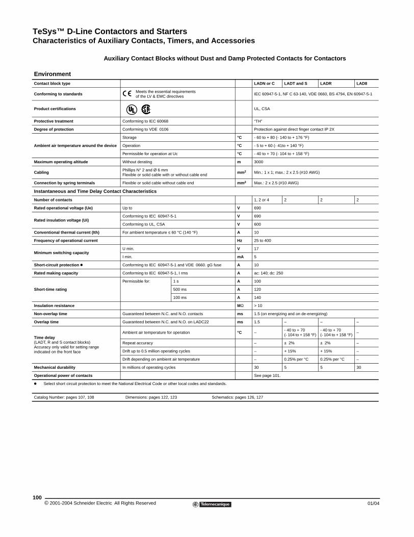
TeSys™ D-Line Contactors and StartersCharacteristics of Auxiliary Contacts, Timers, and Accessories
© 2001-2004 Schneider E100
EnvironmentContact block type
Conforming to standards
Product certifications
Protective treatment
Degree of protection
Ambient air temperature around t
Maximum operating altitude
Cabling
Connection by spring terminals
Instantaneous and Time Dela
Number of contacts
Rated operational voltage (Ue)
Rated insulation voltage (Ui)
Conventional thermal current (Ith
Frequency of operational current
Minimum switching capacity
Short-circuit protection k
Rated making capacity
Short-time rating
Insulation resistance
Non-overlap time
Overlap time
Time delay(LADT, R and S contact blocks)Accuracy only valid for setting rangeindicated on the front face
Mechanical durability
Operational power of contacts
k Select short circuit protection t
Catalog Number: pages 107, 108
Characteristics of Auxiliary Contact Blocks, Timers, and Accessories
Auxiliary Contact Blocks without Dust and Damp Protected Contacts for Contactors
LADN or C LADT and S LADR LAD8
Meets the essential requirements of the LV & EMC directives
IEC 60947-5-1, NF C 63-140, VDE 0660, BS 4794, EN 60947-5-1
UL, CSA
Conforming to IEC 60068 “TH”
Conforming to VDE 0106 Protection against direct finger contact IP 2X
he device
Storage °C - 60 to + 80 (- 140 to + 176 °F)
Operation °C - 5 to + 60 (- 41to + 140 °F)
Permissible for operation at Uc °C - 40 to + 70 (- 104 to + 158 °F)
Without derating m 3000
Phillips N° 2 and Ø 6 mmFlexible or solid cable with or without cable end
mm2 Min.: 1 x 1; max.: 2 x 2.5 (#10 AWG)
Flexible or solid cable without cable end mm2 Max.: 2 x 2.5 (#10 AWG)
y Contact Characteristics
1, 2 or 4 2 2 2
Up to V 690
Conforming to IEC 60947-5-1 V 690
Conforming to UL, CSA V 600
) For ambient temperature ≤ 60 °C (140 °F) A 10
Hz 25 to 400
U min. V 17
I min. mA 5
Conforming to IEC 60947-5-1 and VDE 0660. gG fuse A 10
Conforming to IEC 60947-5-1, I rms A ac: 140; dc: 250
Permissible for: 1 s A 100
500 ms A 120
100 ms A 140
MΩ > 10
Guaranteed between N.C. and N.O. contacts ms 1.5 (on energizing and on de-energizing)
Guaranteed between N.C. and N.O. on LADC22 ms 1.5 – – –
Ambient air temperature for operation °C –- 40 to + 70(- 104 to + 158 °F)
- 40 to + 70(- 104 to + 158 °F)
–
Repeat accuracy – ± 2% ± 2% –
Drift up to 0.5 million operating cycles – + 15% + 15% –
Drift depending on ambient air temperature – 0.25% per °C 0.25% per °C –
In millions of operating cycles 30 5 5 30
See page 101.
o meet the National Electrical Code or other local codes and standards.
Dimensions: pages 122, 123 Schematics: pages 126, 127
lectric All Rights Reserved 01/04
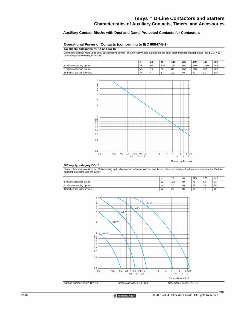
TeSys™ D-Line Contactors and StartersCharacteristics of Auxiliary Contacts, Timers, and Accessories
01/04
Auxiliary Contact Blocks with Dust and Damp Protected Contacts for Contactors
Operational Power of Contacts (conforming to IEC 60947-5-1)AC supply, categories AC-14 and AC-15Electrical durability (valid up to 3600 operating cycles/hour) on an inductive load such as the coil of an electromagnet: making power (cos ϕ 0.7) = 10 times the power broken (cos ϕ 0.4)
V 24 48 115 230 400 440 600
1 million operating cycles VA 60 120 280 560 960 1050 1440
3 million operating cycles VA 16 32 80 160 280 300 420
10 million operating cycles VA 4 8 20 40 70 80 100
DC supply, category DC-13Electrical durability (valid up to 1200 operating cycles/hour) on an inductive load such as the coil of an electromagnet, without economy resistor, the time constant increasing with the power.
V 24 48 125 250 440
1 million operating cycles W 120 90 75 68 61
3 million operating cycles W 70 50 38 33 28
10 million operating cycles W 25 18 14 12 10
Catalog Number: pages 107, 108 Dimensions: pages 122, 123 Schematics: pages 126, 127
Current broken in A
0.1 0.2 0.3 0.40.5
0.60.7
0.80.9
1 2 3 45
67
8910
0.1
0.2
0.3
0.4
0.60.5
0.80.7
7
1
2
3
54
6
81
0.1 0.2 0.3 0.40.5
0.60.7
0.80.9
1 2 3 45
67
8910
0.1
0.2
0.3
0.4
0.60.5
0.80.7
7
1
2
3
54
6
81
440 V
48 V
250 V
125 V
24 V
Current broken in A
101© 2001-2004 Schneider Electric All Rights Reserved
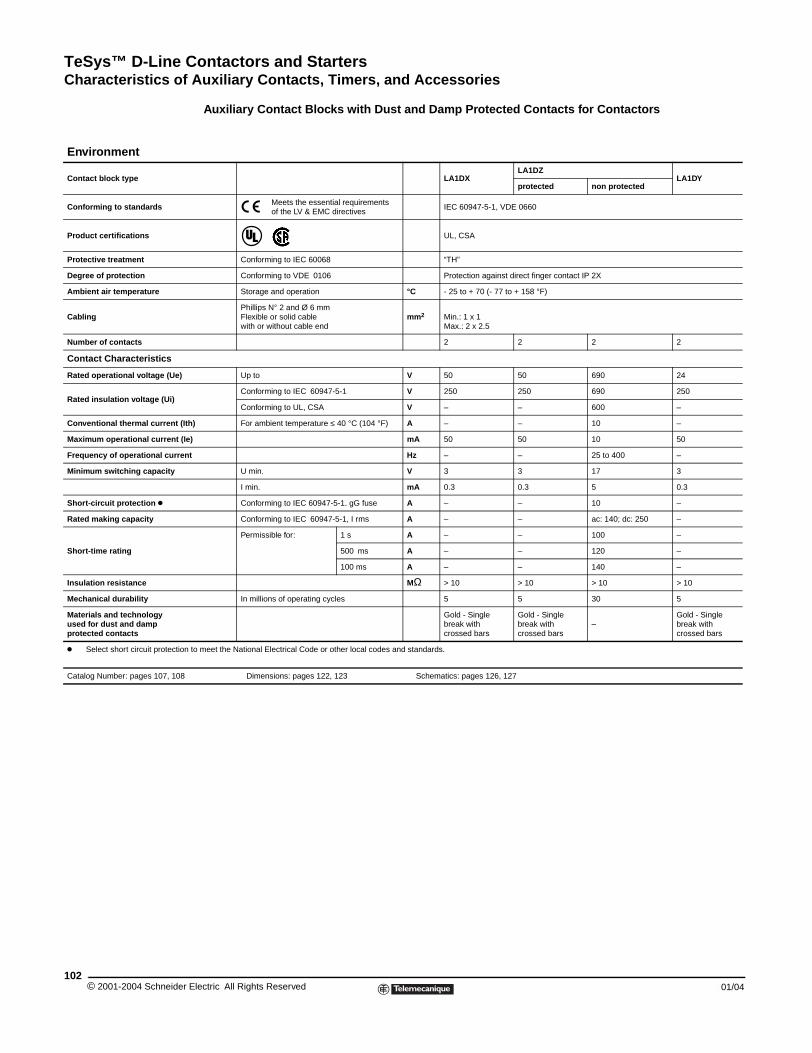
TeSys™ D-Line Contactors and StartersCharacteristics of Auxiliary Contacts, Timers, and Accessories
© 2001-2004 Schneider E102
Environment
Contact block type
Conforming to standards
Product certifications
Protective treatment
Degree of protection
Ambient air temperature
Cabling
Number of contacts
Contact Characteristics
Rated operational voltage (Ue)
Rated insulation voltage (Ui)
Conventional thermal current (Ith
Maximum operational current (Ie)
Frequency of operational current
Minimum switching capacity
Short-circuit protection k
Rated making capacity
Short-time rating
Insulation resistance
Mechanical durability
Materials and technologyused for dust and dampprotected contacts
k Select short circuit protection t
Catalog Number: pages 107, 108
Auxiliary Contact Blocks with Dust and Damp Protected Contacts for Contactors
LA1DXLA1DZ
LA1DYprotected non protected
Meets the essential requirements of the LV & EMC directives
IEC 60947-5-1, VDE 0660
UL, CSA
Conforming to IEC 60068 “TH”
Conforming to VDE 0106 Protection against direct finger contact IP 2X
Storage and operation °C - 25 to + 70 (- 77 to + 158 °F)
Phillips N° 2 and Ø 6 mmFlexible or solid cablewith or without cable end
mm2 Min.: 1 x 1Max.: 2 x 2.5
2 2 2 2
Up to V 50 50 690 24
Conforming to IEC 60947-5-1 V 250 250 690 250
Conforming to UL, CSA V – – 600 –
) For ambient temperature ≤ 40 °C (104 °F) A – – 10 –
mA 50 50 10 50
Hz – – 25 to 400 –
U min. V 3 3 17 3
I min. mA 0.3 0.3 5 0.3
Conforming to IEC 60947-5-1. gG fuse A – – 10 –
Conforming to IEC 60947-5-1, I rms A – – ac: 140; dc: 250 –
Permissible for: 1 s A – – 100 –
500 ms A – – 120 –
100 ms A – – 140 –
MΩ > 10 > 10 > 10 > 10
In millions of operating cycles 5 5 30 5
Gold - Singlebreak withcrossed bars
Gold - Singlebreak withcrossed bars
–Gold - Singlebreak withcrossed bars
o meet the National Electrical Code or other local codes and standards.
Dimensions: pages 122, 123 Schematics: pages 126, 127
lectric All Rights Reserved 01/04
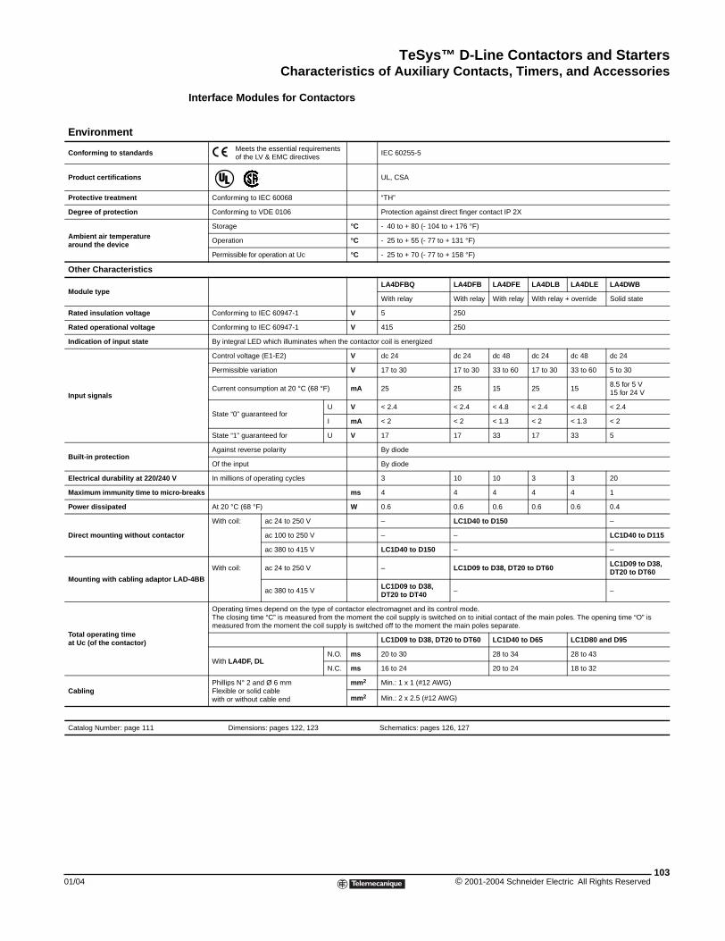
TeSys™ D-Line Contactors and StartersCharacteristics of Auxiliary Contacts, Timers, and Accessories
01/04
Environment
Conforming to standards
Product certifications
Protective treatment
Degree of protection
Ambient air temperaturearound the device
Other Characteristics
Module type
Rated insulation voltage
Rated operational voltage
Indication of input state
Input signals
Built-in protection
Electrical durability at 220/240 V
Maximum immunity time to micro
Power dissipated
Direct mounting without contacto
Mounting with cabling adaptor LA
Total operating timeat Uc (of the contactor)
Cabling
Catalog Number: page 111
Interface Modules for Contactors
Meets the essential requirements of the LV & EMC directives
IEC 60255-5
UL, CSA
Conforming to IEC 60068 “TH”
Conforming to VDE 0106 Protection against direct finger contact IP 2X
Storage °C - 40 to + 80 (- 104 to + 176 °F)
Operation °C - 25 to + 55 (- 77 to + 131 °F)
Permissible for operation at Uc °C - 25 to + 70 (- 77 to + 158 °F)
LA4DFBQ LA4DFB LA4DFE LA4DLB LA4DLE LA4DWB
With relay With relay With relay With relay + override Solid state
Conforming to IEC 60947-1 V 5 250
Conforming to IEC 60947-1 V 415 250
By integral LED which illuminates when the contactor coil is energized
Control voltage (E1-E2) V dc 24 dc 24 dc 48 dc 24 dc 48 dc 24
Permissible variation V 17 to 30 17 to 30 33 to 60 17 to 30 33 to 60 5 to 30
Current consumption at 20 °C (68 °F) mA 25 25 15 25 158.5 for 5 V15 for 24 V
State “0” guaranteed forU V < 2.4 < 2.4 < 4.8 < 2.4 < 4.8 < 2.4
I mA < 2 < 2 < 1.3 < 2 < 1.3 < 2
State “1” guaranteed for U V 17 17 33 17 33 5
Against reverse polarity By diode
Of the input By diode
In millions of operating cycles 3 10 10 3 3 20
-breaks ms 4 4 4 4 4 1
At 20 °C (68 °F) W 0.6 0.6 0.6 0.6 0.6 0.4
r
With coil: ac 24 to 250 V – LC1D40 to D150 –
ac 100 to 250 V – – LC1D40 to D115
ac 380 to 415 V LC1D40 to D150 – –
D-4BB
With coil: ac 24 to 250 V – LC1D09 to D38, DT20 to DT60 LC1D09 to D38,DT20 to DT60
ac 380 to 415 VLC1D09 to D38,DT20 to DT40 – –
Operating times depend on the type of contactor electromagnet and its control mode.The closing time “C” is measured from the moment the coil supply is switched on to initial contact of the main poles. The opening time “O” is measured from the moment the coil supply is switched off to the moment the main poles separate.
LC1D09 to D38, DT20 to DT60 LC1D40 to D65 LC1D80 and D95
With LA4DF, DLN.O. ms 20 to 30 28 to 34 28 to 43
N.C. ms 16 to 24 20 to 24 18 to 32
Phillips N° 2 and Ø 6 mmFlexible or solid cablewith or without cable end
mm2 Min.: 1 x 1 (#12 AWG)
mm2 Min.: 2 x 2.5 (#12 AWG)
Dimensions: pages 122, 123 Schematics: pages 126, 127
103© 2001-2004 Schneider Electric All Rights Reserved
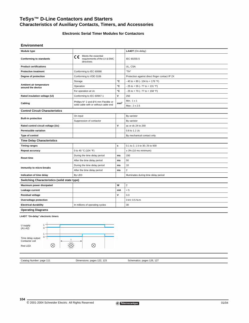
TeSys™ D-Line Contactors and StartersCharacteristics of Auxiliary Contacts, Timers, and Accessories
© 2001-2004 Schneider E104
EnvironmentModule type
Conforming to standards
Product certifications
Protective treatment
Degree of protection
Ambient air temperaturearound the device
Rated insulation voltage (Ui)
Cabling
Control Circuit Characteristi
Built-in protection
Rated control circuit voltage (Uc)
Permissible variation
Type of control
Time Delay Characteristics
Timing ranges
Repeat accuracy
Reset time
Immunity to micro-breaks
Indication of time delay
Switching Characteristics (s
Maximum power dissipated
Leakage current
Residual voltage
Overvoltage protection
Electrical durability
Operating Diagrams
LA4DT “On-delay” electronic timers
U supply(A1-A2)
Time delay outputContactor coil
Red LED
Catalog Number: page 111
01
01
Electronic Serial Timer Modules for Contactors
LA4DT (On-delay)
Meets the essential requirements of the LV & EMC directives
IEC 60255-5
UL, CSA
Conforming to IEC 60068 “TH”
Conforming to VDE 0106 Protection against direct finger contact IP 2X
Storage °C - 40 to + 80 (- 104 to + 176 °F)
Operation °C - 25 to + 55 (- 77 to + 131 °F)
For operation at Uc °C - 25 to + 70 (- 77 to + 158 °F)
Conforming to IEC 60947-1 V 250
Phillips N° 2 and Ø 6 mm Flexible or solid cable with or without cable end
mm2Min.: 1 x 1
Max.: 2 x 2.5
cs
On input By varistor
Suppression of contactor By varistor
V ac or dc 24 to 250
0.8 to 1.1 Uc
By mechanical contact only
s 0.1 to 2; 1.5 to 30; 25 to 500
0 to 40 °C (104 °F) ± 3% (10 ms minimum)
During the time delay period ms 150
After the time delay period ms 50
During the time delay period ms 10
After the time delay period ms 2
By LED Illuminates during time delay period
olid state type)
W 2
mA < 5
V 3.3
3 kV; 0.5 N•m
In millions of operating cycles 30
Dimensions: pages 122, 123 Schematics: pages 126, 127
t
lectric All Rights Reserved 01/04
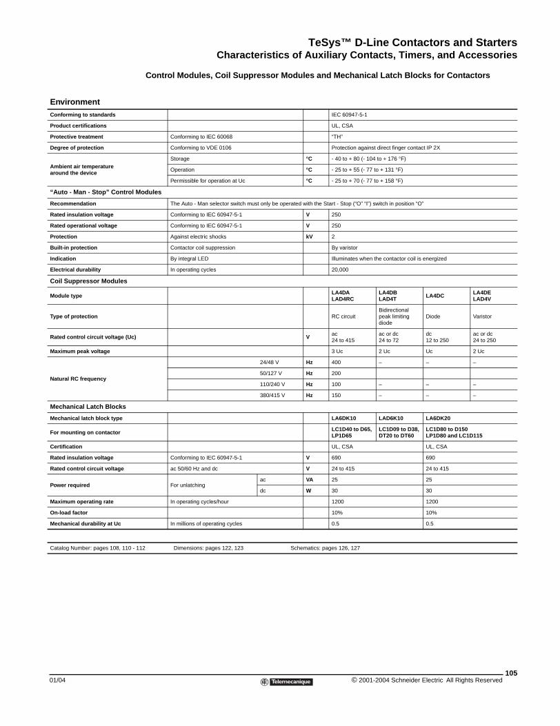
TeSys™ D-Line Contactors and StartersCharacteristics of Auxiliary Contacts, Timers, and Accessories
01/04
EnvironmentConforming to standards
Product certifications
Protective treatment
Degree of protection
Ambient air temperaturearound the device
“Auto - Man - Stop” Control M
Recommendation
Rated insulation voltage
Rated operational voltage
Protection
Built-in protection
Indication
Electrical durability
Coil Suppressor Modules
Module type
Type of protection
Rated control circuit voltage (Uc)
Maximum peak voltage
Natural RC frequency
Mechanical Latch Blocks
Mechanical latch block type
For mounting on contactor
Certification
Rated insulation voltage
Rated control circuit voltage
Power required
Maximum operating rate
On-load factor
Mechanical durability at Uc
Catalog Number: pages 108, 110 - 1
Control Modules, Coil Suppressor Modules and Mechanical Latch Blocks for Contactors
IEC 60947-5-1
UL, CSA
Conforming to IEC 60068 “TH”
Conforming to VDE 0106 Protection against direct finger contact IP 2X
Storage °C - 40 to + 80 (- 104 to + 176 °F)
Operation °C - 25 to + 55 (- 77 to + 131 °F)
Permissible for operation at Uc °C - 25 to + 70 (- 77 to + 158 °F)
odules
The Auto - Man selector switch must only be operated with the Start - Stop (“O” “I”) switch in position “O”
Conforming to IEC 60947-5-1 V 250
Conforming to IEC 60947-5-1 V 250
Against electric shocks kV 2
Contactor coil suppression By varistor
By integral LED Illuminates when the contactor coil is energized
In operating cycles 20,000
LA4DALAD4RC
LA4DBLAD4T LA4DC LA4DE
LAD4V
RC circuitBidirectional peak limiting diode
Diode Varistor
V ac24 to 415
ac or dc24 to 72
dc12 to 250
ac or dc24 to 250
3 Uc 2 Uc Uc 2 Uc
24/48 V Hz 400 – – –
50/127 V Hz 200
110/240 V Hz 100 – – –
380/415 V Hz 150 – – –
LA6DK10 LAD6K10 LA6DK20
LC1D40 to D65, LP1D65
LC1D09 to D38,DT20 to DT60
LC1D80 to D150LP1D80 and LC1D115
UL, CSA UL, CSA
Conforming to IEC 60947-5-1 V 690 690
ac 50/60 Hz and dc V 24 to 415 24 to 415
For unlatchingac VA 25 25
dc W 30 30
In operating cycles/hour 1200 1200
10% 10%
In millions of operating cycles 0.5 0.5
12 Dimensions: pages 122, 123 Schematics: pages 126, 127
105© 2001-2004 Schneider Electric All Rights Reserved
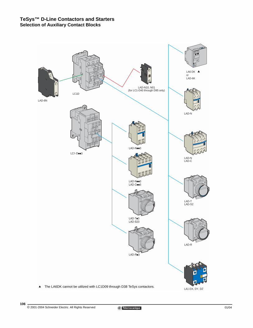
TeSys™ D-Line Contactors and StartersSelection of Auxiliary Contact Blocks
Selection of Auxiliary Contact Blocks
aaa
LA1-DX, DY, DZ
LAD-NLAD-C
LAD-N
LAD-8N
LC1D
LAD-R
LAD-TLAD-S2
LAD-N10, N01(for LC1-D40 through D95 only)
LA6-DKorLAD-6K
q
q The LA6DK cannot be utilized with LC1D09 through D38 TeSys contactors.
© 2001-2004 Schneider Electric All Rights Reserved106
01/04
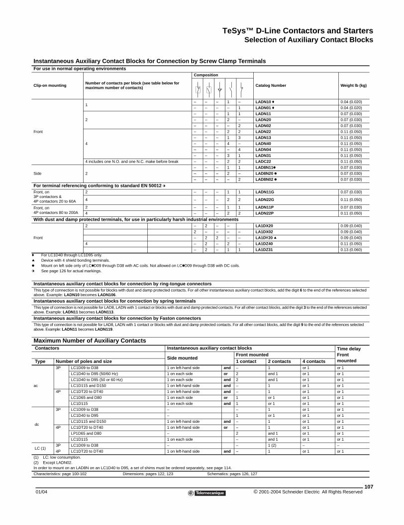
TeSys™ D-Line Contactors and StartersSelection of Auxiliary Contact Blocks
f For LC1D40 through LC1D95 only.q Device with 4 shield bonding terminals.k Mount on left side only of LCkD09 through D38 with AC coils. Not allowed on LCkD09 through D38 with DC coils.l See page 126 for actual markings.
Instantaneous Auxiliary Contact Blocks for Connection by Screw Clamp TerminalsFor use in normal operating environments
Clip-on mounting Number of contacts per block (see table below for maximum number of contacts)
Composition
Catalog Number Weight lb (kg)
Front
1– – – 1 – LADN10 f 0.04 (0.020)
– – – – 1 LADN01 f 0.04 (0.020)
2
– – – 1 1 LADN11 0.07 (0.030)
– – – 2 – LADN20 0.07 (0.030)
– – – – 2 LADN02 0.07 (0.030)
4
– – – 2 2 LADN22 0.11 (0.050)
– – – 1 3 LADN13 0.11 (0.050)
– – – 4 – LADN40 0.11 (0.050)
– – – – 4 LADN04 0.11 (0.050)
– – – 3 1 LADN31 0.11 (0.050)
4 includes one N.O. and one N.C. make before break – – – 2 2 LADC22 0.11 (0.050)
Side 2
– – – 1 1 LAD8N11k 0.07 (0.030)
– – – 2 – LAD8N20 k 0.07 (0.030)
– – – – 2 LAD8N02 k 0.07 (0.030)
For terminal referencing conforming to standard EN 50012 lFront, on3P contactors &4P contactors 20 to 60A
2 – – – 1 1 LADN11G 0.07 (0.030)
4 – – – 2 2 LADN22G 0.11 (0.050)
Front, on4P contactors 80 to 200A
2 – – – 1 1 LADN11P 0.07 (0.030)
4 – – – 2 2 LADN22P 0.11 (0.050)
With dust and damp protected terminals, for use in particularly harsh industrial environments
Front
2 – 2 – – LA1DX20 0.09 (0.040)
2 – – – – LA1DX02 0.09 (0.040)
– 2 2 – – LA1DY20 q 0.09 (0.040)
4 – 2 – 2 – LA1DZ40 0.11 (0.050)
– 2 – 1 1 LA1DZ31 0.13 (0.060)
Instantaneous auxiliary contact blocks for connection by ring-tongue connectorsThis type of connection is not possible for blocks with dust and damp protected contacts. For all other instantaneous auxiliary contact blocks, add the digit 6 to the end of the references selected above. Example: LADN10 becomes LADN106.
Instantaneous auxiliary contact blocks for connection by spring terminalsThis type of connection is not possible for LAD8, LADN with 1 contact or blocks with dust and damp protected contacts. For all other contact blocks, add the digit 3 to the end of the references selected above. Example: LADN11 becomes LADN113.
Instantaneous auxiliary contact blocks for connection by Faston connectorsThis type of connection is not possible for LAD8, LADN with 1 contact or blocks with dust and damp protected contacts. For all other contact blocks, add the digit 9 to the end of the references selected above. Example: LADN11 becomes LADN119.
Maximum Number of Auxiliary Contacts Contactors Instantaneous auxiliary contact blocks Time delay
Front mountedSide mounted
Front mounted Type Number of poles and size 1 contact 2 contacts 4 contacts
ac
3P LC1D09 to D38 1 on left-hand side and – 1 or 1 or 1
LC1D40 to D95 (50/60 Hz) 1 on each side or 2 and 1 or 1 or 1
LC1D40 to D95 (50 or 60 Hz) 1 on each side and 2 and 1 or 1 or 1
LC1D115 and D150 1 on left-hand side and – 1 or 1 or 1
4P LC1DT20 to DT40 1 on left-hand side and – 1 or 1 or 1
LC1D65 and D80 1 on each side or 1 or 1 or 1 or 1
LC1D115 1 on each side and 1 or 1 or 1 or 1
dc
3P LC1D09 to D38 – – 1 or 1 or 1
LC1D40 to D95 – 1 or 1 or 1 or 1
LC1D115 and D150 1 on left-hand side and – 1 or 1 or 1
4P LC1DT20 to DT40 1 on left-hand side or – 1 or 1 or 1
LP1D65 and D80 – 2 and 1 or 1 or 1
LC1D115 1 on each side – and 1 or 1 or 1
LC (1)3P LC1D09 to D38 – – 1 (2) – –
4P LC1DT20 to DT40 1 on left-hand side and – 1 or 1 or 1
(1) LC: low consumption.(2) Except LADN02.In order to mount on an LAD8N on an LC1D40 to D95, a set of shims must be ordered separately, see page 114.
Characteristics: page 100-102 Dimensions: pages 122, 123 Schematics: pages 126, 127
10701/04 © 2001-2004 Schneider Electric All Rights Reserved
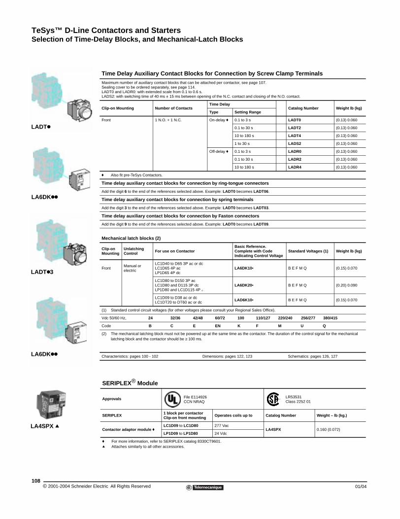
TeSys™ D-Line Contactors and StartersSelection of Time-Delay Blocks, and Mechanical-Latch Blocks
© 2001-2004 Schneider E108
LADTk
LA6DKkk
LADTk3
LA6DKkk
LA4SPX q
Selection of Time-Delay Blocks, and Mechanical-Latch Blocks
Time Delay Auxiliary Contact Blocks for Connection by Screw Clamp TerminalsMaximum number of auxiliary contact blocks that can be attached per contactor, see page 107.Sealing cover to be ordered separately, see page 114.LADT0 and LADR0: with extended scale from 0.1 to 0.6 s.LADS2: with switching time of 40 ms ± 15 ms between opening of the N.C. contact and closing of the N.O. contact.
Clip-on Mounting Number of ContactsTime Delay
Catalog Number Weight lb (kg)Type Setting Range
Front 1 N.O. + 1 N.C. On-delay f 0.1 to 3 s LADT0 (0.13) 0.060
0.1 to 30 s LADT2 (0.13) 0.060
10 to 180 s LADT4 (0.13) 0.060
1 to 30 s LADS2 (0.13) 0.060
Off-delay f 0.1 to 3 s LADR0 (0.13) 0.060
0.1 to 30 s LADR2 (0.13) 0.060
10 to 180 s LADR4 (0.13) 0.060
f Also fit pre-TeSys Contactors.
Time delay auxiliary contact blocks for connection by ring-tongue connectors
Add the digit 6 to the end of the references selected above. Example: LADT0 becomes LADT06.
Time delay auxiliary contact blocks for connection by spring terminals
Add the digit 3 to the end of the references selected above. Example: LADT0 becomes LADT03.
Time delay auxiliary contact blocks for connection by Faston connectors
Add the digit 9 to the end of the references selected above. Example: LADT0 becomes LADT09.
Mechanical latch blocks (2)
Clip-onMounting
UnlatchingControl For use on Contactor
Basic Reference. Complete with Code Indicating Control Voltage
Standard Voltages (1) Weight lb (kg)
FrontManual or electric
LC1D40 to D65 3P ac or dc LC1D65 4P acLP1D65 4P dc
LA6DK10• B E F M Q (0.15) 0.070
LC1D80 to D150 3P ac LC1D80 and D115 3P dcLP1D80 and LC1D115 4P c
LA6DK20• B E F M Q (0.20) 0.090
LC1D09 to D38 ac or dc LC1DT20 to DT60 ac or dc
LAD6K10• B E F M Q (0.15) 0.070
(1) Standard control circuit voltages (for other voltages please consult your Regional Sales Office).
Vdc 50/60 Hz, 24 32/36 42/48 60/72 100 110/127 220/240 256/277 380/415
Code B C E EN K F M U Q
(2) The mechanical latching block must not be powered up at the same time as the contactor. The duration of the control signal for the mechanical latching block and the contactor should be ≥ 100 ms.
Characteristics: pages 100 - 102 Dimensions: pages 122, 123 Schematics: pages 126, 127
SERIPLEX® Module
Approvals File E114926 CCN NRAQ
LR53531 Class 2252 01
SERIPLEX 1 block per contactorClip-on front mounting Operates coils up to Catalog Number Weight – lb (kg.)
Contactor adaptor module fLC1D09 to LC1D80 277 Vac
LA4SPX 0.160 (0.072) LP1D09 to LP1D80 24 Vdc
f For more information, refer to SERIPLEX catalog 8330CT9601.q Attaches similarly to all other accessories.
lectric All Rights Reserved 01/04
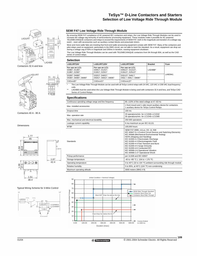
TeSys™ D-Line Contactors and StartersSelection of Low Voltage Ride Through Module
01/04
1.9(47)
LAD4BB
E1 E2
A1 A2
LADLVRT
E2E1
A2A2
A1A1
1.3(32)
LADLVRT
A1
A1
A2
A2
L1 L2
E1
14 13
E2LA9D941
LADLVRT*** LC1D09Ð32LC1D40Ð80*
Do not connect
1.7745
1.6742.4
1.5138.4
1.84
46.8
1.08
27.5
Typical Wiring Scheme for 3-Wire Control
Dimensions
Contactors 40 A - 80 A
Contactors 32 A and less
Selection of Low Voltage Ride Through Module
SEMI F47 Low Voltage Ride Through ModuleBy ensuring SEMI F47 compliance of AC powered IEC contactors and relays, the Low Voltage Ride Through Modules can be used to increase the voltage sag immunity of semiconductor processing equipment. These modules make it possible for AC powered TELEMECANIQUE contactors and relays to exceed the requirements of SEMI F47, both in the magnitude and duration of a voltage sag event – even with accessories such as auxiliary contact blocks and pneumatic timers.
More and more wafer fabs are insisting that front-end wafer processing equipment comply with SEMI F47. Many of the contactors and pilot relays used on equipment, particularly in the EMO circuit, are not able to meet the standard. As a result, equipment can drop out during a voltage sag of 50% in magnitude and 200ms in duration, causing equipment shutdown.
The Low Voltage Ride Through Modules can be used with TELEMECANIQUE contactors from 9A through 80A, as well as the CAD series of control relays.
SelectionLADLVRT24V LADLVRT120V LADLVRT208V Bracket Fuse
For use on LC1:D09B7, D12B7,D18B7, D25B7
For use on LC1:D09G7, D12G7,D18G7, D25G7
For use on LC1:D09LE7, D12LE7,D18LE7, D25LE7
LAD4BB*
LA9D941D32B7, D40B7,D50B7, D65B7, D80B7
D32G7, D40G7,D50G7, D65G7, D80B7
D32LE7, D40L7,D50L7, D65L7, D80B7
-
CADxxxB7 CADxxxG7 CADxxxLE7 -
* The Low Voltage Ride Through Module can be used with all TeSys control relays with 24 VAC, 120 VAC or 208 VAC dual frequency coils.
** LAD4BB must be used when the Low Voltage Ride Through Module is being used with contactors 32 A and less, and TeSys CAD Series of Control Relays.
SpecificationsContinuous operating voltage range and line frequency 85–110% of the rated voltage at 47–63 Hz
Max. installed accessories1 front mount and 1 side mount auxiliary device for contactors1 auxiliary device for TeSys Control Relays
Dropout time 150 ms
Max. operation rate20 operations/min. for LC1D09–LC1D3230 operations/min. for LC1D40–LC1D80
Max. mechanical and electrical durability 250 000 operations
Leakage current capability 6 ma maximum as per IEC 61131
MTBF 100,000 hours
Standards
SEMI F47-0999, cULus, CE, UL 508IEC 60947-5-1 (Control Circuit Devices and Switching Elements)IEC 60068 (Mechanical Environmental Testing)NSTA (Shipping and Handling)IEC 61000-4-2 Electrostatic DischargeIEC 61000-4-3 Electromagnetic FieldIEC 61000-4-4 Fast Transient and BurstIEC 61000-4-5 Surge ImmunityIEC 61000-4-6 Conducted RFIIEC 60068-2-6 Operational VibrationIEC 60068-2-27 Operational Shock
Pickup performance per UL508 and IEC 60947
Storage temperature -40 to +80 °C (- 104 to + 176 °F)
Operating temperature 0 to 40°C (32 to 104 °F) ambient surrounding ride through module
Relative humidity 5 to 95%, at 40°C (104 °F) non-condensing
Maximum operating altitude 3000 meters (9842.4 ft)
90
80
70
60
50
40
30
20
10
00.00 100.00 200.00 300.00 400.00 500.00 600.00
Duration (msec)
Curves Extendto 1000 ms
Must NOT Drop Out above this line
SEMI Ride Through StandardContactor Must Drop OutContactor Must Ride Through
(Initial Condition = Nominal Voltage)
Must Drop Out below this line
Per
cent
Rat
ed C
ontr
ol V
olta
ge
109© 2001-2004 Schneider Electric All Rights Reserved
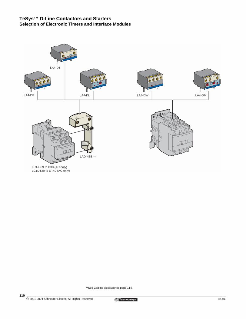
TeSys™ D-Line Contactors and StartersSelection of Electronic Timers and Interface Modules
© 2001-2004 Schneider Electric All Righ110
LA4-DT
LA4-DF
LC1-D09 to D38 (AC only)LC1DT20 to DT40 (AC only)
Selection of Electronic Timers and Interface Modules
**See Cabling Accessories page 114.
LA4-DL
LAD-4BB **
LA4-DW LA4-DM
ts Reserved 01/04
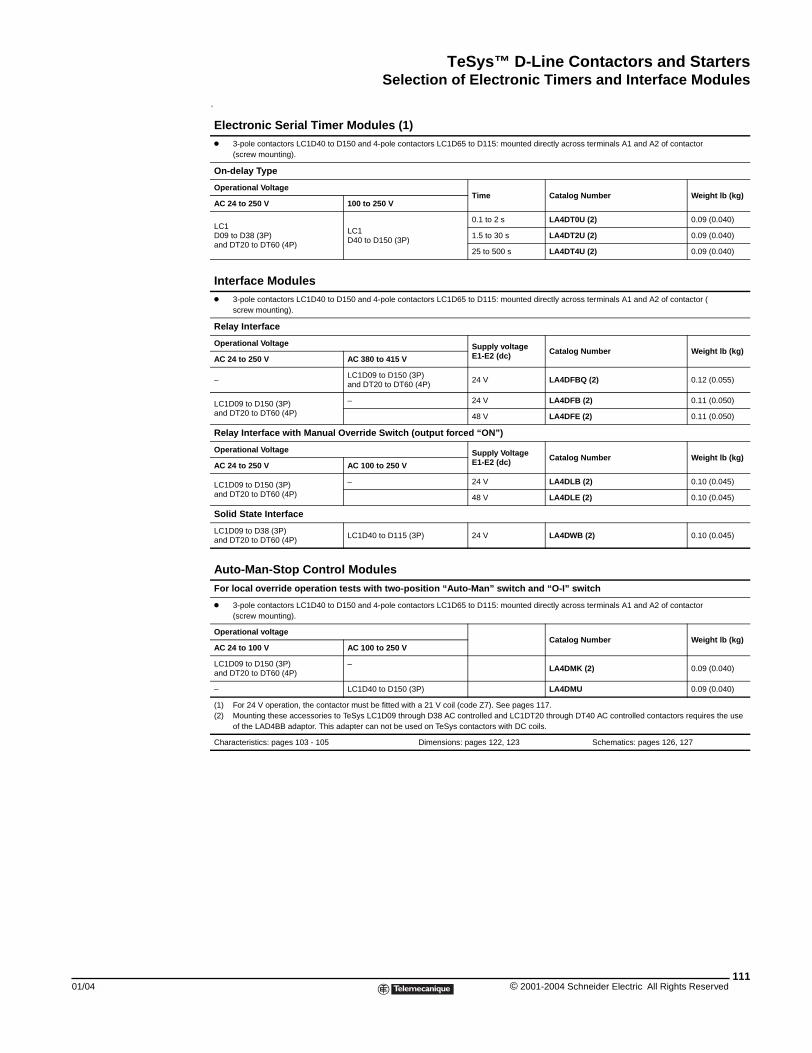
TeSys™ D-Line Contactors and StartersSelection of Electronic Timers and Interface Modules
01/04
q
Electronic Serial Timer Modules (1)k 3-pole contactors LC1D40 to D150 and 4-pole contactors LC1D65 to D115: mounted directly across terminals A1 and A2 of contactor
(screw mounting).
On-delay Type
Operational VoltageTime Catalog Number Weight lb (kg)
AC 24 to 250 V 100 to 250 V
LC1D09 to D38 (3P)and DT20 to DT60 (4P)
LC1D40 to D150 (3P)
0.1 to 2 s LA4DT0U (2) 0.09 (0.040)
1.5 to 30 s LA4DT2U (2) 0.09 (0.040)
25 to 500 s LA4DT4U (2) 0.09 (0.040)
Interface Modulesk 3-pole contactors LC1D40 to D150 and 4-pole contactors LC1D65 to D115: mounted directly across terminals A1 and A2 of contactor (
screw mounting).
Relay Interface
Operational Voltage Supply voltage E1-E2 (dc) Catalog Number Weight lb (kg)
AC 24 to 250 V AC 380 to 415 V
–LC1D09 to D150 (3P)and DT20 to DT60 (4P)
24 V LA4DFBQ (2) 0.12 (0.055)
LC1D09 to D150 (3P)and DT20 to DT60 (4P)
– 24 V LA4DFB (2) 0.11 (0.050)
48 V LA4DFE (2) 0.11 (0.050)
Relay Interface with Manual Override Switch (output forced “ON”)
Operational Voltage Supply VoltageE1-E2 (dc) Catalog Number Weight lb (kg)
AC 24 to 250 V AC 100 to 250 V
LC1D09 to D150 (3P) and DT20 to DT60 (4P)
– 24 V LA4DLB (2) 0.10 (0.045)
48 V LA4DLE (2) 0.10 (0.045)
Solid State Interface
LC1D09 to D38 (3P)and DT20 to DT60 (4P)
LC1D40 to D115 (3P) 24 V LA4DWB (2) 0.10 (0.045)
Auto-Man-Stop Control Modules
For local override operation tests with two-position “Auto-Man” switch and “O-I” switch
k 3-pole contactors LC1D40 to D150 and 4-pole contactors LC1D65 to D115: mounted directly across terminals A1 and A2 of contactor (screw mounting).
Operational voltageCatalog Number Weight lb (kg)
AC 24 to 100 V AC 100 to 250 V
LC1D09 to D150 (3P)and DT20 to DT60 (4P)
– LA4DMK (2) 0.09 (0.040)
– LC1D40 to D150 (3P) LA4DMU 0.09 (0.040)
(1) For 24 V operation, the contactor must be fitted with a 21 V coil (code Z7). See pages 117.(2) Mounting these accessories to TeSys LC1D09 through D38 AC controlled and LC1DT20 through DT40 AC controlled contactors requires the use
of the LAD4BB adaptor. This adapter can not be used on TeSys contactors with DC coils.
Characteristics: pages 103 - 105 Dimensions: pages 122, 123 Schematics: pages 126, 127
111© 2001-2004 Schneider Electric All Rights Reserved
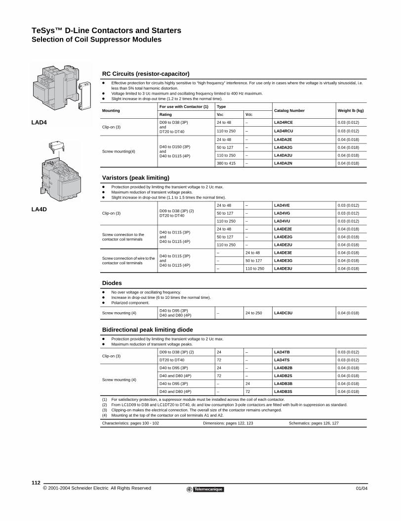
TeSys™ D-Line Contactors and StartersSelection of Coil Suppressor Modules
© 2001-2004 Schneider E112
LAD4
LA4D
Selection of Coil Suppressor Modules
RC Circuits (resistor-capacitor)k Effective protection for circuits highly sensitive to “high frequency” interference. For use only in cases where the voltage is virtually sinusoidal, i.e.
less than 5% total harmonic distortion.k Voltage limited to 3 Uc maximum and oscillating frequency limited to 400 Hz maximum.k Slight increase in drop-out time (1.2 to 2 times the normal time).
MountingFor use with Contactor (1) Type
Catalog Number Weight lb (kg)Rating Vac Vdc
Clip-on (3)D09 to D38 (3P)andDT20 to DT40
24 to 48 – LAD4RCE 0.03 (0.012)
110 to 250 – LAD4RCU 0.03 (0.012)
Screw mounting(4)D40 to D150 (3P)andD40 to D115 (4P)
24 to 48 – LA4DA2E 0.04 (0.018)
50 to 127 – LA4DA2G 0.04 (0.018)
110 to 250 – LA4DA2U 0.04 (0.018)
380 to 415 – LA4DA2N 0.04 (0.018)
Varistors (peak limiting)k Protection provided by limiting the transient voltage to 2 Uc max.k Maximum reduction of transient voltage peaks.k Slight increase in drop-out time (1.1 to 1.5 times the normal time).
Clip-on (3)D09 to D38 (3P) (2)DT20 to DT40
24 to 48 – LAD4VE 0.03 (0.012)
50 to 127 – LAD4VG 0.03 (0.012)
110 to 250 – LAD4VU 0.03 (0.012)
Screw connection to the contactor coil terminals
D40 to D115 (3P)andD40 to D115 (4P)
24 to 48 – LA4DE2E 0.04 (0.018)
50 to 127 – LA4DE2G 0.04 (0.018)
110 to 250 – LA4DE2U 0.04 (0.018)
Screw connection of wire to the contactor coil terminals
D40 to D115 (3P)andD40 to D115 (4P)
– 24 to 48 LA4DE3E 0.04 (0.018)
– 50 to 127 LA4DE3G 0.04 (0.018)
– 110 to 250 LA4DE3U 0.04 (0.018)
Diodesk No over voltage or oscillating frequency.k Increase in drop-out time (6 to 10 times the normal time).k Polarized component.
Screw mounting (4)D40 to D95 (3P)D40 and D80 (4P)
– 24 to 250 LA4DC3U 0.04 (0.018)
Bidirectional peak limiting diodek Protection provided by limiting the transient voltage to 2 Uc max.k Maximum reduction of transient voltage peaks.
Clip-on (3)D09 to D38 (3P) (2) 24 – LAD4TB 0.03 (0.012)
DT20 to DT40 72 – LAD4TS 0.03 (0.012)
Screw mounting (4)
D40 to D95 (3P) 24 – LA4DB2B 0.04 (0.018)
D40 and D80 (4P) 72 – LA4DB2S 0.04 (0.018)
D40 to D95 (3P) – 24 LA4DB3B 0.04 (0.018)
D40 and D80 (4P) – 72 LA4DB3S 0.04 (0.018)
(1) For satisfactory protection, a suppressor module must be installed across the coil of each contactor.(2) From LC1D09 to D38 and LC1DT20 to DT40, dc and low consumption 3-pole contactors are fitted with built-in suppression as standard.(3) Clipping-on makes the electrical connection. The overall size of the contactor remains unchanged.(4) Mounting at the top of the contactor on coil terminals A1 and A2.
Characteristics: pages 100 - 102 Dimensions: pages 122, 123 Schematics: pages 126, 127
lectric All Rights Reserved 01/04
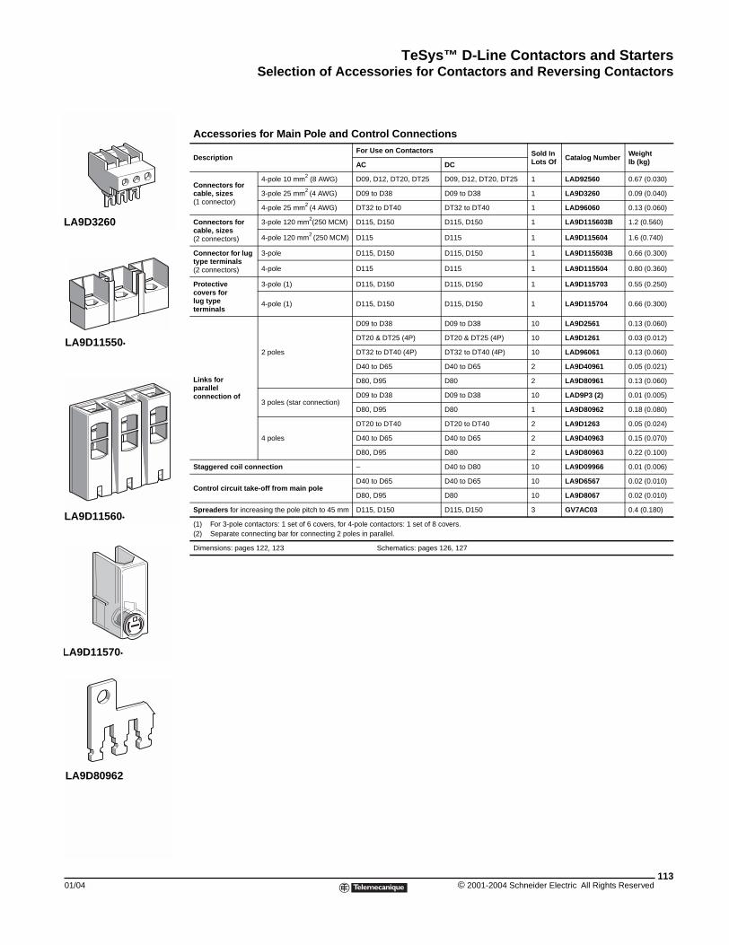
TeSys™ D-Line Contactors and StartersSelection of Accessories for Contactors and Reversing Contactors
01/04
LA9D3260
LA9D11550•
LA9D11560•
LA9D11570•
LA9D80962
Selection of Accessories for Contactors and Reversing Contactors
Accessories for Main Pole and Control Connections
DescriptionFor Use on Contactors Sold In
Lots Of Catalog Number Weight lb (kg)AC DC
Connectors for cable, sizes (1 connector)
4-pole 10 mm2 (8 AWG) D09, D12, DT20, DT25 D09, D12, DT20, DT25 1 LAD92560 0.67 (0.030)
3-pole 25 mm2 (4 AWG) D09 to D38 D09 to D38 1 LA9D3260 0.09 (0.040)
4-pole 25 mm2 (4 AWG) DT32 to DT40 DT32 to DT40 1 LAD96060 0.13 (0.060)
Connectors for cable, sizes(2 connectors)
3-pole 120 mm2(250 MCM) D115, D150 D115, D150 1 LA9D115603B 1.2 (0.560)
4-pole 120 mm2 (250 MCM) D115 D115 1 LA9D115604 1.6 (0.740)
Connector for lug type terminals(2 connectors)
3-pole D115, D150 D115, D150 1 LA9D115503B 0.66 (0.300)
4-pole D115 D115 1 LA9D115504 0.80 (0.360)
Protectivecovers forlug typeterminals
3-pole (1) D115, D150 D115, D150 1 LA9D115703 0.55 (0.250)
4-pole (1) D115, D150 D115, D150 1 LA9D115704 0.66 (0.300)
Links forparallelconnection of
2 poles
D09 to D38 D09 to D38 10 LA9D2561 0.13 (0.060)
DT20 & DT25 (4P) DT20 & DT25 (4P) 10 LA9D1261 0.03 (0.012)
DT32 to DT40 (4P) DT32 to DT40 (4P) 10 LAD96061 0.13 (0.060)
D40 to D65 D40 to D65 2 LA9D40961 0.05 (0.021)
D80, D95 D80 2 LA9D80961 0.13 (0.060)
3 poles (star connection)D09 to D38 D09 to D38 10 LAD9P3 (2) 0.01 (0.005)
D80, D95 D80 1 LA9D80962 0.18 (0.080)
4 poles
DT20 to DT40 DT20 to DT40 2 LA9D1263 0.05 (0.024)
D40 to D65 D40 to D65 2 LA9D40963 0.15 (0.070)
D80, D95 D80 2 LA9D80963 0.22 (0.100)
Staggered coil connection – D40 to D80 10 LA9D09966 0.01 (0.006)
Control circuit take-off from main poleD40 to D65 D40 to D65 10 LA9D6567 0.02 (0.010)
D80, D95 D80 10 LA9D8067 0.02 (0.010)
Spreaders for increasing the pole pitch to 45 mm D115, D150 D115, D150 3 GV7AC03 0.4 (0.180)
(1) For 3-pole contactors: 1 set of 6 covers, for 4-pole contactors: 1 set of 8 covers.(2) Separate connecting bar for connecting 2 poles in parallel.
Dimensions: pages 122, 123 Schematics: pages 126, 127
113© 2001-2004 Schneider Electric All Rights Reserved
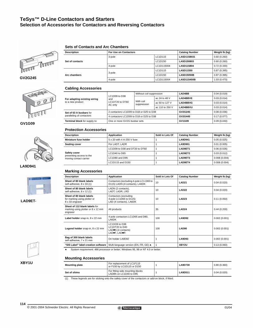
TeSys™ D-Line Contactors and StartersSelection of Accessories for Contactors and Reversing Contactors
© 2001-2004 Schneider E114
GV2G245
GV1G09
LA9D941
LAD9ET•
XBY1U
Sets of Contacts and Arc ChambersDescription For Use on Contactors Catalog Number Weight lb (kg)
Set of contacts
3-pole LC1D115 LA5D1158031 0.60 (0.260)
LC1D150 LA5D150803 0.60 (0.260)
4-pole LC1D115004 LA5D115804 0.72 (0.330)
Arc chambers3-pole
LC1D115 LA5D11550 0.87 (0.395)
LC1D150 LA5D15050B 0.87 (0.395)
4-pole LC1D115004 LA5D115450B 1.03 (0.470)
Cabling Accessories
For adapting existing wiring to a new product
LC1D09 to D38andLC1DT20 to DT60AC only
Without coil suppression LAD4BB 0.04 (0.019)
With coilsuppression
ac 24 to 48 V LAD4BBVE 0.03 (0.014)
ac 50 to 127 V LAD4BBVG 0.03 (0.014)
ac 110 to 250 V LAD4BBVU 0.03 (0.014)
Set of 63 A busbars forparalleling of contactors
2 contactors LC1D09 to D18 or D25 to D38 GV2G245 0.08 (0.036)
4 contactors LC1D09 to D18 or D25 to D38 GV2G445 0.17 (0.077)
Terminal block for supply to: One or more GV2G busbar sets GV1G09 0.09 (0.040)
Protection AccessoriesDescription Application Sold in Lots Of Catalog Number Weight lb (kg)
Miniature fuse holder 5 x 20 with 4 A-250 V fuse 1 LA9D941 0.05 (0.025)
Sealing cover For LADT, LADR 1 LA9D901 0.01 (0.005)
Safety coverpreventing access to themoving contact carrier
LC1D09 to D38 and DT20 to DT60 1 LAD9ET1 0.06 (0.026)
LC1D40 to D65 1 LAD9ET2 0.03 (0.012)
LC1D80 and D95 1 LAD9ET3 0.008 (0.004)
LC1D115 and D150 1 LAD9ET4 0.008 (0.004)
Marking AccessoriesDescription Application Sold in Lots Of Catalog Number Weight lb (kg)
Sheet of 80 blank labelsself-adhesive, 8 x 33 (1)
Contactors (excluding 4-pole LC1-D65 to D115) LADN (4 contacts), LA6DK
10 LAD21 0.04 (0.020)
Sheet of 80 blank labelsself-adhesive, 8 x 12 (1)
LADN (2 contacts), LADT, LADR, LRD
10 LAD22 0.04 (0.020)
Sheet of 80 blank labelsfor marking using plotter or8 x 33 engraver
Contactors (excluding4-pole LC1D65 to D115)LAD (4 contacts), LA6DK
10 LAD23 0.11 (0.050)
Sheet of 112 blank labels for marking using plotter or 8 x 12 mm engraver
All products 35 LAD24 0.44 (0.200)
Label holder snap-in, 8 x 22 mm4-pole contactors LC1D65 and D80, LA6DK
100 LA9D92 0.002 (0.001)
Legend holder snap-in, 8 x 22 mm
LC1DO9 to D38LC1DT20 to D40LADkN (4 contacts)LADkT, LADkR
100 LAD90 0.002 (0.001)
Bag of 300 blank labelsself-adhesive, 7 x 21 mm
On holder LA9D92 1 LA9D93 0.002 (0.001)
“SIS Label” label creation software Multi-language version (EN, FR, GE) q 1 XBY2U 0.13 (0.060)
q System requirement: 486 processor or better; Windows 95, 98 or NT 4.0 or better.
Mounting Accessories
Mounting plate For replacement of LC1F115or F150 by LC1D115 or D150
1 LA9D730 0.80 (0.360)
Set of shims For fitting side mounting blocksLAD8N on LC1D40 to D95
1 LA9D511 0.04 (0.020)
(1) These legends are for sticking onto the safety cover of the contactors or add-on block, if fitted.
lectric All Rights Reserved 01/04
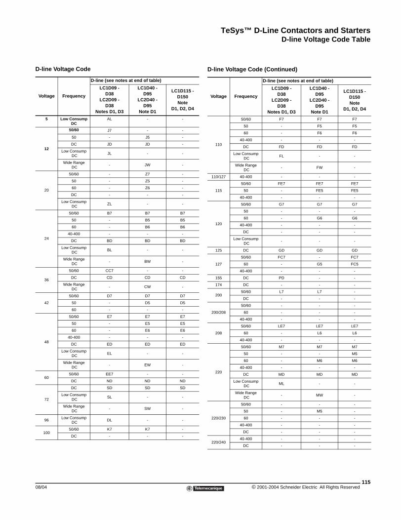
TeSys™ D-Line Contactors and StartersD-line Voltage Code Table
D-line Voltage Code Table
D-line Voltage Code
Voltage Frequency
D-line (see notes at end of table)
LC1D09 - D38
LC2D09 - D38
Notes D1, D3
LC1D40 - D95
LC2D40 - D95
Note D1
LC1D115 - D150 Note
D1, D2, D4
5 Low ConsumpDC
AL - -
12
50/60 J7 - -
50 - J5 -
DC JD JD -
Low Consump DC
JL - -
Wide Range DC
- JW -
20
50/60 - Z7 -
50 - Z5 -
60 - Z6 -
DC - - -
Low Consump DC
ZL - -
24
50/60 B7 B7 B7
50 - B5 B5
60 - B6 B6
40-400 - - -
DC BD BD BD
Low Consump DC
BL - -
Wide Range DC
- BW -
36
50/60 CC7 - -
DC CD CD CD
Wide Range DC
- CW -
42
50/60 D7 D7 D7
50 - D5 D5
60 - - -
48
50/60 E7 E7 E7
50 - E5 E5
60 - E6 E6
40-400 - - -
DC ED ED ED
Low Consump DC
EL - -
Wide Range DC
- EW -
6050/60 EE7 - -
DC ND ND ND
72
DC SD SD SD
Low Consump DC
SL - -
Wide Range DC
- SW -
96Low Consump
DCDL - -
10050/60 K7 K7 -
DC - - -
08/04
110
50/60 F7 F7 F7
50 - F5 F5
60 - F6 F6
40-400 - - -
DC FD FD FD
Low Consump DC
FL - -
Wide Range DC
- FW -
110/127 40-400 - - -
115
50/60 FE7 FE7 FE7
50 - FE5 FE5
40-400 - - -
120
50/60 G7 G7 G7
50 - - -
60 - G6 G6
40-400 - - -
DC - - -
Low Consump DC
- - -
125 DC GD GD GD
127
50/60 FC7 - FC7
60 - G5 FC5
40-400 - - -
155 DC PD - -
174 DC - - -
20050/60 L7 L7 -
DC - - -
200/208
50/60 - - -
60 - - -
40-400 - - -
208
50/60 LE7 LE7 LE7
60 - L6 L6
40-400 - - -
220
50/60 M7 M7 M7
50 - - M5
60 - M6 M6
40-400 - - -
DC MD MD MD
Low Consump DC
ML - -
Wide Range DC
- MW -
220/230
50/60 - - -
50 - M5 -
60 - - -
40-400 - - -
DC - - -
220/24040-400 - - -
DC - - -
D-line Voltage Code (Continued)
Voltage Frequency
D-line (see notes at end of table)
LC1D09 - D38
LC2D09 - D38
Notes D1, D3
LC1D40 - D95
LC2D40 - D95
Note D1
LC1D115 - D150 Note
D1, D2, D4
115© 2001-2004 Schneider Electric All Rights Reserved
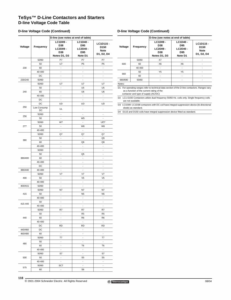
TeSys™ D-Line Contactors and StartersD-line Voltage Code Table
230
50/60 P7 P7 P7
50 U7 P5 P5
60 - - -
40-400 - - -
DC - - -
230/240 50/60 - - -
240
50/60 U7 U7 U7
50 - U5 U5
60 - U6 U6
40-400 - - -
DC - - -
250
DC UD UD UD
Low Consump DC
UL - -
25650/60 - - -
50 - W5 -
277
50/60 W7 - UE7
50 - W6 W6
40-400 - - -
380
50/60 Q7 Q7 Q7
50 - - Q5
60 - Q6 Q6
40-400 - - -
380/400
50/60 - - -
50 - Q5 -
60 - - -
40-400 - - -
DC - - -
380/440 40-400 - - -
400
50/60 V7 V7 V7
50 - V5 V5
40-400 - - -
400/415 50/60 - - -
415
50/60 N7 N7 N7
50 - N5 N5
40-400 - - -
415-44050 - - -
40-400 - - -
440
50/60 R7 R7 R7
50 - R5 R5
60 - R6 R6
40-400 - - -
DC RD RD RD
440/460 DC - - -
460/480 60 - - -
480
50/60 T7 - T7
50 - - -
60 - T6 T6
40-400 - - -
500
50/60 S7 - S7
50 - S5 S5
40-400 - - -
57550/60 SC7 - -
60 - S6 -
D-line Voltage Code (Continued)
Voltage Frequency
D-line (see notes at end of table)
LC1D09 - D38
LC2D09 - D38
Notes D1, D3
LC1D40 - D95
LC2D40 - D95
Note D1
LC1D115 - D150 Note
D1, D2, D4
© 2001-2004 Schneider Electric All Rights Reserved116
600
50/60 X7 - -
60 X6 X6 -
40-400 - - -
66050 Y5 Y5 -
60 - - -
660/690 50/60 - - -
Notes:
D1 For operating ranges refer to technical data section of the D-line contactors. Ranges vary as a function of the current rating of the
contactor and type of supply (AC/DC)
D2 LC1-D150 Contactors utilize dual frequency 50/60 Hz. coils only. Single frequency coils are not available.
D3 LC1D09 -LC1D38 contactors with DC coil have integral suppression device (bi-directional diode) as standard.
D4 D115 and D150 coils have integral suppression device fitted as standard.
D-line Voltage Code (Continued)
Voltage Frequency
D-line (see notes at end of table)
LC1D09 - D38
LC2D09 - D38
Notes D1, D3
LC1D40 - D95
LC2D40 - D95
Note D1
LC1D115 - D150 Note
D1, D2, D4
08/04
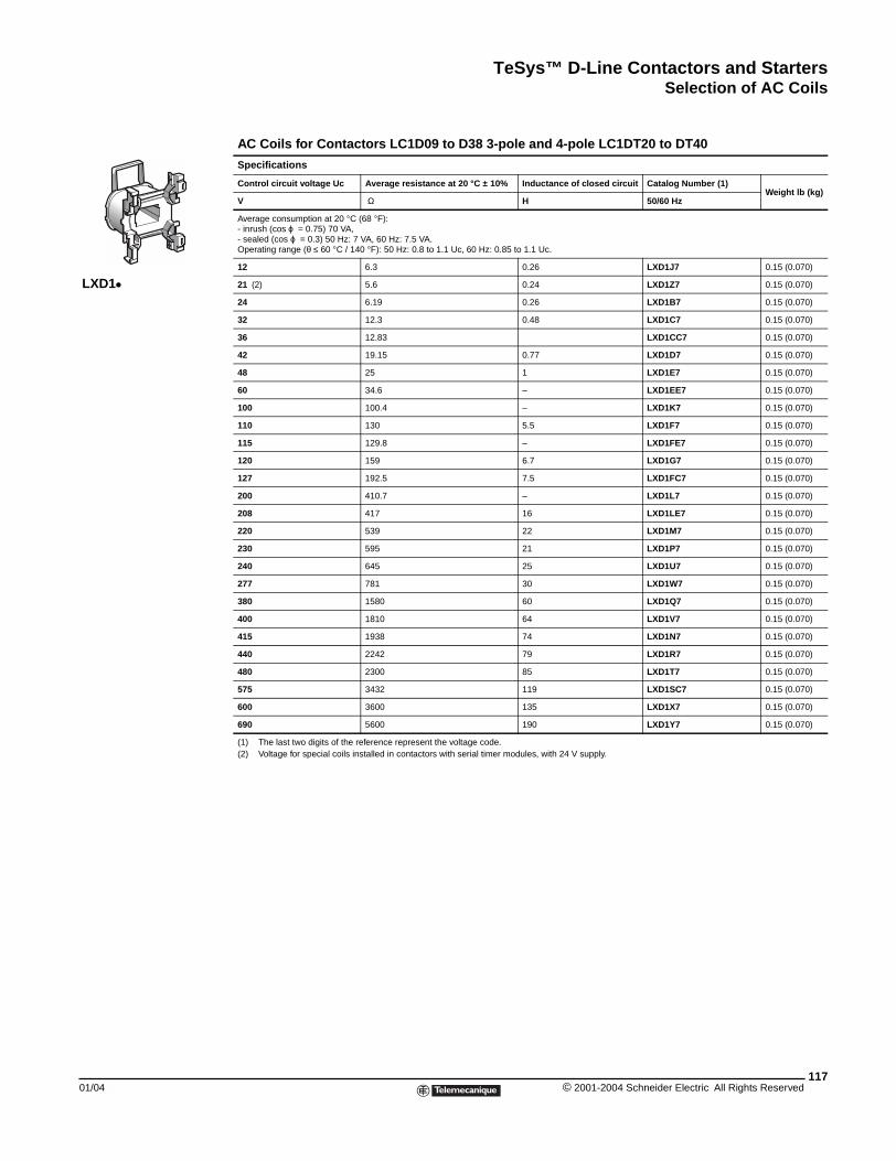
TeSys™ D-Line Contactors and StartersSelection of AC Coils
01/04
LXD1k
Selection of AC Coils
AC Coils for Contactors LC1D09 to D38 3-pole and 4-pole LC1DT20 to DT40
Specifications
Control circuit voltage Uc Average resistance at 20 °C ± 10% Inductance of closed circuit Catalog Number (1)Weight lb (kg)
V Ω H 50/60 Hz
Average consumption at 20 °C (68 °F):- inrush (cos ϕ = 0.75) 70 VA,- sealed (cos ϕ = 0.3) 50 Hz: 7 VA, 60 Hz: 7.5 VA.Operating range (θ ≤ 60 °C / 140 °F): 50 Hz: 0.8 to 1.1 Uc, 60 Hz: 0.85 to 1.1 Uc.
12 6.3 0.26 LXD1J7 0.15 (0.070)
21 (2) 5.6 0.24 LXD1Z7 0.15 (0.070)
24 6.19 0.26 LXD1B7 0.15 (0.070)
32 12.3 0.48 LXD1C7 0.15 (0.070)
36 12.83 LXD1CC7 0.15 (0.070)
42 19.15 0.77 LXD1D7 0.15 (0.070)
48 25 1 LXD1E7 0.15 (0.070)
60 34.6 – LXD1EE7 0.15 (0.070)
100 100.4 – LXD1K7 0.15 (0.070)
110 130 5.5 LXD1F7 0.15 (0.070)
115 129.8 – LXD1FE7 0.15 (0.070)
120 159 6.7 LXD1G7 0.15 (0.070)
127 192.5 7.5 LXD1FC7 0.15 (0.070)
200 410.7 – LXD1L7 0.15 (0.070)
208 417 16 LXD1LE7 0.15 (0.070)
220 539 22 LXD1M7 0.15 (0.070)
230 595 21 LXD1P7 0.15 (0.070)
240 645 25 LXD1U7 0.15 (0.070)
277 781 30 LXD1W7 0.15 (0.070)
380 1580 60 LXD1Q7 0.15 (0.070)
400 1810 64 LXD1V7 0.15 (0.070)
415 1938 74 LXD1N7 0.15 (0.070)
440 2242 79 LXD1R7 0.15 (0.070)
480 2300 85 LXD1T7 0.15 (0.070)
575 3432 119 LXD1SC7 0.15 (0.070)
600 3600 135 LXD1X7 0.15 (0.070)
690 5600 190 LXD1Y7 0.15 (0.070)
(1) The last two digits of the reference represent the voltage code.(2) Voltage for special coils installed in contactors with serial timer modules, with 24 V supply.
117© 2001-2004 Schneider Electric All Rights Reserved
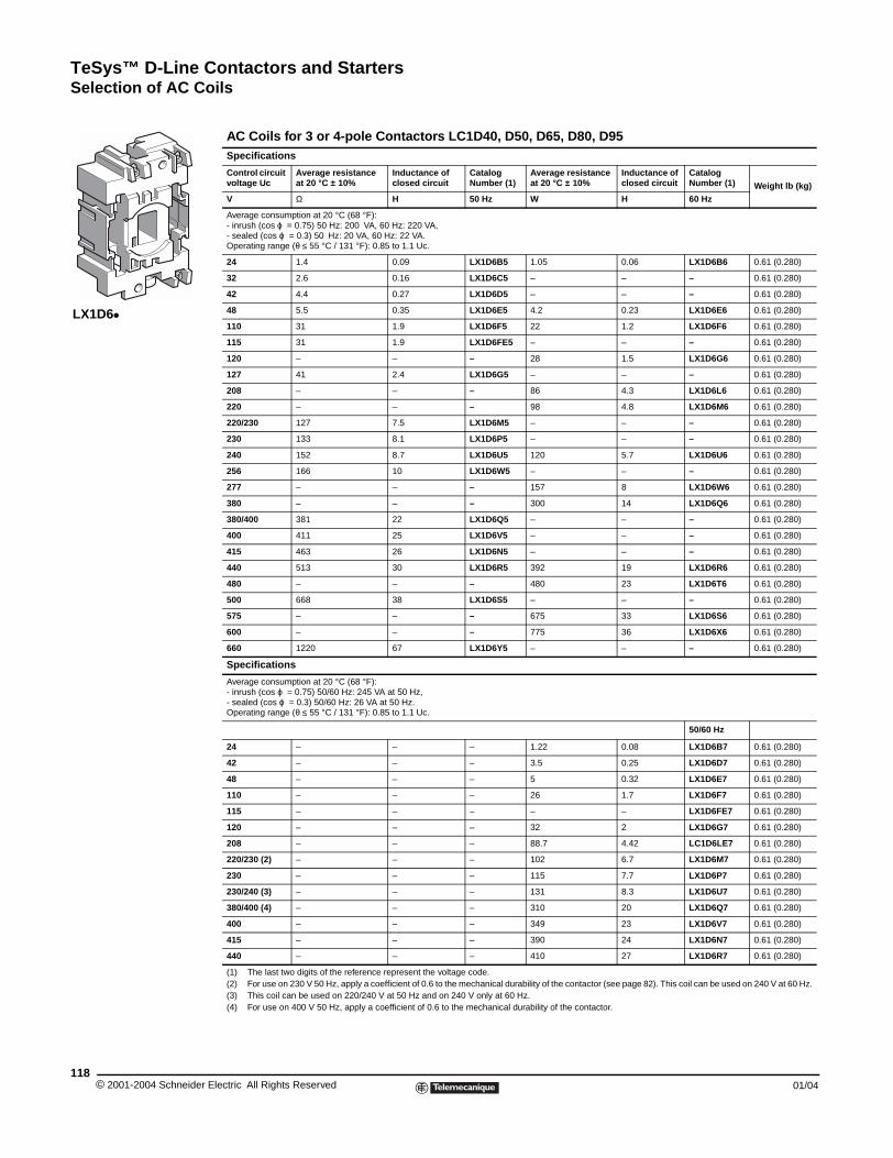
TeSys™ D-Line Contactors and StartersSelection of AC Coils
© 2001-2004 Schneider E118
LX1D6k
AC Coils for 3 or 4-pole Contactors LC1D40, D50, D65, D80, D95Specifications
Control circuit voltage Uc
Average resistance at 20 °C ± 10%
Inductance of closed circuit
Catalog Number (1)
Average resistance at 20 °C ± 10%
Inductance of closed circuit
Catalog Number (1) Weight lb (kg)
V Ω H 50 Hz W H 60 Hz
Average consumption at 20 °C (68 °F):- inrush (cos ϕ = 0.75) 50 Hz: 200 VA, 60 Hz: 220 VA,- sealed (cos ϕ = 0.3) 50 Hz: 20 VA, 60 Hz: 22 VA.Operating range (θ ≤ 55 °C / 131 °F): 0.85 to 1.1 Uc.
24 1.4 0.09 LX1D6B5 1.05 0.06 LX1D6B6 0.61 (0.280)
32 2.6 0.16 LX1D6C5 – – – 0.61 (0.280)
42 4.4 0.27 LX1D6D5 – – – 0.61 (0.280)
48 5.5 0.35 LX1D6E5 4.2 0.23 LX1D6E6 0.61 (0.280)
110 31 1.9 LX1D6F5 22 1.2 LX1D6F6 0.61 (0.280)
115 31 1.9 LX1D6FE5 – – – 0.61 (0.280)
120 – – – 28 1.5 LX1D6G6 0.61 (0.280)
127 41 2.4 LX1D6G5 – – – 0.61 (0.280)
208 – – – 86 4.3 LX1D6L6 0.61 (0.280)
220 – – – 98 4.8 LX1D6M6 0.61 (0.280)
220/230 127 7.5 LX1D6M5 – – – 0.61 (0.280)
230 133 8.1 LX1D6P5 – – – 0.61 (0.280)
240 152 8.7 LX1D6U5 120 5.7 LX1D6U6 0.61 (0.280)
256 166 10 LX1D6W5 – – – 0.61 (0.280)
277 – – – 157 8 LX1D6W6 0.61 (0.280)
380 – – – 300 14 LX1D6Q6 0.61 (0.280)
380/400 381 22 LX1D6Q5 – – – 0.61 (0.280)
400 411 25 LX1D6V5 – – – 0.61 (0.280)
415 463 26 LX1D6N5 – – – 0.61 (0.280)
440 513 30 LX1D6R5 392 19 LX1D6R6 0.61 (0.280)
480 – – – 480 23 LX1D6T6 0.61 (0.280)
500 668 38 LX1D6S5 – – – 0.61 (0.280)
575 – – – 675 33 LX1D6S6 0.61 (0.280)
600 – – – 775 36 LX1D6X6 0.61 (0.280)
660 1220 67 LX1D6Y5 – – – 0.61 (0.280)
Specifications
Average consumption at 20 °C (68 °F):- inrush (cos ϕ = 0.75) 50/60 Hz: 245 VA at 50 Hz,- sealed (cos ϕ = 0.3) 50/60 Hz: 26 VA at 50 Hz.Operating range (θ ≤ 55 °C / 131 °F): 0.85 to 1.1 Uc.
50/60 Hz
24 – – – 1.22 0.08 LX1D6B7 0.61 (0.280)
42 – – – 3.5 0.25 LX1D6D7 0.61 (0.280)
48 – – – 5 0.32 LX1D6E7 0.61 (0.280)
110 – – – 26 1.7 LX1D6F7 0.61 (0.280)
115 – – – – – LX1D6FE7 0.61 (0.280)
120 – – – 32 2 LX1D6G7 0.61 (0.280)
208 – – – 88.7 4.42 LC1D6LE7 0.61 (0.280)
220/230 (2) – – – 102 6.7 LX1D6M7 0.61 (0.280)
230 – – – 115 7.7 LX1D6P7 0.61 (0.280)
230/240 (3) – – – 131 8.3 LX1D6U7 0.61 (0.280)
380/400 (4) – – – 310 20 LX1D6Q7 0.61 (0.280)
400 – – – 349 23 LX1D6V7 0.61 (0.280)
415 – – – 390 24 LX1D6N7 0.61 (0.280)
440 – – – 410 27 LX1D6R7 0.61 (0.280)
(1) The last two digits of the reference represent the voltage code.(2) For use on 230 V 50 Hz, apply a coefficient of 0.6 to the mechanical durability of the contactor (see page 82). This coil can be used on 240 V at 60 Hz.(3) This coil can be used on 220/240 V at 50 Hz and on 240 V only at 60 Hz.(4) For use on 400 V 50 Hz, apply a coefficient of 0.6 to the mechanical durability of the contactor.
lectric All Rights Reserved 01/04
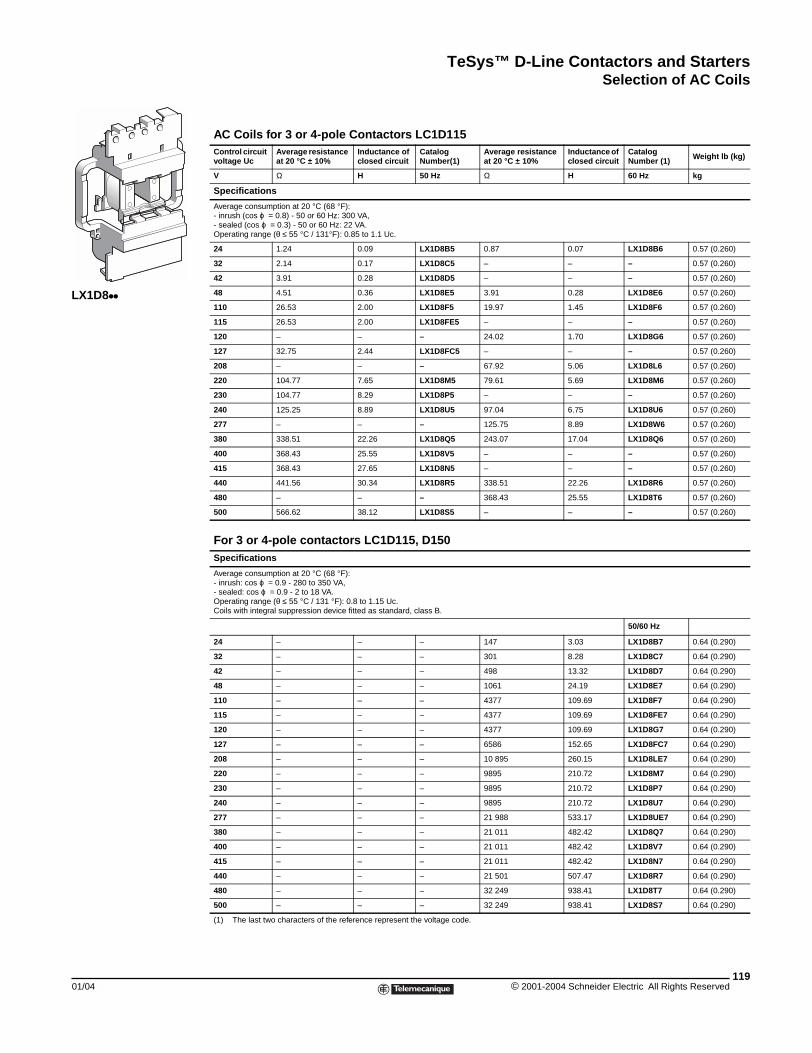
TeSys™ D-Line Contactors and StartersSelection of AC Coils
01/04
LX1D8kk
Selection of AC Coils
AC Coils for 3 or 4-pole Contactors LC1D115Control circuit voltage Uc
Average resistance at 20 °C ± 10%
Inductance of closed circuit
Catalog Number(1)
Average resistance at 20 °C ± 10%
Inductance of closed circuit
Catalog Number (1) Weight lb (kg)
V Ω H 50 Hz Ω H 60 Hz kg
Specifications
Average consumption at 20 °C (68 °F):- inrush (cos ϕ = 0.8) - 50 or 60 Hz: 300 VA,- sealed (cos ϕ = 0.3) - 50 or 60 Hz: 22 VA.Operating range (θ ≤ 55 °C / 131°F): 0.85 to 1.1 Uc.
24 1.24 0.09 LX1D8B5 0.87 0.07 LX1D8B6 0.57 (0.260)
32 2.14 0.17 LX1D8C5 – – – 0.57 (0.260)
42 3.91 0.28 LX1D8D5 – – – 0.57 (0.260)
48 4.51 0.36 LX1D8E5 3.91 0.28 LX1D8E6 0.57 (0.260)
110 26.53 2.00 LX1D8F5 19.97 1.45 LX1D8F6 0.57 (0.260)
115 26.53 2.00 LX1D8FE5 – – – 0.57 (0.260)
120 – – – 24.02 1.70 LX1D8G6 0.57 (0.260)
127 32.75 2.44 LX1D8FC5 – – – 0.57 (0.260)
208 – – – 67.92 5.06 LX1D8L6 0.57 (0.260)
220 104.77 7.65 LX1D8M5 79.61 5.69 LX1D8M6 0.57 (0.260)
230 104.77 8.29 LX1D8P5 – – – 0.57 (0.260)
240 125.25 8.89 LX1D8U5 97.04 6.75 LX1D8U6 0.57 (0.260)
277 – – – 125.75 8.89 LX1D8W6 0.57 (0.260)
380 338.51 22.26 LX1D8Q5 243.07 17.04 LX1D8Q6 0.57 (0.260)
400 368.43 25.55 LX1D8V5 – – – 0.57 (0.260)
415 368.43 27.65 LX1D8N5 – – – 0.57 (0.260)
440 441.56 30.34 LX1D8R5 338.51 22.26 LX1D8R6 0.57 (0.260)
480 – – – 368.43 25.55 LX1D8T6 0.57 (0.260)
500 566.62 38.12 LX1D8S5 – – – 0.57 (0.260)
For 3 or 4-pole contactors LC1D115, D150Specifications
Average consumption at 20 °C (68 °F):- inrush: cos ϕ = 0.9 - 280 to 350 VA,- sealed: cos ϕ = 0.9 - 2 to 18 VA.Operating range (θ ≤ 55 °C / 131 °F): 0.8 to 1.15 Uc.Coils with integral suppression device fitted as standard, class B.
50/60 Hz
24 – – – 147 3.03 LX1D8B7 0.64 (0.290)
32 – – – 301 8.28 LX1D8C7 0.64 (0.290)
42 – – – 498 13.32 LX1D8D7 0.64 (0.290)
48 – – – 1061 24.19 LX1D8E7 0.64 (0.290)
110 – – – 4377 109.69 LX1D8F7 0.64 (0.290)
115 – – – 4377 109.69 LX1D8FE7 0.64 (0.290)
120 – – – 4377 109.69 LX1D8G7 0.64 (0.290)
127 – – – 6586 152.65 LX1D8FC7 0.64 (0.290)
208 – – – 10 895 260.15 LX1D8LE7 0.64 (0.290)
220 – – – 9895 210.72 LX1D8M7 0.64 (0.290)
230 – – – 9895 210.72 LX1D8P7 0.64 (0.290)
240 – – – 9895 210.72 LX1D8U7 0.64 (0.290)
277 – – – 21 988 533.17 LX1D8UE7 0.64 (0.290)
380 – – – 21 011 482.42 LX1D8Q7 0.64 (0.290)
400 – – – 21 011 482.42 LX1D8V7 0.64 (0.290)
415 – – – 21 011 482.42 LX1D8N7 0.64 (0.290)
440 – – – 21 501 507.47 LX1D8R7 0.64 (0.290)
480 – – – 32 249 938.41 LX1D8T7 0.64 (0.290)
500 – – – 32 249 938.41 LX1D8S7 0.64 (0.290)
(1) The last two characters of the reference represent the voltage code.
119© 2001-2004 Schneider Electric All Rights Reserved
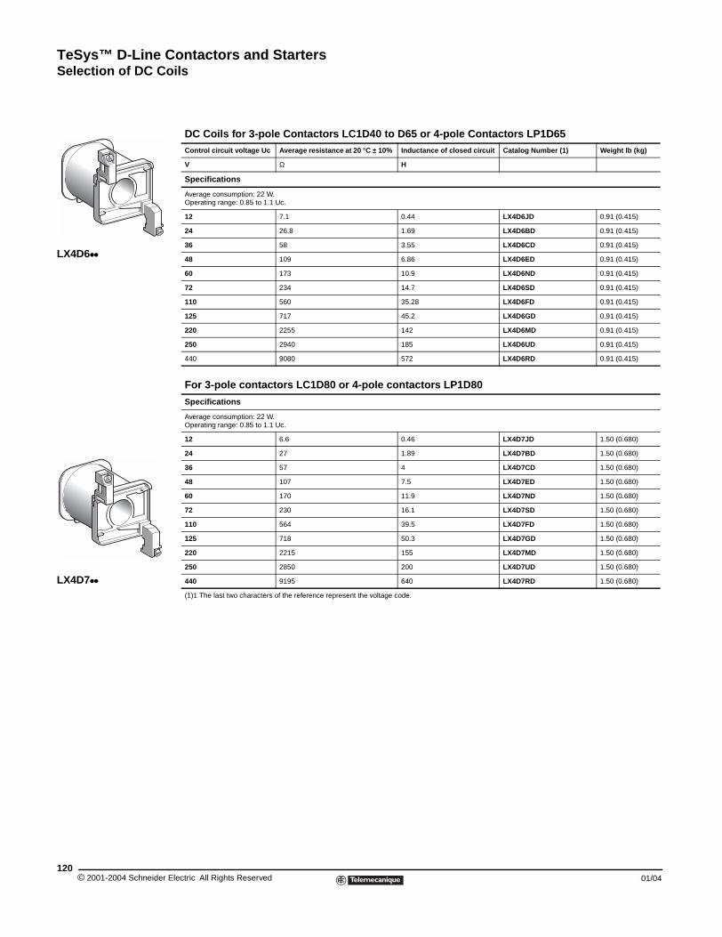
TeSys™ D-Line Contactors and StartersSelection of DC Coils
© 2001-2004 Schneider E120
LX4D6kk
LX4D7kk
Selection of DC Coils
DC Coils for 3-pole Contactors LC1D40 to D65 or 4-pole Contactors LP1D65Control circuit voltage Uc Average resistance at 20 °C ± 10% Inductance of closed circuit Catalog Number (1) Weight lb (kg)
V Ω H
Specifications
Average consumption: 22 W.Operating range: 0.85 to 1.1 Uc.
12 7.1 0.44 LX4D6JD 0.91 (0.415)
24 26.8 1.69 LX4D6BD 0.91 (0.415)
36 58 3.55 LX4D6CD 0.91 (0.415)
48 109 6.86 LX4D6ED 0.91 (0.415)
60 173 10.9 LX4D6ND 0.91 (0.415)
72 234 14.7 LX4D6SD 0.91 (0.415)
110 560 35.28 LX4D6FD 0.91 (0.415)
125 717 45.2 LX4D6GD 0.91 (0.415)
220 2255 142 LX4D6MD 0.91 (0.415)
250 2940 185 LX4D6UD 0.91 (0.415)
440 9080 572 LX4D6RD 0.91 (0.415)
For 3-pole contactors LC1D80 or 4-pole contactors LP1D80
Specifications
Average consumption: 22 W. Operating range: 0.85 to 1.1 Uc.
12 6.6 0.46 LX4D7JD 1.50 (0.680)
24 27 1.89 LX4D7BD 1.50 (0.680)
36 57 4 LX4D7CD 1.50 (0.680)
48 107 7.5 LX4D7ED 1.50 (0.680)
60 170 11.9 LX4D7ND 1.50 (0.680)
72 230 16.1 LX4D7SD 1.50 (0.680)
110 564 39.5 LX4D7FD 1.50 (0.680)
125 718 50.3 LX4D7GD 1.50 (0.680)
220 2215 155 LX4D7MD 1.50 (0.680)
250 2850 200 LX4D7UD 1.50 (0.680)
440 9195 640 LX4D7RD 1.50 (0.680)
(1)1 The last two characters of the reference represent the voltage code.
lectric All Rights Reserved 01/04
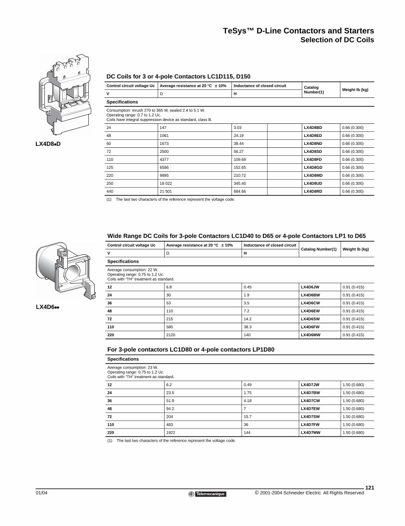
TeSys™ D-Line Contactors and StartersSelection of DC Coils
01/04
LX4D8kD
LX4D6kk
DC Coils for 3 or 4-pole Contactors LC1D115, D150Control circuit voltage Uc Average resistance at 20 °C ± 10% Inductance of closed circuit Catalog
Number(1) Weight lb (kg)V Ω H
Specifications
Consumption: inrush 270 to 365 W, sealed 2.4 to 5.1 W.Operating range: 0.7 to 1.2 Uc.Coils have integral suppression device as standard, class B.
24 147 3.03 LX4D8BD 0.66 (0.300)
48 1061 24.19 LX4D8ED 0.66 (0.300)
60 1673 38.44 LX4D8ND 0.66 (0.300)
72 2500 56.27 LX4D8SD 0.66 (0.300)
110 4377 109.69 LX4D8FD 0.66 (0.300)
125 6586 152.65 LX4D8GD 0.66 (0.300)
220 9895 210.72 LX4D8MD 0.66 (0.300)
250 18 022 345.40 LX4D8UD 0.66 (0.300)
440 21 501 684.66 LX4D8RD 0.66 (0.300)
(1) The last two characters of the reference represent the voltage code.
Wide Range DC Coils for 3-pole Contactors LC1D40 to D65 or 4-pole Contactors LP1 to D65Control circuit voltage Uc Average resistance at 20 °C ± 10% Inductance of closed circuit
Catalog Number(1) Weight lb (kg)V Ω H
Specifications
Average consumption: 22 W.Operating range: 0.75 to 1.2 Uc.Coils with “TH” treatment as standard.
12 6.8 0.45 LX4D6JW 0.91 (0.415)
24 30 1.9 LX4D6BW 0.91 (0.415)
36 53 3.5 LX4D6CW 0.91 (0.415)
48 110 7.2 LX4D6EW 0.91 (0.415)
72 215 14.2 LX4D6SW 0.91 (0.415)
110 580 38.3 LX4D6FW 0.91 (0.415)
220 2120 140 LX4D6MW 0.91 (0.415)
For 3-pole contactors LC1D80 or 4-pole contactors LP1D80
Specifications
Average consumption: 23 W.Operating range: 0.75 to 1.2 Uc.Coils with “TH” treatment as standard.
12 6.2 0.49 LX4D7JW 1.50 (0.680)
24 23.5 1.75 LX4D7BW 1.50 (0.680)
36 51.9 4.18 LX4D7CW 1.50 (0.680)
48 94.2 7 LX4D7EW 1.50 (0.680)
72 204 15.7 LX4D7SW 1.50 (0.680)
110 483 36 LX4D7FW 1.50 (0.680)
220 1922 144 LX4D7MW 1.50 (0.680)
(1) The last two characters of the reference represent the voltage code.
121© 2001-2004 Schneider Electric All Rights Reserved
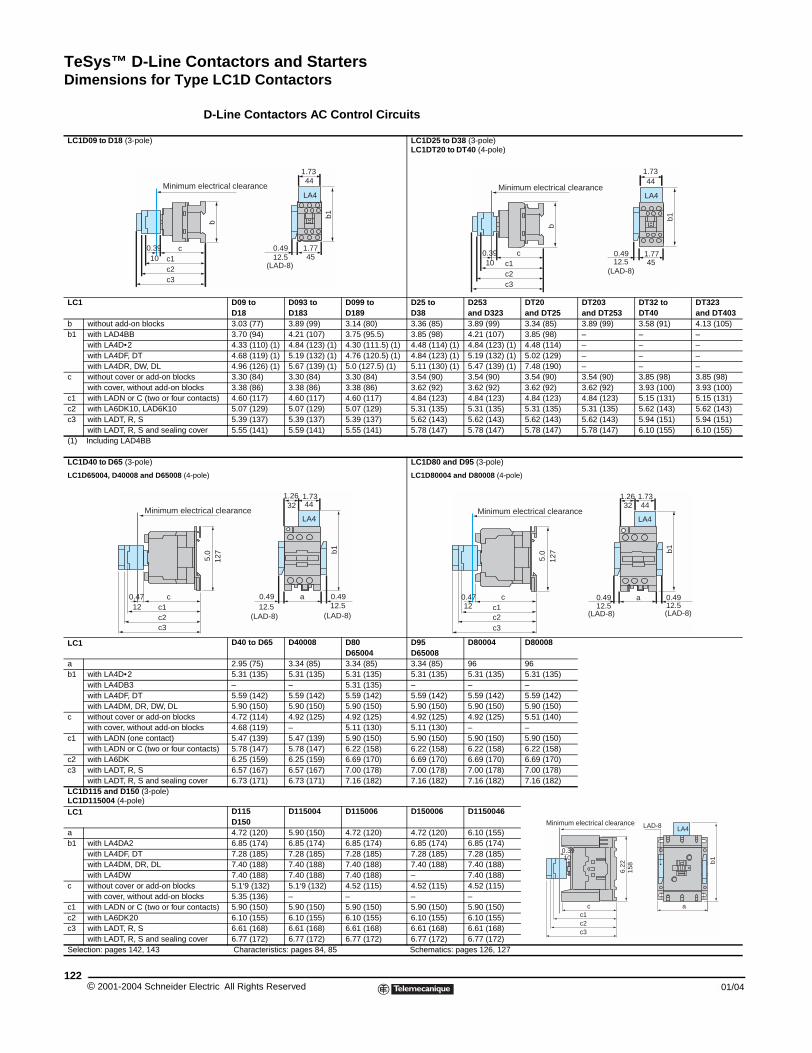
TeSys™ D-Line Contactors and StartersDimensions for Type LC1D Contactors
© 2001-2004 Schneider E122
LC1D09 to D18 (3-pole)
LC1
b without add-on blocksb1 with LAD4BB
with LA4D•2with LA4DF, DTwith LA4DR, DW, DL
c without cover or add-on blockswith cover, without add-on blo
c1 with LADN or C (two or four coc2 with LA6DK10, LAD6K10c3 with LADT, R, S
with LADT, R, S and sealing c(1) Including LAD4BB
LC1D40 to D65 (3-pole)
LC1D65004, D40008 and D65008 (4-
LC1
ab1 with LA4D•2
with LA4DB3with LA4DF, DTwith LA4DM, DR, DW, DL
c without cover or add-on blockswith cover, without add-on blo
c1 with LADN (one contact)with LADN or C (two or four co
c2 with LA6DKc3 with LADT, R, S
with LADT, R, S and sealing cLC1D115 and D150 (3-pole)LC1D115004 (4-pole)LC1
ab1 with LA4DA2
with LA4DF, DTwith LA4DM, DR, DLwith LA4DW
c without cover or add-on blockswith cover, without add-on blo
c1 with LADN or C (two or four coc2 with LA6DK20c3 with LADT, R, S
with LADT, R, S and sealing cSelection: pages 142, 143
cc1c2c3
0.3910
Minimum
c0.47c1c2c3
12
Minimum elec
Dimensions for Type LC1D Contactors
D-Line Contactors AC Control CircuitsX
LC1D25 to D38 (3-pole)LC1DT20 to DT40 (4-pole)
D09 to D093 to D099 to D25 to D253 DT20 DT203 DT32 to DT323 D18 D183 D189 D38 and D323 and DT25 and DT253 DT40 and DT4033.03 (77) 3.89 (99) 3.14 (80) 3.36 (85) 3.89 (99) 3.34 (85) 3.89 (99) 3.58 (91) 4.13 (105)3.70 (94) 4.21 (107) 3.75 (95.5) 3.85 (98) 4.21 (107) 3.85 (98) – – –4.33 (110) (1) 4.84 (123) (1) 4.30 (111.5) (1) 4.48 (114) (1) 4.84 (123) (1) 4.48 (114) – – –4.68 (119) (1) 5.19 (132) (1) 4.76 (120.5) (1) 4.84 (123) (1) 5.19 (132) (1) 5.02 (129) – – –4.96 (126) (1) 5.67 (139) (1) 5.0 (127.5) (1) 5.11 (130) (1) 5.47 (139) (1) 7.48 (190) – – –3.30 (84) 3.30 (84) 3.30 (84) 3.54 (90) 3.54 (90) 3.54 (90) 3.54 (90) 3.85 (98) 3.85 (98)
cks 3.38 (86) 3.38 (86) 3.38 (86) 3.62 (92) 3.62 (92) 3.62 (92) 3.62 (92) 3.93 (100) 3.93 (100)ntacts) 4.60 (117) 4.60 (117) 4.60 (117) 4.84 (123) 4.84 (123) 4.84 (123) 4.84 (123) 5.15 (131) 5.15 (131)
5.07 (129) 5.07 (129) 5.07 (129) 5.31 (135) 5.31 (135) 5.31 (135) 5.31 (135) 5.62 (143) 5.62 (143)5.39 (137) 5.39 (137) 5.39 (137) 5.62 (143) 5.62 (143) 5.62 (143) 5.62 (143) 5.94 (151) 5.94 (151)
over 5.55 (141) 5.59 (141) 5.55 (141) 5.78 (147) 5.78 (147) 5.78 (147) 5.78 (147) 6.10 (155) 6.10 (155)
pole)
LC1D80 and D95 (3-pole)
LC1D80004 and D80008 (4-pole)
D40 to D65 D40008 D80 D95 D80004 D80008D65004 D65008
2.95 (75) 3.34 (85) 3.34 (85) 3.34 (85) 96 965.31 (135) 5.31 (135) 5.31 (135) 5.31 (135) 5.31 (135) 5.31 (135)– – 5.31 (135) – – –5.59 (142) 5.59 (142) 5.59 (142) 5.59 (142) 5.59 (142) 5.59 (142)5.90 (150) 5.90 (150) 5.90 (150) 5.90 (150) 5.90 (150) 5.90 (150)4.72 (114) 4.92 (125) 4.92 (125) 4.92 (125) 4.92 (125) 5.51 (140)
cks 4.68 (119) – 5.11 (130) 5.11 (130) – –5.47 (139) 5.47 (139) 5.90 (150) 5.90 (150) 5.90 (150) 5.90 (150)
ntacts) 5.78 (147) 5.78 (147) 6.22 (158) 6.22 (158) 6.22 (158) 6.22 (158)6.25 (159) 6.25 (159) 6.69 (170) 6.69 (170) 6.69 (170) 6.69 (170)6.57 (167) 6.57 (167) 7.00 (178) 7.00 (178) 7.00 (178) 7.00 (178)
over 6.73 (171) 6.73 (171) 7.16 (182) 7.16 (182) 7.16 (182) 7.16 (182)
D115 D115004 D115006 D150006 D1150046D1504.72 (120) 5.90 (150) 4.72 (120) 4.72 (120) 6.10 (155)6.85 (174) 6.85 (174) 6.85 (174) 6.85 (174) 6.85 (174)7.28 (185) 7.28 (185) 7.28 (185) 7.28 (185) 7.28 (185)7.40 (188) 7.40 (188) 7.40 (188) 7.40 (188) 7.40 (188)7.40 (188) 7.40 (188) 7.40 (188) – 7.40 (188)5.1‘9 (132) 5.1‘9 (132) 4.52 (115) 4.52 (115) 4.52 (115)
cks 5.35 (136) – – – –ntacts) 5.90 (150) 5.90 (150) 5.90 (150) 5.90 (150) 5.90 (150)
6.10 (155) 6.10 (155) 6.10 (155) 6.10 (155) 6.10 (155)6.61 (168) 6.61 (168) 6.61 (168) 6.61 (168) 6.61 (168)
over 6.77 (172) 6.77 (172) 6.77 (172) 6.77 (172) 6.77 (172)Characteristics: pages 84, 85 Schematics: pages 126, 127
b
1.770.49
(LAD-8)
b1
1.73
LA4
44
4512.5
electrical clearance
b
1.77
(LAD-8)
b1
1.73
LA4
c0.39c1c2c3
10
44
450.4912.5
Minimum electrical clearance
b1
a 0.49
(LAD-8)
0.49
(LAD-8)
5.0
1.731.26
LA4
127
12.5 12.5
32 44trical clearance
0.47
5.0 b1
a 0.49
(LAD-8)
0.49
(LAD-8)
1.731.26
cc1c2c3
LA4
12
127
12.5 12.5
32 44Minimum electrical clearance
6.22
c ac1c2c3
b1
LAD-8 LA4
0.39
158
10
Minimum electrical clearance
lectric All Rights Reserved 01/04
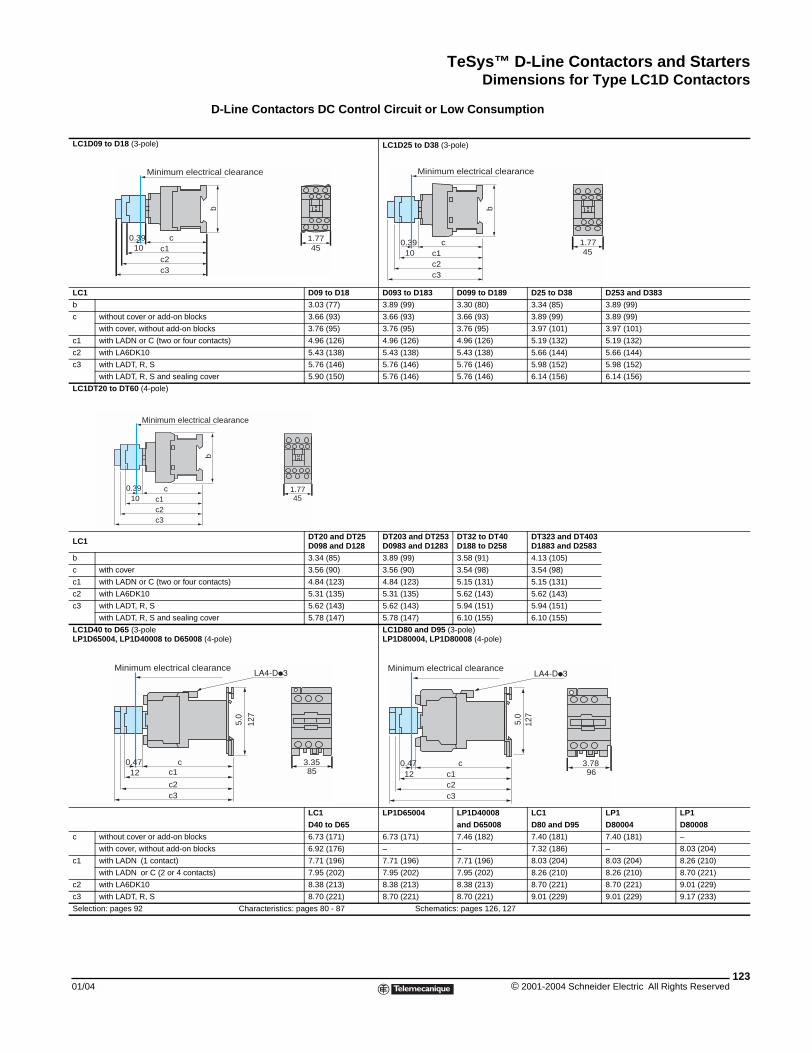
TeSys™ D-Line Contactors and StartersDimensions for Type LC1D Contactors
01/04
LC1D09 to D18 (3-pole)
LC1
b
c without cover or add-on block
with cover, without add-on blo
c1 with LADN or C (two or four c
c2 with LA6DK10
c3 with LADT, R, S
with LADT, R, S and sealing
LC1DT20 to DT60 (4-pole)
LC1
b
c with cover
c1 with LADN or C (two or four c
c2 with LA6DK10
c3 with LADT, R, S
with LADT, R, S and sealing
LC1D40 to D65 (3-poleLP1D65004, LP1D40008 to D65008
c without cover or add-on block
with cover, without add-on blo
c1 with LADN (1 contact)
with LADN or C (2 or 4 conta
c2 with LA6DK10
c3 with LADT, R, S
Selection: pages 92
c0.39c1c2c3
10
Minimum elec
c0.39c1c2c3
10
Minimum electri
c0.47c1
c2c3
12
Minimum electrical cle
D-Line Contactors DC Control Circuit or Low Consumption
LC1D25 to D38 (3-pole)
D09 to D18 D093 to D183 D099 to D189 D25 to D38 D253 and D383
3.03 (77) 3.89 (99) 3.30 (80) 3.34 (85) 3.89 (99)
s 3.66 (93) 3.66 (93) 3.66 (93) 3.89 (99) 3.89 (99)
cks 3.76 (95) 3.76 (95) 3.76 (95) 3.97 (101) 3.97 (101)
ontacts) 4.96 (126) 4.96 (126) 4.96 (126) 5.19 (132) 5.19 (132)
5.43 (138) 5.43 (138) 5.43 (138) 5.66 (144) 5.66 (144)
5.76 (146) 5.76 (146) 5.76 (146) 5.98 (152) 5.98 (152)
cover 5.90 (150) 5.76 (146) 5.76 (146) 6.14 (156) 6.14 (156)
DT20 and DT25D098 and D128
DT203 and DT253D0983 and D1283
DT32 to DT40D188 to D258
DT323 and DT403D1883 and D2583
3.34 (85) 3.89 (99) 3.58 (91) 4.13 (105)
3.56 (90) 3.56 (90) 3.54 (98) 3.54 (98)
ontacts) 4.84 (123) 4.84 (123) 5.15 (131) 5.15 (131)
5.31 (135) 5.31 (135) 5.62 (143) 5.62 (143)
5.62 (143) 5.62 (143) 5.94 (151) 5.94 (151)
cover 5.78 (147) 5.78 (147) 6.10 (155) 6.10 (155)
(4-pole)LC1D80 and D95 (3-pole)LP1D80004, LP1D80008 (4-pole)
LC1 LP1D65004 LP1D40008 LC1 LP1 LP1
D40 to D65 and D65008 D80 and D95 D80004 D80008
s 6.73 (171) 6.73 (171) 7.46 (182) 7.40 (181) 7.40 (181) –
cks 6.92 (176) – – 7.32 (186) – 8.03 (204)
7.71 (196) 7.71 (196) 7.71 (196) 8.03 (204) 8.03 (204) 8.26 (210)
cts) 7.95 (202) 7.95 (202) 7.95 (202) 8.26 (210) 8.26 (210) 8.70 (221)
8.38 (213) 8.38 (213) 8.38 (213) 8.70 (221) 8.70 (221) 9.01 (229)
8.70 (221) 8.70 (221) 8.70 (221) 9.01 (229) 9.01 (229) 9.17 (233)
Characteristics: pages 80 - 87 Schematics: pages 126, 127
c
b
0.39c1c2c3
1.7710 45
Minimum electrical clearance
b
1.7745
trical clearance
b
1.7745
cal clearance
3.35
5.0
127
85
arance
3.78c0.47c1c2c3
5.0
12
127
96
Minimum electrical clearance
123© 2001-2004 Schneider Electric All Rights Reserved
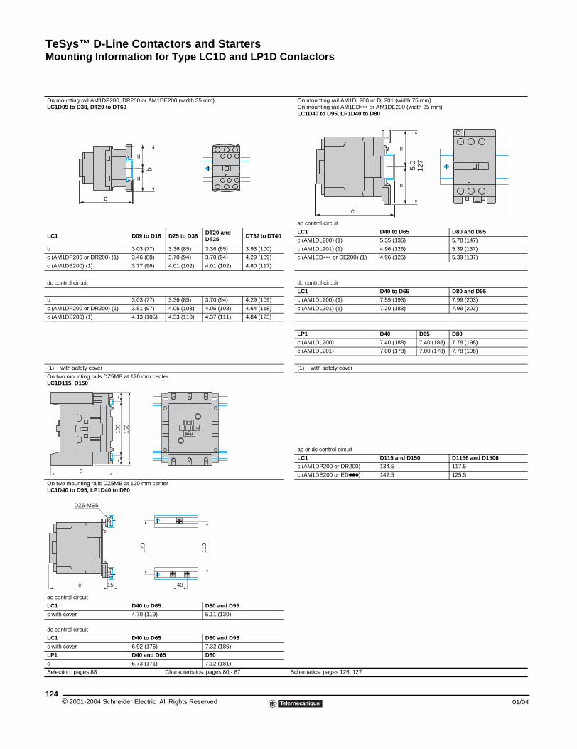
TeSys™ D-Line Contactors and StartersMounting Information for Type LC1D and LP1D Contactors
© 2001-2004 Schneider E124
On mounting rail AM1DP200, DR20LC1D09 to D38, DT20 to DT60
LC1 D0
b 3.
c (AM1DP200 or DR200) (1) 3.
c (AM1DE200) (1) 3.
dc control circuit
b 3.
c (AM1DP200 or DR200) (1) 3.
c (AM1DE200) (1) 4.
(1) with safety cover
On two mounting rails DZ5MB at 12LC1D115, D150
On two mounting rails DZ5MB at 12LC1D40 to D95, LP1D40 to D80
ac control circuit
LC1 D4
c with cover 4.
dc control circuit
LC1 D4
c with cover 6.
LP1 D4
c 6.
Selection: pages 88
c
100
==
158
c
c 15
DZ5-ME5
Mounting Information for Type LC1D and LP1D Contactors
xx
0 or AM1DE200 (width 35 mm) On mounting rail AM1DL200 or DL201 (width 75 mm)On mounting rail AM1ED••• or AM1DE200 (width 35 mm)LC1D40 to D95, LP1D40 to D80
ac control circuit
9 to D18 D25 to D38 DT20 and DT25 DT32 to DT40
LC1 D40 to D65 D80 and D95
c (AM1DL200) (1) 5.35 (136) 5.78 (147)
03 (77) 3.36 (85) 3.36 (85) 3.93 (100) c (AM1DL201) (1) 4.96 (126) 5.39 (137)
46 (88) 3.70 (94) 3.70 (94) 4.29 (109) c (AM1ED••• or DE200) (1) 4.96 (126) 5.39 (137)
77 (96) 4.01 (102) 4.01 (102) 4.60 (117)
dc control circuit
LC1 D40 to D65 D80 and D95
03 (77) 3.36 (85) 3.70 (94) 4.29 (109) c (AM1DL200) (1) 7.59 (193) 7.99 (203)
81 (97) 4.05 (103) 4.05 (103) 4.64 (118) c (AM1DL201) (1) 7.20 (183) 7.99 (203)
13 (105) 4.33 (110) 4.37 (111) 4.84 (123)
LP1 D40 D65 D80
c (AM1DL200) 7.40 (188) 7.40 (188) 7.78 (198)
c (AM1DL201) 7.00 (178) 7.00 (178) 7.78 (198)
(1) with safety cover
0 mm center
ac or dc control circuit
LC1 D115 and D150 D1156 and D1506
c (AM1DP200 or DR200) 134.5 117.5
c (AM1DE200 or EDkkk) 142.5 125.5
0 mm center
0 to D65 D80 and D95
70 (119) 5.11 (130)
0 to D65 D80 and D95
92 (176) 7.32 (186)
0 and D65 D80
73 (171) 7.12 (181)
Characteristics: pages 80 - 87 Schematics: pages 126, 127
=
b
=
5.0
==
c
127
110
120
40
lectric All Rights Reserved 01/04
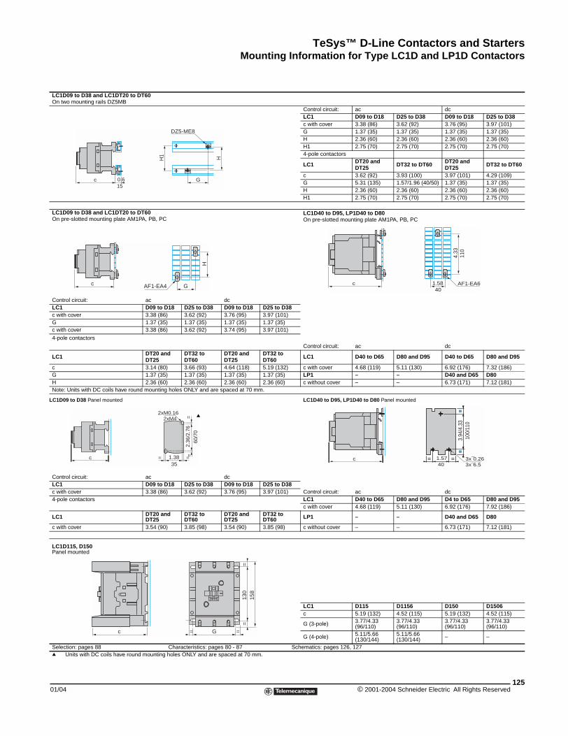
TeSys™ D-Line Contactors and StartersMounting Information for Type LC1D and LP1D Contactors
01/04
LC1D09 to D38 and LC1DT20 to DOn two mounting rails DZ5MB
LC1D09 to D38 and LC1DT20 to DOn pre-slotted mounting plate AM1P
Control circuit:LC1c with coverGc with cover
4-pole contactors
LC1
cGHNote: Units with DC coils have round
LC1D09 to D38 Panel mounted
Control circuit:LC1c with cover4-pole contactors
LC1
c with cover
LC1D115, D150Panel mounted
Selection: pages 88q Units with DC coils have round
c 0.615
c
c
c
T60
Control circuit: ac dcLC1 D09 to D18 D25 to D38 D09 to D18 D25 to D38c with cover 3.38 (86) 3.62 (92) 3.76 (95) 3.97 (101)G 1.37 (35) 1.37 (35) 1.37 (35) 1.37 (35)H 2.36 (60) 2.36 (60) 2.36 (60) 2.36 (60)H1 2.75 (70) 2.75 (70) 2.75 (70) 2.75 (70)4-pole contactors
LC1 DT20 and DT25 DT32 to DT60 DT20 and
DT25 DT32 to DT60
c 3.62 (92) 3.93 (100) 3.97 (101) 4.29 (109)G 5.31 (135) 1.57/1.96 (40/50) 1.37 (35) 1.37 (35)H 2.36 (60) 2.36 (60) 2.36 (60) 2.36 (60)H1 2.75 (70) 2.75 (70) 2.75 (70) 2.75 (70)
T60A, PB, PC
LC1D40 to D95, LP1D40 to D80On pre-slotted mounting plate AM1PA, PB, PC
ac dcD09 to D18 D25 to D38 D09 to D18 D25 to D383.38 (86) 3.62 (92) 3.76 (95) 3.97 (101)1.37 (35) 1.37 (35) 1.37 (35) 1.37 (35)3.38 (86) 3.62 (92) 3.74 (95) 3.97 (101)
Control circuit: ac dcDT20 and DT25
DT32 to DT60
DT20 and DT25
DT32 to DT60 LC1 D40 to D65 D80 and D95 D40 to D65 D80 and D95
3.14 (80) 3.66 (93) 4.64 (118) 5.19 (132) c with cover 4.68 (119) 5.11 (130) 6.92 (176) 7.32 (186)1.37 (35) 1.37 (35) 1.37 (35) 1.37 (35) LP1 – – D40 and D65 D802.36 (60) 2.36 (60) 2.36 (60) 2.36 (60) c without cover – – 6.73 (171) 7.12 (181)
mounting holes ONLY and are spaced at 70 mm.
LC1D40 to D95, LP1D40 to D80 Panel mounted
ac dcD09 to D18 D25 to D38 D09 to D18 D25 to D383.38 (86) 3.62 (92) 3.76 (95) 3.97 (101) Control circuit: ac dc
LC1 D40 to D65 D80 and D95 D4 to D65 D80 and D95c with cover 4.68 (119) 5.11 (130) 6.92 (176) 7.92 (186)
DT20 and DT25
DT32 to DT60
DT20 and DT25
DT32 to DT60 LP1 – – D40 and D65 D80
3.54 (90) 3.85 (98) 3.54 (90) 3.85 (98) c without cover – – 6.73 (171) 7.12 (181)
LC1 D115 D1156 D150 D1506c 5.19 (132) 4.52 (115) 5.19 (132) 4.52 (115)
G (3-pole) 3.77/4.33 (96/110)
3.77/4.33 (96/110)
3.77/4.33 (96/110)
3.77/4.33 (96/110)
G (4-pole) 5.11/5.66 (130/144)
5.11/5.66 (130/144) – –
Characteristics: pages 80 - 87 Schematics: pages 126, 127 mounting holes ONLY and are spaced at 70 mm.
HH1
DZ5-ME8
G
H
AF1-EA4 G AF1-EA61.58
4.33
c40
110
2.36
/2.7
6=
=
1.38= =
2xM4
35
60/7
0
2xM0.16 q
c 1.57= =3.
94/4
.33
==
= ==
== = 3x¯0.26
==
40 3x¯6.510
0/11
0
130
==
158
G= =
125© 2001-2004 Schneider Electric All Rights Reserved
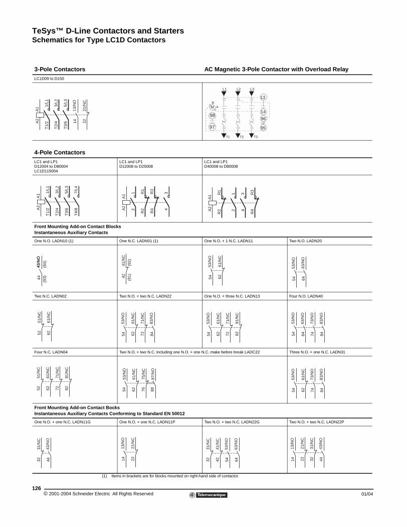
TeSys™ D-Line Contactors and StartersSchematics for Type LC1D Contactors
© 2001-2004 Schneider E126
3-Pole ContactorsLC1D09 to D150
4-Pole ContactorsLC1 and LP1D12004 to D80004LC1D115004
Front Mounting Add-on ConInstantaneous Auxiliary Con
One N.O. LADN10 (1)
Two N.C. LADN02
Four N.C. LADN04
Front Mounting Add-on ConInstantaneous Auxiliary Con
One N.O. + one N.C. LADN11G
A1
A2
13/N
O14
1/L1
T1/
2
3/L2
T2/
4
5/L3
T3/
6 2221
/NC
A1
A2
1/L1
T1/
2
3/L2
T2/
4
5/L3
T3/
6
7/L4
T4/
8
43 N
O44
43/N
O
(94)
(93)
5251
/NC
6261
/NC
5251
/NC
6261
/NC
7271
/NC
8281
/NC
3231
/NC
43/N
O44
Schematics for Type LC1D Contactors
(1) Items in brackets are for blocks mounted on right-hand side of contactor.
AC Magnetic 3-Pole Contactor with Overload Relay
LC1 and LP1D12008 to D25008
LC1 and LP1D40008 to D80008
tact Blockstacts
One N.C. LADN01 (1) One N.O. + 1 N.C. LADN11 Two N.O. LADN20
Two N.O. + two N.C. LADN22 One N.O. + three N.C. LADN13 Four N.O. LADN40
Two N.O. + two N.C. including one N.O. + one N.C. make before break LADC22 Three N.O. + one N.C. LADN31
tact Bockstacts Conforming to Standard EN 50012
One N.O. + one N.C. LADN11P Two N.O. + two N.C. LADN22G Two N.O. + two N.C. LADN22P
L1 L2 L3
T1 T2 T3
M
98
97
BA
13
14
96
95A
1A
2
12
R1
R2
R3
R4
34
A1
A2
R1
R2
R3
R4
12
34
4241
/NC
(91)
(92)
53/N
O54 62
61/N
C
63/N
O64
53/N
O54
7271
/NC
6261
/NC
83/N
O84
53/N
O54 72
71/N
C
6261
/NC
53/N
O54 82
81/N
C
83/N
O84
73/N
O74
63/N
O64
53/N
O54
53/N
O54
61/N
C62
87/N
O88
75/N
C76 62
61/N
C
83/N
O84
73/N
O74
53/N
O54
2221
/NC
13/N
O14 32
31/N
C
4241
/NC
63/N
O64
53/N
O54 32
31/N
C
2221
/NC
43/N
O44
13/N
O14
lectric All Rights Reserved 01/04
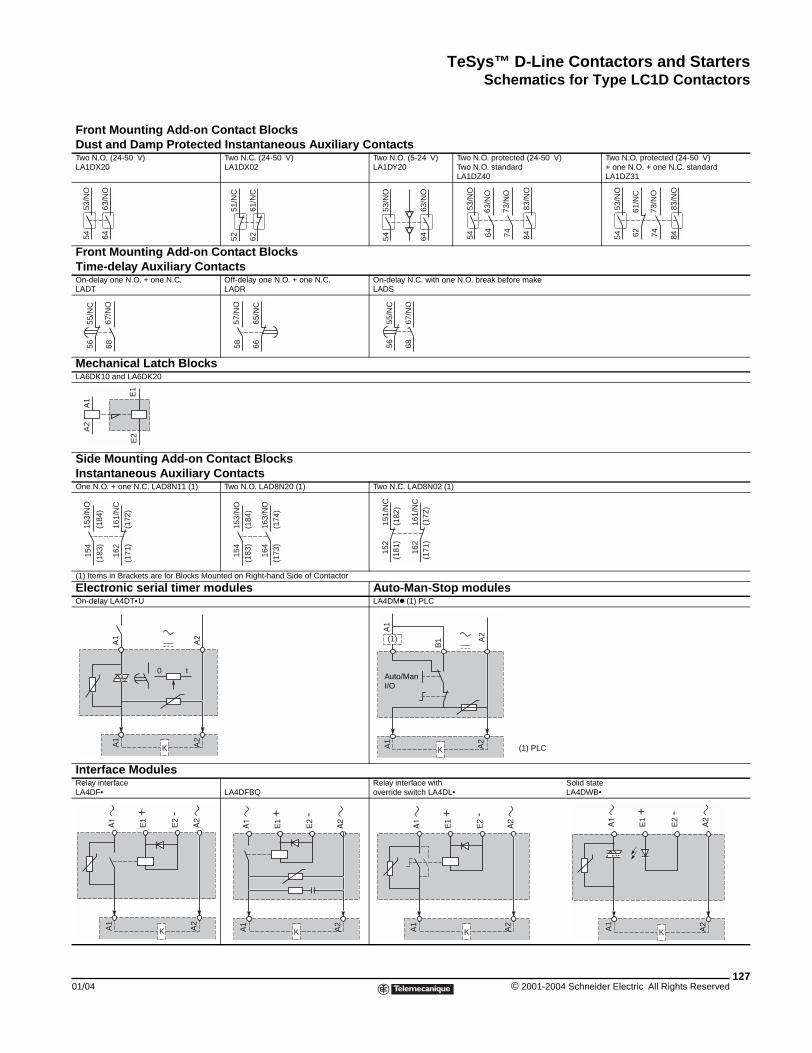
TeSys™ D-Line Contactors and StartersSchematics for Type LC1D Contactors
01/04
Front Mounting Add-oDust and Damp ProtecTwo N.O. (24-50 V)LA1DX20
Front Mounting Add-oTime-delay Auxiliary COn-delay one N.O. + one N.C.LADT
Mechanical Latch BlocLA6DK10 and LA6DK20
Side Mounting Add-onInstantaneous AuxiliarOne N.O. + one N.C. LAD8N11 (1)
(1) Items in Brackets are for Blocks
Electronic serial timerOn-delay LA4DT•U
Interface Modules Relay interfaceLA4DF•
53/N
O54
63/N
O64
55/N
C56
67/N
O68
A1
A2
E1
E2
162
161/
NC
(171
)(1
72)
153/
NO
154
(183
)(1
84)
KA1
A1
t0
KA1
A2
E1
+
E2 -
n Contact Blocksted Instantaneous Auxiliary Contacts
Two N.C. (24-50 V)LA1DX02
Two N.O. (5-24 V)LA1DY20
Two N.O. protected (24-50 V)Two N.O. standardLA1DZ40
Two N.O. protected (24-50 V)+ one N.O. + one N.C. standardLA1DZ31
n Contact Blocksontacts
Off-delay one N.O. + one N.C.LADR
On-delay N.C. with one N.O. break before makeLADS
ks
Contact Blocksy Contacts
Two N.O. LAD8N20 (1) Two N.C. LAD8N02 (1)
Mounted on Right-hand Side of Contactor
modules Auto-Man-Stop modulesLA4DMk (1) PLC
LA4DFBQRelay interface with Solid stateoverride switch LA4DL• LA4DWB•
51/N
C52
61/N
C62
53/N
O54
63/N
O64
53/N
O54
83/N
O84
63/N
O64
73/N
O74 62
61/N
C
53/N
O54
83/N
O84
73/N
O74
6665
/NC
57/N
O58
67/N
O68
55/N
C56
153/
NO
154
(184
)(1
83)
163/
NO
164
(174
)(1
73)
162
161/
NC
(171
)(1
72)
151/
NC
152
(181
)(1
82)
A2
A2
KA1
A2
A2
B1
A1
(1)
Auto/ManI/O
(1) PLC
KA1
A2
E1
+
E2 -
KA1
A2
E1
+
E2 -
KA1
A2
E1
+
E2 -
127© 2001-2004 Schneider Electric All Rights Reserved
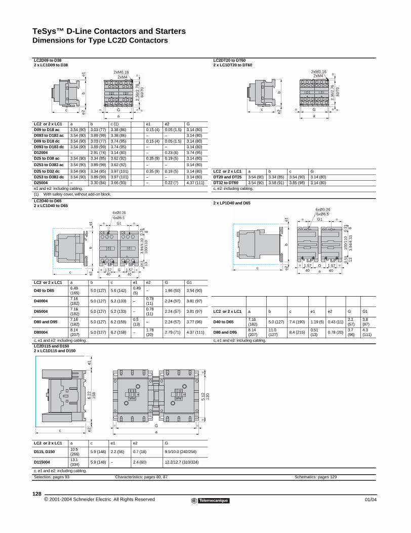
TeSys™ D-Line Contactors and StartersDimensions for Type LC2D Contactors
© 2001-2004 Schneider E128
LC2D09 to D382 x LC1D09 to D38
LC2 or 2 x LC1 a bD09 to D18 ac 3.54 (90) 3.03D093 to D183 ac 3.54 (90) 3.89D09 to D18 dc 3.54 (90) 3.03D093 to D183 dc 3.54 (90) 3.89D12004 – 2.91D25 to D38 ac 3.54 (90) 3.34
D253 to D383 ac 3.54 (90) 3.89
D25 to D32 dc 3.54 (90) 3.34D253 to D383 dc 3.54 (90) 3.89D25004 – 3.30e1 and e2: including cabling.(1) With safety cover, without add-o
LC2D40 to D652 x LC1D40 to D65
LC2 or 2 x LC1 a b
D40 to D65 6.49 (165)
5.0
D40004 7.16 (182)
5.0
D65004 7.16 (182)
5.0
D80 and D95 7.16 (182)
5.0
D80004 8.14 (207)
5.0
c, e1 and e2: including cabling.LC2D115 and D1502 x LC1D115 and D150
LC2 or 2 x LC1 a c
D115, D150 10.5 (266)
5.9
D115004 13.1 (334)
5.9
c, e1 and e2: including cabling.
Selection: pages 93
c
be1
e2
c
be
1e
26.
22e1
e2c
158
Dimensions for Type LC2D Contactors
LC2DT20 to DT602 x LC1DT20 to DT60
c (1) e1 e2 G (77) 3.38 (86) 0.15 (4) 0.05 (1.5) 3.14 (80) (99) 3.38 (86) – – 3.14 (80) (77) 3.74 (95) 0.15 (4) 0.05 (1.5) 3.14 (80) (99) 3.74 (95) – – 3.14 (80) (74) 3.14 (80) – 0.23 (6) 3.74 (95) (85) 3.62 (92) 0.35 (9) 0.19 (5) 3.14 (80)
(99) 3.62 (92) – – 3.14 (80)
(85) 3.97 (101) 0.35 (9) 0.19 (5) 3.14 (80) LC2 or 2 x LC1 a b c G (99) 3.97 (101) – – 3.14 (80) DT20 and DT25 3.54 (90) 3.34 (85) 3.54 (90) 3.14 (80) (84) 3.66 (93) – 0.22 (7) 4.37 (111) DT32 to DT60 3.54 (90) 3.58 (91) 3.85 (98) 3.14 (80)
c, e2: including cabling.n block.
2 x LP1D40 and D65
c e1 e2 G G1
(127) 5.6 (142)0.49 (5)
– 1.96 (50) 3.54 (90)
(127) 5.2 (133) –0.78 (11)
2.24 (57) 3.81 (97)
(127) 5.2 (133) –0.78 (11)
2.24 (57) 3.81 (97) LC2 or 2 x LC1 a b c e1 e2 G G1
(127) 6.2 (158)0.5 (13)
– 2.24 (57) 3.77 (96) D40 to D65 7.16 (182)
5.0 (127) 7.4 (190) 1.19 (5) 0.43 (11)2.2 (57)
3.8 (97)
(127) 6.2 (158) –1.78 (20)
2.79 (71) 4.37 (111) D80 and D95 8.14 (207)
11.0 (127)
8.4 (215)0.51 (13)
0.78 (20)3.7 (96)
4.3 (111)
c, e1 and e2: including cabling.
e1 e2 G
(148) 2.2 (56) 0.7 (18) 9.5/10.0 (242/256)
(148) – 2.4 (60) 12.2/12.7 (310/324)
Characteristics: pages 80, 87 Schematics: pages 129
2xM0.16
G
a
= =
2.36
/2.7
6=
=60
/70
2xM42xM0.16
G
a
= =
2.36
/2.7
6=
=c
be2
60/7
0
2xM4
G1= =
6xØ0.26
1.57
a
= =G 1.57
3.9
4/4
.33
0.31
.05
1
6xØ6.5
40 40
13
81
00
/11
0
c
be1
e2
G1= =6xØ6.5
1.57
a
= =G 1.57
100/
110
6xØ0.26
80.
31130.51
40 40
3.94
/4.3
3
G
a
= =
5.12
==
130
lectric All Rights Reserved 01/04
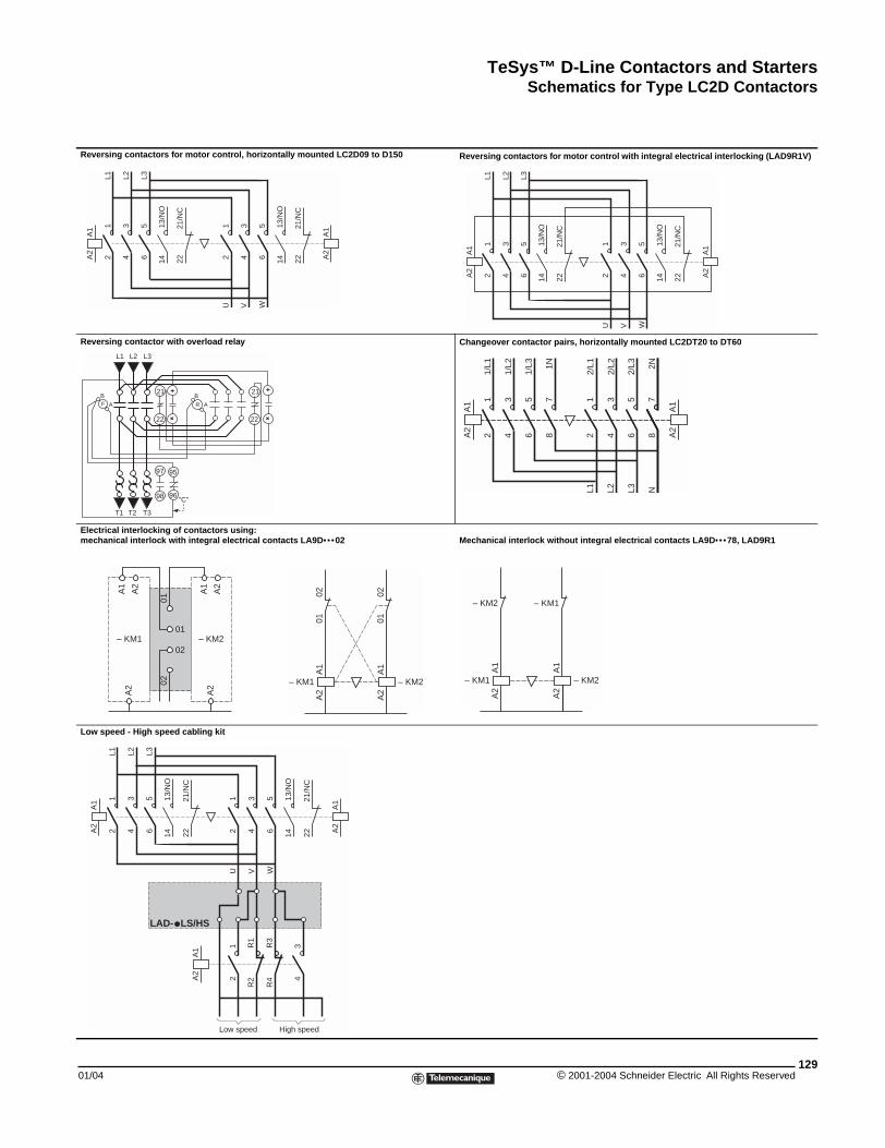
TeSys™ D-Line Contactors and StartersSchematics for Type LC2D Contactors
01/04
Reversing contactors for motor co
Reversing contactor with overload
Electrical interlocking of contactomechanical interlock with integra
Low speed - High speed cabling k
A1
A2
12
34
56
L1 L2 L3
1413
/NO
2221
/NC
L1 L2 L3
21
22
+
+
B
A
B
AF R
T1 T2 T3
97
98 96
95
"C"
0102
01
02
A1
A2
A2
A1
A2
– KM– KM1
A1
A2
12
34
56
L1 L2 L3
1413
/NO
A1
A2
2221
/NC
LS/HSLAD-
Schematics for Type LC2D Contactors
xxx
ntrol, horizontally mounted LC2D09 to D150 Reversing contactors for motor control with integral electrical interlocking (LAD9R1V)
relay Changeover contactor pairs, horizontally mounted LC2DT20 to DT60
rs using: l electrical contacts LA9D••• 02 Mechanical interlock without integral electrical contacts LA9D••• 78, LAD9R1
it
14
12
34
56
U V W
13/N
O
A1
A2
2221
/NC
14
A1
A2
12
34
56
L1 L2 L3
12
34
56
U V W
13/N
O
1413
/NO
A1
A2
2221
/NC
2221
/NC
21
22
+
+
A1
A2
12
34
56
1/L1
1/L2
1/L3
12
34
78
L1 L2 N
A1
A2
56
L3
78
1N
2/L1
2/L2
2/L3 2N
A2
2
A1
A2
– KM1
0102
A1
A2
– KM2
0102
A1
A2
– KM1
– KM2
A1
A2
– KM2
– KM1
14
12
34
12
34
56
U V W
13/N
O
A1
A2
2221
/NC
Low speed High speed
R1
R2
R3
R4
129© 2001-2004 Schneider Electric All Rights Reserved
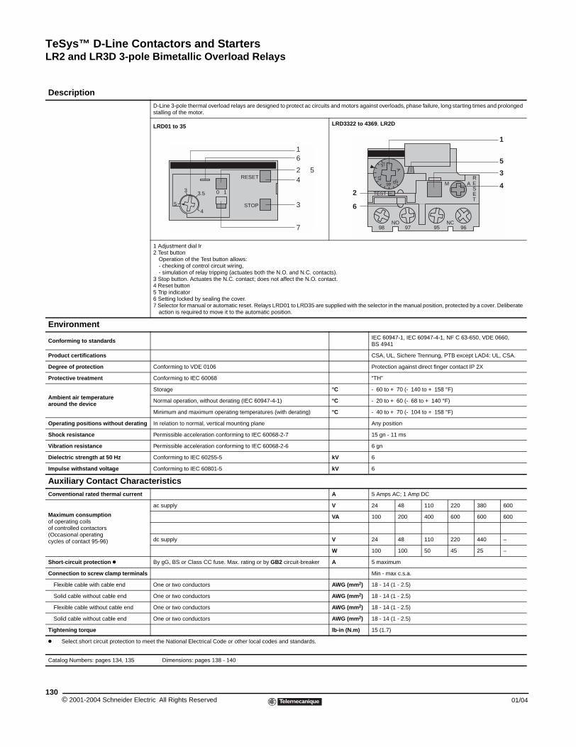
TeSys™ D-Line Contactors and StartersLR2 and LR3D 3-pole Bimetallic Overload Relays
© 2001-2004 Schneider E130
Description
Environment
Conforming to standards
Product certifications
Degree of protection
Protective treatment
Ambient air temperaturearound the device
Operating positions without dera
Shock resistance
Vibration resistance
Dielectric strength at 50 Hz
Impulse withstand voltage
Auxiliary Contact ChaConventional rated thermal curre
Maximum consumptionof operating coilsof controlled contactors(Occasional operatingcycles of contact 95-96)
Short-circuit protection k
Connection to screw clamp termi
Flexible cable with cable end
Solid cable without cable end
Flexible cable without cable end
Solid cable without cable end
Tightening torque
k Select short circuit protection
Catalog Numbers: pages 134, 135
RESET
STOP54
3.53 0 1
16
2 54
7
3
LR2 and LR3D 3-pole Bimetallic Overload Relays
D-Line 3-pole thermal overload relays are designed to protect ac circuits and motors against overloads, phase failure, long starting times and prolonged stalling of the motor.
LRD01 to 35 LRD3322 to 4369, LR2D
1 Adjustment dial Ir 2 Test button
Operation of the Test button allows: - checking of control circuit wiring,- simulation of relay tripping (actuates both the N.O. and N.C. contacts).
3 Stop button. Actuates the N.C. contact; does not affect the N.O. contact.4 Reset button5 Trip indicator6 Setting locked by sealing the cover.7 Selector for manual or automatic reset. Relays LRD01 to LRD35 are supplied with the selector in the manual position, protected by a cover. Deliberate
action is required to move it to the automatic position.
IEC 60947-1, IEC 60947-4-1, NF C 63-650, VDE 0660, BS 4941
CSA, UL, Sichere Trennung, PTB except LAD4: UL, CSA.
Conforming to VDE 0106 Protection against direct finger contact IP 2X
Conforming to IEC 60068 “TH”
Storage °C - 60 to + 70 (- 140 to + 158 °F)
Normal operation, without derating (IEC 60947-4-1) °C - 20 to + 60 (- 68 to + 140 °F)
Minimum and maximum operating temperatures (with derating) °C - 40 to + 70 (- 104 to + 158 °F)
ting In relation to normal, vertical mounting plane Any position
Permissible acceleration conforming to IEC 60068-2-7 15 gn - 11 ms
Permissible acceleration conforming to IEC 60068-2-6 6 gn
Conforming to IEC 60255-5 kV 6
Conforming to IEC 60801-5 kV 6
racteristicsnt A 5 Amps AC; 1 Amp DC
ac supply V 24 48 110 220 380 600
VA 100 200 400 600 600 600
dc supply V 24 48 110 220 440 –
W 100 100 50 45 25 –
By gG, BS or Class CC fuse. Max. rating or by GB2 circuit-breaker A 5 maximum
nals Min - max c.s.a.
One or two conductors AWG (mm2) 18 - 14 (1 - 2.5)
One or two conductors AWG (mm2) 18 - 14 (1 - 2.5)
One or two conductors AWG (mm2) 18 - 14 (1 - 2.5)
One or two conductors AWG (mm2) 18 - 14 (1 - 2.5)
lb-in (N.m) 15 (1.7)
to meet the National Electrical Code or other local codes and standards.
Dimensions: pages 138 - 140
50
A
41 RESET
TEST
98 97 95 96NO NC
M A
37
46
1
5
3
42
6
lectric All Rights Reserved 01/04
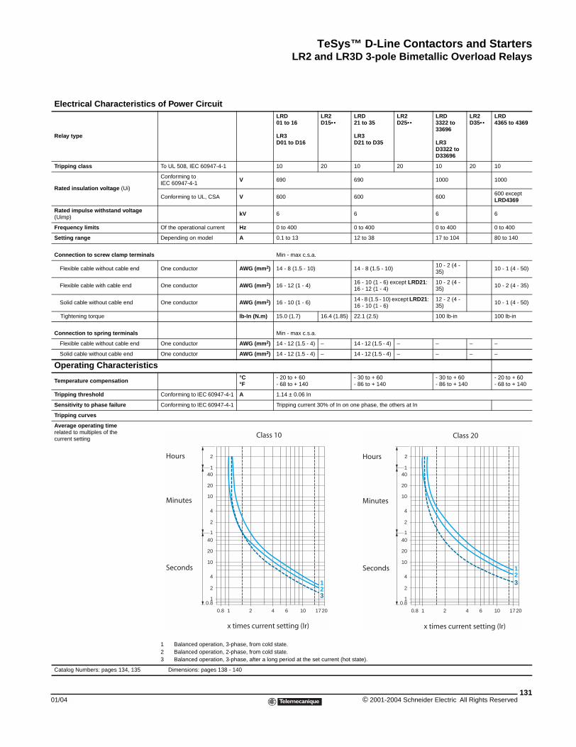
TeSys™ D-Line Contactors and StartersLR2 and LR3D 3-pole Bimetallic Overload Relays
01/04
Electrical Characterist
Relay type
Tripping class
Rated insulation voltage (Ui)
Rated impulse withstand voltage(Uimp)
Frequency limits
Setting range
Connection to screw clamp termi
Flexible cable without cable end
Flexible cable with cable end
Solid cable without cable end
Tightening torque
Connection to spring terminals
Flexible cable without cable end
Solid cable without cable end
Operating Characteris
Temperature compensation
Tripping threshold
Sensitivity to phase failure
Tripping curves
Average operating timerelated to multiples of thecurrent setting
Catalog Numbers: pages 134, 135
ics of Power CircuitLRD 01 to 16
LR3D01 to D16
LR2 D15••
LRD 21 to 35
LR3D21 to D35
LR2 D25••
LRD 3322 to33696
LR3D3322 toD33696
LR2D35••
LRD4365 to 4369
To UL 508, IEC 60947-4-1 10 20 10 20 10 20 10
Conforming to IEC 60947-4-1
V 690 690 1000 1000
Conforming to UL, CSA V 600 600 600600 except LRD4369
kV 6 6 6 6
Of the operational current Hz 0 to 400 0 to 400 0 to 400 0 to 400
Depending on model A 0.1 to 13 12 to 38 17 to 104 80 to 140
nals Min - max c.s.a.
One conductor AWG (mm2) 14 - 8 (1.5 - 10) 14 - 8 (1.5 - 10)10 - 2 (4 - 35)
10 - 1 (4 - 50)
One conductor AWG (mm2) 16 - 12 (1 - 4)16 - 10 (1 - 6) except LRD21: 16 - 12 (1 - 4)
10 - 2 (4 - 35)
10 - 2 (4 - 35)
One conductor AWG (mm2) 16 - 10 (1 - 6)14 - 8 (1.5 - 10) except LRD21: 16 - 10 (1 - 6)
12 - 2 (4 - 35)
10 - 1 (4 - 50)
lb-In (N.m) 15.0 (1.7) 16.4 (1.85) 22.1 (2.5) 100 lb-in 100 lb-in
Min - max c.s.a.
One conductor AWG (mm2) 14 - 12 (1.5 - 4) – 14 - 12 (1.5 - 4) – – – –
One conductor AWG (mm2) 14 - 12 (1.5 - 4) – 14 - 12 (1.5 - 4) – – – –
tics°C°F
- 20 to + 60- 68 to + 140
- 30 to + 60 - 86 to + 140
- 30 to + 60- 86 to + 140
- 20 to + 60- 68 to + 140
Conforming to IEC 60947-4-1 A 1.14 ± 0.06 In
Conforming to IEC 60947-4-1 Tripping current 30% of In on one phase, the others at In
1 Balanced operation, 3-phase, from cold state.2 Balanced operation, 2-phase, from cold state.3 Balanced operation, 3-phase, after a long period at the set current (hot state).
Dimensions: pages 138 - 140
2
140
20
10
4
2
1
40
20
10
4
2
10.8
0.8 1 2 4 6 10 1720
1
32
Hours
Minutes
Seconds
Class 10
x times current setting (Ir)
2
140
20
10
4
2
1
40
20
10
4
2
10.8
0.8 1 2 4 6 10 1720
1
32
Hours
Minutes
Seconds
Class 20
x times current setting (Ir)
131© 2001-2004 Schneider Electric All Rights Reserved
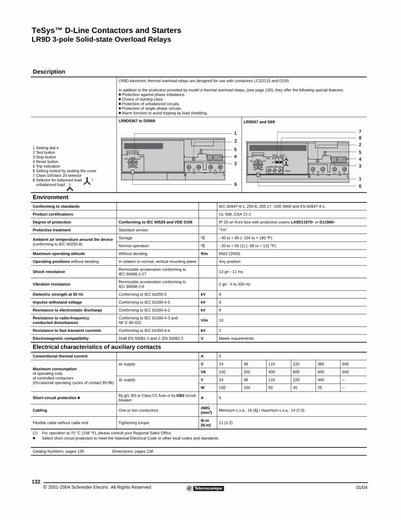
TeSys™ D-Line Contactors and StartersLR9D 3-pole Solid-state Overload Relays
© 2001-2004 Schneider E132
Description
1 Setting dial Ir2 Test button3 Stop button4 Reset button5 Trip indication6 Setting locked by sealing the cove7 Class 10/class 20 selector8 Selector for balanced load /
unbalanced load
EnvironmentConforming to standards
Product certifications
Degree of protection
Protective treatment
Ambient air temperature around t(conforming to IEC 60255-8)
Maximum operating altitude
Operating positions without deratin
Shock resistance
Vibration resistance
Dielectric strength at 50 Hz
Impulse withstand voltage
Resistance to electrostatic discha
Resistance to radio-frequencyconducted disturbances
Resistance to fast transient curre
Electromagnetic compatibility
Electrical characteristiConventional thermal current
Maximum consumptionof operating coils of controlled contactors(Occasional operating cycles of con
Short-circuit protection k
Cabling
Flexible cable without cable end
(1) For operation at 70 °C (158 °Fk Select short circuit protection t
Catalog Numbers: pages 135
LR9D 3-pole Solid-state Overload Relays
LR9D electronic thermal overload relays are designed for use with contactors LC1D115 and D150.
In addition to the protection provided by model d thermal overload relays, (see page 130), they offer the following special features:k Protection against phase imbalance.k Choice of starting class.k Protection of unbalanced circuits.k Protection of single-phase circuits.k Alarm function to avoid tripping by load shedding.
r
LR9D5367 to D5569 LR9D67 and D69
IEC 60947-4-1, 255-8, 255-17, VDE 0660 and EN 60947-4-1
UL 508, CSA 22-2
Conforming to IEC 60529 and VDE 0106 IP 20 on front face with protective covers LA9D11570• or D11560•
Standard version “TH”
he device Storage °C - 40 to + 85 (- 104 to + 185 °F)
Normal operation °C - 20 to + 55 (1) (- 68 to + 131 °F)
Without derating ft/m 6562 (2000)
g In relation to normal, vertical mounting plane Any position
Permissible acceleration conforming to IEC 60068-2-27
13 gn - 11 ms
Permissible acceleration conforming to IEC 60068-2-6
2 gn - 5 to 300 Hz
Conforming to IEC 60255-5 kV 6
Conforming to IEC 61000-4-5 kV 6
rge Conforming to IEC 61000-4-2 kV 8
Conforming to IEC 61000-4-3 and NF C 46-022
V/m 10
nts Conforming to IEC 61000-4-4 kV 2
Draft EN 50081-1 and 2, EN 50082-2 V Meets requirements
cs of auxiliary contactsA 5
tact 95-96)
ac supply V 24 48 110 220 380 600
VA 100 200 400 600 600 600
dc supply V 24 48 110 220 440 –
W 100 100 50 45 25 –
By gG, BS or Class CC fuse or by GB2 circuit-breaker
A 5
One or two conductorsAWG (mm2) Minimum c.s.a.: 16 (1) / maximum c.s.a.: 14 (2.5)
Tightening torquelb-in (N.m) 11 (1.2)
), please consult your Regional Sales Office.o meet the National Electrical Code or other local codes and standards.
Dimensions: pages 138
Ir(A)
15090
127107
NO 9798 NC95 96
2
3
1
45
6
Alarm NO 9798 NC95 96
1
782
34
6
5Ir(A)
15090
127107
+ 24 V - / 103 104
10
20
Class Load
lectric All Rights Reserved 01/04
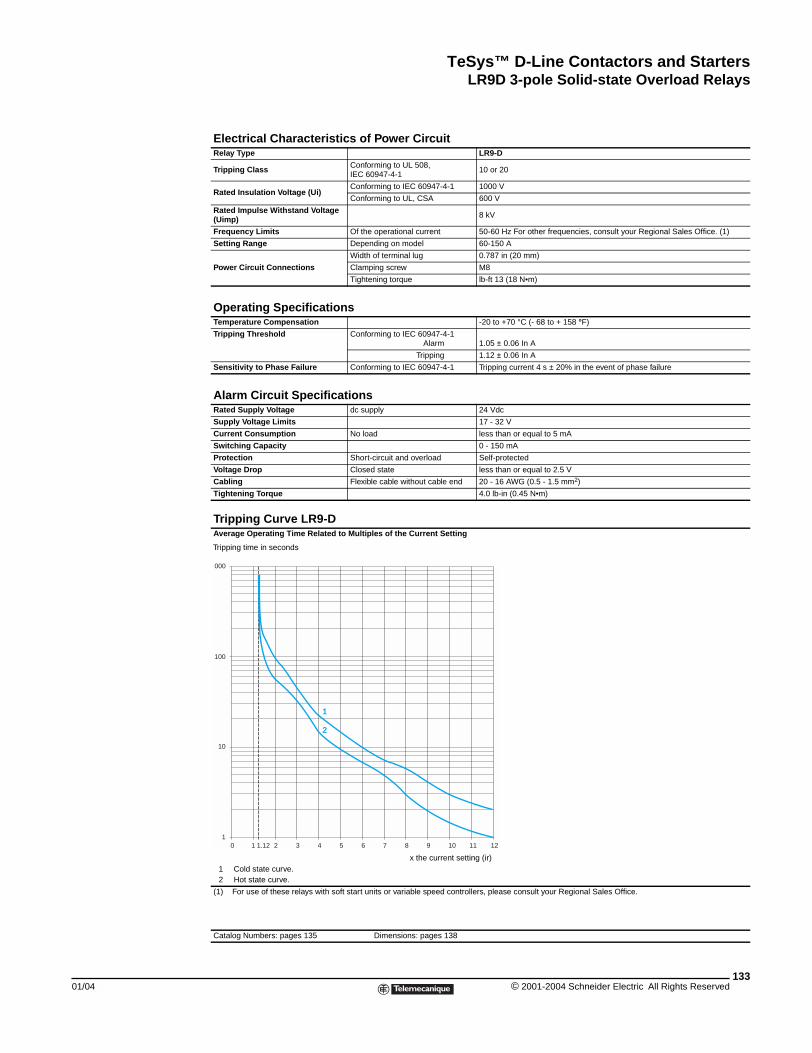
TeSys™ D-Line Contactors and StartersLR9D 3-pole Solid-state Overload Relays
01/04
Electrical Characteristics of Power CircuitRelay Type LR9-D
Tripping Class Conforming to UL 508, IEC 60947-4-1
10 or 20
Rated Insulation Voltage (Ui)Conforming to IEC 60947-4-1 1000 V
Conforming to UL, CSA 600 V
Rated Impulse Withstand Voltage (Uimp) 8 kV
Frequency Limits Of the operational current 50-60 Hz For other frequencies, consult your Regional Sales Office. (1)
Setting Range Depending on model 60-150 A
Power Circuit Connections
Width of terminal lug 0.787 in (20 mm)
Clamping screw M8
Tightening torque lb-ft 13 (18 N•m)
Operating SpecificationsTemperature Compensation -20 to +70 °C (- 68 to + 158 °F)
Tripping Threshold Conforming to IEC 60947-4-1 Alarm 1.05 ± 0.06 In A
Tripping 1.12 ± 0.06 In A
Sensitivity to Phase Failure Conforming to IEC 60947-4-1 Tripping current 4 s ± 20% in the event of phase failure
Alarm Circuit SpecificationsRated Supply Voltage dc supply 24 Vdc
Supply Voltage Limits 17 - 32 V
Current Consumption No load less than or equal to 5 mA
Switching Capacity 0 - 150 mA
Protection Short-circuit and overload Self-protected
Voltage Drop Closed state less than or equal to 2.5 V
Cabling Flexible cable without cable end 20 - 16 AWG (0.5 - 1.5 mm2)
Tightening Torque 4.0 lb-in (0.45 N•m)
Tripping Curve LR9-DAverage Operating Time Related to Multiples of the Current Setting
(1) For use of these relays with soft start units or variable speed controllers, please consult your Regional Sales Office.
Catalog Numbers: pages 135 Dimensions: pages 138
1 Cold state curve.2 Hot state curve.
1
000
100
10
10 1.12 2 3 4 5 6 7 8 9 10 11 12
1
2
Tripping time in seconds
x the current setting (ir)
133© 2001-2004 Schneider Electric All Rights Reserved
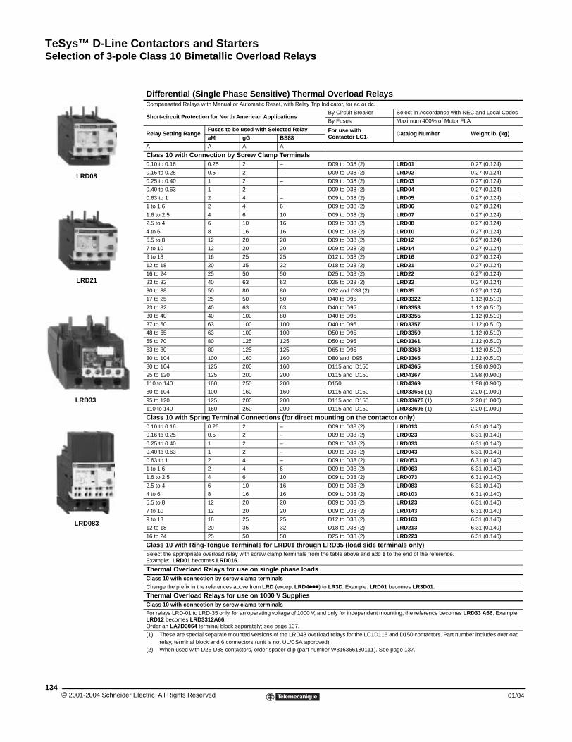
TeSys™ D-Line Contactors and StartersSelection of 3-pole Class 10 Bimetallic Overload Relays
© 2001-2004 Schneider E134
LRD08
LRD21
LRD33
LRD083
Selection of 3-pole Class 10 Bimetallic Overload Relays
Differential (Single Phase Sensitive) Thermal Overload RelaysCompensated Relays with Manual or Automatic Reset, with Relay Trip Indicator, for ac or dc.
Short-circuit Protection for North American ApplicationsBy Circuit Breaker Select in Accordance with NEC and Local Codes
By Fuses Maximum 400% of Motor FLA
Relay Setting RangeFuses to be used with Selected Relay For use with
Contactor LC1- Catalog Number Weight lb. (kg)aM gG BS88
A A A A
Class 10 with Connection by Screw Clamp Terminals0.10 to 0.16 0.25 2 – D09 to D38 (2) LRD01 0.27 (0.124)
0.16 to 0.25 0.5 2 – D09 to D38 (2) LRD02 0.27 (0.124)
0.25 to 0.40 1 2 – D09 to D38 (2) LRD03 0.27 (0.124)
0.40 to 0.63 1 2 – D09 to D38 (2) LRD04 0.27 (0.124)
0.63 to 1 2 4 – D09 to D38 (2) LRD05 0.27 (0.124)
1 to 1.6 2 4 6 D09 to D38 (2) LRD06 0.27 (0.124)
1.6 to 2.5 4 6 10 D09 to D38 (2) LRD07 0.27 (0.124)
2.5 to 4 6 10 16 D09 to D38 (2) LRD08 0.27 (0.124)
4 to 6 8 16 16 D09 to D38 (2) LRD10 0.27 (0.124)
5.5 to 8 12 20 20 D09 to D38 (2) LRD12 0.27 (0.124)
7 to 10 12 20 20 D09 to D38 (2) LRD14 0.27 (0.124)
9 to 13 16 25 25 D12 to D38 (2) LRD16 0.27 (0.124)
12 to 18 20 35 32 D18 to D38 (2) LRD21 0.27 (0.124)
16 to 24 25 50 50 D25 to D38 (2) LRD22 0.27 (0.124)
23 to 32 40 63 63 D25 to D38 (2) LRD32 0.27 (0.124)
30 to 38 50 80 80 D32 and D38 (2) LRD35 0.27 (0.124)
17 to 25 25 50 50 D40 to D95 LRD3322 1.12 (0.510)
23 to 32 40 63 63 D40 to D95 LRD3353 1.12 (0.510)
30 to 40 40 100 80 D40 to D95 LRD3355 1.12 (0.510)
37 to 50 63 100 100 D40 to D95 LRD3357 1.12 (0.510)
48 to 65 63 100 100 D50 to D95 LRD3359 1.12 (0.510)
55 to 70 80 125 125 D50 to D95 LRD3361 1.12 (0.510)
63 to 80 80 125 125 D65 to D95 LRD3363 1.12 (0.510)
80 to 104 100 160 160 D80 and D95 LRD3365 1.12 (0.510)
80 to 104 125 200 160 D115 and D150 LRD4365 1.98 (0.900)
95 to 120 125 200 200 D115 and D150 LRD4367 1.98 (0.900)
110 to 140 160 250 200 D150 LRD4369 1.98 (0.900)
80 to 104 100 160 160 D115 and D150 LRD33656 (1) 2.20 (1.000)
95 to 120 125 200 200 D115 and D150 LRD33676 (1) 2.20 (1.000)
110 to 140 160 250 200 D115 and D150 LRD33696 (1) 2.20 (1.000)
Class 10 with Spring Terminal Connections (for direct mounting on the contactor only)0.10 to 0.16 0.25 2 – D09 to D38 (2) LRD013 6.31 (0.140)
0.16 to 0.25 0.5 2 – D09 to D38 (2) LRD023 6.31 (0.140)
0.25 to 0.40 1 2 – D09 to D38 (2) LRD033 6.31 (0.140)
0.40 to 0.63 1 2 – D09 to D38 (2) LRD043 6.31 (0.140)
0.63 to 1 2 4 – D09 to D38 (2) LRD053 6.31 (0.140)
1 to 1.6 2 4 6 D09 to D38 (2) LRD063 6.31 (0.140)
1.6 to 2.5 4 6 10 D09 to D38 (2) LRD073 6.31 (0.140)
2.5 to 4 6 10 16 D09 to D38 (2) LRD083 6.31 (0.140)
4 to 6 8 16 16 D09 to D38 (2) LRD103 6.31 (0.140)
5.5 to 8 12 20 20 D09 to D38 (2) LRD123 6.31 (0.140)
7 to 10 12 20 20 D09 to D38 (2) LRD143 6.31 (0.140)
9 to 13 16 25 25 D12 to D38 (2) LRD163 6.31 (0.140)
12 to 18 20 35 32 D18 to D38 (2) LRD213 6.31 (0.140)
16 to 24 25 50 50 D25 to D38 (2) LRD223 6.31 (0.140)
Class 10 with Ring-Tongue Terminals for LRD01 through LRD35 (load side terminals only)Select the appropriate overload relay with screw clamp terminals from the table above and add 6 to the end of the reference. Example: LRD01 becomes LRD016.
Thermal Overload Relays for use on single phase loadsClass 10 with connection by screw clamp terminals
Change the prefix in the references above from LRD (except LRD4kkk) to LR3D. Example: LRD01 becomes LR3D01.
Thermal Overload Relays for use on 1000 V SuppliesClass 10 with connection by screw clamp terminals
For relays LRD-01 to LRD-35 only, for an operating voltage of 1000 V, and only for independent mounting, the reference becomes LRD33 A66. Example: LRD12 becomes LRD3312A66.Order an LA7D3064 terminal block separately; see page 137.
(1) These are special separate mounted versions of the LRD43 overload relays for the LC1D115 and D150 contactors. Part number includes overload relay, terminal block and 6 connectors (unit is not UL/CSA approved).
(2) When used with D25-D38 contactors, order spacer clip (part number W816366180111). See page 137.
lectric All Rights Reserved 01/04
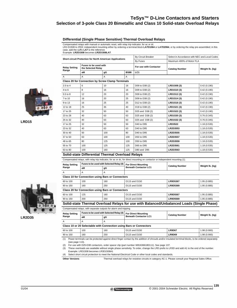
TeSys™ D-Line Contactors and StartersSelection of 3-pole Class 20 Bimetallic and Class 10 Solid-state Overload Relays
01/04
LRD15
LR2D35
Selection of 3-pole Class 20 Bimetallic and Class 10 Solid-state Overload Relays
Differential (Single Phase Sensitive) Thermal Overload RelaysCompensated relays with manual or automatic reset, with relay trip indicator, for ac or dcLR2-D1508 to 2553: independent mounting either by ordering a terminal block LA7D1064 or LA7D2064, or by ordering the relay pre-assembled; in this case, add the suffix LA7 to the reference.Example: LR2D1508 becomes LR2D1508LA7.
Short-circuit Protection for North American ApplicationsBy Circuit Breaker Select in Accordance with NEC and Local Codes
By Fuses Maximum 400% of Motor FLA
Relay Setting Range
Fuses to be used with the Selected Relay For use with Contactor
Catalog Number Weight lb. (kg)
aM gG BS88 LC1
A A A A
Class 20 for Connection by Screw Clamp Terminals
2.5 to 4 6 10 16 D09 to D38 (2) LRD1508 (3) 0.42 (0.190)
4 to 6 8 16 16 D09 to D38 (2) LRD1510 (3) 0.42 (0.190)
5.5 to 8 12 20 20 D09 to D38 (2) LRD1512 (3) 0.42 (0.190)
7 to 10 16 20 25 D09 to D38 (2) LRD1514 (3) 0.42 (0.190)
9 to 13 16 25 25 D12 to D38 (2) LRD1516 (3) 0.42 (0.190)
12 to 18 25 35 40 D18 to D38 (2) LRD1521 (3) 0.42 (0.190)
17 to 25 32 50 50 D25 and D38 (2) LRD1522 (3) 0.42 (0.190)
23 to 28 40 63 63 D25 and D38 (2) LRD1530 (3) 0.76 (0.345)
25 to 32 40 63 63 D25 and D38 (2) LRD1532 (3) 0.76 (0.345)
17 to 25 32 50 50 D40 to D95 LRD3522 1.18 (0.535)
23 to 32 40 63 63 D40 to D95 LR2D3553 1.18 (0.535)
30 to 40 50 100 80 D40 to D95 LR2D3555 1.18 (0.535)
37 to 50 63 100 100 D50 to D95 LR2D3557 1.18 (0.535)
48 to 65 80 125 100 D50 to D95 LR2D3559 1.18 (0.535)
55 to 70 100 125 125 D65 to D95 LR2D3561 1.18 (0.535)
63 to 80 100 160 125 D80 and D95 LR2D3563 1.18 (0.535)
Solid-state Differential Thermal Overload RelaysCompensated relays, with relay trip indicator, for ac or dc, for direct mounting on contactor or independent mounting (1).
Relay Setting Range
Fuses to be used with Selected Relay (4) For Direct Mounting Beneath Contactor LC1 Catalog Number Weight lb. (kg)
aM gG
A A A
Class 10 for Connection using Bars or Connectors
60 to 100 100 160 D115 and D150 LR9D5367 1.95 (0.885)
90 to 150 160 250 D115 and D150 LR9D5369 1.95 (0.885)
Class 20 for Connection using Bars or Connectors
60 to 100 125 160 D115 and D150 LR9D5567 1.95 (0.885)
90 to 150 200 250 D115 and D150 LR9D5569 1.95 (0.885)
Solid-state Thermal Overload Relays for use with Balanced/Unbalanced Loads (Single Phase)Compensated relays, with separate outputs for alarm and tripping.
Relay Setting Range
Fuses to be used with Selected Relay (4) For Direct Mounting Beneath Contactor LC1 Catalog Number Weight lb. (kg)
aM gG
A A A
Class 10 or 20 Selectable with Connection using Bars or Connectors
60 to 100 100 160 D115 and D150 LR9D67 1.98 (0.900)
90 to 150 160 250 D115 and D150 LR9D69 1.98 (0.900)
(1) Power terminals can be protected against direct finger contact by the addition of shrouds and/or insulated terminal blocks, to be ordered separately (see page 113).
(2) For use with D25-D38 contactors, order spacer clip (part number W816366180111). See page 137.(3) These overloads are available without single phase sensitivity. To order, change the LRD prefix to LR3D and add A1 to the end of the number.
Example: LRD1508 becomes LR3D1508A1(4) Select short circuit protection to meet the National Electrical Code or other local codes and standards.
Other Versions Thermal overload relays for resistive circuits in category AC-1. Please consult your Regional Sales Office.
135© 2001-2004 Schneider Electric All Rights Reserved
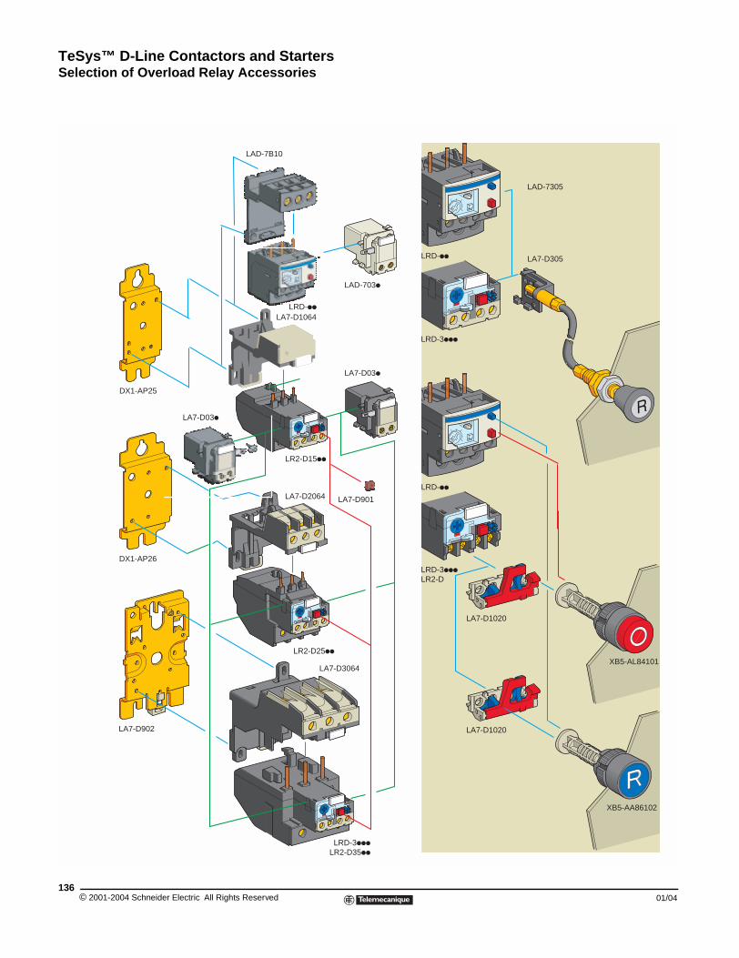
TeSys™ D-Line Contactors and StartersSelection of Overload Relay Accessories
© 2001-2004 Schneider E136
DX1-AP26
LA7-D902
DX1-AP25
Selection of Overload Relay Accessories
LA7-D901LA7-D2064
LAD-703
LA7-D03
LA7-D03
LA7-D1064
LAD-7B10
LA7-D3064
LR2-D15
LRD-
LRD-
LRD-
LR2-D25
LRD-3LR2-D35
LA7-D1020
XB5-AA86102
LA7-D1020
XB5-AL84101
LA7-D305
LAD-7305
LRD-3LR2-D
LRD-3
lectric All Rights Reserved 01/04
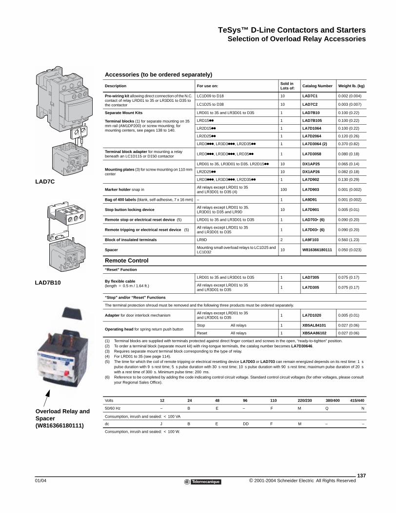
TeSys™ D-Line Contactors and StartersSelection of Overload Relay Accessories
01/04
LAD7C
LAD7B10
Overload Relay and Spacer(W816366180111)
Accessories (to be ordered separately)
Description For use on: Sold in Lots of: Catalog Number Weight lb. (kg)
Pre-wiring kit allowing direct connection of the N.C. contact of relay LRD01 to 35 or LR3D01 to D35 to the contactor
LC1D09 to D18 10 LAD7C1 0.002 (0.004)
LC1D25 to D38 10 LAD7C2 0.003 (0.007)
Separate Mount Kits
Terminal blocks (1) for separate mounting on 35 mm rail (AM1DP200) or screw mounting; for mounting centers, see pages 138 to 140.
LRD01 to 35 and LR3D01 to D35 1 LAD7B10 0.100 (0.22)
LRD15kk 1 LAD7B105 0.100 (0.22)
LR2D15kk 1 LA7D1064 0.100 (0.22)
LR2D25kk 1 LA7D2064 0.120 (0.26)
LRD3kkk, LR3D3kkk, LR2D35kk 1 LA7D3064 (2) 0.370 (0.82)
Terminal block adapter for mounting a relay beneath an LC1D115 or D150 contactor
LRD3kkk, LR3D3kkk, LRD35kk 1 LA7D3058 0.080 (0.18)
Mounting plates (3) for screw mounting on 110 mm center
LRD01 to 35, LR3D01 to D35. LR2D15kk 10 DX1AP25 0.065 (0.14)
LR2D25kk 10 DX1AP26 0.082 (0.18)
LRD3kkk, LR3D3kkk, LR2D35kk 1 LA7D902 0.130 (0.29)
Marker holder snap inAll relays except LRD01 to 35and LR3D01 to D35 (4)
100 LA7D903 0.001 (0.002)
Bag of 400 labels (blank, self-adhesive, 7 x 16 mm) – 1 LA9D91 0.001 (0.002)
Stop button locking device All relays except LRD01 to 35.LR3D01 to D35 and LR9D
10 LA7D901 0.005 (0.01)
Remote stop or electrical reset device (5) LRD01 to 35 and LR3D01 to D35 1 LAD703• (6) 0.090 (0.20)
Remote tripping or electrical reset device (5)All relays except LRD01 to 35 and LR3D01 to D35
1 LA7D03• (6) 0.090 (0.20)
Block of insulated terminals LR9D 2 LA9F103 0.560 (1.23)
Spacer Mounting small overload relays to LC1D25 and LC1D32
10 W816366180111 0.050 (0.023)
Remote Control“Reset” Function
By flexible cable(length = 0.5 m / 1.64 ft.)
LRD01 to 35 and LR3D01 to D35 1 LAD7305 0.075 (0.17)
All relays except LRD01 to 35and LR3D01 to D35
1 LA7D305 0.075 (0.17)
“Stop” and/or “Reset” Functions
The terminal protection shroud must be removed and the following three products must be ordered separately.
Adapter for door interlock mechanismAll relays except LRD01 to 35and LR3D01 to D35
1 LA7D1020 0.005 (0.01)
Operating head for spring return push buttonStop All relays 1 XB5AL84101 0.027 (0.06)
Reset All relays 1 XB5AA86102 0.027 (0.06)
(1) Terminal blocks are supplied with terminals protected against direct finger contact and screws in the open, “ready-to-tighten” position.(2) To order a terminal block (separate mount kit) with ring-tongue terminals, the catalog number becomes LA7D30646.(3) Requires separate mount terminal block corresponding to the type of relay.(4) For LRD01 to 35 (see page 114).(5) The time for which the coil of remote tripping or electrical resetting device LA7D03 or LAD703 can remain energized depends on its rest time: 1 s
pulse duration with 9 s rest time; 5 s pulse duration with 30 s rest time; 10 s pulse duration with 90 s rest time; maximum pulse duration of 20 s with a rest time of 300 s. Minimum pulse time: 200 ms.
(6) Reference to be completed by adding the code indicating control circuit voltage. Standard control circuit voltages (for other voltages, please consult your Regional Sales Office).
Volts 12 24 48 96 110 220/230 380/400 415/440
50/60 Hz – B E – F M Q N
Consumption, inrush and sealed: < 100 VA
dc J B E DD F M – –
Consumption, inrush and sealed: < 100 W.
137© 2001-2004 Schneider Electric All Rights Reserved
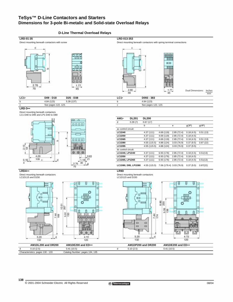
TeSys™ D-Line Contactors and StartersDimensions for 3-pole Bi-metalic and Solid-state Overload Relays
© 2001-2004 Schneider E138
LRD-01-35Direct mounting beneath contactors
LC1• D09 - D1b 4.84 (123)
c See pages
LRD-3•••Direct mounting beneath contactorsLC1-D40 to D95 and LP1-D40 to D
LRD4•••Direct mounting beneath contactorsLC1D115 and D150
AM1DL200 and DR2d 0.10 (2.5)
Characteristics: pages 130 - 133
Dimensions for 3-pole Bi-metallic and Solid-state Overload Relays
D-Line Thermal Overload Relays
LRD-013-353 with screw Direct mounting beneath contactors with spring terminal connections
8 D25 - D38 LC1• D093 - 3835.39 (137) b 4.84 (123)
122, 123. c See pages 122, 123.
80
AM1• DL201 DL200d 0.28 (7) 0.67 (17)
b c e g(3P) g(4P)
ac control circuit:
LC1D40 4.37 (111) 4.69 (119) 2.85 (72.4) 0.18 (4.5) 0.51 (13)
LC1D50 4.37 (111) 4.69 (119) 2.85 (72.4) 0.18 (4.5) -
LC1D65 4.37 (111) 4.69 (119) 2.85 (72.4) 0.18 (4.5) 0.51 (13)
LC1D80 4.55 (115.5) 4.88 (124) 3.03 (76.9) 0.37 (9.5) 0.87 (22)
LC1D95 4.55 (115.5) 4.88 (124) 3.03 (76.9) 0.37 (9.5) -
dc control circuit:
LC1D40, LP1D40 4.37 (111) 6.93 (176) 2.85 (72.4) 0.18 (4.5) 0.51(13)
LC1D50 4.37 (111) 6.93 (176) 2.85 (72.4) 0.18 (4.5) -
LC1D65, LP1D65 4.37 (111) 6.93 (176) 2.85 (72.4) 0.18 (4.5) 0.51(13)
LC1D80, D95, LP1D80 4.55 (115.5) 7.06 (179.4) 3.03 (76.9) 0.37 (9.5) 0.87(22)
LR9DDirect mounting beneath contactorsLC1D115 and D150
00 AM1DE200 and ED••• AM1DP200 and DR200 AM1DE200 and ED•••0.41 (10.5) d 0.10 (2.5) 0.41 (10.5)
Catalog Number: pages 134, 135
Dual Dimensions: Inchesmm
lectric All Rights Reserved 08/04
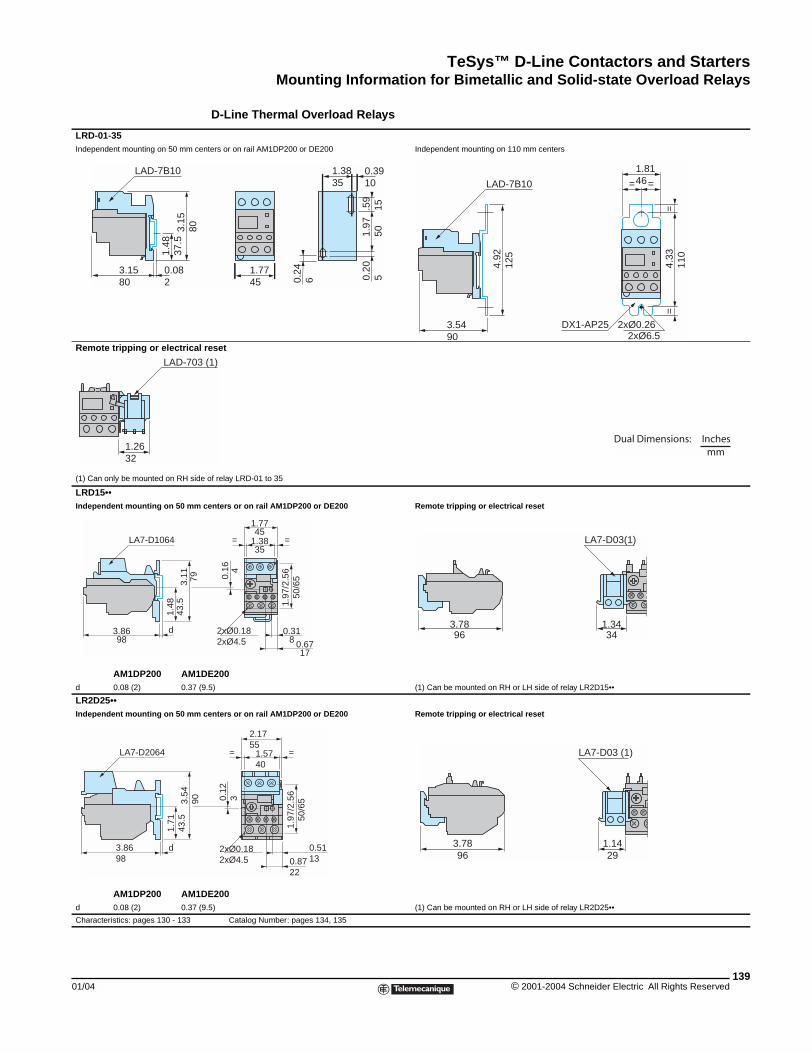
TeSys™ D-Line Contactors and StartersMounting Information for Bimetallic and Solid-state Overload Relays
01/04
LRD-01-35Independent mounting on 50 mm ce
Remote tripping or electrical
(1) Can only be mounted on RH sid
LRD15••Independent mounting on 50 mm
AM1DP200 AM1d 0.08 (2) 0.37 (
LR2D25••Independent mounting on 50 mm
AM1DP200 AM1d 0.08 (2) 0.37 (
Characteristics: pages 130 - 133
0.08 2
3.15 80
1.48
37
.53.
15
80
LAD-7B10
LAD-703
1.26 32
3.86 98
1.48
43
.5
d
3.11
79
LA7-D1064
3.86 98
1.71
43
.5
d
3.54
90
LA7-D2064
Mounting Information for Bimetallic and Solid-state Overload Relays
D-Line Thermal Overload Relays
nters or on rail AM1DP200 or DE200 Independent mounting on 110 mm centers
reset
e of relay LRD-01 to 35
centers or on rail AM1DP200 or DE200 Remote tripping or electrical reset
DE2009.5) (1) Can be mounted on RH or LH side of relay LR2D15••
centers or on rail AM1DP200 or DE200 Remote tripping or electrical reset
DE2009.5) (1) Can be mounted on RH or LH side of relay LR2D25••
Catalog Number: pages 134, 135
1.77 45
1.97
50
0.20
5
1.38 35
0.39 10
0.24
6
.59
15
LAD-7B10
4.33
11
0=
=
1.81 46==
2xØ0.262xØ6.5
DX1-AP253.54 90
4.92
12
5
Dual Dimensions: Inchesmm
(1)
0.16
4
1.97
/2.5
650
/65
0.31 8 0.67
17
2xØ0.182xØ4.5
1.38 35
==
1.77 45
1.34 34
3.78 96
LA7-D03(1)
0.12
3
0.51 130.87
22
2xØ0.182xØ4.5
1.57 40
==
2.17 55
1.97
/2.5
650
/65
1.14 29
3.78 96
LA7-D03 (1)
139© 2001-2004 Schneider Electric All Rights Reserved
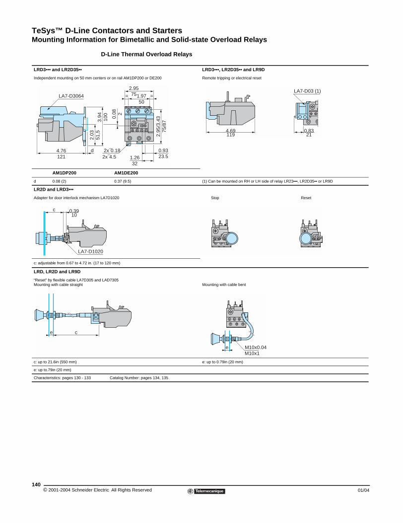
TeSys™ D-Line Contactors and StartersMounting Information for Bimetallic and Solid-state Overload Relays
© 2001-2004 Schneider E140
LRD3••• and LR2D35••
Independent mounting on 50 mm ce
AM1DP200
d 0.08 (2)
LR2D and LRD3•••
Adapter for door interlock mechanis
c: adjustable from 0.67 to 4.72 in. (1
LRD, LR2D and LR9D
“Reset” by flexible cable LA7D305 aMounting with cable straight
c: up to 21.6in (550 mm)
e: up to.79in (20 mm)
Characteristics: pages 130 - 133
4.76 121
LA7-D30642.
03
d
c 0.39 10
LA7-D10
ce
D-Line Thermal Overload Relays
LRD3•••, LR2D35•• and LR9D
nters or on rail AM1DP200 or DE200 Remote tripping or electrical reset
AM1DE200
0.37 (9.5) (1) Can be mounted on RH or LH side of relay LR23•••, LR2D35•• or LR9D
m LA7D1020 Stop Reset
7 to 120 mm)
nd LAD7305Mounting with cable bent
e: up to 0.79in (20 mm)
Catalog Number: pages 134, 135
3.94
10
0
2x¯0.18
51,5 2.95
/3.4
30.08
2
1.97 50
2.95 75 ==
0.93 23.51.26
322x¯4.5
75/8
7
4.69 119
0.83 21
LA7-D03 (1)
20
M10x0.04eM10x1
lectric All Rights Reserved 01/04
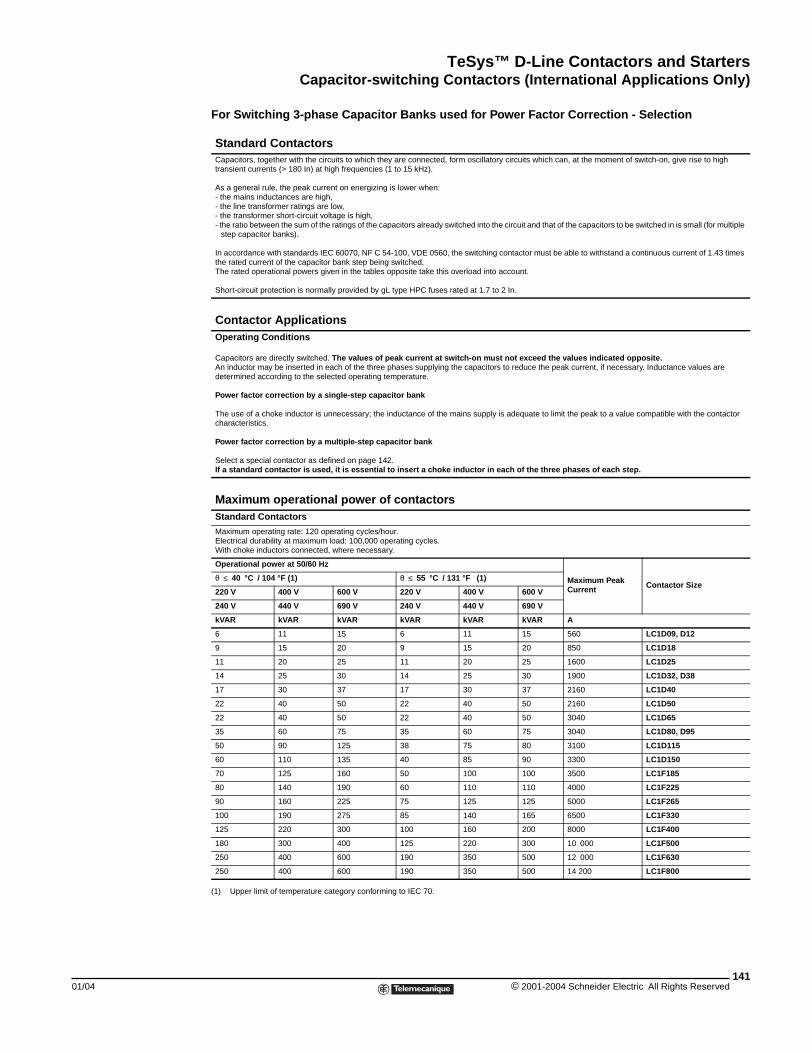
TeSys™ D-Line Contactors and StartersCapacitor-switching Contactors (International Applications Only)
01/04
Capacitor-switching Contactors (International Applications Only)
For Switching 3-phase Capacitor Banks used for Power Factor Correction - Selection
(1) Upper limit of temperature category conforming to IEC 70.
Standard ContactorsCapacitors, together with the circuits to which they are connected, form oscillatory circuits which can, at the moment of switch-on, give rise to high transient currents (> 180 In) at high frequencies (1 to 15 kHz).
As a general rule, the peak current on energizing is lower when:- the mains inductances are high,- the line transformer ratings are low,- the transformer short-circuit voltage is high,- the ratio between the sum of the ratings of the capacitors already switched into the circuit and that of the capacitors to be switched in is small (for multiple
step capacitor banks).
In accordance with standards IEC 60070, NF C 54-100, VDE 0560, the switching contactor must be able to withstand a continuous current of 1.43 times the rated current of the capacitor bank step being switched.The rated operational powers given in the tables opposite take this overload into account.
Short-circuit protection is normally provided by gL type HPC fuses rated at 1.7 to 2 In.
Contactor ApplicationsOperating Conditions
Capacitors are directly switched. The values of peak current at switch-on must not exceed the values indicated opposite.An inductor may be inserted in each of the three phases supplying the capacitors to reduce the peak current, if necessary. Inductance values are determined according to the selected operating temperature.
Power factor correction by a single-step capacitor bank
The use of a choke inductor is unnecessary; the inductance of the mains supply is adequate to limit the peak to a value compatible with the contactor characteristics.
Power factor correction by a multiple-step capacitor bank
Select a special contactor as defined on page 142. If a standard contactor is used, it is essential to insert a choke inductor in each of the three phases of each step.
Maximum operational power of contactorsStandard Contactors
Maximum operating rate: 120 operating cycles/hour.Electrical durability at maximum load: 100,000 operating cycles.With choke inductors connected, where necessary.
Operational power at 50/60 Hz
Maximum Peak Current Contactor Size
θ ≤ 40 °C / 104 °F (1) θ ≤ 55 °C / 131 °F (1)
220 V 400 V 600 V 220 V 400 V 600 V
240 V 440 V 690 V 240 V 440 V 690 V
kVAR kVAR kVAR kVAR kVAR kVAR A
6 11 15 6 11 15 560 LC1D09, D12
9 15 20 9 15 20 850 LC1D18
11 20 25 11 20 25 1600 LC1D25
14 25 30 14 25 30 1900 LC1D32, D38
17 30 37 17 30 37 2160 LC1D40
22 40 50 22 40 50 2160 LC1D50
22 40 50 22 40 50 3040 LC1D65
35 60 75 35 60 75 3040 LC1D80, D95
50 90 125 38 75 80 3100 LC1D115
60 110 135 40 85 90 3300 LC1D150
70 125 160 50 100 100 3500 LC1F185
80 140 190 60 110 110 4000 LC1F225
90 160 225 75 125 125 5000 LC1F265
100 190 275 85 140 165 6500 LC1F330
125 220 300 100 160 200 8000 LC1F400
180 300 400 125 220 300 10 000 LC1F500
250 400 600 190 350 500 12 000 LC1F630
250 400 600 190 350 500 14 200 LC1F800
141© 2001-2004 Schneider Electric All Rights Reserved
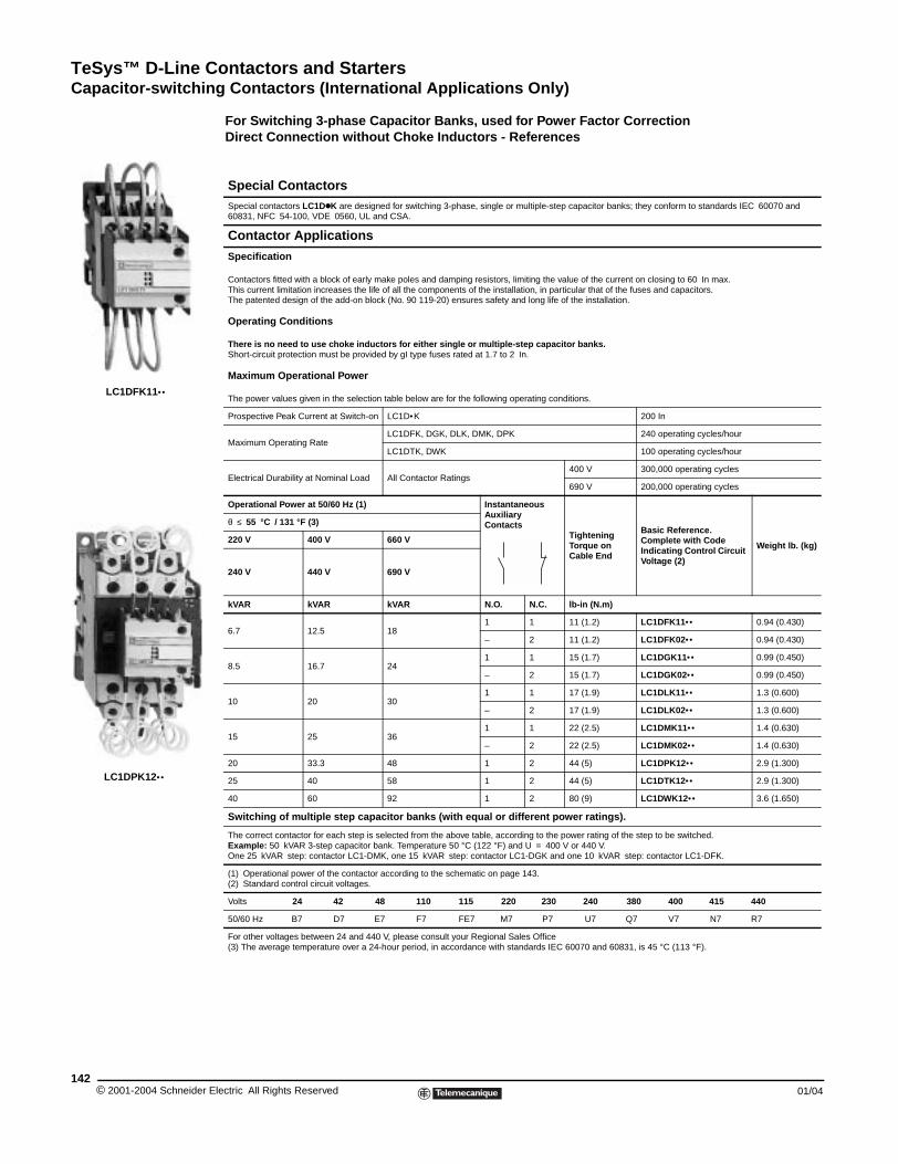
TeSys™ D-Line Contactors and StartersCapacitor-switching Contactors (International Applications Only)
© 2001-2004 Schneider E142
LC1DFK11••
LC1DPK12••
For Switching 3-phase Capacitor Banks, used for Power Factor CorrectionDirect Connection without Choke Inductors - References
Special ContactorsSpecial contactors LC1DkK are designed for switching 3-phase, single or multiple-step capacitor banks; they conform to standards IEC 60070 and 60831, NFC 54-100, VDE 0560, UL and CSA.
Contactor Applications
Specification
Contactors fitted with a block of early make poles and damping resistors, limiting the value of the current on closing to 60 In max.This current limitation increases the life of all the components of the installation, in particular that of the fuses and capacitors.The patented design of the add-on block (No. 90 119-20) ensures safety and long life of the installation.
Operating Conditions
There is no need to use choke inductors for either single or multiple-step capacitor banks.Short-circuit protection must be provided by gI type fuses rated at 1.7 to 2 In.
Maximum Operational Power
The power values given in the selection table below are for the following operating conditions.
Prospective Peak Current at Switch-on LC1D•K 200 In
Maximum Operating RateLC1DFK, DGK, DLK, DMK, DPK 240 operating cycles/hour
LC1DTK, DWK 100 operating cycles/hour
Electrical Durability at Nominal Load All Contactor Ratings400 V 300,000 operating cycles
690 V 200,000 operating cycles
Operational Power at 50/60 Hz (1) Instantaneous Auxiliary Contacts
Tightening Torque on Cable End
Basic Reference.Complete with Code Indicating Control Circuit Voltage (2)
Weight lb. (kg)
θ ≤ 55 °C / 131 °F (3)
220 V 400 V 660 V
240 V 440 V 690 V
kVAR kVAR kVAR N.O. N.C. lb-in (N.m)
6.7 12.5 181 1 11 (1.2) LC1DFK11•• 0.94 (0.430)
– 2 11 (1.2) LC1DFK02•• 0.94 (0.430)
8.5 16.7 241 1 15 (1.7) LC1DGK11•• 0.99 (0.450)
– 2 15 (1.7) LC1DGK02•• 0.99 (0.450)
10 20 301 1 17 (1.9) LC1DLK11•• 1.3 (0.600)
– 2 17 (1.9) LC1DLK02•• 1.3 (0.600)
15 25 361 1 22 (2.5) LC1DMK11•• 1.4 (0.630)
– 2 22 (2.5) LC1DMK02•• 1.4 (0.630)
20 33.3 48 1 2 44 (5) LC1DPK12•• 2.9 (1.300)
25 40 58 1 2 44 (5) LC1DTK12•• 2.9 (1.300)
40 60 92 1 2 80 (9) LC1DWK12•• 3.6 (1.650)
Switching of multiple step capacitor banks (with equal or different power ratings).
The correct contactor for each step is selected from the above table, according to the power rating of the step to be switched.Example: 50 kVAR 3-step capacitor bank. Temperature 50 °C (122 °F) and U = 400 V or 440 V.One 25 kVAR step: contactor LC1-DMK, one 15 kVAR step: contactor LC1-DGK and one 10 kVAR step: contactor LC1-DFK.
(1) Operational power of the contactor according to the schematic on page 143.(2) Standard control circuit voltages.
Volts 24 42 48 110 115 220 230 240 380 400 415 440
50/60 Hz B7 D7 E7 F7 FE7 M7 P7 U7 Q7 V7 N7 R7
For other voltages between 24 and 440 V, please consult your Regional Sales Office(3) The average temperature over a 24-hour period, in accordance with standards IEC 60070 and 60831, is 45 °C (113 °F).
lectric All Rights Reserved 01/04
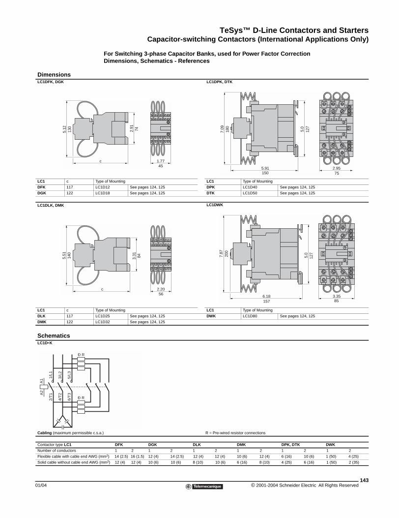
TeSys™ D-Line Contactors and StartersCapacitor-switching Contactors (International Applications Only)
01/04
DimensionsLC1DFK, DGK
LC1 c Ty
DFK 117 LC
DGK 122 LC
LC1DLK, DMK
LC1 c Ty
DLK 117 LC
DMK 122 LC
SchematicsLC1D•K
Cabling (maximum permissible c.s
Contactor type LC1
Number of conductors
Flexible cable with cable end AWG
Solid cable without cable end AWG
5.12
130
5.51
140
A1
A2
1/L1
2/T
1
3/L2
4/T
2
5/L3
6/T
3
Ð R
Ð R
For Switching 3-phase Capacitor Banks, used for Power Factor CorrectionDimensions, Schematics - Referenceszzz
LC1DPK, DTK
pe of Mounting LC1 Type of Mounting
1D12 See pages 124, 125 DPK LC1D40 See pages 124, 125
1D18 See pages 124, 125 DTK LC1D50 See pages 124, 125
LC1DWK
pe of Mounting LC1 Type of Mounting
1D25 See pages 124, 125 DWK LC1D80 See pages 124, 125
1D32 See pages 124, 125
.a.) R = Pre-wired resistor connections
DFK DGK DLK DMK DPK, DTK DWK
1 2 1 2 1 2 1 2 1 2 1 2
(mm2) 14 (2.5) 16 (1.5) 12 (4) 14 (2.5) 12 (4) 12 (4) 10 (6) 12 (4) 6 (16) 10 (6) 1 (50) 4 (25)
(mm2) 12 (4) 12 (4) 10 (6) 10 (6) 8 (10) 10 (6) 6 (16) 8 (10) 4 (25) 6 (16) 1 (50) 2 (35)
1.77c
2.91 74
455.91
5.0
7.09
2.95
180
150
127
75
c
3.31
2.20
84
56
7.87
5.0
6.18 3.35
200
157
127
85
143© 2001-2004 Schneider Electric All Rights Reserved
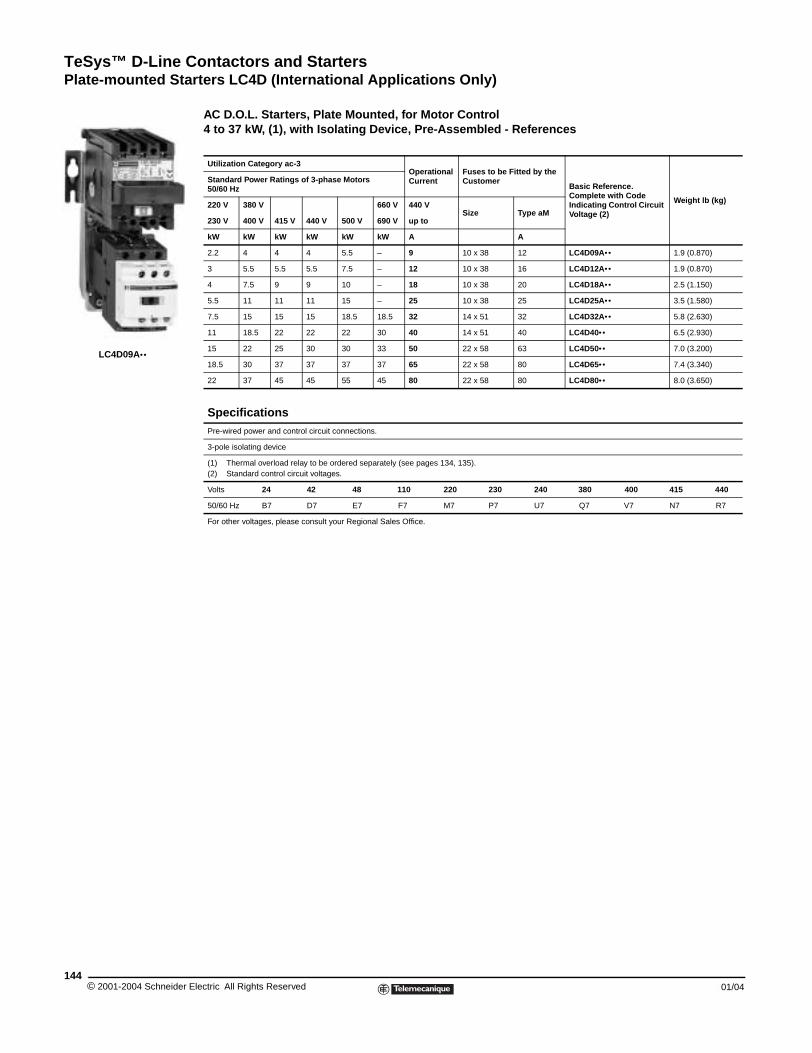
TeSys™ D-Line Contactors and StartersPlate-mounted Starters LC4D (International Applications Only)
© 2001-2004 Schneider E144
LC4D09A••
Plate-mounted Starters LC4D (International Applications Only)
AC D.O.L. Starters, Plate Mounted, for Motor Control4 to 37 kW, (1), with Isolating Device, Pre-Assembled - References
Utilization Category ac-3Operational Current
Fuses to be Fitted by the Customer
Basic Reference.Complete with Code Indicating Control Circuit Voltage (2)
Weight lb (kg)
Standard Power Ratings of 3-phase Motors50/60 Hz
220 V 380 V 660 V 440 VSize Type aM
230 V 400 V 415 V 440 V 500 V 690 V up to
kW kW kW kW kW kW A A
2.2 4 4 4 5.5 – 9 10 x 38 12 LC4D09A•• 1.9 (0.870)
3 5.5 5.5 5.5 7.5 – 12 10 x 38 16 LC4D12A•• 1.9 (0.870)
4 7.5 9 9 10 – 18 10 x 38 20 LC4D18A•• 2.5 (1.150)
5.5 11 11 11 15 – 25 10 x 38 25 LC4D25A•• 3.5 (1.580)
7.5 15 15 15 18.5 18.5 32 14 x 51 32 LC4D32A•• 5.8 (2.630)
11 18.5 22 22 22 30 40 14 x 51 40 LC4D40•• 6.5 (2.930)
15 22 25 30 30 33 50 22 x 58 63 LC4D50•• 7.0 (3.200)
18.5 30 37 37 37 37 65 22 x 58 80 LC4D65•• 7.4 (3.340)
22 37 45 45 55 45 80 22 x 58 80 LC4D80•• 8.0 (3.650)
SpecificationsPre-wired power and control circuit connections.
3-pole isolating device
(1) Thermal overload relay to be ordered separately (see pages 134, 135).(2) Standard control circuit voltages.
Volts 24 42 48 110 220 230 240 380 400 415 440
50/60 Hz B7 D7 E7 F7 M7 P7 U7 Q7 V7 N7 R7
For other voltages, please consult your Regional Sales Office.
lectric All Rights Reserved 01/04
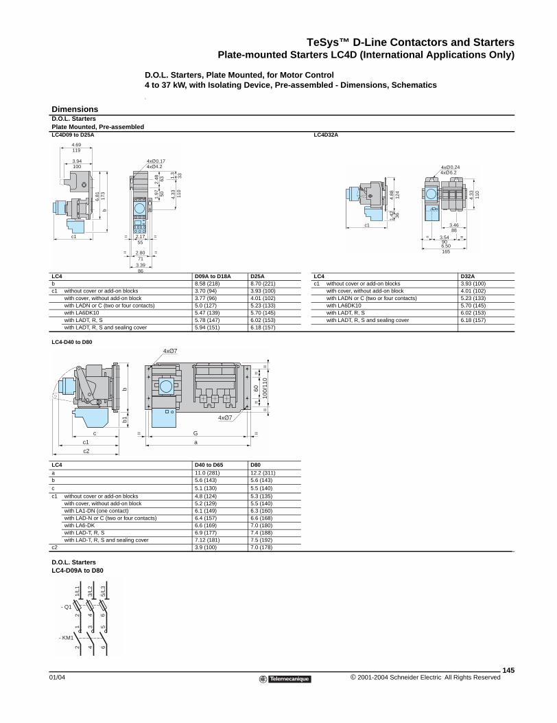
TeSys™ D-Line Contactors and StartersPlate-mounted Starters LC4D (International Applications Only)
01/04
DimensionsD.O.L. StartersPlate Mounted, Pre-assembleLC4D09 to D25A
LC4bc1 without cover or add-on blocks
with cover, without add-on blocwith LADN or C (two or four cowith LA6DK10with LADT, R, Swith LADT, R, S and sealing co
LC4-D40 to D80
LC4ab
c
c1 without cover or add-on blockswith cover, without add-on blocwith LA1-DN (one contact)with LAD-N or C (two or four cwith LA6-DKwith LAD-T, R, Swith LAD-T, R, S and sealing c
c2
D.O.L. StartersLC4-D09A to D80
6.81
b
c1
3.94
119
2
2
3
=
=
100
173
4.69
c
c1
c2
bb1
2 4 6
- Q1
2 4
1 3
- KM1
1/L1
3/L2
5/L3
65
D.O.L. Starters, Plate Mounted, for Motor Control4 to 37 kW, with Isolating Device, Pre-assembled - Dimensions, Schematicsz
dLC4D32A
D09A to D18A D25A LC4 D32A8.58 (218) 8.70 (221) c1 without cover or add-on blocks 3.93 (100)3.70 (94) 3.93 (100) with cover, without add-on block 4.01 (102)
k 3.77 (96) 4.01 (102) with LADN or C (two or four contacts) 5.23 (133)ntacts) 5.0 (127) 5.23 (133) with LA6DK10 5.70 (145)
5.47 (139) 5.70 (145) with LADT, R, S 6.02 (153)5.78 (147) 6.02 (153) with LADT, R, S and sealing cover 6.18 (157)
ver 5.94 (151) 6.18 (157)
D40 to D65 D8011.0 (281) 12.2 (311)5.6 (143) 5.6 (143)
5.1 (130) 5.5 (140)
4.8 (124) 5.3 (135)k 5.2 (129) 5.5 (140)
6.1 (149) 6.3 (160)ontacts) 6.4 (157) 6.6 (168)
6.6 (169) 7.0 (180)6.9 (177) 7.4 (188)
over 7.12 (181) 7.5 (192)3.9 (100) 7.0 (178)
.17
.80
.39
=
=
1.97
2.48
4.33
63
331.3
110
50
86
71
55
0.174.2
c1
1.42
4.88
4.33
3.46
3.54
6.50
==
3612
4
6.20.24
110
165
90
88
G
a
= =
==
60
100/
110
==
145© 2001-2004 Schneider Electric All Rights Reserved
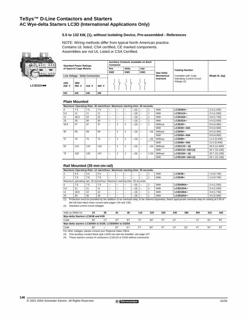
TeSys™ D-Line Contactors and StartersAC Wye-delta Starters LC3D (International Applications Only)
© 2001-2004 Schneider E146
LC3D32Akk
AC Wye-delta Starters LC3D (International Applications Only)
5.5 to 132 kW, (1), without Isolating Device, Pre-assembled - References
NOTE: Wiring methods differ from typical North American practice. Contains UL listed, CSA certified, CE marked components. Assemblies are not UL Listed or CSA Certified.
Standard Power Ratingsof Squirrel Cage Motors
Auxiliary Contacts Available on Each Contactor
Star Delta Mechanical Interlock
Catalog Number
Complete with Code Indicating Control Circuit Voltage (2)
Weigh lb. (kg)
line delta star
KM2 KM3 KM1
Line Voltage - Delta Connection
220/230 V
380/400 V 415 V 440 V
kW kW kW kW
Plate MountedMaximum Operating Rate: 30 starts/hour. Maximum starting time: 30 seconds.
4 7.5 7.5 7.5 – – – – (3) – 1 With LC3D09A•• 3.4 (1.530)
5.5 11 11 11 – – – – (3) – 1 With LC3D12A•• 3.4 (1.530)
11 18.5 22 22 – – – – (3) – 1 With LC3D18A•• 3.8 (1.730)
15 25 30 30 – – – – (3) – 1 With LC3D32A•• 4.5 (2.030)
18.5 37 37 37 – 1 1 – (3) – 1 Without LC3D40•• 9.6 (4.360)
With LC3D40•• A64 9.9 (4.500)
30 55 59 59 – 1 1 – (3) – – (3) Without LC3D50•• 9.6 (4.360)
With LC3D50•• A64 9.9 (4.500)
37 75 75 75 – 1 1 – (3) – – (3) Without LC3D80•• 11.5 (5.200)
With LC3D80•• A64 12.0 (5.400)
63 110 110 110 – 1 1 – (3) – – (3) Without LC3D115•• (4) 26.0 (11.800)
With LC3D115•• A64 (4) 26.7 (12.100)
75 132 132 147 – 1 1 – (3) – 1 (3) Without LC3D150•• (4) 26.7 (12.100)
With LC3D150•• A64 (4) 26.7 (12.100)
Rail Mounted (35 mm DIN rail)Maximum Operating Rate: 12 starts/hour. Maximum starting time: 30 seconds.
3 5.5 5.5 5.5 – – – – – 1 With LC3K06•• 1.6 (0.740)
4 7.5 7.5 7.5 – – – – – 1 With LC3K09•• 1.6 (0.740)
Maximum operating rate: 30 starts/hour. Maximum starting time: 30 seconds.
4 7.5 7.5 7.5 – – – – (3) – 1 With LC3D090A•• 3.4 (1.530)
5.5 11 11 11 – – – – (3) – 1 With LC3D120A•• 3.4 (1.530)
11 18.5 22 22 – – – – (3) – 1 With LC3D180A•• 3.8 (1.730)
15 25 30 30 – – – – (3) – 1 With LC3D320A•• 4.5 (2.030)
(1) Protection must be provided by the addition of an overload relay, to be ordered separately. Select appropriate overload relay for setting at 0.58 of the full load rated motor current (see pages 134 and 135).
(2) Standard control circuit voltages
Volts ac 50/60 Hz 24 36 42 48 110 220 230 240 380 400 415 440
Wye-delta Starters LC3K06 and K09
Code B7 C7 D7 E7 F7 M7 P7 U7 – V7 N7 R7
Wye-delta starters LC3D09A to D150, LC3D090A to D320A
Code B7 – D7 E7 F7 M7 P7 U7 Q7 V7 N7 R7
For other voltages, please consult your Regional Sales Office.(3) One auxiliary contact block type LADN can also be installed, see page 107.(4) These starters consist of contactors LC1D115 or D150 without connectors.
lectric All Rights Reserved 01/04
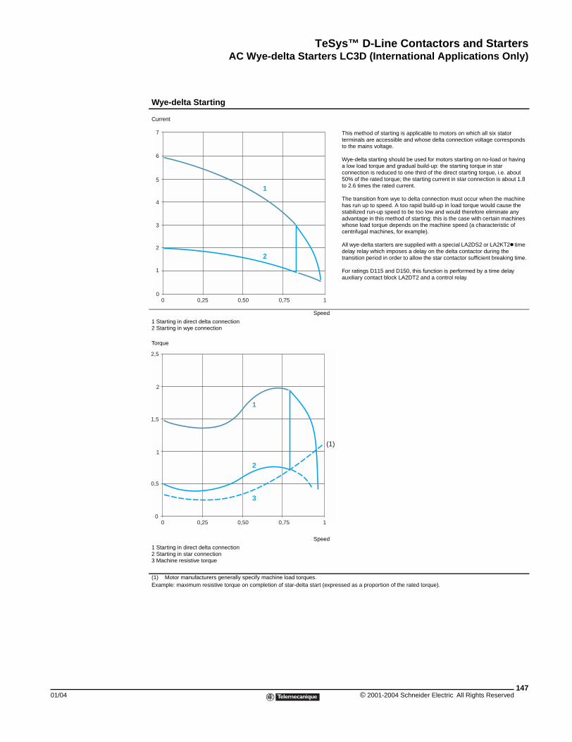
TeSys™ D-Line Contactors and StartersAC Wye-delta Starters LC3D (International Applications Only)
01/04
Wye-delta Starting
Current
This method of starting is applicable to motors on which all six stator terminals are accessible and whose delta connection voltage corresponds to the mains voltage.
Wye-delta starting should be used for motors starting on no-load or having a low load torque and gradual build-up: the starting torque in star connection is reduced to one third of the direct starting torque, i.e. about 50% of the rated torque; the starting current in star connection is about 1.8 to 2.6 times the rated current.
The transition from wye to delta connection must occur when the machine has run up to speed. A too rapid build-up in load torque would cause the stabilized run-up speed to be too low and would therefore eliminate any advantage in this method of starting: this is the case with certain machines whose load torque depends on the machine speed (a characteristic of centrifugal machines, for example).
All wye-delta starters are supplied with a special LA2DS2 or LA2KT2k time delay relay which imposes a delay on the delta contactor during the transition period in order to allow the star contactor sufficient breaking time.
For ratings D115 and D150, this function is performed by a time delay auxiliary contact block LA2DT2 and a control relay.
Speed
1 Starting in direct delta connection2 Starting in wye connection
Torque
Speed
1 Starting in direct delta connection2 Starting in star connection3 Machine resistive torque
(1) Motor manufacturers generally specify machine load torques. Example: maximum resistive torque on completion of star-delta start (expressed as a proportion of the rated torque).
0
1
2
3
4
5
6
7
0 0,25 0,50 0,75 1
1
2
0
0,5
0 0,25 0,50 0,75 1
1
2
3
(1)1
1,5
2
2,5
147© 2001-2004 Schneider Electric All Rights Reserved
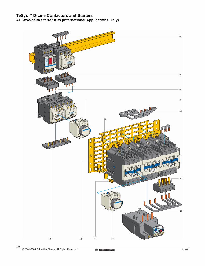
TeSys™ D-Line Contactors and StartersAC Wye-delta Starter Kits (International Applications Only)
AC Wye-delta Starter Kits (International Applications Only)
KM2
KM2
KM2
KM1
KM3
1c
1c2 1a
1b
a
a
a
a
1d
1b
a
© 2001-2004 Schneider Electric All Rights Reserved148
01/04
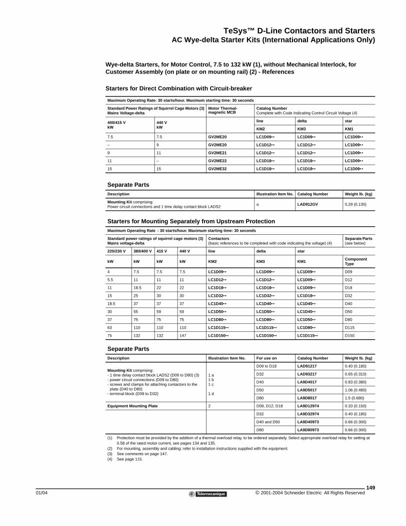
TeSys™ D-Line Contactors and StartersAC Wye-delta Starter Kits (International Applications Only)
01/04
Wye-delta Starters, for Motor Control, 7.5 to 132 kW (1), without Mechanical Interlock, for Customer Assembly (on plate or on mounting rail) (2) - References
Starters for Direct Combination with Circuit-breaker
Maximum Operating Rate: 30 starts/hour. Maximum starting time: 30 seconds
Standard Power Ratings of Squirrel Cage Motors (3)Mains Voltage-delta
Motor Thermal- magnetic MCB
Catalog NumberComplete with Code Indicating Control Circuit Voltage (4)
400/415 VkW
440 VkW
line delta star
KM2 KM3 KM1
7.5 7.5 GV2ME20 LC1D09•• LC1D09•• LC1D09••
– 9 GV2ME20 LC1D12•• LC1D12•• LC1D09••
9 11 GV2ME21 LC1D12•• LC1D12•• LC1D09••
11 – GV2ME22 LC1D18•• LC1D18•• LC1D09••
15 15 GV2ME32 LC1D18•• LC1D18•• LC1D09••
Separate PartsDescription Illustration Item No. Catalog Number Weight lb. (kg)
Mounting Kit comprising: Power circuit connections and 1 time delay contact block LADS2
a LAD912GV 0.29 (0.130)
Starters for Mounting Separately from Upstream ProtectionMaximum Operating Rate : 30 starts/hour. Maximum starting time: 30 seconds
Standard power ratings of squirrel cage motors (3)Mains voltage-delta
Contactors (basic references to be completed with code indicating the voltage) (4)
Separate Parts (see below)
220/230 V 380/400 V 415 V 440 V line delta star
kW kW kW kW KM2 KM3 KM1 Component Type
4 7.5 7.5 7.5 LC1D09•• LC1D09•• LC1D09•• D09
5.5 11 11 11 LC1D12•• LC1D12•• LC1D09•• D12
11 18.5 22 22 LC1D18•• LC1D18•• LC1D09•• D18
15 25 30 30 LC1D32•• LC1D32•• LC1D18•• D32
18.5 37 37 37 LC1D40•• LC1D40•• LC1D40•• D40
30 55 59 59 LC1D50•• LC1D50•• LC1D40•• D50
37 75 75 75 LC1D80•• LC1D80•• LC1D50•• D80
63 110 110 110 LC1D115•• LC1D115•• LC1D80•• D115
75 132 132 147 LC1D150•• LC1D150•• LC1D115•• D150
Separate PartsDescription Illustration Item No. For use on Catalog Number Weight lb. (kg)
Mounting Kit comprising:- 1 time delay contact block LADS2 (D09 to D80) (3)- power circuit connections (D09 to D80)- screws and clamps for attaching contactors to the
plate (D40 to D80)- terminal block (D09 to D32)
1 a1 b1 c
1 d
D09 to D18 LAD91217 0.40 (0.180)
D32 LAD93217 0.65 (0.310)
D40 LA9D4017 0.83 (0.380)
D50 LA9D5017 1.06 (0.480)
D80 LA9D8017 1.5 (0.680)
Equipment Mounting Plate 2 D09, D12, D18 LA9D12974 0.33 (0.150)
D32 LA9D32974 0.40 (0.180)
D40 and D50 LA9D40973 0.66 (0.300)
D80 LA9D80973 0.66 (0.300)
(1) Protection must be provided by the addition of a thermal overload relay, to be ordered separately. Select appropriate overload relay for setting at 0.58 of the rated motor current, see pages 134 and 135.
(2) For mounting, assembly and cabling: refer to installation instructions supplied with the equipment.(3) See comments on page 147.(4) See page 115.
149© 2001-2004 Schneider Electric All Rights Reserved
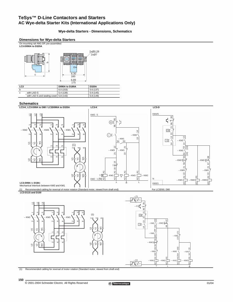
TeSys™ D-Line Contactors and StartersAC Wye-delta Starter Kits (International Applications Only)
© 2001-2004 Schneider E150
Dimensions for Wye-dOn mounting rail AM1-DP, pre-asseLC3-D090A to D320A
LC3bc with LAD-S
with LAD-S and sealing cove
SchematicsLC3-K, LC3-D09A to D80 / LC3D0
(1) Recommended cabling for rev LC3-D115 and D150
(1) Recommended cabling for rev
c
b
– KM2
12
34
56
– KM3
12
U1
V1
W1
U2
V2
W2
12
L1 L2 L3
LC3-D09A to D18A:Mechanical Interlock between KM3
– KM2
12
34
56
– KM3
12
U1
V1
W1
U2
V2
W2
12
L1 L2 L3
Wye-delta Starters - Dimensions, Schematics
elta Startersmbled
D090A to D180A D320A6.0 (153) 5.6 (137)5.4 (139) 5.9 (145)
r 5.8 (143) 5.8 (149)
90A to D320A LC3-K LC3-D
ersal of motor rotation (Standard motor, viewed from shaft end) For LC3D50, D80
ersal of motor rotation (Standard motor, viewed from shaft end)
2xØ0.28
6.30
6.89
KM2KM3 KM1
2xØ7
160
175
U1
V1
W1
U2
V2
W2
2 4 6
34
56
– KM1
12
34
56
3 5
4 6
(1)
and KM1
KM2 : 1 (N)
O
T
T
I
Y
L
KM3 : 5
– KM3 – KM2– KM1
– KM154 53
A1
A2
A1
A2
A1
A2
A1
A2
– KM1– KM3
2122
2221
1516
9596
– KM214
13
A1
A2
– KM1
1314
2122
2221
– KM3
5556
– KM2
5354
– KM1
9596
KM3/5
O
l
6867
– KM2
A1
A2
– KM3
2221
– KM1
A1
A2
– KM2
1314
– KM2
(13)
(14)
KM3/1
N
U1
V1
W1
U2
V2
W2
2 4 6
34
56
– KM1
12
34
56
3 5
4 6
(1)
A1
A2
– KM1
1314
2122
162
161
– KM3
5556
– KM2
184
183
– KM1
9596
– F1
– F1
O
l
153
154
– KM2
A1
A2
– KA1
A1
A2
– KM2
153
154
– KM1
– F2
171
6768
– KM2
172
– KM1
1314
A1
A2
– KM3
– KA1
Y L
lectric All Rights Reserved 01/04
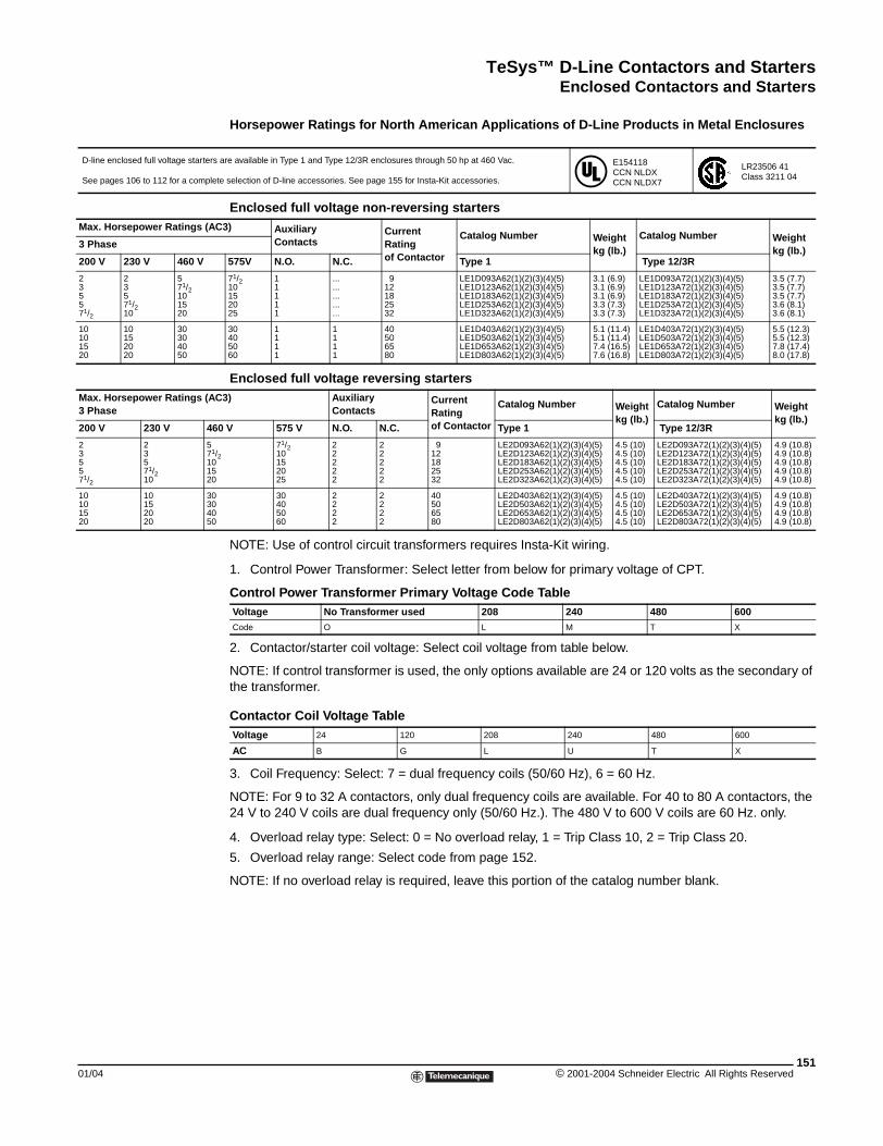
TeSys™ D-Line Contactors and StartersEnclosed Contactors and Starters
01/04
D-line enclosed full voltage starters
See pages 106 to 112 for a complet
Max. Horsepower Ratings (AC
3 Phase
200 V 230 V 460 V
2 2 53 3 71/25 5 105 71/2 1571/2 10 20
10 10 3010 15 3015 20 4020 20 50
Max. Horsepower Ratings (AC3 Phase
200 V 230 V 46
2 2 53 3 71/5 5 105 71/2 1571/2 10 20
10 10 3010 15 3015 20 4020 20 50
Enclosed Contactors and Starters
Horsepower Ratings for North American Applications of D-Line Products in Metal Enclosures
NOTE: Use of control circuit transformers requires Insta-Kit wiring.
1. Control Power Transformer: Select letter from below for primary voltage of CPT.
2. Contactor/starter coil voltage: Select coil voltage from table below.
NOTE: If control transformer is used, the only options available are 24 or 120 volts as the secondary of the transformer.
3. Coil Frequency: Select: 7 = dual frequency coils (50/60 Hz), 6 = 60 Hz.
NOTE: For 9 to 32 A contactors, only dual frequency coils are available. For 40 to 80 A contactors, the 24 V to 240 V coils are dual frequency only (50/60 Hz.). The 480 V to 600 V coils are 60 Hz. only.
4. Overload relay type: Select: 0 = No overload relay, 1 = Trip Class 10, 2 = Trip Class 20.
5. Overload relay range: Select code from page 152.
NOTE: If no overload relay is required, leave this portion of the catalog number blank.
are available in Type 1 and Type 12/3R enclosures through 50 hp at 460 Vac.
e selection of D-line accessories. See page 155 for Insta-Kit accessories.
E154118CCN NLDXCCN NLDX7
LR23506 41Class 3211 04
Enclosed full voltage non-reversing starters3) Auxiliary
ContactsCurrent Ratingof Contactor
Catalog Number Weightkg (lb.)
Catalog Number Weightkg (lb.)
575V N.O. N.C. Type 1 Type 12/3R
71/2 1 ... 9 LE1D093A62(1)(2)(3)(4)(5) 3.1 (6.9) LE1D093A72(1)(2)(3)(4)(5) 3.5 (7.7)10 1 ... 12 LE1D123A62(1)(2)(3)(4)(5) 3.1 (6.9) LE1D123A72(1)(2)(3)(4)(5) 3.5 (7.7)15 1 ... 18 LE1D183A62(1)(2)(3)(4)(5) 3.1 (6.9) LE1D183A72(1)(2)(3)(4)(5) 3.5 (7.7)20 1 ... 25 LE1D253A62(1)(2)(3)(4)(5) 3.3 (7.3) LE1D253A72(1)(2)(3)(4)(5) 3.6 (8.1)25 1 ... 32 LE1D323A62(1)(2)(3)(4)(5) 3.3 (7.3) LE1D323A72(1)(2)(3)(4)(5) 3.6 (8.1)
30 1 1 40 LE1D403A62(1)(2)(3)(4)(5) 5.1 (11.4) LE1D403A72(1)(2)(3)(4)(5) 5.5 (12.3)40 1 1 50 LE1D503A62(1)(2)(3)(4)(5) 5.1 (11.4) LE1D503A72(1)(2)(3)(4)(5) 5.5 (12.3)50 1 1 65 LE1D653A62(1)(2)(3)(4)(5) 7.4 (16.5) LE1D653A72(1)(2)(3)(4)(5) 7.8 (17.4)60 1 1 80 LE1D803A62(1)(2)(3)(4)(5) 7.6 (16.8) LE1D803A72(1)(2)(3)(4)(5) 8.0 (17.8)
Enclosed full voltage reversing starters3) Auxiliary
ContactsCurrent Ratingof Contactor
Catalog Number Weightkg (lb.)
Catalog Number Weightkg (lb.)
0 V 575 V N.O. N.C. Type 1 Type 12/3R
71/2 2 2 9 LE2D093A62(1)(2)(3)(4)(5) 4.5 (10) LE2D093A72(1)(2)(3)(4)(5) 4.9 (10.8)2 10 2 2 12 LE2D123A62(1)(2)(3)(4)(5) 4.5 (10) LE2D123A72(1)(2)(3)(4)(5) 4.9 (10.8)
15 2 2 18 LE2D183A62(1)(2)(3)(4)(5) 4.5 (10) LE2D183A72(1)(2)(3)(4)(5) 4.9 (10.8)20 2 2 25 LE2D253A62(1)(2)(3)(4)(5) 4.5 (10) LE2D253A72(1)(2)(3)(4)(5) 4.9 (10.8)25 2 2 32 LE2D323A62(1)(2)(3)(4)(5) 4.5 (10) LE2D323A72(1)(2)(3)(4)(5) 4.9 (10.8)
30 2 2 40 LE2D403A62(1)(2)(3)(4)(5) 4.5 (10) LE2D403A72(1)(2)(3)(4)(5) 4.9 (10.8)40 2 2 50 LE2D503A62(1)(2)(3)(4)(5) 4.5 (10) LE2D503A72(1)(2)(3)(4)(5) 4.9 (10.8)50 2 2 65 LE2D653A62(1)(2)(3)(4)(5) 4.5 (10) LE2D653A72(1)(2)(3)(4)(5) 4.9 (10.8)60 2 2 80 LE2D803A62(1)(2)(3)(4)(5) 4.5 (10) LE2D803A72(1)(2)(3)(4)(5) 4.9 (10.8)
Control Power Transformer Primary Voltage Code TableVoltage No Transformer used 208 240 480 600
Code O L M T X
Contactor Coil Voltage TableVoltage 24 120 208 240 480 600
AC B G L U T X
151© 2001-2004 Schneider Electric All Rights Reserved
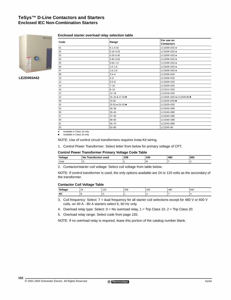
TeSys™ D-Line Contactors and StartersEnclosed IEC Non-Combination Starters
© 2001-2004 Schneider E152
LE2D093A62
Enclosed IEC Non-combination Starters
q Available in Class 10 onlyc Available in Class 20 only
NOTE: Use of control circuit transformers requires Insta-Kit wiring.
1. Control Power Transformer: Select letter from below for primary voltage of CPT.
2. Contactor/starter coil voltage: Select coil voltage from table below.
NOTE: If control transformer is used, the only options available are 24 or 120 volts as the secondary of the transformer.
3. Coil frequency: Select: 7 = dual frequency for all starter coil selections except for 480 V or 600 V coils, on 40 A - 80 A starters select 6, 60 Hz only.
4. Overload relay type: Select: 0 = No overload relay, 1 = Trip Class 10, 2 = Trip Class 20.
5. Overload relay range: Select code from page 155.
NOTE: If no overload relay is required, leave this portion of the catalog number blank.
Enclosed starter overload relay selection table
Code RangeFor use on Contactors
01 0.1–0.16 LC1D09–D32 q
02 0.16–0.25 LC1D09–D32 q
03 0.25–0.40 LC1D09–D32 q
04 0.40–0.63 LC1D09–D32 q
05 0.63–1.0 LC1D09–D32 q
06 1.0–1.6 LC1D09–D32 q
07 1.6–2.5 LC1D09–D32 q
08 2.5–4 LC1D09–D32
10 4–6 LC1D09–D32
12 5.5–8 LC1D09–D32
14 7–10 LC1D09–D32
16 9–13 LC1D12–D32
21 12–18 LC1D18–D32
22 16–24 q 17-25 c LC1D25–D32 q LC1D40-80 c
30 23-28 LC1D25–D32 c
32 25-32 q 23–32 c LC1D25–D32
53 30–38 LC1D40–D80
55 30–40 LC1D40–D80
57 37–50 LC1D40–D80
59 48–65 LC1D40–D80
61 55–70 LC1D40–D80
63 63–80 LC1D40–80
Control Power Transformer Primary Voltage Code TableVoltage No Transformer used 208 240 480 600
Code O L M T X
Contactor Coil Voltage TableVoltage 24 120 208 240 480 600
AC B G L U T X
lectric All Rights Reserved 01/04
TeSys™ D-Line Contactors and StartersEnclosed IEC Combination Starters
01/04
Max. Horsepower Ratings (A3 Phase
200 V 230 V 460 V 575
2 2 5 71/23 3 71/2 10
5 5 10 15
5 71/2 15 20
71/2 10 20 25
10 10 30 30
Max. Horsepower Ratings (A3 Phase
200 V 230 V 460 V 575
2 2 5 71/23 3 71/2 10
5 5 10 15
5 71/2 15 20
71/2 10 20 25
10 10 30 30
Max. Horsepower Ratings (AC3 Phase
200 V 230 V 460 V
2 2 5
3 3 71/25 5 10
5 71/2 15
71/2 10 20
10 10 30
Max. Horsepower Ratings (AC3 Phase
200 V 230 V 460 V
2 2 5
3 3 71/25 5 10
5 71/2 15
71/2 10 20
10 10 30
Enclosed IEC Combination Starters
Horsepower Ratings for North American Applications ofD-Line Products in Metal Enclosures with Fusible Disconnect Switch or Circuit BreakerIEC combination starters combine the requirements of motor overload and short circuit protection in one convenient compact package. All devices provide Type 2 Coordination through 30 hp at 460 V. Devices are available in Type 1 and Type 12/3R enclosures.
NOTE: Use tables and notes from page 152 to complete the catalog numbers. See pages 106 to 112 for a complete selection of D-line accessories. See page 155 for Insta-Kit accessories.
E154118CCN NLDXCCN NLDX7
LR23506 41Class 3211 04
Enclosed full voltage non-reversing fusible combination startersC3) Fuse Clip
RatingAuxiliaryContacts Current
Rating of Contactor
Catalog Number Weightkg (lb.)
Catalog Number Weightkg (lb.)
V AmperesUL Class
N.O. N.C. Type 1 Type 12/3R
30 A CC 1 ... 9 LE1D096B62(1)(2)(3)(4)(5) 8.1 (18) LE1D096B72(1)(2)(3)(4)(5) 8.1 (18)
30 A CC 1 ... 12 LE1D126B62(1)(2)(3)(4)(5) 8.1 (18) LE1D126B72(1)(2)(3)(4)(5) 8.1 (18)
30 A J 1 ... 18 LE1D186B62(1)(2)(3)(4)(5) 8.1 (18) LE1D186B72(1)(2)(3)(4)(5) 8.1 (18)
30 A J 1 ... 25 LE1D256B62(1)(2)(3)(4)(5) 8.1 (18) LE1D256B72(1)(2)(3)(4)(5) 8.1 (18)
60 A J 1 ... 32 LE1D326C62(1)(2)(3)(4)(5) 11.7 (26) LE1D326C72(1)(2)(3)(4)(5) 11.7 (26)
60 A J 1 1 40 LE1D406C62(1)(2)(3)(4)(5) 12.6 (28) LE1D406C72(1)(2)(3)(4)(5) 12.6 (28)
Enclosed full voltage reversing fusible combination startersC3) Fuse Clip
RatingAuxiliaryContacts Current
Rating of Contactor
Catalog Number Weightkg (lb.)
Catalog Number Weightkg (lb.)
V AmperesUL Class
N.O. N.C. Type 1 Type 12/3R
30 A CC 2 2 9 LE2D096B62(1)(2)(3)(4)(5) 11.7 (26) LE2D096B72(1)(2)(3)(4)(5) 11.7 (26)
30 A CC 2 2 12 LE2D126B62(1)(2)(3)(4)(5) 11.7 (26) LE2D126B72(1)(2)(3)(4)(5) 11.7 (26)
30 A J 2 2 18 LE2D186B62(1)(2)(3)(4)(5) 11.7 (26) LE2D186B72(1)(2)(3)(4)(5) 11.7 (26)
30 A J 2 2 25 LE2D256B62(1)(2)(3)(4)(5) 11.7 (26) LE2D256B72(1)(2)(3)(4)(5) 11.7 (26)
60 A J 2 2 32 LE2D326C62(1)(2)(3)(4)(5) 12.2 (27) LE2D326C72(1)(2)(3)(4)(5) 12.2 (27)
60 A J 2 2 40 LE2D406C62(1)(2)(3)(4)(5) 14.0 (31) LE2D406C72(1)(2)(3)(4)(5) 14.0 (31)
Enclosed full voltage non-reversing circuit breaker combination starters3) Auxiliary
ContactsCircuit BreakerMaximumCurrent Rating
Current Rating of Contactor
Catalog Number Weightkg (lb.)
Catalog Number Weightkg (lb.)
575 V N.O. N.C. Type 1 Type 12/3R
71/2 1 - 15 A 9 LE1D097D62(1)(2)(3)(4)(5) 9.0 (20) LE1D097D72(1)(2)(3)(4)(5) 9.0 (20)
10 1 - 15 A 12 LE1D127D62(1)(2)(3)(4)(5) 9.0 (20) LE1D127D72(1)(2)(3)(4)(5) 9.0 (20)
15 1 - 30 A 18 LE1D187E62(1)(2)(3)(4)(5) 9.0 (20) LE1D187E72(1)(2)(3)(4)(5) 9.0 (20)
20 1 - 30 A 25 LE1D257E62(1)(2)(3)(4)(5) 9.0 (20) LE1D257E72(1)(2)(3)(4)(5) 9.0 (20)
25 1 - 50 A 32 LE1D327F62(1)(2)(3)(4)(5) 12.2 (27) LE1D327F72(1)(2)(3)(4)(5) 12.2 (27)
30 1 1 50 A 40 LE1D407F62(1)(2)(3)(4)(5) 13.0 (29) LE1D407F72(1)(2)(3)(4)(5) 13.0 (29)
Enclosed full voltage reversing circuit breaker combination starters3) Auxiliary
ContactsCircuit BreakerMaximumCurrent Rating
Current Rating of Contactor
Catalog Number Weightkg (lb.)
Catalog Number Weightkg (lb.)
575 V N.O. N.C. Type 1 Type 12/3R
71/2 2 2 15 A 9 LE2D097D62(1)(2)(3)(4)(5) 10.8 (24) LE2D097D72(1)(2)(3)(4)(5) 10.8 (24)
10 2 2 15 A 12 LE2D127D62(1)(2)(3)(4)(5) 10.8 (24) LE2D127D72(1)(2)(3)(4)(5) 10.8 (24)
15 2 2 30 A 18 LE2D187E62(1)(2)(3)(4)(5) 12.6 (28) LE2D187E72(1)(2)(3)(4)(5) 12.6 (28)
20 2 2 30 A 25 LE2D257E62(1)(2)(3)(4)(5) 12.6 (28) LE2D257E72(1)(2)(3)(4)(5) 12.6 (28)
25 2 2 50 A 32 LE2D327F62(1)(2)(3)(4)(5) 12.6 (28) LE2D327F72(1)(2)(3)(4)(5) 12.6 (28)
30 2 2 50 A 40 LE2D407F62(1)(2)(3)(4)(5) 14.4 (32) LE2D407F72(1)(2)(3)(4)(5) 14.4 (32)
153© 2001-2004 Schneider Electric All Rights Reserved
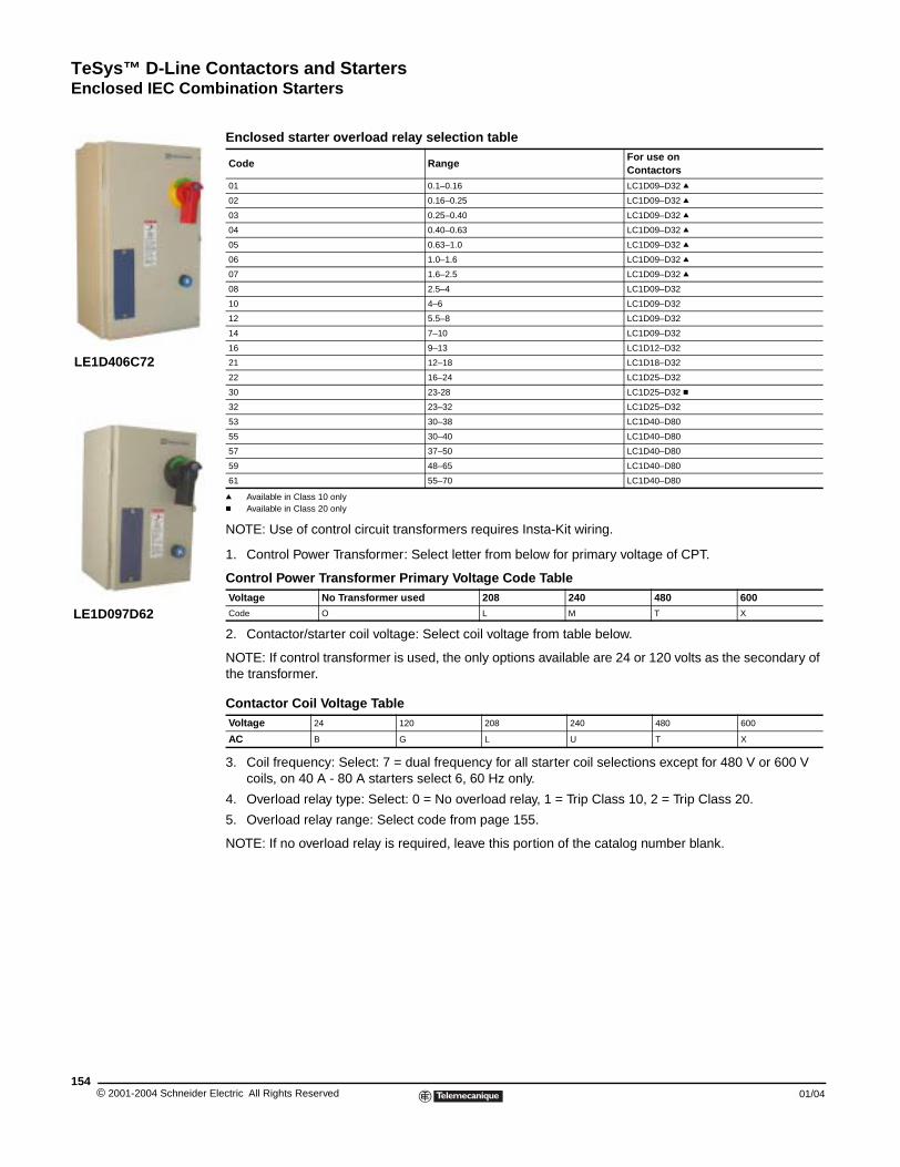
TeSys™ D-Line Contactors and StartersEnclosed IEC Combination Starters
© 2001-2004 Schneider E154
LE1D406C72
LE1D097D62
q Available in Class 10 onlyc Available in Class 20 only
NOTE: Use of control circuit transformers requires Insta-Kit wiring.
1. Control Power Transformer: Select letter from below for primary voltage of CPT.
2. Contactor/starter coil voltage: Select coil voltage from table below.
NOTE: If control transformer is used, the only options available are 24 or 120 volts as the secondary of the transformer.
3. Coil frequency: Select: 7 = dual frequency for all starter coil selections except for 480 V or 600 V coils, on 40 A - 80 A starters select 6, 60 Hz only.
4. Overload relay type: Select: 0 = No overload relay, 1 = Trip Class 10, 2 = Trip Class 20.
5. Overload relay range: Select code from page 155.
NOTE: If no overload relay is required, leave this portion of the catalog number blank.
Enclosed starter overload relay selection table
Code RangeFor use on Contactors
01 0.1–0.16 LC1D09–D32 q
02 0.16–0.25 LC1D09–D32 q
03 0.25–0.40 LC1D09–D32 q
04 0.40–0.63 LC1D09–D32 q
05 0.63–1.0 LC1D09–D32 q
06 1.0–1.6 LC1D09–D32 q
07 1.6–2.5 LC1D09–D32 q
08 2.5–4 LC1D09–D32
10 4–6 LC1D09–D32
12 5.5–8 LC1D09–D32
14 7–10 LC1D09–D32
16 9–13 LC1D12–D32
21 12–18 LC1D18–D32
22 16–24 LC1D25–D32
30 23-28 LC1D25–D32 c
32 23–32 LC1D25–D32
53 30–38 LC1D40–D80
55 30–40 LC1D40–D80
57 37–50 LC1D40–D80
59 48–65 LC1D40–D80
61 55–70 LC1D40–D80
Control Power Transformer Primary Voltage Code TableVoltage No Transformer used 208 240 480 600Code O L M T X
Contactor Coil Voltage TableVoltage 24 120 208 240 480 600
AC B G L U T X
lectric All Rights Reserved 01/04
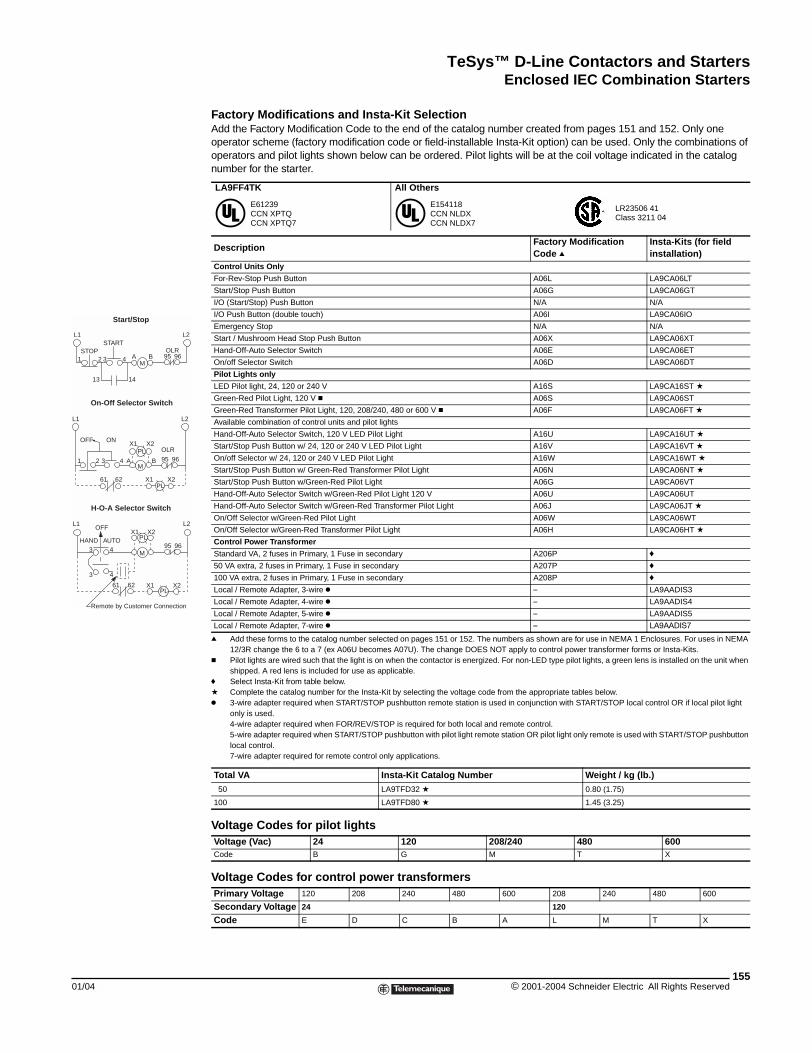
TeSys™ D-Line Contactors and StartersEnclosed IEC Combination Starters
01/04
L1 L2
PL
M
OFF ON
1 2 3 4 A B
OLR
95 96
X1 X2
PL61 62 X1 X2
On-Off Selector Switch
H-O-A Selector Switch
L1 L2
M
HAND AUTO
OFF
PLX1 X2
3 4
3 4
95 96
61 62PL
X1 X2
Remote by Customer Connection
L1 L2START
STOP1 2 A B3 4
M95 96
13 14
OLR
Start/Stop
Factory Modifications and Insta-Kit Selection Add the Factory Modification Code to the end of the catalog number created from pages 151 and 152. Only one operator scheme (factory modification code or field-installable Insta-Kit option) can be used. Only the combinations of operators and pilot lights shown below can be ordered. Pilot lights will be at the coil voltage indicated in the catalog number for the starter.
q Add these forms to the catalog number selected on pages 151 or 152. The numbers as shown are for use in NEMA 1 Enclosures. For uses in NEMA 12/3R change the 6 to a 7 (ex A06U becomes A07U). The change DOES NOT apply to control power transformer forms or Insta-Kits.
c Pilot lights are wired such that the light is on when the contactor is energized. For non-LED type pilot lights, a green lens is installed on the unit when shipped. A red lens is included for use as applicable.
f Select Insta-Kit from table below.a Complete the catalog number for the Insta-Kit by selecting the voltage code from the appropriate tables below.k 3-wire adapter required when START/STOP pushbutton remote station is used in conjunction with START/STOP local control OR if local pilot light
only is used.4-wire adapter required when FOR/REV/STOP is required for both local and remote control.5-wire adapter required when START/STOP pushbutton with pilot light remote station OR pilot light only remote is used with START/STOP pushbutton local control.7-wire adapter required for remote control only applications.
LA9FF4TK All Others
E61239 CCN XPTQCCN XPTQ7
E154118CCN NLDXCCN NLDX7
LR23506 41Class 3211 04
DescriptionFactory Modification Code q
Insta-Kits (for field installation)
Control Units Only
For-Rev-Stop Push Button A06L LA9CA06LT
Start/Stop Push Button A06G LA9CA06GT
I/O (Start/Stop) Push Button N/A N/A
I/O Push Button (double touch) A06I LA9CA06IO
Emergency Stop N/A N/A
Start / Mushroom Head Stop Push Button A06X LA9CA06XT
Hand-Off-Auto Selector Switch A06E LA9CA06ET
On/off Selector Switch A06D LA9CA06DT
Pilot Lights only
LED Pilot light, 24, 120 or 240 V A16S LA9CA16ST a
Green-Red Pilot Light, 120 V c A06S LA9CA06ST
Green-Red Transformer Pilot Light, 120, 208/240, 480 or 600 V c A06F LA9CA06FT a
Available combination of control units and pilot lights
Hand-Off-Auto Selector Switch, 120 V LED Pilot Light A16U LA9CA16UT a
Start/Stop Push Button w/ 24, 120 or 240 V LED Pilot Light A16V LA9CA16VT a
On/off Selector w/ 24, 120 or 240 V LED Pilot Light A16W LA9CA16WT a
Start/Stop Push Button w/ Green-Red Transformer Pilot Light A06N LA9CA06NT a
Start/Stop Push Button w/Green-Red Pilot Light A06G LA9CA06VT
Hand-Off-Auto Selector Switch w/Green-Red Pilot Light 120 V A06U LA9CA06UT
Hand-Off-Auto Selector Switch w/Green-Red Transformer Pilot Light A06J LA9CA06JT a
On/Off Selector w/Green-Red Pilot Light A06W LA9CA06WT
On/Off Selector w/Green-Red Transformer Pilot Light A06H LA9CA06HT a
Control Power Transformer
Standard VA, 2 fuses in Primary, 1 Fuse in secondary A206P f
50 VA extra, 2 fuses in Primary, 1 Fuse in secondary A207P f
100 VA extra, 2 fuses in Primary, 1 Fuse in secondary A208P f
Local / Remote Adapter, 3-wire k – LA9AADIS3
Local / Remote Adapter, 4-wire k – LA9AADIS4
Local / Remote Adapter, 5-wire k – LA9AADIS5
Local / Remote Adapter, 7-wire k – LA9AADIS7
Total VA Insta-Kit Catalog Number Weight / kg (lb.)
50 LA9TFD32 a 0.80 (1.75)
100 LA9TFD80 a 1.45 (3.25)
Voltage Codes for pilot lightsVoltage (Vac) 24 120 208/240 480 600Code B G M T X
Voltage Codes for control power transformersPrimary Voltage 120 208 240 480 600 208 240 480 600
Secondary Voltage 24 120
Code E D C B A L M T X
155© 2001-2004 Schneider Electric All Rights Reserved
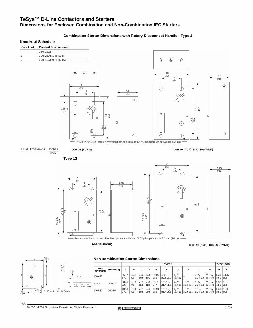
TeSys™ D-Line Contactors and StartersDimensions for Enclosed Combination and Non-Combination IEC Starters
© 2001-2004 Schneider E156
Knockout ScheduleKnockout Conduit Size, in
A 0.50 (12.7)
B 1.00 (25.4); 1.25 (3
C 0.50 (12.7); 0.75 (1
Dual Dimensions: Inchesmm
15.6
25
R
.56
14
DD/2
Provision for
B E
A .50
13
Dimensions for Enclosed Combination and Non-Combination IEC Starters
Combination Starter Dimensions with Rotary Disconnect Handle - Type 1
Type 12
7.5191
0.687517
8203
376
14 356
12.5
318
A
A
B C B
5127
16.5
419
7.5191
10254
18 457
A
A
B C B
R
R
Provision for 1/4 in. screw / Provisión para el tornillo de 1/4 / Option pour vis de 6,3 mm (1/4 po)
D09-25 (FVNR) D09-40 (FVR); D32-40 (FVNR)
. (mm)
1.8)
9.05)
7.75197
Provision for 1/4 in. screw / Provisión para el tornillo de 1/4 / Option pour vis de 6,3 mm (1/4 po)
19.6
2549
8
5127
18.8
7547
9
7.75197
18 457
14 356
397
14.8
7537
8
8203
376
10254
R
R
D09-40 (FVR); D32-40 (FVNR)
1/4" Screw
C.7
519
F G H
J
K
Non-combination Starter DimensionsTYPE 1 TYPE 12/3R
Non-reversing Reversing A B C D E F G H J K D E
D09-25 ...6.77
17210.04255
6.25158
5.38136
9.00228
1-11/425.4-31.7
1/2-3/412.7-19
–1-1/425.4-6.3
1/2 - 3/412.7-19
5.3813.6
11.37288
D32-50 D09-328.66
22010.83275
7.21183
7.25184
9.75247
11/4-11/231.7-38.1
1/2-3/412.7-19
1-11/425.4-31.7
1-1/425.4-6.3
1/2 - 3/412.7-19
5.3813.6
12.15308
D65-80 D40-8010.63270
13.98355
7.21183
9.22234
12.94328
11/4-11/231.7-38.1
1/2-3/412.7-19
1-11/425.4-31.7
1-11/425.4-6.3
1/2 - 3/412.7-19
5.3813.6
15.30385
D09-25 (FVNR)
lectric All Rights Reserved 01/04
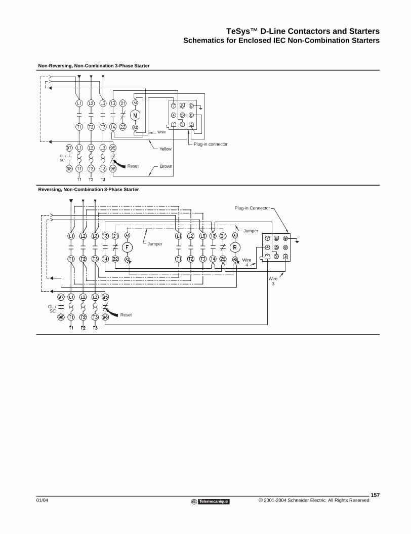
TeSys™ D-Line Contactors and StartersSchematics for Enclosed IEC Non-Combination Starters
01/04
Non-Reversing, Non-Combin
Reversing, Non-Combination
OL /SC
OL / SC
Schematics for Enclosed IEC Non-Combination Starters
ation 3-Phase Starter
3-Phase Starter
Reset Brown
Yellow
White
Plug-in connector
Plug-in Connector
Jumper
Jumper
Reset
Wire4
Wire3
157© 2001-2004 Schneider Electric All Rights Reserved
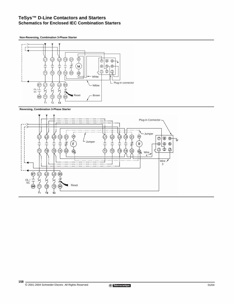
TeSys™ D-Line Contactors and StartersSchematics for Enclosed IEC Combination Starters
© 2001-2004 Schneider E158
Non-Reversing, Combination
Reversing, Combination 3-P
OL /SC
OL / SC
Schematics for Enclosed IEC Combination Starters
3-Phase Starter
hase Starter
Reset Brown
Yellow
White
Plug-in connector
Plug-in Connector
Jumper
Jumper
Reset
Wire4
Wire3
lectric All Rights Reserved 01/04
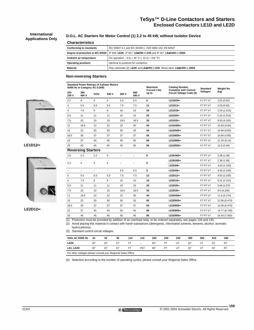
TeSys™ D-Line Contactors and StartersEnclosed Contactors LE1D and LE2D
01/04
InternationalApplications Only
LE1D12••
LE2D12••
Enclosed Contactors LE1D (International Applications Only)
D.O.L. AC Starters for Motor Control (1) 2.2 to 45 kW, without Isolator Device
Non-reversing Starters
(1) Protection must be provided by addition of an overload relay, to be ordered separately, see pages 134 and 135.(2) Avoid placing this material in contact with harsh substances (detergents, chlorinated solvents, ketones, alcohol, aromatic
hydrocarbons).(3) Standard control circuit voltages.
(4) Selection according to the number of operating cycles, please consult your Regional Sales Office.
CharacteristicsConforming to standards IEC 60947-4-1 and IEC 60439-1, VDE 0660-102, EN 60947
Degree of protection to IEC 60529 IP 659: LE2K, IP 657: LEpD09 to D35 and IP 557: LEpD405 to D955
Ambient air temperature For operation: - 5 to + 40 °C (- 41 to + 104 °F)
Operating positions Identical to positions for contactors
Material Poly carbonate (2): LE2K and LEpD09 to D35. Sheet steel: LEpD405 to D955
Standard Power Ratings of 3-phase Motors 50/60 Hz in Category AC-3 (kW) Maximum
Current I theup to
Catalog Number, Complete with Control Circuit Voltage Code (3)
Standard Voltages
Weight lbs (kg)220
230 V380400 V 415V 440 V 500 V 660
690 V
2.2 4 4 4 5.5 5.5 9 LE1DO9•• F7 P7 V7 2.03 (0.92)
3 5.5 5.5 5.5 7.5 7.5 12 LE1D12•• F7 P7 V7 2.03 (0.92)
4 7.5 9 9 10 10 18 LE1D18•• F7 P7 V7 2.24 (1.015)
5.5 11 11 11 15 15 25 LE1D25•• F7 P7 V7 2.24 (1.015)
7.5 15 15 15 18.5 18.5 35 LE1D35•• F7 P7 V7 9.53 (4.320)
11 18.5 22 22 22 30 40 LE1D405•• F7 P7 V7 10.63 (4.82)
15 22 25 30 30 33 50 LE1D505•• F7 P7 V7 10.69 (4.85)
18.5 30 37 37 37 37 65 LE1D655•• F7 P7 V7 10.69 (4.85)
22 37 45 45 55 45 80 LE1D805•• F7 P7 V7 11.33 (5.14)
25 45 45 45 55 45 95 LE1D955•• F7 P7 V7 12.0 (5.44)
Reversing Starters1.5 2.2 2.2 3 – – 6 LE2K065•• F7 P7 V7 2.38 (1.08)
2.2 4 4 4 – – 9LE2K095•• F7 P7 V7 2.38 (1.08)
LE2D09•• F7 P7 V7 4.63 (2.100)
– – – – 5.5 5.5 9 LE2D09•• F7 P7 V7 4.63 (2.100)
3 5.5 5.5 5.5 7.5 7.5 12 LE2D12•• F7 P7 V7 4.63 (2.100)
4 7.5 9 9 10 10 18 LE2D18•• F7 P7 V7 5.31 (2.410)
5.5 11 11 11 15 15 25 LE2D25•• F7 P7 V7 5.66 (2.570
7.5 15 15 15 18.5 18.5 35 LE2D35•• F7 P7 V7 9.0 (4.100)
11 18.5 22 22 22 30 40 LE2D405•• F7 P7 V7 11.6 (5.270)
15 22 25 30 30 33 50 LE2D505•• F7 P7 V7 12.06 (5.470)
18.5 30 37 37 37 37 65 LE2D655•• F7 P7 V7 12.06 (5.470)
22 37 45 45 55 45 80 LE2D805•• F7 P7 V7 14.77 (6.700)
25 45 45 45 55 45 95 LE2D955•• F7 P7 V7 15.43 (7.000)
Volts AC 50/60 Hz 24 42 48 110 115 220 230 240 380 400 415 440
LE2K B7 D7 E7 F7 – M7 P7 U7 Q7 V7 N7 R7
LE1, LE2D B7 D7 E7 F7 FE7 M7 P7 U7 Q7 V7 N7 R7
For other voltages please consult your Regional Sales Office.
159© 2001-2004 Schneider Electric All Rights Reserved
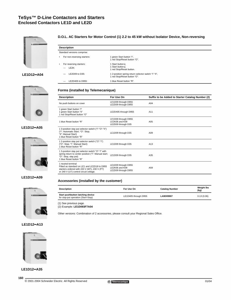
TeSys™ D-Line Contactors and StartersEnclosed Contactors LE1D and LE2D
© 2001-2004 Schneider E160
LE1D12••A04
LE1D12••A09
LE1D12••A13
LE1D12••A05
LE1D12••A35
D.O.L. AC Starters for Motor Control (1) 2.2 to 45 kW without Isolator Device, Non-reversing
(1) See previous page.(2) Example: LE1D093F7A04
Other versions: Combination of 2 accessories, please consult your Regional Sales Office.
Description
Standard versions comprise:
• For non-reversing starters: 1 green Start button “I”,1 red Stop/Reset button “O”.
• For reversing starters:
— LE2K:
1 Start button A,1 Start button E,1 red Stop/Reset button.
— LE2D09 to D35: 1 2-position spring return selector switch “I”-“II”,1 red Stop/Reset button “O”.
— LE2D405 to D955: 1 blue Reset button “R”.
Forms (installed by Telemecanique)
Description For Use On Suffix to be Added to Starter Catalog Number (2)
No push buttons on coverLE1D09 through D955LE2D09 through D955
A04
1 green Start button “I” 1 green Start button “II”1 red Stop/Reset button “O”
LE2D405 through D955 A11
1 blue Reset button “R”LE1D09 through D955LE2K06 and K09LE2D09 through D35
A05
1 3-position stay put selector switch (“I”-”O”-”II”)(“I”: Automatic Start; “O”: Stop; “II”: Manual Start)1 blue Reset button “R”
LE1D09 through D35 A09
1 2-position stay put selector switch (”O”-”I”)(“O”: Stop; “I”: Manual Start)1 blue Reset button “R”
LE1D09 through D35 A13
1 3-position stay put selector switch ”O”-”I” with spring return to center position (”I”: Manual start;”O”: Stop, stay put)1 blue Reset button “R”
LE1D09 through D35 A35
1 neutral terminalFitted as standard on LE1 and LE2D18 to D955starters ordered with 220 V (M7), 230 V (P7)or 240 V (U7) control circuit voltage.
LE1D09 through D955LE2K06 and K09LE2D09 through D955
A59
Accessories (installed by the customer)
Description For Use On Catalog Number Weight lbs (kg)
Start pushbutton latching devicefor stay-put operation (Start-Stop)
LE1D405 through D955 LA9D09907 0.13 (0.06)
lectric All Rights Reserved 01/04
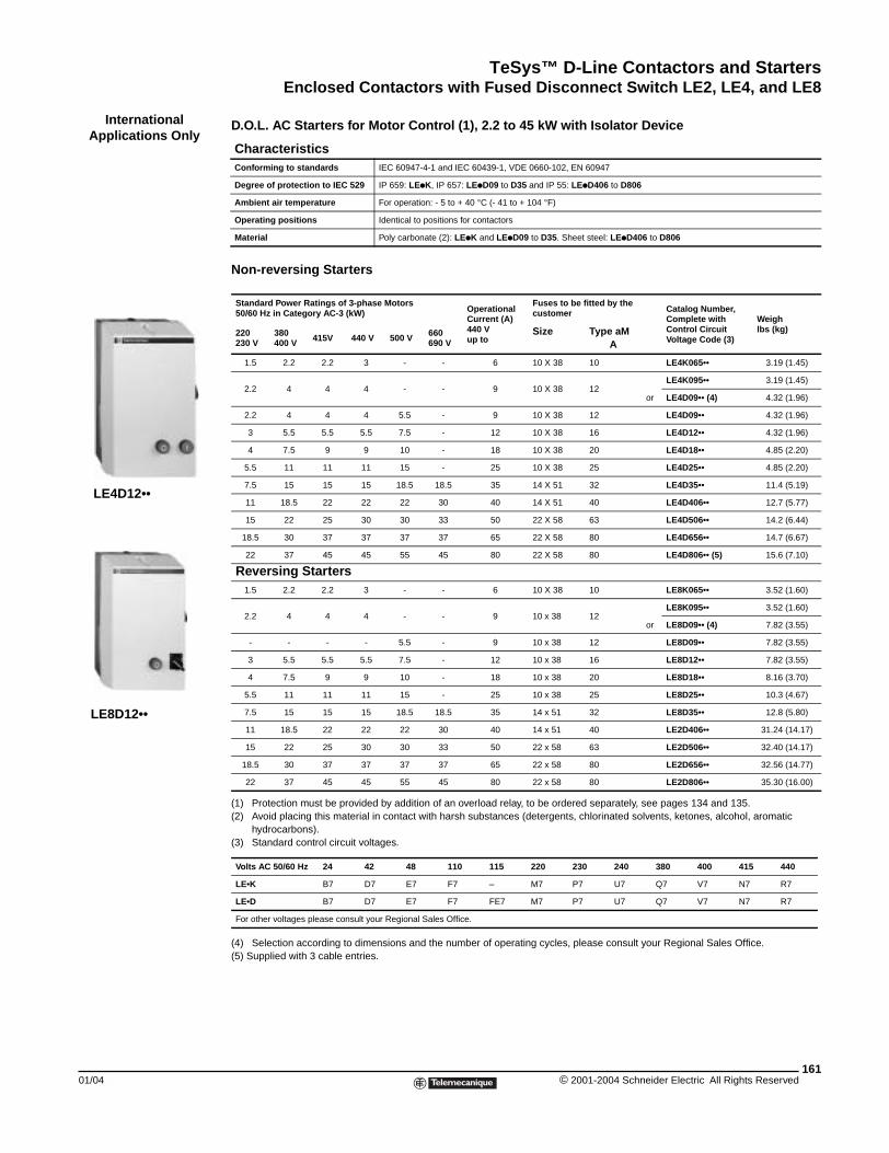
TeSys™ D-Line Contactors and StartersEnclosed Contactors with Fused Disconnect Switch LE2, LE4, and LE8
01/04
InternationalApplications Only
LE4D12••
LE8D12••
Enclosed Contactors with Fused Disconnect Switch LE4K/D (International Application Only)
D.O.L. AC Starters for Motor Control (1), 2.2 to 45 kW with Isolator Device
Non-reversing Starters
(1) Protection must be provided by addition of an overload relay, to be ordered separately, see pages 134 and 135.(2) Avoid placing this material in contact with harsh substances (detergents, chlorinated solvents, ketones, alcohol, aromatic
hydrocarbons).(3) Standard control circuit voltages.
(4) Selection according to dimensions and the number of operating cycles, please consult your Regional Sales Office.(5) Supplied with 3 cable entries.
CharacteristicsConforming to standards IEC 60947-4-1 and IEC 60439-1, VDE 0660-102, EN 60947
Degree of protection to IEC 529 IP 659: LEpK, IP 657: LEpD09 to D35 and IP 55: LEpD406 to D806
Ambient air temperature For operation: - 5 to + 40 °C (- 41 to + 104 °F)
Operating positions Identical to positions for contactors
Material Poly carbonate (2): LEpK and LEpD09 to D35. Sheet steel: LEpD406 to D806
Standard Power Ratings of 3-phase Motors 50/60 Hz in Category AC-3 (kW) Operational
Current (A)440 Vup to
Fuses to be fitted by the customer Catalog Number,
Complete with Control Circuit Voltage Code (3)
Weighlbs (kg)220
230 V380400 V 415V 440 V 500 V 660
690 VSize Type aM
A
1.5 2.2 2.2 3 - - 6 10 X 38 10 LE4K065•• 3.19 (1.45)
2.2 4 4 4 - - 9 10 X 38 12LE4K095•• 3.19 (1.45)
or LE4D09•• (4) 4.32 (1.96)
2.2 4 4 4 5.5 - 9 10 X 38 12 LE4D09•• 4.32 (1.96)
3 5.5 5.5 5.5 7.5 - 12 10 X 38 16 LE4D12•• 4.32 (1.96)
4 7.5 9 9 10 - 18 10 X 38 20 LE4D18•• 4.85 (2.20)
5.5 11 11 11 15 - 25 10 X 38 25 LE4D25•• 4.85 (2.20)
7.5 15 15 15 18.5 18.5 35 14 X 51 32 LE4D35•• 11.4 (5.19)
11 18.5 22 22 22 30 40 14 X 51 40 LE4D406•• 12.7 (5.77)
15 22 25 30 30 33 50 22 X 58 63 LE4D506•• 14.2 (6.44)
18.5 30 37 37 37 37 65 22 X 58 80 LE4D656•• 14.7 (6.67)
22 37 45 45 55 45 80 22 X 58 80 LE4D806•• (5) 15.6 (7.10)
Reversing Starters1.5 2.2 2.2 3 - - 6 10 X 38 10 LE8K065•• 3.52 (1.60)
2.2 4 4 4 - - 9 10 x 38 12LE8K095•• 3.52 (1.60)
or LE8D09•• (4) 7.82 (3.55)
- - - - 5.5 - 9 10 x 38 12 LE8D09•• 7.82 (3.55)
3 5.5 5.5 5.5 7.5 - 12 10 x 38 16 LE8D12•• 7.82 (3.55)
4 7.5 9 9 10 - 18 10 x 38 20 LE8D18•• 8.16 (3.70)
5.5 11 11 11 15 - 25 10 x 38 25 LE8D25•• 10.3 (4.67)
7.5 15 15 15 18.5 18.5 35 14 x 51 32 LE8D35•• 12.8 (5.80)
11 18.5 22 22 22 30 40 14 x 51 40 LE2D406•• 31.24 (14.17)
15 22 25 30 30 33 50 22 x 58 63 LE2D506•• 32.40 (14.17)
18.5 30 37 37 37 37 65 22 x 58 80 LE2D656•• 32.56 (14.77)
22 37 45 45 55 45 80 22 x 58 80 LE2D806•• 35.30 (16.00)
Volts AC 50/60 Hz 24 42 48 110 115 220 230 240 380 400 415 440
LE•K B7 D7 E7 F7 – M7 P7 U7 Q7 V7 N7 R7
LE•D B7 D7 E7 F7 FE7 M7 P7 U7 Q7 V7 N7 R7
For other voltages please consult your Regional Sales Office.
161© 2001-2004 Schneider Electric All Rights Reserved
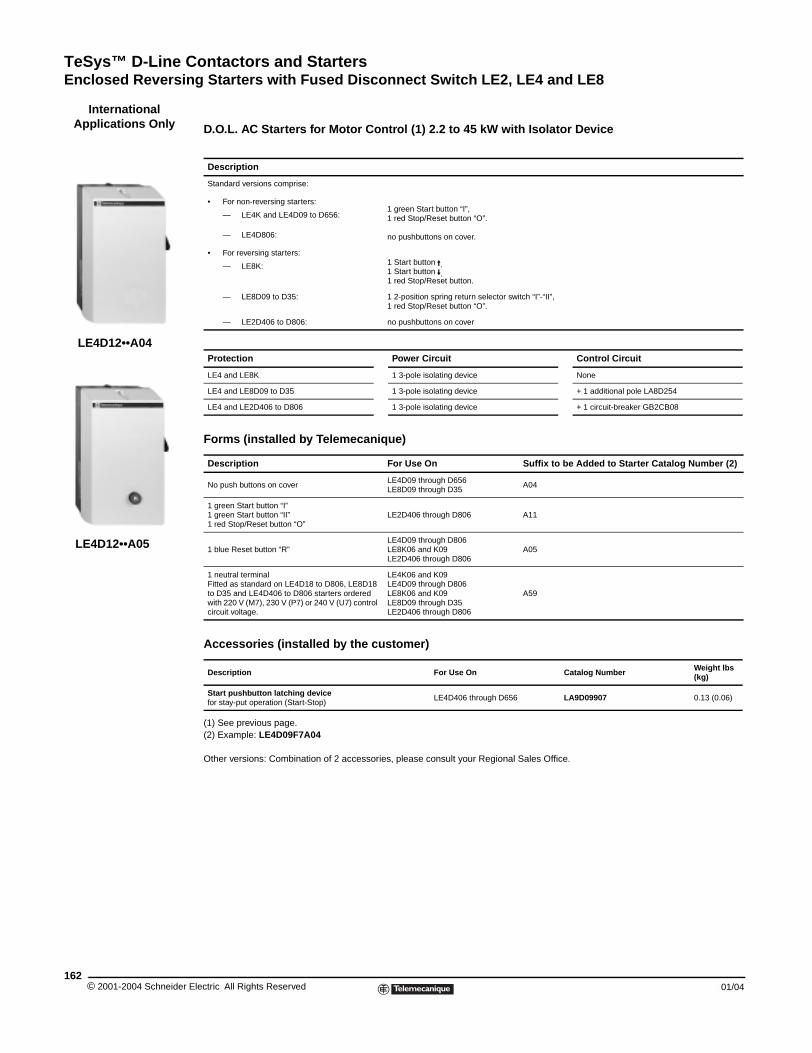
TeSys™ D-Line Contactors and StartersEnclosed Reversing Starters with Fused Disconnect Switch LE2, LE4 and LE8
© 2001-2004 Schneider E162
InternationalApplications Only
LE4D12••A04
LE4D12••A05
Enclosed Reversing Starters with Fused Disconnect Switch LE2D (Int’l App. Only)
D.O.L. AC Starters for Motor Control (1) 2.2 to 45 kW with Isolator Device
(1) See previous page.(2) Example: LE4D09F7A04
Other versions: Combination of 2 accessories, please consult your Regional Sales Office.
Description
Standard versions comprise:
• For non-reversing starters:
— LE4K and LE4D09 to D656:
— LE4D806:
1 green Start button “I”,1 red Stop/Reset button “O”.
no pushbuttons on cover.
• For reversing starters:
— LE8K: 1 Start button A,1 Start button E,1 red Stop/Reset button.
— LE8D09 to D35: 1 2-position spring return selector switch “I”-“II”,1 red Stop/Reset button “O”.
— LE2D406 to D806: no pushbuttons on cover
Protection Power Circuit Control Circuit
LE4 and LE8K 1 3-pole isolating device None
LE4 and LE8D09 to D35 1 3-pole isolating device + 1 additional pole LA8D254
LE4 and LE2D406 to D806 1 3-pole isolating device + 1 circuit-breaker GB2CB08
Forms (installed by Telemecanique)
Description For Use On Suffix to be Added to Starter Catalog Number (2)
No push buttons on coverLE4D09 through D656LE8D09 through D35
A04
1 green Start button “I” 1 green Start button “II”1 red Stop/Reset button “O”
LE2D406 through D806 A11
1 blue Reset button “R”LE4D09 through D806LE8K06 and K09LE2D406 through D806
A05
1 neutral terminalFitted as standard on LE4D18 to D806, LE8D18 to D35 and LE4D406 to D806 starters ordered with 220 V (M7), 230 V (P7) or 240 V (U7) control circuit voltage.
LE4K06 and K09LE4D09 through D806LE8K06 and K09LE8D09 through D35LE2D406 through D806
A59
Accessories (installed by the customer)
Description For Use On Catalog Number Weight lbs (kg)
Start pushbutton latching devicefor stay-put operation (Start-Stop)
LE4D406 through D656 LA9D09907 0.13 (0.06)
lectric All Rights Reserved 01/04
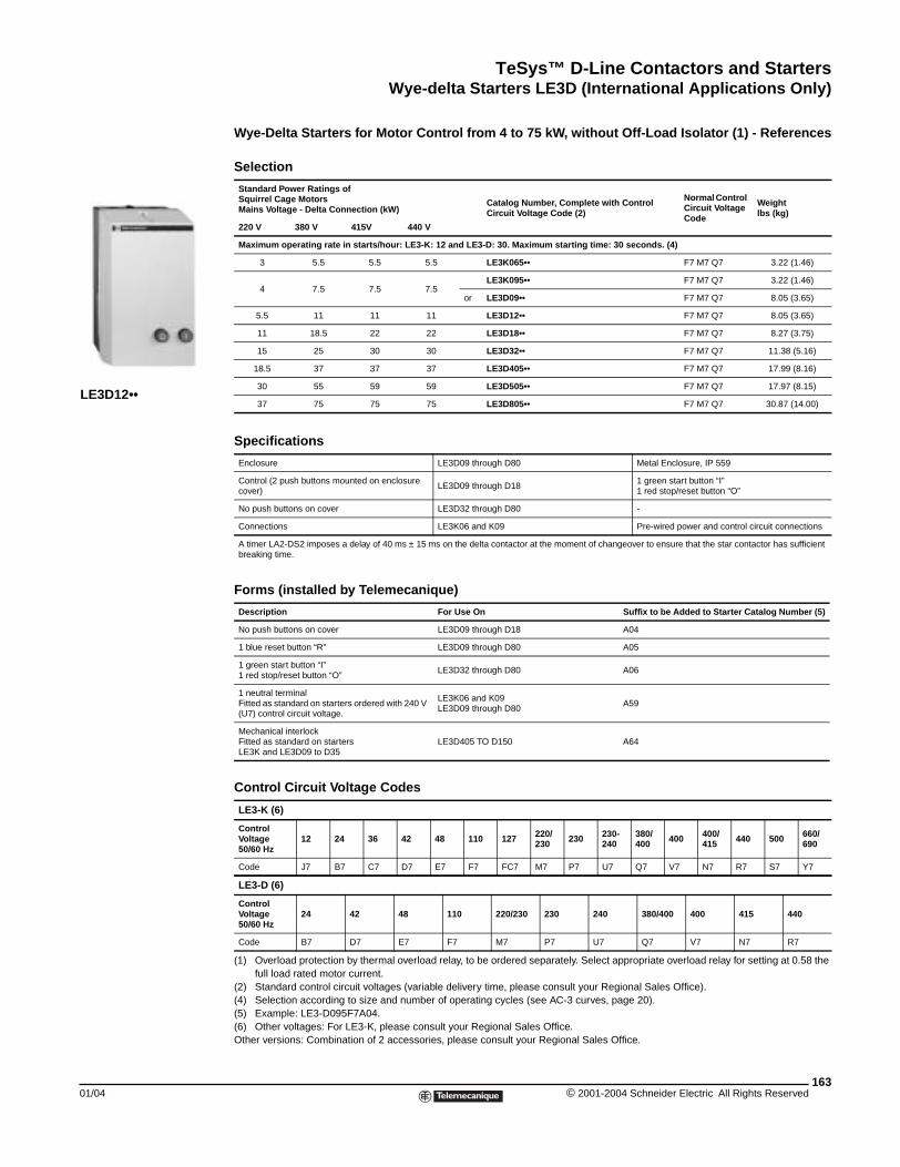
TeSys™ D-Line Contactors and StartersWye-delta Starters LE3D (International Applications Only)
01/04
LE3D12••
Wye-delta Starters LE3D (International Applications Only)
Wye-Delta Starters for Motor Control from 4 to 75 kW, without Off-Load Isolator (1) - References
(1) Overload protection by thermal overload relay, to be ordered separately. Select appropriate overload relay for setting at 0.58 the full load rated motor current.
(2) Standard control circuit voltages (variable delivery time, please consult your Regional Sales Office).(4) Selection according to size and number of operating cycles (see AC-3 curves, page 20).(5) Example: LE3-D095F7A04.(6) Other voltages: For LE3-K, please consult your Regional Sales Office. Other versions: Combination of 2 accessories, please consult your Regional Sales Office.
Selection
Standard Power Ratings of Squirrel Cage Motors Mains Voltage - Delta Connection (kW)
Catalog Number, Complete with Control Circuit Voltage Code (2)
Normal Control Circuit Voltage Code
Weightlbs (kg)
220 V 380 V 415V 440 V
Maximum operating rate in starts/hour: LE3-K: 12 and LE3-D: 30. Maximum starting time: 30 seconds. (4)
3 5.5 5.5 5.5 LE3K065•• F7 M7 Q7 3.22 (1.46)
4 7.5 7.5 7.5LE3K095•• F7 M7 Q7 3.22 (1.46)
or LE3D09•• F7 M7 Q7 8.05 (3.65)
5.5 11 11 11 LE3D12•• F7 M7 Q7 8.05 (3.65)
11 18.5 22 22 LE3D18•• F7 M7 Q7 8.27 (3.75)
15 25 30 30 LE3D32•• F7 M7 Q7 11.38 (5.16)
18.5 37 37 37 LE3D405•• F7 M7 Q7 17.99 (8.16)
30 55 59 59 LE3D505•• F7 M7 Q7 17.97 (8.15)
37 75 75 75 LE3D805•• F7 M7 Q7 30.87 (14.00)
Specifications
Enclosure LE3D09 through D80 Metal Enclosure, IP 559
Control (2 push buttons mounted on enclosure cover)
LE3D09 through D181 green start button “I”1 red stop/reset button “O”
No push buttons on cover LE3D32 through D80 -
Connections LE3K06 and K09 Pre-wired power and control circuit connections
A timer LA2-DS2 imposes a delay of 40 ms ± 15 ms on the delta contactor at the moment of changeover to ensure that the star contactor has sufficient breaking time.
Forms (installed by Telemecanique)
Description For Use On Suffix to be Added to Starter Catalog Number (5)
No push buttons on cover LE3D09 through D18 A04
1 blue reset button “R” LE3D09 through D80 A05
1 green start button “I”1 red stop/reset button “O”
LE3D32 through D80 A06
1 neutral terminalFitted as standard on starters ordered with 240 V (U7) control circuit voltage.
LE3K06 and K09LE3D09 through D80
A59
Mechanical interlockFitted as standard on startersLE3K and LE3D09 to D35
LE3D405 TO D150 A64
Control Circuit Voltage Codes
LE3-K (6)
Control Voltage50/60 Hz
12 24 36 42 48 110 127 220/230 230 230-
240380/400 400 400/
415 440 500 660/690
Code J7 B7 C7 D7 E7 F7 FC7 M7 P7 U7 Q7 V7 N7 R7 S7 Y7
LE3-D (6)
Control Voltage50/60 Hz
24 42 48 110 220/230 230 240 380/400 400 415 440
Code B7 D7 E7 F7 M7 P7 U7 Q7 V7 N7 R7
163© 2001-2004 Schneider Electric All Rights Reserved
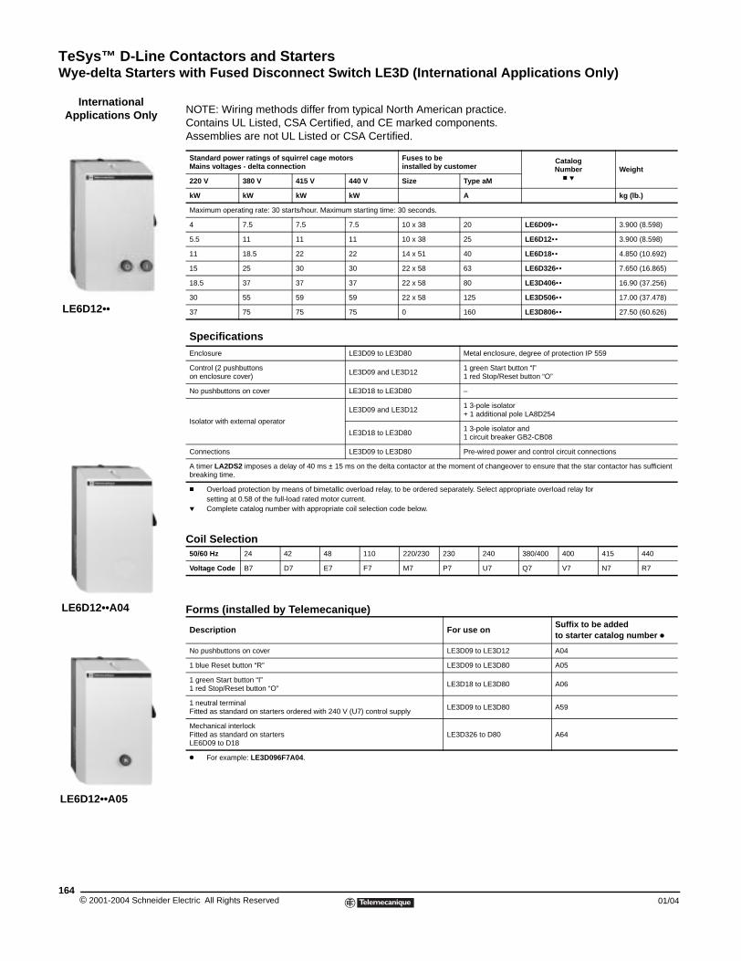
TeSys™ D-Line Contactors and StartersWye-delta Starters with Fused Disconnect Switch LE3D (International Applications Only)
© 2001-2004 Schneider E164
LE6D12••
InternationalApplications Only
LE6D12••A04
LE6D12••A05
Wye-delta Starters with Fused Disconnect Switch LE3D (International Applications Only)
NOTE: Wiring methods differ from typical North American practice.Contains UL Listed, CSA Certified, and CE marked components.Assemblies are not UL Listed or CSA Certified.
Coil Selection
Forms (installed by Telemecanique)
Standard power ratings of squirrel cage motorsMains voltages - delta connection
Fuses to beinstalled by customer
Catalog Number
c pWeight
220 V 380 V 415 V 440 V Size Type aM
kW kW kW kW A kg (lb.)
Maximum operating rate: 30 starts/hour. Maximum starting time: 30 seconds.
4 7.5 7.5 7.5 10 x 38 20 LE6D09•• 3.900 (8.598)
5.5 11 11 11 10 x 38 25 LE6D12•• 3.900 (8.598)
11 18.5 22 22 14 x 51 40 LE6D18•• 4.850 (10.692)
15 25 30 30 22 x 58 63 LE6D326•• 7.650 (16.865)
18.5 37 37 37 22 x 58 80 LE3D406•• 16.90 (37.256)
30 55 59 59 22 x 58 125 LE3D506•• 17.00 (37.478)
37 75 75 75 0 160 LE3D806•• 27.50 (60.626)
SpecificationsEnclosure LE3D09 to LE3D80 Metal enclosure, degree of protection IP 559
Control (2 pushbuttons on enclosure cover)
LE3D09 and LE3D12 1 green Start button “l”1 red Stop/Reset button “O”
No pushbuttons on cover LE3D18 to LE3D80 –
Isolator with external operator
LE3D09 and LE3D12 1 3-pole isolator+ 1 additional pole LA8D254
LE3D18 to LE3D80 1 3-pole isolator and1 circuit breaker GB2-CB08
Connections LE3D09 to LE3D80 Pre-wired power and control circuit connections
A timer LA2DS2 imposes a delay of 40 ms ± 15 ms on the delta contactor at the moment of changeover to ensure that the star contactor has sufficient breaking time.
c Overload protection by means of bimetallic overload relay, to be ordered separately. Select appropriate overload relay for setting at 0.58 of the full-load rated motor current.
p Complete catalog number with appropriate coil selection code below.
50/60 Hz 24 42 48 110 220/230 230 240 380/400 400 415 440
Voltage Code B7 D7 E7 F7 M7 P7 U7 Q7 V7 N7 R7
Description For use onSuffix to be added to starter catalog number k
No pushbuttons on cover LE3D09 to LE3D12 A04
1 blue Reset button “R” LE3D09 to LE3D80 A05
1 green Start button “I” 1 red Stop/Reset button “O”
LE3D18 to LE3D80 A06
1 neutral terminalFitted as standard on starters ordered with 240 V (U7) control supply
LE3D09 to LE3D80 A59
Mechanical interlockFitted as standard on startersLE6D09 to D18
LE3D326 to D80 A64
k For example: LE3D096F7A04.
lectric All Rights Reserved 01/04
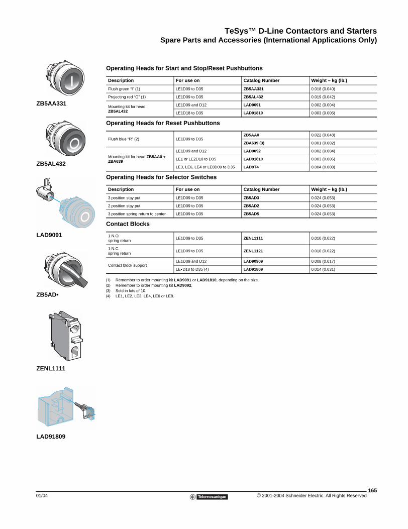
TeSys™ D-Line Contactors and StartersSpare Parts and Accessories (International Applications Only)
01/04
ZB5AA331
ZB5AL432
LAD9091
ZB5AD•
ZENL1111
LAD91809
Spare Parts and Accessories (International Applications Only)
(1) Remember to order mounting kit LAD9091 or LAD91810, depending on the size.(2) Remember to order mounting kit LAD9092.(3) Sold in lots of 10.(4) LE1, LE2, LE3, LE4, LE6 or LE8.
Operating Heads for Start and Stop/Reset Pushbuttons
Description For use on Catalog Number Weight – kg (lb.)
Flush green “I” (1) LE1D09 to D35 ZB5AA331 0.018 (0.040)
Projecting red “O” (1) LE1D09 to D35 ZB5AL432 0.019 (0.042)
Mounting kit for headZB5AL432
LE1D09 and D12 LAD9091 0.002 (0.004)
LE1D18 to D35 LAD91810 0.003 (0.006)
Operating Heads for Reset Pushbuttons
Flush blue “R” (2) LE1D09 to D35ZB5AA0 0.022 (0.048)
ZBA639 (3) 0.001 (0.002)
Mounting kit for head ZB5AA0 + ZBA639
LE1D09 and D12 LAD9092 0.002 (0.004)
LE1 or LE2D18 to D35 LAD91810 0.003 (0.006)
LE3, LE6, LE4 or LE8D09 to D35 LAD9T4 0.004 (0.008)
Operating Heads for Selector Switches
Description For use on Catalog Number Weight – kg (lb.)
3 position stay put LE1D09 to D35 ZB5AD3 0.024 (0.053)
2 position stay put LE1D09 to D35 ZB5AD2 0.024 (0.053)
3 position spring return to center LE1D09 to D35 ZB5AD5 0.024 (0.053)
Contact Blocks
1 N.O. spring return
LE1D09 to D35 ZENL1111 0.010 (0.022)
1 N.C. spring return
LE1D09 to D35 ZENL1121 0.010 (0.022)
Contact block supportLE1D09 and D12 LAD90909 0.008 (0.017)
LE•D18 to D35 (4) LAD91809 0.014 (0.031)
165© 2001-2004 Schneider Electric All Rights Reserved
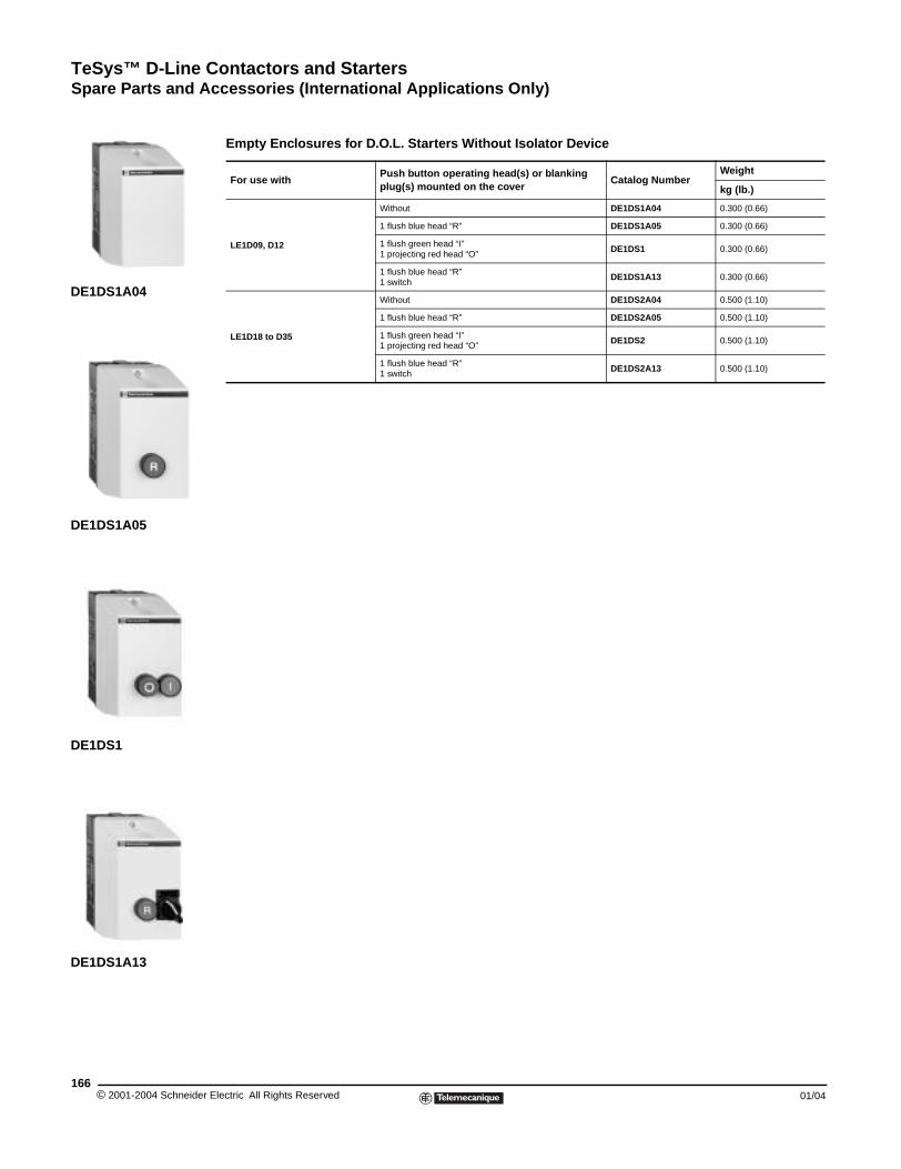
TeSys™ D-Line Contactors and StartersSpare Parts and Accessories (International Applications Only)
© 2001-2004 Schneider E166
DE1DS1A13
DE1DS1A04
DE1DS1A05
DE1DS1
Empty Enclosures for D.O.L. Starters Without Isolator Device
For use withPush button operating head(s) or blanking plug(s) mounted on the cover
Catalog NumberWeight
kg (lb.)
LE1D09, D12
Without DE1DS1A04 0.300 (0.66)
1 flush blue head “R” DE1DS1A05 0.300 (0.66)
1 flush green head “I”1 projecting red head “O”
DE1DS1 0.300 (0.66)
1 flush blue head “R”1 switch
DE1DS1A13 0.300 (0.66)
LE1D18 to D35
Without DE1DS2A04 0.500 (1.10)
1 flush blue head “R” DE1DS2A05 0.500 (1.10)
1 flush green head “I”1 projecting red head “O”
DE1DS2 0.500 (1.10)
1 flush blue head “R”1 switch
DE1DS2A13 0.500 (1.10)
lectric All Rights Reserved 01/04
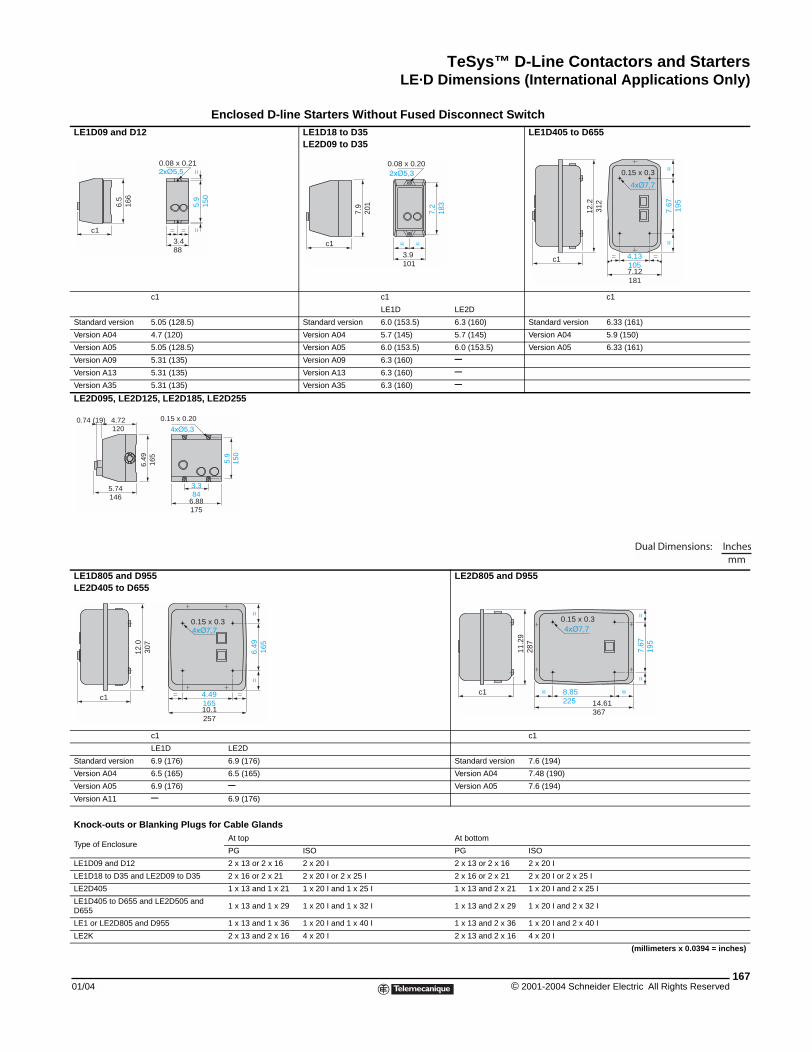
TeSys™ D-Line Contactors and StartersLE·D Dimensions (International Applications Only)
01/04
LE1D09 and D12
c1
Standard version 5.05 (128.5)
Version A04 4.7 (120)
Version A05 5.05 (128.5)
Version A09 5.31 (135)
Version A13 5.31 (135)
Version A35 5.31 (135)
LE2D095, LE2D125, LE2D185
LE1D805 and D955LE2D405 to D655
c1
LE1D
Standard version 6.9 (176)
Version A04 6.5 (165)
Version A05 6.9 (176)
Version A11 –
Knock-outs or Blanking Plug
Type of Enclosure
LE1D09 and D12
LE1D18 to D35 and LE2D09 to D35
LE2D405
LE1D405 to D655 and LE2D505 andD655
LE1 or LE2D805 and D955
LE2K
c1
6.5
166
5.9
==
=
3.488
=
0.08 x 0.21
5.74146
4.72120
3.384
6.88175
6.49
165
0.74 (19) 0.15 x 0.20
c1
12.0
307
=
0.1
LE·D Dimensions (International Applications Only)
Enclosed D-line Starters Without Fused Disconnect Switch LE1D18 to D35LE2D09 to D35
LE1D405 to D655
c1 c1
LE1D LE2D
Standard version 6.0 (153.5) 6.3 (160) Standard version 6.33 (161)
Version A04 5.7 (145) 5.7 (145) Version A04 5.9 (150)
Version A05 6.0 (153.5) 6.0 (153.5) Version A05 6.33 (161)
Version A09 6.3 (160) –Version A13 6.3 (160) –Version A35 6.3 (160) –
, LE2D255
LE2D805 and D955
c1
LE2D
6.9 (176) Standard version 7.6 (194)
6.5 (165) Version A04 7.48 (190)
– Version A05 7.6 (194)
6.9 (176)
s for Cable GlandsAt top At bottom
PG ISO PG ISO
2 x 13 or 2 x 16 2 x 20 I 2 x 13 or 2 x 16 2 x 20 I
2 x 16 or 2 x 21 2 x 20 I or 2 x 25 I 2 x 16 or 2 x 21 2 x 20 I or 2 x 25 I
1 x 13 and 1 x 21 1 x 20 I and 1 x 25 I 1 x 13 and 2 x 21 1 x 20 I and 2 x 25 I
1 x 13 and 1 x 29 1 x 20 I and 1 x 32 I 1 x 13 and 2 x 29 1 x 20 I and 2 x 32 I
1 x 13 and 1 x 36 1 x 20 I and 1 x 40 I 1 x 13 and 2 x 36 1 x 20 I and 2 x 40 I
2 x 13 and 2 x 16 4 x 20 I 2 x 13 and 2 x 16 4 x 20 I
(millimeters x 0.0394 = inches)
150
c1
7.2
183
= =
3.9101
7.9
201
0.08 x 0.20
c1
12.2
312
=
7.12181
= 4.13105
7.67
195
==0.15 x 0.3
5.9
150
Dual Dimensions: Inchesmm
=
10.1257
4.49165
6.49
165
==
5 x 0.3
11.2
928
7
c1 =
14.61367
= 8.85225
7.67
195
==0.15 x 0.3
167© 2001-2004 Schneider Electric All Rights Reserved
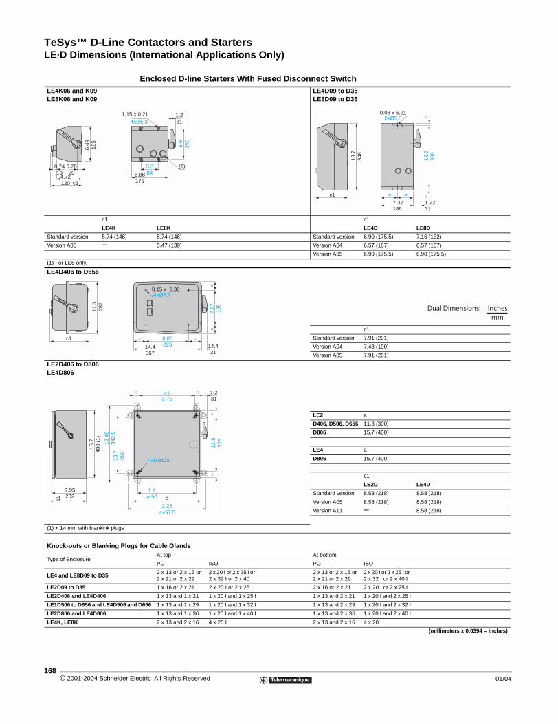
TeSys™ D-Line Contactors and StartersLE·D Dimensions (International Applications Only)
© 2001-2004 Schneider E168
LE4K06 and K09LE8K06 and K09
c1
LE4K
Standard version 5.74 (146)
Version A05 –
(1) For LE8 only.
LE4D406 to D656
LE2D406 to D806LE4D806
(1) + 14 mm with blankink plugs
Knock-outs or Blanking Plug
Type of Enclosure
LE4 and LE8D09 to D35
LE2D09 to D35
LE2D406 and LE4D406
LE1D506 to D656 and LE4D506 an
LE2D806 and LE4D806
LE4K, LE8K
c1
0.7820
6.49
165
4.72120
0.7419
1.15
11.3
287
c1
15.7
400
(1)
7.95202c1
13.7
350
13.4
834
2.5
Enclosed D-line Starters With Fused Disconnect Switch LE4D09 to D35LE8D09 to D35
c1
LE8K LE4D LE8D
5.74 (146) Standard version 6.90 (175.5) 7.16 (182)
5.47 (139) Version A04 6.57 (167) 6.57 (167)
Version A05 6.90 (175.5) 6.90 (175.5)
c1
Standard version 7.91 (201)
Version A04 7.48 (190)
Version A05 7.91 (201)
LE2 a
D406, D506, D656 11.8 (300)
D806 15.7 (400)
LE4 a
D806 15.7 (400)
c1‘
LE2D LE4D
Standard version 8.58 (218) 8.58 (218)
Version A05 8.58 (218) 8.58 (218)
Version A11 – 8.58 (218)
s for Cable GlandsAt top At bottom
PG ISO PG ISO
2 x 13 or 2 x 16 or 2 x 21 or 2 x 29
2 x 20 I or 2 x 25 I or 2 x 32 I or 2 x 40 I
2 x 13 or 2 x 16 or 2 x 21 or 2 x 29
2 x 20 I or 2 x 25 I or 2 x 32 I or 2 x 40 I
1 x 16 or 2 x 21 2 x 20 I or 2 x 25 I 2 x 16 or 2 x 21 2 x 20 I or 2 x 25 I
1 x 13 and 1 x 21 1 x 20 I and 1 x 25 I 1 x 13 and 2 x 21 1 x 20 I and 2 x 25 I
d D656 1 x 13 and 1 x 29 1 x 20 I and 1 x 32 I 1 x 13 and 2 x 29 1 x 20 I and 2 x 32 I
1 x 13 and 1 x 36 1 x 20 I and 1 x 40 I 1 x 13 and 2 x 36 1 x 20 I and 2 x 40 I
2 x 13 and 2 x 16 4 x 20 I 2 x 13 and 2 x 16 4 x 20 I
(millimeters x 0.0394 = inches)
3.3846.88
1755.
915
0
(1)
1.231
x 0.21
c1
13.7
348
12.9
330
==
=
7.32186
1.2231
=
0.08 x 6.21
=
14.4367
=
14.431
8.85225
7.67
195
==
0.15 x 0.30
Dual Dimensions: Inchesmm
== 2.9a-75
1.9a-50 a
2.26a+57.5
12.8
325
==
4xM8x25
1.231
lectric All Rights Reserved 01/04
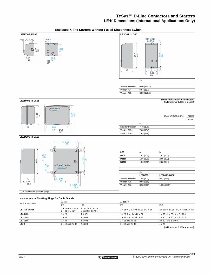
TeSys™ D-Line Contactors and StartersLE·K Dimensions (International Applications Only)
01/04
LE3K065, K095
LE3D405 to D505
LE3D805 to D150
(1) + 14 mm with blankink plugs
Knock-outs or Blanking Plug
Type of Enclosure
LE3D09 to D35
LE3D405
LE3D505
LE3D805
LE3K
3.86.88
175
5.74146
4.72120
6.49
165
0.74 (19) 0.15 x 0.2011
.29
287
c1 = 8
0.
b (1
)
c1
c1 + 0.61 15.5
b -
1.96
5
0
b +
2.26
5
7.5
LE·K Dimensions (International Applications Only)
Enclosed K-line Starters Without Fused Disconnect Switch LE3D09 to D35
c1
Standard version 6.90 (175.5)
Version A04 6.57 (167)
Version A05 6.90 (175.5)
Dimensions shown in millimeters(millimeters x 0.0394 = inches)
c1
Standard version 7.48 (190)
Version A05 7.63 (194)
Version A06 7.63 (194)
LE3 a b
D805 15.7 (400) 15.7 (400)
D1155 19.6 (500) 23.6 (600)
D1505 19.6 (500) 23.6 9600)
c1
LE3D805 LE3D115, D150
Standard version 7.95 (202) 9.92 (252)
Version A05 8.58 (218) –
Version A06 8.58 (218) 10.55 (268)
s for Cable GlandsAt top At bottom
PG ISO PG ISO
2 x 13 or 2 x 16 or 2 x 21 or 2 x 29
2 x 20 I or 2 x 25 I or 2 x 32 I or 2 x 40 I
2 x 13 or 2 x 16 or 2 x 21 or 2 x 29 2 x 20 I or 2 x 25 I or 2 x 32 I or 2 x 40 I
1 x 29 1 X 32 I 1 x 29, 2 x 13 and 2 x 21 1 x 32 I, 2 x 20 I and 2 x 25 I
1 x 36 1 x 40 I 1 x 36, 2 x 13 and 2 x 29 1 x 40 I, 2 x 20 I and 2 x 32 I
1 x 36 1 x 40 I 2 x 13 and 3 x 36 2 x 20 I and 3 x 40 I
2 x 13 and 2 x 16 4 x 20 I 2 x 13 and 2 x 16 4 x 20 I
(millimeters x 0.0394 = inches)
34
5.90
150
c1
13.7
348
12.9
330
==
=
7.32186
=
0.07 x 0.21
=
14.4367
.85225
7.67
195
==
15 x 0.30
Dual Dimensions: Inchesmm
== a - 2.95 75
a - 1.96 50 a
a + 2.26 57.5
b -
2.95
7
5=
=
0.15 x 0.31 x 0.98
169© 2001-2004 Schneider Electric All Rights Reserved
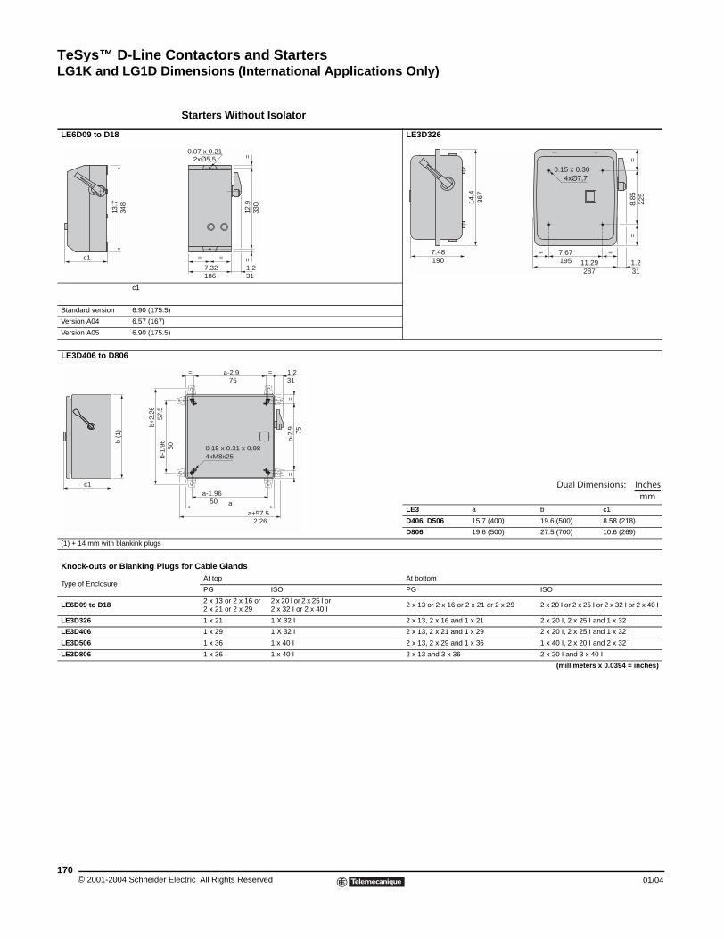
TeSys™ D-Line Contactors and StartersLG1K and LG1D Dimensions (International Applications Only)
© 2001-2004 Schneider E170
LE6D09 to D18
c1
Standard version 6.90 (175.5)
Version A04 6.57 (167)
Version A05 6.90 (175.5)
LE3D406 to D806
(1) + 14 mm with blankink plugs
Knock-outs or Blanking Plug
Type of Enclosure
LE6D09 to D18
LE3D326
LE3D406
LE3D506
LE3D806
c1
13.7
348
b (1
)
c1
b-1.
96
b+2.
26
57.
5
Starters Without Isolator
LE3D326
LE3 a b c1
D406, D506 15.7 (400) 19.6 (500) 8.58 (218)
D806 19.6 (500) 27.5 (700) 10.6 (269)
s for Cable GlandsAt top At bottom
PG ISO PG ISO
2 x 13 or 2 x 16 or 2 x 21 or 2 x 29
2 x 20 I or 2 x 25 I or 2 x 32 I or 2 x 40 I
2 x 13 or 2 x 16 or 2 x 21 or 2 x 29 2 x 20 I or 2 x 25 I or 2 x 32 I or 2 x 40 I
1 x 21 1 X 32 I 2 x 13, 2 x 16 and 1 x 21 2 x 20 I, 2 x 25 I and 1 x 32 I
1 x 29 1 X 32 I 2 x 13, 2 x 21 and 1 x 29 2 x 20 I, 2 x 25 I and 1 x 32 I
1 x 36 1 x 40 I 2 x 13, 2 x 29 and 1 x 36 1 x 40 I, 2 x 20 I and 2 x 32 I
1 x 36 1 x 40 I 2 x 13 and 3 x 36 2 x 20 I and 3 x 40 I
(millimeters x 0.0394 = inches)
12.9
330
==
=
7.32186
1.231
=
0.07 x 0.21
7.48190
14.4
367
8.85
225
==
=
11.29287
=
1.231
7.67195
0.15 x 0.30
== a-2.9 75
a-1.96 50 a
a+57.5 2.26
5
0
b-2.
9
75
==
4xM8x25
1.231
0.15 x 0.31 x 0.98
Dual Dimensions: Inchesmm
lectric All Rights Reserved 01/04
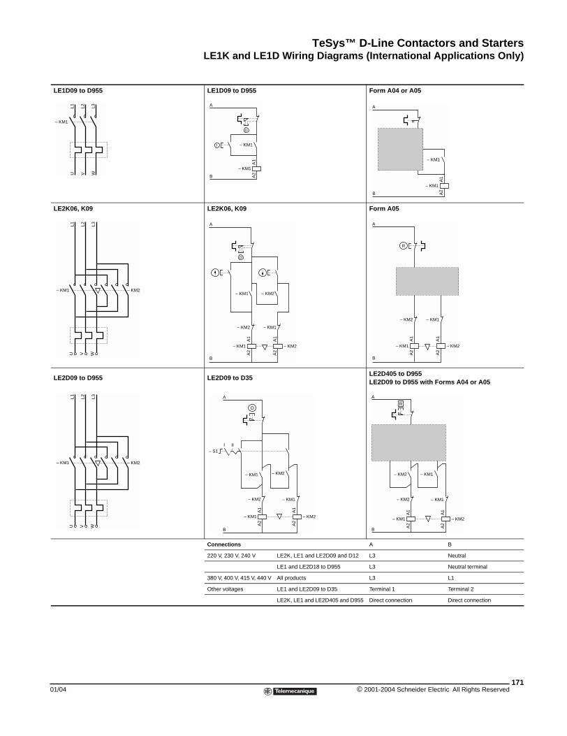
TeSys™ D-Line Contactors and StartersLE1K and LE1D Wiring Diagrams (International Applications Only)
01/04
LE1D09 to D955
LE2K06, K09
LE2D09 to D955
L1 L2
– KM1
U V WL3
– KM1 – KM2
L1 L2 L3
U V W
– KM1 – KM2
L1 L2 L3
U V W
LE1K and LE1D Wiring Diagrams (International Applications Only)
LE1D09 to D955 Form A04 or A05
LE2K06, K09 Form A05
LE2D09 to D35LE2D405 to D955LE2D09 to D955 with Forms A04 or A05
Connections A B
220 V, 230 V, 240 V LE2K, LE1 and LE2D09 and D12 L3 Neutral
LE1 and LE2D18 to D955 L3 Neutral terminal
380 V, 400 V, 415 V, 440 V All products L3 L1
Other voltages LE1 and LE2D09 to D35 Terminal 1 Terminal 2
LE2K, LE1 and LE2D405 and D955 Direct connection Direct connection
B
A
A1
A2
– KM1
– KM1
O
I
1314
2122
A
O
l – KM1
B
A1
A2
– KM1
– KM2
A
B
– KM1
– KM2– KM1
– KM2 – KM1
A1
A2
A1
A2
O
B
– KM2– KM1
– KM2 – KM1
A1
A2
A1
A2
A
R
A1
A2
– KM1
– KM2
– KM2
A
A1
A2
– KM2
– KM1
B
– KM1
– S1III
– KM2
A1
A2
– KM1
2122
– KM2
A
O
A1
A2
– KM2
– KM1
B
R
l l l
– KM1
171© 2001-2004 Schneider Electric All Rights Reserved
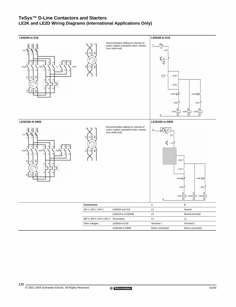
TeSys™ D-Line Contactors and StartersLE2K and LE2D Wiring Diagrams (International Applications Only)
© 2001-2004 Schneider E172
LE6D09 to D18
LE3D326 t0 D806
– KM2
12
34
56
– KM3
12
34
56
U1
V1
W1
U2
V2
W2
1 3 5
2 4 6
– Q1
1/L1
2
3/L2
4
5/L3
6
– KM2
12
34
56
– KM3
12
34
56
–
U1
V1
W1
U2
V2
W2
1 3 5
2 4 6
– Q1
1/L1
2
3/L2
4
5/L3
6
LE2K and LE2D Wiring Diagrams (International Applications Only)
LE6D09 to D18
Recommended cabling for reversal of motor rotation (standard motor, viewed from shaft end).
LE3D326 to D806
Recommended cabling for reversal of motor rotation (standard motor, viewed from shaft end).
Connections A B
220 V, 230 V, 240 V LE6D09 and D12 L3 Neutral
LE6D18 to LE3D806 L3 Neutral terminal
380 V, 400 V, 415 V, 440 V All products L3 L1
Other voltages LE6D09 to D18 Terminal 1 Terminal 2
LE3D326 to D806 Direct connection Direct connection
– KM1
12
34
56
U1
V1
W1
U2
V2
W2
2 4 6
A1
A2
– KM1
– KM3
– KM2
– KM1
l
– KM2
A1
A2
– KM3
– KM1
A1
A2
– KM2
– KM2
B
O
A
Q1Q1
KM1
12
34
56
U1
V1
W1
U2
V2
W2
2 4 6
A1
A2
– KM1
1314
– KM3
– KM2
– KM1
l
– KM2
A1
A2
– KM3
– KM1
A1
A2
– KM2
– KM2
B
A
Q1– F1
2122
– S1
lectric All Rights Reserved 01/04
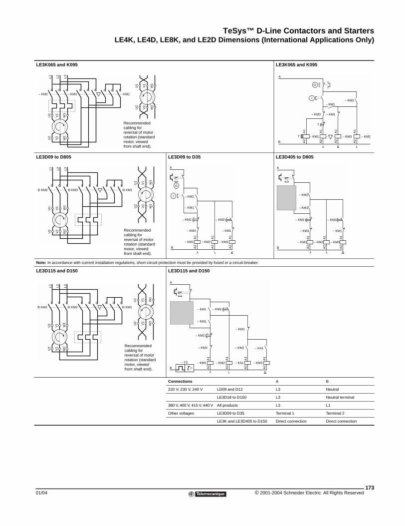
TeSys™ D-Line Contactors and StartersLE4K, LE4D, LE8K, and LE2D Dimensions (International Applications Only)
01/04
LE3K065 and K095
LE3D09 to D805
Note: In accordance with current ins
LE3D115 and D150
– KM2 – KM3
L1 L2 L3
U1
V1
W1
U2
V2
W2
Ð KM2 Ð KM3
U1
V1
W1
U2
V2
W2
L1 L2 L3
Ð KM2 Ð KM3
U1
V1
W1
U2
V2
W2
L1 L2 L3
LE3K065 and K095LE3D09 to D35 LE3D405 to D805
tallation regulations, short-circuit protection must be provided by fused or a circuit-breaker.
LE3D115 and D150
Connections A B
220 V, 230 V, 240 V LD09 and D12 L3 Neutral
LE3D18 to D150 L3 Neutral terminal
380 V, 400 V, 415 V, 440 V All products L3 L1
Other voltages LE3D09 to D35 Terminal 1 Terminal 2
LE3K and LE3D405 to D150 Direct connection Direct connection
– KM1
U1
V1
W1
U2
V2
W2
Recommended cabling for reversal of motor rotation (standard motor, viewed from shaft end).
A
O
– KM3 – KM2– KM1T
T
– KM1
I
Y
L
A1
A2
A1
A2
A1
A2
A1
A2
– KM1– KM3
– KM2
B U
1
V1
W1
U2
V2
W2
Ð KM1
Recommended cabling for reversal of motor rotation (standard motor, viewed from shaft end).
A1
A2
– KM1
– KM3
– KM2
– KM1
– KM2
A1
A2
– KM3
– KM1
A1
A2
– KM2
– KM2
B
A
O
I
Y
L
A1
A2
– KM1
1718
– KM3
– KM2
– KM1
– KM2
A1
A2
– KM3
– KM1
A1
A2
– KM2
– KM2
B
A
I
Y
L
U1
V1
W1
U2
V2
W2
Ð KM1
Recommended cabling for reversal of motor rotation (standard motor, viewed from shaft end).
1718
l
A1
A2
– KM1
– KM3
– KM2
– KM1
– KM2
A1
A2
– KA1
A1
A2
– KM2
– KM1
– F2
– KM2
– KM1
A1
A2
– KM3
– KA1
YL
A
B
173© 2001-2004 Schneider Electric All Rights Reserved
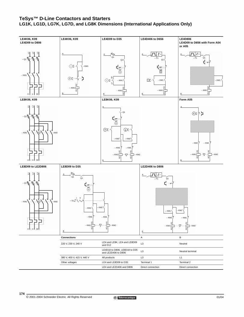
TeSys™ D-Line Contactors and StartersLG1K, LG1D, LG7K, LG7D, and LG8K Dimensions (International Applications Only)
© 2001-2004 Schneider E174
LE4K06, K09LE4D09 to D806
LE8K06, K09
LE8D09 to LE2D806
– Q1
– KM1
L1 L2 L3
U WV
– Q1
– KM1 – KM2
L1 L2 L3
U V W
– Q1
– KM1 – KM2
L1 L2 L3
U V W
LG1K, LG1D, LG7K, LG7D, and LG8K Dimensions (International Applications Only)
LE4K06, K09 LE4D09 to D35 LE4D406 to D656 LE4D806LE4D09 to D656 with Form A04 or A05
LE8K06, K09 Form A05
LE8D09 to D35 LE2D406 to D806
Connections A B
220 V, 230 V, 240 VLE4 and LE8K, LE4 and LE8D09 and D12
L3 Neutral
LE4D18 to D806, LE8D18 to D35 and LE2D406 to D806
L3 Neutral terminal
380 V, 400 V, 415 V, 440 V All products L3 L1
Other voltages LE4 and LE8D09 to D35 Terminal 1 Terminal 2
LE4 and LE2D406 and D806 Direct connection Direct connection
– KM1
O
I
– KM1
A1
A2
A
B B
A
A1
A2
– KM1
– KM1
1817
Q1Q1
O
I
O
l
A1
A2
– KM1
– KM1
Q1– F1
B
A
1314
2122
O
l – KM1
A2
A1
– KM1
Q1– F1
B
A
– KM2– KM1
– KM2
– KM2 – KM1
A1
A2
– Q1
– KM1
A1
A2
A
B
O
– KM2– KM1
– KM2 – KM1
A1
A2
A1
A2
R
A
B
A1
A2
– KM1
– KM2
– KM2
A1
A2
– KM2
– KM1
– KM1
Q1Q1
A
B
– S1III
O
A1
A2
– KM1
2122
– KM2
– KM2
O
A1
A2
– KM2
– KM1
1314
l
– KM1
1314
l l
Q1– F1
A
B
lectric All Rights Reserved 01/04

TeSys™ D-Line Contactors and StartersCross-Reference Table
01/04
Cross-Reference Table
(1) Coil voltages: codes to be added to the end of the new catalog numbers
(2) Coil voltages: codes to be added to the end of the new catalog numbers
3-Pole AC Contactors(1)Connection for Cables with or without Cable End for Ring Terminal Type for Slip on ConnectorsOld Catalog No. New Catalog No. Old Catalog No. New Catalog No. Old Catalog No. New Catalog No.LC1D0900 LC1D09 LC1D09006 LC1D096 LC1D09009 LC1D099
LC1D0910 LC1D09 LC1D09106 LC1D096 LC1D09109 LC1D099
LC1D0901 LC1D09 LC1D09016 LC1D096 LC1D09019 LC1D099
LC1D1200 LC1D12 LC1D12006 LC1D126 LC1D12009 LC1D129
LC1D1210 LC1D12 LC1D12106 LC1D126 LC1D12109 LC1D129
LC1D1201 LC1D12 LC1D12016 LC1D126 LC1D12019 LC1D129
LC1D1800 LC1D18 LC1D18006 LC1D186
LC1D1810 LC1D18 LC1D18106 LC1D186
LC1D1801 LC1D18 LC1D18016 LC1D186
LC1D2500 LC1D25 LC1D25006 LC1D256
LC1D2510 LC1D25 LC1D25106 LC1D256
LC1D2501 LC1D25 LC1D25016 LC1D256
LC1D3200 LC1D32 LC1D32006 LC1D326
LC1D3210 LC1D32 LC1D32106 LC1D326
LC1D3201 LC1D32 LC1D32016 LC1D326
LC1D3810 LC1D38 LC1D38106 LC1D386
LC1D3801 LC1D38 LC1D38016 LC1D386
LC1D4011 LC1D40 LC1D40116 LC1D406
LC1D5011 LC1D50 LC1D50116 LC1D506
LC1D6511 LC1D65 LC1D65116 LC1D656
LC1D8011 LC1D80 LC1D80116 LC1D806
LC1D9511 LC1D95 LC1D95116 LC1D956
LC1D11500 LC1D115 LC1D115006 LC1D1156
LC1D15000 LC1D150 LC1D150006 LC1D1506
4-Pole AC Contactors (1)LC1D12004 LC1DT25 LC1D120046 LC1DT256
LC1D12008 LC1D128 LC1D120086 LC1D1286
LC1D25004 LC1DT40 LC1D250046 LC1DT406
LC1D25008 LC1D258 LC1D250086 LC1D2586
Volts - 50/60 Hz 24 48 220 230 380 400
Voltage Code B7 E7 M7 P7 Q7 V7
3-Pole DC Contactors (2)LP1D0910 LC1D09 LP1D09106 LC1D096 LP1D09109 LC1D099
LP1D0901 LC1D09 LP1D09016 LC1D096 LP1D09019 LC1D099
LP1D1210 LC1D12 LP1D12106 LC1D126 LP1D12109 LC1D129
LP1D1201 LC1D12 LP1D12016 LC1D126 LP1D12019 LC1D129
LP1D1810 LC1D18 LP1D18106 LC1D186
LP1D1801 LC1D18 LP1D18016 LC1D186
LP1D2510 LC1D25 LP1D25106 LC1D256
LP1D2501 LC1D25 LP1D25016 LC1D256
LP1D3210 LC1D32 LP1D32106 LC1D326
LP1D3201 LC1D32 LP1D32016 LC1D326
LP1D4011 LC1D40 LP1D40116 LC1D406
LP1D5011 LC1D50 LP1D50116 LC1D506
LP1D6511 LC1D65 LP1D65116 LC1D656
LP1D8011 LC1D80 LP1D80116 LC1D806
LP1D11500 LC1D115 LC1D115006 LC1D1156
LP1D15000 LC1D150 LC1D150006 LC1D1506
4-Pole DC Contactors (2)LP1D12004 LC1DT25 LC1D120046 LC1DT256
LP1D12008 LC1D128 LC1D120086 LC1D1286
LP1D25004 LC1DT40 LC1D250046 LC1DT406
LP1D25008 LC1D258 LC1D250086 LC1D2586
Volts dc 24 48 72
Voltage Code BD ED SD
175© 2001-2004 Schneider Electric All Rights Reserved
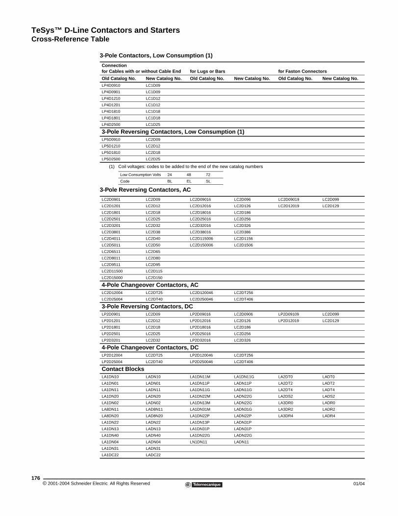
TeSys™ D-Line Contactors and StartersCross-Reference Table
© 2001-2004 Schneider E176
(1) Coil voltages: codes to be added to the end of the new catalog numbers
3-Pole Contactors, Low Consumption (1)
Connection for Cables with or without Cable End for Lugs or Bars for Faston Connectors
Old Catalog No. New Catalog No. Old Catalog No. New Catalog No. Old Catalog No. New Catalog No.
LP4D0910 LC1D09
LP4D0901 LC1D09
LP4D1210 LC1D12
LP4D1201 LC1D12
LP4D1810 LC1D18
LP4D1801 LC1D18
LP4D2500 LC1D25
3-Pole Reversing Contactors, Low Consumption (1)LP5D0910 LC2D09
LP5D1210 LC2D12
LP5D1810 LC2D18
LP5D2500 LC2D25
Low Consumption Volts 24 48 72
Code BL EL SL
3-Pole Reversing Contactors, AC
LC2D0901 LC2D09 LC2D09016 LC2D096 LC2D09019 LC2D099
LC2D1201 LC2D12 LC2D12016 LC2D126 LC2D12019 LC2D129
LC2D1801 LC2D18 LC2D18016 LC2D186
LC2D2501 LC2D25 LC2D25016 LC2D256
LC2D3201 LC2D32 LC2D32016 LC2D326
LC2D3801 LC2D38 LC2D38016 LC2D386
LC2D4011 LC2D40 LC2D115006 LC2D1156
LC2D5011 LC2D50 LC2D150006 LC2D1506
LC2D6511 LC2D65
LC2D8011 LC2D80
LC2D9511 LC2D95
LC2D11500 LC2D115
LC2D15000 LC2D150
4-Pole Changeover Contactors, AC LC2D12004 LC2DT25 LC2D120046 LC2DT256
LC2D25004 LC2DT40 LC2D250046 LC2DT406
3-Pole Reversing Contactors, DC LP2D0901 LC2D09 LP2D09016 LC2D0906 LP2D09109 LC2D099
LP2D1201 LC2D12 LP2D12016 LC2D126 LP2D12019 LC2D129
LP2D1801 LC2D18 LP2D18016 LC2D186
LP2D2501 LC2D25 LP2D25016 LC2D256
LP2D3201 LC2D32 LP2D32016 LC2D326
4-Pole Changeover Contactors, DC LP2D12004 LC2DT25 LP2D120046 LC2DT256
LP2D25004 LC2DT40 LP2D250046 LC2DT406
Contact BlocksLA1DN10 LADN10 LA1DN11M LA1DN11G LA2DT0 LADT0
LA1DN01 LADN01 LA1DN11P LADN11P LA2DT2 LADT2
LA1DN11 LADN11 LA1DN11G LADN11G LA2DT4 LADT4
LA1DN20 LADN20 LA1DN22M LADN22G LA2DS2 LADS2
LA1DN02 LADN02 LA1DN13M LADN22G LA3DR0 LADR0
LA8DN11 LAD8N11 LA1DN31M LADN31G LA3DR2 LADR2
LA8DN20 LAD8N20 LA1DN22P LADN22P LA3DR4 LADR4
LA1DN22 LADN22 LA1DN13P LADN31P
LA1DN13 LADN13 LA1DN31P LADN31P
LA1DN40 LADN40 LA1DN22G LADN22G
LA1DN04 LADN04 LN1DN11 LADN11
LA1DN31 LADN31
LA1DC22 LADC22
lectric All Rights Reserved 01/04
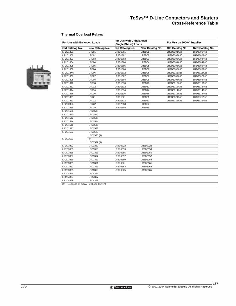
TeSys™ D-Line Contactors and StartersCross-Reference Table
01/04
Thermal Overload Relays
For Use with Balanced LoadsFor Use with Unbalanced (Single Phase) Loads
For Use on 1000V Supplies
Old Catalog No. New Catalog No. Old Catalog No. New Catalog No. Old Catalog No. New Catalog No.LR2D1301 LRD01 LR3D1301 LR3D01 LR2D3301A66 LRD3301A66
LR2D1302 LRD02 LR3D1302 LR3D02 LR2D3302A66 LRD3302A66
LR2D1303 LRD03 LR3D1303 LR3D03 LR2D3303A66 LRD3303A66
LR2D1304 LRD04 LR3D1304 LR3D04 LR2D3304A66 LRD3304A66
LR2D1305 LRD05 LR3D1305 LR3D05 LR2D3305A66 LRD3305A66
LR2D1306 LRD06 LR3D1306 LR3D06 LR2D3306A66 LRD3306A66
LR2D13X6 LRD06 LR3D13X6 LR3D06 LR2D33X6A66 LRD33X6A66
LR2D1307 LRD07 LR3D1307 LR3D07 LR2D3307A66 LRD3307A66
LR2D1308 LRD08 LR3D1308 LR3D08 LR2D3308A66 LRD3308A66
LR2D1310 LRD10 LR3D1310 LR3D10 LR2D3310A66 LRD3310A66
LR2D1312 LRD12 LR3D1312 LR3D12 LR2D3312A66 LRD3312A66
LR2D1314 LRD14 LR3D1314 LR3D14 LR2D3314A66 LRD3314A66
LR2D1316 LRD16 LR3D1316 LR3D16 LR2D3316A66 LRD3316A66
LR2D1321 LRD21 LR3D1321 LR3D21 LR2D3321A66 LRD3321A66
LR2D1322 LRD22 LR3D1322 LR3D22 LR2D3322A66 LRD3322A66
LR2D2353 LRD32 LR3D2353 LR3D32
LR2D2355 LRD35 LR3D2355 LR3D35
LR2D1508 LRD1508
LR2D1510 LRD1510
LR2D1512 LRD1512
LR2D1514 LRD1514
LR2D1516 LRD1516
LR2D1521 LRD1521
LR2D1522 LRD1522
LR2D2553
LRD1530 (1)
or
LRD1532 (1)
LR2D3322 LRD3322 LR3D3322 LR3D3322
LR2D3353 LRD3353 LR3D3353 LR3D3353
LR2D3355 LRD3355 LR3D3355 LR3D3355
LR2D3357 LRD3357 LR3D3357 LR3D3357
LR2D3359 LRD3359 LR3D3359 LR3D3359
LR2D3361 LRD3361 LR3D3361 LR3D3361
LR2D3363 LRD3363 LR3D3363 LR3D3363
LR2D3365 LRD3365 LR3D3365 LR3D3365
LR2D4365 LRD4365
LR2D4367 LRD4367
LR2D4369 LRD4369
(1) Depends on actual Full Load Current.
177© 2001-2004 Schneider Electric All Rights Reserved
TeSys™ D-Line Contactors and Starters
© 2001-2004 Schneider E178
lectric All Rights Reserved 01/04
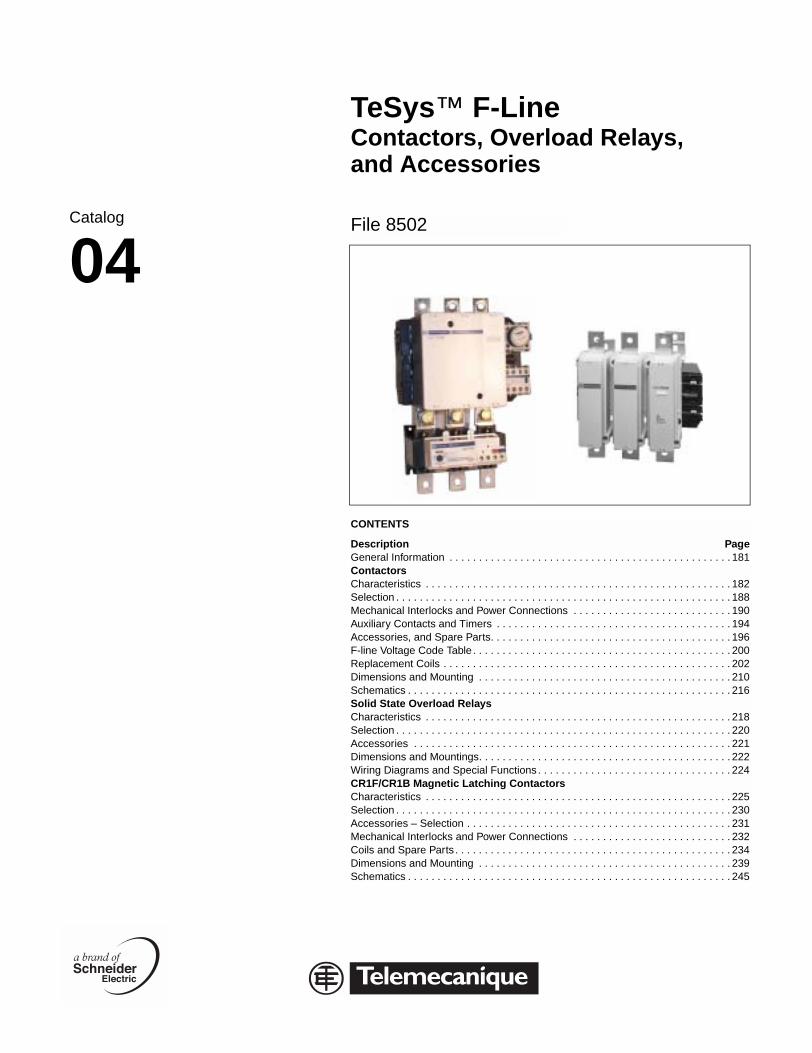
Catalog
04
TeSys™ F-LineContactors, Overload Relays, and Accessories
File 8502
CONTENTS
Description PageGeneral Information . . . . . . . . . . . . . . . . . . . . . . . . . . . . . . . . . . . . . . . . . . . . . . . . 181ContactorsCharacteristics . . . . . . . . . . . . . . . . . . . . . . . . . . . . . . . . . . . . . . . . . . . . . . . . . . . . 182Selection . . . . . . . . . . . . . . . . . . . . . . . . . . . . . . . . . . . . . . . . . . . . . . . . . . . . . . . . . 188Mechanical Interlocks and Power Connections . . . . . . . . . . . . . . . . . . . . . . . . . . . 190Auxiliary Contacts and Timers . . . . . . . . . . . . . . . . . . . . . . . . . . . . . . . . . . . . . . . . 194Accessories, and Spare Parts. . . . . . . . . . . . . . . . . . . . . . . . . . . . . . . . . . . . . . . . . 196F-line Voltage Code Table . . . . . . . . . . . . . . . . . . . . . . . . . . . . . . . . . . . . . . . . . . . . 200Replacement Coils . . . . . . . . . . . . . . . . . . . . . . . . . . . . . . . . . . . . . . . . . . . . . . . . . 202Dimensions and Mounting . . . . . . . . . . . . . . . . . . . . . . . . . . . . . . . . . . . . . . . . . . . 210Schematics . . . . . . . . . . . . . . . . . . . . . . . . . . . . . . . . . . . . . . . . . . . . . . . . . . . . . . . 216Solid State Overload RelaysCharacteristics . . . . . . . . . . . . . . . . . . . . . . . . . . . . . . . . . . . . . . . . . . . . . . . . . . . . 218Selection . . . . . . . . . . . . . . . . . . . . . . . . . . . . . . . . . . . . . . . . . . . . . . . . . . . . . . . . . 220Accessories . . . . . . . . . . . . . . . . . . . . . . . . . . . . . . . . . . . . . . . . . . . . . . . . . . . . . . 221Dimensions and Mountings. . . . . . . . . . . . . . . . . . . . . . . . . . . . . . . . . . . . . . . . . . . 222Wiring Diagrams and Special Functions . . . . . . . . . . . . . . . . . . . . . . . . . . . . . . . . . 224CR1F/CR1B Magnetic Latching ContactorsCharacteristics . . . . . . . . . . . . . . . . . . . . . . . . . . . . . . . . . . . . . . . . . . . . . . . . . . . . 225Selection . . . . . . . . . . . . . . . . . . . . . . . . . . . . . . . . . . . . . . . . . . . . . . . . . . . . . . . . . 230Accessories – Selection . . . . . . . . . . . . . . . . . . . . . . . . . . . . . . . . . . . . . . . . . . . . . 231Mechanical Interlocks and Power Connections . . . . . . . . . . . . . . . . . . . . . . . . . . . 232Coils and Spare Parts . . . . . . . . . . . . . . . . . . . . . . . . . . . . . . . . . . . . . . . . . . . . . . . 234Dimensions and Mounting . . . . . . . . . . . . . . . . . . . . . . . . . . . . . . . . . . . . . . . . . . . 239Schematics . . . . . . . . . . . . . . . . . . . . . . . . . . . . . . . . . . . . . . . . . . . . . . . . . . . . . . . 245
F-Line

TeSys™ F-Line Contactors and Starters
© 2001-2004 Schneider E180
lectric All Rights Reserved 01/04
TeSys™ F-Line Contactors and StartersGeneral Information
01/04
General Information
The F-line contactors and overload relays offer proven performance for resistive loads or large motor starting applications such as fans, crushers, pumps, compressors and overhead cranes. They offer high reliability with long mechanical and electrical life and the most complete line of accessories in the industry.
Contactor Ratings
F-line contactors and overload relays are available in the USA market for inductive motor applications up to 800 full load Amps and resistive loads up to 1000 Amps. They offer motor control and overload protection for motors rated up to 800 horsepower at 480 Vac or 900 horsepower at 600 Vac.
• 2 pole, 3 pole and 4 pole Contactors and Magnetic Latching Contactors
• AC or DC operating coils
• Includes UL listing, CSA Certification and CE mark
• Both North American and international terminal markings
• Replacement parts available
— Contact Kits
— Arc Chambers
— Operating Coils
• Easily installed accessories
— Auxiliary contact blocks with serrated wiping action
— Front mount dust tight auxiliary contact blocks
— Pneumatic time delay blocks
• Solid State Overload Relays
Class 10 or class 20 overload relays are available from 30 to 630 Amperes. They are ambient compensated and include single phase sensitivity for phase unbalance and phase loss protection. They also include the following features: Isolated N.C. trip contact, N.O. alarm contact, manual reset button, rotary dial for adjustable current settings with tamper resistant window, test trip button, momentary stop button and trip indicator.
181© 2001-2004 Schneider Electric All Rights Reserved
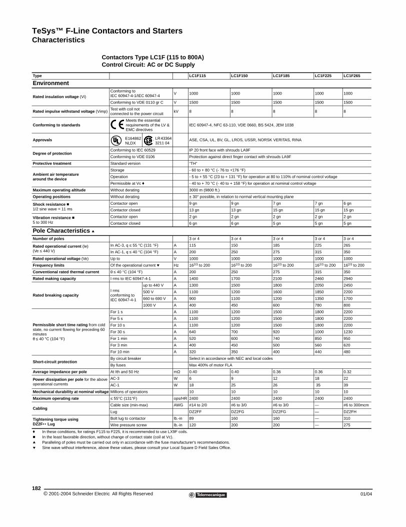
TeSys™ F-Line Contactors and StartersCharacteristics
© 2001-2004 Schneider E182
Type
Environment
Rated insulation voltage (Vi)
Rated impulse withstand voltage
Conforming to standards
Approvals
Degree of protection
Protective treatment
Ambient air temperaturearound the device
Maximum operating altitude
Operating positions
Shock resistance c1/2 sine wave = 11 ms
Vibration resistance c5 to 300 Hz
Pole Characteristics qNumber of poles
Rated operational current (Ie)(Ve ≤ 440 V)
Rated operational voltage (Ve)
Frequency limits
Conventional rated thermal curren
Rated making capacity
Rated breaking capacity
Permissible short time rating fromstate, no current flowing for precedinminutes θ ≤ 40 °C (104 °F)
Short-circuit protection
Average impedance per pole
Power dissipation per pole for the operational currents
Mechanical durability at nominal v
Maximum operating rate
Cabling
Tightening torque usingDZ2F•• Lug
f In these conditions, for ratings c In the least favorable direction,q Paralleling of poles must be cap Sine wave without interference
Characteristics
Contactors Type LC1F (115 to 800A) Control Circuit: AC or DC Supply
LC1F115 LC1F150 LC1F185 LC1F225 LC1F265
Conforming toIEC 60947-4-1/IEC 60947-4
V 1000 1000 1000 1000 1000
Conforming to VDE 0110 gr C V 1500 1500 1500 1500 1500
(Vimp)Test with coil notconnected to the power circuit
kV 8 8 8 8 8
Meets the essential requirements of the LV & EMC directives
IEC 60947-4, NFC 63-110, VDE 0660, BS 5424, JEM 1038
E164862 NLDX
LR 43364 3211 04
ASE, CSA, UL, BV, GL, LROS, USSR, NORSK VERITAS, RINA
Conforming to IEC 60529 IP 20 front face with shrouds LA9F
Conforming to VDE 0106 Protection against direct finger contact with shrouds LA9F
Standard version “TH”
Storage - 60 to + 80 °C (- 76 to +176 °F)
Operation - 5 to + 55 °C (23 to + 131 °F) for operation at 80 to 110% of nominal control voltage
Permissible at Vc f - 40 to + 70 °C (- 40 to + 158 °F) for operation at nominal control voltage
Without derating 3000 m (9800 ft.)
Without derating ± 30° possible, in relation to normal vertical mounting plane
Contactor open 9 gn 9 gn 7 gn 7 gn 6 gn
Contactor closed 13 gn 13 gn 15 gn 15 gn 15 gn
Contactor open 2 gn 2 gn 2 gn 2 gn 2 gn
Contactor closed 6 gn 6 gn 5 gn 5 gn 5 gn
3 or 4 3 or 4 3 or 4 3 or 4 3 or 4
In AC-3, q ≤ 55 °C (131 °F) A 115 150 185 225 265
In AC-1, q ≤ 40 °C (104 °F) A 200 250 275 315 350
Up to V 1000 1000 1000 1000 1000
Of the operational current p Hz 162/3 to 200 162/3 to 200 162/3 to 200 162/3 to 200 162/3 to 200
t θ ≤ 40 °C (104 °F) A 200 250 275 315 350
I rms to IEC 60947-4-1 A 1400 1700 2100 2460 2940
I rmsconforming to IEC 60947-4-1
up to 440 V A 1300 1500 1800 2050 2450
500 V A 1100 1200 1600 1850 2200
660 to 690 V A 900 1100 1200 1350 1700
1000 V A 400 450 600 780 800
cold g 60
For 1 s A 1100 1200 1500 1800 2200
For 5 s A 1100 1200 1500 1800 2200
For 10 s A 1100 1200 1500 1800 2200
For 30 s A 640 700 920 1000 1230
For 1 min A 520 600 740 850 950
For 3 min A 400 450 500 560 620
For 10 min A 320 350 400 440 480
By circuit breaker Select in accordance with NEC and local codes
By fuses Max 400% of motor FLA
At Ith and 50 Hz mΩ 0.40 0.40 0.36 0.36 0.32
above AC-3 W 6 9 12 18 22
AC-1 W 18 25 26 35 39
oltage Millions of operations 10 10 10 10 10
≤ 55°C (131°F) ops/HR 2400 2400 2400 2400 2400
Cable size (min-max) AWG #14 to 2/0 #6 to 3/0 #6 to 3/0 — #6 to 300mcm
Lug DZ2FF DZ2FG DZ2FG — DZ2FH
Bolt lug to contactor lb.-in 89 160 160 — 310
Wire pressure screw lb.-in 120 200 200 — 275
F115 to F225, it is recommended to use LX9F coils. without change of contact state (coil at Vc).rried out only in accordance with the fuse manufacturer's recommendations., above these values, please consult your Local Square D Field Sales Office.
lectric All Rights Reserved 01/04
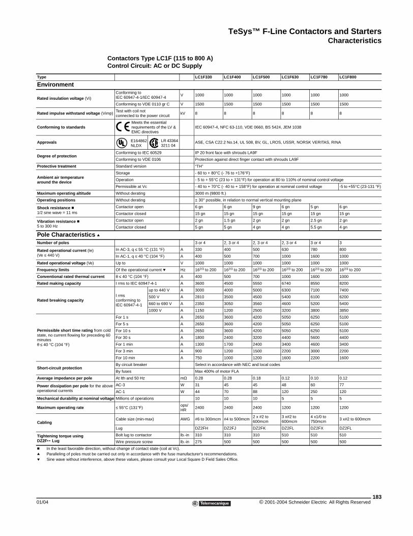
TeSys™ F-Line Contactors and StartersCharacteristics
01/04
Type
Environment
Rated insulation voltage (Vi)
Rated impulse withstand voltage (
Conforming to standards
Approvals
Degree of protection
Protective treatment
Ambient air temperaturearound the device
Maximum operating altitude
Operating positions
Shock resistance c1/2 sine wave = 11 ms
Vibration resistance c5 to 300 Hz
Pole Characteristics qNumber of poles
Rated operational current (Ie)(Ve ≤ 440 V)
Rated operational voltage (Ve)
Frequency limits
Conventional rated thermal curren
Rated making capacity
Rated breaking capacity
Permissible short time rating fromstate, no current flowing for precedinminutes θ ≤ 40 °C (104 °F)
Short-circuit protection
Average impedance per pole
Power dissipation per pole for the operational currents
Mechanical durability at nominal v
Maximum operating rate
Cabling
Tightening torque usingDZ2F•• Lug
c In the least favorable direction, q Paralleling of poles must be cap Sine wave without interference,
Contactors Type LC1F (115 to 800 A)Control Circuit: AC or DC Supply
LC1F330 LC1F400 LC1F500 LC1F630 LC1F780 LC1F800
Conforming toIEC 60947-4-1/IEC 60947-4
V 1000 1000 1000 1000 1000 1000
Conforming to VDE 0110 gr C V 1500 1500 1500 1500 1500 1500
Vimp)Test with coil notconnected to the power circuit
kV 8 8 8 8 8 8
Meets the essential requirements of the LV & EMC directives
IEC 60947-4, NFC 63-110, VDE 0660, BS 5424, JEM 1038
E164862 NLDX
LR 43364 3211 04
ASE, CSA C22.2 No.14, UL 508, BV, GL, LROS, USSR, NORSK VERITAS, RINA
Conforming to IEC 60529 IP 20 front face with shrouds LA9F
Conforming to VDE 0106 Protection against direct finger contact with shrouds LA9F
Standard version “TH”
Storage - 60 to + 80°C (- 76 to +176°F)
Operation - 5 to + 55°C (23 to + 131°F) for operation at 80 to 110% of nominal control voltage
Permissible at Vc - 40 to + 70°C (- 40 to + 158°F) for operation at nominal control voltage -5 to +55°C (23-131 °F)
Without derating 3000 m (9800 ft.)
Without derating ± 30° possible, in relation to normal vertical mounting plane
Contactor open 6 gn 6 gn 9 gn 6 gn 5 gn 6 gn
Contactor closed 15 gn 15 gn 15 gn 15 gn 15 gn 15 gn
Contactor open 2 gn 1.5 gn 2 gn 2 gn 2.5 gn 2 gn
Contactor closed 5 gn 5 gn 4 gn 4 gn 5.5 gn 4 gn
3 or 4 2, 3 or 4 2, 3 or 4 2, 3 or 4 3 or 4 3
In AC-3, q ≤ 55 °C (131 °F) A 330 400 500 630 780 800
In AC-1, q ≤ 40 °C (104 °F) A 400 500 700 1000 1600 1000
Up to V 1000 1000 1000 1000 1000 1000
Of the operational current p Hz 162/3 to 200 162/3 to 200 162/3 to 200 162/3 to 200 162/3 to 200 162/3 to 200
t θ ≤ 40 °C (104 °F) A 400 500 700 1000 1600 1000
I rms to IEC 60947-4-1 A 3600 4500 5550 6740 8550 8200
I rmsconforming to IEC 60947-4-1
up to 440 V A 3000 4000 5000 6300 7100 7400
500 V A 2810 3500 4500 5400 6100 6200
660 to 690 V A 2350 3050 3560 4600 5200 5400
1000 V A 1150 1200 2500 3200 3800 3850
cold g 60
For 1 s A 2650 3600 4200 5050 6250 5100
For 5 s A 2650 3600 4200 5050 6250 5100
For 10 s A 2650 3600 4200 5050 6250 5100
For 30 s A 1800 2400 3200 4400 5600 4400
For 1 min A 1300 1700 2400 3400 4600 3400
For 3 min A 900 1200 1500 2200 3000 2200
For 10 min A 750 1000 1200 1600 2200 1600
By circuit breaker Select in accordance with NEC and local codes
By fuses Max 400% of motor FLA
At Ith and 50 Hz mΩ 0.28 0.28 0.18 0.12 0.10 0.12
above AC-3 W 31 45 45 48 60 77
AC-1 W 44 70 88 120 250 120
oltage Millions of operations 10 10 10 5 5 5
≤ 55°C (131°F)ops/HR
2400 2400 2400 1200 1200 1200
Cable size (min-max) AWG #6 to 300mcm #4 to 500mcm2 x #2 to 600mcm
3 x#2 to 600mcm
4 x1/0 to 750mcm
3 x#2 to 600mcm
Lug DZ2FH DZ2FJ DZ2FK DZ2FL DZ2FX DZ2FL
Bolt lug to contactor lb.-in 310 310 310 510 510 510
Wire pressure screw lb.-in 275 500 500 500 500 500
without change of contact state (coil at Vc).rried out only in accordance with the fuse manufacturer's recommendations. above these values, please consult your Local Square D Field Sales Office.
183© 2001-2004 Schneider Electric All Rights Reserved
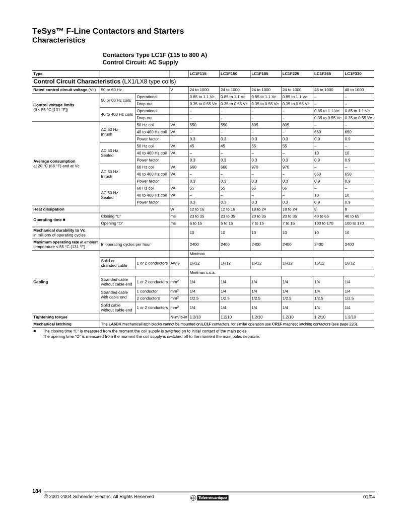
TeSys™ F-Line Contactors and StartersCharacteristics
© 2001-2004 Schneider E184
Type
Control Circuit CharacRated control circuit voltage (Vc)
Control voltage limits (θ ≤ 55 °C [131 °F])
Average consumption at 20 °C (68 °F) and at Vc
Heat dissipation
Operating time c
Mechanical durability to Vcin millions of operating cycles
Maximum operating rate at ambientemperature ≤ 55 °C (131 °F)
Cabling
Tightening torque
Mechanical latching
c The closing time “C” is measurThe opening time “O” is measu
Contactors Type LC1F (115 to 800 A) Control Circuit: AC Supply
LC1F115 LC1F150 LC1F185 LC1F225 LC1F265 LC1F330
teristics (LX1/LX8 type coils)50 or 60 Hz V 24 to 1000 24 to 1000 24 to 1000 24 to 1000 48 to 1000 48 to 1000
50 or 60 Hz coilsOperational 0.85 to 1.1 Vc 0.85 to 1.1 Vc 0.85 to 1.1 Vc 0.85 to 1.1 Vc – –
Drop-out 0.35 to 0.55 Vc 0.35 to 0.55 Vc 0.35 to 0.55 Vc 0.35 to 0.55 Vc – –
40 to 400 Hz coilsOperational – – – – 0.85 to 1.1 Vc 0.85 to 1.1 Vc
Drop-out – – – – 0.35 to 0.55 Vc 0.35 to 0.55 Vc
AC 50 HzInrush
50 Hz coil VA 550 550 805 805 – –
40 to 400 Hz coil VA – – – – 650 650
Power factor 0.3 0.3 0.3 0.3 0.9 0.9
AC 50 HzSealed
50 Hz coil VA 45 45 55 55 – –
40 to 400 Hz coil VA – – – – 10 10
Power factor 0.3 0.3 0.3 0.3 0.9 0.9
AC 60 HzInrush
60 Hz coil VA 660 660 970 970 – –
40 to 400 Hz coil VA – – – – 650 650
Power factor 0.3 0.3 0.3 0.3 0.9 0.9
AC 60 HzSealed
60 Hz coil VA 55 55 66 66 – –
40 to 400 Hz coil VA – – – – 10 10
Power factor 0.3 0.3 0.3 0.3 0.9 0.9
W 12 to 16 12 to 16 18 to 24 18 to 24 8 8
Closing “C” ms 23 to 35 23 to 35 20 to 35 20 to 35 40 to 65 40 to 65
Opening “O” ms 5 to 15 5 to 15 7 to 15 7 to 15 100 to 170 100 to 170
10 10 10 10 10 10
t In operating cycles per hour 2400 2400 2400 2400 2400 2400
Min/max
Solid orstranded cable
1 or 2 conductors AWG 16/12 16/12 16/12 16/12 16/12 16/12
Min/max c.s.a.
Stranded cable without cable end
1 or 2 conductors mm2 1/4 1/4 1/4 1/4 1/4 1/4
Stranded cable with cable end
1 conductor mm2 1/4 1/4 1/4 1/4 1/4 1/4
2 conductors mm2 1/2.5 1/2.5 1/2.5 1/2.5 1/2.5 1/2.5
Solid cablewithout cable end
1 or 2 conductors mm2 1/4 1/4 1/4 1/4 1/4 1/4
N•m/lb-in 1.2/10 1.2/10 1.2/10 1.2/10 1.2/10 1.2/10
The LA6DK mechanical latch blocks cannot be mounted on LC1F contactors, for similar operation use CR1F magnetic latching contactors (see page 226).
ed from the moment the coil supply is switched on to initial contact of the main poles.red from the moment the coil supply is switched off to the moment the main poles separate.
lectric All Rights Reserved 01/04
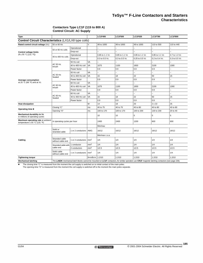
TeSys™ F-Line Contactors and StartersCharacteristics
01/04
Type
Control Circuit CharacRated control circuit voltage (Vc)
Control voltage limits (θ ≤ 55 °C [131 °F])
Average consumption at 20 °C (68 °F) and at Vc
Heat dissipation
Operating time c
Mechanical durability to Vcin millions of operating cycles
Maximum operating rate at ambientemperature ≤ 55 °C (131 °F)
Cabling
Tightening torque
Mechanical latching
c The closing time “C” is measurThe opening time “O” is measu
Contactors Type LC1F (115 to 800 A)Control Circuit: AC Supply
LC1F400 LC1F500 LC1F630 LC1F780 LC1F800
teristics (LX1/LX8 type coils)50 or 60 Hz V 48 to 1000 48 to 1000 48 to 1000 110 to 500 110 to 440
50 or 60 Hz coilsOperational – – – – –
Drop-out – – – – –
40 to 400 Hz coilsOperational 0.85 to 1.1 Vc 0.85 to 1.1 Vc 0.85 to 1.1 Vc 0.85 to 1.1 Vc 0.7 to 1.3 Vc
Drop-out 0.3 to 0.5 Vc 0.3 to 0.5 Vc 0.25 to 0.5 Vc 0.2 to 0.4 Vc 0.3 to 0.5 Vc
AC 50 HzInrush
50 Hz coil VA – – – – –
40 to 400 Hz coil VA 1075 1100 1650 2100 1300
Power factor 0.9 0.9 0.9 0.9 –
AC 50 HzSealed
50 Hz coil VA – – – – –
40 to 400 Hz coil VA 15 18 22 50 15
Power factor 0.9 0.9 0.9 0.9 –
AC 60 HzInrush
60 Hz coil VA – – – – –
40 to 400 Hz coil VA 1075 1100 1650 2100 1300
Power factor 0.9 0.9 0.9 0.9 –
AC 60 HzSealed
60 Hz coil VA – – – – –
40 to 400 Hz coil VA 15 18 22 50 15
Power factor 0.9 0.9 0.9 0.9 –
W 14 18 20 2 x 22 25
Closing “C” ms 40 to 75 40 to 75 40 to 80 40 to 80 40 to 80
Opening “O” ms 100 to 170 100 to 170 100 to 200 130 to 230 20 to 40
10 10 5 5 5
t In operating cycles per hour 2400 2400 1200 600 600
Min/max
Solid orstranded cable
1 or 2 conductors AWG 16/12 16/12 16/12 16/12 16/12
Min/max c.s.a.
Stranded cable without cable end
1 or 2 conductors mm2 1/4 1/4 1/4 1/4 1/4
Stranded cable with cable end
1 conductor mm2 1/4 1/4 1/4 1/4 1/4
2 conductors mm2 1/2.5 1/2.5 1/2.5 1/2.5 1/2.5
Solid cablewithout cable end
1 or 2 conductors mm2 1/4 1/4 1/4 1/4 1/4
N•m/lb-in 1.2/10 1.2/10 1.2/10 1.2/10 1.2/10
The LA6DK mechanical latch blocks cannot be mounted on LC1F contactors, for similar operation use CR1F magnetic latching contactors (see page 226).
ed from the moment the coil supply is switched on to initial contact of the main poles.red from the moment the coil supply is switched off to the moment the main poles separate.
185© 2001-2004 Schneider Electric All Rights Reserved
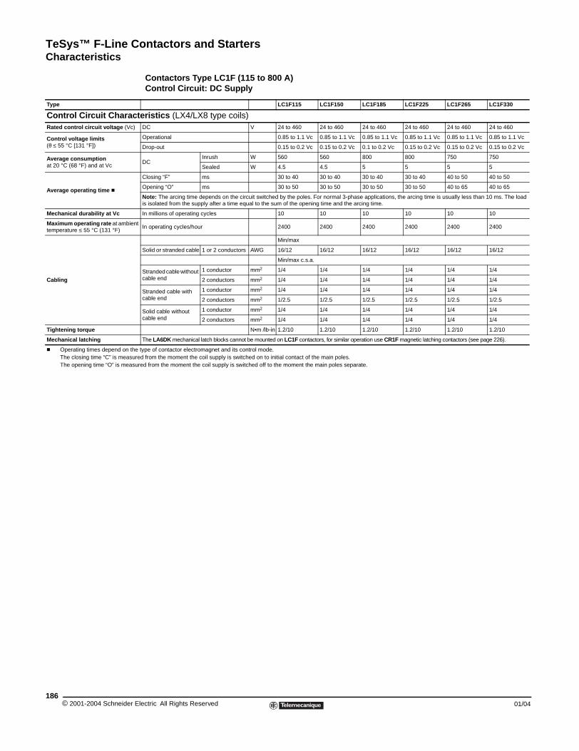
TeSys™ F-Line Contactors and StartersCharacteristics
© 2001-2004 Schneider E186
Type
Control Circuit CharacRated control circuit voltage (Vc)
Control voltage limits(θ ≤ 55 °C [131 °F])
Average consumptionat 20 °C (68 °F) and at Vc
Average operating time c
Mechanical durability at Vc
Maximum operating rate at ambientemperature ≤ 55 °C (131 °F)
Cabling
Tightening torque
Mechanical latching
c Operating times depend on theThe closing time “C” is measurThe opening time “O” is measu
Contactors Type LC1F (115 to 800 A)Control Circuit: DC Supply
LC1F115 LC1F150 LC1F185 LC1F225 LC1F265 LC1F330
teristics (LX4/LX8 type coils)DC V 24 to 460 24 to 460 24 to 460 24 to 460 24 to 460 24 to 460
Operational 0.85 to 1.1 Vc 0.85 to 1.1 Vc 0.85 to 1.1 Vc 0.85 to 1.1 Vc 0.85 to 1.1 Vc 0.85 to 1.1 Vc
Drop-out 0.15 to 0.2 Vc 0.15 to 0.2 Vc 0.1 to 0.2 Vc 0.15 to 0.2 Vc 0.15 to 0.2 Vc 0.15 to 0.2 Vc
DCInrush W 560 560 800 800 750 750
Sealed W 4.5 4.5 5 5 5 5
Closing “F” ms 30 to 40 30 to 40 30 to 40 30 to 40 40 to 50 40 to 50
Opening “O” ms 30 to 50 30 to 50 30 to 50 30 to 50 40 to 65 40 to 65
Note: The arcing time depends on the circuit switched by the poles. For normal 3-phase applications, the arcing time is usually less than 10 ms. The load is isolated from the supply after a time equal to the sum of the opening time and the arcing time.
In millions of operating cycles 10 10 10 10 10 10
t In operating cycles/hour 2400 2400 2400 2400 2400 2400
Min/max
Solid or stranded cable 1 or 2 conductors AWG 16/12 16/12 16/12 16/12 16/12 16/12
Min/max c.s.a.
Stranded cable without cable end
1 conductor mm2 1/4 1/4 1/4 1/4 1/4 1/4
2 conductors mm2 1/4 1/4 1/4 1/4 1/4 1/4
Stranded cable with cable end
1 conductor mm2 1/4 1/4 1/4 1/4 1/4 1/4
2 conductors mm2 1/2.5 1/2.5 1/2.5 1/2.5 1/2.5 1/2.5
Solid cable without cable end
1 conductor mm2 1/4 1/4 1/4 1/4 1/4 1/4
2 conductors mm2 1/4 1/4 1/4 1/4 1/4 1/4
N•m /lb-in 1.2/10 1.2/10 1.2/10 1.2/10 1.2/10 1.2/10
The LA6DK mechanical latch blocks cannot be mounted on LC1F contactors, for similar operation use CR1F magnetic latching contactors (see page 226).
type of contactor electromagnet and its control mode.ed from the moment the coil supply is switched on to initial contact of the main poles.red from the moment the coil supply is switched off to the moment the main poles separate.
lectric All Rights Reserved 01/04
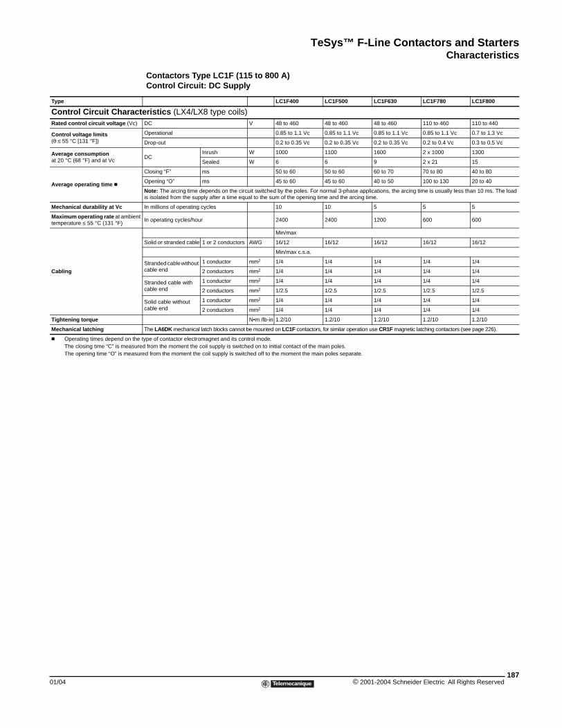
TeSys™ F-Line Contactors and StartersCharacteristics
01/04
Type
Control Circuit CharacRated control circuit voltage (Vc)
Control voltage limits(θ ≤ 55 °C [131 °F])
Average consumptionat 20 °C (68 °F) and at Vc
Average operating time c
Mechanical durability at Vc
Maximum operating rate at ambientemperature ≤ 55 °C (131 °F)
Cabling
Tightening torque
Mechanical latching
c Operating times depend on theThe closing time “C” is measurThe opening time “O” is measu
Contactors Type LC1F (115 to 800 A)Control Circuit: DC Supply
LC1F400 LC1F500 LC1F630 LC1F780 LC1F800
teristics (LX4/LX8 type coils)DC V 48 to 460 48 to 460 48 to 460 110 to 460 110 to 440
Operational 0.85 to 1.1 Vc 0.85 to 1.1 Vc 0.85 to 1.1 Vc 0.85 to 1.1 Vc 0.7 to 1.3 Vc
Drop-out 0.2 to 0.35 Vc 0.2 to 0.35 Vc 0.2 to 0.35 Vc 0.2 to 0.4 Vc 0.3 to 0.5 Vc
DCInrush W 1000 1100 1600 2 x 1000 1300
Sealed W 6 6 9 2 x 21 15
Closing “F” ms 50 to 60 50 to 60 60 to 70 70 to 80 40 to 80
Opening “O” ms 45 to 60 45 to 60 40 to 50 100 to 130 20 to 40
Note: The arcing time depends on the circuit switched by the poles. For normal 3-phase applications, the arcing time is usually less than 10 ms. The load is isolated from the supply after a time equal to the sum of the opening time and the arcing time.
In millions of operating cycles 10 10 5 5 5
t In operating cycles/hour 2400 2400 1200 600 600
Min/max
Solid or stranded cable 1 or 2 conductors AWG 16/12 16/12 16/12 16/12 16/12
Min/max c.s.a.
Stranded cable without cable end
1 conductor mm2 1/4 1/4 1/4 1/4 1/4
2 conductors mm2 1/4 1/4 1/4 1/4 1/4
Stranded cable with cable end
1 conductor mm2 1/4 1/4 1/4 1/4 1/4
2 conductors mm2 1/2.5 1/2.5 1/2.5 1/2.5 1/2.5
Solid cable without cable end
1 conductor mm2 1/4 1/4 1/4 1/4 1/4
2 conductors mm2 1/4 1/4 1/4 1/4 1/4
N•m /lb-in 1.2/10 1.2/10 1.2/10 1.2/10 1.2/10
The LA6DK mechanical latch blocks cannot be mounted on LC1F contactors, for similar operation use CR1F magnetic latching contactors (see page 226).
type of contactor electromagnet and its control mode.ed from the moment the coil supply is switched on to initial contact of the main poles.red from the moment the coil supply is switched off to the moment the main poles separate.
187© 2001-2004 Schneider Electric All Rights Reserved
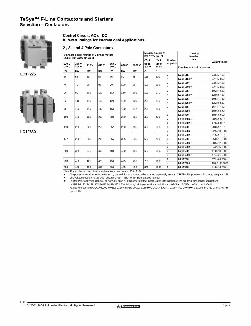
TeSys™ F-Line Contactors and StartersSelection – Contactors
© 2001-2004 Schneider E188
LC1F225
LC1F630
Selection - Contactors
Control Circuit: AC or DC Kilowatt Ratings for International Applications
2-, 3-, and 4-Pole Contactors
Standard power ratings of 3-phase motors50/60 Hz in category AC-3
Maximum current (θ ≤ 40 °C [104 °F])
Number of poles
Catalog Number
q pWeight lb (kg)
AC-3 AC-1
220 V 230 V
380 V400 V 415 V 440 V 660 V
500 V 690 V 1000 V up to 400 V
up to 400 V Panel mount with screws c
kW kW kW kW kW kW kW A A
30 55 59 59 75 80 65 115 2003 LC1F115•• 7.56 (3.430)
4 LC1F1154•• 8.44 (3.830)
40 75 80 80 90 100 65 150 2503 LC1F150•• 7.56 (3.430)
4 LC1F1504•• 8.44 (3.830)
55 90 100 100 110 110 100 185 2753 LC1F185•• 10.2 (4.650)
4 LC1F1854•• 12.0 (5.450)
63 110 110 110 129 129 100 225 3153 LC1F225•• 10.5 (4.750)
4 LC1F2254•• 12.2 (5.550)
75 132 140 140 160 160 147 265 3503 LC1F265•• 16.4 (7.440)
4 LC1F2654•• 18.8 (8.540)
100 160 180 200 200 220 160 330 4003 LC1F330•• 18.9 (8.600)
4 LC1F3304•• 20.9 (9.500)
110 200 220 250 257 280 185 400 500
2 LC1F4002•• 17.6 (8.000)
3 LC1F400•• 20.0 (9.100)
4 LC1F4004•• 22.5 (10.200)
147 250 280 295 355 335 335 500 700
2 LC1F5002•• 21.5 (9.750)
3 LC1F500•• 25.0 (11.350)
4 LC1F5004•• 28.5 (12.950)
200 335 375 400 400 450 450 630 1000
2 LC1F6302•• 34.2 (15.500)
3 LC1F630•• 41.0 (18.600)
4 LC1F6304•• 47.4 (21.500)
220 400 425 425 450 475 450 780 16003 LC1F780•• 87.1 (39.500)
4 LC1F7804•• 105.8 (48.000)
250 450 450 450 450 475 450 800 1000 3 LC1F800•• 41.3 (18.750)
Note: For auxiliary contact blocks and modules (see pages 195 to 196).c The power terminals may be protected by the addition of shrouds, to be ordered separately except LC1F780. For power terminal lugs, see page 199.q Use voltage codes on page 200 “Voltage Codes Table” to complete catalog number.p The following coil types include one normally open holding circuit contact incorporated in the design of the coil for 3-wire control applications:
LX1FF, FG, FJ, FK, FL, LX1FX0422 to FH3802. The following coil types require an additional LA•DN1• , LADN2• , LADN31, or LADN4. Auxiliary contact block: LX1FH0202 to 0362, LX1FH4402 to 10002, LX8F8•W, LX1FX, LX1FX, LX9FF, FG, LX9FH••• 2, LX9FJ, FK, FL, LX4FF, FG FH, FJ, FK, FL.
lectric All Rights Reserved 01/04
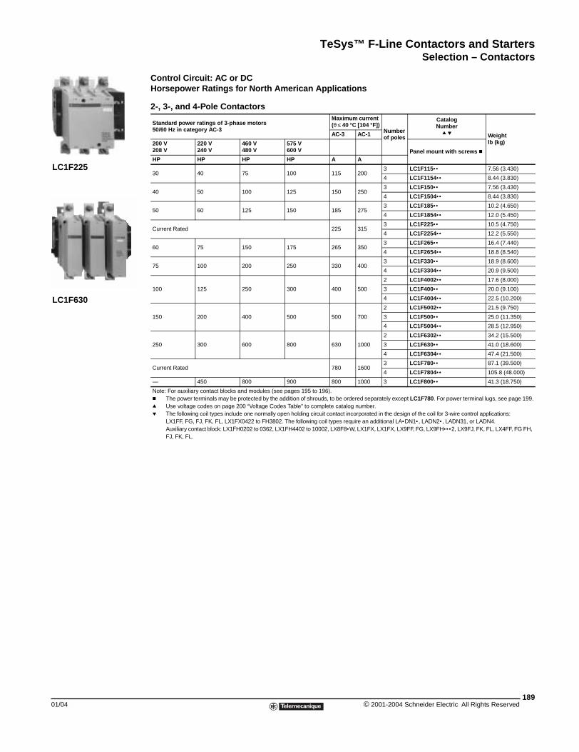
TeSys™ F-Line Contactors and StartersSelection – Contactors
01/04
LC1F225
LC1F630
Control Circuit: AC or DCHorsepower Ratings for North American Applications
2-, 3-, and 4-Pole Contactors
Standard power ratings of 3-phase motors50/60 Hz in category AC-3
Maximum current (θ ≤ 40 °C [104 °F])
Number of poles
Catalog Number
q p Weightlb (kg)
AC-3 AC-1
200 V 208 V
220 V240 V
460 V480 V
575 V600 V Panel mount with screws c
HP HP HP HP A A
30 40 75 100 115 2003 LC1F115•• 7.56 (3.430)
4 LC1F1154•• 8.44 (3.830)
40 50 100 125 150 2503 LC1F150•• 7.56 (3.430)
4 LC1F1504•• 8.44 (3.830)
50 60 125 150 185 2753 LC1F185•• 10.2 (4.650)
4 LC1F1854•• 12.0 (5.450)
Current Rated 225 3153 LC1F225•• 10.5 (4.750)
4 LC1F2254•• 12.2 (5.550)
60 75 150 175 265 3503 LC1F265•• 16.4 (7.440)
4 LC1F2654•• 18.8 (8.540)
75 100 200 250 330 4003 LC1F330•• 18.9 (8.600)
4 LC1F3304•• 20.9 (9.500)
100 125 250 300 400 500
2 LC1F4002•• 17.6 (8.000)
3 LC1F400•• 20.0 (9.100)
4 LC1F4004•• 22.5 (10.200)
150 200 400 500 500 700
2 LC1F5002•• 21.5 (9.750)
3 LC1F500•• 25.0 (11.350)
4 LC1F5004•• 28.5 (12.950)
250 300 600 800 630 1000
2 LC1F6302•• 34.2 (15.500)
3 LC1F630•• 41.0 (18.600)
4 LC1F6304•• 47.4 (21.500)
Current Rated 780 16003 LC1F780•• 87.1 (39.500)
4 LC1F7804•• 105.8 (48.000)
— 450 800 900 800 1000 3 LC1F800•• 41.3 (18.750)
Note: For auxiliary contact blocks and modules (see pages 195 to 196).c The power terminals may be protected by the addition of shrouds, to be ordered separately except LC1F780. For power terminal lugs, see page 199.q Use voltage codes on page 200 “Voltage Codes Table” to complete catalog number.p The following coil types include one normally open holding circuit contact incorporated in the design of the coil for 3-wire control applications:
LX1FF, FG, FJ, FK, FL, LX1FX0422 to FH3802. The following coil types require an additional LA•DN1• , LADN2• , LADN31, or LADN4. Auxiliary contact block: LX1FH0202 to 0362, LX1FH4402 to 10002, LX8F8•W, LX1FX, LX1FX, LX9FF, FG, LX9FH••• 2, LX9FJ, FK, FL, LX4FF, FG FH, FJ, FK, FL.
189© 2001-2004 Schneider Electric All Rights Reserved
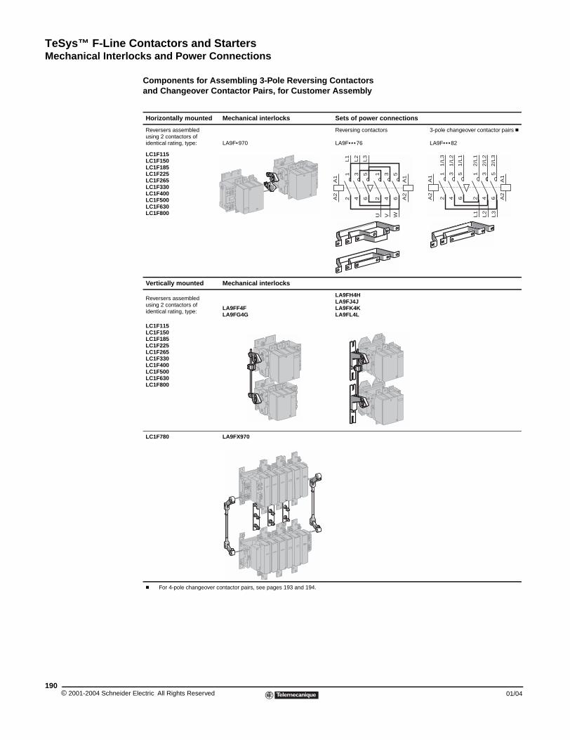
TeSys™ F-Line Contactors and StartersMechanical Interlocks and Power Connections
© 2001-2004 Schneider E190
Mechanical Interlocks and Power Connections
Components for Assembling 3-Pole Reversing Contactors and Changeover Contactor Pairs, for Customer Assembly
Horizontally mounted Mechanical interlocks Sets of power connections
Reversers assembledusing 2 contactors ofidentical rating, type: LA9F•970
Reversing contactors 3-pole changeover contactor pairs c
LA9F••• 76 LA9F••• 82
LC1F115LC1F150LC1F185LC1F225LC1F265LC1F330LC1F400LC1F500LC1F630LC1F800
Vertically mounted Mechanical interlocks
Reversers assembled using 2 contactors ofidentical rating, type:
LA9FF4FLA9FG4G
LA9FH4HLA9FJ4JLA9FK4KLA9FL4L
LC1F115LC1F150LC1F185LC1F225LC1F265LC1F330LC1F400LC1F500LC1F630LC1F800
LC1F780 LA9FX970
c For 4-pole changeover contactor pairs, see pages 193 and 194.
A1
A1
A2
A2
12
34
56
12
34
56
L1
L2
L3
U V W
A2
A2
A1
A1
12
34
56
34
56
1/L
3
1/L
2
1/L
1
L2
12
L1
2/L
1
2/L
2
2/L
3L3
lectric All Rights Reserved 01/04
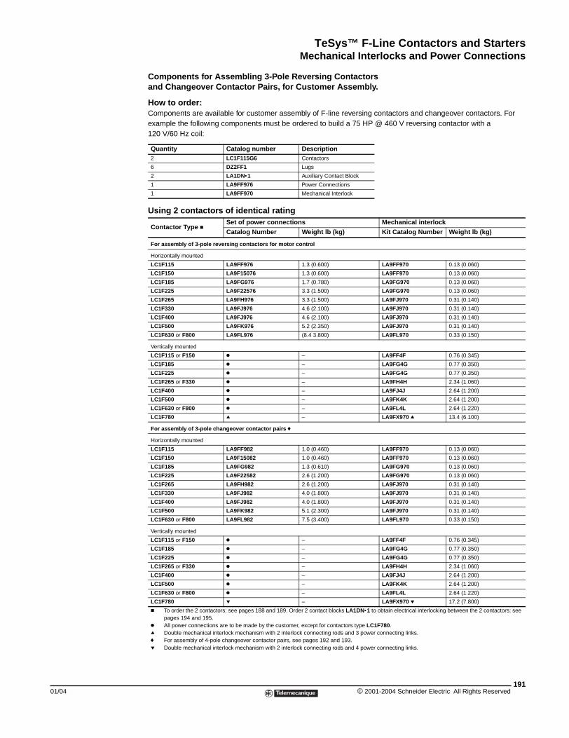
TeSys™ F-Line Contactors and StartersMechanical Interlocks and Power Connections
01/04
Components for Assembling 3-Pole Reversing Contactorsand Changeover Contactor Pairs, for Customer Assembly.
How to order:Components are available for customer assembly of F-line reversing contactors and changeover contactors. For example the following components must be ordered to build a 75 HP @ 460 V reversing contactor with a 120 V/60 Hz coil:
Quantity Catalog number Description2 LC1F115G6 Contactors
6 DZ2FF1 Lugs
2 LA1DN•1 Auxiliary Contact Block
1 LA9FF976 Power Connections
1 LA9FF970 Mechanical Interlock
Using 2 contactors of identical rating
Contactor Type cSet of power connections Mechanical interlock
Catalog Number Weight lb (kg) Kit Catalog Number Weight lb (kg)
For assembly of 3-pole reversing contactors for motor control
Horizontally mounted
LC1F115 LA9FF976 1.3 (0.600) LA9FF970 0.13 (0.060)
LC1F150 LA9F15076 1.3 (0.600) LA9FF970 0.13 (0.060)
LC1F185 LA9FG976 1.7 (0.780) LA9FG970 0.13 (0.060)
LC1F225 LA9F22576 3.3 (1.500) LA9FG970 0.13 (0.060)
LC1F265 LA9FH976 3.3 (1.500) LA9FJ970 0.31 (0.140)
LC1F330 LA9FJ976 4.6 (2.100) LA9FJ970 0.31 (0.140)
LC1F400 LA9FJ976 4.6 (2.100) LA9FJ970 0.31 (0.140)
LC1F500 LA9FK976 5.2 (2.350) LA9FJ970 0.31 (0.140)
LC1F630 or F800 LA9FL976 (8.4 3.800) LA9FL970 0.33 (0.150)
Vertically mounted
LC1F115 or F150 k – LA9FF4F 0.76 (0.345)
LC1F185 k – LA9FG4G 0.77 (0.350)
LC1F225 k – LA9FG4G 0.77 (0.350)
LC1F265 or F330 k – LA9FH4H 2.34 (1.060)
LC1F400 k – LA9FJ4J 2.64 (1.200)
LC1F500 k – LA9FK4K 2.64 (1.200)
LC1F630 or F800 k – LA9FL4L 2.64 (1.220)
LC1F780 q – LA9FX970 q 13.4 (6.100)
For assembly of 3-pole changeover contactor pairs f
Horizontally mounted
LC1F115 LA9FF982 1.0 (0.460) LA9FF970 0.13 (0.060)
LC1F150 LA9F15082 1.0 (0.460) LA9FF970 0.13 (0.060)
LC1F185 LA9FG982 1.3 (0.610) LA9FG970 0.13 (0.060)
LC1F225 LA9F22582 2.6 (1.200) LA9FG970 0.13 (0.060)
LC1F265 LA9FH982 2.6 (1.200) LA9FJ970 0.31 (0.140)
LC1F330 LA9FJ982 4.0 (1.800) LA9FJ970 0.31 (0.140)
LC1F400 LA9FJ982 4.0 (1.800) LA9FJ970 0.31 (0.140)
LC1F500 LA9FK982 5.1 (2.300) LA9FJ970 0.31 (0.140)
LC1F630 or F800 LA9FL982 7.5 (3.400) LA9FL970 0.33 (0.150)
Vertically mounted
LC1F115 or F150 k – LA9FF4F 0.76 (0.345)
LC1F185 k – LA9FG4G 0.77 (0.350)
LC1F225 k – LA9FG4G 0.77 (0.350)
LC1F265 or F330 k – LA9FH4H 2.34 (1.060)
LC1F400 k – LA9FJ4J 2.64 (1.200)
LC1F500 k – LA9FK4K 2.64 (1.200)
LC1F630 or F800 k – LA9FL4L 2.64 (1.220)
LC1F780 p – LA9FX970 p 17.2 (7.800)
c To order the 2 contactors: see pages 188 and 189. Order 2 contact blocks LA1DN•1 to obtain electrical interlocking between the 2 contactors: see pages 194 and 195.
k All power connections are to be made by the customer, except for contactors type LC1F780.q Double mechanical interlock mechanism with 2 interlock connecting rods and 3 power connecting links.f For assembly of 4-pole changeover contactor pairs, see pages 192 and 193.p Double mechanical interlock mechanism with 2 interlock connecting rods and 4 power connecting links.
191© 2001-2004 Schneider Electric All Rights Reserved
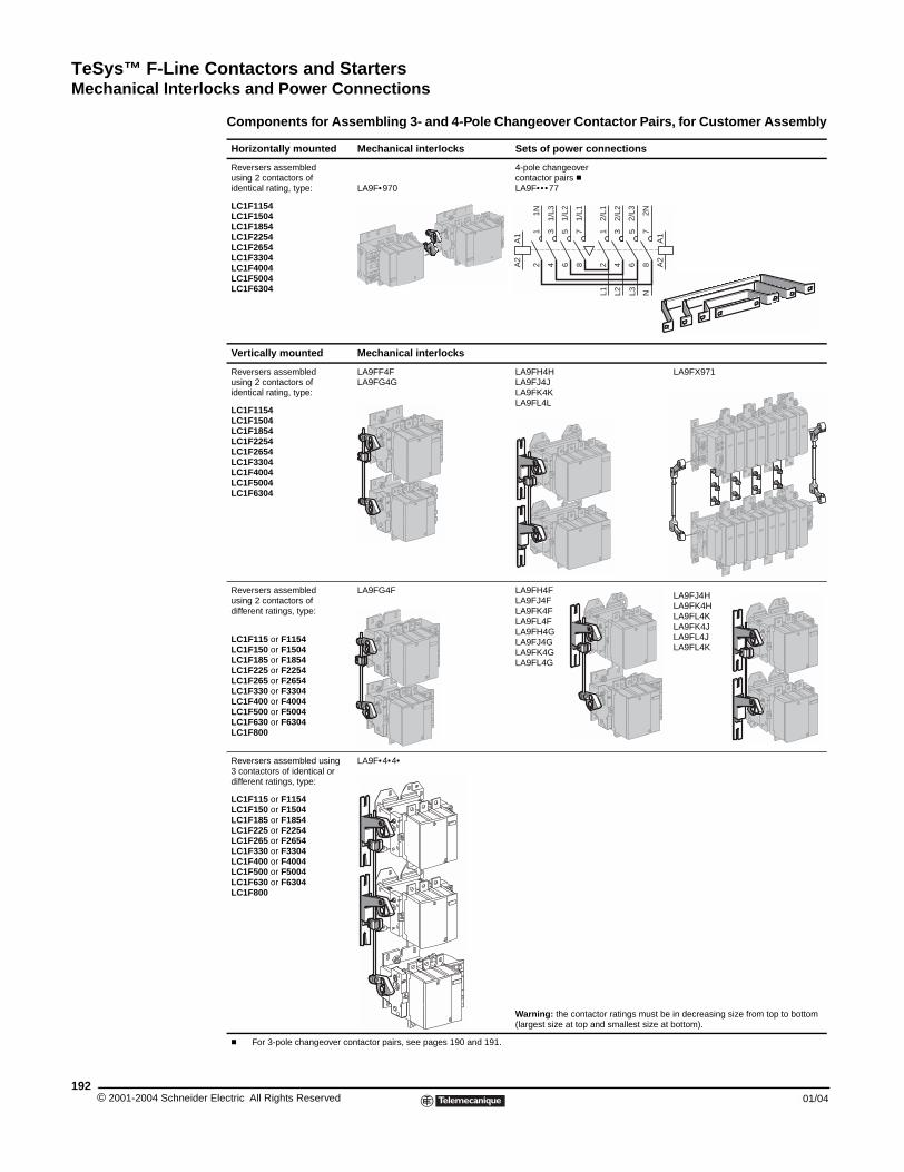
TeSys™ F-Line Contactors and StartersMechanical Interlocks and Power Connections
© 2001-2004 Schneider E192
Components for Assembling 3- and 4-Pole Changeover Contactor Pairs, for Customer Assembly
Horizontally mounted Mechanical interlocks Sets of power connections
Reversers assembledusing 2 contactors ofidentical rating, type: LA9F•970
4-pole changeover contactor pairs cLA9F••• 77
LC1F1154LC1F1504LC1F1854LC1F2254LC1F2654LC1F3304LC1F4004LC1F5004LC1F6304
Vertically mounted Mechanical interlocks
Reversers assembledusing 2 contactors ofidentical rating, type:
LA9FF4FLA9FG4G
LA9FH4HLA9FJ4JLA9FK4KLA9FL4L
LA9FX971
LC1F1154LC1F1504LC1F1854LC1F2254LC1F2654LC1F3304LC1F4004LC1F5004LC1F6304
Reversers assembledusing 2 contactors ofdifferent ratings, type:
LA9FG4F LA9FH4FLA9FJ4FLA9FK4FLA9FL4FLA9FH4GLA9FJ4GLA9FK4GLA9FL4G
LA9FJ4HLA9FK4HLA9FL4KLA9FK4JLA9FL4JLA9FL4K
LC1F115 or F1154LC1F150 or F1504LC1F185 or F1854LC1F225 or F2254LC1F265 or F2654LC1F330 or F3304LC1F400 or F4004LC1F500 or F5004LC1F630 or F6304LC1F800
Reversers assembled using 3 contactors of identical or different ratings, type:
LA9F•4•4•
LC1F115 or F1154LC1F150 or F1504LC1F185 or F1854LC1F225 or F2254LC1F265 or F2654LC1F330 or F3304LC1F400 or F4004LC1F500 or F5004LC1F630 or F6304LC1F800
Warning: the contactor ratings must be in decreasing size from top to bottom (largest size at top and smallest size at bottom).
c For 3-pole changeover contactor pairs, see pages 190 and 191.
A1
A2
A1
A2
12
34
56
34
56
78
1N
1/L3
1/L2
L2
12
L1
78
1/L1
2/L1
2/L2
2/L3 2N
L3 N
lectric All Rights Reserved 01/04
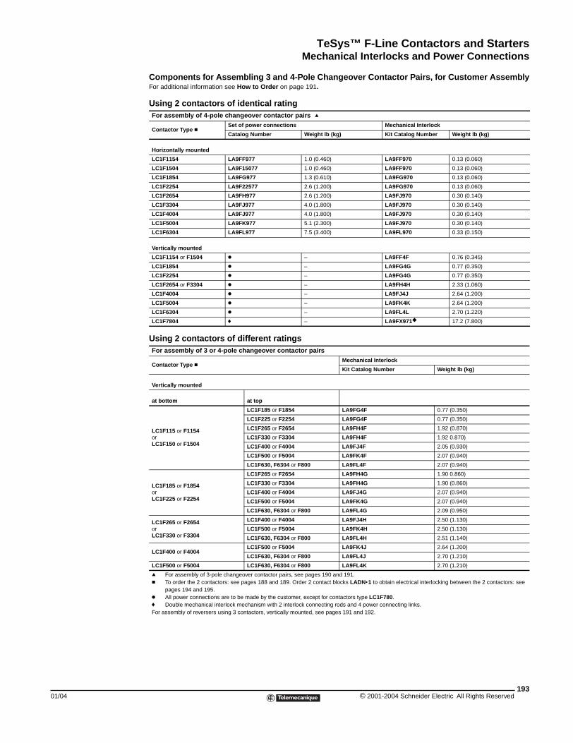
TeSys™ F-Line Contactors and StartersMechanical Interlocks and Power Connections
01/04
Components for Assembling 3 and 4-Pole Changeover Contactor Pairs, for Customer AssemblyFor additional information see How to Order on page 191.
Using 2 contactors of identical ratingFor assembly of 4-pole changeover contactor pairs q
Contactor Type cSet of power connections Mechanical Interlock
Catalog Number Weight lb (kg) Kit Catalog Number Weight lb (kg)
Horizontally mounted
LC1F1154 LA9FF977 1.0 (0.460) LA9FF970 0.13 (0.060)
LC1F1504 LA9F15077 1.0 (0.460) LA9FF970 0.13 (0.060)
LC1F1854 LA9FG977 1.3 (0.610) LA9FG970 0.13 (0.060)
LC1F2254 LA9F22577 2.6 (1.200) LA9FG970 0.13 (0.060)
LC1F2654 LA9FH977 2.6 (1.200) LA9FJ970 0.30 (0.140)
LC1F3304 LA9FJ977 4.0 (1.800) LA9FJ970 0.30 (0.140)
LC1F4004 LA9FJ977 4.0 (1.800) LA9FJ970 0.30 (0.140)
LC1F5004 LA9FK977 5.1 (2.300) LA9FJ970 0.30 (0.140)
LC1F6304 LA9FL977 7.5 (3.400) LA9FL970 0.33 (0.150)
Vertically mounted
LC1F1154 or F1504 k – LA9FF4F 0.76 (0.345)
LC1F1854 k – LA9FG4G 0.77 (0.350)
LC1F2254 k – LA9FG4G 0.77 (0.350)
LC1F2654 or F3304 k – LA9FH4H 2.33 (1.060)
LC1F4004 k – LA9FJ4J 2.64 (1.200)
LC1F5004 k – LA9FK4K 2.64 (1.200)
LC1F6304 k – LA9FL4L 2.70 (1.220)
LC1F7804 f – LA9FX971 17.2 (7.800)
Using 2 contactors of different ratingsFor assembly of 3 or 4-pole changeover contactor pairs
Contactor Type cMechanical Interlock
Kit Catalog Number Weight lb (kg)
Vertically mounted
at bottom at top
LC1F115 or F1154orLC1F150 or F1504
LC1F185 or F1854 LA9FG4F 0.77 (0.350)
LC1F225 or F2254 LA9FG4F 0.77 (0.350)
LC1F265 or F2654 LA9FH4F 1.92 (0.870)
LC1F330 or F3304 LA9FH4F 1.92 0.870)
LC1F400 or F4004 LA9FJ4F 2.05 (0.930)
LC1F500 or F5004 LA9FK4F 2.07 (0.940)
LC1F630, F6304 or F800 LA9FL4F 2.07 (0.940)
LC1F185 or F1854orLC1F225 or F2254
LC1F265 or F2654 LA9FH4G 1.90 0.860)
LC1F330 or F3304 LA9FH4G 1.90 (0.860)
LC1F400 or F4004 LA9FJ4G 2.07 (0.940)
LC1F500 or F5004 LA9FK4G 2.07 (0.940)
LC1F630, F6304 or F800 LA9FL4G 2.09 (0.950)
LC1F265 or F2654orLC1F330 or F3304
LC1F400 or F4004 LA9FJ4H 2.50 (1.130)
LC1F500 or F5004 LA9FK4H 2.50 (1.130)
LC1F630, F6304 or F800 LA9FL4H 2.51 (1.140)
LC1F400 or F4004LC1F500 or F5004 LA9FK4J 2.64 (1.200)
LC1F630, F6304 or F800 LA9FL4J 2.70 (1.210)
LC1F500 or F5004 LC1F630, F6304 or F800 LA9FL4K 2.70 (1.210)
q For assembly of 3-pole changeover contactor pairs, see pages 190 and 191.c To order the 2 contactors: see pages 188 and 189. Order 2 contact blocks LADN•1 to obtain electrical interlocking between the 2 contactors: see
pages 194 and 195.k All power connections are to be made by the customer, except for contactors type LC1F780.f Double mechanical interlock mechanism with 2 interlock connecting rods and 4 power connecting links.For assembly of reversers using 3 contactors, vertically mounted, see pages 191 and 192.
193© 2001-2004 Schneider Electric All Rights Reserved
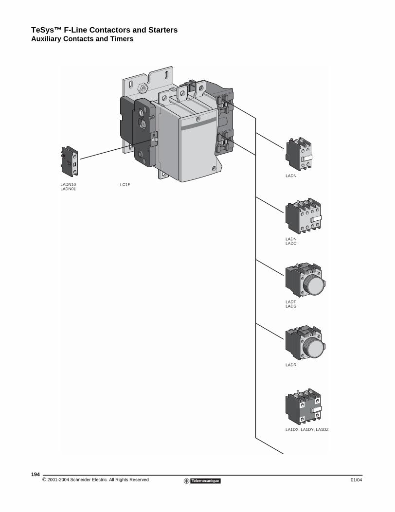
TeSys™ F-Line Contactors and StartersAuxiliary Contacts and Timers
© 2001-2004 Schneider E194
LADN10LADN01
Auxiliary Contacts and Timers
aaa
LA1DX, LA1DY, LA1DZ
LADR
LADTLADS
LADNLADC
LADN
LC1F
lectric All Rights Reserved 01/04
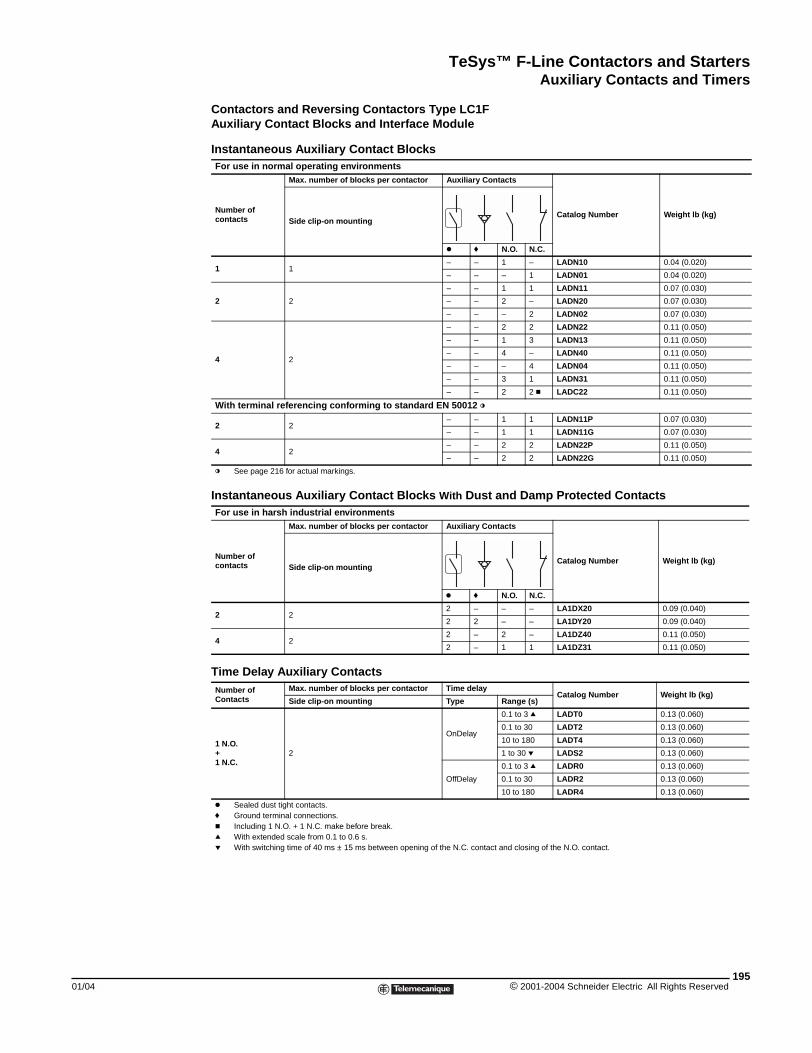
TeSys™ F-Line Contactors and StartersAuxiliary Contacts and Timers
01/04
Contactors and Reversing Contactors Type LC1FAuxiliary Contact Blocks and Interface Module
Instantaneous Auxiliary Contact BlocksFor use in normal operating environments
Number ofcontacts
Max. number of blocks per contactor Auxiliary Contacts
Catalog Number Weight lb (kg)Side clip-on mounting
k f N.O. N.C.
1 1– – 1 – LADN10 0.04 (0.020)
– – – 1 LADN01 0.04 (0.020)
2 2
– – 1 1 LADN11 0.07 (0.030)
– – 2 – LADN20 0.07 (0.030)
– – – 2 LADN02 0.07 (0.030)
4 2
– – 2 2 LADN22 0.11 (0.050)
– – 1 3 LADN13 0.11 (0.050)
– – 4 – LADN40 0.11 (0.050)
– – – 4 LADN04 0.11 (0.050)
– – 3 1 LADN31 0.11 (0.050)
– – 2 2 c LADC22 0.11 (0.050)
With terminal referencing conforming to standard EN 50012 l
2 2 – – 1 1 LADN11P 0.07 (0.030)
– – 1 1 LADN11G 0.07 (0.030)
4 2 – – 2 2 LADN22P 0.11 (0.050)
– – 2 2 LADN22G 0.11 (0.050)
l See page 216 for actual markings.
Instantaneous Auxiliary Contact Blocks With Dust and Damp Protected ContactsFor use in harsh industrial environments
Number ofcontacts
Max. number of blocks per contactor Auxiliary Contacts
Catalog Number Weight lb (kg)Side clip-on mounting
k f N.O. N.C.
2 22 – – – LA1DX20 0.09 (0.040)
2 2 – – LA1DY20 0.09 (0.040)
4 22 – 2 – LA1DZ40 0.11 (0.050)
2 – 1 1 LA1DZ31 0.11 (0.050)
Time Delay Auxiliary ContactsNumber ofContacts
Max. number of blocks per contactor Time delayCatalog Number Weight lb (kg)
Side clip-on mounting Type Range (s)
1 N.O.+ 1 N.C.
2
OnDelay
0.1 to 3 q LADT0 0.13 (0.060)
0.1 to 30 LADT2 0.13 (0.060)
10 to 180 LADT4 0.13 (0.060)
1 to 30 p LADS2 0.13 (0.060)
OffDelay
0.1 to 3 q LADR0 0.13 (0.060)
0.1 to 30 LADR2 0.13 (0.060)
10 to 180 LADR4 0.13 (0.060)
k Sealed dust tight contacts.f Ground terminal connections.c Including 1 N.O. + 1 N.C. make before break.q With extended scale from 0.1 to 0.6 s.p With switching time of 40 ms ± 15 ms between opening of the N.C. contact and closing of the N.O. contact.
195© 2001-2004 Schneider Electric All Rights Reserved
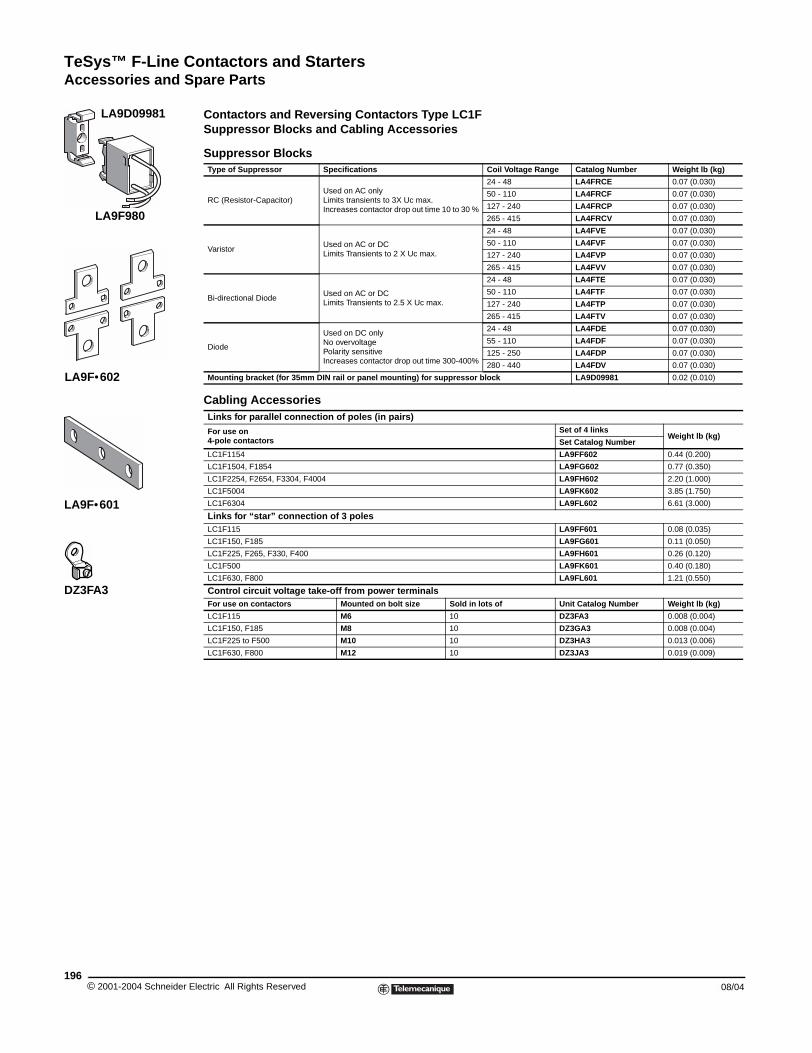
TeSys™ F-Line Contactors and StartersAccessories and Spare Parts
© 2001-2004 Schneider E196
LA9D09981
LA9F•601
DZ3FA3
LA9F•602
LA9F980
Accessories and Spare Parts
Contactors and Reversing Contactors Type LC1FSuppressor Blocks and Cabling Accessories
Suppressor BlocksType of Suppressor Specifications Coil Voltage Range Catalog Number Weight lb (kg)
RC (Resistor-Capacitor)Used on AC onlyLimits transients to 3X Uc max.Increases contactor drop out time 10 to 30 %
24 - 48 LA4FRCE 0.07 (0.030)
50 - 110 LA4FRCF 0.07 (0.030)
127 - 240 LA4FRCP 0.07 (0.030)
265 - 415 LA4FRCV 0.07 (0.030)
VaristorUsed on AC or DCLimits Transients to 2 X Uc max.
24 - 48 LA4FVE 0.07 (0.030)
50 - 110 LA4FVF 0.07 (0.030)
127 - 240 LA4FVP 0.07 (0.030)
265 - 415 LA4FVV 0.07 (0.030)
Bi-directional DiodeUsed on AC or DCLimits Transients to 2.5 X Uc max.
24 - 48 LA4FTE 0.07 (0.030)
50 - 110 LA4FTF 0.07 (0.030)
127 - 240 LA4FTP 0.07 (0.030)
265 - 415 LA4FTV 0.07 (0.030)
Diode
Used on DC onlyNo overvoltagePolarity sensitiveIncreases contactor drop out time 300-400%
24 - 48 LA4FDE 0.07 (0.030)
55 - 110 LA4FDF 0.07 (0.030)
125 - 250 LA4FDP 0.07 (0.030)
280 - 440 LA4FDV 0.07 (0.030)
Mounting bracket (for 35mm DIN rail or panel mounting) for suppressor block LA9D09981 0.02 (0.010)
Cabling AccessoriesLinks for parallel connection of poles (in pairs)
For use on4-pole contactors
Set of 4 linksWeight lb (kg)
Set Catalog Number
LC1F1154 LA9FF602 0.44 (0.200)
LC1F1504, F1854 LA9FG602 0.77 (0.350)
LC1F2254, F2654, F3304, F4004 LA9FH602 2.20 (1.000)
LC1F5004 LA9FK602 3.85 (1.750)
LC1F6304 LA9FL602 6.61 (3.000)
Links for “star” connection of 3 polesLC1F115 LA9FF601 0.08 (0.035)
LC1F150, F185 LA9FG601 0.11 (0.050)
LC1F225, F265, F330, F400 LA9FH601 0.26 (0.120)
LC1F500 LA9FK601 0.40 (0.180)
LC1F630, F800 LA9FL601 1.21 (0.550)
Control circuit voltage take-off from power terminalsFor use on contactors Mounted on bolt size Sold in lots of Unit Catalog Number Weight lb (kg)
LC1F115 M6 10 DZ3FA3 0.008 (0.004)
LC1F150, F185 M8 10 DZ3GA3 0.008 (0.004)
LC1F225 to F500 M10 10 DZ3HA3 0.013 (0.006)
LC1F630, F800 M12 10 DZ3JA3 0.019 (0.009)
lectric All Rights Reserved 08/04
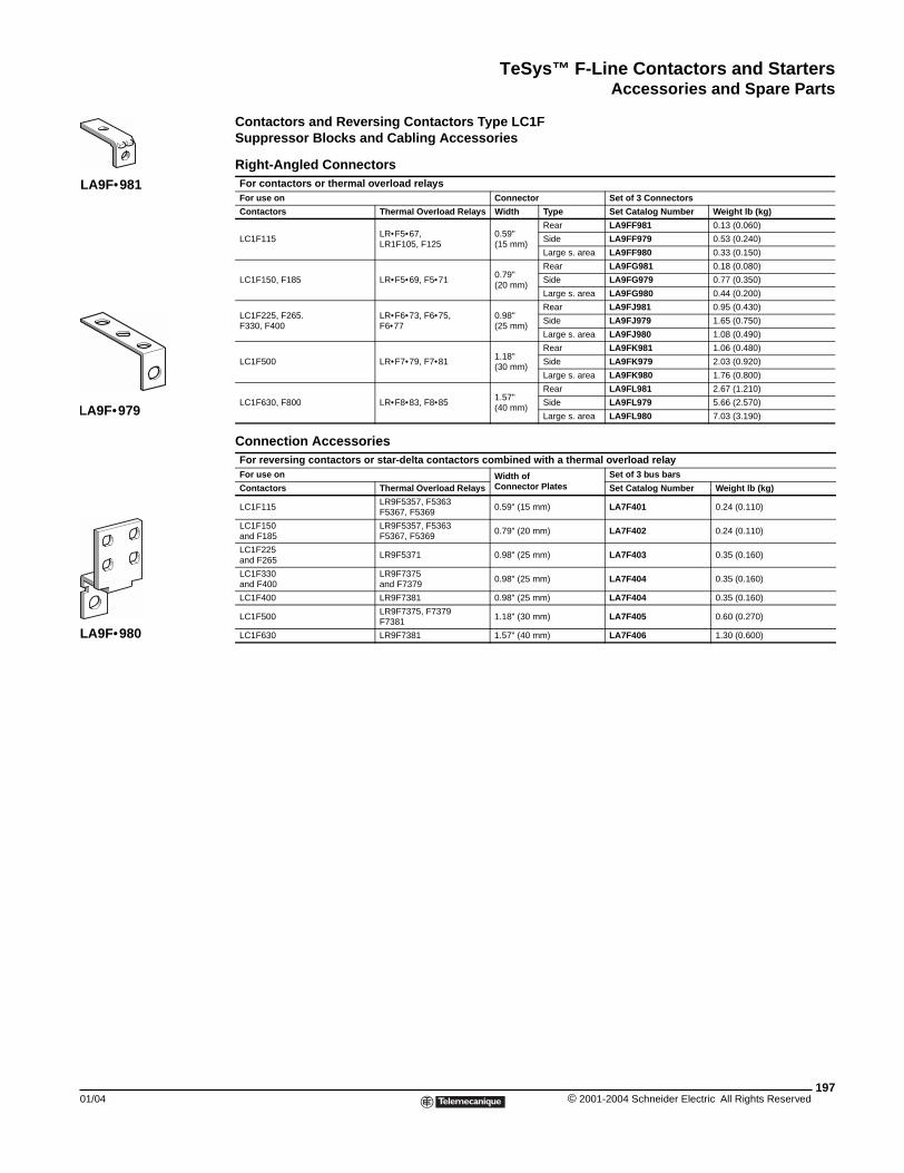
TeSys™ F-Line Contactors and StartersAccessories and Spare Parts
01/04
LA9F•981
LA9F•979
LA9F•980
Contactors and Reversing Contactors Type LC1FSuppressor Blocks and Cabling Accessories
Right-Angled ConnectorsFor contactors or thermal overload relaysFor use on Connector Set of 3 Connectors
Contactors Thermal Overload Relays Width Type Set Catalog Number Weight lb (kg)
LC1F115LR•F5•67,LR1F105, F125
0.59"(15 mm)
Rear LA9FF981 0.13 (0.060)
Side LA9FF979 0.53 (0.240)
Large s. area LA9FF980 0.33 (0.150)
LC1F150, F185 LR•F5•69, F5•710.79"(20 mm)
Rear LA9FG981 0.18 (0.080)
Side LA9FG979 0.77 (0.350)
Large s. area LA9FG980 0.44 (0.200)
LC1F225, F265.F330, F400
LR•F6•73, F6•75, F6•77
0.98"(25 mm)
Rear LA9FJ981 0.95 (0.430)
Side LA9FJ979 1.65 (0.750)
Large s. area LA9FJ980 1.08 (0.490)
LC1F500 LR•F7•79, F7•811.18"(30 mm)
Rear LA9FK981 1.06 (0.480)
Side LA9FK979 2.03 (0.920)
Large s. area LA9FK980 1.76 (0.800)
LC1F630, F800 LR•F8•83, F8•851.57"(40 mm)
Rear LA9FL981 2.67 (1.210)
Side LA9FL979 5.66 (2.570)
Large s. area LA9FL980 7.03 (3.190)
Connection AccessoriesFor reversing contactors or star-delta contactors combined with a thermal overload relayFor use on Width of
Connector PlatesSet of 3 bus bars
Contactors Thermal Overload Relays Set Catalog Number Weight lb (kg)
LC1F115LR9F5357, F5363F5367, F5369
0.59" (15 mm) LA7F401 0.24 (0.110)
LC1F150 and F185
LR9F5357, F5363F5367, F5369
0.79" (20 mm) LA7F402 0.24 (0.110)
LC1F225 and F265
LR9F5371 0.98" (25 mm) LA7F403 0.35 (0.160)
LC1F330 and F400
LR9F7375 and F7379
0.98" (25 mm) LA7F404 0.35 (0.160)
LC1F400 LR9F7381 0.98" (25 mm) LA7F404 0.35 (0.160)
LC1F500LR9F7375, F7379F7381
1.18" (30 mm) LA7F405 0.60 (0.270)
LC1F630 LR9F7381 1.57" (40 mm) LA7F406 1.30 (0.600)
197© 2001-2004 Schneider Electric All Rights Reserved
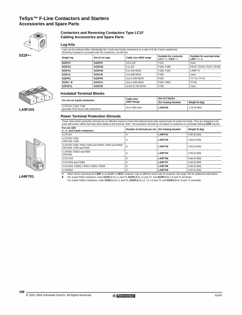
TeSys™ F-Line Contactors and StartersAccessories and Spare Parts
© 2001-2004 Schneider E198
LA9F103
LA9F701
DZ2F••
Contactors and Reversing Contactors Type LC1FCabling Accessories and Spare Parts
Lug KitsLugs can be ordered either individually (for 2-pole and 4-pole contactors) or in sets of 6 (for 3-pole contactors). Mounting hardware is provided with the contactors, not the kits.
Single lug Set of six lugs Cable size AWG range Suitable for contactor LC1•••• / CR1••••
Suitable for overload relay LR9••••• q
DZ2FF1 DZ2FF6 14 to 2/0 F115 none
DZ2FG1 DZ2FG6 6 to 3/0 F150, F185 F5•57, F5•63, F5•67, F5•69
DZ2FH1 DZ2FH6 6 to 300 MCM F265, F330 LR9F•71
DZ2FJ1 DZ2FJ6 4 to 500 MCM F400 none
DZ2FK1 DZ2FK6 2x2 to 600 MCM F500 F7•75, F7•79
DZ2FL• c DZ2FL6 3x2 to 600 MCM F630, F800 F7•81
DZF2FX1 DZ2FX6 4x1/0 to 750 MCM F780 none
Insulated Terminal Blocks
For use on 3-pole contactors Cable SizeAWG Range
Set of 2 blocks
Set Catalog Number Weight lb (kg)
LC1F115, F150, F185(provides IP20 touch-safe protection)
#6 to 300 mcm LA9F103 1.23 (0.560)
Power Terminal Protection ShroudsThese clear plastic protective shrouds are an effective means to meet international touch-safe requirements for power terminals. They are designed to be used with power cables that have been bolted to the terminal. Note: The protection shrouds do not attach to contactors or overloads utilizing DZ2F lug kits.
For use with2-, 3-, and 4-pole contactors Number of shrouds per set Set Catalog Number Weight lb (kg)
LC1F115 6 LA9F701 0.55 (0.250)
LC1F150, F185CR1F150, F185
6 LA9F702 0.55 (0.250)
LC1F225, F265, F330, F400 and F4002, F500 and F5002CR1F265, F400 and F500
6 LA9F703 0.55 (0.250)
LC1F630, F6302 and F800CR1F630
6 LA9F704 0.55 (0.250)
LC1F1154 8 LA9F706 0.66 (0.300)
LC1F1504 and F1854 8 LA9F707 0.66 (0.300)
LC1F2254, F2654, F3304, F4004, F5004 8 LA9F708 0.66 (0.300)
LC1F6304 8 LA9F709 0.66 (0.300)
q When direct mounting the LR9F to an LC1F or CR1F contactor, lugs of different sizes may be required. See page 220 for additional information.c For 3-pole F630 contactors, order DZ2FL1 for L1 and T3, DZ2FL2 for L2 and T2, and DZ2PL3 for L3 and T1 terminals.
For 4-pole F6304 contactors, order DZ2FL1 for L1 and T4, DZ2FL2 for L2, T2, L3 and T3, and DZ2FL3 for L4 and T1 terminals.
lectric All Rights Reserved 01/04
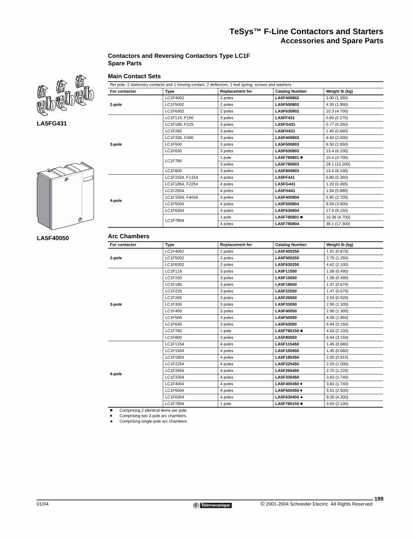
TeSys™ F-Line Contactors and StartersAccessories and Spare Parts
01/04
LA5FG431
LA5F40050
Contactors and Reversing Contactors Type LC1FSpare Parts
Main Contact SetsPer pole: 2 stationary contacts and 1 moving contact, 2 deflectors, 1 leaf spring, screws and washers
For contactor Type Replacement for Catalog Number Weight lb (kg)
2-pole
LC1F4002 2 poles LA5F400802 3.00 (1.350)
LC1F5002 2 poles LA5F500802 4.30 (1.950)
LC1F6302 2 poles LA5F630802 10.3 (4.700)
3-pole
LC1F115, F150 3 poles LA5FF431 0.60 (0.270)
LC1F185, F225 3 poles LA5FG431 0.77 (0.350)
LC1F265 3 poles LA5FH431 1.45 (0.660)
LC1F330, F400 3 poles LA5F400803 4.40 (2.000)
LC1F500 3 poles LA5F500803 6.50 (2.950)
LC1F630 3 poles LA5F630803 13.4 (6.100)
LC1F7801 pole LA5F780801 c 10.4 (4.700)
3 poles LA5F780803 29.1 (13.200)
LC1F800 3 poles LA5F800803 13.4 (6.100)
4-pole
LC1F1504, F1154 4 poles LA5FF441 0.80 (0.360)
LC1F1854, F2254 4 poles LA5FG441 1.20 (0.465)
LC1F2654 4 poles LA5FH441 1.94 (0.880)
LC1F3304, F4004 4 poles LA5F400804 5.95 (2.700)
LC1F5004 4 poles LA5F500804 8.59 (3.900)
LC1F6304 4 poles LA5F630804 17.9 (8.150)
LC1F78041 pole LA5F780801 c 10.36 (4.700)
4 poles LA5F780804 38.1 (17.300)
Arc ChambersFor contactor Type Replacement for Catalog Number Weight lb (kg)
2-pole
LC1F4002 2 poles LA5F400250 1.91 (0.870)
LC1F5002 2 poles LA5F500250 2.75 (1.250)
LC1F6302 2 poles LA5F630250 4.62 (2.100)
3-pole
LC1F115 3 poles LA5F11550 1.08 (0.490)
LC1F150 3 poles LA5F15050 1.08 (0.490)
LC1F185 3 poles LA5F18550 1.47 (0.670)
LC1F225 3 poles LA5F22550 1.47 (0.670)
LC1F265 3 poles LA5F26550 2.03 (0.920)
LC1F330 3 poles LA5F33050 2.90 (1.300)
LC1F400 3 poles LA5F40050 2.90 (1.300)
LC1F500 3 poles LA5F50050 4.08 (1.850)
LC1F630 3 poles LA5F63050 6.94 (3.150)
LC1F780 1 pole LA5F780150 c 4.63 (2.100)
LC1F800 3 poles LA5F80050 6.94 (3.150)
4-pole
LC1F1154 4 poles LA5F115450 1.45 (0.660)
LC1F1504 4 poles LA5F150450 1.45 (0.660)
LC1F1854 4 poles LA5F185450 2.00 (0.910)
LC1F2254 4 poles LA5F225450 2.20 (1.000)
LC1F2654 4 poles LA5F265450 2.70 (1.220)
LC1F3304 4 poles LA5F330450 3.83 (1.740)
LC1F4004 4 poles LA5F400450 f 3.83 (1.740)
LC1F5004 4 poles LA5F500450 f 5.51 (2.500)
LC1F6304 4 poles LA5F630450 q 9.26 (4.200)
LC1F7804 1 pole LA5F780150 c 9.63 (2.100)
c Comprising 2 identical items per pole.f Comprising two 2-pole arc chambers.q Comprising single-pole arc chambers.
199© 2001-2004 Schneider Electric All Rights Reserved
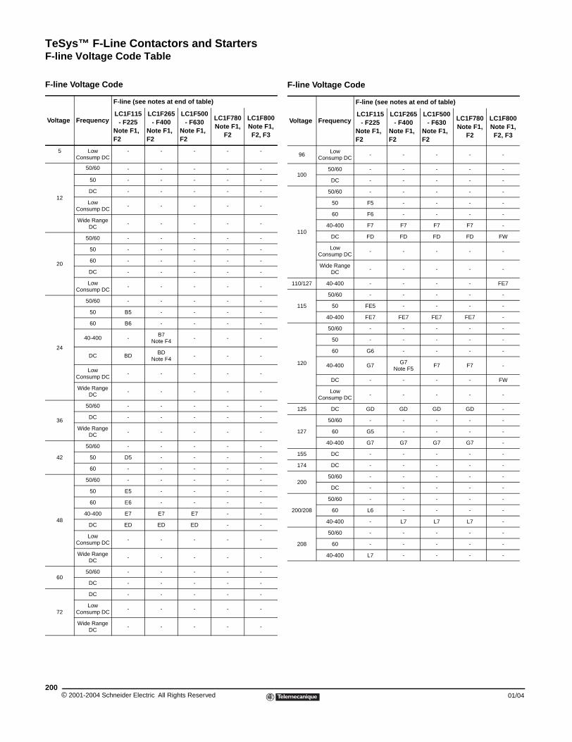
TeSys™ F-Line Contactors and StartersF-line Voltage Code Table
F-line Voltage Code Table
F-line Voltage Code
Voltage Frequency
F-line (see notes at end of table)
LC1F115 - F225
Note F1, F2
LC1F265 - F400
Note F1, F2
LC1F500 - F630
Note F1, F2
LC1F780 Note F1,
F2
LC1F800 Note F1, F2, F3
5 Low Consump DC
- - - - -
12
50/60 - - - - -
50 - - - - -
DC - - - - -
Low Consump DC
- - - - -
Wide Range DC
- - - - -
20
50/60 - - - - -
50 - - - - -
60 - - - - -
DC - - - - -
Low Consump DC
- - - - -
24
50/60 - - - - -
50 B5 - - - -
60 B6 - - - -
40-400 -B7
Note F4- - -
DC BDBD
Note F4- - -
Low Consump DC
- - - - -
Wide Range DC
- - - - -
36
50/60 - - - - -
DC - - - - -
Wide Range DC
- - - - -
42
50/60 - - - - -
50 D5 - - - -
60 - - - - -
48
50/60 - - - - -
50 E5 - - - -
60 E6 - - - -
40-400 E7 E7 E7 - -
DC ED ED ED - -
Low Consump DC
- - - - -
Wide Range DC
- - - - -
6050/60 - - - - -
DC - - - - -
72
DC - - - - -
Low Consump DC
- - - - -
Wide Range DC
- - - - -
© 2001-2004 Schneider Electric All Rights Reserved200
96Low
Consump DC- - - - -
10050/60 - - - - -
DC - - - - -
110
50/60 - - - - -
50 F5 - - - -
60 F6 - - - -
40-400 F7 F7 F7 F7 -
DC FD FD FD FD FW
Low Consump DC
- - - - -
Wide Range DC
- - - - -
110/127 40-400 - - - - FE7
115
50/60 - - - - -
50 FE5 - - - -
40-400 FE7 FE7 FE7 FE7 -
120
50/60 - - - - -
50 - - - - -
60 G6 - - - -
40-400 G7G7
Note F5F7 F7 -
DC - - - - FW
Low Consump DC
- - - - -
125 DC GD GD GD GD -
127
50/60 - - - - -
60 G5 - - - -
40-400 G7 G7 G7 G7 -
155 DC - - - - -
174 DC - - - - -
20050/60 - - - - -
DC - - - - -
200/208
50/60 - - - - -
60 L6 - - - -
40-400 - L7 L7 L7 -
208
50/60 - - - - -
60 - - - - -
40-400 L7 - - - -
F-line Voltage Code
Voltage Frequency
F-line (see notes at end of table)
LC1F115 - F225
Note F1, F2
LC1F265 - F400
Note F1, F2
LC1F500 - F630
Note F1, F2
LC1F780 Note F1,
F2
LC1F800 Note F1, F2, F3
01/04
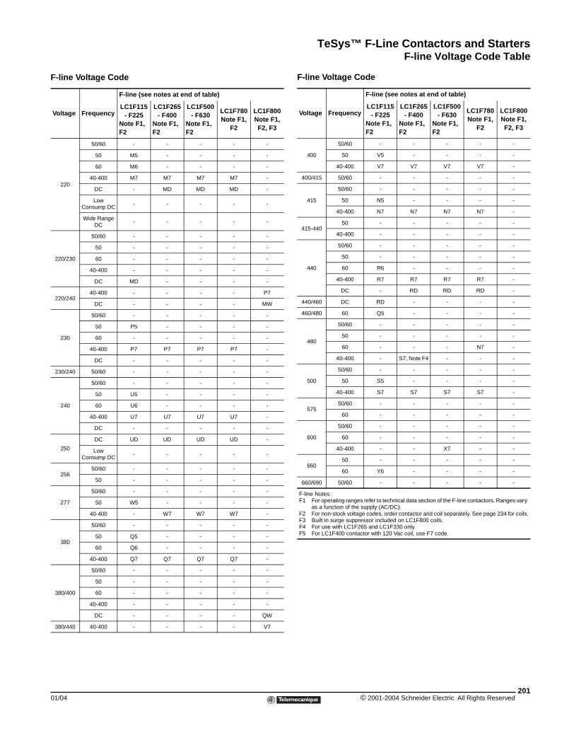
TeSys™ F-Line Contactors and StartersF-line Voltage Code Table
220
50/60 - - - - -
50 M5 - - - -
60 M6 - - - -
40-400 M7 M7 M7 M7 -
DC - MD MD MD -
Low Consump DC
- - - - -
Wide Range DC
- - - - -
220/230
50/60 - - - - -
50 - - - - -
60 - - - - -
40-400 - - - - -
DC MD - - - -
220/24040-400 - - - - P7
DC - - - - MW
230
50/60 - - - - -
50 P5 - - - -
60 - - - - -
40-400 P7 P7 P7 P7 -
DC - - - - -
230/240 50/60 - - - - -
240
50/60 - - - - -
50 U5 - - - -
60 U6 - - - -
40-400 U7 U7 U7 U7 -
DC - - - - -
250
DC UD UD UD UD -
Low Consump DC
- - - - -
25650/60 - - - - -
50 - - - - -
277
50/60 - - - - -
50 W5 - - - -
40-400 - W7 W7 W7 -
380
50/60 - - - - -
50 Q5 - - - -
60 Q6 - - - -
40-400 Q7 Q7 Q7 Q7 -
380/400
50/60 - - - - -
50 - - - - -
60 - - - - -
40-400 - - - - -
DC - - - - QW
380/440 40-400 - - - - V7
F-line Voltage Code
Voltage Frequency
F-line (see notes at end of table)
LC1F115 - F225
Note F1, F2
LC1F265 - F400
Note F1, F2
LC1F500 - F630
Note F1, F2
LC1F780 Note F1,
F2
LC1F800 Note F1, F2, F3
01/04
400
50/60 - - - - -
50 V5 - - - -
40-400 V7 V7 V7 V7 -
400/415 50/60 - - - - -
415
50/60 - - - - -
50 N5 - - - -
40-400 N7 N7 N7 N7 -
415-44050 - - - - -
40-400 - - - - -
440
50/60 - - - - -
50 - - - - -
60 R6 - - - -
40-400 R7 R7 R7 R7 -
DC - RD RD RD -
440/460 DC RD - - - -
460/480 60 Q5 - - - -
480
50/60 - - - - -
50 - - - - -
60 - - - N7 -
40-400 - S7, Note F4 - - -
500
50/60 - - - - -
50 S5 - - - -
40-400 S7 S7 S7 S7 -
57550/60 - - - - -
60 - - - - -
600
50/60 - - - - -
60 - - - - -
40-400 - - X7 - -
66050 - - - - -
60 Y6 - - - -
660/690 50/60 - - - - -
F-line Notes:F1 For operating ranges refer to technical data section of the F-line contactors. Ranges vary
as a function of the supply (AC/DC).F2 For non-stock voltage codes, order contactor and coil separately. See page 234 for coils.F3 Built in surge suppressor included on LC1F800 coils.F4 For use with LC1F265 and LC1F330 only.F5 For LC1F400 contactor with 120 Vac coil, use F7 code.
F-line Voltage Code
Voltage Frequency
F-line (see notes at end of table)
LC1F115 - F225
Note F1, F2
LC1F265 - F400
Note F1, F2
LC1F500 - F630
Note F1, F2
LC1F780 Note F1,
F2
LC1F800 Note F1, F2, F3
201© 2001-2004 Schneider Electric All Rights Reserved
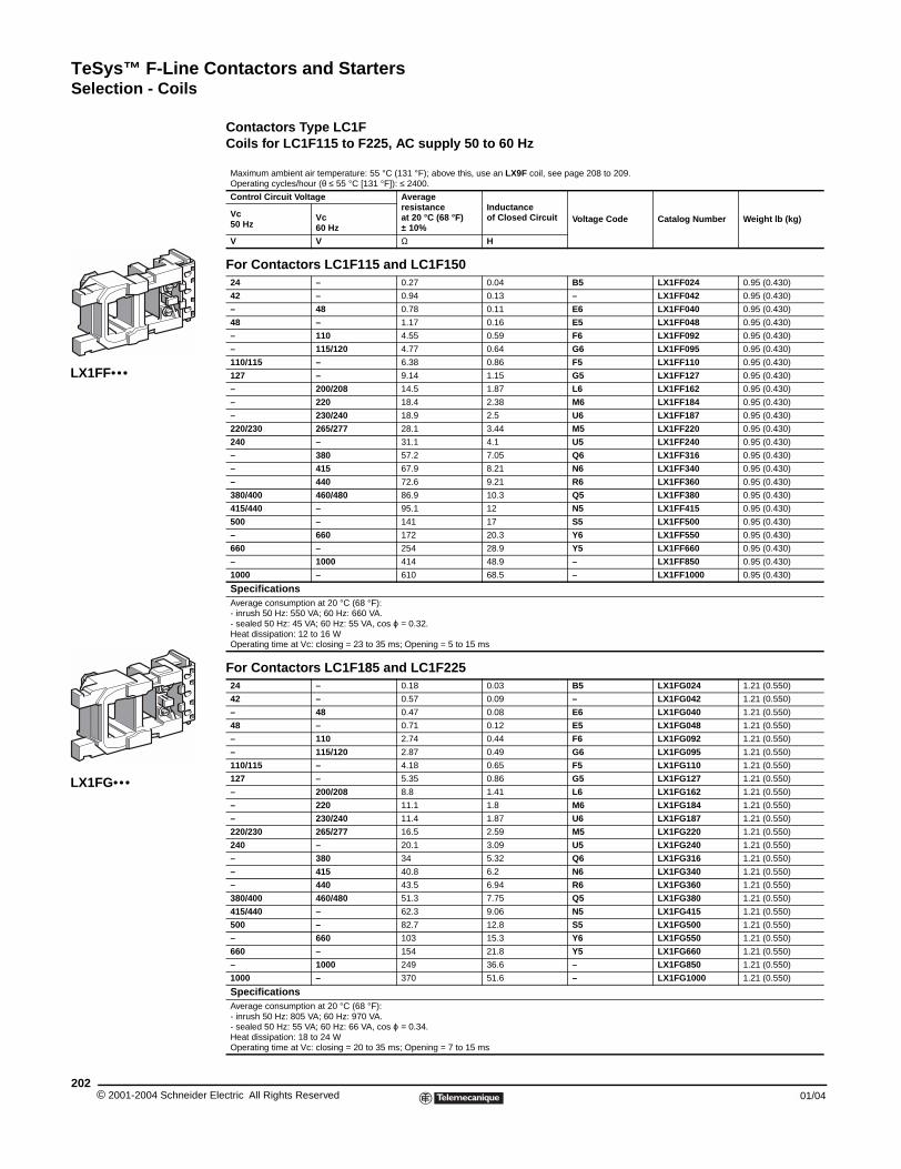
TeSys™ F-Line Contactors and StartersSelection - Coils
© 2001-2004 Schneider E202
LX1FF•••
LX1FG•••
Selection - Coils
Contactors Type LC1FCoils for LC1F115 to F225, AC supply 50 to 60 Hz
Maximum ambient air temperature: 55 °C (131 °F); above this, use an LX9F coil, see page 208 to 209. Operating cycles/hour (θ ≤ 55 °C [131 °F]): ≤ 2400.
Control Circuit Voltage Average resistanceat 20 °C (68 °F)± 10%
Inductanceof Closed Circuit Voltage Code Catalog Number Weight lb (kg)Vc
50 HzVc60 Hz
V V Ω H
For Contactors LC1F115 and LC1F15024 – 0.27 0.04 B5 LX1FF024 0.95 (0.430)
42 – 0.94 0.13 – LX1FF042 0.95 (0.430)
– 48 0.78 0.11 E6 LX1FF040 0.95 (0.430)
48 – 1.17 0.16 E5 LX1FF048 0.95 (0.430)
– 110 4.55 0.59 F6 LX1FF092 0.95 (0.430)
– 115/120 4.77 0.64 G6 LX1FF095 0.95 (0.430)
110/115 – 6.38 0.86 F5 LX1FF110 0.95 (0.430)
127 – 9.14 1.15 G5 LX1FF127 0.95 (0.430)
– 200/208 14.5 1.87 L6 LX1FF162 0.95 (0.430)
– 220 18.4 2.38 M6 LX1FF184 0.95 (0.430)
– 230/240 18.9 2.5 U6 LX1FF187 0.95 (0.430)
220/230 265/277 28.1 3.44 M5 LX1FF220 0.95 (0.430)
240 – 31.1 4.1 U5 LX1FF240 0.95 (0.430)
– 380 57.2 7.05 Q6 LX1FF316 0.95 (0.430)
– 415 67.9 8.21 N6 LX1FF340 0.95 (0.430)
– 440 72.6 9.21 R6 LX1FF360 0.95 (0.430)
380/400 460/480 86.9 10.3 Q5 LX1FF380 0.95 (0.430)
415/440 – 95.1 12 N5 LX1FF415 0.95 (0.430)
500 – 141 17 S5 LX1FF500 0.95 (0.430)
– 660 172 20.3 Y6 LX1FF550 0.95 (0.430)
660 – 254 28.9 Y5 LX1FF660 0.95 (0.430)
– 1000 414 48.9 – LX1FF850 0.95 (0.430)
1000 – 610 68.5 – LX1FF1000 0.95 (0.430)
SpecificationsAverage consumption at 20 °C (68 °F):- inrush 50 Hz: 550 VA; 60 Hz: 660 VA.- sealed 50 Hz: 45 VA; 60 Hz: 55 VA, cos ϕ = 0.32.Heat dissipation: 12 to 16 W Operating time at Vc: closing = 23 to 35 ms; Opening = 5 to 15 ms
For Contactors LC1F185 and LC1F22524 – 0.18 0.03 B5 LX1FG024 1.21 (0.550)
42 – 0.57 0.09 – LX1FG042 1.21 (0.550)
– 48 0.47 0.08 E6 LX1FG040 1.21 (0.550)
48 – 0.71 0.12 E5 LX1FG048 1.21 (0.550)
– 110 2.74 0.44 F6 LX1FG092 1.21 (0.550)
– 115/120 2.87 0.49 G6 LX1FG095 1.21 (0.550)
110/115 – 4.18 0.65 F5 LX1FG110 1.21 (0.550)
127 – 5.35 0.86 G5 LX1FG127 1.21 (0.550)
– 200/208 8.8 1.41 L6 LX1FG162 1.21 (0.550)
– 220 11.1 1.8 M6 LX1FG184 1.21 (0.550)
– 230/240 11.4 1.87 U6 LX1FG187 1.21 (0.550)
220/230 265/277 16.5 2.59 M5 LX1FG220 1.21 (0.550)
240 – 20.1 3.09 U5 LX1FG240 1.21 (0.550)
– 380 34 5.32 Q6 LX1FG316 1.21 (0.550)
– 415 40.8 6.2 N6 LX1FG340 1.21 (0.550)
– 440 43.5 6.94 R6 LX1FG360 1.21 (0.550)
380/400 460/480 51.3 7.75 Q5 LX1FG380 1.21 (0.550)
415/440 – 62.3 9.06 N5 LX1FG415 1.21 (0.550)
500 – 82.7 12.8 S5 LX1FG500 1.21 (0.550)
– 660 103 15.3 Y6 LX1FG550 1.21 (0.550)
660 – 154 21.8 Y5 LX1FG660 1.21 (0.550)
– 1000 249 36.6 – LX1FG850 1.21 (0.550)
1000 – 370 51.6 – LX1FG1000 1.21 (0.550)
SpecificationsAverage consumption at 20 °C (68 °F):- inrush 50 Hz: 805 VA; 60 Hz: 970 VA.- sealed 50 Hz: 55 VA; 60 Hz: 66 VA, cos ϕ = 0.34.Heat dissipation: 18 to 24 WOperating time at Vc: closing = 20 to 35 ms; Opening = 7 to 15 ms
lectric All Rights Reserved 01/04
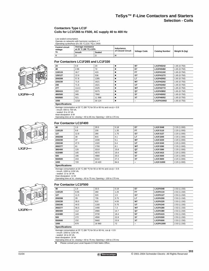
TeSys™ F-Line Contactors and StartersSelection - Coils
01/04
LX1FH••• 2
LX1FJ•••
LX1FK•••
Contactors Type LC1FCoils for LC1F265 to F500, AC supply 40 to 400 Hz
Low sealed consumption.Operate on networks with harmonic numbers ≤ 7Operating cycles/hour (θ ≤ 55 °C [131 °F]) ≤ 2400.
Control circuit voltageVc
Average resistanceat 20 °C (68 °F) ±10% Inductance
of Closed Circuit Voltage Code Catalog Number Weight lb (kg)Inrush Sealed
V Ω Ω H
For Contactors LC1F265 and LC1F33024 0.8 20 c B7 LX1FH0242 1.65 (0.750)
48 2.96 72 c E7 LX1FH0482 1.65 (0.750)
110/115 18.7 415 c F7 LX1FH1102 1.65 (0.750)
120/127 22.9 536 c G7 LX1FH1272 1.65 (0.750)
200/208 57.8 1285 c L7 LX1FH2002 1.65 (0.750)
220/230 71.6 1621 c M7 LX1FH2202 1.65 (0.750)
240 71.6 1621 c U7 LX1FH2402 1.65 (0.750)
277 114.3 2425 c W7 LX1FH2772 1.65 (0.750)
380/415 222 5075 c Q7 LX1FH3802 1.65 (0.750)
480/500 345 7990 c S7 LX1FH5002 1.65 (0.750)
600/660 521 11 988 c X7 LX1FH6002 1.65 (0.750)
1000 1218 30 124 c – LX1FH10002 1.65 (0.750)
SpecificationsAverage consumption at 20 °C (68 °F) for 50 or 60 Hz and cos ϕ = 0.9:- inrush: 600 to 700 VA.- sealed: 8 to 10 VA.Heat dissipation: 8 W Operating time at Vc: closing = 40 to 65 ms; Opening = 100 to 170 ms
For Contactor LC1F40048 1.6 29.5 0.18 E7 LX1FJ048 2.20 (1.000)
110/120 9.8 230 1.35 F7 LX1FJ110 2.20 (1.000)
127 12.8 280 1.75 G7 LX1FJ127 2.20 (1.000)
200/208 30 815 4.1 L7 LX1FJ200 2.20 (1.000)
220/230 37 1030 5.1 M7 LX1FJ220 2.20 (1.000)
230/240 47.5 1320 6.4 U7 LX1FJ240 2.20 (1.000)
265/277 61 1700 8.1 W7 LX1FJ280 2.20 (1.000)
380/400 120 3310 15.8 Q7 LX1FJ380 2.20 (1.000)
415/480 145 4070 19.4 N7 LX1FJ415 2.20 (1.000)
500 190 4980 25.5 S7 LX1FJ500 2.20 (1.000)
550/600 243 6310 27.4 X7 LX1FJ600 2.20 (1.000)
1000 720 19 420 84.6 – LX1FJ1000 2.20 (1.000)
SpecificationsAverage consumption at 20 °C (68 °F) for 50 or 60 Hz and cos ϕ = 0.9:- inrush: 1000 to 1150 VA.- sealed: 12 to 18 VA.Heat dissipation: 14 W Operating time at Vc: closing = 40 to 75 ms; Opening = 100 to 170 ms
For Contactor LC1F50048 1.9 33.5 0.19 E7 LX1FK048 2.53 (1.150)
110/120 9.55 260 1.25 F7 LX1FK110 2.53 (1.150)
127 11.5 315 1.5 G7 LX1FK127 2.53 (1.150)
200/208 29 735 3.75 L7 LX1FK200 2.53 (1.150)
220/230 35.5 915 4.55 M7 LX1FK220 2.53 (1.150)
230/240 44.5 1160 5.75 U7 LX1FK240 2.53 (1.150)
265/277 56.5 1490 7.3 W7 LX1FK280 2.53 (1.150)
380/400 112 2980 14.7 Q7 LX1FK380 2.53 (1.150)
415/480 143 3730 18.4 N7 LX1FK415 2.53 (1.150)
500 172 4590 22.8 S7 LX1FK500 2.53 (1.150)
550/600 232 5660 23.9 X7 LX1FK600 2.53 (1.150)
1000 679 16 960 72 – LX1FK1000 2.53 (1.150)
SpecificationsAverage consumption at 20 °C (68 °F) for 50 or 60 Hz, cos ϕ = 0.9:- inrush: 1050 to 1150 VA.- sealed: 16 to 20 VA.Heat dissipation: 18 W Operating time at Vc: closing = 40 to 75 ms; Opening = 100 to 170 ms
c Please consult your Local Square D Field Sales Office.
203© 2001-2004 Schneider Electric All Rights Reserved
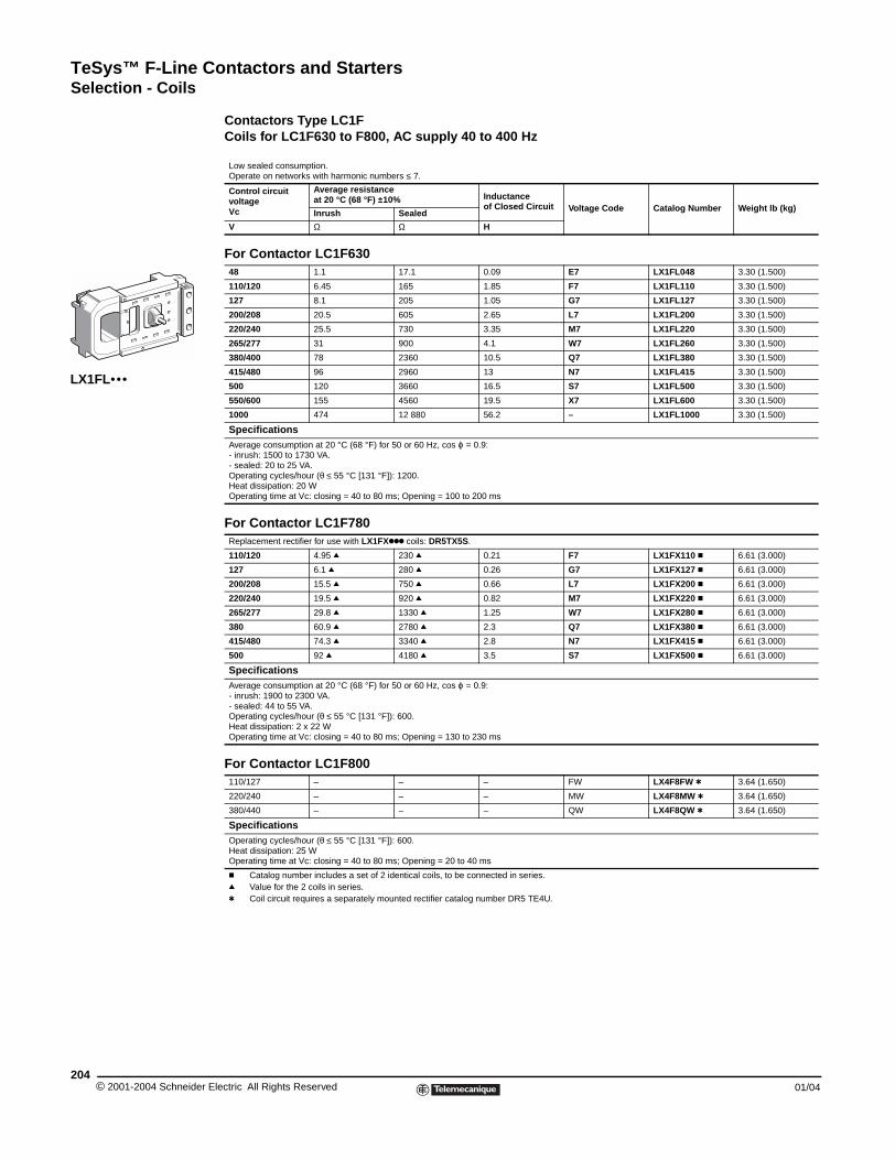
TeSys™ F-Line Contactors and StartersSelection - Coils
© 2001-2004 Schneider E204
LX1FL•••
Contactors Type LC1FCoils for LC1F630 to F800, AC supply 40 to 400 Hz
Low sealed consumption.Operate on networks with harmonic numbers ≤ 7.
Control circuit voltageVc
Average resistanceat 20 °C (68 °F) ±10% Inductance
of Closed Circuit Voltage Code Catalog Number Weight lb (kg)Inrush Sealed
V Ω Ω H
For Contactor LC1F63048 1.1 17.1 0.09 E7 LX1FL048 3.30 (1.500)
110/120 6.45 165 1.85 F7 LX1FL110 3.30 (1.500)
127 8.1 205 1.05 G7 LX1FL127 3.30 (1.500)
200/208 20.5 605 2.65 L7 LX1FL200 3.30 (1.500)
220/240 25.5 730 3.35 M7 LX1FL220 3.30 (1.500)
265/277 31 900 4.1 W7 LX1FL260 3.30 (1.500)
380/400 78 2360 10.5 Q7 LX1FL380 3.30 (1.500)
415/480 96 2960 13 N7 LX1FL415 3.30 (1.500)
500 120 3660 16.5 S7 LX1FL500 3.30 (1.500)
550/600 155 4560 19.5 X7 LX1FL600 3.30 (1.500)
1000 474 12 880 56.2 – LX1FL1000 3.30 (1.500)
SpecificationsAverage consumption at 20 °C (68 °F) for 50 or 60 Hz, cos ϕ = 0.9:- inrush: 1500 to 1730 VA.- sealed: 20 to 25 VA.Operating cycles/hour (θ ≤ 55 °C [131 °F]): 1200.Heat dissipation: 20 W Operating time at Vc: closing = 40 to 80 ms; Opening = 100 to 200 ms
For Contactor LC1F780Replacement rectifier for use with LX1FXkkk coils: DR5TX5S.
110/120 4.95 q 230 q 0.21 F7 LX1FX110 c 6.61 (3.000)
127 6.1 q 280 q 0.26 G7 LX1FX127 c 6.61 (3.000)
200/208 15.5 q 750 q 0.66 L7 LX1FX200 c 6.61 (3.000)
220/240 19.5 q 920 q 0.82 M7 LX1FX220 c 6.61 (3.000)
265/277 29.8 q 1330 q 1.25 W7 LX1FX280 c 6.61 (3.000)
380 60.9 q 2780 q 2.3 Q7 LX1FX380 c 6.61 (3.000)
415/480 74.3 q 3340 q 2.8 N7 LX1FX415 c 6.61 (3.000)
500 92 q 4180 q 3.5 S7 LX1FX500 c 6.61 (3.000)
SpecificationsAverage consumption at 20 °C (68 °F) for 50 or 60 Hz, cos ϕ = 0.9:- inrush: 1900 to 2300 VA.- sealed: 44 to 55 VA.Operating cycles/hour (θ ≤ 55 °C [131 °F]): 600.Heat dissipation: 2 x 22 W Operating time at Vc: closing = 40 to 80 ms; Opening = 130 to 230 ms
For Contactor LC1F800110/127 – – – FW LX4F8FW t 3.64 (1.650)
220/240 – – – MW LX4F8MW t 3.64 (1.650)
380/440 – – – QW LX4F8QW t 3.64 (1.650)
SpecificationsOperating cycles/hour (θ ≤ 55 °C [131 °F]): 600.Heat dissipation: 25 W Operating time at Vc: closing = 40 to 80 ms; Opening = 20 to 40 ms
c Catalog number includes a set of 2 identical coils, to be connected in series.q Value for the 2 coils in series.t Coil circuit requires a separately mounted rectifier catalog number DR5 TE4U.
lectric All Rights Reserved 01/04
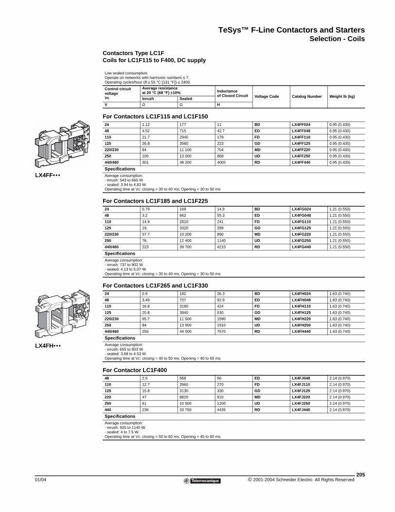
TeSys™ F-Line Contactors and StartersSelection - Coils
01/04
LX4FF•••
LX4FH•••
Contactors Type LC1FCoils for LC1F115 to F400, DC supply
Low sealed consumption.Operate on networks with harmonic numbers ≤ 7.Operating cycles/hour (θ ≤ 55 °C [131 °F]) ≤ 2400.
Control circuit voltageVc
Average resistanceat 20 °C (68 °F) ±10% Inductance
of Closed Circuit Voltage Code Catalog Number Weight lb (kg)Inrush Sealed
V Ω Ω H
For Contactors LC1F115 and LC1F15024 1.12 177 11 BD LX4FF024 0.95 (0.430)
48 4.52 715 42.7 ED LX4FF048 0.95 (0.430)
110 21.7 2940 179 FD LX4FF110 0.95 (0.430)
125 26.8 3560 223 GD LX4FF125 0.95 (0.430)
220/230 84 11 100 704 MD LX4FF220 0.95 (0.430)
250 105 13 000 868 UD LX4FF250 0.95 (0.430)
440/460 301 48 200 4000 RD LX4FF440 0.95 (0.430)
SpecificationsAverage consumption:- inrush: 543 to 665 W.- sealed: 3.94 to 4.83 W.Operating time at Vc: closing = 30 to 40 ms; Opening = 30 to 50 ms
For Contactors LC1F185 and LC1F22524 0.79 169 14.9 BD LX4FG024 1.21 (0.550)
48 3.2 662 55.3 ED LX4FG048 1.21 (0.550)
110 14.9 2810 241 FD LX4FG110 1.21 (0.550)
125 19. 3320 289 GD LX4FG125 1.21 (0.550)
220/230 57.7 10 200 890 MD LX4FG220 1.21 (0.550)
250 76. 12 400 1140 UD LX4FG250 1.21 (0.550)
440/460 223 39 700 4210 RD LX4FG440 1.21 (0.550)
SpecificationsAverage consumption:- inrush: 737 to 902 W.- sealed: 4.13 to 5.07 W.Operating time at Vc: closing = 30 to 40 ms; Opening = 30 to 50 ms
For Contactors LC1F265 and LC1F33024 0.9 192 26.3 BD LX4FH024 1.63 (0.740)
48 3.49 707 92.9 ED LX4FH048 1.63 (0.740)
110 16.8 3180 424 FD LX4FH110 1.63 (0.740)
125 20.8 3840 530 GD LX4FH125 1.63 (0.740)
220/230 65.7 11 500 1590 MD LX4FH220 1.63 (0.740)
250 84 13 900 1910 UD LX4FH250 1.63 (0.740)
440/460 255 44 000 7570 RD LX4FH440 1.63 (0.740)
SpecificationsAverage consumption:- inrush: 655 to 803 W.- sealed: 3.68 to 4.53 W.Operating time at Vc: closing = 40 to 50 ms; Opening = 40 to 65 ms
For Contactor LC1F40048 2.5 558 56 ED LX4FJ048 2.14 (0.970)
110 12.7 2660 270 FD LX4FJ110 2.14 (0.970)
125 15.8 3130 330 GD LX4FJ125 2.14 (0.970)
220 47 8820 910 MD LX4FJ220 2.14 (0.970)
250 61 10 500 1200 UD LX4FJ250 2.14 (0.970)
440 236 33 750 4435 RD LX4FJ440 2.14 (0.970)
SpecificationsAverage consumption:- inrush: 920 to 1140 W.- sealed: 4 to 7.5 W.Operating time at Vc: closing = 50 to 60 ms; Opening = 45 to 60 ms
205© 2001-2004 Schneider Electric All Rights Reserved
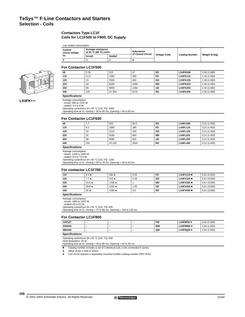
TeSys™ F-Line Contactors and StartersSelection - Coils
© 2001-2004 Schneider E206
LX4FK•••
Contactors Type LC1FCoils for LC1F500 to F800, DC Supply
Low sealed consumption.
Control circuit voltageVc
Average resistance at 20 °C (68 °F) ±10% Inductance
of Closed Circuit Voltage Code Catalog Number Weight lb (kg)Inrush Sealed
V Ω Ω H
For Contactor LC1F50048 2.35 515 67 ED LX4FK048 2.40 (1.080)
110 11.5 2450 280 FD LX4FK110 2.40 (1.080)
125 15 2930 400 GD LX4FK125 2.40 (1.080)
220 44 8150 1080 MD LX4FK220 2.40 (1.080)
250 56 9650 1350 UD LX4FK250 2.40 (1.080)
440 225 31 300 5270 RD LX4FK440 2.40 (1.080)
SpecificationsAverage consumption:- inrush: 990 to 1220 W.- sealed: 4.5 to 8 W.Operating cycles/hour (θ ≤ 55 °C [131 °F]): 2400Operating time at Vc: closing = 50 to 60 ms; Opening = 45 to 60 ms
For Contactor LC1F63048 1.7 353 40.5 ED LX4FL048 3.21 (1.450)
110 8.1 1680 180 FD LX4FL110 3.21 (1.450)
125 10 2110 230 GD LX4FL125 3.21 (1.450)
220 31 5160 650 MD LX4FL220 3.21 (1.450)
250 38 6080 815 UD LX4FL250 3.21 (1.450)
440 152 23 120 2910 RD LX4FL440 3.21 (1.450)
SpecificationsAverage consumption:- inrush: 1420 to 1920 W.- sealed: 6.5 to 72.5 W.Operating cycles/hour (θ ≤ 55 °C [131 °F]): 1200Operating time at Vc: closing = 60 to 70 ms; Opening = 40 to 50 ms
For contactor LC1F780110 6.1 q 280 q 0.26 FD LX4FX110 c 6.61 (3.000)
125 7.7 q 410 q 0.33 GD LX4FX125 c 6.61 (3.000)
220 24.6 q 1100 q 1 MD LX4FX220 c 6.61 (3.000)
250 29.8 q 1330 q 1.25 UD LX4FX250 c 6.61 (3.000)
440 92 q 4180 q 3.5 RD LX4FX440 c 6.61 (3.000)
SpecificationsAverage consumption:- inrush: 1960 to 2420 W.- sealed: 42 to 52 W.Operating cycles/hour (θ ≤ 55 °C [131 °F]): 600Operating time at Vc: closing = 70 to 80 ms; Opening = 100 to 130 ms
For Contactor LC1F800110/127 – – – FW LX4F8FW t 3.64 (1.650)
220/240 – – – MW LX4F8MW t 3.64 (1.650)
380/440 – – – QW LX4F8QW t 3.64 (1.650)
SpecificationsOperating cycles/hour (θ ≤ 55 °C [131 °F]): 600Heat dissipation: 25 W Operating time at Vc: closing = 40 to 80 ms; Opening = 20 to 40 ms
c Catalog number includes a set of 2 identical coils, to be connected in series.q Value of the 2 coils in series.t Coil circuit requires a separately mounted rectifier catalog number DR5 TE4U.
lectric All Rights Reserved 01/04
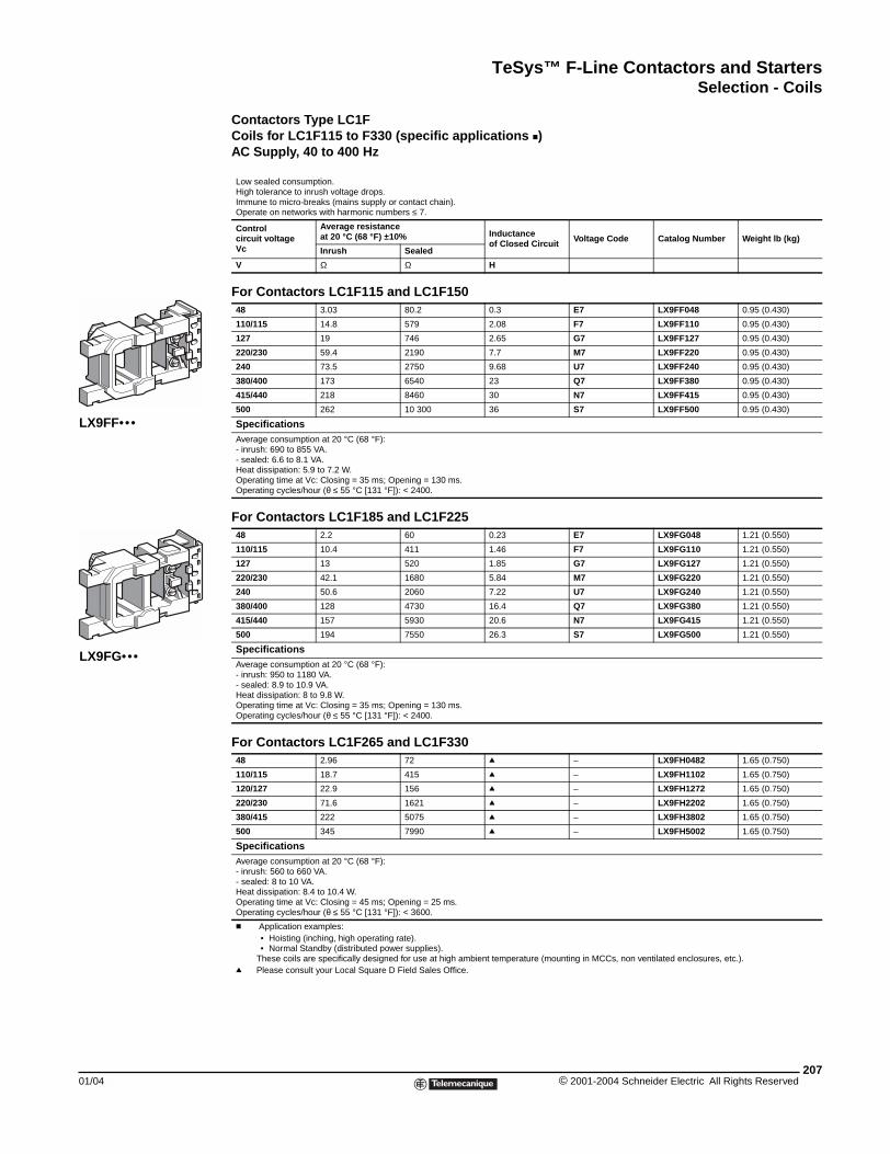
TeSys™ F-Line Contactors and StartersSelection - Coils
01/04
LX9FF•••
LX9FG•••
Contactors Type LC1FCoils for LC1F115 to F330 (specific applications c)AC Supply, 40 to 400 Hz
Low sealed consumption.High tolerance to inrush voltage drops.Immune to micro-breaks (mains supply or contact chain).Operate on networks with harmonic numbers ≤ 7.
Control circuit voltageVc
Average resistance at 20 °C (68 °F) ±10% Inductance
of Closed Circuit Voltage Code Catalog Number Weight lb (kg)Inrush Sealed
V Ω Ω H
For Contactors LC1F115 and LC1F15048 3.03 80.2 0.3 E7 LX9FF048 0.95 (0.430)
110/115 14.8 579 2.08 F7 LX9FF110 0.95 (0.430)
127 19 746 2.65 G7 LX9FF127 0.95 (0.430)
220/230 59.4 2190 7.7 M7 LX9FF220 0.95 (0.430)
240 73.5 2750 9.68 U7 LX9FF240 0.95 (0.430)
380/400 173 6540 23 Q7 LX9FF380 0.95 (0.430)
415/440 218 8460 30 N7 LX9FF415 0.95 (0.430)
500 262 10 300 36 S7 LX9FF500 0.95 (0.430)
SpecificationsAverage consumption at 20 °C (68 °F):- inrush: 690 to 855 VA.- sealed: 6.6 to 8.1 VA.Heat dissipation: 5.9 to 7.2 W.Operating time at Vc: Closing = 35 ms; Opening = 130 ms.Operating cycles/hour (θ ≤ 55 °C [131 °F]): < 2400.
For Contactors LC1F185 and LC1F22548 2.2 60 0.23 E7 LX9FG048 1.21 (0.550)
110/115 10.4 411 1.46 F7 LX9FG110 1.21 (0.550)
127 13 520 1.85 G7 LX9FG127 1.21 (0.550)
220/230 42.1 1680 5.84 M7 LX9FG220 1.21 (0.550)
240 50.6 2060 7.22 U7 LX9FG240 1.21 (0.550)
380/400 128 4730 16.4 Q7 LX9FG380 1.21 (0.550)
415/440 157 5930 20.6 N7 LX9FG415 1.21 (0.550)
500 194 7550 26.3 S7 LX9FG500 1.21 (0.550)
SpecificationsAverage consumption at 20 °C (68 °F):- inrush: 950 to 1180 VA.- sealed: 8.9 to 10.9 VA.Heat dissipation: 8 to 9.8 W.Operating time at Vc: Closing = 35 ms; Opening = 130 ms.Operating cycles/hour (θ ≤ 55 °C [131 °F]): < 2400.
For Contactors LC1F265 and LC1F33048 2.96 72 q – LX9FH0482 1.65 (0.750)
110/115 18.7 415 q – LX9FH1102 1.65 (0.750)
120/127 22.9 156 q – LX9FH1272 1.65 (0.750)
220/230 71.6 1621 q – LX9FH2202 1.65 (0.750)
380/415 222 5075 q – LX9FH3802 1.65 (0.750)
500 345 7990 q – LX9FH5002 1.65 (0.750)
SpecificationsAverage consumption at 20 °C (68 °F):- inrush: 560 to 660 VA.- sealed: 8 to 10 VA.Heat dissipation: 8.4 to 10.4 W.Operating time at Vc: Closing = 45 ms; Opening = 25 ms.Operating cycles/hour (θ ≤ 55 °C [131 °F]): < 3600.
c Application examples:• Hoisting (inching, high operating rate).• Normal Standby (distributed power supplies).
These coils are specifically designed for use at high ambient temperature (mounting in MCCs, non ventilated enclosures, etc.).q Please consult your Local Square D Field Sales Office.
207© 2001-2004 Schneider Electric All Rights Reserved
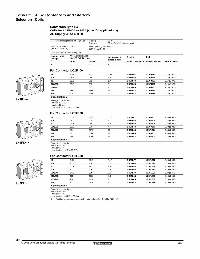
TeSys™ F-Line Contactors and StartersSelection - Coils
© 2001-2004 Schneider E208
LX9FK•••
LX9FJ•••
LX9FL•••
Contactors Type LC1FCoils for LC1F400 to F630 (specific applications)AC Supply, 40 to 400 Hz
Coils with short operating times (at Vc): Closing:Opening:
60 ms50 ms (c side); 20 ms (a side)
Coils for high operating rates (θ ≤ 70 °C [158 °F]):
3600 operating cycles/hour1800 for LC1F630
Coils with low inrush consumption
Control circuitvoltageVc
Average resistanceat 20 °C (68 °F) ±10% Inductance of
closed circuitRectifier Coil
Inrush Sealed Catalog Number c Catalog Number Weight lb (kg)
V Ω Ω H
For Contactor LC1F40048 4.03 43 0.22 DR5TF4V LX9FJ917 2.14 (0.970)
110 25.7 246 1.3 DR5TE4U LX9FJ925 2.14 (0.970)
127 32.3 302 1.7 DR5TE4U LX9FJ926 2.14 (0.970)
220/230 99.5 919 5 DR5TE4U LX9FJ931 2.14 (0.970)
380/415 311 3011 15 DR5TE4S LX9FJ936 2.14 (0.970)
440 386 3690 19 DR5TE4S LX9FJ937 2.14 (0.970)
500 478 4380 23 DR5TE4S LX9FJ938 2.14 (0.970)
SpecificationsAverage consumption:- inrush: 500 VA.- sealed: 23 VA.Heat dissipation: 11.4 to 13.9 W.
For Contactor LC1F50048 3.73 30.7 0.18 DR5TF4V LX9FK917 2.38 (1.080)
110 24 204 1.1 DR5TE4U LX9FK925 2.38 (1.080)
127 29.8 250 1.4 DR5TE4U LX9FK926 2.38 (1.080)
220/230 89.9 770 4 DR5TE4U LX9FK931 2.38 (1.080)
380/415 274 2075 12 DR5TE4S LX9FK936 2.38 (1.080)
440 361 3060 16 DR5TE4S LX9FK937 2.38 (1.080)
500 448 3750 19 DR5TE4S LX9FK938 2.38 (1.080)
SpecificationsAverage consumption:- inrush: 550 VA.- sealed: 31 VA.Heat dissipation: 15 to 18.3 W.
For Contactor LC1F63048 2.81 20.8 0.17 DR5TF4V LX9FL917 3.20 (1.450)
110 13.5 114 0.77 DR5TE4U LX9FL924 3.20 (1.450)
127 20.8 167 1.2 DR5TE4U LX9FL926 3.20 (1.450)
220 52 425 2.9 DR5TE4U LX9FL930 3.20 (1.450)
220/240 64.5 518 3.6 DR5TE4U LX9FL931 3.20 (1.450)
380/400 163 1360 8.8 DR5TE4S LX9FL935 3.20 (1.450)
415/440 204 1670 11 DR5TE4S LX9FL936 3.20 (1.450)
500 312 2510 17 DR5TE4S LX9FL938 3.20 (1.450)
SpecificationsAverage consumption:- inrush: 830 VA.- sealed: 47 VA.Heat dissipation: 22.8 to 27.8 W.
c Rectifier to be ordered separately; weight of rectifier: 0.100 kg (0.22 lbs).
lectric All Rights Reserved 01/04
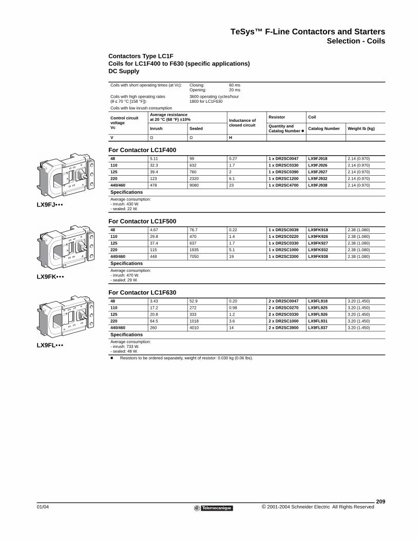
TeSys™ F-Line Contactors and StartersSelection - Coils
01/04
LX9FK•••
LX9FJ•••
LX9FL•••
Contactors Type LC1FCoils for LC1F400 to F630 (specific applications) DC Supply
Coils with short operating times (at Vc): Closing:Opening:
60 ms20 ms
Coils with high operating rates (θ ≤ 70 °C [158 °F]):
3600 operating cycles/hour1800 for LC1F630
Coils with low inrush consumption
Control circuitvoltageVc
Average resistance at 20 °C (68 °F) ±10% Inductance of
closed circuit
Resistor Coil
Inrush Sealed Quantity andCatalog Number c Catalog Number Weight lb (kg)
V Ω Ω H
For Contactor LC1F400 48 5.11 99 0.27 1 x DR2SC0047 LX9FJ918 2.14 (0.970)
110 32.3 632 1.7 1 x DR2SC0330 LX9FJ926 2.14 (0.970)
125 39.4 760 2 1 x DR2SC0390 LX9FJ927 2.14 (0.970)
220 123 2320 6.1 1 x DR2SC1200 LX9FJ932 2.14 (0.970)
440/460 478 9080 23 1 x DR2SC4700 LX9FJ938 2.14 (0.970)
SpecificationsAverage consumption:- inrush: 430 W.- sealed: 22 W.
For Contactor LC1F500 48 4.67 76.7 0.22 1 x DR2SC0039 LX9FK918 2.38 (1.080)
110 29.8 470 1.4 1 x DR2SC0220 LX9FK926 2.38 (1.080)
125 37.4 637 1.7 1 x DR2SC0330 LX9FK927 2.38 (1.080)
220 115 1935 5.1 1 x DR2SC1000 LX9FK932 2.38 (1.080)
440/460 448 7050 19 1 x DR2SC3300 LX9FK938 2.38 (1.080)
SpecificationsAverage consumption:- inrush: 470 W.- sealed: 29 W.
For Contactor LC1F630 48 3.43 52.9 0.20 2 x DR2SC0047 LX9FL918 3.20 (1.450)
110 17.2 272 0.98 2 x DR2SC0270 LX9FL925 3.20 (1.450)
125 20.8 333 1.2 2 x DR2SC0330 LX9FL926 3.20 (1.450)
220 64.5 1018 3.6 2 x DR2SC1000 LX9FL931 3.20 (1.450)
440/460 260 4010 14 2 x DR2SC3900 LX9FL937 3.20 (1.450)
SpecificationsAverage consumption:- inrush: 733 W.- sealed: 48 W.
c Resistors to be ordered separately, weight of resistor: 0.030 kg (0.06 lbs).
209© 2001-2004 Schneider Electric All Rights Reserved
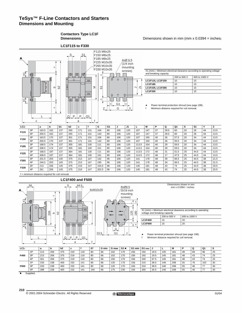
TeSys™ F-Line Contactors and StartersDimensions and Mounting
© 2001-2004 Schneider E210
LC1- a b
F1153P 163.5 162
4P 200.5 162
F1503P 163.5 170
4P 200.5 170
F1853P 168.5 174
4P 208.5 174
F2253P 168.5 197
4P 208.5 197
F2653P 201.5 203
4P 244.5 203
F3303P 213 206
4P 261 206
f = minimum distance required for c
LC1- a b
F400
2P 213 206
3P 213 206
4P 261 206
F500
2P 233 238
3P 233 238
4P 288 238
c Supplied.
L
c
=b
=
X1
X1
L
c
=b
=
209
56
X1
X1
Dimensions and Mounting
Contactors Type LC1FDimensions Dimensions shown in mm (mm x 0.0394 = inches)
LC1F115 to F330
X1 (mm) = Minimum electrical clearance according to operating voltage and breaking capacity
200 to 500 V 600 to 1000 V
LC1F115, LC1F150 10 15
LC1F185 10 15
LC1F225, LC1F265 10 15
LC1F330 10 15
q Power terminal protection shroud (see page 198).f Minimum distance required for coil removal.
b1 b2 c f G G1 J J1 L M P Q Q1 S S1 Y Z
137 265 171 131 106 80 106 120 107 147 37 29.5 60 20 26 44 13.5
137 265 171 131 143 80 106 120 107 147 37 29.5 60 20 26 44 13.5
137 301 171 131 106 80 106 120 107 150 40 26 57.5 20 34 44 13.5
137 301 171 131 143 80 106 120 107 150 40 26 55.5 20 34 44 13.5
137 305 181 130 111 80 106 120 113.5 154 40 29 59.5 20 34 44 13.5
137 305 181 130 151 80 106 120 113.5 154 40 29 59.5 20 34 44 13.5
137 364 181 130 111 80 106 120 113.5 172 48 21 51.5 25 44.5 44 13.5
137 364 181 130 151 80 106 120 113.5 172 48 17 47.5 25 44.5 44 13.5
145 375 213 147 142 96 106 120 141 178 48 39 66.5 25 44.5 38 21.5
145 375 213 147 190 96 106 120 141 178 48 34 66.5 25 44.5 38 21.5
145 375 219 147 154.5 96 106 120 145 181 48 43 74 25 44.5 38 20.5
145 375 219 147 202.5 96 106 120 145 181 48 43 74 25 44.5 38 20.5
oil removal
LC1F400 and F500Dimensions shown in mm mm x 0.0394 = inches
X1 (mm) = Minimum electrical clearance according to operating voltage and breaking capacity
200 to 500 V 600 to 1000 V
LC1F400 15 20
LC1F500 15 20
q Power terminal protection shroud (see page 198).f Minimum distance required for coil removal.
b2 c f G* G min G max G1 c G1 min G1 max J L M P Q Q1 S
375 219 119 80 66 102 170 156 192 19.5 145 181 48 69 96 25
375 219 119 80 66 102 170 156 192 19.5 145 181 48 43 74 25
375 219 119 80 66 150 170 156 240 67.5 145 181 48 43 74 25
400 232 141 80 66 120 170 156 210 39.5 146 208 55 76 102 30
400 232 141 80 66 120 170 156 210 39.5 146 208 55 46 77 30
400 232 141 140 66 175 230 156 265 34.5 146 208 55 46 77 30
J J1b1=
=G1
GZ
= =
Y
4xØ 6.5 (1/4 inch mounting screws)
b2S1
Q
a
P P Q1
f
M
SF115 M6x25F150 M8x25F185 M8x25F225 M10x35F265 M10x35F330 M10x35
G
G123.5 J
120
==
180
==
b2
Q1
a
PQ P
f
M
44.5S
6xM10x358xØ8.5(5/16 inch mounting screws)
lectric All Rights Reserved 01/04
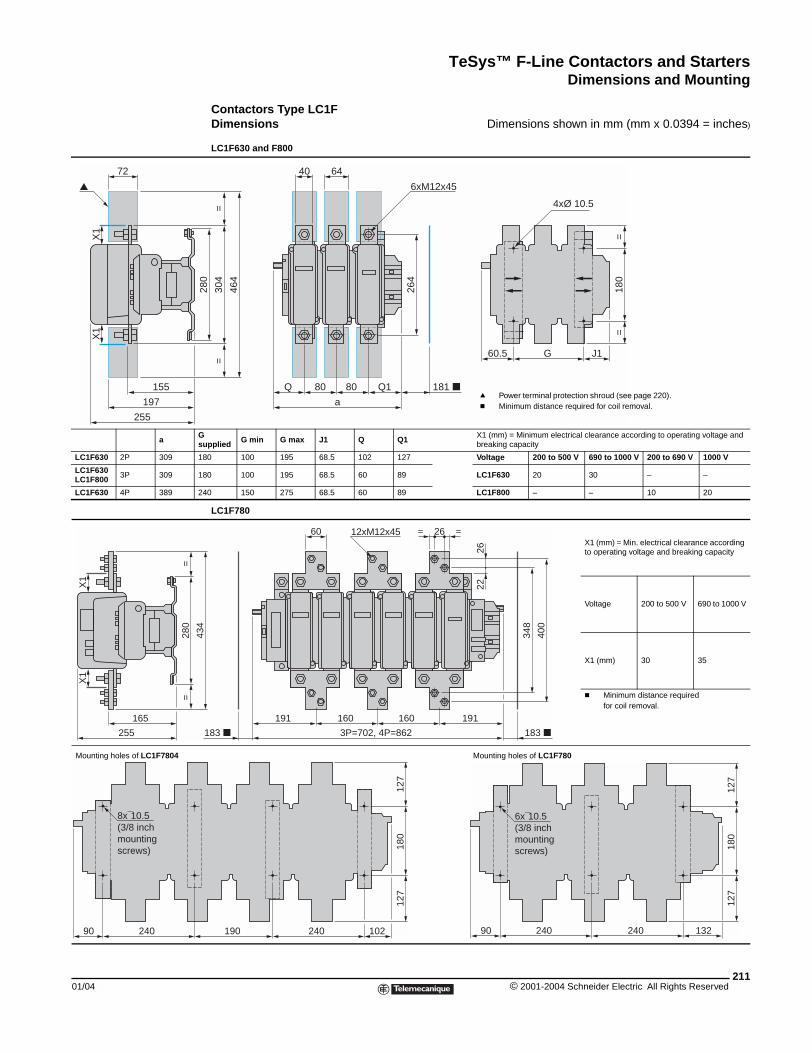
TeSys™ F-Line Contactors and StartersDimensions and Mounting
01/04
a Gs
LC1F630 2P 309 1
LC1F630LC1F800 3P 309 1
LC1F630 4P 389 2
Mounting holes of LC1F7804
155
197
255
X1
72
X1
X1
X1
=28
0=
165
255
24090
8x¯10.5 (3/8 inch mounting screws)
Contactors Type LC1FDimensions Dimensions shown in mm (mm x 0.0394 = inches)
LC1F630 and F800
upplied G min G max J1 Q Q1 X1 (mm) = Minimum electrical clearance according to operating voltage and
breaking capacity
80 100 195 68.5 102 127 Voltage 200 to 500 V 690 to 1000 V 200 to 690 V 1000 V
80 100 195 68.5 60 89 LC1F630 20 30 – –
40 150 275 68.5 60 89 LC1F800 – – 10 20
LC1F780
X1 (mm) = Min. electrical clearance according to operating voltage and breaking capacity
Voltage 200 to 500 V 690 to 1000 V
X1 (mm) 30 35
c Minimum distance required for coil removal.
Mounting holes of LC1F780
180
==
J1G60.5
Q1
a
8080Q
264
181
6440
6xM12x45
=30
4=
280
464
4xØ 10.5
q Power terminal protection shroud (see page 220).c Minimum distance required for coil removal.
191
183
191160 160
183
60 12xM12x45 26= =34
8
400
2226
3P=702, 4P=862
434
102190 240
180
127
127
13224090 240
180
127
127
6x¯10.5 (3/8 inch mounting screws)
211© 2001-2004 Schneider Electric All Rights Reserved
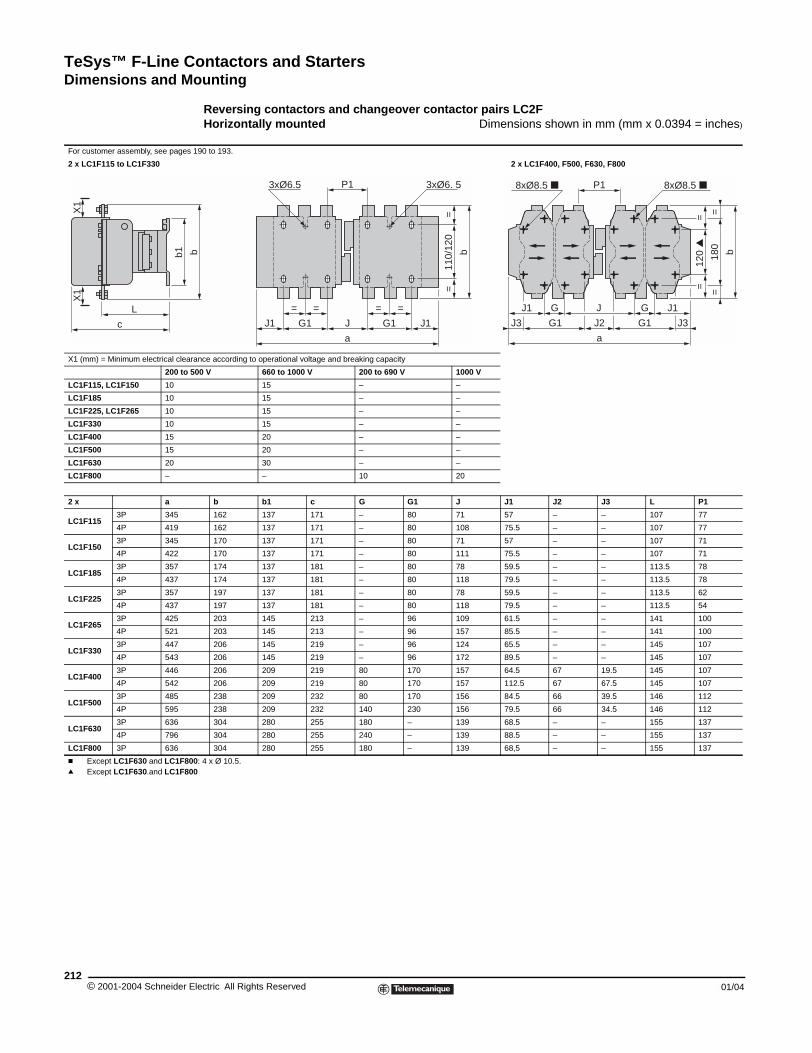
TeSys™ F-Line Contactors and StartersDimensions and Mounting
© 2001-2004 Schneider E212
For customer assembly, see pages
2 x LC1F115 to LC1F330
X1 (mm) = Minimum electrical clear
200 to 5
LC1F115, LC1F150 10
LC1F185 10
LC1F225, LC1F265 10
LC1F330 10
LC1F400 15
LC1F500 15
LC1F630 20
LC1F800 –
2 x a
LC1F1153P 345
4P 419
LC1F1503P 345
4P 422
LC1F1853P 357
4P 437
LC1F2253P 357
4P 437
LC1F2653P 425
4P 521
LC1F3303P 447
4P 543
LC1F4003P 446
4P 542
LC1F5003P 485
4P 595
LC1F6303P 636
4P 796
LC1F800 3P 636
c Except LC1F630 and LC1F80q Except LC1F630.and LC1F80
L
c
b1
X1
X1
Reversing contactors and changeover contactor pairs LC2FHorizontally mounted Dimensions shown in mm (mm x 0.0394 = inches)
190 to 193.
2 x LC1F400, F500, F630, F800
ance according to operational voltage and breaking capacity
00 V 660 to 1000 V 200 to 690 V 1000 V
15 – –
15 – –
15 – –
15 – –
20 – –
20 – –
30 – –
– 10 20
b b1 c G G1 J J1 J2 J3 L P1
162 137 171 – 80 71 57 – – 107 77
162 137 171 – 80 108 75.5 – – 107 77
170 137 171 – 80 71 57 – – 107 71
170 137 171 – 80 111 75.5 – – 107 71
174 137 181 – 80 78 59.5 – – 113.5 78
174 137 181 – 80 118 79.5 – – 113.5 78
197 137 181 – 80 78 59.5 – – 113.5 62
197 137 181 – 80 118 79.5 – – 113.5 54
203 145 213 – 96 109 61.5 – – 141 100
203 145 213 – 96 157 85.5 – – 141 100
206 145 219 – 96 124 65.5 – – 145 107
206 145 219 – 96 172 89.5 – – 145 107
206 209 219 80 170 157 64.5 67 19.5 145 107
206 209 219 80 170 157 112.5 67 67.5 145 107
238 209 232 80 170 156 84.5 66 39.5 146 112
238 209 232 140 230 156 79.5 66 34.5 146 112
304 280 255 180 – 139 68.5 – – 155 137
304 280 255 240 – 139 88.5 – – 155 137
304 280 255 180 – 139 68,5 – – 155 137
0: 4 x Ø 10.5.0
110/
120
==
=
G1 J1
3xØ6. 5
==
G1
=
J1 J
3xØ6.5
a
b
P1b
G
G1 J3
120
=
=
180
==
8xØ8.5
b
GJ1 J1
J2
J
G1J3
8xØ8.5 P1
a
lectric All Rights Reserved 01/04
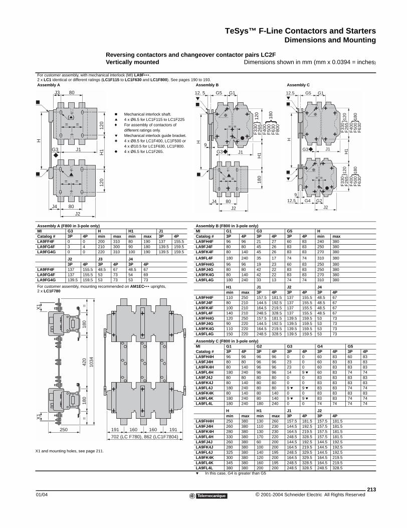
TeSys™ F-Line Contactors and StartersDimensions and Mounting
01/04
For customer assembly, with mecha2 x LC1 identical or different ratingsAssembly A
Assembly A (F800 in 3-pole only)MI G3 HCatalog # 3P 4P mLA9FF4F 0 0 2LA9FG4F 3 4 2LA9FG4G 0 0 2
J2 J3P 4P 3
LA9FF4F 137 155.5 4LA9FG4F 137 155.5 5LA9FG4G 139.5 159.5 5
For customer assembly, mounting re2 x LC1F780
80J4
J2
J1G3
= =
= =
(q)
80J3
H
250
X1
=18
0=
180
420
1034
X1
X1 and mounting holes, see page 21
Reversing contactors and changeover contactor pairs LC2FVertically mounted Dimensions shown in mm (mm x 0.0394 = inches)
nical interlock (MI) LA9F••• . (LC1F115 to LC1F630 and LC1F800). See pages 190 to 193.
Assembly B Assembly C
Assembly B (F800 in 3-pole only)H1 J1 MI G1 G3 G5 H
in max min max 3P 4P Catalog # 3P 4P 3P 4P 3P 4P min max00 310 80 190 137 155.5 LA9FH4F 96 96 21 27 60 83 240 38010 300 90 180 139.5 159.5 LA9FJ4F 80 80 45 26 83 83 250 38020 310 100 190 139.5 159.5 LA9FK4F 80 140 45 26 83 83 270 380
3 J4 LA9FL4F 180 240 35 17 74 74 310 380
P 4P 3P 4P LA9FH4G 96 96 19 23 60 83 250 3808.5 67 48.5 67 LA9FJ4G 80 80 42 22 83 83 250 3803 73 54 69 LA9FK4G 80 140 42 22 83 83 270 3803 73 53 73 LA9FL4G 180 240 33 13 74 74 310 380
commended on AM1EC••• uprights, H1 J1 J2 J4min max 3P 4P 3P 4P 3P 4P
LA9FH4F 110 250 157.5 181.5 137 155.5 48.5 67LA9FJ4F 80 210 144.5 192.5 137 155.5 48.5 67LA9FK4F 100 210 164.5 219.5 137 155.5 48.5 67LA9FL4F 140 210 248.5 328.5 137 155.5 48.5 67LA9FH4G 120 250 157.5 181.5 139.5 159.5 53 73LA9FJ4G 90 220 144.5 192.5 139.5 159.5 53 73LA9FK4G 110 220 164.5 219.5 139.5 159.5 53 73LA9FL4G 150 220 248.5 328.5 139.5 159.5 53 73
Assembly C (F800 in 3-pole only)MI G1 G2 G3 G4 G5Catalog # 3P 4P 3P 4P 3P 4P 3P 4P 3P 4PLA9FH4H 96 96 96 96 0 0 60 83 60 83LA9FJ4H 80 80 96 96 23 0 60 83 83 83LA9FK4H 80 140 96 96 23 0 60 83 83 83LA9FL4H 180 240 96 96 14 9 p 60 83 74 74LA9FJ4J 80 80 80 80 0 0 83 83 83 83LA9FK4J 80 140 80 80 0 0 83 83 83 83LA9FL4J 180 240 80 80 9 p 9 p 83 83 74 74LA9FK4K 80 140 80 140 0 0 83 83 83 83LA9FL4K 180 240 80 140 9 p 9 p 83 83 74 74LA9FL4L 180 240 180 240 0 0 74 74 74 74
H H1 J1 J2min max min max 3P 4P 3P 4P
LA9FH4H 250 380 130 260 157.5 181.5 157.5 181.5LA9FJ4H 260 380 110 230 144.5 192.5 157.5 181.5LA9FK4H 280 380 130 230 164.5 219.5 157.5 181.5LA9FL4H 330 380 170 220 248.5 328.5 157.5 181.5LA9FJ4J 260 380 60 200 144.5 192.5 144.5 192.5LA9FK4J 280 380 100 200 164.5 219.5 144.5 192.5LA9FL4J 325 380 140 195 248.5 329.5 144.5 192.5LA9FK4K 300 380 120 200 164.5 329.5 164.5 219.5LA9FL4K 345 380 160 195 248.5 328.5 164.5 219.5LA9FL4L 380 380 200 200 248.5 328.5 248.5 328.5p In this case, G4 is greater than G5
120
120
H1
= =
F33
0F
265
180
H1
120
F
400
F50
0F
630
F80
0
180
G1G512. 5
J1G3
80J4
= =
H
9
J2
F33
0F
265
H1
120
F
400
F50
0F
630
180
F33
0F
265
120
F
400
F50
0F
630
180
J1G3
G2G4
J2
12,59
= =
G1G512.5
H
c Mechanical interlock shaft.q 4 x Ø6.5 for LC1F115 to LC1F225f For assembly of contactors of
different ratings only.p Mechanical interlock guide bracket.t 4 x Ø8.5 for LC1F400, LC1F500 or
4 x Ø10.5 for LC1F630, LC1F800.k 4 x Ø6.5 for LC1F265.
191 160 160 191
702 (LC F780), 862 (LC1F7804)
1.
213© 2001-2004 Schneider Electric All Rights Reserved
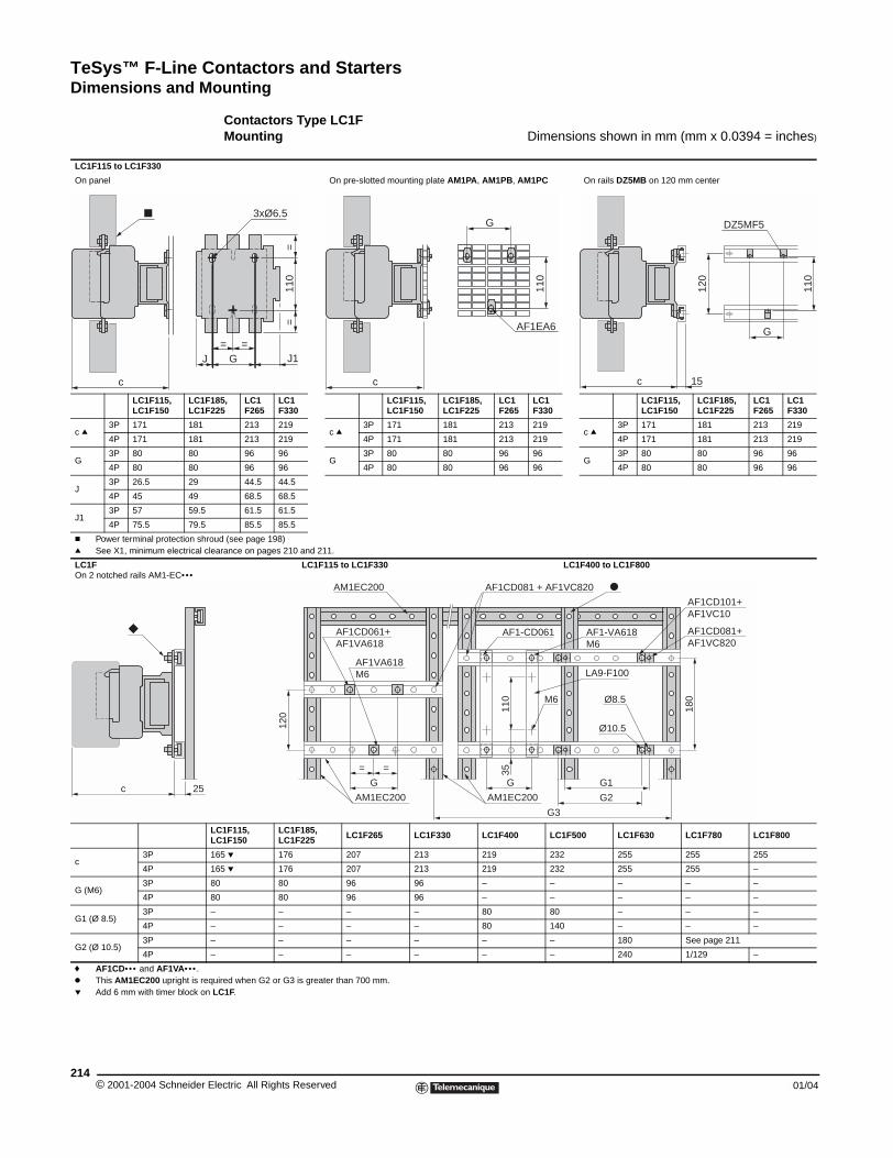
TeSys™ F-Line Contactors and StartersDimensions and Mounting
© 2001-2004 Schneider E214
LC1F115 to LC1F330
On panel
LC1F115, LC1F150
LC1F1LC1F2
c q3P 171 181
4P 171 181
G3P 80 80
4P 80 80
J3P 26.5 29
4P 45 49
J13P 57 59.5
4P 75.5 79.5
c Power terminal protection shroq See X1, minimum electrical cl
LC1F On 2 notched rails AM1-EC•••
LL
c3P 1
4P 1
G (M6)3P 8
4P 8
G1 (Ø 8.5)3P –
4P –
G2 (Ø 10.5)3P –
4P –
f AF1CD••• and AF1VA•••.k This AM1EC200 upright is reqp Add 6 mm with timer block on
c
J
c 25
Contactors Type LC1FMounting Dimensions shown in mm (mm x 0.0394 = inches)
On pre-slotted mounting plate AM1PA, AM1PB, AM1PC On rails DZ5MB on 120 mm center
85, 25
LC1 F265
LC1 F330
LC1F115, LC1F150
LC1F185, LC1F225
LC1 F265
LC1 F330
LC1F115, LC1F150
LC1F185, LC1F225
LC1 F265
LC1 F330
213 219c q
3P 171 181 213 219c q
3P 171 181 213 219
213 219 4P 171 181 213 219 4P 171 181 213 219
96 96G
3P 80 80 96 96G
3P 80 80 96 96
96 96 4P 80 80 96 96 4P 80 80 96 96
44.5 44.5
68.5 68.5
61.5 61.5
85.5 85.5
ud (see page 198)earance on pages 210 and 211.
LC1F115 to LC1F330 LC1F400 to LC1F800
C1F115, C1F150
LC1F185, LC1F225 LC1F265 LC1F330 LC1F400 LC1F500 LC1F630 LC1F780 LC1F800
65 p 176 207 213 219 232 255 255 255
65 p 176 207 213 219 232 255 255 –
0 80 96 96 – – – – –
0 80 96 96 – – – – –
– – – 80 80 – – –
– – – 80 140 – – –
– – – – – 180 See page 211
– – – – – 240 1/129 –
uired when G2 or G3 is greater than 700 mm.LC1F.
c
AF1EA6
110
G3xØ6.5
G=
J1
=
110
=
=
DZ5MF5
c
G
110
120
15
120
Ø10.5
AM1EC200 AF1CD081 + AF1VC820
AM1EC200
AF1CD061+AF1VA618
AF1-CD061 AF1-VA618M6
LA9-F100
AF1CD101+AF1VC10
AF1CD081+AF1VC820
Ø8.5M6
AM1EC200
110
35
180
G
= =
G
AF1VA618M6
G1
G2
G3
lectric All Rights Reserved 01/04
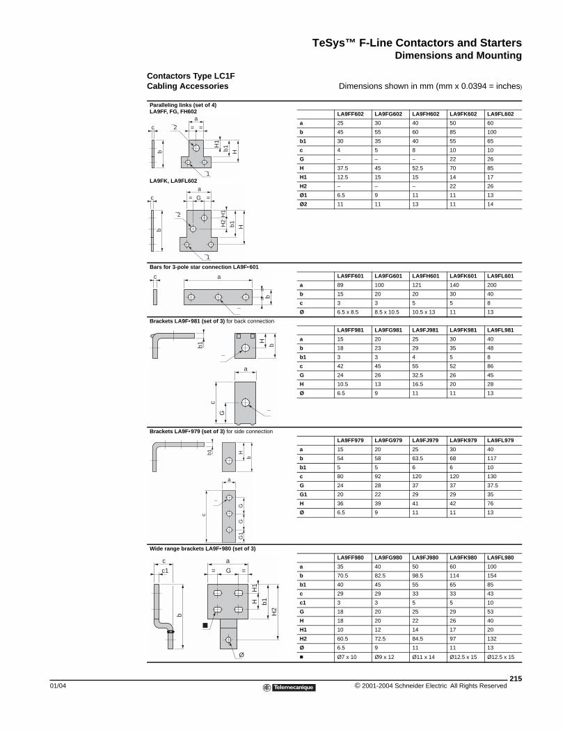
TeSys™ F-Line Contactors and StartersDimensions and Mounting
01/04
Contactors Type LC1F Cabling Accessories Dimensions shown in mm (mm x 0.0394 = inches)
Paralleling links (set of 4)LA9FF, FG, FH602
LA9FK, LA9FL602
LA9FF602 LA9FG602 LA9FH602 LA9FK602 LA9FL602
a 25 30 40 50 60
b 45 55 60 85 100
b1 30 35 40 55 65
c 4 5 8 10 10
G – – – 22 26
H 37.5 45 52.5 70 85
H1 12.5 15 15 14 17
H2 – – – 22 26
Ø1 6.5 9 11 11 13
Ø2 11 11 13 11 14
Bars for 3-pole star connection LA9F•601
LA9FF601 LA9FG601 LA9FH601 LA9FK601 LA9FL601
a 89 100 121 140 200
b 15 20 20 30 40
c 3 3 5 5 8
Ø 6.5 x 8.5 8.5 x 10.5 10.5 x 13 11 13
Brackets LA9F•981 (set of 3) for back connection
LA9FF981 LA9FG981 LA9FJ981 LA9FK981 LA9FL981
a 15 20 25 30 40
b 18 23 29 35 48
b1 3 3 4 5 8
c 42 45 55 52 86
G 24 26 32.5 26 45
H 10.5 13 16.5 20 28
Ø 6.5 9 11 11 13
Brackets LA9F•979 (set of 3) for side connection
LA9FF979 LA9FG979 LA9FJ979 LA9FK979 LA9FL979
a 15 20 25 30 40
b 54 58 63.5 68 117
b1 5 5 6 6 10
c 80 92 120 120 130
G 24 28 37 37 37.5
G1 20 22 29 29 35
H 36 39 41 42 76
Ø 6.5 9 11 11 13
Wide range brackets LA9F•980 (set of 3)
LA9FF980 LA9FG980 LA9FJ980 LA9FK980 LA9FL980
a 35 40 50 60 100
b 70.5 82.5 98.5 114 154
b1 40 45 55 65 85
c 29 29 33 33 43
c1 3 3 5 5 10
G 18 20 25 29 53
H 18 20 22 26 40
H1 10 12 14 17 20
H2 60.5 72.5 84.5 97 132
Ø 6.5 9 11 11 13
c Ø7 x 10 Ø9 x 12 Ø11 x 14 Ø12.5 x 15 Ø12.5 x 15
a
=
¯1
¯2
b
=
H1
b1 H
c
a
=
¯1
¯2
b
=
H1
b1 H
c G
H2
¯
b==
c a
c
G
b1
a
¯
H
b
¯
b1
¯
H
b
c
G1
GG
a
H1
a
= G =
c
c1
b
H b1
H2
Ø
215© 2001-2004 Schneider Electric All Rights Reserved
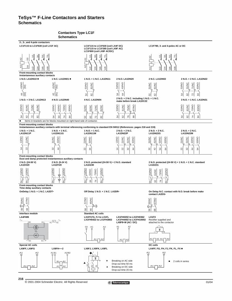
TeSys™ F-Line Contactors and StartersSchematics
© 2001-2004 Schneider E216
2-, 3-, and 4-pole contactors
LC1F115 to LC1F630 (coil LX1F A
Front-mounting contact blocksInstantaneous auxiliary contacts
1 N.O. LA1DN10 c 1 N
1 N.O. + 3 N.C. LA1DN13 4 N
c Items in brackets are for block
Front-mounting contact blocksInstantaneous auxiliary contacts
1 N.O. + 1 N.C. LA1DN11P
1 NLA
Front-mounting contact blocksDust and damp protected instant
2 N.O. (24-50 V)LA1DX20
2 NLA
Front-mounting contact blocksTime delay auxiliary contacts
OnDelay 1 N.O. + 1 N.C. LA2DT•
Interface module
LA4FWB
Special AC coils
LX9FF, LX9FG LX9
A2
03
04
1/L
1T
1/2
3/L
2T
2/4
5/L
3T
3/6
7/L
4T
4/8A
143
/NO
44(9
4)(9
3)
4241
/NC
53/N
O5472
71/N
C
6261
/NC
53/N
O54 82
81/N
C
2221
/NC
13/N
O14 32
31/N
C53
/NO
54
53/N
O54
63/N
O64
55/N
C56
67/N
O68
B2 A1
− E2 E1 +
KA1
A2A1
A2A1 A1 B
Schematics
Contactors Type LC1FSchematics
C) LC1F115 to LC1F630 (coil LX4F DC)LC1F115 to LC1F265 (coil LX9F AC)LC1F800 (coil LX8F AC/DC)
LC1F780, 3- and 4-poles AC or DC
.C. LA1DN01 c 1 N.O. + 1 N.C. LA1DN11 2 N.O. LA1DN20 2 N.C. LA1DN02 2 N.O. + 2 N.C. LA1DN22
.O. LA1DN40 4 N.C. LA1DN04 2 N.O. + 2 N.C. including 1 N.O. + 1 N.C.make before break LA1DC22 3 N.O. + 1 N.C. LA1DN31
s mounted on right-hand side of contactor.
with terminal referencing conforming to standard EN 50012 (References: pages 218 and 219)
.O. + 1 N.C. 1DN11G
1 N.O. + 1 N.C. LA1DN11M
2 N.O. + 2 N.C. LA1DN22P
2 N.O. + 2 N.C. LA1DN22G
2 N.O. + 2 N.C. LA1DN22M
aneous auxiliary contacts
.O. (5-24 V)1DY20
2 N.O. protected (24-50 V) + 2 N.O. standardLA1DZ40
2 N.O. protected (24-50 V) + 1 N.O. + 1 N.C. standardLA1DZ31
Off Delay 1 N.O. + 1 N.C. LA3DR• On Delay N.C. contact with N.O. break before make contact LA2DS•
Standard AC coils
LX1FF,FG, FJ to LX1FLLX1FH0422 to LX1FH3802
LX1FH0202 to LX1FH0362LX1FH4402 to LX1FH10002LX8F8•W (AC / DC)
LX1FX Rectifier supplied andattached to the contactor
DC coils
FH••• 2 LX9FJ, LX9FK, LX9FL LX4FF, FG, FH, FJ, FK, FL, FX c
A1
A2
1/L
1T
1/2
3/L
2T
2/4
5/L
3T
3/6
7/L
4T
4/8
1/L
1T
1/2
3/L
2T
2/4
5/L
3T
3/6
7/L
4T
4/8
A2
A1
6261
/NC
53/N
O54
(92)
(91)
53/N
O54
63/N
O64 62
61/N
C
51/N
C52 72
71/N
C
6251
/NC
53/N
O54
83/N
O84
63/N
O64
73/N
O74
83/N
O84 72
71/N
C
6261
/NC
8281
/NC
5251
/NC
7675
/NC
6261
/NC
53/N
O54
87/N
O88 62
61/N
C
53/N
O54 84
83/N
O
73/N
O74
43/N
O44 22
21/N
C
33/N
O34 22
21/N
C
3231
/NC
13/N
O14
43/N
O44 32
31/N
C
4241
/NC
63/N
O64
53/N
O54 22
21/N
C
3231
/NC
53/N
O54
43/N
O44
6261
/NC
53/N
O54
83/N
O84
73/N
O74
53/N
O54
83/N
O84
63/N
O64
73/N
O74
63/N
O64
6665
/NC
57/N
O58
67/N
O68
55/N
C56
A2
A2A1
A2A103
A2A1
A2A1
A2A1 A2A1
+−
B2B1
A2A1
1 A2/B2
A2A1
+−
01
A2A1
A2A1
f Breaking on AC sideDrop-out time 50 ms
q Breaking on DC sideDrop-out time 20 ms
c 2 coils in series
lectric All Rights Reserved 01/04
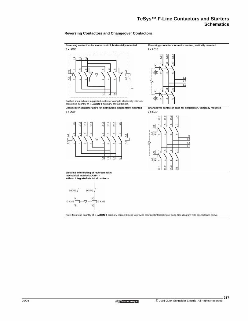
TeSys™ F-Line Contactors and StartersSchematics
01/04
Reversing Contactors and Changeover Contactors
Reversing contactors for motor control, horizontally mounted Reversing contactors for motor control, vertically mounted
2 x LC1F 2 x LC1F
Dashed lines indicate suggested customer wiring to electrically interlock coils using quantity of 2 LA1DN•1 auxiliary contact blocks.
Changeover contactor pairs for distribution, horizontally mounted Changeover contactor pairs for distribution, vertically mounted
2 x LC1F 2 x LC1F
Electrical interlocking of reversers with:mechanical interlock LA9F•••without integrated electrical contacts
Note: Must use quantity of 2 LA1DN•1 auxiliary contact blocks to provide electrical interlocking of coils. See diagram with dashed lines above.
A1
A2
12
34
56
L1 L2 L3
12
34
56
U V W
A1
A2
A1
A2
E1
12
34
1/L1
1/L2
12
34
56
1/L3
56
A1
A2
E1
L3L2L1
A1
A2
12
34
56
1N
1/L3
1/L2
12
34
78
L1 L2 N
A1
A2
56
L3
78
1/L1
2/L1
2/L2
2/L3 2N
A1
A2
E1
12
34
78
1/L1
1/L2 1N
12
34
78
2/L1
2/L2
2N
56
1/L3
56
2/L3
A1
A2
E1
L3L2L1
N
A1
A2
Ð KM2
Ð KM1
A1
A2
Ð KM1
Ð KM2
217© 2001-2004 Schneider Electric All Rights Reserved
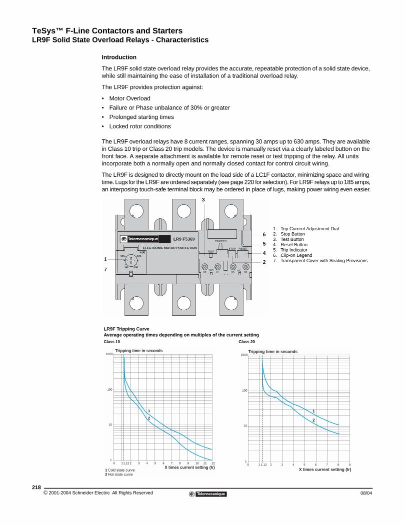
TeSys™ F-Line Contactors and StartersLR9F Solid State Overload Relays - Characteristics
© 2001-2004 Schneider E218
LR9F Solid State Overload Relays - Characteristics
Introduction
The LR9F solid state overload relay provides the accurate, repeatable protection of a solid state device, while still maintaining the ease of installation of a traditional overload relay.
The LR9F provides protection against:
• Motor Overload
• Failure or Phase unbalance of 30% or greater
• Prolonged starting times
• Locked rotor conditions
The LR9F overload relays have 8 current ranges, spanning 30 amps up to 630 amps. They are available in Class 10 trip or Class 20 trip models. The device is manually reset via a clearly labeled button on the front face. A separate attachment is available for remote reset or test tripping of the relay. All units incorporate both a normally open and normally closed contact for control circuit wiring.
The LR9F is designed to directly mount on the load side of a LC1F contactor, minimizing space and wiring time. Lugs for the LR9F are ordered separately (see page 220 for selection). For LR9F relays up to 185 amps, an interposing touch-safe terminal block may be ordered in place of lugs, making power wiring even easier.
LR9F Tripping CurveAverage operating times depending on multiples of the current settingClass 10 Class 20
1. Trip Current Adjustment Dial2. Stop Button3. Test Button4. Reset Button5. Trip Indicator6. Clip-on Legend7. Transparent Cover with Sealing Provisions
LR9 F5369
ELECTRONIC MOTOR PROTECTIONIr(A)
15090
125105
STOP
TRIPPED
TESTRESET
NO 9798 NC95 96
1
3
2
4
6
7
5
1
1000
100
10
10 1,12 2 3 4 5 6 7 8 9 10 11 12
1
2
1 Cold state curve2 Hot state curve
Tripping time in seconds
X times current setting (Ir)10 1,12 2 3 4 5 6 7 8 9
1000
100
10
1
1
2
X times current setting (Ir)
Tripping time in seconds
lectric All Rights Reserved 08/04
TeSys™ F-Line Contactors and StartersLR9F Solid State Overload Relays - Characteristics
01/04
Environment
Power Circuit Characteristics
Auxiliary contact characteristics
Conforming to standards Meets the essential requirements of LV & EMC directives.
IEC 60947-1, 60947-4-1, 255-8, and VDE 0660EN 60947-1. 60947-4-1
Approvals UL508; CSA 22-2, No.14; PTB Pending
Degree of protection Conforming to VDE 0106IP 20 - Protection against direct finger contact with LA9F103 insulated terminal blocks or LA9F7/LA7F7 shrouds
Protective treatment Standard version "TH"
Ambient air temperaturearound the device(conforming to IEC 60255-8)
Storage −40 to + 85 °C (−40 to +185 °F)
Normal operation −20 to + 55 °C (-4 to +131 °F)
Maximum operating altitude Without derating m 2000
Operating positionswithout derating
In relation to normalvertical mounting plane
All positions
Shock resistance Permissible accelerationconforming to IEC 60068-2-7
13 g - 11 ms
Vibration resistance Permissible accelerationconforming to IEC 60068-2-6
2 g
Dielectric strength at 50 Hz Conforming to IEC 60255-5 kV 6
Impulse withstand voltage Conforming to IEC 60801-5 kV 4
Resistance to electrostaticdischarges Conforming to IEC 60801-2 kV
8 (in air)6 (in indirect mode)
Resistance to radio-frequencyconducted disturbances
Conforming to IEC 60801-3and NF C 46-022
V/m 10
Resistance to fast transientcurrents Conforming to IEC 60801-4 kV 2
Electromagnetic compatibility EN50081-1 & 2, EN50082-2 Meets test requirements
Relay Type LR9F F5•57F5•63F5•67F5•69
F5•71 F7•75 F7•79 F7•81
Rated insulation voltage (Vi) Conforming to IEC 60947-4 V 1000
Rated operational voltage (Ve) Conforming to VDE 0110 gr C V 1000
Rated impulse withstand voltage (Vimp) Conforming to IEC 60947-1 kV 8
Rated operational current (Ie) A 30 to 630
Frequency limits Of the operating current Hz 50/60
Power circuit connections
Width of terminal lug mm (in) 20 (0.78) 25 (0.98) 25 (0.98) 30 (1.18) 40 (1.57) 40 (1.57)
Clamping screw M6 M8 M10 M10 M10 M12
Tightening torqueIb • in 90 160 310 310 310 515
N • m 10 18 35 35 35 58
Rated thermal current A 5
Control circuit connections
Stranded cable without cable end
Minimum Maximum
1 conductormm2
1 x 0.75 1 x 4.0
2 conductors 2 x 1.0 2 x 2.5
1 conductorAWG
1 x 18 2 x 12
2 conductors 2 x 16 2 x 14
Stranded cablewith cable end
1 conductormm2
1 x 0.75 1 x 2.5
2 conductors 2 x 1.0 2 x 1.5
Solid cable1 conductor
mm21 x 0.75 1 x 2.5
2 conductors 2 x 1.0 2 x 1.0
Tightening torqueIb • in 11
N • m 1.2
Maximum sealedconsumption of coilson controlled contactors
AC controlV 24 48 110 220 380 600
VA 100 200 400 600 600 600
DC controlV 24 48 110 220 440 –
W 100 100 50 45 25 –
EI64353NKCR
LR433643211 03
219© 2001-2004 Schneider Electric All Rights Reserved
TeSys™ F-Line Contactors and StartersLR9F Solid State Overload Relays - Selection
© 2001-2004 Schneider E220
LR9F53•••
LR9F73•••
LR9F73•••
DZ2F••
LR9F Solid State Overload Relays - Selection
Three-Phase Overload Relays c
Lug Kits
Lugs can be ordered either individually or in sets of six. In some cases the LR9F overload relay mounted directly on the bottom of LC1F contactor will require a different size lug than the contactor itself. Refer to the table below to select the appropriate size lug for your choice of contactor and overload. If all 6 lugs (three for line side of contactor, three for load side of overload relay) are the same, Square D offers a pre-packaged set of six lugs. If the two sizes are different, order 3 of each size lug. Mounting hardware (screws, washers, nuts) are provided with the contactors and overload relays, not with the lugs.
a Customer to obtain from local supplier.
Insulated Terminal Blocks
For contactors LC1F115, LC1F150, and LC1F185, an available touch-safe terminal block may be used in place of lugs for power connections
Current Setting RangeAmps
For Direct Mounting To Contactor LC1•••• /CR1F••••
Class 10 Trip qCatalog Number
Class 20 Trip qCatalog Number
30 to 50 F115 to F185 LR9F5357 LR9F5557
48 to 80 F115 to F185 LR9F5363 LR9F5563
60 to 100 F115 to F185 LR9F5367 LR9F5567
90 to 150 F115 to F185 LR9F5369 LR9F5569
132 to 220 F185 f, F265 LR9F5371 LR9F5571
200 to 330 F265 to F500 LR9F7375 LR9F7575
300 to 500 F265 to F500 LR9F7379 LR9F7579
380 to 630 F400 to F630 LR9F7381 LR9F7581
c When mounting overload relays LR9F5•57 to LR9F5•71 directly beneath the contactor it is recommended that the relays be additionally supported by a mounting plate. For sizes LR9F5•75 to LR9F7•81 use of the supporting mounting plate is mandatory. See page 221 for selection table.
q IEC standard 60947-4 specifies the following trip times when the overload relay senses 7.2 times the setting current: Class 10: between 4 and 10 seconds Class 20: between 6 and 20 secondsf Interconnection kit LA7F407 is required to mount an LR9F•71 to an LCIF185.
Overload Relay Directly mounted to contactor LC1••••
Cable size AWG range Lug Catalog Number
Line side (of contactor) Load side (of overload) Line side (of contactor)
Load side (of overload)
LR9F5•57 to F5•69 F115 14 to 2/0 6 to 3/0 3 ea. DZ2FF1 3 ea. DZ2FG1
LR9F5•57 to F5•71 F150 or F185 6 to 3/0 1 ea. DZ2FG6
LR9F5•71 F265 6 to 300 MCM 1 ea. DZ2FH6
LR9F7•75 to F7•79 F265 or F330 6 to 300 MCM 4 to 500 MCM 3 ea. DZ2FH1 a
LR9F7•75 to F7•81 F400 4 to 500 MCM 4 to 500 MCM 3 ea. DZ2FJ1 a
LR9F7•75 to F7•81 F500 2 x 2 to 600 MCM 4 to 500 MCM 3 ea. DZ2FK1 a
LR9F7•81 F630 3 x 2 to 600 MCM 4 to 500 MCMDZ2FL1DZ2FL2DZ2FL3
a
Insulated terminal block Cable sizeAWG range
Suitable for contactor LC1•••• /CR1••••
Suitable for overload relay LR9•••••
LA9F103 #6 to 300 MCM F115, F150, F185 5•57, F5•63, F5•67, F5•69
lectric All Rights Reserved 08/04
TeSys™ F-Line Contactors and StartersLR9F Solid State Overload Relays - Accessories
01/04
LR9F Solid State Overload Relays - Accessories
LR9F Solid State Overload Relays - Accessories
Mounting Plate for Overload RelayProvides overload relay support when mounted directly to F-Line ContactorFor use with relays:
Catalog Number
LR9F5•57, F5•63, F5•67, F5•69 and F5•71 LA7F901
LR9F7•75, F7•79 and F7•81 LA7F902
Power Terminal Protection Shrouds, Single-PoleThese clear plastic protection shrouds are an effective means to meet international touch-safe requirements for power terminals. They are designed to be used with power cables that have been bolted to the terminal.
NOTE: The protection shrouds do not attach to contactors or overload relays utilizing DZ2F lug kits.
For use with relays Catalog Number
LR9F5•57 LA9F701
LR9F5•63, F5•67, F5•69 LA9F702
LR9F5•71 LA9F705
LR9F7•75, F7•79, F7•81 LA9F703
Power Terminal Protection Shrouds, 3-Poles
For use with relays Catalog Number
LR9F5•57, F5•63, F5•67, F5•69 LA7F701
LR9F5•71 LA7F702
LR9F7•75, F7•79, F7•81 LA7F703
Connection Accessories Required (for mounting overload relays beneath reversing contactors)Application Set of 3 bars
Catalog NumberFor relays For contactor
LR9F5•57, F5•63, F5•67, F5•69 LC1F115 LA7F401
LR9F5•57, F5•63 LC1F150 and F185 LA7F402
LR9F5•71 LC1F185 LA7F407
LR9F5•71 LC1F265 LA7F403
LR9F7•75, F7•79 LC1F265 to F400 LA7F404
LR9F7•81 LC1F400 LA7F404
LR9F7•75, F7•79, F7•81 LC1F500 LA7F405
LR9F7•81 LC1F630 LA7F406
Marking accessories
Description Sold in units of: Catalog Number
Marker holder, snap-in 100 LA7D903
Control Accessories
Description Sold in lots of Catalog Number
Remote electrical reset snap-on module c 1 LA7D03• q
Remote reset function control by flexible cable (length = 0.5 m / 0.02") 1 LA7D305
Locking Device for “Stop” button 10 LA7D901
Remote Stop and/or Reset function control Adaptor for door mounted operator 1 LA7D1020
Rod (snap-off end to obtain required length, between 17 and 120 mm)
1 ZA2BZ13
Operating head for spring return pushbutton 1 ZA2BA8602
Standard control circuit voltages
Volts 12 24 48 96 110 220/230 380/400 415/440
AC 50/60 Hz – B E – F M Q N
Consumption, inrush and sealed: < 100 VA
DC J B E DD F M – –
Consumption, inrush and sealed: < 100 W
c Part number to be completed by adding coil voltage code.q The time for which the coil of remote electrical reset device LA7D03 can remain energized depends on its rest time: 1 s pulse duration with 9 s rest
time; 5 s pulse duration with 30 s rest time; 10 s pulse duration with 90 s rest time: maximum pulse duration of 20 s with rest time of 300 s. Minimum impulse time: 200 ms.
LA7F90•
LA9F70•
LA7F70•
221© 2001-2004 Schneider Electric All Rights Reserved
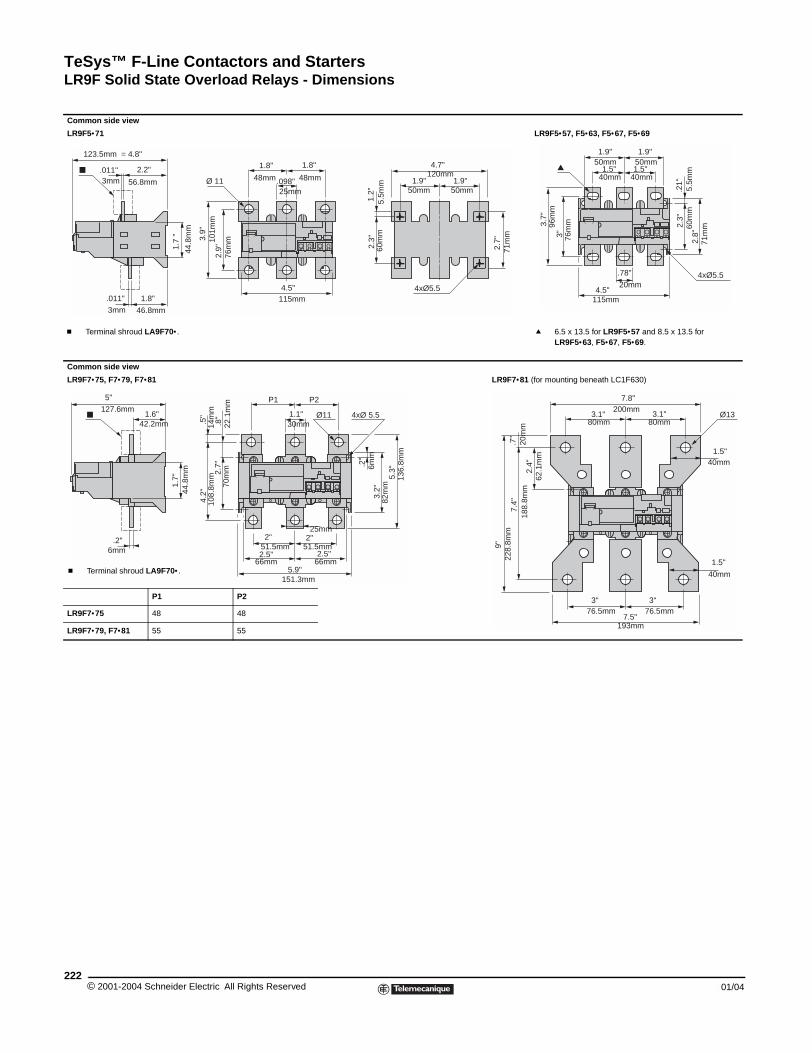
TeSys™ F-Line Contactors and StartersLR9F Solid State Overload Relays - Dimensions
© 2001-2004 Schneider E222
Common side view
LR9F5•71
Common side view
LR9F7•75, F7•79, F7•81
P1
LR9F7•75 48
LR9F7•79, F7•81 55
c Terminal shroud LA9F70•.
56.8mm
123.5mm = 4.8"
3mm
46.8mm3mm
44.8
mm
2.2"
1.8"
1.7
"
.011"
.011"
42.2mm
127.6mm
6mm
44.8
mm
5"
1.6"
.2"
1.7"
c Terminal shroud LA9F70•.
LR9F Solid State Overload Relays - Dimensions
ccc
LR9F5•57, F5•63, F5•67, F5•69
LR9F7•81 (for mounting beneath LC1F630)
P2
48
55
120mm
60m
m
50mm50mm
71m
m
5.5m
m
76m
m
25mm
48mm
101m
m
115mm
Ø 11
4xØ5.5
1.8"
48mm
1.8"
.098"
4.5"
1.9" 1.9"
4.7"
1.2"
2.3"
2.7"3.
9"
2.9"
q 6.5 x 13.5 for LR9F5•57 and 8.5 x 13.5 for LR9F5•63, F5•67, F5•69.
76m
m
40mm40mm
96m
m
50mm50mm
60m
m
71m
m
5.5m
m
4xØ5.5
115mm
20mm
3.7"
3"
1.9"1.9"
1.5"1.5"
.21"
2.3"
2.8"
4.5"
.78"
108.
8mm
14m
m
30mm
P2 P1
151.3mm
Ø11
51.5mm 51.5mm
66mm 66mm
4xØ 5.5
70m
m22
.1m
m
6mm
82m
m
136.
8mm
25mm
4.2"
2.7"
.8"
.5" 1.1"
.2"
3.2"
5.3"
2"2"
2.5"2.5"
5.9"
188.
8mm
20m
m
200mm
80mm80mm
193mm
228.
8mm
76.5mm 76.5mm
62.1
mm
Ø13
40mm
40mm
7.8"
3.1"3.1"
1.5"
1.5"
3" 3"
7.5"
9"
7.4"
2.4"
.7"
lectric All Rights Reserved 01/04
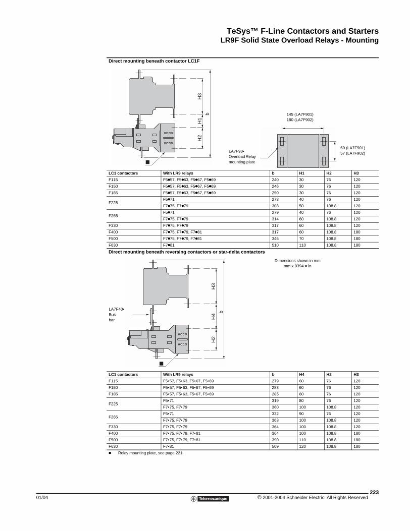
TeSys™ F-Line Contactors and StartersLR9F Solid State Overload Relays - Mounting
01/04
LR9F Solid State Overload Relays - Mounting
Direct mounting beneath contactor LC1F
LC1 contactors With LR9 relays b H1 H2 H3
F115 F5k57, F5k63, F5k67, F5k69 240 30 76 120
F150 F5k57, F5k63, F5k67, F5k69 246 30 76 120
F185 F5k57, F5k63, F5k67, F5k69 250 30 76 120
F225F5k71 273 40 76 120
F7k75, F7k79 308 50 108.8 120
F265F5k71 279 40 76 120
F7k75, F7k79 314 60 108.8 120
F330 F7k75, F7k79 317 60 108.8 120
F400 F7k75, F7k79, F7k81 317 60 108.8 180
F500 F7k75, F7k79, F7k81 346 70 108.8 180
F630 F7k81 510 110 108.8 180
Direct mounting beneath reversing contactors or star-delta contactors
LC1 contactors With LR9 relays b H4 H2 H3
F115 F5•57, F5•63, F5•67, F5•69 279 60 76 120
F150 F5•57, F5•63, F5•67, F5•69 283 60 76 120
F185 F5•57, F5•63, F5•67, F5•69 285 60 76 120
F225F5•71 319 80 76 120
F7•75, F7•79 360 100 108.8 120
F265F5•71 332 90 76 120
F7•75, F7•79 363 100 108.8 120
F330 F7•75, F7•79 364 100 108.8 120
F400 F7•75, F7•79, F7•81 364 100 108.8 180
F500 F7•75, F7•79, F7•81 390 110 108.8 180
F630 F7•81 509 120 108.8 180
c Relay mounting plate, see page 221.
H2
b
H3
H1
145 (LA7F901)180 (LA7F902)
50 (LA7F901)57 (LA7F902)LA7F90•
Overload Relay mounting plate
Dimensions shown in mmmm x.0394 = in
LA7F40•Bus bar
H2
b
H4
H3
223© 2001-2004 Schneider Electric All Rights Reserved
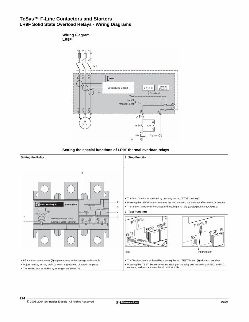
TeSys™ F-Line Contactors and StartersLR9F Solid State Overload Relays - Wiring Diagrams
© 2001-2004 Schneider E224
Setting the Relay
• Lift the transparent cover (7) to ga
• Adjust relay by turning dial (1), wh
• The setting can be locked by sea
protection é
ELECTRON
Ir(A)
15090
125105
1
7
LR9F Solid State Overload Relays - Wiring Diagrams
Wiring DiagramLR9F
Setting the special functions of LR9F thermal overload relays
2: Stop Function
•
• The Stop function is obtained by pressing the red “STOP” button (2).
• Pressing the “STOP” button actuates the N.C. contact, but does not affect the N.O. contact.
• The “STOP” button can be locked by installing a “U” clip (catalog number LA7D901).
3: Test Function
in access to the settings and controls.
ich is graduated directly in amperes.
ling of the cover (7).
• The Test function is activated by pressing the red “TEST” button (3) with a screwdriver.
• Pressing the “TEST” button simulates tripping of the relay and actuates both N.O. and N.C. contacts, and also actuates the trip indicator (5).
95
97
6/T
3
4/T
2
2/T
1
96 98
5/L3
3/L2
1/L1
M
A
1314
KM
KM1
12
34
56
M3
L1 L2 L3
KM
A1
A2
≥ 112 %
N
Manual Reset
Specialized Circuit
Test
Reset
Overload
Tripped
SettingCurrent
LR9 F5369
lectronique moteur
IC MOTOR PROTECTION
STOP
TRIPPED
TESTRESET
NO 9798 NC95 96
3
2
4
6
5
TEST
RETRIPPED
STOPTEST
RESETTRIPPED
STOP
Test Trip Indicator
lectric All Rights Reserved 01/04
CR1F/CR1B Contactors and AccessoriesMagnetic Latching Contactors – Characteristics
01/04
Magnetic Latching Contactors - Characteristics
Magnetic latching contactors of both block and bar mounted types include a special electromagnet which enables them to remain in the “on” position when the coil is no longer energized.
The special properties of magnetic latching contactors make them suitable for a large number of applications:
Properties
• Retention of the sequence memory in automatic control equipment in the event of a control circuit failure.
• Energy saving, since the source of supply to the coil does not need to supply current when the contactor is latched in the closed state.
• Change of state from “Closed” to “Open” by current signal through the coil.
• Unaffected by line interference.
• Utilization of contactors beyond their breaking capacity as operations are performed off Load.
• Contactors are silent in the latched position.
Applications
• Refineries, power stations, excitation circuits.
• Contactors remaining in the closed state for long periods. Example: refineries, power supplies, low voltage distribution.
• Selective opening control.
• No unwanted opening and closing of the main power poles.
• Current carrying at voltages up to 1000 Volts.
Operation of the electromagnet
CR1F contactors
CR1F magnetic latching contactors include a double coil with 3 terminals comprising a latching winding and an unlatching winding. The 2 windings have a common point which can necessitate special wiring precautions when the latching supply is separate from the unlatching supply.
The power supplies may be AC or DC. For DC operation, the polarities indicated must be complied with.
Operating precautions:
• the 2 windings must not be energized simultaneously,
• a winding must not be energized continuously,
• supply to the coils must be via momentary contacts.
Manual opening: If the control voltage is not present, the contactor can be unlatched manually.
CR1B contactors
CR1B magnetic latching contactors included a single coil, supplied with DC or AC through a rectifier.
Latching is obtained by direct supply of the coil in one direction of current flow.
Unlatching is obtained by a reverse current, adjusted by resistors.
LC1D contactors
For applications using smaller contactor sizes than those described in the following pages, it is possible to obtain the same function by the addition of a mechanical latching block type LA6DK, which can be mounted on LC1D contactors (information on D-line contactors starts on page 79).
225© 2001-2004 Schneider Electric All Rights Reserved
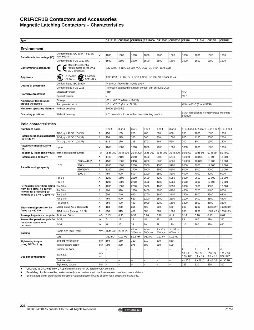
CR1F/CR1B Contactors and AccessoriesMagnetic Latching Contactors – Characteristics
© 2001-2004 Schneider E226
Type
Environment
Rated insulation voltage (Vi)Con775
Con
Conforming to standards
Approvals
Degree of protectionCon
Con
Protective treatmentSta
Spe
Ambient air temperature around the device
Sto
For
Maximum operating altitude Wit
Operating positions Wit
Pole characteristicsNumber of poles
Rated operational current (Ie) (Ve ≤ 440 V)
AC
AC
AC
Rated operational current (Ve) Up
Frequency limits (sine wave) of t
Rated making capacity I rm
Rated breaking capacityI rm
Permissible short time rating from cold state, no currentflowing for preceding 60 minutes at q ≤ 40 °C (104 °F)
For
For
For
For
For
For
For
Short-circuit protection by fuses q ≤ 440 V k
Mo
AC
Average impedance per pole At I
Power dissipated per pole for the above operational currents
AC
AC
CablingCab
Lug
Tightening torque using DZ2F•• Lug
Bol
Wir
Bus bar connections
Num
Bar
Bol
Tig
p CR1F150 to CR1F630 only. CRf Paralleling of poles must be cak Select short circuit protection t
CR1F150 CR1F185 CR1F265 CR1F400 CR1F500 CR1F630 CR1BL CR1BM CR1BP CR1BR
forming to IEC 60947-4-1, BS , 60947-4
V 1000 1000 1000 1000 1000 1000 1000 1000 1000 1000
forming to VDE 0110 grC V 1500 1500 1500 1500 1500 1500 1500 1500 1500 1500
Meets the essential requirements of the LV & EMC directives
IEC 60947-4, NFC 63-110, VDE 0660, BS 5424, JEM 1038
E164862 NLDX p
LR43364 3211 04 p
ASE, CSA, UL, BV, GL, LROS, USSR, NORSK VERITAS, RINA
forming to IEC 60529 IP 20 front face with shrouds LA9F
forming to VDE 0106 Protection against direct finger contact with shrouds LA9F
ndard version “TH” “TC”
cial version – “TH”
rage -60 to +80 °C (-76 to +176 °F)
operation at Vc -15 to +70 °C (5 to +158 °F) -15 to +60°C (5 to +158°F)
hout derating 3000m (9800 ft.)
hout derating ± 5° in relation to normal vertical mounting position± 30° in relation to normal vertical mounting position
3 or 4 3 or 4 3 or 4 3 or 4 3 or 4 3 or 4 1, 2, 3 or 4 1, 2, 3 or 4 1, 2, 3 or 4 1, 2, 3 or 4
-3, q ≤ 40 °C (104 °F) A 150 185 265 400 500 630 750 1000 1500 1800
-1, q ≤ 40 °C (104 °F) A 250 275 350 500 700 1000 800 1250 2000 2750
-4, q ≤ 40 °C (104 °F) A 138 170 245 370 460 560 700 800 1250 1500
to V 1000 1000 1000 1000 1000 1000 1000 1000 1000 1000
he operational current Hz 25 to 200 25 to 200 25 to 200 25 to 200 25 to 200 25 to 200 50 to 60 50 to 60 50 to 60 50 to 60
s A 1700 2100 2940 4500 5500 6740 10 000 10 000 15 000 18 000
s220 to 440 V A 1500 1800 2450 4000 5000 6300 10 000 10 000 15 000 18 000
500 V A 1200 1600 2200 3500 4500 5400 9000 9000 12 000 15 000
660/690 V A 1100 1200 1700 3000 3560 4600 8000 8000 9000 11 000
1000 V A 450 600 800 1200 2500 3200 4000 4000 5000 6000
1 s A 1200 1500 2200 3600 4200 5050 9600 9600 12 000 15 000
5 s A 1200 1500 2200 3600 4200 5050 9600 9600 12 000 15 000
10 s A 1200 1500 2200 3600 4200 5050 7000 8000 9600 12 000
30 s A 700 920 1230 2400 3200 4400 4800 5200 6400 8000
1 min A 600 740 950 1700 2400 3400 3500 3800 5200 6300
3 min A 450 500 620 1200 1500 2200 2100 2400 3600 4400
10 min A 350 400 480 1000 1200 1600 1200 1800 2800 3600
tor circuit AC-3 (type aM) A 160 200 315 400 500 630 800 1200 800 x 2 f 1000 x 2 f
-1 circuit (type gI, BS 88) A 250 315 400 500 800 1000 800 1200 1000 x 2 f 1200 x 2 f
th and 50 Hz mΩ 0.45 0.36 0.32 0.28 0.18 0.12 0.18 0.18 0.13 0.09
-3 W 6 12 22 45 45 48 88 180 290 360
-1 W 18 26 39 70 88 120 115 280 520 680
le size (min - max) AWG #6 to 3/0 #6 to 3/0#6 to 300mcm
#4 to 500mcm
2 x #2 to 600mcm
3 x #2 to 600mcm
– – – –
DZ2 FG DZ2 FG DZ2 FH DZ2 FJ DZ2 FK DZ2 FL – – – –
t lug to contactor lb-in 160 160 310 310 310 510 – – – –
e pressure screw lb-in 200 200 275 500 500 500 – – – –
ber of bars – – – – – – 2 2 3 4
c.s.a.mmin
– – – – – –50 x 51.9 x 0.2
80 x 53.1 x 0.2
100 x 53.9 x 0.2
100 x 103.9 x 0.2
t diameter – – – – – – 4 x Ø 8 4 x Ø 10 4 x Ø 10 4 x Ø 10
htening torque lb-in – – – – – – 185 310 310 310
1B contactors are not UL listed or CSA certified.
rried out only in accordance with the fuse manufacturer's recommendations.o meet the National Electrical Code or other local codes and standards.
lectric All Rights Reserved 01/04
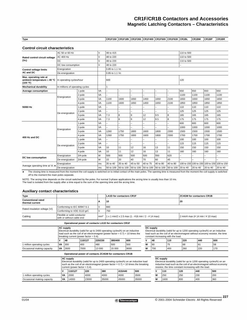
CR1F/CR1B Contactors and AccessoriesMagnetic Latching Contactors – Characteristics
01/04
Type
Control circuit charact
Rated control circuit voltage (Vc)
AC
AC
DC
DC
Control voltage limitsAC and DC
Ene
De-
Max. operating rate at ambient temperature ≤ 40 °C (104 °F)
In o
Mechanical durability In m
Average consumption
Ene
50/60 Hz
De-
400 Hz and DC
Ene
De-
DC low consumptionEne
De-
Average operating time at Vc qEne
De-
q The closing time is measured foff to the moment the main pol
NOTE: The arcing time depends on The load is isolated from the supply
Auxiliary contact charaType
Conventional rated thermal current
Rated insulation voltage (Vi)Con
Con
CablingFlexwith
ACEllobr
V
1 million operating cycles VA
Occasional making capacity VA
1 million operating cycles
Occasional making capacity
CR1F150 CR1F185 CR1F265 CR1F400 CR1F500 CR1F630 CR1BL CR1BM CR1BP CR1BR
eristics50 or 60 Hz V 48 to 415 110 to 500
400 Hz V 48 to 220 110 to 500
V 48 to 220 110 to 500
low consumption V 48 to 220 –
rgization 0.85 to 1.1 Vc
energization 0.85 to 1.1 Vc
perating cycles/hour 600 120
illions of operating cycles 1
rgization
1-pole VA – – – – – – 650 650 650 650
2-pole VA – – – – – – 1100 1100 1100 1100
3-pole VA 1100 1600 1650 1450 1650 2100 1650 1650 1650 1650
4-pole VA 1100 1600 1650 1450 1650 2100 1850 1850 1850 1850
energization
1-pole VA – – – – – – 110 110 110 110
2-pole VA – – – – – – 125 125 125 125
3-pole VA 7.3 8 9 12 9.5 8 165 165 165 165
4-pole VA 7.3 8 9 12 9.5 8 175 175 175 175
rgization
1-pole VA – – – – – – 600 600 600 600
2-pole VA – – – – – – 1000 1000 1000 1000
3-pole VA 1260 1750 1800 1600 1800 2300 1500 1500 1500 1500
4-pole VA 1260 1750 1800 1600 1800 2300 1700 1700 1700 1700
energization
1-pole VA – – – – – – 100 100 100 100
2-pole VA – – – – – – 115 115 115 115
3-pole VA 10 11 12 16 13 11 150 150 150 150
4-pole VA 10 11 12 16 13 11 160 160 160 160
rgization 3/4-pole W 500 500 500 500 550 620 – – – –
energization 3/4-pole W 15 20 40 70 60 45 – – – –
rgization ms 35 to 40 35 to 40 45 to 50 40 to 75 40 to 80 40 to 80 100 to 150 100 to 150 100 to 150 100 to 150
energization ms 50 to 100 50 to 100 50 to 100 50 to 100 50 to 100 50 to 100 20 to 40 20 to 40 20 to 40 20 to 40
rom the moment the coil supply is switched on to initial contact of the main poles. The opening time is measured from the moment the coil supply is switched es separate.
the circuit switched by the poles. For normal 3-phase applications the arcing time is usually less than 10 ms. after a time equal to the sum of the opening time and the arcing time.
cteristicsLA1D for contactors CR1F ZC4GM for contactors CR1B
A 10 20
forming to IEC 60947-5-1 V 660
forming to VDE 0110 grC V 750
ible or solid conductor or without cable end
mm2 1 x 1 min/2 x 2.5 max (1 - #16 min / 2 - # 14 max) 2 min/4 max (# 14 min / # 10 max)
Operational power of contacts LA1D for contactors CR1F
supplyectrical durability (valid for up to 2400 operating cycles/h) on an inductive ad such as the coil of an electromagnet (power factor = 0.7) = 10 times the eaking current (power factor = 0.4).
DC supplyElectrical durability (valid for up to 1200 operating cycles/h) on an inductive load such as the coil of an electromagnet without economy resistor, the time constant increasing with the load.
48 110/127 220/230 380/400 600 V 48 110 220 440 600
300 400 480 500 500 W 90 75 68 61 58
2600 7000 13 000 15 000 9000 W 700 400 260 220 170
Operational power of contacts ZC4GM for contactors CR1B
AC supplyElectrical durability (valid for up to 2400 operating cycles/h) on an inductive load such as the coil of an electromagnet (power factor = 0.7) = 10 times the breaking current (power factor = 0.4).
DC supplyElectrical durability (valid for up to 1200 operating cycles/h) on an inductive load such as the coil of an electromagnet without economy resistor, the time constant increasing with the load.
V 110/127 220 380 415/440 500 V 110 120 440 500
VA 2000 4000 4000 4000 3500 W 250 250 230 200
VA 14000 23000 35000 45000 35000 W 1600 800 400 360
227© 2001-2004 Schneider Electric All Rights Reserved
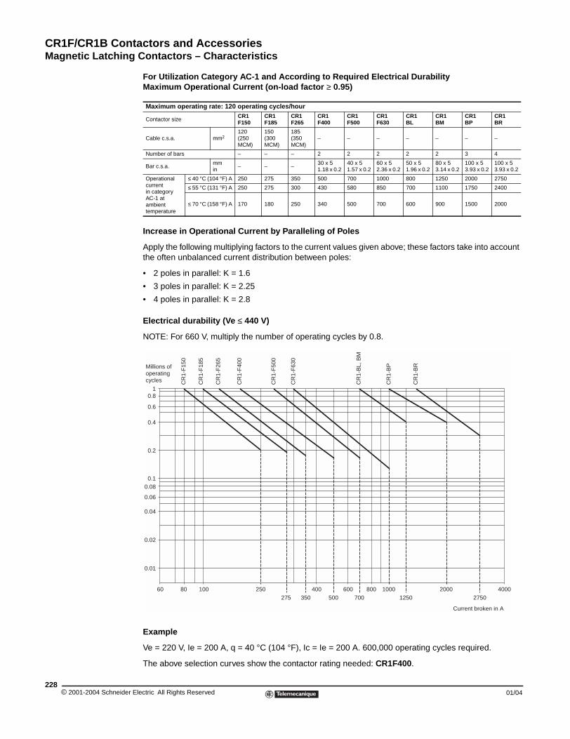
CR1F/CR1B Contactors and AccessoriesMagnetic Latching Contactors – Characteristics
© 2001-2004 Schneider E228
For Utilization Category AC-1 and According to Required Electrical DurabilityMaximum Operational Current (on-load factor ≥ 0.95)
Increase in Operational Current by Paralleling of Poles
Apply the following multiplying factors to the current values given above; these factors take into account the often unbalanced current distribution between poles:
• 2 poles in parallel: K = 1.6
• 3 poles in parallel: K = 2.25
• 4 poles in parallel: K = 2.8
Electrical durability (Ve ≤ 440 V)
NOTE: For 660 V, multiply the number of operating cycles by 0.8.
Example
Ve = 220 V, Ie = 200 A, q = 40 °C (104 °F), Ic = Ie = 200 A. 600,000 operating cycles required.
The above selection curves show the contactor rating needed: CR1F400.
Maximum operating rate: 120 operating cycles/hour
Contactor sizeCR1F150
CR1F185
CR1F265
CR1F400
CR1F500
CR1F630
CR1BL
CR1BM
CR1BP
CR1BR
Cable c.s.a. mm2120 (250 MCM)
150 (300 MCM)
185 (350 MCM)
– – – – – – –
Number of bars – – – 2 2 2 2 2 3 4
Bar c.s.a.mmin
– – –30 x 51.18 x 0.2
40 x 51.57 x 0.2
60 x 52.36 x 0.2
50 x 51.96 x 0.2
80 x 53.14 x 0.2
100 x 53.93 x 0.2
100 x 53.93 x 0.2
Operational current in category AC-1 at ambient temperature
≤ 40 °C (104 °F) A 250 275 350 500 700 1000 800 1250 2000 2750
≤ 55 °C (131 °F) A 250 275 300 430 580 850 700 1100 1750 2400
≤ 70 °C (158 °F) A 170 180 250 340 500 700 600 900 1500 2000
0.01
8060 100 250275
400350 500
600700
800 10001250
20002750
4000
0.02
0.04
0.06
0.080.1
0.2
0.4
0.6
0.81
CR
1-F
150
CR
1-F
185
CR
1-F
265
CR
1-F
400
CR
1-F
500
CR
1-F
630
CR
1-B
L, B
M
CR
1-B
P
CR
1-B
R
Millions ofoperatingcycles
Current broken in A
lectric All Rights Reserved 01/04
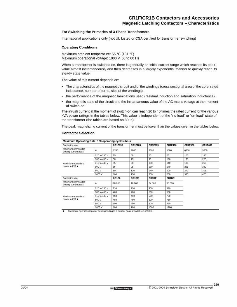
CR1F/CR1B Contactors and AccessoriesMagnetic Latching Contactors – Characteristics
01/04
For Switching the Primaries of 3-Phase Transformers
International applications only (not UL Listed or CSA certified for transformer switching)
Operating Conditions
Maximum ambient temperature: 55 °C (131 °F)Maximum operational voltage: 1000 V, 50 to 60 Hz
When a transformer is switched on, there is generally an initial current surge which reaches its peak value almost instantaneously and then decreases in a largely exponential manner to quickly reach its steady state value.
The value of this current depends on:
• The characteristics of the magnetic circuit and of the windings (cross sectional area of the core, rated inductance, number of turns, size of the windings).
• the performance of the magnetic laminations used (residual induction and saturation inductance).
• the magnetic state of the circuit and the instantaneous value of the AC mains voltage at the moment of switch-on.
The inrush current at the moment of switch-on can reach 20 to 40 times the rated current for the various kVA power ratings in the tables below. This value is independent of the “no-load” or “on-load” state of the transformer (the tables are based on 30 In).
The peak magnetizing current of the transformer must be lower than the values given in the tables below.
Contactor Selection
Maximum Operating Rate: 120 operating cycles /hourContactor size CR1F150 CR1F185 CR1F265 CR1F400 CR1F500 CR1F630
Maximum permissible closing current peak
A 1700 2800 3500 5500 6800 9000
Maximum operational power in kVA c
220 to 230 V 25 40 50 75 100 140
380 to 400 V 50 75 90 130 170 225
415 to 440 V 55 80 100 140 190 250
500 V 65 95 110 170 225 280
660 V 80 120 140 200 270 315
1000 V 100 150 200 250 375 470
Contactor size CR1BL CR1BM CR1BP CR1BR
Maximum permissible closing current peak
A 18 000 18 000 24 000 30 000
Maximum operational power in kVA c
220 to 230 V 230 230 300 380
380 to 400 V 400 400 530 660
415 to 440 V 450 450 560 700
500 V 480 480 600 750
660 V 600 600 800 950
1000 V 700 700 1000 1200
c Maximum operational power corresponding to a current peak at switch-on of 30 In.
229© 2001-2004 Schneider Electric All Rights Reserved
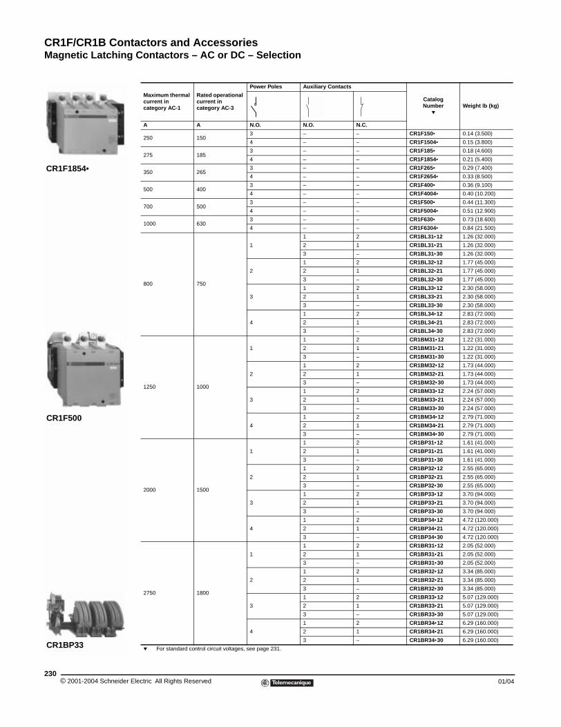
CR1F/CR1B Contactors and AccessoriesMagnetic Latching Contactors – AC or DC – Selection
© 2001-2004 Schneider E230
CR1F1854•
CR1F500
CR1BP33
Magnetic Latching Contactors - AC or DC - Selection
Maximum thermal current in category AC-1
Rated operational current in category AC-3
Power Poles Auxiliary Contacts
Catalog Number
pWeight lb (kg)
A A N.O. N.O. N.C.
250 1503 – – CR1F150• 0.14 (3.500)
4 – – CR1F1504• 0.15 (3.800)
275 1853 – – CR1F185• 0.18 (4.600)
4 – – CR1F1854• 0.21 (5.400)
350 2653 – – CR1F265• 0.29 (7.400)
4 – – CR1F2654• 0.33 (8.500)
500 4003 – – CR1F400• 0.36 (9.100)
4 – – CR1F4004• 0.40 (10.200)
700 5003 – – CR1F500• 0.44 (11.300)
4 – – CR1F5004• 0.51 (12.900)
1000 6303 – – CR1F630• 0.73 (18.600)
4 – – CR1F6304• 0.84 (21.500)
800 750
1
1 2 CR1BL31•12 1.26 (32.000)
2 1 CR1BL31•21 1.26 (32.000)
3 – CR1BL31•30 1.26 (32.000)
2
1 2 CR1BL32•12 1.77 (45.000)
2 1 CR1BL32•21 1.77 (45.000)
3 – CR1BL32•30 1.77 (45.000)
3
1 2 CR1BL33•12 2.30 (58.000)
2 1 CR1BL33•21 2.30 (58.000)
3 – CR1BL33•30 2.30 (58.000)
4
1 2 CR1BL34•12 2.83 (72.000)
2 1 CR1BL34•21 2.83 (72.000)
3 – CR1BL34•30 2.83 (72.000)
1250 1000
1
1 2 CR1BM31•12 1.22 (31.000)
2 1 CR1BM31•21 1.22 (31.000)
3 – CR1BM31•30 1.22 (31.000)
2
1 2 CR1BM32•12 1.73 (44.000)
2 1 CR1BM32•21 1.73 (44.000)
3 – CR1BM32•30 1.73 (44.000)
3
1 2 CR1BM33•12 2.24 (57.000)
2 1 CR1BM33•21 2.24 (57.000)
3 – CR1BM33•30 2.24 (57.000)
4
1 2 CR1BM34•12 2.79 (71.000)
2 1 CR1BM34•21 2.79 (71.000)
3 – CR1BM34•30 2.79 (71.000)
2000 1500
1
1 2 CR1BP31•12 1.61 (41.000)
2 1 CR1BP31•21 1.61 (41.000)
3 – CR1BP31•30 1.61 (41.000)
2
1 2 CR1BP32•12 2.55 (65.000)
2 1 CR1BP32•21 2.55 (65.000)
3 – CR1BP32•30 2.55 (65.000)
3
1 2 CR1BP33•12 3.70 (94.000)
2 1 CR1BP33•21 3.70 (94.000)
3 – CR1BP33•30 3.70 (94.000)
4
1 2 CR1BP34•12 4.72 (120.000)
2 1 CR1BP34•21 4.72 (120.000)
3 – CR1BP34•30 4.72 (120.000)
2750 1800
1
1 2 CR1BR31•12 2.05 (52.000)
2 1 CR1BR31•21 2.05 (52.000)
3 – CR1BR31•30 2.05 (52.000)
2
1 2 CR1BR32•12 3.34 (85.000)
2 1 CR1BR32•21 3.34 (85.000)
3 – CR1BR32•30 3.34 (85.000)
3
1 2 CR1BR33•12 5.07 (129.000)
2 1 CR1BR33•21 5.07 (129.000)
3 – CR1BR33•30 5.07 (129.000)
4
1 2 CR1BR34•12 6.29 (160.000)
2 1 CR1BR34•21 6.29 (160.000)
3 – CR1BR34•30 6.29 (160.000)
p For standard control circuit voltages, see page 231.
lectric All Rights Reserved 01/04
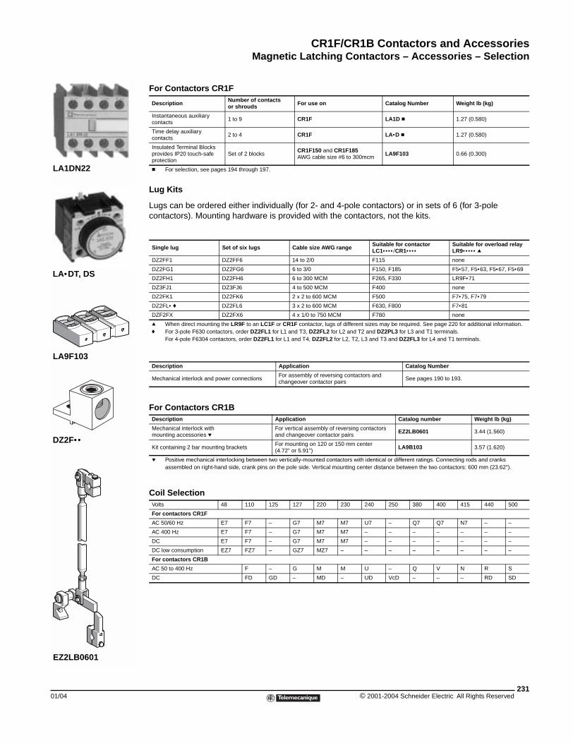
CR1F/CR1B Contactors and AccessoriesMagnetic Latching Contactors – Accessories – Selection
01/04
LA1DN22
LA•DT, DS
LA9F103
EZ2LB0601
DZ2F••
Magnetic Latching Contactors - Accessories - Selection
Lug Kits
Lugs can be ordered either individually (for 2- and 4-pole contactors) or in sets of 6 (for 3-pole contactors). Mounting hardware is provided with the contactors, not the kits.
For Contactors CR1F
Description Number of contacts or shrouds For use on Catalog Number Weight lb (kg)
Instantaneous auxiliary contacts
1 to 9 CR1F LA1D c 1.27 (0.580)
Time delay auxiliary contacts
2 to 4 CR1F LA•D c 1.27 (0.580)
Insulated Terminal Blocksprovides IP20 touch-safe protection
Set of 2 blocksCR1F150 and CR1F185AWG cable size #6 to 300mcm
LA9F103 0.66 (0.300)
c For selection, see pages 194 through 197.
Single lug Set of six lugs Cable size AWG range Suitable for contactorLC1•••• /CR1••••
Suitable for overload relayLR9••••• q
DZ2FF1 DZ2FF6 14 to 2/0 F115 none
DZ2FG1 DZ2FG6 6 to 3/0 F150, F185 F5•57, F5•63, F5•67, F5•69
DZ2FH1 DZ2FH6 6 to 300 MCM F265, F330 LR9F•71
DZ3FJ1 DZ3FJ6 4 to 500 MCM F400 none
DZ2FK1 DZ2FK6 2 x 2 to 600 MCM F500 F7•75, F7•79
DZ2FL• f DZ2FL6 3 x 2 to 600 MCM F630, F800 F7•81
DZF2FX DZ2FX6 4 x 1/0 to 750 MCM F780 none
q When direct mounting the LR9F to an LC1F or CR1F contactor, lugs of different sizes may be required. See page 220 for additional information.f For 3-pole F630 contactors, order DZ2FL1 for L1 and T3, DZ2FL2 for L2 and T2 and DZ2PL3 for L3 and T1 terminals.
For 4-pole F6304 contactors, order DZ2FL1 for L1 and T4, DZ2FL2 for L2, T2, L3 and T3 and DZ2FL3 for L4 and T1 terminals.
Description Application Catalog Number
Mechanical interlock and power connectionsFor assembly of reversing contactors and changeover contactor pairs
See pages 190 to 193.
For Contactors CR1BDescription Application Catalog number Weight lb (kg)
Mechanical interlock with mounting accessories p
For vertical assembly of reversing contactors and changeover contactor pairs
EZ2LB0601 3.44 (1.560)
Kit containing 2 bar mounting bracketsFor mounting on 120 or 150 mm center (4.72" or 5.91")
LA9B103 3.57 (1.620)
p Positive mechanical interlocking between two vertically-mounted contactors with identical or different ratings. Connecting rods and cranks assembled on right-hand side, crank pins on the pole side. Vertical mounting center distance between the two contactors: 600 mm (23.62").
Coil SelectionVolts 48 110 125 127 220 230 240 250 380 400 415 440 500
For contactors CR1F
AC 50/60 Hz E7 F7 – G7 M7 M7 U7 – Q7 Q7 N7 – –
AC 400 Hz E7 F7 – G7 M7 M7 – – – – – – –
DC E7 F7 – G7 M7 M7 – – – – – – –
DC low consumption EZ7 FZ7 – GZ7 MZ7 – – – – – – – –
For contactors CR1B
AC 50 to 400 Hz F – G M M U – Q V N R S
DC FD GD – MD – UD VcD – – – RD SD
231© 2001-2004 Schneider Electric All Rights Reserved
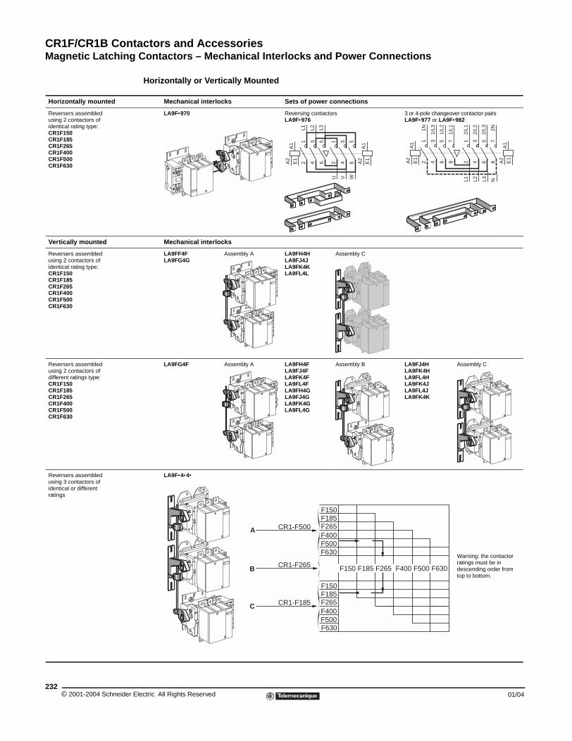
CR1F/CR1B Contactors and AccessoriesMagnetic Latching Contactors – Mechanical Interlocks and Power Connections
© 2001-2004 Schneider E232
Horizontally mounted
Reversers assembledusing 2 contactors ofidentical rating type:CR1F150CR1F185CR1F265CR1F400CR1F500CR1F630
Vertically mounted
Reversers assembledusing 2 contactors ofidentical rating type:CR1F150CR1F185CR1F265CR1F400CR1F500CR1F630
Reversers assembledusing 2 contactors ofdifferent ratings type:CR1F150CR1F185CR1F265CR1F400CR1F500CR1F630
Reversers assembledusing 3 contactors ofidentical or differentratings
Magnetic Latching Contactors - Mechanical Interlocks and Power Connections Components for assembling reversing contactors and changeover pairs CR1F
Horizontally or Vertically Mounted
Mechanical interlocks Sets of power connections
LA9F•970 Reversing contactorsLA9F•976
3 or 4-pole changeover contactor pairsLA9F•977 or LA9F•982
Mechanical interlocks
LA9FF4FLA9FG4G
Assembly A LA9FH4HLA9FJ4JLA9FK4KLA9FL4L
Assembly C
LA9FG4F Assembly A LA9FH4F LA9FJ4FLA9FK4FLA9FL4FLA9FH4GLA9FJ4GLA9FK4GLA9FL4G
Assembly B LA9FJ4HLA9FK4HLA9FL4HLA9FK4JLA9FL4JLA9FK4K
Assembly C
LA9F•4•4•
Warning: the contactor ratings must be in descending order from top to bottom.
A1
E1
A2
A1
A2
E1
12
34
56
12
34
56
L1 L2 L3
U V W
A1
E1
A2
A1
A2
E1
12
34
56
34
56
78
1N
1/L3
1/L2
L2
12
L1
78
1/L1
2/L1
2/L2
2/L3 2N
L3 N
F150F185F265F400F500F630
F150 F185 F265 F400 F500 F630
F185F265F400
F150
F500F630
CR1-F500
CR1-F265
CR1-F185
A
B
C
lectric All Rights Reserved 01/04
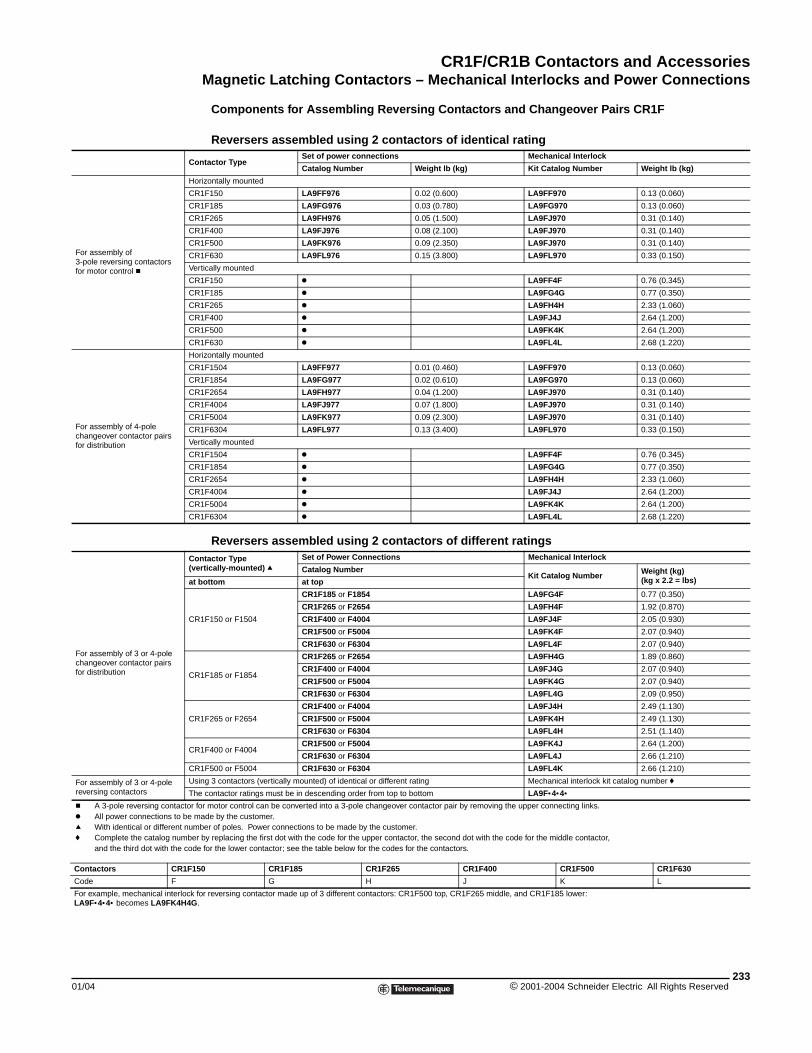
CR1F/CR1B Contactors and AccessoriesMagnetic Latching Contactors – Mechanical Interlocks and Power Connections
01/04
Con
For assembly of 3-pole reversing contactors for motor control c
Hor
CR
CR
CR
CR
CR
CR
Ver
CR
CR
CR
CR
CR
CR
For assembly of 4-pole changeover contactor pairs for distribution
Hor
CR
CR
CR
CR
CR
CR
Ver
CR
CR
CR
CR
CR
CR
For assembly of 3 or 4-pole changeover contactor pairs for distribution
Con(ve
at b
CR
CR
CR
CR
CR
For assembly of 3 or 4-pole reversing contactors
Usi
The
c A 3-pole reversing contactor fok All power connections to be mq With identical or different numf Complete the catalog number
and the third dot with the code
Contactors CR1F15
Code F
For example, mechanical interlock foLA9F•4•4• becomes LA9FK4H4G.
Components for Assembling Reversing Contactors and Changeover Pairs CR1F
Reversers assembled using 2 contactors of identical rating
tactor TypeSet of power connections Mechanical Interlock
Catalog Number Weight lb (kg) Kit Catalog Number Weight lb (kg)
izontally mounted
1F150 LA9FF976 0.02 (0.600) LA9FF970 0.13 (0.060)
1F185 LA9FG976 0.03 (0.780) LA9FG970 0.13 (0.060)
1F265 LA9FH976 0.05 (1.500) LA9FJ970 0.31 (0.140)
1F400 LA9FJ976 0.08 (2.100) LA9FJ970 0.31 (0.140)
1F500 LA9FK976 0.09 (2.350) LA9FJ970 0.31 (0.140)
1F630 LA9FL976 0.15 (3.800) LA9FL970 0.33 (0.150)
tically mounted
1F150 k LA9FF4F 0.76 (0.345)
1F185 k LA9FG4G 0.77 (0.350)
1F265 k LA9FH4H 2.33 (1.060)
1F400 k LA9FJ4J 2.64 (1.200)
1F500 k LA9FK4K 2.64 (1.200)
1F630 k LA9FL4L 2.68 (1.220)
izontally mounted
1F1504 LA9FF977 0.01 (0.460) LA9FF970 0.13 (0.060)
1F1854 LA9FG977 0.02 (0.610) LA9FG970 0.13 (0.060)
1F2654 LA9FH977 0.04 (1.200) LA9FJ970 0.31 (0.140)
1F4004 LA9FJ977 0.07 (1.800) LA9FJ970 0.31 (0.140)
1F5004 LA9FK977 0.09 (2.300) LA9FJ970 0.31 (0.140)
1F6304 LA9FL977 0.13 (3.400) LA9FL970 0.33 (0.150)
tically mounted
1F1504 k LA9FF4F 0.76 (0.345)
1F1854 k LA9FG4G 0.77 (0.350)
1F2654 k LA9FH4H 2.33 (1.060)
1F4004 k LA9FJ4J 2.64 (1.200)
1F5004 k LA9FK4K 2.64 (1.200)
1F6304 k LA9FL4L 2.68 (1.220)
Reversers assembled using 2 contactors of different ratingstactor Type
rtically-mounted) qSet of Power Connections Mechanical Interlock
Catalog NumberKit Catalog Number Weight (kg)
(kg x 2.2 = lbs)ottom at top
1F150 or F1504
CR1F185 or F1854 LA9FG4F 0.77 (0.350)
CR1F265 or F2654 LA9FH4F 1.92 (0.870)
CR1F400 or F4004 LA9FJ4F 2.05 (0.930)
CR1F500 or F5004 LA9FK4F 2.07 (0.940)
CR1F630 or F6304 LA9FL4F 2.07 (0.940)
1F185 or F1854
CR1F265 or F2654 LA9FH4G 1.89 (0.860)
CR1F400 or F4004 LA9FJ4G 2.07 (0.940)
CR1F500 or F5004 LA9FK4G 2.07 (0.940)
CR1F630 or F6304 LA9FL4G 2.09 (0.950)
1F265 or F2654
CR1F400 or F4004 LA9FJ4H 2.49 (1.130)
CR1F500 or F5004 LA9FK4H 2.49 (1.130)
CR1F630 or F6304 LA9FL4H 2.51 (1.140)
1F400 or F4004CR1F500 or F5004 LA9FK4J 2.64 (1.200)
CR1F630 or F6304 LA9FL4J 2.66 (1.210)
1F500 or F5004 CR1F630 or F6304 LA9FL4K 2.66 (1.210)
ng 3 contactors (vertically mounted) of identical or different rating Mechanical interlock kit catalog number f
contactor ratings must be in descending order from top to bottom LA9F•4•4•r motor control can be converted into a 3-pole changeover contactor pair by removing the upper connecting links.ade by the customer.ber of poles. Power connections to be made by the customer.by replacing the first dot with the code for the upper contactor, the second dot with the code for the middle contactor, for the lower contactor; see the table below for the codes for the contactors.
0 CR1F185 CR1F265 CR1F400 CR1F500 CR1F630
G H J K L
r reversing contactor made up of 3 different contactors: CR1F500 top, CR1F265 middle, and CR1F185 lower:
233© 2001-2004 Schneider Electric All Rights Reserved
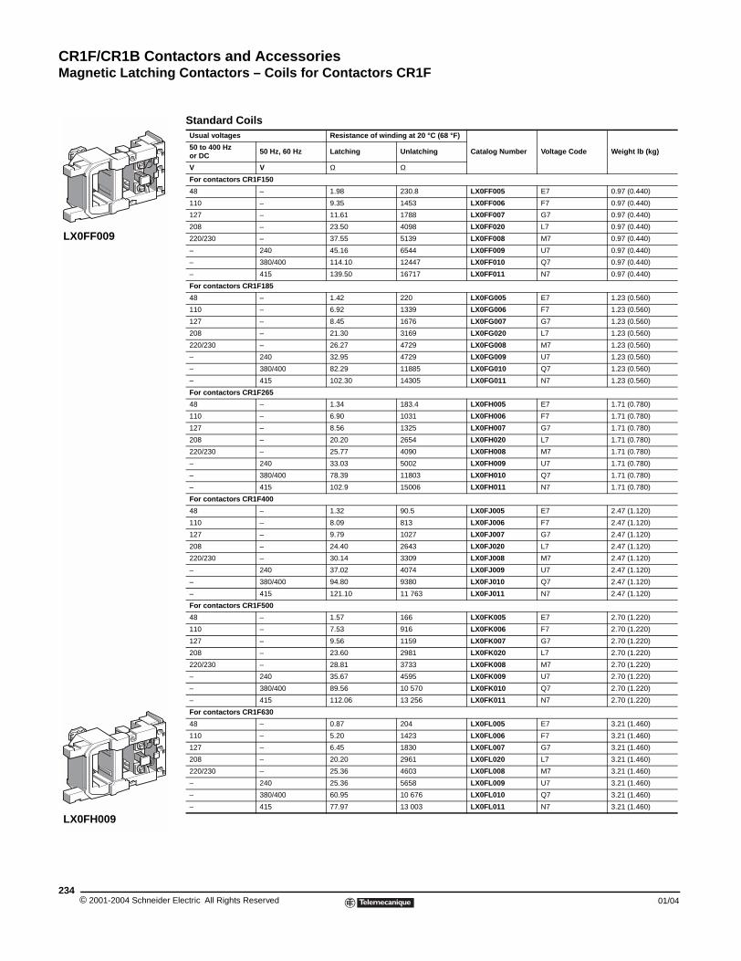
CR1F/CR1B Contactors and AccessoriesMagnetic Latching Contactors – Coils for Contactors CR1F
© 2001-2004 Schneider E234
LX0FF009
LX0FH009
Magnetic Latching Contactors - Coils for Contactors CR1F
Standard CoilsUsual voltages Resistance of winding at 20 °C (68 °F)
Catalog Number Voltage Code Weight lb (kg)50 to 400 Hzor DC 50 Hz, 60 Hz Latching Unlatching
V V Ω Ω
For contactors CR1F150
48 – 1.98 230.8 LX0FF005 E7 0.97 (0.440)
110 – 9.35 1453 LX0FF006 F7 0.97 (0.440)
127 – 11.61 1788 LX0FF007 G7 0.97 (0.440)
208 – 23.50 4098 LX0FF020 L7 0.97 (0.440)
220/230 – 37.55 5139 LX0FF008 M7 0.97 (0.440)
– 240 45.16 6544 LX0FF009 U7 0.97 (0.440)
– 380/400 114.10 12447 LX0FF010 Q7 0.97 (0.440)
– 415 139.50 16717 LX0FF011 N7 0.97 (0.440)
For contactors CR1F185
48 – 1.42 220 LX0FG005 E7 1.23 (0.560)
110 – 6.92 1339 LX0FG006 F7 1.23 (0.560)
127 – 8.45 1676 LX0FG007 G7 1.23 (0.560)
208 – 21.30 3169 LX0FG020 L7 1.23 (0.560)
220/230 – 26.27 4729 LX0FG008 M7 1.23 (0.560)
– 240 32.95 4729 LX0FG009 U7 1.23 (0.560)
– 380/400 82.29 11885 LX0FG010 Q7 1.23 (0.560)
– 415 102.30 14305 LX0FG011 N7 1.23 (0.560)
For contactors CR1F265
48 – 1.34 183.4 LX0FH005 E7 1.71 (0.780)
110 – 6.90 1031 LX0FH006 F7 1.71 (0.780)
127 – 8.56 1325 LX0FH007 G7 1.71 (0.780)
208 – 20.20 2654 LX0FH020 L7 1.71 (0.780)
220/230 – 25.77 4090 LX0FH008 M7 1.71 (0.780)
– 240 33.03 5002 LX0FH009 U7 1.71 (0.780)
– 380/400 78.39 11803 LX0FH010 Q7 1.71 (0.780)
– 415 102.9 15006 LX0FH011 N7 1.71 (0.780)
For contactors CR1F400
48 – 1.32 90.5 LX0FJ005 E7 2.47 (1.120)
110 – 8.09 813 LX0FJ006 F7 2.47 (1.120)
127 – 9.79 1027 LX0FJ007 G7 2.47 (1.120)
208 – 24.40 2643 LX0FJ020 L7 2.47 (1.120)
220/230 – 30.14 3309 LX0FJ008 M7 2.47 (1.120)
– 240 37.02 4074 LX0FJ009 U7 2.47 (1.120)
– 380/400 94.80 9380 LX0FJ010 Q7 2.47 (1.120)
– 415 121.10 11 763 LX0FJ011 N7 2.47 (1.120)
For contactors CR1F500
48 – 1.57 166 LX0FK005 E7 2.70 (1.220)
110 – 7.53 916 LX0FK006 F7 2.70 (1.220)
127 – 9.56 1159 LX0FK007 G7 2.70 (1.220)
208 – 23.60 2981 LX0FK020 L7 2.70 (1.220)
220/230 – 28.81 3733 LX0FK008 M7 2.70 (1.220)
– 240 35.67 4595 LX0FK009 U7 2.70 (1.220)
– 380/400 89.56 10 570 LX0FK010 Q7 2.70 (1.220)
– 415 112.06 13 256 LX0FK011 N7 2.70 (1.220)
For contactors CR1F630
48 – 0.87 204 LX0FL005 E7 3.21 (1.460)
110 – 5.20 1423 LX0FL006 F7 3.21 (1.460)
127 – 6.45 1830 LX0FL007 G7 3.21 (1.460)
208 – 20.20 2961 LX0FL020 L7 3.21 (1.460)
220/230 – 25.36 4603 LX0FL008 M7 3.21 (1.460)
– 240 25.36 5658 LX0FL009 U7 3.21 (1.460)
– 380/400 60.95 10 676 LX0FL010 Q7 3.21 (1.460)
– 415 77.97 13 003 LX0FL011 N7 3.21 (1.460)
lectric All Rights Reserved 01/04
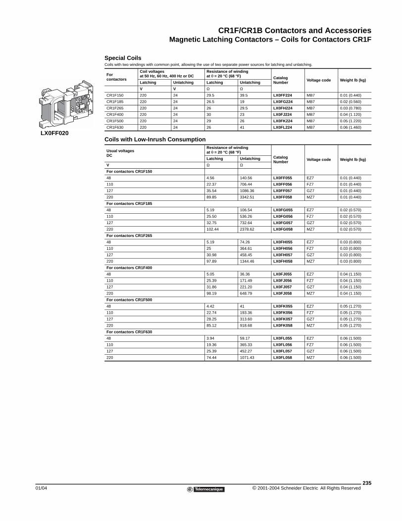
CR1F/CR1B Contactors and AccessoriesMagnetic Latching Contactors – Coils for Contactors CR1F
01/04
LX0FF020
Special CoilsCoils with two windings with common point, allowing the use of two separate power sources for latching and unlatching.
Forcontactors
Coil voltagesat 50 Hz, 60 Hz, 400 Hz or DC
Resistance of winding at θ = 20 °C (68 °F) Catalog
Number Voltage code Weight lb (kg)Latching Unlatching Latching Unlatching
V V Ω Ω
CR1F150 220 24 29.5 39.5 LX0FF224 MB7 0.01 (0.440)
CR1F185 220 24 26.5 19 LX0FG224 MB7 0.02 (0.560)
CR1F265 220 24 26 29.5 LX0FH224 MB7 0.03 (0.780)
CR1F400 220 24 30 23 LX0FJ224 MB7 0.04 (1.120)
CR1F500 220 24 29 26 LX0FK224 MB7 0.05 (1.220)
CR1F630 220 24 26 41 LX0FL224 MB7 0.06 (1.460)
Coils with Low-Inrush Consumption
Usual voltagesDC
Resistance of winding at θ = 20 °C (68 °F)
Catalog Number Voltage code Weight lb (kg)Latching Unlatching
V Ω ΩFor contactors CR1F150
48 4.56 140.56 LX0FF055 EZ7 0.01 (0.440)
110 22.37 706.44 LX0FF056 FZ7 0.01 (0.440)
127 35.54 1086.36 LX0FF057 GZ7 0.01 (0.440)
220 89.85 3342.51 LX0FF058 MZ7 0.01 (0.440)
For contactors CR1F185
48 5.19 106.54 LX0FG055 EZ7 0.02 (0.570)
110 25.50 536.26 LX0FG056 FZ7 0.02 (0.570)
127 32.75 732.64 LX0FG057 GZ7 0.02 (0.570)
220 102.44 2378.62 LX0FG058 MZ7 0.02 (0.570)
For contactors CR1F265
48 5.19 74.26 LX0FH055 EZ7 0.03 (0.800)
110 25 364.61 LX0FH056 FZ7 0.03 (0.800)
127 30.98 458.45 LX0FH057 GZ7 0.03 (0.800)
220 97.89 1344.46 LX0FH058 MZ7 0.03 (0.800)
For contactors CR1F400
48 5.05 36.36 LX0FJ055 EZ7 0.04 (1.150)
110 25.39 171.49 LX0FJ056 FZ7 0.04 (1.150)
127 31.86 221.20 LX0FJ057 GZ7 0.04 (1.150)
220 98.19 648.79 LX0FJ058 MZ7 0.04 (1.150)
For contactors CR1F500
48 4.42 41 LX0FK055 EZ7 0.05 (1.270)
110 22.74 193.36 LX0FK056 FZ7 0.05 (1.270)
127 28.25 313.60 LX0FK057 GZ7 0.05 (1.270)
220 85.12 918.68 LX0FK058 MZ7 0.05 (1.270)
For contactors CR1F630
48 3.94 59.17 LX0FL055 EZ7 0.06 (1.500)
110 19.36 365.33 LX0FL056 FZ7 0.06 (1.500)
127 25.39 452.27 LX0FL057 GZ7 0.06 (1.500)
220 74.44 1071.43 LX0FL058 MZ7 0.06 (1.500)
235© 2001-2004 Schneider Electric All Rights Reserved
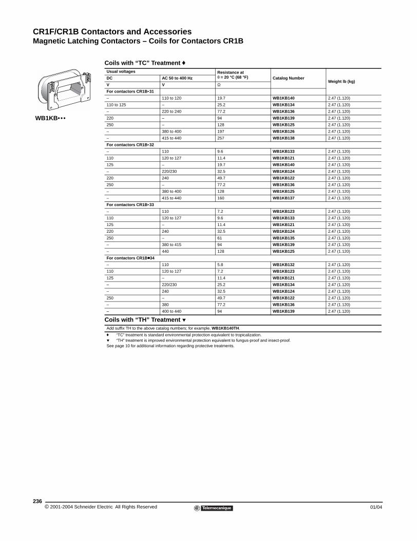
CR1F/CR1B Contactors and AccessoriesMagnetic Latching Contactors – Coils for Contactors CR1B
© 2001-2004 Schneider E236
WB1KB•••
Magnetic Latching Contactors - Coils for Contactors CR1B
Coils with “TC” Treatment fUsual voltages Resistance at
θ = 20 °C (68 °F) Catalog NumberWeight lb (kg)
DC AC 50 to 400 Hz
V V ΩFor contactors CR1B•31
– 110 to 120 19.7 WB1KB140 2.47 (1.120)
110 to 125 – 25.2 WB1KB134 2.47 (1.120)
– 220 to 240 77.2 WB1KB136 2.47 (1.120)
220 – 94 WB1KB139 2.47 (1.120)
250 – 128 WB1KB125 2.47 (1.120)
– 380 to 400 197 WB1KB126 2.47 (1.120)
– 415 to 440 257 WB1KB138 2.47 (1.120)
For contactors CR1B•32
– 110 9.6 WB1KB133 2.47 (1.120)
110 120 to 127 11.4 WB1KB121 2.47 (1.120)
125 – 19.7 WB1KB140 2.47 (1.120)
– 220/230 32.5 WB1KB124 2.47 (1.120)
220 240 49.7 WB1KB122 2.47 (1.120)
250 – 77.2 WB1KB136 2.47 (1.120)
– 380 to 400 128 WB1KB125 2.47 (1.120)
– 415 to 440 160 WB1KB137 2.47 (1.120)
For contactors CR1B•33
– 110 7.2 WB1KB123 2.47 (1.120)
110 120 to 127 9.6 WB1KB133 2.47 (1.120)
125 – 11.4 WB1KB121 2.47 (1.120)
220 240 32.5 WB1KB124 2.47 (1.120)
250 – 61 WB1KB135 2.47 (1.120)
– 380 to 415 94 WB1KB139 2.47 (1.120)
– 440 128 WB1KB125 2.47 (1.120)
For contactors CR1Bk34
– 110 5.8 WB1KB132 2.47 (1.120)
110 120 to 127 7.2 WB1KB123 2.47 (1.120)
125 – 11.4 WB1KB121 2.47 (1.120)
– 220/230 25.2 WB1KB134 2.47 (1.120)
– 240 32.5 WB1KB124 2.47 (1.120)
250 – 49.7 WB1KB122 2.47 (1.120)
– 380 77.2 WB1KB136 2.47 (1.120)
– 400 to 440 94 WB1KB139 2.47 (1.120)
Coils with “TH” Treatment pAdd suffix TH to the above catalog numbers; for example, WB1KB140TH.
f “TC” treatment is standard environmental protection equivalent to tropicalization.p “TH” treatment is improved environmental protection equivalent to fungus-proof and insect-proof.See page 10 for additional information regarding protective treatments.
lectric All Rights Reserved 01/04
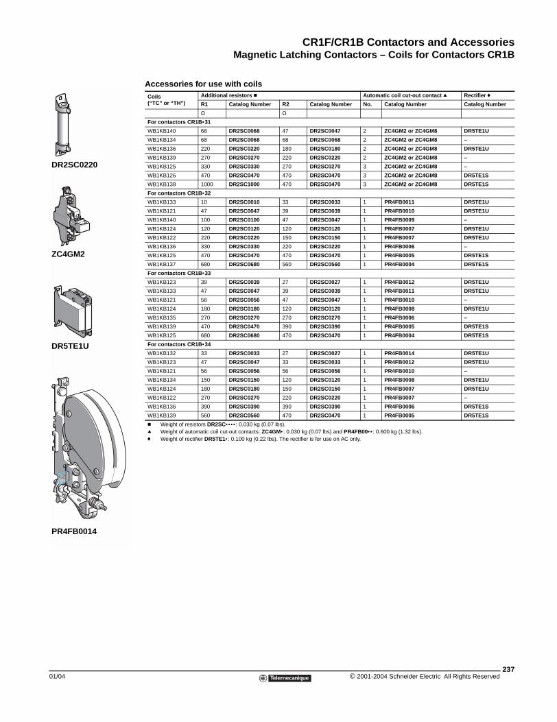
CR1F/CR1B Contactors and AccessoriesMagnetic Latching Contactors – Coils for Contactors CR1B
01/04
DR2SC0220
ZC4GM2
PR4FB0014
DR5TE1U
Accessories for use with coils Coils (“TC” or “TH”)
Additional resistors c Automatic coil cut-out contact q Rectifier f
R1 Catalog Number R2 Catalog Number No. Catalog Number Catalog Number
Ω ΩFor contactors CR1B•31
WB1KB140 68 DR2SC0068 47 DR2SC0047 2 ZC4GM2 or ZC4GM8 DR5TE1U
WB1KB134 68 DR2SC0068 68 DR2SC0068 2 ZC4GM2 or ZC4GM8 –
WB1KB136 220 DR2SC0220 180 DR2SC0180 2 ZC4GM2 or ZC4GM8 DR5TE1U
WB1KB139 270 DR2SC0270 220 DR2SC0220 2 ZC4GM2 or ZC4GM8 –
WB1KB125 330 DR2SC0330 270 DR2SC0270 3 ZC4GM2 or ZC4GM8 –
WB1KB126 470 DR2SC0470 470 DR2SC0470 3 ZC4GM2 or ZC4GM8 DR5TE1S
WB1KB138 1000 DR2SC1000 470 DR2SC0470 3 ZC4GM2 or ZC4GM8 DR5TE1S
For contactors CR1B•32
WB1KB133 10 DR2SC0010 33 DR2SC0033 1 PR4FB0011 DR5TE1U
WB1KB121 47 DR2SC0047 39 DR2SC0039 1 PR4FB0010 DR5TE1U
WB1KB140 100 DR2SC0100 47 DR2SC0047 1 PR4FB0009 –
WB1KB124 120 DR2SC0120 120 DR2SC0120 1 PR4FB0007 DR5TE1U
WB1KB122 220 DR2SC0220 150 DR2SC0150 1 PR4FB0007 DR5TE1U
WB1KB136 330 DR2SC0330 220 DR2SC0220 1 PR4FB0006 –
WB1KB125 470 DR2SC0470 470 DR2SC0470 1 PR4FB0005 DR5TE1S
WB1KB137 680 DR2SC0680 560 DR2SC0560 1 PR4FB0004 DR5TE1S
For contactors CR1B•33
WB1KB123 39 DR2SC0039 27 DR2SC0027 1 PR4FB0012 DR5TE1U
WB1KB133 47 DR2SC0047 39 DR2SC0039 1 PR4FB0011 DR5TE1U
WB1KB121 56 DR2SC0056 47 DR2SC0047 1 PR4FB0010 –
WB1KB124 180 DR2SC0180 120 DR2SC0120 1 PR4FB0008 DR5TE1U
WB1KB135 270 DR2SC0270 270 DR2SC0270 1 PR4FB0006 –
WB1KB139 470 DR2SC0470 390 DR2SC0390 1 PR4FB0005 DR5TE1S
WB1KB125 680 DR2SC0680 470 DR2SC0470 1 PR4FB0004 DR5TE1S
For contactors CR1B•34
WB1KB132 33 DR2SC0033 27 DR2SC0027 1 PR4FB0014 DR5TE1U
WB1KB123 47 DR2SC0047 33 DR2SC0033 1 PR4FB0012 DR5TE1U
WB1KB121 56 DR2SC0056 56 DR2SC0056 1 PR4FB0010 –
WB1KB134 150 DR2SC0150 120 DR2SC0120 1 PR4FB0008 DR5TE1U
WB1KB124 180 DR2SC0180 150 DR2SC0150 1 PR4FB0007 DR5TE1U
WB1KB122 270 DR2SC0270 220 DR2SC0220 1 PR4FB0007 –
WB1KB136 390 DR2SC0390 390 DR2SC0390 1 PR4FB0006 DR5TE1S
WB1KB139 560 DR2SC0560 470 DR2SC0470 1 PR4FB0005 DR5TE1S
c Weight of resistors DR2SC•••• : 0.030 kg (0.07 lbs).q Weight of automatic coil cut-out contacts: ZC4GM• : 0.030 kg (0.07 lbs) and PR4FB00•• : 0.600 kg (1.32 lbs).f Weight of rectifier DR5TE1• : 0.100 kg (0.22 lbs). The rectifier is for use on AC only.
237© 2001-2004 Schneider Electric All Rights Reserved
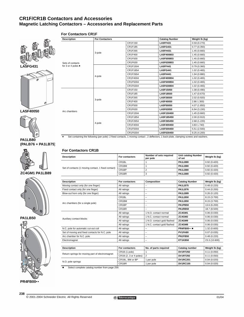
CR1F/CR1B Contactors and AccessoriesMagnetic Latching Contactors – Accessories and Replacement Parts
© 2001-2004 Schneider E238
LA5FG431
LA5F40050
PR4FB00••
PA1LB80 (PALB76 + PA1LB75)
ZC4GM1 PA1LB89
PA1LB50
For Contactors CR1FDescription For Contactors Catalog Number Weight lb (kg)
Sets of contacts for 3 or 4 poles f
3-pole
CR1F150 LA5FF431 0.59 (0.270)
CR1F185 LA5FG431 0.77 (0.350)
CR1F265 LA5FH431 1.45 (0.660)
CR1F400 LA5F400803 1.45 (0.660)
CR1F500 LA5F500803 1.45 (0.660)
CR1F630 LA5F630803 1.45 (0.660)
4-pole
CR1F1504 LA5FF441 0.79 (0.360)
CR1F1854 LA5FG441 1.02 (0.465)
CR1F2654 LA5FH441 1.94 (0.880)
CR1F4004 LA5F400804 1.02 (0.465)
CR1F5004 LA5F500804 1.02 (0.465)
CR1F6304 LA5F630804 1.02 (0.465)
Arc chambers
3-pole
CR1F150 LA5F15050 1.08 (0.490)
CR1F185 LA5F18550 1.47 (0.670)
CR1F265 LA5F26550 2.02 (0.920)
CR1F400 LA5F40050 2.86 1.300)
CR1F500 LA5F50050 4.07 (1.850)
CR1F630 LA5F63050 6.94 (3.150)
4-pole
CR1F1504 LA5F150450 1.45 (0.660)
CR1F1854 LA5F185450 2.00 (0.910)
CR1F2654 LA5F265450 2.68 (1.220)
CR1F4004 LA5F400450 3.83 1.740)
CR1F5004 LA5F500450 5.51 (2.500)
CR1F6304 LA5F630450 9.25 (4.200)
f Set containing the following (per pole): 2 fixed contacts, 1 moving contact , 2 deflectors, 1 back-plate, clamping screws and washers.
For Contactors CR1B
Description For contactors Number of sets required per pole
Unit catalog Number of set Weight lb (kg)
Set of contacts (1 moving contact, 1 fixed contact)
CR1BL 1 PA1LB80 0.92 (0.420)
CR1BM 1 PA1LB80 0.92 (0.420)
CR1BP 2 PA1LB80 0.92 (0.420)
CR1BR 3 PA1LB80 0.92 (0.420)
Description For contactors Composition Catalog Number Weight lb (kg)
Moving contact only (for one finger) All ratings – PA1LB75 0.48 (0.220)
Fixed contact only (for one finger) All ratings – PA1LB76 0.44 (0.200)
Blow-out horn only (for one finger) All ratings – PA1LB89 0.26 (0.120)
Arc chambers (for a single pole)
CR1BL – PA1LB50 8.15 (3.700)
CR1BM – PA1LB50 8.15 (3.700)
CR1BP – PA1PB50 13.6 (6.200)
CR1BR – PA1RB50 18.7 (8.500)
Auxiliary contact blocks
All ratings 1 N.O. contact normal ZC4GM1 0.06 (0.030)
All ratings 1 N.C. contact normal ZC4GM2 0.06 (0.030)
All ratings 1 N.O. contact gold flashed ZC4GM9 0.06 (0.030)
All ratings 1 N.C. contact gold flashed ZC4GM8 0.06 (0.030)
N.C. pole for automatic cut-out coil All ratings – PR4FB00•• c 1.32 (0.600)
Set of moving and fixed contacts for N.C. pole All ratings – PV1FA80 0.07 (0.035)
Arc chamber for N.C. pole All ratings – PN1FB50 0.48 (0.220)
Electromagnet All ratings – ET1KB50 23.3 (10.600)
Description For contactors No. of parts required Catalog number Weight lb (kg)
Return springs for moving part of electromagnetCR1B (1 pole) 1 DV1RT292 0.11 (0.050)
CR1B (2, 3 or 4 poles) 2 DV1RT292 0.11 (0.050)
N.O. pole springsCR1BL, BM or BP 1 per pole DV1RC201 0.04 (0.020)
CR1BR 1 per pole DV1RC155 0.04 (0.020)
c Select complete catalog number from page 259.
lectric All Rights Reserved 01/04
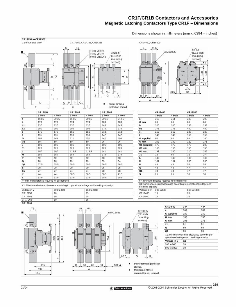
CR1F/CR1B Contactors and AccessoriesMagnetic Latching Contactors Type CR1F – Dimensions
01/04
CR1F150 to CR1F500Common side view
CR1F1503 Pole 4 Po
a 163.5 201.b 170 170b1 137 137b2 301 301c 171 171f 131 131G 106 143G1 80 80J 106 106J1 120 120L 107 107M 150 150P 40 40Q 26 26Q1 57.5 55.5S 20 20S1 27 27Y 44 44Z 13.5 13.5f = minimum distance required for c
X1: Minimum electrical clearance ac
Voltage in V 200 CR1F150 10CR1F185 10CR1F265 10
CR1F630
L
c
=
b=
b2
X1
X1
155
197
255
280
X1
72
X1
Magnetic Latching Contactors type CR1F - Dimensions
Dimensions shown in millimeters (mm x .0394 = inches)
CR1F150, CR1F185, CR1F265 CR1F400, CR1F500
CR1F185 CR1F265 CR1F400 CR1F500le 3 Pole 4 Pole 3 Pole 4 Pole 3 Pole 4 Pole 3 Pole 4 Pole5 168.5 208.5 201.5 244.5 a 213 261 233 288
174 174 203 203 G min 66 66 66 66137 137 145 145 b 206 206 238 238305 305 370 370 b2 375 375 400 400181 181 213 213 c 219 219 232 232130 130 147 147 f 146 146 150 150111 151 142 190 G supplied 80 80 80 14080 80 96 96 G max 102 150 120 175106 106 106 106 G1 supplied 170 170 170 230120 120 120 120 G1 min 156 156 156 156113.5 113.5 141 141 G1 max 192 240 210 265154 154 178 178 J1 12 60 32 2740 40 48 48 L 145 145 146 14629 29 39 34 M 181 181 208 20859.5 59.5 66.5 66.5 P 48 48 55 5520 20 25 25 Q 43 43 47 4734 34 38 38 Q1 74 74 77 7738.5 30.5 30.5 21.5 S 25 25 30 3013.5 13.5 15.5 15.5
oil removal f = minimum distance required for coil removal
cording to operational voltage and breaking capacityX1: Minimum electrical clearance according to operational voltage and breaking capacity
to 500 660 to 1000 Voltage in V 200 to 500 660 to 100015 CR1F400 15 2015 CR1F500 15 2015
CR1F630 3 P 4 P
a 309 389
G supplied 180 240
G min 100 150
G max 195 275
J1 61 81
Q 60 60
Q1 89 89
X1: Minimum electrical clearance according to operational voltage and breaking capacity
Voltage in V X1
200 to 500 20
690 to 1000 30
J J1b1=
=G1
GZ
= =
Y
3xØ6.5 (1/4 inch mounting screws)
S1
Q
a
P P Q1
f
M
SF150 M8x25F185 M8x25F265 M10x35
c Power terminal protection shroud.
Q1
a
PQ P
f
M
44.5S
6xM10x35
G
G123.5 J
120
==
180
==
8x¯8.5(5/16 inch mounting screws)
=30
4=
464
180
==
J1G60.5
4xØ10.5(3/8 inch mounting screws)
Q1
a
8080Q
264
181
6440
6xM12x45
c Power terminal protection shroud.
q Minimum distance required for coil removal.
239© 2001-2004 Schneider Electric All Rights Reserved
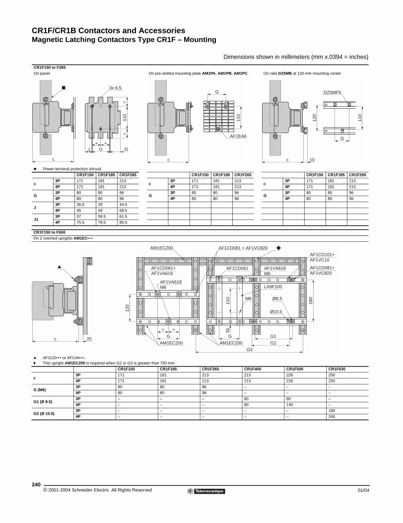
CR1F/CR1B Contactors and AccessoriesMagnetic Latching Contactors Type CR1F – Mounting
© 2001-2004 Schneider E240
CR1F150 to F265
On panel
c Power terminal protection shro
CR1F150
c3P 171
4P 171
G3P 80
4P 80
J3P 26.5
4P 45
J13P 57
4P 75.5
CR1F150 to F650
On 2 notched uprights AM1EC•••
q AF1CD••• or AF1VA••• .f This upright AM1EC200 is req
c3P
4P
G (M6)3P
4P
G1 (Ø 8.5)3P
4P
G2 (Ø 10.5)3P
4P
c
J
c 25
Magnetic Latching Contactors type CR1F - Mounting
Dimensions shown in millimeters (mm x.0394 = inches)
On pre-slotted mounting plate AM1PA, AM1PB, AM1PC On rails DZ5MB at 120 mm mounting center
ud.
CR1F185 CR1F265 CR1F150 CR1F185 CR1F265 CR1F150 CR1F185 CR1F265
181 213c
3P 171 181 213c
3P 171 181 213
181 213 4P 171 181 213 4P 171 181 213
80 96G
3P 80 80 96G
3P 80 80 96
80 96 4P 80 80 96 4P 80 80 96
29 44.5
49 68.5
59.5 61.5
79.5 85.5
uired when G2 or G3 is greater than 700 mm.
CR1F150 CR1F185 CR1F265 CR1F400 CR1F500 CR1F630
171 181 213 213 226 250
171 181 213 213 226 250
80 80 96 – – –
80 80 96 – – –
– – – 80 80 –
– – – 80 140 –
– – – – – 180
– – – – – 240
3x 6.5
G=
J1
=
110
=
=
c
AF1EA6
110
G DZ5MF5
c
G
110
120
15
120
Ø10.5
AM1EC200 AF1CD081 + AF1VC820
AM1EC200
AF1CD061+AF1VA618
AF1CD061 AF1VA618M6
LA9F100
AF1CD101+AF1VC10
AF1CD081+AF1VC820
Ø8.5M6
AM1EC200
110
35
180
G
= =
G
AF1VA618M6
G1
G2
G3
lectric All Rights Reserved 01/04
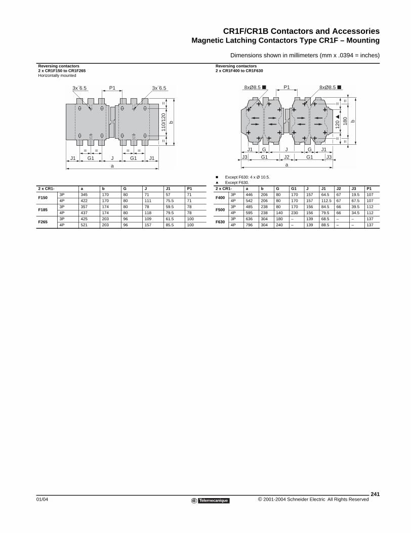
CR1F/CR1B Contactors and AccessoriesMagnetic Latching Contactors Type CR1F – Mounting
01/04
Reversing contactors2 x CR1F150 to CR1F265Horizontally mounted
2 x CR1- a
F1503P 345
4P 422
F1853P 357
4P 437
F2653P 425
4P 521
=
G1
=
J1
3x¯6.5
Dimensions shown in millimeters (mm x .0394 = inches)
Reversing contactors2 x CR1F400 to CR1F630
c Except F630: 4 x Ø 10.5.q Except F630.
b G J J1 P1 2 x CR1- a b G G1 J J1 J2 J3 P1
170 80 71 57 71F400
3P 446 206 80 170 157 64.5 67 19.5 107
170 80 111 75.5 71 4P 542 206 80 170 157 112.5 67 67.5 107
174 80 78 59.5 78F500
3P 485 238 80 170 156 84.5 66 39.5 112
174 80 118 79.5 78 4P 595 238 140 230 156 79.5 66 34.5 112
203 96 109 61.5 100F630
3P 636 304 180 – 139 68.5 – – 137
203 96 157 85.5 100 4P 796 304 240 – 139 88.5 – – 137
110/
120
==
=
G1 J1
3x¯6.5
=
J
ab
P1
G
G1 J3
120
=
=
180
==
8xØ8.5
b
GJ1 J1
J2
J
G1J3
8xØ8.5 P1
a
241© 2001-2004 Schneider Electric All Rights Reserved
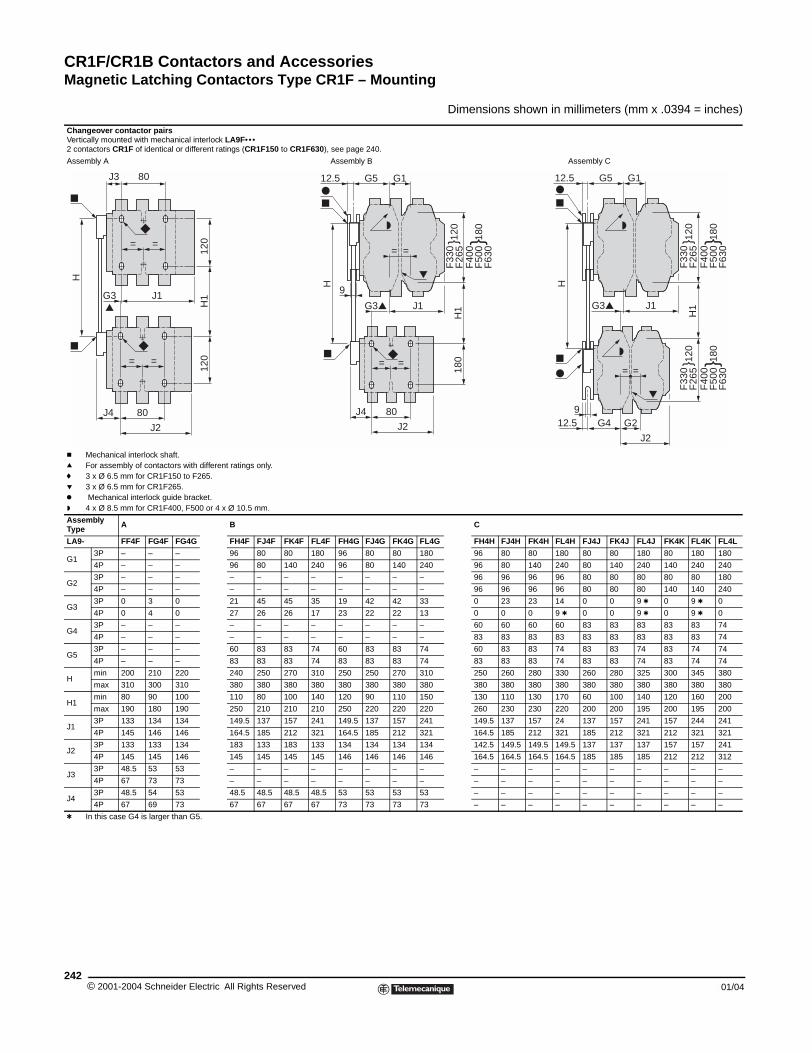
CR1F/CR1B Contactors and AccessoriesMagnetic Latching Contactors Type CR1F – Mounting
© 2001-2004 Schneider E242
Changeover contactor pairsVertically mounted with mechanical 2 contactors CR1F of identical or dif
Assembly A
c Mechanical interlock shaft.q For assembly of contactors witf 3 x Ø 6.5 mm for CR1F150 to p 3 x Ø 6.5 mm for CR1F265.k Mechanical interlock guide braw 4 x Ø 8.5 mm for CR1F400, F5
Assembly Type A
LA9- FF4F FG4F FG4G
G13P – – –
4P – – –
G23P – – –
4P – – –
G33P 0 3 0
4P 0 4 0
G43P – – –
4P – – –
G53P – – –
4P – – –
Hmin 200 210 220
max 310 300 310
H1min 80 90 100
max 190 180 190
J13P 133 134 134
4P 145 146 146
J23P 133 133 134
4P 145 145 146
J33P 48.5 53 53
4P 67 73 73
J43P 48.5 54 53
4P 67 69 73
t In this case G4 is larger than G
80J4
J2
J1G3
= =
= =
80J3
H
Dimensions shown in millimeters (mm x .0394 = inches)
interlock LA9F•••ferent ratings (CR1F150 to CR1F630), see page 240.
Assembly B Assembly C
h different ratings only.F265.
cket.00 or 4 x Ø 10.5 mm.
B C
FH4F FJ4F FK4F FL4F FH4G FJ4G FK4G FL4G FH4H FJ4H FK4H FL4H FJ4J FK4J FL4J FK4K FL4K FL4L
96 80 80 180 96 80 80 180 96 80 80 180 80 80 180 80 180 180
96 80 140 240 96 80 140 240 96 80 140 240 80 140 240 140 240 240
– – – – – – – – 96 96 96 96 80 80 80 80 80 180
– – – – – – – – 96 96 96 96 80 80 80 140 140 240
21 45 45 35 19 42 42 33 0 23 23 14 0 0 9 t 0 9 t 0
27 26 26 17 23 22 22 13 0 0 0 9 t 0 0 9 t 0 9 t 0
– – – – – – – – 60 60 60 60 83 83 83 83 83 74
– – – – – – – – 83 83 83 83 83 83 83 83 83 74
60 83 83 74 60 83 83 74 60 83 83 74 83 83 74 83 74 74
83 83 83 74 83 83 83 74 83 83 83 74 83 83 74 83 74 74
240 250 270 310 250 250 270 310 250 260 280 330 260 280 325 300 345 380
380 380 380 380 380 380 380 380 380 380 380 380 380 380 380 380 380 380
110 80 100 140 120 90 110 150 130 110 130 170 60 100 140 120 160 200
250 210 210 210 250 220 220 220 260 230 230 220 200 200 195 200 195 200
149.5 137 157 241 149.5 137 157 241 149.5 137 157 24 137 157 241 157 244 241
164.5 185 212 321 164.5 185 212 321 164.5 185 212 321 185 212 321 212 321 321
183 133 183 133 134 134 134 134 142.5 149.5 149.5 149.5 137 137 137 157 157 241
145 145 145 145 146 146 146 146 164.5 164.5 164.5 164.5 185 185 185 212 212 312
– – – – – – – – – – – – – – – – – –
– – – – – – – – – – – – – – – – – –
48.5 48.5 48.5 48.5 53 53 53 53 – – – – – – – – – –
67 67 67 67 73 73 73 73 – – – – – – – – – –
5.
F33
0F
265
H1
120
F
400
F50
0F
630
180
F33
0F
265
120
F
400
F50
0F
630
180
J1G3
G2G4
J2
12.59
= =
G1G512.5
H
= =
F33
0F
265
180
H1
120
F
400
F50
0F
630
180
G1G512.5
J1G3
80J4
= =
H
9
J2
120
120
H1
lectric All Rights Reserved 01/04
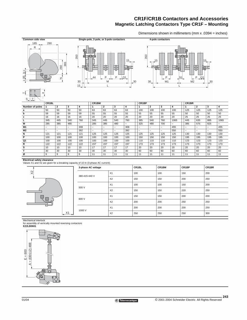
CR1F/CR1B Contactors and AccessoriesMagnetic Latching Contactors Type CR1F – Mounting
01/04
Common side view
CR1BLNumber of poles 1 2a 50 50b 59 59c 16 16L 345 445M 285 385M1 – –M2 – –N 121 121P 100 100Q1 100 100R 122 122S 10 10T 30 30Ø 9 9
Electrical safety clearanceValues X1 and X2 are given for a br
Mechanical interlock for assembly of vertically mounted rEZ2LB0601
a
TS ¯
T
R
290185
85c
bc
X2
A =
(E
Ð11
2) 4
88
E =
600
Dimensions shown in millimeters (mm x .0394 = inches)
Single-pole, 2-pole, or 3-pole contactors 4-pole contactors
CR1BM CR1BP CR1BR3 4 1 2 3 4 1 2 3 4 1 2 3 450 50 63 63 63 63 100 100 100 100 125 125 125 12559 59 55 55 55 55 55 55 55 55 50 50 50 5016 16 20 20 20 20 20 20 20 20 25 25 25 25540 760 345 445 540 760 385 540 760 1065 445 635 885 1065480 – 285 385 480 – 325 480 700 – 385 575 825 –– 308 – – – 308 – – – 455 – – – 455– 392 – – – 392 – – – 550 – – – 550121 121 125 125 125 125 125 125 125 125 130 130 130 130100 100 100 100 100 100 150 150 150 150 195 195 195 195100 100 100 100 100 100 110 110 110 110 123 123 123 123122 122 157 157 157 157 173 173 173 173 173 173 173 17310 10 17 17 17 17 20 20 20 20 20 20 20 2030 30 30 30 30 30 60 60 60 60 60 60 60 609 9 11 11 11 11 11 11 11 11 11 11 11 11
eaking capacity of 10 In (3-phase AC current).
3-phase AC voltage CR1BL CR1BM CR1BP CR1BR
380-415-440 VX1 100 100 150 200
X2 150 150 200 250
500 VX1 100 100 150 200
X2 150 150 220 250
600 VX1 150 150 200 200
X2 200 200 250 250
1000 VX1 200 200 200 250
X2 250 250 250 300
eversing contactors
260
N
365
44 P P Q1
30
15
30M
L
15
350
350
P
30
15
30M1
L
P Q151
M2
15
X1
243© 2001-2004 Schneider Electric All Rights Reserved
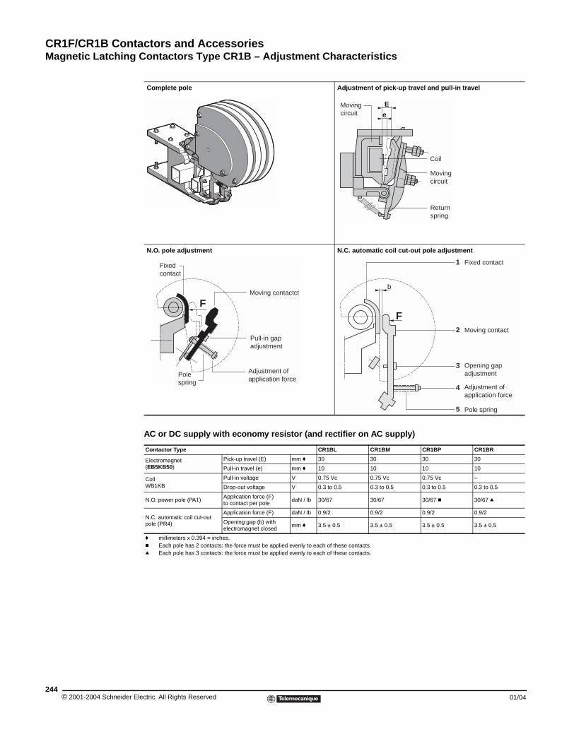
CR1F/CR1B Contactors and AccessoriesMagnetic Latching Contactors Type CR1B – Adjustment Characteristics
© 2001-2004 Schneider E244
AC or DC supply with economy resistor (and rectifier on AC supply)
Magnetic Latching Contactors Type CR1B - Adjustment Characteristics
Complete pole Adjustment of pick-up travel and pull-in travel
N.O. pole adjustment N.C. automatic coil cut-out pole adjustment
Contactor Type CR1BL CR1BM CR1BP CR1BR
Electromagnet (EB5KB50)
Pick-up travel (E) mm f 30 30 30 30
Pull-in travel (e) mm f 10 10 10 10
Coil WB1KB
Pull-in voltage V 0.75 Vc 0.75 Vc 0.75 Vc –
Drop-out voltage V 0.3 to 0.5 0.3 to 0.5 0.3 to 0.5 0.3 to 0.5
N.O. power pole (PA1)Application force (F) to contact per pole
daN / lb 30/67 30/67 30/67 c 30/67 q
N.C. automatic coil cut-out pole (PR4)
Application force (F) daN / lb 0.9/2 0.9/2 0.9/2 0.9/2
Opening gap (b) with electromagnet closed
mm f 3.5 ± 0.5 3.5 ± 0.5 3.5 ± 0.5 3.5 ± 0.5
f millimeters x 0.394 = inches.c Each pole has 2 contacts: the force must be applied evenly to each of these contacts.q Each pole has 3 contacts: the force must be applied evenly to each of these contacts.
E
eMoving circuit
Coil
Moving circuit
Returnspring
FMoving contactct
Pull-in gapadjustment
Adjustment ofapplication force
Pole spring
Fixed contact
b
F
1
2
3
4
5
Fixed contact
Moving contact
Opening gapadjustment
Adjustment of application force
Pole spring
lectric All Rights Reserved 01/04
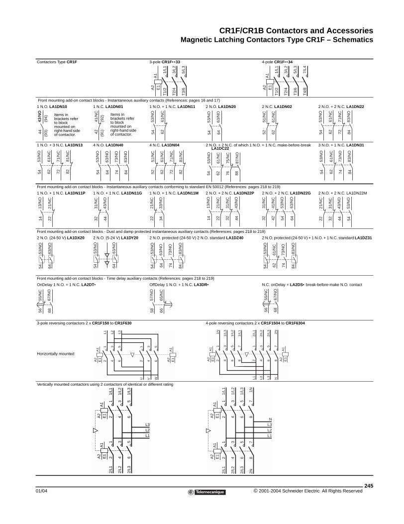
CR1F/CR1B Contactors and AccessoriesMagnetic Latching Contactors Type CR1F – Schematics
01/04
Contactors Type CR1F
Front mounting add-on contact bloc
1 N.O. LA1DN10 1 N
1 N.O. + 3 N.C. LA1DN13 4 N
Front mounting add-on contact block
1 N.O. + 1 N.C. LA1DN11P 1 N
Front mounting add-on contact block
2 N.O. (24-50 V) LA1DX20 2 N
Front mounting add-on contact block
OnDelay 1 N.O. + 1 N.C. LA2DT•
3-pole reversing contactors 2 x CR1
Horizontally mounted
Vertically mounted contactors using
Items in brackets refer to block mounted on right-hand side of contactor.
43 N
O44
43/N
O
(94)
(93) 42
41/N
C
7271
/NC
6261
/NC
53/N
O54 82
81/N
C
53/N
O54
2221
/NC
13/N
O14 32
31/N
C
53/N
O54
63/N
O64
53/N
O54
55/N
C56
67/N
O68
A1
A2
Magnetic Latching Contactors Type CR1F - Schematics
nnn3-pole CR1F•• 33 4-pole CR1F•• 34
ks - Instantaneous auxiliary contacts (References: pages 16 and 17)
.C. LA1DN01 1 N.O. + 1 N.C. LA1DN11 2 N.O. LA1DN20 2 N.C. LA1DN02 2 N.O. + 2 N.C. LA1DN22
.O. LA1DN40 4 N.C. LA1DN04 2 N.O. + 2 N.C. of which 1 N.O. + 1 N.C. make-before-break LA1DC22
3 N.O. + 1 N.C. LA1DN31
s - Instantaneous auxiliary contacts conforming to standard EN 50012 (References: pages 218 to 219)
.O. + 1 N.C. LA1DN11G 1 N.O. + 1 N.C. LA1DN11M 2 N.O. + 2 N.C. LA1DN22P 2 N.O. + 2 N.C. LA1DN22G 2 N.O. + 2 N.C. LA1DN22M
s - Dust and damp protected instantaneous auxiliary contacts (References: pages 218 to 219)
.O. (5-24 V) LA1DY20 2 N.O. protected (24-50 V) 2 N.O. standard LA1DZ40 2 N.O. protected (24-50 V) + 1 N.O. + 1 N.C. standard LA1DZ31
s - Time delay auxiliary contacts (References: pages 218 to 219)
OffDelay 1 N.O. + 1 N.C. LA3DR• N.C. onDelay + LA2DS• break-before-make N.O. contact
F150 to CR1F630 4-pole reversing contactors 2 x CR1F1504 to CR1F6304
2 contactors of identical or different rating
A1
A2
E1
1/L1
T1/
2
3/L2
T2/
4
5/L3
T3/
6
A1
A2
E1
1/L1
T1/
2
3/L2
T2/
4
5/L3
T3/
6
7/L4
T4/
8
Items in brackets refer to block mounted on right-hand side of contactor.(9
1)(9
2)
53/N
O54 62
61/N
C
63/N
O64
53/N
O54 52
51/N
C
6261
/NC
7271
/NC
6261
/NC
83/N
O84
53/N
O54
83/N
O84
73/N
O74
63/N
O64 52
51/N
C
6261
/NC
7271
/NC
8281
/NC
53/N
O54
61/N
C62
87/N
O88
75/N
C76 62
61/N
C
83/N
O84
73/N
O74
53/N
O54
43/N
O44 22
21/N
C
33/N
O34 22
21/N
C
3231
/NC
13/N
O14
43/N
O44 32
31/N
C
4241
/NC
63/N
O64
53/N
O54 22
21/N
C
3231
/NC
53/N
O54
43/N
O44
63/N
O64
53/N
O54
83/N
O84
63/N
O64
73/N
O74 62
61/N
C
53/N
O54
83/N
O84
73/N
O74
6665
/NC
57/N
O58
67/N
O68
55/N
C56
A1
A2
E1
E1
12
34
56
L1
L2
L3
12
34
56
U V W
A1
A2
E1
A1
A2
E1
12
34
56
1N
1/L
3
1/L
2
12
34
56
L1
L2
L3
78
1/L
1
2/L
1
2/L
2
2/L
3
78
N2N
A1
A2
E1
12
34
1/L1
1/L2
12
34
2/L1
2/L2
56
1/L3
56
2/L3
A1
A2
E1
L3L2L1
A1
A2
E1
12
34
78
1/L1
1/L2 1N
12
34
78
2/L1
2/L2
2N
56
1/L3
56
2/L3
A1
A2
E1
L3L2L1
N
245© 2001-2004 Schneider Electric All Rights Reserved
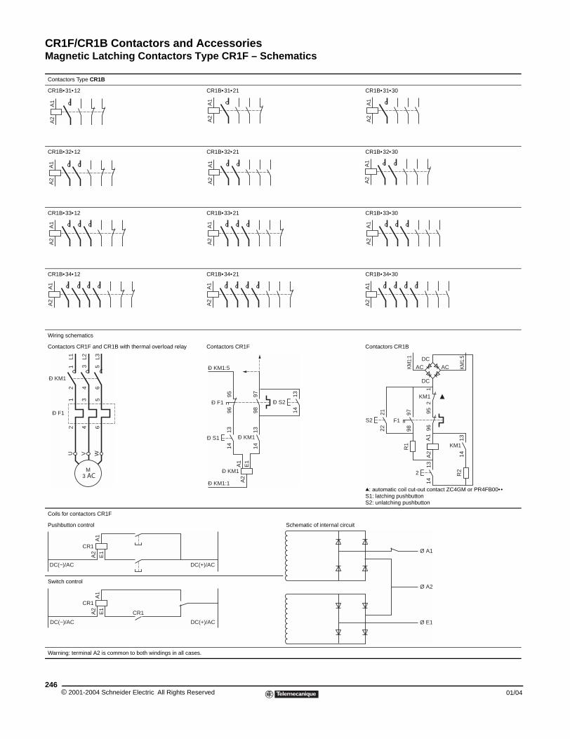
CR1F/CR1B Contactors and AccessoriesMagnetic Latching Contactors Type CR1F – Schematics
© 2001-2004 Schneider E246
Contactors Type CR1B
CR1B•31•12
CR1B•32•12
CR1B•33•12
CR1B•34•12
Wiring schematics
Contactors CR1F and CR1B with th
Coils for contactors CR1F
Pushbutton control
Switch control
Warning: terminal A2 is common to
A1
A2
A1
A2
A1
A2
A1
A2
2 4 6
L1 L2 L3
1 3 5
Ð KM1
U W
M 3 AC
V
1 3 5
2 4 6
Ð F1
A1
A2
CR1
E1
DC(−)/AC
A1
A2
CR1
E1
C
DC(−)/AC
CR1B•31•21 CR1B•31•30
CR1B•32•21 CR1B•32•30
CR1B•33•21 CR1B•33•30
CR1B•34•21 CR1B•34•30
ermal overload relay Contactors CR1F Contactors CR1B
q: automatic coil cut-out contact ZC4GM or PR4FB00••S1: latching pushbuttonS2: unlatching pushbutton
Schematic of internal circuit
both windings in all cases.
A1
A2
A1
A2
A1
A2
A1
A2
A1
A2
A1
A2
A1
A2
A1
A2
1314
Ð KM1
9596
Ð F1
1314
Ð S1
9798
1314
Ð S2
A1
E1
A2
Ð KM1
Ð KM1:1
Ð KM1:5
9695
1314
2
1314
KM1
A1
A2
R1
9798
R2
F12
1
KM1
KM1:
1
KM1:
5
2122
S2
AC AC
DC
DC
DC(+)/AC
Ø A1
Ø E1
Ø A2
R1
DC(+)/AC
lectric All Rights Reserved 01/04
Catalog Number Index
AAB1G . . . . . . . . . . . . . . . . . . . . . . . 56, 72AB1R . . . . . . . . . . . . . . . . . . . . . . . 56, 72AM1DP200 . . . . . . . . . . . . . . . . . . 56, 72AM1ED200 . . . . . . . . . . . . . . . . . . 56, 72CCR1BL31 . . . . . . . . . . . . . . . . . . . . . . 230CR1BL32 . . . . . . . . . . . . . . . . . . . . . . 230CR1BL33 . . . . . . . . . . . . . . . . . . . . . . 230CR1BL34 . . . . . . . . . . . . . . . . . . . . . . 230CR1BM31 . . . . . . . . . . . . . . . . . . . . . 230CR1BM32 . . . . . . . . . . . . . . . . . . . . . 230CR1BM33 . . . . . . . . . . . . . . . . . . . . . 230CR1BM34 . . . . . . . . . . . . . . . . . . . . . 230CR1BP31 . . . . . . . . . . . . . . . . . . . . . 230CR1BP32 . . . . . . . . . . . . . . . . . . . . . 230CR1BP33 . . . . . . . . . . . . . . . . . . . . . 230CR1BP34 . . . . . . . . . . . . . . . . . . . . . 230CR1BR31 . . . . . . . . . . . . . . . . . . . . . 230CR1BR32 . . . . . . . . . . . . . . . . . . . . . 230CR1BR33 . . . . . . . . . . . . . . . . . . . . . 230CR1BR34 . . . . . . . . . . . . . . . . . . . . . 230CR1F150 . . . . . . . . . . . . . . . . . . . . . . 230CR1F1504 . . . . . . . . . . . . . . . . . . . . . 230CR1F185 . . . . . . . . . . . . . . . . . . 230, 233CR1F1854 . . . . . . . . . . . . . . . . . 230, 233CR1F265 . . . . . . . . . . . . . . . . . . 230, 233CR1F2654 . . . . . . . . . . . . . . . . . 230, 233CR1F400 . . . . . . . . . . . . . . . . . . 230, 233CR1F4004 . . . . . . . . . . . . . . . . . 230, 233CR1F500 . . . . . . . . . . . . . . . . . . 230, 233CR1F5004 . . . . . . . . . . . . . . . . . 230, 233CR1F630 . . . . . . . . . . . . . . . . . . 230, 233CR1F6304 . . . . . . . . . . . . . . . . . 230, 233DDE1DS1 . . . . . . . . . . . . . . . . . . . . . . . 166DE1DS1A04. . . . . . . . . . . . . . . . . . . . 166DE1DS1A05. . . . . . . . . . . . . . . . . . . . 166DE1DS1A13. . . . . . . . . . . . . . . . . . . . 166DE1DS2 . . . . . . . . . . . . . . . . . . . . . . . 166DE1DS2A04. . . . . . . . . . . . . . . . . . . . 166DE1DS2A05. . . . . . . . . . . . . . . . . . . . 166DE1DS2A13. . . . . . . . . . . . . . . . . . . . 166DR2SC0010 . . . . . . . . . . . . . . . . . . . 237DR2SC0027 . . . . . . . . . . . . . . . . . . . 237DR2SC0033 . . . . . . . . . . . . . . . . . . . 237DR2SC0039 . . . . . . . . . . . . . . . 209, 237DR2SC0047 . . . . . . . . . . . . . . . 209, 237DR2SC0056 . . . . . . . . . . . . . . . . . . . 237DR2SC0068 . . . . . . . . . . . . . . . . . . . 237DR2SC0100 . . . . . . . . . . . . . . . . . . . 237DR2SC0120 . . . . . . . . . . . . . . . . . . . 237DR2SC0150 . . . . . . . . . . . . . . . . . . . 237DR2SC0180 . . . . . . . . . . . . . . . . . . . 237DR2SC0220 . . . . . . . . . . . . . . . 209, 237DR2SC0270 . . . . . . . . . . . . . . . 209, 237DR2SC0330 . . . . . . . . . . . . . . . 209, 237DR2SC0390 . . . . . . . . . . . . . . . 209, 237DR2SC0470 . . . . . . . . . . . . . . . . . . . 237DR2SC0560 . . . . . . . . . . . . . . . . . . . 237DR2SC0680 . . . . . . . . . . . . . . . . . . . 237DR2SC1000 . . . . . . . . . . . . . . . 209, 237DR2SC1200 . . . . . . . . . . . . . . . . . . . 209DR2SC3300 . . . . . . . . . . . . . . . . . . . 209DR2SC3900 . . . . . . . . . . . . . . . . . . . 209DR2SC4700 . . . . . . . . . . . . . . . . . . . 209DR5TE1S . . . . . . . . . . . . . . . . . . . . . 237DR5TE1U . . . . . . . . . . . . . . . . . . . . . 237DV1RC155 . . . . . . . . . . . . . . . . . . . . 238DV1RC201 . . . . . . . . . . . . . . . . . . . . 238DV1RT292 . . . . . . . . . . . . . . . . . . . . . 238DX1AP25 . . . . . . . . . . . 56, 72, 134, 137DX1AP26 . . . . . . . . . . . . . . . . . . . . . . .134DZ2FF1 . . . . . . . . . . . . . . . . . . . 198, 220DZ2FF6 . . . . . . . . . . . . . . . . . . . . . . . 198DZ2FG1 . . . . . . . . . . . . . . . . . . . . . . 198DZ2FG6 . . . . . . . . . . . . . . . . . . 198, 220DZ2FH1 . . . . . . . . . . . . . . . . . . . 198, 220DZ2FH6 . . . . . . . . . . . . . . . . . . . 198, 220DZ2FJ1 . . . . . . . . . . . . . . . . . . . 198, 220DZ2FJ6 . . . . . . . . . . . . . . . . . . . . . . . 198DZ2FK1 . . . . . . . . . . . . . . . . . . . 198, 220DZ2FK6 . . . . . . . . . . . . . . . . . . . . . . . 198DZ2FL . . . . . . . . . . . . . . . . . . . . . . . . 198DZ2FL1 . . . . . . . . . . . . . . . . . . . . . . . 220DZ2FL2 . . . . . . . . . . . . . . . . . . . . . . . 220DZ2FL3 . . . . . . . . . . . . . . . . . . . . . . . 220DZ2FL6 . . . . . . . . . . . . . . . . . . . . . . . 198DZ2FX6 . . . . . . . . . . . . . . . . . . . . . . . 198DZ3FA3 . . . . . . . . . . . . . . . . . . . . . . . 196DZ3GA3 . . . . . . . . . . . . . . . . . . . . . . 196
DZ3HA3 . . . . . . . . . . . . . . . . . . . . . . . 196DZ3JA3 . . . . . . . . . . . . . . . . . . . . . . . 196DZF2FX1 . . . . . . . . . . . . . . . . . . . . . . 198EET1KB50 . . . . . . . . . . . . . . . . . . . . . . 238EZ2LB0601 . . . . . . . . . . . . . . . . . . . . 231GGV1G09 . . . . . . . . . . . . . . . . . . . . . . . .114GV2G245 . . . . . . . . . . . . . . . . . . . . . . .114GV2G445 . . . . . . . . . . . . . . . . . . . . . . .114GV2ME01 . . . . . . . . . . . . . . . . . . . . . 177GV2ME02 . . . . . . . . . . . . . . . . . . . . . 177GV2ME03 . . . . . . . . . . . . . . . . . . . . . 177GV2ME04 . . . . . . . . . . . . . . . . . . . . . 177GV2ME05 . . . . . . . . . . . . . . . . . . . . . 177GV2ME06 . . . . . . . . . . . . . . . . . . . . . 177GV2ME07 . . . . . . . . . . . . . . . . . . . . . 177GV2ME08 . . . . . . . . . . . . . . . . . . . . . 177GV2ME10 . . . . . . . . . . . . . . . . . . . . . 177GV2ME14 . . . . . . . . . . . . . . . . . . . . . 177GV2ME16 . . . . . . . . . . . . . . . . . . . . . 177GV2ME20 . . . . . . . . . . . . . . . . . . . . . 177GV2ME21 . . . . . . . . . . . . . . . . . . . . . 177GV2ME22 . . . . . . . . . . . . . . . . . . . . . 177GV2ME32 . . . . . . . . . . . . . . . . . . . . . 177GV3A01 . . . . . . . . . . . . . . . . . . . . . . . 177GV3A02 . . . . . . . . . . . . . . . . . . . . . . . 177GV3A03 . . . . . . . . . . . . . . . . . . . . . . . 177GV3A05 . . . . . . . . . . . . . . . . . . . . . . . 177GV3A06 . . . . . . . . . . . . . . . . . . . . . . . 177GV3A08 . . . . . . . . . . . . . . . . . . . . . . . 177GV3A09 . . . . . . . . . . . . . . . . . . . . . . . 177GV3A7 . . . . . . . . . . . . . . . . . . . . . . . . 177GV3ME06 . . . . . . . . . . . . . . . . . . . . . 177LLA . . . . . . . . . . . . . . . . . . . . . . . . . . . 231LA1D . . . . . . . . . . . . . . . . . . . . . . . . . 231LA1DN11G . . . . . . . . . . . . . . . . . . . . 176LA1DX02 . . . . . . . . . . . . . . . . . . . . . . 107LA1DX20 . . . . . . . . . . 107, 195, 216, 245LA1DY20 . . . . . . . . . . 107, 195, 216, 245LA1DZ31 . . . . . . . . . . 107, 195, 216, 245LA1DZ40 . . . . . . . . . . 107, 195, 216, 245LA1KN02 . . . . . . . . . . . . . . . . . . . . 55, 72LA1KN023 . . . . . . . . . . . . . . . . . . . 55, 72LA1KN027 . . . . . . . . . . . . . . . . . . . 55, 72LA1KN02M . . . . . . . . . . . . . . . . . . 55, 72LA1KN04 . . . . . . . . . . . . . . . . . . . . . . . 55LA1KN043 . . . . . . . . . . . . . . . . . . . . . . 55LA1KN047 . . . . . . . . . . . . . . . . . . . . . . 55LA1KN11 . . . . . . . . . . . . . . . . . . . . 55, 72LA1KN113 . . . . . . . . . . . . . . . . . . . 55, 72LA1KN117 . . . . . . . . . . . . . . . . . . . 55, 72LA1KN11M . . . . . . . . . . . . . . . . . . 55, 72LA1KN11P . . . . . . . . . . . . . . . . . . . 55, 72LA1KN13 . . . . . . . . . . . . . . . . . . . . . . . 55LA1KN133 . . . . . . . . . . . . . . . . . . . . . . 55LA1KN137 . . . . . . . . . . . . . . . . . . . . . . 55LA1KN13M . . . . . . . . . . . . . . . . . . . . . 55LA1KN20 . . . . . . . . . . . . . . . . . . . . 55, 72LA1KN203 . . . . . . . . . . . . . . . . . . . 55, 72LA1KN207 . . . . . . . . . . . . . . . . . . . 55, 72LA1KN22 . . . . . . . . . . . . . . . . . . . . . . . 55LA1KN223 . . . . . . . . . . . . . . . . . . . . . . 55LA1KN227 . . . . . . . . . . . . . . . . . . . . . . 55LA1KN22M . . . . . . . . . . . . . . . . . . . . . 55LA1KN22P . . . . . . . . . . . . . . . . . . . . . . 55LA1KN31 . . . . . . . . . . . . . . . . . . . . . . . 55LA1KN313 . . . . . . . . . . . . . . . . . . . . . . 55LA1KN317 . . . . . . . . . . . . . . . . . . . . . . 55LA1KN31M . . . . . . . . . . . . . . . . . . . . . 55LA1KN40 . . . . . . . . . . . . . . . . . . . . . . . 55LA1KN403 . . . . . . . . . . . . . . . . . . . . . . 55LA1KN407 . . . . . . . . . . . . . . . . . . . . . . 55LA2KT2E . . . . . . . . . . . . . . . . . . . . 55, 72LA2KT2U . . . . . . . . . . . . . . . . . . . . 55, 72LA4DA2E . . . . . . . . . . . . . . . . . . . . . . .112LA4DA2G . . . . . . . . . . . . . . . . . . . . . . .112LA4DA2U . . . . . . . . . . . . . . . . . . . . . . .112LA4DA2N . . . . . . . . . . . . . . . . . . . . . . .112LA4DB2B . . . . . . . . . . . . . . . . . . . . . . .112LA4DB2S . . . . . . . . . . . . . . . . . . . . . . .112LA4DB3B . . . . . . . . . . . . . . . . . . . . . . .112LA4DB3S . . . . . . . . . . . . . . . . . . . . . . .112LA4DC1U . . . . . . . . . . . . . . . . . . . . . . .112LA4DC3U . . . . . . . . . . . . . . . . . . . . . . .112LA4DE2E . . . . . . . . . . . . . . . . . . . . . . .112LA4DE2G . . . . . . . . . . . . . . . . . . . . . . .112LA4DE2U . . . . . . . . . . . . . . . . . . . . . . .112LA4DE3E . . . . . . . . . . . . . . . . . . . . . . .112LA4DE3G . . . . . . . . . . . . . . . . . . . . . . .112
LA4DE3U . . . . . . . . . . . . . . . . . . . . . . 112LAD4RCE . . . . . . . . . . . . . . . . . . . . . . 112LAD4RCU . . . . . . . . . . . . . . . . . . . . . . 112LAD4TB. . . . . . . . . . . . . . . . . . . . . . . . 112LAD4TS. . . . . . . . . . . . . . . . . . . . . . . . 112LAD4VE . . . . . . . . . . . . . . . . . . . . . . . 112LAD4VG . . . . . . . . . . . . . . . . . . . . . . . 112LAD4VU . . . . . . . . . . . . . . . . . . . . . . . 112LA4DFBQ . . . . . . . . . . . . . . . . . . . . . . 111LA4DFB. . . . . . . . . . . . . . . . . . . . . . . . 111LA4DFE. . . . . . . . . . . . . . . . . . . . . . . . 111LA4DLB. . . . . . . . . . . . . . . . . . . . . . . . 111LA4DLE. . . . . . . . . . . . . . . . . . . . . . . . 111LA4DMK . . . . . . . . . . . . . . . . . . . . . . . 111LA4DMU . . . . . . . . . . . . . . . . . . . . . . . 111LA4DT0U . . . . . . . . . . . . . . . . . . . . . . 111LA4DT2U . . . . . . . . . . . . . . . . . . . . . . 111LA4DT4U . . . . . . . . . . . . . . . . . . . . . . 111LA4DWB . . . . . . . . . . . . . . . . . . . . . . . 111LA4FRCE . . . . . . . . . . . . . . . . . . . . . . 196LA4FRCF . . . . . . . . . . . . . . . . . . . . . . 196LA4FRCP . . . . . . . . . . . . . . . . . . . . . . 196LA4FRCV . . . . . . . . . . . . . . . . . . . . . . 196LA4FRVE . . . . . . . . . . . . . . . . . . . . . . 196LA4FRVF. . . . . . . . . . . . . . . . . . . . . . . 196LA4FRVP . . . . . . . . . . . . . . . . . . . . . . 196LA4FRVV . . . . . . . . . . . . . . . . . . . . . . 196LA4FTE . . . . . . . . . . . . . . . . . . . . . . . . 196LA4FTF . . . . . . . . . . . . . . . . . . . . . . . . 196LA4FTP . . . . . . . . . . . . . . . . . . . . . . . . 196LA4FTV . . . . . . . . . . . . . . . . . . . . . . . . 196LA4FDE. . . . . . . . . . . . . . . . . . . . . . . . 196LA4FDF. . . . . . . . . . . . . . . . . . . . . . . . 196LA4FDP. . . . . . . . . . . . . . . . . . . . . . . . 196LA4FDV. . . . . . . . . . . . . . . . . . . . . . . . 196LA4KA1U . . . . . . . . . . . . . . . . . . . . . . . 56LA4KC1B . . . . . . . . . . . . . . . . . . . . . . . 56LA4KC1E . . . . . . . . . . . . . . . . . . . . . . . 56LA4KE1B . . . . . . . . . . . . . . . . . . . . . . . 56LA4KE1E . . . . . . . . . . . . . . . . . . . . . . . 56LA4KE1FC . . . . . . . . . . . . . . . . . . . . . . 56LA4KE1UG . . . . . . . . . . . . . . . . . . . . . . 56LA4SPX. . . . . . . . . . . . . . . . . . . . . . . . 108LA5D1158031 . . . . . . . . . . . . . . . . . . . 114LA5D150803 . . . . . . . . . . . . . . . . . . . . 114LA5D115804 . . . . . . . . . . . . . . . . . . . . 114LA5D11550 . . . . . . . . . . . . . . . . . . . . . 114LA5D15050B. . . . . . . . . . . . . . . . . . . . 114LA5D115450B. . . . . . . . . . . . . . . . . . . 114LA5F115450 . . . . . . . . . . . . . . . . . . . . 199LA5F11550 . . . . . . . . . . . . . . . . . . . . . 199LA5F150450 . . . . . . . . . . . . . . . . 199, 238LA5F15050 . . . . . . . . . . . . . . . . . 199, 238LA5F185450 . . . . . . . . . . . . . . . . 199, 238LA5F18550 . . . . . . . . . . . . . . . . . 199, 238LA5F225450 . . . . . . . . . . . . . . . . . . . . 199LA5F22550 . . . . . . . . . . . . . . . . . . . . . 199LA5F265450 . . . . . . . . . . . . . . . . 199, 238LA5F26550 . . . . . . . . . . . . . . . . . 199, 238LA5F330450 . . . . . . . . . . . . . . . . . . . . 199LA5F33050 . . . . . . . . . . . . . . . . . . . . . 199LA5F400250 . . . . . . . . . . . . . . . . . . . . 199LA5F400450 . . . . . . . . . . . . . . . . 199, 238LA5F40050 . . . . . . . . . . . . . . . . . 199, 238LA5F400802 . . . . . . . . . . . . . . . . . . . . 199LA5F400803 . . . . . . . . . . . . . . . . 199, 238LA5F400804 . . . . . . . . . . . . . . . . 199, 238LA5F500250 . . . . . . . . . . . . . . . . . . . . 199LA5F500450 . . . . . . . . . . . . . . . . 199, 238LA5F50050 . . . . . . . . . . . . . . . . . 199, 238LA5F500802 . . . . . . . . . . . . . . . . . . . . 199LA5F500803 . . . . . . . . . . . . . . . . 199, 238LA5F500804 . . . . . . . . . . . . . . . . 199, 238LA5F630250 . . . . . . . . . . . . . . . . . . . . 199LA5F630450 . . . . . . . . . . . . . . . . 199, 238LA5F63050 . . . . . . . . . . . . . . . . . 199, 238LA5F630802 . . . . . . . . . . . . . . . . . . . . 199LA5F630803 . . . . . . . . . . . . . . . . 199, 238LA5F630804 . . . . . . . . . . . . . . . . 199, 238LA5F780150 . . . . . . . . . . . . . . . . . . . . 199LA5F780801 . . . . . . . . . . . . . . . . . . . . 199LA5F780803 . . . . . . . . . . . . . . . . . . . . 199LA5F780804 . . . . . . . . . . . . . . . . . . . . 199LA5F80050 . . . . . . . . . . . . . . . . . . . . . 199LA5F800803 . . . . . . . . . . . . . . . . . . . . 199LA5FF431 . . . . . . . . . . . . . . . . . 199, 238LA5FF441 . . . . . . . . . . . . . . . . . 199, 238LA5FG431 . . . . . . . . . . . . . . . . . 199, 238LA5FG441 . . . . . . . . . . . . . . . . . 199, 238LA5FH431 . . . . . . . . . . . . . . . . . 199, 238LA5FH441 . . . . . . . . . . . . . . . . . 199, 238
LA6DK10 . . . . . . . . . . . . . . . . . . . . . . .108LA6DK20 . . . . . . . . . . . . . . . . . . . . . . .108LA7D03 . . . . . . . . . . . . . . . . . . . .137, 221LA7D1020 . . . . . . . . . . . . . . . . . .137, 221LA7D1064 . . . . . . . . . . . . . . . . . . . . . . 137LA7D2064 . . . . . . . . . . . . . . . . . . . . . . 137LA7D305 . . . . . . . . . . . . . . . . . . .137, 221LA7D3064 . . . . . . . . . . . . . . . . . . . . . .137LA7D3058 . . . . . . . . . . . . . . . . . . . . . .137LA7D901 . . . . . . . . . . . . . . . . . . .137, 221LA7D902 . . . . . . . . . . . . . . . . . . . . . . .137LA7D903 . . . . . . . . . . . . . . . . . . .137, 221LA7F401 . . . . . . . . . . . . . . . . . . .197, 221LA7F402 . . . . . . . . . . . . . . . . . . .197, 221LA7F403 . . . . . . . . . . . . . . . . . . .197, 221LA7F404 . . . . . . . . . . . . . . . . . . .197, 221LA7F405 . . . . . . . . . . . . . . . . . . .197, 221LA7F406 . . . . . . . . . . . . . . . . . . .197, 221LA7F407 . . . . . . . . . . . . . . . . . . . . . . .221LA7F701 . . . . . . . . . . . . . . . . . . . . . . .221LA7F702 . . . . . . . . . . . . . . . . . . . . . . .221LA7F703 . . . . . . . . . . . . . . . . . . . . . . .221LA7F901 . . . . . . . . . . . . . . . . . . . . . . .221LA7F902 . . . . . . . . . . . . . . . . . . . . . . .221LA7K0064 . . . . . . . . . . . . . . . . . . . . . . .63LA9AADIS3 . . . . . . . . . . . . . . . . . . . . .155LA9AADIS4 . . . . . . . . . . . . . . . . . . . . .155LA9AADIS5 . . . . . . . . . . . . . . . . . . . . .155LA9AADIS7 . . . . . . . . . . . . . . . . . . . . .155LA9B103 . . . . . . . . . . . . . . . . . . . . . . .231LA9CA06DT. . . . . . . . . . . . . . . . . . . . .155LA9CA06ET. . . . . . . . . . . . . . . . . . . . .155LA9CA06FT . . . . . . . . . . . . . . . . . . . . .155LA9CA06GT . . . . . . . . . . . . . . . . . . . .155LA9CA06HT. . . . . . . . . . . . . . . . . . . . .155LA9CA06IO . . . . . . . . . . . . . . . . . . . . .155LA9CA06JT . . . . . . . . . . . . . . . . . . . . .155LA9CA06LT . . . . . . . . . . . . . . . . . . . . .155LA9CA06NT. . . . . . . . . . . . . . . . . . . . .155LA9CA06ST. . . . . . . . . . . . . . . . . . . . .155LA9CA06UT. . . . . . . . . . . . . . . . . . . . .155LA9CA06VT. . . . . . . . . . . . . . . . . . . . .155LA9CA06WT . . . . . . . . . . . . . . . . . . . .155LA9CA16ST. . . . . . . . . . . . . . . . . . . . .155LA9CA16UT. . . . . . . . . . . . . . . . . . . . .155LA9CA16VT. . . . . . . . . . . . . . . . . . . . .155LA9CA16WT . . . . . . . . . . . . . . . . . . . .155LA9D09907 . . . . . . . . . . . . . . . . . . . . .160LA9D09966 . . . . . . . . . . . . . . . . . . . . . 113LA9D09980 . . . . . . . . . . . . . . . . . . . . .196LA9D09981 . . . . . . . . . . . . . . . . . . . . .196LA9D91 . . . . . . . . . . . . . . . . . . . . . . . .137LA9D11502 . . . . . . . . . . . . . . . . . . . . . .98LA9D115503B . . . . . . . . . . . . . . . . . . . 113LA9D115504 . . . . . . . . . . . . . . . . . . . . 113LA9D115603B . . . . . . . . . . . . . . . . . . . 113LA9D115604 . . . . . . . . . . . . . . . . . . . . 113LA9D115703 . . . . . . . . . . . . . . . . . . . . 113LA9D11569 . . . . . . . . . . . . . . . . . . . . . .98LA9D115704 . . . . . . . . . . . . . . . . . . . .113LA9D1260 . . . . . . . . . . . . . . . . . . . . . . 113LA9D1261 . . . . . . . . . . . . . . . . . . . . . . 113LA9D1263 . . . . . . . . . . . . . . . . . . . . . . 113LA9D12974 . . . . . . . . . . . . . . . . . . . . .149LA9D2561 . . . . . . . . . . . . . . . . . . . . . .113LA9D11569 . . . . . . . . . . . . . . . . . . . . . .98LA9D3260 . . . . . . . . . . . . . . . . . . . . . .113LA9D32974 . . . . . . . . . . . . . . . . . . . . .149LA9D4002 . . . . . . . . . . . . . . . . . . . . . . .98LA9D40961 . . . . . . . . . . . . . . . . . . . . . 113LA9D40963 . . . . . . . . . . . . . . . . . . . . . 113LA9D4017 . . . . . . . . . . . . . . . . . . . . . .149LA9D40961 . . . . . . . . . . . . . . . . . . . . . 113LA9D40963 . . . . . . . . . . . . . . . . . . . . . 113LA9D40973 . . . . . . . . . . . . . . . . . . . . .149LA9D5017 . . . . . . . . . . . . . . . . . . . . . .149LA9D50978 . . . . . . . . . . . . . . . . . . . . . .98LA9D511 . . . . . . . . . . . . . . . . . . . . . . .114LA9D6567 . . . . . . . . . . . . . . . . . . . . . . 113LA9D6569 . . . . . . . . . . . . . . . . . . . . . . .98LA9D730 . . . . . . . . . . . . . . . . . . . . . . .114LA9D8002 . . . . . . . . . . . . . . . . . . . . . . .98LA9D8017 . . . . . . . . . . . . . . . . . . . . . .149LA9D8067 . . . . . . . . . . . . . . . . . . . . . .113LA9D8069 . . . . . . . . . . . . . . . . . . . . . . .98LA9D80961 . . . . . . . . . . . . . . . . . . . . . 113LA9D80962 . . . . . . . . . . . . . . . . . . . . . 113LA9D80963 . . . . . . . . . . . . . . . . . . . . . 113LA9D80973 . . . . . . . . . . . . . . . . . . . . .149LA9D80978 . . . . . . . . . . . . . . . . . . . . . .98LA9D90 . . . . . . . . . . . . . . . . . . . . . .56, 72
24701/04 © 2001-2004 Schneider Electric All Rights Reserved
Catalog Number Index
LA9D901. . . . . . . . . . . . . . . . . . . . . . . .114LA9D92 . . . . . . . . . . . . . . . . . . . . . . . .114LA9D93. . . . . . . . . . . . . . . . . . . . . . . . .114LA9D941 . . . . . . . . . . . . . . . . . . . . . . .114LA9D973 . . . . . . . . . . . . . . . . . . . . 56, 72LA9D9PVGV . . . . . . . . . . . . . . . . . . . . 98LA9E01 . . . . . . . . . . . . . . . . . . . . . 56, 72LA9E02 . . . . . . . . . . . . . . . . . . . . . 56, 72LA9F . . . . . . . . . . . . . . . . . . . . . . . . . 233LA9F103 . . . . . . . . . . . . . . 137, 198, 231LA9F15076 . . . . . . . . . . . . . . . . . . . . 191LA9F15077 . . . . . . . . . . . . . . . . . . . . 193LA9F15082 . . . . . . . . . . . . . . . . . . . . 191LA9F22576 . . . . . . . . . . . . . . . . . . . . 191LA9F22577 . . . . . . . . . . . . . . . . . . . . 193LA9F22582 . . . . . . . . . . . . . . . . . . . . 191LA9F701 . . . . . . . . . . . . . . . . . . 198, 221LA9F702 . . . . . . . . . . . . . . . . . . 198, 221LA9F703 . . . . . . . . . . . . . . . . . . 198, 221LA9F704 . . . . . . . . . . . . . . . . . . . . . . 198LA9F705 . . . . . . . . . . . . . . . . . . . . . . 221LA9F706 . . . . . . . . . . . . . . . . . . . . . . 198LA9F707 . . . . . . . . . . . . . . . . . . . . . . 198LA9F708 . . . . . . . . . . . . . . . . . . . . . . 198LA9F709 . . . . . . . . . . . . . . . . . . . . . . 198LA9F980 . . . . . . . . . . . . . . . . . . . . . . 196LA9FF4F . . . . . . . . . . . . . . 191, 193, 233LA9FF601 . . . . . . . . . . . . . . . . . . . . . 196LA9FF602 . . . . . . . . . . . . . . . . . . . . . 196LA9FF970 . . . . . . . . . . . . . 191, 193, 233LA9FF976 . . . . . . . . . . . . . . . . . 191, 233LA9FF977 . . . . . . . . . . . . . . . . . 193, 233LA9FF979 . . . . . . . . . . . . . . . . . . . . . 197LA9FF980 . . . . . . . . . . . . . . . . . . . . . 197LA9FF981 . . . . . . . . . . . . . . . . . . . . . 197LA9FF982 . . . . . . . . . . . . . . . . . . . . . 191LA9FG4F . . . . . . . . . . . . . . . . . . 193, 233LA9FG4G . . . . . . . . . . . . . 191, 193, 233LA9FG601 . . . . . . . . . . . . . . . . . . . . . 196LA9FG602 . . . . . . . . . . . . . . . . . . . . . 196LA9FG970 . . . . . . . . . . . . . 191, 193, 233LA9FG976 . . . . . . . . . . . . . . . . . 191, 233LA9FG977 . . . . . . . . . . . . . . . . . 193, 233LA9FG979 . . . . . . . . . . . . . . . . . . . . . 197LA9FG980 . . . . . . . . . . . . . . . . . . . . . 197LA9FG981 . . . . . . . . . . . . . . . . . . . . . 197LA9FG982 . . . . . . . . . . . . . . . . . . . . . 193LA9FH4F . . . . . . . . . . . . . . . . . . 193, 233LA9FH4G . . . . . . . . . . . . . . . . . . 193, 233LA9FH4H . . . . . . . . . . . . . . 191, 193, 233LA9FH601 . . . . . . . . . . . . . . . . . . . . . 196LA9FH602 . . . . . . . . . . . . . . . . . . . . . 196LA9FH976 . . . . . . . . . . . . . . . . . 191, 233LA9FH977 . . . . . . . . . . . . . . . . . 193, 233LA9FH982 . . . . . . . . . . . . . . . . . . . . . 191LA9FJ4F . . . . . . . . . . . . . . . . . . 193, 233LA9FJ4G . . . . . . . . . . . . . . . . . . 193, 233LA9FJ4H . . . . . . . . . . . . . . . . . . 193, 233LA9FJ4J . . . . . . . . . . . . . . 191, 193, 233LA9FJ970 . . . . . . . . . . . . . 191, 193, 233LA9FJ976 . . . . . . . . . . . . . . . . . 191, 233LA9FJ977 . . . . . . . . . . . . . . . . . 193, 233LA9FJ979 . . . . . . . . . . . . . . . . . . . . . 197LA9FJ980 . . . . . . . . . . . . . . . . . . . . . 197LA9FJ981 . . . . . . . . . . . . . . . . . . . . . 197LA9FJ982 . . . . . . . . . . . . . . . . . . . . . 191LA9FK4F . . . . . . . . . . . . . . . . . . 193, 233LA9FK4G . . . . . . . . . . . . . . . . . . 193, 233LA9FK4H . . . . . . . . . . . . . . . . . . 193, 233LA9FK4J . . . . . . . . . . . . . . . . . . 193, 233LA9FK4K . . . . . . . . . . . . . . 191, 193, 233LA9FK601 . . . . . . . . . . . . . . . . . . . . . 196LA9FK602 . . . . . . . . . . . . . . . . . . . . . 196LA9FK976 . . . . . . . . . . . . . . . . . 191, 233LA9FK977 . . . . . . . . . . . . . . . . . 193, 233LA9FK979 . . . . . . . . . . . . . . . . . . . . . 197LA9FK980 . . . . . . . . . . . . . . . . . . . . . 197LA9FK981 . . . . . . . . . . . . . . . . . . . . . 197LA9FK982 . . . . . . . . . . . . . . . . . . . . . 191LA9FL4F . . . . . . . . . . . . . . . . . . 193, 233LA9FL4G . . . . . . . . . . . . . . . . . . 193, 233LA9FL4H . . . . . . . . . . . . . . . . . . 193, 233LA9FL4J . . . . . . . . . . . . . . . . . . 193, 233LA9FL4K . . . . . . . . . . . . . . . . . . 193, 233LA9FL4L . . . . . . . . . . . . . . 191, 193, 233LA9FL601 . . . . . . . . . . . . . . . . . . . . . 196LA9FL602 . . . . . . . . . . . . . . . . . . . . . 196LA9FL970 . . . . . . . . . . . . . 191, 193, 233LA9FL976 . . . . . . . . . . . . . . . . . 191, 233LA9FL977 . . . . . . . . . . . . . . . . . 193, 233LA9FL979 . . . . . . . . . . . . . . . . . . . . . 197
LA9FL980 . . . . . . . . . . . . . . . . . . . . . . 197LA9FL981 . . . . . . . . . . . . . . . . . . . . . . 197LA9FL982 . . . . . . . . . . . . . . . . . . . . . . 191LA9FX970 . . . . . . . . . . . . . . . . . . . . . 191LA9FX971u . . . . . . . . . . . . . . . . . . . . 193LA9K0969 . . . . . . . . . . . . . . . . . . . . 56, 72LA9K0970 . . . . . . . . . . . . . . . . . . . . 56, 72LA9P5152 . . . . . . . . . . . . . . . . . . . . . . 114LA9TD32 . . . . . . . . . . . . . . . . . . . . . . . 155LA9TD80 . . . . . . . . . . . . . . . . . . . . . . . 155LAD21 . . . . . . . . . . . . . . . . . . . . . . . . . 114LAD22 . . . . . . . . . . . . . . . . . . . . . . . . . 114LAD23 . . . . . . . . . . . . . . . . . . . . . . . . . 114LAD24 . . . . . . . . . . . . . . . . . . . . . . . . . 114LAD3PVPG . . . . . . . . . . . . . . . . . . . . . 98LAD4 . . . . . . . . . . . . . . . . . . . . . . . . . . 112LAD4BB. . . . . . . . . . . . . . . . 109, 111, 114LAD4BBVE . . . . . . . . . . . . . . . . . . . . . 114LAD4BBVG . . . . . . . . . . . . . . . . . . . . . 114LAD4BBVU . . . . . . . . . . . . . . . . . . . . . 114LAD6K10 . . . . . . . . . . . . . . . . . . . . . . . 108LAD8N11 . . . . . . . . . . . . . . . . . . 107, 176LAD8N20 . . . . . . . . . . . . . . . . . . 107, 176LAD8N02. . . . . . . . . . . . . . . . . . . . . . . 107LAD7C. . . . . . . . . . . . . . . . . . . . . . . . . 137LAD7C2. . . . . . . . . . . . . . . . . . . . . . . . 137LAD7B10 . . . . . . . . . . . . . . . . . . . . . . . 137LAD7B105 . . . . . . . . . . . . . . . . . . . . . 137LAD7305 . . . . . . . . . . . . . . . . . . . . . 137LAD703 . . . . . . . . . . . . . . . . . . . . . . . 137LAD8 . . . . . . . . . . . . . . . . . . . . . . . . . 100LAD9091 . . . . . . . . . . . . . . . . . . . . . . 165LAD9092 . . . . . . . . . . . . . . . . . . . . . . 165LAD91217 . . . . . . . . . . . . . . . . . . . . . 149LAD912GVq . . . . . . . . . . . . . . . . . . . . 149LAD91810 . . . . . . . . . . . . . . . . . . . . . . 165LAD93217 . . . . . . . . . . . . . . . . . . . . . 149LAD96060 . . . . . . . . . . . . . . . . . . . . . . 113LAD9P3 . . . . . . . . . . . . . . . . . . . . . . . . 113LAD9ECT1 . . . . . . . . . . . . . . . . . . . . . 114LAD9ET1 . . . . . . . . . . . . . . . . . . . . . . 114LAD9ET2. . . . . . . . . . . . . . . . . . . . . . . 114LAD9ET3. . . . . . . . . . . . . . . . . . . . . . . 114LAD9ET4. . . . . . . . . . . . . . . . . . . . . . . 114LAD9R1 . . . . . . . . . . . . . . . . . . . . . . . . 98LAD9R1V . . . . . . . . . . . . . . . . . . . . . . . 98LAD9T4 . . . . . . . . . . . . . . . . . . . . . . . . 165LAD9V1 . . . . . . . . . . . . . . . . . . . . . . . . 98LAD9V10 . . . . . . . . . . . . . . . . . . . . . . . 98LAD9V11 . . . . . . . . . . . . . . . . . . . . . . . 98LAD9V12 . . . . . . . . . . . . . . . . . . . . . . . 98LAD9V13 . . . . . . . . . . . . . . . . . . . . . . . 98LAD9V2 . . . . . . . . . . . . . . . . . . . . . . . . 98LAD9V5 . . . . . . . . . . . . . . . . . . . . . . . . 98LAD9V6 . . . . . . . . . . . . . . . . . . . . . . . . 98LADC22 . . . . . . . . . . . . . . . 107, 176, 195LADLVRT. . . . . . . . . . . . . . . . . . . . . . . 109LADN01 . . . . . . . . . . . . . . . 107, 176, 195LADN02 . . . . . . . . . . . . . . . 107, 176, 195LADN04 . . . . . . . . . . . . . . . 107, 176, 195LADN10 . . . . . . . . . . . . . . . 107, 176, 195LADN11 . . . . . . . . . . . . . . . 107, 176, 195LADN11G . . . . . . . . . . . . . . 107, 176, 195LADN11P . . . . . . . . . . . . . . 107, 176, 195LADN13 . . . . . . . . . . . . . . . 107, 176, 195LADN20 . . . . . . . . . . . . . . . 107, 176, 195LADN22 . . . . . . . . . . . . . . . 107, 176, 195LADN22G . . . . . . . . . . . . . . 107, 176, 195LADN22P . . . . . . . . . . . . . . 107, 176, 195LADN31 . . . . . . . . . . . . . . . 107, 176, 195LADN31G . . . . . . . . . . . . . . . . . . . . . . 176LADN31P . . . . . . . . . . . . . . . . . . . . . . 176LADN40 . . . . . . . . . . . . . . . 107, 176, 195LADR0 . . . . . . . . . . . . . . . . 108, 176, 195LADR2 . . . . . . . . . . . . . . . . 108, 176, 195LADR4 . . . . . . . . . . . . . . . . 108, 176, 195LADS2 . . . . . . . . . . . . . . . . 108, 176, 195LADT0 . . . . . . . . . . . . . . . . 108, 176, 195LADT2 . . . . . . . . . . . . . . . . 108, 176, 195LADT4 . . . . . . . . . . . . . . . . 108, 176, 195LC1D09 . . . . . . . . . 88, 91, 149, 175, 176LC1D093 . . . . . . . . . . . . . . . . . . . . 89, 91LC1D096 . . . . . . . . . . . . . . . . 90, 92, 175LC1D098 . . . . . . . . . . . . . . . . . . . . . . . 91LC1D0983 . . . . . . . . . . . . . . . . . . . . . . 91LC1D0986 . . . . . . . . . . . . . . . . . . . . . . 92LC1D099 . . . . . . . . . . . . . . . . . . . . . . 175LC1D115 . . . . . . . . . . . . 88, 91, 149, 175LC1D115004 . . . . . . . . . . . . . . . . . . . . 91LC1D1150046 . . . . . . . . . . . . . . . . . . . 92LC1D1156 . . . . . . . . . . . . . . . 90, 92, 175
LC1D12 . . . . . . . . . 88, 91, 149, 175, 176LC1D123 . . . . . . . . . . . . . . . . . . . . 89, 91LC1D126 . . . . . . . . . . . . . . . . 90, 92, 175LC1D128 . . . . . . . . . . . . . . . . . . . 91, 175LC1D1283 . . . . . . . . . . . . . . . . . . . . . . 91LC1D1286 . . . . . . . . . . . . . . . . . . . . . . 92LC1D129 . . . . . . . . . . . . . . . . . . . . . . 175LC1D150 . . . . . . . . . . . . 88, 91, 149, 175LC1D1506 . . . . . . . . . . . . . . . 90, 92, 175LC1D18 . . . . . . . . . 88, 91, 149, 175, 176LC1D183 . . . . . . . . . . . . . . . . . . . . 89, 91LC1D186 . . . . . . . . . . . . . . . . 90, 92, 175LC1D25 . . . . . . . . . . . . . 88, 91, 175, 176LC1D253 . . . . . . . . . . . . . . . . . . . . 89, 91LC1D256 . . . . . . . . . . . . . . . . 90, 92, 175LC1D258 . . . . . . . . . . . . . . . . . . . 91, 175LC1D2583 . . . . . . . . . . . . . . . . . . . . . . 91LC1D2586 . . . . . . . . . . . . . . . . . . 92, 175LC1D32 . . . . . . . . . . . . . 88, 91, 149, 175LC1D323 . . . . . . . . . . . . . . . . . . . . . . . 89LC1D326 . . . . . . . . . . . . . . . . 90, 92, 175LC1D38 . . . . . . . . . . . . . . . . . 88, 91, 175LC1D383 . . . . . . . . . . . . . . . . . . . . . . . 89LC1D386 . . . . . . . . . . . . . . . . 90, 92, 175LC1D40 . . . . . . . . . . . . . 88, 91, 149, 175LC1D40004 . . . . . . . . . . . . . . . . . . . . . 91LC1D400046 . . . . . . . . . . . . . . . . . . . . 92LC1D40008 . . . . . . . . . . . . . . . . . . . . . 91LC1D400086 . . . . . . . . . . . . . . . . . . . . 92LC1D406 . . . . . . . . . . . . . . . . 90, 92, 175LC1D50 . . . . . . . . . . . . . 88, 91, 149, 175LC1D506 . . . . . . . . . . . . . . . . . . . 90, 175LC1D6LE7 . . . . . . . . . . . . . . . . . . . . . 118LC1D65 . . . . . . . . . . . . . . . . . 88, 91, 175LC1D65004 . . . . . . . . . . . . . . . . . . . . . 91LC1D800046 . . . . . . . . . . . . . . . . . . . . 92LC1D65008 . . . . . . . . . . . . . . . . . . . . . 91LC1D800086 . . . . . . . . . . . . . . . . . . . . 92LC1D806 . . . . . . . . . . . . . . . . 90, 92, 175LC1D80 . . . . . . . . . . . . . 88, 91, 149, 175LC1D80004 . . . . . . . . . . . . . . . . . . . . . 91LC1D800046 . . . . . . . . . . . . . . . . . . . . 92LC1D80008 . . . . . . . . . . . . . . . . . . . . . 91LC1D800086 . . . . . . . . . . . . . . . . . . . . 92LC1D806 . . . . . . . . . . . . . . . . 90, 92, 175LC1D95 . . . . . . . . . . . . . . 88, 91, 92, 175LC1D956 . . . . . . . . . . . . . . . . . . . 90, 175LC1DFK02 . . . . . . . . . . . . . . . . . . . . 142LC1DFK11 . . . . . . . . . . . . . . . . . . . . 142LC1DGK02 . . . . . . . . . . . . . . . . . . . . 142LC1DGK11 . . . . . . . . . . . . . . . . . . . . 142LC1DLK02 . . . . . . . . . . . . . . . . . . . . . 142LC1DLK11 . . . . . . . . . . . . . . . . . . . . . 142LC1DMK02 . . . . . . . . . . . . . . . . . . . . 142LC1DMK11 . . . . . . . . . . . . . . . . . . . . 142LC1DPK12 . . . . . . . . . . . . . . . . . . . . 142LC1DT188 . . . . . . . . . . . . . . . . . . . . . . 91LC1DT1886 . . . . . . . . . . . . . . . . . . . . . 92LC1DT20 . . . . . . . . . . . . . . . . . . . . . . . 91LC1DT203 . . . . . . . . . . . . . . . . . . . . . . 91LC1DT206 . . . . . . . . . . . . . . . . . . . . . . 92LC1DT25 . . . . . . . . . . . . . . . . . . . 91, 175LC1DT253 . . . . . . . . . . . . . . . . . . . . . . 91LC1DT256 . . . . . . . . . . . . . . . . . . 92, 175LC1DT2583 . . . . . . . . . . . . . . . . . . . . . 91LC1DT32 . . . . . . . . . . . . . . . . . . . . . . . 91LC1DT323 . . . . . . . . . . . . . . . . . . . . . . 91LC1DT326 . . . . . . . . . . . . . . . . . . . . . . 92LC1DT40 . . . . . . . . . . . . . . . . . . . 91, 175LC1DT403 . . . . . . . . . . . . . . . . . . . . . . 91LC1DT406 . . . . . . . . . . . . . . . . . . 92, 175LC1DTK12 . . . . . . . . . . . . . . . . . . . . 142LC1DWK12 . . . . . . . . . . . . . . . . . . . . 142LC1F115 . . . . . . . . . . . . . . . . . . 188, 189LC1F1154 . . . . . . . . . . . . . . . . . 188, 189LC1F150 . . . . . . . . . . . . . . . . . . 188, 189LC1F1504 . . . . . . . . . . . . . . . . . 188, 189LC1F185 . . . . . . . . . . . . . . . . . . 188, 189LC1F1854 . . . . . . . . . . . . . . . . . 188, 189LC1F225 . . . . . . . . . . . . . . . . . . 188, 189LC1F2254 . . . . . . . . . . . . . . . . . 188, 189LC1F265 . . . . . . . . . . . . . . . . . . 188, 189LC1F2654 . . . . . . . . . . . . . . . . . 188, 189LC1F330 . . . . . . . . . . . . . . . . . . 188, 189LC1F3304 . . . . . . . . . . . . . . . . . 188, 189LC1F400 . . . . . . . . . . . . . . . . . . 188, 189LC1F4002 . . . . . . . . . . . . . . . . . 188, 189LC1F4004 . . . . . . . . . . . . . . . . . 188, 189LC1F500 . . . . . . . . . . . . . . . . . . 188, 189LC1F5002 . . . . . . . . . . . . . . . . . 188, 189LC1F5004 . . . . . . . . . . . . . . . . . 188, 189
LC1F630 . . . . . . . . . . . . . . . . . . 188, 189LC1F6302 . . . . . . . . . . . . . . . . . 188, 189LC1F6304 . . . . . . . . . . . . . . . . . 188, 189LC1F780 . . . . . . . . . . . . . . . . . . 188, 189LC1F7804 . . . . . . . . . . . . . . . . . 188, 189LC1F800 . . . . . . . . . . . . . . . . . . 188, 189LC1K0601 . . . . . . . . . . . . . . . . . . . . . . 43LC1K06013 . . . . . . . . . . . . . . . . . . . . . 43LC1K06015 . . . . . . . . . . . . . . . . . . . . . 43LC1K06017 . . . . . . . . . . . . . . . . . . . . . 43LC1K0610 . . . . . . . . . . . . . . . . . . . . . . 43LC1K06103 . . . . . . . . . . . . . . . . . . . . . 43LC1K06105 . . . . . . . . . . . . . . . . . . . . . 43LC1K06107 . . . . . . . . . . . . . . . . . . . . . 43LC1K09004 . . . . . . . . . . . . . . . . . . . . . 46LC1K090043 . . . . . . . . . . . . . . . . . 46, 47LC1K090045 . . . . . . . . . . . . . . . . . . . . 46LC1K090047 . . . . . . . . . . . . . . . . . . . . 46LC1K09008 . . . . . . . . . . . . . . . . . . . . . 46LC1K090083 . . . . . . . . . . . . . . . . . 46, 47LC1K090085 . . . . . . . . . . . . . . . . . . . . 46LC1K090087 . . . . . . . . . . . . . . . . . . . . 46LC1K0901 . . . . . . . . . . . . . . . . . . . 43, 46LC1K09013 . . . . . . . . . . . . . . . 43, 46, 47LC1K09015 . . . . . . . . . . . . . . . . . . 43, 46LC1K09017 . . . . . . . . . . . . . . . . . . 43, 46LC1K0910 . . . . . . . . . . . . . . . . . . . 43, 46LC1K09103 . . . . . . . . . . . . . . . 43, 46, 47LC1K09105 . . . . . . . . . . . . . . . . . . 43, 46LC1K09107 . . . . . . . . . . . . . . . . . . 43, 46LC1K1201 . . . . . . . . . . . . . . . . . . . . . . 43LC1K12013 . . . . . . . . . . . . . . . . . . . . . 43LC1K12015 . . . . . . . . . . . . . . . . . . . . . 43LC1K12017 . . . . . . . . . . . . . . . . . . . . . 43LC1K1210 . . . . . . . . . . . . . . . . . . . . . . 43LC1K12103 . . . . . . . . . . . . . . . . . . . . . 43LC1K12105 . . . . . . . . . . . . . . . . . . . . . 43LC1K12107 . . . . . . . . . . . . . . . . . . . . . 43LC1K1601 . . . . . . . . . . . . . . . . . . . . . . 43LC1K16013 . . . . . . . . . . . . . . . . . . . . . 43LC1K16015 . . . . . . . . . . . . . . . . . . . . . 43LC1K16017 . . . . . . . . . . . . . . . . . . . . . 43LC1K1610 . . . . . . . . . . . . . . . . . . . . . . 43LC1K16103 . . . . . . . . . . . . . . . . . . . . . 43LC1K16105 . . . . . . . . . . . . . . . . . . . . . 43LC1K16107 . . . . . . . . . . . . . . . . . . . . . 43LC2D09 . . . . . . . . . . . . . . . . . . . . 93, 176LC2D0906 . . . . . . . . . . . . . . . . . . . . . 176LC2D093 . . . . . . . . . . . . . . . . . . . . . . . 94LC2D096 . . . . . . . . . . . . . . . . . . . 95, 176LC2D099 . . . . . . . . . . . . . . . . . . . . . . 176LC2D115 . . . . . . . . . . . . . . . . . . . . . . 176LC2D11500 . . . . . . . . . . . . . . . . . . . . . 93LC2D115004 . . . . . . . . . . . . . . . . . . . . 96LC2D1150046²² . . . . . . . . . . . . . . . . . . 97LC2D1156 . . . . . . . . . . . . . . . . . . 95, 176LC2D12 . . . . . . . . . . . . . . . . . . . . 93, 176LC2D123 . . . . . . . . . . . . . . . . . . . . . . . 94LC2D126 . . . . . . . . . . . . . . . . . . . 95, 176LC2D129 . . . . . . . . . . . . . . . . . . . . . . 176LC2D150 . . . . . . . . . . . . . . . . . . . . . . 176LC2D15000 . . . . . . . . . . . . . . . . . . . . . 93LC2D1506 . . . . . . . . . . . . . . . . . . 95, 176LC2D18 . . . . . . . . . . . . . . . . . . . . 93, 176LC2D183 . . . . . . . . . . . . . . . . . . . . . . . 94LC2D186 . . . . . . . . . . . . . . . . . . . 95, 176LC2D25 . . . . . . . . . . . . . . . . . . . . 93, 176LC2D253 . . . . . . . . . . . . . . . . . . . . . . . 94LC2D256 . . . . . . . . . . . . . . . . . . . 95, 176LC2D32 . . . . . . . . . . . . . . . . . . . . 93, 176LC2D323 . . . . . . . . . . . . . . . . . . . . . . . 94LC2D326 . . . . . . . . . . . . . . . . . . . 95, 176LC2D38 . . . . . . . . . . . . . . . . . . . . 93, 176LC2D383 . . . . . . . . . . . . . . . . . . . . . . . 94LC2D386 . . . . . . . . . . . . . . . . . . . 95, 176LC2D40 . . . . . . . . . . . . . . . . . . . . 93, 176LC2D50 . . . . . . . . . . . . . . . . . . . . 93, 176LC2D65 . . . . . . . . . . . . . . . . . . . . 93, 176LC2D65004 . . . . . . . . . . . . . . . . . . . . . 96LC2D650046 . . . . . . . . . . . . . . . . . . . . 97LC2D80 . . . . . . . . . . . . . . . . . . . . 93, 176LC2D80004 . . . . . . . . . . . . . . . . . . . . . 96LC2D800046 . . . . . . . . . . . . . . . . . . . . 97LC2D95 . . . . . . . . . . . . . . . . . . . . 93, 176LC2DT20 . . . . . . . . . . . . . . . . . . . . 96, 97LC2DT25 . . . . . . . . . . . . . . . . 96, 97, 176LC2DT256 . . . . . . . . . . . . . . . . . . . . . 176LC2DT32 . . . . . . . . . . . . . . . . . . . . 96, 97LC2DT40 . . . . . . . . . . . . . . . . 96, 97, 176LC2DT406 . . . . . . . . . . . . . . . . . . . . . 176LC2DT60 . . . . . . . . . . . . . . . . . . . . 96, 97
© 2001-2004 Schneider Electric All Rights Reserved248
01/04
Catalog Number Index
LC2K0601 . . . . . . . . . . . . . . . . . . . . . . 48LC2K06013 . . . . . . . . . . . . . . . . . . . . . 48LC2K06015 . . . . . . . . . . . . . . . . . . . . . 48LC2K06017 . . . . . . . . . . . . . . . . . . . . . 48LC2K0610 . . . . . . . . . . . . . . . . . . . . . . 48LC2K06103 . . . . . . . . . . . . . . . . . . . . . 48LC2K06105 . . . . . . . . . . . . . . . . . . . . . 48LC2K06107 . . . . . . . . . . . . . . . . . . . . . 48LC2K09004 . . . . . . . . . . . . . . . . . . . . . 51LC2K090043 . . . . . . . . . . . . . . . . . . . . 51LC2K090045 . . . . . . . . . . . . . . . . . . . . 51LC2K090047 . . . . . . . . . . . . . . . . . . . . 51LC2K0901 . . . . . . . . . . . . . . . . . . . 48, 51LC2K09013 . . . . . . . . . . . . . . . . . . 48, 51LC2K09015 . . . . . . . . . . . . . . . . . . 48, 51LC2K09017 . . . . . . . . . . . . . . . . . . 48, 51LC2K0910 . . . . . . . . . . . . . . . . . . . 48, 51LC2K09103 . . . . . . . . . . . . . . . . . . 48, 51LC2K09105 . . . . . . . . . . . . . . . . . . 48, 51LC2K09107 . . . . . . . . . . . . . . . . . . 48, 51LC2K1201 . . . . . . . . . . . . . . . . . . . . . . 48LC2K12013 . . . . . . . . . . . . . . . . . . . . . 48LC2K12015 . . . . . . . . . . . . . . . . . . . . . 48LC2K12017 . . . . . . . . . . . . . . . . . . . . . 48LC2K1210 . . . . . . . . . . . . . . . . . . . . . . 48LC2K12103 . . . . . . . . . . . . . . . . . . . . . 48LC2K12105 . . . . . . . . . . . . . . . . . . . . . 48LC2K12107 . . . . . . . . . . . . . . . . . . . . . 48LC2K1601 . . . . . . . . . . . . . . . . . . . . . . 48LC2K16013 . . . . . . . . . . . . . . . . . . . . . 48LC2K16015 . . . . . . . . . . . . . . . . . . . . . 48LC2K16017 . . . . . . . . . . . . . . . . . . . . . 48LC2K1610 . . . . . . . . . . . . . . . . . . . . . . 48LC2K16103 . . . . . . . . . . . . . . . . . . . . . 48LC2K16105 . . . . . . . . . . . . . . . . . . . . . 48LC2K16107 . . . . . . . . . . . . . . . . . . . . . 48LC3D090A . . . . . . . . . . . . . . . . . . . . . 146LC3D09A . . . . . . . . . . . . . . . . . . . . . . 146LC3D115 . . . . . . . . . . . . . . . . . . . . . . 146LC3D120A . . . . . . . . . . . . . . . . . . . . . 146LC3D12A . . . . . . . . . . . . . . . . . . . . . . 146LC3D150 . . . . . . . . . . . . . . . . . . . . . . 146LC3D180A . . . . . . . . . . . . . . . . . . . . . 146LC3D18A . . . . . . . . . . . . . . . . . . . . . . 146LC3D320A . . . . . . . . . . . . . . . . . . . . . 146LC3D32A . . . . . . . . . . . . . . . . . . . . . . 146LC3D40 . . . . . . . . . . . . . . . . . . . . . . . 146LC3D50 . . . . . . . . . . . . . . . . . . . . . . . 146LC3D80 . . . . . . . . . . . . . . . . . . . . . . . 146LC3K06 . . . . . . . . . . . . . . . . . . . . . . . 146LC3K09 . . . . . . . . . . . . . . . . . . . . . . . 146LC4D09A . . . . . . . . . . . . . . . . . . . . . . 144LC4D12A . . . . . . . . . . . . . . . . . . . . . . 144LC4D18A . . . . . . . . . . . . . . . . . . . . . . 144LC4D25A . . . . . . . . . . . . . . . . . . . . . . 144LC4D32A . . . . . . . . . . . . . . . . . . . . . . 144LC4D40 . . . . . . . . . . . . . . . . . . . . . . . 144LC4D50 . . . . . . . . . . . . . . . . . . . . . . . 144LC4D65 . . . . . . . . . . . . . . . . . . . . . . . 144LC4D80 . . . . . . . . . . . . . . . . . . . . . . . 144LC7K0601 . . . . . . . . . . . . . . . . . . . . . . 44LC7K06015 . . . . . . . . . . . . . . . . . . . . . 44LC7K06017 . . . . . . . . . . . . . . . . . . . . . 44LC7K0610 . . . . . . . . . . . . . . . . . . . . . . 44LC7K06105 . . . . . . . . . . . . . . . . . . . . . 44LC7K06107 . . . . . . . . . . . . . . . . . . . . . 44LC7K09004 . . . . . . . . . . . . . . . . . . . . . 46LC7K090045 . . . . . . . . . . . . . . . . . . . . 46LC7K090047 . . . . . . . . . . . . . . . . . . . . 46LC7K09008 . . . . . . . . . . . . . . . . . . . . . 46LC7K090085 . . . . . . . . . . . . . . . . . . . . 46LC7K090087 . . . . . . . . . . . . . . . . . . . . 46LC7K0901 . . . . . . . . . . . . . . . . . . . 44, 46LC7K09015 . . . . . . . . . . . . . . . . . . 44, 46LC7K09017 . . . . . . . . . . . . . . . . . . 44, 46LC7K0910 . . . . . . . . . . . . . . . . . . . 44, 46LC7K09105 . . . . . . . . . . . . . . . . . . 44, 46LC7K09107 . . . . . . . . . . . . . . . . . . 44, 46LC7K1201 . . . . . . . . . . . . . . . . . . . . . . 44LC7K12015 . . . . . . . . . . . . . . . . . . . . . 44LC7K12017 . . . . . . . . . . . . . . . . . . . . . 44LC7K1210 . . . . . . . . . . . . . . . . . . . . . . 44LC7K12105 . . . . . . . . . . . . . . . . . . . . . 44LC7K12107 . . . . . . . . . . . . . . . . . . . . . 44LC8K0601 . . . . . . . . . . . . . . . . . . . . . . 49LC8K06015 . . . . . . . . . . . . . . . . . . . . . 49LC8K06017 . . . . . . . . . . . . . . . . . . . . . 49LC8K0610 . . . . . . . . . . . . . . . . . . . . . . 49LC8K06105 . . . . . . . . . . . . . . . . . . . . . 49LC8K06107 . . . . . . . . . . . . . . . . . . . . . 49LC8K09004 . . . . . . . . . . . . . . . . . . . . . 51
LC8K090045 . . . . . . . . . . . . . . . . . . . . 51LC8K090047 . . . . . . . . . . . . . . . . . . . . 51LC8K0901 . . . . . . . . . . . . . . . . . . . 49, 51LC8K09015 . . . . . . . . . . . . . . . . . . 49, 51LC8K09017 . . . . . . . . . . . . . . . . . . 49, 51LC8K0910 . . . . . . . . . . . . . . . . . . . 49, 51LC8K09105 . . . . . . . . . . . . . . . . . . 49, 51LC8K09107 . . . . . . . . . . . . . . . . . . 49, 51LC8K1201 . . . . . . . . . . . . . . . . . . . . . . 49LC8K12015 . . . . . . . . . . . . . . . . . . . . . 49LC8K12017 . . . . . . . . . . . . . . . . . . . . . 49LC8K1210 . . . . . . . . . . . . . . . . . . . . . . 49LC8K12105 . . . . . . . . . . . . . . . . . . . . . 49LC8K12107 . . . . . . . . . . . . . . . . . . . . . 49LE1D09. . . . . . . . . . . . . . . . . . . . . . . . 159LE1D093A6 . . . . . . . . . . . . . . . . . . . . 151LE1D093A7 . . . . . . . . . . . . . . . . . . . . 151LE1D096B6 . . . . . . . . . . . . . . . . . . . . 153LE1D096B7 . . . . . . . . . . . . . . . . . . . . 153LE1D097D6 . . . . . . . . . . . . . . . . . . . . 153LE1D097D7 . . . . . . . . . . . . . . . . . . . . 153LE1D12. . . . . . . . . . . . . . . . . . . . . . . . 159LE1D123A6 . . . . . . . . . . . . . . . . . . . . 151LE1D126B6 . . . . . . . . . . . . . . . . . . . . 153LE1D126B7 . . . . . . . . . . . . . . . . . . . . 153LE1D127D6 . . . . . . . . . . . . . . . . . . . . 153LE1D127D7 . . . . . . . . . . . . . . . . . . . . 153LE1D18. . . . . . . . . . . . . . . . . . . . . . . . 159LE1D183A6 . . . . . . . . . . . . . . . . . . . . 151LE1D183A7 . . . . . . . . . . . . . . . . . . . . 151LE1D186B7 . . . . . . . . . . . . . . . . . . . . 153LE1D187E6 . . . . . . . . . . . . . . . . . . . . 153LE1D187E7 . . . . . . . . . . . . . . . . . . . . 153LE1D25. . . . . . . . . . . . . . . . . . . . . . . . 159LE1D253A6 . . . . . . . . . . . . . . . . . . . . 151LE1D253A7 . . . . . . . . . . . . . . . . . . . . 151LE1D256B6 . . . . . . . . . . . . . . . . . . . . 153LE1D256B7 . . . . . . . . . . . . . . . . . . . . 153LE1D257E7 . . . . . . . . . . . . . . . . . . . . 153LE1D323A6 . . . . . . . . . . . . . . . . . . . . 151LE1D323A7 . . . . . . . . . . . . . . . . . . . . 151LE1D326C6 . . . . . . . . . . . . . . . . . . . . 153LE1D326C7 . . . . . . . . . . . . . . . . . . . . 153LE1D327F6. . . . . . . . . . . . . . . . . . . . . 153LE1D327F7. . . . . . . . . . . . . . . . . . . . . 153LE1D35. . . . . . . . . . . . . . . . . . . . . . . . 159LE1D403A6 . . . . . . . . . . . . . . . . . . . . 151LE1D403A7 . . . . . . . . . . . . . . . . . . . . 151LE1D405 . . . . . . . . . . . . . . . . . . . . . . 159LE1D406C6 . . . . . . . . . . . . . . . . . . . . 153LE1D406C7 . . . . . . . . . . . . . . . . . . . . 153LE1D407F6. . . . . . . . . . . . . . . . . . . . . 153LE1D407F7. . . . . . . . . . . . . . . . . . . . . 153LE1D503A6 . . . . . . . . . . . . . . . . . . . . 151LE1D503A7 . . . . . . . . . . . . . . . . . . . . 151LE1D505 . . . . . . . . . . . . . . . . . . . . . . 159LE1D653A6 . . . . . . . . . . . . . . . . . . . . 151LE1D653A7 . . . . . . . . . . . . . . . . . . . . 151LE1D655 . . . . . . . . . . . . . . . . . . . . . . 159LE1D803A6 . . . . . . . . . . . . . . . . . . . . 151LE1D803A7 . . . . . . . . . . . . . . . . . . . . 151LE1D805 . . . . . . . . . . . . . . . . . . . . . . 159LE1D955 . . . . . . . . . . . . . . . . . . . . . . 159LE2D09. . . . . . . . . . . . . . . . . . . . . . . . 159LE2D093A6 . . . . . . . . . . . . . . . . . . . . 151LE2D093A7 . . . . . . . . . . . . . . . . . . . . 151LE2D096 . . . . . . . . . . . . . . . . . . . . . . 162LE2D096B6 . . . . . . . . . . . . . . . . . . . . 153LE2D096B7 . . . . . . . . . . . . . . . . . . . . 153LE2D097D6 . . . . . . . . . . . . . . . . . . . . 153LE2D097D7 . . . . . . . . . . . . . . . . . . . . 153LE2D12. . . . . . . . . . . . . . . . . . . . . . . . 159LE2D123A6 . . . . . . . . . . . . . . . . . . . . 151LE2D123A7 . . . . . . . . . . . . . . . . . . . . 151LE2D126 . . . . . . . . . . . . . . . . . . . . . . 162LE2D126B6 . . . . . . . . . . . . . . . . . . . . 153LE2D126B7 . . . . . . . . . . . . . . . . . . . . 153LE2D127D6 . . . . . . . . . . . . . . . . . . . . 153LE2D127D7 . . . . . . . . . . . . . . . . . . . . 153LE2D18. . . . . . . . . . . . . . . . . . . . . . . . 159LE2D183A6 . . . . . . . . . . . . . . . . . . . . 151LE2D183A7 . . . . . . . . . . . . . . . . . . . . 151LE3D18. . . . . . . . . . . . . . . . . . . . . . . . 163LE2D186 . . . . . . . . . . . . . . . . . . . . . . 162LE2D186B6 . . . . . . . . . . . . . . . . . . . . 153LE2D186B7 . . . . . . . . . . . . . . . . . . . . 153LE2D187E6 . . . . . . . . . . . . . . . . . . . . 153LE2D187E7 . . . . . . . . . . . . . . . . . . . . 153LE2D25. . . . . . . . . . . . . . . . . . . . . . . . 159LE2D253A6 . . . . . . . . . . . . . . . . . . . . 151LE2D253A7 . . . . . . . . . . . . . . . . . . . . 151
LE2D256 . . . . . . . . . . . . . . . . . . . . . . 162LE2D256B6. . . . . . . . . . . . . . . . . . . . . 153LE2D256B7. . . . . . . . . . . . . . . . . . . . . 153LE2D257E6. . . . . . . . . . . . . . . . . . . . . 153LE2D257E7. . . . . . . . . . . . . . . . . . . . . 153LE2D323A6. . . . . . . . . . . . . . . . . . . . . 151LE2D323A7. . . . . . . . . . . . . . . . . . . . . 151LE2D326 . . . . . . . . . . . . . . . . . . . . . . 162LE2D326C6. . . . . . . . . . . . . . . . . . . . . 153LE2D326C7. . . . . . . . . . . . . . . . . . . . . 153LE2D327F6 . . . . . . . . . . . . . . . . . . . . . 153LE2D327F7 . . . . . . . . . . . . . . . . . . . . . 153LE2D35 . . . . . . . . . . . . . . . . . . . . . . . . 159LE2D403A6. . . . . . . . . . . . . . . . . . . . . 151LE2D403A7. . . . . . . . . . . . . . . . . . . . . 151LE2D406 . . . . . . . . . . . . . . . . . . 159, 162LE2D406C6. . . . . . . . . . . . . . . . . . . . . 153LE2D406C7. . . . . . . . . . . . . . . . . . . . . 153LE2D407F6 . . . . . . . . . . . . . . . . . . . . . 153LE2D407F7 . . . . . . . . . . . . . . . . . . . . . 153LE2D503A6. . . . . . . . . . . . . . . . . . . . . 151LE2D503A7. . . . . . . . . . . . . . . . . . . . . 151LE2D506 . . . . . . . . . . . . . . . . . . 159, 162LE2D653A6. . . . . . . . . . . . . . . . . . . . . 151LE2D653A7. . . . . . . . . . . . . . . . . . . . . 151LE2D656 . . . . . . . . . . . . . . . . . . . . . . . 159LE2D803A6. . . . . . . . . . . . . . . . . . . . . 151LE2D803A7. . . . . . . . . . . . . . . . . . . . . 151LE2D805 . . . . . . . . . . . . . . . . . . . . . . . 159LE2D806 . . . . . . . . . . . . . . . . . . . . . . . 159LE2D655 . . . . . . . . . . . . . . . . . . . . . . 161LE2D656 . . . . . . . . . . . . . . . . . . . . . . 162LE2D805 . . . . . . . . . . . . . . . . . . . . . . 163LE2D806 . . . . . . . . . . . . . . . . . . . . . . 162LE2D955 . . . . . . . . . . . . . . . . . . . . . . 159LE2K065 . . . . . . . . . . . . . . . . . . . . . . 159LE2K095 . . . . . . . . . . . . . . . . . . . . . . 159LE3D09 . . . . . . . . . . . . . . . . . . . . . . . 163LE3D12 . . . . . . . . . . . . . . . . . . . . . . . 163LE3D32 . . . . . . . . . . . . . . . . . . . . . . . . 163LE3D405 . . . . . . . . . . . . . . . . . . . . . . . 163LE3D406 . . . . . . . . . . . . . . . . . . . . . . 164LE3D505 . . . . . . . . . . . . . . . . . . . . . . . 163LE3D506 . . . . . . . . . . . . . . . . . . . . . . 164LE3D805 . . . . . . . . . . . . . . . . . . . . . . . 163LE3D806 . . . . . . . . . . . . . . . . . . . . . . 164LE3K065 . . . . . . . . . . . . . . . . . . . . . . 163LE3K095 . . . . . . . . . . . . . . . . . . . . . . 163LE4K065 . . . . . . . . . . . . . . . . . . . . . . . 159LE4K095 . . . . . . . . . . . . . . . . . . . . . . . 159LE4D09 . . . . . . . . . . . . . . . . . . . . . . . . 159LE4D09 . . . . . . . . . . . . . . . . . . . . . . . . 159LE4D12 . . . . . . . . . . . . . . . . . . . . . . . . 159LE4D18 . . . . . . . . . . . . . . . . . . . . . . . . 159LE4D25 . . . . . . . . . . . . . . . . . . . . . . . . 159LE4D35 . . . . . . . . . . . . . . . . . . . . . . . . 159LE4D406 . . . . . . . . . . . . . . . . . . . . . . . 159LE4D506 . . . . . . . . . . . . . . . . . . . . . . . 159LE4D656 . . . . . . . . . . . . . . . . . . . . . . . 159LE4D806 . . . . . . . . . . . . . . . . . . . . . . . 159LE6D09 . . . . . . . . . . . . . . . . . . . . . . . . 164LE6D12 . . . . . . . . . . . . . . . . . . . . . . . . 164LE6D18 . . . . . . . . . . . . . . . . . . . . . . . . 164LE6D326 . . . . . . . . . . . . . . . . . . . . . . . 164LE8K065 . . . . . . . . . . . . . . . . . . 159, 162LE8K095 . . . . . . . . . . . . . . . . . . 159, 162LE8D09 . . . . . . . . . . . . . . . . . . . . . . . . 159LE8D12 . . . . . . . . . . . . . . . . . . . . . . . . 159LE8D18 . . . . . . . . . . . . . . . . . . . . . . . . 159LE8D25 . . . . . . . . . . . . . . . . . . . . . . . . 159LE8D35 . . . . . . . . . . . . . . . . . . . . . . . . 159LP1D40004 . . . . . . . . . . . . . . . . . . 91, 92LP1D40008 . . . . . . . . . . . . . . . . . . 91, 92LP1D65004 . . . . . . . . . . . . . . . . . . . . . 91LP1D800046 . . . . . . . . . . . . . . . . . . . . 92LP1D65008 . . . . . . . . . . . . . . . . . . . . . 91LP1D650086 . . . . . . . . . . . . . . . . . . . . 92LP1D80004 . . . . . . . . . . . . . . . . . . . . . 91LP1D800046 . . . . . . . . . . . . . . . . . . . . 92LP1D80008 . . . . . . . . . . . . . . . . . . . . . 91LP1D800086 . . . . . . . . . . . . . . . . . . . . 92LP1K0601 . . . . . . . . . . . . . . . . . . . . . . 45LP1K06013 . . . . . . . . . . . . . . . . . . . . . 45LP1K06015 . . . . . . . . . . . . . . . . . . . . . 45LP1K06017 . . . . . . . . . . . . . . . . . . . . . 45LP1K0610 . . . . . . . . . . . . . . . . . . . . . . 45LP1K06103 . . . . . . . . . . . . . . . . . . . . . 45LP1K06105 . . . . . . . . . . . . . . . . . . . . . 45LP1K06107 . . . . . . . . . . . . . . . . . . . . . 45LP1K09004 . . . . . . . . . . . . . . . . . . . . . 47LP1K090045 . . . . . . . . . . . . . . . . . . . . 47
LP1K090047 . . . . . . . . . . . . . . . . . . . . .47LP1K09008 . . . . . . . . . . . . . . . . . . . . . .47LP1K090085 . . . . . . . . . . . . . . . . . . . . .47LP1K090087 . . . . . . . . . . . . . . . . . . . . .47LP1K0901 . . . . . . . . . . . . . . . . . . . .45, 47LP1K09013 . . . . . . . . . . . . . . . . . . . . . .45LP1K09015 . . . . . . . . . . . . . . . . . . .45, 47LP1K09017 . . . . . . . . . . . . . . . . . . .45, 47LP1K0910 . . . . . . . . . . . . . . . . . . . .45, 47LP1K09103 . . . . . . . . . . . . . . . . . . . . . .45LP1K09105 . . . . . . . . . . . . . . . . . . .45, 47LP1K09107 . . . . . . . . . . . . . . . . . . .45, 47LP1K1201 . . . . . . . . . . . . . . . . . . . . . . .45LP1K12013 . . . . . . . . . . . . . . . . . . . . . .45LP1K12015 . . . . . . . . . . . . . . . . . . . . . .45LP1K12017 . . . . . . . . . . . . . . . . . . . . . .45LP1K1210 . . . . . . . . . . . . . . . . . . . . . . .45LP1K12103 . . . . . . . . . . . . . . . . . . . . . .45LP1K12105 . . . . . . . . . . . . . . . . . . . . . .45LP1K12107 . . . . . . . . . . . . . . . . . . . . . .45LP2D40004 . . . . . . . . . . . . . . . . . . . . . .96LP2400046 . . . . . . . . . . . . . . . . . . . . . .97LP2D80004 . . . . . . . . . . . . . . . . . . . . . .96LP2D800046 . . . . . . . . . . . . . . . . . . . . .97LP2K0601 . . . . . . . . . . . . . . . . . . . . . . .50LP2K06015 . . . . . . . . . . . . . . . . . . . . . .50LP2K06017 . . . . . . . . . . . . . . . . . . . . . .50LP2K06103 . . . . . . . . . . . . . . . . . . . . . .50LP2K06105 . . . . . . . . . . . . . . . . . . . . . .50LP2K06107 . . . . . . . . . . . . . . . . . . . . . .50LP2K09004 . . . . . . . . . . . . . . . . . . . . . .52LP2K090045 . . . . . . . . . . . . . . . . . . . . .52LP2K090047 . . . . . . . . . . . . . . . . . . . . .52LP2K09013 . . . . . . . . . . . . . . . . . . .50, 52LP2K09015 . . . . . . . . . . . . . . . . . . .50, 52LP2K09017 . . . . . . . . . . . . . . . . . . .50, 52LP2K09103 . . . . . . . . . . . . . . . . . . .50, 52LP2K09105 . . . . . . . . . . . . . . . . . . .50, 52LP2K09107 . . . . . . . . . . . . . . . . . . .50, 52LP2K12013 . . . . . . . . . . . . . . . . . . . . . .50LP2K12015 . . . . . . . . . . . . . . . . . . . . . .50LP2K12017 . . . . . . . . . . . . . . . . . . . . . .50LP2K1210 3 . . . . . . . . . . . . . . . . . . . . . .50LP2K12105 . . . . . . . . . . . . . . . . . . . . . .50LP2K12107 . . . . . . . . . . . . . . . . . . . . . .50LP4K0601 . . . . . . . . . . . . . . . . . . . . . . .68LP4K06013 . . . . . . . . . . . . . . . . . . . . . .68LP4K06015 . . . . . . . . . . . . . . . . . . . . . .68LP4K06017 . . . . . . . . . . . . . . . . . . . . . .68LP4K0610 . . . . . . . . . . . . . . . . . . . . . . .68LP4K06103 . . . . . . . . . . . . . . . . . . . . . .68LP4K06105 . . . . . . . . . . . . . . . . . . . . . .68LP4K06107 . . . . . . . . . . . . . . . . . . . . . .68LP4K09004 . . . . . . . . . . . . . . . . . . . . . .70LP4K090043 . . . . . . . . . . . . . . . . . . . . .70LP4K090045 . . . . . . . . . . . . . . . . . . . . .70LP4K090047 . . . . . . . . . . . . . . . . . . . . .70LP4K09008 . . . . . . . . . . . . . . . . . . . . . .70LP4K090083 . . . . . . . . . . . . . . . . . . . . .70LP4K090085 . . . . . . . . . . . . . . . . . . . . .70LP4K090087 . . . . . . . . . . . . . . . . . . . . .70LP4K0901 . . . . . . . . . . . . . . . . . . . .68, 70LP4K09013 . . . . . . . . . . . . . . . . . . .68, 70LP4K09015 . . . . . . . . . . . . . . . . . . .68, 70LP4K09017 . . . . . . . . . . . . . . . . . . .68, 70LP4K0910 . . . . . . . . . . . . . . . . . . . .68, 70LP4K09103 . . . . . . . . . . . . . . . . . . .68, 70LP4K09105 . . . . . . . . . . . . . . . . . . .68, 70LP4K09107 . . . . . . . . . . . . . . . . . . .68, 70LP4K1201 . . . . . . . . . . . . . . . . . . . . . . .68LP4K12013 . . . . . . . . . . . . . . . . . . . . . .68LP4K12015 . . . . . . . . . . . . . . . . . . . . . .68LP4K12017 . . . . . . . . . . . . . . . . . . . . . .68LP4K1210 . . . . . . . . . . . . . . . . . . . . . . .68LP4K12103 . . . . . . . . . . . . . . . . . . . . . .68LP4K12105 . . . . . . . . . . . . . . . . . . . . . .68LP4K12107 . . . . . . . . . . . . . . . . . . . . . .68LP5K0601 . . . . . . . . . . . . . . . . . . . . . . .69LP5K06013 . . . . . . . . . . . . . . . . . . . . . .69LP5K06015 . . . . . . . . . . . . . . . . . . . . . .69LP5K06017 . . . . . . . . . . . . . . . . . . . . . .69LP5K0610 . . . . . . . . . . . . . . . . . . . . . . .69LP5K06103 . . . . . . . . . . . . . . . . . . . . . .69LP5K06105 . . . . . . . . . . . . . . . . . . . . . .69LP5K06107 . . . . . . . . . . . . . . . . . . . . . .69LP5K09004 . . . . . . . . . . . . . . . . . . . . . .71LP5K090043 . . . . . . . . . . . . . . . . . . . . .71LP5K090045 . . . . . . . . . . . . . . . . . . . . .71LP5K090047 . . . . . . . . . . . . . . . . . . . . .71LP5K0901 . . . . . . . . . . . . . . . . . . . .69, 71LP5K09013 . . . . . . . . . . . . . . . . . . .69, 71
24901/04 © 2001-2004 Schneider Electric All Rights Reserved
Catalog Number Index
LP5K09015 . . . . . . . . . . . . . . . . . . 69, 71LP5K09017 . . . . . . . . . . . . . . . . . . 69, 71LP5K0910 . . . . . . . . . . . . . . . . . . . 69, 71LP5K09103 . . . . . . . . . . . . . . . . . . 69, 71LP5K09105 . . . . . . . . . . . . . . . . . . 69, 71LP5K09107 . . . . . . . . . . . . . . . . . . 69, 71LP5K1201 . . . . . . . . . . . . . . . . . . . . . . 69LP5K12013 . . . . . . . . . . . . . . . . . . . . . 69LP5K12015 . . . . . . . . . . . . . . . . . . . . . 69LP5K12017 . . . . . . . . . . . . . . . . . . . . . 69LP5K1210 . . . . . . . . . . . . . . . . . . . . . . 69LP5K12103 . . . . . . . . . . . . . . . . . . . . . 69LP5K12105 . . . . . . . . . . . . . . . . . . . . . 69LP5K12107 . . . . . . . . . . . . . . . . . . . . . 69LR2K0301 . . . . . . . . . . . . . . . . . . . . . . 63LR2K0302 . . . . . . . . . . . . . . . . . . . . . . 63LR2K0303 . . . . . . . . . . . . . . . . . . . . . . 63LR2K0304 . . . . . . . . . . . . . . . . . . . . . . 63LR2K0305 . . . . . . . . . . . . . . . . . . . . . . 63LR2K0306 . . . . . . . . . . . . . . . . . . . . . . 63LR2K0307 . . . . . . . . . . . . . . . . . . . . . . 63LR2K0308 . . . . . . . . . . . . . . . . . . . . . . 63LR2K0310 . . . . . . . . . . . . . . . . . . . . . . 63LR2K0312 . . . . . . . . . . . . . . . . . . . . . . 63LR2K0314 . . . . . . . . . . . . . . . . . . . . . . 63LR2K0316 . . . . . . . . . . . . . . . . . . . . . . 63LR2K0321 . . . . . . . . . . . . . . . . . . . . . . 63LR2K0322 . . . . . . . . . . . . . . . . . . . . . . 63LR3D01 . . . . . . . . . . . . . . . . . . . . . . . 177LR3D02 . . . . . . . . . . . . . . . . . . . . . . . 177LR3D03 . . . . . . . . . . . . . . . . . . . . . . . 177LR3D04 . . . . . . . . . . . . . . . . . . . . . . . 177LR3D05 . . . . . . . . . . . . . . . . . . . . . . . 177LR3D06 . . . . . . . . . . . . . . . . . . . . . . . 177LR3D07 . . . . . . . . . . . . . . . . . . . . . . . 177LR3D08 . . . . . . . . . . . . . . . . . . . . . . . 177LR3D10 . . . . . . . . . . . . . . . . . . . . . . . 177LR3D12 . . . . . . . . . . . . . . . . . . . . . . . 177LR3D14 . . . . . . . . . . . . . . . . . . . . . . . 177LR3D16 . . . . . . . . . . . . . . . . . . . . . . . 177LR3D21 . . . . . . . . . . . . . . . . . . . . . . . 177LR3D22 . . . . . . . . . . . . . . . . . . . . . . . 177LR3D32 . . . . . . . . . . . . . . . . . . . . . . . 177LR3D3322 . . . . . . . . . . . . . . . . . . . . . 177LR3D3353 . . . . . . . . . . . . . . . . . . . . . 177LR3D3355 . . . . . . . . . . . . . . . . . . . . . 177LR3D3357 . . . . . . . . . . . . . . . . . . . . . 177LR3D3359 . . . . . . . . . . . . . . . . . . . . . 177LR3D3361 . . . . . . . . . . . . . . . . . . . . . 177LR3D3363 . . . . . . . . . . . . . . . . . . . . . 177LR3D3365 . . . . . . . . . . . . . . . . . . . . . 177LR3D35 . . . . . . . . . . . . . . . . . . . . . . . 177LR9F5357 . . . . . . . . . . . . . . . . . . . . . 220LR9F5363 . . . . . . . . . . . . . . . . . . . . . 220LR9F5367 . . . . . . . . . . . . . . . . . . . . . 220LR9F5369 . . . . . . . . . . . . . . . . . . . . . 220LR9F5371 . . . . . . . . . . . . . . . . . . . . . 220LR9F5557 . . . . . . . . . . . . . . . . . . . . . 220LR9F5563 . . . . . . . . . . . . . . . . . . . . . 220LR9F5567 . . . . . . . . . . . . . . . . . . . . . 220LR9F5569 . . . . . . . . . . . . . . . . . . . . . 220LR9F5571 . . . . . . . . . . . . . . . . . . . . . 220LR9F7375 . . . . . . . . . . . . . . . . . . . . . 220LR9F7379 . . . . . . . . . . . . . . . . . . . . . 220LR9F7381 . . . . . . . . . . . . . . . . . . . . . 220LR9F7575 . . . . . . . . . . . . . . . . . . . . . 220LR9F7579 . . . . . . . . . . . . . . . . . . . . . 220LR9F7581 . . . . . . . . . . . . . . . . . . . . . 220LRD01 . . . . . . . . . . . . . . . . . . . . . . . . 177LRD013 . . . . . . . . . . . . . . . . . . . . . . . .134LRD02 . . . . . . . . . . . . . . . . . . . . . . . . 177LRD023 . . . . . . . . . . . . . . . . . . . . . . . 134LRD03 . . . . . . . . . . . . . . . . . . . . . . . . 177LRD033 . . . . . . . . . . . . . . . . . . . . . . . 134LRD04 . . . . . . . . . . . . . . . . . . . . . . . . 134LRD043 . . . . . . . . . . . . . . . . . . . . . . . 134LRD05 . . . . . . . . . . . . . . . . . . . . . . . . 177LRD053 . . . . . . . . . . . . . . . . . . . . . . . 134LRD06 . . . . . . . . . . . . . . . . . . . . . . . . 177LRD063 . . . . . . . . . . . . . . . . . . . . . . . 134LRD07 . . . . . . . . . . . . . . . . . . . . . . . . 177LRD073 . . . . . . . . . . . . . . . . . . . . . . . 134LRD08 . . . . . . . . . . . . . . . . . . . . . . . . 177LRD083 . . . . . . . . . . . . . . . . . . . . . . . 134LRD10 . . . . . . . . . . . . . . . . . . . . . . . . 177LRD103 . . . . . . . . . . . . . . . . . . . . . . . 134LRD12 . . . . . . . . . . . . . . . . . . . . . . . . 177LRD123 . . . . . . . . . . . . . . . . . . . . . . . 134LRD14 . . . . . . . . . . . . . . . . . . . . . . . . 134LRD143 . . . . . . . . . . . . . . . . . . . . . . . 134LRD1508 . . . . . . . . . . . . . . . . . . . . . . 177
LRD1510 . . . . . . . . . . . . . . . . . . . . . . 177LRD1512 . . . . . . . . . . . . . . . . . . . . . . 177LRD1514 . . . . . . . . . . . . . . . . . . . . . . 177LRD1516 . . . . . . . . . . . . . . . . . . . . . . 177LRD1521 . . . . . . . . . . . . . . . . . . . . . . 177LRD1522 . . . . . . . . . . . . . . . . . . . . . . 177LRD1530 . . . . . . . . . . . . . . . . . . . . . . 177LRD1531 . . . . . . . . . . . . . . . . . . . . . . 177LRD16 . . . . . . . . . . . . . . . . . . . . . . . . 177LRD163 . . . . . . . . . . . . . . . . . . . . . . . . 134LRD21 . . . . . . . . . . . . . . . . . . . . . . . . 177LRD213 . . . . . . . . . . . . . . . . . . . . . . . . 134LRD22 . . . . . . . . . . . . . . . . . . . . . . . . 177LRD223 . . . . . . . . . . . . . . . . . . . . . . . . 134LRD32 . . . . . . . . . . . . . . . . . . . . . . . . 177LRD3301A66 . . . . . . . . . . . . . . . . . . . 177LRD3302A66 . . . . . . . . . . . . . . . . . . . 177LRD3303A66 . . . . . . . . . . . . . . . . . . . 177LRD3304A66 . . . . . . . . . . . . . . . . . . . 177LRD3305A66 . . . . . . . . . . . . . . . . . . . 177LRD3306A66 . . . . . . . . . . . . . . . . . . . 177LRD3307A66 . . . . . . . . . . . . . . . . . . . 177LRD3308A66 . . . . . . . . . . . . . . . . . . . 177LRD3310A66 . . . . . . . . . . . . . . . . . . . 177LRD3312A66 . . . . . . . . . . . . . . . . . . . 177LRD3314A66 . . . . . . . . . . . . . . . . . . . 177LRD3316A66 . . . . . . . . . . . . . . . . . . . 177LRD3321A66 . . . . . . . . . . . . . . . . . . . 177LRD3322 . . . . . . . . . . . . . . . . . . . . . . 177LRD3322A66 . . . . . . . . . . . . . . . . . . . 177LRD3353 . . . . . . . . . . . . . . . . . . . . . 177LRD3355 . . . . . . . . . . . . . . . . . . . . . 177LRD3357 . . . . . . . . . . . . . . . . . . . . . 177LRD3359 . . . . . . . . . . . . . . . . . . . . . 177LRD3361 . . . . . . . . . . . . . . . . . . . . . 177LRD3363 . . . . . . . . . . . . . . . . . . . . . 177LRD3365 . . . . . . . . . . . . . . . . . . . . . . 177LRD33X6A66 . . . . . . . . . . . . . . . . . . . 177LRD35 . . . . . . . . . . . . . . . . . . . . . . . . 177LRD3522 . . . . . . . . . . . . . . . . . . . . . . . 135LRD4365 . . . . . . . . . . . . . . . . . . . . . . 177LRD4367 . . . . . . . . . . . . . . . . . . . . . . 177LRD4369 . . . . . . . . . . . . . . . . . . . . . . 177LR9D5367 . . . . . . . . . . . . . . . . . . . . . . 135LR9D5369 . . . . . . . . . . . . . . . . . . . . . . 135LR9D5567 . . . . . . . . . . . . . . . . . . . . . . 135LR9D5569 . . . . . . . . . . . . . . . . . . . . . . 135LR9D67 . . . . . . . . . . . . . . . . . . . . . . . . 135LR9D69 . . . . . . . . . . . . . . . . . . . . . . . . 135LX0FF005 . . . . . . . . . . . . . . . . . . . . . . 234LX0FF006 . . . . . . . . . . . . . . . . . . . . . . 234LX0FF007 . . . . . . . . . . . . . . . . . . . . . . 234LX0FF008 . . . . . . . . . . . . . . . . . . . . . . 234LX0FF009 . . . . . . . . . . . . . . . . . . . . . . 234LX0FF010 . . . . . . . . . . . . . . . . . . . . . . 234LX0FF011 . . . . . . . . . . . . . . . . . . . . . . 234LX0FF020 . . . . . . . . . . . . . . . . . . . . . . 234LX0FF055 . . . . . . . . . . . . . . . . . . . . . . 235LX0FF056 . . . . . . . . . . . . . . . . . . . . . . 235LX0FF057 . . . . . . . . . . . . . . . . . . . . . . 235LX0FF058 . . . . . . . . . . . . . . . . . . . . . . 235LX0FF224 . . . . . . . . . . . . . . . . . . . . . . 235LX0FG005 . . . . . . . . . . . . . . . . . . . . . 234LX0FG006 . . . . . . . . . . . . . . . . . . . . . 234LX0FG007 . . . . . . . . . . . . . . . . . . . . . 234LX0FG008 . . . . . . . . . . . . . . . . . . . . . 234LX0FG009 . . . . . . . . . . . . . . . . . . . . . 234LX0FG010 . . . . . . . . . . . . . . . . . . . . . 234LX0FG011 . . . . . . . . . . . . . . . . . . . . . 234LX0FG020 . . . . . . . . . . . . . . . . . . . . . 234LX0FG055 . . . . . . . . . . . . . . . . . . . . . 235LX0FG056 . . . . . . . . . . . . . . . . . . . . . 235LX0FG057 . . . . . . . . . . . . . . . . . . . . . 235LX0FG058 . . . . . . . . . . . . . . . . . . . . . 235LX0FG224 . . . . . . . . . . . . . . . . . . . . . 235LX0FH005 . . . . . . . . . . . . . . . . . . . . . 234LX0FH006 . . . . . . . . . . . . . . . . . . . . . 234LX0FH007 . . . . . . . . . . . . . . . . . . . . . 234LX0FH008 . . . . . . . . . . . . . . . . . . . . . 234LX0FH009 . . . . . . . . . . . . . . . . . . . . . 234LX0FH010 . . . . . . . . . . . . . . . . . . . . . 234LX0FH011 . . . . . . . . . . . . . . . . . . . . . 234LX0FH020 . . . . . . . . . . . . . . . . . . . . . 234LX0FH055 . . . . . . . . . . . . . . . . . . . . . 235LX0FH056 . . . . . . . . . . . . . . . . . . . . . 235LX0FH057 . . . . . . . . . . . . . . . . . . . . . 235LX0FH058 . . . . . . . . . . . . . . . . . . . . . 235LX0FH224 . . . . . . . . . . . . . . . . . . . . . 235LX0FJ005 . . . . . . . . . . . . . . . . . . . . . . 234LX0FJ006 . . . . . . . . . . . . . . . . . . . . . . 234LX0FJ007 . . . . . . . . . . . . . . . . . . . . . . 234
LX0FJ008 . . . . . . . . . . . . . . . . . . . . . 234LX0FJ009 . . . . . . . . . . . . . . . . . . . . . 234LX0FJ010 . . . . . . . . . . . . . . . . . . . . . 234LX0FJ011 . . . . . . . . . . . . . . . . . . . . . 234LX0FJ020 . . . . . . . . . . . . . . . . . . . . . 234LX0FJ055 . . . . . . . . . . . . . . . . . . . . . 235LX0FJ056 . . . . . . . . . . . . . . . . . . . . . 235LX0FJ057 . . . . . . . . . . . . . . . . . . . . . 235LX0FJ058 . . . . . . . . . . . . . . . . . . . . . 235LX0FJ224 . . . . . . . . . . . . . . . . . . . . . 235LX0FK005 . . . . . . . . . . . . . . . . . . . . . 234LX0FK006 . . . . . . . . . . . . . . . . . . . . . 234LX0FK007 . . . . . . . . . . . . . . . . . . . . . 234LX0FK008 . . . . . . . . . . . . . . . . . . . . . 234LX0FK009 . . . . . . . . . . . . . . . . . . . . . 234LX0FK010 . . . . . . . . . . . . . . . . . . . . . 234LX0FK011 . . . . . . . . . . . . . . . . . . . . . 234LX0FK020 . . . . . . . . . . . . . . . . . . . . . 234LX0FK055 . . . . . . . . . . . . . . . . . . . . . 235LX0FK056 . . . . . . . . . . . . . . . . . . . . . 235LX0FK057 . . . . . . . . . . . . . . . . . . . . . 235LX0FK058 . . . . . . . . . . . . . . . . . . . . . 235LX0FK224 . . . . . . . . . . . . . . . . . . . . . 235LX0FL005 . . . . . . . . . . . . . . . . . . . . . 234LX0FL006 . . . . . . . . . . . . . . . . . . . . . 234LX0FL007 . . . . . . . . . . . . . . . . . . . . . 234LX0FL008 . . . . . . . . . . . . . . . . . . . . . 234LX0FL009 . . . . . . . . . . . . . . . . . . . . . 234LX0FL010 . . . . . . . . . . . . . . . . . . . . . 234LX0FL011 . . . . . . . . . . . . . . . . . . . . . 234LX0FL020 . . . . . . . . . . . . . . . . . . . . . 234LX0FL055 . . . . . . . . . . . . . . . . . . . . . 235LX0FL056 . . . . . . . . . . . . . . . . . . . . . 235LX0FL057 . . . . . . . . . . . . . . . . . . . . . 235LX0FL058 . . . . . . . . . . . . . . . . . . . . . 235LX0FL224 . . . . . . . . . . . . . . . . . . . . . 235LX1D6B5 . . . . . . . . . . . . . . . . . . . . . . 118LX1D6B6 . . . . . . . . . . . . . . . . . . . . . . 118LX1D6B7 . . . . . . . . . . . . . . . . . . . . . . 118LX1D6C5 . . . . . . . . . . . . . . . . . . . . . . 118LX1D6D5 . . . . . . . . . . . . . . . . . . . . . . 118LX1D6D7 . . . . . . . . . . . . . . . . . . . . . . 118LX1D6E5 . . . . . . . . . . . . . . . . . . . . . . 118LX1D6E6 . . . . . . . . . . . . . . . . . . . . . . 118LX1D6E7 . . . . . . . . . . . . . . . . . . . . . . 118LX1D6F5 . . . . . . . . . . . . . . . . . . . . . . 118LX1D6F6 . . . . . . . . . . . . . . . . . . . . . . 118LX1D6F7 . . . . . . . . . . . . . . . . . . . . . . 118LX1D6FE5 . . . . . . . . . . . . . . . . . . . . . 118LX1D6FE7 . . . . . . . . . . . . . . . . . . . . . 118LX1D6G5 . . . . . . . . . . . . . . . . . . . . . 118LX1D6G6 . . . . . . . . . . . . . . . . . . . . . 118LX1D6G7 . . . . . . . . . . . . . . . . . . . . . 118LX1D6L6 . . . . . . . . . . . . . . . . . . . . . . 118LX1D6M5 . . . . . . . . . . . . . . . . . . . . . 118LX1D6M6 . . . . . . . . . . . . . . . . . . . . . 118LX1D6M7 . . . . . . . . . . . . . . . . . . . . . 118LX1D6N5 . . . . . . . . . . . . . . . . . . . . . . 118LX1D6N7 . . . . . . . . . . . . . . . . . . . . . . 118LX1D6P5 . . . . . . . . . . . . . . . . . . . . . . 118LX1D6P7 . . . . . . . . . . . . . . . . . . . . . . 118LX1D6Q5 . . . . . . . . . . . . . . . . . . . . . 118LX1D6Q6 . . . . . . . . . . . . . . . . . . . . . 118LX1D6Q7 . . . . . . . . . . . . . . . . . . . . . 118LX1D6R5 . . . . . . . . . . . . . . . . . . . . . . 118LX1D6R6 . . . . . . . . . . . . . . . . . . . . . . 118LX1D6R7 . . . . . . . . . . . . . . . . . . . . . . 118LX1D6S5 . . . . . . . . . . . . . . . . . . . . . . 118LX1D6S6 . . . . . . . . . . . . . . . . . . . . . . 118LX1D6T6 . . . . . . . . . . . . . . . . . . . . . . 118LX1D6U5 . . . . . . . . . . . . . . . . . . . . . . 118LX1D6U6 . . . . . . . . . . . . . . . . . . . . . . 118LX1D6U7 . . . . . . . . . . . . . . . . . . . . . . 118LX1D6V5 . . . . . . . . . . . . . . . . . . . . . . 118LX1D6V7 . . . . . . . . . . . . . . . . . . . . . . 118LX1D6W5 . . . . . . . . . . . . . . . . . . . . . 118LX1D6W6 . . . . . . . . . . . . . . . . . . . . . 118LX1D6X6 . . . . . . . . . . . . . . . . . . . . . . 118LX1D6Y5 . . . . . . . . . . . . . . . . . . . . . . 118LX1D8B5 . . . . . . . . . . . . . . . . . . . . . . 119LX1D8B6 . . . . . . . . . . . . . . . . . . . . . . 119LX1D8B7 . . . . . . . . . . . . . . . . . . . . . . 119LX1D8C5 . . . . . . . . . . . . . . . . . . . . . . 119LX1D8C7 . . . . . . . . . . . . . . . . . . . . . . 119LX1D8D5 . . . . . . . . . . . . . . . . . . . . . . 119LX1D8D7 . . . . . . . . . . . . . . . . . . . . . . 119LX1D8E5 . . . . . . . . . . . . . . . . . . . . . . 119LX1D8E6 . . . . . . . . . . . . . . . . . . . . . . 119LX1D8E7 . . . . . . . . . . . . . . . . . . . . . . 119LX1D8F5 . . . . . . . . . . . . . . . . . . . . . . 119LX1D8F6 . . . . . . . . . . . . . . . . . . . . . . 119
LX1D8F7 . . . . . . . . . . . . . . . . . . . . . . 119LX1D8FC5 . . . . . . . . . . . . . . . . . . . . . 119LX1D8FC7 . . . . . . . . . . . . . . . . . . . . . 119LX1D8FE5 . . . . . . . . . . . . . . . . . . . . . 119LX1D8FE7 . . . . . . . . . . . . . . . . . . . . . 119LX1D8G6 . . . . . . . . . . . . . . . . . . . . . . 119LX1D8G7 . . . . . . . . . . . . . . . . . . . . . . 119LX1D8L6 . . . . . . . . . . . . . . . . . . . . . . 119LX1D8LE7 . . . . . . . . . . . . . . . . . . . . . 119LX1D8M5 . . . . . . . . . . . . . . . . . . . . . . 119LX1D8M6 . . . . . . . . . . . . . . . . . . . . . . 119LX1D8M7 . . . . . . . . . . . . . . . . . . . . . . 119LX1D8N5 . . . . . . . . . . . . . . . . . . . . . . 119LX1D8N7 . . . . . . . . . . . . . . . . . . . . . . 119LX1D8P5 . . . . . . . . . . . . . . . . . . . . . . 119LX1D8P7 . . . . . . . . . . . . . . . . . . . . . . 119LX1D8Q5 . . . . . . . . . . . . . . . . . . . . . . 119LX1D8Q6 . . . . . . . . . . . . . . . . . . . . . . 119LX1D8Q7 . . . . . . . . . . . . . . . . . . . . . . 119LX1D8R5 . . . . . . . . . . . . . . . . . . . . . . 119LX1D8R6 . . . . . . . . . . . . . . . . . . . . . . 119LX1D8R7 . . . . . . . . . . . . . . . . . . . . . . 119LX1D8S5 . . . . . . . . . . . . . . . . . . . . . . 119LX1D8S7 . . . . . . . . . . . . . . . . . . . . . . 119LX1D8T6 . . . . . . . . . . . . . . . . . . . . . . 119LX1D8T7 . . . . . . . . . . . . . . . . . . . . . . 119LX1D8U5 . . . . . . . . . . . . . . . . . . . . . . 119LX1D8U6 . . . . . . . . . . . . . . . . . . . . . . 119LX1D8U7 . . . . . . . . . . . . . . . . . . . . . . 119LX1D8UE7 . . . . . . . . . . . . . . . . . . . . . 119LX1D8V5 . . . . . . . . . . . . . . . . . . . . . . 119LX1D8V7 . . . . . . . . . . . . . . . . . . . . . . 119LX1D8W6 . . . . . . . . . . . . . . . . . . . . . . 119LX1FF024 . . . . . . . . . . . . . . . . . . . . . 202LX1FF040 . . . . . . . . . . . . . . . . . . . . . 202LX1FF042 . . . . . . . . . . . . . . . . . . . . . 202LX1FF048 . . . . . . . . . . . . . . . . . . . . . 202LX1FF092 . . . . . . . . . . . . . . . . . . . . . 202LX1FF095 . . . . . . . . . . . . . . . . . . . . . 202LX1FF1000 . . . . . . . . . . . . . . . . . . . . 202LX1FF110 . . . . . . . . . . . . . . . . . . . . . 202LX1FF127 . . . . . . . . . . . . . . . . . . . . . 202LX1FF162 . . . . . . . . . . . . . . . . . . . . . 202LX1FF184 . . . . . . . . . . . . . . . . . . . . . 202LX1FF187 . . . . . . . . . . . . . . . . . . . . . 202LX1FF220 . . . . . . . . . . . . . . . . . . . . . 202LX1FF240 . . . . . . . . . . . . . . . . . . . . . 202LX1FF316 . . . . . . . . . . . . . . . . . . . . . 202LX1FF340 . . . . . . . . . . . . . . . . . . . . . 202LX1FF360 . . . . . . . . . . . . . . . . . . . . . 202LX1FF380 . . . . . . . . . . . . . . . . . . . . . 202LX1FF415 . . . . . . . . . . . . . . . . . . . . . 202LX1FF500 . . . . . . . . . . . . . . . . . . . . . 202LX1FF550 . . . . . . . . . . . . . . . . . . . . . 202LX1FF660 . . . . . . . . . . . . . . . . . . . . . 202LX1FF850 . . . . . . . . . . . . . . . . . . . . . 202LX1FG024 . . . . . . . . . . . . . . . . . . . . . 202LX1FG040 . . . . . . . . . . . . . . . . . . . . . 202LX1FG042 . . . . . . . . . . . . . . . . . . . . . 202LX1FG048 . . . . . . . . . . . . . . . . . . . . . 202LX1FG092 . . . . . . . . . . . . . . . . . . . . . 202LX1FG095 . . . . . . . . . . . . . . . . . . . . . 202LX1FG1000 . . . . . . . . . . . . . . . . . . . . 202LX1FG110 . . . . . . . . . . . . . . . . . . . . . 202LX1FG127 . . . . . . . . . . . . . . . . . . . . . 202LX1FG162 . . . . . . . . . . . . . . . . . . . . . 202LX1FG184 . . . . . . . . . . . . . . . . . . . . . 202LX1FG187 . . . . . . . . . . . . . . . . . . . . . 202LX1FG220 . . . . . . . . . . . . . . . . . . . . . 202LX1FG240 . . . . . . . . . . . . . . . . . . . . . 202LX1FG316 . . . . . . . . . . . . . . . . . . . . . 202LX1FG340 . . . . . . . . . . . . . . . . . . . . . 202LX1FG360 . . . . . . . . . . . . . . . . . . . . . 202LX1FG380 . . . . . . . . . . . . . . . . . . . . . 202LX1FG415 . . . . . . . . . . . . . . . . . . . . . 202LX1FG500 . . . . . . . . . . . . . . . . . . . . . 202LX1FG550 . . . . . . . . . . . . . . . . . . . . . 202LX1FG660 . . . . . . . . . . . . . . . . . . . . . 202LX1FG850 . . . . . . . . . . . . . . . . . . . . . 202LX1FH0482 . . . . . . . . . . . . . . . . . . . . 203LX1FH10002 . . . . . . . . . . . . . . . . . . . 203LX1FH1102 . . . . . . . . . . . . . . . . . . . . 203LX1FH1272 . . . . . . . . . . . . . . . . . . . . 203LX1FH2002 . . . . . . . . . . . . . . . . . . . . 203LX1FH2202 . . . . . . . . . . . . . . . . . . . . 203LX1FH2402 . . . . . . . . . . . . . . . . . . . . 203LX1FH2772 . . . . . . . . . . . . . . . . . . . . 203LX1FH3802 . . . . . . . . . . . . . . . . . . . . 203LX1FH5002 . . . . . . . . . . . . . . . . . . . . 203LX1FH6002 . . . . . . . . . . . . . . . . . . . . 203LX1FJ048 . . . . . . . . . . . . . . . . . . . . . . 203
© 2001-2004 Schneider Electric All Rights Reserved250
01/04
Catalog Number Index
LX1FJ1000 . . . . . . . . . . . . . . . . . . . . 203LX1FJ110 . . . . . . . . . . . . . . . . . . . . . 203LX1FJ127 . . . . . . . . . . . . . . . . . . . . . 203LX1FJ200 . . . . . . . . . . . . . . . . . . . . . 203LX1FJ220 . . . . . . . . . . . . . . . . . . . . . 203LX1FJ240 . . . . . . . . . . . . . . . . . . . . . 203LX1FJ280 . . . . . . . . . . . . . . . . . . . . . 203LX1FJ380 . . . . . . . . . . . . . . . . . . . . . 203LX1FJ415 . . . . . . . . . . . . . . . . . . . . . 203LX1FJ500 . . . . . . . . . . . . . . . . . . . . . 203LX1FJ600 . . . . . . . . . . . . . . . . . . . . . 203LX1FK048 . . . . . . . . . . . . . . . . . . . . . 203LX1FK1000 . . . . . . . . . . . . . . . . . . . . 203LX1FK110 . . . . . . . . . . . . . . . . . . . . . 203LX1FK127 . . . . . . . . . . . . . . . . . . . . . 203LX1FK200 . . . . . . . . . . . . . . . . . . . . . 203LX1FK220 . . . . . . . . . . . . . . . . . . . . . 203LX1FK240 . . . . . . . . . . . . . . . . . . . . . 203LX1FK280 . . . . . . . . . . . . . . . . . . . . . 203LX1FK380 . . . . . . . . . . . . . . . . . . . . . 203LX1FK415 . . . . . . . . . . . . . . . . . . . . . 203LX1FK500 . . . . . . . . . . . . . . . . . . . . . 203LX1FK600 . . . . . . . . . . . . . . . . . . . . . 203LX1FL048 . . . . . . . . . . . . . . . . . . . . . 204LX1FL1000 . . . . . . . . . . . . . . . . . . . . 204LX1FL110 . . . . . . . . . . . . . . . . . . . . . 204LX1FL127 . . . . . . . . . . . . . . . . . . . . . 204LX1FL200 . . . . . . . . . . . . . . . . . . . . . 204LX1FL220 . . . . . . . . . . . . . . . . . . . . . 204LX1FL260 . . . . . . . . . . . . . . . . . . . . . 204LX1FL380 . . . . . . . . . . . . . . . . . . . . . 204LX1FL415 . . . . . . . . . . . . . . . . . . . . . 204LX1FL500 . . . . . . . . . . . . . . . . . . . . . 204LX1FL600 . . . . . . . . . . . . . . . . . . . . . 204LX1FX110 . . . . . . . . . . . . . . . . . . . . . 204LX1FX127 . . . . . . . . . . . . . . . . . . . . . 204LX1FX200 . . . . . . . . . . . . . . . . . . . . . 204LX1FX220 . . . . . . . . . . . . . . . . . . . . . 204LX1FX280 . . . . . . . . . . . . . . . . . . . . . 204LX1FX380 . . . . . . . . . . . . . . . . . . . . . 204LX1FX415 . . . . . . . . . . . . . . . . . . . . . 204LX1FX500 . . . . . . . . . . . . . . . . . . . . . 204LX4D6BD . . . . . . . . . . . . . . . . . . . . . 120LX4D6BW . . . . . . . . . . . . . . . . . . . . . 121LX4D6CD . . . . . . . . . . . . . . . . . . . . . 120LX4D6CW . . . . . . . . . . . . . . . . . . . . . 121LX4D6ED . . . . . . . . . . . . . . . . . . . . . 120LX4D6EW . . . . . . . . . . . . . . . . . . . . . 121LX4D6FD . . . . . . . . . . . . . . . . . . . . . 120LX4D6FW . . . . . . . . . . . . . . . . . . . . . 121LX4D6GD . . . . . . . . . . . . . . . . . . . . . 120LX4D6JD . . . . . . . . . . . . . . . . . . . . . . 120LX4D6JW . . . . . . . . . . . . . . . . . . . . . 121LX4D6MD . . . . . . . . . . . . . . . . . . . . . 120LX4D6MW . . . . . . . . . . . . . . . . . . . . . 121LX4D6ND . . . . . . . . . . . . . . . . . . . . . 120LX4D6RD . . . . . . . . . . . . . . . . . . . . . 120LX4D6SD . . . . . . . . . . . . . . . . . . . . . 120LX4D6SW . . . . . . . . . . . . . . . . . . . . . 121LX4D6UD . . . . . . . . . . . . . . . . . . . . . 120LX4D7BD . . . . . . . . . . . . . . . . . . . . . 120LX4D7BW . . . . . . . . . . . . . . . . . . . . . 121LX4D7CD . . . . . . . . . . . . . . . . . . . . . 120LX4D7CW . . . . . . . . . . . . . . . . . . . . . 121LX4D7ED . . . . . . . . . . . . . . . . . . . . . 120LX4D7EW . . . . . . . . . . . . . . . . . . . . . 121LX4D7FD . . . . . . . . . . . . . . . . . . . . . 120LX4D7FW . . . . . . . . . . . . . . . . . . . . . 121LX4D7GD . . . . . . . . . . . . . . . . . . . . . 120LX4D7JD . . . . . . . . . . . . . . . . . . . . . . 120LX4D7JW . . . . . . . . . . . . . . . . . . . . . 121LX4D7MD . . . . . . . . . . . . . . . . . . . . . 120LX4D7MW . . . . . . . . . . . . . . . . . . . . . 121LX4D7ND . . . . . . . . . . . . . . . . . . . . . 120LX4D7RD . . . . . . . . . . . . . . . . . . . . . 120LX4D7SD . . . . . . . . . . . . . . . . . . . . . 120LX4D7SW . . . . . . . . . . . . . . . . . . . . . 121LX4D7UD . . . . . . . . . . . . . . . . . . . . . 120LX4D8BD . . . . . . . . . . . . . . . . . . . . . 121LX4D8ED . . . . . . . . . . . . . . . . . . . . . 121LX4D8FD . . . . . . . . . . . . . . . . . . . . . 121LX4D8GD . . . . . . . . . . . . . . . . . . . . . 121LX4D8MD . . . . . . . . . . . . . . . . . . . . . 121LX4D8ND . . . . . . . . . . . . . . . . . . . . . 121LX4D8RD . . . . . . . . . . . . . . . . . . . . . 121LX4D8SD . . . . . . . . . . . . . . . . . . . . . 121LX4D8UD . . . . . . . . . . . . . . . . . . . . . 121LX4F8FW . . . . . . . . . . . . . . . . . 204, 206LX4F8MW . . . . . . . . . . . . . . . . . 204, 206LX4F8QW . . . . . . . . . . . . . . . . . 204, 206LX4FF024 . . . . . . . . . . . . . . . . . . . . . 205
LX4FF048 . . . . . . . . . . . . . . . . . . . . . 205LX4FF110 . . . . . . . . . . . . . . . . . . . . . 205LX4FF125 . . . . . . . . . . . . . . . . . . . . . 205LX4FF220 . . . . . . . . . . . . . . . . . . . . . 205LX4FF250 . . . . . . . . . . . . . . . . . . . . . 205LX4FF440 . . . . . . . . . . . . . . . . . . . . . 205LX4FG024 . . . . . . . . . . . . . . . . . . . . . 205LX4FG048 . . . . . . . . . . . . . . . . . . . . . 205LX4FG110 . . . . . . . . . . . . . . . . . . . . . 205LX4FG125 . . . . . . . . . . . . . . . . . . . . . 205LX4FG220 . . . . . . . . . . . . . . . . . . . . . 205LX4FG250 . . . . . . . . . . . . . . . . . . . . . 205LX4FG440 . . . . . . . . . . . . . . . . . . . . . 205LX4FH024 . . . . . . . . . . . . . . . . . . . . . 205LX4FH048 . . . . . . . . . . . . . . . . . . . . . 205LX4FH110 . . . . . . . . . . . . . . . . . . . . . 205LX4FH125 . . . . . . . . . . . . . . . . . . . . . 205LX4FH220 . . . . . . . . . . . . . . . . . . . . . 205LX4FH250 . . . . . . . . . . . . . . . . . . . . . 205LX4FH440 . . . . . . . . . . . . . . . . . . . . . 205LX4FJ048 . . . . . . . . . . . . . . . . . . . . . 205LX4FJ110 . . . . . . . . . . . . . . . . . . . . . 205LX4FJ125 . . . . . . . . . . . . . . . . . . . . . 205LX4FJ220 . . . . . . . . . . . . . . . . . . . . . 205LX4FJ250 . . . . . . . . . . . . . . . . . . . . . 205LX4FJ440 . . . . . . . . . . . . . . . . . . . . . 205LX4FK048 . . . . . . . . . . . . . . . . . . . . . 206LX4FK110 . . . . . . . . . . . . . . . . . . . . . 206LX4FK125 . . . . . . . . . . . . . . . . . . . . . 206LX4FK220 . . . . . . . . . . . . . . . . . . . . . 206LX4FK250 . . . . . . . . . . . . . . . . . . . . . 206LX4FK440 . . . . . . . . . . . . . . . . . . . . . 206LX4FL048 . . . . . . . . . . . . . . . . . . . . . 206LX4FL110 . . . . . . . . . . . . . . . . . . . . . 206LX4FL125 . . . . . . . . . . . . . . . . . . . . . 206LX4FL220 . . . . . . . . . . . . . . . . . . . . . 206LX4FL250 . . . . . . . . . . . . . . . . . . . . . 206LX4FL440 . . . . . . . . . . . . . . . . . . . . . 206LX4FX110 . . . . . . . . . . . . . . . . . . . . . 206LX4FX125 . . . . . . . . . . . . . . . . . . . . . 206LX4FX220 . . . . . . . . . . . . . . . . . . . . . 206LX4FX250 . . . . . . . . . . . . . . . . . . . . . 206LX4FX440 . . . . . . . . . . . . . . . . . . . . . 206LX9FF048 . . . . . . . . . . . . . . . . . . . . . 207LX9FF110 . . . . . . . . . . . . . . . . . . . . . 207LX9FF127 . . . . . . . . . . . . . . . . . . . . . 207LX9FF220 . . . . . . . . . . . . . . . . . . . . . 207LX9FF240 . . . . . . . . . . . . . . . . . . . . . 207LX9FF380 . . . . . . . . . . . . . . . . . . . . . 207LX9FF415 . . . . . . . . . . . . . . . . . . . . . 207LX9FF500 . . . . . . . . . . . . . . . . . . . . . 207LX9FG048 . . . . . . . . . . . . . . . . . . . . . 207LX9FG110 . . . . . . . . . . . . . . . . . . . . . 207LX9FG127 . . . . . . . . . . . . . . . . . . . . . 207LX9FG220 . . . . . . . . . . . . . . . . . . . . . 207LX9FG240 . . . . . . . . . . . . . . . . . . . . . 207LX9FG380 . . . . . . . . . . . . . . . . . . . . . 207LX9FG415 . . . . . . . . . . . . . . . . . . . . . 207LX9FG500 . . . . . . . . . . . . . . . . . . . . . 207LX9FH0482 . . . . . . . . . . . . . . . . . . . . 207LX9FH1102 . . . . . . . . . . . . . . . . . . . . 207LX9FH1272 . . . . . . . . . . . . . . . . . . . . 207LX9FH2202 . . . . . . . . . . . . . . . . . . . . 207LX9FH3802 . . . . . . . . . . . . . . . . . . . . 207LX9FH5002 . . . . . . . . . . . . . . . . . . . . 207LX9FJ917 . . . . . . . . . . . . . . . . . . . . . 208LX9FJ918 . . . . . . . . . . . . . . . . . . . . . 209LX9FJ925 . . . . . . . . . . . . . . . . . . . . . 208LX9FJ926 . . . . . . . . . . . . . . . . . 208, 209LX9FJ927 . . . . . . . . . . . . . . . . . . . . . 209LX9FJ931 . . . . . . . . . . . . . . . . . . . . . 208LX9FJ932 . . . . . . . . . . . . . . . . . . . . . 209LX9FJ936 . . . . . . . . . . . . . . . . . . . . . 208LX9FJ937 . . . . . . . . . . . . . . . . . . . . . 208LX9FJ938 . . . . . . . . . . . . . . . . . 208, 209LX9FK917 . . . . . . . . . . . . . . . . . . . . . 208LX9FK918 . . . . . . . . . . . . . . . . . . . . . 209LX9FK925 . . . . . . . . . . . . . . . . . . . . . 208LX9FK926 . . . . . . . . . . . . . . . . . 208, 209LX9FK927 . . . . . . . . . . . . . . . . . . . . . 209LX9FK931 . . . . . . . . . . . . . . . . . . . . . 208LX9FK932 . . . . . . . . . . . . . . . . . . . . . 209LX9FK936 . . . . . . . . . . . . . . . . . . . . . 208LX9FK937 . . . . . . . . . . . . . . . . . . . . . 208LX9FK938 . . . . . . . . . . . . . . . . . 208, 209LX9FL917 . . . . . . . . . . . . . . . . . . . . . 208LX9FL918 . . . . . . . . . . . . . . . . . . . . . 209LX9FL924 . . . . . . . . . . . . . . . . . . . . . 208LX9FL925 . . . . . . . . . . . . . . . . . . . . . 209LX9FL926 . . . . . . . . . . . . . . . . . 208, 209LX9FL930 . . . . . . . . . . . . . . . . . . . . . 208
LX9FL931 . . . . . . . . . . . . . . . . . . 208, 209LX9FL935 . . . . . . . . . . . . . . . . . . . . . . 208LX9FL936 . . . . . . . . . . . . . . . . . . . . . . 208LX9FL937 . . . . . . . . . . . . . . . . . . . . . . 209LX9FL938 . . . . . . . . . . . . . . . . . . . . . . 208LXD1B7 . . . . . . . . . . . . . . . . . . . . . . . 117LXD1C7 . . . . . . . . . . . . . . . . . . . . . . . 117LXD1CC7 . . . . . . . . . . . . . . . . . . . . . . 117LXD1D7 . . . . . . . . . . . . . . . . . . . . . . . 117LXD1E7 . . . . . . . . . . . . . . . . . . . . . . . 117LXD1EE7 . . . . . . . . . . . . . . . . . . . . . . 117LXD1F7 . . . . . . . . . . . . . . . . . . . . . . . 117LXD1FC7 . . . . . . . . . . . . . . . . . . . . . . 117LXD1FE7 . . . . . . . . . . . . . . . . . . . . . . 117LXD1G7 . . . . . . . . . . . . . . . . . . . . . . . 117LXD1J7 . . . . . . . . . . . . . . . . . . . . . . . 117LXD1K7 . . . . . . . . . . . . . . . . . . . . . . . 117LXD1L7 . . . . . . . . . . . . . . . . . . . . . . . 117LXD1LE7 . . . . . . . . . . . . . . . . . . . . . . 117LXD1M7 . . . . . . . . . . . . . . . . . . . . . . . 117LXD1N7 . . . . . . . . . . . . . . . . . . . . . . . 117LXD1P7 . . . . . . . . . . . . . . . . . . . . . . . 117LXD1Q7 . . . . . . . . . . . . . . . . . . . . . . . 117LXD1R7 . . . . . . . . . . . . . . . . . . . . . . . 117LXD1SC7 . . . . . . . . . . . . . . . . . . . . . . 117LXD1T7 . . . . . . . . . . . . . . . . . . . . . . . 117LXD1U7 . . . . . . . . . . . . . . . . . . . . . . . 117LXD1V7 . . . . . . . . . . . . . . . . . . . . . . . 117LXD1W7 . . . . . . . . . . . . . . . . . . . . . . . 117LXD1X7 . . . . . . . . . . . . . . . . . . . . . . . 117LXD1Y7 . . . . . . . . . . . . . . . . . . . . . . . 117LXD1Z7 . . . . . . . . . . . . . . . . . . . . . . . 117PPA1LB50 . . . . . . . . . . . . . . . . . . . . . . . 238PA1LB75 . . . . . . . . . . . . . . . . . . . . . . . 238PA1LB76 . . . . . . . . . . . . . . . . . . . . . . . 238PA1LB80 . . . . . . . . . . . . . . . . . . . . . . . 238PA1LB89 . . . . . . . . . . . . . . . . . . . . . . . 238PA1PB50 . . . . . . . . . . . . . . . . . . . . . . 238PA1RB50 . . . . . . . . . . . . . . . . . . . . . . 238PN1FB50 . . . . . . . . . . . . . . . . . . . . . . 238PR4FB00 . . . . . . . . . . . . . . . . . . . . . . 238PR4FB0004 . . . . . . . . . . . . . . . . . . . . 237PR4FB0005 . . . . . . . . . . . . . . . . . . . . 237PR4FB0006 . . . . . . . . . . . . . . . . . . . . 237PR4FB0007 . . . . . . . . . . . . . . . . . . . . 237PR4FB0008 . . . . . . . . . . . . . . . . . . . . 237PR4FB0009 . . . . . . . . . . . . . . . . . . . . 237PR4FB0010 . . . . . . . . . . . . . . . . . . . . 237PR4FB0011 . . . . . . . . . . . . . . . . . . . . 237PR4FB0012 . . . . . . . . . . . . . . . . . . . . 237PR4FB0014 . . . . . . . . . . . . . . . . . . . . 237WWB1KB121 . . . . . . . . . . . . . . . . . . . . . 236WB1KB122 . . . . . . . . . . . . . . . . . . . . . 236WB1KB123 . . . . . . . . . . . . . . . . . . . . . 236WB1KB124 . . . . . . . . . . . . . . . . . . . . . 236WB1KB125 . . . . . . . . . . . . . . . . . . . . . 236WB1KB126 . . . . . . . . . . . . . . . . . . . . . 236WB1KB132 . . . . . . . . . . . . . . . . . . . . . 236WB1KB133 . . . . . . . . . . . . . . . . . . . . . 236WB1KB134 . . . . . . . . . . . . . . . . . . . . . 236WB1KB135 . . . . . . . . . . . . . . . . . . . . . 236WB1KB136 . . . . . . . . . . . . . . . . . . . . . 236WB1KB137 . . . . . . . . . . . . . . . . . . . . . 236WB1KB138 . . . . . . . . . . . . . . . . . . . . . 236WB1KB139 . . . . . . . . . . . . . . . . . . . . . 236WB1KB140 . . . . . . . . . . . . . . . . . . . . . 236W816366180111. . . . . . . . . . . . . . . . . 137XXBY1U . . . . . . . . . . . . . . . . . . . . . . . . 114XB5AL84101 . . . . . . . . . . . . . . . . . . . . 137XB5AA86102. . . . . . . . . . . . . . . . . . . . 137ZZA2BA8602 . . . . . . . . . . . . . . . . . . . . 221ZA2BZ13 . . . . . . . . . . . . . . . . . . . . . . 221ZB5AA0. . . . . . . . . . . . . . . . . . . . . . . . 165ZB5AA331. . . . . . . . . . . . . . . . . . . . . . 165ZB5AL432 . . . . . . . . . . . . . . . . . . . . . . 165ZB5A639 . . . . . . . . . . . . . . . . . . . . . . . 165ZB5AD2. . . . . . . . . . . . . . . . . . . . . . . . 165ZB5AD3. . . . . . . . . . . . . . . . . . . . . . . . 165ZB5AD5. . . . . . . . . . . . . . . . . . . . . . . . 165ZC4GM1 . . . . . . . . . . . . . . . . . . . . . . . 238ZC4GM2 . . . . . . . . . . . . . . . . . . . 237, 238ZC4GM8 . . . . . . . . . . . . . . . . . . . 237, 238ZC4GM9 . . . . . . . . . . . . . . . . . . . . . . . 238
25101/04 © 2001-2004 Schneider Electric All Rights Reserved

Catalog No. 8502CT9901R5/03 January 2004 © 2001-2004 Schneider Electric All Rights Reserved Replaces 8502CT9901R9/02 dated 11/02.
Schneider Electric8001 Highway 64 EastKnightdale, NC 275451-888-SquareD(1-888-778-2733)www.SquareD.com
Schneider Canada Inc.19 Waterman Avenue, M4B 1 Y2Toronto, Ontario1-800-565-6699www.schneider-electric.ca
Related Documents


![contactores - telemecanique[1]](https://static.cupdf.com/doc/110x72/557211ba497959fc0b8f6927/contactores-telemecanique1.jpg)

