TEKNO 2 UP WOOD-BURNING FIREPLACE EN Installation, use and maintenance page 2

Welcome message from author
This document is posted to help you gain knowledge. Please leave a comment to let me know what you think about it! Share it to your friends and learn new things together.
Transcript
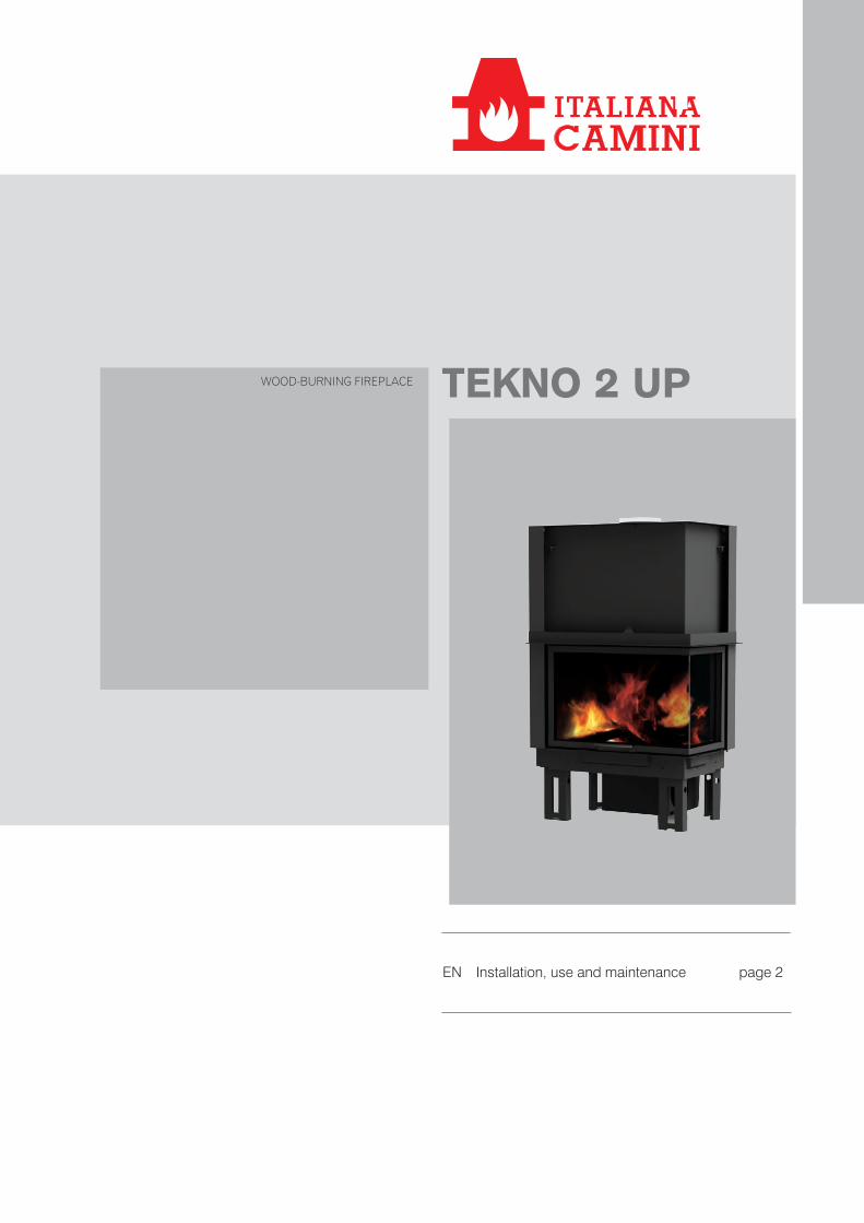
TEKNO 2 UPWOOD-BURNING FIREPLACE
EN Installation, use and maintenance page 2
2
EN
GLI
SH
The undersigned company with registered office in Via Vincenzo Monti 47 - 20123 Milan (Italy) - Tax ID code and VAT number 00192220192
Hereby declares, under its sole responsibility, that:The product mentioned below complies with EU Regulation 305/2011 and the harmonised EU standard Standard EN 13229:2001+A1:2003+A2:2004+AC:2006+AC:2007
WOOD-BURINING FIREPLACE, bearing the brand ITALIANA CAMINI called TEKNO 2 UP
SERIAL NO.: Rating plate reference Performance declaration: (DoP No. EK 163): Rating plate reference
The liability of the Manufacturer is limited to the supply of the product
CONTENTS
Introduction 3
Safety information 4
Technical data 5
Dimensions 6
Preparation and unpacking 8
Installation 10
Instructions for use 22
Maintenance 26
In the event of any problems 27
3
EN
GLI
SH
The product is uniquely identified by a number, the
“counterfoil”, which is indicated on the warranty certificate.
Please keep:
• the warranty certificate accompanying the product
• the purchase receipt given to you by the retailer
• the declaration of conformity given to you by the installer.
The warranty conditions are given in the warranty certificate
accompanying the product.
MEANING OF SYMBOLSIn some parts of the manual the following symbols are used:
INFORMATION: failure to comply with these requirements will compromise product use.
ATTENTION: carefully read and understand the message in question, since failure to follow the instructions in it could cause serious damage to the product and put the safety of those using it at risk.
Dear Sir/Madam
We thank you for and congratulate you on choosing our
product. Before using it, we ask you to read this manual
carefully, in order for you to be able to make the most of all
its functions in total safety.
This manual is an integral part of the product. We ask you
to keep it for the entire lifetime of the product. If you lose it,
you can request a copy from your dealer or download it from
www.italianacamini.it
After unpacking the product, check the condition and
completeness of the contents.
In the event of error, immediately contact the retailer where
the purchase was made, providing them with a copy of the
warranty booklet and the sales receipt.
The appliance must be installed and operated in compliance
with local and national law and European regulations. For the
installation, and for anything not specifically indicated in the
manual, observe local regulations.
The diagrams provided in this manual are for illustration
purposes only: they do not always strictly refer to your
specific model, and are not binding in any way.
4
EN
GLI
SH
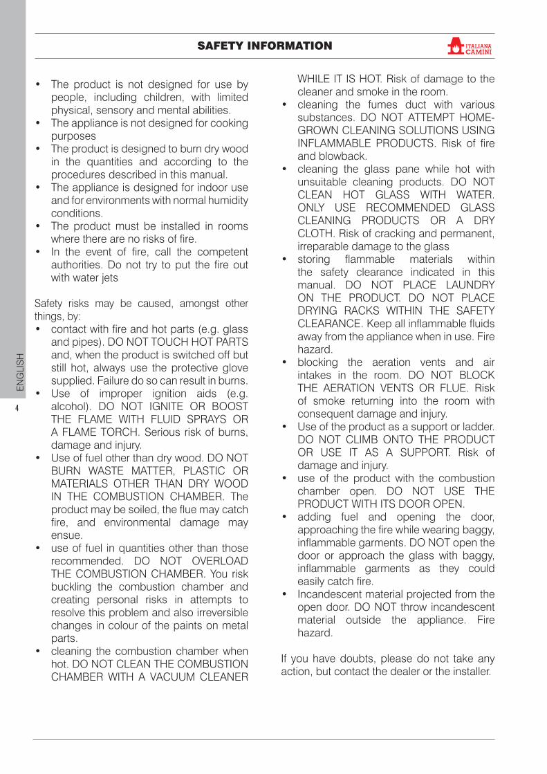
SAFETY INFORMATION
• The product is not designed for use by people, including children, with limited physical, sensory and mental abilities.
• The appliance is not designed for cooking purposes
• The product is designed to burn dry wood in the quantities and according to the procedures described in this manual.
• The appliance is designed for indoor use and for environments with normal humidity conditions.
• The product must be installed in rooms where there are no risks of fire.
• In the event of fire, call the competent authorities. Do not try to put the fire out with water jets
Safety risks may be caused, amongst other things, by:• contact with fire and hot parts (e.g. glass
and pipes). DO NOT TOUCH HOT PARTS and, when the product is switched off but still hot, always use the protective glove supplied. Failure do so can result in burns.
• Use of improper ignition aids (e.g. alcohol). DO NOT IGNITE OR BOOST THE FLAME WITH FLUID SPRAYS OR A FLAME TORCH. Serious risk of burns, damage and injury.
• Use of fuel other than dry wood. DO NOT BURN WASTE MATTER, PLASTIC OR MATERIALS OTHER THAN DRY WOOD IN THE COMBUSTION CHAMBER. The product may be soiled, the flue may catch fire, and environmental damage may ensue.
• use of fuel in quantities other than those recommended. DO NOT OVERLOAD THE COMBUSTION CHAMBER. You risk buckling the combustion chamber and creating personal risks in attempts to resolve this problem and also irreversible changes in colour of the paints on metal parts.
• cleaning the combustion chamber when hot. DO NOT CLEAN THE COMBUSTION CHAMBER WITH A VACUUM CLEANER
WHILE IT IS HOT. Risk of damage to the cleaner and smoke in the room.
• cleaning the fumes duct with various substances. DO NOT ATTEMPT HOME-GROWN CLEANING SOLUTIONS USING INFLAMMABLE PRODUCTS. Risk of fire and blowback.
• cleaning the glass pane while hot with unsuitable cleaning products. DO NOT CLEAN HOT GLASS WITH WATER. ONLY USE RECOMMENDED GLASS CLEANING PRODUCTS OR A DRY CLOTH. Risk of cracking and permanent, irreparable damage to the glass
• storing flammable materials within the safety clearance indicated in this manual. DO NOT PLACE LAUNDRY ON THE PRODUCT. DO NOT PLACE DRYING RACKS WITHIN THE SAFETY CLEARANCE. Keep all inflammable fluids away from the appliance when in use. Fire hazard.
• blocking the aeration vents and air intakes in the room. DO NOT BLOCK THE AERATION VENTS OR FLUE. Risk of smoke returning into the room with consequent damage and injury.
• Use of the product as a support or ladder. DO NOT CLIMB ONTO THE PRODUCT OR USE IT AS A SUPPORT. Risk of damage and injury.
• use of the product with the combustion chamber open. DO NOT USE THE PRODUCT WITH ITS DOOR OPEN.
• adding fuel and opening the door, approaching the fire while wearing baggy, inflammable garments. DO NOT open the door or approach the glass with baggy, inflammable garments as they could easily catch fire.
• Incandescent material projected from the open door. DO NOT throw incandescent material outside the appliance. Fire hazard.
If you have doubts, please do not take any action, but contact the dealer or the installer.
®
5
EN
GLI
SH
The manufacturer reserves the right to modify the product at its own discretion and with-out notification, with a view to improvements.The drawings are for guidance only and they may not always refer to the specific model.
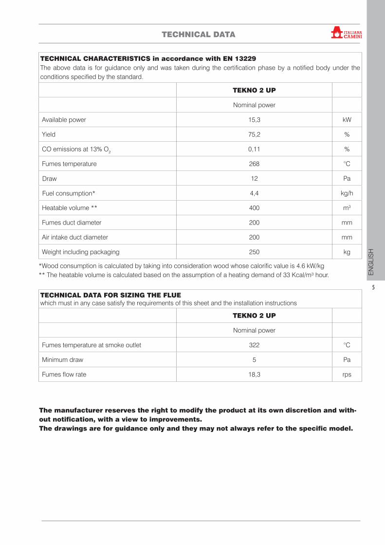
TECHNICAL CHARACTERISTICS in accordance with EN 13229 The above data is for guidance only and was taken during the certification phase by a notified body under the conditions specified by the standard.
TEKNO 2 UP
Nominal power
Available power 15,3 kW
Yield 75,2 %
CO emissions at 13% O2 0,11 %
Fumes temperature 268 °C
Draw 12 Pa
Fuel consumption* 4,4 kg/h
Heatable volume ** 400 m3
Fumes duct diameter 200 mm
Air intake duct diameter 200 mm
Weight including packaging 250 kg
TECHNICAL DATA FOR SIZING THE FLUE which must in any case satisfy the requirements of this sheet and the installation instructions
TEKNO 2 UP
Nominal power
Fumes temperature at smoke outlet 322 °C
Minimum draw 5 Pa
Fumes flow rate 18,3 rps
TECHNICAL DATA
*Wood consumption is calculated by taking into consideration wood whose calorific value is 4.6 kW/kg** The heatable volume is calculated based on the assumption of a heating demand of 33 Kcal/m³ hour.
®
6
EN
GLI
SH
DIMENSIONS
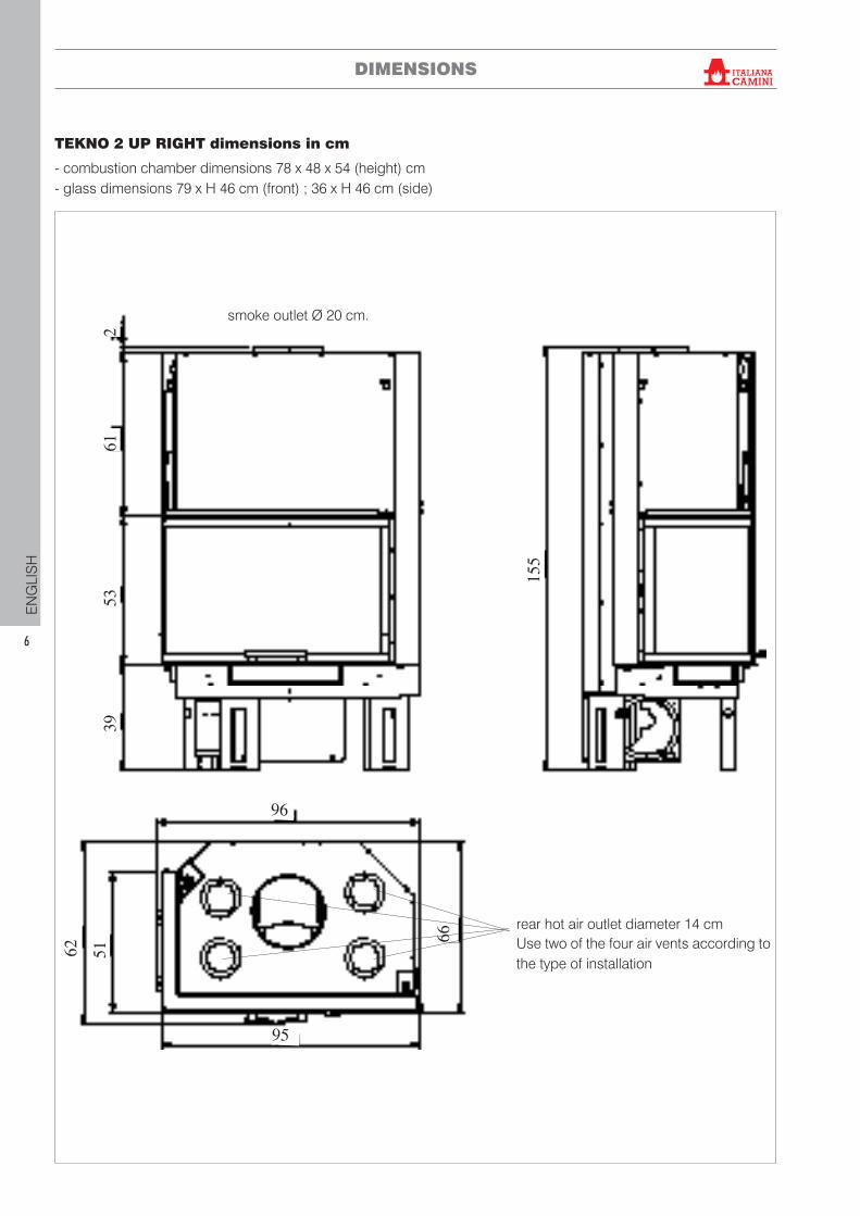
TEKNO 2 UP RIGHT dimensions in cm
- combustion chamber dimensions 78 x 48 x 54 (height) cm - glass dimensions 79 x H 46 cm (front) ; 36 x H 46 cm (side)
261
5339
155
66
62 51
95
96
smoke outlet Ø 20 cm.
rear hot air outlet diameter 14 cmUse two of the four air vents according to the type of installation
®
7
EN
GLI
SH
DIMENSIONS
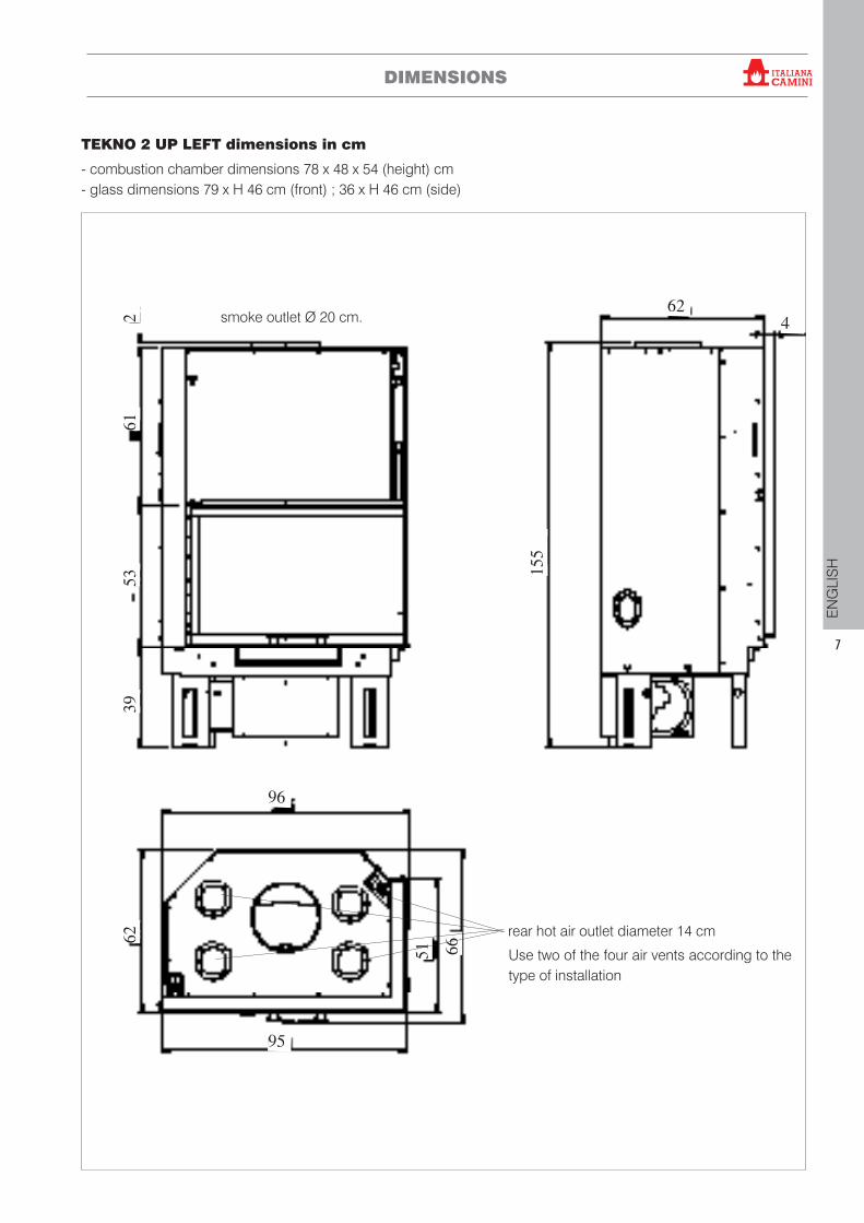
TEKNO 2 UP LEFT dimensions in cm
- combustion chamber dimensions 78 x 48 x 54 (height) cm - glass dimensions 79 x H 46 cm (front) ; 36 x H 46 cm (side)
95
6651
622
6153
39
96
155
624smoke outlet Ø 20 cm.
rear hot air outlet diameter 14 cm
Use two of the four air vents according to the type of installation
®
8
EN
GLI
SH
INSTALLATION
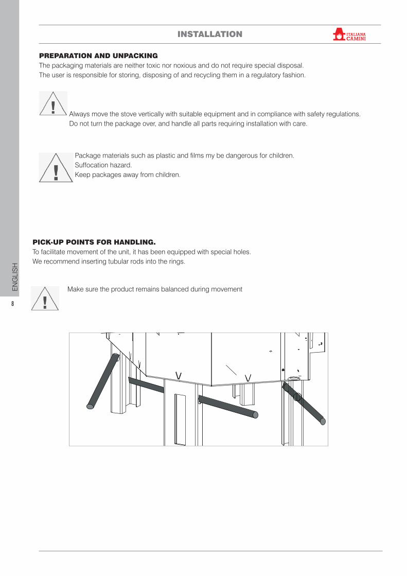
PREPARATION AND UNPACKINGThe packaging materials are neither toxic nor noxious and do not require special disposal. The user is responsible for storing, disposing of and recycling them in a regulatory fashion.
Always move the stove vertically with suitable equipment and in compliance with safety regulations. Do not turn the package over, and handle all parts requiring installation with care.
PICK-UP POINTS FOR HANDLING.To facilitate movement of the unit, it has been equipped with special holes.We recommend inserting tubular rods into the rings.
Make sure the product remains balanced during movement
Package materials such as plastic and films my be dangerous for children.Suffocation hazard. Keep packages away from children.
®
9
EN
GLI
SH
INSTALLATION
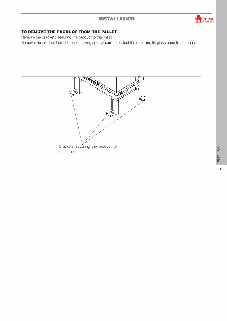
TO REMOVE THE PRODUCT FROM THE PALLET Remove the brackets securing the product to the pallet. Remove the product from the pallet, taking special care to protect the door and its glass pane from impact.
brackets securing the product to the pallet.
®
10
EN
GLI
SH
INSTALLATION
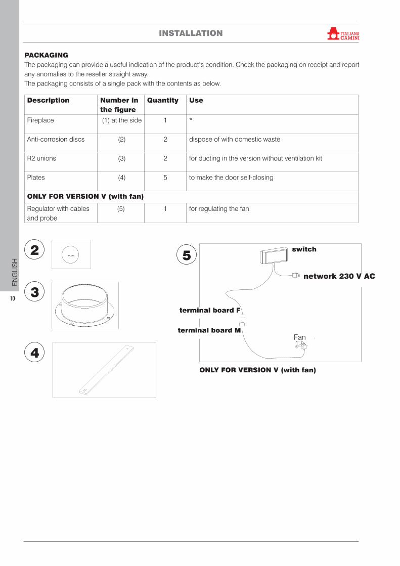
PACKAGINGThe packaging can provide a useful indication of the product’s condition. Check the packaging on receipt and report any anomalies to the reseller straight away.The packaging consists of a single pack with the contents as below.
Description Number in the figure
Quantity Use
Fireplace (1) at the side 1 *
Anti-corrosion discs (2) 2 dispose of with domestic waste
R2 unions (3) 2 for ducting in the version without ventilation kit
Plates (4) 5 to make the door self-closing
ONLY FOR VERSION V (with fan)
Regulator with cables and probe
(5) 1 for regulating the fan
2
3
4
xxxxx
24
04
90
.1
2.1
7/G
Ventilatore
5
ONLY FOR VERSION V (with fan)
switch
terminal board F
terminal board MFan
network 230 V AC
®
11
EN
GLI
SH
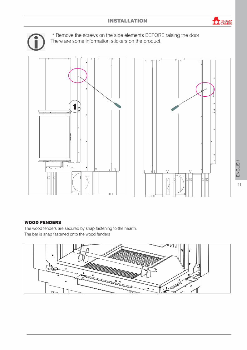
* Remove the screws on the side elements BEFORE raising the doorThere are some information stickers on the product.
1
INSTALLATION
WOOD FENDERSThe wood fenders are secured by snap fastening to the hearth.The bar is snap fastened onto the wood fenders
®
12
EN
GLI
SH
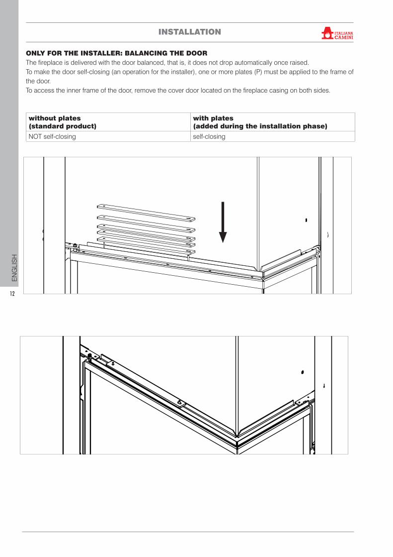
ONLY FOR THE INSTALLER: BALANCING THE DOORThe fireplace is delivered with the door balanced, that is, it does not drop automatically once raised.To make the door self-closing (an operation for the installer), one or more plates (P) must be applied to the frame of the door. To access the inner frame of the door, remove the cover door located on the fireplace casing on both sides.
without plates(standard product)
with plates(added during the installation phase)
NOT self-closing self-closing
INSTALLATION ®
13
EN
GLI
SH
INSTALLATION
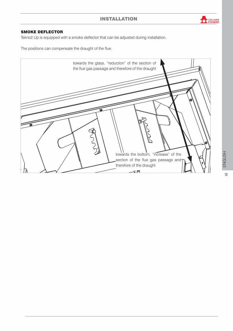
SMOKE DEFLECTOR Tekno2 Up is equipped with a smoke deflector that can be adjusted during installation.
The positions can compensate the draught of the flue.
towards the bottom, “increase” of the section of the flue gas passage and therefore of the draught
towards the glass, “reduction” of the section of the flue gas passage and therefore of the draught
®
14
EN
GLI
SH
REMARKS ON INSTALLATIONNote that:• the appliance must be installed by authorised
technical personnel• the appliance must be installed and operated
in compliance with local and national laws and European regulations
• if installed in a condominium, the appliance must be approved by the administrator.
Here are a few general instructions, although these do not obviate the need to comply with local regulations and do not affect the installer’s liability for the installation.
INSTALLATION
FLUE SYSTEM (Fumes duct, flue and chimney pot)This chapter has been drawn up pursuant to European regulations EN 13384, EN 1443, EN 1856 and EN 1457. The installer must observe both these and any other local regulations. This manual does not in any way substitute such regulations.
The product must be connected to a flue system which ensures that the fumes produced by combustion are expelled in complete safety.
Before positioning the appliance, one must check that the flue is suitable.
FUMES DUCT, FLUEThe fumes duct (which connects the combustion chamber smoke outlet with the flue) and the flue itself must, among other regulatory requirements:• receive the fumes from a single product (the outlets
of multiple appliances may not be conveyed into a single flue)
• have a mainly vertical course (no horizontal sections and bends of over 45° are allowed)
• have no downwards sloping sections• have a preferably circular internal cross section
and nevertheless with a ratio of the sides of less than 1.5
• terminate at roof level with a proper chimney pot: the flue may not discharge directly on the wall or into an enclosed space, even if the space in question is open to the sky
• be made of material with rated fire reaction class A1 as per UNI EN 13501 or analogous national regulations
• be certified, with a chimney plate if metal• keep the initial section.
Checking the suitability of the installation space• The room must have a volume of at least 40 m3
• The appliance may not be installed in a bedroom, bathroom or in the same room as other equipment which draws air for combustion from the room itself, or in any area with an explosive atmosphere. Any extraction fans operating in the same room/area of the product, may affect its draw
• In Italy, check the compatibility pursuant to UNI 10683 and UNI 7129 in the presence of gas-fired products
• The floor must be able to bear the weight of the product and its accessories.
Protection from heat and safety clearancesThe surfaces of the building adjacent to the product must be protected against overheating.The insulation to be used will depend on the type of surface in question.Observe the following minimum distance from inflammablematerials- 10 cm from the non-glass rear of the appliance- 150 cm from the glass sides. Do not place any inflammable materials at shorter distances.
Power linesno power lines must be present in the walls and in the ceilings within the recessed area of the product
PLEASE NOTE:If the fireplace is not level there may be problems with the door’s sliding movement.
®
15
EN
GLI
SH
INSTALLATION
THE FUMES DUCT• if it is metal, it must have CE marking (EN 1856-2) or some similar national standard marking;• may not be made of flexible metal material• in order to check the flow, we recommend the use of a damper if the draught is above 25 Pa
THE FLUE:• it must have a draught capable of creating
depressurisation, which is ideally around 12 Pa. Lower draughts may lead to leaks of smoke when the door is opened; higher values tend to generate fast combustion and reduced efficiency
• must be correctly sized to satisfy the requirements for flue gas discharging (EN 13384-1)
• must preferably be insulated, in steel with a circular internal section. If rectangular, the internal corners must have a radius of not less than 20 mm, with a ratio of the internal dimensions of <1.5
• must normally be at least 3-4 metres in vertical length
• must have a constant cross section• must be waterproof and thermally insulated to
ensure a good draw• must preferably have a collection chamber for
non-combusted matter and condensation• must be at least in the T400 category with
appropriate resistance against soot igniting• If pre-existing, must be clean, to prevent the fire
hazard.
THE CHIMNEY POT • must be anti-downdraught • must have an internal cross section equivalent to
that of the flue and a fumes outlet at least double that of the interior of the flue
• for dual flues (which should be spaced at least 2 m apart) the chimney pot of the flue receiving the fumes from the solid fuel appliance or that from the higher storey, must be at least 50 cm higher
• needs to beyond the back flow zone• it must allow for maintenance of the chimney.
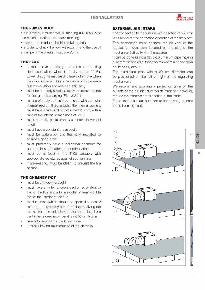
EXTERNAL AIR INTAKE The connection to the outside with a section of 300 cm2 is essential for the correction operation of the fireplace. This connection must connect the air vent of the regulating mechanism (located on the side of the mechanism) directly with the outside.It can be done using a flexible aluminium pipe making sure that it is sealed at those points where air dispersion could easily occur.The aluminium pipe with a 20 cm diameter can be positioned on the left or right of the regulating mechanism.We recommend applying a protection grille on the outside of the air inlet duct which must not, however, reduce the effective cross section of the intake.The outside air must be taken at floor level (it cannot come from high up).
8
ITA
LIA
NO
Trasporto del monoblocco Per facilitare il trasporto, é possibilealleggerire il monoblocco, togliendo:- contrappesi, fondale in ghisa, i fian-chi in ghisa, il piano fuoco in ghisa, lavaschetta raccoglicenere, la grigliacenere in ghisa, il mantello di chiusura.
È anche possibile smontare il portelloneagendo come segue:
Fase 1 (fig. H)- abbassare il portellone in posizione di
totale chiusura, agire sulle viti a brugola (X) avvitandole completamente.
Pulizia del vetro (fig. L)- Per pulire il vetro è possibile aprire ad
anta il portello del focolare sbloccando mediante l’apposito utensile(mano fredda in dotazione) la piastranottolino al lato dx del portellone(ruotare di 90°).
- Il portello adesso può essere apertoad anta.
- Una volta terminata la pulizia, fissarenuovamente la piastra nottolino.
fig. E
Presa d'aria esterna (figg. E-F-G)Il collegamento con l'esterno di sezio-ne pari 300 cm2 è assolutamentenecessario per il buon funzionamentodel caminetto, deve essere quindiinderogabilmente realizzato.
Detto collegamento deve raccordaredirettamente con l'esterno il bocchettonedel meccanismo di regolazione ubicatosul fianco del meccanismo stesso.
Può essere realizzato con tubo flessibiledi alluminio curando bene la sigillaturadei punti nei quali potrebbe verificarsidispersione di aria.
Il tubo di alluminio Ø20 può essereposizionato indipendentemente adestra o a sinistra del meccanismo diregolazione.
È consigliabile applicare all'esterno delcondotto presa aria una griglia di prote-zione che comunque non deve ridurre lasezione utile passante.
L'aria esterna deve essere captata a livel-lo pavimento (non può provenire dall'al-to).
Nel posizionamento del cavo coman-do serrandina aria esterna (4c) fareattenzione che non vada a contattocon le parti calde del camino, in quan-to si danneggerebbe la guaina in pla-stica.
ISTRUZIONI PER L’INSTALLAZIONE
fig. F
fig. G
fig. L
X
fig. H
Fase 2 (fig. I)- aprire il portellone ad anta, allentare
il grano di sicurezza (Y) e svitarecompletemente la vite a brugola (Z),
- tirare con molta cura la parte bassadel portellone verso se stessi in mododa sfilare il portellone.
YZ
fig. I
®
16
EN
GLI
SH
INSTALLATION
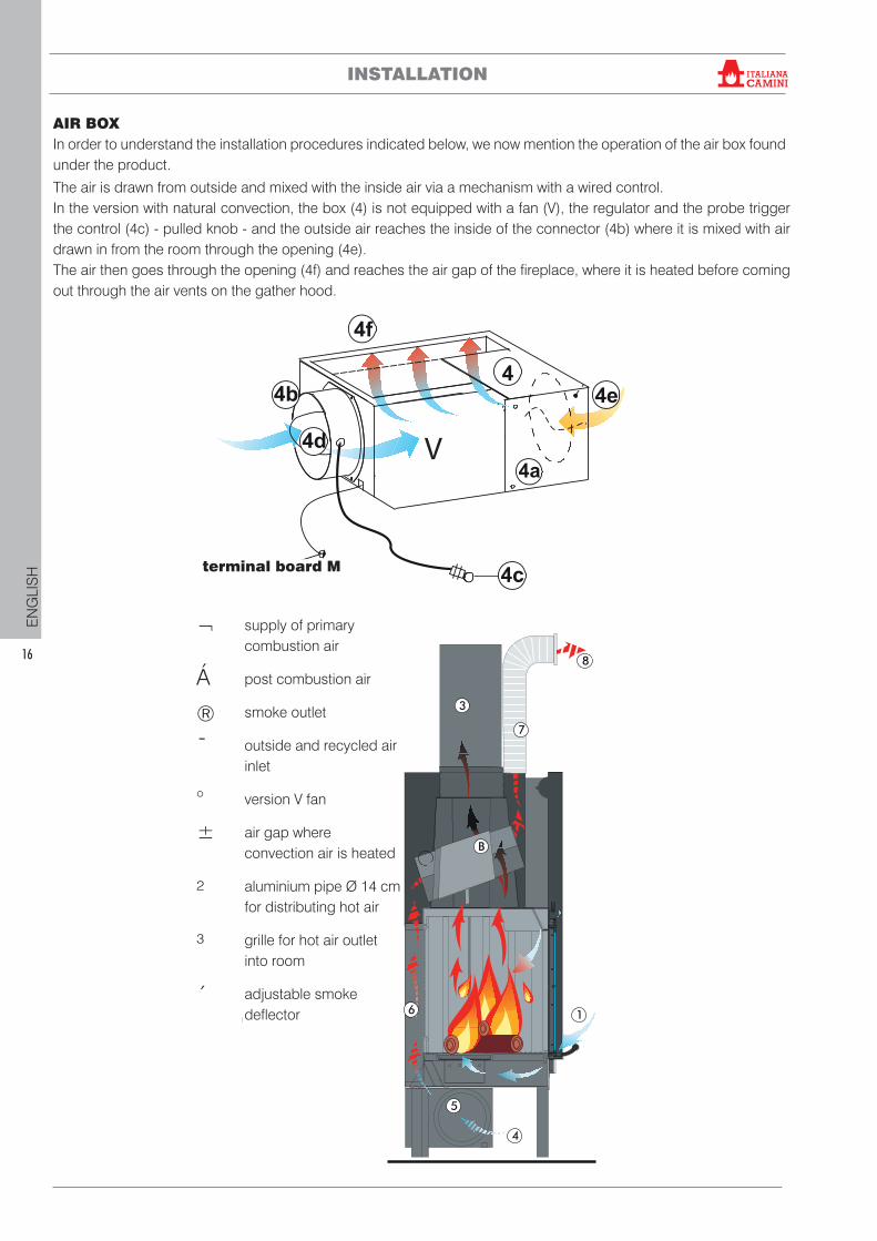
AIR BOXIn order to understand the installation procedures indicated below, we now mention the operation of the air box found under the product.
alimentazione aria prima-ria di combustione
aria post combustione
uscita fumi
ingresso aria esterna e diricircolo
ventilattore versione V
intercapedine di riscalda-mento aria di convezione
tubo in alluminio Ø 14 cmdistribuzione aria calda
griglia uscita aria calda inambiente
1
1
2
3
3
4
4
5
5
6
6
7
7
8
9
B
8
deflettore fumi regolabile
The air is drawn from outside and mixed with the inside air via a mechanism with a wired control.In the version with natural convection, the box (4) is not equipped with a fan (V), the regulator and the probe trigger the control (4c) - pulled knob - and the outside air reaches the inside of the connector (4b) where it is mixed with air drawn in from the room through the opening (4e).The air then goes through the opening (4f) and reaches the air gap of the fireplace, where it is heated before coming out through the air vents on the gather hood.
V
supply of primary combustion air
post combustion air
smoke outlet
outside and recycled air inlet
version V fan
air gap where convection air is heated
aluminium pipe Ø 14 cm for distributing hot air
grille for hot air outlet into room
adjustable smoke deflector
terminal board M
¬
Á
®¯
°±
²
³
´
®
17
EN
GLI
SH
INSTALLATION
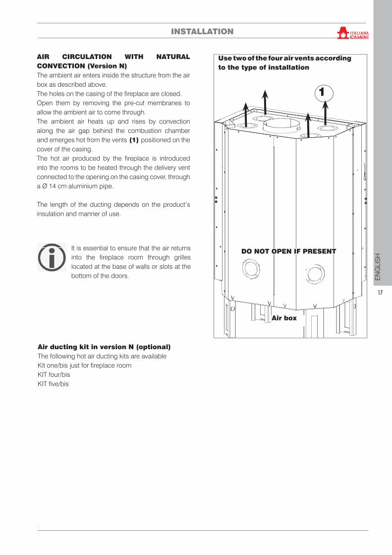
AIR CIRCULATION WITH NATURAL CONVECTION (Version N)The ambient air enters inside the structure from the air box as described above.The holes on the casing of the fireplace are closed. Open them by removing the pre-cut membranes to allow the ambient air to come through.The ambient air heats up and rises by convection along the air gap behind the combustion chamber and emerges hot from the vents (1) positioned on the cover of the casing.The hot air produced by the fireplace is introduced into the rooms to be heated through the delivery vent connected to the opening on the casing cover, through a Ø 14 cm aluminium pipe.
The length of the ducting depends on the product’s insulation and manner of use.
1
It is essential to ensure that the air returns into the fireplace room through grilles located at the base of walls or slots at the bottom of the doors.
Air ducting kit in version N (optional)The following hot air ducting kits are availableKit one/bis just for fireplace roomKIT four/bisKIT five/bis
DO NOT OPEN IF PRESENT
Air box
Use two of the four air vents according to the type of installation
®
18
EN
GLI
SH
INSTALLATION
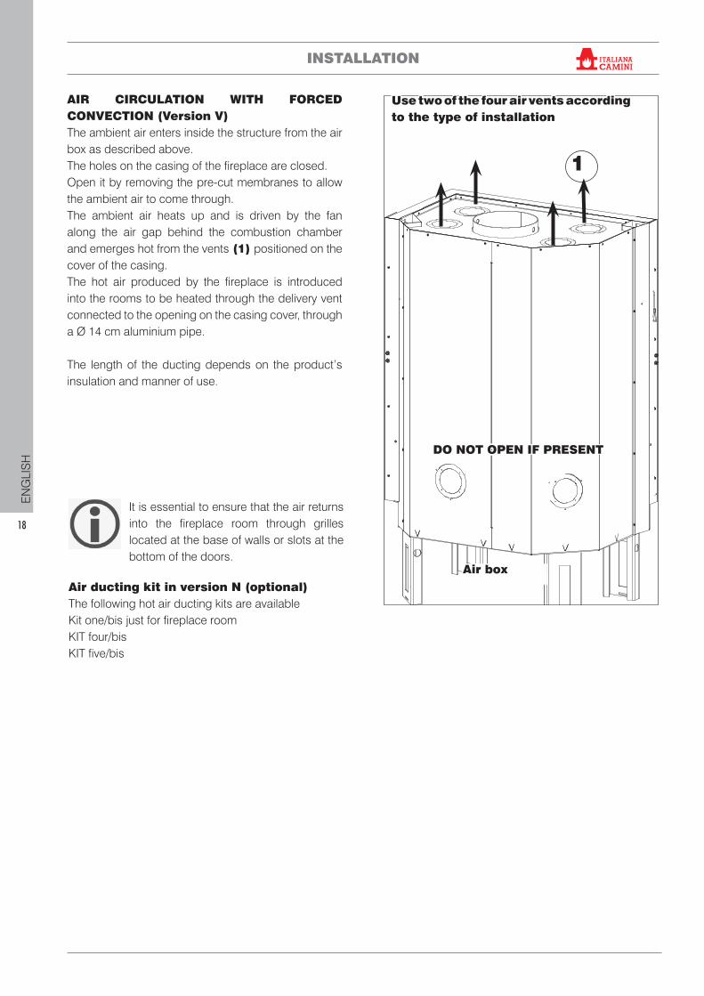
AIR CIRCULATION WITH FORCED CONVECTION (Version V)The ambient air enters inside the structure from the air box as described above.The holes on the casing of the fireplace are closed. Open it by removing the pre-cut membranes to allow the ambient air to come through.The ambient air heats up and is driven by the fan along the air gap behind the combustion chamber and emerges hot from the vents (1) positioned on the cover of the casing.The hot air produced by the fireplace is introduced into the rooms to be heated through the delivery vent connected to the opening on the casing cover, through a Ø 14 cm aluminium pipe.
The length of the ducting depends on the product’s insulation and manner of use.
It is essential to ensure that the air returns into the fireplace room through grilles located at the base of walls or slots at the bottom of the doors.
Air ducting kit in version N (optional)The following hot air ducting kits are availableKit one/bis just for fireplace roomKIT four/bisKIT five/bis
1
DO NOT OPEN IF PRESENT
Air box
Use two of the four air vents according to the type of installation
®
19
EN
GLI
SH
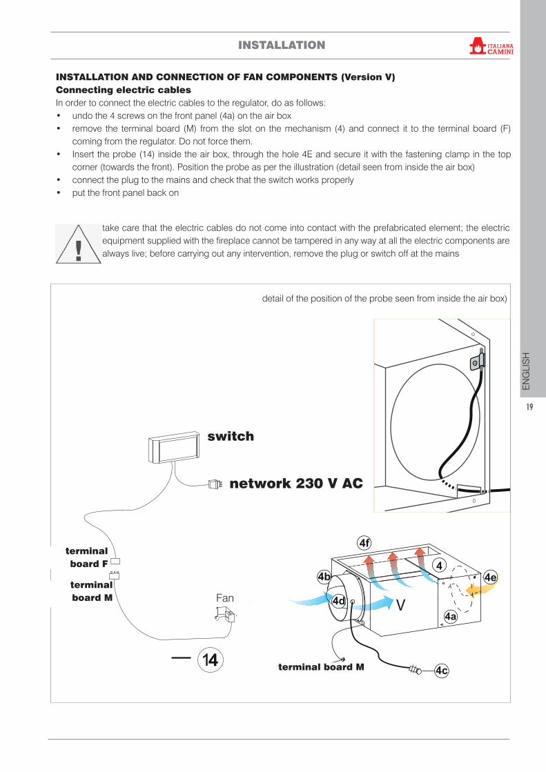
INSTALLATION AND CONNECTION OF FAN COMPONENTS (Version V)Connecting electric cablesIn order to connect the electric cables to the regulator, do as follows:• undo the 4 screws on the front panel (4a) on the air box• remove the terminal board (M) from the slot on the mechanism (4) and connect it to the terminal board (F)
coming from the regulator. Do not force them.• Insert the probe (14) inside the air box, through the hole 4E and secure it with the fastening clamp in the top
corner (towards the front). Position the probe as per the illustration (detail seen from inside the air box)• connect the plug to the mains and check that the switch works properly • put the front panel back on
24
04
90
.1
2.1
7/G
Ventilatore V
take care that the electric cables do not come into contact with the prefabricated element; the electric equipment supplied with the fireplace cannot be tampered in any way at all the electric components are always live; before carrying out any intervention, remove the plug or switch off at the mains
istruzioni per l’installazioneAvvertenzeOltre a quanto indicato nel pre-sente documento, tenere in con-siderazione le norme UNI:- n. 10683 - generatori dicalore a legno: requisiti di instal-lazione
- n. 9615 - calcolo delledimensioni interne dei camini.
In particolare:- prima di iniziare qualsiasioperazione di montaggio èimportante verificare la compati-bilità dell'impianto come stabilitodalla norma UNI 10683 ai para-grafi 4.1/ 4.1.1 / 4.1.2.
- a montaggio ultimato, l'in-stallatore dovrà provvedere alleoperazioni di "messa in esercizio"ed a rilasciare documentazionecome richiesto dalla norma UNI10683 rispettivamente aiparagrafi 4.6 e 5.
PER TEKNO 1: fino ad instal-lazione terminata, tenere lavite (10 f) completamenteavvitata alla struttura (fig. H -pagina 4).
Prima di installare il rivestimentoverificare la corretta funziona-lità dei collegamenti, deicomandi e tutte le parti in movi-mento.La verifica va eseguita a cami-no acceso ed a regime per alcu-ne ore, prima di rivestire ilmonoblocco al fine di potereventualmente intervenire.Quindi, le operazioni di finituraquali ad esempio:- costruzione della controcappa- montaggio del rivestimento- esecuzione di lesene, tinteg-giature, ecc.vanno eseguite a collaudo ulti-mato con esito positivo.
Italiana Camini non risponde diconseguenza degli oneri derivatisia da interventi di demolizioneche di ricostruzione anche seconseguenti a lavori di sostituzio-ni di eventuali pezzi del caminet-to difettosi.
Presa d'aria esterna (figg.G-H-I)Il collegamento con l'esterno disezione pari 300 cm2 è assolu-tamente necessario per il buonfunzionamento del caminetto,deve essere quindi inderoga-bilmente realizzato.
Detto collegamento deve raccor-dare direttamente con l'esternouno dei bocchettoni del meccani-smo di regolazione ubicati sulretro o sul pavimento del mecca-nismo stesso.
Può essere realizzato con tuboflessibile di alluminio curandobene la sigillatura dei punti neiquali potrebbe verificarsi disper-sione di aria.
Il tubo di alluminio diametro20 cm può essere posizionatoindipendentemente a destra oa sinistra.
È consigliabile applicare all'ester-no del condotto presa aria unagriglia di protezione che comun-que non deve ridurre la sezioneutile passante.
L'aria esterna deve essere captataa livello pavimento (non può pro-venire dall'alto).
Nel posizionamento del cavocomando serrandina ariaesterna (4c) fare attenzioneche non vada a contatto con leparti del camino, in quanto sidanneggerebbe la guaina inplastica.
BBA
A
3
- Il monoblocco è dotato di deflettore fumi all’interno dellacappa sopra il tubo scambiatore. Regolare il deflettore fumiin modo da compensare il tiraggio della canna fumariacome illustrato nella figura sottostante.
Monoblocco (fig. A)Per definire l'esatto posizionamen-to del caminetto è importanteverificare con quale rivestimentoverrà completato.In base al modello prescelto, lacollocazione dovrà essere esegui-ta in modo differente (consultarele istruzioni di montaggio conte-nute nella confezione di ciascunrivestimento).Durante l'installazione verificaresempre piombo e livello.
- praticare nella parete o sulpavimento un foro per la presad'aria esterna e collegarlo almeccanismo di regolazione ariacome descritto nel capitolo"presa d'aria estrerna"
- collegare il caminetto allacanna fumaria con canna inacciaio inox, usando i diametri
Deflettore (B) esteso “riduce lasezione passaggio fumi” e quindiil tiraggio della canna fumaria
Deflettore (B) rientrato “aumentala sezione passaggio fumi” equindi il tiraggio della cannafumaria
Installazione sondaLa sonda deve essereposizionata come daillustrazione.
Particolare visto dall’in-terno del meccanismoregolazione aria (4).
indicati nella tabella dati tecnicie le indicazioni del capitolo"canna fumaria e comignolo" .
- sono disponibili kit per la cana-lizzazione dell'aria calda (vedicapitolo a pag. 8)
PER TEKNO 1- ad installazione terminata, abi-litare lo scorrimento del portello-ne togliendo la vite (10 f) e le vitidi bloccaggio contrappeso (10i)a pagina 4.
PER TEKNO 2-3- ad installazione terminata, abi-litare lo scorrimento del portello-ne tramite il chiavistello (10 l) esvitare le viti bloccaggio contrap-peso (10i) a pagina 5-6.
- verificare il comportamento ditutte le parti in movimento.detail of the position of the probe seen from inside the air box)
INSTALLATION
switch
terminal board M Fan
network 230 V AC
terminal board M
terminal board F
®
20
EN
GLI
SH
INSTALLATION
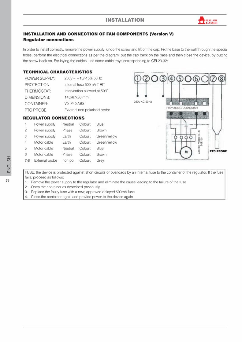
INSTALLATION AND CONNECTION OF FAN COMPONENTS (Version V)Regulator connections
In order to install correctly, remove the power supply; undo the screw and lift off the cap. Fix the base to the wall through the special
holes, perform the electrical connections as per the diagram, put the cap back on the base and then close the device, by putting
the screw back on. For laying the cables, use some cable trays corresponding to CEI 23-32:
TECHNICAL CHARACTERISTICS
POWER SUPPLY: 230V~ +10/-15% 50Hz
PROTECTION: Internal fuse 500mA T RIT
THERMOSTAT: Intervention allowed at 50°C
DIMENSIONS: 145x67x30 mm
CONTAINER: V0 IP40 ABS
PTC PROBE External non polarised probe
REGULATOR CONNECTIONS1 Power supply Neutral Colour: Blue
2 Power supply Phase Colour: Brown
3 Power supply Earth Colour: Green/Yellow
4 Motor cable Earth Colour: Green/Yellow
5 Motor cable Neutral Colour: Blue
6 Motor cable Phase Colour: Brown
7-8 External probe non pol. Colour: Grey
FUSE: the device is protected against short circuits or overloads by an internal fuse to the container of the regulator. If the fuse fails, proceed as follows:1. Remove the power supply to the regulator and eliminate the cause leading to the failure of the fuse2. Open the container as described previously3. Replace the faulty fuse with a new, approved delayed 500mA fuse4. Close the container again and provide power to the device again
PTC PROBE
230V AC 50Hz
IRREVERSIBLE CONNECTOR
AIR
BO
X M
OTO
R E
BM
D
2E12
0
®
21
EN
GLI
SH
INSTALLATION
Facings, gather hood and ventsFace the product only after having completed the following steps:• connecting the product to the smoke outlet and
air intake; • checking the correct operation of the appliance
when hot. Perform checks on the appliance when lit and after a few hours’ operation; check the connections, the controls and all moving parts
• check that the appliance is level.
The installer must implement all the installation good practices and take all the necessary precautions against overheating and fire.
In particular:• if a plinth is constructed beneath the hearth level,
it must include a suitable slot for the passage of recirculation air from the room;
• if the Air Diffuser Kit is installed, it must be possible to inspect or replace the fans;
• wooden parts must be protected with fireproof panels, which must not be placed against one another but spaced at least 1 cm apart to enable air to flow and prevent heat build-up. The gather hood can be made with fireproof panels, plasterboard or gypsum slabs; during construction, the hot air ducting kit must be mounted as described above.
The interior of the gather hood should be aerated by exploiting the flow of air coming from below (the space between the door and mantel) which convective currents will cause to exit from the grille on top, thus allowing heat recovery and preventing undue overheating.In addition to that mentioned above, take into account the regulations in force in the relevant country concerning “insulation, finishes, facings and safety recommendations”.
Compensation ventsIt is essential to install them. We suggest installing them on the front: one beneath and one above the combustion chamber opening.
Carry out all the finishing operations, for example the gather hood, the cladding etc. only after the tests have been completed successfully
®
22
EN
GLI
SH
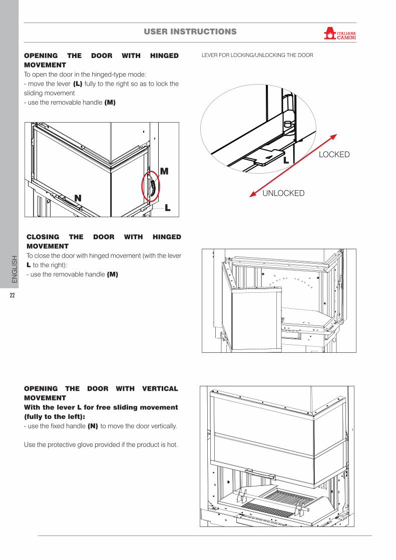
OPENING THE DOOR WITH HINGED MOVEMENT To open the door in the hinged-type mode:- move the lever (L) fully to the right so as to lock the sliding movement- use the removable handle (M)
LEVER FOR LOCKING/UNLOCKING THE DOOR
OPENING THE DOOR WITH VERTICAL MOVEMENTWith the lever L for free sliding movement (fully to the left):- use the fixed handle (N) to move the door vertically.
Use the protective glove provided if the product is hot.
CLOSING THE DOOR WITH HINGED MOVEMENTTo close the door with hinged movement (with the lever L to the right):- use the removable handle (M)
L
NL
M
USER INSTRUCTIONS
UNLOCKED
LOCKED
®
23
EN
GLI
SH
USER INSTRUCTIONS
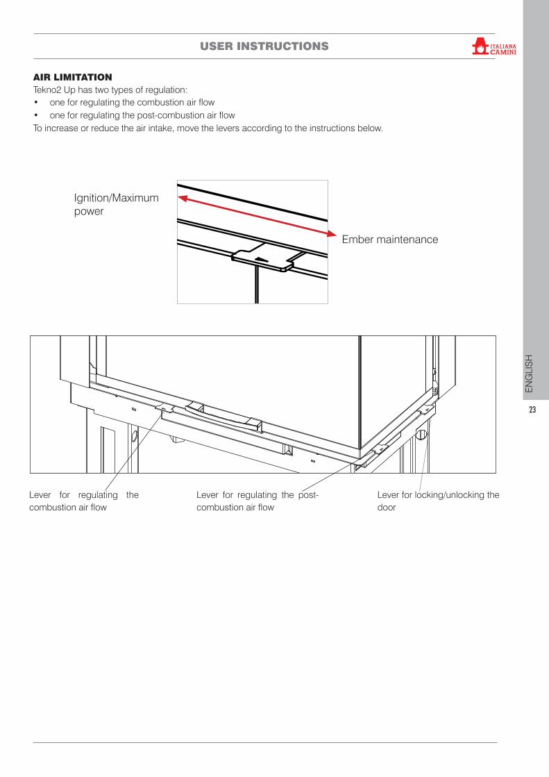
AIR LIMITATIONTekno2 Up has two types of regulation:• one for regulating the combustion air flow• one for regulating the post-combustion air flowTo increase or reduce the air intake, move the levers according to the instructions below.
Lever for regulating the combustion air flow
Lever for regulating the post-combustion air flow
Lever for locking/unlocking the door
Ember maintenance
Ignition/Maximum power
®
24
EN
GLI
SH
Ignition with the combustion chamber cold.1. Check that the existing ash bed is not too high. If the ash bed becomes too high there is a danger that hot embers may fall out of the combustion chamber when the combustion chamber door is opened to add wood.2. Move the lever for regulating the air valve to the “fully open” position. There will be an intense flow of combustion air to the wood in the combustion chamber allowing quick and efficient combustion.3. Place the wood in the combustion chamber without packing it excessively. Place an ignition unit among the logs, and ignite. Never use ignition products such as petrol, alcohol and the like.4. At this point, close the door and monitor for a few minutes. If the fire should go out, open the door slowly, place another ignition unit among the logs and ignite it again.
Adding wood when the combustion chamber is hotWhen is the right time to add wood? When the fuel has almost finished and is in hot embers. Using the glove provided, open the hinged door slowly (to avoid the creation of air vortices which could cause smoke to leak out). Add the desired quantity of wood into the combustion chamber, placing it on top of the existing embers (within the quantity limits indicated in the technical sheet).
Operation with low initial draughtIn order to draw in the air for combustion and to discharge the smoke, the combustion chamber needs the draught created by the flue. If the draught is weak, initially light a “start up” fire using smaller pieces of ignition material. Once the correct level of draught has been restored, you can add the fuel.
As with all appliances, a wood appliance heats up and cools down during the various operating stages. This causes normal levels of expansion. This expansion may cause slight settling noises that cannot be used as a cause for complaint.
FUELThe product is designed for burning wood pellets or logs. Use dry wood logs (max. 20% humidity)Using damp wood will make the product and flue dirty, risk the release of smoke and provide a lower heat output.Each type of wood has different properties that influence the output of the combustion process.The data given in this manual refers to the wood used during certification. Generally speaking, wood has a calorific value of approximately 4.5 kWh/kg. When freshly cut it has a calorific value of approximately 2 kWh/kg.Generally speaking, we recommend using beech, elm or other class A1 woods in accordance with UNI EN ISO 17225-5.Avoid the prolonged use of woods rich in aromatic oils (e.g. eucalyptus). This may deteriorate the cast iron components.Use the recommended quantities of wood. Overloading may lead to overheating, causing the following damage: • possible buckling of the internal parts;• possible irreversible alterations in the colour of
the paint on the metal parts, for which neither Edilkamin nor the retailer can be held responsible.
For reasons of safety and environmental compatibility, DO NOT burn, among other, plastic, painted wood, coal or bark. Do not use the product as an incinerator. The use of these fuels will invalidate the warranty.
First ignition procedure• Make sure you have read and understood this
manual• Remove all flammable materials from the appliance
(manuals, labels, etc.). Make sure you remove the labels on the glass. They would irreparably damage the glass if they melted.
To light the fire in the combustion chamber, always use smaller pieces of wood. Use larger pieces of wood to feed the fire once it has started. Place the wood on the combustion grille.
On first ignition, there may be a slight smell of paint, which will disappear in a short time.
Always use the glove provided to touch any hot parts. Avoid direct contact with hot parts.
USER INSTRUCTIONS ®
25
EN
GLI
SH
Min Max
OFF ON
AUTO MAN
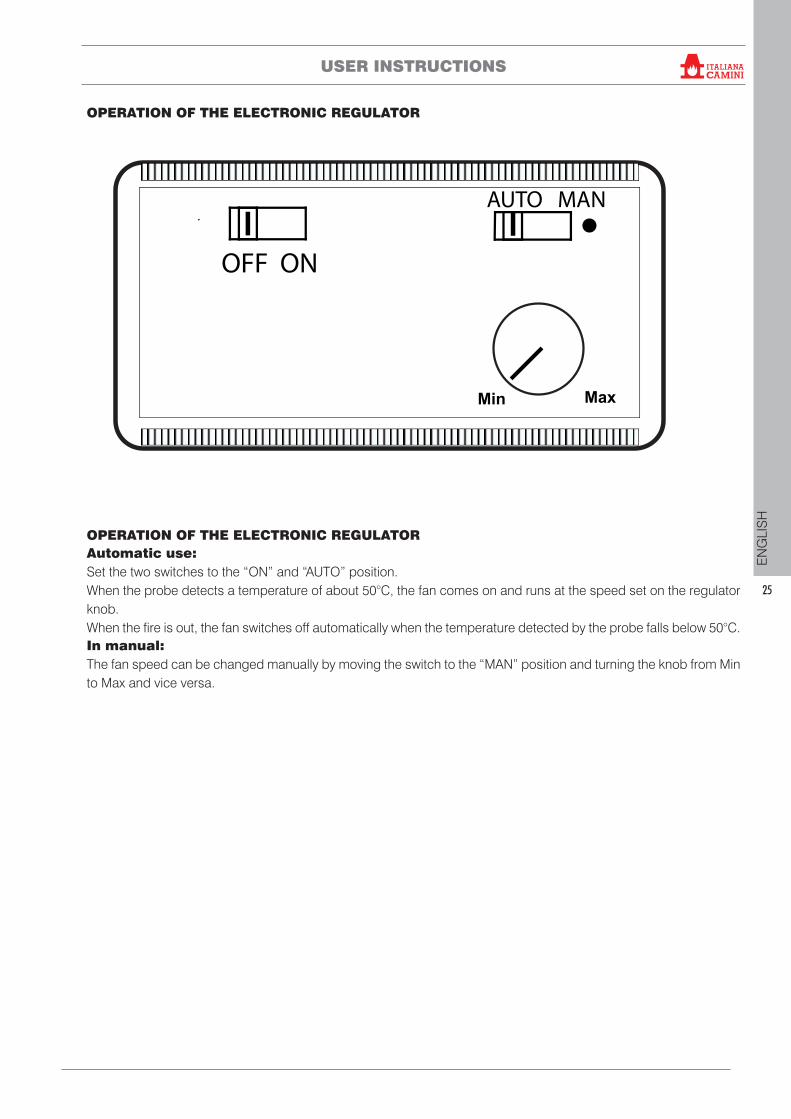
OPERATION OF THE ELECTRONIC REGULATOR Automatic use:Set the two switches to the “ON” and “AUTO” position. When the probe detects a temperature of about 50°C, the fan comes on and runs at the speed set on the regulator knob.When the fire is out, the fan switches off automatically when the temperature detected by the probe falls below 50°C.In manual:The fan speed can be changed manually by moving the switch to the “MAN” position and turning the knob from Min to Max and vice versa.
OPERATION OF THE ELECTRONIC REGULATOR
USER INSTRUCTIONS ®
26
EN
GLI
SH
MAINTENANCE
Cleaning the glassUse specific products for cleaning the door glass (see our Glasskamin price list).Do not spray the product onto the painted areas or onto the door gasket. As an alternative to a cleaning product, you can use a cloth soaked with a bit of white ash and some newspaper. Take care that the ash has no solid parts which may scratch the glass.
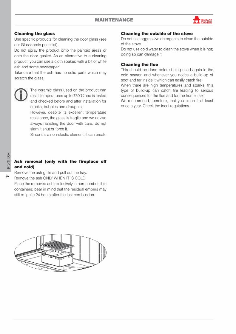
Ash removal (only with the fireplace off and cold)Remove the ash grille and pull out the tray. Remove the ash ONLY WHEN IT IS COLD. Place the removed ash exclusively in non-combustible containers; bear in mind that the residual embers may still re-ignite 24 hours after the last combustion.
The ceramic glass used on the product can resist temperatures up to 750°C and is tested and checked before and after installation for cracks, bubbles and draughts.However, despite its excellent temperature resistance, the glass is fragile and we advise always handling the door with care; do not slam it shut or force it. Since it is a non-elastic element, it can break.
Cleaning the outside of the stoveDo not use aggressive detergents to clean the outside of the stove. Do not use cold water to clean the stove when it is hot; doing so can damage it.
Cleaning the flueThis should be done before being used again in the cold season and whenever you notice a build-up of soot and tar inside it which can easily catch fire. When there are high temperatures and sparks, this type of build-up can catch fire leading to serious consequences for the flue and for the home itself. We recommend, therefore, that you clean it at least once a year. Check the local regulations.
®
27
EN
GLI
SH
TROUBLESHOOTING
1) If smoke comes out of the combustionchamber opening, check whether:The installation is correct (smoke duct, flue, chimneypot; air intake).The wood being used is dry.The door was opened too quickly
2) If the combustion is uncontrolled, checkwhether:The sealing gaskets of the combustion chamber doorare intact.The combustion chamber door is closed properly.
3) If the glass becomes soiled quickly,check whether:The wood being used is dry.All the same, be aware that after a few hours ofoperation, it is normal for a slight layer of soot to formon the glass.
4) If a fire starts in the flue or you needto immediately stop combustion in thefireplace:• if you can do so safely, remove the ash and
embers with metal tools and containers, using thefireproof glove
• contact emergency services if a fire starts
5) If you notice any unusual smells, checkwhether:This is the first ignition: in this case a smell of paint isnormal.
If you do not manage to resolve a problem, contact your retailer or, in countries where they exist, contact the authorised Technical Assistance Centre. They will only be able to assist under warranty if a product fault is proven.
DISPOSALAt the end of its service life, dispose of the product as required by regulations.
TROUBLESHOOTING ®

code 941901-GB 03.18/B
*941901-GB*
Related Documents