1 Tekla Structural Designer 2018i User Guides September 2018 (6.1.06) © 2018 Trimble Solutions Corporation.

Welcome message from author
This document is posted to help you gain knowledge. Please leave a comment to let me know what you think about it! Share it to your friends and learn new things together.
Transcript
1
Tekla Structural Designer
2018i User Guides
September 2018 (6.1.06)
© 2018 Trimble Solutions Corporation.


3

i
Table of Contents
User Guides ................................................................................................................................................................ 1
Basics of Tekla Structural Designer ............................................................................................................... 1
About Tekla Structural Designer ............................................................................................................... 1
Tekla Structural Designer Philosophy ..................................................................................................... 1
How does the Tekla Structural Designer way of working differ from traditional methods?
............................................................................................................................................................................... 2
Interface Overview .......................................................................................................................................... 3
Interface components ............................................................................................................................... 3
File menu ....................................................................................................................................................... 3
Quick Access Toolbar ................................................................................................................................ 4
Viewcube ....................................................................................................................................................... 4
Ribbon ............................................................................................................................................................ 4
Project Workspace ..................................................................................................................................... 4
Structure Tree .............................................................................................................................................. 5
Groups Tree .................................................................................................................................................. 5
Loading Tree ................................................................................................................................................ 6
Wind Model Tree ........................................................................................................................................ 6
Connections Tree ........................................................................................................................................ 6
Status Tree .................................................................................................................................................... 7
Cutting Planes .............................................................................................................................................. 7
Report Index ................................................................................................................................................. 7
Scene Views .................................................................................................................................................. 8
Basic Tooltip ................................................................................................................................................. 8
Select Entity Tooltip ................................................................................................................................... 9
Right-click Menu ......................................................................................................................................... 9
Properties Window .................................................................................................................................... 9
Property Dialog ........................................................................................................................................ 10
Scene Content .......................................................................................................................................... 11
Loading drop list ...................................................................................................................................... 12
Process Window ....................................................................................................................................... 12
Status Bar .................................................................................................................................................... 13
Hiding, re-displaying and moving windows ................................................................................. 14
To auto hide a window: ......................................................................................................................... 14
To close a window: .................................................................................................................................. 15
To re-display a window that has been closed: ............................................................................. 15

Table of Contents
ii
To move a window to a new location .............................................................................................. 15
To dock a window as a tabbed page in another window ........................................................ 15
To open a tabbed page in another window .................................................................................. 15
To dock a window using the docking control .............................................................................. 15
Commands on the ribbon toolbars ....................................................................................................... 16
Right-click menu commands .............................................................................................................. 16
Add XYZ Point... ........................................................................................................................................ 16
Animate... .................................................................................................................................................... 17
Apply property set... ............................................................................................................................... 17
Check Member ......................................................................................................................................... 17
Check members ....................................................................................................................................... 17
Check model ............................................................................................................................................. 17
Check model patches ............................................................................................................................. 18
Check model slabs .................................................................................................................................. 18
Check Panel ............................................................................................................................................... 18
Check Patches ........................................................................................................................................... 18
Check plane ............................................................................................................................................... 18
Check plane patches .............................................................................................................................. 19
Check plane slabs .................................................................................................................................... 19
Check Punching Shear ........................................................................................................................... 19
Check Slabs ................................................................................................................................................ 20
Check Slab Patch ..................................................................................................................................... 21
Check Truss ................................................................................................................................................ 21
Check Wall ................................................................................................................................................. 21
Check walls ................................................................................................................................................ 21
Copy ............................................................................................................................................................. 22
Create property set... .............................................................................................................................. 22
Delete Element ......................................................................................................................................... 22
Design Member ....................................................................................................................................... 22
Design members ...................................................................................................................................... 22
Design model ............................................................................................................................................ 23
Design model patches ........................................................................................................................... 23
Design model slabs ................................................................................................................................ 23
Design Patches ......................................................................................................................................... 24
Design plane ............................................................................................................................................. 24
Design plane patches............................................................................................................................. 25
User Guides (US)
iii
Design plane slabs .................................................................................................................................. 25
Design Punching Shear ......................................................................................................................... 26
Design Slabs .............................................................................................................................................. 26
Design Slab Patch .................................................................................................................................... 27
Design Truss .............................................................................................................................................. 27
Design using Tekla Tedds .................................................................................................................... 28
Design Wall ................................................................................................................................................ 28
Design walls ............................................................................................................................................... 29
Edit ................................................................................................................................................................ 29
Generate Detailing Drawing... ............................................................................................................. 29
Interactive Design.................................................................................................................................... 29
Open load analysis view ....................................................................................................................... 29
Open member view ................................................................................................................................ 29
Open view .................................................................................................................................................. 29
Redraw ......................................................................................................................................................... 29
Report for member ................................................................................................................................. 30
Save Screenshot ....................................................................................................................................... 30
Save View Configuration... ................................................................................................................... 30
Show Member Loading ......................................................................................................................... 30
Undo/Redo ................................................................................................................................................ 30
Zoom Out ................................................................................................................................................... 30
Zoom to selection ................................................................................................................................... 30
Keyboard functions ..................................................................................................................................... 30
Customising the appearance of the user interface ......................................................................... 31
Working with the Project Workspace ................................................................................................... 31
Working with the Structure Tree ....................................................................................................... 31
Structure branch ...................................................................................................................................... 32
Levels branch ............................................................................................................................................ 32
Frames, Slopes and Surfaces branches ........................................................................................... 32
Architectural Grids branch ................................................................................................................... 33
Sub Models branch ................................................................................................................................. 33
Members branch...................................................................................................................................... 33
Slabs branch .............................................................................................................................................. 34
Walls and Roofs branches .................................................................................................................... 35
Result Strips branch ................................................................................................................................ 35
Working with the Groups Tree ........................................................................................................... 35

Table of Contents
iv
How do I re-apply automatic grouping in order to reset manually edited groups? ..... 36
How do I split an existing member group into smaller groups? ........................................... 36
How do I manually move an existing member between groups? ........................................ 36
How do I remove an existing member group? ............................................................................ 36
How do I rename groups? ................................................................................................................... 37
Working with the Loading Tree .............................................................................................................. 37
Working with the Wind Model Tree ................................................................................................. 38
Pressure Zones ......................................................................................................................................... 38
Wind Directions........................................................................................................................................ 38
Wind Loadcases ....................................................................................................................................... 38
How do I use the Wind Model Tree to display a Wind Direction View? ............................ 38
Working with the Connections Tree ................................................................................................ 38
How do I update connections? .......................................................................................................... 38
How do I edit an existing connection? ............................................................................................ 39
How do I locate a connection in the visible view? ...................................................................... 40
Working with the Status Tree .................................................................................................................. 40
The Report Index .......................................................................................................................................... 40
Working with Scene Views, View Regimes and Scene Content ................................................. 40
Opening and Closing and Saving Scene Views............................................................................ 41
How do I open a 3D view of my entire structure? ...................................................................... 41
How do I open a 3D view of an existing sub model? ................................................................ 41
How do I open a 3D view of a single member? ........................................................................... 41
How do I open a 2D view of an existing construction level? .................................................. 41
How do I open a 2D view of an existing frame? .......................................................................... 42
How do I open a 2D view of an existing sloped plane? ........................................................... 42
How do I open a 3D view of an existing curved surface? ........................................................ 42
View Configurations ............................................................................................................................... 43
How do I close a view? .......................................................................................................................... 43
Zooming/Panning/Rotating and Walking through Scene Views .......................................... 43
How do I zoom in/zoom out/zoom extents?................................................................................ 44
How do I pan the view? ........................................................................................................................ 44
How do I manually rotate the view .................................................................................................. 44
How do I use the ViewCube to display one of the preset views? ......................................... 44
How do I walk through the model in a 3D view? ........................................................................ 46
How do I display a 2D view in 3D? ................................................................................................... 46
Controlling Scene Content................................................................................................................... 47
User Guides (US)
v
How do I display the Scene Content window?............................................................................. 47
How do I make selections in the Scene Content Window? ..................................................... 48
How do I reinstate the default Scene Content selections? ...................................................... 50
Scene Content Entity Categories ....................................................................................................... 50
Scene Content Plan Category ............................................................................................................. 66
View Regime .............................................................................................................................................. 74
Structural View ......................................................................................................................................... 74
Solver View ................................................................................................................................................ 75
Results View ............................................................................................................................................... 75
Wind View .................................................................................................................................................. 75
Review View ............................................................................................................................................... 75
Changing the View Regime ................................................................................................................. 75
Scene View Tab Groups ........................................................................................................................ 76
To create a new Tab Group from an existing view tab ............................................................. 76
To create a new Tab Group using the docking control ............................................................ 76
To move a view between Tab Groups ............................................................................................. 77
Working with Command Prompts ............................................................................................................. 77
Selecting Entities .......................................................................................................................................... 78
How do I select an individual entity? ............................................................................................... 78
How do I add further entities to the current selection? ........................................................... 79
How do I select multiple entities by dragging a box? ............................................................... 80
How do I select multiple entities by dragging a line? ............................................................... 80
How do I deselect a single entity from the current selection?............................................... 80
How do I deselect multiple entities by dragging a box or line? ............................................ 81
How do I deselect all entities? ............................................................................................................ 81
Entity selection using Find ................................................................................................................... 81
Member selection using the Structure Tree .................................................................................. 82
Member selection using the Groups Tree...................................................................................... 82
Entity Nodes ....................................................................................................................................................... 82
Starting a New Project .................................................................................................................................... 83
Home toolbar ..................................................................................................................................................... 84
Creating a new project from scratch .................................................................................................... 86
How do I create a new project from scratch? ............................................................................... 86
Working with templates ............................................................................................................................ 87
How do I create a new template? ..................................................................................................... 87
How do I create a new project from a template? ....................................................................... 88
Table of Contents
vi
Model Settings .............................................................................................................................................. 88
How to apply and manage Model Settings ....................................................................................... 89
Model Settings dialog ........................................................................................................................... 89
Design Codes Settings .......................................................................................................................... 89
Units Settings ............................................................................................................................................ 89
References Settings ................................................................................................................................ 90
Loading Settings ...................................................................................................................................... 91
Grouping Settings ................................................................................................................................... 91
Material List Settings .............................................................................................................................. 91
Beam Lines Settings ............................................................................................................................... 91
Rigid Zones Settings .............................................................................................................................. 92
Curved Beams Settings ......................................................................................................................... 93
Validation Settings .................................................................................................................................. 93
Load Reductions Settings ..................................................................................................................... 94
EHF Settings .............................................................................................................................................. 94
User Defined Attributes Settings ....................................................................................................... 95
Graphics View Settings .......................................................................................................................... 96
Structural BIM Settings.......................................................................................................................... 96
Editing project details using Project Wiki ........................................................................................... 97
How do I edit the project details and view the revision history? .......................................... 97
How do I record revisions? .................................................................................................................. 98
Head Codes and Design Codes .............................................................................................................. 98
How do I configure the default design codes to be applied to new projects? ............... 99
How do I change design codes in an existing project? ............................................................ 99
Units .................................................................................................................................................................. 99
How do I configure the default units to be applied to new projects? ................................ 99
How do I change units and units precision in an existing project?.................................... 100
References .................................................................................................................................................... 101
Reference Format basics ..................................................................................................................... 101
How do I configure the default references to be applied to new projects? ................... 103
How do I change reference formats and texts in an existing project? ............................. 103
How do I edit reference format syntax applied to an object type? ................................... 103
How do I change the text used for the materials and characteristics in the reference
format? ...................................................................................................................................................... 104
How do I renumber members? ........................................................................................................ 104
How do I renumber slabs? ................................................................................................................. 105

User Guides (US)
vii
Settings .......................................................................................................................................................... 105
Working with setting sets .................................................................................................................. 105
Selecting a settings set the first time the program is run ...................................................... 106
How do I edit the content of a settings set? ............................................................................... 106
How do I add a different settings set? .......................................................................................... 107
How do I specify the active settings set? ..................................................................................... 107
How do I import a settings set for a different region? ........................................................... 108
How do I delete a settings set? ........................................................................................................ 108
How do I load settings from a settings set to the current project? ................................... 108
How do I save settings from the current project to a settings set? ................................... 109
How do I copy a settings set from one computer to another? ........................................... 109
General and display settings ................................................................................................................. 110
Settings dialog ........................................................................................................................................ 110
Settings Sets Settings .......................................................................................................................... 110
General Settings ..................................................................................................................................... 111
Results Viewer Settings ....................................................................................................................... 112
Structure Defaults.................................................................................................................................. 113
Section Defaults ..................................................................................................................................... 113
Solver Settings ........................................................................................................................................ 113
Scene Settings ........................................................................................................................................ 113
Slab Deflection Settings ...................................................................................................................... 115
How do I adjust the bands in the legend when graphically reviewing ratios? .............. 116
Materials ........................................................................................................................................................ 118
Materials dialog .......................................................................................................................................... 118
Materials - Sections .............................................................................................................................. 119
Sections dialog ....................................................................................................................................... 120
How do I add a user defined section to the database? .......................................................... 121
How do I delete a user defined section from the database? ................................................ 122
How do I edit a user defined section in the database? .......................................................... 122
How do I manage section orders? .................................................................................................. 123
How do I add connection resistances to the database? ......................................................... 123
Select Section dialog ............................................................................................................................ 124
How do I select a section from the Select Section dialog? ................................................... 125
Materials - Material ................................................................................................................................... 125
Materials - Reinforcement ...................................................................................................................... 126
Materials - Metal Decking ...................................................................................................................... 128

Table of Contents
viii
Materials - Shear Connectors ................................................................................................................ 128
Materials - Model....................................................................................................................................... 128
Upgrading the material databases ...................................................................................................... 130
Adding materials to the database when they are not listed for a head code ................ 130
How do I add a material grade that is not listed for a particular head code? ............... 130
How do I add reinforcement that is not listed for a particular head code? .................... 131
How do I change default steel sections to be from a different country for a particular
head code?............................................................................................................................................... 132
How do I change default design section orders for a particular head code? ................ 133
BIM Integration ............................................................................................................................................... 134
Tekla Structures Import and Export .................................................................................................... 134
How do I export a model to Tekla Structures? .......................................................................... 134
Autodesk Revit Import and Export ...................................................................................................... 135
How do I export a model to Autodesk Revit Structure? ......................................................... 135
IFC Export ...................................................................................................................................................... 135
How do I export a model to IFC? .................................................................................................... 135
Westok Cellbeam Import and Export ................................................................................................. 135
How do I export a beam to Westok Cellbeam? ......................................................................... 135
How do I import a beam from Westok Cellbeam? ................................................................... 136
STAAD Export .............................................................................................................................................. 137
How do I export a model to STAAD? ............................................................................................. 137
Export to STAAD - Limitations .......................................................................................................... 137
Robot Export ................................................................................................................................................ 137
How do I export a model to Autodesk Robot Structural Analysis? .................................... 137
Export to Autodesk Robot Structural Analysis - Limitations ................................................. 137
Cloud Export ................................................................................................................................................ 138
How do I export a model to the Cloud? ....................................................................................... 138
TEL File Import ............................................................................................................................................ 138
How do I import a project from a TEL file? .................................................................................. 138
Import from a TEL file - Assumptions and Limitations ............................................................ 139
3D DXF Import ............................................................................................................................................ 142
How do I import from a 3D DXF file? ............................................................................................ 142
Import from a 3D DXF file - Assumptions and Limitations ................................................... 143
Export to IDEA StatiCa Connection Design ...................................................................................... 144
Export to IDEA StatiCa - Limitations............................................................................................... 144
How do I export connections to IDEA StatiCa Connection Design? .................................. 144
User Guides (US)
ix
How do I review IDEA connections that have been designed in Tekla Structural
Designer? .................................................................................................................................................. 145
Export to Tekla Connection Designer................................................................................................. 145
How do I export connections to Tekla Connection Designer?............................................. 145
How do I return connection data from Tekla Connection Designer to Tekla Structural
Designer? .................................................................................................................................................. 145
Export to Tekla Portal Frame Designer .............................................................................................. 146
How do I export portal frames to Tekla Portal Frame Designer? ........................................ 146
How do I return revised sections from Tekla Portal Frame Designer to Tekla Structural
Designer? .................................................................................................................................................. 146
ADAPT Export .............................................................................................................................................. 146
How do I export a model to ADAPT?............................................................................................. 146
Export to ADAPT - Limitations.......................................................................................................... 147
Modeling and Editing Guide ...................................................................................................................... 150
Model toolbar ............................................................................................................................................. 150
Levels group ................................................................................................................................................. 150
Grid and Construction Lines group ..................................................................................................... 151
Steel group ................................................................................................................................................... 153
Concrete group ........................................................................................................................................... 154
Slabs group .................................................................................................................................................. 155
Timber group ............................................................................................................................................... 156
Cold Formed group ................................................................................................................................... 157
Panels group ................................................................................................................................................ 158
Miscellaneous group ................................................................................................................................ 158
Validate .......................................................................................................................................................... 159
Properties and Property Sets ................................................................................................................. 159
How do I edit the properties of a single entity? ........................................................................ 159
How do I edit the properties of multiple entities? .................................................................... 160
How do I edit the properties of a single model object? ......................................................... 160
How do I save properties to a named Property Set from the Properties Window? .... 160
How do I recall a previously saved property set from the Properties Window? ........... 161
How do I save the properties of an existing model object to a named Property Set?
...................................................................................................................................................................... 162
How do I apply a property set to an individual existing model object? .......................... 162
How do I apply a property set to multiple existing model objects? .................................. 162
How do I apply a property set in the Review View?................................................................. 162
How do I graphically review where property sets have been applied? ............................ 163

Table of Contents
x
Manage Property Sets ......................................................................................................................... 163
How do I export a property set? ...................................................................................................... 163
How do I import a property set? ..................................................................................................... 163
How do I delete a property set? ...................................................................................................... 163
Construction Levels ................................................................................................................................... 164
Construction Levels dialog ................................................................................................................. 164
How do I open the Construction Levels dialog? ....................................................................... 166
How do I insert a single Construction Level? .............................................................................. 166
How do I insert multiple Construction Levels?........................................................................... 167
How do I make one level an identical copy of another? ........................................................ 167
How do I make one level an independent copy of another? ............................................... 167
How do I delete a construction level? ........................................................................................... 168
How do I modify the properties associated with a level? ...................................................... 168
Frames and Slopes..................................................................................................................................... 168
How do I create a Frame? .................................................................................................................. 169
How do I create a Slope?.................................................................................................................... 169
Grid Lines, Construction Lines and User Points .............................................................................. 170
Architectural Grids and Grid Lines .................................................................................................. 170
Why are the grid lines not being shown at a particular level? ............................................. 171
How to I apply an existing architectural grid to a specific level? ........................................ 171
How do I create a rectangular grid line system? ....................................................................... 171
How do I create a radial grid line system? ................................................................................... 173
How do I create a single grid line between two points? ........................................................ 175
How do I create a parallel grid line? .............................................................................................. 175
How do I create one or more parallel (quick) grid lines? ....................................................... 176
How do I create a perpendicular grid line? ................................................................................. 177
How do I create a grid arc? ............................................................................................................... 177
How do I import grids from a .dxf, or import a .dxf as a shadow? ..................................... 178
How do I set the initial number or letter used for grids? ....................................................... 179
How do I change the name or color of an existing architectural grid? ............................ 179
How do I change the name of an individual grid-line, -arc? ................................................ 179
How do I renumber all grids? ........................................................................................................... 179
How do I extend, move or rotate grid lines and arcs? ............................................................ 179
How do I stretch, shorten, or rotate a grid line? ....................................................................... 180
How do I move a grid line in a perpendicular direction? ....................................................... 180
How do I stretch or shorten a grid arc? ........................................................................................ 180

User Guides (US)
xi
How do I adjust the radius of a grid arc? ..................................................................................... 180
How do I move a grid arc? ................................................................................................................. 181
Construction Lines ................................................................................................................................ 181
How do I create a rectangular construction line system? ...................................................... 181
How do I create a radial construction line system?.................................................................. 182
How do I create a single construction line between two points? ....................................... 183
How do I create a parallel construction line? ............................................................................. 184
How do I create one or more parallel (quick) construction lines? ...................................... 185
How do I create a perpendicular construction line? ................................................................ 186
How do I create a construction line arc? ...................................................................................... 186
How do I extend, move or rotate construction lines and arcs? ........................................... 187
How do I stretch, shorten, or rotate a construction line? ...................................................... 187
How do I move a construction line in a perpendicular direction?...................................... 187
How do I stretch or shorten a construction arc? ....................................................................... 188
How do I adjust the radius of a construction arc? .................................................................... 188
How do I move a construction arc? ................................................................................................ 188
User Points (XYZ Points) ..................................................................................................................... 188
How do I create a user point? .......................................................................................................... 188
Dimensions ................................................................................................................................................... 189
How do I create a single dimension? ............................................................................................. 189
Steel, Cold Rolled, and Cold Formed member modeling ........................................................... 189
Modeling Steel Columns and Cold Formed Columns ............................................................. 189
Steel column overview ........................................................................................................................ 189
Parapet post overview ......................................................................................................................... 190
How do I specify the column type and section size? ............................................................... 190
How do I create a single column in a 2D View? ........................................................................ 191
How do I create a series of columns in a 2D View? ................................................................. 191
How do I create a single column in a Frame, or Structure View? ....................................... 192
How do I align a column to a specific angle, or an angled gridline? ................................ 192
How do I create an inclined column? ............................................................................................ 192
How do I create a cranked column? ............................................................................................... 192
How do I create a plated or compound section steel column? ........................................... 193
How do I create a concrete filled, or encased concrete steel column? ............................ 194
How do I create a gable post, or parapet post? ........................................................................ 194
How do I specify column connection eccentricity? .................................................................. 194
How do I specify a column splice? .................................................................................................. 195
Table of Contents
xii
How do I modify the position of a single column stack? ....................................................... 195
How do I modify the position of an entire column? ................................................................ 196
Modeling Steel Beams and Cold Formed Beams ...................................................................... 196
Steel beam overview ............................................................................................................................ 196
How do I specify the beam type and section size? .................................................................. 198
How do I create a single span beam? ............................................................................................ 198
How do I create a plated or compound section steel beam? .............................................. 199
How do I create a Westok Cellular, Westok Plated, or Fabsec beam? .............................. 200
How do I create a series of single span beams? ........................................................................ 200
How do I create a continuous beam? ............................................................................................ 201
How do I add a haunch to an existing beam? ............................................................................ 201
How do I create a curved beam? ..................................................................................................... 202
How do I modify the position of a beam? ................................................................................... 203
Modeling Steel Braces and Cold Formed Braces ...................................................................... 203
Steel brace overview ............................................................................................................................ 203
How do I specify the brace type and section size? ................................................................... 204
How do I create a single brace? ....................................................................................................... 205
How do I create an X, K, V or A brace? ......................................................................................... 205
How do I modify the position of a brace? ................................................................................... 206
Modeling Steel Joists ........................................................................................................................... 206
How do I specify the joist type and size? ..................................................................................... 206
How do I create a steel joist? ............................................................................................................ 207
How do I modify the position of a steel joist? ........................................................................... 207
Modeling Steel Trusses ....................................................................................................................... 207
How do I use the Steel Truss Wizard? ........................................................................................... 207
How do I use the Space Truss Wizard? ......................................................................................... 208
How do I define a Free Form Truss? ............................................................................................... 208
How do I edit the geometry of an existing steel truss? .......................................................... 209
How do I edit the section sizes, material grades and section orientations in an existing
steel truss? ............................................................................................................................................... 209
Modeling Portal Frames ...................................................................................................................... 209
Portal frames overview ........................................................................................................................ 209
Portal Frame dialog .............................................................................................................................. 210
How do I create a single span portal frame? .............................................................................. 212
How do I create a multi-span portal frame? ............................................................................... 214
How do I edit the properties of an existing portal frame? .................................................... 214

User Guides (US)
xiii
Modeling Cold Rolled Sections ........................................................................................................ 215
How do I create a single cold rolled section? ............................................................................. 215
How do I modify the position of a cold rolled section? ......................................................... 215
Modeling Web Openings ................................................................................................................... 215
How do I add web openings using Quick Layout? ................................................................... 216
How do I add web openings manually? ....................................................................................... 218
Compound Sections.................................................................................................................................. 221
Concrete member modeling ................................................................................................................. 221
Modeling Concrete Walls ................................................................................................................... 221
Concrete wall overview ....................................................................................................................... 221
How do I specify whether the wall is to be meshed or mid-pier? ...................................... 222
How do I create a concrete wall in a 2D View? .......................................................................... 222
How do I create a concrete wall in a Frame, or Structure View? ......................................... 223
How do I specify extensions? ............................................................................................................ 223
How do I specify releases? ................................................................................................................. 224
Automatic support generation ......................................................................................................... 224
How do I edit a wall support? ........................................................................................................... 225
How do I create a door or window opening in an existing concrete wall? ..................... 225
Modeling Concrete Columns ............................................................................................................ 226
Concrete column overview ................................................................................................................ 226
How do I specify the column shape and size? ........................................................................... 226
How do I create a single concrete column in a 2D View? ...................................................... 226
How do I create a series of concrete columns in a 2D View? ............................................... 227
How do I create a single concrete column in a Frame, or Structure View?..................... 227
How do I align a column to a specific angle, or an angled gridline? ................................ 228
How do I specify the column alignment relative to the grid? .............................................. 228
How do I create a hollow column? ................................................................................................. 229
How do I create an inclined column? ............................................................................................ 229
How do I create a cranked column? ............................................................................................... 230
How do I modify the position of a single column stack? ....................................................... 230
How do I modify the position of an entire column? ................................................................ 231
How do I edit the column alignment or specify an offset? ................................................... 231
Modeling Concrete Beams ................................................................................................................ 232
Concrete beam overview .................................................................................................................... 232
How do I specify the beam size? ..................................................................................................... 232
How do I create a single span concrete beam? ......................................................................... 232
Table of Contents
xiv
How do I create a continuous concrete beam? ......................................................................... 233
How do I create a series of concrete beams? ............................................................................. 234
How do I create a curved concrete beam? .................................................................................. 234
How do I specify the beam alignment relative to the grid? .................................................. 235
How do I specify and use beam flanges for an existing beam? .......................................... 237
How do I specify and use beam flanges for multiple beams simultaneously? .............. 238
How do I edit the beam alignment or specify an offset? ....................................................... 238
How do I modify the position of a beam? ................................................................................... 240
Member global offsets ............................................................................................................................. 240
Global offset combined with major offset example ..................................................................... 241
Global offset only example .................................................................................................................... 242
Slab modeling ............................................................................................................................................. 243
Overview of slab modeling ................................................................................................................ 244
The Concept of Slabs and Slab Panels .......................................................................................... 244
Panel sub-division ................................................................................................................................. 245
Creating slab panels ............................................................................................................................. 246
How do I choose the slab type and specify its properties? ................................................... 246
How do I specify the parent slab to which the panel belongs? ........................................... 246
How do I create slab panels by bay? ............................................................................................. 247
How do I create slab panels by points? ........................................................................................ 247
Modeling slab and mat openings ................................................................................................... 248
How do I create a rectangular slab opening? ............................................................................. 248
How do I create a circular slab opening? ..................................................................................... 249
How do I delete a slab opening? ..................................................................................................... 249
Adding overhangs to existing slab or mat edges ..................................................................... 249
How do I add an overhang to a slab edge? ................................................................................ 250
How do I add a curved overhang to a slab edge? .................................................................... 250
Modeling column drops ..................................................................................................................... 251
How do I create a column drop? ..................................................................................................... 251
Splitting and joining slabs and mats .............................................................................................. 251
How do I split a slab? ........................................................................................................................... 252
How do I join slabs? ............................................................................................................................. 252
Slab steps ...................................................................................................................................................... 253
How do I modify the shape or size of a panel? ......................................................................... 253
How do I modify a panel by moving a node? ............................................................................ 253
How do I modify a panel by moving an edge? .......................................................................... 254

User Guides (US)
xv
How do I apply curved edges to existing slab items? .................................................................. 255
How do I delete an entire slab from my model? ........................................................................... 255
Timber member modeling ..................................................................................................................... 255
Modeling Timber Columns ................................................................................................................ 256
How do I create a single timber column in a 2D View? .......................................................... 256
How do I create a series of timber columns in a 2D View? ................................................... 256
How do I create a single timber column in a Frame, or Structure View? ......................... 257
How do I align a column to a specific angle, or an angled gridline? ................................ 257
How do I create an inclined column? ............................................................................................ 257
How do I create a cranked column? ............................................................................................... 257
How do I modify the position of a single column stack? ....................................................... 258
How do I modify the position of an entire column? ................................................................ 258
Modeling Timber Beams .................................................................................................................... 258
How do I create a single span timber beam? ............................................................................. 258
How do I create a series of single span timber beams? ......................................................... 259
How do I create a continuous timber beam? ............................................................................. 259
How do I create a curved timber beam? ...................................................................................... 260
How do I modify the position of a beam? ................................................................................... 261
Modeling Timber Braces ..................................................................................................................... 262
How do I create a single timber brace? ........................................................................................ 262
How do I create an X, K, V or A brace? ......................................................................................... 262
How do I modify the position of a brace? ................................................................................... 263
Modeling Timber Trusses ................................................................................................................... 263
How do I use the Timber Truss Wizard? ....................................................................................... 263
How do I use the Timber Space Truss Wizard? .......................................................................... 264
How do I define a Free Form Timber Truss? ............................................................................... 264
How do I edit the geometry of an existing timber truss? ...................................................... 265
How do I edit the section sizes, material grades and section orientations in an existing
timber truss?............................................................................................................................................ 265
Panel modeling ........................................................................................................................................... 265
Modeling Roof Panels ......................................................................................................................... 265
How do I create a roof panel? .......................................................................................................... 265
How do I edit the properties of a roof panel? ............................................................................ 266
Modeling Wall Panels .......................................................................................................................... 266
How do I create a wall panel? ........................................................................................................... 266
How do I edit the properties of a wall panel? ............................................................................ 267
Table of Contents
xvi
How do I create a wall panel with a parapet? ............................................................................ 267
How do I reverse a wall panel? ........................................................................................................ 268
Support, Analysis Element and Bearing Wall modeling .............................................................. 268
Modeling Supports ............................................................................................................................... 268
How do I create a single support? .................................................................................................. 268
How do I create a rotated support using 3 Grid Points? ........................................................ 268
How do I create a spring support? ................................................................................................. 269
How do I edit the properties of supports? .................................................................................. 269
Modeling Analysis Elements ............................................................................................................. 269
How do I create an analysis element? ........................................................................................... 269
How do I modify the position of an analysis element?........................................................... 270
Modeling Bearing Walls ...................................................................................................................... 270
Bearing wall overview .......................................................................................................................... 270
How do I create a bearing wall in a 2D View? ............................................................................ 270
How do I create a bearing wall in a Frame, or Structure View? ........................................... 271
User Defined Attributes (UDAs) ............................................................................................................ 271
User Defined Attribute definition .................................................................................................... 272
How do I set up UDA definitions for new models? .................................................................. 273
How do I set up UDA definitions in the current model? ........................................................ 273
Attaching UDA values to members and panels ......................................................................... 273
How do I attach a UDA value using the Properties Window? .............................................. 273
How do I attach an existing UDA value in the Review View? ............................................... 274
How do I graphically review the UDA values that have been attached? ......................... 274
How do I open a file that has been attached as a UDA? ........................................................ 274
Selection by UDA ....................................................................................................................................... 275
Using UDAs to filter reports and material lists ........................................................................... 275
How do I apply a Selected UDAs filter to Material List Review Data? ............................... 275
How do I apply a Selected UDAs filter to a report? ................................................................. 275
Sub Models .................................................................................................................................................. 275
Sub Model Characteristics ................................................................................................................. 276
Definitions ................................................................................................................................................ 276
Basic rules of sub-models .................................................................................................................. 276
Sub Models dialog ..................................................................................................................................... 277
Working with Sub Models.................................................................................................................. 278
How do I open the Sub Models dialog? ....................................................................................... 278
How do I create Sub Models?........................................................................................................... 278

User Guides (US)
xvii
How do I delete Sub Models? .......................................................................................................... 278
How do I open a 3D view of an existing Sub Model? ............................................................. 279
Sub Structures ............................................................................................................................................. 279
Sub Structure Characteristics ................................................................................................................. 279
Working with Sub Structures ............................................................................................................ 279
How do I create a new sub structure? ........................................................................................... 279
How do I add or remove existing elements in an existing sub structure? ...................... 280
How do I review all existing sub structures? ............................................................................... 280
How do I open a 3D view of an existing sub structure? ......................................................... 280
Measure commands ................................................................................................................................. 280
How do I Measure distances? ........................................................................................................... 280
How do I Measure Angles? ................................................................................................................ 281
What are the points I can click to create a member? .............................................................. 281
Model Validation ........................................................................................................................................ 284
How do I run model validation? ...................................................................................................... 284
How do I control which conditions are considered during model validation? .............. 284
Edit commands ........................................................................................................................................... 284
Edit toolbar ................................................................................................................................................... 284
Copying, moving and mirroring objects ....................................................................................... 286
How do I copy elements to a new location? ............................................................................... 286
How do I copy and rotate elements to a new location? ........................................................ 287
How do I move elements to a new location? ............................................................................. 287
How do I move and rotate elements to a new location? ....................................................... 288
How do I mirror elements to a new location? ............................................................................ 288
Copy Loads .............................................................................................................................................. 291
How do I copy all member loads from one span to another? ............................................. 291
How do I copy just one member load if several are applied to the same span? .......... 291
How do I copy panel area, level and slab loads? ...................................................................... 292
How do I copy panel point, line and patch loads? ................................................................... 292
How do I copy structure loads? ....................................................................................................... 293
How do I copy loads to another loadcase? ................................................................................. 293
Joining and splitting members ......................................................................................................... 294
How do I Join Members (Make Continuous)? ............................................................................ 294
How do I Split Members? ................................................................................................................... 294
Concrete Beam Lines ............................................................................................................................ 295
How do I Automatically Join All Concrete Beams (Make Continuous)? ........................... 295

Table of Contents
xviii
Reversing member axes and panel faces ..................................................................................... 295
How do I reverse the local x axis of a beam? ............................................................................. 295
How do I reverse the outward face of a wind panel? .............................................................. 296
Cutting Planes ......................................................................................................................................... 296
How do I activate or deactivate a cutting plane? ...................................................................... 296
How do I move a cutting plane in order to hide part of the model? ................................ 297
How do I reshow the hidden part of the model? ...................................................................... 297
Moving the model, or the DXF shadow ........................................................................................ 297
How do I move the model to a new location? ........................................................................... 297
How do I move the dxf shadow? ..................................................................................................... 298
Rationalizing the model ...................................................................................................................... 298
How do I remove unused sloped planes, frames, grids, and construction lines? ......... 299
How do I update grid and construction lines to extend only a short length beyond
where they are required? ................................................................................................................... 299
Creating infill members ....................................................................................................................... 299
How do I create infills? ........................................................................................................................ 299
Merging Planes ...................................................................................................................................... 301
How do I merge planes? ..................................................................................................................... 301
Adding, moving or deleting XYZ Points ....................................................................................... 301
How do I add, move, or delete user points? ............................................................................... 301
Loading Guide ................................................................................................................................................. 302
Load toolbar ................................................................................................................................................. 302
Structure group .......................................................................................................................................... 302
Wind Load group ....................................................................................................................................... 303
Snow Load group ....................................................................................................................................... 304
Seismic Load group ................................................................................................................................... 304
Decomposition group .............................................................................................................................. 305
Panel Loads group ..................................................................................................................................... 305
Member Loads group ............................................................................................................................... 306
Structure Loads group ............................................................................................................................. 307
Validate .......................................................................................................................................................... 308
Working with Load Cases ....................................................................................................................... 308
Loading Dialog Loadcases Page ...................................................................................................... 308
How do I create load cases? .............................................................................................................. 310
How do I indicate that reductions apply to live (imposed) load cases? ........................... 311
How do I renumber all loadcases? .................................................................................................. 311

User Guides (US)
xix
How do I add loads into a load case? ........................................................................................... 312
Working with Load Groups .................................................................................................................... 312
Loading Dialog Load Groups Page ................................................................................................. 312
How do I create load groups? .......................................................................................................... 314
Example of inclusive and exclusive load groups ....................................................................... 315
Working with Combinations .................................................................................................................. 315
Loading Dialog Combinations Page .............................................................................................. 316
How do I generate load combinations automatically? ........................................................... 317
How do I create load combinations manually?.......................................................................... 318
How do I create a Vibration Mass combination? ...................................................................... 319
How do I import loadcases and combinations from a spreadsheet? ................................ 319
How do I renumber all combinations? .......................................................................................... 323
Working with Envelopes .......................................................................................................................... 323
Loading Dialog Envelopes Page ...................................................................................................... 324
How do I create envelopes? .............................................................................................................. 325
Working with Load Patterns .................................................................................................................. 325
Overview of Load Patterns ................................................................................................................. 325
How do I set an imposed load case to be patterned? ............................................................ 326
How do I set a combination to be patterned? ........................................................................... 327
Pattern Load Cases ............................................................................................................................... 327
How do I update load patterns? ...................................................................................................... 328
Working with the Wind Wizard ............................................................................................................ 329
Running the Wind Wizard .................................................................................................................. 329
How do I run the Wind Wizard? ...................................................................................................... 329
How do I add a new wind direction? ............................................................................................. 330
How do I delete a wind direction? .................................................................................................. 330
How do I delete the entire wind model? ...................................................................................... 330
Reviewing wind zones and wind zone loads .............................................................................. 330
Zone Loads toolbar .............................................................................................................................. 330
How do I open a Wind View? ........................................................................................................... 331
How do I view the Wind Zones? ...................................................................................................... 332
How do I edit a Wind Zone? ............................................................................................................. 332
How do I view the Wind Zone Loads? ........................................................................................... 332
How do I change a Wind Zone Load? ........................................................................................... 333
What happens if I make changes to my model? ....................................................................... 333
Wind loadcase definition .................................................................................................................... 334

Table of Contents
xx
How do I Define Wind Loadcases? ................................................................................................. 334
How do I add new Wind loadcases? .............................................................................................. 334
How do I delete Wind loadcases? ................................................................................................... 335
Working with Simple Wind .................................................................................................................... 335
How do I manually create a loadcase for Simple Wind? ........................................................ 335
How do I create a Simple Wind Load? .......................................................................................... 335
How do I edit Simple Wind load vertical properties? .............................................................. 336
How do I edit Simple Wind load width? ....................................................................................... 336
Working with the Snow Wizard ............................................................................................................ 336
How do I run the Snow Wizard............................................................................................................. 337
Manually applying Snow Loads to Snow Loadcases ................................................................ 337
How do I manually apply a Uniform Snow load? ...................................................................... 337
How do I manually apply a Valley Snow load? .......................................................................... 338
How do I manually apply a Local Drift Snow load? .................................................................. 338
How do I apply a user override to a snow load? ....................................................................... 339
Notes about the graphical display of Snow Loads........................................................................ 339
Update Snow Loads .................................................................................................................................. 340
Delete Snow ................................................................................................................................................. 340
Working with Seismic Loads .................................................................................................................. 340
Running the Seismic Wizard ............................................................................................................. 340
How do I run the Seismic Wizard? .................................................................................................. 340
How do I display the Horizontal Design Spectrum? ..................................................................... 341
How do I delete Seismic Loads? ........................................................................................................... 341
Load Decomposition................................................................................................................................. 341
How do I manually decompose slab loads for an individual construction level? ......... 342
How do I manually decompose slab loads for all the required levels? ............................ 342
How do I view the decomposed loads (either with, or without load values)? ............... 342
Working with Panel Loads ...................................................................................................................... 343
How do I create a point load? .......................................................................................................... 343
How do I create a line load? .............................................................................................................. 344
How do I create a patch load?.......................................................................................................... 344
How do I create a polygonal load? ................................................................................................. 345
How do I create a perimeter load? ................................................................................................. 345
How do I create a variable patch load? ........................................................................................ 346
How do I create an area load? .......................................................................................................... 347
How do I create a variable area load? ........................................................................................... 347

User Guides (US)
xxi
How do I create a slab load? ............................................................................................................. 348
How do I create a level load? ............................................................................................................ 348
How do I edit a load? ........................................................................................................................... 348
How do I delete a load? ...................................................................................................................... 348
Working with Member Loads ................................................................................................................ 348
How do I create a full UDL? ............................................................................................................... 348
How do I create a partial length UDL or VDL? ........................................................................... 349
How do I create a trapezoidal load? .............................................................................................. 349
How do I create a point or moment load? .................................................................................. 350
How do I create a torsion full UDL? ............................................................................................... 350
How do I create a partial length torsion UDL or torsion VDL? ............................................ 350
Working with Structure Loads ............................................................................................................... 350
How do I create a nodal load? ......................................................................................................... 351
How do I create a temperature load? ............................................................................................ 351
How do I create a settlement load? ............................................................................................... 351
Analysis Guide.................................................................................................................................................. 351
Analyze toolbar ............................................................................................................................................... 351
Analysis Options ......................................................................................................................................... 355
How to apply and manage Analysis Options.............................................................................. 355
To modify analysis options in the current project .................................................................... 355
To modify analysis option defaults for future projects ........................................................... 356
1st Order Non-Linear Options .............................................................................................................. 356
2nd Order Non-Linear Options ............................................................................................................ 357
1st Order Vibration Options .................................................................................................................. 357
2nd Order Buckling Options .................................................................................................................. 359
1st Order Seismic Options ...................................................................................................................... 359
Modification Factors ................................................................................................................................. 361
Meshing ......................................................................................................................................................... 362
Composite Steel Beams ........................................................................................................................... 362
Working with FE meshed slabs ............................................................................................................. 363
How do I specify whether a level uses meshed slabs in analysis or FE load
decomposition? ..................................................................................................................................... 363
How do I control the mesh parameters to be used? ............................................................... 364
How do I apply different mesh parameters at different levels? .......................................... 364
How do I review the slab mesh prior to running the analysis? ............................................ 365
Slab mesh groups .................................................................................................................................. 365

Table of Contents
xxii
Example of mesh groups at a slab step ........................................................................................ 365
Discontinuity of force contours at slab steps (and column drops) .................................... 366
Mesh group boundary warnings ..................................................................................................... 368
Working with FE meshed walls ............................................................................................................. 368
How do I control the global wall mesh parameters to be used? ........................................ 369
How do I override the global wall mesh parameters for an individual wall? ................. 369
How do I review the wall mesh prior to running the analysis? ............................................ 369
Working with rigid and semi-rigid diaphragms ............................................................................. 370
How do I activate rigid diaphragm action within a slab? ....................................................... 370
How do I activate semi-rigid diaphragm action within a slab? ........................................... 370
How do I identify which nodes are constrained by rigid diaphragms? ............................ 370
How do I intentionally exclude individual nodes from a rigid diaphragm? .................... 371
How do I intentionally exclude a slab panel from a diaphragm? ....................................... 372
Running an analysis .................................................................................................................................. 372
How do I run 1st order linear or non-linear analysis? ............................................................. 372
How do I run a 1st order linear analysis? ..................................................................................... 372
How do I run a 1st order non-linear analysis? ........................................................................... 372
How do I run 2nd order linear or non-linear analysis? ........................................................... 373
How do I run a 2nd order linear analysis? ................................................................................... 373
How do I run a 2nd order non-linear analysis?.......................................................................... 373
How do I run 1st order vibration analysis?....................................................................................... 373
How do I run 2nd order buckling analysis? ..................................................................................... 373
How do I run 1st or 2nd order seismic analysis? ....................................................................... 374
How do I run a 1st order RSA seismic analysis? ........................................................................ 374
How do I run a 2nd order RSA seismic analysis? ...................................................................... 374
How do I run FE chasedown and Grillage chasedown analysis? .............................................. 374
How do I run a Analyze All (Static)? .................................................................................................... 374
Graphical display of the solver model (Solver View) .................................................................... 375
How do I open a Solver View? .......................................................................................................... 375
How do I display the Solver Model used for a particular analysis type? .......................... 375
How do I see Solver Node and Solver Element properties? ................................................. 376
Tabular data (Solver Model Data) ........................................................................................................ 376
Tabular display of Node and Element Data ................................................................................ 376
How do I view tabulated node co-ordinates and degrees of freedom? .......................... 376
How do I view tabulated solver element properties? .............................................................. 376
Tabular display of Reactions, Deflections and End Forces .................................................... 376
User Guides (US)
xxiii
How do I view tabular results for support reactions? .............................................................. 376
How do I view tabular results for nodal deflections? .............................................................. 377
How do I view tabular results for solver element end forces? ............................................. 377
What does the asterisk next to certain nodes signify in the Element End Forces table?
...................................................................................................................................................................... 378
How do I view tabular results for wall lines? ............................................................................... 378
Tabular display of Vibration and Buckling Analysis results ................................................... 378
How do I view tabular results for mode shapes? ...................................................................... 378
How do I view the summed mass for vibration mass combinations? ............................... 378
How do I view the dynamic masses for vibration mass combinations? ........................... 379
How do I view the active masses by node? ................................................................................. 379
How do I view the total masses by node? ................................................................................... 379
How do I view vibration frequencies and modal masses? ..................................................... 379
How do I view buckling factors? ...................................................................................................... 379
Graphical display of the analysis results (Results View) .............................................................. 380
Results toolbar ........................................................................................................................................ 380
Result Type group ................................................................................................................................. 380
Scale Settings group ............................................................................................................................ 381
Reactions group ..................................................................................................................................... 381
1D Results group ................................................................................................................................... 382
Deflections group .................................................................................................................................. 383
Sway Drift and Storey Shear group ................................................................................................ 383
Notional Horizontal Forces ................................................................................................................ 384
2D Results group ................................................................................................................................... 384
AsReq group............................................................................................................................................ 385
2D Deflections group ........................................................................................................................... 386
2D Strip Results group ........................................................................................................................ 386
2D Wall Results group ......................................................................................................................... 387
Text group ................................................................................................................................................ 387
Cross checking the sum of reactions against the load input ................................................ 388
Loadcase Properties ............................................................................................................................. 388
Displaying 1D and 2D results, deflections and reactions ....................................................... 390
How do I choose which analysis to see the results for? ......................................................... 390
How do I choose the loadcase, combination, or envelope to see the results for? ...... 391
How do I display Support Reactions? ............................................................................................ 391
How do I display Beam End Reactions? ........................................................................................ 391

Table of Contents
xxiv
How do I display 1D Results and 1D Deflections? .................................................................... 391
How do I display 2D Results and 2D Deflections? .................................................................... 392
How do I animate 1D and 2D Deflections? ................................................................................. 392
How do I display AsReq contours? ................................................................................................. 393
What are 2D Wall Results and how do I display them? .......................................................... 393
How do I increase the amplitude of the diagrams? ................................................................. 394
How do I see a 3D display of the results in a 2D view? .......................................................... 394
How do I customise the display of 2D contours? ..................................................................... 395
Displaying sway/drift, wind drift and storey shear ................................................................... 395
How do I display Sway Deflections and Relative Sway Deflections? ................................. 396
How do I display Drift Deflections? ................................................................................................ 396
How do I display Wind Drift Deflections? .................................................................................... 396
How do I display Dir 1 and Dir 2 Shears? ..................................................................................... 397
Displaying Mode Shapes .................................................................................................................... 397
How do I display mode shapes? ...................................................................................................... 397
Displaying Notional Forces and Seismic Equivalent Lateral Forces ................................... 397
EHF .............................................................................................................................................................. 397
Notional Loads ....................................................................................................................................... 398
NHF ............................................................................................................................................................. 398
Seismic ....................................................................................................................................................... 398
Displaying RSA Seismic Results ....................................................................................................... 398
Result Type .............................................................................................................................................. 398
Mode Shapes .......................................................................................................................................... 398
1D Element Results ............................................................................................................................... 399
Story Shear ............................................................................................................................................... 400
Support Reactions ................................................................................................................................. 402
2D Wall Results ...................................................................................................................................... 403
Working with 2D Strips and displaying Strip Results .............................................................. 404
Result Strip Overview ........................................................................................................................... 404
How do I create a Result Strip? ........................................................................................................ 405
How do I delete a Result Strip? ........................................................................................................ 406
How do I view the results for a Result Strip? .............................................................................. 406
How are the strip results calculated? ............................................................................................. 406
Displaying analysis results for individual members (Loading Analysis View) ................. 407
Loading Analysis toolbar .................................................................................................................... 407
How do I open a Loading Analysis View? .................................................................................... 408
User Guides (US)
xxv
Displaying RSA Seismic Results in a Loading Analysis View ................................................. 408
Loading Analysis View Properties for Columns ......................................................................... 410
Loading Analysis View Properties for Beams .............................................................................. 413
Analysis results sign conventions ........................................................................................................ 416
Introduction ............................................................................................................................................. 416
Axis Systems ............................................................................................................................................ 416
General ...................................................................................................................................................... 416
Object Orientation ................................................................................................................................ 416
Diagram Conventions .......................................................................................................................... 417
Global Coordinate System ................................................................................................................. 417
Global Axis System and Applied Load Directions ..................................................................... 417
Resulting Deflection Directions ........................................................................................................ 418
Building Directions 1 and 2 ............................................................................................................... 418
Building Directions and Applied Load Directions ..................................................................... 418
Resulting Deflection Directions ........................................................................................................ 419
User Coordinate System ..................................................................................................................... 419
UCS Axis System and Applied Load Directions .......................................................................... 419
Resulting Deflection Directions ........................................................................................................ 419
1D Member Local Coordinate System........................................................................................... 420
General case for 1D members .......................................................................................................... 420
Special case for 1D members ........................................................................................................... 425
Mid-pier Wall Coordinate System ................................................................................................... 428
Wall Axis System and Applied Load Directions ......................................................................... 428
Result Axis System and Directions .................................................................................................. 429
2D Member Local Coordinate System........................................................................................... 433
Horizontal Panel Local Axis System and Applied Load Directions ..................................... 433
Vertical and Sloped Panel Local Axis System and Applied Load Directions ................... 434
2D Member Forces Sign Convention ................................................................................................. 435
Result Line Coordinate System ........................................................................................................ 437
Result Axis System ................................................................................................................................ 437
General Case ........................................................................................................................................... 437
Special Case ............................................................................................................................................. 437
Result Strip Coordinate System ....................................................................................................... 438
Result Axis System ................................................................................................................................ 438
General Case ........................................................................................................................................... 438
Special Case ............................................................................................................................................. 439
Table of Contents
xxvi
Foundation Reaction Coordinate System .................................................................................... 439
Result Axis System and Directions .................................................................................................. 439
Reactions .................................................................................................................................................. 440
Design Guide .................................................................................................................................................... 440
Design toolbar ................................................................................................................................................. 441
Design Options ........................................................................................................................................... 443
How to apply and manage Design Options ................................................................................ 443
To modify design options in the current project ...................................................................... 443
To modify design option defaults for future projects ............................................................. 443
Design Options-Analysis ......................................................................................................................... 444
Design Options-General .......................................................................................................................... 444
Design Options-Concrete-Reinforcement Parameters ................................................................ 445
Design Options-Concrete-Beam ..................................................................................................... 446
Concrete - Beam - Reinforcement Settings ................................................................................ 446
Concrete - Beam - Detailing Options ............................................................................................ 447
Concrete - Beam - Top Longitudinal Bar Pattern ...................................................................... 448
Concrete - Beam - Bottom Longitudinal Bar Pattern .............................................................. 449
Concrete - Beam - Link Settings ...................................................................................................... 450
Concrete - Beam - General Parameters ........................................................................................ 452
Design Options-Concrete-Column ................................................................................................. 453
Concrete - Column - Reinforcement Layout ............................................................................... 453
Concrete - Column - Detailing Options ........................................................................................ 455
Concrete - Column - General Parameters .................................................................................... 456
Design Options-Concrete-Wall ........................................................................................................ 457
Concrete - Wall - Reinforcement Layout ...................................................................................... 457
Concrete - Wall - Detailing Options ............................................................................................... 459
Concrete - Wall - General Parameters ........................................................................................... 459
Design Options-Concrete-Slab ........................................................................................................ 460
Concrete - Slab - Reinforcement Layout ...................................................................................... 460
Concrete - Slab - Patches ................................................................................................................... 461
Concrete - Slab - General Parameters ........................................................................................... 462
Design Options-Concrete Punching Shear ...................................................................................... 462
Design Options-Concrete Isolated Foundations ....................................................................... 464
Concrete - Isolated Foundations - Reinforcement Layout .................................................... 464
Concrete - Isolated Foundations - Foundation Size ................................................................ 465
Concrete - Isolated Foundations - General Parameters ......................................................... 465

User Guides (US)
xxvii
Concrete - Isolated Foundations - Piles........................................................................................ 466
Design Options-Concrete Mat Foundations .................................................................................... 467
Design Options-Composite Beams ..................................................................................................... 467
Design Options-Design Forces ............................................................................................................. 467
Design Options-Design Groups ........................................................................................................... 468
Design Options-Autodesign .................................................................................................................. 468
Design Options-Design Warnings ....................................................................................................... 469
Design Options-Steel Joists ................................................................................................................... 471
Design Options-Sway & Drift Checks ................................................................................................ 471
Static Analysis & Design .......................................................................................................................... 472
Member design modes ............................................................................................................................ 473
Do I run Design Steel, Design Concrete or Design All? .......................................................... 473
Design Steel ............................................................................................................................................. 474
Design Concrete .................................................................................................................................... 474
Design All ................................................................................................................................................. 474
Do I run Design...(Gravity), or Design...(Static)? .......................................................................... 474
Design (Gravity) ...................................................................................................................................... 474
Design (Static) ......................................................................................................................................... 474
Design Steel (Gravity) .......................................................................................................................... 475
How do I run Design Steel (Gravity)? ............................................................................................. 475
Design Steel (Static).............................................................................................................................. 476
How do I run Design Steel (Static)? ................................................................................................ 476
Design Concrete (Gravity) .................................................................................................................. 477
How do I run Design Concrete (Gravity)? .................................................................................... 477
Design Concrete (Static) ..................................................................................................................... 478
How do I run Design Concrete (Static)?........................................................................................ 478
Design All (Gravity) ............................................................................................................................... 479
How do I run Design All (Gravity)? ................................................................................................. 479
Design All (Static) .................................................................................................................................. 480
How do I run Design All (Static)?..................................................................................................... 480
How can I check if Autodesign is on or off? ............................................................................... 481
RSA Analysis & Design ............................................................................................................................. 481
Design Steel (RSA)................................................................................................................................. 481
How do I run Design Steel (RSA)? ................................................................................................... 482
Design Concrete (RSA) ........................................................................................................................ 482
How do I run Design Concrete (RSA)?........................................................................................... 483
Table of Contents
xxviii
Design All (RSA) ..................................................................................................................................... 483
How do I run Design All (RSA)?........................................................................................................ 484
Slab design, patches and punching shear ........................................................................................ 484
Create Patches ........................................................................................................................................ 484
What is a patch?..................................................................................................................................... 485
How do I create a column patch? ................................................................................................... 485
How do I create a beam patch? ....................................................................................................... 486
How do I create a wall patch? .......................................................................................................... 488
How do I create a panel patch? ....................................................................................................... 489
How do I edit the properties of an existing patch? .................................................................. 491
How do I resize an existing patch? ................................................................................................. 491
Perform Slab Design............................................................................................................................. 492
How do I design or check all slab panels in the model? ........................................................ 492
How do I design or check all slab panels in a single level/slope/sub-model? .............. 492
How do I design an individual slab panel? .................................................................................. 492
How do I only check all slab panels in the model? .................................................................. 492
How do I only check all slab panels in a single level/slope/sub-model? ......................... 493
How do I check an individual slab panel? .................................................................................... 493
Perform Patch Design .......................................................................................................................... 493
How do I design or check all patches in the model? ............................................................... 493
How do I design or check all patches in a single level/slope/sub-model? ..................... 493
How do I design an individual patch? ........................................................................................... 494
How do I only check all patches in the model? ......................................................................... 494
How do I only check all patches in a single level/slope/sub-model? ................................ 494
How do I check an individual patch? ............................................................................................. 494
Add Punching Shear Checks ............................................................................................................. 495
How do I create a Punching Check item? .................................................................................... 495
Punching Check axis orientation ..................................................................................................... 495
How do I specify stud rail reinforcement? ................................................................................... 496
Overview of the Edit Reinforcement Dialog ................................................................................ 496
How do I edit the properties of an existing Punching Check item? .................................. 499
Perform Punching Shear Checks ..................................................................................................... 500
How do I run punching shear checks for the entire structure? ........................................... 501
How do I selectively run punching shear checks for a level, slope, or sub structure? 501
How do I check an individual punching check item? .............................................................. 501
How do I design an individual punching check item? ............................................................ 502
User Guides (US)
xxix
Floor Vibration ............................................................................................................................................ 502
How do I create a Floor Vibration Check item? ......................................................................... 502
How do I create a check which considers two or three adjoining spans? ....................... 503
How do I edit the properties of an existing Floor Vibration Check item? ....................... 504
How do I check vibration for all Floor Vibration Check items? ............................................ 504
How do I check floor vibration for an individual Floor Vibration Check item? .............. 504
Designing/checking individual members or subsets of members .............................................. 505
Slab Deflection Guide ................................................................................................................................... 505
Slab Deflection toolbar ............................................................................................................................ 506
Options, Events and Analyze Groups ............................................................................................. 506
Results, Events and Scale Settings Groups .................................................................................. 507
Check Lines, Slab Deflections and Show/Alter State Groups ............................................... 507
Slab Deflection Options ........................................................................................................................... 508
How to apply and manage Slab Deflection Options ............................................................... 508
To modify slab deflection options in the current project ...................................................... 508
To modify slab deflection option defaults for future projects ............................................. 509
New Load Event Defaults ........................................................................................................................ 509
New Check Defaults .................................................................................................................................. 509
Aging, Creep & Shrinkage ...................................................................................................................... 510
Modification Factors ................................................................................................................................. 510
Iterative Cracked Section Analysis .................................................................................................. 510
Use of Convergence settings to control the Iterative Cracked Section Analysis. ......... 511
Event Sequences ........................................................................................................................................ 511
Load Event Sequences Dialog .......................................................................................................... 512
How do I edit an Event Sequence? ................................................................................................. 514
How do I define a Custom Event Sequence? .............................................................................. 514
How do I apply Custom Event Sequences to specific submodels? .................................... 515
Deflection Checks ...................................................................................................................................... 515
Slab Deflection Check Catalogue .................................................................................................... 515
How do I add a check to the Deflection Check Catalogue? .................................................. 516
Slab Deflection Analysis .......................................................................................................................... 516
How do I run slab deflection analysis for the current sub model? ......................................... 517
How do I run slab deflection analysis for all sub models? ......................................................... 517
How do I run slab deflection analysis for selected sub models? ............................................. 517
Check Lines ................................................................................................................................................... 517
Check Line Overview ............................................................................................................................ 517

Table of Contents
xxx
How do I create a Check Line? ......................................................................................................... 518
How do I delete a Check Line? ......................................................................................................... 518
Graphical display of Slab Deflection Results ................................................................................... 518
Slab Deflection Results ........................................................................................................................ 519
How do I display Deflection contours? ......................................................................................... 519
How do I display Extent of Cracking? ............................................................................................ 519
How do I display Relative Stiffness? ............................................................................................... 520
How do I display Effective Reinforcement? ................................................................................. 520
Check Line Results ................................................................................................................................ 520
How do I view deflections along all Check Lines? .................................................................... 520
How do I view detailed deflections/average slopes for an individual Check Line?...... 521
How do I view the Check Line Status? ........................................................................................... 521
How do I view the Check Line Utilisation? ................................................................................... 521
Slab Deflection Status .......................................................................................................................... 521
How do I view the Slab Deflection Status? .................................................................................. 521
How do I view the Slab Deflection Utilisation? .......................................................................... 522
Slab Deflection Reports ........................................................................................................................... 522
Check Line Report ................................................................................................................................. 522
How do I view a report for an individual Check Line? ............................................................. 522
How do I view a report for all/multiple Check Lines? .............................................................. 522
Effective Modulus Report ................................................................................................................... 522
How do I generate an Effective Modulus Report? .................................................................... 523
Slab Reinforcement ................................................................................................................................... 523
How do I increase the amplitude of the diagrams? ................................................................. 524
How do I customise the display of 2D contours? ..................................................................... 524
Foundations Guide ......................................................................................................................................... 525
Foundations toolbar ...................................................................................................................................... 525
Foundation Options....................................................................................................................................... 527
Pile Type Catalogue .................................................................................................................................. 527
How do I set up the pile type catalogue? .................................................................................... 528
Pad and Strip Base modelling ............................................................................................................... 528
How do I create a pad base column? ................................................................................................. 528
How do I create a strip base wall? ....................................................................................................... 528
Pile Cap modelling .................................................................................................................................... 529
How do I create a pile cap? .................................................................................................................... 529
User Defined Pile Arrangement ....................................................................................................... 530
User Guides (US)
xxxi
Pile Arrangement dialog ..................................................................................................................... 530
How do I open the Pile Arrangement dialog? ............................................................................ 531
How do I create a user defined pile arrangement? .................................................................. 531
Isolated Foundation design ................................................................................................................... 532
How do I design or check all pad and strip bases in the model? ............................................ 532
How do I design or check all pile caps in the model? ................................................................. 532
How do I check an individual isolated foundation? ...................................................................... 532
How do I design an individual isolated foundation? .................................................................... 532
Mat Foundation modelling .................................................................................................................... 533
How do I create a minimum area or rectangular mat?................................................................ 533
How do I create a strip mat? ................................................................................................................. 534
How do I create an area mat? ............................................................................................................... 534
How do I create a mat within bays? .................................................................................................... 534
How do I create a piled mat? ............................................................................................................ 534
How do I specify if a piled mat is ground bearing? ................................................................. 535
How do I place an individual pile in a mat? ................................................................................ 535
How do I place a pile array in a mat? ............................................................................................ 535
How do specify the pile direction of an inclined pile? ............................................................ 535
Mat design, patches and punching shear ......................................................................................... 537
Design Mats ............................................................................................................................................. 537
How do I design or check all mats in the model? ..................................................................... 537
How do I check all mats in a single floor? ................................................................................... 537
How do I design all mats in a single floor? ................................................................................. 538
How do I check an individual mat? ................................................................................................ 538
How do I design an individual mat? ............................................................................................... 538
Design Review Guide .................................................................................................................................... 538
Review toolbar ................................................................................................................................................. 539
Review Data toolbar ...................................................................................................................................... 543
Working with the Review View ............................................................................................................. 544
Setting the Design Type to Review ..................................................................................................... 544
Reviewing Member Design ................................................................................................................ 544
Member Design Status ........................................................................................................................ 544
Member Design Ratio .......................................................................................................................... 545
Depth Ratio .............................................................................................................................................. 545
Reviewing Foundation and Pile Design ........................................................................................ 545
Foundation Design and Pile Design Status ................................................................................. 545

Table of Contents
xxxii
Foundation Design and Pile Design Ratios ................................................................................. 546
Reviewing Slab Design ........................................................................................................................ 546
Slab/Mat Design Status....................................................................................................................... 546
Slab/Mat Design Ratio......................................................................................................................... 547
Slab/Mat Design droplist .................................................................................................................... 547
Reviewing Connection Design .......................................................................................................... 547
Connection Design Status .................................................................................................................. 547
Connection Design Ratio .................................................................................................................... 548
Show/Alter State .................................................................................................................................... 548
Show/Alter State .................................................................................................................................... 548
Auto\Check Design ............................................................................................................................... 548
BIM Status ................................................................................................................................................ 549
Braced/Bracing ....................................................................................................................................... 550
Column Splices ....................................................................................................................................... 551
Concrete Beam Flanges ...................................................................................................................... 552
Copy Properties...................................................................................................................................... 552
Deflection Limits .................................................................................................................................... 553
Diaphragm On\Off ................................................................................................................................ 554
Drift check ................................................................................................................................................ 555
Fixed\Pinned............................................................................................................................................ 556
Gravity Only ............................................................................................................................................. 557
Material Grade ........................................................................................................................................ 558
Property Sets ........................................................................................................................................... 558
Punch Check Position .......................................................................................................................... 559
Report Filter ............................................................................................................................................. 559
Restrained\Unrestrained ..................................................................................................................... 560
Section ....................................................................................................................................................... 561
SFRS Direction ........................................................................................................................................ 562
SFRS Type ................................................................................................................................................. 563
Shear Connectors .................................................................................................................................. 564
Size Constraints ...................................................................................................................................... 565
Slab Reinforcement .............................................................................................................................. 566
Stud auto layout .................................................................................................................................... 567
Sub Structures ........................................................................................................................................ 568
Sway check ............................................................................................................................................... 568
Sub Structures ........................................................................................................................................ 569

User Guides (US)
xxxiii
Transverse reinforcement ................................................................................................................... 569
UDA ............................................................................................................................................................ 570
Web openings ........................................................................................................................................ 570
Westok openings ................................................................................................................................... 570
Wind drift ................................................................................................................................................. 570
Working with the Review Data view ................................................................................................... 571
How do I display a Design Summary in a Review Data table? ............................................. 571
How do I display Sway Results in a Review Data table? ......................................................... 572
How do I display Storey Shear in a Review Data table? ......................................................... 572
How do I display Drift Results in a Review Data table? .......................................................... 572
How do I display Seismic Drift Results in a Review Data table? .......................................... 572
How do I display Wind Drift Results in a Review Data table? .............................................. 573
How do I display Connection Resistance checks in a Review Data table? ...................... 573
How do I display a Material List in a Review Data table? ....................................................... 573
Reporting Guide .............................................................................................................................................. 574
Report toolbar ............................................................................................................................................. 574
Contents group ........................................................................................................................................... 574
Filters Group ................................................................................................................................................ 575
Appearance group ..................................................................................................................................... 576
Navigation group ....................................................................................................................................... 576
Export group ................................................................................................................................................ 576
Reports and Report Terminology Explained ........................................................................................ 577
Creating Reports ........................................................................................................................................ 579
How do I configure a Model Report? ............................................................................................ 579
How do I display a Model Report? ................................................................................................. 580
How do I configure a Member Report? ........................................................................................ 581
How do I display an individual Member Report? ...................................................................... 581
How do I select the Member Report style to use in the Model Report? ......................... 581
How do I select the Member Report style to use in an individual Member Report? .. 582
How do I modify the Report Structure? ........................................................................................ 582
How do I print a Report? .................................................................................................................... 582
Filtering Reports ......................................................................................................................................... 583
What are the different types of filter? ........................................................................................... 583
How do I create and edit a filter? .................................................................................................... 583
How do I apply a filter? ....................................................................................................................... 584
Formatting Reports ................................................................................................................................... 585

Table of Contents
xxxiv
Report Settings ....................................................................................................................................... 585
How do I apply report settings? ...................................................................................................... 585
Report Settings-Styles ......................................................................................................................... 585
Report Settings-Page Options ......................................................................................................... 586
Report Settings-Table Options ........................................................................................................ 586
Report Settings-Document Options .............................................................................................. 586
Report Settings-Picture Fonts........................................................................................................... 587
Headers and Footers ............................................................................................................................ 587
How do I enter company details (logo, address etc.) in the header? ................................ 587
How do I enter project specific details (job ref, structure etc.) in the header? .............. 588
How do I create a new header layout? .......................................................................................... 588
Exporting Reports ...................................................................................................................................... 589
How do I export a report to PDF? ................................................................................................... 589
How do I export a report to Word? ................................................................................................ 589
How do I export a report to Excel? ................................................................................................. 590
How do I export a report to Tedds? ............................................................................................... 590
Example Reports ......................................................................................................................................... 590
Solver Model Data Report ................................................................................................................. 590
How do I show a Solver Model Data Report? ............................................................................ 590
Building Loading Report ..................................................................................................................... 590
How do I show a Building Loading Report? ................................................................................ 591
Building Analysis Checks Report ..................................................................................................... 591
How do I show a Building Analysis Checks Report? ................................................................ 591
Building Design Report ....................................................................................................................... 591
How do I show a Building Design Report? .................................................................................. 591
Material Listing Report ........................................................................................................................ 591
How do I show a Material Listing Report? ................................................................................... 591
Beam End Forces Report .................................................................................................................... 592
What data is output in each Beam End Forces Report configuration? ............................. 592
How do I change the default Beam End Forces Report configuration? ........................... 593
How do I show a Beam End Forces Report? ............................................................................... 594
Bracing Forces Report.......................................................................................................................... 594
How do I show a Bracing Forces Report? .................................................................................... 594
Foundation Reactions Report ........................................................................................................... 594
How do I show a Foundation Reactions Report? ...................................................................... 596
Seismic Design Report ......................................................................................................................... 596
User Guides (US)
xxxv
How do I show a Seismic Design Report?.................................................................................... 596
Member Design Report ...................................................................................................................... 596
How do I show a Member Design Report? ................................................................................. 596
Connection Resistance Check Report ............................................................................................ 596
How do I create a Connection Resistance Check Report? ..................................................... 597
How do I show a Connection Resistance Check Report? ....................................................... 597
Setting up the Report Page Header and Footer ................................................................................. 597
Drawing Guide ................................................................................................................................................. 597
Draw toolbar ..................................................................................................................................................... 598
Overview of Drawings ................................................................................................................................... 599
Drawing Settings ........................................................................................................................................ 601
How to apply and manage Drawing Settings ............................................................................. 601
To modify drawing settings in the current project ................................................................... 601
To modify drawing setting defaults for future projects .......................................................... 601
Export Preferences ................................................................................................................................ 602
How do I add a new drawing scale? .............................................................................................. 602
Layer Configuration .............................................................................................................................. 602
How do I add, modify, copy or remove a layer configuration? ........................................... 603
Layer Style ................................................................................................................................................ 604
How do I add, modify, copy or remove a drawing style? ...................................................... 604
Drawing Options ........................................................................................................................................ 605
Options - Planar Drawings ................................................................................................................. 606
General tab .............................................................................................................................................. 606
Beams tab ................................................................................................................................................. 607
Columns tab ............................................................................................................................................ 607
Walls tab ................................................................................................................................................... 608
Slabs and Mats tab ............................................................................................................................... 608
Loads tab .................................................................................................................................................. 609
Options - Member Details ...................................................................................................................... 610
Beam Detail - Content ......................................................................................................................... 610
Grouped Beams tab .............................................................................................................................. 610
Levels tab .................................................................................................................................................. 610
Cross sections tab ................................................................................................................................. 610
Bar Labels tab ......................................................................................................................................... 611
Dimensions tab ...................................................................................................................................... 612
Quantities tab ......................................................................................................................................... 612

Table of Contents
xxxvi
Beam Detail - Style ............................................................................................................................... 612
Beam Labels tab ..................................................................................................................................... 612
Cross sections tab ................................................................................................................................. 613
Longitudinal Bars tab ........................................................................................................................... 613
Stirrups/Links tab................................................................................................................................... 613
Dimensions tab ...................................................................................................................................... 614
Column Detail - Content .................................................................................................................... 614
Grouped Columns tab ......................................................................................................................... 614
Levels tab .................................................................................................................................................. 614
Cross sections tab ................................................................................................................................. 614
Dimensions tab ...................................................................................................................................... 614
Column Detail - Style ........................................................................................................................... 615
Column Labels tab ................................................................................................................................ 615
Cross sections tab ................................................................................................................................. 615
Longitudinal Bars tab ........................................................................................................................... 615
Ties/Links tab .......................................................................................................................................... 615
Dimensions tab ...................................................................................................................................... 616
Wall Detail - Content ........................................................................................................................... 616
Levels tab .................................................................................................................................................. 616
Cross sections tab ................................................................................................................................. 616
Dimensions tab ...................................................................................................................................... 616
Wall Detail - Style .................................................................................................................................. 617
Wall Labels tab ....................................................................................................................................... 617
Cross sections tab ................................................................................................................................. 617
Horizontal & Vertical Bars tab .......................................................................................................... 617
Horizontal Bars and Ties/Links tab ................................................................................................. 618
Dimensions tab ...................................................................................................................................... 618
Options - Member Schedules ............................................................................................................... 618
Beam Schedule Options ...................................................................................................................... 618
General tab .............................................................................................................................................. 618
Bar Key tab ............................................................................................................................................... 619
Column Schedule Options ...................................................................................................................... 619
Wall Schedule Options ............................................................................................................................. 620
Options - Slabs and Mats ....................................................................................................................... 620
Layout ........................................................................................................................................................ 620
Slabs and Mats tab ............................................................................................................................... 620

User Guides (US)
xxxvii
Patches tab .............................................................................................................................................. 622
Punching Shear tab .............................................................................................................................. 623
Punching Check Detail - Content .................................................................................................... 623
Dimensions tab ...................................................................................................................................... 623
Quantities tab ......................................................................................................................................... 623
Punching Check Detail - Style .......................................................................................................... 623
General tab .............................................................................................................................................. 623
Options - Foundations ............................................................................................................................. 624
Foundation Layout ................................................................................................................................ 624
Slabs and Mats tab ............................................................................................................................... 624
Isolated Foundations tab .................................................................................................................... 625
Isolated Foundation Detail-Content .............................................................................................. 626
Isolated Foundation Detail-Style ..................................................................................................... 627
Planar Drawings .......................................................................................................................................... 627
How do I create a General Arrangement drawing? .................................................................. 628
How do I create a Beam End Forces drawing? ........................................................................... 628
How do I create a Column Splice Loads drawing? ................................................................... 629
How do I create a Foundation Reactions drawing? ................................................................. 629
How do I create a Loading Plan drawing? ................................................................................... 630
DXF Export Preferences dialog ............................................................................................................. 630
Member Details .......................................................................................................................................... 631
How do I create a concrete beam detail? .................................................................................... 632
How do I create a concrete column detail? ................................................................................. 632
How do I create a concrete wall detail? ........................................................................................ 633
How do I create a non concrete beam detail? ........................................................................... 633
How do I create a non concrete column detail?........................................................................ 634
Slabs and Mats ............................................................................................................................................ 634
How do I create a Punching Check Detail drawing? ................................................................ 634
How do I create a Slab or Mat Layout drawing? ....................................................................... 635
Foundations ................................................................................................................................................. 635
How do I create a Base or Pile Cap Detail drawing? ................................................................ 636
How do I create a Foundation Layout drawing? ....................................................................... 636
Drawing Management ............................................................................................................................. 637
How do I add new drawings and specify their content? ........................................................ 637
How do I specify the layout? ............................................................................................................. 638
For load dependant drawing variants, how do I specify the loading? .............................. 638

Table of Contents
xxxviii
How do I view a drawing? .................................................................................................................. 638
How do I consolidate the bar marks used on concrete detail drawings? ........................ 638
How do I apply a revision to a drawing? ...................................................................................... 639
How do I view the revision history of a drawing? ..................................................................... 639
Concrete Member Schedules ................................................................................................................ 639
How do I create a concrete beam schedule? .............................................................................. 640
How do I create a concrete column schedule? .......................................................................... 641
How do I create a concrete wall schedule? ................................................................................. 641
Schedule Management ............................................................................................................................ 641
How do I add new drawings and specify their content? ........................................................ 642
How do I specify the layout? ............................................................................................................. 642
How do I view a drawing? .................................................................................................................. 642
How do I consolidate the bar marks? ............................................................................................ 642
How do I apply a revision to a drawing? ...................................................................................... 643
How do I view the revision history of a drawing? ..................................................................... 643
Glossary ................................................................................................................................................................... 645

1
User Guides
The User Guides describe the general operation of the program.
Topics in this section
• Basics of Tekla Structural Designer
• Starting a New Project
• BIM Integration
• Modeling and Editing Guide
• Loading Guide
• Analysis Guide
• Design Guide
• Slab Deflection Guide
• Foundations Guide
• Design Review Guide
• Reporting Guide
• Drawing Guide
• Object Properties
Basics of Tekla Structural Designer
About Tekla Structural Designer
Tekla Structural Designer is a tool for structural engineers. It is an integrated model-based 3D
solution for analysis and design1 of multi-material structures. Tekla Structural
Designer features interactive modeling, automated structural analysis and design, drawing
and report creation.
Tekla Structural Designer supports multiple design codes including ACI/AISC, Eurocodes,
British, Indian and Australian Standards.
Tekla Structural Designer Philosophy
One of the main aims of Tekla Structural Designer is to allow you to rapidly build your model,
apply loads and then design it for an appropriate set of design forces. On a day to day basis,

User Guides
2
you don’t need to be involved with the underlying analysis models required to achieve this,
instead you can focus on the design results…
To make this possible, the program automatically creates and analyses multiple solver
models, each one being based on a different but widely accepted approach.
By designing for the forces from all the solver models, you can be confident that each
scenario has been catered for.
How does the Tekla Structural Designer way of working differ from
traditional methods?
The traditional modelling, analysis and design process might be summarized under the
following headings:
1. Provide a way to input/describe the model.
2. Analyze it.
3. Design it.
4. Produce Calculations.
5. Produce Drawings.
A similar process is followed in Tekla Structural Designer with the exception that analysis and
design are merged into a single process.
As a result the workflow is as follows:
1. Input the Geometry and Loads:
A key requirement these days is “BIM Integration” - the ability to be able to transfer data
from one application to another. Tekla Structural Designer has tools to automatically
import model data from Neutral Files and from 3D DXF to facilitate this.
Of course you can always build the model directly - the Quick Start Guides covers many
of the modeling techniques required to achieve this so no further mention is required
here.
Once the physical model has been created, the next step is to load it. A wide range of
loads can be applied in a flexible system of loadcases, with a wind load generator
available to automatically create the wind load cases. Load combinations can also be
generated automatically.
You should also consider pattern loading - patterned beam loads can be created
automatically; patterned slab loads can be manually created for design of slabs.
2. Combined Analysis and Design:
Tekla Structural Designer automatically performs the analyses required to enable member
design to proceed: in effect Analysis and Design (with the exception of slab design) are
combined into a single automated process.
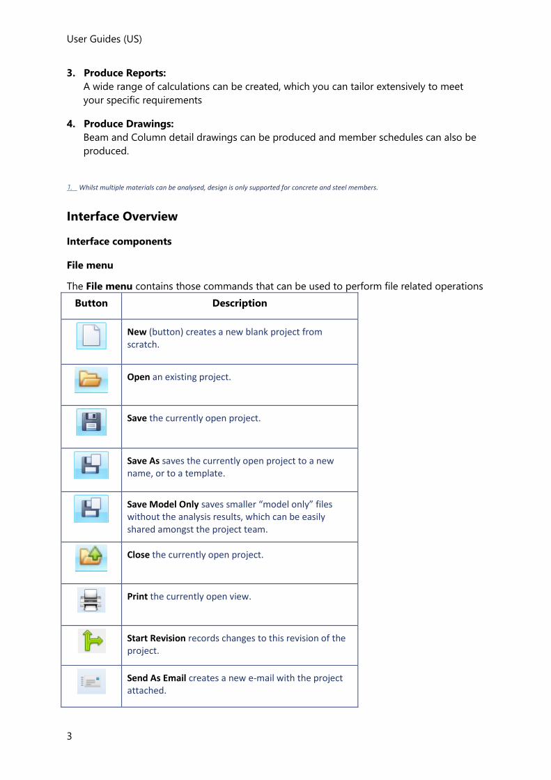
User Guides (US)
3
3. Produce Reports:
A wide range of calculations can be created, which you can tailor extensively to meet
your specific requirements
4. Produce Drawings:
Beam and Column detail drawings can be produced and member schedules can also be
produced.
1. Whilst multiple materials can be analysed, design is only supported for concrete and steel members.
Interface Overview
Interface components
File menu
The File menu contains those commands that can be used to perform file related operations
Button Description
New (button) creates a new blank project from scratch.
Open an existing project.
Save the currently open project.
Save As saves the currently open project to a new name, or to a template.
Save Model Only saves smaller “model only” files without the analysis results, which can be easily shared amongst the project team.
Close the currently open project.
Print the currently open view.
Start Revision records changes to this revision of the project.
Send As Email creates a new e-mail with the project attached.
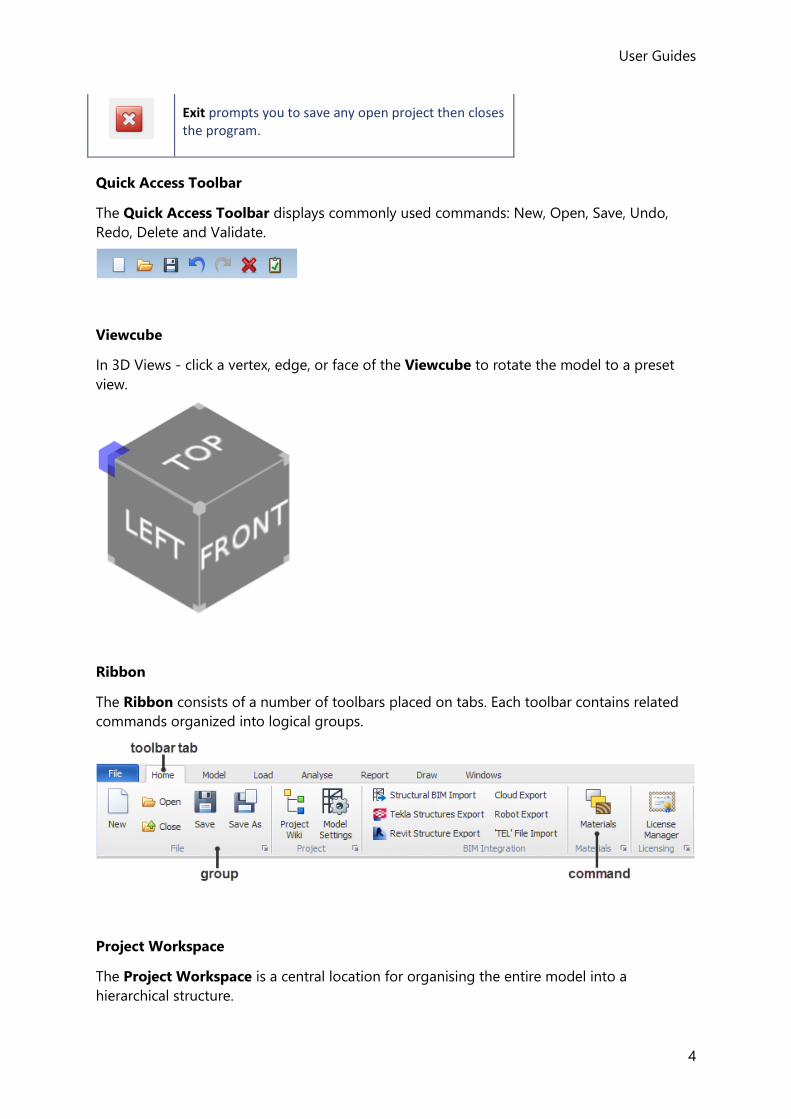
User Guides
4
Exit prompts you to save any open project then closes the program.
Quick Access Toolbar
The Quick Access Toolbar displays commonly used commands: New, Open, Save, Undo,
Redo, Delete and Validate.
Viewcube
In 3D Views - click a vertex, edge, or face of the Viewcube to rotate the model to a preset
view.
Ribbon
The Ribbon consists of a number of toolbars placed on tabs. Each toolbar contains related
commands organized into logical groups.
Project Workspace
The Project Workspace is a central location for organising the entire model into a
hierarchical structure.
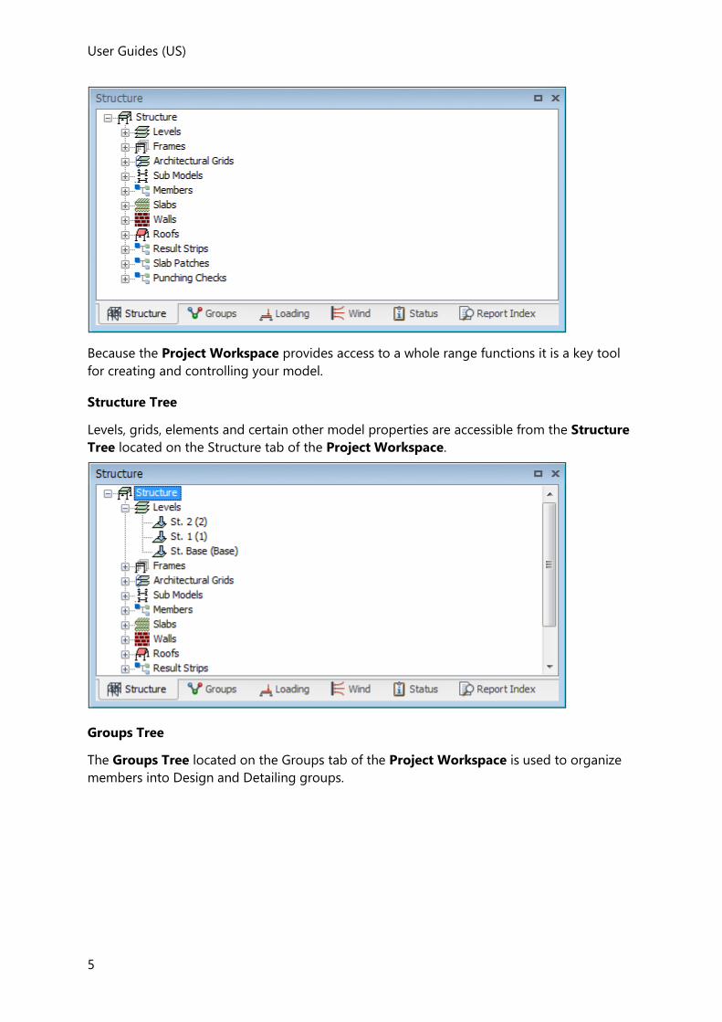
User Guides (US)
5
Because the Project Workspace provides access to a whole range functions it is a key tool
for creating and controlling your model.
Structure Tree
Levels, grids, elements and certain other model properties are accessible from the Structure
Tree located on the Structure tab of the Project Workspace.
Groups Tree
The Groups Tree located on the Groups tab of the Project Workspace is used to organize
members into Design and Detailing groups.
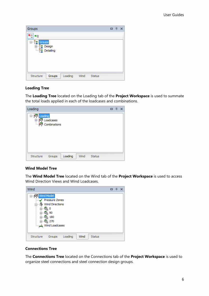
User Guides
6
Loading Tree
The Loading Tree located on the Loading tab of the Project Workspace is used to summate
the total loads applied in each of the loadcases and combinations.
Wind Model Tree
The Wind Model Tree located on the Wind tab of the Project Workspace is used to access
Wind Direction Views and Wind Loadcases.
Connections Tree
The Connections Tree located on the Connections tab of the Project Workspace is used to
organize steel connections and steel connection design groups.

User Guides (US)
7
Status Tree
The Status Tree located on the Status tab of the Project Workspace is used to review the
status of the model and analyses that have been performed. It also displays the
import/export status.
Cutting Planes
The Cutting Planes symbol is displayed in the bottom right hand corner of the Scene View
when any of the cutting planes are currently active.
Report Index
The Report Index is located in the Project Workspace. When a Report is displayed it
contains bookmarks that can be used to move around the report.

User Guides
8
Scene Views
2D and 3D views (and solver views) of the model, sub models, frames, construction levels
and individual members can be displayed in tabbed windows.
Basic Tooltip
Basic tooltips display the name of the command and may also include a brief description of
its function.
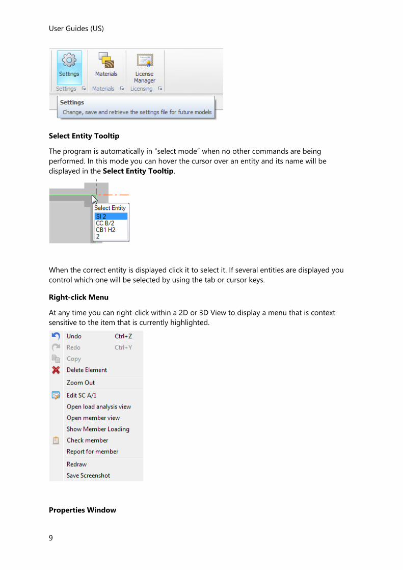
User Guides (US)
9
Select Entity Tooltip
The program is automatically in “select mode” when no other commands are being
performed. In this mode you can hover the cursor over an entity and its name will be
displayed in the Select Entity Tooltip.
When the correct entity is displayed click it to select it. If several entities are displayed you
control which one will be selected by using the tab or cursor keys.
Right-click Menu
At any time you can right-click within a 2D or 3D View to display a menu that is context
sensitive to the item that is currently highlighted.
Properties Window
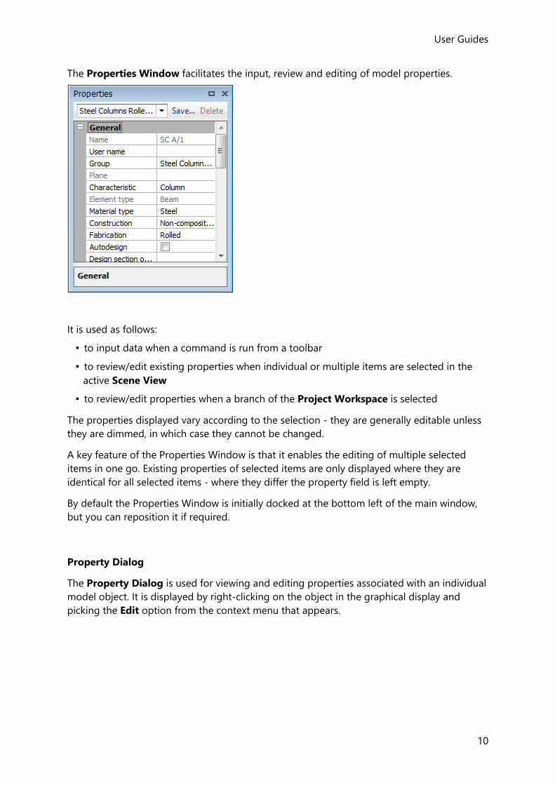
User Guides
10
The Properties Window facilitates the input, review and editing of model properties.
It is used as follows:
• to input data when a command is run from a toolbar
• to review/edit existing properties when individual or multiple items are selected in the
active Scene View
• to review/edit properties when a branch of the Project Workspace is selected
The properties displayed vary according to the selection - they are generally editable unless
they are dimmed, in which case they cannot be changed.
A key feature of the Properties Window is that it enables the editing of multiple selected
items in one go. Existing properties of selected items are only displayed where they are
identical for all selected items - where they differ the property field is left empty.
By default the Properties Window is initially docked at the bottom left of the main window,
but you can reposition it if required.
Property Dialog
The Property Dialog is used for viewing and editing properties associated with an individual
model object. It is displayed by right-clicking on the object in the graphical display and
picking the Edit option from the context menu that appears.
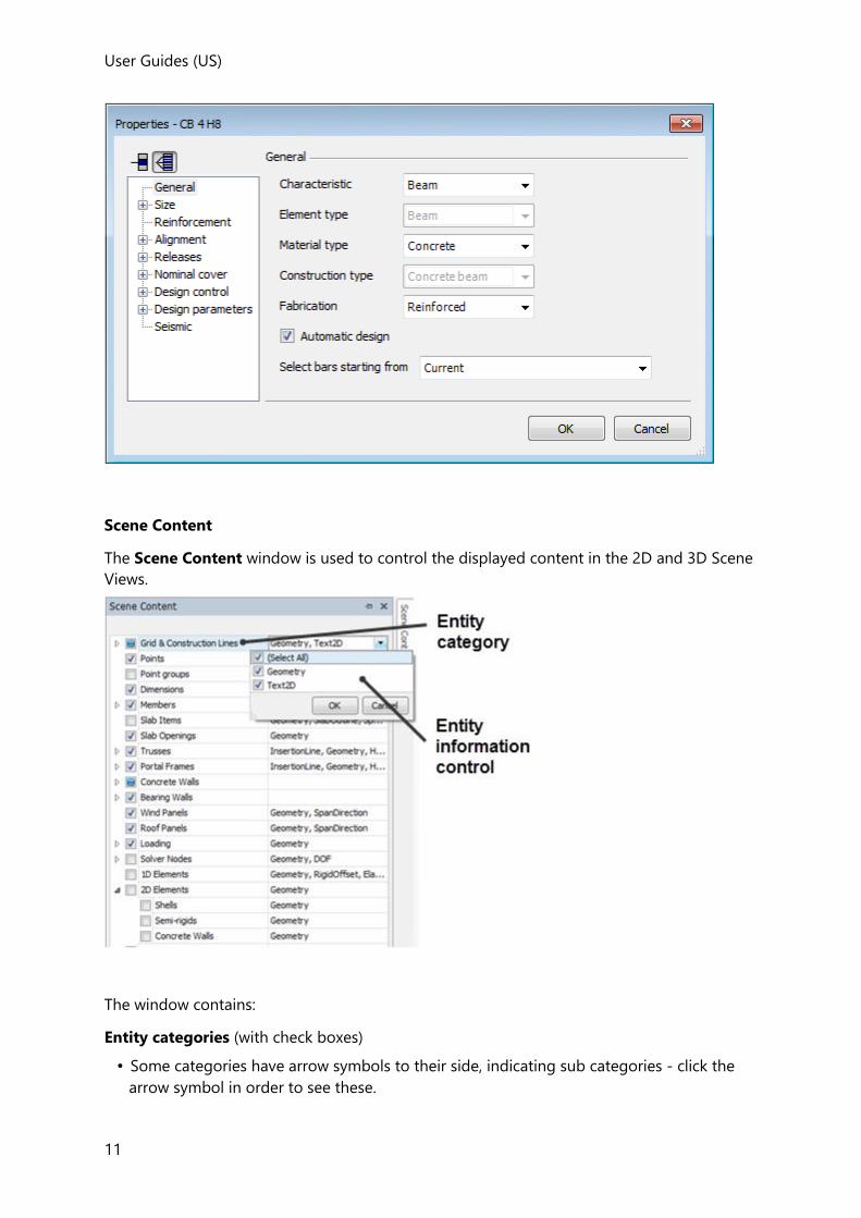
User Guides (US)
11
Scene Content
The Scene Content window is used to control the displayed content in the 2D and 3D Scene
Views.
The window contains:
Entity categories (with check boxes)
• Some categories have arrow symbols to their side, indicating sub categories - click the
arrow symbol in order to see these.
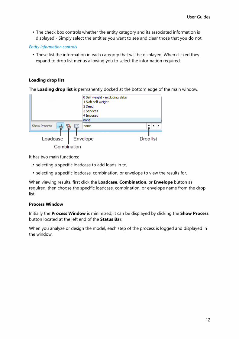
User Guides
12
• The check box controls whether the entity category and its associated information is
displayed - Simply select the entities you want to see and clear those that you do not.
Entity information controls
• These list the information in each category that will be displayed. When clicked they
expand to drop list menus allowing you to select the information required.
Loading drop list
The Loading drop list is permanently docked at the bottom edge of the main window.
It has two main functions:
• selecting a specific loadcase to add loads in to,
• selecting a specific loadcase, combination, or envelope to view the results for.
When viewing results, first click the Loadcase, Combination, or Envelope button as
required, then choose the specific loadcase, combination, or envelope name from the drop
list.
Process Window
Initially the Process Window is minimized; it can be displayed by clicking the Show Process
button located at the left end of the Status Bar.
When you analyze or design the model, each step of the process is logged and displayed in
the window.
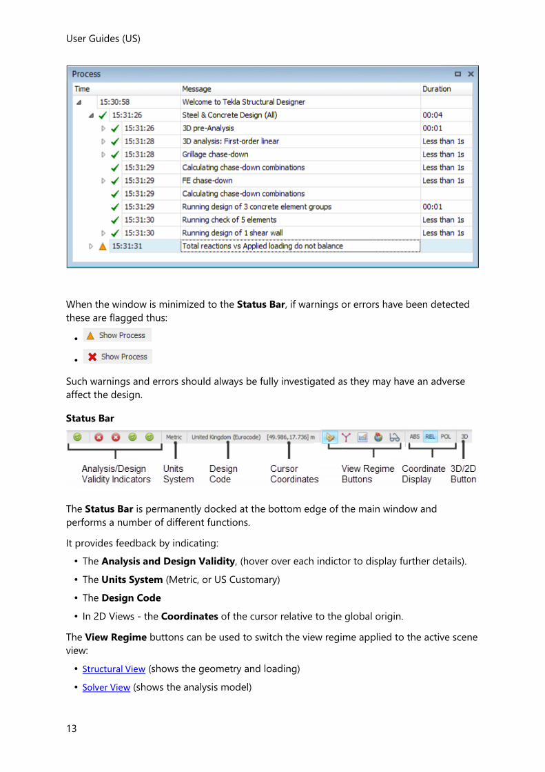
User Guides (US)
13
When the window is minimized to the Status Bar, if warnings or errors have been detected
these are flagged thus:
•
•
Such warnings and errors should always be fully investigated as they may have an adverse
affect the design.
Status Bar
The Status Bar is permanently docked at the bottom edge of the main window and
performs a number of different functions.
It provides feedback by indicating:
• The Analysis and Design Validity, (hover over each indictor to display further details).
• The Units System (Metric, or US Customary)
• The Design Code
• In 2D Views - the Coordinates of the cursor relative to the global origin.
The View Regime buttons can be used to switch the view regime applied to the active scene
view:
• Structural View (shows the geometry and loading)
• Solver View (shows the analysis model)

User Guides
14
• Results View (shows the analysis results)
• Wind View (shows the wind model)
• Review View (for graphically interrogating the model properties/status)
It sets the display method for coordinate tooltips:
• ABS (Absolute)
• REL (Relative)
• POL (Polar)
In 2D views - the 3D/2D toggle button is activated:
• 2D - the content of the 2D view is displayed in plan
• 3D - the content of the 2D view is displayed in isometric
Hiding, re-displaying and moving windows
The Properties Window, Process Window, Scene Content and each of the Project
Workspace tabs (shown below) are displayed in windows that can be resized and
repositioned, or docked to an edge of another window.
To auto hide a window:
To increase the area available for graphical display you can choose to Auto Hide any of the
windows.
1. Click the window Auto Hide option icon ( ).
2. The window contracts immediately to a tab.
3. Click the window tab to expand it.
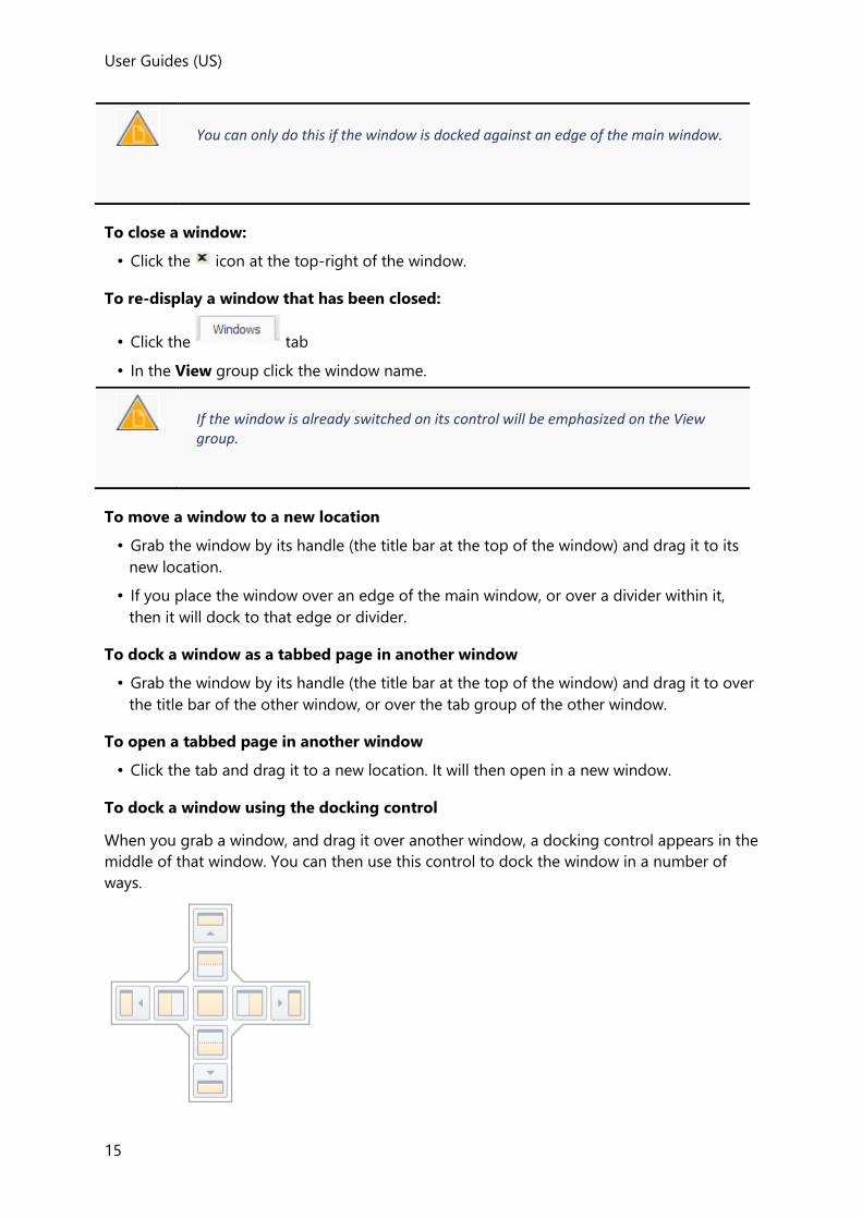
User Guides (US)
15
You can only do this if the window is docked against an edge of the main window.
To close a window:
• Click the icon at the top-right of the window.
To re-display a window that has been closed:
• Click the tab
• In the View group click the window name.
If the window is already switched on its control will be emphasized on the View group.
To move a window to a new location
• Grab the window by its handle (the title bar at the top of the window) and drag it to its
new location.
• If you place the window over an edge of the main window, or over a divider within it,
then it will dock to that edge or divider.
To dock a window as a tabbed page in another window
• Grab the window by its handle (the title bar at the top of the window) and drag it to over
the title bar of the other window, or over the tab group of the other window.
To open a tabbed page in another window
• Click the tab and drag it to a new location. It will then open in a new window.
To dock a window using the docking control
When you grab a window, and drag it over another window, a docking control appears in the
middle of that window. You can then use this control to dock the window in a number of
ways.

User Guides
16
1. To dock to a tabbed page of the current window:
• Drag the grabbed window over the central button of the docking control and then
release the mouse.
The grabbed window becomes a tab of the current window.
2. To dock as a new window at an edge of the current window:
• Drag the grabbed window over one of the buttons adjacent to the central button of the
docking control and then release the mouse.
The grabbed window is docked above, below, to the left, or to the right of the current
window (depending on the button chosen in the docking control).
3. To dock as a new window at an edge of the main window:
• Drag the grabbed window over one of the outer buttons of the docking control and then
release the mouse.
The grabbed window is docked at the top, bottom, left, or right of the main window
(depending on the button chosen in the docking control).
Commands on the ribbon toolbars
The majority of commands are organized on toolbars located on the ribbon.
• Home toolbar
• Model toolbar
• Edit toolbar
• Load toolbar
• Zone Loads toolbar
• Analyze toolbar
• Design toolbar
• Report toolbar
• Draw toolbar
• Results toolbar
• Review toolbar
• Review Data toolbar
• Loading Analysis toolbar
Right-click menu commands
Hovering the cursor over the top of an entity and right-clicking will display a menu
containing options which vary depending upon the entity being clicked on.
Add XYZ Point...
User points (XYZ Points) can be used to connect beams, columns, braces etc. without having
to define an intersection between grid lines or construction lines.
User Guides (US)
17
Animate...
Once 1D or 2D deflections are being displayed, you can use the Animate command to
animate them.
Apply property set...
Use the Apply property set command to display the Select property set dialog, so that a
previously saved property set can be applied to the currently highlighted element.
Check Member
Use the Check Member command to check an individual member using the existing Static
or RSA analysis results. A results dialog is then displayed allowing the detailed calculations to
be viewed.
Do any of the following:
To check Do this
a member from a 2D or 3D view
1. Hover the mouse pointer over the member.
2. If a different entity is highlighted, press the <down
arrow> cursor key until the correct reference is shown in
the Select Entity tooltip
3. Right click and select Check Member > Static/RSA (as
required)
a member from the Structure Tree
1. In the Members branch locate the member reference.
2. Right click and select Check Member > Static/RSA (as
required)
Check members
Use the Check members command to check the selected members using the existing Static
or RSA analysis results.
1. Right click the Members branch (or any of its sub branches) in the Structure Tree.
2. Select Check members > Static/RSA (as required)
Check model
Use the Check model command to check all members in the model using the existing Static
or RSA analysis results.
1. Right click the Structure branch in the Structure Tree.
2. Select Check model > Static/RSA (as required)
User Guides
18
Check model patches
Use the Check model patches command to perform a check of all patches in the model
using the existing analysis results.
1. Right click the Structure branch in the Structure Tree.
2. Select Check model patches
Check model slabs
Use the Check model slabs command to perform a check of all slab panels in the model
using the existing analysis results.
1. Right click the Structure branch in the Structure Tree.
2. Select Check model slabs
Check Panel
Use the Check Panel command to check the highlighted slab panel using the existing
analysis results. The results dialog is then displayed allowing the detailed calculations to be
viewed.
1. Hover the mouse pointer over the panel.
2. If a different entity is highlighted, press the <down arrow> cursor key until the correct
reference is shown in the Select Entity tooltip
3. Right click and select Check Panel
Check Patches
Use the Check Patches command to check all slab patches in the model or just those in the
current level/slope using the existing analysis results.
Do any of the following:
To check Do this
all patches in the model 1. Right click in the 3D Structure view.
2. Select Check Patches
all patches in the current level/slope
1. Right click in the level or slope view.
2. Select Check Patches
Check plane
Use the Check plane command to perform a check of all members in the selected plane
using the existing analysis results.
Do any of the following:
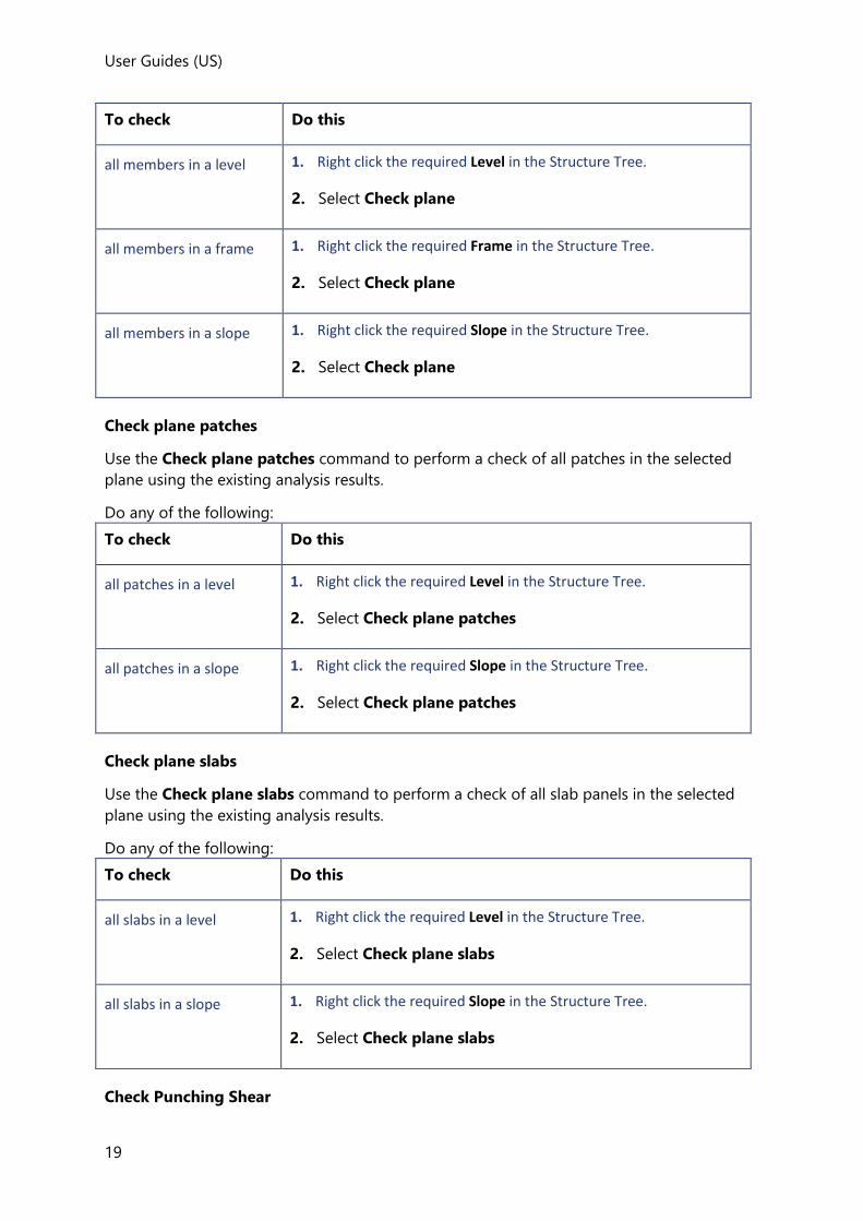
User Guides (US)
19
To check Do this
all members in a level 1. Right click the required Level in the Structure Tree.
2. Select Check plane
all members in a frame 1. Right click the required Frame in the Structure Tree.
2. Select Check plane
all members in a slope 1. Right click the required Slope in the Structure Tree.
2. Select Check plane
Check plane patches
Use the Check plane patches command to perform a check of all patches in the selected
plane using the existing analysis results.
Do any of the following:
To check Do this
all patches in a level 1. Right click the required Level in the Structure Tree.
2. Select Check plane patches
all patches in a slope 1. Right click the required Slope in the Structure Tree.
2. Select Check plane patches
Check plane slabs
Use the Check plane slabs command to perform a check of all slab panels in the selected
plane using the existing analysis results.
Do any of the following:
To check Do this
all slabs in a level 1. Right click the required Level in the Structure Tree.
2. Select Check plane slabs
all slabs in a slope 1. Right click the required Slope in the Structure Tree.
2. Select Check plane slabs
Check Punching Shear

User Guides
20
Use the Check Punching Shear command to check the selected punching check items.
The extent of checking that is performed depends on the head code being worked to:
BS and IS Head Codes
Checks are performed on the slab shear stresses which take into account the
reinforcement present (background and column/general patches).
AISC and Eurocode Head Codes
Checks are performed on the slab shear stresses which take into account the
reinforcement present (background and column/general patches) and if the Use
reinforcement option has been selected the specified reinforcement arrangement is
checked.
Do any of the following:
To check Do this
all punching check items in the model
1. Right click the Structure branch in the Structure Tree.
2. Select Check Punching Shear
all punching check items in the current level/slope/sub structure
1. Right click the required Level/Slope/Sub structure in the Structure Tree.
2. Select Check Punching Shear
an individual punching check item from a 2D or 3D view
1. Hover the mouse pointer over the punching check item.
2. If a different entity is highlighted, press the <down
arrow> cursor key until the correct reference is shown in
the Select Entity tooltip
3. Right click and select Check Punching Shear
an individual punching check item from the Structure Tree
1. In the Punching Checks branch locate the punching check item.
2. Right click and select Check Punching Shear
Check Slabs
Use the Check Slabs command to check all the slab panels in the model or just those in the
current level/slope using the existing analysis results.
Do any of the following:
To check Do this

User Guides (US)
21
all slabs in the model 1. Right click in the 3D Structure view.
2. Select Check Slabs
all slabs in the current level/slope
1. Right click in the level or slope view.
2. Select Check Slabs
Check Slab Patch
Use the Check Slab Patch command to perform a check of the selected patch using the
existing analysis results. The results dialog is then displayed allowing the detailed
calculations to be viewed.
1. Hover the mouse pointer over the slab patch.
2. If a different entity is highlighted, press the <down arrow> cursor key until the correct
reference is shown in the Select Entity tooltip
3. Right click and select Check Slab Patch
Check Truss
Use the Check Truss command to perform a check of all truss members in the highlighted
truss using the existing analysis results.The results dialog is then displayed allowing the
detailed calculations to be viewed.
1. Hover the mouse pointer over the truss.
2. If a different entity is highlighted, press the <down arrow> cursor key until the correct
reference is shown in the Select Entity tooltip
3. Right click and select Check Truss
Check Wall
Use the Check Wall command to check the highlighted wall using the existing analysis
results. The results dialog is then displayed allowing the detailed calculations to be viewed.
1. Hover the mouse pointer over the wall.
2. If a different entity is highlighted, press the <down arrow> cursor key until the correct
reference is shown in the Select Entity tooltip
3. Right click and select Check Wall
Check walls
Use the Check walls command to perform a check of all walls in the selected branch using
the existing analysis results.

User Guides
22
1. Right click Walls in the Structure Tree.
2. Select Check walls
Copy
Copies existing selected entities to new locations in the model.
Create property set...
Creates a new property set based on the properties of the currently highlighted element.
Delete Element
Deletes the currently highlighted element.
Design Member
Use the Design Member command to perform a design of the highlighted member or slab
panel. The results dialog is then displayed allowing the detailed calculations to be viewed.
Design Member ignores the auto-design setting of the member. (i.e. it will always perform a design even if the auto-design property is off.
Design Member does not perform an analysis before the design - it always uses the existing analysis results, (even if the analysis status is ‘Out of Date’).
Do any of the following:
To design Do this
a member from a 2D or 3D view
1. Hover the mouse pointer over the member.
2. If a different entity is highlighted, press the <down
arrow> cursor key until the correct reference is shown in
the Select Entity tooltip
1. Right click and select Design Member > Static/RSA (as required)
a member from the Structure Tree
1. In the Members branch locate the member reference.
2. Right click and select Design Member > Static/RSA (as
required)
Design members
Use the Design members command to perform a check or design (according to individual
autodesign settings) of the selected members using the existing Static or RSA analysis results

User Guides (US)
23
Design members does not perform an analysis before the design - it always uses the existing analysis results, (even if the analysis status is ‘Out of Date’).
1. Right click the Members branch (or any of its sub branches) in the Structure Tree.
2. Select Design members > Static/RSA (as required)
Design model
Use the Design model command to perform a check or design of all members and walls in
the model.
Design model does not perform an analysis before the design - it always uses the existing analysis results, (even if the analysis status is ‘Out of Date’).
1. Right click the Structure branch in the Structure Tree.
2. Select Design model > Static/RSA (as required)
Requires at least one member or wall in the model to be in auto-design mode.
Design model patches
Use the Design model patches command to perform a check or design of all patches in the
model according to individual autodesign settings.
Design model patches does not perform an analysis before the design - it always uses the existing analysis results, (even if the analysis status is ‘Out of Date’).
1. Right click the Structure branch in the Structure Tree.
2. Select Design model patches
Requires at least one patch in the model to be in auto-design mode.
Design model slabs
Use the Design model slabs command to perform a check or design of all slab panels in the
model according to individual autodesign settings.
Design model slabs does not perform an analysis before the design - it always uses the existing analysis results, (even if the analysis status is ‘Out of Date’).

User Guides
24
1. Right click the Structure branch in the Structure Tree.
2. Select Design model slabs
Requires at least one slab in the model to be in auto-design mode.
Design Patches
Use the Design Patches command to perform a check or design (according to individual
autodesign settings) of all slab patches in the model or just those in the current level/slope.
Design Patches does not perform an analysis before the design - it always uses the existing analysis results, (even if the analysis status is ‘Out of Date’).
Do any of the following:
To design Do this
all patches in the model 1. Right click in the 3D Structure view.
2. Select Design Patches
all patches in the current level/slope
1. Right click in the level or slope view.
2. Select Design Patches
Design plane
Use the Design plane command to perform a check or design (according to individual
autodesign settings) of all members in the plane according to individual autodesign settings.
This command requires at least one member in the selected plane to be in auto-design
mode.
If any grouped members are designed and the grouped member design option is on, all members of the group are considered in the design even if they are not in the selected plane.
Design plane does not perform an analysis before the design - it always uses the existing analysis results, (even if the analysis status is ‘Out of Date’).
Do any of the following:
To design Do this

User Guides (US)
25
all members in a level 1. Right click the required Level in the Structure Tree.
2. Select Design plane
all members in a frame 1. Right click the required Frame in the Structure Tree.
2. Select Design plane
all members in a slope 1. Right click the required Slope in the Structure Tree.
2. Select Design plane
Design plane patches
Use the Design plane patches command to perform a check or design (according to
individual autodesign settings) of all patches in the plane according to individual autodesign
settings.
This command requires at least one patch in the selected plane to be in auto-design mode.
Design plane patches does not perform an analysis before the design - it always uses the existing analysis results, (even if the analysis status is ‘Out of Date’).
Do any of the following:
To design Do this
all patches in a level 1. Right click the required Level in the Structure Tree.
2. Select Design plane patches
all patches in a slope 1. Right click the required Slope in the Structure Tree.
2. Select Design plane patches
Design plane slabs
Use the Design plane slabs command to perform a check or design (according to individual
autodesign settings) of all slab panels in the plane according to individual autodesign
settings.
This command requires at least one slab in the selected plane to be in auto-design mode.
Design plane patches does not perform an analysis before the design - it always uses the existing analysis results, (even if the analysis status is ‘Out of Date’).
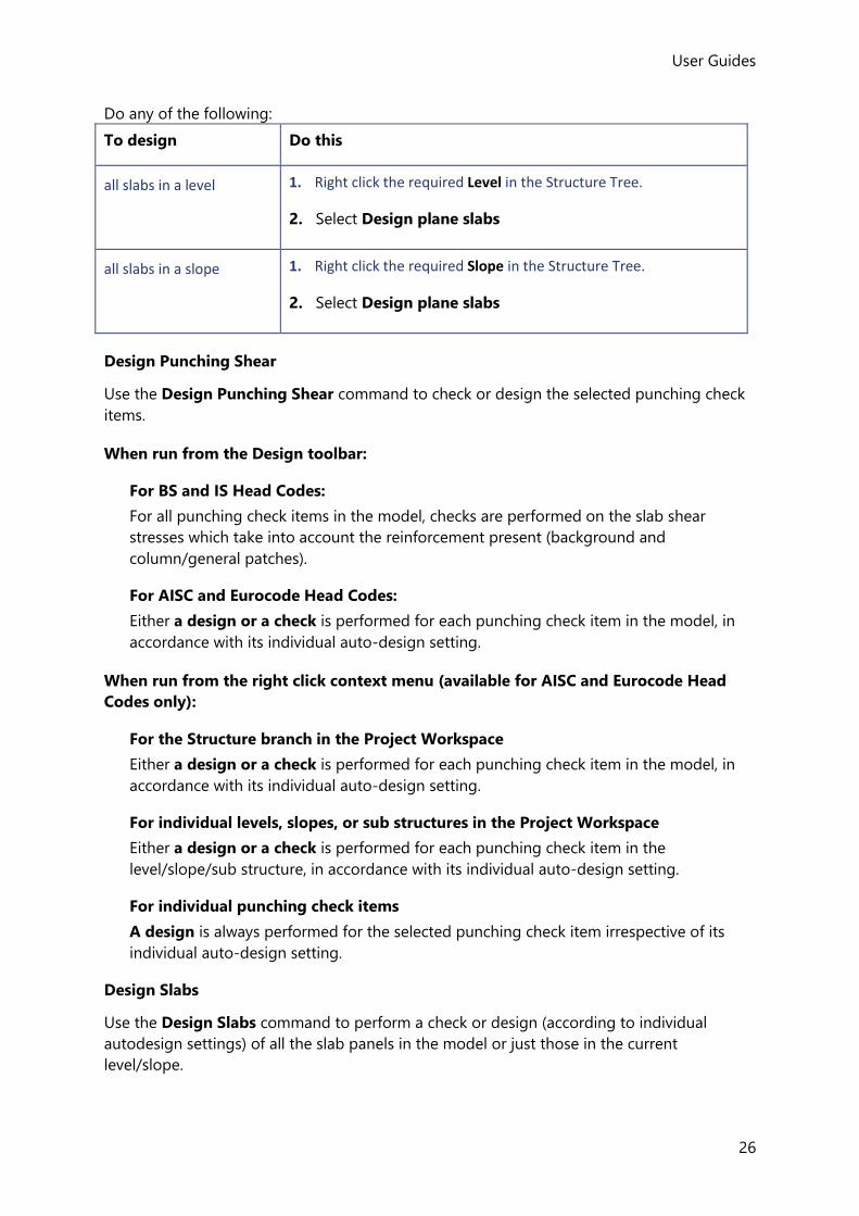
User Guides
26
Do any of the following:
To design Do this
all slabs in a level 1. Right click the required Level in the Structure Tree.
2. Select Design plane slabs
all slabs in a slope 1. Right click the required Slope in the Structure Tree.
2. Select Design plane slabs
Design Punching Shear
Use the Design Punching Shear command to check or design the selected punching check
items.
When run from the Design toolbar:
For BS and IS Head Codes:
For all punching check items in the model, checks are performed on the slab shear
stresses which take into account the reinforcement present (background and
column/general patches).
For AISC and Eurocode Head Codes:
Either a design or a check is performed for each punching check item in the model, in
accordance with its individual auto-design setting.
When run from the right click context menu (available for AISC and Eurocode Head
Codes only):
For the Structure branch in the Project Workspace
Either a design or a check is performed for each punching check item in the model, in
accordance with its individual auto-design setting.
For individual levels, slopes, or sub structures in the Project Workspace
Either a design or a check is performed for each punching check item in the
level/slope/sub structure, in accordance with its individual auto-design setting.
For individual punching check items
A design is always performed for the selected punching check item irrespective of its
individual auto-design setting.
Design Slabs
Use the Design Slabs command to perform a check or design (according to individual
autodesign settings) of all the slab panels in the model or just those in the current
level/slope.

User Guides (US)
27
Design Slabs does not perform an analysis before the design - it always uses the existing analysis results, (even if the analysis status is ‘Out of Date’).
Do any of the following:
To design Do this
all slabs in the model 1. Right click in the 3D Structure view.
2. Select Design Slabs
all slabs in the current level/slope
1. Right click in the level or slope view.
2. Select Design Slabs
Design Slab Patch
Use the Design Slab Patch command to perform a design of the selected patch. The results
dialog is then displayed allowing the detailed calculations to be viewed.
Design Slab Patch ignores the auto-design settings of the individual patch. (i.e. the patch is always designed, even if its auto-design property is off.)
Design Slab Patch does not perform an analysis before the design - it always uses the existing analysis results, (even if the analysis status is ‘Out of Date’).
1. Hover the mouse pointer over the patch.
2. If a different entity is highlighted, press the <down arrow> cursor key until the correct
reference is shown in the Select Entity tooltip
3. Right click and select Design Slab Patch
Design Truss
Use the Design Truss command to perform a check or design (according to individual
autodesign settings) of all truss members in the highlighted truss. The results dialog is then
displayed allowing the detailed calculations to be viewed.
Design Truss does not perform an analysis before the design - it always uses the existing analysis results, (even if the analysis status is ‘Out of Date’).
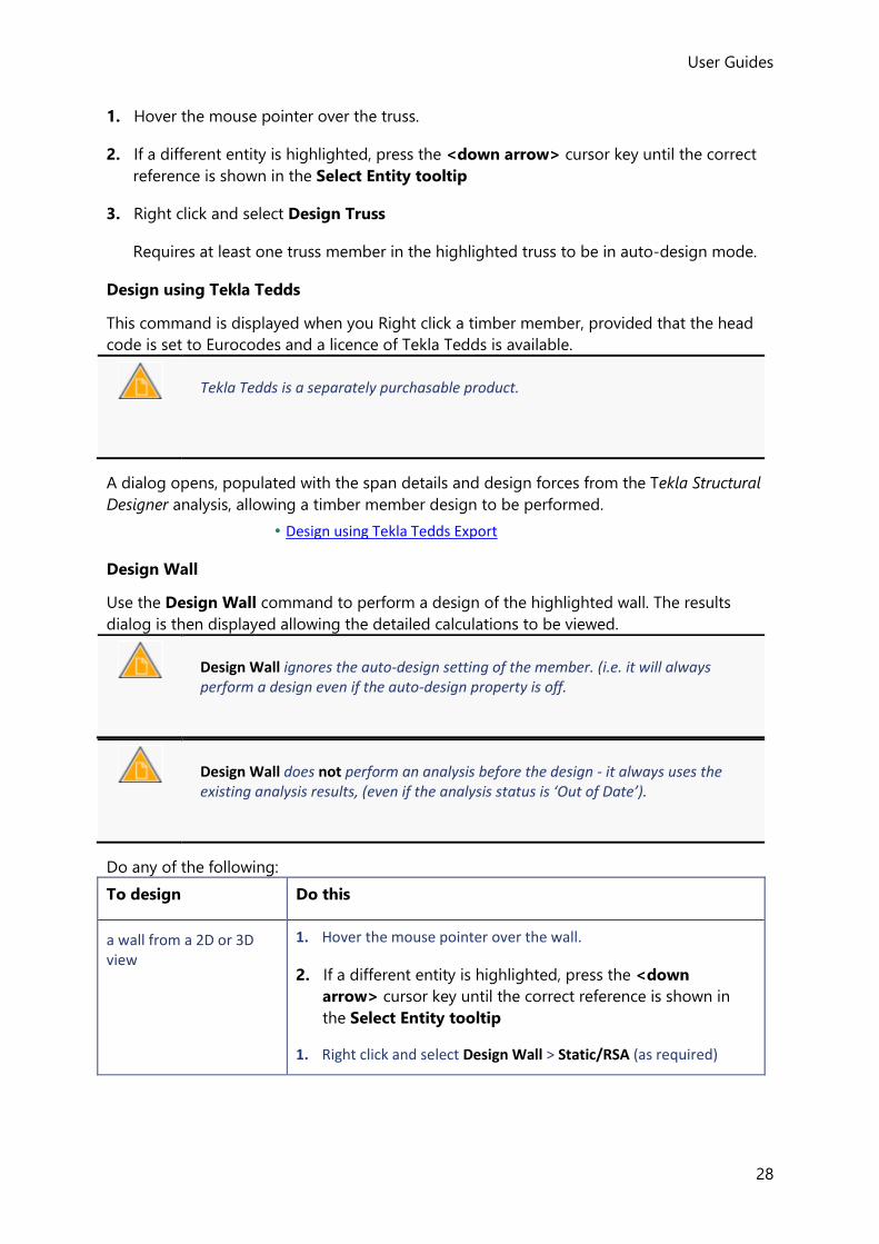
User Guides
28
1. Hover the mouse pointer over the truss.
2. If a different entity is highlighted, press the <down arrow> cursor key until the correct
reference is shown in the Select Entity tooltip
3. Right click and select Design Truss
Requires at least one truss member in the highlighted truss to be in auto-design mode.
Design using Tekla Tedds
This command is displayed when you Right click a timber member, provided that the head
code is set to Eurocodes and a licence of Tekla Tedds is available.
Tekla Tedds is a separately purchasable product.
A dialog opens, populated with the span details and design forces from the Tekla Structural
Designer analysis, allowing a timber member design to be performed.
• Design using Tekla Tedds Export
Design Wall
Use the Design Wall command to perform a design of the highlighted wall. The results
dialog is then displayed allowing the detailed calculations to be viewed.
Design Wall ignores the auto-design setting of the member. (i.e. it will always perform a design even if the auto-design property is off.
Design Wall does not perform an analysis before the design - it always uses the existing analysis results, (even if the analysis status is ‘Out of Date’).
Do any of the following:
To design Do this
a wall from a 2D or 3D view
1. Hover the mouse pointer over the wall.
2. If a different entity is highlighted, press the <down
arrow> cursor key until the correct reference is shown in
the Select Entity tooltip
1. Right click and select Design Wall > Static/RSA (as required)

User Guides (US)
29
a wall from the Structure Tree
1. In the Walls branch locate the wall reference.
2. Right click and select Design Wall > Static/RSA (as
required)
Design walls
Use the Design walls command to perform a check or design (according to individual
autodesign settings) of the selected walls using the existing Static or RSA analysis results
Design walls does not perform an analysis before the design - it always uses the existing analysis results, (even if the analysis status is ‘Out of Date’).
1. Right click the Walls branch in the Structure Tree.
2. Select Design Walls > Static/RSA (as required)
Edit
Displays the Edit Element Properties dialog, opened at the General page for the currently
highlighted element.
Generate Detailing Drawing...
Creates a Drawing for the currently highlighted member.
•
Interactive Design...
This command is only available for concrete beams and columns.
When clicked, it opens a dialog showing the existing design of the highlighted member for
the currently supplied reinforcement. From here you can interactively modify the
reinforcement and instantly see the result.
Open load analysis view
Opens a Loading Analysis View for the currently highlighted member.
Open member view
Opens a Member View containing the currently highlighted member.
The Member toolbar includes commands to edit the member, design it, create a member
report and generate a member detail drawing.
Open view
Opens a 2D view of the frame, slope or level that contains the currently highlighted panel.
Redraw
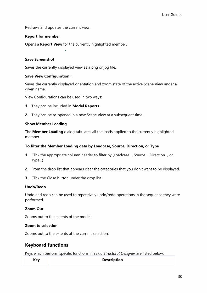
User Guides
30
Redraws and updates the current view.
Report for member
Opens a Report View for the currently highlighted member.
•
Save Screenshot
Saves the currently displayed view as a png or jpg file.
Save View Configuration...
Saves the currently displayed orientation and zoom state of the active Scene View under a
given name.
View Configurations can be used in two ways:
1. They can be included in Model Reports.
2. They can be re-opened in a new Scene View at a subsequent time.
Show Member Loading
The Member Loading dialog tabulates all the loads applied to the currently highlighted
member.
To filter the Member Loading data by Loadcase, Source, Direction, or Type
1. Click the appropriate column header to filter by (Loadcase..., Source..., Direction..., or
Type...)
2. From the drop list that appears clear the categories that you don’t want to be displayed.
3. Click the Close button under the drop list.
Undo/Redo
Undo and redo can be used to repetitively undo/redo operations in the sequence they were
performed.
Zoom Out
Zooms out to the extents of the model.
Zoom to selection
Zooms out to the extents of the current selection.
Keyboard functions
Keys which perform specific functions in Tekla Structural Designer are listed below:
Key Description

User Guides (US)
31
F1 Displays Help.
F2 Enables keyboard input of values into “Data Entry” tooltips.
F8 Toggles display of the ViewCube in 3D views.
Up/Down cursor keys
Used to scroll between entities in the Select Entity tooltip when multiple entities have been detected.
Ctrl Holding Ctrl when selecting adds to the current selection.
Esc Cancels the current command.
ZA Zoom Extents.
ZS Zoom to Selection.
Customising the appearance of the user interface
You can use skins to change the appearance of the user interface.
To apply a new skin:
1. Click Window > Skins (drop list)
2. Select a new skin from the list.
Working with the Project Workspace
The Project Workspace is the central control area for your model, providing access to a range
of functions.
The different Project Workspace pages are accessed by clicking the appropriate tab. Each
page contains an expandable tree.
Working with the Structure Tree
The purpose of the Structure Tree is to organize the model geometry in a hierarchical way.
When opened for a new model it contains only two sub branches as shown below.
As the model geometry develops new branches are added as and when required.
When a branch or sub-branch is selected, the common properties of the branch/sub branch
are also displayed in the Properties Window from where they can be edited.

User Guides
32
Structure branch
To display the structure properties:
1. Open the Structure Tree
2. Click
The Structure Properties are then displayed in the Properties Window
These control the structure’s principal direction and default meshing properties.
Levels branch
To display and edit properties common to all levels:
1. Open the Structure Tree
2. Click
The Level Properties common to all levels are displayed in the Properties Window.
To display and edit the properties for an individual level:
1. Click the plus sign ( ) to the left of to show all the construction levels in your
model.
2. Click an individual level to display its Level Properties in the Properties Window.
To display the Construction Levels dialog:
1. Right-click
The Construction Levels dialog is displayed.
Frames, Slopes and Surfaces branches
A branch is added when the first frame is created and a branch when the
first slope is created.
A branch is created automatically when a curved truss or curved space truss has
been defined. Curved trusses have a single horizontal or vertical curved surface, whereas
space trusses have two surfaces.
To display and edit the properties for an individual frame:
1. Open the Structure Tree
2. Click the plus sign ( ) to the left of to show all the currently defined frames in
your model.
3. Click an individual frame to display its Frame Properties in the Properties Window.
User Guides (US)
33
To display and edit the properties for an individual slope:
1. Open the Structure Tree
2. Click the plus sign ( ) to the left of to show all the currently defined slopes in
your model.
3. Click an individual slope to display its Slope Properties in the Properties Window.
Architectural Grids branch
To edit grid color, name or visibility:
1. Open the Structure Tree
2. Click the plus sign ( ) to the left of to show all the currently defined
grids
3. Click a grid in order to display its properties in the Properties Window.
To renumber all grids:
1. Right-click
2. Choose Renumber from the menu.
Sub Models branch
To display and edit the properties for an individual sub model:
1. Open the Structure Tree
2. Click the plus sign ( ) to the left of to show the existing sub models.
3. Click an individual sub model to display its Sub Model Properties in the Properties
Window.
To display the Sub Models dialog:
• Double-click
Members branch
Members are classified by material and type, then further classified by fabrication and then
by shape.
To display and edit common properties for members of a particular type and
fabrication:
1. Open the Structure Tree
2. Click the plus sign ( ) to the left of to show the existing member types.

User Guides
34
3. Click the plus sign ( ) to the left of an existing type to show the fabrication types.
4. Click a fabrication type to display the common properties of all members of that type in
the Properties Window
To display and edit common properties for members of a particular type, fabrication
and shape:
1. Expand the branch and sub-branches as described above, then:
2. Click the plus sign ( ) to the left of fabrication type to show the shapes.
3. Click a shape to display the common properties of all members of that shape.
To display and edit the properties of an individual member in the Properties Window:
1. Expand the branch and sub-branches as described above, then:
2. Click the plus sign ( ) to the left of the shape type to show individual member
references.
3. Click a member reference to display the properties of the individual member.
To view a member in a new window, select it in visible views, delete it, or edit it in a
Properties Dialog:
1. Expand the branch and sub-branches as described above, then:
2. Right-click a member reference and select the required option from the context menu.
Slabs branch
To display and edit properties common to all slabs:
1. Open the Structure Tree
2. Click
3. Those properties common to all slabs are displayed in the Properties Window.
To display and edit the properties of a parent slab:
1. Click the plus sign ( ) to the left of to show the existing parent slabs.
2. Click a parent slab to display its properties.
To edit the properties of a parent slab in a Property Dialog, or to delete it:
1. Click the plus sign ( ) to the left of to show the existing parent slabs.
2. Right-click a parent slab to either edit it in a dialog, or delete it.

User Guides (US)
35
To display and edit the properties of a slab item:
1. Click the plus sign ( ) to the left of to show the existing parent slabs.
2. Click the plus sign ( ) to the left of a parent slab to show all the slab items (slab panels)
within it.
3. Click a slab item to display its properties.
Walls and Roofs branches
To display and edit the properties of a wall or roof panel:
1. Open the Structure Tree
2. Click the plus sign ( ) to the left of and to show all the currently
defined Wall and Roof Panels
3. Left click a wall or roof panel to display its properties in the Properties Window.
Result Strips branch
To display and edit the properties of a result strip:
1. Open the Structure Tree
2. Click the plus sign ( ) to the left of to show all the currently defined Result
Strips
3. Left click a result strip to display its properties in the Properties Window.
Related topics
• Working with 2D Strips and displaying Strip Results
Working with the Groups Tree
The Groups Tree is used to organize members into design groups.
If concrete members have been defined these are also organized into further groups for
detailing purposes.
The application of grouping is of most benefit in concrete structures.
You can right-click a group name in order to select all of its members simultaneously in the visible views.

User Guides
36
If any user defined attributes (UDAs) have been defined these are also displayed on the Groups Tree, so that all members with a particular attribute value can similarly be selected in the visible views.
How do I re-apply automatic grouping in order to reset manually edited groups?
There are occasions where it becomes necessary to re-apply automatic grouping for a
specific member type.
To re-group a specific member type
1. In the Groups Tree, right-click the member type to be re-grouped.
2. Choose Regroup Members from the right-click menu.
Grouping is reapplied for the chosen member type only.
To regroup ALL member types
1. Click (located at the top of the Groups Tree) to automatically regroup all member
types and undo any manual grouping.
How do I split an existing member group into smaller groups?
1. Right-click the group name to be split in the Groups Tree.
2. Choose Split Group from the right-click menu.
All members of the group are placed into individual groups - in effect making them un-
grouped.
How do I manually move an existing member between groups?
1. In the Groups Tree open the group containing the member to be moved.
2. Click and drag the member name over the group name to which it is to be moved.
Provided that the member meets the geometric criteria to belong to the group, a small
rectangle will be displayed alongside the cursor. At this point release the mouse button
to move the member to the new group.
If the member does not meet the geometric criteria to belong to the group, the cursor
will display a barred circle.
How do I remove an existing member group?

User Guides (US)
37
1. Right-click the group name to be removed in the Groups Tree.
2. Choose Remove Group from the right-click menu.
All members of the group are placed into individual groups - in effect making them un-
grouped.
How do I rename groups?
To manually rename individual groups in the current project:
1. In the Groups Tree right-click the group to be renamed.
2. Choose Rename Group from the right-click menu.
To modify the group name defaults for future projects:
1. Click Home > Settings ( )
2. In the Settings Sets page of the dialog select the settings set to be updated.
You can update any settings set simply by selecting it from the droplist, it does not need to be active.
3. In the Grouping page of the dialog, review and edit the default group names as
required.
4. If you change any of the settings, click:
• OK - to save the changes to the selected settings set (to act as defaults for future
projects when that set is active), or
• Cancel - to cancel the changes
Working with the Loading Tree
The Loading Tree is used to organize the loadcases and combinations into a hierarchical
structure.
It also provides a summary of each loadcase that can be used to cross check the sum of
reactions determined by each of the analyses performed against the sum of the loads
applied.
The status of each loadcase or combination is indicated as follows:
- Total Reaction in equilibrium with the Total Load on Structure
- Total Reaction not in equilibrium with the Total Load on Structure
User Guides
38
- Total Reaction not available
Working with the Wind Model Tree
Once the wind modeling process has been completed, the Wind Model Tree can be used to
display the resulting Wind Model views. It comprises the following branches:
Pressure Zones
Solely indicates if the pressure zone calculations have been performed.
Wind Directions
Each Wind Direction View can be displayed from here. Wind direction dependent properties
can be accessed through the relevant Wind Direction View and then edited by selecting the
relevant roof- or wall-elements.
Wind Loadcases
Wind Loadcases can be created and edited from here
How do I use the Wind Model Tree to display a Wind Direction View?
Wind direction dependent properties can be accessed through the relevant Wind Direction
View and then edited by selecting the relevant roof- or wall-elements.
1. Right-click the direction required in the Wind Directions branch of the tree.
2. Choose Open View from the right-click menu.
Working with the Connections Tree
The purpose of the Connections Tree is to organize the model’s steel connections in a
hierarchical way, by Type (i.e. Type/Reference), and by Group (i.e. Type/Section
size/Reference).
When opened for the first time, or if the model has been edited in a way that affects the
connection configurations within it, you must first right-click the Connections main branch
and select “Update Connections” in order to find all the valid connections.
How do I update connections?
To generate connections for the first time, or to regenerate connections after changes to the
model:
1. In the Connections Tree, right-click the Connections branch.
2. Choose Update Connections from the right-click menu.
All valid steel connections in the model are found and listed in the Connections Tree.
They also are also shown by bounding boxes in the Scene Views.

User Guides (US)
39
If the model has been changed so that new connections exist, these are not generated automatically; you are required to update connections as required.
Rules relating to connection formation
1. beam to column connection
a) beam connections to the column base are ignored
b) column must be a symmetric section
c) more then 1 beam attached to the same column face prevents any connection
d) a continuous beam connected to the column flanges prevents any connection
e) a beam with a fully fixed or moment end condition connected to the column web
prevents any connection
2. beam to beam - for a particular construction point (node)
a) any column at the node prevents the connection
b) only two beam ends can be connected, a 3rd beam at the same node prevents
any connection.
c) connections cannot be formed at beam internal nodes
d) the beams being connected must be symmetric and of the same section size
e) connected beam ends cannot be free or pinned
f) top flange haunches prevent the connection
g) beam ends being connected must have no end plates specified, or both have the same
end plate
h) beam ends being connected must have no bottom haunch specified, or both have the
same bottom haunch
3. any non-steel member at the node prevents any connection
4. braces are ignored in the procedure
How do I edit an existing connection?
1. Right-click the connection to be edited in the Connections Tree.
2. Choose Edit from the right-click menu.
An appropriate dialog opens to allow the connection to be edited.
Requires a Tekla Connection Designer licence.

User Guides
40
How do I locate a connection in the visible view?
To view a member in a new window, select it in visible views, delete it, or edit it in a
Properties Dialog:
1. Right-click the connection to be edited in the Connections Tree.
2. Choose Select in visible views from the right-click menu.
The current view is recentred to display the chosen connection.
Working with the Status Tree
The Status Tree is used to review:
• Validation status for the model.
See: Model Validation.
• Validation status for the analysis.
The analysis model validation is performed automatically as part of the analysis process.
• Decomposition status.
This branch indicates if load decomposition has been successfully completed.
• Solver status.
This branch lists those analyses which have been performed. A tick indicates the analysis
was successful so that results are available to view.
• BIM validation
If the model has been imported/exported (e.g. to Robot, or Revit) then any warnings or
errors that relate to the import/export are listed on this branch.
The Report Index
When a report view is active the Report Index can be used to locate and display a specific
section in a multi-page report.
Working with Scene Views, View Regimes and Scene Content
display views of the model (or a part of it) in tabbed windows. Different scene views can be
created to show 3D views, 2D plans, frames, planes or individual members.
For each scene view you can choose a View Regime appropriate to the task being
performed. Different regimes are available including a regime for creating the structure, and
separate regimes for viewing the analysis model, the wind model, the analysis results, and
the design.

User Guides (US)
41
There is also a separate Load Analysis View for displaying the force and moment diagrams
for individual members.
Opening and Closing and Saving Scene Views
Multiple scene views can be displayed simultaneously in tabbed windows docked within the
main window. If required, specific views can be permanently saved as View Configurations.
How do I open a 3D view of my entire structure?
1. Open the Structure Tree
2. Double click to open a
(or right-click to open a )
How do I open a 3D view of an existing sub model?
1. Open the Structure Tree
2. Click the plus sign ( ) to the left of to show all the currently defined sub
models, then:
3. Double click an individual sub model to open a
(or right-click to open a )
How do I open a 3D view of a single member?
To open a single member view from within another view:
1. Hover the cursor over the member until it becomes highlighted, then,
2. Right-click and then click Open (member ref) view from the context menu.
To open a single member view from the Project Workspace:
1. Open the Structure Tree
2. Click the plus sign ( ) to the left of
3. Expand the appropriate sub-branches to display the member references:
4. Right-click the required member reference and choose Open view
How do I open a 2D view of an existing construction level?
1. Open the Structure Tree
2. Click the plus sign ( ) to the left of to show all the construction levels in your
model, then:

User Guides
42
3. Double click an individual level to open a
(or right-click to open a )
Before you can view a 2D view of a construction level, you must have created that level in your model.
How do I open a 2D view of an existing frame?
1. Open the Structure Tree
2. Click the plus sign ( ) to the left of to show all the frames in your model, then:
3. Double click an individual frame to open a
(or right-click to open a )
Before you can view a 2D view of a frame, you must have created that frame in your model.
How do I open a 2D view of an existing sloped plane?
1. Open the Structure Tree
2. Click the plus sign ( ) to the left of to show all the slopes in your model, then:
3. Double click an individual slope to open a
(or right-click to open a )
Before you can view a 2D view of a sloped plane, you must have created that plane in your model.
How do I open a 3D view of an existing curved surface?
1. Open the Structure Tree
2. Click the plus sign ( ) to the left of to show all the surfaces in your model,
then:
3. Double click an individual surface to open a of the surface

User Guides (US)
43
Curved surfaces are only created in the model to assist modelling of curved trusses and space trusses.
View Configurations
Once a Scene View has been orientated to show a specific area of the model, it can be saved
if required to a View Configuration.
View Configurations can then be used in two ways:
1. They can be included as Views in Model Reports (in which case they retain the Scene
Content settings that were in place when the View Configuration was saved).
2. They can be re-opened in a new Scene View at a subsequent time (in which case they
adopt whatever Scene Content settings are currently in place).
To save a View Configuration:
1. right-click in the View and choose Save View Configuration... from the context menu.
2. Enter a descriptive name, then click OK.
To re-open a saved a View Configuration:
1. Click Home > Manage View Configurations
2. Select the view configuration required.
3. Click Open
To delete a a View Configuration:
1. Click Home > Manage View Configurations
2. Select the view configuration required.
3. Click Delete
How do I close a view?
1. Click the icon at the top-right of the view tab.
Zooming/Panning/Rotating and Walking through Scene Views
The mouse is used to manually, zoom, pan, or rotate the model to any orientation you
require. Additionally, the model can be rotated to a range of preset views using the
ViewCube.
User Guides
44
A walk through mode is available for 3D views.
How do I zoom in/zoom out/zoom extents?
To manually zoom in and out:
1. The mouse wheel is used to zoom in and out.
To zoom extents:
1. Simply right-click anywhere within the view and select Zoom Out from the menu.
The keyboard shortcut “ZA” can also be used to zoom extents.
How do I pan the view?
1. Simply hold down the middle mouse button and drag.
2. Once you have achieved the pan you require release the mouse button.
How do I manually rotate the view
If none of the standard Viewcube views are appropriate, you can rotate the model to get to
just the view you require.
1. Simply right-click and hold over the 3D view, and move the mouse to perform the
rotation.
2. Once you have achieved the view you require simply release the mouse button.
How do I use the ViewCube to display one of the preset views?
The ViewCube provides quick access to a range of preset views in any 3D view.
1. Move the cursor over the ViewCube to make it active.
2. Simply use one of the methods below to choose the view that you want to see.
a) To display one of the eight isometric views click the required vertex on the ViewCube. If the required vertex is not visible spin the ViewCube by clicking on one of the other vertices until the required one appears.

User Guides (US)
45
b) To display one of the twelve edge views click the required edge on the ViewCube. If the required edge is not visible spin the ViewCube by clicking on a vertex adjacent to the required edge.
c) To display one of the six face views click the required face on the ViewCube. If the required face is not visible spin the ViewCube by clicking on a vertex adjacent to the required face.
With a face view displayed additional ViewCube controls become active.
d) If the required face is not visible you can roll the ViewCube on to an adjacent face by clicking on one of triangular controls.
e) If the required face view is displayed, but the orientation of the face is not correct you can rotate it clockwise, or anti-clockwise by clicking on one of the two arrow controls.

User Guides
46
Pressing F8 toggles the display of the ViewCube on and off.
How do I walk through the model in a 3D view?
When you are working in a 3D view it is sometimes useful to be able to walk through the
model.
1. Click Home > Walk ( )
This puts you into walk mode:
Use the arrow keys to move back/forward/left /right.
Use Q/Z to move up/down.
To rotate click and drag the right mouse button.
Press [Esc] to exit walk mode.
How do I display a 2D view in 3D?
When you are working in a 2D view it is often useful to display it in 3D, as this gives you a 3D
view whilst hiding the rest of the structure.
You can switch between the 2D and 3D by clicking the 3D/2D toggle button.
The 3D/2D toggle button is located at the bottom right hand corner of the 2D view and also at the right hand end of the Status Bar at the bottom right of the screen.
1. If the 2D view is currently displayed in plan, the 3D/2D toggle button will be labeled 3D.
2. Click the 3D/2D toggle button.
3. The 2D view is now displayed in 3D (and the 3D/2D toggle button changes to 2D.
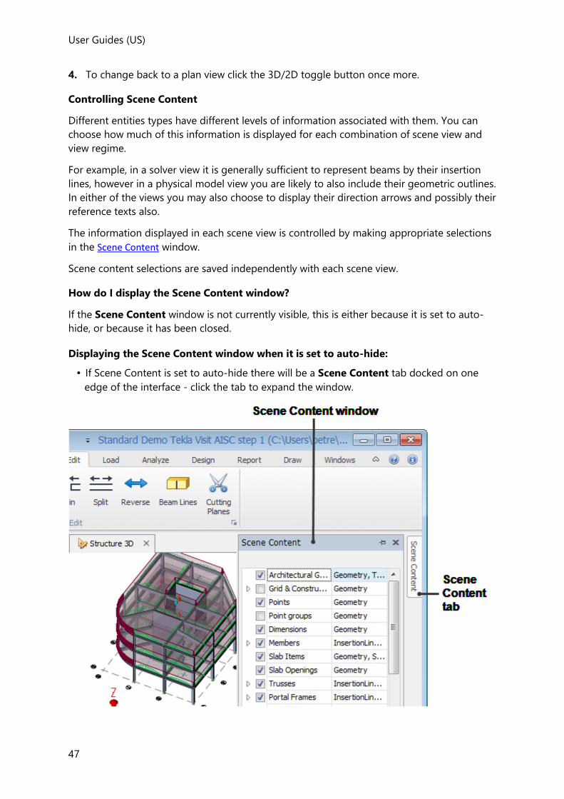
User Guides (US)
47
4. To change back to a plan view click the 3D/2D toggle button once more.
Controlling Scene Content
Different entities types have different levels of information associated with them. You can
choose how much of this information is displayed for each combination of scene view and
view regime.
For example, in a solver view it is generally sufficient to represent beams by their insertion
lines, however in a physical model view you are likely to also include their geometric outlines.
In either of the views you may also choose to display their direction arrows and possibly their
reference texts also.
The information displayed in each scene view is controlled by making appropriate selections
in the Scene Content window.
Scene content selections are saved independently with each scene view.
How do I display the Scene Content window?
If the Scene Content window is not currently visible, this is either because it is set to auto-
hide, or because it has been closed.
Displaying the Scene Content window when it is set to auto-hide:
• If Scene Content is set to auto-hide there will be a Scene Content tab docked on one
edge of the interface - click the tab to expand the window.
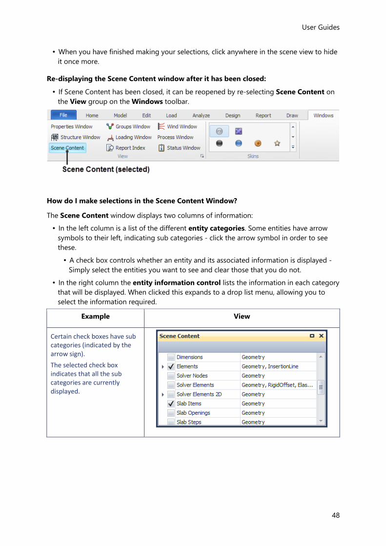
User Guides
48
• When you have finished making your selections, click anywhere in the scene view to hide
it once more.
Re-displaying the Scene Content window after it has been closed:
• If Scene Content has been closed, it can be reopened by re-selecting Scene Content on
the View group on the Windows toolbar.
How do I make selections in the Scene Content Window?
The Scene Content window displays two columns of information:
• In the left column is a list of the different entity categories. Some entities have arrow
symbols to their left, indicating sub categories - click the arrow symbol in order to see
these.
• A check box controls whether an entity and its associated information is displayed -
Simply select the entities you want to see and clear those that you do not.
• In the right column the entity information control lists the information in each category
that will be displayed. When clicked this expands to a drop list menu, allowing you to
select the information required.
Example View
Certain check boxes have sub categories (indicated by the arrow sign).
The selected check box indicates that all the sub categories are currently displayed.

User Guides (US)
49
Clicking the arrow expands the category....
To hide a particular sub category clear it...
When some, but not all sub categories are cleared, the main category is shown as a shaded box.
The information displayed for each entity type can be controlled by expanding the entity information control...
If you switch off the display of a particular entity type, then some commands that affect that entity type can no longer be performed. For instance if you switch off the display of Slab Items, then you cannot define slab or area loads on a floor, since there are no slab panels for you to select.

User Guides
50
If planar objects (slabs, roofs, area loads etc.) lie over the start point for performing a selection in the current scene view, you can use Scene Content to switch off their display, (assuming you don't want to have them considered in your selection.
How do I reinstate the default Scene Content selections?
You do not have to worry about changing the initial Scene Content configuration as you can
reinstate the default selections at any time.
To discard your current selections and reinstate the defaults:
1. Close the View.
2. Re-open the View from the Structure Tree.
Scene Content Entity Categories
When the Scene Content window is accessed it indicates which entities are selected for
display in the current scene view.
Although the entity categories listed in the content vary depending on the view type (3D/2D)
and the view regime (Structural/Solver/Results/Review etc.), most categories are common to
multiple views.
The entity categories are generally self-explanatory, but some clarification may be useful.
Architectural Grids
This category is not displayed for 2D views.
This category is used to show/hide architectural grids in 3D views. When selected they are
displayed at the lowest level in the model. (

User Guides (US)
51
Grid & Construction Lines can be displayed at any level.)
Grid & Construction Lines
This category is used to show/hide grid and construction lines at individual levels in both 2D
and 3D windows.
The levels at which grids are displayed/not displayed are controlled via the Properties Window for each individual level. Grids are only displayed in 2D windows if Show grids in plane view is selected and only displayed in 3D windows if Show grids in 3D view is selected.
Points
These are the construction points (CP) that are formed at connections between members.
Point Groups
These are for advanced use only - in normal use they should be switched off.
Dimensions
Shows any dimensions that have been applied.
Members, Trusses and Portal Frames
The Members category has a sub category for each of the member types.
Members, Trusses and Portal Frames can each have the following entity information
displayed.
Geometry
This shows the faces of the member by shading them.
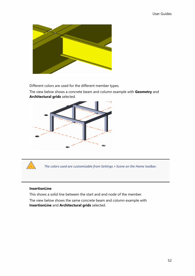
User Guides
52
Different colors are used for the different member types.
The view below shows a concrete beam and column example with Geometry and
Architectural grids selected.
The colors used are customizable from Settings > Scene on the Home toolbar.
InsertionLine
This shows a solid line between the start and end node of the member.
The view below shows the same concrete beam and column example with
InsertionLine and Architectural grids selected.

User Guides (US)
53
LoadingLine
This shows a solid line through the center of the member. Any member loads are applied
along this line, (which may be at an offset to the InsertionLine).
The zoomed in view below shows the same concrete beam and column example with
InsertionLine and LoadingLine selected.
Normals
These are unlikely to be required in general usage, but can be selected in order to see
the normal directions at each corner of the member.
The view below shows the same concrete beam and column example with Geometry and
Normals selected.
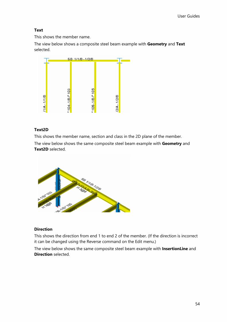
User Guides
54
Text
This shows the member name.
The view below shows a composite steel beam example with Geometry and Text
selected.
Text2D
This shows the member name, section and class in the 2D plane of the member.
The view below shows the same composite steel beam example with Geometry and
Text2D selected.
Direction
This shows the direction from end 1 to end 2 of the member. (If the direction is incorrect
it can be changed using the Reverse command on the Edit menu.)
The view below shows the same composite steel beam example with InsertionLine and
Direction selected.
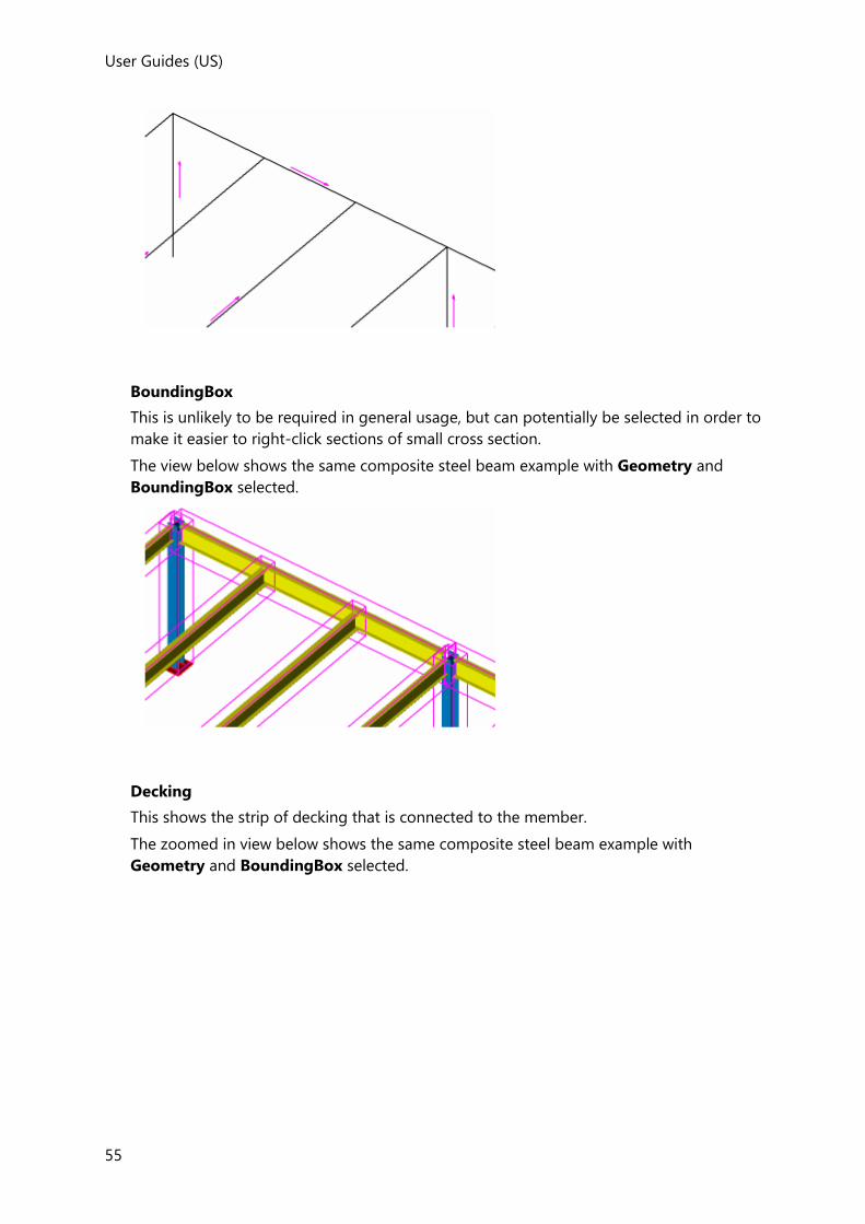
User Guides (US)
55
BoundingBox
This is unlikely to be required in general usage, but can potentially be selected in order to
make it easier to right-click sections of small cross section.
The view below shows the same composite steel beam example with Geometry and
BoundingBox selected.
Decking
This shows the strip of decking that is connected to the member.
The zoomed in view below shows the same composite steel beam example with
Geometry and BoundingBox selected.
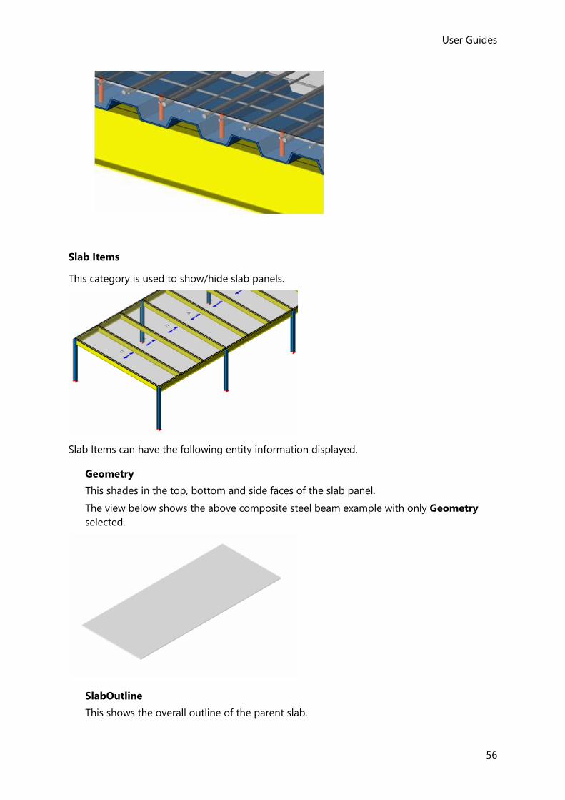
User Guides
56
Slab Items
This category is used to show/hide slab panels.
Slab Items can have the following entity information displayed.
Geometry
This shades in the top, bottom and side faces of the slab panel.
The view below shows the above composite steel beam example with only Geometry
selected.
SlabOutline
This shows the overall outline of the parent slab.
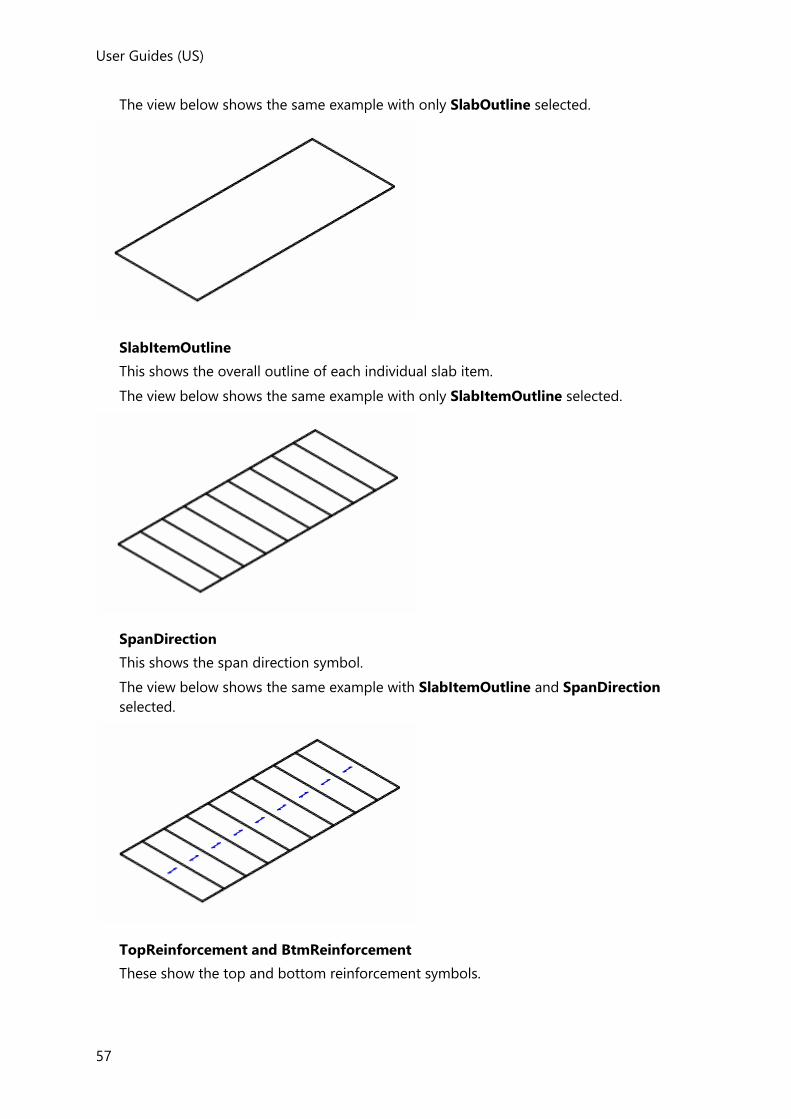
User Guides (US)
57
The view below shows the same example with only SlabOutline selected.
SlabItemOutline
This shows the overall outline of each individual slab item.
The view below shows the same example with only SlabItemOutline selected.
SpanDirection
This shows the span direction symbol.
The view below shows the same example with SlabItemOutline and SpanDirection
selected.
TopReinforcement and BtmReinforcement
These show the top and bottom reinforcement symbols.
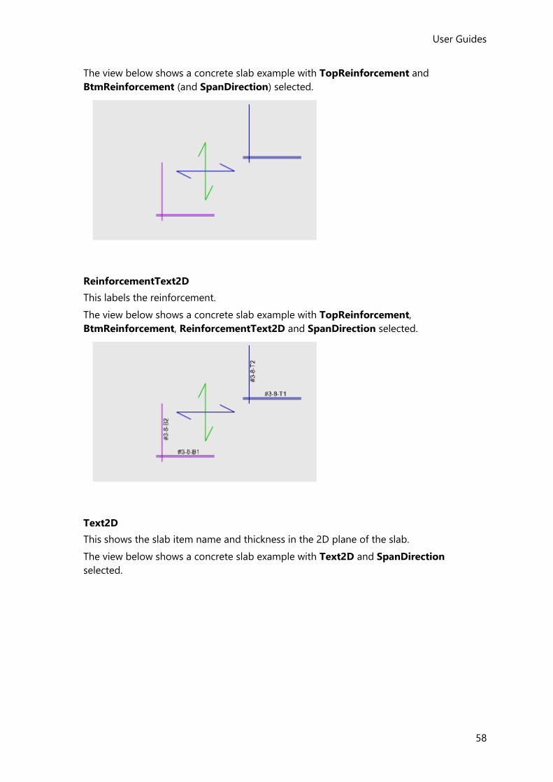
User Guides
58
The view below shows a concrete slab example with TopReinforcement and
BtmReinforcement (and SpanDirection) selected.
ReinforcementText2D
This labels the reinforcement.
The view below shows a concrete slab example with TopReinforcement,
BtmReinforcement, ReinforcementText2D and SpanDirection selected.
Text2D
This shows the slab item name and thickness in the 2D plane of the slab.
The view below shows a concrete slab example with Text2D and SpanDirection
selected.

User Guides (US)
59
Slab Openings
Geometry
Crossed lines are used to represent the location of each opening.
Concrete Walls
This entity has three sub categories
Concrete Walls
This sub category can have the following entity information displayed.
Geometry - This shades in the top, bottom and side faces of the wall panel.
Mesh - This option is not used! To see the mesh you must first clear Geometry and then
select Concrete Walls inside the 2D Elements entity category instead.
Edges - This shows the left and right edges of the wall.
Support - This shows the wall support.
Wall Elements
This sub category is used to show/hide the 1D elements that exist within concrete walls.
When modelled using FE shells a single wall element exists along the top of the wall (as
shown below). When modelled as mid-pier additional wall elements are also created
along the base of the wall and vertically through the middle of the wall). These wall
elements have the same entity information available as Members..

User Guides
60
Wall Lines
This sub category only relates to walls modelled using FE shells.
Wall lines are not displayed for the working solver model because they are only formed at the point of analysis. Therefore if you have switched them on in Scene Content but they are still not being shown, trying changing the Solver Model that is being displayed, (from the right-click menu when in the Solver View).
It shows/hides the result lines (used to determine the total internal forces in a wall mesh),
and also the wall line itself (used to display the forces from the result lines in an intuitive
way).
Wall lines have the following entity information.
Geometry - Shows/hides the wall line.
Result Lines - Shows/hides the result lines.
UCS - Shows/hides the user co-ordinate system that applies to the wall line.
Bearing Walls
This entity has two sub-categories
Bearing Walls
This sub category can have the following entity information displayed.
Geometry - This shades in the top, bottom and side faces of the wall panel.
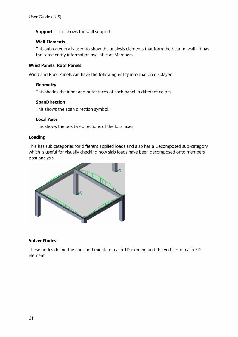
User Guides (US)
61
Support - This shows the wall support.
Wall Elements
This sub category is used to show the analysis elements that form the bearing wall. It has
the same entity information available as Members.
Wind Panels, Roof Panels
Wind and Roof Panels can have the following entity information displayed.
Geometry
This shades the inner and outer faces of each panel in different colors.
SpanDirection
This shows the span direction symbol.
Local Axes
This shows the positive directions of the local axes.
Loading
This has sub categories for different applied loads and also has a Decomposed sub-category
which is useful for visually checking how slab loads have been decomposed onto members
post analysis.
Solver Nodes
These nodes define the ends and middle of each 1D element and the vertices of each 2D
element.

User Guides
62
1D Elements
These are 1D elements in the analysis model. They have the following entity information.
Geometry - A single line is used.
Text - This shows the element number.
Rigid Offset - This is shown as a thicker line.
ElasticExtension - This is the portion of 1D Element that exists inside the boundary of a
connected member.
LocalAxes - The local axis system that applies to the 1D Element can optionally be
displayed.
Releases - The end releases can also be displayed.
2D Elements
These are 2D finite elements that may have been used in the analysis.
2D elements are not displayed for the working solver model, (even when you have chosen to mesh slabs/walls). This is because 2D elements are only formed at the point of analysis. Therefore if you have switched them on in Scene Content but they are still not being shown, trying changing the Solver Model that is being displayed, (from the right-click menu when in the Solver View).
There are three sub-categories

User Guides (US)
63
Shells - This sub-category specifically refers to the 2D elements used in slab meshes, (in
the FE chasedown model, and also in the 3D Analysis model when slabs have been
meshed).
Semi-rigids - This sub-category specifically refers to the 2D elements used in to model
one way spanning slabs when they have been modelled as semi-rigid diaphragms
Concrete Walls - This sub-category specifically refers to the 2D elements used in
concrete walls when the option to use mid-pier has not been selected.
Diaphragms
This category is only available when in a Solver View.
This category shows/hides the diaphragm as a shaded plane.
For flexible diaphragms the mesh can also be shown.
Slabs
This category shows/hides the slab mesh used for load decomposition.
Supports
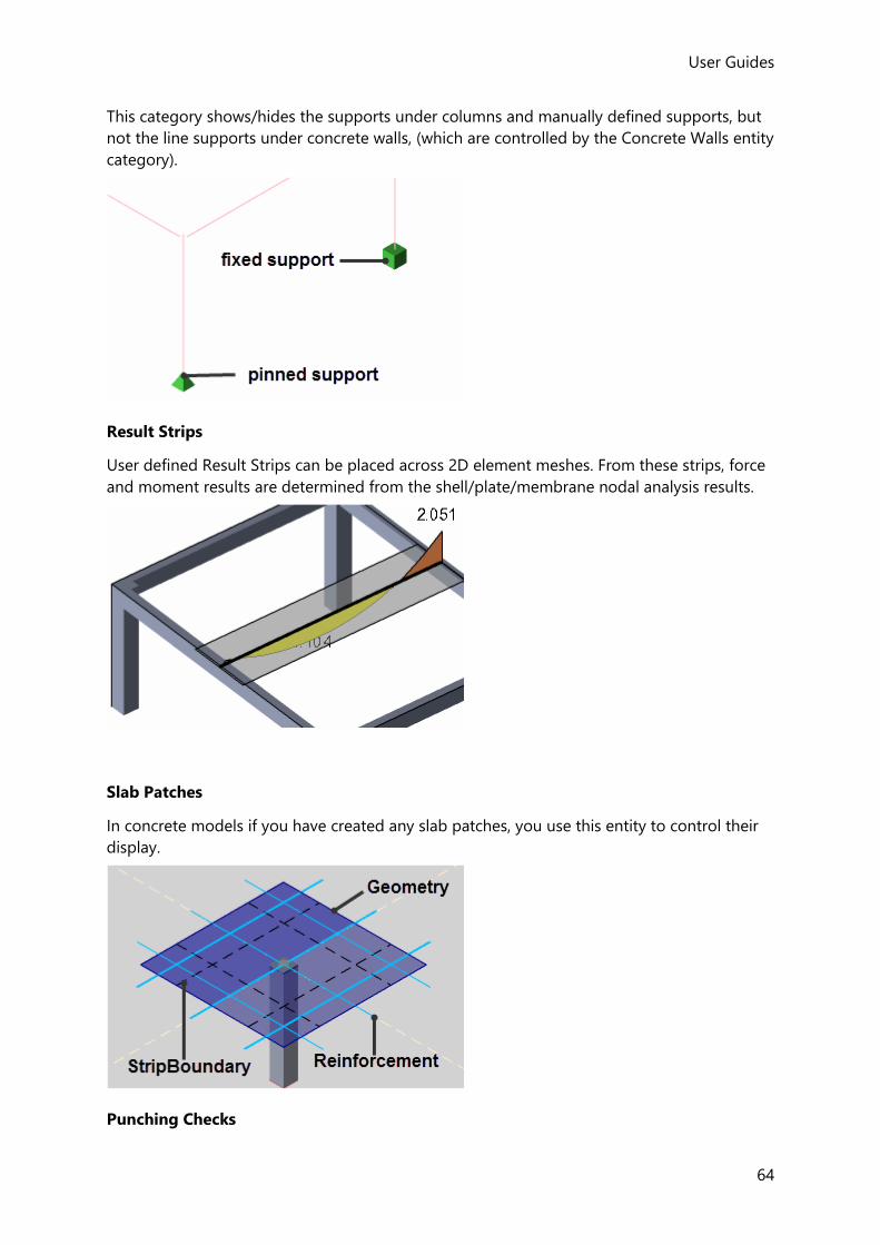
User Guides
64
This category shows/hides the supports under columns and manually defined supports, but
not the line supports under concrete walls, (which are controlled by the Concrete Walls entity
category).
Result Strips
User defined Result Strips can be placed across 2D element meshes. From these strips, force
and moment results are determined from the shell/plate/membrane nodal analysis results.
Slab Patches
In concrete models if you have created any slab patches, you use this entity to control their
display.
Punching Checks

User Guides (US)
65
In concrete models if you have created any punching check items, you use this entity to
control their display.
Floor Vibration Checks
Beams
Shades the critical beams in each check.
CriticalSlab
Shades the critical slab item in each check.
Levels, Frames, Slopes
Geometry
Shades the extents of each Level, Frame, or Slope entity.
Pad Base, Pile Cap, Pile
Geometry
Shows the faces of each Pad Base, Pile Cap, or Pile by shaping them.
Center of Mass
For any given load case or combination, all gravity loads (self weight, slab dry, live, etc.)
applied to a given floor have a center of action (or centre of mass), a point about which the
loads would balance if a pinned support were positioned at this location in plan.
You can graphically review this for each floor and each loadcase/combination. By hovering
the cursor over the center of mass a tooltip displays its coordinates.
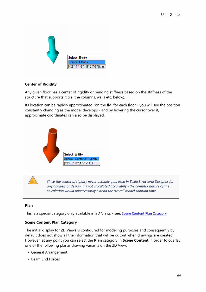
User Guides
66
Center of Rigidity
Any given floor has a center of rigidity or bending stiffness based on the stiffness of the
structure that supports it (i.e. the columns, walls etc. below).
Its location can be rapidly approximated “on the fly” for each floor - you will see the position
constantly changing as the model develops - and by hovering the cursor over it,
approximate coordinates can also be displayed.
Since the center of rigidity never actually gets used in Tekla Structural Designer for any analysis or design it is not calculated accurately - the complex nature of the calculation would unnecessarily extend the overall model solution time.
Plan
This is a special category only available in 2D Views - see: Scene Content Plan Category
Scene Content Plan Category
The initial display for 2D Views is configured for modeling purposes and consequently by
default does not show all the information that will be output when drawings are created.
However, at any point you can select the Plan category in Scene Content in order to overlay
one of the following planar drawing variants on the 2D View:
• General Arrangement
• Beam End Forces

User Guides (US)
67
• Foundation Layout
• Loading Plan
• Slab/Mat Layout
In each of these variants you can then selectively choose the individual drawing layers to be
overlaid. This can be very useful for displaying information that would otherwise not be
available whilst modelling.
Plan Sub Categories
The main sub categories beneath Plan are as follows:
General
This sub-category is used for displaying grids, construction lines and dimensions as they
would appear on the general arrangement drawings.
Members
This sub-category is used for displaying the various different member types labelled as
they would appear on the general arrangement drawings.
Walls
This sub-category is used for displaying concrete walls labelled as they would appear on
the general arrangement drawings.
Slabs/Mats
This sub-category is used for displaying concrete slabs labelled as they would appear on
the general arrangement drawings.
Reinforcement
This sub-category is used for displaying slab reinforcement as it would appear on the
slab detailing drawings.
Other
This sub-category is used for displaying various other items that can be output to the
general arrangement drawings.
In the first release it is not yet possible to overlay Beam End Forces or Foundation Reactions on a scene view. They can however be displayed on general arrangement drawings.
Tables
This sub-category is used for displaying tables of information that can be output to the
general arrangement drawings.
Connections
This sub-category is used for displaying connection names, attributes and reactions.

User Guides
68
To use the Plan Category
1. Ensure a 2D View is active.
2. In Scene Content, select Plan
3. Adjacent to the Plan check box use the drop list to choose the drawing variant.
Only those layers that exist in the General Arrangement, Foundation Layout, Loading Plan or Slab/Mat Layout drawing variants can be displayed.
The sub categories beneath Plan correspond to the drawing layers in the chosen drawing
variant. (By default the layers that are initially active match those in the first Layer
Configuration for the drawing variant in Drawing Settings).
4. Adjust the layers to be displayed by selecting/clearing the Plan sub categories as
required.
Layer content can be further controlled via Drawing Options in exactly the same way that it is controlled when creating the drawings themselves.
5. Layer colors, line types, fonts and font sizes match those in the first Layer Style for the
drawing variant in Drawing Settings).
Example
To illustrate how the Plan category would typically be used, consider the following
composite beam example designed to the AISC 360 ASD code:
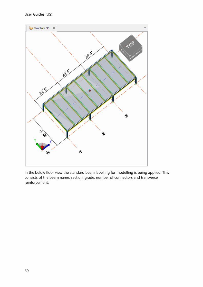
User Guides (US)
69
In the below floor view the standard beam labelling for modelling is being applied. This
consists of the beam name, section, grade, number of connectors and transverse
reinforcement.

User Guides
70
When the Tekla Structural Designer drawings are produced, it is likely that additional design
information would also be conveyed, for example the amount beam camber required.
The camber is included in one of the drawing layers, so it should also be possible to include
it in the 2D scene view - (provided we know the layer it belongs to).
The procedure to follow is therefore:
1. Make the 2D scene view showing the beams the active view.
2. Open Scene Content and select the Plan category.
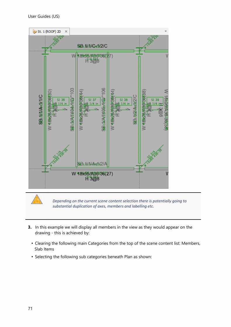
User Guides (US)
71
Depending on the current scene content selection there is potentially going to substantial duplication of axes, members and labelling etc.
3. In this example we will display all members in the view as they would appear on the
drawing - this is achieved by:
• Clearing the following main Categories from the top of the scene content list: Members,
Slab Items
• Selecting the following sub categories beneath Plan as shown:
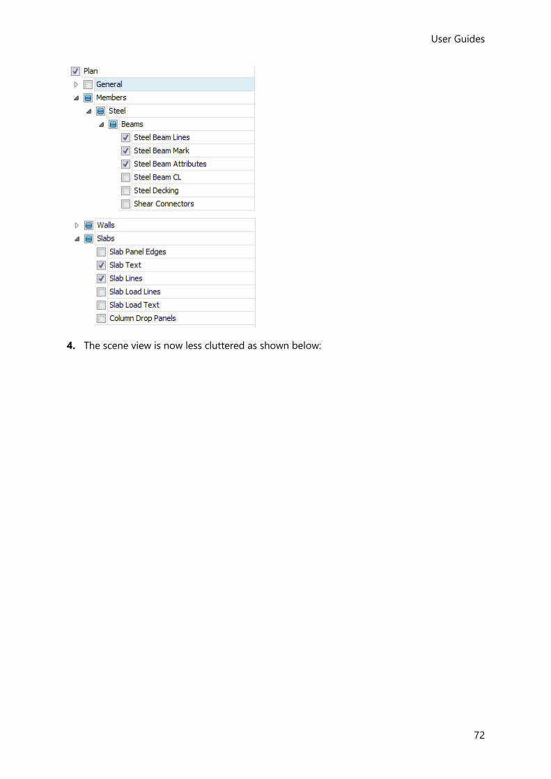
User Guides
72
4. The scene view is now less cluttered as shown below:
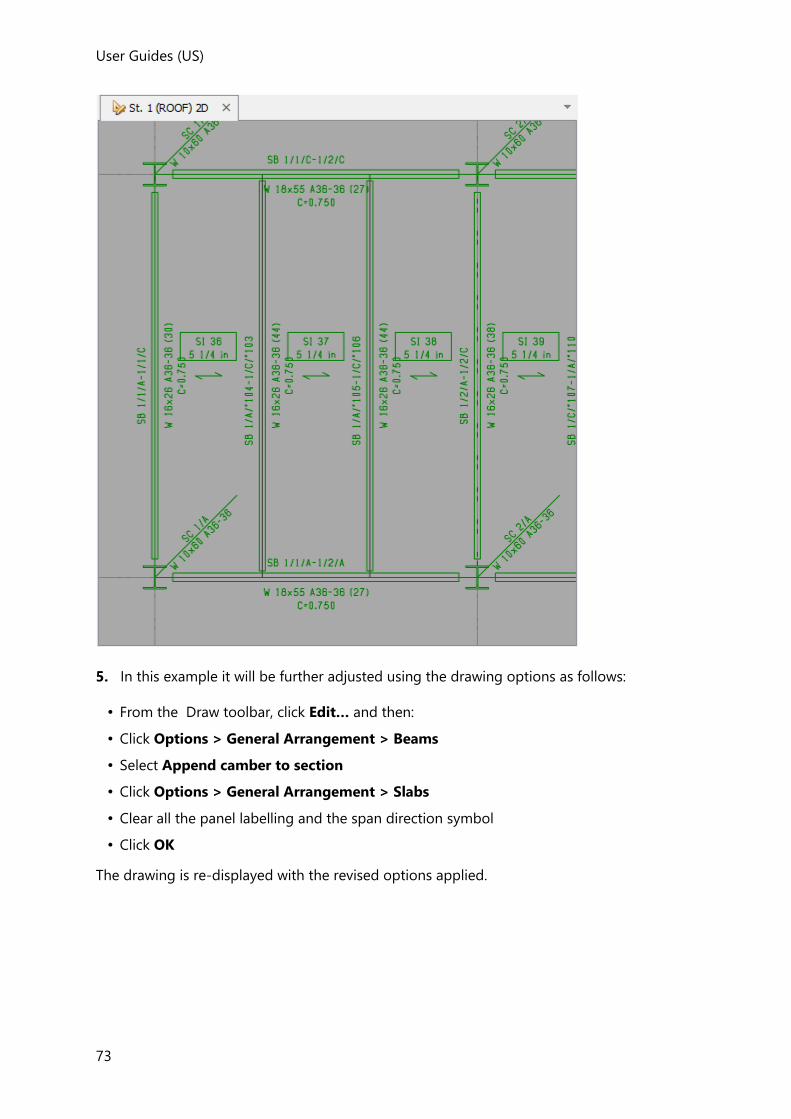
User Guides (US)
73
5. In this example it will be further adjusted using the drawing options as follows:
• From the Draw toolbar, click Edit… and then:
• Click Options > General Arrangement > Beams
• Select Append camber to section
• Click Options > General Arrangement > Slabs
• Clear all the panel labelling and the span direction symbol
• Click OK
The drawing is re-displayed with the revised options applied.

User Guides
74
View Regime
Different view regimes are available for:
• physical modeling of the structure geometry and loading, (Structural View)
• displaying the analysis model, (Solver View)
• displaying analysis results, (Results View)
• displaying the wind models, (Wind View)
• graphically interrogating the model properties/status, (Review View)
Structural View
Structural Views offer physical modeling of the structure with the aid of grids in either 3D
or 2D.
Both geometry and loading are typically defined within this type of view.

User Guides (US)
75
A new scene view can be opened in this regime from the Structure Tree in the Project
Workspace. You can change an existing scene view to this regime from the Status Bar, or by
right-clicking on its view tab.
Solver View
2D and 3D Solver Views are mainly used for previewing and interrogating the analytical
model, but they can also be used for modeling purposes.
A new scene view can be opened in this regime from the Structure Tree in the Project
Workspace. You can change an existing scene view to this regime from the Status Bar, or by
right-clicking on its view tab.
Results View
A Results View opens automatically at the end of an analysis - it is used for graphically
displaying the various analysis results.
You can change an existing scene view to this regime from the Status Bar, or by right-clicking
on its view tab.
Wind View
Wind Views becomes available after running the Wind Wizard - these are used for
graphically displaying the wind zones and zone load details.
Once the wind wizard has been run, you can change an existing scene view to this regime
from the Status Bar, or by right-clicking on its view tab.
Review View
A Review View opens automatically at the end of the Design All (Static) process - it is used for
graphically interrogating the model properties/status.
You can change an existing scene view to this regime from the Status Bar, or by right-clicking
on its view tab.
Changing the View Regime
An existing scene view can be switched to another mode, either from the status bar, or by
right-clicking on its view tab.
To change the view regime from the status bar
The different view regimes are shown on buttons in the Status Bar at the bottom right of the
screen.
Click one of the unselected buttons to make the active scene view display in that regime.
To change the view regime from the active view tab
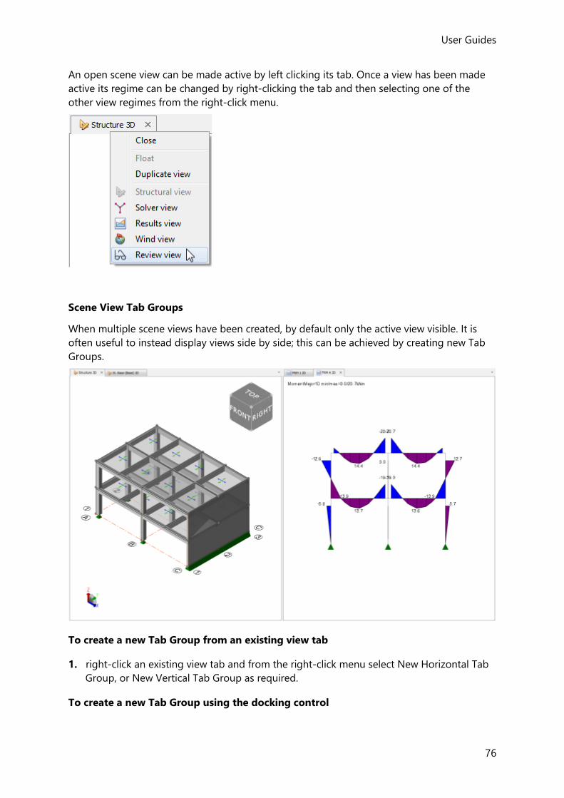
User Guides
76
An open scene view can be made active by left clicking its tab. Once a view has been made
active its regime can be changed by right-clicking the tab and then selecting one of the
other view regimes from the right-click menu.
Scene View Tab Groups
When multiple scene views have been created, by default only the active view visible. It is
often useful to instead display views side by side; this can be achieved by creating new Tab
Groups.
To create a new Tab Group from an existing view tab
1. right-click an existing view tab and from the right-click menu select New Horizontal Tab
Group, or New Vertical Tab Group as required.
To create a new Tab Group using the docking control

User Guides (US)
77
When you grab a view by its tab and drag it, a docking control appears in the middle of the
view. You can then use this control to create a new Tab Group.
To create a new Vertical Tab Group:
1. Drag the grabbed view over the left or right button of the docking control and then
release the mouse.
To create a new Horizontal Tab Group:
1. Drag the grabbed view over the top or bottom button of the docking control and then
release the mouse.
To move a view between Tab Groups
1. right-click the view tab and from the right-click menu select ‘Move to Next Tab Group.
Working with Command Prompts
Yellow command prompts are displayed across the top of the active view to guide you
through each Tekla Structural Designer command.
Press <Esc> in a command prompt to cancel, or go back
• Press <Esc> at the first command prompt to cancel.
• Press <Esc> at subsequent command prompts to go back to the first prompt.
• Selecting another command also cancels the current command.
Example
The parallel grid line command consists of four steps - hence four consecutive command
prompts are displayed:
The grid line is created after the fourth prompt, after which the second prompt is
automatically redisplayed:

User Guides
78
At this point you could either continue to create additional lines parallel to the original, or by
pressing <Esc> go back to the first prompt:
You could then select a new reference line and continue again, or by pressing <Esc> again
cancel the command.
Using the tooltip for input in a command
When you are required to specify a distance or pick a point, a tooltip appears displaying the
current value.
To enter a value either:
• move the cursor to the point required and click to use it,
• alternatively, press <F2> to type an exact number and press <Enter> to use it.
Undoing a command
Once a command has completed, to undo it do the following:
• Click Undo in the Quick Access Toolbar
Undo and redo can be used to repetitively undo/redo commands in the sequence they were
performed.
Selecting Entities
In order to perform an operation (edit, delete etc.) on an entity, or group of entities they
must first be selected.
All entity types can be selected/deselected using the mouse provided they are visible in the
scene view you are working in. Alternatively they can be selected using the Find command.
Members can also be selected from the Structure Tree and the Groups Tree.
If planar objects (slabs, roofs, area loads etc.) lie over the start point for performing your
selection, you may want to use Scene Content to switch off their display, (assuming you don’t
want to have them considered in your selection).
How do I select an individual entity?
1. Move the cursor over the required entity in one of the 2D or 3D Views.
• If the entity is the only one at that location it will become highlighted (it will also be
the one listed in the Select Entity tooltip).

User Guides (US)
79
• If several entities exist at the same location they will all be listed in the Select Entity
tooltip, only the first one being highlighted. If this is not the required entity, use the
tab key or up/down cursor keys to scroll through the list.
2. When the required entity is highlighted, you can either press the Enter key or left click to
select it.
The selected entity’s properties are displayed in the Properties Window.
Example View
Four entities are located under the current cursor position, so each of these are listed in the Select Entity tooltip.
We require to select the horizontal beam, however the currently highlighted entity shown in the tooltip is a slab panel.
By pressing the tab key once, the next entity in the list (a column) becomes highlighted.
This is still not correct, so press the tab key once more - the required beam is now highlighted.
Either press the Enter key or left click and the beam is selected.
Individual members can also be selected by clicking their name in the Structure Tree.
How do I add further entities to the current selection?
User Guides
80
1. Hold the Ctrl key whilst clicking on each subsequent entity.
The selected entity’s properties are added to those already displayed in the Properties
Window.
How do I select multiple entities by dragging a box?
If you only want to select those entities which are totally encompassed by the box, then:
1. Move the cursor to the left corner of an imaginary box which will encompass the entities
that you want to select.
2. Click and hold the left mouse button.
3. Drag to the diametrically opposite corner of the box (you will see a purple rectangle on
the screen which follows your mouse movements and helps you to check the area you
are selecting).
4. Release the mouse button.
If you want to select those entities which are totally encompassed by the box, and which it crosses, then:
1. Move the cursor to the right corner of an imaginary box which will encompass the
entities that you want to select.
2. Click and hold the left mouse button.
3. Drag to the diametrically opposite corner of the box (you will see a green rectangle on
the screen which follows your mouse movements and helps you to check the area you
are selecting).
4. Release the mouse button.
The selected entities’ properties are displayed in the Properties Window.
How do I select multiple entities by dragging a line?
1. Hold the Shift key whilst clicking and dragging the left mouse button to create a line.
2. Release the mouse button.
Any entities crossed by the line are selected and have their properties displayed in the
Properties Window.
How do I deselect a single entity from the current selection?
1. Click the entity you want to de-select.
The entity’s properties are removed from the Properties Window.

User Guides (US)
81
How do I deselect multiple entities by dragging a box or line?
To deselect only those entities totally encompassed by the box:
1. Move the cursor to the left corner of an imaginary box which will encompass the entities
that you want to deselect.
2. Hold the Ctrl key whilst clicking and holding the left mouse button.
3. Drag to the diametrically opposite corner of the box (you will see a purple rectangle on
the screen which follows your mouse movements and helps you to check the area you
are selecting).
4. Release the mouse button then release the Ctrl key.
Entities that were previously selected are unselected; entities that were previously
unselected are selected.
To deselect those entities which are either encompassed by the box, or crossed by it:
1. Move the cursor to the right corner of an imaginary box which will encompass the
entities that you want to select.
2. Hold the Ctrl key whilst clicking and holding the left mouse button.
3. Drag to the diametrically opposite corner of the box (you will see a green rectangle on
the screen which follows your mouse movements and helps you to check the area you
are selecting).
4. Release the mouse button then release the Ctrl key.
Entities that were previously selected are unselected; entities that were previously
unselected are selected.
To deselect entities by dragging a line:
1. Hold the Ctrl and Shift keys whilst clicking and dragging the left mouse button to create
a line.
2. Release the mouse button.
Entities that were previously selected are unselected; entities that were previously
unselected are selected.
How do I deselect all entities?
1. Press the Esc key to deselect all currently selected entities.
The information displayed in the Properties Window is also cleared.
Entity selection using Find
User Guides
82
If you know the name of the entity you are looking for it can be selected using the Find
command.
1. Click Home > Find ( )
2. Type a part of the name you are looking for into the box.
Any matching entity names are immediately displayed in the table below.
3. Click an entity name that you want to select.
Hold the Ctrl key whilst clicking to append further selections.
4. Click Select.
The selected entities’ properties are displayed in the Properties Window.
Member selection using the Structure Tree
Only individual members can be selected from the Structure Tree , (it in not possible to select
multiple members in this way).
1. Expand the Members branch of the Structure Tree and then the appropriate sub-
branches until the member names are displayed.
If you want to find a particular reinforced rectangular concrete column click the plus sign ( ) to the left of the Concrete Column entry, then the plus sign ( ) to the left of the Reinforced Concrete entry, then the plus sign ( ) to the left of the Rectangular entry.
2. Right-click the required member name and then pick Select in visible views from the
context menu.
Member selection using the Groups Tree
Member groups and individual members can both be selected from the Groups Tree.
1. Expand the appropriate branch of the Groups Tree until you can click the required group
or member name.
2. Right-click the required group or member name and then pick Select in visible
views from the context menu.
Entity Nodes
When an individual entity is selected the nodes that define it are also displayed; each entity
type having a different number of nodes associated.
For example:

User Guides (US)
83
• Grid lines and single span 1D elements have nodes at each end and at the mid-point.
• Panels have nodes at each vertex and at the mid-point of each edge.
• Concrete walls have nodes at each corner.
grid line
1D element
panel
wall
A node can be selected and moved in order to stretch, shorten, reshape or move the entity.
Starting a New Project
New models are initiated from the Home toolbar. They can either be created from scratch, or,
if you intend to create several models from a common start point, you might consider
setting up a template in advance.
Either way, before commencing you should take a few moments to review the defaults that
will be applied to the model. These are held in the “active” settings set in the Settings dialog.
Ensuring these match your typical requirements at the outset saves time as it eliminates
unnecessary editing at a later stage.
Once a model is open, its settings can be edited from the Model Settings dialog.
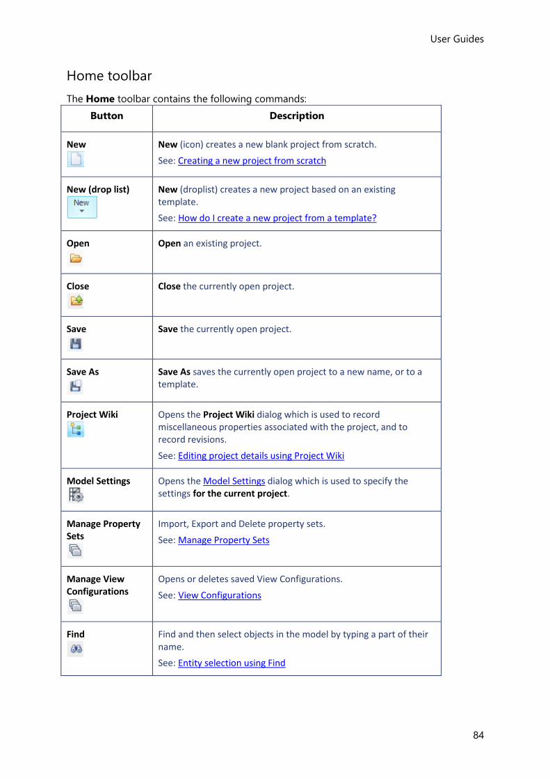
User Guides
84
Home toolbar
The Home toolbar contains the following commands:
Button Description
New
New (icon) creates a new blank project from scratch.
See: Creating a new project from scratch
New (drop list)
New (droplist) creates a new project based on an existing template.
See: How do I create a new project from a template?
Open
Open an existing project.
Close
Close the currently open project.
Save
Save the currently open project.
Save As
Save As saves the currently open project to a new name, or to a template.
Project Wiki
Opens the Project Wiki dialog which is used to record miscellaneous properties associated with the project, and to record revisions.
See: Editing project details using Project Wiki
Model Settings
Opens the Model Settings dialog which is used to specify the settings for the current project.
Manage Property Sets
Import, Export and Delete property sets.
See: Manage Property Sets
Manage View Configurations
Opens or deletes saved View Configurations.
See: View Configurations
Find
Find and then select objects in the model by typing a part of their name.
See: Entity selection using Find

User Guides (US)
85
Walk
Walk through 3D views.
See: How do I walk through the model in a 3D view?
Structural BIM Import
Import a model from a Neutral File.
See: How do I import a project from a Structural BIM Import file?
Tekla Structures Export
Export a model to Tekla Structures.
See: How do I export a model to Tekla Structures?
Autodesk Revit Export
Export a model to Revit.
See: How do I export a model to Autodesk Revit Structure?
IFC Export
Export a model to IFC.
See: How do I export a model to IFC?
Cellbeam Export
Export a beam to Westok Cellbeam.
See: How do I export a beam to Westok Cellbeam?
Cellbeam import and Export are not yet available in the current release.
Cellbeam Import
Import a beam from Westok Cellbeam.
See: How do I import a beam from Westok Cellbeam?
Cellbeam import and Export are not yet available in the current release.
STAAD Export Export a model to the STAAD.
See: How do I export a model to STAAD?
Robot Export Export a model to Robot.
See: How do I export a model to Autodesk Robot Structural Analysis?
Cloud Export Export a model to the Cloud.
See: How do I export a model to the Cloud?
‘TEL’ File Import Import a model from a TEL File.
See: How do I import a project from a TEL file?
3D DXF Import Import a model from a 3D DXF File.
See: How do I import from a 3D DXF file?

User Guides
86
TCD Export Export connections to Tekla Connection Designer.
TPFD Export Export portal frames to Tekla Portal Frame Designer.
See: How do I export portal frames to Tekla Portal Frame Designer?
ADAPT Export
Export a model to ADAPT.
See: How do I export a model to ADAPT?
Settings
Opens the Settings dialog which controls the defaults that are applied prior to starting a new project.
Materials
Opens the Materials dialog for viewing and adding to the list of materials available to work with.
Check for Updates Click this button to check that the program is up to date.
If critical updates are available, you will be notified, and you can select whether you want to install the updates.
License Manager
Opens the License Manager.
Related topics
• Commands on the ribbon toolbars
Creating a new project from scratch
Before creating a new project you should ensure an appropriate settings set is active. See: How do I specify the active settings set?
How do I create a new project from scratch?
1. Click Home > New ( )
(being careful to click the icon button as shown, rather than the drop list button beneath
it).
2. Your new project opens and you will see:
User Guides (US)
87
• two Scene Views - St. Base (Base) 2D (which will show the Base level of your model)
in front of Structure 3D (which will show the whole model in 3D).
• a tabbed Project Workspace - in which the Structure tab displays a Structure
Tree containing a Structure main entry below which there two major branches —
Levels and Sub Models
• a Properties Window - which, (provided the Structure main entry is selected in the
Structure Tree), shows the General and Meshing defaults for the current model.
3. Click Structure in the Structure Tree and review the General defaults in the Properties
Window:
• Select Show Building Direction Arrows.
• Since by default the Building Direction Rotation is 0 degrees the building’s
principal axes (Dir 1 and Dir 2) are initially aligned with global X and Y. If you are
defining a model that is aligned differently you should adjust the Building Direction
Rotation to suit.
4. Click the plus sign ( ) to the left of Levels and you will see that your model contains
only a base level. Double click Levels to display the Construction Levels dialog from where
you can add more levels as needed.
If you are creating a steel structure each level you add should be set as T.O.S. (top of steel). If you are creating either a concrete or mixed material structure you should instead set the type as S.S.L.(structural slab level)
Once the levels have been set up you can:
• left click an existing level in the Structure Tree to show the details for that level in
the Properties Window. If you amend these details they are applied to the level
immediately.
• double-click the name of a Construction Level to open a 2D view for that level.
5. You can then proceed to add building objects, either in the Structure 3D view, or any of
the 2D level views.
Working with templates
If the projects you will be creating share a common start point, a template can be employed
to avoid repetition of input. In order to use a template you must have created it previously. It
can contain as much or as little of a model that you consider applicable to serve as the start
point for subsequent models. For example, a particular template may comprise a simple grid
and the height of the First Floor Construction Level only.
How do I create a new template?
1. Start a new project. (See Creating a new project from scratch)

User Guides
88
2. Create only the model data that you want to be included in the template.
3. Click Home > Save As ( )
4. In the Save As dialog, change the Save as type to Tekla Structural Designer template
file (*.tsmdt).
5. Enter a file name to describe the template and ensure the dialog is pointing to the folder
where you want the template to reside.
6. Click Save.
How do I create a new project from a template?
Before creating a new project from a template you should ensure an appropriate settings set is active. See: How do I specify the active settings set?
To create a new project from a template:
1. Click Home > New ( )
(being careful to click the lower drop list button, rather than the icon button above it).
The drop list menu consists of the most recently used templates and an Open
Template option to navigate to any other templates not shown.
2. Select the required template from the list. The template opens and you will see:
• One or more Scene Views - their content matching the selected template,
• a Project Workspace displaying a Structure Tree matching the selected template,
3. Click Home > Save As ( )
4. In the Save As dialog, change the Save as type to Tekla Structural Designer project
files (*.tsmd).
5. Enter a file name to describe the project and ensure the dialog is pointing to the folder
where you want the project to reside.
6. Click Save.
7. You can then proceed to add the remaining building objects and loads as necessary to
complete the project.
Model Settings
Various defaults and settings that apply to the current project only can be controlled via
the Model Settings dialog.
User Guides (US)
89
How to apply and manage Model Settings
To access the model settings:
• Click Home > Model Settings ( )
If you change any model settings, click:
• OK - to apply the changes directly to the current project, or
• Save... - to save the changes back to the active settings set for future use, or
• Cancel... - to cancel the changes
You can also click:
• Load... - to revert to the model settings specified in the active settings set. (This loads all
of the model settings in the set, not just those displayed on the current page. It does not
load Analysis Options or Design Options.)
Model Settings dialog
Located on the Home toolbar, the Model Settings dialog ( ) contains various pages for
controlling defaults and settings that apply to the current project only.
Design Codes Settings
The Design Codes page appears on both the Model Settings dialog and the Settings dialog. It is
used to specify the head code and subsequent design codes that apply.
Head Code
Select the head code to automatically populate the subsequent action and resistance
codes.
Design Codes
The action and resistance codes are dependent on the selected head code. The drop
down menus can be used to select between alternatives where applicable.
Units Settings
The Units page appears on both the Model Settings dialog and the Settings dialog. It is used is
used to specify the units format and precision that apply.
System
Use the drop list to select either Metric or US Customary Units.
See: Units
Table of Quantities
This table lists each quantity, showing its current unit and precision.
Settings
When a quantity is selected from the table, its available units are displayed here.

User Guides
90
Precision
When a quantity is selected from the table, its precision is displayed here.
Exponential Format
Specify the lower and upper limits for when exponential formats should be applied.
References Settings
The References page appears on both the Model Settings dialog and the Settings dialog. It is
used to specify the References that apply.
General page
Numbering
When object references include the Count item, this field can be used to specify the start
number to count from at each construction level, (eg 1, 100, 1000).
Renumbering Direction
The renumbering directions that you set here control the way that member numbering
gets applied when you use the Renumber command.
Grid Line Naming
The initial number and initial letter specified are applied to the first gridlines; the labeling
for subsequent lines follows the sequence of the naming style. You can choose to ignore
letters “I” and “O”.
Groups page
This page is used to specify (for the settings set selected at the top of the page) the
default text used for each member type’s group labelling.
Sub-group Name
Enter the text that you want to use for group labelling here.
This text forms the stem of the Design Group and Detailing Group names that are
displayed on the Groups tab of the Project Workspace. These names are shown in the
output reports and drawings when grouped design has been applied.
Formats page
Object/Reference Format/Edit
This table lists each object type showing its current reference format. Reference formats
are fully customizable, being built up from component “items” arranged in any order -
click the Edit button to change.
Texts page
Characteristics
When object references include the Characteristic item, this table can be used to specify
the text used to designate the characteristic.

User Guides (US)
91
Materials
When object references include the Material item, this table can be used to specify the
text used to designate the material.
Loading Settings
The Loading page appears on both the Model Settings dialog and the Settings dialog. It is used
to specify if pattern loading is applied to steel beams.
Use pattern loading for steel beams
When selected - pattern loading will automatically be applied to continuous steel beams
in addition to any concrete beams. When cleared - pattern loading is applied to concrete
beams only.
Grouping Settings
The Grouping page on the Model Settings dialog is used to control the tolerance applied
when members are grouped.
Maximum edge length variation
This field allows for a tolerance to be applied to the automatic grouping. A member can
only be included in an existing group if its span length is within the specified tolerance of
the group’s (average) span length.
Maximum length variation
For trusses this field allows for a length tolerance to be applied to the automatic
grouping. A truss can only be included in an existing group if its span length is within the
specified tolerance of the group’s (average) span length.
Maximum height variation
For trusses this field allows for a height tolerance to be applied to the automatic
grouping. A truss can only be included in an existing group if its height is within the
specified tolerance of the group’s (average) height.
Material List Settings
The Material List page appears on both the Model Settings dialog and the Settings dialog. It is
used is used to specify settings affecting material lists.
Ignore openings with area less than
This setting allows you to specify the size of opening that can be considered small
enough to be ignored when determining the quantity of slab reinforcement required.
Beam Lines Settings
User Guides
92
The Beam Lines page appears on both the Model Settings dialog and the Settings dialog. It is
used to control the parameters used for continuous concrete beam formation.
These parameters are only used to control the automatic concrete beam joining that occurs during the design process or when the Beam Lines command is run. They are NOT considered when members are joined manually using the ‘Join’ command.
Join pinned beam end
This option allows you to control whether joining should occur or not if a pin is defined
at the end the last span of the first beam or the start of the first span of the second
beam, the fixity at the end in question changing from pinned to continuous once joined.
If the beam is subsequently re-split at the same location the pin gets reinstated.
Limiting join angle in plan
This field specifies the limiting angle in plan to be applied for joining beams, (only beams
meeting in plan at an angle less than the specified value can be joined).
Where two beams start at the end of the first, the one that has the minimum angle is the
one that gets connected.
Limiting join angle in elevation
This field specifies the limiting angle in elevation to be applied for joining beams, (only
beams meeting in elevation at an angle less than the specified value can be joined).
Where two beams start at the end of the first, the one that has the minimum angle is the
one that gets connected.
Minimum section overlaps
This field can be used to apply a tolerance when joining beams if they do not fully
overlap in section. This can be used to prevent joining if there is very little physical
overlap between the beam cross sections.
Rigid Zones Settings
Design codes allow engineers to assume parts of concrete beams/columns are rigid, leading
to more efficient designs. The Rigid Zones page appears on both the Model Settings
dialog and the Settings dialog. It is used to apply these rigid zones, and also to control their
rigidity.
Percentage of rigidity
This field can be used to specify the extent of the rigid zone created.
(This will only have an effect if Rigid Zones are applied)
Rigid zones not applied
This check box is used to switch rigid zones on/off. This affects where releases are
applied in the analysis model and where members start and end for design.
When rigid zones are not applied, the design model corresponds to the analysis model;
when they are applied, the design model is defined between the ends of the rigid zones,
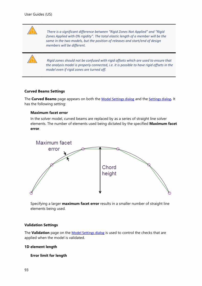
User Guides (US)
93
There is a significant difference between “Rigid Zones Not Applied” and “Rigid Zones Applied with 0% rigidity”. The total elastic length of a member will be the same in the two models, but the position of releases and start/end of design members will be different.
Rigid zones should not be confused with rigid offsets which are used to ensure that the analysis model is properly connected, i.e. it is possible to have rigid offsets in the model even if rigid zones are turned off.
Curved Beams Settings
The Curved Beams page appears on both the Model Settings dialog and the Settings dialog. It
has the following setting:
Maximum facet error
In the solver model, curved beams are replaced by as a series of straight line solver
elements. The number of elements used being dictated by the specified Maximum facet
error.
Specifying a larger maximum facet error results in a smaller number of straight line
elements being used.
Validation Settings
The Validation page on the Model Settings dialog is used to control the checks that are
applied when the model is validated.
1D element length
Error limit for length
User Guides
94
This field is used to control when an error is displayed when very short analysis elements
are detected.
Warning limit for length
This field is used to control when a warning is displayed when very short analysis
elements are detected.
2D element quality
Error limit for quality
This field is used to control when an error is displayed when poor quality 2D elements are
detected.
Warning limit for quality
This field is used to control when a warning is displayed when poor quality 2D elements
are detected.
2D element quality depends on two things, skew and aspect ratio. 0% is bad quality - a “squashed” triangle tends towards this. 100% is perfect quality - an equilateral triangle is perfect quality.
Check for validation warnings
This list specifies which Model, Analysis and Design validation checks are performed. If a
check box is cleared the validation check is not performed.
Load Reductions Settings
The Load Reductions page on the Model Settings dialog is used to control the live load
reductions.
Reduction percentage
These fields are used to specify the reduction to be applied for the number of floors
carried.
EHF Settings
The EHF page on the Model Settings dialog is used to control the percentages of load used for
the EHF calculations when working to Eurocodes.
The percentages are material independent (i.e. the same percentages are used for concrete
and steel), and vary depending on the height of the structure and the number of columns in
each direction.
Height of structure
Used to specify the effective height of the structure to be used in the EHF calculations.
Set Default
User Guides (US)
95
Sets the height to the highest construction level.
Number of Columns in X and Y directions
In the Eurocode Cl 5.2(5) the calculation of the reduction factor m depends on the
number of contributing members, m.
Valid input for m in the X and Y directions is any whole number from 1 to 1000. The
default value is 1 which results in m = 1.000. If a value of 1000 is entered then m would
reduce to 0.707.
Global initial sway imperfections
Displays the calculated alpha values and phi percentages for the above input.
User Defined Attributes Settings
The User Defined Attributes page appears on both the Model Settings dialog and the Settings
dialog. It displays a table of the attributes that are available for the current project. You can
add new attribute definitions or delete them, and also set each attribute’s type and control
the values that are permitted.
Fields
Name
The name of the attribute that will be displayed in the UDA section of the Properties
Window.
Type drop list
Attributes must be set to be one to three types: Text, Number, or File.
Source drop list
To restrict the allowable input for an attribute to a preset list choose Value List,
otherwise choose Custom Value.
Values
This field is only active when the source is set to Value List. It is used to limit the
allowable values to a preset list.
Buttons
Creates a blank row in the table for defining a new attribute.
Deletes the currently selected attribute from the table.
Moves the currently selected attribute upwards in the table. The order in
which attributes are listed in the Properties Window reflects the order in the
table.
Moves the currently selected attribute downwards in the table. The order in
which attributes are listed in the Properties Window reflects the order in the
table.

User Guides
96
Updates the settings in the currently displayed settings set and closes the
dialog. The settings that apply to the current model are NOT updated.
Closes the dialog without making changes to the settings set.
Graphics View Settings
The Graphic View Setting page on the Model Settings dialog is used to control the display of
miscellaneous items in the 2D and 3D Views.
Results
In the Results View, values of storey shear below the value entered here are not shown.
Piles
If Show full pile length box is cleared, you can enter your a default length to be used for
the display of all piles.
2x scale for steel columns
Select to display steel columns at double their size in 2D Views.
Structural BIM Settings
The Structural BIM Settings page appears on both the Model Settings dialog and the Settings
dialog. It is used to control the structural BIM import and export processes within the current
model.
Export - Continuous Objects page
Separate Objects for each stack/span/panel
Select the check boxes as required to specify which column/beam/wall types are
exported as separate objects.
Rebar information in Tekla Structural Designer is organised by stacks and spans. If you choose not to export concrete members as separate objects, then no rebar information will be exported.
Export - Reinforcement Information page
Concrete columns - Bar marks
Select the check box to include bar marks in the exported reinforcement information.
Concrete beams - Bar type references
Select the check box to include bar type references in the exported reinforcement
information.
Concrete beams - Link leg count
Select the check box to include the link leg count in the exported reinforcement
information.
Concrete beams - Region length percentage
User Guides (US)
97
Select the check box to include the region length percentage in the exported
reinforcement information.
Export - Mappings page (Settings dialog only, not Model Settings)
If you experience difficulties exporting a Structural BIM file this potentially could be
because either the Material, or Decking mappings that are used have become corrupt. In
this situation the TSD Support Team may direct you to reset the respective mappings
using on of the buttons on this page.
Import page
Concrete beams - Default “Allow automatic join”
An Auto Join process is run at the end of the Import. This setting is used to control
whether new imported concrete beams default to Auto Join or not.
While the default setting is to Auto Join new beams, if the BIM model contains
continuous beams as one piece, you would probably not want them to be Auto Joined
when imported - in which case you could clear this setting.
After the initial import, this can be changed using the normal Beam Properties if
necessary.
Steel columns - Ignore splice offsets in physical member positions
Splice offsets are modelled differently in Tekla Structural Designer and the BIM Platforms.
There are 3 ways of modelling them in the BIM Platforms:
• Ignore the offsets - the physical and analysis model both start and end at floor levels
• Model the physical length of each lift correctly - but modify the analysis model so
that the wires start and end at floor levels
• Model the physical length of each lift correctly - and leave the analysis model so it
matches the physical, i.e. the wires start and end above the floor levels
The default for this setting is checked, but it should be unchecked for the 3rd situation
above, where the offsets are modelled and the analysis model matches the physical.
We would recommend it is also unchecked for the 1st situation, where the offsets are
ignored for the physical and analytical model.
The BIM Export mirrors the Import with regard to splice offsets.
Import - Mappings page (Settings dialog only, not Model Settings)
If you experience difficulties importing a Structural BIM file this potentially could be
because either the Material, or Decking mappings that are used have become corrupt. In
this situation the TSD Support Team may direct you to reset the respective mappings
using one of the buttons on this page.
Editing project details using Project Wiki
Model statistics and revision control information are stored in Project Wiki.
How do I edit the project details and view the revision history?
User Guides
98
You set the initial project details as you create a new project. If you want to change these
later, or view other project parameters this is done as follows:
• Click Home > Project Wiki ( )
From the Project Wiki dialog you can see:
Project Summary
Parameters are entered here for inclusion in the output reports.
Revisions
Revision history can be tracked here.
Sessions
Shows the time at which each revision was started and last saved.
Changes
Displays the changes associated with each revision.
Metrics
Displays statistics related to the model size.
How do I record revisions?
You set the initial project details as you create a new project. If you want to change these
later, this is easily done.
1. You must save the project before you can start recording revisions. (eg “ABC123”)
2. Click the File menu >
3. Enter the Revision ID and add a notes related to this revision.
4. In order to keep a record of the changes made in this revision, check Track Changes.
5. Click OK.
6. Continue to develop the model then save it to a new name.(eg “ABC123 rev A”)
7. Repeat steps 2-5 above as required.
Head Codes and Design Codes
Tekla Structural Designer allows you to choose from a range of international design codes of
practice. Each new project will initially adopt the codes that have been specified in the active
settings set, however it is also possible to change codes in mid project.
The head code is used to control which action and resistance codes are available for
selection.

User Guides (US)
99
How do I configure the default design codes to be applied to new projects?
1. Click Home > Settings ( )
2. Select a suitable settings set from the drop list and make it active.
3. Use the Design Codes page of the Settings dialog to choose the codes required.
Having set the codes as required, Tekla Structural Designer will retain these as the default
codes to apply for each new project until you decide to amend them.
To start a new project with the chosen design codes:
• Click Home > New ( )
How do I change design codes in an existing project?
1. Click Home > Model Settings ( )
2. In the Design Codes page of the dialog choose the codes required.
If you change design codes in mid project, any existing load combinations will be lost - you will therefore need to recreate them. Depending on the type of construction and the actual code change applied, it is possible that additional data will also need to be re-specified. For example changing from British codes to Eurocodes results in a loss of composite beam stud layouts. “Simple” columns may also require the support at the base to be re-specified in this situation.
Units
Tekla Structural Designer allows you to switch between Metric and US Customary units.
Furthermore, you can then choose the units with which you are comfortable working. For
example if using US Customary units you can choose to input forces in either kip or lb. Input
lengths can be input in either feet or inches, or if you prefer feet and inches - length values
that are not whole numbers can be input either as decimals or fractions to your required
precision.
How do I configure the default units to be applied to new projects?
1. Click Home > Settings ( )
2. Select a suitable settings set from the drop list and make it active.
3. Use the Units page of the dialog to choose the System required.

User Guides
100
4. You can then tailor the way the chosen units system will be applied. The various options
allow you to set the units and the precision (number of decimal places or fractions) which
you want Tekla Structural Designer to use.
Note that the length unit can be set appropriate for the type of dimension being input:
• Fine Dimension units - these are used for defining stud spacings, section size
constraints and other typically small distances.
• Dimension units - these are used for defining grid spacings, positioning members,
positioning load locations etc. They are also used to control the accuracy of any
measured dimension lines that you apply to the model.
• Deflection units - these are used for reporting deflection results.
• Distance units - these are used for defining large dimensions.
Having set the units as required, Tekla Structural Designer will then expect input in the
same format.
If the Dimension unit is set to ft, in fract. Then to input a dimension of two feet six and one quarter inches you would type: 2’ 6 1/4” To input a series of irregular grid lines at spacings of fifteen feet, followed by three spacings of twenty feet six and one half inches, followed by one spacing of fifteen feet you would type: 15’,3*20’ 6 1/2”,15’
To start a new project with the chosen units:
• Click Home > New ( )
How do I change units and units precision in an existing project?
1. Click Home > Model Settings ( )
2. Use the Units page of the dialog to choose the System required.
3. You can then tailor the way the chosen units system will be applied. The various options
allow you to set the units and the precision (number of decimal places or fractions) which
you want Tekla Structural Designer to use.
Note that the length unit can be set appropriate for the type of dimension being input:
• Fine Dimension units - these are used for defining stud spacings, section size
constraints and other typically small distances.
• Dimension units - these are used for defining grid spacings, positioning members,
positioning load locations etc. They are also used to control the accuracy of any
measured dimension lines that you apply to the model.
• Deflection units - these are used for reporting deflection results.
• Distance units - these are used for defining large dimensions.
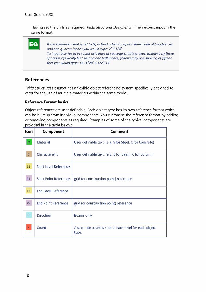
User Guides (US)
101
Having set the units as required, Tekla Structural Designer will then expect input in the
same format.
If the Dimension unit is set to ft, in fract. Then to input a dimension of two feet six and one quarter inches you would type: 2’ 6 1/4” To input a series of irregular grid lines at spacings of fifteen feet, followed by three spacings of twenty feet six and one half inches, followed by one spacing of fifteen feet you would type: 15’,3*20’ 6 1/2”,15’
References
Tekla Structural Designer has a flexible object referencing system specifically designed to
cater for the use of multiple materials within the same model.
Reference Format basics
Object references are user definable. Each object type has its own reference format which
can be built up from individual components. You customise the reference format by adding
or removing components as required. Examples of some of the typical components are
provided in the table below:
Icon Component Comment
Material User definable text: (e.g. S for Steel, C for Concrete)
Characteristic User definable text: (e.g. B for Beam, C for Column)
Start Level Reference
Start Point Reference grid (or construction point) reference
End Level Reference
End Point Reference grid (or construction point) reference
Direction Beams only
Count A separate count is kept at each level for each object type.

User Guides
102
Reinforcement> Bar Layer
The layer in which the reinforcement is placed in the slab/beam.
T1 is the top surface reinforcement in the 1st (outer) layer
T2 is the top surface reinforcement in the 2nd (inner) layer
B1 is the bottom surface reinforcement in the 1st (outer) layer
B2 is the bottom surface reinforcement in the 2nd (inner) layer
Reinforcement> Bar Size
Reinforcement> Center spacing
the center to center spacing between bars
Reinforcement> Detailing prefix
A detailing prefix is typically added in front of the bar size.
Custom Text Fixed text: (e.g. “Block C”)
Separator (backslash)
Separator (dash)
Separator (slash)
Separator (space)
Separator (times)
The default reference formats from the active Settings Set for each object type are applied
as objects of that type are created.
You can edit the syntax of the reference format at any time and objects created after the edit
will adopt the new format.
You can optionally include a separator between each of the components.
You can include fixed custom text within the reference format e.g. "DB" or "B", "G", "Block
C" at any position within the reference.
Once objects have been created you can edit their names on an object by object basis if
required so that they can be further individualized.

User Guides (US)
103
The start and end reference points P1 and P2, work from the grids that you define, and from
the construction points which have been created automatically when you place members
which don’t lie between existing points.
These reference points, when constructed using two grid reference points, always need to
automatically use a separator e.g. A/11 to avoid confusion as A1 and 1 could be confused.
A separate count for each level is kept for beams, braces, joists, but not a separate count by
material. So for example Steel beams and Concrete beams are included in the same count on
a level.
If the direction prefix is specified, then separate counts are made for each direction. Direction
1 is defined as objects falling within +- 45 degrees of the horizontal and Direction 2 +- 45
degrees of the vertical of the global axis.
For members the group reference in not included as part of the reference format; instead
options are provided within the Scene Content settings and the GA drawing's control to show
either the object reference and/or the group reference.
Also for members the geometric shape and section size are not included as part of the
reference format, instead options are provided within the Scene Content settings and the GA
drawing's control to show this information.
How do I configure the default references to be applied to new projects?
1. Click Home > Settings ( )
2. Select a suitable settings set from the drop list and make it active.
3. Click References
4. You can then tailor the way the references will be applied to each of the object types in
new projects.
To start a new project with these references:
• Click Home > New ( )
How do I change reference formats and texts in an existing project?
1. Click Home > Model Settings ( )
2. Click References
3. You can then tailor the way references will be applied.
How do I edit reference format syntax applied to an object type?
On the Reference Formats page, click the Edit... button to display the Edit Reference
Format dialog for the selected object type, then:
To add an extra component to the reference format:
User Guides
104
1. Click Add... and choose the component required.
2. The chosen component initially appears at the end of the reference format.
To re-order the components in the reference format:
1. Hover the cursor over the component to be moved.
2. Drag the component to reposition it.
To add a Custom Text component to the reference format:
1. Click Add... and choose the Custom Text component.
2. Drag the new component to the position required.
3. Next, click the component to edit it.
4. Type the text required in the box, then click Set.
To remove a component from the reference format:
1. Hover the cursor over the component to be removed.
2. Drag the component until it is outside the Edit Reference Format dialog.
How do I change the text used for the materials and characteristics in the reference
format?
1. When the References page is displayed, click Texts to display the Texts sub-page.
2. On the Materials or Characteristics tab locate the type to be changed and edit the text as
required.
3. Click OK.
How do I renumber members?
The renumber command can be applied in order to simultaneously renumber all member
types in the model whose reference format includes a “count”.
The member types referenced in this way would have initially been numbered in the order in
which they were created. Renumbering makes the members easier to find in the model and
on drawings.
Renumber works from the lowest plane/level in the model upwards. By default the count
starts at 1 and continues sequentially. The renumbering direction (top left of each level to
the bottom right, bottom left of each level to the top right etc.) is controlled via Model
Settings> References> General. The starting value can also be controlled on the same page.
To renumber members:
1. On the Project Workspace Structure tab, right-click Members.
User Guides (US)
105
2. From the right-click menu, choose Renumber.
All members in the model that include a count in their reference format are automatically
renumbered.
How do I renumber slabs?
The renumber command can be applied in order to simultaneously renumber all slab items
in the model.
Slab items would have initially been numbered in the order in which they were created.
Renumbering makes them easier to find in the model and on drawings.
Renumber works from the lowest plane/level in the model upwards. By default the count
starts at 1 and continues sequentially. The renumbering direction (top left of each level to
the bottom right, bottom left of each level to the top right etc.) is controlled via Model
Settings> References> General. The starting value can also be controlled on the same page.
To renumber slab items:
1. On the Project Workspace Structure tab, right-click Slabs.
2. From the right-click menu, choose Renumber.
All slab items in the model are automatically renumbered.
Settings
Various defaults (referred to collectively as a “settings set”) can be managed via the Settings
dialog. When these settings are edited you will find that mainly they do not get directly
applied to the current project - they do however get applied to future projects.
are the exception, as they are applied instantly whenever the settings set to which they
belong is made “active”.
Settings and defaults in the current project (with the exception of general and display settings) are not controlled directly from the Settings dialog - these can only be changed from the Model Settings, Analysis Options, or Design Options dialogs.
Working with setting sets
Initial setup
The very first time the program is run you are required to select a country/region in order to
configure an appropriate initial settings set.
Importing/adding further sets

User Guides
106
You are not restricted to a single settings set - you can import additional sets for other
countries/regions and add customized copies of existing sets (to cater for different types of
project for example).
Editing the set contents
You can review and customize the settings in a particular set simply by selecting it from the
drop list at the top of the page and then making the changes required.
Changing the defaults in a set won’t affect the defaults in a model that is already open - these can only be changed from the Model Settings, Analysis Options, or Design Options dialogs.
The active set
You choose the settings set to be applied to a new project by designating it as the
active set.
Ensuring the active set is specified correctly before commencing work on a new model is an
efficient way to ensure the most appropriate defaults are in place at the outset, minimising
the need to change Model Settings, Analysis and Design Options etc. at a later stage.
If you subsequently further customize the settings within an individual project you can save
these back to the active set if you require.
Distributing sets
In order to apply consistent settings on a company wide basis, once suitable settings sets
have been configured, the resulting settings files can be made available to all users within
the company by manually copying them to the appropriate folder on each computer.
Selecting a settings set the first time the program is run
The first time the program is run after installation, you will be asked to select an appropriate
region. This configures a settings set for you containing defaults most appropriate to the
region selected.
Each settings set includes defaults for:
• Design Codes
• Units
• Section Defaults
• Settings for Drawings, Schedules and Reports
Although only one region can be selected at this point, you can subsequently import settings sets for any of the other regions if you so require. Each set can then be modified to your exact needs via the Settings dialog dialog.
How do I edit the content of a settings set?
User Guides (US)
107
1. Click Home > Settings ( )
2. On the Settings Sets page select the settings set to be edited from the drop list.
3. Use the various pages of the Settings dialog to tailor the set to your requirements. The
various options allow you to:
• configure the font use to display results in the Results Viewer,
• configure the appearance of the Reports,
• set the units with which you are comfortable working, and set the precision (number of
decimal places) to which you want Tekla Structural Designer to use for each unit type,
• set the Design Codes to be applied,
• set default section sizes for each of the member types,
• set if confirmations are required for specific actions,
• set element references,
• configure the appearance of the Schedules,
• configure drawing types and styles,
• configure the colors used in the 2D and 3D views.
4. When the settings are configured as required click OK to save them to the currently
selected Settings Set.
How do I add a different settings set?
1. Click Home > Settings ( )
2. In the Settings Sets page of the dialog click Add
3. Enter the name of the new set and then click OK
4. Use the various pages of the Settings dialog to configure the settings that apply for the
new set.
5. When the settings are configured as required click OK to save them to the currently
selected Settings Set.
How do I specify the active settings set?
1. Click Home > Settings ( )
2. On the Settings Sets page select the settings set required from the drop list.
3. Click >> Active to make this the default set for new projects.
4. Click OK to close the dialog.
User Guides
108
How do I import a settings set for a different region?
1. Click Home > Settings ( )
2. From the Settings Sets page of the dialog click Import...
3. Choose the country to import the settings for and click OK.
How do I delete a settings set?
1. Click Home > Settings ( )
2. In the Settings Sets page of the dialog choose the set to be deleted from the dropdown
list.
3. Click Remove to delete it.
How do I load settings from a settings set to the current project?
Having edited the settings within an individual project, you may subsequently require to
change them back to the original defaults from the settings set, or you may even decide to
replace them with settings from a different settings set.
Firstly you need to ensure the required settings set is active as follows:
1. Open the Settings dialog at the Settings Sets page.
2. Select the settings set you want to use to update settings within the current project.
3. If it is not already the active set, click the >>Active button to make it so.
4. Click OK
Next you have to choose which settings are to be updated. (You are able to update either:
Analysis Options, Design Options, Drawing Settings, or Model Settings.)
1. Open the dialog containing the settings to be updated, either:
• Click Home > Model Settings ( )
• Click Analyse > Options ( )
• Click Design > Options ( )
• Click Draw > Edit... ( )
2. Click the Load... button.
3. Click Yes to update the model settings with those from the active settings set.

User Guides (US)
109
How do I save settings from the current project to a settings set?
In some instances, you may decide that specific changes you’ve made to the model settings,
analysis options or design options should be applied not just within the existing project but
to new projects also. To do this the changes have to be saved back to the active settings set.
Firstly you need to ensure the required settings set is active as follows:
1. Open the Settings dialog at the Settings Sets page.
2. Select the settings set you want to be updated from the drop list.
3. If it is not already the active set, click the >>Active button to make it so.
4. Click OK
Next you have to choose which settings are to be updated. (You are able to update either:
Analysis Options, Design Options, Drawing Settings, or Model Settings.)
1. Open the dialog containing the settings to be saved, either:
• Click Home > Model Settings ( )
• Click Analyse > Options ( )
• Click Design > Options ( )
• Click Draw > Edit... ( )
2. Click the Save... button.
3. Click Yes to update the active Settings Set with the current settings shown in the dialog.
How do I copy a settings set from one computer to another?
In order to apply consistent settings on a company wide basis, once a suitable settings set
has been configured on one computer, the resulting xml file would need to be manually
copied to other computers to make it available to other users.
1. On the computer containing the settings set to be copied: click Home > Settings ( )
2. On the Settings Sets page of the dialog, ensure the set to be copied has a name that
distinguishes it from the default installed sets - (if necessary click Rename to do this.)
3. Next, click Open Folder
4. Select the required xml file and manually transfer it to the settings folder on each
destination computer - (the settings folder is located by clicking Open Folder from the
Settings dialog on each destination computer).
User Guides
110
5. Restart Tekla Structural Designer on the destination computers in order to see the new
set listed on the Settings Sets page.
General and display settings
The settings on the General, Results Viewer, Report and Scene pages control the appearance
and behaviour of different areas of the user interface.
Provided the set that has been edited is the active set - any changes are instantly applied to
the current work-session when you click OK to close the Settings dialog.
These general and display settings continue to apply in future work-sessions (for any model)
whenever the edited set is active.
Settings dialog
Located on the Home toolbar, the Settings ( ) dialog serves two purposes:
• to manage defaults (referred to collectively as a settings set) that are applied to future
projects
• to manage that are applied instantly to the current work session
Settings Sets Settings
The Settings Sets page on the Settings dialog controls the settings sets which are used to
create the model/analysis/design settings in new projects, and which can also be used to
replace the model/analysis/design settings in existing projects.
Fields
Settings set drop list
The drop list displays all the existing settings sets.
The selected set’s content can be viewed/edited by clicking on the other pages of the
Settings dialog.
Buttons
Creates a new settings set which is initially a copy of the active settings set.
It can then be customized by clicking on the other pages of the Settings dialog and
making edits as required.
Makes the settings set that is currently displayed in the drop list the active
settings set.
Displays a dialog from which you can choose to import setting sets
applicable to other geographic regions.
Can be used to rename the settings set that is currently displayed in the drop
list.

User Guides (US)
111
Can be used to remove the settings set that is currently displayed in the drop
list.
Opens the folder in which the existing settings sets are located.
Updates the settings in the currently displayed settings set and closes the
dialog. The settings that apply to the current model are NOT updated.
Closes the dialog without making changes to the settings set.
General Settings
This page and sub-pages on the Settings dialog are used to (for the settings set selected at
the top of the page):
• configure the language,
• configure autosave,
• set the font used in the Results Viewer,
• configure which actions require confirmation.
Unlike other “settings set” settings, changes to general settings are instantly applied to the current work-session when you click OK to close the Settings dialog (provided the edits were made to the active set).
Language
Preferred Language
Changing the language changes the terminology used in the interface and output.
For example the term “links” is used when the language is English (United Kingdom) but
this becomes “stirrups” when the language is English (United States).
The Preferred Language cannot be configured differently between Settings Sets.
Appearance
Windows
You can elect to show the tabs at the top rather than the bottom of the project
workspace by selecting the Show captions on top check box.
Autosave
Autosave
Used to enable the autosave feature and set the autosave interval.
User Guides
112
When autosave is enabled, a backup is made of the model at a specified interval (minimum 5 minutes). If you have to restart the program after a crash; then provided the autosave is newer than the last saved version of the model, you will be offered the opportunity to open the autosaved version.
Confirmations
Confirm on
Click to clear the check boxes for those operations that you don’t want to have to
confirm each time.
Update Service
Enable update service
This option defines whether you can update Tekla Structural Designer.
If you only select the Enable update service option, you will have to update Tekla
Structural Designer manually. To update Tekla Structural Designer manually, click Home >
Check for updates.
Check for updates when starting Tekla Structural Designer
If you select this option, every time you start the software it will automatically check for
critical updates.
If critical updates are available, you will be notified, and you can select whether you want
to install the updates.
Check for non critical updates every [N] day(s)
This option allows you to select how often to check for non-critical updates.
To define the number of days between each check, type the desired number in the field.
Tekla Customer Experience Improvement Program
This option allows you to define whether you want to give us valuable anonymous data
on your use of Tekla Structural Designer.
The data is collected monthly, and used only to improve the quality, reliability, and
performance of Tekla Structural Designer.
The Update service option must be enabled so that you can participate in the Tekla Customer experience improvement program.
Results Viewer Settings
This page and sub-pages on the Settings dialog are used to configure (for the settings set
selected at the top of the page) the appearance of the on screen results viewer.
User Guides (US)
113
Unlike other “settings set” settings, changes to results viewer settings are instantly applied to the current work-session when you click OK to close the Settings dialog (provided the edits were made to the active set).
General
Viewer font
The Viewer font only controls the text that is displayed in the left hand pane of the
results viewer.
Styles
Calc Normal
Calc Normal is not currently used.
Table
The Table font controls all the text displayed in the right hand pane of the results viewer,
with the exception of the first row in any table.
Table Heading
The Table Heading font controls the first row in any table.
Structure Defaults
This page on the Settings dialog is used to specify (for the settings set selected at the top of
the page) miscellaneous structure defaults.
Unlike other “settings set” settings, changes to nominal cover are applied instantaneously for new members.
Section Defaults
This page on the Settings dialog is used to specify (for the settings set selected at the top of
the page) the default section size when a new member is created for each member type.
Solver Settings
This page on the Settings dialog is used to specify (for the settings set selected at the top of
the page) the solver method that gets applied.
Two different solvers are available. The compressed sparse row solver is preferred as this will
generally reduce the time required for analysis (particularly for finite element analysis).
Scene Settings
This page on the Settings dialog is used to control (for the settings set selected at the top of
the page) the color and opacity of each object type in the scene views.
User Guides
114
Unlike other “settings set” settings, changes to scene settings are instantly applied to the current work-session when you click OK to close the Settings dialog (provided the edits were made to the active set).
Colors page
Reset Colors
Resets all the colors to the default settings.
Color Name
The item to which the color applies.
An arrow is displayed to the left of some of the items, this can be clicked on in order to
set the colors for sub-items.
Opacity
Use the slider to set the opacity
Color
Set the color for each item as required.
Fonts page
Reset Fonts
Resets all the fonts to the default settings.
Font Name
The item to which the font applies.
Font, Size, Bold, Italic
Set for each item as required.
Contours page
This page is used to configure the way that FE contours are displayed in the Results View.
The default configuration consists of 10 evenly sized contours, each accounting for 10% of
the total range. You can increase or decrease the number of contours, and also change the
size and the color of individual contours.
Lower bound (%)
The lower bound of each contour cannot be edited directly - instead it is adjusted by
editing the Size (%)
Upper bound (%)
The upper bound of each contour cannot be edited directly - instead it is adjusted by
editing the Size (%)
Size (%)

User Guides (US)
115
You can edit the size of individual contours as required, however the sum of the sizes
must equate to 100%.
Color
Click the color of a contour in order to change it.
Split
Click this button to divide the selected contour into two contours, each being half the
size of the original.
Delete
Click this button to remove the selected contour.
Reset
Click this button to reset to the default configuration of 10 evenly sized contours.
Utilization Ratios page
This page is used to configure the way that ratio bands are displayed when reviewing design
ratios.
The default configuration consists of 6 evenly sized bands, each accounting for 20% of the
range from 0.0 to 1.0. You can increase or decrease the number of bands, and also change
the size and the color of individual bands. The highest band can be increased above 1.0 if
required.
View Settings page
Results
Many columns can have very small values of storey shear associated with them which can
detract from the important ones. The Do not display values of storey shear below
setting provides a means to limit the values for a new model. Storey shears less than the
limiting value set here are not displayed in the Results View.
Piles
The pile lengths displayed in the views can be cropped by clearing the Show full pile
length setting. You can specify a shorter pile length to be displayed.
Slab Deflection Settings
This page on the Settings dialog is used to control the slab deflection defaults applied to
new models.
New Load Event Defaults page
See: New Load Event Defaults
New Check Defaults page
See: New Check Defaults
Creep & Shrinkage page
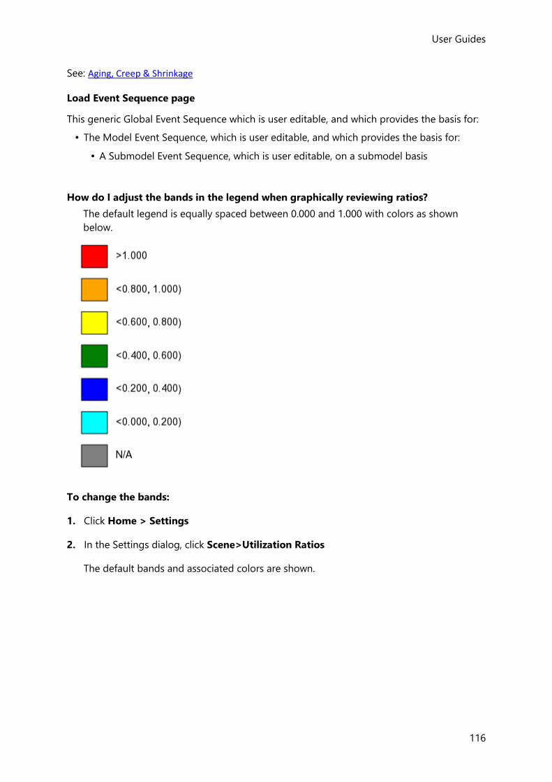
User Guides
116
See: Aging, Creep & Shrinkage
Load Event Sequence page
This generic Global Event Sequence which is user editable, and which provides the basis for:
• The Model Event Sequence, which is user editable, and which provides the basis for:
• A Submodel Event Sequence, which is user editable, on a submodel basis
How do I adjust the bands in the legend when graphically reviewing ratios?
The default legend is equally spaced between 0.000 and 1.000 with colors as shown
below.
To change the bands:
1. Click Home > Settings
2. In the Settings dialog, click Scene>Utilization Ratios
The default bands and associated colors are shown.

User Guides (US)
117
From here you can change ratio values, change colors, and delete or add values (max 10).
At any point you can click Reset to restore the default equally spaced bands.
3. When the bands are as required, click OK.
4. If the active view was previously displaying ratios you may need to refresh it (by
switching the Ratio off and on) to see the new bands/colors.

User Guides
118
Materials
Tekla Structural Designer’s databases store an extensive range of sections, materials,
reinforcement, decking and connectors for each Head Code and/or Country.
The initial (system) data in the databases is protected so that standard items cannot be
accidently edited or deleted, but you can supplement it with extra (user) data from other
sources/suppliers if so required. Any user data you add is fully editable.
The databases are accessed via the Materials dialog.
Although the Materials dialog can be used to view the properties for any of the head codes, only those properties for the currently specified head code in Model Settings can be applied to the model.
Materials dialog
Accessed by clicking Home> Materials, this dialog is used to manage the material
databases.
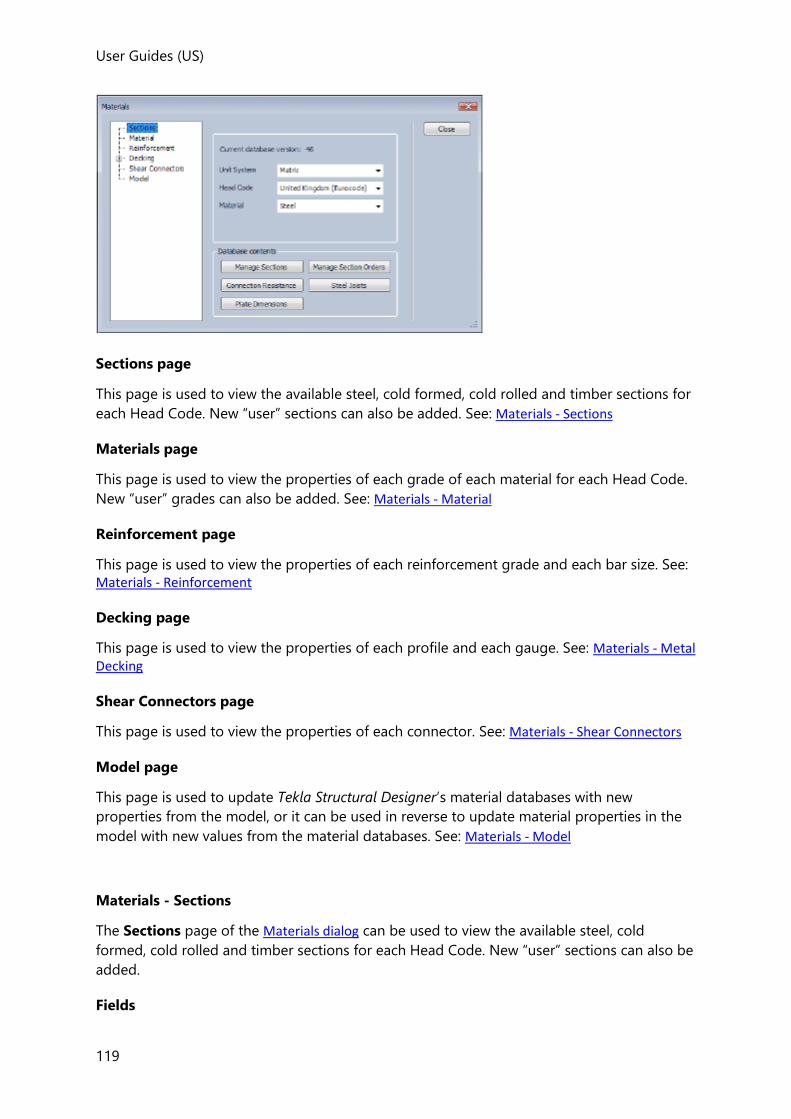
User Guides (US)
119
Sections page
This page is used to view the available steel, cold formed, cold rolled and timber sections for
each Head Code. New “user” sections can also be added. See: Materials - Sections
Materials page
This page is used to view the properties of each grade of each material for each Head Code.
New “user” grades can also be added. See: Materials - Material
Reinforcement page
This page is used to view the properties of each reinforcement grade and each bar size. See:
Materials - Reinforcement
Decking page
This page is used to view the properties of each profile and each gauge. See: Materials - Metal Decking
Shear Connectors page
This page is used to view the properties of each connector. See: Materials - Shear Connectors
Model page
This page is used to update Tekla Structural Designer’s material databases with new
properties from the model, or it can be used in reverse to update material properties in the
model with new values from the material databases. See: Materials - Model
Materials - Sections
The Sections page of the Materials dialog can be used to view the available steel, cold
formed, cold rolled and timber sections for each Head Code. New “user” sections can also be
added.
Fields
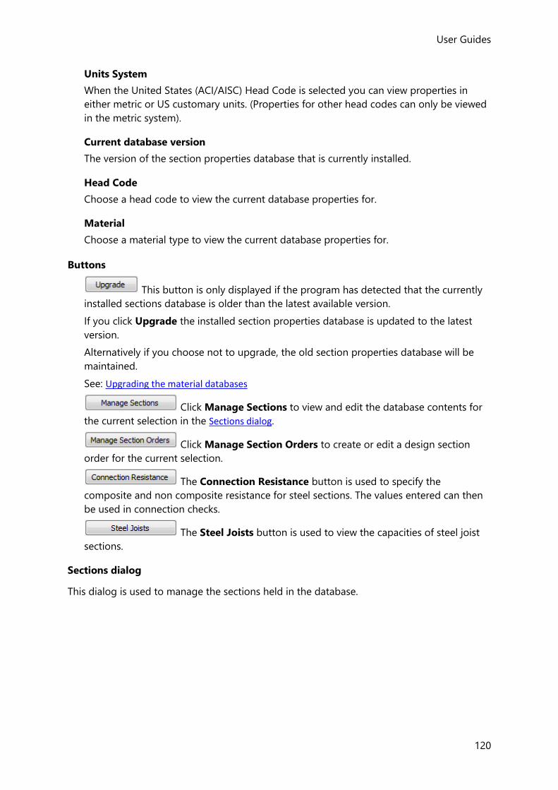
User Guides
120
Units System
When the United States (ACI/AISC) Head Code is selected you can view properties in
either metric or US customary units. (Properties for other head codes can only be viewed
in the metric system).
Current database version
The version of the section properties database that is currently installed.
Head Code
Choose a head code to view the current database properties for.
Material
Choose a material type to view the current database properties for.
Buttons
This button is only displayed if the program has detected that the currently
installed sections database is older than the latest available version.
If you click Upgrade the installed section properties database is updated to the latest
version.
Alternatively if you choose not to upgrade, the old section properties database will be
maintained.
See: Upgrading the material databases
Click Manage Sections to view and edit the database contents for
the current selection in the Sections dialog.
Click Manage Section Orders to create or edit a design section
order for the current selection.
The Connection Resistance button is used to specify the
composite and non composite resistance for steel sections. The values entered can then
be used in connection checks.
The Steel Joists button is used to view the capacities of steel joist
sections.
Sections dialog
This dialog is used to manage the sections held in the database.

User Guides (US)
121
• The Details button is then used to view properties of the selected section.
• The Add... button can be used to add further sections to the database.
The Delete button can be used to delete user defined sections.
The Edit... button can be used to edit user defined sections.
How do I add a user defined section to the database?
Either the Select Section dialog, or the Sections dialog can be used to add sections to the
database.
If you require to edit an existing user defined section you can only do so from the Section dialog.
To open the Sections dialog:
1. Click Home > Materials ( )
2. In the Sections page of the dialog click Manage Sections.
The Sections dialog is displayed.
To add a section:
1. Select the database country from the Country droplist.
2. Select the section geometry required from the Page pane.

User Guides
122
(If the shape you require is not shown it may have been filtered out - click the Geometry
filter if you need to check this.)
3. Click Add...
4. Enter values for each of the variables requested and then click OK
The new section size should now be shown on the Item pane.
How do I delete a user defined section from the database?
Either the Select Section dialog, or the Sections dialog can be used to delete user defined
sections from the database.
If you require to edit an existing user defined section you can only do so from the Section dialog.
To open the Sections dialog:
1. Click Home > Materials ( )
2. In the Sections page of the dialog click Manage Sections.
The Sections dialog is displayed.
To delete a section:
1. Select the database country from the Country droplist.
2. Select the section geometry required from the Page pane.
(If the shape you require is not shown it may have been filtered out - click the Geometry
filter if you need to check this.)
3. Select the user defined section size to be deleted from the Item pane.
4. Click Delete.
Only user defined sections (i.e. those marked “*”) can be deleted from the database.
How do I edit a user defined section in the database?
User defined section properties can only be edited via the Sections dialog.

User Guides (US)
123
To open the Sections dialog:
1. Click Home > Materials ( )
2. In the Sections page of the dialog click Manage Sections.
The Sections dialog is displayed.
To edit a section:
1. Select the database country from the Country droplist.
2. Select the section geometry required from the Page pane.
(If the shape you require is not shown it may have been filtered out - click the Geometry
filter if you need to check this.)
3. Select the user defined section size to be edited from the Item pane.
Only user defined sections (i.e. those marked “*”) can be edited in this way.
4. Click Edit...
How do I manage section orders?
1. Click Home > Materials ( )
2. Click the Sections page
3. Select the Head Code required.
4. Select the Material required.
5. Click Manage Section Orders
6. Choose the section order required
7. Click Edit...
How do I add connection resistances to the database?
1. Click Home > Materials ( )
2. Click the Sections page
3. Select the Head Code required.

User Guides
124
4. Select Steel from the Material droplist.
5. Click Connection Resistance
The Connection Resistance dialog is displayed.
6. Click Columns...
Two resistances are by default displayed: Non-composite and Composite.
You are not restricted to these as you can define ‘n’ resistances and give them their own
titles e.g. Flex End Plate 4 bolt, Flex End Plate 6 bolt, Fin Plate etc.
7. Click OK to close this dialog.
8. Click Add...
The Select Section dialog is displayed.
9. Select the database country from the Country droplist.
10. Choose the section required from the Page pane.
(If the shape you require is not shown it may have been filtered out - click the Geometry
filter if you need to check this.)
11. Click Select
12. Enter the resistances as required for this section size.
13. Either click Add... to add resistances for another section, or click OK when done.
Select Section dialog
This dialog provides the means to select sections for use in the model. It can also be used to
add (and delete) user defined sections to the section database if required.

User Guides (US)
125
How do I select a section from the Select Section dialog?
1. If the displayed country is not correct you can select another from the Country droplist.
2. Select the section geometry required from the Page pane.
(If the shape you require is not shown it may have been filtered out - click the Geometry
filter if you need to check this.)
3. Select the section size required from the Item pane.
Any section size marked “#” has limited availability. Any section size marked “*” is a user defined section that has been manually added to the database.
4. Click the Select button.
Materials - Material
The Materials page of the Materials dialog can be used to view the properties of each grade
of each material for each Head Code. New “user” grades can also be added.
Fields
Current database version
The version of the material database that is currently installed.
Head Code

User Guides
126
Choose a head code to view the current database properties for.
Material Type
Choose a material type to view the current database properties for.
Available Grades
Choose a specific grade from list in order to view the material properties associated with
it in the current database.
Where there is more than one grade, one will be listed as the default.
When a new member is created, the grade applied will be the default in the Material
database for the Head Code specified in Model Settings.
Buttons
This button is only displayed if the program has detected that the currently
installed materials database is older than the latest available version.
If you click Upgrade the installed material properties database is updated to the latest
version.
Alternatively if you choose not to upgrade, the old material properties database will be
maintained.
If your required grade does not exist in the current database version, this
button can be used to display a dialog allowing a “user” grade to be defined.
When a “system” grade is selected, this button displays a dialog to view the
properties.
When a “user” grade is selected, this button displays a dialog to edit the
properties.
When a “user” grade is selected, this button can be used to delete the grade.
(“System” grades are protected and cannot be deleted).
Makes the currently highlighted grade the default grade for the displayed
head code.
Materials - Reinforcement
The Reinforcement page of the Materials dialog can be used to view the properties of each
reinforcement grade and each bar size.
Where there is more than one class, one will be listed as the default class to apply to new
members.
If required new classes and new bar sizes can be defined using the Add... buttons.
Fields

User Guides (US)
127
Current database version
The version of the reinforcement properties database that is currently installed.
Head Code
Choose a head code to view the current database properties for.
Country
Choose a country to view the current database properties for.
Type
Choose a bar type to view the current database properties for.
Rib Type
Choose a rib type to view the current database properties for.
Available Classes
Choose a specific class from list in order to view the properties associated with it in the
current database.
Where there is more than one class, one will be listed as the default.
When a new member is created, the class applied will be the default in the
Reinforcement database for the Head Code specified in Model Settings.
Available Sizes
Choose a specific size from list in order to view the properties associated with it in the
current database.
Buttons
This button is only displayed if the program has detected that the currently
installed reinforcement database is older than the latest available version.
If you click Upgrade the installed reinforcement database is updated to the latest
version.
Alternatively if you choose not to upgrade, the old reinforcement database will be
maintained.
If your required class/size does not exist in the current database version, this
button can be used to display a dialog allowing a “user” class/size to be defined.
When a “system” class/size is selected, this button displays a dialog to view
the properties.
When a “user” class/size is selected, this button displays a dialog to edit the
properties.
When a “user” class/size is selected, this button can be used to delete it.
(“System” classes/sizes are protected and cannot be deleted).

User Guides
128
Makes the currently highlighted class the default class for the displayed
head code, country and type.
Materials - Metal Decking
The Metal Decking page of the Materials dialog can be used to view the properties of each
profile and each gauge.
Where there is more than one profile, one will be listed as the default profile to apply to new
decks for the displayed country. (The >>Default button can be used to change this if
required.)
If required new profiles and new gauges can be defined using the Add... buttons.
Materials - Shear Connectors
The Shear Connectors page of the Materials dialog can be used to view the properties of
each connector.
When composite beams are used with composite slabs, the default shear connector used will
be the one displayed as the Default for Metal.
If composite beams are used with precast panels, a taller stud would typically required; the
default shear connector used in this case is the one displayed as the Default for Concrete.
The >>Def. Metal and >>Def. Concrete buttons can be used to change these if required.
If required new connector sources and connectors can be defined using the Add... buttons.
Materials - Model
The Model page of the Materials dialog can be used to update Tekla Structural Designer’s
material databases with new properties from the model, or it can be used in reverse to
update material properties in the model with new values from the material databases.
Understanding the “In Database” status indicator
Provided there are no inconsistencies between the material data in the model and the
databases, the Model page will be shown similar to the one below:

User Guides (US)
129
• The solid circle against each material data object indicates the data for that object
matches that in the database.
• If Show only objects not saved in the database is selected, then nothing is displayed as
everything is consistent.
If there is an inconsistency between the material data in the model and the databases, the
Model page will show this by placing a tick against those object classes where there is a
problem:
• If Show only objects not saved in the database is then selected, then only the
inconsistent data is displayed making it easier to drill down and locate the problem
objects.
The inconsistency can be resolved by first checking the problem objects and then choosing
to either Add to Database (from the model) or Update from Database (to the model).
Adding material properties from the model to a material database
When you define a member the material properties assigned to it are initially read from the
appropriate material database but subsequently held with the member itself. This means that
the model can be opened and run on another computer, even if it doesn’t have a matching
material in its database.
When such a mis-match between the model’s material data and the material database arises,
you are not required to add the missing properties to the database. It may however be
beneficial to do so if you anticipate that you will need to re-use the property in question in
new models.
Updating the model’s material properties from a material database

User Guides
130
As stated above, once a member has been created its material properties are permanently
held with it. Consequently if Tekla Structural Designer’s material databases are subsequently
updated, the member itself will not be automatically updated.
If this situation arises you can choose to refresh the model’s material data with data from a
material database wherever there is a mis-match between the two.
Upgrading the material databases
The installed material databases each have their own database version, (displayed separately
on each page of the Materials dialog). The original data in each of these databases is referred
to as “system data” and cannot be edited. The version number relates specifically to this
system data.
From time to time new system data might become available through a program update.
When this happens, an Upgrade button is displayed adjacent to the current database
version on the relevant page of the Materials dialog. You then have the choice to either
upgrade the database or retain the old version.
Any extra items you add to the databases are referred to as “user data”, this data is fully
editable. Adding user data has no effect on the database version.
Updating the database version does not cause you to lose any user data you may have added to the old version, since it is automatically copied back in to the new database.
In certain circumstances an inconsistency can arise between the user data in a model and the
installed databases. (Typically this can occur if a model containing user data is transferred to
a different computer). Such inconsistencies can be identified and resolved from the Model
page of the Materials dialog, either by updating the model data, or by updating the
databases.
Adding materials to the database when they are not listed for a head code
In a number of world regions, engineers may be required to design using locally sourced
sections, materials, and reinforcement that are not listed in the materials database for the
current head code.
In order to do this you would need to manually add the material properties to the database.
If you add data to the database, you are responsible both for its accuracy and applicability to the chosen design head code.
How do I add a material grade that is not listed for a particular head code?
1. Click Home > Materials ( )
User Guides (US)
131
2. From the Material page of the dialog choose the Head Code required.
3. Choose the material type required.
4. If the grade you require is not listed for the chosen head code, click Add...
5. Enter the grade properties.
You are responsible both for its accuracy and applicability of the entered properties for the chosen design head code.
6. Click OK to return to the Materials dialog.
7. The new grade will be shown on the list of available grades.
8. Select the new grade then click >>Default in order to make this the default grade for
this material for the selected head code.
How do I add reinforcement that is not listed for a particular head code?
You are responsible both for the accuracy and applicability of manually entered reinforcement properties for the chosen design head code.
To add a new reinforcement class
1. Click Home > Materials ( )
2. From the Reinforcement page of the dialog choose the Head Code required.
3. Choose the Country to assign the reinforcement to.
4. Choose the Type and Rib Type required.
5. If the class of reinforcement you require is not listed, click Add...
6. Enter the reinforcement class properties.
7. Click OK to return to the Materials dialog.
8. The new class will be shown on the list of available classes.
9. Select the new class then click >>Default in order to make this the default class for the
selected combination of head code and country.
To add new reinforcement sizes

User Guides
132
When the new class is selected you will notice that initially it does not have any bar sizes
specified. You must therefore add all the sizes you intend to use.
1. In the available sizes area of the dialog, click Add...
2. Enter the properties of the first bar size.
3. Continue in the same way to add all the bar sizes you want to be considered.
4. When all the sizes have been added, click Close
To specify the bar size range to be applied in auto design
After the new reinforcement has been added to the materials database, you can then specify
the minimum and maximum bar sizes that should apply to the different concrete members
when they are auto-designed.
1. Click Design > Options ( )
2. From the Concrete page of the dialog locate the reinforcement settings for each of the
member types in turn:
• Beam
• Column
• Wall
• Slab> Slab on Beams
• Slab> Flat Slab
• Punching Shear
• Foundations> Isolated Foundations> Pad Base
• Foundations> Isolated Foundations> Pile Cap
• Foundations> Mat Foundations
3. For each of the above, choose the Country to which the new reinforcement was
assigned, then choose the minimum and maximum bar sizes that apply to auto-design.
4. The new design options will now apply to the current project - if you want them to apply
to new projects as well the changes have to be saved back to the active settings set.
How do I change default steel sections to be from a different country for a particular
head code?
5. Click Home > Settings ( )
6. From the Section Defaults page of the dialog select the settings set to edit.
7. In the table, click the currently displayed section for each of the steel member types in
order to change them.
User Guides (US)
133
The Select Section dialog should be displayed.
To change the country:
1. The existing country is displayed in the left hand column first cell - click it to select a
different country.
To change the section shapes displayed in the list:
1. The shapes that are displayed are filtered by the left hand column second cell - click this
cell to filter by a different shape.
To select the default section:
1. Choose the shape required from the range displayed in left hand column.
2. Choose the section from the range displayed in table.
3. Click Select to update the default section and return to the Settings dialog.
4. Repeat for other member types as required.
The new default sections will be applied to new models, provided the settings set that was edited is the active set.
How do I change default design section orders for a particular head code?
1. Click Home > Settings ( )
2. From the Section Order Defaults page of the dialog select the settings set to edit.
3. In the table, click the currently displayed section order for each of the member types in
order to change them.
4. Choose the country from the droplist.
If there are no section orders listed for the chosen country, this is because they do not yet exist for the current head code. However, the section orders can still be created by using the “Import...” feature, as described below.
5. Highlight an available section order from the list, then click Select
6. Repeat for other member types as required.
User Guides
134
The new section order defaults will be applied to new models, provided the settings set that was edited is the active set.
Using “Import...”to create new section orders for a particular head code
If the required section order for the chosen country is not listed, this is because it doesn’t
exist for the current head code. In which case it can be created as follows:
1. Click Home > Settings ( )
2. From the Section Order Defaults page of the dialog select a settings set that contains
the required section order.
3. In the table, click the required section order - the Select a Section Order dialog is then
displayed.
4. Click Export and save the section order as an XML format file.
5. Close the Select a Section Order dialog
6. From the Section Order Defaults page of the Settings dialog return to the settings set
that was originally being edited.
7. In the table, click the section order to be changed.
8. Choose the country from the droplist.
9. Click Import and select the XML file that was saved in step 4 above.
10. Once the file has been imported, click Select to choose it.
11. Repeat for other member types as required.
BIM Integration
BIM integration commands are all located on the Home toolbar.
Tekla Structures Import and Export
When the project is begun in Tekla Structures we recommend using the Analytical Model link to TSD.
How do I export a model to Tekla Structures?
1. Create your model in Tekla Structural Designer in the usual way.
User Guides (US)
135
2. Click Home > Tekla Structures Export ( )
This opens the Save As dialog which gives the name of the Revit Structure file which
Tekla Structural Designer will create. You can change the name and location of the Revit
Structure file if necessary.
3. Specify the file name and location then click Save to create the Tekla Structures file.
4. Launch Tekla Structures and open the file to see your project.
Autodesk Revit Import and Export
How do I export a model to Autodesk Revit Structure?
1. Create your model in Tekla Structural Designer in the usual way.
2. Click Home > Revit Export
This shows a dialog which leads you through the export process.
3. Review each page, modify if required then click Next
4. On the final page, specify the name and location of the export file, then click Finish
5. Launch Revit Structure and open the file to see your project.
IFC Export
How do I export a model to IFC?
1. Create your model in Tekla Structural Designer in the usual way.
2. Click Home > IFC Export
This shows a dialog which leads you through the export process.
3. Review each page, modify if required then click Next
4. On the final page, specify the name and location of the export file, choose the file format,
then click Finish
Westok Cellbeam Import and Export
How do I export a beam to Westok Cellbeam?
Cellbeam import and Export are only available for BS and Eurocode Head Codes.

User Guides
136
1. Click Home > Cellbeam Export
Any Westok Cellular beams that have been defined in the model will be listed.
2. From the list, select the beams which you want to transfer to Westok Cellbeam.
Click Next
3. Choose the export format and enter a file name.
Click Next
4. Ensure that you have a tick against the design combinations whose results you want to
use in the Westok beam design.
Click Next
5. You will see a dialog asking you to pick the folder into which the Westok files are to be
placed. Do so and then click Export to place the selected beam files to this folder.
6. Click Finish
How do I import a beam from Westok Cellbeam?
Cellbeam import and Export are only available for BS and Eurocode Head Codes.
In order to import Westok beams into your model you must have previously created these in your Tekla Structural Designer model, and have exported them for Westok design. When you do this each beam is given a unique identifier. This means that when you import the results from the Westok file, Tekla Structural Designer knows to which beam in your model the imported details apply.
7. Click Home > Cellbeam Import
8. Click Add...
you will see the Open dialog.
9. Navigate to the folder which contains the file you want to import and click the
appropriate file names. You can select single or multiple files using the standard
Windows method, then click Open
10. Click Import
Provided that Tekla Structural Designer recognises the identifier, the details in the files
will be imported to the associated beam in your model. If Tekla Structural Designer does
not recognise the identifier of the beam, then you will see a message to this effect.

User Guides (US)
137
STAAD Export
How do I export a model to STAAD?
1. Create your model in Tekla Structural Designer in the usual way.
2. Click Home > STAAD Export
This shows a dialog which gives the name of the file which Tekla Structural Designer will
create. You can change the name and location of the file if necessary.
3. Once the file details are correct click Save to create the STAAD file.
4. Launch STAAD and open the file to see your project.
Export to STAAD - Limitations
The scope of the STAAD Export is constrained by the limitations of the STAAD Text File (STD)
Format.
• Elastic extensions cannot be defined in STAAD, so additional 1D elements are created to
preserve model connectivity.
• The exported file will not group elements in any way. 1D elements will not be grouped as
members, (columns, beams, etc). Nor will there be any grouping of faceted elements
from a curved member. 2D elements will not be grouped into panels.
• Section Data is exported as Analysis Properties only, i.e. no attempt is made to reference
STAAD library sections.
• Material Data is exported as Analysis Properties only, i.e. no attempt is made to reference
STAAD library materials.
Robot Export
How do I export a model to Autodesk Robot Structural Analysis?
1. Create your model in Tekla Structural Designer in the usual way.
2. Click Home > Robot Export
This shows a dialog which gives the name of the Robot file which Tekla Structural
Designer will create. You can change the name and location of the Robot file if necessary.
3. Once the file details are correct click Save to create the Robot file.
4. Launch Robot and open the file to see your project.
Export to Autodesk Robot Structural Analysis - Limitations

User Guides
138
The scope of the Robot Export is constrained by the limitations of the Robot Text File (STR)
Format.
• The model exported is that used for 1st Order Linear Static analysis, (refer to Linear
analysis of structures containing material nonlinearity in the Analysis Limitations and
Assumptions section of the Analysis Handbook for details of how material nonlinearity is
removed from the exported model.)
• 1D Element Springs are totally omitted from the export.
• Elastic extensions cannot be defined in Robot, so additional 1D elements are created to
preserve model connectivity.
• The exported file will not group elements in any way. 1D elements will not be grouped as
members, (columns, beams, etc). Nor will there be any grouping of faceted elements
from a curved member. 2D elements will not be grouped into panels.
• Section Data is exported as Analysis Properties only, i.e. no attempt is made to reference
Robot library sections.
• Material Data is exported as Analysis Properties only, i.e. no attempt is made to reference
Robot library materials.
• Loads in Projection are converted to equivalent loads in Robot.
• Robot will not import the material properties for Timber from the STR file. When the file
is opened in Robot, it is possible to delete the G value and then adjust the values
manually after import.
• It is not possible to define part-length distributed torsional loads in the STR file so they
are converted to equivalent full-length distributed torsional loads.
Cloud Export
How do I export a model to the Cloud?
1. Create your model in Tekla Structural Designer in the usual way.
2. Click Home > Cloud Export
This shows a dialog which gives the name of the file which Tekla Structural Designer will
create. You can change the name and location of the file if necessary.
3. Once the file details are correct click OK to create the file.
TEL File Import
How do I import a project from a TEL file?
1. Click Home > ‘TEL’ File Import

User Guides (US)
139
TEL File Import will not be active unless there is an open document.
You will see the first page of the BIM Integration Wizard for importing a TEL file.
2. Either click to browse to the required .TEL file, or type the full path into the box
directly, then click Next.
The next page of the wizard allows you to re-locate the import model.
3. If required, enter the amounts to move or rotate the model, then click Next.
The final page of the wizard verifies the mapping of material grades. Every material in the
.TEL file will be listed and requires mapping to an appropriate material within Tekla
Structural Designer.
4. Select an appropriate material type and grade for each material using the drop lists, then
click Finish.
The model is imported. If there are any associated warning messages, these can be
reviewed from the BIM branch of the Status tree in the Project Workspace.
Import from a TEL file - Assumptions and Limitations
The following points should be noted when importing TEL files:
Round Tripping
There is no "round-tripping" for TEL file imports, i.e. the import data is used to create new
objects in the model, not update existing ones. All existing objects and data are maintained.
Data that is imported
The following TEL file information is imported:
• Project Summary (new models only)
• Project Name, Engineer etc.
• Support conditions
• Any associated UCS is imported
• Spring supports including Linear & Non-linear
In S-Frame for non-linear spring the default is F_max = 0 but this does not mean the
spring has zero capacity, F_max is simply ignored. This is not the case in Tekla
Structural Designer - F_max =0 means the spring has zero capacity! Hence for models with compression-only springs imported from S-Frame, all nonlin spring supports with F_max = 0 will need editing and a non-zero F_max value adding or analysis will fail.

User Guides
140
• 1D Elements
• These are imported as analysis elements, but contiguous elements are not merged
into members (straight or curved).
• Rigid Offsets are replicated by additional relatively stiff 1D elements.
Automatic supports are not created (e.g. under columns).
• Panels - Area Load Only
• These are created as Roof or Wall Panels without openings
• Panels - Shell : Tri, Quad or Mixed
• These are created as Meshed Concrete Walls (vertical planes only) or 2-way Spanning
Slab Items
• Material Properties - these are mapped manually during the import.
• Thickness
• Panels - Rigid or Independent Diaphragm
• These are created as 1-way spanning Slab Items.
• Material Properties - these are mapped manually during the import.
• Thickness
• Panels - Holes
• These are created as Slab or Wall openings - but must be rectangular for Walls and
rectangular or circular for Slabs, otherwise warnings are generated.
• Loadcases (Linear Only)
• Nodal loads
• Settlement Loads
• 1D Element Loads including Uniform Temperature Loads
• Area Panel Loads, not including Uniform Temperature Loads
• Combinations
Exclusions
The following exclusions apply to the import of TEL file information:
• Units - the Tekla Structural Designer model units are not changed to match the TEL file
units - however values are converted to the Tekla Structural Designer model units.
• There is no special handling. for 2D files. They are imported in the same plane as they are
defined in S-Frame - the X-Y plane - and default constraints are not imported (see
below).

User Guides (US)
141
• Default Constraints are not imported and no warning is generated.
Default constraints are supports applied to all nodes without exception internally during
analysis - i.e. these supports are not displayed in the S-Frame interface. For models
marked as 2D these supports restrict displacement to the X-Y plane and are as follows:
Fz, My and Mz fixed. Default constraints may be manually applied in 3D models - the S-
Frame model can be examined to confirm their nature. The import does not replicate
these supports. To ensure equivalence these fixed supports must be applied manually to
all nodes; either in the S-Frame model prior to import or in Tekla Structural Designer
subsequently.
• No physical members are created by the import. S-Frame physical members are treated
like any other 1D element and imported as a single analysis element. In particular Tekla
Structural Designer does not merge contiguous elements into members (straight or
curved) or identify columns, beams etc. No warnings are generated.
In addition, for S-Frame physical models please note the following:
• Intermediate nodes that do not form the ends of other elements are not imported. If
such nodes have supports applied then the model will not be equivalent and should
be adjusted to ensure equivalence.
• If physical members have tapered sections, these members should be first sub-
divided in S-Frame before importing to Tekla Structural Designer to produce an
equivalent model.
• Alternatively the S-Frame model can be converted to an analytical model in S-Frame
prior to import using the S-Frame command for this.
• Staged Construction data is not imported - no warning is generated.
Typically, the entire model is imported, representing the last stage in which the model is
complete. Otherwise turn the 'Staged Construction' setting in S-Frame off prior to import.
This will remove all stages but the last and issue a warning to this effect. The model is
then non-staged and so should be valid for import.
• Although the following can be modeled as single objects in Tekla Structural Designer, no
attempt is made to import them as single objects from collections of S-Frame objects.
• Mid-pier walls
• Trusses
• Portal Frames
• Inactive Elements - these are imported as inactive Analysis Elements of the Beam type.
These are quite likely to originate from tension-only cross bracing in Fastrak Building Designer models. In this situation you are advised to click the warning to identify the relevant part of the model; delete both "braces"; then create new braces using the specific X-Brace Pair.
• Wall and Strip Integration lines are not imported with a warning to this effect.
• Tapered Sections - A 1D Element is imported, however no tapered section dimension
data is imported - a warning is issued to this effect.

User Guides
142
• Prestress data for 1D & 2D Elements is not imported.
• Percentage Fixity data for 1D Elements is not imported.
• Non-Linear Spring Data by graph - 1D Elements and Supports are imported but the
spring stiffnesses are set = 0 - a warning is issued to this effect.
• Non-structural alignment and offsets (Cardinal Point data) is ignored and warnings are
issued if they are non-zero.
• Panels - General Diaphragms, Mat Foundations, Membranes and Plates are excluded and
a warning is issued.
• Diaphragm Panel Node Exclusions are ignored.
• 2D Elements are excluded and a warning is issued.
• Meshing properties for panels are excluded without warning.
• Shear Walls - only quadrilaterals can be created.
• Diaphragm Constraints - these are excluded and a warning is issued to this effect. Any
diaphragm constraints must be replicated in Tekla Structural Designer to ensure
equivalence
• Slaved Nodes - excluded and a warning is issued.
• Lumped Mass are excluded.
• Groups are excluded.
• Notional Load Factors - NHF or EHF are added to combinations with the sign indicating
positive or negative for each direction, but the actual value is ignored. The standard
notional load calculation method is used and default Strength Factor, i.e. 1.0.
• Non-zero Gravitational Factors for Global X & Y - excluded and a warning is issued.
• Thermal Gradient Loads for 1D & 2D Elements are excluded.
• Moving Loads are excluded.
• Time History Loads are excluded.
• 2D Element Loads - excluded and a warning is issued.
• RSA Data is excluded.
3D DXF Import
How do I import from a 3D DXF file?
1. Click Home > 3d DXF Import
3D DXF Import is only active if there is a document open in a 3D View, (it cannot be selected from a 2D View).

User Guides (US)
143
2. Browse to the required .dxf file, or type the full path into the box directly, then click
Open.
3. You will now see a Dxf Import dialog which allows you to control the layers and colors
which you want to import (self-explanatory). The dialog also allows you to apply offsets
or rotate the model before data is imported.
4. Click OK
Any line segments found in the selected layers are then imported as Analysis elements.
Import from a 3D DXF file - Assumptions and Limitations
The following points should be noted when importing 3D DXF files:
Round Tripping
There is no "round-tripping" for 3D DXF file imports, i.e. the import data is used to create
new objects in the model, not update existing ones. All existing objects and data are
maintained.
Data that is imported
Analysis Elements are created from line segments in the selected layers of the DXF file as
follows:
• All LINES in these layers become 1D Analysis Elements
• Arcs and circles in the selected layers are excluded without any warning
• Blocks are not handled - no warnings
• Polylines in the selected layers are excluded without any warning
• 3D Solids in the selected layers are excluded without any warning
• 2D Faces for 3D objects in the selected layers are excluded without any warning
• All ends of lines in the selected layers will be nodes
• Crossing lines - we do not introduce nodes at their intersections
• No reading of any text
• No intelligence on "through members"
• No gridlines/construction lines
• No 2D elements
• No supports
• No section properties
• No materials
• No loads
• No combinations

User Guides
144
Export to IDEA StatiCa Connection Design
Only valid connections listed in the Connections Tree can be exported. For details of how to
create valid connections, see: How do I update connections?.
Export to IDEA StatiCa - Limitations
The following geometrical limitations should be noted.
• For connections identified as ‘Moment Connections’ using Update connections in TSD
any out of plane members are not exported.
• For any connections identified in TSD the brace members are not passed through to
IDEA.
• For any connection type, haunches are not exported.
• TSD uses ToS and the wire model is at this level too. The export to IDEA depicts the ToS
so that the 3D graphic looks correct. However, the wire model typically connects at
offsets of half the beam depth. This introduces additional forces/moments due to
eccentricity of line of action etc. This line of action of the force set can be adjusted in
IDEA.
How do I export connections to IDEA StatiCa Connection Design?
Export requires an IDEA StatiCa licence.
1. Right-click the connection in a Scene View.
2. Choose Export Connection to IDEA StatiCa from the right-click menu, selecting the
analysis results to use at the same time.
3. Specify the file name and location for this connection.
The IDEA StatiCa application opens to allow the connection to be designed, the following
data having been transferred:
• Connection geometry
• section profile & material grade
• Connection forces for each active solved Tekla Structural Designer combination.
The Tekla Structural Designer model remains frozen until you close the IDEA StatiCa connection.
4. Add bolts, stiffeners etc as required and design the connection.
User Guides (US)
145
5. When you close the connection Tekla Structural Designer becomes active once more; the
connection file is automatically embedded in the model.
How do I review IDEA connections that have been designed in Tekla Structural
Designer?
6. Within Tekla Structural Designer click Review>UDA
7. In the Properties Window set Mode to Review and Attribute to IDEA StatiCa file
8. Joints associated with IDEA StatiCa are shown
9. Use the right-click context menu to open previously exported connections back to IDEA
StatiCa.
Export to Tekla Connection Designer
Only valid connections listed in the Connections Tree can be exported. For details of how to
create valid connections, see: How do I update connections?.
How do I export connections to Tekla Connection Designer?
To export multiple connections in one go:
1. Select the connections to be exported in a Scene View.
2. Click Home> TCD Export
The Tekla Connection Designer application opens to allow the selected connections to be
designed.
To export a single connection:
1. Right-click the connection in a Scene View.
2. Choose Export <connection name> to Tekla Connection Designer from the right-click
menu.
The Tekla Connection Designer application opens to allow the connection to be designed.
Export requires a Tekla Connection Designer licence.
How do I return connection data from Tekla Connection Designer to Tekla Structural
Designer?
Base plate connection data from Tekla Connection Designer can be returned as follows:
• In Tekla Connection Designer click Connection> Return Connection to TSD

User Guides
146
In this release, Moment Connection data from Tekla Connection Designer is only partially returned. (e.g. Bolt layouts and endplate dimensions are not returned).
Export to Tekla Portal Frame Designer
How do I export portal frames to Tekla Portal Frame Designer?
To export multiple frames in one go:
1. Select the frames to be exported in a Scene View.
2. Click Home> TPFD Export
The Tekla Portal Frame Designer application opens to allow the selected frames to be
designed.
To export a single frame:
1. Right-click the frame in a Scene View.
2. Choose Export <frame name> to Tekla Portal Frame Designer from the right-click
menu.
The Tekla Portal Frame Designer application opens to allow the frame to be designed.
Export requires a Tekla Portal Frame Designer licence.
How do I return revised sections from Tekla Portal Frame Designer to Tekla Structural
Designer?
If the section sizes have been revised in Tekla Portal Frame Designer they can be returned as
follows:
• In Tekla Portal Frame Designer click Portal Frame> Return sections to model
ADAPT Export
How do I export a model to ADAPT?
1. Create your model in Tekla Structural Designer in the usual way.
2. Click Home > ADAPT Export
This shows a dialog which gives the name of the ADAPT file which Tekla Structural
Designer will create. You can change the name and location of the ADAPT file if
necessary.

User Guides (US)
147
3. Once the file details are correct click Save to create the ADAPT file.
4. Launch ADAPT and open the file to see your project.
Export to ADAPT - Limitations
The scope of the ADAPT Export is constrained by the fact that some geometries,
configurations and properties possible in Tekla Structural Designer are beyond the scope of
ADAPT. This imposes some unavoidable limitations on the Export at this time, for example:
• Only concrete materials and members are exported.
• Only rectangular and circular column sections are supported.
• Only horizontal beams and slabs are exported.
• Roof and wall panels are not supported.
• For concrete walls, the following are not supported (all of which may be in a Tekla
Structural Designer); wall openings, non-rectangular walls, wall extension, walls with top
ends not at a level.
Note that both loads as well as reactions are linked to their reference member/object in
Tekla Structural Designer. This means that any loads or reactions applied to a member that
are beyond scope of the export will not be exported either.
Comprehensive details of what gets exported and what is beyond scope are as follows:
Units
• Units are SI in the export file
Levels
• Number of levels Included
• Level height Included
Gridlines
• Beyond scope (Adapt import)
Materials
• Concrete: Normal weight Included
• Concrete: Lightweight Beyond scope (Adapt import)
• Structural Steel Beyond Scope (TSD export)
• Mild Steel (Rebar) Beyond Scope (TSD export)
• Timber Beyond Scope (TSD export)
• Prestressing Beyond Scope (TSD export)
• Other / generic Beyond Scope (TSD export)
Section types
• Concrete squared / rectangular Included
User Guides
148
• Concrete circular Included
• Concrete irregular Beyond scope (Adapt import)
• Steel sections Beyond Scope (TSD export)
• Timber sections Beyond Scope (TSD export)
Load combinations
• All active combinations are included apart from Seismic Inertia which is beyond scope
Loadcases
• All loadcases are included apart from EHF/NHF which is beyond scope
Beams
• Concrete beam at level Included
• Export by span Included
• Horizontal offsets Included
• Vertical offsets Included
• TSD Labelling Included
• Concrete beam not at level Beyond Scope (TSD export)
• Non-concrete beams Beyond Scope (TSD export)
• End trimming at column interface Beyond Scope (TSD export)
• Sloping beams Beyond scope (Adapt import)
• Axially rotated beams Beyond scope (Adapt import)
• Reinforcement Beyond scope (Adapt import)
Columns
• Concrete column: squared/rectangular Included
• Concrete column: circular Included
• Export by stack Included
• Axially rotated columns Included
• TSD labelling Included
• Tilted columns Included
• Multi-stack columns Included
• Non-concrete columns Beyond Scope (TSD export)
• Concrete column: irregular Beyond scope (Adapt import)
• Columns with holes Beyond scope (Adapt import)
• Reinforcement Beyond scope (Adapt import)
Walls
User Guides (US)
149
• Concrete meshed walls Included
• Concrete mid-pier walls Included
• Export by stack Included
• TSD labelling Included
• No internal wall members Included
• Multi-stack walls Included
• Bearing walls Included
• Wall alignments Included
• Slopping walls Beyond scope (Adapt import)
• Wall openings Beyond scope (Adapt import)
• Wall extensions Beyond Scope (TSD export)
• Non-rectangular walls Beyond scope (Adapt import)
• Reinforcement Beyond scope (Adapt import)
Slabs
• Concrete slab on beams Included
• Concrete flat slabs Included
• Export by panel Included
• TSD labelling Included
• Vertical offsets Included
• Slab overhangs Included
• Non-concrete slabs Beyond Scope (TSD export)
• Slopping slabs Beyond scope (Adapt import)
• Reinforcement Beyond scope (Adapt import)
Drop panels
• Concrete slab drops Included
• Trimming at slab edges Beyond Scope (TSD export)
• Reinforcement Beyond scope (Adapt import)
Openings
• Slab rectangular openings Included
• Slab circular openings Included
Braces
• Beyond Scope (TSD Export)
Loading
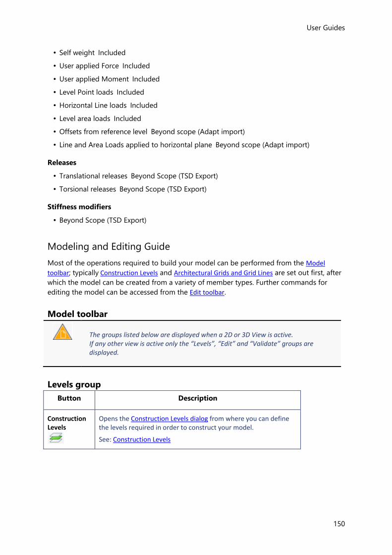
User Guides
150
• Self weight Included
• User applied Force Included
• User applied Moment Included
• Level Point loads Included
• Horizontal Line loads Included
• Level area loads Included
• Offsets from reference level Beyond scope (Adapt import)
• Line and Area Loads applied to horizontal plane Beyond scope (Adapt import)
Releases
• Translational releases Beyond Scope (TSD Export)
• Torsional releases Beyond Scope (TSD Export)
Stiffness modifiers
• Beyond Scope (TSD Export)
Modeling and Editing Guide
Most of the operations required to build your model can be performed from the Model
toolbar; typically Construction Levels and Architectural Grids and Grid Lines are set out first, after
which the model can be created from a variety of member types. Further commands for
editing the model can be accessed from the Edit toolbar.
Model toolbar
The groups listed below are displayed when a 2D or 3D View is active. If any other view is active only the “Levels”, “Edit” and “Validate” groups are displayed.
Levels group
Button Description
Construction Levels
Opens the Construction Levels dialog from where you can define the levels required in order to construct your model.
See: Construction Levels

User Guides (US)
151
Frame
Creates a Frame when in a 3D View, (when a 2D View is displayed Frame is inactive). The drop list underneath can be used to delete existing Frames.
A Frame is simply a 2D View of the model created in a vertical plane defined by an existing grid line.
Because only those members that lie within the plane of the Frame are displayed, this type of view can be particularly useful for defining bracing.
See: Frames and Slopes
Sloped Plane
Creates a Sloped Plane when in a 3D View, (when a 2D View is displayed Sloped Plane is inactive). The droplist underneath can be used to delete existing Sloped Planes.
A Sloped Plane is simply a 2D View of the model created in a sloped plane. It is defined by selecting 3 existing grid points.
Because only those members that lie within the plane of the Slope are displayed, this type of view can be particularly useful for defining inclined roofs and ramps.
See: Frames and Slopes
Grid and Construction Lines group
The Grid and Construction Lines group contains a Grid Line drop list, a Construction
Line drop list and the Dimension command.
The commands on the two drop lists are only available when a 2D view representing the
construction level on which you want to create your grid or construction lines is active.
Button Description
Grid Line
(on 1st drop list)
Inserts a grid line between two specified points.
Parallel
(on 1st drop list)
Inserts a parallel grid line at a specified distance from the selected line.
Parallel (quick)
(on 1st drop list)
Inserts multiple parallel grid lines at specified distances from the selected line.
For example:
3*5 - inserts 3 parallel lines, each at 5m spacing
3,4,5 - inserts 3 parallel lines at spacings of 3,4, and 5m respectively.

User Guides
152
Perpendicular
(on 1st drop list)
Inserts a perpendicular grid line at a specified location on the selected line.
Rectangular Wizard
(on 1st drop list)
Used to insert a system of grid lines in two directions at a specified angle.
Sector Wizard
(on 1st drop list)
Used to insert a system of radial and arc grid lines.
Arc
(on 1st drop list)
Used to insert an arc grid line.
Import DXF (on 1st drop list)
Used to import grid lines from a dxf file.
Construction Line
(on 2nd drop list)
Inserts a construction line between two specified points.
Parallel
(on 2nd drop list)
Inserts a parallel construction line at a specified distance from the selected line.
Parallel (quick)
(on 2nd drop list)
Inserts multiple parallel construction lines at specified distances from the selected line.
For example:
3*5 - inserts 3 parallel lines, each at 5m spacing
3,4,5 - inserts 3 parallel lines at spacings of 3,4, and 5m respectively.
Perpendicular
(on 2nd drop list)
Inserts a perpendicular construction line at a specified location on the selected line.
Rectangular Wizard
(on 2nd drop list)
Used to insert a system of construction lines in two directions at a specified angle.
Sector Wizard
(on 2nd drop list)
Used to insert a system of radial and arc construction lines.
Arc Used to insert an arc construction line.

User Guides (US)
153
(on 2nd drop list)
Dimension
Dimensions allow you to show distances in your structure between appropriate points. The dimension lines are included on any drawings you create.
Related topics
• Grid Lines, Construction Lines and User Points
• Dimensions
Steel group
The Steel group contains the following commands:
Button Description
Steel Column
(on 1st drop list)
Creates a steel column which adopts the specified steel column properties set
Plated
(on 1st drop list)
Creates a plated steel column which adopts the specified steel column properties set
Concrete Filled
(on 1st drop list)
Creates a concrete filled steel column which adopts the specified steel column properties set
Concrete Encased
(on 1st drop list)
Creates a concrete encased steel column which adopts the specified steel column properties set
Steel Beam
(on 2nd drop list)
Creates a steel beam which adopts the specified steel beam properties set
Plated
(on 2nd drop list)
Creates a plated steel beam which adopts the specified steel beam properties set
Westok Cellular
(on 1st drop list)
Creates a Westok cellular steel beam which adopts the specified steel beam properties set
Westok Plated
(on 1st drop list)
Creates a Westok plated steel beam which adopts the specified steel beam properties set
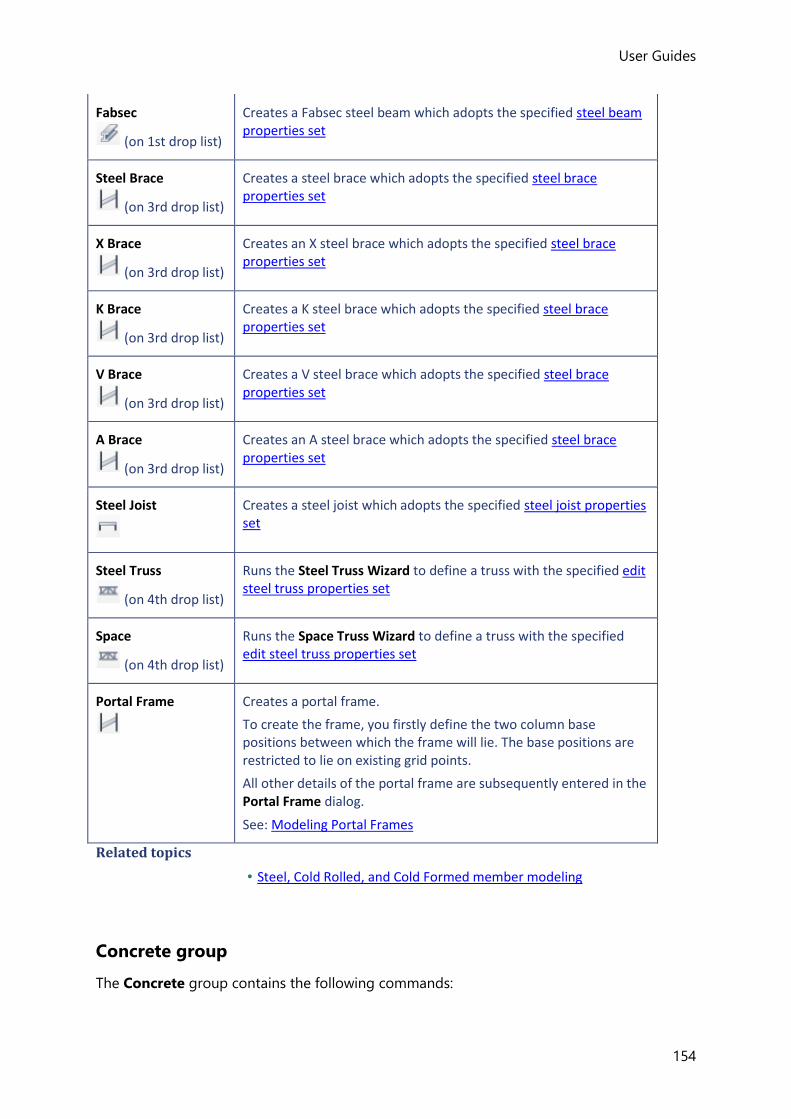
User Guides
154
Fabsec
(on 1st drop list)
Creates a Fabsec steel beam which adopts the specified steel beam properties set
Steel Brace
(on 3rd drop list)
Creates a steel brace which adopts the specified steel brace properties set
X Brace
(on 3rd drop list)
Creates an X steel brace which adopts the specified steel brace properties set
K Brace
(on 3rd drop list)
Creates a K steel brace which adopts the specified steel brace properties set
V Brace
(on 3rd drop list)
Creates a V steel brace which adopts the specified steel brace properties set
A Brace
(on 3rd drop list)
Creates an A steel brace which adopts the specified steel brace properties set
Steel Joist
Creates a steel joist which adopts the specified steel joist properties set
Steel Truss
(on 4th drop list)
Runs the Steel Truss Wizard to define a truss with the specified edit steel truss properties set
Space
(on 4th drop list)
Runs the Space Truss Wizard to define a truss with the specified edit steel truss properties set
Portal Frame
Creates a portal frame.
To create the frame, you firstly define the two column base positions between which the frame will lie. The base positions are restricted to lie on existing grid points.
All other details of the portal frame are subsequently entered in the Portal Frame dialog.
See: Modeling Portal Frames
Related topics
• Steel, Cold Rolled, and Cold Formed member modeling
Concrete group
The Concrete group contains the following commands:
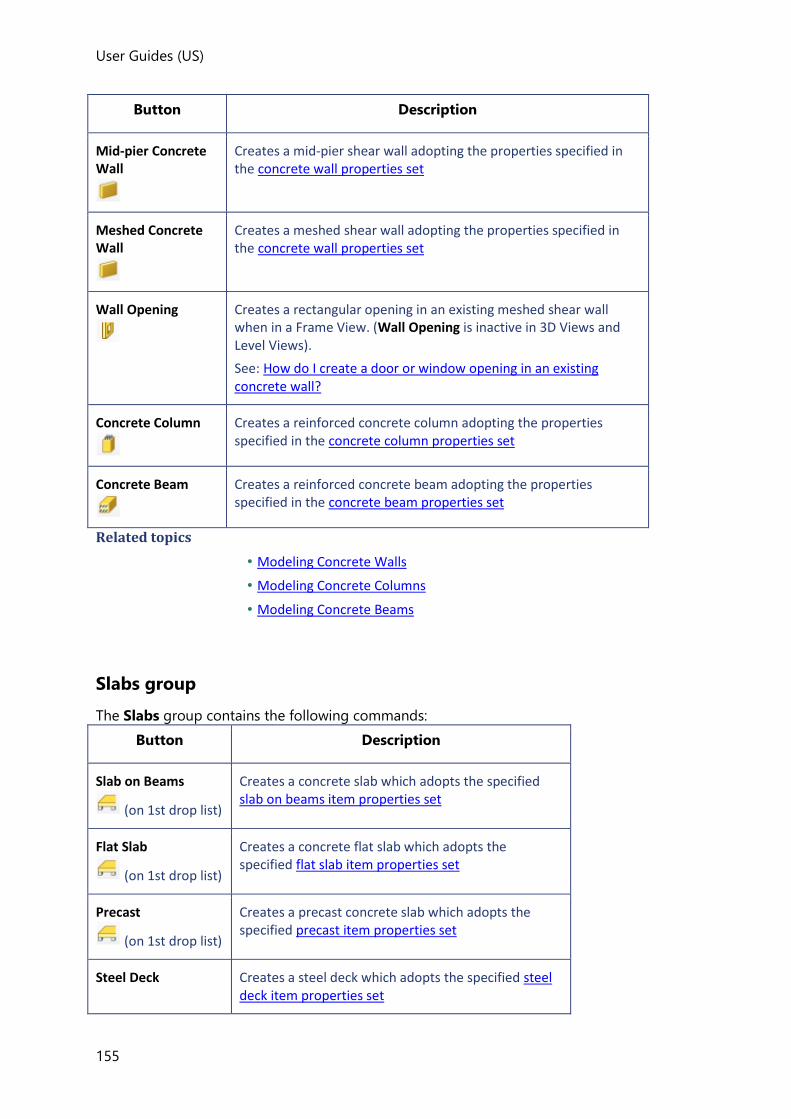
User Guides (US)
155
Button Description
Mid-pier Concrete Wall
Creates a mid-pier shear wall adopting the properties specified in the concrete wall properties set
Meshed Concrete Wall
Creates a meshed shear wall adopting the properties specified in the concrete wall properties set
Wall Opening
Creates a rectangular opening in an existing meshed shear wall when in a Frame View. (Wall Opening is inactive in 3D Views and Level Views).
See: How do I create a door or window opening in an existing concrete wall?
Concrete Column
Creates a reinforced concrete column adopting the properties specified in the concrete column properties set
Concrete Beam
Creates a reinforced concrete beam adopting the properties specified in the concrete beam properties set
Related topics
• Modeling Concrete Walls
• Modeling Concrete Columns
• Modeling Concrete Beams
Slabs group
The Slabs group contains the following commands:
Button Description
Slab on Beams
(on 1st drop list)
Creates a concrete slab which adopts the specified slab on beams item properties set
Flat Slab
(on 1st drop list)
Creates a concrete flat slab which adopts the specified flat slab item properties set
Precast
(on 1st drop list)
Creates a precast concrete slab which adopts the specified precast item properties set
Steel Deck Creates a steel deck which adopts the specified steel deck item properties set

User Guides
156
(on 1st drop list)
Timber Deck
(on 1st drop list)
Creates a timber deck which adopts the specified timber deck item properties set
Composite Slab
(on 1st drop list)
Creates a composite slab which adopts the specified composite slab item properties set
Column Drop
(on 2nd drop list)
Creates a column drop which adopts the specified column drop properties
Slab Opening
(on 2nd drop list)
Creates a slab opening which adopts the specified slab opening and mat opening properties
Slab Overhang
(on 2nd drop list)
Creates a slab overhang which adopts the specified slab overhang and mat overhang properties
Slab Split
This command is used to split an existing slab.
See: How do I split a slab?
Slab Join
This command is used to join an existing slabs.
See: How do I join slabs?
Related topics
• Slab modeling
Timber group
The Steel group contains the following commands:
Button Description
Timber Column
Creates a timber column which adopts the specified timber column properties set
Timber Beam
Creates a timber beam which adopts the specified timber beam properties set
Timber Brace Creates a timber brace which adopts the specified
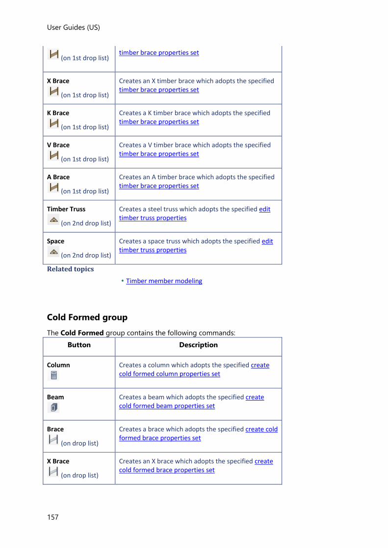
User Guides (US)
157
(on 1st drop list) timber brace properties set
X Brace
(on 1st drop list)
Creates an X timber brace which adopts the specified timber brace properties set
K Brace
(on 1st drop list)
Creates a K timber brace which adopts the specified timber brace properties set
V Brace
(on 1st drop list)
Creates a V timber brace which adopts the specified timber brace properties set
A Brace
(on 1st drop list)
Creates an A timber brace which adopts the specified timber brace properties set
Timber Truss
(on 2nd drop list)
Creates a steel truss which adopts the specified edit timber truss properties
Space
(on 2nd drop list)
Creates a space truss which adopts the specified edit timber truss properties
Related topics
• Timber member modeling
Cold Formed group
The Cold Formed group contains the following commands:
Button Description
Column
Creates a column which adopts the specified create cold formed column properties set
Beam
Creates a beam which adopts the specified create cold formed beam properties set
Brace
(on drop list)
Creates a brace which adopts the specified create cold formed brace properties set
X Brace
(on drop list)
Creates an X brace which adopts the specified create cold formed brace properties set
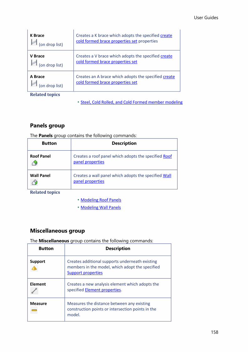
User Guides
158
K Brace
(on drop list)
Creates a K brace which adopts the specified create cold formed brace properties set properties
V Brace
(on drop list)
Creates a V brace which adopts the specified create cold formed brace properties set
A Brace
(on drop list)
Creates an A brace which adopts the specified create cold formed brace properties set
Related topics
• Steel, Cold Rolled, and Cold Formed member modeling
Panels group
The Panels group contains the following commands:
Button Description
Roof Panel
Creates a roof panel which adopts the specified Roof panel properties
Wall Panel
Creates a wall panel which adopts the specified Wall panel properties
Related topics
• Modeling Roof Panels
• Modeling Wall Panels
Miscellaneous group
The Miscellaneous group contains the following commands:
Button Description
Support
Creates additional supports underneath existing members in the model, which adopt the specified Support properties
Element
Creates a new analysis element which adopts the specified Element properties.
Measure
Measures the distance between any existing construction points or intersection points in the model.

User Guides (US)
159
See: How do I Measure distances?
Measure Angle
Measures angles between existing points in 2D Views.
See: How do I Measure Angles?
Bearing Wall
Creates a bearing wall.
See: Modeling Bearing Walls
Related topics
• Modeling Supports
Validate
Button Description
Validate
This command is used to perform the model validity checks.
See: Model Validation
Properties and Property Sets
When a new entity is created, it adopts the properties that are displayed in the Properties
Window at that particular time. You should therefore ensure the properties are correct before
you place the entity.
When an existing entity is selected its properties are displayed in the Properties
Window from where they can be edited.
If multiple entities are selected the Properties Window can still be used to make edits, but
only the common properties are displayed.
When a model object such as a beam, slab item or concrete wall is selected its properties
can also be edited using a Property Dialog.
In a typical model you may want to apply the same properties to similar model objects at a
number of different locations. To do this efficiently, once properties have been set up for a
member, slab item or roof panel you can save them away to a named Property Set for
subsequent recall.
The Manage Property Sets dialog can be used to export saved property sets to a file so that
they can then be imported into other Tekla Structural Designer models.
How do I edit the properties of a single entity?

User Guides
160
1. Select the entity in the graphical display or from the Structure Tree.
(How do I select an individual entity?)
2. Change the Properties of the entity using the Properties Window.
How do I edit the properties of multiple entities?
The common properties of multiple entities can be displayed and edited using the Properties
Window.
You may decide to change the grade of steel applied to all steel beams in your structure. This can be done easily by selecting all beams and then using the Properties Window to change the grade. The change gets applied to all selected beams irrespective of whether they are simple, composite or plated.
The Properties Window will show a blank where an item (Reference format, Alignment,
Offset, Report etc.) is not identical for all the selected entities.
If you change a blanked item, Tekla Structural Designer applies the new setting to all the
selected entities.
If you leave a blank item blank, then Tekla Structural Designer maintains the current diverse
settings for the selected entities.
If multiple entities of the different types are selected, then property information is displayed
separately for each type. A dropdown menu at the top of the Properties Window is used for
moving between types.
To edit multiple entities in the Properties Window:
1. Select the entities in the graphical display. (See How do I add further entities to the current
selection?)
2. If entities of different types have been selected, use the dropdown menu at the top of
the Properties Window to select the required type.
3. Change the properties as required using the Properties Window.
How do I edit the properties of a single model object?
1. Hover the cursor over the object to be edited until it becomes highlighted in the Select
Entity tooltip. (If several entities are listed use the tab key to scroll).
2. right-click and select ... from the dropdown menu.
3. Edit the properties as required and then click OK
How do I save properties to a named Property Set from the Properties Window?

User Guides (US)
161
Properties can only be saved to a property set from the Properties Window when there are no objects selected - this ensures that unique entries exist for each of the properties in the set.
1. Click the model object type you want to save a property set for from the tab.
2. The drop list at the top of the Properties Window should now read “<unsaved set>”
3. Specify the properties as required, then click the Save... button.
4. Enter a name for the saved set.
How do I recall a previously saved property set from the Properties Window?
Provided you have previously saved a property set, you can recall it again later from the
Properties Window - but only when it is applicable to the current command.
For example, assume different steel beam properties have previously been assigned to the
main, secondary and edge beams in a structure, each being saved to a set for re-use. You
subsequently want to re-use the edge beam properties.
To recall the edge beam property set:
1. Click tab >
Properties applicable to steel beams are displayed in the Properties Window.
2. Click the drop list at the top of the Properties Window, only the previously saved steel
beam property sets are displayed.

User Guides
162
3. Choose the Edge Beams property set.
How do I save the properties of an existing model object to a named Property Set?
1. Hover the cursor over the object until it becomes highlighted.
2. Right-click and select Create Property Set from the context menu. (If the object has
more than one span you will also need to select the span required.)
3. Enter a name for the property set then click OK.
How do I apply a property set to an individual existing model object?
1. Hover the cursor over the object until it becomes highlighted.
2. Right-click and select Apply property set... from the context menu.
3. Select the property set to be applied then click OK.
The property set is only applied to the individual member that was right-clicked on (even if multiple members were selected). To apply the property set to multiple members simultaneously see: How do I apply a property set to multiple existing model objects?
How do I apply a property set to multiple existing model objects?
1. Select the objects to be updated.
2. Ensure the drop list at the top of the Properties Window displays the correct object
type.
3. At the top of the Properties Window click Apply...
4. Select the property set to be applied then click OK.
All of the selected objects (provided they are of the same object type) have the property
set applied.
How do I apply a property set in the Review View?
1. Click Review > Property Sets
2. In the Properties Window:
• choose Apply Property Set
• select the entity type
• select the property set to apply
3. In the Review View click the objects to which the set is to be applied.

User Guides (US)
163
How do I graphically review where property sets have been applied?
1. Click Review > Property Sets
2. In the Properties Window, choose Review All
3. Still in the Properties Window, select the entity type to review.
Entities of the selected type are colour coded to indicate where property sets have been
applied.
Related topics
• How do I apply a property set in the Review View?
Manage Property Sets
Once property sets have been saved, they can be exported from the current model so that
they can be imported into other Tekla Structural Designer models.
How do I export a property set?
1. Click Home > Manage Property Sets
2. In the Manage property sets dialog select the sets to be exported.
3. Click Export...
4. Save the properties to a .tsps file.
How do I import a property set?
1. Click Home > Manage Property Sets
2. In the Manage property sets dialog select the sets to be imported.
3. Click Import...
4. Browse to the location where the .tsps file to be imported is located and open it.
5. The property sets contained in the file should now be listed in the Manage property
sets dialog.
How do I delete a property set?
1. Click Home > Manage Property Sets
2. In the Manage property sets dialog locate the set to be deleted.
3. Click Delete

User Guides
164
4. Click OK
Construction Levels
The Construction Levels dialog is used to define those levels that you need to identify in order
to construct your model. They could be floors or roofs, or they may simply be intermediate
levels required in order to define specific items...
Construction Levels dialog
From this dialog you can define the levels required in order to construct your model.
Fields
Ref
Each construction level should be given a unique reference. Typically this might be a
storey number, 1, 2 , 3 etc.
Name
Each construction level can also be given a name to further assist identification. “First
Floor”, or “Mezzanine” etc.
Type
Select the type from the drop down menu:
• T.O.S = Top of Steel
• S.S.L = Structural Slab Level
• T.O.F = Top of Foundation
Slabs are modeled above the level when it is set to T.O.S but below the level when it is set to S.S.L or T.O.F
Level
The height of the construction level above the base level.
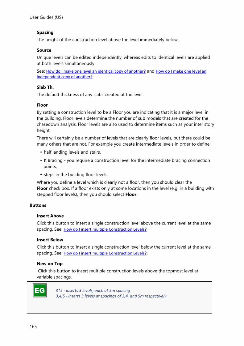
User Guides (US)
165
Spacing
The height of the construction level above the level immediately below.
Source
Unique levels can be edited independently, whereas edits to identical levels are applied
at both levels simultaneously.
See: How do I make one level an identical copy of another? and How do I make one level an independent copy of another?
Slab Th.
The default thickness of any slabs created at the level.
Floor
By setting a construction level to be a Floor you are indicating that it is a major level in
the building. Floor levels determine the number of sub models that are created for the
chasedown analysis. Floor levels are also used to determine items such as your inter story
height.
There will certainly be a number of levels that are clearly floor levels, but there could be
many others that are not. For example you create intermediate levels in order to define:
• half landing levels and stairs,
• K Bracing - you require a construction level for the intermediate bracing connection
points,
• steps in the building floor levels.
Where you define a level which is clearly not a floor, then you should clear the
Floor check box. If a floor exists only at some locations in the level (e.g. in a building with
stepped floor levels), then you should select Floor.
Buttons
Insert Above
Click this button to insert a single construction level above the current level at the same
spacing. See: How do I insert multiple Construction Levels?
Insert Below
Click this button to insert a single construction level below the current level at the same
spacing. See: How do I insert multiple Construction Levels?.
New on Top
Click this button to insert multiple construction levels above the topmost level at
variable spacings.
3*5 - inserts 3 levels, each at 5m spacing 3,4,5 - inserts 3 levels at spacings of 3,4, and 5m respectively

User Guides
166
New at the Bottom
Click this button to insert multiple construction levels below the bottommost level at
variable spacings.
Delete
Deletes the selected level.
Related topics
• Construction Levels
• How do I open the Construction Levels dialog?
• Sub Models
How do I open the Construction Levels dialog?
To open from the ribbon:
• Click Model > Construction Levels ( )
To open from the Structure Tree:
• Double-click
Related topics
• Construction Levels dialog
How do I insert a single Construction Level?
1. In the Construction Levels dialog, select an existing level.
2. Click Insert Above or Insert Below as appropriate.
3. If necessary change the default level name to something more appropriate.
4. For the new level specify the height above the base in the Level field, the inter-storey
Spacing is then calculated automatically; alternatively if you specify the inter-storey
Spacing the Level is calculated automatically.
A default height is calculated for the new level based on the spacings of any existing levels immediately above/below it. Either accept, or adjust as required.
5. Indicate if the level is to be treated as a Floor by selecting the appropriate check box.
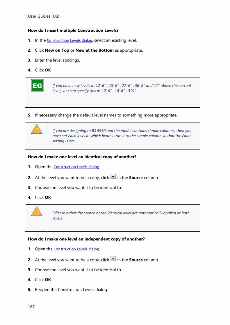
User Guides (US)
167
How do I insert multiple Construction Levels?
1. In the Construction Levels dialog, select an existing level.
2. Click New on Top or New at the Bottom as appropriate.
3. Enter the level spacings.
4. Click OK
If you have new levels at 12’ 6” , 18’ 6” , 27’ 6” , 36’ 6” and 27” above the current level, you can specify this as 12’ 6” , 18’ 6” , 3*9’
5. If necessary change the default level names to something more appropriate.
If you are designing to BS 5950 and the model contains simple columns, then you must set each level at which beams trim into the simple column so that the Floor setting is Yes.
How do I make one level an identical copy of another?
1. Open the Construction Levels dialog.
2. At the level you want to be a copy, click in the Source column.
3. Choose the level you want it to be identical to.
4. Click OK
Edits to either the source or the identical level are automatically applied at both levels.
How do I make one level an independent copy of another?
1. Open the Construction Levels dialog.
2. At the level you want to be a copy, click in the Source column.
3. Choose the level you want it to be identical to.
4. Click OK
5. Reopen the Construction Levels dialog.

User Guides
168
6. Click in the Source column at the same level and change the setting back to unique
7. Click OK
Edits to a unique level are applied to that level only.
How do I delete a construction level?
To delete from the Construction Levels dialog:
1. Select the level to be removed.
2. Click Delete
3. Click OK
To delete from the Structure Tree:
1. Open the branch of the Structure Tree.
2. Right-click the title of the construction level to be removed.
3. Click Delete from the context menu that appears.
This option completely deletes the entire level and all its associated details — all beams, members, slabs… You cannot recover the level once you have deleted it. Please take due care when you use this feature.
How do I modify the properties associated with a level?
Certain properties can be modified directly from the Construction Levels dialog, however there
are a number of other parameters associated with levels that can only be edited in the
Properties Window.
To edit in the Properties Window:
1. Open the branch of the Structure Tree.
2. Select the title of the construction level to be edited.
3. Make your changes to the Level Properties displayed in the Properties Window.
Frames and Slopes
User Guides (US)
169
A Frame is simply a 2D View of the model created in a vertical plane defined by an existing
grid line - because only those members that lie within the plane of the Frame are displayed,
this type of view can be particularly useful for defining bracing.
A Slope is simply a 2D View of the model created in a sloped plane. It is defined by selecting
3 existing grid points - because only those members that lie within the plane of the Slope are
displayed, this type of view can be particularly useful for defining inclined roofs and ramps.
A sloped plane must be entirely contained within a single Sub Model because the Sub Model determines the mesh parameters to be applied.
In a sloped plane positive Y is always aligned to the up-slope direction, so that positive X is always perpendicular to the slope.
How do I create a Frame?
1. Obtain a 3D view of your structure in which you can see the base grid line associated
with the frame that you want to create.
2. Click Model > Frame ( )
3. Position the cursor over the grid line for the frame you want to create.
4. Click to create the frame.
5. This creates a frame view for the selected grid line. You can open this view by clicking the
plus sign ( ) to the left of in the Structure Tree and then double-clicking the
name of the frame whose view you want to open.
How do I create a Slope?
In order to create a slope you need to be able to click three existing grid points (that are not
co-linear) which lie in the plane of the slope.
Grid points are formed at grid line intersections on construction levels. Therefore, if the points required to define the slope don’t currently exist, you may need to insert new construction levels and/or grid lines to form them.
To create a slope:
1. Obtain a 3D view of your structure in which you can see three grid points which define
the sloped plane.

User Guides
170
If you cannot see grid line intersections on a particular construction level in the 3D view select the level in the Structure Tree and then select Show grids in the 3D view in the Properties Window. (At the same time you can also clear the same property at other levels in order to simplify the display.)
2. Click Model > Sloped Plane ( )
3. Click the three points which define the sloped plane.
4. This creates a sloped plane view. You can open this view by clicking the plus sign ( ) to
the left of in the Structure Tree and then double-clicking the name of the
sloped plane whose view you want to open.
Grid Lines, Construction Lines and User Points
Grid lines facilitate the placing of objects in your model. Construction lines serve the same
purpose, only without displaying a grid bubble.
User points (XYZ Points) can also be defined in space using X, Y, Z coordinates without
having to define an intersection between grid lines or construction lines.
Architectural Grids and Grid Lines
An Architectural Grid is a collection of Grid Lines that lie in a horizontal plane. Each
architectural grid is only displayed in the 3D View at the lowest level in the structure (they
are not displayed in 2D Views). Vertical lines can be projected from each grid intersection of
the architectural grid - these extend to the topmost level at which the architectural grid has
been applied.
Each architectural grid can be assigned a color and can be set to display grid line names and
vertical lines via the architectural grid properties. (Note that when these options are checked
they will only be displayed provided the Architectural Grids>Text2D and VerticalLines
options are also checked in Scene Content.)
Separate architectural grids could be created as a means to allow two disconnected
structures to be created in the same model (where the only 'connection' is a movement joint
between the two structures). They can also be used to allow distinct grids to be applied at
different levels in the same structure (for example where there might be a concrete car park
at one grid spacing at lower levels that supports a steel framed structure above it set out at
different grid spacings).
This works provided the two architectural grids are not shared by members at the same level. Errors could result if members that are set out by different architectural grids are connected to each other.

User Guides (US)
171
Each Grid Line is associated with an architectural grid and is only created at a given level
provided the architectural grid has been applied at that level.
Grid lines that have been created at a given level can optionally be shown or not shown in
both the 2D and 3D views via the level properties. (Note that when these show options are
checked the lines will only be displayed provided the relevant Grid & Construction Lines
options are also checked in Scene Content.)
Why are the grid lines not being shown at a particular level?
Having activated the display of grid & construction lines in Scene Content for a particular 2D
or 3D view, you may still find that the grid lines are not displayed on particular levels.
In this situation you should first check the level properties to ensure that grids are set to be
shown. This is done as follows:
1. Open the Levels branch of the Structure Tree.
2. Left-click the level at which you want to have the grids shown.
3. In the Properties Window for the level - select Show grids in plane view to make the
grids visible in the 2D view, select Show grids in 3D view to make the grids visible at
that level in 3D views.
If the grids are still not visible in the 3D view at certain levels, you will need to ensure
they have been applied at the levels in question - see: How to I apply an existing architectural grid to a specific level?
How to I apply an existing architectural grid to a specific level?
1. Open the Architectural Grids branch of the Structure Tree.
2. Right-click the architectural grid name required and then pick Edit... from the context
menu.
3. Ensure the levels at which you want the architectural grid to be applied are all checked.
How do I create a rectangular grid line system?
1. Make sure that the 2D view representing the construction level on which you want to
create your rectangular grid system is active.
2. Click Model > , and select
3. Enter a name for the grid and choose a color for the grid lines you want to create.
4. If you want to create the same grid layout on every construction level in your building
ensure that each level is selected in the dialog. If you don’t want the grid to be displayed
at a particular level clear it.
5. Define the origin of the grid system, either by clicking in the 2D view, or by entering the
coordinates in the Rectangular Grid Wizard dialog.

User Guides
172
6. Choose which grid lines you want to create, in the X direction only, in the Y direction
only, or in both directions, and choose the grid line representation - dash dot, dot… that
you want to use for these grid lines.
7. Define the layout of grids for the bays in the X direction.
If you are only creating grid lines in the X direction, then the wizard skips this step.
You can define a regular or irregular grid layout:
• for a regular grid you define the number of bays you want to create and the bay
centers,
• for an irregular grid you define the distance between successive pairs of grid lines,
separating the numbers by commas. If you have a number of bays that are at the
same centers, then you can specify these as a single entry.
If you have bay centres of 18’, 27’ , 18’ 6” , 18’ 6” , 18’ 6” and 27” you can specify this as 18’ , 27’ , 3x18’ 6” , 27”
You can also specify the reference of the first grid line, and by how much you want to
increment that reference to give the references of the other lines that you create.
Numerical grid line numbering is self explanatory. For alphanumeric grid lines, if you specify that the first grid line reference is to be D, and specify an increment of 3, your grid lines will be referenced D, G, J, M…
8. Define the layout of grids for the bays in the Y direction.
If you are only creating grid lines in the Y direction, then the wizard skips this step.
You can define a regular or irregular grid layout:
• for a regular grid you define the number of bays you want to create and the bay
centers,
• for an irregular grid you define the distance between successive pairs of grid lines,
separating the numbers by commas. If you have a number of bays that are at the
same centers, then you can specify these as a single entry.
User Guides (US)
173
If you have bay centres of 18’, 27’ , 18’ 6” , 18’ 6” , 18’ 6” and 27” you can specify this as 18’ , 27’ , 3x18’ 6” , 27”
Again you can specify the reference of the first grid line, and how you want to increment
the grid line reference to give the references of the other lines that you create.
9. Define the rotation of the grid. You can do this graphically by moving the mouse over
the 2D view and clicking, or by entering values into the wizard’s dialog. If you use the
latter approach you can specify the rotation either with respect to the grid system’s local
x or local y directions.
This is useful if you are going to create a grid system which is not orthogonal.
10. Finally specify the angle between the grid’s axes, you can do this with respect to either
the X or Y axis system and click Finish to create your grid layout. Again you can do this
graphically, or you can use the wizards dialog - it’s your choice.
How do I create a radial grid line system?
1. Make sure that the 2D view representing the construction level on which you want to
create your radial grid system is active.
2. Click Model > , and select
3. If you want to create the same grid layout on every construction level in your building
ensure that each level is checked in the dialog. If you don’t want the grid to be displayed
at a particular level clear it.
4. Define the origin of the grid system, either by clicking in the 2D view, or by entering the
coordinates in the Radial Grid Wizard dialog.
5. Choose which grid lines you want to create, the radial lines only, the arcs only, or both of
these, and choose the grid line representation - dash dot, dot… that you want to use for
these grid lines.
6. Define the layout of the arcs that you will create.
If you are only creating radial grid lines the wizard skips this step.
You can define a regular or irregular grid layout:

User Guides
174
• for a regular grid you define the number of arcs you want to create and the distance
between them,
• for an irregular grid you define the distance between successive pairs of arcs lines,
separating the numbers by commas. If you have a number of arcs that are the same
distance apart, then you can specify these as a single entry.
If you have arcs at distances of 9’, 12’ , 10’ 6” , 10’ 6” , 10’ 6” and 12” you can specify this as 9’ , 12’ , 3x10’ 6” , 12”
You can also specify the reference of the first grid line, and by how much you want to
increment that reference to give the references of the other lines that you create.
Numerical grid line numbering is self explanatory. For alphanumeric grid lines, if you specify that the first grid line reference is to be D, and specify an increment of 3, your grid lines will be referenced D, G, J, M…
You can also choose whether the arc grid lines are to be true curves, or represented as a
series of straight lines between those points where the arc intersects the other grid lines
created as part of this process.
7. Define the layout of radial grid segments that you want to achieve.
If you are only creating grid arcs the wizard skips this step.
You can define a regular or irregular radial line layout:
• for a regular layout you define the number of radial lines you want to create and the
angle between them,
• for an irregular radial line layout you define the angle between successive pairs of
radial lines, separating the numbers by commas. If you have a number of lines that
are at the same centers, then you can specify these as a single entry.
If you have angles of 30°, 45°, 30°, 30°, 30°, 30° and 45° you can specify this as 30,45,4*30,45.
Again you can specify the reference of the first grid line, and how you want to increment
the reference to give the references of the other radial lines that you create.
8. Finally define the rotation of the grid. You can do this graphically by moving the mouse
over the 2D view and clicking, or by entering values into the wizard’s dialog. If you use

User Guides (US)
175
the latter approach you can specify the rotation either with respect to the grid system’s
local x or local y directions.
How do I create a single grid line between two points?
1. Make sure that the 2D view representing the construction level on which you want to
create your grid line is active.
If you want to create a series of grid lines which form a regular or irregular,
rectangular or radial grid system, the Tekla Structural Designer Rectagular and Sector Wizards give the speediest solutions.
2. Click Model > , and select
3. Pick the point where you want the grid line to start (Point 1).
The tooltip gives the cursor’s coordinates exactly. If it has not snapped to an existing point you can press <F2> to enter the exact coordinates of the point required.
4. Pick the point where you want the grid line to end (Point 2).
The tooltip displays either the absolute, relative, or polar coordinates of Point 2 depending on whether the ABS, REL or POL button is highlighted in the Status Bar at the bottom right of the screen. To switch the display simply click one of the other buttons.
5. The grid line is created between the points you have picked.
The grid line does not extend to infinity. Please take care to ensure that the grid line is of sufficient length to meet your needs.
How do I create a parallel grid line?
This option creates a grid line parallel to an existing one, but of a different length. If you
want to use this option, then you must have at least one existing grid line in the current 2D-
window.
1. Click Model > , and select

User Guides
176
2. Enter a name for the grid line in the Properties Window.
3. Select the grid line to which your new grid line is to be parallel.
4. You will see a dotted line which is parallel to the grid line you selected in step 3, and
which follows the cursor.
The tooltip gives the distance of the dotted line from the initial grid line you selected in step 3. You can press <F2> to enter the exact distance if required.
As you zoom further and further into the model the distance by which the cursor moves alters in smaller and smaller increments, so for more accuracy zoom in.
5. Once you have achieved the distance you require:
• click to locate your new grid line at this position
• pick a point to define the end 1 extent
• pick a second point to define the end 2 extent
6. The new grid line is created, you can now:
• Move the cursor and continue placing other grid lines with respect to the line you
picked in step 3.
• Press <Esc> to end grid placement.
How do I create one or more parallel (quick) grid lines?
This option creates one or more grid lines parallel to, and the same length as, an existing
one. If you want to use this option, then you must have at least one existing grid line in the
current 2D-window.
1. Click Model > , and select
2. Select the grid line to which your new grid lines will be parallel.
3. You will see a line which is parallel to the grid line you selected in step 2, and which
follows the cursor.
The tooltip gives the distance of the new line from the initial grid line you selected in
step 2.
As you zoom further and further into the model the distance by which the cursor moves alters in smaller and smaller increments, so for more accuracy zoom in.
You can define a single grid line, or a series of grid lines on a regular, or irregular layout:
• for a single grid line click to place it, or press <F2> to define it’s offset exactly.
User Guides (US)
177
• for a series of grid lines press <F2> then define the distance between successive pairs
of grid lines, separating the numbers by commas. If you have a number of bays that
are at the same centers, then you can specify these as a single entry.
If you have bay centres of 18’, 27’ , 18’ 6” , 18’ 6” , 18’ 6” and 27” you can specify this as 18’ , 27’ , 3x18’ 6” , 27”
How do I create a perpendicular grid line?
If you want to use this option, then you must have at least one existing grid line in the
current 2D-window.
1. Click Model > , and select
2. Enter a name for the grid line in the Properties Window.
3. Select the grid line to which your new grid line is to be perpendicular.
4. You will see a dotted line overlying the grid line you selected in step 3, and which follows
the cursor.
The tooltip gives the perpendicular distance to your new grid line from the middle of
the grid line you selected in step 3.
As you zoom further and further into the model the distance by which the cursor moves alters in smaller and smaller increments, so for more accuracy zoom in.
5. Once you have achieved the distance you require:
• click to locate your new grid line at this position,
• pick a point to define the end 1 extent
• pick a second point to define the end 2 extent.
6. The new grid line is created, you can now:
• Move the cursor and continue placing other grid lines with respect to the line you
picked in step 3.
• Press <Esc> to end grid placement.
How do I create a grid arc?
1. Click Model > , and select
2. Enter a name for the grid line in the Properties Window.

User Guides
178
3. Select the point which lies at the center of the grid arc which you want to create.
The tooltip gives the cursor’s coordinates exactly.
4. As you move the cursor you will see a line which rotates about the center defined in step
3. This end of this line marks the start of the grid arc you are creating. Once you have
achieved the required location click to set this.
5. Now you will see two dotted lines, a radial line through the center defined in step 3, and
an arc which indicates the sweep of the grid arc you are creating. Once you have
achieved the required sweep click to create your new arc at this position.
How do I import grids from a .dxf, or import a .dxf as a shadow?
The .dxf file that you want to use must be available before you start the import process. You
can either have been sent the file, or have created it yourself in some other application.
1. Open a 2D View of a construction level (to enable the Grid Line dropdown).
2. Click Model > , and select
You will see the Open dialog, navigate to the folder which contains the file you want to
import, select the appropriate file name and click Open
3. You will now see the Dxf Import Wizard. This first page of the dialog allows you to
control the layers and colors which you want to import (self-explanatory). Of more
interest are the output options which allow you choose either Architectural Grids or
Shadow.
• If you import the Architectural Grids from the .dxf file, then all the elements in the
selected layers of the .dxf file are mapped to Tekla Structural Designer grid lines. You
must therefore ensure that you switch off all the layers in the dxf apart from the
layers in which the grids have been defined.
• If you import the .dxf as a Shadow, then Tekla Structural Designer imports the .dxf file
but does not create any Tekla Structural Designer objects. You can then use the
intersection points and such like as the source on which to add the Tekla Structural
Designer objects you require.
4. If required you can adjust the scale and/or offsets for the dxf before proceeding.
5. Click Next to move to the second page of the dialog.
6. The Architectural grids options allow you to control how the grids are created.
• Select By layer to have separate named grids for each layer imported from the dxf.
• Select By color to have separate named grids for each color imported from the dxf.

User Guides (US)
179
• Select Merged to have a single merged grid containing every layer/color imported
from the dxf.
7. If you want to import the same grid layout to every construction level in your building
ensure that each level is checked in the dialog. If you don’t want the grid to be displayed
at a particular level clear it.
8. Click Finish to close the wizard and complete the import.
How do I set the initial number or letter used for grids?
The initial number and letter to be used for grid numbering is specified in the Model
Settings. New grids automatically use the next available number or letter depending on
whether they are labeled numerically, or alphanumerically.
1. Click Home > Model Settings ( )
2. Use the References - General sub page to set the initial values and also to set the naming
style.
How do I change the name or color of an existing architectural grid?
1. Expand in the Structure Tree to display the existing grids.
2. Pick the architectural grid name to be changed from the list.
3. Use the Properties Window to see and / or amend the details of the architectural grid.
How do I change the name of an individual grid-line, -arc?
1. Select the grid line or -arc to be renamed.
2. Edit the User name for the grid line as shown in the Properties Window.
How do I renumber all grids?
1. Right-click in the Structure Tree and choose Renumber from the
menu.
Every grid line in the model is renumbered in sequence.
How do I extend, move or rotate grid lines and arcs?
A grid line can be modified as follows:
• It can be stretched, shortened, or be rotated by moving one of its end nodes.
• It can also be moved in a perpendicular direction by moving its center node.
Similarly a grid arc can be modified as follows:
• It can be stretched or shortened by moving one of its end nodes.

User Guides
180
• It can have its radius adjusted by moving the middle node on the arc perimeter.
• It can be moved in any direction by moving its center node.
Grid lines and arcs can only be moved in a 2D, not 3D view.
How do I stretch, shorten, or rotate a grid line?
1. In a 2D View, select only the grid line you want to modify.
The two end nodes and the center node of the grid line should become visible.
2. Click to select one of the end nodes of the grid line.
3. Click where this node is to be moved to.
The grid line moves to its new position accordingly.
How do I move a grid line in a perpendicular direction?
1. In a 2D View, select only the grid line you want to modify.
The two end nodes and the center node of the grid line should become visible.
2. Click to select the center node of the grid line.
3. Click where this node is to be moved to.
The grid line moves to its new position accordingly.
How do I stretch or shorten a grid arc?
1. In a 2D View, select only the arc you want to modify.
The two end nodes and a middle node on the arc perimeter should become visible, along
width a node at the center of the arc.
2. Click to select one of the end nodes.
3. Click where this node is to be moved to.
The arc stretches or shortens accordingly.
How do I adjust the radius of a grid arc?
1. In a 2D View, select only the arc you want to modify.
The two end nodes and a middle node on the arc perimeter should become visible, along
width a node at the center of the arc.
User Guides (US)
181
2. Click to select the middle node on the perimeter.
3. Click where this node is to be moved to.
The arc radius adjusts accordingly.
How do I move a grid arc?
1. In a 2D View, select only the arc you want to modify.
The two end nodes and a middle node on the arc perimeter should become visible, along
width a node at the center of the arc.
2. Click to select the center node of the arc.
3. Click where this node is to be moved to.
The arc moves to its new position accordingly.
Construction Lines
Construction lines serve the same purpose as Architectural Grids and Grid Lines, only without
displaying a grid bubble.
How do I create a rectangular construction line system?
1. Make sure that the 2D view representing the construction level on which you want to
create your rectangular construction line system is active.
2. Click Model > , and select
3. Define the origin of the construction line system, either by clicking in the 2D view, or by
entering the coordinates in the Rectangular Grid Wizard dialog.
4. Choose which construction lines you want to create, in the X direction only, in the Y
direction only, or in both directions, and choose the line representation - dash dot, dot…
that you want to use for these construction lines.
5. Define the layout of construction lines for the bays in the X direction.
If you are only creating construction lines in the X direction, then the wizard skips this step.
You can define a regular or irregular construction line layout:
• for a regular grid you define the number of bays you want to create and the bay
centers,

User Guides
182
• for an irregular grid you define the distance between successive pairs of construction
lines, separating the numbers by commas. If you have a number of bays that are at
the same centers, then you can specify these as a single entry.
If you have bay centres of 18’, 27’ , 18’ 6” , 18’ 6” , 18’ 6” and 27” you can specify this as 18’ , 27’ , 3x18’ 6” , 27”
6. Define the layout of construction lines for the bays in the Y direction.
If you are only creating construction lines in the Y direction, then the wizard skips this step.
7. Define the rotation of the grid. You can do this graphically by moving the mouse over
the 2D view and clicking, or by entering values into the wizard’s dialog. If you use the
latter approach you can specify the rotation either with respect to the construction line
system’s local x or local y directions.
This is useful if you are going to create a construction line system which is not orthogonal.
8. Finally specify the angle between the construction line axes, you can do this with respect
to either the X or Y axis system and click Finish to create your construction line layout.
Again you can do this graphically, or you can use the wizards dialog - it’s your choice.
How do I create a radial construction line system?
1. Make sure that the 2D view representing the construction level on which you want to
create your radial construction line system is active.
2. Click Model > , and select
3. Define the origin of the grid system, either by clicking in the 2D view, or by entering the
coordinates in the Radial Grid Wizard dialog.
4. Choose which construction lines you want to create, the radial lines only, the arcs only, or
both of these, and choose the line representation - dash dot, dot… that you want to use
for these construction lines.
5. Define the layout of the arcs that you will create.

User Guides (US)
183
If you are only creating radial construction lines the wizard skips this step.
You can define a regular or irregular layout:
• for a regular layout you define the number of arcs you want to create and the distance
between them,
• for an irregular layout you define the distance between successive pairs of arcs lines,
separating the numbers by commas. If you have a number of arcs that are the same
distance apart, then you can specify these as a single entry.
If you have arcs at distances of 9’, 12’ , 10’ 6” , 10’ 6” , 10’ 6” and 12” you can specify this as 9’ , 12’ , 3x10’ 6” , 12”
You can also choose whether the arc construction lines are to be true curves, or
represented as a series of straight lines between those points where the arc intersects the
other construction lines created as part of this process.
6. Define the layout of radial construction line segments that you want to achieve.
If you are only creating arcs the wizard skips this step.
You can define a regular or irregular radial line layout:
• for a regular layout you define the number of radial lines you want to create and the
angle between them,
• for an irregular radial line layout you define the angle between successive pairs of
radial lines, separating the numbers by commas. If you have a number of lines that
are at the same centers, then you can specify these as a single entry.
If you have angles of 30°, 45°, 30°, 30°, 30°, 30° and 45° you can specify this as 30,45,4*30,45.
7. Finally define the rotation of the layout. You can do this graphically by moving the
mouse over the 2D view and clicking, or by entering values into the wizard’s dialog. If
you use the latter approach you can specify the rotation either with respect to the
construction line system’s local x or local y directions.
How do I create a single construction line between two points?

User Guides
184
If you want to create a series of construction lines which form a regular or irregular,
rectangular or radial system, the Tekla Structural Designer wizards give the speediest solutions.
1. Make sure that the 2D view representing the construction level on which you want to
create your construction line is active.
2. Click Model >
3. Pick the point where you want the construction line to start (Point 1).
The tooltip gives the cursor’s coordinates exactly. If it has not snapped to an existing point you can press <F2> to enter the exact coordinates of the point required.
4. Pick the point where you want the construction line to end (Point 2).
The tooltip displays either the absolute, relative, or polar coordinates of Point 2 depending on whether the ABS, REL or POL button is highlighted in the Status Bar at the bottom right of the screen. To switch the display simply click one of the other buttons.
5. The construction line is created between the points you have picked.
The grid line does not extend to infinity. Please take care to ensure that the grid line is of sufficient length to meet your needs.
How do I create a parallel construction line?
This option creates a construction line parallel to an existing line, but of a different length. If
you want to use this option, then you must have at least one existing grid or construction
line in the current 2D-window.
1. Click Model > , and select
2. Select the line to which your new construction line is to be parallel.
3. You will see a dotted line which is parallel to the line you selected in step 3, and which
follows the cursor.

User Guides (US)
185
The tooltip gives the distance of the dotted line from the initial line you selected in
step 3. You can press <F2> to enter the exact distance if required.
As you zoom further and further into the model the distance by which the cursor moves alters in smaller and smaller increments, so for more accuracy zoom in.
4. Once you have achieved the distance you require:
• click to locate your new construction line at this position
• pick a point to define the end 1 extent
• pick a second point to define the end 2 extent
5. The new construction line is created, you can now:
• Move the cursor and continue placing other construction lines with respect to the
line you picked in step 3.
• Press <Esc> to end construction line placement.
How do I create one or more parallel (quick) construction lines?
This option creates one or more construction lines parallel to, and the same length as, an
existing line. If you want to use this option, then you must have at least one existing grid or
construction in the current 2D-window.
1. Click Model > , and select
2. Select the line to which your new construction lines will be parallel.
3. You will see a line which is parallel to the line you selected in step 3, and which follows
the cursor.
The tooltip gives the distance of the new line from the initial line you selected in step
3.
As you zoom further and further into the model the distance by which the cursor moves alters in smaller and smaller increments, so for more accuracy zoom in.
You can define a single construction line, or a series of lines on a regular, or irregular layout:
• for a single construction line click to place it, or press <F2> to define it’s offset
exactly.
• for a series of lines press <F2> then define the distance between successive pairs,
separating the numbers by commas. If you have a number of bays that are at the
same centers, then you can specify these as a single entry.

User Guides
186
If you have bay centres of 18’, 27’ , 18’ 6” , 18’ 6” , 18’ 6” and 27” you can specify this as 18’ , 27’ , 3x18’ 6” , 27”
How do I create a perpendicular construction line?
If you want to use this option, then you must have at least one existing grid or construction
in the current 2D-window.
1. Click Model > , and select
2. Select the line to which your new construction line is to be perpendicular.
3. You will see a dotted line overlying the line you selected in step 3, and which follows the
cursor.
The tooltip gives the perpendicular distance to your new line from the middle of the
line you selected in step 3.
As you zoom further and further into the model the distance by which the cursor moves alters in smaller and smaller increments, so for more accuracy zoom in.
4. Once you have achieved the distance you require:
• click to locate your new construction line at this position,
• pick a point to define the end 1 extent
• pick a second point to define the end 2 extent.
5. The new construction line is created, you can now:
• Move the cursor and continue placing other construction lines with respect to the
line you picked in step 3.
• Press <Esc> to end construction line placement.
How do I create a construction line arc?
1. Click Model > , and select
2. Select the point which lies at the center of the arc which you want to create.
The tooltip gives the cursor’s coordinates exactly.
User Guides (US)
187
3. As you move the cursor you will see a line which rotates about the center defined in step
3. This end of this line marks the start of the arc you are creating. Once you have
achieved the required location click to set this.
4. Now you will see two dotted lines, a radial line through the center defined in step 3, and
an arc which indicates the sweep of the arc you are creating. Once you have achieved the
required sweep click to create your new arc at this position.
How do I extend, move or rotate construction lines and arcs?
A construction line can be modified as follows:
• It can be stretched, shortened, or be rotated by moving one of its end nodes.
• It can also be moved in a perpendicular direction by moving its center node.
Similarly a construction arc can be modified as follows:
• It can be stretched or shortened by moving one of its end nodes.
• It can have its radius adjusted by moving the middle node on the arc perimeter.
• It can be moved in any direction by moving its center node.
Construction lines and arcs can only be moved in a 2D, not 3D view.
How do I stretch, shorten, or rotate a construction line?
1. In a 2D View, select only the construction line you want to modify.
The two end nodes and the center node of the construction line should become visible.
2. Click to select one of the end nodes of the construction line.
3. Click where this node is to be moved to.
The construction line moves to its new position accordingly.
How do I move a construction line in a perpendicular direction?
1. In a 2D View, select only the construction line you want to modify.
The two end nodes and the center node of the construction line should become visible.
2. Click to select the center node of the construction line.
3. Click where this node is to be moved to.
The construction line moves to its new position accordingly.
User Guides
188
How do I stretch or shorten a construction arc?
1. In a 2D View, select only the arc you want to modify.
The two end nodes and a middle node on the arc perimeter should become visible, along
width a node at the center of the arc.
2. Click to select one of the end nodes.
3. Click where this node is to be moved to.
The arc stretches or shortens accordingly.
How do I adjust the radius of a construction arc?
1. In a 2D View, select only the arc you want to modify.
The two end nodes and a middle node on the arc perimeter should become visible, along
width a node at the center of the arc.
2. Click to select the middle node on the perimeter.
3. Click where this node is to be moved to.
The arc radius adjusts accordingly.
How do I move a construction arc?
1. In a 2D View, select only the arc you want to modify.
The two end nodes and a middle node on the arc perimeter should become visible, along
width a node at the center of the arc.
2. Click to select the center node of the arc.
3. Click where this node is to be moved to.
The arc moves to its new position accordingly.
User Points (XYZ Points)
User points can be used to connect beams, columns, braces etc. without having to define an
intersection between grid lines or construction lines.
How do I create a user point?
1. Make sure that XYZ points are visible in Scene Content.
2. Right click in the view and pick Add XYZ point... from the context menu.

User Guides (US)
189
3. Enter the point co-ordinates and click OK.
Once a user point has an item connected to it, if the item is moved a new point is created and the existing user point remains.
Dimensions
Dimensions allow you to show distances in your structure between appropriate points. The
dimension lines are included on any drawings you create.
How do I create a single dimension?
1. Click Model > Dimension ( )
2. Click the grid point at the start of the dimension.
3. Click the grid point at the end of the dimension. Tekla Structural Designer will show a line
between these two points.
4. Move this line to the point where you want the dimension line to lie (somewhere where it
will be easily visible, and will not conflict with the rest of your model’s details). Tekla
Structural Designer shows the dimension line itself, and the two locator lines at its ends.
Simply move the dimension line to the correct location and click to create it.
Steel, Cold Rolled, and Cold Formed member modeling
Modeling Steel Columns and Cold Formed Columns
Steel column overview
A single steel column can be created over several story heights (stacks) and can start and
finish at any level. Different column sections can be defined in each stack, (provided a splice
is defined at the change point).
Each steel column stack is placed on an insertion line between points, but its geometry is
drawn to reflect the major and minor snap points (and any offsets) specified in the column
properties.
Major snap and offset

User Guides
190
Minor snap and offset
Steel column alignment snap points and offsets have no affect on the positioning of the 1D solver elements in the solver models - the solver elements are always inserted along the steel column insertion lines. This is different to the approach adopted for concrete column solver elements (in which the alignment snap points and offsets are structurally significant).
Parapet post overview
Steel parapet posts are single span members with fixed end connections.
Their specific purpose is to act as a means to transfer load from wind wall panels into
columns - the decomposed load from the panel being applied as a point load and moment
at the node connecting the parapet post to the column.
Parapet posts are not designed in Tekla Structural Designer.
How do I specify the column type and section size?
To specify the type of steel column:
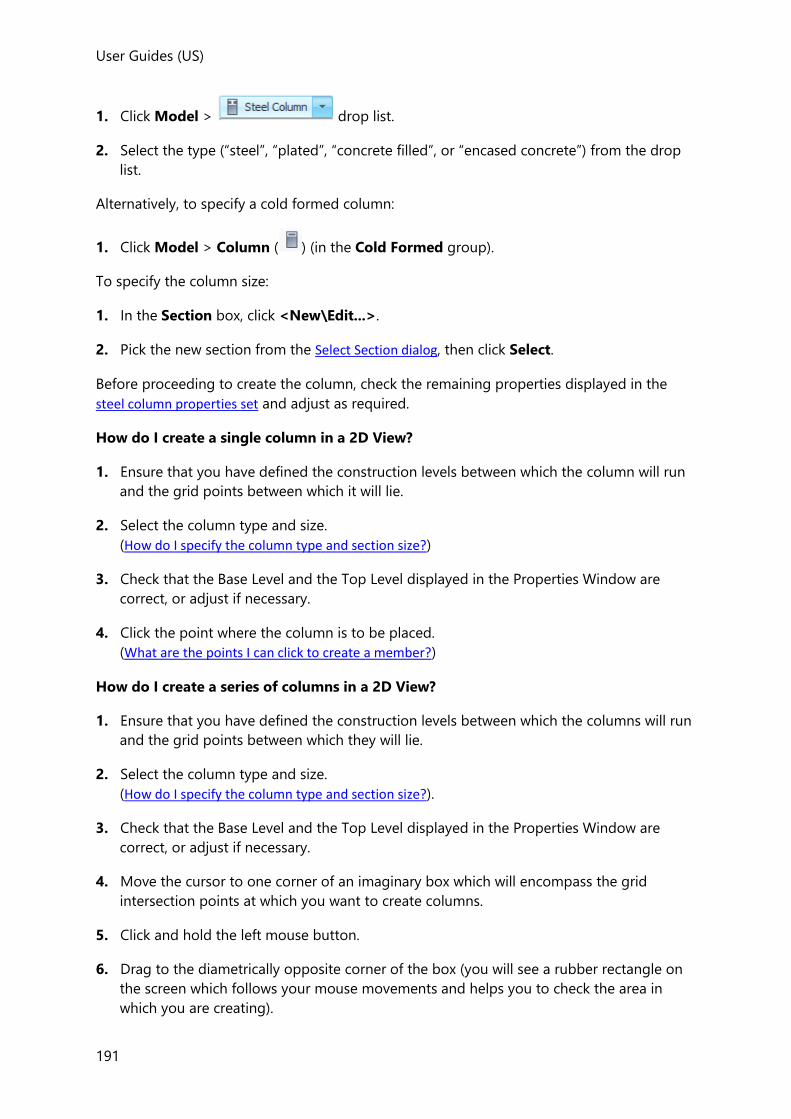
User Guides (US)
191
1. Click Model > drop list.
2. Select the type (“steel”, “plated”, “concrete filled”, or “encased concrete”) from the drop
list.
Alternatively, to specify a cold formed column:
1. Click Model > Column ( ) (in the Cold Formed group).
To specify the column size:
1. In the Section box, click <New\Edit...>.
2. Pick the new section from the Select Section dialog, then click Select.
Before proceeding to create the column, check the remaining properties displayed in the
steel column properties set and adjust as required.
How do I create a single column in a 2D View?
1. Ensure that you have defined the construction levels between which the column will run
and the grid points between which it will lie.
2. Select the column type and size.
(How do I specify the column type and section size?)
3. Check that the Base Level and the Top Level displayed in the Properties Window are
correct, or adjust if necessary.
4. Click the point where the column is to be placed.
(What are the points I can click to create a member?)
How do I create a series of columns in a 2D View?
1. Ensure that you have defined the construction levels between which the columns will run
and the grid points between which they will lie.
2. Select the column type and size.
(How do I specify the column type and section size?).
3. Check that the Base Level and the Top Level displayed in the Properties Window are
correct, or adjust if necessary.
4. Move the cursor to one corner of an imaginary box which will encompass the grid
intersection points at which you want to create columns.
5. Click and hold the left mouse button.
6. Drag to the diametrically opposite corner of the box (you will see a rubber rectangle on
the screen which follows your mouse movements and helps you to check the area in
which you are creating).
User Guides
192
7. Once the rubber rectangle encompasses the grid intersection points at which you want
to create columns, release the mouse button.
How do I create a single column in a Frame, or Structure View?
In order to define a column in a frame-, or structure-view you must have already defined the
construction levels between which the column will run and the grid points between which it
will lie.
To create the column:
1. Select the column type and size.
(How do I specify the column type and section size?)
2. Click the point where the column is to start.
(What are the points I can click to create a member?)
3. Click the point where the column is to end. Tekla Structural Designer creates the column
between these two points.
How do I align a column to a specific angle, or an angled gridline?
Three options are provided for specifying the alignment of a new column - achieved by
setting the Rotation property as follows:
• 0, 90, 180, 90 - aligns the column to the global axes
• Angle - aligns the column to the exact rotation angle you specify
• Define - aligns the column to the angle of any grid line you select
How do I create an inclined column?
An inclined column can only be created in a Frame, or Structure View.
In order to define the column you must have defined the construction levels between which
the column will run and the grid points between which it will lie.
1. Select the column type and size.
(How do I specify the column type and section size?)
2. Click the point where the column is to start.
(What are the points I can click to create a member?)
3. Click the point where the column is to end. Tekla Structural Designer creates the column
between these two points.
Related topics
• How do I create a cranked column?
How do I create a cranked column?
A cranked column can only be created in a Frame, or Structure View.

User Guides (US)
193
In order to define the column you must have defined the construction levels between which
the column will run and the grid points between which it will lie.
1. Select the column type and size.
(How do I specify the column type and section size?).
2. Click the point where the column is to start.
3. Press and hold the CTRL key on the keyboard and click the next node of your cranked
column.
4. Repeat step 3 until you have defined the penultimate node of your cranked column.
Release the CTRL key and click the point where the column is to end.
How do I create a plated or compound section steel column?
1. Click Model > , and select Plated.
2. In the Section box, click <New/Edit...>.
3. In the Select Section dialog, choose the required compound section type from the left
hand pane.
4. Select the required section from the list of sections that appear for the selected type, or if
the section is not listed click Add...
• Enter sections, plate dimensions and gaps as required to fully define the section
• Either accept the generated name or rename it
• Click OK to add the section
• Once the new section has been added to the list it can then be selected.
The section is automatically added to the Materials database so that it doesn’t have to be redefined when required in subsequent models.
5. Review the remaining properties in the properties window and adjust as necessary.
How you then proceed to place the column depends on whether you are in a 2D View, or a
Frame/Structure View.
To apply a plated or compound section to an existing steel column
In the column properties:
1. In the Fabrication box, click Plated.
2. From the Section droplist, either select a compound section that has already been
applied in the model, or choose <New/Edit...> to select a new one.

User Guides
194
How do I create a concrete filled, or encased concrete steel column?
Concrete filled and concrete encased steel columns can be analysed, but cannot currently be designed in Tekla Structural Designer.
1. Click Model > , and select Concrete Filled, or Concrete Encased.
2. The column will adopt its properties from those currently displayed in the steel column
properties set. Review the properties and adjust as necessary.
How you then proceed to place the column depends on whether you are in a 2D View, or a
Frame/Structure View.
How do I create a gable post, or parapet post?
1. Click Model > Steel Column ( )
(or any of the other element types - it does not actually matter which.)
2. In the Characteristic box, click Gable post, or Parapet post as required.
The properties displayed are updated appropriate to the type of post chosen.
3. Before proceeding to create the post, check the remaining properties in the gable post
properties set or parapet post properties set and adjust as necessary.
For gable posts, consider in particular: - if an axial load release at the top is required (set under the Releases heading) - what wind load deflection parameters are required (set under the Deflection limits heading)
4. Click where the member is to start (Point 1).
(What are the points I can click to create a member?)
If you are using a point along a member, then click the member first to see its points, then either click the point you want to use, or type the distance to the point from the start of the member.
5. Click where the member is to end (Point 2).
How do I specify column connection eccentricity?

User Guides (US)
195
Eccentricity moments are determined using the vertical end reactions of incoming beams at
each level applied at the connection eccentricities specified in the column properties dialog.
The eccentricity at each face can be edited as follows:
1. Select the column(s).
2. The properties are displayed in the edit steel column properties set - expand the properties
for the Level within which the eccentricities are to be edited.
3. Expand the Eccentricity heading.
4. Ensure the relevant apply face eccentricity box is selected then specify the eccentricity
from the face.
If you uncheck the apply face eccentricity box any end reactions applied at that face will not generate any eccentricity moments.
Face A can be identified graphically, from which the other face labels follow, see: Object Orientation
How do I specify a column splice?
Splices can be added at the base of each column stack (apart from stack 1) as required. The
splice offset is then used to locate each splice at a practical distance above the floor level.
To add a splice:
1. Select the columns.
2. The properties are displayed in the edit steel column properties set - expand the properties
for the stack within which the splice is required.
3. Select Splice.
4. A splice can be added at the base of each stack (apart from stack 1) as required. The
splice offset can be set to locate the splice at a practical distance above the floor level.
You should notice that the Section property, (which was previously dimmed) is now editable,
allowing you to specify a different section size above the space position.
How do I modify the position of a single column stack?
A column stack’s position can best be modified in either a Frame, or Structure View.
1. In Scene Content, ensure that Grid & Construction Lines is selected.

User Guides
196
2. Select the column for which a stack is to be moved.
The column is highlighted in one color, the column end nodes and middle node in
another.
3. Select one end nodes for the column stack to be moved. (Ensure the node is highlighted
in the Select Entity tooltip when selecting, as opposed to one of the members
connecting to the node.)
4. Click a grid or construction point to redefine the column stack end node position.
The entire column is redrawn with the selected node moved to the new position.
5. Select the next end node. (Ensure the node is highlighted in the Select Entity
tooltip when selecting, as opposed to one of the members connecting to the node.)
6. Click a grid or construction point to redefine the end node position.
The column is redrawn once more with the selected node moved to the new position.
How do I modify the position of an entire column?
Simply use the Move command located on the Edit ribbon.
Modeling Steel Beams and Cold Formed Beams
Steel beam overview
Steel beam members can be defined as single span, or continuous over multiple spans. If
continuous, although a single beam member is created, this does not prohibit different beam
sections from being defined in each span.
Each steel beam span is placed on an insertion line between points, but its geometry is
drawn to reflect:
• the major and minor snap points (and any offsets) specified in the beam properties.
• the level “type” specified in the construction level dialog
Major snap and offset
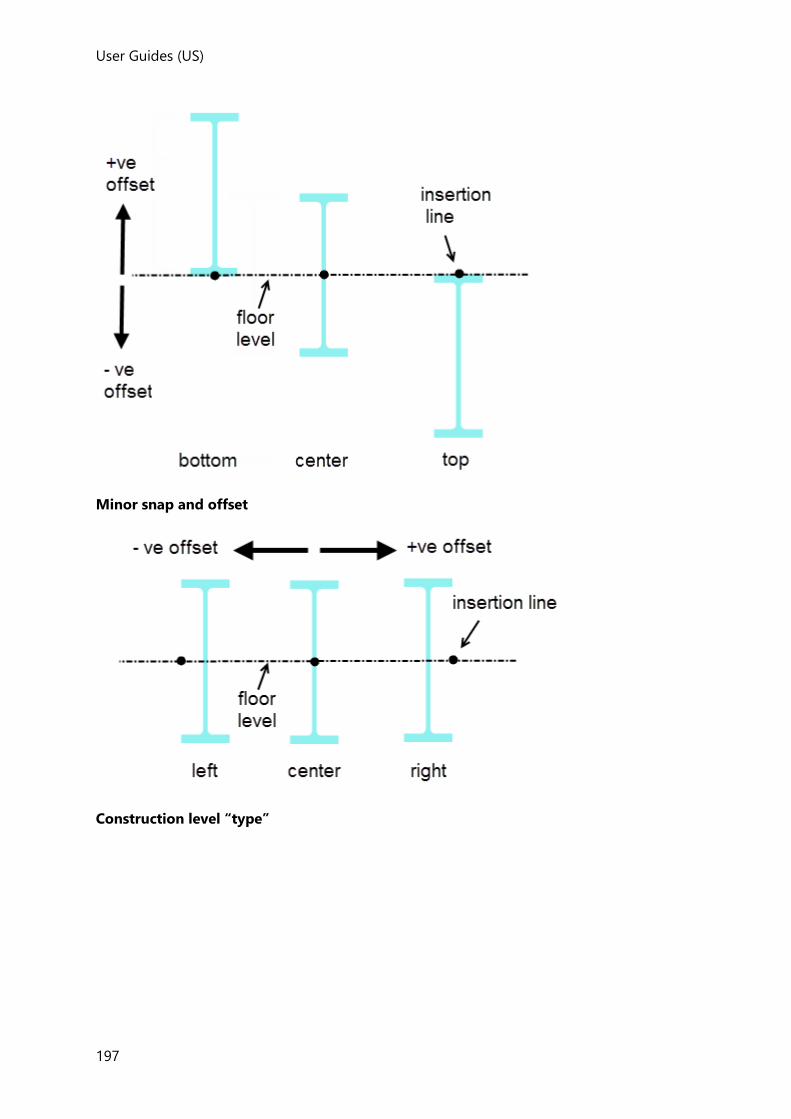
User Guides (US)
197
Minor snap and offset
Construction level “type”

User Guides
198
• When the level type is set to T.O.S (top of steel), each beam is displayed according to the
alignment snap points and offsets specified.
• When the level type is set to S.S.L (structural slab level), each beam is in addition lowered
by the slab thickness specified in the construction level dialog.
Steel beam alignment snap points and offsets and the construction level type have no affect on the positioning of the 1D solver elements in the solver models. This is a different approach to that adopted for concrete beam solver elements.
How do I specify the beam type and section size?
To specify the type of steel beam:
1. Click Model > drop list.
2. Select the type (“Steel”, “Plated”, “Westok Cellular”, “Westok Plated”, or “Fabsec”) from
the drop list.
Alternatively, to specify a cold formed beam:
1. Click Model > Beam ( ) (in the Cold Formed group).
To specify the beam size:
1. In the Section box, click <New\Edit...>.
2. Pick the new section from the Select Section dialog, then click Select.
Before proceeding to create the beam, check the remaining properties in the steel beam
properties set and adjust as required.
How do I create a single span beam?
1. Select the beam type and size.
(How do I specify the beam type and section size?)

User Guides (US)
199
2. Click where the beam is to start (Point 1).
(What are the points I can click to create a member?)
If you are using a point along a member, then click the member first to see its points, then either click the point you want to use, or type the distance to the point from the start of the member.
3. Click where the beam is to end (Point 2).
If you are prompted to pick another point (Point 3), this will be due to Continuous being selected in the beam property set. In order to create a single span beam simply click once again on Point 2, or press the Enter key.
How do I create a plated or compound section steel beam?
1. Click the Model > , and select Plated.
2. In the Section box, click <New/Edit...>.
3. In the Select Section dialog, choose the required compound section type from the left
hand pane.
4. Select the required section from the list of sections that appear for the selected type, or if
the section is not listed click Add...
• Enter sections, plate dimensions and gaps as required to fully define the section
• Either accept the generated name or rename it
• Click OK to add the section
• Once the new section has been added to the list it can then be selected.
The section is automatically added to the Materials database so that it doesn’t have to be redefined when required in subsequent models.
5. Review the remaining properties in the properties window and adjust as necessary.
How you then proceed to place the beam depends on whether you are in a 2D View, or a
Frame/Structure View.
To apply a plated or compound section to an existing steel beam
In the beam properties:
1. In the Fabrication box, click Plated.
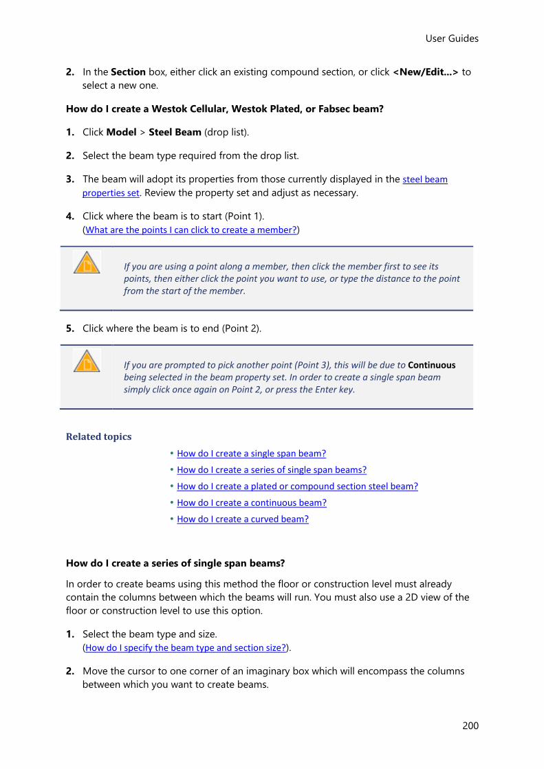
User Guides
200
2. In the Section box, either click an existing compound section, or click <New/Edit...> to
select a new one.
How do I create a Westok Cellular, Westok Plated, or Fabsec beam?
1. Click Model > Steel Beam (drop list).
2. Select the beam type required from the drop list.
3. The beam will adopt its properties from those currently displayed in the steel beam
properties set. Review the property set and adjust as necessary.
4. Click where the beam is to start (Point 1).
(What are the points I can click to create a member?)
If you are using a point along a member, then click the member first to see its points, then either click the point you want to use, or type the distance to the point from the start of the member.
5. Click where the beam is to end (Point 2).
If you are prompted to pick another point (Point 3), this will be due to Continuous being selected in the beam property set. In order to create a single span beam simply click once again on Point 2, or press the Enter key.
Related topics
• How do I create a single span beam?
• How do I create a series of single span beams?
• How do I create a plated or compound section steel beam?
• How do I create a continuous beam?
• How do I create a curved beam?
How do I create a series of single span beams?
In order to create beams using this method the floor or construction level must already
contain the columns between which the beams will run. You must also use a 2D view of the
floor or construction level to use this option.
1. Select the beam type and size.
(How do I specify the beam type and section size?).
2. Move the cursor to one corner of an imaginary box which will encompass the columns
between which you want to create beams.
User Guides (US)
201
3. Click and hold the left mouse button.
4. Drag to the diametrically opposite corner of the box (you will see a rubber rectangle on
the screen which follows your mouse movements and helps you to check the area in
which you are creating).
5. Once the rubber rectangle encompasses the columns between which you want beams
creating, release the mouse button.
6. Beams are created between each adjacent pair of columns within the area you select.
How do I create a continuous beam?
1. Select the beam type and size.
(How do I specify the beam type and section size?)
2. In the Properties Window, ensure that the Continuous option is selected and adjust any
other details as necessary.
3. Click where the beam is to start.
(What are the points I can click to create a member?)
If you are using a point along a member, then click the member first to see its points, then either click the point you want to use, or type the distance to the point from the start of the member.
4. Click the next node of your continuous beam.
5. Repeat step 4 until you have defined the penultimate node of your continuous beam.
6. Click where the beam is to end.
7. You are now prompted to pick another point, simply click once again on the same point,
or press the Enter key in order to create the continuous beam.
You cannot define continuous beams which are curved either horizontally or vertically.
How do I add a haunch to an existing beam?
1. Hover the cursor over the beam in which you want to add haunches so that it becomes
highlighted.
2. Right-click and select ... from the dropdown menu.
3. Click the Haunches page of the properties dialog
User Guides
202
4. Select Quick layout.
5. Click the Create button.
6. Define the haunch and end plate geometry as required, then click OK.
Although haunches are considered in the analysis, they are not considered in the beam design.
Caution: In the current release, you should avoid connecting any other member into the haunched portion of a beam.
How do I create a curved beam?
1. Select the beam type and size.
(How do I specify the beam type and section size?).
2. In the Properties Window, ensure that the Linearity is set to Curved Major (if it is to
curve vertically), or Curved Minor (if it is to curve horizontally), and an appropriate
Chord height value is specified to define the curve.
You can control the direction in which horizontally curved beams curve. When you place the beam you select its start point and its end point. The beam always curves such that if you were to look along the theoretical line from the start point to the end point, then the curve on the beam will always lie to the right of that line.
For vertically curved beams, a negative chord height value can be used to reverse the curve direction.
3. Adjust any other details in the property set as necessary.
4. Click where the beam is to start (Point 1).
(What are the points I can click to create a member?)
If you are using a point along a member, then click the member first to see its points, then either click the point you want to use, or type the distance to the point from the start of the member.
5. Click where the beam is to end (Point 2).
User Guides (US)
203
When defining beams which curve vertically, if you are using a 2D view of the floor or construction level, then the vertical projection of the beam is out of the plane of the floor or construction level that you are using. In this case you will not see the beam on the graphical display. You will need to change to a 3D view of the floor, construction level or the entire Structure in order to see them.
Horizontally curved beams always take the chord height defined in the property set, they do not curve automatically to fit on any curved grid line that you may have defined.
How do I modify the position of a beam?
You can modify an individual beam’s position in both 2D and 3D views.
1. Select the beam to be moved.
The beam is highlighted in one color, the beam end nodes and middle node in another.
2. Now select the beam end node that is to be moved. (Ensure the node is highlighted in
the Select Entity tooltip when selecting, as opposed to one of the members connecting
to the node.)
3. Click a grid or construction point to redefine the beam end node position.
The beam is redrawn spanning to the new end position.
Modeling Steel Braces and Cold Formed Braces
Steel brace overview
Tekla Structural Designer allows you to define braces to provide lateral stability to your
structure. Alternatively you can specify rigid frames to achieve the same effect. You can also
use both methods within a single structure should this be necessary.
Steel braces are single span members with pinned end connections, that are only able to
resist axial compression and tension.
Each steel brace is placed on an insertion line between points, with its geometry being drawn
to reflect the major and minor snap points (and any offsets) specified in the brace properties.
The alignment snap points and offsets have no affect on the positioning of the solver elements created in the solver models, as these will be created directly between the insertion points.
Element loads cannot be applied directly to the brace itself and moments due to self weight
loading are ignored.

User Guides
204
As well as single braces, you are also able to define pairs of braces to form X, K, V and A type
braces.
These brace pairs can be defined in any vertical, horizontal or sloped plane within bays
formed by the intersections of column and beams. Each brace in the pair has independent
properties.
A vertical load release can be applied to the end of a V or A type brace pair so that they
don’t prop other members against gravity loads, (you are prevented from releasing single
braces, or other brace pairs in this way).
V and A brace pairs in models imported from Revit are only recognised as a pair if they have already been released vertically in Revit. If they have not, they will be imported as two single braces without a vertical release.
The split command is available to split pairs into individual braces.
Input method for A and V Braces
A and V Braces should be modeled using special tools which can be found on the 'Steel
Brace' drop list in the 'Steel' section on the 'Model' tab.
Although it is also possible to model the exact same brace arrangement using individual
elements created using the simple 'Steel Brace' command, it is important to note that whilst
the Notional Loads \ EHFs (Equivalent Horizontal Forces) calculated for models built using
the A or V Brace tools are correct, this is not the case when the A or V braces are built up out
of individual brace members. In this latter case, elements of the vertical loads that are
supported by the bracing system are 'lost' and are not included in the Notional Load \ EHF
calculations with the result that the calculated Notional Loads \ EHFs are not correct.
Inactive steel braces
Individual steel braces can be made inactive in the solver model by clearing Active in the
brace properties.
Tension only and compression only braces
Once a steel brace has been placed its properties can be edited if required to specify that it
is Tension only or Compression only.
Tension only and Compression only members are non-linear elements and therefore require non-linear analysis. If linear analysis is performed they will be treated as linear elements.
How do I specify the brace type and section size?
To specify the type of steel brace:
1. Click Model > drop list.

User Guides (US)
205
2. Select the type (Steel Brace, X, K, V, or A) from the drop list.
Alternatively, to specify a cold formed brace:
1. Click Model > Brace ( ) (in the Cold Formed group).
To specify the brace size:
1. In the Section box, click <New\Edit...>.
2. Pick the new section from the Select Section dialog, then click Select.
Before proceeding to create the brace, check the remaining properties in the steel brace
properties set and adjust as required.
How do I create a single brace?
1. Select the brace type and size.
(How do I specify the brace type and section size?)
2. Click where the brace is to start (Point 1).
(What are the points I can click to create a member?)
If you are using a point along a member, then click the member first to see its points, then either click the point you want to use, or type the distance to the point from the start of the member.
3. Click where the brace is to end (Point 2).
A and V Braces should be modeled using special tools which can be found on the 'Steel Brace' drop list in the 'Steel' section on the 'Model' tab. Although it is also possible to model the exact same brace arrangement using individual elements created using the simple 'Steel Brace' command, it is important to note that whilst the EHFs (Equivalent Horizontal Forces) calculated for models built using the A or V Brace tools are correct, this is not the case when the A or V braces are built up out of individual brace members. In this latter case, elements of the vertical loads that are supported by the bracing system are 'lost' and are not included in the EHF calculations with the result that the calculated EHFs are not correct.
How do I create an X, K, V or A brace?
1. Click Model, then from the drop list select the pattern required (X, K, V,
or A).
2. The braces will adopt their properties from the currently displayed steel beam properties
set. Review the properties and adjust as necessary.
User Guides
206
3. Click to identify the bottom corner of the bay to be braced, (Point 1).
4. Click to identify the opposite bottom corner of the bay to be braced, (Point 2).
5. Click to identify the top corner of the bay to be braced, (Point 3). You will see a rubber
rectangle on the screen which follows your mouse movements and helps you to check
the orientation is correct.
6. Click to identify the opposite top corner of the bay to be braced, (Point 4).
7. The brace pattern is created within the area you have selected.
How do I modify the position of a brace?
You can modify an individual brace’s position in both 2D and 3D views.
1. Select the brace to be moved.
The brace is highlighted in one color, the brace end nodes in another.
2. Now select the end node that is to be moved. (Ensure the node is highlighted in the
Select Entity tooltip when selecting, as opposed to one of the members connecting to
the node.)
3. Click a grid or construction point to redefine the brace end node position.
The brace is redrawn spanning to the new end position.
Modeling Steel Joists
Steel joists are a specific type of member used in the United States. They are constrained to standard types specified by the US Steel Joist Institute. They are standardized in terms of span, depth and load carrying capacity.
Steel joists (or bar joists) are simply supported secondary members, which do not support
any other members - they only support loaded areas.
• Steel joists can be defined with ends at differing levels.
• They cannot support any other member.
• Slab and roof loads are supported by steel joists and loads are distributed to them.
How do I specify the joist type and size?
To specify the type of joist:
1. Click Model > Steel Joist
2. In the Section box, click <New\Edit...>.
3. Pick the series and then the size required from the Select Section dialog, then click Select

User Guides (US)
207
Before proceeding to create the joist check the remaining steel joist properties set in the
Properties Window and adjust as required.
How do I create a steel joist?
1. Select the joist type and size.
(How do I specify the joist type and size?)
2. Click where the joist is to start (Point 1).
(What are the points I can click to create a member?)
If you are using a point along a member, then click the member first to see its points, then either click the point you want to use, or type the distance to the point from the start of the member.
3. Click where the joist is to end (Point 2).
How do I modify the position of a steel joist?
You can modify the joist position in both 2D and 3D views.
1. Select the joist to be moved.
The joist is highlighted in one color, the joist end nodes in another.
2. Now select the end node that is to be moved. (Ensure the node is highlighted in the
Select Entity tooltip when selecting, as opposed to one of the members connecting to
the node.)
3. Click a grid or construction point to redefine the joist end node position.
The joist is redrawn spanning to the new end position.
Modeling Steel Trusses
Trusses are particular arrangements of members which Tekla Structural Designer calculates
automatically for you. Once you have created a truss you can copy this throughout your
model as necessary, and you can pick a truss and move it to the location you require.
Once you have defined and loaded your trusses Tekla Structural Designer automatically
checks the member sizes you have specified to determine their adequacy.
How do I use the Steel Truss Wizard?
1. Click Model > Steel Truss ( )
2. Choose the truss shape from the list of standard truss patterns.
User Guides
208
3. Click the truss Start Point.
(What are the points I can click to create a member?)
If you are using a point along a member, then click the member first to see its points, then either click the point you want to use, or type the distance to the point from the start of the member.
4. Click the truss End Point, then click Next
5. Specify the truss alignment parameters, then click Next
6. Specify the truss details, then click Finish
How do I use the Space Truss Wizard?
1. Click Model > drop list.
2. Select Space from the drop list.
3. Choose either a linear or planar truss type and then specify the alignment and number of
bays, then click Next
4. In the 2D or 3D View, click the truss location points:
• for a linear truss - click the start and end points
• for a planar truss - click the four corners,
5. Specify the height, then click Next
6. Define either a straight or curved truss geometry then click Finish
7. Specify the truss alignment parameters, then click Next
8. Specify the truss details, then click Finish
How do I define a Free Form Truss?
A free form truss can be created by placing a series of truss members in the shape required.
1. Open a 2D Frame view in which the truss is to be created. (Note that free form trusses
cannot be created in a 3D view, or 2D level view).
2. Click Model > drop list.
3. Select Free Form from the drop list.
4. Click where the first truss member is to start.

User Guides (US)
209
5. Click where the first truss member is to end.
6. Continue in the same way to pace each truss member until the truss geometry is
complete.
7. Press <Esc> to finish.
How do I edit the geometry of an existing steel truss?
1. Hover the cursor over the truss to be edited so that it becomes highlighted.
2. Right-click and select ... from the dropdown menu.
The Truss Wizard is displayed.
3. Edit the properties as required and then click OK
How do I edit the section sizes, material grades and section orientations in an existing
steel truss?
1. Hover the cursor over the truss to be edited so that it becomes highlighted.
2. Left click the truss to display the edit steel truss properties set. Review the properties,
adjust as necessary and then click OK
Modeling Portal Frames
Portal frames overview
Portal frame buildings are modelled in Tekla Structural Designer as a series of 2D frames
connected together by eaves beams, purlins and rails to form a 3D structure.
Geometric Properties
Each portal frame is a special entity which is created by defining its geometric properties in
the Portal Frame dialog. Once created these geometric properties can then be edited if
required using the same dialog.
Design Properties
Design related properties are specified in the portal frame properties set. The rafter sizes,
column sizes, and supports can also be edited via the property set.
Support Properties
The supports under portal frame columns can be either be defined in the:
• Portal Frame dialog,
• or the portal frame properties set,
• or the Support properties set
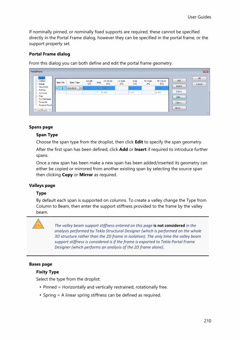
User Guides
210
If nominally pinned, or nominally fixed supports are required, these cannot be specified
directly in the Portal Frame dialog, however they can be specified in the portal frame, or the
support property set.
Portal Frame dialog
From this dialog you can both define and edit the portal frame geometry.
Spans page
Span Type
Choose the span type from the droplist, then click Edit to specify the span geometry.
After the first span has been defined, click Add or Insert if required to introduce further
spans.
Once a new span has been make a new span has been added/inserted its geometry can
either be copied or mirrored from another existing span by selecting the source span
then clicking Copy or Mirror as required.
Valleys page
Type
By default each span is supported on columns. To create a valley change the Type from
Column to Beam, then enter the support stiffness provided to the frame by the valley
beam.
The valley beam support stiffness entered on this page is not considered in the analysis performed by Tekla Structural Designer (which is performed on the whole 3D structure rather than the 2D frame in isolation). The only time the valley beam support stiffness is considered is if the frame is exported to Tekla Portal Frame Designer (which performs an analysis of the 2D frame alone).
Bases page
Fixity Type
Select the type from the droplist:
• Pinned = Horizontally and vertically restrained, rotationally free.
• Spring = A linear spring stiffness can be defined as required.
User Guides (US)
211
The base properties displayed on this page only relate to the support provided in the plane of the portal frame. Out of plane support properties can only be specified in the portal frame property set or the support property set.
If nominally pinned, or nominally fixed supports are required, these cannot be specified
directly in the Portal Frame dialog, however they can be specified in the portal frame
property set, or the support property set. See: Partial fixity of column bases
Enhanced View checkbox
This checkbox is only displayed if a licence of Tekla Portal Frame Designer is detected.
When checked, extra rows are displayed to show the ULS, SLS and Stability stiffness
values that apply when the frame is exported to Tekla Portal Frame Designer.
Haunches page
Active checkbox
Uncheck to remove a specific haunch.
Depth Option
Select the depth to be used:
• User = The depth specified in the table is used.
• Max. cut depth = The max cut depth that can be achieved for the specified haunch
size is used.
Rafters page
This page is used to specify the rafter section and grade.
Capacity
If required a user capacity can be specified to override the default when the frame is
exported to Tekla Portal Frame Designer.
When design is performed in Tekla Structural Designer the default capacity is always used - any user capacity that has been specified on this page is ignored.
Columns page
This page is used to specify the column section and grade.
Capacity
If required a user capacity can be specified to override the default when the frame is
exported to Tekla Portal Frame Designer.
When design is performed in Tekla Structural Designer the default capacity is always used - any user capacity that has been specified on this page is ignored.
User Guides
212
Ties page
Active checkbox
Check in order to specify a tie.
Type Option
This option only applies to the data exported to Tekla Portal Frame Designer
• Yielding = In Tekla Portal Frame Designer a tie that yields under axial compression
• Strut = In Tekla Portal Frame Designer a tie that can carry axial tension and
compression
When a tied portal frame is analysed in Tekla Structural Designer the tie can carry both axial tension and compression irrespective of the Type specified on this page.
Location
Used to specify where the tie connects to the frame.
Tie Members page
If any ties have been specified, this page is used to specify their section and grade.
Parapets page
Active checkbox
Check in order to specify a parapet.
Height
This height of the parapet measured from the top of the column
Parapet Members page
If any parapets have been specified, this page is used to specify their section and grade.
Related topics
• How do I create a single span portal frame?
• How do I create a multi-span portal frame?
How do I create a single span portal frame?
1. Click Model > Portal Frame
2. Click the grid point for the first column base.
(This also set the local X and Y co-ordinate origin for the frame.)
3. Click the grid point for the second column base.
(This also defines the positive local X axis direction for the frame.)
User Guides (US)
213
The second grid point must lie in the same construction level as the first grid point.
The Portal Frame dialog is displayed allowing you to specify the geometry and section
property details for all the elements within the frame.
Initially the local co-ordinates of the Lh and Rh Eaves are invalid (as denoted by the red
crosses), this is because the eaves height has yet to be defined.
4. Click Edit... to specify the eaves level, choose the frame type required, and complete the
frame geometry for the first span.
5. Once the span geometry has been defined, click OK to return to the Portal Frame
dialog.
6. Click Rafters to review the rafter section sizes.
7. Click Columns to review the column section sizes.
8. Click Haunches to specify any haunches.
9. Click Bases to specify the base fixity as either Pinned or Fixed and if necessary adjust the
base levels.
Nominally Pinned and Nominally Fixed bases can also be specified, but only by editing individual support properties in the Properties Window after closing the Portal Frame dialog. When partially fixed bases have been defined, their fixity type is subsequently displayed as “User” in the Portal Frame dialog. See: Partial fixity of column bases
10. If required click the other pages of the Portal Frame dialog in order to specify where
required any:
• Valleys
• Ties
• Tie Members
• Parapets
• Parapet Members
The horizontal, vertical and rotational stiffnesses that can be defined on the Valleys page for a valley beam support are only ever used when the frame is exported to the Portal Frame Designer program for elastic plastic analysis and design. Because the frame is exported in 2D, the valley beam (which is out of plane) is replaced by a spring support with these stiffnesses.

User Guides
214
In Tekla Structural Designer, as there is no spring support at the valley, these stiffnesses have no affect on the analysis or design.
11. Click Spans to add extra spans into the frame.
See: How do I create a multi-span portal frame?
How do I create a multi-span portal frame?
1. Start by defining a single span frame.
See: How do I create a single span portal frame?
2. Then, from the Spans page of the Portal Frame dialog use the buttons to introduce extra
spans as required:
• Click Add to introduce a new span at the end of the frame.
• Click Insert to insert a new span below the currently highlighted span.
• Click Copy to copy the currently highlighted span to a target span. (This can only be used
to replace a pre-existing span with the copied span, it does not insert a new span).
• Click Mirror to mirror the currently highlighted span to a target span. (This can only be
used to replace a pre-existing span with the mirrored span, it does not insert a new span).
How do I edit the properties of an existing portal frame?
To edit the overall frame properties:
1. Hover the cursor over the portal frame to be edited so that it becomes highlighted.
2. Right-click and select ... from the context menu.
The Portal Frame dialog is displayed.
3. Edit the properties as required and then click OK
To edit the properties of an individual portal frame member:
1. Hover the cursor over the portal frame member to be edited.
2. Use the down arrow key to scroll through the objects listed in the Select Entity tooltip.
3. When the individual portal frame member becomes highlighted (as opposed to the
entire portal frame), right-click and select the option to edit the individual member from
the context menu.
The Properties Dialog for the member is displayed.

User Guides (US)
215
4. Edit the properties as required and then click OK
Modeling Cold Rolled Sections
The following characteristic types of cold rolled section can be specified in Tekla Structural
Designer: Track, Stud, Joist, Purlin, Rail, Eaves Beam.
Cold rolled sections can be modelled and analysed in Tekla Structural Designer but they are not designed.
How do I create a single cold rolled section?
1. Click Model > Steel Beam ( )
(or any of the other element types - it does not actually matter which.)
2. Change the Characteristic in the property set to the type of cold rolled section you
require.
The properties displayed are updated appropriate to the chosen cold rolled section type.
3. Review the Cold Rolled Properties and adjust as necessary.
4. Click where the member is to start (Point 1).
(What are the points I can click to create a member?)
If you are using a point along a member, then click the member first to see its points, then either click the point you want to use, or type the distance to the point from the start of the member.
5. Click where the member is to end (Point 2).
How do I modify the position of a cold rolled section?
You can modify a cold rolled section in both 2D and 3D views.
1. Click the section you want to modify. You will see two handles at its ends. To move the
end of the section, click its handle and move it to its new location with the mouse. When
the end is where you want it click again to fix the end to that point.
Modeling Web Openings

User Guides
216
Although web openings can be added to steel beams and columns they are only considered in the design of composite and non composite beams designed to either Eurocodes, BS codes, or AISC
Web openings can be added either by a 'Quick-layout' process or manually.
'Quick-layout' creates web openings at the maximum depth and spaced at the minimum
centers recommended for the section size while also meeting certain geometric and
proximity recommendations.
Web openings can be defined manually in two ways from the Web Openings dialog page.
With Quick-layout cleared, the Add button adds a new line to the web openings grid to
allow the geometric properties of the web opening to be defined, or alternatively, use of the
Add button opens the Web Opening Details dialog page which gives access to more help
and guidance when defining the opening. Both methods make use of 'Warning' and 'Invalid'
text for data entry checks to provide assistance as the opening parameters are defined.
On the Web Opening Details dialog page, the Center button will position the opening on the
beam centre whilst the Auto button will position the opening to meet the spacing
recommendations. Also on this page tool tips give information on the recommended values
for all the opening parameters.
As web openings are defined, they are immediately visible in the diagram on the Web
Openings dialog page. This diagram displays the results of the geometric and proximity
checks that are carried out on the opening parameters using 'Warning' and 'Invalid' display
colours to highlight those areas that are outside the recommended limits.
The areas that are subjected to the checks are end posts, web posts, web opening
dimensions and tee dimensions.
This display helps you to decide whether to make any adjustments to the opening
parameters before their design is checked.
You should bear in mind that the checks carried out at this stage are geometric checks only
and compliance with recommended limits is no guarantee that the opening will pass the
subsequent engineering design checks.
Related topics
• Web Openings to AISC
• Web Openings to SCI P355
• Web Openings to SCI P068
How do I add web openings using Quick Layout?
This method enables you to create maximum depth openings spaced at the minimum
centers appropriate to the section size.
1. Hover the cursor over the member in which you want to add the web openings so that it
becomes highlighted.

User Guides (US)
217
2. Right-click and select ... from the dropdown menu.
3. Ensure Automatic design in the properties is cleared.
(Web openings cannot be added to members that are in Autodesign mode.)
4. Click the Web openings page of the properties dialog
5. Select Quick layout.
6. Select where you want to start setting out from via the Label openings from droplist.
7. Select the type (square, rectangular or circular) from the Type droplist.
Data for the first web opening is automatically created as follows:
• lO - the length of opening (for rectangular openings only)
• dO - the depth of opening
• LCR - the distance from the setting out point to the center of the opening
• LC - the distance from end 1 of the member to the center of the opening.
• dC - the distance from the top of the member to the center of the opening
• LCR relative to - indicates the setting out point from which LCR is measured (defaults to
your selection from the Label openings from droplist)
• Nr. rel. to - this field only applies if you have chosen the Opening -> option from the
LCR relative to droplist. It is used to specify an existing opening number that you
want to use as the setting out point for the new opening.
8. If stiffening is required select the location from the Stiffening droplist.
Data for the stiffeners is entered manually as follows:
You may need to widen the dialog page to see the relevant column headings.

User Guides
218
• dS - depth of stiffener
• tS - thickness of stiffener
• LS - length of stiffener
• eS - the distance from edge of the opening to the center of the stiffener.
9. Click then select from the Type droplist to create further openings from the
chosen setting out point as required.
10. At any point you can use the Label openings from droplist to switch to a new setting
out point for the next opening.
Related topics
• How do I add web openings manually?
• Web Openings to AISC
• Web Openings to SCI P355
• Web Openings to SCI P068
How do I add web openings manually?
This method enables you to create openings to your own specified depth and spacing.
1. Hover the cursor over the member in which you want to add the web openings so that it
becomes highlighted.
2. Right-click and select ... from the dropdown menu.
3. Ensure Automatic design in the properties is cleared.
(Web openings cannot be added to members that are in Autodesign mode.)

User Guides (US)
219
4. Click the Web openings page of the properties dialog
5. Ensure the Quick layout check box is cleared.
6. Select where you want to start setting out from via the Label openings from droplist.
7. Click (as opposed to )
8. Select the type (square, rectangular or circular) from the Type droplist.
9. Manually specify the dimensions of the web opening:
• lO - the length of opening (for rectangular openings only)
• dO - the depth of opening
10. Manually specify the distance from the setting out point for the web opening
• LCR relative to - indicates the setting out point from which LCR is measured (defaults to
your selection from the Label openings from droplist)
• Nr. rel. to - this field only applies if you have chosen the Opening -> option from the
LCR relative to droplist. It is used to specify an existing opening number that you
want to use as the setting out point for the new opening.
• LCR - the distance from the setting out point to the center of the opening
• LC - the distance from end 1 of the member to the center of the opening.
Click Add for LCR and LC to be automatically calculated as the minimum values appropriate to the size of opening.
• dC - the distance from the top of the member to the center of the opening

User Guides
220
Click Center for dC to be automatically calculated to position the opening centrally in the section depth.
11. If stiffening is required check the Stiffened check box - this creates a second page on
the dialog.
Select the location from the Stiffening droplist.
Data for the stiffeners is entered as follows:
• dS - depth of stiffener
• tS - thickness of stiffener
• LS - length of stiffener
• eS - the distance from edge of the opening to the center of the stiffener.
12. Click to create the opening.
13. To create further openings, either:
• click to create multiple copies of a selected opening, or
• click to create a single opening of a different size or spacing,
Related topics
• How do I add web openings using Quick Layout?
• Web Openings to AISC
• Web Openings to SCI P355
• Web Openings to SCI P068

User Guides (US)
221
Compound Sections
A comprehensive list of predefined compound section types is available in Tekla Structural
Designer including many common arrangements such as: Rolled I sections with plates to the
bottom, top or both flanges; rolled channels toe to toe and back to back and with or without
plates; rolled angles and steel joists in a star arrangement.
You add user defined sections to the database for each compound section type as and when
required. Once they have been defined, compound sections are then available for all models.
Compound sections can only be applied to steel beams and steel columns, and while they
participate fully in analysis, generally they are not designed (apart from for the limited
circumstances detailed below).
Compound sections can only be designed in the following circumstances: - Head Code must be set to either Eurocode or BS - Characteristic must be set to Beam - Compound section type must be set to either Plated Beam or Plated Column
Concrete member modeling
Modeling Concrete Walls
Concrete wall overview
Concrete walls can be created over several story heights, and can start and finish at any level.
Although a single wall is created, this does not prohibit different thicknesses from being

User Guides
222
defined in each panel, (in which case the panels will be set back on one or both faces,
depending on the alignment that has been specified).
The creation of continuous wall in this way, (as opposed to defining a new wall at each story)
does not have any significance for analysis or design purposes, but is ultimately important
for detailing purposes.
The points used to place a concrete wall define the exact size and position of the wall’s
analysis model. Its alignment and extension properties have no affect on this model. Either
an FE meshed, or mid-pier wall analysis can be adopted on a wall by wall basis.
Provided AutomaticGenerateSupport is selected, if no slab or other member exists beneath
the wall when it is first created, a support is automatically placed underneath it.
Meshed walls default to the model’s mesh parameters, but these can be overridden to allow
a user defined mesh to be applied to an individual wall.
Minor axis releases can be applied at the top and bottom of each panel - pinned
connections to incoming slabs and members can be modelled in this way.
If you want to create door or window openings in the wall it must be defined as a meshed
wall - openings cannot be catered for in mid-pier walls.
Both meshed and mid-pier concrete walls introduce structural strength and stiffness to your
model, but they do not perform the same function as Wall Panels, i.e. they do not act as a
medium via which loads calculated by the Wind Wizard get applied to your structure.
Therefore, in order for these wind loads to be applied you should create additional Wall
Panels in the same physical locations as the Concrete Walls.
How do I specify whether the wall is to be meshed or mid-pier?
You initially choose whether a meshed or mid-pier model is to be adopted by making the
appropriate selection from the concrete wall droplist in the Model toolbar.
Subsequently, you can change the model type for an existing wall by changing the Wall
Type property in the wall properties.
How do I create a concrete wall in a 2D View?
1. Ensure that you have defined the construction levels between which the wall will run and
the grid points between which it will lie.
2. Click Model > Concrete Wall drop list ( )
3. Click the model type required (Meshed, or Mid-pier).
4. The wall will adopt properties from the concrete wall properties set displayed in the
Properties Window.
5. Check that the Base Level and the Top Level shown in the property set are correct, or
adjust if necessary.
User Guides (US)
223
6. Check that the Thickness and other properties shown in the property set are also
correct, and again adjust if necessary.
7. Click where the wall is to start (Point 1).
(What are the points I can click to create a member?)
If you are using a point along a member, then click the member first to see its points, then either click the point you want to use, or type the distance to the point from the start of the member.
8. Click where the wall is to end (Point 2).
How do I create a concrete wall in a Frame, or Structure View?
In order to define a wall in a frame-, or structure-view you must have already defined the
construction levels between which the wall will run and the grid points between which it will
lie.
To create the wall:
1. Click Model > Concrete Wall drop list ( )
2. Click the model type required (Meshed, or Mid-pier).
3. The wall will adopt its properties from the concrete wall properties set displayed in the
Properties Window.
4. Check that the Base Level and the Top Level shown in the property set are correct, or
adjust if necessary.
5. Check that the Thickness and other properties shown in the property set are also
correct, and again adjust if necessary.
6. Click the point where the base of the wall is to start.
(What are the points I can click to create a member?)
7. Click the point where the base of the wall is to end.
8. Click the point where the top of the wall is to start.
9. Click the point where the top of the wall is to end.
10. Tekla Structural Designer creates the wall between these four points.
How do I specify extensions?
To automatically trim a new wall back to the face of existing columns or walls:
1. Select the AutomaticExtension check box in the Properties Window when creating the
wall.

User Guides
224
Or, to manually trim or extend existing walls:
1. Select the wall to be trimmed or extended.
2. Specify the required End 1 extension or End 2 extension in the Properties Window:
• A positive extension extends the wall length beyond its insertion point.
• A negative extension trims the wall back from the insertion point.
How do I specify releases?
1. Select the wall to be released.
2. In the Properties Window, open the Releases properties.
3. Select the appropriate release from the Minor Top or Minor Bottom droplist as
required:
• Fixed
• Pinned
• Continuous (incoming members pinned) - only available for FE meshed walls
To specify a pinned connection to a supported slab you should use an FE meshed wall and then select Continuous (incoming members pinned) rather than pinned. This is because the pinned option also releases the wall panel above from the wall panel below - which may result in a mechanism during the analysis.
Automatic support generation
The AutomaticGenerateSupport check box in the wall properties is used to control whether
a support is automatically created at the wall base level as follows:
• When AutomaticGenerateSupport is on:
• Generate support cannot be off.
• if there are members/slabs underneath the wall capable of providing support - no
support is generated.
• if there are no members/slabs underneath the wall capable of providing support - a
support is generated.
• When AutomaticGenerateSupport is off:
• If Generate support is on - a support is generated.
• If Generate support is off - no support is generated.
When a support is required, a line support is formed under a meshed wall, a point support under a mid-pier wall, and a series of point supports under a bearing wall.
User Guides (US)
225
When a support is required, its degrees of freedom are as specified in the Wall support area of the wall properties.
How do I edit a wall support?
Supports can only be edited or deleted for both mid-pier and meshed concrete walls via the
wall properties.
To edit wall support fixity:
1. Expand Wall Support in the wall properties
2. Specify the degrees of freedom as required.
Because the discrete supports at each node are angled in the global axis system (always) and not aligned with the wall major/minor axes; it is necessary to set both Mx and My as Free in order to ensure that angled walls are pinned out of plane. (It is not strictly necessary if the wall is aligned in global X or Y, you could set just Mx, or My free as appropriate). Similarly, both Mx and My should be set as Fixed in order to ensure that angled walls are fixed out of plane.
To remove a wall support:
1. Uncheck Generate support in the wall properties.
The Generate support property will only be available for editing if the AutomaticGenerateSupport property is inactive. If AutomaticGenerateSupport is on, Generate support will be automatically cleared if members are created underneath a wall to support it - similarly it will be automatically rechecked if these members are deleted.
How do I create a door or window opening in an existing concrete wall?
Openings are only active in meshed (not mid-pier) concrete walls.
1. Open a Frame view of the frame containing the meshed concrete wall within which you
want to create an opening.
2. Click Model > Wall Opening

User Guides
226
• Either, click within the outline of an existing wall panel to define the opening relative to
the bottom left corner of the wall,
• or, click a specific node within an existing wall panel to define the opening relative to the
selected node.
3. Pick the first corner of the opening.
(Press <F2> if required to enter its exact position.)
4. Drag to the diametrically opposite corner of the opening (you will see a rubber rectangle
on the screen which follows your mouse movements and helps you to check the area in
which you are creating the opening).
5. Click to define the opposite corner of the opening.
(Again, press <F2> if required to enter its exact position.)
Modeling Concrete Columns
Concrete column overview
A single concrete column can be created over several story heights (stacks) and can start and
finish at any level. Different column sections can be defined in each stack, and the column is
not restricted to being co-linear between stacks.
The creation of continuous concrete columns in this way, (as opposed to defining a new
column at each story) does not have any significance for analysis or design purposes, but is
ultimately important for detailing purposes.
The physical location of the column is a determined from the alignment snap points and
offsets specified in the column properties, and the insertion point(s) picked.
How do I specify the column shape and size?
1. Click Model > Concrete Column ( )
2. In the Properties Window the Section box shows the default shape and size.
3. In the Section box, click <New\Edit...>.
4. Select the shape then enter the size in the dialog.
5. Click OK to save. (Do not click Add unless you want to create a hollow column - See How
do I create a hollow column?).
How do I create a single concrete column in a 2D View?
Ensure that you have defined the construction levels between which the column will run and
the grid points between which it will lie, then:

User Guides (US)
227
1. Click Model > Concrete Column ( )
2. Check the Base Level and Top Level shown in the Properties Window are correct -
adjust if necessary.
3. Check the column Section is correct - adjust if necessary.
(How do I specify the column shape and size?)
4. Check the other concrete column properties set values are also correct - adjust if necessary.
5. Click the point where the column is to be placed.
(What are the points I can click to create a member?)
How do I create a series of concrete columns in a 2D View?
Ensure that you have defined the construction levels between which the column will run and
the grid points between which it will lie, then:
1. Click Model > Concrete Column ( )
2. Check the Base Level and Top Level shown in the Properties Window are correct -
adjust if necessary.
3. Check the column Section is correct - adjust if necessary.
(How do I specify the column shape and size?)
4. Check the other concrete column properties set values are also correct - adjust if necessary.
5. Move the cursor to one corner of an imaginary box which will encompass the grid
intersection points at which you want to create columns.
6. Click and hold the left mouse button.
7. Drag to the diametrically opposite corner of the box (you will see a rubber rectangle on
the screen which follows your mouse movements and helps you to check the area in
which you are creating).
8. Once the rubber rectangle encompasses the grid intersection points at which you want
to create columns, release the mouse button.
How do I create a single concrete column in a Frame, or Structure View?
In order to define a column in a frame-, or structure-view you must have already defined the
construction levels between which the column will run and the grid points between which it
will lie.
To create the column:
1. Click Model > Concrete Column ( )

User Guides
228
2. Check the column Section is correct - adjust if necessary.
(How do I specify the column shape and size?)
3. Check the other concrete column properties set values are also correct - adjust if necessary.
4. Click the point where the column is to start.
(What are the points I can click to create a member?)
5. Click the point where the column is to end. Tekla Structural Designer creates the column
between these two points.
How do I align a column to a specific angle, or an angled gridline?
Three options are provided for specifying the alignment of a new column - achieved by
setting the Rotation property as follows:
• 0, 90, 180, 90 - aligns the column to the global axes
• Angle - aligns the column to the exact rotation angle you specify
• Define - aligns the column to the angle of any grid line you select
How do I specify the column alignment relative to the grid?
How each column is initially placed relative to the grid depends on the Automatic
alignment setting in the concrete column properties set.
If Automatic alignment is on:
Columns on the perimeter of the grid are aligned with their faces flush to the perimeter and
internal columns are aligned centrally on the grid.

User Guides (US)
229
If Automatic alignment is off:
Columns are aligned according to the Major and Minor alignment settings in the concrete
column properties set.
How do I create a hollow column?
1. Click Model > Concrete Column ( )
2. In the Properties Window the Section box shows the default shape and size.
3. In the Section box, click <New\Edit...>.
4. Select the shape then enter the size in the dialog.
5. In the same dialog, click Add
6. In the tabular part of the dialog, select the shape and dimensions of the void.
7. Leave the minor and major offsets as 0.0 to position the void centrally in the column, or
adjust as necessary to create an offset.
How do I create an inclined column?
An inclined column can only be created in a Frame, or Structure View.
In order to define the column you must have defined the construction levels between which
the column will run and the grid points between which it will lie.
1. Click Model > Concrete Column ( )
User Guides
230
2. The column will adopt properties from the currently displayed concrete column properties
set.
3. Check that the properties shown in the property set are correct or adjust if necessary.
4. Click the point where the column is to start.
(What are the points I can click to create a member?)
5. Click the point where the column is to end. Tekla Structural Designer creates the column
between these two points.
Related topics
• How do I create a cranked column?
How do I create a cranked column?
A cranked column can only be created in a Frame, or Structure View.
In order to define the column you must have defined the construction levels between which
the column will run and the grid points between which it will lie.
1. Click Model > Concrete Column ( )
2. The column will adopt properties from the currently displayed concrete column properties
set.
3. Check that the properties shown in the property set are correct or adjust if necessary.
4. Click the point where the column is to start.
5. Press and hold the CTRL key on the keyboard and click the next node of your cranked
column.
6. Repeat step 3 until you have defined the penultimate node of your cranked column.
Release the CTRL key and click the point where the column is to end.
How do I modify the position of a single column stack?
A column stack’s position can best be modified in either a Frame, or Structure View.
1. In Scene Content, ensure that the Grid & Construction Lines box is checked.
2. Select the column for which a stack is to be moved.
The column is highlighted in one color, the column end nodes and middle node in
another.
3. Select one end nodes for the column stack to be moved. (Ensure the node is highlighted
in the Select Entity tooltip when selecting, as opposed to one of the members
connecting to the node.)
4. Click a grid or construction point to redefine the column stack end node position.

User Guides (US)
231
The entire column is redrawn with the selected node moved to the new position.
5. Select the next end node. (Ensure the node is highlighted in the Select Entity
tooltip when selecting, as opposed to one of the members connecting to the node.)
6. Click a grid or construction point to redefine the end node position.
The column is redrawn once more with the selected node moved to the new position.
How do I modify the position of an entire column?
Simply use the Move command located on the Edit ribbon.
How do I edit the column alignment or specify an offset?
Once columns have been placed their alignments can be adjusted and further offsets
specified if required.
• A single column’s alignment can be adjusted either in the Properties Dialog or in the
Properties Window
• Multiple columns can only be realigned using the Properties Window
The example below illustrates editing the alignment in the Properties Window.
1. Select the columns to be offset.
2. Ensure the column properties are displayed in the Properties Window, (use the drop list
at the top of the window if necessary).
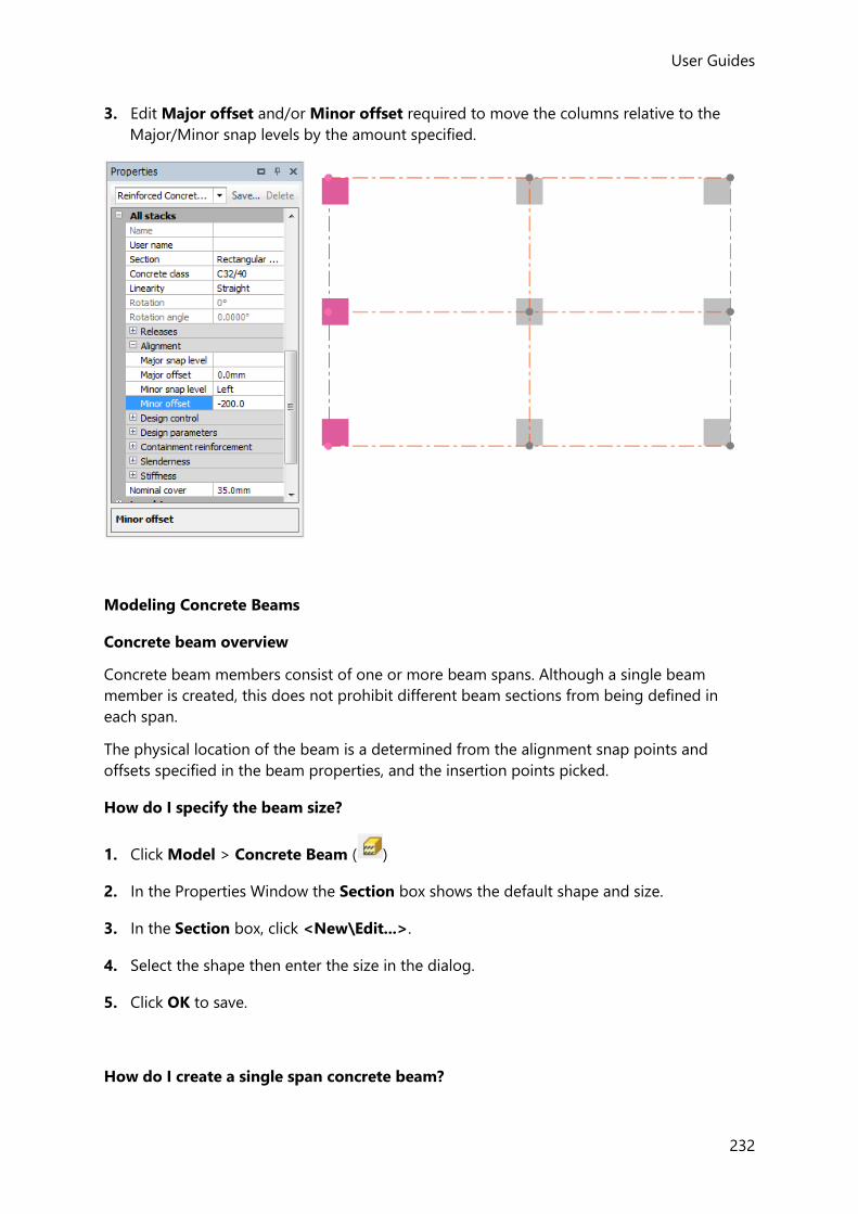
User Guides
232
3. Edit Major offset and/or Minor offset required to move the columns relative to the
Major/Minor snap levels by the amount specified.
Modeling Concrete Beams
Concrete beam overview
Concrete beam members consist of one or more beam spans. Although a single beam
member is created, this does not prohibit different beam sections from being defined in
each span.
The physical location of the beam is a determined from the alignment snap points and
offsets specified in the beam properties, and the insertion points picked.
How do I specify the beam size?
1. Click Model > Concrete Beam ( )
2. In the Properties Window the Section box shows the default shape and size.
3. In the Section box, click <New\Edit...>.
4. Select the shape then enter the size in the dialog.
5. Click OK to save.
How do I create a single span concrete beam?

User Guides (US)
233
1. Click Model > Concrete Beam ( )
2. In the Properties Window, check the Section box shows the correct size - adjust if
necessary.
(How do I specify the beam size?)
3. Check the other concrete beam properties set values are also correct - adjust if necessary.
4. Click where the beam is to start (Point 1).
(What are the points I can click to create a member?)
If you are using a point along a member, then click the member first to see its points, then either click the point you want to use, or type the distance to the point from the start of the member.
5. Click where the beam is to end (Point 2).
If you are prompted to pick another point (Point 3), this will be due to Continuous being selected in the beam property set. In order to create a single span beam simply click once again on Point 2, or press the Enter key.
How do I create a continuous concrete beam?
1. Click Model > Concrete Beam ( )
2. In the Properties Window, check the Section box shows the correct size - adjust if
necessary.
(How do I specify the beam size?)
3. Check the other concrete beam properties set values are also correct - adjust if necessary.
4. Click where the beam is to start.
(What are the points I can click to create a member?)
If you are using a point along a member, then click the member first to see its points, then either click the point you want to use, or type the distance to the point from the start of the member.
5. Click the next node of your continuous beam.
6. Repeat step 4 until you have defined the penultimate node of your continuous beam.
7. Click where the beam is to end.

User Guides
234
8. You are now prompted to pick another point, simply click once again on the same point,
or press the Enter key in order to create the continuous beam.
You cannot define continuous beams which are curved either horizontally or vertically.
How do I create a series of concrete beams?
In order to create beams using this method the floor or construction level must already
contain the columns between which the beams will run. You must also use a 2D view of the
floor or construction level to use this option.
1. Click Model > Concrete Beam ( )
2. Check that in the Properties Window shows the correct size - adjust if
necessary.
(How do I specify the beam size?)
3. To create continuous beams between the supports -
check the box.
4. Else to create a series of single span beams between the supports -
clear the box.
5. Review the other concrete beam properties set values and adjust if necessary.
6. Move the cursor to one corner of an imaginary box which will encompass the columns
between which you want to create beams.
7. Click and hold the left mouse button.
8. Drag to the diametrically opposite corner of the box (you will see a rubber rectangle on
the screen which follows your mouse movements and helps you to check the area in
which you are creating).
9. Once the rubber rectangle encompasses the columns between which you want beams
creating, release the mouse button.
10. Beams are created between each adjacent pair of columns within the area you select.
How do I create a curved concrete beam?
1. Click Model > Concrete Beam ( )
2. The beam will adopt its properties from the displayed concrete beam properties set; ensure
that the Linearity is set to Curved Major (if it is to curve vertically), or Curved Minor (if

User Guides (US)
235
it is to curve horizontally), and appropriate Chord height and Maximum facet error values
have been specified to define the curve.
You can control the direction in which horizontally curved beams curve. When you place the beam you select its start point and its end point. The beam always curves such that if you were to look along the theoretical line from the start point to the end point, then the curve on the beam will always lie to the right of that line.
For vertically curved beams, a negative chord height value can be used to reverse the curve direction.
3. Adjust any other details in the property set as necessary.
4. Click where the beam is to start (Point 1).
(What are the points I can click to create a member?)
If you are using a point along a member, then click the member first to see its points, then either click the point you want to use, or type the distance to the point from the start of the member.
5. Click where the beam is to end (Point 2).
When defining beams which curve vertically, if you are using a 2D view of the floor or construction level, then the vertical projection of the beam is out of the plane of the floor or construction level that you are using. In this case you will not see the beam on the graphical display. You will need to change to a 3D view of the floor, construction level or the entire Structure in order to see them.
Horizontally curved beams always take the chord height defined in the property set, they do not curve automatically to fit on any curved grid line that you may have defined.
How do I specify the beam alignment relative to the grid?
For initial placement, beams are aligned relative to the grid depending on the Automatic
alignment setting in the concrete beam properties set.
If Automatic alignment is on:
When placed by boxing around columns, each beam’s alignment follows that of the columns
between which it spans.

User Guides
236
In the below example, because the edge columns were aligned flush with the grid, when the
beams are placed (by boxing around the columns) with automatic alignment on, they are
flush also.
However, if the edge columns had been aligned centrally, when the beams are placed with
automatic alignment on, they would be central also.
If Automatic alignment is off:

User Guides (US)
237
Beams are aligned according to the Major and Minor alignment settings in the concrete
beam properties set.
How do I specify and use beam flanges for an existing beam?
1. Hover the cursor over the beam to be edited so that it becomes highlighted.
2. Right-click and select ... from the dropdown menu.
The Concrete Beam Property Dialog is displayed.
3. Open the Design Control page of the dialog for a particular span and select Consider
flanges.
Further boxes are opened up displaying the flange dimensions (initially all zero).
4. To specify the flange dimensions, click Calculate flanges.
- the flange dimensions are automatically calculated.
5. If required you can add an allowance for openings to reduce the calculated widths by a
specified amount.
6. Repeat the above for additional spans in the beam as required.

User Guides
238
Once flanges have been specified in this way they will be considered in the concrete beam
design calculations, however the flanged beam properties are not by default used in the
analysis.
To use flanged beam properties in the analysis (in addition to the design calculations)
1. Select Include flanges in analysis.
2. Repeat for additional spans in the beam as required.
How do I specify and use beam flanges for multiple beams simultaneously?
1. Select the beams to be edited.
2. The edit concrete beam properties set shared by the beams are displayed in the Properties
Window.
3. Located under All spans - Design Control, select Consider flanges.
Further boxes are opened up displaying the flange dimensions (initially all zero).
4. To specify the flange dimensions, firstly select Calculate flanges so that it becomes
highlighted:
5. Then click the button - the flange dimensions are automatically calculated.
Only flange dimensions which are common to all the selected beams can be shown in the fields; where different flange dimensions have been calculated for the selected beams, the fields are left blank.
6. If required you can add an allowance for openings to reduce the calculated widths by a
specified amount.
Once flanges have been specified in this way they will be considered in the concrete beam
design calculations, however the flanged beam properties are not by default used in the
analysis.
To use flanged beam properties in the analysis (in addition to the design calculations)
1. Located under All spans - Design Control, select Include flanges in analysis.
How do I edit the beam alignment or specify an offset?
Once beams have been placed their alignments can be adjusted and further offsets specified
if required.
• A single beam’s alignment can be adjusted either in the Properties Dialog or in the
Properties Window

User Guides (US)
239
• Multiple beams can only be realigned using the Properties Window
The example below illustrates editing the alignment in the Properties Window.
1. Select the beams to be edited.
2. Ensure the beam properties are displayed in the Properties Window, (use the drop list at
the top of the window if necessary).
3. Edit the Major and/or Minor snap level as required to realign the beams in the vertical
and horizontal planes respectively.
4. Edit the Minor offset to move the beams horizontally relative to the Minor snap level by
the amount specified.
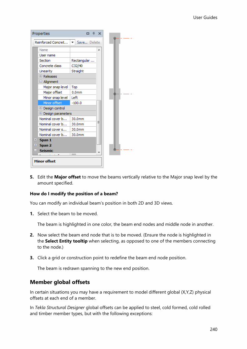
User Guides
240
5. Edit the Major offset to move the beams vertically relative to the Major snap level by the
amount specified.
How do I modify the position of a beam?
You can modify an individual beam’s position in both 2D and 3D views.
1. Select the beam to be moved.
The beam is highlighted in one color, the beam end nodes and middle node in another.
2. Now select the beam end node that is to be moved. (Ensure the node is highlighted in
the Select Entity tooltip when selecting, as opposed to one of the members connecting
to the node.)
3. Click a grid or construction point to redefine the beam end node position.
The beam is redrawn spanning to the new end position.
Member global offsets
In certain situations you may have a requirement to model different global (X,Y,Z) physical
offsets at each end of a member.
In Tekla Structural Designer global offsets can be applied to steel, cold formed, cold rolled
and timber member types, but with the following exceptions:
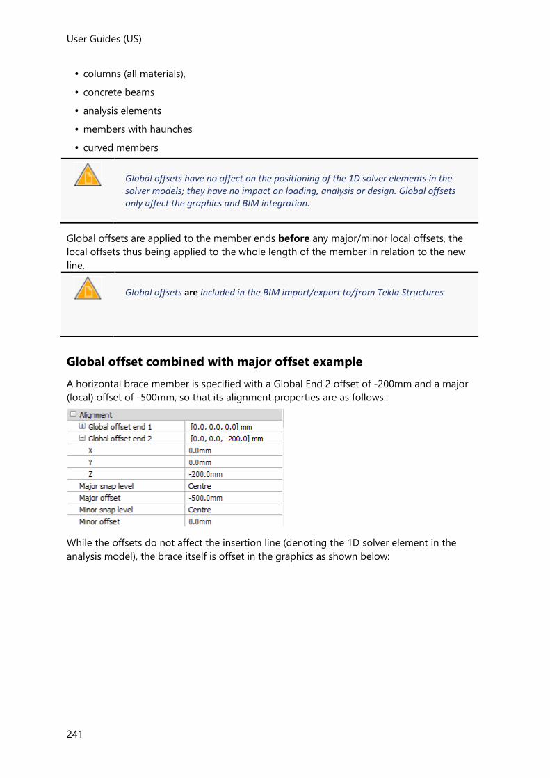
User Guides (US)
241
• columns (all materials),
• concrete beams
• analysis elements
• members with haunches
• curved members
Global offsets have no affect on the positioning of the 1D solver elements in the solver models; they have no impact on loading, analysis or design. Global offsets only affect the graphics and BIM integration.
Global offsets are applied to the member ends before any major/minor local offsets, the
local offsets thus being applied to the whole length of the member in relation to the new
line.
Global offsets are included in the BIM import/export to/from Tekla Structures
Global offset combined with major offset example
A horizontal brace member is specified with a Global End 2 offset of -200mm and a major
(local) offset of -500mm, so that its alignment properties are as follows:.
While the offsets do not affect the insertion line (denoting the 1D solver element in the
analysis model), the brace itself is offset in the graphics as shown below:

User Guides
242
Global offset only example
A diagonal brace member is specified with a Global End 1 offsets of 200mm in Z and 400mm
in Y, the Major and Minor (local) offsets are both 0mm, so that its alignment properties are
as follow
While the offsets do not affect the insertion line (denoting the 1D solver element in the
analysis model), the brace itself is offset in the graphics as shown below:

User Guides (US)
243
Slab modeling
Slabs are the medium via which loads placed on a floor are decomposed back to the
supporting structure.
Slabs can be created in levels or inclined planes. The vertical alignment of all slabs in a given
level is determined by the “type” assigned to the level:
• T.O.S - the base of each slab item aligns with the level
• S.S.L - the top of each slab item aligns with the level
Each “parent” slab consists of a number of individual panels (slab items); these can either be
connected or separated from each other, however they must be on the same level.
Every parent slab has a unique name. A slab name used at one level cannot be re-used at a different level.
The individual panels initially inherit their properties from the parent slab, but once they
have been created they can be edited to allow certain of properties to be amended: the
rotation angle can be changed; the slab depth can be overridden; a panel can be excluded

User Guides
244
from the diaphragm. When a slab depth override has been applied you can also apply a
vertical offset in order to model a slab step.
Vertical offsets are not structurally significant as they have no affect on the analysis mesh position relative to the top of the slab in the solver model. The mesh properties would however reflect any change to the slab thickness.
Slab boundaries can be straight or curved.
Openings of any shape can be created within slabs.
In flat slabs, at points where the slab is supported by columns, column drop panels can be
applied to thicken the slab, (drop panels are effectively slab items with an increased
thickness).
Overview of slab modeling
The Concept of Slabs and Slab Panels
Tekla Structural Designer stores slab data in the form of “parent slabs” each consisting of one
or more slab items (or slab panels).
In the view above there are 24 slab items grouped together in one slab.
Some data is set at the “slab” level and is common to all panels, other data is set at the “slab
panel” level.
In simple overview terms the data breakdown is as follows:
Slab Data:

User Guides (US)
245
• Thickness
• Vertical Offset
• Material Properties
• Analysis Settings
• General Design Settings
Slab Panel Data:
• Cover
• Reinforcement information
• Specific Design Settings
In modeling terms you are thus able to create slabs over a wide area, there is no reason at
this stage to consider sub-sections of the slab - it is just one big expanse of slab.
When it comes to design you then need to conceptualize the slab as a series of design
panels. Each design panel will have it's own design settings and it's own design results.
Different reinforcement can be selected in different panels. You also have to consider pattern
loading (some panels loaded and others not). When results are then presented in
calculations and drawings you are able to specifically reference the design panels.
Panel sub-division
Regardless of how the slabs and panels are initially created, you are able to further divide (or
re-form) them via the Slab Split and Slab Join commands. There are several reasons why
you may choose to do this relating to refining geometry (adding steps), pattern loading, and
panel design.
When it comes to flat slabs in particular, the way that slabs are split for the purposes of
pattern loading is a matter of engineering judgement - the views below show a couple of
options that 2 different engineers might both justifiably choose for the same slab perimeter.

User Guides
246
Creating slab panels
•
How do I choose the slab type and specify its properties?
1. Click Model, then from the first Slabs drop list select the slab type required.
2. Define panel properties for the chosen slab type.
Slab Type Property Set
Slab on Beams slab on beams item properties set
Flat Slab flat slab item properties set
Precast precast item properties set
Steel Deck steel deck item properties set
Timber Deck timber deck item properties set
Composite Slab composite slab item properties set
3. Before placing the panel confirm the Slab and Select bays properties (under the
General heading) are set as required.
How do I specify the parent slab to which the panel belongs?
1. Under the General heading use the Slab property to specify that you want to either:

User Guides (US)
247
• create a New Slab
• automatically add to an existing parent slab
• manually select the parent slab.
2. When the panel properties are defined it can then be placed either by bays or by picking
points.
When using the Add to existing option, at the point of slab item creation a check is made to find if there is a existing slab in the plane with same properties. If found - the new panel will be added to it (if two are found then the one that is physically closest is used). If not found - a new parent slab is created.
The option to manually select the parent slab is only available in 2D Views, and then only after one or more panels have been placed in that view.
How do I create slab panels by bay?
This method is only available in 2D Views.
1. Under the General heading ensure that the Select bays property is checked.
A “Create Slab Item: Select Bay” prompt appears and the bays in which slab items can be
placed (i.e those that have members attached to all sides) are identified by shading.
If no bays are identified this could be due to invalid member intersections: - Validate the model to detect and correct any beams with crossing centerlines.
2. To create the panel(s):
• Either click within the outline of a bay bounded by beams/walls to add an individual
panel, or
• Drag a box to add panels into all bounded bays,
Dragging the box from left to right: - places panels in those bays totally enclosed by the box. Dragging the box from right to left: - places panels in all bays that are either enclosed by, or cross the box. Hold down the [Shift] key while dragging: - creates a line instead of a box. Panels are placed in all bays that are cross the line.
How do I create slab panels by points?
User Guides
248
This method is available in both 2D and 3D Views.
1. Under the General heading ensure that the Select bays property is cleared.
2. Pick the first point to define a corner of the panel.
3. Continue and pick the other points which define the panel outline.
4. When you get to the final point double-click to create the panel.
Modeling slab and mat openings
Simple Openings
Simple openings can be quickly defined from within existing slabs. Such openings are
rectangular or circular in plan.
The Slab Opening command is located on the droplist in the Slabs group, it is only accessible when a 2D view is active.
Openings can
• cross more than one panel/slab
• be overlayed/joined to create openings which together have shapes other than
rectangular
• cut across a stepped edge
• be applied to level and sloping slabs
Openings cannot
• be applied to one way spanning slabs
• Cannot reside within or cut a column drop
Irregular Openings
Alternatively, more complex openings can be created by using construction lines and
constructing panels around an irregular shape.
How do I create a rectangular slab opening?
1. Open a 2D view of the level containing the slab or mat within which you want to create
an opening.
2. Click Model > Slab Opening (located on the second Slabs drop list) or
Foundations > Mat Opening (located on the first Mats drop list) as appropriate.
3. The slab opening and mat opening properties are displayed in the Properties Window.
4. Use the Opening Type property in this set to specify a Rectangular opening.

User Guides (US)
249
5. If required enter a rotation angle to rotate the opening on plan.
6. Click within the outline of an existing slab/mat panel to define a corner of the opening.
(Press <F2> if required to enter its exact position.)
7. Drag to the diametrically opposite corner of the opening (you will see a rubber rectangle
on the screen which follows your mouse movements and helps you to check the area in
which you are creating the opening).
8. Click to define the opposite corner of the opening.
(Again, press <F2> if required to enter its exact position.)
How do I create a circular slab opening?
1. Open a 2D view of the level containing the slab or mat within which you want to create
an opening.
2. Click Model > Slab Opening (located on the second Slabs drop list) or
Foundations > Mat Opening (located on the first Mats drop list) as appropriate.
3. The slab opening and mat opening properties are displayed in the Properties Window.
4. Use the Opening Type property in this set to specify a Circular opening.
5. Click within the outline of an existing slab panel to define the center of the opening.
(Press <F2> if required to enter its exact position.)
6. Drag then click to define the radius of the opening.
(Again, press <F2> if required to enter the exact radius.)
How do I delete a slab opening?
1. Open the Slab Openings branch of the Structure Tree.
2. Right-click over the Name of the slab opening you want to delete.
3. Click Delete from the context menu which appears.
Adding overhangs to existing slab or mat edges
The building objects that we have dealt with thus far are defined along the grid lines that we
have created. For slabs this may not be entirely the case. Particularly for slabs the edge of the
slab may extend beyond the grid line, either to the edge of the beam which supports the
edge of the slab, or, around the perimeter of the building to meet the inside face of the
cladding.
In order to cater for these common situations, Tekla Structural Designer allows you to define
overhangs to the edges of a slab (full length or partial length). An overhang may extend
across many panels in one slab. Any loads that you define over an overhang will be included
in the total loading on your building. .

User Guides
250
The Slab Overhang command is located on the droplist in the Slabs group, it is only accessible when a 2D view is active.
How do I add an overhang to a slab edge?
In order to define a slab overhang you must have already defined the slab to which it
applies.
To create the overhang:
1. Open a 2D view of the level containing the slab for which you want to create an
overhang.
2. Click Model > Slab Overhang (located on the second Slabs drop list) or
Foundations > Mat Overhang (located on the first Mats drop list) as appropriate.
3. The slab overhang and mat overhang properties are displayed in the Properties Window
from where you can enter the width of the overhang.
4. Click along the edge of an existing slab/mat panel to define the start point of the
overhang.
(Press <F2> if required to enter its exact position.)
5. Click along the same edge to define the end point of the overhang.
(Press <F2> if required to enter its exact position.)
How do I add a curved overhang to a slab edge?
In order to define a curved slab overhang you must have already defined the slab to which it
applies.
To create the overhang:
1. Open a 2D view of the level containing the slab for which you want to create an
overhang.
2. Click Model > Slab Overhang (located on the second Slabs drop list) or
Foundations > Mat Overhang (located on the first Mats drop list) as appropriate.
3. In the slab overhang and mat overhang properties, (displayed in the Properties Window),
clear Edge Affiliated.
4. Enter the curvature of the overhang.
5. Enter the width of the overhang.
6. Click along the edge of an existing slab panel to define the start point of the overhang.
(Press <F2> if required to enter its exact position.)

User Guides (US)
251
7. Click along the same edge to define the end point of the overhang.
(Press <F2> if required to enter its exact position.)
Modeling column drops
In order to increase punching resistance, drop panels can be inserted within concrete slabs at
points where they are supported by columns. Column drops are a slab thickening that can be
above the slab, below the slab or both. A column drop is rectangular in plan and is aligned
to the column axes.
The extent of the drop is limited by the extent of the slab boundary. (The cut back drop shape may not be rectangular).
How do I create a column drop?
In order to define a slab drop you must have already defined the concrete slab to which it
applies.
To create the drop:
1. Click Model, then from the second Slabs drop list select Column Drop.
2. The column drop properties are displayed in the Properties Window from where you can
enter the geometry of the drop.
The drop is always positioned centrally over the supporting column.
3. Click an existing column connected to a concrete slab panel to create a single drop
panel, or box around multiple columns to create a series of drops.
For the drop panel to be inserted correctly, it is important that in the construction level dialog the setting out point “Type” for the slab level in question is set as S.S.L. not T.O.S.
Splitting and joining slabs and mats
Existing slab panels can be sub-divided into smaller panels using the Slab Split command.
Similarly they can be merged into larger panels using the Slab Join command.

User Guides
252
The Slab Split and Slab Join commands are only accessible when a 2D view is active.
How do I split a slab?
1. Click Model > Slab Split, or Foundations > Mat Split as appropriate.
2. Hover the cursor over the slab edge where you want the split to start.
The points used to define the cut line can be outside the boundary of the slabs being split - they don’t have to be on the slab edges - you can also use grid points or other “points of interest”.
3. Suggested split points along the edge are highlighted (the selected point being indicated
by a red dot).
4. Click at the point indicated, or move the cursor further along the edge to identify other
points at which it could be split.
5. Hover the cursor over another slab edge (either of the same, or another panel).
• Either click at the point required and continue to click subsequent points to continue
splitting,
• or, double click to complete the split.
6. Any slab panels entirely crossed by the cut line are split along it.
How do I join slabs?
1. Click Model > Slab Join, or Foundations > Mat Join as appropriate.
2. Pick the first of the slab panels you wish to join, (the “Master” panel).
3. Pick the next slab panel.
The two panels are joined to create a new panel which adopts the properties of the
“Master” panel.
The panels to be joined must share a common edge.
4. Pick additional panels as required to add to the “Master” panel, or press Esc when
complete.

User Guides (US)
253
Slab steps
A step is modeled in Tekla Structural Designer as a panel to which a slab depth override
and/or vertical offset is applied.
Steps can therefore be located anywhere in a slab that a panel can be created, the Slab Split
and Slab Join commands are likely to prove useful in their creation.
The additional data needed to allow any panel to be stepped up or down is:
• Override slab depth (checked)
• Depth
• Vertical offset
(+ve raises the panel surface and -ve drops it).
Vertical offsets are not structurally significant as they have no affect on the analysis mesh position relative to the top of the slab in the solver model. The mesh properties would however reflect any change to the slab thickness.
How do I modify the shape or size of a panel?
You can modify a panel in both 2D and 3D Views; either by moving its nodes, or its edges.
How do I modify a panel by moving a node?
A panel can be modified by moving the nodes at its corners, or at the mid-points of the
panel edges as follows:
1. Select the panel you want to modify.
2. Click a node to select it.
3. Move the mouse over an existing construction point or intersection, then click to
reposition the node.
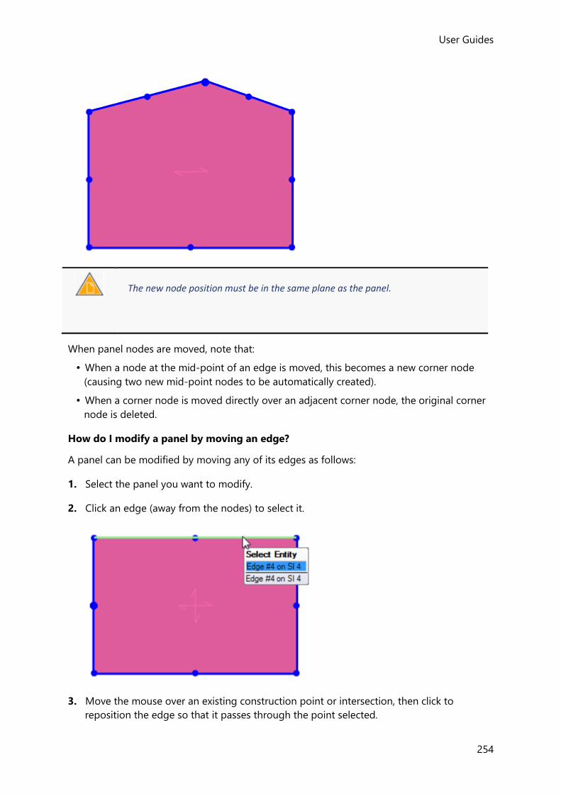
User Guides
254
The new node position must be in the same plane as the panel.
When panel nodes are moved, note that:
• When a node at the mid-point of an edge is moved, this becomes a new corner node
(causing two new mid-point nodes to be automatically created).
• When a corner node is moved directly over an adjacent corner node, the original corner
node is deleted.
How do I modify a panel by moving an edge?
A panel can be modified by moving any of its edges as follows:
1. Select the panel you want to modify.
2. Click an edge (away from the nodes) to select it.
3. Move the mouse over an existing construction point or intersection, then click to
reposition the edge so that it passes through the point selected.

User Guides (US)
255
The new edge position must be in the same plane as the panel.
How do I apply curved edges to existing slab items?
1. Select the slab items you want to modify.
2. To apply the same degree of curvature to all the slab edges:
• Locate the All edges property
• Uncheck Linear
• Enter the Curvature required as a chord offset, specify a positive value to curve
inwards, a negative value to curve outwards.
3. To apply curvature to a specific edge:
• Locate the Edge property (1,2,3 etc.) for the required edge
• Uncheck Linear
• Enter the Curvature required as a chord offset, specify a positive value to curve
inwards, a negative value to curve outwards.
4. The slab panel is redrawn with the specified curvature.
How do I delete an entire slab from my model?
1. Open the Slabs branch of the Structure Tree.
2. Right-click over the Name of the slab you want to delete.
3. Click Delete slab from the context menu which appears.
4. Tekla Structural Designer deletes the entire slab from your model.
Timber member modeling
Timber sections can be modelled and analysed in Tekla Structural Designer.
Individual timber members can be designed to Eurocodes provided you have access to a
Tekla Tedds. This is achieved by right clicking the member and selecting “Design using Tekla
Tedds”.
Tekla Tedds is a separately purchasable product.

User Guides
256
• Design using Tekla Tedds Export
Modeling Timber Columns
How do I create a single timber column in a 2D View?
1. Ensure that you have defined the construction levels between which the column will run
and the grid points between which it will lie.
2. Click Model > Timber Column ( )
3. The column will adopt properties from the currently displayed timber column properties
set.
4. Check that the Base Level and the Top Level shown in the property set are correct, or
adjust if necessary.
5. Check that the other properties shown in the property set are also correct, and again
adjust if necessary.
6. Click the point where the column is to be placed.
(What are the points I can click to create a member?)
How do I create a series of timber columns in a 2D View?
1. Ensure that you have defined the construction levels between which the column will run
and the grid points between which it will lie.
2. Click Model > Timber Column ( )
3. The column will adopt properties from the currently displayed timber column properties
set.
4. Check that the Base Level and the Top Level shown in the property set are correct, or
adjust if necessary.
5. Check that the other properties shown in the property set are also correct, and again
adjust if necessary.
6. Move the cursor to one corner of an imaginary box which will encompass the grid
intersection points at which you want to create columns.
7. Click and hold the left mouse button.
8. Drag to the diametrically opposite corner of the box (you will see a rubber rectangle on
the screen which follows your mouse movements and helps you to check the area in
which you are creating).
9. Once the rubber rectangle encompasses the grid intersection points at which you want
to create columns, release the mouse button.
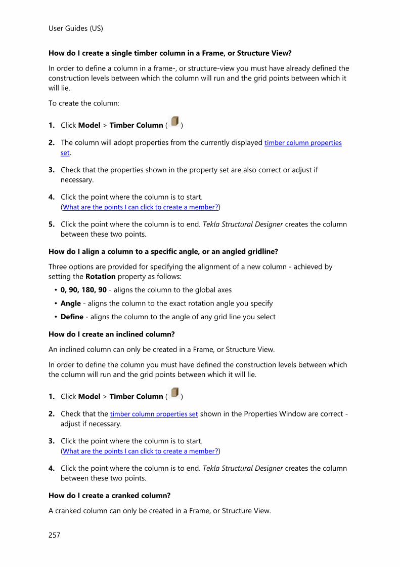
User Guides (US)
257
How do I create a single timber column in a Frame, or Structure View?
In order to define a column in a frame-, or structure-view you must have already defined the
construction levels between which the column will run and the grid points between which it
will lie.
To create the column:
1. Click Model > Timber Column ( )
2. The column will adopt properties from the currently displayed timber column properties
set.
3. Check that the properties shown in the property set are also correct or adjust if
necessary.
4. Click the point where the column is to start.
(What are the points I can click to create a member?)
5. Click the point where the column is to end. Tekla Structural Designer creates the column
between these two points.
How do I align a column to a specific angle, or an angled gridline?
Three options are provided for specifying the alignment of a new column - achieved by
setting the Rotation property as follows:
• 0, 90, 180, 90 - aligns the column to the global axes
• Angle - aligns the column to the exact rotation angle you specify
• Define - aligns the column to the angle of any grid line you select
How do I create an inclined column?
An inclined column can only be created in a Frame, or Structure View.
In order to define the column you must have defined the construction levels between which
the column will run and the grid points between which it will lie.
1. Click Model > Timber Column ( )
2. Check that the timber column properties set shown in the Properties Window are correct -
adjust if necessary.
3. Click the point where the column is to start.
(What are the points I can click to create a member?)
4. Click the point where the column is to end. Tekla Structural Designer creates the column
between these two points.
How do I create a cranked column?
A cranked column can only be created in a Frame, or Structure View.

User Guides
258
In order to define the column you must have defined the construction levels between which
the column will run and the grid points between which it will lie.
1. Click Model > Timber Column ( )
2. Check that the timber column properties set shown in the Properties Window are correct -
adjust if necessary.
3. Click the point where the column is to start.
4. Press and hold the CTRL key on the keyboard and click the next node of your cranked
column.
5. Repeat step 3 until you have defined the penultimate node of your cranked column.
Release the CTRL key and click the point where the column is to end.
How do I modify the position of a single column stack?
A column stack’s position can best be modified in either a Frame, or Structure View.
1. In Scene Content, ensure that the Grid & Construction Lines box is checked.
2. Select the column for which a stack is to be moved.
The column is highlighted in one color, the column end nodes and middle node in
another.
3. Select one end nodes for the column stack to be moved. (Ensure the node is highlighted
in the Select Entity tooltip when selecting, as opposed to one of the members
connecting to the node.)
4. Click a grid or construction point to redefine the column stack end node position.
The entire column is redrawn with the selected node moved to the new position.
5. Select the next end node. (Ensure the node is highlighted in the Select Entity
tooltip when selecting, as opposed to one of the members connecting to the node.)
6. Click a grid or construction point to redefine the end node position.
The column is redrawn once more with the selected node moved to the new position.
How do I modify the position of an entire column?
Simply use the Move command located on the Edit ribbon.
Modeling Timber Beams
How do I create a single span timber beam?
User Guides (US)
259
1. Click Model > Timber Beam ( )
2. The beam will adopt properties from the currently displayed timber beam properties set.
Review the property set and adjust as necessary.
3. Click where the beam is to start (Point 1).
(What are the points I can click to create a member?)
If you are using a point along a member, then click the member first to see its points, then either click the point you want to use, or type the distance to the point from the start of the member.
4. Click where the beam is to end (Point 2).
If you are prompted to pick another point (Point 3), this will be due to Continuous being selected in the beam property set. In order to create a single span beam simply click once again on Point 2, or press the Enter key.
How do I create a series of single span timber beams?
In order to create beams using this method the floor or construction level must already
contain the columns between which the beams will run. You must also use a 2D view of the
floor or construction level to use this option.
1. Click Model > Timber Beam ( )
2. The beams will adopt their properties from the currently displayed timber beam properties
set. Review the properties and adjust as necessary.
3. Move the cursor to one corner of an imaginary box which will encompass the columns
between which you want to create beams.
4. Click and hold the left mouse button.
5. Drag to the diametrically opposite corner of the box (you will see a rubber rectangle on
the screen which follows your mouse movements and helps you to check the area in
which you are creating).
6. Once the rubber rectangle encompasses the columns between which you want beams
creating, release the mouse button.
7. Beams are created between each adjacent pair of columns within the area you select.
How do I create a continuous timber beam?

User Guides
260
1. Click Model > Timber Beam ( )
2. The beam will adopt its properties from the currently displayed timber beam properties
set; ensure that the Continuous option is selected and adjust any other details as
necessary.
3. Click where the beam is to start.
(What are the points I can click to create a member?)
If you are using a point along a member, then click the member first to see its points, then either click the point you want to use, or type the distance to the point from the start of the member.
4. Click the next node of your continuous beam.
If you are using a point along a beam or member, then click the beam or member first to see its points, then either click the point you want to use, or type the distance to the point from the start of the beam.
5. Repeat step 4 until you have defined the penultimate node of your continuous beam.
6. Click where the beam is to end.
7. You are now prompted to pick another point, simply click once again on the same point,
or press the Enter key in order to create the continuous beam.
You cannot define continuous beams which are curved either horizontally or vertically.
How do I create a curved timber beam?
1. Click Model > Timber Beam ( )
2. The beam will adopt its properties from the currently displayed timber beam properties
set; ensure that the Linearity is set to Curved Major (if it is to curve vertically), or Curved
Minor (if it is to curve horizontally), and an appropriate Chord height value is specified
to define the curve.

User Guides (US)
261
You can control the direction in which horizontally curved beams curve. When you place the beam you select its start point and its end point. The beam always curves such that if you were to look along the theoretical line from the start point to the end point, then the curve on the beam will always lie to the right of that line.
For vertically curved beams, a negative chord height value can be used to reverse the curve direction.
3. Adjust any other details in the property set as necessary.
4. Click where the beam is to start (Point 1).
(What are the points I can click to create a member?)
If you are using a point along a member, then click the member first to see its points, then either click the point you want to use, or type the distance to the point from the start of the member.
5. Click where the beam is to end (Point 2).
When defining beams which curve vertically, if you are using a 2D view of the floor or construction level, then the vertical projection of the beam is out of the plane of the floor or construction level that you are using. In this case you will not see the beam on the graphical display. You will need to change to a 3D view of the floor, construction level or the entire Structure in order to see them.
Horizontally curved beams always take the chord height defined in the property set, they do not curve automatically to fit on any curved grid line that you may have defined.
How do I modify the position of a beam?
You can modify an individual beam’s position in both 2D and 3D views.
1. Select the beam to be moved.
The beam is highlighted in one color, the beam end nodes and middle node in another.
2. Now select the beam end node that is to be moved. (Ensure the node is highlighted in
the Select Entity tooltip when selecting, as opposed to one of the members connecting
to the node.)
3. Click a grid or construction point to redefine the beam end node position.

User Guides
262
The beam is redrawn spanning to the new end position.
Modeling Timber Braces
Tekla Structural Designer allows you to define braces to provide lateral stability to your
structure. Alternatively you can specify rigid frames to achieve the same effect. You can also
use both methods within a single structure should this be necessary.
How do I create a single timber brace?
1. Click Model > Timber Brace ( )
2. The brace will adopt properties from the currently displayed timber brace properties set.
Review the property set and adjust as necessary.
3. Click where the brace is to start (Point 1).
(What are the points I can click to create a member?)
If you are using a point along a member, then click the member first to see its points, then either click the point you want to use, or type the distance to the point from the start of the member.
4. Click where the brace is to end (Point 2).
A and V Braces should be modeled using special tools which can be found on the '’Timber Brace' drop list in the 'Timber' section on the 'Model' tab.
Although it is also possible to model the exact same brace arrangement using individual elements created using the simple 'Timber Brace' command, it is important to note that whilst the EHFs (Equivalent Horizontal Forces) calculated for models built using the A or V Brace tools are correct, this is not the case when the A or V braces are built up out of individual brace members. In this latter case, elements of the vertical loads that are supported by the bracing system are 'lost' and are not included in the EHF calculations with the result that the calculated EHFs are not correct.
How do I create an X, K, V or A brace?
1. Click Model, then from the drop list select the pattern required (X, K,
V, or A).

User Guides (US)
263
2. The braces will adopt their properties from the currently displayed timber brace properties
set. Review the properties and adjust as necessary.
3. Click to identify the bottom corner of the bay to be braced, (Point 1).
4. Click to identify the opposite bottom corner of the bay to be braced, (Point 2).
5. Click to identify the top corner of the bay to be braced, (Point 3). You will see a rubber
rectangle on the screen which follows your mouse movements and helps you to check
the orientation is correct.
6. Click to identify the opposite top corner of the bay to be braced, (Point 4).
7. The brace pattern is created within the area you have selected.
How do I modify the position of a brace?
You can modify an individual brace’s position in both 2D and 3D views.
1. Select the brace to be moved.
The brace is highlighted in one color, the brace end nodes in another.
2. Now select the end node that is to be moved. (Ensure the node is highlighted in the
Select Entity tooltip when selecting, as opposed to one of the members connecting to
the node.)
3. Click a grid or construction point to redefine the brace end node position.
The brace is redrawn spanning to the new end position.
Modeling Timber Trusses
Trusses are particular arrangements of members which Tekla Structural Designer calculates
automatically for you. Once you have created a truss you can copy this throughout your
model as necessary, and you can pick a truss and move it to the location you require.
How do I use the Timber Truss Wizard?
1. Click Model > Timber Truss ( )
2. Choose the truss shape from the list of standard truss patterns.
3. Click the truss Start Point.
(What are the points I can click to create a member?)
If you are using a point along a member, then click the member first to see its points, then either click the point you want to use, or type the distance to the point from the start of the member.
User Guides
264
4. Click the truss End Point, then click Next
5. Specify the truss alignment parameters, then click Next
6. Specify the truss details, then click Finish
How do I use the Timber Space Truss Wizard?
1. Click Model > drop list.
2. Select Space from the drop list.
3. Choose either a linear or planar truss type and then specify the alignment and number of
bays, then click Next
4. In the 2D or 3D View, click the truss location points:
• for a linear truss - click the start and end points
• for a planar truss - click the four corners,
5. Specify the height, then click Next
6. Define either a straight or curved truss geometry then click Finish
7. Specify the truss alignment parameters, then click Next
8. Specify the truss details, then click Finish
How do I define a Free Form Timber Truss?
A free form timber truss can be created by placing a series of truss members in the shape
required.
1. Open a 2D Frame view in which the truss is to be created. (Note that free form trusses
cannot be created in a 3D view, or 2D level view).
2. Click Model > drop list.
3. Select Free Form from the drop list.
4. Click where the first truss member is to start.
5. Click where the first truss member is to end.
6. Continue in the same way to pace each truss member until the truss geometry is
complete.
7. Press <Esc> to finish.

User Guides (US)
265
How do I edit the geometry of an existing timber truss?
1. Hover the cursor over the truss to be edited so that it becomes highlighted.
2. Right-click and select ... from the dropdown menu.
The Truss Wizard is displayed.
3. Edit the properties as required and then click OK
How do I edit the section sizes, material grades and section orientations in an existing
timber truss?
1. Hover the cursor over the truss to be edited so that it becomes highlighted.
2. Left click the truss to display the edit timber truss properties. Review the property set,
adjust as necessary and then click OK
Panel modeling
Topics listed here relate specifically to modeling each of the different panel types found on
the Model tab.
Modeling Roof Panels
Roofs are the medium via which loads placed on a sloping plane are decomposed back to
the supporting structure. Area loads on roofs can act either vertically or normal to the roof
plane.
How do I create a roof panel?
In order to define a roof panel you must have already defined the grid points with which to
define its outline, and you must identify these in order.
To create the roof panel:
1. Click Model > Roof Panel ( )
2. Click the grid point where the panel is to start.
3. Click the grid point which identifies the next vertex of the panel.
4. Continue to click the grid points which define the perimeter of your panel until you reach
the final point. You now have two options:
• either double click this final point,
• or single click the final point, and then click the first point of the panel again.
5. Tekla Structural Designer will create a roof panel between the points that you identified.

User Guides
266
You cannot define a roof panel which does not lie in a single plane. If the points you
define do not so lie, then Tekla Structural Designer will fail the panel during validation.
How do I edit the properties of a roof panel?
You can edit roof panel properties in both 2D and 3D Views.
1. Hover the cursor over the panel to be edited so that it becomes highlighted.
2. Left click to select it.
The selected Roof panel properties are displayed in the Properties Window.
If required, at this point you can add further roof panels to the current selection by
holding the Ctrl key whilst clicking on each subsequent panel.
3. Edit these properties as required. Any changes are automatically applied to all the
selected panels.
Modeling Wall Panels
Wall panels (also referred to as Wind Walls) are the medium via which loads calculated by
the Simple Wind Loading generator and Wind Wizard are applied to your structure. Wall
panels do not introduce any structural strength or stiffness of any kind to your structure. If
you wish to introduce walls that resist gravity or lateral loads then you must model these by
defining them as concrete walls.
How do I create a wall panel?
In order to define a wall panel you must have already defined the grid points which define
the panel vertices, and you must identify these in order.
To create the wall panel:
1. Click Model > Wall Panel ( )
2. Click the grid point where the panel is to start.
3. Click the grid point which identifies the next vertex of the panel.
4. Continue to click the grid points which define the perimeter of your panel until you reach
the final point. You now have two options:
• either double click this final point,
• or single click the final point, and then click the first point of the panel again.
User Guides (US)
267
The minimum number of grid points to define a wall panel is 3.
5. Tekla Structural Designer will create a wall panel between the points that you identified.
You cannot define a wall panel which does not lie in a single plane. If the points you
define do not so lie, then Tekla Structural Designer will fail the panel during validation.
How do I edit the properties of a wall panel?
You can edit wall panel properties in both 2D and 3D Views.
1. Hover the cursor over the panel to be edited so that it becomes highlighted.
2. Left click to select it.
The selected Wall panel properties are displayed in the Properties Window.
If required, at this point you can add further wall panels to the current selection by
holding the Ctrl key whilst clicking on each subsequent panel.
3. Edit these properties as required. Any changes are automatically applied to all the
selected panels.
How do I create a wall panel with a parapet?
A wall panel with a parapet should be modeled in two parts:
• An ordinary wall panel is created up to the roof level.
• A second wall panel is created above the roof level which is then marked as a parapet.
Modeling in this way ensures the wind analysis correctly accounts for the parapet.
To create the two parts of the wall panel:
1. Open a Frame view in which the wall can be created.
2. Create the wall panel below the roof level as an ordinary wall panel.
3. Create the wall panel above the roof level as an ordinary wall panel. (A construction level
may be required to define the top level of the parapet.)
To mark the upper wall panel as a parapet:
1. To ensure no existing wall panels are currently selected, press the ESC key.
2. Hover the cursor over the panel to be edited so that it becomes highlighted.

User Guides
268
3. Left click to select it.
The selected Wall panel properties are displayed in the Properties Window.
4. In the Properties Window select the check box to indicate the panel is a parapet wall.
How do I reverse a wall panel?
Wall panels are generally created so as to have their outer faces automatically pointing
outwards. For certain complex building geometries, it may occasionally be necessary to alter
the inner and outer face of the panel. Should this be necessary it is achieved using the
Reverse option.
1. Click Model > Reverse ( ) (in the Edit group).
2. Click the wall panel to be reversed.
The selected panel changes color to indicate it has been reversed.
Support, Analysis Element and Bearing Wall modeling
Modeling Supports
Supports allow you to constrain points in your structure vertically and rotationally. You can
use supports to model connections to existing structures, so that you don’t need to
incorporate these in your current model. The fixity provided at an existing support can be
changed by modifying the Support properties.
How do I create a single support?
Supports can only be placed at existing grid points.
To create the support:
1. Click Model > Support ( )
2. The support will adopt properties from the currently displayed Support properties. Review
the property set and adjust as necessary.
3. Click the grid point where you want to create the support.
How do I create a rotated support using 3 Grid Points?
A local coordinate system can be applied to your supports, allowing the X and Y axes to be
rotated about global Z.
1. Click Model > Support ( )
2. Before placing the support, ensure that the 3 Grid Points option is selected in the
Support properties.

User Guides (US)
269
3. Click the grid point where you want to create the support, then to define the support
direction click a second point (to define the x direction) and click a third point (to define
the y direction). Note that the z direction cannot be changed.
How do I create a spring support?
Linear and non linear supports are both created in a similar fashion.
1. Click Model > Support ( )
2. Before placing the support, edit its properties as follows:
• Ensure that in the direction the spring is required to act, the degree of freedom is set
to Free
• Enter the stiffness properties as described in the Support properties.
3. Click the grid point where you want to create the support.
How do I edit the properties of supports?
You can edit support properties in both 2D and 3D views.
1. Hover the cursor over the support to be edited so that it becomes highlighted.
2. Left click to select it.
The selected support’s Support properties are displayed in the Properties Window.
If required, at this point you can add further supports to the current selection by holding
the Ctrl key whilst clicking on each subsequent support.
3. Edit these properties as required. Any changes are automatically applied to all the
selected supports.
Modeling Analysis Elements
How do I create an analysis element?
1. Click Model > Element ( )
2. The member will adopt properties from the currently displayed Element properties. Review
the property set and adjust as necessary.
3. Click where the member is to start (Point 1).
(What are the points I can click to create a member?)
User Guides
270
If you are using a point along a member, then click the member first to see its points, then either click the point you want to use, or type the distance to the point from the start of the member.
4. Click where the member is to end (Point 2).
How do I modify the position of an analysis element?
You can modify an individual analysis element’s position in both 2D and 3D views.
1. Select the element to be moved.
The element is highlighted in one color, the end nodes and middle node in another.
2. Now select the element end node that is to be moved. (Ensure the node is highlighted in
the Select Entity tooltip when selecting, as opposed to any other member/element
connecting to the node.)
3. Click a grid or construction point to redefine the element end node position.
The analysis element is redrawn spanning to the new end position.
Modeling Bearing Walls
Bearing wall overview
Bearing Walls are used to provide resistance to vertical compressive loads (but not lateral
loads) and to support certain other member types. Unreinforced masonry walls, for example,
could be modelled as bearing walls.
Bearing Walls can be created over several story heights. A single wall is created with a
uniform thickness between the base and top level.
The location of the wall is a determined from the alignment specified in the bearing wall
properties, and the insertion points picked.
Bearing Walls do not perform the same function as Wall Panels, i.e. they do not act as a
medium via which loads calculated by the Wind Wizard get applied to your structure.
Therefore, in order for these wind loads to be applied you should create additional Wall
Panels in the same physical locations as the Bearing Walls.
How do I create a bearing wall in a 2D View?
1. Ensure that you have defined the construction levels between which the wall will run and
the grid points between which it will lie.

User Guides (US)
271
2. Click Model > Bearing Wall ( )
3. The wall will adopt properties from the Bearing wall properties set displayed in the
Properties Window.
4. Check that the Base Level and the Top Level shown in the property set are correct, or
adjust if necessary.
5. Check that the Thickness and other properties shown in the property set are also
correct, and again adjust if necessary.
6. Click where the wall is to start (Point 1).
(What are the points I can click to create a member?)
7. Click where the wall is to end (Point 2).
Tekla Structural Designer creates the wall between the points clicked on.
How do I create a bearing wall in a Frame, or Structure View?
In order to define a wall in a frame-, or structure-view you must have already defined the
construction levels between which the wall will run and the grid points between which it will
lie.
To create the wall:
1. Click Model > Bearing Wall ( )
2. The wall will adopt its properties from the Bearing Wall properties displayed in the
Properties Window.
3. Check that the Thickness and other properties shown in the property set are also
correct, and again adjust if necessary.
4. Click the first corner of the wall.
5. Either click:
• the opposite corner of the wall to create it in a single click, or
• the adjacent, and then the opposite corner of the wall to create it in using two clicks
Tekla Structural Designer creates the wall between the points clicked on.
User Defined Attributes (UDAs)
User defined attributes (UDAs) can be defined to save miscellaneous data to individual
members and panels.
UDAs are flexible and can be used for a variety of purposes, for example:
• to apply descriptive labels, such as construction phases,

User Guides
272
• to record paint specifications,
• to attach office documents, pictures, or any other associated files,
• to link to design files from other applications,
• to select members/panels according to their UDA (from the Project Workspace Groups
tree).
When a file is attached as an attribute, you are given the option to embed it within the Tekla
Structural Designer file. When embedded, the attached file gets included when the model is
transferred to another computer.
The embedded file only gets attached when the model is saved using Save or Saves As. Embedded files are not attached when you use Save Model Only. Similarly if you have to revert to an autosaved version of the model this will not have the embedded files attached.
Material lists and member design reports can be filtered for specific UDAs.
UDAs are transferred when models are exported to Tekla Structures and Revit. In the current
release UDAs are not yet included on Tekla Structural Designer drawings.
UDA definitions and values
Example UDA definitions have been included in the default settings sets. These are fully
customizable and can easily be edited to suit your needs. The definitions that apply to the
current model can be edited via Model Settings.
A specific UDA value is attached by selecting the members to which it applies and entering
the value required into the UDA area of the Properties Window.
Once a UDA value exists it can also be assigned to members graphically (or removed from
them) using the Review View.
User Defined Attribute definition
UDAs are defined on the User Defined Attributes page of either the Model Settings dialog,
or the Settings dialog, (according to whether they are to be applied to the current model, or
new models).
To add a UDA definition you must click Add to create a new blank row in the table, then
specify the following parameters:
• Name - e.g. Class, Note, Phase, File etc.
• Type - Text, Number, or File
• Source - Custom value, or Value List
• Values - these are the listed value choices that apply when the source is Value List

User Guides (US)
273
The order in which UDAs are listed in the Properties Window replicates the order in which the Attributes are listed in the Model Settings dialog. The Move Up and Move Down buttons can be used to reorder as required.
How do I set up UDA definitions for new models?
User Defined Attribute definitions are held in the settings sets. The “active” settings set
contains the attribute definitions that are applied when a new model is created.
1. Click Home > Settings ( )
2. On the Settings Sets page select the settings set to which the UDA apply.
3. On the User Defined Attributes Settings page define the attributes as required.
How do I set up UDA definitions in the current model?
The User Defined Attributes that are available to the current model are held in the Model
Settings.
1. Click Home > Model Settings ( )
2. On the User Defined Attributes Settingspage define the attributes as required.
Attaching UDA values to members and panels
How do I attach a UDA value using the Properties Window?
1. Select the members/panels to which the attributes are to be attached.
2. If the selection consists different member types, use the droplist at the top of the
Properties Window to display the properties of the first type.
3. Under the UDA heading in the Properties Window, define the value for each attribute
that you want to attach.
4. If the attribute being attached is a file, select Embedded on the dialog if you want the
file to be saved inside the model data file. Only embedded files are automatically
transferred when the model is copied to another computer.
For multi-span beams, and multi-stack columns/walls you can attach separate UDAs to individual spans/stacks as required.
5. If there are additional member types in the current selection, use the droplist at the top
of the Properties Window to display the properties of the next type and then define the
attribute values once again.
User Guides
274
How do I attach an existing UDA value in the Review View?
1. Click Review > UDA
2. In the Properties Window, select the relevant attribute.
3. For the Review/Update property, choose Update Selected.
4. Use the droplist to select one of the existing values for the selected attribute.
5. Choose the Selection Mode (Only Add, Only Remove, Add or Remove).
6. Click individual members, (or drag a box around multiple members) to add/remove the
UDA value.
When the Selection mode is “Add or Remove” the UDA will toggle between being attached /not attached when you click a member or box around multiple members
Two additional check boxes are provided in the Properties Window to assist in the above
process:
• Filter by Value - hides everything apart from those members which have the current
UDA value.
• Use other Value Color - displays members that have an “other value” of the selected
attribute in a different color. Those members that don’t have the attribute attached are
displayed in a “not set” color.
How do I graphically review the UDA values that have been attached?
1. Click Review > UDA
2. In the Properties Window, select the attribute to review.
3. In the Properties Window, for the Review/Update property select Review All.
The members/panels are color coded for to represent the different values of the selected
attribute and a legend is displayed.
How do I open a file that has been attached as a UDA?
1. Click Review > UDA
2. In the Properties Window, select the attribute to review.
3. In the Properties Window, for the Review/Update property select Review All.
4. Click the member or panel that has the file attached.
Provided the file extension has been associated with an application, the application
should open and display the file.

User Guides (US)
275
Selection by UDA
To select members/panels by UDA name or value:
1. From the Project Workspace Groups tab, open the User Defined Attributes branch.
2. Right-click on the UDA name or value and choose Select in visible views.
3. All members in the model with the specified UDA are selected.
Using UDAs to filter reports and material lists
How do I apply a Selected UDAs filter to Material List Review Data?
1. Click Review > Tabular Data
2. From the drop list on the View Type toolbar group to choose Material List.
3. From the Type drop list on the Filter toolbar group to choose Selected UDAs.
4. From the Item drop list on the Filter toolbar group to choose the required UDA values,
then click OK.
How do I apply a Selected UDAs filter to a report?
1. Click Report> Model Report...
2. Select the report from the list of Available Styles.
3. In the Report Structure, right-click the chapter or sub-heading to be filtered.
4. From the context menu, choose Model Filter > Edit\New...
5. In the Select Filter dialog, click Add
6. In the Filter properties, choose the Selected UDAs type
7. Choose the UDA values on the selected items list.
8. Click OK.
Sub Models

User Guides
276
Structures can if required be sub-divided by horizontal planes between levels in order to
create sub-models. Each sub-model can then be used to control the slab mesh parameters at
the levels within it.
Until further sub-models have been introduced a structure will initially be treated as a single
sub model, so that the same mesh parameters are applied globally to all meshed slabs.
Additional sub-models are created automatically (for every level specified as a Floor in the
Construction Levels dialog) when either a Grillage chasedown or FE chasedown analysis is
performed. They can also be defined manually from the Sub Models dialog.
The slab mesh parameters specified for a sub-model are then used in any analysis that
requires the slabs to be meshed (i.e. load decomposition, building analysis with meshed
floors, or FE chasedown analysis).
In both grillage and FE chasedown the analyses are performed one sub-model at a time. The
topmost sub-model is analyzed first, its support reactions are then applied as loads for the
analysis of the sub-model below. This sequence continues until all sub-models down to the
foundation level have been analyzed.
For both of these analysis types you can if required edit the default support conditions
applied to the sub-models.
Sub Model Characteristics
Definitions
The following definitions are applied:
• Sub-model - part of the 3D model between two horizontal sub model divide planes. Each
sub model contains all members entirely between the two horizontal planes. For those
columns, wall and braces severed by a divide plane, the stacks and brace length above
the top plane are included in the sub-model as are the stacks and brace length below the
lower plane.
• Sub-model divide planes - are horizontal planes that can be positioned (added, deleted
or moved) in the 3D structure. These sub-model divide planes are notional and infinite.
They are only permitted to cut through the structure where they only “sever”
• Column stacks
• Walls stacks
• Steel Braces
• Sub model supports - the “artificial” supports as defined by the system for the column
and wall stack ends and braces that pass through the divide planes
• Structure supports - the supports in the 3D structure as defined by the user
• Column and Wall stacks - the span length of a column or wall
• The volume of the sub-model - the 3D space that exists between any two adjacent sub-
model divide planes
Basic rules of sub-models

User Guides (US)
277
There are a number of basic rules to assist understanding of sub-models.
All sub-models when considered together form the complete structure - only some column
stacks, some wall stacks and some braces (those split by sub-model divide planes) are in
more than one sub-model. So:
• Every member in the 3D model is in at least one sub-model.
• A sub-model cannot contain a member already in a sub-model unless that member is a
column, wall or brace divided by a sub-model divide plane.
• A sub-model must contain at least one beam member, one truss member or one slab
panel.
Sub Models dialog
This dialog is accessed from the Structure Tree. It is used to split the structure into a
continuous series of sub-models, working from the top of the building down to and
including the foundations.
Fields
Level
Initially (before any analysis has been performed) only be two levels are displayed, one at
a set distance (2m) above the top construction level and a second at the same distance
below the base level. These cannot be changed. At this point there is a single sub-model
comprising the whole structure.
Active
Only active levels act to divide the structure into sub-models. The top and bottom levels
must always remain active, as there must always be at least one sub model.
Once intermediate levels have been inserted, you can choose to inactivate them if
required, in which case the sub-model immediately above and the sub-model
immediately below the level in question are merged into a single sub-model.
Auto Generate
If you have made any adjustments to the cutting planes, or cutting plane levels, or made
any of them inactive you must also clear Auto-Generate - otherwise the changes you
have made will be lost the next time the sub models are generated.

User Guides
278
Buttons
Click this button to insert a new level between the selected level and the
one above. It defaults to being exactly half way between them but can be edited
manually, provided it remains between the two.
Click this button to insert a new level between the selected level and the
one below. It defaults to being exactly half way between them but can be edited
manually, provided it remains between the two.
Deletes the selected level.
This button can optionally be used to auto-generate default sub models
for every level specified as a Floor in the Construction Levels dialog. You may choose to
do this if you want to review the sub models prior to the first run of the analysis. It is
optional as default sub models will be generated for you automatically when you run the
analysis (provided the Auto Generate box on the dialog is checked). The Generate button
can also be used to revert back to the default sub models at any time.
If you have made any adjustments to the cutting planes, cutting plane levels, or made any of them inactive you should avoid clicking the Generate button (even if the Auto Generate box is cleared) - as you will lose the edits that you have made.
Working with Sub Models
How do I open the Sub Models dialog?
To open from the Structure Tree:
• Double-click
To open from the ribbon:
• Click Model > Sub Models ( )
How do I create Sub Models?
1. In the Sub Models dialog click Generate to automatically create the sub model levels,
alternatively click Insert Above and/or Insert Below to manually create them.
2. For each new level if necessary modify the height above the base in the Level field.
How do I delete Sub Models?
1. In the Sub Models dialog select the sub model level to be removed then click Delete
2. Click OK to close the dialog.

User Guides (US)
279
How do I open a 3D view of an existing Sub Model?
1. In the Project Workspace, expand the Sub Models branch of the Structure Tree, then:
2. Double click a sub model
(or right-click it to open a view of a particular type).
Sub Structures
If required, you can choose to place collections of elements into named sub-structures. This
can prove useful in large models as individual sub-structures can then be differentiated by
color and worked on in separate sub-structure views.
The purpose of sub structures is primarily to simplify modelling visualisation - the sub structures themselves are never analysed. They are distinct from, and not to be confused with Sub Models.
Sub Structure Characteristics
The basic features of sub structures are:
• Elements can exist in more than one sub structure.
• Not every element has to be in a sub-structure.
• Deleting a sub-structure does not delete the elements within it.
Working with Sub Structures
How do I create a new sub structure?
1. On the status bar, click Review View
2. Click Review > Sub Structures
3. In the Review/Update dialog box in the Properties Window select Update Selected
4. In the Update Sub Structure dialog box select --New--.
5. In the Name dialog box enter a name for the sub structure.
6. Choose a color for the substructure.
7. In the Review View click or box around the members to be included in the sub structure.
8. Change the Selection Mode to only Remove, or Add or Remove) if you need to remove
members from the sub structure.

User Guides
280
How do I add or remove existing elements in an existing sub structure?
1. On the status bar, click Review View
2. Click Review > Sub Structures
3. In the Review/Update dialog box in the Properties Window select Update Selected
4. In the Update Sub Structure dialog box select the sub structure to edit.
5. In the Selection Mode dialog box choose the edit operation required.
6. In the Review View click or box around the members to be edited.
How do I review all existing sub structures?
1. On the status bar, click Review View
2. Click Review > Sub Structures
3. In the Review/Update dialog box in the Properties Window select Review All
Each sub structure is shown in a different color in the display.
How do I open a 3D view of an existing sub structure?
1. In the Project Workspace, expand the Sub Structures branch of the Structure Tree, then:
2. Double click a sub structure
(or right-click it to open a view of a particular type).
Measure commands
How do I Measure distances?
To measure the distance between any two points in the model:
1. Click Model > Measure ( )
2. Pick a node to define the start position.
3. Pick a second node to measure to.
The distance between the nodes is displayed on the current view - to clear the measurement
press [Esc].

User Guides (US)
281
How do I Measure Angles?
You can only measure angles in 2D Views:
1. Click Model > Measure Angle ( )
2. Pick a node to define the arc center.
3. Pick a second node to define the start position.
4. Pick a third node to define the end position.
The clockwise angle between the start and end position is displayed on the current view - to
clear the measurement press [Esc].
What are the points I can click to create a member?
Beams, columns, braces, analysis elements etc. are collectively referred to as “members”. In
order to define any of these you must define the points between which they will lie.
The points that you click can be any combination of:
Point Note

User Guides
282
grid or construction points,
To pick a grid or construction point that lies part way along, or at the end of an existing member; simply move the cursor along the member to the point required.
The dialog displays:
• CP when it finds a grid or construction point at the
end of a member.
• Inters when it finds a grid or construction point part
way along a member
To specifically use one or other of these points, press the down cursor key until the correct point is highlighted (as shown above) in the dialog.
standard points on elements which you have already defined,
Position the cursor over an existing element and the standard points will automatically appear along it. These are at 0.250, 0.333, 0.500, 0.667, 0.750 of the span of the element.

User Guides (US)
283
special points on elements which you have already defined,
Special points are created automatically and allow you to create a member which is:
• perpendicular to the first element that you picked,
• perpendicular to the second element that you picked,
• perpendicular to the X axis (that is whose ends lie at the same X distance from the origin of your model),
• perpendicular to the Y axis (that is whose ends lie at the same Y distance from the origin of your model).
Having picked the first point at the end of an existing element, to use one of these special points position the cursor over the second existing element and a dotted line indicates the perpendicular standard point location.
a point at a specific distance (whose value you enter directly) along a member.
To pick a point at a specific distance, simply move the cursor along the element to the point required and click to specify it.
You can zoom in to achieve finer accuracy when moving along the element.
Alternatively, by pressing <F2> you can type the exact distance directly and then press <Enter> to use it.
This option creates a grid intersection point over the top of the element. If you want to use the point again, then you can pick it as any other grid intersection point. Please note that this option does not create a new point along the element.

User Guides
284
Model Validation
Your structure should be validated before it is analysed and designed. Validation checks all
elements in your structure for a wide range of conditions. If any condition is not satisfied
then Tekla Structural Designer tells you.
Validation is performed automatically whenever a design process is initiated from the Design
ribbon, but it can also be run manually at any time.
The checks that are performed during validation can be set within Validation Settings.
At the end of the validation two types of message could be displayed in the Project
Workspace Status Tree:
Errors
Error messages prevent the analysis from continuing until appropriate corrective action is
taken.
Warnings
Although warning messages do not prevent the analysis process from continuing, it is
very important that these messages are reviewed to decide whether any action is
warranted.
How do I run model validation?
1. On either the Model, or Load tab, click Validate ( )
The validation checks are performed and if any issues exist these are displayed as
warning messages.
How do I control which conditions are considered during model validation?
1. Click Home > Model Settings ( )
2. On the Validation page check the validation conditions to be considered.
Edit commands
The Edit toolbar provides commands to copy, move, mirror and rotate the model (or a part of
it).
It also has commands for splitting, joining, deleting and reversing the direction of members.
Edit toolbar
The Edit toolbar contains the following commands:
Button Description

User Guides (US)
285
Copy
Copies existing selected objects to new locations in the model.
See: Copying, moving and mirroring objects
Copy Loads Copies existing selected loads to new locations or between loadcases.
See: Copy Loads
Move
Moves existing selected objects to new locations in the model.
See: Copying, moving and mirroring objects
Mirror
Make a reflected copy of existing selected objects about a given plane.
See: Copying, moving and mirroring objects
Delete
This command is used to delete items.
Join
Joins members to make a longer continuous member.
See: How do I Join Members (Make Continuous)?
Split
Splits existing continuous members.
See: How do I Split Members?
Reverse
Reverses the front and back faces of a wind wall panel. The front of each wall should be facing outwards in order to correctly determine the wind direction relative to the wall.
Also reverses the local X-axis of a beam. This can be useful for standardizing output.
See: Reversing member axes and panel faces
Beam Lines
Joins existing concrete beams to make a continuous concrete beam.
See: How do I Automatically Join All Concrete Beams (Make Continuous)?
Cutting Planes
Cutting Planes are useful tools for temporarily hiding parts of the model that obscure the area that you require to work on.
By dragging a cutting plane so that it slices through your model everything that is on the positive side of the plane is hidden, leaving only items on the negative side still visible.
See: Cutting Planes

User Guides
286
Move Model
Moves the entire model to a new origin.
See: How do I move the model to a new location?
Rationalize Opens a dialog which allows you to:
• Remove unused sloped planes and frames
• Remove unused grid lines
• Remove unused construction lines
• Update all grid and construction lines to extend exactly 1’8” beyond the point they are required.
See: Rationalizing the model
Move DXF Shadow
Moves the dxf shadow to a new origin.
See: How do I move the dxf shadow?
Create Infills
Creates a pattern of infill members in the selected bay.
See: Creating infill members
Merge Planes Used to merge two closely spaced planes.
See: Merging Planes
XYZ Points... Used to add, move, or delete user points.
See: Adding, moving or deleting XYZ Points
Related topics
• Commands on the ribbon toolbars
Copying, moving and mirroring objects
The Copy, Move and Mirror editing commands only becomes active after you have selected
the objects that you want to edit.
How do I copy elements to a new location?
To copy existing elements to new locations in the model:
1. Select the members to be copied.
2. Click Edit > Copy

User Guides (US)
287
Alternatively you can select Copy from the right-click context menu.
3. In the Copy Elements dialog, you can either choose to clear elements from the set to be
copied (if so required), or leave all elements selected in order to copy the entire selection.
4. Pick the Reference node.
5. In the Properties Window, select Keep Elevation if you want to copy the selected
elements horizontally only (ignoring any difference in the elevation between the
Reference node and the new position); alternatively clear Keep Elevation if you want to
the copied elements to be moved both vertically and horizontally.
6. Pick the new position to move the members to.
7. The selected members are copied to the new location.
How do I copy and rotate elements to a new location?
To copy and rotate existing elements to new locations in the model:
1. Select the members to be copied.
2. Click Edit > Copy
Alternatively you can select Copy from the right-click context menu.
3. In the Copy Elements dialog, you can either choose to clear elements from the set to be
copied (if so required), or leave all elements selected in order to copy the entire selection.
4. In the Properties Window enter the rotation required about the Z axis.
5. Pick the Reference node.
6. In the Properties Window, select Keep Elevation if you want to copy the selected
elements horizontally only (ignoring any difference in the elevation between the
Reference node and the new position); alternatively clear Keep Elevation if you want to
the copied elements to be moved both vertically and horizontally.
7. Pick the new position to move the members to.
8. The selected members are copied to the new location and rotated.
How do I move elements to a new location?

User Guides
288
To move elements to new locations in the model:
1. Select the members to move.
2. Click Edit > Move ( )
3. Pick the Reference node.
4. Pick the new position to move the members to.
5. The selected members are moved to the new location.
How do I move and rotate elements to a new location?
To move and rotate elements to new locations in the model:
1. Select the members to move.
2. Click Edit > Move ( )
3. In the Properties Window enter the rotation required about the Z axis.
4. Pick the Reference node.
5. Pick the new position to move the members to.
6. The selected members are moved and rotated to the new location.
How do I mirror elements to a new location?
To copy existing elements by mirroring them about a specified plane:
1. Select the members to be mirrored.
2. Click Edit > Mirror ( )
3. In the Properties Window select the mirror mode:
• Along Y - mirrors about a global XZ plane defined by a single reference node
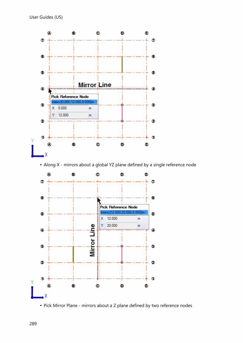
User Guides (US)
289
• Along X - mirrors about a global YZ plane defined by a single reference node
• Pick Mirror Plane - mirrors about a Z plane defined by two reference nodes
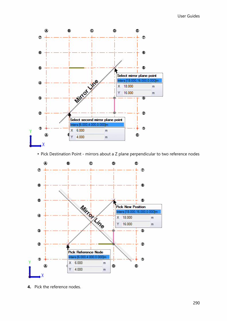
User Guides
290
• Pick Destination Point - mirrors about a Z plane perpendicular to two reference nodes
4. Pick the reference nodes.
User Guides (US)
291
5. The selected members are mirrored about the selected plane.
Copy Loads
The Copy Loads command can be used to copy member, panel and structure loads to
different locations. It can also be used to copy loads between loadcases.
How do I copy all member loads from one span to another?
1. Click Edit > Copy Loads
2. In the Properties Window, select the Copy Span Loading mode.
3. In the Properties Window, choose to either copy loads in Current loadcase or All
loadcases.
• If Current loadcase - you must also select the required loadcase from the Loading
drop list.
A “Select loaded element span” prompt is displayed.
4. Click the span containing the member loads to be copied.
An “Apply loading onto span(s)” prompt is displayed.
5. Click a span that you want to apply the loads to.
The member loads are copied to the chosen span.
The source span and the destination span do not need to be the same length
6. Click additional spans as required to continue applying the loads.
7. Press <Esc> in order to select a different loaded element span to copy from, or press
<Esc> twice to exit the command.
How do I copy just one member load if several are applied to the same span?
1. Click Edit > Copy Loads
2. In the Properties Window, select Copy Member/Area Load mode.
A “Select load to be copied” prompt is displayed.
3. Click the member load to be copied.
An “Apply load copy” prompt is displayed.
4. Click a span that you want to apply the load to.
User Guides
292
The member load is copied to the chosen span.
The source span and the destination span do not need to be the same length
5. Click additional spans as required to continue applying the load.
6. Press <Esc> in order to select a different load to copy, or press <Esc> twice to exit the
command.
How do I copy panel area, level and slab loads?
1. Click Edit > Copy Loads
2. Select the required load case from the Loading drop list.
3. In the Properties Window, select Copy Member/Area Load mode.
A “Select load to be copied” prompt is displayed.
4. Click the Area, Slab or Level load to be copied.
An “Apply load copy” prompt is displayed.
5. Click a panel where the load is to be applied.
The copied load is applied.
6. Click additional panels as required to continue applying the load.
7. Press <Esc> in order to select a different load to copy, or press <Esc> twice to exit the
command.
How do I copy panel point, line and patch loads?
1. Click Edit > Copy Loads
2. Select the required load case from the Loading drop list.
3. In the Properties Window, select Copy Plane Loads mode.
A “Select load to be copied” prompt is displayed.
4. Click the panel point, line or patch load to be copied.
At this point you can add to the selection if required by clicking on additional loads; you
can also remove a load from the selection by clicking on it once more.
A red circle displays the original reference point for the selected loads.
5. To apply the loads either:
User Guides (US)
293
• Click a panel node to define a new reference point at that node - the loads are
applied at the same offset from the new reference point.
• Click anywhere within a panel boundary at a different level to define a new reference
point directly above/below the original reference point - the loads are applied at the
same offset from the new reference point.
If you choose a new reference point that results in the loads being applied outside the panel area, they will not be applied to the model. In this situation a warning will be issued during validation
6. Click as required to define further reference points to continue applying the loads.
7. Press <Esc> in order to select different loads to copy, or press <Esc> twice to exit the
command.
How do I copy structure loads?
1. Click Edit > Copy Loads
2. In the Properties Window, select Copy Member/Area Load mode.
A “Select load to be copied” prompt is displayed.
3. Click the structure load to be copied.
An “Apply load copy” prompt is displayed.
4. Click where you want to apply the load to.
The structure load is copied to the new location.
5. Click additional locations as required to continue applying the load.
6. Press <Esc> in order to select a different load to copy, or press <Esc> twice to exit the
command.
How do I copy loads to another loadcase?
1. Click Edit > Copy Loads
2. Select the loadcase to be copied from using the Loading drop list.
3. In the Properties Window, select Copy Loads to another Loadcase mode.
4. In the Properties Window, select the loadcase to Copy loads to.
A “Select load to be copied” prompt is displayed.
5. Click the load to be copied.
User Guides
294
At this point you can add to the selection if required by clicking on additional loads; you
can also remove a load from the selection by clicking on it once more.
6. To copy the loads to the loadcase displayed in the Properties Window press <Enter>
7. Press <Esc> in order to select a different load to copy, or press <Esc> twice to exit the
command.
Joining and splitting members
The Join and Split commands are used for joining discontinuous members, and splitting
continuous members of any material.
How do I Join Members (Make Continuous)?
Provided that the angle between two similar members is less than 45 degrees in both plan
and elevation, you are able to join them to make a longer continuous member.
The “Join” command can be used to manually join concrete beams, even when the Allow automatic join beam property is cleared. This is because this property only applies to the automatic joining that occurs during design process or when the “Beam Lines” command is run.
1. Click Edit > Join ( )
2. Hover the cursor over the member that is to be joined to another member.
3. Both the original member and the member to which it will be joined become highlighted
and the point at which they will be joined is indicated by a red dot. If the wrong end is
being joined, move the cursor towards the other end of the member until the correct end
is indicated.
The joined beams must have an end point in common. (If beams fail to join, they have probably been defined using different grid or construction lines at the end point in question).
4. Click the highlighted members to join them.
5. Pick additional members to join as required, or press <Esc> when complete.
How do I Split Members?
Members that have previously been joined can be split if required.
1. Click Edit > Split ( )
2. Hover the cursor over previously joined members that you want to split.
User Guides (US)
295
3. The member is highlighted and the point where it will be split is indicated by a red dot.
Only those members that are valid for splitting are highlighted when you hover the cursor over them.
4. Click the member to split it at the point indicated, or move the cursor further along the
member to identify other points at which it could be split.
If the member being split is a concrete beam, it is split into two separate beams; the first
one having the Allow automatic join end 2 beam property cleared, the second one
having the Allow automatic join end 1 beam property cleared. This prevents the two
beams from being automatically made continuous once again when the model is
designed.
Concrete Beam Lines
Concrete beam lines are formed automatically as part of the combined analysis and design
process. However, if you would prefer to have greater control, you can choose to run the
Beam Lines command manually. In this way you can verify that continuous beam lines are
formed as you intend before proceeding with the design.
When run manually, the Beam Lines command is applied to all concrete beam members in
the model, irrespective of whether they are selected or not.
Discontinuous concrete beam ends can only be joined if the Allow automatic join beam
property is checked for the appropriate beam ends at the join.
The ends will then only be joined if all the following criteria are met:
• the angle in plan at which the two beams meet is less than the Limiting join angle in
plan specified in Model Settings > Beam Lines,
• the angle in elevation at which the two beams meet is less than the Limiting join angle
in elevation specified in Model Settings > Beam Lines,
• the amount by which the cross sectional areas of the two beams overlap is greater than
the Minimum section overlap percentage specified in Model Settings > Beam Lines.
In addition, if either of the two beam ends being joined is pinned, they will not be joined
unless the Join pinned beam end box is checked in Model Settings > Beam Lines.
How do I Automatically Join All Concrete Beams (Make Continuous)?
1. Click Edit > Beam Lines ( )
Reversing member axes and panel faces
How do I reverse the local x axis of a beam?
User Guides
296
You can easily end up with beams running forwards and backwards if a consistent approach
has not adopted during model creation when clicking on start and end nodes. This can result
in confusing force diagrams in printed output.
The Reverse command can be used to manually standardize by flipping axes one beam at a
time. In this way it is possible to force all beams to run left to right and bottom to top of a
plan view.
To reverse a beam:
1. Click Edit > Reverse ( )
2. Click a beam to reverse its direction.
How do I reverse the outward face of a wind panel?
The front of each wall should be facing outwards in order to correctly determine the wind
direction relative to the wall. To check this is the case, ensure that all the outward faces are
displayed in the color assigned to “Wind Wall - Front”. If a wall is facing in the wrong
direction you should reverse it.
1. Click Edit > Reverse ( )
2. Click a wind wall panel to reverse its direction.
Cutting Planes
Six cutting planes initially form a cube around the extents of each model. By activating a
cutting plane it can be moved inwards so that it slices through the model, everything to the
positive side of the plane is temporarily hidden from view, making it easier to work on areas
inside the model.
How do I activate or deactivate a cutting plane?
To activate a cutting plane:
1. Click Edit > Cutting Planes ( )
Six (initially deactivated) cutting planes are shown.
2. Click a plane to activate it.
The active cutting plane faces are shown in a different color. (By default blue indicates
the positive side of the plane and red the reverse side).
To deactivate a cutting plane:
1. Click an active plane to deactivate it.
Any part of the model that was previously hidden from view by the plane is re-displayed.
User Guides (US)
297
How do I move a cutting plane in order to hide part of the model?
When a cutting plane is active, a large arrow projects from it’s center. The arrow is used to
reposition the plane.
To move an active cutting plane:
1. Click the arrow at the center of the plane.
The arrow is replaced by a line indicating the direction in which the plane can move.
2. Drag the plane to a new position, (or press <F2> to enter an exact distance).
The cutting plane is redrawn at the new position; if it slices through the model,
everything to the positive side of the plane is hidden from view.
How do I reshow the hidden part of the model?
Once a cutting plane has been positioned, there is no need to move it in order to reshow the
hidden part of the model - all you need to do is deactivate the plane (by clicking on it once
more).
Moving the model, or the DXF shadow
The Move Model command is used to relocate the entire model to a new co-ordinate in the
XY plane.
Similarly, the Move DXF Shadow command is used to relocate a dxf shadow, (this command
only becomes available once a shadow has been imported).
How do I move the model to a new location?
In order to move the model you first have to decide which reference point to use. The
reference points are determined by drawing an imaginary box aligned to X and Y around the
extents of the model as shown below:

User Guides
298
• Bounds Corner - equates to the lower left hand corner of the imaginary box.
• Bounds Centroid - equates to the centroid of the imaginary box.
1. Click Edit > Move Model ( )
2. Choose the reference point as either Bounds Corner or Bounds Centroid.
3. Enter the required target co-ordinate of the reference point.
4. Click Move
How do I move the dxf shadow?
1. Click Edit > Move DXF Shadow
2. Choose an existing point on the DXF Shadow as the reference point.
3. Click any other point to specify the new position of the reference point.
Rationalizing the model

User Guides (US)
299
The Rationalize command provides an efficient way to remove all unused sloped planes,
frames, grids and construction lines from the model.
In addition, it can optionally update all grid and construction lines to extend only a short
length (1’8” ) beyond the point they are required.
After running a summary of changes made is listed in the Process Window.
How do I remove unused sloped planes, frames, grids, and construction lines?
Sloped planes, frames, grids and construction lines are unused if they have no objects
associated with them - provided they are unused they can be removed in a single operation
as follows:
1. Click Edit > Rationalize
2. Select the check box(es) for the unused items you want to remove.
Planes removes unused sloped planes and unused frames also.
3. Click OK
How do I update grid and construction lines to extend only a short length beyond
where they are required?
1. Click Edit > Rationalize
2. Check Shrink/Extend Grid & Construction Lines
3. Click OK
All grids and construction lines in the model are updated to extend a fixed length, (1’8” ) beyond the point they are required.
Creating infill members
The Create Infills command can be used to rapidly place a pattern of infill members into
selected bays in a Level, Sloped Plane, or Frame.
Only those bays with members attached to all sides can be selected.
How do I create infills?
To define the infill member properties and pattern:
1. Click Edit > Create Infills ( )
User Guides
300
A “Select bay” prompt appears and the bays in which infills can be placed (i.e those that
have members attached to all sides) are identified by shading.
2. Adjust the properties in the Properties Window -
Click Define Beams and choose:
• By Number - to specify the number of (equally spaced) members in the pattern
• By max spacing- to specify the spacing of members in the pattern
Click Direction and choose:
• Perpendicular - to have the members drawn perpendicular to the highlighted edge
member
• Parallel with left - to have the members drawn parallel to the edge member that
connects to end 1 of the highlighted edge member
• Parallel with right - to have the members drawn parallel to the edge member that
connects to end 2 of the highlighted edge member
3. Define the Element Parameters as required.
If you have saved properties to a named Property Set, these can be recalled simply by selecting the set from the droplist at the top of the Properties Window. See: How do I save properties to a named Property Set from the Properties Window?
To place the pattern in a single bay:
1. Hover the cursor over the required bay, adjacent to the required edge member.
A preview of the infill pattern (as it applies for the highlighted edge member) is
displayed.
2. To change the orientation, either move the cursor to a different edge member, or adjust
the general parameters in the Properties Window.
3. When both the preview and the Element Parameters are as required, click within the bay
to create the pattern.
To place the pattern in multiple bays:
1. At the “Select bay” prompt drag a box to select the required bays.
A “Select reference bay” prompt appears.
2. Hover the cursor over one of the selected bays, adjacent to the required edge member.
A preview of the infill pattern (as it applies for the highlighted edge member) is
displayed.

User Guides (US)
301
3. To change the orientation, either move the cursor to a different edge member, or adjust
the general parameters in the Properties Window.
4. When both the preview and the Element Parameters are as required, click within the bay
to create the pattern in the selected bays.
Merging Planes
Where a model contains very close planes, as can often occur in imported models, for
example, the Merge Planes command allows the you to merge two planes by selecting a
destination plane and then a source plane. Where possible, everything on the source plane
will be moved to the destination plane, and the source plane will be deleted. If the merge is
not possible, a message is given in the Process window and the model will be unchanged.
How do I merge planes?
1. Click Edit > Merge Planes
Existing Level, Frame, and Slope planes are displayed in the active view.
If the view is cluttered by having all the plane types displayed simultaneously, and you only want to merge Levels, consider switching off Frames and Slopes in Scene Content.
2. Pick the destination plane.
3. Pick the source plane.
If the planes can be merged, everything on the source plane will be moved to the
destination plane, and the source plane will be deleted. If the merge is not possible, a
message is given in the Process window and the model will be unchanged.
Adding, moving or deleting XYZ Points
How do I add, move, or delete user points?
1. Click Edit > XYZ Points...
An “XYZ Points” dialog appears.
2. Click Add to add a new point, Delete to remove an existing point, or click in the table to
edit the co-ordinates of existing points.

User Guides
302
Once a user point has an item connected to it, if the point is edited or deleted, the item is not affected.
Loading Guide
Individual loads are applied to the model from the Load toolbar. The same toolbar is used for
creating loadcases and combinations and also for accessing the Wind and Seismic Wizards.
Load toolbar
The groups listed below are displayed on the toolbar when a 2D or 3D View is active. If any other view is active the “Panel Loads”, “Member Loads”, “Structure Loads” and “Validate” groups are hidden.
Structure group
The Structure group contains the following commands:
Button Description
Loadcases
This command opens the Loading dialog at the Loadcases page. The same dialog is used to create either loadcases, groups, combinations or envelopes.
See: Working with Load Cases
Load Groups This command opens the Loading dialog at the Load Groups page. The same dialog is used to create either loadcases, groups, combinations or envelopes.
See: Working with Load Groups
Combination
This command opens the Loading dialog at the Combinations page. The same dialog is used to create either loadcases, groups, combinations or envelopes.
See: Working with Combinations
Envelope
This command opens the Loading dialog at the Envelopes page. The same dialog is used to create either loadcases, groups, combinations or envelopes.
See: Working with Envelopes

User Guides (US)
303
Update Patterns
If load patterns have been applied and the building geometry or loading is subsequently modified, to ensure the load patterns reflect theses changes you are required to update the pattern loads by clicking this button.
See: Working with Load Patterns
Wind Load group
The Wind Load group contains the following commands:
Button Description
Wind Wizard...
The Wind Wizard dialog is used for defining the information that is required in order to calculate the wind loading on the structure.
See: How do I run the Wind Wizard?
The Wind Wizard requires at least one wall panel or roof panel to have been defined before it becomes available.
Update Zones
If it is necessary to change the roof type of your structure, or if you alter your structure dimensionally, then changes to the existing wind zoning do not occur automatically. This is intentional, since you may wish to make subsequent alterations before you recalculate the zoning. Once you have completed your changes the Update Zones button is used to incorporate the changes and recalculate the zoning details.
See: What happens if I make changes to my model?
Wind Loadcases
The Wind Loadcases dialog is used for defining the details of each wind loadcase.
See:
• How do I Define Wind Loadcases?
• How do I add new Wind loadcases?
• How do I delete Wind loadcases?
Delete Wind Model
Deletes the wind model data previously defined using the Wind Wizard.
See: Working with the Wind Wizard
Decomposition This command is used to decompose loads from 1-way and 2-way slabs onto supporting members.
See: Working with the Wind Wizard
User Guides
304
Snow Load group
The Snow Load group contains the following commands:
Button Description
Snow wizard... The Snow wizard dialog is used to automate snow loadcase generation.
See: How do I run the Snow Wizard
The Snow Wizard is not currently available for the Indian, Australian, or British Standard snow code variants.
Uniform Snow Uniform Snow loads are applied manually.
See: How do I manually apply a Uniform Snow load?
Valley Snow Valley Snow loads are applied manually.
See: How do I manually apply a Valley Snow load?
Local Drift Snow Local Drift Snow loads are applied manually.
See: How do I manually apply a Local Drift Snow load?
Update Snow Loads See: Update Snow Loads
Delete Snow Deletes the snow model data previously defined using the Snow Wizard.
See: Delete Snow
Seismic Load group
The Seismic Load group contains the following command:
Button Description
Seismic Wizard...
This wizard can be run to define the parameters required for determining the seismic loading and load cases on the structure.
See: Working with Seismic Loads
Horizontal Spectrum The Horizontal Spectrum is generated by the Seismic Wizard.
This button displays the resulting spectrum for either direction 1 or direction 2, (the choice of direction being made in the Properties Window).

User Guides (US)
305
Delete Seismic
Deletes all the seismic data entered in the Seismic Wizard along with Horizontal Spectrum, the Seismic Loadcases and Seismic Load Combinations.
Decomposition group
The Decomposition group contains the following command:
Button Description
Decomposition
This command is used to decompose loads from 1-way and 2-way slabs onto supporting members.
See: How do I manually decompose slab loads for an individual construction level?
Panel Loads group
The Panel Loads group contains the following commands:
Button Description
Point Load
This command is used to apply a point load to any panel.
See: How do I create a point load?
Line Load
This command is used to a apply line load to any panel.
See: How do I create a line load?
Point Loads and Line loads can only be applied in 2D views (not 3D).
Patch Load
This command is used to apply a patch load to any panel.
See: How do I create a patch load?
Patch loads can only be applied in 2D views (not 3D).
Polygon Load This command is used to apply a polygonal load to any panel.
See: How do I create a polygonal load?
Polygonal loads can only be applied in 2D views (not 3D).

User Guides
306
Perimeter Load This command is used to apply a load around the external perimeter of all slabs at a given level.
See: How do I create a perimeter load?
Variable Patch Load
This command is used to apply variable patch load to any panel.
See: How do I create a variable patch load?
Variable patch loads can only be applied in 2D views (not 3D).
Area Load
This command is used to apply an area load to any panel. Area loads entirely cover an individual panel.
See: How do I create an area load?
Variable Area Load
This command is used to apply a variable area load to any panel. Area loads entirely cover an individual panel.
See: How do I create a variable area load?
Level Load
This command is used to apply a level load to all
slabs at the current level.
See: How do I create a level load?
Slab Load
This command is used to apply a slab load to all slab panels that constitute an individual slab.
See: How do I create a slab load?
Member Loads group
The Member Loads group contains the following commands:
Button Description
Full UDL
This command is used to apply a full UDL to a member (beam, column, brace etc.)
See: How do I create a full UDL?
UDL
This command is used to apply a UDL to a member (beam, column, brace etc.)
See: How do I create a partial length UDL or VDL?
VDL
This command is used to apply a VDL to a member (beam, column, brace etc.)
See: How do I create a partial length UDL or VDL?

User Guides (US)
307
Trapezoidal Load
This command is used to apply a trapezoidal load to a member (beam, column, brace etc.)
See: How do I create a trapezoidal load?
Point Load
This command is used to apply a point load to a member (beam, column, brace etc.)
See: How do I create a point or moment load?
Moment Load
This command is used to apply a moment load to a member (beam, column, brace etc.)
See: How do I create a point or moment load?
Torsion Full UDL
This command is used to apply a torsion full UDL to a member (beam, column, brace etc.)
See: How do I create a torsion full UDL?
Torsion UDL
This command is used to apply a torsion UDL to a member (beam, column, brace etc.)
See: How do I create a partial length torsion UDL or torsion VDL?
Torsion VDL
This command is used to apply a torsion VDL to a member (beam, column, brace etc.)
See: How do I create a partial length torsion UDL or torsion VDL?
Structure Loads group
The Member Loads group contains the following commands:
Button Description
Nodal Load
This command is used to apply a nodal load to a solver node.
See: How do I create a nodal load?
Temperature Load
This command is used to apply a temperature load (a global rise in temperature) to individual elements/panels, selected elements/panels, or to all elements/panels.
See: How do I create a temperature load?
Settlement Load
This command is used to apply a settlement load (a translation or a rotation) to a support.
See: How do I create a settlement load?

User Guides
308
Validate
Button Description
Validate
This command is used to perform the model validity checks.
See: Model Validation
Working with Load Cases
Applied loads are defined within load cases, with each load case being assigned to one of
the following load types:
• Self weight -excluding slabs
• Slab wet
• Slab dry
• Dead
• Live
• Roof Live
• Wind
• Snow
• Snow Drift
• Temperature
• Settlement
• Seismic
Loading Dialog Loadcases Page
This Loading dialog page is used to define loadcases.

User Guides (US)
309
Loadcases Pane
Within this pane you can:
• Click the Loadcases main branch to view a summary table of all the loadcases on the
right hand side (as above).
• Click individual loadcases to view and edit settings specific to the selected loadcase.
• Click one of the loadcase name sub branches to edit the settings for the loadcase
selected.
Loadcase Summary Table
Loadcase Title
Click to edit individual loadcase names.
Type
Select the type from the drop list.
Calc Automatically
When selected loads in the self weight loadcases are calculated automatically.
Include in Generator
When selected the loadcase will be included in the automatically generated
combinations.
Live Load Reductions
When selected live load reductions will be applied in this loadcase.
Pattern Load
When selected pattern loading will be applied for this loadcase.
Individual Loadcases
Name
Click to edit the loadcase title.
Include in Generated Combinations
When selected the loadcase will be included in the automatically generated
combinations.
Automatic Loading
When selected loads in the self weight loadcases are calculated automatically.
Prior to Brittle Finishes [%]
For Dead load types, specifies the percentage of dead load applied prior to brittle
finishes.
Reductions
For live load types, select for reductions to be applied in this loadcase.

User Guides
310
Pattern Load
When selected pattern loading will be applied for this loadcase.
Long Term [%]
For live load types, a proportion of the load is identified as long term (default 33%). This
determines, for the Serviceability Limit State, what proportion of the load is used in
conjunction with the long term modular ratio of concrete and what proportion with the
short term modular ratio for the design of composite steel beams.
Category of imposed loads
For imposed load types, select the category from the drop list
Combination factors
For specifying psi factors appropriate to the loadcase.
Buttons
Displays the Loadcases Pane and Loadcase Summary Table (as above).
Displays the Loading Dialog Load Groups Page.
Displays the Loading Dialog Combinations Page.
Displays the Loading Dialog Envelopes Page.
Closes the dialog and saves changes.
Closes the dialog without saving changes.
Adds a new loadcase. See: How do I create load cases?
Copies the selected loadcase.
Deletes the selected loadcase.
Renumbers all loadcases sequentially in the Loadcase Summary Table.
(removing any gaps in the numbering).
How do I create load cases?
When you create a new model a Self-weight - excluding slabs load case is automatically
created. You cannot access this load case as the loads it contains are automatically calculated
from the objects in your structure.
Three further load cases are defined, although these are initially empty - you must define the
loading in each of these manually. You will almost certainly need to create other load cases
to contain the loads that your building must withstand.
1. Click Load > Loadcases ( )
User Guides (US)
311
This will display the Loading Dialog Loadcases Page listing the current load cases which have
been defined.
2. Click Add to create a new load case.
3. Enter the Loadcase Title and choose it's Type.
4. Choose whether it should be included when load combinations are automatically
generated.
5. Click OK to create the load case.
6. Your new load case will now appear in the list of load cases available in the Loading drop
list.
How do I indicate that reductions apply to live (imposed) load cases?
When you create a load case of type Live, an option is provided to allow for live load
reductions to be calculated in accordance with the reduction percentages specified in Model
Settings.
This option is not provided if the type is set to “Roof Live”.
To activate reductions in an existing imposed load case:
1. Click Load > Loadcases ( )
This will display the Loading Dialog Loadcases Page listing the current load cases which have
been defined.
2. Select the live load case to which the reductions are to be applied.
Provided that the Type is Live a Reductions check box is displayed on the dialog.
3. Select Reductions.
4. Click OK to close the dialog.
How do I renumber all loadcases?
When loadcases are deleted from the Loading dialog the remaining loadcases retain their
original loadcase number.
To renumber the remaining loadcases in sequence (with no gaps):
1. Right-click the Loadcases branch in the Loading tab of Project Workspace.

User Guides
312
2. From the right-click menu, choose Renumber.
How do I add loads into a load case?
Loads can be defined from either a 2D, or a 3D view (depending on the load type). Loads
cannot be defined in a solver view, or a solver model data view.
Working with Load Groups
Load Groups facilitate the generation of combinations (primarily for design of Industrial
Structures where many loading scenarios must be considered).
Key operational points/ features are:
• Load Groups are an aid to building Combinations - both manually and using the
Generator - and their use is entirely optional.
• Once a Combination is built using Load Groups, the link to the Load Group is lost – the
Combination is made up only of Loadcases. Only Loadcases and Combinations are
analysed – Load Groups are not.
• Each Load Group holds items of a single load type - e.g. “Dead” or “Live”...etc. - and can
contain both multiple loadcases and other Load Groups.
• The fundamental Load Groups setting is the “Class” which is either “Inclusive” or
“Exclusive”:
• When “Inclusive” – all loadcases are added at once into a combination.
• When “Exclusive” – loadcases are used one at a time in combinations. Thus for
example, where an Exclusive Load Group contains four loadcases, the Generator will
produce four combinations for all required combinations which include the group’s
load Type (e.g. “Imposed”), each containing only one of the group’s four cases.
The Load Groups Process
To make use of Load Groups you would proceed as follows:
1. Define Loadcases as normal
2. If required, create Load Groups from Loadcases and/or other Load Groups
3. Create Combinations by combining Loadcases and/or Load Groups
The end result is Loadcases and Combinations (built up of factored loadcases). These are
then run through analysis and design
Loading Dialog Load Groups Page
This Loading dialog page is used to define load groups.

User Guides (US)
313
Load Groups Pane
Within this pane you can:
• Click the Load Groups main branch to view a summary table of all the load groups on
the right hand side.
• Click an individual load group sub branch to view and edit the selected load group (as
above).
Load Groups Summary Table
Load Group Title
Click to edit individual load group names.
Type
The type is determined automatically, (the Load Group takes on the Type of the 1st
Loadcase/Load Group added into that Load Group).
Class
Select the class (Inclusive/Exclusive) from the drop list.
Include in Generator
When selected the load group will be included in the automatically generated
combinations.
Individual Load Groups
Name
Click to edit the load group title.
Class
Select the class (Inclusive/Exclusive). See: Example of inclusive and exclusive load groups
Include in Generated Combinations
User Guides
314
When selected the load group will be included in the automatically generated
combinations.
A Warning triangle (as shown above) is displayed if both a Loadcase and Load Group containing the Loadcase are set to ‘Include in Generated Combinations’. If you continue the affected loadcase factors are additive – e.g. if two of the same Loadcase are included in a Combination with factors of 1.25 and 1.5 the loadcase in the combination with have a factor of 2.75
Buttons
Displays the Loading Dialog Loadcases Page.
Displays the Load Groups Pane and Loadcase Summary Table (as above).
Displays the Loading Dialog Combinations Page.
Displays the Loading Dialog Envelopes Page.
Closes the dialog and saves changes.
Closes the dialog without saving changes.
Adds a new loadcase. See: How do I create load cases?
Copies the selected loadcase.
Deletes the selected loadcase.
Not applicable for Load Groups.
How do I create load groups?
Load groups can be created manually as required.
1. Click Load > Load Groups
This will display the Loading Dialog Load Groups Page listing any current load groups which
have been defined.
2. Click Add to create a new load group.
3. Enter the Load Group Title and choose its Class
“Inclusive” – all loadcases are added at once into a combination
“Exclusive” – loadcases are used one at a time in combinations
4. Click the load group name in the left hand panel of the dialog to display the available
loadcases.

User Guides (US)
315
5. Select each load case in turn to be included and click the right arrow button to copy it
into the load group.
A Load Group can only contain items of one load type.
6. Click OK to save the load group.
Example of inclusive and exclusive load groups
If you were to manually create a combination to include:
• Loadcase 1
• Load Group 1 (“Inclusive” which contains Loadcases 2 & 3)
• Load Group 2 (“Inclusive” which contains Loadcases 4 & 5)
• Load Group 3 (“Exclusive” which contains Loadcases 6 & 7)
• Load Group 4 (“Exclusive” which contains Loadcases 8 & 9)
When you click OK to close the Loading dialog, the following combinations are created with
the relevant factors according to Load Type
• Combination 1 containing Loadcases 1 + 2 + 3 + 4 + 5 + 6 + 8
• Combination 2 containing Loadcases 1 + 2 + 3 + 4 + 5 + 6 + 9
• Combination 3 containing Loadcases 1 + 2 + 3 + 4 + 5 + 7 + 8
• Combination 4 containing Loadcases 1 + 2 + 3 + 4 + 5 + 7 + 9
Working with Combinations
Combinations allow you to assemble sets of load cases, applying the appropriate factors for
the strength and service condition. These factors are specific to the design code that is being
worked to.
Combinations fall into five types with a number of options being available for each of these
types:
Combination
Type
Description Active/Inactive Strength Service
Construction Stage Only required for design of composite beams
Not applicable Not applicable
Not applicable

User Guides
316
Gravity Consists of gravity loads only (Self Weight, Dead, Slab Dry, Slab Wet, Live, Roof Live and Snow)
On/Off On/Off On/Off
Lateral In addition to gravity load contains lateral loads due to Notional Loads or Wind
On/Off On/Off On/Off
Seismic Consists of gravity and/or lateral loads as well as seismic load cases
On/Off On Not applicable
Vibration Mass Only required if a vibration analysis is performed
On/Off
Not applicable
Not applicable
• Active/Inactive - switches the combination on/off for analysis/design and vibration
• Strength - If the Strength column is not ticked and the combination is active, it is not
assessed for design
• Service - If the Service column is not ticked and the combination is active, the
combination is not assessed for deflection.
Loading Dialog Combinations Page
This Loading dialog page is used to define load combinations.
Combinations Pane
Within this pane you can:
• Click the Combinations main branch to view a summary table of all the combinations on
the right hand side (as above).
User Guides (US)
317
• Click one of the combination name sub branches to edit the settings for the combination
selected.
Combination Summary Table
Design Combination Title
Click to edit individual combination names.
Camber
If camber has been applied to any steel beams as a proportion of the deflection, this box
is used to specify the combination on which the camber calculations should be based.
Class
Select the class from the drop list.
Active
Switches the combination on/off for analysis/design.
Strength
If the Strength box is not ticked and the combination is active, it is not assessed for
design.
Service
If the Service box is not ticked and the combination is active, the combination is not
assessed for deflection.
Buttons
Displays the Loading Dialog Loadcases Page.
Displays the Loading Dialog Load Groups Page.
Displays the Combinations Page (as above).
Displays the Loading Dialog Envelopes Page.
Closes the dialog and saves changes.
Closes the dialog without saving changes.
Adds a new combination. See: How do I create load combinations manually?
Copies the selected combination.
Deletes the selected combination.
Runs the load combination generator. See: How do I generate load combinations automatically?
How do I generate load combinations automatically?

User Guides
318
The easiest way to create load combinations is to generate them automatically. All Loadcases
and/or Load Groups with ‘Include in Generator’ selected are included in the generated
combinations.
If a Construction Stage combination is required it should be created manually.
1. Click Load > Combination ( )
This will display the Loading Dialog Combinations Page listing any current combinations
which have been defined.
2. Click Generate to initiate the combination generator.
3. If you need to generate combinations for a range of different scenarios, ensure you type
in (or choose from the droplist if appropriate) a scenario name on the Initial
Parameters page. This scenario name is then added as a prefix to all the combinations
generated in the this run of the generator. You can then rerun the generator to create
additional scenarios.
Leave the scenario field blank if you have no need to consider different scenarios.
4. Specify the remaining Initial Parameters as required then click Next
5. Depending on the number of combination types that were requested on the initial
parameters page, one or more pages of combinations are generated. Review each of
these by clicking the Next/Previous buttons and amend if required.
6. Click Finish to save the load combination.
7. Your new load combination will now appear in the list of combinations available in the
Loading drop list.
8. To review the factors and options that have been applied, select the combination name
from the list on the left side of the dialog.
How do I create load combinations manually?
Load combinations can be created manually if required, with a default factor being used for
each load case as it is added to the combination.
1. Click Load > Combination ( )
User Guides (US)
319
This will display the Loading Dialog Combinations Page listing any current combinations
which have been defined.
2. Click Add to create a new combination.
3. Enter the Combination Title and choose its Class.
4. Choose whether it should be Active.
5. Choose if it is a Strength combination.
6. Choose if it is a Service combination.
7. Click the combination name in the left hand panel of the dialog to display the available
loadcases.
8. Select each load case in turn to be included and click the right arrow button to copy it
into the combination.
9. Click OK to save the load combination.
10. Your new load combination will now appear in the list of combinations available in the
Loading drop list.
11. To review the factors and options that have been applied, re-display the Loading dialog
then select the combination name from the list on the left side of the dialog.
How do I create a Vibration Mass combination?
1. Click Load > Combination ( )
This will display the Loading Dialog Combinations Page listing any current combinations
which have been defined.
2. Click Add to create a new combination.
3. Enter the Combination Title and choose Vibration Mass from the Class drop list.
4. Click the combination name in the left hand panel of the dialog to review/amend the
loadcases to be included.
5. Click the Applied mass tab to set the directions to be considered, and if required, to
specify the level below which mass can be ignored.
6. Click the Second order effects tab to define the amplifier to be applied.
7. Click OK to save the load combination.
8. Your new load combination will now appear in the list of combinations available in the
Loading drop list.
How do I import loadcases and combinations from a spreadsheet?

User Guides
320
Loadcases and combinations defined in an Excel Spreadsheet can be imported via the
‘Import…’ button on the Loading dialog.
The data must be in the form of a matrix of combination factors in which load cases form the
row headers and combinations the column headers or vice-versa. Where a matrix value is
blank the associated case is omitted from the combination. The load type can be set by
including in the loadcase name “DL” for dead load, “LL” for Imposed and “Wind” for Wind
(without quotes).
The selected spreadsheet’s Worksheets are automatically listed and one is selected for
import.
Flexible controls allow definition of whether Loadcases are listed in a column and
combinations in a row or vice-versa and selection of the case and combination column/row
sources. Identified cases and combinations can be reviewed prior to import and the case
Type can be edited as necessary.
The following default/ automatically determined load cases are not supported by this feature and would need to be manually added to combinations after import; Self weight - excluding slabs, Slab self weight, Notional Loads (EHF, NHF and NL).
Example
We want to import the following loadcases and combinations:
Combination Name Loadcase Strength Factor
dead + imposed DL Dead 1.35
LL Imposed 1.5
Dead+Imp+Wind Accomp DL Dead 1.35
LL Imposed 1.5
Wind 0.75
Dead+Imp Accomp+Wind DL Dead 1.35
LL Imposed 1.05
Wind 1.5
Dead+Wind DL Dead 1.35
Wind 1.5
1. In an Excel spreadsheet a matrix of loadcases and combinations is set out like this:
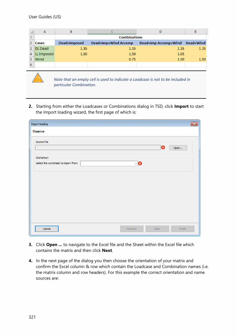
User Guides (US)
321
Note that an empty cell is used to indicate a Loadcase is not to be included in particular Combination.
2. Starting from either the Loadcases or Combinations dialog in TSD, click Import to start
the Import loading wizard, the first page of which is:
3. Click Open ... to navigate to the Excel file and the Sheet within the Excel file which
contains the matrix and then click Next.
4. In the next page of the dialog you then choose the orientation of your matrix and
confirm the Excel column & row which contain the Loadcase and Combination names (i.e.
the matrix column and row headers). For this example the correct orientation and name
sources are:
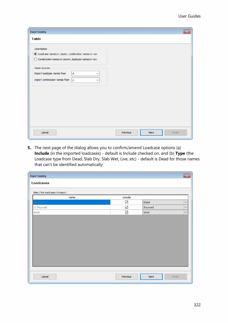
User Guides
322
5. The next page of the dialog allows you to confirm/amend Loadcase options (a)
Include (in the imported loadcases) - default is Include checked on, and (b) Type (the
Loadcase type from Dead, Slab Dry, Slab Wet, Live, etc) - default is Dead for those names
that can’t be identified automatically:
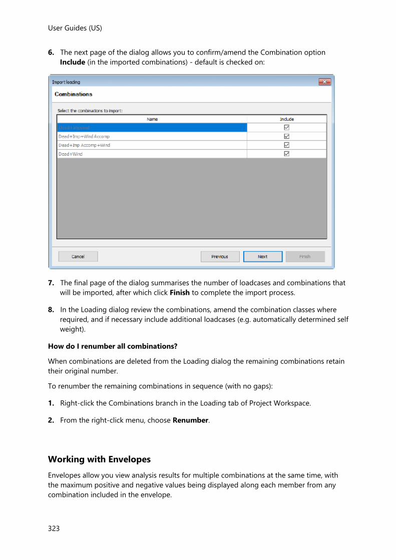
User Guides (US)
323
6. The next page of the dialog allows you to confirm/amend the Combination option
Include (in the imported combinations) - default is checked on:
7. The final page of the dialog summarises the number of loadcases and combinations that
will be imported, after which click Finish to complete the import process.
8. In the Loading dialog review the combinations, amend the combination classes where
required, and if necessary include additional loadcases (e.g. automatically determined self
weight).
How do I renumber all combinations?
When combinations are deleted from the Loading dialog the remaining combinations retain
their original number.
To renumber the remaining combinations in sequence (with no gaps):
1. Right-click the Combinations branch in the Loading tab of Project Workspace.
2. From the right-click menu, choose Renumber.
Working with Envelopes
Envelopes allow you view analysis results for multiple combinations at the same time, with
the maximum positive and negative values being displayed along each member from any
combination included in the envelope.

User Guides
324
If you have defined patterned load combinations, you only need to include the “base case” pattern combination in the envelope - all pattern combinations derived from the base case are automatically included.
Gravity, Lateral and Seismic combination classes can all be included in the same envelope. Seismic RSA combinations should not be included in envelopes as the result cannot currently be displayed.
Loading Dialog Envelopes Page
This Loading dialog page can be used to define envelopes.
Envelopes Pane
Within this pane you can:
• Click the Envelopes main branch to view a summary table of all the envelopes on the
right hand side (as above).
• Click one of the envelope name sub branches to edit the settings for the envelope
selected.
Envelope Summary Table
Design Envelope Title
Click to edit individual envelope names.
Buttons
Displays the Loading Dialog Loadcases Page.
Displays the Loading Dialog Combinations Page.
Displays the Envelopes Page (as above).
Closes the dialog and saves changes.
Closes the dialog without saving changes.
Adds a new envelope. See: How do I create envelopes?

User Guides (US)
325
Copies the selected envelope.
Deletes the selected envelope.
How do I create envelopes?
Envelopes are created manually if required as follows:
1. Click Load > Envelope ( )
This will display the Loading Dialog Envelopes Page listing any current envelopes which
have been defined.
2. Click Add to create a new envelope.
3. Enter the Envelope Title.
4. Click the envelope name in the left hand panel of the dialog to display the available
combinations.
5. Select each combination in turn to be included and click the right arrow button to copy it
into the envelope.
6. Click OK to save the envelope.
7. Your new envelope will now appear in the list of envelopes available in the Loading drop
list.
If you have defined patterned load combinations, you only need to include the “base case” pattern combination in the envelope - all pattern combinations derived from the base case are automatically included.
Gravity, Lateral and Seismic combination classes can all be included in the same envelope. Seismic RSA combinations should not be included in envelopes as the result cannot currently be displayed.
Working with Load Patterns
The factors for the loaded and unloaded spans when pattern loading is applied to live loads
are specific to the design code being worked to.
Overview of Load Patterns
Basic Steps of the Load Patterning Process
The live loads patterning process in Tekla Structural Designer is applied as follows:

User Guides
326
1. Firstly, you must set the individual live load cases to be patterned as required - these are
the “fully loaded” pattern load cases.
(See: How do I set an imposed load case to be patterned?)
2. Next, set the gravity combinations containing live load cases to be patterned as required
- these are the “base case” pattern combinations.
(See: How do I set a combination to be patterned?)
3. With patterns set as above, then after load decomposition the building analysis will
automatically set up the pattern cases for concrete beams in Dir1 and Dir2 directions - 10
pattern cases (beams live loads on/off by span) for each pattern gravity combination - 5
for beams along Dir1 and 5 for beams along Dir2. Pattern cases are also set up for
continuous steel beams if the option for this has been activated in Model Settings>
Loading.
(See: Pattern Load Cases)
4. By default, only beam loads, and slab loads that have been decomposed on to beams,
are patterned. Loads applied to meshed slabs should be manually patterned using
engineering judgement; this is achieved by toggling the loading status via Update Load
Patterns.
(See: How do I update load patterns?)
Clarification of the Slab and Beam Load Pattern Application Rules
Slab load patterning only applies where 2-way slabs have been meshed in the solver model,
i.e.
• in FE Chasedown Analysis
• in 3D Analysis where 2-way slabs are set as meshed
This means that the slab load pattern setting has no effect on:
• 1-way spanning slabs
• 2-way slabs not meshed in 3D Analysis (because the slab loads are being decomposed
to beams and walls prior to creation of the solver model)
• 2-way slabs in Grillage Chasedown Analysis (again, because the slab loads are being
decomposed to beams and walls prior to creation of the solver model)
Consequently in 3D Analysis and Grillage Chasedown Analysis:
• When a beam is set to “Full Load” it will receive the full decomposed load from adjacent
unmeshed 2-way slabs irrespective of whether the slabs themselves are set to “Full Load”
or “Min Load”.
• When a beam is set to “Min Load” it will receive the min decomposed load from adjacent
unmeshed 2-way slabs irrespective of whether the slabs themselves are set to “Full Load”
or “Min Load”.
How do I set an imposed load case to be patterned?
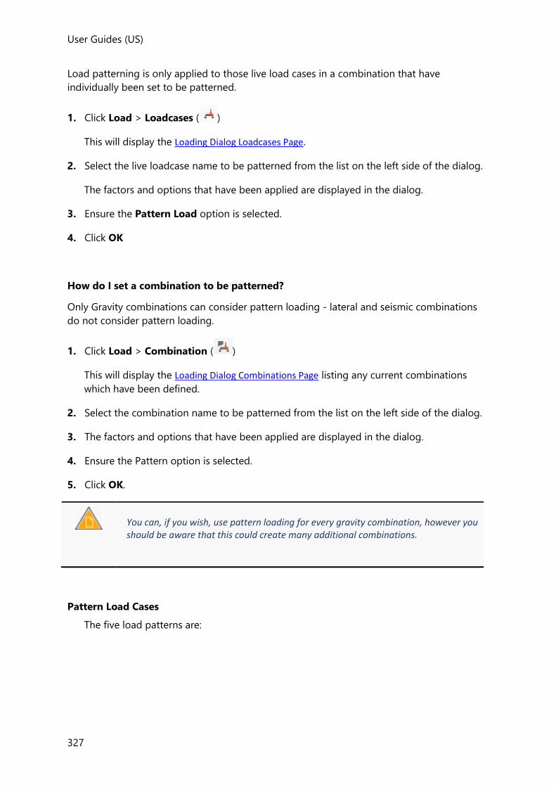
User Guides (US)
327
Load patterning is only applied to those live load cases in a combination that have
individually been set to be patterned.
1. Click Load > Loadcases ( )
This will display the Loading Dialog Loadcases Page.
2. Select the live loadcase name to be patterned from the list on the left side of the dialog.
The factors and options that have been applied are displayed in the dialog.
3. Ensure the Pattern Load option is selected.
4. Click OK
How do I set a combination to be patterned?
Only Gravity combinations can consider pattern loading - lateral and seismic combinations
do not consider pattern loading.
1. Click Load > Combination ( )
This will display the Loading Dialog Combinations Page listing any current combinations
which have been defined.
2. Select the combination name to be patterned from the list on the left side of the dialog.
3. The factors and options that have been applied are displayed in the dialog.
4. Ensure the Pattern option is selected.
5. Click OK.
You can, if you wish, use pattern loading for every gravity combination, however you should be aware that this could create many additional combinations.
Pattern Load Cases
The five load patterns are:

User Guides
328
In effect, a pattern combination containing pattern live load cases results in 11 combinations
- the "base case" combination and 10 pattern combinations derived from it.
If the building geometry or loading is subsequently modified, to ensure the load patterns
reflect these changes you are required to update the pattern loads.
There are NOT separate pattern combinations for beams and slabs, there is just one set of 10 pattern combinations associated with each “fully loaded” pattern combination.
How do I update load patterns?
Beam load patterning is a completely automatic process; the only way you can influence
whether a beam is subject to “full” or “min” load is by editing the continuous beam lines.
Conversely, slab load patterning is a completely manual process. Hence if slab load
patterning is required, e.g. for slab design purposes, you are required to manually update the
load patterns using engineering judgement.
To manually specify slab load patterning:
1. Click Load > Update Load Patterns
2. In the Properties Window, select each pattern in turn and review the loading status of
the beams and slabs.
3. Click a slab to toggle its loading status.
User Guides (US)
329
Working with the Wind Wizard
A Wind Wizard is used to automate the wind modeling process. This uses databases where
appropriate (depending on the wind code) to determine the appropriate wind details for
your structure location and then calculates the appropriate wind loading details for it in
accordance with the chosen wind code.
The Wind Wizard is not currently available for the AS:1170.2 wind code variant.
Having defined the wind directions in which you are interested, the appropriate wind zones
on the roofs and walls of your structure are automatically calculated. You can set the type of
each roof to achieve the correct zoning, and can then tailor the zoning to account for
particular features in more detail, if you so require.
The wind modeling process can automatically define standard wind loadcases for you based
on the usual internal pressure coefficients, or you can define the loadcase information
yourself. In both cases the appropriate wind pressures are calculated on each zone. You can
then combine these wind loadcases into design combinations in the usual way.
You will find that the determination of the wind speeds, the pressures and the zones is
rigorous but the final wind loads adopted are your responsibility.
Running the Wind Wizard
The Wind Wizard is run to define the information required for the wind analysis of the
structure. It uses this information to automatically determine the wind zoning and external
pressure coefficients for the roofs and walls.
How do I run the Wind Wizard?
The Wind Wizard requires at least one wall panel or roof panel to have been defined before it becomes available.
The Wind Wizard guides you through the process of defining the information that is
required in order to calculate the wind loading on the structure.
1. Click Load > Wind Wizard... ( )
A Wind Wizard appropriate for the selected wind loading code will start, and you can use
its pages to define the necessary information.
2. Run through the various pages of the Wind Wizard by clicking Next>. When you reach
the end of the Wind Wizard the Next> button will change to Finish. Click this button to
terminate the Wind Wizard.

User Guides
330
After running the Wind Wizard the roof and wall zones can be reviewed for each wind
direction.
How do I add a new wind direction?
Simply run the Wind Wizard again. You will find that all the existing details are maintained.
You can simply add the new direction in the Results page.
You will also need to add new wind loadcases and design combinations to incorporate the
wind loading for the new direction into your calculations.
How do I delete a wind direction?
Simply run the Wind Wizard again. You will find that all the existing details are maintained.
You can delete the line for the direction you no longer require in the Results page.
You will also need to update your wind loadcases and design combinations to remove the
details for the wind direction you have removed from your calculations.
How do I delete the entire wind model?
Occasionally you may require to delete the entire wind model and start the wind modeling
process from scratch.
1. Click Load > Delete Wind
All the previously defined wind directions and wind loadcases are removed.
Reviewing wind zones and wind zone loads
After the wind model has been established by the wind wizard, you can graphically display
the wind zones and loading that apply for a particular wind direction by opening the
appropriate Wind View.
Zone Loads toolbar
The Zone Loads toolbar contains the following commands:
Button Description
Wind Direction This control is used to switch between the Wind Direction displayed in the active Wind View.
See How do I open a Wind View?
Wind Zones Graphically displays the Wind Zone information for the current direction.
See How do I view the Wind Zones?
Zone Loads Graphically displays the Zone load information for the current direction.
See How do I view the Wind Zone Loads?

User Guides (US)
331
Roof Type Graphically displays the Roof Type.
Std. Table No. Graphically displays the Standard Table No.
Crosswind Breadth
Graphically displays the Crosswind Breadth.
Multibay Graphically displays Multibay information.
Name Graphically displays the wind zone name.
-ve Cpe Graphically displays the -ve Cpe values for the zones.
+ve Cpe Graphically displays the +ve Cpe values for the zones.
Net Pressure Graphically displays the net pressure in zones.
Area Graphically displays the area in zones on net pressure diagrams.
Applied Load Graphically displays the applied load in zones on net pressure diagrams.
Cpi Graphically displays the Cpi in zones on net pressure diagrams.
Cpe Graphically displays the Cpe in zones on net pressure diagrams.
Beneficial (Head Code Eurocode or BS)
Zone loads that have been manually set to “Beneficial” are labelled accordingly and shown with reduced net pressures.
How do I open a Wind View?
Wind Views are only available after the Wind Wizard has been run to establish the wind model.
In order to view the wind zones and loading that apply for a particular wind direction you
have to first of all open the appropriate Wind View.
1. On the Wind tab of the Project Workspace, right-click the Wind Direction in which you
are interested.
2. Click Open view from the context menu.

User Guides
332
This simultaneously opens the chosen wind direction view and switches to the Zone
Loads ribbon from where you can review wind zone data graphically.
How do I view the Wind Zones?
1. Open a Wind Direction view which shows the details for the wind direction in which you
are interested.
2. Click Show > Wind Zones
3. The Wind Direction view shows the zones that are applied to the structure for this wind
direction.
How do I edit a Wind Zone?
1. Open a Wind Direction view which shows the details for the wind direction in which you
are interested.
2. From the Wind tab of the Project Workspace, expand the Wall Zones or Roof
Zones branch for the wind direction in question.
3. In the required branch, right-click the panel containing the zone to be edited and choose
Edit Zones...
4. Initially the dialog shows the automatically calculated values for the particular wind zone.
You can change these on a zone-by-zone basis by removing the check against Std.
5. Make the edits as required in the dialog and click OK.
How do I view the Wind Zone Loads?
Once you have defined your wind loadcases you can view the wind zone loading that is
generated.
1. Open a Wind Direction view which shows the details for the wind direction in which you
are interested.
2. Click Show > Zone Loads
3. In the Loading drop list pick the particular wind loadcase in which you are interested from
the list of wind loadcases.
4. The Wind Direction view shows the loads that are applied to the structure for this
loadcase in this wind direction.
Related topics

User Guides (US)
333
• How do I Define Wind Loadcases?
How do I change a Wind Zone Load?
To change a wind zone load:
1. Open a Wind Direction view which shows the details for the wind direction in which you
are interested.
2. Click Zone Loads from the Show group.
3. In the Loading drop list pick the particular wind loadcase in which you are interested from
the list of wind loadcases.
4. The Wind Direction view shows the loads that are applied to the structure for this
loadcase in this wind direction.
5. Click the particular zone that you want to change and you will see the Wind Load Zone
Data dialog.
6. Initially this dialog shows the automatically calculated values for the particular wind zone.
You can change these on a zone-by-zone basis should this prove necessary.
7. In order to make changes to the automatically calculated values, you must first remove
the check against Default. The values used to determine the load and the Beneficial
load box (see below) then become active.
8. Enter the details that you require for these values, Once these settings meet with your
approval click OK and the zone will be updated to show the result of your changes.
Beneficial
When working to Eurocodes, by checking this box the nett pressure for such loads is
reduced to zero (see Clause 7.1.2 (2) Note b.), or is reduced if working to BS6399-2.
When working to BS6399-2, by checking this box the nett pressure for such loads is
reduced by 40%.
What happens if I make changes to my model?
If it is necessary to change the roofs or walls of your structure, either because you change
the face of a wall, or the type of a roof, or if you alter your structure dimensionally, then
changes to the existing wind zoning do not occur automatically. This is intentional, since you
may wish to make subsequent alterations before you recalculate the zoning. Once you have
completed your changes it is simple to incorporate them and recalculate the zoning details.
1. Make the changes that you require to your model. If you can see existing zoning
information, then this information will be removed for any walls or roofs you modify.
2. To reinstate the zoning,

User Guides
334
• Click Load > Update Zones ( )
3. The wind zoning calculations run in the background. once these are complete the new
zoning layout for your structure will be shown.
If you have defined your own zone layout for any roof or wall, and you make changes to that roof or wall, then the existing zones will be maintained. It is your responsibility to update these appropriately.
Wind loadcase definition
It is not practical to automatically determine critical combinations and thus required wind
loadcases. Thus you control the generation of wind loadcases manually.
How do I Define Wind Loadcases?
Once you have defined the basic wind data for your model, and calculated the wind zoning
using the Wind Wizard, you can then define the wind loadcases you want to investigate.
1. Click Load > Wind Loadcases
2. Use the Wind Loadcases dialog to Add the details of each wind loadcase individually, or
alternatively if you want to selectively generate standard wind loadcases for the wind
directions you defined in the Wind Wizard, then click Auto
If you want to use the Auto option, then you must do so before you have defined any other wind loadcases. Once a wind loadcase exists Auto is unavailable.
How do I add new Wind loadcases?
Once you have defined wind loadcases it is an easy matter to create additional ones if you
require them.
1. Click Load > Wind Loadcases
2. In the Wind Loadcases dialog click Add to create a line for your new loadcase in the
table of wind loadcases.
3. Enter the appropriate details directly into this line.
4. Repeat steps 2 and 3 for each new loadcase you wish to create.
5. Once your list of loadcases is complete click OK to close the Wind Loadcases dialog.

User Guides (US)
335
6. Don’t forget to update / augment your design combinations to take account of your new
wind loadcases.
How do I delete Wind loadcases?
Once you have defined wind loadcases it is an easy matter to delete ones that you no longer
require.
1. Click Load > Wind Loadcases
2. In the Wind Loadcases dialog click the line relating to the wind loadcase you want to
delete.
3. Click Delete to permanently delete this wind loadcase.
4. Repeat steps 2 and 3 for each loadcase you wish to delete.
5. Once your list of loadcases is complete click OK to close the Wind Loadcases dialog.
6. Don’t forget to update your design combinations to take account of the wind loadcases
you have deleted.
Working with Simple Wind
The Simple Wind loading method is an alternative to using the Wind Wizard. It allows you
to input wind loads directly without having to construct a wind model.
In order access Simple Wind, you must first create and then select the loadcase in which the
simple wind loads are to be added.
How do I manually create a loadcase for Simple Wind?
1. Click Load > Loadcases
2. Use the Loadcases dialog to Add a new loadcase, give it an appropriate name and
ensure the Type is set as Wind, then click OK
How do I create a Simple Wind Load?
1. Ensure you are in a 3D Structure View, not a 2D View.
2. In the Loading toolbar, select a manually created loadcase of type Wind, (i.e not one that
has been automatically created by the Wind Wizard).
The Simple Wind command should now be available.
3. Click Load > Simple Wind
4. Click to define the start point of the load width.
5. Click to define the end point of the load width.
User Guides
336
The Simple Wind Loading dialog is displayed - this is used to define a wind load profile
within the width specified, up the height building.
The initial default enables you to specify a single area load from the lowest level of the
building, up to the highest level that contains a rigid diaphragm.
6. Enter the area load required.
7. To create a stepped profile up the height of the building, use the buttons on the right of
the dialog to specify the levels at which the load changes, (these do not have to coincide
with actual levels in the building), then enter the load required at each level.
8. Once your load is complete click OK to close the dialog.
The load does not have to begin at the lowest level in the building. If you have one or more levels below ground, you can simply adjust the value of the lowest level in the dialog.
How do I edit Simple Wind load vertical properties?
The Simple Wind dialog can be redisplayed for an existing simple wind load as follows:
• Double click anywhere within the graphical representation of the simple wind load.
How do I edit Simple Wind load width?
1. Select the Simple Wind Load to be edited.
The load becomes highlighted, and the two nodes that define the load width are shown.
2. Select one of the two nodes, then click a new location for the node.
The load is regenerated between the two nodes.
Working with the Snow Wizard
For both the ASCE7 and Eurocode snow codes variants a Snow Wizard can be used to
automate snow loadcase generation.
The wizard is run in order to set up:
• basic snow data
• snow loadcases

User Guides (US)
337
• snow loads within the balanced (undrifted) snow loadcases
Snow loads in drift snow loadcases are not set up automatically and must therefore be
manually applied.
The Snow Wizard is not currently available for the Indian, Australian, or British Standard snow code variants.
How do I run the Snow Wizard
The Snow Wizard consists of two pages: the first page is used to define the basic data for
the chosen snow loading code, the second page is used to set up the actual number of
loadcases to be generated.
1. Click Load > Snow Wizard...
A Snow Wizard appropriate for the selected snow loading code will start.
2. On the first page define the basic data, then click Next>
3. On the second page specify the loadcases to be generated and the number of drift
directions to be considered.
4. Click Finish to complete the Snow Wizard.
After running the Snow Wizard the loadcases that have been set up can then be reviewed.
Manually applying Snow Loads to Snow Loadcases
While the loads in the balanced (or undrifted) snow loadcases are created automatically, the
loads in the drift cases have to be applied manually as Uniform Snow, Valley Snow, or Local
Drift Snow loads.
Snow loads that are not appropriate for the currently selected loadcase are unavailable.
How do I manually apply a Uniform Snow load?
1. Select the required snow loadcase in the Loading drop list.
2. From the Snow Load group on the ribbon, select Uniform Snow
3. Review the load details displayed in the Properties Window and adjust as necessary.

User Guides
338
Note the Windward/Leeward option for Uniform Loads in the Unbalanced cases.
4. Click anywhere on the relevant roof panel to apply the load.
How do I manually apply a Valley Snow load?
1. Select the required snow loadcase in the Loading drop list.
2. From the Snow Load group on the ribbon, select Valley Snow
3. Select a roof panel that identifies the Left (L) roof panel of the valley in which the load is
to be applied, (the Right (R) panel is automatically determined).
The valley load is automatically calculated.
If required a user override can be applied to the calculated load by selecting the load and
selecting Override load value in the Properties Window.
If you rerun the Snow Wizard any user overrides that have been applied are maintained.
How do I manually apply a Local Drift Snow load?
It is not necessary to have walls in order to use drift loads - you can create a drift against a completely free edge of a roof panel if required.
1. Select the required snow loadcase in the Loading drop list.
2. From the Snow Load group on the ribbon, select Local Drift Snow
3. In the Properties Window choose the Drift type: (Step, or Parapet or projection).
4. In the Properties Window define the appropriate height and roof lengths for the drift.
5. Review the other load details displayed in the Properties Window and adjust as
necessary.
6. Hover the cursor over the required roof panel edge along which the drift will act.
The closest appropriate edge becomes highlighted.

User Guides (US)
339
7. Pick the load start position on the panel.
8. Pick the load end position.
If required a user override can be applied to the calculated load by selecting the load and
selecting Override load value in the Properties Window.
If you rerun the Snow Wizard any user overrides that have been applied are maintained.
How do I apply a user override to a snow load?
User overrides can be applied if required for snow load values and drift lengths.
1. Select the snow load.
2. In the Properties Window check the appropriate override box.
3. Enter the override value.
If you rerun the Snow Wizard any user overrides that have been applied are maintained.
Notes about the graphical display of Snow Loads
1. In the graphic displays it is the loading magnitude rather than the depth of loading that
is depicted. This should be borne in mind when reviewing the load that has been
calculated on structures such as the low pitched valley model shown below:
Although the above appears to indicate snow load rising above the ridges, because it is
the magnitude being depicted this is not actually the case.

User Guides
340
2. Although the graphics depict loads on sloped lengths - all loads and lengths quoted in
the properties are given such that distances are in the horizontal plane and loads applied
vertically in the horizontal plane.
Update Snow Loads
Having run the Snow Wizard, if the roof geometry is subsequently modified the snow loads
would need to be recalculated. Click Update Snow Loads on the Loads ribbon to achieve
this.
Delete Snow
Occasionally you may require to delete the entire snow model and start the process from
scratch. This is done as follows:
• Click Load > Delete Snow
The basic data that was previously entered in the Snow Wizard is re-set and the loadcases
set up by the Snow Wizard are deleted.
Working with Seismic Loads
A Seismic Wizard is provided to enable the definition of all the parameters required to
determine the seismic loading and load cases so that a seismic analysis can be run on the
structure.
The Seismic Wizard is not currently available for the AS:1170.4 code variant.
Running the Seismic Wizard
The Seismic Wizard guides you through the process of defining the information required for
the seismic analysis of the structure. It uses this information to the seismic loading (a force
and moment, applied to every floor and construction level).
How do I run the Seismic Wizard?
1. Click Load > Seismic Wizard... ( )
A wizard appropriate for the selected loading code will start, and you can use its pages to
define the necessary information.
2. Run through the various pages of the wizard by clicking Next>. When you reach the end
the Next> button will change to Finish. Click this button to terminate the Seismic
Wizard.
User Guides (US)
341
3. After running the Seismic Wizard the Combination Generator is displayed to allow you to
set up the seismic load combinations.
Related topics
• ASCE7 Seismic Wizard
• UBC 1997 Seismic Wizard
• Eurocode EN1998-1:2004 Seismic Wizard
How do I display the Horizontal Design Spectrum?
After running the Seismic Wizard the Horizontal Design Spectrum can be viewed.
1. Click Load > Horizontal Design Spectrum
You can switch between the Dir 1 and Dir 2 spectrum via the Properties Window.
How do I delete Seismic Loads?
Occasionally you may require to delete the seismic loads and start the seismic modeling
process from scratch.
1. Click Load > Delete Seismic
All the previously defined seismic loads are removed.
Load Decomposition
The way in which load decomposition is performed (if at all) depends on the how the slabs
are modeled and how they are spanning.
For 1-way spanning slabs:
• slab loads are always decomposed directly on to supporting members before 3D analysis
is performed.
For 2-way spanning slabs:
• load decomposition is not required at those levels where the option mesh 2-way slabs
in 3D Analysis is applied.
• at other levels, before 3D analysis can be performed, any loads applied to 2-way slabs
have to be decomposed back on to the supporting members.
• to achieve this, a separate FE load decomposition is carried out automatically prior to the
3D analysis.

User Guides
342
Where load decomposition has occurred, the resulting decomposed loads (rather than the
original slab loads) get applied to the 3D analysis model.
For verification purposes you can elect to display the decomposed loads in the 3D views.
Although load decomposition is carried out automatically, (when you click to analyze the
structure), the Decomposition command provides an optional way to perform the same task
manually - you may elect to do this in order to manually check that loads are being
decomposed as you intend prior to running the analysis. In the context of big/complex
models this can be a useful time saver, particularly as manual decomposition can be carried
out on a level by level basis.
How do I manually decompose slab loads for an individual construction level?
1. Open a 2D view of the level required and display it in 3D.
Related topics
• How do I display a 2D view in 3D?
2. Click Load > Decomposition ( )
Provided the relevant Scene Content settings are activated, (i.e. Slabs > Mesh and
Loading > Decomposed), you should then see an FE mesh generated within the slab
panels and the resulting decomposed loads applied to the beams.
How do I manually decompose slab loads for all the required levels?
1. Open the Structure 3D view.
2. Click Load > Decomposition ( )
How do I view the decomposed loads (either with, or without load values)?
1. Open a 3D view physical view of the model, (or a 2D view displayed in 3D).
2. In Scene Content expand the Loading group and select Decomposed.
3. To view the decomposed load values click in the cell to the right of the
Decomposed option and select both Geometry and Text.
4. To view the decomposed load without values click in the cell to the right of the
Decomposed option and clear Text.
5. Select the load case from the Loading drop list.
Decomposed loads do not exist at levels where the option mesh 2-way slabs in 3D Analysis has been applied. At levels where this is not the case you can view the decomposed loads, (but you cannot see any shell results from the FE load decomposition).

User Guides (US)
343
Working with Panel Loads
Panel loads are used to apply loads to slab panels (a.k.a “slab items”), roof panels and wall
panels as follows:
• Point, Line, Patch and Polygonal Loads can be applied anywhere within individual or
across multiple slab, roof or wall panels. They can only be applied in 2D views (not 3D).
• Area Loads entirely cover a slab, roof or wall panel.
• Slab Loads entirely cover all slab panels in a parent slab.
• Level Loads entirely cover all parent slabs in a level.
A parent slab can consist of slab panels that are physically separated from each other, however they must be on the same level.
How do I create a point load?
1. Open a 2D view of the level in which you want to apply the load.
2. Select an appropriate load case from the Loading drop list.
3. Click Load > Point Load ( ) (in the Panel Loads group).
4. Review the load details displayed in the Properties Window and adjust as necessary.
5. Click a reference node from which the load position can be offset - this can be the
start/end point of any member at the level.
To select a reference node, Points must be switched on in Scene Content.
6. Click again to specify the load position graphically, or press <F2> to enter the position
via the keyboard.
If the slab/panel is moved by manually selecting & re-positioning the slab/panel nodes then the point load does not move with the slab/panel.
However, if any of the grid lines defining the reference node are moved then the load will move also.

User Guides
344
How do I create a line load?
1. Open a 2D view of the level in which you want to apply the load.
2. Select an appropriate load case from the Loading drop list.
3. Click Load > Line Load ( )
4. Review the load details displayed in the Properties Window and adjust as necessary.
5. Click a reference node from which the load position can be offset - this can be the
start/end point of any member at the level.
To select a reference node, Points must be switched on in Scene Content.
6. Click to specify the load start position graphically, or press <F2> to enter the position via
the keyboard.
Note that this is an offset (X, Y) from the chosen reference node.
7. Click, or press <F2> to specify the load end position.
Note that when entered via keyboard this is an offset (X, Y) from the load start position.
How do I create a patch load?
1. Open a 2D view of the level in which you want to apply the load.
2. Select an appropriate load case from the Loading drop list.
3. Click Load > Patch Load ( )
4. Review the load details displayed in the Properties Window and adjust as necessary.
5. Click a reference node from which the load position can be offset - this can be the
start/end point of any member at the level.
To select a reference node, Points must be switched on in Scene Content.
6. Click to specify a corner position of the load graphically, or press <F2> to enter the
corner position via the keyboard.

User Guides (US)
345
7. Click, or press <F2> to specify the size.
(Specified as the offset dimensions from the corner position.)
8. Click, or press <F2> to define the rotation.
How do I create a polygonal load?
1. Open a 2D view of the level in which you want to apply the load.
2. Select an appropriate load case from the Loading drop list.
3. Click Load > Polygon Load
4. Review the load details displayed in the Properties Window and adjust as necessary.
5. Click a reference node from which the load position can be offset - this can be the
start/end point of any member at the level.
To select a reference node, Points must be switched on in Scene Content.
6. Click to specify the load start position graphically, or press <F2> to enter the position via
the keyboard.
Note that this is an offset (X, Y) from the chosen reference node.
7. Click to specify a corner position of the load graphically, or press <F2> to enter the
corner position via the keyboard.
8. Continue to specify the remaining corner positions in the same way.
9. When the polygon is complete press <Enter> (or, click once more on the first corner
defined) to create the load.
Once a polygonal load has been created, its shape can subsequently be graphically edited by: - selecting the load, - clicking on one of its vertices, - clicking again to move the vertex to a new position
How do I create a perimeter load?
1. Open a 2D or 3D view showing the level at which you want to apply the load.

User Guides
346
2. Select an appropriate load case from the Loading drop list.
3. Click Load > Perimeter Load
4. Review the load details displayed in the Properties Window and adjust as necessary,
note in particular:
• Create as line loads - creates the load as series of separate line loads along each
external edge. (Leave cleared to created as a single load object.)
• Ignore openings - creates the load around external perimeters only but not around
internal opening perimeters.
5. Click any slab or mat item.
The load is created around the external perimeter of every continuous area of slabs at
the identified level.
How do I create a variable patch load?
Variable patch loads are not just restricted to quadrilaterals - they can be any polygonal shape.
1. Open a 2D view of the level in which you want to apply the load.
2. Select an appropriate load case from the Loading drop list.
3. Click Load > Variable Patch Load ( )
4. Review the load details displayed in the Properties Window and adjust as necessary. (At
this point you are only required to specify three load values to describe the variable load,
their locations are picked graphically at a later stage.)
5. Click a reference node from which the load position can be offset - this can be the
start/end point of any member at the level.
To select a reference node, Points must be switched on in Scene Content.
6. Click to specify the load start position graphically, or press <F2> to enter the position via
the keyboard.
Note that this is an offset (X, Y) from the chosen reference node.

User Guides (US)
347
7. Click to specify a corner position of the load graphically, or press <F2> to enter the
corner position via the keyboard.
8. Continue to specify the remaining corner positions in the same way.
9. When the polygon is complete press <Enter> (or, click once more on the first corner
defined).
10. Click one of the corners of the polygon to pick the position of Load 1.
11. Click another corner to pick the position of Load 2.
12. Click another corner to pick the position of Load 3.
Once a variable patch load has been created, its shape can subsequently be graphically edited by: - selecting the load, - clicking on one of its vertices, - clicking again to move the vertex to a new position.
How do I create an area load?
1. Open a 2D view of the level in which you want to apply the load.
2. Select an appropriate load case from the Loading drop list.
3. Click Load > Area Load ( )
4. Review the load details displayed in the Properties Window and adjust as necessary.
5. Click the panel to which the load will be applied.
How do I create a variable area load?
1. Open the 3D view, frame view or sloped plane view in which you want to apply the load.
Variable Area Load can only be applied to non-horizontal slab and roof panels, as well as wall panels and concrete walls - hence they can’t be applied in a 2D view.
2. Select an appropriate load case from the Loading drop list.
3. Click Load > Variable Are Load ( )

User Guides
348
4. Review the load details displayed in the Properties Window and adjust as necessary.
5. Click the panel to which the load will be applied.
How do I create a slab load?
1. Select an appropriate load case from the Loading drop list.
2. Click Load > Slab Load ( )
3. Review the load details displayed in the Properties Window and adjust as necessary.
4. Click any slab panel within the parent slab in order to apply the load to all panels within
the parent slab.
How do I create a level load?
1. Select an appropriate load case from the Loading drop list.
2. Click Load > Level Load ( )
3. Review the load details displayed in the Properties Window and adjust as necessary.
4. Click any slab panel in order to apply the load to all slabs within the level.
How do I edit a load?
1. Select the load to be edited.
2. Review the load details displayed in the Properties Window and adjust as necessary.
How do I delete a load?
1. Ensure the load case containing the load is displayed in the Loading drop list.
2. Click Delete ( ) on the Quick Access toolbar.
3. Select the load to be deleted and click to delete it.
Working with Member Loads
Member Loads are used to apply loads to one dimensional members (beams, columns,
braces etc.)
How do I create a full UDL?

User Guides (US)
349
1. Select an appropriate load case from the Loading drop list.
2. Click Load > Full UDL ( )
3. Review the load details displayed in the Properties Window and adjust as necessary.
4. Click anywhere along the element to apply the load.
How do I create a partial length UDL or VDL?
1. Select an appropriate load case from the Loading drop list.
2. Click Load > UDL ( ), or VDL ( )
3. Review the load details displayed in the Properties Window and adjust as necessary.
4. Hover the cursor over the element until it is displayed with a number of special points
along it.
5. Pick the load start position either by clicking on one of the special points, or by clicking
at any given distance along the element, or by pressing <F2> to enter the position by
the keyboard.
6. Click again, or press <F2> to specify the load length.
How do I create a trapezoidal load?
1. Select an appropriate load case from the Loading drop list.
2. Click Load > Trapezoidal Load ( )
3. Review the load details displayed in the Properties Window and adjust as necessary.
4. Hover the cursor over the element until it is displayed with a number of special points
along it.
5. Pick the load position either by clicking on one of the special points, or by clicking at any
given distance along the element, or by pressing <F2> to enter the position by the
keyboard.
The load position defines the point at which the trapezoidal load (which is symmetrical) reaches its maximum intensity.
User Guides
350
How do I create a point or moment load?
1. Select an appropriate load case from the Loading drop list.
2. Click Load > Point Load ( ), or Moment load ( ) (on the Member Loads panel).
3. Review the load details displayed in the Properties Window and adjust as necessary.
4. Hover the cursor over the element until it is displayed with a number of special points
along it.
5. Pick the load position either by clicking on one of the special points, or by clicking at any
given distance along the element, or by pressing <F2> to enter the position by the
keyboard.
How do I create a torsion full UDL?
1. Select an appropriate load case from the Loading drop list.
2. Click Load > Torsion Full UDL ( )
3. Review the load details displayed in the Properties Window and adjust as necessary.
4. Click anywhere along the element to apply the load.
How do I create a partial length torsion UDL or torsion VDL?
1. Select an appropriate load case from the Loading drop list.
2. Click Load > Torsion UDL ( ), or Torsion VDL ( )
3. Review the load details displayed in the Properties Window and adjust as necessary.
4. Hover the cursor over the element until it is displayed with a number of special points
along it.
5. Pick the load start position either by clicking on one of the special points, or by clicking
at any given distance along the element, or by pressing <F2> to enter the position by
the keyboard.
6. Click again, or press <F2> to specify the load length.
Working with Structure Loads
The following Structure Loads can be applied:
User Guides (US)
351
• Nodal load - applied at solver node locations.
• Temperature load - a global rise in temperature applied to individual elements/panels,
selected elements/panels, or to all elements/panels .
• Settlement load - a translation or a rotation applied to a support (in the support UCS
system).
How do I create a nodal load?
1. Select an appropriate load case from the Loading drop list.
2. Click Load > Nodal Load ( )
3. Review the load details displayed in the Properties Window and adjust as necessary.
4. Pick the load position by clicking on a node.
How do I create a temperature load?
1. Select an appropriate load case from the Loading drop list.
2. Click Load > Temperature Load ( )
3. Review the load details displayed in the Properties Window and adjust as necessary.
4. Click anywhere along the element to apply the load.
How do I create a settlement load?
1. Select an appropriate load case from the Loading drop list.
2. Click Load > Settlement Load ( )
3. Review the load details displayed in the Properties Window and adjust as necessary.
4. Pick the load position by clicking on a supported node.
Analysis Guide
An extensive range of 1st and 2nd order analyses can be performed from the Analyze toolbar.
Analyze toolbar

User Guides
352
The Analyze toolbar contains the following commands:
Button Description
Options
Opens the Analysis Options dialog.
See: Analysis Options
1st Order Linear Runs a linear static analysis.
This analysis type is suitable for structures where secondary effects are negligible. Any nonlinear springs or nonlinear elements present are constrained to act linearly.
Loadcases and Combinations to be considered in the analysis can be pre-selected.
Nonlinearity Included:
• Geometric: No
• Material: No
See: How do I run a 1st order linear analysis?
1st Order Non-linear
Runs a nonlinear analysis with loading applied in a single step.
This analysis type is suitable for structures where secondary effects are negligible and nonlinear springs/elements are present.
Loadcases and Combinations to be considered in the analysis can be pre-selected.
Nonlinearity Included:
• Geometric: No
• Material: Yes
See: How do I run a 1st order non-linear analysis?
1st Order Vibration
Runs an unstressed vibration analysis to determine the structure's natural frequencies.
The structure is assumed to be in an unstressed state and nonlinear elements are constrained to act linearly.
Nonlinearity Included:
• Geometric: No
• Material: No
See: How do I run 1st order vibration analysis?

User Guides (US)
353
2nd Order Linear
Runs a 2-stage P-Delta analysis.
This analysis type is suitable for structures where secondary effects are of comparable magnitude to primary effects. Any nonlinear springs or nonlinear elements present are constrained to act linearly.
Loadcases and Combinations to be considered in the analysis can be pre-selected.
Nonlinearity Included:
• Geometric: Yes
• Material: No
See: How do I run a 2nd order linear analysis?
2nd Order Non-linear
Runs a nonlinear analysis with loading applied in a single step.
This analysis type is suitable for structures where secondary effects are of comparable magnitude to primary effects and nonlinear springs/elements are present.
Loadcases and Combinations to be considered in the analysis can be pre-selected.
Nonlinearity Included:
• Geometric: Yes
• Material: Yes
See: How do I run a 2nd order non-linear analysis?
2nd Order Buckling
Runs a linear buckling analysis to determine a structure's susceptibility to buckling.
The stressed state of the structure is determined from linear analysis; therefore nonlinear elements are constrained to act linearly.
Loadcases and Combinations to be considered in the analysis can be pre-selected.
Nonlinearity Included:
• Geometric: Yes
• Material: No
See: How do I run 2nd order buckling analysis?
1st Order RSA Seismic
Runs Modal Response Spectrum Analysis to determine the peak response of the structure to earthquakes. Any nonlinear springs or nonlinear elements present are constrained to act linearly. For RSA Seismic Combinations, the peak responses are enveloped around the static results for 1st Order Linear Analysis.
Nonlinearity Included:
• Geometric: No
• Material: No
See: How do I run a 1st order RSA seismic analysis?

User Guides
354
2nd Order RSA Seismic
Runs Modal Response Spectrum Analysis to determine the peak response of the structure to earthquakes. Any nonlinear springs or nonlinear elements present are constrained to act linearly. For RSA Seismic Combinations, the peak responses are enveloped around the static results for 2nd Order Linear Analysis.
Nonlinearity Included:
• Geometric: Yes
• Material: No
See: How do I run a 2nd order RSA seismic analysis?
Tabular Data Displays the analysis model data in spreadsheets for review/editing.
See: Tabular data (Solver Model Data)
Mesh Slabs Slabs are meshed automatically for FE Load Decomposition, FE Chasedown, and also if specified in the 3D Analysis. This command is only used if you need to mesh slabs manually.
See: Working with FE meshed slabs
Update Wall Beams
Wall Beams are created automatically as internal 1D elements within walls in the analysis model. Their analytical properties are determined automatically from the geometry of the wall. If the model has been changed wall beams are updated automatically when you run the analysis.
This command is only used if you need to update wall beams manually.
See: Working with FE meshed walls
Analyse All (Static)
Runs all the analyses required (for all loadcases and combinations) to enable design to proceed:
• 3D Analysis - (either first or second order, as specified in
Design Options > Analysis)
• Grillage Chasedown
• FE Chasedown
Once analysis is complete, individual members can be checked or designed.
See: How do I run FE chasedown and Grillage chasedown analysis?
Update Diaphragms are updated to reflect the latest model changes every time the model is analysed or designed. They can also be updated manually after the model has been edited by clicking the Update.
See: Working with rigid and semi-rigid diaphragms
The above command is only available in Solver Views. It is not displayed in the Solver Model Data View.
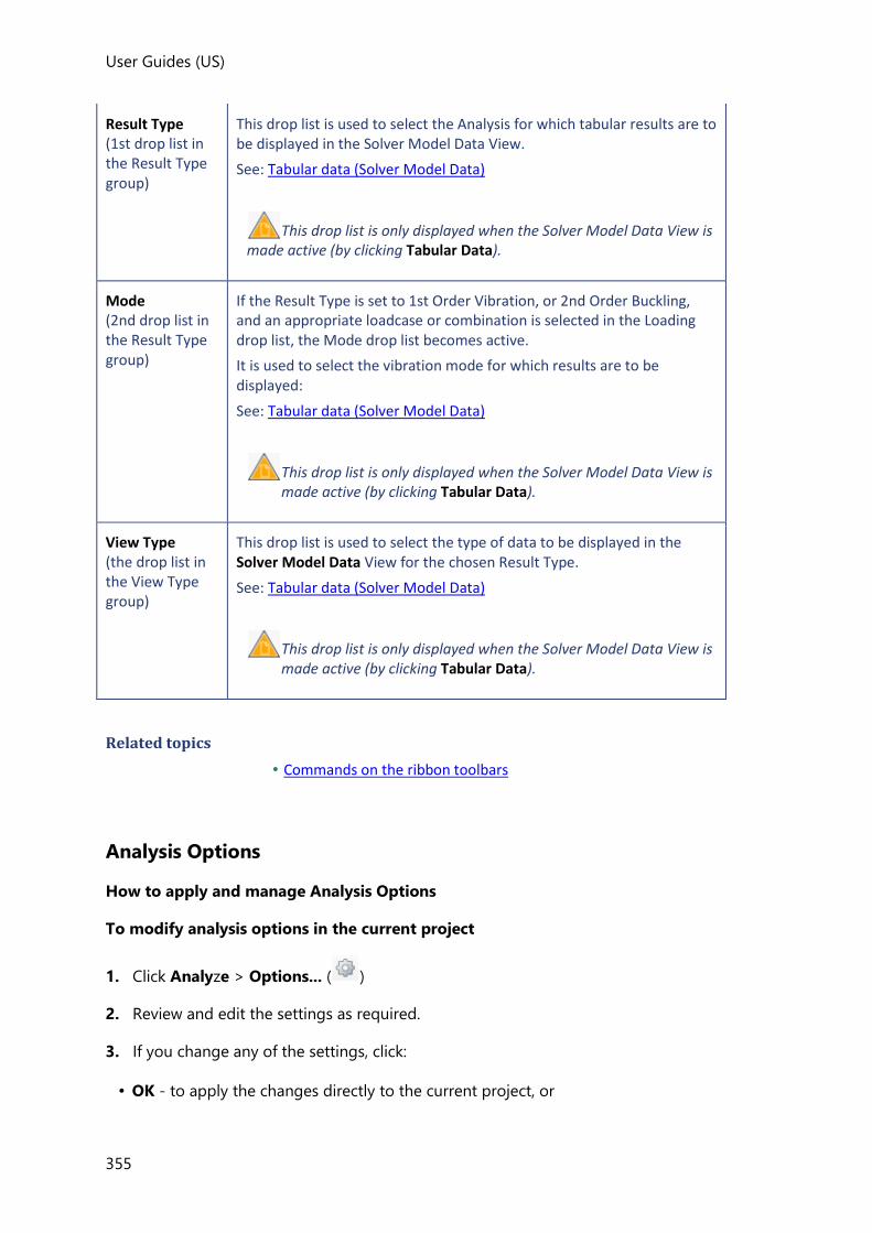
User Guides (US)
355
Result Type (1st drop list in the Result Type group)
This drop list is used to select the Analysis for which tabular results are to be displayed in the Solver Model Data View.
See: Tabular data (Solver Model Data)
This drop list is only displayed when the Solver Model Data View is made active (by clicking Tabular Data).
Mode (2nd drop list in the Result Type group)
If the Result Type is set to 1st Order Vibration, or 2nd Order Buckling, and an appropriate loadcase or combination is selected in the Loading drop list, the Mode drop list becomes active.
It is used to select the vibration mode for which results are to be displayed:
See: Tabular data (Solver Model Data)
This drop list is only displayed when the Solver Model Data View is made active (by clicking Tabular Data).
View Type (the drop list in the View Type group)
This drop list is used to select the type of data to be displayed in the Solver Model Data View for the chosen Result Type.
See: Tabular data (Solver Model Data)
This drop list is only displayed when the Solver Model Data View is made active (by clicking Tabular Data).
Related topics
• Commands on the ribbon toolbars
Analysis Options
How to apply and manage Analysis Options
To modify analysis options in the current project
1. Click Analyze > Options... ( )
2. Review and edit the settings as required.
3. If you change any of the settings, click:
• OK - to apply the changes directly to the current project, or
User Guides
356
• Save... - to save the changes back to the active settings set (to act as defaults for future
projects), or
• Cancel... - to cancel the changes
You can also click:
• Load... - to revert to the analysis options specified in the active settings set.
To modify analysis option defaults for future projects
1. Click Home > Settings ( )
2. In the Analysis Options page of the dialog, select the settings set to be updated, then
review and edit the settings as required.
You can update any settings set simply by selecting it from the droplist, it does not need to be active.
3. If you change any of the settings, click:
• OK - to save the changes to the selected settings set (to act as defaults for future
projects when that set is active), or
• Cancel - to cancel the changes
1st Order Non-Linear Options
Convergence Criteria
Maximum number of iterations
default = 100
Tolerance
default = 0.0001
Relative
default = on
Relaxation Factors
Relaxation factors control an amount of nominal compression tension-only braces can
undergo while remaining active during analysis iteration. This improves convergence for rare
problematic models/ loading situations in which otherwise most or all braces may experience
compression and become inactive, causing instability and preventing solution. When

User Guides (US)
357
converged tension-only braces will still have only either zero or tension force. The process is
entirely automatic by default and it is anticipated the factors will not require manual editing
for most circumstances.
Use relaxation factors for tension only elements
default cleared
Minimum relaxation factor
default = 0.1
Maximum relaxation factor
default = 0.5
If the model still fails to converge when using relaxation factors, expanding the allowable
range (by changing the above minimum and maximum values) may produce convergence.
Relaxation factors are not activated by default as it is anticipated they will not be required for the majority of models. In addition, since the solution process is necessarily more complex, their use can increase the analysis time to a degree.
2nd Order Non-Linear Options
The options available are identical to those for 1st order non-linear.
1st Order Vibration Options
Extraction Method
Jacobi
An iterative transformation method used to calculate all Eigen values and Eigen Vectors.
Good for small models but unsuitable for medium to large models
Subspace
An iterative simultaneous vector method to calculate the smallest Eigen values and
corresponding Eigen Vectors. Suitable for quickly finding the lowest frequencies in
medium to large models.
FEAST
uses the FEAST algorithm to effectively calculate all the eigenvalues within a specific
range. Suitable for any size structure. See: http://www.ecs.umass. Ledu/~polizzi/feast/ for
more information.
Automatic
Initially uses Subspace to find the lowest modes. If the stopping criteria (either mass, or
number of modes) is not met FEAST is then automatically used to find higher modes until
the stopping criteria is fulfilled.
Stopping Criteria
User Guides
358
Stopping criteria prevent analysis continuing forever. If either of these criteria are met the
analysis will not look for any more modes
Modes
Automatic number of modes
If this option is selected you then specify the mass participation required in each
direction. You can optionally specify an initial number of modes, (which should be close
to the actual number required in order to speed up the analysis process).
Total number of modes
If Automatic number of modes is cleared you specify the total number of modes
required, (default 10).
Jacobi Settings
Max number of sweeps
A sweep is a transformation of every off-diagonal in the global matrices. This sets the
maximum number of sweeps allowed.
Sweep tolerance
At the end of each sweep values are checked against the previous sweeps results. If the
difference is less than this tolerance the result is converged, and the analysis is complete.
Subspace Settings
Maximum number of iterations
The number of iterations to perform.
Tolerance
At the end of each iteration values are checked against the previous iterations results. If
the difference is less than this tolerance the result is converged, and the analysis is
complete.
FEAST
Initial search range
Specifies the initial range of values FEAST will search for Eigen values in.
Overestimation multiplier
Within each range specifies the initial guess for the subspace dimension. to be used: an
overestimate of the predicted number of modes in the range.
Maximum modes in range
The maximum allowable modes in the range. If more modes are found in a range the
range is split into several smaller ranges.
Minimum search range
When a range is smaller than this it will no longer be split, even if the maximum number
of modes is greater than that allowed.

User Guides (US)
359
2nd Order Buckling Options
Maximum number of iterations
default = 1000
Tolerance
default = 0.00001
Max number of sweeps
default = 50
Sweep tolerance
default = 1.0E-12
Modes
default = 10
Show negative buckling factors
default = no
Extraction method
The Jacobi method is more suited for small models and Subspace method more suited
for large models. Choose Automatic for the program to determine the most appropriate
method for your structure.
1st Order Seismic Options
Extraction Method
Jacobi
An iterative transformation method used to calculate all Eigen values and Eigen Vectors.
Good for small models but unsuitable for medium to large models
Subspace
An iterative simultaneous vector method to calculate the smallest Eigen values and
corresponding Eigen Vectors. Suitable for quickly finding the lowest frequencies in
medium to large models.
FEAST
uses the FEAST algorithm to effectively calculate all the eigenvalues within a specific
range. Suitable for any size structure. See: http://www.ecs.umass. Ledu/~polizzi/feast/ for
more information.
Automatic
Initially uses Subspace to find the lowest modes. If the criteria (either mass, or number of
modes) FEAST is then automatically used to find higher modes until the stopping criteria
is fulfilled.
User Guides
360
Stopping Criteria
Stopping criteria prevent analysis continuing forever. If either of these criteria are met the
analysis will not look for any more modes
Modes
Initial number of modes
In order to speed up the analysis process you can specify an initial number of modes you
expect to be required to achieve the required participation, (this should be close to the
actual number required; if you enter too few, or too many, the analysis may take longer.)
Mass participation for RSA
you specify the mass participation required in each direction. (If this isn’t achieved before
the stopping criteria apply, the RSA analysis will still be performed but a warning will be
issued.
Min. Mass participation for RSA
If the minimum participation isn’t achieved before the stopping criteria apply, the RSA
analysis is not performed.
The parameters in the stopping criteria supersede both the number of modes and mass percentage.
Jacobi Settings
Max number of sweeps
A sweep is a transformation of every off-diagonal in the global matrices. This sets the
maximum number of sweeps allowed.
Sweep tolerance
At the end of each sweep values are checked against the previous sweeps results. If the
difference is less than this tolerance the result is converged, and the analysis is complete.
Subspace Settings
Maximum number of iterations
The number of iterations to perform.
Tolerance
At the end of each iteration values are checked against the previous iterations results. If
the difference is less than this tolerance the result is converged, and the analysis is
complete.
FEAST
Initial search range
Specifies the initial range of values FEAST will search for Eigen values in.
Overestimation multiplier

User Guides (US)
361
Within each range specifies the initial guess for the subspace dimension. to be used: an
overestimate of the predicted number of modes in the range.
Maximum modes in range
The maximum allowable modes in the range. If more modes are found in a range the
range is split into several smaller ranges.
Minimum search range
When a range is smaller than this it will no longer be split, even if the maximum number
of modes is greater than that allowed.
Modal Combination Method
To determine the representative maximum “response” of interest for a loadcase, the
relevant values for each Relevant Mode are combined by using the method specified.
Note that once modes have been combined the relative signs are lost.
CQC
Suitable for models where modes are closely spaced or well-spaced
SRSS
Suitable only for models where modes are well-spaced
Modification Factors
Different factors can be applied for each of the different materials in each of the different
solver models in order to adjust the following properties:
• E - Youngs Modulus
• G - Shear Modulus
• Itorsion - Section Inertia about local X
• Imajor - Section Inertia about local Y
• Iminor - Section Inertia about local Z
• Area - Section Area in compression/tension
• Aparallel to minor - Section Shear Area in local Y
• Aparallel to major - Section Shear Area in local Z
• t - shell thickness (applicable to concrete only)
These factors also vary according to the member types, (and in the case of concrete
members whether they are cracked or not).
Although default modification factors for each material are provided in the settings sets to
reflect the design code being worked to, you should check that these are appropriate for
your particular analysis model.
If you make changes to any of these factors, analysis must be repeated.
User Guides
362
Concrete slab (Flat Slab, Foundation Mat, Beam and Slab) modification factors only apply to solver models in which the slab adopts a “Shell” mesh; they do not get applied in solver models where the slab adopts a “Semi-Rigid” mesh.
Meshing
These parameters can be adjusted in order to fine tune the meshes that are produced in
slabs and walls. The default settings are generally appropriate, but they could potentially be
adjusted if 2D element quality errors are being created during validation.
Composite Steel Beams
Inertia used for loading analysis
Allows the engineer to specify the inertia to be used in the global analysis of the model
for a composite steel beam:
• Steel beam (default)
• Long term composite
• Short term composite
US Head Code:
When long or short term inertia is selected, this only applies to the following sections:
• Rolled symmetric I sections (without web openings)
For all other sections the standard steel beam inertia is used regardless of the analysis
option selected.
EC Head Code:
When long or short term inertia is selected, this only applies to the following sections:
• Symmetric I rolled sections (without web openings)
• I plated sections (without web openings)
• Westok plated sections (without web openings)
• Fabsec sections (without web openings)
For all other sections the standard steel beam inertia is used regardless of the analysis
option selected.
BS Head Code:
When long or short term inertia is selected, this only applies to the following sections:
• Symmetric I rolled sections (without web openings)
• Asymmetric I rolled sections (without web openings)
• I plated sections (without web openings)

User Guides (US)
363
• Westok plated sections (without web openings)
• Fabsec sections (without web openings)
For all other sections the standard steel beam inertia is used regardless of the analysis
option selected.
Aus Head Code:
Design of composite beams is not currently supported for the Australian Head Code.
IS Head Code:
Design of composite beams is not currently supported for the Indian Head Code.
Working with FE meshed slabs
At those levels where 2-way spanning slabs exist, FE meshing is applied as follows:
• If a level has the option Mesh 2-way Slabs in Analysis cleared, then the slabs at that
level are only meshed in order to allow load decomposition to occur prior to analysis. In
the analysis itself the slabs are not meshed. This is the default setting.
• If a level has the option Mesh 2-way Slabs in Analysis selected, then load
decomposition is not performed for the 2-way slabs at that level and they are meshed in
the analysis.
• 2-way spanning slabs are always meshed in the FE Chasedown that occurs as part of the
static design process.
In all of the above situations, the meshes are created according to the defined mesh
parameters.
How do I specify whether a level uses meshed slabs in analysis or FE load
decomposition?
A level based setting is used to control whether 2 way slabs are meshed in the building
analysis, or FE load decomposition is carried out instead.
You can choose to use FE meshed slabs at certain levels only and FE decomposition at the
remaining levels if you so require.
To use meshed 2 way slabs in building analysis at all levels:
1. Highlight in the Structure Tree.
2. In the Properties Window, check Mesh 2-way Slabs in 3D Analysis.
To use FE decomposed slab loads at all levels:

User Guides
364
1. Highlight in the Structure Tree.
2. In the Properties Window, clear Mesh 2-way Slabs in 3D Analysis.
To use meshed 2 way slabs at specific levels and FE decomposed slab loads at others:
1. Expand in the Structure Tree.
2. Click each construction level in turn and select/clear Mesh 2-way Slabs in 3D Analysis
as required.
How do I control the mesh parameters to be used?
Mesh parameters are held as properties of the structure so that initially the same mesh
parameters are applied globally on all floors.
The parameters are specified as follows:
1. Select the Structure branch in the Structure Tree.
2. You will see the Structure properties in the Properties Window.
3. Adjust the Shell Mesh Size and Shell Uniformity Factor as required.
Although the default size and uniformity (3’ 6” and 50%) are likely to be conservative, the degree of mesh refinement applied remains the users responsibility.
To optimize solution time consider using a coarser mesh during design development before switching to a more refined mesh at the final design stage.
Different mesh parameters can be applied at specific floors, by introducing additional sub models.
How do I apply different mesh parameters at different levels?
1. If you require different mesh parameters at a specific level, you will firstly need to
introduce an additional sub model at that level.
(See: How do I create Sub Models?)
2. Once the new sub model has been created, expand the Sub Models branch in the
Structure Tree and select it.

User Guides (US)
365
3. You will see the properties of the selected sub model in the Properties Window.
4. Check the Override Model’s box.
5. Adjust the shell mesh size and uniformity as required.
How do I review the slab mesh prior to running the analysis?
1. Open a Solver View.
2. Right-click anywhere in the view and choose Solver Models from the context menu.
3. From the sub-menu choose the solver model appropriate to the analysis to be run.
The slab mesh will be displayed if it is applicable to the Solver Model selected.
The slab mesh is not displayed in the Working Solver Model as this shows the model in its form prior to any analysis and 2D elements are only formed at the point of analysis.
Slab mesh groups
To facilitate meshing, slab panels and features are gathered together automatically into
“mesh groups” and meshed as a single entity. Mesh groups cannot be edited directly.
A mesh group contains one or more panels with identical analysis attributes. Since panel
thickness is a key analysis attribute, by definition a slab step (or column drop) will produce
an additional mesh group.
Example of mesh groups at a slab step
Consider the following three slab panels with thicknesses as shown:

User Guides
366
Although there are 3 panels, there are only two slab depths, so only two mesh groups are
required:
Related topics
• Discontinuity of force contours at slab steps (and column drops)
Discontinuity of force contours at slab steps (and column drops)

User Guides (US)
367
As a consequence of slab panels to either side of a step being placed into different mesh
groups, the solver nodes along the boundary are shared by both groups. Each node on the
boundary reports a single value of deflection, but two values of force, (one for each group) -
hence there will be a discontinuity of force contours along the boundary.
Deflection contours (no discontinuity):
Moment contours (discontinuity along boundary):

User Guides
368
This force discontinuity is a genuine result - the slabs share the same curvature at the step
and have the same elastic modulus, so the moment must be directly proportional to the
inertia of each panel.
Other programs may choose to average the value across the boundary when generating the contours, but the approach adopted by Tekla Structural Designer is to be preferred since averaging would result in an unrealistically high design of the thinner slab.
Mesh group boundary warnings
Meshing may fail or produce undesirable results when there is challenging mesh group
boundary geometry. In this case warnings that point towards the source of meshing issues
are provided.
Examples of possible warning triggers are:
• short edges
• distance between a hole and an edge
• small area enclosed by mesh group
Working with FE meshed walls

User Guides (US)
369
By default, (unless they are edited to use a mid-pier model), concrete walls adopt an FE
meshed model when the building is analyzed.
Meshed walls default to the model’s mesh parameters, but these can be overridden to allow
a user defined mesh to be applied to an individual wall.
How do I control the global wall mesh parameters to be used?
Mesh parameters are held as properties of the structure so that initially the same mesh
parameters are applied globally to all meshed walls.
The parameters are specified as follows:
1. Select the Structure branch in the Structure Tree.
2. You will see the Structure properties in the Properties Window.
3. Use the Wall mesh type property to control the shape of mesh applied:
Used to specify the wall mesh type:
• Quad only
• Tri only
• Quad dominant
4. Adjust the Wall mesh horizontal size and Wall mesh vertical size as required.
How do I override the global wall mesh parameters for an individual wall?
If you require different wall mesh parameters to be applied to specific walls, this is achieved
by editing the wall properties.
1. Select the walls to be edited.
2. In the Properties Window use the Wall mesh type property to control the shape of
mesh applied.
3. Adjust the Wall mesh horizontal size and Wall mesh vertical size as required.
How do I review the wall mesh prior to running the analysis?
1. Open a Solver View.
2. Right-click anywhere in the view and choose Solver Models from the context menu.
3. From the sub-menu choose the solver model appropriate to the analysis to be run.
The wall mesh will be displayed if it is applicable to the Solver Model selected.
The wall mesh is not displayed in the Working Solver Model as this shows the model in its form prior to any analysis and 2D elements are only formed at the point of analysis.

User Guides
370
Working with rigid and semi-rigid diaphragms
Diaphragms are formed in every slab panel of a parent slab when the Diaphragm option in
the slab properties is set to Rigid, or Semi-Rigid.
• When a rigid diaphragm is specified, nodal constraints are automatically applied to the
associated slab nodes.
• When a semi-rigid diaphragm is specified, a mesh of semi-rigid 2D elements is created
within the slab.
How do I activate rigid diaphragm action within a slab?
By default slabs are initially created with rigid diaphragm option already set.
You can review and edit this setting for specific slabs as follows:
1. From the Slabs branch of the Structure Tree, select the slab which contains the
diaphragm.
2. In the Properties Window, set the Diaphragm option as required.
Setting the Diaphragm option in the properties of a Slab Item has the same effect as setting it in the properties of the parent Slab. Either way all Slab Items in the Slab adopt the new Diaphragm option setting.
How do I activate semi-rigid diaphragm action within a slab?
Semi-rigid diaphragms can be formed in both one-way and two-way spanning slabs, their
properties can be reviewed and edited by selecting the slab in which they are contained:
1. From the Slabs branch of the Structure Tree, select the slab
2. In the Properties Window set the Diaphragm option to Semi-rigid
3. If required use Divide stiffness by to adjust the flexibility of the diaphragm.
4. The meshing parameters that are adopted for the semi-rigid diaphragms are controlled
in the Structure properties. (Displayed by selecting the “Structure” branch in the Structure
Tree).
Setting the Diaphragm option in the properties of a Slab Item has the same effect as setting it in the properties of the parent Slab. Either way all Slab Items in the Slab adopt the new Diaphragm option setting.
How do I identify which nodes are constrained by rigid diaphragms?

User Guides (US)
371
In order to see which nodes are constrained by diaphragms you must firstly open a Solver
View. (See How do I open a Solver View?).
In the Solver View, rigid and semi-rigid diaphragms are represented as different colored
shaded planes.
Nodes constrained by a rigid diaphragm can be identified as follows:
• Firstly they must lie within, or be on the edge of, the shaded rigid diaphragm plane.
• Secondly, they must not be excluded nodes (i.e they should be solid, rather than hollow).
The following are therefore not constrained by a rigid diaphragm:
• Solid nodes that lie outside the shaded rigid diaphragm plane.
• Excluded (i.e. hollow) nodes.
How do I intentionally exclude individual nodes from a rigid diaphragm?
1. In order to exclude specific nodes from a rigid diaphragm you must firstly open a Review View.
2. Click Review > Diaphragm On\Off
3. Nodes are then displayed as follows:
User Guides
372
• Included nodes - these are only constrained if they lie within, or on the edge of a rigid
diaphragm. If they are outside the rigid diaphragm they are not constrained by it.
• Excluded nodes - these are always unconstrained.
4. Click a node to toggle its state between included and excluded.
How do I intentionally exclude a slab panel from a diaphragm?
By default, a rigid diaphragm is formed in all the individual slab panels within a slab, however
it is then possible to indicate that specific slab panels should be excluded as follows:
1. In the Structure View, select the slab panel to be excluded.
2. In the Properties Window, clear Include in diaphragm.
Individual slab panels can also be excluded graphically using the ‘Diaphragm On\Off command in the Review View. Clicking a slab panel toggles its inclusion in the diaphragm.
Running an analysis
How do I run 1st order linear or non-linear analysis?
How do I run a 1st order linear analysis?
1. Click Analyze > 1st Order Linear
2. In the Select loading dialog, choose the combinations and loadcases to be analyzed,
then click OK.
At the end of the analysis the active view switches to a Results View and the tab
switches from Analysis to Results - ready for reviewing the results graphically.
How do I run a 1st order non-linear analysis?
1. Click Analyze > Options ( )
Review the 1st order non-linear convergence criteria and adjust if required.
2. Click Analyze > 1st Order Non-linear
3. In the Select loading dialog, choose the combinations and loadcases to be analyzed,
then click OK.
At the end of the analysis the active view switches to a Results View and the tab
switches from Analysis to Results - ready for reviewing the results graphically.

User Guides (US)
373
How do I run 2nd order linear or non-linear analysis?
How do I run a 2nd order linear analysis?
1. Click Analyze > 2nd Order Linear
2. In the Select loading dialog, choose the combinations and loadcases to be analyzed,
then click OK.
At the end of the analysis process the active view is switched to a Results View and the
active tab is switched to Results - ready for reviewing the results graphically.
How do I run a 2nd order non-linear analysis?
1. Click Analyze > Options ( )
Review the 2nd order non-linear convergence criteria and adjust if required.
2. Click Analyze > 2nd Order Non-linear
3. In the Select loading dialog, choose the combinations and loadcases to be analyzed,
then click OK.
At the end of the analysis process the active view is switched to a Results View and the
active tab is switched to Results - ready for reviewing the results graphically.
How do I run 1st order vibration analysis?
Note that this type of analysis requires an active Vibration Mass combination.
(How do I create a Vibration Mass combination?)
1. Click Analyze > Options ( )
Review the 1st order vibration analysis options and adjust if required.
2. Click Analyze > 1st Order Vibration
At the end of the analysis process the active view is switched to a Results View and the
active tab is switched to Results - ready for reviewing the results graphically.
How do I run 2nd order buckling analysis?
1. Click Analyze > Options ( )
Review the 2nd order buckling options and adjust if required.
2. Click Analyze > 2nd Order Buckling
3. In the Select loading dialog, choose the combinations and loadcases to be analyzed,
then click OK

User Guides
374
At the end of the analysis process the active view is switched to a Results View and the
active tab is switched to Results - ready for reviewing the results graphically.
How do I run 1st or 2nd order seismic analysis?
How do I run a 1st order RSA seismic analysis?
1. Click Analyze > Options ( )
Review the 1st order seismic analysis options and adjust if required.
2. Click Analyze > 1st Order RSA Seismic
At the end of the analysis process the active view is switched to a Results View and the
active tab is switched to Results - ready for reviewing the results graphically.
How do I run a 2nd order RSA seismic analysis?
1. Click Analyze > Options ( )
Review the seismic analysis options and adjust if required.
2. Click Analyze > 2nd Order RSA Seismic
At the end of the analysis process the active view is switched to a Results View and the
active tab is switched to Results - ready for reviewing the results graphically.
How do I run FE chasedown and Grillage chasedown analysis?
These analyses are run (in addition to the 1st or 2nd order 3D Analysis) by selecting Analyze
All (Static).
They are also be run when required as part of the combined analysis and design process:
• Grillage Chasedown Analysis is performed if one or more concrete members exist.
• FE Chasedown Analysis is performed if two-way slabs exist, or by user option (i.e. if in
the Design Options dialog you have opted to design the concrete beams, columns, or
walls for FE Chasedown results).
Both these analyses are run for loadcases only and not for combinations.
How do I run a Analyze All (Static)?
1. Click Analyzse > Analyzse All (Static)
All the analyses required to enable the static design to proceed are performed for all
loadcases and combinations as follows:
• 3D Analysis - (either first or second order, as specified in Design Options > Analysis)

User Guides (US)
375
• Grillage Chasedown - if one or more concrete members exist.
• FE Chasedown - if two-way slabs exist, or by user option.
At the end of the above analyses the active view switches to a Review View and the tab
switches from Analysis to Review - ready for individual members to be checked or
designed.
Graphical display of the solver model (Solver View)
The Solver Model used for each analysis type can be viewed in 2D or 3D from an
appropriate Solver View.
The following entities are not part of the Solver Model: grid and construction lines, dimensions, slabs and slab openings, wind wall and roof panels. Consequently they are never displayed in Solver Views. Conversely, when diaphragms exist in the Solver Model, they are only displayed in Solver Views, but are not displayed in the other view types.
How do I open a Solver View?
To open a Solver View as a new view:
1. Duplicate an existing 2D or 3D view by right-clicking its tab and selecting Duplicate
View from the right-click menu.
2. Change the view type of the newly opened duplicate view:
• either by right-clicking its tab and selecting Solver View from the right-click menu,
• or by clicking the Solver View button on the Status Bar.
To change an existing view to a Solver View:
1. Select an appropriate existing 2D or 3D view.
2. Change the view type of the view:
• either by right-clicking its tab and selecting Solver View from the right-click menu,
• or by clicking the Solver View button on from the Status Bar.
How do I display the Solver Model used for a particular analysis type?
1. Open a Solver View.
2. Right-click anywhere in the view and choose Solver Models from the context menu.
3. From the sub-menu choose the solver model required.

User Guides
376
Only those solver models used in previous analyses are available. However you can preview the model that would be used in a future analysis if required by holding the control key while right clicking to access the full solver model list.
How do I see Solver Node and Solver Element properties?
1. Open a Solver View
2. Display the appropriate Solver View
3. Select the node or element required.
4. The selected node or element’s properties are displayed in the Properties Window.
Tabular data (Solver Model Data)
The Solver Model Data View provides a tabular means to view the raw analysis data and
certain results for the different analysis types that have been performed.
Tabular display of Node and Element Data
How do I view tabulated node co-ordinates and degrees of freedom?
1. Click Analyze > Tabular Data
A Solver Model Data View opens in a new tab.
2. From the View Type droplist choose the Nodes
How do I view tabulated solver element properties?
1. Click Analyze > Tabular Data
A Solver Model Data View opens in a new tab.
2. From the View Type droplist choose the Elements
Tabular display of Reactions, Deflections and End Forces
How do I view tabular results for support reactions?
1. Click Analyze > Tabular Data
A Solver Model Data View opens in a new tab.
2. From the Result Type droplist choose the analysis type.

User Guides (US)
377
Support reactions can be viewed for all analysis types apart from 1st order Vibration and 2nd order Buckling.
3. From the View Type droplist choose Nodal Forces
4. Select the load case, combination, or envelope required from the Loading drop list.
How do I view tabular results for nodal deflections?
1. Click Analyze > Tabular Data
A Solver Model Data View opens in a new tab.
2. From the Result Type droplist choose the analysis type.
Nodal deflections can be viewed for all analysis types apart from 1st order Vibration and 2nd order Buckling.
3. From the View Type droplist choose Nodal Delections
4. Select the load case, combination, or envelope required from the Loading drop list.
5. If a combination has been selected, from the Result Type droplist choose between
Strength Factors and Service Factors
How do I view tabular results for solver element end forces?
1. Click Analyze > Tabular Data
A Solver Model Data View opens in a new tab.
2. From the Result Type droplist choose the analysis type.
Element end forces can be viewed for all analysis types apart from 1st order Vibration and 2nd order Buckling.
3. From the View Type droplist choose Element End Forces
4. Select the load case, combination, or envelope required from the Loading drop list.

User Guides
378
The results displayed are the “raw” analysis results; the Element End Forces results have not had any axial load reductions applied.
What does the asterisk next to certain nodes signify in the Element End Forces table?
When displaying the table of element end forces, if you have modeled rigid arms then you
may see asterisks against the start or end nodes of certain element numbers.
If the node number has an asterisk next to it, it signifies that the results are actually output at
the end of the rigid arm rather than at the node itself.
How do I view tabular results for wall lines?
1. Click Analyze > Tabular Data
A Solver Model Data View opens in a new tab.
2. From the Result Type droplist choose the analysis type.
Wall line forces can be viewed for all analysis types apart from 1st order Vibration and 2nd order Buckling.
3. From the View Type droplist choose Wall Lines
4. Select the load case, combination, or envelope required from the Loading drop list.
Tabular display of Vibration and Buckling Analysis results
How do I view tabular results for mode shapes?
1. Click Analyze > Tabular Data
A Solver Model Data View opens in a new tab.
2. From the Result Type droplist choose the analysis type.
Mode shapes can only be viewed for 1st order Vibration and 2nd order Buckling analysis types.
3. From the View Type droplist choose Mode Shape
4. Select the loading required from the Loading drop list.
How do I view the summed mass for vibration mass combinations?
User Guides (US)
379
1. Click Analyze > Tabular Data
A Solver Model Data View opens in a new tab.
2. From the Result Type droplist choose the 1st Order Vibration analysis type.
3. From the View Type droplist choose Summed Mass
How do I view the dynamic masses for vibration mass combinations?
1. Click Analyze > Tabular Data
A Solver Model Data View opens in a new tab.
2. From the Result Type droplist choose the 1st Order Vibration analysis type.
3. From the View Type droplist choose Dynamic Masses
How do I view the active masses by node?
1. Click Analyze > Tabular Data
A Solver Model Data View opens in a new tab.
2. From the Result Type droplist choose the 1st Order Vibration analysis type.
3. From the View Type droplist choose Active Masses by Node
How do I view the total masses by node?
1. Click Analyze > Tabular Data
A Solver Model Data View opens in a new tab.
2. From the Result Type droplist choose the 1st Order Vibration analysis type.
3. From the View Type droplist choose Total Masses by Node
How do I view vibration frequencies and modal masses?
1. Click Analyze > Tabular Data
A Solver Model Data View opens in a new tab.
2. From the Result Type droplist choose the 1st Order Vibration analysis type.
3. From the View Type droplist choose Vibration Frequencies
4. Select the load combination required from the Loading drop list.
How do I view buckling factors?
1. Click Analyze > Tabular Data

User Guides
380
A Solver Model Data View opens in a new tab.
2. From the Result Type droplist choose the 2nd Order Buckling analysis type.
3. From the View Type droplist choose Buckling Factors
4. Select the load case or combination required from the Loading drop list.
Graphical display of the analysis results (Results View)
Once you have defined and analyzed your model you can review the results of the analysis
graphically in 2D or 3D Results Views using the Results toolbar.
Results toolbar
Result Type group
The Result Type group contains two drop lists and two buttons:
Button Description
Analysis Type (1st drop list)
Use the Analysis Type drop list to choose which analysis type to display results for:
Mode (2nd drop list)
If the Analysis Type is set to 1st Order Vibration, or 2nd Order Buckling, and an appropriate loadcase or combination is selected in the Loading drop list, the Mode drop list becomes active.
It is used to select the vibration mode for which results are to be displayed:
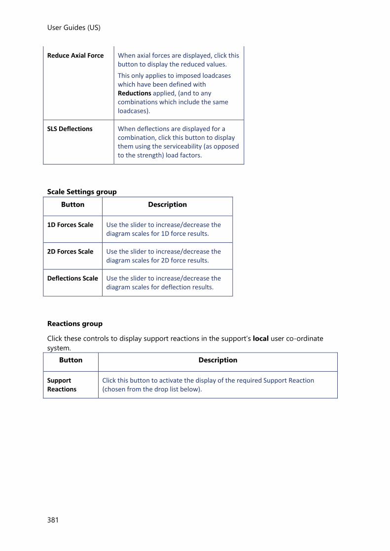
User Guides (US)
381
Reduce Axial Force When axial forces are displayed, click this button to display the reduced values.
This only applies to imposed loadcases which have been defined with Reductions applied, (and to any combinations which include the same loadcases).
SLS Deflections When deflections are displayed for a combination, click this button to display them using the serviceability (as opposed to the strength) load factors.
Scale Settings group
Button Description
1D Forces Scale Use the slider to increase/decrease the diagram scales for 1D force results.
2D Forces Scale Use the slider to increase/decrease the diagram scales for 2D force results.
Deflections Scale Use the slider to increase/decrease the diagram scales for deflection results.
Reactions group
Click these controls to display support reactions in the support’s local user co-ordinate
system.
Button Description
Support Reactions
Click this button to activate the display of the required Support Reaction (chosen from the drop list below).

User Guides
382
Support Reactions (drop list)
Use the Support Reactions drop list to choose which reaction to display:
• Fx - (corresponds to Fminor in the Foundation Reactions Report)
• Fy - (corresponds to Fmajor in the Foundation Reactions Report)
• Fz - (corresponds to Fvert in the Foundation Reactions Report)
• Mx - (corresponds to Mmajor in the Foundation Reactions Report)
• My - (corresponds to Mminor in the Foundation Reactions Report)
• Mz - (corresponds to Mtor in the Foundation Reactions Report)
• Fxyz - displays the local reactions in Fx and Fy and Fz
• Mxyz - displays the local reactions in Mx and My and Mz
• Total - displays all the local reactions (Fx, Fy, Fz, Mx, My, Mz)
Beam End Reactions
Click this button to activate the display of the required Beam End Reaction (chosen from the drop list below).
Beam End Reactions (drop list)
Use the Beam End Reactions drop list to choose which reaction to display:
• Shear Major (Fz)
• Moment Major (My)
• Shear & Moment Major (Fz & My)
• Shear Minor (Fy)
• Moment Minor (Mz)
• Shear & Moment Minor (Fy & Mz)
• Shear Major & Minor (Fz & Fy)
• Axial (Fx)
• Torsion (Mx)
1D Results group
Click these controls to display analysis results for 1D elements: beams, columns, trusses etc.
(Walls modeled using the mid-pier option also fall into this category.)
Button Description
1D Results Click this button to activate the display of the required 1D Result (chosen from the drop list below).

User Guides (US)
383
1D Results (drop list)
Use the 1D Results drop list to choose which result type to display:
• Axial Force - in local x
• Shear Major - along local z
• Shear Minor - along local y
• Torsion - about local x
• Moment Major - bending about local y
• Moment Minor - bending about local z
• Moment Biaxial - bending about local y and z
Deflections group
Click these controls to display deflection results for 1D members: beams, columns, trusses
etc. (Walls modeled using the mid-pier option also fall into this category.)
Whole structure absolute global deflections are shown which are relative to the undeformed
model.
Button Description
Deflections Click this button to activate the display of the required Deflection Result (chosen from the drop list below).
Deflections (drop list)
Use the 1D Results drop list to choose which result type to display:
• X - model deflections in the global X
• Y - model deflections in the global Y
• Z - model deflections in the global Z
• Dir 1- model deflections in the building direction 1
• Dir 2 - model deflections in the building direction 2
• Total - total (resultant) model deflections
Sway Drift and Storey Shear group
Click these controls to display sway, drift and storey shear results.
Button Description
View sway in the global X direction
View sway in the global Y direction

User Guides
384
View relative sway in the X direction
View relative sway in the Y direction
View storey shear in direction 1
View storey shear in direction 2
Notional Horizontal Forces
Button Description
Displays the calculated equivalent horizontal forces for the selected combination.
Displays the calculated equivalent lateral forces/torsions for the selected loadcase or combination.
2D Results group
Click these controls to display FE contours for two dimensional elements (i.e. FE slabs and FE
walls).
Note that contours are always in the panel axis system and based on the shell nodal forces.
Button Description
2D Results Click this button to activate the display of the required 2D Result (chosen from the drop list below).
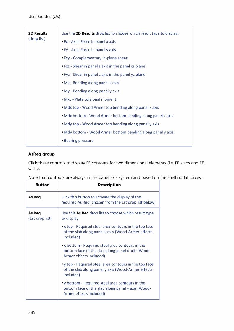
User Guides (US)
385
2D Results (drop list)
Use the 2D Results drop list to choose which result type to display:
• Fx - Axial Force in panel x axis
• Fy - Axial Force in panel y axis
• Fxy - Complementary in-plane shear
• Fxz - Shear in panel z axis in the panel xz plane
• Fyz - Shear in panel z axis in the panel yz plane
• Mx - Bending along panel x axis
• My - Bending along panel y axis
• Mxy - Plate torsional moment
• Mdx top - Wood Armer top bending along panel x axis
• Mdx bottom - Wood Armer bottom bending along panel x axis
• Mdy top - Wood Armer top bending along panel y axis
• Mdy bottom - Wood Armer bottom bending along panel y axis
• Bearing pressure
AsReq group
Click these controls to display FE contours for two dimensional elements (i.e. FE slabs and FE
walls).
Note that contours are always in the panel axis system and based on the shell nodal forces.
Button Description
As Req Click this button to activate the display of the required As Req (chosen from the 1st drop list below).
As Req (1st drop list)
Use this As Req drop list to choose which result type to display:
• x top - Required steel area contours in the top face of the slab along panel x axis (Wood-Armer effects included)
• x bottom - Required steel area contours in the bottom face of the slab along panel x axis (Wood-Armer effects included)
• y top - Required steel area contours in the top face of the slab along panel y axis (Wood-Armer effects included)
• y bottom - Required steel area contours in the bottom face of the slab along panel y axis (Wood-Armer effects included)
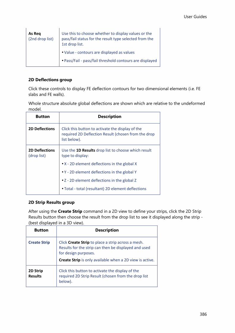
User Guides
386
As Req (2nd drop list)
Use this to choose whether to display values or the pass/fail status for the result type selected from the 1st drop list.
• Value - contours are displayed as values
• Pass/Fail - pass/fail threshold contours are displayed
2D Deflections group
Click these controls to display FE deflection contours for two dimensional elements (i.e. FE
slabs and FE walls).
Whole structure absolute global deflections are shown which are relative to the undeformed
model.
Button Description
2D Deflections Click this button to activate the display of the required 2D Deflection Result (chosen from the drop list below).
2D Deflections (drop list)
Use the 1D Results drop list to choose which result type to display:
• X - 2D element deflections in the global X
• Y - 2D element deflections in the global Y
• Z - 2D element deflections in the global Z
• Total - total (resultant) 2D element deflections
2D Strip Results group
After using the Create Strip command in a 2D view to define your strips, click the 2D Strip
Results button then choose the result from the drop list to see it displayed along the strip -
(best displayed in a 3D view).
Button Description
Create Strip Click Create Strip to place a strip across a mesh. Results for the strip can then be displayed and used for design purposes.
Create Strip is only available when a 2D view is active.
2D Strip Results
Click this button to activate the display of the required 2D Strip Result (chosen from the drop list below).

User Guides (US)
387
2D Strip Results (drop list)
Use the drop list to choose which result type to display:
• Deflection - displays a Deflection diagram along the strip
• Shear - displays a Shear Force diagram along the strip
• Moment - displays a Moment diagram along the strip
• Design Moment - displays a Design Moment diagram along the strip
• AsReq - displays an Area of Steel Required diagram along the strip
2D Wall Results group
FE Wall results can be collated and displayed on Result Lines that are created automatically
within FE walls. (The resulting display being similar to that for 1D results in mid-pier walls.)
Button Description
2D Wall Results
Click this button to activate the display of the required 2D Wall Result (chosen from the drop list below).
2D Wall Results (drop list)
Use the drop list to choose which result type to display:
• Axial Force - displays an Axial Force diagram along the result line
• Shear Major - displays a Shear Force Major diagram along the result line
• Shear Minor - displays a Shear Force Minor diagram along the result line
• Torsion - displays a Torsion diagram along the result line
• Moment Major - displays a Moment Major diagram along the result line
• Moment Minor - displays a Moment Minor diagram along the result line
Text group
Click these controls to display numerical values on the diagrams for the selected result.
Button Description

User Guides
388
Displays the Deflection value on deflection diagrams.
Displays the Axial Force value on axial force diagrams.
Displays the Shear Force value on shear force diagrams.
Displays the Reaction value on support reaction and beam end reaction diagrams.
Displays the Torsion value on torsion diagrams.
Displays the Moment value on moment diagrams.
Cross checking the sum of reactions against the load input
Once an analysis has been performed the Loading Tree can be used to quickly check that the
Total Reaction from each analysis equates to the Total Load on Structure. This allows you
to quickly establish that none of the applied load has gone missing.
The status of each loadcase and combination is indicated as follows:
- Total Reaction in equilibrium with the Total Load on Structure
- Total Reaction not in equilibrium with the Total Load on Structure
- Total Reaction not available
Loadcase Properties
When you select a loadcase in the Loading Tree, the following properties are displayed in the
Properties Window.
General
This section provides summations (in global X, Y & Z) of the different load types applied to
the structure, from these the total applied load is determined.
The total reaction from the 3D Analysis result is also reported.
Property Description
Member Loads Sum of all loads applied that have been as Member Loads to the structure.

User Guides (US)
389
Nodal Loads Sum of all loads applied that have been as Nodal Loads to the structure.
Total NHF Dir 1 Sum of NHFs in Dir 1.
Total NHF Dir 2 Sum of NHFs in Dir 2.
Decomposable Loads
Sum of all loads applied as Panel Loads to the structure (prior to load decomposition).
1 way Decomp Results
After load decomposition - this is the sum of loads decomposed on to members from one way spanning panels.
2 way Decomp Results
After load decomposition - this is the sum of loads decomposed on to members from two way spanning panels.
Total User Applied Load
Sum of all loads applied to the structure (prior to load decomposition).
Total Load on Structure
Sum of the 1 way and 2 way Decomp results.
Total Reaction Sum of reactions from the 3D Analysis.
The reported Total User Applied Load should be compared to the Total Load on
Structure, then the reported Total Load on Structure should also be cross checked against
the Total Reaction.
FE Chasedown
Property Description
Total Reaction Overall sum of reactions from the FE Chasedown Analysis.
[-] Each
Submodel
Load from above Sum of all vertical load applied to this sub model from the sub model directly above it.
Load Applied Sum of vertical load applied within the sub model.
Reaction Sum of reactions from the analysis of the FE sub model.

User Guides
390
The Total User Applied Load (from the General section) should be cross checked against
the Total Reaction.
In addition, for each sub-model the Load Applied when added to the Load from above
should equate to the Reaction.
Grillage Chasedown
Property Description
Total Reaction Overall sum of reactions from the Grillage Chasedown Analysis.
[-] Each
Submodel
Load from above Sum of all vertical load applied to this sub model from the sub model directly above it.
Load Applied Sum of vertical load applied within the sub model.
Reaction Sum of reactions from the analysis of the grillage sub model.
The Total User Applied Load (from the General section) should be cross checked against
the Total Reaction.
In addition, for each sub-model the Load Applied when added to the Load from above
should equate to the Reaction.
Displaying 1D and 2D results, deflections and reactions
Once the analysis type, and the loadcase, combination, or envelope have been chosen, the
result can be displayed simply by selecting the required effect from the appropriate group
on the Results ribbon.
• 1D groups show results for 1D elements - i.e. beams, columns, trusses etc, and also for
walls modeled using the mid-pier option.
• 2D groups show results for 2D elements - i.e. FE slabs and FE walls.
How do I choose which analysis to see the results for?
When several analysis types have been performed, the results of each one are held
separately, hence there is no need to re-perform a particular analysis to recall its results.
1. Select the analysis type required from the drop list in the Result Type group of the
Results tab.
2. Select the diagrams to display for this analysis type as required.

User Guides (US)
391
How do I choose the loadcase, combination, or envelope to see the results for?
1. First click the Loadcase, Combination, or Envelope button on the Loading drop list.
2. Then select the specific loadcase, combination, or envelope name required from the drop
list.
How do I display Support Reactions?
1. Select the analysis type required from the drop list in the Result Type group of the
Results tab.
2. Select the load case or combination to display from the Loading drop list.
3. From the Reactions group choose
• Click Support Reactions
• Choose the reaction required from the drop list.
4. From the Text group choose Reaction.
How do I display Beam End Reactions?
1. Select the analysis type required from the drop list in the Result Type group of the
Results tab.
2. Select the load case or combination to display from the Loading drop list.
3. From the Reactions group choose
• Click Beam End Reactions
• Choose the reaction required from the drop list.
4. From the Text group choose Reaction.
How do I display 1D Results and 1D Deflections?

User Guides
392
1. Select the analysis type required from the drop list in the Result Type group of the
Results tab.
2. Select the load case or combination to display from the Loading drop list.
To view 1D Results:
• From the 1D Results group click 1D Results then from the drop list underneath it
choose the result required
To view 1D Deflections:
• From the Deflections group click Deflections then from the drop list underneath it
choose the deflection required
To show values on the diagrams:
• From the Text group choose the effects required
How do I display 2D Results and 2D Deflections?
1. Select the analysis type required from the drop list in the Result Type group of the
Results tab.
2. Select the load case or combination to display from the Loading drop list.
To view 2D Results:
• From the 2D Results group click 2D Results then from the drop list underneath it
choose the result required
To view 2D Deflections:
• From the 2D Deflections group click 2D Deflections then from the drop list
underneath it choose the deflection required
How do I animate 1D and 2D Deflections?
Once the required deflections are displayed, they can be animated as follows:
1. Right click in the view and from the context menu select Animate
The animation commences.
2. If required you can change the number of frames per second, the cycle duration and the
amplitude by adjusting the sliders and clicking Apply in the Animation dialog.
3. To end the animation, simply close the Animation dialog.

User Guides (US)
393
Animations are available for static displacements and those for vibration and buckling analysis.
How do I display AsReq contours?
AsReq contours can either be displayed as:
• values, or,
• as a pass/fail threshold
Displaying as a pass/fail threshold helps to visualize minimum patch sizes when optimizing
panel and patch reinforcement as it highlights the specific areas in which the existing
reinforcement is not sufficient.
1. Select the analysis type required from the drop list in the Result Type group of the
Results tab.
2. Select the load case or combination to display from the Loading drop list.
3. In the AsReq group choose the effect that you want to be displayed from the first drop
list.
To view AsReq contours as values:
• From the second drop list in the AsReq group choose Value
To view AsReq contours as values:
• From the second drop list in the AsReq group choose Pass/Fail
What are 2D Wall Results and how do I display them?
By post-processing the FE meshed wall nodal analysis results, it is possible to determine
forces and moments along Result Lines automatically created within the walls - these results
can then be used for design purposes.
The sign convention for Result Line output follows that of the mid-pier wall model.
To view the 2D Wall Results:
1. Open a 3D View containing the walls to be viewed.
2. Select the analysis type required from the drop list in the Result Type group of the
Results tab.

User Guides
394
3. Select the load case or combination to display from the Loading drop list.
4. From the 2D Wall Results group click 2D Wall Results then from the drop list
underneath it choose the result required
5. Tekla Structural Designer will display the chosen effect on the Result Line.
How do I increase the amplitude of the diagrams?
The Forces and Deflections sliders on the settings pane are used to adjust the diagrams.
Minimum Amplitude Maximum Amplitude
How do I see a 3D display of the results in a 2D view?
Because the diagrams are plotted on each element in the planes in which they act, when you
are working in a 2D view you will need switch on an isometric display to see the out of plane
forces.
2D Frame View 2D Frame View
displayed isometrically
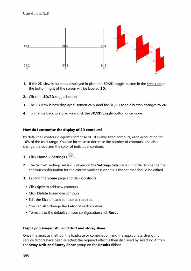
User Guides (US)
395
1. If the 2D view is currently displayed in plan, the 3D/2D toggle button in the Status Bar at
the bottom right of the screen will be labeled 3D.
2. Click the 3D/2D toggle button.
3. The 2D view is now displayed isometrically (and the 3D/2D toggle button changes to 2D.
4. To change back to a plan view click the 3D/2D toggle button once more.
How do I customise the display of 2D contours?
By default all contour diagrams comprise of 10 evenly sized contours, each accounting for
10% of the total range. You can increase or decrease the number of contours, and also
change the size and the color of individual contours.
1. Click Home > Settings ( )
2. The “active” settings set is displayed on the Settings Sets page - in order to change the
contour configuration for the current work session this is the set that should be edited.
3. Expand the Scene page and click Contours.
• Click Split to add new contours
• Click Delete to remove contours
• Edit the Size of each contour as required.
• You can also change the Color of each contour.
• To revert to the default contour configuration click Reset
Displaying sway/drift, wind drift and storey shear
Once the analysis method, the loadcase or combination, and the appropriate strength or
service factors have been selected; the required effect is then displayed by selecting it from
the Sway Drift and Storey Shear group on the Results ribbon.

User Guides
396
How do I display Sway Deflections and Relative Sway Deflections?
1. In the Result Type group of the Results tab - select an appropriate analysis method (e.g.
first order linear) and also ensure that Strength Factors are selected.
Sway deflections are not displayed if Service Factors are selected.
2. Select the load case or combination to display from the Loading drop list.
3. From the Sway Drift and Storey Shear group:
• Click Drift
• From the droplist choose the Sway X, Sway Y, Relative Sway X, Relative Sway Y as
required.
4. From the Text group choose Deflection.
How do I display Drift Deflections?
1. In the Result Type group of the Results tab - select an appropriate analysis method (e.g.
first order linear) and also ensure that Strength Factors are selected.
Drift deflections are not displayed if Service Factors are selected.
2. Select the load case or combination to display from the Loading drop list.
3. From the Sway Drift and Storey Shear group:
• Click Drift
• From the droplist choose the Drift X or Drift Y as required.
4. From the Text group choose Deflection.
How do I display Wind Drift Deflections?
1. In the Result Type group of the Results tab - select an appropriate analysis method (e.g.
first order linear) and also ensure that Service Factors are selected.
Wind Drift deflections are not displayed if Strength Factors are selected.

User Guides (US)
397
2. Select the wind combination to display from the Loading drop list.
3. From the Sway Drift and Storey Shear group:
• Click Drift
• From the droplist choose the Wind Drift X or Wind Drift Y as required.
4. From the Text group choose Deflection.
How do I display Dir 1 and Dir 2 Shears?
1. In the Result Type group of the Results tab - select an appropriate analysis method.
2. Select the load case or combination to display from the Loading drop list.
3. From the Sway Drift and Storey Shear group:
• Click Drift
• From the droplist choose the Dir 1 Shear or Dir 2 Shear as required.
Displaying Mode Shapes
Mode shapes can be displayed for 1st Order Vibration, 2nd Order buckling, 1st Order RSA
Seismic and 2nd Order RSA Seismic analyses.
How do I display mode shapes?
When several analysis types have been performed, the results of each one are held
separately, hence there is no need to re-perform a particular analysis to recall its results.
1. On the Results ribbon, select the analysis type required (either 1st Order Vibration, 2nd
Order buckling, 1st Order RSA Seismic, or 2nd Order RSA Seismic) from the drop list in
the Result Type group.
2. Select the loadcase or combination required from the Loading drop list.
For RSA Seismic analysis only loadcases should be selected, as mode shapes are not applicable for combinations and hence cannot be viewed.
3. Select the mode required from the Mode drop list in the Result Type group.
4. Select the diagram to be displayed.
Displaying Notional Forces and Seismic Equivalent Lateral Forces
EHF
(Applicable to Eurocode only) To see the magnitude of EHF in a particular combination:

User Guides
398
1. Select the combination required from the Loading drop list.
2. On the Results ribbon, click EHF in the Notional Horizontal Forces group.
Notional Loads
(Applicable to United States (ACI/AISC) only) To see the magnitude of notional loads in a
particular combination:
1. Select the required combination which includes notional loads from the Loading drop
list.
2. On the Results ribbon, click NL in the Notional Horizontal Forces group.
NHF
(Applicable to BS and Australian codes only) To see the magnitude of NHF in a particular
combination:
1. Select the combination required from the Loading drop list.
2. On the Results ribbon, click NHF in the Notional Horizontal Forces group.
Seismic
To see the magnitude of equivalent lateral forces in a seismic loadcase or combination:
1. Select the required seismic loadcase or combination from the Loading drop list.
2. On the Results ribbon, click Seismic in the Notional Horizontal Forces group.
Displaying RSA Seismic Results
Result Type
When the Result Type is set to 1st or 2nd Order RSA Seismic, the results that can be
displayed depend on the type of the currently selected Loadcase or Combination.
Mode Shapes
Mode Shapes can be displayed for:
• RSA Seismic Loadcases
• Combined (CQC) or Combined (SRSS) - depending on your choice in Analysis Options
• Plus all relevant modes for this loadcase
• Effective Seismic Weight Combination
• List of all modes returned by the Vibration Analysis
Mode Shapes are not displayed for:
• RSA Torsion Loadcases
• Static Loadcases included in the RSA Seismic Combination

User Guides (US)
399
• RSA Seismic Combinations
1D Element Results
1D Element Results are displayed as follows:
• RSA Seismic Loadcases
• Combined (CQC) or Combined (SRSS) - depending on your choice in Analysis Options
Absolute values are determined at various points along each member and then
plotted on both the positive and negative side of the diagram, (so that the diagrams
are always symmetrical about the base line).
• All relevant modes
A standard enveloped diagram is displayed
• RSA Torsion Loadcases - displayed as per 1st order linear analysis
• Static Loadcases included in the RSA Seismic Combination - displayed as per 1st order
linear analysis
• Effective Seismic Weight Combination - not available
• RSA Seismic Combinations
An envelope is drawn showing the seismic results above and below the static result.
• Base line is through the static values
• Top line is static value + seismic value
• Bottom line is static value - seismic value

User Guides
400
Story Shear
Story Shears are displayed as follows:
• RSA Seismic Loadcases
• Combined (CQC) or Combined (SRSS) - depending on your choice in Analysis Options
Absolute values are determined at each position of interest and the result is then
shown as both positive and negative.

User Guides (US)
401
• All relevant modes
A standard diagram with a single value at each point of interest is displayed
• RSA Torsion Loadcases - displayed as per 1st order linear analysis
• Static Loadcases included in the RSA Seismic Combination - displayed as per 1st order
linear analysis
• Effective Seismic Weight Combination - not available
• RSA Seismic Combinations
The diagram displays two values at each point of interest:
• static value + seismic value
• static value - seismic value.
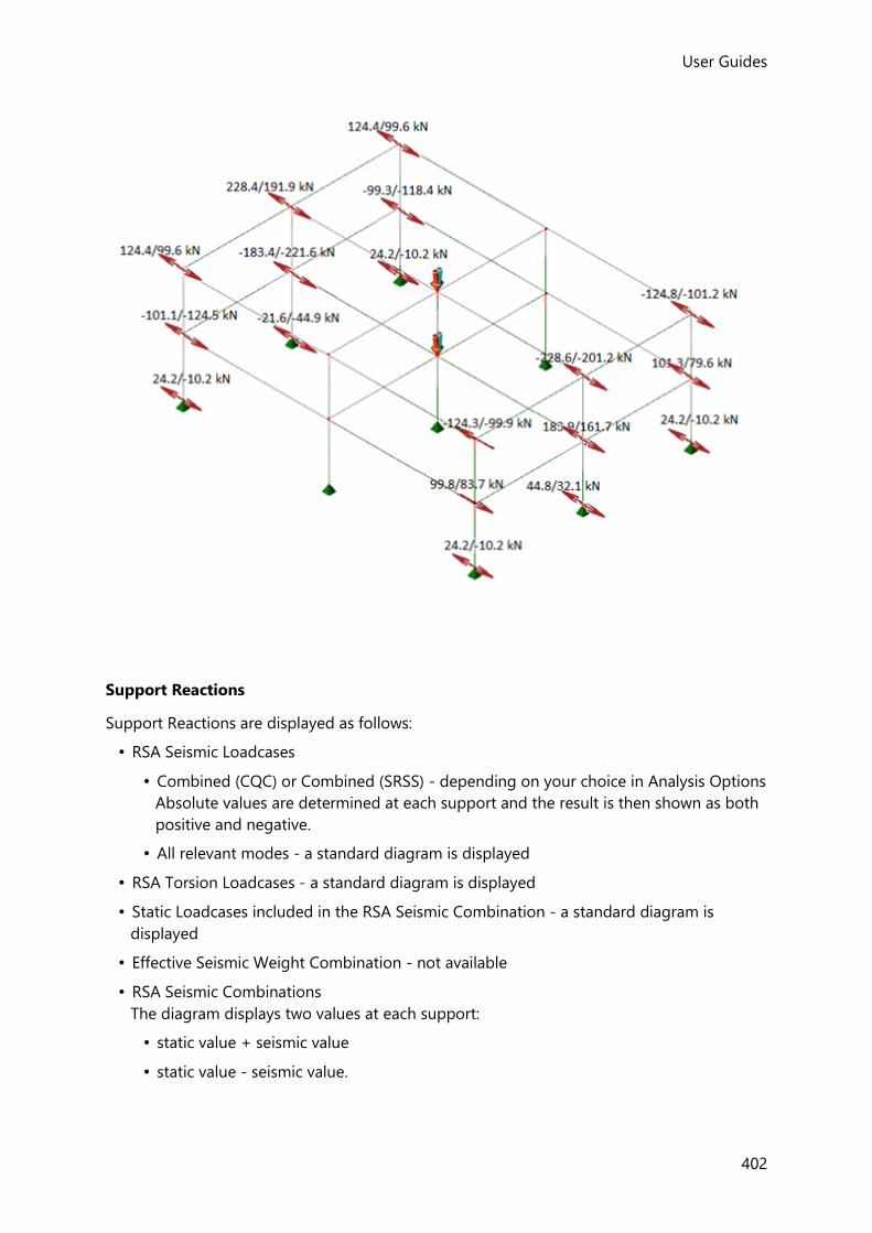
User Guides
402
Support Reactions
Support Reactions are displayed as follows:
• RSA Seismic Loadcases
• Combined (CQC) or Combined (SRSS) - depending on your choice in Analysis Options
Absolute values are determined at each support and the result is then shown as both
positive and negative.
• All relevant modes - a standard diagram is displayed
• RSA Torsion Loadcases - a standard diagram is displayed
• Static Loadcases included in the RSA Seismic Combination - a standard diagram is
displayed
• Effective Seismic Weight Combination - not available
• RSA Seismic Combinations
The diagram displays two values at each support:
• static value + seismic value
• static value - seismic value.

User Guides (US)
403
2D Wall Results
2D Wall Results are displayed as follows:
• RSA Seismic Loadcases
• Combined (CQC) or Combined (SRSS) - depending on your choice in Analysis Options
Absolute values are determined at points along the wall line and then plotted on both
the positive and negative side of the diagram, (so that the diagrams are always
symmetrical about the wall line).
• All relevant modes - a standard diagram is displayed
• RSA Torsion Loadcases - a standard diagram is displayed
• Static Loadcases included in the RSA Seismic Combination - a standard diagram is
displayed
• Effective Seismic Weight Combination - not available
• RSA Seismic Combinations
An envelope is drawn showing the seismic results above and below the static result.
• Base line is through the static values
• Line above is static value + seismic value
• Line below is static value - seismic value

User Guides
404
Working with 2D Strips and displaying Strip Results
Result Strip Overview
User defined Result Strips can be placed across 2D element meshes. From these strips, force
and moment results are determined from the shell/plate/membrane nodal analysis results -
these can then be used for design purposes, (typically for slab design).
Engineering judgement is required when positioning the strips to ensure suitable design
forces are obtained. By default they have parallel edges, but tapering strips can also be
defined as shown below:
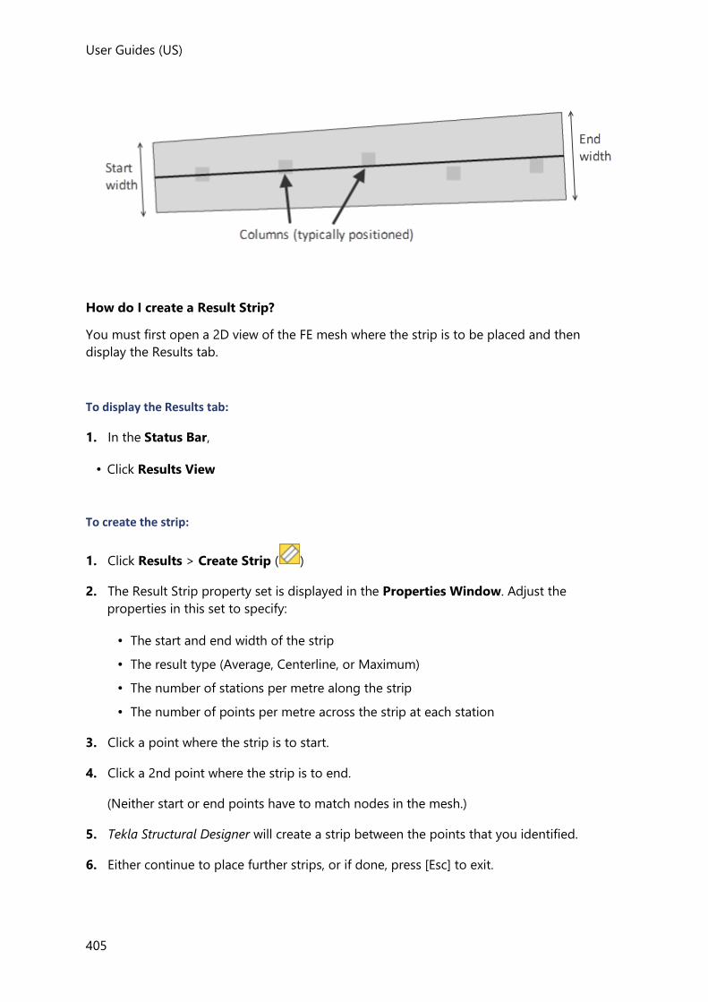
User Guides (US)
405
How do I create a Result Strip?
You must first open a 2D view of the FE mesh where the strip is to be placed and then
display the Results tab.
To display the Results tab:
1. In the Status Bar,
• Click Results View
To create the strip:
1. Click Results > Create Strip ( )
2. The Result Strip property set is displayed in the Properties Window. Adjust the
properties in this set to specify:
• The start and end width of the strip
• The result type (Average, Centerline, or Maximum)
• The number of stations per metre along the strip
• The number of points per metre across the strip at each station
3. Click a point where the strip is to start.
4. Click a 2nd point where the strip is to end.
(Neither start or end points have to match nodes in the mesh.)
5. Tekla Structural Designer will create a strip between the points that you identified.
6. Either continue to place further strips, or if done, press [Esc] to exit.

User Guides
406
How do I delete a Result Strip?
To be able to delete a strip you must first ensure that Result Strips are switched on in Scene Content.
1. Open a View containing the strips to be deleted.
2. Click Delete
3. Click the strip to be deleted.
How do I view the results for a Result Strip?
Once a Result Strip has been defined in the model you can obtain results for it without
having to re-run the analysis (providing an analysis has been run previously):
1. Open a 3D View containing the strips to be viewed.
2. Select the analysis type required from the drop list in the Result Type group of the
Results tab.
3. Select the load case or combination you want to display should be selected from the
Loading drop list.
4. From the 2D Strip Results group on the Results tab, choose the effect that you want to
be displayed.
5. Tekla Structural Designer will display the chosen effect on the strip along with the
maximum positive and negative values (calculated in accordance with the method
specified in the strip properties).
How are the strip results calculated?
Along the strip center line there are a user defined number of stations. At each station there
is a transverse line with a user defined number of points along it.
Final results are always given by station and obtaining them may or may not use points.
User Guides (US)
407
There are three alternative ways to calculate the results:
• Normal - the results on the center of the Result Strip are calculated at each station
The shell elements local to each station are considered and a weighted average force is
calculated based on the distance of the element nodes from the station.
This is repeated for all stations along the center line of the strip to give the results for the
strip.
• Maximum - results on the transverse line across the strip are calculated for each station
along the strip.
The shell elements local to each point are considered and a weighted average force is
calculated based on the distance of the element nodes from the point. The maximum
result across the strip from all points is taken as the result for the station on the strip
center line. Note that maximum values include nodes within the strip.
The values calculated at points are always weighted averages of results at adjacent nodes
- hence they are always less than the peak nodal values.
This is repeated for all stations along the center line of the strip to give the results for the
strip.
• Average - average over strip width
The results are obtained in the same way as for the maximum above but in this case are
averaged to give the results for each station.
This is repeated for all stations along the center line of the strip to give the results for the
strip.
All forces in the results are rotated to be in the axis system of the Result Strip.
Displaying analysis results for individual members (Loading Analysis View)
The Loading Analysis toolbar is used to view the loading and analysis result diagrams for
individual members.
It is activated by right-clicking on a member and selecting Open Load Analysis View from
the context menu that is displayed.
Loading Analysis toolbar
The Loading Analysis toolbar contains the following commands:
Button Description
Refresh Loading If any changes have been made to the structure while the loading view has remained open, you must click Refresh Loading in order to update the display accordingly.
User Guides
408
Result Type (drop list)
Use the drop list to choose the analysis type for which results are to be displayed.
Axial View the element loading and results for axial and torsion.
Major View the element loading and results for the major axis.
Minor View the element loading and results for the minor axis.
Next Move the cursor to the next set of results along the element.
Prev Move the cursor to the previous set of results along the element.
How do I open a Loading Analysis View?
1. Right-click the member you want to view and select Open Load Analysis View from the
context menu that is displayed.
2. Select the load case or combination you want to display from the Loading drop list.
3. Select the analysis type for which you want to see the results from the Result Type drop
list on the ribbon.
4. If displaying results for a load combination - select whether to view the results based on
Strength or Service Factors.
5. Select the axis type to view (Axial, Major, or Minor) from the Direction group on the
ribbon.
The results are displayed accordingly and can then be further controlled using the
Properties Window.
Displaying RSA Seismic Results in a Loading Analysis View
Loading Analysis Views for 1st or 2nd Order RSA Seismic result types use the same rules as
those applied to multi-member Results Views for the same result types, i.e. as follows:
RSA Seismic Loadcases
• Combined (CQC) or Combined (SRSS) - depending on your choice in Analysis Options
Absolute values are determined at various points along each member and then plotted
on both the positive and negative side of the diagram, (so that the diagrams are always
symmetrical about the base line).
• All relevant modes - a standard enveloped diagram is displayed
• RSA Torsion Loadcases - displayed as per 1st order linear analysis
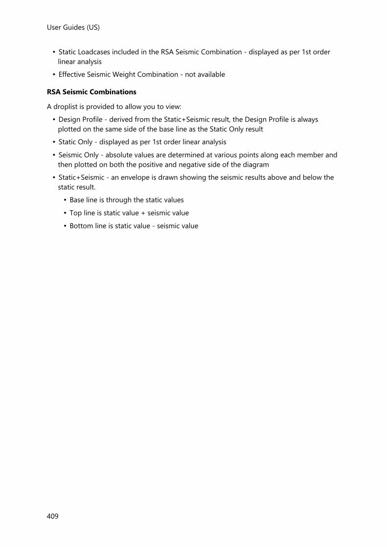
User Guides (US)
409
• Static Loadcases included in the RSA Seismic Combination - displayed as per 1st order
linear analysis
• Effective Seismic Weight Combination - not available
RSA Seismic Combinations
A droplist is provided to allow you to view:
• Design Profile - derived from the Static+Seismic result, the Design Profile is always
plotted on the same side of the base line as the Static Only result
• Static Only - displayed as per 1st order linear analysis
• Seismic Only - absolute values are determined at various points along each member and
then plotted on both the positive and negative side of the diagram
• Static+Seismic - an envelope is drawn showing the seismic results above and below the
static result.
• Base line is through the static values
• Top line is static value + seismic value
• Bottom line is static value - seismic value
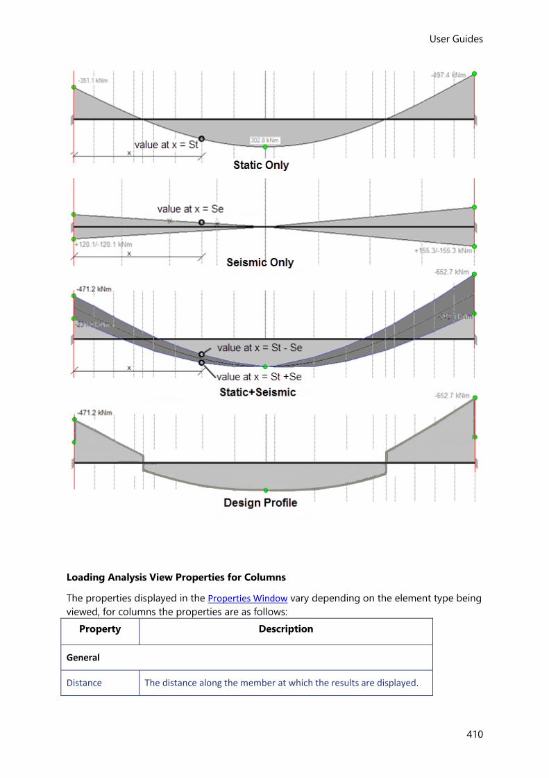
User Guides
410
Loading Analysis View Properties for Columns
The properties displayed in the Properties Window vary depending on the element type being
viewed, for columns the properties are as follows:
Property Description
General
Distance The distance along the member at which the results are displayed.

User Guides (US)
411
For concrete columns only: If rigid zones have been applied, only the non-rigid length of the column is displayed in the loading analysis view.
Stack Specifies the stack for which results are displayed.
Axial force above
The axial force in the column immediately above the cross section at the distance specified.
(This property is only displayed if the Axial direction is selected.)
Axial force below
The axial force in the column immediately below the cross section at the distance specified.
(This property is only displayed if the Axial direction is selected.)
Axial force reduced above
The axial force in the column immediately above the cross section at the distance specified, taking into account imposed load reductions.
(This property is only displayed if the Axial direction is selected.)
Axial force reduced below
The axial force in the column immediately below the cross section at the distance specified, taking into account imposed load reductions.
(This property is only displayed if the Axial direction is selected.)
Torsion moment above
The torsion in the column immediately above the cross section at the distance specified.
(This property is only displayed if the Axial direction is selected.)
Torsion moment below
The torsion in the column immediately below the cross section at the distance specified.
(This property is only displayed if the Axial direction is selected.)
Shear above The major or minor shear force immediately above the cross section at the distance specified.
(This property is only displayed if the Major or Minor direction is selected.)
Shear below The major or minor shear force immediately below the cross section at the distance specified.
(This property is only displayed if the Major or Minor direction is selected.)
Moment above The major or minor moment immediately above the cross section at the distance specified.
(This property is only displayed if the Major or Minor direction is selected.)

User Guides
412
Moment below The major or minor moment immediately below the cross section at the distance specified.
(This property is only displayed if the Major or Minor direction is selected.)
Ecc. Moment above
The major or minor moment due to eccentricity immediately above the cross section at the distance specified.
(This property is only displayed if the Major or Minor direction is selected.)
Ecc. Moment below
The major or minor moment due to eccentricity immediately below the cross section at the distance specified.
(This property is only displayed if the Major or Minor direction is selected.)
Relative deflection
The relative deflection in the major or minor direction at the distance specified.
(This property is only displayed if the Major or Minor direction is selected.)
Load above The applied distributed load in the major or minor direction immediately above the cross section at the distance specified.
(This property is only displayed if the Major or Minor direction is selected.)
Load below The applied distributed load in the major or minor direction immediately below the cross section at the distance specified.
(This property is only displayed if the Major or Minor direction is selected.)
Force The applied point load in the major or minor direction at the distance specified.
(This property is only displayed if the Major or Minor direction is selected.)
Moment The applied moment in the major or minor direction at the distance specified.
(This property is only displayed if the Major or Minor direction is selected.)
Show axial force
If cleared, the axial force diagram is removed from the view.
(This property is only displayed if the Axial direction is selected.)
Show axial force reduced
If cleared, the axial force diagram is removed from the view.
(This property is only displayed if the Axial direction is selected.)

User Guides (US)
413
Show torsion moment
If cleared, the torsion diagram is removed from the view.
(This property is only displayed if the Axial direction is selected.)
Show loading If cleared, the loading diagram is removed from the view.
(This property is only displayed if the Major or Minor direction is selected.)
Show shear If cleared, the shear diagram is removed from the view.
(This property is only displayed if the Major or Minor direction is selected.)
Show moment If cleared, the moment diagram is removed from the view.
(This property is only displayed if the Major or Minor direction is selected.)
Show dimensions
If cleared, the dimensions are removed from the view.
(This property is only displayed if the Axial direction is selected.)
Show extremes If cleared, the max and min values are removed from the view.
Loading Analysis View Properties for Beams
The properties displayed in the Properties Window vary depending on the element type being
viewed and the Result Type selected, for beams the properties for the different Result Types
are as follows:
Result Type: Axial
Property Description
General
Distance The distance along the member at which the results are displayed.
For concrete beams only: If rigid zones have been applied, only the non-rigid length of the beam is displayed in the loading analysis view.
Span Specifies the span for which results are displayed.
Axial force left The axial force in the beam immediately to the left of the cross section at the distance specified.
Axial force right The axial force in the beam immediately to the right of the cross section at the distance specified.
Torsion moment left
The torsion in the beam immediately to the left of the cross section at the distance specified.

User Guides
414
Torsion moment right
The torsion in the beam immediately to the right of the cross section at the distance specified.
Relative angle of twist
The relative angle of twist (due to torsion) in the beam cross section, at the distance specified.
Angle of twist derivative
A droplist allowing the selection of the derivative of angle of twist:
• First
• Second
• Third
(This property is displayed for “Open” sections only).
Angle of twist derivative left
The relative angle of twist (due to torsion) in the beam cross section, immediately to the left of the distance specified.
(This property is displayed for “Open” sections only).
Angle of twist derivative right
The relative angle of twist (due to torsion) in the beam cross section, immediately to the right of the distance specified.
(This property is displayed for “Open” sections only).
Show axial force
If cleared, the axial force diagram is removed from the view.
(This property is only displayed if the Axial direction is selected.)
Show torsion moment
If cleared, the torsion diagram is removed from the view.
(This property is only displayed if the Axial direction is selected.)
Show relative angle of twist
If cleared, the relative angle of twist diagram is removed from the view.
Show angle of twist derivative
If cleared, the angle of twist derivative diagram is removed from the view.
(This property is displayed for “Open” sections only).
Show dimensions
If cleared, the dimensions are removed from the view.
Show extremes If cleared, the max and min values are removed from the view.
Result Type: Major, Minor, Major Principal, Minor Principal
Property Description
General
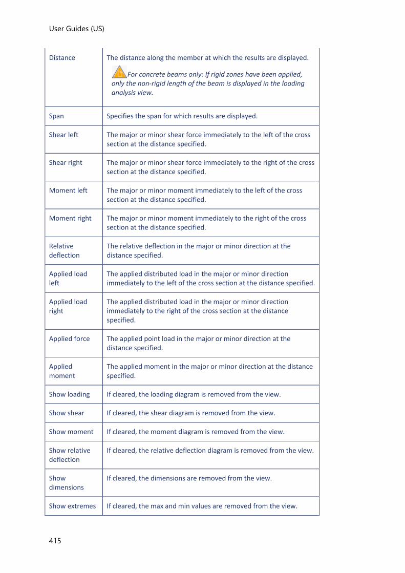
User Guides (US)
415
Distance The distance along the member at which the results are displayed.
For concrete beams only: If rigid zones have been applied, only the non-rigid length of the beam is displayed in the loading analysis view.
Span Specifies the span for which results are displayed.
Shear left The major or minor shear force immediately to the left of the cross section at the distance specified.
Shear right The major or minor shear force immediately to the right of the cross section at the distance specified.
Moment left The major or minor moment immediately to the left of the cross section at the distance specified.
Moment right The major or minor moment immediately to the right of the cross section at the distance specified.
Relative deflection
The relative deflection in the major or minor direction at the distance specified.
Applied load left
The applied distributed load in the major or minor direction immediately to the left of the cross section at the distance specified.
Applied load right
The applied distributed load in the major or minor direction immediately to the right of the cross section at the distance specified.
Applied force The applied point load in the major or minor direction at the distance specified.
Applied moment
The applied moment in the major or minor direction at the distance specified.
Show loading If cleared, the loading diagram is removed from the view.
Show shear If cleared, the shear diagram is removed from the view.
Show moment If cleared, the moment diagram is removed from the view.
Show relative deflection
If cleared, the relative deflection diagram is removed from the view.
Show dimensions
If cleared, the dimensions are removed from the view.
Show extremes If cleared, the max and min values are removed from the view.

User Guides
416
Analysis results sign conventions
Tekla Structural Designer adopts the standard convention for engineering / CAD software that lower case x, y, z represent local coordinate systems whereas upper case X, Y, Z represent the global coordinate system.
Introduction
Axis Systems
The following axis systems are relevant in the software:
• Global Coordinate System - the global XYZ axis system within which all other systems exist
• Building Directions 1 and 2 - the principle axes of the building - Dir 1 being rotated at an
angle to global X in the horizontal plane.
• User Coordinate System - a local coordinate system defined by the system or the user
• 1D Member Local Coordinate System - the local coordinate system applicable to all 1D
members - beams, columns, braces etc
• Mid-pier Wall Coordinate System - the local coordinate system applicable to walls modeled
using the mid-pier option
• 2D Member Local Coordinate System - the local coordinate system applicable to all 2D
members - walls and slabs
• Result Line Coordinate System - the local coordinate system applicable to Result Lines
• Result Strip Coordinate System - the local coordinate system applicable to Result Strips
• Foundation Reaction Coordinate System - the local coordinate system applicable to
foundations
General
The global (XYZ) and local (xyz) axis systems all follow the right hand rule.
• x-axis = pointing index finger
• y-axis = crooked middle finger
• z-axis = extended thumb
And the directions of +ve rotation
• +ve rotation about x: the y-axis moves toward the z-axis.
• +ve rotation about y: the z-axis moves toward the x-axis.
• +ve rotation about z: the x-axis moves toward the y-axis.
Object Orientation
Tekla Structural Designer takes account of an object’s orientation when displaying the
analysis results. Therefore, to apply the sign convention correctly you need to know which is

User Guides (US)
417
end 1 and which is end 2 for beams/walls and you also need to know which is Face A for
columns.
To determine the orientation
In the Members group within Scene Content, if you switch the Direction option on, then
Tekla Structural Designer shows an arrow on all beams, walls and columns.
• The arrow points from the start to the end of beams/walls and is drawn along the top
face.
• The arrow points from the bottom to the top of columns along Face A. Looking down
from the top of a column, Face B, C, and D then follow in the clockwise direction.
Diagram Conventions
All arrows should point in the direction of the force or moment - and so are reversed for -ve
forces and moments - eg
Global Coordinate System
Global Axis System and Applied Load Directions

User Guides
418
Resulting Deflection Directions
Building Directions 1 and 2
Building Directions and Applied Load Directions
Global axes (+ve Z vertically up) and angle between X and Dir 1 = where is +ve in RH rule
about Z
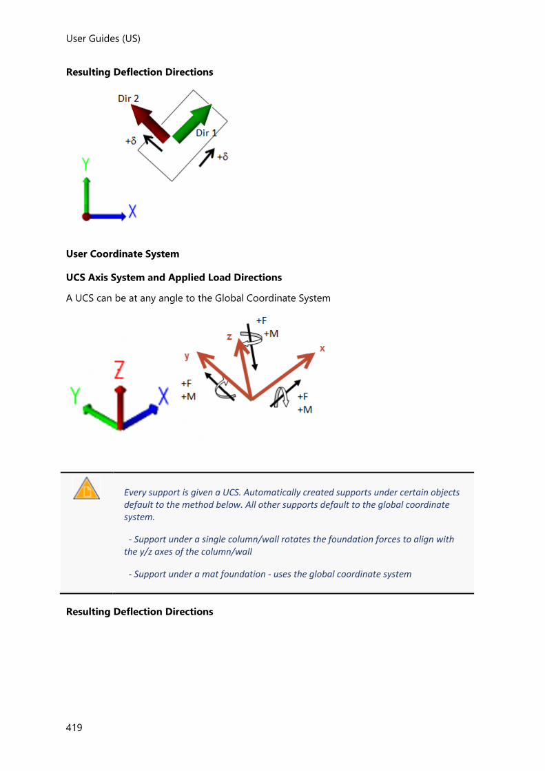
User Guides (US)
419
Resulting Deflection Directions
User Coordinate System
UCS Axis System and Applied Load Directions
A UCS can be at any angle to the Global Coordinate System
Every support is given a UCS. Automatically created supports under certain objects default to the method below. All other supports default to the global coordinate system.
- Support under a single column/wall rotates the foundation forces to align with the y/z axes of the column/wall
- Support under a mat foundation - uses the global coordinate system
Resulting Deflection Directions
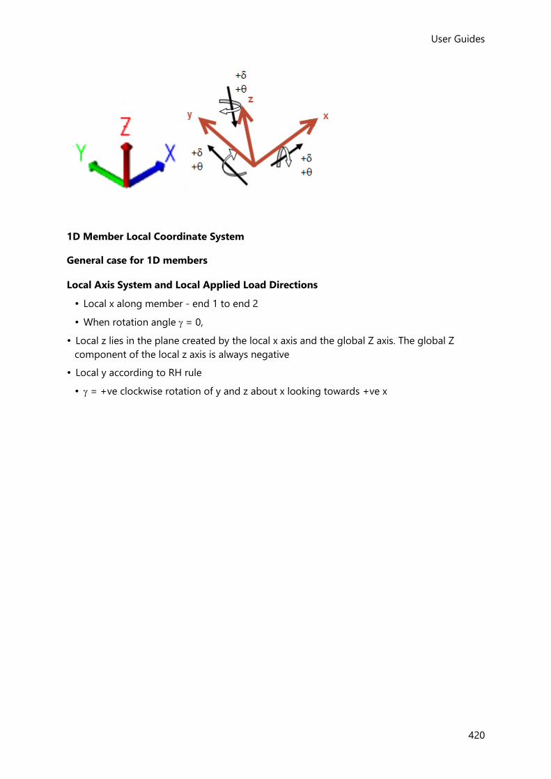
User Guides
420
1D Member Local Coordinate System
General case for 1D members
Local Axis System and Local Applied Load Directions
• Local x along member - end 1 to end 2
• When rotation angle = 0,
• Local z lies in the plane created by the local x axis and the global Z axis. The global Z
component of the local z axis is always negative
• Local y according to RH rule
• = +ve clockwise rotation of y and z about x looking towards +ve x

User Guides (US)
421
With the local axis aligned as shown above, it can be seen that:
• Major direction loads act in the local xz plane; positive Major direction Force (Fz), and
Moment (My) are shown below:

User Guides
422
• Minor direction loads act in the local xy plane; positive Minor direction Force (Fy), and
Moment (Mz) are shown below:
• Positive Axial Force (Fx) acts in the local x direction, and positive Axial Moment (Mx) acts
clockwise about local x as shown below:
Result Axis System and Directions
In the Major Axis:
• Moment Major = bending about y
• Shear Major = shear along z
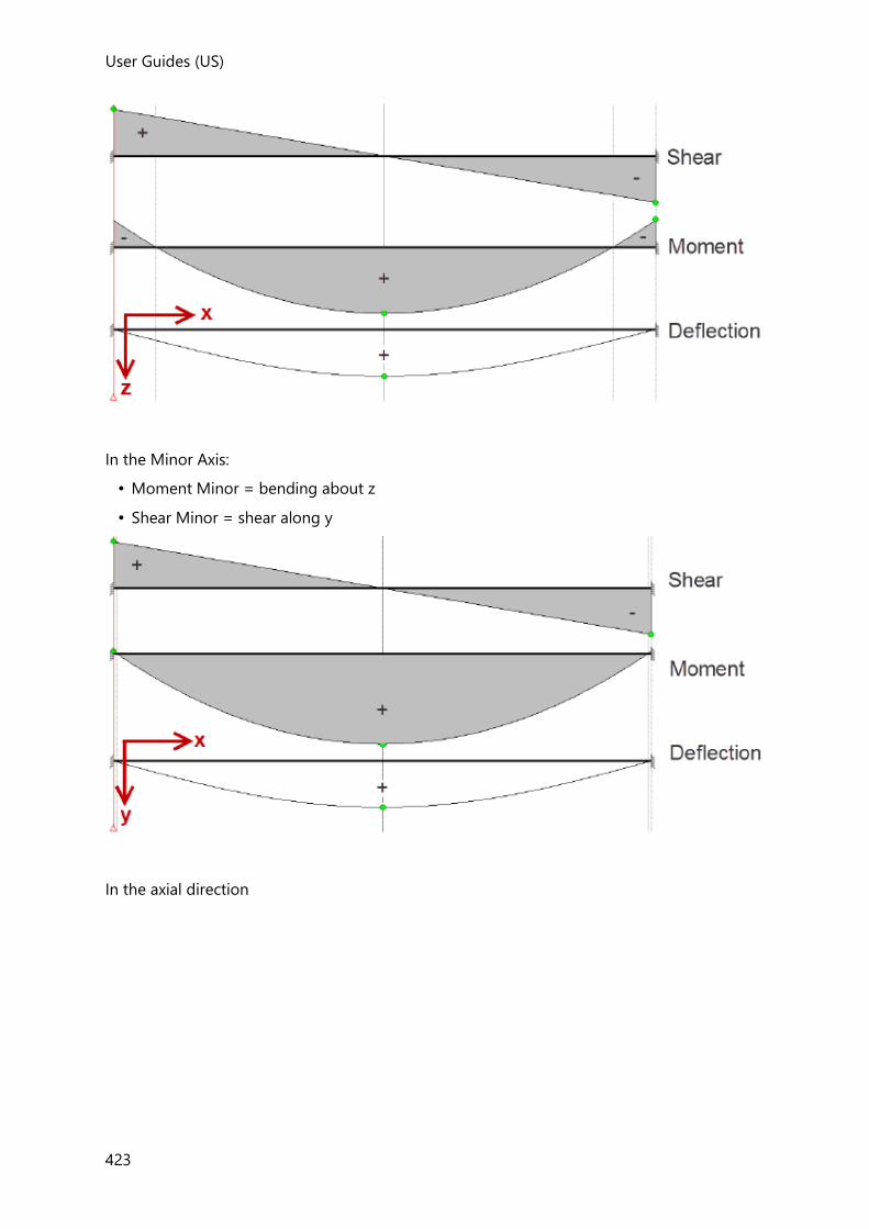
User Guides (US)
423
In the Minor Axis:
• Moment Minor = bending about z
• Shear Minor = shear along y
In the axial direction

User Guides
424
Member End Forces and Directions
Member End Forces are the forces applied to the rest of the structure by the member.
Positive beam end reactions act as shown for a beam with its Local Axis System indicated
below:

User Guides (US)
425
Special case for 1D members
Local Axis System and Applied Load Directions
Local x aligns with global Z (i.e vertical)
• When rotation angle = 0,
• Local y aligns with global X
• Local z according to RH rule
• = +ve clockwise rotation of y and z about x looking towards +ve x

User Guides
426
Applied Force directions are as follows:
• Major direction loads act in the local xz plane; positive Major direction Force (Fz), and
Moment (My) are as shown above.
• Minor direction loads act in the local xy plane; positive Minor direction Force (Fy), and
Moment (Mz) are as shown above.
• Positive Axial Force (Fx) acts in the local x direction, and positive Axial Moment (Mx) acts
clockwise about local x as shown above.
Result Axis System and Directions
In the Major Axis:
• Moment Major = bending about y
• Shear Major = shear along z

User Guides (US)
427
In the Minor Axis:
• Moment Minor = bending about z
• Shear Minor = shear along y
In the axial direction

User Guides
428
Mid-pier Wall Coordinate System
Wall Axis System and Applied Load Directions
Centered on the centroid of the cut section
• x axis lies along the stem mid-pier element (+ve lowest to highest)
• z axis in the plane of the wall (+ve end 2 to end 1)
• y axis follows the RH rule and is normal to the wall
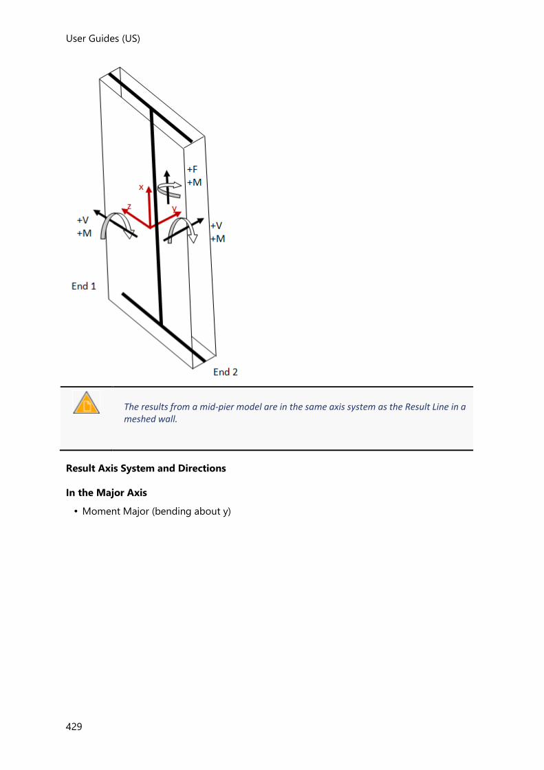
User Guides (US)
429
The results from a mid-pier model are in the same axis system as the Result Line in a meshed wall.
Result Axis System and Directions
In the Major Axis
• Moment Major (bending about y)

User Guides
430
• Shear Major (shear along z)

User Guides (US)
431
In the Minor Axis
• Moment Minor (bending about z)
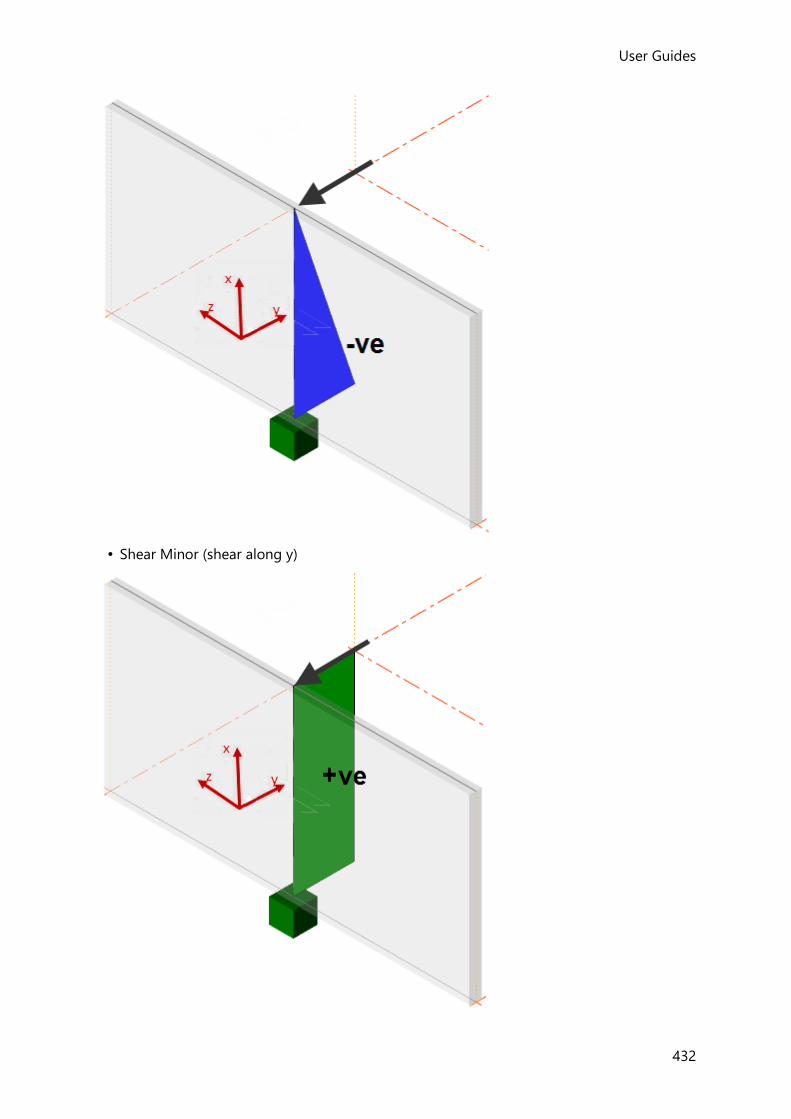
User Guides
432
• Shear Minor (shear along y)

User Guides (US)
433
Axial and torsion
• force in x and torsion about x
2D Member Local Coordinate System
Horizontal Panel Local Axis System and Applied Load Directions
Horizontal panel local axes are -
Local z is normal to the plane of the panel
When = 0,
• Local x is in the plane of the panel, aligned with global X and +ve in +ve global X
• Local y is in the plane of the panel and follows the RH rule
• = +ve clockwise rotation of x and y about z looking towards +ve z

User Guides
434
Vertical and Sloped Panel Local Axis System and Applied Load Directions
Vertical and Sloped panel local axes are -
• Local z is normal to the plane of the panel
• When = 0,
• Local x is in the plane of the panel and in a horizontal plane
• Local y is in the plane of the panel and follows the line of greatest slope of the plane (+ve
in the direction of +ve global)
• = +ve clockwise rotation of x and y about z looking towards +ve x
Sloped panel (axes at )
Vertical panel (axes when = 0)

User Guides (US)
435
2D Member Forces Sign Convention
The diagram below illustrates the forces and the panel and 2D element axis system (for
results).
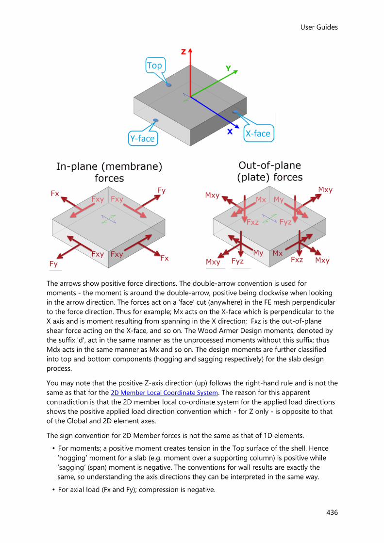
User Guides
436
The arrows show positive force directions. The double-arrow convention is used for
moments - the moment is around the double-arrow, positive being clockwise when looking
in the arrow direction. The forces act on a ‘face’ cut (anywhere) in the FE mesh perpendicular
to the force direction. Thus for example; Mx acts on the X-face which is perpendicular to the
X axis and is moment resulting from spanning in the X direction; Fxz is the out-of-plane
shear force acting on the X-face, and so on. The Wood Armer Design moments, denoted by
the suffix 'd', act in the same manner as the unprocessed moments without this suffix; thus
Mdx acts in the same manner as Mx and so on. The design moments are further classified
into top and bottom components (hogging and sagging respectively) for the slab design
process.
You may note that the positive Z-axis direction (up) follows the right-hand rule and is not the
same as that for the 2D Member Local Coordinate System. The reason for this apparent
contradiction is that the 2D member local co-ordinate system for the applied load directions
shows the positive applied load direction convention which - for Z only - is opposite to that
of the Global and 2D element axes.
The sign convention for 2D Member forces is not the same as that of 1D elements.
• For moments; a positive moment creates tension in the Top surface of the shell. Hence
‘hogging’ moment for a slab (e.g. moment over a supporting column) is positive while
‘sagging’ (span) moment is negative. The conventions for wall results are exactly the
same, so understanding the axis directions they can be interpreted in the same way.
• For axial load (Fx and Fy); compression is negative.

User Guides (US)
437
• We are not usually concerned about the sign of shear, however, for completeness; out-
of-plane shear (Fxz and Fyz) is positive when shear is such that moment is increasing in
the positive X or Y direction.
Result Line Coordinate System
Centered on the centroid of the cut section
• z axis lies along the Result Line (+ve - end 2 to end 1)
• y axis normal to plane of mesh (generally +ve in the +ve Z direction, special case +ve x
towards +ve Z)
• x axis follows the RH rule and lies in the mesh - x is therefore perpendicular to the cut
line
The results from a Result Line are exactly as that for a mid-pier model when the cut is horizontal and the cut direction matches the direction required.
Result Axis System
• In the Major Axis = bending about y and shear along z
• In the Minor Axis = bending about z and shear along y
• Axial and torsion = force in x and bending about x
General Case
Special Case

User Guides
438
Result Strip Coordinate System
Centered at each station along the strip center line (single or several continuous strips)
• z axis normal to plane of mesh (generally +ve in the -ve Z direction, special case +ve x
towards +ve Z)
• x axis lies along the Result Strip (+ve - end 1 to end 2)
• y axis lies along the transverse line to the strip and follows the RH rule - y is therefore
perpendicular to the strip line
Result Axis System
• Deflection - in the z axis
• Out of plane moment about the y axis
• Shear in the z axis
General Case

User Guides (US)
439
Special Case
Foundation Reaction Coordinate System
Result Axis System and Directions
The foundation reaction coordinate system is aligned with the coordinate system for the
support node whether that is the Global Coordinate System or a User Coordinate System.
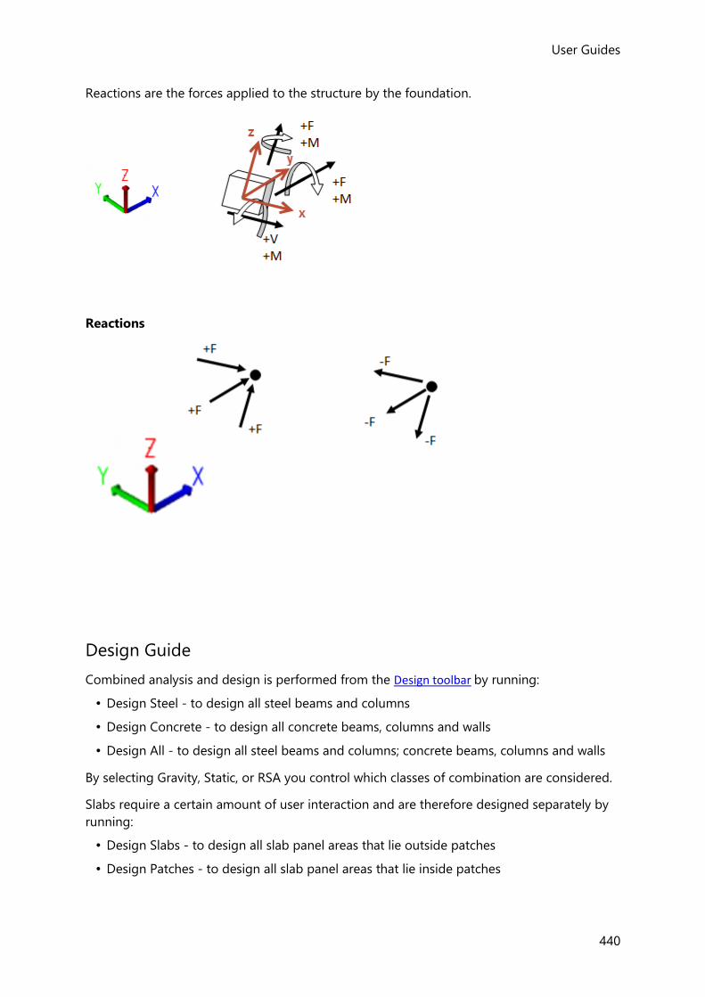
User Guides
440
Reactions are the forces applied to the structure by the foundation.
Reactions
Design Guide
Combined analysis and design is performed from the Design toolbar by running:
• Design Steel - to design all steel beams and columns
• Design Concrete - to design all concrete beams, columns and walls
• Design All - to design all steel beams and columns; concrete beams, columns and walls
By selecting Gravity, Static, or RSA you control which classes of combination are considered.
Slabs require a certain amount of user interaction and are therefore designed separately by
running:
• Design Slabs - to design all slab panel areas that lie outside patches
• Design Patches - to design all slab panel areas that lie inside patches

User Guides (US)
441
• Design Punching Shear - to design all punching check items (Not available for Australia
Head Code)
Floor vibrations can also be checked by running:
• Check Floor Vibration - to establish the response of the floor to dynamic excitation
Design toolbar
The Design toolbar contains the following commands:
Button Description
Options
Opens the Design Options dialog.
See Design Options
Validate
Validates the model for any design issues which might exist.
See Model Validation
Design Steel (Gravity)
Initiates an analysis-design process for steel members for gravity combinations only.
See Design Steel (Gravity)
Design Steel (Static)
Initiates a complete static analysis-design process for all steel members in the structure.
See Design Steel (Static)
Design Steel (RSA)
Initiates a complete RSA analysis-design process for all steel members in the structure.
See Design Steel (RSA)
Design Concrete (Gravity)
Initiates an analysis-design process for all concrete members in the structure for gravity combinations only.
See Design Concrete (Gravity)
Design Concrete (Static)
Initiates a complete static analysis-design process for all concrete members in the structure.
See Design Concrete (Static)
Design Concrete (RSA)
Initiates a complete RSA analysis-design process for all concrete members in the structure.
See Design Concrete (RSA)
Design All (Gravity)
Initiates an analysis-design process for all members in the structure for gravity combinations only.
See Design All (Gravity)

User Guides
442
Design All (Static)
Initiates a complete static analysis-design process for all members in the structure.
See Design All (Static)
Design All (RSA)
Initiates a complete RSA analysis-design process for all members in the structure.
See Design All (RSA)
Patch Column
(on drop list)
Creates a column patch which adopts the specified create column patch properties set
See How do I create a column patch?
Patch Beam
(on drop list)
Creates a beam patch which adopts the specified create beam patch properties set
See How do I create a beam patch?
Patch Wall
(on drop list)
Creates a wall patch which adopts the specified create wall patch properties set
See How do I create a wall patch?
Patch Panel
(on drop list)
Creates a panel patch which adopts the specified create panel patch properties set
See How do I create a panel patch?
Design Patches
Designs or checks slab reinforcement in all slab areas inside patches.
See Slab design, patches and punching shear
Design Slabs
Designs or checks slab reinforcement in all slab areas that are not inside patches.
See Slab design, patches and punching shear
Add Check
Used to add a punching shear check around a column or wall perimeter.
See How do I create a Punching Check item?
Design Punching Shear
Performs the punching shear checks.
See Perform Punching Shear Checks
Add Check
Used to add a floor vibration check for a slab area.
See How do I create a Floor Vibration Check item?
Check Floor Vibration
Performs the floor vibration checks.
See How do I check vibration for all Floor Vibration Check items?

User Guides (US)
443
Related topics
• Commands on the ribbon toolbars
Design Options
How to apply and manage Design Options
To modify design options in the current project
1. Click Design > Options... ( )
2. Review and edit the settings as required.
3. If you change any of the settings, click:
• OK - to apply the changes directly to the current project, or
• Save... - to save the changes back to the active settings set (to act as defaults for future
projects), or
• Cancel... - to cancel the changes
You can also click:
• Load... - to revert to the design options specified in the active settings set.
To modify design option defaults for future projects
1. Click Home > Settings ( )
2. In the Design Options page of the dialog, select the settings set to be updated, then
review and edit the settings as required.
You can update any settings set simply by selecting it from the droplist, it does not need to be active.
3. If you change any of the settings, click:
• OK - to save the changes to the selected settings set (to act as defaults for future
projects when that set is active), or
• Cancel - to cancel the changes

User Guides
444
Design Options-Analysis
Analysis
The Analysis options on this page allow you choose whether a first or second order 3D Analysis is performed.
For steel structures in particular you should consider running a first-order analysis for the initial gravity design before switching to a second-order analysis for the final design.
Solve lateral loadcases in isolation if non-linear analysis is required during design
In non-linear analysis, lateral loadcases will often fail to solve at all or take a long time to
converge when considered in isolation - this is especially true for compression only
foundation mats. Hence it is suggested that this check box is left cleared.
If you need to see the results for the individual lateral loadcases you can either run the
analysis directly from the Analyses ribbon, (or if you know that the analysis does not fail,
you can select this check box.)
Stability Coefficient Tolerance
If very small deflections were to be used in the calculation of the Stability Coefficient. then
potentially very high Stability Coefficients could erroneously be reported.
To prevent this, the Stability Coefficient Tolerance provides you with a means to control the
value of deflection that can safely be ignored. setting the analysis to first-order If the second
order drift is less than the tolerance defined here (default stack height/10000), the Stability
Coefficient is returned as 'N/A' with a note to say that the 'Drift is small enough to be
ignored'.
Reduced Stiffness Factor
This factor is only exposed once the analysis is set to second-order. For correct design to the
AISC Specification using the DAM, this should be set to 0.8.
As an alternative to setting the analysis to first-order to explore the reason for any second
order analysis failure, it is possible to alter this factor. If you set it to a value of say 10, this
will stiffen both the Modulus of elasticity (E) and the shear modulus of elasticity (G) by a
factor of 10 in the second order analysis. Although the results will not be able to be used for
a valid design, it should now be possible to run the analysis to see which member might fail
a design and hence be the cause of the analysis instability. This factor can then be reduced
towards 0.8 for further investigation.
•
Design Options-General
General

User Guides (US)
445
Use multi-core processors for design
leave this option selected to take advantage of multi-core processing during the design
phase.
Run chase-downs concurrently
leave this option selected to take advantage of multi-core processing during the chase-
down analysis phase.
The above options are only displayed when the design settings are accessed from the Settings dialog on the Home toolbar.
Gravity Design
Fix column nodes horizontally
When selected, this option automatically applies lateral translational fixed supports to
column nodes for the 3D Analysis performed during the gravity design processes. This is
useful at the early design stage when lateral systems have not been established. The
automatic lateral supports can remove unwanted lateral displacements that may prevent
the analysis from completing and/ or produce unrealistic forces.
The ‘Fix Column nodes horizontally’ setting does not apply to: - Column nodes that are in a rigid floor diaphragm, - Analysis run as a separate process, - Analyse All (Static), - 3D Analysis performed during Design...(Static).
Design Options-Concrete-Reinforcement Parameters
Reinforcement anchorage length parameters
These parameters are used in the calculation of the ultimate bond stress, from which the
anchorage lengths are determined.
Eurocode:
Plain Bars Bond Quality Modifier
Allowable range 0.1 - 1.0; default 0.5
Type-1 Bars Bond Quality Modifier
Allowable range 0.1 - 1.0; default 0.8
Type-2 Bars Bond Quality Modifier
Allowable range 0.1 - 1.0; default 1.0

User Guides
446
ACI:
Plain Bars Bond Quality Modifier
Allowable range 0.1 - 1.0; default 0.5
Deformed Bars Bond Quality Modifier
Allowable range 0.1 - 1.0; default 1.0
Design Options-Concrete-Beam
This page has several sub-pages for setting up the options that are used in the beam design.
Concrete - Beam - Reinforcement Settings
This page is used to set limits on the ranges and spacings of bars used in the design.
General
Country
The available bar sizes and properties are taken from the Materials -
Reinforcement database according to the country selected.
Longitudinal bars
Minimum bar size
Sets the minimum allowable bar size that can be used in the design process.
Maximum bar size
Sets the maximum allowable bar size that can be used in the design process.
Minimum side bar size
Sets the minimum allowable side bar size that can be used in the design process.
Minimum top steel clear spacing
Sets the minimum allowable top steel clear spacing that can be used in the design
process.
Minimum bottom steel clear spacing
Sets the minimum allowable bottom steel clear spacing that can be used in the design
process.
Maximum tension steel spacing
Sets the maximum allowable tension steel spacing that can be used in the design
process.
Maximum compression steel spacing
Sets the maximum allowable compression steel spacing that can be used in the design
process.
User Guides (US)
447
Use single bars when beam width <=
Single bars are only permitted in beams less than the width specified.
Steel overstrength factor (ACI only)
This factor is used in seismic design to account for the reinforcement steel yielding
overstrength.
Short Span
Short Span maximum length
Spans smaller than the value set here are treated as short spans. Support bars of short
spans are merged with the span bars.
Concrete - Beam - Detailing Options
Settings on this page relate to the detail that is produced, but have no affect on the design.
Longitudinal Bars
Use same size bars in multilayer arrangements
Select to use the same bar size in each layer.
Use same number of bars in each layer
Select to use the same number of bars in each layer.
Cut Length
Cut length rounding increment
Cut lengths are rounded to the value specified.
Longitudinal Bar Curtailment
Merge identical longitudinal bars if appropriate
Merging is only possible in some of the standard bar patterns - top bar patterns 1 and 2
don't have any bars that can merge.
In other patterns, bars of the same size, number and position can be merged, provided
that the total length of the merged bar does not exceed the max allowable bar length.
The max bar length can be verified from Home > Materials > Reinforcement by clicking an available bar size and then clicking the View… button.
Extend top longitudinal support bars symmetrically
Extends the support bars symmetrically to both spans based on the larger effective span
length; but only if the spans vary by less than the percentage specified.
Extend top longitudinal support bars by anchorage length
Adds an anchorage lengths to the calculated extension lengths.
Eurocode:
User Guides
448
Min anchorage length {value} x dia
The minimum anchorage length as a multiple of bar diameter is controlled with this
setting.
ACI:
Min anchorage length of plain bars {value} x dia
The minimum anchorage length as a multiple of bar diameter is controlled with this
setting (only used when the rib type is ‘Plain’).
End Support Curtailment
Extend top span bars to end support
Extends the top span bars of the first and last spans to the end supports.
Use ‘U’ bars at end support if appropriate
Under certain conditions this option replaces the top and bottom bars at the end support
region with 'U' bars. The bars that are joined/merged to create the 'U' bars depend on
the top and bottom patterns chosen for the beam.
The anchorage lengths for the resulting 'U' bars are taken as the lengths required for the
pair of bars that made the 'U' bar.
Extend and bob all bars for supporting member widths up to
This setting is provided to control the extension/application of end bobs within the
supporting member. It allows anchorage lengths to be reduced in situations where they
would otherwise extend too far into the supporting member. In the ordinary situation
where the supporting members are perpendicular narrow beams the bars are bobbed in
the normal way. In situations where the supporting members are wider than the entered
value reduced anchorages result (as for anchorage into in-plane walls).
The setting is applied at each end support as follows:
1. Calculate required anchorage length
2. Determine support width
If anchorage length
> (support width - cover): bob bars
Else if support width
< entered value for this setting: extend and bob bars
Else: Provide straight anchorage
Links
Select same bar size in support region and in the span
Select to use the same bar size in the support and span regions.
Select symmetrical link in support region
Select to use same link arrangement (bar size and spacing) in both supports.
Concrete - Beam - Top Longitudinal Bar Pattern

User Guides (US)
449
This page is used to configure the patterns used for the top bars.
Standard Pattern Setup
Longitudinal Bar Pattern
This drop list is used to select a pattern to be viewed/modified in the Design Options
dialog.
Default Pattern
Longitudinal Default Pattern
This drop list is used to select the pattern that gets applied to new beams when they are
first created.
The ‘Default Pattern’ cannot be used to change the pattern associated with existing beams. This can only be achieved by editing the beam properties.
Continuous Span + Cantilever (Backspan)
This tab is used to define how the selected Longitudinal Bar Pattern gets applied to
continuous spans and cantilever backspans. An interactive diagram is also displayed which
updates as changes are made.
Bar check boxes
Selected bars that are also dimmed are mandatory for the selected pattern. Other bars
can optionally be included in the pattern according to your preference.
Region Fields
The regions in which bars are applied are defined as a percentage of the span length.
Single Span
This tab is used to define how the selected Longitudinal Bar Pattern gets applied to single
spans. An interactive diagram is also displayed which updates as changes are made.
Cantilever
This tab is used to define how the selected Longitudinal Bar Pattern gets applied to
cantilevers. An interactive diagram is also displayed which updates as changes are made.
Concrete - Beam - Bottom Longitudinal Bar Pattern
This page is used to configure the patterns used for the bottom bars.
Standard Pattern Setup
Longitudinal Bar Pattern
This drop list is used to select a pattern to be viewed/modified in the Design Options
dialog.
Default Pattern

User Guides
450
Longitudinal Default Pattern
This drop list is used to select the pattern that gets applied to new beams when they are
first created.
The ‘Default Pattern’ cannot be used to change the pattern associated with existing beams. This can only be achieved by editing the beam properties.
Continuous Span + Cantilever (Backspan)
This tab is used to define how the selected Longitudinal Bar Pattern gets applied to
continuous spans and cantilever backspans. An interactive diagram is also displayed which
updates as changes are made.
Bar check boxes
Selected bars that are also dimmed are mandatory for the selected pattern. Other bars
can optionally be included in the pattern according to your preference.
Region Fields
The regions in which bars are applied are defined as a percentage of the span length.
Bar Lapping
• Inside Support - select this option to lap the bottom bars in the middle of the support
region.
• Outside Support - select this option to lap the bottom bars at the face of the support
region.
Single Span
This tab is used to define how the selected Longitudinal Bar Pattern gets applied to single
spans. An interactive diagram is also displayed which updates as changes are made.
Cantilever
This tab is used to define how the selected Longitudinal Bar Pattern gets applied to
cantilevers. An interactive diagram is also displayed which updates as changes are made.
Concrete - Beam - Link Settings
Shear Design Regions - Normal
When considering shear, the design shear checks are performed in each of 3 regions S1 , S2
and S3 as shown below. In each region, the maximum vertical shear from all load
combinations is determined and this maximum value used to determine the shear
reinforcement required in that region.
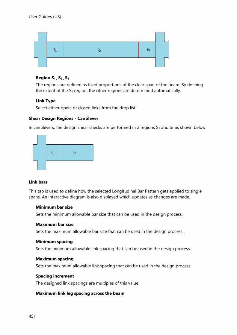
User Guides (US)
451
Region S1 , S2 , S3
The regions are defined as fixed proportions of the clear span of the beam. By defining
the extent of the S1 region, the other regions are determined automatically.
Link Type
Select either open, or closed links from the drop list.
Shear Design Regions - Cantilever
In cantilevers, the design shear checks are performed in 2 regions S1 and S2 as shown below.
Link bars
This tab is used to define how the selected Longitudinal Bar Pattern gets applied to single
spans. An interactive diagram is also displayed which updates as changes are made.
Minimum bar size
Sets the minimum allowable bar size that can be used in the design process.
Maximum bar size
Sets the maximum allowable bar size that can be used in the design process.
Minimum spacing
Sets the minimum allowable link spacing that can be used in the design process.
Maximum spacing
Sets the maximum allowable link spacing that can be used in the design process.
Spacing increment
The designed link spacings are multiples of this value.
Maximum link leg spacing across the beam
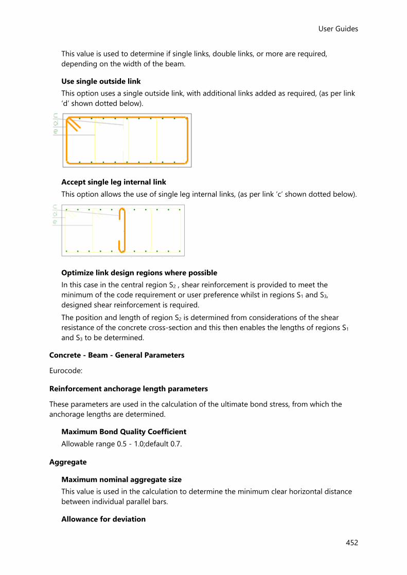
User Guides
452
This value is used to determine if single links, double links, or more are required,
depending on the width of the beam.
Use single outside link
This option uses a single outside link, with additional links added as required, (as per link
‘d’ shown dotted below).
Accept single leg internal link
This option allows the use of single leg internal links, (as per link ‘c’ shown dotted below).
Optimize link design regions where possible
In this case in the central region S2 , shear reinforcement is provided to meet the
minimum of the code requirement or user preference whilst in regions S1 and S3,
designed shear reinforcement is required.
The position and length of region S2 is determined from considerations of the shear
resistance of the concrete cross-section and this then enables the lengths of regions S1
and S3 to be determined.
Concrete - Beam - General Parameters
Eurocode:
Reinforcement anchorage length parameters
These parameters are used in the calculation of the ultimate bond stress, from which the
anchorage lengths are determined.
Maximum Bond Quality Coefficient
Allowable range 0.5 - 1.0;default 0.7.
Aggregate
Maximum nominal aggregate size
This value is used in the calculation to determine the minimum clear horizontal distance
between individual parallel bars.
Allowance for deviation

User Guides (US)
453
This value is used in the calculation to determine the limiting nominal concrete cover,
cnom, lim
• cnom, lim = cmin + Δcdev
ACI:
Fixity
Fixity Coefficient β1
This coefficient is applied to the maximum positive moment in the beam span (excluding
support positions) to set a user defined minimum design moment for beam support
regions.
Allowable range 0.0 - 1.0; default 0.25
Deflection
Long term deflection period
Allowable range 3 - 60 months; default 60
Time at which brittle finishes are introduced
Allowable range 1- 6 months; default 1
All Codes:
FE Chasedown
Design Beams for FE Chasedown analysis results
Provided FE Chasedown Analysis has been performed (which requires the model to
contain two way spanning slabs) this option can be used to specify that beams are
designed for the forces obtained from this analysis in addition to the forces obtained
from the 3D Analysis and Grillage Chasedown Analysis.
Effective flanges calculation
Tolerance on rectilinearity
The calculation of the effective width is only carried out for concrete beams if they lie
within the tolerance on rectilinearity set here. The default tolerance is 15 degrees; at
greater angles you will be prompted to enter the effective width manually.
Design Options-Concrete-Column
This page has several sub-pages for setting up the options that are used in the column
design.
Concrete - Column - Reinforcement Layout
This page is used to set limits on the ranges and spacings of bars used in the design.
General
Country
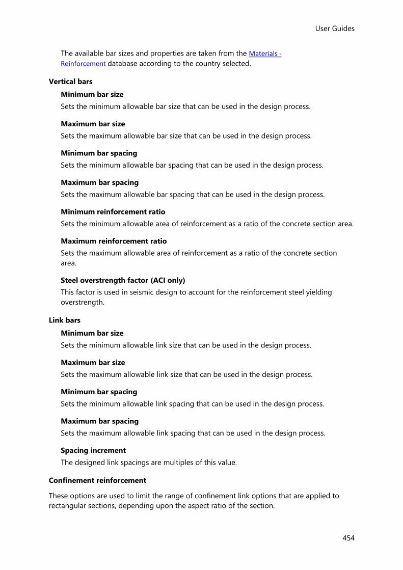
User Guides
454
The available bar sizes and properties are taken from the Materials -
Reinforcement database according to the country selected.
Vertical bars
Minimum bar size
Sets the minimum allowable bar size that can be used in the design process.
Maximum bar size
Sets the maximum allowable bar size that can be used in the design process.
Minimum bar spacing
Sets the minimum allowable bar spacing that can be used in the design process.
Maximum bar spacing
Sets the maximum allowable bar spacing that can be used in the design process.
Minimum reinforcement ratio
Sets the minimum allowable area of reinforcement as a ratio of the concrete section area.
Maximum reinforcement ratio
Sets the maximum allowable area of reinforcement as a ratio of the concrete section
area.
Steel overstrength factor (ACI only)
This factor is used in seismic design to account for the reinforcement steel yielding
overstrength.
Link bars
Minimum bar size
Sets the minimum allowable link size that can be used in the design process.
Maximum bar size
Sets the maximum allowable link size that can be used in the design process.
Minimum bar spacing
Sets the minimum allowable link spacing that can be used in the design process.
Maximum bar spacing
Sets the maximum allowable link spacing that can be used in the design process.
Spacing increment
The designed link spacings are multiples of this value.
Confinement reinforcement
These options are used to limit the range of confinement link options that are applied to
rectangular sections, depending upon the aspect ratio of the section.
User Guides (US)
455
Aspect ratio change point
The value entered here determines which rectangular sections are considered to have a
low aspect ratio and which are considered to have a high aspect ratio.
Use double links for low aspect ratio
Select to use double links where applicable in preference to single links for sections with
a low aspect ratio.
Use double links for high aspect ratio
Select to use double links where applicable in preference to single links for sections with
a high aspect ratio.
Use triple links for low aspect ratio
Select to use triple links where applicable in preference to double or single links for
sections with a low aspect ratio.
Use cross links for low aspect ratio
Select to use cross links where applicable in preference to triple, double or single links for
sections with a low aspect ratio.
Concrete - Column - Detailing Options
Settings on this page relate to the detail that is produced, but have no affect on the design.
Longitudinal Bars
Cut length rounding increment
Cut lengths are rounded to the value specified.
The overall steel bar cut length is stored in the Material data on the Home tab. For existing bars it can be verified by clicking Materials > Reinforcement. Then click an available bar size and click the View… button.
Kicker dimension
The height of column kicker cast above the slab level.
Join identical bars where possible
When this option is selected, bars are merged only if the bar size and layout in the
current and adjacent stack are identical and proving that the max bar length is not
exceeded.
Links
Number of span region links required to use separate regions
The column design may have utilized span regions to economize on the link
requirements, however, if these only exist over a short length you may prefer to
standardize the link spacing on the detail. This setting allows you to specify the minimum
number of span region links that are necessary for a span region to be indicated on the
detail.

User Guides
456
Provide links through full foundation depth
Select to draw links through the full depth of the foundation.
Foundation penetration depth of links
If the Provide links through full foundation depth option is cleared this field becomes
accessible; allowing for the penetration depth of links into the foundation to be specified.
Provide links through floor depth for internal columns
• For columns restrained by flat slabs - links are always provided through the floor
depth irrespective of this setting.
• For columns restrained by beam and slab - links are always provided through the
beam depth for edge columns but are only provided for internal columns when the
option is selected. When cleared, links are provided up to the soffit of the shallowest
beam depth.
Concrete - Column - General Parameters
General
Bar sizes no smaller than stack above
Select to ensure that bar sizes do not reduce in lower stacks.
Match bar position to stack above
Select to have the starting arrangement for longitudinal bars match the arrangement of
the bars in the stack above, if the section geometry matches.
Increase main bar size preferentially
Select to have the corner bars increased in preference to the intermediate bars. All bars
start off at the same size (unless the initial bar size is driven by the current arrangement
or the stack above), but when the check fails the corner bars will be increased in size if all
bar sizes are the same, otherwise the intermediate bars will be increased in size. This
means that when the final design is produced, either all bars will be the same size or the
corner bars will be one size larger than the intermediate bars.
Alternatively, if you require all bar sizes to be the same, clearing this option results in all
bar sizes being increased together.
Reinforcement anchorage length parameters (Eurocode only)
These parameters are used in the calculation of the ultimate bond stress, from which the
anchorage lengths are determined.
Maximum Bond Quality Coefficient
Allowable range 0.5 - 1.0.
Aggregate
Maximum nominal aggregate size

User Guides (US)
457
This value is used in the calculation to determine the minimum clear horizontal distance
between individual parallel bars.
Allowance for deviation (Eurocode only)
This value is used in the calculation to determine the limiting nominal concrete cover,
cnom, lim
cnom, lim = cmin + Δcdev
FE Chasedown
Design Columns for FE Chasedown analysis results
Provided an FE Chasedown has been performed (which requires the model to contain
two way spanning slabs) this option can be used to specify that columns are designed for
the forces obtained from the FE Chasedown analysis in addition to the forces from the
other analyses that have been performed.
Design Options-Concrete-Wall
This page has several sub-pages for setting up the options that are used in the wall design.
Concrete - Wall - Reinforcement Layout
This page is used to set limits on the ranges and spacings of bars used in the design.
General
Country
The available bar sizes and properties are taken from the Materials -
Reinforcement database according to the country selected.
Vertical bars
Minimum bar size
Sets the minimum allowable bar size that can be used in the design process.
Maximum bar size
Sets the maximum allowable bar size that can be used in the design process.
Minimum bar spacing
Sets the minimum allowable bar spacing that can be used in the design process.
Maximum bar spacing
Sets the maximum allowable bar spacing that can be used in the design process.
Spacing increment
The designed bar spacings are multiples of this value.
Minimum reinforcement ratio
Sets the minimum allowable area of reinforcement as a ratio of the concrete section area.
User Guides
458
Maximum reinforcement ratio
Sets the maximum allowable area of reinforcement as a ratio of the concrete section
area.
Vertical bars in end zone
Minimum bar size
Sets the minimum allowable bar size that can be used in the design process.
Maximum bar size
Sets the maximum allowable bar size that can be used in the design process.
Minimum reinforcement ratio
Sets the minimum allowable area of reinforcement as a ratio of the end zone area.
Maximum reinforcement ratio
Sets the maximum allowable area of reinforcement as a ratio of the end zone area.
Horizontal bars
Minimum bar size
Sets the minimum allowable bar size that can be used in the design process.
Minimum reinforcement ratio
Sets the minimum allowable area of reinforcement as a ratio of the end zone area.
Link/horizontal bars
Minimum bar spacing
Sets the minimum allowable bar spacing that can be used in the design process.
Maximum bar spacing
Sets the maximum allowable bar spacing that can be used in the design process.
Spacing increment
The designed bar spacings are multiples of this value.
Link/confinement bars
Minimum bar size
Sets the minimum allowable bar size that can be used in the design process.
Maximum bar size
Sets the maximum allowable bar size that can be used in the design process.
Confinement bars in end zone
Minimum bar size
Sets the minimum allowable bar size that can be used in the design process.
Maximum bar size
Sets the maximum allowable bar size that can be used in the design process.

User Guides (US)
459
Substitute loose bars if mesh inadequate
Select to use additional loose bars in the end zones when the mesh is inadequate.
Concrete - Wall - Detailing Options
Settings on this page relate to the detail that is produced, but have no affect on the design.
Longitudinal Bars
Cut length rounding increment
Cut lengths are rounded to the value specified.
The overall steel bar cut length is stored in the Material data on the Home tab. For existing bars it can be verified by clicking Materials > Reinforcement. Then click an available bar size and click the View… button.
Kicker dimension
The height of column kicker cast above the slab level.
Join identical bars where possible
When this option is selected, bars are merged only if the bar size and layout in the
current and adjacent stack are identical and proving that the max bar length is not
exceeded.
Links
Number of span region links required to use separate regions
The wall design may have utilized span regions to economize on the link requirements,
however, if these only exist over a short length you may prefer to standardize the link
spacing on the detail. This setting allows you to specify the minimum number of span
region links that are necessary for a span region to be indicated on the detail.
Provide links through full foundation depth
Select to draw links through the full depth of the foundation.
Foundation penetration depth of links
If the Provide links through full foundation depth option is cleared this field becomes
accessible; allowing for the penetration depth of links into the foundation to be specified.
Provide links through floor depth for internal walls
• For walls restrained by flat slabs - links are always provided through the floor depth
irrespective of this setting.
• For walls restrained by beam and slab - links are always provided through the beam
depth for edge walls but are only provided for internal walls when the option is
selected. When cleared, links are provided up to the soffit of the shallowest beam
depth.
Concrete - Wall - General Parameters
User Guides
460
Reinforcement anchorage length parameters
These parameters are used in the calculation of the ultimate bond stress, from which the
anchorage lengths are determined.
Maximum Bond Quality Coefficient
Allowable range 0.5 - 1.0.
Aggregate
Maximum nominal aggregate size
This value is used in the calculation to determine the minimum clear horizontal distance
between individual parallel bars.
Allowance for deviation
This value is used in the calculation to determine the limiting nominal concrete cover,
cnom, lim
cnom, lim = cmin + Δcdev
FE Chasedown
Design Columns for FE Chasedown analysis results
Provided an FE Chasedown has been performed (which requires the model to contain
two way spanning slabs) this option can be used to specify that walls are designed for
the forces obtained from the FE Chasedown analysis in addition to the forces obtained
from the other analyses that have been performed.
Design Options-Concrete-Slab
This page has two sub-pages for setting up the options that are used in the slab and flat slab
design.
Concrete - Slab - Reinforcement Layout
This page has two tabs for setting limits on the range and spacing of bars for slabs on beams
and flat slabs.
General
Country
The available bar sizes and properties are taken from the Materials -
Reinforcement database according to the country selected.
Principal/secondary bars
Minimum loose bar size
Sets the minimum allowable loose bar size that can be used in the design process.
Maximum loose bar size
Sets the maximum allowable loose bar size that can be used in the design process.
User Guides (US)
461
Minimum clear spacing
Sets the minimum allowable clear bar spacing that can be used in the design process.
Minimum spacing (slab auto-design)
Sets the minimum allowable clear bar spacing used in the panel auto-design process. As
this only applies to panels, it allows panel design to more readily select bars at a wider
spacing, while allowing patch design to more readily pass by reducing min spacing check
failures in the patches.
Maximum principal bar spacing distance
Sets the maximum allowable bar spacing as a distance.
Maximum principal bar spacing x slab depth
In addition to the above maximum distance - this sets the maximum allowable bar
spacing as a function of the slab depth.
Maximum secondary bar spacing distance
Sets the maximum allowable bar spacing that can be used in the design process.
Maximum principal bar spacing x slab depth.
Maximum secondary bar spacing x slab depth
In addition to the above maximum distance - this sets the maximum allowable bar
spacing as a function of the slab depth.
Bar spacing increment
The bar spacings are multiples of this value.
Maximum bar length
Sets the maximum length of bar.
Bar length increment
The bar lengths are multiples of this value.
Slab edge clearance
Sets the clearance from the reinforcement to the slab edge.
Reinforcement
Auto selection of outer bars
Select to have the bars in the outer layer selected automatically.
Make bob for top steel of cantilevers
Select to apply a bob to the end of the top steel in cantilevers.
Use mesh where possible
Select to use mesh where possible.
Concrete - Slab - Patches

User Guides
462
This page has separate tabs for setting default properties for each path type.
Reinforcement
Use mesh where possible
Select to use mesh where possible.
Patch Size
Width, Lx, Ly
Sets the default patch size to be used.
Strip Proportions
Edge strip width as proportion of patch width
for column patches this ratio controls how the patch width is split between edge and
center strips.
Center strip width
for beam patches this sets the width of the center strip.
Concrete - Slab - General Parameters
Reinforcement anchorage length parameters
These parameters are used in the calculation of the ultimate bond stress, from which the
anchorage lengths are determined.
Maximum Bond Quality Coefficient
Allowable range 0.5 - 1.0.
Cover and Spacing check parameters
Maximum nominal aggregate size
This value is used in the calculation to determine the minimum clear horizontal distance
between individual parallel bars.
Allowance for deviation (Eurocode only)
This value is used in the calculation to determine the limiting nominal concrete cover,
cnom, lim
cnom, lim = cmin + Δcdev
Detailing
Allowance for additional detailing bars
The total mass of bars for slabs/mats shown in material listing reports and on slab/mat
detailing drawings will be increased by the percentage specified here.
Design Options-Concrete Punching Shear
This page sets up the parameters for punching shear stud rail design.
User Guides (US)
463
General
Country
The available bar sizes and properties are taken from the Materials -
Reinforcement database according to the country selected.
Reinforcement bars
Minimum bar size
Sets the minimum allowable bar size that can be welded to the rail in the design process.
Maximum bar size
Sets the maximum allowable bar size that can be welded to the rail in the design process.
Diagonal spacing between rails
Sets the maximum allowable diagonal spacing for radial layouts.
Spacing along rail
Minimum spacing
Sets the minimum allowable bar spacing along each rail.
Maximum spacing
Sets the maximum allowable bar spacing along each rail.
Spacing increment
The bar spacing adopted will be a multiple of this value.
Spacing to the first reinforcement line
Minimum spacing
Sets the minimum spacing from the column face to the first reinforcement line.
Maximum spacing
Sets the maximum spacing from the column face to the first reinforcement line.
Spacing increment
The spacing from the column face will be a multiple of this value.
Auto-design
Method
Auto-design can either be set to minimise the bar size, or minimise the number of rails.
Starting number of studs per face
this is the minimum number of studs per face that will be used when auto-designing
from minima.
Diagonal spacing between rails (for circular arrangements)

User Guides
464
Maximum spacing
Sets the maximum diagonal spacing between the outermost studs in the last critical
perimeter.
Spacing between rails in the Y direction
Minimum spacing
Sets the minimum allowable rail spacing in Y.
Maximum spacing
Sets the maximum allowable rail spacing in Y.
Spacing increment
The rail spacing in Y adopted will be a multiple of this value.
Spacing between rails in the Z direction
Minimum spacing
Sets the minimum allowable rail spacing in Z.
Maximum spacing
Sets the maximum allowable rail spacing in Z.
Spacing increment
The rail spacing in Z adopted will be a multiple of this value.
Design Options-Concrete Isolated Foundations
This page has several sub-pages for setting up the options that are used in pad base and pile
cap design.
Concrete - Isolated Foundations - Reinforcement Layout
This page has two tabs for setting limits on the range and spacing of bars for pad bases and
pile caps.
General
Country
The available bar sizes and properties are taken from the Materials -
Reinforcement database according to the country selected.
Principal/secondary bars
Minimum loose bar size
Sets the minimum allowable loose bar size that can be used in the design process.
Maximum loose bar size
Sets the maximum allowable loose bar size that can be used in the design process.
Minimum clear spacing

User Guides (US)
465
Sets the minimum allowable clear bar spacing that can be used in the design process.
Maximum principal bar spacing
Sets the maximum allowable principal bar spacing as a distance.
Maximum secondary bar spacing
Sets the maximum allowable secondary bar spacing as a distance.
Bar spacing increment
The bar spacings are multiples of this value.
Reinforcement
Use mesh where possible
Select to use mesh where possible.
Concrete - Isolated Foundations - Foundation Size
This page has two tabs for setting the size parameters used in the design process for pad
bases and pile caps.
Minimum depth
Sets the minimum allowable depth.
Maximum depth
Sets the maximum allowable depth.
Auto-design depth increment
Sets the depth increment.
Minimum side length
Sets the minimum allowable side length.
Maximum side length under columns
Sets the maximum side length under columns as a distance.
Maximum side length ratio under columns
Sets the maximum side length ratio under columns.
Rounding increment for footing dimensions and pile spacing
The overall footing size is rounded to this value.
Default 3-pile cap shape
the default shape when 3 piles are used can be set to either triangular or rectangular.
Concrete - Isolated Foundations - General Parameters
Reinforcement anchorage length parameters (Eurocode only)

User Guides
466
These parameters are used in the calculation of the ultimate bond stress, from which the
anchorage lengths are determined.
Maximum Bond Quality Coefficient
Allowable range 0.5 - 1.0.
Cover and Spacing check parameters
Maximum nominal aggregate size
This value is used in the calculation to determine the minimum clear horizontal distance
between individual parallel bars.
Allowance for deviation (Eurocode only)
This value is used in the calculation to determine the limiting nominal concrete cover,
cnom, lim
cnom, lim = cmin + Δcdev
Pad Base Shear Reactions at Pinned Bases (ACI/AISC and BS head codes only)
Ignorable percentage of passive pressure
Default of 1% is typically a negligible load level. (if you don’t want to ignore small shear
forces at pinned bases set this value to zero).
Design safety factors (ACI/AISC only)
FOS for sliding and uplift checks
The factor of safety considered for sliding and uplift check (default 1.5).
Pad Base Foundation bearing capacity (Eurocode only)
Use presumed bearing capacity method (EN 1997-1 cl 6.5.2.4)
If this option is selected the bearing pressure is checked for serviceability combinations
using the presumed bearing resistance specified in the pad base properties (no ‘STR’ and
‘GEO’ capacities).
Pile Cap Design parameters
Tolerance for pile position
The allowable deviation of the pile position from its original plan position which is used
in the design moment calculations.
Concrete - Isolated Foundations - Piles
Minimum and maximum number of piles for pile caps under columns
These parameters apply when a pile cap under a column has been set to auto design the
piles.
Minimum spacing option
Sets whether the minimum spacing check uses a set value, or a multiple of the pile
width/circumference.

User Guides (US)
467
Minimum spacing of piles
Sets the minimum spacing (either as a value, or as multiple of the pile
width/circumference).
Minimum pile edge distance
Minimum distance from the pile face to edge of foundation.
Pile auto-design method
When a pile cap has been set to auto design, you can choose to use the smallest number
of high capacity piles or more piles of lowest capacity.
Pile one-way shear checks - Limit maximum critical section size
This option provides flexibility to the consideration of an upper limit on the pile one-way
shear critical section length in pile cap design. You can opt to apply a limit or not, and to
set the maximum length to be considered when the limit is enabled, allowing control of
the level of conservatism in the check.
Design Options-Concrete Mat Foundations
The options displayed here are identical to those applied to slabs.
Design Options-Composite Beams
Effective flange width calculation
Tolerance on rectilinearity
The calculation of the effective width is only carried out for composite beams if they lie
within the tolerance on rectilinearity set here. The default tolerance is 15 degrees; at
greater angles you will be prompted to enter the effective width manually.
Design Options-Design Forces
Ignore Forces Below
A full 3D analysis may expose small forces that are normally ignored in the design of
members. The options for ignore forces below on the Design Forces page of the Design
Options dialog simply provide you with a way of setting negligible/nominal force levels with
which you are comfortable. When the small forces from the 3D analysis are below the
specified threshold levels they are ignored so that design can proceed automatically. If the
forces are above these limits, then you will be warned during the design process but the
forces will still be ignored.
Concrete Beams
Torsion force % of concrete resistance

User Guides
468
For Eurocode design only, this defines a user specified ignorable torque limit. If the
maximum torsional moment acting on the beam is less than this limit then design for
torsion is not performed.
This setting is only applicable for design to Eurocodes. For all other Head Codes it is not used and can be ignored.
Design Options-Design Groups
Check those member types for which grouped design is to be applied.
When grouped, only one member in the group is designed. This design is then copied to the
remaining members in the group so that they can be checked. Any failing member in the
group is redesigned, and the process repeated until all members pass, or a design is not
possible.
Design Options-Autodesign
This option controls what happens to individual steel and concrete member autodesign
settings, and isolated foundation autodesign settings at the end of the design process.
The first two options need little explanation:
• Always - The autodesign setting is automatically cleared at the end of the design
process - putting every member into check mode.
• Never - The autodesign setting (either selected, or cleared) is always retained at the end
of the design process.
The third option When check status is at worst makes the change from autodesign
conditional upon the design status as follows:
• Pass - The autodesign setting is only automatically cleared at the end of the design
process for members with design status: Pass
• Warning - The autodesign setting is only automatically cleared at the end of the design
process for members with design status: Pass, or Warning
• Fail - The autodesign setting is only automatically cleared at the end of the design
process for members with design status: Pass, Warning, or Fail
• Invalid - The autodesign setting is only automatically cleared at the end of the design
process for members with design status: Pass, Warning, Fail or Invalid
• Beyond Scope - The autodesign setting is only automatically cleared at the end of the
design process for members with design status: Pass, Warning, Fail, Invalid or Beyond
Scope.
The most practical use of the When check status is at worst option would be to set it to
Pass and start with all members in autodesign mode. At the end of the first design run
passing members would be set to check mode, allowing you to focus on the remaining
members still in autodesign mode.

User Guides (US)
469
Design Options-Design Warnings
Concrete Seismic Warnings
Warnings used as guidance during the design of a structure to US seismic provisions are in
effect by default. These can be de-activated as found useful.
The following selection is available:
Specified concrete grade is too low
• Compliance with ACI 318-08 and ACI 318-11 Section 21.1.4.2, "(..) f'c, shall not be less
than 3000 psi."
• Applies to normal weight reinforced concrete columns and beams part of Special
Moment Frames
• Applies to normal weight reinforced concrete walls assigned as Special Reinforced
Concrete Structural Walls
• Prompts the user to increase the concrete grade of the member
Specified longitudinal reinforcement grade too high
• Compliance with ACI 318-11 Section 21.1.5.2, "(..) reinforcement resisting earth-quake
induced flexure, axial force, or both, shall comply with ASTM A706, Grade 60.";
• Applies to normal weight reinforced columns and beams part of Special Moment
Frames
• Applies to normal weight reinforced concrete walls assigned as Special Reinforced
Concrete Structural Walls
• Prompts the user to use lower longitudinal reinforcement grades
Column at the end of the beam is not in the same seismic frame
• Used to validate if the frame of which the beam is part off is correctly set-up as a
seismic frame
• Applies to normal weight reinforced concrete beams part of a seismic force resisting
system
• Applies to both SRFS type and direction
• Checks both ends of each beam span
• Prompts the user to set up a consistent SFRS type and direction between all members
of the frame
Beam at the end of the column is not in the same seismic frame
• Used to validate if the frame of which the column is part off is correctly set-up as a
seismic frame
• Applies to normal weight reinforced concrete columns part of a seismic force
resisting system
• Checks the top of each column stack
User Guides
470
• Prompts the user to set up a consistent SFRS type and direction between all members
of the frame
Beam support region size is too small
• Compliance with ACI 318-08 and ACI 318-11 Section 21.3.4.2, "(..) hoops shall be
provided over lengths not less than 2h measured from the face of the supported
member toward the midspan"
• Applies to normal weight reinforced concrete beams part of Intermediate and Special
Moment Frames
• Comes into effect if the length of the end shear design regions is smaller than the
requirement
• Prompts the user to review the shear design regions - Design options
High seismic to conventional demand on non-SFRS beams / High seismic to
conventional demand ratio of non-SFRS columns / High seismic to conventional
demand of non-SFRS walls
• Used to recognize when a member has a significant contribution to the building's
lateral force resistance but has not been assigned to the SFRS with the required
ductility properties
• Specifically apply to each member type
• The highest non-seismic design ratio from bending and shear design is obtained
• The highest seismic design ratio from bending and shear design is obtained
• Comes into effect when the ratio between seismic and non-seismic values is higher
than a given threshold (default = 1.0)
• The maximum seismic/non-seismic ratio threshold that triggers the warning is set
through the "Seismic to conventional minimum demand ratio" field on the same page
• Prompts the user to either include the member in the SFRS or review the structure
layout to reduce the contribution of the member to the lateral force resistance
Non-SFRS design requirements applicable in SDC D-F
• Compliance with ACI 318-08 and ACI 318-11 Sections 21.13.1, "Requirements of
section 21.13 apply to members not designated as part of the seismic-force-resisting
system in structures assigned to SDC D, E and F"
• Applies to normal weight reinforced concrete beams, column and walls not included
in the SFRS
• Comes into effect in Seismic Design Category, SDC D or above
• Prompts the user to apply code prescribed requirements on top of current design
Steel Static Warnings
Additional notional loads required when alpha Pr/Py > 0.5, C2.3
• Compliance with 7.3 (3) of AISC 360-05 and C2.3 of AISC 360-10 requires the
stiffness of certain members to be reduced. When the ratio of the required axial

User Guides (US)
471
compressive force (Pr) and the axial yield strength (Py = Fy Ag) is > 0.5 then this
stiffness must be reduced further
• As an alternative which is the approach adopted in Tekla Structural Designer, an
additional notional load of 0.001 Yi can be applied instead
• When the program identifies that the ratio of Pr/Py exceeds 0.5 a warning is given to
alert the designer
• If this additional notional load has been dealt with by the designer then this warning
is no longer relevant and this option allows you to switch off the warning
Concrete Seismic
Seismic to conventional minimum demand ratio
This ratio is used to set the threshold above which the ‘High seismic to conventional
demand‘ warnings come into effect.
Design Options-Steel Joists
The loading pattern on each joist is assessed and classified as Uniform (or near uniform),
Equivalent Uniform or Non-Uniform taking into account user defined tolerances.
Uniform load tolerance
if the calculated percentage load tolerance is less than this value, the load is classified as
‘Uniform’.
Equivalent load tolerance
if the calculated percentage load tolerance is greater than this value, the load is classified as
‘Non-uniform’.
If 0% equivalent load tolerance is specified then only pure uniform loading is accepted.
Maximum eccentricity of zero shear
In the equivalent uniform load method the position of the point of zero shear relative to the
centre span point of the joist is determined. If this is located outside this maximum
eccentricity of zero shear value then the load is classified as 'Non-uniform'.
Deflection increase to allow for shear
Deflections due to live load are calculated using the following effective inertia value:
Ieffective = Igross / (1 + R)
where
R = the deflection increase to allow for shear effects (defaulted to 15%) and applied to
KCS only.
Design Options-Sway & Drift Checks

User Guides
472
Merge short stacks
• With this setting off (default): the Sway/Drift, Wind Drift & Seismic Drift checks are
performed for all column stacks and wall panels irrespective of their stack lengths.
• With this setting on: you can specify a minimum stack length.
The ‘Merge short stacks’ option does not apply to columns/walls where you have elected to merge stacks manually (via the column/wall properties).
The following logic is applied to merging stacks when the setting is on:
1. Start at the topmost stack of the column/wall.
2. If the stack length is less than the merge limit then merge with the stack below.
3. Check again to see if then new length exceeds the merge limit, if not then merge again
with the next stack below.
4. Repeat step 3 as required until the stack length exceeds the merge limit.
5. For subsequent stacks repeat steps 2 and 3 as required until the length exceeds the
merge limit.
6. When the bottommost stack is reached, if this needs to be merged, merge with the
stack above.
If a single stack column or single panel wall length is less than the merge short stacks limit it is not considered for sway/drift, wind drift, seismic drift checks.
Check wind cases only
A Wind Drift check is performed for columns and walls for all combinations containing wind
load case(s).
• With this setting on (default): the Wind Drift check only considers the effects of the wind
load case(s) in each wind combination.
• With this setting off: the check considers the effects of all load cases in wind
combinations (which would include drift induced by gravity loads).
Related topics
• Wind drift
• Sway checks
• Drift checks
Static Analysis & Design

User Guides (US)
473
Member design modes
Before you start the analysis and design process, every design member in your model will be
set into one of two possible modes:
• Check design mode - you assign your desired section size (steel members) or section
size and reinforcement (concrete members) and the program then determines if the
section/reinforcement is sufficient.
• Autodesign mode - you select the desired section type and the program then
automatically determines a suitable size of the chosen section type (steel members); or
you assign your desired section size and the program then automatically determines a
suitable reinforcement configuration (concrete members).
You can quickly review (and update) the mode applied to every member in the model using the ‘Auto\Check design’ toggle on the Review toolbar.
Once the autodesign\check design modes have been set appropriately you can then begin
the member design process.
Your choice of which analysis-design process to run will be affected by the materials used
(steel, concrete, or both) and also the combination types that you want to consider (gravity,
or all) - steel structures in particular may require an initial ‘gravity design’.
Do I run Design Steel, Design Concrete or Design All?
Your choice will depend on the materials used in the model.
In simple terms:
• if your model consists of steel members only, you can run the design from the Analysis
& Design Steel group on the Design toolbar. (i.e. Design Steel (Gravity) and Design Steel
(Static)
• if your model consists of concrete members only, you can run the design from the
Analysis & Design Concrete group on the Design toolbar. (i.e. Design Concrete (Gravity)
and Design Concrete (Static)
• if your model consists of a mix of both concrete and steel members, you can run the
design from the Analysis & Design group on the Design toolbar. (i.e. Design All (Gravity)
and Design All (Static)
For structures that are mostly steel but have a few concrete members: instead of running Design All, you could run Design Steel (in order to focus on the steel design) before switching to Design Concrete for the remaining members. In this way during the steel design phase you are not running grillage and FE chasedown analyses when they are not required .
The processes that get initiated reflect your choice as follows:

User Guides
474
Design Steel
• performs a 3D Analysis,
• does not perform Grillage Chasedown or FE Chasedown analysis,
• designs/checks all steel elements and shear walls,
• does not design/check concrete beams or columns.
Design Concrete
• performs a 3D Analysis and a Grillage Chasedown analysis,
• may also be required to perform an FE Chasedown analysis,
• designs/checks all concrete beams, columns and shear walls,
• does not design/check steel elements.
Design All
• performs a 3D Analysis and a Grillage Chasedown analysis,
• may also be required to perform an FE Chasedown analysis,
• designs/checks all concrete beams, columns and shear walls,
• design/checks all steel elements.
Do I run Design...(Gravity), or Design...(Static)?
Design (Gravity)
Although your final design should consider all combinations, designing for gravity
combinations can be a useful way to rapidly pre-size those members in the structure that are
not subjected to lateral loads.
Designing members for gravity combinations is a technique more likely to be employed for steel rather than concrete structures.
This technique involves the use of first-order analysis on a limited set of design
combinations.
• Design Steel (Gravity) - rapid gravity sizing of the majority of steel members
• Design Concrete (Gravity) - design of concrete members for gravity combinations only
• Design All (Gravity) - design of all steel and concrete members for gravity combinations
only
Because lateral systems may not have been established at this stage, those column nodes
that are not in a rigid floor diaphragm are by default fixed horizontally. (This default can be
changed if required in Home > Settings > Design Options > General)
Design (Static)
User Guides (US)
475
Once initial member sizes have been adequately sized, you should make a Sway sensitivity
assessment (ACI/AISC), as this can affect the Choice of analysis type (ACI/AISC) used in the final
static design.
This final static design is invoked by selecting the Design (Static) process applicable to the
type of material involved:
• Design Steel (Static) - full design of all steel members
• Design Concrete (Static) - full design of all concrete members
• Design All (Static) - full design of all steel and concrete members
For each of the above, 3D Analysis is performed (first, or second order as specified in
Design Options > Analysis) for all active combinations to establish a set of design forces.
If the model contains concrete members, Grillage chasedown and potentially FE
chasedown are performed to establish additional sets of design forces.
All members are checked or designed for the appropriate design requirements. Gravity
members are checked for gravity combinations, lateral members are checked for all
combinations. Only active combinations are checked.
Design Steel (Gravity)
Performs analysis of all active gravity load combinations and then designs or checks steel
members.
Overview:
• A 3D Analysis is run (excluding pattern loading) to establish a set of design forces for
the steel members.
• For the above analysis, lateral translational fixed supports can optionally be applied to
column nodes in order to remove unwanted lateral displacements that may prevent the
analysis from completing and/ or produce unrealistic forces (controlled via Settings>
Design Options> General on the Home ribbon).
• Each ‘gravity only’ steel member is then either checked, or designed - according to its
autodesign setting - for gravity combinations only.
• Remaining steel members set to auto-design are designed for gravity combinations, to
give them a reasonable start size prior to consideration of the lateral load combinations.
(Remaining steel members set to check-design are not checked.)
• On completion of the gravity sizing process all steel members are set to check-design
mode. At this point it is possible that the lateral members are under-sized (having been
designed for the gravity combinations only) so it is recommended that you reset them to
auto-design mode before continuing the design process.
• No design forces are established for concrete elements in a multi-material building.
How do I run Design Steel (Gravity)?
1. Prior to running the design you should have assigned appropriate Autodesign settings
to the steel members:

User Guides
476
• Autodesign ‘on’ - new section sizes will be designed
• Autodesign ‘off’ - existing section sizes will be checked
2. You should also be aware of the Design Options ( ) that are in place, in particular:
• Design Options-Analysis - which sets the analysis type to be run,
• Design Options-Design Forces - which sets the levels at which forces can be ignored,
• Design Options-Autodesign - which controls how Autodesign settings will be reset after
the design
3. To run the design:
Click Design Steel (Gravity)
4. At the end of the analysis-design process the active view switches to a Review View and
the tab switches from Design to Review - ready for reviewing the design graphically.
Design Steel (Static)
Performs analysis of all active static load combinations (gravity, lateral, and ELF seismic) then
designs or checks every steel member.
Overview:
• A first-order analysis of all unfactored loadcases is carried to establish Serviceability Limit
State requirements such as deflections.
• EHF's are determined for every active combination in which they have been included.
• Having established the EHF's, their contributions to frame deflections are determined
using a first-order analysis. cr values are also established.
• 3D Analysis is performed (first, or second order as specified in Design Options >
Analysis) for all active combinations to establish a set of design forces.
• All steel members set to autodesign mode are designed for the appropriate design
requirements. Gravity members are designed for gravity combinations, lateral members
are designed for all combinations. Only active combinations are checked. If section sizes
are changed the analysis-design cycle is repeated.
• All steel members set to check mode are checked for the appropriate design
requirements. Gravity members are checked for gravity combinations, lateral members
are checked for all combinations. Only active combinations are checked.
• At the end of the process, all autodesign settings are typically cleared - putting every
member into check mode. You can change this if required via Design Options-Autodesign.
How do I run Design Steel (Static)?
1. Prior to running the design you should have assigned appropriate Autodesign settings
to the steel members:
• Autodesign ‘on’ - new section sizes will be designed

User Guides (US)
477
• Autodesign ‘off’ - existing section sizes will be checked
2. You should also be aware of the Design Options ( ) that are in place, in particular:
• Design Options-Analysis - which sets the analysis type to be run,
• Design Options-Design Forces - which sets the levels at which forces can be ignored,
• Design Options-Autodesign - which controls how Autodesign settings will be reset after
the design
3. To run the design:
Click Design Steel (Static)
4. At the end of the analysis-design process the active view switches to a Review View and
the tab switches from Design to Review - ready for reviewing the design graphically.
Design Concrete (Gravity)
Performs analysis of all active gravity load combinations and then designs or checks every
concrete member (but not concrete slabs).
Overview:
• 3D Analysis is run to establish a set of design forces for the concrete members.
• For the above analysis, lateral translational fixed supports can optionally be applied to
column nodes in order to remove unwanted lateral displacements that may prevent the
analysis from completing and/ or produce unrealistic forces (controlled via Settings>
Design Options> General on the Home ribbon).
• Grillage chasedown analysis is performed to establish a second set of design forces.
• If the model contains flat slabs, or slabs on beams, FE chasedown analysis is also
performed. The results being (optionally) used to establish a third set of design forces for
concrete beams, columns and walls.
• Every concrete member is then either checked, or designed - according to its autodesign
setting - for gravity combinations only.
• No design forces are established for steel elements in a multi-material building.
How do I run Design Concrete (Gravity)?
1. Prior to running the design you should have assigned appropriate Autodesign settings
to the concrete members:
• Autodesign ‘on’ - new reinforcement will be designed
• Autodesign ‘off’ - existing reinforcement will be checked
2. You should also review the Design Options that are in place - to do this:
Click Design > Options ( )

User Guides
478
3. To run the design:
Click Design Concrete (Gravity)
4. At the end of the analysis-design process the active view switches to a Review View and
the tab switches from Design to Review - ready for reviewing the design graphically.
Design Concrete (Static)
Performs analysis of all active static load combinations (gravity, lateral, and ELF seismic) then
designs or checks every concrete member.
Overview:
• A first-order analysis of all unfactored loadcases is carried to establish Serviceability Limit
State requirements.
• EHF's are determined for every active combination in which they have been included.
• Having established the EHF's, their contributions to frame deflections are determined
using a first-order analysis. cr values are also established.
• 3D Analysis is performed (first, or second order as specified in Design Options >
Analysis) for all active combinations to establish a set of design forces.
• Grillage chasedown analysis is performed to establish a second set of design forces.
• If the model contains flat slabs, or slabs on beams, FE chasedown analysis is also
performed. The results being (optionally) used to establish sets of design forces for
concrete beams, columns and walls.
• All concrete members set to auto-design mode are designed for the appropriate design
requirements. Only active combinations are checked.
• All concrete members set to check mode are checked for the appropriate design
requirements. Only active combinations are checked.
• At the end of the process, all autodesign settings are typically retained - however you can
change this if required via Design Options-Autodesign.
How do I run Design Concrete (Static)?
1. Prior to running the design you should have assigned appropriate Autodesign settings
to the concrete members:
• Autodesign ‘on’ - new reinforcement will be designed
• Autodesign ‘off’ - existing reinforcement will be checked
2. You should also review the Design Options that are in place - to do this:
Click Design > Options ( )
3. To run the design:
Click Design Concrete (Static)
User Guides (US)
479
4. At the end of the analysis-design process the active view switches to a Review View and
the tab switches from Design to Review - ready for reviewing the design graphically.
Design All (Gravity)
Performs analysis of all active gravity load combinations and then designs or checks every
member (but not concrete slabs).
Overview:
• 3D Analysis is run - excluding pattern loading - to establish a set of design forces for the
steel and concrete members.
• For the above analysis, lateral translational fixed supports can optionally be applied to
column nodes in order to remove unwanted lateral displacements that may prevent the
analysis from completing and/ or produce unrealistic forces (controlled via Settings>
Design Options> General on the Home ribbon).
• Grillage chasedown analysis is performed to establish a second set of design forces (for
concrete members only).
• If the model contains flat slabs, or slabs on beams, FE chasedown analysis is also
performed. The results being (optionally) used to establish a third set of design forces for
concrete beams, columns and walls.
• Each member is then either checked, or designed - according to its autodesign setting -
for gravity combinations only.
• On completion of the gravity sizing process all steel members are set to check-design
mode. At this point it is possible that the lateral members are under-sized (having been
designed for the gravity combinations only) so it is recommended that you reset them to
auto-design mode before continuing the design process.
How do I run Design All (Gravity)?
1. Prior to running the design you should have assigned appropriate Autodesign settings
to all members:
• Autodesign ‘on’ - new section sizes will be designed for steel members and new
reinforcement will be designed for concrete members
• Autodesign ‘off’ - existing section sizes will be checked for steel members and
existing reinforcement will be checked for concrete members
2. You should also review the Design Options that are in place - to do this:
Click Design > Options ( )
3. To run the design:
Click Design All (Gravity)
4. At the end of the analysis-design process the active view switches to a Review View and
the tab switches from Design to Review - ready for reviewing the design graphically.

User Guides
480
Design All (Static)
Performs analysis of all active static load combinations (gravity, lateral, and ELF seismic) then
designs or checks every member (but not concrete slabs).
Overview:
• A first-order analysis of all unfactored loadcases is performed to establish Serviceability
Limit State requirements such as deflections.
• EHF's are determined for every active combination in which they have been included.
• Having established the EHF's, their contributions to frame deflections are determined
using a first-order analysis. cr values are also established.
• 3D Analysis is performed (first, or second order as specified in Design Options >
Analysis) for all active combinations to establish a set of design forces.
• Grillage chasedown analysis is performed to establish a second set of design forces (for
the design of concrete members only).
• If the model contains flat slabs, or slabs on beams, FE chasedown analysis is also
performed. The results being (optionally) used to establish sets of design forces for
concrete beams, columns and walls.
• All steel members set to auto-design mode are designed for the appropriate design
requirements. Gravity members are designed for gravity combinations, lateral members
are designed for all combinations. Only active combinations are checked. If section sizes
are changed the analysis-design cycle is repeated.
• All steel members set to check mode are checked for the appropriate design
requirements. Gravity members are checked for gravity combinations, lateral members
are checked for all combinations. Only active combinations are checked.
• All concrete members set to auto-design mode are designed for the appropriate design
requirements. Only active combinations are checked.
• All concrete members set to check mode are checked for the appropriate design
requirements. Only active combinations are checked.
• At the end of the process, all autodesign settings are typically cleared for steel members
but retained for concrete members - you can change this if required via Design Options-Autodesign.
How do I run Design All (Static)?
1. Prior to running the design you should have assigned appropriate Autodesign settings
to all members:
• Autodesign ‘on’ - new section sizes will be designed for steel members and new
reinforcement will be designed for concrete members
• Autodesign ‘off’ - existing section sizes will be checked for steel members and
existing reinforcement will be checked for concrete members
2. You should also review the Design Options that are in place - to do this:

User Guides (US)
481
Click Design > Options ( )
3. To run the design:
Click Design All (Static)
4. At the end of the analysis-design process the active view switches to a Review View and
the tab switches from Design to Review - ready for reviewing the design graphically.
How can I check if Autodesign is on or off?
1. Select the members for which you want to review or change the Autodesign property.
2. Check the current Autodesign setting shown in the Properties Window is correct -
adjust if necessary.
• Autodesign ‘on’ - new reinforcement will be designed
• Autodesign ‘off’ - existing reinforcement will be checked
Alternatively, edit the member to do the same thing:
1. Highlight the member and right-click it to display the context menu.
2. Choose Edit from the context menu.
3. Review the Automatic design setting in the dialog - adjust if necessary.
RSA Analysis & Design
RSA load combinations should be set up in advance of RSA Design by running the Seismic Wizard (choosing the option to use Modal Response Spectrum Analysis). The Seismic Wizard is not currently available for the AS:1170.4 code variant.
Design Steel (RSA)
Performs analysis of all active RSA load combinations and then designs steel members.
Overview:
• Validation - standard model and analysis validation plus additional seismic specific
checks are performed
• 1st Order Vibration Analysis - performed for the Effective Seismic Weight Combination
only, which determines the fundamental periods for directions 1 & 2
• Pre-Analysis for Seismic - (seismic weight and seismic torque calculations)

User Guides
482
• Static Analysis - 1st Order Linear or 2nd Order Linear for all RSA Seismic Combinations
and all their relevant loadcases, i.e. included Static Loadcases, but not RSA Seismic or and
RSA Torsion Loadcases.
• RSA Analysis - a set of results are generated for a sub-set of vibration modes for each
RSA Seismic Loadcase. The results for each mode are then combined into a single set
• Accidental Torsion Analysis - nodal loads are generated for each RSA Torsion Loadcase,
these are then analysed using 1st Order Linear analysis.
• All steel members set to autodesign mode are designed taking the current size that has
been determined from static design as a starting point. If section sizes are changed the
analysis-design cycle is repeated.
• All steel members set to check mode are checked for the appropriate design
requirements.
How do I run Design Steel (RSA)?
1. First, check the Autodesign property is correctly set for all members:
• Autodesign ‘on’ - new section sizes will be designed
• Autodesign ‘off’ - existing section sizes will be checked
(How can I check if Autodesign is on or off?)
2. Next, review the Design Options and adjust if required:
• Click Design > Options ( )
3. Then:
• Click Design Steel (RSA)
At the end of the analysis-design process the active view switches to a Review View and
the tab switches from Design to Review - ready for reviewing the design graphically.
Design Concrete (RSA)
Performs analysis of all active RSA load combinations and then designs concrete members.
Overview:
• Validation - standard model and analysis validation plus additional seismic specific
checks are performed
• 1st Order Vibration Analysis - performed for the Effective Seismic Weight Combination
only, which determines the fundamental periods for directions 1 & 2
• Pre-Analysis for Seismic - (seismic weight and seismic torque calculations)
• Static Analysis - 1st Order Linear or 2nd Order Linear for all RSA Seismic Combinations
and all their relevant loadcases, i.e. included Static Loadcases, but not RSA Seismic or and
RSA Torsion Loadcases.

User Guides (US)
483
• RSA Analysis - a set of results are generated for a sub-set of vibration modes for each
RSA Seismic Loadcase. The results for each mode are then combined into a single set
• Accidental Torsion Analysis - nodal loads are generated for each RSA Torsion Loadcase,
these are then analysed using 1st Order Linear analysis.
• All concrete members set to autodesign mode are designed taking the current
reinforcement that has been determined from static design as a starting point.
• All concrete members set to check mode are checked for the appropriate design
requirements.
How do I run Design Concrete (RSA)?
1. First, check the Autodesign property is correctly set for all members:
• Autodesign ‘on’ - new reinforcement will be designed for concrete members
• Autodesign ‘off’ - existing reinforcement will be checked for concrete members
(How can I check if Autodesign is on or off?)
2. Next, review the Design Options and adjust if required:
• Click Design > Options ( )
3. Then:
• Click Design Concrete (RSA)
At the end of the analysis-design process the active view switches to a Review View and
the tab switches from Design to Review - ready for reviewing the design graphically.
Design All (RSA)
Performs analysis of all active RSA load combinations and then designs all members.
Overview:
• Validation - standard model and analysis validation plus additional seismic specific
checks are performed
• 1st Order Vibration Analysis - performed for the Effective Seismic Weight Combination
only, which determines the fundamental periods for directions 1 & 2
• Pre-Analysis for Seismic - (seismic weight and seismic torque calculations)
• Static Analysis - 1st Order Linear or 2nd Order Linear for all RSA Seismic Combinations
and all their relevant loadcases, i.e. included Static Loadcases, but not RSA Seismic or and
RSA Torsion Loadcases.
• RSA Analysis - a set of results are generated for a sub-set of vibration modes for each
RSA Seismic Loadcase. The results for each mode are then combined into a single set
• Accidental Torsion Analysis - nodal loads are generated for each RSA Torsion Loadcase,
these are then analysed using 1st Order Linear analysis.
User Guides
484
• All steel members set to autodesign mode are designed taking the current size that has
been determined from static design as a starting point. If section sizes are changed the
analysis-design cycle is repeated.
• All concrete members set to autodesign mode are designed taking the current
reinforcement that has been determined from static design as a starting point.
• All steel and concrete members set to check mode are checked for the appropriate
design requirements.
How do I run Design All (RSA)?
1. First, check the Autodesign property is correctly set for all members:
• Autodesign ‘on’ - new section sizes will be designed for steel members and new
reinforcement will be designed for concrete members
• Autodesign ‘off’ - existing section sizes will be checked for steel members and
existing reinforcement will be checked for concrete members
(How can I check if Autodesign is on or off?)
2. Next, review the Design Options and adjust if required:
• Click Design > Options ( )
3. Then:
• Click Design All (RSA)
At the end of the analysis-design process the active view switches to a Review View and
the tab switches from Design to Review - ready for reviewing the design graphically.
Slab design, patches and punching shear
The overall slab design process comprises the following steps:
• Create Patches - slab patches are placed over columns, beams, walls or panels as required,
• Perform Slab Design - slab panel areas that lie outside the patch areas are designed,
• Perform Patch Design - patches are designed,
• Add Punching Shear Checks - punching shear checks are placed as required (Not available
for Australia Head Code),
• Perform Punching Shear Checks - punching shear checks are performed for the whole
model or individually (Not available for Australia Head Code).
Create Patches
Rectangular patches of reinforcement can be applied to a slab panel to act in addition to the
background reinforcement.
After selecting the required patch type from the drop down menu, patches are placed in the
model by clicking or boxing around elements in either 2D or 3D Views.
User Guides (US)
485
What is a patch?
Patches are used during the design of concrete slabs as a way of managing the physical and
design data. They each define a rectangular area of slab within which FE Analysis results are
collected enabling a design to be performed. Design moments are calculated along Result
Strips embedded within each patch. Depending on the patch type it can contain up to 6
result strips, catering for up to 3 strips of reinforcement in each of two perpendicular
directions.
The following patch types are available:
• column patch - at column stack heads
• beam patch - along beams
• wall patch - along walls
• panel patch - at a specified position within the panel boundary
• not restricted to a ‘centralised’ position and also not restricted to existing purely
within one panel
• might also be positioned under loads
These patches are either in the top or the bottom of the slab and may or may not have
reinforcement defined in them. If no reinforcement is defined then the background
reinforcement is used. If reinforcement is defined then for the top/bottom, x/y direction, you
have the option to use the sum of the background + patch reinforcement - if reasonably
aligned.
Note that patches may overlap on the plan view, there is no restriction on this, even patches
relating to the same layer of reinforcement are allowed to overlap. This situation is handled
conservatively during design by simply ignoring the overlap.
How do I create a column patch?
1. Click Design
Then from the Patch drop list ( ) select Patch Column
2. The create column patch properties set is displayed.
• Use the Lx and Ly properties to specify the patch size.
• Use the Surface property to specify the layer.
• Select the Autodesign property in order to have the reinforcement automatically
designed.
• Only select the Consider patch surface moments only property if you don’t want to
consider the opposite surface.
Situations when you need to select this option should be very rare. (Typically when the check of slab reinforcement in the opposite surface fails but another patch exists in the same location at that face - when the other patch is designed additional reinforcement would be provided at that surface, so the surface check is not

User Guides
486
required for the original patch.)
To place the patch over a specific column:
1. Click a column node within the slab. Tekla Structural Designer will add a patch to the
selected column.
To create multiple patches by windowing:
1. Move the cursor to one corner of an imaginary box which will encompass the columns
for which you want to define patches.
2. Click and hold the left mouse button.
3. Drag to the diametrically opposite corner of the box (you will see a rubber rectangle on
the screen which follows your mouse movements and helps you to check the area in
which you are creating patches).
4. Once the rubber rectangle encompasses the creation area release the mouse button and
Tekla Structural Designer will create patches to all columns which are totally within the
rubber rectangle.
How do I create a beam patch?
1. Click Design
Then from the Patch drop list ( ) select Patch Beam
2. The create beam patch properties set is displayed.
• Use the Surface property to specify the layer.
• Select the Autodesign property in order to have the reinforcement automatically
designed.
• Define the required Patch Width perpendicular to the beam span.
• Define the required Center Strip Width.
The two end strips are recalculated accordingly and cannot be edited.
• Only select the Consider patch surface moments only property if you don’t want to
consider the opposite surface.
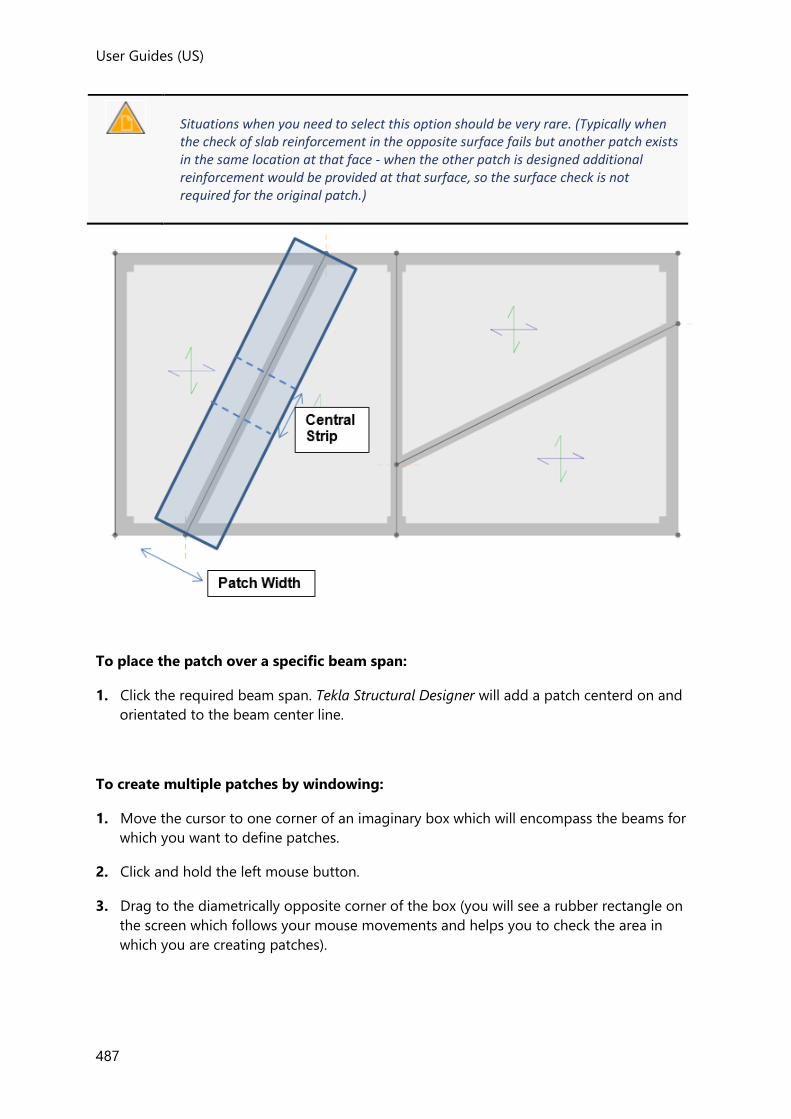
User Guides (US)
487
Situations when you need to select this option should be very rare. (Typically when the check of slab reinforcement in the opposite surface fails but another patch exists in the same location at that face - when the other patch is designed additional reinforcement would be provided at that surface, so the surface check is not required for the original patch.)
To place the patch over a specific beam span:
1. Click the required beam span. Tekla Structural Designer will add a patch centerd on and
orientated to the beam center line.
To create multiple patches by windowing:
1. Move the cursor to one corner of an imaginary box which will encompass the beams for
which you want to define patches.
2. Click and hold the left mouse button.
3. Drag to the diametrically opposite corner of the box (you will see a rubber rectangle on
the screen which follows your mouse movements and helps you to check the area in
which you are creating patches).

User Guides
488
4. Once the rubber rectangle encompasses the creation area release the mouse button and
Tekla Structural Designer will create patches to all beams which are totally within the
rubber rectangle.
How do I create a wall patch?
1. Click Design
Then from the Patch drop list ( ) select Patch Wall
2. The create wall patch properties set is displayed.
• Use the Surface property to specify the layer.
• Select the Autodesign property in order to have the reinforcement automatically
designed.
• Only select the Consider patch surface moments only property if you don’t want to
consider the opposite surface.
Situations when you need to select this option should be very rare. (Typically when the check of slab reinforcement in the opposite surface fails but another patch exists in the same location at that face - when the other patch is designed additional reinforcement would be provided at that surface, so the surface check is not required for the original patch.)
3. Define the required Patch Width perpendicular to the wall.
To place a single patch along a specific wall:
1. Choose the Create Mode
• Single Patch Along Wall
2. Click the required wall. Tekla Structural Designer will add a patch centerd on and
orientated to the wall center line.
To place an internal patch and two end patches along a specific wall:
1. Choose the Create Mode
• Internal with End Patches
2. Click the required wall. Tekla Structural Designer will add one internal patch and two end
patches centerd on and orientated to the wall center line.

User Guides (US)
489
To place an end patch at one end of a specific wall:
1. Choose the Create Mode
• End Patch at Wall End
2. Click near to the required end of the wall. Tekla Structural Designer will add a patch at
the end of the wall closest to the point clicked on.
To place an internal patch part way along a specific wall:
1. Choose the Create Mode
• Internal Patch
2. Move the cursor along the required wall and then click to define the required start point.
3. Move the cursor further along the wall and click again to define the required end point.
4. Tekla Structural Designer will add a patch between the two points clicked on.
To create patches along multiple walls by windowing:
1. Choose one of the following Create Modes as required:
• Single Patch Along Wall
• Internal with End Patches
2. Move the cursor to one corner of an imaginary box which will encompass the walls for
which you want to define patches.
3. Click and hold the left mouse button.
4. Drag to the diametrically opposite corner of the box (you will see a rubber rectangle on
the screen which follows your mouse movements and helps you to check the area in
which you are creating patches).
5. Once the rubber rectangle encompasses the creation area release the mouse button and
Tekla Structural Designer will create patches to all walls which are totally within the
rubber rectangle.
How do I create a panel patch?
1. Click Design
Then from the Patch drop list ( ) select Patch Panel
2. The create panel patch properties set is displayed.

User Guides
490
• Use the Lx and Ly properties to specify the patch size.
• Use the Surface property to specify the layer.
• Select the Autodesign property in order to have the reinforcement automatically
designed.
• Only select the Consider patch surface moments only property if you don’t want to
consider the opposite surface.
Situations when you need to select this option should be very rare. (Typically when the check of slab reinforcement in the opposite surface fails but another patch exists in the same location at that face - when the other patch is designed additional reinforcement would be provided at that surface, so the surface check is not required for the original patch.)
To place the patch at the centroid of a specific panel:
1. Ensure Create Patch at Centroid is selected.
2. Click anywhere within the required panel. Tekla Structural Designer will add a patch at the
panel centroid.
To place the patch elsewhere within a specific panel:
Ensure Create Patch at Centroid is cleared.
• To define the patch by its corners, leave Define corner points selected and click to
select the first, and then the second corner of the patch. Tekla Structural Designer will add
a patch at the chosen position.
• To define the patch by its center, clear Define corner points and click where you want
the center of the patch to be within the required panel. Tekla Structural Designer will add
a patch at the chosen position.
To create multiple centroid patches by windowing:
1. Ensure Create Patch at Centroid is selected.
2. Move the cursor to one corner of an imaginary box which will encompass the panels
within which you want to define patches.
3. Click and hold the left mouse button.
4. Drag to the diametrically opposite corner of the box (you will see a rubber rectangle on
the screen which follows your mouse movements and helps you to check the area in
which you are creating patches).

User Guides (US)
491
5. Once the rubber rectangle encompasses the creation area release the mouse button and
Tekla Structural Designer will create patches at the centroids of all the panels that are
totally within the rubber rectangle.
How do I edit the properties of an existing patch?
1. Hover the cursor over the patch to be edited.
The Select Entity tooltip should appear.
2. Press the <down arrow> cursor key until the patch name is highlighted in the Select
Entity tooltip.
3. Press <Enter>
One of the below property sets should be displayed, (appropriate to the type of patch
selected).
• edit column patch properties set
• edit beam patch properties set
• edit wall patch properties set
• edit panel patch properties set
4. Edit the properties as required.
• Use the Lx and Ly properties to specify the patch size.
• Use the Surface property to specify the layer.
• Select the Autodesign property in order to have the reinforcement automatically
designed.
• Use the Consider Strips property to specify the directions of reinforcement to be
designed.
• Use the Reinforcement property to specify the type and direction of reinforcement
to be designed.
• Define the required Width of each strip.
• Specify whether each strip is to be designed for the average, or maximum Design
Force within it.
How do I resize an existing patch?
1. Hover the cursor over the patch to be resized.
The Select Entity tooltip should appear.
2. Press the <down arrow> cursor key until the patch name is highlighted in the Select
Entity tooltip.
3. Press <Enter>

User Guides
492
4. Hover the cursor the patch edge, or patch corner to be adjusted.
The Select Entity tooltip should appear.
5. Press the <down arrow> cursor key until the Edge #, or Node # is highlighted in the
Select Entity tooltip.
6. Press <Enter>
7. Click and drag to move the selected edge or corner.
Perform Slab Design
After any required patches have been placed, you can determine the top and bottom
reinforcement requirements in all the slab panel areas that lie outside of the patch areas.
(Because patch areas are excluded from panel design, patches should be placed before slab
panels are designed.)
Before the slabs can be checked you need to have run an analysis to establish the slab
design moments - this can be achieved by running any of the design processes (Design
Concrete, Design All etc.)
How do I design or check all slab panels in the model?
1. From the Design ribbon, click Design Slabs ( )
All panels in the model are designed or checked automatically (in accordance with their
individual ‘auto-design’ settings).
How do I design or check all slab panels in a single level/slope/sub-model?
1. Open a view of the level/slope/sub-model to be designed.
2. Right-click and choose Design Slabs.
All slabs in the selected level/slope/sub-model are designed - potentially picking new
reinforcement, (regardless of their individual ‘auto-design’ settings).
How do I design an individual slab panel?
1. Hover the cursor over the top of the panel to be designed.
The Select Entity tooltip should appear.
2. If necessary press the <down arrow> cursor key until the slab panel name is highlighted
in the Select Entity tooltip.
3. Right-click and from the context menu pick Design Panel.
The results of the design are displayed in a dialog on screen.
How do I only check all slab panels in the model?
1. Open the Structure Page of the Project Workspace.
User Guides (US)
493
2. Right-click on the Structure branch and choose Check model slabs.
All slabs in the model have their reinforcement checked (regardless of their individual
‘auto-design’ settings).
How do I only check all slab panels in a single level/slope/sub-model?
1. Open a view of the level/slope/sub-model to be designed.
2. Right-click and choose Check Slabs.
All slabs in the selected level/slope/sub-model have their reinforcement checked
(regardless of their individual ‘auto-design’ settings).
How do I check an individual slab panel?
1. Hover the cursor over the top of the panel to be designed.
The Select Entity tooltip should appear.
2. If necessary press the <down arrow> cursor key until the slab panel name is highlighted
in the Select Entity tooltip.
3. Right-click and from the context menu pick Check Panel.
The results of the check are displayed in a dialog on screen.
Perform Patch Design
Assuming the slab panel designs resulting from the Perform Slab Design or Design
Mats process are satisfactory you can then proceed to the slab patch design.
Patch design should follow panel design as the additional patch reinforcement requirement
takes account of the existing background level of reinforcement provided by the panels.
For each strip within each patch, As,reqd is determined and compared with As,prov - the patch
reinforcement + the background reinforcement (when requested and allowed).
How do I design or check all patches in the model?
1. From the Design ribbon, click Design Patches ( )
All patches in the model are designed or checked automatically (in accordance with their
individual ‘auto-design’ settings).
How do I design or check all patches in a single level/slope/sub-model?
1. Open a view of the level/slope/sub-model to be designed.
2. Right-click and choose Design Patches.
User Guides
494
All patches in the selected level/slope/sub-model are designed - potentially picking new
reinforcement, (regardless of their individual ‘auto-design’ settings).
How do I design an individual patch?
1. Hover the cursor over the top of the patch to be designed.
The Select Entity tooltip should appear.
2. If necessary press the <down arrow> cursor key until the patch name is highlighted in
the Select Entity tooltip.
3. Right-click and from the context menu pick Design Slab Patch.
The results of the design are displayed in a dialog on screen.
How do I only check all patches in the model?
1. Open the Structure Page of the Project Workspace.
2. Right-click on the Structure branch and choose Check model patches.
All patches in the model have their reinforcement checked (regardless of their individual
‘auto-design’ settings).
How do I only check all patches in a single level/slope/sub-model?
1. Open a view of the level/slope/sub-model to be designed.
2. Right-click and choose Check Patches.
All patches in the selected level/slope/sub-model have their reinforcement checked
(regardless of their individual ‘auto-design’ settings).
How do I check an individual patch?
1. Hover the cursor over the top of the patch to be designed.
The Select Entity tooltip should appear.
2. If necessary press the <down arrow> cursor key until the patch name is highlighted in
the Select Entity tooltip.
3. Right-click and from the context menu pick Check Slab Patch.
The results of the check are displayed in a dialog on screen.
User Guides (US)
495
Add Punching Shear Checks
Located on the Design toolbar, the Add Check ( ) command can be used to apply
punching shear checks to:
• concrete columns (with and without drops) and walls supporting a flat slab
• concrete columns and walls supported by a flat slab or foundation mat
• concrete columns (with and without drops) and walls through a flat slab
• point loads on a flat slab or foundation mat
How do I create a Punching Check item?
Punching Check items, (the objects to which the punching shear information and calculations
are attached), are created using the Add Check command. They can be created in both 2D
and 3D Views.
1. Click Design
Then click Add Check ( )
2. The create punching check properties set is displayed
- check that the location for the slab tension reinforcement is correctly specified, then set
the remaining properties as required.
(The Point Load properties are irrelevant unless you are adding the check to a point load
position).
3. To create the check, either:
• Hover the cursor over the required column node, wall node, or point load, until a ‘Pick
Punch Check Location’ tool tip appears, then click to add the Punching Check item at the
selected node, or
• Click and drag a box to add Punching Check items to all potential check locations within
the box.
Punching Check axis orientation
When a Punching Check is applied to a column, the check Y and Z axes are automatically
orientated to align with the column Major and Minor axes. (The two axis systems are locked
together; if the column is rotated, the punching check axes also rotate).

User Guides
496
When a Punching Check is applied to a point load, you must manually define the punching
check Z axis orientation by specifying the ‘Point Load Orientation’ in relation to Global Y.
Point Load Orientation (along with Point Load Breadth, and Depth) are not applicable when the check is applied to a column.
How do I specify stud rail reinforcement?
For checks at columns or under slab point loads; provided the Head Code is Eurocode or ACI,
then an orthogonal or circular arrangement of stud rails can be specified and then either
checked or designed as required.
1. Create a punching check item.
2. In the create punching check properties set, select the option to use reinforcement
- choose whether to autodesign the reinforcement, then set the reinforcement properties
as required.
Once the check has been placed, by right-clicking on the punching check item you can choose Edit Reinforcement in order to graphically modify the punching reinforcement arrangement.
Overview of the Edit Reinforcement Dialog

User Guides (US)
497
Graphic
The graphic updates to reflect the defined reinforcement and also indicates other items
specific to the check location:
• Column section
• Punching shear check local axis
• Using the YZ system assumes that the vertical force is positive upwards following the
right hand rule
• This is also the local axis system for the column elements so it is easier to relate
• Slab openings
• Slab opening dead-zones
• Interruption in perimeters and reinforcement
• Slab edges
• Stud rail reinforcement
• Design rails in red: Rails considered for design
• Detailing rails in blue: Rails which are considered for detailing purposes only
• Perimeters
• Dashed lines around the column section
• Critical section
• Darker region inside the perimeters conditioned by slab edges and opening dead-
zones

User Guides
498
Fields
Use reinforcement
Select in order to apply a default punching reinforcement arrangement that can then
either be checked, or used as the starting reinforcement for an auto-design.
You would only choose to clear the check box when specifying a new check if you want
to perform an auto-design but starting from Minima.
Auto-design
When run in Auto-design mode, the reinforcement is increased until either a pass is
achieved or the limiting reinforcement parameter limits have been exceeded.
Select reinforcement starting from
This option controls the starting point for auto-design procedures and is therefore only
displayed if Auto-design is ‘on’.
• Minima - removes the current arrangement and begins with the minimum allowed
bar size.
• Current - auto-design commences from the current bar arrangement.
Select reinforcement
Reinforcement type
In the current release only Stud reinforcement is considered.
Arrangement type
The options are:
• Orthogonal
• Circular
Rib type
Specifies the reinforcement rib type.

User Guides (US)
499
Grade
The reinforcement grades that are available here are set from the Materials button on the
Home ribbon.
Bar size
The reinforcement bar sizes that are available here are set from the Materials button on
the Home ribbon.
Spacing from column face
Defines the spacing of the first bar in each rail from the column face.
Spacing
Defines the spacing between bars along each rail.
Studs
Number of studs per rail
Number of studs on each rail.
Number of diagonal stud rails on one corner
The number of stud rails adjacent to each corner of the column.
(This property is only displayed when the ‘Arrangement Type’ is Circular)
Number of studs per column face
The number of stud rails adjacent to the column face in the local Y and Z directions.
Rails spacing
Spacing between rails in the local Y and directions.
Buttons
OK
Closes the dialog and saves the current reinforcement.
Cancel
Closes the dialog without saving changes.
Check
Opens the Results dialog displaying the detailed results for the current design.
How do I edit the properties of an existing Punching Check item?
Using the Properties Window:
1. Hover the cursor over the punching check item to be edited.
The Select Entity tooltip should appear.
2. Press the <down arrow> cursor key until the punching check item name is highlighted
in the Select Entity tooltip.
User Guides
500
• Press <Enter>
The edit punching check properties set for the item should be displayed in the
Properties Window.
3. Edit the properties as required.
Using the Edit Reinforcement Dialog
(This option is not available for checks applied to walls)
1. Hover the cursor over the punching check item to be edited.
2. Right-click and choose Edit Reinforcement
The properties are displayed graphically in a dialog - this method is recommended as it
provides:
• an interactive view of the reinforcement arrangement
• a convenient ‘Check’ button to check the arrangement
•
Perform Punching Shear Checks
Since the punching shear checks are dependent on using the correct levels of slab
reinforcement, (typically provided by patch reinforcement) - they should only be performed
after any patches have been designed.
When punching shear checks are run:
• At each location an applied load on the slab is calculated accounting for the difference in
column/wall axial load and bending
• A check is then performed on the slab shear stresses, accounting for the reinforcement
present (background and column/general patches)
• Provided the Head Code is Eurocode or ACI, punching reinforcement can optionally be
designed as an orthogonal or circular arrangement of stud rails in the following locations:
• concrete columns supporting a flat slab without drops
• concrete columns supported by a flat slab or foundation mat
• concrete columns through a flat slab without drops
• point loads on a flat slab or foundation mat
Column head drops and the presence of openings within a certain distance of the punching
shear boundary are taken into account in the calculations.
Where punching shear checks are closely spaced and the perimeters overlap the checks are beyond scope.

User Guides (US)
501
Punching shear checks are flagged as beyond scope if the Punching Check item does not connect to a Flat Slab.
Punching shear checks applied to walls should be viewed with caution. In particular there is some debate regarding their applicability to long walls - the check doesn’t consider the potential for stress concentrations at the ends of the wall.
How do I run punching shear checks for the entire structure?
Punching shear checks can be run for the entire structure either from the Design toolbar, or
from the Project Workspace.
To perform all punching checks from the Design toolbar:
• From the Design toolbar, click Design Punching Shear ( )
To perform all punching checks from the Project Workspace:
• Right click Structure in the Project Workspace Structure Tree and choose Check Punching
Shear or Design Punching Shear from the context menu.
How do I selectively run punching shear checks for a level, slope, or sub structure?
Punching shear checks can be run for an individual level, slope or sub structure from the
Project Workspace.
To perform punching checks for a level, slope, or sub structure:
• Right click an individual level, slope, or sub structure in the Project Workspace Structure
Tree and choose Check Punching Shear or Design Punching Shear from the context menu.
Punching shear checks are performed for all Punching Check items in the selected level,
slope, or sub structure.
How do I check an individual punching check item?
1. Hover the cursor over the top of the Punching Check item to be checked.
The Select Entity tooltip should appear.
2. If necessary press the <down arrow> cursor key until the Punching Check item name is
highlighted in the Select Entity tooltip.
3. Right-click and from the context menu pick Check Punching Shear.
The results of the check are displayed in a dialog on screen.

User Guides
502
Check Punching Shear ignores the auto-design setting of the punching check item. (i.e. it will always perform a check even if the auto-design property is on.)
How do I design an individual punching check item?
To carry out stud rail reinforcement design for the highlighted punching check item:
1. Hover the cursor over the top of the Punching Check item to be designed.
The Select Entity tooltip should appear.
2. If necessary press the <down arrow> cursor key until the Punching Check item name is
highlighted in the Select Entity tooltip.
3. Right-click and from the context menu pick Design Punching Shear.
The results of the design are displayed in a dialog on screen.
Design Punching Shear ignores the auto-design setting of the punching check item. (i.e. it will always perform a design even if the auto-design property is off.
Floor Vibration
The Add Check ( ) command in the Floor Vibration Group can be used to apply a floor
vibration check over a user defined rectangular or polygon shaped slab area.
In order to create the check a primary beam, secondary beam, and critical slab item have to
be identified; associated data also has to be specified before the Check Floor
Vibration command can be used to perform the calculation.
How do I create a Floor Vibration Check item?
Floor Vibration Check items, (the objects to which the floor vibration check information and
calculations are attached), are created using the Add Check command. They can only be
created in 2D Views.
1. Click Design
Then from the Floor Vibrations group click Add Check ( )
2. The Floor Vibration Check Properties set is displayed, in the set:
• Choose to define a Rectangular or Polygon area of slab,
• If rectangular - accept the angle of 0 degrees if the area is orthogonal to the global
axes, or enter the angle at which the rectangle is to be drawn.
3. To create the check area, either:

User Guides (US)
503
• If rectangular - click once to define the first corner, then drag, then click a second
time to define the opposite corner
• If polygon - click as required to define the polygon, (ensuring that you close the
shape by clicking on the first point a second time).
4. The prompt changes to ‘Create Vibration Check: PrimaryBeam’
• Hover the cursor over the required beam, until it becomes highlighted, then click to
select it.
(the beam reference should appear in the Properties window)
5. The prompt changes to ‘Create Vibration Check: SecondaryBeam’
• Hover the cursor over the required beam, until it becomes highlighted, then click to
select it.
(again, the beam reference should appear in the Properties window)
6. The prompt changes to ‘Create Vibration Check: CriticalSlab’
• Hover the cursor over the required slab, until it becomes highlighted, then click to
select it.
(the slab reference should appear in the Properties window)
• Provided that a composite slab item has been identified as the critical slab, the
critical slab item properties are automatically defined, for other slab item types you
are required to input these values manually.
7. The prompt changes to ‘Create Vibration Check: ConfirmCreate’
• Before confirming the check, you should review the check data in the Properties
Window.
8. Once all the properties are displayed as required, left click anywhere in the Scene View in
order to create the check.
• The primary beam, secondary beam and critical slab are shown highlighted and the
prompt changes to allowing you to continue creating further checks if required:
• If no further checks are required, press [Esc] to exit from the command.
How do I create a check which considers two or three adjoining spans?
The process is identical to that required for single spans, except that in the Primary, and/or
Secondary Beam Adjoining Spans droplist you should select Two Span, or Three Span as
required.
If the Two Span option is selected:
• When you hover the cursor to select the beam, only beams of two or more spans are
available to be highlighted,

User Guides
504
• When a beam is highlighted, note that it is the beam directly under the cursor that
will be nominated as the ‘critical beam’, the second highlighted beam will be
nominated as the ‘adjoining beam’.
• Note also that the second highlighted beam (the ‘adjoining beam’) will be the beam
closest to the cursor position, hence to highlight the adjoining beam at a particular
end of the critical beam, simply move the cursor toward that end of the critical beam.
If the Three Span option is selected:
• When you hover the cursor to select the beam, only beams of three or more spans
are available to be highlighted,
• When a beam is highlighted, note that it is the beam directly under the cursor that
will be nominated as the ‘critical beam’, the second highlighted beam will be
nominated as the ‘adjoining beam’.
• Note also that the second highlighted beam (the ‘adjoining beam’) will be the beam
closest to the cursor position, hence to highlight the adjoining beam at a particular
end of the critical beam, simply move the cursor toward that end of the critical beam.
How do I edit the properties of an existing Floor Vibration Check item?
In order to select the check for editing, ensure that Floor Vibration Checks have been set to be displayed in Scene Content.
1. Hover the cursor over the slab area where the Floor Vibration Check item exists.
The Select Entity tooltip should appear.
2. Press the <down arrow> cursor key until the floor vibration check item name is
highlighted in the Select Entity tooltip.
3. Press <Enter>
The Floor Vibration Check Properties set for the item should be displayed.
4. Edit the properties as required.
How do I check vibration for all Floor Vibration Check items?
1. Click Design
Then click Check Floor Vibration ( )
Floor vibration checks are performed for all Floor Vibration Check items in the model.
How do I check floor vibration for an individual Floor Vibration Check item?
1. Hover the cursor over the top of the Floor Vibration Check item to be checked.
The Select Entity tooltip should appear.
2. If necessary press the <down arrow> cursor key until the Floor Vibration Check item
name is highlighted in the Select Entity tooltip.
User Guides (US)
505
3. Right-click and from the context menu pick Check Floor Vibration.
The results of the check are displayed in a dialog on screen.
Designing/checking individual members or subsets of members
At the end of the structure design process, you can right click on a specific member and
Check Member to view its detailed results.
If at this stage you want to quickly investigate alternative properties for the member, you are
able to do so without having to re-perform the entire structure analysis and design. Simply
change the properties assigned to the member and then re-run Check Member to see the
new results.
Alternatively run Design Member to auto-design it in isolation (again without having to re-
perform the entire structure analysis design).
Similarly in order to speed up the design process you can work on individual floors, frames,
or member types by choosing the appropriate design or check option from the right click
context menu in the Project Workspace.
Changing the section size, design mode, or other properties associated with a member will invalidate the analysis and potentially the design status for the model (displayed in the Status Bar).
Slab Deflection Guide
A rigorous approach to estimating slab deflection using iterative cracked section analysis can
be undertaken from the Slab Deflection toolbar.
Iterative cracked section analysis is currently only available for the Eurocode and ACI/AISC Head Codes.
Topics in this section
• Slab Deflection Options
• Event Sequences
• Deflection Checks
• Slab Deflection Analysis
• Check Lines
• Graphical display of Slab Deflection Results

User Guides
506
• Slab Deflection Reports
• Slab Reinforcement
Related video
• Rigorous slab deflection (Eurocode)
• Rigorous slab deflection (ACI)
Related topics
• Slab Deflection Handbook
Slab Deflection toolbar
Rigorous slab deflection checking is undertaken from the Slab deflection toolbar.
The shortened form of the toolbar is shown below.
The full form of the toolbar is displayed when the Slab Deflection View regime is enabled. It
is split into the following groups - Settings, Events, Analyze , Results, Check lines, Slab
Deflections and Slab Reinforcement.
Options, Events and Analyze Groups
These groups contain the following commands:
Button Description
Options
Opens the Slab Deflection Options dialog giving access to:
• Analysis Modification Factors
• Concrete Properties
• Settings relating to Creep and Shrinkage
See: Slab Deflection Options
Event Sequences Submodel Event Sequences give access to override aspects of the model event sequence on a submodel basis.
See: Load Event Sequences Dialog
Deflection Checks
The default check requirements associated with Check Lines (also associated with events)
See: Slab Deflection Check Catalogue
User Guides (US)
507
Analyze Current Only active when current view is a 2D plane or a submodel.
See: How do I run slab deflection analysis for the current sub model?
Analyze All Analyzes all submodels regardless of current view/selection.
See: How do I run slab deflection analysis for all sub models?
Analyze Selected Opens dialog allowing analysis of selected submodels.
See: How do I run slab deflection analysis for the current sub model?
Results, Events and Scale Settings Groups
These groups contain the following commands:
Button Description
Result Result type selection drop down:
• Deflections
• Extent of Cracking
• Relative Stiffness
Result Direction The directions on this drop down depend on the selected Result.
Result Type Result type selection drop down:
• Instantaneous
• Total
• Differential - not available for extent of cracking
Start Event Start Event dropdown - active only if differential, less than Event.
See: Event Sequences
Event Event dropdown.
See: Event Sequences
Deflections Use the slider to increase/decrease the diagram scales for deflection results.
Crack Width Use the slider to increase/decrease the diagram scales for crack width results.
Check Lines, Slab Deflections and Show/Alter State Groups
These groups contain the following commands:

User Guides
508
Button Description
Create Creates a Slab Deflection Check Line (2D View only).
See: How do I create a Check Line?
Deflections Displays the deflections along each check line.
See: How do I view deflections along all Check Lines?
Status Displays the Status of the check lines.
See: How do I view the Check Line Status?
Utilisation Displays the Utilisation of the check lines.
See: How do I view the Check Line Utilisation?
Status
Each slab panel is color coded to indicate its slab deflection status (Pass, Fail, Warning, Error, Beyond Scope, Unknown.)
See How do I view the Slab Deflection Status?
Utilisation
Each slab panel is color coded to indicate its slab deflection utilisation ratio.
See How do I view the Slab Deflection Utilisation?
Slab Reinforcement
Each slab or mat is color coded to indicate the reinforcement provided in the layer/direction indicated in the Properties Window.
Clicking on a slab updates its reinforcement to match what you have set in the Properties Window.
See Slab Reinforcement
Related topics
• Commands on the ribbon toolbars
Slab Deflection Options
How to apply and manage Slab Deflection Options
To modify slab deflection options in the current project
1. Click Slab Deflection > Options... ( )
2. Review and edit the settings as required.
3. If you change any of the settings, click:

User Guides (US)
509
• OK - to apply the changes directly to the current project, or
• Save... - to save the changes back to the active settings set (to act as defaults for future
projects), or
• Cancel... - to cancel the changes
You can also click:
• Load... - to revert to the analysis options specified in the active settings set.
To modify slab deflection option defaults for future projects
1. Click Home > Settings ( )
2. In the Slab Deflection Options page of the dialog, select the settings set to be updated,
then review and edit the settings as required.
You can update any settings set simply by selecting it from the droplist, it does not need to be active.
3. If you change any of the settings, click:
• OK - to save the changes to the selected settings set (to act as defaults for future
projects when that set is active), or
• Cancel - to cancel the changes
New Load Event Defaults
These are default values that are used when working with the Event Sequences dialog. You
should amend these defaults to suit your own preferences.
Start time offset
In the Event Sequences dialog, when you click Add then the new event Load Start
time value is created that automatically has a value = the previous event start time + the
Start time offset.
Construction load
In the Event Sequences dialog, when you click Add the Construction load is automatically
assigned the value defined here.
The construction load is defined in the form of an area load. The default value is dependant
on the head code being worked to.
New Check Defaults
Deflection limit
User Guides
510
When a new check is added to the Slab Deflection Check Catalogue it initially defaults to the
deflection limit set here.
Aging, Creep & Shrinkage
Allowance for shrinkage effects in total deflection
This amplification “base factor” for shrinkage can be specified within the range 0.1 to 0.9
Aging Coefficient US Head Code only
The Aging Coefficient is only displayed when the accessed from the Settings menu.
For the ACI approach 2 methods for creep/aging are offered: user defined and automatic.
Modification Factors
Different factors can be applied for each of the different concrete element types in order to
adjust the following properties:
• E - Youngs Modulus
• G - Shear Modulus
• Itorsion - Section Inertia about local X
• Imajor - Section Inertia about local Y
• Iminor - Section Inertia about local Z
• Area - Section Area in compression/tension
• Aparallel to minor - Section Shear Area in local Y
• Aparallel to major - Section Shear Area in local Z
• t - shell thickness
Different factors can be specified for beams, columns and walls to according to whether the
members are cracked or not.
Although default modification factors are provided in the settings sets to reflect the design
code being worked to, you should check that these are appropriate for your particular
analysis model.
If you make changes to any of these factors, analysis must be repeated.
The reason why Flat Slab, Foundation Mat and Beam and Slab modification factors are also displayed here is to provide another way for you to edit the E value associated with a concrete grade. (Without this you would have to create a new material and apply it to all the required members.)
Iterative Cracked Section Analysis
User Guides (US)
511
Global Convergence Criteria
Maximum number of iterations
default = 200
Tolerance
Tolerance used when determining global convergence.
Local Convergence Criteria
Maximum number of iterations
default = 500
Tolerance (moment ratio recovery)
This is a peculiarity of the local convergence approach that has been adopted.
To account for cracking in earlier events, the extent of cracking is saved on the element.
To find the extent of cracking for the current event, it is more convenient to have the
value of moment that caused the earlier extent of cracking. To calculate that moment it is
necessary to run a short iteration (run at the start of each Event).
The value set here is the tolerance for that short iteration.
Tolerance (extent of cracking)
Tolerance used when determining extent of cracking.
Smoothing Parameter (Eurocode only)
Range = (>0.0 and <1.0), default = 0.05
Use of Convergence settings to control the Iterative Cracked Section Analysis.
If the analysis does not converge a message is displayed in the Project Workspace Status
Tree, it could be a global or local problem.
To resolve global convergence failures:
• Increase max iterations
• Decrease tolerance
To resolve local convergence failures:
• Increase max iterations
• Decrease the tolerance for extent of cracking, (leave the tolerance for moment ratio
recovery unchanged)
• If Eurocode, increase the Smoothing Parameter
Event Sequences
In order to perform sequential load analysis you must first define the event sequences in
which load is applied.

User Guides
512
• The Model Event Sequence is initially applied to all submodels in the structure.
• Custom Event Sequences can also be defined which can be used to override the Model
Event Sequence for specific submodels.
For further details, see: Event Sequences in Depth in the Slab Deflections Engineer’s Handbook
Load Event Sequences Dialog
The Load Event Sequences dialog is used to define named sequences which are each
collections of “Load Events.”
Each event can be provided a Name, a Load start time, Beta coefficient, Temperature,
Relative humidity, Number of exposed slab faces, Construction load, Load cases to be
considered and the % of the load to apply to the slab. The % of load applied is separated
into loads applied directly to the sub-model, and loads coming from the reactions
established in analysis of the sub-models above.
Event Sequences page
When this page is active you can:
• Add a Custom Load Event Sequences.
See: How do I define a Custom Event Sequence?
• Remove a selected Custom Load Event Sequences.
• Review which Event Sequences are used in submodels
Model Event Sequences page
The workflow is typically started by defining the Model Event Sequence, which is initially
applied to all submodels in the structure.
When this page is active you can:
• Review the existing Load Events and edit all the quantities (except included loadcases)
• Add an event to the end of the sequence
• Insert an event above the selected event in the sequence
• Remove events
User Guides (US)
513
• Move Up or Move Down events to re-order the sequence
• Reset the Model Event Sequence to the default Event Sequence in the active Settings Set
Custom Event Sequences pages
Pages for custom Event Sequences are only displayed if they have been added from the
Event Sequences page.
When a custom event sequences page is active you can:
• Review the existing Load Events and edit all the quantities (except included loadcases)
• Add an event to the end of the sequence
• Insert an event above the selected event in the sequence
• Remove events
• Move Up or Move Down events to re-order the sequence
• Reset the custom event sequence to be the same as the Model Event Sequence
Load Event sub-pages
Load Event sub-pages are displayed under the Model Event Sequence, and any custom Event
Sequences pages. Each Load Event has a separate sub-page which is used to define the
loadcases included in the Load Event.
The [>>] and [<<] buttons are used to add or remove loadcases from the Included
Loadcases list.
On submodel
specifies the percentage of each included loadcase on the submodel.
From chasedown
specifies the percentage of each included loadcase from the chasedown.
For propping loadcases - “From Chasedown” should be 0%.
Update custom event sequences
When selected, changes made to the Event in the Model Event Sequence are also
replicated in custom event sequences.
Submodels page
This page is provided to allow you to override the Model Event Sequence for a specific
submodel when required.
When this page is active you can:
• Review the Model/Custom Event Sequences associated with each submodel.

User Guides
514
Model Event Sequences and Custom Event Sequences do not behave differently - they are both just Event Sequences.
How do I edit an Event Sequence?
To edit an Event Sequence:
1. Click Slab Deflection > Event Sequences
The Load Event Sequences dialog is displayed, containing the Model Event Sequence
and any Custom Event Sequences that have been defined.
2. Select the Event Sequence to edit.
The Event Sequence page is displayed, tabulating the load events and various
parameters associated with each event.
Each load event has a sub-page in which the loads to be included can be specified.
To define a new Load Event:
With the required Event Sequence page displayed:
1. Select an existing event, then click Insert to create a new event above the selected event.
Alternatively click Add to create a new event at the end of the Event Sequence.
• A new load event is created in the table and a new sub-page is added for the event
in the left hand pane.
2. Select the new sub-page for the event in the left hand pane, then:
• Enter a more descriptive name for the load event.
• Click the [>>] and [<<] buttons to add or remove loadcases from the Included
Loadcases list.
• Edit the percentages of load included on the submodel and from the chasedown as
required.
3. In the left hand pane, reselect the Event Sequence, then:
• In the table edit the various parameters associated with the new load event as
required.
4. If necessary click the Move Up or Move Down buttons in order to rearrange the order of
the events.
5. When the Load Sequence is complete, click OK.
How do I define a Custom Event Sequence?
1. Click Slab Deflection > Event Sequences
User Guides (US)
515
2. Click Add
A new Custom Event Sequence is created in the table and a new sub-page is added for
the event sequence in the left hand pane.
• Enter a more descriptive name for the Custom Event Sequence.
3. Edit the new Event Sequence as required.
How do I apply Custom Event Sequences to specific submodels?
1. Click Slab Deflection > Event Sequences
2. In the left hand pane, click Submodels
The table displays the event sequence assigned to each submodel.
3. Use the droplist to change the Event Sequence assigned to a specific submodel as
required.
Deflection Checks
The Deflection Check Catalogue is used to define the deflection checks that are applied to
check lines.
Each deflection check has a unique name and can either be defined as a total or
instantaneous check for a specific event, or a differential check between load events. A
deflection limit is set and you can specify if the check is to be applied to each new check line
as it is defined.
Slab Deflection Check Catalogue
Accessed by clicking Deflection Checks on the Slab Deflection ribbon, the Slab Deflection
Check Catalogue is used to set up the deflection checks to be performed during the analysis
Fields
Name
Click on the name to rename it as required.
Type
Options are Total, Instantaneous, or Differential.
For further details, see: Slab Deflection Types in the Slab Deflections Engineers Handbook.

User Guides
516
Start Event
Only required when a differential check is specified.
Event
The event to which the check is applied.
Deflection Limit
The limit to be checked.
Use in new Check Lines
Check the box only to be automatically apply the check to new check lines as they are
created.
Buttons
Add
Adds a new row in the table for defining a new check. See: How do I add a check to the Deflection Check Catalogue?
Remove
Removes the selected check from the table.
How do I add a check to the Deflection Check Catalogue?
1. Click Slab Deflection > Deflection Checks
The Slab Deflection Check Catalogue is displayed, containing any checks that have been
defined.
2. Click Add
A new check is created in the table, select the name in order to give it a more descriptive
title.
3. Choose the check Type: (Total, Instantaneous, or Differential)
• If the Type is Differential, select the Start Event from the droplist
4. Select the Event to check from the droplist
5. Enter the Deflection Limit to be checked
6. Select Use in new Check Lines if you want this check to be performed in each check line
that is created.
Slab Deflection Analysis
For an overview of the analysis process, see: Slab Deflection Analysis in the Slab Deflections Engineer’s Handbook
User Guides (US)
517
How do I run slab deflection analysis for the current sub model?
To analyze a specific sub model:
1. Open a view of the required sub model from the Structure Tree in the Project Workspace.
2. Click Slab Deflection> Analyze Current
At the end of the analysis the active submodel view switches into a Slab Deflections
View regime and the tab switches from Analysis to Results - ready for reviewing the
results graphically.
How do I run slab deflection analysis for all sub models?
To analyze all sub models:
1. Click Slab Deflection > Options ( )
Review the slab defection options and adjust if required.
2. Click Slab Deflection> Analyze All
At the end of the analysis the active submodel view switches into a Slab Deflections
View regime and the tab switches from Analysis to Results - ready for reviewing the
results graphically.
How do I run slab deflection analysis for selected sub models?
To analyze selected sub models:
1. Click Slab Deflection> Analyze Selected
2. Choose the Sub models to be analyzed from the dialog.
At the end of the analysis the submodel view switches into a Slab Deflections
View regime and the tab switches from Analysis to Results - ready for reviewing the
results graphically.
Check Lines
Check Line Overview
User defined Check Lines can be placed across 2D element meshes, They are similar to 2D
results strips, (but with zero width and different properties). From these check lines,
deflection results are determined from the shell/plate/membrane nodal analysis results -
these can then be checked against specified limits for slab design purposes.
Engineering judgement is required when positioning the check lines to ensure worst case
deflections are obtained.

User Guides
518
For further details, see: Check Lines in Depth in the Slab Deflections Engineer’s Handbook
How do I create a Check Line?
You must first open a 2D view of the FE mesh where the check line is to be placed and
ensure you are working in the Slab Deflection View Regime.
1. In the Status Bar, Click Slab Deflections View
2. Click Slab Deflection> Create (in the Check Lines Group)
3. The Check Line property set is displayed in the Properties Window. Adjust the
properties in this set to specify:
• The number of stations
• The upper and lower Flat Zone Reductions
• Up to 6 deflection checks to be performed (these can either be selected from the
predefined Deflection Checks Catalogue, or a new check can be defined)
4. Click a point where the strip is to start.
5. Click a 2nd point where the strip is to end.
(Neither start or end points have to match nodes in the mesh.)
6. Tekla Structural Designer will create a check line between the points that you identified.
7. Either continue to place further check lines, or if done, press [Esc] to exit.
How do I delete a Check Line?
To be able to delete a check line you must first ensure that Slab Deflection Check Lines are switched on in Scene Content.
1. Open a View containing the check lines to be deleted.
2. Click Delete
3. Click the check lines to be deleted.
Graphical display of Slab Deflection Results

User Guides (US)
519
Once slab deflection analysis has been performed extra groups are displayed on the Slab
Deflections ribbon to allow you to review the results.
Slab Deflection Results
Once a slab deflection analysis has been performed, the results are available for display in
the Slab Deflection View Regime.
The results can be displayed by making appropriate selections from the Results and Events
groups of the Slab Deflection ribbon.
The following results are available from the droplist:
• Deflections
• Instantaneous
• Total
• Differential
• Extent of Cracking
• Relative Stiffness
• Effective Reinforcement
How do I display Deflection contours?
1. From the Results group Result droplist, select Deflections, then from the same group:
• Select the Result Direction
• Select the Result Type (Instantaneous, Total, or Differential)
2. From the Events group, select the Event
• if viewing differential deflections also select the Start Event.
Hover the cursor over a specific solver node in order to see the nodal displacement at that location displayed in a tooltip.
How do I display Extent of Cracking?
1. From the Results group Result droplist, select Extent of Cracking.
2. From the same group, select the Result Direction.
3. From the Events group, select the Event.

User Guides
520
Hover the cursor over a specific solver element in order to see the detailed cracking calculation parameters for that element displayed in a tooltip.
How do I display Relative Stiffness?
1. From the Results group Result droplist, select Relative Stiffness.
2. From the same group, select the Result Direction.
3. From the Events group, select the Event.
Hover the cursor over a specific solver element in order to see the detailed relative stiffness calculation parameters for that element displayed in a tooltip.
How do I display Effective Reinforcement?
1. From the Results group Result droplist, select Effective Reinforcement.
2. From the same group, select the Result Direction.
Hover the cursor over a specific solver element in order to see the detailed effective reinforcement calculation parameters for that element displayed in a tooltip.
Check Line Results
How do I view deflections along all Check Lines?
1. From the Check Lines group in the Loading Analysis toolbar, select Deflections.
The deflected shape of each check line and an accompanying legend is displayed in the
current view.
For clarity you may want to switch off other results to obtain a clearer view.
User Guides (US)
521
How do I view detailed deflections/average slopes for an individual Check Line?
1. Right click on the Check Line you want to view and select Open deflections check
view from the context menu that is displayed.
2. Select the Result Type and the Event from the Loading Analysis toolbar.
3. Tekla Structural Designer will display the deflections and average slopes in a deflections
view.
How do I view the Check Line Status?
1. Ensure the current view is in the Slab Deflections view regime.
2. From the Check Lines group in the Loading Analysis toolbar, select Status.
Color codes are used to graphically display the status of each Check Line.
How do I view the Check Line Utilisation?
1. Ensure the current view is in the Slab Deflections view regime.
2. From the Check Lines group in the Loading Analysis toolbar, select Utilisation.
Color codes are used to graphically display the utilisation of each Check Line.
Slab Deflection Status
Check line status is associated with slab item status as follows:
• If a check line crosses a slab item and fails then the slab item fails
• If no check line crosses a slab item then the slab item deflection status is unknown
• If all check lines crossing a slab item pass then the slab item passes
The worst utilisation check line utilisation associated with a slab item is then the slab item
utilisation
How do I view the Slab Deflection Status?
1. Ensure the current view is in the Slab Deflections view regime.
2. From the Slab Deflection group in the Loading Analysis toolbar, select Status.
Color codes are used to graphically display the status of each slab panel, based on the
worst result of all Check Lines that lie inside the slab panel boundary.

User Guides
522
How do I view the Slab Deflection Utilisation?
1. Ensure the current view is in the Slab Deflections view regime.
2. From the Slab Deflection group in the Loading Analysis toolbar, select Utilisation.
Color codes are used to graphically display the utilisation of each of each slab panel,
based on the worst utilisation of all Check Lines that lie inside the slab panel boundary.
Slab Deflection Reports
Check Line Report
A Slab Deflection Check Lines report can be generated for multiple check lines from the
Reports toolbar. The same report can also be generated for individual check lines from the
right click menu.
How do I view a report for an individual Check Line?
1. Right click on the Check Line you want the report for and select Report for
Member from the context menu that is displayed.
2. Tekla Structural Designer will display a report consisting of a defection check summary
table.
Optionally the report can be configured to include a picture showing the Check Line location within the slab, (by clicking Member Report on the Reports ribbon and choosing the Slab Deflection Check Line as the Member Type.)
How do I view a report for all/multiple Check Lines?
1. Click Report> Model Report
2. Create a report that includes the Slab Deflection Check Lines chapter (located under
Concrete>Slab/Mat Design per Plane).
3. Apply Model filters to the report as required.
Effective Modulus Report
A slab Effective Modulus Report can be exported to Excel for an individual slab panel, or all
panels.

User Guides (US)
523
How do I generate an Effective Modulus Report?
1. Right click on a slab panel and select Export Eff. Modulus Report to Excel.
2. Choose whether to export for the current slab item, or all slab items from the sub menu
that is displayed.
3. The report opens in Excel, (assuming Excel is installed).
Slab Reinforcement
This command provides a means to graphically review and modify slab panel and patch
reinforcement, allowing you to update the bar size and spacing applied in each layer and
direction.
To modify slab reinforcement:
1. Click Slab Deflection> Slab Reinforcement
2. In the Properties Window, select the Slab Reinforcement you want to modify, (Panel, or
Patch).
3. Select the Reinforcement Direction you want to modify, (BarsX, BarsY or Mesh).
4. Select the Slab Layer you want to modify, (Top or Bottom).
5. If modifying bars, select the Bar Parameters you want to modify, (Bar Size, Spacing, or Bar
Size & Spacing).
6. Use the Apply drop list to select the Bar Parameters that you want to apply.
7. Click an individual slab to update the reinforcement to that specified.
8. Use Status to check that the updated reinforcement is sufficient.
To graphically copy reinforcement between panels or patches:
1. Click Slab Deflection> Slab Reinforcement
2. In the Properties Window, select the Slab Reinforcement you want to modify, (Panel, or
Patch).
3. Select the Reinforcement Direction you want to modify, (BarsX, BarsY or Mesh).
4. Select the Slab Layer you want to modify, (Top or Bottom).
5. Leave the Apply drop list empty.

User Guides
524
6. Click the panel or patch containing the reinforcement to be copied.
7. Click the panels or patches to which you want to apply the reinforcement.
To change the source of the reinforcement being copied press [Esc] and select a different panel or patch.
How do I increase the amplitude of the diagrams?
The Forces and Deflections sliders on the settings pane are used to adjust the diagrams.
Minimum Amplitude Maximum Amplitude
How do I customise the display of 2D contours?
By default all contour diagrams comprise of 10 evenly sized contours, each accounting for
10% of the total range. You can increase or decrease the number of contours, and also
change the size and the color of individual contours.
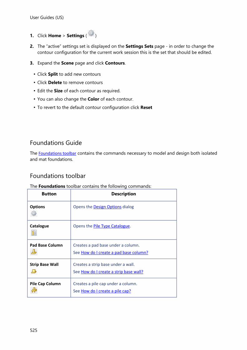
User Guides (US)
525
1. Click Home > Settings ( )
2. The “active” settings set is displayed on the Settings Sets page - in order to change the
contour configuration for the current work session this is the set that should be edited.
3. Expand the Scene page and click Contours.
• Click Split to add new contours
• Click Delete to remove contours
• Edit the Size of each contour as required.
• You can also change the Color of each contour.
• To revert to the default contour configuration click Reset
Foundations Guide
The Foundations toolbar contains the commands necessary to model and design both isolated
and mat foundations.
Foundations toolbar
The Foundations toolbar contains the following commands:
Button Description
Options
Opens the Design Options dialog
Catalogue
Opens the Pile Type Catalogue.
Pad Base Column
Creates a pad base under a column.
See How do I create a pad base column?
Strip Base Wall
Creates a strip base under a wall.
See How do I create a strip base wall?
Pile Cap Column
Creates a pile cap under a column.
See How do I create a pile cap?

User Guides
526
Design Pad Bases
Performs the design of all pad bases in the model.
See How do I design or check all pad and strip bases in the model?
Design Pile Caps
Performs the design of all isolated foundations in the model.
See How do I design or check all pile caps in the model?
Minimum Area
Creates a minimum area mat foundation under selected columns/walls.
See How do I create a minimum area or rectangular mat?
Rectangular
Creates a rectangular mat foundation under selected columns/walls.
See How do I create a minimum area or rectangular mat?
Strip
Creates a strip mat foundation.
See How do I create a strip mat?
Area
Creates an area mat foundation.
See How do I create an area mat?
Bays Creates a mat foundation within an enclosed area defined by grids.
See How do I create a mat within bays?
Column Drop
(on drop list)
Creates a column drop which adopts the specified column drop properties
Mat Opening
(on drop list)
Creates a mat opening which adopts the specified slab opening and mat opening properties
Mat Overhang
(on drop list)
Creates a mat overhang which adopts the specified slab overhang and mat overhang properties
Mat Split
This command is used to split an existing mat.
See: How do I split a slab?
Mat Join
This command is used to join an existing mat.
See: How do I join slabs?

User Guides (US)
527
Pile
Creates a single pile which adopts the specified create pile properties set
Pile Array
Creates a pile array which adopts the specified create pile properties set
Design Mats
Designs or checks reinforcement in all mats that are not inside patches.
See Design Mats
Design Patches
Designs or checks slab reinforcement in all slab areas inside patches.
See Perform Patch Design
Patch Column
(on drop list)
Creates a column patch which adopts the specified create column patch properties set
See How do I create a column patch?
Patch Beam
(on drop list)
Creates a beam patch which adopts the specified create beam patch properties set
See How do I create a beam patch?
Patch Wall
(on drop list)
Creates a wall patch which adopts the specified create wall patch properties set
See How do I create a wall patch?
Patch Panel
(on drop list)
Creates a panel patch which adopts the specified create panel patch properties set
See How do I create a panel patch?
Design Punching Shear
Performs the punching shear checks.
See Perform Punching Shear Checks
Add Check
Used to add a punching shear check around a column or wall perimeter.
See How do I create a Punching Check item?
Related topics
• Commands on the ribbon toolbars
Foundation Options
Pile Type Catalogue

User Guides
528
In order to use piles, you must first set up a catalogue of pile types.
How do I set up the pile type catalogue?
1. Click Foundations > Catalogue (
)
2. The Pile Catalogue is displayed - from here you can add, edit or delete individual pile
types.
3. Click Add... to enter the Pile Type Properties
Pad and Strip Base modelling
• pad base - an isolated foundation that supports a single column
• strip base - an isolated foundation that supports a single wall
How do I create a pad base column?
1. Click Foundations > Pad Base Column ( )
2. The Pad Base Column Properties set is displayed - specify the properties as required.
To place a pad base under a specific column:
1. Click anywhere on the required column. Tekla Structural Designer will add a pad base
under the column.
To create multiple pad bases by windowing:
1. Move the cursor to one corner of an imaginary box which will encompass the columns
under which you want to define bases.
2. Click and hold the left mouse button.
3. Drag to the diametrically opposite corner of the box (you will see a rubber rectangle on
the screen which follows your mouse movements and helps you to check the area in
which you are creating bases).
4. Once the rubber rectangle encompasses the creation area release the mouse button and
Tekla Structural Designer will create bases under all columns which are totally within the
rubber rectangle.
How do I create a strip base wall?
User Guides (US)
529
1. Click Foundations > Strip Base Wall ( )
2. The Strip Base Wall Properties set is displayed - specify the properties as required.
To place a strip base under a specific wall:
1. Click anywhere on the required wall. Tekla Structural Designer will add a strip base under
the wall.
To create multiple strip bases by windowing:
1. Move the cursor to one corner of an imaginary box which will encompass the walls under
which you want to define bases.
2. Click and hold the left mouse button.
3. Drag to the diametrically opposite corner of the box (you will see a rubber rectangle on
the screen which follows your mouse movements and helps you to check the area in
which you are creating bases).
4. Once the rubber rectangle encompasses the creation area release the mouse button and
Tekla Structural Designer will create bases under all walls which are totally within the
rubber rectangle.
Pile Cap modelling
• pile cap - an isolated piled foundation that supports a single column
How do I create a pile cap?
Before a pile cap can be placed, the Pile Type Catalogue must contain at least one pile type.
1. Click Foundations > Pile Cap Column ( )
2. The Pile Cap Column Properties set is displayed - specify the properties as required.
To place a pile cap under a specific column:
1. Click anywhere on the required column. Tekla Structural Designer will add a pile cap
under the column.
To create multiple pile caps by windowing:
1. Move the cursor to one corner of an imaginary box which will encompass the columns
under which you want to define pile caps.
2. Click and hold the left mouse button.
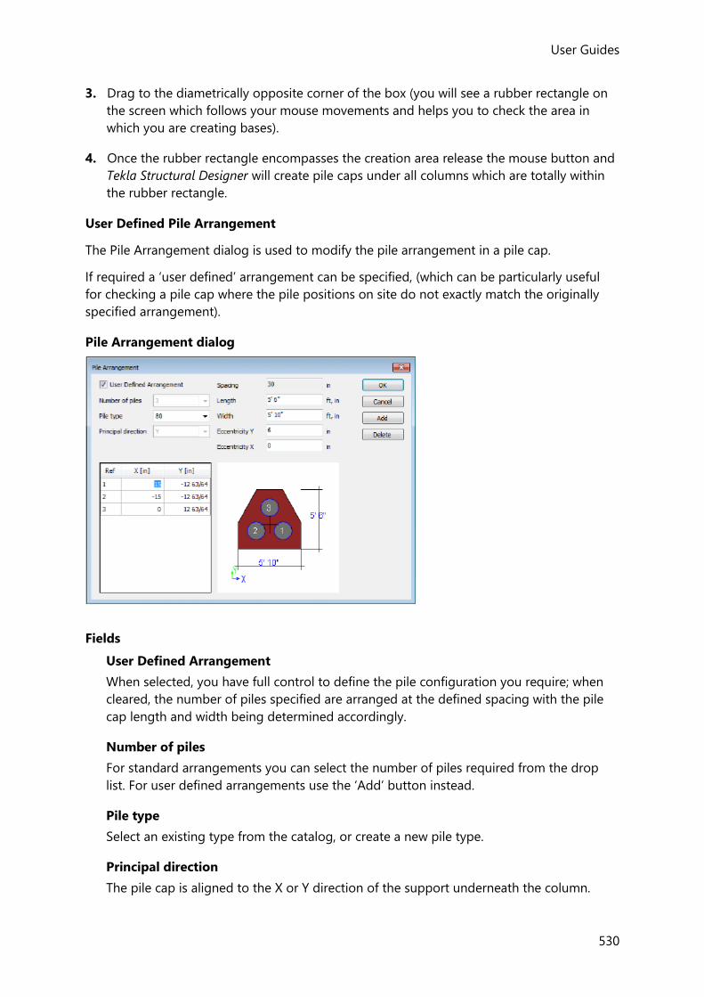
User Guides
530
3. Drag to the diametrically opposite corner of the box (you will see a rubber rectangle on
the screen which follows your mouse movements and helps you to check the area in
which you are creating bases).
4. Once the rubber rectangle encompasses the creation area release the mouse button and
Tekla Structural Designer will create pile caps under all columns which are totally within
the rubber rectangle.
User Defined Pile Arrangement
The Pile Arrangement dialog is used to modify the pile arrangement in a pile cap.
If required a ‘user defined’ arrangement can be specified, (which can be particularly useful
for checking a pile cap where the pile positions on site do not exactly match the originally
specified arrangement).
Pile Arrangement dialog
Fields
User Defined Arrangement
When selected, you have full control to define the pile configuration you require; when
cleared, the number of piles specified are arranged at the defined spacing with the pile
cap length and width being determined accordingly.
Number of piles
For standard arrangements you can select the number of piles required from the drop
list. For user defined arrangements use the ‘Add’ button instead.
Pile type
Select an existing type from the catalog, or create a new pile type.
Principal direction
The pile cap is aligned to the X or Y direction of the support underneath the column.
User Guides (US)
531
Spacing
The pile spacing determines the arrangement, but does not apply to user defined
arrangements.
Length
Length of the pile cap
Width
Width of the pile cap
Eccentricity Y
Eccentricity in Y of the pile cap centroid from the centroid of the column it supports.
Eccentricity X
Eccentricity in X of the pile cap centroid from the centroid of the column it supports.
Pile Positioning Table (only editable for user defined arrangements)
Ref
The individual pile references as displayed on the accompanying diagram.
X
Eccentricity in X of the pile centroid from the centroid of the pile cap.
Y
Eccentricity in Y of the pile centroid from the centroid of the pile cap.
Buttons
Adds a new pile to the Pile Positioning Table.
Deletes the pile currently highlighted in the Pile Positioning Table.
How do I open the Pile Arrangement dialog?
1. Select the pile cap to be edited.
2. In the Pile Cap Properties, click ‘Pile Arrangement’
3. Click the button located at the right side of the ‘Pile Arrangement’ property box.
4. The Pile Arrangement dialog is displayed.
How do I create a user defined pile arrangement?
1. Select the pile cap to be edited.
2. Open the Pile Arrangement dialog.
3. Click ‘User Defined Arrangement’.

User Guides
532
4. If the selected pile cap had ‘auto-design piles’ turned on, you will be prompted to turn it
off - click Yes to do this and proceed.
5. Specify the pile configuration as required - when the preview picture displays the
arrangement as required, click OK.
Isolated Foundation design
Before bases and pile caps can be designed you need to have run an analysis to establish the
base design forces - either by running Analyse All (Static), or by running any of the design
processes (Design Concrete, Design All etc.).
Once this is complete, isolated foundations can then be batch designed from the toolbar, or
designed individually from the right-click context menu. Grouping can be employed to
rationalize the designs produced.
How do I design or check all pad and strip bases in the model?
• Click Foundations > Design Pad Bases
All pad and strip bases in the model are designed or checked automatically (in
accordance with their individual ‘auto-design’ settings). All active Static and RSA
combinations are considered.
How do I design or check all pile caps in the model?
• Click Foundations > Design Pile Caps
All pile caps in the model are designed or checked automatically (in accordance with
their individual ‘auto-design’ settings). All active Static and RSA combinations are
considered.
How do I check an individual isolated foundation?
1. Hover the cursor over the top of the foundation to be designed.
The Select Entity tooltip should appear.
2. If necessary press the <down arrow> cursor key until the foundation name is
highlighted in the Select Entity tooltip.
3. Right-click and from the context menu pick Check Member.
The results of the check are displayed in a dialog on screen.
How do I design an individual isolated foundation?
1. Hover the cursor over the top of the foundation to be designed.
The Select Entity tooltip should appear.
2. If necessary press the <down arrow> cursor key until the foundation name is
highlighted in the Select Entity tooltip.
User Guides (US)
533
3. Right-click and from the context menu pick Design Member.
The results of the design are displayed in a dialog on screen.
Mat Foundation modelling
Mat foundations support multiple columns and walls - they can be ground bearing,
supported on piles, or both. The following different tools for creating mat foundations are
provided:
• minimum area - creates an overhanging polygonal mat so as to minimise the area
required
• rectangular - creates an overhanging rectangular mat by one of two methods
• at a specified angle to the global axes, or
• smallest rectangular area (aligned to the global axes)
• strip - creates a constant width mat along a series of points that are not restricted to
being in the same line
• area - creates an overhanging polygonal mat by identifying points around its outline
• bay - creates a mat with no overhang by clicking within a closed grid area
• pile - creates a individual piles underneath existing mats
• pile array - creates an array of piles underneath existing mats
How do I create a minimum area or rectangular mat?
1. Click Foundations > Minimum Area ( ), or Rectangular ( ),
2. The foundation mat properties set is displayed - specify the properties as required.
To create a mat in a 3D view:
1. Click anywhere on the first column or wall to be supported.
2. Continue clicking on subsequent columns or walls as required.
3. Either click one of the supported members, or press <Enter> to create the mat.
To create a mat in a 2D view:
1. To select multiple walls - click and drag from right to left to encompass those walls
under which you want to define the mat.
2. To select multiple columns - click and drag from left to right to encompass those
columns under which you want to define the mat.
3. To add individual columns and wall - click each member individually.
4. Either click one of the supported members, or press <Enter> to create the mat.
User Guides
534
How do I create a strip mat?
1. Open a 2D view at the base level where the strip is to be placed.
2. Click Foundations > Strip( )
3. The foundation mat properties set is displayed - specify the strip width and other
properties as required.
4. Pick the strip start point
5. Click subsequent points to define the strip as required.
6. Either click once again on the last point, or press <Enter> to create the strip.
How do I create an area mat?
1. Click Foundations > Area ( )
2. The foundation mat properties set is displayed - specify the properties as required.
3. Pick a construction point at a corner of the area.
4. Pick subsequent construction points for each remaining corner.
5. Either click once again on the last point, or press <Enter> to create the mat.
How do I create a mat within bays?
1. Click Foundations > Bays
2. The foundation mat properties set is displayed - specify the properties as required.
3. Select a bay by either by clicking within an enclosed area defined by grids; or by
dragging around the area required.
How do I create a piled mat?
A piled mat can either be supported on piles alone, or by a combination of ground springs
and piles.
Piles can either be placed individually at specific locations within the mat, or an array of
equally spaced piles can be created.

User Guides (US)
535
How do I specify if a piled mat is ground bearing?
1. Define the slab mat using any of the existing mat creation methods.
2. In the slab item properties, review the Soil Parameters that have been applied.
Either clear Use Ground Bearing Springs if the mat is to be supported on piles alone, or
leave it checked to support the mat by a combination of ground springs and piles.
How do I place an individual pile in a mat?
1. Click Foundations > Pile
2. In the 2D or 3D View, click the slab mat in which the pile is to be placed.
3. If defining an inclined pile; specify the pile direction in the pile properties window.
4. In the 2D or 3D View, select the pile position.
How do I place a pile array in a mat?
1. Click Foundations > Pile Array
2. Specify the Pile Array Properties to define the pile type, spacing and, for raking piles the
pile direction.
You can graphically preview the array by hovering the cursor over a mat.
3. Click an individual mat, or box around multiple mats to apply the pile array.
The array is displayed on the mats that have been selected.
4. If required, continue to add further mats to the selection, or to finish selecting, click once
more on one of the mats that have already been selected.
5. Select the reference point from which piles in the array are laid out.
The piles are placed in the mat. At this point you can either press Esc to finish the
command, or you can continue to place the same array on additional mats.
How do specify the pile direction of an inclined pile?
The pile direction is specified in the pile properties window in using one of the following
methods:
To specify the direction as a vector:
Whilst any values can be entered, the Z value of the vector must be a negative number, as
this ensures that the highest point of the pile is at the node where it connects to the mat
foundation.
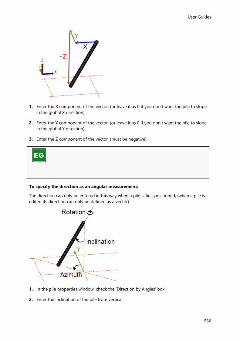
User Guides
536
1. Enter the X component of the vector, (or leave it as 0 if you don’t want the pile to slope
in the global X direction).
2. Enter the Y component of the vector, (or leave it as 0 if you don’t want the pile to slope
in the global Y direction).
3. Enter the Z component of the vector, (must be negative).
To specify the direction as an angular measurement:
The direction can only be entered in this way when a pile is first positioned, (when a pile is
edited its direction can only be defined as a vector).
1. In the pile properties window, check the ‘Direction by Angles’ box.
2. Enter the inclination of the pile from vertical.

User Guides (US)
537
3. Enter the azimuth, (i.e. the as a horizontal angle measured clockwise about positive
global Z).
4. Enter the rotation about the piles longitudinal axis. (Since the pile is only checked for
axial capacity, the rotation angle has no effect on the pile checks, but you could still use
this to vary how the moment and shear force values are shown.)
Mat design, patches and punching shear
Since a mat foundation is simply a type of slab, once it has been created, a similar design
process can be followed:
• Create Patches - patches are placed under columns, beams, walls or in panels as required.
• Design Mats - mat panel areas that lie outside the patch areas are designed, (if the mat is
supported on piles these are also designed),
• Perform Patch Design - patches are designed,
• Add Punching Shear Checks - punching shear checks are placed under columns supported
by the mat as required,
• Perform Punching Shear Checks - punching shear checks are performed.
Design Mats
Once any required patches have been placed, you can determine the top and bottom
reinforcement requirements in the mats that lie outside of the patch areas. (Because patch
areas are excluded from panel design, patches should be placed before mats are designed.)
Before the mats can be designed you have to run an analysis to establish the design
moments - either by running Analyse All (Static), or by running any of the design processes
(Design Concrete, Design All etc.).
All active Static and RSA combinations are considered in the design process.
How do I design or check all mats in the model?
1. Click Foundations
Then click Design Mats ( )
All mats in the model are designed or checked automatically (in accordance with their
individual ‘auto-design’ settings).
How do I check all mats in a single floor?

User Guides
538
1. Open a 2D View of the floor to be designed.
2. Right-click and choose Check Slabs.
All slab panels in the floor have their reinforcement checked (regardless of their
individual ‘auto-design’ settings).
How do I design all mats in a single floor?
1. Open a 2D View of the floor to be designed.
2. Right-click and choose Design Slabs.
All mats in the floor are designed - potentially picking new reinforcement, (regardless of
their individual ‘auto-design’ settings).
How do I check an individual mat?
1. Hover the cursor over the top of the mat to be designed.
The Select Entity tooltip should appear.
2. If necessary press the <down arrow> cursor key until the mat name is highlighted in the
Select Entity tooltip.
3. Right-click and from the context menu pick Check Panel.
The results of the check are displayed in a dialog on screen.
How do I design an individual mat?
1. Hover the cursor over the top of the mat to be designed.
The Select Entity tooltip should appear.
2. If necessary press the <down arrow> cursor key until the mat name is highlighted in the
Select Entity tooltip.
3. Right-click and from the context menu pick Design Panel.
The results of the design are displayed in a dialog on screen.
Design Review Guide
The Review View opens automatically at the end of the structure design process, it can also
be accessed at any time by clicking in the Status Bar.
In this view by selecting from the Review toolbar, you can graphically display the design
status for members or slabs; you can also interrogate, and/or modify a variety of model
parameters and properties.

User Guides (US)
539
In addition, by clicking (Tabular Data) from this toolbar, you can open a Review
Data view, from where by making appropriate selections from the Review Data toolbar you
can display tables of Sway Results, Design Summaries and Material Lists.
Review toolbar
The Review toolbar contains the following commands:
Button Description
Design Type (1st drop list)
Use the Design Type drop list to choose which design type to display results for: Static, RSA, or Combined.
Status
Each member is color coded to indicate its design status (Pass, Fail, Warning, Error, Beyond Scope, Unknown.)
See Member Design Status
Ratio
Each member is color coded to indicate its design utilisation ratio.
See Member Design Ratio
Depth Ratio
Each beam is color coded to indicate its span to depth utilisation ratio.
See Depth Ratio
Foundation Design Status
Each foundation is color coded to indicate its design status (Pass, Fail, Warning, Error, Beyond Scope, Unknown.)
See Foundation Design and Pile Design Status
Foundation Design Ratio
Each foundation is color coded to indicate its design utilisation ratio.
See Foundation Design and Pile Design Ratios
Piles Status
Each pile is color coded to indicate its design status (Pass, Fail, Warning, Error, Beyond Scope, Unknown.)
See Foundation Design and Pile Design Status
Piles Ratio
Each pile is color coded to indicate its design utilisation ratio.
See Foundation Design and Pile Design Ratios
Slab/Mat Design Status
Each slab panel is color coded to indicate its design status (Pass, Fail, Warning, Error, Beyond Scope, Unknown.) for the selected condition chosen from the droplist.
See Slab/Mat Design Status
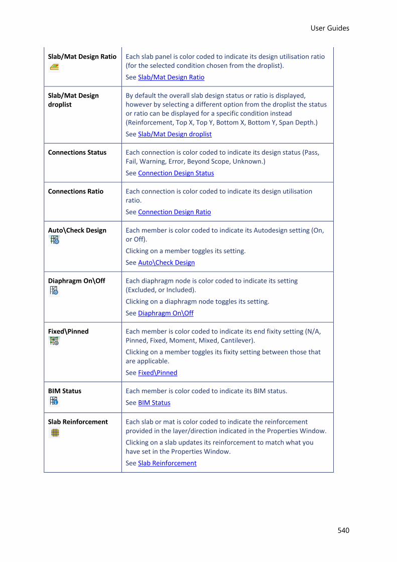
User Guides
540
Slab/Mat Design Ratio
Each slab panel is color coded to indicate its design utilisation ratio (for the selected condition chosen from the droplist).
See Slab/Mat Design Ratio
Slab/Mat Design droplist
By default the overall slab design status or ratio is displayed, however by selecting a different option from the droplist the status or ratio can be displayed for a specific condition instead (Reinforcement, Top X, Top Y, Bottom X, Bottom Y, Span Depth.)
See Slab/Mat Design droplist
Connections Status Each connection is color coded to indicate its design status (Pass, Fail, Warning, Error, Beyond Scope, Unknown.)
See Connection Design Status
Connections Ratio Each connection is color coded to indicate its design utilisation ratio.
See Connection Design Ratio
Auto\Check Design
Each member is color coded to indicate its Autodesign setting (On, or Off).
Clicking on a member toggles its setting.
See Auto\Check Design
Diaphragm On\Off
Each diaphragm node is color coded to indicate its setting (Excluded, or Included).
Clicking on a diaphragm node toggles its setting.
See Diaphragm On\Off
Fixed\Pinned
Each member is color coded to indicate its end fixity setting (N/A, Pinned, Fixed, Moment, Mixed, Cantilever).
Clicking on a member toggles its fixity setting between those that are applicable.
See Fixed\Pinned
BIM Status
Each member is color coded to indicate its BIM status.
See BIM Status
Slab Reinforcement
Each slab or mat is color coded to indicate the reinforcement provided in the layer/direction indicated in the Properties Window.
Clicking on a slab updates its reinforcement to match what you have set in the Properties Window.
See Slab Reinforcement

User Guides (US)
541
Steel
Each steel member is color coded to indicate its section and grade.
Clicking on a steel member updates its section and/or grade to match what you have set in the Properties Window.
See Material Grade and Section
Copy Properties
After firstly selecting a parameter in the Properties Window you are able to copy it from a designated source member to valid target members.
See Copy Properties
Report Filter
This command is only accessible once member filters have been defined.
Each member is color coded to indicate if it is included in the currently selected filter.
Clicking a member toggles its inclusion status.
See Report Filter
Sub Structures
Each member is color coded to indicate if it is included in any Sub Structures.
By making selections in the Properties Window, new sub structures can be created and existing ones edited.
See Sub Structures
Concrete Beam Flanges
Each concrete beam is color coded to indicate its if flanges are considered and flange widths determined.
See Use of beam flanges
Column Splices
Potential splice locations in steel columns are color coded to indicate where splices exist.
See Column Splices
Property Sets
Each member or panel is color coded to indicate if it has had a saved Property Set applied to it.
See Property Sets
UDA
Each member and panel is color coded to indicate the value of the chosen attribute in the Properties Window.
See UDA
Show/Alter State
Provides access to a wider range of Show/Alter State commands via the Properties Window.
Some Show/Alter State commands are repeated in the toolbar; others can only be accessed via this button.
See Show/Alter State

User Guides
542
Braced \Bracing (via Show/Alter State button)
Each concrete wall and column is color coded to indicate its braced setting (Braced, Bracing) in the direction indicated in the Properties Window.
Clicking on a concrete wall or column toggles its setting between those that are applicable.
See Braced/Bracing
Deflection Limits (via Show/Alter State button)
Allows you to review deflection limits or copy the specified deflection limits from one steel beam to others.
See Deflection Limits
Gravity Only (via Show/Alter State button)
Each steel beam and column is color coded to indicate where its gravity only setting.
See Gravity Only
Punch Check Position (via Show/Alter State button)
Each punching check item is color coded to indicate its Loaded Perimeter position (Corner, Edge Z, Edge Y, Internal).
Clicking on a punching check item or boxing around it toggles its setting.
See Punch Check Position
Restrained \Unrestrained (via Show/Alter State button)
Each member is color coded to indicate its restraints setting (N/A, Unrestrained, Partially Restrained, Fully Restrained).
Clicking on a member toggles its setting between those that are applicable.
See Restrained\Unrestrained
SFRS Direction (via Show/Alter State button)
Each member is color coded to indicate the SFRS direction.
Clicking on a member updates it to match what you have set in the Properties Window.
See SFRS Direction
SFRS Type (via Show/Alter State button)
Each member is color coded to indicate the SFRS type.
Clicking on a member updates it to match what you have set in the Properties Window.
See SFRS Type
Shear connectors (via Show/Alter State button)
Clicking on a target composite beam updates its shear connectors to match those of the source beam.
See Shear Connectors
Size Constraints (via Show/Alter State button)
Allows you to review size constraints for steel members or copy the specified size constraints from one steel member to others.
See Size Constraints

User Guides (US)
543
Steel (via Show/Alter State button)
In Review mode each steel member is color coded to indicate its grade.
In Copy mode clicking on a steel member updates its grade to match that of a source member.
See Material Grade
Steel section (via Show/Alter State button)
In Review mode each steel member is color coded to indicate its section.
In Copy mode clicking on a steel member updates its section to match that of a source member.
See Section
Stud auto layout (via Show/Alter State button)
Clicking on a composite beam updates its stud auto layout setting.
See Stud auto layout
Transverse Reinforcement (via Show/Alter State button)
Clicking on a target composite beam updates its transverse reinforcement to match those of the source beam.
See Transverse reinforcement
Web openings (via Show/Alter State button)
Clicking on a target member updates its web openings to match those of the source member.
See Web openings
Westok openings (via Show/Alter State button)
Clicking on a target member updates its web openings to match those of the source member.
See Westok openings
Tabular Data
Displays the Review Data toolbar which allows spreadsheets to be displayed for further review.
See Working with the Review Data view
Review Data toolbar
The Review Data toolbar contains the following groups:
Button Description
View Type (drop list)
Choose the spreadsheet to be displayed by selecting from this drop list:
• How do I display Sway Results in a Review Data table?
• How do I display a Design Summary in a Review Data table?
• How do I display a Material List in a Review Data table?
Material Type Choose the material type to be displayed, (only one material at a time).

User Guides
544
Characteristic Choose the member type to be displayed, (only one member at a time).
Construction For steel members only - choose the construction type to be displayed.
Fabrication Choose the fabrication type to be displayed. The choices available depend on the material and characteristic selections.
Content For the Material List spreadsheet for concrete only - Choose the content to be displayed.
Filter (drop list)
Use the drop lists to apply group based or geometric filters to the data.
Working with the Review View
Setting the Design Type to Review
The Design Type drop list on the Review toolbar enables you to focus on a specific design
type (Static, RSA, or Combined) when reviewing the member, foundation and slab designs.
Reviewing Member Design
Member Design Status
Color codes are used to graphically display the design status of each member.
The following classifications are applied:
Status Description

User Guides (US)
545
Unknown Prior to being designed, the member status is set to unknown.
Beyond Scope Design of this member is beyond the scope of the program.
Error The member cannot currently be designed because an error has occurred.
Warning Although the member has passed the design checks, one or more warnings have been issued.
The user should review these warnings before deciding if any further action is required.
Fail The member has failed one or more design checks.
Pass The member has passed all design checks.
Member Design Ratio
Color codes are used to graphically display the design ratio of each member.
The ‘N/A’ colour code (which is assigned if there is no ratio, or if it is smaller than the lowest band), indicates those members either beyond scope or which have yet to be designed.
Depth Ratio
All steel and concrete beams are color coded to indicate their span to depth utilisation ratios.
Reviewing Foundation and Pile Design
Foundation Design and Pile Design Status

User Guides
546
Color codes are used to graphically display the design status.
The following classifications are applied:
Status Description
Unknown Prior to being designed, the status is set to unknown.
Beyond Scope Design of this foundation/pile is beyond the scope of the program.
Error The foundation/pile cannot currently be designed because an error has occurred.
Warning Although the design checks have passed, one or more warnings have been issued.
The user should review these warnings before deciding if any further action is required.
Fail The design checks have failed.
Pass All design checks have passed.
Foundation Design and Pile Design Ratios
Color codes are used to graphically display the design ratios.
The ‘N/A’ colour code (which is assigned if there is no ratio, or if it is smaller than the lowest band), indicates those foundations or piles either beyond scope or which have yet to be designed.
Reviewing Slab Design
Slab/Mat Design Status
Color codes are used to graphically display the design status of each slab panel.
The following classifications are applied:
Status Description
Unknown Prior to being designed, the slab panel status is set to unknown.
Beyond Scope Design of this slab panel is beyond the scope of the program.
Error The slab panel cannot currently be designed because an error has occurred.
Warning Although the slab panel has passed the design checks, one or more warnings have been issued.
The user should review these warnings before deciding if any further action is required.
User Guides (US)
547
Fail The slab panel has failed one or more design checks.
Pass The slab panel has passed all design checks.
Slab/Mat Design Ratio
Color codes are used to graphically display the design ratio of each slab panel.
The ‘N/A’ colour code (which is assigned if there is no ratio, or if it is smaller than the lowest band), indicates those slab panels either beyond scope or which have yet to be designed.
Slab/Mat Design droplist
The droplist is used in combination with the Slab Design Status and Ratio buttons to filter
the review information.
• Overall - the governing Top X, Top Y, Bottom X, Bottom Y, or span depth result is
displayed
• Reinforcement - the governing Top X, Top Y, Bottom X, or Bottom Y result is displayed
• Top X - the result is only displayed for top reinforcement in the X direction
• Top Y - the result is only displayed for top reinforcement in the Y direction
• Bottom X - the result is only displayed for bottom reinforcement in the X direction
• Bottom Y - the result is only displayed for bottom reinforcement in the Y direction
• Span Depth - the span to depth result is displayed
Reviewing Connection Design
Connection Design Status
Color codes are used to graphically display the design status of each connection.
The following classifications are applied:
Status Description
Unknown Prior to being designed, the connection status is set to unknown.
Beyond Scope Design of this connection is beyond the scope of the program.
Error The connection cannot currently be designed because an error has occurred.
Warning Although the connection has passed the design checks, one or more warnings have been issued.
The user should review these warnings before deciding if any further action is required.
User Guides
548
Fail The connection has failed one or more design checks.
Pass The connection has passed all design checks.
Connection Design Ratio
Color codes are used to graphically display the design ratio of each connection.
The ‘N/A’ colour code (which is assigned if there is no ratio, or if it is smaller than the lowest band), indicates those connections either beyond scope or which have yet to be designed.
Show/Alter State
The Show/Alter State group of commands collectively provide an efficient means to
graphically review and/or edit various model properties. For each of these commands
entities are color coded in accordance with a legend, the entity color changing to reflect
changes as they are made.
Most of the Show/Alter State commands include a Filter feature in the Properties Window
to control both the visibility of entities by their current setting, and also which are ‘active’ (i.e.
those which can be edited) by their type and characteristic (where appropriate). Inactive but
visible entities are shaded a light transparent grey for which there is an opacity control also
in the Properties Window.
Show/Alter State
Provides access to a range of Show/Alter State commands via the Properties Window.
1. Open a Review View
2. Click Review > Show/Alter State
3. In the Properties Window, click the Attributes list, and then click the required command.
Ctrl [A] on the keyboard is a shortcut key for cycling through the Attributes droplist, (provided that you have nothing highlighted in the Properties Window at the time).
Auto\Check Design
This command provides a means to:
• graphically alter member autodesign settings,
• or by changing the Attribute, graphically alter stud auto layout settings (see: Stud auto
layout)
Autodesign

User Guides (US)
549
Options
Mode • Toggle - clicking on a member/slab switches auto design on/off
• SetOn - clicking on a member/slab only sets auto design on
SetOff - clicking on a member/slab only sets auto design off
Shortcut: Ctrl [M] cycles through the Modes, (provided that you have nothing highlighted in the Properties Window at the time).
Filter
Show • All - all members are shown
• On- only members with autodesign on are shown
• Off - only members with autodesign off are shown
Entity Type Select from the droplist to filter the display to a particular entity type
Characteristic Select from the droplist to filter the display to a particular characteristic
Scene
Opacity N/A Reduces the opacity of elements to which the command is not applicable
To alter autodesign settings:
1. Open a Review View
2. Click Review > Auto\Check Design
Members and slabs are color coded to show their autodesign setting.
3. Choose the appropriate mode in the Properties Window, then either:
• Click an individual member to toggle/set its Autodesign setting.
• Drag a box from left to right to toggle/set the Autodesign setting for all members totally
enclosed by the box.
• Drag a box from right to left to toggle/set the Autodesign setting for all members that
are either enclosed by the box, or cut by the box perimeter.
BIM Status
This command provides a means to graphically assess the BIM Status, and also to exclude
members and panels from the import/export process.
BIM status
Filter

User Guides
550
Show Select from the droplist to filter the display to a particular BIM status
Entity Type Select from the droplist to filter the display to a particular entity type
Scene
Opacity N/A Reduces the opacity of elements to which the command is not applicable
BIM Status Values:
Status Description
New If newly created in Tekla Structural Designer
Imported If created externally
Exported If exported
Updated If modified by an import
Deleted If the member appears to have been deleted in the other system
Mixed If the status varies from span to span in multi-span beams, or lift to lift in multi-lift columns.
Excluded Indicates those parts of the model that have been excluded from the BIM process.
Not modified Indicates those parts of the model that have not been modified by the last BIM import.
To include/exclude members and panels from the BIM process:
1. Open a Review View
2. Click Review > BIM Status
• Click an individual member\panel to exclude it, click it once more to re-include it.
• Drag a box from left to right to toggle the exclude setting for all members totally
enclosed by the box.
• Drag a box from right to left to toggle the exclude setting for all members that are either
enclosed by the box, or cut by the box perimeter
Braced/Bracing
This command provides a means to graphically assess and modify the slenderness settings in
each direction for concrete columns and walls.
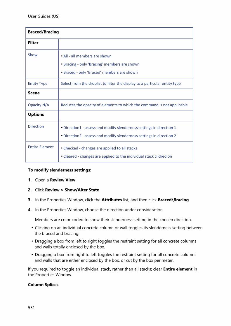
User Guides (US)
551
Braced/Bracing
Filter
Show • All - all members are shown
• Bracing - only ‘Bracing’ members are shown
• Braced - only ‘Braced’ members are shown
Entity Type Select from the droplist to filter the display to a particular entity type
Scene
Opacity N/A Reduces the opacity of elements to which the command is not applicable
Options
Direction • Direction1 - assess and modify slenderness settings in direction 1
• Direction2 - assess and modify slenderness settings in direction 2
Entire Element • Checked - changes are applied to all stacks
• Cleared - changes are applied to the individual stack clicked on
To modify slenderness settings:
1. Open a Review View
2. Click Review > Show/Alter State
3. In the Properties Window, click the Attributes list, and then click Braced\Bracing
4. In the Properties Window, choose the direction under consideration.
Members are color coded to show their slenderness setting in the chosen direction.
• Clicking on an individual concrete column or wall toggles its slenderness setting between
the braced and bracing.
• Dragging a box from left to right toggles the restraint setting for all concrete columns
and walls totally enclosed by the box.
• Dragging a box from right to left toggles the restraint setting for all concrete columns
and walls that are either enclosed by the box, or cut by the box perimeter.
If you required to toggle an individual stack, rather than all stacks; clear Entire element in
the Properties Window.
Column Splices
User Guides
552
This command provides a means to graphically assess and modify splice positions within
steel columns.
To modify column splices:
1. Open a Review View
2. Click Review > Column Splices
All potential splice locations are color coded to indicate if they are on or off.
3. Click a potential splice location to toggle its setting between on and off, or in a 2D View
click-and-drag a window to toggle multiple splices in one go.
Concrete Beam Flanges
This command provides a means to graphically review the flanges of concrete beams.
To review concrete beam flanges:
1. Open a Review View
2. Click Review > Concrete Beam Flanges
Each concrete beam is color coded to indicate its if flanges are considered and flange
widths determined.
Copy Properties
This command provides a means to graphically copy a specified element parameter (e.g. web
openings, connectors or transverse reinforcement) from a source member to other valid
target members.
To copy properties:
1. Open a Review View
2. Click Review > Copy Properties
3. In the Properties Window, select the parameter of the member you want to be copied
(e.g. web openings, connectors or transverse reinforcement).
4. Next click the source member that contains the property to be copied. The color coding
should update accordingly:
• Source - this color identifies the member that was clicked on. (If this is incorrect, press
[Esc] in order to reselect.)
• Same as Source - this color identifies those members in which the selected parameter
already matches the Source.
• Valid Target - this color identifies those members to which it is possible to copy the
selected parameter.

User Guides (US)
553
• NA - this color identifies those members to which it is not possible to copy the
selected parameter.
• Either click an individual target member, or box around a series of target members to
copy the selected parameter to them.
Deflection Limits
Graphically review specified deflection limits, and copy the limits from one steel beam to
others.
Deflection Limits
Options
Mode • Copy - copy specified deflection limits from one steel beam to others
• Review - graphically review the deflection limits
Shortcut: Ctrl [M] cycles through the Modes, (provided that you have nothing highlighted in the Properties Window at the time)
By load type • Checked - provides options for selecting an individual load type and load limit
• Cleared - limits for all load types
Scene
Opacity N/A Reduces the opacity of elements to which the command is not applicable
To copy deflection limits:
1. Open a Review View
2. Click Review > Show/Alter State
3. In the Properties Window, click the Attributes list, and then click Deflection Limits
4. Set the Mode to Copy
5. Either leave By Load type cleared if you want to copy the limits for all load types, or
check it if you want to specify an individual load type.
If you specify an individual load type you can also choose to copy the absolute value, the
span over factor, or both.
6. Select a valid source beam.
7. Select a beam to copy the limits to.
8. Continue copying as required, or press ESC when done.

User Guides
554
To review deflection limits:
1. Set the Mode to Review
2. Select the load type to be reviewed.
Diaphragm On\Off
The ‘Include in diaphragm’ setting for slab items, roofs and nodes can be toggled
graphically.
Diaphragm
Options
Mode • Toggle - clicking on a slab/roof/node switches it between included/excluded
• Include - clicking on a slab/roof/node includes it
• Exclude - clicking on a slab/roof/node excludes it
Shortcut: Ctrl [M] cycles through the Modes, (provided that you have nothing highlighted in the Properties Window at the time).
Filter
Show • All - all slabs/roofs/nodes are shown
• Included- only included slabs/roofs/nodes are shown
• Excluded - only excluded slabs/roofs/nodes are shown
Entity Type Select from the droplist to filter the display to a particular entity type
Scene
Opacity N/A Reduces the opacity of elements to which the command is not applicable
To display the current diaphragm settings:
1. Open a Review View
2. Click Review > Diaphragm On\Off
Slab items, roofs and nodes are color coded to show their ‘Include in diaphragm’ setting.
The Properties Window shows the currently selected ‘toggle’ mode.
To toggle the diaphragm settings for slab items or roofs:
First set the ‘Entity type’ in the Properties Window to ‘Slab Item’ or ‘Roof’ then either:
• Click an individual panel.
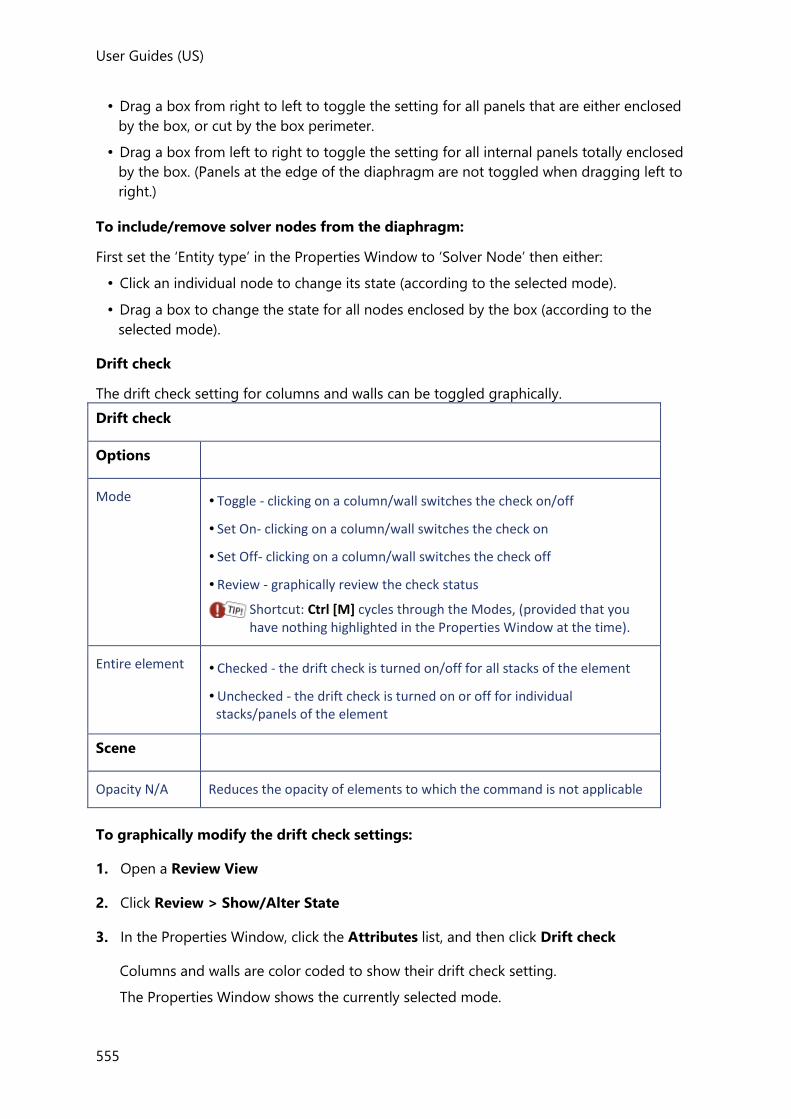
User Guides (US)
555
• Drag a box from right to left to toggle the setting for all panels that are either enclosed
by the box, or cut by the box perimeter.
• Drag a box from left to right to toggle the setting for all internal panels totally enclosed
by the box. (Panels at the edge of the diaphragm are not toggled when dragging left to
right.)
To include/remove solver nodes from the diaphragm:
First set the ‘Entity type’ in the Properties Window to ‘Solver Node’ then either:
• Click an individual node to change its state (according to the selected mode).
• Drag a box to change the state for all nodes enclosed by the box (according to the
selected mode).
Drift check
The drift check setting for columns and walls can be toggled graphically.
Drift check
Options
Mode • Toggle - clicking on a column/wall switches the check on/off
• Set On- clicking on a column/wall switches the check on
• Set Off- clicking on a column/wall switches the check off
• Review - graphically review the check status
Shortcut: Ctrl [M] cycles through the Modes, (provided that you have nothing highlighted in the Properties Window at the time).
Entire element • Checked - the drift check is turned on/off for all stacks of the element
• Unchecked - the drift check is turned on or off for individual stacks/panels of the element
Scene
Opacity N/A Reduces the opacity of elements to which the command is not applicable
To graphically modify the drift check settings:
1. Open a Review View
2. Click Review > Show/Alter State
3. In the Properties Window, click the Attributes list, and then click Drift check
Columns and walls are color coded to show their drift check setting.
The Properties Window shows the currently selected mode.
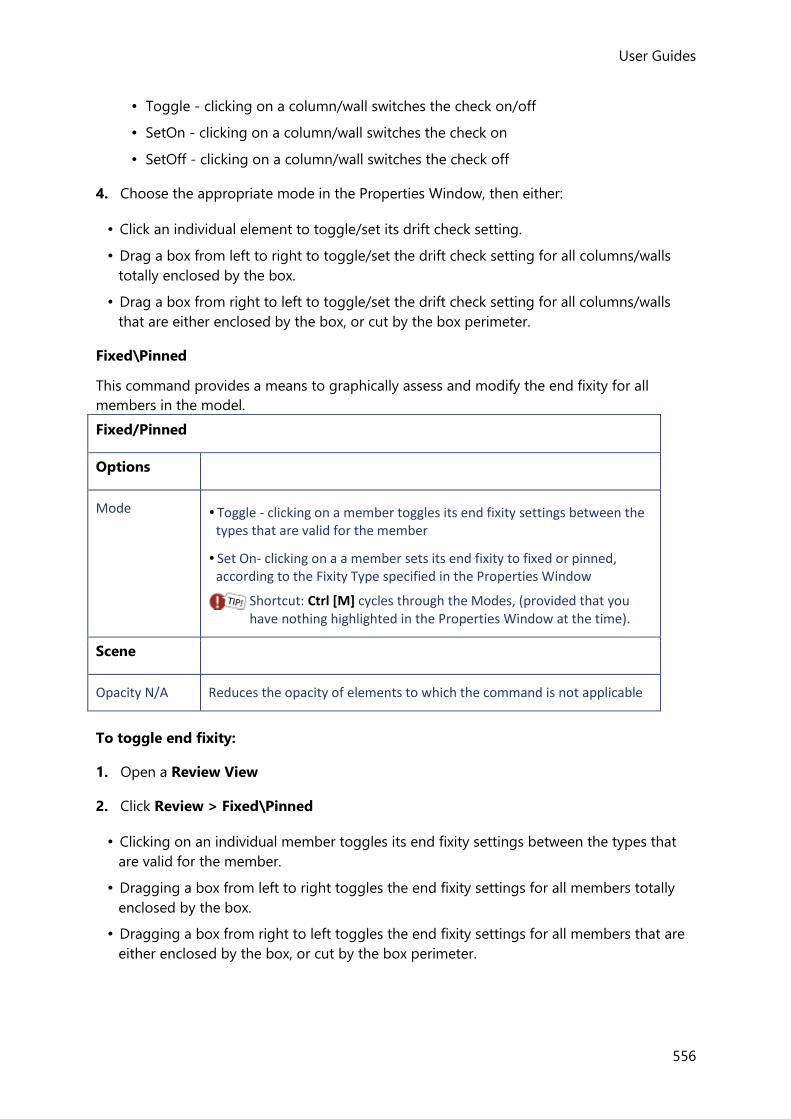
User Guides
556
• Toggle - clicking on a column/wall switches the check on/off
• SetOn - clicking on a column/wall switches the check on
• SetOff - clicking on a column/wall switches the check off
4. Choose the appropriate mode in the Properties Window, then either:
• Click an individual element to toggle/set its drift check setting.
• Drag a box from left to right to toggle/set the drift check setting for all columns/walls
totally enclosed by the box.
• Drag a box from right to left to toggle/set the drift check setting for all columns/walls
that are either enclosed by the box, or cut by the box perimeter.
Fixed\Pinned
This command provides a means to graphically assess and modify the end fixity for all
members in the model.
Fixed/Pinned
Options
Mode • Toggle - clicking on a member toggles its end fixity settings between the types that are valid for the member
• Set On- clicking on a a member sets its end fixity to fixed or pinned, according to the Fixity Type specified in the Properties Window
Shortcut: Ctrl [M] cycles through the Modes, (provided that you have nothing highlighted in the Properties Window at the time).
Scene
Opacity N/A Reduces the opacity of elements to which the command is not applicable
To toggle end fixity:
1. Open a Review View
2. Click Review > Fixed\Pinned
• Clicking on an individual member toggles its end fixity settings between the types that
are valid for the member.
• Dragging a box from left to right toggles the end fixity settings for all members totally
enclosed by the box.
• Dragging a box from right to left toggles the end fixity settings for all members that are
either enclosed by the box, or cut by the box perimeter.
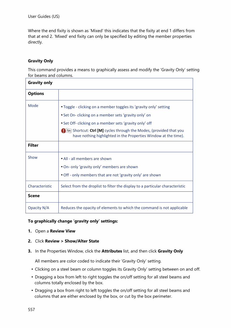
User Guides (US)
557
Where the end fixity is shown as ‘Mixed’ this indicates that the fixity at end 1 differs from
that at end 2. ‘Mixed’ end fixity can only be specified by editing the member properties
directly.
Gravity Only
This command provides a means to graphically assess and modify the ‘Gravity Only’ setting
for beams and columns.
Gravity only
Options
Mode • Toggle - clicking on a member toggles its ‘gravity only’ setting
• Set On- clicking on a member sets ‘gravity only’ on
• Set Off- clicking on a member sets ‘gravity only’ off
Shortcut: Ctrl [M] cycles through the Modes, (provided that you have nothing highlighted in the Properties Window at the time).
Filter
Show • All - all members are shown
• On- only ‘gravity only’ members are shown
• Off - only members that are not ‘gravity only’ are shown
Characteristic Select from the droplist to filter the display to a particular characteristic
Scene
Opacity N/A Reduces the opacity of elements to which the command is not applicable
To graphically change ‘gravity only’ settings:
1. Open a Review View
2. Click Review > Show/Alter State
3. In the Properties Window, click the Attributes list, and then click Gravity Only
All members are color coded to indicate their ‘Gravity Only’ setting.
• Clicking on a steel beam or column toggles its Gravity Only’ setting between on and off.
• Dragging a box from left to right toggles the on/off setting for all steel beams and
columns totally enclosed by the box.
• Dragging a box from right to left toggles the on/off setting for all steel beams and
columns that are either enclosed by the box, or cut by the box perimeter.
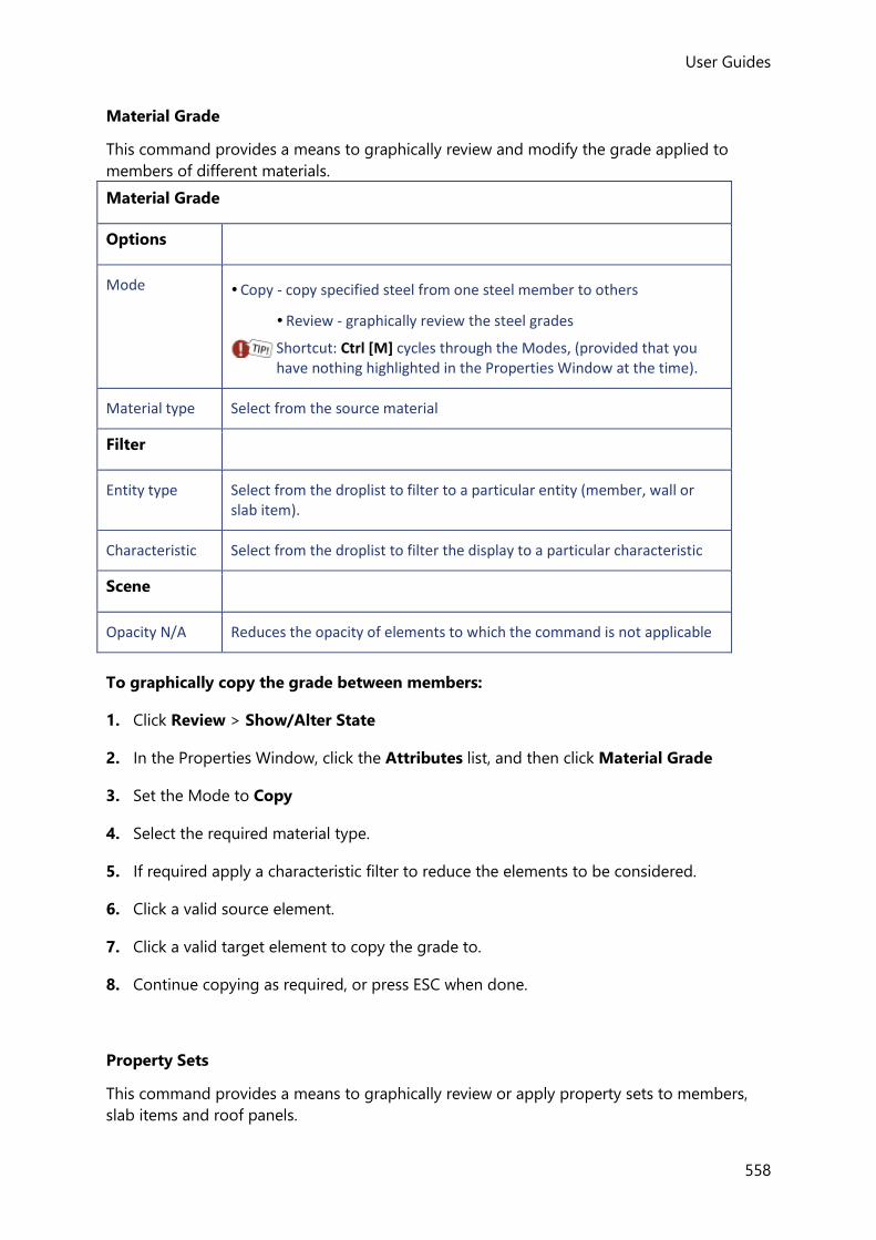
User Guides
558
Material Grade
This command provides a means to graphically review and modify the grade applied to
members of different materials.
Material Grade
Options
Mode • Copy - copy specified steel from one steel member to others
• Review - graphically review the steel grades
Shortcut: Ctrl [M] cycles through the Modes, (provided that you have nothing highlighted in the Properties Window at the time).
Material type Select from the source material
Filter
Entity type Select from the droplist to filter to a particular entity (member, wall or slab item).
Characteristic Select from the droplist to filter the display to a particular characteristic
Scene
Opacity N/A Reduces the opacity of elements to which the command is not applicable
To graphically copy the grade between members:
1. Click Review > Show/Alter State
2. In the Properties Window, click the Attributes list, and then click Material Grade
3. Set the Mode to Copy
4. Select the required material type.
5. If required apply a characteristic filter to reduce the elements to be considered.
6. Click a valid source element.
7. Click a valid target element to copy the grade to.
8. Continue copying as required, or press ESC when done.
Property Sets
This command provides a means to graphically review or apply property sets to members,
slab items and roof panels.

User Guides (US)
559
Property Sets
Review/Update Choose to review or apply property sets
Show • All - all members are shown
• On- only ‘gravity only’ members are shown
• Off - only members that are not ‘gravity only’ are shown
Entity Type Select from the droplist to filter the display to a particular entity type
Characteristic Select from the droplist to filter the display to a particular characteristic
Property set When applying property sets, choose a property set from this list (which is filtered by the selected entity type/characteristic).
Punch Check Position
This command provides a means to graphically modify the assumed punching check position
for determining the loaded perimeter when the perimeter is close to a free edge.
How do I modify the assumed punch check position in the Review View?
1. Open a Review View
2. Click Review > Show/Alter State
3. In the Properties Window, click the Attributes list, and then click Punch Check Position
4. Click or box around punching check items to change their positions:
• Click a punch check item on a Z edge to toggle its position between ‘Edge Z’ and
‘Internal’.
• Click a punch check item on a Y edge to toggle its position between ‘Edge Y’ and
‘Internal’.
• Click a punch check item on a corner to toggle its position between ‘Corner’, ‘Edge Z’
‘Edge Y’ and ‘Internal’.
• Clicking an internal punch check item does not toggle its position.
• Dragging a box from left to right toggles the position setting (as described above) for
all punch check items totally enclosed by the box.
• Dragging a box from right to left toggles the position setting (as described above) for
all punch check items that are either enclosed by the box, or cut by the box perimeter.
Report Filter

User Guides
560
This command provides a means to graphically review and modify any member filters that
have been defined.
The Report Filter command remains unavailable until a member filter has been defined. (A members filter is defined by clicking Members in the Filters group on the Report toolbar).
1. Open a Review View
2. Click Review > Report Filter
• Clicking on an individual member toggles its inclusion in the selected member filter
between ‘on’ and ‘off’.
• Dragging a box from left to right toggles the inclusion setting for all members totally
enclosed by the box.
• Dragging a box from right to left toggles inclusion setting for all members that are either
enclosed by the box, or cut by the box perimeter.
Restrained\Unrestrained
This command provides a means to graphically assess and modify the lateral restraint
settings for all steel beams and columns in the model.
Restrained\Unrestrained
Options
Mode • Toggle - clicking on a member toggles it between fully restrained and unrestrained
• Set On- clicking on a member sets it to fully restrained
• Set Off- clicking on a member sets it to unrestrained
Shortcut: Ctrl [M] cycles through the Modes, (provided that you have nothing highlighted in the Properties Window at the time).
Filter
Show Select from the droplist to filter the display to a members with a particular restraint condition
Scene
Opacity N/A Reduces the opacity of elements to which the command is not applicable
To graphically change restraint settings:
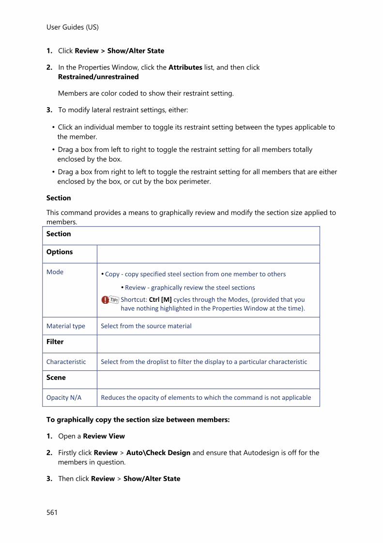
User Guides (US)
561
1. Click Review > Show/Alter State
2. In the Properties Window, click the Attributes list, and then click
Restrained/unrestrained
Members are color coded to show their restraint setting.
3. To modify lateral restraint settings, either:
• Click an individual member to toggle its restraint setting between the types applicable to
the member.
• Drag a box from left to right to toggle the restraint setting for all members totally
enclosed by the box.
• Drag a box from right to left to toggle the restraint setting for all members that are either
enclosed by the box, or cut by the box perimeter.
Section
This command provides a means to graphically review and modify the section size applied to
members.
Section
Options
Mode • Copy - copy specified steel section from one member to others
• Review - graphically review the steel sections
Shortcut: Ctrl [M] cycles through the Modes, (provided that you have nothing highlighted in the Properties Window at the time).
Material type Select from the source material
Filter
Characteristic Select from the droplist to filter the display to a particular characteristic
Scene
Opacity N/A Reduces the opacity of elements to which the command is not applicable
To graphically copy the section size between members:
1. Open a Review View
2. Firstly click Review > Auto\Check Design and ensure that Autodesign is off for the
members in question.
3. Then click Review > Show/Alter State
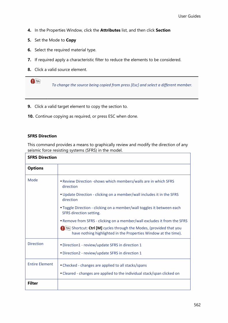
User Guides
562
4. In the Properties Window, click the Attributes list, and then click Section
5. Set the Mode to Copy
6. Select the required material type.
7. If required apply a characteristic filter to reduce the elements to be considered.
8. Click a valid source element.
To change the source being copied from press [Esc] and select a different member.
9. Click a valid target element to copy the section to.
10. Continue copying as required, or press ESC when done.
SFRS Direction
This command provides a means to graphically review and modify the direction of any
seismic force resisting systems (SFRS) in the model.
SFRS Direction
Options
Mode • Review Direction -shows which members/walls are in which SFRS direction
• Update Direction - clicking on a member/wall includes it in the SFRS direction
• Toggle Direction - clicking on a member/wall toggles it between each SFRS direction setting.
• Remove from SFRS - clicking on a member/wall excludes it from the SFRS
Shortcut: Ctrl [M] cycles through the Modes, (provided that you have nothing highlighted in the Properties Window at the time).
Direction • Direction1 - review/update SFRS in direction 1
• Direction2 - review/update SFRS in direction 1
Entire Element • Checked - changes are applied to all stacks/spans
• Cleared - changes are applied to the individual stack/span clicked on
Filter
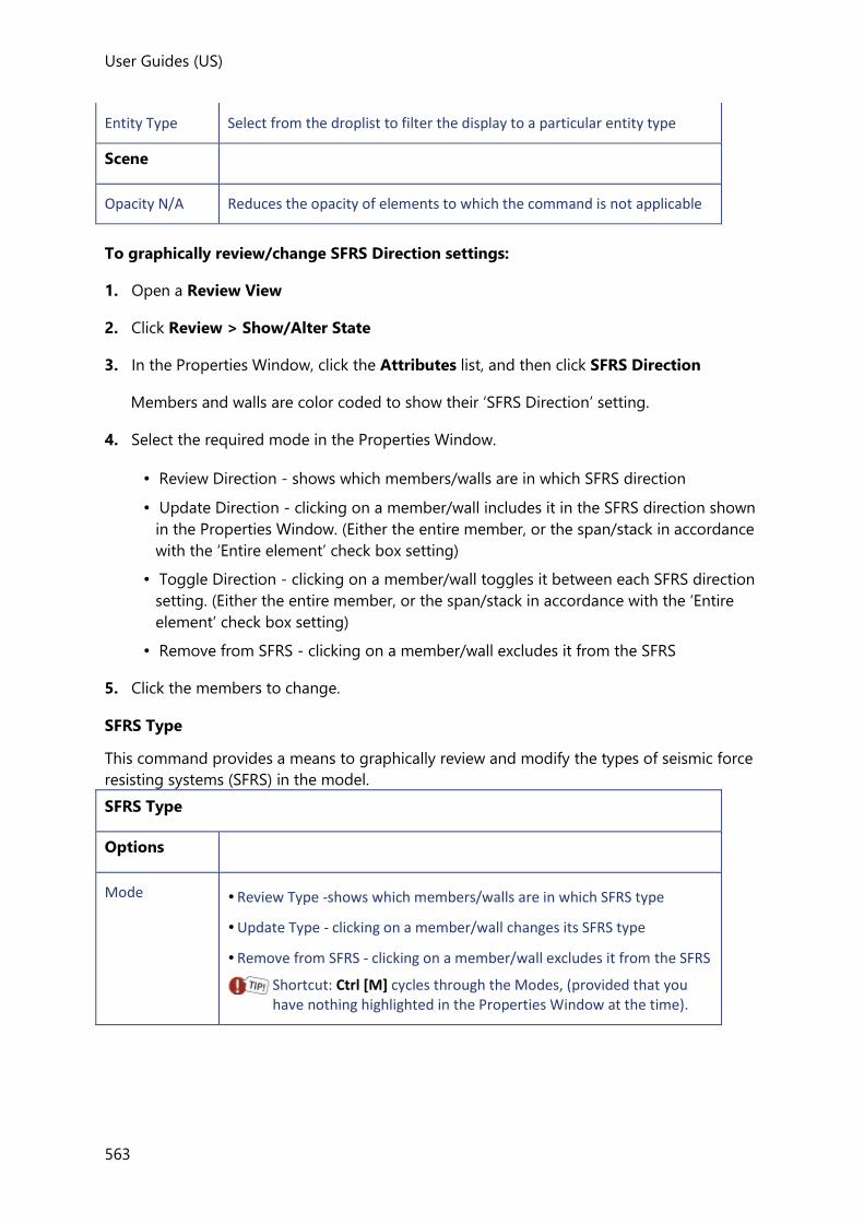
User Guides (US)
563
Entity Type Select from the droplist to filter the display to a particular entity type
Scene
Opacity N/A Reduces the opacity of elements to which the command is not applicable
To graphically review/change SFRS Direction settings:
1. Open a Review View
2. Click Review > Show/Alter State
3. In the Properties Window, click the Attributes list, and then click SFRS Direction
Members and walls are color coded to show their ‘SFRS Direction’ setting.
4. Select the required mode in the Properties Window.
• Review Direction - shows which members/walls are in which SFRS direction
• Update Direction - clicking on a member/wall includes it in the SFRS direction shown
in the Properties Window. (Either the entire member, or the span/stack in accordance
with the ‘Entire element’ check box setting)
• Toggle Direction - clicking on a member/wall toggles it between each SFRS direction
setting. (Either the entire member, or the span/stack in accordance with the ‘Entire
element’ check box setting)
• Remove from SFRS - clicking on a member/wall excludes it from the SFRS
5. Click the members to change.
SFRS Type
This command provides a means to graphically review and modify the types of seismic force
resisting systems (SFRS) in the model.
SFRS Type
Options
Mode • Review Type -shows which members/walls are in which SFRS type
• Update Type - clicking on a member/wall changes its SFRS type
• Remove from SFRS - clicking on a member/wall excludes it from the SFRS
Shortcut: Ctrl [M] cycles through the Modes, (provided that you have nothing highlighted in the Properties Window at the time).

User Guides
564
Select direction When updating the type:
• Checked - the direction is changed to the direction specified in the Properties Window
• Cleared - when the type is updated the original direction is maintained
Direction When updating the type:
• Direction1 - sets the SFRS to direction 1
• Direction2 - sets the SFRS to direction 1
Entire Element • Checked - changes are applied to all stacks/spans
• Cleared - changes are applied to the individual stack/span clicked on
Filter
Entity Type Select from the droplist to filter the display to a particular entity type
Scene
Opacity N/A Reduces the opacity of elements to which the command is not applicable
To graphically review/change SFRS Type settings:
1. Open a Review View
2. Click Review > Show/Alter State
3. In the Properties Window, click the Attributes list, and then click SFRS Type
Members and walls are color coded to show their ‘SFRS Type’ setting.
4. Select the required mode in the Properties Window.
• Review Type - shows which members/walls are in which SFRS type
• Update Type - clicking on a member/wall includes it in the SFRS type and direction
shown in the Properties Window. (Either the entire member, or the span/stack in
accordance with the ‘Entire element’ check box setting)
• Remove from SFRS - clicking on a member/wall excludes it from the SFRS
5. Click the members to change.
Shear Connectors
Composite beam shear connector data can be copied from a source beam to other
composite beams as follows:
1. Open a Review View

User Guides (US)
565
2. Click Review > Show/Alter State
3. In the Properties Window, click the Attributes list, and then click Shear Connectors
Composite beams that can act as a source for the shear connector data are color coded
in the Review View.
4. Click a valid source beam.
5. Click an a valid target beam to update its shear connector data to match the source.
Size Constraints
Graphically review specified size constraints for steel beams, columns, and braces, and copy
the constraints from one steel member to others.
Deflection Limits
Options
Mode • Copy - copy specified size constraints from one steel member to others
• Review - graphically review the size constraints
Shortcut: Ctrl [M] cycles through the Modes, (provided that you have nothing highlighted in the Properties Window at the time).
By constraint type
• Checked - provides options for selecting an individual constraint type to review or copy
• Cleared - when copying, all size constraints are copied
Scene
Opacity N/A Reduces the opacity of elements to which the command is not applicable
To copy size constraints:
1. Open a Review View
2. Click Review > Show/Alter State
3. In the Properties Window, click the Attributes list, and then click Size Constraints
4. Set the Mode to Copy
5. Either leave By constraint type cleared if you want to copy all the constraint types, or
check it if you only want to copy an individual constraint type.
6. Select a valid source steel member.
7. Select a steel member to copy the constraints to.
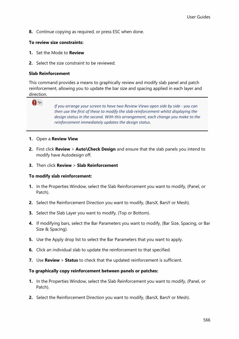
User Guides
566
8. Continue copying as required, or press ESC when done.
To review size constraints:
1. Set the Mode to Review
2. Select the size constraint to be reviewed.
Slab Reinforcement
This command provides a means to graphically review and modify slab panel and patch
reinforcement, allowing you to update the bar size and spacing applied in each layer and
direction.
If you arrange your screen to have two Review Views open side by side - you can then use the first of these to modify the slab reinforcement whilst displaying the design status in the second. With this arrangement, each change you make to the reinforcement immediately updates the design status.
1. Open a Review View
2. First click Review > Auto\Check Design and ensure that the slab panels you intend to
modify have Autodesign off.
3. Then click Review > Slab Reinforcement
To modify slab reinforcement:
1. In the Properties Window, select the Slab Reinforcement you want to modify, (Panel, or
Patch).
2. Select the Reinforcement Direction you want to modify, (BarsX, BarsY or Mesh).
3. Select the Slab Layer you want to modify, (Top or Bottom).
4. If modifying bars, select the Bar Parameters you want to modify, (Bar Size, Spacing, or Bar
Size & Spacing).
5. Use the Apply drop list to select the Bar Parameters that you want to apply.
6. Click an individual slab to update the reinforcement to that specified.
7. Use Review > Status to check that the updated reinforcement is sufficient.
To graphically copy reinforcement between panels or patches:
1. In the Properties Window, select the Slab Reinforcement you want to modify, (Panel, or
Patch).
2. Select the Reinforcement Direction you want to modify, (BarsX, BarsY or Mesh).

User Guides (US)
567
3. Select the Slab Layer you want to modify, (Top or Bottom).
4. Click the panel or patch containing the reinforcement to be copied.
5. Click the panels or patches to which you want to apply the reinforcement.
To change the source of the reinforcement being copied press [Esc] and select a different panel or patch.
6. Use Review > Slab Design Status to check that the updated reinforcement is sufficient.
Stud auto layout
The stud auto layout setting for composite beams can be toggled graphically.
Stud auto layout
Options
Mode • Toggle - clicking on a beam switches auto layout on/off
• Set On- licking on a beam only sets auto layout on
• Set Off- clicking on a beam only sets auto layout off
Shortcut: Ctrl [M] cycles through the Modes, (provided that you have nothing highlighted in the Properties Window at the time).
Filter
Show Select from the droplist to filter the display to a members with a particular auto layout condition
Scene
Opacity N/A Reduces the opacity of elements to which the command is not applicable
To graphically modify the stud auto layout settings:
1. Open a Review View
2. Click Review > Show/Alter State
3. In the Properties Window, click the Attributes list, and then click Stud auto layout
Composite beams are color coded to show their auto layout setting.
The Properties Window shows the currently selected mode.
• Toggle - clicking on a beam switches auto layout on/off

User Guides
568
• SetOn - clicking on a beam only sets auto layout on
• SetOff - clicking on a beam only sets auto layout off
4. Choose the appropriate mode in the Properties Window, then either:
• Click an individual beam to toggle/set its auto layout setting.
• Drag a box from left to right to toggle/set the auto layout setting for all beams totally
enclosed by the box.
• Drag a box from right to left to toggle/set the auto layout setting for all beams that are
either enclosed by the box, or cut by the box perimeter.
Sub Structures
This command provides a means to graphically create, review and modify sub structures for
modeling purposes.
These can prove useful in large models as individual sub-structures can then be
differentiated by color and worked on in separate sub-structure views.
1. Open a Review View
2. Click Review > Sub Structures
Sway check
The sway check setting for columns and walls can be toggled graphically.
Sway check
Options
Mode • Toggle - clicking on a column/wall switches the check on/off
• Set On- clicking on a column/wall switches the check on
• Set Off- clicking on a column/wall switches the check off
• Review - graphically review the check status
Shortcut: Ctrl [M] cycles through the Modes, (provided that you have nothing highlighted in the Properties Window at the time).
Entire element • Checked - the check is turned on/off for all stacks of the element
• Unchecked - the check is turned on or off for individual stacks/panels of the element
Scene
Opacity N/A Reduces the opacity of elements to which the command is not applicable
To graphically modify the sway check settings:

User Guides (US)
569
1. Open a Review View
2. Click Review > Show/Alter State
3. In the Properties Window, click the Attributes list, and then click Sway check
Columns and walls are color coded to show their sway check setting.
The Properties Window shows the currently selected mode.
• Toggle - clicking on a column/wall switches the check on/off
• SetOn - clicking on a column/wall switches the check on
• SetOff - clicking on a column/wall switches the check off
4. Choose the appropriate mode in the Properties Window, then either:
• Click an individual element to toggle/set its sway check setting.
• Drag a box from left to right to toggle/set the sway check setting for all columns/walls
totally enclosed by the box.
• Drag a box from right to left to toggle/set the sway check setting for all columns/walls
that are either enclosed by the box, or cut by the box perimeter.
Sub Structures
This command provides a means to graphically create, review and modify sub structures for
modeling purposes.
These can prove useful in large models as individual sub-structures can then be
differentiated by color and worked on in separate sub-structure views.
1. Open a Review View
2. Click Review > Sub Structures
Transverse reinforcement
Composite beam transverse reinforcement can be copied from a source beam to other
composite beams as follows:
1. Open a Review View
2. Click Review > Show/Alter State
3. In the Properties Window, click the Attributes list, and then click Transverse
reinforcement
Composite beams that can act as a source for the transverse reinforcement data are color
coded in the Review View.
4. Click a valid source beam.

User Guides
570
5. Click a valid target beam to update its transverse reinforcement data to match the
source.
UDA
This command provides a means to graphically review and modify the values of attributes
that have been attached to the model.
Web openings
Web openings can be copied from a source member to other members as follows:
1. Open a Review View
2. Click Review > Show/Alter State
3. In the Properties Window, click the Attributes list, and then click Web Openings
Members that can act as a source for the web opening data are color coded in the
Review View.
4. Click a valid source member.
5. Click a valid target member to update its web openings data to match the source.
Westok openings
Westok openings can be copied from a source member to other members as follows:
1. Open a Review View
2. Click Review > Show/Alter State
3. In the Properties Window, click the Attributes list, and then click Westok Openings
Members that can act as a source for the Westok opening data are color coded in the
Review View.
4. Click a valid source member.
5. Click a valid target member to update its Westok openings data to match the source.
Wind drift
The wind drift check setting for columns and walls can be toggled graphically.
Wind drift
Options
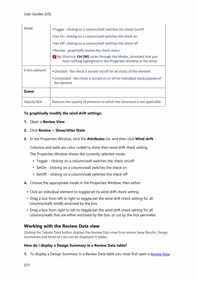
User Guides (US)
571
Mode • Toggle - clicking on a column/wall switches the check on/off
• Set On- clicking on a column/wall switches the check on
• Set Off- clicking on a column/wall switches the check off
• Review - graphically review the check status
Shortcut: Ctrl [M] cycles through the Modes, (provided that you have nothing highlighted in the Properties Window at the time).
Entire element • Checked - the check is turned on/off for all stacks of the element
• Unchecked - the check is turned on or off for individual stacks/panels of the element
Scene
Opacity N/A Reduces the opacity of elements to which the command is not applicable
To graphically modify the wind drift settings:
1. Open a Review View
2. Click Review > Show/Alter State
3. In the Properties Window, click the Attributes list, and then click Wind drift
Columns and walls are color coded to show their wind drift check setting.
The Properties Window shows the currently selected mode.
• Toggle - clicking on a column/wall switches the check on/off
• SetOn - clicking on a column/wall switches the check on
• SetOff - clicking on a column/wall switches the check off
4. Choose the appropriate mode in the Properties Window, then either:
• Click an individual element to toggle/set its wind drift check setting.
• Drag a box from left to right to toggle/set the wind drift check setting for all
columns/walls totally enclosed by the box.
• Drag a box from right to left to toggle/set the wind drift check setting for all
columns/walls that are either enclosed by the box, or cut by the box perimeter.
Working with the Review Data view
Clicking the Tabular Data button displays the Review Data view from where Sway Results, Design Summaries and Material Lists can be displayed in tables.
How do I display a Design Summary in a Review Data table?
1. To display a Design Summary in a Review Data table you must first open a Review View.

User Guides
572
2. Then click Review > Tabular Data
(A Review Data View opens in a new tab.)
3. From the drop list on the View Type toolbar group choose Design Summary.
4. Make selections from the other groups on the toolbar in order to filter to the specific
results required.
How do I display Sway Results in a Review Data table?
1. To display Sway Results in a Review Data table you must first open a Review View.
2. Then click Review > Tabular Data
(A Review Data View opens in a new tab.)
3. From the drop list on the View Type toolbar group choose Sway.
4. Make selections from the other groups on the toolbar in order to filter to the specific
results required.
How do I display Storey Shear in a Review Data table?
1. To display Floor Forces in a Review Data table you must first open a Review View.
2. Then click Review > Tabular Data
(A Review Data View opens in a new tab.)
3. From the drop list on the View Type toolbar group choose Storey Shear
4. From the Loading drop list choose the loadcase or combination required.
How do I display Drift Results in a Review Data table?
Drift Results are only relevant to models in which the United States (ACI/AISC) Head code has been selected.
1. To display Drift Results in a Review Data table you must first open a Review View.
2. Then click Review > Tabular Data
(A Review Data View opens in a new tab.)
3. From the drop list on the View Type toolbar group choose Drift.
4. Make selections from the other groups on the toolbar in order to filter to the specific
results required.
How do I display Seismic Drift Results in a Review Data table?

User Guides (US)
573
1. To display Seismic Drift Results in a Review Data table you must first open a Review View.
2. Then click Review > Tabular Data
(A Review Data View opens in a new tab.)
3. From the drop list on the View Type toolbar group choose Seismic Drift.
4. Make selections from the other groups on the toolbar in order to filter to the specific
results required.
How do I display Wind Drift Results in a Review Data table?
1. To display Wind Drift Results in a Review Data table you must first open a Review View.
2. Then click Review > Tabular Data
(A Review Data View opens in a new tab.)
3. From the drop list on the View Type toolbar group choose Wind Drift.
4. Make selections from the Material Type and Fabrication groups to identify the column
results required.
5. From the Loading drop list choose the wind loadcase or combination to be checked.
How do I display Connection Resistance checks in a Review Data table?
The connection resistance check compares the maximum vertical shear from the gravity
combinations against a pre-defined resistance for the supporting member.
This check requires you to have specified a set of resistances for each section serial size, composite\non composite, for the current head code. These are specified from the Materials dialog on the Home ribbon.The resistances are saved to the database and can subsequently be used for checking other structures.
1. To display Connection Resistances in a Review Data table you must first open a Review
View.
2. Then click Review > Tabular Data
(A Review Data View opens in a new tab.)
3. From the drop list on the View Type toolbar group choose Connection Resistance
4. Make selections from the other groups on the toolbar in order to filter to the specific
results required.
How do I display a Material List in a Review Data table?

User Guides
574
The material list displayed in a Review Data table is not suitable for printing - to obtain a formatted list that can be output you should display a Material Listing Report instead.
1. To display a Material List as a Review Data table you must first open a Review View.
2. Then click Review > Tabular Data
(A Review Data View opens in a new tab.)
3. From the drop list on the View Type toolbar group choose Material List.
4. Make selections from the other groups on the toolbar in order to filter to the specific
results required.
For example, to display the loose bar estimate in a flat slab you would choose: - ‘Concrete’ from the ‘Material Type’ group - ‘Slabs’ from the ‘Characteristic’ group - ‘Loose Bars’ from the ‘Content’ group.
Reporting Guide
A wide range of reports which can be tailored to meet your specific requirements can be
created from the Report toolbar.
Report toolbar
The ‘Contents’ and ‘Filters’ groups described below are always displayed, but the ‘Appearance’, ‘Navigation’ and ‘Export’ groups are hidden until a Report view is active.
Contents group
The Contents group contains the following commands:
Button Description
Select Use the drop list to select the report to be created. The chosen report can then be viewed by clicking Show Report.

User Guides (US)
575
Model Report...
Opens a dialog which can be used to:
• setup a new Model Report,
• edit and filter the content for an existing
Model Report.
Member Report...
Opens a dialog which can be used to:
• setup a new Member Report,
• edit and filter the content for an existing
Member Report.
Show Report Displays the selected Model Report (i.e. the one that is shown in the Select drop list) on screen.
Clicking Show Report also activates other groups on the toolbar to enable:
• the appearance of the report to be controlled,
• navigation around the report,
• export of the report.
Filters Group
The Filters group contains the following commands:
Button Description
Levels Opens a dialog for creating a new Model Filter which can be used to output selected levels only.
Frames
Opens a dialog for creating a new Model Filter which can be used to output selected frames only.
Planes Opens a dialog for creating a new Model Filter which can be used to output selected planes only.
Loadcases Opens a dialog for creating a new Loading Filter which can be used to output selected loadcases only.
Combinations Opens a dialog for creating a new Loading Filter which can be used to output selected combinations only.
Members Opens a dialog for creating a new Model Filter which can be used to output selected members only.
Design Groups Opens a dialog for creating a new Model Filter which can be used to output selected design groups only.

User Guides
576
Trusses Opens a dialog for creating a new Model Filter which can be used to output selected trusses only.
Portal Frames Opens a dialog for creating a new Model Filter which can be used to output selected portal frames only.
Appearance group
Use the commands in this group to control the appearance of the currently displayed report.
Button Description
Settings Opens the Settings dialog which can be used to configure paragraph styles and other report display options.
Page Setup
Opens the Page Setup dialog which can be used to configure page size and orientation.
Edit Header
Opens the Document headers/footers dialog which can be used to configure the layout and content of the page header and footers.
Edit Footer Opens the Document headers/footers dialog which can be used to configure the layout and content of the page headers and footers.
Navigation group
Use the commands in this group to move through the currently displayed report.
Button Description
Previous Page, First Page, Next Page, Last Page
Use the commands in this group to move around the currently open report.
Report Index Displays the report index in the Project Workspace. This can be used to navigate through the report.
Export group
The commands in this group can be used to export the currently open report to other
programs.

User Guides (US)
577
Button Description
PDF Exports the report to a pdf document.
Word Exports the report to a word document.
Excel Exports the report to an Excel document.
Tedds Exports the report to a Tedds document.
Reports and Report Terminology Explained
This topic provides background information to improve your understanding of the report
creation process and the terminology involved.
Model Reports
Model Reports are used to set up the printed output for the entire structure, (or a part of it).
These reports are configured by choosing specific output categories (‘chapters’) from a list of
all the available output categories. You can include entire chapters, or just those headings
within the chapter you require. The resulting subset of chapters is referred to as a Report
Structure. Filters can then be applied to individual headings in the Report Structure to limit
the output that is produced.
Model Report chapters include:
• Structure
Structure data under headings such as ‘Loadcases’, ‘Wind Data’ etc.
• Analysis
Analysis model properties and results.
• Concrete, Steel, Timber, Cold Formed, Cold Rolled, General Material
• Member Reports for each of the different member types. Each of these can be set up
to contain as much or as little output as you require. This is achieved by configuring a
separate Member Report for each member type that you have included.
• Design Summary Tables can also be included for those members that can be
designed.
• Beam End Forces, Bracing Forces, Foundation Reactions
Chapters for specific sets of analysis results.
• Picture
A 3D view of the whole structure, or by applying a Model Filter you can choose selected
sub structures in 3D, or 2D views of selected frames or levels.
Applied loads can also be displayed on the picture by applying a Loading Filter.
• View
The current display in any 2D or 3D Scene View can be saved at any time as a View

User Guides
578
Configuration. Each of these view configurations can then be included in the Model
Report as required by including a separate View chapter for each configuration required.
• Analysis Diagram
A 3D diagram of the whole structure, or by applying a Model Filter you can choose
selected sub structures in 3D, or 2D diagrams of selected frames or levels.
The analysis results to be displayed are configured by applying a Loading Filter and
choosing the Analysis Method.
• Material Listing
Tabulated quantities of materials.
• Revision History
The revision history that has been recorded in the Project Wiki.
Member Reports
Member Reports are not output directly from the Report toolbar, they are only output as
part of the Model Report, (or, by right-clicking on an individual member and clicking ‘Report
for member’).
They are set up in a similar way to the Model Report itself with chapters including:
• Picture
This is the 3D view you obtain by right-clicking on a member and clicking ‘Open member
view’.
• Drawing
This is the dxf you obtain by right-clicking on a member and clicking ‘Generate Detail
Drawing’.
• Loading
This is the table you obtain by right-clicking on a member and clicking ‘Show Member
Loading’.
• Force and Deflected Shape Diagrams
These are the diagrams you obtain by right-clicking on a member and clicking ‘Open
load analysis view’.
Available Styles
A number of sample reports are available for selection from the Available Styles list. These
reports serve as templates and can be modified to suit the model in question.
If there isn’t already a report that can be customized to meet your needs you can add further
reports to the list.
If you start a new project, the same default reports will be available, but they are reset to the default report structures. It is not currently possible to save customized reports from the Report Contents dialog in order to apply them to other projects.
Active Model Report

User Guides (US)
579
The active model report is simply the default report shown on the drop list on the Report
toolbar - unless a report view is already active, (in which case the view’s report is shown n the
drop list instead.)
The active model report can be specified by clicking the ‘>> Active’ button in the Report
Contents dialog for Model Reports.
Active Member Report
When you right-click a member in a 2D or 3D View and choose Report for Member; the
member report that has been specified as being active is the one that is generated.
The active member report can be specified by clicking the ‘>> Active’ button in the Report
Contents dialog for Member Reports.
Active and Inactive Chapters
When the Report Contents dialog is displayed each chapter in the current report structure
can be marked as either active, or inactive. Only those chapters that are marked as active get
included when the report is generated.
Filters
Filters can be employed to limit the amount of output produced, different filters being
applicable for different data types:
• Model Filters - By default output is produced for the entire structure, but if required it
can be filtered for selected levels, frames, or planes. For certain data types (e.g.
Foundation Reactions) output can be filtered for selected beams, columns or walls. If user
defined attributes (UDAs) have ben applied, these can also be used to filter the output.
• Loading Filters - By default output is produced for all loadcases and all combinations,
but if required it can be filtered for selected loadcases and combinations.
Creating Reports
How do I configure a Model Report?
1. Click Report > Model Report... ( )
2. Choose a report as follows:
• To choose an existing report, use the Available Styles list.
• To add a new report, click , then type a name for the new report in the Active
Style box.
3. Review the Report Structure and modify it if required.
(See: How do I modify the Report Structure?)

User Guides
580
4. To limit the amount of output to selected levels, frames, planes, or sub structures only;
apply a model filter.
(See: How do I apply a filter?)
5. For ‘Loadcases’ and ‘Combinations’ sub-chapters you can further limit the output by
applying a loading filter.
(See: How do I apply a filter?)
6. If you have created specific view configurations of the model and want to include these
in the report you must include a separate View chapter for each view configuration
required.
7. If the Report Structure includes any member chapters (Beams, Columns, Walls etc.):
• for each chapter ensure the appropriate Member Report style is selected.
(See: How do I select the Member Report style to use in the Model Report?)
• ensure the selected Member Report style for each chapter is configured as required.
(See: How do I configure a Member Report?)
8. Click OK
9. Click Show Report ( )
The chosen report should now be displayed in a new window from where it can be
reviewed.
If it contains loading analysis views of individual members (e.g. force diagrams or
pictures) these are displayed for each member type according to the Member
Report style that was selected above.
When the model report is displaying the information as required it can then printed.
(See: How do I display a Model Report?)
If you have included a Drawing in the Report Structure, you should specify appropriate settings for it:
- Right-click the Drawing in the Report Structure
- Click Settings...
- Select the Drawing Type and Style from the drop lists
- Specify the Scale and Text Block Spacing
How do I display a Model Report?
1. Select the report to display from the drop list on the Report toolbar.
2. Click Show Report ( )
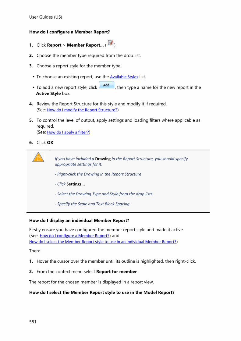
User Guides (US)
581
How do I configure a Member Report?
1. Click Report > Member Report... ( )
2. Choose the member type required from the drop list.
3. Choose a report style for the member type.
• To choose an existing report, use the Available Styles list.
• To add a new report style, click , then type a name for the new report in the
Active Style box.
4. Review the Report Structure for this style and modify it if required.
(See: How do I modify the Report Structure?)
5. To control the level of output, apply settings and loading filters where applicable as
required.
(See: How do I apply a filter?)
6. Click OK
If you have included a Drawing in the Report Structure, you should specify appropriate settings for it:
- Right-click the Drawing in the Report Structure
- Click Settings...
- Select the Drawing Type and Style from the drop lists
- Specify the Scale and Text Block Spacing
How do I display an individual Member Report?
Firstly ensure you have configured the member report style and made it active.
(See: How do I configure a Member Report?) and
How do I select the Member Report style to use in an individual Member Report?)
Then:
1. Hover the cursor over the member until its outline is highlighted, then right-click.
2. From the context menu select Report for member
The report for the chosen member is displayed in a report view.
How do I select the Member Report style to use in the Model Report?

User Guides
582
Each member type can have a number of ‘member report styles’ available, (each being
configured to produce a different level of output). You therefore need to specify which one
to use if the member type is included in the Model Report.
With the required Model Report selected in the Report Contents dialog; to select the
Member Report Style to be used in the Model Report:
1. Locate the specific member chapter, (Beams, Columns etc.) in the report structure.
2. Right-click the chapter and select the required member report style from the ‘Style’
option.
How do I select the Member Report style to use in an individual Member Report?
To control the report that gets generated when you right-click a member in a 2D or 3D View
and choose ‘Report for Member’, the active member report needs to be set correctly.
1. Click Report > Member Report... ( )
2. Choose the member type required from the drop list.
3. In the list of available styles, one will be marked ‘(active)’.
• if this is the style you want to use simply click OK to close the dialog,
• or, choose a different style and click , then click OK.
How do I modify the Report Structure?
Having selected a report from the Available Styles list you can modify its structure as
follows:
1. Drag the chapters and options to be included from the left to right. To permanently
remove unwanted chapters and options drag them back from right to left.
2. Re-arrange the report order as required by dragging selected chapters up or down.
3. To exclude a specific chapter from the report, whilst maintaining the report structure;
make it inactive by right-clicking on the chapter and clearing Active. (It can subsequently
be re-introduced if required by rechecking Active.)
4. Right-click each chapter to specify any filtering requirements. (See: How do I apply a filter?)
5. Click OK
To aid the report structuring process, an option is provided to display the structure as either a Flat, or a Hierarchical layout.
How do I print a Report?

User Guides (US)
583
The report displayed in the active Report View is printed as follows:
1. Click the File menu
2. Click
Filtering Reports
What are the different types of filter?
There are two main categories of filter that can be applied to chapters in the Report
Structure, each chapter having different filters available according to its content.
Model Filters are available to enable selective output based on:
• Selected levels
• Selected frames
• Selected planes
• Selected groups
• Selected members
• Selected trusses
• Selected portal frames
• Selected levels
• Selected sub structures
• Selected UDAs
Loading Filters are available to enable selective output based on:
• Selected loadcases
• Selected combinations
• Selected envelopes
How do I create and edit a filter?
Filters can be created and edited either directly from the Report toolbar as described below;
or at the same time as they are applied to a chapter in the Report Structure, by right-clicking
on the chapter and then clicking Edit\New... from the relevant filter menu.
1. Click the type of filter required from the Filters group on the Report toolbar.
A dialog is displayed listing any existing filters of the chosen type.
2. Click , then enter a name for the new filter.

User Guides
584
3. In the Selected items area of the dialog, select the check boxes as required to define the
content of the filter.
4. Click OK
If a Members filter is created, it can subsequently be reviewed and edited graphically via the Report Filter button on the Review toolbar.
5. Once a filter has been created, it then has to be applied to a specific report.
How do I apply a filter?
Filters are applied to reports as follows:
1. Click Report > Model Report... , or Member Report... to open the appropriate Report
Contents dialog.
2. Choose the report to be filtered.
In the Report Structure any chapters that can be filtered will always show the currently applied filter in blue text.
3. Right-click a chapter and choose the required filter type and filter name from the right-
click menu.
If the available filters do not meet your requirements, choose ‘Edit/New...’ from the right-
click menu, then:
1. Click
2. Enter a name to describe the filter.
3. Select the check boxes as required under Selected Items to define the filter
requirements.
4. Click OK
If a filter type is not applicable for the selected chapter it will be unavailable.

User Guides (US)
585
Members filters specifically, can subsequently be reviewed and edited graphically via the Report Filter button on the Review toolbar.
Formatting Reports
Tekla Structural Designer allows you to customize the appearance of the reports in a number
of ways.
Report Settings
These settings are used to control (for the settings set selected at the top of the page) the
appearance of the reports. The various options allow you to configure paragraph styles, page
margins and numbering, tables, headers/footers and other options.
Unlike other “settings set” settings, changes to report settings are instantly applied to the current work-session when you click OK to close the Settings dialog (provided the edits were made to the active set).
How do I apply report settings?
1. Click Report > Settings ( )
2. Use the Report sub-pages to format the report.
The various options allow you to set:
• Styles - customize the paragraph styles to be applied to the different areas of the
report.
• Page Options - specify page margins and numbering.
• Table Options - control the appearance of tables.
• Document Options - control display of header/footer and other options.
• Picture Fonts - control the appearance of fonts used in pictures and force diagrams.
3. Having configured the report format as required, click OK to apply it to the current
project.
The specified report settings are applied to the current project and continue to apply in future work-sessions for all models.
Report Settings-Styles
Report Styles
The list displays the styles that are used in reports.

User Guides
586
The selected style’s appearance can modified by adjusting the font, color and other
parameters as required
Report Settings-Page Options
Page margins, numbering and frame
Adjust as required.
Report Settings-Table Options
Table style, border and width
Adjust as required.
Report Settings-Document Options
Header/footer
Show document header
Select to include the header at the top of each report page.
Show border in document header
Select to draw a border around each field cell in the header.
Show document footer
Select to include the footer at the bottom of each report page.
Show border in document footer
Select to draw a border around each cell in the footer.
Show document field description in line with the value
Select to display the field descriptions in line with the field values in each cell, or leave
cleared to display the field values on a new line.
Underline document field cell
Select to underline each field cell value.
Image width
Percentage of page width
Specify the width for all images that are included in reports.
Paragraphs
Spacing
Specify the paragraph spacing in reports.
Page breaks
Start each item on a new page
Select to start each chapter of the report on a new page.
Start each member report on a new page
Select to start each member on a new page.

User Guides (US)
587
Report Settings-Picture Fonts
If you have included any pictures in your reports, you can use these settings to control the
fonts that are used within them.
Headers and Footers
Default page header and footer layouts are provided, but you can also create and save your
own layouts as required.
How do I enter company details (logo, address etc.) in the header?
1. Click Show Report ( ) on the Report toolbar
2. Click Edit Header ( )
Assuming you have not already created your own header layouts, there will only be a
‘Default Header’ layout available, (you can rename this if you wish, by over-typing the
displayed name).
Note that the default layout already contains a field for the address.
For each of the following operations, ensure ‘Fields’ remains highlighted at the top left of
the dialog.
First select the Fields to be included:
1. Highlight ‘Address’ in the Available fields list, then click the Edit... button (the one below
the Available fields list).
The ‘Address’ field comprises up to 11 individual fields, only those listed in the ‘Included
fields’ will be shown in the header.
2. In the Field properties area of the dialog, move fields between ‘Included’ and ‘Available’
as required.
Next define the text to be displayed:
1. In the left hand Available fields list, highlight the first text field (e.g. Company Name) that
appears as an ‘Included field’.
2. In the Field properties area, type in the text that you want to appear for this field.
3. Highlight the next text field (e.g. Address Line 1) that appears as an ‘Included field’.
User Guides
588
4. Type in the text that you want to appear for this field.
5. Repeat until all the text fields included in the address have been defined.
Finally select the logo:
By default there is only one image field (Company Logo) available.
1. In the Available fields list, highlight ‘Company Logo’.
2. In the Field properties area, click the [...] button to browse to the image you want to use
as the logo.
Large logos are automatically resized to fit within the column width in which they are placed. However, it should be noted that using physically smaller images saves memory and reduces the time taken to export reports. For the same reason it is recommended that logos are created in PNG format rather than BMP format.
If you want to include additional images in the header/footer simply click ‘Add Image Field’ to create extra place holders for each one.
3. Click ‘Headers’ at the top left of the dialog to re-display the layout to ensure the
‘Company Logo’ field is assigned to the appropriate cell in the header.
4. If further images are required return to the ‘Fields’ pane, click and
repeat the above process.
How do I enter project specific details (job ref, structure etc.) in the header?
1. Click Project Wiki ( ) on the Home toolbar
2. On the Project Summary page of the Project Wiki dialog, type the text that you want to
appear for each field that appears in the header.
How do I create a new header layout?
To customize report headers and footers you must first display a report on screen, then:
1. Click Edit Header ( )
The Document headers/footers dialog is displayed allowing you to create new headers
and footers, or modify existing ones.
2. Click New
A default header is displayed in the Current layout area.
User Guides (US)
589
3. In the ‘Name’ field, (optionally) give the new layout a more descriptive name.
The default header can be reconfigured to suit your requirements as follows:
To remove an existing field to create an empty cell:
Move the cursor over the Current Layout area and the Field under the cursor will be
highlighted in red, click the field to remove it and create an empty cell.
To place a field into an empty cell (or replace an existing field):
Drag the field required from the ‘Available fields’ list into the cell.
To join multiple cells into a single merged cell:
Left click and drag over the cells to be joined.
(If you subsequently require to unjoin previously joined cells you can do so from the
right-click menu.)
To modify the field alignment within a cell:
Right-click the required cell in the layout and set the horizontal and vertical alignment
options as required.
To insert or remove rows or columns in the layout, or change the alignment:
Right-click over the layout and select the command required from the context menu.
To change the column widths in the layout:
Click Edit... under the Current Layout and adjust the widths as required.
To review the new layout:
Once the changes have been made click OK to re-display the report and review their
effect.
Exporting Reports
How do I export a report to PDF?
1. Set up your report so that it contains the information you require.
2. Click PDF ( )
(in the Export group).
3. Click OK.
How do I export a report to Word?
1. Set up your report so that it contains the information you require.
2. Click Word ( )
(in the Export group).
3. Click OK.

User Guides
590
How do I export a report to Excel?
1. Set up your report so that it contains the information you require.
2. Click Excel ( )
(in the Export group).
3. Click OK.
How do I export a report to Tedds?
1. Set up your report so that it contains the information you require.
2. Click Tedds ( )
(in the Export group).
3. Click OK.
Example Reports
A number of standard reports are installed by default. Although these are unlikely to match
your exact needs, in many cases they can serve as templates which can then be edited to suit
your individual requirements.
Solver Model Data Report
By default this report will include a picture of the model and then list the following tables of
analysis model input data:
• Nodes
• Node support Details
• Elements
• Element-Members
• Element Properties
• contains to PDF?
How do I show a Solver Model Data Report?
1. Select Solver Model Data from the drop list on the Report toolbar.
2. Click Show Report ( )
3. If the resulting report is displaying too little, or too much information, you can adjust the
content by re-configuring the report.
Building Loading Report
By default this report will include a picture of the model and then list the following tables of
loading related input data:

User Guides (US)
591
• Action Codes
• Resistance Codes
• Combinations
• Wind Data
How do I show a Building Loading Report?
1. Select Building Loading from the drop list on the Report toolbar.
2. Click Show Report ( )
3. If the resulting report is displaying too little, or too much information, you can adjust the
content by re-configuring the report.
Building Analysis Checks Report
By default this report will list the following tables:
• Loadcase Summary
• Analysis Drift Results
• Analysis Sway Results
How do I show a Building Analysis Checks Report?
1. Select Building Analysis Checks from the drop list on the Report toolbar.
2. Click Show Report ( )
3. If the resulting report is displaying too little, or too much information, you can adjust the
content by re-configuring the report.
Building Design Report
By default this report displays the design results for the building at a summary level.
How do I show a Building Design Report?
1. Select Building Design from the drop list on the Report toolbar.
2. Click Show Report ( )
3. If the resulting report is displaying too little, or too much information, you can adjust the
content by re-configuring the report.
Material Listing Report
By default the material listing report is displayed for all members in the building.
How do I show a Material Listing Report?
User Guides
592
1. Select Material Listing from the drop list on the Report toolbar.
2. Click Show Report ( )
3. If the resulting report is displaying too little, or too much information, you can adjust the
content by re-configuring the report.
Beam End Forces Report
This report is typically generated for steel or timber beams in order to provide connection
design forces in one of the following configurations:
• End 1/End 2
• End 1/End 2 + Coincident
• Higher End Only
• Higher End Only + Coincident (initial default)
Choose an End 1/End 2 configuration if you intend to design the connections at both ends
of each beam independently, otherwise choose Both Ends to standardise your connection
designs and employ the same connection at both ends of the beam where possible.
For each of the above, if you choose + Coincident, the maximum and minimum for each of
the 6 forces is reported in a separate row in the table along with the coincident forces in the
other directions, (potentially generating many more pages of output).
What data is output in each Beam End Forces Report configuration?
Six columns of forces, (Fx, Fy, Fz, Mx, My, Mz) are output for each configuration as follows:
End 1/End 2
For each end of each steel beam: A single row of data is output for those
loadcases/combinations/envelopes in the chosen loading filter:
• Fx, Fy, Fz, Mx, My, Mz,
End 1/End 2 + Coincident
For each end of each steel beam: A separate row is output for each loadcase, combination, or
envelope (according to the loading filter applied) for the maximum and the minimum of
each of the 6 forces, along with the coincident forces in the other directions.
Potentially up to 12 rows of data could theoretically be output for loadcase, combination, or
envelope as follows:
• maximum: Fx, (+ coincident Fy, Fz, Mx, My, Mz)
• minimum: Fx, (+ coincident Fy, Fz, Mx, My, Mz)
• maximum: Fy, (+ coincident Fx, Fz, Mx, My, Mz)
• minimum: Fy, (+ coincident Fx, Fz, Mx, My, Mz)
• maximum: Fz, (+ coincident Fx, Fy, Mx, My, Mz)

User Guides (US)
593
• minimum: Fz, (+ coincident Fx, Fy, Mx, My, Mz)
• maximum: Mx, (+ coincident Fx, Fy, Fz, My, Mz)
• minimum: Mx, (+ coincident Fx, Fy, Fz, My, Mz)
• maximum: My, (+ coincident Fx, Fy, Fz, Mx, Mz)
• minimum: My, (+ coincident Fx, Fy, Fz, Mx, Mz)
• maximum: Mz, (+ coincident Fx, Fy, Fz, Mx, My)
• minimum: Mz, (+ coincident Fx, Fy, Fz, Mx, My)
The loadcases/combination/envelope names in which these maximums/minimums occur are
also reported.
Higher End Only
For each steel beam: Two rows of data are output for the chosen loading filter:
• max (end 1, end 2): Fx, Fy, Fz, Mx, My, Mz,
• min (end 1, end 2): Fx, Fy, Fz, Mx, My, Mz.
Loadcase/combination/envelope names are not included for this configuration as they could
vary for each of the 6 values.
Higher End Only + Coincident (initial default)
For each steel beam: Potentially up to 12 rows of data could theoretically be output for the
loading filter applied. A separate row is output for the maximum and the minimum of each
of the 6 forces, along with the coincident forces in the other directions.
• max (end 1, end 2): Fx, (+ coincident Fy, Fz, Mx, My, Mz)
• min (end 1, end 2): Fx, (+ coincident Fy, Fz, Mx, My, Mz)
• max (end 1, end 2): Fy, (+ coincident Fx, Fz, Mx, My, Mz)
• min (end 1, end 2): Fy, (+ coincident Fx, Fz, Mx, My, Mz)
• max (end 1, end 2): Fz, (+ coincident Fx, Fy, Mx, My, Mz)
• min (end 1, end 2): Fz, (+ coincident Fx, Fy, Mx, My, Mz)
• max (end 1, end 2): Mx, (+ coincident Fx, Fy, Fz, My, Mz)
• min (end 1, end 2): Mx, (+ coincident Fx, Fy, Fz, My, Mz)
• max (end 1, end 2): My, (+ coincident Fx, Fy, Fz, Mx, Mz)
• min (end 1, end 2): My, (+ coincident Fx, Fy, Fz, Mx, Mz)
• max (end 1, end 2): Mz, (+ coincident Fx, Fy, Fz, Mx, My)
• min (end 1, end 2): Mz, (+ coincident Fx, Fy, Fz, Mx, My)
The loadcases/combination/envelope names in which these maximums/minimums occur are
also reported.
How do I change the default Beam End Forces Report configuration?

User Guides
594
1. Click Report > Model Report
2. Select Beam End Forces from the Available Styles list.
3. Expand the Beam End Forces group under Chapters and Options.
4. Drag the required configurations in/out of the Report Structure as required.
5. Click OK
How do I show a Beam End Forces Report?
1. Select Beam End Forces from the drop list on the Report toolbar.
2. Click Show Report ( )
3. If the resulting report is displaying too little, or too much information, you can adjust the
content by re-configuring the report.
Bracing Forces Report
For steel buildings provides the bracing design forces for all loadcases and combinations.
How do I show a Bracing Forces Report?
1. Select Bracing Forces from the drop list on the Report toolbar.
2. Click Show Report ( )
3. If the resulting report is displaying too little, or too much information, you can adjust the
content by re-configuring the report.
Foundation Reactions Report
This report summarizes the foundation design forces and is available in two configurations:
• Foundation Reactions (initial default)
• Foundation Reactions + Coincident
By choosing the Foundation Reactions configuration, 6 forces are output (in the support’s
local co-ordinate system) for the selected loadcases, combinations, or envelopes.
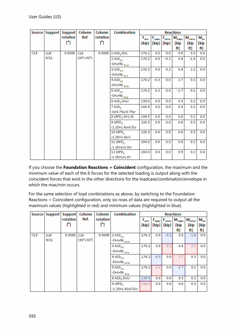
User Guides (US)
595
If you choose the Foundation Reactions + Coincident configuration, the maximum and the
minimum value of each of the 6 forces for the selected loading is output along with the
coincident forces that exist in the other directions for the loadcase/combination/envelope in
which the max/min occurs.
For the same selection of load combinations as above, by switching to the Foundation
Reactions + Coincident configuration, only six rows of data are required to output all the
maximum values (highlighted in red) and minimum values (highlighted in blue).

User Guides
596
Using the ‘Foundation Reactions + Coincident’ option, the table will never contain more than 12 rows (one each for the maximum and minimum of each of the 6 forces) - irrespective of the number of loadcases or combinations that have been selected.
How do I show a Foundation Reactions Report?
1. Select Foundation Reactions from the drop list on the Report toolbar.
2. Click Show Report ( )
3. If the resulting report is displaying too little, or too much information, you can adjust the
content by re-configuring the report.
Seismic Design Report
By default this report will list the following tables:
• Seismic Loading Summary
• Analysis Seismic Drift Results
How do I show a Seismic Design Report?
1. Select Seismic Design from the drop list on the Report toolbar.
2. Click Show Report ( )
3. If the resulting report is displaying too little, or too much information, you can adjust the
content by re-configuring the report.
Member Design Report
By default this report displays the design results for each member at a summary level.
How do I show a Member Design Report?
1. Select Member Design from the drop list on the Report toolbar.
2. Click Show Report ( )
3. If the resulting report is displaying too little, or too much information, you can adjust the
content by re-configuring the report.
Connection Resistance Check Report
Although this report is not one of the standard reports installed by default it is very easy to
create.

User Guides (US)
597
How do I create a Connection Resistance Check Report?
1. Click Model Report on the Report toolbar.
2. Click Add
3. Enter the report Name (e.g. “Connection Resistance Check”) in the box provided under
Active Style.
4. In the Chapters and Options pane, expand Steel> Beam Design
5. Drag Steel> Beam Design> Connection Resistance across to the Report Structure
pane.
6. In the Chapters and Options pane, expand Steel> Brace Design
7. Drag Steel> Brace Design> Connection Resistance across to the Report Structure
pane.
8. Click OK
How do I show a Connection Resistance Check Report?
1. Select Connection Resistance Check from the drop list on the Report toolbar.
2. Click Show Report ( )
Setting up the Report Page Header and Footer
Default page header and footer layouts are provided, but you can also create and save your
own layouts as required.
Topics in this section
• How do I enter company details (logo, address etc.) in the header?
• How do I enter project specific details (job ref, structure etc.) in the header?
• How do I create a new header layout?
Related video
• Report Headers and Footers
Drawing Guide
Drawings of individual levels and frames are created directly from the Draw toolbar, whilst
single member drawings are created for selected members from the right-click menu.

User Guides
598
Alternatively drawings can be created in batch via Drawing Management.
Draw toolbar
The Draw toolbar contains the following commands:
Button Description
Edit...
Opens the Model Settings dialog at the Drawings page.
See Drawing Settings
Drawing Management...
Opens a dialog for the generation and laying out of multiple drawings on to a single drawing sheet. The dialog can also be used to manage drawing revisions.
See Drawing Management
Schedule Management...
Opens a dialog for the generation of schedules on drawing sheets. The dialog can also be used to manage schedule revisions.
See Schedule Management
Beam Schedule
Opens a dialog to configure and then create a beam schedule.
See Concrete Member Schedules
Column Schedule
Opens a dialog to configure and then create a column schedule.
See Concrete Member Schedules
Wall Schedule Opens a dialog to configure and then create a wall schedule.
See Concrete Member Schedules
General Arrangement
Opens a dialog to configure and then create a general arrangement drawing. See Planar Drawings
Beam End Forces
Opens a dialog to configure and then create a beam end forces drawing. See Planar Drawings
Column Splice Loads
Opens a dialog to configure and then create a column splice loads drawing. See Planar Drawings

User Guides (US)
599
Foundation Reactions
Opens a dialog to configure and then create a foundation reactions drawing. See Planar Drawings
Loading Plan
Opens a dialog to configure and then create a loading plan drawing. See Planar Drawings
Slab/Mat Detailing
Opens a dialog to configure and then create a slab or mat detail drawing.
See Planar Drawings
Foundation Layout
Opens a dialog to configure and then create a foundation layout drawing. See Foundations
Overview of Drawings
In Tekla Structural Designer there are five main drawing categories, each containing a
number Drawing Variants (see table below).
Each variant has a number of specific Drawing Options available to further configure the
drawing appearance.
Each variant contains a set number of Drawing Layers. These are switched on or off as
required. Whether each layer is on or off is controlled by the Layer Configuration that is
selected. You can either use the default layer configurations or add your own.
The appearance of each layer (color, linestyle, font etc.) is controlled by the Layer Style. Again,
you can either use the default layer styles or add your own.
Drawing Options, Drawing Layers and Layer Styles are all managed via Drawing Settings.
Drawing Variants
Category Drawing Variant Description
Planar Drawings
General Arrangement General Arrangement (GA) of 2D levels and frames.
Foundation Reactions A GA that also contains support reactions (to assist foundation design).
Loading Plan A GA that also contains applied loads for the selected loadcase.
Beam End Forces A GA that also contains forces at the ends of steel beams (to assist steel connection design).
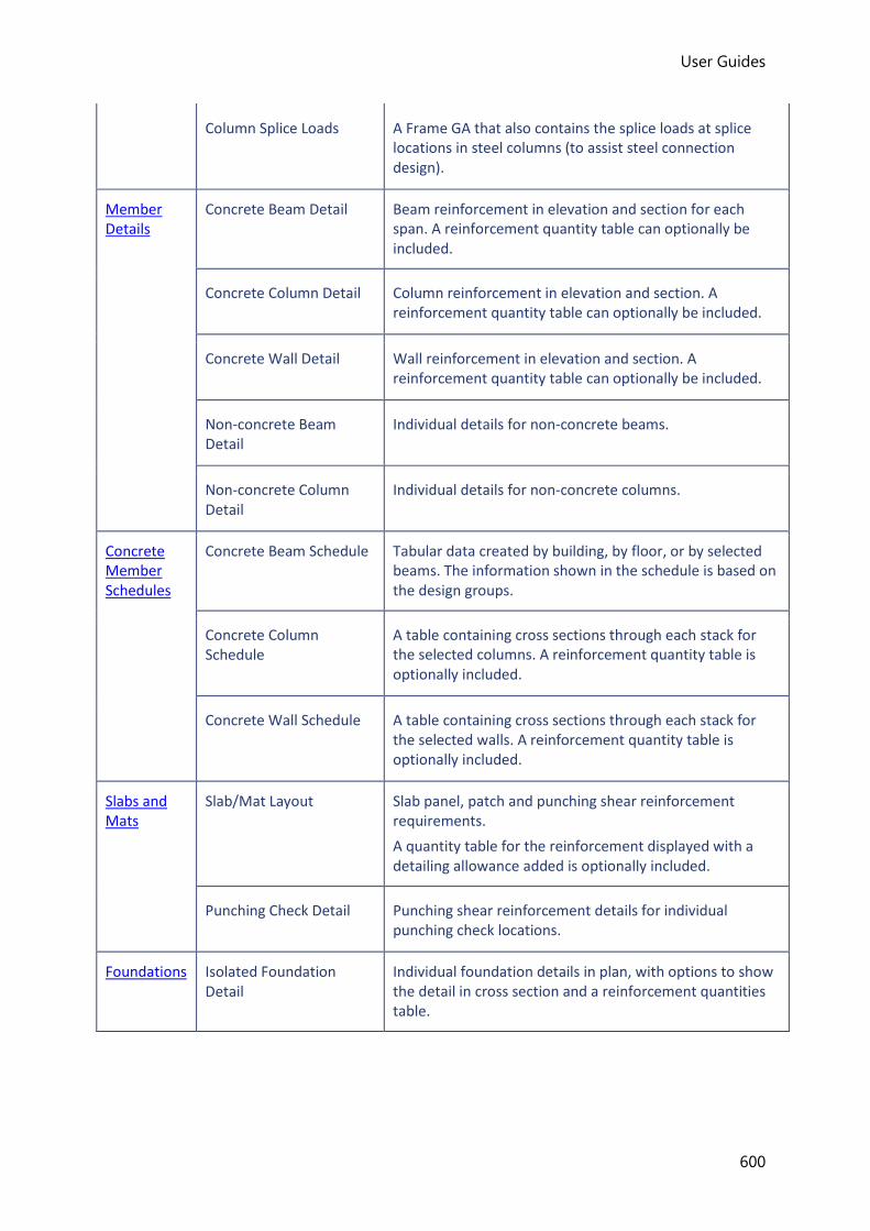
User Guides
600
Column Splice Loads A Frame GA that also contains the splice loads at splice locations in steel columns (to assist steel connection design).
Member Details
Concrete Beam Detail Beam reinforcement in elevation and section for each span. A reinforcement quantity table can optionally be included.
Concrete Column Detail Column reinforcement in elevation and section. A reinforcement quantity table can optionally be included.
Concrete Wall Detail Wall reinforcement in elevation and section. A reinforcement quantity table can optionally be included.
Non-concrete Beam Detail
Individual details for non-concrete beams.
Non-concrete Column Detail
Individual details for non-concrete columns.
Concrete Member Schedules
Concrete Beam Schedule Tabular data created by building, by floor, or by selected beams. The information shown in the schedule is based on the design groups.
Concrete Column Schedule
A table containing cross sections through each stack for the selected columns. A reinforcement quantity table is optionally included.
Concrete Wall Schedule A table containing cross sections through each stack for the selected walls. A reinforcement quantity table is optionally included.
Slabs and Mats
Slab/Mat Layout Slab panel, patch and punching shear reinforcement requirements.
A quantity table for the reinforcement displayed with a detailing allowance added is optionally included.
Punching Check Detail Punching shear reinforcement details for individual punching check locations.
Foundations Isolated Foundation Detail
Individual foundation details in plan, with options to show the detail in cross section and a reinforcement quantities table.

User Guides (US)
601
Foundation Layout A GA at foundation level showing isolated bases, pile layouts, and mats.
Isolated foundation details, a reinforcement quantities table and an isolated foundation schedule can optionally be included.
Drawing Settings
How to apply and manage Drawing Settings
To modify drawing settings in the current project
1. Click Draw > Edit... ( )
(alternatively you could also click Home > Model Settings ( ) > Drawings)
2. Review and edit the settings as required.
3. If you change any of the settings, click:
• OK - to apply the changes directly to the current project, or
• Save... - to save the changes back to the active settings set (to act as defaults for future
projects), or
• Cancel... - to cancel the changes
You can also click:
• Load... - to revert to the drawing settings specified in the active settings set.
To modify drawing setting defaults for future projects
1. Click Home > Settings ( )
2. In the Settings Sets page of the dialog select the settings set to be updated.
You can update any settings set simply by selecting it from the droplist, it does not need to be active.
3. In the Drawings page of the dialog, review and edit the settings as required.
4. If you change any of the settings, click:
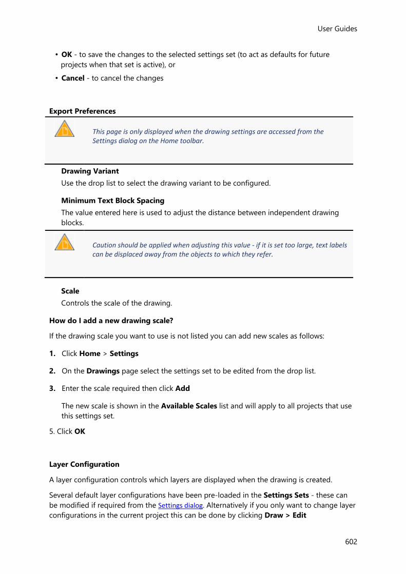
User Guides
602
• OK - to save the changes to the selected settings set (to act as defaults for future
projects when that set is active), or
• Cancel - to cancel the changes
Export Preferences
This page is only displayed when the drawing settings are accessed from the Settings dialog on the Home toolbar.
Drawing Variant
Use the drop list to select the drawing variant to be configured.
Minimum Text Block Spacing
The value entered here is used to adjust the distance between independent drawing
blocks.
Caution should be applied when adjusting this value - if it is set too large, text labels can be displaced away from the objects to which they refer.
Scale
Controls the scale of the drawing.
How do I add a new drawing scale?
If the drawing scale you want to use is not listed you can add new scales as follows:
1. Click Home > Settings
2. On the Drawings page select the settings set to be edited from the drop list.
3. Enter the scale required then click Add
The new scale is shown in the Available Scales list and will apply to all projects that use
this settings set.
5. Click OK
Layer Configuration
A layer configuration controls which layers are displayed when the drawing is created.
Several default layer configurations have been pre-loaded in the Settings Sets - these can
be modified if required from the Settings dialog. Alternatively if you only want to change layer
configurations in the current project this can be done by clicking Draw > Edit
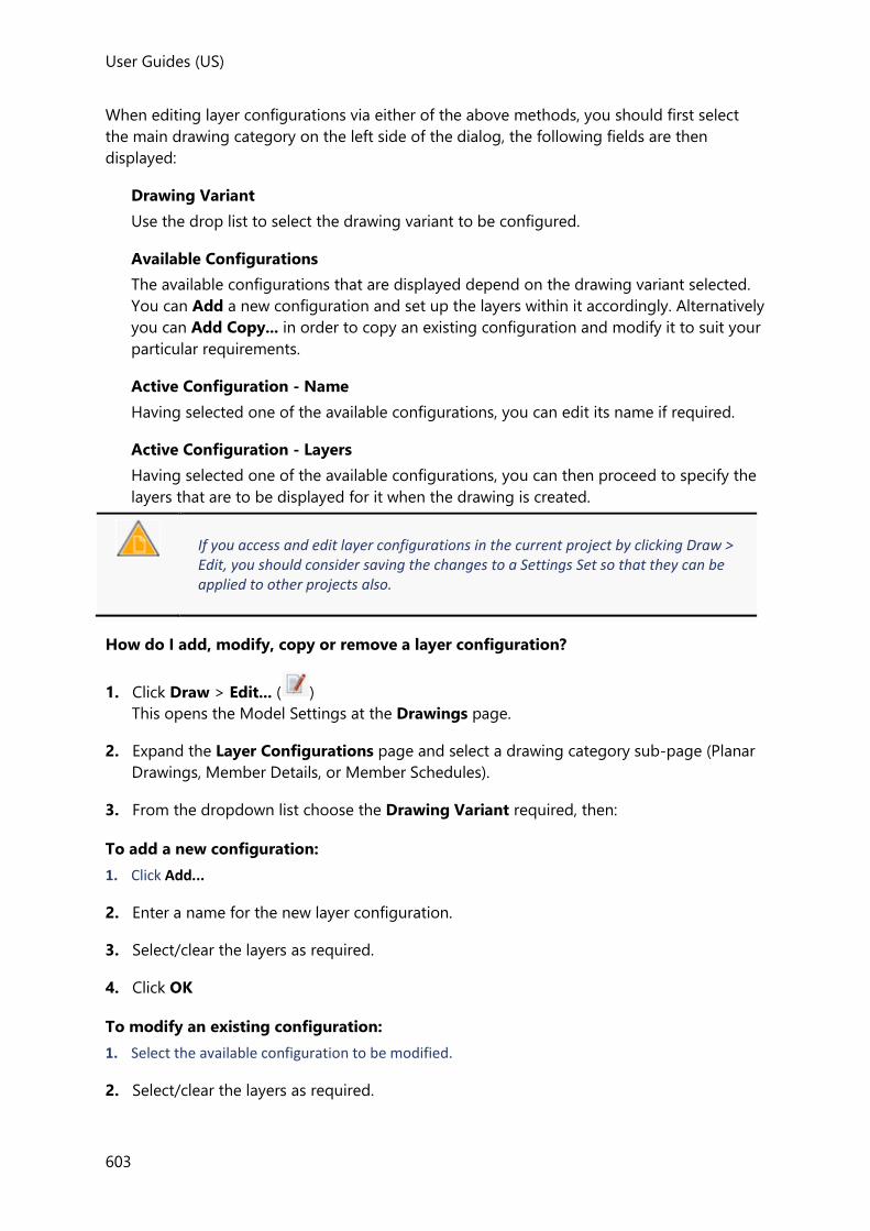
User Guides (US)
603
When editing layer configurations via either of the above methods, you should first select
the main drawing category on the left side of the dialog, the following fields are then
displayed:
Drawing Variant
Use the drop list to select the drawing variant to be configured.
Available Configurations
The available configurations that are displayed depend on the drawing variant selected.
You can Add a new configuration and set up the layers within it accordingly. Alternatively
you can Add Copy... in order to copy an existing configuration and modify it to suit your
particular requirements.
Active Configuration - Name
Having selected one of the available configurations, you can edit its name if required.
Active Configuration - Layers
Having selected one of the available configurations, you can then proceed to specify the
layers that are to be displayed for it when the drawing is created.
If you access and edit layer configurations in the current project by clicking Draw > Edit, you should consider saving the changes to a Settings Set so that they can be applied to other projects also.
How do I add, modify, copy or remove a layer configuration?
1. Click Draw > Edit... ( )
This opens the Model Settings at the Drawings page.
2. Expand the Layer Configurations page and select a drawing category sub-page (Planar
Drawings, Member Details, or Member Schedules).
3. From the dropdown list choose the Drawing Variant required, then:
To add a new configuration:
1. Click Add...
2. Enter a name for the new layer configuration.
3. Select/clear the layers as required.
4. Click OK
To modify an existing configuration:
1. Select the available configuration to be modified.
2. Select/clear the layers as required.
User Guides
604
3. Click OK
To copy an existing configuration:
1. Select the available configuration to copy from.
2. Click Copy
3. Enter a name for the new layer configuration.
4. Select/clear the layers as required.
5. Click OK
To remove an existing configuration:
1. Select the available configuration to be removed.
2. Click Remove
3. Click OK
Layer Style
In order to control how a drawing is displayed (line types, fonts, colors etc.) you will need to
apply a drawing Style.
Several default layer styles have been pre-loaded in the Settings Sets - these can be
modified if required from the Settings dialog. Alternatively if you only want to change layer
styles in the current project this can be done by clicking Draw > Edit
When editing layer styles via either of the above methods, you should first select the main
drawing category on the left side of the dialog, the following fields are then displayed:
Drawing Variant
Use the drop list to select the drawing variant to be configured.
Available Styles
The available styles that are displayed depend on the drawing variant selected. You can
Add a new style and set up the layers within it accordingly. Alternatively you can Add
Copy... in order to copy an existing style and modify it to suit your particular
requirements.
Active Style - Name
Having selected one of the available styles, you can edit its name if required.
Active Style - Layers
Having selected one of the available styles, you can then proceed to specify the
appearance of layers within it when the drawing is created.
How do I add, modify, copy or remove a drawing style?

User Guides (US)
605
1. Click Draw > Edit... ( )
This opens the Model Settings at the Drawings page.
2. Expand the Layer Styles page and select a drawing category sub-page (Planar Drawings,
Member Details, or Member Schedules).
3. From the dropdown list choose the Drawing Variant required, then:
To add a new style:
1. Click Add...
2. Enter a name for the new drawing style.
3. Configure the colors, line types, fonts etc. for each of layers as required.
4. Click OK
To modify an existing style:
1. Select the available style to be modified.
2. Modify the colors, line types, fonts etc. as required.
3. Click OK
To copy an existing style:
1. Select the available style to copy from.
2. Click Copy
3. Enter a name for the new drawing style.
4. Modify the colors, line types, fonts etc. as required.
5. Click OK
To remove an existing style:
1. Select the available style to be removed.
2. Click Remove
3. Click OK
Drawing Options
You must expand the Options page and select the sub-page for an individual drawing variant in order to see the applicable options for that particular variant.

User Guides
606
Options - Planar Drawings
After selecting the appropriate Planar Drawings sub-page (General Arrangement, Foundation
Reactions, Loading Plan, Slab/Mat Detail, or Beam End Forces), use the menu tabs to
configure the options as required.
General tab
Hatching
Show columns and walls above the level as hatched
Select to hatch columns and walls that continue above the current level.
Show transfer column and walls as cross hatched
Select to cross hatch transfer columns and walls.
Reaction Values (Foundation Reactions and Beam End Forces Variants only)
Current Loading Values
values are displayed for the loadcase or combination currently selected in the Loading
drop list.
Max/Min Values by Loadcase/Combination
max and min values are displayed for each loadcase/combination.
Max Absolute Value by Loadcase/Combination
the max absolute value is displayed for each loadcase/combination.
Force & Moment Values (Foundation Reactions and Beam End Forces Variants only)
Factor by
for the current drawing variant, the values displayed are factored by the amount
specified.
A factor can be applied to the forces and moments that are displayed if required.
Moment Values, Shear Force Values and Axial Force Values (Foundation Reactions and
Beam End Forces Variants only)
None
values are not displayed.
Only greater than
moments/forces are only displayed if the absolute value is greater than the value
specified.
All
values are always displayed, (even if zero).
Enveloped Reaction Values (Beam End Forces Variant only)

User Guides (US)
607
Include coincident forces
when a beam end forces drawing is created for a loading envelope and this option is
selected, further options are presented allowing you to choose the max/min values and
coincident forces to display.
Beams tab
Grouped Beam Labelling
These two options only apply when the beams have been designed using groups.
Use detail group name
Select to use the detail group name, or clear to use the design group name in the label.
Include the beam name
Select to include the beam name in the label for grouped beams.
Beam Labelling Position
Above, Inside, Below
Sets the location of the beam label in relation to the beam.
Beam Attributes
Show beam size in parentheses
check to place brackets around the beam size in the label.
Camber
Append camber to section
displays the amount of camber specified for steel beams.
Camber prefix
specifies the camber prefix used in the label.
Composite Properties
Stud separator
for composite beams the number of studs are displayed inside the chosen separator.
Columns tab
Grouped Column Labelling
These two options only apply when the columns have been designed using groups.
Use detail group name

User Guides
608
Select to use the detail group name, or clear to use the design group name in the label.
Include the column name
Select to include the column name in the label for grouped columns.
Column Labelling Position
The column size is either included at the right of the label, or on the line below the label.
Column Attributes
Show column size in parentheses
check to place brackets around the column size in the label.
Steel Columns
2x scale for steel columns
Select to draw steel columns at double the drawing scale.
Walls tab
Wall Labelling Position
Above, Inside, Below
Sets the location of the wall label in relation to the wall.
Wall Attributes
Show wall size in parentheses
check to place brackets around the wall size in the label.
Slabs and Mats tab
Panel Labeling
Include panel reference
Select to include the slab panel reference in the label.

User Guides (US)
609
Include panel thickness
Select to include the slab panel thickness in the label.
Include surface offset (if non zero)
Select to include any surface offset that has been applied to the slab panel in the label.
Include border around label
Select this check box to add a border around the label.
Align label to panel reinforcement
Select this check box to align the label to the slab panel span direction.
- When selected the label is displayed as below left
- When cleared the label is displayed as below left
Slab/Mat Geometry
Include panel span direction symbol
Select to include the symbol
Loads tab
(Loading Plan Variant only)
Display size
Width of line/UDL/VDL loads on plan
Each of these load types is drawn as a hatched rectangle of fixed width when drawn in
plan - this setting controls the width.

User Guides
610
Height of line/UDL/VDL loads on elevation
Each of these load types is drawn as a hatched rectangle of fixed height when drawn in
elevation - this setting controls the height.
Point load marker size
This setting controls the drawn size of point loads.
Options
Show dimensions for panel loads
Select to include the dimensions of panel loads.
Include dimensions to reference points
Select to include the dimensions from panel loads to the reference points that were used
to set them out.
Show dimensions for member loads
Select to include the dimensions of member loads.
Options - Member Details
These are used to further control the appearance of the different drawing categories.
Beam Detail - Content
These settings are used to control the content of the beam detail drawings.
Grouped Beams tab
Show grouped beam number
Provided the beams in the model have been arranged into detailing groups - checking
this option causes the Detailing Group to be used as the member label instead of the
beam reference.
If detailing groups have not been used, this option has no effect - the beam reference is
always used as the member label.
Levels tab
Show span levels
Select to show the span levels on the elevation.
Cross sections tab
Spans
Choose which cross sections to display from the drop list:
• None

User Guides (US)
611
• First Span
(i.e. for multi-span beams, cross-sections are not shown for 2nd and subsequent spans)
• All Spans
Positions
If cross sections are displayed, choose where they are to be positioned from the drop list:
• Span Only
• Support
• Support and Span
Bar annotation
Choose the cross section annotation from the drop list:
• None
• Standard
• IStructE
Display bar marks
For Standard and IStructE annotation you have the option to display bar marks in the
cross section labels.
Show slab lines in section
Select to display slab lines in sections, as shown below::
When the option is cleared the slab lines are not displayed:
Bar Labels tab
Show bar marks in elevation
Select to include bar marks in the bar labels on the elevation. They will also be displayed
on the cross-sections provided the Cross-sections > Display bar marks option is also
checked.
If this option is cleared, bar marks are not displayed on cross-sections - irrespective of
the Cross-sections > Display bar marks option.
Show steel bar layer information

User Guides
612
Select to show steel bar layer information, (B1, B2, T1, T2 etc.)
Dimensions tab
Laps
Where laps exist these are either dimensioned, not dimensioned, or the dimension is
replaced by a standard label (TL) according to the drop list selection.
Anchorage lengths
Where anchorage lengths are required these are either dimensioned, not dimensioned,
or the dimension is replaced by a standard label (AL) according to the drop list selection.
Axes
Axes are either not shown, shown above the beam with dimensions, or shown below the
beam with dimensions.
Additional bottom span bar positioning dimensions
When optional 2nd span bars have been employed, these can be dimensioned from the
face of the support by checking this option.
Support region length
Where different stirrup regions has been employed along a beam span, the length of the
support regions is dimensioned on the elevation by checking this option.
First and last stirrups
Select to add dimensions from the face of the supports to the first and last stirrups.
Support columns and clear spans
Select to add dimensions showing the width of each supporting column and the clear
beam span between supports.
Beam section
Select to dimension the beam depth and width on the cross section.
Slabs in beam sections
Select to dimension the slab depth on the cross section.
Quantities tab
Show reinforcement quantities table
select this check box to include reinforcement quantity tables on the drawings.
Beam Detail - Style
These settings are used to control the style of the beam detail drawings.
Beam Labels tab

User Guides (US)
613
Print beam labels below the detail
Select to show the beam label centrally below each span. When cleared the label is
positioned immediately above each span.
Underline beam labels
Select to underline the beam label on the elevation.
Label every span of multi-span beams
Select to repeat the beam label below the detail for every beam span.
Cross sections tab
Section label style
Choose the label naming style to be applied to the cross sections from the drop list.
Restart section labels in each beam line
When multiple beam lines are displayed on the same drawing sheet, select this check box
to restart the section labels for each line.
Add beam name label as prefix to section labels
Select to prefix each section label with the beam name.
Longitudinal Bars tab
Draw bar groups in same elevated layer at different levels
Select to draw the bars displaced vertically (although they are in the same elevated layer),
to enhance the display.
Display elevated bobs at same position as shifted
Select to draw bobs displaced vertically (when they are bent at the same position), to
enhance the display.
Display only a single side bar in detail
If multiple side bars are required in each face, when this option is selected only a single
side bar is drawn full length. When cleared, all side bars are drawn full length.
Stirrups/Links tab
Draw stirrup labels in line
Select to show stirrup labels in line on the elevation:
When cleared the labels are drawn above the line.

User Guides
614
Print stirrup labels inside beam
Select to show the stirrup labels inside the beam; clear to show below the beam.
Stirrup label distance from bottom edge
When stirrup labels are positioned inside the beam this setting is used to control their
vertical position.
Dimensions tab
Draw lap dimensions outside the detail
Select to draw lap dimensions outside the detail.
Lap and anchorage rounding increment
This option is used to control the rounding increment of lap and anchorage dimensions.
Column Detail - Content
These settings are used to control the content of the column detail drawings.
Grouped Columns tab
Show grouped column number
Select to display column groups
Levels tab
Show levels
Select to label the construction levels
Cross sections tab
Show sections
Select to show cross sections through each stack
Bar annotation
Choose the cross section annotation from the drop list (None, Standard, IStructE).
Display bar marks
For Standard and IStructE annotation you have the option to display bar marks in the
cross section labels
Dimensions tab

User Guides (US)
615
Laps
Where laps exist these are either dimensioned, not dimensioned, or given a standard
label according to the drop list selection
Support region length
Select to dimension the support regions on the elevation
Levels
Select to add dimensions between levels
Grid line offsets
Select to add dimensions from the grid to the column face on the elevation
Connecting elements and clear heights
Select to add dimensions connecting elements and clear heights
Column section
Select to add column dimensions on the section
Column Detail - Style
These settings are used to control the style of the column detail drawings.
Column Labels tab
Underline column labels
Select to underline the column label on the elevation
Cross sections tab
Section label style
Choose the label style to be applied to the cross sections from the drop list
Restart section labels in each column line
When multiple columns are displayed on the same drawing sheet, select this check box
to restart the section labels for each column
Add column name label as prefix to section labels
Select to as a prefix each section label with the column name
Longitudinal Bars tab
Show hidden bar ends
Select to show hidden bar ends
Ties/Links tab
Draw tie labels in line

User Guides
616
Select to show tie labels in line on the elevation, (as below left), or leave cleared to
display above the line (as below right):
Dimensions tab
Lap dimension rounding increment
This option is used to control the rounding increment of lap dimensions
Wall Detail - Content
These settings are used to control the content of the wall detail drawings.
Levels tab
Show levels
Select to label the construction levels
Cross sections tab
Show sections
Select to show cross sections through each stack
Bar annotation
Choose the cross section annotation from the droplist (None, Standard, IStructE).
Display bar marks
For Standard and IStructE annotation you have the option to display bar marks in the
cross section labels
Dimensions tab
Laps
Where laps exist these are either dimensioned, not dimensioned, or given a standard
label according to the droplist selection
Support region length
Select to dimension the support regions on the elevation
Levels

User Guides (US)
617
Select to add dimensions between levels
Grid line offsets
Select to add dimensions from the grid to the column face on the elevation
Connecting elements and clear heights
Select to add dimensions connecting elements and clear heights
Wall section
Select to add wall dimensions on the section
Wall Detail - Style
These settings are used to control the style of the wall detail drawings.
Wall Labels tab
Underline wall labels
Select to underline the wall label on the elevation
Cross sections tab
Section label style
Choose the label style to be applied to the cross sections from the drop list.
Add wall name label as prefix to section labels
Select to as a prefix each section label with the wall name.
Don’t label typical panel bars
When selected the typical bars are not labelled in the cross section:
When cleared every bar is labelled.
Horizontal & Vertical Bars tab
Show hidden bar ends

User Guides
618
Select to show hidden bar ends
Horizontal Bars and Ties/Links tab
Draw tie labels in line
Select to show tie labels in line on the elevation, (as below left), or leave cleared to
display above the line (as below right):
Dimensions tab
Lap dimension rounding increment
This option is used to control the rounding increment of lap dimensions
Options - Member Schedules
Beam Schedule Options
These settings are used to control the appearance of the concrete beam schedule.
General tab
Texts
Item
Select an item in the list to see the text label that will applied to it in the schedule.
Text
If required you can edit the text to be displayed in the schedule for the selected item.
Columns
Size Column Format
Choose whether to display the width of the beam or its height first in the size column.
Use single column for size
Check to display both the width and height in a single column.
Use single column for bottom bars

User Guides (US)
619
Check to display the bottom bars in a single column.
Omit top middle bars column
Check to omit the top middle bars from the schedule.
Use single column for stirrups
Check to display the stirrups in a single column.
Show only design group name
Check to display only the design group name in the mark column.
Bar Key tab
Reference
Every reference that can potentially appear in the bar bending details table is listed.
Hover the cursor over a reference to see the bar and its associated note.
Use Custom Name
Select the check box against a reference in order to apply a custom name.
Custom Name
any text entered here will replace the original reference in the bar bending details table.
Column Schedule Options
These settings are used to control the content of the concrete column schedules.
General
Show grouped column number
Select to show column groups
Include starter bars
Select to include starter bars
Show reinforcement quantities table
Select to include the quantities table
Cross sections
Bar annotation
Choose the cross section annotation from the drop list (Standard, IStructE).
Display bar marks
Select to display bar marks in the cross section labels.
User Guides
620
Show outline of stack below
Select to show the outline of the stack below.
Dimension column section
Select to add column dimensions on the section.
Dimension levels
Select to add dimensions between levels.
Wall Schedule Options
These settings are used to control the content of the concrete wall schedules.
General
Include starter bars
Select to include starter bars
Show reinforcement quantities table
Select to include the quantities table
Cross sections
Bar annotation
Choose the cross section annotation from the drop list (Standard, IStructE).
Display bar marks
Select to display bar marks in the cross section labels.
Show outline of panel below
Select to show the outline of the panel below.
Dimension wall section
Select to add wall dimensions on the section.
Dimension levels
Select to add dimensions between levels.
Options - Slabs and Mats
Layout
Slabs and Mats tab
Panel Labeling
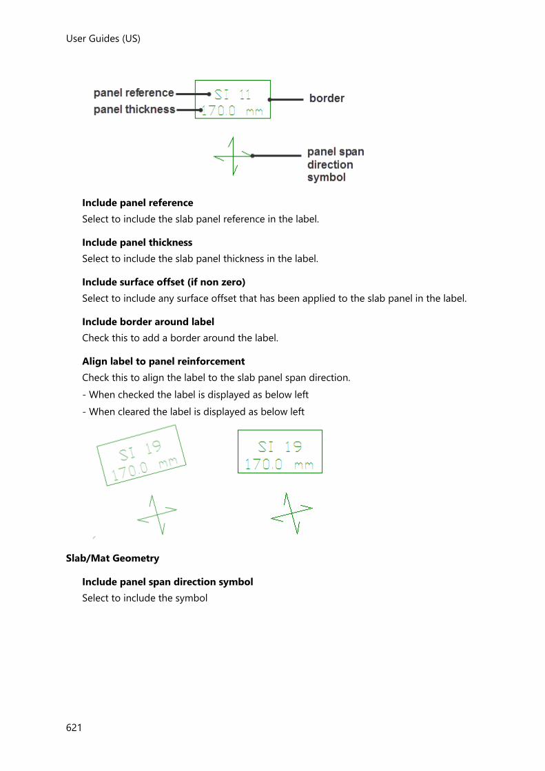
User Guides (US)
621
Include panel reference
Select to include the slab panel reference in the label.
Include panel thickness
Select to include the slab panel thickness in the label.
Include surface offset (if non zero)
Select to include any surface offset that has been applied to the slab panel in the label.
Include border around label
Check this to add a border around the label.
Align label to panel reinforcement
Check this to align the label to the slab panel span direction.
- When checked the label is displayed as below left
- When cleared the label is displayed as below left
Slab/Mat Geometry
Include panel span direction symbol
Select to include the symbol

User Guides
622
Reinforcement Display
Extend loose bar panel reinforcement lines across full panel
Leave this option cleared to display the loose bar reinforcement as above, otherwise the
bars are drawn across the entire panel.
Reinforcement Labelling
Always show main bar layer for rectangular mesh
If the mesh is not a square mesh it is normal practice to put the main bars in the outer
layer, (no text is required on the drawing in this situation). However, when this is not the
case this is indicated on the drawing by adding B2 (if bottom mesh) or T2 (if top mesh)
aligned to the main bar direction.
Anchorage rounding increment
Specifies the rounding value applied to the anchorage length.
If a square mesh (i.e. if it does have the same size and spacing of bars in both directions) is applied then a square mesh symbol is used which indicatively shows bars equally spaced in both directions. If the mesh is not a square mesh (i.e. if it does not have the same size and spacing of bars in both directions) then a rectangular mesh symbol is used which indicatively shows bars in both directions but with closer spacing for the more closely spaced bars in the mesh.
Patches tab
General
Show patches with no reinforcement
If a patch has no reinforcement specified you can choose not to show it on the drawing
by clearing this option.

User Guides (US)
623
Anchorage Length
You are given the option to either draw the bars with full anchorage lengths, or to draw
curtailed (indicative) anchorage lengths instead.
Punching Shear tab
Show punching reinforcement details
Select to include a detail to the side of the layout showing the punching shear
reinforcement provided.
Don’t show area of steel requirement where rails have been designed
When checked: the area of steel requirement is shown for punching check items where
rails are not provided (e.g. walls and column drops), but is not shown elsewhere.
When cleared: the area of steel requirement is shown for all punching check items.
Hide punching reinforcement on the main layout
Select to hide the punching reinforcement on the main layout. It will still be shown in the
detail (provided that the above ‘Show punching reinforcement details’ is checked).
Punching Check Detail - Content
These settings are used to control the content of the beam detail drawings.
Dimensions tab
Show column to first stud spacing
Select to add a dimension from the column face to the first stud.
Show stud spacing
Select to add dimensions showing the stud spacings along the rail.
Show rail spacing
Select to add dimensions showing the rail spacings.
Include schematic showing stud dimensions
Select to add a schematic showing the stud width and height above the rail.
Quantities tab
Show reinforcement quantities table
Select to include reinforcement quantity tables on the drawings.
Punching Check Detail - Style
These settings are used to control the style of the beam detail drawings.
General tab
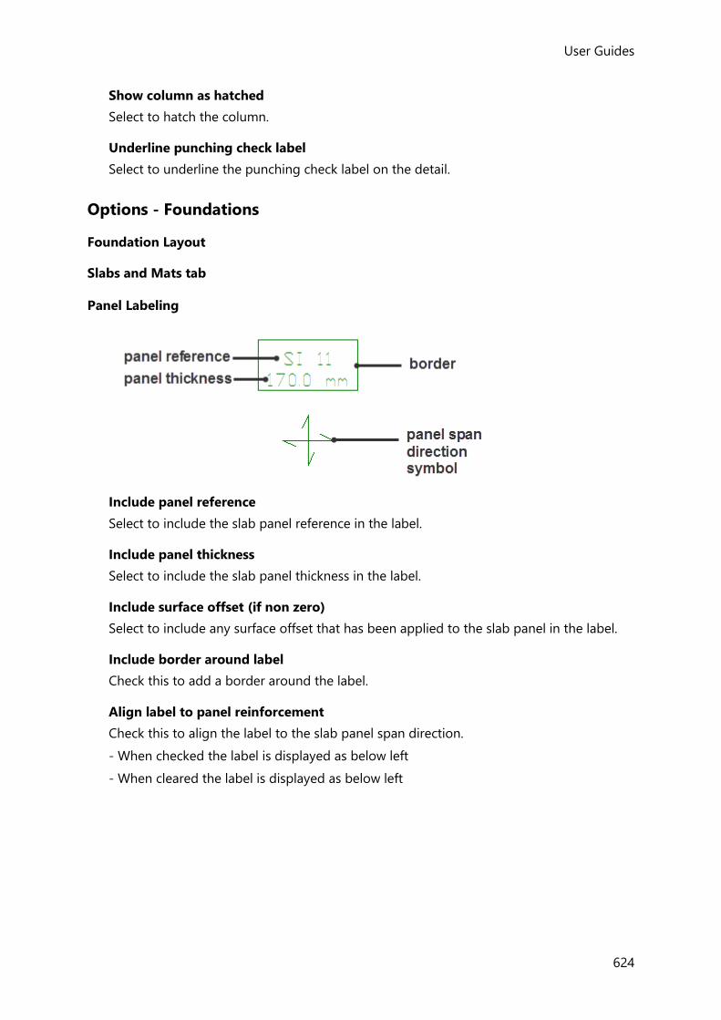
User Guides
624
Show column as hatched
Select to hatch the column.
Underline punching check label
Select to underline the punching check label on the detail.
Options - Foundations
Foundation Layout
Slabs and Mats tab
Panel Labeling
Include panel reference
Select to include the slab panel reference in the label.
Include panel thickness
Select to include the slab panel thickness in the label.
Include surface offset (if non zero)
Select to include any surface offset that has been applied to the slab panel in the label.
Include border around label
Check this to add a border around the label.
Align label to panel reinforcement
Check this to align the label to the slab panel span direction.
- When checked the label is displayed as below left
- When cleared the label is displayed as below left

User Guides (US)
625
Slab/Mat Geometry
Include panel span direction symbol
Select to include the symbol
Mats
Show pile location table
Select to include a table showing the pile locations.
Show pile references
Select to show the pile references on the layout.
Isolated Foundations tab
Drawing Content
Show pile type name
Select to include the pile type names in the footing attributes displayed for each pile cap
on the layout.
Show foundation details
Select to include pad/strip base and pile cap details to the side of the layout (showing
the designed reinforcement).
Show reinforcement quantities table
Select to include the reinforcement quantities table for the pad/strip bases and pile
caps shown on the layout.

User Guides
626
Show pad/strip base schedule
Select to include the reinforcement schedule for the pad/strip bases on the layout.
Show pile cap schedule
Select to include the reinforcement schedule for the pile caps on the layout.
Show allowable pile capacity
Select to include the allowable pile capacity table for the piles under pile caps on the
layout.
Dimensions on plan
Show overall dimensions
Select to include the overall dimensions of the pad/strip bases and pile caps on the
layout.
Show pile spacings
Select to include the pile cap pile spacing dimensions on the layout.
Grouped Foundation Labelling
Include the foundation name
Select to include the pad/strip base or pile cap name in the footing mark for grouped
footings on the layout.
Labelling Position
Above/Below
controls where the footing mark and attributes are displayed for isolated foundations on
the layout.
Isolated Foundation Detail-Content
These settings are used to control the content of the base detail drawings.
Grouped Foundations: Show number of foundations in group
Select to display the number of bases/pile caps in the group
Cross sections: Positions
Choose ‘None’ to exclude, or choose ‘Length’ for a length-wise section or ‘Length and
Width’ to display cross sections in both directions.
Pile Labels: Show pile type name
Select to include the pile type name in the label.
Dimensions: Show overall dimensions
Select to include the overall dimensions of the base/pile cap.
User Guides (US)
627
Dimensions: Show overall dimensions
Select to include dimensions of the column/wall being supported.
Dimensions: Show pile spacings
For pile caps, select this check box to include dimensions from center to center of each
pile.
Quantities: Show reinforcement quantities table
Select to show the reinforcement quantities table for the base.
Isolated Foundation Detail-Style
These settings are used to control the style of the column detail drawings.
General: Show supported member as hatched
Select to hatch columns and walls that are supported on the base pile cap.
General: Underline foundation label
Select to underline the foundation label on the detail
Cross-sections: Section label style
Choose the label style to be applied to the cross sections from the drop list
Cross-sections: Restart labels in each foundation
When multiple foundations are included on the same drawing, checking this option
causes the labelling to restart from the beginning on each section.
Planar Drawings
The following drawing variants fall into this category:
General Arrangement
General Arrangement drawings show the member layouts for 2D levels and frames.
Beam End Forces
Beam End Force drawings are similar to General Arrangements but also display the forces at
the ends of steel beams for the purpose of connection design.
Column Splice Loads
This drawing should be created from a Frame View in order to display the splice loads at
splice locations in steel columns.
Foundation Reactions
Foundation Reaction drawings include support reactions to assist foundation design.
Loading Plan

User Guides
628
Loading Plan drawings show the applied loads for individual loadcases.
Prior to creating any of these drawings you should ensure that the Options - Planar Drawings have been configured to meet your requirements.
How do I create a General Arrangement drawing?
1. Open a 2D scene view displaying the part of the model to be included on the drawing.
For example a particular construction level, frame, or sloped plane.
2. Click Draw > General Arrangement ( )
The above button is only available when the current view is displayed in 2D. If the button is dimmed, check that you are not in a Structure view or in a 2D scene view displayed in 3D.
3. In the DXF Export Preferences dialog choose the Layer Configuration and Layer Style required.
4. Specify the drawing scale.
5. If required modify the Minimum Text Block Spacing, (in order to adjust the distance
between independent lines of text).
6. Either accept the automatic file name, or enter the name directly.
7. Click OK
How do I create a Beam End Forces drawing?
Beam End Force drawings are typically created to assist connection design in steel structures. These forces are not relevant in concrete structures and therefore do not get displayed for concrete beams.
1. Open a 2D Results View displaying the part of the model to be included on the drawing.
For example a particular construction level, frame, or sloped plane.
2. From the Loading drop list select the loadcase or combination to be displayed.
3. Click Draw > Beam End Forces ( )
The above button is only available when the current view is displayed in 2D. If the button is grayed out, check that you are not in a Structure view or in a 2D scene view displayed in 3D.

User Guides (US)
629
4. In the DXF Export Preferences dialog choose the Layer Configuration and Layer Style required.
5. Specify the drawing scale.
6. If required modify the Minimum Text Block Spacing, (in order to adjust the distance
between independent lines of text).
7. Either accept the automatic file name, or enter the name directly.
8. Click OK
How do I create a Column Splice Loads drawing?
Column Splice drawings are typically created to assist connection design in steel structures. These forces are not relevant in concrete structures.
1. Open a Frame view containing the steel frame for which you want to see the column
splice loads.
2. In the Status Bar click Results View
3. From the Loading drop list select the loadcase or combination to be displayed.
4. Click Draw > Column Splice Loads
The above button is only available when the current view is displayed in 2D. If the button is grayed out, check that you are not in a Structure view or in a 2D scene view displayed in 3D.
5. In the DXF Export Preferences dialog choose the Layer Configuration and Layer Style required.
6. Specify the drawing scale.
7. If required modify the Minimum Text Block Spacing, (in order to adjust the distance
between independent lines of text).
8. Either accept the automatic file name, or enter the name directly.
9. Click OK
How do I create a Foundation Reactions drawing?
1. Open a 2D Results View displaying the part of the model to be included on the drawing.
(Typically the base construction level).
2. From the Loading drop list select the loadcase or combination to be displayed.
3. Click Draw > Foundation Reactions ( )

User Guides
630
The above button is only available when the current view is displayed in 2D. If the button is grayed out, check that you are not in a Structure view or in a 2D scene view displayed in 3D.
4. In the DXF Export Preferences dialog choose the Layer Configuration and Layer Style required.
5. Specify the drawing scale.
6. If required modify the Minimum Text Block Spacing, (in order to adjust the distance
between independent lines of text).
7. Either accept the automatic file name, or enter the name directly.
8. Click OK
How do I create a Loading Plan drawing?
1. Open a 2D scene view displaying the part of the model to be included on the drawing.
For example a particular construction level, frame, or sloped plane.
2. From the Loading drop list select the loadcase to be displayed.
3. Click Draw > Loading Plan ( )
The above button is only available when the current view is displayed in 2D. If the button is grayed out, check that you are not in a Structure view or in a 2D scene view displayed in 3D.
4. In the DXF Export Preferences dialog choose the Layer Configuration and Layer Style required.
5. Specify the drawing scale.
6. If required modify the Minimum Text Block Spacing, (in order to adjust the distance
between independent lines of text).
7. Either accept the automatic file name, or enter the name directly.
8. Click OK
DXF Export Preferences dialog
From this dialog you can specify the drawing location and control both its content and
appearance
Use automatic file name

User Guides (US)
631
Leave the box checked in order to create the drawing with an automatically generated file
name in the same folder as the model. Uncheck to specify an alternative file name and
location.
Layer Configuration
The Layer Configuration drop list is used to specify which layers are included in the dxf.
Layer Style
The Layer Style drop list is used to specify the appearance of the text and lines in the included
layers.
Scale
Controls the scale of the drawing.
Minimum Text Block Spacing
The Minimum Text Block Spacing is used in order to adjust the distance between
independent drawing blocks.
Caution should be applied when adjusting this value - if it is set too large, text labels can be displaced away from the objects to which they refer.
Member Details
The following drawing variants fall into this category:
Concrete Beam Detail
This drawing displays the beam reinforcement in elevation and section for each span. A
reinforcement quantity table can optionally be included.
Concrete Column Detail
This drawing displays the column reinforcement in elevation and section. A reinforcement
quantity table can optionally be included.
Concrete Wall Detail
This drawing displays the wall reinforcement in elevation and section. A reinforcement
quantity table can optionally be included.
Non-concrete Beam Detail
Non-concrete beam detail drawings are used to display individual steel beam details.
Non-concrete Column Detail
Non-concrete column detail drawings are used to display individual steel beam details.
User Guides
632
Prior to creating any of these drawings you should ensure that the Options - Member Details have been configured to meet your requirements.
How do I create a concrete beam detail?
Prior to creating your beam detail drawings you should ensure that both the Beam Detail - Content and the Beam Detail - Style options have been configured to meet your requirements.
To create a beam detail:
1. Hover the cursor over the beam to be detailed until its outline becomes highlighted.
2. Right-click and select Generate Detailing Drawing... from the context menu to display
the DXF Export Preferences dialog.
3. Choose the Layer Configuration and Layer Style required.
4. Specify the drawing scale.
5. If required modify the Minimum Text Block Spacing, (in order to adjust the distance
between independent lines of text).
6. Either accept the automatic file name, or enter the name directly.
7. Click OK
How do I create a concrete column detail?
Prior to creating your column detail drawings you should ensure that both the Column Detail - Content and the Column Detail - Style options have been configured to meet your requirements.
To create a column detail:
1. Hover the cursor over the column to be detailed until its outline becomes highlighted.
2. Right-click and select Generate Detailing Drawing... from the context menu to display
the DXF Export Preferences dialog.
3. Choose the Layer Configuration and Layer Style required.
4. Specify the drawing scale.
5. If required modify the Minimum Text Block Spacing, (in order to adjust the distance
between independent lines of text).

User Guides (US)
633
6. Either accept the automatic file name, or enter the name directly.
7. Click OK
How do I create a concrete wall detail?
Prior to creating your column detail drawings you should ensure that both the Wall Detail - Content and the Wall Detail - Style options have been configured to meet your requirements.
To create a wall detail:
1. Hover the cursor over the wall to be detailed until its outline becomes highlighted.
2. Right-click and select Generate Detailing Drawing... from the context menu to display
the DXF Export Preferences dialog.
3. Choose the Layer Configuration and Layer Style required.
4. Specify the drawing scale.
5. If required modify the Minimum Text Block Spacing, (in order to adjust the distance
between independent lines of text).
6. Either accept the automatic file name, or enter the name directly.
7. Click OK
How do I create a non concrete beam detail?
Prior to creating your beam detail drawings you should ensure that both the Beam Detail - Content and the Beam Detail - Style options have been configured to meet your requirements.
To create a beam detail:
1. Hover the cursor over the beam to be detailed until its outline becomes highlighted.
2. Right-click and select Generate Detailing Drawing... from the context menu to display
the DXF Export Preferences dialog.
3. Choose the Layer Configuration and Layer Style required.
4. Specify the drawing scale.
5. If required modify the Minimum Text Block Spacing, (in order to adjust the distance
between independent lines of text).
6. Either accept the automatic file name, or enter the name directly.
User Guides
634
7. Click OK
How do I create a non concrete column detail?
Prior to creating your column detail drawings you should ensure that both the Column Detail - Content and the Column Detail - Style options have been configured to meet your requirements.
To create a column detail:
1. Hover the cursor over the column to be detailed until its outline becomes highlighted.
2. Right-click and select Generate Detailing Drawing... from the context menu to display
the DXF Export Preferences dialog.
3. Choose the Layer Configuration and Layer Style required.
4. Specify the drawing scale.
5. If required modify the Minimum Text Block Spacing, (in order to adjust the distance
between independent lines of text).
6. Either accept the automatic file name, or enter the name directly.
7. Click OK
Slabs and Mats
The following drawing variants fall into this category:
Slab/Mat Layout
Slab and mat detail drawings are used to convey slab panel reinforcement and patch
reinforcement requirements, (which may take the form of either loose bars or mesh).
The drawings also include a quantity table for the reinforcement displayed with a detailing
allowance added.
An option is provided to also show punching check reinforcement details at the side of the
main layout.
Punching Check Detail
This drawing shows an individual punching check detail in plan, with an option to show the
reinforcement quantities table
How do I create a Punching Check Detail drawing?
To create a punching check detail:
1. Hover the cursor over the punching check to be detailed until its outline becomes
highlighted.

User Guides (US)
635
2. Right-click and select Generate Detailing Drawing... from the context menu to display
the DXF Export Preferences dialog.
3. Choose the Layer Configuration and Layer Style required.
4. Specify the drawing scale.
5. If required modify the Minimum Text Block Spacing, (in order to adjust the distance
between independent lines of text).
6. Either accept the automatic file name, or enter the name directly.
7. Click OK
How do I create a Slab or Mat Layout drawing?
1. Open a 2D scene view displaying the slabs/mats to be included on the drawing.
2. Click Draw > Slab/Mat Detailing ( )
The above button is only available when the current view is displayed in 2D. If the button is grayed out, check that you are not in a Structure view or in a 2D scene view displayed in 3D.
The DXF Export Preferences dialog is displayed.
3. Choose the Layer Configuration and Layer Style required.
4. Specify the drawing scale.
5. If required modify the Minimum Text Block Spacing, (in order to adjust the distance
between independent lines of text).
6. Either accept the automatic file name, or enter the name directly.
7. Click OK
Foundations
The following drawing variants fall into this category:
Isolated Foundation Detail
This drawing shows an individual foundation detail in plan, with options to show:
• the detail in cross section
• reinforcement quantities table
Foundation Layout

User Guides
636
This drawing shows the piling layout and also the layout of isolated foundations, with
options to show:
• isolated foundation details
• reinforcement quantities table
• isolated foundation schedule
• pile location table
How do I create a Base or Pile Cap Detail drawing?
Prior to creating your base detail drawings you should ensure that both the Isolated Foundation Detail-Content and the Isolated Foundation Detail-Style options have been configured to meet your requirements.
To create a base/pile cap detail:
1. Hover the cursor over the base/pile cap to be detailed until its outline becomes
highlighted.
2. Right-clickRight-click and select Generate Detailing Drawing... from the context
menu to display the DXF Export Preferences dialog.
3. Choose the Layer Configuration and Layer Style required.
4. Specify the drawing scale.
5. If required modify the Minimum Text Block Spacing, (in order to adjust the distance
between independent lines of text).
6. Either accept the automatic file name, or enter the name directly.
7. Click OK
How do I create a Foundation Layout drawing?
1. Open a 2D scene view displaying the piles/bases/pile caps to be included on the
drawing.
2. Click Draw > Foundation Layout ( )
The above button is only available when the current view is displayed in 2D. If the button is grayed out, check that you are not in a Structure view or in a 2D scene view displayed in 3D.
The DXF Export Preferences dialog is displayed.
3. Choose the Layer Configuration and Layer Style required.
User Guides (US)
637
4. Specify the drawing scale.
5. If required modify the Minimum Text Block Spacing, (in order to adjust the distance
between independent lines of text).
6. Either accept the automatic file name, or enter the name directly.
7. Click OK
Drawing Management
Although individual drawings can be created as and when required, it is often more efficient
to create a batch of drawings in a single operation. This becomes an almost essential
requirement when working in large models.
The Drawing Management... command facilitates this process allowing you to:
• Select the drawing variant
• Either manually add a drawing sheet, or generate a series of drawing sheets
• Select the frames, levels or members for which drawings are to be created
• Arrange the drawings on the drawing sheet, (either in a linear or grid arrangement)
• For load dependant drawing variants, select the loadcases/combinations
• Create drawing revisions
• View the revision history
• Reset bar marks on concrete detail drawings (in order to remove gaps in the bar mark
numbering)
How do I add new drawings and specify their content?
For all drawing variants this can be done manually as follows:
1. Click Draw > Drawing Management...
2. Specify the drawing variant.
3. Click Add
4. Enter a Name for the new drawing sheet
5. Click Content...
6. To choose from a list of only those items not already placed on a drawing: pick ‘Show
unassigned only’, else pick ‘Show all’
7. Drag the items to be included from the left pane to the right pane of the Drawing
Content dialog.
8. Click OK

User Guides
638
For concrete beam and column detail variants the drawings can also be generated
automatically:
1. Click Draw > Drawing Management...
2. Select either the Concrete Beam Detail or Concrete Column Detail drawing variant as
required.
3. Click Generate
Drawings are created with their content automatically generated: one drawing will
contain containing typical beams or columns, additional drawings are also created which
contain any ungrouped beams or columns
4. If necessary you can click the available drawings in order to rename them.
How do I specify the layout?
1. Select the drawing name from the available drawings list.
2. Click Layout...
3. Choose the direction and arrangement of the layout as required
4. Click OK
For load dependant drawing variants, how do I specify the loading?
1. Select the drawing name from the available drawings list.
2. Click Loading...
3. Choose the loadcases and combinations required
4. Click OK
How do I view a drawing?
1. Select the drawing name from the available drawings list.
2. Click View Drawing...
3. In DXF Export Preferences choose the drawing type and style required.
4. Specify the drawing scale.
5. If required modify the Minimum Text Block Spacing, (in order to adjust the distance
between independent lines of text).
6. Click OK
How do I consolidate the bar marks used on concrete detail drawings?

User Guides (US)
639
Each bar geometry that has ever been used in the model has an associated mark - and this
information is not automatically deleted. That means if a model is designed and some of the
bars fall out of use, their bark mark assignment is still retained. Consequently there is the
potential for gaps in the bar marks and bar marks starting at high numbers. To avoid this a
Reset ALL Marks button is provided.
It is envisaged that this consolidation feature is used as follows:
Phase 1 - During initial design development you would want to continually consolidate.
In this stage things can change a lot and the bar marks used will climb quickly leaving
lots of gaps. Nothing is being issued so there is no problem consolidating.
Phase 2 - At later stages (once information starts to be issued/shared with others) it
becomes increasingly preferable not to consolidate.
To consolidate the bar marks on all drawing sheets:
1. Click Draw > Drawing Management...
2. Select the Concrete Beam Detail or Concrete Column Detail drawing variant as
required.
3. Click Reset ALL Marks
How do I apply a revision to a drawing?
To apply a revision:
1. Click Draw > Drawing Management...
2. Select the drawing
3. Click Create Revision...
4. Enter a revision name
5. Enter the revision note.
6. Click OK
How do I view the revision history of a drawing?
To view revision history:
1. Click Draw > Drawing Management...
2. Select the drawing
3. Click History...
Concrete Member Schedules
The following drawing variants fall into this category:
User Guides
640
Concrete Beam Schedule
A beam schedule (not to be confused with a bar bending schedule) is a particular form of
output which is generated by the Engineer in which the reinforcement is listed on a span by
span basis. The beam schedule is used by other parties (such as a specialist detailing firm or
a contractor) to produce the bar bending schedules that are necessary for the construction
to proceed.
Beam schedules are created by building, by floor or by selected beams. The information
shown in the schedule is based on the design groups.
Beam schedules are created in dxf format even though they don't include graphical
information, so that they can be added to the beam detail drawings.
Concrete Column Schedule
Column schedules display a cross section through each stack for the selected columns. A
reinforcement quantity table is optionally included.
Concrete Wall Schedule
Wall schedules display a cross section through each stack for the selected walls. A
reinforcement quantity table is optionally included.
Prior to creating any of these drawings you should ensure that the Options - Member Schedules have been configured to meet your requirements.
How do I create a concrete beam schedule?
1. Open a 2D scene view displaying the beams to be included on the schedule. For example
a particular construction level, frame, or sub model.
2. Click Draw > Beam Schedule ( )
The above button is only available when the current view is displayed in 2D. If the button is grayed out, check that you are not in a Structure view or in a 2D scene view displayed in 3D.
3. In the DXF Export Preferences dialog choose the drawing type and style required.
4. Specify the drawing scale.
5. If required modify the Minimum Text Block Spacing, (in order to adjust the distance
between independent lines of text).
6. Either accept the automatic file name, or enter the name directly.
7. Click OK

User Guides (US)
641
How do I create a concrete column schedule?
1. Open a 3D View or Frame View displaying the columns to be included on the schedule.
2. Click Draw > Column Schedule ( )
3. Select the columns to be included, then click OK
4. In the DXF Export Preferences dialog choose the drawing type and style required.
5. Specify the drawing scale.
6. If required modify the Minimum Text Block Spacing, (in order to adjust the distance
between independent lines of text).
7. Either accept the automatic file name, or enter the name directly.
8. Click OK
How do I create a concrete wall schedule?
1. Open a 3D View or Frame View displaying the walls to be included on the schedule.
2. Click Draw > Wall Schedule ( )
3. Select the walls to be included, then click OK
4. In the DXF Export Preferences dialog choose the drawing type and style required.
5. Specify the drawing scale.
6. If required modify the Minimum Text Block Spacing, (in order to adjust the distance
between independent lines of text).
7. Either accept the automatic file name, or enter the name directly.
8. Click OK
Schedule Management
Although individual schedules can be created as and when required, it is also possible to
create a batch of schedules in a single operation.
The Schedule Management... command facilitates this process allowing you to:
• Select the drawing variant
• Add the drawing
• Select members to be included
• Arrange the drawing layout, (either in a linear or grid arrangement)

User Guides
642
• Create revisions
• View the revision history
• Reset bar marks (in order to remove gaps in the bar mark numbering)
How do I add new drawings and specify their content?
1. Click Draw > Schedule Management...
2. Specify the drawing variant.
3. Click Add
4. Enter a Name for the new drawing
5. Click Content...
6. To choose from a list of only those items not already placed on a drawing: pick ‘Show
unassigned only’, else pick ‘Show all’
7. Drag the members to be included from the left pane to the right pane of the Drawing
Content dialog.
8. Click OK
How do I specify the layout?
1. Select the drawing name from the available drawings list.
2. Click Layout...
3. Choose the direction and arrangement of the layout as required
4. Click OK
How do I view a drawing?
1. Select the drawing name from the available drawings list.
2. Click View Drawing...
3. In DXF Export Preferences choose the drawing type and style required.
4. Specify the drawing scale.
5. If required modify the Minimum Text Block Spacing, (in order to adjust the distance
between independent lines of text).
6. Click OK
How do I consolidate the bar marks?

User Guides (US)
643
Each bar geometry that has ever been used in the model has an associated mark - and this
information is not automatically deleted. That means if a model is designed and some of the
bars fall out of use, their bark mark assignment is still retained. Consequently there is the
potential for gaps in the bar marks and bar marks starting at high numbers. To avoid this a
Reset ALL Marks button is provided.
It is envisaged that this consolidation feature is used as follows:
Phase 1 - During initial design development you would want to continually consolidate.
In this stage things can change a lot and the bar marks used will climb quickly leaving
lots of gaps. Nothing is being issued so there is no problem consolidating.
Phase 2 - At later stages (once information starts to be issued/shared with others) it
becomes increasingly preferable not to consolidate.
To consolidate the bar marks on all drawings:
1. Click Draw > Schedule Management...
2. Select the Concrete Beam, Column , or Wall Schedule drawing variant as required.
3. Click Reset ALL Marks
How do I apply a revision to a drawing?
To apply a revision:
1. Click Draw > Drawing Management...
2. Select the drawing
3. Click Create Revision...
4. Enter a revision name
5. Enter the revision note.
6. Click OK
How do I view the revision history of a drawing?
To view revision history:
1. Click Draw > Drawing Management...
2. Select the drawing
3. Click History...

645
Glossary
2
2D view: view that displays objects in a two dimensional plane
3
3D view: view that displays objects three dimensionally
A
analysis model: structural model that is created from a physical model and used for
analyzing structural behavior and subsequently for design
analysis part: analysis model object that is a representation of a building object in an
analysis model
architectural grid: modeling aid that represents a three-dimensional complex of horizontal
and vertical planes
B
background reinforcement: The overall panel reinforcement in the slab top and bottom in
directions x and y. The background level of reinforcement can be "none".
beam: linear building object in a mainly horizontal position
BIM: process of modeling and communicating the structure of a building in detail to benefit
the entire construction life cycle. Building information modeling facilitates the
exchange and use of building information in a digital format.
building object: object that represents something that will exist in the real building or be
closely related to it
C
column: linear building object in a mainly vertical position
construction line: construction object that represents a line between two points
construction point; CP: point at the end of a building object
D

Glossary
646
diaphragm: analysis model object that connects more than two nodes that move with
exactly the same rotation and translation
drawing: building contract document that shows, in graphic or pictorial form, the design,
location, and dimension of the elements of a project
drawing object: object that is represented in a Tekla Structural Designer drawing
E
element intersection; Elm Inters: point at the intersection of two building objects
entity: Collective term for any object used in the modelling process. For example, model
objects and modelling aids are both entities.
G
global coordinate system: coordinate system that reflects the entire space of a Tekla
Structural Designer model . A tripod representing positive global X, Y and Z lies at the
bottom left of each 3D view.
grid line: single line that visualizes a single grid plane on a view plane
grid point: point at the intersection of two grid lines
H
highlight: to emphasize a single object so that it stands out. Right click menu commands
operate on highlighted (not selected) objects
I
intersection; Inters: point at the intersection of two grid or construction lines
L
load: model object that represents a force or system of forces carried by a structure or a part
of a structure
load combination: set of loadcases multiplied by their partial safety factors
loadcase: set of loads that are caused by the same action and to which the user wants to
refer collectively
Loading Analysis View: window that is used for reviewing the forces and moments in an
individual member
local coordinate system: coordinate system that applies to an individual building object
M

User Guides (US)
647
mesh group: Interconnecting panels and slab features with sufficient common properties
are gathered together automatically into ‘mesh groups’. Each mesh group is meshed
as a single entity in the meshing process.
model: pattern of an object, a system, or a process that exists or will exist in the real world
model object: Entity that is represented in a Tekla Structural Designer model. A model
object is either created in a model or imported into it. For example, an individual steel
beam, concrete wall or support is a model object.
Model Settings: the settings applied to the current Tekla Structural Designer model
modeling aid: Entity that represents information that is only relevant in building a model.
For example, grids, points, construction lines, frames, planes, and reference drawings
are modeling aids.
N
node: analysis model object that Tekla Structural Designer creates at a defined point of an
analysis model based on analysis part connectivity
O
object: collection of human and computer interpretable data that is needed to model,
manufacture, and construct a structure
P
patch: A special rectangular area of slab at a location in a slab at which design will be
performed. The patch may or may not have additional reinforcement defined in its
area.
physical model: structural model with a direct or indirect counterpart in the structure to be
built
pick: to click one or more points in a model in order to execute an action using those points
point: modeling aid that represents a determined place in a coordinate system
Properties Window: a dialog box in which the properties related to an object can be given
values (for example, Grid Line Properties).
punching shear: The punching basic control perimeter surrounds a load or loaded object
that might punch through a slab with a shear failure and hence is a location at which
a punching shear check is to be performed.
R
reinforced concrete: concrete structure which contains reinforcement designed on the
assumption that the concrete and reinforcement act together in resisting forces
reinforcement mesh; mesh: reinforcement that represents a mesh of steel bars in two
perpendicular directions In Tekla Structural Designer, the reinforcement mesh bars in
Glossary
648
one direction are called main bars and reinforcement mesh bars perpendicular to
them are called crossing bars.
reinforcement; reinforcement object: building object that represents steel bars that are
cast into the concrete in such a manner that the steel and the concrete act together
in resisting forces Reinforcement types are reinforcing bars (also referred to as
rebars) and reinforcement meshes,
reinforcing bar; rebar: reinforcement that represents a steel bar used to increase the tensile
strength of concrete
report: model output that is represented as a list of information for the entire Tekla
Structural Designer model, or selected objects, Reports react to modifications in the
Tekla Structures model.
result strip: A result strip is a line from point A to point B in the plane of a slab which has a
width. The results for bending, shear and deflection are calculated at stations along
the length of the strip centre line and displayed to you and used in slab design. .
Results View: view that is used for reviewing the analysis results
Review View: view that is used for reviewing the design model and design status
S
select: to choose one or more objects in order to execute a command directed at them
Settings; Settings Set: a set of defaults typically configured for a particular geographic
region
slab: A grouping of slab panels with the same general properties. The panels can either be
connected or separated from each other, however they must be on the same level.
Each panel in a slab must have certain attributes the same (e.g. slab type and
material) but can have other attributes that differ (e.g. thickness and the direction of
reinforcement).
slab panel; slab item: An individual area of slab, often within a single bay, that can have
specific properties (e.g.reinforcement) that can differ from other panels within the
slab. It is also an "on/off" area for pattern loading. Slab design is performed by panel.
slope; sloped plane: construction object that represents a plane that is not perpendicular to
the global axes
Solver View: view that is used for reviewing the underlying analytical model
Structural View: view that is used for modeling purposes
T
Tekla Structural Designer drawing: drawing that includes the output of the selected
information in a Tekla Structural Designer model or a part of the model and other
information related to the model and the project Tekla Structural Designer drawings
react to modifications in the Tekla Structural Designer model and are updated
accordingly

User Guides (US)
649
Tekla Structural Designer model: model that is built with Tekla Structural Designer and
that represents a structure to be constructed, containing information needed to
analyse and design the structure, and other information related to the project
U
user coordinate system; UCS: local coordinate system defined by the user
V
view: representation of a Tekla Structural Designer model or a part of it, which is displayed
inside the Tekla Structural Designer window
W
Wind View: view that is used for reviewing wind zones and zone load details
Related Documents