U.S. Department of Transportation National Highway Traffic Safety Administration People Saving People http://www.nhtsa.dot.gov DOT HS 808 803 Final Report September 1998 Technology Review for Electronically Controlled Braking Systems This document is available to the public from the National Technical Information Service, Springfield, Virginia 22161.

Welcome message from author
This document is posted to help you gain knowledge. Please leave a comment to let me know what you think about it! Share it to your friends and learn new things together.
Transcript
U.S. Departmentof TransportationNational HighwayTraffic SafetyAdministration
People Saving Peoplehttp://www.nhtsa.dot.gov
DOT HS 808 803
Final Report
September 1998
Technology Review forElectronically ControlledBraking Systems
This document is available to the public from the National Technical Information Service, Springfield, Virginia 22161.
This publication is distributed by the U.S. Department ofTransportation. National Highway Traffic SafetyAdministration, in the interest of information exchange.The opinions, findings and conclusions expressed in thispublication are those of the author(s) and not necessarilythose of the Department of Transportation or the NationalHighway Traffic Safety Administration. The United StatesGovernment assumes no liability for its contents or usethereof. If trade or manufacturer’s name or products arementioned, it is because they are considered essential tothe object of the publication and should not be construedas an endorsement. The United States Government doesnot endorse products or manufacturers.

1. Report No. 2. Government Accession No. I 3. Recipient’s Catalog No.
DOT HS 8 0 8 8 0 34. Title and Subtitle
Technology Review for Electronically Controlled Braking Systems
7. Author(s)Grace, R., Wiss, J. W., Hudak, J. J., and Eubanks, C.N. l
8. Performing Organization Report No.
9. Performing Organization Name and AddressCarnegie MellonDriving Research Center700 Technology DrivePittsburgh, PA 15230-2950
12. Sponsoring Agency Name and AddressDOT/National Highway Traffic Safety Administration400 Seventh Street, S.W.Washington, D.C. 20590
15. Supplementary Notes -Additional Contributors*Motor & Equipment Manufacturers Association10 Laboratory DriveResearch Triangle Park, NC 27709-3966
13. Type of Report and Period CoveredFinal Report
14. Sponsoring Agency Code
l SAE Truck and Bus Council - Future Brake Systems Forum (SAE-EBS Task Force)Society of Automotive Engineers400 Commonwealth Drive .Warrendale, PA 15096-0001
16. AbstractElectronically Controlled Braking Systems (ECBS) offer many potential benefits to the trucking industry in the areas of safety, reliability,
enhanced driver feedback, and maintainability. ECBS are being tested by a number of manufacturers. These systems are intended to replace thecurrent pneumatic brake application signal with an electronic actuation signal. This report represents a preliminary review of ECBS technology. Thestakeholders considered in this report are the users (operating truck fleets), the truck manufacturers, the brake manufacturers, and the federalgovernment.
The ultimate customers, the fleets, are key to the successful introduction of ECBS. The fleets see ECBS as a promising technology and naturalevolution of the success of electronically controlled engines and transmissions. The major concern of the federal government is safety. The NationalHighway Traffic Safety Administration (NHTSA ) interest are to create a practical performance standard for ECBS or to provide information toestablish industry recommended practices. These performance standards should provide a minimum standard for stopping capabilities and safetyassurance (fail-safe performance). The major issue facing NHTSA is whether to modify federal motor vehicle standard No. 121, to include ECBS, orto produce a new regulation that directly addresses the issues of ECBS.
The identified barriers to the deployment of ECBS are: the potential increased cost of ECBS; lack of data on ECBS promised benefits; lack ofindustrial standards regarding ECBS; lack of human factors data regarding new ECBS features such as brake feel; lack of federal regulations;system security - assuring that information available on the communications buss remains proprietary.
17. Key WordsPneumatic BrakingSafetyPerformance StandardsFail-safeSoftwareCritical Systems
18. Distribution StatementElectronically Controlled Braking Systems Document is available to the U.S. public through theReliability National Technical Information Service,Communications architecture Springfield, VA 22161Communications ProtocolCompatibility
19. Security Classif. (of this report)Unclassified
IForm DOT F 1700.7 (8-72)
20 Security Classif. (of this page) 21. No. of Pages 22. PriceUnclassified
Reproduction of completed page authorized

i
TABLE OF CONTENTS
1 EXECUTIVE SUMMARY................................ ................................ ................................ ................................ ...... 1
2 INTRODUCTION ................................ ................................ ................................ ................................ ................... 3
2.1 BRIEF REVIEW OF PNEUMATIC BRAKING TECHNOLOGIES................................ ................................ ..... 4
3 STAKE HOLDERS’ ISSUES ................................ ................................ ................................ ................................ .. 5
3.1 FLEETS (CUSTOMERS)................................ ................................ ................................ ................................ ..... 53.2 TRUCK MANUFACTURERS................................ ................................ ................................ ............................. 63.3 BRAKE MANUFACTURERS................................ ................................ ................................ ............................. 73.4 FEDERAL GOVERNMENT................................ ................................ ................................ ................................ 7
4 IDENTIFIED BARRIERS TO COMMERCIAL INTRODUCTION ................................ ................................ .... 8
5 COMMUNICATIONS PROTOCOLS................................ ................................ ................................ .................. 10
6 FAIL-SAFE ANALYSIS................................ ................................ ................................ ................................ ........ 16
6.1 SAFETY AND RELIABILITY................................ ................................ ................................ ........................... 166.2 SOFTWARE SAFETY AND RELIABILITY................................ ................................ ................................ ..... 17
6.2.1 Fault- Tolerant Software Engineering ................................ ................................ .......................... 176.2.2 Software System Analysis ................................ ................................ ................................ ............. 19
6.3 FAIL-SAFE ANALYSIS FOR DISTRIBUTED CONTROL SYSTEMS................................ ............................. 19
7 COMPATIBILITY ISSUES................................ ................................ ................................ ................................ .. 22
7.1 ECBS CLASSIFICATIONS AND CONFIGURATIONS................................ ................................ .................... 227.2 COMPATIBILITY WITH PNEUMATIC/ABS SYSTEMS................................ ................................ ................. 267.3 COMPATIBILITY AMONG BRAKE MANUFACTURERS................................ ................................ .............. 28
7.3.1 Tractor/Trailer Compatibility................................ ................................ ................................ ....... 287.3.2 Component Level Compatibility ................................ ................................ ................................ ... 30
8 SENSORS FOR DIAGNOSTICS AND IMPROVED BRAKING PERFORMANCE ................................ ......... 31
8.1 BRAKE DIAGNOSTIC SENSORS................................ ................................ ................................ .................... 318.2 DIAGNOSTIC TOOLS ................................ ................................ ................................ ................................ ...... 338.3 SENSORS FOR ENHANCED BRAKING CAPABILITIES................................ ................................ ............... 34
9 REGULATORY ISSUES................................ ................................ ................................ ................................ .............. 35
9.1 REGULATORY ISSUES AND STAKEHOLDER COMMENTS................................ ................................ ....... 359.2 POSSIBLE CHANGES FMVSS NO. 121................................ ................................ ................................ ........... 369.3 AAR SPECIFICATIONS FOR ELECTRONIC BRAKING SYSTEM FOR FREIGHT TRAINS......................... 379.4 DESIGN NEUTRAL PERFORMANCE BASED REGULATION................................ ................................ ...... 38
9.4.1 FAA Regulatory Model ................................ ................................ ................................ ................ 399.5 CLOSING REMARKS................................ ................................ ................................ ................................ ....... 41
10 9 RECOMMENDATION FOR FURTIIER STUDY................................ ................................ ............................ 41
10.1 TRACK TESTS................................ ................................ ................................ ................................ .................. 4110.2 TECHNICAL REVIEW OF CRITICAL SOFTWARE DEVELOPMENT PROCESSES................................ ..... 42
11 REFERENCES ................................ ................................ ................................ ................................ ...................... 44
Al PROPOSED CHANGES TO FMVSS NO. 121 ................................ ................................ ................................ .... A-l
ii
A2 AAR SPECIFICATION S-4200 ................................ ................................ ................................ ............................... A-8
A3 AAR SPECIFICATION S-4210................................ ................................ ................................ ............................. A-27
A4 AAR SPECIFICATION S-4220 ................................ ................................ ................................ ............................... A49
A5 AAR SPECIFICATION S-4230................................ ................................ ................................ ............................. A-56
A6 FAA REGULATIONS................................ ................................ ................................ ................................ .......... A-100
A7 EUROPEAN REGULATIONS................................ ................................ ................................ ............................ A-104
1 EXECUTIVE SUMMARY
Pneumatic truck brakes use air as a medium for transmitting pressure from a driver control to theservice brake. The modem pneumatic braking system is a split air system which consists of twoseparate air circuits. The primary brake circuit typically controls the brakes on the rear drive axlesand the trailer. The secondary brake circuit typically controls the air on the front steering axle andcan also be used to control the trailer brakes. If a failure occurs in either circuit, the pressure iscontained and partial braking capability is maintained for a limited number of brake actuations.
Electronically Controlled Braking Systems (ECBS) is the next technology step in the evolution ofpneumatic brakes. With ECBS the actuation of the pneumatic brakes is done through electronicmessaging and active computer control, but the stopping power remains air pressure. When thedriver depresses the brake pedal an electronic control unit (ECU) detects the position of the brakepedal and transmits a corresponding braking signal to one or more brake control ECU’s. The brakecontrol ECU’s then adjust the brake pressure or stopping torque to the commanded value. WithECBS brake actuation time is significantly reduced and costly plumbing in the tractor is reduced.
ECBS offer many potential benefits to the trucking industry in the areas of safety, reliability,enhanced driver feedback, and maintainability. ECBS are being tested by a number ofmanufacturers. These systems are intended to replace the current pneumatic brake applicationsignal with an electronic actuation signal. This report represents a preliminary review of ECBStechnology. Its objectives are to identify the potential benefits of ECBS, to identify the barriers tocommercial introduction and to develop a rational test plan to support the introduction of ECBS.
The stakeholders considered in this report are the commercial truck fleets, the truck manufacturers,the brake manufacturers and the federal government. The ultimate customers, the fleets, are key tothe successful introduction of ECBS. The fleets see ECBS as a promising technology and a naturalevolution of the success of electronic engines and transmissions.
The truck manufacturer’s role is primarily one of systems integration. They are responsible for theinstallation of systems obtained from the various ECBS manufacturers. They are also responsiblefor meeting government safety regulations and for assuring that ECBS work safely, reliably andeffectively with other systems on the vehicle. To accomplish this they will need to work closelywith other stakeholders to define a safe, reliable and effective communications architecture.
Brake manufacturers are primarily responsible for the safety, reliability and effectiveness of theirECBS products. They are responsible for designing and manufacturing systems that meet therequirements of their customers (the fleets and truck manufacturers). They are also responsible forthe fail-safe performance of the internal system features including all pneumatic, electronic andsoftware components. The brake manufacturers will, of course, play a major role in developingstandards for compatibility of ECBS among manufacturers. The brake manufacturers will also havea hand in the design of the communications architecture and the development of standards forcompatibility between tractors and trailers
The major concern of the federal government is safety. The National Highway Traffic SafetyAdministration (NHTSA) is eventually responsible for developing the safety standards. NHTSA’sinterests are to create a practical performance standard for ECBS or to provide information toestablish industry recommended practices. These performance standards should provide aminimum standard for stopping capabilities and safety assurance (fail-safe performance). The
1

major issue facing NHTSA is whether to modify federal motor vehicle safety standard FMVSSNo. 121, to include ECBS, or to produce a new regulation that directly addresses the issues ofECBS.The Federal Highway Administration (FHWA) also plays a role in ECBS standards. As the bodythat is responsible for the safe operation of motor vehicles used in interstate commerce, FHWA isinterested in developing inspection standards that are both thorough and efficient. ECBS, ifdesigned properly, could allow inspectors to evaluate the status of the braking system throughelectronic communications methods.
The identified barriers to the deployment of ECBS are: the potential increased cost of ECBS; lackof data on ECBS promised benefits; lack of industrial standards regarding ECBS; lack of humanfactors data regarding new ECBS features such as brake feel; lack of federal regulations; systemsecurity - assuring that information available on the communications bus remains proprietary.
An essential part of ECBS is a safe, reliable and effective communications protocol. Threecommunications protocols applicable to ECBS are presented and compared. The standardsconsidered here are: 1) SAE 51939 which is the most likely candidate for use with ECBS; 2)Echelon/LonWorks which is currently being applied to electronic braking for freight trains; and 3)TTP (time triggered protocol) which is a new protocol claiming to have features that will improvethe ability to analyze the safety and reliability of distributed control systems. These networkprotocols are based on standards produced by the International Standard Organization (ISO) foropen system interchange (OSI) known as the ISO-OSI 7-Layer Reference Model.
Safety and reliability of ECBS are key issues. ECBS as a safety critical system must not fail or fail-safe (i.e. allow the vehicle to stop safely after a failure occurs). Addressing these issues requires adiscussion of safety and reliability issues for both software and communications components ofECBS. Because of the inherent complexity of both software and communication systems, it isimpossible to assure safety. However, tools and methods have been developed for both systemdesign and system evaluation that have been shown to produce safe and reliable systems.
Compatibility is also an important issue for ECBS. Since ECBS will likely be phased in over manyyears, it is important that ECBS equipped tractors (trailers) be compatible with today’spneumatic/ABS equipped trailers (tractors). It is also desirable to have compatibility amongmanufacturers. Tractor-trailer compatibility for different manufacturers requires a common andopen communications architecture. Component level compatibility, which requires a much moredetailed standardization process, is desired by the fleets. However, brake manufacturers may wishto differentiate their product at the component level.
ECBS and its associated communications protocol will provide a basis for the addition of sensorsfor both diagnostic purposes and to improve the braking process, potentially decreasing stoppingdistances and improving the stability of the vehicle.
The deployment of ECBS will require a review and modification of existing braking regulations.Three approaches for this are provided in this report. The first approach considers minimal changesto the existing FMVSS No. 121. Although this approach is expedient, it does not address theimportant issues regarding software safety and reliability. The second approach looks to therailroad industry where detailed specifications are being developed for electronic brakes. Therailroad approach is specific to a particular communications protocol and spells out in great detailhow safety and reliability are to be achieved. The drawback to this approach is that it is rigid andrequires industry consensus for innovation to occur. The third approach looks to the aviation
2

industry for a true performance based / design neutral approach. The drawback to this approach iscompliance. Compliance will likely require a significant paper trail from the brake manufacturers,the truck manufacturers and the fleets (maintenance, etc.)
In conclusion, it is recommended that a program proceed as soon as possible to quantify the benefitsof ECBS. The logical starting place for this endeavor is at the test track. Through track tests theimproved braking performance of ECBS can be clearly demonstrated when compared to today’spneumatic/ABS brakes.
It is also recommended that a program to technically review software development processes asapplied to safety critical systems be considered by NHTSA This information will provide NHTSAand the industry as a whole with the knowledge base needed to both evaluate and regulate these newsoftware based safety critical systems.
2 INTRODUCTION
Electronically Controlled Braking Systems (ECBS) are being tested by a number of manufacturers.These systems are intended to replace the current pneumatic brake application signal with anelectronic actuation signal. ECBS offer many potential benefits to the trucking industry in the areasof safety, reliability, enhanced driver feedback, and maintainability. The potential benefits include:
[] shorter stopping distance,
[] improved traction control,
[] load adjustable deceleration control,
[] brake fade sensing and compensation,
[] reduced brake actuation time,
[] more sophisticated system and component diagnostics,
[] improved brake wear,
[ ] reduced maintenance costs.
ECBS with a pneumatic backup system are currently being evaluated on tractors and trailers. Thesesystems represent the first effort to deploy commercial ECBS in the U. S. However, for the benefitsof ECBS to be fully realized, a number of obstacles must be overcome. First, tractor and trailerECBS must be shown to be safe and effective. Only when all wheels are equipped with ECBS, cansmart braking strategies be employed that can provide safer stopping with improved stability. Inaddition, concerns regarding safety, reliability, durability, initial cost and maintenance costs ofECBS must be demonstrated and quantified. For fleets to accept ECBS, steps must be taken todemonstrate that they are safe and reliable. ECBS must also be affordable, easy to trouble-shoot,repairable at a reasonable cost, and not require extensive retraining of technicians.
This report represents a preliminary review of ECBS technology. Its objectives are to identify thepotential benefits of ECBS, to identify the barriers to commercial introduction and to develop arational test plan to support the introduction of ECBS. Information presented in this report wasgathered from the literature and from discussions with various stakeholders.
3

2.1 BRIEF REVIEW OF PNEUMATIC BRAKING TECHNOLOGIES
Pneumatic truck brakes use air as a medium for transmitting pressure from a driver control to theservice brake. The modem pneumatic braking system is a split air system which consists of twoseparate air circuits. The primary brake circuit typically controls the brakes on the rear drive axlesand the trailer. The secondary brake circuit typically controls the air on the front steering axle andcan also be used to control the trailer brakes. If a failure occurs in either circuit, the pressure iscontained and partial braking capability is maintained for a limited number of brake actuations.
The current heavy vehicle brake standards are pneumatic brakes with Antilock Braking Systems(ABS). As of March 1, 1997 all new tractors are to be equipped with ABS. As of March 1, 1998all new trailers will be equipped with ABS. The purpose of ABS is to maintain maximum vehiclestability during extreme braking conditions.
The current implementation of ABS is the application of a computer controlled brake modulationsystem over top of conventional pneumatic brakes. The goal of the ABS is to maintain wheel slip ata point that provides a balance between braking traction and cornering traction. Maximum brakingtraction can occur at a wheel slip that corresponds to sharply reduce cornering traction. Hence,ABS is a compromise between braking and stability
ECBS is the next technology step in the evolution of pneumatic brakes. With ECBS the actuationof the pneumatic brakes is done through electronic messaging and active computer control, but thestopping power remains air pressure. When the driver depresses the brake pedal an electroniccontrol unit (ECU) detects the position of the brake pedal and transmits a corresponding brakingsignal to one or more brake control ECU’s. The brake control ECU’s then adjust the brake pressureor stopping torque to the commanded value. With ECBS brake actuation time is significantlyreduced and costly plumbing in the tractor is reduced.
As ECBS becomes accepted, additional sensors can be added to provide information necessary foradditional ECBS specific features. For example, by implementing an axle load sensor, the brakingpressure for each axle can be load-adjusted for more even braking. Feedback can be provided togive the driver a brake feel similar to that of hydraulic brakes. Temperature sensors or torquesensors may also be incorporated to enhance the ability to diagnose system performance and to takesteps to avoid catastrophic and costly incidents. The addition of active suspension used togetherwith ECBS is the basis for vehicle dynamic control (Ref. 1,2). Eventually sophisticated collisionavoidance systems will use ECBS as a means for controlling the brakes to help avoid crashes.
Currently ECBS is offered in the U. S. on tractors only with dual redundant pneumatic backupsystems. A dual redundant pneumatic backup system employs two independent pneumatic circuitsconsistent with FMVSS 12 1. The next step in the evolution of ECBS will be to extend ECBS to thetrailer. In the following evolutionary steps, the cost of the system can be reduced by theintroduction of ECBS with a single pneumatic backup system. This will reduce the cost andcomplexity of the pneumatic system while maintaining compatibility with standard pneumaticsystems. The final evolutionary step might be to develop a redundant ECBS with no pneumaticbackup. A redundant ECBS system contains two independent ECBS control systems but nopneumatic backup system. Compatibility of the redundant ECBS tractor (trailer) with a pneumatic
A

trailer (tractor) can be accomplished by adding capability to convert the electronic(pneu.matic)signals to a pneumatic (electronic) signal.
3 STAKE HOLDERS’ ISSUES
3.1 FLEETS (CUSTOMERS)
The ultimate customers, the fleets, are key to the successful introduction of ECBS. The fleets seeECBS as a promising technology and a natural evolution of the success of electronic engines andtransmissions.
The benefits of ECBS to the fleets include:
[] Improved stopping performance under all driving conditions.
This includes minimizing brake actuation time, reducing the potential for brake fade, andproviding better brake balance.
[] Providing the driver and fleet manager with feedback and system status information.
Onboard system diagnostics have the potential to identify problems with the braking system inan early stage (before a brake failure occurs). This information can be presented to the driver,transmitted to the fleet manager and/or used as part of the roadside inspection process. Basedon this information, appropriate decisions can be made with regard to corrective actions. Thisconcept of just in time (JIT) maintenance has the potential of reducing maintenance costs andpreventing potentially hazardous brake failures.
[] Expanding the uses of a common maintenance and diagnostic communications architecture.
The trend in the industry is to move towards computer-based diagnostic and maintenancesystems. These systems offer a potential for rapidly inspecting, diagnosing and repairingonboard brake systems.
[ ] Reduction in brake shoe wear.
Conventional pneumatic brakes can provide uneven braking force leading to high temperaturesfor the brake shoes that are carrying the greater load. This situation leads to rapid accelerationof brake shoe wear due to the higher temperature, and may contribute to brake fade. Electroniccontrol would, in principle, provide for even braking, sharply reducing the potential for theseproblems.
In addition, the potential exists for the automatic coordination of the engine retarder systemswith ECBS, further reducing brake shoe wear.
[] Rapid roadside inspection.
Onboard diagnostics could be used by the enforcement community as an alternative orsupplement to manual brake inspection. This, in principle, can reduce the valuable time spent
5
for roadside brake inspection providing a significant productivity benefit to the fleets and theenforcement community.
[] Provide a basis for innovation.
The widespread application of ECBS would provide an onboard infrastructure needed todevelop new important safety features. Electronic control would ease the introduction of discbrakes on the steering axle by providing a means to adjusting for the different pneumaticrequirements of disc brakes. In addition, the introduction of active suspension used inconjunction with ECBS makes possible the application of vehicle dynamic control (VDC).
Fleets Concerns:
[] The benefits as discussed above need to be clearly demonstrated and quantified.
[] The impact on residual (trade-in) value must be explored and explained. Will the rapidevolution of electronics and software render a vehicle obsolete in a relatively short period oftime?
[] The durability and maintainability of the ECBS must be clearly demonstrated.
[ ] Standards related to ECBS must be put in place including:
[] Communications architectures must be developed that insure interoperability amongmanufacturers and ensure the safety/reliability of the communications process.
[] Standards for interoperability between tractors (trailers) with ECBS and trailers (tractors)with conventional pneumatic/ABS brakes.
[] SAE 5560 trailer/tractor connector.
[] Standards for ECBS diagnostic messages.
[] Recommended maintenance practices must be put in place including:
[ ] Recommended procedures for use of computer-based diagnostic equipment.
[] Recommended procedures/actions for responding to onboard diagnostic messages.
3.2 TRUCK MANUFACTURERS
The truck manufacturer’s role is primarily one of systems integration. They are responsible for theinstallation of systems obtained from the various ECBS manufacturers. They are also responsiblefor assuring that ECBS work safely, reliably and effectively with other systems on the vehicle. Toaccomplish this they will need to work closely with other stakeholders to define a safe, reliable andeffective communications architecture.
The truck manufacturers, as the designers and implementers of the vehicles’ communications
6
architecture, will be responsible for the various diagnostic interfaces for the driver, maintenancepersonnel, and enforcement personnel. Compatibility with tractor and trailer is also a majorconcern. They will coordinate with other stakeholders to assure tractor/trailer compatibility. Thetruck manufacturers will also have a hand in establishing standards for compatibility of ECBSamong manufacturers. They are also responsible for implementing complex braking and collisionavoidance strategies that will require the coordination of multiple systems on the vehicle.
3.3 BRAKE MANUFACTURERS
Brake manufacturers are primarily responsible for the safety, reliability and effectiveness of theirECBS products. They are responsible for specifying, designing and manufacturing systems thatmeet the requirements of their customers (the fleets and truck manufacturers). They are alsoresponsible for the fail-safe performance of the internal system features including all pneumatic,electronic and software components.
The brake manufacturers will, of course, play a major role in developing standards for compatibilityof ECBS among manufacturers. The brake manufacturers will also have a hand in the design of thecommunications architecture and the development of standards for compatibility between tractorsand trailers
3.4 FEDERAL GOVERNMENT
The major concern of the federal government is safety. Congress passed the “National Traffic andMotor Vehicle Safety- Act of 1966” (recodified as Chapter 301 of Title 49 U.S. Code) with thepurpose of reducing accidents, and deaths and injuries resulting from traffic accidents. Part of thatAct directed the Secretary of Transportation to establish motor vehicle safety standards for motorvehicles and equipment in interstate commerce. The Act defined “Motor Vehicle Safety Standards”to mean a minimum standard for motor vehicle performance, or motor vehicle equipmentperformance, which is practicable, which meets the needs for motor vehicle safety, and providesobjective cntena.
The National Highway Traffic Safety Administration (NHTSA) is eventually responsible fordeveloping the safety standards as defined above. According to this definition, NHTSA’s interestswould be to create a practical performance standard for ECBS or to provide information to establishindustry recommended practices. These performance standards should provide a minimum standardfor stopping capabilities and safety assurance (fail-safe performance). The major issue facingNHTSA is whether to modify federal motor vehicle safety standard (FMVSS)-121 to include ECBSor to produce a new regulation that directly addresses the issues of ECBS.
The Federal Highway Administration (FHWA) also plays a role in ECBS standards. As the bodythat is responsible for the safe operation of motor vehicles used in interstate commerce, FHWA isinterested in developing inspection standards that are both thorough and efficient. ECBS, ifdesigned properly. could allow inspectors to evaluate the status of the braking system throughcommunications methods.

[] When should the driver override the suggested action?
[] Are the automatic features such as “limp mode” safe under all conditions?
[] Will the driver be given the ability to override the automatic features?
[] Federal regulations.
Federal regulations currently do not prohibit ECBS, provided there exists a pneumatic backupsystem in compliance with FMVSS No. 121. Regulatory changes will be necessary for ECBSintroduction. However, there is little consensus within the industry as to how to proceed indeveloping new regulations. Suggested directions for incorporation of ECBS-based regulationsinclude:
[] Modifying FMVSS 121 to include ECBS.
A major concern with this approach is the specification of electronic and software safety. Itis difficult to develop a regulation that will assure safety and reliability of proprietaryelectronics and software.
[] Developing new performance-based regulations.
All segments of the trucking industry are seeking new government regulations that aredesign neutral (non prescriptive). The goal is to establish new regulations that will assurethe safety and reliability of braking systems while not limiting the innovation required toadvance both braking systems and associated safety systems.
[] Coordination with European regulations.
Many brake and truck manufacturers have strong links to Europe. These links includecooperation with European counterparts, and in many cases American truck manufacturers arepartially or fully owned by European companies. These strong links have led to efforts withinthe industry to standardize products resulting in better cooperation and lower cost to thecustomer. However, the brake designs and the regulator environments in these twocommunities are very different. The European regulation (ECE 324-R13) is less designrestrictive than FMVSS No. 121. This results in a wider variation in braking system designsamong manufacturers. The approval process is very demanding and costly. An extensive set ofdesign reviews and system tests must be conducted in conjunction with a Europeangovernmental authority. Any effort to develop a truly universal brake design and regulatorysystem will be challenging.
[] System security.
ECBS will include capability of exchanging system information through both wired andwireless interfaces. The information available from the system could include:
[] Diagnostic information intended for use by technicians.
[] Inspection information intended for use by the enforcement community.
9

4 IDENTIFIED BARRIERS TO COMMERCIAL INTRODUCTION
In this section we will define and briefly discuss the identified barriers to commercial introductionof ECBS. The identified issues will be discussed in detail in the following sections:
[] Cost.
Trucking is a highly competitive industry with very small profit margins. Hence, for ECBS tobe accepted by the fleets it must be cost effective. If cost of ECBS is greater than that ofcurrent braking systems, then the increased costs will need to be balanced with a correspondingincrease in productivity and/or improved safety. In addition, fleets are concerned about theimpact ECBS will have on the residual value of used vehicles related to the obsolescence of therapidly evolving electronics and software.
[] Lack of data on ECBS.
Although the benefits of ECBS are appealing, the industry remains skeptical with regard torealization of these promises. In addition, considerable disagreement is present in the industrywith regard to the nature and magnitude of the benefits. These issues can only be resolved bycollecting data over time and quantifying the safety, productivity, and reliability benefits.
[] Lack of standardization.
Standards play an important role in the process of introducing ECBS. A number of importantstandards must be put in place before ECBS can be widely accepted. Some of the standardsprocesses have begun and others are yet to be initiated. Standards issues include:
o Compatibility of systems across manufacturers.
o Compatibility of new ECBS equipped tractors (trailers) and current pneumatic/ABS trailers(tractors).
o Complete definition and standardization of the in-vehicle and off-vehicle communicationsprotocols.
o Specification for storage and acquisition of diagnostic and inspection information.
[] Lack of human factors data.
Proposed ECBS products include potential improvements in the driver interface and possibleautomatic intervention for potentially hazardous situations. Features being discussed includethe incorporation of a brake feel, presenting the driver with diagnostic and fault indicators,providing the driver with suggested actions to be taken depending on the severity of the fault,and automatic interventions such as “limit mode” that limit the driver’s actions.
Careful study of these proposed driver interface features and automatic intervention features isimportant from both acceptance and safety points of view. Questions to be asked include:
o Is the “brake feel” appropriate and useful to the driver?
o Are the fault indicators easily identified and interpreted by drivers, technicians andinspection officials?
o Are the suggested actions provided by the system appropriate under all circumstances?
8

o Management information intended for use by fleet management.
o Warranty and liability information for use by the manufacturer.
In addition, it is possible that programmable ECBS features be included in some products. Thisinformation would presumably be accessed through the above-mentioned communicationsmeans. These features could be used to optimize, or otherwise alter, the system’s characteristicsfor the particular driving circumstances.
Unauthorized access in any of the above situations is problematic. It is important thatenforcement officials and technicians have access only to the information needed. It is vital thatunauthorized personnel not be allowed to alter the programming of the system possibly reducingbraking effectiveness and system safety. To accomplish this, network security procedures mustbe implemented within the selected network architecture.
5 COMMUNICATIOSS PROTOCOLS
In this section three communications protocols applicable to ECBS will be presented and compared.The standards considered here are SAE J1939, Echelon/LonWorks and TTP (time triggeredprotocol). These modem computer networks are designed in a highly structured way. To reducetheir design complexity, most networks are organized as a series of layers, each one built upon itspredecessor. These network protocols are based on standards produced by the InternationalStandard Organization (ISO) for open system interchange (OSI) known as the ISO-OSI 7-LayerReference Model (Ref. 3).
The seven OSI layers are defined below:
1) Application Layer
The application layer contains a variety of protocols that are commonly needed. In controlnetworks the application layer IS responsible for message formats, machine independent signalcharacterization, and specifying parameter ranges. For example, there are hundreds of incompatibleterminal types in the world. Consider the plight of a full screen editor that is supposed to work overa network with many differenr terminal types, each with different screen layouts, escape sequencesfor inserting and deleting text. moving the cursor, etc.
One way to solve this problem is to define an abstract network virtual terminal for which editorsand other programs can be written. To handle each terminal type, a piece of software must bewritten to map the functions of the network virtual terminal onto the real terminal. For example,when the editor moves the virtual terminal’s cursor to the upper left-hand comer of the screen, thissoftware must issue the proper command sequence to the real terminal to get its cursor there, too.All the virtual terminal software is in the application layer.
Another application layer function is file transfer. Different file systems have different file namingconventions, different ways of representing text lines, and so on. Transferring a file between twodifferent systems requires handling these and other incompatibilities. This work, too, belongs to theapplication layer, as do electronic mail, remote job entry, directory lookup, and various othergeneral-purpose and special-purpose facilities.
10

2) Presentation Layer
The presentation layer performs certain functions that are requested sufficiently often to warrant ageneral solution, rather than letting each user develop a unique solution. Unlike all the lower layers,which are just interested in moving bits reliably from here to there, the presentation layer isconcerned with the syntax and semantics of the information transmitted.
A typical example of a presentation service is encoding data in a standard,.agreed upon way. Mostuser programs do not exchange random binary bit strings. They exchange things such as sensorinputs in defined units and status information with each bit having a defined status indication for acomponent of a control application. The job of managing these abstract data structures andconverting from the representation used inside the computer to the network standard representationis handled by the presentation layer.
The presentation layer is also concerned with other aspects of information representation. Forexample, security issues such as data encryption and authentication are part of the presentationlayer.
3) Session Layer
The session layer allows users on different machines to establish sessions between them toexchange larger amounts of data for a specific purpose. A session might be used to allow a user toconnect a diagnostic device to the network and to transfer a diagnostic information file from one ormore nodes’. If a large amount of information is being sent, the session layer can also allow forconnection recovery if an error occurs during the file transfer.
4) Transport Layer
The basic function of the transport layer is to accept data from the session layer, split it up intosmaller units if need be, pass these to the network layer, and ensure that the pieces all arrivecorrectly at the other end. The function of the transport layer is to isolate the session layer from theinevitable changes in the hardware. Under normal conditions, the transport layer creates a distinctnetwork connection for each transport connection required by the session layer.
The transport layer also determines what type of service to provide to the session layer, andultimately the users of the network. Transport layer functions include end-to-end acknowledgments,packet sequencing, and duplicate message detection.
Network: Routes the information in the network
The network layer is concerned with controlling the operation of the network. A key design issue isdetermining how packets are routed from source to destination. Routes could be based on statictables that are “wired into” the network and rarely changed. They could also be determined at thestart of each conversation; for example, a diagnostic terminal session.
’ A node is any device that sends and/or receives information across the network.
11
6) Data Link Layer
The main task of the data link layer is to take a raw transmission facility and transform it into a linethat appears free of transmission errors in the network layer. It accomplishes this task by having thesender break the input data up into data frames (typically less than a few hundred bytes), transmitthe frames sequentially, and process the acknowledgment frames sent back by the receiver. Sincethe physical layer merely accepts and transmits a stream of bits without any regard to meaning ofstructure, it is up to the data link layer to create and recognize frame boundaries. This can beaccomplished by attaching special bit patterns to the beginning and end of the frame. If there is achance that these bit patterns might occur in the data, special care must be taken to avoid confusion.The data link layer also provides error control between adjacent nodes.
7) Physical Layer
The physical layer is concerned with transmitting raw bits over a communication channel. Thedesign issues have to do with making sure that when one side sends a 1 bit, it is received by theother side as a 1 bit, not as a 0 bit. Typical questions here are how many volts should be used torepresent a 1 and how many for a 0, how many microseconds a bit lasts, whether transmission mayproceed simultaneously in both directions, how the initial connection is established and how it istom down when both sides are finished, and how many pins the network connector has and whateach pin is used for. The design issues here deal largely with mechanical, electrical, and proceduralinterfaces, and the physical transmission medium, which lies below the physical layer. Physicallayer design can properly be considered to be within the domain of the electrical engineer.
SAE J1939
Of these three protocols, SAE J1939 is the clear leader for truck applications. Currently SAE J1939is being employed for electronic engine and transmission control. SAE J1939 (Ref. 4, 5, 6, 7) isrecommended practice (RP) for a “Class C” protocol based on Controller Area Network (CAN) 2.0(Ref. 8). SAE 51939 is intended to be a true plug-and-play network; that is, the protocol is definedsufficiently to assure that any node developed by any manufacturer will function properly in thenetwork providing the node complies with the published protocol specifications.
To accomplish plug-and-play capability involves defining all seven layers of the network protocol,and specifying a number of specific features of the control loops used in the vehicle. The approachtaken by J 1939 is to define all nodes and interconnections on the network. Hence for any “new”device to be added to a vehicle it must first be added to the system architecture.
The CAN protocol is targeted at high-speed, real-time control and can operate at up to 1 Mbyte/sec.CAN is based on the ISO 7 layer model, but defines only layers 1 and 2. Robert Bosch GmbHdeveloped the CAN protocol in the early 1980s and worked with Intel on the first siliconimplementation. This initial implementation of CAN version 1.2 (now known as version 2.0 partA) only allows for an 11-bit message identifier, thus limiting the number of distinct messages to2032. In 1993 Intel released a new controller, the 82527, the first component to support the latestversion of CAN version 2.0B. CAN 2.0B supports both the standard 11-bit and enhanced 29-bitidentifier, allowing millions of distinct messages. CAN 2.0B is supported by a number ofintegrated circuit manufacturers.
12

CAN is a protocol for short messages. Each transmission can carry 0 - 8 bytes of data. This makesit suitable for transmission of trigger signals and measurement values needed for controlapplications. It is a CSMA/AMP (Carrier Sense Multiple Access / Arbitration by Message Priority)type of protocol The protocol is message oriented and each message has a specific priorityaccording to which it gains access to the bus’ in case of simultaneous transmission.
An ongoing transmission is never interrupted. Any node that wants to transmit a message waitsuntil the bus is free and then starts to send the identifier its message bit by.bit. A zero is dominantover a one and a node has lost the arbitration when it has written a one but reads a zero on the bus.As soon as a node has lost the arbitration, it stops transmitting but continues reading the bus signals.When the bus is free again, the CAN Controller automatically makes a new attempt to transmit itsmessage.
As the amount of data that can be sent in one transmission is limited to eight bytes, the maximumlatency time of the highest priority message can be calculated. The maximum latency time of anymessage can be calculated if the nodes are restricted to the use of the same message identifier, oncetransmitted, unti1 a specified time has elapsed. Every CAN Controller in a network will receive anymessage transmitted on the bus. Each node has to check whether a message is for it or not.
CAN was designed for event-driven systems, but it is not difficult to use the protocol in time-driven’systems. Systems mixing both principles are also possible. The CAN Controller 72005 from NECoffers some features for time tagging of messages and for synchronization of local clocks at eachnode.
CAN features include:
[] High data rates (1 Megabytes per sec (Mb/s) if the bus length is less than 40 meters).
[] Non-destructive collision detection using bitwise arbitration.
[] Specified message priority on the bus.
[] The messages have a predictable maximum latency time. A trigger message with no data andthe highest priority can have a maximum latency time of 54 microsecond (us) on the bus if 1Mb/s transfer rate is used.
[] Messages can be sent point-to-point or be broadcasted or multicasted.
[] Powerful error detection and handling is employed.
[ ] Low-cost CAN Controllers and micro-controllers with built-in CAN Controllers arecommercially available from Intel, Motorola, Philips, Siemens, and NEC.
’ Bus is a general term used to describe the electrical medium used for communications. The most common bus inECBS applications is a simple twisted-pair of wires.
13

Echelon/LonWorks
Echelon first introduced LonWorks in 1990 and worked with Motorola and Toshiba to develop thefirst silicon implementations (Neuron 3 12, 3 150). Recently, Echelon has made arrangements toport the LonTalk protocol to user selected processors. LonWorks is currently being employed in awide variety of applications in a number of industries.
The American Association of Railroads (AAR) has chosen LonWorks for the control of electronicbrakes for freight trains. This implementation uses the Echelon PLT- 10 power-line transceiver thattransmits a signal on the power line.
LonWorks, like CAN, is a protocol for short messages. Maximum message size is 256 bytes. Inpractice, most messages carry only a few bytes. The main difference between CAN and Echelon isthe bus access method. Bus access is accomplished through Non-Persistent CSMA (Non-PersistentCarrier Sense Multiple Access). The potential message latency for this technique is much higherthan CAN, making it not as effective for real-time control applications needing response time in thefew msec. range. Minimum latency on a LonWorks network is 7 msec. Typical latency is on theorder of 50 msec.
As with CAN, an ongoing transmission is never interrupted. Any node that wants to transmit amessage waits until the bus is free before it starts sending its message. Figure 1 is a graphicalrepresentation of the LonTalk bus access method. After the bus goes quiet, each node will delay itsmessage transmission based on an assigned priority time slot or a randomly selected non-prioritytime slot. The first (n) time slots are used to send priority messages. Any priority 1 message willbegin transmission during the first priority time slot. Any lower priority or non-priority messagewill not transmit until all priority 1 messages are transmitted. Only one node of a given priority canexist on a network.
Figure 1: LonTalk Bus Access Method: Once the bus becomes inactive, each node with amessage to send will gain access based on a designated priority time slot or arandomly selected non-priority time slot.
Buss Channel “Packet Cycle”
Packet 1 2 3 4 . . . n Packet . .I I IPriority Slots
|Non-priority Slots
14

Non-priority messages gain access to the bus based on the selection of a random delay time. I fseveral non-priority messages are waiting to be sent, the node that selects the shortest random delaytime will send its message while the others wait for the next quiet bus period.
Time Triggered Protocol
TTP has been specifically developed by Bosch AG for use in safety critical control environments.TTP is being considered for X-by-wire systems in passenger cars where Xmay be braking , steeringor any other control system. The main difference between TTP and CAN or Echelon is the busaccess feature. CAN and Echelon are event-driven protocols using CSMA bus access. That is, eachnode generates and receives messages in a conversational manner with minimal coordination withthe other nodes on the network. If two or more nodes need to send a message, they compete for busaccess using the rules of the bus access scheme. The approach used for TTP is to let each nodetransmit only in a selected time slot within a message cycle. Each node is assigned a time slot oflength At to transmit a message. For a network of N nodes, each node must wait NxAt to transmitits next message. This eliminates the chance for collisions (assuming proper time synchronization)and provides a predictable latency for all messages.
The major advantage of TTP is that it simplifies the fail-safe analysis process for distributed controlsystems. The analysis of event-driven distributed control systems with all the associated timingparameters is very complex. With TTP, the analysis can be simplified and split into two parts:
1) Analyze each algorithm independent of network concerns.Standard techniques used in fail-safe analysis of software can be used for this part.
2) Verify the time-triggered aspects of the network.This is primarily insuring that the clocks on each node remain synchronized.
Drawbacks of TTP are:
[] Latency for all messages grows as the number of nodes grows.
[] A large fraction of a message cycle can be wasted if many do not choose to transmit one everymessage cycle.
[ ] Is not immune to all network failure modes including the bus continuity and the babbling idiotnode fault.
6 FAIL-SAFE ANALYSIS
It is a difficult process to determine the safety and reliability of a complex system involvingelectronics, software, and communications. Well established techniques are available for theevaluation of electronics reliability that have been used extensively by the military. The probabilityof any electronic failure can be directly calculated based on a mean time between failure estimatefor each component in the circuit. Mean time between failure estimates are available for manymilitary and industrial rated components.
15
Software reliability analysis processes are more complicated and less deterministic than those forelectronics. The number of potential software failure modes is typically very large making acomplete analysis impossible. However, a number of techniques have been successfully applied tofail-safe analysis of software (Ref. 9).
Communication reliability analysis processes, as applied to distributed control, can be looked at asan extension of software reliability. Only recently have the issues related to distributed control beenconsidered as part of a formal analysis process (Ref. 10).
6.1 SAFETY AND RELIABILITY
It is very important to distinguish between safety and reliability. The reliability of a system can bedefined as the probability that a system has full function in a time interval of a specified length,given that the system had full function at the start of the time interval. The safety of a system canbe defined as the probability that a system does not fail in such a way that dangerous personalinjuries or large economical losses can occur. As with reliability, safety can be defined as theprobability that such critical failures do not occur in a time interval of a specified length, given thatthe system had fu l l function at the start of the time interval.
A system can be very safe even if the system is unreliable. This is true if the system has a highprobability of failing in a way that is not dangerous. Many systems can, without problems, bestopped when a safety critical failure is detected (fail silent mode). Other systems such as airplanesmust remain operational after a fault occurs (fail operational mode). Current pneumatic brakingsystems are an example of a fail-silent system. If an error is detected in the primary braking system,emergency brakes are applied and the vehicle is stopped. Aircraft controls must remain operationalduring a flight. Hence, aircraft controls employ fail-safe operational systems.
In order to achieve a fail-safe behavior, it is required that the system is designed in such a way thatit can either detect all failures that will lead to hazardous situations or that failures do not lead tohazardous situations. For the detection of such errors, some sort of redundancy normally isrequired. It is also required that the system can be forced to enter a safe state. For example, anopen in a circuit might mean vital communications cannot be maintained. It is then required thatthe open circuit be detected, and that the system can be safely shut down or returned to a safecondition.
A system which is not developed with fail-safe behavior in mind will achieve that safety that isgiven by its failure rate. The problem with this is that the requirements for safety norrnally are muchhigher than the requirements for reliability. A typical figure for a hardware component is 1 failurein 105 hours and for a complete system, 1 failure in 104 hours. Such figures almost never meetsafety demands.
6.2 SOFTWARE SAFETY AND RELIABILITY
Software reliability engineering is centered around a very important software attribute - reliability.Software reliability is defined as the probability of failure-free software operation for a specifiedperiod of time in a specified environment (Ref. 11). It is one of the attributes of software quality, amulti-dimensional property that includes other customer satisfaction factors including:
16

functionality, usability, performance, serviceability, capability, maintainability, and documentation(Ref. 12). Measurement of system failures is a key component in the quantification of reliability.
There is a significant difference in the way that software fails versus the way that hardware fails.Since software evolves through the first two stages of system development (specification & design,prototype) it is subject only to design errors; that is, the programmer has made an error in theinterpretation or implementation of the specification. If the error has not been discovered andcorrected during validation tests, it may eventually be discovered by the user. The observation oferrors is a random process. Unlike physical failures, once they are discovered and corrected, designerrors will not recur. However, an unknown number of new errors may be created in the process ofcorrecting a known programming error.
Since data on design errors is scarce, there is no uniformly accepted evaluation model equivalent toMJL-HDBK-2 17E (military standard for computing the failure rate of specific types of integratedcircuits). These types of software faults are generally termed permanent fault, being that the causeis an inadequacy in the design (or implementation) of the system. Transient faults are faults that aredue to temporary environmental conditions that cannot be resolved by repair of the system. Themain issue here is that even though software can be graded as highly reliable, transient faults canlead to system failure.
6.2.1 Fault-Tolerant Software Engineering
Software development processes and methods have been studied for decades. Despite that, we stilldo not have tools to guarantee that complicated software systems are fault-free. In fact, it maynever happen that we will be able to guarantee error-free software. The reason is that the two basicways of showing that software is correct, proof of program correctness and exhaustive testing, maynever be practical for use with very complex software-based systems. Techniques for provingsoftware correct (generally termed “formal methods”) tend to work only for relatively small andsimple synchronous systems, while testing methods, although increasingly more sophisticated, donot guarantee production of error-free code because exhaustive testing is not practical in almost allcases. Therefore, it is necessary to investigate techniques that permit software-based systems tooperate reliably and safely even when (potential) faults are present.
General methods that have shown effectiveness in increasing the fault-tolerance of system softwareinclude: assertion testing (acceptance testing), algorithmic, recovery blocks, N-versionprogramming. Assertion testing is a programmer provided, program specific, error detectionmechanism that provides a check on the interim results of program execution. Relatively simpleassertion tests would include testing boundary conditions (i.e., the interim result should not be anylarger than “x”), and comparison/evaluation among two or more software variables (i.e., result xshould be within + 2 of result y). Depending upon the criticality of the potential failure, moreextensive assertion checks can be developed but at the risk of increasing computation time, whichmay have undesirable side effects such as missing program scheduling deadlines or tripping watch-dog timers. In its strictest sense, assertion testing provides a means of fault detection. The“corrective” follow-up action is a graceful abort of the operation into some controlled, restartablestate.
17

Algorithmic fault-tolerance is somewhat of an extension to assertion testing. For example, considera block of data that is stored as an array. To help ensure that the data inserted into the table iscorrect, it can be checked by various assertions. Once in the table, algorithmic fault-tolerancemethods can be applied to help ensure the consistency of the data. One such method is thegeneration of row and/or column checksums to detect and correct single bit errors and detectmultiple bit errors.
Recovery blocks is a method of fault-tolerance that employs software redundancy and allows fordetection and correction of an error. The process begins when the output of the first module istested for acceptability. Generally the acceptability test is a simple assertion. If the test fails, itrestores (or rolls-back) the state of the system before the first or primary module was executed. Itthen allows a second (backup) module to execute and applies the same acceptance test. There canbe multiple backup modules. If none of the backup modules produce acceptable results, then thesystem fails.
N-version programming is another type of fault-tolerant redundancy scheme. It proposes parallelexecution of N independently developed functionally equivalent versions with adjudication of theiroutputs by a voter. All of the N-versions receive the same data set on which to apply theircomputations. The outputs are evaluated by a voter and the correct output is chosen. Generally thecorrect output is chosen by simple majority, hence, an odd number of versions (i.e., 3) aredeveloped and used. This method relies on multiple parallel computers which forward their resultsto a single, simpler voter machine. This method, while incurring the cost of multiple hardwareconfigurations, allows for parallel execution of the alternate schemes, resulting in shorter latencieswhen a fault has been detected. This is the scheme used in many avionics systems; perhaps the bestknown is the space shuttle.
6.2.2 Software System Analysis
A common feature in the above mentioned fault tolerance schemes is some method of faultdetection usually performed by applying some software test to system variables. In many cases, thereason for checking the specified variable stems from criticality issues determined during thesystem design. The development of reliability graphs which aid in the prediction of systemreliability is closely linked to the values of the critical system variables. Fault trees, which is oneparticular type of reliability graph, is one of the most widely used methods for analyzing softwaresystems. Fault trees provide a graphical and logical framework for analyzing the failure modes ofsystems (both hardware and software). Their use helps the analyst to assess the impact of softwarefailures on an overall system, or to prove that certain failure modes cannot occur (or occur withnegligible probability). Fault tree models provide a conceptually simple modeling framework thatcan be used to compare different design alternatives or architectures for fault tolerance.
A fault tree consists of the undesired top event (system or subsystem failure) linked to more basicevents by logic gates. The top event is resolved into its constituents causes, connected by AND,OR, and M-out-of-N logic gates, which are further resolved until basic events are identified. Thebasic event represents basic causes for the failure, and represent the limit of resolution of the faulttree.
18

Analysis of the fault tree begins with an enumeration of the minimal set of component failureswhich cause system failure. This set is termed the minimal cut set. The minimal cut set contains alist of non-redundant elements that can cause the top event. Typically, for a complex system, manytop failure modes can occur, and each will have a minimal cut set. Usually, the first step in analysisis to survey the minimal cut sets for any single point of failure. Single points of failure areidentified by cut sets with a single element. In hardware-software systems for example, a singlesensor can sometimes be identified as a single point of failure. Knowing this, adequate softwarefault detection (and correction) schemes can be developed to eliminate and minimize the probabilityof a specific failure mode.
Fault tree analysis emanated from the need to determine the reliability of hardware systems. Thesame method can be applied to software systems. For example, fault tree analysis can be applied tothe recovery block and N-version programming methods discussed above to provide a qualitativedesign aid. Specifically, they can help the designer determine a good set of on-line reasonablenesschecks and off-line validation tests to cover a class of potential faults.
6.3 FAIL-SAFE ANALYSIS FOR DISTRIBUTED CONTROL SYSTEMS
Design of safe distributed control systems calls for special considerations of certain design aspects.Timing aspects. node error handling, and functional allocation between different nodes areimportant. For example. SAE J1939 has a number of different error detection mechanismsimplemented that are used to increase the safety of the bus. CSMA/AMP bus access reduces thelikelihood of a babbling idiot node fault; the use of a cyclic redundancy check reduces thelikelihood of not detecting erroneous messages; and the differential signal encoding method usedtogether with shielded twisted pair cable reduces the likelihood of electromagnetic interferencecausing bus errors.
The validation of a distributed control system requires the evaluation of aspects not present in aconventional control system. Current work in this area has suggested the need of new validationmethods for distributed control systems (Ref. 10, 13). In order to get a safe distributed controlsystem. it is especially important to detect and handle a number of fault types that are eithercompletely unique for distributed systems or become much more important for distributed systems.Examples of such fault types are node faults, bus faults, timing faults, data consistency faults,initialization/restart faults. babbling idiot faults and configuration faults.
Questions to be considered for each type of defined fault are given below:
Node faults:
The operation of the control system is dependent on the correct operation of all nodes. Examples ofquestions to address by a fail-safe analysis are:
[ ] Does a node in the system know the status (operational, idle, incorrect) of the other relatednodes?
[] What happens if a node is involuntarily disconnected; e.g., by a damaged cable?
[] What action is taken when a node detects an internal error?
19

[ ] What action is taken when a node detects an error in the surrounding system?
[] Will a node continue to run its application software also when a large number of input signalsare changed within a short time?
[] Is there some mechanism to read back and compare important data between the nodes?
Bus faults:
[] Bus faults are anything that will result in the loss of a message or the reception of an erroneousmessage. Examples of questions to address by a fail-safe analysis are:
[] Are mechanisms in place to assure that an erroneous message is detected as it is sent from onenode to another node?
[] What action is taken when a node detects an erroneous message?
[] What happens if the communication cannot be properly started?
[] Can fault tolerance be achieved by use of double busses?
[] Will a node continue to run its application software also when a large number of incorrectmessages are sent on the bus?
Timing faults
Timing errors are perhaps most commonly addressed when discussing errors in distributed systems.Examples of questions to address by a fail-safe analysis are:
[] How can you tell if the specified response time of the machinery is kept?
[] Can the transfer time of a message be guaranteed?
[ ] Are there guarantees that a node is not processing old data?
[ ] Is the system robust for old data as odd events?
[ ] How is a delayed message handled?
[] How long is the start-up time on the distributed system?
[] Can control algorithms be processed with adequate speed?
Data consistency faults:
These faults occur when cooperating nodes use data of different ages. Examples of questions toaddress by a fail-safe analysis are:
[] Are there mechanisms to guarantee that a message will arrive at all destinations?
[] Is there some mechanism to read back and compare important data between the nodes?
Initialization/restart faults:
These errors occur at the start up sequence of the control system. Examples of questions to addressby a fail-safe analysis are:
20

o Is correct priority given to every node?
o Will all operation of the system not start before complete initialization?
o Which nodes may send out a request for restart?
“Babbling idiot” faults:
This term is used to describe when a node is constantly transmitting and occupying the bus.
o How is a node that is constantly transmitting and occupying the bus to be handled?
Configuration faults:
These faults are the result of user errors when connecting and configuring the nodes on the bus.Examples of questions to address by a fail-safe analysis are:
o Are all nodes of correct type?
o If parameterization is used, are all parameters correct; i.e., are all diagnostic parameters definedthe same for all nodes and diagnostic devices?
o Is the used bit rate correct?
o Are all nodes using the correct communication protocol?
Currently there are no widely accepted formal methods for fail-safe analysis of a distributed controlsystem, however, development work is underway. Indeed, the number of successful distributedcontrol systems introduced in a variety of industries indicates a significant proprietary capability.Any future development work should include the addition of distributed control issues into formalanalysis methods such as fault tree analysis (FTA) and failure mode and effects analysis (FMEA).Methods for both fail-safe analysis and testing will have to be considered.
7 COMPATIBILITY ISSUES
Compatibility is a multifaceted term that includes a number of interrelated issues that are essentialto the definition of ECBS-brakes as a product. These issues address many of the differing opinionsamong stakeholders that need to be resolved before ECBS can gain widespread acceptance. Thefleets’ concerns related to resale value and obsolescence raises the question of backwardcompatibility. Will ECBS equipped tractors (trailers) be compatible with trailers (tractors)equipped with pneumatic/ABS brakes, and will newer more sophisticated versions of ECBS becompatible with older versions of ECBS?
Compatibility among brake manufacturers is also an important issue. There appears to be aconsensus that compatibility among manufacturers should exist at the tractor/trailer level. That is, atractor equipped with ECBS from manufacturer “A” should be compatible with a trailer equippedwith ECBS from manufacturer “B”. However, there is little agreement about compatibility andinteroperability ability at the component level. Truck and trailer manufacturers wish to purchasebraking components as a commodity from a number of suppliers, while brake manufacturers maywish to maintain a competitive advantage by marketing a proprietary product.
21
In this section we will attempt to frame many of the issues related to ECBS compatibility. It is notour intent to resolve these issues which are best resolved within an industry standards process atSAE and/or TMC.
7.1 ECBS CLASSIFICATIONS AND CONFIGURATIONS
In order to discuss the issues of compatibility, it is necessary to classify the wide variety of possiblebraking configurations. We have attempted to keep definitions within thissection consistent withpublished definitions (Ref. 14, 15) wherever practical.
Definitions:
Pneumatic control circuit: A pneumatic control circuit is a pressure signal that is used tocommand a brake application. For standard pneumatic brakes thisconsists of the brake valve and the relay valve. System designs canhave either 1 or 2 pneumatic control circuits. The nth pneumaticcontrol circuit employed in a braking system is represented as Pn.
Electronic control circuit: An electronic control circuit is an electrical signal that is used tocommand a brake application. For ECBS brakes this includes theECUs and a communications means between the ECUs. The nthelectronic control circuit employed in a braking system is representedas En.
Working circuit: The working circuit supplied the energy for applying the brakes andIncludes the air pressure in the reservoir and the brake chamber. Thenth working control circuit employed in a braking system isrepresented as Wn.
Tractor configurations:
Figure 2 illustrates the combinations of electrical and pneumatic circuits considered in this section.The control circuits are combined with two working circuits in multiple combinations.
Figure 2.a) is the conventtonal pneumatic/ABS system (OE-2P). If either the primary control circuit(P1) or the primary working circuit W2 fails, the vehicle is put into emergency brake by the backupcircuits (P2, W2).
Figure 2.b) shows two possible electronic control systems with redundant pneumatic backupcircuits (1 E-2P).
(i) A single electronic control circuit (El) is employed as a primary system for both workingcircuits (W1, W2). Two pneumatic control circuits (Pl, P2) are equivalent to a standardpneumatic braking system and are employed as a backup system.
(ii) A single electronic control circuit (El) is employed as a primary system together with theprimary working circuit (W 1). An independent pneumatic control circuit (Pl) is employed
22
as a backup for working circuit #I (WI). A second pneumatic control circuit (P2) andworking circuit (W2) are employed as a complete second backup system.
Figure 2.c) shows four possible electronic control systems with single pneumatic backup circuits.
(i) A single electronic control circuit (El) is employed as a primary system for both workingcircuits (Wl, W2). A single pneumatic control circuit (Pl) is employed as a backup systemfor both working circuits (WI, W2). The control of Wl with Pl i s made possible using adecoupling valve.
(ii) El is employed as a primary system for both working circuits (Wl, W2). Pl and W2 arecombined as a backup system.
(iii) El is employed as a primary system for Wl. Pl is employed as a backup system for Wland W2.
(iv) El is employed as a primary system for Wl. Pl and W2 are combined as a backup system.
Figure 2.d) shows four possible redundant electronic control systems. These systems are equivalentto Figure 2.c) with Pl replaced with E2.
(v)
(vi)
(vii)
(viii)
A single electronic control circuit (El) is employed as a primary system for both workingcircuits (Wl, W2). A second electronic control circuit (E2) is employed as a backup systemfor both working circuits (Wl, W2).
El is employed as a primary system for both working circuits (Wl, W2). E2 and W2 arecombined as a backup system.
E 1 is employed as a primary system for Wl . E2 is employed as a backup system for Wland W2.
El is employed as a primary system for Wl . E2 and W2 are combined as a backup system.
Figure 3 illustrates the combinations of electrical and pneumatic circuits considered in this sectionfor trailers. The control circuits are combined with one working circuit in multiple combinations.A minimum number of control and working circuits are presented. The additional control andworking circuits will not affect the discussion of tractor/trailer compatibility.
Figure 3.a) is a conventional trailer service brake system (including ABS) (0E-1P).
Figure 3.b) is an electronic control system with a single pneumatic backup. This system requirestwo control lines (one electric one pneumatic) to the tractor.
23
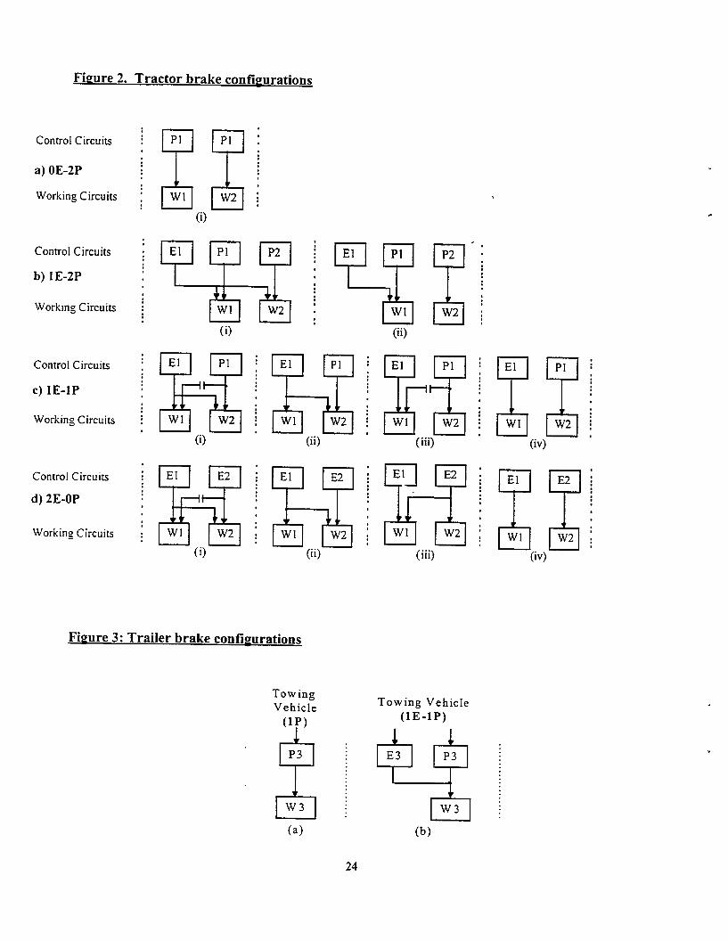

The (0E-2P)-( 1 E- 1 P) combination is functionally equivalent to the conventional tractor trailercombination. The (2E-0P)-( 1 E) is a totally electronic system providing the same level ofredundancy as the conventional pneumatic system. The (2E-0P)-( I E- 1 P) combination is a totallyelectronic system providing equivalent redundancy as the conventional tractor/trailer combination.A potential weakness for these four combinations is that a single control line is used between thetractor and the trailer.
Only the (1 E-l P) trailer is compatible with all three tractor systems. The (1E-l P) trailer combinedwith the (0E-2P) or (2E-1 P) tractor provides the same level of redundancy as the standardpneumatic/AM system. The ( 1 E-1P)-( 1 E- 1 P) combination provides for redundant control of allbrakes plus provides a second control line between the tractor and the trailer potentially improvingsystem reliability.
The ( 1 E-l P) tractor combined with the (1 P) or (1 E) trailer will function but will not provideredundant control of the trailer brakes. Redundant control can be provided for these combinations ifadditional capabilities are added to the tractor or trailer. (See discussion below.) The (0E-2p)-( 1E)and (2E-0P)-( 1 P) combinations are not compatible unless additional capabilities are added to thetractor or trailer.
It is claimed (Ref. 14) that “the fully electric brake by wire system (2E) does not have anyfunctional advantages nor are there any cost savings if you take into consideration the additionalbattery.” This logic would lead to the selection of 1E-1P as the standard for both tractors andtrailers. The added reliability of a second control link between the tractor/trailer is an additionalplus for this combination. Compatibility problems are also less of a concern for the (1E-1P)approach.
Other opinions in the industry see the 2E-0P combination as the low cost final solution for ECBS.To get to this final solution, intermediate steps need to be taken to assure compatibility. Theseintermediate steps include adding additional equipment to the tractor or trailer for those customerswho are interested in compatibility during the transitional period.
Compatibility with OE-1 P trailers with the 2E-0P tractor can be obtained by adding an E to Pconverter. This would involve adding an additional pressure control loop on the tractor to create thepneumatic control circuit for the trailer. Adding a P to E converter on the (IE) trailer would allowcompatibility with OE-2P tractors. This involves adding to the trailer a pressure sensor andappropriate electronics (analog to digital converter) to generate a digital signal which can be used asa reference for the electronic control loops in the trailer.
For each solution put forward, a number of additional compatibility issues should be considered.The most obvious is the interface between the tractor and the trailer. For full compatibility, theinterface must include:
1. a pneumatic supply line
2. a pneumatic control line
3. an ABS/ECBS power connection
26
4. a communications connection (employing a well defined communications protocol)
Techniques must also be developed for automatically identifying the trailer type that is connected.The compatibility of the tractor /trailer (or lack thereof) could be presented to the driver as part ofthe user interface. It is of primary importance that the vehicle brakes are not released if the systemsare incompatible.
Synchronization of tractor trailer brakes is also important. A brake system. of a tractor/trailercombination is considered well synchronized if any differences between tractor and trailer delaytimes and crack pressures are kept to a minimum (Ref. 21). The potential for significant variation inbrake synchronization ECBS equipped tractors and pneumatic/ABS equipped trailers is a problemthat must be addressed for tractor trailer compatibility.
How the backup systems are employed when the primary control circuit fails must also beconsidered. If the tractor’s (trailer) primary circuit fails, what action will be taken? How will thetrailer (tractor) know when to switch to a backup circuit? Will emergency brakes be applied or willthe operator maintain control of the backup system? For full compatibility, standards will need tobe generated that prescribe how this switch-over occurs for all combinations of tractors and trailers.
It is not clear at this time whether the pneumatic backup system associated with the (1E-1P) systemswill include independent ABS capabilities. It can be argued that ABS functionality is not neededfor a backup system which is intended to be used for short periods. It can also be argued that failurecould take place during a braking maneuver when ABS is needed.
7.3 COMPATIBILITY AMONG BRAKE MANUFACTURERS
Compatibility among manufacturers is a complicated issue. Given the wide variety of ECBScombinations that may exist, the varying and potentially conflicting stakeholder opinions, sortingout all the variables will be a daunting task. Decisions made in this area will most certainly effectdecisions related to ECBS configurations discussed in the last section. It is not the intent of thisreport to resolve these compatibility issues. These issues are best resolved through industry groupssuch as TMC and S A E .
7.3.1 Tractor/Trailer Compatibility
There appears to be a consensus among stakeholders (fleets, brake manufacturers, truckmanufacturers and government) that ECBS should be compatible at the tractor/trailer level. Atractor equipped with company A’s ECBS should be compatible with a trailer equipped withcompany B’s ECBS. This demand places a number of constraints on the design of a system. Acommon communications protocol must be used for all compatible systems. The system must bedefined sufficiently to assure true interoperability. In addition, it may be necessary to standardizesome of the functional aspects of the systems. This can also be part of the communications protocolinteroperability guidelines.
If absolute compatibility is desired, then this demand would likely limit the number of featuresincluded in an ECBS-braking system. Specifying a minimum level of compatibility, however,would allow manufacturers to add product distinguishing features that would only be fully used if
27
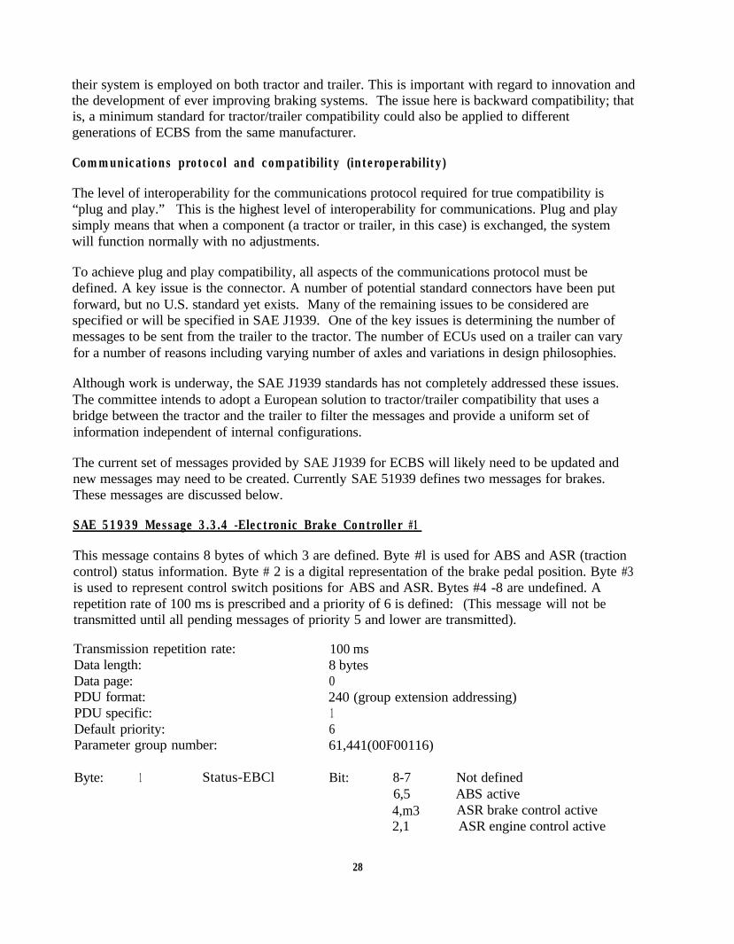
their system is employed on both tractor and trailer. This is important with regard to innovation andthe development of ever improving braking systems. The issue here is backward compatibility; thatis, a minimum standard for tractor/trailer compatibility could also be applied to differentgenerations of ECBS from the same manufacturer.
Communications protocol and compatibility (interoperability)
The level of interoperability for the communications protocol required for true compatibility is“plug and play.” This is the highest level of interoperability for communications. Plug and playsimply means that when a component (a tractor or trailer, in this case) is exchanged, the systemwill function normally with no adjustments.
To achieve plug and play compatibility, all aspects of the communications protocol must bedefined. A key issue is the connector. A number of potential standard connectors have been putforward, but no U.S. standard yet exists. Many of the remaining issues to be considered arespecified or will be specified in SAE J1939. One of the key issues is determining the number ofmessages to be sent from the trailer to the tractor. The number of ECUs used on a trailer can varyfor a number of reasons including varying number of axles and variations in design philosophies.
Although work is underway, the SAE J1939 standards has not completely addressed these issues.The committee intends to adopt a European solution to tractor/trailer compatibility that uses abridge between the tractor and the trailer to filter the messages and provide a uniform set ofinformation independent of internal configurations.
The current set of messages provided by SAE J1939 for ECBS will likely need to be updated andnew messages may need to be created. Currently SAE 51939 defines two messages for brakes.These messages are discussed below.
SAE 51939 Message 3.3.4 -Electronic Brake Controller #1
This message contains 8 bytes of which 3 are defined. Byte #l is used for ABS and ASR (tractioncontrol) status information. Byte # 2 is a digital representation of the brake pedal position. Byte #3is used to represent control switch positions for ABS and ASR. Bytes #4 -8 are undefined. Arepetition rate of 100 ms is prescribed and a priority of 6 is defined: (This message will not betransmitted until all pending messages of priority 5 and lower are transmitted).
Transmission repetition rate: 100 msData length: 8 bytesData page: 0PDU format: 240 (group extension addressing)PDU specific: 1Default priority: 6Parameter group number: 61,441(00F00116)
Byte: 1 Status-EBCl Bit: 8-7 Not defined6,5 ABS active4,m3 ASR brake control active2,1 ASR engine control active
28
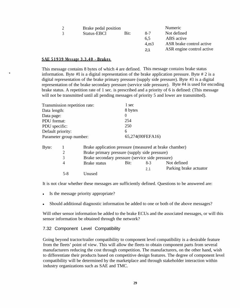
23
Brake pedal position NumericStatus-EBCl Bit: 8-7 Not defined
6,5 ABS active4,m3 ASR brake control active2,1 ASR engine control active
SAE 51939 Message 3.3.40 - Brakes
This message contains 8 bytes of which 4 are defined. This message contains brake statusinformation. Byte #1 is a digital representation of the brake application pressure. Byte # 2 is adigital representation of the brake primary pressure (supply side pressure). Byte #3 is a digitalrepresentation of the brake secondary pressure (service side pressure). Byte #4 is used for encodingbrake status. A repetition rate of 1 sec. is prescribed and a priority of 6 is defined: (This messagewill not be transmitted until all pending messages of priority 5 and lower are transmitted).
Transmission repetition rate: 1 secData length: 8 bytesData page: 0PDU format: 254PDU specific: 250Default priority: 6Parameter group number: 65,274(00FEFA16)
Byte: 1234
5-8
Brake application pressure (measured at brake chamber)Brake primary pressure (supply side pressure)Brake secondary pressure (service side pressure)Brake status Bit: 8-3 Not defined
2,1 Parking brake actuatorUnused
It is not clear whether these messages are sufficiently defined. Questions to be answered are:
l Is the message priority appropriate?
l Should additional diagnostic information be added to one or both of the above messages?
Will other sensor information be added to the brake ECUs and the associated messages, or will thissensor information be obtained through the network?
7.32 Component Level Compatibility
Going beyond tractor/trailer compatibility to component level compatibility is a desirable featurefrom the fleets’ point of view. This will allow the fleets to obtain component parts from severalmanufacturers reducing the cost through competition. The manufacturers, on the other hand, wishto differentiate their products based on competitive design features. The degree of component levelcompatibility will be determined by the marketplace and through stakeholder interaction withinindustry organizations such as SAE and TMC.
29
Component level compatibility calls for standardizing all aspects of the ECBS design. This willinvolve several standardization efforts working together with SAE and TMC. The goal of thesestandardization efforts is to sufficiently design the ECBS systems so that each component can bedefined in terms of functionality, mechanical interfaces, electrical interfaces, and pneumaticconnections.
A decision will need to be made with regard to the number of ECUs employed on both the tractorand the trailer. Will an ECU service an axle or a wheel? Sensor and actuator connections will needto be specified including connector type, signal definition, and electrical properties of the signal.Common mounting strategies for each component will need to be standardized. Finally, thepressure control loops will also need to be standardized. This will involve specifying the accuracyand timing of the control system.
8 SENSORS FOR DIAGNOSTICS AND IMPROVED BRAKING PERFORMANCE
Initially ECBS will incorporate a limited sensor package. Sensors for monitoring supply tank airpressure, brake chamber air pressure, and an ABS wheel sensor can provide sufficient capabilitiesfor fielding ECBS. Additional information regarding the status of the communications bus will alsobe available to the diagnostic system. Even this limited set of information can be used to provide asignificant diagnostic capability. Diagnostic capabilities and brake functionality can beconsiderably enhanced by introducing additional sensors.
8.1 BRAKE DIAGNOSTIC SENSORS
Brake system monitoring can be divided into brake status monitoring and brake performancemonitoring. As defined in a recent FHWA study of onboard diagnostic equipment (Ref. 16), brakestatus monitoring is intended to ‘monitor key variables that correlate to impending system failures.”Here the definition of brake status is modified as: “‘static measurements (vehicle not moving) thatcan correlate to impending system failure.”
Brake performance monitoring is defined as: dynamic measurements (vehicle moving) that cancorrelate to impending system failure or indicate serious system performance degradation.Performance monitoring can result in an immediate notification to the driver of a problem or astorage of information about selected brake applications. This historical information is stored onthe vehicle for later access by authorized personnel. The system can be designed to store sensorinformation for the last several brake applications and/or for braking applications that involveextreme conditions. For example, a set of historical braking information may include all sensorreading for the last 5 brake applications and for braking applications when ABS was activated andwhen maximums were observed for brake shoe temperature, brake chamber pressure, and braketorque.
ECBS brake system status and performance can be determined by monitoring brake adjustmentparameters (push rod stroke or brake shoe travel), brake lining wear, brake system air leaks (brakechamber pressure and/or compressor duty cycle), brake torque, brake shoe temperatures andcommunication bus status. The relationship to brake function for these parameters is discussedbelow:
30

[ ] Brake adjustment / push rod stroke (brake status)
The current method for checking brake adjustment utilizes a measurement of push rod strokeduring a static brake application. While the inspector is underneath the truck, the driver isinstructed to apply the brakes. The inspector notes the push rod travel and compares this with amaximum allowable value. A sensor to measure push rod stroke or alternatively brake padtravel would eliminate the need for manual inspection of brake adjustment.
[ ] Brake shoe thickness (brake status)
When possible, brake shoe thickness is measured during roadside inspection. This inspection isdone visibly if an inspection dust cover or sight hole is provided. If no opening is provided toinspect the shoe, the measurement cannot be made without removing the wheel assembly. Inthese cases, brake linings are not inspected at the roadside. A brake lining sensor wouldeliminate the need for manual inspection of brake linings.
[ ] Brake system air leaks (brake status and brake performance)
Brake system air leaks are a critical part of roadside inspections. Roadside inspectors check forair leaks simply by observing the air reservoir gauge and by simply listening to them. Theprocedure is to have the driver run the engine at idle and then apply and hold the service brake.The inspector observes the air reservoir gauge on the dash until it drops to 80 psi. At that point,the compressor should activate and the air pressure should remain the same or increase. A dropin pressure indicates a serious leak in the air system.
An onboard method for detecting air leaks could include adding diagnostic software to interpretthe reservoir air pressure signal in the same manner as the inspector. This would involve noadditional sensors. An alternate method would be to correlate air compressor activity withleaks. To distinguish leaks from frequent or heavy brake activity, it would be necessary tocorrelate brake activity (as observed on the communications bus) with compressor activity.
[] Brake torque sensor (brake performance)
Brake torque sensors can provide direct evidence of reduced braking efficiency. It does not,however, identify the root cause of the problem. If the brake torque sensor is used as part of theactive control loop, an inability to supply the commanded brake torque would result. If thetorque sensor is not used as part of the active control loop, the resulting torque could becompared with the expected torque given the pressure in the brake chamber. The driver couldbe warned about a serious reduction in braking torque by using a lamp or other user interface.In addition, the time and sensor information related to the low torque event could be stored forlater retrieval by inspectors or maintenance technicians.
q Brake temperature sensor (brake performance)
Brake temperature is currently not actively monitored. Maintenance technicians do, however,look for signs of high temperature such as discoloration of metal parts. By measuring thetemperature of the brake shoe, the driver could be warned by using a lamp or other userinterface. This information could help a driver avoid the situation of brake fade due to
31

excessive brake shoe temperature. In addition, the time and sensor information related to thehigh temperature event could be stored for later retrieval by inspectors or maintenancetechnicians.
[] Communication bus status (brake status and brake performance)
Communications bus failure constitutes a serious brake failure. As with the sensor relatedproblems, a failure of the communications bus that Iasts for more than a specified period of timecould be communicated to the driver and stored as a time-stamped event for later retrieval byinspectors or maintenance technicians.
8.2 DIAGNOSTIC TOOLS
For diagnostic capabilities to be most effective, properly designed diagnostic tools must beavailable. The design of the diagnostic tools is an important part of the communication protocolstandard. Diagnostic tool design raises issues related to standardization of diagnostic informationwithin a braking system and security measures. A diagnostic tool includes a means of accessing thediagnostic information (a query method), a means to interpret diagnostic information, and a meansfor displaying the information to the operator (driver, technician or inspector).
Onboard diagnostic displays currently being considered include red and yellow light indicators tothe driver. The red light indicates a serious brake failure while the yellow light indicates a minorbrake defect. ECE regulation R-13 has specified a set of light indicators for tractor trailercombinations. Four lights are used: a red-yellow light pair is used for indicating tractor faults, anda second red-yellow light pair for indicating trailer faults. It may also be useful to provide thedriver with a means of accessing fault codes which can be communicated to maintenance personnelor dispatchers.
Maintenance personnel will require a much more sophisticated diagnostic tool. Some sort ofalphanumeric and/or graphical display will likely be necessary. The system, depending on itscomplexity, can be a hand-held device, a laptop or desktop computer. In either case, the diagnosticdevice should be able to access all brake status and stored brake performance information. Thediagnostic tool should be designed for intuitive operation reducing the training required for thetechnician and reducing the potential for misinterpreting information.
Roadside inspection will require a diagnostic tool similar to that for maintenance personnel. Themain difference will be security measures that will be built into either the onboard network or thediagnostic tool. The inspector will only have access to information required by the inspectionprotocol. The network link to the inspector will also need to be considered. A wireless link willensure that connecting the diagnostic system does not introduce electrical faults into the system andmay provide a means for gathering inspection information without stopping the vehicle.
8.3 SENSORS FOR ENHANCED BRAKING CAPABILITIES
ECBS stopping capabilities may be enhanced through the addition of appropriate sensors. Thesensor information would be used to modify the control of brake chamber pressure for each wheelin an attempt to provide shorter and more controlled braking maneuvers. The possibility of adding
32
sensors for the purpose of advanced control of braking and handling is given below. Brakingstrategies will be discussed at a very general level and no attempt will be made to determine themerit of any specific strategy.
It is important to point out that most of the braking strategies considered are a compromise betweentotal stopping distance and vehicle control. (Stopping distance usually must be lengthened to obtainmore control.) In addition, automated braking strategies remove decision making from the driverwho can adjust his braking strategy based on the situation. The appropriateness of any specificbraking strategy should be carefully analyzed for effectiveness in avoiding and reducing the severityof crashes under a variety of driving conditions.
The addition of multiple sensors to a braking system could also negatively impact the systemreliability. The consequences of sensor failure should be carefully scrutinized as part of a formalfail-safe analysis.
Sensors for advanced braking strategies:
[] Torque sensor:
A direct measurement of braking torque would provide the most direct measurement of brakingeffort for each w heel. With the application of a brake torque sensor, a braking command couldbe interpreted as a request for a specific braking torque rather than a brake pressure. Within theaccuracy of the sensors, the braking for all wheels can be precisely balanced.
[] Axle load sensor:
A direct measurement of axle load would provide a means for adjusting the brake pressure.(orbrake torque if used in conjunction with a torque sensor) for each axle. This could, in principle,reduce stopping distances (Ref. 14, 15). Brake pressures are controlled for equal frictionloading. This results in reducing the onset of ABS as‘long as possible.
[] Coupling force sensor:
A coupling force sensor can be used to minimize the forces between the tractor trailer duringbraking.
9 REGULATORY ISSUES
Within the current regulations (FMVSS No. 121) (Ref. 17), ECBS are not allowed. In this sectionwe will explore a number of issues related to the modification or adoption of regulations that wouldallow various forms of ECBS. Regulations that consider ECBS as an allowed option areconsidered. No consideration is given to the possibility of mandating ECBS.
Efforts are currently underway to establish performance criteria for pneumatic braking systems(Ref. 18, 19). These efforts are focused on the in-use performance of braking systems. Issues beingconsidered are braking component variations that can degrade braking performance, and inspectionand test procedures that can be used to identify component related problems.
33
These issues, for the most part, are outside the scope of this effort. The discussion here will beconfined to issues related to ECBS. However, issues related to overall brake and overall electronicsystems’ performance will be discussed at a general level.
9.1 REGULATORY ISSUES AND STAKEHOLDER COMMENTS
ECBS specific regulatory issues to be considered are listed below together with a summary ofstakeholder comments.
A list of the questions asked to the identified stakeholders and a summary of the responses to eachquestion are given below:
[] What variations of ECBS should be allowed within the regulations?
A consensus opinion among the stakeholders is in favor of allowing all redundant combinationsof ECBS.
[] Should FMVSS No. 121 be modified to allow ECBS or should a new performance basedregulation be established for all braking systems?
Most of the interviewed stakeholders were in favor of new performance based regulations. Theindustry as a whole appears to view prescriptive regulations such as FMVSS No. 121 as animpediment to innovation. In addition, a number of stakeholders observed that it is difficult toprescribe safety into the design of a complex system involving electronics, software, andasynchronous communications.
[] What specific changes should be made to FMVSS No. 121 to allow ECBS?
A document suggesting possible changes to FMVSS No. 121 for the addition of ECBS has beenproduced by the SAE Truck and Bus Task Force-Future Brake Systems Forum. This documentis reproduced in the next subsection as an example of how FMVSS No. 121 can be modified toinclude ECBS. The document represents a recommendation for minimal changes to theregulations. The document does not address the issue of fail-safe performance (electronics,software, and communications safety) in any depth.
[] Should stopping capabilities requirements for ECBS be different than for standard brakingsystems?
There appears to be little agreement over defining stopping capabilities within a regulation. Thecollected opinions covered a wide range of opinions and included the following divergent views:“The stopping capabilities for ECBS should not be different than those specified in FMVSS No.121”; and “The brakes should be able to safely stop the vehicle under all driving conditions.”
[] Should regulations address compatibility among different brake manufacturers? Shouldregulations address compatibility with older pneumatic/ABS? Should SAE J1939 be mandatedas the inter-vehicle communications standard for ECBS?
34

Most interviewed stakeholders agreed that these three issues are best resolved at the voluntarystandards level. Efforts within SAE and TMC are currently addressing these issues.
[ ] At what level should system safety/ fault tolerance (electronic, communication, and softwaresafety) be addressed in the regulation?
Here also, there is little agreement among the stakeholders. Comments ranged from regulationsshould hold manufacturers responsible for the safety, reliability, durability, and maintainabilityof the systems throughout the product life cycle to regulations should not address these issues.
9.2 POSSIBLE CHANGES FMVSS No. 121
A report has been produced by the Heavy Duty Brake Manufacturers Association that suggestedchanges for FMVSS No. 121 to allow ECBS (Appendix Al). The document addresses a number ofdefinitions and attempts to parallel many of the pneumatic requirements with “equivalent”electronic requirements. For example, batteries used for ECBS are compared to air reservoirs. Thedocument briefly addresses the issues of fault detection and indicator lamps for the driver. Theissues of tractor/trailer compatibility are also addressed. The important issue of fail-safeperformance is not addressed in any depth.
If the regulation is to consider fail-safe issues, specifications for operation and testing of each ECBSnode (ECU and associated sensors) will need to be added. The specifications should assure that thenode will operate or fail-safe under all operating conditions. Each node has the potential to fail. Thequestions are how likely is the node to fail and how will these potential failures manifestthemselves.
For example, consider the pressure sensor used in brake sensor control loop. If the press&e sensorfails, will it fail in a high state (maximum pressure reading), a low state (minimum pressurereading) or in an unknown state (serious change in calibration)? Will redundant sensors be used to’assure that a single sensor failure can be identified? What action will be taken if a failure occurs?Will exception messages be defined to inform the other nodes and the driver of the error and theseverity of the error?
In addition, network failures will need to be considered. The addition of network failures iscomplicated since non-ECBS nodes on the network can be the cause of communications failure.Some have suggested that a separated ECBS subnet be employed to avoid this problem. Alsonetwork failures can effect one or all of the braking nodes. This can lead to a multitude ofsituations where some nodes are operating normally while others have lost communications.
9.3 AAR SPECIFICATIONS FOR ELECTRONIC BRAKING SYSTEM FOR FREIGHTTRAINS
The work done by the American Association of Railroads (AAR) in the area of electronic brakes forfreight trains can provide some guidance for changing FMVSS No. 121. The AAR has developed adesign specific specification for ECBS. The specification, based on over five years of design andtesting, was adopted in May 1997. The four documents that make up the specification deal withmany of the important issues related to safety critical systems.
35

The AAR specifications include a number of important issues related to fail-safe operation.Although the failure modes applicable to rail applications are not necessarily applicable to trucks,the AAR specification can still provide some guidance.
The AAR specification is currently comprised of four documents: S4200, S4210, S4220, S4230.These documents are reproduced in Appendix A-2, A-3, A-4, A-5. A brief review of thesedocuments is given below.
S4200 PERFORMANCE REQUIREMENT FOR TESTING ELECTRICALLY CONTROLLEDPNEUMATIC CABLE-BASED (ECP) FREIGHT BRAKE SYSTEMS
The overall objectives of this specification are;
1. Assure that the performance of electrically controlled pneumatic (ECP) freight brakesystems is uniform and consistent among equipment from different manufacturers.
2. Assure that cars equipped with AAR approved ECP brake systems from differentmanufacturers can be operated together in any electrically braked train.
3. Assure that AAR approved electric brake systems meet a high standard level of safetyand reliability.
S42 10 PERFORMANCE SPECIFICATION FOR ECP BRAKE SYSTEM CABLE,CONNECTORS AND JUNCTION BOXES
Objective:
To establish the qualification test procedure for an electric brake trainline connector, cable andend-of-car junction box. The qualification test procedure is intended to verify that the designedcomponents have high reliability, will withstand harsh environmental conditions, and have aminimum of an 8-year operating life.
This standard applies to ECP brake system power and signal cable intended for use oninterchange freight cars and locomotives equipped with AAR-approved ECP brake systems.
S4220 PERFORMANCE SPECIFICATION FOR ECP BRAKE DC POWER SUPPLY
Objective:
The purpose of the ECP power supply is to provide the battery charging supply from thelocomotive(s) in the consist (train) to each car, through the hardwire trainline, sharing the sameconductors with the communication signals (power line overlay mode). It is therefore essentialthat the quality of the electrical power supplied to the line be sufficiently well controlled so asnot to interfere with the communications.
S4230 INTRA-TRAIN COMMUNICATION SPECIFICATION
36
This specification is to define the requirements for an intra-train communications system forfreight equipment in revenue interchange service. The specification is intended to facilitateinteroperability between freight cars and locomotives, without limiting the proprietary designapproaches used by individual suppliers.
9.4 DESIGN NEUTRAL PERFORMANCE BASED REGULATION .
Within a performance based regulation, the requirements for ECBS stopping capabilities can likelyremain as stated in FMVSS No. 12 1. The addition of stopping tests that demonstrate the addedbenefit of ECBS control can be considered but are not essential. A more complex aspect of aperformance based regulation is specifying the system safety and reliability (fail-safe operation).
ECBS is a double-edged sword as it pertains to the safety and reliability of braking systems. Asdiscussed in previous sections, advanced electronic control techniques may provide for improvedbraking performance and improved vehicle control in a variety of situations. In addition, advanceddiagnostic features of ECBS, when equipped with the proper sensor input, can provide a continuousassessment of the vehicle braking capabilities. Diagnostic capabilities can also provide for a moreefficient and effective roadside inspection.
On the other side, complex systems involving electronics, software and communications are subjectto unexpected and unpredictable failures. This potential for unexpected failures is greatly reducedthrough the application of appropriate design processes and failure analysis techniques.
Specifying performance standards within a regulation for fail-safe operation is a difficult task. Toinvestigate this approach it appears wise to consider standards and methods from other industrieswith more experience in these areas. The FAA has a long history of successfully developing andapplying performance based regulations for complex electronic systems. (A review of applicableFAA regulations is given in Appendix A-6.)
9.4.1 FAA Regulatory Model
As an exercise, an attempt to adapt the FAA regulatory language to ECBS is given below. Thisinformation is presented not as a proposed regulation but as a starting point for discussion. In thisexercise it should be remembered that the fail-safe requirements for aircraft are considerably morestringent than what is needed for a ground vehicle. Aircraft systems must be designed to “failoperational" standards. That is, the aircraft systems must continue to function (remain in the air)when a fault or series of faults occur. Ground vehicles can and are designed for “fail silent”operation. That is, when a fault is detected, the vehicle is stopped. Fail silent operation is easier toachieve and results in lower development and system component costs.
The following is one possible adaptation of language used in FAA regulations applied to ECBS.Changes to the FAA language have been made to include language for fail silent performance to theexisting language for fail operational performance.
Modified FM Regulations
37
(a) The equipment, systems, and installations of ECBS equipment must be designed so that they:
(1) perform their functions under any foreseeable operating conditions, or
(2) safely stop the vehicle when a serious fault occurs.
(b) The ECBS and associated components, considered separately and in relation to other electronicsystems, must be designed so that:
(1) the occurrence of any failure condition which would prevent the continued safe driving orstopping of the vehicle is extremely unlikely or is detectable by the system;
(2) the occurrence of any other failure (with non ECBS electronic equipment) would either notreduce the effectiveness of the system or be detectable by the system.
(c) Warning information must be provided to alert the driver to unsafe operating conditions andenable him to take appropriate action. System controls and associated warning systems meansmust be designed to minimize driver errors which may create additional hazards.
(d) Compliance with the requirements of paragraph (b) of this section must be shown by analysis(FEMA, FMECA, Fault Tree Analysis, etc.) and where necessary, by appropriate tests. Theanalysis must consider:
(1) possible modes of failure, including malfunctions and damage from external sources;
(2) the probability of multiple failures and undetected failures (this could be changed to anysingle failure);
(3) the resulting effects on the vehicle and driver, considering the possible vehicle operatingconditions; and
(4) the driver warning cues, corrective action required, and the capability of detecting faults.
The very general language used above and in the FAA regulations signifies the fact that it isdifficult to prescribe safety and reliability for complex systems. Safety for such systems can be bestachieved through the application of appropriate design processes and analysis and testingprocedures.
Regulatory Compliance
Within a generally worded performance-based regulation one must consider how regulatorycompliance is achieved. The FAA takes a very active role working with aircraft manufacturers andcarriers to assure that the systems are adequately analyzed and tested. This costly and timeconsuming approach is probably not applicable to the trucking industry. Some level of self-compliance seems more appropriate.
The ECE is currently considering a form of self compliance that may be applicable. The concept isto develop an ISO 9000 type procedure for self compliance (ECE regulations are discussed in
38

Appendix A-7). The procedure will clearly define all aspects of the compliance process includinganalysis, testing, and all associated documentation-
In addition to the general Ianguage about safety and reliability, a number of more specific minimumstandards could be added. The manufacturers would be free to design and implement systems thatrepresent an improvement over the minimum standards. In addition, incentives could be providedto encourage fleets and manufacturers to add desirable features to the system. Examples ofminimum standards and incentive-based features are given below: .
1. Compatibility
In any regulation, specific language will be needed to assure that the potential incompatibility oftractors and trailers does not pose a safety risk. As discussed in the section on tractor/trailercompatibility, there are a number of options for obtaining compatibility. SAE and TMC are theappropriate forums for developing compatibility specifications.
2. Diagnostic capabilities
As discussed in a previous section, the most basic ECBS systems will include sensors forpressure regulation and wheel sensor for ABS operation. The system will also have knowledgeof the communication status. Based on this information, a minimum level of diagnosticinformation can be specified within a regulation together with storage and display requirements.
Additional sensors can also be considered. These sensors can be selected to provide a morecomplete real-time onboard diagnostic information or to provide a more complete set ofinformation for roadside inspection. The addition of these sensors can be a regulatoryrequirement or can be part of an incentive package. The major benefit to the fleet for thispackage would be reduced roadside inspection burden.
3. Minimum safety analysis and testing
In general, effective safety assurance processes are being applied within the industry. Majormanufacturers of ECBS likely employ sophisticated safety analysis procedures to assure thesafety and reliability of their products. As discussed in previous sections, a variety oftechniques can be used to obtain the desired outcome. In addition, standards exist for FEMAanalysis within SAE (Ref. 20).
A performance regulation may wish to address this area to assure that competitive pressures donot unduly influence manufacturers to cut comers. This may be of particular concern for smallcompanies that wish to produce third part replacements for braking systems. If this were thecase, several steps could be taken to assure that an appropriate safety analysis is carried out.Regulations could specify the SAE FEMA standard as a minimum requirement that could bereplaced by an equivalent or superior process. The SAE FEMA standard may need to beupdated to better include software safety and reliability.
In addition, regulations could provide manufacturers with analysis requirements such as a list ofpotential hazards (i.e., uncommanded brake application, loss of brake pressure) to be consideredin the safety analysis process.
39

9.5 CLOSING REMARKS
ECBS, as the first of several safety critical electronic systems to be installed on heavy trucks,represents an opportunity to develop a technology independent framework for safety assurance. Adesign-neutrai systems approach to safety assurance can provide a high level of confidence within aregulatory model that will encourage advancement of technology and safety assurancemethodologies.
To accomplish this, a substantial level of communication and cooperation among all stakeholderswill be needed. Efforts currently underway within SAE, TMC, and at ITS America offer the bestsettings for accomplishing these goals. It is recommended that NHTSA and FHWA play an activerole in these efforts in order to facilitate the cooperation of the industry stakeholders and to betterunderstand the needs of this rapidly evolving industry.
10 9 RECOMMENDATION FOR FURTHER STUDY
10. 1 TRACK TESTS
The next step in the evaluation of ECBS is to carry out a series of track tests that will quantify anumber of performance and compatibility features. This effort will require a significant level ofcooperation between an independent test organization (ITO), and industry partners (primarily thebrake manufacturers and the truck manufacturers). The industry partners’ primary responsibilitywill be to provide the tractors and trailers equipped with ECBS. The ITO’s primary responsibilitywill be to impartially carry out the tests and data analysis. The IT0 and industry partners will worktogether with other industry stakeholders to define a detailed test protocol and associated datacollection systems.
The test protocol can address a number of ECBS issues including stopping distance, vehicle controlduring stopping maneuvers. and tractor/trailer compatibility. The test protocol should be carefullycrafted to highlight the benefits of ECBS. It is also important that the detailed test protocol beacceptable to all industry stakeholders. An industry forum, such as the SAE Future Brake SystemForum, is an appropriate venue for presenting the test protocol for industry comments. The testsshould measure stopping distance and other important parameters associated with vehicle controland tractor/trailer compatibility. This will include combinations of tests on straight and curvedtracks each with normal friction. reduced friction and split friction surfaces (half the wheels on anormal friction surface and half on a reduced friction surface).
Tractors and trailers equipped with a (1E-1P) ECBS configuration are the best choice for these tests.The (1E- 1P) systems provide compatibility with conventional tractors and trailers. For this reasonthe (1E-1P) system is expected to be the standard for some time (Ref. 21).
The data collection system must acquire the information needed to quantify the capabilities of thevarious combinations of braking systems. Stopping distance can be measured simply with markingson the track or by using an optical range finder. Vehicle control can be best quantified byemploying accelerometers and yaw rate sensors in key locations on the tractor and trailer.Tractor/trailer compatibility can be measured by monitoring the pressure for each wheel in order todetermine the synchronization of brake application (Ref. 21). Measuring the coupling force
40

between the tractor and the trailer will also provide an indication for tractor/trailer compatibility.
The stopping capabilities of ECBS systems in various tractor trailer configurations can be tested andcompared to stopping performance for a standard pneumatic/ABS brake system. Potentialconfigurations to be tested include:
. Conventional pneumatic /ABS system
l ECBS tractor and conventional trailer
l ECBS tractor and trailer
By including these three configurations, the benefits of the full ECBS and tractor only ECBS can bedirectly compared to the conventional braking system.
10.2 TECHNICAL REVIEW OF CRITICAL SOFTWARE DEVELOPMENT PROCESSES
A number of recent advancements have been made in software risk management under sponsorshipof ARPA at the Carnegie Mellon Software Engineering Institute. As with earlier work in electronicrisk management, such as FMEA, these processes are becoming a requirement for military systems.They are also beginning to flow from the military to the commercial sector. Examples of formalprocesses that apply to ECBS and other onboard safety systems are:
The Capability and Maturity Model (CMM)
The Capability Maturity Model for software describes the principles and practices underlyingsoftware process maturity in terms of an evolutionary path from an ad hoc chaotic process to amature disciplined process. The defined maturity levels are:
1. initial
2. repeatable
3. defined
4. managed
5. optimized
The effectiveness and reliability of the software developed is believed to increase as the softwaredevelopment process moves up the five levels.
Rate Monotonic Analysis (RMA) for Real Time Systems
RMA is a collection of quantitative methods that enable real time system developers to understand,analyze, and predict the timing behaviors of real time systems. The proper application of thismethodology can lead to a better understanding of the risks involved in a safety critical softwaresystem.
41

Team Risk Management ( T R M )
Team Risk Management defines the organizational structure and operational activities for managingrisks throughout all phases of a software development program. It defines the role of allparticipating team organizations, groups, and agencies directly involved in the program. Thegovernment and contractors are provided with processes, methods, and tools that enable bothorganizations to better anticipate outcomes and make better decisions.
These new processes and methods can provide NHTSA with a solid foundation for introducing riskmanagement concepts into new regulations (Ref. 22). They can also form the bases for extendingindustry-based recommended practices for software development system reliability. Managementtools, such as TRM, can also be used to coordinate the development and eventual integration ofmultiple collision warning systems.
We propose that NHTSA initiate a program to review the application of these and other applicabletechniques to ECBS and other safety critical onboard systems. The proposed report will detail thefundamentals of the applicable processes such as CMM, RMA, and TRM and suggest how theymay be used by NHTSA as part of its R&D and regulatory processes.
42
11 REFERENCES
1. Hecker, F.. Hummel, S., Jundt, O. Leimbach. D., Faye, I., and Schramm, H.. “Vehicle DynamicsControl for Commercial Vehicles ” Proceedings of the I997 SAE Truck and Bus Meeting andExposition, November 1 7-20, 199 7.
2. Ervin. R., Fancher, P.. Christopher, W., “Heavy Truck Stability Enhancement” Proceedings ofthe Third Annual Automotive Enhanced Driving /Night Vision Conference, September 16-1 7,1997.
3. “The Seven Layer Reference Model. ‘* UNI Corporation http://bbs-win.uniinc.msk.ru/tech1/1994/osi/layers.htm.
4. Surface Vehicle Recommended Practice, SAE 1939/1 I. Physical Layer-25OK bits/s, ShieldedTwisted Pair
5. Surface Vehicle Recommended Practice, SAE 1939/21, Data Link Layer
6. Surface Vehicle Recommended Practice, SAE 1939/71. Vehicle Application Layer
7. Surface Vehicle Recommended Practice, SAE 1939/73, Application Layer - Diagnostics
8. Fredriksson, L.-B., “Controller Area Networks and the Protocol CAN for Machine ControlSystems, ” Mechatronics, Vol. 4, No. 2, pp. 159-192, 1994.
9. "Using Fault Tree Analysis in Developing Reliable Software. ” Ovstedal, E.O., IFAC Safecomp‘91 Trondheim Norway, 1991.
10. Jacobson, J.. Johansson, L.-A., Lundin, M., “Safety of Distributed Machine Control Systems, ”Swedish National Testing and Research Institute; BorAs, Sweden 1996 ECBS Brakes in the RailIndustry.
I 1. ANSI/IEEE “Standard Glossary of Software Engineering Terminology ”
12. Graciv, R. B. “Practical Software Metrics for Project Management and Process Improvement, ”Prentice Hall, Englewood Cliffs, NJ, 1992.
13. “Performance Prediction of the SAE JI 8.50 and Related Buses for In- Vehicle CommunicationsRequirements for the ITS Safety-Related User Services, “preparedfor DOT/NHTSA/OCARunder contract no. DTNH22-93-D-07317.
14. Decker, H., Wrede, J., “Brake-by- Wire Solutions, Advantages and the Need forStandardization, ” Bosch 1994.
15. Decker, H., Wrede, J., “Brake-by- Wire for Commercial Vehicles, ” SAE International Truck andBus Meeting and Exposition, November, 1992.
43

16. Middleton. Dan, et al,, “Assess the Feasibility of a Standardized EIectronic Diagonostic Devicefor Maintenance and Inspection of Commercial Motor Vehicles, ” Texas TransportationInstitute, Texas A&M University System, April 1995, Report No. FHWA-MC-97-070.
1 7. Federal Motor Vehicle Safety Standards: Air Brake Systems, U.S. Department ofTransportation, National Highway Transportation Administration, 49 CFR Part 571, March1997.
18. “Heavy Vehicle Air Brake Performance, ” National Transportation Safety Board Safety Study,Report No. NTSB/ss-92-01, April 29, 1992.
19.. “Performance Criteria for Air Brake Component Combinations on In-Use Commercial MotorVehicles, ” U.S. Department of Transportation, Federal Highway Administration, FHWA-MC-96-008, June 1996.
20. Surface Vehicle Recommended Practice, SAE 1739, Potential Failure Mode and EffectsAnalysis in Design (Design FMEA) and Potential Failure Mode and Effects Analysis inManufacturing and Assembly Processes (Process FMEA) Reference Manual.
21. Lindemann, K., Petersen, E., Schult. M., Korn, A., "EBS and Tractor Trailer BrakeCompatibility, ” Proceedings of the SAE Truck and Bus Meeting and Exposition, November I7-19, 1997.
22. Willke. T. L., Shires, TM., Cowgill, R.M., Selig, B.J.. “U.S. Risk Management Can ReduceRegulation. Enhance Safety, ” Oil & Gas Journal, June 16, 1997.
44
Al PROPOSED CHANGES TO FMVSS NO. 121
The following is a report supplied by the heavy duty truck manufacturers as a contribution to thistask order.
Authors: Richard HildebrandtPaul Oppenheimer
A-l

SAE EBS Working GroupFMVSS 121 Modifications for Electronic Controlled Air Brake Systems
FMVSS 121 AIR BRAKE SYSTEMS
Re-Draft to accommodate Electronic Control of Service, Emergency and Parking Brake Systems
(Amendments and additions are in italics).
S4 . Definitions
“Agricultural commodity trailer” means a trailer ..and an arrangement of airand/or electricalcontrol lines and reservoirs that minimizes damages in field operations
"Air brake system" means a systemmechanical componentsAn Electronic Controlled Brake System (ECBS) is also considered to be an air brake system.
"Data communication " means the transfer of da ta
"Electronic Controlled Air Brake System" means an air brake system that uses electronic control totransmit signals from the driver control to a compressed air system which actuates the service brakes.This definition includes full pneumatic, full electrical and combined pneumatic/electronic controlsystems.The emergency and parking brake systems may also use electronic control signals from thedriver controls.
"Electric trailer control line" means an electrical connection between towing vehicles and towedvehicles, which provides the braking control function. It comprises the electrical wiring and theconnectors and includes the parts for data communication and the electrical energy supply for the controltransmission of the towed vehicle.
"Pulpwood trailer" means a trailer and an arrangement of airand/or electricalcontrol lines and reservoirs designed to minimize damage in off-road operations
S5 Requirements
S5.1.2A Air reservoirs
S5.1.2B Electrical energy reservoirs (batteries)a) In the event of a failure of the electrical energy source and starting from the nominal value of thebattery energy level, as specified by the vehicle OEM, after 10 minutes of full-treadle brake application.it shall meet the requirements specified in S5.3.1
b) When the battery voltage falls below a value at which the stopping distances specified in S5.3.1 can nolonger be achieved the red brake system indicator lamp specified in S5.1.5B shall be activated.
c) After the red brake system indicator lamp has been activated it should be possible to apply the serviceand parking brake controls and obtain at least the emergency braking performance specified in S5.7.1.and the parking brake performance specified in S5.6.1 or 5.6.2, respectively.
A-2

SAE EBS Working GroupFMVSS 121 Modifications for Electronic Controlled Air Brake Systems
S5.1.5A Warning signal
A signal . . . . . . . . audible and visualA red brake system indicator lamp as specified in S5.1.5.B may be used to satisfy this requirement.
S5.1.5.B Brake system indicator lamp
Each motor vehicle equipped with ECBS shall have one red brake system inidicator lamp and if thevehicle is designed to pull trailer(s), the motor vehicle shall have another red brake system indicatorlamp for the trailer brake system, the lamp(s) mounted in front of an in clear view of the driver, whichmeets the requirements of S5.1.5.B(1) through S5.1.5.B(3)
S5.1.5.B(1)
The brake system indicator lamp shall be activated whenever the following conditions occur:
(a) A loss of electrical continuity (e.g. breakage, disconnection) in the service brake control system(excluding the battery) such that the stopping distances specified in S5.3.1 can no longer be achieved.
(b) When the battery voltage falls below a value at which the stopping distances specified in S5.3.1 canno longer be achieved
(c) A loss of electrical continuity (eg. breakage, disconnection) in the parking brake control system(excluding the battery) such that the performance specified in S5.6.1 or S5.6.2 can no longer be achieved.
(d) When a truck tractor without a pneumatic control line is coupled to a trailer without an electricaltrailer control line. (figure 4)
Additionally, any truck tractor with ECBS connected to a trailer with ECBS via an electric trailer controlline shall activate the trailer brake system indicator lamp whenever the following conditions occur-
(c) A loss of electrical continuity (eg. breakage, disconnection) in the trailer service and parking brakecontrol systems such that the retardation forces specified in S5.4.1 and 5.6.1 or 5.6.2. respectively, can nolonger be achieved.
(f) When there is an electrical failure (eg. interruption or defect in the data communication) in theelectric trailer control line.
S5.1.5.B(2)
The indicator lamp shall rematn activated as long as on above mentioned condition exists, whenever theignition (start) switch is in the "on " position whether or not the engine is running. Each message aboutthe existence of such a condition shall be stored after the ignition switch is turned to the "off" positionand automatically reactivated when the ignition switch is again turned to the “on” position.
A-3

SAE EBS Working GroupFMVSS 121 Modifications for Electronic Controlled Air Brake Systems
S5.1.5.B(3)
The indicator lamp shall also be activated as a check of lamp function whenever the ignition is turned tothe "on" or "run" position. The indicator shall be deactivated at the end of the check of lamp function unless there is on above-mentioned condition or a message about such a condition that existed when thekey switch was last turned to the "off" position.
S5.1.6A Antilock Brake System
S5.1.6.B Electronic Controlled Brake System (ECBS)
(a) The electric trailer control line (signal) shall transmit braking data between the tractor and trailer(s)for control of trailer(s) braking. Other information may be transferred by this line provided that thebraking functions have priority and are maintained in the normal and failed modes. The transmission ofother information shall not delay the braking functions.
(b) A truck tractor equipped with an electric trailer control line and pneumatic control line shall recognize that the coupling of a trailer equipped only with a pneumatic control line is not compatible;and when the system is energized the brakes on either vehicle shall be automatically applied with atleast the effectiveness prescribed for the parking brake performace in S5.6.1 or 5.6.2. The red indicatorlight (S5.1.5.B(1)(d), together with the trailer. A RS malfunction light (S5.1.6.2(b)). shall warn the driver.See Figure 4.
(c) In the case of a truck tractor equipped with both pneumatic and electric trailer control lines, bothcontrol signals shall be present at the coupling head and at the connector. When such a truck tractor isconnected to a trailer which is also equipped with both pneumatic and electric trailer control lines. thenboth signals shall be present at the trailer, and the trailer shall decide which control signal to use.
(d) A trailer may be equipped with an electric trailer control line and no pneumatic control line, providedthat it can only he operated in conjunction with a towing vehicle with an electric trailer control line.Otherwise, when connected to an incompatible vehicle, the trailer parking brakes shall remain applied.or be automatically applied, and the trailer ABS malfunction light shall also be activated (S5.1.6.2(b)).See figure 4.
(e) It must be passable to apply and release the service brakes when the ignition is switched "off", andprovide a full control signal for the service braking system of the trader. It must also be possible to applyand release the parking brake when the ignition is switched "off".
(f) Any electrical auxilary equipment (eg. lights wipers) shall not adversely affect the service. emergencyand parking brake performance, either in normal operations or after a failure in such auxiliary devices.
A 4

SAE EBS Working GroupFMVSS 121 Modifications for Electronic Controlled Air Brake Systems
S5.1.6.2(b)
Each truck tractor manufactured............ is capable of transmitting a malfunction signal from the antilockbrake system(s) on one or more towed vehicles (eg. trailers and dollies),and ECBS failures as described in S5.1.5.B(1)(d), (e) and (f), and where a towing vehicle without anelectric trailer control line is coupled to a trailer without a pneumatic control line,to the trailer ABS malfunction lamp............unless a trailer ABS malfunction signal is present.
S5.1.7 Service brake stop lamp switch
A switch or signal that lights the stop lamps...
S5.5.1 Antilock System Malfunction.....antilock system shall not increase the actuation and release times of the service brakes beyond therequirements of S5.3.3 and S5.3.1.
S5.6.3.1 (Parking brake system - Application and holding)
The parking brake system shall.......are at the levels determined in S5.6.3.4.In the case of a parking brake system with electric control, the driver shall be able to apply the parkingbrake with any single break in the electric wiring of the parking brake control system, and achieve theperformance specified in SS.6.1 or S5.6.2, unless the parking brake is fully applied automatically. Theappropriate red brake system indicator light shall also be activated (S5.1.5.B(1)(c)).
N.B. THIS FAILURE MODE ("any single break in the electric wiring of the parking brake controlsystem") MAY ALSO BE RELEVANT TO THE FOLLOWING PARAGRAPHS DEALINGWITH "any single leakage-type failure" -:S5.6.3.3, S5.6.1.4, S5.6.5.1, S5.6.5.3, S5.6.6.1, S5.6.6.3, S5.6.6.4 and S5.6.6.6
S5.7.1 Emergency Brake System Performance
When stoppcd six times...........on a road service having a PFC of 0.9. with a single failure in the servicebrake system.resulting from a loss of electrical continuity (eg. breakage, disconnection) in the service brake controlsystem (excluding the battery), orof a part designed to contain compressed air or brake fluid. ........ .and with unlimited wheel lockuppermitted at any speed.
S5.7.3 Towing Vehicle Emergency Brake Requirements
(d) In the case of towing vehicles equipped with ECBS be capable of providing modulated control to thetrailer by means of the service brake control, with a single failure in the towing vehicle service brakesystem as specified in S5.7.1
A-5
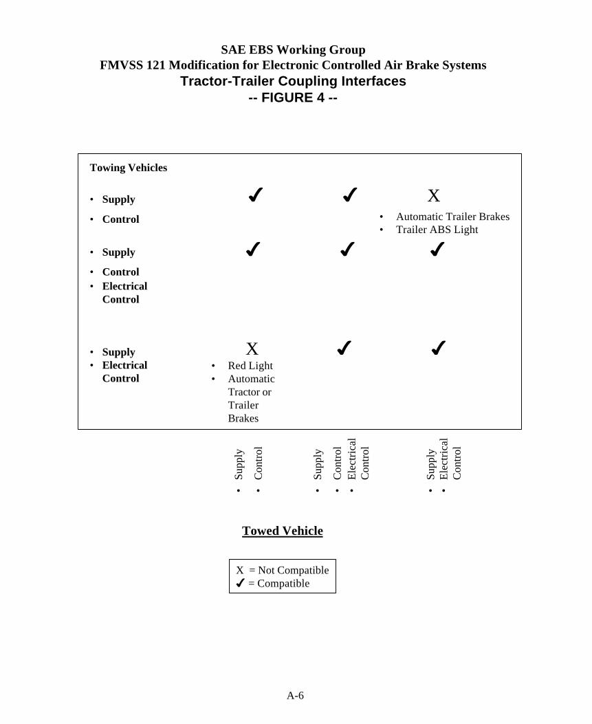
SAE EBS Working GroupFMVSS 121 Modification for Electronic Controlled Air Brake Systems
Tractor-Trailer Coupling Interfaces-- FIGURE 4 --
Towing Vehicles
• Supply
• Control
• Supply
• Control• Electrical
Control
• Supply• Electrical
Control
4 4 X• Automatic Trailer Brakes• Trailer ABS Light
4 4 4
X 4 4• Red Light• Automatic
Tractor orTrailerBrakes
•Su
pply
•C
ontro
l
•Su
pply
•C
ontro
l•
Elec
trica
lC
ontro
l
•Su
pply
•El
ectri
cal
Con
trol
Towed Vehicle
X = Not Compatible4 = Compatible
A-6

A-7
SAE EBS Working GroupFMVSS 121 Modifications for Electronic Controlled Air Brake Systems
BRAKE SYSTEM INDICATION LAMP OPERATION
(FIGURE 5)
S5.1.5B (Proposed)Red
(Truck, Bus,Tractor)
Red(Trailer)
Yellow (ABS)
(Truck, Bus,Tractor)
Yellow(ABS)
(Trailer)A. Service Brake
Electrical ControlX
B. Battery Low Voltage XC. Parking Brake
Electrical ControlX
D. Tractor ECL withTrailer PCL (Fig. 4)
X XE. Trailer Service and
Parking BrakeElectrical Control
X
F. ECL Data Defect X
S5.1.6.2(b) (Proposed)Tractor ECL withTrailer PCL
X
S5.1.6.2(b) (Proposed)Tractor PCL withTrailer ECL
X
S5.1.5.A (Current)Low Pressure
Optional
S.5.1.6.2(a) and (b) (Current)ABS Malfunction
X(a) X(b)
Note: ECL = Electronic Control LinePCL = Pneumatic Control Line

SAE EBS Working GroupFMVSS 121 Modifications for Electronic Controlled Air Brake Systems
WARNING LIGHTS AND BRAKE PERFORMANCE AFTER ELECTRICAL ‘FAILURES’- FIGURE 6 -
SB = Service Brake Performance S5.3.1EB = Emergency Brake Performance S5.7.1
PB = Parking Brake Performance S5.6.1 or 5.6.2WARNING
LIGHT PERFORMANCE
ECL = Electric Trailer Control LinePCL = Pneumatic Control Line
COMMENTS
S5.1.2.B(b),(c) Battery – Low VoltageS5.1.5.B(1)(b)
Red (Truck) EB – PB
S5.1.2.B(a) Energy Source Failure SB After 10 minutes full-treadle apply
S5.7.1, S5.7.3 Service Brake Electrical FailureS5.1.5.B(1)(a)
Red (Truck) EB Modulated Electronic Control toTrailer
S5.1.5.B(1)(c) Parking Brake Electrical FailureS5.6.3.1
Red (Truck) PB
S5.1.6.2(b) Trailer Service Brake Electrical FailureS5.1.5.B(1)(c)
Red (Trailer)
S5.1.5.B(1)(c) Trailer ParkingS5.1.6.2(b) Brake Electrical Failure
Red (Trailer) PB
S5.1.5.B(1)(f) Data Defect in ECL Red (Trailer)
S5.1.6.B(b) Tractor ECL with Trailer PCLS5.1.5.B(1)(d)
Red (Trailer) Automatic PB Application
S5.1.6.B(d) Tractor PCL with Trailer ECL Yellow ABS(Trailer)
Automatic Trailer PB Application
S5.1.6.B(e) Ignition Switch “Off” SB – EB – PBS5.1.6.B (f) Auxiliary Electrical Equipment
(including failure)SB – EB – PB No Adverse Effects

A2 AAR SPECIFICATION S-4200
Specification S-4200
PERFORMANCE REQUIREMENT FOR TESTING ELECTRICALLYCONTROLLED PNEUMATIC CABLE-BASED (ECP) FREIGHT BRAKE SYSTEMS
Adopted: May, 1997
1.0 PURPOSE
The overall objectives of this specification are:
I. Assure that the performance of electrically controlled pneumatic (ECP) freight brakesystems is uniform and consistent among equipment from different manufacturers.
2. Assure that cars equipped with AAR approved ECP brake systems from differentmanufacturers can be operated together in any electrically braked train.
3. Assure that AAR approved electric brake systems meet a high standard level of safetyand reliability.
2.0 SCOPE
This specification defines the requirements for an AAR approved freight train power brakeusing electrically controlled freight brake systems suitable for service in all-electric braked trains.Operation of such systems in a conventionally braked train is covered by AAR Specifications S-46 1,S-462. S-464 and S-467.
2.1 Definitions
2.1.1 Electrically Controlled Pneumatic (ECP) Brake SystemA train power braking system operated by compressed air and controlled by electrical signals
originated at the locomotive for service and emergency applications. The brake pipe is used toprovide a constant supply of air to the reservoirs. Graduated release and re-application must beavailable. The system responds appropriately to undesired separation or malfunction of hoses.cabling, or brake pipe.
2.1.2 Car Control Device (CCD)The CCD is an electronic control device which replaces the function of the pneumatic service
and emergency portions during electric braking and provides for electrically controlled service andemergency brake applications. The CCD interprets and acknowledges the electrical signals and
A-9

controls the reservoir charging. and the service and emergency braking functions on the car. It willalso send a warning signal to the locomotive in case any of the components cannot respondappropriately to a braking command. Each CCD has a unique electronic address that is keyed to carreporting marks and numbers.
2.1.2-lIn order to aid in system diagnostic services, the CCD will be able to measure the
communication signal level at its interface to the communication media. The CCD will make thismeasurement with a resolution of _ +0.05 Volts RMS. The signal measuring circuitry will have animpedance of no less than 20,000 ohms in the frequency band of 100kHz to 450kHz. The hardwarewhich provides this measurement should have no adverse effect on the communication signal. It isrecommended that this measurement be made on the low voltage side of the CCD coupling circuit.
2.1.3 Head End Unit (HEU)Brake system control device used by the locomotive engineer to control the electric brake
system. The specific functions of the HEU are:
Provide man/machine interface to operate the ECP brake system, either directly or through aLocomotive System Integration (LSI) interface.
Provide a data display to the engineer.
l Provide controls which allow the engineer to make the following brake commands with onemovement:
Minimum service ( 15% application)Full service (100% application)Emergency ( 120% application)Full releaseGraduate application and release in 1% increments
l Monitor the End of Tram (EOT) beacon.
l Provide a means to turn off train line power whenever communication with the EOT is notestablished and during operation in switching mode.
l Provide a means to supply a two-second power application to “wake up” CCDs in a sleepmode.
l Provide mechanisms to conduct ECP brake system initial terminal test.
2.1.4 Overlay Brake SystemAn ECP brake system which is capable of operating in a conventionally braked train. A
failure to the ECP brake system operating as an overlay system would enable a train to continue to
A-IO
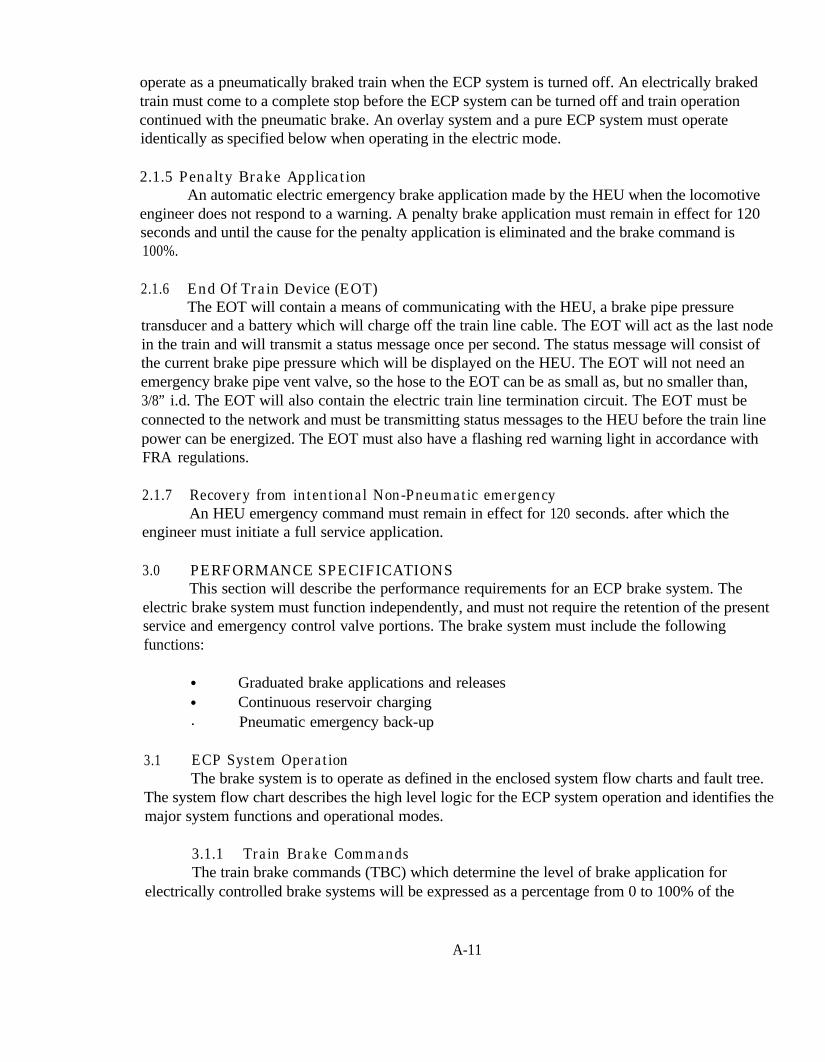
operate as a pneumatically braked train when the ECP system is turned off. An electrically brakedtrain must come to a complete stop before the ECP system can be turned off and train operationcontinued with the pneumatic brake. An overlay system and a pure ECP system must operateidentically as specified below when operating in the electric mode.
2.1.5 Penalty Brake ApplicationAn automatic electric emergency brake application made by the HEU when the locomotive
engineer does not respond to a warning. A penalty brake application must remain in effect for 120seconds and until the cause for the penalty application is eliminated and the brake command is100%.
2.1.6 End Of Train Device (EOT)The EOT will contain a means of communicating with the HEU, a brake pipe pressure
transducer and a battery which will charge off the train line cable. The EOT will act as the last nodein the train and will transmit a status message once per second. The status message will consist ofthe current brake pipe pressure which will be displayed on the HEU. The EOT will not need anemergency brake pipe vent valve, so the hose to the EOT can be as small as, but no smaller than,3/8” i.d. The EOT will also contain the electric train line termination circuit. The EOT must beconnected to the network and must be transmitting status messages to the HEU before the train linepower can be energized. The EOT must also have a flashing red warning light in accordance withFRA regulations.
2.1.7 Recovery from intentional Non-Pneumatic emergencyAn HEU emergency command must remain in effect for 120 seconds. after which the
engineer must initiate a full service application.
3.0 PERFORMANCE SPECIFICATIONSThis section will describe the performance requirements for an ECP brake system. The
electric brake system must function independently, and must not require the retention of the presentservice and emergency control valve portions. The brake system must include the followingfunctions:
l Graduated brake applications and releasesl Continuous reservoir charging. Pneumatic emergency back-up
3.1 ECP System OperationThe brake system is to operate as defined in the enclosed system flow charts and fault tree.
The system flow chart describes the high level logic for the ECP system operation and identifies themajor system functions and operational modes.
3.1.1 Train Brake CommandsThe train brake commands (TBC) which determine the level of brake application for
electrically controlled brake systems will be expressed as a percentage from 0 to 100% of the
A-11

maximum full service braking force in 1% increments. The brake pipe pressure setting willdetermine the maximum full service brake cylinder pressure as shown in Table 1 and according tothe foilowtng formula:
PBC = 0.711 * PS
These pressures are for cars loaded to 100% gross rail load.
3.1.1.1Brake cylinder pressure tolerance will be _+2 psi. An initial command during the initialization
of the train brake system will set each CCD to the full service brake cylinder pressure setting.
3.1.1.2Emergency command will result in a brake cylinder pressure which is 120% of the full
service brake cylinder pressure setting with a tolerance of _+2 psi (Table 1).
3.1.1.3Minimum service application wiil be a 15% brake application. Once a minimum service
application is made, it must be possible to reduce the brake application in 1% increments.
3.1.1.4The HEU brake controller must provide the engineer a means for requesting;a. Direct brake releaseb. Graduated brake releasec. Graduated service brake applicationd. Full service brake applicatione. Emergency brake application
TABLE 1 - MAXIMUM FULL SERVICE BRAKE CYLINDER PRESSURES, LOADEDBRAKE RATIOS AND EMERGENCY B.C. PRESSURES
I I
A-12

3.1.2 Brake Cylinder Pressure Control for Empty or Partial Load Conditions
3.1.2.1The CCD must be designed such that the brake cylinder pressure for any application
is reduced in proportion to the percentage of gross rail load. The percentage GRL for any car isdetermined by a message from the HEU during system initialization or by a load weighing device onthe car. This percentage GRL is locked into the CCD memory every time the train brake system isinitialized during the initial terminal air brake test or when the load condition of the train is changed.On those cars equipped with on-board load sensing equipment for conventional operation, theempty/load condition information from the HEU will take precedence when the car is operated in anelectrically braked train. If the car is equipped with a proportional empty/load device, then the datafrom that device will take precedence over the information from the HEU.
When the brake system is initialized during the initial terminal inspection or at anotherlocation where the train is loaded or emptied, the car is told what its’ percentage of gross rail load is,either by a message from the HEU or by an on-board self weighing device.
The CCD will provide the brake cylinder pressure necessary to keep the loaded and partiallyloaded car brake ratio no higher than 12.8% of gross rail load at a 90 psi brake pipe pressure undermost load conditions. The loaded brake ratio will vary depending on the brake pipe pressure (seeTable 1). The CCD will determine the brake cylinder pressure based on formulas and limits shownbelow. Note that the empty car brake ratio may be greater than 12.8%.
3.1.2.2 Full Service Brake Cylinder PressureThe CCD can use the following procedure to compute the maximum brake cylinder pressure
for its particular car loading. Note that this pressure will be less than or equal to the loaded brakecylinder pressure given in section 3.1.1, Train Brake Commands.
P B C M A X = ( NBR* W)/C
Where NBR = 0.128 * BPP/90BPP = Operating brake pipe pressureC = (Ap*LR*EFF)Ap = Area of the B.C. piston(s)LR = Lever ratioEFF = Measured rigging efficiency @ 64.0 psi brake cylinder
pressurew = Total car weight at initial terminalPBC = Maximum brake cylinder pressure for the cars’ current %GRL
The constant C is programmed into the CCD only once when it is installed on a particularcar. The constant C remains unchanged as long as a particular CCD remains with its car. The CCDmust have the software capability to be adjusted by the car builder for the constant C.
A-13
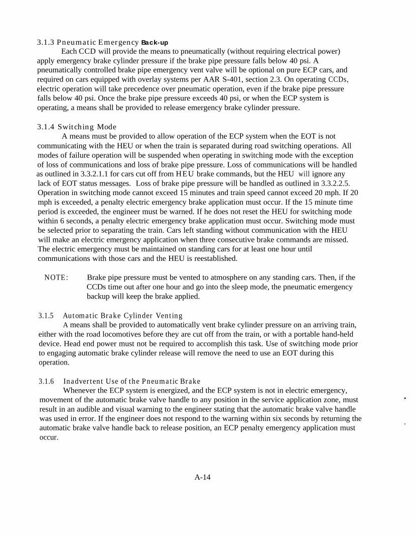
3.1.3 Pneumatic Emergency Back-upEach CCD will provide the means to pneumatically (without requiring electrical power)
apply emergency brake cylinder pressure if the brake pipe pressure falls below 40 psi. Apneumatically controlled brake pipe emergency vent valve will be optional on pure ECP cars, andrequired on cars equipped with overlay systems per AAR S-401, section 2.3. On operating CCDs,electric operation will take precedence over pneumatic operation, even if the brake pipe pressurefalls below 40 psi. Once the brake pipe pressure exceeds 40 psi, or when the ECP system isoperating, a means shall be provided to release emergency brake cylinder pressure.
3.1.4 Switching ModeA means must be provided to allow operation of the ECP system when the EOT is not
communicating with the HEU or when the train is separated during road switching operations. Allmodes of failure operation will be suspended when operating in switching mode with the exceptionof loss of communications and loss of brake pipe pressure. Loss of communications will be handledas outlined in 3.3.2.1.1 for cars cut off from HEU brake commands, but the HEU will ignore anylack of EOT status messages. Loss of brake pipe pressure will be handled as outlined in 3.3.2.2.5.Operation in switching mode cannot exceed 15 minutes and train speed cannot exceed 20 mph. If 20mph is exceeded, a penalty electric emergency brake application must occur. If the 15 minute timeperiod is exceeded, the engineer must be warned. If he does not reset the HEU for switching modewithin 6 seconds, a penalty electric emergency brake application must occur. Switching mode mustbe selected prior to separating the train. Cars left standing without communication with the HEUwill make an electric emergency application when three consecutive brake commands are missed.The electric emergency must be maintained on standing cars for at least one hour untilcommunications with those cars and the HEU is reestablished.
NOTE: Brake pipe pressure must be vented to atmosphere on any standing cars. Then, if theCCDs time out after one hour and go into the sleep mode, the pneumatic emergencybackup will keep the brake applied.
3.1.5 Automatic Brake Cylinder VentingA means shall be provided to automatically vent brake cylinder pressure on an arriving train,
either with the road locomotives before they are cut off from the train, or with a portable hand-helddevice. Head end power must not be required to accomplish this task. Use of switching mode priorto engaging automatic brake cylinder release will remove the need to use an EOT during thisoperation.
3.1.6 Inadvertent Use of the Pneumatic BrakeWhenever the ECP system is energized, and the ECP system is not in electric emergency,
movement of the automatic brake valve handle to any position in the service application zone, mustresult in an audible and visual warning to the engineer stating that the automatic brake valve handlewas used in error. If the engineer does not respond to the warning within six seconds by returning theautomatic brake valve handle back to release position, an ECP penalty emergency application mustoccur.
A-14
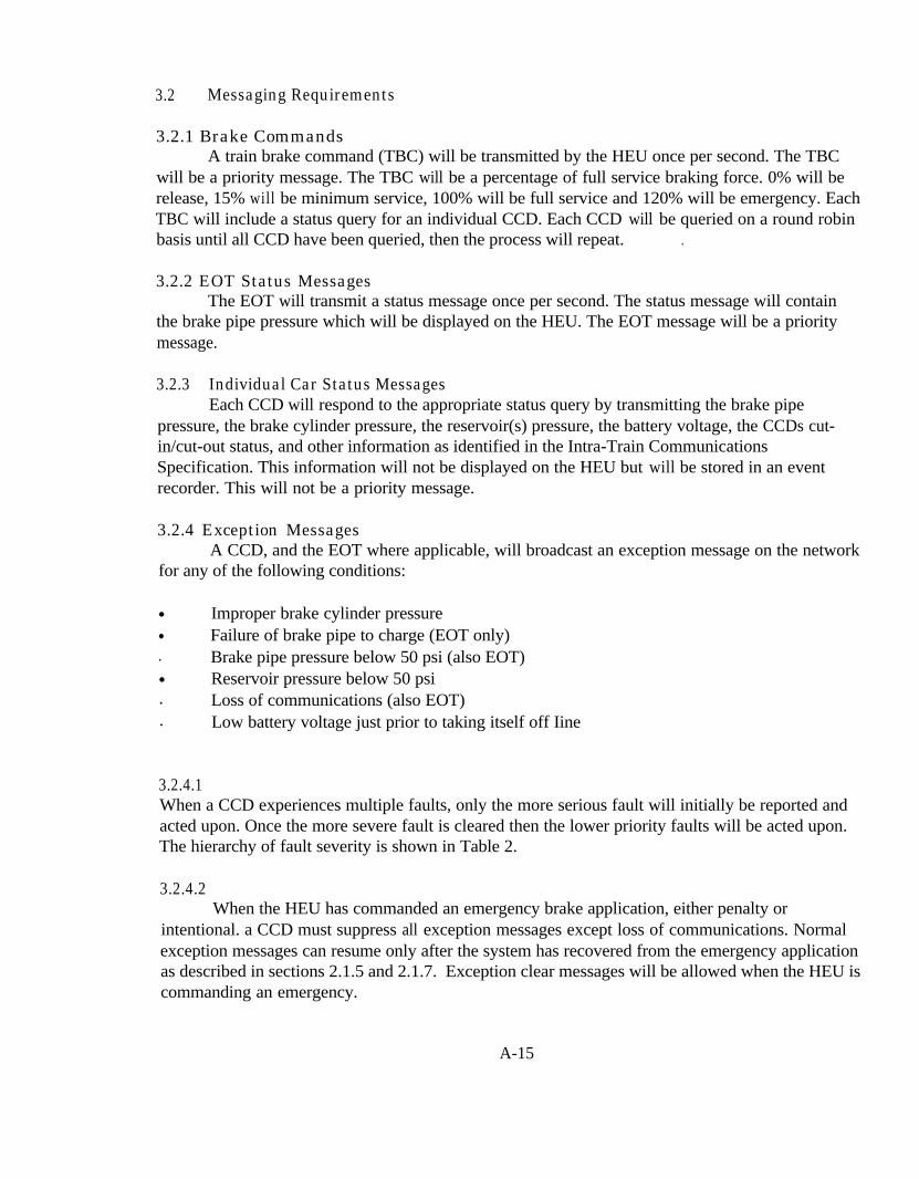
3.2 Messaging Requirements
3.2.1 Brake CommandsA train brake command (TBC) will be transmitted by the HEU once per second. The TBC
will be a priority message. The TBC will be a percentage of full service braking force. 0% will berelease, 15% will be minimum service, 100% will be full service and 120% will be emergency. EachTBC will include a status query for an individual CCD. Each CCD will be queried on a round robinbasis until all CCD have been queried, then the process will repeat. .
3.2.2 EOT Status MessagesThe EOT will transmit a status message once per second. The status message will contain
the brake pipe pressure which will be displayed on the HEU. The EOT message will be a prioritymessage.
3.2.3 Individual Car Status MessagesEach CCD will respond to the appropriate status query by transmitting the brake pipe
pressure, the brake cylinder pressure, the reservoir(s) pressure, the battery voltage, the CCDs cut-in/cut-out status, and other information as identified in the Intra-Train CommunicationsSpecification. This information will not be displayed on the HEU but will be stored in an eventrecorder. This will not be a priority message.
3.2.4 Exception MessagesA CCD, and the EOT where applicable, will broadcast an exception message on the network
for any of the following conditions:
l Improper brake cylinder pressurel Failure of brake pipe to charge (EOT only). Brake pipe pressure below 50 psi (also EOT)l Reservoir pressure below 50 psi. Loss of communications (also EOT). Low battery voltage just prior to taking itself off Iine
3.2.4.1When a CCD experiences multiple faults, only the more serious fault will initially be reported andacted upon. Once the more severe fault is cleared then the lower priority faults will be acted upon.The hierarchy of fault severity is shown in Table 2.
3.2.4.2When the HEU has commanded an emergency brake application, either penalty or
intentional. a CCD must suppress all exception messages except loss of communications. Normalexception messages can resume only after the system has recovered from the emergency applicationas described in sections 2.1.5 and 2.1.7. Exception clear messages will be allowed when the HEU iscommanding an emergency.
A-15
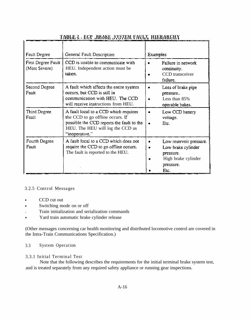
TABLE 2 _ ECP BRAKE SYSTEM FAULT HIERARCHY
HEU. Independent action must beCCD transceiver
Less than 85%tructions from HEU.
the CCD to go offline occurs. I
HEU. The HEU will log the CCD as
The fault is reported to the HEU.High brake cylinder
3.2.5 Control Messages
l CCD cut outl Switching mode on or off. Train initialization and serialization commandsl Yard train automatic brake cylinder release
(Other messages concerning car health monitoring and distributed locomotive control are covered inthe Intra-Train Communications Specification.)
3.3 System Operation
3.3.1 Initial Terminal TestNote that the following describes the requirements for the initial terminal brake system test,
and is treated separately from any required safety appliance or running gear inspections.
A-16

3.3.1.1 Train Make Up ProceduresThe EOT must be connected to the last car, and all cables must be connected completing a
circuit, before train line power can be energized.
3.3.1 .2The remaining test procedures are shown in the attached Terminal Test flow chart.
3.3.2 Failure ModesThese failure modes are for pure ECP or overlay operation.
3.3.2.1 Signal Transmission FailureSignal transmission failure is defined as a total failure of the entire electric brake control
network, such that communication to and/or from the last car is broken at some point in the train.
3.3.2.1.1 Single or Multiple Breaks in the Communications NetworkIf any CCD (and the EOT) determines that it has missed three consecutive HEU beacons, it
will maintain the current brake application and transmit a “loss of signal” message. If that CCDsubsequently receives a “loss of signal” message from any other CCD or the EOT within one second,then that CCD will assume that the entire communications link is broken and must make an electricemergency brake application. If that CCD does not receive a “loss of signal” message from anyother CCD. it will cut itself out with the brake cylinder connected to atmosphere per Para. 3.3.2.2.2.The HEU must detect the failure when three consecutive EOT status messages are missed. The HEUmust then transmit an electric emergency brake application command to all CCDs still incommunication with the HEU.
3.3.2.1.2The locomotive engineer must be given an audible and visible warning of network failure.
and an electric emergency application must be made. Emergency application on the cut off cars mustbe held for one hour, after which the pneumatic emergency will maintain the application as theCCDs time out and enter a “battery conservation” mode.
3.3.2.1.3In the event of train line communications failure, the system will return to normal operation
when the HEU receives three consecutive EOT messages after the train has come to a stop per Para.2.1.5.
3.3.2.2 Individual Car Control Device FailureIndividual car control device failure is defined as the failure of any one CCD to respond
appropriately to commands from the HEU.
3.3.2.2.1 Incorrect Brake Cylinder PressureIf the brake cylinder pressure monitored by each CCD does not correspond correctly _ (+5 psi)
with the brake signal command after allowing for the build up time or release time, a 15 second
A-17
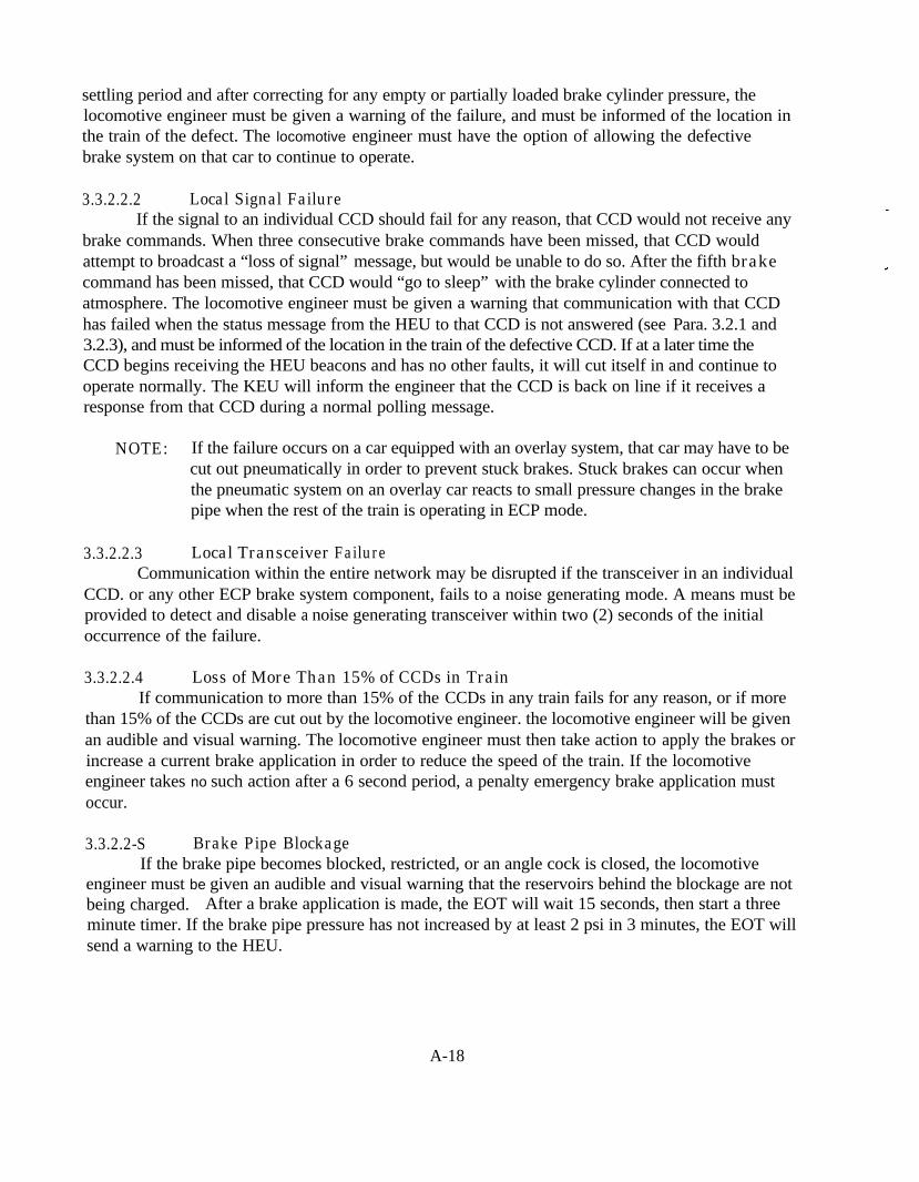
settling period and after correcting for any empty or partially loaded brake cylinder pressure, thelocomotive engineer must be given a warning of the failure, and must be informed of the location inthe train of the defect. The locomotive engineer must have the option of allowing the defectivebrake system on that car to continue to operate.
3.3.2.2.2 Local Signal FailureIf the signal to an individual CCD should fail for any reason, that CCD would not receive any
brake commands. When three consecutive brake commands have been missed, that CCD wouldattempt to broadcast a “loss of signal” message, but would be unable to do so. After the fifth brakecommand has been missed, that CCD would “go to sleep” with the brake cylinder connected toatmosphere. The locomotive engineer must be given a warning that communication with that CCDhas failed when the status message from the HEU to that CCD is not answered (see Para. 3.2.1 and3.2.3), and must be informed of the location in the train of the defective CCD. If at a later time theCCD begins receiving the HEU beacons and has no other faults, it will cut itself in and continue tooperate normally. The KEU will inform the engineer that the CCD is back on line if it receives aresponse from that CCD during a normal polling message.
NOTE: If the failure occurs on a car equipped with an overlay system, that car may have to becut out pneumatically in order to prevent stuck brakes. Stuck brakes can occur whenthe pneumatic system on an overlay car reacts to small pressure changes in the brakepipe when the rest of the train is operating in ECP mode.
3.3.2.2.3 Local Transceiver FailureCommunication within the entire network may be disrupted if the transceiver in an individual
CCD. or any other ECP brake system component, fails to a noise generating mode. A means must beprovided to detect and disable a noise generating transceiver within two (2) seconds of the initialoccurrence of the failure.
3.3.2.2.4 Loss of More Than 15% of CCDs in TrainIf communication to more than 15% of the CCDs in any train fails for any reason, or if more
than 15% of the CCDs are cut out by the locomotive engineer. the locomotive engineer will be givenan audible and visual warning. The locomotive engineer must then take action to apply the brakes orincrease a current brake application in order to reduce the speed of the train. If the locomotiveengineer takes no such action after a 6 second period, a penalty emergency brake application mustoccur.
3.3.2.2-S Brake Pipe BlockageIf the brake pipe becomes blocked, restricted, or an angle cock is closed, the locomotive
engineer must be given an audible and visual warning that the reservoirs behind the blockage are notbeing charged. After a brake application is made, the EOT will wait 15 seconds, then start a threeminute timer. If the brake pipe pressure has not increased by at least 2 psi in 3 minutes, the EOT willsend a warning to the HEU.
A-18

3.3.2.2.6 Brake Pipe SeparationIf the brake pipe breaks or separates, each CCD and the EOT must transmit a “loss of
pressure” message to the HEU when the brake pipe pressure is at or below 50 psi. When the HEUreceives three consecutive “loss of pressure” messages from at least three separate cars within tenseconds, HEU transmits a penalty electric emergency brake application command. NOTE: In thecase of a train break-in-two, the train may also be initiating an electric emergency brake applicationdue to signal loss (see para.3.3.2.1.1).
3.3.3 Recovery from EmergenciesIn all cases. an ECP emergency has to stay in effect for 120 seconds. Recovery cannot be
made until the 120 second time period has elapsed.
CAUSE RECOVERY PROCEDURE
Low B.P. pressure(3.3.2.2.6)
After the 120 second time period, any three CCDs reporting B.P.pressure of 60 psi or higher will start a 60 second timer. After 60seconds, the engineer may command a full service application. Ifthe B.P. pressure is at least 60 psi at all reporting CCDs, then thesystem returns to normal operation. If there are still at least threeCCDs in the train reporting lower than 50 psi B.P. pressure, theseCCDs will again initiate an emergency application. The engineerwill then have to wait 120 seconds and repeat the recovery process.If the recovery is still unsuccessful, a serious leak still exists in thetrain. This recovery procedure is identical in either switch or runmode.
Loss ofcommunications(3.3.2. I)
After the 120 second waiting period, and after the break in thecommunications line has been repaired, the system will return tonormal operation when the HEU receives the EOT beacon. At thatpoint a full service application will restore the system to normaloperation. If the communications break cannot be repaired, and thetrain must be moved in switch mode to a siding, the CCDs behindthe communications break which are in emergency will release whenthe brake pipe pressure is reduced by 15 to 35 psi and held for 30seconds.
Inadvertent use of After the 120 second waiting period, a full service brake applicationthe pneumatic brake will return the system to normal operation.
Percentage ofoperative brakesfalls below 85%
After the 120 second waiting period, the train may be operated inswitch mode to set out enough defective cars to return to at least85% operative brakes. The system must be re-initialized to return tonormal operation.
A-19

4.0 PERFORMANCE TESTS FOR SINGLE CAR BRAKE EQUIPMENTThese tests will be made on an AAR approved single car test rack. Initialize the CCD as
follows:
c =G R L =
This will result in the following target brake cylinder pressures for different load conditions asshown in table 3;
572 BPP = 90 psi286.000 lbs Lt. Wt .= 43,000 lbs
After the 120 second waiting period, reset the system to switchmode.
Switching modetime or speedexceeded
TABLE 3 - TARGET BRAKE CYLINDER PRESSURES
The following tests 4.1 through 4.4.1 are to be conducted at 100% load, then repeated at 50%load and 0% load.
4.1 Minimum Service Requirements
4.1.1 Application TestMake a minimum service electric brake application (15% brake application). Final brake
cylinder pressure should be 9.6 _ + 2 psi in no more than 2.0 seconds
A-20
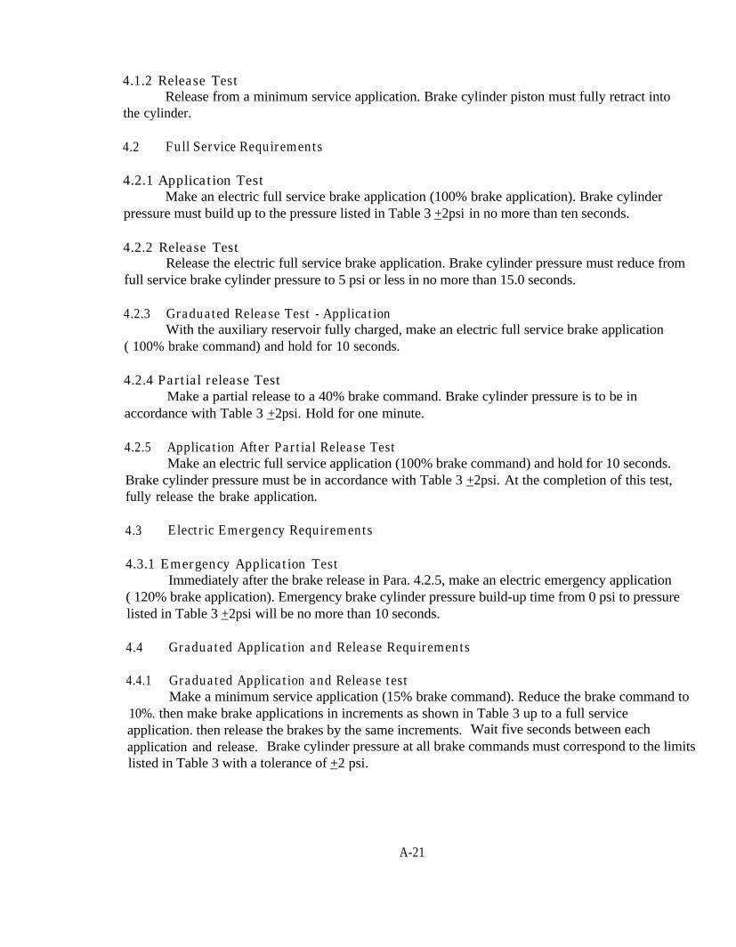
4.1.2 Release TestRelease from a minimum service application. Brake cylinder piston must fully retract into
the cylinder.
4.2 Full Service Requirements
4.2.1 Application TestMake an electric full service brake application (100% brake application). Brake cylinder
pressure must build up to the pressure listed in Table 3 _ +2psi in no more than ten seconds.
4.2.2 Release TestRelease the electric full service brake application. Brake cylinder pressure must reduce from
full service brake cylinder pressure to 5 psi or less in no more than 15.0 seconds.
4.2.3 Graduated Release Test - ApplicationWith the auxiliary reservoir fully charged, make an electric full service brake application
( 100% brake command) and hold for 10 seconds.
4.2.4 Partial release TestMake a partial release to a 40% brake command. Brake cylinder pressure is to be in
accordance with Table 3 _ +2psi. Hold for one minute.
4.2.5 Application After Partial Release TestMake an electric full service application (100% brake command) and hold for 10 seconds.
Brake cylinder pressure must be in accordance with Table 3 _ +2psi. At the completion of this test,fully release the brake application.
4.3 Electric Emergency Requirements
4.3.1 Emergency Application TestImmediately after the brake release in Para. 4.2.5, make an electric emergency application
( 120% brake application). Emergency brake cylinder pressure build-up time from 0 psi to pressurelisted in Table 3 _ +2psi will be no more than 10 seconds.
4.4 Graduated Application and Release Requirements
4.4.1 Graduated Application and Release testMake a minimum service application (15% brake command). Reduce the brake command to
10%. then make brake applications in increments as shown in Table 3 up to a full serviceapplication. then release the brakes by the same increments. Wait five seconds between eachapplication and release. Brake cylinder pressure at all brake commands must correspond to the limitslisted in Table 3 with a tolerance of _ +2 psi.
A-21
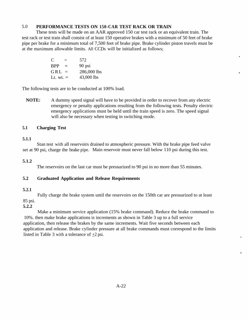
5.0 PERFORMANCE TESTS ON 150-CAR TEST RACK OR TRAINThese tests will be made on an AAR approved 150 car test rack or an equivalent train. The
test rack or test train shall consist of at least 150 operative brakes with a minimum of 50 feet of brakepipe per brake for a minimum total of 7,500 feet of brake pipe. Brake cylinder piston travels must beat the maximum allowable limits. All CCDs will be initialized as follows;
C = 572BPP = 90 psiG R L = 286,000 lbsLt. wt. = 43,000 lbs
The following tests are to be conducted at 100% load.
NOTE: A dummy speed signal will have to be provided in order to recover from any electricemergency or penalty applications resulting from the following tests. Penalty electricemergency applications must be held until the train speed is zero. The speed signalwill also be necessary when testing in switching mode.
5.1 Charging Test
5.1.1Stan test with all reservoirs drained to atmospheric pressure. With the brake pipe feed valve
set at 90 psi, charge the brake pipe.. Main reservoir must never fall below 110 psi during this test.
5.1.2The reservoirs on the last car must be pressurized to 90 psi in no more than 55 minutes.
5.2 Graduated Application and Release Requirements
5.2.1Fully charge the brake system until the reservoirs on the 150th car are pressurized to at least
85 psi.5.2.2
Make a minimum service application (15% brake command). Reduce the brake command to10%. then make brake applications in increments as shown in Table 3 up to a full serviceapplication, then release the brakes by the same increments. Wait five seconds between eachapplication and release. Brake cylinder pressure at all brake commands must correspond to the limitslisted in Table 3 with a tolerance of _ +2 psi.
A-22
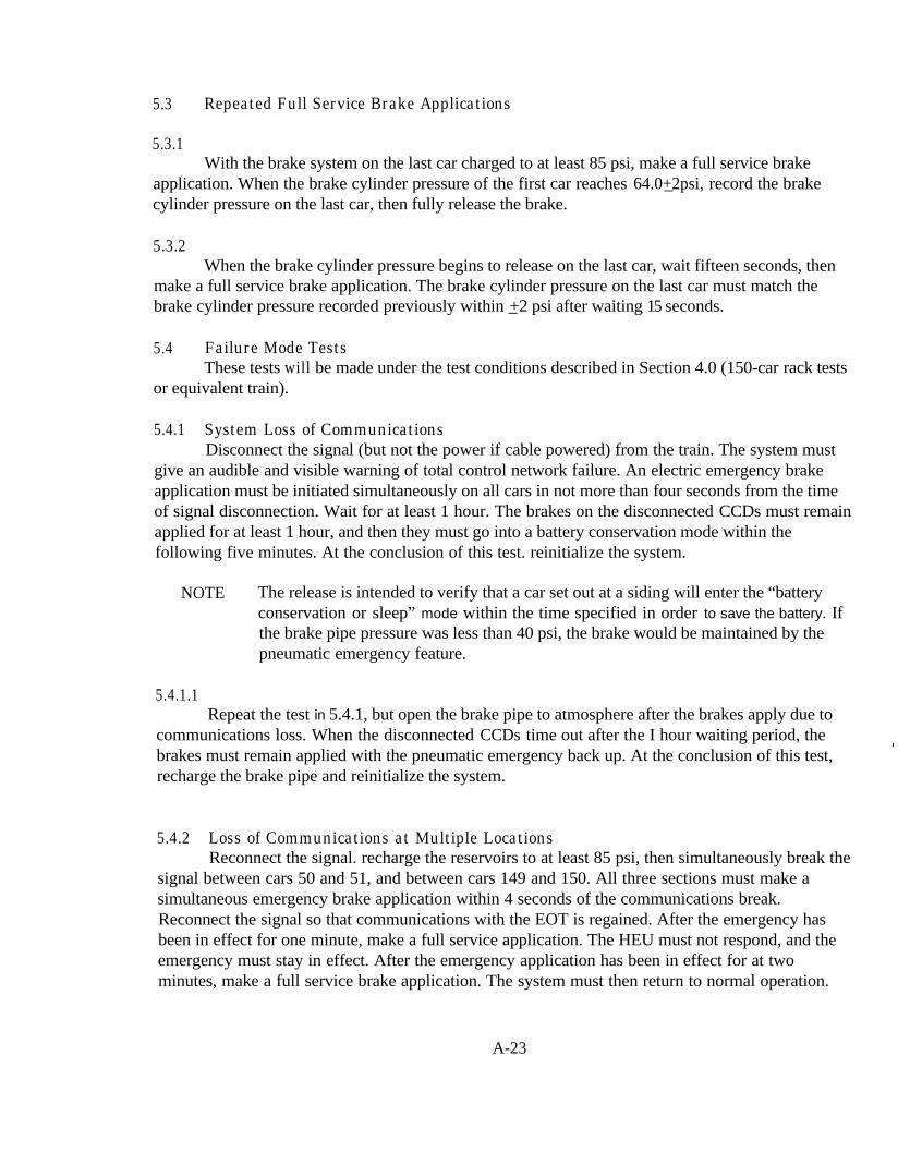
5.3 Repeated Full Service Brake Applications
5.3.1With the brake system on the last car charged to at least 85 psi, make a full service brake
application. When the brake cylinder pressure of the first car reaches _64.0+2psi, record the brakecylinder pressure on the last car, then fully release the brake.
5.3.2When the brake cylinder pressure begins to release on the last car, wait fifteen seconds, then
make a full service brake application. The brake cylinder pressure on the last car must match thebrake cylinder pressure recorded previously within _+2 psi after waiting 15 seconds.
5.4 Failure Mode TestsThese tests will be made under the test conditions described in Section 4.0 (150-car rack tests
or equivalent train).
5.4.1 System Loss of CommunicationsDisconnect the signal (but not the power if cable powered) from the train. The system must
give an audible and visible warning of total control network failure. An electric emergency brakeapplication must be initiated simultaneously on all cars in not more than four seconds from the timeof signal disconnection. Wait for at least 1 hour. The brakes on the disconnected CCDs must remainapplied for at least 1 hour, and then they must go into a battery conservation mode within thefollowing five minutes. At the conclusion of this test. reinitialize the system.
NOTE The release is intended to verify that a car set out at a siding will enter the “batteryconservation or sleep” mode within the time specified in order to save the battery. Ifthe brake pipe pressure was less than 40 psi, the brake would be maintained by thepneumatic emergency feature.
5.4.1.1Repeat the test in 5.4.1, but open the brake pipe to atmosphere after the brakes apply due to
communications loss. When the disconnected CCDs time out after the I hour waiting period, thebrakes must remain applied with the pneumatic emergency back up. At the conclusion of this test,recharge the brake pipe and reinitialize the system.
5.4.2 Loss of Communications at Multiple LocationsReconnect the signal. recharge the reservoirs to at least 85 psi, then simultaneously break the
signal between cars 50 and 51, and between cars 149 and 150. All three sections must make asimultaneous emergency brake application within 4 seconds of the communications break.Reconnect the signal so that communications with the EOT is regained. After the emergency hasbeen in effect for one minute, make a full service application. The HEU must not respond, and theemergency must stay in effect. After the emergency application has been in effect for at twominutes, make a full service brake application. The system must then return to normal operation.
A-23

5.4.3 Loss of Communications to a Single CCDMake a 100% (full service) brake application and wait for at least 8 seconds. Break the
communications path to the CCD on one of the cars. The brakes on that car must begin to releasewithin six seconds.
5.4.4 Loss of Train line PowerReconnect the signal, release and recharge the brake system, and disconnect the power, but
not the signal, from the cable. The system must give an audible and visible warning of total powerfailure. The system must continue to operate on battery power for at least 15 minutes. Cut out 16CCDs ( 10.7%). The HEU must command a penalty emergency brake application. After waiting 2minutes, re-connect the cut out CCDs.
5.4.5 Brake Cylinder LeakageReconnect the power, then disable any one CCD in the consist by opening a brake cylinder
pipe to atmosphere. Make a 15% brake application. After a 15 second waiting period, the systemmust give the engineer a warning of the low brake cylinder pressure, indicate the brake cylinderpressure and indicate the location in the train of the defect. CIose the brake cylinder pipe openingand release the brake.
54.6 Excessive Brake Cylinder Pressure
5.4.6.1Make a 15% minimum service brake application. With the 15% brake command in effect,
connect brake pipe pressure, reservoir pressure or some other higher air pressure source to brakecylinder pressure on any one CCD. After a 15 second waiting period, the system must give theengineer a warning of the high brake cylinder pressure, indicate the brake cylinder pressure andindicate the location in the train of the defect. The CCD controlling that brake cylinder must notrelease the brake. Remove the high pressure air source at the completion of this test..
5.4.7 Intentional CCD Cut OutWith the 15% brake command still in effect, send a command from the HEU which will
electrically cut out an individual CCD. The brake cylinder pressure on the that CCD must reduce toatmospheric pressure. Make a full service brake application. The cut out CCD must not respond.
5.4.8.1 Less Than 85% operativeRelease the brake. Send a command from the HEU to cut out another 21 CCDs spaced at
random throughout the train to simulate a number of defective or intentionally cut out CCDs (thisassumes that the CCD cut out in 5.4.7 is already cut out. The total number of CCDs needed to be cutout for this test is 22) The HEU should give an indication that 14.7% of the CCDs have been cut-out.
A-24
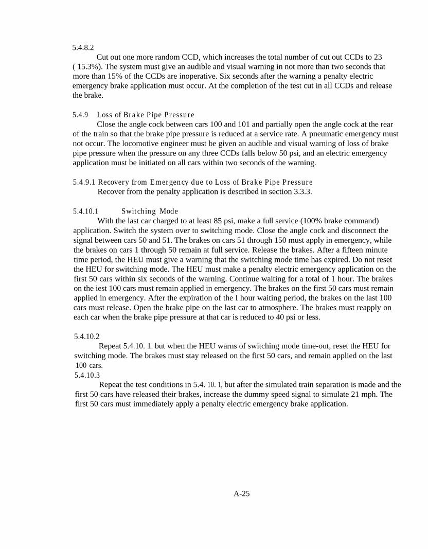
5.4.8.2Cut out one more random CCD, which increases the total number of cut out CCDs to 23
( 15.3%). The system must give an audible and visual warning in not more than two seconds thatmore than 15% of the CCDs are inoperative. Six seconds after the warning a penalty electricemergency brake application must occur. At the completion of the test cut in all CCDs and releasethe brake.
5.4.9 Loss of Brake Pipe PressureClose the angle cock between cars 100 and 101 and partially open the angle cock at the rear
of the train so that the brake pipe pressure is reduced at a service rate. A pneumatic emergency mustnot occur. The locomotive engineer must be given an audible and visual warning of loss of brakepipe pressure when the pressure on any three CCDs falls below 50 psi, and an electric emergencyapplication must be initiated on all cars within two seconds of the warning.
5.4.9.1 Recovery from Emergency due to Loss of Brake Pipe PressureRecover from the penalty application is described in section 3.3.3.
5.4.10.1 Switching ModeWith the last car charged to at least 85 psi, make a full service (100% brake command)
application. Switch the system over to switching mode. Close the angle cock and disconnect thesignal between cars 50 and 51. The brakes on cars 51 through 150 must apply in emergency, whilethe brakes on cars 1 through 50 remain at full service. Release the brakes. After a fifteen minutetime period, the HEU must give a warning that the switching mode time has expired. Do not resetthe HEU for switching mode. The HEU must make a penalty electric emergency application on thefirst 50 cars within six seconds of the warning. Continue waiting for a total of 1 hour. The brakeson the iest 100 cars must remain applied in emergency. The brakes on the first 50 cars must remainapplied in emergency. After the expiration of the I hour waiting period, the brakes on the last 100cars must release. Open the brake pipe on the last car to atmosphere. The brakes must reapply oneach car when the brake pipe pressure at that car is reduced to 40 psi or less.
5.4.10.2Repeat 5.4.10. 1. but when the HEU warns of switching mode time-out, reset the HEU for
switching mode. The brakes must stay released on the first 50 cars, and remain applied on the last100 cars.5.4.10.3
Repeat the test conditions in 5.4. 10. 1, but after the simulated train separation is made and thefirst 50 cars have released their brakes, increase the dummy speed signal to simulate 21 mph. Thefirst 50 cars must immediately apply a penalty electric emergency brake application.
A-25
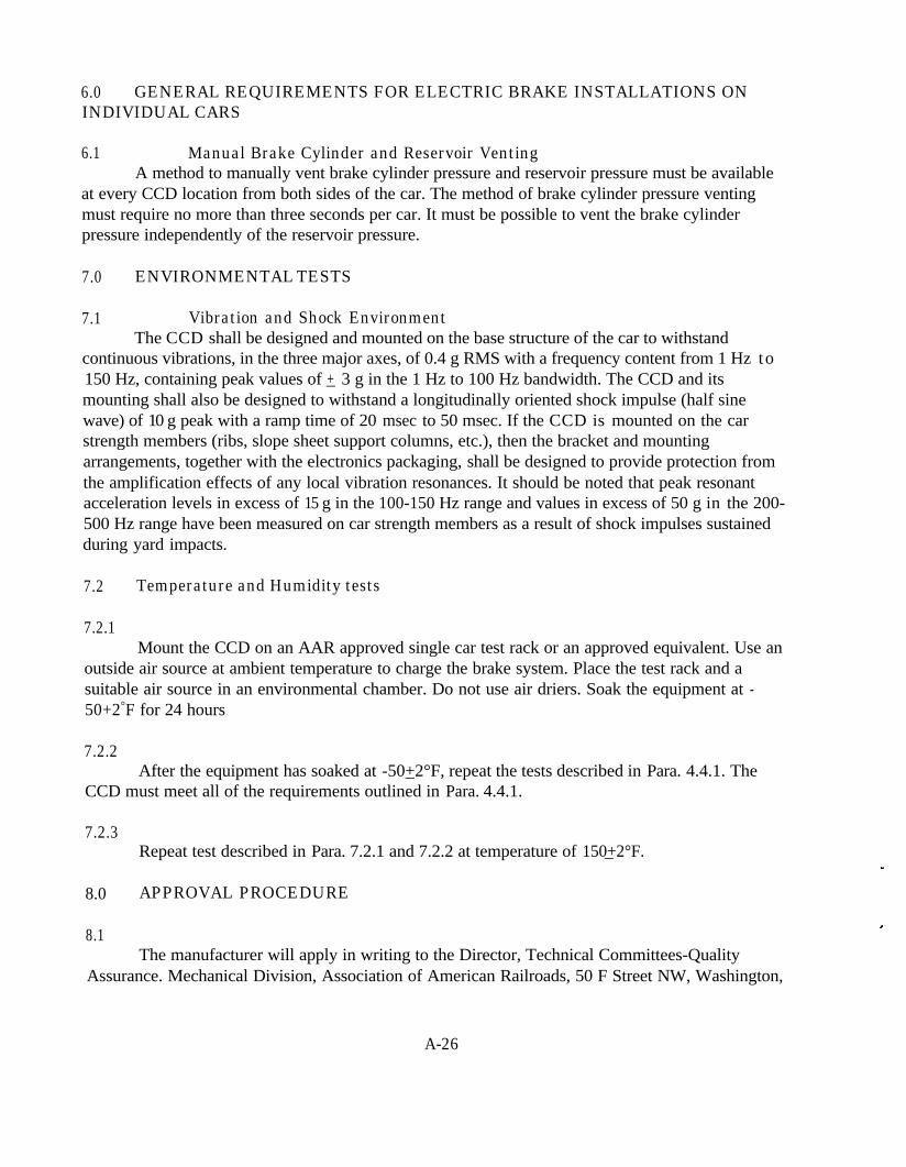
6.0 GENERAL REQUIREMENTS FOR ELECTRIC BRAKE INSTALLATIONS ONINDIVIDUAL CARS
6.1 Manual Brake Cylinder and Reservoir VentingA method to manually vent brake cylinder pressure and reservoir pressure must be available
at every CCD location from both sides of the car. The method of brake cylinder pressure ventingmust require no more than three seconds per car. It must be possible to vent the brake cylinderpressure independently of the reservoir pressure.
7.0 ENVIRONMENTAL TESTS
7.1 Vibration and Shock EnvironmentThe CCD shall be designed and mounted on the base structure of the car to withstand
continuous vibrations, in the three major axes, of 0.4 g RMS with a frequency content from 1 Hz to150 Hz, containing peak values of _+ 3 g in the 1 Hz to 100 Hz bandwidth. The CCD and itsmounting shall also be designed to withstand a longitudinally oriented shock impulse (half sinewave) of 10 g peak with a ramp time of 20 msec to 50 msec. If the CCD is mounted on the carstrength members (ribs, slope sheet support columns, etc.), then the bracket and mountingarrangements, together with the electronics packaging, shall be designed to provide protection fromthe amplification effects of any local vibration resonances. It should be noted that peak resonantacceleration levels in excess of 15 g in the 100-150 Hz range and values in excess of 50 g in the 200-500 Hz range have been measured on car strength members as a result of shock impulses sustainedduring yard impacts.
7.2 Temperature and Humidity tests
7.2.1Mount the CCD on an AAR approved single car test rack or an approved equivalent. Use an
outside air source at ambient temperature to charge the brake system. Place the test rack and asuitable air source in an environmental chamber. Do not use air driers. Soak the equipment at -50+2°F for 24 hours
7.2.2After the equipment has soaked at _-50+2°F, repeat the tests described in Para. 4.4.1. The
CCD must meet all of the requirements outlined in Para. 4.4.1.
7.2.3Repeat test described in Para. 7.2.1 and 7.2.2 at temperature of _150+2°F.
8.0 APPROVAL PROCEDURE
8.1The manufacturer will apply in writing to the Director, Technical Committees-Quality
Assurance. Mechanical Division, Association of American Railroads, 50 F Street NW, Washington,
A-26
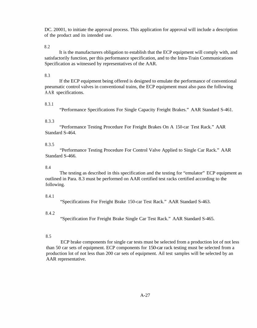
DC. 20001, to initiate the approval process. This application for approval will include a descriptionof the product and its intended use.
8.2It is the manufacturers obligation to establish that the ECP equipment will comply with, and
satisfactorily function, per this performance specification, and to the Intra-Train CommunicationsSpecification as witnessed by representatives of the AAR.
8.3If the ECP equipment being offered is designed to emulate the performance of conventional
pneumatic control valves in conventional trains, the ECP equipment must also pass the followingA A R specifications.
8.3.1“Performance Specifications For Single Capacity Freight Brakes.” AAR Standard S-461.
8.3.3“Performance Testing Procedure For Freight Brakes On A 150-car Test Rack.” AAR
Standard S-464.
8.3.5“Performance Testing Procedure For Control Valve Applied to Single Car Rack.” AAR
Standard S-466.
8.4The testing as described in this specification and the testing for “emulator” ECP equipment as
outlined in Para. 8.3 must be performed on AAR certified test racks certified according to thefollowing.
8.4.1“Specifications For Freight Brake 150-car Test Rack.” AAR Standard S-463.
8.4.2“Specification For Freight Brake Single Car Test Rack.” AAR Standard S-465.
8.5ECP brake components for single car tests must be selected from a production lot of not less
than 50 car sets of equipment. ECP components for 150-car rack testing must be selected from aproduction lot of not less than 200 car sets of equipment. Ail test samples will be selected by anAAR representative.
A-27

8.6Results of ail required tests will be provided by the manufacturer and furnished free of charge
to the AAR for evaluation.
8.7After the AAR examination of the ECP brake equipment and supporting information, the
AAR will notify the manufacturer or supplier as to whether the product has been given a conditionalapproval or has been disapproved.
A-28

A3 AAR SPECIFICATION S-4210
Specification S-4210
PERFORMANCE SPECIFICATION FOR ECP BRAKE SYSTEM CABLE,
CONNECTORS AND JUNCTION BOXES
Adopted May, 1997
1.0 PURPOSE
To establish the qualification test procedure for an electric brake trainline connector, cableand end-of-car junction box. The qualification test procedure is intended to verify that thedesigned components have high reliability, will withstand harsh environmental conditions, andhave a minimum of an 8 year operating life.
2.0 SCOPE
This standard applies to ECP Brake System power and signal cable intended for use oninterchange freight cars and locomotives equipped with AAR approved ECP brake systems.
2.1 Referenced Documents
ASTM B-8 Standard Specification for Concentric Stranded Copper forElectrical Conductors.
ASTM B-33 Tinned Soft or Annealed Copper Wires
ASTM B-172 Standard Specification for Rope Lay Stranded Copper ConductorsHaving Bunch-Stranded Members for electrical Conductors.
ASTM B298 Standard Specification for Silver Coated Soft or Annealed copperWires.
A-29
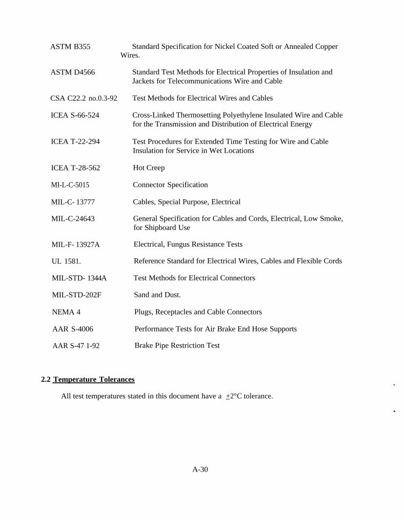
ASTM B355 Standard Specification for Nickel Coated Soft or Annealed CopperWires.
ASTM D4566
CSA C22.2 no.0.3-92
ICEA S-66-524
ICEA T-22-294
ICEA T-28-562
MI-L-C-5015
MIL-C- 13777
MIL-C-24643
MIL-F- 13927A
UL 1581.
MIL-STD- 1344A
MIL-STD-202F
NEMA 4
AAR S-4006
AAR S-47 1-92
Standard Test Methods for Electrical Properties of Insulation andJackets for Telecommunications Wire and Cable
Test Methods for Electrical Wires and Cables
Cross-Linked Thermosetting Polyethylene Insulated Wire and Cablefor the Transmission and Distribution of Electrical Energy
Test Procedures for Extended Time Testing for Wire and CableInsulation for Service in Wet Locations
Hot Creep
Connector Specification
Cables, Special Purpose, Electrical
General Specification for Cables and Cords, Electrical, Low Smoke,for Shipboard Use
Electrical, Fungus Resistance Tests
Reference Standard for Electrical Wires, Cables and Flexible Cords
Test Methods for Electrical Connectors
Sand and Dust.
Plugs, Receptacles and Cable Connectors
Performance Tests for Air Brake End Hose Supports
Brake Pipe Restriction Test
2.2 Temperature Tolerances
All test temperatures stated in this document have a _+2°C tolerance.
A-30

3.0 GENERAL SERVICE INTER-CAR CABLE
3.1 General Characteristics
The cable shall consist of two #8AWG conductors and a shield. The conductors must have aminimum of IWO twists per foot. The cable shall be rated to 600V and a have a characteristicimpedance of 50 Ohms _ +10%. The operating temperature range is -45°C to 65°C. The overalloutside diameter must be 0.700 inch minimum to 0.750 inch maximum. The dimensionaltolerance for any given cable outside diameter is _+0.025 inches.
3.2 Conductors
3.2.1
Conductors shall be #8AWG and consist of annealed tinned copper per ASTM B-33 and shallhave rope stranding sufficient to meet flexibility requirements.
3.2.2
The cross sectional area of the conductors shall not be less than 98% of the cross sectionalarea specified. Resistance values shall be in accordance with ICEA S-66-524.
3.3 Insulation. General Requirements
3.3.1
The insulated w ire and cable shall be suitable for electrically controlled freight brake systemsfor the railroad industry and all requirements and parameters specified herein must be met.
A-3 1
3.3.2
The Insulation shall be right fitting over the stranded conductors and be clean strippingwithout damage to strands.
3.3.3
The insulation shall be fungus resistant and shall be tested in accordance with Mil-F-13927A.After thirty days, the material must be fungus inert.
3.3.4
The insulation thickness at any point shall not be less than 90% of the nominal average wallthickness to meet the requirements of section 3.1.
3.3.5
The insulation shall have a continuous temperature rating of 90°C as determined by testtemperatures used, and temperature related parameters established herein. This cable is notcertified for use within locomotive engine rooms. If cable is routed through locomotive enginerooms. the cable insulation must be rated at 125°C.
3.4 Insulation, Properties and Tests
Unless otherwise stated. ail testing in section 3.4 will be done on samples removed fromcompleted cable.
3.4.1 Unaged Tensile and Elongation
When tested in accordance with ICEA S-66-524, the minimum values measured on insulationsamples which have been removed from the conductor shall be as follows:
Tensile strength - 750 psi. Elongation - 200%
A-32

3.4.2 Aged Tensile and Elongation
When tested as above, insulation which has been aged in a circulating air oven for 168 hoursat 12 1°C shall have the following minimum values:
Tensile strength - 75% of unaged value Elongation - 75% of unaged value
3.4.3 Dielectric Proof Test
Insulated conductors shall withstand test voltages as specified in ICEA S-66-524 for fiveminutes after a six hour immersion in water. The water shall be normal tap water (conductive),and at room temperature. The sample shall be wound in a coil with a diameter of 20 times theinsulated diameter. The required test voltage shall be 6.0 KV AC (RMS) and 18 KV DC.
3.4.4 Impulse Dielectric or Spark Test
100% of all wire made to this specification shall withstand either the dielectric proof test(3.4.3) or a 100% impulse dielectric test of 18.0 KV.
3.4.5 Insulation Resistance in 25°C Water
The center 20 foot section of a 25 foot length of insulated conductor shall be immersed innormal tap water which is maintained at 25°C for 24 hours. Following this conditioning period.the sample shall pass the dielectric proof test (3.4.3), and the insulation resistance shall bemeasured per ICEA procedures. The minimum acceptable insulation resistance value shall becalculated using the insulation resistance constant value K at 10,000. Resistance is calculated as:
R = K * log(OD/ID)
3.4.6 Long Term Insulation Resistance
A sample shall be immersed for 26 weeks in a water bath maintained at 90°C and with 600volts rms applied continuously. Insulation resistance measurements shall be taken weekly. The
A-33
minimum acceptable insulation resistance value shall not be less than ten megohms based on1000 feet after the 26 week test.
3.4.7 Long Term Direct Current Service Test
Insulation shall be evaluated for suitability for service in wet locations using the testspecimens and procedure described in ICEA T-22-294. The water temperature shall bemaintained at 90°C with a continuous test voltage of 600 volts DC negative applied to theconductor. The test shall be conducted for a minimum of 16 weeks. The minimum acceptablemeasured dissipation factor (power factor) shall not exceed 0.05.
3.4.8 Cold Bend Test
The cold bend test shall be run per UL-1 581, paragraph 580 except the conditioningtemperatures shall be -45°C. the sample shall not be removed from the cooling chamber whenperforming the test. and the mandrel size, tension weights, and number of turns shall be asindicated below:
Mandrel Size - 5/8". Tension Weights - 10 pounds, Number of Turns - 6
The insulation shall nor exhibit visible cracks, and after bending, must pass the dielectric prooftest (3.4.3).
3.4.9 Cold Impact Test
The cold impact test shall be run per UL-1581. paragraph 590, or per CSA C22.2 No.0.3-92.except the conditioning and actual test temperature shall be -45°C.
3.4.10 Cold Shock (unwind) Test
A sample shall be prepared with a length not to exceed two feet. The mandrel, tensionweights, and number of turns shall be as indicated below:
A-34

Mandrel Size - 5/8"
Tension Weights - 10 pounds
Number of Turns - 6
The assembly shall then be conditioned at -45°C, for a minimum of one hour. While still at -45°C. the sample shall be unwrapped within the cold box at a speed of 15 RPM. The insulationshall not exhibit visible cracks, and shall pass the dielectric proof test (2.4.3).
3.4.11 Insulation Shrinkage Test
A 24-inch sample of completed wire shall be cut flush and straight at both ends. The sampleshall be placed in a loose coil and condition in a circulating air oven for I68 hours at 121°C.Following the conditioning period, the sample shall be removed from the oven and allowed tocool for at least one hour at room temperature. The sample shall then be wrapped around a 3/8”mandrel for six turns and insulation shrinkage at both ends shall be measured. The maximumallowable shrinkage shall be 1/8” on either end.
3.4.12 Aged Insulation Resistance
A 25-foot sample coil of finished insulated wire shall be conditioned in a circulating air ovenfor I68 hours at 12 1°C. Following the conditioning period, the sample shall be removed fromthe oven and allowed to cool at room temperature for at least one hour. The sample must passthe dielectric proof test (3.4.3). and shall pass the insulation resistance test in 25°C water test(3.4.5).
3.4.13 Aged Cold Shock Test
A sample of finished insulated wire shall be conditioned in a circulating air oven for 168hours at 121°C. The sample shall then pass the cold shock (unwind) test (3.4.10).
3.4.14 Penetration Test
A sample of the insulated conductor, jig, and plunger/chisel, shall be conditioned for aminimum of one hour at 12 1°C. The plunger/chisel shall consist of a metal plunger having asharp chisel knife edge, (approximately 0.001 inch radius or less), with a provision for adding
A-35

weight. The plunger/chisel shall be positioned in a suitable metal jig with a 750 gram totalweight. The sample shall be placed under, and a right angle to, the plunger/chisel cutting edge.After preconditioning the weighted plunger shall be gently lowered into contact with the cablesurface. A six volt buzzer circuit between the conductor and the plunger/chisel shall be used toindicate a test failure. The weighted plunger/chisel shall then be raised, the wire sample rotated120° in the radial plane. and the test repeated. The process shall be repeated a third time, againrotating the sample 120° in the radial plane. The sample shall not indicate a short circuit in tenminutes or less in any of the three trials.
3.4.15 Crush Resistance Test
Finished samples of wire shall be placed between two flat steel plates, (2-l/4” x 2-l/4” xl/4”) with comers and edges rounded to l/8” radius, mounted parallel and in a horizontal plane.The plates shall be closed at a rate of 0.2 inches per minute until the conductor is grounded toeither of the steel plates as indicated by a low voltage (6 volts DC) buzzer circuit. The crushresistance shall be the average of ten trials, ail conducted at room temperature. The insulatedconductor shall exhibit a crush resistance of at least 2,500 pounds.
3.4.16 Hot Creep Test
Test according to ICEA T-28-562 at 175°C. At the conclusion of the test the samples shallhave the following minimum values:
Max. Elongation - 100%
Set - 5%
3.5 Fillers
Cables shall include fillers as necessary to insure that the finished cable diameter is asspecified in section 3.1. Fillers used must be non-wicking and compatible with other cablecomponents.
3.6 Binder
Cables may include a binder over the cable core, under the overall jacket. Additional bindersmay be used as necessary dependent on cable construction and manufacturing techniques.Binders used must be compatible with other components.
A-36

3.7 Shield
The shield shall be designed to significantly reduce the effects of electromagnetic and radiofrequency interference (EMI/RFI) by shielding the cable core with a tinned copper braided shield.To insure the shield can effectively reduce EMI/RFI, the minimum shield resistance shall bethree ohms/1000 feet ( 10 milii-ohms per meter) at 25°C. Minimum shield coverage is 85%.
3.8 Shield Drain Wire
The cable shall incorporate a drain wire for the shield. The drain wire shall be a minimumwire size of #22 AWG.
3.9 Jacket
A heavy duty, flexible low temperature material such as polychloroprene shall be used andshall have reinforcing served thread(s) located at approximately the middle of the jacket wall,and shall meet the following requirements.
3.9.1 Unaged Tensile and Elongation
When tested in accordance with ICEA S-66-524, the minimum values measured on jacketsamples which have been removed from the cable shall be as follows:
Tensrle Strength - 1,850 psi
Elongation - 200%
Modulus at 200% - 850 psi
20% set, max
3.9.2 Aged Tensile and Elongation
When tested as above in 3.8.1, jacket which has been aged in a circulation air oven for 168hours at 100°C shall retain the following minimum values:
A-37

Tensile Strength - 80% retention of unaged value
Elongation - 80% retention of unaged value
3.9.3 Oil Aged Tensile and Elongation
When tested as above in 3.8.1, jacket which has been aged in ASTM #2 oil or equivalent for18 hours at I 20°C shall retain the following minimum values:
Tensile Strength - 80% retention of unaged value
Elongation - 80% retention of unaged value
3.9.4 Low Temperature Brittleness
When samples of jacket are tested in accordance with Mil-C- 13777, the minimum acceptablelow temperature brittleness value shall be at -45°C.
3.9.5 Sunlight Exposure
Test according to UL 158 1, section 2000, Sunlight Resistance. After 300 hours of exposure,the cable shall retain the following minimum values:
Tensile Strength - 85% retention of unaged value
Elongation - 85% retention of unaged value
3.10 Completed Cable
Unless otherwise stated, ail tests in section 3.9 will be done on samples of completedc a b l e .
A-38
3.10.1 Abrasion Resistance Test
Test according to Mil-C-24643 except test apparatus shall be set up to test between theoverall shield and the abrasion tool. The sample shall be in contact with the wheel for aminimum of 90°. The weight used shall be two lbs. The minimum acceptable cycles is 500.
3.10.2 Cold Bend Test
The cold bend test shall be run according to section 3.4.8 except that the mandrel size shallbe ten times the finished jacketed diameter.
3.10.3 Cold Impact Test
The cold impact test shall be run according to section 3.4.9.
3.10.4 Flex Test
Test a sample of completed cable according to MIL-C- 13777. The bend test shall use a 5/8”diameter mandrel and a 50 pound weight. At the conclusion of the test subject the cable to aninsulation resistance test (3.4.5).
3.10.5 Crush Test
Test according to section 3.4.15.
3.10.6 Cable Identification
The cable shall be marked throughout its length at regular intervals on the surface of thejacket or on a marker tape pulled in directly under the jacket with the following information:
AAR Specification Number
Manufacturers Name
2/C 8 AWG, 600 V
A-39

Unique Part Number
Quarter and Year of Manufacture
3.10.7 Final Electrical Testing
3.10.7.1 Dielectric Proof Test
Measure the dielectric withstand voltage from conductor to conductor and conductor toshield. The required test voltage shall be 6.0 KV AC (RMS) and 18 KV DC.
3.10.7.2 Insulation Resistance
Measure insulation resistance conductor to conductor and conductor to shield at 500 VDC.The minimum insulation resistance shall be R = K*log(OD/ID) where the insulation resistanceconstant K = 10,000..
3.10.7.3 Conductor Direct Current Resistance
Minimum Requirements per section 3.2.
3.10.7.4 Shield Resistance
Measured in accordance to section 2 of ICEA S-66-524. Minimum requirements persection 3.7.
3.10.7.5 Cable Characteristic Impedance
Test according to ASTM D4566. Method 2, Option 1, at 250 KHz.
A-40

4.0 GENERAL SERVICE UNDER CAR CABLE
This cable shall meet ail requirements of section 3.0 with the following exceptions.
4.1
A metal conduit, flexible conduit, cable armor, or equivalent which can accommodate thiscable may be used at the option of the end user.
5.0 HIGH TEMPERATURE UNDER CAR CABLE
This cable is intended to be thermally insulated. A cable which meets all of the requirementsof section 3 but with insulation rated at higher than 90°C may be required to meet the individualrequirements of the railroad or car owner depending on car design and thaw shed characteristics.
6.0 INTER-CAR CONNECTORS
6.1 Electrical Qualification Test Procedure
6.1.1 Insulation resistance test
Mated pair, 500 V, 1 minute hold time. 500 Megohms minimum resistance. Conduct testbetween conductors and between conductors and shield.
6.1.2 High Potential Test
Mated pair. 2200 VDC. 5 minute hold, with a maximum accepted leakage of 5 microamperes.
A-41

6.1.3 Wet Mate Test
Immerse two connectors in water, take out of water and immediately mate while still wetwith rhe connectors in a horizontal position. Perform insulation resistance test (6.1.1) or Hi-Pottest.
6.2 Environmental
6.2.1 Salt Spray
Subject two unmated connectors to a salt spray per MIL-STD-1344A, Method 1001.1 TestCondition A. Mate connectors and make a voltage drop test (72.2) and make the insulationresistance test (6.1.1).
6.2.2 Humidity/Temperature Test
Test a pair of mated connectors per MIL-STD- 1344, Method 1002, Test Procedure Type III.Immediately after completion of the last test cycle, conduct a voltage drop test (7.2.2) and aninsulation resistance test (6.1.1). Then remove the connectors from the test chamber, un-mateand let sit at ambient conditions. Within 1 to 2 hours after removing from the chamber, re-mateand repeat the voltage drop test (7.2.2) and the insulation resistance test (6.1.1).
7.0 CONNECTOR ASSEMBLIES
A connector assembly is defined as an intercar connector, cable, and carbody junction boxconnector as described in section 8.1. The assembly may or may not be integrated with an airhose coupling.
A-42

7.1 Strength Member
7.1.1
The strength member will be external to the cable. It must support the connector such thatthe lowest point of the connector is 4 to 5 inches above the top of rail with the car fully loaded.The strength member must bear the pull apart forces.
7.1.2
The strength member must be capable of sustaining 200% of the maximum pull apart force..
7.1.3
The forces exerted during any disconnection must not result in damage to the portion of theconnector on the car body junction box or to the permanent wiring on the car, even in the eventof complete lanyard failure.
7.2 Mechanical Qualification Test Procedures
7.2.1 Definitions
For purposes of this specification, the following definitions pertain:
7.2.1.1
Un-Mate - uncoupling the connectors manually without uncoupling the cars themselves.
7.2.1.2
Pull-apart - uncoupling the connectors by uncoupling the cars. Pull apart forces must bethrough the external strength member.
A-43
7.2.2 Voltage Drop Test
Mated pair, 20 amp current, made at 66°C, room temperature and at -45°C. Apply currentand measure the voltage drop. The maximum allowable post-test voltage drop of the assembledpair is 100 millivolts from end sill connector to end sill connector.
7.2.3 Durability
Run a pair of connector assemblies through1000 mate/pull-apart cycles. Measure voltagedrop before test, and after cycle #1, 250,500,750 and 1000. Voltage drop must not exceed thecriteria defined in 7.2.2. Perform a insulation resistance test (6.1.l) as a final test. The pull apartforces must be measured at cycle #250,500,750 and 1000. The pull-apart forces must meet thetest criteria in section 7.25. The mate forces must never increase to the point that a normalhuman being has difficulty in coupling the connectors.
7.2.4
Connector assemblies must be capable of being coupled/uncoupled under current industryraiicar couplers, i.e rotary dump, bottom shelf, angle cock and traveling hose carrier designs.Coupling/uncoupling must be performed with a metal support strap meeting appropriate sectionsof current AAR specification S-4006.
7.2.5 Pull-Apart Forces
Measure the pull-apart forces at room temperature, at -45°C and at 66°C. Rate of separationshould be at least 2 fps ( 1.4 mph). Connector assemblies should be soaked at the high and lowtest temperatures for a sufficient time to ensure that the connector assemblies reach the requiredtemperature. The pull-apart forces must be no less than 100 pounds, and no more than 400pounds. The mate forces must never increase to the point that a normal human being hasdifficulty in coupling the connectors. It must never be necessary to use tools to coupleconnectors.
7.2.6 Thermal Shock
Cycle mated connectors between -45°C and 66°C for 5 cycles. Connectors must be soaked at-45°C in one temperature chamber, then immediately placed in a second temperature chamber
A-44

and soaked at 66°C. Connectors must be soaked at the high and low test temperatures for asufficient time to ensure that the connectors reach the required temperature. One cycle is definedas raising the temperature of the connector, then lowering the temperature in the reverse order.Examine for physical damage, loose fasteners, etc. At the completion of the 5 cycles, afterreaching room temperature, conduct an insulation resistance test (6.1.l ), a wet mate test (6.1.2)and a pull apart test (7.2.5, at room temperature only)
7.2.7 Physical Shock
Measure the initial mate/unmate forces and voltage drop. Suspend a mated pair of connectorsfrom a 12 foot long rope or cable so that the connection point of the connector assemblies justcomes in contact wirh a concrete wall or steel beam. Pull the connectors out from the wail untilthe connection point is raised six feet, then release. The mated connector assemblies shouldimpact while in a venicai position. The connectors must be impacted on the bottom and oneside. A suggested test fixture is shown in Figure 1. Impact a total of eight times per axis.Conduct this test at room temperature, -45°C and at 66°C. For the tests at the temperatureextremes. conduct the tests within one minute from removing the connectors from thetemperature chamber. Connectors must be soaked at the high and Iow test temperatures for asufficient time to ensure that the connectors reach the required temperature. The mate/unmateforces must meet the test criteria in section 7.2.5. Voltage drop must not exceed that defined in7.2.2. Conduct an insulation resistance test (6.1.1). Repeat physical shock test with a singleunmated connector.
7.2.8 Extreme Temperature Pull Apart
Pull a mated pair of connector assemblies apart. Rate of separation should be at least 2 fps( 1.4 mph). Prepare rhe cable assemblies by cooling them in a temperature chamber at -45°C andcoat with a minimum of 1/2 inch of ice. Measure the force required to separate the connectors.Repeat by recoupling the connector assemblies, putting them back in the temperature chamberand re-establishing the 1/2 inch thick ice coating. Repeat for a total of 25 uncouplings. Make aninsulation resistance test (6.1. I), a pull apart test (7.2.5) at room temperature only and a voltagedrop test (7.2.2) before the first test and after the 25th uncoupling. Repeat this test with a pair ofconnectors heated to 66°C for 30 minutes minimum between each of 25 uncouplings.
7.2.9 Frozen Connector Mate Test
Prepare a patr of cable assemblies by cooling them in a temperature chamber at -45°C.Remove them from the chamber and immediately couple the connectors together. The mateforces must never increase to the point that a normal human being has difficulty in coupling the
A-45

connectors. It must never be necessary to use tools to couple connectors. It is permissible toknock the two connectors together to remove any ice before mating the connectors.
7.3 Environmental
7.3.1 Fluid Resistance
Test connector samples according to method 1016 of MIL-STD- 1344 (one sample per fluid).The test fluids will be diesel fuel, lubricating oil (fluid type d), Isopropyl alcohol (fluid type I)and sulfuric acid (0.5% concentration). The connectors must be tested unmated. Following thefluid immersion cycles. the connectors must be mated without being wiped off, then given thepull apart test at room temperature only (7.2.5), an insulation resistance test (6.1. I) and a voltagedrop test (7.2.2).
7.3.2 Sunlight Exposure
Test according to section 3.9.5.
7.3.3 Sand/Dust Exposure
Mated connectors will be tested according to method 110 of MIL-STD-202. Following thesand immersion cycles, the connectors must be given the pull apart test at room temperature only(7.2.5), a wet mate test (6.1.2) and a voltage drop test (7.2.2).
7.4 Life Test
7.4.1 Pre-Test
Perform insulation resistance test (6.1. 1) and voltage drop test (7.2.2).
7.4.2 Aging
Place a mated pair of connector assemblies at 2 x rated voltage in a temperature chamber.Age the mated pair at 107°C for 168 hours.
A-46

7.4.3 Post Test
Perform insulation resistance test (6.1. l), voltage drop test (7.2.2) and pull apart test (7.2.5)at room temperature only.
8.0 CAR BODY CONNECTIONS
8.1 Connectors
All connectors used between the end-of-car cable and carbody connection will meet theappropriate requirements of this specification. The connector shall be designed so that the plugon the end of cable shall form the “weak link” in the connection so that the receptacle portion,attached to the junction box or conduit extension (see 8.3. 1), shall not be damaged if the cable issnagged by track debris. The assembly shall be designed to withstand a pull-apart force of noless than 400 pounds to a maximum of 600 pounds in any direction.
8.2 Junction Box
The assembled junction box or enclosure at the end sill of the car and at the split to the CCDshall be sealed and meet the requirements NEMA 4. The junction box removable covers shall besecured with captive screws/fasteners to prevent loss of these items during inspection and repairs.
8.3 Car bodv Connector Mounting Envelope
The car body connection must be within a 1.5 inch radius sphere centered on the angle cock tohose connection.
8.3.1
An alternate to the junction box will be a connector built into the end of the cable conduit.The end of the conduit must be solidly supported at the end of the car within 12 inches of the carbody connector.
A-47

8.4.1 Cable Length
The length of the entire connector assembly must be 40 +1 inches for conventional cars and51 +1 inches for rotary dump cars.
8.4.2
Cars with sliding center sills or end of car trolley arrangements will require an intermediatecable between the car body connection of the connector assembly and the car body itself. Allwiring connections on the intermediate cable will use ring terminals.
8.5 Carbodv Wiring Connections
8.5.1 Connection Types
All wiring connections on the car itself, for example from the main cable to the CCD, willuse low resistance ring terminals and crimped connections. The ring terminals shall be bolted tosuitably sized terminal posts with locknuts and plain washers or plain nuts with shake-proofwashers, capable of withstanding a vibration level of _+ 5g over a frequency range 20 - 80 Hz.
8.5.2 Connection Resistance
The electrical resistance of bolted and crimped connections shall not exceed 10 milli-ohms.
8.5.3 Cable Shield Grounding
The cable shield shall be grounded to the car body at the junction box containing the liveconnections to the CCD. using ring terminals crimped to the drain wire bolted to terminal postsas specified in 8.5.1.
A-48

9.0 CRIMP STRENGTH
9.1 Crimp Tensile Pull Test
The sample contact shall be attached to the specified #8 AWG wire and placed in a standardtensile-testing machine. Sufficient force shall be applied to pull the wire out of the samplecontact or break the wire or the sample. The travel speed of the head shall be one inch perminute. The clamping surfaces may be serrated to provide sufficient clamping force. During thepull test, the sample contact shall not break or separate from the wire before the minimum tensilestrength of 150 pounds is reached.
10.0 APPROVAL PROCEDURE
10.1
The manufacturer will apply in writing to the Director, Technical Committees-QualityAssurance, Mechanical Division, Association of American Railroads, 50 F Street NW,Washington. DC, 20001, to initiate the approval process. This application for approval willinclude a description of the product and its intended use.
10.2
The manufacturer will, at no expense to the AAR, provide a sample of each cable and/orconnector to each member of the Brake Systems Subcommittee.
10.3
The manufacturer will supply at least 500 feet of production cable, or 50 productionconnector assemblies, from which an AAR representative will select the necessary test samples.
10.4
The manufacturer will provide test data and certify that the cable and/or connector meets allrequirements of this specification. Testing must be performed or witnessed by the AAR Research
A-49
and Test Department. or be conducted by a certified outside laboratory. The AAR may, at theirdiscretion. require further testing at any time to ensure continued compliance.
10.5
After the Brake Systems Sub-committee examination of the cable and supportinginformation, the Sub-committee will notify the manufacturer or supplier as to whether theproduct has been given a conditional approval or has been disapproved.
A-50
A4 AAR SPECIFICATION S-4220
Specification S-4220
PERFORMANCE SPECIFICATION FOR ECP BRAKE DC POWER SUPPLY
Adopted: May, 1997
1.0 PURPOSE
The supply of electrical power to the Electronically Controlled Pneumatic (ECP) brakecontrollers and the other electronic components on the freight car is vital to the safe and reliableoperation of the system. The power on each car is maintained through a rechargeable batterysystem, at a nominal voltage of 12 VDC. The purpose of the ECP power supply is to provide thebattery charging supply from the locomotive(s) in the consist to each car, through the hardwiretrainline. sharing the same conductors with the communication signals (power line overlaymode). It is therefore essential that the quality of the electrical power supplied to the line besufficiently well controlled so as not interfere with the communications. The basic requirementof the ECP power supply is that it converts a nominal 74 VDC (locomotive battery) supply anddelivers a 230 VDC supply to the trainline at a power level of 2500 watts. The converter mayalso be required to provide an optional auxiliary 24 VDC supply, rated at 150 watt, to power thedisplays, the computer and other auxiliary loads within the head end brake controller.
2.0 ELECTRICAL PERFORMANCE
2.1 Input Voltage
The converter input is nominally 74 VDC with an operating range from 40 VDC to 100VDC. with the following provisions:
2.1.1 Input Isolation
Input and output conductors shall be isolated from the chassis and from one another towithstand 2.5 KV rms.
A-51

2.1.2 Input Ripple
The converter shall provide the specified output in the presence of the following input ripplevoltages with the input at nominal voltage: 18 Vp-p from DC to 6 KHZ, reducing linearly to 4Vp-p at 50 KHz, remaining at 4 Vp-p to 250 MHZ, thereafter reducing linearly to 0.1 Vp-p at400 MHZ.
2.1.3 Input Protection
The converter shall not be damaged by input voltages in the range from 25 VDC to 135 VDC,or by input spikes of _+2 KV. having a duration of 50 microseconds, containing 0.05 Joules ofenergy and occurring at the rate of 10 spikes per second.
2.1.4 Inrush Current
When commanded "ON", the converter in-rush current shall not exceed 200 amperes.
2.2 Output Voltage
2.2.1 Voltage Range
The converter primary load output voltage is nominally 230 VDC. Under all line and loadconditions. the output voltage shall remain in the range from 212 VDC to 248 VDC.
2.2.2 Voltage Ripple
The maximum voltage ripple shall not exceed 100 mV p-p.
2.2.3 Voltage Regulation
The output voltage shall not vary by more than _+8% from nominal for combined no load tofull load and rated input voltage change.
A-52

2.3 Output Impedance
The power supply differential mode output impedance shall not be less than 2 k ohms in thefrequency range 100 KHz to 450 Khz.
2.4 Output Current
The output current shall nominally be in the range from 0.1 A minimum to 10.9 A maximum.The load will be capacitive from DC to 4 KHz and inductive at all higher frequencies.
2.5 Output Load Transients
The output shall be capable of withstanding a load inrush current of 130 amperes decayinglogarithmically to 10.9 A in 15 milliseconds, with recurring 1 ampere peaks at a 100 KHz rate.
2.6 Output Protection
2.6.1 Current Limit
The output shall current limit at 15 amperes nominal and will return to normal operationwhen the overload is removed.
2.6.2 Overvoltage
The output overvoltage shall be set at 250 VDC _+ 0.5%. If this voltage is exceeded. theconverter will latch “OFF” requiring the input power to be turned “OFF” to reset.
2.6.3 Line Voltage Polarity
The output control of the power supply shall incorporate an automated means to detect thepresence and polarity of an existing supply on the trainline and to prevent the closure of theoutput breaker in the event of a polarity mismatch. In order to minimize the risk of malfunctionit is recommended that a 3 sec measurement period be used to determine the line voltage polarity.
A-53
If no existing supply is detected then the power supply is free to apply a voltage at its defaultpolarity.
2.6.4 Reverse Polarity Protection
Since the polarity of the trainline supply voltage cannot be predefined, adequate protectionshall be provided to ensure that the power supply (including any output’ filter circuits) not bedamaged by reverse polarity energization from the trainline.
2.7 Output On/Off Control
The output On/Off control shall be interlocked with the trainline communications system sothat the 230 VDC supply can only applied to the trainline when the lead locomotive head-endunit (HEU) and end-of-tram (EOT) beacon messages are being received and the power supplyhas been “enabled” (armed) by the HEU. Please note that these requirements are intended topermit the control of any power supply in the train from the lead locomotive and tofacilitate the use of multiple power supplies for very long trains. The power supply controlfunction may be provided by one of two methods.
2.7. I External Control
The output voltage at the power supply will be turned “ON” and “OFF’ in response to theclosing (ON) or opening (OFF) of a set of external contacts, located in a separate control box.These contacts will be rated for a maximum current of 50 mADC
A separate control box will be provided with the capability of providing the 50 mADCcurrent to the control terminals of the power supply in response to control messages from theHEU and the presence of the HEU/EOT beacons. As a minimum, it is expected that the controlbox would include an Echelon PLT10A transceiver or equivalant with a neuron basedmicroprocessor or equivalent to provide the control intelligence.
2.7.2 Integrated Control
The output voltage at the power supply will be turned “ON” and “OFF’ in response to theHEU control and beacon messages by means of a Echelon PLT10A compliant device integrateddirectly into the power supply. The features of the integrated control system shall be compatiblewith those specified for the external control, described in section 2.7.1.
A-54
2.8 Auxiliary Output
An optional auxiliary output may be required, with the following characteristics:
2.8.1 Output Voltage
The output voltage shall be 24 VDC _+ 1%. The maximum voltage ripple shall not exceed _+ 5mV p-p.
2.8.2 Output Current
The rated output current shall be 0 to 6.0 A
2.8.3 Output Control/Protection
If provided, the control of the auxiliary supply shall be completely independent of theprimary load supply. The auxiliary output shall be protected by a breaker or “slow blow” typefuse, rated at 15 A.
3.0 ELECTROMAGNETIC COMPATIBILITY
3.1 Radiated Emissions
Radiated emissions must not exceed 30,000 uV/m (micro-volts per meter) below 200 KHzdecreasing to 100 uV/m at 27 MHZ. Specially guarded bands are:
30 uV/mm from 27.2 MHZ to 27.3 MHZ
30 uV/mm from 158 MHZ to 165 MHZ
70 uV/mm from 450 MHZ to 460 MHZ
A-55

3.2 Output Conducted Emissions
Output conducted emissions shall generally meet the requirements of FCC Section 15.107.Specifically, the conducted emissions may not exceed 100 dbuV at 20 KHz, decreasing to 50dbuV at 130 KHz and continuing to 450 KHz, with 12 db/decade rise above 450 KHz.
3.3 Input Conducted Emissions
Input conducted emissions may not exceed 0.3 V p-p from 30 Hz to 50 KHz and 10 mV p-pfrom 50 KHz to 400 MHZ.
4.0 ENVIRONMENTAL CONDITIONS
The converter will operate under the following conditions or natural combinations ofconditions:
4.1 Operating Temperature
The converter will operate within the temperature range from - 45 °C to + 70°C.
4.2 Storage Temperature
The converter may be stored within the temperature range from - 50°C to + 85°C.
4.3 Vibration
The converter will survive and operate in an environment where it will experience thefollowing vibration input:
frequency range 5 to 10 Hz 0.3 in amplitude sine wave
frequency range 10 to 300 Hz a level of 3g in any axis
A-56

4.4 Shock
The converter will survive and operate in an environment where it will experience shock at alevel of 3g for 1 1 milliseconds half sine wave in any axis.
4.5 Rain/moisture Intrusion
The converter enclosure shall be sealed so that it is capable of operating in a water saturatedenvironment, such as the cavity below the locomotive cab floor or inside the nose compartmentof the locomotive, where the door may have been left open .Direct water spray testing toNEMA 250- 199 1 M6.7.1 or equivalent will be accepted as evidence of compliance with thisrequirement.
4.6 Mounting Orientation
The converter shall be made available in models for rack, bulkhead or deckplate mountings.
4.7 Airflow
The convener shall be cooled by natural convection and shall not depend on ambient airflowfor cooling. Stimng fans may be used internally to circulate the air over the heatsinks and breakup any hot spots, provided that adequate protection is provided against malfunction of the powersupply due to then failure.
5.0 MECHANICAL AND INSTALLATION
5.1 Dimensions
The convener dtmensions will not exceed 19” wide by 15 ” deep by 10.5” high.
5.2 Weight
The converter weight will not exceed 50 pounds.
A-57

5.3 Electrical Connections
The input and output connections shall be made using ring terminals bolted to terminal stripswith locknuts or plain nuts with shake-proof washers, capable of withstanding a vibration levelof-t 3g over a frequency range of 20 - 80 Hz. A protective cover must be provided for theelectrical connections.
5.4 Adjustment
The converter shall require no external adjustments
5.5 Warmup Time
The converter shall provide full rated performance within one second after the ON contactclosure is made.
A-58

A5 AAR SPECIFICATION S-4230
Specification S-4230
INTRA-TRAIN COMMUNICATION SPECIFICATION
Adopted: May, 1997
1.0 INTRODUCTION
This specification was prepared by the Association of American Railroads in cooperationwith their member railroads and the supply industry. The detailed contents were developed throughan open forum process of public meetings. The purpose of this specification is to define therequirements for an intra-train communications system for freight equipment in revenue interchangeservice. The specification is intended to facilitate interoperability between freight cars andlocomotives, without limiting the proprietary design approaches used by individual suppliers.
The intended use of the intra-train communications system is control of electronicallycontrolled pneumatic (ECP) brakes and remote multiple units (distributed locomotives), and thecontinuous monitoring and safety reporting of various components on freight cars and locomotives.
2.0 SCOPE
This document sets forth the requirements for an intra-train communication system. Thisspecification outlines the basic communications hardware, system protocol. and message andperformance requirements trainline communication network. The specification designates off-the-shelf communications technology, for the purpose of reducing both the cost and time required tobring the benefits of electrically controlled brakes, distributed motive power. and safety/healthmonitoring to the railroad industry.
A-59
The inherent principle behind this specification is to define only those necessary interfacesbetween vehicles within the train. in order to maintain system-wide interchange of cars, whiledefining performance levels for sub-system components. The performance requirements areintended to encourage high performance, low cost and maintenance, and high reliability equipmentdesigns. Equipment suppliers are free to accomplish these requirements by means of unique designsand technology that they consider to be cost
effective and appropriate. Suppliers and railroads producing and purchasing systems in accordancewith this specification are responsible for ensuring that all regulatory and safety requirements aremet.
3.0 ECP BRAKE SYSTEM REQUIREMENTS
3.1 General
3.1.1 Protocol
To promote the highest reasonable level of interoperability, all nodes using the electric trainlinecommunication media must fully implement the LonTalk protocol in the manner prescribed in thisdocument.
3.1.2 Transceiver Compatibility
In order to control conducted noise on the electric trainline communication media, alltransceivers accessing this media must be compatible with the Echelon model PLT-10 transceiver.
A-60

3.1.3 Variable Type Convention
The following variable type convention is used in this document:
[signed] long int 16 bit quantity
unsigned long int 16 bit quantity
signed char 8 bit quantity
[unsigned] char 8 bit quantity
[signed] [short] int 8 bit quantity
unsigned [short] int 8 bit quantity
enmun (int type) 8 bit quantity
3.14 Device Documentation
3.1.4.1 Program Identification
This ID is used to identify the type of device. It is a 8 byte value. This ID is specified by thefollowing compiler directive:
#pragma set_std_prog_id f:mmm:cc:cc:ss:nn:w:w
where:
f = format type. This is to be set to fm = 8.
A-61

mmm = Manufacturer ID. 12 bits. Additional manufacturer ID numbers will be assigned asrequired. The current manufacturer ID numbers are:
Value Manufacturer
I NYAB
2 TSM
3 WABCO
4 Zeftron
5 HoneywellI
6 I GE/Harris
7 I Graham White
8 MA/COM
cc = device class. Additional device classes will be assigned as required. The current deviceclasses are:
Value Device Type
I CCD
2 DPM
3 EOT
4 HEU
5 Power Supply
6 Event Recorder
ss = device subclass.
A-62

nn = model number.
w = software version
3.1.4.2 Vehicle Identification
The reporting mark and other vehicle data is made available to the network as the vehicleinformation network variable. The vehicle information network variabIe is a config class networkvariable. The contents of the vehicle information network variable is stored in EEPROM and canonly be changed by another node on the network (i.e. a network manager).
The vehicle identification should be provided to the HEU by every vehicle in the trainthrough the use of the vehicle-ID network variable.
The vehicle-ID network variable uses the following data structure:
typedef struct vehicle-id
{
char report_mark[11];
char aar_type[4];
unsigned length;
} vehicle-id;
field descriptions for vehicle-id:
l report-mark contains the car reporting mark.
0 aar_type is the AAR car type code.
l length is the length over pulling faces (stretched) of the vehicle in feet with a one (1)foot resolution.
A-63

3.1.4.3 Network Variable Self Documentation
Network variables should be documented in a common manner. The network variable selfdocumentation strings are given with the network variable table data.
3.1.4.4 Allowed Device Types
In order to effectively manage the message bandwidth and protect the signal integrity of thetrainline communication network. only devices described within this document are allowed access totransmit messages on the trainline communication network while the train is in operation.Furthermore. these devices must fully comply with the guidelines governing message frequency anduse.
The allowed device types are:
l Head End Unit (HEU),
l End of Train Device (EOT),
l Car Control Device (CCD),
l Power Supply Controller (PSC),
l Distributed Power Module (DPM),
. any passive ( non transmitting) device, such as an event recorder, is allowed.
3.2 The Head End Unit (HEU)
No more than one HEC may be present in a locomotive, and only one HEU may be operating asa brake system controller in a train.
3.2.1 Function
3.2.1.1 Brake System Control
The Head End Unit. or HEU. is the control unit for the ECP Brake System.
A-64

3.2.1.2 User Interface
The HEU may connect to the user interface either directly or through a Locomotive SystemIntegration (LSI) interface, if the locomotive is so equipped.
3.2.1.3 Locomotive Systems Integration (LSI) Interface
In order to maintain information/communication integration, the HEU will contain a LSIcommunication interface for those locomotives so equipped.
3.2.1.4 ECP Brake System Network Management
The HEU is responsible for the following basic network management services:
l Node/vehicle detection,
l Logical address assignment,
l Train database management,
l Event/exception logging,
l Network supervisory functions.
In order to promote interoperability of equipment, network management services are to be performedusing LonWorks(R) network management messages and services.
3.2.1.4.1 ECP Brake Subnet / Node Address Assignment
The following guidelines should be used in assigning subnet / node addresses to selfinstalling devices in the ECP Brake system:
l Subnets 1 through 9 are reserved for ECP brakes.
l The active (master) HEU is SUBNET 1 and NODE 1.
A-65

l A passive HEU is any address except SUBNET 1 and NODE2.
l The EOT is SUBNET 1 and NODE 2.
1 or SUBNETT 1 and NODE
3.2.1.5 Multiple HEU Handling
The HEU is configurable as either an active (master) unit or as a passive (slave) unit. Onlythe active HEU may send command messages. In order to prevent the occurrence of multiple activeHEUs in the network, a HEU should default to a passive mode. Only an appropriate input from thetrain operator will cause an HEU to become active. An HEU must “listen” for the existence ofanother HEU for three seconds before becoming active. An HEU must remain inactive if thepresence of an active HEU is detected.
If a locomotive containing an active HEU is added to a train already containing an activeHEU then all active HEUs must warn the operator of the conflict. Also, emergency brakeapplication must be made. and all active HEUs must become passive.
3.2.2 HEU Output Messages
3.2.2.1 The HEU Beacon
The purpose of the HEU beacon is to convey the current brake command to all nodesconnected to the trainline communication network. The HEU beacon also serves as an indication oftrainline continuity. The HEU Beacon is a priority message. This message is to be broadcast to allnodes in the network with no acknowledgments.
One CCD is polled each second by the HEU. The subnet & node address of the CCD beingpolled is contained within the HEU beacon. When polled the CCD should respond by transmitting aCCD Status message to the HEU. If a CCD fails to respond to two polls it is logged as inoperativeby the HEU.
A-66

3.2.2.1.1 Contents of the HEU Beacon
The HEU data structure is used for the HEU beacon message.
typedef struct heu-data-struct
{
unsigned mode;
unsigned brake-apply-percent;
unsigned subnet;
unsigned node;
} heu-data-struct;
Field Descriptions:
l mode is the operating mode for the entire brake system. Performance definitions of thesemodes is provided in the ECP Brake Performance Specification, S*** section * of the AARManual of Standards and Recommended Practices. The following table provides the definedvalues for the mode field:
A-67

Mode
Value Definition
ECP Overiav Cut Out
l brake_apply_percent is the desired brake application level for the CCDs
. subnet is the subnet of the next CCD to respond with a status message.
l node is the node number of the nexr CCD to respond with a status message.
3.2.2.1.2 Frequency of the HEU Beacon
The HEU beacon is broadcast to all nodes in the train once per second. An HEU beaconcontaming an emergency brake command will be issued immediately upon operator request.
3.2.2.2 Vehicle Configuration
The vehicle configure message is used to update data stored on an individual CCD whichaffects rhe performance of the vehicles braking system. A default value for each parameter must bestored on the CCD for use if a different value is not specified from the HEU. This message shouldbe addressed to an individual CCD and is to be acknowledged.
A-68

3.2.2.2.1 Contents of the Vehicle Configuration Message
The vehicle configuration message contains the following data structure:
typedef struct vehicle-config-data
{
unsigned config_switch;
unsigned long net_braking_ratio;
},
description for vehicle-config-data:
l config_switch is a bitfield containing switchable data for setting CCD.config_switch uses the following bitfield:
config_switch
bit Definition
0 = Loaded, 1 = Empty
Default
0 = Loaded. This isoverridden by on board
A-69
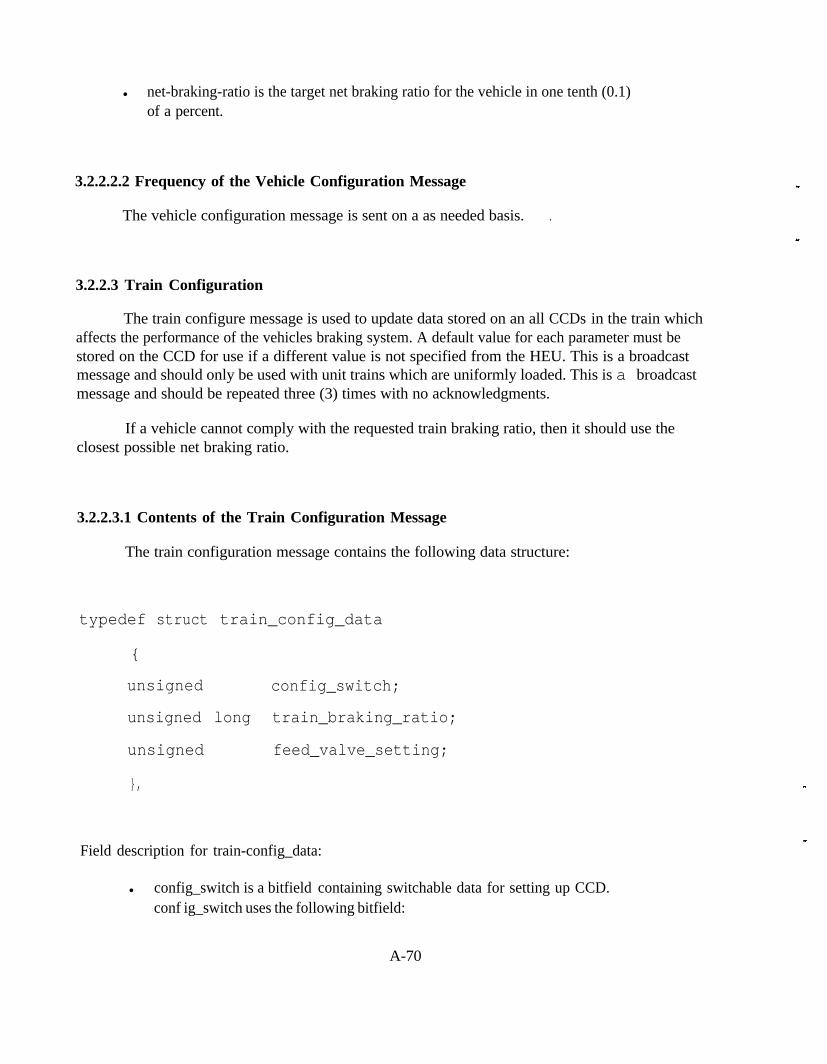
l net-braking-ratio is the target net braking ratio for the vehicle in one tenth (0.1)of a percent.
3.2.2.2.2 Frequency of the Vehicle Configuration Message
The vehicle configuration message is sent on a as needed basis. .
3.2.2.3 Train Configuration
The train configure message is used to update data stored on an all CCDs in the train whichaffects the performance of the vehicles braking system. A default value for each parameter must bestored on the CCD for use if a different value is not specified from the HEU. This is a broadcastmessage and should only be used with unit trains which are uniformly loaded. This is a broadcastmessage and should be repeated three (3) times with no acknowledgments.
If a vehicle cannot comply with the requested train braking ratio, then it should use theclosest possible net braking ratio.
3.2.2.3.1 Contents of the Train Configuration Message
The train configuration message contains the following data structure:
typedef struct train_config_data
{
unsigned config_switch;
unsigned long train_braking_ratio;
unsigned feed_valve_setting;
},
Field description for train-config_data:
l config_switch is a bitfield containing switchable data for setting up CCD.conf ig_switch uses the following bitfield:
A-70

config_s witch
bit Definition
A (LSB) 0 = Loaded, 1 = Empty
Default
0 = Loaded. This isoverridden by on board
load sensor
B
C
spare
spare
E
F
G
I-I
spare
spare
spare
spare
l train-braking-ratio is the target net braking ratio for the train in one tenth (0. I)of a percent. If this is set to zero (0). then each vehicle shouid use its default net brakingratio.
. feed-valve-setting is the brake pipe pressure for the train in PSIG. This has aresolution of one (1) PSI.
3.2.2.3.2 Frequency of the Train Configuration Message
The vehicle configuration message is sent on a as needed basis.
3.2.2.4 Time Synchronization
In order to promote coherent event tracking, the time synchronization message is used to setthe internal clocks of all nodes in the network to approximately the same time. The time should beset to Eastern Standard Time (EST). This message is broadcast to ail nodes in the network andshould be repeated three (3) times with no acknowledgments.
A-7 I
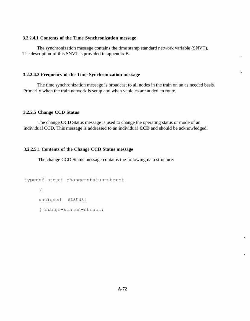
3.2.2.4.1 Contents of the Time Synchronization message
The synchronization message contains the time stamp standard network variable (SNVT).The description of this SNVT is provided in appendix B.
3.2.2.4.2 Frequency of the Time Synchronization message
The time synchronization message is broadcast to all nodes in the train on an as needed basis.Primarily when the train network is setup and when vehicles are added en route.
3.2.2.5 Change CCD Status
The change CCD Status message is used to change the operating status or mode of anindividual CCD. This message is addressed to an individual CCD and should be acknowledged.
3.2.2.5.1 Contents of the Change CCD Status message
The change CCD Status message contains the following data structure.
typedef struct change-status-struct
{
unsigned status;
} change-status-struct;
A-72

Field Descriptions:
l status is the current status of the CCD.
s tatus
bit Definition Default
A (LSB) 0 = cut out, 1 = cut in 1 = cut in
B spare
C spare I
D
E
F
G
spare
spare
spare
spare
H spare
3.2.2.5.2 Frequency of the Change CCD Status message
The Change CCD Status message is sent on an as needed basis.
3.2.2.6 Exception Update Request
The exception update request is used when an unknown exception message is received by theHEU. This message is addressed to the node which generated the unknown exception message.This message is acknowledged with an exception update from the target node.
A-73

3.2.2.6.1 Contents of the Exception Update Request
The data structure for the request for an exception code update is:
typedef struct exception_update_rq_struct
{
unsigned long code;
} exception-update-rq_struct;
Field Description:
. code is the unknown exception code.
3.2.2.6.2 Frequency of the Exception Update Request
The exception update request message is sent on an as needed basis.
3.2.2.7 End of Train (EOT) Command
The EOT command is used to request the end of train device to perform a special function.The EOT command is addressed to the EOT and should be acknowledged.
A-74

3.2.2.7.1 Contents of the EOT Command
The EOT Command structure is used for the EOT Command message.
typedef struct eot_command_struct
{
unsigned command;
} eot_command_struct;
Field Description:
l command is the current command sent to EOT. Command is a bit field which uses thefollowing definition:
command
bit Definition
A (LSB)
B 0 = marker off, 1 = marker on
C
D
0 = blue flag off, 1 = blue flag on
spare
E
F
G
H
spare
spare
spare
spare
A-75

3.2.2.7.2 Frequency of the EOT Command
The EOT command is sent on an as needed basis.
3.2.2.8 Power Suppiy Enable
3.2.2.8.1 Contents of the Power Supply Enable Message
The power supply enable message uses the SNVT State. The enable/disable bit of SNVTState is used to indicate whether a power supply controller (PSC) will activate a given power supply.This message is sent to each PSC in the tram individually.
3.2.2.8.2 Frequency of the Power Supply Enable Message
The power supply enable message is transmitted during the initial setup of a locomotivecontaining a PSC. Also, this message may be sent on an as needed basis.
3.2.2.9 Power Switch
3.2.2.9.1 Contents of Power Supply Switch Message
The power supply switch message uses the SNVT State. The on/off bit of SNVTState IS used to command the PSCs to turn on all enabled power supplies. In order to have all powersupplies activate at approximately the same time, this message must be broadcast. Note that powerwill not be supplied to the electric trainline until both the power supply switch message and the EOTBeacon message are received by the PSC.
3.2.2.9.2 Frequency of Power Supply Switch
The Power Supply Switch message is transmitted on an as needed basis.
A-76
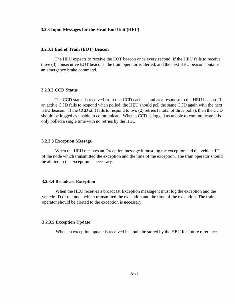
3.2.3 Input Messages for the Head End Unit (HEU)
3.2.3.1 End of Train (EOT) Beacon
The HEU expects to receive the EOT beacon once every second. If the HEU fails to receivethree (3) consecutive EOT beacons, the train operator is alerted, and the next HEU beacon containsan emergency brake command.
3.2.3.2 CCD Status
The CCD status is received from one CCD each second as a response to the HEU beacon. Ifan active CCD fails to respond when polled, the HEU should poll the same CCD again with the nextHEU beacon. If the CCD still fails to respond to two (2) retries (a total of three polls), then the CCDshould be logged as unable to communicate. When a CCD is logged as unable to communicate it isonly polled a single time with no retries by the HEU.
3.2.3.3 Exception Message
When the HEU receives an Exception message it must log the exception and the vehicle IDof the node which transmitted the exception and the time of the exception. The train operator shouldbe alerted to the exception is necessary.
3.2.3.4 Broadcast Exception
When the HEU receives a broadcast Exception message it must log the exception and thevehicle ID of the node which transmitted the exception and the time of the exception. The trainoperator should be alerted to the exception is necessary.
3.2.3.5 Exception Update
When an exception update is received it should be stored by the HEU for future reference.
A-71
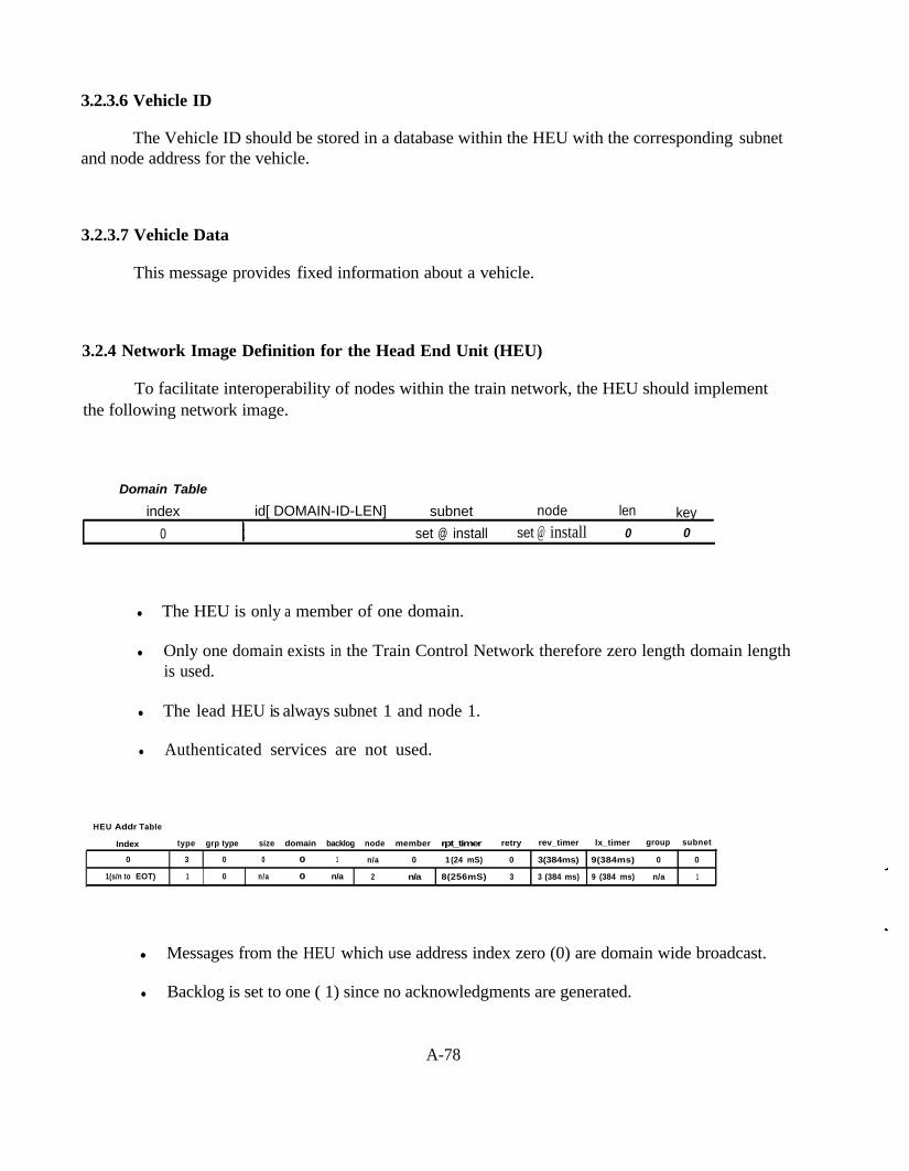
3.2.3.6 Vehicle ID
The Vehicle ID should be stored in a database within the HEU with the corresponding subnetand node address for the vehicle.
3.2.3.7 Vehicle Data
This message provides fixed information about a vehicle.
3.2.4 Network Image Definition for the Head End Unit (HEU)
To facilitate interoperability of nodes within the train network, the HEU should implementthe following network image.
Domain Table
index id[ DOMAIN-ID-LEN] subnet node len key0 set @ install set @ install 0 0
l The HEU is only a member of one domain.
l Only one domain exists in the Train Control Network therefore zero length domain lengthis used.
l The lead HEU is always subnet 1 and node 1.
l Authenticated services are not used.
HEU Addr Table
Index type grp type size domain backlog node member rpt_timer retry rev_timer lx_timer group subnet
0 3 0 0 0 1 n/a 0 1 (24 mS) 0 3(384ms) 9(384ms) 0 0
1(s/n to EOT) 1 0 n/a 0 n/a 2 n/a 8(256mS) 3 3 (384 ms) 9 (384 ms) n/a 1
l Messages from the HEU which use address index zero (0) are domain wide broadcast.
l Backlog is set to one ( 1) since no acknowledgments are generated.
A-78

HEU Network Variable Configuration Table
l Bound ECP brake network variables use selector range 0x0000 to 0 x 0 F F F .
l Unbound network variables use selector range 0x3000 to 0x3FFF.
3.3 The Car Control Device (CCD)
3.3.1 Function of the CCD
The function of the CCD to regulate the brake cylinder pressure of a vehicle. The CCDshould perform in accordance with the ECP Brake Performance Specification, S*** section * of theAAR Manual of Standards and Recommended Practices. No more than one CCD should active on asingle car or. in the case of multi-platform articulated cars, no more than one CCD per platform.
If a Standard Car Network interface is provided within the CCD it must comply with section4 of this document.
A-79

3.3.2 CCD Output Messages
3.3.2.1 CCD Status
When the logical address of a CCD is designated within the contents of the HEU beacon thenthat CCD must return a CCD status message to the HEU. This message is unacknowledged.
3.3.2.1.1 Contents of CCD Status Message
The CCD Status Data structure is used by the CCD status message.
typedef struct status-data-struct
{
unsigned status;
unsigned battery-volts;
unsigned brake_pipe_pressure;
unsigned supply_res_pressure;
unsigned percent-brake;
};
Field Descriptions:
l status is the current status of the CCD.
status
bit Definition Default
A(LSB) 0 = cut out. 1 = cut in 1 =cutin
B spare
C, spare
A-SO
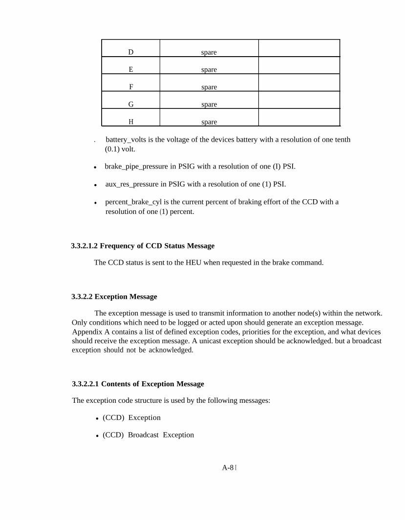
D
E
F
G
H
spare
spare
spare
spare
spare
. battery_volts is the voltage of the devices battery with a resolution of one tenth(0.1) volt.
l brake_pipe_pressure in PSIG with a resolution of one (I) PSI.
l aux_res_pressure in PSIG with a resolution of one (1) PSI.
l percent_brake_cyl is the current percent of braking effort of the CCD with aresolution of one (1) percent.
3.3.2.1.2 Frequency of CCD Status Message
The CCD status is sent to the HEU when requested in the brake command.
3.3.2.2 Exception Message
The exception message is used to transmit information to another node(s) within the network.Only conditions which need to be logged or acted upon should generate an exception message.Appendix A contains a list of defined exception codes, priorities for the exception, and what devicesshould receive the exception message. A unicast exception should be acknowledged. but a broadcastexception should not be acknowledged.
3.3.2.2.1 Contents of Exception Message
The exception code structure is used by the following messages:
l (CCD) Exception
l (CCD) Broadcast Exception
A-8 I

typedef struct exception-code-struct
{
char ccd_id[11];
unsigned long code;
unsigned long data;
int priority;
};
Field Descriptions:
l ccd_id is the ID of the device generating the exception (car reporting mark).
l code is the exception code. A list of defined codes is provided in appendix A
l data is additional data which may be required by the HEU.
A-82

l priority Indicates the severity of the exception, and the recommended action whichshould be taken.
Priority
train must be stopped immediately at service rate ifs of this priority are
record and notif o erator a CCD is cutout
3.3.2.2.2 Frequency of Exception Message
Exception messages are transmitted on an as needed basis. Once an exception is transmittedfrom a node, it is not retransmitted unless the priority of the condition changes.
3.3.2.3 Exception Update
When an unknown exception code is sent to the HEU, the HEU may request an exceptioncode update from the sending node. The response to the exception update request is the exceptionupdate message.
A-83

3.3.2.3.1 Contents of Exception Update
The data structure for the exception code update is:
typedef struct exception-update
{
unsigned long code;
char description[28];
} exception update;
Field Descriptions:
l code is the exception code number.
l description is a string up to twenty-eight (28) characters in length. This contains adescription of the code.
3.3.2.3.2 Frequency of Exception Update
The Exception update message is transmitted on an as needed basis.
3.3.3 Input Messages for the CCD
3.3.3.1 HEU Beacon
When the HEU beacon is received by a CCD, the CCD should set the target brake cylinderpressure accordingly. If the CCD’s subnet and node address is contained in the HEU beacon, thenthe CCD should respond by sending a CCD status message to the HEU.
A-84

3.3.3.2 EOT Beacon
A CCD should respond to the absence or presence of the EOT Beacon in accordance with thePerformance Requirement for Testing Electrically Controlled Pneumatic Cable-Based (ECP) FreightBrake Systems, S-4200 section 3.3.3.2.1 of the AAR Manual of Standards and RecommendedPractices.
3.3.3.3 Broadcast Exception in
A CCD should respond to a broadcast exception message in accordance with the, S-4200section 3.3.2 of the AAR Manual of Standards and Recommended Practices.
3.3.3.4 Vehicle ID In
Receiving a Vehicle ID In message causes the CCD to overwrite its vehicle identificationinformation with the information contained within the message.
3.3.3.5 Vehicle Fixed Information
Fixed information which affects the braking performance of a CCD can be updated using thevehicle information message. In order to preserve this information in the event of a power loss, thisdata is stored in the CCD as a configuration class network variable.
A-85

3.3.3.5.1 Contents of the Vehicle Fixed Information Message
The Vehicle information message uses the following data structure:
typedef struct vehicle_data
int brake_constant;
unsigned long loaded_weight;
int empty_weight;
} vehicle-data;
field descriptions for vehicle-data:
l brake-constant in units of inches’).
l loaded-weight is the gross loaded weight in Kips.
l empty-weight in Kips.
3.3.3.6 Vehicle Configuration
When a vehicle configuration message is received a CCD must overwrite its existingconfiguration with the new data.
A-86

3.3.3.7 Train Configuration
When a train configuration message is received a CCD must use this configuration instead ofits default vehicle configuratxon.
3.3.3.8 Time Synch
When a Time Synch message is received by a CCD it should set its internal clock tocorrespond with the time contained within the message.
3.3.3.9 Change CCD Status
When a change CCD status message is received by a CCD, the receiving CCD must complyand perform as required by the new status.
3.3.3.10 Exception Update Request
A CCD should respond to an Exception update request by sending an exception updatemessage to the HEU for the exception code contained within the exception update request.
3.3.4 Network image Definition for the CCD
Domain Tableindex id[ DOMAIN-ID-LEN]
0
subnet node len keyset @ install set @ install 0 0
. All CCDs are members of one domain.
l Only one domain exists in the Train Control Network therefore zero length domain lengthis used.
l Authenticated services are not used.
A-87
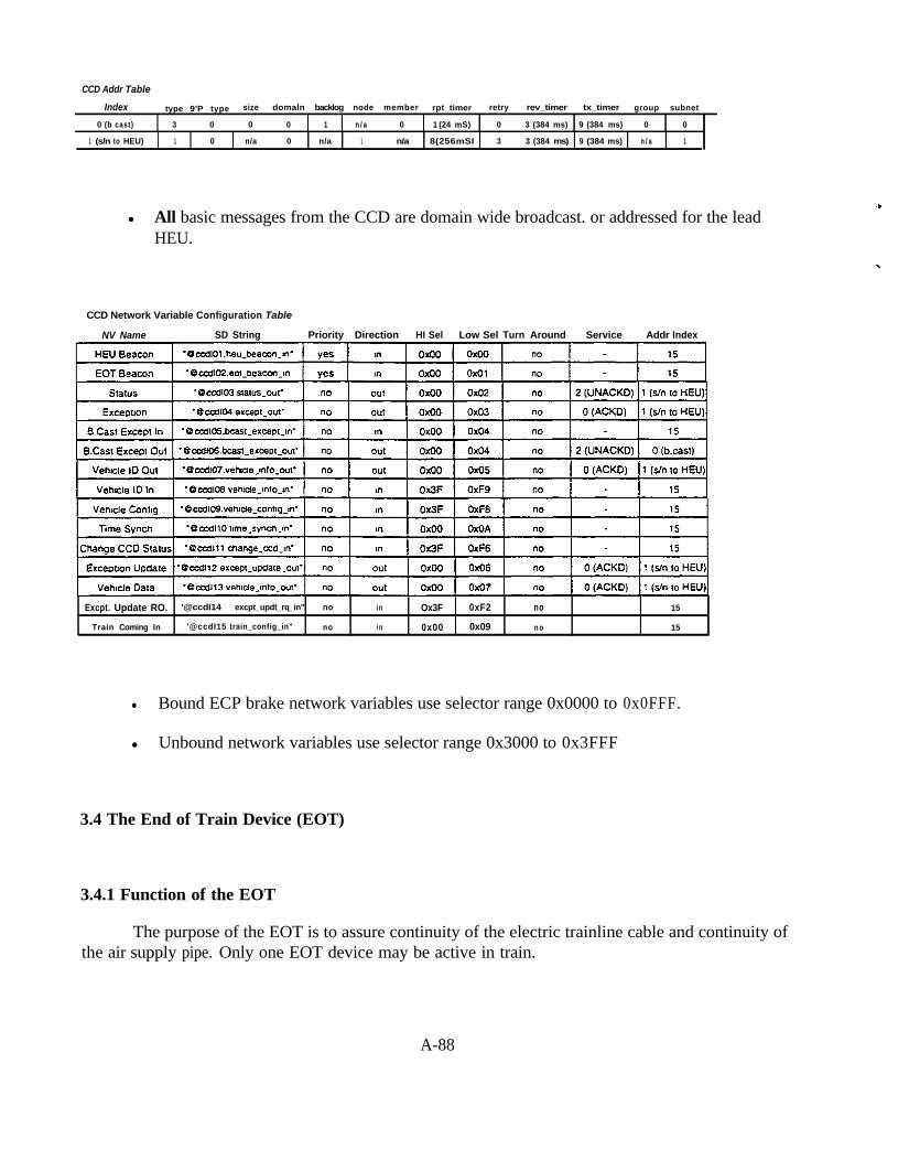
CCD Addr Table
Index type 9’P type size domaln backlog node member rpt_timer retry rev_timer tx_timer group subnet
0 (b cast) 3 0 0 0 1 n / a 0 1 (24 mS) 0 3 (384 ms) 9 (384 ms) 0 0
1 (s/n to HEU) 1 0 n/a 0 n/a 1 n/a 8(256mSI 3 3 (384 ms) 9 (384 ms) n / a 1
l All basic messages from the CCD are domain wide broadcast. or addressed for the leadHEU.
CCD Network Variable Configuration Table
NV Name SD String Priority Direction HI Sel Low Sel Turn Around Service Addr Index
Excpt. Update RO. '@ccdl14 excpt_updt_rq_in"’ no i n Ox3F 0xF2 no 15
Train Coming In '@ccdl15 train_config_in" no i n 0x00 0x09 n o 15
l Bound ECP brake network variables use selector range 0x0000 to 0x0FFF.
l Unbound network variables use selector range 0x3000 to 0x3FFF
3.4 The End of Train Device (EOT)
3.4.1 Function of the EOT
The purpose of the EOT is to assure continuity of the electric trainline cable and continuity ofthe air supply pipe. Only one EOT device may be active in train.
A-88

3.4.2 EOT Output Messages
3.4.2.1 EOT Beacon
3.4.2.1.1 Contents of the EOT Beacon
The EOT data structure is used for the EOT beacon message.
typedef struct eot_data_struct
{
unsigned status;
unsigned brake_pipe_pressure;
unsigned battery-volts;
} eot_data_struct;
A-89

Field Descriptions:
. status is the current status of the EOT. Status is a bit field which uses the followingdefinition:
status
bit
A (LSB)
Definition
0 = Dower off, 1 = power on
B 0 = marker off, 1 = marker on
C 0 = blue flag off, 1 = blue flag on
D 0 = train stopped. 1 = train moving
E spare
F spare
l brake_pipe_pressure in PSIG with one (1) PSI resolution.
l battery_volts with one tenth (0.1) volt resolution.
3.4.2.1.2 Frequency of the EOT Beacon
The EOT beacon IS transmitted once per second.
A-90

3.4.2.2 Exception Message
The exception message is used to transmit information to another node(s) within the network.Only conditions which need to be logged or acted upon should generate an exception message.Appendix A contains a list of defined exception codes. priorities for the exception, and what devicesshould receive the exception message. A unicast exception should be acknowledged. but a broadcastexception should not be acknowledged.
l
3.4.2.2.1 Contents of Exception Message
The exception code structure is used by the following messages:
l (EOT) Exception
l (EOT) Broadcast Exception
typedef struct exception_code_struct
{
char ccd_id[11];
unsigned long code;
unsigned long data;
int priority;
Field Descriptions:
l ccd_id is the ID of the device generating the exception (car reporting mark).
l code is the exception code. A list of defined codes is provided in appendix A
l data is additional data which may be required by the HEU.
A-9 1

l priority Indicates the severity of the exception, and the recommended action whichshouid be taken.
Priority
train must be stopped immediately at service rate ifthree or more like messages of this priority are
7 record and notify operator a CCD is cutout
8 record only
9 Event / No need to clear.
3.4.2.2.2 Frequency of Exception Message
Exception messages are transmitted on an as needed basis. Once an exception is transmittedfrom a node, it is not retransmitted unless the priority of the condition changes.
3.4.2.3 Exception Update
When an unknown exception code is sent to the HEU, the HEU may request an exceptioncode update from the sending node. The response to the exception update request is the exceptionupdate message.
A-92
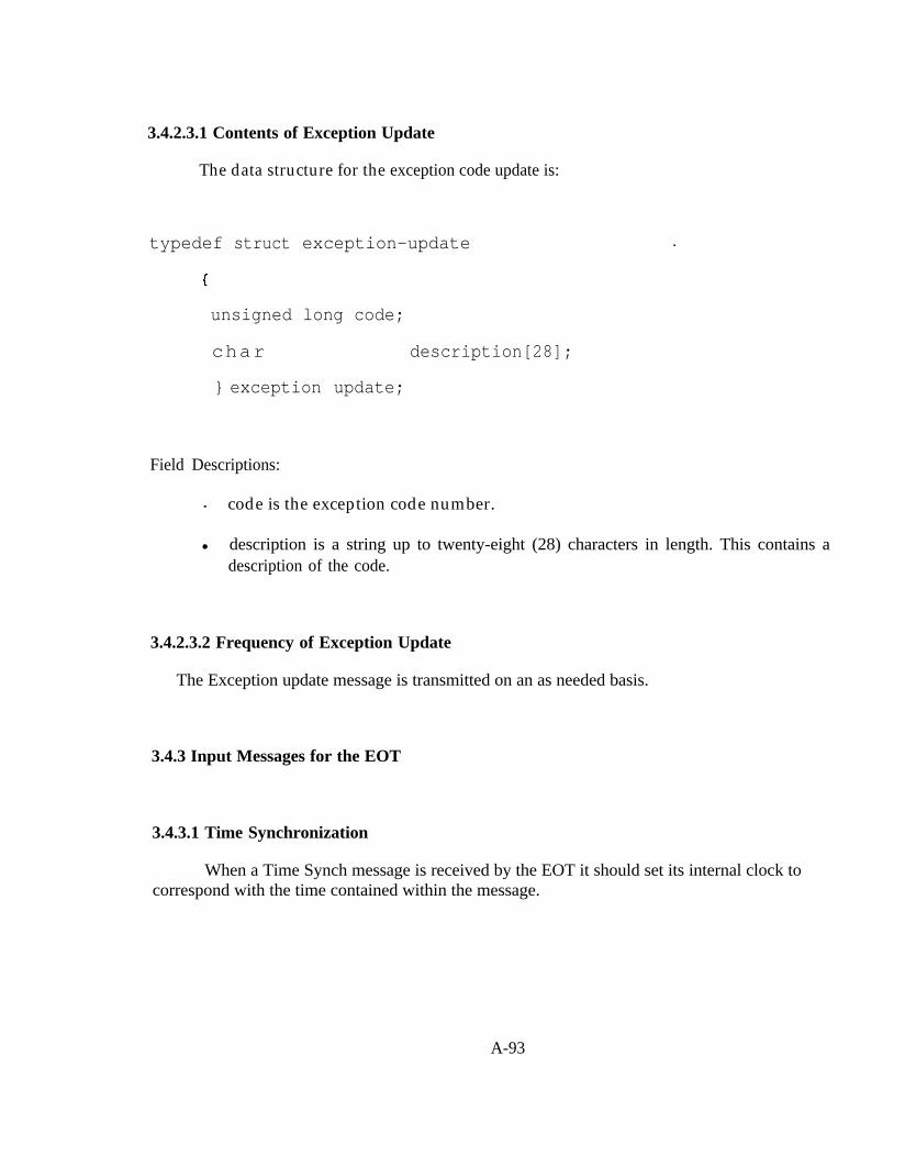
3.4.2.3.1 Contents of Exception Update
The data structure for the exception code update is:
typedef struct exception-update
unsigned long code;
char description[28];
} exception update;
Field Descriptions:
. code is the exception code number.
l description is a string up to twenty-eight (28) characters in length. This contains adescription of the code.
3.4.2.3.2 Frequency of Exception Update
The Exception update message is transmitted on an as needed basis.
3.4.3 Input Messages for the EOT
3.4.3.1 Time Synchronization
When a Time Synch message is received by the EOT it should set its internal clock tocorrespond with the time contained within the message.
A-93

3.4.3.2 EOT Command
When an EOT command message is received, the EOT must change its operation to complywith the command message.
3.4.3.3 HEU Beacon
The HEU beacon is used by the EOT to check the continuity of the trainline. The EOTshould respond to a failure to receive the HEU beacon in accordance with S-4200 of the AARManual of Standards and Recommended Practices.
3.4.3.4 Broadcast Exception In
An EOT should respond to a broadcast exception message in accordance with S-4200 of theAAR Manual of Standards and Recommended Practices.
3.4.3.5 Exception Update Request
An EOT should respond to an Exception Update Request by sending an exception updatemessage to the HEU for the exception code contained within the exception update request.
3.4.4 Network Image Definition for the EOT
Domain Tableindex id[ DOMAIN-ID-LEN] subnet node len key
I 0 I set @ install set @ install 0 0
l The EOT is only a member of one domain.
l Only one domain exists in the Train Control Network therefore zero length domain lengthis used.
l The EOT is always subnet 1 and node 2.
l Authenticated services are not used.
A-94

EOT Addr Table
Index type grp type size domain backlog node member rpt_timer retry rev_timer tx_timer group subnet
0 lb cast) 3 0 0 0 1 n/a 0 1 (24 mS) 0 3(384 ms) 9(384 ms) 0 0
1 (s/n to HEU) 1 0 n/a 0 n/a I n/a 8 (256 mS) 3 3(384ms) 9(384ms) n/a 1
l All basic messages from the EOT are domain wide broadcast.
EOT Network variable Configuration Table
NV Name SD string Priority Direction HI Set Low Set Turn Around Service Addr Index
B Cast Except Out "@eot107.bcast_except_out" o no out 0x00 0x04 no 2 (UNACKD) 0 (b.cast)
B Cast Except In "@eot108 bcast_except_in’ no in 0x00 0x04 no - 15
HEU Beacon In "@eot109 heu_beacon_in" yes in 0x00 0x00 no - 15
l Bound ECP brake network variables use selector range 0x0000 to 0x0FFF.
l Unbound network variables use selector range 0x3000 to 0x3FFF.
3.5 The Power Supply Controller (PSC)
3.51 Function of the Power Supply Controller
The purpose of the power supply controller (PSC) is to allow network based control of thetrainline power supplies. This device is also used to prevent the power from being applied to theelectric trainiine while vehicles are being added or removed from the train. No more than one powersupply controller is allowed per locomotive.
A-95
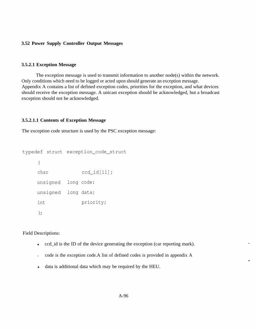
3.52 Power Supply Controller Output Messages
3.5.2.1 Exception Message
The exception message is used to transmit information to another node(s) within the network.Only conditions which need to be logged or acted upon should generate an exception message.Appendix A contains a list of defined exception codes, priorities for the exception, and what devicesshould receive the exception message. A unicast exception should be acknowledged, but a broadcastexception should not be acknowledged.
3.5.2.1.1 Contents of Exception Message
The exception code structure is used by the PSC exception message:
typedef struct
{
char
unsigned
unsigned
int
};
exception_code_struct
ccd_id[11];
long code:
long data;
priority;
Field Descriptions:
l ccd_id is the ID of the device generating the exception (car reporting mark).
. code is the exception code.A list of defined codes is provided in appendix A
l data is additional data which may be required by the HEU.
A-96

l priority indicates the severity of the exception, and the recommended action whichshould be taken.
Priority
Code Description
0 exception clear
1 train must be stopped emergency rate
2
3
4
6
7
8
train must be stopped immediately at service rate
train must be stopped immediately at service rate ifthree or more like messages of this priority arereceived within 10 seconds.
reduced speed to next convenient point
5 maintenance required at next terminal
maintenance required at destination terminal
record and notify operator a CCD is cutout
record onlv
9 Event / No need to clear.
3.5.2.1.2 Frequency of Exception Message
Exception messages are transmitted on an as needed basis. Once an exception is transmittedfrom a node. it is not retransmitted unless the priority of the condition changes.
A-97

3.5.3 Input Messages for the PSC
3.5.3.1 HEU Beacon
The PSC should not allow the power supply to provide an output voltage until the HEUBeacon is received. This function overrides any command from the HEU. Also, if the HEU beaconis missed for three consecutive seconds the PSC should turn the power supply output off.
3.5.3.2 Time Synch
When a Time Synch message is received by the EOT it should set its internal clock tocorrespond with the time contained within the message.
3.5.3.3 Power Supply Enable
When the power supply enable message is received the PSC should enable or disable thepower supply accordingly. If no power supply enable message is received then the PSC assumes adefault of “power supply disabled.”
3.5.3.4 Power Switch
When the power switch enabled is received the PSC should activate or deactivate the powersupply accordingly. Note that the power supply may not be activated until the EOT beacon isreceived and a power on message from the HEU is received.
A-98

3.5.4 Network Image for the Power Supply Controller
Domain Tableindex
0
id[ DOMAIN-ID-LEN] subnet node len keyset @ install set @ install 0 0
l All PSCs are members of one domain.
l Only one domain exists in the Train Control Network therefore zero length domain lengthis used.
l Authenticated services are not used.
PSC Addr Table
Index type grp type size domaln backlog node member rpt_tlmer retry rev_tlmer tx_tlmer g r o u p subnet
0 (s/n to HEU) 1 0 rva 0 n/a 1 n/a 1 (24 mS) 3 3 (384 ms) 9 (384 ms) rila 1
PSC Network Variable Configuration Table
l Bound ECP brake network variables use selector range 0x0000 to 0x0FFF.
l Unbound network variables use selector range 0x3000 to 0x3FFF.
A-99
4.0 STANDARD CAR NETWORK INTERFACE REQUIREMENTS
Provisions for a standard car network interface are contained in S*** section * of the AARManual of Standards and Recommended Practices.
5.0 DISTRIBUTED LOCOMOTIVE CONTROL SYSTEM REQUIREMENTS
Provisions for distributed locomotive control are contained in S*** section * of the AARManual of Standards and Recommended Practices.
A-100

APPENDIX A
EXCEPTION CODES
Exception Number Exception Description Priority Transmission Type
10000 Loss of Communication with HEU 1 Broadcast
10001 Loss of Brake Pipe Pressure 2 or 3 Unicast to HEU
10002 Brake Pipe Not Charging 2 or 3 Unicast to HEU
10010 Loss of Head End Power 2 or 3 Unicast to HEU
10011 Low Head End Power 4 Unicast to HEU
10020 Low Res. Pressure
10030 Low Brake Cylinder Pressure
10031 High Brake Cylinder Pressure
10040 Low Battery Voltage
10041 High Battery Voltage
3 Unicast to HEU
8 Unicast to HEU
7 Unicast to HEU
7 Unicast to HEU
8 Unicast to HEU
A-101

APPENDIX B
LONWORKS STANDARD NETWORK VARIABLE LIST
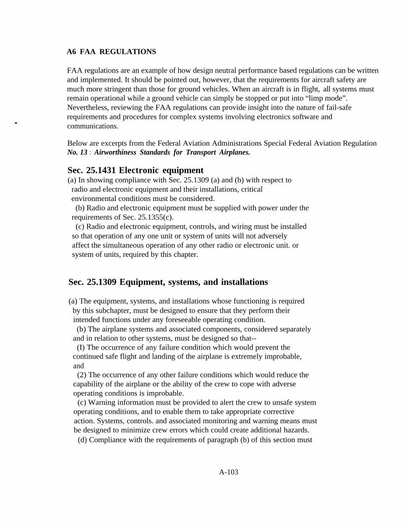
A6 FAA REGULATIONS
FAA regulations are an example of how design neutral performance based regulations can be writtenand implemented. It should be pointed out, however, that the requirements for aircraft safety aremuch more stringent than those for ground vehicles. When an aircraft is in flight, all systems mustremain operational while a ground vehicle can simply be stopped or put into “limp mode”.Nevertheless, reviewing the FAA regulations can provide insight into the nature of fail-saferequirements and procedures for complex systems involving electronics software andcommunications.
Below are excerpts from the Federal Aviation Administrations Special Federal Aviation RegulationNo. 13 : Airworthiness Standards for Transport Airplanes.
Sec. 25.1431 Electronic equipment(a) In showing compliance with Sec. 25.1309 (a) and (b) with respect to
radio and electronic equipment and their installations, criticalenvironmental conditions must be considered.
(b) Radio and electronic equipment must be supplied with power under therequirements of Sec. 25.1355(c).
(c) Radio and electronic equipment, controls, and wiring must be installedso that operation of any one unit or system of units will not adverselyaffect the simultaneous operation of any other radio or electronic unit. orsystem of units, required by this chapter.
Sec. 25.1309 Equipment, systems, and installations
(a) The equipment, systems, and installations whose functioning is requiredby this subchapter, must be designed to ensure that they perform theirintended functions under any foreseeable operating condition.(b) The airplane systems and associated components, considered separately
and in relation to other systems, must be designed so that--(I) The occurrence of any failure condition which would prevent the
continued safe flight and landing of the airplane is extremely improbable,and
(2) The occurrence of any other failure conditions which would reduce thecapability of the airplane or the ability of the crew to cope with adverseoperating conditions is improbable.
(c) Warning information must be provided to alert the crew to unsafe systemoperating conditions, and to enable them to take appropriate correctiveaction. Systems, controls. and associated monitoring and warning means mustbe designed to minimize crew errors which could create additional hazards.
(d) Compliance with the requirements of paragraph (b) of this section must
A-103

be shown by analysis, and where necessary, by appropriate ground, flight, orsimulator tests. The analysis must consider--
(1) Possible modes of failure. including malfunctions and damage fromexternal sources.
(2) The probability of multiple failures and undetected failures.(3) The resulting effects on the airplane and occupants, considering the
stage of flight and operating conditions, and(4) The crew warning cues, corrective action required, and the capability,
of detecting faults.(e) Each installation whose functioning is required by this subchapter, and
that requires a power supply, is an “essential load” on the power supply. Thepower sources and the system must be able to supply the following power loadsin probable operating combinations and for probable durations:
(1) Loads connected to the system with the system functioning normally.(2) Essential loads, after failure of any one prime mover, power converter,
or energy storage device.(3) Essential loads after failure of--(i) Any one engine on two-engine airplanes; and(ii) Any two engines on three-or-more-engine airpianes.(4) Essential loads for which an alternate source of power is required by
this chapter, after any failure or malfunction in any one power supplysystem, distribution system, or other utilization system.
(f) In determining compliance with paragraphs (e) (2) and (3) of thissection, the power loads may be assumed to be reduced under a monitoringprocedure consistent with safety in the kinds of operation authorized. Loadsnot required in controlled flight need not be considered for the two-engine-inoperative condition on airplanes with three or more engines.(g) In showing compliance with paragraphs (a) and (b) of this section with
regard to the electrical system and equipment design and installation,critical environmental conditions must be considered. For electricalgeneration. distribution. and utilization equipment required by or used incomplying with this chapter, except equipment covered by Technical StandardOrders containing environmental test procedures, the ability to providecontinuous. safe service under foreseeable environmental conditions may beshown by environmental tests. design analysis, or reference to previouscomparable service experience on other aircraft.
[Amdt. 25-23, 35 FR 5679, Apr. 8, 1970, as amended by Amdt. 25-38, 411 FR55467. Dec. 20. 1976; Amdt. 25-41, 42 FR 36970, July 18. 1977]
A-104

Sec. 25.1355 Distribution system.
(a) The distribution system includes the distribution busses, theirassociated feeders, and each control and protective device.
(b) [Reserved](c) If two independent sources of electrical power for particular equipment
or systems are required by this chapter, in the event of the failure of onepower source for such equipment or system, another power source (includingits separate feeder) must be automatically provided or be manually selectableto maintain equipment or system operation.
[Doc.. No. 5066, 299 FR 18291, Dec. 24, 1964, as amended by Amdt. 25-23, 355 FR5679, Apr. 8, 1970; Amdt. 25-38, 41 FR 55468, Dec. 20, 1976]
Sec. 25.1363 Electrical system tests
(a) When laboratory tests of the electrical system are conducted--( 1) The tests must be performed on a mock-up using the same generating
equipment used in the airplane;(2) The equipment must simulate the electrical characteristics of the
distribution wiring and connected loads to the extent necessary for validtest results: and
(3) Laboratory generator drives must simulate the actual prime movers onthe airplane with respect to their reaction to generator loading, includingloading due to faults.
(b) For each flight condition that cannot be simulated adequately in thelaboratory or by ground tests on the airplane, flight tests must be made.
Sec. 25.1357 Circuit protective devices.
(a) Automatic protective devices must be used to minimize distress to theelectrical system and hazard to the airplane in the event of wiring faults orserious malfunction of the system or connected equipment.(b) The protective and control devices in the generating system must be
designed to de-energize and disconnect faulty power sources and powertransmission equipment from their associated busses with sufficient rapidityto provide protection from hazardous over-voltage and other malfunctioning.(c) Each resettable circuit protective device must be designed so that,
when an overload or circuit fault exists, it will open the circuitirrespective of the position of the operating control.(d) If the ability to reset a circuit breaker or replace a fuse is
A-105

essential to safety in flight, that circuit breaker or fuse must be locatedand identified so that it can be readily reset or replaced in flight.
(e) Each circuit for essential loads must have individual circuitprotectron. However, individual protection for each circuit in an essentialload system (such as each position light circuit in a system) is notrequired.(f) If fuses are used, there must be spare fuses for use in flight equal to
at least 50 percent of the number of fuses of each rating required for .complete circuit protection.
(g) Automatic reset circuit breakers may be used as integral protectors forelectrical equipment (such as thermal cut-outs) if there is circuitprotection to protect the cable to the equipment.
A-106

A7 EUROPEAN REGULATIONS
A4.1 OVERVIEW OF ECE BRAKING REGULATIONS
The regulation for heavy vehicle brakes is ECE 324 R- 13. This “type approval” sytle regulation hasthree main features:
1) an approval process
2) brake system specifications
3) brake performance tests
Each of these regulatory components are discussed below.
Approval process
The approval process for braking systems under rRl3 is quite complex. A complete componentlevel design specification must be submitted to the authorizing body for its review. The authorityexamines the regulation with regard to compliance with the brake system specifications (Brakesystem specifications are discussed in the following section). The authority is also responsible forcarrying out the brake performance tests.
Excerpts from ECE 324 R- 13 related to Approval
3.1. The application for approval of a vehicle type with regard to braking shall besubmitted by the vehicle manufacturer or by his duly accredited representative.
3.2. It shall be accompanied by the undermentioned documents in triplicate and by thefollowing particulars:
3.2.1. a description of the vehicle type with regard to the items specified in paragraph 2.2.above. The numbers and/or symbols identifying the vehicle type and, in the case ofpower-driven vehicles. the engine type shall be specified;
3.2.2. a list of the components, duly identified, constituting the braking system:
3.2.3. a diagram of assembled braking system and an indication of the position of itscomponents on the vehicle;
3.2.4. detailed drawings of each component to enable it to be easily located and identified.
A-107
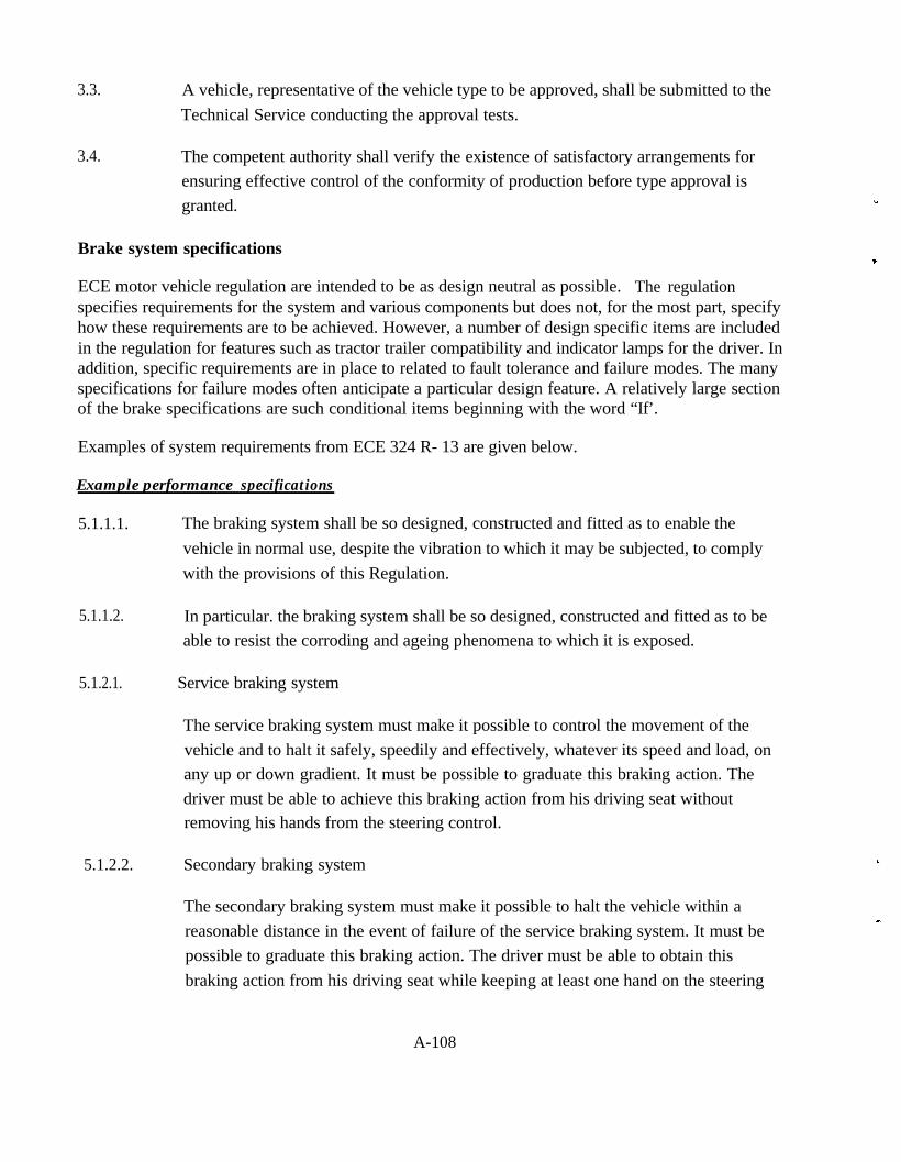
3.3.
3.4.
A vehicle, representative of the vehicle type to be approved, shall be submitted to theTechnical Service conducting the approval tests.
The competent authority shall verify the existence of satisfactory arrangements forensuring effective control of the conformity of production before type approval isgranted.
Brake system specifications
ECE motor vehicle regulation are intended to be as design neutral as possible. The regulationspecifies requirements for the system and various components but does not, for the most part, specifyhow these requirements are to be achieved. However, a number of design specific items are includedin the regulation for features such as tractor trailer compatibility and indicator lamps for the driver. Inaddition, specific requirements are in place to related to fault tolerance and failure modes. The manyspecifications for failure modes often anticipate a particular design feature. A relatively large sectionof the brake specifications are such conditional items beginning with the word “If’.
Examples of system requirements from ECE 324 R- 13 are given below.
Example performance specifications
5.1.1.1. The braking system shall be so designed, constructed and fitted as to enable thevehicle in normal use, despite the vibration to which it may be subjected, to complywith the provisions of this Regulation.
5.1.1.2.
5.1.2.1. Service braking system
5.1.2.2. Secondary braking system
In particular. the braking system shall be so designed, constructed and fitted as to beable to resist the corroding and ageing phenomena to which it is exposed.
The service braking system must make it possible to control the movement of thevehicle and to halt it safely, speedily and effectively, whatever its speed and load, onany up or down gradient. It must be possible to graduate this braking action. Thedriver must be able to achieve this braking action from his driving seat withoutremoving his hands from the steering control.
The secondary braking system must make it possible to halt the vehicle within areasonable distance in the event of failure of the service braking system. It must bepossible to graduate this braking action. The driver must be able to obtain thisbraking action from his driving seat while keeping at least one hand on the steering
A-108

control. For the purposes of these provisions it is assumed that not more than onefailure of the service braking system can occur at one time.
Example compatibility specifications
5. 1 .2.4. Pneumatic connections between power-driven vehicles and trailers.
In the case of a braking system operated by compressed-air,.the pneumatic link withthe trailer must be of the type with two or more lines. However, in all cases, all therequirements of this Regulation must be satisfied by the use of only two lines. Shut-off devices which are not automatically actuated shall not be permitted.
In the case of tractor and semi-trailer combinations, the flexible hoses shall be a partof the tractor vehicle. In ail other cases, the flexible hoses shall be a part of the trailer.
Example driver interface specifications
5.2.1.4.2. The failure of a part of a hydraulic transmission system shall be signaled to the driverby a device comprising a red tell-tale lamp lighting up not later than on actuation ofthe control and remaining lit as long as the failure persists and the ignition (start)switch is in the “on” (run) position. However, a device comprising a red tell-tale lamplighting up when the fluid in the reservoir is below a certain level specified by themanufacturer is permitted. The tell-tale lamp must be visible even by daylight; thesatisfactory condition of the lamp must be easily verifiable by the driver from the
driver’s seat. The failure of a component of the device must not entail total loss of thebraking system’s effectiveness.
Example Failure mode specifications
5.2.1.2.1. There must be at least two controls, independent of each other and readily accessibleto the driver from his normal driving position.
For all categories of vehicles. except M2 and M3, every brake control (excluding aretarder control) shall be designed such that it returns to the fully off position whenreleased. This requirement shall not apply to a parking brake control (or that part of acombined control) when it is mechanically locked in an applied position;
5.2.1.2.2. the control of the service braking system must be independent of the control of theparking braking system;
A-109
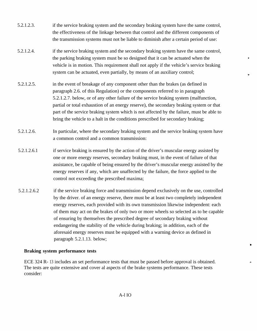
5.2.1.2.3.
5.2.1.2.4.
5.2.1.2.5.
5.2.1.2.6.
5.2.1.2.6.1
5.2.1.2.6.2
if the service braking system and the secondary braking system have the same control,the effectiveness of the linkage between that control and the different components ofthe transmission systems must not be liable to diminish after a certain period of use:
if the service braking system and the secondary braking system have the same control,the parking braking system must be so designed that it can be actuated when thevehicle is in motion. This requirement shall not apply if the vehicle’s service brakingsystem can be actuated, even partially, by means of an auxiliary control;
in the event of breakage of any component other than the brakes (as defined inparagraph 2.6. of this Regulation) or the components referred to in paragraph5.2.1.2.7. below, or of any other failure of the service braking system (malfunction,partial or total exhaustion of an energy reserve), the secondary braking system or thatpart of the service braking system which is not affected by the failure, must be able tobring the vehicle to a halt in the conditions prescribed for secondary braking;
In particular, where the secondary braking system and the service braking system havea common control and a common transmission:
if service braking is ensured by the action of the driver’s muscular energy assisted byone or more energy reserves, secondary braking must, in the event of failure of thatassistance, be capable of being ensured by the driver’s muscular energy assisted by theenergy reserves if any, which are unaffected by the failure, the force applied to thecontrol not exceeding the prescribed maxima;
if the service braking force and transmission depend exclusively on the use, controlledby the driver. of an energy reserve, there must be at least two completely independentenergy reserves, each provided with its own transmission likewise independent: eachof them may act on the brakes of only two or more wheels so selected as to be capableof ensuring by themselves the prescribed degree of secondary braking withoutendangering the stability of the vehicle during braking; in addition, each of theaforesaid energy reserves must be equipped with a warning device as defined inparagraph 5.2.1.13. below;
Braking system performance tests
ECE 324 R- 13 includes an set performance tests that must be passed before approval is obtained.The tests are quite extensive and cover al aspects of the brake systems performance. These testsconsider:
A-l IO

[] Stopping performance for:
[ ] Normal road adhesion
[] Reduced road adhesion
[] Cold brakes
[] Hot brakes
[] Fiat surface conditions
[] Down hill conditions
[] Loaded trailers
[] Unloaded trailers
[] Braking rate of trailer
[] Response time
[] Capacity of air reservoirs
[] Brake distribution tests
[] Antilock brake performance
A4.2 FUTURE DIRECTION FOR ECE REGULATIONS.
Work is underway within the ECE to produce a method for self compliance for Motor vehicleregulations. The current proposal is to develop an IS0 9000 process for self compliance. The IS09000 process would specify in great detail the procedure for caring out each compliance test. Itwould also specify documentation associated with each test. Within this framework each truckmanufacturers would be audited by an ECE authority (member country) for IS0 9000 compliance.Once a company IS compliant it may then use the prescribed process to self certify its products.
A second initiative within ECE is the concept of functional equivalence. This concept if realizedwould produce a means for moving to a more design neutral regulation. This initiative has begunvery recently and is not well defined. Self compliance is the first priority. The concept of functionalequivalence will be pursued only after self compliance is achieved.
Changes to ECE R13 for ECBS
The following IS a report produced by the Heavy Duty Brake Manufactures regarding recent changesto ECE-R 13 related to ECBS.
“ELECTRONICALLY CONTROLLED BRAKING SYSTEMS” - ECBS
United Nations ECE Regulation No. 13 has recently been amended to cater for ECBS on motorvehicles and on trailers; the relevant specifications are in doc. TRANS/WP.29/505 dated 9 July 1996(Supplement 2 to the 09 Series of Amendments to ECE Regulation No. 13).
A-111

Supplement 2 to the 09 Series of Amendments will enter into force on 22 February 1997. This is thedate when vehicle manufacturers may apply for type-approval of vehicles with ECBS. From 1October 1998, any vehicle with ECBS submitted for a new type-approval must meet the 09“Supplement 2” specifications. There will be a third date (in 2000 or later), when existing type-approvals must be updated to the 09 level.
The above specifications for ECBS were initiated in 1989 by a committee of industry experts andsubsequently elaborated within 11 meetings of a joint government/industry Working Group.,
The final specifications were approved by the GRRF committee in December 1995 and adopted bythe senior WP.29 committee in June 1996 for official inclusion within ECE Regulation No. 13.
PRINCIPLES
The following principles were agreed for the introduction of ECBS into ECE Regulation No. 13(R. 13):
1.
2--
3.
4.
5.
6.
7.
Vehicles with ECBS should not be subject to more stringent performance demands than vehicleswithout ECBS, e.g., the same stopping distances should be applicable.
NB. This would be a starting point; like with ABS (Antilock Braking Systems), more stringentspecifications may be introduced later.
The same safety requirements (secondary/residual performance and failure indication) shouldapply to vehicles with ECBS as to vehicles without ECBS.
NB. Electronic controls may give rise to new types of faults, errors, and malfunctions whichrequire special consideration, e.g., serial data bus communication faults.
Electronic control of the braking system should be considered as an optional alternative tocurrent hydraulic, pneumatic or combined control systems; i.e., ECBS should not be mandatoryfor any vehicle category.
All potential electronic control solutions should be taken into account, from the simplest partialelectronic devices to the most sophisticated fully electronic control systems.
Further technical developments should not be inhibited.
The ECBS specifications should be integrated within the present Regulation. They should not beadded within a separate Annex, as for ABS in Annex I3 to R.13.
Compatibility between old and new towing vehicles and trailers should be ensured, or adequatewarning provided to the driver.
-A-l 12

The technical content of doc.TRANS/WP.29/505 may be summarized as follows:
A) SERVICE BRAKING WITH ECBS
It shall be possible to apply the service brakes after the ignition has been switched off.
A failure in the electric wiring (breakage, disconnection) of the control systems shall ensure that theresidual and secondary (and trailer) performance can be achieved and be indicated to the driver. Thesame conditions apply to a deterioration of the battery energy; an alternator failure shall ensure atleast 20 full service brake applications.
Auxiliary electrical equipment (lights, wipers) shall not affect the service braking performance.
B) BRAKE FAILURE AND DEFECT WARNING INDICATOR LIGHTS
The numerous features of ECBS and the multitude of electronic failure modes has been recognizedby differentiating between minor defects which do not affect the service brake performance (yellowlight) and major failures which do (red light). Dynamic faults shall be memorized for staticindication. The same philosophy has been extended to trailers with ECBS; minor defects will beindicated by a second yellow light and major failures by the primary red light together with thesecond yellow light.
C) ELECTRIC PARKING BRAKES
It shall be possible to apply the parking brake after the ignition has been switched off, but releaseshall be prevented. A failure in the electric wiring shall be indicated to the driver, and subsequentlyallow the parking brake to be applied and released.
D) TRACTOR/TRAILER COMPATIBILITY
The connections between towing vehicles and trailers shall comprise one pneumatic supply line andone or two control lines, which may be pneumatic and/or electric. Vehicles with only the electriccontrol line will not be type-approved until the reliability of such systems has been confirmed inservice. Furthermore, when such vehicles are coupled to vehicles with only the pneumatic controlline, then the driver shall be warned and the brakes on one of the vehicles shall be automaticallyapplied.
E) ELECTRONIC AUTOMATIC COMPENSATION
Various forms of compensation, including “coupling force control,” are specifically permitted;however, either a failure of such sub-systems or an excessive amount of compensation, shall beindicated to the driver by the yellow light.
A-l 13
F) SERIAL DATA COMMUNICATION
Provision has been made for use of the Bosch CAN system as specified in ISO. 11992 for theinterface of towing vehicles and trailers to ensure interchangeability.
The data will be transmitted via the 2 free pins on the ISO.7638 ABS electrical connector to providetrailer braking control and additional failure warning to the driver.
G) TRAILERS WITH ECBS
Similar provisions apply to trailers.
A-l 14

DOT HS 808 803September 1998
Related Documents