Technology Project

Technology Project
Dec 10, 2015
Proiect tehnologie (Civil Engineering). An 4
Welcome message from author
This document is posted to help you gain knowledge. Please leave a comment to let me know what you think about it! Share it to your friends and learn new things together.
Transcript

Technology Project
1.PROJECT THEME: The designing of technology of multistoried buildings
2.PROJECT DATA: In annexes are given the building drawings, extracts of building quantities, number of levels and original ground level (CTN) thus: for n=11 Annex 3- Laboratory building.
3.PROJECT CONTENT:
A. INFRASTRUCTURE
1) Plan of Digging
2) Estimating quantities of earthworks (digging and filling earth)
3) Excavator and vehicle calculation
4) Working instructions
5) Technological Schemes
B. SUPERSTRUCTURE
1) List of Technological waves
2) Choice of tower crane
3) Designing of technological waves
4) Working Instructions
5) Technological schemes
6) Technical memoir for infrastructure and superstructure
Technical memoir - Laboratory building
Infrastructure
The building infrastructure is made by isolated foundations and between A-B rows, 1-2 axes there are continous foundations too. Foundation blocks are made by plain concrete BC7.5 and the bolsters and the diaphragms by reinforced concrete BC15, the reinforcement consisting in OB37 steel bars. Ground floor (0.00m level) flooring slab is made by poorly reinforced concrete BC7.5, reinforcement consisting in OB37 steel wire nets. Natural ground level (CTN) is at -1.00m and the terrain geotechnical characteristics are given in the attached plans.
Superstructure
The building is a frame system with monolithic columns and transversal prefabricated beams : GPT 1 type for slabs and GPT 2 type for roof. Along the building, at the slabs level, there are reinforced concrete prefabricated beams: GL type for facade - A,C rows and GM type – B row. The slabs are made by strips with gaps (GFP type), being supported by the transversal prefabricated beams. In front of the columns, along A,B,C rows, there are zones with monolithic reinforced concrete B250.
The closing walls (30 cm thickness) are made along the perimeter by light concrete small blocks. The partition walls (15 cm thickness) are made by bricks with vertical gaps GVP. The floorings are made by polished concrete and PVC layer.
The roofing is terrace type made by reinforced concrete prefabricated caissons. The attic along the rows A and C is prefabricated GA type and along the axes 1 and 9 is made by full brick masonry (25 cm width). Roof structure is given in the attached plan.
The staircase and the monolithic zone (between axes 1-2) will not be considere on the technological sheet. Number of levels of the building is 7 (GF+6L). Columns and monolithic zones framework system is established with project supervisor.

I. Infrastructure
1.Natural terrain level
CTN = -1.00m
2. Estimative quantities of earthworks
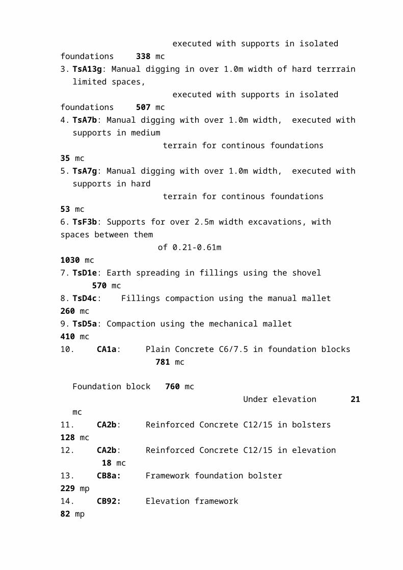
1. TsG3a: Terrain cleaning 1400 mp2. TsA13b: Manual digging in over 1.0m width of medium terrrain limited spaces, executed with supports in isolated foundations 338 mc3. TsA13g: Manual digging in over 1.0m width of hard terrrain limited spaces, executed with supports in isolated foundations 507 mc4. TsA7b: Manual digging with over 1.0m width, executed with supports in medium terrain for continous foundations 35 mc5. TsA7g: Manual digging with over 1.0m width, executed with supports in hard terrain for continous foundations 53 mc6. TsF3b: Supports for over 2.5m width excavations, with spaces between them of 0.21-0.61m 1030 mc7. TsD1e: Earth spreading in fillings using the shovel 570 mc8. TsD4c: Fillings compaction using the manual mallet 260 mc9. TsD5a: Compaction using the mechanical mallet 410 mc10. CA1a: Plain Concrete C6/7.5 in foundation blocks 781 mc
Foundation block 760 mc Under elevation 21 mc
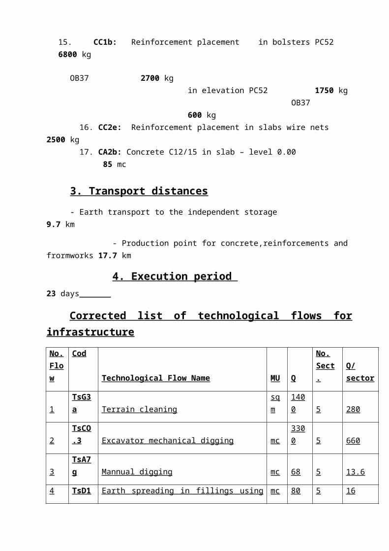
11. CA2b: Reinforced Concrete C12/15 in bolsters 128 mc12. CA2b: Reinforced Concrete C12/15 in elevation 18 mc13. CB8a: Framework foundation bolster 229 mp14. CB92: Elevation framework 82 mp15. CC1b: Reinforcement placement in bolsters PC52 6800 kg
OB37 2700 kgin elevation PC52 1750 kg OB37 600 kg
16. CC2e: Reinforcement placement in slabs wire nets 2500 kg 17. CA2b: Concrete C12/15 in slab – level 0.00 85 mc
3. Transport distances
- Earth transport to the independent storage 9.7 km
- Production point for concrete,reinforcements and frormworks 17.7 km
4. Execution period 23 days
Corrected list of technological flows for infrastructure
No. Flow
CodTechnological Flow Name MU Q
No. Sect. Q/sector
1 TsG3a Terrain cleaning sqm 1400 5 280
2 TsCO.3 Excavator mechanical digging mc 3300 5 660
3 TsA7g Mannual digging mc 68 5 13.6
4 TsD1e Earth spreading in fillings using the shovel mc 80 5 16
5 TsD.5a Compaction using the mechanical mallet mc 1960 5 392
6 CA.1a Simple concrete C6/7,5 in foundation blocks mc 762 5 152.4
CA.1a Simple concrete C6/7,5 under staircase and elevator area elevations mc 55.77 1 55.77
7 CA.2b Reinforced concrete C12/15 in bolsters mc 112 5 22.4
CA.2b Reinforced concrete C12/15 in staircase and elevator area bolsters mc 8.8 1 8.8
8 CA.2b Reinforced concrete C12/15 in elevation mc 46.75 5 9.35
CA.2b Reinforced concrete C12/15 in staircase and elevator area elevation mc 10.7 1 10.7
9 CB.10 Reusable panels formwork for foundations blocks sqm 858.6 5 171.72
CB.10 Reusable panels formwork for staircase and elevator area foundation sqm 72 1 72
10 DB.8a Formwork for bolsters sqm 220 5 44
DB.8a Formwork for staircase and elevator area bolster sqm 18 1 18
11 CB.92 Formwork for elevation sqm 40.15 5 8.03
12 CC.1b Placing the reinforcement in bolsters - OB 37 kg 2700 5 540
CC.1b Placing the reinforcement in bolsters - PC 52 kg 6800 5 1360
CC.1b Placing the reinforcement in elevation - OB 37 kg 600 5 120
CC.1b Placing the reinforcement in elevation - PC 52 kg 1750 5 350
13 CC.2c Placing the reinforcement wire nets into the slab kg 2500 5 500
14 CA.2b Concrete C12/15 in slab, at 0,00 m mc 85 5 17
Excavator and Vehicle Calculation
Choice and calculus of the tehnological equipment and of the means of transport for infrastructure
1. Excavator S601 with resversed shovel
Pm=48,4mc/h
2. Mechanical Mallet
3. Buldozer S.650
- used for deforestation the bushes
- length of blade: 3,00 m
- width of blade: 0,70 m
4. Interior vibrators
5. Mixer type Man Tga de 5 mc
- length: 8,15 m
- width: 2,50 m
- height: 3,65 m
- payload: 14,00 t
- curb weight: 12,00 t
- engine power: 310 CP
- volume: 6 m3
- maximum speed: 65 km/h
6. Loading truck Man TGA

- dimensions (gauge) of the bin: - length: 4,60 m
- width: 2,30 m
- depth: 1,10 m
- volume of the bin: 18 m3
- maximum speed: 120 km/h
7. Truck Man
- length: 8,46 m
- width: 2,45 m
- height: 2,53 m
- 280 CP
- total weight: 14500kg
- maximum speed: 100 km/h
8. Tipping bin with hose
- capacity: qnc=1 m3
- weight: 452 kg
9. Device for controlling the bins 5,5 tf
- length: 3,50 m
- weight: G1=86 kgf
- maximum load: 5,5 tf
10.Auto-truck with charger arm

Working Instructions for infrastructure
Projection of the files for the technological flow ; Technological details
Technological file for flow number 2
Name of the flow
Mechanized excavation executed by excavator.
Operations:
- drawing axes- placement of the equipement- excavation of the pit for the foundation- loading (earth) in loading trucks for transporting it to the far(remote) warehouse - digged earth evacuation.
Description of the tehnological flow:- drawing is executed based on the axes marked on the terminals with topographical
instruments, exterior contour (contour of the excavation) and interior contour (base of the excavation); they will be drawn using lime
- mechanized excavation of the foundation pits will be done (form ground level excavated with the bulldozer -0,5 m) by hydraulic excavator S601 c equiped (with an inverse spoon) having the capacity of 1,14 mc. The excavated earth is loaded in loading trucks type Man Tga and it’s transported at the warehouse; the unloaded earth near the pit it’s pushed with the bulldozer to the closest warehouse near the working site. The size of the excavator bin was established based on the hypothesis of performing the excavation in the hypothesis of the digging execution in a sector, during two work changings, like it follows:
The digging will be executed, with a negative target, in frontal felling with unloading into the damper or to the nearest warehouse.
- on a sector it will be done one longitudinal back course the range allowing to cover the whole sector and the unloading
- checking the depth of excavation it’s done with the T-square lineal targeting the superior part of some temporary flagpoles over the bollards.
Resources:

- main equipment: Excavator s601 with a counter spoon over tires
- manpower: - mechanic for excavator
- mecanic for bulldozer
- driver for the loading truck
- topographer
- carpenter
- equipment and means of transport: Dumper Man Tga 19.215-DFK
- materials: boards 1/2, wood rullers 1010, stiks
- devices and equipments: teodolite, rod 4 m, T-square lineal.
Special problems (CTC, NTS, PSI)
- it’s forbidden the stationary of the works withinh the range of action of the excavator; the minimal distance between the edges of the platform of the loading truck and the most proeminent side of the excavator will be 1,50 m
- it will be taken measures for evoiding the eventual landslides at the excavation site
- increasing the attention of the eventual meeting in the pit of electric cables or gas pipes or sewerage pipes,in case of existence of one of these the excavation will be continued after deplugging those sistems
- while loading the eart the driver will not remain in his cabin of the truck and rotating the cup will be not be done above the cabin.
Technological file for flow no 7
Name of the flow:
Bolster reinforcing- pouring concrete Procedure:
- transportation from the preparation station to the object- assemblage
Technological Flow Description:- the concrete is brought to the site by the 5mc autoagitating truck
- if possible, concrete pouring will be done directly from the autoagitating truck; otherwise, the concrete will be discharged into clamshells situated in the action area of the crane, the lifting of the clamshell will be done slowly up to a vertical position, in order to avoid concrete overflow

- the consolidation will be made by vibration with the interior vibrator, having the flask of 50 mmResources:
- main facility: - 5mc Man autoagitating truck - handling device of the clamshell - 1 mc clamshell - crane - interior vibrator
- manpower: - steel bender - autoagitating truck driver - crane operators
- technological equipment and small robotism inventory: - 2 m extension chamfer - 5,5 tf handling device of the clamshell
- main materials: - Bc.15Special problems (CTC, NTS, PSI)
- checking of labour protection trainning- during the works, the workers will wear a protection helmet- before pouring the concrete, the technical leader of the works will check:
- reinforcement arrangement- connection of the stirrups - existence of the spacers- position and elevation of the formwork , its tightness and cleaning
- conformation to maximum capacity for each lifting device - cleaning the clamshells is made in established position on the ground - the concrete is checked so the existing documentation to correspond with the
demanded - from the pouring concrete will be taken cubic samples for further checking; the results will be written in the unique concrete index
Technological file for flow no 8 Name of the flow:
- removing of formwork of the bolster Procedure:
- loosening of the rigidities - removing of formwork of the bolster - cleaning of the formwork - moving and assemblage of the formwork to the next foundations or transportation to
the warehouse Technological Flow Description:
- at the minimum removing of the formwork term (1-2 days) will be done the loosening of the rigidities and the removing of the framework

- after removing of the framework, the framework will be cleaned with the help of a spatula and a wire brush; it will be coated with special substances
- the framework assembly from sector 1, already prepared, will be moved and assembled to the foundations in sector 3 Resources:
- manpower: - carpenters - technological equipment and small robotism inventory
Special problems (CTC, NTS, PSI)- checking of labour protection trainning- during the works, the workers will wear a protection helmet - after removing of the formwork, the dimensions, the aberrations towards axes and
dimensions will be checked; the aberrations must be of the followings: - horizontal position aberrations of the axes 10 mm- vertical position aberrations of the axes 10 mm- dimension aberrations: length, width, height 20 mm
- after checkings, the axes will be marked, with non washable paint.
Tehnological file for flow number 10
Name of the flow:Formwork for the foundation bolster
Operations:- transporting and unloading the component elements of the formwork in the
warehouse- transporting the component elements of the formwork near the foundation pits and
asambling the formwork - drawing the position of the formwork- mounting the assembles of the formwork- checking
Descrbing tehnological flow- for execution of the bolster’s formwork it will be used a CMU type formwork.
Resources:- main materials: - formwork CMU
- special substances to remove forms from concrete- manpower : - specialized team in carpenters
Special problems (CTC, NTS, PSI)- checking the intrstructions for labor protections- while the working is in progress workers will wear a protection helmet- all of the formwork elements are mounted by workers trained in NTS- it’s forbidden to support the formwork obliquelly
- before the concrete pouring, the leader of the workplace (engineer) it’s forced to check: the integrity, the stability, the terrain supporting, tightness, and stage of the formwork cleaning
- admisable errors on mounting the formwork:- at length 15 mm- at width 6 mm- at height10 mm- inchination towards the project 3 mm/m, but not more than 15 mm/m per
total.
Tehnological file for flow number 12Name of the flow:
Reinforcement of the bolster and elevation.Operations:
- transporting and unloading the reinforcement at the site- straightening(fasonare) the reinforcement- transporting the mesh and carcase - checking.
Technological Flow Description:
- the reinforcement is brought in bunches of bars from the materials warehouse with a platform auto-truck having a crane arm in order to ensure the reinforcement dischargement
- near the materials warehouse will be installed a platform for cutting and forming the reinforcement into networks (for the bolster reinforcement) and cages (for vertical elements reinforcement)
- the transportation and assemblage of reinforcement networks and cages will be done manually in case of small weights or mechanically, with the help of a crane, in case of large weights
Resources:
- main materials: - PC.52 and OB.37 reinforcement- main facility: - auto-truck with charger arm - manpower: - steel benders
- auto-truck driver
Special Problems (CTC, NTS, PSI)
- checking of labour protection trainning- during the works, the workers will wear a protection helmet- at the end of the reinforcing and before pouring the concrete, the technical leader of
the works will check if the reinforcing was done within the project norms (reinforcement steel

quality, diameters, arrangement), ensurance of the concrete cover and the border in admissible aberrations; the observations will be written in the recording of the proceedings of the works, which will be hidden
- admissible aberrations for foundation reinforcement:
- distance between bar axes 10 mm- thickness of the covering layer 10 mm- partial or total lengths regarding the project:
- L < 1 m 5 mm- L = 1...10 m 20 mm
II. Superstructure
1.Number of levels
GF+6L
2. Estimative quantities of earthworks
The extras is done for one current level and for the roof. It doesn’t contain the staircase and elevator works.
1. CB2j: Reinforced concrete C12/15 in columns 35 mp2. CB11d: Reusable panels framewok for columns 253 mp3. CC2g: Reinforcement placement in columns PC52 2100 kg
OB37 500 kg4. CB2j: Reinforced concrete C15/20 – in slab (monolithic zones A,B,C) 10 mc5. CB11c: Reusable panels framework for slab 68 mp 6. CB22d: Supports consisting of extensible metallic beams and metallic props 68 mp 7. CC2g: Reinforcement placement in monolithic slab OB37 750 kg8. CP10d: Transversal prefabricated beams placement GPT1 type – 0.3x0.65x8.65m – G = 4.2t/piece 18 pie./level GPT2 type – 0.3x0.60x8.90m – G = 4t/piece 18 pie./level 9. CP10d: Longitudinal prefabricated beams placement GL1 type – 0.25x0.70x5.45m – G = 2.4t/piece 15 pie./level
GM type – 0.25x0.70x5.35m – G = 2.3t/piece 8 pie./level 10. CP10d: Prefabricated beams monolithisation with concrete B300 - for current level 4.2 mc - for roof 2 mc 11. CP10d: Placement of the prefabricated strips GFP type - 0.99x0.22x5.65m-G=1.4t/piece 117 pie.12. CA10: Plain concrete C6/7.5 used for overconcreting 24 mc

13. CD6a: Closing walls (30 cm thickness) made by light concrete small blocks 290x240x188mm 78 mc14. CA5h: Partition walls (15 cm thickness) made by bricks with vertical gaps GVP 290x140x88mm 53 mc15. CG15a:Floorings made by
polished concrete 2cm with cement mortar M100-T 410 mp16. CG3b: Floorings made by plastic materials PVC layer on textile support glued with prenadez 368 mp17. CP10d: Placement of roof’s prefabricated caissons 1.50x5.90x0.20m –G =1.1t/piece 96 pie.
18. CP10d: Placement of attic’s prefabricated beams (A,C rows) GA type – 0.25x1.0x5.90m – G =3.7t/piece 16 pie. 19. CP23c: Attic’s beams and caissons monolithisation with concrete BC22.5 - caissons 12 mc
- attic’s beams 2 mc 20. CD4j: Full brick masonry (25 cm thickness, 1 m height) for attic (1,9 axes) 3 mc 21. IzF21c: Hidroinsulation support layer - cement mortar M100 (3cm) 860 mp 22. IzF4c+3 IzF4b: Hidroinsulation 3c+1P+5B 860 mp 23. IzF22a: Hidroinsulation protection layer(sand) 860 mp
3. Transport distances
- Production point for concrete,reinforcements and frormworks 12.2 km
- Materials storage 16.2 km
List of Technological waves
LIST OF TECHNOLOGICAL WAVES FOR THE SUPERSTRUCTURE AND THEIR REPARTITION
Sector 6
Sector 5
Sector 4
Sector 3
Sector 2
Sector 1
Sector GF

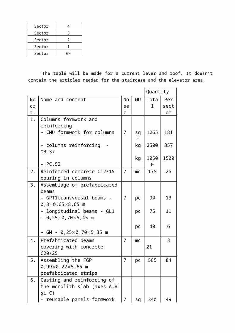
The table will be made for a current lever and roof. It doesn’t contain the articles needed for the staircase and the elevator area.
Quantity
No crt.
Name and content No sec
MU Total Per sector
1. Columns formwork and reinforcing - CMU formwork for columns 7 sqm 1265 181
- columns reinforcing - OB.37 kg 2500 357 - PC.52 kg 10500 1500
2. Reinforced concrete C12/15 pouring in columns
7 mc 175 25
3. Assemblage of prefabricated beams - GPT1transversal beams -
0,30,658,65 m7 pc 90 13
- longitudinal beams - GL1 - 0,250,705,45 m
pc 75 11
- GM - 0,250,705,35 m
pc 40 6
4. Prefabricated beams covering with concrete C20/25
7 mc 21 3
5. Assembling the FGP 0,990,225,65 m prefabricated strips
7 pc 585 84
6. Casting and reinforcing of the monolith slab (axes A,B şi C)
- reusable panels formwork 7 sqm 340 49 - supporting with metallic extendible
beams and metallic props sqm 340 49
- monolith slab reinforcing OB.37 kg 3750 5367. Reinforced concrete C15/.20 - covering
the slab (monolith areas A, B şi C)7 mc 50 7
8. Concrete C6/7,5 pouring into the overconcreting
7 mc 24 3
9. Closing walls (30 cm) execution made of bricks with vertical holes GVP 29014088 mm
7 mc 78 11
10. Interior partition walls execution made of BCA strips (15 cm thickness and 60 cm width)
7 sqm 2650 379
pc 840 12011. Paving execution made of foppish 2cm
thickness concrete with cement mortar M.100 - T
7 sqm 2050 293

12. Paving execution made of plastic materials like PVC carpet over textile base, serried with pasting
7 sqm 368 53
13. Assembling the GPT2 - 0,300,608,90 m transversal prefabricated beams for roofing
7 pc 18 3
14. Prefabricated beams for roofing – covering
1 mc 2 2
15. Assembling the GA - 0,251,005,90 m transversal beams for the attic (axe A şi C)
1 pc 16 16
16. Assembling the prefabricated coffers at the roof
1 pc 96 96
1,505,900,20 m
17. Covering with C18/22.5 of -coffers 1 mc 12 12 - attic beams 1 mc 2 2
18. Execution of full brick masonry made of bricks having 25 cm thickness and 1 m height at the attic (axes 1 şi 9)
1 mc 9 9
19. Pouring the waterproofing support layer made of mortar cement M.100 of 3 cm thickness
1 sqm 860 860
20. Execution of waterproofing 3C+1P+5B 1 sqm 860 86021. Execution of a protecting layer for the
waterproofing, made of sand 1 sqm 860 860
Choice of Tower Crane and other Equipment
No. crt.
Name of the facility Technological characteristics No. flow
1 Tower Liebherr 130 EC-b-6 Crane
Rmax = 60m Rmin = 20m Hmax = 67,5m Qmax = 6 t Qmin = 1,5 tNo sections: - tower = 4 - arm = 4
1, 2, 3, 4, 5, 6, 8, 9, 10, 11, 12, 13, 15, 16, 18, 19, 20, 21.
2 Man Autoagitating truck qn = 5 cm qutil = 14,00 t L = 8.15m B = 2,5 m h= 3,65 m Vm,ax
= 90 km/h
2, 4, 7, 8, 14, 17, 19.
3 Interior vibrator Vei-58 2, 4, 7, 17.

List of the technological equipment
No.
crt
Name Technical charac. MUQuant.
No flow
1 Universal weight manipulating device U156B
Qcap = 3.2t
Qprop = 148t
pc. 1 1, 2, 4, 6, 8, 9, 10, 11, 12, 18, 19, 20, 21.
2 Manipulating device and prefabricated elements mounting U328
Qmax = 8t
Qprop = 0.6t
Ua = 3.8m
pc. 1 3, 5, 13, 15, 16.
3 Cmu columns formwork Coaste 0,7*0,4*0.025 6
4 Extendible and sustainable metallic beams and metallic props
Designing of technological waves
Technological file for the flow number 1Name of the flow:
- formwork and reinforcing the central column Operations:
- transporting and unloading of the formwork elements and reinforcement carcass in the local deposit - pre-mounting the formwork panels in pairs, making a spatial formwork assembly- tracing the position of the formwork- mounting a spatial formwork assembly- mounting the reinforcements- mounting the second spatial formwork assembly- checking and successive corrections
Description of the technological flow:- formworks and reinforcements are transported to the site by a Man truck- the formworks and carcass are unloaded with the use of tower crane directly in the objects warehouse

- two formwork panels are mounted in a spatial formwork assembly- mounting of the spatial formworks assembly and carcass are realized with the tower crane- a spatial CMU I formwork assembly is mounted on one side of the column and after that the carcass are mounted- the positioning of the carcass regarding the formwork is checked- the second spatial CMU formwork assembly is mounted
Resources:- main materials: - small CMU formwork panels
- CMu type calots - substances for removing formwork
- man power: - carpenters team- iron worker teams- crane operator
Special Problems(CTC, NTS, PSI):- work protection instruction is checked- during the work, the workers will be fully equipped(helmets, gloves, safety belts)- mounting the formwork at height, must be performed from standing on flooring boards- all formwork elements are mounted by NTS trained men- inclined bracing of the formwork is strictly forbidden - before concrete pouring the site leader is obliged to check: integrity, stability terrain stability, impermeability and cleanness of the formwork- admitted variations at mounting:
- length 15 mm- width 6 mm- height 10 mm- inclining regarding the project, between 3 mm/m and15 mm/m
Technological file for flow number 2Name of the flow:
- concrete pouring of the central column Operations:
- preparing the concrete at the concrete station.- transporting the concrete from the station to the site- pouring the concrete- protecting the concrete after pouring
Description of the technological flow:- preparation of the concrete is performed in a station where processes that can influence concrete quality are strictly observed: correct dosage of the aggregates, cement, water and admixtures, required to realize the composition regarding the specified recipe, mixing and unloading

- concrete is transported to the site with the motor concrete mixer of 5 cubic meters capacity- pouring the concrete is made by a straw bin, disposed in the action zone of the crane; its lifting will be made slowly until vertical position in order to avoid spilling the concrete- the pouring will be performed in layers of 44 cm thick, in order to be vibrated properly- compacting is made through vibration with an inner vibrator having the dose of 78 mm- after pouring and vibration, the concrete is protected against rapid drying, by covering with protection materials combined with water, in order to maintain the surface of the concrete permanently wet, minimum 7 days after pouring, or 14 days, depending of the concrete type.
Resources:- main devices: - auto concrete mixer MAN 5 mc
- bin handling device - 1 cubic meter bin with straw - crane - inner vibrator
- man power: - carpenters team- iron worker teams- crane operator
- technological equipment and small mechanization inventory: - bin handling device (for 5,5 tf bins) - main materials: - C12/15
Special problems:(CTC, NTS, PSI):- work protection instruction is checked- during the work, the workers will be fully equipped(helmets, gloves, safety belts)- before pouring the concrete, the technical leader will check:- reinforcement position- stirrups binding- spacer existence- height and position of the formwork as well as the impermeability and the cleanness of the formwork- maximum breaking weight for each lifting device should be respected- cleaning the bins on the ground- concrete is checked to see if it corresponds with the ones in the designer’s specifications- maneuvering the vibrator will be performed only by trained personnel - the concreter who is responsible for vibrating will be fully equipped- vibrator’s shell will be tied on the ground
Technological scheme for flow number 3Name of the flow:
- mounting of the prefabricated longitudinal GL1 beamsOperations:
- transporting and unloading the prefab elements in the local deposit- placing in position and momentary fixing- checking the position and permanent fixing.
Description of the technological flow:- the transport is performed by long prefab adapted MAN truck- prefabricated elements are deposited in the approach of the crane, in special arranged places- they are put in horizontal position on wooden supports or other elastic materials as close as possible to the normal resting or lifting position- as works, there are checked the following:- element’s geometry- element’s quality- the presence, existence and the quality of the pads, reinforcements and assembly parts- grabbing position of the prefab elements- supporting surfaces under the aspect of dimensions, planeity, horizontality - axis tracing- putting into place is made by the help of the hook of the crane with the chosen device, lifting, handling and manipulating over the mounting place, lowering and putting the element on its supports. - momentary fixing, it must provide stability to the element, until the final position- checking the position- correcting and compensating the corrections is made with jacks, resting devices or some thin layers of mortar.- permanent fixing is made through wet, dry or mixed joints-to insert the concrete in the joining space, there can be used straw bins, chutes, compaction of the concrete being made with the inner vibrator or by stuffing with poles.
Resources:- main materials: - prefabricated longitudinal GL1 beams
- holding device- man power: - iron worker teams
- crane operator
Special problems:(CTC, NTS, PSI)- work protection instruction is checked- during the work, the workers will be fully equipped(helmets, gloves, safety belts)- mounting the formwork at height, must be performed from standing on flooring boards- all prefabricated elements are mounted by NTS trained men- before concrete pouring the site leader is obliged to check: integrity, stability terrain stability, impermeability and cleanness of the formwork.

- admitted variations for prefabricated elements:- rectilinearity 15 mm- perpendicularity 16 mm- position with respect to axis in horizontal plan: 10 mm- position with respect to level height 10 mm- resting heads -15 mm
Related Documents