Technology Focus Electronics/Computers Software Materials Mechanics/Machinery Manufacturing Bio-Medical Physical Sciences Information Sciences Books and Reports 11-09 November 2009

Welcome message from author
This document is posted to help you gain knowledge. Please leave a comment to let me know what you think about it! Share it to your friends and learn new things together.
Transcript

Technology Focus
Electronics/Computers
Software
Materials
Mechanics/Machinery
Manufacturing
Bio-Medical
Physical Sciences
Information Sciences
Books and Reports
11-09 November 2009


NASA Tech Briefs, November 2009 1
INTRODUCTIONTech Briefs are short announcements of innovations originating from research and develop-
ment activities of the National Aeronautics and Space Administration. They emphasize information considered likely to be transferable across industrial, regional, or disciplinary linesand are issued to encourage commercial application.
Availability of NASA Tech Briefs and TSPsRequests for individual Tech Briefs or for Technical Support Packages (TSPs) announced herein shouldbe addressed to
National Technology Transfer CenterTelephone No. (800) 678-6882 or via World Wide Web at www.nttc.edu
Please reference the control numbers appearing at the end of each Tech Brief. Infor mation on NASA’s Innovative Partnerships Program (IPP), its documents, and services is also available at the same facility oron the World Wide Web at http://www.nasa.gov/offices/ipp/network/index.html
Innovative Partnerships Offices are located at NASA field centers to provide technology-transfer access toindustrial users. Inquiries can be made by contacting NASA field centers listed below.
Ames Research CenterLisa L. Lockyer(650) [email protected]
Dryden Flight Research CenterGregory Poteat(661) [email protected]
Glenn Research CenterKathy Needham(216) [email protected]
Goddard Space Flight CenterNona Cheeks(301) [email protected]
Jet Propulsion LaboratoryAndrew Gray(818) [email protected]
Johnson Space Centerinformation(281) [email protected]
Kennedy Space CenterDavid R. Makufka(321) [email protected]
Langley Research CenterBrian Beaton(757) [email protected]
Marshall Space Flight CenterJim Dowdy(256) [email protected]
Stennis Space CenterRamona Travis(228) 688-3832 [email protected]
Carl Ray, Program ExecutiveSmall Business Innovation Research (SBIR) & Small Business Technology Transfer (STTR) Programs(202) [email protected]
Doug Comstock, DirectorInnovative Partnerships Program Office(202) [email protected]
NASA Field Centers and Program Offices


5 Technology Focus: Test & Measurement
5 Cryogenic Chamber for Servo-Hydraulic Materials Testing
5 Apparatus Measures Thermal ConductanceThrough a Thin Sample From Cryogenic to Room Temperature
5 Rover Attitude and Pointing System Simulation Testbed
6 Desktop Application Program To Simulate Cargo-Air-Drop Tests
6 Multimodal Friction Ignition Tester
7 Small-Bolt Torque-Tension Tester
9 Electronics/Computers9 Integrated Spacesuit Audio System Enhances
Speech Quality and Reduces Noise
9 Hardware Implementation of a BilateralSubtraction Filter
10 Simple Optoelectronic Feedback in Microwave Oscillators
11 Small X-Band Oscillator Antennas
12 Free-Space Optical Interconnect Employing VCSEL Diodes
15 Manufacturing & Prototyping15 Discrete Fourier Transform Analysis in a Complex
Vector Space
15 Miniature Scroll Pumps Fabricated by LIGA
16 Self-Assembling, Flexible, Pre-Ceramic Composite Preforms
17 Software17 Flightspeed Integral Image Analysis Toolkit
17 Work Coordination Engine
17 Multi-Mission Automated Task Invocation Subsystem
18 Autonomously Calibrating a Quadrupole Mass Spectrometer
18 Determining Spacecraft Reaction Wheel Friction Parameters
19 Materials19 Composite Silica Aerogels Opacified With Titania
20 Multiplexed Colorimetric Solid-Phase Extraction
20 Detecting Airborne Mercury by Use ofPolymer/Carbon Films
21 Lattice-Matched Semiconductor Layers on SingleCrystalline Sapphire Substrate
23 Mechanics/Machinery23 Pressure-Energized Seal Rings To Better
Withstand Flows
24 Rollerjaw Rock Crusher
27 Bio-Medical27 Microwave Sterilization and
Depyrogenation System
27 Quantifying Therapeutic and Diagnostic Efficacyin 2D Microvascular Images
29 Physical Sciences29 NiF2/NaF:CaF2/Ca Solid-State High-Temperature
Battery Cells
30 Critical Coupling Between Optical Fibers andWGM Resonators
31 Microwave Temperature Profiler Mounted in aStandard Airborne Research Canister
31 Alternative Determination of Density of the Titan Atmosphere
32 Solar Rejection Filter for Large Telescopes
33 Information Sciences33 Automated CFD for Generation of Airfoil
Performance Tables
34 Progressive Classification Using Support Vector Machines
35 Active Learning With Irrelevant Examples
35 A Data Matrix Method for Improving theQuantification of Element Percentages ofSEM/EDX Analysis
37 Books & Reports37 Deployable Shroud for the International
X-Ray Observatory
37 Improved Model of a Mercury Ring Damper
37 Optoelectronic pH Meter: Further Details
37 X-38 Advanced Sublimator
37 Solar Simulator Represents the Mars Surface Solar Environment
NASA Tech Briefs, November 2009 3
This document was prepared under the sponsorship of the National Aeronautics and Space Administration. Neither the United States Govern-ment nor any person acting on behalf of the United States Government assumes any liability resulting from the use of the information containedin this document, or warrants that such use will be free from privately owned rights.
11-09 November 2009


NASA Tech Briefs, November 2009 5
Technology Focus: Test & Measurement
Cryogenic Chamber for Servo-Hydraulic Materials Testing Goddard Space Flight Center, Greenbelt, Maryland
A compact cryogenic test chambercan be cooled to approximately 5 to 6Kelvin for materials testing. The systemincludes a temperature controller andmultiple sensors to measure specimentemperature at different locations. Thetesting chamber provides a fast and easymethod to perform materials testing atlower than liquid nitrogen temperature(77 K). The advantage of this chamber isthat lower than 77 K temperatures areachievable, and the temperature can becontrolled and stabilized during a test.
The purpose of the chamber is to coola composite lap shear specimen to ap-proximately 20 K so that tensile testforce and displacement data may be ac-quired at this cryogenic temperature
range. Other specimens of similar sizeand possibly different geometry can alsobe tested using the same technique withminimal chamber modification.
The chamber is constructed fromcommercially available supplies and ma-terials. A copper pipe is capped at theends, allowing a segment of the speci-men to pass through each side and at-tach to a tension-testing machine. A coilof tubing wraps around the outside toallow cooling with cold gas from the endof a transfer line that is inserted into liq-uid-helium supply dewar. The transferline feeds liquid helium into the tubecoil of the chamber through a gas-tightquick-connect fitting. The cold heliumgas cools the chamber and flows inside
the chamber to cool and exchange heatbefore venting through the outlet. Theinlet and outlet lines are thin-walledstainless-steel tubing that traverses athick layer of high-performance insula-tion. Stainless-steel wire is adhered withepoxy to the outer chamber wall andfunctions as a heater for temperaturecontrol. The temperature of the cham-ber and specimen are monitored, and astandard PID (proportional–integral–de-rivative) control is applied to the heatercircuit to regulate temperature.
This work was done by John J. Francis andJames Tuttle of Goddard Space Flight Center.For further information, contact the GoddardInnovative Partnerships Office at (301) 286-5810. GSC-15694-1
An apparatus allows the measure-ment of the thermal conductanceacross a thin sample clamped betweenmetal plates, including thermal bound-ary resistances. It allows in-situ variationof the clamping force from zero to 30 lb(133.4 N), and variation of the sampletemperature between 40 and 300 K. Ithas a special design feature that mini-mizes the effect of thermal radiation onthis measurement.
The apparatus includes a heater platesandwiched between two identical thin
samples. On the side of each sample oppo-site the heater plate is a cold plate. Inorder to take data, the heater plate is con-trolled at a slightly higher temperaturethan the two cold plates, which are con-trolled at a single lower temperature. Thesteady-state controlling power supplied tothe hot plate, the area and thickness of samples, and the temperature drop acrossthe samples are then used in a simple cal-culation of the thermal conductance.
The conductance measurements canbe taken at arbitrary temperatures
down to about 40 K, as the entire setupis cooled by a mechanical cryocooler.The specific geometry combined withthe pneumatic clamping force controlsystem and the steady-state temperaturecontrol approach make this a uniqueapparatus.
This work was done by James G. Tuttle ofGoddard Space Flight Center. For further in-formation, contact the Goddard InnovativePartnerships Office at (301) 286-5810. GSC-15698-1
Apparatus Measures Thermal Conductance Through a ThinSample From Cryogenic to Room TemperatureGoddard Space Flight Center, Greenbelt, Maryland
Rover Attitude and Pointing System Simulation Testbed NASA’s Jet Propulsion Laboratory, Pasadena, California
The MER (Mars Exploration Rover)Attitude and Pointing System SimulationTestbed Environment (RAPSSTER) pro-vides a simulation platform used for thedevelopment and test of GNC (guidance,navigation, and control) flight algorithmdesigns for the Mars rovers, which was
specifically tailored to the MERs, but hassince been used in the development ofrover algorithms for the Mars ScienceLaboratory (MSL) as well.
The software provides an integratedsimulation and software testbed environ-ment for the development of Mars rover
attitude and pointing flight software. Itprovides an environment that is able torun the MER GNC flight software di-rectly (as opposed to running an algo-rithmic model of the MER GNC flightcode). This improves simulation fidelityand confidence in the results. Further-

6 NASA Tech Briefs, November 2009
Desktop Application Program To Simulate Cargo-Air-Drop TestsLyndon B. Johnson Space Center, Houston, Texas
The DSS Application is a computerprogram comprising a Windows versionof the UNIX-based Decelerator SystemSimulation (DSS) coupled with an Excelfront end. The DSS is an executablecode that simulates the dynamics of air-dropped cargo from first motion in anaircraft through landing. The bare DSSis difficult to use; the front end makes iteasy to use. All inputs to the DSS, con-trol of execution of the DSS, and post-processing and plotting of outputs are
handled in the front end. The front endis graphics-intensive.
The Excel software provides thegraphical elements without need for ad-ditional programming. Categories ofinput parameters are divided into sepa-rate tabbed windows. Pop-up commentsdescribe each parameter. An error-checking software component evaluatescombinations of parameters and alertsthe user if an error results. Case files canbe created from inputs, making it possi-
ble to build cases from previous ones.Simulation output is plotted in 16 chartsdisplayed on a separate worksheet, en-abling plotting of multiple DSS caseswith flight-test data. Variables assignedto each plot can be changed. Selectedinput parameters can be edited from theplot sheet for quick sensitivity studies.
This program was written by Peter Cuth-bert of Johnson Space Center. Further infor-mation is contained in a TSP (see page 1).MSC-24014-1
more, the simulation environment al-lows the user to “single step” through itsexecution, pausing, and restarting atwill. The system also provides for the in-troduction of simulated faults specific toMars rover environments that cannot bereplicated in other testbed platforms, tostress test the GNC flight algorithmsunder examination.
The software provides facilities to dothese stress tests in ways that cannot be
done in the real-time flight system test-beds, such as time-jumping (both for-wards and backwards), and introductionof simulated actuator faults that would bedifficult, expensive, and/or destructive toimplement in the real-time testbeds. Ac-tual flight-quality codes can be incorpo-rated back into the development-testsuite of GNC developers, closing the loopbetween the GNC developers and theflight software developers. The software
provides fully automated scripting, allow-ing multiple tests to be run with varyingparameters, without human supervision.
This work was done by Charles A. Vanelli,Jonathan F. Grinblat, Samuel W. Sirlin, andSam Pfister of Caltech for NASA’s Jet Propul-sion Laboratory.
This software is available for commercial li-censing. Please contact Karina Edmonds ofthe California Institute of Technology at(626) 395-2322. Refer to NPO-46288.
Multimodal Friction Ignition TesterResponses of material specimens to vibrational friction in pressurized oxygen are recorded.Marshall Space Flight Center, Alabama
The multimodal friction ignitiontester (MFIT) is a testbed for experi-ments on the thermal and mechanicaleffects of friction on material specimensin pressurized, oxygen-rich atmos-pheres. In simplest terms, a test involvesrecording sensory data while rubbingtwo specimens against each other at acontrolled normal force, with either arandom stroke or a sinusoidal strokehaving controlled amplitude and fre-quency. The term “multimodal” in thefull name of the apparatus refers to a ca-pability for imposing any combinationof widely ranging values of the atmos-pheric pressure, atmospheric oxygencontent, stroke length, stroke frequency,and normal force. The MFIT was de-signed especially for studying the ten-dency toward heating and combustionof nonmetallic composite materials andthe fretting of metals subjected to dy-namic (vibrational) friction forces in thepresence of liquid oxygen or pressurizedgaseous oxygen — test conditions ap-
proximating conditions expected to beencountered in proposed composite-material oxygen tanks aboard aircraftand spacecraft in flight.
The MFIT includes a stainless-steelpressure vessel capable of retaining therequired test atmosphere. Mounted
atop the vessel is a pneumatic cylindercontaining a piston for exerting thespecified normal force between the twospecimens (see figure). Through a shaftseal, the piston shaft extends downwardinto the vessel. One of the specimens ismounted on a block, denoted the pres-
The Pressure Vessel and Mechanisms of the MFIT are depicted here in a simplified, partly schematicform emphasizing the basic principle of operation.
Pneumatic Cylinderand Piston
Pressure Vessel
Piston Shaft
Pressure Block
Slip Block
Specimen Attachedto Pressure Block
Specimen MovingWith Slip Block Electrodynamic
Vibration Exciter

NASA Tech Briefs, November 2009 7
Small-Bolt Torque-Tension TesterGoddard Space Flight Center, Greenbelt, Maryland
Current torque-tension measurementtechniques involve using load washers asthe force measuring transducer. The dis-advantage of load washers is that they aretoo large to be used with fasteners smallerthan about size #8. The device describedhere measures the torque-tension rela-tionship for fasteners as small as #0.
The small-bolt tester consists of a plateof high-strength steel into which threeminiature load cells are recessed. Thedepth of the recess is sized so that thethree load cells can be shimmed, the op-timum height depending upon the testhardware. The three miniature load cellsare arranged in an equilateral triangularconfiguration with the test bolt alignedwith the centroid of the three. This is akinematic arrangement. The three load
cells define a plane and since the test boltinterfaces at the centroid of the threeload cells, each load cell reacts 1/3 of thetotal bolt preload. Because of this, onlyone of the three load cells is really re-quired with the other two being redun-dant. Having the additional load cellsadds redundancy and confidence to thesystem. The signals from the three minia-ture load cells are read by three individ-ual force-measurement indicators.
The test bolt interfaces to a uniquebushing that is recessed from the oppositeside from the load cells. The replaceablebushings used in the device allow the sys-tem to test with the appropriate in servicematerials if required. The deep recess (orcounterbore) allows for testing of boltsthat are as short as 0.38-in. (≈10-mm).
The outside diameter of the bushing isthreaded to interface with the threadedrecessed hole. There is a hole in the cen-ter of the bushing where the test boltpasses through. The bushing material andhole size can be customized to replicateactual in-service hardware. This is impor-tant to account for the different frictioncoefficients at the interfaces.
As a test bolt is tightened, the bolt an-alyzer continually monitors and recordsboth the torque and preload until thetarget preload is reached. The data arestored digitally, which allows for easydata analysis.
This work was done by Alan J. Posey of God-dard Space Flight Center. Further informationis contained in a TSP (see page 1). GSC-15718-1
sure block, at the lower end of the pistonshaft. This specimen is pressed downagainst the other specimen, which ismounted in a recess in another block,denoted the slip block, that can bemoved horizontally but not vertically.The slip block is driven in reciprocatinghorizontal motion by an electrodynamicvibration exciter outside the pressurevessel. The armature of the electrody-namic exciter is connected to the slipblock via a horizontal shaft that extendsinto the pressure vessel via a secondshaft seal. The reciprocating horizontalmotion can be chosen to be randomwith a flat spectrum over the frequencyrange of 10 Hz to 1 kHz, or to be sinu-
soidal at any peak-to-peak amplitude upto 0.8 in. (≈2 cm) and fixed or varyingfrequency up to 1 kHz.
The temperatures of the specimenand of the vessel are measured by ther-mocouples. A digital video cameramounted outside the pressure vessel isaimed into the vessel through a sapphirewindow, with its focus fixed on the inter-face between the two specimens. A posi-tion transducer monitors the displace-ment of the pneumatic-cylinder shaft.The pressure in the vessel is also moni-tored. During a test, the output of thevideo camera, the temperatures, and thepneumatic-shaft displacement are moni-tored and recorded. The test is contin-
ued for a predetermined amount of time(typically, 10 minutes) or until either (1)the output of the position transducershows a sudden change indicative ofdegradation of either or both specimens,(2) ignition or another significant reac-tion is observed, or (3) pressure in thevessel increases beyond a pre-set levelthat triggers an automatic shutdown.
This work was done by Eddie Davis ofMarshall Space Flight Center, Bill Howard ofQualis Corp., and Stephen Herald of Inte-grated Concepts & Research Corp. For furtherinformation, contact Sammy Nabors, MSFCCommercialization Assistance Lead, [email protected]. Refer to MFS-32613-1.


NASA Tech Briefs, November 2009 9
Electronics/Computers
A new approach has been proposedfor increasing astronaut comfort andspeech capture. Currently, the specialdesign of a spacesuit forms an extremeacoustic environment making it difficultto capture clear speech without compro-mising comfort. The current system,called Communication-Cap-based Audio(CCA), relies on a single microphoneplaced close to the subject’s mouth.While this results in clear audio, it alsohas problems: wire fatigue, blind mat-ing, interference with food/drink, needfor custom communication caps, andnot being able to adjust the microphoneduring extravehicular activities.
The proposed Integrated SpacesuitAudio (ISA) system is to incorporate themicrophones into the helmet and usesoftware to extract voice signals frombackground noise. The system wouldrely on an array of microphones to en-
hance speech quality. It will feature per-formance similar to the CCA systemwhile providing comfort, ease of use,and logistical convenience. In this study,the feasibility of using microphone arraybeam forming or multichannel noise re-duction plus a single-channel post-filterto combat a variety of in-helmet noisewas validated.
The developed multichannel plussingle-channel noise reduction ap-proach can effectively enhance the in-telligibility or quality of the speechfrom the subject. Using the acousticdata recorded inside spacesuits, it wasshown that the developed multichan-nel noise reduction algorithm can helpimprove the signal-to-noise ratio (SNR)by approximately 20 dB in ideal cases,and 8–12 dB in worst cases. With fourmicrophones, the multichannel noisereduction algorithm can yield a 4–5 dB
gain in SNR with no distortion, and12–15 dB SNR with a moderate amountof speech distortion. This new ap-proach is more practical and more ad-vantageous than the traditional micro-phone array beam-forming solutions.
This system would be applicable notonly for spaceflight, but also for telecollab-oration, human-machine interface, hands-free in-car phone interface, acoustic sur-veillance, and any kind of system wherewide-area sound sensing is important.
This work was done by Yiteng (Arden)Huang, Jingdong Chen, and Shaoyan(Sharyl) Chen of WeVoice, Inc. for Glenn Re-search Center.
Inquiries concerning rights for the commer-cial use of this invention should be addressedto NASA Glenn Research Center, InnovativePartnerships Office, Attn: Steve Fedor, MailStop 4–8, 21000 Brookpark Road, Cleve-land, Ohio 44135. Refer to LEW-18405-1.
Integrated Spacesuit Audio System Enhances Speech Qualityand Reduces NoiseThis technology can also be adapted for teleconferencing, telemedicine, wireless voicecommunication, and other hands-free communications.John H. Glenn Research Center, Cleveland, Ohio
A bilateral subtraction filter has been im-plemented as a hardware module in theform of a field-programmable gate array(FPGA). In general, a bilateral subtrac-tion filter is a key subsystem of a high-quality stereoscopic machine vision sys-tem that utilizes images that are largeand/or dense. Bilateral subtraction filtershave been implemented in software ongeneral-purpose computers, but the pro-cessing speeds attainable in this way —even on computers containing the fastestprocessors — are insufficient for real-timeapplications. The present FPGA bilateralsubtraction filter is intended to accelerateprocessing to real-time speed and to be aprototype of a link in a stereoscopic-ma-chine-vision processing chain, now underdevelopment, that would process large
and/or dense images in real time andwould be implemented in an FPGA.
In terms that are necessarily oversim-plified for the sake of brevity, a bilateralsubtraction filter is a smoothing, edge-preserving filter for suppressing low-fre-quency noise. The filter operationamounts to replacing the value for eachpixel with a weighted average of the val-ues of that pixel and the neighboringpixels in a predefined neighborhood orwindow (e.g., a 9×9 window). The filterweights depend partly on pixel valuesand partly on the window size.
The present FPGA implementation ofa bilateral subtraction filter utilizes a 9×9window. This implementation was de-signed to take advantage of the ability todo many of the component computa-
tions in parallel pipelines to enable pro-cessing of image data at the rate at whichthey are generated. The filter can beconsidered to be divided into the follow-ing parts (see figure):• An image pixel pipeline with a 9×9-
pixel window generator,• An array of processing elements;• An adder tree;• A smoothing-and-delaying unit; and• A subtraction unit.
After each 9×9 window is created, theaffected pixel data are fed to the pro-cessing elements. Each processing ele-ment is fed the pixel value for its posi-tion in the window as well as the pixelvalue for the central pixel of the win-dow. The absolute difference betweenthese two pixel values is calculated and
Hardware Implementation of a Bilateral Subtraction FilterModules like this one are necessary for real-time stereoscopic machine vision.NASA’s Jet Propulsion Laboratory, Pasadena, California

10 NASA Tech Briefs, November 2009
used as an address in a lookup table.Each processing element has a lookuptable, unique for its position in the win-dow, containing the weight coefficients
for the Gaussian function for that posi-tion. The pixel value is multiplied bythe weight, and the outputs of the pro-cessing element are the weight and
pixel-value·weight product. The prod-ucts and weights are fed to the addertree. The sum of the products and thesum of the weights are fed to the di-vider, which computes the sum of prod-ucts ÷ the sum of weights. The outputof the divider is denoted the bilateralsmoothed image.
The smoothing function is a simpleweighted average computed over a 3×3subwindow centered in the 9×9 window.After smoothing, the image is delayed byan additional amount of time needed tomatch the processing time for comput-ing the bilateral smoothed image. Thebilateral smoothed image is then sub-tracted from the 3×3 smoothed image toproduce the final output.
The prototype filter as implemented ina commercially available FPGA processesone pixel per clock cycle. Operation at aclock speed of 66 MHz has been demon-strated, and results of a static timinganalysis have been interpreted as suggest-ing that the clock speed could be in-creased to as much as 100 MHz.
This work was done by Andres Huertas,Robert Watson, and Carlos Villalpando ofCaltech and Steven Goldberg of Indelible Sys-tems for NASA’s Jet Propulsion Laboratory.Further information is contained in a TSP(see page 1). NPO-45906
A Bilateral Subtraction Filter is implemented in an FPGA that performs parallel pipeline computationsin a moving 9×9-pixel window.
Line Buffer Row ProcessingElement
Weights
Products
Line Buffer Row ProcessingElement
Line Buffer
Line Buffer
SubtractionUnit
Output
Divider
Sum ofProducts
Sum ofWeights
Center-Pixel Delay and3x3 Center-Biased
Smoother
Weights
Products
AdderTree
Row ProcessingElement
Weights
Products
Row ProcessingElement
Weights
Products
PixelValues In
Simple Optoelectronic Feedback in Microwave OscillatorsPhase and frequency stability would be enhanced greatly.NASA’s Jet Propulsion Laboratory, Pasadena, California
A proposed method of stabilizing mi-crowave and millimeter-wave oscillatorscalls for the use of feedback in optoelec-tronic delay lines characterized by highvalues of the resonance quality factor(Q). The method would extend the ap-plicability of optoelectronic feedbackbeyond the previously reported class ofoptoelectronic oscillators that comprisetwo-port electronic amplifiers in closedloops with high-Q feedback circuits.
The upper part of the figure illustratesthe example of a typical free-running oscil-lator in a conventional form stabilizedwith an external metal radio-frequency(RF) resonant cavity. The oscillator couldbe of any of a variety of types, includingthose based on Gunn diodes, impact ava-lanche transit-time (IMPATT) diodes, kly-strons, backward-wave tubes, and others.The maximum Q of a typical resonantmetal cavity ranges from about 104 at anoscillation frequency of 10 GHz down to
A High-Q Optoelectronic Delay Line would be substituted for the RF resonant cavity of a conventionalfree-running oscillator stabilized with an external resonator.
RF OscillatorTo Be
Stabilized
PhaseShifter
Laser
Electro-Optical Modulator
High-Q Opto-ElectronicFeedback Loop
Photodetector
Fiber-OpticDelay Line
RF OscillatorTo Be
Stabilized
PhaseShifter
RF ResonantCavity
CONVENTIONAL
PROPOSED

NASA Tech Briefs, November 2009 11
103 at a frequency of 100 GHz and to evenlower values at higher frequencies. In con-trast, the maximum Q attainable in a res-onator based on an optoelectronic delayline is of the order of 106 at a frequency of10 GHz and increases with frequency.
The proposed method is partly similarto two older patented methods that in-volve the use of fiber-optic delay lines asRF-phase-noise discriminators. However,unlike those methods, the proposedmethod does not call for the generationof a low-frequency signal applied to acontrol port of the oscillator to be stabi-lized. Instead, the delayed RF signalwould simply be returned to the oscilla-tor, as described below.
The lower part of the figure shows anexample of the same oscillator as before,but this time stabilized by use of opto-electronic feedback according to theproposed method. The RF signal fromthe oscillator would be fed through a cir-culator to an electro-optical modulator,
which would modulate the RF signalonto a laser beam. After traveling thelength of an optical fiber or other opti-cal delay line, a photodetector would de-modulate the signal. The RF output ofthe photodetector would be returned viathe circulator to the oscillator.
The return of the delayed RF signalwould enforce a steady phase in an oth-erwise noisy free-running oscillator,thereby suppressing phase noise in theoscillations. This stabilizing effect is ex-pected as a consequence of the fre-quency-pulling effect or self-injectionlocking observed previously in oscilla-tors equipped with high-Q external reso-nant cavities.
The original tunability of the free-run-ning oscillator would be substantiallypreserved in the presence of optoelec-tronic stabilization, except as describednext: Upon tuning of the oscillator, thefrequency of the oscillator would notchange continuously but would jump be-
tween successive resonances of the opto-electronic feedback loop . Typical fre-quency jumps would likely range from afew tens of kilohertz for a kilometer-longfiber-optic delay line up to a few giga-hertz for an optical microresonator.
This work was done by Lute Maleki andVladimir Iltchenko of Caltech for NASA’s JetPropulsion Laboratory. Further information iscontained in a TSP (see page 1).
In accordance with Public Law 96-517,the contractor has elected to retain title to thisinvention. Inquiries concerning rights for itscommercial use should be addressed to:
Innovative Technology Assets ManagementJPLMail Stop 202-2334800 Oak Grove DrivePasadena, CA 91109-8099(818) 354-2240E-mail: [email protected] to NPO-40144, volume and number
of this NASA Tech Briefs issue, and thepage number.
A small, segmented microstrip patchantenna integrated with an X-band feed-back oscillator on a high-permittivitysubstrate has been built and tested (seeFigure 1). The oscillator antenna is pow-ered by commercial solar photovoltaiccells mounted nearby or on the samesubstrate. This oscillator antenna is aprototype for demonstrating the feasibil-ity of such devices as compact, low-power-consumption building blocks ofadvanced, lightweight, phased antennaarrays that would generate steerablebeams for communication and remote-sensing applications.
The solar-powered oscillator antennaincludes a commercially available super-low-noise, high-frequency field-effecttransistor integrated into the center ofthe segmented microstrip-patch antenna.Along with bias lines, a feedback loop,and other conductors that are parts ofthe oscillator antenna circuitry, the patchantenna was formed by etching the corre-sponding pattern out of a surface metallayer on the substrate, which is a commer-cial microwave laminate having a relativepermittivity of 10.2 and a thickness of0.635 mm. The oscillator antenna occu-pies an area of 5 by 6 mm on the sub-strate. The oscillator feedback path ex-
Figure 1. A Schematic of Oscillator Antenna is shown with feedback loop. The dimensions are in mil-limeters.
Small X-Band Oscillator Antennas In some applications, these compact units could be powered by solar cells. John H. Glenn Research Center, Cleveland, Ohio
4.88
DrainE
H
Source
4.886.88
Gate
Capacitor
2.14
1.00

12 NASA Tech Briefs, November 2009
tends between the drain and gate termi-nals of the transistor and includes a 1.2-pF capacitor that passes the oscillationsignal while providing DC isolation be-tween the drain and the gate.
A comparison between simulated andexperimental performance data con-firmed that the oscillation frequency iscontrolled mainly by the length of thefeedback path. The RF signal radiated atthe fundamental frequency from thesolar powered antenna is shown in Fig-ure 2(a). The magnetic field radiationpattern of the solar powered antenna isshown in Figure 2(b). The solar-pow-ered oscillator antenna radiates a powerof 1.8 mW at a frequency of about 11.2GHz with a directivity of 5.25 relative toan isotropic radiation pattern. Thepower in the second harmonic at 22.4GHz is 20 dB below the fundamental sig-nal level. It has been found that a cur-rent of about 120 mA is needed to initi-ate oscillation, but thereafter the device
can continue to oscillate at a current <20mA. One of the drawbacks of using com-mercial solar cells is its large size due tolow efficiency. Ways to minimize solar-cell area could include: (1) poweringthe oscillator antenna from a recharge-able battery that would be recharged bya single, smaller solar cell, (2) the use ofmore-efficient solar cells, and/or (3) theuse of a capacitor to supply the high cur-rent needed to start oscillation.
One notable advantage of using high-permittivity substrates is the inherent re-duction in the sizes of resonant antennaelements. In addition to compactness,the designs of this oscillator antenna fea-ture simple geometry, and the radiatedpower levels and radiation efficiency arecomparable to those typical of oscillatorantennas on lower-permittivity, thickersubstrates.
Another motivation for the use of high-permittivity substrates is the prospect ofdeveloping solar oscillator array antenna
as fully integrated circuits. Some essentialcomponents of such a development havealready been accomplished: High-mobil-ity transistor structures are readily avail-able on insulating substrates having di-electric properties similar to those of themicrowave laminate material mentionedabove. Dielectric substrate materials in-cluding gallium arsenide and sapphirethat support high-frequency active elec-tronic devices have relative permittivitiesbetween 10 and 14.
This work was done by Richard Q. Lee, FélixA. Miranda, Eric B. Clark, and David M. Wiltof Glenn Research Center and Carl H. Mueller,Carol L. Kory, and Kevin M. Lambert ofAnalex Corp. Further information is con-tained in a TSP (see page 1).
Inquiries concerning rights for the commer-cial use of this invention should be addressedto NASA Glenn Research Center, InnovativePartnerships Office, Attn: Steve Fedor, MailStop 4–8, 21000 Brookpark Road, Cleve-land, Ohio 44135. Refer to LEW-18114-1.
-10
-20
-30
Rela
tive
Gai
n, d
B
Angle, Degrees
-80 -40 0 40 80
11.26 GHz
(b)
H Co-polarization
H Cross-polarization
0
-30
-50
-70
-90
Am
plit
ud
e, d
B
Frequency, GHz
11.250 11.255 11.260 11.265 11.270 11.275
(a)
Figure 2. Performance Characteristics: (a) RF power emitted from solar powered radiating oscillator (the resolution bandwidth is 270 kHz) and (b) far fieldradiation pattern of solar powered radiating oscillator antenna.
Free-Space Optical Interconnect Employing VCSEL Diodes These optical interconnects are applicable for large-capacity interconnection betweeninformation-processing equipment.John H. Glenn Research Center, Cleveland, Ohio
Sensor signal processing is widely usedon aircraft and spacecraft. The schemeemploys multiple input/output nodesfor data acquisition and CPU (centralprocessing unit) nodes for data process-ing. To connect 110 nodes and CPU
nodes, scalable interconnections such asbackplanes are desired because thenumber of nodes depends on require-ments of each mission. An optical back-plane consisting of vertical-cavity sur-face-emitting lasers (VCSELs), VCSEL
drivers, photodetectors, and transim-pedance amplifiers is the preferred ap-proach since it can handle several hun-dred megabits per second datathroughput. Conventional electrical in-terconnects severely limit the perform-

NASA Tech Briefs, November 2009 13
ance of high-speed networks because ofparasitic resistance and capacitance,which limit bandwidth and cause clocksignals to skew. Moreover, they cause pincongestion and require large and bulkymulti-pin connectors.
The next generation of satellite-bornesystems will require transceivers andprocessors that can handle several Gb/sof data. These systems will significantlybenefit from optical interconnect tech-nology. This technique integrates laserdiodes (LDs) and photodetectors (PDs)with RF/microwave electronic circuitryon a chip to form optical interconnects.
Optical interconnects have beenpraised for both their speed and function-ality with hopes that light can relieve theelectrical bottleneck predicted for thenear future. High-speed, small-area metal-semiconductor-metal (MSM) photodetec-tors will allow dense photodetector arraysand provide added practicality to inter-connects, without compromising overallperformance. Optoelectronic intercon-
nects provide a factor of ten improvementover electrical interconnects.
Optical interconnect requires opera-tion at high frequency with low RF/mi-crowave losses at both the input and out-put end of the link while maintaining alarge dynamic range. It is expected thatVCSELs have higher reliability thanedge-emitting laser diodes, as well as lowpower consumption, single-mode opera-tion, and relative ease of fabricationwhile having very large bandwidths. Inan interconnect circuit, laser diodes aredirectly intensity-modulated by theRF/microwave signals, and the photode-tectors detect the received intensity-modulated signals.
For free-space optical interconnects,VCSEL diodes provide significant advan-tages over traditional edge-emitting laserdiodes. Edge-emitting diodes must be cutand mounted after being fabricated,while VCSEL diodes can lase directly onthe wafer. It is also possible to create ar-rays of VCSEL diodes directly on the
wafer, a virtual impossibility for the edge-emitting types. VCSEL diodes can be fab-ricated on the same wafer as the MSMphotodetectors, increasing the function-ality of an array of interconnects.
Optical interconnect technology hasapplications mainly in interchassis chip-to-chip interconnections. However, itcan also find applications in intrachas-sis board-to-board for high-speed andEMI-free interconnections. Optical in-terconnects are also suited for large-ca-pacity and high-density interconnec-tion between information processingequipment.
This work was done by Rainee N. Simons,Gregory R. Savich, and Heidi Torres of GlennResearch Center. Further information is con-tained in a TSP (see page 1).
Inquiries concerning rights for the commer-cial use of this invention should be addressedto NASA Glenn Research Center, InnovativePartnerships Office, Attn: Steve Fedor, MailStop 4–8, 21000 Brookpark Road, Cleveland,Ohio 44135. Refer to LEW-18444-1.


NASA Tech Briefs, November 2009 15
Manufacturing & Prototyping
Alternative computational strategiesfor the Discrete Fourier Transform(DFT) have been developed using analy-sis of geometric manifolds. This ap-proach provides a general framework forperforming DFT calculations, and sug-gests a more efficient implementation ofthe DFT for applications using iterativetransform methods, particularly phase re-trieval. The DFT can thus be imple-mented using fewer operations whencompared to the usual DFT counterpart.
The software decreases the run time ofthe DFT in certain applications such asphase retrieval that iteratively call theDFT function. The algorithm exploits aspecial computational approach basedon analysis of the DFT as a transforma-tion in a complex vector space. As such,this approach has the potential to realizea DFT computation that approaches Noperations versus Nlog(N) operations forthe equivalent Fast Fourier Transform(FFT) calculation.
This work was done by Bruce H. Dean ofGoddard Space Flight Center. For furtherinformation, contact the Goddard Innova-tive Partnerships Office at (301) 286-5810.
This invention is owned by NASA, and apatent application has been filed. Inquiriesconcerning nonexclusive or exclusive licensefor its commercial development should be ad-dressed to the Patent Counsel, Goddard SpaceFlight Center, (301) 286-7351. Refer to GSC-15684-1.
Discrete Fourier Transform Analysis in a Complex Vector Space Goddard Space Flight Center, Greenbelt, Maryland
Miniature scroll pumps have beenproposed as roughing pumps (low -vacuum pumps) for miniature scien-tific instruments (e.g., portable massspectrometers and gas analyzers) thatdepend on vacuum. The larger scrollpumps used as roughing pumps insome older vacuum systems are fabri-cated by conventional machining. Typ-ically, such an older scroll pump in-cludes (1) an electric motor with aneccentric shaft to generate orbital mo-tion of a scroll and (2) conventionalbearings to restrict the orbital motionto a circle.
The proposed miniature scroll pumpswould differ from the prior, larger onesin both design and fabrication. A minia-ture scroll pump would include twoscrolls: one mounted on a stationarybaseplate and one on a flexure stage(see figure). An electromagnetic actua-tor in the form of two pairs of voice coilsin a push-pull configuration would makethe flexure stage move in the desired cir-cular orbit. The capacitance betweenthe scrolls would be monitored to pro-vide position (gap) feedback to a con-trol system that would adjust the drivesignals applied to the voice coils to main-tain the circular orbit as needed for pre-cise sealing of the scrolls. To minimize
power consumption and maximize pre-cision of control, the flexure stage wouldbe driven at the frequency of its mechan-ical resonance.
The miniaturization of these pumpswould entail both operational and man-ufacturing tolerances of <1 µm. Suchtight tolerances cannot be achieved eas-
Miniature Scroll Pumps Fabricated by LIGA These would serve as roughing pumps for vacuum systems of miniature instruments. NASA’s Jet Propulsion Laboratory, Pasadena, California
Frame
FlextureStage
Scrolls
VoiceCoil
A Miniature Scroll Pump includes a scroll mounted on a flexure stage and a scroll mounted on a sta-tionary baseplate. The voice coils drive the flexure stage in a circular orbit to effect pumping.

16 NASA Tech Briefs, November 2009
Self-Assembling, Flexible, Pre-Ceramic Composite PreformsPliable, unfired preforms deploy in-situ to save fuel and weight costs.John H. Glenn Research Center, Cleveland, Ohio
In this innovation, light weight, hightemperature, compact aerospace struc-tures with increased design options aremade possible by using self-assembling,flexible, pre-ceramic composite materi-als. These materials are comprised of ei-ther ceramic or carbon fiber performs,which are infiltrated with polymer pre-cursors that convert to ceramics uponthermal exposure. The preform archi-tecture can vary from chopped fibersformed into blankets or felt, to continu-ous fibers formed into a variety of 2D or3D weaves or braids. The matrix mate-rial can also vary considerably. Fordemonstration purposes, a 2D carbonweave was infiltrated with a SiC polymerprecursor. The green or unfired mate-rial is fabricated into its final shape whileit is still pliable. It is then folded orrolled into a much more compact shape,which will occupy a smaller space. Withthis approach, the part remains as onecontinuous piece, rather than being fab-ricated as multiple sections, whichwould require numerous seals for even-tual component use. The infiltrated pre-
form can then be deployed in-situ. Thecomponent can be assembled into itsfinal shape by taking advantage of theelasticity of the material, which permitsthe structure to unfold and spring intoits final form under its own stored en-ergy. The pre-ceramic composites areconverted to ceramics and rigidized im-mediately after deployment.
The final ceramic composite yields ahigh-temperature, high-strength mate-rial suitable for a variety of aerospacestructures. The flexibility of the mate-rial, combined with its high-temperaturestructural capacity after rigidization,leads to a less complex component de-sign with an increased temperaturerange. The collapsibility of these struc-tures allows for larger components to bedesigned and used, and also offers thepotential for increased vehicle perform-ance. For the case of collapsible nozzleextensions, a larger nozzle, and thus alarger nozzle exit plane, is possible be-cause interference with surroundingstructures can be avoided in the col-lapsed state. The larger exit plane leads
to an increase in expansion area ratio,which has the potential to increasethrust and overall rocket performance.In general, the use of advanced ceramicmaterials can lead to improved engineand vehicle performance. The ceramicscan run hotter, so less cooling is re-quired. Fuel to coolant ratios can be bal-anced more readily to reduce weight.Engine efficiency can also be increasedwith hotter combustion and exhausttemperatures. In addition, the ceramiccomposites themselves can reduce thecomponent weight by as much as 50 per-cent, which can translate into greaterpayload for the vehicle.
This work was done by Martha H. Jaskowiakand Andrew J. Eckel of Glenn Research Centerand Daniel Gorican of Arctic Slope RegionalCorp. Further information is contained in aTSP (see page 1).
Inquiries concerning rights for the commer-cial use of this invention should be addressedto NASA Glenn Research Center, InnovativePartnerships Office, Attn: Steve Fedor, MailStop 4–8, 21000 Brookpark Road, Cleve-land, Ohio 44135. Refer to LEW-18421-1.
ily by conventional machining of high-aspect-ratio structures like those ofscroll-pump components. In addition,the vibrations of conventional motorsand ball bearings exceed these tight tol-erances by an order of magnitude.Therefore, the proposed pumps wouldbe fabricated by the microfabricationmethod known by the German acronymLIGA (“lithographie, galvanoformung,abformung,” which means lithography,
electroforming, molding) because LIGAhas been shown to be capable of provid-ing the required tolerances at large as-pect ratios.
This work was done by Dean Wiberg, KirillShcheglov, Victor White, and Sam Bae of Cal-tech for NASA’s Jet Propulsion Laboratory.Further information is contained in a TSP(see page 1).
In accordance with Public Law 96-517,the contractor has elected to retain title to this
invention. Inquiries concerning rights for itscommercial use should be addressed to:
Innovative Technology Assets ManagementJPLMail Stop 202-2334800 Oak Grove DrivePasadena, CA 91109-8099E-mail: [email protected] to NPO-21161, volume and number
of this NASA Tech Briefs issue, and thepage number.

NASA Tech Briefs, November 2009 17
Software
Flightspeed Integral ImageAnalysis Toolkit
The Flightspeed Integral ImageAnalysis Toolkit (FIIAT) is a C librarythat provides image analysis functions ina single, portable package. It providesbasic low-level filtering, texture analysis,and subwindow descriptor for applica-tions dealing with image interpretationand object recognition. Designed withspaceflight in mind, it addresses:
• Ease of integration (minimal exter-nal dependencies)
• Fast, real-time operation using integerarithmetic where possible (useful forplatforms lacking a dedicated floating-point processor)
• Written entirely in C (easily modified)• “Mostly static” memory allocation• 8-bit image data
The basic goal of the FIIAT library isto compute meaningful numerical de-scriptors for images or rectangularimage regions. These n-vectors can thenbe used directly for novelty detection orpattern recognition, or as a featurespace for “higher-level” pattern recogni-tion tasks. The library provides routinesfor leveraging training data to derive de-scriptors that are most useful for a spe-cific data set. Its runtime algorithms ex-ploit a structure known as the “integralimage.” This is a caching method thatpermits fast summation of values withinrectangular regions of an image. This in-tegral frame facilitates a wide range offast image-processing functions.
This toolkit has applicability to a widerange of autonomous image analysistasks in the space-flight domain, includ-ing novelty detection, object and sceneclassification, target detection for au-tonomous instrument placement, andscience analysis of geomorphology. Itmakes real-time texture and patternrecognition possible for platforms withsevere computational restraints. Thesoftware provides an order of magnitudespeed increase over alternative softwarelibraries currently in use by the researchcommunity.
FIIAT can commercially support intel-ligent video cameras used in intelligentsurveillance. It is also useful for objectrecognition by robots or other au-tonomous vehicles.
This work was done by David R. Thompsonof Caltech for NASA’s Jet Propulsion Laboratory.
The software used in this innovation isavailable for commercial licensing. Pleasecontact Karina Edmonds of the California In-stitute of Technology at (626) 395-2322.Refer to NPO-46871.
Work Coordination EngineThe Work Coordination Engine
(WCE) is a Java application integratedinto the Service Management Database(SMDB), which coordinates the dis-patching and monitoring of a workorder system. WCE de-queues work or-ders from SMDB and orchestrates thedispatching of work to a registered set ofsoftware worker applications distributedover a set of local, or remote, heteroge-neous computing systems. WCE moni-tors the execution of work orders oncedispatched, and accepts the results ofthe work order by storing to the SMDBpersistent store.
The software leverages the use of arelational database, Java Messaging Sys-tem (JMS), and Web Services using Sim-ple Object Access Protocol (SOAP)technologies to implement an efficientwork-order dispatching mechanism ca-pable of coordinating the work of mul-tiple computer servers on various plat-forms working concurrently ondifferent, or similar, types of data or al-gorithmic processing. Existing (legacy)applications can be wrapped with aproxy object so that no changes to theapplication are needed to make themavailable for integration into the workorder system as “workers.” WCE auto-matically reschedules work orders thatfail to be executed by one server to adifferent server if available. From initia-tion to completion, the system managesthe execution state of work orders andworkers via a well-defined set of events,states, and actions. It allows for config-urable work-order execution timeoutsby work-order type.
This innovation eliminates a currentprocessing bottleneck by providing ahighly scalable, distributed work-ordersystem used to quickly generate productsneeded by the Deep Space Network(DSN) to support space flight operations.WCE is driven by asynchronous messagesdelivered via JMS indicating the availabil-ity of new work or workers. It runs com-pletely unattended in support of thelights-out operations concept in the DSN.
This work was done by Silvino Zendejas,Tung Bui, Bach Bui, Shantanu Malhotra,Fannie Chen, Rachel Kim, Christopher Allen,Ivy Luong, and George Chang of Caltech andSyed Sadaqathulla of Raytheon for NASA’s JetPropulsion Laboratory. Further information iscontained in a TSP (see page 1).
This software is available for commercial li-censing. Please contact Karina Edmonds ofthe California Institute of Technology at(626) 395-2322. Refer to NPO-45014.
Multi-Mission AutomatedTask Invocation Subsystem
Multi-Mission Automated Task Invoca-tion Subsystem (MATIS) is software thatestablishes a distributed data-processingframework for automated generation ofinstrument data products from a space-craft mission. Each mission may set up aset of MATIS servers for processing itsdata products. MATIS embodies lessonslearned in experience with prior instru-ment-data-product-generation software.
MATIS is an event-driven workflowmanager that interprets project-specific,user-defined rules for managingprocesses. It executes programs in re-sponse to specific events under specificconditions according to the rules. Be-cause requirements of different mis-sions are too diverse to be satisfied byone program, MATIS accommodatesplug-in programs. MATIS is flexible inthat users can control such processingparameters as how many pipelines torun and on which computing machinesto run them.
MATIS has a fail-safe capability. Ateach step, MATIS captures and retainspertinent information needed to com-plete the step and start the next step. Inthe event of a restart, this information isretrieved so that processing can be re-sumed appropriately.
At this writing, it is planned to developa graphical user interface (GUI) formonitoring and controlling a product-generation engine in MATIS. The GUIwould enable users to schedule multipleprocesses and manage the data productsproduced in the processes. AlthoughMATIS was initially designed for instru-ment data product generation, the ar-chitecture does not preclude it frombeing used for different applications. Itis planned that the MATIS team mem-bers will provide a set of application

18 NASA Tech Briefs, November 2009
guides for others outside the current or-ganization to use the system.
This program was written by Cecilia S.Cheng, Rajesh R. Patel, Elias M. Sayfi, andHyun H. Lee of Caltech for NASA’s JetPropulsion Laboratory.
This software is available for commercial li-censing. Please contact Karina Edmonds ofthe California Institute of Technology at(626) 395-2322. Refer to NPO-45630.
Autonomously Calibrating a Quadrupole Mass Spectrometer
A computer program autonomouslymanages the calibration of a quadrupoleion mass spectrometer intended for usein monitoring concentrations andchanges in concentrations of organicchemicals in the cabin air of the Interna-tional Space Station. The instrument pa-rameters calibrated include the voltageon a channel electron multiplier, a dis-criminator threshold, and an ionizercurrent. Calibration is achieved by ana-lyzing the mass spectrum obtained whilesweeping the parameter ranges in aheuristic procedure, developed by mass-spectrometer experts, that involves de-tection of changes in signal trends thathumans can easily recognize but cannotnecessarily be straightforwardly codifiedin an algorithm.
The procedure includes calculationof signal-to-noise ratios, signal-increase
rates, and background-noise-increaserates; finding signal peaks; and identify-ing peak patterns. The software pro-vides for several recovery-from-errorscenarios and error-handling schemes.The software detects trace amounts ofcontaminant gases in the mass spec-trometer and notifies associated com-mand-and-data-handling software toschedule a cleaning. Furthermore, thesoftware autonomously analyzes themass spectrum to determine whetherthe parameters of a radio-frequencyramp waveform are set properly so thatthe peaks of the mass spectrum are atexpected locations.
This work was done by Seungwon Lee andBenjamin J. Bornstein of Caltech for NASA’s JetPropulsion Laboratory. Further information iscontained in a TSP (see page 1).
This software is available for commer-cial licensing. Please contact Karina Ed-monds of the California Institute of Tech-nology at (626) 395-2322. Refer toNPO-45364.
Determining Spacecraft Re-action Wheel Friction Pa-rameters
Software was developed to character-ize the drag in each of the Cassinispacecraft’s Reaction Wheel Assemblies(RWAs) to determine the RWA frictionparameters. This tool measures thedrag torque of RWAs for not only the
high spin rates (>250 RPM), but alsothe low spin rates (<250 RPM) wherethere is a lack of an elastohydrody-namic boundary layer in the bearings.RWA rate and drag torque profiles asfunctions of time are collected viatelemetry once every 4 seconds andonce every 8 seconds, respectively. In-termediate processing steps single-outthe coast-down regions.
A nonlinear model for the dragtorque as a function of RWA spin rate isincorporated in order to characterizethe low spin rate regime. The tool thenuses a nonlinear parameter optimizationalgorithm based on the Nelder-Meadsimplex method to determine the vis-cous coefficient, the Dahl friction, andthe two parameters that account for thelow spin-rate behavior.
This program was written by SiamakSarani of Caltech for NASA’s Jet PropulsionLaboratory.
In accordance with Public Law 96-517,the contractor has elected to retain title to thisinvention. Inquiries concerning rights for itscommercial use should be addressed to:
Innovative Technology Assets ManagementJPLMail Stop 202-2334800 Oak Grove DrivePasadena, CA 91109-8099E-mail: [email protected] to NPO-44712, volume and number
of this NASA Tech Briefs issue, and thepage number.

NASA Tech Briefs, November 2009 19
Materials
A further improvement has been madeto reduce the high-temperature thermalconductivities of the aerogel-matrix com-posite materials described in “ImprovedSilica Aerogel Composite Materials”(NPO-44287), NASA Tech Briefs, Vol. 32,No. 9 (September 2008), page 50. Becausethe contribution of infrared radiation toheat transfer increases sharply with tem-perature, the effective high-temperaturethermal conductivity of a thermal-insula-tion material can be reduced by opacifyingthe material to reduce the radiative contri-bution. Therefore, the essence of the pres-ent improvement is to add an opacifyingconstituent material (specifically, TiO2powder) to the aerogel-matrix composites.
To recapitulate from the cited priorarticle: A material of the type to whichthis improvement applies consists of asilica aerogel matrix reinforced with sil-ica fibers and silica powder. The advan-tage of an aerogel-matrix composite ma-terial of this type, relative to neat
aerogels and prior aerogel-matrix com-posites, lies in formulations andprocesses that result in superior proper-ties, which include (1) much less shrink-age during a supercritical-drying processemployed in producing a typical aero-gel, (2) much less shrinkage during ex-posure to high temperature, and (3) as aresult of the reduction in shrinkage,much less or even no cracking.
An opacified aerogel-matrix/silica-powder/silica-fiber composite is synthe-sized by means of a sol-gel process. Ex-cept for the addition of the TiO2 powder,the process is almost identical to thatused to make the prior, non-opacifiedversion. The first step is to make a silicasol composed of tetramethylorthosili-cate, methanol, acetonitrile, and nitricacid through refluxing. The second stepis to prepare a solution for casting thecomposite aerogel: Fumed silica (325-mesh powder having specific surfacearea of about 200 m2/g), silica powder
(particle sizes between 1 and 2 µm) andTiO2 powder (also in particle sizes be-tween 1 and 2 µm) are suspended in ace-tonitrile and then the silica sol, water,and ammonium hydroxide base areadded to the acetonitrile/powder sus-pension. After thus preparing the aero-gel-casting solution, a piece of silica fiberfelt (destined to become the fiber rein-forcement in the composite) is placed ina mold. Then the aerogel-casting solu-tion is poured into the mold, where itpermeates the silica fiber felt. After thesolution has gelled, the casting is trans-ferred to an autoclave filled with acetoni-trile, wherein the casting is subjected tosupercritical drying at a temperature of295 °C and pressure of 5.5 MPa.
The proportions of the various con-stituents can be chosen to minimizeshrinkage or otherwise adjusted to suit aspecific application. In determining theproportion of TiO2 to use in a given ap-plication, it is necessary to consider thatas the concentration of TiO2 increases,the opacity increases (and thus the ra-diative contribution to heat transfer de-creases) while the conductive contribu-tion to heat transfer increases. Theoptimum proportion of TiO2 would bethe one that minimizes the effectivethermal conductivity (the total of theconductive plus radiative contributions),as shown by example in the figure.
This work was done by Jong-Ah Paik, Jef-frey Sakamoto, Steven Jones, Jean-Pierre Fleur-ial, Salvador DiStefano, and Bill Nesmith ofCaltech for NASA’s Jet Propulsion Laboratory.Further information is contained in a TSP(see page 1).
In accordance with Public Law 96-517,the contractor has elected to retain title to thisinvention. Inquiries concerning rights for itscommercial use should be addressed to:
Innovative Technology Assets ManagementJPLMail Stop 202-2334800 Oak Grove DrivePasadena, CA 91109-8099E-mail: [email protected] to NPO-44732, volume and number
of this NASA Tech Briefs issue, and thepage number.
Composite Silica Aerogels Opacified With TitaniaThermal insulation is enhanced by reducing the radiative contribution to heat transfer.NASA’s Jet Propulsion Laboratory, Pasadena, California
Effective Thermal Conductivities of silica aerogel samples containing five different proportions of SiO2were measured in a vacuum at temperatures from 297 to 1,073 K. The sample containing TiO2 at aconcentration of 100 mg/cm3 exhibited the lowest conductivities.
1,073K
973K
873K
573K
297K
0
0.00
0.03
0.06
0.09
0.12
0.15
50 100
Concentration of TiO2 in Aerogel, mg/cm3
Effe
ctiv
e Th
erm
al C
on
du
ctiv
ity,
W/(
m·K
)
150 200

20 NASA Tech Briefs, November 2009
Films made of certain polymer/car-bon composites have been found to bepotentially useful as sensing films fordetecting airborne elemental mercuryat concentrations on the order of tensof parts per billion or more. That is tosay, when the polymer/carbon compos-ite films are exposed to air containingmercury vapor, their electrical resist-ances decrease by measurableamounts. Because airborne mercury isa health hazard, it is desirable to detectit with great sensitivity, especially in en-closed environments in which there is arisk of a mercury leak from lamps orother equipment.
The present effort to develop polymer-based mercury-vapor sensors comple-ments the work reported in NASA TechBriefs “Detecting Airborne Mercury byUse of Palladium Chloride” (NPO-44955), Vol. 33, No. 7 (July 2009), page48 and “De tecting Airborne Mer cury byUse of Gold Nanowires” (NPO-44787),Vol. 33, No. 7 (July 2009), page 49. Likethose previously reported efforts, the pres-ent effort is motivated partly by a need toenable operation and/or regeneration ofsensors under relatively mild conditions— more specifically, at temperatures
Detecting Airborne Mercury by Use of Polymer/Carbon Films These films can be operated and regenerated at mild temperatures. NASA’s Jet Propulsion Laboratory, Pasadena, California
CH2
CH2CH2CH2NH2
CHn
CH2 CH m
N NCI–
+
EYN1
n = 0.2, m = 0.8
CH2
CH2CH2CH2NH2
CHn
CH2 CH m
N NCI–
+
EYN2
n = 0.5, m = 0.5
Figure 1. These Polymers were selected as components of mercury-detecting polymer/carbon sensorfilms based on quantum-mechanical computations of energies of binding between mercury atomsand polymer chemical functionalities, like these, containing amine functional group.
Multiplexed Colorimetric Solid-Phase ExtractionThis analytical platform enables simultaneous determination of trace analytes in water.Lyndon B. Johnson Space Center, Houston, Texas
Multiplexed colorimetric solid-phase ex-traction (MC-SPE) is an extension of col-orimetric solid-phase extraction (C-SPE)— an analytical platform that combinescolorimetric reagents, solid phase extrac-tion, and diffuse reflectance spectroscopyto quantify trace analytes in water. In C-SPE, analytes are extracted and complexedon the surface of an extraction membraneimpregnated with a colorimetric reagent.The analytes are then quantified directlyon the membrane surface using a hand-held diffuse reflectance spectrophotome-ter. Im por tant ly, the use of solid-phase ex-traction membranes as the matrix forimpregnation of the colorimetric reagentscreates a concentration factor that enablesthe detection of low concentrations of ana-lytes in small sample volumes.
In extending C-SPE to a multiplexedformat, a filter holder that incorporatesdiscrete analysis channels and a jig thatfacilitates the concurrent operation ofmultiple sample syringes have been de-signed, enabling the simultaneous de-termination of multiple analytes. Sepa-rate, single analyte membranes, placedin a readout cartridge create unique,analyte-specific addresses at the exit ofeach channel. Following sample expo-sure, the diffuse reflectance spectrum ofeach address is collected serially and theKubelka-Munk function is used to quan-tify each water quality parameter via cal-ibration curves. In a demonstration,MC-SPE was used to measure the pH ofa sample and quantitate Ag(I) andNi(II).
This work was done by Daniel B. Gazda,James S. Fritz, and Marc D. Porter of IowaState University for Johnson Space Center.For further information, contact the JSC In-novation Partnerships Office at (281) 483-3809.
In accordance with Public Law 96-517,the contractor has elected to retain title to thisinvention. Inquiries concerning rights for itscommercial use should be addressed to:
Iowa State University ResearchFoundation, Inc.310 Lab of MechanicsAmes, IA 50011-2131Phone No.: (515) 294-4740Fax No.: (515) 294-0778Refer to MSC-23850-1, volume and num-
ber of this NASA Tech Briefs issue, and thepage number.

closer to room temperature than to the el-evated temperatures (>100°C ) neededfor regeneration of sensors based onnoble-metal films.
The present polymer/carbon filmsare made from two polymers, denoted
EYN1 and EYN2 (see Figure 1), both ofwhich are derivatives of poly-4-vinylpyridine with amine functional groups.Composites of these polymers with 10to 15 weight percent of carbon wereprepared and solution-deposited onto
the JPL ElectronicNose sensor sub-strates for testing. Preliminary test re-sults showed that the resulting sensorfilms gave measurable indications ofairborne mercury at concentrations onthe order of tens of parts per billion(ppb) or more. The operating temper-ature range for the sensing films was 28to 40°C and that the sensor films regen-erated spontaneously, without heatingabove operating temperature (see Fig-ure 2).
This work was done by Abhijit Shevade,Margaret Ryan, Margie Homer, AdamKisor, April Jewell, Shiao-Pin Yen, KennethManatt, Mario Blanco, and William God-dard of Caltech for NASA’s Jet PropulsionLaboratory.
In accordance with Public Law 96-517,the contractor has elected to retain title to thisinvention. Inquiries concerning rights for itscommercial use should be addressed to:
Innovative Technology Assets Man agementJPLMail Stop 202-2334800 Oak Grove DrivePasadena, CA 91109-8099E-mail: [email protected] to NPO-45003, volume and number
of this NASA Tech Briefs issue, and thepage number.
NASA Tech Briefs, November 2009 21
0.008
0.006
0.004
0.002
0.000
No
rmal
ized
Ch
ang
e in
Res
ista
nce
Time, Minutes
180 200 220 240
45 ppb Hg 35 ppb Hg
Figure 2. Small Changes in Electrical Resistances of four polymer/carbon composite films to airbornemercury vapor were observed at concentrations as low as tens of parts per billion.
SiGe is an important semiconductoralloy for high-speed field effect transis-tors (FETs), high-temperature thermo-electric devices, photovoltaic solar cells,and photon detectors. The growth ofSiGe layer is difficult because SiGe alloyshave different lattice constants fromthose of the common Si wafers, whichleads to a high density of defects, includ-ing dislocations, micro-twins, cracks, anddelaminations.
This innovation utilizes newly devel-oped rhombohedral epitaxy of cubicsemiconductors on trigonal substratesin order to solve the lattice mismatchproblem of SiGe by using trigonal singlecrystals like sapphire (Al2O3) as sub-strate to give a unique growth-orienta-tion to the SiGe layer, which is automat-ically controlled at the interface upon
sapphire (0001). This technology is dif-ferent from previous silicon on insula-tor (SOI) or SGOI (SiGe on insulator)technologies that use amorphous SiO2as the growth plane.
A cubic semiconductor crystal is a spe-cial case of a rhombohedron with theinter-planar angle, α = 90°. With a math-ematical transformation, all rhombohe-drons can be described by trigonal crystallattice structures. Therefore, all cubic lat-tice constants and crystal planes (hkl)’scan be transformed into those of trigonalcrystal parameters. These unique align-ments enable a new opportunity of per-fect lattice matching conditions, whichcan eliminate misfit dislocations. Previ-ously, these atomic alignments werethought to be impossible or very difficult.With the invention of a new x-ray diffrac-
tion measurement method here, growthof cubic semiconductors on trigonal crys-tals became possible.
This epitaxy and lattice-matching con-dition can be applied not only to SiGe(111)/sapphire (0001) substrate rela-tions, but also to other crystal structuresand other materials, including similarcrystal structures which have point-group rotational symmetries by 120° be-cause the cubic (111) direction has 120°rotational symmetry. The use of slightlymiscut (<±10°) sapphire (0001) sub-strate can be used to improve epitaxialrelationships better by providing attrac-tive atomic steps in the epitaxial process.
This work was done by Sang Choi andGlen King of Langley Research Center andYeonjoon Park. Further information is con-tained in a TSP (see page 1). LAR-16868-1
Lattice-Matched Semiconductor Layers on Single CrystallineSapphire SubstrateRhombohedrally grown lattice-matched semiconductor alloys can be used in photovoltaic solarcells and photon detectors.Langley Research Center, Hampton, Virginia


NASA Tech Briefs, November 2009 23
Mechanics/Machinery
Pressure-energized seal rings intended to withstand flowsbetter than do conventional pressure-energized seal ringshave been conceived. The concept applies, more specifi-cally, to seal rings used on some valve stems, pistons, andthe like. A conventional pressure-energized seal ring gener-ally has a U-shaped cross section and consists of an elas-tomer or other suitable polymer with an embedded metalenergizing spring (see Figure 1). The working fluid fromthe high-pressure side that one seeks to seal is allowed intothe U-shaped cavity, so that the pressure pushes the sides ofthe seal ring tighter against the gland and body sealing sur-faces, thereby increasing the degree of sealing. Unfortu-
Pressure-Energized Seal Rings To Better Withstand FlowsExposed lips that can be grabbed by flows would be eliminated. Stennis Space Center, Mississippi
Figure 1. A Conventional Pressure-Energized Seal Ring is pushed di-rectly against two sealing surfaces by the pressure in the working fluid.
VIEW OF SEAL FROM PRESSURIZED SIDE
A A
VIEW A-A
Metal or Other Hard-Spring Material
Poly(tetrafluoroethylene) or Other Soft Seal Material
ENLARGED PARTIAL MERIDIONAL CROSS SECTION OFSEAL IN A TYPICAL APPLICATION
Metal or Other Hard-Spring Material
Poly(tetrafluoroethylene)or Other Soft Seal Material
High-Pressure Working Fluid
BodyPiston or Stem
Pressure pushes sidesof seal tighter againstgland and body wall.
Figure 2. A Conceptual Pressure-Energized Seal Ring would be directly pushedaxially (vertically in this view) against a gland sealing surface but would be in-directly pushed radially against the body sealing surface through squashing.
A A
B B
VIEW OF SEAL FROM PRESSURIZED SIDE
VIEW A-A
High-Pressure Working Fluid
VIEW B-B
ENLARGED PARTIAL MERIDIONAL CROSS SECTION OFSEAL IN A TYPICAL APPLICATION
ENLARGED PARTIAL MERIDIONAL CROSS SECTIONSHOWING ALTERNATIVE ALL-METAL SEAL
High-Pressure Working Fluid
SeatRetainer
SeatRetainer
Piston or Stem
Piston or Stem
Vent
Body
Body
Deformation under pressure extendsdiamond tip into body wall, increasing
sealing force. Tip could be rounded,flat or otherwise shaped.
Deformation under pressurepushes soft metal tips harder
against sealing surfaces.
Hard MetalSpring Ring
Soft MetalSeat Tipsp

24 NASA Tech Briefs, November 2009
nately, when the seal ring is exposed toflow of the working fluid, under someconditions, the flow grabs the lip of theU-shaped cross section and ejects or de-forms the seal ring so that, thereafter, aproper seal is not obtained.
Figure 2 depicts one of several alter-native seal rings according to the pres-ent concept. One element of the con-cept is to modify the U-shaped crosssection from that of the correspondingconventional seal ring to eliminate theexposed lip and prevent entry of theworking fluid into the U-shaped cavity.Unlike in the conventional seal, pres-surized fluid would not push the sealring directly against the both glandand body sealing surfaces. Instead, thepressure would directly push the sealring against a gland sealing surfaceonly. In so doing, the pressure wouldsquash the seal ring into a smaller vol-ume bounded by the gland and bodysealing surfaces, and would thereby in-directly press the seal ring more tightly
against the body sealing surface.To enhance the desired squashing
deformation, a spring having an ap-proximately parallelogram cross sec-tion would be embedded in the modi-fied U-shaped cavity. As the pressurepushed two corners of the approximateparallelogram closer together along theaxis of the seal ring, the other two cor-ners of the approximate parallelogramwould be pushed farther apart along aradius of the ring, thereby causing thepolymeric ring material to push radiallyharder against the body sealing surface.From the radially innermost corner ofthe approximate parallelogram, thespring material would extend radially,then axially into recesses in the sealgland. These extensions would help torestrain the seal ring against ejection.
A seat retainer would hold the sealingring in the gland and form a mechanicalcompression seal to prevent or at leastreduce leakage of pressurized fluid intothe cavity behind the seal. However, be-
cause there would likely be a little leak-age, the cavity behind the seal should bevented to the low pressure side to pre-vent buildup of pressure in the cavityover time; otherwise, the built-up pres-sure could cause ejection of the seal ringwhen the pressure on the high-pressureside was reduced.
Polymeric seal-ring materials may notbe able to withstand working conditionsin applications that involve abrasiveand/or hot working fluids. For such ap-plications, all-metal seal rings may bepreferred. The bottom part of Figure 2shows one example of an alternativegland configuration with an all-metalseal ring.
This work was done by Bruce Farner ofStennis Space Center.
Inquiries concerning rights for the commer-cial use of this invention should be addressedto the Intellectual Property Manager, StennisSpace Center, (228) 688-1929. Refer to SSC-00262/3, volume and number of this NASATech Briefs issue, and the page number.
Rollerjaw Rock Crusher The main advantages would be reduced weight and less complexity. NASA’s Jet Propulsion Laboratory, Pasadena, California
The rollerjaw rock crusher melds theconcepts of jaw crushing and roll crush-ing long employed in the mining androck-crushing industries. Rollerjaw rockcrushers have been proposed for inclu-sion in geological exploration missionson Mars, where they would be used topulverize rock samples into powders inthe tens of micrometer particle sizerange required for analysis by scientificinstruments. On Earth, scaled-up roller-jaw rock crushers could be used in min-ing and rock-crushing operations inwhich jaw crushers followed by rollcrushers or roll mills have traditionallybeen used. A single rollerjaw rockcrusher would be less complex andwould weigh about half as much as doesan equivalent conventional combinationof a jaw crusher and a roller crusher.
In the mining and rock-crushing indus-tries, it is widely recognized that in orderto reduce the particle size of minerals, it isoften necessary to employ a succession ofcomminution machines. Jaw crushers aregenerally used for coarse crushing, conecrushers for intermediate crushing, androll crushers for producing finer particles.Ball mills and other mills are sometimesused to effect further particle size reduc-
tion. In addition, it is sometimes necessaryto provide conveyors for transportingcrushed rock between successive com-minution machines.
A rollerjaw rock crusher (see figure)would include a single actuator and pro-
cessing wedge gap to perform the func-tions of a jaw crusher and a roll crusher.The wedge gap would be formed betweenan actuated jaw-plate and a floating jaw-plate equipped with a roller at its lowerend. The single actuator would consist of a
Roller
Toggle
Exit Gap
UnidirectionalMechanism
FloatingJaw-Plate
Cam
ActuatedJaw-Plate
A Rollerjaw Rock Crusher would be a single machine that would perform functions heretofore per-formed by a conventional combination of a jaw crusher, a conveyor, and roll crusher.

NASA Tech Briefs, November 2009 25
motor-and-gearbox drive that would turna cam to produce an eccentric motion ofthe actuated-jaw-plate.
Incoming rocks would be crushedvia conventional jaw action in theupper portion of the wedge gap. Therocks would be broken into smallerpieces and squeezed toward the rollerin a downward/inward motion. Therewould be no need for a separatemechanism to transport rock piecesfrom the jaw-crushing to the roll-crushing stage.
Once small enough, rock particleswould encounter the roller, which, inconjunction with the actuated jaw-plate,
would function in a manner similar tothat of a conventional roll crusher. Itwould not be necessary to actively powerthe roller. A unidirectional mechanismwould ensure that the roller rotatedonly downward on the crushing face. Avery small exit gap at the lower end ofthe wedge gap could be tolerated be-cause the combination of the motionsof the actuated plate and the rollerwould mimic the motion of two rollersduring the compression phase of the ec-centric-motion cycle. The rotation ofthe roller would also facilitate clearingof pulverized material that sometimesadheres to the jaw plate surface.
This work was done by Gregory Peters, KyleBrown, and Stephen Fuerstenau of Caltechfor NASA’s Jet Propulsion Laboratory.
In accordance with Public Law 96-517,the contractor has elected to retain title to thisinvention. Inquiries concerning rights for itscommercial use should be addressed to:
Innovative Technology Assets Manage-ment, JPL
Mail Stop 202-2334800 Oak Grove DrivePasadena, CA 91109-8099E-mail: [email protected] to NPO-44767, volume and number
of this NASA Tech Briefs issue, and thepage number.


NASA Tech Briefs, November 2009 27
Microwave Sterilization and Depyrogenation SystemLightweight and portable systems can be deployed to provide medical-grade water.John H. Glenn Research Center, Cleveland, Ohio
A fully functional, microgravity-com-patible microwave sterilization and depy-rogenation system (MSDS) prototypewas developed that is capable of produc-ing medical-grade water (MGW) withoutexpendable supplies, using NASApotable water that currently is availableaboard the International Space Station(ISS) and will be available for Lunar andplanetary missions in the future. The mi-crowave-based, continuous MSDS effi-ciently couples microwaves to a single-phase, pressurized, flowing water streamthat is rapidly heated above 150 ºC.Under these conditions, water is rapidlysterilized. Endotoxins, significant bio-logical toxins that originate from thecell walls of gram-negative bacteria andwhich represent another defining MGWrequirement, are also deactivated (i.e.,depyrogenated) albeit more slowly, withsuch deactivation representing a moredifficult challenge than sterilization.
Several innovations culminated in thesuccessful MSDS prototype design. The
most significant is the antenna-directedmicrowave heating of a water streamflowing through a microwave steriliza-tion chamber (MSC). Novel antenna de-signs were developed to increase mi-crowave transmission efficiency. Theseimprovements resulted in greater than95-percent absorption of incident mi-crowaves. In addition, incorporation ofrecuperative heat exchangers (RHxs) inthe design reduced the microwavepower required to heat a water streamflowing at 15 mL/min to 170 ºC to only50 W. Further improvements in energyefficiency involved the employment of asecond antenna to redirect reflected mi-crowaves back into the MSC, eliminatingthe need for a water load and simplify-ing MSDS design.
A quick connect (QC) is another in-novation that can be sterilized and de-pyrogenated at temperature, and thencooled using a unique flow design, al-lowing collection of MGW at atmos-pheric pressure and 80 ºC. The final in-
novation was the use of in-line mixersincorporated in the flow path to disruptlaminar flow and increase contact timeat a given flow rate.
These technologies can be employedin small-scale systems for efficient pro-duction of MGW in the laboratory or ina range of larger systems that meet vari-ous industrial requirements. The mi-crowave antennas can also be adapted toselectively sterilize vulnerable connec-tions to ultra-pure water production fa-cilities or biologically vulnerable systemswhere microorganisms may intrude.
This work was done by James R. Akse,Roger W. Dahl, and Richard R. Wheeler, Jr.,of UMPQUA Research Co. for Glenn Re-search Center. Further information is con-tained in a TSP (see page 1).
Inquiries concerning rights for the commer-cial use of this invention should be addressedto NASA Glenn Research Center, InnovativePartnerships Office, Attn: Steve Fedor, MailStop 4–8, 21000 Brookpark Road, Cleve-land, Ohio 44135. Refer to LEW-18455-1.
Bio-Medical
VESGEN is a newly automated, user-interactive program that maps andquantifies the effects of vascular thera-peutics and regulators on microvascu-lar form and function. VESGEN ana-lyzes two-dimensional, black and whitevascular images by measuring impor-tant vessel morphology parameters.This software guides the user througheach required step of the analysisprocess via a concise graphical user in-terface (GUI). There are control op-tions ranging from “one-click” analysisgiven a primary output, to step-by-stepcontrol over each image and algorithmused in an analysis. An option is pro-vided to select a vascular tissue type,which determines the general collec-tions of algorithms, intermediate im-
ages, and output images and measure-ments that will be produced. The UIautomatically restructures itself to pro-vide customized user controls forstudying the requested type of tissue.
Three major types of vascular tissuescan be analyzed: branching trees, net-works, and tree-network composites.Parameters measured include vesseldiameter, length, branchpoints, den-sity, and fractal dimension. For treetype vessels, those measurements, aswell as the number and tortuosity ofvessels, are reported as dependentfunctions of vessel branching genera-tion. VESGEN uses the fundamentalimage-processing concepts of 8-neigh-bor pixel connectivity, skeleton anddistance map to create typically 5 to 12
(or greater) generations of vascularbranching from a single parent vessel.For network type vessels, measure-ments of avascular regions are alsomade. Measurements of tree-networkcomposites combine aspects of treeand network analyses.
Primary applications of the VESGEN codeare 2D vascular images acquired as clinicaldiagnostic images of the human retina and asexperimental studies of the effects of vascu-lar regulators and therapeutics on vessel re-modeling. Appli cations of VESGEN will beextended to predictive modeling studies ofthe response of human normal and patho-logical microvasculature to vascular thera-peutics and regulators and to 3D vasculartrees that are characteristic of organs such asthe lung and brain.
Quantifying Therapeutic and Diagnostic Efficacy in 2DMicrovascular ImagesJohn H. Glenn Research Center, Cleveland, Ohio

28 NASA Tech Briefs, November 2009
VESGEN is written in Java as a plug-infor ImageJ (a free, publicly availableimage-processing software from NationalInstitutes for Health). The software canbe further modified for specific applica-tions, or as an ImageJ-independent, stand-alone code. The current VESGEN pro-gram is at approximately TechnologyReadiness Level (TRL) 4-6, requiring onlyuser knowledge of image pre-processing
to binarize the vessels. The sole user inputrequirement is a binary (black/white)digital image in which the vascular archi-tecture (i.e. vascular morphology or pat-tern) appears in black. An optional, butvery useful and desirable, user input re-quirement is the microscope calibrationfactor, so that the quantified results out-put can be specified in physical units suchas microns in addition to pixels.
This work was done by Patricia Parsons-Wingerter, Mary B. Vickerman, and PatriciaA. Keith of Glenn Research Center. Further in-formation is contained in a TSP (see page 1).
Inquiries concerning rights for the commer-cial use of this invention should be addressedto NASA Glenn Research Center, InnovativePartnerships Office, Attn: Steve Fedor, MailStop 4–8, 21000 Brookpark Road, Cleve-land, Ohio 44135. Refer to LEW-18277-1.
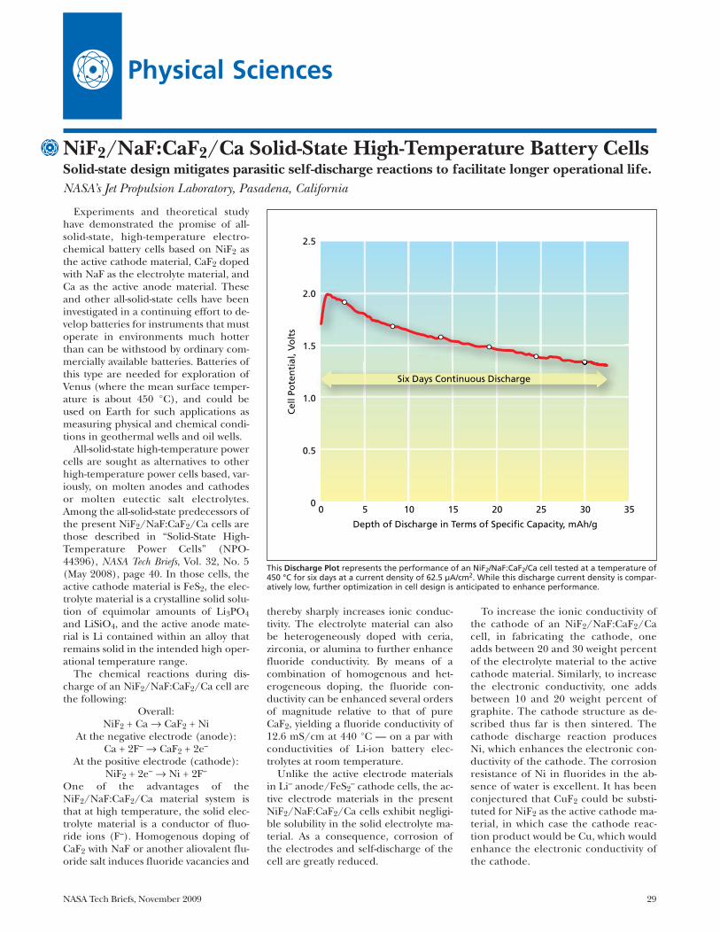
NASA Tech Briefs, November 2009 29
Experiments and theoretical studyhave demonstrated the promise of all-solid-state, high-temperature electro-chemical battery cells based on NiF2 asthe active cathode material, CaF2 dopedwith NaF as the electrolyte material, andCa as the active anode material. Theseand other all-solid-state cells have beeninvestigated in a continuing effort to de-velop batteries for instruments that mustoperate in environments much hotterthan can be withstood by ordinary com-mercially available batteries. Batteries ofthis type are needed for exploration ofVenus (where the mean surface temper-ature is about 450 °C), and could beused on Earth for such applications asmeasuring physical and chemical condi-tions in geothermal wells and oil wells.
All-solid-state high-temperature powercells are sought as alternatives to otherhigh-temperature power cells based, var-iously, on molten anodes and cathodesor molten eutectic salt electrolytes.Among the all-solid-state predecessors ofthe present NiF2/NaF:CaF2/Ca cells arethose described in “Solid-State High-Temperature Power Cells” (NPO-44396), NASA Tech Briefs, Vol. 32, No. 5(May 2008), page 40. In those cells, theactive cathode material is FeS2, the elec-trolyte material is a crystalline solid solu-tion of equimolar amounts of Li3PO4and LiSiO4, and the active anode mate-rial is Li contained within an alloy thatremains solid in the intended high oper-ational temperature range.
The chemical reactions during dis-charge of an NiF2/NaF:CaF2/Ca cell arethe following:
Overall:NiF2 + Ca → CaF2 + Ni
At the negative electrode (anode):Ca + 2F– → CaF2 + 2e–
At the positive electrode (cathode):NiF2 + 2e– → Ni + 2F–
One of the advantages of theNiF2/NaF:CaF2/Ca material system isthat at high temperature, the solid elec-trolyte material is a conductor of fluo-ride ions (F–). Homogenous doping ofCaF2 with NaF or another aliovalent flu-oride salt induces fluoride vacancies and
thereby sharply increases ionic conduc-tivity. The electrolyte material can alsobe heterogeneously doped with ceria,zirconia, or alumina to further enhancefluoride conductivity. By means of acombination of homogenous and het-erogeneous doping, the fluoride con-ductivity can be enhanced several ordersof magnitude relative to that of pureCaF2, yielding a fluoride conductivity of12.6 mS/cm at 440 °C — on a par withconductivities of Li-ion battery elec-trolytes at room temperature.
Unlike the active electrode materialsin Li– anode/FeS2
– cathode cells, the ac-tive electrode materials in the presentNiF2/NaF:CaF2/Ca cells exhibit negligi-ble solubility in the solid electrolyte ma-terial. As a consequence, corrosion ofthe electrodes and self-discharge of thecell are greatly reduced.
To increase the ionic conductivity ofthe cathode of an NiF2/NaF:CaF2/Cacell, in fabricating the cathode, oneadds between 20 and 30 weight percentof the electrolyte material to the activecathode material. Similarly, to increasethe electronic conductivity, one addsbetween 10 and 20 weight percent ofgraphite. The cathode structure as de-scribed thus far is then sintered. Thecathode discharge reaction producesNi, which enhances the electronic con-ductivity of the cathode. The corrosionresistance of Ni in fluorides in the ab-sence of water is excellent. It has beenconjectured that CuF2 could be substi-tuted for NiF2 as the active cathode ma-terial, in which case the cathode reac-tion product would be Cu, which wouldenhance the electronic conductivity ofthe cathode.
Physical Sciences
NiF2/NaF:CaF2/Ca Solid-State High-Temperature Battery Cells Solid-state design mitigates parasitic self-discharge reactions to facilitate longer operational life.NASA’s Jet Propulsion Laboratory, Pasadena, California
This Discharge Plot represents the performance of an NiF2/NaF:CaF2/Ca cell tested at a temperature of450 °C for six days at a current density of 62.5 µA/cm2. While this discharge current density is compar-atively low, further optimization in cell design is anticipated to enhance performance.
00
0.5
1.0
1.5
2.0
2.5
5 10 15
Depth of Discharge in Terms of Specific Capacity, mAh/g
Cel
l Po
ten
tial
, Vo
lts
20 25 30 35
0
Six Days Continuous Discharge

30 NASA Tech Briefs, November 2009
The anode of an NiF2/NaF:CaF2/Cacell consists of a solid Ca metal layerformed by pressing dendritic Ca into adisk shape and roughening the surface toenhance contact with the cathode/elec-trolyte/graphite. The conversion of theactive anode material (Ca) to the mainingredient (CaF2) of the electrolyte mate-rial during discharge is fortuitous in thatthe accumulation of this material facili-tates further discharge, unlike in mostother electrochemical power cells,wherein accumulation of discharge prod-ucts hinders further discharge. Ideally,the anode would be fabricated as a Ca
alloy containing approximately 5 molepercent of Na to form the desired NaFdopant for the CaF2 electrolyte as the celldischarges. At 450 °C, this alloy would re-main a solid solution.
Several NiF2/NaF:CaF2/Ca cells havebeen fabricated and tested. The figurepresents results from one such test. Fortesting purposes, these cells have beentreated as primary (non-rechargeable)cells, but it is possible that these cells arerechargeable. If further tests confirm thatthey are rechargeable, then some of thecost and risk associated with manufactureand use of high-temperature batteries
could be reduced: Before being installedfor use, batteries could be heated to oper-ating temperatures; charged and dis-charged several times to verify that theirvoltages, capacities, and discharge-rate ca-pabilities are as expected; then recharged;and finally cooled. In contrast, the volt-ages, capacities, and discharge-rate capa-bilities of non-rechargeable batteries can-not be verified prior to final use.
This work was done by William West, JayWhitacre, and Linda Del Castillo of Caltechfor NASA’s Jet Propulsion Laboratory. Furtherinformation is contained in a TSP (see page1). NPO-44643
Critical Coupling Between Optical Fibers and WGM ResonatorsRecipes address issues of phase matching, aperture matching, and suppressing intermodal coupling.NASA’s Jet Propulsion Laboratory, Pasadena, California
Two recipes for ensuring critical cou-pling between a single-mode opticalfiber and a whispering-gallery-mode(WGM) optical resonator have been de-vised. The recipes provide for phasematching and aperture matching, bothof which are necessary for efficient cou-pling. There is also a provision for sup-pressing intermodal coupling, which isdetrimental because it drains energyfrom desired modes into undesired ones.
According to one recipe, the tip ofthe single-mode optical fiber is either ta-pered in diameter or tapered in effec-tive diameter by virtue of being cleavedat an oblique angle. The effective indexof refraction and the phase velocity at agiven position along the taper dependon the diameter (or effective diameter)and the index of refraction of the bulkfiber material. As the diameter (or effec-tive diameter) decreases with decreas-ing distance from the tip, the effectiveindex of refraction also decreases. Criti-cal coupling and phase matching can beachieved by placing the optical fiberand the resonator in contact at theproper point along the taper. Thisrecipe is subject to the limitation thatthe attainable effective index of refrac-tion lies between the indices of refrac-tion of the bulk fiber material and theatmosphere or vacuum to which the res-onator and fiber are exposed.
The other recipe involves a refine-ment of the previously developed tech-nique of prism coupling, in which thelight beam from the optical fiber is col-limated and focused onto one surfaceof a prism that has an index of refrac-
tion greater than that of the resonator.Another surface of the prism is placedin contact with the resonator. The vari-ous components are arranged so that
the collimated beam is focused at theprism/resonator contact spot. Therecipe includes the following additionalprovisions:
A Typical Whispering-Gallery-Mode Resonator is characterized by, among other parameters, radii ofcurvature r and R that appear in the equations that describe the conditions for critical coupling.
WGM RESONATOR VIEWED ALONG AXIS OF SMMETRY
SECTION A-A OF WGM RESONATOR
2R
R
r: Radius of Curvature inMeridonal Plane atPoint of Contact
A A

NASA Tech Briefs, November 2009 31
Alternative Determination of Density of the Titan AtmosphereNASA’s Jet Propulsion Laboratory, Pasadena, California
An alternative has been developed todirect measurement for determining thedensity of the atmosphere of the Saturnmoon Titan as a function of altitude. Thebasic idea is to deduce the density versusaltitude from telemetric data indicative ofthe effects of aerodynamic torques on theattitude of the Cassini Saturn orbiterspacecraft as it flies past Titan at variousaltitudes. The Cassini onboard attitude-control software includes a componentthat can estimate three external per-axis
torques exerted on the spacecraft. Theseestimates are available via telemetry.
The atmospheric torque vector is theproduct of (1) a drag coefficient (whichis known from ground-based experimentand analysis), (2) the Titan atmosphericdensity that one seeks to determine, (3)the square of the Titan-relative space-craft speed (which is known from naviga-tion monitoring), and (4) the projectedarea of the spacecraft and the offset dis-tance between the center of pressure and
center of mass, both of which are knownfunctions of the attitude of the spacecraftrelative to the known velocity throughthe atmosphere. Hence, the atmosphericdensity is the only unknown and can bedetermined from the other quantities,which are known.
This work was done by Allan Lee, Jay Brown,Antonette Feldman, Scott Peer, and Eric Wangof Caltech for NASA’s Jet Propulsion Laboratory.
Further information is contained in a TSP(see page 1). NPO-44606
Many atmospheric research aircraftuse a standard canister design to mountinstruments, as this significantly facili-tates their electrical and mechanical in-tegration and thereby reduces cost.Based on more than 30 years of air-borne science experience with the Mi-crowave Temperature Profiler (MTP),the MTP has been repackaged withstate-of-the-art electronics and other de-sign improvements to fly in one of thesestandard canisters.
All of the controlling electronics areintegrated on a single 4×5-in. (≈10×13-cm) multi-layer PCB (printed circuitboard) with surface-mount hardware.Improved circuit design, including a
self-calibrating RTD (resistive tempera-ture detector) multiplexer, was imple-mented in order to reduce the size andmass of the electronics while providingincreased capability. A new microcon-troller-based temperature controllerboard was designed, providing bettercontrol with fewer components. Fivesuch boards are used to provide localcontrol of the temperature in variousareas of the instrument, improving ra-diometric performance. The new step-per motor has an embedded controllereliminating the need for a separate con-troller board.
The reference target is heated toavoid possible emissivity (and hence
calibration) changes due to moisturecontamination in humid environ-ments, as well as avoiding issues withambient targets during ascent and de-scent. The radiometer is a double-side-band heterodyne receiver tuned se-quentially to individual oxygenemission lines near 60 GHz, with theline selection and intermediate fre-quency bandwidths chosen to accom-modate the altitude range of the air-craft and mission.
This work was done by Michael J. Mahoneyand Richard F. Denning of Caltech and JackFox of NCAR for NASA’s Jet Propulsion Lab-oratory. For more information, contact [email protected]. NPO-46737
Microwave Temperature Profiler Mounted in a StandardAirborne Research Canister NASA’s Jet Propulsion Laboratory, Pasadena, California
• In fabricating the resonator, onestrives to obtain
r = R[1–(nd/np)2], where r is the vertical radius of curva-ture at the contact spot as defined inthe figure; R is the horizontal radius ofcurvature, also as defined in the fig-ure; nd is the effective index of refrac-tion of the desired mode in the res-onator; and np is the index ofrefraction of the prism.• The reason for this choice of r and R is
that it ensures aperture matching witha Gaussian beam cross section at thecontact spot.
• The numerical aperture (NA) of thecollimated beam must be chosen tohave the following value:
NA = sin(λ/h), where λ is the vacuum wavelength of thelight that one seeks to couple into andout of the resonator, and h is a magni-tude of the evanescent electromagneticfield of the resonator, given by
h ≈ λ/[2π(nd2–np
2)1/2].• In practice, the fabrication process
does not yield precisely the desired ra-dius r : instead, it yields a slightly dif-ferent value, r′. Therefore, after fabri-cation, in order to ensure phasematching, one must select a new de-sired mode for which the effectiveindex of refraction is given by
nd = np(1–r′/R)1/2.• Intermodal coupling is suppressed by
use of what, at the time of writing this
article, was reported to be a “singlemode technique” but not otherwisedescribed. The technique was re-ported to be described in “Morphol-ogy-dependent photonic circuit ele-ments,” Optics Letters Vol. 31, Issue 9,page 1313.This work was done by Andrey Matsko, Lute
Maleki, Vladimir Iltchenko, and AnatoliySavchenkov of Caltech for NASA’s Jet Propul-sion Laboratory. Further information is con-tained in a TSP (see page 1).
This invention is owned by NASA, and apatent application has been filed. Inquiriesconcerning nonexclusive or exclusive licensefor its commercial development should be ad-dressed to the Patent Counsel, NASA Man-agement Office–JPL. Refer to NPO-45462.

32 NASA Tech Briefs, November 2009
To reject solar radiation photons atthe front aperture for large telescopes, amosaic of large transmission mode fil-ters is placed in front of the telescope orat the aperture of the dome. Filteringoptions for effective rejection of sun-light include a smaller filter down-pathnear the focus of the telescope, and alarge-diameter filter located in the frontof the main aperture. Two types of largefilters are viable: reflectance mode andtransmittance mode.
In the case of reflectance mode, a di-electric coating on a suitable substrate(e.g. a low-thermal-expansion glass) isarranged to reflect only a single, narrowwavelength and to efficiently transmit allother wavelengths. These coatings arecommonly referred to as notch filter. Inthis case, the large mirror located infront of the telescope aperture reflectsthe received (signal and background)light into the telescope. In the case of
transmittance mode, a dielectric coatingon a suitable substrate (glass, sapphire,clear plastic, membrane, and the like) isarranged to transmit only a single wave-length and to reject all other wave-lengths (visible and near IR) of light.The substrate of the large filter will de-termine its mass. At first glance, a largeoptical filter with a diameter of up to 10m, located in front of the main aperture,would require a significant thickness toavoid sagging. However, a segmented fil-ter supported by a structurally ruggedgrid can support smaller filters.
The obscuration introduced by thegrid is minimal because the total areacan be made insignificant. This configu-ration can be detrimental to a diffrac-tion-limited telescope due to diffractioneffects at the edges of each sub-panel.However, no discernable degradationwould result for a 20× diffraction-limittelescope (a photon bucket). Even the
small amount of sagging in each sub-panel should have minimal effect in theperformance of a non-diffraction lim-ited telescope because the part has noappreciable optical power.
If the front aperture filter is inte-grated with the telescope dome, it willreject heat from the dome and will sig-nificantly reduce dome temperature reg-ulation requirements and costs. Also,the filter will protect the telescope opticsfrom dust and other contaminants inthe atmosphere. It will be simpler toclean or replace this filter than the tele-scope primary mirror. It may be neces-sary to paint the support grid with ahighly reflective material to avoid over-heating.
This work was done by Hamid Hemmatiand James Lesh of Caltech for NASA’s JetPropulsion Laboratory. Further informationis contained in a TSP (see page 1). NPO-40421
Solar Rejection Filter for Large Telescopes Filters help avoid thermal loading of the receiver by incident sunlight. NASA’s Jet Propulsion Laboratory, Pasadena, California
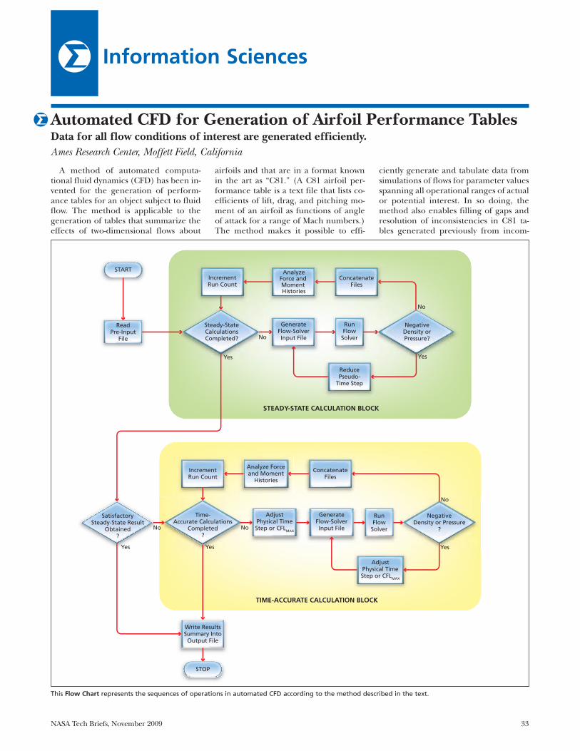
NASA Tech Briefs, November 2009 33
Information Sciences
A method of automated computa-tional fluid dynamics (CFD) has been in-vented for the generation of perform-ance tables for an object subject to fluidflow. The method is applicable to thegeneration of tables that summarize theeffects of two-dimensional flows about
airfoils and that are in a format knownin the art as “C81.” (A C81 airfoil per-formance table is a text file that lists co-efficients of lift, drag, and pitching mo-ment of an airfoil as functions of angleof attack for a range of Mach numbers.)The method makes it possible to effi-
ciently generate and tabulate data fromsimulations of flows for parameter valuesspanning all operational ranges of actualor potential interest. In so doing, themethod also enables filling of gaps andresolution of inconsistencies in C81 ta-bles generated previously from incom-
Automated CFD for Generation of Airfoil Performance Tables Data for all flow conditions of interest are generated efficiently. Ames Research Center, Moffett Field, California
This Flow Chart represents the sequences of operations in automated CFD according to the method described in the text.
START
Yes
Yes Yes
No No
Yes
Yes
No
No
No
STOP
ReadPre-Input
File
Steady-StateCalculationsCompleted?
IncrementRun Count
IncrementRun Count
Write ResultsSummary Into
Output File
Analyze Forceand Moment
Histories
AnalyzeForce and Moment Histories
ConcatenateFiles
ConcatenateFiles
GenerateFlow-SolverInput File
AdjustPhysical TimeStep or CFLMAX
AdjustPhysical TimeStep or CFLMAX
ReducePseudo-
Time Step
STEADY-STATE CALCULATION BLOCK
TIME-ACCURATE CALCULATION BLOCK
GenerateFlow-SolverInput File
RunFlow
Solver
RunFlow
Solver
SatisfactorySteady-State Result
Obtained?
Time-Accurate Calculations
Completed?
NegativeDensity or Pressure
?
NegativeDensity orPressure?

34 NASA Tech Briefs, November 2009
plete experimental data or from theoret-ical calculations that involved question-able assumptions.
The method can be implemented byuse of any of a variety of digital proces-sors comprising hardware and softwaresubsystems capable of simulating flows.The hardware subsystem could be, forexample, a microprocessor, a main-frame computer, a digital signal proces-sor, or a portable computer. The soft-ware subsystem can include any of anumber of flow solvers — that is, com-puter programs that solve the govern-ing equations of flow. One such pro-gram that is particularly suitable foruse in this method is ARC2D, whichutilizes finite-difference techniques tonumerically solve the Reynolds-aver-aged Navier-Stokes equations of two-di-mensional compressible flow.
At the beginning of a process usingthis method, the processor receives a de-scription of the airfoil and a pre-inputfile, which contains parameters represen-tative of the ranges of flow conditions inwhich the airfoil is to be tested via com-putational simulations. The processorcan perform steady-state and/or time-ac-curate calculations for simulating flows.Steady-state calculations are typically ap-plicable to such conventional flow condi-tions as small angles of attack with fullyattached flows for which the solutionsare independent of time. Time-accuratecalculations model the temporal behav-iors of time-varying flows.
The upper part of the figure illus-trates steady-state calculations accord-ing to this method. After reading thepre-input file, the processor determineswhether the steady-state calculationsspecified by that file have been com-pleted. If the calculations have notbeen completed, the processor gener-ates a flow-solver input file, then theprocessor executes the flow solver usingthis input file. If the output of the flowsolver includes a negative density orpressure, which is physically impossible,then the pseudo-time step used in theflow solver is reduced and the flowsolver is run again using the same in-puts. This sub-process is repeated, ifnecessary, until neither the pressurenor the density in the output of the flowsolver is negative, at which point theoutput of the flow solver is concate-nated into an output file. Next, theprocessor analyzes the residual historyof forces and pitching moments and in-crements the run count. The processorthen returns to the step in which it de-termines whether the steady-state calcu-lations have been completed. If the cal-culations are found to have beencompleted, the processor determineswhether satisfactory results were ob-tained. If satisfactory results were notobtained, the processor switches totime-accurate mode.
The lower part of the figure depictstime-accurate calculations according tothis method. First, the processor deter-
mines whether the time-accurate calcu-lations have been completed. If not, theprocessor adjusts the physical time stepor the maximum allowable value,CFLMAX, of the Courant-Friedrichs-Levynumber. [The Courant-Friedrichs-Levynumber (CFL) is the product of a timestep and a speed characteristic of theflow.] Next, the processor generates aflow-solver input file using the adjustedphysical time step or adjusted CFLMAX.If negative density or pressure is foundin the output of the flow solver, then thephysical time step or CFLMAX is furtheradjusted, a corresponding new flow-solver input file is generated, and theflow solver is run again. This subprocessis repeated, if necessary, until neitherthe pressure nor the density is negative.Next, the processor analyzes the forceand moment histories and incrementsthe run count. The processor then re-turns to the step in which it determineswhether the time-accurate or the steady-state calculations have been completed.If the time-accurate calculations arefound to have been completed, or if thesteady-state calculations have been com-pleted with satisfactory results, then theprocessor writes the results into an out-put file.
This work was done by Roger Strawn of theU.S. Army and E. A. Mayda and C. P. vanDam of the University of California for AmesResearch Center. Further information is con-tained in a TSP (see page 1).ARC-15649-1
Progressive Classification Using Support Vector MachinesAn approximate classification is generated rapidly, then iteratively refined over time.NASA’s Jet Propulsion Laboratory, Pasadena, California
An algorithm for progressive classifi-cation of data, analogous to progressiverendering of images, makes it possibleto compromise between speed and ac-curacy. This algorithm uses support vec-tor machines (SVMs) to classify data.An SVM is a machine learning algo-rithm that builds a mathematical modelof the desired classification concept byidentifying the critical data points,called support vectors. Coarse approxi-mations to the concept require only afew support vectors, while precise,highly accurate models require farmore support vectors. Once the modelhas been constructed, the SVM can beapplied to new observations. The costof classifying a new observation is pro-
portional to the number of support vec-tors in the model. When computationalresources are limited, an SVM of the ap-propriate complexity can be produced.However, if the constraints are notknown when the model is constructed,or if they can change over time, amethod for adaptively responding tothe current resource constraints is re-quired. This capability is particularlyrelevant for spacecraft (or any otherreal-time systems) that perform on-board data analysis.
The new algorithm enables the fast,interactive application of an SVM clas-sifier to a new set of data. The classifi-cation process achieved by this algo-rithm is characterized as progressive
because a coarse approximation to thetrue classification is generated rapidlyand thereafter iteratively refined. Thealgorithm uses two SVMs: (1) a fast, ap-proximate one and (2) slow, highly ac-curate one. New data are initially clas-sified by the fast SVM, producing abaseline approximate classification.For each classified data point, the algo-rithm calculates a confidence indexthat indicates the likelihood that it wasclassified correctly in the first pass.Next, the data points are sorted bytheir confidence indices and progres-sively reclassified by the slower, moreaccurate SVM, starting with the itemsmost likely to be incorrectly classified.The user can halt this reclassification

NASA Tech Briefs, November 2009 35
process at any point, thereby obtainingthe best possible result for a givenamount of computation time. Alterna-tively, the results can be displayed asthey are generated, providing the userwith real-time feedback about the cur-rent accuracy of classification.
Computational savings are realizedthrough the guided application of re-sources only to those items that are es-timated to be misclassified. The coarseapproximation may suffice for items
that can be classified easily, and morecomputation can be devoted to am-biguous or difficult cases. Thus, the al-gorithm enables the user to exert di-rect, dynamic control over the balancebetween classification speed and accu-racy. When constraints on computationtime and other resources preclude a to-tally accurate classification of all thedata, this algorithm provides the bestpossible approximation to the classifi-cation of each item, rather than fully
classifying only a fraction of the dataset and leaving the rest marked “un-known.”
This work was done by Kiri Wagstaff andMichael Kocurek of Caltech for NASA’s JetPropulsion Laboratory. Further information iscontained in a TSP (see page 1).
The software used in this innovation isavailable for commercial licensing. Pleasecontact Karina Edmonds of the California In-stitute of Technology at (626) 395-2322.Refer to NPO-44089.
Active Learning With Irrelevant ExamplesClassification algorithms can be trained to recognize and reject irrelevant data.NASA’s Jet Propulsion Laboratory, Pasadena, California
An improved active learning methodhas been devised for training data classi-fiers. One example of a data classifier isthe algorithm used by the United StatesPostal Service since the 1960s to recog-nize scans of handwritten digits for pro-cessing zip codes. Active learning algo-rithms enable rapid training withminimal investment of time on the partof human experts to provide training ex-amples consisting of correctly classified(labeled) input data. They function byidentifying which examples would bemost profitable for a human expert tolabel. The goal is to maximize classifieraccuracy while minimizing the numberof examples the expert must label.
Although there are several well-estab-lished methods for active learning, theymay not operate well when irrelevant ex-amples are present in the data set. That
is, they may select an item for labelingthat the expert simply cannot assign toany of the valid classes. In the context ofclassifying handwritten digits, the irrele-vant items may include stray marks,smudges, and mis-scans. Querying theexpert about these items results inwasted time or erroneous labels, if theexpert is forced to assign the item to oneof the valid classes.
In contrast, the new algorithm pro-vides a specific mechanism for avoidingquerying the irrelevant items. This algo-rithm has two components: an activelearner (which could be a conventionalactive learning algorithm) and a rele-vance classifier. The combination ofthese components yields a method, de-noted Relevance Bias, that enables theactive learner to avoid querying irrele-vant data so as to increase its learning
rate and efficiency when irrelevant itemsare present.
The algorithm collects irrelevant datain a set of rejected examples, then trainsthe relevance classifier to distinguish be-tween labeled (relevant) training exam-ples and the rejected ones. The activelearner combines its ranking of the itemswith the probability that they are relevantto yield a final decision about which itemto present to the expert for labeling. Ex-periments on several data sets havedemonstrated that the Relevance Biasapproach significantly decreases thenumber of irrelevant items queried andalso accelerates learning speed.
This work was done by Kiri Wagstaff of Cal-tech and Dominic Mazzoni of Google, Inc. forNASA’s Jet Propulsion Laboratory. For more in-formation, contact [email protected]. NPO-44094
A simple 2D M×N matrix involvingsample preparation enables the micro-analyst to peer below the noise floor ofelement percentages reported by theSEM/EDX (scanning electron mi-croscopy/energy dispersive x-ray)analysis, thus yielding more meaning-ful data.
Using the example of a 2×3 sampleset, there are M = 2 concentration levels
of the original mix under test: 10 per-cent ilmenite (90 percent silica) and 20percent ilmenite (80 percent silica). Foreach of these M samples, N = 3 separateSEM/EDX samples were drawn. In thistest, ilmenite is the element of interest.By plotting the linear trend of the Msample’s known concentration versusthe average of the N samples, a muchhigher resolution of elemental analysis
can be performed. The resulting trendalso shows how the noise is affecting thedata, and at what point (of smaller con-centrations) is it impractical to try to ex-tract any further useful data.
This work was done by John Lane ofKennedy Space Center. For further informa-tion, contact the Kennedy Innovative Part-nerships Program Office at (321) 861-7158.KSC-13303
A Data Matrix Method for Improving the Quantification ofElement Percentages of SEM/EDX AnalysisJohn F. Kennedy Space Center, Florida


NASA Tech Briefs, November 2009 37
Books & Reports
Deployable Shroud for the International X-Ray Observatory
A document describes the design of alightweight (between 100 to 200 kg),light-tight shroud of about 3.9 meters indiameter that could be stowed into a verysmall volume, and be deployed to 12 me-ters. The shroud will consist of two con-centric multi-layer blankets (MLIs) thatare constructed in an accordion shape.The blankets have 2-mil (≈50 µm) Kap-ton outer layers, and several ¼-mil (≈6.4-µm) thick inner layers with Dacron net-ting scrim cloth. The two blankets areseparated by 10 cm that creates a “Whip-ple Shield” effect that reduces the num-ber of micrometeorite penetrations fromthousands to less than 30 over the satel-lite’s expected ten-year lifetime.
A 1/25th scale model of a shroud wasconstructed. It consists of nine flat sec-tions with pleats and individual cornerpieces that are taped between the flatsections. The 18 pleated folds are 19 mmwide. Hexagonal corner pieces aretaped between the facets and work bet-ter if they are thinner than the bulk ofthe blanket.
A full-scale section of a shroud hasbeen made to provide insights into thedesign, stowage, and handling issues. Acomplete shroud of 29 pleats will stow to174 mm with no compression. The ac-cordion-style construction allows theshroud to be stowed into a channel thatis less than 20 cm tall and 30 cm wide.
This work was done by David W. Robinsonof Goddard Space Flight Center. Further infor-mation is contained in a TSP (see page 1).GSC-15779-1
Improved Model of a Mercury Ring Damper
A short document discusses the gen-eral problem of mathematical modelingof the three-dimensional rotational dy-namics of rigid bodies and of the use ofEuler parameters to eliminate the singu-larities occasioned by the use of Euler an-gles in such modeling. The documentgoes on to characterize a Hamiltonianmodel, developed by the authors, that uti-lizes the Euler parameters and, hence, issuitable for use in computational simula-tions that involve arbitrary rotational mo-tion. In this formulation unlike in prior
Euler-parameter-based formulations,there are no algebraic constraints. Thisformulation includes a general potential-energy function, incorporates a mini-mum set of momentum variables, andtakes an explicit state-space form conven-ient for numerical implementation.
Practical application of this formula-tion has been demonstrated by the de-velopment of a new and simplifiedmodel of the rotational motion of arigid rotor to which is attached a par-tially filled mercury ring damper. Mod-els like this one are used in guidanceand control of spin-stabilized spacecraftand gyroscope-stabilized seekers inguided missiles.
This work was done by Eric P. Fahrentholdand Ravishankar Shivarma of the Universityof Texas for Johnson Space Center. Further in-formation is contained in a TSP (see page 1).MSC-23830-1
Optoelectronic pH Meter:Further Details
A collection of documents providesfurther detailed information about anoptoelectronic instrument that meas-ures the pH of an aqueous cell-culturemedium to within ±0.1 unit in the rangefrom 6.5 to 7.5. The instrument at anearlier stage of development was re-ported in “Optoelectronic InstrumentMonitors pH in a Culture Medium”(MSC-23107), NASA Tech Briefs, Vol. 28,No. 9 (September 2004), page 4a.
To recapitulate: The instrument in-cludes a quartz cuvette through whichthe medium flows as it is circulatedthrough a bioreactor. The medium con-tains some phenol red, which is an or-ganic pH-indicator dye. The cuvettesits between a light source and a pho-todetector. [The light source in the ear-lier version comprised red (625 nm) andgreen (558 nm) light-emitting diodes(LEDs); the light source in the presentversion comprises a single green- (560nm)-or-red (623 nm) LED.] The redand green are repeatedly flashed in al-ternation. The responses of the photodi-ode to the green and red are processedelectronically to obtain the ratio be-tween the amounts of green and redlight transmitted through the medium.The optical absorbance of the phenolred in the green light varies as a knownfunction of pH. Hence, the pH of the
medium can be calculated from theaforesaid ratio.
This work was done by Antony S. Jeevara-jan and Melody M. Anderson of JohnsonSpace Center and Ariel V. Macatangay ofWyle Laboratories. Further information iscontained in a TSP (see page 1). MSC-23854-1
X-38 Advanced SublimatorA document discusses a heat rejection
device for transferring heat from a spacevehicle by venting water into spacethrough the use of a novel, two-stagewater distribution system. The systemconsists of two different, porous mediathat stop water-borne contaminantsfrom clogging the system and causingoperational failures.
Feedwater passes through a small noz-zle, then into a porous disk made of sin-tered stainless steel, and then finally intolarge-pore aluminum foam. The smallerpore layer of the steel disk controls thepressure drop of the feedwater. The iceforms in the foam layer, and then subli-mates, leaving any contaminants behind.The pore-size of the foam is two ordersof magnitude larger than the currentporous plate sublimators, allowing for agreater tolerance for contaminants.Using metallic fibers in the foam alsonegates problems with compressionseen in the use of poly(tetrafluoroethyl-ene) felt.
This work was done by Chuck Dingell,Clemente Quintana, and Suy Le of JohnsonSpace Center and David S. Hafermalz, MikeClark, and Robert Cloutier of Jacobs Sver-drup. Further information is contained in aTSP (see page 1).
This invention is owned by NASA, and apatent application has been filed. Inquiriesconcerning nonexclusive or exclusive licensefor its commercial development should be ad-dressed to the Patent Counsel, Johnson SpaceCenter, (281) 483-1003. Refer to MSC-24207-1.
Solar Simulator Representsthe Mars Surface Solar Environment
A report discusses the development ofa Mars surface, laboratory-based solarsimulator to create solar cells that canfunction better on Mars. The Mars Opti-mized Solar cell Technology (MOST) re-

38 NASA Tech Briefs, November 2009
quired defining the surface incidentspectrum, developing an appropriatelaboratory solar simulator measurementcapability, and developing and testingcommercial cells modified for the Marssurface spectrum.
Based on analysis and measurements ofthe Mars surface spectrum, a standardspectrum has been developed for testingby modifying the output spectrum of stan-dard xenon commercial space solar simu-lators with light filtered to reproduce aMars surface spectral distribution suitablefor measuring existing solar cells. An ex-ternal filter wheel has been fabricatedthat holds a number of filter elements.
The appropriate filters are determined byanalysis and filter availability, and aretested to verify the spectrum for solar-celltesting. The filter assembly is adjustable tochanges in the simulator output due tospecific light bulbs or bulb aging.
Prior to the advent of the MOST pro-gram, the estimated Mars surface solararray performance was based on its AM0output at the distance of Mars, modifiedby a factor to account for the atmos-phere. With the continuing success of theMars exploration rovers (MERs), it isclear that the use of multijunction photo-voltaics on the surface is a realistic optionfor high-power, long-life operation. The
MOST program has resulted in develop-ment of a solar simulator that can providethe appropriate spectrum of sunlight onthe Martian surface. The MOST programis in the process of demonstrating thatAM0-optimized high efficiency solar cellscan be tailored to operate more optimallyunder Mars surface conditions, and togenerate higher power and predictabilityover a range of conditions.
This work was done by Paul M. Stella,Stephen F. Dawson, Robert L. Mueller, NickMardesich, and Donald Rapp of Caltech forNASA’s Jet Propulsion Laboratory. For moreinformation, contact [email protected]


National Aeronautics andSpace Administration
Related Documents