Technology Focus Electronics/Computers Software Materials Mechanics/Machinery Manufacturing Bio-Medical Physical Sciences Information Sciences Books and Reports Green Design 06-11 June 2011 https://ntrs.nasa.gov/search.jsp?R=20110012577 2018-05-31T14:51:50+00:00Z

Welcome message from author
This document is posted to help you gain knowledge. Please leave a comment to let me know what you think about it! Share it to your friends and learn new things together.
Transcript

Technology Focus
Electronics/Computers
Software
Materials
Mechanics/Machinery
Manufacturing
Bio-Medical
Physical Sciences
Information Sciences
Books and Reports
Green Design
06-11 June 2011
https://ntrs.nasa.gov/search.jsp?R=20110012577 2018-05-31T14:51:50+00:00Z

Availability of NASA Tech Briefs and TSPsRequests for individual Tech Briefs or for Technical Support Packages (TSPs) announced herein shouldbe addressed to
National Technology Transfer CenterTelephone No. (800) 678-6882 or via World Wide Web at www.nttc.edu
Please reference the control numbers appearing at the end of each Tech Brief. Infor mation on NASA’s Innovative Partnerships Program (IPP), its documents, and services is also available at the same facility oron the World Wide Web at http://www.nasa.gov/offices/ipp/network/index.html
Innovative Partnerships Offices are located at NASA field centers to provide technology-transfer access toindustrial users. Inquiries can be made by contacting NASA field centers listed below.
Ames Research CenterMary Walsh(650) [email protected]
Dryden Flight Research CenterYvonne D. Gibbs(661) [email protected]
Glenn Research CenterJoe Shaw, Acting Chief(216) [email protected]
Goddard Space Flight CenterNona Cheeks(301) [email protected]
Jet Propulsion LaboratoryIndrani Graczyk(818) [email protected]
Johnson Space Centerinformation(281) [email protected]
Kennedy Space CenterDavid R. Makufka(321) [email protected]
Langley Research CenterElizabeth B. Plentovich(757) [email protected]
Marshall Space Flight CenterJim Dowdy(256) [email protected]
Stennis Space CenterRamona Travis(228) 688-3832 [email protected]
Carl Ray, Program ExecutiveSmall Business Innovation Research (SBIR) & Small Business Technology Transfer (STTR) Programs(202) [email protected]
Doug Comstock, Partnerships Innovation and CommercialSpace Program Office (formerly IPP)(202) [email protected]
INTRODUCTIONTech Briefs are short announcements of innovations originating from research and developmentactivities of the National Aeronautics and Space Administration. They emphasize information con-sidered likely to be transferable across industrial, regional, or disciplinary lines and are issued toencourage commercial application.
June 2011 1


This document was prepared under the sponsorship of the National Aeronautics and Space Administration. Neither the United States Govern-ment nor any person acting on behalf of the United States Government assumes any liability resulting from the use of the information containedin this document, or warrants that such use will be free from privately owned rights.
NASA Tech Briefs, June 2011 3
06-11 June 2011
5 Technology Focus: Data Acquisition
5 Wind and Temperature Spectrometry of the Upper Atmosphere in Low-Earth Orbit
5 Health Monitor for Multitasking, Safety-Critical, Real-Time Software
6 Stereo Imaging Miniature Endoscope 7 Early Oscillation Detection Technique for
Hybrid DC/DC Converters7 Parallel Wavefront Analysis for a 4D
Interferometer
9 Electronics/Computers9 Schottky Heterodyne Receivers With Full
Waveguide Bandwidth9 Carbon Nanofiber-Based, High-Frequency,
High-Q, Miniaturized Mechanical Resonators
10 Ultracapacitor-Based Uninterrupted Power Supply System
11 Coaxial Cables for Martian Extreme Temperature Environments
11 Using Spare Logic Resources To Create Dynamic Test Points
13 Software13 Autonomous Coordination of Science
Observations Using Multiple Spacecraft 13 Autonomous Phase Retrieval Calibration13 EOS MLS Level 1B Data Processing
Software, Version 3 14 Cassini Tour Atlas Automated Generation 14 Software Development Standard
Processes (SDSP)
15 Manufacturing & Prototyping15 Graphite Composite Panel Polishing Fixture15 Material Gradients in Oxygen System
Components Improve Safety15 Ridge Waveguide Structures in
Magnesium-Doped Lithium Niobate16 Modifying Matrix Materials to Increase Wet-
ting and Adhesion
17 Green Design17 Lightweight Magnetic Cooler With a
Reversible Circulator17 The Invasive Species Forecasting System
19 Mechanics/Machinery19 Method for Cleanly and Precisely
Breaking Off a Rock Core Using a RadialCompressive Force
19 Praying Mantis Bending Core Breakoff and Retention Mechanism
20 Scoring Dawg Core Breakoff and Retention Mechanism
20 Rolling-Tooth Core Breakoff and Retention Mechanism
21 Vibration Isolation and Stabilization System for Spacecraft Exercise Treadmill Devices
23 Bio-Medical23 Microgravity-Enhanced Stem Cell Selection23 Diagnosis and Treatment of Neurological
Disorders by Millimeter-Wave Stimulation
25 Physical Sciences25 Passive Vaporizing Heat Sink25 Remote Sensing and Quantization of
Analog Sensors 25 Phase Retrieval for Radio Telescope and
Antenna Control 26 Helium-Cooled Black Shroud for Subscale
Cryogenic Testing
27 Information Sciences27 Receive Mode Analysis and Design of
Microstrip Reflectarrays 27 Chance-Constrained Guidance With
Non-Convex Constraints

NASA Tech Briefs, June 2011 5
Technology Focus: Data Acquisition
Wind and Temperature Spectrome-try (WATS) is a new approach to meas-ure the full wind vector, temperature,and relative densities of major neutralspecies in the Earth’s thermosphere.The method uses an energy-angle spec-trometer moving through the tenuousupper atmosphere to measure directlythe angular and energy distributions ofthe air stream that enters the spec-trometer. The angular distributiongives the direction of the total velocityof the air entering the spectrometer,and the energy distribution gives themagnitude of the total velocity. Thewind velocity vector is uniquely deter-mined since the measured total veloc-ity depends on the wind vector and theorbiting velocity vector.
The orbiting spectrometer moves su-personically, Mach 8 or greater, throughthe air and must point within a few de-
grees of its orbital velocity vector (theram direction). Pointing knowledge iscritical; for example, pointing errors0.1° lead to errors of about 10 m/s in thewind. The WATS method may also be ap-plied without modification to measurethe ion-drift vector, ion temperature,and relative ion densities of major ionicspecies in the ionosphere. In such an ap-plication it may be called IDTS: Ion-DriftTemperature Spectrometry.
A spectrometer-based coordinate sys-tem with one axis instantaneously point-ing along the ram direction makes itpossible to transform the Maxwellian ve-locity distribution of the air molecules toa Maxwellian energy-angle distributionfor the molecular flux entering the spec-trometer. This implementation of WATSis called the gas kinetic method (GKM)because it is applied to the case of theMaxwellian distribution.
The WATS method follows from therecognition that in a supersonic plat-form moving at 8,000 m/s, the measure-ment of small wind velocities in the airon the order of a few 100 m/s and lessrequires precise knowledge of the angleof incidence of the neutral atoms andmolecules. The same is true for the caseof ion-drift measurements. WATS alsoprovides a general approach that can ob-tain non-equilibrium distributions asmay exist in the upper regions of thethermosphere, above 500 km and intothe exosphere. Finally, WATS serves as amass spectrometer, with very low massresolution of roughly 1 part in 3, but eas-ily separating atomic oxygen from mo-lecular nitrogen.
This work was done by Federico Herrero ofGoddard Space Flight Center. Further informa-tion is contained in a TSP (see page 1).GSC-15753-1
Wind and Temperature Spectrometry of the Upper Atmospherein Low-Earth OrbitMulti-point measurements can enhance the capabilities of the GPS network, as well as othercommunication applications.Goddard Space Flight Center, Greenbelt, Maryland
Health Monitor for Multitasking, Safety-Critical, Real-Time SoftwareA single software module addresses many health management problems.John F. Kennedy Space Center, Florida
Health Manager can detect “BadHealth” prior to a failure occurring byperiodically monitoring the applicationsoftware by looking for code corruptionerrors, and sanity-checking each criticaldata value prior to use. A processor’smemory can fail and corrupt the soft-ware, or the software can accidentallywrite to the wrong address and overwritethe executing software. This innovationwill continuously calculate a checksumof the software load to detect corruptedcode. This will allow a system to detect afailure before it happens.
This innovation monitors each soft-ware task (thread) so that if any task re-ports “bad health,” or does not report to
the Health Manager, the system is de-clared bad. The Health Manager reportsoverall system health to the outsideworld by outputting a square wave sig-nal. If the square wave stops, this indi-cates that system health is bad or hungand cannot report. Either way, “badhealth” can be detected, whether causedby an error, corrupted data, or a hungprocessor.
A separate Health Monitor Task isstarted and run periodically in a loopthat starts and stops pending on a sema-phore. Each monitored task registerswith the Health Manager, which main-tains a count for the task. The register-ing task must indicate if it will run more
or less often than the Health Manager. Ifthe task runs more often than theHealth Manager, the monitored taskcalls a health function that incrementsthe count and verifies it did not go overmax-count. When the periodic HealthManager runs, it verifies that the countdid not go over the max-count and ze-roes it. If the task runs less often thanthe Health Manager, the periodicHealth Manager will increment thecount. The monitored task zeroes thecount, and both the Health Managerand monitored task verify that the countdid not go over the max-count.
The Health Manager reports its systemhealth status to the outside world by tog-
6 NASA Tech Briefs, June 2011
gling an output pin creating a squarewave signal. If the system hangs com-pletely prior to reporting its health status,the square wave is no longer generated.This absence of the square wave, whetherintentional or because the Health Man-ager is hung, indicates bad health, analo-gous to a deadman switch. This is done by
creating a Health Manager ReportingTask, which loops and pends on a sema-phore. A timer Interrupt Service Routinegives the semaphore that allows theHealth Manager to run. When the HealthManager Reporting Task receives thesemaphore, it reads the system health sta-tus. If the status is good, an output pin is
toggled. If the status is bad health, itlatches the system’s bad health variable soit can never switch back to good healthand stops the square wave.
This work was done by Roger Zoerner ofKennedy Space Center. Further informationis contained in a TSP (see page 1). KSC-12809
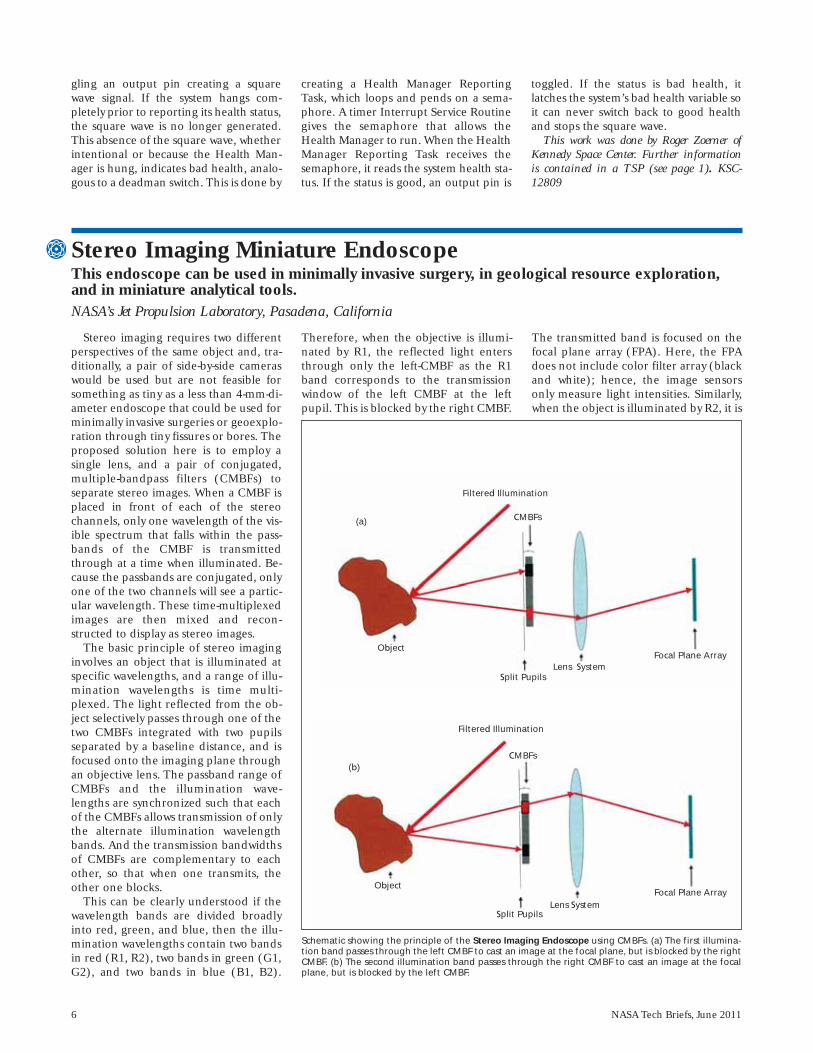
Stereo imaging requires two differentperspectives of the same object and, tra-ditionally, a pair of side-by-side cameraswould be used but are not feasible forsomething as tiny as a less than 4-mm-di-ameter endoscope that could be used forminimally invasive surgeries or geoexplo-ration through tiny fissures or bores. Theproposed solution here is to employ asingle lens, and a pair of conjugated,multiple-bandpass filters (CMBFs) toseparate stereo images. When a CMBF isplaced in front of each of the stereochannels, only one wavelength of the vis-ible spectrum that falls within the pass-bands of the CMBF is transmittedthrough at a time when illuminated. Be-cause the passbands are conjugated, onlyone of the two channels will see a partic-ular wavelength. These time-multiplexedimages are then mixed and recon-structed to display as stereo images.
The basic principle of stereo imaginginvolves an object that is illuminated atspecific wavelengths, and a range of illu-mination wavelengths is time multi-plexed. The light reflected from the ob-ject selectively passes through one of thetwo CMBFs integrated with two pupilsseparated by a baseline distance, and isfocused onto the imaging plane throughan objective lens. The passband range ofCMBFs and the illumination wave-lengths are synchronized such that eachof the CMBFs allows transmission of onlythe alternate illumination wavelengthbands. And the transmission bandwidthsof CMBFs are complementary to eachother, so that when one transmits, theother one blocks.
This can be clearly understood if thewavelength bands are divided broadlyinto red, green, and blue, then the illu-mination wavelengths contain two bandsin red (R1, R2), two bands in green (G1,G2), and two bands in blue (B1, B2).
Therefore, when the objective is illumi-nated by R1, the reflected light entersthrough only the left-CMBF as the R1band corresponds to the transmissionwindow of the left CMBF at the leftpupil. This is blocked by the right CMBF.
The transmitted band is focused on thefocal plane array (FPA). Here, the FPAdoes not include color filter array (blackand white); hence, the image sensorsonly measure light intensities. Similarly,when the object is illuminated by R2, it is
Stereo Imaging Miniature Endoscope This endoscope can be used in minimally invasive surgery, in geological resource exploration,and in miniature analytical tools. NASA’s Jet Propulsion Laboratory, Pasadena, California
Schematic showing the principle of the Stereo Imaging Endoscope using CMBFs. (a) The first illumina-tion band passes through the left CMBF to cast an image at the focal plane, but is blocked by the rightCMBF. (b) The second illumination band passes through the right CMBF to cast an image at the focalplane, but is blocked by the left CMBF.
Filtered Illumination
CMBFs(a)
Object
Split PupilsLens System
Focal Plane Array
(b)
Object
Split PupilsLens System
Focal Plane Array
CMBFs
Filtered Illumination
NASA Tech Briefs, June 2011 7
Oscillation or instability is a situationthat must be avoided for reliable hybridDC/DC converters. A real-time electron-ics measurement technique was devel-oped to detect catastrophic oscillationsat early stages for hybrid DC/DC con-verters. It is capable of identifying low-level oscillation and determining the de-gree of the oscillation at a uniquefrequency for every individual model ofthe converters without disturbing theirnormal operations. This technique isspecially developed for space-used hy-brid DC/DC converters, but it is alsosuitable for most of commercial and mil-itary switching-mode power supplies.
This is a weak-electronic-signal detec-tion technique to detect hybrid DC/DCconverter oscillation presented as a spe-cific noise signal at power input pins. It isbased on principles of feedback controlloop oscillation and RF signal modula-
tions, and is realized by using signalpower spectral analysis. On the powerspectrum, a channel power amplitude atcharacteristic frequency (CPcf) and achannel power amplitude at switching fre-quency (CPsw) are chosen as oscillationlevel indicators. If the converter is stable,the CPcf is a very small pulse and the CPswis a larger, clear, single pulse. At earlystage of oscillation, the CPcf increases to acertain level and the CPsw shows a smallpair of sideband pulses around it. If theconverter oscillates, the CPcf reaches to ahigher level and the CPsw shows morehigh-level sideband pulses. A comprehen-sive stability index (CSI) is adopted as aquantitative measure to accurately assigna degree of stability to a specific DC/DCconverter. The CSI is a ratio of normaland abnormal power spectral density, andcan be calculated using specified andmeasured CPcf and CPsw data.
The novel and unique feature of thistechnique is the use of power channelamplitudes at characteristic frequencyand switching frequency to evaluate sta-bility and identify oscillations at an earlystage without interfering with a DC/DCconverter’s normal operation. This tech-nique eliminates the probing problemof a gain/phase margin method by con-necting the power input to a spectral an-alyzer. Therefore, it is able to evaluatestability for all kinds of hybrid DC/DCconverters with or without remote sensepins, and is suitable for real-time and in-circuit testing. This frequency-domaintechnique is more sensitive to detect os-cillation at early stage than the time-do-main method using an oscilloscope.
This work was done by Bright L. Wang ofGoddard Space Flight Center. Further informa-tion is contained in a TSP (see page 1).GSC-15777-1
Early Oscillation Detection Technique for Hybrid DC/DC ConvertersPotential users include commercial and military power supply manufacturers, and high-reliability electronic product companies.Goddard Space Flight Center, Greenbelt, Maryland
transmitted only through the right-CMBF and is blocked by the left-CMBF.This continues over other wavelengthbands as well.
So, it can be seen that the image sen-sors at the focal plane are measuringlight intensities of alternately transmit-ted light from the two CMBFs. At theend of one complete illumination cycle,six images will have been collected.Then the images from R1, G1, and B1become the primary colors for the leftside of the stereo image, and R2, G2,and B2 become that of the right side of
the stereo image. Two stereo imageshave been time-multiplexed on the sameimaging chip. This intensity data isstored as an array from which the 3Dstereoscopic color image is constructedby applying processing and reconstruc-tion algorithms.
This work was done by Youngsam Bae,Harish Manohara, Victor E. White, andKirill V. Shcheglov of Caltech and HrayrShahinian of Skull Base Institute forNASA’s Jet Propulsion Laboratory. Fur-ther information is contained in a TSP (seepage 1).
In accordance with Public Law 96-517,the contractor has elected to retain title tothis invention. Inquiries concerning rightsfor its commercial use should be addressedto:
Innovative Technology Assets ManagementJPLMail Stop 202-2334800 Oak Grove DrivePasadena, CA 91109-8099E-mail: [email protected] to NPO-47420, volume and number
of this NASA Tech Briefs issue, and thepage number.
Parallel Wavefront Analysis for a 4D InterferometerNASA’s Jet Propulsion Laboratory, Pasadena, California
This software provides a program-ming interface for automating data col-lection with a PhaseCam interferometerfrom 4D Technology, and distributingthe image-processing algorithm across acluster of general-purpose computers.
Multiple instances of 4Sight (4D Tech-nology’s proprietary software) run on a
networked cluster of computers. Eachconnects to a single server (the con-troller) and waits for instructions. Thecontroller directs the interferometer toseveral images, then assigns each imageto a different computer for processing.When the image processing is finished,the server directs one of the computers
to collate and combine the processedimages, saving the resulting measure-ment in a file on a disk.
The available software captures ap-proximately 100 images and analyzesthem immediately. This software sepa-rates the capture and analysisprocesses, so that analysis can be done

8 NASA Tech Briefs, June 2011
at a different time and faster by run-ning the algorithm in parallel acrossseveral processors.
The PhaseCam family of interferome-ters can measure an optical system inmilliseconds, but it takes many secondsto process the data so that it is usable. Incharacterizing an adaptive optics system,like the next generation of astronomicalobservatories, thousands of measure-
ments are required, and the processingtime quickly becomes excessive.
A programming interface distributesdata processing for a PhaseCam interfer-ometer across a Windows computingcluster. A scriptable controller programcoordinates data acquisition from the in-terferometer, storage on networkedhard disks, and parallel processing. Idletime of the interferometer is minimized.
This architecture is implemented inPython and JavaScript, and may be al-tered to fit a customer’s needs.
This work was done by Shanti R. Rao of Cal-tech for NASA’s Jet Propulsion Laboratory. Formore information, contact [email protected].
This software is available for commercial li-censing. Please contact Daniel Broderick ofthe California Institute of Technology [email protected]. Refer to NPO -47384.

NASA Tech Briefs, June 2011 9
Electronics/Computers
Schottky Heterodyne Receivers With Full Waveguide BandwidthNew receivers are designed for high-resolution spectroscopic studies.Goddard Space Flight Center, Greenbelt, Maryland
Compact THz receivers with broadbandwidth and low noise have been de-veloped for the frequency range from100 GHz to 1 THz. These receivers meetthe requirements for high-resolutionspectroscopic studies of planetary atmos-pheres (including the Earth’s) fromspacecraft, as well as airborne and bal-loon platforms. The ongoing research issignificant not only for the developmentof Schottky mixers, but also for the cre-ation of a receiver system, including theLO chain.
The new receivers meet the goals ofhigh sensitivity, compact size, low totalpower requirement, and operationacross complete waveguide bands. Theexceptional performance makes thesereceivers ideal for the broader range ofscientific and commercial applications.These include the extension of sophisti-cated test and measurement equipmentto 1 THz and the development of low-cost imaging systems for security applica-tions and industrial process monitoring.As a particular example, a WR-1.9SHM
(400–600 GHz) has been developed (seeFigure 1), with state-of-the-art noise tem-perature ranging from 1,000–1,800 K(DSB) over the full waveguide band.Also, a Vector Network Analyzer exten-der has been developed (see Figure 2)for the WR1.5 waveguide band (500–750GHz) with 100-dB dynamic range.
This work was done by Jeffrey Hesler andThomas Crowe of Virginia Diodes, Inc. for God-dard Space Flight Center. Further informationis contained in a TSP (see page 1). GSC-15798-1
4000
3000
2000
1000
0
400 450 500 550 600
Mix
er N
ois
e Te
mp
. (K
,DSB
)
Frequency (GHz)
120
100
80
60
40
20
0
500 550 600 650 700 750
Dyn
amic
Ran
ge,
dB
Frequency, GHz
Figure 1. Measured Performance of a WR-1.9 (400–600 GHz) subharmonicmixer (shown in inset).
Figure 2. Measured Dynamic Range of a VDI WR-1.5 (500–750 GHz) VNAfrequency extender module.
High Q resonators are a critical com-ponent of stable, low-noise communica-tion systems, radar, and precise timingapplications such as atomic clocks. Inelectronic resonators based on Si inte-grated circuits, resistive losses increase asa result of the continued reduction in de-vice dimensions, which decreases their Qvalues. On the other hand, due to the
mechanical construct of bulk acousticwave (BAW) and surface acoustic wave(SAW) resonators, such loss mechanismsare absent, enabling higher Q-values forboth BAW and SAW resonators com-pared to their electronic counterparts.The other advantages of mechanical res-onators are their inherently higher radi-ation tolerance, a factor that makes them
attractive for NASA’s extreme environ-ment planetary missions, for example tothe Jovian environments where the radi-ation doses are at hostile levels. Despitethese advantages, both BAW and SAWresonators suffer from low resonant fre-quencies and they are also physicallylarge, which precludes their integrationinto miniaturized electronic systems.
Carbon Nanofiber-Based, High-Frequency, High-Q, MiniaturizedMechanical ResonatorsThese miniature resonators can be used in portable electronics, communications systems, andother wireless systems. NASA’s Jet Propulsion Laboratory, Pasadena, California
10 NASA Tech Briefs, June 2011
Because there is a need to move theresonant frequency of oscillators to theorder of gigahertz, new technologiesand materials are being investigated thatwill make performance at those frequen-cies attainable. By moving to nanoscalestructures, in this case vertically ori-ented, cantilevered carbon nanotubes(CNTs), that have larger aspect ratios(length/thickness) and extremely highelastic moduli, it is possible to overcomethe two disadvantages of both bulkacoustic wave (BAW) and surfaceacoustic wave (SAW) resonators.
Nano-electro-mechanical systems(NEMS) that utilize high aspect rationanomaterials exhibiting high elasticmoduli (e.g., carbon-based nanomateri-als) benefit from high Qs, operate athigh frequency, and have small forceconstants that translate to high respon-sivity that results in improved sensitivity,lower power consumption, and im -proved tunablity. NEMS resonators haverecently been demonstrated using top-down, lithographically fabricated ap -proaches to form cantilever or bridge-type structures. Top-down approaches,however, rely on complicated and ex-pensive e-beam lithography, and oftenrequire a release mechanism. Reso -nance effects in structures synthesizedusing bottom-up approaches have alsorecently been reported based on carbonnanotubes, but such approaches have re-lied on a planar two-dimensional (2D)geometry. In this innovation, verticallyaligned tubes synthesized using a bot-
tom-up approach have been considered,where the vertical orientation of thetubes has the potential to increase inte-gration density even further.
The simulation of a vertically ori-ented, cantilevered carbon nanotubewas performed using COMSOL Multi -physics, a finite element simulationpackage. All simulations were per-formed in a 2D geometry that providedconsistent results and minimized com-putational complexity. The simulationsassumed a vertically oriented, can-tilevered nanotube of uniform density(1.5 g/cm3). An elastic modulus was as-sumed to be 600 GPa, relative permittiv-ity of the nanotube was assumed to be5.0, and Poisson’s ratio was assumed tobe 0.2. It should be noted that the rela-tive permittivity and Poisson’s ratio forthe nanotubes of interest are not knownaccurately. However, as in previous simu-lations, the relative permittivity and Pois-son’s ratios were treated as weak vari-ables in the simulation, and nosignificant changes were recognizedwhen these variables were varied.
Of interest in the simulations of aCNT resonator were the structural strainand deflection of the nanotube, and theelectrostatic interactions between thenanotube and nanomanipulator probe.Structural boundary conditions werearranged such that the exposed lengthsand tip of the nanotube were allowed tomove freely while all other surfaces wereheld fixed (including the nanotubebase). These conditions simulated a
fixed, cantilevered beam in a domain ad-jacent to a nanomanipulator probe ofinfinite elastic modulus. Electrostaticboundary conditions were chosen suchthat the nanotube was grounded, an ACvoltage with DC bias was applied to thesurface of the nanoprobe adjacent tothe nanotube, and all other boundariesin the system were selected such that noelectrical charge exists on, or outside of,those surfaces. The solution domain wassimulated as a vacuum. Preliminary ex-periments have suggested that electro-mechanical coupling can occur betweena scanning electron microscope (SEM)beam and a vertically oriented, can-tilever carbon nanofiber (CNF) causingthe CNF to mechanically resonate withdisplacements two or three times largerthan the tube diameters.
This work was done by Anupama B. Kauland Larry W. Epp of Caltech and Leif Baggeof the University of Texas for NASA’s JetPropulsion Laboratory. For more informa-tion, contact [email protected].
In accordance with Public Law 96-517,the contractor has elected to retain title to thisinvention. Inquiries concerning rights for itscommercial use should be addressed to:
Innovative Technology Assets ManagementJPLMail Stop 202-2334800 Oak Grove DrivePasadena, CA 91109-8099E-mail: [email protected] to NPO-47238 , volume and number
of this NASA Tech Briefs issue, and thepage number.
The ultracapacitor-based uninter-rupted power supply (UPS) system en-hances system reliability; reduces life-of-system, maintenance, and downtimecosts; and greatly reduces environmentalimpact when compared to conventionalUPS energy storage systems. This designprovides power when required and ab-sorbs power when required to smooththe system load and also has excellentlow-temperature performance. The UPSused during hardware tests at Glenn isan efficient, compact, maintenance-free,rack-mount, pure sine-wave inverterunit.
The UPS provides a continuous out-put power up to 1,700 W with a surge rat-ing of 1,870 W for up to one minute at anominal output voltage of 115 VAC. Theultracapacitor energy storage systemtested in conjunction with the UPS israted at 5.8 F. This is a bank of ten sym-metric ultracapacitor modules.
Each module is actively balancedusing a linear voltage balancing tech-nique in which the cell-to-cell leakage isdependent upon the imbalance of theindividual cells. The ultracapacitors arecharged by a DC power supply, whichcan provide up to 300 VDC at 4 A. A
constant-voltage, constant-currentpower supply was selected for this appli-cation. The long life of ultracapacitorsgreatly enhances system reliability,which is significant in critical applica-tions such as medical power systems andspace power systems. The energy stor-age system can usually last longer thanthe application, given its 20-year lifespan. This means that the ultracapaci-tors will probably never need to be re-placed and disposed of, whereas batter-ies require frequent replacement anddisposal. The charge-discharge effi-ciency of rechargeable batteries is ap-
Ultracapacitor-Based Uninterrupted Power Supply SystemThis technology provides essential backup power, increases safety, and reduces environmental impact.John H. Glenn Research Center, Cleveland, Ohio
NASA Tech Briefs, June 2011 11
proximately 50 percent, and after somehundreds of charges and discharges,they must be replaced. The charge-dis-charge efficiency of ultracapacitors ex-ceeds 90 percent, and can accept morethan a million charges and discharges.Thus, there is a significant energy sav-ings through the efficiency improve-ment, and there is far less downtime forapplications and labor involved in re-placing an ultracapacitor versus batter-
ies. Also, the lengthy lifespan of this de-sign would greatly reduce the disposalproblems posed by lead acid, nickel cad-mium, lithium, and nickel metal hy-dride batteries.
This innovation is recyclable by na-ture, which further reduces system costs.The disposal of ultracapacitors is simple,as they are constructed of non-hazardouscomponents. They are also safer thanbatteries in that they can be easily dis-
charged, and left indefinitely in a safe,discharged state where batteries cannot.
This work was done by Dennis J. Eichen-berg for Glenn Research Center. Further infor-mation is contained in a TSP (see page 1).
Inquiries concerning rights for the commer-cial use of this invention should be addressedto NASA Glenn Research Center, InnovativePartnerships Office, Attn: Steven Fedor, MailStop 4–8, 21000 Brookpark Road, Cleve-land, Ohio 44135. Refer to LEW-18649-1.
Work was conducted to validate theuse of the rover external flexible coaxialcabling for space under the extreme en-vironments to be encountered duringthe Mars Science Laboratory (MSL) mis-sion. The antennas must survive allground operations plus the nominal670-Martian-day mission that includessummer and winter seasons of the Marsenvironment.
Successful development of processesestablished coaxial cable hardware fa-tigue limits, which were well beyond theexpected in-flight exposures. In keepingwith traditional qualification philoso-
phy, this was accomplished by subjectingflight-representative coaxial cables totemperature cycling of the same depthas expected in-flight, but for three timesthe expected number of in-flight ther-mal cycles.
Insertion loss and return loss testswere performed on the coaxial cablesduring the thermal chamber breaks. Avector network analyzer was calibratedand operated over the operational fre-quency range 7.145 to 8.450 GHz. Eventhough some of the exposed cablesfunction only at UHF frequencies (ap-proximately 400 MHz), the testing was
more sensitive, and extending the testrange down to 400 MHz would have costfrequency resolution.
The Gore flexible coaxial cables,which were the subject of these tests,proved to be robust and displayed nosign of degradation due to the 3X expo-sure to the punishing Mars surface oper-ations cycles.
This work was done by Rajeshuni Rame-sham, Wayne L. Harvey, Sam Valas, andMichael C. Tsai of Caltech for NASA’s JetPropulsion Laboratory. For more informa-tion, contact [email protected]. NPO-47452
Coaxial Cables for Martian Extreme Temperature Environments NASA’s Jet Propulsion Laboratory, Pasadena, California
A technique has been devised to en-able creation of a dynamic set of testpoints in an embedded digital electronicsystem. As a result, electronics con-tained in an application specific circuit[e.g., gate array, field programmablegate array (FPGA)] can be internally“probed,” even when contained in aclosed housing during all phases of test.
In the present technique, the testpoints are not fixed and limited to asmall number; the number of test points
can vastly exceed the number of buffersor pins, resulting in a compact footprint.Test points are selected by means ofspare logic resources within the ASIC(s)and/or FPGA(s). A register is pro-grammed with a command, which isused to select the signals that are sentoff-chip and out of the housing for mon-itoring by test engineers and externaltest equipment.
The register can be commanded byany suitable means: for example, it
could be commanded through a com-mand port that would normally be usedin the operation of the system. In theoriginal application of the technique,commanding of the register is per-formed via a MIL-STD-1553B communi-cation subsystem.
This work was done by Richard Katz andIgor Kleyner of Goddard Space Flight Center.Further information is contained in a TSP(see page 1). GSC-15490-1
Using Spare Logic Resources To Create Dynamic Test PointsGoddard Space Flight Center, Greenbelt, Maryland

NASA Tech Briefs, June 2011 13
Software
Autonomous Coordinationof Science ObservationsUsing Multiple Spacecraft
This software provides capabilities forautonomous cross-cueing and coordi-nated observations between multiple or-bital and landed assets. Previous workhas been done in re-tasking a singleEarth orbiter or a Mars rover in re-sponse to that craft detecting a scienceevent. This work enables multiple space-craft to communicate (over a networkdesigned for deep-space communica-tions) and autonomously coordinate thecharacterization of such a science event.
This work investigates a new paradigmof space science campaigns where oppor-tunistic science observations are au-tonomously coordinated among multiplespacecraft. In this paradigm, opportunis-tic science detections can be cued by mul-tiple assets where a second asset is re-quested to take additional observationscharacterizing the identified surface fea-ture or event. To support this new para-digm, an autonomous science system formultiple spacecraft assets was integratedwith the Interplanetary Network DTN(Delay Tolerant Network) to provide com-munication between spacecraft assets.
This technology enables new missionconcepts that are not feasible with cur-rent technology. The ability to rapidlycoordinate activities across spacecraftwithout requiring ground in the loopenables rapid reaction to dynamicevents across platforms, such as a surveyinstrument followed by a targeted high-resolution instrument, as well as regularsimultaneous observations.
This work was done by Tara A. Estlin, SteveA. Chien, Rebecca Castano, Daniel M. Gaines,Joshua R. Doubleday, Joshua B. Schoolcraft,Amalaye Oyake, Ashton G. Vaughs, and Jor-dan L. Torgerson of Caltech and Charles deGranville for NASA’s Jet Propulsion Labora-tory. For more information, [email protected].
This software is available for commercial li-censing. Please contact Daniel Broderick ofthe California Institute of Technology [email protected]. Refer to NPO-47398.
Autonomous Phase Retrieval Calibration
The Palomar Adaptive Optics Systemactively corrects for changing aberra-
tions in light due to atmospheric turbu-lence. However, the underlying internalstatic error is unknown and uncor-rected by this process. The dedicatedwavefront sensor device necessarily liesalong a different path than the sciencecamera, and, therefore, doesn’t meas-ure the true errors along the path lead-ing to the final detected imagery. Thisis a standard problem in adaptive optics(AO) called “non-common path error.”
The previous method of calibratingthis error consisted of manually apply-ing different polynomial shapes (via ac-tuator voltages) at different magni-tudes onto the deformable mirror andnoting if the final image quality hadimproved or deteriorated, before mov-ing onto the next polynomial mode.This is a limited, time-consuming, andsubjective process, and structural andenvironmental changes over time ne-cessitate a new calibration over a pe-riod of months.
The Autonomous Phase Retrieval Cal-ibration (APRC) software suite performsautomated sensing and correction itera-tions to calibrate the Palomar AO systemto levels that were previously unreach-able. APRC controls several movablecomponents inside the AO system to col-lect the required data, automaticallyprocesses data using an adaptive phaseretrieval algorithm, and automaticallycalculates new sets of actuator voltagecommands for the deformable mirror.APRC manages and preserves all essen-tial data during this process.
The APRC software calculates the truewavefront error of the full optical system,then uses the existing AO system de-formable mirror (DM) to correct the de-tected error. This provides a significantleap in performance by precisely correct-ing what were once “un-calibratable” er-rors. Furthermore, the corrective patternfound by this process serves as the under-lying nominal shape of the DM, uponwhich the adaptive corrections for atmos-pheric turbulence are based.
This work was done by Siddarayappa A.Bikkannavar, Catherine M. O’Hara, andMitchell Troy of Caltech for NASA’s Jet Propul-sion Laboratory. Further information is con-tained in a TSP (see page 1).
This software is available for commercial li-censing. Please contact Daniel Broderick ofthe California Institute of Technology [email protected]. Refer to NPO-47270.
EOS MLS Level 1B Data Processing Software, Version 3
This software is an improvement onVersion 2, which was described in “EOSMLS Level 1B Data Processing, Version2.2,” NASA Tech Briefs, Vol. 33, No. 5(May 2009), p. 34. It accepts the EOSMLS Level 0 science/engineering data,and the EOS Aura spacecraftephemeris/attitude data, and producescalibrated instrument radiances and as-sociated engineering and diagnosticdata. This version makes the code morerobust, improves calibration, providesmore diagnostics outputs, defines theGalactic core more finely, and fixes theequator crossing.
The Level 1 processing software man-ages several different tasks. It qualifies eachdata quantity using instrument configura-tion and checksum data, as well as datatransmission quality flags. Statistical testsare applied for data quality and reason-ableness. The instrument engineering data(e.g., voltages, currents, temperatures, andencoder angles) is calibrated by the soft-ware, and the filter channel space refer-ence measurements are interpolated ontothe times of each limb measurement withthe interpolates being differenced fromthe measurements. Filter channel calibra-tion target measurements are interpolatedonto the times of each limb measurement,and are used to compute radiometric gain.The total signal power is determined andanalyzed by each digital autocorrelatorspectrometer (DACS) during each data in-tegration. The software converts eachDACS data integration from an autocorre-lation measurement in the time domaininto a spectral measurement in the fre-quency domain, and estimates separatelythe spectrally, smoothly varying and spec-trally averaged components of the limbport signal arising from antenna emissionand scattering effects. Limb radiances arealso calibrated.
The radiance at the limb port of theradiometer module is computed, includ-ing non-atmospheric radiance contribu-tions from antenna emission and scatter-ing. It is the task of the retrieval/forwardmodel software (Level 2) to computethe atmospheric component of the limbradiation reaching this interface. It is ne-cessitated by the greatly increased band-width of EOS MLS radiometers, and the
14 NASA Tech Briefs, June 2011
double-sideband nature of most meas-urements. Estimates of the random com-ponent of uncertainty (noise) on eachlimb radiance are also determined.Spacecraft inertial pointing and startracker data are combined with space-craft and GHz antenna structural/ther-mal data and scan mechanism encoderdata to estimate the boresight angles foreach radiometer. The software collectsand generates ancillary data (e.g., tan-gent point location, local solar time,local solar zenith angle, flags for brightobjects in the field of view) that areneeded in Level 2 processing. A log fileis produced that summarizes instrumentperformance and outputs.
This work was done by Vincent S. Perun,Robert F. Jarnot, Paul A. Wagner, Richard E.Cofield IV, and Honghanh T. Nguyen of Cal-tech and Christina Vuu of Raytheon forNASA’s Jet Propulsion Laboratory. For moreinformation, contact [email protected].
This software is available for commercial li-censing. Please contact Daniel Broderick ofthe California Institute of Technology [email protected]. Refer to NPO-47219.
Cassini Tour Atlas Automated Generation
During the Cassini spacecraft’s cruisephase and nominal mission, the CassiniScience Planning Team developed andmaintained an online database of geo-metric and timing information calledthe Cassini Tour Atlas. The Tour Atlasconsisted of several hundreds ofmegabytes of EVENTS mission planningsoftware outputs, tables, plots, and im-ages used by mission scientists for obser-vation planning. Each time the nominal
mission trajectory was altered ortweaked, a new Tour Atlas had to be re-generated manually.
In the early phases of Cassini’s Equi-nox Mission planning, an a priori esti-mate suggested that mission tour design-ers would develop approximately 30candidate tours within a short period oftime. So that Cassini scientists couldproperly analyze the science opportuni-ties in each candidate tour quickly andthoroughly so that the optimal series oforbits for science return could be se-lected, a separate Tour Atlas was re-quired for each trajectory.
The task of manually generating thenumber of trajectory analyses in the al-lotted time would have been impossible,so the entire task was automated usingcode written in five different program-ming languages. This software auto-mates the generation of the Cassini TourAtlas database. It performs with oneUNIX command what previously took aday or two of human labor.
This work was done by Kevin R. Grazier, ChrisRoumeliotis, and Robert D. Lange of Caltech forNASA’s Jet Propulsion Lab oratory. For more in-formation, contact [email protected].
This software is available for commercial li-censing. Please contact Daniel Broderick ofthe California Institute of Technology [email protected]. Refer to NPO-47282.
Software Development Standard Processes (SDSP)
A JPL-created set of standardprocesses is to be used throughout thelifecycle of software development. TheseSDSPs cover a range of activities, frommanagement and engineering activities,
to assurance and support activities.These processes must be applied to soft-ware tasks per a prescribed set of proce-dures. JPL’s Software Quality Improve-ment Project is currently working at thebehest of the JPL Software ProcessOwner to ensure that all applicable soft-ware tasks follow these procedures.
The SDSPs are captured as a set of 22standards in JPL’s software process do-main. They were developed in-house atJPL by a number of Subject Matter Ex-perts (SMEs) residing primarily withinthe Engineering and Science Direc-torate, but also from the Business Opera-tions Directorate and Safety and MissionSuccess Directorate. These practices in-clude not only currently performed bestpractices, but also JPL-desired futurepractices in key thrust areas like softwarearchitecting and software reuse analysis.Additionally, these SDSPs conform tomany standards and requirements towhich JPL projects are beholden.
This work was done by Milton L. Lavin,James J. Wang, Ronald Morillo, John T.Mayer, Barzia Jamshidian Tehrani, KennethJ. Shimizu, Belinda M. Wilkinson, Jairus M.Hihn, Rosana B. Borgen, Kenneth N. Meyer,Kathleen A. Crean, George C. Rinker,Thomas P. Smith, Karen T. Lum, Robert A.Hanna, Daniel E. Erickson, Edward B.Gamble Jr., Scott C. Morgan, Michael G. Kel-say, Brian J. Newport, Scott A. Lewicki, JeaneG. Stipanuk, Tonja M. Cooper, and LeilaMeshkat of Caltech for NASA’s Jet PropulsionLaboratory. Further information is containedin a TSP (see page 1).
This software is available for commercial li-censing. Please contact Daniel Broderick ofthe California Institute of Technology [email protected]. Refer to NPO-47301.
NASA Tech Briefs, June 2011 15
Manufacturing & Prototyping
The use of high-strength, lightweightcomposites for the fixture is the novelfeature of this innovation. The main ad-vantage is the light weight and highstiffness-to-mass ratio relative to alu-minum.
Meter-class optics require supportduring the grinding/polishing processwith large tools. The use of aluminumas a polishing fixture is standard, withpitch providing a compliant layer toallow support without deformation.Unfortu nately, with meter-scale optics,a meter-scale fixture weighs over 120 lb(≈55 kg) and may distort the opticsbeing fabricated by loading the mirrorand/or tool used in fabrication. Theuse of composite structures that arelightweight yet stiff allows standardtechniques to be used while providingfor a decrease in fixture weight by al-most 70 percent.
Mounts classically used to supportlarge mirrors during fabrication are espe-cially heavy and difficult to handle. Themount must be especially stiff to avoid de-formation during the optical fabricationprocess, where a very large and heavy lapoften can distort the mount and opticbeing fabricated. If the optic is placed ontop of the lapping tool, the weight of theoptic and the fixture can distort the lap.Fixtures to support the mirror duringfabrication are often very large plates ofaluminum, often 2 in. (≈5 cm) or more inthickness and weight upwards of 150 lb(≈68 kg). With the addition of a backingmaterial such as pitch and the mirror it-self, the assembly can often weigh over250 lb (≈113 kg) for a meter-class optic.
This innovation is the use of a light-weight graphite panel with an aluminumhoneycomb core for use as the polishingfixture. These materials have been used
in the aerospace industry as structuralmembers due to their light weight andhigh stiffness. The grinding polishing fix-ture consists of the graphite compositepanel, fittings, and fixtures to allow inter-face to the polishing machine, and intro-duction of pitch buttons to support theoptic under fabrication. In its operation,the grinding polishing fixture acts as areaction structure to the polishing tool.It must be stiff enough to avoid impart-ing a distorted shape to the optic underfabrication and light enough to avoidself-deflection. The fixture must alsowithstand significant tangential loadsfrom the polishing machine during op-erations.
This work was done by John Hagopian,Carl Strojny, and Jason Budinoff of GoddardSpace Flight Center. Further information iscontained in a TSP (see page 1). GSC-15911-1
Graphite Composite Panel Polishing FixtureComposite fixture eliminates problems that may be caused by those made from aluminum.Goddard Space Flight Center, Greenbelt, Maryland
Oxygen system components fabri-cated by Laser Engineered Net Shap-ing™ (LENS™) could result in im-proved safety and performance. LENS™is a near-net shape manufacturingprocess fusing powdered materials in-jected into a laser beam. Parts can befabricated with a variety of elementalmetals, alloys, and nonmetallic materialswithout the use of a mold. The LENS™
process allows the injected materials tobe varied throughout a single work-piece. Hence, surfaces exposed to oxy-gen could be constructed of an oxygen-compatible material while theremainder of the part could be one cho-sen for strength or reduced weight. Un-like conventional coating applications, acompositional gradient would exist be-tween the two materials, so no abrupt
material boundary exists. Without an in-terface between dissimilar materials,there is less tendency for chipping orcracking associated with thermal-expan-sion mismatches.
This work was done by Bradley S. Forsythof Honeywell Technology Solutions, Inc., forJohnson Space Center. For further informa-tion, contact the JSC Innovation PartnershipsOffice at (281) 483-3809. MSC-23166-1
Material Gradients in Oxygen System Components Improve SafetyLyndon B. Johnson Space Center, Houston, Texas
Ridge Waveguide Structures in Magnesium-Doped Lithium NiobateGoddard Space Flight Center, Greenbelt, Maryland
This work proposes to establish thefeasibility of fabricating isolated ridgewaveguides in 5% MgO:LN. Ridge wave-guides in MgO:LN will significantly im-prove power handling and conversion ef-
ficiency, increase photonic componentintegration, and be well suited to space-based applications. The key innovationin this effort is to combine recently avail-able large, high-photorefractive-damage-
threshold, z-cut 5% MgO:LN with novelridge fabrication techniques to achievehigh-optical power, low-cost, high-vol-ume manufacturing of frequency conver-sion structures. The proposed ridge

16 NASA Tech Briefs, June 2011
Modifying Matrix Materials to Increase Wetting and AdhesionImprovements are achieved at lower cost and without degradation of fibers.Marshall Space Flight Center, Alabama
waveguide structure should maintain thecharacteristics of the periodically poledbulk substrate, allowing for the efficientfrequency conversion typical of wave-guides and the high optical damagethreshold and long lifetimes typical ofthe 5% doped bulk substrate. The lowcost and large area of 5% MgO:LNwafers, and the improved performanceof the proposed ridge waveguide struc-ture, will enhance existing measurementcapabilities as well as reduce the re-sources required to achieve high-per-formance specifications.
The purpose of the ridge waveguidesin MgO:LN is to provide platform tech-
nology that will improve optical powerhandling and conversion efficiencycompared to existing waveguide tech-nology. The proposed ridge waveguideis produced using standard microfabri-cation techniques. The approach is en-abled by recent advances in inductivelycoupled plasma etchers and chemicalmechanical planarization techniques.In conjunction with wafer bonding,this fabrication methodology can beused to create arbitrarily shaped wave-guides allowing complex optical cir-cuits to be engineered in nonlinear op-tical materials such as magnesiumdoped lithium niobate. Researchers
here have identified NLO (nonlinearoptical) ridge waveguide structures ashaving suitable value to be the leadingfrequency conversion structures. Itsvalue is based on having the low-costfabrication necessary to satisfy the chal-lenging pricing requirements as well asachieve the power handling and otherspecifications in a suitably compactpackage.
This work was done by Phillip Himmer ofMontana State University and Philip Battle,William Suckow, and Greg Switzer of AdvRInc. for Goddard Space Flight Center. Furtherinformation is contained in a TSP (see page1). GSC-16031-1
In an alternative approach to in-creasing the degrees of wetting and ad-hesion between the fiber and matrixcomponents of organic-fiber/polymermatrix composite materials, the matrixresins are modified. Heretofore, it hasbeen common practice to modify thefibers rather than the matrices: Thefibers are modified by chemicaland/or physical surface treatmentsprior to combining the fibers with ma-trix resins — an approach that entailsconsiderable expense and usually re-sults in degradation (typically, weaken-ing) of fibers.
The alternative approach of modify-ing the matrix resins does not entaildegradation of fibers, and affords op-portunities for improving the mechan-ical properties of the fiber composites.
The alternative approach is more cost-effective, not only because it elimi-nates expensive fiber-surface treat-ments but also because it does notentail changes in procedures for man-ufacturing conventional composite-material structures.
The alternative approach is best de-scribed by citing an example of its appli-cation to a composite of ultra-high-mo-lecular-weight polyethylene (UHMWPE)fibers in an epoxy matrix. The epoxy ma-trix was modified to a chemically reac-tive, polarized epoxy nano-matrix to in-crease the degrees of wetting andadhesion between the fibers and the ma-trix. The modification was effected by in-corporating a small proportion (0.3weight percent) of reactive graphiticnanofibers produced from functional-
ized nanofibers into the epoxy matrixresin prior to combining the resin withthe UHMWPE fibers. The resulting in-crease in fiber/matrix adhesion mani-fested itself in several test results, notablyincluding an increase of 25 percent inthe maximum fiber pullout force and anincrease of 60–65 percent in fiber pull-out energy. In addition, it was conjec-tured that the functionalized nanofibersbecame involved in the cross linking re-action of the epoxy resin, with resultantenhancement of the mechanical proper-ties and lower viscosity of the matrix.
This work was done by Katie Zhong of NorthDakota State University for Marshall SpaceFlight Center. For further information, contactSammy Nabors, MSFC Commercialization As-sistance Lead, at [email protected] to MFS-32665-1
NASA Tech Briefs, June 2011 17
Green Design
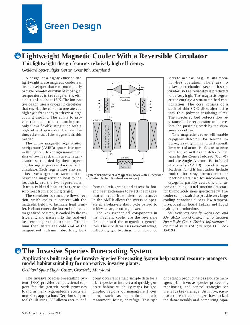
A design of a highly efficient andlightweight space magnetic cooler hasbeen developed that can continuouslyprovide remote/distributed cooling attemperatures in the range of 2 K witha heat sink at about 15 K. The innova-tive design uses a cryogenic circulatorthat enables the cooler to operate at ahigh cycle frequency to achieve a largecooling capacity. The ability to pro-vide remote/distributed cooling notonly allows flexible integration with apayload and spacecraft, but also re-duces the mass of the magnetic shieldsneeded.
The active magnetic regenerativerefrigerator (AMRR) system is shownin the figure. This design mainly con-sists of two identical magnetic regen-erators surrounded by their super-conducting magnets and a reversiblecirculator. Each regenerator also hasa heat exchanger at its warm end toreject the magnetization heat to theheat sink, and the two regeneratorsshare a cold-end heat exchanger to ab-sorb heat from a cooling target.
The circulator controls the flow direc-tion, which cycles in concert with themagnetic fields, to facilitate heat trans-fer. Helium enters the hot end of the de-magnetized column, is cooled by the re-frigerant, and passes into the cold-endheat exchanger to absorb heat. The he-lium then enters the cold end of themagnetized column, absorbing heat
from the refrigerant, and enters the hot-end heat exchanger to reject the magne-tization heat. The efficient heat transferin the AMRR allows the system to oper-ate at a relatively short cycle period toachieve a large cooling power.
The key mechanical components inthe magnetic cooler are the reversiblecirculator and the magnetic regenera-tors. The circulator uses non-contacting,self-acting gas bearings and clearance
seals to achieve long life and vibra-tion-free operation. There are novalves or mechanical wear in this cir-culator, so the reliability is predictedto be very high. The magnetic regen-erator employs a structured bed con-figuration. The core consists of astack of thin GGG disks alternatingwith thin polymer insulating films.The structured bed reduces flow re-sistance in the regenerator and there-fore the pumping work by the cryo-genic circulator.
This magnetic cooler will enablecryogenic detectors for sensing in-frared, x-ray, gamma-ray, and submil-limeter radiation in future sciencesatellites, as well as the detector sys-tems in the Constellation-X (Con-X)and the Single Aperture Far-Infraredobservatory (SAFIR). Scientific ap p -lica tions for this innovation includecooling for x-ray micro calorimeterspectrometers used for microanalysis,cryogenic particle detectors, and su-
perconducting tunnel junction de tectorsfor biomolecule mass spectrometry. Thecooler can be scaled to provide very largecooling capacities at very low tempera-tures, ideal for liquid helium and liquidhydrogen productions.
This work was done by Weibo Chen andJohn McCormick of Creare, Inc. for GoddardSpace Flight Center. Further information iscontained in a TSP (see page 1). GSC-15410-1
Lightweight Magnetic Cooler With a Reversible CirculatorThis lightweight design features relatively high efficiency.Goddard Space Flight Center, Greenbelt, Maryland
30K
ReversibleCirculator
HotHX
HotHX
15KMagnet
Mic
rom
ach
ined
Act
ive
Mag
net
ic R
egen
erat
or
Detector
Cold HX
~2K
System Schematic of a Magnetic Cooler with a reversiblecirculator. (Note: HX is heat exchanger)
The Invasive Species Forecasting Sys-tem (ISFS) provides computational sup-port for the generic work processesfound in many regional-scale ecosystemmodeling applications. Decision supporttools built using ISFS allow a user to load
point occurrence field sample data for aplant species of interest and quickly gen-erate habitat suitability maps for geo-graphic regions of management con-cern, such as a national park,monument, forest, or refuge. This type
of decision product helps resource man-agers plan invasive species protection,monitoring, and control strategies forthe lands they manage. Until now, scien-tists and resource managers have lackedthe data-assembly and computing capa-
The Invasive Species Forecasting System Applications built using the Invasive Species Forecasting System help natural resource managersmodel habitat suitability for non-native, invasive plants. Goddard Space Flight Center, Greenbelt, Maryland
18 NASA Tech Briefs, June 2011
bilities to produce these maps quicklyand cost efficiently.
ISFS focuses on regional-scale habitatsuitability modeling for invasive terres-trial plants. ISFS’s component architec-ture emphasizes simplicity and adapt-ability. Its core services can be easilyadapted to produce model-based deci-sion support tools tailored to particularparks, monuments, forests, refuges, andrelated management units. ISFS can beused to build standalone run-time toolsthat require no connection to the Inter-net, as well as fully Internet-based deci-sion support applications.
ISFS provides the core data structures,operating system interfaces, network in-terfaces, and inter-component con-straints comprising the canonical work-flow for habitat suitability modeling. Thepredictors, analysis methods, and geo-graphic extents involved in any particularmodel run are elements of the user spaceand arbitrarily configurable by the user.ISFS provides small, lightweight, readilyhardened core components of generalutility. These components can be adaptedto unanticipated uses, are tailorable, andrequire at most a loosely coupled, non-proprietary connection to the Web. Users
can invoke capabilities from a commandline; programmers can integrate ISFS’score components into more complex sys-tems and services. Taken together, thesefeatures enable a degree of decentraliza-tion and distributed ownership that havehelped other types of scientific informa-tion services succeed in recent years.
This work was done by John Schnase ofGoddard Space Flight Center, Neal Most andRoger Gill of INNOVIM, and Peter Ma ofSigma Space Corporation. For further infor-mation, contact the Goddard InnovativePartnerships Office at (301) 286-5810. GSC-15714-1/61–7-1.
NASA Tech Briefs, June 2011 19
Mechanics/Machinery
The Mars Sample Return mission hasthe goal to drill, break off, and retainrock core samples. After some resultsgained from rock core mechanics test-ing, the realization that scoring teethwould cleanly break off the core afteronly a few millimeters of penetration,and noting that rocks are weak in ten-sion, the idea was developed to use sym-metric wedging teeth in compression toweaken and then break the core at thecontact plane. This concept was devel-oped as a response to the break-off andretention requirements.
The wedges wrap around the esti-mated average diameter of the core to
get as many contact locations as possi-ble, and are then pushed inward, radi-ally, through the core towards one an-other. This starts a crack and begins toapply opposing forces inside the coreto propagate the crack across the planeof contact.
The advantage is in the simplicity.Only two teeth are needed to break fivevarieties of Mars-like rock cores withlimited penetration and reasonableforces. Its major advantage is that it doesnot require any length of rock to be at-tached to the parent in order to breakthe core at the desired location. Testdata shows that some rocks break off on
their own into segments or break offinto discs. This idea would grab and re-tain a disc, push some discs upward andothers out, or grab a segment, break itat the contact plane, and retain the por-tion inside of the device. It also doesthis with few moving parts in a simple,space-efficient design.
This discovery could be implementedinto a coring drill bit to precisely breakoff and retain any size rock core.
This work was done by Megan Richardsonand Justin Lin of Caltech for NASA’s JetPropulsion Laboratory. Further informationis contained in a TSP (see page 1). NPO-47444
Method for Cleanly and Precisely Breaking Off a Rock CoreUsing a Radial Compressive Force This technique can be used by civil engineers in rock, ground, and concrete coring and sampling. NASA’s Jet Propulsion Laboratory, Pasadena, California
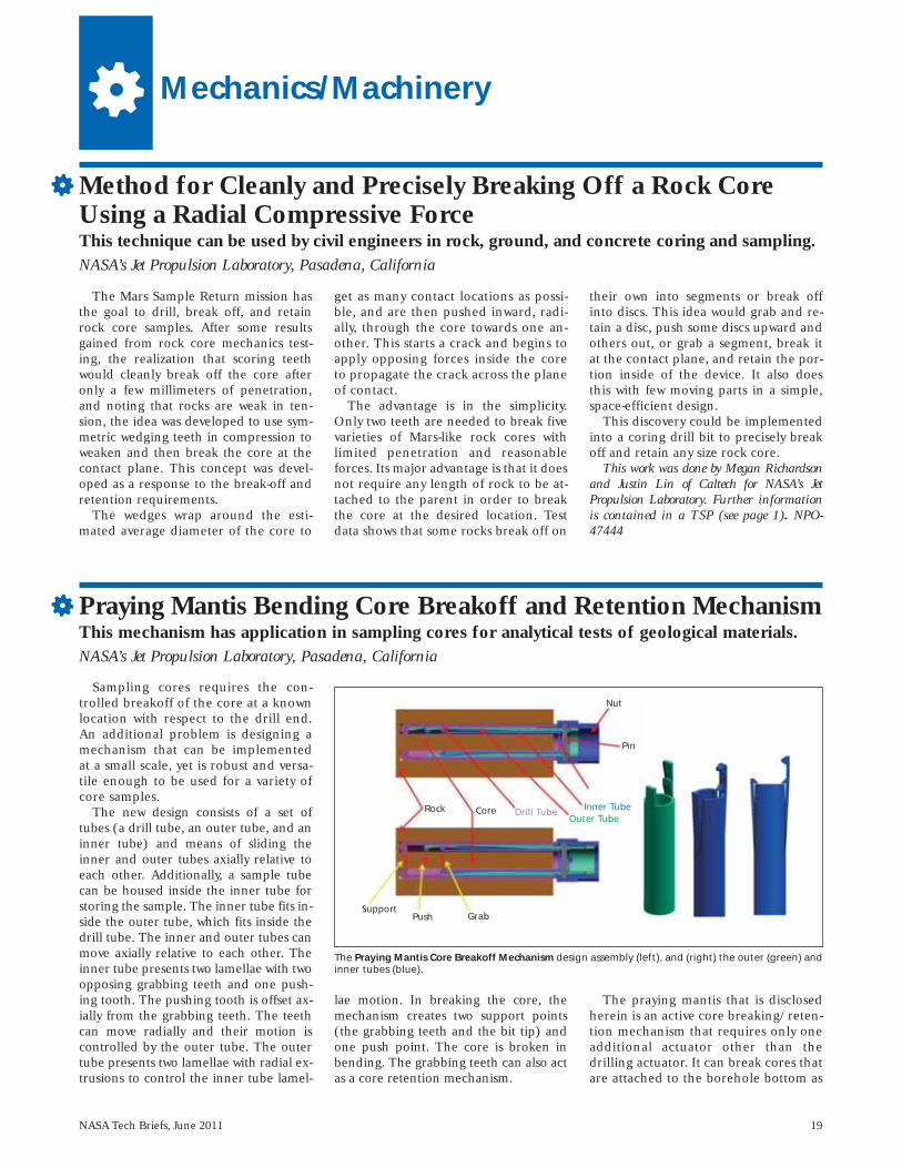
Sampling cores requires the con-trolled breakoff of the core at a knownlocation with respect to the drill end.An additional problem is designing amechanism that can be implementedat a small scale, yet is robust and versa-tile enough to be used for a variety ofcore samples.
The new design consists of a set oftubes (a drill tube, an outer tube, and aninner tube) and means of sliding theinner and outer tubes axially relative toeach other. Additionally, a sample tubecan be housed inside the inner tube forstoring the sample. The inner tube fits in-side the outer tube, which fits inside thedrill tube. The inner and outer tubes canmove axially relative to each other. Theinner tube pre sents two lamellae with twoopposing grabbing teeth and one push-ing tooth. The pushing tooth is offset ax-ially from the grabbing teeth. The teethcan move radially and their motion iscontrolled by the outer tube. The outertube presents two lamellae with radial ex-trusions to control the inner tube lamel-
lae motion. In breaking the core, themechanism creates two support points(the grabbing teeth and the bit tip) andone push point. The core is broken inbending. The grabbing teeth can also actas a core retention mechanism.
The praying mantis that is disclosedherein is an active core breaking/reten-tion mechanism that requires only oneadditional actuator other than thedrilling actuator. It can break cores thatare attached to the borehole bottom as
Praying Mantis Bending Core Breakoff and Retention Mechanism This mechanism has application in sampling cores for analytical tests of geological materials. NASA’s Jet Propulsion Laboratory, Pasadena, California
The Praying Mantis Core Breakoff Mechanism design assembly (left), and (right) the outer (green) andinner tubes (blue).
Nut
Pin
Rock Core Drill TubeOuter Tube
Inner Tube
SupportPush Grab

20 NASA Tech Briefs, June 2011
This novel core break-off and reten-tion mechanism consists of a scoringdawg controlled by a set of two tubes (adrill tube and an inner tube). The drilltube and the inner tube have longitudi-nal concentric holes. The solution canbe implemented in an eccentric tubeconfiguration as well where the tubeshave eccentric longitudinal holes. Theinner tube presents at the bottom twocontrol surfaces for controlling the ori-entation of the scoring dawg. The drilltube pre sents a sunk-in profile on theinside of the wall for housing the scor-ing dawg. The inner tube rotation rela-tive to the drill tube actively controls theorientation of the scoring dawg andhence its penetration and retrieval fromthe core. The scoring dawg presents ashaft, two axially spaced arms, and a
tooth. The two arms slide on the controlsurfaces of the inner tube. The tooth,when rotated, can penetrate or be ex-tracted from the core.
During drilling, the two tubes move to-gether maintaining the scoring dawgcompletely outside the core. After the de-sired drilling depth has been reached theinner tube is rotated relative to the drilltube such that the tooth of the scoringdawg moves toward the central axis. Byrotating the drill tube, the scoring dawgcan score the core and so reduce its crosssectional area. The scoring dawg can alsoact as a stress concentrator for breakingthe core in torsion or tension. Afterbreaking the core, the scoring dawg canact as a core retention mechanism.
For scoring, it requires the core to beattached to the rock. If the core is bro-
ken, the dawg can be used as a reten-tion mechanism. The scoring dawg re-quires a hard-tip insert like tungstencarbide for scoring hard rocks. The rel-ative rotation of the two tubes can becontrolled manually or by an additionalactuator. In the implemented design so-lution the bit rotation for scoring was inthe same direction as the drilling. Thedevice was tested for limestone coresand basalt cores. The torque requiredfor breaking the 10-mm diameter lime-stone cores was 5 to 5.8 lb-in. (0.56 to0.66 N-m).
This work was done by Mircea Badescu,Stewart Sherrit, Yoseph Bar-Cohen, Xiaoqi Bao,and Paul G. Backes of Caltech for NASA’s JetPropulsion Laboratory. Further informationis contained in a TSP (see page 1). NPO-47355
Sampling cores requires the controlled breakoff ofthe core at a known location with respect to the drillend. An additional problem is designing a mechanismthat can be implemented at a small scale that is robustand versatile enough to be used for a variety of coresamples. This design consists of a set of tubes (a drilltube and an inner tube) and a rolling element (rollingtooth). An additional tube can be used as a sampletube. The drill tube and the inner tube have longitudi-nal holes with the axes offset from the axis of eachtube. The two eccentricities are equal. The inner tubefits inside the drill tube, and the sample tube fits insidethe inner tube.
While drilling, the two tubes are positioned relativeto each other such that the sample tube is aligned withthe drill tube axis and core. The drill tube includesteeth and flutes for cuttings removal. The inner tubeincludes, at the base, the rolling element implementedas a wheel on a shaft in an eccentric slot. An additionalslot in the inner tube and a pin in the drill tube limit
Rolling-Tooth Core Breakoff and Retention Mechanism The mechanism has applications in analytical tests of geological materials. NASA’s Jet Propulsion Laboratory, Pasadena, California
The Rolling-Tooth Design of the core breakoff and retention mechanism (left), and theassembled parts (right).
well as broken cores, and it also acts asa core retention device. The cores arebroken at the bottom of the sampletube with a clean cut. The inventionuses a core bending principle and doesnot induce additional axial load on thedrill/robotic arm.
This invention is potentially applica-ble to sample return and in situ missionsto planets such as Mars and Venus,moons such as Titan and Europa, andcomets. It is also applicable to terrestrialapplications like forensic sampling andgeological sampling in the field.
This work was done by Mircea Badescu,Stewart Sherrit, Yoseph Bar-Cohen, XiaoqiBao, and Randel A. Lindemann of Caltechfor NASA’s Jet Propulsion Laboratory. Fur-ther information is contained in a TSP (seepage 1). NPO-47356
Scoring Dawg Core Breakoff and Retention Mechanism NASA’s Jet Propulsion Laboratory, Pasadena, California
NASA Tech Briefs, June 2011 21
A novel, passive system has been devel-oped for isolating an exercise treadmill de-vice from a spacecraft in a zero-G environ-ment. The Treadmill 2 Vibration Isolationand Stabilization System (T2-VIS) mechan-ically isolates the exercise treadmill fromthe spacecraft/space station, thereby elim-inating the detrimental effect that high im-pact loads generated during walking/run-ning would have on the spacecraft
structure and sensitive microgravity scienceexperiments. This design uses a second-stage spring, in series with the first stage, toachieve an order of magnitude higher ex-ercise-frequency isolation than conven-tional systems have done, while maintain-ing desirable low-frequency stabilityperformance. This novel isolator design, inconjunction with appropriately configuredtreadmill platform inertia properties, has
been shown (by on-orbit zero-G testing on-board the International Space Station) todeliver exceedingly high levels of isola-tion/stability performance.
This work was done by Ian Fialho, CraigTyer, Bryan Murphy, Paul Cotter, and Sreeku-mar Thampi of The Boeing Company for John-son Space Center. For further information con-tact the JSC Innovation Partnerships Officeat (281) 483-3809. MSC-24847-1
Vibration Isolation and Stabilization System for SpacecraftExercise Treadmill DevicesLyndon B. Johnson Space Center, Houston, Texas
the relative motion of the two tubes.While drilling, the drill assembly rotatesrelative to the core and forces the rollingtooth to stay hidden in the slot along theinner tube wall. When the drilling depthhas been reached, the drill bit assemblyis rotated in the opposite direction, andthe rolling tooth is engaged and pene-trates into the core. Depending on thestrength of the created core, the rollingtooth can score, lock the inner tube rela-
tive to the core, start the eccentric mo-tion of the inner tube, and break thecore. The tooth and the relative positionof the two tubes can act as a core catcheror core-retention mechanism as well.The design was made to fit the core andhole parameters produced by an existingbit; the parts were fabricated and a seriesof demonstration tests were performed.
This invention is potentially applica-ble to sample return and in situ missions
to planets such as Mars and Venus, tomoons such as Titan and Europa, and tocomets. It is also applicable to terrestrialapplications like forensic sampling andgeological sampling in the field.
This work was done by Mircea Badescu,Donald B. Bickler, Stewart Sherrit, YosephBar-Cohen, Xiaoqi Bao, and Nicolas H.Hudson of Caltech for NASA’s Jet PropulsionLaboratory. Further information is con-tained in a TSP (see page 1). NPO-47354


NASA Tech Briefs, June 2011 23
Bio-Medical
Microgravity-Enhanced Stem Cell SelectionThis method provides rapid selection and proliferation of stem cells using a hydrofocusing bioreactor.Goddard Space Flight Center, Greenbelt, Maryland
Stem cells, both embryonic and adult,promise to revolutionize the practice ofmedicine in the future. In order to real-ize this potential, a number of hurdlesmust be overcome. Most importantly,the signaling mechanisms necessary tocontrol the differentiation of stem cellsinto tissues of interest remain to be elu-cidated, and much of the present re-search on stem cells is focused on thisgoal. Nevertheless, it will also be essen-tial to achieve large-scale expansion and,in many cases, assemble cells in 3D astransplantable tissues. To this end, mi-crogravity analog bioreactors can play asignificant role.
Microgravity bioreactors were origi-nally conceived as a tool to study the cel-lular responses to microgravity. How-ever, the technology can address some ofthe shortcomings of conventional cellculture systems; namely, the deficiencyof mass transport in static culture andhigh mechanical shear forces in stirredsystems. Unexpectedly, the conditionscreated in the vessel were ideal for 3Dcell culture. Recently, investigators havedemonstrated the capability of the mi-crogravity bioreactors to expandhematopoietic stem cells compared to
static culture, and facilitate the differen-tiation of umbilical cord stem cells into3D liver aggregates.
Stem cells are capable of differentiat-ing into functional cells. However, thereare no reliable methods to induce thestem cells to form specific cells or to gainenough cells for transplantation, whichlimits their application in clinical ther-apy. The aim of this study is to select thebest experimental setup to reach highproliferation levels by culturing thesecells in a microgravity-based bioreactor.In typical cell culture, the cells sedimentto the bottom surface of their containerand propagate as a one-cell-layer sheet.Prevention of such sedimentation af-fords the freedom for self-assembly andthe propagation of 3D tissue arrays.
Suspension of cells is easily achievableusing stirred technologies. Unfortun -ately, in conventional bioreactors, stirringinvokes deleterious forces that disruptcell aggregation and results in cell death.First-generation rotating bioreactors pro-vided rotation on the horizontal axis,which resulted in the suspension of cellswithout stirring, thus providing a suitableenvironment to propagate cells withoutsedimentation to a surface. The rotating-
wall bioreactors did not provide a way toremove air bubbles that were causingshear and disrupting 3D cultures. John-son Space Center successfully engineeredthe hydrofocusing bioreactor (HFB) thatresolved the problem of removing the airbubbles from the fluid medium ofNASA’s rotating-wall space bioreactors.
The HFB uses the principle of hydro-dynamic focusing that simultaneouslyproduces a low-shear fluid culture envi-ronment and a variable hydrofocusingforce that can control the movement, lo-cation, and removal of suspended cells,tissues, and air bubbles from the biore-actor. The HFB is a rotating, dome-shaped cell culture vessel with a centrallylocated sampling port and an internalviscous spinner. The vessel and spinnercan rotate at different speeds either inthe same or opposite directions. Rota-tion of the vessel and viscous interactionat the spinner generate a hydrofocusingforce. Adjusting the differential rotationrate between vessel and spinner controlsthe magnitude of the force.
This work was done by Pier Paolo Claudioand Jagan Valluri of Goddard Space FlightCenter. Further information is contained ina TSP (see page 1). GSC-15807-1
Increasingly, millimeter waves arebeing employed for telecomm, radar,and imaging applications. To date in theU.S, however, very few investigations onthe impact of this radiation on biologi-cal systems at the cellular level havebeen undertaken. In the beginning, toexamine the impact of millimeter waveson cellular processes, researchers dis-covered that cell membrane depolariza-tion may be triggered by low levels of in-
tegrated power at these high frequen-cies. Such a situation could be used toadvantage in the direct stimulation ofneuronal cells for applications in neuro-prosthetics and diagnosing or treatingneurological disorders.
An experimental system was set up todirectly monitor cell response on expo-sure to continuous-wave, fixed-fre-quency, millimeter-wave radiation atlow and modest power levels (0.1 to
100 safe exposure standards) between50 and 100 GHz. Two immortalized celllines derived from lung and neuronaltissue were transfected with green fluo-rescent protein (GFP) that locates onthe inside of the cell membrane lipidbi-layer. Oxonol dye was added to thecell medium. When membrane depo-larization occurs, the oxonal bound tothe outer wall of the lipid bi-layer canpenetrate close to the inner wall where
Diagnosis and Treatment of Neurological Disorders by Millimeter-Wave StimulationThese techniques enable new treatments for neurological disorders and dysfunction.NASA’s Jet Propulsion Laboratory, Pasadena, California
24 NASA Tech Briefs, June 2011
the GFP resides. Under fluorescent ex-citation (488 nm), the normally greenGFP (520 nm) optical signal quenchesand gives rise to a red output when theoxonol comes close enough to the GFPto excite a fluorescence resonance en-ergy transfer (FRET) with an output at620 nm.
The presence of a strong FRET signa-ture upon exposures of 30 seconds to 2minutes at 5–10 mW/cm2 RF power at 50GHz, followed by a return to the normal520-nm GFP signal after a few minutesindicating repolarization of the mem-brane, indicates that low levels of RF en-ergy may be able to trigger non-destruc-tive membrane depolarization withoutdirect cell contact. Such a mechanismcould be used to stimulate neuronal cellsin the cortex without the need for inva-sive electrodes as millimeter waves pene-trate skin and bone on the order of 1–5
mm in depth. Although 50 GHz couldnot readily penetrate from the outerskull to the center of the cortex, implantson the outer skull or even on the scalpcould reach the outer layer of the cere-bral cortex where substantial benefitcould be realized from such non-contacttype excitation.
The stimulation system describedhere for cerebral cortex, brainstem,spinal cord, or peripheral nerves in-cludes an implantable housing, a con-trol unit carried by the implantablehousing, a millimeter-wave delivery de-vice (including at least one emissionsite), and at least one millimeter-wavesource operatively coupled to the con-trol unit, and coupled to at least one mil-limeter-wave emission site. Optionalcomponents for monitoring of neuronalfunction can be included, such as anelectroencephalographic system, an
electromyographic system, a system foroptical or infrared imaging of intrinsicneuronal signals, and/or magnetic reso-nance imaging/spectroscopy systems.
This work was done by Peter H. Siegel ofCaltech and Victor Pikov of HMRI forNASA’s Jet Propulsion Laboratory. For moreinformation, contact [email protected].
In accordance with Public Law 96-517,the contractor has elected to retain title to thisinvention. Inquiries concerning rights for itscommercial use should be addressed to:
Innovative Technology Assets Manage-ment
JPLMail Stop 202-2334800 Oak Grove DrivePasadena, CA 91109-8099E-mail: [email protected] to NPO-47198, volume and number
of this NASA Tech Briefs issue, and thepage number.
NASA Tech Briefs, June 2011 25
Physical Sciences
This method enables sensing andquantization of analog strain gauges. Bymanufacturing a piezoelectric sensorstack in parallel (physical) with a piezo-electric actuator stack, the capacitanceof the sensor stack varies in exact pro-portion to the exertion applied by theactuator stack. This, in turn, varies theoutput frequency of the local sensor os-cillator. The output, Fout, is fed to aphase detector, which is driven by a sta-ble reference, Fref.
The output of the phase detector is asquare waveform, Dout, whose duty cycle,tW, varies in exact proportion accordingto whether Fout is higher or lower thanFref. In this design, should Fout be pre-cisely equal to Fref, then the waveformhas an exact 50/50 duty cycle.
The waveform, Dout, is of generallyvery low frequency suitable for safetransmission over long distances withoutcorruption. The active portion of thewaveform, tW, gates a remotely locatedcounter, which is driven by a stable oscil-lator (source) of such frequency as togive sufficient digitization of tW to theresolution required by the application.
The advantage to this scheme is that itnegates the most-common, presentmethod of sending either very low levelsignals (viz. direct output from the sen-sors) across great distances (anything overone-half meter) or the need to transmitwidely varying higher frequencies oversignificant distances thereby eliminatinginterference [both in terms of beat fre-quency generation and in-situ EMI (elec-
tromagnetic interference)] caused by in-effective shielding. It also results in a sig-nificant reduction in shielding mass.
This work was done by Karl F. Strauss ofCaltech for NASA’s Jet Propulsion Laboratory.
In accordance with Public Law 96-517,the contractor has elected to retain title to thisinvention. Inquiries concerning rights for itscommercial use should be addressed to:
Innovative Technology Assets ManagementJPLMail Stop 202-2334800 Oak Grove DrivePasadena, CA 91109-8099E-mail: [email protected] to NPO-46665, volume and number
of this NASA Tech Briefs issue, and thepage number.
Remote Sensing and Quantization of Analog Sensors This technique has applications in automotive ride and steering sensors, and in industrialvibration and process monitors. NASA’s Jet Propulsion Laboratory, Pasadena, California
A passive vaporizing heat sink has beendeveloped as a relatively lightweight,compact alternative to related prior heatsinks based, variously, on evaporation ofsprayed liquids or on sublimation ofsolids. This heat sink is designed forshort-term dissipation of a large amountof heat and was originally intended foruse in regulating the temperature ofspacecraft equipment during launch orre-entry. It could also be useful in a terres-trial setting in which there is a require-
ment for a lightweight, compact means ofshort-term cooling. This heat sink in-cludes a hermetic package closed with apressure-relief valve and containing anexpendable and rechargeable coolantliquid (e.g., water) and a conductive car-bon-fiber wick. The vapor of the liquid es-capes when the temperature exceeds theboiling point corresponding to the vaporpressure determined by the setting of thepressure-relief valve. The great advantageof this heat sink over a melting-paraffin
or similar phase-change heat sink ofequal capacity is that by virtue of the≈10× greater latent heat of vaporization,a coolant-liquid volume equal to ≈1/10 ofthe paraffin volume can suffice.
This work was done by Timothy R.Knowles, Victor A. Ashford, Michael G. Car-penter, and Thomas M. Bier of Energy ScienceLaboratories, Inc., for Johnson Space Center.For further information, contact the JohnsonCommercial Technology Office at (281) 483-3809. MSC-23414-1
Passive Vaporizing Heat SinkLyndon B. Johnson Space Center, Houston, Texas
Phase-retrieval is a general term usedin optics to describe the estimation ofoptical imperfections or “aberrations.”The purpose of this innovation is to de-velop the application of phase retrievalto radio telescope and antenna control
in the millimeter wave band. Earlier techniques do not approxi-
mate the incoherent subtraction processas a coherent propagation. This approx-imation reduces the noise in the dataand allows a straightforward application
of conventional phase retrieval tech-niques for radio telescope and antennacontrol.
The application of iterative-transformphase retrieval to radio telescope and an-tenna control is made by approximating
Phase Retrieval for Radio Telescope and Antenna Control Goddard Space Flight Center, Greenbelt, Maryland
26 NASA Tech Briefs, June 2011
the incoherent subtraction process as acoherent propagation. Thus, for systemsutilizing both positive and negative polar-ity feeds, this approximation allows bothsurface and alignment errors to be as-sessed without the use of additional hard-ware or laser metrology. Knowledge of
the antenna surface profile allows errorsto be corrected at a given surface temper-ature and observing angle. In addition toimperfections of the antenna surface fig-ure, the misalignment of multiple anten-nas operating in unison can reduce ordegrade the signal-to-noise ratio of the
received or broadcast signals. This tech-nique also has application to the align-ment of antenna array configurations.
This work was done by Bruce Dean of God-dard Space Flight Center. Further informationis contained in a TSP (see page 1). GSC-15977-1
This shroud provides a deep-spacesimulating environment for testingscaled-down models of passively coolingsystems for spaceflight optics and in-struments. It is used inside a liquid-ni-trogen-cooled vacuum chamber, and itis cooled by liquid helium to 5 K. It hasan inside geometry of approximately1.6 m diameter by 0.45 m tall. The in-side surfaces of its top and sidewallshave a thermal absorptivity greater than0.96. The bottom wall has a large cen-tral opening that is easily customized toallow a specific test item to extendthrough it. This enables testing of scalemodels of realistic passive cooling con-figurations that feature a very largetemperature drop between the deep-space-facing cooled side and theSun/Earth-facing warm side.
This shroud has an innovative ther-mal closeout of the bottom wall, so thata test sample can have a hot (roomtemperature) side outside of theshroud, and a cold side inside theshroud. The combination of this close-out and the very black walls keeps radi-ated heat from the sample’s warm endfrom entering the shroud, reflecting
off the walls and heating the sample’scold end.
The shroud includes 12 vertical rec-tangular sheet-copper side panels thatare oriented in a circular pattern. Usingtabs bent off from their edges, these sidepanels are bolted to each other and to asteel support ring on which they rest.The removable shroud top is a large cop-per sheet that rests on, and is bolted to,the support ring when the shroud isclosed. The support ring stands on fourfiberglass tube legs, which isolate it ther-mally from the vacuum chamber bottom.The insides of the cooper top and sidepanels are completely covered with 25-mm-thick aluminum honeycomb panels.This honeycomb is painted black beforeit is epoxied to the copper surfaces. Aspiral-shaped copper tube, clamped atmany different locations to the outsideof the top copper plate, serves as part ofthe liquid helium cooling loop.
Another copper tube, plumbed in aseries to the top plate’s tube, is clampedto the sidewall tabs where they arebolted to the support ring. Flowing liq-uid helium through these tubes coolsthe entire shroud to 5 K. The entire
shroud is wrapped loosely in a layer ofdouble-aluminized Kapton. The supportring’s inner diameter is the largest possi-ble hole through which the test item canextend into the shroud.
Twelve custom-sized trapezoidal cop-per sheets extend inward from the sup-port ring to within a few millimeters ofthe test item. Attached to the inner edgeof each of these sheets is a custom-shaped strip of Kapton, which is alu-minum-coated on the warm-facing(outer) side, and has thin Dacron net-ting attached to its cold-facing side. ThisKapton rests against the test item, butthe Dacron keeps it from making signif-icant thermal contact. The result is anon-contact, radiatively reflective ther-mal closeout with essentially no gapthrough which radiation can pass. Inthis way, the part of the test item outsidethe shroud can be heated to relativelyhigh temperatures without any radiativeheat leaking to the inside.
This work was done by James Tuttle,Michael Jackson, Michael DiPirro, and JohnFrancis for Goddard Space Flight Center. Fur-ther information is contained in a TSP (seepage 1). GSC-15968-1
Helium-Cooled Black Shroud for Subscale Cryogenic TestingA sheet metal and honeycomb design allows a space-like thermal environment to be maintainedaround a test item.Goddard Space Flight Center, Greenbelt, Maryland

NASA Tech Briefs, June 2011 27
Traditionally microstrip or printed re-flectarrays are designed using the “trans-mit mode” technique. In this method,the size of each printed element is cho-sen so as to provide the required value ofthe reflection phase such that a colli-mated beam results along a given direc-tion. The reflection phase of eachprinted element is approximated usingan infinite array model. The infinitearray model is an excellent engineeringapproximation for a large microstriparray since the size or orientation of ele-ments exhibits a slow spatial variation.
In this model, the reflection phasefrom a given printed element is approxi-mated by that of an infinite array of ele-ments of the same size and orientationwhen illuminated by a local plane wave.Thus the reflection phase is a function ofthe size (or orientation) of the element,the elevation and azimuth angles of inci-dence of a local plane wave, and polariza-tion. Typically, one computes the reflec-tion phase of the infinite array as afunction of several parameters such assize/orientation, elevation and azimuthangles of incidence, and in some casesfor vertical and horizontal polarization.The design requires the selection of thesize/orientation of the printed elementto realize the required phase by interpo-lating or curve fitting all the computeddata. This is a substantially complicatedproblem, especially in applications re-
quiring a computationally intensive com-mercial code to determine the reflectionphase. In dual polarization applicationsrequiring rectangular patches, oneneeds to determine the reflection phaseas a function of five parameters (dimen-sions of the rectangular patch, elevationand azimuth angles of incidence, and po-larization). This is an extremely complexproblem.
The new method employs the reci-procity principle and reaction concept,two well-known concepts in electromag-netics to derive the receive mode analy-sis and design techniques. In the “re-ceive mode design” technique, thereflection phase is computed for aplane wave incident on the reflectarrayfrom the direction of the beam peak. Inantenna applications with a single colli-mated beam, this method is extremelysimple since all printed elements seethe same angles of incidence. Thus thenumber of parameters is reduced bytwo when compared to the transmitmode design. The reflection phasecomputation as a function of five pa-rameters in the rectangular patch arraydiscussed previously is reduced to acomputational problem with three pa-rameters in the receive mode. Further-more, if the beam peak is in the broad-side direction, the receive mode designis polarization independent and the re-flection phase computation is a func-
tion of two parameters only. For asquare patch array, it is a function ofthe size, one parameter only, thus mak-ing it extremely simple.
The present method is substantiallyless intensive computationally. Sincemost practical antenna arrays requirethe design of a broadside beam or a sin-gle collimated beam, the receive modedesign is expected to be substantiallysimpler than the traditional transmitmode design. In addition, when a de-signer needs to generate the reflectionphase data using a computer intensivecommercial software such as AnsoftHFSS, the reduction of computationaleffort in the receive mode will result in asubstantial saving in design turnaroundtime. Similarly the receive mode analysistechnique has potential to save com-puter time for large reflectarrays.
Microstrip reflectarrays have desirablefeatures such as ease of design, manufac-ture, and deployment for application inmany space-based radar and remotesensing systems. They are being investi-gated for many JPL systems such asSWOT (Surface Water Ocean Topogra-phy). The receive mode design andanalysis technique is expected to findmany future applications in NASA.
This work was done by Sembiam Ren-garajan of Caltech for NASA’s Jet Propul-sion Laboratory. For more information, con-tact [email protected]. NPO-47408
Information Sciences
Receive Mode Analysis and Design of Microstrip Reflectarrays A new method developed for the design of microstrip reflectarrays is extremely efficient. NASA’s Jet Propulsion Laboratory, Pasadena, California
Missions to small bodies, such ascomets or asteroids, require autonomousguidance for descent to these small bod-ies. Such guidance is made challengingby uncertainty in the position and veloc-ity of the spacecraft, as well as the uncer-tainty in the gravitational field aroundthe small body. In addition, the require-
ment to avoid collision with the asteroidrepresents a non-convex constraint thatmeans finding the optimal guidance tra-jectory, in general, is intractable.
In this innovation, a new approach isproposed for chance-constrained opti-mal guidance with non-convex con-straints. Chance-constrained guidance
takes into account uncertainty so that theprobability of collision is below a speci-fied threshold. In this approach, a newbounding method has been developedto obtain a set of decomposed chanceconstraints that is a sufficient conditionof the original chance constraint. Thedecomposition of the chance constraint
Chance-Constrained Guidance With Non-Convex Constraints This solution can be used for non-convex guidance problems in small-body rendezvous, formation flight, and uninhabited aerial vehicle applications. NASA’s Jet Propulsion Laboratory, Pasadena, California
28 NASA Tech Briefs, June 2011
enables its efficient evaluation, as well asthe application of the branch and boundmethod. Branch and bound enablesnon-convex problems to be solved effi-ciently to global optimality.
Considering the problem of finite-horizon robust optimal control of dy-namic systems under Gaussian-distrib-uted stochastic uncertainty, with stateand control constraints, a discrete-time,continuous-state linear dynamics modelis assumed. Gaussian-distributed stochas-tic uncertainty is a more natural modelfor exogenous disturbances such as wind
gusts and turbulence than the previouslystudied set-bounded models. However,with stochastic uncertainty, it is often im-possible to guarantee that state con-straints are satisfied, because there is typ-ically a non-zero probability of having adisturbance that is large enough to pushthe state out of the feasible region.
An effective framework to address ro-bustness with stochastic uncertainty isoptimization with chance constraints.These require that the probability of vio-lating the state constraints (i.e., theprobability of failure) is below a user-
specified bound known as the riskbound. An example problem is to drivea car to a destination as fast as possiblewhile limiting the probability of an acci-dent to 10–7. This framework allowsusers to trade conservatism against per-formance by choosing the risk bound.The more risk the user accepts, the bet-ter performance they can expect.
This work was done by Lars James Black-more of Caltech and Masahiro Ono andBrian Williams of MIT for NASA’s JetPropulsion Laboratory. For more information,contact [email protected]. NPO-47305


National Aeronautics andSpace Administration
Related Documents