AO0-A096 390 TACTICAL WEAPON GIDANCE AND CONTROL INFORMATION AND -TC F/6 17/7 TECHNOLOGY ASSESSMENT OF RING LASER GYROSCOPES, 1W JUL 79 J A TEKIELA UNCLASSIFIED 6ACIAC-TA-79-01 NL EhmImIIIIIIIII I llfl..l.f. EhllEEEllEEllE IIIIIIIIIIIIIu IEEEIIIIII

Welcome message from author
This document is posted to help you gain knowledge. Please leave a comment to let me know what you think about it! Share it to your friends and learn new things together.
Transcript

AO0-A096 390 TACTICAL WEAPON GIDANCE AND CONTROL INFORMATION AND -TC F/6 17/7
TECHNOLOGY ASSESSMENT OF RING LASER GYROSCOPES, 1WJUL 79 J A TEKIELA
UNCLASSIFIED 6ACIAC-TA-79-01 NLEhmImIIIIIIIIII llfl..l.f.EhllEEEllEEllEIIIIIIIIIIIIIuIEEEIIIIII
TA,4CTICAL- W:,PO)N
c4\C2I/.\c2CLJIOA-NCG: & ~N~LIN OMATION Ar-ALYSIS CENTER
OLEVELVGACIAC TA- 79-01
0
Oct TECHNOLOGY ASSESSMENT OF
RING LASER GYROSCOPES
DTICJ. A. Tekiela ELECTEIIT Research Institute MAR 1 6 19812310 West 35th StreetChicago, IL. 60616 W
C: BJULY 1979
but fl d.
Sponsored byU. S. ARMY MISSILE COMMANDRedstone Arsenal. AL 35809 8 1 001 OYP
~~--.
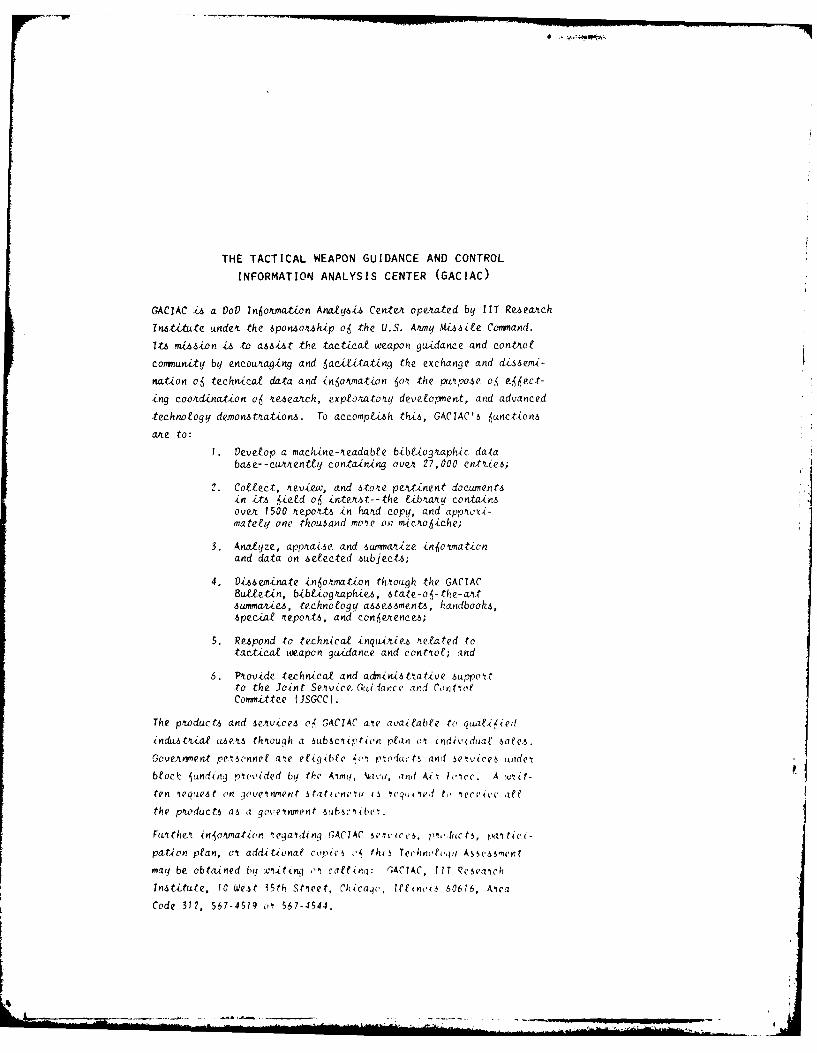
THE TACTICAL WEAPON GUIDANCE AND CONTROL
INFORMATION ANALYSIS CENTER (GACIAC)
GACIAC i~s a VoV ln6otmation Analysi~s Cen-teA opexated by ITT Reseatch
Institute undex the sponzoxuhip o6j tke U.S. At'my Misile Coimnand.
Its mission is to asist the tactcalf weapon guidance and contxot
commnity by encoutagZng and 6acititating the ex.change. and d&s~emi-
nation o6 technical data and in~o'unation 60k the pw~pose oj e6,4ect-
-ing cootdination o6 4eaxch, exptotato~ty develoment, and advanced
technolfogy demonzt'ation6. To accomptkh this, GACIAC'6 junctionu,
axe to:
1. Develop a maclvine-'iaadabee b-ibtiogtaph1c databaz~e--cwutentey containing ovex 27,000 enies;
2. Colect, 4eview, and sto'te peAtinent documentsin its 6ied o6 inte'it-the (ibuvy containsovvt 1500 4epoxttz in hatd copy, and apptoxi-mateeq one thou3and rno'e on mico6riche;
3. Analyze, app'rai-6c and -swmnax.ze in~o'irationand dota on selfected subjects;
4. Dissemitnate inou'at.Lon thtio'gh the GACIACBulletin, b-ibiogLaphiue, 6tote-o -the-ovuts5ummaxtcez, technology assessments, handboof6,~special~ ttepoktts, and con~eAences;
5. Respond to technical inqmiiez tetfated totacicalf weapon guidance and contiot; and
6. P'tovide techn~icol and adini-sttative 6uippoitto the Joint Se~nuice. Guidance and ContiofCommi~ttee (JSGCC).
The pitoduct.6 and seewiceA oj GACIAC a're available to quati<ied
indu,tiio use". th'toulh a 6ubsc'ui't<(n plan (11 ndividuae sczte5.
GoveAvnen~t pe16onnef aie efiq~bfe '(- pmoducts and 5ei'icv6 tindej
btoc uncinji piovided by the A"niq, '4dvl, dkid oki Vcicc. A wijt-
ten ieqtes on :7oveitnment stationeii 15 3 le '. I 'ivv 4.(ea
the p.tixducts as a goveinrnent 5(Absc be .
FLurthei inio'tJat{(n 'ieqairdinq GACIAC s5''ii e,, p~ihc t5, pa tic4 -
po.Uon plan, vi additionaP co!.)ic (,41 tht~s Tee iiceo,ju sesrcr
may be obtai~ned by wq-tinq oi caltinq: ITCAC T Qcsea~cf
Institute, 10 West 35th St'reet, Chricap', fehmoo ' 60616, Aica
Code 312, 567-4579 .jl 567-4544.

UnclassifiedSECURITY CLASSIFICATION OF THIS PAGE (non.u Does Entered)
REPOT DO AENTTIONPAGEREAD INSTRUCTIONSBEFORE COMPLETING FORM
IREPORT NUMBER 12 OTACESSION NO3. RECIPIENT'S CATALOG,%l V 4ER
'~*GACIAC..TA-79-01 A4. TITLE (wiJ1.ITT 5. TYPE OF REPORT A PER&OD-.COVERED
i- Technology Assessment of Ring Tehia I~ssmn* Laser Gyroscopes /6. PERFORMING ORG. REPOOT NUMBER
7. .UHRe S .. -~.- . CONTRACT OR GRANT NUMBER(S)
~ John A.,/Tekiela DSA 90 \7-~C-3840
9. PERFORMING ORGANIZATION NAME AND ADDRESS T 10. PROGRAM ELtMENT PROJECT, TASKI AREA IN WORK UNIT NUV9ERS
IIT Research Institute ~10 W. 35th Street I/Chicago, Illinois 60616
111 CONTNOLLINc. OFFICE NAME ANAD ADDRESS 12 EOT DATE
l Defense Logistics Agency P/11 Julf 079 ____
Cameron Station ,- .~ 113. NUMB ER OF PAGES
Alexandri. VA 22314 9!4MONITORING AGENCY NAME 6 ADDRESSMI d,IitnI from Cor,olling Of ice SECURITY CLASS. (of thim. rPort)
iU.S. Army Missile Command UcasfeJAttn: DRSMI-T rI_.1 DECLASSIFICATION'DOWNGRADING
~RedstoneArsenal, Alabama 35809 SHDL
16. tiSTRIBUTION STATFMENI -'f tih H-ot
(see not~e 18below )
17, DISTRIBUTION STATEM~t.T (of te abstract entered In Block 20, If differentI fronm Report)
IS. SUPPLEMENTARY NOTE,
This technical assessment is available from GACIAC only.Reproduction is not authorized except by specific permission.
19 KFEY WORDS (Cc,,,tin-a ,,r, -v, side it tiaess mioqd identify by block numnber)
Laser Gyroscopes Faraday CellsRing Lasers Sagnac EffectLaser Gyro 3ias Tutorial Presentation
Lock-InInterferome ter'Pip r-ros Cot, o back
This assessment reviews the laser gyroscope's history from itsearliest conceptual formulation and discusses the experimentswhich led to the first successful application of the'instrumentin 1963. The basic theory of operation is discussed I ~d abibliography of related scientific documents currently in theGACIAC file is included as a source of more information. Thefundamental problems which have been encountered in the develop-ment of the laser gyroscope are discussed and the methods .
DO, 1JAN73 1473 EDITION OF i NOVGS IS OBSOLETE Unclassified ~i~'SECURITY CLASSIFICATION OF THIS PAC.F (W,-r Par& Fnfee4i
Unclassified,ECUITY CLASSFICATION OF THIS PAGK(ISS Date Kut.d
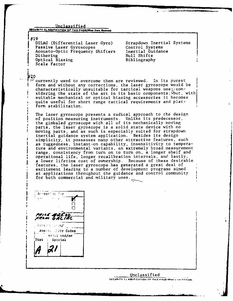
1#19DILAG (Differential Laser Gyro) Strapdown Inertial Systems
Passive Laser Gyroscopes Control SystemsAcousto-Optic Frequency Shifters Inertial GuidanceDithering Null ShiftsOptical Biasing BibliographyScale Factor
K. currently used to overcome them are reviewed. In its purestform and without any corrections, the laser gyroscope would becharacteristically unsuitable for tactical weapons use con-sidering the state of the art in its basic components;'but, with
* suitable mechanical or optical biasing accessories it becomesquite useful for short range tactical requirements and plat-form stabilization.
j The laser gyroscope presents a radical approach to the designof position measuring instruments. Unlike its predecessor,the gimbaled gyroscope with all of its mechanically moving
, parts, the laser gyroscope is a solid state device with nomoving parts, and as such is especially suited for strapdowninertial guidance system application. Besides its designsimplicity, it possesses many other attractive features, suchas ruggedness, instant-on capability, insensitivity to tempera-ture and environmental variants, an extremely broad measurementrange, consistency from turn on to turn on, a longer shelf andoperational life, longer recalibration intervals, and lastly,a lower lifetime cost of ownership. Because of these desirablefeatures, the laser gyroscope has generated a great deal ofexcitement leading to a number of development programs aimedat applications throughout the guidance and control community Ifor both commercial and military uses.
A, es ) n )r
* -
ni -
Aver - ty CodesAV.,l and/or
at1 Spccil
UnclassifiedSECURITY CL ASSIFICA iO a OF TMIS PAGF(Wh,, 1'. F.''ped)
GACIAC TA- 79- 01 JULY 1979
TECHNOLOGY ASSESSMENTOF
RING LASER GYROSCOPES
Prepared by:
J. A. Tekiela
IIT Research Institute10 West 35th StreetChicago, Illinois 60616
Copies available from GACIAC only.p Reproduction not authorized except
/D~pTb%' 41it% by specific permission.
GACIAC
A DOD INFORMATION ANALYSIS CENTER
OPERATED BY lIT RESEARCH INSTITUTE, 10 W. 35th ST., CHICAGO, IL. 60616SPONSORED BY U. S. ARMY MISSILE COMMAND, REDSTONE ARSENAL, AL. 35809

GACIAC TA-79-01 July 1979
PREFACE
This technical assessment was prepared by the Tactical
Weapon Guidance and Control Information Analysis Center under
Contract DSA 900-77-C-3840, for the U.S. Army Missile Command
(MICOM). It is intended to cover the basic concepts of ring
laser gyroscopes, the various aapects of which have been
touched upon by many authors, ana to provide a source of ref-
erence material for those interested in this direction
measuring system.
Much of the material used in this technical assessment was
based on the quoted references and does not represent original
work.
This assessment reviews the laser gyroscope's history from
its earliest conceptual formulation and to the present applica-
tions of the instrument. Inherently, the laser gyroscope has
many desirable features as compared to its mechanical counter-
part, the gimballed gyro. For this reason, the laser gyroscope
has generated a great deal of excitement leading to a number
of development programs aimed at applications throughout the
guidance and control community for both commercial and military
uses.
iv

GACIAC TA-79-01 July 1979
TABLE OF CONTENTS
Page
1. INTRODUCTION..........................
2. GYROSCOPES - HISTORICAL DEVELOPMENT. ............ 2
3. LASER GYROSCOPE......................3
3.1 Introduction . . . . . . . . . . . . . . . . . . . 3
3.2 Development ...................... 3
3.3 Other Interferometer Shapes .................
3.4 Ring Laser Interferometer ............... 12
3.5 Laser Gyroscope Output................15
3.6 Laser Gyroscope Errors................16
3.7 Differential Laser Gyroscope (DILAG) ........ 22
3.8 Passive Ring Resonators ................ 27
4. LASER GYROSCOPE APPLICATIONS ................ 29
4.1 Strapdown Inertial System Characteristics. ...... 29
4.2 Aircraft Inertial Navigation ............ 30
4.3 Weapon Guidance ...................
4.4 Ballistic Missiles.................36
4.5 Gun Fire Control..................36
4.6 Space Vehicles...................37
4.7 Other Applications.................37
5. COMPANIES DEVELOPING LASER GYROSCOPES .......... 39
6. CONCLUSION.........................40
REFERENCES...................... . .. ..... . . .. .. .. ... 4
BIBLIOGRAPHY..........................43
V -
GACIAC TA-79-01 July 1979
LIST OF FIGURES
Figure
1 Sagnac Interferometer ....... ............... 5
2 Circular Rotating Sagnac Interferometer ... ...... 7
3a Square Model Interferometer .... ............ . 10
3b Equilateral Triangle Model Interferometer .. ..... 10
4 Ring Laser Gyroscope Basic Elements .. ........ .. 14
5 Laser Gyroscope Errors ..... .............. . 18
6 Fundamental Laser Gyroscope Construction ..... 23
7 Gas Flow in a DC Laser Discharge .. ......... ... 24
8 Four Wave Ring Laser Gyroscope ... .......... . 25
9 Passive Ring Resonator Laser Gyroscope . ...... . 28
LIST OF TABLES
Table Page
1 RLGN Performance Specifications ... .......... . 32
2 Inertial System Requirements .......... ..... 33
3 SLIC-15 Laser Gyro Characteristics (la) ....... .. 35
4 MK 16 Stable Element RLG Parameters .. ........ .. 37
vi

GACIAC TA-79-01 July 1979
TECHNOLOGY ASSESSMENT OFRING LASER GYROSCOPES
1. INTRODUCTION
The ring laser gyroscope is a relatively young concept in
gyroscopic devices which has provoked a great deal of interest
and work and which may be destined to revolutionize the future
methods of position measurement. A solid state device unlike
its predecessor, the gimbaled gyroscope, its expanded use may
be likened to the widespread use of the quartz watches of today
over the mechanical watches of yesterday.
This document initially will review some of the laser
gyroscope's history and basic formulation. The major portion
will broadly cover the technical aspects of the device to a
reasonable depth; however, many references are cited by which
the reader can pursue the subject onto a very high technical
level. A chronological bibliography is also presented of
documents currently available in the GACIAC library which cover
the subject from its beginning and includes its many ramifica-
tions.
In addition to the discussion of the fundamentals of ring
laser gyroscopes, the device's shortcomings and error sources
are also discussed along with the methods currently being
used or experimented with to overcome the errors. A short
discussion of possible applications completes this review.

GACIAC TA-79-01 July 1979
2. GYROSCOPES - HISTORICAL DEVELOPMENT
The device we know today as the gyroscope is really the
evolution of an ancient toy, the spinning top, which predates
the Christian era. However, the fact that the spinning top
could be useful in some way as a scientific instrument was not
recognized until the year 1752 (Reference 1) with the first
publication on a gyroscopic device. About ten years before,
an ingenious mechanic, Serson, recognizing the property of a
spinning top to affect a vertical position, produced a crude
gyroscope, intending to create an artificial horizon. A gyro
sextant was developed and built using the Serson device and
tested successfully in 1743; however, little or no additional
work was done on the stabilized sextant for over 100 years.
In 1852, the term "gyroscope" was first used by the French
scientist Leon Foucault in a memoir read before the Academy of
Sciences in Paris. He used a gyro in an attempt to demonstrate
and measure the rotation of the earth. This experiment, called
the "first gyro experiment of Foucault", was based on the fact
that a gyro, properly suspended, retains the direction of its
spin axis in space when its supports are rotated. The experi-
ment was really unsuccessful in determining the earth's rotation
rate, but it did lead to further experiments and the eventual
development of the gyro compass and the gyro stabilizer. These
experiments were conducted by many scientists in searching
for applications of the gyro, including Sperry, who was instru-
mental in several developments such as an artificial horizon,
a gyro compass, huge ship stabilizers, and the gyro stabiliza-
tion of aircraft using an autopilot.
Today, gyroscopes have evolved into extremely sensitive
and high precision instruments for the measurement of direction.
These devices are used for artificial horizons, gyro compasses,
directional gyros, rate gyros, autopilots and accurate inertial
navigation systems for military and civilian use.
Gyroscopes developed thus far were mechanical in nature,
using a spinning wheel, or mass, called a rotor mounted in a
2
GACIAC TA-79-01 July 1979
frame called a Cardan-suspension or gimbals. This is the gyro-
scope configuration familiar to most people. These conventional
gyroscopes using the spinning mass as the sensing element (sub-
ject to Newton's first law) have many sources of error, leading
to inaccuracies which are very costly to minimize.
Bearing friction, spin motor wear, unbalance of the rotor,
mechanical structures subject to environmental temperatures,
and "spin up" time are some of the problems that must be over-
come in the design and construction of mechanical gyros. This
results in the need for precision machining requirements,
complicated assemblies, and rigid manufacturing processes,
which make the device very costly. In addition, auxilliary
hardware is required for voltage control and temperature con-
trol, necessary to obtain high accuracy. This adds to the cost.
Periodic maintenance and recalibration are also necessary,
which though not an initial cost, must be considered in the
overall cost and down time of the unit.
Now, after 200 years of development, the mechanical gyro-
scope is being replaced by a new generation of direction
measuring devices, the laser gyroscope, which shows promise of
being less costly and more dependable than its predecessor.
3
GACIAC TA-79-O July 1979
3. LASER GYROSCOPE
3.1 Introduction
The laser gyroscope is a solid state, integrating rate
gyroscope that measures inertial rotation rates with high pre-
cision. In its simplest form, the laser gyroscope has no
mechanical or moving parts, is not subject to temperature
extremes, is ready for use in a fraction of a second and does
not require periodic calibration and maintenance. It is a com-
pact device adaptable for use in short range tactical missiles,
aircraft inertial navigation systems, stabilization devices for
shipboard gun control systems, attitude control and as a north
finding compass. The gyroscope will perform in very high g
environments and having no mechnical parts, requires little or
no maintenance or calibration.
The laser gyroscope is not, however, without its faults,
one of which is the inability to match the high accuracy and
low drift rates of conventional gyroscopes.
3.2 Development
A significant step in the development of the laser gyro-
scope occurred in 1913 and is attributed to Sagnac (Reference 2),
who demonstrated the feasibility of an optical system capable
of measuring the state of rotation of a frame of reference,
using an optical interferometer, in which the interferoneter
was at rest.
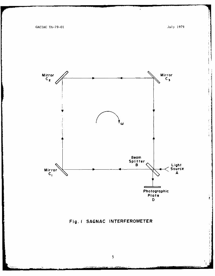
The principal of Sagnac's interferometer is shown in
Figure 1. A light beam coming from the source A is split at
the beamnsplitter, B, into a beam circulating the loop in a
clockwise direction and a beam circulating the loop in a counter-
clockwise direction, with both beams reunited at B so that
interference fringes are observed at D. When the entire inter-
ferometer is rotated at an angular rate of ,w radians per second,
the detected fringe shift, _1Z, is given by the relation,
- - - (i),C
4
GACIAC TA-79-01 July 1979 i
Mirror MroC2 C3 *
B LightMirror -4Source
C1 A
PhotographicPlate
D
Fig. I SAGNAC INTERFEROMETER
5
GACIAC TA-79-01 July 1979
where
A = the area enclosed by the light path,
= the vacuum wavelength,
c = the velocity of light.
In the interferometer, the frequency is determined by the source,
and as such, the contra-rotating beams are of the same frequency.
As the system rotates, however, the time it takes for each of
the contra-rotating beams to traverse its respective path is
different, so at the point of recombination the output will have
a phase difference that is dependent on the rotation rate of the
system. This effect can be explained as follows. Consider the
ideal circular interferometer of radius R (Figure 2). The light
directed at the beamsplitter at A is represented by a quantum
of electromagnetic energy, or photons. One photon is reflected
from the surface of the beamsplitter and travels in a clockwise
direction around the optical circuit, while another photon passes
through the beamsplitter and travels in a counterclockwise direc-
tion around the optical circuit. The photons travel at the speed
of light, c. When the interferometer is stationary, the transit
time, t, for each of the photons to traverse the physical path
length of the interferometer is given by 2R/c, where 2nR is the
path length.
Assume now that the interferometer is rotated in a clockwise
direction at a constant angular velocity, w (radians/unit time).
While the device is rotating, the closed path transit time from
the beamsplitter around and back to the beamsplitter becomes
quite different for the contra-rotating photons. This is because
during the transit time of the photons, the beamsplitter is
angularly displaced from position A to a new position, A'. Now,
with respect to inertial space, the photon traveling with the
clockwise direction of the rotating interferometer must traverse
a distance greater than the distance 2nR, while the photon
traveling against the interferometer rotation will traverse a
distance shorter than 2nR in order for each beam, respectively,
6
GACIAC TA-79-01 July 1979
Beamnsplitter
Source
Point OfObservation
Fig. 2 CIRCULAR ROTATING SAGNAC INTERFERO-METER
7
GACIAC TA-79-01 July 1979
to reach the new position of the beamsplitter at A'. The speed
of light, c, being a constant, the travel time taken by each of
the photons will also be different.
The inertial distance between A and A' is given by Rwt
The distance traversed by each of the contra-rotating photons
would be
ct± = 27R + Rwt+, (2)
where t+ is the transit time of the photon rotating in the
direction of the rotating interferometer and t- is the transit
time of the other. In terms of time, Eq. 2 becomes
+ 2TR (3)- c + Rw
The differential time of travel, At, between the contra-rotating
photons is given by
At= t+ - t_ (4)
or,
A 27TR - 2TrRc-Rw c+R'
t -21TRw + 2,Rw
c2 -R
2W2 c
2 -R2w
2
since c2 >> R2w 2
4 2WAt= 4TrR (5)2
The area, A, of a circle is given by rR2; therefore
At = 4A (6)C 2
which is the fundamental equation for the rotating interferometer.
di
JI

GACIAC TA-79-01 July 1979
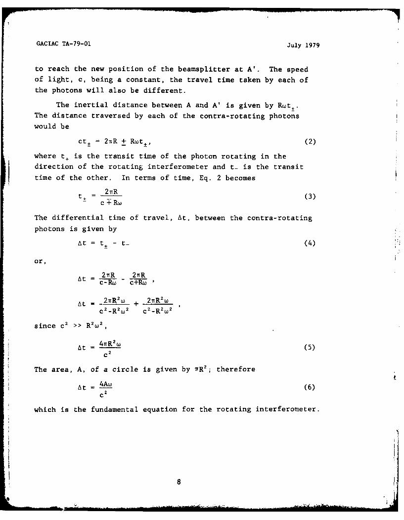
3.3 Other Interferometer Shapes
A square interferometer, similar to the Sagnac experiment
(Figure 3a), and an equilateral triangle interferometer (Figure 3b),
which is, in fact, the predominant laser gyro configuration, are
now examined.
Consider the square of Figure 3a, of side length 2R and
perimeter 8R. Assume the square encloses a circle of radius R.
The distance traversed by a photon in a stationary system is 8R.
Again, assume the interferometer is rotated in a clockwise
direction at a constant angular velocity, w, resulting in the
repositioning of the device a very small distance, At.
Assuming At to be much less than 8R, At will be approximated
as the arc length of the circle of radius R moving at an angular
velocity w over the time t+, and again is given by Rwt±. This
distance traversed by the contra-rotating photons in a rotating
system is
ct± = 8R + Rwt+ (7)
In terms of time,
t 8R
± c +Rw
In terms of differential time,
At -8R2 + 8R2 , (8)C
2 C 2
At 16Rw (8)c 2
The area, A, of the square is given by 4R2 ; therefore,
At =
c 2
the fundamental equation for the rotating interferometer.
9
GACIAC TA-79-01 July 1979
R
2R
Fig. 3a SQUARE MODEL INTERFEROMETER
Fig. 3b EQUILATERAL TRIANGLE MODEL INTERFEROMETER
10
GACIAC T-90TA-79- July 1979
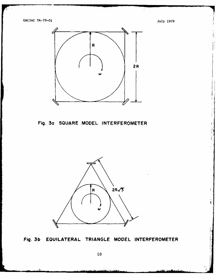
Considering the equilateral triangle of Figure 3b of side
length 2RV" and perimeter of 6RV3, the distance traversed by a
photon in a rotating system is
ct± = 6R/3 + Rwt+ (9)
Again, assuming At << 6R/T and considered as the arc length of a
circle of radius R enclosed by the triangle. In terms of time,
t+=6RV3
c+Rw
In terms of differential time,
At = 6R 2 /3W + 6R 2 V3WC
2 C 2
12R 2 /3WAt = (10)c 2
The area, A, of the equilateral triangle is given by 3R2/3;
therefore,
At =c
2
again, the fundamental equation for the rotating interferometer.
The optical path difference, A., is given by cAt; therefore,
from Eq. 4
A -4Aw IiAt. = (11)
c
This equation, then, is generalized for any enclosed optical
configuration and shows that the path difference is proportional
to the enclosed area and the rotational velocity.
Although the axis of rotation is assumed to be at the center
of the system, it can be shown that the optical path difference
given by Eq. 11 is independent of the location of the axis.
The fringe shift observed using the Sagnac interferometer
and as described by Eq. 1 is proportional to the area circumvented
..11L
GACIAC TA-79-01 July 1979
by the device. Since the measure of rotation rate is the phase
difference resulting from the difference in path length, and sincethe path length difference is much less than a wavelength, adevice having a large area is required in order to observe ameasurable fringe when measuring low rotation rates. In 1925,Michelson and Gale measured the rotation rate of the earth normal
to the device, which was located near Chicago, by using an optical
path length of about one nautical mile (Reference 3). The config-uration was a rectangle with sides 2010 by 1113 feet with an
enclosed area of about 2.08 x 10⁵ square meters. The largesize was necessary to produce a measurable path difference, At,at the rotation rate of the earth. In this experiment, the
measured path difference amounted to about 1300 A or about
A, fringe.
3.4 Ring Laser Interferometer
The Sagnac interferometer, because of size requirements andlack of sensitivity, would not be useful as a practical gyroscope.
Although Michelson and Gale used broadbanded monochromatic light
as the external source, using a laser as the external light sourcewould not improve the operation because the optical path differ-
ence would be much less than a wavelength. The solution is an
active optical oscillator set into a closed, or ring, optical
cavity. For this ring interferometer to be useful for measuring
small length changes a device is required whose frequency isdependent on the length of the optical path traversed.* In this
way the signals of two independent oscillators, each having a
frequency dependent on the optical cavity length can be trans-
formed into a measurable difference, or beat frequency, that
would be a measure of length difference. This is accomplishedby placing two laser oscillators into the optical path, thereby
creating an active interferometer, and making the laser frequency
dependent on the optical path length. Figure 4 shows a laser
gyro optical diagram. One leg of the triangle is notched out to
facilitate a gas discharge tube containing a mixture of helium
and neon. At certain wavelengths, light will experience gain
12

GACIAC TA-79-O1 July 1979
as i2. passes through the gas discharge. This gain is fixed so
thav losses due to the reflecting mirrors, diffraction, and
other causes are equalized.
When the gas discharge tubes are energized, two contra-
rotating light beams traverse the optical path, each an inde-
pendent frequency. The oscillation frequency for the
reinforcement of the light waves, that is, the lowest order
transverse mode, requires that the optical path length, k, be
exactly equal to an integer number of wavelengths. The system
would not lase otherwise. The ability to generate and sustain
stable contra-rotating oscillations in a ring laser was first
demonstrated in 1963 by Macek and Davis of Sperry Rand (Refer-
ence 4) in their experiment to sense rotation rate with a ring
laser. The device built then for the laboratory experiment was
the very first laser gyroscope.
The basic requirement is that the laser wavelength must be
an integer, N, fraction of the optical path length, or,
NX = L (12)
The value of N is usually in the order of one million. In terms
of frequency,
f Nc (13)
Now, small changes in path length result in small changes in
frequency,
Af AL (14)
The resulting beat frequency, Af, can be related to the rotation
rate, w, from Eq. 11, given as
A- 4A (15)
Substituting Eq. 14 into Eq. 11 yields
Af 4A (16)
13

GACIAC TA-79-01 July 1979
p rism-~ ~~ Photod ad es
Readout' .' Substrate
Dielectric Mirror(99%/ Reflecting)
Contra - rotatingLaser Beams
MirrorMirror
Laser Gain Medium
Fig. 4 RING LASER GYROSCOPE BASIC ELEMENTS
14
GACIAC TA-79-01 July 1979
Using this principal, beat frequencies on the order of a few
Hertz would be produced for rotation rates of a few degrees per
hour, using perimeter lengths of less than 12 inches. Since
these beat frequencies amount to only about 10-" of the optical
frequency, the sensitivity of such an active optical oscillator,
or ring laser gyro, is much greater than the interferometer
technique, and permits low rotation rates to be measured using
devices having a fairly small size.
3.5 Laser Gyroscope Output
Since the difference in the optical frequencies of the contra-
rotating beams is proportional to the angular turning rate,
output information is obtained by monitoring the difference
frequency. Of course, if the laser gyro were not rotating,
the contra-rotating beams would be equal in frequency, resulting
in zero difference frequency. If the laser gyro were rotating
uniformly, the beat frequency would be a constant, proportional
to the turning rate.
A direct measurement of the beat frequency is accomplished
by combining the contra-rotating beams using optics so that
they are parallel. Figure 4 shows an optical method for com-
bining the beams to obtain a readout. Less than 0.1% of the
incident light of both beams is transmitted through the optical
coating of the output mirror. The wavefronts of the two beams
will interfere with each other, because of the frequency differ-
ential, and will alternately reinforce or cancel forming a fringe
pattern. The fringe pattern will move in either direction
depending on the direction of rotation of the laser gyro. Each
fringe represents one cycle of phase change between the two
beams. Two photo diodes arc used to sense the direction of
movement of the fringe pattern. Dimensions of the detector are
much smaller than the spacing between the fringes. As the
intensity maximum moves past the detector, a signal is generated
whose frequency is proportional to the input turning rate.
Because of the digital output, the laser gyro is inherently
an integrating rate gyro. A pulse count determines the rotation
15

GACIAC TA-79-01 July 1979
angle of the gyro as a function of time and is independent of
variations in the rotation rate. The number of counts as a
function of angular displacement is referred to as the gyroscope's
scale factor (SF), and can be expressed as counts per radian,
counts per arcsecond, or more commonly, arcseconds per count.
From the relationship of Af/w and SF, and, substituting Eq. 16
yields,4A
SF L counts per radian, (17)LX
where each count is a 2 7 phase difference between the two beams.
For example, the Honeywell RLG GG 1328, having an equilateral
triangle perimeter length of 8.4 inches and a laser wavelength
of 0.6328 microns, has a scale factor of about 65,000 counts
per radian. The reciprocal scale factor is 3.147 arcseconds
per count (Reference 5). A 3600 circle is equivalent to
1,296,000 arcseconds; therefore, turning this gyroscope through
one complete revolution would result in 411,821 counts. If this
gyroscope were in inertial space, rotating it through a complete
revolution first in one direction and then the other would
result in a zero pulse count.
3.6 Laser Gyroscope Errors
3.6.1 Lock-In
Lock-in is a phenomenon common to closely coupled electro-
magnetic oscillators. In electronic oscillators the frequency
of a tank circuit can be perturbed by the injection of another
signal operating at a frequency very close to that of the free
running oscillator. That is, at some critical combination of
signal strength and frequency difference, a free running
oscillator will lock to the external signal. Similarly, in a
ring laser gyroscope, a mutual coupling will exist between the
two contra-rotating beams when the rotation rate becomes quite
small. The result is the frequency differential goes to zero
causing a zero output before the turning rate goes to zero.
Backscattering, caused by imperfections in the mirror coatings,
allows a small portion of the energy of each of the contra-
16
GACIAC TA-79-01 July 1979
rotating beams to be refelected into the path of the other beams,
resulting in the locking of contra-rotating beam frequencies.
Depending on the lock-in threshold value of the particular
device, no rotation rate values can be measured below it.
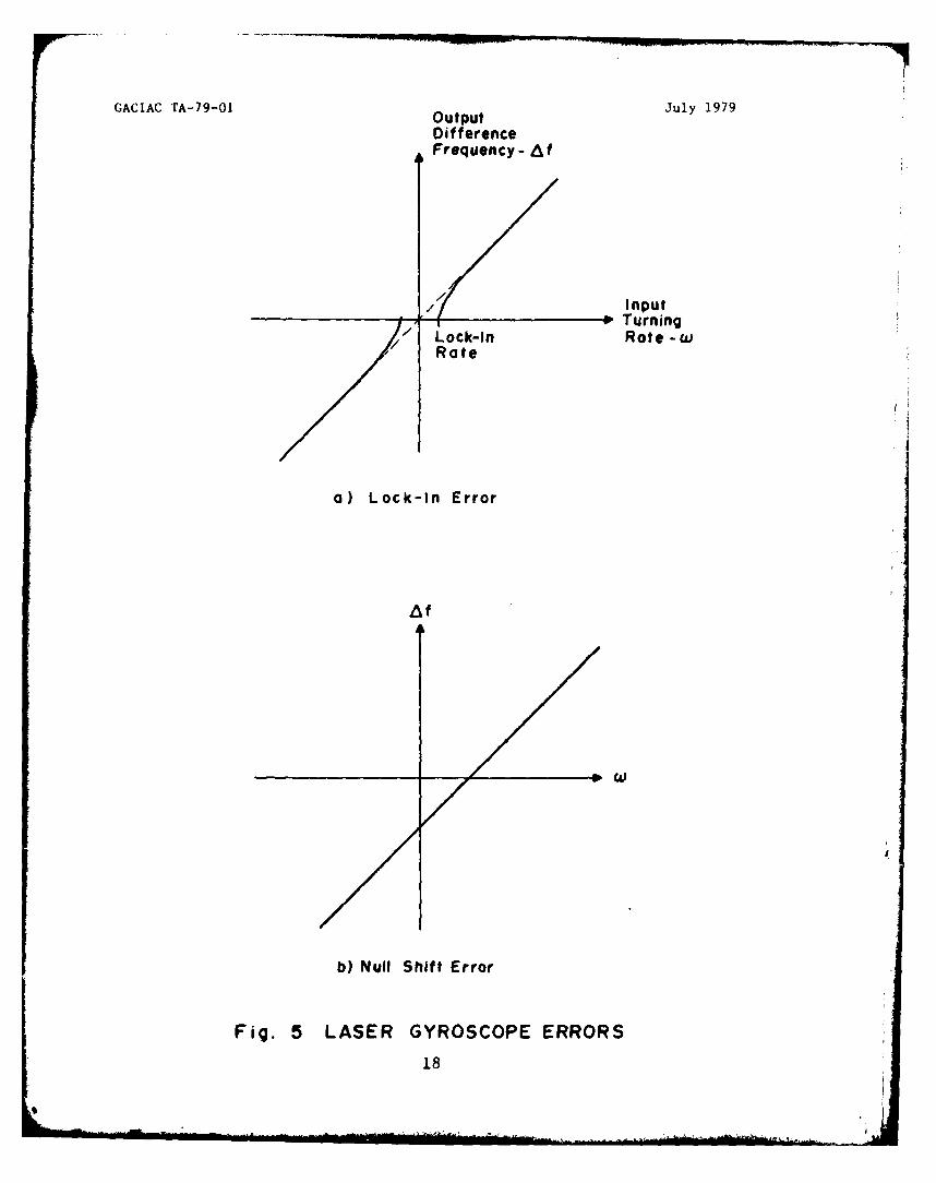
Figure 5a shows the differential output frequency as a function
of rotation rate, illustrating the effects of lock-in. As an
example of a fairly representative gyroscope, at high turning
rates (>100 to 200 per second) the differential frequency is
proportional to the input rate, resulting in a linear output.
At lower turning rates (<50 per second) the output becomes
quite nonlinear, and at the lock-in rate (about 0.01 to 0.1 degrees
per second or one-tenth to one revolution per hour) the output
goes to zero. Navigation requirements are on the order of
0.01 degrees per hour.
3.6.2 Laser Gyro Biasing
Lock-in is a fundamental inadequacy of the laser gyro;
however, it has been largely overcome with two methods of laser
biasing, mechanical rotation and magnetooptical elements. Laser
biasing applies a known turning rate to the gyro, moving the
operating point of the gyro away from the lock-in point. Input
to the gyro, then, is the sum of the bias rate and the actual
input rate. When measuring the actual output rate, the bias
must be subtracted from the measured rate.
3.6.2.1 Bias Stability
A fixed DC bias, either mechanical or electrooptical,
requires very good stability to eliminate any gyro errors caused
by bias drift. For example, in order to measure input rates of
0.1 degree per hour using a fixed bias of 10' degrees per hour
(about 46 rpm) a bias sLabiliLy of 10 would be required. This
would require a high degree of magnetic and thermal stability.
An alternating bias technique overcomes the bias stability
problem. Since the laser gyro is an integrating rate gyro, an
oscillating bias technique in which the bias alternates between
positive and negative states (sinusoidally or square wave) would
result in only the net rotation angle appearing in the output.
17
GACIAC TA-79-01 Output July 1979
DifferenceFrequency - A
/ Input/ Turning
// Lock-in Rate -wRate
a) Lock-In Error
b) Null Shift Error
Fig. 5 LASER GYROSCOPE ERRORS
18
GACIAC TA-79-01 July 1979
The laser gyro is biased out of the lock-in range most of the
time. This oscillation bias technique reduces the requirements
on the absolute stability of the magnitude of the bias. The
oscillating bias technique can be employed by using either
magnetooptical devices and varying the magnetic field of the
bias element, or by mechanically (dithering) oscillating the
entire gyro.
3.6.2.2 Mechanical Dithering
Mechanical dithering is a technique by which the entire
laser gyro is oscillated about its input axis at a sinusoidal
or square wave rate. This laser biasing technique is accomplished
by mechanically dithering the laser block at high frequency
through a stiff dither flexure suspension built into the gyro
assembly. Springs on each side of the laser block suspend it
from the center post. Piezoelectric transducers on one of the
springs provide the dither drive mechanism to vibrate the block
about the input axis. The dither rate amplitude and acceleration
are designed so that the dwell time in the lock-in zone (at twice
the dither frequency) is short, such that lock-in will never
develop (Reference 6). Angular velocities range from 50 to 250
degrees per second and the oscillation frequency varies from
100 Hz to 500 Hz, depending on the manufacturer and the instru-
ment (Reference 5). Subtracting the dithering bias from the
output is either done optically, by mounting the optical output
detector on the undithered instrument case, or electronically.
3.6.2.3 Magnetooptical Biasing
Magnetooptical biasing elements, when placed in the optical
path of the laser light, present a path that appears longer for
the light going in one direction than for light going in the
opposite direction. The apparent difference in the optical
path lengths of the contra-rotating beams causes them to oscil-
late at different frequencies, resulting in an apparent rotation
rate set apart from the lock-in range. There are two such
devices used in ring laser gyros, Faraday cells and magnetic
mirrors.
19
GACIAC TA-79-OI July 1979
3.6.2.4 Magnetic Mirror Biasing
Magnetic mirror biasing is a technique which, unlike the
real mechanical rotation applied by dithering, employs an
artificial oscillatory bias applied to the gyro to introduce
an apparent rotation. A magnetic coating on the mirror, when
saturated by an applied magnetic field, causes a differential
phase delay between the contra-rotating beams, biasing them
away from the lock-in frequency (Reference 7). The resulting
bias placed on the gyro is controllable by the applied magnetic
field. Bias uncertainties are compensated for by using a square
wave alternating biasing technique. Operating in a saturated
bias state eliminates error susceptibility to stray magnetic
fields (Reference 6).
3.6.2.5 Faraday Cells
The Faraday cell is made of a magnetically active material
that has the effect of increasing the optical path length of
light passing through it. It is a transmissive device that is
placed in one of the legs of the optical cavity. The Faraday
cell's index of refraction to circularly polarized light is
altered by the applied magnetic field. Because the laser gyros
use plane polarized light, quarter wave plates are used to
circularly polarize the entering light and plane polarize the
exiting light. A change in the optical path lengths of the
contra-rotating beams is created, resulting in a difference
frequency away from the lock-in range. Bias errors are can-
celled by using square wave alternating control fields.
Faraday cells generally require magnetic shielding around
the gyro to minimize magnetically induced error effects.
Additional limitations of the Faraday cell have been the intro-
duction of thermal and acceleration sensitive bias errors
through birefringent and anisotropic effects. The latter error
can be decreased by reducing the length of the Faraday cell,
but this causes a reduction of bias capability which, in turn,
generates scale factor nonlinearities due to the inability to
keep the average rate into the gyro outside of the lock-in region 1(Reference 6).
20
GACIAC TA-79-01 July 1979
3.6.3 Bias Technique Advantages
Magnetooptical biasing has the advantage of developing an
artificial rotation of the laser gyro electrically, without the
need of mechanical devices. Another advantage is the ability to
generate a square wave bias that has a low frequency and a rapid
traversal rate through lock-in, lowering random noise generated
from this error source (Reference 6).
Any altering bias technique should be perfectly symmetrical
to avoid generating a DC drift term. Mechanical bias avoids
this since the motion is physically bounded, negating long term
accumulated drift. Also, large bias requires high counting
rate circuits and large (MHz) bandwidths. With mechanical bias,
it is possible to design the readout system such that the motion
of the fringe pattern due to the bias is compensated by the
mechanical bias motion. Bias counts are not detected and smaller
bandwidth circuitry can be used (Reference 8).
3.6.4 Null Shift
When the optical cavity is anisotropic it will exhibit
different property values when measured along the optical path
in the two opposite directions. Since the laser frequency is a
function of the optical path length, any anisotropic effects
will result in the two waves oscillating at different frequencies
while the device is at rest. This results in a null shift of
the output as shown in Figure 5b.
Another source of null shift error is due to the DC current
used to excite the laser gyroscope. When a gas discharge is
sustained with a DC current the gas flows in the discharge
cavity. The gas flows toward the cathode in the center of the
discharge and back to the anode close to the cavity walls. The
laser energy is concentrated in the center of the cavity. The
gas flow toward the cathode produces a shift in the index of
refraction depending on the relative directions of the laser
energy and the gas flow. The cavity will appear longer in one
direction compared to the other and will produce a null shift.
21
GACIAC TA-79-01 July 1979
By constructing the laser gyroscope in a balanced configuration,
with one cathode and two anodes, such that the current effects
are cancelled since the energy traveling around the cavity passes
through gas traveling both with and against the laser energy,
this effect is reduced. The two anode currents are also balanced
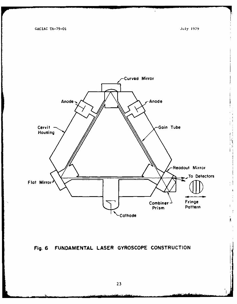
to help reduce this effect. Figure 6 shows the construction of
a laser gyroscope and Figure 7 shows the gas flow path in a DC
laser discharge (Reference 9).
3.6.5 Drift
Drift is the laser gyroscope error that remains and is
principally due to Faraday cells and magnetic mirrors, when used
as biasing elements, and to bulk flows of the excited neon atoms
in the laser gas (Reference 5). The latter is due primarily to
DC discharge current in the laser gas and thermal gradients along
the walls. Normally, the discharge currents in the two arms are
balanced; however, instability and noise of this balance will
cause drift.
Temperature of the whole device will also effect drift by
changing the optical path dimensions or by changing the position
of the reflecting mirrors.
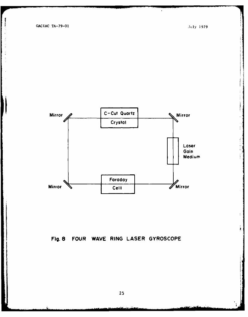
3.7 Differential Laser Gyroscope (DILAG)
Lock-in at low turning rates is the major fault of two wave
laser gyros, but can be overcome by mechanically or electrically
dithering the gyro away from the lock-in range. Both techniques,
however, have imperfections as already discussed. The applica-
tion of a large fixed bias fails also, because of noise, drift,
and environmental sensitivity of the biasing elements. A four
wave ring laser gyro (Figure 8) is an optical bias concept that
overcomes the biasing problems of the two-wave gyros by reducing
the influence of scattering from the mirrors without resorting
to DC biasing. The four wave laser gyro is also referred to as a
multi-oscillator, a four mode, or, most often, the differential
laser gyro (DILAG).
With the four wave laser gyro concept, a pair of two wave
laser gyros operate within the same optical path. One pair of
22
GACIAC TA-79-01 July 1979
/-Curved Mirror
Anode-N fAnode
Cervit G ain Tube
Housing
Readout Mirror
• To DetectorsFlat Mirror
Combiner FringePrism Pattern
Cathode
Fig. 6 FUNDAMENTAL LASER GYROSCOPE CONSTRUCTION
23L '.

GACIAC TA-79-01 July 1979
Direction Of
Fig. 7 GAS FLOW IN A DC LASER DISCHARGE
24
GACIAC TA-79-01 July 1979
LaserGainMedium
MirrorIl-Cl&,Mro
1 Fig. 8 FOUR WAVE RING LASER GYROSCOPE
25

GACIAC TA-79-0.1 July 1979
traveling contra-rotating waves are right hand circularly
polarized and the other pair of contra-rotating waves are left
hand circularly polarized. The right circularly polarized and
left circularly polarized waves are separated in frequency by
many hundreds of MHz by an optical element, historically a C-cutquartz crystal. The Faraday cell biasing element differentiates
between the two rotational senses of the circularly polarized
waves, independent of direction of wave propagation. The CW left
hand and CCW right hand waves have identical path lengths through
the element, while the CW right hand the CCW left hand also have
identical path lengths through the element. The CCW right handand CW left hand contra-rotating waves decrease in frequency and
the CW right hand and CCW left hand contra-rotating waves bothincrease in frequency. Applying a rotation to the gyro causes
the clockwise and counterclockwise waves to shift in frequency by
the same amount as in a two wave laser gyro. The large bias, Af,
of the Faraday cell results in the CW left hand wave being lower
frequency than the CCW left hand wave and the CW right hand wave
being higher frequency than the CCW right hand wave. Applying
a rotation input, the frequency spacing of one pair of oppositely
directed waves will decrease while the other pair will increase.
From Eq. 16 and the applied bias
f- f 2 = Af - X
AL
The resulting beat frequency, f bo is defined as
f= Uf - f4) - (fl - f2)
Substituting from above
f 8Aw (18)
Two important features of the four wave laser gyro are apparent
from Eq. 18. First, the beat frequency is independent of the
bias frequency, Af, thereby cancelling any instability in the
26
GACIAC TA-79-01 July 1979
biasing element, and second, the scale factor is twice the scale
factor of the two wave gyro. Additionally, there is a reduction
in coupling because of mirror scattering due to the orthogonality
of countra-rotating waves (Reference 5). Scale factor linearity
is excellent and is maintained to as low as 1/3 degree per hour
(Reference 10).
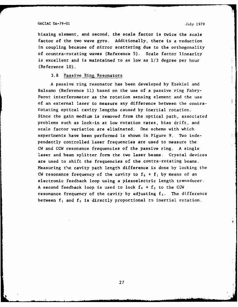
3.8 Passive Ring Resonators
A passive ring resonator has been developed by Ezekiel and
Balsamo (Reference 11) based on the use of a passive ring Fabry-
Perot interferometer as the rotation sensing element and the use
of an external laser to measure any difference between the contra-rotating optical cavity lengths caused by inertial rotation.
Since the gain medium is removed from the optical path, associated
problems such as lock-in at low rotation rates, bias drift, and
scale factor variation are eliminated. One scheme with which
experiments have been performed is shown in Figure 9. Two inde-
pendently controlled laser frequencies are used to measure the
CW and CCW resonance frequencies of the passive ring. A single
laser and beam splitter form the two laser beams. Crystal devices
are used to shift the frequencies of the contra-rotating beams.
Measuring the cavity path length difference is done by locking the
CW resonance frequency of the cavity to f0 + f, by means of an
electronic feedback loop using a piezoelectric length transducer.
A second feedback loop is used to lock f0 + f2 to the CCW
resonance frequency of the cavity by adjusting f2 . The difference
between f, and f2 is directly proportional to inertial rotation.
27
GACIAC TA-79-01 July 1979
VCO Servo Difference Amplifier
At-oust- -Oti Detectors
Piezoelectric ServoLength Transducer
Fig. 9 PASSIVE RING RESONATOR LASER GYROSCOPE
28
GACIAC TA-79-O1 July 1979
4. LASER GYROSCOPE APPLICATIONS
Development of the laser gyroscope has progressed to the
point where it is ready for full production. Laser gyroscopes
are being considered for the Navy's MK-16 Shipboard Fire Control
System and the Advanced Strategic Air Launch Missile (ASALM)
(Reference 12). Other systems with application to aircraft navi-
gation both military and commercial, space navigation, andmissile guidance are under development. All these systems are
based on the strapdown inertial navigator concept. The advent
of the low-cost computer has made strapdown navigation the
concept of the future. Additionally, present strapdown tech-
nology has demonstrated performance in the 1 nmi/hr category
similar to that of the classical gimbaled systems, with future
production costs estimated to be half of the mechanical systems
(Reference 13).
4.1 Strapdown Inertial System Characteristics
Inertial navigation systems depend on measurement with
respect to a Newtonian reference frame. Conventional gyro
systems using gimbals maintain such a reference frame in a
stabilized platform, which is isolated from the vehicle being
navigated. These systems are mechanically complex and costly,
are thermally sensitive, require long turn-on time, and also
need frequent calibration. A strapdown navigation system is a
variation of this system, but one in which the sensor is
physically mounted on the vehicle, turning as the vehicle turns.
The transformation from the sensor reference frame to the
inertial reference frame is computed using an onboard computer
rather than mechanically. This requires an inherently complex
computer to analytically perform the functions provided implicitly
by the mechanical gimbal assembly. In recent years, low-cost,
high-speed digital computers made such computations practical
and the strapdown systems a realistic alternate to mechanical
systems. The advantage of the strapdown system is the decrease
in mechanical complexity because of the elimination of the
gimbal assembly.
29

GACIAC TA-79-O July 1979
The laser gyro is a device perfectly suitable for strapdown
sensor systems and really has been developed for this applica-
tion. It meets all the requirements for low-cost digital strap-
down missile guidance and control, especially for tactical
missile midcourse guidance. Weapon delivery systems require
attitude, attitude rate, and linear motion in addition to
vehicle velocity and position in a more severe vehicle mounted
environment for strapdown systems. A wide dynamic range andhigh rate performance (inherently unlimited) of the laser gyro
provide these capabilities. Laser gyros also have other out-
standing features such as excellent scale factor linearity, long
term stability, bias stability and insensitivity to acceleration,
vibration and high-g shock. Additionally, the laser gyros have
an instant-on capability, since there is no warm-up time, and
are stable from turn-on to turn-on even after long periods of
dormancy. They require no thermal compensation, have a very long
shelf life, require less frequent periodic recalibration (about
once a year) compared to their mechanical counterparts, have their
own built-in test capability and are suitable for low-cost mass
production. Ownership and life cycle costs are much less than
the gimballed systems.
Laser gyros are inherently compact. Including electronics,
three axis gyro units occuplying only 250 cubic inches have been
built. Complete systems require about 1000 cubic inches.
4.2 Aircraft Inertial Navi&_ation
Air Force Standards for future aircraft navigation reference
systems specify a position error rate of 0.8 nmi/hr for the first
hour and 1.0 nmi/hr thereafter. Velocity error is specified as
2.5 ft/sec for the first two hours (Reference 11). Following
is a compilation of systems designed for aircraft navigation.
Only Honeywell and Sperry appear to have reached the development
stage to offer production units or units designed for specific
purposes.
30
I,

GACIAC TA-79-01 July 1979
4.2.1 Honeywell Systems
LINS (Laser Inertial Navigation System) - In 229 hours of
flight tests conducted in 1975 the LINS system has demonstrated
a CEP rate of 0.89 nmi/hr and a velocity accuracy of 3 ft/sec
(References 13,14). LINS is a company development for commercial
aircraft. Prototype models were to be delivered to the Boeing
Company and the U.S. Government during March 1978 for further
tests.
RLGN (Ring Laser Gyro Navigator) - RLGN is a variant of LINS
and is being developed by the Naval Air Development Center. It is
designed as a nominal 1 nmi/hr system and is being developed for
multiple aircraft applications. System delivery was expected in
August 1978. Flight tests will be conducted over the next two
years in a Navy P-3C aircraft, an Air Force F-106 aircraft and
an Army helicopter. A summary of performance specifications is
given in Table 1 (Reference 15).
CAINS (Carrier Aircraft Inertial Navigation System) - Thisproject, conducted by the Naval Air Systems Command, has produced
a standardized system with at-sea alignment capabilities for
five first line tactical aircraft: the F-14A, A-6E, S-3A, E-2C,
and RF-4B. This system is a variant of the RLGN. Installation
on an E-2C was planned for 1979 for carrier operations and evalua-
tion of at-sea alignment and navigation capability (Reference 15).
ARINC 704 - This commercial system has been selec-ted by
Boeing for the 757/767 aircraft. Production deliveries are
scheduled to begin in early 1981. Flight test results gave a
position error rate (95% probability) of 1.74 nmi/hr and a
velocity error (95% probability, 4 hr) of 7.22 kts.
4.2.2 Sperr__Systems
AHRS (Attitude and Headin Reference System) - This is a
generic system compatible with either the SLIC-15 or SLIC-7 laser
gyro designed for aircraft environments. Analytical measurements
were conducted on this system (Reference 16).
31

GACIAC TA-79-O1 July 1979
Table I
RLGN Performance Specifications
Reaction Time <5 min
Position Accuracy 1 nmi/hr CEP rate
Velocity Accuracy 3 ft/sec per axis (RMS)
Attitude Accuracy 2.5 arc min (RMS)
Heading Accuracy 3.0 arc min (RMS)
Acceleration Capability 10 g's each axis
Rate Capability 400 deg/sec each axis
Reliability 2500 hr MTBF
Test Provisions BIT, incl. sensors
Environmental Capability MIL-E-5400 and MIL-STD-810C
32

GACIAC TA-79-01 July 1979
Differential Omega-Ring Laser Strapdown Aircraft Navigator -
This hybrid system uses a laser gyro similar to the SLIC-15 in
conjunction with the Differential Omega navaid system and is
designed for aircraft environments. It is an inertial mixed
navigation system that produces a truly synergistic navigation
capability. This results in a very accurate position and velocity
measurement (Reference 17).
4.3 Weapon Guidance
Laser gyro strapdown systems find wide application in
missile midcourse guidance and control. However, the primary
concern in tactical weapon delivery system development is low
acquisition cost. Tactical weapon systems which require inertial
reference systems are: Wide Area Antiarmor Munition (WAAM),
Advanced Conventional Standoff Missile (ACSM), GBU-15 Glide Bomb,
and Advanced Medium Range Air-to-Air Missile (AMRAAM) (Refer-
ence 12).
Table 2 shows an approximate set of laser gyro requirements
to satisfy the typical inertial air-to-surface missile mission.
Latest technology gyros using mechanical dither or magnetic
mirror biasing have achieved the requirements outlined. Higher
grade performance (0.1°/hr) would require something like a
differential gyro (DILAG).
Table 2
Inertial System Requirements
Residual Bias DriftHorizontal Axes 0.10 /hrVertical Axes 1.0°/hr-
Random White Noise Drift 0.03°/Vi?
Random Markovian Drift(1 hr correction time) 0.10/hr
Scale Factor Stability 200 PPM
Scale Factor Asymmetry 10 PPM
Rate Range 100-400°/sec
Some specific systems are the following.
33
GACIAC TA-79-01 July 1979
LCIGS (Low Cost Inertial Guidance System) - The Air Force
Armament Laboratory is developing this system concept for mid-
course guidance of tactical air-to-surface missiles. It employs
a modular concept which contributes to its low cost. This
system is technology independent down to the sensor level.
4.3.1 Honeywell Systems
ATIGS (Advanced Tactical Inertial Guidance System) - This
program is being conducted by the Naval Weapons Center, China
Lake, for the development of a low cost inertial midcourse guidance
system for air-to-surface missiles. The original system was
delivered for flight tests in May 1974 and has undergone over 40
captive flight tests totaling 100 hours. Performance of the
system steadily improved during this period from an initial CEP
rate of 3.5 nmi/hr to 1.25 nmi/hr (Reference 18).SIG-D (Simplified Inertial Guidance Demonstration) - An
evolution of the ATIGS system, SIG-D is being developed by the
Army Missile Command to demonstrate guidance and control and
propulsion technologies for an extended range surface-to-surface
missile. The program, which began in March 1976, includes
hardware-in-the-loop simulations at MICOM, sled testing at
Holloman AFB, and the firing of three test vehicles at White
Sands Missile Range (Reference 18).
4.3.2 Speriy Systems
SLIC-15 Laser Gyjro IMU - The Sperry SLIC-15 laser gyro IMU
was integrated into a tactical missile midcourse guidance system
under the Air Force Radiometric Area Correlation Guidance (RACG)
flight test program. Flight testing of the SLIC-15 IMU was
scheduled for the spring of 1976 onboard a C-141 and a T-33 air-
craft. Results of those tests are not available; however,
previous flight testing of Sperry ring laser gyro units performed
by NASA at the Marshall Space Center showed performance to be
3 to 5 nmi/hr. The SLIC-15 laser gyro characteristics are shown
in Table 3. (References 19,20)
34

GACIAC TA-79-01 July 1979
Table 3
SLIC-15 Laser Gyro Characteristics (lo)
g Insensitive Drift
(Turn-on Repeatability) l'0°/hr
White Noise Random Drift 0.030/Ai-
Markovian Random Drift(>1 hr correlation time)
g Sensitive Drift NIL
Anisoelastic Drift NIL
Scale-Factor Nominal Value 3.3 arc-sec/pulse
Scale-Factor Stability 0.01%
Scale-Factor Linearity 0.01%
Sensitive-Axis Alignment Stability 6 arc-sec
35
4 6*

GACIAC TA-79-01 July 1979
SLIC-7 Laser Gyro IMU - SLIC-7 laser gyro units were fabri-
cated for the Army for use as a tactical missile directional
control system.
4.4 Ballistic Missiles
One area for which strapdown systems are particularly suitable
is that of re-entry vehicle guidance. The adverse acceleration
environment experienced in this application makes the characteris-
tics of the laser gyro attractive. A program is being conducted
at the Space and Missile Systems Organization to investigate such
laser gyro systems. This system, developed by Honeywell, is
referred to as DINS (Dormant Inertial Navigation System). Flight
testing will he conducted with equipment aboard the Advanced
Maneuvering Re-entry Vehicle (Reference 12).
In the area of ballistic missile defense, Sperry is develop-
ing a three-axis laser gyro using the SLIC-7 sensor for use in a
strapdown system for the Army's Advanced Interceptor Missile
Subsystem (AIMS) program, an adjunct of the Army's Ballistic
Missile Defense System Technology Program. Extremely high input
rates along with a high acceleration and shock environment
dictated the use of the laser gyro for this application. Design
goals are +1000 deg/sec with overload limits of +5000 deg/sec.
(Reference 20)
4.5 Gun Fire Control
Sperry, under Navy sponsorship, has developed a laser syro
shipboard stable element which provides stabilization data to
gun laying computers. This system, designated the MK 16 MOD 11,
provides significant improvements in reliability, maintainability,
accuracy, and operational flexibility. The function of the MK 16
MOD 11 stable element is to provide stabilfration of the pun
director and the gun order outputs of the fire control system
against the effects of a ship's roll, pitch and yaw motions.
Initial sea trials were very successful. Three SI&;-15 laser
gyros are used in this system as part of the sensor and are
similar to those used in the SLIC-15 laser gyro. This system may
36
GACIAC TA-79-01 July 1979
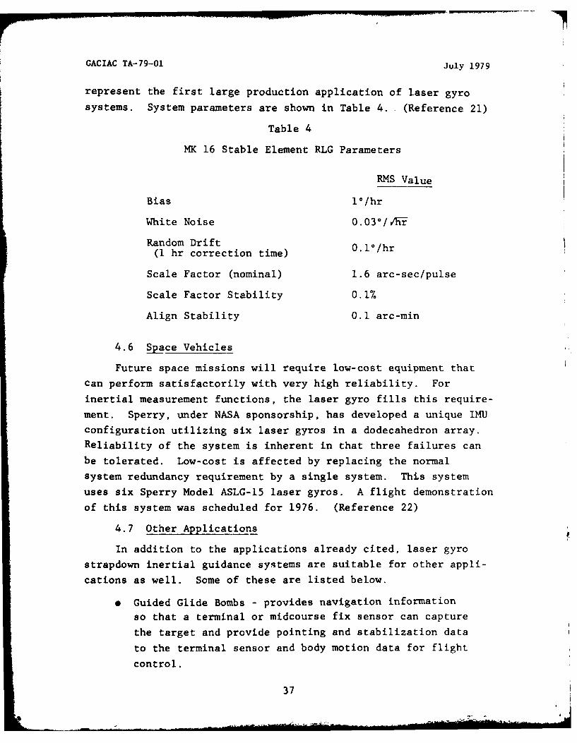
represent the first large production application of laser gyro
systems. System parameters are shown in Table 4. (Reference 21)
Table 4
MK 16 Stable Element RLG Parameters
RMS Value
Bias 10 /hr
White Noise 0.03°/1vi-
Random Drift(1 hr correction time) 0"l°/hr
Scale Factor (nominal) 1.6 arc-sec/pulse
Scale Factor Stability 0.1%
Align Stability 0.1 arc-min
4.6 Space Vehicles
Future space missions will require low-cost equipment thatcan perform satisfactorily with very high reliability. For
inertial measurement functions, the laser gyro fills this require-
ment. Sperry, under NASA sponsorship, has developed a unique IMU
configuration utilizing six laser gyros in a dodecahedron array.
Reliability of the system is inherent in that three failures can
be tolerated. Low-cost is affected by replacing the normal
system redundancy requirement by a single system. This system
uses six Sperry Model ASLG-15 laser gyros. A flight demonstration
of this system was scheduled for 1976. (Reference 22)
4.7 Other Applications
In addition to the applications already cited, laser gyro
strapdown inertial guidance systems are suitable for other appli-
cations as well. Some of these are listed below.
* Guided Glide Bombs - provides navigation information
so that a terminal or midcourse fix sensor can capture
the target and provide pointing and stabilization data
to the terminal sensor and body motion data for flight
control.
37
GACIAC TA-79-01 July 1979
" Torpedos - provides body motion and heading data for
torpedo trajectory stabilization and control.
" Aircraft Attitude and Heading Reference - in conjunction
with true air speed and magnetic heading sensors providesall necessary body rate and body acceleration sensingalong with attitude information. May also be used for
input data to Synthetic Aperture Radar signal processing
systems where vehicle motion is required.
" Spin Rate Sensor - this application for missile control
makes use of the wide dynamic range capability of the
laser gyro.
* Cruise Missiles - laser gyro inertial guidance systems
can supply data required for guidance, autopilot, and
other reference functions.
" Spacecraft Attitude Reference - provides highly accurate
attitude control for applications such as the NASA space
telescope and other satellites.
" Pointing and Tracking - provides stabilization information
for systems requiring accurate pointing, such as largeantennas, guns, telescopes, or lasers.
38
GACIAC TA-79-01 July 1979
5. COMPANIES DEVELOPING LASER GYROSCOPES
In addition to Honeywell and Sperry, other companies are
involved in laser gyro R & D. Among the principal U.S. companies
are Litton, Northrup, Raytheon, Rockwell, Singer/Kearfott, andHamilton Standard. Much additional work is being conducted
through Government research laboratories. Both four wave and twowave systems are being investigated and developed.
Only Honeywell, at this time, appears ready for laser gyroproduction. Currently it is building a 4,400 square foot manu-
facturing facility capable of producing 30 laser gyros per month.The new facility has been designed to be expandable to make morethan 300 laser gyros per month.
'"
39
GACIAC TA-79-01 July 1979
6. CONCLUSION
The foregoing sections have attempted to define the basicsof ring laser gyroscopes. Historical background and development,
theory, mechanization, errors, biasing, alternatives and applica-
tions have been presented. A chronological bibliography of some
of the significant literature is also presented. As ring laser
gyroscope technology has matured over the past decade and a half,a large amount of literature has been written on the subject, with
most of it openly available.
One subject that has not yet been addressed, however, is
the current state of the art of laser gyroscopes. A review of
efforts of domestic developers and producers is needed to provide
information on current specifications, mechanical and electrical
characteristics, unit costs, test results and data, and system
applications.
Lastly, the ring laser gyroscope shows great promise as a
future position measuring device; however, many problems have yet
to be solved before it has widespread use in tactical weapons.
40

GACIAC TA-79-01 July 1979
REFERENCES
1. Sorg, H.W., "From Serson to Draper - Two Centuries of Gyro-scopic Development," Navigation: Journal of the Instituteof Navigation, Vol. 23,N.4 .313-3-2, Winter 1976-77.
2. Post, E.J., "Sagnac Effect," Reviews of Modern Physics,Vol. 39, No. 2, pp. 475-493, Apri1T9q7.
3. Michelson, A.A., Gale, H.G., "The Effect of the Earth'sRotation on the Velocity of Light," The AstrophysicalJournal, Vol. 61, No. 3, pp. 140-145-ApriIM925.
4. Macek, W.M., Davis Jr; D.T.M., "Rotation Rate Sensing withTraveling-Wave Ring Lasers," Applied Physics Letters, Vol. 2,No. 3, pp. 67-68, 1 February - .
5. Coccoli, J.D., An Overview of Laser Gyros, Charles StarkDraper Lab., Inc., Cambridge, Mass., August 1978.
6. Savage, P.G., "Strapdown Sensors," AGARD Lecture SeriesNo. 95, Strap-Down Inertial Systems, NATO, May 1978.
7. Morrison, R.F., Levinson, E; ,Bryant Jr., B.L., "The SLIC-7Laser Gyro Inertial Guidance System," NAECON '77 Record,NAECON Conference, Dayton, Ohio, May 1977.
8. Aronowitz, F., "The Laser Gyro," Laser Applications, Vol. 1,Academic Press, New York, 1971.
9. Killpatrick, J., "The Laser Gyro," IEEE Spectrum, pp. 44-45,October 1967.
10. Matthews, J.B. and Bates Jr., D.R., "Future Applications ofLow Cost Strapdown Laser Inertial Navigation Systems,"AGARD Conference Proceedings No. 220, Applications ofAd-n-ces In-Navigation-to iGuiida--ceand Control, NATO,May 1977.
11. Ezekiel, S. and Balsamo, S.R., "Passive Ring Resonator LaserGyroscope," Applied Physics Letters, Vol. 30, No. 9,1 May 1977.
12. Stowell, W.K., McAdory, R.W. and Ziernicki, R., "Air ForceApplications for Optical Rotation Rate Sensors," Proc. ofthe Society of Photo-Optical Instrumentation Engin-e-rs-,Vol. 157, San Diego, California, 30-31 August 197n'.
13. Savage, P.G., "Laser Gyros in Strapdown Inertial NavigationSystems," Proc. of the IEEE Position Location and Navigation
4Y1PoSium, a Diego 0
41

GACIAC TA-79-01 July 1979
14. Mathews, Jr., M.A., "Laser Inertial Navigator to Be FlightTested," ICAO Bulletin, pp. 18-21, March 1978.
15. Laser Gyro Reflections, Issue No. 4, Advanced DevelopmentProgram ice- Naval Air Systems Command, June 1978.
16. San Giovanni, Jr., C., "Performance of a Ring Laser Strap-down Attitude and Heading Reference for Aircraft," Proc. ofthe American Institute of Aeronautics and AstronauticsGuidance and Control Conference, Palo Alto, California,7-9 Augus iT91.
17. San Giovanni, Jr., C., "Performance of a DifferentialOmega-Ring Laser Aircraft Navigator," NAECON '78 Record,NAECON Conference, Dayton, Ohio, May 178.
18. Honeywell, Avionics Division, St. Petersburg, Florida.
19. Morrison, R.F., Levinson, E. and McAdory, R.W., "The SLIC-15Laser Gyro IMU for Midcourse Missile Guidance," Proc. of theInstitute of Navigation National Aerospace Symposium,'risterPennsylvania, April 1976.
20. Levinson, E., "Laser Gyro Strapdown Inertial System Applica-tions," AGARD Lecture Series No. 95, Strap-Down InertialSystems, NATO, May 1978.
21. Morrison, R.F. and Strang, C.B., "A Missile Laser Gyro RateSensor," Proc. of the American Institute of Aeronautics andAstronautics Guidance and Control Conference, San Diego,Cal iforni7a, 16-18Augus t-1'76.
22. Thomson, K., Schwartz, B., San Giovanni, Jr., C., Young, E.A.and Howie, G.R., "The Laser Gyro MK16 MOD 11 ShipboardStable Element," NAECON '78 Record, NAECON Conference,Dayton, Ohio, May 1978.
23. Morrison, R.F. and Walls, B., "Space Tug Laser Gyro IMU,"Proc. of the American Astronautical Society, 21st AnnualMeeting, 26-28 August 75
42

GACIAC TA-79-01 July 1979
BIBLIOGRAPHY
1. Michelson, A.A. and Gale, H.G., "The Effect of the Earth'sRotation on the Velocity of Light," The AstrophysicalJournal, Vol. 61, No. 3, April 1925.
2. Adler, R., "A Study of Locking Phenomena in Oscillators,"Proceedings of the I.R.E. and Waves and Electrons, Vol. 34,Juni146.
3. Rosenthal, A.H., "Regererative Circulatory Multiple-BeamInterferometry for the Study of Light-Propagation Effects,"Journal of the Optical Society of America, Vol. 52, No. 10,October 1962.
4. Macek, W.M. and Davis, Jr., D.T.M., "Rotation Rate Sensingwith Traveling-Wave Ring Lasers," Appl4ed Physics Letters,Vol. 2, No. 3, February 1963.
5. Proctor, E.K., "On the Minimum Detectable Rotation Rate fora Laser Rotation Sensor," Proc. IEEE, Vol. 51, July 1963.
6. Heer, C.V., "Resonant Frequencies of an ElectromagneticCavity in an Accelerated System of Reference," The PhysicalReview, Vol. 134, No. 4A, 18 May 1964.
7. Lamb, Jr., W.E., "Theory of an Optical Maser," PhysicalReview, Vol. 134, No. 6A, 15 June 1964.
8. Collins, Jr., S.A., and Davis, Jr., D.T.M., "Modes in aTriangular Ring Optical Resonator," Applied Optics, Vol. 3,No. 11, November 1964.
9. Smith, R.C. and Watkins, L.S., "A Proposed Method forReducing the Locking Frequency of a Ring Laser," Proc. IEEE,Vol. 53, February 1965.
10. Itzkan, I., "A Circular Ring Laser," Proc. IEEE, Vol. 53,February 1965.
11. Rigrod, W.W., "The Optical Ring Resonator," The Bell SystemTechnical Journal, Vol. 44, May 1965.
12. Aronowitz, F., "Theory of a Traveling-Wave Optical Maser,"Physical Review, Vol. 139, No. 3A, 2 August 1965.
13. Rigrod, W.W., "Bistable Traveling-Wave Oscillations of IonRing Laser," IEEE Journal of Quantum Electronics, Vol. QE-l,No. 7, October 1965.
14. Belenov, E.M., Markin, E.P., Morozov, V.N. and Oraevskii,A.N., "Interaction of Traveling Waves in a Ring Laser,"JETP Letters, Vol. 3, 1966.
43
GACIAC TA-79-01 July 1979
15. Aronowitz, F. and Collins, R.J., "Mode Coupling Due to Back-scattering in a He-Ne Traveling-Wave Ring Laser," AppliedPhysics Letters, Vol. 9, No. 1, 1 July 1966.
16. Lee, P.H. and Atwood, J.G., "Measurement of SaturationInduced Optical Nonreciprocity in a Ring Laser Plasma,"IEEE Journal of Quantum Electronics, Vol. QE-2, No. 8,August 1966.
17. Christiansen, D., "Laser Gyro Comes in Quartz," Electronics,Vol. 39, 19 September 1966.
18. de Lang, H., "Derivation of the Relation Between Two WeaklyCoupled Nonlinear Optical Oscillators," Applied PhysicsLetters, Vol. 9, No. 5, 1 September 1966.
19. Klass, P.J., "Laser Unit Challenges Conventional Gyros,"Aviation Week and Space Technology, 12 September 1966.
20. Thomson, A.F.H. and King, P.G.R., "Ring-Laser Accuracy,"Electronics Letters, Vol. 2, No. 11, November 1966.
21. Hutchings, T.J., Winocur, J., Durrett, R.H., Jocobs, E.D.and Zingery, W.L., "Amplitude and Frequency Characteristicsof a Ring Laser," Physical Review, Vol. 152, No. 1,2 December 1966.
22. Tang, C.L. and Statz, H., "Phase-Locking of Laser Oscillatorsby Injected Signal," Journal of AppLied Physics, Vol. 38,No. 1, January 1967.
23. Schwartz, B., "Strapdown Inertial Navigation Systems,"Sperry Engineering Review, Vol. 20, January 1967.
24. Klimontovich, Yu.L., Kuryatov, V.N. and Landa, P.S., "WaveSynchronization in a Gas Laser with a Ring Resonator,"Soviet Physics JETP, Vol. 24, No. 1, January 1967.
25. Post, E.J., "Sagnac Effect," Reviews of Modern Physics,Vol. 39, No. 2, April 1967.
26. Killpatrick, J., "The Laser Gyro," IEEE Spectrum,October 1967.
27. Podgorski, T.J. and Aronowitz, F., "Langmuir Flow Effectsin the Laser Gyro," IEEE Journal of Quantum Electronics,Vol. QE-4, No. 1, January 1968.
28. Bass, M., Statz, H. and deMars, G.A., "Suppression ofClose-Lying Modes in Ring Lasers and Related Devices,"Journal of Applied Physics, Vol. 39, No. 8, July 1968.
29. Hetherington, A., Burrell, G.J. and Moss, T.S., Propertiesof He-Ne Rin Lasers at 3.39 Microns, Rept. No. -- 6U99,
44

GACIAC TA-79-01 July 1979
AD 859 774, Royal Aircraft Establishment, Farnborough,England, May 1969.
30. Gibson, W.H., The Application of a Solid State Helium-NeonGas Laser to Miss- Guidance, AD 713 527, U.S. ArmyAdvanced Ballistic Missile Defense Agency. Huntsville,Alabama, 1970.
31. Aronowitz, F. and Collins, R.J., "Lock-In and Intensity-Phase Interaction in the Ring Laser," Journal of AppliedPhysics, Vol. 41, No. 1, January 1970.
32. Hutchinson, I.N. and Inglima, P.K., An Improved Ring LaserRate Sensor for Use in Strapdown InertT- 1Systems, Ameri-canT-n-ltut-6 of ronautics an--Astronautcs, Augus t 1970.
33. Aronowitz, F., "The Laser Gyro," Laser Applications, AcademicPress, New York, Vol. 1, 1971.
34. Vescial, F., Watson, O.L. and Zingery, W.L., Ring LaserTechniques Investigation. Vol. 1, Rept. No. AFAL-TR-71-339,
-59 U76 Air For c viLAvion icsaboratory, Wright-PattersonAFB, Ohio, November 1971.
35. The Honeywell Laser Gro, Honeywell Rept. No. 7040-3332,Honeyl7,---I-.7-T-6vernment and Aeronautical Products Division,Minneapolis, Minnesota, September 1973.
36. Morrison, R.F., Garret, H. and Walls, B., "A Strapdown LaserGyro Navigator," NAECON '74 Record, NAECON Conference,13-15 May 1974.
37. Shcherbakov, Y.A., A Method for Determining the Error of aLaser Gyroscope When Measuring te Turning n- oia --
Moving Base, Rept. No. FTD-HT-23238-74, AD 783 970,oreign Technology Division, Wright-Patterson AFB, Ohio,
July 1974.
38. Mochalov, A.V. and Mynbaev, D.K., Dependence of the CaptureZone of a Laser Gyroscope on Its Emiion Frequency Differ-ence, Rpt. No. FTD-HT-23-2317-74,' AD 783 993, ForeignTe-hnology Division, Wright-Patterson AFB, Ohio, July 1974.
39. Sperry Model A SLG 15 Laser Gyro, Operation, Service andPerformance Mnual, Rept. No. 4284-20104-1, Contract No.
-226 -7C--881,AD B004 888L, Sperry Gyroscope, GreatNeck, New York, November 1974.
40. Savage, P.G., "The Honeywell Laser Inertial NavigationSystem (LINS)," NAECON '75 Record, NAECON, Dayton, Ohio,1975.
45

GACIAC TA-79-01 July 1979
41. Pasik, D.J., Morris, J., Gneses, M.I. and Taylor, G.R.,"A Ring Laser Gyro Strapdown Inertial Navigation SystemTest," AIAA Paper No. 75-1095, AIAA Guidance and ControlConf: ,Boston, Mass., 20-22 Aug~uist -7.
42. Morrison, R.F. and Walls, B., "Space Tug Laser Gyro IMU,"Proc. American Astronautical Society, 2 1st Annual Meeting,26 - August i19-75.
43. Ball, W.F., "The Application of Ring Laser Gyro Technologyto Low-Cost Inertial Navigation," AGARD Conference Proceed-ings No. 176, Medium Accuracy Low- 7gi ---
n-defjo-r-f7-Norway, 8-12 September 1975.
44. Henning, H.B., Polarization Uses in Laser G yros, AD A022 212,Rand Corp. , Santa Monca,- Cai-f 7 -ctoT 7Tr- .
45. Lianis, G. and Whicker, D., "Electromagnetic Phenomena inRotating Media," Arch. for Rotational Mechanics and Analysis,Vol. 57, No. 4, i 75. . .
46. Morrison, R.F., Levinson, E. and McAdory, R.W., "The SLIC-15Laser Gyro IMU for Midcourse Missile Guidance." Proc.Institute of Navigation National Aerospace Sympoium,
47. Vali, V. and Shorthill, R.W., "Fibre Ring Interferometer,"AppliedOptics, Vol. 15, No. 5, May 1976.
48. Morrison, R.F. and Strang, C., "A Missile Laser Gyro RateSensor," Proc. of Aerican Institute of Aeronautics andAstronautics GUifance and Contr6TConference, San Diego,Ca-Tfr6rWY n ia,-4 i--Augu t-~ 1-976. -
49. Kuznetsov, G.M., Segeyev, M.A. and Eymbke, V.V., AzimuthDetermination by Laser Gyroscope, Rept. No. FTD-U---(-
--T3T--V - 1 --6E Foreign Technology Division,Wright-Patterson AFB, Ohio, October 1976.
50. Savage, P.G., "Laser Gyros in Strapdown Inertial NavigationSystems," Proc. IEEE Position Location and NavigationS~__d_ ymosu, aDiego, Ci fon a , 1 -3 N6 -m5-e -T97_6-.yp os iurn, a7 i ri1niiY-e-g 6
51. Sanders, V., "High-Precision Reflectivity MeasurementTechnique for Low-Loss Laser Mirror," Apjpled Optics,Vol. 16, No. 1, January 1977.
52. Vali, V. and Shorthill, R.W., "Ring Interferoteter 950 mLong," Applied Optics, Vol. 16, No. 2 ,February 1977.
53. Johnston, J.V., Pugh, R.E. and Tarrant, D.W, Sperry LaserGr Navigation System, Rept. No. TG-77-5, AD B18 623,
-Aiiir'MTsl--Research and Development Command, RedstoneArsenal, Alabama, 22 February 1977.
46
GACIAC TA-79-01 July 1979
54. Ezekiel, S. and Balsamo, S.R., "Passive Ring Resonator LaserGyroscope," Applied Physics Letters, Vol. 30, No. 9,I May 1977.
55. Matthews, J.B. and Bates, Jr., D.R., "Future Applications ofLow Cost Strapdown Laser Inertial Navigation Systems." AGARDConference Proceedings No. 220, Applications of Advances inNavigation to Guidance and Control, NATO, May 1977.
56. Morrison, R.R., Levinson, E. and Bryant, Jr., B.L., "TheSLIC-7 Laser Gyro Inertial," NAECON '77 Record, NAECON Con-ference, Dayton, Ohio, 17-19 May 1977.
57. Feldman, J. and Helfant, S., "A Laser Gyro Evaluation Planand Test Results," NAECON '77 Record, NAECON Conference.Dayton, Ohio, l7-19HRay T77.I
58. Grant, D., Hambenne, J., Hutchings, T., Sanders, V. andScully, M., "A Multioscillator (Four-Mode) Ring Laser GyroReport," NAECON '77 Record, NAECON Conference, Dayton, Ohio,17-19 May-717.
59. Mueller, C.E., Phelps, R.K. and Scheidenhelm, R., "TacticalGuidance Requirements for Strapdown Inertial," NAECON '77Record, NAECON Conference, Dayton, Ohio, 17-19 May 1977.
60. Perlmutter, L.D., Kraemer, J.W. and Roessler, N.J., "Strap-down Inertial Sensor Requirements for Tactical Guidance,"NAECON '77 Record, NAECON Conference, Dayton, Ohio,17-19 May 1977.
61. Klass, P.J., "Laser Gyros Find Increased Application,"Aviation Week and Space Technology, 25 July 1977.
62. Fedorov, B.F., Sheremetyev, A.G. and Umnikov, V.N. OpticalQuantum Gyroscope, Rept. No. FTD-ID(RS)T-1754-77, AD-025 384L,Foreign Technology Division, Wright-Patterson AFB, Ohio,October 1977.
63. Savage, P.G., "Calibration Procedures for Laser Gyro Strap-down Inertial Navigation Systems," Proc. 9th Annual Electro-Optics/Laser Conference and Exhibition, Anaheim, California,25-27 October 1977.
64. San Giovanni, Jr., C., "Performance of a Differential Omega-Ring Laser Strapdown Aircraft Navigator," NAECON '78 Record,NAECON Conference, Dayton, Ohio, May 1978.
65. Thomson, K., Schwartz, B., San Giovanni, Jr., C. Young, E.and Howie, G., "The Laser Gyro MK16 MOD 11 Shipboard StableElement," NAECON '78 Record, NAECON Conference, Dayton, Ohio,May 1978.
47
GACIAC TA-79-01 July 1979
66. Nicholas, J.J. and Youin , E.A., ShipbardApplications ofLaser Gyros for Navigation and stabilizat[inSperry Gyroscope,
67. Mathews, M.A., Jr., "Laser Inertial Navigator to Be FlightTested," ICAO Bulletin, March 1978.
68. Levinson, E. , "Laser-Gyro Strapdown Inertial System Applica-tions," AGARD Lecture Series No. 95, Strapdown InertialSystems, IATO0, May 1978.
69. Savage, P.G., "Strapdown Sensors," AGARD Lecture SeriesNo. 95, Strapdown Inertial SytmM , ~ 98
70. Garg, S.C., Morrow, L.D., Mamen, R., "Strapdown NavigationTechnology: A Literature Survey," Journal of Guidance andControl, Vol. 1, No. 3, May-June 197-
71. Coccoli, J.D., An Overview of Laser Gyros, C.S. Draper Lab.,Inc. , Cambridge71_Miis., AKugE197TW.
72. San Giovanni, Jr., C., "Performance of a Ring Laser StrapdownAttitude and Heading Reference for Aircraft," Proc. ofAmerican Institute of Aeronautics and Astronautics GCuidance
and Control Cnife-rence, Palo Alto, Callfrii 7-9 AugiuisF978.73. Engebretson, H.J., Ring Laser Gyro Program at Rockwell,
Rept. No. X78-928/201, Rockwell International, Ele-ctronicSystems Group, Anaheim, California, 24 August 1978.
74. "Laser Inertial Rotation Sensors," Proc. of the SceyofPhoto-Optical Instrumentation Engineers, Vol. 157, San Diego,CT2Lifornia, 30-31 Adgust 1978.
75. Hutchings, L., Development and Test of a Small BodyDithered Laser UyroLitton systems, Inc., Woodland Hills,California.
48

TECHNOLOGY ASSESSMENT OF RING LASER GYROSCOPES Date: July 1979
INSTRUCTIONS TO THE USER: The above publication was produced by the Tactical WeaponsGuidance and Control Information Analysis Center, an information Analysis Centeradministratively managed and funded by the Defense Logistics Agency (DLA). Since it isthe policy of DoD and DLA that this Center be responsive to the scientific and technicalinformation needs of the Defense community, we would appreciate it if you would completethis questionnaire and return it to us. In that way we can use your evaluation and theother information you provide us to more effectively guide this Center in meeting yourneeds for scientific and technical information and also to assess the value of thisCenter to DoD.
1. Name 2. Organization
3. Job Title 4. Field of Specialization
5. Please evaluate this publication (Check off one or more as applicable).
Information irrelevant Difficult to useInformation relevant Use it oftenInformation outdated Hardly use itInformation timely Overall very useful to my jobInformation technically excellent Overall not very useful to my jobInformation technically satisfactory Got my money's worthInformation technically unsatisfactory Did not get my money's worthEasy to use Other_______________
6. Benefits you gained by using this publication.
a. How often would you estimate that you have consulted or will consult this
productyer day, week, month, or year (Circle one).
b. What is the average amount of time that it would take you to otherwise locate
this information yourself?________________
c. What do you estimate this time would cost you?____________
d. Can you think of instances in which the information contained in this producthelped to save/avoid costs on a project/task? (e.g., eliminated or shorteneda test, substituted material or components) Please list these projects/tasks(e.g., Minuteman III/flight test instrumentation system) individually alongwith estimated costs saved/avoided.
e. Intangible benefits (please describe).
7. If you think any aspects of this publication to be inadequate, how can it beimproved?
(Staple Here)
(Fold on Dotted Lines)
------------------------------------------------------------ ------------a
DEFENSE LOGISTICS AGENCYCameron Station
Alexandria, Virginia 22314 POSTAGE AND FEES PAIDDEFENSE LOGISTICS AGENCY
DOD 300Official Business
Penalty for Private Use, $300
DEFENSE LOGISTICS AGENCYAttn: DSAH-SCT
4D660Cameron StationAlexandria, Virginia 22314
8. Please tell us about your needs for scientific and technical information.What organized body of information would help you in doing your job? Please
include such specifics as the materials, components, devices, or properties a(electrical, magnetic, etc.) for which you need information. Also the formatthat would be most useful to you; forecast of number of years that this bodyof information will be required by the Defense community; forecast of totalsavings to you if this information was readily available.
. .
TECHNOLOGY ASSESSMENT OF RING LASER GYROSCOPES Date: July 1979
INSTRUCTIONS TO THE USER: The above publication was produced by the Tactical WeaponsGuidance and Control Information Analysis Center, an Information Analysis Centeradministratively managed and funded by the Defense Logistics Agency (DLA). Since it Isthe policy of DoD and DLA that this Center be responsive to the scientific and technicalinformation needs of the Defense community, we would appreciate it if you would complete
ther questionnaire and return it to us. In that way we can use your evaluation and theohrinformation you provide us to more effectively guide this Center in meeting your
needs for scientific and technical information and also to assess the value of thisCenter to DoD.
1. Name 2. Organization
3. Job Title 4. Field of Specialization
5. Please evaluate this publication (Check off one or more as applicable).
Information irrelevant Difficult to useInformation relevant Use It oftenInf ormat ion outdated liardly use itInformation timely Overall very useful to my jobInformation technically excellent Overall not very useful to my jobInformation technically satisfactory Got my money's worthInformation technically unsatisfactory Did not get my money's worthEasy to use Other___________
6. Benefits you gained by using this publication.
a. How often would you estimate that you have consulted or will consult this
product er day, week, month, or year (Circle one).
b. What Is the average amount of time that it would take you to otherwise locatethis information yourself?________________
c. What do you estimate this time would cost you?____________
d. Can you think of instances in which the information contained in this producthelped to save/avoid costs on a project/task? (e.g., eliminated or shorteneda test, substituted material or components) Please list these projects/tasks(e.g., Minuteman Ill/flight test instrumentation system) individually alongwith estimated costs saved/avoided.
e. Intangible benefits (please describe).
17. if you think any aspects of this publication to be inadequate, how can It bet improved?

(Staple Here)
(Fold on Dotted Lines)
------------------------------------------------------------------------ I
DEFENSE LOGISTICS AGENCYCameron Station
Alexandria, Virginia 22314 POSTAGE AND FEES PAIDDEFENSE LOGISTICS AGENCY
DOD 300Official Business
Penalty for Private Use, $300
DEFENSE LOGISTICS AGENCYAttn: DSAH-SCT
4D660Cameron StationAlexandria, Virginia 22314
-------------------------------------------------------------------------------------------------
8. Please tell us about your needs for scientific and technical information.What organized body of information would help you in doing your Job? Pleaseinclude such specifics as the materials, components, devices, or properties(electrical, magnetic, etc.) for which you need information. Also the formatthat would be most useful to you; forecast of number of years that this bodyof information will be required by the Defense comunity; forecast of totalsavings to you if this information was readily available.
I.
DATE
Related Documents