Diamond and Related Materials 8 (1999) 1183–1192 Review Techniques for filtering graphite macroparticles in the cathodic vacuum arc deposition of tetrahedral amorphous carbon films M. Hakovirta a,b, *, V.-M. Tiainen b, P. Pekko b a Material Science and Tech. Division (MST-8), Mail Stop K762, Los Alamos National Laboratory, Los Alamos, NM, 87545USA b Department of Physics, University of Helsinki, P.O. Box 9, FIN-00014 University of Helsinki, Finland Received 4 December 1998; accepted 4 February 1999 Abstract Filtered cathodic vacuum arc (FCVA) deposition has been found to be a reliable technique for the production of high quality tetrahedral amorphous carbon films (ta-C ). These coatings can be used as protective coatings for di erent applications ranging from cutting tools to human hip joint prosthesis. The FCVA technique is widely used in di erent laboratories around the world with somewhat di erent technical implementations. A serious disadvantage in the FCVA technique is the graphite particles that are emitted from the solid graphite cathode during the arc-discharge. A variety of di erent techniques exist to diminish their production and transport. However, some of the magnetic filtering designs that are used to reduce the macroparticle transport into the substrate do not work well with high melting point cathode materials such as graphite. Although the influence of graphite particles for the ta-C coating performance in some applications is controversial, many applications demand that the produced ta-C film is practically particle-free. This is especially important in corrosion resistance, electrical and optical applications. In this paper an introduction to di erent FCVA devices is presented. Di erent magnetic filtering designs together with control techniques for macroparticle generation have been reviewed and their advantages and disadvantages in the plasma transport and particle filtering e ciency have been discussed. © 1999 Elsevier Science S.A. All rights reserved. Keywords: Cathodic vacuum arc; Graphite macroparticles; Filtering; Tetrahedral amorphous carbon 1. Introduction as magnetron, DC and RF-sputtering, hydrocarbon ion beam and plasma immersion ion processing (PIIP), that can be used for the production of diamond-like films The filtered cathodic vacuum arc (FCVA) process like amorphous carbon (a-C ) and hydrogenated amor- has been proven to be a reliable technique that can phous carbon (a-C:H ). Usually these films have inferior produce extremely high quality (80% sp3 bonding frac- properties [11–13] compared to ta-C films, which may tion) ta-C coatings [1–3]. Also recently close to 90% limit their use in some applications. However, these sp3 bonding fractions have been reported for FCVA techniques have the advantage that they can be expanded deposited ta-C films [4]. These coatings have physical more easily into large production scale and thus the cost properties very close to natural diamond and therefore of the coatings can be kept more attractive for industry. they are ideal for many applications that demand unique Since the properties of ta-C coatings are in many performance in corrosion and wear resistance [5–7]. applications better, the development of a larger scale The ta-C coatings also have properties that make them FCVA system is under continuous progress. One solu- very attractive for many optical and electrical applica- tion can be the combination of PIIP and FCVA tions [8–10]. The basic FCVA system is an inexpensive techniques. and straightforward system to build and therefore an Although long term development of di erent FCVA attractive technique for the production of high quality devices has generated a technique that can produce ta-C ta-C films. There are other deposition techniques such films with the highest reported quality (sp3 bonding fraction, hardness, wear resistance, etc.) [14,15], there * Corresponding author. Fax: +1-505-665-3935. E-mail address: [email protected] (M. Hakovirta) still exists a problem with graphite macroparticles. The 0925-9635/99/$ – see front matter © 1999 Elsevier Science S.A. All rights reserved. PII: S0925-9635(99)00111-9

Welcome message from author
This document is posted to help you gain knowledge. Please leave a comment to let me know what you think about it! Share it to your friends and learn new things together.
Transcript
Diamond and Related Materials 8 (1999) 1183–1192
Review
Techniques for filtering graphite macroparticles in the cathodicvacuum arc deposition of tetrahedral amorphous carbon films
M. Hakovirta a,b, *, V.-M. Tiainen b, P. Pekko ba Material Science and Tech. Division (MST-8), Mail Stop K762, Los Alamos National Laboratory, Los Alamos, NM, 87545USA
b Department of Physics, University of Helsinki, P.O. Box 9, FIN-00014 University of Helsinki, Finland
Received 4 December 1998; accepted 4 February 1999
Abstract
Filtered cathodic vacuum arc (FCVA) deposition has been found to be a reliable technique for the production of high qualitytetrahedral amorphous carbon films (ta-C). These coatings can be used as protective coatings for different applications rangingfrom cutting tools to human hip joint prosthesis. The FCVA technique is widely used in different laboratories around the worldwith somewhat different technical implementations. A serious disadvantage in the FCVA technique is the graphite particles thatare emitted from the solid graphite cathode during the arc-discharge. A variety of different techniques exist to diminish theirproduction and transport. However, some of the magnetic filtering designs that are used to reduce the macroparticle transportinto the substrate do not work well with high melting point cathode materials such as graphite. Although the influence of graphiteparticles for the ta-C coating performance in some applications is controversial, many applications demand that the producedta-C film is practically particle-free. This is especially important in corrosion resistance, electrical and optical applications. In thispaper an introduction to different FCVA devices is presented. Different magnetic filtering designs together with control techniquesfor macroparticle generation have been reviewed and their advantages and disadvantages in the plasma transport and particlefiltering efficiency have been discussed. © 1999 Elsevier Science S.A. All rights reserved.
Keywords: Cathodic vacuum arc; Graphite macroparticles; Filtering; Tetrahedral amorphous carbon
1. Introduction as magnetron, DC and RF-sputtering, hydrocarbon ionbeam and plasma immersion ion processing (PIIP), thatcan be used for the production of diamond-like filmsThe filtered cathodic vacuum arc (FCVA) processlike amorphous carbon (a-C) and hydrogenated amor-has been proven to be a reliable technique that canphous carbon (a-C:H). Usually these films have inferiorproduce extremely high quality (80% sp3 bonding frac-properties [11–13] compared to ta-C films, which maytion) ta-C coatings [1–3]. Also recently close to 90%limit their use in some applications. However, thesesp3 bonding fractions have been reported for FCVAtechniques have the advantage that they can be expandeddeposited ta-C films [4]. These coatings have physicalmore easily into large production scale and thus the costproperties very close to natural diamond and thereforeof the coatings can be kept more attractive for industry.they are ideal for many applications that demand uniqueSince the properties of ta-C coatings are in manyperformance in corrosion and wear resistance [5–7].applications better, the development of a larger scaleThe ta-C coatings also have properties that make themFCVA system is under continuous progress. One solu-very attractive for many optical and electrical applica-tion can be the combination of PIIP and FCVAtions [8–10]. The basic FCVA system is an inexpensivetechniques.and straightforward system to build and therefore an
Although long term development of different FCVAattractive technique for the production of high qualitydevices has generated a technique that can produce ta-Cta-C films. There are other deposition techniques suchfilms with the highest reported quality (sp3 bondingfraction, hardness, wear resistance, etc.) [14,15], there* Corresponding author. Fax: +1-505-665-3935.
E-mail address: [email protected] (M. Hakovirta) still exists a problem with graphite macroparticles. The
0925-9635/99/$ – see front matter © 1999 Elsevier Science S.A. All rights reserved.PII: S0925-9635 ( 99 ) 00111-9
1184 M. Hakovirta et al. / Diamond and Related Materials 8 (1999) 1183–1192
macroparticles are especially a disadvantage for such tions [23]. With the presence of a reactive backgroundgas, oxides, nitrides and carbides can also be producedproperties as corrosion resistance and optical transpar-
ency. In this paper different FCVA techniques have been [24]. Arc enhanced glow discharge units can also beused for ion-cleaning of complicated surfaces [25]. Thedescribed focusing the discussions into pulsed cathodic
arc sources. The large variety of different filtering tech- continuous plasma source design aims to minimize thedischarge current and to guarantee uniform cathodeniques has been presented and their performance in
terms of graphite macroparticle filtering efficiency and erosion in order to reduce macroparticle production (seeSection 3.2).carbon plasma transport has been discussed.
Although some metallic plasma arc devices are basedon a random arc principle, carbon plasma generatingsources usually have magnetic equipment for cathode2. Filtered cathodic vacuum arc sourcesspot control. It confines the spot to the front of thecathode and provides uniform cathode evaporation byThere are two main categories of cathodic arc devices:
continuous; and pulsed mode sources. Due to cathode controlling the spot movement. These sources usuallyneed an ignition system to maintain steady arc burningspot movement the former ones sometimes require peri-
odic re-ignition of the arc and are thus referred to as and they need very good cooling to avoid mechanicalbreakdowns due to the Ohmic heating. Some researchquasi-continuous sources. Also some pulsed units can
be operated on such high frequencies that they approach groups use sample biasing to get better adhesion andsufficient ion energy. However, increased sample biasingcontinuous mode [16 ].
Although the history of the vacuum arc devices goes may lead to film breakdowns by arcing, that is, theconductive plasma short-circuits the source to the target.back >100 years, their industrial applications did not
gain popularity until the 1960s and 1970s when the There is at least one commercial unit available based oncontinuous operation (Fig. 1) [26 ].technical difficulties were overcome. For the time being
continuous arc devices are more popular in the industry A continuous carbon plasma source for ta-C pro-duction was first presented by Aksenov et al. Theirbecause of their higher deposition rates. However, in
the case of ta-C coatings, pulsed arc discharge units solution can be considered as an archetype of stationaryvacuum arc sources. In this model the cathode washave a few clear advantages. One of the biggest is that
with pulsed arc sources it is possible to achieve high ion made of pure graphite rod and held at 20 V below thegrounded anode. Uniform cathode erosion was guaran-energies [17], which generally means better adhesion
[18]. teed by deflecting the cathodic spot with a magneticcoil. Outside of the cylindrical anode was another coilUsually the plasma beam is produced with cathodic
arc sources although several reports of anodic arc devices that created a magnetic field to steer the plasma into atoroidal plasma duct. The duct was surrounded withexist. The main benefits of anodic arcs are high degree
of ionization and reduced macroparticle formation. As coils that created a plasma deflecting magnetic field tocathodic arc devices they are suitable for high ratedeposition [19]. At least one group has made experi-ments to produce diamond-like carbon (DLC) withanodic arc. The films were grown with hydrogen as abackground gas and thus the coating had high hydrogencontent (a-C:H) [20]. Apart from solid graphite cath-odes, the carbon plasma can be generated also fromcarbon containing gases like methane. One way to createsuch plasma is to lead the gas through several cascadedcathodes towards a grounded anode [21]. The resultingamorphous carbon films are particle-free but containsignificant amounts of hydrogen (a-C:H) [22].
Competing techniques for vacuum arc sources aresputtering, laser ablation, ion-assisted deposition (IAD)and mass-selected ion beam systems of which, outsidethe scope of ta-C processing, the sputtering techniquehas been taken into large scale industrial use.
2.1. Continuous filtered cathodic vacuum arc sources
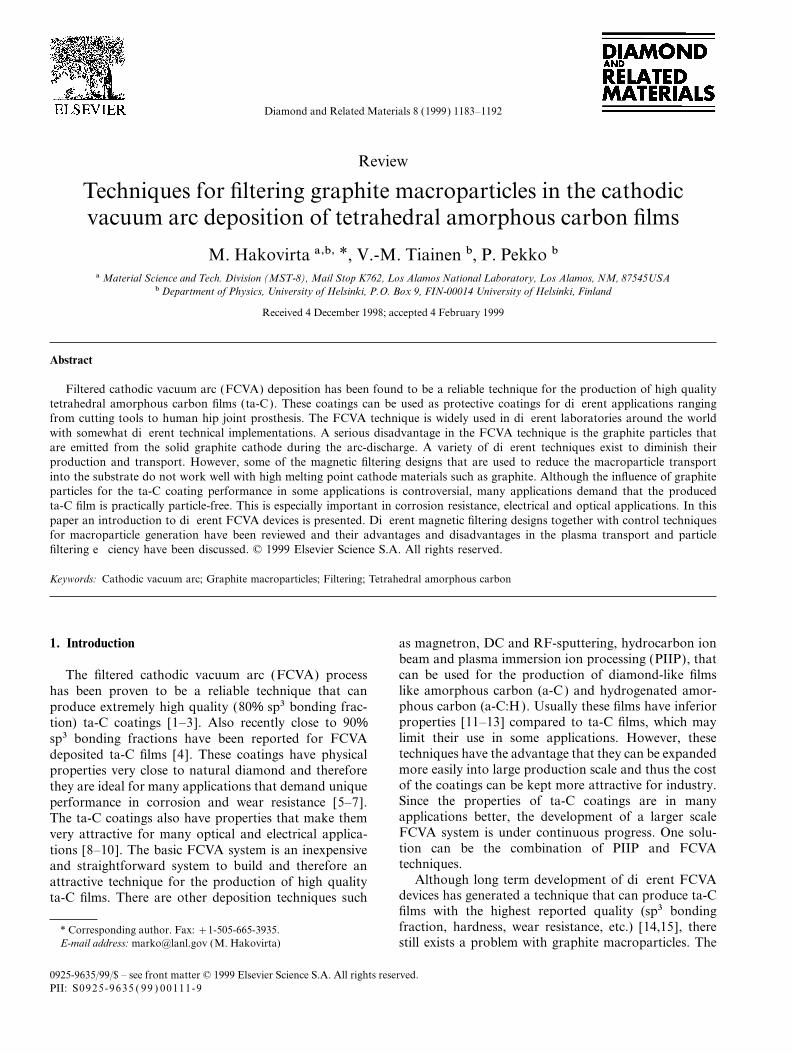
Fig. 1. Continuous arc source setup: (a) cathode; (b) insulator; (c)Continuous vacuum arc sources have been adapted stabilizing coil; (d) focusing coil; (e) ignitor with ceramic insert; (f )
cathode water cooling; and (g) anode water cooling.to industrial use mainly in metal film deposition applica-

1185M. Hakovirta et al. / Diamond and Related Materials 8 (1999) 1183–1192
guide the plasma into the target. It was also possible topositively bias the duct to create a radial electric fieldand thus improve the plasma output. At the end of theduct was a plasma beam scanning magnet to achievehomogenous coatings. The growth rate was reported tobe 1–50 A s−1 [27].
Continuous plasma sources are usually based ondiscrete arc although distributed arc systems have beenreported. In these devices, the arc is distributed over adiffuse area due to elevated cathode temperature insteadof localized cathodic spots [28]. With a distributed arcit is possible to obtain narrower ion energy distribution,use slightly higher arc voltage and simultaneously reducearc current density, amplitude of voltage oscillationsand the number of macroparticles generated [29].
2.2. Pulsed filtered cathodic vacuum arc sources
Pulsed vacuum arc sources have some clear practicaladvantages compared to continuously operating ones.Because the pulse duration is short (typically 100 ns–5 ms [16,30]) the cathode spot does not have enoughtime to drift off from the cathode. Therefore, no supple-mentary devices are needed to suppress cathode spotmovement. However, if the cathode spot occurs closeto the rim of the cathode drifting can occur. Due to thepulsed operating mode there is less Ohmic heating bothin solenoid construction and cathode and thus these Fig. 2. Schematic representation of: (a) pulsed cathodic vacuum arcsources do not require as extensive cooling arrange- unit with magnetic filtering; and (b) plasma unit in detail [36 ].ments, if any.
The most common design of the pulsed sources has plasma yield. Pulse frequency is controlled by adjustinga cylindrical cathode and a ring shaped anode to allow voltage, current and the spark gap of the breaker unit.plasma flow through the anode towards the target. The As in the original configuration, the solenoid is in seriestrigger system is usually more sophisticated than the with the cathode-anode unit so that the arc current alsoones in continuously operating sources. In addition to generates the steering magnetic field (see Fig. 2a).geometrical differences pulsed plasma sources can be Capacitors and the inductance of the solenoid definedistinguished by different ignition systems and by the the pulse duration and shape.pulse duration and shape. Another variant of the pulsed FCVA system can be
A pulsed carbon plasma source with ring shaped seen in Fig. 3. In this version the tubular anode hasanode was originally presented by Maslov et al. [31]. been split into longitudinal rods to improve the penetra-The plasma was generated by discharging a capacitor tion of the arc steering magnetic field into the plasmabank between the cathode and anode. The beam was unit (Fig. 3a). As usual, the arc unit and the solenoid
are in series. This system uses more advanced electronicsfocused with a solenoid in series with the discharge unit.to control the shape, the timing and the duration of theThe arc was initiated by a circular igniter at the workingpulse. The anode is held in ground potential and afterend of the cathode. Both the cylindrical cathode andthe trigger pulse two pulses, start and main arc pulse,the coaxial anode were made of pure graphite. Theare used to run the cathodic arc [16] (Fig. 3b). Incathode diameter was 30 mm and the cathode had ancombination with this system target biasing is also usedopening with 110 mm. Typical operation parametersto achieve sufficient ion energies [37,38].were 100–500 V charging voltage, 2000 mF capacitor
and 0.1–35 Hz pulse frequency. Sometimes this type ofplasma accelerator is referred to as an end-window
3. Macroparticlesplasma source.Anttila and co-workers have improved this system
3.1. Generationby introducing a new ignition system and a filteringsolenoid (Fig. 2) [32–35]. In addition to the arc-initiat-ing spark, the ignition unit, combined with a rotating In the FCVA plasma source used for the production
of ta-C films the cathode is made of solid graphite. Thecathode, provides cathode abrasion to ensure steady

1186 M. Hakovirta et al. / Diamond and Related Materials 8 (1999) 1183–1192
graphite in a cathodic spot, reported by Maslov et al.,are in the range 106–107 A cm−2 and 107–108 W cm−2[39]. The main plasma arc is produced when this con-ducting preliminary stage plasma will short-circuit theanode-cathode circuitry. Also, after the trigger pulse, ahigh voltage start pulse can be used to help the mainarc to initiate [16 ].
The formation of graphite macroparticles during thisprocess is unavoidable. There are several models thattry to explain the physics behind their generation. Inthe cathodic spots the temperature gradient is extremelyhigh. This can produce sufficiently high thermal stressto create thermal shock particles that are emitted fromthe cathodic spots. However, Kandah and Meunier [40]concluded recently that in a graphite cathode triggeredwith a laser pulse the thermal shock particle emissionsdo not play a large role in macroparticle creation.Another model suggests that because of the slowlymoving ions a positive electric potential will be creatednear the ionization area above the cathode surface. Thepotential difference between this area and the cathodesurface will therefore produce ion back stream pressurethat ejects macroparticles from the molten cathodicspots. This model was originally presented by McClure[41]. Furthermore, it has also been suggested that theextremely high electrical field that is created in theionization area would pull molten particles from thecathodic spot. A more recent model by Beilis et al. [42]explains that microscopic protrusions that are generatedduring the arc-discharge process and are present on thesurface of a graphite cathode (Fig. 4) could explodebecause of the high electric current that passes throughand heats them [43,44].
After the particles are emitted from the cathodesurface there are some effects that will take place. Theparticles will first encounter ion bombardment that willincrease their speed and deflect them [45,46 ]. Ion bom-bardment together with electron bombardment will alsoFig. 3. (a) Schematic presentation of cathodic arc unit with a ringheat up the graphite macroparticles and will producetrigger and a different anode construction. (b) General layout of a
FCVA system with target bias and arc pulse modulator. evaporation [45]. However, Anders has previouslyshown that the evaporation effect does not play asignificant role in macroparticle transport [47]. Thecarbon plasma ignition process can be produced by
using a short electrical trigger pulse or appropriate laser macroparticles will also encounter a negative chargingeffect from the electron bombardment [46 ].pulse into the graphite cathode. The basic construction
of the electronic ignition system is quite straightforward.Some designs have an ignition tip that is insulated from 3.2. Control of the particle generationthe cathode but is lying on top of it. Other designs usean ignition ring that is also insulated from the cathode. Understanding of the macroparticle generation pro-
cess is important if one wants to reduce the productionIn both cases, the trigger pulse produces an electricspark over the insulating gap. This pulse produces of the particles in situ. There are some effective control
techniques that can be used. Chhowalla et al. havecathodic spots that locally melt the cathode materialand evaporate it. During this process a high electron shown that by using a cathode consisting of compressed
graphite powder, the cathodic arc discharge is moredensity and electric field is created above the cathodicspot. The dense electron bombardment produces ioniza- confined within deep erosion holes and thus the macro-
particle emission is greatly reduced [48]. It has also beention of the vaporized graphite. Sufficient current andpower densities for vaporization and ionization of shown that the particle yield goes up with higher cathode

1187M. Hakovirta et al. / Diamond and Related Materials 8 (1999) 1183–1192
Fig. 4. Graphite protrusions on the surface of a graphite cathode [47].
temperature [46]. By using an effective water cooling particles traveling towards the sample. This conditioncan be obtained by using a specific shielding or by asystem for the cathode this effect can be reduced. The
high cathodic arc current is also one factor that increases magnetic steering of the plasma to a macroparticlesecure area.particle generation and speed. However, decreasing the
current can lower the deposition rate significantly. Themechanical abrasion of the cathode during the operationof the FCVA system reduces the graphite particle emis- 4.1. Magnetic filter designssion. This technique evens out the graphite protrusionsthat are one of the possible sources for the macroparticle There are various filtering designs that are used in
different research groups and commercial institutes [50–generation [42]. Also the activity center for the cathodicspots changes during the abrasion and therefore the 52]. An overview of most commonly used magnetic
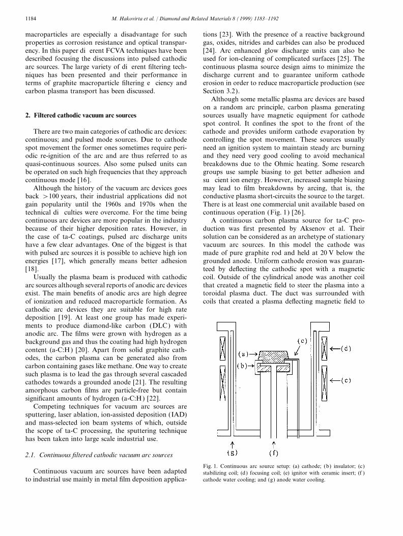
filter designs in the FCVA systems is presented in Fig. 5.local temperature on the cathode surface can be keptlower. Another advantage in this technique is that the Although most of these designs work under the
conditions where plasma is produced from low meltingcathode wears off evenly and therefore the plasma yieldand cathode lifetime can be kept considerably higher point cathode materials, some of them do not work well
in the FCVA systems that use high melting point cathodethan without the abrasion [44]. In the case of continuousvacuum arc sources a technique that produces similar materials. The main difference in the filtering of macro-
particles produced from these two different cathoderesults is the cathode spot motion by using a magneticfield [49]. This technique can be implemented with both material categories is in the particle scattering. The low
melting point materials produce particles that are mostlypermanent magnet configuration and electromagneticcoils. In the presence of a magnetic field perpendicular in a liquid state during their flight time. These particles,
when hitting the inner surface of a solenoid duct, stickto the cathode surface, the cathodic spots move circum-ferentially along the cathode surface. well into the point of contact. When the solenoid duct
is bent 90°, the plasma is magnetically steered so that itfollows its contour. The molten particles, because oftheir high inertia, will collide with the inner surface and4. Filtering of graphite particleswill, for the most part, be filtered. However, the graphitemacroparticles will stay solid and will perform multipleAfter the initial control of the macroparticle genera-
tion there are still graphite particles traveling towards scattering when hitting the solenoid duct walls. Thegraphite particles have high enough speed to performthe target [41]. The next approach is to use a proper
filtering technique. The basic idea in the filtering of many scattering events until they finally reach the target.In order to present the scattering of graphite macropar-flying graphite macroparticles is to produce a non-line-
of-sight or non-line-of-scatter condition for the graphite ticles from the inside of a duct wall, a long time exposure
1188 M. Hakovirta et al. / Diamond and Related Materials 8 (1999) 1183–1192
Fig. 5. Schematic representation of the magnetic filtering designs. (a) Straight duct; (b) toroidal duct; (c) knee duct; (d) knee duct with baffles; and(e) 90° free-standing solenoid.
(5 s) photograph (Fig. 6) was taken during the depos- and the length of the solenoid) so that the inductanceis low and thus the plasma confinement is strong enoughition of ta-C film with a toroidal duct filter.
Other designs like the 90° free-standing solenoid work to avoid the plasma erosion of the coils. This design hasalso some weakness in filtering efficiency since a fractionbetter [53]. Some of the particles can scatter from the
coils but the probability for this is much lower compared of particles have a direct passage into the target(Fig. 7a).to the knee or toroidal duct designs. The drawback is
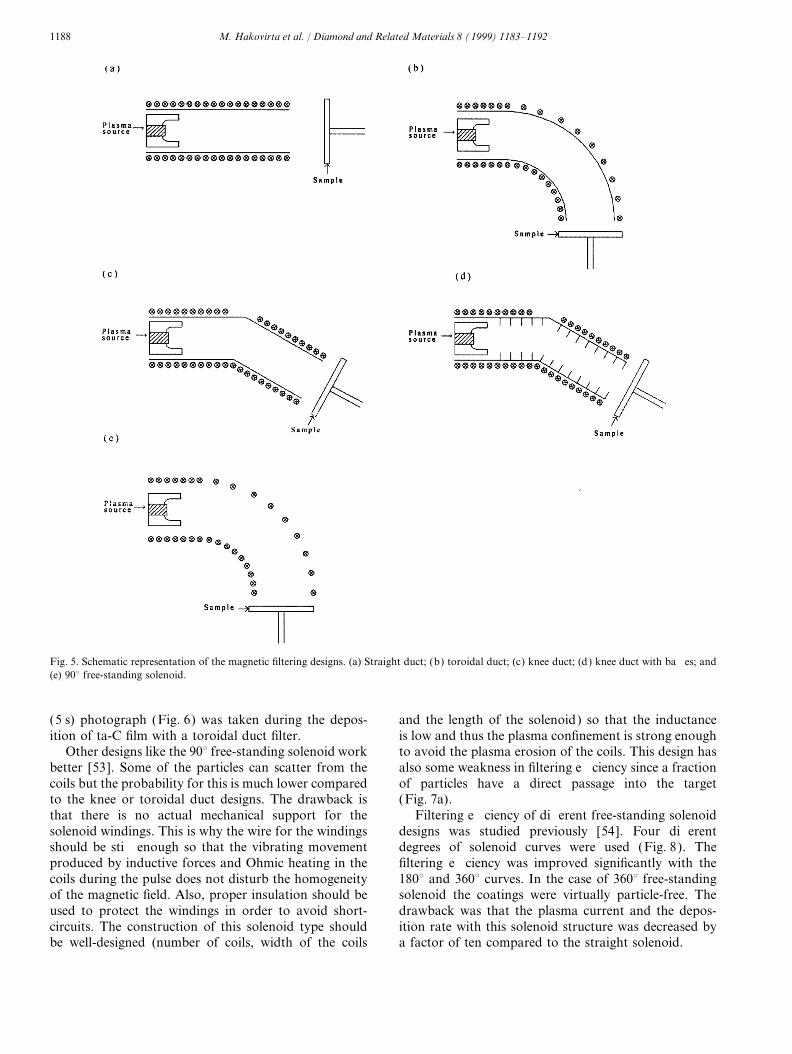
that there is no actual mechanical support for the Filtering efficiency of different free-standing solenoiddesigns was studied previously [54]. Four differentsolenoid windings. This is why the wire for the windings
should be stiff enough so that the vibrating movement degrees of solenoid curves were used (Fig. 8). Thefiltering efficiency was improved significantly with theproduced by inductive forces and Ohmic heating in the
coils during the pulse does not disturb the homogeneity 180° and 360° curves. In the case of 360° free-standingsolenoid the coatings were virtually particle-free. Theof the magnetic field. Also, proper insulation should be
used to protect the windings in order to avoid short- drawback was that the plasma current and the depos-ition rate with this solenoid structure was decreased bycircuits. The construction of this solenoid type should
be well-designed (number of coils, width of the coils a factor of ten compared to the straight solenoid.

1189M. Hakovirta et al. / Diamond and Related Materials 8 (1999) 1183–1192
Fig. 6. Graphite macroparticle trajectories in a typical toroidal ductdesign. The diameter of the duct was 7 cm.
An improvement in the filtering efficiency of the 90°free-standing solenoid can be obtained by using a hybridapproach. In this design the line-of-sight access throughthe spaces between the coils has been prevented by usinga straight tube inside the solenoid before the 90° curve.
Fig. 8. Profilometer traces measured from the ta-C coatings producedwith four different curves [0, 90, 180 and 360° (a–d), respectively] ofthe plasma-steering solenoid. The profilometer trace measured on theclean Si(100) wafer is shown for comparison (e). The thickness of thefilms was about 700 nm [57].
The drawback in this design is that some of the particlescan scatter from the end of the tube into the target(Fig. 7b). An improvement to this model is a hybridmodel that has a half-open straight tube inside thesolenoid. This ‘gutter’ prevents multiple scattering fromthe tube into the target (Fig. 7c). The particles arescattered to the open side of the solenoid tube and theonly particles that can reach the substrate are the onesthat scatter from the coils at the end of the solenoid.Also an important structural improvement in these twodesigns compared to the 90° free-standing solenoid isbetter support for the solenoid coils.
Another magnetic filter design that works both withthe high and low melting point cathodes is a solenoidduct with baffles at the inside surface of the duct(Fig. 5d). The function of the baffles is to prevent themultiple scattering from guiding the particles into thesample. The only possibility for particles to scatter intothe substrate is from the edges of the baffles. TheFig. 7. The scattering projectiles in different solenoid designs. (a) Free
standing solenoid; (b) hybrid model; and (c) half-open hybrid model. drawback in this design is that it is relatively difficult to

1190 M. Hakovirta et al. / Diamond and Related Materials 8 (1999) 1183–1192
construct. Also the baffles can limit the plasma transport the entrance of the plasma to the solenoid [60]. Whenusing only duct bias an increase in output of a factorefficiency of the duct.of 10 was reported by Anders et al. [58]. These improve-ments are very important for the increase in the depos-4.2. Plasma transport in magnetic filtersition rate of a FCVA system and thus for thedevelopment of the FCVA system into larger pro-The filtering efficiency of a FCVA system is a combi-
nation of both the control of macroparticle generation duction scale.and the efficiency of the magnetic filter. Both of thesetechniques should be used in order to minimize the 4.3. Filtering efficiency in background gasparticle contents inside the film. However, the disadvan-tage is that most of these techniques limit the plasma FCVA devices are often operated with inert back-
ground gas in order to improve the arc stability.transport into the substrate.In commercial applications the deposition time has Therefore the influence of this background pressure to
the filtering efficiency should be considered. Keidar et al.to be minimized. Therefore, the plasma confinement andplasma transport efficiency are very important factors have suggested that in the presence of background gas
the electrostatic repulsion of macroparticles will bein the design of a FCVA system. The first reportedresearch on the plasma transport efficiency inside a increased [63–65]. Also the background gas produces a
floating potential for the substrate because of thetoroidal magnetic filter was presented by Aksenov et al.[55] Since then there has been many theoretical and decreased ion flow velocity. In this case, macroparticles
with low angle of incidence can more easily repel electro-experimental publications [56–60] on the subject andthe development of new magnetic filter designs is still statically from the substrate. Keidar et al. concluded
that the probability of reflection from the substratecontinuing [61,62].Because the plasma density inside a magnetic filter in decreases with increasing size of the macroparticles,
velocity and the angle of incidence and increases withthe FCVA system is very high, the single particle modelfor ion transport is not valid and thus the movement of higher background pressure.the electrons dominates the plasma transport. The singleparticle model would assume that the collision frequencyof the electrons and ions is considerably lower than the 5. Other filtering techniqueselectron cyclotron frequency. This way a Coulomb inter-action would not be strong enough to have influence on Some filter designs do not use a conventional bent
duct. However, the idea of having a non-line-of-sight orthe plasma transport and the collective movementbetween electrons and ions would not apply. non-line-of-scatter path for the macroparticles to the
substrate is, still the same. A good example of such aThe magnetic field inside the solenoid is only able toconfine the light electrons and not the heavy ions. The device is the ‘dome’ filter design. In this design the
plasma arc is guided with the influence of an electronelectrons are guided along the magnetic field lines andthe heavy ions follow them because of the strong cou- flow into the target. The magnetic field is produced by
the ‘dome’ shaped magnetic coils outside the ductpling with electric field. The behavior of the plasma inthe 90° curve is disturbed by the difference between the (Fig. 9). The upper anodes function as a drain for
electrons and create the electrostatic field that guidesmass of electrons and ions. The centrifugal force in thecurve will make the ions move closer to the solenoidwall. However, the radial electric field produced fromthis plasma polarization will restrict the drift movementof heavier ions This effect can produce out-of-planeplacement of the plasma. Also other plasma transporta-tion losses can occur. According to the work of Bileket al., the other dominant plasma current loss mecha-nisms in the solenoid are converging magnetic field(magnetic mirror effect) and electron diffusion perpen-dicular to magnetic field lines [52].
These plasma loss mechanisms can be reduced byusing more precise magnetic field configurations andhigher magnetic field strengths [56,58,60]. Also, properpositive duct or strip electrode bias can limit ion driftin the curve of the duct. Anders et al. earlier reported afactor of 20–30 increase in the plasma output when
Fig. 9. ‘Dome’ macroparticle filtering system [69].using duct bias and magnetic field configuration near

1191M. Hakovirta et al. / Diamond and Related Materials 8 (1999) 1183–1192
ions from the plasma source. Since the macroparticles One example of this is the use of ta-C/Cr multilayerstructures to solve the problem of graphite macroparticlestill have a line-of-scatter condition from the inner
surface of the duct the macroparticle filtering efficiency induced pinholes in the applications that demand highwear and corrosion resistance [70,71].of this design can be enhanced by using baffles inside
the ‘dome’ walls [66 ].Another filtering technique is to deflect the plasma
around an obstacle in front of the plasma source that Acknowledgementsemits macroparticles. This can be done by setting amagnetic coil as an object in front of the plasma source. This work was sponsored by the Academy of Finland,
Finnish National Graduate School for MaterialsThe ‘magnetic island’ structure produces a transversemagnetic field that deflects the plasma into the substrate Science, Magnus Ehrnroot Foundation, Emil Aaltonen
Foundation, Finnish Cultural Foundation and U.S.that is placed behind the magnetic coil, safe from themacroparticles. Also in this case, applying baffles into Department of Energy. Los Alamos National
Laboratory is operated by the University of Californiathe inner surface of the duct structure improves filteringefficiency. Other designs have also been reported but for the U.S. Department of Energy under Contract No.
W-7405-ENG-36.their use with high melting point cathode materials likegraphite is not beneficial. The solid macroparticles inmost of these designs have a line-of-scatter conditionthat allows the macroparticles to travel into the sample References[67–69].
[1] M. Chhowalla, Y. Yin, G.A.J. Amaratunga, D.R. McKenzie, T.Frauenheim, Appl. Phys. Lett. 69 (1996) 2344.
[2] I.I. Aksenov, V.E. Strelnitskij, Surf. Coat. Technol. 47 (1991) 252.6. Summary and conclusions[3] R. Lossy, D.L. Pappas, R.A. Roy, J.P. Doyle, J. Bruley, J. Appl.
Phys. 77 (1995) 4750.For the time being there is no general purpose filtering [4] S. Xu, D. Flynn, B.K. Tay, S. Prawer, K.W. Nugent, S.R.P. Silva,
Y. Lifshitz, W.I. Milne, Philos. Mag. B 76 (1997) 351.system for the FCVA system that can produce 100%[5] M. Hakovirta, Diamond Relat. Mater. 5 (1996) 186.graphite macroparticle free ta-C coating with high[6 ] S. Santavirta, A. Anttila, P. Aspenberg, R. Gomez, E. Barrena,deposition rate. However, many filter designs that can
S.B. Goodman, M. Hukkanen, R. Lappalainen, L. Nordletten,produce high quality films with very low graphite macro- P.A. Revell, Y.T. Konttinen, Finn. J. Ortop. Traumatol. 5particle content do exist. (1995) 356.
[7] R. Lappalainen, A. Anttila, H. Heinonen, Clin. Orthop. Relat.The total macroparticle filtering efficiency is a combi-Res. 352 (1998) 118.nation of the control of macroparticle generation in the
[8] L.K. Cheah, X. Shi, B.K. Tay, S.R.P. Silva, Z. Sun, Diamondplasma source and the filtering during the flight of theRelat. Mater. 7 (1998) 640.
macroparticles. In order to achieve good results both of [9] B.K. Tay, X. Shi, L.K. Cheak, D.I. Flynn, Thin Solid Films 308these methods should be used. The most commonly (1997) 268.
[10] B.S. Satyanarayana, A. Hart, W.I. Milne, J. Robertson, Appl.used magnetic filtering designs: straight and toroidalPhys. Lett. 71 (1997) 1430.duct (without baffles) can be used with low melting
[11] R.G. Lacerda, F.C. Marques, Appl. Phys. Lett. 73 (1998) 617.point cathode materials but problems will occur with[12] N. Savvides, J. Appl. Phys. 58 (1985) 518.
high melting point cathode materials. The multiple [13] A.A. Voevodin, J.M. Schneider, C. Caperaa, P. Stevenson, A.scattering of solid state macroparticles can guide them Matthews, Vacuum 46 (1995) 299.
[14] S. Xu, B.K. Tay, H.S. Tan, L. Zhong, Y.Q. Tu, S.R.P. Silva, W.I.into the sample. Other designs like the 90° free-standingMilne, J. Appl. Phys. 79 (1996) 7234.solenoid or the hybrid solenoid work better because
[15] M. Weiler, S. Sattel, T. Giessen, K. Jung, H. Ehrnhardt, V.S.line-of-scatter conditions are less likely to occur. IfVeerasamy, J. Robertson, Phys. Rev. B 53 (1996) 1594.
baffles are used inside the toroidal or straight duct [16 ] B.P. Wood, W.A. Reass, I. Henins, Surf. Coat. Technol. 85designs, the filtering efficiency will be improved (1996) 70.
[17] V.-M. Tiainen, P. Pekko, A. Anttila, R. Lappalainen, indramatically.preparation.There are also other magnetic filter systems, but these
[18] J. Salo, R. Lappalainen, A. Anttila, Appl. Phys. A 61 (1995) 353.systems are usually more difficult and more expensive[19] A.M. Dorodnov, A.N. Kuznetsov, V.A. Petrosov, Sov. Tech.
to construct. Also the particle filtering efficiency has not Phys. Lett. 5 (8) (1979) 418.been reported to be a competitive alternative to the 90° [20] J. Buck, J. Bur am Orde, M. Mauchbach, Mater. Sci. Eng. A140
(1991) 770.magnetic filter construction.[21] R. van de Sanden, http://www.etp.phy.tue.nl/depo1/source.htm,Many interesting applications for graphite particle
Department of Physics, Eindhoven University of Technology.free ta-C produced by FCVA lay ahead. Because entirely[22] J.W. Zou, K. Schmidt, K. Reichelt, B. Dischler, J. Appl. Phys.
particle-free ta-C coatings are very difficult to produce, 67 (1990) 487.other techniques can be used to avoid the influence of [23] D.A. Karpov, Surf. Coat. Technol. 96 (1997) 22.
[24] R.L. Boxman, V. Zhitomirsky, B. Alterkop, E. Gidalevich, I.graphite macroparticles to the ta-C coating performance.

1192 M. Hakovirta et al. / Diamond and Related Materials 8 (1999) 1183–1192
Beilis, M. Keidar, S. Goldsmith, Surf. Coat. Technol. 86–87 [46 ] R.L. Boxman, S. Goldsmith, Surf. Coat. Technol. 52 (1992) 39.[47] A. Anders, J. Appl. Phys. 82 (1997) 3679.(1996) 243.[48] M. Chhowalla, M. Weiler, C.A. Davis, B. Kleinsorge,[25] J. Vetter, W. Burgmer, A.J. Perry, Surf. Coat. Technol. 59
G.A.J. Amaratunga, Appl. Phys. Lett. 67 (1995) 894.(1993) 152.[49] L.P. Sablev, J.I. Dolotov, R.I. Stupak, V.A. Osipov, Prib. Tech.[26 ] , Cathodic Arc Source with Arc Ignition System, Technical
Eksp. 4 (1976) 247.Description and Instruction Manual, Efremov Institute, St.[50] R. Lossy, D.L. Pappas, R.A. Roy, J.J. Cuomo, V.M. Sura, Appl.Petersburg, Russia, 1996.
Phys. Lett. 61 (1992) 171.[27] I.I. Aksenov, S.I. Vakula, V.G. Padalka, V.E. Strel’nitskii, V.M.[51] D.A. Baldwin, S. Falabella, 38th Annual Technical ConferenceKhoroshikn, Sov. Phys. Tech. Phys. 25 (1980) 1164.
Proceedings, (1995)[28] A.I. Vasin, A.M. Dorodnov, V.A. Petrosov, Sov. Phys. Tech.[52] M.M.M. Bilek, D.R. McKenzie, Y. Yin, M.U. Chhowalla, W.I.Phys. 5 (1979) 634.
Milne, IEEE Transact. Plasma Sci. 24 (1996) 1291.[29] V.S. Veerasamy, G.A.J. Amaratunga, M. Weiler, J.S. Park, W.I.[53] M. Hakovirta, K.C. Walter, B.P. Wood, M. Nastasi, DiamondMilne, Surf. Coat. Technol. 68/69 (1994) 301.
Relat. Mater., (in press), 1998.[30] J. Salo, Nucl. Instrum. Methods B 95 (1995) 119.[54] M. Hakovirta, J. Salo, A. Anttila, R. Lappalainen, Diamond[31] A.I. Maslov, G.K. Dmitriev, Yu.D. Chistyakov, Probory i Tekh-
Relat. Mater. 4 (1995) 1335.nika Eksperimenta 3 (1985) 146.[55] I.I. Aksenov, V.A. Belous, V.G. Padalka, V.M. Khoroshikh, Sov.[32] J.-P. Hirvonen, J. Koskinen, R. Lappalainen, A. Anttila, Mater.
J. Plasma Phys. 4 (1978) 425.Sci. Forum 52&53 (1989) 197.[56 ] J. Storer, J.E. Galvin, I.G. Brown, J. Appl. Phys. 66 (1989) 5245.[33] J.-P. Hirvonen, R. Lappalainen, J. Koskinen, A. Anttila, T.R.[57] D.B. Boercker, D.M. Sanders, J. Storer, S. Falabella, J. Appl.Jervis, M. Turkula, J. Mater. Res. 5 (1990) 2524.
Phys. 69 (1991) 115.[34] A. Anttila, J.-P. Hirvonen, J. Koskinen, US Patent 5 078 848,[58] A. Anders, S. Anders, I.G. Brown, Plasma Sources Sci. Technol.1992.
4 (1995) 1.[35] A. Anttila, R. Lappalainen, V-M. Tiainen, M. Hakovirta, Adv.[59] X. Shi, Y. Qiang, H.S. Tang, B.K. Tay, IEEE Trans. Plasma Sci.Mater. 9 (1997) 1161.
24 (1996) 1309.[36 ] V.-M. Tiainen, http://www.physics.helsinki.fi/~diamond/,
[60] S. Anders, A. Anders, I.G. Brown, J. Appl. Phys. 75 (1994) 4895.Department of Physics, University of Helsinki, Finland.
[61] Y. Yin, D.R. McKenzie, J. Vac. Sci. Technol. A 14 (1996) 3059.[37] E.G. Gerstner, D.R. McKenzie, M.K. Puchert, P.Y. Timbrell, [62] D.R. McKenzie, Y. Yin, E.G. Gerstner, M.M.M. Bilek, IEEE
J. Zou, J. Vac. Sci. Technol. A 13 (1995) 406. Trans. Plasma Sci. 25 (4) (1997) 652.[38] H.A. Davis, B.P. Wood, C.P. Munson, L.J. Bitteker, M.A. Nas- [63] M. Keidar, I. Beilis, R.L. Boxman, S. Goldsmith, Surf. Coat.
tasi, D.J. Rej, W.J. Waganaar, K.C. Walter, D.M. Coetes, H.M. Technol. 86 (1996) 87–415.Schleinitz, Mater. Chem. Phys. 54 (1998) 213. [64] A.W. Baouchi, A.J. Perry, Surf. Coat. Technol. 49 (1991) 253.
[39] A.I. Maslov, G.K. Dmitriev, Y.D. Chistyakov, Instrum. Exp. [65] I.I. Aksenov, I.I. Konovalov, V.G. Padalka, V.M. Khoroshikh,Technol. 28 (1985) 662. Teplofizika Vysokikh Temperatur 22 (1984) 650.
[40] M. Kandah, J-L. Meunier, J. Vac. Sci. Technol. A 13 (1995) 2444. [66 ] S. Falabella, D.M. Sanders, J. Vac. Sci. Technol. A 10 (1992) 394.[41] G.W. McClure, J. Appl. Phys. 45 (1974) 2078. [67] D.B. Boercker, S. Falabella, D.M. Sanders, Surf. Coat. Technol.[42] I.I. Beilis, I.D. Garibashvily, G. Mesyetts, V.A. Skvortsov, V.E. 53 (1992) 239.
Fortov, Proc. XIVth Int. Symp. On Discharges and Electrical [68] V.A. Osipov, V.G. Padalka, L.P. Sablev, R.I. Stupak, Prib. Tech.Insulation in Vacuum, Santa Fe, NM, September (1990) 548. Eksp. 6 (1978) 173.
[43] F. Banhart, Phys. Rev. E, (1995) [69] G.V. Klljuchko, V.G. Padalka, L.P. Sablev, R.I. Stupak, U.S.[44] M. Hakovirta, I. Koponen, R. Lappalainen, A. Anttila, Diamond Patent No. 4, 492 845, 1985.
Relat. Mater. 7 (1998) 23. [70] M. Hakovirta, Diamond Relat. Mater., (in press), 1999.[71] J.S. Zabiski, A.A. Voevodin, J. Vac. Sci. Technol. A, (1998).[45] R.L. Boxman, S. Goldsmith, J. Appl. Phys. 52 (1981) 151.
Related Documents