Titanium/Stainless Steel Elastic Nail System. For elastic stable intramedullary nailing (ESIN). Technique Guide

Welcome message from author
This document is posted to help you gain knowledge. Please leave a comment to let me know what you think about it! Share it to your friends and learn new things together.
Transcript

Titanium/Stainless Steel Elastic Nail System. For elastic stableintramedullary nailing (ESIN).
Technique Guide
0X6.000.207_AB 07.04.10 13:01 Seite Cvr1

Image intensifier control
WarningThis description alone does not provide sufficient background for direct use ofthe instrument set. Instruction by a surgeon experienced in handling theseinstruments is highly recommended.
Reprocessing, Care and Maintenance of Synthes InstrumentsFor general guidelines, function control and dismantling of multi-part instruments,please refer to: www.synthes.com/reprocessing
0X6.000.207_AB 07.04.10 13:01 Seite Cvr2

Synthes 1
Table of Contents
Introduction
Surgical Technique for Standard Indications
Surgical Technique for Extended Indications
Product Information
Bibliography 58
TEN/STEN System 2
Indications 4
Clinical Cases 5
Biomechanical Principle of ESIN 10
Biological Aspects of ESIN 11
Femur – Ascending Technique (pediatrics only) 13 Femur – Descending Technique (pediatrics only) 30
Tibia – Descending Technique (pediatrics only) 32
Forearm 34
Humerus – Ascending Technique 47
Humerus – Descending Technique 48
Proximal Radius: radial neck 49
Distal Radius and Ulna diaphyseal – metaphyseal, displaced fracture 50
Clavicle 51
Implants 53 Instruments 54
Sets 56
0X6.000.207_AB 07.04.10 13:01 Seite 1

TEN/STEN System. For elastic stableintramedullary nailing.
Dedicated implants for safe stable fixation
TEN end caps– Two sizes of end caps to cover all nail diameters– Sharp self-cutting thread for proper fixation in bone– Provide additional axial stability in unstable situation– Prevent soft-tissue irritation– Facilitate implant removal
Nail tip– Allows easy nail insertion and sliding along the medullary
canal– Height of the tip guarantees correct relation to the medullary
cavity– Facilitates nail manipulation for fracture reduction
Nail diameters – Six nail diameters for all indications (reduced stock)– Available in titanium alloy (Ti-6Al-7Nb) or stainless steel– Ti alloy implants combine excellent mechanical stability with elastic
properties– Stainless steel implants for higher mechanical
requirements
Nail marking– Allows direct visual control of the alignment of the nail tip in the
medullary canal reducing exposure to the image intensifier
For nail diameters:1.5 – 2.5 mm
For nail diameters:3.0 – 4.0 mm
4.0 mm3.5 mm3.0 mm2.5 mm2.0 mm1.5 mm
0X6.000.207_AB 07.04.10 13:01 Seite 2

Sophisticated instruments for easyand safe handling
Inserter for TEN– Facilitates nail insertion and advancement in the
medullary canal– Marking on instrument indicates nail tip orientation in
the medullary canal– Hammer guide allows controlled blows on the inserter
Awl for TEN– Sharp tip allows easy entry to the medullary canal– Curved awl simplifies the access to the clavicle,
radius and ulna and helps avoid penetration of the bilateral cortex
Extraction pliers for TEN– Secure grasping hold of the nails with the tip of the pliers – Ratchet lock for easy handling– Hammer guide use permits easy nail extraction
Cutter for TEN– Allows very precise and smooth cutting of the nail– Can be used very close to the skin without damaging
the soft-tissues– All nail diameters can be cut
Impactor for TEN– Controlled and precise end placement of elastic nail
thanks to the specific depths of the holes at the tips ofthe corresponding impactors
– Permits optimal positioning and fixation of all sizes of end caps
– Bevelled (large/small) or straight impactors are available
Synthes 3
0X6.000.207_AB 07.04.10 13:01 Seite 3

Indications in PediatricsElastic stable intramedullary nailing (ESIN) with the TitaniumElastic Nail (TEN) or Stainless Steel Nail (STEN) is indicated forthe management of diaphyseal and certain metaphyseal/-epi-physeal fractures of long bones in children and young adults.Besides its application for the osteosynthesis of pathologicalfractures in children, TEN and STEN can also be used as im-plants in orthopedics.
As follows: – diaphyseal and certain metaphyseal fractures of long
bones– certain metaphyseal/-epiphyseal fractures
(Salter Harris I and II), including radial neck, subcapitalhumerus, metatarsal and metacarpal fractures
– complex clavicular fractures: – significant dislocation – shortening > 2 cm– vascular-/nerve injuries– polytrauma– bilateral injuries of scapula (“floating shoulder”)– open fractures– threat of skin perforation at fracture ends
– pathologic fractures– orthopedics
Indications in AdultsIn adult patients, TEN is used for the osteosynthesis of clavicle, forearm and humerus fractures.
As follows:– diaphyseal fractures of long bone fractures in upper
extremity– clavicle shaft fractures
Indications
4 Synthes Titanium/Stainless Steel Elastic Nail System Technique Guide
0X6.000.207_AB 07.04.10 13:01 Seite 4

Preoperative Postoperative Follow-up
Clinical Cases
Case 1: Pediatric Femur – Ascending Technique with End Cap
Synthes 5
Case 2: Pediatric Femur – Ascending Technique with End Cap
Preoperative Follow-upPostoperative
0X6.000.207_AB 07.04.10 13:01 Seite 5

Case 4: Pediatric Humerus – Ascending Technique
Preoperative Postoperative Follow-up
Case 3: Pediatric Tibia
Clinical Cases
6 Synthes Titanium/Stainless Steel Elastic Nail System Technique Guide
Preoperative Follow-upPostoperative
0X6.000.207_AB 07.04.10 13:01 Seite 6

Preoperative Postoperative Follow-up
Case 5: Pediatric Humerus – Descending Technique
Synthes 7
Preoperative Postoperative Follow-up
Case 6: Pediatric Radius and Ulna – R. Antegrade /U. Antegrade
0X6.000.207_AB 07.04.10 13:01 Seite 7

Case 8: Pediatric Radius Neck
Preoperative Reduction Follow-up
Clinical Cases
8 Synthes Titanium/Stainless Steel Elastic Nail System Technique Guide
Case 7: Pediatric Radius and Ulna – R. Antegrade /U. Retrograde with End Cap
Preoperative Postoperative Follow-up
0X6.000.207_AB 07.04.10 13:01 Seite 8

Synthes 9
0X6.000.207_AB 07.04.10 13:01 Seite 9

R
F
S
C
S
C
F� �
F�
F�
F�
F�
F�
�
R�
R�
R�
R�
R�
R�
R�
R�
�
�
Biomechanical Principle of Elastic Stable Intramedullary Nailing (ESIN)
The elastic flexible nails are bent and inserted into themedullary canal. This elastic deformation within the medul-lary canal creates a bending moment within the longbone that is not rigid, but that is stable enough to reduceand fix the fracture1, 2.
1 Dietz HG, Schmittenbecher P, Illing P (1997) Intramedulläre Osteosynthese im Wachstumsalter. München: Urban und Schwarzenberg.
2 Dietz HG, Schmittenbecher P, Slongo T, Wilkins K (2006) Elastic Stable Intramedullary Nailing (ESIN) in Children. AO Manual of Fracture Management. New York: Thieme.
F = force acting on the boneR = restoring force of the nailS = shear forceC = compressive force
�
�
�
Flexural stability
Translationalstability
Rotational stability
Axial stability
10 Synthes Titanium/Stainless Steel Elastic Nail System Technique Guide
0X6.000.207_AB 07.04.10 13:01 Seite 10

B
A
B
A
Bone healingThe development of the ESIN technique is based on theaim of achieving rapid bone healing, while respecting all thechild-specific bone-healing properties. In children, osteo-blasts in the inner cellular layer of the thick periosteum areable to build new bone more rapidly. Later in life, as the periosteum becomes thinner, the bone-healing process isprolonged in line with the patient’s age. This methodthus preserves the periosteum allowing a rapid bone healingin children.
Double-frame modelThe double-frame model illustrates the principle of theESIN technique. The inner frame consists of the medullarycanal containing the elastic flexible nails and the bone (A in 1 and 2), where-as the muscles on the anterior/poste-rior, medial/lateral sides form the outer frame (B in 1 and 2).Both frames have to be functional in order to provide sufficient stability for reducing and maintaining fracture reduction.
ExceptionsIn the tibia, the application of the principle of ESIN is moredemanding because of the missing outer frame, and musclecoverage on the medial and lateral sides. In the clavicle,the elastic nails are used to treat certain fractures. However,no standard ESIN technique is applied, but rather the elas-tic nail is used, because it adapts to the special anatomic fea-tures of the clavicle.
Biological Aspects of Elastic StableIntramedullary Nailing (ESIN)
Figure 1
Figure 2
Synthes 11
0X6.000.207_AB 07.04.10 13:01 Seite 11

The following section describes the principally used surgicaltechniques. In general, careful preoperative planning,correct choice of implant and a precise rotational check onthe basis of the non-operated extremity are all crucial fora successful clinical result.
Surgical Technique for StandardIndications
12 Synthes Titanium/Stainless Steel Elastic Nail System Technique Guide
0X6.000.207_AB 07.04.10 13:01 Seite 12

1
2
Femoral fractures in children are typically stabilized with twonails of identical diameter, inserted in a retrograde mannerfrom medial and lateral entry points above the distal physis.Antegrade nailing, with a lateral entry point for both nails,is normally reserved for very distal femoral fractures.
This technique guide describes the more common retrogradetechnique in detail. For femoral fractures in children of average stature, use of 3.0 mm, 3.5 mm or 4.0 mm diameternails is recommended according to the patient anatomy.The use of end caps further increases the axial stability, pro-tects the soft-tissue from irritation and facilitates subsequentimplant removal.
Femur – Ascending Technique(pediatrics only)
1Position the patient
Place the child in a supine position on a radiolucent opera-ting table (1). The fracture table (2) can be used for largerchildren.
Secure small children to the operating table. The assistant extends the injured extremity. Free positioning allowsbetter control of the nail position and rotation. Position theimage intensifier so that AP and lateral x-rays can berecorded over the full length of the femur.
Synthes 13
0X6.000.207_AB 07.04.10 13:01 Seite 13

A=1⁄3 B
1⁄3 B
A=1⁄3 B
2Determine the nail diameter
Measure the isthmus of the medullary canal on the x-ray image. The diameter of the individual nail (A) shouldbe 30 – 40% of the narrowest diameter of the medullarycanal (B). Choose nails with identical diameter (indicated bythe same color), so that the opposing bending forces areequal, avoiding malalignment with varus or valgus malposi-tioning.
For femoral nailing of children with average stature, usethe following rough guideline for age-matched selection ofthe nail diameter:
Femur – Ascending Technique(pediatrics only)
14 Synthes Titanium/Stainless Steel Elastic Nail System Technique Guide
Age (years) Nail size (mm)
6 – 8 3.0
9 –11 3.5
12 –14 4.0
0X6.000.207_AB 07.04.10 13:01 Seite 14

3Pre-bend nail
Instrument
359.219 Inserter for TEN
Regarding the biomechanical properties, a good contactof the nail with the inner side of the cortex is essential, especially for long oblique, spiral or complex fractures, wherea danger of shortening exists. Pre-bending in this case istherefore highly recommended.
To achieve a good three point contact of the elastic nail inthe femur, it is recommended to pre-bend the nail overthe length of the bone three times the diameter of themedullary canal. The nails can be pre-bent either by hand orusing the inserter and pliers. For this fix the tip of the nail inthe inserter and contour the nail by hand or with the pliers;it is important to precontour the nail in the plane of the tip.The vertex of the arch should be located at the level of thefracture zone. Both nails should be pre-contoured in thesame way.
Synthes 15
0X6.000.207_AB 07.04.10 13:01 Seite 15

1–2 cm
4Determine the nail entry point
IncisionMake one incision in each case on the lateral and medial aspects of the distal femur, starting at the planned entrypoint, and extend distally for 2 – 4 cm depending on thechild’s size.
Nail entry pointsThe insertion points on the femur should be 1 to 2 cm proximal to the distal physis. In children, this is about one fingerbreadth proximal to the upper pole of the patella.
Note: Precisely matched openings of the medullary canal onboth sides are essential for optimal symmetrical bracing.
If necessary, check the intended insertion points under theimage intensifier.
Femur – Ascending Technique(pediatrics only)
16 Synthes Titanium/Stainless Steel Elastic Nail System Technique Guide
0X6.000.207_AB 07.04.10 13:01 Seite 16

45°
5Open medullary canal
Instrument
359.213 Awl for TEN
Divide the fascia lata over a sufficient length. Insert theawl at the upper end of the incision perpendicular to thebone. With rotating movements make a central mark.
Lower the awl to an angle of 45° in relation to the shaft axisand continue perforating the bone at an upward angle.The opening should be slightly larger than the selected naildiameter.*
When using end caps for the nails, make sure that the holescorrespond to the core-diameter of the end cap.
Check the position and insertion depth of the awl with theimage intensifier.
* Identical approach on the medial side.
Synthes 17
0X6.000.207_AB 07.04.10 13:01 Seite 17

Alternative technique
Instrument
312.460 Double Drill Guide 4.5/3.2
315.280 Drill Bit � 2.7 mm, length 125/100 mm, 3-flute, for Quick Coupling
315.290 Drill Bit � 3.2 mm, length 195/170 mm, 3-flute, for Quick Coupling
315.480 Drill Bit � 4.5 mm, length 195/170 mm, 3-flute, for Quick Coupling
If the cortical bone is very hard, open up the medullary canalwith the corresponding drill bit and the double drill guide4.5/3.2. The drill bit may be lowered by 45° only while thedrill is running, otherwise the bit could break.
Check the position and insertion depth of the drill bit underthe image intensifier.
Note: When opening the medial side, be careful not tolet the drill bit slip posteriorly into the region of the femoralartery.
Femur – Ascending Technique(pediatrics only)
18 Synthes Titanium/Stainless Steel Elastic Nail System Technique Guide
0X6.000.207_AB 07.04.10 13:01 Seite 18

1
2
3
6Insert the nail
Instruments
359.219 Inserter for TEN
321.170 Pin Wrench � 4.5 mm, length 120 mm
321.250 Spanner Wrench, for Nos. 357.180, 357.181, 359.201 and 359.219
Load the first nail in the inserter. Align the laser markingon the straight nail end with one of the guide markings onthe inserter. Tighten the nail in the inserter in the desired position using the pin wrench or the spanner wrench.
Insert the nail into the medullary canal with the nail tipat right angles to the bone shaft (1). Rotate the nail through180° (2) with the inserter and align the nail tip with theaxis of the medullary canal (3).
If necessary, check the position of the nail tip under the image intensifier.
Note: The laser marking on the nail end indicates the nailtip alignment. This facilitates nail insertion, helps to reducethe x-ray exposure time and prevents excessive crossoverof the nails (corkscrew effect).
Synthes 19
0X6.000.207_AB 07.04.10 13:01 Seite 19

7Advance the nail
Instruments
359.219 Inserter for TEN
359.221 Combined Hammer for TEN
359.218 Hammer Guide for TEN
321.170 Pin Wrench � 4.5 mm, length 120 mm
Advance the nail manually up to the fracture site, using oscillating movements or with gentle blows to the impactionsurface of the inserter using the slotted part of the combi-ned hammer. This step can be facilitated by using of thehammer guide for TEN. Direct blows on the T-piece of the in-serter are to be avoided. Drive the first nail to the level ofthe fracture.
Note: Never rotate the nail more than 180°.
Monitor the advancement of the nail under the image inten-sifier. Ensure that the convex side of the nail tip slides alongthe inner side of the cortex. The nail will bend as it pro-gresses up the canal.
Femur – Ascending Technique(pediatrics only)
20 Synthes Titanium/Stainless Steel Elastic Nail System Technique Guide
0X6.000.207_AB 07.04.10 13:01 Seite 20
Synthes 21
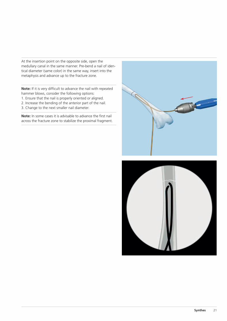
At the insertion point on the opposite side, open themedullary canal in the same manner. Pre-bend a nail of iden-tical diameter (same color) in the same way, insert into themetaphysis and advance up to the fracture zone.
Note: If it is very difficult to advance the nail with repeatedhammer blows, consider the following options:1. Ensure that the nail is properly oriented or aligned.2. Increase the bending of the anterior part of the nail.3. Change to the next smaller nail diameter.
Note: In some cases it is advisable to advance the first nailacross the fracture zone to stabilize the proximal fragment.
0X6.000.207_AB 07.04.10 13:01 Seite 21

8Reduce the fracture
Instrument
359.209 F-Tool for Reduction, small
Note: It is helpful to make a preliminary reduction beforesterile draping of the leg, especially when the fracture tableis used.
The proximal fragment can be manipulated and precise reduction can be achieved by means of protruding nails using the so called “joystick” technique.
If this maneuver does not result in an acceptable reduction,intraoperative closed reduction can be facilitated by theuse of the F-tool for reduction. The two arms of the F-toolshould lie as close together as possible.
To assemble the small F-Tool:1. Thread one threaded rod at the end of the bar.2. Thread the second rod into the bar so the rods just fit
across the leg.3. Thread the third rod into the opposite end of the bar.
Note: If a closed reduction is not possible within 20 –30 minor after several attempts, a short incision and an open reduction are recommended.
Femur – Ascending Technique(pediatrics only)
22 Synthes Titanium/Stainless Steel Elastic Nail System Technique Guide
0X6.000.207_AB 07.04.10 13:01 Seite 22

9Cross the fracture with the nails
Instruments
359.219 Inserter for TEN
359.218 Hammer Guide for TEN
359.221 Combined Hammer for TEN
When the cavities are aligned correctly, advance the nails al-ternately with gentle hammer blows or oscillating move-ments far enough across the fracture zone to ensure that themain fragments are held firmly. Then advance the nails asfar as the metaphysis. The tips of the nails in the proximalfragment must be correctly aligned in the frontal plane.At this point check the stability and rotation. Once the nailsare fixed in the metaphysis it is no longer possible toadjust the rotation.
When in doubt, check the alignment under the image intensifier.
Note: If a nail has to be rotated 180° to cross the fractureline, twist the nail back afterward. Orientation of the nail isfacilitated by marks on the inserter.Example: Start 0�1�2
Back 2�1�0
Note: Ensure that the second nail is in front of (or behind)the first nail distally and proximally; otherwise it will not bepossible to align the nails properly. Avoid the “corkscrewphenomenon”.
Corkscrew phenomenon
Synthes 23
0X6.000.207_AB 07.04.10 13:01 Seite 23

359.217.003
359.217.001
359.217.002
4.0 mm, 3.5 mm
2.5, 2.0 mm
3.0 mm
10Cut the nails to length
Instrument
359.217 Cutter for TEN
If the nail tips in the proximal fragment are correctly located,then the nails can be shortened to the required length withthe cutter for TEN, which allows the nails to be cut very closeto the bone cortex.
If end caps for TEN � 3.0 to 4.0 mm (475.900) are used,the nail end lengths protruding from the cortex should notexceed 10 mm, which can be achieved by using of the bevelled impactor (359.206).
Assemble the cutter for TEN according to the picture andmake sure that the stop nut (359.217.003) is tightened. Rotate the cutting bolt (359.217.001) to the fully open posi-tion. In the fully open position, the lettering “TOP” is alignedboth on the cutting bolt and cutting sleeve (359.217.002).
Slide the nail through the appropriate marked opening cuttersleeve. The black ring on the cutting sleeve indicates thepoint at which the nail will be cut.
Place the handle on the cutting bolt. With a firm grip, movehandles toward each other in one fluid motion to cut the nail.The trimmed portion of the nail is captured within the cutter.
Note: Excessively long nail ends result in pseudobursa formation and prevent free flexion of the knee. They can alsoperforate the skin and cause infections.
Femur – Ascending Technique(pediatrics only)
24 Synthes Titanium/Stainless Steel Elastic Nail System Technique Guide
0X6.000.207_AB 07.04.10 13:01 Seite 24

A
BX
X Y
Alternative Technique
Instrument
388.720 Bolt Cutter
If the specific cutter for TEN is not available, then the follow-ing procedure should be considered.
Estimate the distance (X) between the current position ofthe nail tips (A) and the definitive anchoring position (B)in the proximal part on the image intensifier. This distanceplus an extraction length of 10 mm (Y) produces the distancefrom the bone to the cutting point.
Note: If end caps are used, the correct length of the nail endhas to be considered.
Synthes 25
0X6.000.207_AB 07.04.10 13:01 Seite 25

11Final nail positioning
Instruments
359.206 Impactor for TEN, bevelled
359.221 Combined Hammer for TEN
359.215 Extraction Pliers for TEN
After the nails have been inserted and its length adapted,the corresponding bevelled impactor for TEN brings the nailsinto their planned anchorage position in the proximal meta-physis with gentle hammer blows.
In this process the bevelled part of the impactor must reachthe cortical bone. This position guarantees a protection ofabout 8 –10 mm.
Note: If the nail has been over-inserted, use the extractionpliers to grip and retract the nail. Slight bending of the remaining nail tip will facilitate later removal.
Note: If end caps are used, always use the bevelled impactorto ensure that the protruding length of nail end is correct.
Femur – Ascending Technique(pediatrics only)
26 Synthes Titanium/Stainless Steel Elastic Nail System Technique Guide
0X6.000.207_AB 07.04.10 13:01 Seite 26

12Insertion of TEN end caps
Instruments
359.219 Inserter for TEN
359.222 Screwdriver Shaft for End Cap for TEN � 3.0 to 4.0 mm (No. 475.900)
321.170 Pin Wrench � 4.5 mm, length 120 mm
The end cap (475.900) is inserted over the correctly cut endof the nail and threaded into the metaphysis obliquely.
The use of end caps is indicated in unstable fractures, e.g.long oblique, spiral and comminuted fractures. In addition,end caps also prevent soft tissue irritation and facilitate extraction of the nail.
Insert the screwdriver shaft into the inserter and tighten itwith the pin wrench. Mount the end cap on the screwdriverby aligning the “D” flats. Place the end cap over the nailend and thread it clockwise into the bone at the entry site.The threaded portion of the end cap directed toward thebone must be fully inserted.
Check the correct position of the end cap under the imageintensifier.
Synthes 27
0X6.000.207_AB 07.04.10 13:01 Seite 27

13Post-operative care
Post-operative radiograph images should show an anatomi-cal reduction that would be expected in a child. The nailsshould be positioned correctly with good distal and proximalanchorage.
Depending on the age of the child, immediate passive mo-tion by a physiotherapist or continuous passive motion (CPM)should be started on the first day after the operation. Onthe second day, mobilization on crutches with toe contactmay be possible depending on the pain. The patient is usu-ally discharged after 3 to 5 days.
First clinical and x-ray checks are usually performed 4 – 5 weeks post-operatively. Full weight-bearing may bestarted depending on the callus formation.
Normal activities and school sport can usually be resumed after 6 – 8 weeks.
Bone healing is controlled after 4 – 6 months, and nail removal can usually be scheduled for months 6 – 8.
Femur – Ascending Technique(pediatrics only)
28 Synthes Titanium/Stainless Steel Elastic Nail System Technique Guide
0X6.000.207_AB 07.04.10 13:01 Seite 28

14Removal of the implants
Instruments
359.215 Extraction Pliers for TEN
359.218 Hammer Guide for TEN
359.219 Inserter for TEN
359.221 Combined Hammer for TEN
359.222 Screwdriver Shaft for End Cap for TEN � 3.0 to 4.0 mm (No. 475.900)
If end caps were used, the end caps are removed using thecorresponding screwdriver shaft mounted on the inserter forTEN.
Open the old incisions and expose the ends of the nails.Use the extraction pliers for TEN to first bend the ends of thenails so that they are lifted clear of the formed callus.
With the hammer guide for TEN firmly screwed onto the extraction pliers for TEN, the nails can easily be removed withstrong axial blows along the guide with the combined hammer for TEN.
Synthes 29
0X6.000.207_AB 07.04.10 13:01 Seite 29
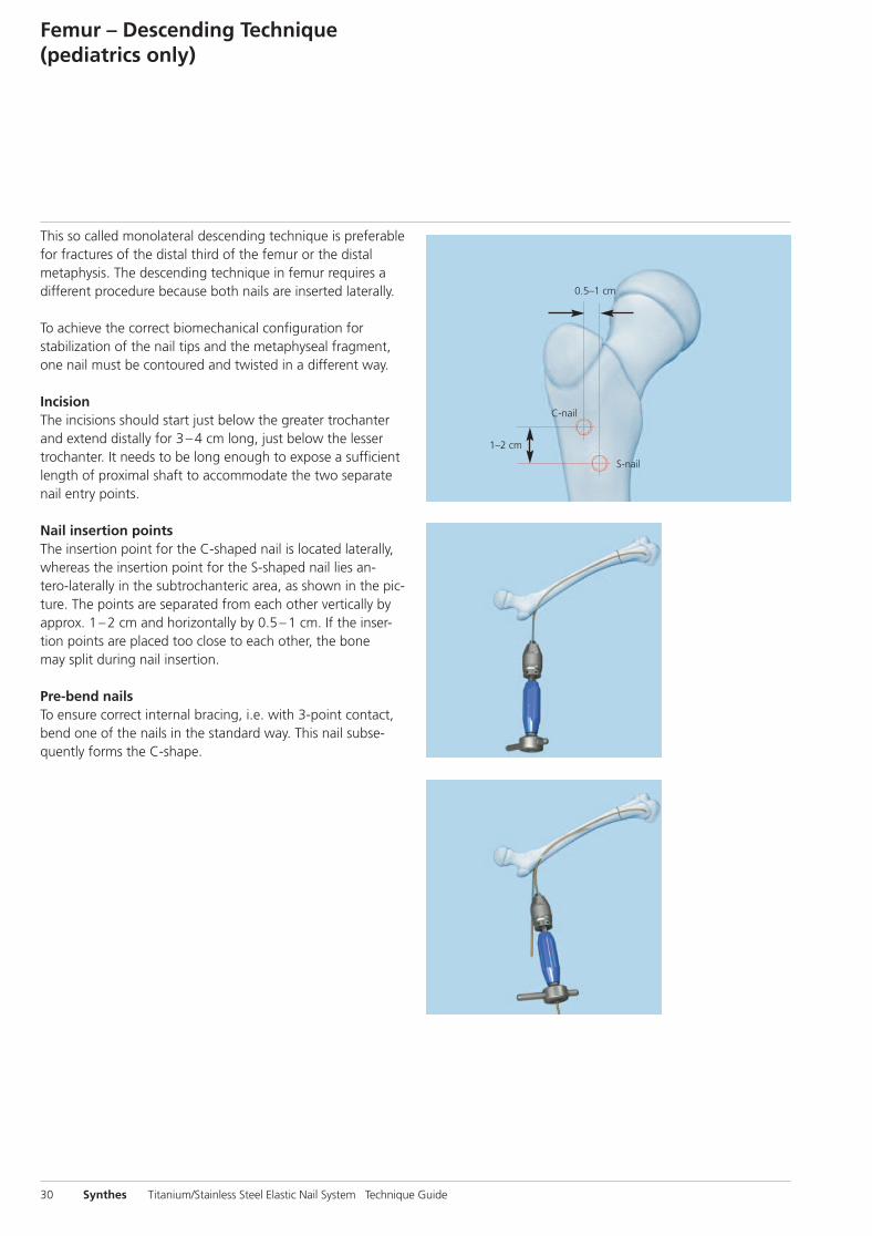
This so called monolateral descending technique is preferablefor fractures of the distal third of the femur or the distalmetaphysis. The descending technique in femur requires adifferent procedure because both nails are inserted laterally.
To achieve the correct biomechanical configuration for stabilization of the nail tips and the metaphyseal fragment,one nail must be contoured and twisted in a different way.
Incision The incisions should start just below the greater trochanterand extend distally for 3 –4 cm long, just below the lessertrochanter. It needs to be long enough to expose a sufficientlength of proximal shaft to accommodate the two separatenail entry points.
Nail insertion points The insertion point for the C-shaped nail is located laterally,whereas the insertion point for the S-shaped nail lies an-tero-laterally in the subtrochanteric area, as shown in the pic-ture. The points are separated from each other vertically byapprox. 1 – 2 cm and horizontally by 0.5 – 1 cm. If the inser-tion points are placed too close to each other, the bonemay split during nail insertion.
Pre-bend nailsTo ensure correct internal bracing, i.e. with 3-point contact,bend one of the nails in the standard way. This nail subse-quently forms the C-shape.
Femur – Descending Technique(pediatrics only)
1–2 cm
0.5–1 cm
S-nail
C-nail
30 Synthes Titanium/Stainless Steel Elastic Nail System Technique Guide
0X6.000.207_AB 07.04.10 13:01 Seite 30

C-shaped nail S-shaped nail
Intraoperatively
Synthes 31
Nail insertion Introduce the first C-shaped pre-bent nail through the moreproximal lateral entry point, reduce the fracture with thenail and achieve primary stabilization.
Insert the second C-shaped nail, with only the first third being pre-bent, through the more distal / anterior hole untilit has good contact with the medial cortex along its lengthof curvature. This is when the nail has been advanced two-thirds distally. In this position rotate the nail 180° clock-wise or counter-clock wise. The external part of the nailis then bent in a distal direction by almost 90°, creating an S-shape.
Final positioning and anchoring of the nailsOnce the fracture is reduced, advance the nail into the distalfragment and align the nail tips so that they diverge fromeach other.
Note: End caps can also be used in the descending technique.
0X6.000.207_AB 07.04.10 13:01 Seite 31

2–3 cm
The descending technique should always be used fortibial fractures. Tibial fractures in children typically requiretwo nails inserted from medial and lateral entry pointsat the proximal tibia. The nail diameters are determined bythe diameter of the isthmus of the medullary canal as previously described (see page 14) and are normally between2.5 mm and 4.0 mm, depending on the patient’s age andbone size.
Pre-bending is recommended and performed as shown in thestandard femoral technique (see page 15).
IncisionThe symmetrical skin incisions are made on the same levelon the medial and lateral sides of the tibial tuberosity. Theseare 2 –3 cm in length proximal to the planned entry points.
Nail insertionThe entry points are situated anteriorly on the proximal medial and proximal lateral metaphyseal cortices, 2 cm distalto the proximal physis, next to the tibial tuberosity.
Note: Due to the asymmetrical placement of the tibia in rela-tion to the muscle coat, its triangular form and its wide prox-imal metaphysis, special biomechanical problems arise re-garding stability. Therefore, these special problems must betaken into account.
Tibia – Descending Technique(pediatrics only)
32 Synthes Titanium/Stainless Steel Elastic Nail System Technique Guide
0X6.000.207_AB 07.04.10 13:01 Seite 32

Synthes 33
Due to the triangular shape of the tibial medullary canal,both nails tend to lie dorsally, which would result in recurva-tion. Therefore, before hammering the nails in their final position in the distal metaphysis turn the tips of both nailsslightly posteriorly in order to achieve the physiological antecurvation of the tibia.
Compress the fracture to prevent fixation in distraction andcut the nails to length. The nail ends should be kept shortand not bent upward in view of minimal soft-tissue cover.
Note: Since tibial fractures, especially oblique and spiral fractures, have a great tendency to shorten, the use of endcaps is highly recommended in these cases to preventmalalignment.
0X6.000.207_AB 07.04.10 13:01 Seite 33

Forearm
If stabilization of an adult forearm fracture with theESIN technique is indicated, it is important to follow the correct procedure. In this situation the technique for pediatric and adult fractures is similar. However, in pediatricsthe penetration of the physis must be avoided at all costs.
Forearm fractures typically require a single nail inserted ineach bone since the radius and ulna form a single unit together with the interosseous membrane.
Nails may be used either antegrade or retrograde, dependingon the fracture location and the surgeon preference.
In this surgical technique guide, it is recommended that thenail is always placed in a retrograde approach in the radius toavoid the risk of damage of the deep branch of the radialnerve. By contrast, in the ulna the nail can be inserted via anantegrade or retrograde approach.
TEN end caps can be used to avoid soft-tissue irritationand damage to tendons caused by nail ends, as well as to facilitate implant removal.
The following section describes the technique for pediatricand adult fractures.
34 Synthes Titanium/Stainless Steel Elastic Nail System Technique Guide
0X6.000.207_AB 07.04.10 13:01 Seite 34

1
2
1Position the patient
Position the patient more on the lateral side of the operatingtable in the supine position with the affected arm placedon a radiolucent arm table (1). The image intensifier is posi-tioned in such a manner that it does not interfere withthe surgical field.
Note: Positioning the arm directly under the image inten- sifier (2) guarantees a better x-ray image quality, reduces exposure time to radiation and produces a bigger, more focused, image of the fracture site.
Synthes 35
0X6.000.207_AB 07.04.10 13:01 Seite 35

2Determine the nail diameter
The nail diameters are about two thirds of the medullary isthmus of each bone. Nails with identical diameter are chosen so that the opposing bending forces are equal, avoid-ing malalignment with varus or valgus mal positioning.
For forearm fractures a nail diameter of 1.5, 2.0 and 2.5 mmis usually used in pediatrics, whereas 3.0 mm nails may alsobe used in adults.
Forearm
36 Synthes Titanium/Stainless Steel Elastic Nail System Technique Guide
0X6.000.207_AB 07.04.10 13:01 Seite 36

3Determine nail entry point in the radius
Incision There are two different approaches for generating the distalradial insertion point: the old traditional approach with a distal lateral insertion, which involves the risk of damage tothe superficial branch of the radial nerve, the newer dorsalapproach over Lister’s tubercle.
As regards the direction of the incision, a longitudinal skin incision is traditionally made. Alternatively a transverseskin cut can be performed, taking account of cosmetic andcomfort aspects.
Note: An open dissection is recommended to prevent tendon damage.
Entry pointIn the radius, the insertion point is approx. 2 cm proximal tothe distal physis; in adults 4 cm proximal to the joint line.
The following surgical technique steps and pictures describethe dorsal approach.
Synthes 37
0X6.000.207_AB 07.04.10 13:01 Seite 37

45°
4Create the nail entry point in the radius
Instrument
359.213 Awl for TEN
Alternative instrument
359.214 Awl, curved, length 180 mm
Place the awl directly on Lister’s tubercle under visual control.Insert the awl in the original way as described.
Note: Take care not to penetrate the controlateral cortex.
Insert the awl at the upper end of the incision perpendicularto the bone. With rotating movements make a central mark.Lower the awl to an angle of 45° in relation to the shaftaxis and then continue perforating the bone at an upwardangle. The opening should be slightly larger than the se-lected nail diameter.*
When using end caps for the nails, make sure that the holescorrespond to the core-diameter of the end cap (475.905).
Note: When using TEN end caps, make sure that the smallTEN end caps (475.905) are used.
* Identical approach on the ulna.
Forearm
38 Synthes Titanium/Stainless Steel Elastic Nail System Technique Guide
0X6.000.207_AB 07.04.10 13:01 Seite 38

5Insert nail in the radius
Instruments
359.219 Inserter for TEN
321.170 Pin Wrench � 4.5 mm, length 120 mm
321.250 Spanner Wrench, for Nos. 357.180, 357.181, 359.201 and 359.219
Because the radius is often more difficult to reduce, it shouldbe splinted first. Insert the radial nail manually with the inserter for TEN into the medullary canal, with the nail tip atright angles to the bone shaft. Then rotate the nail through180° with the inserter and align the nail tip with the axisof the medullary canal. Advance the nail up to the fracturesite with oscillating movements.
Note: The use of a hammer is not recommended since hammering may produce further fracture fragments.
Synthes 39
0X6.000.207_AB 07.04.10 13:01 Seite 39

a
b
6Determine nail entry point in the ulna
Two different techniques can be used for nailing of the ulna: a antegrade approach from the lateral cortex of the
proximal metaphysis; b retrograde approach from the medial cortex of the distal
metaphysis.
The advantages of the retrograde nailing are as follows: – no change of forearm position during reduction– always good visualization on the image intensifier– no change of forearm position during nail insertion
IncisionFor the antegrade technique perform the longitudinalskin incision on the dorso-radial side, of the proximal ulna,3 cm distal to the apophysis.
For the retrograde technique, make a 2 – 3 cm incisionover the distal ulna starting 3 cm proximal to the palpable ulnar styloid.
Entry pointFor the antegrade technique, the nail entry point is onthe antero-lateral side of the proximal metaphysis, approx.2 cm distal to the apophyseal plate in the proximal ulna.
For the retrograde technique, the nail entry point is on theantero-lateral side of the distal metaphysis, approx. 2 cmfrom the joint line.
The following text describes the surgical technique for theretrograde approach with both nails inserted retrograde.
Forearm
40 Synthes Titanium/Stainless Steel Elastic Nail System Technique Guide
0X6.000.207_AB 07.04.10 13:01 Seite 40

45°
7Create the nail entry point in the ulna
Instruments
359.213 Awl for TEN
359.219 Inserter for TEN
321.170 Pin Wrench � 4.5 mm, length 120 mm
321.250 Spanner Wrench, for Nos. 357.180, 357.181, 359.201 and 359.219
Alternative instrument
359.214 Awl, curved, length 180 mm
At the determined nail entry point, first place the awl per-pendicular to the cortex and then gradually widening the angle to enter the medullary canal with rotating movementsas previously described for the radius (step 4, p. 38).
Synthes 41
0X6.000.207_AB 07.04.10 13:01 Seite 41

9Reduce and fix the radius
Instruments
359.219 Inserter for TEN
321.170 Pin Wrench � 4.5 mm, length 120 mm
321.250 Spanner Wrench, for Nos. 357.180, 357.181, 359.201 and 359.219
Align the radial nail tip with the medullary canal of the proximal fragment. Then, manually advance the nailwith smooth oscillating movements until the tip reachesthe proximal fragment at the level of the olecranon.
Note: If reduction cannot be achieved with this method,then open reduction needs to be performed. A small incisionat the fracture level should be done and the fragmentsaligned using small reduction clamps. The radial nail is ableto cross the fracture line and to be advanced into the proxi-mal fragment.
8Insert the nail into the ulna
Instruments
359.219 Inserter for TEN
321.170 Pin Wrench � 4.5 mm, length 120 mm
321.250 Spanner Wrench, for Nos. 357.180, 357.181, 359.201 and 359.219
Manually insert and advance the ulna nail up to the fracturesite using the inserter for TEN.
Forearm
42 Synthes Titanium/Stainless Steel Elastic Nail System Technique Guide
0X6.000.207_AB 07.04.10 13:01 Seite 42

10Reduce and fix the ulna
Instruments
359.205 Impactor for TEN, straight
359.215 Extraction Pliers for TEN
359.219 Inserter for TEN
321.170 Pin Wrench � 4.5 mm, length 120 mm
321.250 Spanner Wrench, for Nos. 357.180, 357.181, 359.201 and 359.219
The ulna usually reduces spontaneously after radius reduction.
Advance the ulna nail with the inserter for TEN across thefracture line into the proximal metaphysis.
Note: Independently of the technique (radius retrograde/ulna antegrade or radius retrograde/ulna retrograde),at the end both nail tips should be rotated towards the interosseous membrane for maximal spread.
Synthes 43
0X6.000.207_AB 07.04.10 13:01 Seite 43

11Cut the nails to length and finalize nail position
Instruments
359.217 Cutter for TEN
359.205 Impactor for TEN, straight
359.220 Impactor, bevelled, small, for TEN � 1.5 to 3.0 mm
When the nails are correctly positioned in the opposite metaphysis, cut the protruding nail ends approximately 1 cmfrom the bone.
Using the impactor for TEN (359.205 or 359.220), push thenails in both bones into their final position. Be carefulnot to over-insert the nail, 5 mm of nail end should protrudebeyond the cortex. If the nails are over-inserted, use the extraction pliers for TEN (359.215) to retract the nails.
The use of small TEN end caps is highly recommended toprevent soft-tissue and tendon irritation, and also to provideadditional stability (especially in adult patients). Since nail diameters of 1.5 to 2.5 mm are usually employed for forearmfractures, the corresponding end caps for TEN � 1.5 to2.5 mm (475.905) are used.
The protruding nail end lengths should not exceed 5 mmotherwise the end cap will not be sufficiently screwedinto the bone. Use of the impactor ensures the correct pro-truding length of nail end.
Alternatively: If TEN end caps are not used, the radialnail end should be left longer and placed sufficiently far out-side the tendon compartment to reduce constant frictionand tendon rupture.
Forearm
44 Synthes Titanium/Stainless Steel Elastic Nail System Technique Guide
0X6.000.207_AB 07.04.10 13:01 Seite 44

12Insertion of TEN End Caps
Instruments
321.170 Pin Wrench � 4.5 mm, length 120 mm
359.219 Inserter for TEN
359.226 Screwdriver Shaft for End Cap for TEN � 1.5 to 2.5 mm (No. 475.905)
359.205 Impactor for TEN, straight
359.220 Impactor, bevelled, small, for TEN � 1.5 to 3.0 mm
End caps prevent nail migration and soft-tissue irritation andfacilitate extraction of the nail.
Insert the screwdriver shaft into the inserter and tightenit with the pin wrench. Mount the end cap (475.905) on thescrew driver by aligning the “D” flats. Place the end capover the nail end and thread it clockwise into the bone at theentry site. The threaded portion of the end cap directed toward the bone must be fully inserted.
Note: When using end caps, it is recommended to positionthe nails with the impactor for TEN (359.205 or 359.220).
Synthes 45
0X6.000.207_AB 07.04.10 13:01 Seite 45

13Post-operative care
No post-operative immobilization is required, active motioncan commence as soon as it is tolerated.
The removal of the nails is usually recommended after4 to 6 months depending on the fully circumferential com-plete bone remodeling (woven bone) at the fracture site.The bone healing time is especially dependent on the patient’s age.
Forearm
46 Synthes Titanium/Stainless Steel Elastic Nail System Technique Guide
0X6.000.207_AB 07.04.10 13:01 Seite 46

1–2 cm
1–2 cm
0.5–1 cm
Humerus – Ascending Technique
The ascending, monolateral nail technique is used to treatfractures of the proximal humerus and the humeral shaft.In the ascending technique two nails are inserted retrogradefrom the lateral (radial) ventral aspect of the distal humerus.An ulnar approach risks damaging the ulnar nerve andmust be avoided.
Position the patient supine with the injured extremity onthe arm table. With subcapital fractures the shoulder needsto be positioned inside the table to prevent the metaledge of the table interfering with the image.
The nail diameters are determined as previously described inthe standard femoral technique (see page 14).
For all unilateral nail insertions the technique for bending thenails is identical to that described in the femoral descendingtechnique (see page 30).
IncisionStart the skin incision 1 cm above the palpable prominenceof the lateral epicondyle and progresses 3 – 4 cm proximallyup the lateral aspect of the humerus.
It is recommended to prepare the ventral aspect of the distal,lateral humerus by sub-periosteal preparation to visualize thebone and the entry points.
Nail insertionThe nail insertion points are located on the supracondylar lateral ventral aspect, outside the capsule.
Caution: Be aware of the position of the radial nerve in relation to the fracture.
Note: In unstable or comminuted fractures, we recommendthe use of the corresponding end cap (for surgical technique,please refer to the standard femoral technique, step 12, p. 27).
Synthes 47
0X6.000.207_AB 07.04.10 13:01 Seite 47

1.5–2.5 cm
0.5–1 cm
Humerus – Descending Technique
The descending monolateral technique is used for adult andpediatric fractures of the distal humerus, including supra-condylar humerus fractures.
The nail diameters are determined as previously described inthe standard femoral technique.
IncisionMake a 3 – 4 cm skin incision in children and a 4 – 5 cm skinincision in adults, proximal to the planned insertion point.Then expose the humerus subperiostally.
Nail insertionThe insertion points are located laterally and distal to the in-sertion of the deltoid muscle. A more distal entry point couldcause injury to the radial nerve.
The nail insertion points are separated from each other vertically by 1.5 – 2.5 cm and horizontally by 0.5 –1 cm.
Caution: Be aware of the position of the radial nerve in relation to the fracture.
48 Synthes Titanium/Stainless Steel Elastic Nail System Technique Guide
0X6.000.207_AB 07.04.10 13:01 Seite 48

Surgical Technique for Extended IndicationsProximal Radius: radial neck
Because of its flexibility, the nail is very suitable for the closed reduction and fixation of radial neck fracture as wellas Salter-Harris (SH) I and II fractures of the proximal radius.
The nail diameter is determined as previously described in the technique for the forearm (see page 36). A nail diame-ter of 2.0 or 2.5 mm is usually used for radial neck and SH Iand II fractures.
Incision and Nail Entry PointThe skin incision and nail entry point are identical to thosedescribed in the forearm technique (see page 37).
ReductionAlign the well bent tip of the nail with the dislocated radialhead in the most dislocated view on the image intensifier.Advance the tip across the fracture in the radial neck or head.Decompaction of the fracture can be achieved by applyingslight axial pressure or slight hammering to the nail. Then reduce the fracture by rotating the nail through 180°.
In cases of complete or severe dislocation, apply externalpressure to the head of the radius to place it in front of thenail tip.
A severely dislocated head of radius can be moved towardthe nail and reduced with the aid of a 1.2 or 1.6 mmKirschner wire (joystick method).
Note: If indicated in adults, the same technique as describedfor pediatric patients can be followed.
Note: In this technique the nail is primarily used as a reduction device and secondly as an implant.
Synthes 49
0X6.000.207_AB 07.04.10 13:01 Seite 49

Distal Radius and Ulna diaphyseal –metaphyseal, displaced fractures
The standard technique for forearm fractures can be employed for these kinds of fractures. However one major difference should be considered. Whereas the nails are not pre-bent in the forearm surgical technique, the nails haveto be pre-bent for these fracture patterns.
Before the radial nail crosses the fracture site, the nail shouldbe bent to resist the tendency of the fracture to drift into valgus malalignment. The apex of the bent nail should be atthe level of the fracture site.
Note: Sufficient stability can be achieved only if there isgood contact between the nail and the distal fragment.
Note: If fracture reduction cannot be obtained with the ESIN,an alternative technique should be used, e.g. using the smallexternal fixator (186.430).
50 Synthes Titanium/Stainless Steel Elastic Nail System Technique Guide
0X6.000.207_AB 07.04.10 13:01 Seite 50

Clavicle
Because of their elasticity, Titanium Elastic Nails are used totreat fractures of the clavicle. The nail adapts to the anatomicrequirements and allows minimally invasive surgery. The use of TEN allows a small incision, immediate resumption of activities and load bearing, significant pain reduction and optimal functional results.
Usually one elastic nail is inserted through the medial portionof the clavicle towards the lateral side.
The insertion from the medial side allows better identifica-tion of the medial aspect of the clavicle and easier handlingcompared to a lateral approach. It also minimizes the risk of damage to the central vessels.
IncisionMake a 1 – 1.5 cm long skin along the anatomical skin-lineof the medial clavicle end.
Nail insertionThe nail entry point is 1 to 2 cm distal to the sterno-clavicularjoint in the center of the proximal clavicle in the anteriorquadrant. This is a region of low cortical thickness.
The use of the small end caps (475.905) with the impactor(359.205 or 359.220) for these indications is highly recommended, because TEN end caps prevent skin irritationand nail migration.
Synthes 51
0X6.000.207_AB 07.04.10 13:01 Seite 51

Product Information
The Titanium/Stainless Steel Elastic Nail (TEN/STEN) System was developed for elastic stable intramedullary nailing (ESIN).
− The optimal material was chosen for appropriate mechanical stability combined with adequate elasticity
− Nails are available in diameters of 1.5 mm to 4.0 mm andcan be adjusted to length
− Color-coding is used for easy identification − The tip of the nail allows easy insertion and sliding − Marks on the end of the nail provide appropriate
orientation of the nail in the intramedullary canal − End caps are available for all nail diameters − End caps offer additional axial stability, prevent
shortening and soft-tissue irritation and facilitate implant removal
− Sophisticated instruments guarantee safe and easy handling
52 Synthes Titanium/Stainless Steel Elastic Nail System Technique Guide
0X6.000.207_AB 07.04.10 13:01 Seite 52

Implants
STEN/TEN
Stainless steel Titanium Nail diameter Length (mm) Color of Ti version
275.915 475.915 1.5 300 violet
275.920 475.920 2.0 440 green
275.925 475.925 2.5 440 pink
275.930 475.930 3.0 440 gold
275.935 475.935 3.5 440 light blue
275.940 475.940 4.0 440 violet
STEN/TEN End Caps
Stainless steel Titanium For nail diameters Length of part Color of Ti version screwed into bone (mm)
275.900 475.900 3.0 –4.0 14 green
275.905 475.905 1.5 –2.5 8.1 rose red
Implants are available nonsterile or sterile packed. Add suffix "S" to article number to order sterile product.
Synthes 53
0X6.000.207_AB 07.04.10 13:01 Seite 53

321.170 Pin Wrench � 4.5 mm, length 120 mm
Instruments
359.205 Impactor for TEN, straight
359.206 Impactor for TEN, bevelled
359.213 Awl for TEN
359.215 Extraction Pliers for TEN
359.217 Cutter for TEN
359.218 Hammer Guide for TEN
359.219 Inserter for TEN
359.221 Combined Hammer for TEN
359.222 Screwdriver Shaft for End Cap for TEN � 3.0 to 4.0 mm (No. 475.900)
359.226 Screwdriver Shaft for End Cap for TEN � 1.5 to 2.5 mm (No. 475.905)
359.220 Impactor, bevelled, small, for TEN � 1.5 to 3.0 mm
54 Synthes Titanium/Stainless Steel Elastic Nail System Technique Guide
0X6.000.207_AB 07.04.10 13:01 Seite 54

Optional instruments
312.460 Double Drill Guide 4.5/3.2
315.280 Drill Bit � 2.7 mm, length 125/100 mm, 3-flute, for Quick Coupling
315.290 Drill Bit � 3.2 mm, length 195/170 mm, 3-flute, for Quick Coupling
315.480 Drill Bit � 4.5 mm, length 195/170 mm, 3-flute, for Quick Coupling
321.250 Spanner Wrench, for Nos. 357.180, 357.181, 359.201 and 359.219
359.204 Pliers, flat-nosed, for TEN
359.209 F-Tool for Reduction, small
359.214 Awl, curved, length 180 mm, for Clavicular Fractures
388.720 Bolt Cutter
Synthes 55
0X6.000.207_AB 07.04.10 13:01 Seite 55

Setlist Modular Trays TEN System
Modular trays for TEN instruments and implants
01.009.011 Modular TEN Instrument Tray, size 1/1, with Contents
68.009.001 Modular Tray, size 1/1, for TEN Instruments, without Contents
359.217 Cutter for TEN 1
359.213 Awl for TEN 1
359.219 Inserter for TEN 1
359.215 Extraction Pliers for TEN 1
359.221 Combined Hammer for TEN 1
359.218 Hammer Guide for TEN 1
321.170 Pin Wrench � 4.5 mm, length 120 mm 1
01.009.012 Modular TEN Instrument and Implant Tray, size 1/1, with Contents
68.009.002 Modular Tray, size 1/1, for TEN Instruments and Implants, without Contents
359.222 Screwdriver Shaft for End Cap for TEN � 3.0 to 4.0 mm (No. 475.900) 1
359.226 Screwdriver Shaft for End Cap for TEN � 1.5 to 2.5 mm (No. 475.905) 1
475.900* End Cap for TEN � 3.0 to 4.0 mm, Titanium Alloy (TAN) 6
475.905* End Cap for TEN � 1.5 to 2.5 mm, Titanium Alloy (TAN) 6
475.915* TEN - Titanium Elastic Nail � 1.5 mm, length 300 mm, Titanium Alloy (TAN), violet 6
475.920* TEN - Titanium Elastic Nail � 2.0 mm, length 440 mm, Titanium Alloy (TAN), green 6
475.925* TEN - Titanium Elastic Nail � 2.5 mm, length 440 mm, Titanium Alloy (TAN), pink 6
475.930* TEN - Titanium Elastic Nail � 3.0 mm, length 440 mm, Titanium Alloy (TAN), gold 6
475.935* TEN - Titanium Elastic Nail � 3.5 mm, length 440 mm, Titanium Alloy (TAN), light blue 6
475.940* TEN - Titanium Elastic Nail � 4.0 mm, length 440 mm, Titanium Alloy (TAN), violet 6
359.205 Impactor for TEN, straight 1
359.206 Impactor for TEN, bevelled 1
Optional storage
68.009.003 Labelling Clip for Modular TEN Instrument Tray
68.009.004 Labelling Clip for Modular TEN Instrument and Implant Tray
68.000.101 Lid for Modular Tray, size 1/1
689.511 Vario Case, Framing, size 1/1, height 126 mm
689.507 Lid (Stainless Steel), size 1/1, for Vario Case
*also available as stainless steel
56 Synthes Titanium/Stainless Steel Elastic Nail System Technique Guide
0X6.000.207_AB 07.04.10 13:01 Seite 56

Optional instruments
312.460 Double Drill Guide 4.5/3.2 1
315.280 Drill Bit � 2.7 mm, length 125/100 mm, 3-flute, for Quick Coupling 1
315.290 Drill Bit � 3.2 mm, length 195/170 mm, 3-flute, for Quick Coupling 1
315.480 Drill Bit � 4.5 mm, length 195/170 mm, 3-flute, for Quick Coupling 1
321.250 Spanner Wrench, for Nos. 357.180, 357.181, 359.201 and 359.219 1
359.214 Awl, curved, length 180 mm, for Clavicular Fractures 1
359.209 F-Tool for Reduction, small 1
359.220 Impactor, bevelled, small, for TEN � 1.5 to 3.0 mm
388.720 Bolt Cutter
Modular tray for implant removal
01.009.015 Modular TEN Extraction Instrument Tray (with contents)
68.009.005 Modular Tray, size 1/1, for TEN Extraction Instruments, without Contents 1
359.219 Inserter for TEN 1
359.215 Extraction Pliers for TEN 1
359.221 Combined Hammer for TEN 1
359.218 Hammer Guide for TEN 1
321.170 Pin Wrench � 4.5 mm, length 120 mm 1
359.222 Screwdriver Shaft for End Cap TEN 1
359.226 Screwdriver Shaft for End Cap for TEN � 1.5 to 2.5 mm (No. 475.905) 1
Optional storage
68.009.006 Labelling Clip for Modular TEN Extraction Instrument Tray
68.000.101 Lid for Modular Tray, size 1/1
689.507 Lid (Stainless Steel), size 1/1, for Vario Case
689.508 Vario Case, Framing, size 1/1, height 45 mm
Optional instruments
321.250 Spanner Wrench, for Nos. 357.180, 357.181, 359.201 and 359.219 1
359.204 Pliers, flat-nosed, for TEN 1
395.380 T-Handle for Steinmann Pins and Schanz Screws
Synthes 57
0X6.000.207_AB 07.04.10 13:01 Seite 57

Bibliography
GeneralDietz HG, Schmittenbecher P, Illing P (1997) IntramedulläreOsteosynthese im Wachstumsalter. München: Urban undSchwarzenberg
Dietz HG, Schmittenbecher P, Slongo T, Wilkins K (2006)Elastic Stable Intramedullary Nailing (ESIN) in Children. AO Manual of Fracture Management. New York: Thieme
Hunter JB (2005) The principles of elastic stable intra-medullary nailing in children. Injury 36 Suppl 1:A20–4
Ligier JN, Metaizeau JP, Prévot J, Lascombes P (1985) Elasticstable intramedullary pinning of long bone shaft fractures in children. Z Kinderchir 40(4):209–12
Metaizeau JP (2004) Stable elastic intramedullary nailing forfractures of the femur in children. J Bone Joint Surg Br86(7):954–7 Review
FemurFlynn JM, Hresko T, Reynolds RA, Blasier RD, Davidson R,Kasser J (2001) Titanium Elastic Nails for Pediatric FemurFractures: A Muticenter Study of Early Results with Analysisof Complications. J Pediatr Orthop 21(1):4–8
ForearmWalz M, Kolbow B, Möllenhoff G (2006) Distale Ulnafrakturals Begleitverletzung des körperfernen Speichenbruchs. Mini-mal-invasive Versorgung mittels elastisch stabiler intramedul-lärer Nagelung (ESIN). Unfallchirurg 109(12):1058–1063
HumerusKhodadadyan-Klostermann C, Raschke M, Fontes R, MelcherI, Sossan A, Bagchi K, Haas N (2002) Treatment of complexproximal humeral fractures with minimally invasive fixation of the humeral head combined with flexible intramedullarywire fixation – introduction of a new treatment concept. Langenbecks Arch Surg 387(3–4):153–160
Williams PR, Shewring D (1998) Use of an elastic in-tramedullary nail in difficult humeral fractures. Injury29(9):661–670
ClavicleAndermahr J, Jubel A, Elsner A, Johann J, Prokop A, RehmKE, Koebke J (2007) Anatomy of the Clavicle and the In-tramedullary Nailing of Midclavicular Fractures. Clin Anat20(1):48–56
Jubel A, Andermahr J, Schiffer G, Rehm KE (2002) Die Tech-nik der intramedullären Osteosynthese der Klavikula mitelastischen Titannägeln. Unfallchirurg 105(6):511–516
Kettler M, Schieker M, Braunstein V, König M, Mutschler W(2007) Flexible intramedullary nailing for stabilization of displaced midshaft clavicle fractures. Acta Orthop 78(3):424–429
Narayanan UG, Hyman JE, Wainwright AM, Rang M, AlmanBA (2004) Complications of elastic stable intramedullary nail fixation of pediatric femoral fractures, and how to avoidthem. Journal of Pediatr Orthop 24(4):363–369
58 Synthes Titanium/Stainless Steel Elastic Nail System Technique Guide
0X6.000.207_AB 07.04.10 13:01 Seite 58

0X6.000.207_AB 07.04.10 13:01 Seite 59

0X6.000.207_AB 07.04.10 13:01 Seite 60

0X6.000.207_AB 07.04.10 13:01 Seite UG3

0123 036.
000.
207
AB
3008
0024
©
04/
2010
Syn
thes
, Inc
. or
its a
ffili
ates
A
ll rig
hts
rese
rved
Sy
nthe
s an
d Va
rio C
ase
are
trad
emar
ks o
f Sy
nthe
s, In
c. o
r its
aff
iliat
es
All technique guides are available as PDF files at www.synthes.com/lit
Ö036.000.207öAB„ä
0X6.000.207_AB 07.04.10 13:01 Seite UG4
Related Documents