הפקולטה להנדסת מכונות , הטכניון חיפה ט' שבט תשע" ה92 בינואר9102 חוברת תקציריםTechnion – Israel Institute of Technology Faculty of Mechanical Engineering Internal Combustion Engines Lab Association of Engineers, Architects and Graduates in Technological Sciences in Israel Ministry of National Infrastructures, Energy and Water Resources Directorate of Defense Research & Development (DDR&D) Aeronautical Division

Welcome message from author
This document is posted to help you gain knowledge. Please leave a comment to let me know what you think about it! Share it to your friends and learn new things together.
Transcript

, הטכניוןהפקולטה להנדסת מכונות חיפה
השבט תשע" 'ט 9102בינואר 92
תקצירים חוברת
Technion – Israel Institute of Technology
Faculty of Mechanical Engineering
Internal Combustion Engines Lab
Association of Engineers, Architects and
Graduates in Technological Sciences in
Israel
Ministry of National Infrastructures,
Energy and Water Resources
Directorate of Defense Research &
Development (DDR&D)
Aeronautical Division
Proceedings 4th Conference on Propulsion Technologies for Unmanned Aerial Vehicles, Haifa, Israel, January 29, 2015
2
Conference Program
4th
Conference on Propulsion Technologies for
Unmanned Aerial Vehicles
Thursday, January 29, 2015
Shirley and Manny Ravet Auditorium, D. Dan and Betty Kahn Building
Faculty of Mechanical Engineering, Technion, Haifa
03:8 – 0388 Welcome and Registration
Opening session Chairperson: Leonid Tartakovsky, Technion
0388 – 03:8 Welcome: Wayne D. Kaplan, Executive Vice President for Research, Technion Yoram Halevi, Dean, Faculty of Mechanical Engineering, Technion
Uri Zvikel, Head Propulsion Branch, Directorate of Defense Research & Development, MAFAT
Emanuel Liban, Chairman, Israeli Society of Mechanical Engineers
0338 – 10300 Keynote address: Internal combustion engines for UAV
Wai Cheng, Director, Sloan Automotive Lab, MIT, USA
Morning plenary session
Chairperson: Yitzhak (Itche) Hochmann, Edmatech
10:00 – 10:30 UAS Operational Evaluation, Integration and Aging Challenges in the Israeli Air Force
Col. Erez Kabariti, Israeli Air Force
10:30 – 11:00 UAV Engines in Operational Environments – Lessons Learnt and Technical Implications
Hemi Oron, Senior Director, UAV Engines Plant, Elbit Systems - UAS
11:00 – 11:30 Coffee break
Noon plenary session
Chairperson: Kobi Feldman, Israeli Aerospace Industries
11:30 – 12:00 Automotive Technology in UAV Propulsion Systems
Emanuel Liban, Edmatech Ltd. – CEO
12:00 – 12:25 Progress in Development of a Small Rotary SI Engine
N. Shkolnik, A. Shkolnik, D. Littera and M. Nickerson, LiquidPiston, Inc., USA
12:25 – 12:50 UAV Engine Control Development Using a Model-Based Design Environment
Yonathan Nassau, Menachem Lerer, UAS Division, Elbit Systems

Proceedings 4th Conference on Propulsion Technologies for Unmanned Aerial Vehicles, Haifa, Israel, January 29, 2015
3
12:50 – 14:00 Lunch
Afternoon session "New Concepts"
Chairperson: Nir Geva, Elbit Systems
14:00 – 14:25 Development of a PCM-based engine for Micro Aerial Vehicles (MAV)
J. Fuchs, A. Lidor, E. Sher and D. Weihs, Technion
14:25 – 14:50 Solar High Altitude Unmanned Vehicle Propulsion System Feasibility Analysis
D. Weihs and M. Harmatz, Technion
14:50 – 15:15 Common-rail fuel injection systems for diesel engines with piezo-injectors
Erez Mosafi, Ledico – Bosch Israel
15:15 – 15:40 Experimental study of burning velocities of hydrogen-rich gaseous fuels
Ahmad Omari and Leonid Tartakovsky, Technion
Afternoon session "Engine Design &
Performance"
Chairperson: Gil Finder, Israel Defense Forces
14:00 – 14:25 Supercharging of UAV engines – benefits and challenges
Yehuda Fass, Israeli Aerospace Industries
14:25 – 14:50 Engine design and performance optimization through advanced simulation tools
Arnon Poran and Leonid Tartakovsky, Technion
14:50 – 15:15 Knock and surface ignition problems in UAV spark-ignition engines and ways of their prevention
Ran Amiel1, Kobi Cohen
2 and Leonid Tartakovsky
1
1 – Technion; 2 – Israeli Air Force
15:15 – 15:40 Four-Stroke Engine with a Port in the Cylinder Sleeve
A.L. Zhmudyak, L.M. Zhmudyak
Closing remarks
15:40 – 15:50
Leonid Tartakovsky, Chairman Organizing Committee
Proceedings 4th Conference on Propulsion Technologies for Unmanned Aerial Vehicles, Haifa, Israel, January 29, 2015
4
Organizing Committee
Leonid Tartakovsky, Faculty of Mechanical Engineering, Technion –
Israel Institute of Technology, Conference Chairman. Email:
Kobi Feldman, Israeli Aerospace Industries
Gil Finder, Israel Defense Forces
Yitzhak (Itche) Hochmann, Edmatech Advanced Engineering
Consultants Ltd.
Emanuel Liban, Chairman of Israeli Association of Mechanical
Engineers
Amihai Magal, Israel Defense Forces
Hemi Oron, Elbit Systems
Michael Shapiro, Faculty of Mechanical Engineering, Technion –
Israel Institute of Technology
Conference Secretary:
Mrs. Ruthie Bouscher, [email protected] Phone: +972-4-8292065, Fax:
+972-4-8295711
Proceedings 4th Conference on Propulsion Technologies for Unmanned Aerial Vehicles, Haifa, Israel, January 29, 2015
5
Keynote address
IC Engines for Unmanned Airborne Vehicles
Wai Cheng1*
1Department of Mechanical Engineering, MIT, Cambridge, Massachusetts, USA
* Presenting author email: [email protected]
Keywords: UAV; IC engines
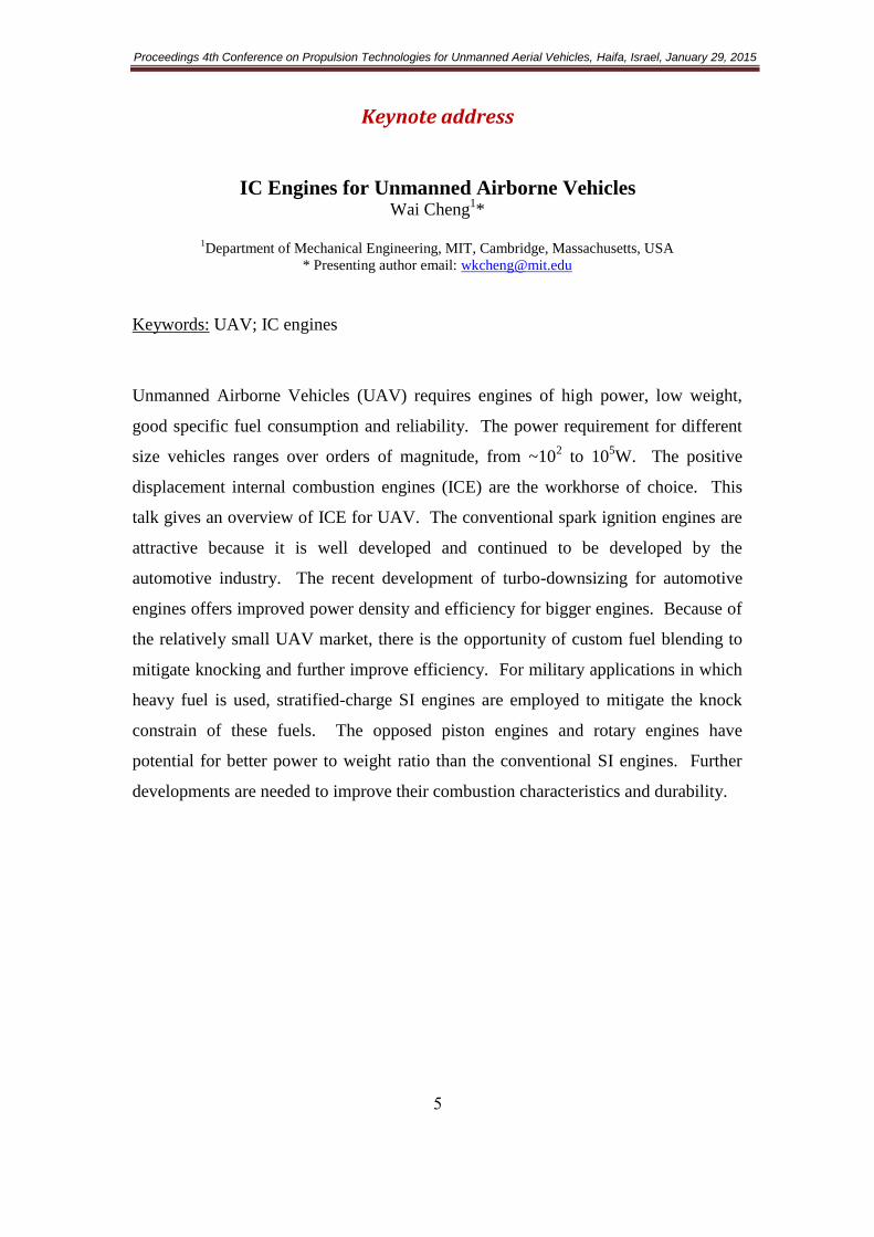
Unmanned Airborne Vehicles (UAV) requires engines of high power, low weight,
good specific fuel consumption and reliability. The power requirement for different
size vehicles ranges over orders of magnitude, from ~102 to 10
5W. The positive
displacement internal combustion engines (ICE) are the workhorse of choice. This
talk gives an overview of ICE for UAV. The conventional spark ignition engines are
attractive because it is well developed and continued to be developed by the
automotive industry. The recent development of turbo-downsizing for automotive
engines offers improved power density and efficiency for bigger engines. Because of
the relatively small UAV market, there is the opportunity of custom fuel blending to
mitigate knocking and further improve efficiency. For military applications in which
heavy fuel is used, stratified-charge SI engines are employed to mitigate the knock
constrain of these fuels. The opposed piston engines and rotary engines have
potential for better power to weight ratio than the conventional SI engines. Further
developments are needed to improve their combustion characteristics and durability.

Proceedings 4th Conference on Propulsion Technologies for Unmanned Aerial Vehicles, Haifa, Israel, January 29, 2015
6
UAS Operational Evaluation, Integration and Aging Challenges in
the Israeli Air Force
Col. Erez Kabariti
Israeli Air Force, IDF
Keywords: Unmanned aerial vehicle; UAV Operational requirements; UAV
Monitoring and diagnostics; Requirements for UAV
UAV Air Systems plays important role and continuously emerging its volume
and capabilities in the operational doctrine of the Israeli Air Force. This trend which
dates back 10 years ago, as a result of the modern warfare challenges requires
adaptable solutions for versatile and rapidly changing operational requirements. In
parallel to the research and development effort of new Unmanned Air System,
significant challenges flourish in the area of aging Unmanned Aircraft operational
evaluation, integration and maintenance.
The challenges are pretty known in the life cycle of weapon system; starting
from the Development, continue with Certification by the airworthiness agency (Air
Force Material Directorate) which depicts inherent dilemma of balancing operational
requirements, safety and budget, throughout the Evaluation Phase, performed during
high-tempo operations. This delicate balance requires large investments in
Monitoring and Diagnostics, an emerging vector in recent years, which is based on
the capability to predict the UAV status in real-time and provides an early warning on
forthcoming failure.
An additional evolving challenge is focused on the integrated debriefing
capability, overarching technical and engineering through operational aspects. The
presentation will provide an insight into the integrated debriefing capability,
embedding the Air Force legacy holistic debriefing methodology. Moreover,
questions on the technical professions and knowledge required to operate and
maintain those systems will be answered.
The Israeli Air Force is the Lead of the Fleet and operates aging UAVs.
Common methods for maintaining manned aircraft are delicately adapted to
composite materials-made UAVs. The presentation will provide insight into advanced
non-destructive tests and complex engineering activity which enable today air vehicle
life extension, where international standards were not in hand when those aging
UAVs were developed. Finally, advanced maintenance concepts and contracts will be
discussed, which are based on performance and outputs, complementing the aging
advanced fleet in the Air Force.

Proceedings 4th Conference on Propulsion Technologies for Unmanned Aerial Vehicles, Haifa, Israel, January 29, 2015
7
UAV Engines in Operational Environments – Lessons Learnt and
Technical Implications
Hemi Oron
Senior Director, UAV Engines Plant, Elbit Systems – UAS, Nes-Ziyona, Israel
Presenting author email: [email protected]
Keywords: UAV Engines; Wankel; Piston
The study is based on several hundreds of thousands of flight hours performed by
UAV‘s worldwide in operational service. The areas of operations covered by this
paper were: Iraq and Afghanistan (British Artillery), Gaza Strip (Israel IDF), Rio
de Janeiro – Maracana (Brazilian Forces) and others. Due to the nature of these
operations, the information provided herein refers only to technical aspects, and
does not point specifically on specific operations.
UAV‘s in operational and combat zones are subject to enhanced requirements, as their
operation is usually referred to as ―lifesaving missions‖. This means they will fly
in almost any condition, and be used to the extreme limits.
UAV engines were originally built for leisure and hobbies, or in better cases for
motorcycles and light sport aviation. They were not intended for a continuous full
power operation for long durations, nor for performance at high altitudes.
Operation areas are not defined by where it is good to fly, but on where the threat is.
And the threat can be in a remote desert, in a heavy populated hostile area, or in the
vicinities of a football stadium jammed with 100,000 fans.
Engines of strenuous operational missions are modified to provide solutions to such
environments. Several challenges and solutions are presented. Among them:
• Acoustic signature attenuation
• Air (for combustion and cooling) filtration
• Shortening the TBS (Time Between Sorties)
• Rain and Hale protection
• Icing conditions protection
• Very Cold environments
• Increased Altitude operation
• Multi Fuel requirements
• Semi-prepared runways
• Engine Certification requirements
• Engine Health Monitoring
• ―Get Home capabilities‖
• Engines‘ mishaps
Short term and long term solution to such requirements will be discussed and
presented.

Proceedings 4th Conference on Propulsion Technologies for Unmanned Aerial Vehicles, Haifa, Israel, January 29, 2015
8
Automotive Technology in UAV Propulsion Systems
E. Liban
EDMATECH Advanced Engineering Consulting Ltd, Tel-Aviv, Israel
Presenting author email: [email protected]
Keywords: Internal Combustion Engine; Unmanned Aerial Vehicle; Engine
technology; Hybrid propulsion; Fuel cell
The driving force behind the developments in IC (Internal Combustion)
propulsion in the last four decades is the Automotive Industry.
The high and unpredictable fuel prices, environmental regulations and fierce
competition in the Global Market Place lead to a steep reduction in fuel consumption
and weight and increase in reliability and customer satisfaction in spite of the
enormous complexity of presents Power Train Systems.
The Automotive Industries invested double digit, Billions of U.S in R&D,
manufacture and testing. Among the most outstanding achievements are:
• "Common Rail" system for Diesel engines.
• Direct Injection (High Pressure Fuel System) in Otto Cycle engines.
• Increase of pressure ratio in Otto Cycle engines .
• New generation of Injectors
• Electronic Controls with Multiple Sensors (FADEC –Full Authority digital
Electronic Control or EFI – Electronic Fuel Injection).
• Real Time Control of the Thermodynamic Cycle.
• Turbo charging ( Single and Multistage(.
• Emissions Reduction.
• Multi-fuel Capability.
• Higher Power to Weight and Volume Ratio engines
• Increase in usage of light materials such as Aluminium Alloys and Hi-Temp
Plastics.
• Reduction in Friction losses and wear due to new materials, coatings, advanced
bearings, and new low viscosity lubricants
• Smaller engines with fewer numbers of cylinders .
Proceedings 4th Conference on Propulsion Technologies for Unmanned Aerial Vehicles, Haifa, Israel, January 29, 2015
9
• "Piston Deactivation"
• Starter – Alternator
• Powerful and Reliable rechargeable batteries
• Hybrid propulsion
• "Fuel Cells" ( Hydrogen Fuel (
During this period the Aircraft I/C engines industries were in stagnation and even
suffered a set back due do the shrinking market of piston engine powered aircrafts,
Turbofan– engines competition and lack of R&D funds.
The few developments that happened in Europe and USA were based on derivatives
and ideas from automotive technology .
The typical Mission Profile of UAV consist of Take –off , Climb, Cruise and Loiter
and is very different from the automotive regime and requirements. Therefore the A/C
Engines do not need all the new features of advanced automotive engine but on the
other hand they have to meet Airworthiness Specifications.
In the lecture the main automotive technologies will be described with an emphasis on
their possible application in A/C propulsion and the characteristic of ideal UAV
engine will be described.

Proceedings 4th Conference on Propulsion Technologies for Unmanned Aerial Vehicles, Haifa, Israel, January 29, 2015
01
Progress in Development of a Small Rotary SI Engine
Nikolay Shkolnik*, Mark Nickerson, Daniele Littera and Alexander Shkolnik
LiquidPiston, Inc. Bloomfield, CT, USA.
* Presenting author email: [email protected]
Keywords: Rotary Engine; High Power Density, High Efficiency, Low Vibration
This paper builds on prior work presented by Shkolnik et al [1], and describes
progress in development of ―XMv3‖ – an innovative, 4-stroke, small, rotary internal
combustion engine designed to operate on the Spark Ignition (SI) version of the
patented High Efficiency Hybrid Cycle (SI-HEHC). The HEHC was originally
developed for application to larger engines using heavy fuel, compression ignition
(CI), including high compression ratio (CR), constant-volume (isochoric) combustion,
and overexpansion. First law analysis using air-standard assumptions shows that the
HEHC has a theoretical efficiency of 75% [2]. The XMv3 rotary engine, in its current
form, is being developed to operate in SI mode (SI-HEHC), albeit at lower
efficiencies than predicted for CI-HEHC. Predicted efficiencies are still higher than
those for conventional piston and other rotary engines. As this engine does not have
poppet valves, and the gas may be fully expanded before the exhaust stroke begins, it
is relatively quiet and may not require a muffler. Similar to the Wankel rotary
engine, the XMv3 engine contains only two primary moving parts – a shaft and rotor,
resulting in compact size and low-vibration operation. Unlike the Wankel, however,
the XMv3 engine is uniquely configured to adopt the HEHC with its associated
efficiency and NVH benefits, as well as a unique direct seal lubrication method. The
result is an engine which is compact, lightweight, low-vibration, quiet, and fuel-
efficient. The above mentioned advantages, along with XMv3‘s favorable form factor
and ability to operate in both horizontal and vertical directions, could be of special
interest for the UAV applications.
XMv3 is a 70cc, 1 rotor / 3 chamber rotary engine, expected to produce 3-5 HP,
with up to 2.7 kW/kg specific power, with efficiencies up to 20% higher than
conventional piston engines. Building a small rotary engine presents unique
challenges in sealing, thermal management, and tribology. Further tuning and
optimization is necessary and is currently underway to fully exploit the advantages of
HEHC with the X architecture engines. This paper will review the HEHC as well as
XMv3‘s design, challenges encountered, and provide an overview of recent
experimental results.
High Efficiency Hybrid Cycle (HEHC)
As the name implies, the HEHC attempts to combine (hybridize) the best features
of several thermodynamic cycles, including the Diesel, Otto, and Atkinson cycles to
create a highly efficient engine. In its purest form, the HEHC combines the following
features:
High CR of air (e.g. Diesel cycle)
Constant-volume (isochoric) combustion (e.g. Otto cycle) achieved by long-
duration burn, through a dwell in volume near Top Dead Center (TDC).
Proceedings 4th Conference on Propulsion Technologies for Unmanned Aerial Vehicles, Haifa, Israel, January 29, 2015
00
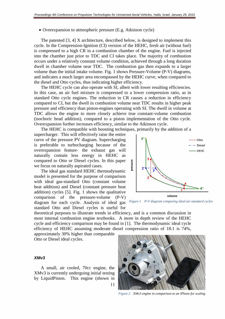
Overexpansion to atmospheric pressure (E.g. Atkinson cycle)
The patented [3, 4] X architecture, described below, is designed to implement this
cycle. In the Compression-Ignition (CI) version of the HEHC, fresh air (without fuel)
is compressed to a high CR in a combustion chamber of the engine. Fuel is injected
into the chamber just prior to TDC and CI takes place. The majority of combustion
occurs under a relatively constant volume condition, achieved through a long duration
dwell in chamber volume near TDC. The combustion gas then expands to a larger
volume than the initial intake volume. Fig. 1 shows Pressure-Volume (P-V) diagrams,
and indicates a much larger area encompassed by the HEHC curve, when compared to
the diesel and Otto cycles, thus indicating higher efficiency.
The HEHC cycle can also operate with SI, albeit with lower resulting efficiencies.
In this case, an air fuel mixture is compressed to a lower compression ratio, as in
standard Otto cycle engines. The reduction in CR causes a reduction in efficiency
compared to CI, but the dwell in combustion volume near TDC results in higher peak
pressure and efficiency than piston-engines operating with SI. The dwell in volume at
TDC allows the engine to more closely achieve true constant-volume combustion
(isochoric head addition), compared to a piston implementation of the Otto cycle.
Overexpansion further increases efficiency, similar to the Atkinson cycle.
The HEHC is compatible with boosting techniques, primarily by the addition of a
supercharger. This will effectively raise the entire
curve of the pressure PV diagram. Supercharging
is preferable to turbocharging because of the
overexpansion feature- the exhaust gas will
naturally contain less energy in HEHC as
compared to Otto or Diesel cycles. In this paper
we focus on naturally aspirated cases.
The ideal gas standard HEHC thermodynamic
model is presented for the purpose of comparison
with ideal gas-standard Otto (constant volume
heat addition) and Diesel (constant pressure heat
addition) cycles [5]. Fig. 1 shows the qualitative
comparison of the pressure-volume (P-V)
diagram for each cycle. Analysis of ideal gas
standard Otto and Diesel cycles is useful for
theoretical purposes to illustrate trends in efficiency, and is a common discussion in
most internal combustion engine textbooks. A more in depth review of the HEHC
cycle and efficiency comparison may be found in [1]. The thermodynamic ideal cycle
efficiency of HEHC assuming moderate diesel compression ratio of 18:1 is 74%,
approximately 30% higher than comparable
Otto or Diesel ideal cycles.
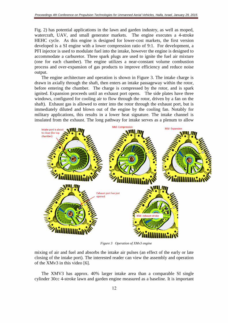
XMv3
A small, air cooled, 70cc engine, the
XMv3 is currently undergoing initial testing
by LiquidPiston. This engine (shown in
Figure 1 P-V diagram comparing ideal air-standard cycles
Figure 2 XMv3 engine in comparison to an iPhone for scaling
Proceedings 4th Conference on Propulsion Technologies for Unmanned Aerial Vehicles, Haifa, Israel, January 29, 2015
02
Fig. 2) has potential applications in the lawn and garden industry, as well as moped,
watercraft, UAV, and small generator markets. The engine executes a 4-stroke
HEHC cycle. As this engine is designed for lower-cost markets, the first version
developed is a SI engine with a lower compression ratio of 9:1. For development, a
PFI injector is used to modulate fuel into the intake, however the engine is designed to
accommodate a carburetor. Three spark plugs are used to ignite the fuel air mixture
(one for each chamber). The engine utilizes a near-constant volume combustion
process and over-expansion of gas products to improve efficiency and reduce noise
output.
The engine architecture and operation is shown in Figure 3. The intake charge is
drawn in axially through the shaft, then enters an intake passageway within the rotor,
before entering the chamber. The charge is compressed by the rotor, and is spark
ignited. Expansion proceeds until an exhaust port opens. The side plates have three
windows, configured for cooling air to flow through the rotor, driven by a fan on the
shaft). Exhaust gas is allowed to enter into the rotor through the exhaust port, but is
immediately diluted and blown out of the engine by the cooling fan. Notably for
military applications, this results in a lower heat signature. The intake channel is
insulated from the exhaust. The long pathway for intake serves as a plenum to allow
mixing of air and fuel and absorbs the intake air pulses (an effect of the early or late
closing of the intake port). The interested reader can view the assembly and operation
of the XMv3 in this video [6].
The XMV3 has approx. 40% larger intake area than a comparable SI single
cylinder 30cc 4-stroke lawn and garden engine measured as a baseline. It is important
Figure 3 Operation of XMv3 engine

Proceedings 4th Conference on Propulsion Technologies for Unmanned Aerial Vehicles, Haifa, Israel, January 29, 2015
03
to remark that the XMv3 has three chambers, with a displacement of 23cc each (23.3
x 3 = 70cc total). A single set of intake and exhaust ports operates for all the three
chambers. Furthermore, the ports open and close rapidly as they are not cam-driven.
A great advantage of rotary engines is the lack of reciprocating motion. XMv3 has the
potential to be almost vibration-free, which would be especially useful in hand-held,
UAV, and mobile power applications, where the weight of mounting brackets and
frame can be reduced. Analysis results indicate a reduction of two orders of
magnitude on the shaking forces and moments.
The XMv3 engine is a
proof of concept engine
designed to demonstrate the
scalability of the HEHC
and X engine geometry, as
well as operation at steady-
state with air cooling.
Initial motoring results
show good motoring
pressures (>16 bar peak),
indicating that sealing is
less of an issue, especially
at higher RPM. Leakage
problems are still
significant for XMv3 at low
speed, and improvements to
sealing are in progress. At
higher RPM, the pressures
are notably higher than in
the piston engine due to
improved breathing, and a
slight ramming effect from the delayed intake-port closing.
Figure 5 Motoring and Firing traces for XMv3
Figure 4 XMv3 section view and flow configuration

Proceedings 4th Conference on Propulsion Technologies for Unmanned Aerial Vehicles, Haifa, Israel, January 29, 2015
04
The newly developed engine has demonstrated 3.5 HP (indicated) at 7000rpm
with 25 BTDC spark advance. Indicated efficiency is 10%. With continued
development, this engine, weighing 3.5 lbs., is expected to produce 3-5 HP brake at
up to 14,000 RPM.
Further development of the engine will focus on improving sealing and volumetric
efficiency, as well as finer engine calibration. The goal for the XMv3 is to achieve
high power density (3-5hp for an engine that weighs 3 lb.) with higher efficiency
(20% to 25%) than a 4-stroke SI piston engine of the same displacement, with the
added advantages of low vibration and low noise.
Conclusions
In this paper we reviewed the HEHC and the XMv3 rotary engine architecture,
which together allow for high power density, low NVH, a reduction in number of
moving parts, fuel flexibility, and scalability, making this engine architecture
particularly suitable for UAV applications. While the engine is in the early stages of
development, its initial performance (3.5 indicated HP at 10,000 RPM) is supporting
of our analytical models. A good agreement between 0D/1D models and the initial
test results indicate that the target efficiency and power levels are achievable.
Acknowledgement
The authors wish to thank Northwater Capital Management and Adams Capital
Management for funding this development as well as members of the engineering /
technical team which helped in the design and testing of the X engines, including
especially: Alexander Kopache, Chuankai Sun, Ganapathy Machamada, Kyle
Becker, Nicholas Medeiros, Ryan Leary, Jamael Velasquez, Len Louthan; the team at
Davinci engineering: Dave Gruenwald, Bryan Danner, Eddie Phillips; the team at
Century Tool, especially Lee Sroczenski.
References
1. Development of a Small Rotary SI/CI Combustion Engine, Alexander Shkolnik, Daniele
Littera, Mark Nickerson, and Nikolay Shkolnik, Kukwon Cho, SAE 2014-32-0104
2. Shkolnik, N. and Shkolnik, A., ―High Efficiency Hybrid Cycle Engine‖, proceedings of the
ASME Fall Conference on Internal Combustion Engines, ICEF2005-1221, 2005,
doi:10.1115/ICEF2005-1221
3. Shkolnik, N., and Shkolnik, A. (2013) Cycloid rotor engine, US Patent # 8,523,546.
4. Shkolnik, N., and Shkolnik, A. (2014) Hybrid Cycle Combustion Engine and Methods, US
Patent # 8,794,211.
5. Heywood, J. (1988) Internal Combustion Engine Fundamentals, McGraw-Hill, New York.
6. LiquidPiston (2014) ‗X‘ Engine animation. Website URL:
http://liquidpiston.com/technology/how-it-works/

Proceedings 4th Conference on Propulsion Technologies for Unmanned Aerial Vehicles, Haifa, Israel, January 29, 2015
05
UAV Engine Control Development Using a Model-Based Design
Environment
Yonathan Nassau, Menachem Lerer Elbit Systems LTD - UAS – UEP
* Presenting author email: [email protected], [email protected]
Keywords: ECU; Model Based Design; Simulink; Hardware-In-Loop (HIL)
The growing number of UAV applications in military and civil applications
led to stringent requirements for compliance with formal international design and
development standards. The design and development process of an engine control unit
(ECU) cannot readily therefore be adopted from existing off-the-shelf automotive or
aerospace systems. The Model-Based Design process described here can offer
significant advantages in cost, performance and mainly, time to market.
The development environment is based on the Matlab and Simulink platform
with the applicable tools for the selected target machine (this paper describes a target
device based on a Freescale Power PC processor). The entire ECU model may be
developed as a set of building blocks for all the sensors, actuators, engine
management strategies and control logic. All unique UAV requirements such as dual
or triple redundancy on sensors and actuators, health monitoring, fail-safe strategies,
limp-home capability, logging and host computer communication, can be readily
designed and tested.
The next step of machine code generation can be performed both in the
traditional methods of manual coding, testing and documentation, or by using the
Matlab Embedded Coder that provides automatic code generation with provisions for
full documentation. The embedded coder offers a highly efficient development
process that can save a lot of time and cost. Once the target machine is loaded with
the code, the design verification process may be performed by using the actual target
ECU as the hardware-in-the loop (HIL) device coupled to a suitable test environment
system that simulates all engine components. The test system should be capable to run
automated scripts, fault injections, events capture and logging. The test system
described here is based on the National Instruments Compact-RIO FPGA system.
The ECU can now be integrated with the engine installation and start operating
in the calibration process. The calibration process may be performed by using the
CCP (CAN based) or XCP (Ethernet based) communication protocols and a suitable
software application such as ETAS INCA, Vector CANape, or ATI Vision. The
engine can now be operated in the test cell through the entire operational envelope
while optimizing the ECU maps and lookup tables.
This development process was initially demonstrated at UEP on a small single-
cylinder 2-stroke engine. The entire process that started by building the Simulink
model and ended in the test cell with a fully configured engine and ECU, took less
than 10 days.
This paper describes the development process of an ECU for a 4-cylinder 4-
stroke engine with full redundancy on sensors, logic and ignition. The ECU also
provides turbocharger control, wide-range Lambda control at sea-level to 30K Ft
altitude, and knock control.
Proceedings 4th Conference on Propulsion Technologies for Unmanned Aerial Vehicles, Haifa, Israel, January 29, 2015
06
Development of a PCM-based engine for Micro Aerial Vehicles
(MAV)
J. Fuchs1, A. Lidor
2, E. Sher
2* and D. Weihs
2
1Faculty of Mechanical Engineering, Technion – Israel Institute of Technology, Haifa, 3200003, Israel 2Faculty of Aerospace Engineering, Technion – Israel Institute of Technology, Haifa, 3200003, Israel
* Presenting author email: [email protected]
Keywords: Phase Change Materials; Micro Aerial Vehicles; MAV; Energy Source;
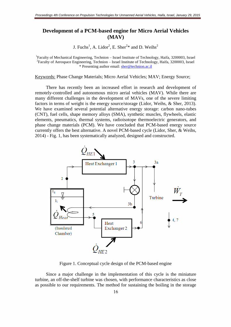
There has recently been an increased effort in research and development of
remotely-controlled and autonomous micro aerial vehicles (MAV). While there are
many different challenges in the development of MAVs, one of the severe limiting
factors in terms of weight is the energy source/storage (Lidor, Weihs, & Sher, 2013).
We have examined several potential alternative energy storage: carbon nano-tubes
(CNT), fuel cells, shape memory alloys (SMA), synthetic muscles, flywheels, elastic
elements, pneumatics, thermal systems, radioisotope thermoelectric generators, and
phase change materials (PCM). We have concluded that PCM-based energy source
currently offers the best alternative. A novel PCM-based cycle (Lidor, Sher, & Weihs,
2014) - Fig. 1, has been systematically analyzed, designed and constructed.
Figure 1. Conceptual cycle design of the PCM-based engine
Since a major challenge in the implementation of this cycle is the miniature
turbine, an off-the-shelf turbine was chosen, with performance characteristics as close
as possible to our requirements. The method for sustaining the boiling in the storage

Proceedings 4th Conference on Propulsion Technologies for Unmanned Aerial Vehicles, Haifa, Israel, January 29, 2015
07
tank was also examined, with several options in mind. We came into the conclusion
that the original proposed solution of using a portion of the superheated vapors
benefits significant advantages over the alternatives (injection of a portion of the
superheated fluids, electrical heating or using air ducts through the insulation). We
have also reevaluated the system properties for the different possible PCM fluids, in
regards to our working pressure limitation (as required by our purchased turbine, an
Air Turbine Tools 201SV model, designed for 40,000rpm and 700kPa), with the
results presented in Table 1.
Table 1. Comparison of the system properties for different PCM fluids
Properties at working pressure of 700kPa Optimal conditions
Fluid Initial mass
Final mass
Mass flow
Tank volum
e Tank temp.
Optimal pressure
(for minimum
mass)
Optimal pressure
initial mass
[kg] [g] [g/s] [L] [°C] [kPa] [kg]
Nitrogen 0.9548 39.26 1.367 1.367 -174.7 1746 0.8057
Helium ~above critical pressure (227.5kPa)~
190 0.5425
Methane 0.5236 15.48 0.4234 1.401 -131.4 2163 0.4211
Argon 1.487 42.18 1.204 1.202 -162.4 2161 1.252
Oxygen 1.076 28.82 0.8727 1.062 -159.3 2339 0.8577
CO2 1.44 22.97 1.181 1.25 -49.37 2950 1.079
Ethane 0.9469 24.93 0.7683 1.967 -43.16 1988 0.7806
Fluorine 1.261 32.68 1.023 0.9436 -166.6 2453 0.9947
To properly measure the output and to characterize the system, a custom made
testing bench was also designed and fabricated. The experimental system is already
partially assembled, with the turbine and test bench completed, and the PCM storage
tank undergoing design. The first stage of the experiments, aimed at characterising the
turbine under pressurized air (without the complexity of the PCM system), is
currently underway.
References
Lidor, A., Sher, E. & Weihs, D. (2014). Phase-change-materials as energy source for micro aerial
vehicles (MAV). Applied Thermal Engineering, 65(1), 185–193.
Lidor, A., Weihs, D. & Sher, E. (2013). Alternative power-plants for micro aerial vehicles (MAV).
53rd Israel Annual Conference on Aerospace Sciences 2013, 1, 600–619.

Proceedings 4th Conference on Propulsion Technologies for Unmanned Aerial Vehicles, Haifa, Israel, January 29, 2015
08
Solar High Altitude Unmanned Vehicle Propulsion System
Feasibility Analysis
D. Weihs* and M. Harmatz
Faculty of Aerospace Engineering and Autonomous Systems Program, Technion, Haifa
*Presenting author email: [email protected]
Keywords: Solar propulsion; HALE UAV
The promise of solar energy for propulsion of High Altitude, Long Endurance unmanned aerial
vehicles has long attracted interest as a possible unlimited endurance configuration. However,
limitations of energy conversion and storage and the fact that at the altitudes considered ( around
20km) there are eternal winds of over 20 m/s have prevented these vehicles from becoming practical,
and therefore hybrid solutions have been proposed in the past ( Harmatz & Weihs,1996).
Existing solar UAVs come in two types – ones for HALE observation use which have the advantage of
being above the weather and very low atmospheric attenuation but have to deal with the high west
winds mentioned above, and ground-covering low altitude UAVs, which suffer weather and
attenuation, but under some constraints can move much more slowly and thus reach balance of energy
input and requirements.
Table 1 shows three existing configurations, none of which is free of all the constraints above.
Cruise
Power
[kw]
Engines
Max.
Power
[kw]
Battery/
Fuel Cell
Specific
Energy
[w-hr/kg]
Battery/
Fuel Cell
Weight
[kg]
Total
Weight
[kg]
Solar
Cells
Eff.
[%]
Wing
Aspect
Ratio
Wing
Span
[m]
Velocity
[m/sec]
Altitude
[km] Name
18 21 450 385 1050 19 31 75 12 51 Helios HP03
10 30 220 430 1600 22 20 63.4 51-33 5.1-5.1 Solar Impulse
0.52 1.5 350 21 53 10 20 22.5 25
1 55.1 Zephyr 7
Recent developments in solar cell efficiencies, aerodynamic efficiency and fuel cell storage
capacities, as well as advanced design of flight trajectories have changed the situation. This has
encouraged us to perform a reevaluation of the feasibility of fully solar powered, unlimited endurance
UAVs. Thus, efficiencies of solar cells have increased from about 15-18% to about 30% in the last
decade. Rechargeable closed circuit fuel cells have reached capacities of around 500 W*hr/kg, wing
designs with stable lift coefficients of up to 1.7, i.e. an improvement of over 40%, better conversion to
electric energy and a new flight mechanics approach that can save up to 20% in the storage
requirements is presented here. The combination of these changes have made the flight based on solar
energy alone (within limitation of middle-east latitudes) possible, and the present paper includes the
analysis and configurations that give a positive energy balance.
Flying at altitudes of above 18000 m, which is above regular air corridors releases the UAV from
regulatory problems, while allowing a full use of solar energy, as atmospheric attenuation is essentially
negligible and no clouds reach that altitude. However, this altitude is out of the atmospheric boundary
layer, and thus constant west to east winds of up to 80 m/s are blowing there. This requires the UAV to
move at least at the wind speed in order to be able to keep station above a certain area. We will utilize
a ―window‖, of average velocities of about 20 m/s that exists at between 18-24 Km.
The major issue in solar-powered vehicles is the fact that the sun only shines for part of the 24 hr
cycle, so that excess energy must be stored, and used during the dark hours. The present paper will
show two techniques for reducing the amount of electrical energy stored, first by using some of the
excess energy to climb during daytime and slowly descend during the dark to initial height. The second
technique is flying into the wind and using biomimetic soaring techniques.

Proceedings 4th Conference on Propulsion Technologies for Unmanned Aerial Vehicles, Haifa, Israel, January 29, 2015
09
Fig 1. Potential battery type trajectory
Table 2. HALE UAV with minimal wingspan , for all-year use. WPL=100kg, PPL=1000w, F.C. Spec.
Energy=600w-hr/kg, Design for winter, With Maneuver Max. Aero. Eff.=40, PV Cells Eff.=30%,
Structure Part=0.25, Propulsion Spec.Weight=2.5kg/kw
Lift
Coeff.
Required
Power
[Kw]
Mean
Day
Excess
Power
[kw]
Part of
Daylight
Excess
Energy
Stored in
Fuel Cell
[%]
Fuel
Cell
Weight
[Kg]
Total
Weight
[Kg]
Span
[m]
Cells
Cover.
Ratio
Base
Velocity
[m/sec]
Base
Altitude
[km]
Flight
Season
1.05 6.4 0 80 280 650 62.2 1.0 28 5..2 Winter
1.05 6.4 0.76 32 280 650 62.2 1.0 28 5..2 Summer
0.48 7.4 0.21 33 280 650 62.2 1.0 31 17.0 Summer
Conclusions
With present capabilities a large ( >60 m) wingspan HALE UAV with a practical payload is close to
being feasible , and if no power is required for the payload can be built. One interesting conclusion was
that there exists an optimum covering of the wing, i/e/ full covering may be suboptimal. Two original
energy sparing techniques are presented.
1. The potential energy ―battery‖, i.e. converting part of the excess energy during sunlight hours to
altitude, instead of storing in fuel cells/batteries.
2. For station keeping- flying into the wind.
Acknowledgments
We thank R. Gordana, Zwickel and E. Liban for support and useful discussions.
Proceedings 4th Conference on Propulsion Technologies for Unmanned Aerial Vehicles, Haifa, Israel, January 29, 2015
21
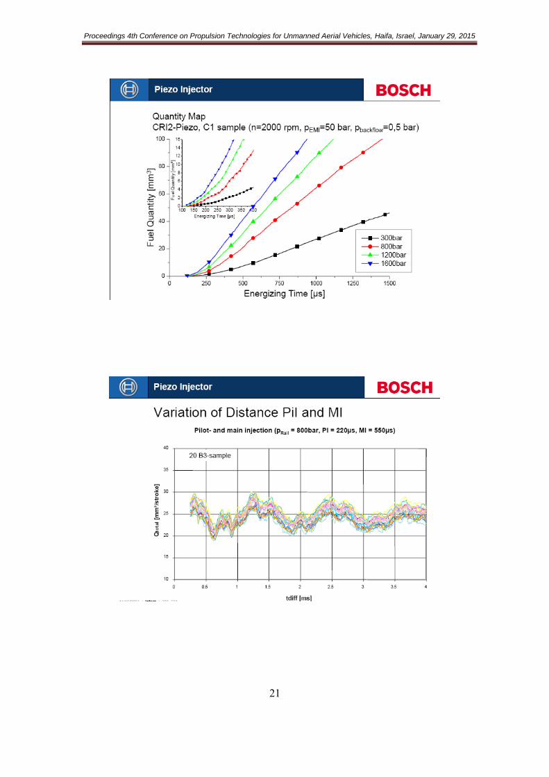
Common-rail fuel injection systems for diesel engines with piezo-
injectors
Erez Mosafi
Bosch – Ledico, Rishon-le-Zion, Israel
* Presenting author email: [email protected]
Keywords: Diesel engine; Fuel injection; Common-rail system; Piezo injector
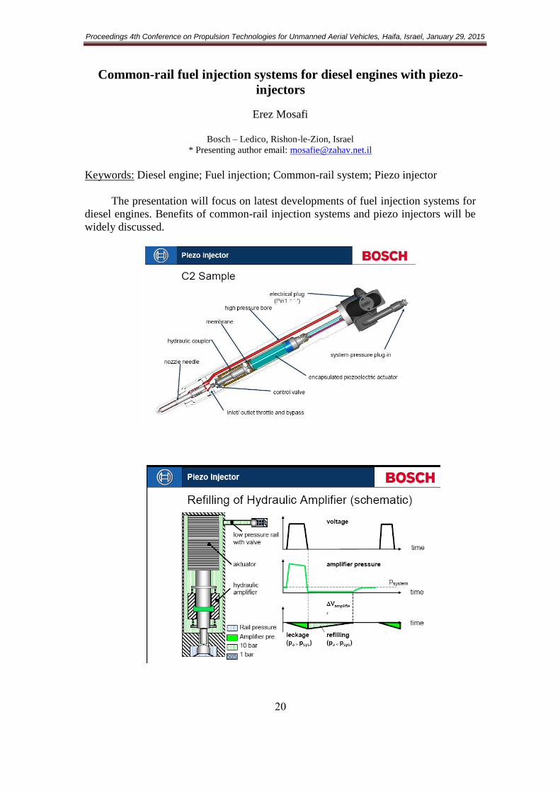
The presentation will focus on latest developments of fuel injection systems for
diesel engines. Benefits of common-rail injection systems and piezo injectors will be
widely discussed.
Proceedings 4th Conference on Propulsion Technologies for Unmanned Aerial Vehicles, Haifa, Israel, January 29, 2015
20

Proceedings 4th Conference on Propulsion Technologies for Unmanned Aerial Vehicles, Haifa, Israel, January 29, 2015
22

Proceedings 4th Conference on Propulsion Technologies for Unmanned Aerial Vehicles, Haifa, Israel, January 29, 2015
23
Laminar burning velocity of alcohol reforming products and effects of cellularity on flame propagation
A. Omari*, M. Shapiro and L. Tartakovsky
Faculty of Mechanical Engineering, Technion, Haifa, Technion City, 32000, Israel
* Presenting author email: [email protected]
Keywords: Laminar burning velocity; cellularity; steam reforming; hydrogen;
Utilizing exhaust gas heat emitted from an internal combustion engines (ICE)
for an on-board alcohol reforming is a promising way to produce hydrogen-rich
syngas, while recovering part of the otherwise totally wasted exhaust gas energy.
Feeding the engine with these gases contributes to a higher flame speed, higher knock
resistance and wider lean flammability limits, all of which result in an increased
overall efficiency as well as in mitigation of hazardous emissions. Moreover, utilizing
on-board alcohol reforming will combine the distribution and storage advantages of
liquid fuels with the combustion benefits of hydrogen.
Various alcohol reforming processes may contribute to different compositions
of the produced reforming products (syngas). Among the parameters that determine
this composition are: alcohol type, water-alcohol ratio, reforming temperature and
catalyst selectivity. Different reformate compositions in turn have different
combustion properties. High hydrogen containing reformates have wide flammability
limits; high burning velocities and cellular flame structure which further contributes
to a faster flame propagation. Contrary, increased CO and CH4 fractions in the
reformates result in a higher energy density and better pre-ignition resistance. On the
other hand, the above not fully oxidised carbon products can enhance coke formation
in the reformer which badly affects its operation and hence the systems reliability.
Simulating the joint reformer-ICE operation using computer software is
considered a powerful and cost-effective initiative for providing better insight when
determining the optimal reforming process and the resulting reformate composition.
The knowledge of the laminar burning velocity for various alcohol reforming
products is a key factor allowing the determination of the actual in cylinder heat
release rate necessary for the above mentioned simulations.
This research investigates the laminar burning velocities of H2, CO, CO2 and
CH4 mixtures that simulate methanol and ethanol steam reforming products for
various water-alcohol ratios. The influence of flame cellularity on the flame
propagation speed was studied as well. A spherical constant volume combustion
vessel was designed for this purpose (Fig.1). The flame propagation was filmed using
a high-speed camera along with a Schlieren system and the pressure rise during flame
propagation was monitored. From the latter data, both the laminar burning velocity
and the apparent cellular burning velocity were derived. The change in burning
Proceedings 4th Conference on Propulsion Technologies for Unmanned Aerial Vehicles, Haifa, Israel, January 29, 2015
24
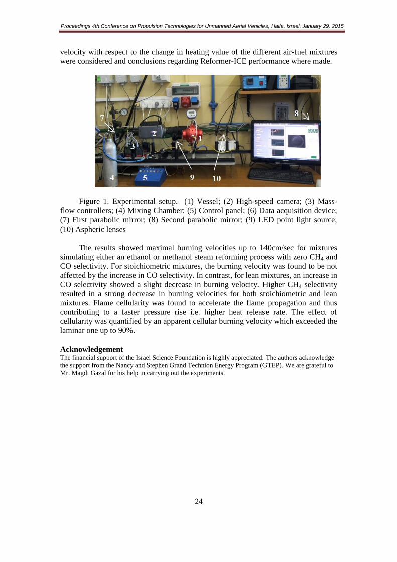
velocity with respect to the change in heating value of the different air-fuel mixtures
were considered and conclusions regarding Reformer-ICE performance where made.
Figure 1. Experimental setup. (1) Vessel; (2) High-speed camera; (3) Mass-
flow controllers; (4) Mixing Chamber; (5) Control panel; (6) Data acquisition device;
(7) First parabolic mirror; (8) Second parabolic mirror; (9) LED point light source;
(10) Aspheric lenses
The results showed maximal burning velocities up to 140cm/sec for mixtures
simulating either an ethanol or methanol steam reforming process with zero CH4 and
CO selectivity. For stoichiometric mixtures, the burning velocity was found to be not
affected by the increase in CO selectivity. In contrast, for lean mixtures, an increase in
CO selectivity showed a slight decrease in burning velocity. Higher CH4 selectivity
resulted in a strong decrease in burning velocities for both stoichiometric and lean
mixtures. Flame cellularity was found to accelerate the flame propagation and thus
contributing to a faster pressure rise i.e. higher heat release rate. The effect of
cellularity was quantified by an apparent cellular burning velocity which exceeded the
laminar one up to 90%.
Acknowledgement The financial support of the Israel Science Foundation is highly appreciated. The authors acknowledge
the support from the Nancy and Stephen Grand Technion Energy Program (GTEP). We are grateful to
Mr. Magdi Gazal for his help in carrying out the experiments.

Proceedings 4th Conference on Propulsion Technologies for Unmanned Aerial Vehicles, Haifa, Israel, January 29, 2015
25
Supercharging of UAV engines – benefits and challenges
Y. Fass1*, J. Feldman
1
1Israel Aerospace Industries, Ben-Gurion Airport, Israel
* Presenting author email: [email protected]
Keywords: Turbocharger; UAV; supercharger; altitude;
UAV industry uses internal combustion engines (IC) engines for propulsion,
converting the engine work to thrust using a propeller. The main disadvantage for
using IC engine in UAV's is based on their operation principle. A naturally aspirated
engine will produce power in direct proportion to the density of the intake air. At sea
level, air has a density of 1.225 kg/m^3. At 10,000ft altitude, the density drops to
0.904 kg/m^3. This means an engine that delivers 100HP at sea level will deliver
100*0.904/1.225=73.8HP at 10,000ft.
A UAV engine that uses turbocharger to regain the power loss at high altitude is
referred to as a normalized engine. A normalized engine usually has a waste-gate to
pass all of the exhaust gas at sea level. Consequently, no turbocharging takes place at
sea level. As the engine starts to lose power with increased altitude, the waste-gate
gradually closes by an automatic control. The turbocharger then compresses the inlet
air to sea level pressure. This allows the engine to deliver essentially sea-level
horsepower.
The engine continues to develop sea-level horsepower up to an altitude where
the waste-gate is completely closed. At this point, called critical altitude, all the
exhaust gases pass through the turbine. When the UAV climbs above critical altitude,
the engine will start to lose power. The turbocharger can no longer deliver air at sea-
level pressure. Illustration of engine power, with/without a turbocharger, versus
altitude is shown in Figure 6.
Figure 6. Engine performance VS altitude, with/without turbocharger

Proceedings 4th Conference on Propulsion Technologies for Unmanned Aerial Vehicles, Haifa, Israel, January 29, 2015
26
The operation line of turbochargers in UAV's is different than in automotive
industry. In automotive, the main reason to use turbocharging system is to produce
more power from given engine displacement while in aviation the usage of the
turbocharger is to maintain SL power at high altitude .In automotive, the boost
pressure is set to produce the power required by the engine manufacturer and the
pressure ratio will remain constant for a range of engine RPM's. In UAV's, the
pressure ratio gradually rise as the UAV climb. The difference between operation
lines is described in Figure 7.
Figure 7. UAV vs. automotive operation lines
In our work we show the variety of turbochargers on the market and the unique
modification and installation process for turbocharging UAV's engines. This process
includes charge air cooling, operation line calculations, boost control, exhaust gas
management and piping.

Proceedings 4th Conference on Propulsion Technologies for Unmanned Aerial Vehicles, Haifa, Israel, January 29, 2015
27
Design and Performance Optimization through Advanced Simulation
Tools
A. Poran1*, L. Tartakovsky
1
1Faculty of Mechanical Engineering, Technion, Haifa, 32000, Israel
* Presenting author email: [email protected]
Keywords: Simulations; computer aided engineering; internal combustion engines
The recent increase in computational power has enabled the creation of detailed
computerized models of various engine components as well as construction of
comprehensive vehicle models out of numerous system mechanisms. Thus, in the last
couple of decades computer-aided engineering (CAE) tools have become prevalent in
the competitive automotive industry (Shi et al, 2011, Sher & Bar-Kohany, 2002).
Companies report that extensive usage of CAE tools significantly reduces the number
of prototypes produced in the development processes and to a substantial decrease in
development time and cost (Thomke, 1998, Whitfield, 2001). Other benefits of
software modelling originate from the fact that virtual experiments and modifications
are much faster and cheaper to perform compared to physical ones; therefore, more
modifications and experiments are conducted and engineers can gain a more profound
understanding of the effects of different parameters on the system‘s behaviour
(Thomke, 1998). The same qualities also make software simulations a good tool for
concept proofing.
The broad usage of CAE tools has led to development of many modelling
methods suitable for different cases. To fit a method to a model, it is important first to
specify the model goals and required accuracy; these specifications together with
experimental data already available on the system will determine the right model to be
used.
The presentation examines and describes different projects performed at the
Technion Internal Combustion Engines (TICEL) laboratory and demonstrates how
different goals and available experimental data lead to creation of different models.
The first example model was derived to examine a novel concept of a direct-
injection internal combustion engine with exhaust gas waste heat recovery through
methanol steam-reforming (Fig. 1).
Figure 8. Direct injection internal combustion engine with thermo-chemical
recuperation through methanol steam reforming.
The main goals of the model aimed to prove that the exhaust gas contains
enough available energy to sustain the endothermic methanol steam reforming process

Proceedings 4th Conference on Propulsion Technologies for Unmanned Aerial Vehicles, Haifa, Israel, January 29, 2015
28
and to estimate the size of the reforming system. According to these goals and the fact
that at the time of the model creation there was no experimental data available, the
created model utilized a 1-D gas exchange semi-predictive combustion model,
Woschni heat transfer correlation for the in-cylinder heat transfer, and detailed
chemical kinetics for the reformer (Poran et al, 2014). In addition to the achievement
of simulation goals, the model also showed that lean combustion possibilities, enabled
due to the reforming process, have greater contribution to the overall system
efficiency than the waste heat recovery (Fig 2.).
Figure 9. Brake thermal efficiency as a function of reformer heat transfer area and
Lambda.
The second project studies knock in a turbo-charged Rotax 914 engine. The project
goals aim first to identify when and where the knock phenomenon occurs and then
propose several ways of preventing it. These goals required utilization of a fully
predictive combustion model calibrated with experimentally obtained indicated
pressure measurements. Available CAD files were used to create detailed intake
system. The generated model predicts the air-flow and fuel consumption with
maximal error of 3% and can also predict knocking.
Even though the model has reached good agreement with the experimental data,
acquirement of experimental information such as motoring test, and temperature
measurements at various locations will further improve this model and hence its
knock predictions.
The last example examines the use of commercial reciprocating piston software
to model a rotary Wankel engine (Tartakovsky et al, 2012). Since there was no
experimental regarding intake and exhaust discharge coefficients, CFD simulation
was used to calculate them. The results of this simulation where then inserted to 1-D
gas exchange model. Heat transfer and combustion coefficients were calculated using
available traditional models. The model used experimentally obtained combustion
chamber temperatures. Even though the rotary engine was simulated through a virtual
reciprocating piston, simulations performed predicted engine performance parameters
with high accuracy (Fig. 3).

Proceedings 4th Conference on Propulsion Technologies for Unmanned Aerial Vehicles, Haifa, Israel, January 29, 2015
29
Figure 3. Wankel engines 802 and 802W: predicted (lines) and measured (dots)
values of the brake power (left) and fuel consumption (right) over full load curve.
The given examples show that difference in data availability and project requirements
lead to creation of different models; each model requires detailed modelling of a
different part of the system. Yet, all models provide sufficient simulation results.
Acknowledgement
The financial support of the Israel Science Foundation is highly appreciated. The
authors acknowledge the support from the Nancy and Stephen Grand Technion
Energy Program (GTEP).
References Poran, A., Artoul, M., Sheintuch, M., & Tartakovsky, L. (2014). Modeling Internal Combustion Engine
with Thermo-Chemical Recuperation of the Waste Heat by Methanol Steam Reforming. SAE
International Journal of Engines., 7(1):234-242, 2014, doi:10.4271/2014-01-1101.
Sher, E., & Bar-Kohany, T. (2002). Optimization of variable valve timing for maximizing performance
of an unthrottled SI engine—a theoretical study. Energy, 27(8), 757-775.
Shi, Y., Hai-Wen, G., & Rolf Deneys, R. (2011). Computational optimization of internal combustion
engines. London: Springer.
Tartakovsky, L., Baibikov, V., Gutman, M., Veinblat, M. et al., "Simulation of Wankel Engine
Performance Using Commercial Software for Piston Engines," SAE Technical Paper 2012-32-
0098, 2012, doi:10.4271/2012-32-0098.
Thomke, S. H. (1998). Simulation, learning and R&D performance: Evidence from automotive
development. Research Policy , 27.1: 55-74.
Whitfield, K. (2001). Toyota Pursues the Elusive'Triple WOW'. Automotive Manufacturing and
Production, 113.9:58

Proceedings 4th Conference on Propulsion Technologies for Unmanned Aerial Vehicles, Haifa, Israel, January 29, 2015
31
Knock and surface ignition problems in UAV spark-ignition engines
and ways of their prevention
R.AMIEL.1*, K.COHEN.
2
1Faculty of Mechanical Engineering, Technion – Israel Institute of Technology, Haifa, 32000, Israel
2I.D.F, Air Force, Tel Aviv, Israel
* Presenting author email: [email protected]
Keywords: Knock; Detonation; surface ignition; SI engine
The knock phenomenon in spark ignition (SI) internal combustion engines
(ICE) has been a limiting factor in power generation since the invention of the Otto
cycle in the mid-19th
century. Knock (or detonation) is an abnormal combustion in the
ICE cylinder, caused by an undesired flame front formed inside the cylinder in
addition to the flame initiated from the spark ignition. Two main phenomena that
cause this are surface ignition and/or mixture ignition due to the increased pressure
and temperature during the progress of the flame through the cylinder.
Abnormal combustion is called ―knock‖ because of the noise generated by the
colliding of the multiple flame fronts and the increased cylinder pressure that causes
the piston, connecting rod and bearings to resonate. The presence of multiple flame
fronts can have serious effects on the ICE: decrease in engine power output and
longevity, increase in pollutant emissions and total destruction of the engine in the
worst cases. (Heywood, 1988, Zhen et al, 2011).
IAF's Rotax 914 engines have undergone a number of detonations which
caused engine damage, mission aborts and even severe accidents. As a result, the IAF
has initiated a stricter engine operational policy; it has also improved the detonation
identification algorithm, and started using fuels of better quality. Despite the measures
taken, the problem still exists and requires attention.
The main goal of our research is to study the causes of knocks in the Rotax
914 engine, find the methods to identify their start and prevent them. During normal
operation of the Rotax 914 engine, the knock phenomenon occurred and forced the
platform operators to stop its work. The knock phenomenon results in significant
damage to the designated tasks of the platform and causes economic losses due to
mechanical destruction of the engine.
The first step in our research is to build a computer model of the engine in the GT-
SUITE software. The most important feature in the model is the combustion profile
inside the cylinder, which is designed to predict combustion and flame behavior in
various conditions as similar as possible to the real ones in the engine. The model will
be used to test a variety of knock treatments, which in turn will be applied on the
Rotax 914 engine in real experiments.
Proceedings 4th Conference on Propulsion Technologies for Unmanned Aerial Vehicles, Haifa, Israel, January 29, 2015
30
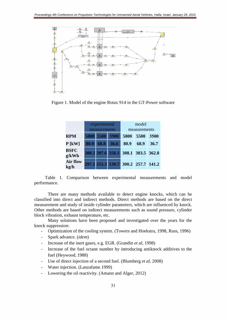
Figure 1. Model of the engine Rotax 914 in the GT-Power software
experimental
measurements
model
measurements
RPM 5800 5500 0033 5800 5500 0033
P [kW] 80.9 68.8 36.6 80.9 68.9 36.7
BSFC
g/kWh 300.2 297.6 356.1 308.1 303.5 362.8
Air flow
kg/h 297.1 255.3 139.7 300.2 257.7 141.2
Table 1. Comparison between experimental measurements and model
performance.
There are many methods available to detect engine knocks, which can be
classified into direct and indirect methods. Direct methods are based on the direct
measurement and study of inside cylinder parameters, which are influenced by knock.
Other methods are based on indirect measurements such as sound pressure, cylinder
block vibration, exhaust temperature, etc.
Many solutions have been proposed and investigated over the years for the
knock suppression:
- Optimization of the cooling system. (Towers and Hoekstra, 1998, Russ, 1996)
- Spark advance. (idem)
- Increase of the inert gases, e.g. EGR. (Grandin et al, 1998)
- Increase of the fuel octane number by introducing antiknock additives to the
fuel (Heywood, 1988)
- Use of direct injection of a second fuel. (Blumberg et al, 2008)
- Water injection. (Lanzafame, 1999)
- Lowering the oil reactivity. (Amann and Alger, 2012)

Proceedings 4th Conference on Propulsion Technologies for Unmanned Aerial Vehicles, Haifa, Israel, January 29, 2015
32
The above methods are going to be simulated on the GT-SUITE model and the
relevant ones will then be implemented on the engine.
Acknowledgement The financial support of MAFAT is highly appreciated.
References Heywood, J.B., Internal Combustion Engine Fundamentals, McGraw-Hill, New York, 1988.
Zhen X., Wang, Y., Xu, S., Zhu, Y., Tao, C., Xu, T., Song M. (2011) The engine knock analysis – An
overview. Applied Energy.
Lanzafame R. (1999) Water injection effects in a single-cylinder CFR Engine. SAE Technical Paper
no. 1999-01-0568.
Towers J.M, Hoekstra R.L. (1998) Engine knock, a renewed concern in motorsports – a literature
review. SAE technical paper no. 983026.
Russ S. (1996) A review of the effect of engine operating conditions on borderline knock. SAE
technical paper no. 960497.
Amann, M. and Alger, T., (2012) Lubricant Reactivity Effects on Gasoline Spark Ignition Engine
Knock, SAE Int. J.
Fuels Lubr.
Grandin B., Angstrom H.E., Stalhammar P., Olofsson E. (1998) Knock suppression in a turbocharged
SI engine by using cooled EGR. SAE Technical Paper no. 982476
Blumberg P.N, Bromberg L, Kang H, Tai C. (2008) Simulation of high efficiency heavy duty SI engines
using direct injection of alcohol for knock avoidance, SAE Technical Paper no. 2008-01-2447
Proceedings 4th Conference on Propulsion Technologies for Unmanned Aerial Vehicles, Haifa, Israel, January 29, 2015
33
Four-Stroke Engine with a Port in the Cylinder Sleeve
A.L. Zhmudyak
1, L.M. Zhmudyak
2*
1R&D, Panaya, Raanana, 43657, Israel
2 Rehovot, 7645501, Israel
* Presenting author email: [email protected]
Keywords: four-stroke engine; port; cylinder; sleeve
1. Introduction
We propose a new four-stroke engine, where the exhaust gas from the cylinder
flows out through the valves and through the port in the cylinder sleeve.
In naturally aspirated engines, pressure in the intake manifold is lower than in
the exhaust manifold. Out-dated turbo-supercharging engines also have this pressure
correlation. In these conventional 4-stroke internal combustion engines, intake and
exhaust is realized through valves in the cylinder head only. Use of a constantly open
port in the cylinder sleeve for gas exchange was impossible in these engines for the
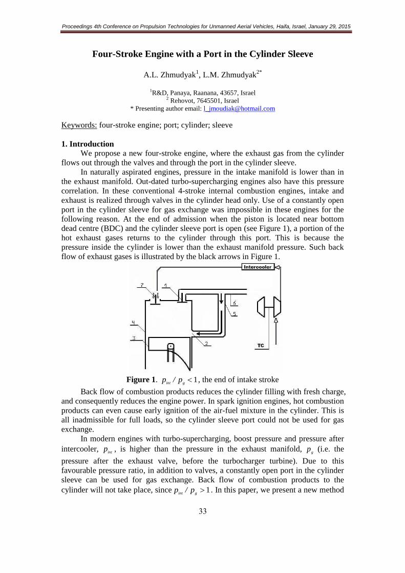
following reason. At the end of admission when the piston is located near bottom
dead centre (BDC) and the cylinder sleeve port is open (see Figure 1), a portion of the
hot exhaust gases returns to the cylinder through this port. This is because the
pressure inside the cylinder is lower than the exhaust manifold pressure. Such back
flow of exhaust gases is illustrated by the black arrows in Figure 1.
Figure 1. 1gint
p/p , the end of intake stroke
Back flow of combustion products reduces the cylinder filling with fresh charge,
and consequently reduces the engine power. In spark ignition engines, hot combustion
products can even cause early ignition of the air-fuel mixture in the cylinder. This is
all inadmissible for full loads, so the cylinder sleeve port could not be used for gas
exchange.
In modern engines with turbo-supercharging, boost pressure and pressure after
intercooler, int
p , is higher than the pressure in the exhaust manifold, g
p (i.e. the
pressure after the exhaust valve, before the turbocharger turbine). Due to this
favourable pressure ratio, in addition to valves, a constantly open port in the cylinder
sleeve can be used for gas exchange. Back flow of combustion products to the
cylinder will not take place, since 1gint
p/p . In this paper, we present a new method
Proceedings 4th Conference on Propulsion Technologies for Unmanned Aerial Vehicles, Haifa, Israel, January 29, 2015
34
for gas exchange in 4-stroke internal combustion engines. To realize the proposed gas
exchange method, a constantly open port in the cylinder sleeve should be made in
addition to the valves in the cylinder head. We term such an engine as an ―A-engine‖.
2. Method of Work of the Proposed Engine
Let us consider the working processes of the A-engine at full load, as well as
maximum and nominal loads. At these loads 1gint
p/p .
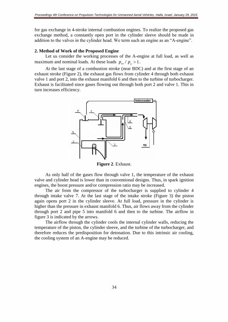
At the last stage of a combustion stroke (near BDC) and at the first stage of an
exhaust stroke (Figure 2), the exhaust gas flows from cylinder 4 through both exhaust
valve 1 and port 2, into the exhaust manifold 6 and then to the turbine of turbocharger.
Exhaust is facilitated since gases flowing out through both port 2 and valve 1. This in
turn increases efficiency.
Figure 2. Exhaust.
As only half of the gases flow through valve 1, the temperature of the exhaust
valve and cylinder head is lower than in conventional designs. Thus, in spark ignition
engines, the boost pressure and/or compression ratio may be increased.
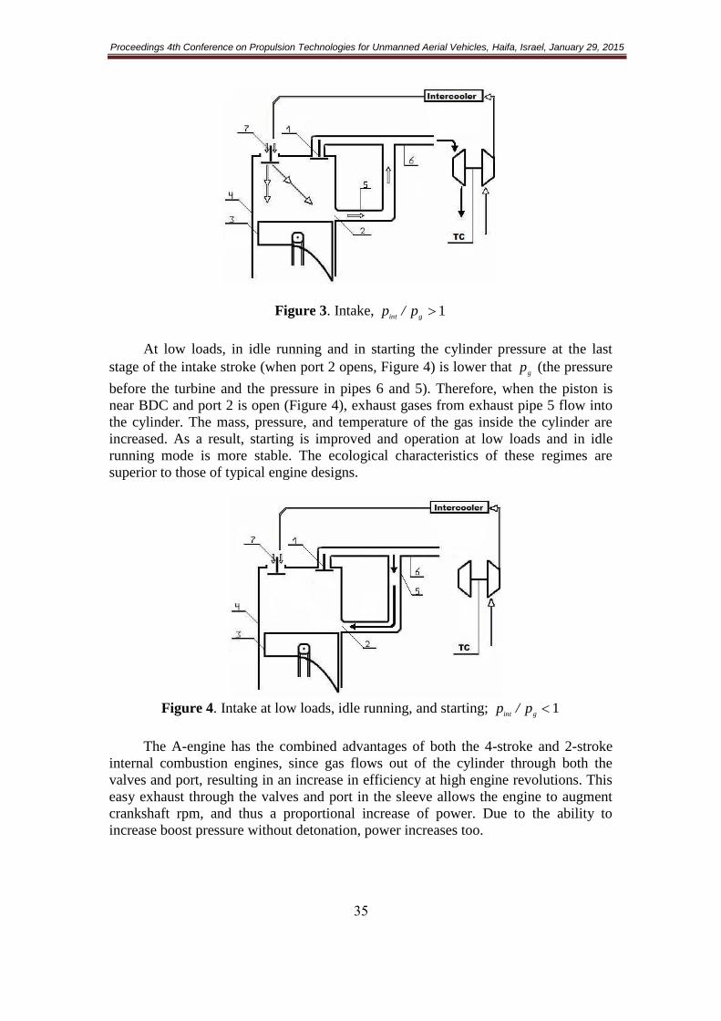
The air from the compressor of the turbocharger is supplied to cylinder 4
through intake valve 7. At the last stage of the intake stroke (Figure 3) the piston
again opens port 2 in the cylinder sleeve. At full load, pressure in the cylinder is
higher than the pressure in exhaust manifold 6. Thus, air flows away from the cylinder
through port 2 and pipe 5 into manifold 6 and then to the turbine. The airflow in
figure 3 is indicated by the arrows.
The airflow through the cylinder cools the internal cylinder walls, reducing the
temperature of the piston, the cylinder sleeve, and the turbine of the turbocharger, and
therefore reduces the predisposition for detonation. Due to this intrinsic air cooling,
the cooling system of an A-engine may be reduced.
Proceedings 4th Conference on Propulsion Technologies for Unmanned Aerial Vehicles, Haifa, Israel, January 29, 2015
35
Figure 3. Intake, 1gint
p/p
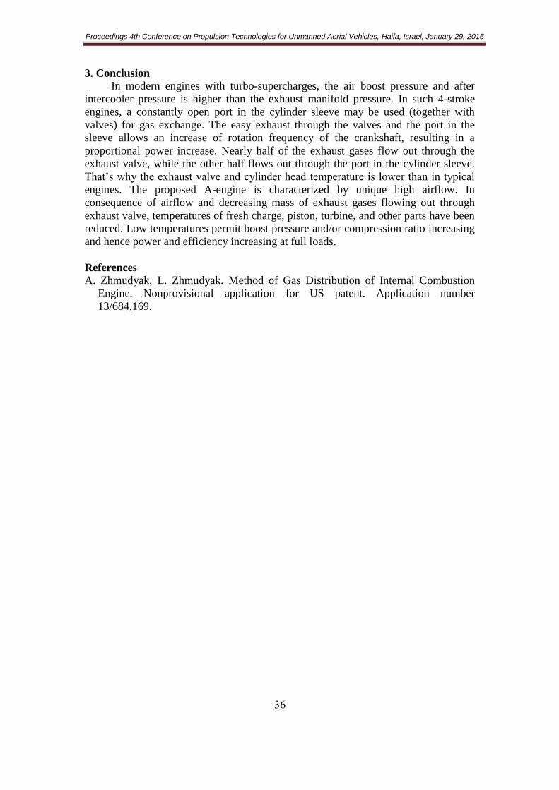
At low loads, in idle running and in starting the cylinder pressure at the last
stage of the intake stroke (when port 2 opens, Figure 4) is lower that g
p (the pressure
before the turbine and the pressure in pipes 6 and 5). Therefore, when the piston is
near BDC and port 2 is open (Figure 4), exhaust gases from exhaust pipe 5 flow into
the cylinder. The mass, pressure, and temperature of the gas inside the cylinder are
increased. As a result, starting is improved and operation at low loads and in idle
running mode is more stable. The ecological characteristics of these regimes are
superior to those of typical engine designs.
Figure 4. Intake at low loads, idle running, and starting; 1gint
p/p
The A-engine has the combined advantages of both the 4-stroke and 2-stroke
internal combustion engines, since gas flows out of the cylinder through both the
valves and port, resulting in an increase in efficiency at high engine revolutions. This
easy exhaust through the valves and port in the sleeve allows the engine to augment
crankshaft rpm, and thus a proportional increase of power. Due to the ability to
increase boost pressure without detonation, power increases too.
Proceedings 4th Conference on Propulsion Technologies for Unmanned Aerial Vehicles, Haifa, Israel, January 29, 2015
36
3. Conclusion
In modern engines with turbo-supercharges, the air boost pressure and after
intercooler pressure is higher than the exhaust manifold pressure. In such 4-stroke
engines, a constantly open port in the cylinder sleeve may be used (together with
valves) for gas exchange. The easy exhaust through the valves and the port in the
sleeve allows an increase of rotation frequency of the crankshaft, resulting in a
proportional power increase. Nearly half of the exhaust gases flow out through the
exhaust valve, while the other half flows out through the port in the cylinder sleeve.
That‘s why the exhaust valve and cylinder head temperature is lower than in typical
engines. The proposed A-engine is characterized by unique high airflow. In
consequence of airflow and decreasing mass of exhaust gases flowing out through
exhaust valve, temperatures of fresh charge, piston, turbine, and other parts have been
reduced. Low temperatures permit boost pressure and/or compression ratio increasing
and hence power and efficiency increasing at full loads.
References
A. Zhmudyak, L. Zhmudyak. Method of Gas Distribution of Internal Combustion
Engine. Nonprovisional application for US patent. Application number
13/684,169.
Related Documents