Technical Information Air-condensed water chillers and heat pumps YCSA/YCSA-H 50, 60, 80, 100 T and TP (R-407C) Ref.: TYC5-CE6 Clima Roca York S.L. is participating in the EUROVENT Certification Program. Products are as listed in the EUROVENT Directory of Certified Products, in the program AC1, AC2 and AC3. EUROVENT CERTIFIED PERFORMANCE CGM-97/013 ACCORDING TO ISO 14001 STANDARDS ER-0028/1991 ACCORDING TO ISO 9001 STANDARDS

Technical YCSA 50-100
Dec 24, 2015
Manual tehnic
Welcome message from author
This document is posted to help you gain knowledge. Please leave a comment to let me know what you think about it! Share it to your friends and learn new things together.
Transcript

Technical Information
Air-condensed water chillersand heat pumpsYCSA/YCSA-H 50, 60, 80, 100 T and TP(R-407C)
Ref.: TYC5-CE6
Clima Roca York S.L. is participating in the EUROVENT Certification Program.Products are as listed in the EUROVENT Directory of Certified Products,in the program AC1, AC2 and AC3.
E U R O V E N TCERTIFIED PERFORMANCE
CGM-97/013AC
CO
RD
ING
TO
ISO
140
01 S
TAN
DA
RD
S
ER-0028/1991AC
CO
RD
ING
TO
ISO
900
1 S
TAN
DA
RD
S

2
Index
General information 3
- General description 3- Nomenclature 3- Models available and capacities 3- Features and advantages 3
Technical Specifications 3
- Accesories and options 4- Physical data, cool only units 5- Physical data, heat pump units 6- Units without Pack 7- Operation, cooling and hydraulic diagram,
cool only unit 8- Operation, cooling and hydraulic diagram,
heat pump unit 9- Cooling capacities YCSA 10- Cooling capacities YCSA with 20% glycol 11- Cooling capacities YCSA with 30% glycol 12- Cooling capacities YCSA-H 13- Cooling capacities YCSA-H with 20% glycol 14- Cooling capacities YCSA-H with 30% glycol 15- Heating capacities 16- Available pressure and pressure drop of water
circuit and filter 16 - 17
Installation Instructions 18
- Inspection 18- Environmental protection 18- Elimination of the unit 18
Page Page
- Safety 18- Transportation 18- Handling 18- Warming signs 18- Location 19- Fastening the unit 19- Clearances 19
Wiring 19
- Electrical connections 19- Scroll compressors, rotational direction 19- Hydraulic connections 19- Dimensions and hydraulic connections 20 - 21- Minimum technical clearance 22- Wiring diagram 23 - 25- Wiring 26- Electrical characteristics 27- Limits of use 27- Prior to final approval of the installation 27
Operating instructions µµµµµC2 + Expansion (Rev.1015) 28
- Unit description 28- Standard components 28- General diagram 29- Symbols on the display 30- Functions related to the control buttons 30- Location of controls 31- Parameter tables 31 - 41
Accessories 42 - 47

3
YCSA 60 T P E2
Air/water water chiller withaxial fans
Approximate cooling capacity inkW
Voltage (400.3.50)
With Hydro Kit (Pack)
Edition
Cooling capacity
Heating capacity
Heat pump model
Cool only model YCSA YCSA YCSA YCSA50 60 80 100
49.2 61.2 78.7 98Cooling capacity
YCSA-H 60 T P E2
Air/water heat pump withaxial fans
Approximate cooling capacity inkW
Voltage (400.3.50)
With Hydro Kit (Pack)
Edition
YCSA-H YCSA-H YCSA-H YCSA-H50 60 80 100
47 62.9 74.3 96
55.6 63.6 81.2 106
General InformationGeneral descriptionThe YCSA/YCSA-H 50, 60, 80 and 100 units are high-per-formance air-water water chillers and heat pumps usingR-407C ecological refrigerant.These units are designed for air conditioning or industrialapplications that require cold or hot water. They are silentand compact units, equipped with vertical air discharge axialfans, that can be installed directly outdoors. They are avail-able in two Versions: with and without a Hydro Kit, which in-cludes a buffer tank and a high head pressure pump.The control system of these units is a specially programmedelectronic controller to be used on air-water water chillersand heat pumps equipped with tandem compressors.Easy to use and safe, these units precision control the waterreturn temperature of the installation, carry out defrost cy-cles, modulate fan speeds and control compressor, pumpand electric heater start-ups. By reading the control probesand safety elements, the controller protects the entire equip-ment against malfunctions. The system allows connecting theunit to a standard RS485 monitoring network. For further in-formation, please see Operating Instructions.The YCSA/YCSA-H 50, 60, 80 and 100 units are made ofproven quality components and manufactured in compliancewith standards in force (ISO 9001 certification).
Nomenclature
Models available and capacities
Cooling capacities in kW for 12/7° C entering/leavingwater temperature, and 35° C ambient temperature.
Heating capacities in kW for 40/45° C entering/leavingwater temperature, and 7° C ambient temperature.
Features and advantages
Technical SpecificationsThese units are supplied completely factory-assembled anwith all refrigerant tubing and wiring ready for installation onthe job site. After mounting, these units must go through anoperational test with water. Refrigerant leaks will also bechecked during this process.
Manufactured to ISO 9001 High quality level
Features Advantages
Accessibility Easy maintenance
Main switch Operator safety
Variable speed fan Low noise level and condensation control
R-407C refrigerant Does not harm the ozone layer
Minimum dimensions Minimum footprint
Microprocessor for controland alarms
Easy and safe operation
Hydro Kit For installations with a low water volume
Communications connec-tion
Ideal for building management
Low height and weight Space for installing on terraces
Factory tested equipment Operating quality control
4
Sheeting casingThe units are made of galvanized steel sheeting andanticorrosion nuts and bolts. Panels can be removed for ac-cess to internal components. The casing parts are paintedwith white RAL9001 oven-baked polymerized enamel.
CompressorsTwo hermetic Scroll compressors mounted in tandem on railsand antivibratory supports are used. Both compressors areconnected for operation with one single cooling circuit. Start-up is carried out by two independent starters. These com-pressors are equipped with electronic modules that protectthem against high operating temperatures. The sump heat-ers operate only when the compressor is inoperative.
Indoor heat exchangerComprises a stainless steel plate exchanger, adequately in-sulated by a layer of closed-cell elastomer foam. Includes anantifreeze heater monitored by the controller and a differen-tial pressure switch acting as a flow control switch. The re-frigerant side of said exchanger accepts an operating pres-sure of 30 bar, whereas the water side accepts 10 bar. Whenthe unit includes a Hydro Kit, maximum admissible pressureon the water side is 6 bar (adjustment of the tank relief valve).
Outdoor heat exchangerMade up of two notched aluminium fin coils and grooved cop-per tubing mechanically expanded within the fin assembly.
FansOf the axial and low sound level type. Equipped with single-phase motors with IP54 protection. These motors allow speedcontrol by means of a phase cut-out shifter controlled by theunit controller. This allows unit operation at low ambient tem-peratures (-10°C).On cool only units, an optional low ambient temperature kitcan reach -18°C. On heat pumps, the fan will remain inop-erative during defrosts.
Electric and control panelLocated at the front of the unit, and with IP44 protection. Theoperating and control components are factory mounted, wiredand tested. The door of this control panel is equipped with alocking isolator that turns power supply off. Inside we find thecontactors for compressors and the pump, the transformer,magneto-thermal protectors, controller electronic plates,speed control, connecting strip and the keyboard-display withthe unit controls.
Control keyboard-displayThis device is accessible through an external leak-tight plas-tic cover. This is an easy-to-use control with three accesslevels: Direct, User (password) and Factory (password). Forfurther information, please see Operating Instructions.
Cooling circuitThe cool only unit cooling circuit includes: expansion valve,filter-dryer, liquid sight glass, high and low pressure switches,service valves for isolating the condensing unit, and Schradervalves on the high and low sides. The heat pump model also
includes the four-way valve (powered in the summer cycleand during defrosts), the check valve and a liquid tank. Thesuction tubing is coated with closed-cell elastomer.
Hydro Kit (Pack)These units include a Pack assembled with the componentsof a Hydro Kit. This assembly is located within the unit frameand does not increase the footprint of same. It includes thefollowing components: Lined buffer tank with an antifreezeheater, centrifugal pump, expansion vessel charged with ni-trogen at 1.5 bar, relief valve set to 6 bar, water circuit pres-sure gauge, two air bleed valves, filling valve and drain valve.Also includes a mesh filter for the water circuit. This filter issupplied loose for installation at the most convenient point.
Protecting gridsTo protect the coils from possible impacts. Made of steelsheeting and painted with oven baked polymerized whiteenamel (RAL9001).
Accessories and optionsUnit without Hydro KitIncludes the elements described in the previously mentionedspecifications, less the Hydro Kit (Pack). The water circuitincludes an air bleed valve. Connections are ready for fieldinstallation.
Flow switchFor field installation. Insures sufficient water circulation whenthe unit is in operation.
Anticorrosion protection of finsTwo options are available:- Aluminium fins with Blue Fin primer.- Copper fins.
Water filter (2" and 2 1/2")Supplied as a standard element on units including the HydroKit (Pack).Optional on units not including the Pack.The warrantee of the unit will not be valid if a water filter hasnot been installed.
Remote control unitWall-mounted remote control unit with keyboard for cool/heatand ON/OFF functions. Includes power supply, alarm andcool/heat LEDs. Maximum cable length: 50 m.
Remote terminalFor total access and control of the system by means of thedisplay and buttons. Allows selecting cool, heat and off func-tions. Can also modify operating parameters and monitor thesystem. Can be installed at a maximum distance of 1040 m.
BMS connectionsBy means of a serial board, it is possible to connect the sys-tem to a standard RS485 monitoring network.
Low ambient temperature kitIncludes two pressure transducers for controlling condens-ing pressure at low ambient temperature (-18°C). Availablefor cool only units only.

5
Physical data, cool only units
Units with Hydro Kit (Version P)
Units without Pack
(1) Weight for unit empty. (2) Available static pressure, Eurovent certified. (3) Pressure with clean filter.
Cooling capacity 49.2 61.2 78.7 98
Capacity control 50/100
Power supply 400.3.50
Compressor consumption 2 x 8.6 2 x 11.3 2 x 12.8 2 x 18
Compressor intensity 2 x 16.5 2 x 19.5 2 x 23.5 2 x 33
No. of refrigerant circuits 1
No. of compressors 1 TANDEM
Compressor type SCROLL
Oil charge 8.1 9.4
Oil type
Evaporating unit type PLATES
Nominal water flow 8 470 10 530 13 540 16 860
No. of fans 2 3
Fan diameter 630 710
Fan consumption 2 x 365 2 x 625 3 x 530 3 x 760
Fan intensity 2 x 1.8 2 x 2.5 3 x 2.45 3 x 3.4
Total air flow 14 000 17 000 21 000 32 000
Refrigerant type R-407C
Refrigerant charge 18 22 33 37
Sound power level 85 87 90
Sound power level at 5 m. 65.5 67 68
Sound power level at 10m 59.5 61 62
Dimensions
Length 2 103 2 943 3 336
Width 1 004 1 108 1 140
Height 1 398 1 400 1 582
Water connection, female 2"
Water filter 2" 2 1/2"
YCSA-50T and TP
POLYOL ESTER OIL
Characteristics
kW
%
V/ph
kW
A
l
l/h
mm
W
A
m3/h
kg
dB (A)
dB (A)
dB (A)
mm
mm
mm
YCSA-60T and TP YCSA-80T and TP YCSA-100T and TP
No. of pumps 1
Pump consumption 1 350 1 850 2 200 3 120
Pump intensity 2.9 3.4 4.3 5.4
Unit water content 179 181 274 278
Expansion vessel volume 12 18 25
Tank capacity 170 260
Relief valve setting 6
Max. unit power supply consump. 24.3 32.3 38.3 53.9
Max. unit current intensity 46.4 57.7 71 91.5
Start-up current (compressor) 127 167 198 225
Weight (1) 624 706 870 1 030
kPa
kPa
W
A
l
l
l
Bar
kW
A
A
kg
225 263 223 265
212 243 176 265
Start-up current (compressor) 127 167 198 225
Water circuit pressure drop 50 37 59 60
Max. unit power supply consump. 22.9 30.4 36.1 50.8
Max. unit current intensity 43.5 54.3 66.7 86.1
Weight (1) 568 650 798 964
A
kPa
kW
A
kg
Available static pressure at nominalflow (without filter) (2)
Available static pressure at nomi-nal flow (with filter) (3)

6
Cooling capacity 47 62.9 74.3 96
Heating capacity 55.6 63.6 81.2 106
Capacity control 50/100
Power supply 400.3.50
Compressor consumption in cooling 2 x 9.2 2 x 11.1 2 x 13.2 2 x 18
Compressor consumption in heating 2 x 10.2 2 x 12 2 x 13.9 2 x 20.2
Compressor intensity in cooling 2 x 17.7 2 x 19.8 2 x 23.8 2 x 33
Compressor intensity in heating 2 x 19 2 x 21 2 x 24.6 2 x 36
No. of refrigerant circuits 1
No. of compressors 1 TANDEM
Compressor type SCROLL
Oil charge in litres 8.1 9.4
Oil type
Evaporating unit type PLATES
Nominal flow in cooling 8 090 10 820 12 450 16 510
Nominal flow in heating 9 560 10 940 14 480 18 230
No. of fans 2 3
Fan diameter 630 710
Total fan consumption 2 x 365 2 x 625 3 x 530 3 x 760
Total fan intensity 2 x 1.8 2 x 2.5 3 x 2.45 3 x 3.4
Total air flow 14 000 17 000 21 000 32 000
Refrigerant type R-407C
Refrigerant charge 15,5 23 33 37
Sound power level 85 87 90
Sound power level at 5 m. 65.5 67 68
Sound power level at 10 m. 59.5 61 62
Dimensions
Length 2 103 2 943 3 200
Width 1 004 1 108 1 200
Height 1 398 1 400 1 605
Water connections, female 2"
Water filter, female 2" 2 1/2"
POLYOL ESTER OIL
Characteristics
kW
kW
%
V/ph
kW
kW
A
A
l
l/h
l/h
mm
W
A
m3/h
kg
dB (A)
dB (A)
mm
mm
mm
YCSA-H 50T and TP
YCSA-H 60T and TP
YCSA-H 80T and TP
YCSA-H 100T and TP
Physical data, heat pump units

7
Units with Hydro Kit (Version P)
Start-up current (compressor) 127 167 198 225
Cool mode pressure drop 36 46 52 55
Heat mode pressure drop 49 46 65 70
Max. unit power supply consumption 22.9 30.4 36.1 50.8
Max. current intensity 43.5 54.3 66.7 86.1
Weight (1) 580 664 824 1 000
A
kPa
kPa
kW
A
kg
Units without Pack
(1) Weight for unit empty. (2) Available static pressure, Eurovent certified. (3) Pressure with clean filter.
No. of pumps 1
Pump consumption 1 350 1 850 2 200 3 120
Pump intensity 2.9 3.4 4.3 5.4
Unit water content 179 181 274 278
Expansion vessel volume 12 18 25
Tank capacity 170 260
Relief valve setting 6
Max. unit power supply consumption 24.3 32.3 38.3 53.9
Max. unit current intensity 46.4 57.7 71 91.5
Start-up current (compressor) 127 167 198 225
Weight (1) 636 720 890 1 065
kPa
kPa
kPa
kPa
W
A
l
l
l
Bar
kW
A
A
kg
235 245 240 273
222 222 202 273
194 245 206 237
178 222 147 237
Available static pressure at rated flow(without filter) for cooling mode (2)
Available static pressure at rated flow (withfilter) for cooling mode (3)
Available static pressure at rated flow (with-out filter) for heating mode
Available static pressure at rated flow (withfilter) for heating mode (3)
8
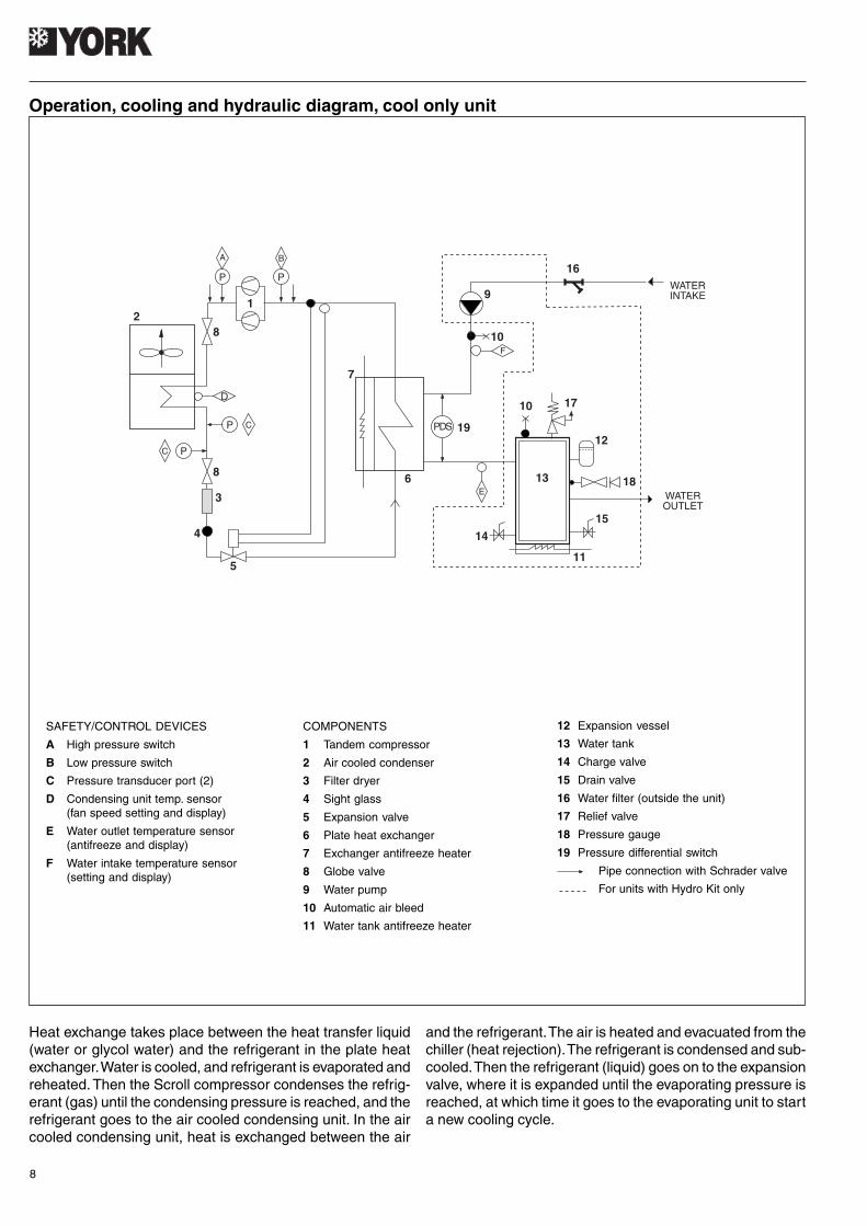
Operation, cooling and hydraulic diagram, cool only unit
SAFETY/CONTROL DEVICES
A High pressure switch
B Low pressure switch
C Pressure transducer port (2)
D Condensing unit temp. sensor(fan speed setting and display)
E Water outlet temperature sensor(antifreeze and display)
F Water intake temperature sensor(setting and display)
COMPONENTS
1 Tandem compressor
2 Air cooled condenser
3 Filter dryer
4 Sight glass
5 Expansion valve
6 Plate heat exchanger
7 Exchanger antifreeze heater
8 Globe valve
9 Water pump
10 Automatic air bleed
11 Water tank antifreeze heater
12 Expansion vessel
13 Water tank
14 Charge valve
15 Drain valve
16 Water filter (outside the unit)
17 Relief valve
18 Pressure gauge
19 Pressure differential switch
Pipe connection with Schrader valve
For units with Hydro Kit only
Heat exchange takes place between the heat transfer liquid(water or glycol water) and the refrigerant in the plate heatexchanger. Water is cooled, and refrigerant is evaporated andreheated. Then the Scroll compressor condenses the refrig-erant (gas) until the condensing pressure is reached, and therefrigerant goes to the air cooled condensing unit. In the aircooled condensing unit, heat is exchanged between the air
and the refrigerant. The air is heated and evacuated from thechiller (heat rejection). The refrigerant is condensed and sub-cooled. Then the refrigerant (liquid) goes on to the expansionvalve, where it is expanded until the evaporating pressure isreached, at which time it goes to the evaporating unit to starta new cooling cycle.
D
P
A
P
B
1
8
8
PC
5
4
7
9
16
10F
6
PDS 19
E
15
14
11
12
1710
2
3
13 18WATEROUTLET
WATERINTAKE
P C

9
Operation, cooling and hydraulic diagram, heat pump unit
SAFETY/CONTROL DEVICES
A High pressure switch
B Low pressure switch
E Condensing unit temperature sensors (2)(fan speed setting, defrosts and display)
F Water outlet temperature sensor(antifreeze and display)
G Water intake temperature sensor(setting and display)
COMPONENTS
1 Tandem compressor
2 Air cooled condenser
3 Filter dryer
4 Sight glass
5 Expansion valve
6 Plate heat exchanger
7 Exchanger antifreeze heater
8 Globe valve
9 4-way valve
10 Liquid receiver
11 Water pump
12 Automatic air bleed
13 Water tank antifreeze heater
14 Expansion vessel
15 Water tank
16 Charge valve
17 Drain valve
18 Water filter (outside the unit)
19 Relief valve
20 Water pressure gauge
21 Pressure differential switch
22 Check valve
Pipe connection with Schrader valve
For units with Hydro Kit only
Cooling cycleThe 4-way valve is activated. Heat exchange takes placebetween the heat transfer liquid (water or glycol water) andthe refrigerant in the plate heat exchanger. Water is cooled,and refrigerant is evaporated and reheated. Then the Scrolltype compressor condenses the refrigerant (gas) until thecondensing pressure is reached, and the refrigerant goes tothe air cooled condensing unit. In the air cooled condensingunit, heat is exchanged between the air and the refrigerant.The air is heated and evacuated from the chiller (heat rejec-tion). The refrigerant is condensed and sub-cooled. Then the
refrigerant (liquid) goes on to the expansion valve, where it isexpanded until the evaporating pressure is reached, at whichtime it goes to the evaporating unit to start a new coolingcycle.
Heating cycleThe cycle is reversed to heating mode. The 4-way valve isnot activated. The condensing unit becomes the evaporatingunit, and the evaporating unit becomes the condensing unit.The water in the heat exchanger is heated.
E
3
4
5
7
8
8
2
9ON
P
A B
P
18
1912
11
14
13
21
G
PDS
F
1017
13
16
15 20
6
1
WATEROUTLET
WATERINTAKE
22
10
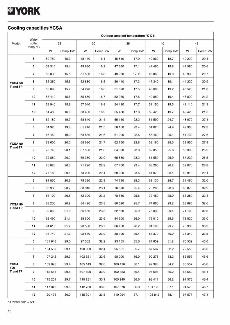
Model
W Comp. kW W Comp. kW W Comp. kW W Comp. kW W Comp. kW
5 50 780 15.3 48 140 16.1 45 510 17.0 42 860 18.7 40 220 20.4
6 52 310 15.4 49 830 16.2 47 360 17.1 44 460 18.8 41 580 20.6
7 53 830 15.5 51 500 16.3 49 260 17..2 46 060 19.0 42 930 20.7
8 55 360 15.6 52 880 16.5 50 440 17.3 47 340 19.1 44 220 20.9
9 56 890 15.7 54 270 16.6 51 690 17.5 48 600 19.2 45 520 21.0
10 58 410 15.8 55 650 16.7 52 930 17.6 49 880 19.4 46 820 21.2
11 59 940 15.9 57 040 16.8 54 180 17.7 51 150 19.5 48 110 21.3
12 61 480 16.0 58 430 16.9 55 430 17.8 52 420 19.7 49 420 21.5
5 62 180 19.7 58 640 21.4 55 110 22.2 51 590 24.7 48 070 27.1
6 64 320 19.8 61 240 21.5 58 160 22.4 54 020 24.9 49 900 27.3
7 66 460 19.9 63 830 21.6 61 200 22.6 56 460 25.1 51 730 27.6
8 68 600 20.0 65 680 21.7 62 760 22.8 58 160 25.3 53 550 27.9
9 70 740 20.1 67 530 21.8 64 320 23.0 59 850 25.6 55 390 28.2
10 72 880 20.2 69 380 22.0 65 880 23.2 61 550 25.9 57 230 28.5
11 75 020 20.3 71 220 22.2 67 450 23.4 63 260 26.2 59 070 28.8
12 77 160 20.4 73 090 22.4 69 020 23.6 64 970 26.4 60 910 29.1
5 81 850 20.6 78 320 22.9 74 790 25.3 68 130 28.7 61 460 32.0
6 83 930 20.7 80 310 23.1 76 690 25.4 70 280 28.8 63 870 32.2
7 86 100 20.8 82 390 23.2 78 680 25.6 72 480 29.0 66 280 32.4
8 88 230 20.9 84 420 23.3 80 620 25.7 74 660 29.2 68 690 32.6
9 90 360 21.0 86 460 23.5 82 560 25.9 76 830 29.4 71 100 32.8
10 92 490 21.1 88 500 23.6 84 500 26.0 79 010 29.5 73 520 33.0
11 94 610 21.2 90 530 23.7 86 450 26.2 81 190 29.7 75 930 33.2
12 96 740 21.3 92 570 23.9 88 390 26.4 83 370 30.0 78 340 33.5
5 101 948 29.0 97 552 32.2 93 155 35.6 84 859 31.2 76 552 45.0
6 104 539 29.1 100 030 32.4 95 521 35.7 87 537 32.2 79 553 45.3
7 107 242 29.3 102 621 32.6 98 000 36.0 90 278 33.2 82 555 45.6
8 109 895 29.4 105 149 32.8 100 416 36.1 92 993 34.2 85 557 45.8
9 112 548 29.5 107 690 33.0 102 833 36.4 95 696 35.2 88 559 46.1
10 115 201 29.7 110 231 33.1 105 249 36.6 98 411 36.2 91 573 46.4
11 117 842 29.8 112 760 33.3 107 678 36.8 101 126 37.1 94 575 46.7
12 120 495 30.0 115 301 33.5 110 094 37.1 103 842 38.1 97 577 47.1
Outdoor ambient temperature °C DB
25 30 35 40 45Wateroutlet
temp. °C
YCSA 50T and TP
YCSA 60T and TP
YCSA 80T and TP
YCSA100T and TP
Cooling capacities YCSA
∆T water side = 5°C
11
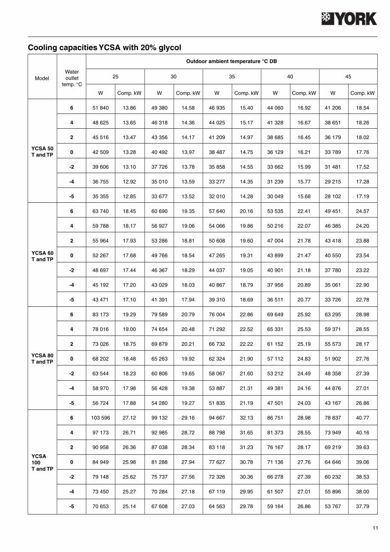
Model
W Comp. kW W Comp. kW W Comp. kW W Comp. kW W Comp. kW
6 51 840 13.86 49 380 14.58 46 935 15.40 44 060 16.92 41 206 18.54
4 48 625 13.65 46 318 14.36 44 025 15.17 41 328 16.67 38 651 18.26
2 45 516 13.47 43 356 14.17 41 209 14.97 38 685 16.45 36 179 18.02
0 42 509 13.28 40 492 13.97 38 487 14.75 36 129 16.21 33 789 17.76
-2 39 606 13.10 37 726 13.78 35 858 14.55 33 662 15.99 31 481 17.52
-4 36 755 12.92 35 010 13.59 33 277 14.35 31 239 15.77 29 215 17.28
-5 35 355 12.85 33 677 13.52 32 010 14.28 30 049 15.68 28 102 17.19
6 63 740 18.45 60 690 19.35 57 640 20.16 53 535 22.41 49 451 24.57
4 59 788 18.17 56 927 19.06 54 066 19.86 50 216 22.07 46 385 24.20
2 55 964 17.93 53 286 18.81 50 608 19.60 47 004 21.78 43 418 23.88
0 52 267 17.68 49 766 18.54 47 265 19.31 43 899 21.47 40 550 23.54
-2 48 697 17.44 46 367 18.29 44 037 19.05 40 901 21.18 37 780 23.22
-4 45 192 17.20 43 029 18.03 40 867 18.79 37 956 20.89 35 061 22.90
-5 43 471 17.10 41 391 17.94 39 310 18.69 36 511 20.77 33 726 22.78
6 83 173 19.29 79 589 20.79 76 004 22.86 69 649 25.92 63 295 28.98
4 78 016 19.00 74 654 20.48 71 292 22.52 65 331 25.53 59 371 28.55
2 73 026 18.75 69 879 20.21 66 732 22.22 61 152 25.19 55 573 28.17
0 68 202 18.48 65 263 19.92 62 324 21.90 57 112 24.83 51 902 27.76
-2 63 544 18.23 60 806 19.65 58 067 21.60 53 212 24.49 48 358 27.39
-4 58 970 17.98 56 428 19.38 53 887 21.31 49 381 24.16 44 876 27.01
-5 56 724 17.88 54 280 19.27 51 835 21.19 47 501 24.03 43 167 26.86
6 103 596 27.12 99 132 29.16 94 667 32.13 86 751 28.98 78 837 40.77
4 97 173 26.71 92 985 28.72 88 798 31.65 81 373 28.55 73 949 40.16
2 90 958 26.36 87 038 28.34 83 118 31.23 76 167 28.17 69 219 39.63
0 84 949 25.98 81 288 27.94 77 627 30.78 71 136 27.76 64 646 39.06
-2 79 148 25.62 75 737 27.56 72 326 30.36 66 278 27.39 60 232 38.53
-4 73 450 25.27 70 284 27.18 67 119 29.95 61 507 27.01 55 896 38.00
-5 70 653 25.14 67 608 27.03 64 563 29.78 59 164 26.86 53 767 37.79
Outdoor ambient temperature °C DB
25 30 35 40 45Wateroutlet
temp. °C
YCSA 50T and TP
YCSA 60T and TP
YCSA 80T and TP
YCSA100T and TP
Cooling capacities YCSA with 20% glycol

12
Model
W Comp. kW W Comp. kW W Comp. kW W Comp. kW W Comp. kW
6 51 002 13.63 48 585 14.33 46 175 15.10 43 350 16.63 40 540 18.23
4 47 840 13.43 45 573 14.12 43 312 14.87 40 662 16.38 30 027 17.96
2 44 780 13.23 42 658 13.91 40 542 14.66 38 061 16.15 35 594 17.70
0 41 822 13.06 39 840 13.73 37 864 14.47 35 547 15.93 33 243 17.46
-2 38 966 12.88 37 119 13.54 35 278 14.27 33 119 15.72 30 973 17.23
-4 36 161 12.72 34 447 13.37 32 738 14.09 30 735 15.52 28 743 17.01
-5 34 784 12.64 33 135 13.28 31 491 14.00 29 565 15.42 27 648 16.90
6 62 712 18.14 59 710 19.02 56 705 19.82 52 670 22.03 48 650 24.16
4 58 824 17.87 56 008 18.73 53 189 19.52 49 404 21.70 45 634 23.80
2 55 061 17.61 52 425 18.47 49 787 19.25 46 244 21.39 42 715 23.46
0 51 424 17.38 48 962 18.22 46 498 18.99 43 189 21.10 39 893 23.15
-2 47 912 17.14 45 618 17.97 43 323 18.73 40 240 20.82 37 169 22.83
-4 44 463 16.92 42 334 17.75 40 204 18.49 37 343 20.55 34 493 22.54
-5 42 770 16.82 40 722 17.63 38 673 18.37 35 921 20.42 33 179 22.40
6 81 832 18.96 78 304 20.44 74 771 22.47 68 524 25.48 62 270 28.50
4 76 758 18.68 73 449 20.13 70 136 22.14 64 275 25.10 58 409 28.07
2 71 848 18.41 68 751 19.84 65 649 21.82 60 164 24.74 54 673 27.67
0 67 102 18.17 64 209 19.58 61 313 21.53 56 189 24.41 51 061 27.30
-2 62 519 17.92 59 824 19.31 57 125 21.24 52 352 24.08 47 574 26.93
-4 58 019 17.69 55 517 19.07 53 013 20.97 48 583 23.77 44 149 26.59
-5 55 809 17.58 53 403 18.94 50 994 20.83 46 733 23.62 42 468 26.42
6 101 926 26.66 97 531 28.66 93 131 31.59 85 349 28.49 77 560 40.09
4 95 606 26.26 91 484 28.23 87 357 31.11 80 058 28.06 72 751 39.49
2 89 491 25.91 85 632 27.86 81 769 30.70 74 937 27.69 68 098 38.97
0 83 579 25.54 79 975 27.46 76 368 30.26 69 986 27.29 63 599 38.41
-2 77 871 25.19 74 514 27.09 71 152 29.85 65 207 26.92 59 256 37.88
-4 72 265 24.85 69 149 26.71 66 030 29.44 60 513 26.55 54 990 37.36
-5 69 513 24.71 66 516 26.57 63 516 29.28 58 208 26.41 52 896 37.16
Outdoor ambient temperature °C DB
25 30 35 40 45
Wateroutlet
temp. °C
YCSA 50T and TP
YCSA 60T and TP
YCSA 80T and TP
YCSA100T and TP
Cooling capacities YCSA with 30% glycol

13
Model
W Comp. kW W Comp. kW W Comp. kW W Comp. kW W Comp. kW
5 48 560 16.4 46 040 17.3 43 520 18.2 40 990 20.1 38 460 21.9
6 50 020 16.5 47 650 17.4 45 290 18.3 42 520 20.2 39 760 22.1
7 51 480 16.6 49 250 17.5 47 050 18.5 44 050 20.4 41 050 22.3
8 52 940 16.7 50 570 17.7 48 240 18.6 45 270 20.5 42 290 22.4
9 54 400 16.8 51 900 17.8 49 430 18.7 46 480 20.7 43 530 22.6
10 55 860 16.9 53 220 17.9 50 620 18.9 47 700 20.8 44 770 22.7
11 57 320 17.0 54 550 18.0 51 810 19.0 48 910 21.0 46 010 22.9
12 58 790 17.1 55 880 18.1 53 010 19.2 50 130 21.1 47 260 23.1
5 63 900 20.2 60 270 21.1 56 640 21.9 53 020 24.4 49 400 26.8
6 66 100 20.2 62 940 21.2 59 770 22.1 55 520 24.6 51 280 27.0
7 68 300 20.3 65 600 21.3 62 900 22.3 58 030 24.8 53 160 27.2
8 70 500 20.3 67 500 21.4 64 500 22.5 59 770 25.0 55 040 27.5
9 72 700 20.4 69 400 21.5 66 100 22.7 61 510 25.3 56 930 27.8
10 74 900 20.4 71 300 21.7 67 710 22.9 63 260 25.6 58 820 28.1
11 77 100 20.5 73 200 21.9 69 320 23.1 65 010 25.8 60 710 28.4
12 79 300 20.6 75 120 22.1 70 940 23.3 66 770 26.0 62 600 28.7
5 75 481 24.0 71 193 25.1 66 905 26.0 62 629 29.0 58 353 31.8
6 78 080 24.0 74 347 25.2 70 603 26.3 65 582 29.2 60 574 32.1
7 80 679 24.1 77 489 25.3 74 300 26.5 68 547 29.5 62 795 32.3
8 83 277 24.1 79 734 25.4 76 190 26.7 70 603 29.7 65 015 32.7
9 85 876 24.2 81 978 25.5 78 080 27.0 72 658 30.1 67 248 33.0
10 88 475 24.2 84 222 25.8 79 982 27.2 74 725 30.4 69 481 33.4
11 91 074 24.4 86 467 26.0 81 884 27.5 76 792 30.7 71 713 33.7
12 93 672 24.5 88 735 26.3 83 797 27.7 78 871 30.9 73 946 34.1
5 97 526 32.6 91 986 34.1 86 446 35.4 80 921 39.4 75 396 43.3
6 100 884 32.6 96 061 34.2 91 223 35.7 84 736 39.7 78 265 43.6
7 104 242 32.8 100 121 34.4 96 000 36.0 88 567 40.0 81 134 43.9
8 107 599 32.8 103 021 34.5 98 442 36.3 91 223 40.4 84 004 44.4
9 110 957 32.9 105 921 34.7 100 884 36.6 93 879 40.8 86 888 44.9
10 114 315 32.9 108 820 35.0 103 341 37.0 96 549 41.3 89 773 45.4
11 117 672 33.1 111 720 35.4 105 798 37.3 99 220 41.7 92 658 45.8
12 121 030 33.3 114 651 35.7 108 271 37.6 101 907 42.0 95 542 46.3
Outdoor ambient temperature °C DB (80% RH)
25 30 35 40 45Wateroutlet
temp. °C
YCSA-H50
T and TP
YCSA-H60
T and TP
YCSA-H80
T and TP
YCSA-H100
T and TP
Cooling capacities YCSA-H
∆T water side = 5°C

14
Model
W Comp. kW W Comp. kW W Comp. kW W Comp. kW W Comp. kW
6 49 570 14.85 47 220 15.66 44 880 16.47 42 140 18.18 39 400 19.89
4 46 497 14.63 44 292 15.43 42 097 16.22 39 527 17.91 36 957 19.59
2 43 522 14.43 41 459 15.22 39 405 16.01 36 999 17.67 34 593 19.33
0 40 647 14.23 38 720 15.00 36 802 15.78 34 555 17.42 32 308 19.05
-2 37 871 14.03 36 076 14.80 34 288 15.56 32 195 17.18 30 102 18.80
-4 35 145 13.84 33 479 14.60 31 820 15.35 29 877 16.94 27 935 18.54
-5 33 807 13.77 32 204 14.52 30 608 15.27 28 739 16.85 26 871 18.44
6 65 505 18.18 62 370 19.08 59 230 19.89 55 020 22.14 50 820 24.30
4 61 444 17.91 58 503 18.79 55 558 19.59 51 609 21.81 47 669 23.94
2 57 513 17.67 54 761 18.55 52 004 19.33 48 308 21.52 44 620 23.62
0 53 714 17.42 51 143 18.28 48 569 19.05 45 116 21.21 41 672 23.28
-2 50 046 17.18 47 651 18.03 45 252 18.80 42 035 20.92 38 826 22.96
-4 46 443 16.94 44 220 17.78 41 994 18.54 39 009 20.63 36 031 22.65
-5 44 674 16.85 42 536 17.69 40 395 18.44 37 524 20.52 34 659 22.53
6 77 376 22.4 73 679 22.7 69 972 23.7 64 993 26.3 60 029 28.9
4 72 579 22.0 69 111 22.3 65 634 23.3 60 964 25.9 56 307 28.5
2 67 936 21.7 64 690 22.0 61 435 23.0 57 064 25.5 52 705 28.1
0 63 448 21.4 60 417 21.7 57 377 22.7 53 294 25.2 49 224 27.7
-2 59 115 21.1 56 291 21.4 53 458 22.4 49 655 24.8 45 862 27.3
-4 54 860 20.8 52 239 21.1 49 610 22.1 46 080 24.5 42 561 26.9
-5 52 770 20.7 50 249 21.0 47 721 21.9 44 325 24.4 40 940 26.8
6 99 974 30.4 95 198 30.8 90 407 32.1 83 975 35.7 77 561 39.2
4 93 776 29.9 89 296 30.3 84 802 31.6 78 769 35.2 72 752 38.7
2 87 777 29.5 83 584 29.9 79 378 31.2 73 730 34.7 68 098 38.1
0 81 979 29.1 78 063 29.5 74 134 30.8 68 860 34.2 63 600 37.6
-2 76 380 28.7 72 731 29.1 69 071 30.4 64 157 33.8 59 256 37.1
-4 70 882 28.3 67 496 28.7 64 099 29.9 59 538 33.3 54 991 36.6
-5 68 182 28.2 64 925 28.5 61 658 29.8 57 271 33.1 52 896 36.4
Outdoor ambient temperature °C DB (80% RH)
25 30 35 40 45
Wateroutlet
temp. °C
YCSA-H50
T and TP
YCSA-H60
T and TP
YCSA-H80
T and TP
YCSA-H100
T and TP
Cooling capacities YCSA-H with 20% glycol
15
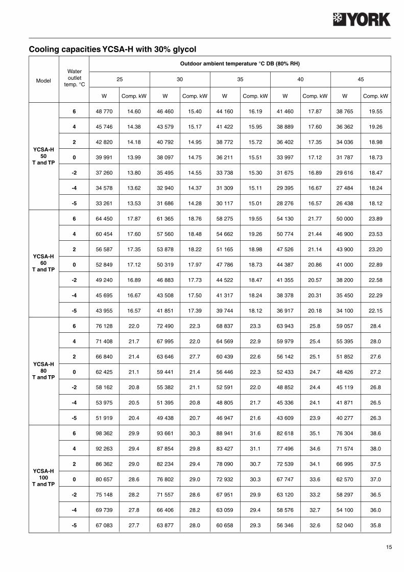
Model
W Comp. kW W Comp. kW W Comp. kW W Comp. kW W Comp. kW
6 48 770 14.60 46 460 15.40 44 160 16.19 41 460 17.87 38 765 19.55
4 45 746 14.38 43 579 15.17 41 422 15.95 38 889 17.60 36 362 19.26
2 42 820 14.18 40 792 14.95 38 772 15.72 36 402 17.35 34 036 18.98
0 39 991 13.99 38 097 14.75 36 211 15.51 33 997 17.12 31 787 18.73
-2 37 260 13.80 35 495 14.55 33 738 15.30 31 675 16.89 29 616 18.47
-4 34 578 13.62 32 940 14.37 31 309 15.11 29 395 16.67 27 484 18.24
-5 33 261 13.53 31 686 14.28 30 117 15.01 28 276 16.57 26 438 18.12
6 64 450 17.87 61 365 18.76 58 275 19.55 54 130 21.77 50 000 23.89
4 60 454 17.60 57 560 18.48 54 662 19.26 50 774 21.44 46 900 23.53
2 56 587 17.35 53 878 18.22 51 165 18.98 47 526 21.14 43 900 23.20
0 52 849 17.12 50 319 17.97 47 786 18.73 44 387 20.86 41 000 22.89
-2 49 240 16.89 46 883 17.73 44 522 18.47 41 355 20.57 38 200 22.58
-4 45 695 16.67 43 508 17.50 41 317 18.24 38 378 20.31 35 450 22.29
-5 43 955 16.57 41 851 17.39 39 744 18.12 36 917 20.18 34 100 22.15
6 76 128 22.0 72 490 22.3 68 837 23.3 63 943 25.8 59 057 28.4
4 71 408 21.7 67 995 22.0 64 569 22.9 59 979 25.4 55 395 28.0
2 66 840 21.4 63 646 27.7 60 439 22.6 56 142 25.1 51 852 27.6
0 62 425 21.1 59 441 21.4 56 446 22.3 52 433 24.7 48 426 27.2
-2 58 162 20.8 55 382 21.1 52 591 22.0 48 852 24.4 45 119 26.8
-4 53 975 20.5 51 395 20.8 48 805 21.7 45 336 24.1 41 871 26.5
-5 51 919 20.4 49 438 20.7 46 947 21.6 43 609 23.9 40 277 26.3
6 98 362 29.9 93 661 30.3 88 941 31.6 82 618 35.1 76 304 38.6
4 92 263 29.4 87 854 29.8 83 427 31.1 77 496 34.6 71 574 38.0
2 86 362 29.0 82 234 29.4 78 090 30.7 72 539 34.1 66 995 37.5
0 80 657 28.6 76 802 29.0 72 932 30.3 67 747 33.6 62 570 37.0
-2 75 148 28.2 71 557 28.6 67 951 29.9 63 120 33.2 58 297 36.5
-4 69 739 27.8 66 406 28.2 63 059 29.4 58 576 32.7 54 100 36.0
-5 67 083 27.7 63 877 28.0 60 658 29.3 56 346 32.6 52 040 35.8
Outdoor ambient temperature °C DB (80% RH)
25 30 35 40 45
Wateroutlet
temp. °C
YCSA-H50
T and TP
YCSA-H60
T and TP
YCSA-H80
T and TP
YCSA-H100
T and TP
Cooling capacities YCSA-H with 30% glycol

16
W W W W W W W W
30 35 080 13.6 38 130 13.9 42 710 14.4 48 220 14.7 53 150 14.8 58 080 14.9 60 780 14.4 65 290 13.4
35 34 090 15.1 37 170 15.5 41 790 16.0 47 350 16.8 52 300 17.6 57 260 17.4 60 010 17.3 64 590 15.5
40 33 100 16.7 36 210 17.1 40 870 17.8 46 470 18.3 51 460 18.4 56 440 18.5 59 230 18.1 63 890 17.6
45 32 110 18.2 35 250 19.0 39 950 20.3 45 600 21.0 50 610 20.7 55 620 20.5 58 460 20.2 63 190 19.6
50 39 030 21.4 44 720 22.2 49 760 22.4 54 800 22.6 57 680 22.2 62 490 21.7
30 40 110 15.9 43 600 16.3 48 840 16.9 55 130 17.2 60 780 17.3 66 410 17.4 69 500 16.9 74 660 15.7
35 38 980 17.7 42 500 18.1 47 790 18.7 54 140 19.7 59 800 20.6 65 480 20.4 68 620 20.2 73 860 18.1
40 37 850 19.5 41 400 20.0 46 730 20.8 53 150 21.4 58 840 21.5 64 540 21.6 67 730 21.2 73 060 20.6
45 36 720 21.3 40 310 22.2 45 680 23.8 52 140 24.6 57 870 24.2 63 600 24.0 66 850 23.6 72 260 22.9
50 44 630 25.0 51 150 26.0 56 900 26.2 62 660 26.5 65 960 26.0 71 460 24.9
30 51 214 18.4 55 666 18.8 62 353 19.5 70 397 19.9 77 594 20.1 84 791 20.2 88 733 19.5 95 317 18.2
35 49 768 20.5 54 265 21.0 61 009 21.7 69 127 22.8 76 353 23.9 83 594 23.6 87 609 23.5 94 295 21.0
40 48 323 22.6 52 863 23.2 59 666 24.1 67 842 24.8 75 127 25.0 82 397 25.1 86 470 24.5 93 273 23.9
45 46 878 24.7 51 462 25.8 58 323 27.5 66 572 28.5 73 886 28.1 81 200 27.8 85 346 27.4 92 251 26.6
50 56 980 29.0 65 287 30.1 72 645 30.4 80 003 30.6 84 207 30.1 91 230 29.4
30 66 855 26.8 72 668 27.4 81 396 28.4 91 897 29.0 101 293 29.2 110 688 29.4 115 834 28.4 124 429 26.4
35 64 968 29.8 70 838 30.5 79 643 31.5 90 239 33.1 99 673 34.7 109 125 34.3 114 366 34.1 123 095 30.5
40 63 082 32.9 69 009 33.7 77 890 35.1 88 562 36.1 98 072 36.3 107 563 36.5 112 880 35.7 121 761 34.7
45 61 195 35.9 67 179 37.4 76 136 40.0 86 904 41.4 96 452 40.8 106 000 40.4 111 412 39.8 120 427 38.6
50 74 383 42.2 85 227 43.8 94 832 44.1 104 437 44.5 109 926 43.8 119 093 42.8
Outdoor ambient temperature °C DB (80% RH)
Wateroutlet
temp. °C
YCSA-H50
T and TP
Comp.kW
Comp.kW
Model -5 -3 0 3 5 7 10 15
YCSA-H60
T and TP
Comp.kW
Comp.kW
Comp.kW
Comp.kW
Comp.kW
Comp.kW
YCSA-H80
T and TP
YCSA-H100
T and TP
7 500 8 000 9 000 10 000 11 000 12 000 13 000 14 000
360 347 317 280 241 193 141 77
353 340 309 272 229 181 128 62
348 335 303 265 220 169 115 44
Water flow (l/h)
Water at 10° C
Water with 20% glycol (mix at 2° C)
Water with 30% glycol (mix at -2° C)
6 000 7 000 8 000 9 000 10 000 11 000 12 000 13 000
277 256 234 213 180 147 108 66
270 249 226 200 168 133 91 46
265 244 219 190 157 120 75 27
Water flow (l/h)
Water at 10° C
Water with 20% glycol (mix at 2° C)
Water with 30% glycol (mix at -2° C)
Heating capacities
∆T water side = 5°C
Available pressure and pressure drop of water circuit and filterAvailable pressure YCSA/YCSA-H 50 with Hydro Kit (kPa)
Available pressure YCSA/YCSA-H 60 with Hydro Kit (kPa)

17
Water flow (l/h)
Water at 10° C
Water with 20% glycol (mix at 2° C)
Water with 30% glycol (mix at -2° C)
6 000 7 000 8 000 9 000 10 000 11 000 12 000 13 000
20 26 34 44 52 63 73 84
24 31 40 52 62 75 87 100
27 35 46 59 70 85 99 113
Water flow (l/h)
Water at 10° C
Water with 20% glycol (mix at 2° C)
Water with 30% glycol (mix at -2° C)
7 500 8 000 9 000 10 000 11 000 12 000 13 000 14 000
22 25 32 37 46 53 60 72
26 30 38 44 55 63 71 86
30 34 43 50 62 72 81 97
Water flow (l/h)
Water at 10° C
Water with 20% glycol (mix at 2° C)
Water with 30% glycol (mix at -2° C)
Water flow (l/h))
Water at 10° C
Water with 20% glycol (mix at 2° C)
Water with 30% glycol (mix at -2° C)
Water flow (l/h)
Water at 10° C
Water with 20% glycol (mix at 2° C)
Water with 30% glycol (mix at -2° C)
6 000 7 000 8 000 9 000 10 000 11 000 12 000 13 000 14 000 15 000
9 11 13 14 17 24 33 42 53 65
11 13 16 17 20 29 39 50 63 77
12 15 18 19 23 32 45 57 72 88
Water flow (l/h)
Water at 10° C
Water with 20% glycol (mix at 2° C)
24 000 24 500 25 000 25 500 26 000 26 500 27 000 27 500 28 000 28 500
0 1 3 12 22 33 46 58 68 84
0 1.2 3.6 14 26 39 55 69 81 100
Available pressure YCSA/YCSA-H 80 with Hydro Kit (kPa)
Available pressure YCSA/YCSA-H 100 with Hydro Kit (kPa)
Pressure drop YCSA/YCSA-H 50 without Hydro Kit (kPa)
Pressure drop YCSA/YCSA-H 60 without Hydro Kit (kPa)
Pressure drop YCSA/YCSA-H 80 without Hydro Kit (kPa)
Pressure drop YCSA/YCSA-H 100 without Hydro Kit (kPa)
Pressure drop of 2" filter (kPa)
Pressure drop of 2 1/2" filter (kPa)
8 000 9 000 10 000 11 000 12 000 13 000 14 000 15 000 16 000 17 000 18 000 19 000
300 287 274 260 247 231 215 198 181 161 141 118
252 241 230 218 208 194 181 166 152 135 118 99
222 213 203 193 183 171 159 147 134 119 104 87
8 000 9 000 10 000 11 000 12 000 13 000 14 000 15 000 16 000 17 000 18 000 19 000
26 32 37 43 49 55 62 68 74 81 89 97
31 38 44 51 58 65 74 81 88 96 106 115
35 43 50 58 66 74 84 92 100 109 120 131
Water flow (l/h)
Water at 10° C
Water with 20% glycol (mix at 2° C)
Water with 30% glycol (mix at -2° C)
Water flow (l/h)
Water at 10° C
Water with 20% glycol (mix at 2° C)
Water with 30% glycol (mix at -2° C)
11 000 12 000 13 000 14 000 15 000 16 000 17 000 18 000 19 000 20 000
365 351 337 320 304 284 263 242 218 191
307 295 283 269 255 239 221 203 183 161
270 260 250 237 225 210 195 179 161 141
11 000 12 000 13 000 14 000 15 000 16 000 17 000 18 000 19 000 20 000
30 32 35 38 43 48 52 57 64 72
36 38 42 45 51 57 62 68 76 86
41 43 47 51 48 65 70 77 86 97

18
Installation InstructionsInspectionUpon reception, inspect the merchandise and notify both thecarrier and the insurance company, in writing, of any possi-ble damage.
Environmental protectionPackingPacking is made of recyclable material. Its eliminate shouldbe carried out in accordance with the existing local regula-tions on selective collection of residual material.
Elimination of the unitUpon disassembly of the unit, its components should be re-cuperated ecologically. The cooling circuit contains refriger-ant which should be recovered and returned to the gas manu-facturer for recycling.Oil will remain in the sealed compressor and, therefore, itmust be returned with its circuit sealed.The air conditioning unit will be deposited in an area estab-lished by the local authorities, for its selective recuperation.
SafetyInstallation and maintenance operations of this air condition-ing system should be carried out only by qualified and expertpersonnel. Periodical maintenance operations, such as clean-ing the coils and air filters, should be carried out so as tokeep unit performance at an optimum.
This unit should be installed and used in accordance with:- Low Voltage Electrotechnical Regulations.- Safety Regulations for Cooling Plants and Installations.- Regulations on Pressure Equipment.- Basic Construction Standards.- Local ordinances
TransportationThe units should always be transported in a vertical positionso as to avoid oil leaking out of the compressor. If, for anyreason, this position need be changed sporadically, they willremain in that position a strictly necessary period of time.
HandlingThis unit should be handled by using the metal rails suppliedfor fastening and transportation.
Warning signsThe following signs indicate the presence of possible dan-gerous conditions for the users or maintenance personnel.When found on the unit, their meaning should be taken intoaccount.
CAUTION
This symbol indicates an electrical riskor hazard.
Caution: The unit is equipped with a re-mote control system and can start auto-matically. Before having access to theinterior of the unit, disconnect the powersupply so as to avoid any contact withthe fan turbine in motion.
Caution: Fan in operation.
Caution: It is obligatory to read the in-structions prior to any handling.
Caution: Do not touch hot surfaces.
Attention: Possible gas leaks due to in-adequate handling.

19
LocationBefore locating the unit in place, check the specificationsdescribed on same to be sure you have received the ad-equate product.The unit should be placed on a perfectly horizontal plane,making sure the base can support the weight of the unit.If you want to insure the absence of vibration, the unit can beplaced on a cork or similar antivibratory base, or fastened toits base with antivibratory plates or supports.Figure 11 indicates the clearances and fastening points foreach model.
Fastening the unitBefore installing the unit, make sure the structure can with-stand the weight of same.If the unit is placed on the floor, a concrete base should beprepared so as to distribute its weight evenly. See Fig. 7.
ClearancesThe installation of each unit should have clearances for:a) Air intake and discharge.b) Maintenance servicing.c) Power supply connection.For correct operation, always respect the minimum distancesindicated in the general dimensions diagrams with regard topossible obstructions of free air circulation or maintenanceservicing.
WiringElectrical connectionsThe established national regulations should be followedin all cases.Each unit is supplied with a control box to which the powersupply will be connected through a fused main switch or anautomatic switch.
Loose cables can produce overheating of the terminals or an incor-rect operation of the unit. A fire hazard may also exist. Therefore,make sure all cables are connected tightly.
WARNING
Scroll compressors, rotational directionThe Scroll compressors, just like the fans, operate correctlyin one single rotational direction. When starting the equip-ment up, make sure this rotational direction is correct.If it is not correct:- The compressor does not compress.- It makes an unusual noise.- Amp consumption is lower.- It overheats.
Hydraulic connectionsThe hydraulic connections of the water intake and outlet ofthe chiller should be carried out respecting the intake andoutlet directions indicated.Galvanised iron or copper tubing can be use, with dimen-sions no lower than those indicated, and keeping in mind thepressure drops of said connections and of the internal ex-changer of the installation.Pump dimensioning should be carried out considering a nomi-nal flow that allows an ∆t within the operating limits.In all cases, a flow switch should be installed so as to avoidthe possibility of operation without water circulation.An expansion vessel should be installed in the water returntubing.This vessel must be adequate for the total water volume ofthe installation.During the winter season, with outdoor temperatures below0°C, precautions should be taken to avoid the water fromfreezing in the tubing networks.Usual application is to fill the circuit with an antifreeze mix-ture (glycol).

20
YCSA/YCSA-H 50 and 60 T TP
Dimensions and hydraulic connections
Notes:A- Water intake, Ø 2" Gas F.B- Water outlet, Ø 2" Gas F.C- Auxiliary lines.D- Power supply.E- Water intake 3/8" Gas F.
(4)Ø16,5
347
317
B (2")
A (2")
248
447
59 886
1004
59
1410
E
145
70
C(Ø23)
206 1691
2103
206
D(Ø48)
50 50
AIR OUTLET
Rear view
Side view Front view
AIRINTAKE
View from above
AIRINTAKE

21
YCSA/YCSA-H 80 and 100 T TP
Dimensions and hydraulic connections
Notes:A- Water intake, Ø 2" Gas F.B- Water outlet, Ø 2" Gas F.C- Auxiliary lines.D- Power supply.E- Water intake 3/8" Gas F.
(6)Ø16,5
336
G
B (2")
A (2")
389
436
E
145
70
C(Ø23)
F E
C
F
D(Ø61)
50 50
E 67 D
A
67
B
YCSA
80
100
A
1108
1140
B
1400
1582
C
2943
3336
D
970
1002
E
1265
1318
F
207
350
G
317
327
AIR OUTLET
Side view Front view
Rear view
AIRINTAKE
AIRINTAKE
View from above

22
Minimum technical clearance
1500
2000
1000
10001000
1000 2000 1000
1500
1000
3000
1000 1500
1000
1000
AIROUTLET

23
Wiring diagram, YCSA/YCSA-H 50, 60, 80 and 100 (µµµµµC2), 400.3.50
I-24
52b
(1 d
e 3)
YC
SA
/YC
SA
-H-
50, 6
0, 8
0, 1
00 (
µC2)
400.
3.50
45
12
36
78
9
TH
E C
OM
PO
NE
NT
S IN
CLU
DE
D IN
TH
ES
E B
OX
ES
AR
E S
TAN
DA
RD
AC
CE
SS
OR
IES
TH
E C
OM
PO
NE
NT
S IN
CLU
DE
D IN
TH
ES
E B
OX
ES
AR
E N
OT
SU
PP
LIE
D B
Y T
HE
MA
NU
FAC
TU
RE
R
BA
SE
CO
NT
RO
L M
OD
ULE
EX
PAN
SIO
N M
OD
ULE
TH
ER
MA
L P
RO
TE
CTO
R C
OM
PR
ES
SO
R 1
TH
ER
MA
L P
RO
TE
CTO
R C
OM
PR
ES
SO
R 2
WAT
ER
INTA
KE
(N
TC
PR
OB
E)
WAT
ER
OU
TLE
T (
NT
C P
RO
BE
)
A1
MO
DU
LE F
AN
SP
EE
D C
ON
TR
OL
CO
OLI
NG
TE
MP
ER
ATU
RE
(N
TC
PR
OB
E)
A2
MO
DU
LE F
AN
SP
EE
D C
ON
TR
OL
CO
OLI
NG
TE
MP
ER
ATU
RE
(N
TC
PR
OB
E)
FAN
MO
TOR
SC
ON
DE
NS
ER
S
EV
AP
OR
ATIN
G U
NIT
HE
ATE
R
PR
OT
EC
TIO
N F
US
ES
A1
AN
D A
2(3
15m
A S
LOW
)
SP
EE
D S
WIT
CH
FU
SE
FLO
W S
WIT
CH
FAN
SP
EE
DC
ON
TR
OLL
ER
HIG
H P
RE
SS
UR
E S
WIT
CH
(AU
TOM
ATIC
RE
SE
T)
LOW
PR
ES
SU
RE
SW
ITC
H(A
UTO
MAT
IC R
ES
ET
)
CO
MP
RE
SS
OR
1 C
ON
TAC
TOR
CO
MP
RE
SS
OR
2 C
ON
TAC
TOR
PU
MP
CO
NTA
CTO
R
CO
MP
RE
SS
OR
S 1
AN
D 2
FAN
S
PU
MP
GE
NE
RA
L P
RO
TE
CT
ION
DIF
FE
RE
NT
IAL
PR
ES
SU
RE
SW
ITC
HW
ATE
R C
IRC
UIT
AU
TOM
ATIC
SW
ITC
HE
S
SU
MP
HE
ATE
R C
OM
P. 1
SU
MP
HE
ATE
R C
OM
P. 2
RE
MO
TE
CO
OL/
HE
AT
RE
MO
TE
ON
/OF
F
230/
24V
TR
AN
SF
OR
ME
R
TAN
K H
EAT
ER
TH
ER
MA
L P
RO
TE
CTO
RS
FAN
S M
3, M
4 A
ND
M5
4-W
AY
VA
LVE
(YC
SA
-H O
NLY
)
A1:
A2:
A3:
A4:
B1:
B2:
B3:
B7:
C1,
C2,
C3:
EH
:
F1,
F2:
F3:
FS
:
FS
C:
HP
:
LP
:
K1:
K2:
K3:
M1,
M2:
M3,
M4,
M5:
M6:
PG
:
PD
W:
Q:
R7:
R8:
RC
H:
RO
O:
T: TH
:
TK
1, T
K2,
TK
3:
V4V
:
M6
K3
21
65
43
21
65
43
1413
Q3
K1
21
65
43
M1
21
65
43
K2
21
65
43
M2
21
65
43
L
Q6
(3A
)
N
L1
N
A3T
2
T1
M1
M2
(16)
S2
S1
A4T
2
T1
M1
M2
(29)
S2
S1
FS
L1
L1NN
Q5
Q30
m A
400V
,3 ~
,50H
z,N
,L2
L3
L2L3
IO
L1N
Q7
L2L3
(28) 1413 (28) (*)
C1
M3
M4
C2
TK1 (19)
TK2 (31)
M5
C3
TK3 (31)
Y B
K1
(20)
K2
(33)
(70W
)(7
0W)
Q1
Q2
(22)
(33)
A3
(6)
(16)
A4
(7)
(29)
Q4
M5
M4
M3
M1
M2
M6
MO
TOR
PO
SIT
ION
3x25
+
, N
3x25
+
, N
3x35
+
, N
3x50
+
, N
"B"
mm
Cu
2
YC
SA
50/
60
YC
SA
80/
100
FS
C
LO
AD
R721 22
R821 22
F3
LN
YG
ND
YC
SA
50 60
Q5
63A
80A
80 100
100A
125A
"B"
mm
2 C
u

24
Wiring diagram, YCSA/YCSA-H 50, 60, 80 and 100 (µµµµµC2), 400.3.50
I-24
52b
(2 o
f 3)
YC
SA
/YC
SA
-H-
50, 6
0, 8
0, 1
00 (
µC2)
400.
3.50
1314
1011
1215
1619
2021
22
21 3
4 65 21
22
(2)
(8)
BY
N2
N3
N4
21 3
4 65 13
14
(1)
(28)
2325
26
PLP
RC
HM
1
M2
A3
(6)
PHP
RO
O
TK
1C
5
1718
TK
TK
80 V
A
230V 0V
L1 N
1F1
GO G
B1
GN
D
B2
GN
D
B3 Y
ID5
GN
D
ID3
ID4
ID1
ID2
A1
BB
1B
2B
3
µ ch
iller
2
N1
N2
C½ N3
N4
C¾
C5
N5
C½
C¾
LN
F1
Y B
N1
K1
A1
A2(COMP. 1)
(V4V)
1413
1211
109
8
76
54
32
1
1
7
2
8
3 9
4 10
5 11
6
12
WATER INTAKE
WATER OUTLET
PROBE COIL
B1
B2
B3
B
J1
J2
F2
F2
T
+TG
ND 2
tLA
N
EH
(75w
)
K3A
1
A2
(PUMP)
V4V
(**)
N5
AL
AR
M
a b c d e f g
(*)
(1)
(2)
(*)
ON
UN
ITS
WIT
H H
YD
RO
KIT
ON
LY(*
*) Y
CS
A-H
ON
LY
24V
F1,
F2:
315
mA
(S
low
)
ID4
ID2
ID1
ID3
ID5
TH
(*)
(2x2
00w
)

25
Wiring diagram, YCSA/YCSA-H 50, 60, 80 and 100 (µµµµµC2), 400.3.50
I-24
52a
(3 o
f 3)
YC
S/Y
CS
A-H
- 50
, 60,
80,
100
(µC
2)40
0.3.
50
2728
21 3
4 65 21
22
(3)
(9)
2930
31
M1
M2
B7
PROBE COIL
+TG
ND
tLA
N/4
85
Y1
PG
TK
3T
K
TK
TK
2T
K
TK
A4
(7)
FS
(1)
Q3
(1)
K3
PD
W
3233
GO G
B5
GN
D
B6
GN
D
B7
Y1
ID10
GN
D
ID8
ID9
ID6
ID7
A2
µ ch
iller
2 (E
xpan
sion
)
N6
N7
C6/
7
N8
N9
C8/
9C
10
N10
C6/
7
LN
N6
K2A
1
A2
(COMP. 2)
1413
1211
109
8
76
54
32
1
12
34
56
B
J3
J4
78
910
1112
(3)
C8/
9
ID10
ID9
ID7
ID6
ID8 5
4
13 14(*
)
13 14(*
)
3
a b c d e f g y1 LNB
(*)
ON
UN
ITS
WIT
H H
YD
RO
KIT
ON
LY

26
YCSA/YCSA-H 50, 60, 80 and 100 T/TP
Wiring
L1
PE
L3
N
L2
POWER SUPPLY400V - 3 + N - ph - 50Hz
N
N3
C
NO
REMOTE ON/OFF SWITCH
PUMP RELAYMÁX 2A RESIST. A 230Vac(VERSION WITHOUT PACK ONLY)
B EXTERNAL GENERALPROTECTION
YCSA CONNECTING STRIP TERMINALS
TERMINALS EXTERNAL EQUIPMENT
YCSA CONNECTING STRIP VOLT-FREE CONTACT
CLIENT WIRING
YCSA CONNECTING STRIPEXTERNAL CONNECTING STRIP
MAIN SWITCH
230 Vca THERMINAL
N5
GENERAL ALARM (VOLT-FREE INVERTERCONTACT, MAX. 2A RESIST. AT 230Vca)
4
B
FLOW SWITCH (ON UNITS WITHOUT A PACK, AND A NOCONTACT FROM THE PUMP CONTACTOR AND A NOCONTACT FROM THE PUMP MEGNETOTHERMALSWITCH IN SERIES WITH THE FLOW SWITCH)
ID5
B
REMOTE HEAT/COOL SWITCH.CLOSED = HEAT, OPEN =COOL(YCSA-H ONLY)
C5
ID1
ID10

27
2 x 17.5 2 x 19 2 x 9.2 2 x 10.2
2 x 16.5 - 2 x 8.6 -
2 x 19.8 2 x 21 2 x 11.1 2 x 12
2 x 19.5 - 2 x 11.3 -
2 x 23.8 2 x 24.6 2 x 13.2 2 x 13.9
2 x 23.5 - 2 x 12.8 -
2 x 33 2 x 36 2 x 18 2 x 20.2
2 x 33 - 2 x 18 -
Nominal NominalW
Start
Compressor Fans
Power supplyV.ph.Hz.
Model Nominal kWNominal A
AHeatCoolAHeatCool
YCSA-H60
Nominal Nominal
Pump
WA
YCSA60
YCSA-H50
YCSA50
127 2 x 3652 x 1,8 1 3502,9
167 2 x 6252 x 2,5 1 8503,4
YCSA-H100
YCSA100
YCSA-H80
YCSA80
198 3 x 5303 x 2,45 2 2004,3
225 3 x 7603 x 3,4 2 7005,2
Electrical characteristics
400.3.50
- - - -
Voltage limits
Nominal at 400
DB air inlet temperature to coil
Operating cycle
Water outlet temperature
Operating cycle
Temp. differentialbetween the wateroutlet and intake
Minimum °C Maximum °C Minimum °C Maximum °C Minimum°C
Maximum°CMinimum Maximum Cool Heat Cool Heat Cool Heat Cool Heat
Model
(1) At lower water temperatures, it is advisable to use glycol type antifreeze mixtures. Minimum Tº with glycol -5 (2) IPESL - SdM - UMT - TÜV,38°C SAQ, 40°C DUTCH. (3) -18°C with low temperature kit (optional) in models YCSA (4) 45°C if intake air is -5°C.
YCSA
Limits of use
342 436 -10 (3) 46 (2) 6 (1) 15 3 7-10 20 30 50 (4)
- That the guarantee card has been filled out.- That maintenance instructions have been
given, or a periodical revision contract hasbeen signed.
- That operating instructions have been givento the user.
Check:- That voltage is always between 342 - 436 V.- That the power supply cable section is at least
equal to the section recommended in thecorresponding wiring diagrams.
Prior to final approval of the installation
YCSA-H

Ref.: Y-R70103 0705
Related Documents