Huawei OceanStor Mission-Critical Hybrid Flash Storage Systems Technical White Paper Issue 01 Date 2020-01-01 HUAWEI TECHNOLOGIES CO., LTD.

Welcome message from author
This document is posted to help you gain knowledge. Please leave a comment to let me know what you think about it! Share it to your friends and learn new things together.
Transcript

Huawei OceanStor Mission-Critical Hybrid Flash Storage Systems
Technical White Paper
Issue 01
Date 2020-01-01
HUAWEI TECHNOLOGIES CO., LTD.
Issue 01 (2020-01-01) Copyright © Huawei Technologies Co.,
Ltd.
i
Copyright © Huawei Technologies Co., Ltd. 2019. All rights reserved.
No part of this document may be reproduced or transmitted in any form or by any means without prior
written consent of Huawei Technologies Co., Ltd.
Trademarks and Permissions
and other Huawei trademarks are trademarks of Huawei Technologies Co., Ltd.
All other trademarks and trade names mentioned in this document are the property of their respective
holders.
Notice
The purchased products, services and features are stipulated by the contract made between Huawei and
the customer. All or part of the products, services and features described in this document may not be
within the purchase scope or the usage scope. Unless otherwise specified in the contract, all statements,
information, and recommendations in this document are provided "AS IS" without warranties, guarantees or
representations of any kind, either express or implied.
The information in this document is subject to change without notice. Every effort has been made in the
preparation of this document to ensure accuracy of the contents, but all statements, information, and
recommendations in this document do not constitute a warranty of any kind, express or implied.
Huawei Technologies Co., Ltd.
Address: Huawei Industrial Base
Bantian, Longgang
Shenzhen 518129
People's Republic of China
Website: https://e.huawei.com
Huawei OceanStor Mission-Critical Hybrid Flash
Storage Systems
Technical White Paper Contents
Issue 01 (2020-01-01) Copyright © Huawei Technologies Co.,
Ltd.
ii
Contents
1 Executive Summary ............................................................................................................. 1
2 Overview ................................................................................................................................ 2
2.1 OceanStor Mission-Critical Hybrid Flash Storage Series ......................................................................................... 2
2.2 Product Highlights and Customer Benefits .................................................................................................................. 3
3 System Architecture ............................................................................................................ 7
3.1 Hardware Architecture ...................................................................................................................................................... 7
3.1.1 System Hardware Design ............................................................................................................................................ 7
3.1.2 Disk Enclosure Design................................................................................................................................................ 10
3.1.2.1 SAS Disk Enclosures............................................................................................................................................... 11
3.1.2.2 Smart SAS and Smart NVMe Disk Enclosures ................................................................................................. 11
3.1.3 Full Hardware Redundancy ....................................................................................................................................... 13
3.1.4 Chip Design ................................................................................................................................................................... 13
3.1.5 SmartMatrix 3.0 Full-Mesh Architecture ................................................................................................................. 17
3.1.5.1 Fully Interconnected Controllers ........................................................................................................................... 18
3.1.5.2 Fully Shared Front-End Interconnect Modules .................................................................................................. 19
3.1.5.3 Fully Shared Back-End Interconnect Modules .................................................................................................. 21
3.1.5.4 Fully Shared Scale-Out Interface Modules......................................................................................................... 22
3.1.5.5 RDMA Interconnection Channels for Low Latency ........................................................................................... 23
3.1.6 Security and Trustworthiness Design ...................................................................................................................... 25
3.1.6.1 Software Integrity Protection .................................................................................................................................. 25
3.1.6.2 Secure Boot ............................................................................................................................................................... 25
3.1.6.3 Trusted Measurement ............................................................................................................................................. 26
3.1.6.4 SED Data Encryption ............................................................................................................................................... 27
3.2 Software Architecture ..................................................................................................................................................... 28
3.2.1 Block Virtualization ...................................................................................................................................................... 29
3.2.2 SAN and NAS Convergence ..................................................................................................................................... 32
3.2.3 Load Balancing ............................................................................................................................................................. 33
3.2.4 Data Caching ................................................................................................................................................................ 33
3.2.5 End-to-End Data Integrity Protection....................................................................................................................... 34
3.2.6 Various Software Features......................................................................................................................................... 35
3.2.7 Flash-Oriented System Optimization....................................................................................................................... 35
4 Smart Series Features ....................................................................................................... 36

Huawei OceanStor Mission-Critical Hybrid Flash
Storage Systems
Technical White Paper Contents
Issue 01 (2020-01-01) Copyright © Huawei Technologies Co.,
Ltd.
iii
4.1 SmartVirtualiztaion .......................................................................................................................................................... 36
4.2 SmartMigration ................................................................................................................................................................. 38
4.2.1 SmartMigration for Block ............................................................................................................................................ 38
4.2.2 SmartMigration for File ............................................................................................................................................... 39
4.3 SmartDedupe and SmartCompression ...................................................................................................................... 42
4.4 SmartTier ........................................................................................................................................................................... 44
4.4.1 SmartTier for Block ...................................................................................................................................................... 44
4.4.2 SmartTier for File ......................................................................................................................................................... 45
4.5 SmartThin .......................................................................................................................................................................... 47
4.6 SmartQoS.......................................................................................................................................................................... 47
4.7 SmartPartition................................................................................................................................................................... 49
4.8 SmartCache ...................................................................................................................................................................... 51
4.9 SmartErase ....................................................................................................................................................................... 52
4.10 SmartMulti-Tenant ......................................................................................................................................................... 52
4.11 SmartQuota..................................................................................................................................................................... 54
4.12 SmartMotion ................................................................................................................................................................... 55
5 Hyper Series Features ....................................................................................................... 57
5.1 HyperSnap ........................................................................................................................................................................ 57
5.1.1 HyperSnap for Block ................................................................................................................................................... 57
5.1.2 HyperSnap for File ....................................................................................................................................................... 58
5.2 HyperClone ....................................................................................................................................................................... 60
5.2.1 HyperClone for Block .................................................................................................................................................. 60
5.2.2 HyperClone for File...................................................................................................................................................... 64
5.3 HyperReplication ............................................................................................................................................................. 65
5.3.1 HyperReplication/S for Block .................................................................................................................................... 66
5.3.2 HyperReplication/A for Block ..................................................................................................................................... 68
5.3.3 HyperReplication/A for File ........................................................................................................................................ 70
5.4 HyperMetro ....................................................................................................................................................................... 73
5.4.1 HyperMetro for Block .................................................................................................................................................. 73
5.4.2 HyperMetro for File ...................................................................................................................................................... 76
5.5 HyperVault......................................................................................................................................................................... 79
5.6 HyperCopy ........................................................................................................................................................................ 80
5.7 HyperMirror ....................................................................................................................................................................... 82
5.8 HyperLock ......................................................................................................................................................................... 85
5.9 3DC..................................................................................................................................................................................... 88
A More Information................................................................................................................ 89
B Feedback ............................................................................................................................. 90
Huawei OceanStor Mission-Critical Hybrid Flash
Storage Systems
Technical White Paper 1 Executive Summary
Issue 01 (2020-01-01) Copyright © Huawei Technologies Co.,
Ltd.
1
1 Executive Summary
Huawei OceanStor mission-critical hybrid flash storage systems (OceanStor
mission-critical hybrid flash storage series for short) are designed to provide excellent data services for enterprise-class applications. OceanStor mission-critical hybrid flash storage series consists of OceanStor 6800 V5, 18500 V5, and 18800 V5.
This document describes the key technologies, unique advantages, and customer benefits of OceanStor mission-critical hybrid flash storage series in terms of product positioning, hardware architecture, software architecture, and software features.
Huawei OceanStor Mission-Critical Hybrid Flash
Storage Systems
Technical White Paper 2 Overview
Issue 01 (2020-01-01) Copyright © Huawei Technologies Co.,
Ltd.
2
2 Overview
2.1 OceanStor Mission-Critical Hybrid Flash Storage Series
2.2 Product Highlights and Customer Benefits
2.1 OceanStor Mission-Critical Hybrid Flash Storage Series
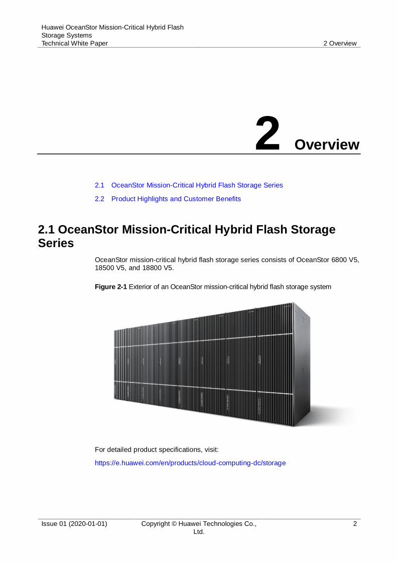
OceanStor mission-critical hybrid flash storage series consists of OceanStor 6800 V5, 18500 V5, and 18800 V5.
Figure 2-1 Exterior of an OceanStor mission-critical hybrid flash storage system
For detailed product specifications, visit:
https://e.huawei.com/en/products/cloud-computing-dc/storage
Huawei OceanStor Mission-Critical Hybrid Flash
Storage Systems
Technical White Paper 2 Overview
Issue 01 (2020-01-01) Copyright © Huawei Technologies Co.,
Ltd.
3
2.2 Product Highlights and Customer Benefits
OceanStor mission-critical hybrid flash storage series is the latest generation of
Huawei high-end storage series.
Leveraging a best-in-class SmartMatrix 3.0 architecture, HyperMetro for both SAN and NAS, flash storage optimization technologies, a cutting-edge hardware platform, and a full range of software features used for efficiency improvement and data protection, the storage series delivers world-leading reliability, performance, and solutions that meet the storage needs of various applications such as large-database
Online Transaction Processing (OLTP), Online Analytical Processing (OLAP), and cloud computing.
Applicable to sectors and industries such as government, finance, carrier, manufacturing, and healthcare, OceanStor mission-critical hybrid flash storage series is the best choice for core applications of enterprises.
Converged: Accelerated Data Service Efficiency
Powered by the latest OceanStor OS, OceanStor mission-critical hybrid flash storage
series provides converged and unified storage resource pools that boast the agility of storage resource scheduling. This enables free data mobility and helps enterprise IT architectures develop into cloud-based architectures.
Convergence of all types of flash storage
Huawei provides comprehensive flash storage products that support
interconnection and communication between one another, regardless of their types, levels, and versions. The convergence of data storage, management, and O&M ensures that storage systems can deliver high performance (6 million IOPS) and low latency (1 ms), as well as the long-term robust reliability of SSDs.
Convergence of SAN and NAS
SAN and NAS are converged to provide elastic storage services, improve storage
resource utilization, and reduce the total cost of ownership (TCO). Underlying storage resource pools directly provide both SAN and NAS services, thereby shortening storage resource access paths and thereby boosting the industry-leading performance and functionality of SAN and NAS services to even greater levels.
Convergence of storage resource pools
The built-in heterogeneous virtualization function, SmartVirtualization, enables OceanStor mission-critical hybrid flash storage series to take over the storage systems (of different levels, types, and models) of other mainstream vendors, and integrate them into a unified storage resource pool. This can eliminate data silos
and enable unified resource management, automation, and service orchestration. In addition, data can be automatically migrated from third-party storage to Huawei storage without interrupting services. This reduces the migration time by an average of 60%.
Convergence of multiple data centers
OceanStor mission-critical hybrid flash storage series can be deployed in the
gateway-free active-active data centers solution (HyperMetro for both SAN and NAS) that integrates SAN and NAS storage services to achieve service continuity across data centers. The active-active data centers (two data centers) can be smoothly upgraded to three data centers, delivering the highest level of service continuity in geo-redundant mode. Customers can also deploy hierarchical data

Huawei OceanStor Mission-Critical Hybrid Flash
Storage Systems
Technical White Paper 2 Overview
Issue 01 (2020-01-01) Copyright © Huawei Technologies Co.,
Ltd.
4
centers for the purpose of centralized disaster recovery. The storage series supports backup of data from 64 subordinate data centers to a central data center.
Convergence of cloud resources
OceanStor mission-critical hybrid flash storage series can be deployed in the
hybrid-cloud-based storage solution in which data disaster recovery between private cloud and public cloud can be implemented through on- and off-premise resource collaboration and data flows, achieving smooth migration of enterprise storage services to the cloud.
Stable and Reliable: 99.9999% High Availability from Products to Solutions
The industry-leading SmartMatrix 3.0 system architecture and comprehensive reliability technologies help customers achieve always-on services.
Chip-level reliability
Four types of chips (controller CPU, southbridge, network adapter, and SAS controller) are integrated to reduce points of failures. Reliability, Availability and Serviceability (RAS) technologies such as module-level error recovery and error correction code (ECC) are used to ensure CPU reliability. SSD chips are equipped with wear leveling algorithm and Huawei-patented anti-wear leveling
algorithm to improve SSD reliability. Intelligent BMC chips implement comprehensive management and control over components such as the CPUs and memory modules, shortening the fault recovery time from 2 hours to 10 minutes.
4-controller symmetric controller enclosure
With the SmartMatrix architecture, OceanStor mission-critical hybrid flash storage series integrates four controllers into the 4 U space of a controller enclosure, achieving full redundancy of controllers. The controllers are then interconnected through a passive backplane. In addition, continuous cache mirroring as well as front-end and back-end I/O interface module interconnection techniques are used, further enhancing 4-controller redundancy, with each of the four controllers acting
as a hot backup for each other. Even if three controllers fail at the same time, service stability is protected, maximizing the continuity of mission-critical applications and preventing a single-point running status that is often seen in scenarios where traditional high-end storage systems are upgraded or a controller is faulty.
Load balancing across controllers
The multi-controller architecture allows load balancing among controllers and eliminates single points of failure, thereby ensuring high availability of storage systems and stable running of services.
Full hardware redundancy
All components and channels are redundant to prevent single points of failure. Fault detection, recovery, and isolation can be independently implemented for each component and channel, ensuring stable system running.
Rapid data restoration
Innovative block-level virtualization reduces the time required to reconstruct 1 TB of data from 10 hours to 30 minutes. Being compared with traditional storage
systems, OceanStor mission-critical hybrid flash storage series reduces the risks of data damage caused by disk failures by 95%.
DIX + PI end-to-end data protection

Huawei OceanStor Mission-Critical Hybrid Flash
Storage Systems
Technical White Paper 2 Overview
Issue 01 (2020-01-01) Copyright © Huawei Technologies Co.,
Ltd.
5
Based on PI and DIX, OceanStor mission-critical hybrid flash storage series provides solutions that protect data integrity all the way from application systems and HBAs to storage systems and disks. This prevents damage to data, further protecting services.
A wide range of data protection software
The Hyper series data protection software includes HyperSnap, HyperClone, HyperVault, HyperReplication, HyperMetro, 3DC, and other data protection technologies. They protect user data locally, remotely, inside systems, and across different regions, and achieve 99.9999% availability, maximizing service continuity and data availability.
HyperMetro for both SAN and NAS
OceanStor mission-critical hybrid flash storage series supports HyperMetro for both SAN and NAS, ensuring high availability of databases and file services. HyperMetro enables load balancing of active-active mirrors and non-disruptive cross-site takeover. This protects core application systems against breakdown as well as ensures zero loss of core application data and zero service interruption. In
addition, the gateway-free design can effectively reduce the purchase cost and deployment complexity. A single set of equipment can be smoothly upgraded to active-active mode and further expanded to the geo-redundant mode with three data centers.
Fast: Outstanding Performance Achieved to Meet Ever-Increasing Requirements of Enterprise Services
The next-generation storage hardware that perfectly matches hybrid flash storage delivers the best performance in the industry. The flash-oriented system architecture is capable of quickly responding to core service requirements.
Flash storage architecture
OceanStor mission-critical hybrid flash storage series uses the flash-oriented system architecture. Based on flash convergence technology, multi-core CPUs,
resource scheduling, adaptive cache, redundant array of independent disks (RAID), and interworking between the OceanStor OS and disks are all specially designed to suit flash memory. The storage systems can intelligently sense HDDs and SSDs, automatically distinguish media types, and dynamically select the optimal algorithms. This allows the storage systems to deliver stable I/O
response time of less than 1 ms in the event of a large number of service access requests, thereby ensuring optimal performance for critical applications.
Industry-leading specifications
OceanStor mission-critical hybrid flash storage series uses Huawei Kunpeng processors, remote direct memory access (RDMA) between controllers, and
back-end 100 Gbit/s NVMe over Fabric or 12 Gbit/s SAS 3.0 high-speed ports, and supports a maximum of 768 front-end ports with each controller enclosure to provide up to 1280 GB/s system bandwidth, fully meeting the requirements of applications for concurrent accesses to core databases at a low latency.
Flexible scalability
OceanStor mission-critical hybrid flash storage series supports high-speed
enterprise-class NVMe SSDs and SAS SSDs. A single storage system can be equipped with a maximum of 32 controllers, 32 TB cache, and 9600 disks, providing up to 6 million IOPS at a low latency of 1 ms and achieving industry-leading performance and specifications.

Huawei OceanStor Mission-Critical Hybrid Flash
Storage Systems
Technical White Paper 2 Overview
Issue 01 (2020-01-01) Copyright © Huawei Technologies Co.,
Ltd.
6
Intelligent: AI-based Management
AI is used to reconstruct storage management.
Intelligent O&M
Intelligent remote monitoring enables cloud-based 24/7 proactive monitoring,
remote maintenance, automatic inspection, minute-level fault detection, automatic fault reporting, and automatic trouble ticket creation. Intelligent fault diagnosis enables visualized paths between hosts and storage systems, performance association analysis, and automatic fault location.
Intelligent prediction and evaluation
Intelligent risk prediction identifies system risks in advance based on the analysis
of disks, configurations, capacity, performance, and other aspects. Intelligent service planning allows planning of system performance and capacity based on host service load analysis and system capacity prediction.

Huawei OceanStor Mission-Critical Hybrid Flash
Storage Systems
Technical White Paper 3 System Architecture
Issue 01 (2020-01-01) Copyright © Huawei Technologies Co.,
Ltd.
7
3 System Architecture
3.1 Hardware Architecture
3.2 Software Architecture
3.1 Hardware Architecture
OceanStor mission-critical hybrid flash storage series uses the SmartMatrix
multi-controller architecture. A storage system can be expanded horizontally, in the unit of controller enclosures, to achieve a linear increase in both performance and capacity.
Being equipped with four controllers for redundancy, a controller enclosure uses interconnect I/O modules to implement full interconnection at the front end and back
end. Hosts can concurrently access four controllers after being interconnected with the controllers using front-end Fibre Channel interconnect I/O modules. 12 Gbit/s SAS 3.0 or 100 Gbit/s RDMA interconnect I/O modules are used to implement back-end interconnection. Controller enclosures are fully interconnected using scale-out interface modules (without using switches).
The full-interconnection architecture eliminates single points of failures of all field replaceable units (FRUs), including front-end interface modules, controllers, back-end interface modules, power modules, BBUs, fan modules, and disks. Two or more FRUs are installed in full redundancy. All FRUs are hot-swappable and can be replaced in online mode.
3.1.1 System Hardware Design
OceanStor mission-critical hybrid flash storage series employs 4 U active-active
high-density controller enclosures. Each controller enclosure houses two or four controllers and supports a maximum of 16 Huawei-developed Kunpeng 920 processors. Each controller supports a maximum of four Kunpeng 920 processors. The following figure shows a controller enclosure.

Huawei OceanStor Mission-Critical Hybrid Flash
Storage Systems
Technical White Paper 3 System Architecture
Issue 01 (2020-01-01) Copyright © Huawei Technologies Co.,
Ltd.
8
Figure 3-1 Controller enclosure
The controller enclosures of OceanStor mission-critical hybrid flash storage series employ the disk and controller separation design. Each controller enclosure supports
28 hot-swappable I/O modules that can be fully interconnected and shared by four controllers.
Front-end interface modules include 4-port 8 Gbit/s, 16 Gbit/s, and 32 Gbit/s Fibre Channel interface modules, 4-port 10GE and 25GE interface modules, as well as 2-port 40GE and 100GE interface modules.
Scale-out interface modules are 2-port 100 Gbit/s RDMA interface modules.
Back-end interface modules include 4-port 12 Gbit/s SAS interface modules (for connecting to SAS disk enclosures) and 2-port 100 Gbit/s RDMA interface modules (for connecting to smart SAS or NVMe disk enclosures).
OceanStor mission-critical hybrid flash storage series supports the following types of disk enclosures:
SAS disk enclosure
Smart SAS disk enclosure
Smart NVMe disk enclosure
Each controller enclosure of OceanStor mission-critical hybrid flash storage series has two management modules. Each management module has three GE ports
(maintenance and management network ports), one USB port, and one serial port.
Huawei OceanStor Mission-Critical Hybrid Flash
Storage Systems
Technical White Paper 3 System Architecture
Issue 01 (2020-01-01) Copyright © Huawei Technologies Co.,
Ltd.
9
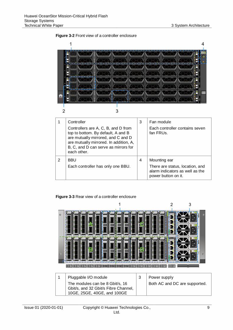
Figure 3-2 Front view of a controller enclosure
1 Controller
Controllers are A, C, B, and D from top to bottom. By default, A and B are mutually mirrored, and C and D are mutually mirrored. In addition, A,
B, C, and D can serve as mirrors for each other.
3 Fan module
Each controller contains seven fan FRUs.
2 BBU
Each controller has only one BBU.
4 Mounting ear
There are status, location, and alarm indicators as well as the power button on it.
Figure 3-3 Rear view of a controller enclosure
1 Pluggable I/O module
The modules can be 8 Gbit/s, 16 Gbit/s, and 32 Gbit/s Fibre Channel, 10GE, 25GE, 40GE, and 100GE
3 Power supply
Both AC and DC are supported.
Huawei OceanStor Mission-Critical Hybrid Flash
Storage Systems
Technical White Paper 3 System Architecture
Issue 01 (2020-01-01) Copyright © Huawei Technologies Co.,
Ltd.
10
interface modules.
2 Management module
Each management module provides one serial port, one maintenance network port, and two management network ports.
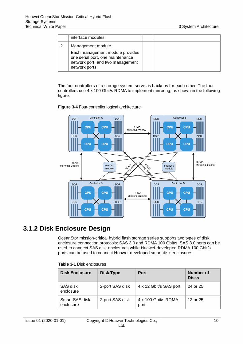
The four controllers of a storage system serve as backups for each other. The four controllers use 4 x 100 Gbit/s RDMA to implement mirroring, as shown in the following figure.
Figure 3-4 Four-controller logical architecture
3.1.2 Disk Enclosure Design
OceanStor mission-critical hybrid flash storage series supports two types of disk enclosure connection protocols: SAS 3.0 and RDMA 100 Gbit/s. SAS 3.0 ports can be used to connect SAS disk enclosures while Huawei-developed RDMA 100 Gbit/s ports can be used to connect Huawei-developed smart disk enclosures.
Table 3-1 Disk enclosures
Disk Enclosure Disk Type Port Number of
Disks
SAS disk enclosure
2-port SAS disk 4 x 12 Gbit/s SAS port 24 or 25
Smart SAS disk enclosure
2-port SAS disk 4 x 100 Gbit/s RDMA port
12 or 25
Huawei OceanStor Mission-Critical Hybrid Flash
Storage Systems
Technical White Paper 3 System Architecture
Issue 01 (2020-01-01) Copyright © Huawei Technologies Co.,
Ltd.
11
Disk Enclosure Disk Type Port Number of Disks
Smart NVMe disk enclosure
2-port NVMe SSD
4 x 100 Gbit/s RDMA port
36
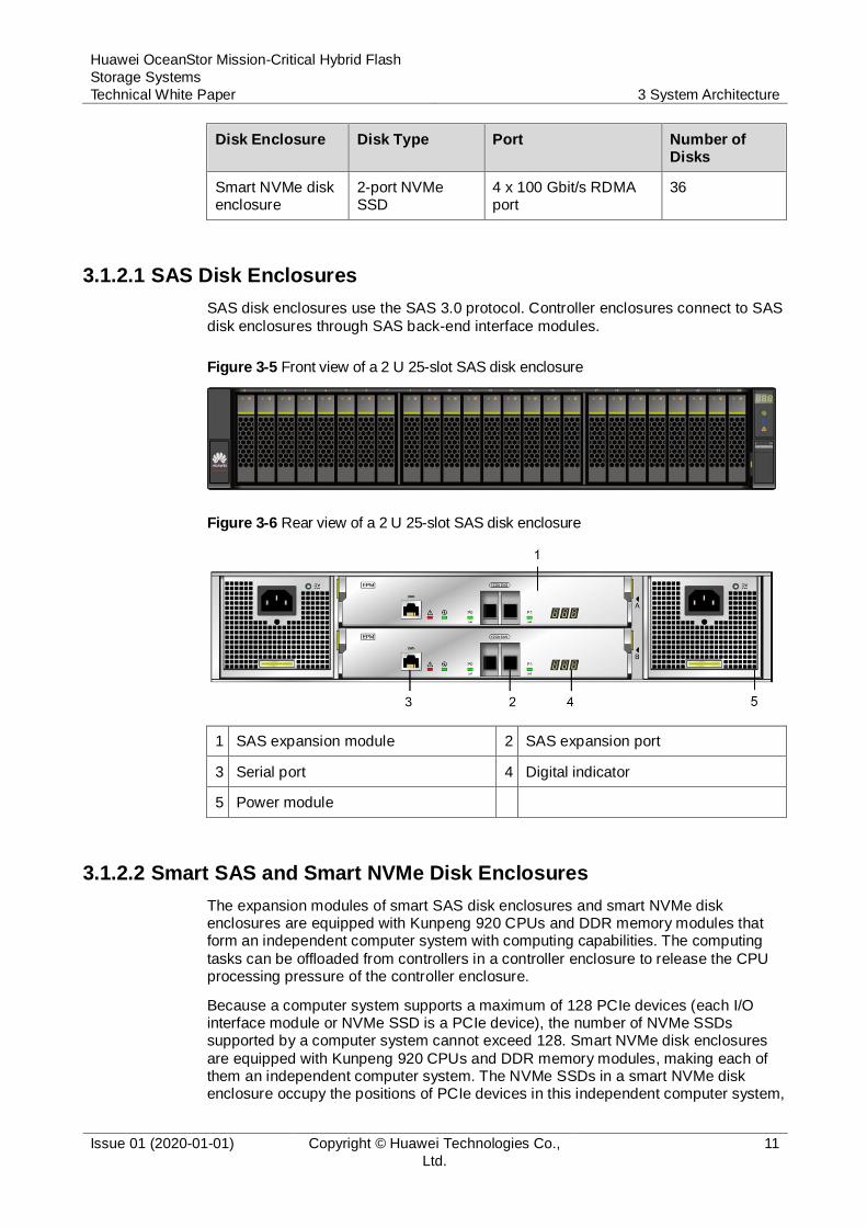
3.1.2.1 SAS Disk Enclosures
SAS disk enclosures use the SAS 3.0 protocol. Controller enclosures connect to SAS
disk enclosures through SAS back-end interface modules.
Figure 3-5 Front view of a 2 U 25-slot SAS disk enclosure
Figure 3-6 Rear view of a 2 U 25-slot SAS disk enclosure
1 SAS expansion module 2 SAS expansion port
3 Serial port 4 Digital indicator
5 Power module
3.1.2.2 Smart SAS and Smart NVMe Disk Enclosures
The expansion modules of smart SAS disk enclosures and smart NVMe disk enclosures are equipped with Kunpeng 920 CPUs and DDR memory modules that form an independent computer system with computing capabilities. The computing
tasks can be offloaded from controllers in a controller enclosure to release the CPU processing pressure of the controller enclosure.
Because a computer system supports a maximum of 128 PCIe devices (each I/O interface module or NVMe SSD is a PCIe device), the number of NVMe SSDs supported by a computer system cannot exceed 128. Smart NVMe disk enclosures
are equipped with Kunpeng 920 CPUs and DDR memory modules, making each of them an independent computer system. The NVMe SSDs in a smart NVMe disk enclosure occupy the positions of PCIe devices in this independent computer system,

Huawei OceanStor Mission-Critical Hybrid Flash
Storage Systems
Technical White Paper 3 System Architecture
Issue 01 (2020-01-01) Copyright © Huawei Technologies Co.,
Ltd.
12
instead of the positions of PCIe devices in a controller enclosure. In addition, smart NVMe disk enclosures connect to a controller enclosure through 100 Gbit/s RDMA ports, allowing a storage system to support a large number of NVMe SSDs.
A controller enclosure connects to smart SAS and smart NVMe disk enclosures through 100 Gbit/s RDMA back-end interface modules to provide high-bandwidth and
low-latency transmission channels. The following figures show the front and rear views of a smart NVMe disk enclosure. (The exterior of a smart SAS disk enclosure is similar to that of a smart NVMe disk enclosure. The differences lie in the number of disk slots and disk types.)
Figure 3-7 Front view of a 2 U 36-slot smart NVMe disk enclosure
Figure 3-8 Rear view of a 2 U 36-slot smart NVMe disk enclosure
1 Expansion module 2 100GE RDMA expansion module
3 Management network port 4 Maintenance network port
5 Serial port 6 Digital indicator
NVMe is intended to provide reliable NVMe commands and data transmission. NVMe over Fabrics can extend NVMe to various storage networks, which reduces the processing overhead of storage network protocol stacks, achieves high concurrency and low latency for applications, and adapts to storage architecture evolution driven by SSDs. NVMe over Fabrics can map NVMe commands and data to multiple fabric
links, including Fibre Channel, InfiniBand, RoCE v2, iWARP, and TCP.
NVMe over Fabric is also supported in back-end interconnection.
NVMe over RoCE v2 applies to the network on which controllers are connected to smart NVMe disk enclosures.
NVMe multi-queue polling designed for multi-core Kunpeng 920 CPUs enables
lock-free processing of concurrent I/Os, making computing capacities of processors into full play.

Huawei OceanStor Mission-Critical Hybrid Flash
Storage Systems
Technical White Paper 3 System Architecture
Issue 01 (2020-01-01) Copyright © Huawei Technologies Co.,
Ltd.
13
Read requests to NVMe SSDs are prioritized, accelerating response to read requests when data is being written into NVMe SSDs.
Being compared with SCSI, NVMe reduces 40% of overhead in the host network protocol stacks, saving CPU resources for more host applications.
3.1.3 Full Hardware Redundancy
All components and channels of OceanStor mission-critical hybrid flash storage series
are fully redundant, eliminating single points of failure. Components and channels can detect, repair, and isolate faults independently to ensure stable system running.
Table 3-2 Fully redundant hardware components
Hardware Component Redundancy Fault Impact
Bay PDU 1 + 1 None
Controller enclosure
Controller 1 + 3 Performance deteriorates accordingly.
Power module 2 + 2 None
Fan module 6 + 1 None
BBU 1 + 3 None
Interface module 1 + 1 None
Management module
1 + 1 None
SAS disk enclosure
Expansion module 1 + 1 None
Power module 1 + 1 None
Fan module 1 + 1 None
Smart SAS disk enclosure
Expansion module 1 + 1 None
Power module 1 + 1 None
Fan module 1 + 1 None
Smart NVMe
disk enclosure
Expansion module 1 + 1 None
Power module 1 + 1 None
Fan module 1 + 1 None
3.1.4 Chip Design
With continuous accumulation and investment in the chip field, Huawei has developed some key chips for storage systems, including SSD controller chips, front-end interface chips (SmartIO chips), management BMC chips, and Arm chips. These chips are applied to OceanStor mission-critical hybrid flash storage series.

Huawei OceanStor Mission-Critical Hybrid Flash
Storage Systems
Technical White Paper 3 System Architecture
Issue 01 (2020-01-01) Copyright © Huawei Technologies Co.,
Ltd.
14
Figure 3-9 Key chips
Kunpeng 920
OceanStor mission-critical hybrid flash storage series uses Arm-based 7 nm processors, namely Kunpeng 920 series developed by Huawei HiSilicon as the CPU
processors.
Kunpeng 920 CPU processors support up to 2.6 GHz CPU frequency, have multiple specifications of cores (24-core, 32-core, 48-core, and 64-core), and are applicable to all OceanStor hybrid flash storage systems. In addition to delivering functions of central processing units, Kunpeng 920 processors also integrate the capabilities of
100 Gbit/s RoCE network chips, SAS initiator chips, and southbridge chips. One processor is capable of providing 100 Gbit/s RDMA for smart disk enclosure connections, SAS protocol for SAS disk enclosure connections, and southbridge for connections of storage management ports and serial ports, simplifying the storage hardware design and reducing the power consumption.
The CPU processors of Kunpeng 920 series support RAID, data integrity field (DIF),
deduplication algorithm (SHA-256), compression algorithm (Gzip and ZLib), encryption algorithm (AES256), and password encryption algorithms (SM3 and SM4). These algorithms can be directly used by Kunpeng 920 series without the need to use other software.

Huawei OceanStor Mission-Critical Hybrid Flash
Storage Systems
Technical White Paper 3 System Architecture
Issue 01 (2020-01-01) Copyright © Huawei Technologies Co.,
Ltd.
15
Figure 3-10 Kunpeng 920
Network Chip Hi1822
All OceanStor hybrid flash storage systems support SmartIO interface modules that are equipped with Hi1822 converged intelligent chips developed by Huawei HiSilicon.
With the support from these powerful chips, OceanStor hybrid flash storage systems are capable of supporting up to 32 Gbit/s Fibre Channel ports and 100GE ports.
Figure 3-11 Network chip Hi1822
The Fibre Channel ports or Ethernet ports on SmartIO interface modules support
FastWrite. It reduces four handshakes in a transmission task to two, remarkably
Huawei OceanStor Mission-Critical Hybrid Flash
Storage Systems
Technical White Paper 3 System Architecture
Issue 01 (2020-01-01) Copyright © Huawei Technologies Co.,
Ltd.
16
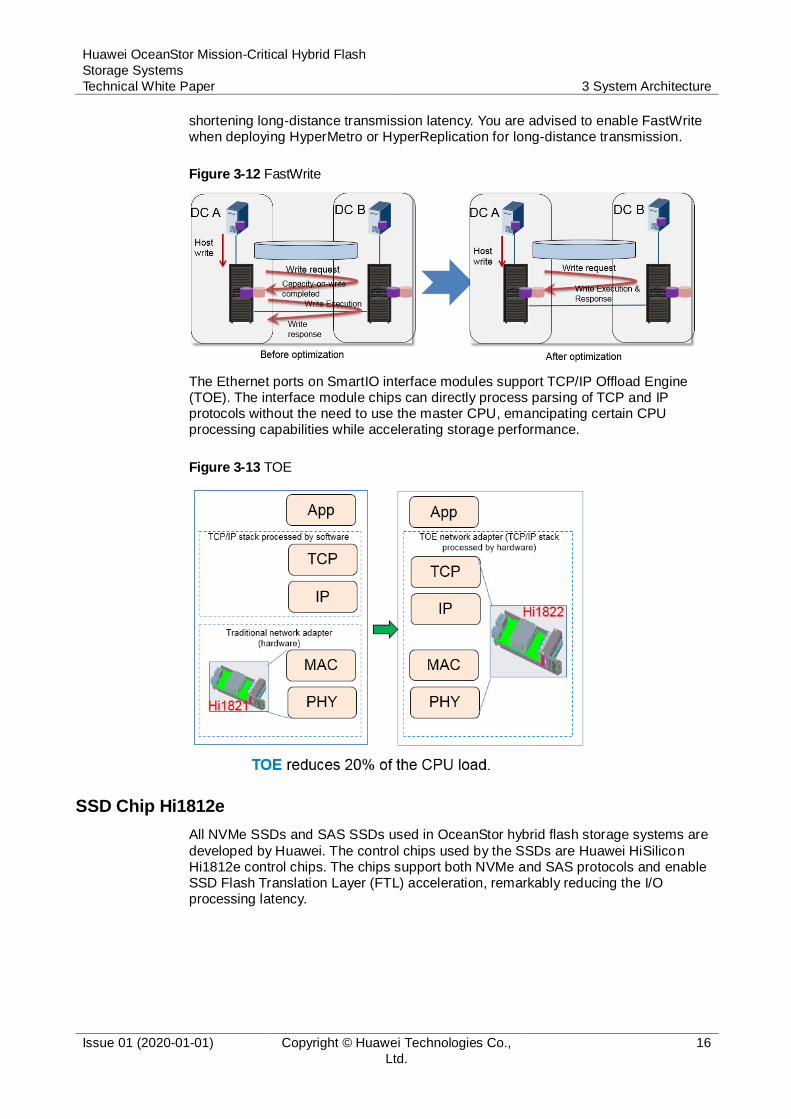
shortening long-distance transmission latency. You are advised to enable FastWrite when deploying HyperMetro or HyperReplication for long-distance transmission.
Figure 3-12 FastWrite
The Ethernet ports on SmartIO interface modules support TCP/IP Offload Engine (TOE). The interface module chips can directly process parsing of TCP and IP protocols without the need to use the master CPU, emancipating certain CPU processing capabilities while accelerating storage performance.
Figure 3-13 TOE
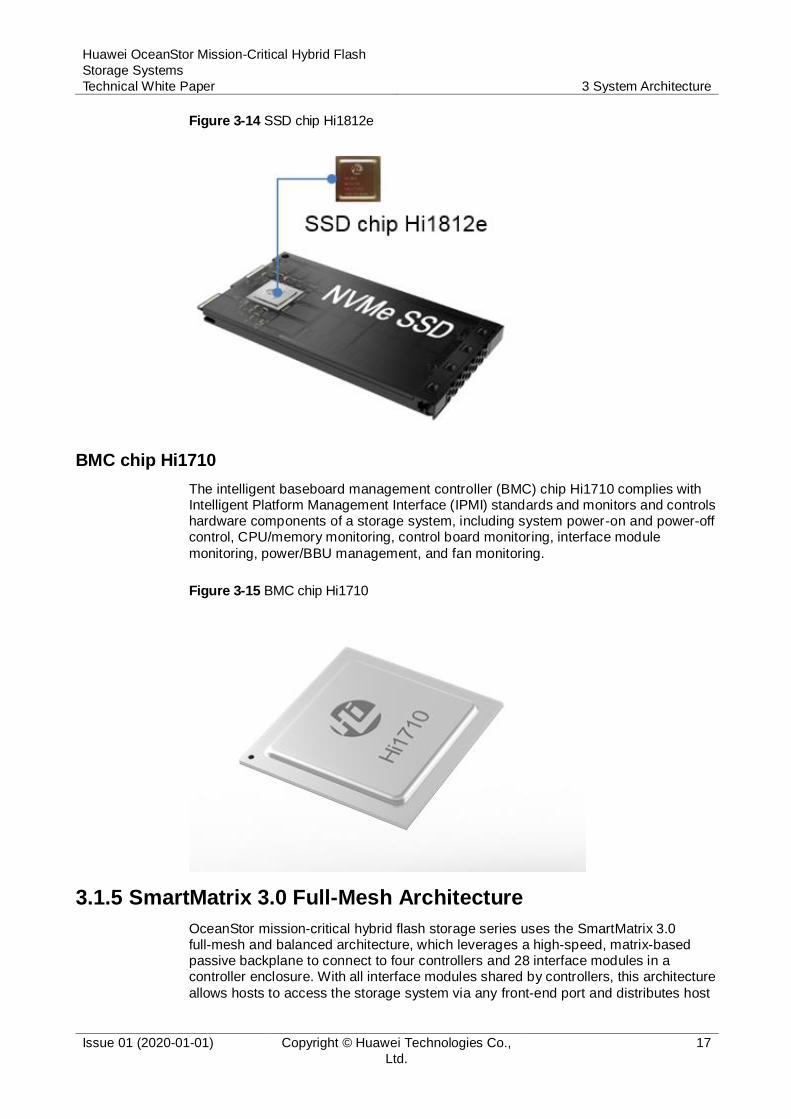
SSD Chip Hi1812e
All NVMe SSDs and SAS SSDs used in OceanStor hybrid flash storage systems are
developed by Huawei. The control chips used by the SSDs are Huawei HiSilicon Hi1812e control chips. The chips support both NVMe and SAS protocols and enable SSD Flash Translation Layer (FTL) acceleration, remarkably reducing the I/O processing latency.
Huawei OceanStor Mission-Critical Hybrid Flash
Storage Systems
Technical White Paper 3 System Architecture
Issue 01 (2020-01-01) Copyright © Huawei Technologies Co.,
Ltd.
17
Figure 3-14 SSD chip Hi1812e
BMC chip Hi1710
The intelligent baseboard management controller (BMC) chip Hi1710 complies with Intelligent Platform Management Interface (IPMI) standards and monitors and controls hardware components of a storage system, including system power-on and power-off control, CPU/memory monitoring, control board monitoring, interface module
monitoring, power/BBU management, and fan monitoring.
Figure 3-15 BMC chip Hi1710
3.1.5 SmartMatrix 3.0 Full-Mesh Architecture
OceanStor mission-critical hybrid flash storage series uses the SmartMatrix 3.0 full-mesh and balanced architecture, which leverages a high-speed, matrix-based passive backplane to connect to four controllers and 28 interface modules in a controller enclosure. With all interface modules shared by controllers, this architecture
allows hosts to access the storage system via any front-end port and distributes host

Huawei OceanStor Mission-Critical Hybrid Flash
Storage Systems
Technical White Paper 3 System Architecture
Issue 01 (2020-01-01) Copyright © Huawei Technologies Co.,
Ltd.
18
I/Os to any controllers. It prevents single point of failure (SPOF) on traditional mission-critical storage systems in the case of system upgrades or controller failures, ensuring service continuity of mission-critical applications.
3.1.5.1 Fully Interconnected Controllers
A controller enclosure of OceanStor mission-critical hybrid flash storage series
contains four controllers, each of which is an independent hot-swappable service processing unit. Each controller connects to the passive backplane through three pairs of high-speed RDMA links, thereby fully interconnecting with the other three controllers. A controller enclosure contains 28 interface modules, each of which connects to four controllers through four PCIe links. Front-end interconnect modules
(FIMs), controllers, and back-end interconnect modules (BIM) are fully interconnected through the passive backplane. Data flows between controllers can be directly transmitted through RDMA links without third-party forwarding, implementing balanced, fast, and efficient access. No external cables or switches are required to connect the four controllers within a controller enclosure. This simplifies deployment and eliminates the risk of human errors. In addition, the passive backplane uses only
passive components, further improving reliability.
Figure 3-16 Full-mesh architecture
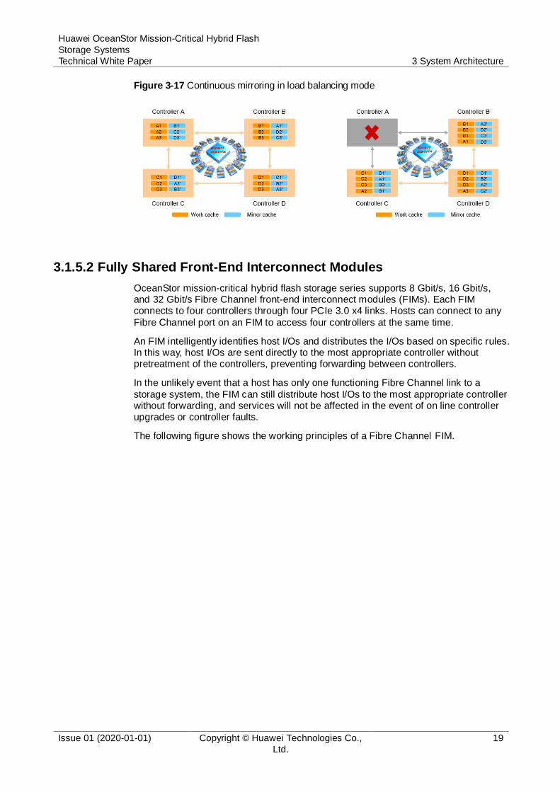
Based on a full-mesh architecture, OceanStor mission-critical hybrid flash storage series provides continuous mirroring among four controllers in load balancing mode. As shown in the following figure, cache data on each controller is evenly mirrored to the other three controllers. If controller A is faulty, cache data is evenly mirrored among controllers B, C, and D. If controller D further fails, cache data is evenly
mirrored between controllers B and C. This ensures that services are available even when three controllers out of four fail. This design ensures high availability of services in the event that multiple controllers fail successively or at the same time.
Huawei OceanStor Mission-Critical Hybrid Flash
Storage Systems
Technical White Paper 3 System Architecture
Issue 01 (2020-01-01) Copyright © Huawei Technologies Co.,
Ltd.
19
Figure 3-17 Continuous mirroring in load balancing mode
3.1.5.2 Fully Shared Front-End Interconnect Modules
OceanStor mission-critical hybrid flash storage series supports 8 Gbit/s, 16 Gbit/s, and 32 Gbit/s Fibre Channel front-end interconnect modules (FIMs). Each FIM connects to four controllers through four PCIe 3.0 x4 links. Hosts can connect to any
Fibre Channel port on an FIM to access four controllers at the same time.
An FIM intelligently identifies host I/Os and distributes the I/Os based on specific rules. In this way, host I/Os are sent directly to the most appropriate controller without pretreatment of the controllers, preventing forwarding between controllers.
In the unlikely event that a host has only one functioning Fibre Channel link to a
storage system, the FIM can still distribute host I/Os to the most appropriate controller without forwarding, and services will not be affected in the event of on line controller upgrades or controller faults.
The following figure shows the working principles of a Fibre Channel FIM.
Huawei OceanStor Mission-Critical Hybrid Flash
Storage Systems
Technical White Paper 3 System Architecture
Issue 01 (2020-01-01) Copyright © Huawei Technologies Co.,
Ltd.
20
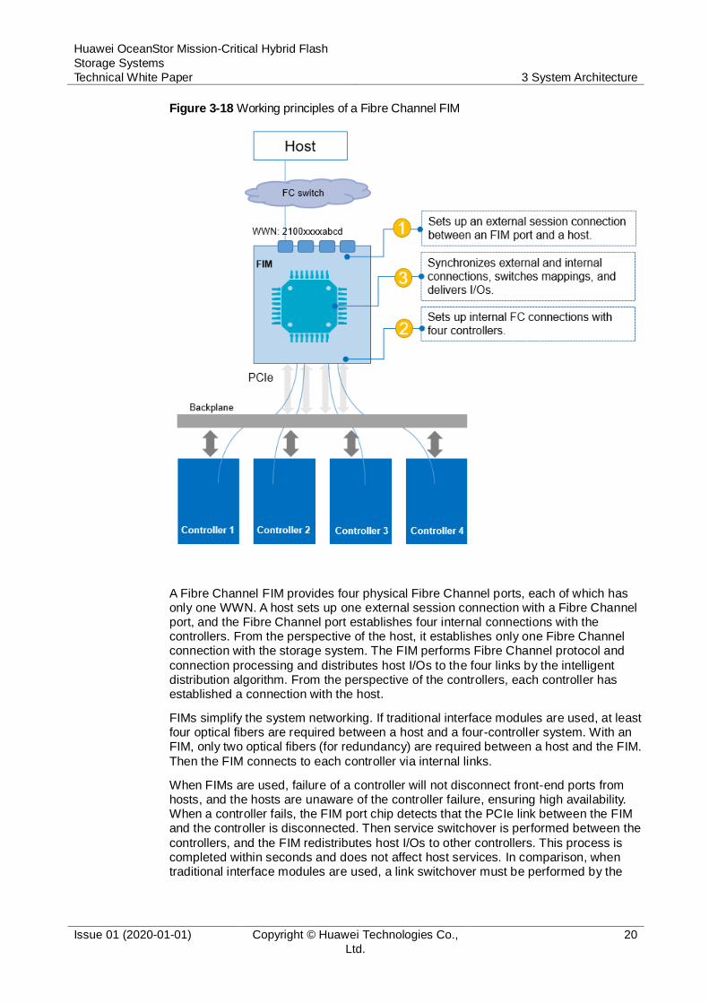
Figure 3-18 Working principles of a Fibre Channel FIM
A Fibre Channel FIM provides four physical Fibre Channel ports, each of which has only one WWN. A host sets up one external session connection with a Fibre Channel port, and the Fibre Channel port establishes four internal connections with the controllers. From the perspective of the host, it establishes only one Fibre Channel connection with the storage system. The FIM performs Fibre Channel protocol and
connection processing and distributes host I/Os to the four links by the intelligent distribution algorithm. From the perspective of the controllers, each controller has established a connection with the host.
FIMs simplify the system networking. If traditional interface modules are used, at least four optical fibers are required between a host and a four-controller system. With an FIM, only two optical fibers (for redundancy) are required between a host and the FIM.
Then the FIM connects to each controller via internal links.
When FIMs are used, failure of a controller will not disconnect front-end ports from hosts, and the hosts are unaware of the controller failure, ensuring high availability. When a controller fails, the FIM port chip detects that the PCIe link between the FIM and the controller is disconnected. Then service switchover is performed between the
controllers, and the FIM redistributes host I/Os to other controllers. This process is completed within seconds and does not affect host services. In comparison, when traditional interface modules are used, a link switchover must be performed by the

Huawei OceanStor Mission-Critical Hybrid Flash
Storage Systems
Technical White Paper 3 System Architecture
Issue 01 (2020-01-01) Copyright © Huawei Technologies Co.,
Ltd.
21
host's multipathing software in the event of a controller failure, which takes a longer time (10 to 30 seconds) and reduces reliability.
In the following figure, if controller 1 is faulty, services on controller 1 are switched over to other controllers within 1s. At the same time, the FIM detects that the link to controller 1 is disconnected and redistributes host I/Os to other functioning controllers
by using the intelligent algorithm. The whole process takes less than a second and the host is unaware of the fault because the Fibre Channel link between the FIM and the host is not disconnected.
Figure 3-19 Service failover between controllers
3.1.5.3 Fully Shared Back-End Interconnect Modules
OceanStor mission-critical hybrid flash storage series supports traditional SAS, smart SAS, and smart NVMe disk enclosures. It uses shared SAS 3.0 interface modules (for
interconnection with SAS disk enclosures) or 100 Gbit/s RDMA interface modules (for interconnection with smart SAS and smart NVMe disk enclosures) for back-end expansion. Each of these interface modules connects to the four controllers in a controller enclosure through four PCIe 3.0 x4 lanes. In this way, disks in each disk enclosure can be simultaneously accessed by all four controllers.
Huawei OceanStor Mission-Critical Hybrid Flash
Storage Systems
Technical White Paper 3 System Architecture
Issue 01 (2020-01-01) Copyright © Huawei Technologies Co.,
Ltd.
22
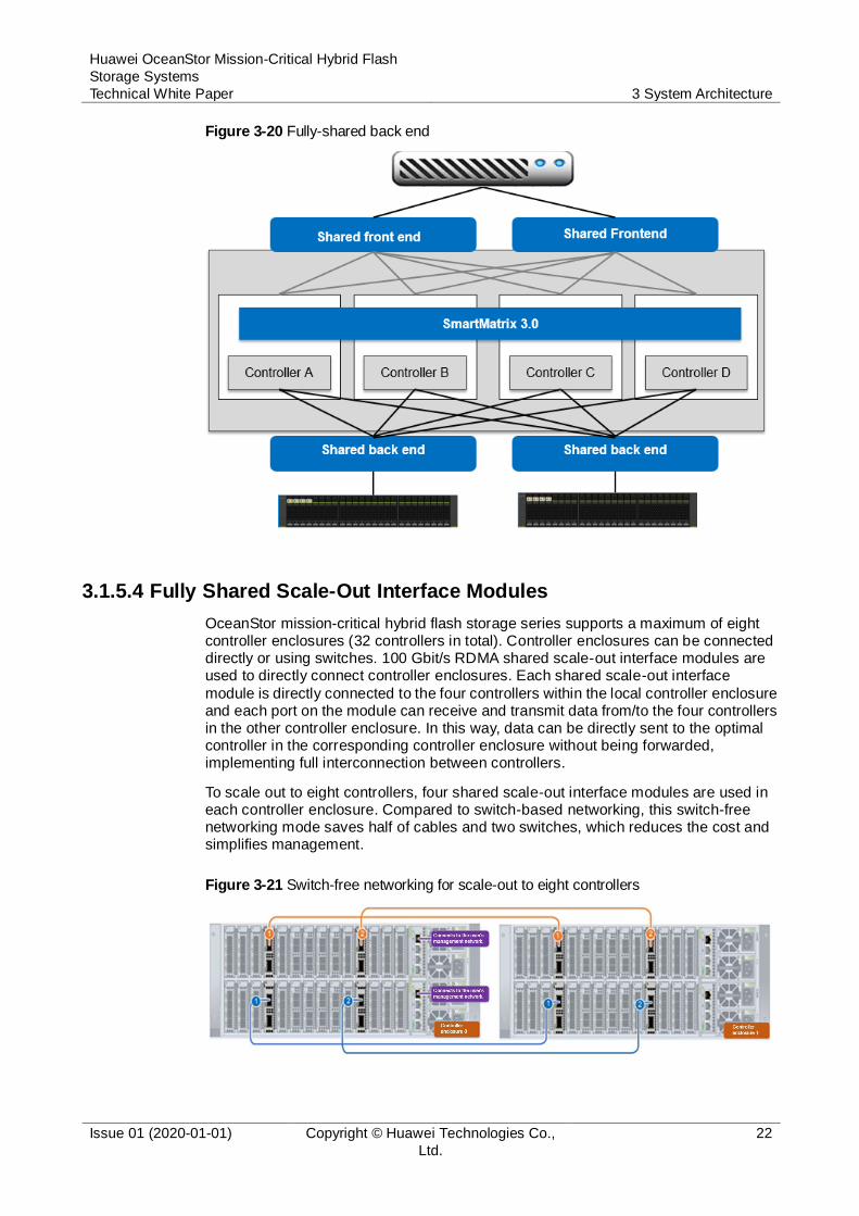
Figure 3-20 Fully-shared back end
3.1.5.4 Fully Shared Scale-Out Interface Modules
OceanStor mission-critical hybrid flash storage series supports a maximum of eight controller enclosures (32 controllers in total). Controller enclosures can be connected directly or using switches. 100 Gbit/s RDMA shared scale-out interface modules are used to directly connect controller enclosures. Each shared scale-out interface
module is directly connected to the four controllers within the local controller enclosure and each port on the module can receive and transmit data from/to the four controllers in the other controller enclosure. In this way, data can be directly sent to the optimal controller in the corresponding controller enclosure without being forwarded, implementing full interconnection between controllers.
To scale out to eight controllers, four shared scale-out interface modules are used in each controller enclosure. Compared to switch-based networking, this switch-free networking mode saves half of cables and two switches, which reduces the cost and simplifies management.
Figure 3-21 Switch-free networking for scale-out to eight controllers
Huawei OceanStor Mission-Critical Hybrid Flash
Storage Systems
Technical White Paper 3 System Architecture
Issue 01 (2020-01-01) Copyright © Huawei Technologies Co.,
Ltd.
23
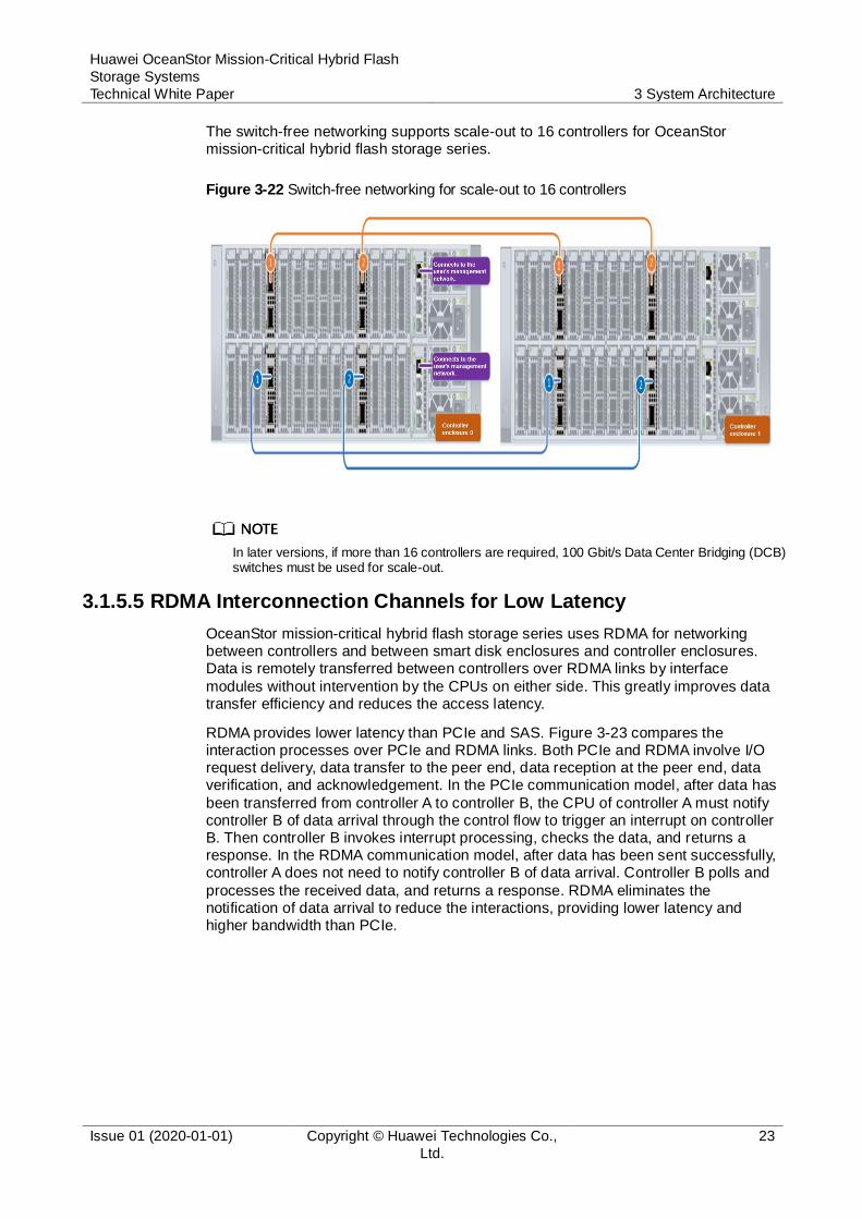
The switch-free networking supports scale-out to 16 controllers for OceanStor mission-critical hybrid flash storage series.
Figure 3-22 Switch-free networking for scale-out to 16 controllers
In later versions, if more than 16 controllers are required, 100 Gbit/s Data Center Bridging (DCB) switches must be used for scale-out.
3.1.5.5 RDMA Interconnection Channels for Low Latency
OceanStor mission-critical hybrid flash storage series uses RDMA for networking between controllers and between smart disk enclosures and controller enclosures. Data is remotely transferred between controllers over RDMA links by interface
modules without intervention by the CPUs on either side. This greatly improves data transfer efficiency and reduces the access latency.
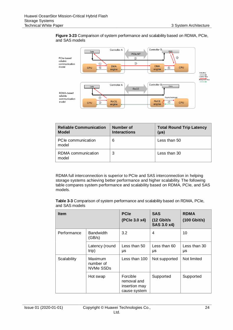
RDMA provides lower latency than PCIe and SAS. Figure 3-23 compares the interaction processes over PCIe and RDMA links. Both PCIe and RDMA involve I/O request delivery, data transfer to the peer end, data reception at the peer end, data verification, and acknowledgement. In the PCIe communication model, after data has
been transferred from controller A to controller B, the CPU of controller A must notify controller B of data arrival through the control flow to trigger an interrupt on controller B. Then controller B invokes interrupt processing, checks the data, and returns a response. In the RDMA communication model, after data has been sent successfully, controller A does not need to notify controller B of data arrival. Controller B polls and
processes the received data, and returns a response. RDMA eliminates the notification of data arrival to reduce the interactions, providing lower latency and higher bandwidth than PCIe.
Huawei OceanStor Mission-Critical Hybrid Flash
Storage Systems
Technical White Paper 3 System Architecture
Issue 01 (2020-01-01) Copyright © Huawei Technologies Co.,
Ltd.
24
Figure 3-23 Comparison of system performance and scalability based on RDMA, PCIe, and SAS models
Reliable Communication Model
Number of Interactions
Total Round Trip Latency (μs)
PCIe communication model
6 Less than 50
RDMA communication
model
3 Less than 30
RDMA full interconnection is superior to PCIe and SAS interconnection in helping storage systems achieving better performance and higher scalability. The following table compares system performance and scalability based on RDMA, PCIe, and SAS models.
Table 3-3 Comparison of system performance and scalability based on RDMA, PCIe, and SAS models
Item PCIe
(PCIe 3.0 x4)
SAS
(12 Gbit/s SAS 3.0 x4)
RDMA
(100 Gbit/s)
Performance Bandwidth (GB/s)
3.2 4 10
Latency (round trip)
Less than 50 μs
Less than 60 μs
Less than 30 μs
Scalability Maximum number of NVMe SSDs
Less than 100 Not supported Not limited
Hot swap Forcible removal and
insertion may cause system
Supported Supported

Huawei OceanStor Mission-Critical Hybrid Flash
Storage Systems
Technical White Paper 3 System Architecture
Issue 01 (2020-01-01) Copyright © Huawei Technologies Co.,
Ltd.
25
Item PCIe
(PCIe 3.0 x4)
SAS
(12 Gbit/s SAS 3.0 x4)
RDMA
(100 Gbit/s)
breakdown.
Number of controllers that can access a
disk enclosure simultaneously
2 4 4
3.1.6 Security and Trustworthiness Design
3.1.6.1 Software Integrity Protection
Digital signatures are used to protect product and upgrade software packages to be installed on onsite devices from being tampered with, ensuring software integrity. A
software package uses an internal digital signature and a product package digital signature. After the software package is sent to the customer over the network, the upgrade module of the storage system verifies the digital signature and performs the upgrade only after the verification is successful. This ensures the integrity and uniqueness of the upgrade package and internal software modules.
Figure 3-24 Software integrity protection
3.1.6.2 Secure Boot
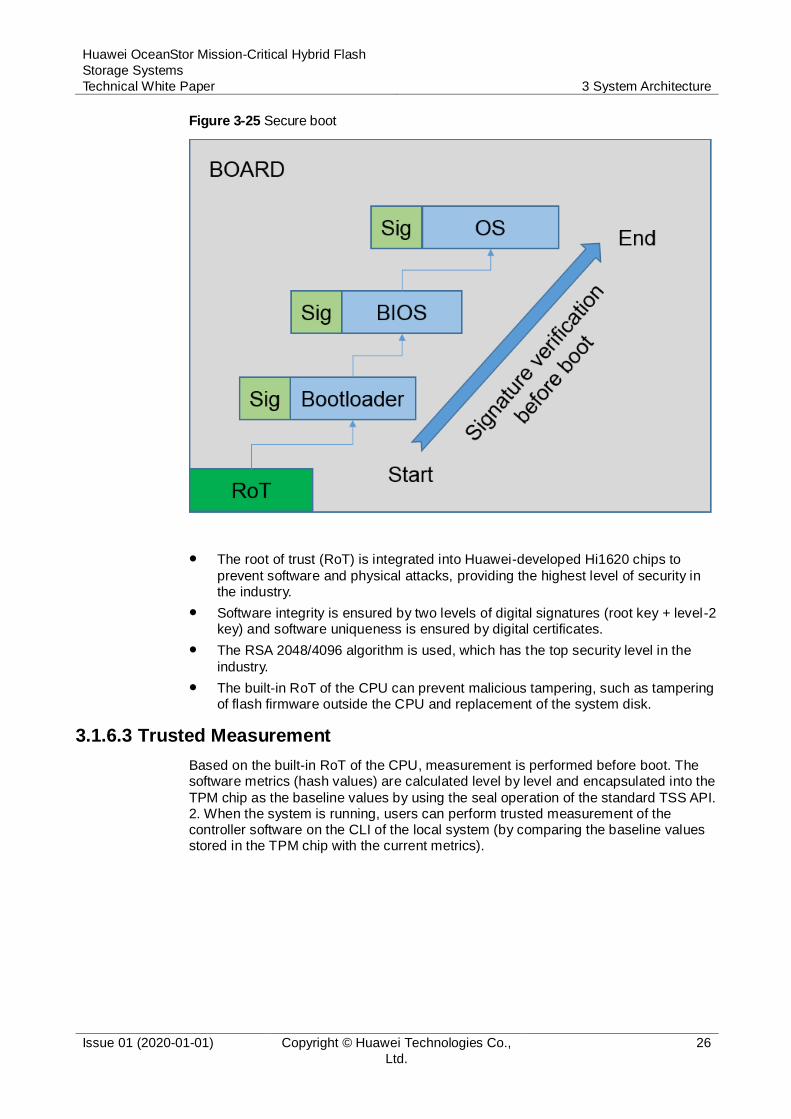
After the device is powered on, the initial startup module starts and verification is performed level by level. If the verification is successful, the device starts. Digital signatures are used to verify firmware integrity to prevent firmware and operating systems from being tampered with.
Huawei OceanStor Mission-Critical Hybrid Flash
Storage Systems
Technical White Paper 3 System Architecture
Issue 01 (2020-01-01) Copyright © Huawei Technologies Co.,
Ltd.
26
Figure 3-25 Secure boot
The root of trust (RoT) is integrated into Huawei-developed Hi1620 chips to
prevent software and physical attacks, providing the highest level of security in the industry.
Software integrity is ensured by two levels of digital signatures (root key + level-2 key) and software uniqueness is ensured by digital certificates.
The RSA 2048/4096 algorithm is used, which has the top security level in the
industry.
The built-in RoT of the CPU can prevent malicious tampering, such as tampering of flash firmware outside the CPU and replacement of the system disk.
3.1.6.3 Trusted Measurement
Based on the built-in RoT of the CPU, measurement is performed before boot. The software metrics (hash values) are calculated level by level and encapsulated into the
TPM chip as the baseline values by using the seal operation of the standard TSS API. 2. When the system is running, users can perform trusted measurement of the controller software on the CLI of the local system (by comparing the baseline values stored in the TPM chip with the current metrics).

Huawei OceanStor Mission-Critical Hybrid Flash
Storage Systems
Technical White Paper 3 System Architecture
Issue 01 (2020-01-01) Copyright © Huawei Technologies Co.,
Ltd.
27
Figure 3-26 Trusted measurement
3.1.6.4 SED Data Encryption
OceanStor mission-critical hybrid flash storage series can work with self-encrypting drives (SEDs) and either Internal Key Manager (built-in key management system) or External Key Manager (an independent key management system) to implement static data encryption. The data encryption feature uses the AES 256 algorithm to encrypt user data on storage to ensure the confidentiality, integrity, and availability of user
data.
Internal Key Manager
Internal Key Manager is a key management application built in OceanStor mission-critical hybrid flash storage series for managing the AK life cycle of SEDs. Internal Key Manager supports key generation, updating, destruction, backup, and restoration.
Internal Key Manager is easy to deploy, configure, and manage. Therefore, Internal
Key Manager is recommended if there are no higher requirements and key management is only being used by storage systems in a data center. It is unnecessary to deploy an independent key management system.
Huawei OceanStor Mission-Critical Hybrid Flash
Storage Systems
Technical White Paper 3 System Architecture
Issue 01 (2020-01-01) Copyright © Huawei Technologies Co.,
Ltd.
28
External Key Manager
OceanStor mission-critical hybrid flash storage series supports the External Key Manager (an independent key management system) that uses the Key Manager Server (KMS) of a third-party system to manage keys.
External Key Manager uses standard KMIP + TLS protocols. Therefore, External Key Manager is recommended if multiple systems in a data center require centralized key management.
External Key Manager supports key generation, updating, destruction, backup, and restoration. Two External Key Managers can be deployed to synchronize keys in real time for enhanced reliability.
SEDs
SEDs use AKs and data encryption keys (DEKs) to implement two layers of security protection.
AK mechanism
After data encryption has been enabled on a storage system, the storage system activates the AutoLock function for an SED, applies an AK from the key manager, and stores the AK on the SED. AutoLock protects the SED and allows only the
storage system itself to access the SED. When the storage system accesses an SED, it acquires an AK from the key manager and compares it with the AK stored on the SED. If the acquired AK and stored AK are the same, the SED decrypts the DEK for data encryption or decryption. If they are different, all read and write operations fail.
DEK mechanism
After AutoLock authentication succeeds, the SED uses its hardware circuits and internal DEK to encrypt or decrypt the data. DEK will encrypt data after it has been written to disks. The DEK cannot be acquired separately, meaning that the original information on an SED cannot be recovered mechanically after it is removed from the storage system.
3.2 Software Architecture
The software suite provided by the OceanStor mission-critical hybrid flash storage
series consists of software deployed on storage systems, software on maintenance terminals, and software on application servers. These three types of software work jointly to deliver storage, backup, and disaster recovery services in a smart, efficient, and cost-effective manner.
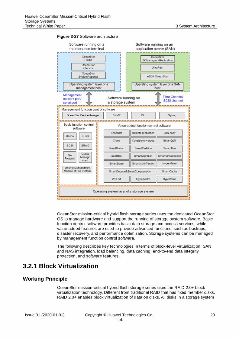
Figure 3-27 shows the software architecture.
Huawei OceanStor Mission-Critical Hybrid Flash
Storage Systems
Technical White Paper 3 System Architecture
Issue 01 (2020-01-01) Copyright © Huawei Technologies Co.,
Ltd.
29
Figure 3-27 Software architecture
OceanStor mission-critical hybrid flash storage series uses the dedicated OceanStor
OS to manage hardware and support the running of storage system software. Basic function control software provides basic data storage and access services, while value-added features are used to provide advanced functions, such as backups, disaster recovery, and performance optimization. Storage systems can be managed by management function control software.
The following describes key technologies in terms of block-level virtualization, SAN
and NAS integration, load balancing, data caching, end-to-end data integrity protection, and software features.
3.2.1 Block Virtualization
Working Principle
OceanStor mission-critical hybrid flash storage series uses the RAID 2.0+ block virtualization technology. Different from traditional RAID that has fixed member disks, RAID 2.0+ enables block virtualization of data on disks. All disks in a storage system
Huawei OceanStor Mission-Critical Hybrid Flash
Storage Systems
Technical White Paper 3 System Architecture
Issue 01 (2020-01-01) Copyright © Huawei Technologies Co.,
Ltd.
30
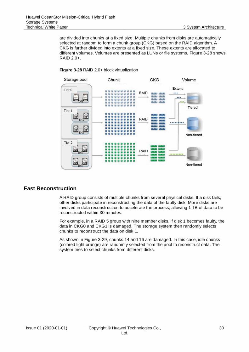
are divided into chunks at a fixed size. Multiple chunks from disks are automatically selected at random to form a chunk group (CKG) based on the RAID algorithm. A CKG is further divided into extents at a fixed size. These extents are allocated to different volumes. Volumes are presented as LUNs or file systems. Figure 3-28 shows RAID 2.0+.
Figure 3-28 RAID 2.0+ block virtualization
Fast Reconstruction
A RAID group consists of multiple chunks from several physical disks. If a disk fails, other disks participate in reconstructing the data of the faulty disk. More disks are involved in data reconstruction to accelerate the process, allowing 1 TB of data to be reconstructed within 30 minutes.
For example, in a RAID 5 group with nine member disks, if disk 1 becomes faulty, the data in CKG0 and CKG1 is damaged. The storage system then randomly selects chunks to reconstruct the data on disk 1.
As shown in Figure 3-29, chunks 14 and 16 are damaged. In this case, idle chunks (colored light orange) are randomly selected from the pool to reconstruct data. The system tries to select chunks from different disks.

Huawei OceanStor Mission-Critical Hybrid Flash
Storage Systems
Technical White Paper 3 System Architecture
Issue 01 (2020-01-01) Copyright © Huawei Technologies Co.,
Ltd.
31
Figure 3-29 RAID 2.0+ fast reconstruction (1)
As shown in Figure 3-30, chunk 61, on disk 6, and chunk 81, on disk 8, are randomly
selected. Data will be reconstructed to these two chunks.
Figure 3-30 RAID 2.0+ fast reconstruction (2)
The bottleneck for traditional data reconstruction typically lies in the target disk (a hot spare disk) because data on all member disks is written to a target disk for
reconstruction. As a result, the write bandwidth is the key factor deciding the reconstruction speed. For example, if 2 TB of data on a disk is reconstructed and the write bandwidth is 30 MB/s, it will take 18 hours to complete data reconstruction.
RAID 2.0+ improves data reconstruction in the following two aspects:
Multiple target disks
In the preceding example, if two target disks are used, the reconstruction time will be shortened from 18 hours to 9 hours. If more chunks and member disks are involved, the number of target disks will be equal to that of member disks. As a result, the reconstruction speed linearly increases.
Chunk-specific reconstruction
If fewer chunks are allocated to a faulty disk, less data needs to be reconstructed,
further accelerating reconstruction.
RAID 2.0+ shortens the reconstruction time per TB to 30 minutes, greatly reducing the probability of a dual-disk failure.
Huawei OceanStor Mission-Critical Hybrid Flash
Storage Systems
Technical White Paper 3 System Architecture
Issue 01 (2020-01-01) Copyright © Huawei Technologies Co.,
Ltd.
32
Load Balancing Among Disks
RAID 2.0+ automatically balances workloads on disks and evenly distributes data from volumes to all disks of a storage system. This prevents individual disks from being overloaded and enhances reliability. As more disks participate in data reads and
writes, storage system performance improves.
Maximized Disk Utilization
Performance
In a RAID 2.0+ environment, LUNs or file systems are created using storage space from a storage resource pool and are no longer limited by the number of disks in a RAID group, greatly boosting the performance of a single LUN or file system.
Capacity
The number of disks in a storage resource pool is not limited by the RAID level. This eliminates the chance of usage differences of different RAID groups in traditional volume management environments. Coupled with dynamic LUN or file system capacity expansion, disk space usage is remarkably improved.
Enhanced Storage Management Efficiency
Easy planning
It is unnecessary to spend much time in planning storage. Customers simply need to create a storage pool by using multiple disks, set the tiering policies of the storage pool, and allocate space (volumes) from the storage pool.
Easy expansion of storage pools
To expand the capacity of a storage pool, customers just need to insert new disks, and the system will automatically distribute data evenly across all disks.
Easy expansion of volumes
When customers need to expand the capacity of a volume, they only need to specify the size of the volume to be expanded. The system automatically allocates the required space from the storage pool and adjusts the data distribution of the volume to evenly distribute the volume data across all disks.
3.2.2 SAN and NAS Convergence
OceanStor mission-critical hybrid flash storage series adopts a SAN and NAS convergence design. NAS gateways are no longer needed. One set of hardware and software supports both SAN and NAS as well as file access protocols such as Network File System (NFS), Common Internet File System (CIFS), FTP, and HTTP, and file backup protocol Network Data Management Protocol (NDMP). Like SAN, NAS supports scale-out of eight controllers. Hosts can access any LUN or file system
from a front-end port on any controller.
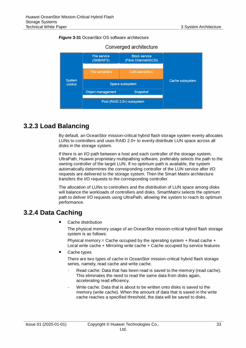
Figure 3-31 shows the converged architecture of the storage systems. File systems and LUNs directly interact with the space subsystem. The file system architecture is based on objects. Each file or folder acts as an object, and each file system is an object set. LUNs are classified into thin LUNs and thick LUNs. The two types of LUNs
come from the storage pool system and space system, instead of file systems. In this way, this converged architecture delivers a simplified software stack and provides a higher storage efficiency than the traditional unified storage architecture. In addition, LUNs and file systems are independent from each other.
Huawei OceanStor Mission-Critical Hybrid Flash
Storage Systems
Technical White Paper 3 System Architecture
Issue 01 (2020-01-01) Copyright © Huawei Technologies Co.,
Ltd.
33
Figure 3-31 OceanStor OS software architecture
3.2.3 Load Balancing
By default, an OceanStor mission-critical hybrid flash storage system evenly allocates
LUNs to controllers and uses RAID 2.0+ to evenly distribute LUN space across all disks in the storage system.
If there is an I/O path between a host and each controller of the storage system, UltraPath, Huawei proprietary multipathing software, preferably selects the path to the owning controller of the target LUN. If no optimum path is available, the system
automatically determines the corresponding controller of the LUN service after I/O requests are delivered to the storage system. Then the Smart Matrix architecture transfers the I/O requests to the corresponding controller.
The allocation of LUNs to controllers and the distribution of LUN space among disks will balance the workloads of controllers and disks. SmartMatrix selects the optimum
path to deliver I/O requests using UltraPath, allowing the system to reach its optimum performance.
3.2.4 Data Caching
Cache distribution
The physical memory usage of an OceanStor mission-critical hybrid flash storage system is as follows:
Physical memory = Cache occupied by the operating system + Read cache +
Local write cache + Mirroring write cache + Cache occupied by service features
Cache types
There are two types of cache in OceanStor mission-critical hybrid flash storage series, namely, read cache and write cache.
− Read cache: Data that has been read is saved to the memory (read cache).
This eliminates the need to read the same data from disks again, accelerating read efficiency.
− Write cache: Data that is about to be written onto disks is saved to the memory (write cache). When the amount of data that is saved in the write cache reaches a specified threshold, the data will be saved to disks.

Huawei OceanStor Mission-Critical Hybrid Flash
Storage Systems
Technical White Paper 3 System Architecture
Issue 01 (2020-01-01) Copyright © Huawei Technologies Co.,
Ltd.
34
Read cache and write cache reduce disk-related operations, improve read and write performance of storage systems, and protect disks from being damaged due to repeated read and write operations.
If the write cache is not used, all cache can be used as the read cache. Each storage system reserves the minimum read cache to ensure that read cache
resources are still available even if the write workload is heavy.
Cache prefetch
In the event of a large number of random I/Os, OceanStor mission-critical hybrid flash storage series identifies sequential I/Os with the multi-channel sequential I/O identification algorithm. For the sequential I/Os, the storage systems use prefetch and merge algorithms to optimize system performance in various
application scenarios.
The prefetch algorithm supports intelligent prefetch, constant prefetch, and variable prefetch. By automatically identifying I/O characteristics, intelligent prefetch determines whether data is prefetched and determines the prefetch length, ensuring that the system performance meets requirements of different
scenarios.
By default, storage systems adopt the intelligent prefetch algorithm. However, in application scenarios with definite I/O models, users can also configure storage systems to use constant prefetch or variable prefetch. These two algorithms allow users to define a prefetch length.
Cache eviction
When the cache usage reaches a specified threshold, the cache eviction algorithm calculates the access frequency of each data block based on historical and current data access frequencies. The eviction algorithm then works with the multi-channel sequential I/O identification algorithm to evict unnecessarily cached data. In addition, you can configure the cache priority of a volume and adjust the
priority of each I/O for a specific service. Data with low priorities is eliminated first, and high-priority data is cached to ensure the data hit rate.
3.2.5 End-to-End Data Integrity Protection
The ANSI T10 Protection Information (PI) standard provides a way to check data integrity when accessing a storage system. This check is undertaken based on the PI field defined in the T10 standard. This standard adds an 8-byte PI field to the end of
each sector to check data integrity. In most cases, the T10 PI is used to ensure the integrity of data in a storage system.
Data Integrity Extensions (DIX) further extend the protection scope of T10 PI. Therefore, DIX+T10 PI can achieve complete end-to-end data protection.
In addition to using T10 PI to ensure the integrity of data in a storage system, OceanStor mission-critical hybrid flash storage series also adopts DIX + T10 PI to
implement end-to-end data integration protection. A storage system verifies and delivers PI fields of data in real time. If a host does not support PI, the storage system adds the PI fields to the host interface and then delivers the fields. In a storage system, PI fields are forwarded, transmitted, and stored together with user data. Then, before user data is read by a host again, the storage system uses PI fields to check the
accuracy and integrity of user data.

Huawei OceanStor Mission-Critical Hybrid Flash
Storage Systems
Technical White Paper 3 System Architecture
Issue 01 (2020-01-01) Copyright © Huawei Technologies Co.,
Ltd.
35
3.2.6 Various Software Features
OceanStor mission-critical hybrid flash storage series provides the Smart series features to accelerate system efficiency and the Hyper series features to protect data.
The Smart series features include SmartDedupe, SmartCompression, SmartThin, SmartVirtualization, SmartMotion, SmartMigration, SmartTier, SmartQoS, SmartPartition, SmartErase, SmartMulti-Tenant, SmartCache, and SmartQuota.
These software features help users improve storage efficiency and reduce the total cost of ownership (TCO).
The Hyper series features include HyperSnap, HyperClone, HyperReplication, HyperMetro, HyperVault, HyperCopy, HyperMirror, and HyperLock. These software features help users implement data backup and disaster recovery. In addition, the storage systems can be used in various disaster recovery solutions
in which three data centers are deployed.
3.2.7 Flash-Oriented System Optimization
SSDs deliver high performance for random I/O accesses, and ensure low latency, however, their erase times are limited. HDDs deliver high performance for sequential I/O accesses but their erase times are not restricted. Huawei has optimized SSDs, as well as the hybrid storage of SSDs and HDDs used in OceanStor mission-critical
hybrid flash storage series, to achieve better performance and reliability.
Seamless collaboration between OceanStor OS and Huawei SSD (HSSD) firmware
SSDs use flash chips that are involved in erasure operations. When erasure operations are being performed, other data in the channels that is involved in the
erasure operations is inaccessible. As a result, a latency of 1 ms to 2 ms occurs, leading to performance fluctuations.
Huawei storage systems use HSSDs. OceanStor OS is designed to work alongside HSSDs to ensure that erasure operations are sequentially performed on multiple HSSDs. OceanStor OS does not read data from HSSDs on which erasures are being performed. Instead, data is read from other HSSDs based on
a RAID redundancy mechanism, thereby ensuring stable latency.
Intelligent SSD perception by cache
Storage systems use different dirty data flushing policies for SSDs and HDDs. When Huawei-certified disks are connected, the storage systems automatically identify the media types. For SSDs, the storage systems delay the flushing of
active data, reduce the flushing times, and decrease write amplification based on the Least Recently Used (LRU) algorithm. This boosts system performance and prolongs the service life of SSDs.
Performance optimized using multiple cores
In terms of a multi-core scheduling mechanism, system performance is optimized for the NUMA architecture. For example, messages related to a single I/O are
dispatched to the same CPU to reduce cross-CPU access overheads and increase the CPU cache hit ratio.
With regard to multi-thread operating efficiency, a data structure design is used to prevent multiple threads from concurrently accessing data on the cache line of the CPU L1 cache. This eliminates the pseudo-sharing of the CPU L1 cache,
improves the CPU L1 cache efficiency, and reduces the CPU overhead in memory-based data access.
Huawei OceanStor Mission-Critical Hybrid Flash
Storage Systems
Technical White Paper 4 Smart Series Features
Issue 01 (2020-01-01) Copyright © Huawei Technologies Co.,
Ltd.
36
4 Smart Series Features
4.1 SmartVirtualiztaion
4.2 SmartMigration
4.3 SmartDedupe and SmartCompression
4.4 SmartTier
4.5 SmartThin
4.6 SmartQoS
4.7 SmartPartition
4.8 SmartCache
4.9 SmartErase
4.10 SmartMulti-Tenant
4.11 SmartQuota
4.12 SmartMotion
4.1 SmartVirtualiztaion
SmartVirtualization is used to take over heterogeneous storage systems (including
other Huawei storage systems and third-party storage systems), protecting customer investments. SmartVirtualization conceals the software and hardware differences between local and heterogeneous storage systems, allowing the local system to use and manage the heterogeneous storage resources as if they were local resources. In addition, SmartVirtualization can work with SmartMigration to migrate data from heterogeneous storage systems online, facilitating device replacement.
Working Principle
SmartVirtualization maps the heterogeneous storage system to the local storage
system, which in turn uses external device LUNs (eDevLUNs) to take over and manage the heterogeneous resources. eDevLUNs consist of metadata volumes and data volumes. The metadata volumes manage the data storage locations of eDevLUNs and use the physical space of the local storage system. The data volumes

Huawei OceanStor Mission-Critical Hybrid Flash
Storage Systems
Technical White Paper 4 Smart Series Features
Issue 01 (2020-01-01) Copyright © Huawei Technologies Co.,
Ltd.
37
are logical representations of external LUNs, and use the physical space of the heterogeneous storage system. eDevLUNs on the local storage system match external LUNs on the heterogeneous storage system, allowing application servers to access data on the external LUNs through the eDevLUNs.
Figure 4-1 Heterogeneous storage virtualization
SmartVirtualization uses LUN masquerading to set the world wide names (WWNs) and Host LUN IDs of eDevLUNs on OceanStor series to the same values as those on the heterogeneous storage system. After data migration is complete, the host's multipathing software switches over the LUNs online without interrupting services.
Application Scenarios
Heterogeneous array takeover
Because customers build data centers over time, the storage arrays they use may come from different vendors. Storage administrators can use SmartVirtualization to manage and configure existing devices, protecting investments.
Heterogeneous data migration
Customers may need to replace storage systems with warranty periods that are
about to expire or performance that does not meet service requirements. SmartVirtualization and SmartMigration can migrate customer data to OceanStor series online without interrupting host services.
Heterogeneous disaster recovery
If service data is stored at two sites having heterogeneous storage systems and
requires robust service continuity, SmartVirtualization can work with HyperReplication to allow data on LUNs in heterogeneous storage systems to be
Huawei OceanStor Mission-Critical Hybrid Flash
Storage Systems
Technical White Paper 4 Smart Series Features
Issue 01 (2020-01-01) Copyright © Huawei Technologies Co.,
Ltd.
38
mutually backed up. If a disaster occurs, a functional service site takes over services from the failed service site and then recovers data.
Heterogeneous data protection
Data on LUNs that reside in heterogeneous storage systems may be attacked by viruses or corrupted. SmartVirtualization can work with HyperSnap to instantly
create snapshots for LUNs that reside in heterogeneous storage systems, and use these snapshots to rapidly restore data to a specific point in time if the data is corrupted.
4.2 SmartMigration
4.2.1 SmartMigration for Block
SmartMigration implements intelligent data migration based on LUNs. Data on a source LUN can be completely migrated to a target LUN without interrupting ongoing services. SmartMigration supports data migration within a Huawei storage system or between a Huawei storage system and a compatible heterogeneous storage system.
When the system receives new data during migration, it simultaneously writes the new data to both the source and target LUNs and records data change logs (DCLs) to ensure data consistency. After migration is complete, the source and target LUNs exchange information so that the target LUN can take over services.
SmartMigration involves data synchronization and LUN information exchange.
Data Synchronization
1. Before migration, customers must configure the source and target LUNs.
2. When migration begins, the source LUN replicates data to the target LUN.
3. During migration, the host can still access the source LUN, and when the host writes data to the source LUN, the system records the DCL.
4. The system writes the incoming data to both the source and target LUNs.
− If data is successfully written to both LUNs, the system clears the record in the DCL.
− If data fails to be written to the target LUN, the storage system identifies the data that failed to be synchronized according to the DCL. Then, the system copies the data to the target LUN. After the data is copied, the storage system returns a write success to the host.
− If data fails to be written to the source LUN, the system returns a write failure
to notify the host to re-send the data. Upon receiving the data again, the system only writes the data to the source LUN.
LUN Information Exchange
After data replication is complete, host I/Os are temporarily suspended, and the source and target LUNs exchange information, as seen in Figure 4-2.

Huawei OceanStor Mission-Critical Hybrid Flash
Storage Systems
Technical White Paper 4 Smart Series Features
Issue 01 (2020-01-01) Copyright © Huawei Technologies Co.,
Ltd.
39
Figure 4-2 LUN information exchange
The LUN information exchange is instantaneous, and does not interrupt services.
Application Scenarios
Storage system upgrades with SmartVirtualization
SmartMigration works with SmartVirtualization to migrate data from legacy storage systems (from Huawei or other vendors) to new Huawei storage systems.
This improves service performance and data reliability.
Data migration for capacity, performance, and reliability adjustments
4.2.2 SmartMigration for File
SmartMigration implements intelligent data migration based on file systems. Data on a source file system can be fully migrated to a target storage pool without interrupting ongoing services. SmartMigration supports data migration across controllers or
storage pools within a Huawei storage system.
When the system receives new data during migration, it simultaneously writes the new data to both the source and target file systems and records DCLs to ensure data consistency. After migration is complete, file system information is exchanged, so that the target file system can take over services from the source system.
Huawei OceanStor Mission-Critical Hybrid Flash
Storage Systems
Technical White Paper 4 Smart Series Features
Issue 01 (2020-01-01) Copyright © Huawei Technologies Co.,
Ltd.
40
SmartMigration involves data synchronization and file system information exchange.
Data Synchronization
1. Creates a target file system in the target storage pool.
2. Copies all data of the first snapshot for the source file system to the target file system. During this period, the host writes data to the source file system only and DCLs are recorded.
3. Copies the incremental data in subsequent snapshots to the target file system,
and generates a snapshot for the target file system upon completing the copy of incremental data in each snapshot. (The snapshot for the target file system is named after the corresponding snapshot for the source file system.) During this period, the host writes data to the source file system only and DCLs are recorded.
4. Copies all differential data written by the host to the source file system during
snapshot synchronization. During this period, the host writes data to both the source and target file systems.
5. Synchronizes the metadata of the source file system to the target file system. During this period, the host writes data to both the source and target file systems.
6. Synchronizes the configurations (quota) of the file systems.
File System Information Exchange
After data replication is complete, host I/Os are temporarily suspended, and the
source and target file systems exchange information, as seen in Figure 4-3.

Huawei OceanStor Mission-Critical Hybrid Flash
Storage Systems
Technical White Paper 4 Smart Series Features
Issue 01 (2020-01-01) Copyright © Huawei Technologies Co.,
Ltd.
41
Figure 4-3 File system information exchange
The file system information exchange is instantaneous, and does not interrupt services.
Application Scenarios
Data migration may be required due to capacity limitations, or for performance and reliability optimization.
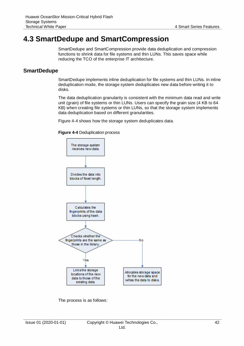
Huawei OceanStor Mission-Critical Hybrid Flash
Storage Systems
Technical White Paper 4 Smart Series Features
Issue 01 (2020-01-01) Copyright © Huawei Technologies Co.,
Ltd.
42
4.3 SmartDedupe and SmartCompression
SmartDedupe and SmartCompression provide data deduplication and compression
functions to shrink data for file systems and thin LUNs. This saves space while reducing the TCO of the enterprise IT architecture.
SmartDedupe
SmartDedupe implements inline deduplication for file systems and thin LUNs. In inline deduplication mode, the storage system deduplicates new data before writing it to disks.
The data deduplication granularity is consistent with the minimum data read and write
unit (grain) of file systems or thin LUNs. Users can specify the grain size (4 KB to 64 KB) when creating file systems or thin LUNs, so that the storage system implements data deduplication based on different granularities.
Figure 4-4 shows how the storage system deduplicates data.
Figure 4-4 Deduplication process
The process is as follows:
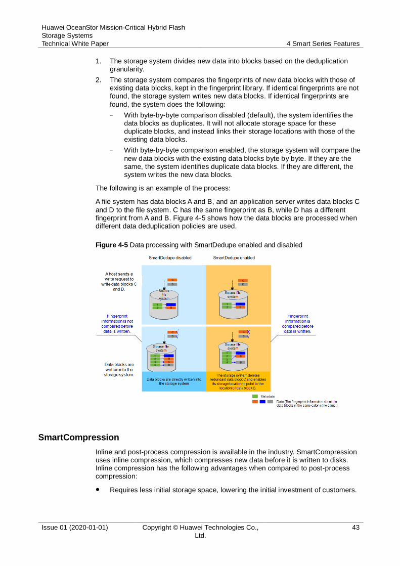
Huawei OceanStor Mission-Critical Hybrid Flash
Storage Systems
Technical White Paper 4 Smart Series Features
Issue 01 (2020-01-01) Copyright © Huawei Technologies Co.,
Ltd.
43
1. The storage system divides new data into blocks based on the deduplication granularity.
2. The storage system compares the fingerprints of new data blocks with those of existing data blocks, kept in the fingerprint library. If identical fingerprints are not found, the storage system writes new data blocks. If identical fingerprints are
found, the system does the following:
− With byte-by-byte comparison disabled (default), the system identifies the data blocks as duplicates. It will not allocate storage space for these duplicate blocks, and instead links their storage locations with those of the existing data blocks.
− With byte-by-byte comparison enabled, the storage system will compare the
new data blocks with the existing data blocks byte by byte. If they are the same, the system identifies duplicate data blocks. If they are different, the system writes the new data blocks.
The following is an example of the process:
A file system has data blocks A and B, and an application server writes data blocks C
and D to the file system. C has the same fingerprint as B, while D has a different fingerprint from A and B. Figure 4-5 shows how the data blocks are processed when different data deduplication policies are used.
Figure 4-5 Data processing with SmartDedupe enabled and disabled
SmartCompression
Inline and post-process compression is available in the industry. SmartCompression uses inline compression, which compresses new data before it is written to disks. Inline compression has the following advantages when compared to post-process compression:
Requires less initial storage space, lowering the initial investment of customers.

Huawei OceanStor Mission-Critical Hybrid Flash
Storage Systems
Technical White Paper 4 Smart Series Features
Issue 01 (2020-01-01) Copyright © Huawei Technologies Co.,
Ltd.
44
Generates fewer I/Os, applicable to SSDs, which restrict the number of reads and writes.
Compresses data blocks after snapshots are created, saving space.
SmartCompression compresses data blocks based on the user-configured compression policy. The storage system supports the following compression policies:
Fast policy (default)
This policy has a higher compression speed but lower efficiency in capacity saving.
Deep policy
This policy significantly improves capacity saving efficiency but takes longer to perform compression and decompression.
Figure 4-6 shows how data blocks are processed when different data compression policies are used.
Figure 4-6 Data processing with SmartCompression enabled and disabled
Interworking of SmartDedupe and SmartCompression
SmartDedupe and SmartCompression can work together. When they are both
enabled, data is deduplicated and then compressed, saving more storage space.
SmartDedupe and SmartCompression work in in-line mode. When the functions are enabled, new data is deduplicated and compressed. When the functions are disabled, deduplicated data cannot be restored.
4.4 SmartTier
4.4.1 SmartTier for Block
SmartTier implements dynamic storage tiering.

Huawei OceanStor Mission-Critical Hybrid Flash
Storage Systems
Technical White Paper 4 Smart Series Features
Issue 01 (2020-01-01) Copyright © Huawei Technologies Co.,
Ltd.
45
SmartTier categorizes storage media into three storage tiers based on performance: high-performance tier (SSDs), performance tier (SAS disks), and capacity tier (NL-SAS disks). Storage tiers can be used independently or together to provide data storage space.
SmartTier performs intelligent data storage based on LUNs, segmenting data into
extents (with a default size of 4 MB, configurable from 512 KB to 64 MB). SmartTier collects statistics on and analyzes the activity of data based on extents and matches the data of various activity levels with proper storage media. More-active data will be promoted to higher-performance storage media (such as SSDs), whereas less-active data will be demoted to more cost-effective storage media with larger capacities (such as NL-SAS disks).
SmartTier implements data monitoring, placement analysis, and data relocation, as shown in the following figure:
Figure 4-7 SmartTier implementation
Data monitoring and data placement analysis are automated by the storage system, and data relocation is initiated manually or by a user-defined policy.
SmartTier improves storage system performance and reduces storage costs to meet enterprise requirements of both performance and capacity. By preventing historical data from occupying expensive storage media, SmartTier ensures effective
investment and eliminates energy consumption caused by idle capacities. This reduces the TCO and optimizes the cost-effectiveness.
4.4.2 SmartTier for File
SmartTier also applies to file systems. It helps customers simplify data life cycle management, improve media usage, and reduce costs. SmartTier dynamically relocates data by file, among different media based on user-defined tiering policies.
A storage pool can be composed of SSDs and HDDs. SmartTier automatically
promotes files to high-performance media (SSDs) or demotes files to large-capacity media (HDDs, including SAS and NL-SAS disks) based on user-configured tiering policies. Users can specify tiering policies by file name, file size, file type, file creation time, and SSD usage. Figure 4-8 shows the working principles of SmartTier.
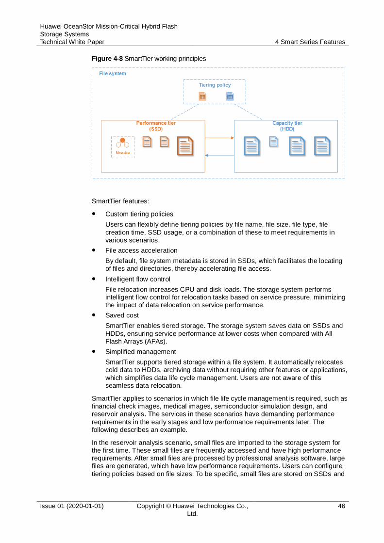
Huawei OceanStor Mission-Critical Hybrid Flash
Storage Systems
Technical White Paper 4 Smart Series Features
Issue 01 (2020-01-01) Copyright © Huawei Technologies Co.,
Ltd.
46
Figure 4-8 SmartTier working principles
SmartTier features:
Custom tiering policies
Users can flexibly define tiering policies by file name, file size, file type, file
creation time, SSD usage, or a combination of these to meet requirements in various scenarios.
File access acceleration
By default, file system metadata is stored in SSDs, which facilitates the locating of files and directories, thereby accelerating file access.
Intelligent flow control
File relocation increases CPU and disk loads. The storage system performs intelligent flow control for relocation tasks based on service pressure, minimizing the impact of data relocation on service performance.
Saved cost
SmartTier enables tiered storage. The storage system saves data on SSDs and
HDDs, ensuring service performance at lower costs when compared with All Flash Arrays (AFAs).
Simplified management
SmartTier supports tiered storage within a file system. It automatically relocates cold data to HDDs, archiving data without requiring other features or applications,
which simplifies data life cycle management. Users are not aware of this seamless data relocation.
SmartTier applies to scenarios in which file life cycle management is required, such as financial check images, medical images, semiconductor simulation design, and reservoir analysis. The services in these scenarios have demanding performance
requirements in the early stages and low performance requirements later. The following describes an example.
In the reservoir analysis scenario, small files are imported to the storage system for the first time. These small files are frequently accessed and have high performance requirements. After small files are processed by professional analysis software, large files are generated, which have low performance requirements. Users can configure
tiering policies based on file sizes. To be specific, small files are stored on SSDs and
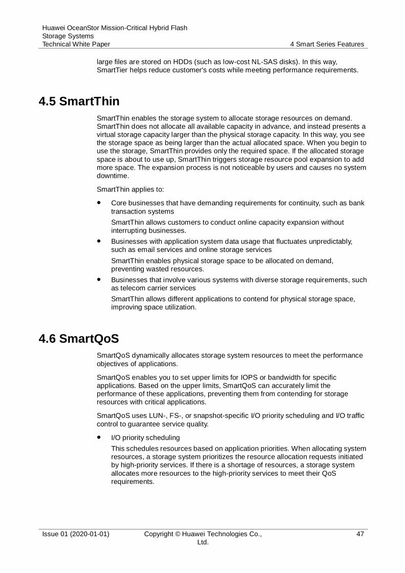
Huawei OceanStor Mission-Critical Hybrid Flash
Storage Systems
Technical White Paper 4 Smart Series Features
Issue 01 (2020-01-01) Copyright © Huawei Technologies Co.,
Ltd.
47
large files are stored on HDDs (such as low-cost NL-SAS disks). In this way, SmartTier helps reduce customer's costs while meeting performance requirements.
4.5 SmartThin
SmartThin enables the storage system to allocate storage resources on demand. SmartThin does not allocate all available capacity in advance, and instead presents a virtual storage capacity larger than the physical storage capacity. In this way, you see the storage space as being larger than the actual allocated space. When you begin to use the storage, SmartThin provides only the required space. If the allocated storage
space is about to use up, SmartThin triggers storage resource pool expansion to add more space. The expansion process is not noticeable by users and causes no system downtime.
SmartThin applies to:
Core businesses that have demanding requirements for continuity, such as bank
transaction systems
SmartThin allows customers to conduct online capacity expansion without interrupting businesses.
Businesses with application system data usage that fluctuates unpredictably, such as email services and online storage services
SmartThin enables physical storage space to be allocated on demand, preventing wasted resources.
Businesses that involve various systems with diverse storage requirements, such as telecom carrier services
SmartThin allows different applications to contend for physical storage space, improving space utilization.
4.6 SmartQoS
SmartQoS dynamically allocates storage system resources to meet the performance
objectives of applications.
SmartQoS enables you to set upper limits for IOPS or bandwidth for specific applications. Based on the upper limits, SmartQoS can accurately limit the performance of these applications, preventing them from contending for storage resources with critical applications.
SmartQoS uses LUN-, FS-, or snapshot-specific I/O priority scheduling and I/O traffic
control to guarantee service quality.
I/O priority scheduling
This schedules resources based on application priorities. When allocating system resources, a storage system prioritizes the resource allocation requests initiated by high-priority services. If there is a shortage of resources, a storage system
allocates more resources to the high-priority services to meet their QoS requirements.

Huawei OceanStor Mission-Critical Hybrid Flash
Storage Systems
Technical White Paper 4 Smart Series Features
Issue 01 (2020-01-01) Copyright © Huawei Technologies Co.,
Ltd.
48
Figure 4-9 I/O priority scheduling process
I/O traffic control
This limits the traffic of some applications by limiting their IOPS or bandwidth, thereby preventing these applications from affecting other applications. I/O traffic control involves I/O request processing, token distribution, and dequeuing control.

Huawei OceanStor Mission-Critical Hybrid Flash
Storage Systems
Technical White Paper 4 Smart Series Features
Issue 01 (2020-01-01) Copyright © Huawei Technologies Co.,
Ltd.
49
Figure 4-10 Managing LUN or snapshot I/O queues
4.7 SmartPartition
SmartPartition is a smart cache partitioning technique developed by Huawei. SmartPartition ensures high performance of mission-critical applications by
partitioning cache resources. An administrator can allocate a cache partition of a specific size to an application. The storage system then ensures that the application has exclusive permission to use its allocated cache resources.
Cache is the most critical factor that affects the performance of a storage system.
For a write service, a larger cache size means a higher write combination rate and higher write hit ratio (write hit ratio of a block in a cache).
For a read service, a larger cache size means a higher read hit ratio.
Different types of services have different cache requirements.
For a sequential service, the cache size only needs to meet the bandwidth requirements for destaging aggregated I/Os.
For a random service, a larger cache size indicates that I/Os are more likely to fall onto stripes within the cache, thereby improving performance.
SmartPartition can be used with other QoS techniques (such as SmartQoS) for better QoS effects.
Working Principle
SmartPartition allocates cache resources to services (the actual control objects are
LUNs and file systems) based on partition sizes, thereby ensuring the QoS of mission-critical services.
Figure 4-11 illustrates the SmartPartition working principle.
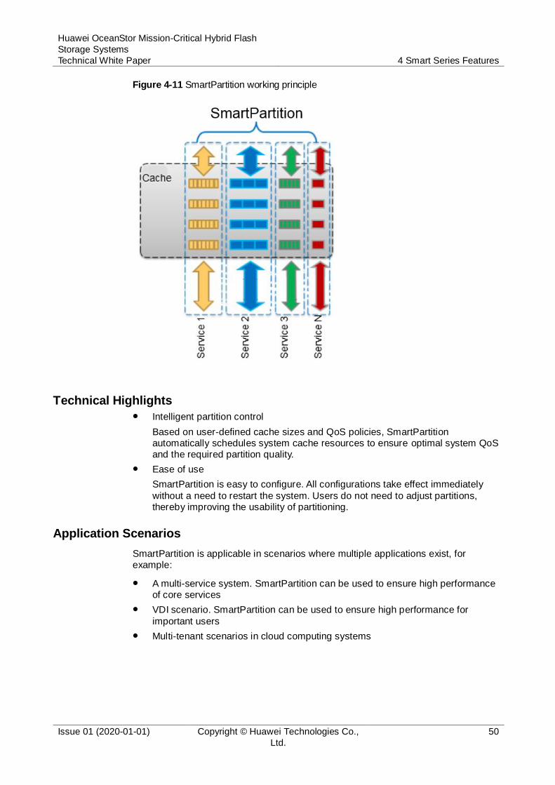
Huawei OceanStor Mission-Critical Hybrid Flash
Storage Systems
Technical White Paper 4 Smart Series Features
Issue 01 (2020-01-01) Copyright © Huawei Technologies Co.,
Ltd.
50
Figure 4-11 SmartPartition working principle
Technical Highlights Intelligent partition control
Based on user-defined cache sizes and QoS policies, SmartPartition automatically schedules system cache resources to ensure optimal system QoS and the required partition quality.
Ease of use
SmartPartition is easy to configure. All configurations take effect immediately
without a need to restart the system. Users do not need to adjust partitions, thereby improving the usability of partitioning.
Application Scenarios
SmartPartition is applicable in scenarios where multiple applications exist, for example:
A multi-service system. SmartPartition can be used to ensure high performance of core services
VDI scenario. SmartPartition can be used to ensure high performance for
important users
Multi-tenant scenarios in cloud computing systems

Huawei OceanStor Mission-Critical Hybrid Flash
Storage Systems
Technical White Paper 4 Smart Series Features
Issue 01 (2020-01-01) Copyright © Huawei Technologies Co.,
Ltd.
51
4.8 SmartCache
SmartCache, serving as a read cache module of a storage system, uses SSDs to
store clean hot data that RAM cache cannot hold. Figure 4-12 shows the logical architecture of SmartCache.
Figure 4-12 Logical architecture of SmartCache
SmartCache improves performance when accessing hot data through a LUN or file system. The working principle is as follows:
1. After a LUN or file system is enabled with SmartCache, RAM cache delivers hot data to SmartCache.
2. SmartCache establishes a mapping relationship between the data and the SSD in the memory and stores the data on the SSD.
3. When the host delivers a new read I/O to the storage system, the system preferentially looks for the required data in RAM cache.
− If the required data cannot be found, the system then looks for the required
data in SmartCache.
− If the required data is found in SmartCache, the corresponding data is read from the SSD and returned to the host.
When the amount of data buffered in SmartCache reaches the upper limit, SmartCache selects cache blocks according to the LRU algorithm, clears mapping items in the lookup table, and eliminates data on the buffer blocks. Data writes and
elimination are continually performed, ensuring that data stored on SmartCache is frequently accessed data.
Application Scenarios
SmartCache applies to services that have hotspot areas and intensive random read I/Os, such as databases, OLTP applications, web services, and file services.
Huawei OceanStor Mission-Critical Hybrid Flash
Storage Systems
Technical White Paper 4 Smart Series Features
Issue 01 (2020-01-01) Copyright © Huawei Technologies Co.,
Ltd.
52
4.9 SmartErase
As a head cannot read data from or write data to the same point every time, newly
written data cannot precisely overwrite the original data. For this reason, some data will remain. Dedicated devices can be used to obtain copies of the original data (data shadow), and the more times data is overwritten, the less residual data that exists.
SmartErase employs overwriting to destroy data on LUNs. SmartErase provides two methods for destroying data: DoD 5220.22-M and customized.
DoD 5220.22-M
DoD 5220.22-M is a data destruction standard that was introduced by the US Department of Defense (DoD). This standard provides a software method for destroying data on writable storage media, namely, three times of overwriting:
− Using an 8-bit character to overwrite all addresses
− Using the complementary codes of the character (complements of 0 and 1)
to overwrite all addresses
− Using a random character to overwrite all addresses
Customized
For customized overwriting, a system generates data based on internal algorithms and uses that data to overwrite all addresses of LUNs a specific
number of times. The number of times for overwriting range from 3 to 99 (7 by default).
4.10 SmartMulti-Tenant
SmartMulti-Tenant allows the creation of multiple virtual storage systems (vStores) in a physical storage system. vStores can share the same storage hardware resources in a multi-protocol unified storage architecture, without affecting the data security or privacy of each other.
SmartMulti-Tenant implements management, network, and resource isolation, which
prevents data access between vStores and ensures security.
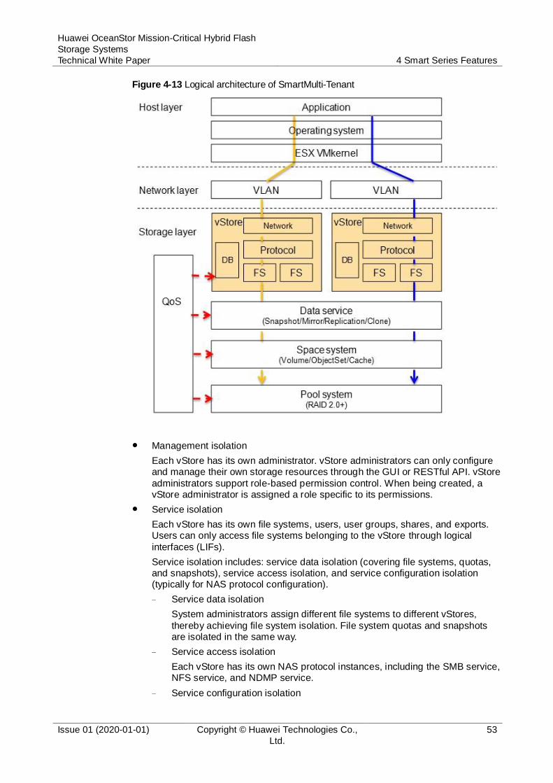
Huawei OceanStor Mission-Critical Hybrid Flash
Storage Systems
Technical White Paper 4 Smart Series Features
Issue 01 (2020-01-01) Copyright © Huawei Technologies Co.,
Ltd.
53
Figure 4-13 Logical architecture of SmartMulti-Tenant
Management isolation
Each vStore has its own administrator. vStore administrators can only configure and manage their own storage resources through the GUI or RESTful API. vStore
administrators support role-based permission control. When being created, a vStore administrator is assigned a role specific to its permissions.
Service isolation
Each vStore has its own file systems, users, user groups, shares, and exports. Users can only access file systems belonging to the vStore through logical
interfaces (LIFs).
Service isolation includes: service data isolation (covering file systems, quotas, and snapshots), service access isolation, and service configuration isolation (typically for NAS protocol configuration).
− Service data isolation
System administrators assign different file systems to different vStores,
thereby achieving file system isolation. File system quotas and snapshots are isolated in the same way.
− Service access isolation
Each vStore has its own NAS protocol instances, including the SMB service, NFS service, and NDMP service.
− Service configuration isolation
Huawei OceanStor Mission-Critical Hybrid Flash
Storage Systems
Technical White Paper 4 Smart Series Features
Issue 01 (2020-01-01) Copyright © Huawei Technologies Co.,
Ltd.
54
Each vStore can have its own users, user groups, user mapping rules, security policies, SMB shares, NFS shares, AD domain, DNS service, LDAP service, and NIS service.
Network isolation
VLANs and LIFs are used to isolate the vStore network, preventing illegal host
access to vStore's storage resources.
vStores use LIFs to configure services. A LIF belongs only to one vStore to achieve logical port isolation. You can create LIFs from GE ports, 10GE ports, 25GE ports, 40GE ports, 100GE ports, bond ports, or VLANs.
4.11 SmartQuota
In a NAS file service environment, resources are provided to departments, organizations, and individuals as shared directories. Because each department or person has unique resource requirements or limitations, storage systems must
allocate and restrict resources, based on the shared directories, in a customized manner. SmartQuota can restrict and control resource consumption for directories, users, and user groups, perfectly tackling all of these challenges.
SmartQuota allows you to configure the following quotas:
Space soft quota
Specifies a soft space limit. If any new data writes are performed and would result in this limit being exceeded, the storage system reports an alarm. This alarm indicates that space is insufficient and asks the user to delete unnecessary files or expand the quota. The user can still continue to write data to the directory.
Space hard quota
Specifies a hard space limit. If any new data writes are performed and would
result in this limit being exceeded, the storage system prevents the writes and reports an error.
File soft quota
Specifies a soft limit on the file quantity. If the number of used files exceeds this limit, the storage system reports an alarm. This alarm indicates that the file
resources are insufficient and asks the user to delete unnecessary files or expand the quota. The user can still continue to create files or directories.
File hard quota
Specifies a hard limit on the file quantity. If the number of used files for a quota exceeds this limit, the storage system prevents the creation of new files or directories and reports an error.
SmartQuota employs space and file hard quotas to restrict the maximum number of resources available to each user. The process is as follows:
1. In each write I/O operation, SmartQuota checks whether the accumulated quota (Quotas of the used space and file quantity + Quotas of the increased space and file quantity in this operation) exceeds the preset hard quota.
− If yes, the write I/O operation fails.
− If no, follow-up operations can be performed.

Huawei OceanStor Mission-Critical Hybrid Flash
Storage Systems
Technical White Paper 4 Smart Series Features
Issue 01 (2020-01-01) Copyright © Huawei Technologies Co.,
Ltd.
55
2. After the write I/O operation is allowed, SmartQuota adds an incremental amount of space and number of files to the previously used amount of space and number of files. This is done separately.
3. SmartQuota updates the quota (used amount of space and number of files + incremental amount of space and number of files) and allows the quota and I/O
data to be written into the file system.
The I/O operation and quota update succeed or fail at the same time, ensuring that the used capacity is correct during each I/O check.
If the directory quota, user quota, and group quota are concurrently configured in a shared directory in which you are performing operations, each write I/O operation will be restricted by these three quotas. All types of quota are checked. If the hard quota of one type of quota does not pass the check, the I/O will be rejected.
SmartQuota does the following to clear alarms: When the used resource of a user is lower than 90% of the soft quota, SmartQuota clears the resource over-usage alarm. In this way, even though the used resource is slightly higher or lower than the soft quota, alarms are not frequently generated or cleared.
4.12 SmartMotion
In the IT industry, enterprises and administration departments are faced with numerous challenges concerning capacity, performance, and costs related to data
storage. Enterprises cannot accurately assess the growth of service performance when purchasing storage systems. In addition, as service volume grows, it is hard to adjust existing services after disks are added to legacy storage systems.
To address the preceding problems, enterprises must develop a long-term performance requirement plan in the initial stages of IT system construction.
SmartMotion dynamically migrates data and evenly distributes data across all disks,
resolving the problems facing customers. Customers need to assess only recent performance requirements when purchasing storage systems, significantly reducing initial purchase costs and total TCO. If the system performance requirements increase with the service volume, customers only need to add disks to storage systems. After the disks are added, SmartMotion migrates data and evenly distributes the original
service data across all disks, notably improving service performance.
SmartMotion is implemented based on RAID 2.0+. For RAID 2.0+, the space of all the disks in a disk domain is divided into fixed CKs. When CKGs are required, disks are selected in a pseudo-random manner and the CKs from these disks compose CKGs based on a RAID algorithm. All CKs are then evenly distributed across all disks.
When disks are added into a disk domain, the storage system starts SmartMotion. The implementation of a SmartMotion task is performed as follows:
1. Selects the first CKG that is not load-balanced.
2. Selects disks for the CKG in a pseudo-random manner.
− If the selected disks are consistent with the original disks of the CKG, this CKG is skipped and the process goes back to 1.
− If the selected disks are inconsistent, the process goes to 3.
Huawei OceanStor Mission-Critical Hybrid Flash
Storage Systems
Technical White Paper 4 Smart Series Features
Issue 01 (2020-01-01) Copyright © Huawei Technologies Co.,
Ltd.
56
3. Compares the original disks of the CKG with the newly selected disks and computes the mapping between the source disks and the target disks based on disk differences. Then, selects the source disks and target disks.
4. Traverses all the source disks for the CKG, allocates new CKs from the target disks, and migrates data from the source disks to the target disks to release the
source disks.
5. After all CKGs in the system are traversed, the SmartMotion task is complete. Otherwise, the process goes back to 1 and processes the next CKG.
After the SmartMotion task is complete, disks are selected for all CKGs in a pseudo-random manner and all required data is migrated. All CKs are evenly distributed across all available disks.
Huawei OceanStor Mission-Critical Hybrid Flash
Storage Systems
Technical White Paper 5 Hyper Series Features
Issue 01 (2020-01-01) Copyright © Huawei Technologies Co.,
Ltd.
57
5 Hyper Series Features
5.1 HyperSnap
5.2 HyperClone
5.3 HyperReplication
5.4 HyperMetro
5.5 HyperVault
5.6 HyperCopy
5.7 HyperMirror
5.8 HyperLock
5.9 3DC
5.1 HyperSnap
5.1.1 HyperSnap for Block
HyperSnap can quickly generate a consistent image, that is, a duplicate, for a source LUN at a point in time without interrupting the services that are running on the source LUN. The duplicate is available immediately after being generated, and reading or writing the duplicate has no impact on source data. HyperSnap helps with online
backups, data analysis, and application testing. It works based on the mapping table and copy-on-write (COW) technology.
Technical Highlights
Zero-duration backup window
Traditional backup deteriorates application servers' performance, or even interrupts ongoing services. Therefore, a traditional backup task can be executed only after application servers are stopped or during off-peak hours. A backup window refers to the data backup duration, which is the maximum downtime
tolerated by applications. HyperSnap can back up data online, and requires a backup window that takes almost zero time and does not interrupt services.
Less occupied disk capacity
Huawei OceanStor Mission-Critical Hybrid Flash
Storage Systems
Technical White Paper 5 Hyper Series Features
Issue 01 (2020-01-01) Copyright © Huawei Technologies Co.,
Ltd.
58
After creating a consistent copy of a source LUN, HyperSnap uses a COW volume to save data on the source LUN at the snapshot point in time upon the first update. The size of the COW volume is independent of the source LUN size but dependent on the amount of data changed on the source LUN. If the amount of changed data is small, the snapshot captures a consistent copy of the source
LUN and uses a small disk space. The consistent copy can be used for service tests, saving disk space.
Quick data restoration
Data backed up using traditional offline backup methods cannot be read online. Long-time data restoration is required before a usable duplicate of the source data that was backed up at the specific point in time is available. HyperSnap can
directly read the snapshot volume to obtain data on the source volume at the snapshot point in time. This allows it to quickly restore data in the case of data corruption on the source volume.
Data consistency by consistency group
For OLTP applications, snapshots for multiple pieces of source LUN data must be
created at the same time. In this way, associated application data distributed on different LUNs can be kept at the same point in time. For example, the management data, service data, and log information of a database application are distributed on different source LUNs. Consistent copies of the three source LUNs must be created at the same time. Otherwise, the three source LUNs
cannot be restored to the same point in time, losing data dependency. HyperSnap provides snapshot consistency groups to resolve this problem. I/Os on multiple source LUNs are frozen at the snapshot point in time, and a snapshot is generated for the frozen I/Os.
Continuous data protection through timing snapshots
OceanStor series allows snapshots to be created for a source LUN at multiple
points in time. Working together with BCManager eReplication on the host, HyperSnap can create or delete snapshots at minute-level intervals. In addition, a snapshot policy can be set to automate the activation and stopping of snapshot tasks. As time elapses, snapshots are generated at multiple points, implementing continuous data protection at a low cost.
Snapshot copy
A snapshot copy backs up the data of a snapshot at the snapshot activation point in time. It does not back up data written to the snapshot after the snapshot activation point in time. The snapshot copy and source snapshot share the COW volume space of the source LUN, but the private space is independent. The snapshot copy is a writable snapshot and is independent of the source snapshot.
The read and write processes of a snapshot copy are the same as those of a common snapshot.
Snapshot copy allows users to obtain multiple data copies of a snapshot for various purposes.
5.1.2 HyperSnap for File
HyperSnap can quickly generate a consistent image, that is, a duplicate, for a source
file system at a certain point in time without interrupting services running on the source file system. This duplicate is available immediately after being generated, and reading or writing the duplicate does not impact the data on the source file system. HyperSnap helps with online backups, data analysis, and application testing. HyperSnap can:
Huawei OceanStor Mission-Critical Hybrid Flash
Storage Systems
Technical White Paper 5 Hyper Series Features
Issue 01 (2020-01-01) Copyright © Huawei Technologies Co.,
Ltd.
59
Create file system snapshots and back up these snapshots to tapes.
Provide data backups of the source file system so that end users can restore accidentally deleted files.
Work together with HyperReplication and HyperVault for remote replication and backup.
HyperSnap works based on ROW file systems. In a ROW file system, new or modified data does not overwrite the original data but instead is written to newly allocated storage space. This ensures enhanced data reliability and high file system scalability. ROW-based HyperSnap, used for file systems, can create snapshots in seconds. The snapshot data does not occupy any additional disk space unless the source files are deleted or modified.
Technical Highlights
Zero-duration backup window
A backup window refers to the maximum backup duration tolerated by applications before data is lost. Traditional backup deteriorates file system performance, or can even interrupt ongoing applications. Therefore, a traditional backup task can only be executed after applications are stopped or if the workload is comparatively light. HyperSnap can back up data online, and requires
a backup window that takes almost zero time and does not interrupt services.
Snapshot creation within seconds
To create a snapshot for a file system, only the root node of the file system needs to be copied and stored in caches and protected against power failure. This reduces the snapshot creation time to seconds.
Reduced performance loss
HyperSnap makes it easy to create snapshots for file systems. Only a small amount of data needs to be stored on disks. After a snapshot is created, the system checks whether data is protected by a snapshot before releasing the data space. If the data is protected by a snapshot, the system records the space of the data block that is protected by the snapshot but is deleted by the file system. This
results in a negligible impact on system performance. Background data space reclamation contends some CPU and memory resources against file system services only when the snapshot is deleted. However, performance loss remains low.
Less occupied disk capacity
The file system space occupied by a snapshot (a consistent duplicate) of the source file system depends on the amount of data that changed after the snapshot was generated. This space never exceeds the size of the file system at the snapshot point in time. For a file system with little changed data, only a small storage space is required to generate a consistent duplicate of the file system.
Rapid snapshot data access
A file system snapshot is presented in the root directory of the file system as an independent directory. Users can access this directory to quickly access the snapshot data. If snapshot rollback is not required, users can easily access the data at the snapshot point in time. Users can also recover data by copying the file or directory if the file data in the file system is corrupted.
If using a Windows client to access a CIFS-based file system, a user can restore a file or folder to the state at a specific snapshot point in time. To be specific, a user can right-click the desired file or folder, choose Restore previous versions
Huawei OceanStor Mission-Critical Hybrid Flash
Storage Systems
Technical White Paper 5 Hyper Series Features
Issue 01 (2020-01-01) Copyright © Huawei Technologies Co.,
Ltd.
60
from the short-cut menu, and select one option for restoration from the displayed list of available snapshots containing the previous versions of the file or folder.
Quick file system rollback
Backup data generated by traditional offline backup tasks cannot be read online. A time-consuming data recovery process is inevitable before a usable duplicate
of the source data at the backup point in time is available. HyperSnap can directly replace the file system root with specific snapshot root and clear cached data to quickly roll the file system back to a specific snapshot point in time.
You must exercise caution when using the rollback function because snapshots created after the rollback point in time are automatically deleted after a file system rollback succeeds.
Continuous data protection by timing snapshots
HyperSnap enables users to configure policies to automatically create snapshots at specific time points or at specific intervals.
The maximum number of snapshots for a file system varies depending on the product model. If the upper limit is exceeded, the earliest snapshots are
automatically deleted. The file system also allows users to periodically delete snapshots.
As time elapses, snapshots are generated at multiple points, implementing continuous data protection at a low cost. It must be noted that snapshot technology cannot achieve real continuous data protection. The interval between
two snapshots determines the granularity of continuous data protection.
5.2 HyperClone
5.2.1 HyperClone for Block
HyperClone generates a complete physical copy of a source LUN at a point in time
without interrupting ongoing services. If the clone is split, writing data to and reading data from the physical copy do not affect source LUN data.
Working Principle for Non-immediately Available Clone
HyperClone is implemented through a combination of bitmap and COW, and a combination of bitmap and dual-write (where data is written to the primary and secondary LUNs simultaneously). The working principle is as follows:
After a secondary LUN is added to a clone group, all data in the primary LUN is
replicated to the secondary LUN by default. This is called initial synchronization, and a progress bitmap reflects the synchronization process. If the primary LUN receives a write request from the production host during initial synchronization, the storage system checks the synchronization progress, and performs subsequent operations as follows:
If the write-targeted data block has not been synchronized to the secondary LUN, data is written to the primary LUN and the storage system notifies the host of a write success. Then, the data is synchronized to the secondary LUN during the subsequent synchronization task.
If the write-targeted data block has already been synchronized, data is written to both the primary and secondary LUNs.
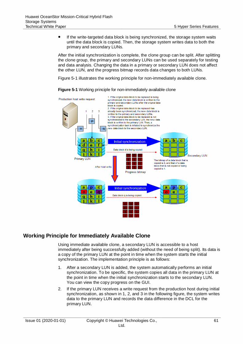
Huawei OceanStor Mission-Critical Hybrid Flash
Storage Systems
Technical White Paper 5 Hyper Series Features
Issue 01 (2020-01-01) Copyright © Huawei Technologies Co.,
Ltd.
61
If the write-targeted data block is being synchronized, the storage system waits until the data block is copied. Then, the storage system writes data to both the primary and secondary LUNs.
After the initial synchronization is complete, the clone group can be split. After splitting the clone group, the primary and secondary LUNs can be used separately for testing
and data analysis. Changing the data in a primary or secondary LUN does not affect the other LUN, and the progress bitmap records data changes to both LUNs.
Figure 5-1 illustrates the working principle for non-immediately available clone.
Figure 5-1 Working principle for non-immediately available clone
Working Principle for Immediately Available Clone
Using immediate available clone, a secondary LUN is accessible to a host immediately after being successfully added (without the need of being split). Its data is a copy of the primary LUN at the point in time when the system starts the initial synchronization. The implementation principle is as follows:
1. After a secondary LUN is added, the system automatically performs an initial synchronization. To be specific, the system copies all data in the primary LUN at
the point in time when the initial synchronization starts to the secondary LUN. You can view the copy progress on the GUI.
2. If the primary LUN receives a write request from the production host during initial synchronization, as shown in 1, 2, and 3 in the following figure, the system writes data to the primary LUN and records the data difference in the DCL for the
primary LUN.
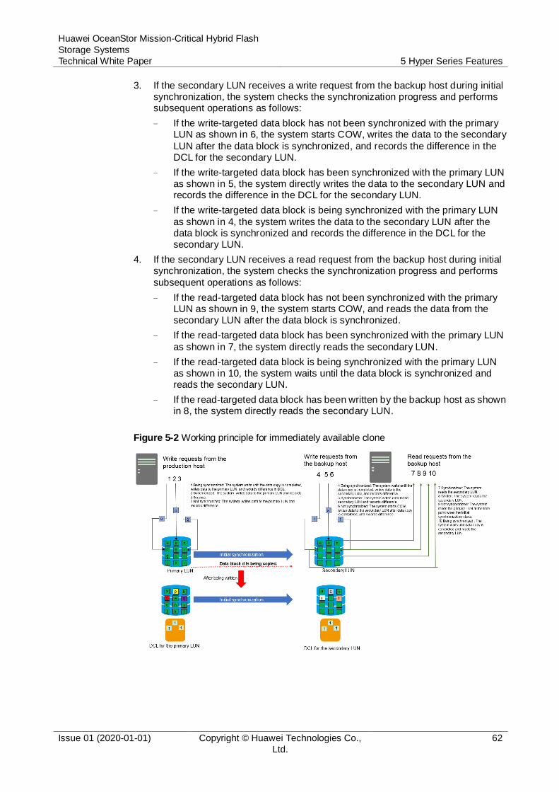
Huawei OceanStor Mission-Critical Hybrid Flash
Storage Systems
Technical White Paper 5 Hyper Series Features
Issue 01 (2020-01-01) Copyright © Huawei Technologies Co.,
Ltd.
62
3. If the secondary LUN receives a write request from the backup host during initial synchronization, the system checks the synchronization progress and performs subsequent operations as follows:
− If the write-targeted data block has not been synchronized with the primary LUN as shown in 6, the system starts COW, writes the data to the secondary
LUN after the data block is synchronized, and records the difference in the DCL for the secondary LUN.
− If the write-targeted data block has been synchronized with the primary LUN as shown in 5, the system directly writes the data to the secondary LUN and records the difference in the DCL for the secondary LUN.
− If the write-targeted data block is being synchronized with the primary LUN
as shown in 4, the system writes the data to the secondary LUN after the data block is synchronized and records the difference in the DCL for the secondary LUN.
4. If the secondary LUN receives a read request from the backup host during initial synchronization, the system checks the synchronization progress and performs
subsequent operations as follows:
− If the read-targeted data block has not been synchronized with the primary LUN as shown in 9, the system starts COW, and reads the data from the secondary LUN after the data block is synchronized.
− If the read-targeted data block has been synchronized with the primary LUN
as shown in 7, the system directly reads the secondary LUN.
− If the read-targeted data block is being synchronized with the primary LUN as shown in 10, the system waits until the data block is synchronized and reads the secondary LUN.
− If the read-targeted data block has been written by the backup host as shown in 8, the system directly reads the secondary LUN.
Figure 5-2 Working principle for immediately available clone
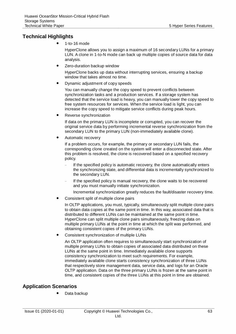
Huawei OceanStor Mission-Critical Hybrid Flash
Storage Systems
Technical White Paper 5 Hyper Series Features
Issue 01 (2020-01-01) Copyright © Huawei Technologies Co.,
Ltd.
63
Technical Highlights
1-to-16 mode
HyperClone allows you to assign a maximum of 16 secondary LUNs for a primary LUN. A clone in 1-to-N mode can back up multiple copies of source data for data
analysis.
Zero-duration backup window
HyperClone backs up data without interrupting services, ensuring a backup window that takes almost no time.
Dynamic adjustment of copy speeds
You can manually change the copy speed to prevent conflicts between
synchronization tasks and a production services. If a storage system has detected that the service load is heavy, you can manually lower the copy speed to free system resources for services. When the service load is light, you can increase the copy speed to mitigate service conflicts during peak hours.
Reverse synchronization
If data on the primary LUN is incomplete or corrupted, you can recover the original service data by performing incremental reverse synchronization from the secondary LUN to the primary LUN (non-immediately available clone).
Automatic recovery
If a problem occurs, for example, the primary or secondary LUN fails, the
corresponding clone created on the system will enter a disconnected state. After this problem is resolved, the clone is recovered based on a specified recovery policy.
− If the specified policy is automatic recovery, the clone automatically enters the synchronizing state, and differential data is incrementally synchronized to the secondary LUN.
− If the specified policy is manual recovery, the clone waits to be recovered and you must manually initiate synchronization.
Incremental synchronization greatly reduces the fault/disaster recovery time.
Consistent split of multiple clone pairs
In OLTP applications, you must, typically, simultaneously split multiple clone pairs
to obtain data copies at the same point in time. In this way, associated data that is distributed to different LUNs can be maintained at the same point in time. HyperClone can split multiple clone pairs simultaneously, freezing data on multiple primary LUNs at the point in time at which the split was performed, and obtaining consistent copies of the primary LUNs.
Consistent synchronization of multiple LUNs
An OLTP application often requires to simultaneously start synchronization of multiple primary LUNs to obtain copies of associated data distributed on these LUNs at the same point in time. Immediately available clone supports consistency synchronization to meet such requirements. For example, immediately available clone starts consistency synchronization of three LUNs
that respectively store management data, service data, and logs for an Oracle OLTP application. Data on the three primary LUNs is frozen at the same point in time, and consistent copies of the three LUNs at this point in time are obtained.
Application Scenarios
Data backup

Huawei OceanStor Mission-Critical Hybrid Flash
Storage Systems
Technical White Paper 5 Hyper Series Features
Issue 01 (2020-01-01) Copyright © Huawei Technologies Co.,
Ltd.
64
HyperClone can generate multiple physical copies of a primary volume and allow multiple services to access data concurrently.
Data recovery and protection
If primary LUN data is corrupted by a virus or human error, or is physically damaged, a data copy from the secondary LUN taken at a suitable point in time
can be reversely copied to the primary LUN. Then, the primary LUN can be restored to its state when the data copy was created.
5.2.2 HyperClone for File
HyperClone creates a clone file system, which is a copy, for a parent file system at a specified point in time. Clone file systems can be shared to clients exclusively to meet the requirements of rapid deployment, application tests, and DR drills.
Working Principle
A clone file system is a readable and writable copy taken from a point in time that is
based on redirect-on-write (ROW) and snapshot technologies.
Figure 5-3 Working principle of HyperClone for File
As shown in Figure a, the storage system writes new or modified data onto the newly allocated space of the ROW-based file system, instead of overwriting the
original data. The storage system records the point in time of each data write, indicating the write sequence. The points in time are represented by serial numbers, in ascending order.
As shown in Figure b, the storage system creates a clone file system as follows:
− Creates a read-only snapshot in the parent file system.

Huawei OceanStor Mission-Critical Hybrid Flash
Storage Systems
Technical White Paper 5 Hyper Series Features
Issue 01 (2020-01-01) Copyright © Huawei Technologies Co.,
Ltd.
65
− Copies the root node of the snapshot to generate the root node of the clone file system.
− Creates an initial snapshot in the clone file system.
This process is similar to the process of creating a read-only snapshot during which no user data is copied. Snapshot creation can be completed in one or
two seconds. Before data is modified, the clone file system shares data with its parent file system.
As shown in Figure c, modifying either the parent file system or the clone file system does not affect the other system.
− When the application server modifies data block A of the parent file system, the storage pool allocates new data block A1 to store new data. Data block A
is not released because it is protected by snapshots.
− When the application server modifies data block D of the clone file system, the storage pool allocates new data block D1 to store new data. Data block D is not released because its write time is earlier than the creation time of the clone file system.
Figure d shows the procedure for splitting a clone file system:
− Deletes all read-only snapshots from the clone file system.
− Traverses the data blocks of all objects in the clone file system, and allocates new data blocks in the clone file system for the shared data by overwriting data. This splits shared data.
− Deletes the associated snapshots from the parent file system.
After splitting is complete, the clone file system is independent of the parent file system. The time required to split the clone file system depends on the size of the share data.
Technical Highlights
Rapid deployment
In most scenarios, a clone file system can be created in seconds and can be accessed immediately after being created.
Saved storage space
A clone file system shares data with its parent file system and occupies extra storage space only when it modifies shared data.
Effective performance assurance
HyperClone has a negligible impact on system performance because a clone file
system is created based on the snapshot of the parent file system.
Splitting a clone file system
After a clone file system and its parent file system are split, they become completely independent of each other.
5.3 HyperReplication
HyperReplication, developed on the OceanStor OS unified storage software platform, is compatible with the replication protocols used by all generations and models of Huawei OceanStor converged storage products. HyperReplication enables OceanStor
V3 and later converged storage systems to construct highly flexible disaster recovery solutions.
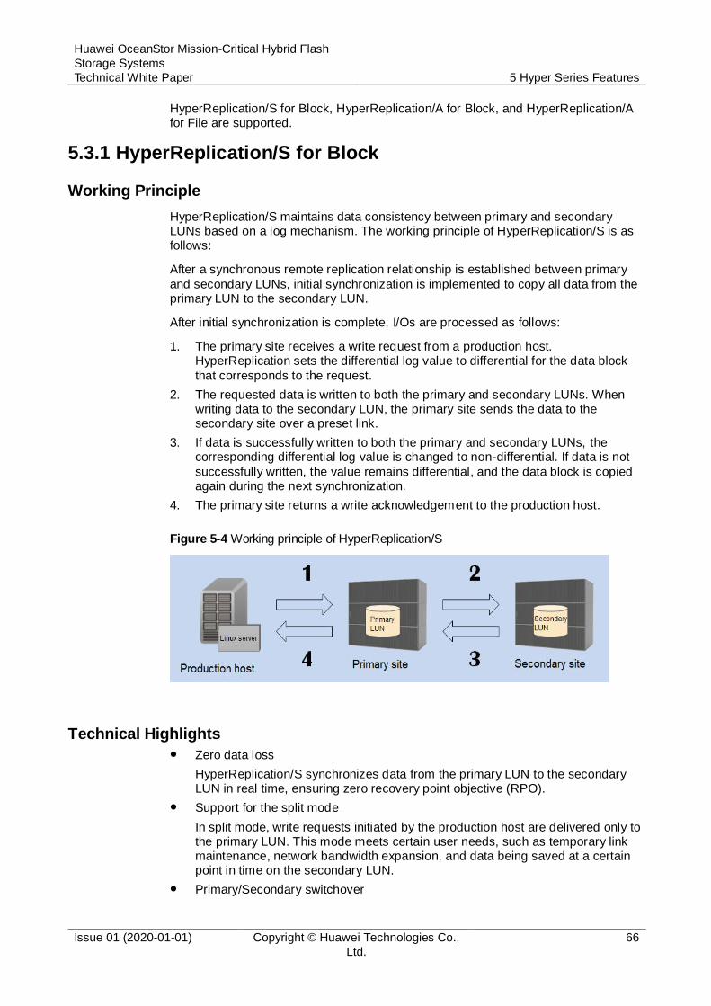
Huawei OceanStor Mission-Critical Hybrid Flash
Storage Systems
Technical White Paper 5 Hyper Series Features
Issue 01 (2020-01-01) Copyright © Huawei Technologies Co.,
Ltd.
66
HyperReplication/S for Block, HyperReplication/A for Block, and HyperReplication/A for File are supported.
5.3.1 HyperReplication/S for Block
Working Principle
HyperReplication/S maintains data consistency between primary and secondary LUNs based on a log mechanism. The working principle of HyperReplication/S is as follows:
After a synchronous remote replication relationship is established between primary
and secondary LUNs, initial synchronization is implemented to copy all data from the primary LUN to the secondary LUN.
After initial synchronization is complete, I/Os are processed as follows:
1. The primary site receives a write request from a production host. HyperReplication sets the differential log value to differential for the data block
that corresponds to the request.
2. The requested data is written to both the primary and secondary LUNs. When writing data to the secondary LUN, the primary site sends the data to the secondary site over a preset link.
3. If data is successfully written to both the primary and secondary LUNs, the corresponding differential log value is changed to non-differential. If data is not
successfully written, the value remains differential, and the data block is copied again during the next synchronization.
4. The primary site returns a write acknowledgement to the production host.
Figure 5-4 Working principle of HyperReplication/S
Technical Highlights
Zero data loss
HyperReplication/S synchronizes data from the primary LUN to the secondary LUN in real time, ensuring zero recovery point objective (RPO).
Support for the split mode
In split mode, write requests initiated by the production host are delivered only to the primary LUN. This mode meets certain user needs, such as temporary link maintenance, network bandwidth expansion, and data being saved at a certain point in time on the secondary LUN.
Primary/Secondary switchover
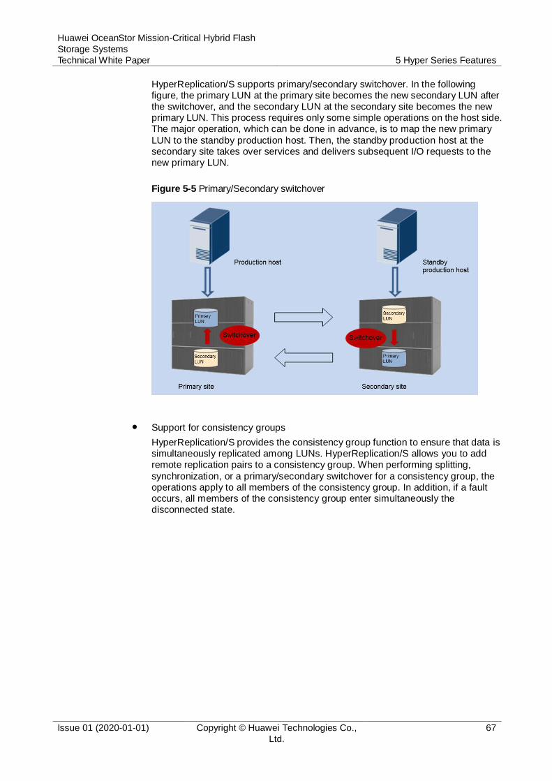
Huawei OceanStor Mission-Critical Hybrid Flash
Storage Systems
Technical White Paper 5 Hyper Series Features
Issue 01 (2020-01-01) Copyright © Huawei Technologies Co.,
Ltd.
67
HyperReplication/S supports primary/secondary switchover. In the following figure, the primary LUN at the primary site becomes the new secondary LUN after the switchover, and the secondary LUN at the secondary site becomes the new primary LUN. This process requires only some simple operations on the host side. The major operation, which can be done in advance, is to map the new primary
LUN to the standby production host. Then, the standby production host at the secondary site takes over services and delivers subsequent I/O requests to the new primary LUN.
Figure 5-5 Primary/Secondary switchover
Support for consistency groups
HyperReplication/S provides the consistency group function to ensure that data is simultaneously replicated among LUNs. HyperReplication/S allows you to add remote replication pairs to a consistency group. When performing splitting,
synchronization, or a primary/secondary switchover for a consistency group, the operations apply to all members of the consistency group. In addition, if a fault occurs, all members of the consistency group enter simultaneously the disconnected state.
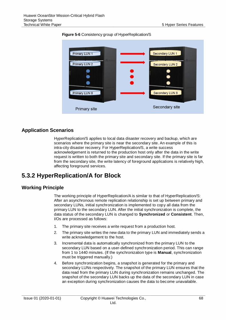
Huawei OceanStor Mission-Critical Hybrid Flash
Storage Systems
Technical White Paper 5 Hyper Series Features
Issue 01 (2020-01-01) Copyright © Huawei Technologies Co.,
Ltd.
68
Figure 5-6 Consistency group of HyperReplication/S
Application Scenarios
HyperReplication/S applies to local data disaster recovery and backup, which are scenarios where the primary site is near the secondary site. An example of this is intra-city disaster recovery. For HyperReplication/S, a write success acknowledgement is returned to the production host only after the data in the write request is written to both the primary site and secondary site. If the primary site is far
from the secondary site, the write latency of foreground applications is relatively high, affecting foreground services.
5.3.2 HyperReplication/A for Block
Working Principle
The working principle of HyperReplication/A is similar to that of HyperReplication/S: After an asynchronous remote replication relationship is set up between primary and secondary LUNs, initial synchronization is implemented to copy all data from the primary LUN to the secondary LUN. After the initial synchronization is complete, the
data status of the secondary LUN is changed to Synchronized or Consistent. Then, I/Os are processed as follows:
1. The primary site receives a write request from a production host.
2. The primary site writes the new data to the primary LUN and immediately sends a write acknowledgement to the host.
3. Incremental data is automatically synchronized from the primary LUN to the
secondary LUN based on a user-defined synchronization period. This can range from 1 to 1440 minutes. (If the synchronization type is Manual, synchronization must be triggered manually.)
4. Before synchronization begins, a snapshot is generated for the primary and secondary LUNs respectively. The snapshot of the primary LUN ensures that the
data read from the primary LUN during synchronization remains unchanged. The snapshot of the secondary LUN backs up the data of the secondary LUN in case an exception during synchronization causes the data to become unavailable.
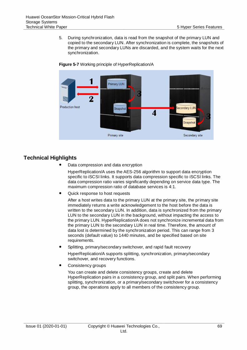
Huawei OceanStor Mission-Critical Hybrid Flash
Storage Systems
Technical White Paper 5 Hyper Series Features
Issue 01 (2020-01-01) Copyright © Huawei Technologies Co.,
Ltd.
69
5. During synchronization, data is read from the snapshot of the primary LUN and copied to the secondary LUN. After synchronization is complete, the snapshots of the primary and secondary LUNs are discarded, and the system waits for the next synchronization.
Figure 5-7 Working principle of HyperReplication/A
Technical Highlights Data compression and data encryption
HyperReplication/A uses the AES-256 algorithm to support data encryption specific to iSCSI links. It supports data compression specific to iSCSI links. The data compression ratio varies significantly depending on service data type. The maximum compression ratio of database services is 4:1.
Quick response to host requests
After a host writes data to the primary LUN at the primary site, the primary site
immediately returns a write acknowledgement to the host before the data is written to the secondary LUN. In addition, data is synchronized from the primary LUN to the secondary LUN in the background, without impacting the access to the primary LUN. HyperReplication/A does not synchronize incremental data from the primary LUN to the secondary LUN in real time. Therefore, the amount of
data lost is determined by the synchronization period. This can range from 3 seconds (default value) to 1440 minutes, and be specified based on site requirements.
Splitting, primary/secondary switchover, and rapid fault recovery
HyperReplication/A supports splitting, synchronization, primary/secondary
switchover, and recovery functions.
Consistency groups
You can create and delete consistency groups, create and delete HyperReplication pairs in a consistency group, and split pairs. When performing splitting, synchronization, or a primary/secondary switchover for a consistency group, the operations apply to all members of the consistency group.
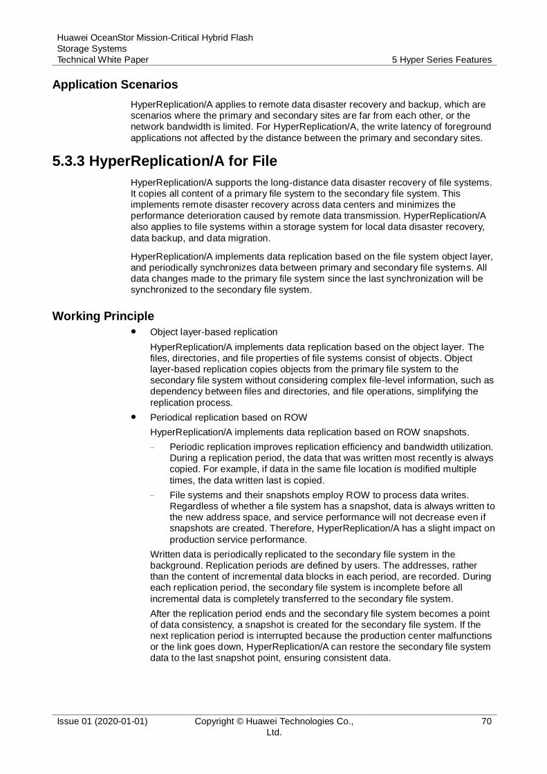
Huawei OceanStor Mission-Critical Hybrid Flash
Storage Systems
Technical White Paper 5 Hyper Series Features
Issue 01 (2020-01-01) Copyright © Huawei Technologies Co.,
Ltd.
70
Application Scenarios
HyperReplication/A applies to remote data disaster recovery and backup, which are scenarios where the primary and secondary sites are far from each other, or the network bandwidth is limited. For HyperReplication/A, the write latency of foreground
applications not affected by the distance between the primary and secondary sites.
5.3.3 HyperReplication/A for File
HyperReplication/A supports the long-distance data disaster recovery of file systems. It copies all content of a primary file system to the secondary file system. This implements remote disaster recovery across data centers and minimizes the performance deterioration caused by remote data transmission. HyperReplication/A also applies to file systems within a storage system for local data disaster recovery,
data backup, and data migration.
HyperReplication/A implements data replication based on the file system object layer, and periodically synchronizes data between primary and secondary file systems. All data changes made to the primary file system since the last synchronization will be synchronized to the secondary file system.
Working Principle Object layer-based replication
HyperReplication/A implements data replication based on the object layer. The files, directories, and file properties of file systems consist of objects. Object layer-based replication copies objects from the primary file system to the secondary file system without considering complex file-level information, such as dependency between files and directories, and file operations, simplifying the
replication process.
Periodical replication based on ROW
HyperReplication/A implements data replication based on ROW snapshots.
− Periodic replication improves replication efficiency and bandwidth utilization. During a replication period, the data that was written most recently is always copied. For example, if data in the same file location is modified multiple
times, the data written last is copied.
− File systems and their snapshots employ ROW to process data writes. Regardless of whether a file system has a snapshot, data is always written to the new address space, and service performance will not decrease even if snapshots are created. Therefore, HyperReplication/A has a slight impact on
production service performance.
Written data is periodically replicated to the secondary file system in the background. Replication periods are defined by users. The addresses, rather than the content of incremental data blocks in each period, are recorded. During each replication period, the secondary file system is incomplete before all
incremental data is completely transferred to the secondary file system.
After the replication period ends and the secondary file system becomes a point of data consistency, a snapshot is created for the secondary file system. If the next replication period is interrupted because the production center malfunctions or the link goes down, HyperReplication/A can restore the secondary file system data to the last snapshot point, ensuring consistent data.

Huawei OceanStor Mission-Critical Hybrid Flash
Storage Systems
Technical White Paper 5 Hyper Series Features
Issue 01 (2020-01-01) Copyright © Huawei Technologies Co.,
Ltd.
71
Figure 5-8 Working principle of HyperReplication/A for File
1. The production storage system receives a write request from a production host.
2. The production storage system writes the new data to the primary file system and immediately sends a write acknowledgement to the host.
3. When a replication period starts, HyperReplication/A creates a snapshot for the
primary file system.
4. The production storage system reads and replicates snapshot data to the secondary file system based on the incremental information received since the last synchronization.
5. After incremental replication is complete, the content of the secondary file system is the same as the snapshot of the primary file system. The secondary file system
becomes the point of data consistency.
Technical Highlights
Splitting and incremental resynchronization
If you want to suspend data replication from the primary file system to the secondary file system, you can split the remote replication pair. For HyperReplication/A, splitting will stop the ongoing replication process and later periodical replication.
After splitting, if the host writes new data, the incremental information will be recorded. You can start a synchronization session after splitting. During resynchronization, only incremental data is replicated.
Splitting applies to device maintenance scenarios, such as storage array upgrades and replication link changes. In such scenarios, splitting can reduce the
number of concurrent tasks so that the system becomes more reliable. The replication tasks will be resumed or restarted after maintenance.
Automatic recovery
If data replication from the primary file system to the secondary file system is interrupted due to a fault, remote replication enters the interrupted state. If the

Huawei OceanStor Mission-Critical Hybrid Flash
Storage Systems
Technical White Paper 5 Hyper Series Features
Issue 01 (2020-01-01) Copyright © Huawei Technologies Co.,
Ltd.
72
host writes new data when remote replication is in this state, the incremental information will be recorded. After the fault is rectified, remote replication is automatically recovered, and incremental resynchronization is automatically implemented.
Readable and writable secondary file system and incremental failback
Normally, a secondary file system is readable but not writable. When accessing a secondary file system, the host reads the data on snapshots generated during the last backup. After the next backup is completed, the host reads the data on the new snapshots.
A readable and writable secondary file system applies to scenarios in which backup data must be accessed during replication.
You can set a secondary file system to readable and writable if the following conditions are met:
− Initial synchronization has been implemented. For HyperReplication/A, data on the secondary file system is in the complete state after initial synchronization.
− The remote replication pair is in the split or interrupted state.
If data is being replicated from the primary file system to the secondary file system (the data is inconsistent on the primary and secondary file systems) and you set the secondary file system to readable and writable, HyperReplication/A restores the data in the secondary file system to the
point in time at which the last snapshot was taken.
After the secondary file system is set to readable and writable, HyperReplication/A records the incremental information about data that the host writes to the secondary file system for subsequent incremental resynchronization. After replication recovery, you can replicate incremental data from the primary file system to the secondary file system or from the
secondary file system to the primary file system (a primary/secondary switchover is required before synchronization). Before a replication session starts, HyperReplication/A restores target end data to a point in time at which a snapshot was taken and the data was consistent with source end data. Then, HyperReplication/A performs incremental resynchronization from the
source end to the target end.
Readable and writable secondary file systems are commonly used in disaster recovery scenarios.
Primary/Secondary switchover
Primary/secondary switchover exchanges the roles of the primary and secondary file systems. These roles determine the direction in which the data is copied. Data
is always copied from the primary file system to the secondary file system.
Primary/secondary switchover is commonly used for failback during disaster recovery.
Quick response to host I/Os
All I/Os generated during file system asynchronous remote replication are
processed in the background. A write success acknowledgement is returned immediately after host data is written to the cache. Incremental information is recorded and snapshots are created only when data is flushed from cache to disks. Therefore, host I/Os can be responded to quickly.
Asynchronous replication for file systems within a vStore on a storage system
Asynchronous replication can be implemented for two file systems within a vStore on a storage system for disaster recovery, backup, and migration. This function

Huawei OceanStor Mission-Critical Hybrid Flash
Storage Systems
Technical White Paper 5 Hyper Series Features
Issue 01 (2020-01-01) Copyright © Huawei Technologies Co.,
Ltd.
73
enables fast intra-system backup without the need to purchase remote devices and network resources, reducing costs and improving efficiency.
Synchronization of snapshots from a primary file system to a secondary file system
Manually and periodically created snapshots of a primary file system can be
synchronized to a secondary file system. After a primary/secondary switchover, the new primary file system still has snapshots at historical points in time. This function allows the secondary file system to retain a large number of snapshots, relieving the capacity pressure of the local file system. Users can manually create, delete, and modify snapshots and set the number of snapshots retained on the secondary file system.
5.4 HyperMetro
HyperMetro, an array-level active-active technology, enables two storage systems to
work in active-active mode in two different locations up to 300 km away from each other. For example, the systems could be in the same equipment room or just in the same city.
OceanStor series supports both HyperMetro for Block and HyperMetro for File.
OceanStor series can provide HyperMetro solutions with OceanStor V3 series,
OceanStor V5 series, OceanStor F V3 series, and OceanStor F V5 series.
5.4.1 HyperMetro for Block
HyperMetro allows two LUNs from two storage arrays to maintain real-time data consistency and to be accessible to hosts. If one storage array fails, hosts automatically choose the path to the other storage array for service access. If the links between the storage arrays are interrupted, a quorum server deployed at a third location determines which storage array continues providing services.
HyperMetro supports both Fibre Channel (8 Gbit/s, 16 Gbit/s, and 32 Gbit/s) and IP networking (10GE, 25GE, 40GE, and 100GE).

Huawei OceanStor Mission-Critical Hybrid Flash
Storage Systems
Technical White Paper 5 Hyper Series Features
Issue 01 (2020-01-01) Copyright © Huawei Technologies Co.,
Ltd.
74
Figure 5-9 Architecture of HyperMetro for Block
Technical Highlights
Gateway-free active-active solution
Simple networking makes deployment easy. The gateway-free design improves reliability and performance because it ensures one less possible failure point, and eliminates the 0.5 ms to 1 ms latency caused by a gateway.
Active-active mode
Storage arrays in two data centers are accessible to hosts, implementing load balancing across data centers.
Site access optimization
UltraPath is optimized specifically for active-active scenarios. It can identify region information to reduce cross-site access, reducing latency. UltraPath can read data from the local or remote storage array. However, when the local
storage array is working properly, UltraPath preferentially reads data from and writes data to the local storage array. This prevents data reads and writes across data centers.
FastWrite
In a common SCSI write process, a write request goes back and forth twice
between two data centers to complete two interactions, Write Alloc and Write Data. FastWrite optimizes the storage transmission protocol and reserves cache space on the destination array for receiving write requests. Write Alloc is omitted and only one interaction is required. FastWrite halves the time required for data
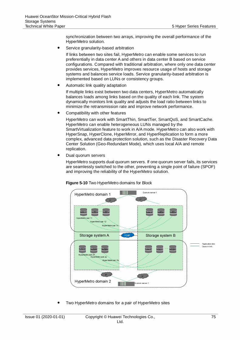
Huawei OceanStor Mission-Critical Hybrid Flash
Storage Systems
Technical White Paper 5 Hyper Series Features
Issue 01 (2020-01-01) Copyright © Huawei Technologies Co.,
Ltd.
75
synchronization between two arrays, improving the overall performance of the HyperMetro solution.
Service granularity-based arbitration
If links between two sites fail, HyperMetro can enable some services to run preferentially in data center A and others in data center B based on service
configurations. Compared with traditional arbitration, where only one data center provides services, HyperMetro improves resource usage of hosts and storage systems and balances service loads. Service granularity-based arbitration is implemented based on LUNs or consistency groups.
Automatic link quality adaptation
If multiple links exist between two data centers, HyperMetro automatically
balances loads among links based on the quality of each link. The system dynamically monitors link quality and adjusts the load ratio between links to minimize the retransmission rate and improve network performance.
Compatibility with other features
HyperMetro can work with SmartThin, SmartTier, SmartQoS, and SmartCache.
HyperMetro can enable heterogeneous LUNs managed by the SmartVirtualization feature to work in A/A mode. HyperMetro can also work with HyperSnap, HyperClone, HyperMirror, and HyperReplication to form a more complex, advanced data protection solution, such as the Disaster Recovery Data Center Solution (Geo-Redundant Mode), which uses local A/A and remote
replication.
Dual quorum servers
HyperMetro supports dual quorum servers. If one quorum server fails, its services are seamlessly switched to the other, preventing a single point of failure (SPOF) and improving the reliability of the HyperMetro solution.
Figure 5-10 Two HyperMetro domains for Block
Two HyperMetro domains for a pair of HyperMetro sites

Huawei OceanStor Mission-Critical Hybrid Flash
Storage Systems
Technical White Paper 5 Hyper Series Features
Issue 01 (2020-01-01) Copyright © Huawei Technologies Co.,
Ltd.
76
Two HyperMetro domains can be configured for a pair of HyperMetro sites. A HyperMetro domain consists of a local storage system, a remote storage system, and a quorum server. Application servers can access data on both storage systems in a HyperMetro domain. The two HyperMetro domains can be configured with different arbitration modes and quorum servers. HyperMetro pairs
or HyperMetro consistency groups can be added to different HyperMetro domains to meet different arbitration requirements of services.
5.4.2 HyperMetro for File
HyperMetro enables hosts to virtualize the file systems of two storage systems as a single file system on a single storage system. In addition, HyperMetro keeps data in both of these file systems consistent. Data is read from or written to the primary storage system, and is synchronized to the secondary storage system in real time. If
the primary storage system fails, HyperMetro uses vStore to switch services to the secondary storage system, without losing any data or interrupting any applications.
HyperMetro provides the following benefits:
High availability with geographic protection
Easy management
Minimal risk of data loss, reduced system downtime, and quick disaster recovery
Negligible disruption to users and client applications
HyperMetro supports both Fibre Channel (8 Gbit/s, 16 Gbit/s, and 32 Gbit/s) and IP networking (10GE, 25GE, 40GE, and 100GE).
Figure 5-11 Architecture of HyperMetro for File
Technical Highlights
Gateway-free solution
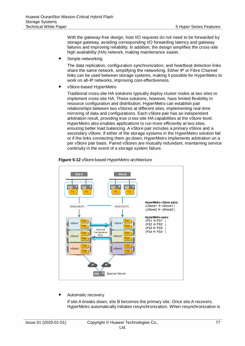
Huawei OceanStor Mission-Critical Hybrid Flash
Storage Systems
Technical White Paper 5 Hyper Series Features
Issue 01 (2020-01-01) Copyright © Huawei Technologies Co.,
Ltd.
77
With the gateway-free design, host I/O requests do not need to be forwarded by storage gateway, avoiding corresponding I/O forwarding latency and gateway failures and improving reliability. In addition, the design simplifies the cross-site high availability (HA) network, making maintenance easier.
Simple networking
The data replication, configuration synchronization, and heartbeat detection links share the same network, simplifying the networking. Either IP or Fibre Channel links can be used between storage systems, making it possible for HyperMetro to work on all-IP networks, improving cost-effectiveness.
vStore-based HyperMetro
Traditional cross-site HA solutions typically deploy cluster nodes at two sites to
implement cross-site HA. These solutions, however, have limited flexibility in resource configuration and distribution. HyperMetro can establish pair relationships between two vStores at different sites, implementing real-time mirroring of data and configurations. Each vStore pair has an independent arbitration result, providing true cross-site HA capabilities at the vStore level.
HyperMetro also enables applications to run more efficiently at two sites, ensuring better load balancing. A vStore pair includes a primary vStore and a secondary vStore. If either of the storage systems in the HyperMetro solution fail or if the links connecting them go down, HyperMetro implements arbitration on a per vStore pair basis. Paired vStores are mutually redundant, maintaining service
continuity in the event of a storage system failure.
Figure 5-12 vStore-based HyperMetro architecture
Automatic recovery
If site A breaks down, site B becomes the primary site. Once site A recovers, HyperMetro automatically initiates resynchronization. When resynchronization is

Huawei OceanStor Mission-Critical Hybrid Flash
Storage Systems
Technical White Paper 5 Hyper Series Features
Issue 01 (2020-01-01) Copyright © Huawei Technologies Co.,
Ltd.
78
complete, the HyperMetro pair returns to its normal state. If site B then breaks down, site A becomes the primary site again to maintain host services.
Easy upgrade
To use the HyperMetro feature, upgrade your storage system software to the latest version and purchase the required feature license. You can establish a
HyperMetro solution between the upgraded storage system and another storage system, without the need for extra data migration. Users are free to include HyperMetro in initial configurations or add it later as required.
FastWrite
In a common SCSI write process, a write request goes back and forth twice between two data centers to complete two interactions, Write Alloc and Write
Data. FastWrite optimizes the storage transmission protocol and reserves cache space on the destination array for receiving write requests, while Write Alloc is omitted and only one interaction is required. FastWrite halves the time required for data synchronization between two arrays, improving the overall performance of the HyperMetro solution.
Self-adaptation to link quality
If there are multiple links between two data centers, HyperMetro automatically implements load balancing among these links based on quality. The system dynamically monitors link quality and adjusts the load ratio between links to minimize the retransmission rate and improve network performance.
Compatibility with other features
HyperMetro can be used with SmartThin, SmartQoS, and SmartCache. HyperMetro can also work with HyperVault, HyperSnap, and HyperReplication to form a more complex and advanced data protection solution, such as the Disaster Recovery Data Center Solution (Geo-Redundant Mode), which uses HyperMetro and HyperReplication.
Dual quorum servers
HyperMetro supports dual quorum servers. If one quorum server fails, its services are seamlessly switched to the other, preventing a single point of failure (SPOF) and improving the reliability of the HyperMetro solution.
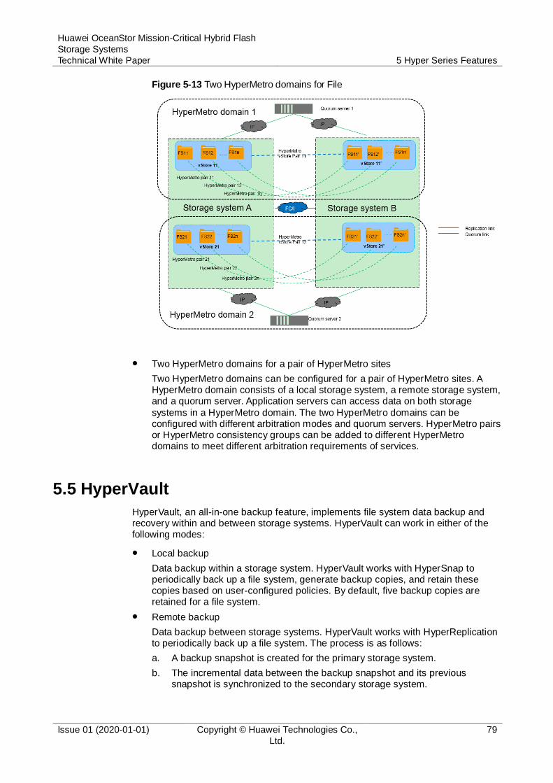
Huawei OceanStor Mission-Critical Hybrid Flash
Storage Systems
Technical White Paper 5 Hyper Series Features
Issue 01 (2020-01-01) Copyright © Huawei Technologies Co.,
Ltd.
79
Figure 5-13 Two HyperMetro domains for File
Two HyperMetro domains for a pair of HyperMetro sites
Two HyperMetro domains can be configured for a pair of HyperMetro sites. A HyperMetro domain consists of a local storage system, a remote storage system, and a quorum server. Application servers can access data on both storage
systems in a HyperMetro domain. The two HyperMetro domains can be configured with different arbitration modes and quorum servers. HyperMetro pairs or HyperMetro consistency groups can be added to different HyperMetro domains to meet different arbitration requirements of services.
5.5 HyperVault
HyperVault, an all-in-one backup feature, implements file system data backup and recovery within and between storage systems. HyperVault can work in either of the following modes:
Local backup
Data backup within a storage system. HyperVault works with HyperSnap to periodically back up a file system, generate backup copies, and retain these copies based on user-configured policies. By default, five backup copies are retained for a file system.
Remote backup
Data backup between storage systems. HyperVault works with HyperReplication to periodically back up a file system. The process is as follows:
a. A backup snapshot is created for the primary storage system.
b. The incremental data between the backup snapshot and its previous snapshot is synchronized to the secondary storage system.

Huawei OceanStor Mission-Critical Hybrid Flash
Storage Systems
Technical White Paper 5 Hyper Series Features
Issue 01 (2020-01-01) Copyright © Huawei Technologies Co.,
Ltd.
80
c. After data is synchronized, a snapshot is created on the secondary storage system.
By default, 35 snapshots can be retained on the backup storage system.
Technical Highlights
High cost efficiency
HyperVault can be seamlessly integrated into the primary storage system and provide data backup without additional backup software. Huawei-developed
storage management software, OceanStor DeviceManager, allows you to configure flexible backup policies and efficiently perform data backup.
Fast data backup
HyperVault works with HyperSnap to achieve second-level local data backup. For remote backup, the system performs full backup the first time, and then only
backs up incremental data blocks. This allows HyperVault to provide faster data backup than software that backs up data every time.
Fast data recovery
HyperVault uses snapshot rollback technology to implement local data recovery, without requiring additional data resolution. This allows it to achieve second-level data recovery. Remote recovery, which is incremental data recovery, can be used
when local recovery cannot meet requirements. Each copy of backup data is a logically full backup of service data. The backup data is saved in its original format and can be accessed immediately.
Simple management
Only one primary storage system, one backup storage system, and native
management software, OceanStor DeviceManager, are required. This mode is simpler and easier to manage than old network designs, which contain primary storage, backup software, and backup media.
5.6 HyperCopy
HyperCopy copies data from a source LUN to a target LUN within a storage system or between storage systems.
HyperCopy implements full copy, which copies all data from a source LUN to a target LUN. Figure 5-14 illustrates the working principle of HyperCopy.
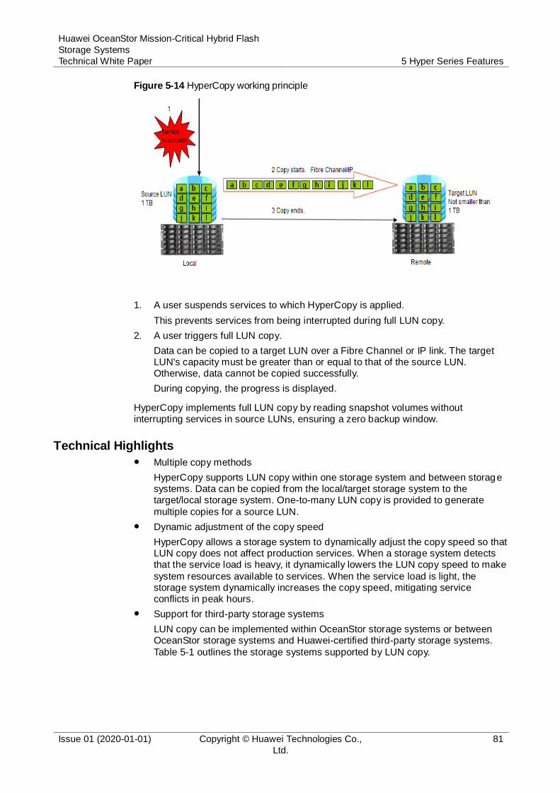
Huawei OceanStor Mission-Critical Hybrid Flash
Storage Systems
Technical White Paper 5 Hyper Series Features
Issue 01 (2020-01-01) Copyright © Huawei Technologies Co.,
Ltd.
81
Figure 5-14 HyperCopy working principle
1. A user suspends services to which HyperCopy is applied.
This prevents services from being interrupted during full LUN copy.
2. A user triggers full LUN copy.
Data can be copied to a target LUN over a Fibre Channel or IP link. The target LUN's capacity must be greater than or equal to that of the source LUN. Otherwise, data cannot be copied successfully.
During copying, the progress is displayed.
HyperCopy implements full LUN copy by reading snapshot volumes without interrupting services in source LUNs, ensuring a zero backup window.
Technical Highlights
Multiple copy methods
HyperCopy supports LUN copy within one storage system and between storage systems. Data can be copied from the local/target storage system to the target/local storage system. One-to-many LUN copy is provided to generate
multiple copies for a source LUN.
Dynamic adjustment of the copy speed
HyperCopy allows a storage system to dynamically adjust the copy speed so that LUN copy does not affect production services. When a storage system detects that the service load is heavy, it dynamically lowers the LUN copy speed to make
system resources available to services. When the service load is light, the storage system dynamically increases the copy speed, mitigating service conflicts in peak hours.
Support for third-party storage systems
LUN copy can be implemented within OceanStor storage systems or between OceanStor storage systems and Huawei-certified third-party storage systems.
Table 5-1 outlines the storage systems supported by LUN copy.
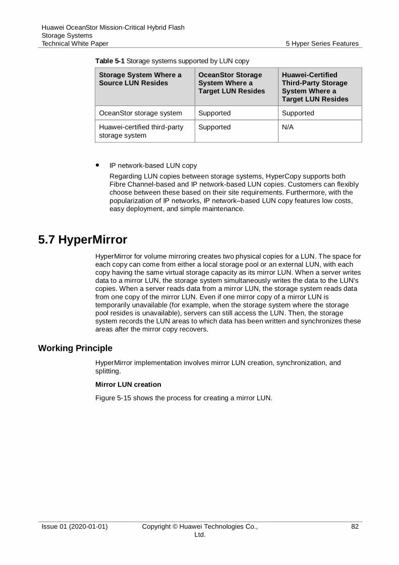
Huawei OceanStor Mission-Critical Hybrid Flash
Storage Systems
Technical White Paper 5 Hyper Series Features
Issue 01 (2020-01-01) Copyright © Huawei Technologies Co.,
Ltd.
82
Table 5-1 Storage systems supported by LUN copy
Storage System Where a Source LUN Resides
OceanStor Storage System Where a Target LUN Resides
Huawei-Certified Third-Party Storage System Where a Target LUN Resides
OceanStor storage system Supported Supported
Huawei-certified third-party
storage system
Supported N/A
IP network-based LUN copy
Regarding LUN copies between storage systems, HyperCopy supports both Fibre Channel-based and IP network-based LUN copies. Customers can flexibly choose between these based on their site requirements. Furthermore, with the
popularization of IP networks, IP network–based LUN copy features low costs, easy deployment, and simple maintenance.
5.7 HyperMirror
HyperMirror for volume mirroring creates two physical copies for a LUN. The space for each copy can come from either a local storage pool or an external LUN, with each copy having the same virtual storage capacity as its mirror LUN. When a server writes data to a mirror LUN, the storage system simultaneously writes the data to the LUN's copies. When a server reads data from a mirror LUN, the storage system reads data
from one copy of the mirror LUN. Even if one mirror copy of a mirror LUN is temporarily unavailable (for example, when the storage system where the storage pool resides is unavailable), servers can still access the LUN. Then, the storage system records the LUN areas to which data has been written and synchronizes these areas after the mirror copy recovers.
Working Principle
HyperMirror implementation involves mirror LUN creation, synchronization, and
splitting.
Mirror LUN creation
Figure 5-15 shows the process for creating a mirror LUN.
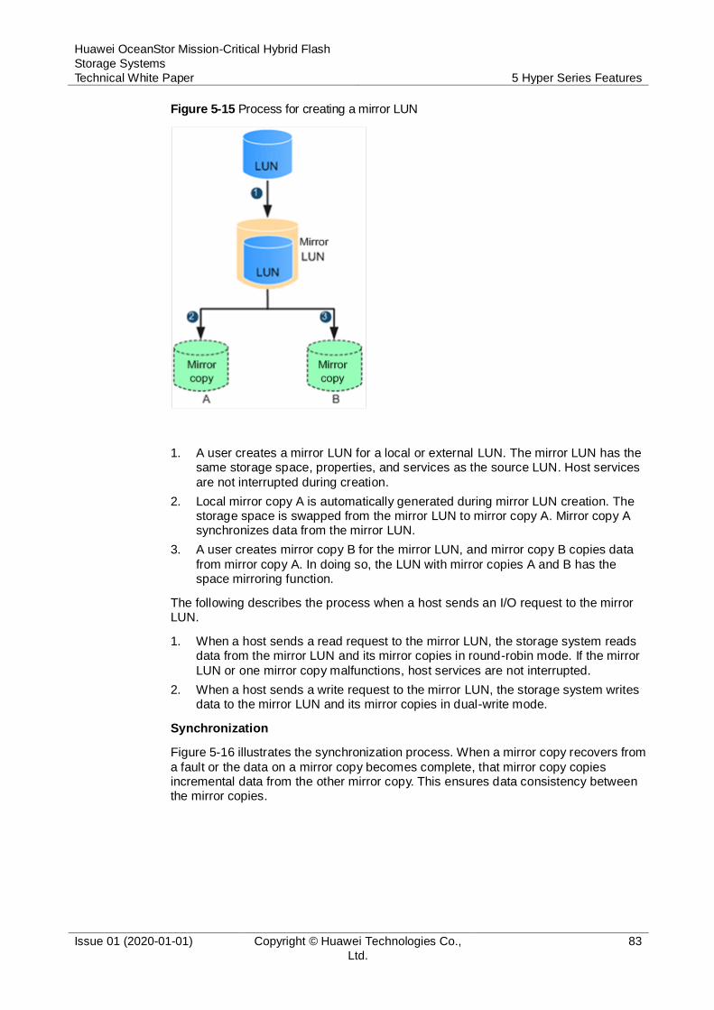
Huawei OceanStor Mission-Critical Hybrid Flash
Storage Systems
Technical White Paper 5 Hyper Series Features
Issue 01 (2020-01-01) Copyright © Huawei Technologies Co.,
Ltd.
83
Figure 5-15 Process for creating a mirror LUN
1. A user creates a mirror LUN for a local or external LUN. The mirror LUN has the same storage space, properties, and services as the source LUN. Host services
are not interrupted during creation.
2. Local mirror copy A is automatically generated during mirror LUN creation. The storage space is swapped from the mirror LUN to mirror copy A. Mirror copy A synchronizes data from the mirror LUN.
3. A user creates mirror copy B for the mirror LUN, and mirror copy B copies data
from mirror copy A. In doing so, the LUN with mirror copies A and B has the space mirroring function.
The following describes the process when a host sends an I/O request to the mirror LUN.
1. When a host sends a read request to the mirror LUN, the storage system reads data from the mirror LUN and its mirror copies in round-robin mode. If the mirror
LUN or one mirror copy malfunctions, host services are not interrupted.
2. When a host sends a write request to the mirror LUN, the storage system writes data to the mirror LUN and its mirror copies in dual-write mode.
Synchronization
Figure 5-16 illustrates the synchronization process. When a mirror copy recovers from
a fault or the data on a mirror copy becomes complete, that mirror copy copies incremental data from the other mirror copy. This ensures data consistency between the mirror copies.
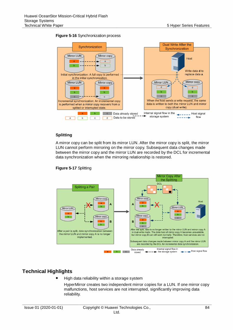
Huawei OceanStor Mission-Critical Hybrid Flash
Storage Systems
Technical White Paper 5 Hyper Series Features
Issue 01 (2020-01-01) Copyright © Huawei Technologies Co.,
Ltd.
84
Figure 5-16 Synchronization process
Splitting
A mirror copy can be split from its mirror LUN. After the mirror copy is split, the mirror LUN cannot perform mirroring on the mirror copy. Subsequent data changes made
between the mirror copy and the mirror LUN are recorded by the DCL for incremental data synchronization when the mirroring relationship is restored.
Figure 5-17 Splitting
Technical Highlights
High data reliability within a storage system
HyperMirror creates two independent mirror copies for a LUN. If one mirror copy malfunctions, host services are not interrupted, significantly improving data
reliability.

Huawei OceanStor Mission-Critical Hybrid Flash
Storage Systems
Technical White Paper 5 Hyper Series Features
Issue 01 (2020-01-01) Copyright © Huawei Technologies Co.,
Ltd.
85
Robust data reliability of heterogeneous storage systems
When SmartVirtualization is used to take over LUNs of heterogeneous storage systems, HyperMirror is employed to create a mirror LUN and local mirror copies for each heterogeneous LUN. Services will not be interrupted if heterogeneous storage systems are unstable or their links are down.
Minor impact on host performance
Mirror copies generated by HyperMirror reside in the cache of their LUN, and concurrent write and round-robin read technologies are implemented between mirror spaces. This ensures host service performance is not affected.
Ensured host service continuity
HyperMirror allows mirror copies to be created online for ongoing LUNs. In this
way, host services are unaware of any changes made to LUN data space.
5.8 HyperLock
With the explosive growth of information, increasing importance has been pinned on secure access and application. To comply with laws and regulations, important data such as case documents from courts, medical records, and financial documents can be read but not written within a specific period. Therefore, measures must be taken to prevent such data from being tampered with. In the storage industry, Write Once Read
Many (WORM) is the most common method used to archive and back up data, ensure secure data access, and prevent data tampering.
Huawei's WORM feature is called HyperLock. A file protected by WORM can enter the read-only state after data is written to it. In the read-only state, the file can be read, but cannot be deleted, modified, or renamed. WORM can prevent data from being tampered with, meeting the data security requirements of enterprises and
organizations.
File systems that WORM has been configured for are called WORM file systems and can only be configured by administrators. There are two WORM modes:
Regulatory Compliance WORM (WORM-C for short): applies to archive scenarios where data protection mechanisms are implemented to comply with
laws and regulations.
Enterprise WORM (WORM-E): mainly used by enterprises for internal control.
Working Principle
With WORM, data can be written to files once only, and cannot be rewritten, modified, deleted, or renamed. If a common file system is protected by WORM, files in the WORM file system can be read only within the protection period. After WORM file systems are created, they must be mapped to application servers using the NFS or
CIFS protocol.
WORM enables files in a WORM file system to be shifted between initial state, locked state, appending state, and expired state, preventing important data from being tampered with within a specified period. Figure 5-18 shows how a file shifts from one state to another.
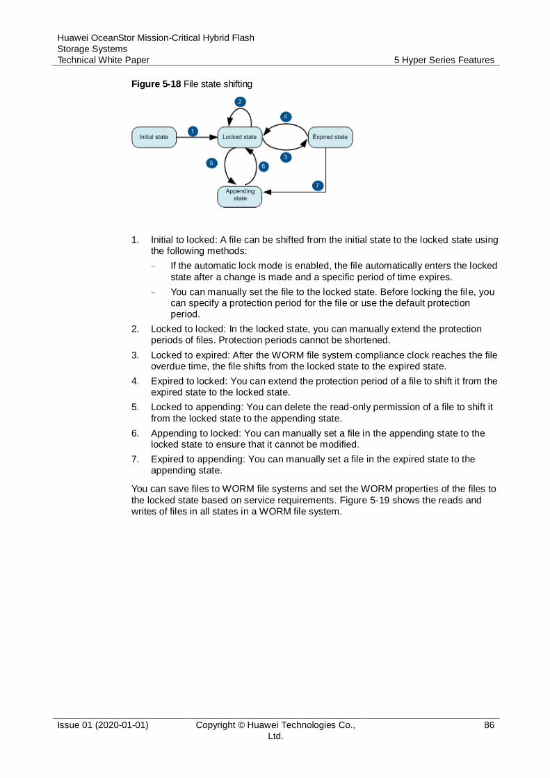
Huawei OceanStor Mission-Critical Hybrid Flash
Storage Systems
Technical White Paper 5 Hyper Series Features
Issue 01 (2020-01-01) Copyright © Huawei Technologies Co.,
Ltd.
86
Figure 5-18 File state shifting
1. Initial to locked: A file can be shifted from the initial state to the locked state using the following methods:
− If the automatic lock mode is enabled, the file automatically enters the locked
state after a change is made and a specific period of time expires.
− You can manually set the file to the locked state. Before locking the file, you can specify a protection period for the file or use the default protection period.
2. Locked to locked: In the locked state, you can manually extend the protection periods of files. Protection periods cannot be shortened.
3. Locked to expired: After the WORM file system compliance clock reaches the file overdue time, the file shifts from the locked state to the expired state.
4. Expired to locked: You can extend the protection period of a file to shift it from the expired state to the locked state.
5. Locked to appending: You can delete the read-only permission of a file to shift it
from the locked state to the appending state.
6. Appending to locked: You can manually set a file in the appending state to the locked state to ensure that it cannot be modified.
7. Expired to appending: You can manually set a file in the expired state to the appending state.
You can save files to WORM file systems and set the WORM properties of the files to
the locked state based on service requirements. Figure 5-19 shows the reads and writes of files in all states in a WORM file system.
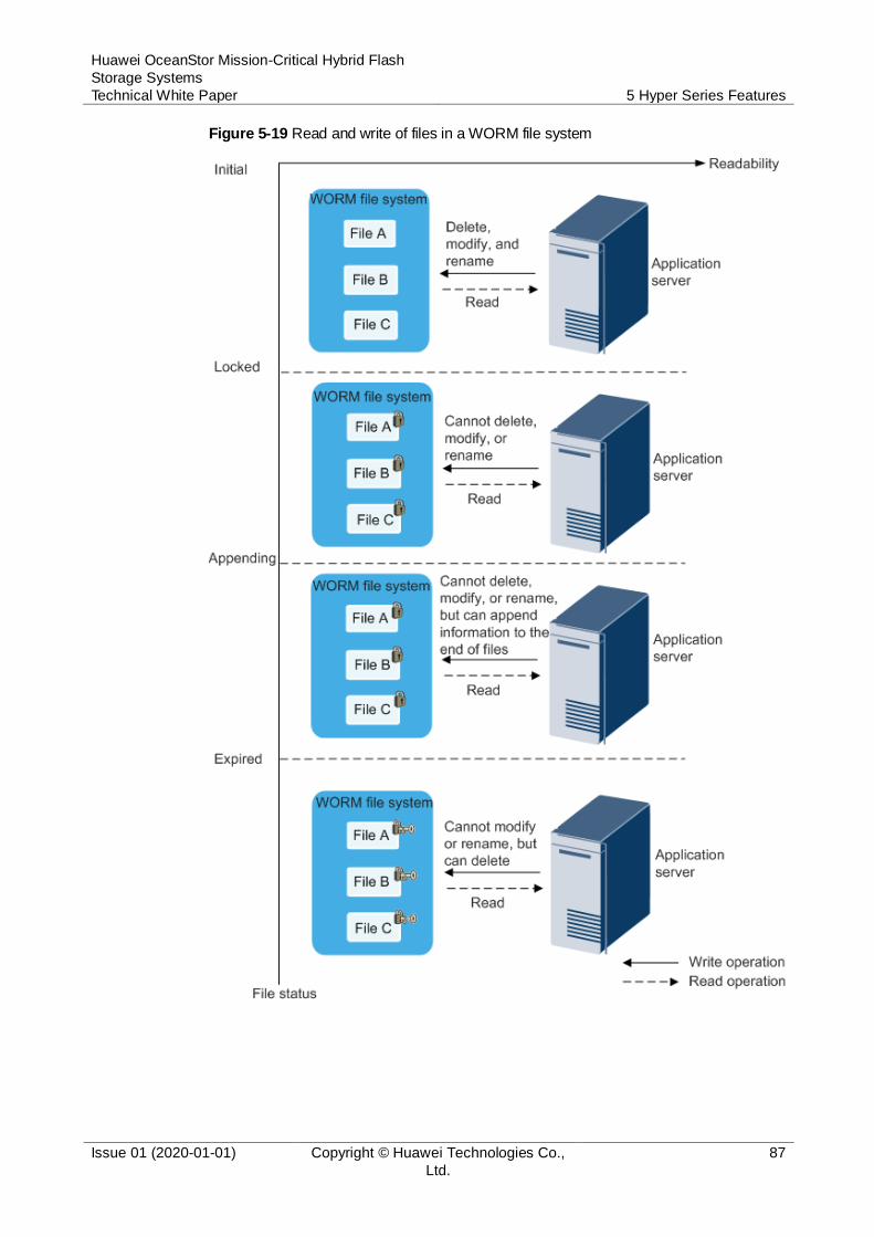
Huawei OceanStor Mission-Critical Hybrid Flash
Storage Systems
Technical White Paper 5 Hyper Series Features
Issue 01 (2020-01-01) Copyright © Huawei Technologies Co.,
Ltd.
87
Figure 5-19 Read and write of files in a WORM file system
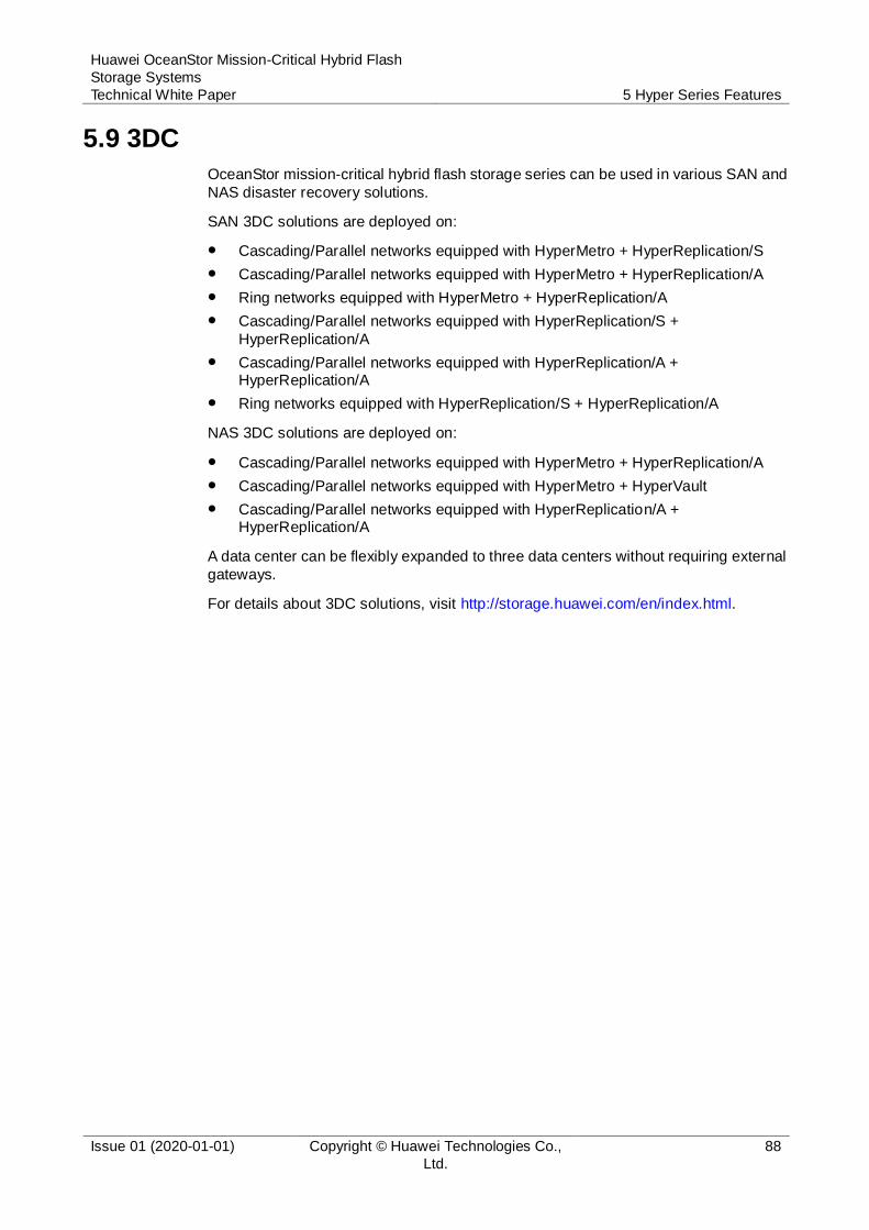
Huawei OceanStor Mission-Critical Hybrid Flash
Storage Systems
Technical White Paper 5 Hyper Series Features
Issue 01 (2020-01-01) Copyright © Huawei Technologies Co.,
Ltd.
88
5.9 3DC
OceanStor mission-critical hybrid flash storage series can be used in various SAN and
NAS disaster recovery solutions.
SAN 3DC solutions are deployed on:
Cascading/Parallel networks equipped with HyperMetro + HyperReplication/S
Cascading/Parallel networks equipped with HyperMetro + HyperReplication/A
Ring networks equipped with HyperMetro + HyperReplication/A
Cascading/Parallel networks equipped with HyperReplication/S +
HyperReplication/A
Cascading/Parallel networks equipped with HyperReplication/A + HyperReplication/A
Ring networks equipped with HyperReplication/S + HyperReplication/A
NAS 3DC solutions are deployed on:
Cascading/Parallel networks equipped with HyperMetro + HyperReplication/A
Cascading/Parallel networks equipped with HyperMetro + HyperVault
Cascading/Parallel networks equipped with HyperReplication/A + HyperReplication/A
A data center can be flexibly expanded to three data centers without requiring external
gateways.
For details about 3DC solutions, visit http://storage.huawei.com/en/index.html.
Huawei OceanStor Mission-Critical Hybrid Flash
Storage Systems
Technical White Paper A More Information
Issue 01 (2020-01-01) Copyright © Huawei Technologies Co.,
Ltd.
89
A More Information
For more information about OceanStor mission-critical hybrid flash storage series,
visit:
https://e.huawei.com/en/products/cloud-computing-dc/storage
For more information about Huawei storage, visit:
https://e.huawei.com/en/products/cloud-computing-dc/storage
For after-sales support, visit our technical support website:
https://support.huawei.com/enterprise/en
For pre-sales support, visit the following website:
https://e.huawei.com/en/how-to-buy/contact-us
You can also contact your local Huawei office:
https://e.huawei.com/en/branch-office

Huawei OceanStor Mission-Critical Hybrid Flash
Storage Systems
Technical White Paper B Feedback
Issue 01 (2020-01-01) Copyright © Huawei Technologies Co.,
Ltd.
90
B Feedback
Huawei welcomes your suggestions for improving our documentation. If you have
comments, please send your feedback to [email protected].
We seriously consider all suggestions we receive and will strive to make necessary changes to the document in the next release.
Related Documents