Self-Built Exhibition Spaces 2013 GUIDELINES TECHNICAL SYSTEM REQUIREMENTS

Welcome message from author
This document is posted to help you gain knowledge. Please leave a comment to let me know what you think about it! Share it to your friends and learn new things together.
Transcript
Self-Built Exhibition Spaces 2013
GUIDELINESTECHNICAL SYSTEM REQUIREMENTS
This document together with supplements or revisions will be simultaneously issued on
the Participants Digital Management System PDMS.
Please visit the PDMS regularly for detailed information.
April 2013
The images and the content are
© Expo 2015 S.p.A. - Milano | April 2013
Expo 2015 S.p.A.
Via Rovello, 2 - 20121 Milano, Italy
www.expo2015.org
t: +39 0289459400
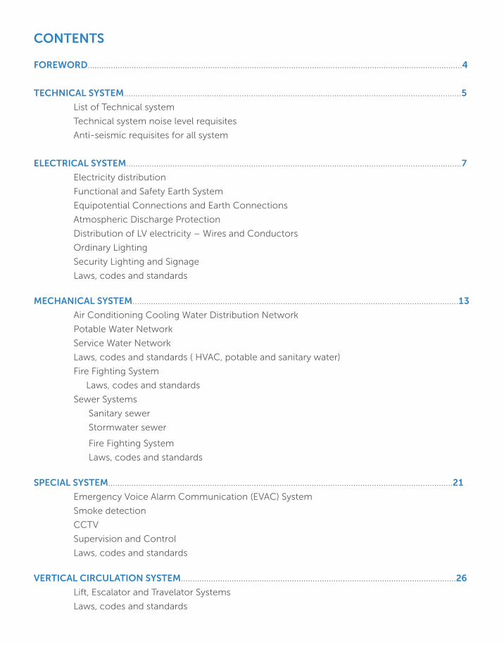
CONTENTS
FOREWORD..................................................................................................................................................................4
TECHNICAL SYSTEM..................................................................................................................................................5
List of Technical system
Technical system noise level requisites
Anti-seismic requisites for all system
ELECTRICAL SYSTEM.................................................................................................................................................7
Electricity distribution
Functional and Safety Earth System
Equipotential Connections and Earth Connections
Atmospheric Discharge Protection
Distribution of LV electricity – Wires and Conductors
Ordinary Lighting
Security Lighting and Signage
Laws, codes and standards
MECHANICAL SYSTEM.............................................................................................................................................13
Air Conditioning Cooling Water Distribution Network
Potable Water Network
Service Water Network
Laws, codes and standards ( HVAC, potable and sanitary water)
Fire Fighting System
Laws, codes and standards
Sewer Systems
Sanitary sewer
Stormwater sewer
Fire Fighting System
Laws, codes and standards
SPECIAL SYSTEM.....................................................................................................................................................21
Emergency Voice Alarm Communication (EVAC) System
Smoke detection
CCTV
Supervision and Control
Laws, codes and standards
VERTICAL CIRCULATION SYSTEM.......................................................................................................................26
Lift, Escalator and Travelator Systems
Laws, codes and standards
FOREWORD
In accordance with the “Special Regulations Nos. 4, 5 and 7” and the
“Guide - Design, Construction, Set-up and Dismantling”, this Guidelines
presents the general supplies and all the technical information needed to
design and plan the technical system for Self-Built Exhibition Spaces. Detailed
specifications will be provided in dedicated Technical Dossier for each lot.
This Guidelines intend to help Participant with various elements and
requirements that must be considered while preparing the project of the
Exhibition space.
This document provides Participant with references to relevant legislation for
each item.
4 | TECHNICAL SYSYEM REQUIREMENT
TECHNICAL SYSTEM
For each Participant’s Self-built Exhibition Space, the Organizer will supply, for
the six-months Event, the below listed utilities, in compliance with modalities
indicated in this document.
List of Technical System• Electrical system
• Condensation water for HVAC system (air conditioning water)
• Potable water system
• Service water system (non-potable for toilets, urinals, irrigation, facilities
cleaning)
• Fire-fighting system
• Sanitary sewer system
• Stormwater sewer system
• Fire Detection and Fire Alarm system
• Emergency voice alarm communication (EVAC) system
• Supervision and control system
• Closed-Circuit Television(CCTV) system
• Access control system
• Anti-intrusion system
• Telecommunication and data transmission system
No natural gas supply is provided.
It will be the Participant’s duty to ensure that all technical systems on its lot
are properly designed, installed, tested, inspected and certified. A copy of the
associated documentation must be provided to Expo 2015 S.p.A. (hereinafter
“Organizer”) prior to final operational start-up. Countries shall submit to
the Organizer in digital format (.xls, .dwg, .doc) the final architectural and
technological systems design for their pavilions. As explained in detail in the
Technological Services Guide, despite the common areas of the Exhibition Site
in which the Organizer will be directly responsible for the technology solutions
deployed, within Self Built and Cluster Exhibition spaces, the Participant will
be responsable of technology solutions. To support Participants in the design
and implementation of technical services, the Organizer has included some
of the services which will be highly integrated into the Expo 2015 technical
infrastructure in the Basic Package of the Technology Services Guidelines
and, as such, these services will be provided by Expo Official Partners. The
TECHNICAL SYSYEM REQUIREMENT | 5
Organizer with its Official Partners defined a number of technology solutions
aimed at addressing specific needs and requirements of Participants. The
technology solutions proposed to Participants are designed to be seamlessly
integrated with the Expo Milano 2015’s technology frameworking order
to guarantee integration of service operation an a continuity of the Visitor
Experience inside/outside Exhibition spaces. The Organizer believes that this
approach will enable a high level of features, quality, efficiency, and support
service required to smoothly operate the Exobiton site during the six months
of the event.. Moreover, the Organizer will directly guarantee the quality and
the efficiency of technology solutions implemented by providing a single
face reference point to interact with during the whole Event lifecycle and
for all technologies involved. To guarantee the continuity of both the Visitor
Experience and the site and service operations, the Organizer decided to guide
the deployment and the integration of some basic technological solutions
generally already foreseen by Participants within their Exhibition Space.
In the Technological Services Catalogue annexed to the Technological
Services Guide, the Organizer has developed a mandatory offer for Participants
in order to build with all of them the first layer of Basic technological services
that enable Participants to be fully integrated with Expo Milano 2015 Smart
City Expo, in detail:
• Security & Access
• Basic Smart Energy
• Network, Internet & Cloud
• WI-FI
• Fixed Voice
Technical System Noise Level RequisitesEach Participat has to ensure the respect of noise level limits specified by
D.P.C.M. 14 November 1997, “Limit values for noise sources”, for Class III land
use. According to DPCM 14-11-’97, maximum noise emission level at noise
receptor, measured as equivalent continuous sound level ( Leq in dB(A) ),
can’t exceed:
• 55dB(A)from 6:00a.m. to 10:00p.m.
• 45dB(A)from 10:00p.m. to 6:00.a.m.
Anti-Seismic Requisites for All Technical SystemAny element of a technical system that exceeds 30% of the total dead load
on the floor where it is installed, or 10% of the total dead load of the entire
structure, requires specific anti-seismic anchorage. Technical system elements
not exceeding the above threshold levels must be designed in compliance
with the requirements laid out in NTC 2008, section 7.2.4.
Furthermore, Participating Countries shall ensure compliance with all
additional instructions for technical systems specified in the explanatory
circularno.617of2009(“InstructionsfortheApplicationofNewTechnical
Standards and Regulations for Buildings per Ministerial Decree of 14 January
2008”).
6 | TECHNICAL SYSYEM REQUIREMENT
ELECTRICAL SYSTEM
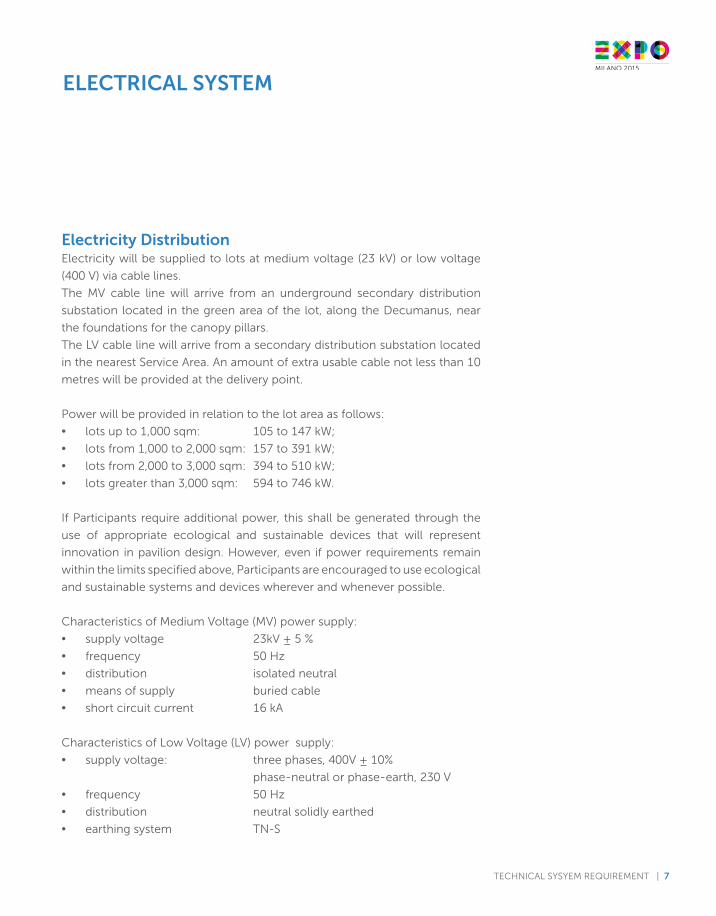
Electricity DistributionElectricity will be supplied to lots at medium voltage (23 kV) or low voltage
(400 V) via cable lines.
The MV cable line will arrive from an underground secondary distribution
substation located in the green area of the lot, along the Decumanus, near
the foundations for the canopy pillars.
The LV cable line will arrive from a secondary distribution substation located
in the nearest Service Area. An amount of extra usable cable not less than 10
metres will be provided at the delivery point.
Power will be provided in relation to the lot area as follows:
• lots up to 1,000 sqm: 105 to 147 kW;
• lots from 1,000 to 2,000 sqm: 157 to 391 kW;
• lots from 2,000 to 3,000 sqm: 394 to 510 kW;
• lotsgreaterthan3,000sqm: 594to746kW.
If Participants require additional power, this shall be generated through the
use of appropriate ecological and sustainable devices that will represent
innovation in pavilion design. However, even if power requirements remain
within the limits specified above, Participants are encouraged to use ecological
and sustainable systems and devices wherever and whenever possible.
Characteristics of Medium Voltage (MV) power supply:
• supply voltage 23kV ± 5 %
• frequency 50 Hz
• distribution isolated neutral
• means of supply buried cable
• shortcircuitcurrent 16kA
Characteristics of Low Voltage (LV) power supply:
• supply voltage: three phases, 400V ± 10%
phase-neutral or phase-earth, 230 V
• frequency 50 Hz
• distribution neutral solidly earthed
• earthing system TN-S
TECHNICAL SYSYEM REQUIREMENT | 7
The electrical system, devices and materials have to meet IEC and/or EN
standards.
Participating Countries have to provide an Uninterruptible Power Supply
(UPS) to ensure continuity of electrical current in the event of a power outage.
The UPS have to be properly sized to provide at least 1 hour of autonomous
power to ensure safe evacuation of visitors, if necessary.
Power for the smoke detection system (including fire dampers, smoke
evacuators, and other safety systems), emergency communication system,
emergency lighting circuits and portions of the power outlet circuits have to
be backed up by an UPS in order to ensure continuity of service if the mains
supply is temporarily lost.
The Participant also has to provide a technical room that will contain the
necessary MV and LV equipment (transformer, electrical panels, UPS, etc.,
depending on specific needs). The technical room have to be outfitted
with a fire detection system that activates an alarm on the main supervision
system and on the pavilion smoke detection system. Manuals and related
diagrams, the general single-line wiring diagram and all necessary safety and
control user points and equipment shall be located in the technical room.
The technical room have to be ventilated or air conditioned, if necessary, to
ensure that internal temperature remains below 30°C.
All points where cables enter or exit the technical room have to be sealed
with appropriate REI 120 fire resistant barriers that are fully certified in terms
of materials and installation.
A perimeter earth collector made of flat copper bar will be installed in the
technical room. All structural conducting metalwork in the room will be
connected to this collector using green-yellow ground wire of appropriate
section. The metal structures, board foundation plate, and board grounding
plate of electrical panels and the substation grounding system and all other
relevant components will be connected so as to ensure equipotential of all
conductive metalwork.
A release button on the UPS will allow disconnecting electrical power in
emergency situations.
All release buttons will be clearly labelled and clearly specify which services
they deactivate. Any use of the release buttons will be signalled on the main
supervision and control system.
The cable lines for the electrical system and special systems have to be clearly
and separately identified.
It has to be noted that the provison of MT lines and system are part of the
basic Technology Service offered by Expo Partner.
8 | TECHNICAL SYSYEM REQUIREMENT
Functional and Safety Earth SystemA general grounding system shall be provided for the building, both to limit
step and contact potentials and to ensure equipotentiality. This system will be
connected to Expo general grounding system in several points.
Equipotential Connections and Earth ConnectionsThe metal pipes, metal conduits, principal concrete reinforcement rods and
main metal frame members will all be connected to the building grounding
system.
Atmospheric Discharge ProtectionVerification in accordancewith standards (seeCEI EN 62305) have to be
performed by Participants for protection against atmospheric discharges.
Distribution of LV electricity - Cables and ConductorsCables for electricity distribution and special systems (public address, smoke
detection, CCTV, etc.) will consist of a copper conductor with cross linked
elastomeric or rubber insulation.
Electrical cables have to bear a quality certification marking and be
appropriately sized and coordinated with protection measures as specified
in relevant IEC standards. They shall be self-extinguishing and fire retardant
(CEI20-35/EN60332,CEI20-37,EN50267,CEI20-38and CEI20-22 ) for
ordinary installations and fire resistant (CEI 20-45 ) for emergency and safety
systems such as Emergency Voice Alarm Communication (EVAC) systems,
emergency lighting systems, main power to the fire detection system, power
to forced smoke and heat evacuation systems, emergency controls, alarm
panels and signalling systems (e.g., fire damper controls, Air Handling Units (
AHU ) shutdown, EVAC interfacing systems, etc.), and generally for all security
and safety systems that require fire resistant electrical power cables.
All the cables (both for ordinary installations and fire resistant) shall be
halogen-free rated for ultra-low emission of smoke and toxic gases and
withoutcorrosivegases.(CEI20-37,EN50267,CEI20-38).
Non metallic pipes and accessories must be self-estinguishing and halogen-
free.
Monomodal fibre-optic cables shall be used for signal transmission to and
from the supervision and remote control systems.
All cables and wires will be appropriately coded and marked so as to ensure
unambiguous identification.
Ordinary Lighting Normal lighting system shall ensure lighting levels as specified by applicablestandards(UNIEN12464).
TECHNICAL SYSYEM REQUIREMENT | 9
Outdoor lightingOutdoor lighting systems must be designed using appropriate criteria and
methods for preventing light pollution and upward light dispersion, with
particular emphasis on eco-sustainability and maximization of energy savings
and safety levels (e.g. equipment for the reduction of the luminous flux and
remote control).
It is prohibited, for merely purposes of reference, to have light beams facing
upwards.
Outdoor lighting installations shall be designed and constructed in compliance
withLR17/2000ands.m.i.andD.G.R.Lombardian.VII/6162of20/09/2001.
It has to be noted the Outdoor lighting is part of the basic technology package
offered by Expo 2015 Official Partner.
Security Lighting and Signaling Security lighting and signaling system shall provide minimum lighting levels
during power outages and shall indicate the emergency exits by means of
luminous signs.
Security lighting shall be installed along emergency exit routes and in external
areas. In general, the system shall meet the requirements of the UNI EN 1838
standard. Power to the security lighting and signaling system shall be ensured
by an UPS with at least 1 hour autonomy.
Power cables for security lighting and signaling systems shall be fire resistant.
Laws, codes and standardsThe list below contains the principal applicable laws and technical codes and
standards for the design, installation, and testing of special systems present
on the lot:
• D.P.R. no. 547 of 27 April 1955 - “Legal provisions in force regarding
accident prevention, fire protection, and the construction of equipment
and systems”;
• C.E.I. (Comitato Elettrotecnico Italiano - Italian Electrotechnical
Committee);
• U.N.I. (Ente Nazionale Italiana di Unificazione - Italian Unification
Authority) - U.N.E.I. (Unione dell’Elettricità Italiana - Italian Electricity
Union);
• Standards for technical specifications and special standards for utility
systems and materials;
• Special regulations issued by local Fire Departments, local authorities,
ISPESL (Superior Institute for Workplace Health and Safety), ASL (Local
Healthcare Agency), or local electricity authority;
• D.M. no 37 of 22 January 2008 - Regulation regarding the enactment of
Article 11-quaterdecies, subsection 13, letter a) of Law no. 248 of 2005
reorganizing provisions for installation of systems in buildings.
• Law no. 626 of 5March 1990 - “Standards and regulations regarding
10 | TECHNICAL SYSYEM REQUIREMENT
improvements in workplace health and safety” and associated variants.
• European Directive 96/92/EC of 19 December 1996 regarding shared
standards for the European electricity market.
• D.L.no.79of16March1999-EnactmentofEuropeanDirective9/92/EC
regarding shared standards for the European electricity market.
• Resolution no. 91/99 of the Electricity and Gas Authority. Definition of
method for identifying and verifying suitable clients and creation of the
list of suitable clients.
• Resolutionno. 66/01of theElectricity andGasAuthority.Modification
of method for verifying the quality of suitable clients as referred to in
Resolution no. 91 of 30 June 1991 of the Electricity and Gas Authority.
• UNI EN 1838 - Application of illumination engineering. Emergency
lighting
• UNIEN12464–“WorkplaceIllumination”
• CEI 20-22 - Electrical cable fire tests
• CEI20-36-Electricalcablefireresistancetests,Part4andPart5
• CEI 20-37 - Shared cable fire test methods. Tests of gases emitted during
combustion of electrical cable materials
• CEI 20-38 - Halogen-free electrical cables with fire-retardant rubber
insulationfornominalvoltagesU0/Unotexceeding0.6-1kV.
• CEI 20-45 - Electrical cables with fire resistant, fire retardant, halogen-
free (LS0H)mixed elastomeric insulation for nominal voltages U0/U of
0.6-1kV.
• EN 50200 – Fire resistance test methods for unprotected emergency
circuit wiring.
• Electromagnetic Compatibility
Conformity to European Directive 2008/108/EC (“EMC Directive”),
which must be referenced in the Technical Booklet of the products
and components used.
The products and components used must meet the requirements
of applicable EMC standards;.Levels of electromagnetic disturbance
must comply with the EMC product and context standards (the
assumed contexts are residential, commercial, and light industry).
The main reference codes and standards are:
- EN 61000-6-3 Electromagnetic Compatibility. General emission
standards. Part 1: Residential, commercial and light-industry spaces.
- EN 61326-1 Electrical metering, monitoring and laboratory
equipment. Electromagnetic compatibility regulations. Part 1: general
rules.
- EN 55014-1 Electromagnetic Compatibility. Requisites for household
electrical appliances, electrical tools, and similar devices. Part 1:
Emission.
TECHNICAL SYSYEM REQUIREMENT | 11
- EN 55022 Measurement methods and limits for radio interference
caused by information technology devices.
- EN61000-3-2Electromagneticcompatibility,Part3:LimitsSection
2: Harmonic current emission limits (equipment with input current ≤
16Aperphase).
- EN61000-3-3ElectromagneticCompatibility.Part3:LimitsSection
3: Voltage fluctuation and flicker limits in low-voltage system for
equipmentwithnominalcurrent≤16A.
- CEIEN50160:Characteristicsofvoltageprovidedbypublicelectricity
grids.
• Outdoor lighting
- L.R. Lombardia 17/2000
- D.G.R.Lombardiano.VII/6162of20September2001
12 | TECHNICAL SYSYEM REQUIREMENT
Air Conditioning Cooling Water Distribution NetworkCooling water from the canal surrounding the Expo Site will be provided to
each lot for air conditioning purposes (assume a canal water temperature of
23°C ± 2°C for system design). This water will be distributed via a dedicated
network of supply and return pipes. The minimum pressure available to the
buildings is 100 kPa.
Quantities of cooling water will be determined in accordance with lot size:
• lots up to 1,000 sqm: from 2.5 to 3.8 l/s;
• lots from 1,000 to 2,000 sqm: from 4.3 to 7.4 l/s
• lots from 2,000 to 3,000 sqm: from 7.8 to 10.5 l/s;
• lots over 3,000 sqm: from 11.1 to 18.0 l/s.
Cooling water will circulate through a heat exchanger inside the buildings on
each lot. The heat exchanger and circuit must be designed to allow variable
flow rate to ensure the temperature increase of the cooling water does not
exceed 10°C.
The quantity of water circulating in the system will be user-regulated by means
of a 2-way modulating valve. The Organizer will have control of an additional
valve installed in a dedicated inspection pit located along the secondary side
routes. Under normal conditions, this valve will be closed. However, if the
temperature of the heat exchanger return water exceeds set limits (i.e., if the
temperature increase is more than 10°C) this valve will be opened.
The heat exchanger will be connected to a chiller for the production of
the cooling fluid that will circulate in the pavilion HVAC system. The heat
exchanger and chiller will be provided and maintained by Participants or
association(s) to whom the lot is assigned.
Thetestpressureofthisnetworkis16bar:pipeworkandvalvesmusttherefore
be suitably dimensioned to handle such pressure.
All lots will be served by the external main utilities (“piastra”) cooling water
network: hook-up points shall be located in inspection pits.
In accordance with the estimated cooling power needs for each lot, the
chillers shall have:
MECHANICAL SYSTEM
TECHNICAL SYSYEM REQUIREMENT | 13
• an Energy Efficiency Ratio (EER) ≥ 4 for chillers with cooling power not
exceeding 100 kW;
• an EER ≥ 5 for chillers with cooling power exceeding 100 kW.
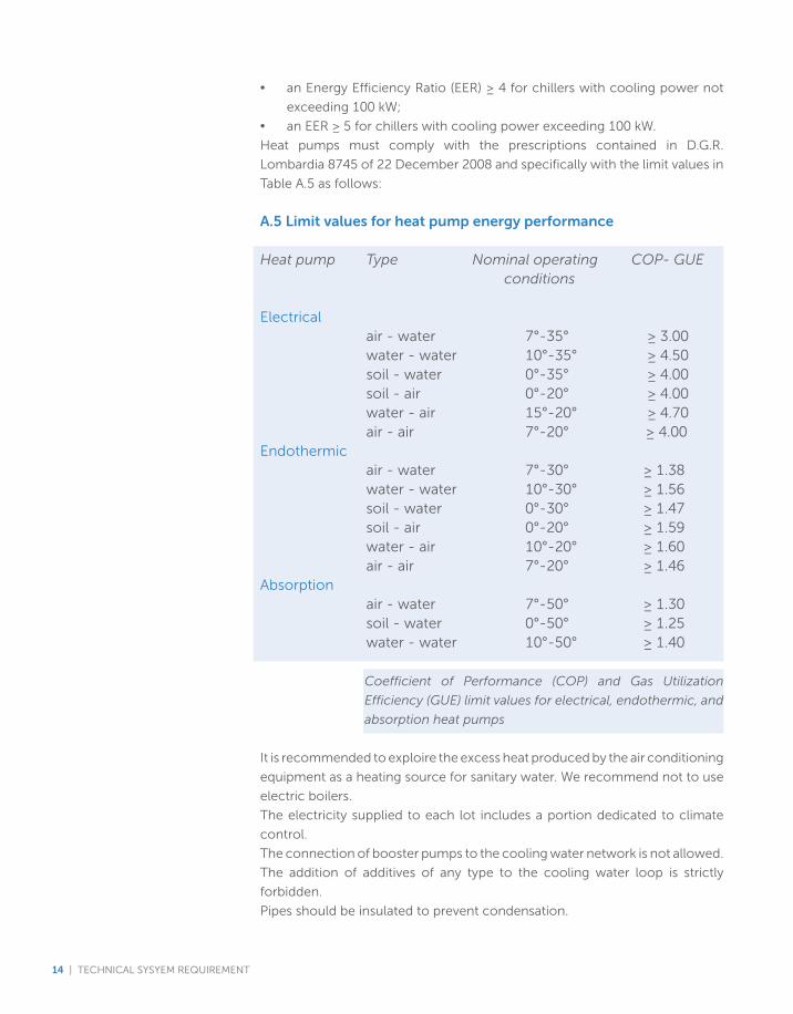
Heat pumps must comply with the prescriptions contained in D.G.R.
Lombardia 8745 of 22 December 2008 and specifically with the limit values in
Table A.5 as follows:
A.5 Limit values for heat pump energy performance
Heat pump Type Nominal operating COP- GUE conditions
Electrical air - water 7°-35° ≥ 3.00
water - water 10°-35° ≥ 4.50 soil - water 0°-35° ≥ 4.00 soil - air 0°-20° ≥ 4.00 water - air 15°-20° ≥ 4.70 air - air 7°-20° ≥ 4.00
Endothermic air - water 7°-30° ≥ 1.38 water-water 10°-30° ≥1.56 soil - water 0°-30° ≥ 1.47 soil - air 0°-20° ≥ 1.59 water-air 10°-20° ≥1.60 air-air 7°-20° ≥1.46Absorption air - water 7°-50° ≥ 1.30 soil - water 0°-50° ≥ 1.25 water - water 10°-50° ≥ 1.40
Coefficient of Performance (COP) and Gas Utilization
Efficiency (GUE) limit values for electrical, endothermic, and
absorption heat pumps
It is recommended to exploire the excess heat produced by the air conditioning
equipment as a heating source for sanitary water. We recommend not to use
electric boilers.
The electricity supplied to each lot includes a portion dedicated to climate
control.
The connection of booster pumps to the cooling water network is not allowed.
The addition of additives of any type to the cooling water loop is strictly
forbidden.
Pipes should be insulated to prevent condensation.
14 | TECHNICAL SYSYEM REQUIREMENT
The cooling water pipes must be white on the outside to clearly identify them.
The pipework layout and controls should be designed so as to allow easy
inspection and maintenance.
The air conditioning systems must comply with all laws and regulations in
force in Italy and in the Region of Lombardy.
Water consumption will be monitored for each exhibition space by means of
water meters installed at the supply points for each lot.
Potable Water NetworkThe minimum pressure available for the building will be 2 bar. Quantities will
vary depending on lot area:
- lotsupto1,000sqm: 0.36to0.50l/s(litrespersecond);
- lots from 1,000 to 2,000 sqm: 0.50 to 0.82 l/s;
- lots from 2,000 to 3,000 sqm: 0.82 to 1.32 l/s;
- lots over 3,000 sqm: 1.32 to 2.59 l/s.
Thenetworktestpressurewillbe16bar: the installedpipeworkandvalves
must be suitable for such pressures.
All lots will be served by the external Potable water network in the main utilities
system (“piastra”): the hook-up points shall be inspectable. At each point of
supply the following devices will be installed in the listed order: a butterfly
valve, a water meter, a backflow preventer, and a butterfly valve operated
by a servo motor (allowing the water supply to each building to be shut off
remotely).
There will also be a bypass line with butterfly valve to ensure supply continuity
during operation maintenances on the meter or on the backflow preventer.
ThedesignofthePotablewatersystemshallcomplywithUNIEN806standard
“Specification For Installations Inside Buildings Conveying Water For Human
Consumption” and UNI 9182 “Hot and Cold Water Supply and Distribution
Installations – Design, Testing, and Management Criteria”.
Only devices supplying Potable water may be connected to the Potable water
network. This may include components such as faucets, showers, kitchen
sinks, beverage vending machines, etc.
Participants are asked to observe point NC-2009 WEc3 (LEED certification) for
Water Use Reduction. Specifically, it is recommended that participants adopt
strategies that will reduce their water consumption by at least 30%.
The connection of booster pumps to the network is not allowed.
Pipes should be insulated to prevent condensation.
Pipes for Potable water pipes must be blue on the outside to clearly identify
them.
TECHNICAL SYSYEM REQUIREMENT | 15
The pipework layout and controls should be designed so as to allow easy
inspection and maintenance.
Water consumption will be monitored for each exhibition space by means of
water meters installed at the supply points for each lot.
Service Water Network (toilets, urinals, irrigation, facilities cleaning)The minimum pressure available for the building will be 2 bar. Quantities will
vary depending on lot area:
- lotsupto1,000sqm: 1.10to1.26l/s;
- lotsfrom1,000to2,000sqm: 1.26to1.82l/s;
- lots from 2,000 to 3,000 sqm: 1.82 to 2.34 l/s;
- lots over 3,000 sqm: from 2.34 to 3.33 l/s.
Thenetworktestpressurewillbe16bar: the installedpipeworkandvalves
must be suitable for such pressures.
All lots will be served by the external piastra (main utilities network) service
water network: the hook-up points shall be inspectable and include, in the
following order: a butterfly valve, a water meter and a servo-motor operated
butterfly valve allowing water to be shut off to each building remotely.
There will also be a bypass line with butterfly valve to ensure continuity of
supply in the event of maintenance operations on the meter.
Service water pipes must be green on the outside to clearly identify them.
Only devices using sanitary water for non-Potable purposes shall be connected
to the service water network. These include toilets, urinals, cleaning water
spigots, irrigation systems, and any other equipment that uses non-potable
water.
Participants shall make all efforts to reduce consumption of irrigation water
by 50%, in spite of the fact that the use of water from the sanitary water
network fully meets the NC-2009 WEc1 requirement (LEED certification) for
Water Efficient Landscaping.
For specific detail concering irrigation water for food production, please kindly
observe Point NC-2009 WEc3 (LEED certification) for Water Use Reduction.
Specifically, Participnats shall adopt strategies that provide a minimum 30%
reduction in water consumption.
The connection of booster pumps to the network is not allowed.
Pipes should be insulated to prevent condensation.
The estimated sanitary water needs are based on the use of tank toilets.
The pipework layout and controls should be designed so as to allow easy
16 | TECHNICAL SYSYEM REQUIREMENT
inspection and maintenance.
Water consumption will be monitored for each exhibition space by means of
water meters installed at the supply points for each lot.
Laws, codes and standardsThe list below contains the principal applicable laws and technical codes and
standards for the design, installation, and testing of special systems present
on the lot:
• D.P.R. 459/96 Regulation for the enactment of Directives 89/392/EEC,
91/368/EEC,93/44/EECand93/68/EEContheapproximationofthelaws
of Member States regarding machinery;
• Utility system maintenance law;
• D.P.R. no. 547 of 27 April 1955 - Standards for workplace accident
prevention
• D.G.R. Lombardia no. 8-8745 of 22 December 2008 – Resolutions
regarding legal provisions for energy efficiency in buildings and building
energy certification
• D.Lgs. no. 115 of 30 May 2008 - Enactment of European Directive
2006/32/EC regarding energy end-use efficiency and energy services
andrepealingEuropeanDirective93/76/EEC.
• D.Lgs. no. 192 of 19 August 2005 - “Enactment of European Directive
2002/91/EC on the energy performance of buildings”
• D.Lgs.no.311of29December2006- “Correctionsandsupplemental
provisions to D.Lgs. no. 192 of 19 August 2005, enacting European
Directive 2002/91/EC on the energy performance of buildings”.
• D.L. of 26 January 2010 -UpdateofD.L. of 11March2008 regarding
energy upgrades of buildings (Official Bulletin no. 35 of 12 February 2010).
• D.P.R.no.412of26August1993–“Regulationprovidingstandardsfor
hte design, installation, operation and maintenance of building heating/
cooling plants in order to reduce energy consumption in application of
Article 4, Subsection 4 of Law no. 10 of 9 January 1991”.
• D.P.R. no. 59 of 2 April 2009 - Enactment regulation for Article 4,
Subsection 1, Letters a) and b) of D.Lgs. no. 192 of 19 August 2005,
regarding the enactment of European Directive 2002/91/EC on energy
performance of buildings.
• D.M. no. 37 of 22 January 2008 Ministry of Economic Development
- Regulation regarding the enactment of Article 11-quaterdecies,
Subsection 13, Letter a) of Law no. 248 of 2 December 2005, reorganizing
provisions regarding installation of utility systems in buildings - (Official
Bulletinno.61of12March2008).
• UNI 9182 STANDARD- “Hot and cold water supply and distribution
systems. Design, testing and operating criteria.”
• UNIENSTANDARD806-“Specificationsofdrinkingwatersupplysystems
in buildings”.
TECHNICAL SYSYEM REQUIREMENT | 17
• UNI STANDARD 10339 – “Air handling systems for occupant wellbeing.
General information, classification and requisites. Rules for bid requests,
proposals, orders and supply.”
• UNI EN STANDARD 13779 – “HVAC performance requisites”
• EN1366-2:1999-“Serviceplantfireresistancetests–Firedampers”
Fire Fighting systemAll lots will be connected to the Fire fighting network in the main utility system
(“piastra”) and supplied by two De110 offtakes.
Water is supplied to the Fire fighting network from four double groundwater
wells located south of the Expo Site.
Thesystemtestpressureis16bar.
Themaximumflowrateforeachlotis6.0l/s.
The hook-ups are located in inspection manholes installed in the roadway
around the lot. Each offtake will be equipped with a gate valve to regulate
flow to the individual building.
The system shall be designed in compliance with D.P.R. n. 151 of 1 August
2011 – Simplified regulation of procedures regarding fire prevention per
Article 49, subsection 4-quater, of Italian Legislative Decree no. 78 of 31 May
2010, implemented with amendments by Italian Law no. 122 of 30 July 2010.
The pipework must be dimensioned to allow a flow velocity of approximately
1m/sandmustbesuitabletowithstandthetestpressureof16bar.
Measures must be taken to ensure that the water does not freeze inside the
pipes (insulation or other means).
The fire water pipes must be red on the outside to clearly identify their use.
Portable or trolley-mounted fire extinguishers and proper fire fighting system
signalling devices must be provided in compliance with fire regulations in
force.
The final design must incorporate Fire Department requirements regarding
the Fire Prevention Certificate (Certificato Prevenzione Incendi – CPI).
The pipework layout and controls should be designed so as to allow easy
inspection and maintenance.
The Contractor must observe Italian D.P.R. of 1 August 2011 as regards fire
prevention in all phases of the project, from obtainment of the Preliminary
Feasibility Authorization (Nullaosta di fattibilità – NOF) to the completion
of the CPI and the Certified Declaration of Work Start-up (Segnalazione
Certificata di Inizio Attività –SCIA) and must, for this purpose, engage the
services of a certified professional registered with the Italian Ministry of the
Interior per Italian Law no. 818 of 7 December 1984.
18 | TECHNICAL SYSYEM REQUIREMENT
Laws, codes and standardsThe list below contains the principal applicable laws and technical codes and
standards for the design, installation, and testing of special systems present
on the lot:
• UNI STANDARD 10779 (July 2007): “Fire extinguishing systems. Hydrants.
Design, installation and operation”
• D.M. n. 81 of 10 March 1998: “General criteria for workplace fire safety
and emergency management”
• D.P.R. no. 151 of 1 August 2011 - Simplification of fire prevention
regulation procedures per Article 49, Subsection 4-quater of D.L. no. 78
of 31 May 2010, amended and enacted into Law no. 122 of 30 July 2010.
SEWER SYSTEM
Sanitary sewerThe sanitary sewer system in each exhibition space comprises the internal
collection system receiving wastewater from sanitary facilities (toilets, urinals,
sinks, etc.) and secondary ventilation of the toilet discharge system.
All sanitary wastewater will flow into the Expo Site sanitary sewer system, which
is connected to the Milan sanitary sewer system, which sends wastewater to
the Nosedo and San Rocco wastewater treatment plants.
The sanitary sewer for each lot shall be made using PVC SN8, PE100 or
vitrified clay pipes laid with an inclination assuring a minimum flow velocity of
0.5 m/s at average daily flowrate (see Circular of the Ministry of Public Works
no.11633).
It must be possible to inspect the pipework at specific points inside and outside
the buildings. Properly sized inspection pits must be planned at every junction
and change of direction, approximately one every 30 metres as a general rule.
An inspection trap must be installed immediately upstream of every point
where the pavilion sewer system joins the Expo Site sanitary sewer network,
external to the building lots. If the building is outfitted with kitchen facilities,
an oil trap must be installed in the kitchen wastewater collection system.
No contaminants of any sort may be introduced into the sanitary sewer.
The sanitary sewer pipes must be black on the outside to clearly identify their
use.
Stormwater sewerThe stormwater sewer system will collect all rainwater coming from building
roofs, paved areas, and paved walkways in the outdoor exhibition areas.
All rainwater collected on the lot will flow into the Expo Site stormwater
TECHNICAL SYSYEM REQUIREMENT | 19
sewer. Water in the Site stormwater sewer flows through an oil trap and
settling basin, then into the phytopurification basins and is then released into
the perimeter canal.
The stormwater sewer shall be dimensioned accounting for 10-year
precipitation events (the threshold of severity that may be expected to occur
only once every 10 years) as derived from a local rainfall chart.
The water shall flow through pipes made of PVC SN8, PE100 or prefabricated
reinforced concrete. The pipeline must be outfitted with appropriately sized
inspection pits at every inflow point and/or change of direction, generally one
every 30 metres.
No contaminants of any sort may be introduced into the stormwater sewer.
The stormwater sewer pipes must be grey on the outside to clearly identify
their use.
Laws, codes and standardsThe list below contains the principal applicable laws and technical codes and
standards for the design, installation, and testing of special systems present
on the lot:
• D.Lgs.no.152of3April2006-“Environmentalstandards”
• L.R.Lombardiano.62of27May1985–“Regulationofdischargesfrom
civil developments and public sewers”.
• City of Milan - Local hygiene code, (R.I.)
• Regional Water Recovery Plan (P.R.R.A.) of the Region of Lombardy,
• Water Use and Protection Program (P.T.U.A.)
• RegionalRegulationsnos.2,3and4of24March2006.
• UNIEN12056-1-5:2001Gravity-feddischargesystemsinbuildings
• CircularoftheMinistryofPublicWorksno.11633
• UNI EN 752:2008 Wastewater discharge connections and sewer intakes
outside of buildings.
• UNIEN476:2011Generalrequisitesforcomponentsusedinwastewater
discharge pipes, connections and sewer intakes for gravity-fed discharge
systems.
20 | TECHNICAL SYSYEM REQUIREMENT
The following special systems are provided to each lot:
• Emergencyvoicealarmcommunication(EVAC)system
• Smoke/firedetectionsystem
• Closed-CircuitTelevision(CCTV)system
• Accesscontrolsystem
• Anti-intrusionsystem
• Supervisionandcontrolsystem
Emergency Voice Alarm Communication (EVAC) SystemAn emergency evacuation public address system is planned for the external
common areas and walkways on the Expo Milano 2015 Site.
Cable lines have been planned between the nearby Service Areas and the
various pavilions to allow information transfer between the main supervision
and control system and the internal pavilion evacuation systems.
The battery limit is represented by the special systems inspection pit located
outside of the pavilion.
The EVAC system is obligatory both inside and outside of the pavilions and
must be certified in compliance with the relevant standards and regulations
(EN54-4,EN54-16,EN54-24).
The EVAC system must be powered via an uninterruptible power supply (UPS)
with fire resistant power cable with CEI 20-45 certification.
EVAC system speakers in every zone shall have two speakers lines (Line A and
Line B), both using halogen-free fire resistant cables with ultra-low fume and
toxic gases emission and without corrosive gases per CEI 20-45 standard.
The EVAC system shall notify for each speakers line any fault condition, as
open circuit, and short circuit, and shall show the line number where fault
conditions are present.
This system shall be installed in compliance with the UNI 72-40 standard, Part
19.
The EVAC system shall have clean (voltage-free) contacts to communicate
conditions of alarm and malfunctioning to the main supervision and control
SPECIAL SYSTEM
TECHNICAL SYSYEM REQUIREMENT | 21
system.
The method and procedure of interaction between the pavilion EVAC system
and the EVAC system in the common areas and walkways, will be determined
during the pavilion design phase. It has to be noted that the EVAC system
is part of the Technology service Basic Package and it will be provided and
integrated by the Expo Official Safe City and Main Operation Center Partner.
Smoke/fire detection systemSmoke/fire detection system must be provided in compliance with the most
recent edition of the UNI 9795 standard (currently the 2010 edition) and with
fire department requirements.
All devices and equipment must be certified per EN 54 parts 2 and 4.
The central unit of the smoke/fire detection system must be powered via an
uninterruptible power supply (UPS) with fire resistant power cable with CEI
20-45 certification. The same power system and cable must be used for all
components of the system that are not directly powered by the central unit,
such as the audible/visible notification appliances.
Regarding connections for the smoke/fire detection system components
(sensors, call buttons, input/output modules), the UNI 9795 standard calls
for cables that resist flames for a minimum of 30 minutes per CEI EN 50200
standard and that ensure ultra-low fume and toxic gases emissions and
without corrosive gases.
Power to the smoke/fire detection system central unit, forced smoke/heat
evacuation systems, fire dampers, emergency controls and signals (e.g., fire
dampers closed, AHU stopped), interface between the smoke/fire detection
unit and the EVAC system, acoustic/visual notification appliances, and other
similar safety systems must be provided via halogen-free fire resistant cables
that ensure ultra-low fume and toxic gases emission and without corrosive
gases per CEI 20-45 standard.
The system shall be analogical with individually addressable sensors.
The smoke/fire detection system must be provided with a network connection
so that it can be integrated with the Expo Site supervision and control system
via an open protocol.
The control unit shall have clean (voltage-free) contacts to communicate
conditions of alarm and malfunction to the main supervision and control
system.
The battery limit is the special systems inspection pit outside of the pavilion.
The control unit must be powered as follows:
22 | TECHNICAL SYSYEM REQUIREMENT
a. integrated power unit with option of cascade connection and battery
charging, with surveillance function meeting the EN 54-4 standard.
b. power from batteries in emergency conditions / power outage.
The final design must account for fire department requirements for the Fire
Prevention Certificate (Certificato Prevenzione Incendi – CPI) as well as any
instructions or requirements from local or national public security authorities.
It has to be noted that the Smoke detection system is part of the Technology
service Basic Package and it will be provided and integrated by the Expo
Official Safe City and Main Operation Center Partner.
CCTVThe videosurveillance system of Participants Exhibition Spaces together with
the common areas external videosurveillance system will be integrated into
the Expo Site video surveillance system provided by the Safe City and the
Operation Center. Participants shall adopt Closed-Circuit Television Cameras
with IP capability. Please refer to the Technology Services Guide, basic service
package.
The battery limit for the Site security network connection is a special systems
inspection pit outside of the Exhibition Space.
The method and procedure for interaction between the pavilion CCTV system
and the common area videosurveillance system will be determined during the
design phase.
Access Control SystemOn request, each Participant will have the option of communicating alarm or
malfunction signals from the local access-control system in the Participant’s
pavilion to the main Site supervision system to ensure monitoring of
anomalous conditions.
The means for achieving this will be defined during the design process.
Anti-intrusion SystemOn request, each Participant will have the option of communicating alarm or
malfunction signals from the local anti-intrusion system in the Participant’s
pavilion to the main Site supervision system to ensure monitoring of
anomalous conditions.
The means for achieving this will be defined during the pavilion design process.
TECHNICAL SYSYEM REQUIREMENT | 23
Supervision and Control systemThe main Expo Site supervision and control system will monitor the following
consumption rates for each pavilion:
• Electrical power
• Potable water
• Sanitary water
• Cooling water
The meters that monitor this consumption will be installed by the Organizer
in the point-of-delivery inspection pit for the lot and the data will be
transmitted to the main supervision and control system via a PLC installed by
the Organizer in the inspection pit.
As a further guarantee of fire safety, Participant shall install a pressure sensor
in the firewater system and shall transmit the data to the main Expo fire
supervision and control system.
Pressure sensors shall also be installed on the supply lines for Potable water,
sanitary water, and cooling water and the data transmitted to the main Expo
Site supervision and control system.
Voltage detection devices must also be installed on the MV and LV terminal
blocks in the pavilion electrical panels, and this datum also shall be
communicated to the main supervision and control system.
Any other possible status monitoring, measurements, or other needs shall be
communicated to the Organizer when the project is presented.
The battery limit is the special systems inspection pit outside of the pavilion.
Laws, codes and standardsThe list below contains the principal applicable laws and technical codes and
standards for the design, installation, and testing of special systems present
on the lot:
• EN54-4,EN54-16, andEN54-24STANDARDS foremergencypublic
address/auditory alarm system.
• D.P.R. no. 246 Regulation enacting European Directive 89/106/EEC
regarding construction products (CPD).
• D.P.R. no. 499 of 10 December 1999 “Regulation enacting European
Directive89/106/EEC.
• D.L. of 5 March 2007 Application of European Directive 89/106/EEC
regarding construction products (CPD).
• UNI Standard 72-40, Part 19 “Fixed fire detection and alarm systems -
Part 19: Design, installation, activation, operation and maintenance of
voice alarm systems for safety purposes.”
• UNI Standard 9795:2010 as subsequently amended” Automatic fixed fire
detection and alarm systems. Design, installation and operation.”
• EN 54 Standard for all sub-parts of fire-fighting legislation.
24 | TECHNICAL SYSYEM REQUIREMENT
• UNI Standard 11224 “Preliminary check and maintenance of fire detection
systems”.
• EN 12094 Standard with all sub-parts
• CEI EN Standard 50131-1/IS2 “Alarm systems – Intrusion and robbery
alarm systems”.
• CEI Standard 79/2 “Breaking-and-entering, intrusion, and theft prevention
systems and personal protection systems - Special standards for breaking-
and-entering and intrusion prevention systems (N.B. For CCTV systems
see Annexes A and B).
• CEI Standard 79/3 V1 “Breaking-and-entering, intrusion, and theft
prevention systems, and personal protection systems - Special standards
for breaking-and-entering and intrusion prevention systems (N.B. For
CCTVsystemsseeSection6“Requisites”,Section8“Testing”,andSection
9 “Maintenance”)
• EN50132 Standard for CCTV systems.
TECHNICAL SYSYEM REQUIREMENT | 25
Lift, Escalator and Travelator SystemsShould escalators, lifts or freight elevators be necessary inside the Exhibition
Space, they must comply with the safety regulations and requirements for
elimination of architectural barriers listed below.
The lifts must be equipped with return-to-floor systems in the event of a
power outage. The lift cabin must have a user accessible emergency button
and a telephone line connecting to the organization in charge of maintenance
of the systems.
Laws, codes and standardsThe list below contains the principal applicable laws and technical codes and
standards for the design, installation, and testing of special systems present
on the lot:
• EuropeanDirectiveonLifts95/16/EC,enactedintoItalian lawasD.P.R.
no.162of30April1999
• D.M. of 18 September 1975 “Technical safety standards for the
construction and operation of escalators for public use”.
• UNI EN Standard 115:2005 “Safety rules for the construction and
installation of escalators and moving walkways (travelators).”
• D.P.R.no.162of30April1999-RegulationforenactingtheEuropean
Directive on Lifts 95/16/EC and simplifying procedures for obtaining
authorization and operating licences for lifts and freight elevators.
• L. no. 13 of 9 January 1989 - “Provisions to promote the elimination or
circumvention of architectural barriers in privately owned buildings.”
• D.M.no.236of14June1989–“Technicalprovisionsforguaranteeingthe
accessibility, adaptability, and visitability of privately owned buildings and
subsidized or facilitated public residential buildings in order to overcome
or eliminate architectural barriers.”
• L.R. Lombardia no. 6 of 20 February 1989 “Standards and technical
implementation provisions regarding the elimination of architectural
barriers”.
• D.P.R. 459/96 Regulation for the enactment of Directives 89/392/EEC,
91/368/EEC,93/44/EECand93/68/EEContheapproximationofthelaws
of Member States regarding machinery.
• D.P.R. no. 547 of 27 April 1955 - Standards for workplace accident
prevention
VERTICAL CIRCULATION SYSTEM
26 | TECHNICAL SYSYEM REQUIREMENT
L. (Legge - Law)
D.L. [Decreto Legge – Law Decree]
D.Lgs. [Decreto legislativo – Legislative Decree]
D.M. [Decreto ministeriale – Ministerial Decree]
D.P.R. [Decreto del Presidente della Repubblica – Presidential Decree]
L.R. Lombardia [Legge Regionale, Regione Lombardia – Regional Law, Lombardy
Region]
D.P.G.R. Lombardia [Decreto del Presidente della Giunta Regionale Lombarda - Decree
issued by the Chairman of the Regional Committee -Lombardy Region]
D.G.R. Lombardia [Deliberazione della Giunta Regionale, Regione Lombardia - Regional
Committee Resolution, Lombardy Region]
V.I.A. [Valutazione di Impatto Ambientale - EIA Environmental Impact Assessment]
s.m.i. [successive modifiche e integrazioni – subsequent amendments]
Legal abbreviation and acronyms
TECHNICAL SYSYEM REQUIREMENT | 27

Expo 2015 S.p.A.
Via Rovello, 2 - 20121 Milano, Italy
www.expo2015.org
t: +39 0289459400
28 | TECHNICAL SYSYEM REQUIREMENT
Related Documents