TECHNICAL NOTE 2612 STRESS PROBLEMS IN PRESSURIZED CABINS By W. Flugge Stanford University Washington February 1952

Welcome message from author
This document is posted to help you gain knowledge. Please leave a comment to let me know what you think about it! Share it to your friends and learn new things together.
Transcript

TECHNICAL NOTE 2612
STRESS PROBLEMS IN PRESSURIZED CABINS
By W. Flugge
Stanford Univers i ty
Washington
February 1952


NATIONAL ADVISORY COMMITTEE FOR mRONAUTICS
TECHNICAL NOTE 2612
STRESS PROBUMS I N PRESSURIZED CABINS
SUMMARY
The repor t presents information on the s t r e s s problems i n t he analysis of pressurized cabins of high-alt i tude a i r c r a f t not met with i n other f i e l d s of s t r e s s analysis r e l a t i ng t o a i r c r a f t . The mater ia l may be roughly divided in to s h e l l problems and p la te problems, t he former being concerned with the curved walls of the cabin o r pressure vessel and the l a t t e r being concerned with small rectangular panels of i t s walls, framed by s t i f feners , but not necessari ly plane.
INTRODUCTION
The analysis of pressurized cabins of high-alt i tude a i r c r a f t pre- sents par t i cu la r s t r e s s problems not usually met with i n other f i e l d s of s t r e s s analysis re la t ing t o a i r c r a f t , It is t he purpose of the present report t o gather information on these problems and t o make it ea s i l y accessible t o a i r c r a f t engineers. Some of the work i n t h i s f i e l d i s presented i n references 1 t o 10.
This report contains a choice of subjects taken from the theory of p la tes and she l l s which is expected t o be useful f o r the designer of pressurized airplane cabins o r similar Lightweight pressure vessels. This mater ia l may be roughly divided in to s h e l l problems and p l a t e problems, the former being concerned with the curved walls of the cabin o r pressure vessel and t he l a t t e r , with small rectangular panels of i t s walls, framed by s t i f feners , but not necessari ly plane.
As f a r as s h e l l problems a r e concerned, some use has been made of a manuscript fo r a book on "s t resses i n Shells ," which the author is preparing. (See reference 3.) The prospect t h a t t h i s book w i l l be available sonie time i n 1952 makes it possible t o discuss i n the present report several problems which a r e too complex t o explain here i n a l l t h e i r mathematical de ta i l s .
The pressurized cabin i s a ra ther new element i n the a i rplane s t ructure ah,d w i l l , i n a l l probability,. undergo future development. Pn view of t h i s s i tuat ion, no attempt has been made t o present anything l i k e a textbook on the subject giving time-tested methods f o r solving
NACA TN 2612
various problems, but ra ther an attempt has been made t o show the general P
l i ne s of thought which have proved t o be useful and t o give suggestions f o r t h e i r application.
w
This investigation was carr ied out a t Stanford University under the sponsorship and with the f inanc ia l assistance of the National Advisory Committee f o r Aeronautics,
SYMBOIS
X9Y9z rectangular coordinates ,
fl, 6 angular coordinates
UY V I W displacements
a radius of cylinder o r sphere
a,b s ides of rectangle; axes of e l l i p se or e l l i p so id
2 span of beam
thickness of p l a t e o r s h e l l
pressure difference between i n t e r i o r and ex te r io r of cabin
dis t r ibuted load on she l l s (force per un i t area of middle surface), i n di rect ions , 8, and r a d i a l
normal forces i n she l l s (force per uni t length of section), i n d i rec t ion , 8, o r x
bending moment i n p l a t e s and she l l s (moment per un i t length of sect ion)
twis t ing moment i n p la tes (moment per un i t length of section)
normal s t r e s s
shear s t r e s s
e l a s t i c modulus
Poisson' s r a t i o

NACA TN 2612 -
SHELL PR0BL;EMS
Cylindrical She l l
Circular cylinder.- The fuselage of a high-alt i tude passenger plane i s usually of c i rcu la r cross section and is, f o r most of i t s length, almost cylindrical . Some useful information regarding its s t rength may be found, therefore, when a c i rcu la r cylinder closed a t both ends by some kind of bulkhead which permits the a i r pressure inside t c be greater than t h a t outside ( f i g . 1) is considered. The pressure difference w i l l be cal led p.
For a homogeneous s h e l l of thickness t the s t resses produced by t h i s pressure are given by the well-known bo i le r formulas f o r hoop s t r e s s a@ and a x i a l s t r e s s a,:
The s h e l l of a pressure cabin i s reinforced by r ings and s t r ingers , which par t i c ipa te i n carrying the load. The s t r ingers w i l l always be spaced c losely enough t o make the d i s t r ibu t ion of the longitudinal s t r e s s on the skin between them p rac t i c a l l y uniform. With the r ings t h i s may be d i f fe ren t . The l imi t ing case, t ha t is, t ha t they too are c losely
,spaced, w i l l be considered here.
I n f inding the s t resses , s t a r t f romthe in te rna l forces per un i t length of sect ion acting i n the she l l , When a s l i c e of length Ax = 1. i s cut out of the s h e l l ( f ig . 2 ) , the hoop force
is found, and when the force prra2 act ing on each bulkhead is d i s t r ibu ted over the circumference 2rra s f the cylinder, the longitudinal force
transmitted by the uni t length of a sect ion r igh t across the s h e l l i s found.
\
4 NACA TN 2612
If t he s h e l l has no s t i f feners , the s t resses u$ and ax are
found by dividing N@ and Nx by the wall thickness t, which, of course, r e su l t s i n the bo i l e r formulas (1) . In the cabin s h e l l a re r ings of cross sect ion An a t distance 2 from each other and s t r ingers of cross section AL a t an angular distance 6 (see f i g . 3). If these areas are dis t r ibuted over the cross sect ion of the skin, t he effect ive thicknesses
a re introduced; however, the s t resses u and ux a re not simply the quotients ~ $ / t $ and 4/tX (see, e. g., reference 1) . The reason f o r
t h i s is apparent when one considers the f a c t t ha t the skin i s i n a two- dimensional s t a t e of s t r e s s and therefore f o r the sane s t r a i n i t s s t r e s s is d i f fe ren t from t h a t i n the s t i f feners .
Let the s t resses in the skin be u and ax as before, i n the
s t r ingers , UL, and i n t he r ings, an. Then Hooke's law w i l l y ie ld the
following re la t ions f o r the hoop s t r a i n €, and the longitudinal s t r a i n EX:
E being Young's modulus and v Poisson's ra t io .
On the other hand, t he def in i t ion of the in te rna l forces i s :

NACA TN 2612
Solving t h e four equations ( 3 ) and (4) f o r the s t resses ,
t.$$ + V (tg - t).Nx
= (f - v2) ta tx + v 2 t ( t g + tX - t)
D1 - v2)tx + v2t]N$ - vtNx b~ =
(1 - v2) tg tx + v2t (tg + tx - t)

i
NACA TN 2612
When the sings are f a r apart, these formulas are no longer appli- cable, The problem must then be s p l i t , with t he s h e l l without r ings considered f i r s t and the influence of the r ings introduced afterward (see sec t ion e n t i t l e d " ~ n t e r a c t i o n between Shel l and ,Rings1'). When there are no rings t@ = t, and the formulas a re simplif ied considerably:
-
p a ( 1 - 2 v ) vpa ax = + -
2-t x t
It appears t ha t UL i s always smaller by a fac tor 1 - 2V than it would be i f it were obtained by simply d i s t r ibu t ing Nx over the whole section. For the skin s t r e s s crx the fac tor depends on the r a t i o
~ ~ \ a G t , and i f one wri tes
the f ac to r k w i l l be a s shown i n f igure 4. For A L / ~ G ~ = 0 the bo i l e r formulas are val id , and ax = 0.506. For AL/aGt = 1.0, the
diagram shows ox = 0.4crg. The difference between these two values
of uX i s small, but both are much l e s s than the hoop s t ress . This
i s very desirable since the over-all bending of %he fuselage due t o a i r forces act ing on the control surfaces produces addit ional s t resses ax which must be superimposed on the s t r e s s ux due t o cabin pressure. .
Since the s t r ingers take an important share of the ax ia l load, it - i s not good practice t o in terrupt them a t the rings. Care should be taken t o insure t h a t t he forces carried by =the s t r ingers can go s t ra igh t through from one bulkhead t o the other, or t o the end of the cabin shel l .
Double cylinders.- The c i rcular cross section i s ce r ta in ly the best one, both f o r aerodynamic and s t ruc tura l reasons. However, it has some prac t ica l disadvantages when used as a passenger cabin, Most serious

NACA TI? 2612
i s the fac t t ha t a horizontal f l oo r must necessari ly be b u i l t in, requiring addit ional weight; and leaving beneath it space which i s not e a s i l y used.
This s i tua t ion is improvea by a cross sect ion which, with some exaggeration, i s shown i n f igure 5. It consists of par t s of two c i r c l e s and a s t ra igh t horizontal t i e between them.
Begin with a discussion of the weight of t h i s structure. Under t he act ion of an in te rna l pressure p t he hoop s t resses i n the upper cylin-
der and i n the lower cylinder w i l l be :
The s t r e s s i n the t i e follows from the equilibrium a t i t s ends (fig. 6):
u3t3 = u t cos al + a t cos a2 81 1 Id2 2
= p(al con al + a2 cos a2)
I f tl, t2, and t3 are chosen such t ha t the three s t resses a re a l l
equal t o the same value u given by t he allowable s t r e s s i n t he material,
tg = $(al cos al + a2 COS a2 )
The material invested i n t he s t ructure is given by the area $, of its metall ic cross section. The two c i r c l e s contribute t o it
NACA TN 2612
2tlal(n - al) + 2t2a2(n - a2) = $Ea12(n - al) + 2a2 (" - %)I and the t i e contributes
P 2t3c = 2 ( a 1 cos al + a2 cos ,a2)c
Now /
c = a1 s i n al
= a2 s i n a2
and hence
2t3c = P 2(al2 cos al s i n al + a22 cos 9 s i n 9 u )
= 2 (a12 s i n 2al + a22 s i n 2%) (J
Summing up the three par ts , the t o t a l metall ic cross sect ion i s found t o be:
1 ' A, = 2 2E12(n u - a1 + s i n 2al) + a22(n - a2 + s i n 2% )1
On the other hand, the area of the hollow cross sect ion Ah describes the useful space i n the fuselage. It i s
1 ~h = a12(. - al + $ s i n 2a1) + a22(n - a;, + 2 s i n 2a2 ) It i s seen t ha t the r a t i o of the two areas

2C NACA TN 2612 -
- does not depend upon the par t i cu la r choice of the dimensions of t he cross section. For a simple c i rcu la r cylinder of radius a the re i s obtained by similar reasoning:
Ah = xa 2
and hence
as before. This indicates t h a t f o r the same inside space the same s t ruc tu r a l weight i s required and one is freed from weight considera- t i ons when choosing t h a t combination of al, a2, al, and a2 which
4
seems best f o r other reasons The va l i d i t y of t h i s r e s u l t i s r e s t r i c t ed t o cross sections where the t i e ac t s i n tension, and t h i s is exact ly the configuration which is most in te res t ing i n a i r c r a f t construction. In p r ac t i c a l applications, of course, addi t ional s t resses w i l l change the pic ture t o some extent, and the weight of d i f fe ren t shapes w i l l not be equal, but the important f a c t remains t ha t these is no f i r s t -o rde r loss o r gain i n choosing one o r another of the sections compared.
In teract ion between Shel l and Rings
Bending of a cy l indr ica l shell . - If the r ings a re not spaced c losely enough t o be considered as par t of an anisotropic shel l , the problem i l l u s t r a t e d by f igure 7 must be t reated. Cut the s h e l l i n the plane of t he r ing and a t i ts connection with the ring. The pressure p applied t o the s h e l l w i l l lead t o a hoop s t r a i n
E# which may be found from
Hookers law (3) and formulas (6a) t o (6b) and consequently w i l l lead t o a r a d i a l displacement
w~ =
0 I
NACA TN 2612
The r ing receives no load and, therefore, has no deformation. I n order - t o close the gap between the r ing and the deformed she l l , add shearing forces T per un i t length of t he edges. I n the r ing of cross section
AR these shearing forces produce the s t r e s s
and hence t he r a d i a l displacement
2 ore exactly, aal should be wri t ten instead of a , where al i s the
radius of the center l i n e of the r ing . )
For the she l l , t he force T is a transverse shear Q, which pro- duces bending s t resses . In order t o f i nd them, some d e t a i l s of the theory of bending of an anisotropic cylinder must be developed. It i s necessary t o consider only t he in te rna l forces and moments shown on the s h e l l element i n f igure 8: The hoop force Nfl, the bending moment s, and the transverse shear Qx. They are a l l functions of x ( f i g . 7) , as i s the r ad i a l def lect ion w.
The forces and moments must s a t i s f y the conditions of equilibrium of the s h e l l element. They y ie ld two equations:
which, a f t e r elimination of %, give the relat ion:
The hoop force Nfl produces a hoop s t r a i n G#_ which a y be obtained from
equa*ions (3a) and (5a) t o (5c) with Nx = 0. This s t r a i n leads t o a -
r a d i a l displacement ,

NACA TN 2612
w = acg
The constant 9 = E t t x
2 , which has the dimension of a force tx - v (tx - t)
per unit length, is the extensional r ig id i ty of the she l l i n the direc- t i on of the hoop forces. Figure 9 shows that , i n the range of prac t ica l interest , D@ is only s l igh t ly greater than E t , and it is safe t o say
The bending moment Mx produces a curvature d2w/dx2 of the generators, I f I i s the moment of iner t ia of the cross section of a s t r inger and the attached skin of width a6 divided by the distance a6 of the stringers,
Here too the coefficient E I is s l ight ly influenced by the fac t tha t the skin has a two-dhensional s t r e s s system. This refinement of the theory w i l l not be discussed here. There is another circumstance, perhaps even more serious, which w i l l also be neglected here: The centroid of the section t o which I is referred is not exactly a t the distance a from the axis of the cylinder but a t a somewhat shorter distance. This influence may be studied with a more general se t of equations, but since the difference of the two rad i i is not great, it w i l l probably not be of first-order importance: however, it may be responsible f o r some second-order effects which otherwise might not be explained.
By introducing the expressions for N@ and % into equation (9), the d i f fe rent ia l equation of the problem is obtained:
12 NACA TN 2612
The general solut ion of t h i s equation consists of four terms. Only F.
those which are symmetrical with respect t o the plane x = 0 are needed. They are:
a.
KX KX KX w = C1 cosh cos - + C2 s inh - s i n - a a a a
with
The boundary conditions a t x = 212 are t h a t the slope dw/dx must be zero and t h a t the def lect ion must assume a ce r ta in value wl. h his w i l l be discussed l a t e r . )
Introducing the solut ion here, C 1 and C2 are found and then
W = W1
Ecosh p s i n B + cosh p s inh p + cos p s i n p
2Px 2px cos - + (cosh p s i n p - s inh p cos p ) cosh - 2 2
2Bx I s inh p cos p ) s inh s i n -
with
NACA TN 2612 13
'? The in te rna l forces can now be found easily. From equations (8a) and (11) it follows t ha t
- E t 2wl - - 2Bx 213x s i n - + p s i n j3 cosh - 2a2p(cosh j3 sinh p + cos fi s i n P ) 2 2
2Px Si,& f3 cos p s inh - 2px)
C O S - 2 2
For x = 2/2 t h i s i s the force T applied t o the edge of the she l l :
Ettwl cosh2p - cos2p T = - -
2a2p cOsh P s inh P + cos p s i n P (13)
Combining t h i s with the preceding formula
2Px 2Px 2Bx 2Px cosh p s i n p cosh - s i n - -+ sinh p cos p s inh cos - 2 2 2 & = T
2 cosh2p - 60s j3
Introducing the solution w i n to equations (11) and (10) and expressing W l by T;
2 = -T - Ecosh p s i n p - 4~ cosh2j3 - cos2p
s inh j3 cos p ) cosh * cos a - 2 2
2Px 2 8 ~ 1 (cosh p s i n p + sinh p cos j3) s inh - s i n - 7. 2

and, adding the hoop force due t o the pressure p,
NACA TN 2612
Etw a Nd = pa + -
T 2 a ~ [cash P s i n p + = pa - 2 cosh2p - cos f3
2Px si* p cos 8) cosh $ cos - + 2
2 Px (cosh p s i n p - s inh p cos p) s inh - s i n 2
The magnitude of the shearing force T s t i l l has t o be found. Write, f o r abbreviation, T = -kwl, where k is defined by equation (13).
Then the following deformations are found: Under the act ion of the in te rna l pressure alone the she l l has t he def lec t ion wo given a t the beginning of t h i s section, and the sing, none. The addi t ional load T bends t he edge of the s h e l l back, producing wl = - ~ / k , and the r ing
has a posi t ive displacement w~ = Z T ~ ~ / E A R a s was seen ea r l i e r .
Now, under the combined action of pressure p and shear T, the r ad i a l displacement of s h e l l and r ing must be - the same
From t h i s equation
NACA TN 2612
Upon the introduction of wo and k t h i s yields
1 cosh p s inh p + cos p s i n /3 2 cosh2p - cos p
With the numerical value of T from t h i s formula, one may obtain from the preceding formylas values f o r N$ and &. The complete solution
of the mechanical problem of the in teract ion of the s h e l l and the r ings is now obtained.
The shear depends on many parameters, and no attempt has been made here t o represent formula (14) by diagrams. However, the d i s t r ibu t ion of Nd and % along a generator of the cylinder depends e s sen t i a l l y
on p: When p i s small (c losely spaced rings, heavy s t r i nge r s ) , the picture looks somewhat l i k e f igure 10(a ) , and the case where it i s adequate t o represent the influence of the s t r ingers by the e f fec t ive
* thickness t o as defined by equation (2) is approached. But when B is great ( r ings f a r apart , l i g h t s t r i nge r s ) , the in te rna l forces are l i k e those sketched i n f igure 10(b): I n t h i s case the influence of each r i ng is loca l ly restrained.
Floating skin. - From f igure 10 it appears t h a t there is not much v i r tue i n providing r ings t o help the skin carry the cabin pressure
,because the skin alone can do t ha t % e l l enough and the r ings only cause trouble. The rings dis turb the simple s t r e s s system considerably, and the force 292 t ransmitted f romthe s h e l l t o the r i ng produces a highly undesirable t ens i l e s t r e s s i n the r i ve t s which connect the skin t o the ring.
However, the r ings a re needed f o r many important purposes. They help t o introduce t he l o c a l load gently in to the shel l , they support the s t r ingers against buckling, and they s t i f f e n t he s h e l l as a whole t o prevent a collapse by large-scale buckling. The problem is, how does one malse the r ings available f o r a l l these purposes without introducing the forces T? I
The solution i s the f loa t ing skin. I t s basic idea may be explained from equation (14). If the r ings are very weak, AR -+ 0, the denomi-
nator of t h i s formula becomes in f in i t e , and T = 0. The term ~ / A R *
comes from q, equation ( 7 ) ) and represents the deformability of t he r ing by a r ad i a l load '6, or, more exactly, the r a d i a l displacement of
NACA TJY 2612
those points where t he r ing is fixed t o t he s h e l l (skin and s t r ingers ) . C
This deformability may be increased eas i ly without weakening t he ring. It is only necessary t o intersperse an e l a s t i c element between the r i ng e
proper and the s h e l l (including s t r ingers ) as it is indicated by the sketch, f igure 11, Formula (7) n u s t then be replaced by
c being an e l a s t i c constant depending on t he shape and s i ze of the connecting l i n k between r ing and skin. In formula (14) it is then necessary t o write
instead of ~ / A R and now there i s the pos s ib i l i t y of making t he denomi-
nator as great a s desired. Of course, such a f l ex ib l e connection is only worth while i f t h e denominator i n equation (14) is appreciably increased by adding t he term ~ c / a ~ .
Doors and Windows
When the cabin is under pressure, the door must, of course, be closed, but it cannot be expected t ha t the door panel w i l l be very e f f i c i en t i n transmitt ing hoop forces N@ or longitudinal forces N, across the door opening. Both have t o be carr ied around it by the door frame, and t h i s disturbance of the smooth flow of forces w i l l ce r ta in ly lead t o an increase i n s t ruc tura l weight. I n order t o keep t h i s increase as small as possible, some de t a i l s of t he l oca l s t r e s s system w i l l have t o be studied.
Since the door needs a frame, it is reasonable t o extend the l a t e r a l pa r t s of t h i s frame a l l around the s h e l l a s two of i t s rings. Outside of the par t of t he fuselage l imited by these r ings the hoop force does not m e t with any obstruction. The problem i s , what must be done with the forces which are intercepted by the s i l l and t he head of the frame? With the usual dimensions of fuselages and doors these forces are considerable. A door frame strong enough t o r e s i s t them would be a heavy structure,
2
NACA TN 2612 17
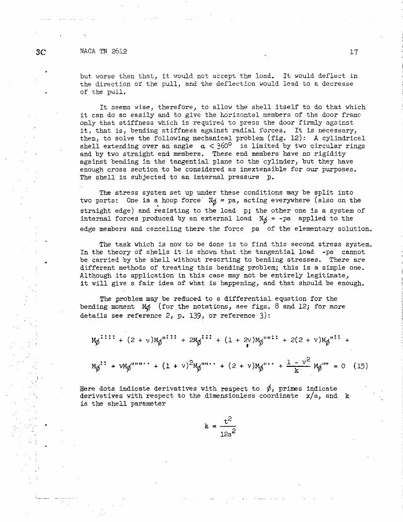
but worse than t h a t , it would not accept the load. It would def lect i n the di rect ion of the pul l , and t he def lect ion would lead t o a decrease of the pul l .
It seems wise, therefore, t o allow the s h e l l i t s e l f t o do t h a t which it can do so ea s i l y and t o give the horizontal members of the door frame only t ha t s t i f f ne s s which i s required t o press the door f irmly against it, t h a t i s , bending s t i f fne s s against r ad i a l forces. It i s necessary, then, t o solve t he following mechanical problem ( f i g . 12): A cy l indr ica l s h e l l extending over an angle a < 360' is l imited by two c i rcu la r r ings and by two s t r a igh t end members. These end members have no r i g i d i t y against bending i n the tangent ia l plane t o the cylinder, but they have enough cross section t o be considered a s inextensible f o r our purposes. The s h e l l i s subjected t o an in te rna l pressure pe
The s t r e s s system s e t up under these conditions may be s p l i t i n to two par ts : One is a hoop force ' N# = pa, act ing everywhere (a l so on the
4
s t ra igh t edge) and r e s i s t i ng t o t he load p; the other one is a system of in te rna l forces produced by an external load N# = -pa applied t o t he
edge members and canceling there the force pa of the elementary solution.
The task which is now t o be done i s t o f ind t h i s second s t r e s s system. I n the theory of she l l s it i s shown t h a t the tangent ia l load -pa cannot be carr ied by the s h e l l without resor t ing t o bending s t resses , There are d i f fe ren t methods of t r e a t i ng t h i s bending problem; t h i s i s a simple one. Although i t s application i n t h i s case may not be e n t i r e l y legit imate, it w i l l give a f a i r idea of what is happening, and t h a t should be enough.
The problem may be reduced t o a d i f f e r en t i a l equation f o r the bending moment M$ ( f o r the notations, see f i g s . 8 and 12; f o r more d e t a i l s see reference 2, p. 139, or reference 3) :
Here dots indicate derivatives with respect t o 6, primes indicate derivatives with respect t o the dimensionless coordinate x/a, and k i s the s h e l l parameter

It may ea s i l y be ver i f i ed tha t
NACA TN 2612
?a = Gem@ s i n - a
is a so lu t ion of the d i f f e r en t i a l equation. Here X is s t i l l an a rb i t r a ry constant. Write
\ \
where n is a posi t ive integer; the discussion w i l l l a t e r be confined t o n = 1.
When the solut ion is introduced in to the d i f f e r en t i a l equation, it i s found t h a t m must s a t i s fy a ce r ta in algebraic equation. After some dras t i c simplif ications (reference 4) it may be brought in to the following f om:
This equation has the complex solutions
with
When any one of the eight complex values m is introduced into the formula f o r Mg$, one elementary solution i s obtained. They a l l show a v a r i a b i l i t y i n x-direction according t o s i n n-12. The same fac tor w i l l appear i n t he corresponding hoop forces Nd. When it i s desired t o use these solutions t o describe the s t resses due t o a uniform d is t r ibu t ion
NACA TN 2612
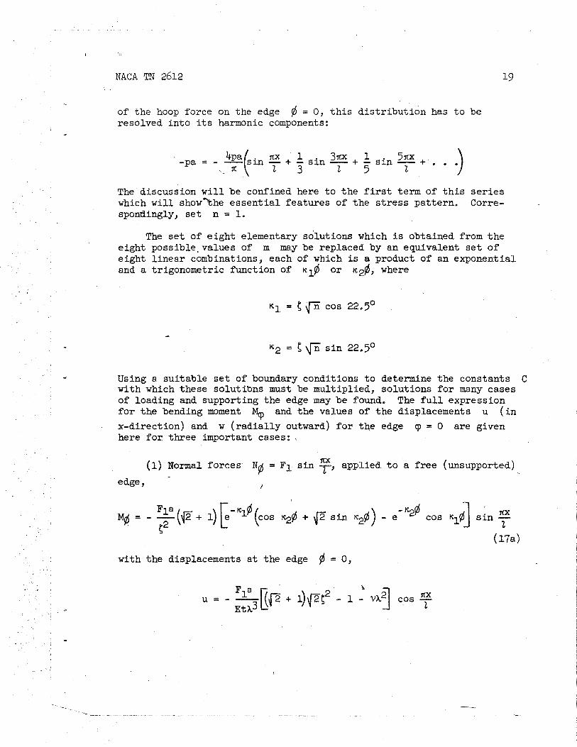
of the hoop force on the edge 6 = 0 , t h i s d i s t r i bu t i on has t o be resolved i n to i ts harmonic components:
nx ' 1 3nx 1 5nx -pa - &(Sin - + - s i n - + - s i n - + . .
.,. x 2 3 2 5 2
The discussion w i l l be confined here t o t he first term of t h i s s e r i e s which w i l l showthe e s sen t i a l features of the s t r e s s pat tern , Corre- spondingly, s e t n = 1.
The s e t of e igh t elementary solutions which is obtained from t h e eight possible, values of m may be replaced by an equivalent s e t of e ight l inear combinations, each of which is a product of an exponential. and a trigonometric function of rrl# OF K ~ @ , where
Using a sui table s e t of boundary conditions t o determine the constants C with which these solutibns must be multiplied, solutions f o r many cases of loading and supporting the edge may be found, The f u l l expression f o r t he bending moment $ and the values of t he displacements u ( i n
x-direction) and w ( r ad i a l l y outward) f o r the edge 9 = 0 are given here f o r three important cases:
(1) Normal forces N# = F1 s i n 7, * applied t o a f r e e (unsupported)
edge 9 /
- ~ l # q = - ~ ( ~ - + l ) [ e ~2 (cos ~ ~ @ + ~ s i n r r ~ ) - e -"@ cos lil@ I 7 s i n -
with the displacements a t the edge @ = 0,
r L NACA TN 2612
Fla ax ,=-,kF+ 1)2(4 + (I. - 2 x 2 ) ( ~ + 1) f i c2 + (2 + v - s i n t EtX
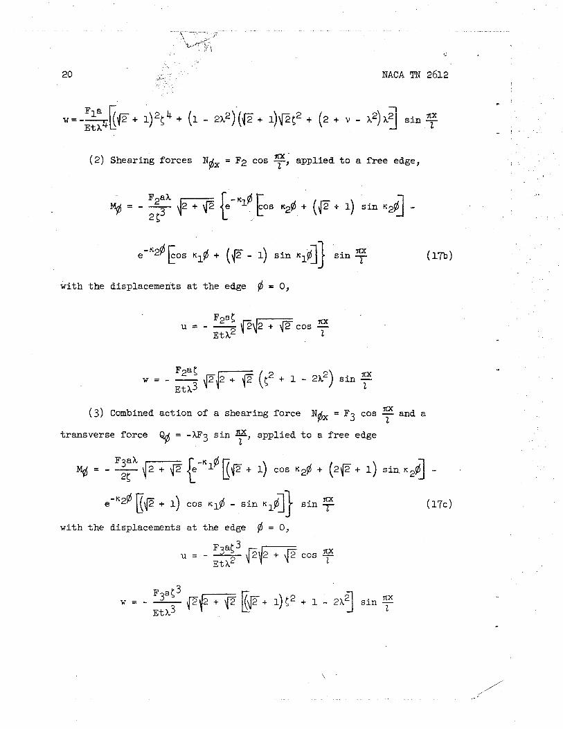
(2 ) Shearing forces Nfix = F2 cos - nx ' applied t o a f r ee edge, 2 '
XX e-"" EOS + (e - 1) s i n .,$I} s i n - 2
with t h e displacements a t the edge fi = 0,
u = - - ax F2a5 p\J2+ cos - ~ t ~ 2 z
w = - - 'Jr x - 2x2) s i n i-
(3) Combined act ion of a shearing force Nfix = Fg cos and a 2
t ransverse force 9 = -XF3 s i n - applied t o a f r ee edge 2 '
F3aX -kl@ = - C(c + 1) cos K,$ + ( 2 8 + 1) sin. K 2 f i I -
ax e-'2@ Bp + I) cos - s i n ~~f i ]} s i n
with the displacements a t the edge fi = 0,
u = - - F3ai-' pJ2+ ~ t ~ 2
w = - - 7fx F3af3 p k i i [p + 4 <2 + 1 - s i n - Etk3 2

NACA TN 2612 21
Coming back t o the o r ig ina l problem represented by figure 12, 'ihe bending moment &$ may be found by superposing the three solutions - (equations (17a) t o ( 1 7 ~ ) ) with appropriate values of the constants F1, F2, and F3. These can be found from three boundary conditions a t the
edge fi = 0.
The f i r s t harmonic of the load pa shown i n f igure 12 is 4pa ax Nb = - - s i n -. In order t o give N t h i s value, it i s necessary
X 2 t o s e t
and t h i s i s the f i r s t of three conditions, The other two follow from the deformation which the door frame imposes on the shel l . Since the cross sect ion of t h i s frame i s assumed t o be large enough t o neglect ax ia l deformations, u = 0 a t = 0 f o r the shel l . Another assump- t i o n formulated previously i s t ha t the door frame w i l l not def lect - very much i n the w-direction. Therefore, w = 0 a t fl = 0 f o r the
shel l ,
4
When u and w are expressed as sums of the contributions of F1, F2, and F3, according t o the formulas given before, and s e t equal t o
zero, there a re two l inear equations from which F2 and F3 may be
found. The r e su l t i s as follows:
- v . The bending moment due t o the combined action of Fp, F2,
and F3 can now be computed; going back through de t a i l s of tpe theory
NACA TN 2612
which have not been reproduced here, the hoop force N and the longi- ..
tud ina l force Nx i n the s h e l l can a l so be found.
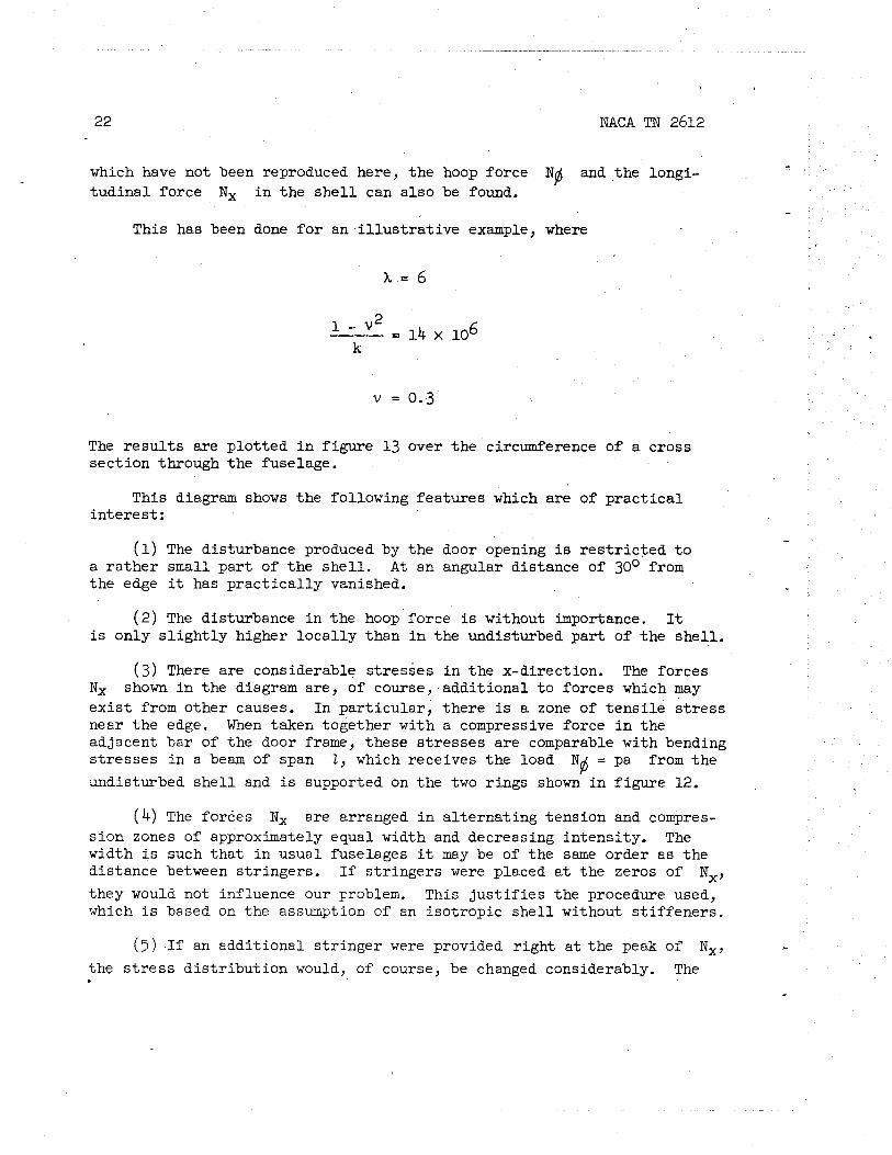
This has been done f o r an i l l u s t r a t i v e example, where
The r e s u l t s are p lot ted i n f igure 13 over t he circumference of a cross sec t ion through the fuselage.
This diagram shows the following features which are of p r ac t i c a l in te res t :
(1) The disturbance produced by the door opening i s r e s t r i c t e d t o a ra the r small par t of the she l l . A t an angular distance of 30° from the edge it has p r ac t i c a l l y vanished.
( 2 ) The disturbance i n the hoop force is without importance. It is only s l i g h t l y higher l oca l l y than i n the undisturbed par t of the shel l .
( 3 ) There are considerable s t resses i n the x-direction. The forces Nx shown i n the diagram are, of course, addi t ional t o forces which may e x i s t from other causes. In par t icular , there is a zone of t en s i l e s t r e s s near the edge. When taken together with a compressive force i n the adjacent bar of the door frame, these s t r e s s e s a re comparable with bending s t resses i n a beam of span 2 , which receives the load N@ = pa from the
undisturbed s h e l l and is supported on the two rings shown i n f igure 12.
(4 ) The forces Nx a re arranged i n a l t e rna t ing tension and compres- s ion zones of approximately equal width and decreasing in tensi ty . The width is such t ha t i n usual fuselages it may be of the same order as the distance between s t r ingers . If s t r ingers were placed a t the zeros of Nx, they would not influence our problem. This j u s t i f i e s the procedure used, which i s based on the assumption of an isot ropic s h e l l without s t i f feners .
( 5 ) I f an addit ional s t r inger were provided r igh t a t the peak of N,, - the s t r e s s d i s t r ibu t ion would, of course, be changed considerably. The
-

essen t ia l e f fec t of t h i s measure would be beneficial : The s t r inger would share the ax i a l load with the she l l . Therefore, it may be suggested t h a t only the width of the f i r s t tension zone be determined, and a good s t r inger - be provided a t i t s center, t ha t is, a t a distance of ~ O O / K ~ f r omthe
door frame.
Bulkheads
General formulas f o r she l l s of revolution.- A cyl indr ical pressure cabin must be closed a t i ts end by a bulkhead. This bulkhead may be constructed as a' f l a t wall b u i l t up of ve r t i c a l and horizontal beams and a metal sheet. The beams have t o transmit the a i r pressure by bending s t resses t o the circumference of the bulkhead, from where it can be t ransferred t o the cyl indr ical cabin wall. Since the t o t a l a i r pressure on the bulkhead i s a force of considerable magnitude, a f l a t bulkhead w i l l r e s u l t i n a heavy construction, which should be avoided i f possible.
The preferable shape of a bulkhead i s t ha t 02 a s h e l l s imilar t o a bo i le r end. When the cabin has a c i rcu la r cross section, such a bulk- head w i l l be a s h e l l of revolution. As a basis f o r i ts s t r e s s analysis a shor t account of the theory of such she l l s w i l l be given here. ,
Figure 14 shows the middle surface of a s h e l l of revolution; i t s in tersect ions with planes normal t o i t s axis a re p a r a l l e l c i rc les , and i ts intersect ions with planes cdntaining the axis are a l l equal t o each other and a re cal led meridians. A t a l l points of a pa r a l l e l c i r c l e the angle 6 between i t s plane and a tangent t o the meridian has the same value and i s therefore character is t ic f o r t h i s c i rc le . The angle between the plane of a meridian and the ve r t i c a l w i l l be cal led 0. Since a point of the s h e l l is-determined by the p a r a l l e l and the meridian on which it l i e s , the angles and 0 may be used as coordinates on the shel l .
I f the s h e l l i s cut along a p a r a l l e l c i r c l e ( f ig . 15), the s t r e s se s transmitted there can be found. A s i s usual i n s h e l l theory, equations a re not wri t ten f o r the s t r e s s but f o r the meridional force Ng which
a c t s on the uni t length of the c i rc le . This force has the di rect ion of t h e meridian. The resul tant of a l l the meridional forces act ing on one p a r a l l e l c i r c l e i s horizontal and of the magnitude sin 9)2~rr, and it
must be equal t o the resul tant R = nr2-p of the a i r pressure. Hence
R N@ = 2nr s i n 6

24 NACA TN 2612
When the s h e l l i s cut along a meridian, in te rna l forces, t ha t i s , the hoop forces No, a re found, but they are not the same a t a l l points of the-meridian and, therefore, cannot be found as simply a s Nd. A
s h e l l element l imited by two adjacent meridians and two adjacent pa r a l l e l c i r c l e s ( f i g . 16) has t o be cut out. The sides of t h i s element, which are par t s of meridians, have the length r l d#, where rl is the radius
of curvature of the meridian. The other two sides have t he length r de ( s l i g h t l y di f ferent from each other because r is not t he same on both p a r a l l e l c i rc les ) . The equilibrium of the forces ~ ~ ( r de), Ng kl dg), and the air pressure p ( r de)(r l dg) i n the di rect ion of a normal t o the
s h e l l y ie lds the equstion
N (r de)d$ + ~ ~ ( r ~ dg)de s i n g = p ( r de)(rl d g ) ' @
The f ac to r s i n fl i n the second term comes from the f a c t t ha t the resu l tan t of the hoop forces l i e s i n the plane of the pa ra l l e l c i r c l e and has t o be projected on the normal t o the shel l . The equation may be simplified t o
Introducing Nfl from equation ( l 8a ) in to t h i s equation,
s i n 6 2rl s i n fl
Equations (18a) and (18b) are suf f ic ien t t o f ind the in ternal forces Nfl and Be when the shape of the she l l is known. In order t o permit the
best use of the space i n the pressure cabin and i n the fuselage a t i t s rear , an ideal bulkhead should be as f l a t as possible. This might lead t o a bulkhead designed t o meet the cyl indr ical cabin wall a t an angle, as shown i n f igure 17(a) . A t the edge of the bulkhead equation (18a) w i l l y ie ld a ce r ta in value of the force
Nfl which) of course, must have the
d i rec t ion of a tangent t o the meridian. Now t h i s force cannot be trans- mitted t o the cylinder because t h i s s h e l l can only r e s i s t a force Nx having the direct ion of a generator. The difference, t ha t i s , the r ad i a l component of N$, must be transmitted t o a s t i f fen ing ring. It leads

4c NACA TN 2612 25
there t o a compressive force of considerable magnitude. The corresponding deformation, a decrease of the r ing diameter, f i t s i n no way t o t ha t of - the cylinder and no be t t e r t o t h a t of t he bulkhead. Therefore, a l l the trouble with bending s t resses described i n the section e n t i t l e d "Bending of a Cylindrical she l l " a r i ses here again but i n a much more serious magnitude. The meridian of the bulkhead should, therefore, always end with a tangent pa r a l l e l t o the generators of the cyl indr ical cabin w a l l .
A t t h e center of the bulkhead r = 0 and fl = 0, and formulas 18(a) and. l 8 (b ) become indef ini te . I f the meridian has a f i n i t e radius of curvature rl a t t h i s point, then, i n i ts v i c in i t y the r e l a t i on
. r = rl. s i n fl
holds. Introducing it into equations (18) , they yie ld
The tendency t o make the bulkhead as f l a t as possible might lead t o a meridian with an extremely feeble curvature i n the cen t ra l par t . In the extreme case, f o r the curvature l/rl = 0, the s t resses become inf ini te .
This i s i l l u s t r a t e d by f igure 18. The meridian i n t he upper hal f is a 3 4 biquadratic parabola a x = r , and the diagrams of the forces *B
and No show the consequences of insuf f ic ien t curvature of t he she l l . The lower half of t he f igure shows how eas i l y the s i t ua t i on can be improved. Here the cen t ra l par t of the s h e l l i s replaced by a spher ical segment, and a t once the s t resses a re reduced t o a moderate magnitude.
It may be mentioned t ha t the meridian chosen f o r t h i s example does not f u l f i l l the condition of a smooth t r ans i t i on t o a cylinder, and, therefore, cannot be recommended even i n the improved form, but t h e essen t ia l e f f ec t shown i n f igure 18 is, of course, t r ue f o r any other shape with insuff ic ient curvature.
E l l ipso ida l bulkhead.- An oblate e l l i p so id ( f ig . 19) used as a bulkhead provides a good compromise between the desi re t o avoid dead angles and dark corners and the necessi ty of providing a smooth flow of forces. Relations between the r a d i i r, rl, and fl may be found
from the equation of the e l l i p t i c meridian. They are:
NACA TN 2612
r = a2 s i n jd
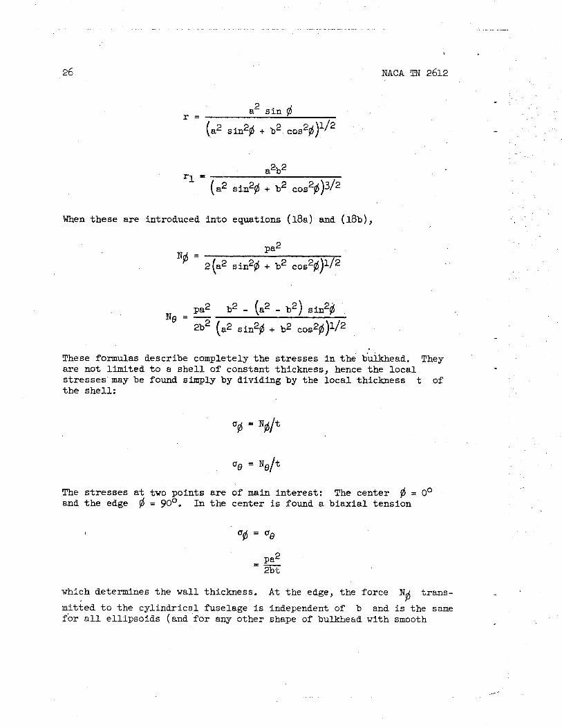
When these are introduced in to equations ( l 8a ) and (18b),
These formulas describe completely the s t resses i n t h e buikhead. They a re not l imited t o a s h e l l of constant thickness, hence the l oca l s t resses may be found sFmply by dividing by the l oca l thickness t of t he shel l :
The s t r e s se s a t two points a re of main in te res t : The center = 0' and t he edge @ = go0, I n the center is found a b i ax i a l tension
which determines the wall thickness. A t the edge, the force Nfi t rans-
mitted t o the cyl indr ical fuselage i s independent of b and is the same f o r a l l e l l ipsoids (and f o r any other shape of bulkhead with smooth

t ransi t ion t o the cylinder). The hoop force No depends largely on the r a t i o a/b of the axes. If b = 0.707a it becomes zero, and i f the
- el l ipsoid is s t i l l f l a t t e r the hoop force w i l l be a compression. Since it i s desirable t o build the bulkhead as f l a t as possible, this f a c t deserves special attention. The compressive s t ress may be rather high, but it is confined t o a small zone. Figures 20(a) and 20(b) show two examples of the s t ress distribution. In any case it w i l l be wise t o provide for a s t i f fening r ing a t the connection between the bulkhead and the fuselage.
The compressive hoop s t r e s s has s t i l l another consequence which needs consideration. It produces an e l a s t i c deformation, which decreases the diameter of the boundary c i r c l e of the bulkhead. On the other hand, the diameter of the cylindrical wall of the fuselage w i l l increase i n the part i n front of the bulkhead as a consequence of the posit ive hoop s t r e s s i n a cylindrical shel l , and w i l l not change a t a l l i n the par t behind the bulkhead where there is no internal pressure. The deforma- t ions of the three shel ls look somewhat as shown i n figure 21. Sirice the shel ls are connected t o each other, such a discrepancy cannot ex is t i n r ea l i ty but w i l l be prevented by a system of bending s t resses i n the boundary zones of a l l three parts. In boilers and other pressure vessels these bending s t resses are rather serious and means t o avoid them are desirable. In pressure cabins they may be of some minor importance, but it is certainly be t te r t o eliminate them as f a r as possible,
The discrepancy between the two cylindrical parts is, of course, unavoidable, but the edge deformation of the bulkhead should l i e between those of the two cylinders. That means, at least , t ha t the hoop force N# must be positive. A hemisphere would f u l f i l l t h i s condition per-
fect ly , but as a bulkhead it would lead t o poor ut%%ization of space. A be t te r solution is t o turn the el l ipsoidal bulkhead with its convex side toward the pressure cabin (fig. 22(a)). Then the previous fsr- mulas are s t i l l applicable, but the signs of a l l s t resses are reversed. That is &sirable a t the edge but certainly not i n the center, where compressive stresses create a buckling problem. This w i l l be avoided by the bulkhead shown i n figure 22(b). The trouble ~ 5 t h t h i s shape is tha t the membrane stresses a t the sharp edge between the convex and concave shel ls cannot make equilibrium with each other without %he help of a s t i f fening ring. This is shown by figure 23. The two meridional forces N# shown there, one a tension and the other a compression, w i l l have the same horizontal component and thus assure the ax ia l equilibrium of the shell; but t he i r rad ia l components are both directed outwardb and, therefore, camst equilibrate each other. I f a sing is provided, %hey m y both be transmitted t o it as shorn, leading %o a compressibPe hoop force i n the ring. But here a new di f f icu l ty arises. The hoop s t ra ins of the three parts w i l l not f i t together and w i l l again lead t o beading
28 €3
NACA TN 2612
stresses. It may be t h a t they w i l l turn out t o be l e s s serious i n a par t i cu la r case, but a t l e a s t they are now a t a place where they do not produce qui l t ing of the surface of the fuselage.
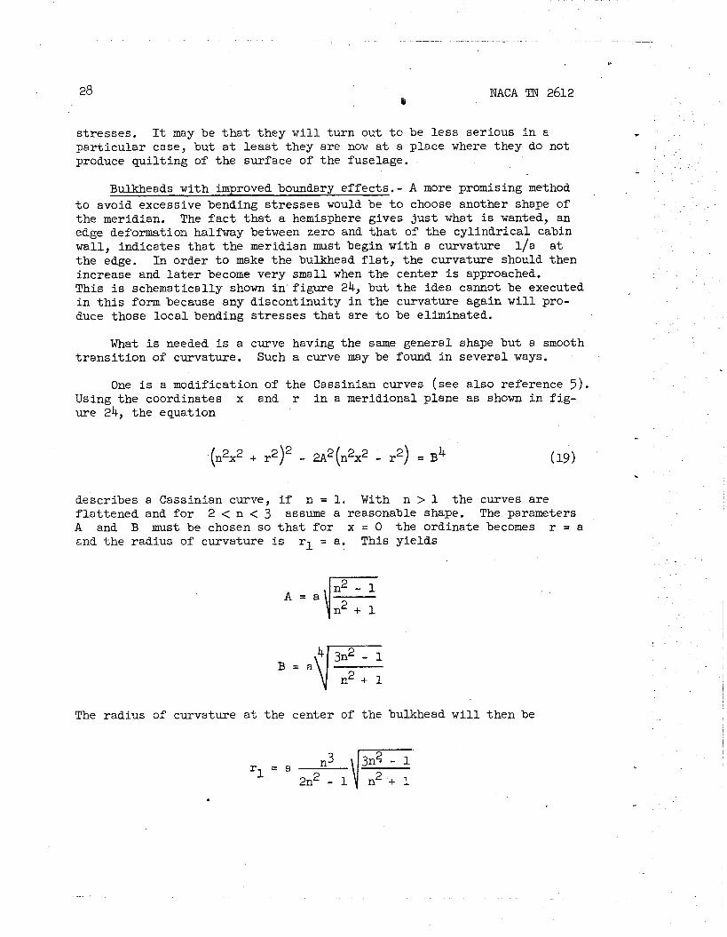
Bulkheads with improved boundary effects.- A more promising method t o avoid excessive bending s t resses would be t o choose another shape of the meridian. The f a c t t ha t a hemisphere gives just what is wanted, an edge deformation hal-y between zero and t h a t of the cyl indr ical cabin wall, indicates t ha t t he meridian must begin with a curvature l / a a t the edge. In order t o make the bulkhead f l a t , the curvature should then increase and l a t e r become very small when the center i s approached. This i s schematically shown i n f igure 24, but the idea cannot be executed i n t h i s form because any discontinuity i n the curvature again w i l l pro- duce those l oca l bending s t resses t ha t are t o be eliminated.
What is needed i s a curve having the same general shape but a smooth t r ans i t i on of curvature. Such a curve may be found i n several ways.
One is a modification of the Cassinian curves (see a l so reference 5 ) . Using the coordinates x and r i n a meridional plane as shown i n f ig - ure 24, the equation
. describes a Cassinian curve, i f n = 1. With n > 1 the curves are f l a t t ened and fo r 2 < n < 3 assume a reasonable shape. The parameters A and B must be chosen so t h a t f o r x = 0 the ordinate becomes r = a and the radius of curvature is rl = a. This yields
The radius of curvature a t the center of the bulkhead w i l l then be

NACA TN 2612
With these data the in te rna l forces a t the most in te res t ing points can be found. A t the edge equations (18a) and (18b) with r = rl = a
- and fl = go0 give:
A t t he center equation (18c) must be used and
Nyj = No
is obtained.
But t h i s i s not enough. To be safe from surprises, one must have the s t r e s s 'distribution along t he meridian. It can be found by the following procedure.
a .
Assume x and from equation (19) f ind r, or vice versa, depending on which w i l l give the greater accuracy. Then compute
r - = r J l i . 0 2 s i n 6
I NACA TN 2612
r - - rr"
r1 s i n $ 1 + (r ' )2
Now formulas ( 18a) and (18b) may be applied.
This was done f o r n = 2 and the r e su l t s shown i n f igure 25 were obtained. The hoop force Ne f a l l s t o zero and r i s e s a t the center of the bulkhead toward the value previously mentioned. I f n > 2 i s chosen, the hoop force w i l l become negative, and yery much so i f n is too great. This, of course, should be avoided.
Bulkhead f o r double cylinders. - In a double--cylinder cabin the two cylinders may have t h e i r bulkheads a t d i f ferent s ta t ions . Between the two bulkheads the longer cylinder mst have a full c i rcu la r cross sec- t ion, and its* intersect ion with the first bulkhead leads t o a d i f f i c u l t s t r e s s problem.
This s i t ua t i on i s eased considerably i f it is possible t o have both bulkheads a t the same cross section. Their shapes may then be chosen such t h a t they in te r sec t i n a plane horizontal curve. This w i l l be the case when they a re oblate e l l ipso ids with the r a t i o b:a = b t : a ' . They may then be derived by a f f ine transformation from two spheres as indi- cated by f igure 26.
A reinforcing r i ng must be provided along the in tersect ion of the , two shel ls . It w i l l now be shown t h a t t h i s r ing, which has the shape
of a hal f -e l l ipse , w i l l be s t ressed i n i t s own plane only, and, with a ce r ta in exception, w i l l even be f r ee from bending s t resses .
I n the case of two spheres t h i s i s evident. Introduce coordinates , $', and 8 as shown i n f igure 26. If the two she l l s are inf la ted by a pressure p, the in te rna l forces w i l l be
i n the upper s h e l l and
i n the lower. The forces N@ f o r $ = 180° - a and N$' f o r
6' = 180° - a' a c t on the r ing as shown i n f igure 27. Since

NACA mJ 2612
a s i n a = a ' s i n a t
the v e r t i c a l components N s i n a and N ~ ' s i n a' balance each other @ and the horizontal components combine t o a uniform r a d i a l load, pro- ducing a posi t ive hoop force
1 F = c p ( a cos a + a t cos a')
i n t he ring.
When there a re two e l l ipso ids , the s t r e s s analysis i s not so simple. One might th ink of using the solut ion given under the sect ion e n t i t l e d "El l ipsoidal B.l;llkheadt' f o r a s ingle e l l ipso id and of determining from it the forces ac t ing on the e l l i p t i c ring. But there is no reason t o believe t h a t the ax i a l symmetry assumed i n deriving t ha t solut ion s t i l l e x i s t s when par t of the s h e l l has been cut away and i t s symmetry thus destroyed. The clue t o the solutiorl i s the idea t ha t the r ing s h a l l be f r e e of bending moments, and it has only t o be shown tha t a solut ion with t h i s property ex i s t s , t h a t it is unique, and how t o f i nd i t ,
To f u l f i l l t h i s program, some notions of the theory of aff ine she l l s a re needed ( f o r d e t a i l s see references 2, 3, and 5 ) . They w i l l be pre- sented here as applied t o the par t i cu la r problem t o be solved.
I n addit ion t o the curvi l inear coordinates $, 8 and , 8 on the two spheres, two systems of rectangular coordinates a r e now introduced: x, y, and z f o r the e l l ipso ids and x*, p, and z* f o r t he spheres. The simple geometrical r e l a t i on between the two she l l s i s represented by
with n = b/a. A s curvi l inear coordinates on the e l l i p so id s the values of # ( o r P I t ) and 8 f o r the corresponding points on the spheres a r e used. These coordinates do not represent angles t h a t can ,
be measured on the e l l ipsoids , but each p a i r of values $,8 defines

3 2 NACA TN 2612
c lea r ly one po'int on the she l l , and t h i s i s a l l t h a t coordinates a re "
expected t o do. - A s h e l l element is cut out of the upper sphere by two meridians 8
and 8 a d8 and by two pa r a l l e l s @ and @ + djd. It has the area
a* = a* s i n @ djd a8
When it i s projected on the planes (y*,zX), (z*,xX), and (x*,Y*), the projected areas a r e found:
d ~ ~ * = a* s i n @ cos 8
wYx = dA* s i n @ s i n 8
a,* = dA* cos @
The element of the bulkhead s h e l l is simply the projection of the element d ~ * on t he e l l ipso id . Both have the same projection on the \
yz-plane; but the other two projections a re reduced i n the r a t i o n: 1:
dA, = L u x *
= dA* s i n jd cos 8
* dAy = n dAy
= b_ dA* s i n @ s i n 8 a
= 2 d ~ * cos @ a
When the e l l i p so id is infla.ted by an i n t e rna l pressure p, the force acting on the element i s p dA and has the rectangular components p dAx, p dAy7 and p dAz p a r a l l e l t o the axes x, y, and z. This load pro- duces i n t e rna l forces transmitted a t the four s ides of the s h e l l

5C NACA TN 2612 3 3
element b4. On each s ide of the element t h i s force l i e s i n a tangent ia l plane t o the s h e l l and may be resolved in to a normal and a shear com- ponent. Something be t t e r can be done: Oblique components p a r a l l e l t o .. the coordinate l i ne s @ = Constant and 8 = Constant can be used. These forces divided by t he length dsfi o r dsg of the l i n e element
are cal led N$, Ng, and Nge, as indicated i n f igure 28.
A simple r e l a t i on between these forces and a ce r t a in system of in te rna l forces N@*, NoX, and N @ ~ * i n the sphere w i l l now be
established. These forces must, of course, l i e on tangents t o the sphere, and they w i l l be chosen i n such a way t h a t they have the same projections on the yz-plane as t he corresponding forces i n the e l l ipso id . Then both w i l l have the same components in, the di rect ions y and z, but t he x-components of the forces N i n the e l l i p so id w i l l equal n times the x-components of the forces N* i n the sphere.
The forces N* of the sphere w i l l be i n equilibrium with a load which has the same y- and z-components as t h a t applied t o t he elb%ipss%d9 but l / n times i ts x-component .
I f the load components per un i t area d ~ * of the sphere a re denoted by P X * ~ py*, and pzX,
a = p I; a* s i n @ cos 8
py* aA* = p d 8 y
b = p a* s i n $4 s i n B
pz* d.A* = p a, I
= p $ aA* cos @
NACA TN 2612
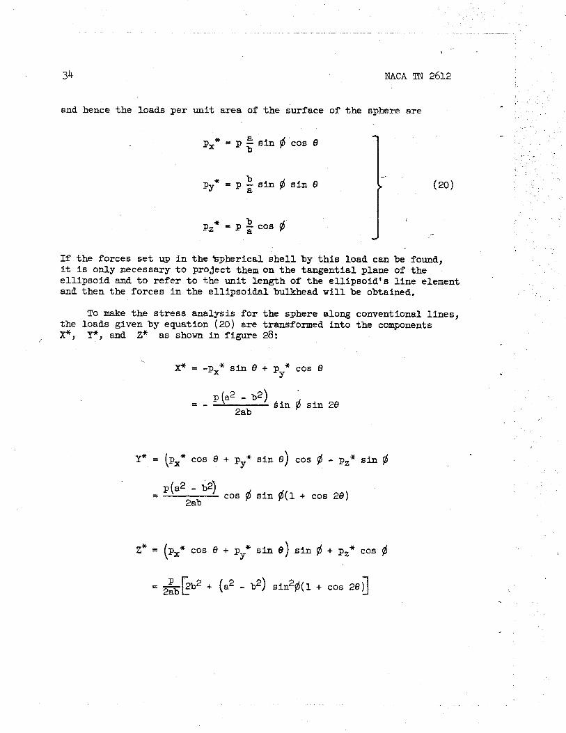
and hence the loads per unit area of the surface of the sphere me
b pz* = p ;; cos @
If the forces s e t up i n the Bpherical she l l by t h i s load can be found, it is only necessary t o project them on the tangential plane of the el l ipsoid and t o re fer t o the unit length of the el l ipsoid 's l i ne element and then the forces i n the el l ipsoidal bulkhead w i l l be obtained.
To make the s t r e s s analysis f o r the sphere along conventional l ines, the loads given by equation (20) are transformed into the components P, Y*, and Z* as shown i n figure 28:
P = -p,* s i n 8 + p * cos 0 Y
- - - p (a2 - be) kin 6 s i n 28
2ab
Y* = (p,* cos 6 + p * s i n 8) cos 6 - p,* s i n @ Y
- - p(a2 - d2) cos @ s i n @ ( 1 + cos 28)
2ab
Z* = (P,* cos + p * sin 0) s i n @ + pZ* cos @ Y
= ~ k b ' 2ab + (a2 - b2) sin2$(1 + cos 29)l
,
NACA TN 2612
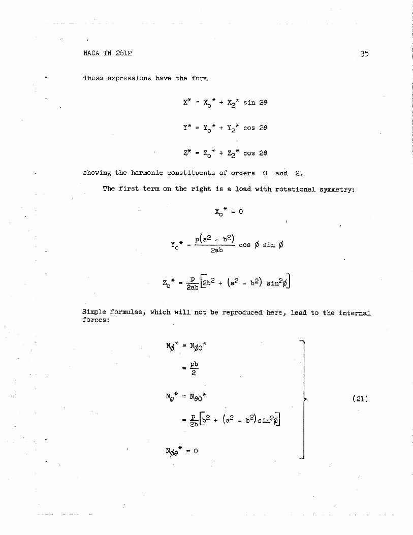
These expressions have the form
X* = xo* + $* s i n 29
Z* = z0* + %* cos 29
showing the harmonic consti tuents of orders 0 anit 2,
The f i r s t term on the r i gh t is a load with ro ta t iona l symmetry:
%* = 0
YO* = p(a2 - b2)
cos s i n 2ab
Simple f s m l a s , which w i l l not be reproduced here, lead t o the i n t e rna l forces :

+.
NACA TI? 2612
These formulas are val id f o r the upper sphere of radius a. For the lower sphere it i s necessary t o write simply a ' , b' , and $' , instead of a, b, and $, respectively. -
The second harmonic of t he load,
x2* = - p(a2 - b2) s i n $
2ab
y2* = p (a2 - b2)
cos 6 s i n 6 2ab
may not be handled so eas i ly . It leads t o forces which depend a l so on a sine o r cosine of 28 and may be wri t ten a s
N $ ~ * = ~ $ 8 ~ ~ s i n 28
The basic formulas connecting N#**, Ne2*, and NfiQ2 * with the load
components x2*, y2*, and z2* may be found i n the l i t e r a t u r e ( re fe r -
ence 2, pp. 37 t o 44, or reference 3). They lead t o a solution having two f r e e constants f o r each of the spheres. One constant i n each pa i r may be determined from the condition t ha t the s t resses are f i n i t e a t 6 = 0 and #' = 0. The other two are s t i l l t o be determined. In t h i s way are obtained
NACA TN 2612
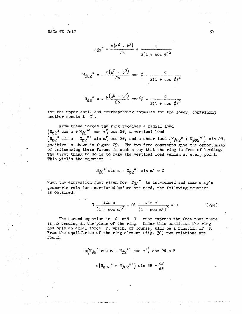
p(a2 - b2) ~ $ 2 ~ = + C
2b 2(1 + cos $)2
= - p(a2 - b2) cos fi - C 2b 2 ( 1 + cos $12
Ne2* = - c 2b 2 (1 9 cos
f o r the upper s h e l l and corresponding formulas f o r the lower, containing another constant c ' .
From these forces the r ing receives a r ad i a l load ( N $ ~ * COS a + JYd2*' cos a') cos 28, a ve r t i c a l load
(Nfi2* s i n a - N$~* ' s i n a') cos 28, and a shear load
posi t ive as shown i n f igure 29. The two f ree constants give the opportunity - of influencing these forces i n such a way t ha t the r ing is f r ee of beading. The f i r s t th ing t o do is t o make the ve r t i c a l load vanish a t every point , This yields t he equation
C
N $ ~ * s i n a - N $ ~ * ' s i n a' = 0
When the expression jus t given f o r N $ ~ * is introduced and some simple geometric re la t ions mentioned before are used, the following equation is obtained:
C s i n a - C' s i n a'
2 = 0
( 1 - sos a12 ( 1 - cos at') ( 22a )
The secocd equation i n C and C 1 must express the f a c t t h a t there is no bending i n the plane of the ring. Under t h i s condition the r ing has only an ax i a l force F, which, of course, w i l l be a function of 8. From the equilibrium of the r ing element ( f i g . 30) two re la t ions a re found:
c(Nfi2* cos a + N pj2*' cos a') cos 28 = F
dF C ( N $ ~ ~ * + N $ ~ ~ * ' ) s i n 28 = -
dB

NACA TN 2612
From the f i r s t one it is possible t o write F = F2 cos 28, and, elimi-
nating F2 from both equations,
When the expressions found f o r the in te rna l f o ~ c e s of both she l l s are again introduced and then simplified by appropriate use of geometric re la t ions , t h i s w i l l y ie ld the second equation f o r C and C':
(1 - 2 cos a ) (1 - 2 cos a ' ) 3p(a2 - b2) s i n ( a + a ' ) C + C' - -
2 b s i n a' ( 22b (1 - cos a) (1 - cos at l2
These two equations, when solved i n general terms, y ie ld
3P(a2 - b2) ( 1 - cos a12 s i n ( a + a t ) C =
b s i n a + s i n a' - 2 s i n (a + a')
Introducing t h i s i n to the formulas f o r the in te rna l forces, the following expressions f o r the upper sphere a re found:
3 s i n (a + a')
s i n a + s i n a' - 2 s i n (a + i
3 s i n (a + a') I (1 - cos a) 2
s in a + s i n a' - 2 s i n (a + a') (1 + cos @)2 C These and those i n equations (21) are the forces s e t up i n the
spherical s h e l l by the f i c t i t i o u s load (20). The l a s t s tep necessary
NACA TN 2612
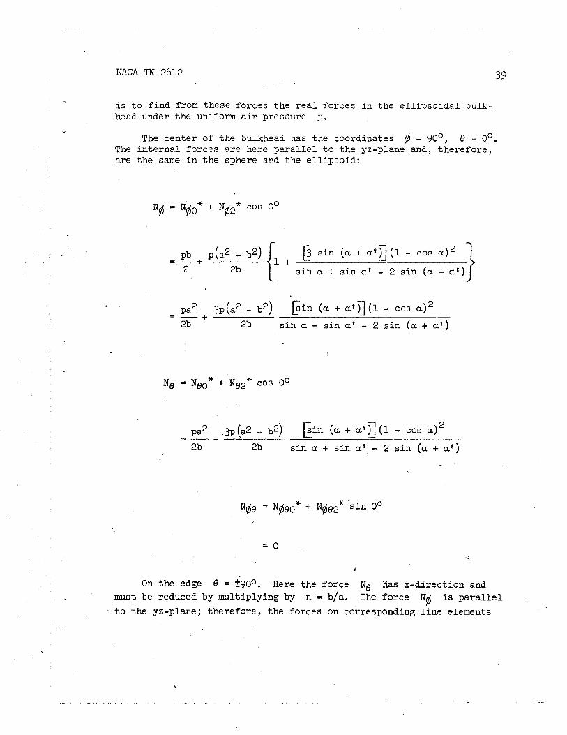
i s t o f i nd from these forces the r e a l forces i n the e l l i p so ida l bulk- head under the uniform a i r pressure p.
.. The center of the bulkhead has the coordinates 6 = 90°, 8 = 0'.
The i n t e r m 1 forces a re here pa ra l l e l t o the yz-plane and, therefore, are the same i n the sphere and the e l l ipsoid:
N$ = N $ ~ * + N ~ ~ * cos o0
s i n ( a + a ' g (1 - cos a ) = - +
2 2b - "' i. + s i n a + s i n at - 2 s i n ( a + a t )
2% 2b s i n a + s i n at - 2 s i n ( a + a t )
pa2 3p (a2 - b2) k i n ( a + c r ' q (1 - cos a ) 2 - - - - --.
2b 2b s i n a i- s i n a% - 2 s i n (a + a s ) /
N$48 = R@$o* c N @ ~ * s i n o"
C
On the edge 8 = ?go0. Rere the force N Ifas x-direction and - must be reduced by multiplying by n = b/a. The force lV6 is p a r a l l e l
t o the yz-plane; therefore, the forces on corresponding l i n e elements

40 NACA TN 2612 -
of sphere and e l l ipso id are the same but the l i ne element i s reduced i n the r a t i o b/a, hence the force per uni t length of t h i s element increased by a fac tor a/b. The shear i s zero. Thus on the edge of the e l l ipsoid:
* cos 1800)
= - - 3 s i n ( a + ' ~ ' )
2 2b2 s i n a + s i n a t - 2 s i n ( a + a t ) ( l + c o s 9 )
(2b2- a2) a 3pa (a2 - b2) s i n ( a + a t ) (1- cos a) 2 - - -
2b2 2b2 s i n a + s i n a' - 2 s i n ( a + a' ) (1+ cos @)2
N6 = + N ~ ~ * cos 3.800)
3 s i n ( a + a') s i n a + s i n at - 2 s i n (a + a ' ) (1 + cos 9)
pa 3p(a2 - b2) s i n (a + a' ) = - + (1 - cos a)2 2 2a s i n a + s i n a' - 2 s i n (a + a ' ) (1 + cos 6)'
An example fo r the dis t r ibut ion of these forces over the circumfer- ence i s shown i n f igure 31. In the top and'bottom zones the forces are
' ra ther uniformly distr ibuted, but there are marked peaks a t the junction of the two el l ipsoids . This f a c t indicates t ha t s t resses i n she l l s should be determined carefully.
i C NACA TN 2612
In a l l the preceding formulas, the denominator
s i n a + s i n a' - 2 s i n ( a + a')
appears. It may happen t ha t a and a' have such values t h a t t h i s denominator i s zero, i n which case the formulas would yie ld i n f i n i t e s t resses . This indicates t ha t i n such a case the combination of t he two spher ical o r e l l i p so ida l she l l s i s capable of an inextensional defbrmation and t h a t r i g i d i t y can only be secured by giving the neck r ing suf f ic ien t r i g i d i t y against bending i n i t s own plane, If plane bending of t he r ing i s t o be assured, then equation (22a) between t h e two constants C and C' s t i l l must hold. The bending moment i n the r ing then becomes independent of the choice of C , Equation (22b) becomes useless and must be replaced by the condition t h a t t h e in te rna l forces assume f i n i t e values. This leads t o C = C' = 0,
The somewhat lengthy analysis of t h e double bulkhead has been reproduced here not only because of the par t i cu la r problem under con- s iderat ion but as an example of two important features of t h i n shel ls :
- (1) The f a c t t h a t the s t i f fen ing r i ng along the in tersect ion of
two pa r t s of the s h e l l is usually f r ee of bending moments
(2) The use of aff ine re la t ions f o r the solut ion of s h e l l problems
Nose of Plane
General rules.- The nose of the fuselage may have so many various \
shapes t h a t not much can be sa id i n general about i ts s t r e s s analysis . ' In high-speed planes aerodynamic consideration m y lead t o shaping the
nose as a perfect surface of revolution. If it is par t of t he pres- surized cabin, it may be t rea ted with formulas (18a) and (18b) f o r s t resses i n such shel ls ; i f the cabin terminates i n a bulkhead back of t he nose, a l l t h a t has been sa id about the rea r bulkhead is applicable.
The modern passenger plane usually has a nose which looks l i k e t h a t shown i n f igure 32. The major par t of it i s a she l l , but the smooth surface is interrupted by many windows. I n such cases a s h e l l analysis
' . as described i n the preceding sections w i l l , i n general, be too com- pl icated f o r p rac t ica l purposes. A s regards the s t r e s s analysis of such s t ructures , the following f ac t s should be kept i n mind:
*
(1) A l l la rge uninterrupted par t s of t he metal skin w i l l a c t as shel ls , whether they are f ixed on a so l i d framework o r only s t i f fened
., ' by- r ings and s t r ingers . The s t i f f ene r s which are connected t o the she l l ,

NACA TN 2612
although absolutely necessary f o r the introduction of l oca l loads and as a buckling reinforcement, are obstructions t o a smooth flow of s t r e s s i n the s h e l l proper and lead t o qu i l t ing and t o tyns i le s tzesses i n r ive t s . ..
(2 ) A l l edges of such s h e l l parts , f o r example, along the windows, must be s t i f fened by edge members. It i s always advantageous t o shape
. these edge members a f t e r -plane curves. With ra re exceptions they w i l l not then be subjected t o bending i n space, but they must o f fe r resistance t o bending i n t h e i r plane and require the corresponding r ig id i ty , bracing, and support.
(3) There i s ,no need f o r making cross sections c i rcular . Any curved s h e l l can r e s i s t an in te rna l pressure, but, of course, the s t r e s s dis- t r i bu t i on w i l l be l e s s uniform and may ea s i l y have l oca l zones of com- pression i f the cross sections are f a r from circular .
, (4) Areas of extremely low curvature should be avoided. Membrane
s h e l l theory leads t o extremely high s t resses i n such par t s and, owing t o these s t resses , t he panel bulges out, thus increasing the curvature and reducing _the s t ress . I n addit ion t h i s bulging invariably leads t o some plagi&ef~ynat_ion a t the edges of the panel and, therefore, t o a ~ermanent bu lg in~ , which i s undesirable. -
El l ipso id with t h r ee d i f fe ren t axes.- A general e l l ipso id is a ;kind of a s h e l l which probably w i l l not occur as par t of a pressure cabin.- - However, i t s membrane forces are eas i ly computed and may give an idea of what may happen i n other she l l s of noncircular cross section.
- - Consider an e l l i p so id having the three half-axes a > b > c and
being subjected t o an in te rna l pressure p. In order t o f i nd the - -- membrane forces, e s tab l i sh re la t ions between them and those i n a sphere of radius b under a c e r t a in load. This follows the same l i ne s a s the theory f o r the double bulkhead i n the section en t i t l ed "~ulkhead fo r Double cylinders." -
_ In rectangular coordinates x*, y*, and z* the sphere has the 1
equation __
and i n coordinates x, y, and z the equation of the e l l ipso id i s - -
' NACA TN 2612
As surface coordinates on the sphere the angles and 6 are used as shown i n f igure 33. Through the re la t ions
- each point of the- sphere corresponds t o a point on the e l l ipso id . By a t t r i bu t i ng the same values of fl and 8 t o both, a system of coordi- nates is established on the e l l ipso id . Its l i ne s fl = Constant a r e p a r a l l e l e l l i p se s i n horizontal. planes. Its l i ne s 8 = Constant a re e l l i p se s i n planes through the z-axis.
The s h e l l element on t h e sphere has t he area
dA* = a d$a s i n fl dfl
and i ts projections on the coordinate planes a r e <
* - dAx = d.A* s i n fl 'cos 8
I
d.Ay* = a* s i n fl s i n 6
* aA* cos fl , dA_z -
The projections of the correspondi& element of the e l l i p so id are
44 NACA TN 2612 *
Multiplying t h i s by p yie lds the components of the force p d A acting on t h a t element. The corresponding forces on the spherical element are then
b px* dA* = - p dAx a
b = g p a* s i n $ cos 8
= p dA* s i n $ s i n 8
From these re la t ions are found px*, * and pZ*, t he loads per un i t P~ ,
area of the sphere, i n di rect ions x*, y*, and z*. They are connected with the usual components, X* i n di rect ion 8, Y* i n di rect ion $, and Z* i n the r a d i a l d i rect ion by the formulas:
= -px* s in 6 + p * cos 8 Y
Y* = (pXf cos 8 + p Y * s i n 6) cos $ - p,* s i n 6
* * Z* = (px* cos 9 + p s i n 0) s i n $ + .pz cos 6 Y
Introducing p,*, pyx, and pz*, they yield:
p = p z a 5 b(c - i) s i n s i n 20
n X2 s i n 26
NACA mJ 2612
P ac Y* = 0 s m s i n [ji + - - 2 5) - je - $1 0 s iB] b2 c 66
ac z* = tE f + ( + - 2 2) sin2# - ( - 3 sin2@ cor 26 b2 C . 1
Z, + Z+ cos 28
The corresponding membrane forces may be found from well-known formulas (reference 2, pp. 37 t o 39). They are:
u pc a ~ $ 9 = T ( g - 4) cos sin ae
To f i nd the forces i n the e l l ipsoid , the r a t i o of the corresponding l i n e elements is needed. The r e su l t s a r e mentioned only f o r the th ree points A, B, and C.
A t t he point A fl = go0, 6 = go, and

46 NACA m 2612
A t the point B fl = go0, 0 = 90°, and
A t the point C $ = 0' and 0 may have any value. When f3 = 0' is assumed a rb i t r a r i l y , then N p l i e s i n the xz-plane, and Re, i n the .
- yz-plane, and the i n t e rna l forces are:
. I f (a2 + b2)c2 < a2b2, the force No a t the points A and B becomes
a compressiod. The other four formulas always yie ld posit ive forces when a 2 b 2 c. These r e su l t s may serve as a f i r s t or ienta t ion of what i s t o be expected i n she l l s of noncircular cross section under the action of an in te rna l pressure.
NACA TN 2612
Stresses i n Thin F la t Sheets
Plane p la tes are not very desirable as par t s of the wall of a pres- sure vessel, but it of ten i s not possible t o avoid them. Therefore, the s t resses s e t up i n them by a l a t e r a l pressure p w i l l be considered here.
I f such a pla te were th ick enough, it might carry i ts load by bending s t resses as does t he reinforced concrete f loor s lab of a building; however, the skin of an airplane is much too t h i n t o ca r ry an appreciable load with to lerable bending s t resses . I t s s t r e s s system i s a superposition of bending s t resses and of the s t resses i n a f l ex ib le skin.
The subject of t h i s sect ion w i l l be such a t h i n skin of rectangular shape. Its s t r e s s problem i s essen t ia l ly nonlinear. I n two dimensions it i s so involved t ha t a l l theore t ica l and experimental e f f o r t spent on it up t o the present is s t i l l f a r from giving a complete answer t o a l l questions which the engineer might ask. Therefore, a discussion is f i r s t presented f o r the one-dimensional problem which, i n many cases, w i l l give useful information f o r p rac t ica l purposes and beyond t h a t w i l l
- show the general features of the s t r e s s system present i n the two- dimensional case,
Thin sheet s t ressed i n one dimension.- Consider a t h i n p l a t e a s shown i n f igure 34. In the x-direction it has the span 2 , and t h e
.sides x = +1/2 are supported i n such a way t ha t not only the deflec- t i o n w but a lso a displacement u i n t he x-direction i s prohibited. I n the di rect ion of the y-axis t he p la te is supposed t o be long enough t o make the conditions a t the shor ter s ides immaterial.
For the purpose of s t r e s s analysis cut a s t r i p of un i t width out of t h i s p la te . Because of t he end conditions, t he l a t e r a l load p w i l l produce a d i rec t s t r e s s a along t he s t r i p , which is necessari ly independent of x. If the def lect ion w i s large enough, t h i s s t r e s s w i l l be capable of carrying the load.
This can be seen'on an element of length dx cut from the s t r i p ( f i g . 35). The . condition of ve r t i c a l equilibrium is:
NACA TN 2612
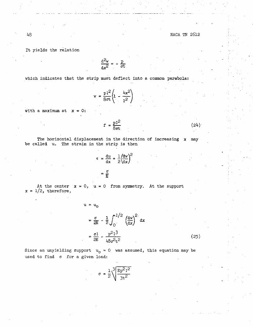
It yie lds the r e l a t i on
which indicates t h a t t he s t r i p must def lect i n to a common parabola:
y i t h a maximum a t x = 0:
The horizontal displacement i n the di rect ion of increasing x may be cal led u. The s t r a i n i n the s t r i p is then
A t the center x = 0, u = 0 from symmetry. A t t he support x = 212, therefore,
Since an unyielding support uo = 0 was assumed, t h i s equation may be
used t o f ind a f o r a given load:
7c NACA TN 2612
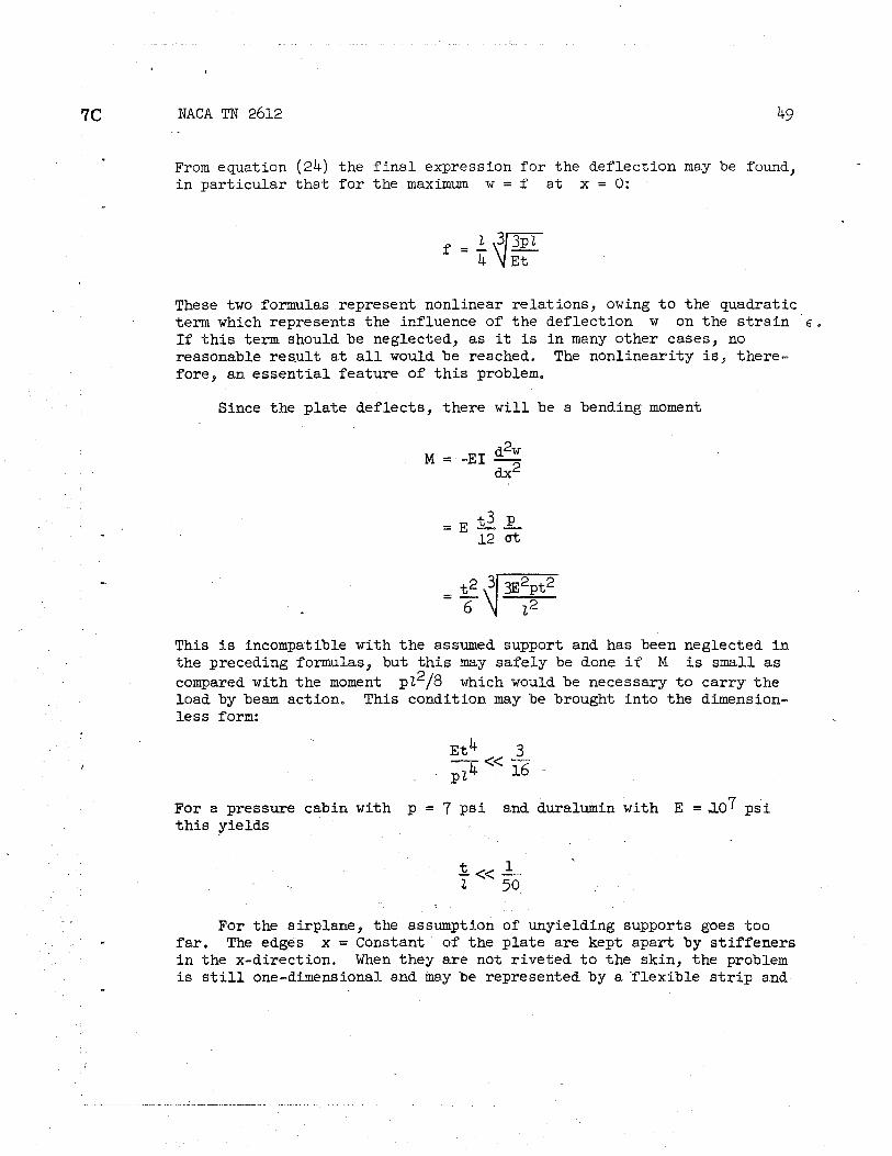
From equation (24) the f i n a l expression f o r the def lect ion may be found, i n par t i cu la r t h a t f o r the maximum w = f a t x = 0:
These two formulas represent nonlinear re la t ions , owing t o the quadratic t e r n which represents the influence of t he def lect ion w on the s t r a i n E. I f t h i s term should be neglected, a s it is i n many other cases, no reasonable res.ult a t a l l would be reached, The nonlineari ty is, there- fore, an e s sen t i a l feature of t h i s problem.
Since the p la te def lects , there w i l l be a bending moment
This is incompatible with t he assumed support and has been neglected i n the preceding formulas, but t h i s m y safely be done i f M i s small a s compared with the moment p22/8 which would be necessary t o ca r ry t he load by beam action. This condition may be brought in to the dimension- l e s s form:
For a pressure cabin with p = 7 p s i and duralumin with E = ~ 0 7 p s i t h i s yields
For the airplane, the assumption of unyielding supports goes too f a r . The edges x = Constant of the p la te are kept apart by s t i f f ene r s i n the x-direction. When they a re not r iveted t o the skin, the problem i s s t i l l one-dimensional and may be represented by a f l ex ib le s t r i p and

NACA TN 2612
a s t r u t as shown i n f igure 36. The f l ex ib le s t r i p is exposed t o the load p and def lec t s under it; its ends a re kept apart by a s t r u t of cross section A1, which has a compressive force N = -at; the supports
are such t h a t they allow the corresponding e l a s t i c deformation of the bar.
When the cross sect ion of one s t i f f e n e r i s A, and the distance between s t i f f ene r s is d, then the area A1 = ~ / d corresponds t o a ' s t r i p of un i t width of the plate.
When the horizontal displacement u is assumed t o be zero a t x = 0 (midspan), equation (25) may again be used f o r the displacement uo a t the end, but now % must correspond t o the f a c t t h a t the s t r u t becomes
shor ter by N Z / E A ~ :
Introducing t h i s i n to equation (25),
f o r the s t r e s s i n the pla te . The greates t def lect ion follows then from equation (24) :
Comparing these two formulas with those which were obtained f o r nonyielding supports, it is seen t h a t they become iden t ica l f o r A1 ---t me
Since t / ~ ~ is more l i k e l y t o be equal t o 1 than 0, the assumption of nonyielding supports may lead t o e r rors of about 25 percent, overrating the s t r e s s and underrating the deflection. It seems, therefore, not worth while t o spend much e f f o r t on the two-dimensional problem if t h i s e f f ec t i s not taken i n to account. However, the simpler formulas are good enough f o r estimating the order of magnitude of a and f and f o r discussing t he influence of the bending s t i f f n e s s of the plate.
The formulas (26a) and (26b) are suf f ic ien t if the sheet panel is . par t of a f l a t bulkhead. But i n most other cases the wall, consisting o f ' t he sheet and i t s s t i f f ene r s , has t o transmit an in te rna l force such

NACA TN 2612
as Nx or N$ explained i n the section ent i t led "circular Cylinder." These forces may be due t o the over-all bending of the fuselage, t o the action of the internal pressure on other par ts of i t s wall, and t o other causes. When the sheet i s f l a t and bulges out, the dis t r ibut ion of t h i s force on sheet and s t i f feners is no longer governed by the formulas ( 5 ) . It may be found by adding an axia l force P t o the s t r i p and s t r u t system of figure 36 (see f ig . 37).
If 0 again indicates the s t r e s s i n the sheet, the force i n the s t r u t is
and the horizontal displacement a-t; x = 212 must be
Equating t h i s t o the expression (25),
- This may eas i ly be solved i n any given case. The deflection %: follows then from equation (24).
Some resul ts are shown i n figure 38 i n dimensionless variables. The values fo r the parameter p ~ / ~ t have been chosen as rather extreme i n
, order t o cover the whole f i e l d of pract ical interest . For most of the diagrams, t / ~ ~ = 1 has been assumed, but one of them shows the t rena fo r a variation of t h i s parameter. I
The diagrams show the influence of the force P. They emphasize tha t a solution of the two-dimensional problem which disregards t h i s influence cannot yield more than a rough approximation of the r e a l a i r - plane problem, even i f it were an exact solution of the simplified problem.
Thin sheet stressed i n two dimensions.- Assuming a suff ic ient ly th in plate, the formulas developed i n the preceding section are exact
.- fo r inf in i te ly long rectangles, 1% is probable tha t they w i l l yield good resu l t s i f the r a t i o of %he sides i s P:4 or even 1:3, but when
I the rectangle approaches a square, they become inapplicable.

NACA TN 2612 - .
To f i nd out how the r e su l t s must be modified i n such cases, consider a square p la te framed by four equal s t i f f ene r s ( f i g . 39). When the p l a t e bulges out under a l a t e r a l load p, s t resses a w i l l be s e t up i n two di rect ions , which a re denoted ax and ay. The s t i f f ene r s w i l l receive
compressive forces. The p la te i n t h e i r immediate v i c in i t y must have the same s t r a i n and hence a compressive s t ress . The d i s t r ibu t ion of ay along one of the edges must, therefore, be as shown on the f igure,
A t the center of t h e p l a t e ax = a When two s t r i p s are cut out Y' along t he coordinate axes, each one w i l l car ry one-half of the load p, and the curvature w i l l be hal f of t h a t which would follow with t h i s same a from the one-dimensional theory. When the horizontal s t r i p is followed toward the r i g h t edge of the pla te , the s t r e s s uy w i l l
decrease and f i n a l l y become negative. Where it passes zero, the one- dimensional theory w i l l y ie ld the correct curvature, and closer t o the edge the curvature of the square p la te w i l l be greater than t h a t of a s ingle s t r i p . A s ingle s t r i p was seen t o de f lec t as a parabola. The p ro f i l e of the square p la te must, therefore, be f a r from a s ine curve, and r e su l t s computed on t h i s assumption must, therefore, be interpreted with some reserve.
When a diagonal o? the p la te is followed ax always equals cry,
but both s t resses decrease the f a the r away they are from the center . The curvature i n both di rect ions must, therefore, become greater , and a sharp fo ld may be expected toward the corner. But a t l e a s t the re is a region where ax and cry become negative and a re no longer capable
of carrying any load a t a l l . Here even the th innest p la te must have e s sen t i a l bending s t ress . The thinner the p la te is, the smaller t h i s region w i l l be, and the sharper the curvature w i l l become. It follows t h a t the highest s t r e s s e s w i l l occur on o r near the corners. They may or may not be responsible f o r the ult imate load of t he ' p l a t e , depending on the pos s ib i l i t y of smoothening the peak by l o c a l p l a s t i c flow, but they a re c e r t a i n ly responsible f o r permanent deformations which produce t h a t qu i l t ing of f l a t panels which makes airplanes unsightly and is not much appreciated by the aerodynamicist.
There is l i t t l e numerical information avai lable on square and rec- tangular plates. Some papers (references 6 and 10) a r e mentioned i n the references of t h i s report . One of them, reference 6, contains ra the r complete mater ia l f o r p la tes with unyielding supports ( f i g . 34); however, t h i s paper i s based on the assumption t h a t the p rof i l e s of the deflected p la te along both axes a r e sine curves. In pa r t i cu la r , t h i s assumption is a l so made f o r the lengkhwise p rof i l e of long p la tes (1:4), where it leads t o an overrat ing of the influence of the support a t the shor t s ides. The r e s u l t s f o r the long pla te , therefore, do not check with the one-dimensional theory. However, the two-dimensional problem is

NACA TN 2612 5 3
so complex tha t a c r i t i c a l use of the diagrams of Moness (reference 6) i s the best tha t can be recommended a t t h i s time.
Thermal Stresses in Window Panes
The window panes of a pressure cabin are not only exposed t o the difference i n pressure between the in te r ior of the cabin and the f ree atmosphere but also t o a considerable difference i n temperature, The bending stresses due t o the pressure may eas i ly be found from text- book formulas, but the thermal stresses require some discussion,
Consider a plate of uniform thickness, sjmply supported along i ts edge. Assume tha t no load is applied but tha t there is a difference T between the temperatures of i ts faces. When the temperature is increased
8 by T, a positive s t r a i n
w i l l occur i n every direction, a being the coefficient of thermal expansion. When only one side of the plate i s heated, E is the dif- ference i n s t r a in between both sides, and t h i s difference leads t o a curvature
i n every direction. The middle surface of the g l a t e is then deformed into a small part of a sphere of radius l / ~ * -
If the plate is circular, t h i s i s a11 that happens. The window w i l l slightl/y deflect t o the warmer side, and no -t;heraeal stresses w i l l be se t up. But if the plate i s rectangular, the deformed shape w i l l no longer f i t on the support, and, i n order t o make it f i t , the support w i l l exert forces on the plate and these forces w i l l produce bending stresses.
Formulas f o r the bending moments which correspond t o these s t resses w i l l now be established and discussed. In doing so, the following nota- tfons w i l l be used ( f ig . 40) :
X Y Y coordinates 4
.- w Clef lection
Mx9% bending moments
M x ~ twisting moment

NACA TN 2612
Kx curvature i n x-direction I
1
K bending s t i f fne s s
The s t resses and deformation due t o heating of t he upper face of the p l a t e w i l l be b u i l t up i n three steps. The f i r s t one has-already been done, namely, the application of t he temperature difference t o t he fre;! p la te , r esu l t ing i n a uniform bending without s t ress .
In the second s tep t h i s deformation i s completely removed by applying, . . along a l l four edges of the pla te , constant external bending moments Mo of appropriate size. They produce bending moments
i n the p l a t e which are constant everywhere and i n a l l directions. Now, the curvature tcx of the pla te i s re la ted t o the bending moment by the *
well-known formula:
I n t h i s case, it yie lds
To remove t he thermal deformation, K~ must be made equal t o - a~ / t
and theref ore I
Under the combined action 02' t he temperature T and the edge moments Mo the p la te i s perfect ly plane and may be attached t o i t s
supports. Now the t h i r d s tep may be done: The condition of simply supported edges must be real ized and the edge load Mo compensated by
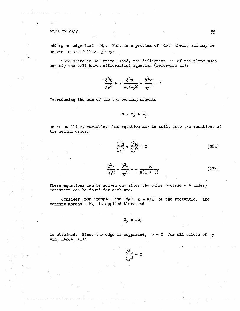
NACA TN 2612 . -
55
adding an edge load -Mo. This i s a problem of p la te theory and may be
solved i n the foPPowing way:
When there i s no l a t e r a l load, the def lect ion w of the p la te must s a t i s f y the well-known d i f f e r en t i a l equation (reference 11) :
Introducing the swn of the two bending moments
as an aux i l i a ry variable, t h i s equation may be s p l i t i n to two equations of the second order:
These equations can be sQPved one a f t e r t he other because a boundary condition can be found f o r each one.
Consider, f o r example, the edge x = a12 of the rectangle. The bending moment -Mo is applied there and
is obtained. Since the edge is supported, w = 0 f o r a l l values ~f y and, hence, a lso

NACA TN 2612
Introducing t h i s in to the e l a s t i c law
it can be concluded t h a t = -IrMo on t h i s edge and, hence, t h a t
M = - ( 1 + v ) M , ( 3 0 )
A s imilar reasoning may be made f o r the three other edges.
The solution of equation (28a) with the boundary condition (30) i s extremely simple. It is a constant, M = - ( 1 + v)M, .
Now equation (28b) may be attacked. Introducing the r e su l t jus t obtained,
and the boundary condition i s , of course, w = 0.
This d i f f e r en t i a l equation with t h i s boundary condition is known i n the theory of tors ion of a bar having rectangular cross section. A l l t h a t i s necessary i s t o t rans la te the so1utio.n known there in to the terminology of the pla te problem.
The solution is :
nxa n3 cosh - 2b

3c NACA TN 2612 57
One may e a s i l y ver i fy t ha t t h i s expression s a t i s f i e s the d i f f e r en t i a l equation and t ha t w = 0 f o r y = fb/2. A t the other two edges, x = fa/2, equation (31) yields:
The sum i n the parentheses happens t o be the Fourier s e r i e s representa- t i o n of the function
va l id i n the in te rva l -b/2 5 y 5 b/2, and, therefore, the expression i n parentheses vanishes a t every point of the two edges x = Constant of the pla te . This proves t h a t the solut ion r ea l l y s a t i s f i e s the condition w = 0 on a l l four s ides of t he rectangle.
The bending moments can now be found ea s i l y by introducing the - solution (31) in to the e l a s t i c law (29):
nxx cosh - b
n cosh
, These a r e the bending moments produced i n s t eg t h e e . To obtain t he bending moments f o r t he o r ig ina l problem, the moment 1?IQ s f the second s tep must be added; the f i r s t s t ep makes no contribution to the s t resses , When &, is expressed by the temperature difference T, wri t ing

58 NACA TN 2612
f i n a l l y
nrrx C O S ~ -
nYla n cosh - 2b
& cosh - nsrY 1
na COB - M~ = - ~ a t 4 (-1) b b
331 1,3,* a n cosh - nsa 2b
The solution would not be complete without having the twisting moment +
Step two does not make a contribution t o it, but it can be obtained from equation ( 31) alone, using the formula
There is obtained
nrrx n*Y 1
s i n . s i n - M~~ = - E U ~ ~ T
b
331 193, . nrra n cosh - 2b
\
The formulas for the moments are the solution of the problem as it was formulated a t the beginning. It is now necessary t o discuss t h i s r e su l t and t o draw some pract ical conclusions from it. -

NACA TN 2612
A t the edges y = +b/2
nrcy cos - = 0 b
f o r a l l odd integers n and hence
That t he moment vanishes corresponds t o the assumed simple support.
That Mx does not do so- is ~ u e t o t$e f a c t t ha t the edge i s kept s t r a igh t
i n s p i t e of the applied temperature difference.
A t the edges x = fa/2 there is the corresponding r e s u l t
s = o
1. 2 % = 5 Eat T
but t o obtain it the Fourier s e r i e s
must be added up which yie lds x/4 f o r a l l points of the in te rva l -b/2 5 y < b/2.
I '. For i n t e r i o r points of the pla te , the se r ies appearing i n t h e
formulas Mx and My has very good convergence, For the center of
a square pla te , -
- can be found eas i ly .

, NACA TN 2612
The most interesting part of the solution is the formula fo r the twisting moment When x < a/2, the quotient of the two hyperbolic
Y' functions decreases exponentially with increasing n and produces a good convergence of the series; but on the edge x = a/2 t h i s beneficial influence i s l o s t and the ser ies converges slowly. I f x = a/2 is kept and the corner y = b/2 is approached, the ser ies becomes
and t h i s series is divergent or, i f t h i s expression is admitted, yields the value a. This s ingular i ty of the twisting moment which, of course, appears a t a l l four corners, is of pract ical importance. It is true tha t r e a l objects always f ind a way t o avoid inf in i te stresses, Here the f i n i t e thickness of the plate, the f i n i t e width of the zone t o which the reactions are applied, and the e l a s t i c yielding of , the support may ac t i n t h i s way, but, nevertheless, the singularity i n our solution reveals the fac t tha t stresses ,near the corner w i l l be extremely high and tha t it would be wiser t o round the corners l ibera l ly than t o t r u s t . the good w i l l of the structure.
Buckling of Cylindrical Panel
The metal skin of the pressurized cabin is subdivided into rec- tangular panels by rings and axia l s t i f feners (stringers). In every such panel, the wall is subjected t o a hoop s t ress a@ due t o the cabin pressure p, Additionally, there may be an axial s t r e s s ax (tension
or compression) and a shear s t r e s s T (f ig . 41). The hoop s t ress
increases the shear s t r e s s T required fo r buckling i n the presence of a given ax.
For t h i s buckling problem, Kromm (reference 7) has worked out two diagrams which give the c r i t i c a l shear T as a function of the hoop s t r e s s a assuming e i ther p = 0 (case "a", f ig. 43(a)) or
ax = a 2 (case "b", f ig . 43(b)). Of course, the r a t i o between the two a l stresses ax and a t may have any other value between or beyond these
l i m i t s , but, since the influence of ax on the c r i t i c a l shear is not large, the choice made by Kromm is suff ic ient .
Krommts paper gives only a short description of the method used fo r solving the problem, referring fo r more detai ls t o his ea r l i e r papers on

NACA TN 2612
s t a b i l i t y problems i n cylinders. A s t i l l shorter out l ine w i l l be given here of the laborious procedure and an explanation of the diagrams resu l t ing from it.
The object of the graphs i s a rectangular panel, cut from a c i rcu la r cylinder of radius a and supported on i t s edges. Its length is supposed t o be much greater than i t s width so t ha t the buckling is not influenced much by t he support on the curved sides.
When t h i s panel is subjected t o t he cabin pressure p it w i l l bulge out, again forming a cy l indr ica l surface, but with a smaller radius r < a. This radius r may ea s i l y be found i f the lengthwise edges of t he panel. a re fixed. I n the deformed s t a t e ( f ig . 42) a simple consideration of equilibrium yields f o r the hoop s t r e s s the r e l a t i on
On the other hand, the length of t he a r c of radius r and chord b is
the length of the same arc before deformation is
and hence the hoop s t r a i n i s
b2 1 - - - - - - 24(2 a')
When a, = 0 (case "a"),

62 NACA TN 2612
Equating th i s t o the value from equation (32), .
In case "b,"- E has simply t o be replaced by 2 ~ / ( 2 - v). ,
In connection with the buckling problem, the relations between p and. r must be expressed by a cer tain se t of dimensionless variables used there. Using Kromm's notation, the curvature of the undeformed cylinder i s described by the parameter
\
tha t of the deformed shel l , by
and the pressure p, by the parameter
The relat ion just found between p and r reads then i n case "a": \
and i n case "b":
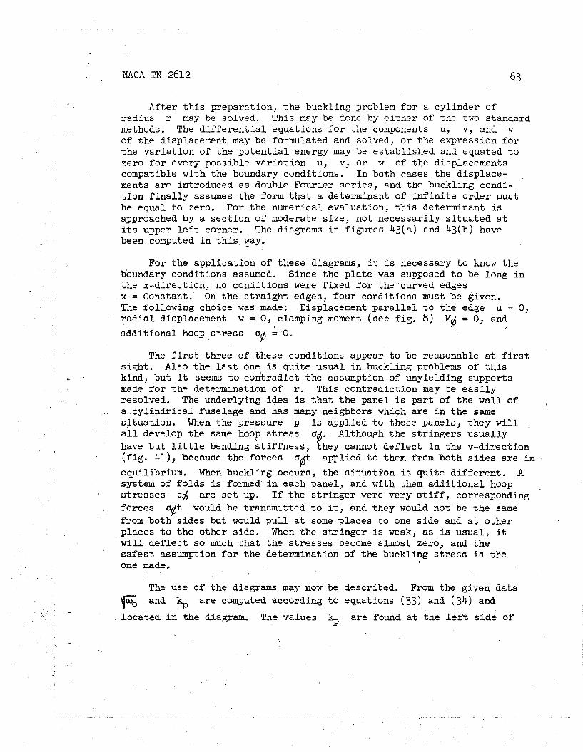
After t h i s preparation, the buckling problem fo r a cylinder of radius r may be solved. This may be done by e i t he r of the two standard methods. The d i f f e r en t i a l equations f o r the components u, v, and w of the displacement may be formulated and solved, o r the expression f o r the var ia t ion of the po ten t ia l energy may be established and equated t o zero f o r every possible var ia t ion u, v, o r w of the displacements compatible with the boundary conditions. I n both cases the displace- ments are introduced as double Fourier se r ies , and the buckling condi- t i o n f i n a l l y assumes the form t h a t a determinant of i n f i n i t e order must be equal t o zero. For the numerical evaluation, t h i s determinant i s approached by a section of moderate size, not necessari ly s i tua ted a t i t s upper l e f t corner. The diagrams i n f igures 43(a) and 43(b) have been computed i n t h i s way. -
For the application of these diagrams, it i s necessary t o know the boundary c ~ n d i t i o n s assumed. Since the p la te was supposed t o be long i n the x-direction, no conditions were f ixed f o r the curved edges x = Constant. On the s t ra igh t edges, four conditions must be given. The following choice was made: Displacement pa r a l l e l t o the edge u = 0, r a d i a l displacement w = 0, clamping moment (see f i g . 8) M# = 0, and addi t ional hoop s t r e s s upj = 0.
The f i r s t three of these conditions appear t o be reasonable a t f i r s t s ight , Also the l a s t one is quite usual i n buckling problems of t h i s kind, but it seems t o contradict the assumption of unyielding supports made f o r the determination of r. This contradiction may be e a s i l y resolved. The underlying idea is t ha t the panel i s par t of the wal l of a cyl indr ical fuselage and has many neighbors which are i n the same s i tuat ion. When the pressure p is applied t o these panels, they w i l l a l l develop the same hoop s t r e s s 06. Although the s t r ingers usual ly have but l i t t l e bending s t i f fne s s , they cannot def lect i n the v-direction ( f ig . 41), because the forces 8 t applied t o them from both s ides a re i n 6 equilibrium. When buckling occurs, the s i tua t ion is qui te d i f fe ren t . A system of folds is formed i n each panel, and with them addi t ional hoop s t resses u are s e t up. I f t he s t r inger were very s t i f f , corresponding forces u@t would be transmitted t o it, and they would not be t he same from both s ides but would p u l l a t some places t o one s ide and a t other places t o the other side. When the s t r inger is weak, a s i s usual, it w i l l def lect so much tha t the s t resses become almost zero, and t he s a f e s t assumption f o r the determination of the buckling s t r e s s is the one made. -
The use of t he diagrams may now be described. From the given data Fo and $ are computed according t o equations (33) and (34) and - located i n t he diagram. The values kL, are found a t t he l e f t s ide of
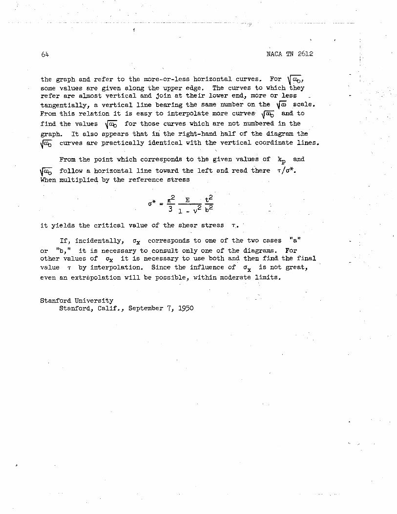
NACA TI? 2612
the graph and r e f e r t o the more-or-less horizontal curves. For 6, some values a re given along t he upper edge. The curves t o which they r e f e r a re almost v e r t i c a l and join a t t h e i r lower end, more o r l e s s -
tangential ly, a v e r t i c a l l i n e bearing the same number on t he \Cijj scale. From t h i s r e l a t i on it is easy t o interpolate more curves fi and t o
f i nd the values 6 f o r those curves which a re not numbered i n the
graph. It a l so appears t h a t i n the right-hand half of the diagram the
fi curves a re p rac t ica l ly iden t ica l with t he v e r t i c a l coordinate l ines.
From the point which corresponds t o the given values of kp and
follow a horizontal l i n e toward the l e f t and read there T/u*. When multiplied by the reference s t r e s s
it y ie lds the c r i t i c a l value of the shear s t r e s s T.
I f , incidentally, ax corresponds t o one of t he two cases "a" o r "b," it is necessary t o consua;t only one of t he diagrams. For other values of ax it i s necessary t o use both and then f i nd the f i n a l value T by interpolation. Since the influence of ax i s not great, even an extrapolat ion w i l l be possible , within moderate limits,
Stanford University Stanford, Calif., September 7, 1950
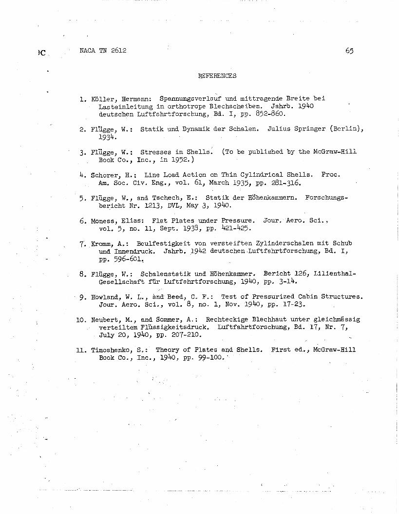
)C , NACA TN 2612
REFERENCES
1. Kdller, Hermann: ~pannungsverlauf und mittragende Brei te b e i Lasteinlei tung i n orthotrope Blechscheiben. Jahrb. 1940 deutschen Luftfahrtforschung, Bd. I, pp. 852-860.
2. Flzgge, W.: S t a t i k und Dynamik der Schalen. Ju l ius Springer ( ~ e r l i n ) , 1934
3. ~l'irgge, W.: Stresses i n Shells. (TO be published by the McGraw-Hill Book Co., Inc., i n 1952. )
4. Schorer, H.: Line Load Action on Thin Cylindrical Shel ls , Proc. Am. Soc. Civ. Eng., vol. 61, March 1935, pp. 281-316.
5 . Fliigge, W., and Tschech, E. : Sta t i k der ~6henkammern. Forschungs- bericht N r . 1213, DVL, May 3, 1940.
6. Moness, Elias: F la t Pla tes under Pressure. Jour. Aero. Sc i , , vole 5 , no. 11, Sept. 1938, pp. 421-425.
7. Kromm, A.: Beulfest igkeit von vers te i f t en Zylinderschalen m i t Schub und Innendruck. Jahrb. $942 deutschen.Luftfahrtforschung, Bd. I, pp. 596-601.
8. Fliigge, W.: Schalenstat ik und Kdhenkamer. Besicht 126, LilienthaP- Gesellschaft fiir Luftf ahrtforschung, 1940, pp, 3-14.
- 9. Howland, W. L., andBeed, C, F.: Test of Pressurized Cabin Structures. Jour. Aero. Sci., vole 8, no. 1, Nov. 1940, pp. 17-23,
10. Neubert, M., and Sommer, A , : Wechteckige Blechhaut unter gleichmzssig vertei l tem FlCssigkeitsdruck, Wtfahr t f s r schung , Bd. 17, N r . 7, July 20, 1940, pp. 207-210.
, ..
11. Timoshenko, S.: Theory of Plates and Shells. F i r s t ed,, McGraw-Hill Book Co., Inc., 1940, pp. 99-100, '

NACA TN 2612
J
Figure 1.- Cylindrical shel l .
Figure 2.- Par t cut from a cylindrical she l l subjected t o in te rna l pressure p.

NACA TN 2612
Figure 3,- Part of cross section through a cylindrical shell ~th.stringers,
Figure 4,- Factor k for longitudinal stress in skin of stiffened shell,

NACA TN 2612
Figure 5.- Cross sec t ion through a pressur ized cabin cons is t ing of two c y l i n d r i c a l s h e l l s .
Figure 6.- D e t a i l of f i g u r e 5: Forces a t junction of two cyl inders .

NACA TN 2612
Figure 7.- Longitudinal section through cy l indr ica l s h e l l and reinforcing r ings ,
Figure 8,- Element of cyliradrical shel l , showing in te rna l forces,
\

NACA 'I!N 2612
, Figure 9.- Extensional r i g i d i t y of s h e l l agains t cross sect ion of s t r ingers .
( a ) Closely spaced r ings, heavy s t r ingers .
(b) Rings f a r apar t , l i g h t s t r ingers .
Figure 10.- Typical d i s t r ibu t ion of bending moment Y, and hoop force Nfl i n s h e l l between two r ings .

Figure 11.- Yielding connection between s h e l l and ring,
Figure 12,- Cylindrical shell, having a door opening.

Fig
ure
13
.-
Lo
ng
itu
din
al f
orc
e N,
and
hoop
fo
rce
N$
in a
cro
ss s
ec
tio
n
thro
ug
h a
cy
lin
dri
ca
l sh
ell
hav
ing
a
do
or
open
ing.

NACA TN 2612
Figure 14,- She l l of revolution,
Ma, -.
15.- Axial sect ion through a s h e l l of revolution.
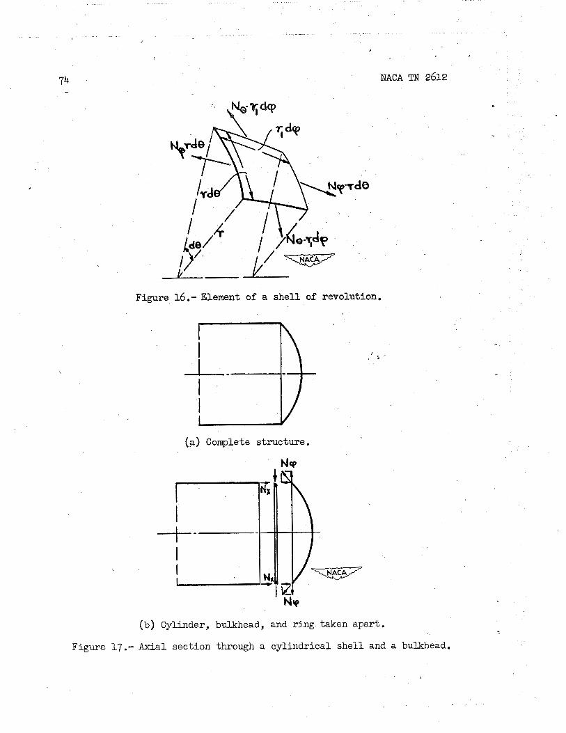
Figure 16.- Element of a she l l of revolution.
(a) Complete structure.
NACA TN 2612
. Nlo
Cylinder, bulkhead, and ring taken apar t ,
Figure 17.- Axial section through a cyl indr ical s h e l l and a bulkhead.

NACA TN 2612
-Figure 18.-,Meridional force NP( and hoop force Ne in two different bulkheads, Upper half, extremely flat shape; lower half, sufficiently dished shape.

NACA TN 2612
Figure 19.- Notation f o r an e l l i p t i c meridian.
Figure 20.- Meridional force N$ and hoop force Ne in twc e l l ipso ida l bulkheads.

NACA TN 2612
(a) Par t s before pressure i s applied,
(b) Exaggerated scheme of d e f o m t i o n . when pressure p i s applied t o cabin a t l e f t of bulkhead,
Figure 21.- Continuous cy l indr ica l s h e l l having-an inserted bulkhead.
Figure 22,- Possible shapes of bulkheads,
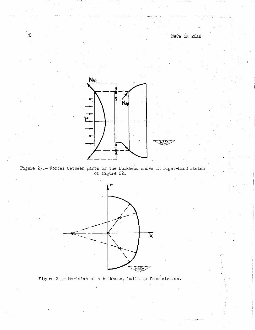
NACA TN 2612
Figure 23.- Forces between p a r t s of t h e bulkhead shown i n right-hand sketch of f i g u r e 22.
Figure 24.- Meridian of a bulkhead, b u i l t up from c i r c l e s .

NACA TN 2612
_Figure 25,- ~ e r i d i a n of a specia l bulkhead designed f o r minimum discrepancy in membrane deformation; d i s t r ibu t ion of in te rna l forces in t h i s s h e l l and in adjoining cylinder,

NACA TN 2612
Figure 26.- Bulkhead f o r double cylinders, consisting of two el l ipsoids ( l e f t ) , and corresponding spheres ( r igh t ) .

NACA TN 2612
Figure 27.- Forces acting on the ring between two spheres shown in figure 26.
Figure 28,- Affine shell elements,

NACA TN $612
Figure 29.- Sign convention f o r forces transmitted from spher ical she l l s t o connecting ring.
Figure 30.- Element of r ing shown i n f igure 29.
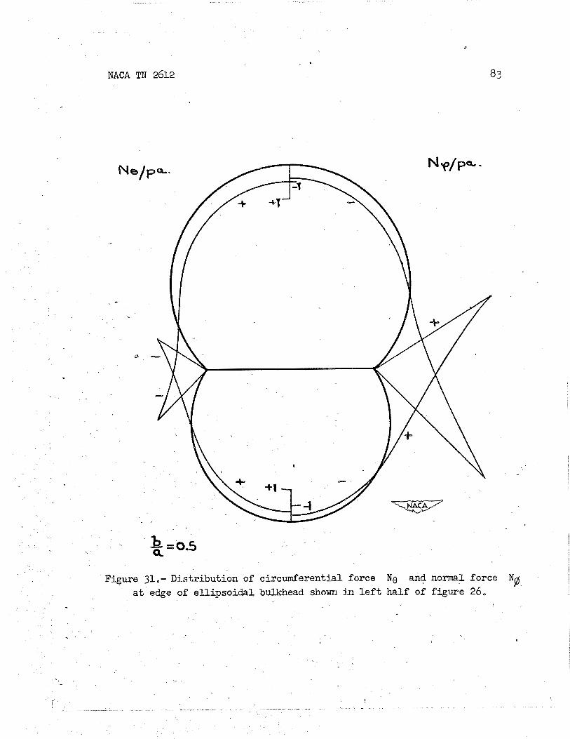
NACA TN 2612
Figure 31,- Distr ibution of ciscutnfesential force Mg and normal force a t edge of e l l ipso ida l bulkhead shown in l e f t haLf of f iguse 26,
Ng

NACA TN 2612 .
Figure 32.- Nose of a pressurized cabin.
(a) Spherical s h e l l ,
(b) E l l ipso ida l she l l .
Figure 33.- Sketches of she l l s .

NACA TI? 2612
. ? -- - -
Figure 34.- P la te s t r i p subjected t o l a t e r a l pressure,
Figure 35.- Side view of an element, of a p la te s t r i p .

NACA TN 2612
i /
Figure 36.- Plate s t r i p undergoing large deflection and s t ra ight s t i f fener .
\
Figure 37.- Same system a s i n figure 36, but subjected t o an addit ional horizontal load.

NACA TN 2612
l-i
a k .r( 0 X bi *- & a ,
6" 5 .I4 M * Mbi
* f-4 a * a, k -I= + -GJ G 0 a, d 0
Q c
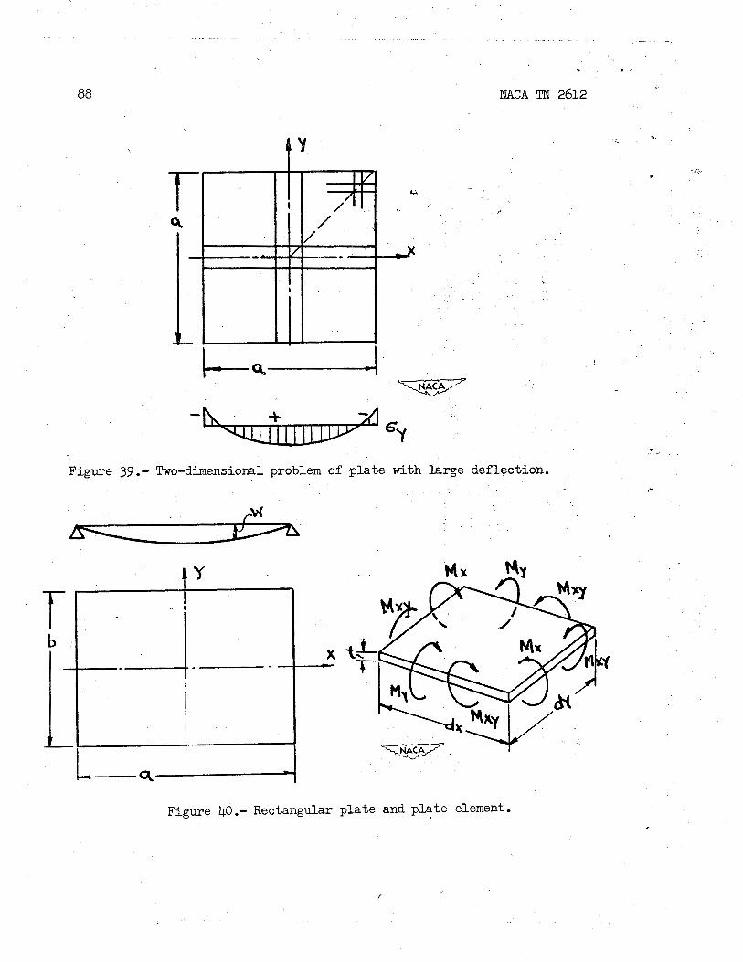
NACA TN 2612
Figure 39.- Two-dimensional problem of p la te with large deflection.
PM
Figme 40.- Rectangular p la te and p l a t e element.

12c NACA TN 2612
Figure 41,- Cylindrical panel,
Figure k2,- Section through cy l indr ica l panel before and a f t e r appl ica t ion of i n t e rna l pressure p,

(a)
a, =
0
.
Fig
ure
43.
- D
iagr
ams
fro
m r
efe
ren
ce
7 f
or
bu
ckli
ng
lo
ad
of
cy
lin
dri
ca
l p
an
el
show
n in
fig
ure
41.

NACA TN 2612
NACA - Langley Field, va. .
Related Documents