1 Technical Specifications for In-Vacuum Undulator System IU22 (3.0 meters) August 18, 2011 National Synchrotron Radiation Research Center 101 Hsin-Ann Road, Hsinchu Science Park, Hsinchu 30076, Taiwan (R.O.C.)

Welcome message from author
This document is posted to help you gain knowledge. Please leave a comment to let me know what you think about it! Share it to your friends and learn new things together.
Transcript

1
Technical Specifications
for
In-Vacuum Undulator System IU22
(3.0 meters)
August 18, 2011
National Synchrotron Radiation Research Center
101 Hsin-Ann Road, Hsinchu Science Park,
Hsinchu 30076, Taiwan (R.O.C.)

2
Contents 1 Introduction ....................................................................................................................... 5
1.1 Purpose ........................................................................................................... 5
1.2 Background ..................................................................................................... 5
1.3 Utility system available in NSRRC .................................................................. 6
1.3.1 Water cooling ................................................................................................... 6
1.3.2 Electricity supply .............................................................................................. 6
1.4 Scope of Work for the Complete In-vacuum Undulator ................................... 6
1.4.1 Design of IU22 ................................................................................................. 6
1.4.2 Production, Test, and Delivery ......................................................................... 7
1.5 Scope of Supply for the Complete In-vacuum Undulator ................................ 7
1.6 Elements outside the scope of supply ............................................................. 8
2 GENERAL ISSUES ........................................................................................................... 9
2.1 Tendering ......................................................................................................... 9
2.1.1 Adjudication of Bid ........................................................................................... 9
2.1.2 Documentation Required with the Tender ....................................................... 9
2.2 Timescales ...................................................................................................... 11
2.2.1 Start of contract .............................................................................................. 11
2.2.2 Conceptual Design Review(CDR) .................................................................. 11
2.2.3 Detailed Design Review(DDR) ....................................................................... 11
2.2.4 Pre-acceptance Test ...................................................................................... 12
2.2.5 Acceptance Test ............................................................................................ 12
2.3 Location of Delivery ....................................................................................... 12
2.4 Warranty Period ............................................................................................. 12
2.5 Contact Management .................................................................................... 13
2.5.1 Contact Engineer ........................................................................................... 13
2.5.2 Production Schedule ..................................................................................... 13
2.5.3 Progress Reports ........................................................................................... 13
2.6 Vendor’s responsibilities ................................................................................ 14
2.6.1 Technical Responsibilities .............................................................................. 14
2.6.2 Design Choices and NSRRC Approval ......................................................... 14
2.6.3 Deviation from Technical Specification .......................................................... 14
2.7 Inspections .................................................................................................... 14
2.8 Subcontracting ............................................................................................... 15
2.9 Others ............................................................................................................ 15
3 SPECIFICATIONS .......................................................................................................... 16
3.1 Definitions ...................................................................................................... 16
3.2 Magnetic Field Measurement System requirement ....................................... 17

3
3.3 Magnetic Performance .................................................................................. 20
3.3.1 Quality Assurance of Magnetic Materials ...................................................... 20
3.3.2 IU22 Magnetic Circuit Structures ................................................................... 22
3.3.3 Field Homogeneity Requirements ................................................................. 23
3.3.4 Field Errors .................................................................................................... 23
3.3.5 Field Error correction ..................................................................................... 26
3.3.6 Spectral intensity Requirements .................................................................... 27
3.4 Mechanical Engineering Construction ........................................................... 28
3.4.1 Engineering Estimation .................................................................................. 28
3.4.2 Main Structure ............................................................................................... 29
3.4.3 Gap driven System ........................................................................................ 29
3.4.4 Positioning and Leveling System .................................................................. 31
3.4.5 Fiducials......................................................................................................... 32
3.4.6 Wiring and junction boxes ............................................................................. 33
3.4.7 Cooling piping and coupler ............................................................................ 35
3.5 In-vacuum Beam and Link Rods ................................................................... 35
3.6 Mechanical precision inspection .................................................................... 37
3.6.1 Crossed Beam parallelism precision inspection ............................................ 37
3.6.2 In-vacuum Beam precision inspection ........................................................... 37
3.6.3 Link rods supporter precision ........................................................................ 37
3.6.4 Gap Movement inspection ............................................................................. 38
3.7 Vacuum System ............................................................................................. 39
3.7.1 Vacuum components ..................................................................................... 39
3.7.2 Vacuum Chambers ........................................................................................ 40
3.7.3 Photon absorbers .......................................................................................... 41
3.7.4 Final vacuum pressure inspection ................................................................. 42
3.8 Thermal sensors ............................................................................................ 43
3.9 Impedance and Wake-field reduction devices ............................................... 44
3.10 Encoders(Movement Monitoring) .................................................................. 45
3.11 Interlock and Protection System .................................................................... 46
3.12 Other Requirements and Constraints ............................................................ 47
3.13 Bake-out facility ............................................................................................. 48
3.14 Safety and Radiation ..................................................................................... 49
4 DESIGN REVIEW REPORT ........................................................................................... 52
4.1 General Requirements on CDR and DDR ..................................................... 52
4.2 Contents of the CDR ..................................................................................... 53
4.3 Contents of the DDR ..................................................................................... 55
5 Quality assurance and testing ........................................................................................ 57

4
5.1 Quality assurance program ........................................................................... 57
5.2 General agreements for Pre-acceptance tests.............................................. 57
5.3 Magnetic Field Measurement for the Pre-acceptance Test ........................... 57
5.4 Mechanical Measurements for Pre-acceptance Test .................................... 59
5.5 Ultimate Vacuum pressure for Pre-acceptance Test ..................................... 60
5.6 Measurement Data Analysis and Reports ..................................................... 60
5.7 Acceptance Test ............................................................................................ 61
5.8 Test of Control Interfaces ............................................................................... 63
5.9 DELIVERY ..................................................................................................... 63
5.10 Shipment to NSRRC ...................................................................................... 63
5.10.1 Concern on Transportation ............................................................................ 65
5.11 Requirements on the Operating and Maintenance Manuals ......................... 66
5.12 Spare Components and Guarantee .............................................................. 66
6 Control System provided by NSRRC .............................................................................. 68
6.1 General .......................................................................................................... 68
6.2 Hardware architecture ................................................................................... 69
6.3 Rack Specification and cables ...................................................................... 71
6.4 Software Architecture .................................................................................... 71

1
Th
ring
20 K
on th
erro
Ta
here
elec
the
devi
with
con
tape
IU22
NSR
Fi
Introd
1.1 Pur
he Taiwan Ph
to produce h
KeV by using
he magnet a
r at all gaps.
1.2 Bac
aiwan Photo
ein) is under
ctron beam e
hard X-ray u
ices. To enh
one (1) in-v
tract, are fo
er Undulator
2 shall be a q
RRC’s contro
igure 1.1 The
ductio
rpose
hoton Source
high brillianc
g the 3rd to th
assemblies a
.
ckgroun
on Source of
r constructio
energy of 3.0
users. There
ance the flux
vacuum undu
or designing,
of magnetic
quasi turn-ke
ol system.
e layout of IU
n
e (TPS) requ
ce hard x-ray
he 9th harmon
nd on the gir
nd
f the Nationa
n at Hsinchu
0 GeV with 5
e are 24 stra
x and brillian
ulator (IU). T
production,
c period 22 m
ey system, a
U22 in the TP
5
uires an in-va
ys. The energ
nics of ID spe
rder deforma
al Synchrotr
u Science P
500 mA beam
aight section
nce of the ha
hese techni
and testing
mm, hereina
and then the
PS storage ri
acuum undul
gy range of h
ectrum. Very
ations to assu
ron Radiation
Park, Hsinchu
m current is b
ns in the TP
ard X-ray, N
ical specific
g of the In-va
fter referred
undulator wo
ing
ator to be us
hard x-rays i
y tight toleran
ure a small R
n Research
u city, Taiwa
being prepar
PS storage ri
SRRC plans
cations, as p
acuum Undu
to as IU22,
ould be easi
sed in the sto
is between 5
nces are req
RMS phase a
Center (NS
an. The TPS
red in deman
ings for inse
s to equip he
part of purch
ulator/ In-vac
with IU in s
ly integrated
orage
5 and
uired
angle
RRC
with
nd of
ertion
erself
hase
cuum
short.
d with
6
1.3 Utility system available in NSRRC
The vendor must manufacture an IU22 which can be compatible with NSRRC utility system
and operated in NSRRC. The utility system is available in NSRRC are shown in following
sections.
1.3.1 Water cooling
Water resistivity: Higher than 10MΩ
Inlet temperature: 25 ± 0.1
Maximum temperature variation: 25 ± 0.5
Inlet pressure: 7.0 kgf/cm2
Maximum outlet pressure: 8.0 kgf/cm2
1.3.2 Electricity supply
The AC electricity supplied available in NSRRC
Line voltage: 380 VAC-3P and 220 VAC-1P and 208 VAC-3P and 120 VAC-1P
Frequency: 60 Hz
Voltage harmonic distortion: 5%( for IEEE/std 519-1992)
Phase imbalance: 5%( for IEEE/std 519-1992)
Conductor distribution 3Phase+ neutral
Short circuit capacity: When 80A circuit breaker for 220V is applied, the short
circuit breaking capacity needs 10kA or more.
1.4 Scope of Work for the Complete In-vacuum
Undulator
1.4.1 Design of IU22
The design works from vendor are listed below and works have to satisfy the required
technical specifications in this content.
1) Hybrid type magnetic circuit design on IU22.
2) Design of a mechanical support structure acting as a carriage for the magnetic
assembly, vacuum system, and mechanical chain.
3) Design a mechanical gap driven system.
4) Design of interlock system.

7
5) Design of gap monitoring system.
6) Design of an ultra-high vacuum (UHV) system for IU22.
7) Design of water cooled flexible transition taper and its cooling system.
8) Design of a water heating/cooling channel for magnet arrays, out-of-vacuum
beam.
9) Design bake-out and in-vacuum beam temperature stabilized system.
10) Design of survey and alignment system for support structure.
1.4.2 Production, Test, and Delivery
1) Procurement and manufacture of all parts required for a successful
completion of IU22.
2) Production documentation, manufacturing drawings, assembly drawings and
procedures for construction, assembly, and commission of the complete three
IUs.
3) Production of the whole IU.
4) Pre-acceptance test report.
5) Acceptance test report.
6) Delivery of the IU to NSRRC site.
7) Quality assurance documentation for all parts and processes.
8) NSRRC staff training and English manuals for operation and maintenance.
1.5 Scope of Supply for the Complete In-vacuum
Undulator
To complete this project, vendor has to deliver the following items to NSRRC.
1) IU manufactured, assembled, tested, delivered, and tested at NSRRC.
2) Complete set of 3D and 2D manufacturing and assembly drawings in the form
of 3 paper copies and one electronic copy which will be provided on a DVD.
3) Quality assurance documentation for all parts and processes.
4) Inspection certificates of mechanical frame, vacuum chambers, vacuum
components.
5) Pre-acceptance test and Acceptance test reports.

8
6) Tools for magnet module change, transition taper assembly, all kinds of jigs
related to maintenance are provided by vendor.
1.6 Elements outside the scope of supply
The vendor shall provide their own dry Nitrogen purge cart, vacuum roughing cart, Helium
leak detector, hot/cool water circulation system, and related instrumentations (such as portable
controller for NEG pump or portable controller for bake-out etc.) for the purpose of performing
the Pre-acceptance test and Acceptance test.

9
2 GENERAL ISSUES
This chapter describes tendering, responsibility of the vendor and important milestones and
time schedule of completion of an in-vacuum undulator. NSRRC shall approve in writing that
the vendor has met the requirements of each review and acceptance test. If the requirements
are satisfied then the vendor may begin the next phase.
2.1 Tendering
2.1.1 Adjudication of Bid
NSRRC shall adjudicate bids according to the administrative clauses.
2.1.2 Documentation Required with the Tender
The bidder shall provide sufficient tendering documentation as described in 1) to 4) to allow
an evaluation of the bids.
1) Technical Design Solutions
The technical design solutions required to complete the IU to this set of
specifications in the form of a preliminary conceptual design which includes (but
is not limited to):
a. Design of magnetic undulator system.
b. Design of the mechanical frame and linear guides to support the
undulator beams, vacuum vessel, and mechanical chain under
magnetic load for in-vacuum undualtor.
c. Design of mechanical chain, gear boxes, spindles, motors
(torque/velocity curves, resistance, and inductance), and encoders for
in-vacuum undualtor.
d. Design of link rods.
e. Design of vacuum system (pumps, gauges, temperature sensors, and
their distribution), main vacuum vessel chamber, flexible transition
chamber, and fixed transition chamber.
f. Design of flexible transition taper.
g. Design of upstream and downstream photon absorbers.

10
h. Design of bake-out system including the design of water heating/cooling
channel for the magnet arrays and flexible transition taper and linear
guilders for bellow shaft supporters.
i. Design of interlock and protection system.
j. Design of measurement system before and after the vacuum
chamber assembled.
2) Work packages
The bidder shall include a list of work packages from the IU that will be
subcontracted and names of the subcontractors.
3) Specification of facilities
The bidder shall include a list (specifications) of their own relevant facilities and
equipment which are used to manufacture, assemble, and perform the
measurement and acceptance tests for IU. The facilities may include (but are not
limited to) the clean room, Hall probe bench, long coil bench and bake-out
system.
4) Critical procedures
The bidder shall include a general description of the critical procedures used in
constructing the IU including:
a. Welding plan.
b. Procedures for cleaning, conditioning, and testing the vacuum vessel
and vacuum subassemblies.
c. Procedures for manufacturing the frame.
d. Procedures for manufacturing of the vacuum system.
e. Procedures for alignment of the in-vacuum beams before magnetic
field correction and assembly of vacuum vessels.
f. Magnetic field measurement systems before and after vacuum
chamber assembly.
5) Evidence of experiences on in-vacuum undualtors
The bidder shall provide the evidence to proof his/her company has
successful experiences to install in-vacuum undualtors into electron
accelerators (storage ring) with ultra-high vacuum pressure environments

11
(P<3x10⁻⁸ Pascal). NSRRC demands vendors to provide concrete evidence
and track records to prove that they have constructed and completed at least
two in-vacuum undulators in the preceding five years. The undulators must
be successfully installed and operated in the storage ring of an electron
accelerator that provides synchrotron radiation for beamlines and
experimental stations.
2.2 Timescales
Following the award contract, the design stage shall not exceed 255 calendar days. The main
project milestones are shown in Table 2.1. All design meeting and production time must take
place within this time schedule.
Table 2.1 Main project milestone
Milestone Days after start of contract
CDR meeting +120
DDR meeting +255
Mechanical performance test +730
Pre-acceptance test +765
IU Delivered in NSRRC +810
Acceptance Tests by NSRRC +840
2.2.1 Start of contract
When the contract is signed from both side (vendor and NSRRC) , the contract starts. All
main milestones must take place within the time schedule.
2.2.2 Conceptual Design Review(CDR)
A conceptual design review shall take place not later than 120 days after signing of the
contract. The vendor shall meet with designated reviewers at NSRRC to present the content
specified in the chapter 4 and other requirements in the specification.
2.2.3 Detailed Design Review(DDR)
No later than 135 days after the conceptual design review, the vendor shall present a) the

12
final engineering drawings, b) detailed construction and testing plan, c) production schedule
etc. to the review teams. The other relevant requirements on design reviews will be given in
chapter 4. All additional works may proceed after written acceptance of the final design. Any
minor changes after DDR meeting shall be negotiated and accepted by mutual agreements.
2.2.4 Pre-acceptance Test
The general requirements of the pre-acceptance test are stated in the chapter 5. The vendor
shall perform the pre-acceptance test with the witness of NSRRC representatives at vendor
site. The vendor shall propose to NSRRC, in detail, the pre-acceptance tests reports and
procedures to demonstrate that the IU meets the technical specification. The tests shall be
agreed upon with NSRRC in writing. Within 7 days following the conclusion of the
pre-acceptance test the vendor shall issue to NSRRC the detailed results of the
pre-acceptance test in the form of a report. After IU22 passes the pre-acceptance test and
authentication by NSRRC representatives, IU22 can be delivered to NSRRC.
2.2.5 Acceptance Test
The acceptance test shall be completed in 840 days after start of contract. The vendor is
responsible for conducting the acceptance test with NSRRC staffs and insuring the results
meet required specifications. The general requirements of the acceptance test are stated in
chapter 5. The vendor shall propose to NSRRC, in detail, the acceptance tests and procedures
to demonstrate the IU meet the technical specification, the test items and methods shall be
agreed upon with NSRRC in writing. Within 7 days following the conclusion of the
acceptance test the vendor shall issue to NSRRC the detailed results of the acceptance test
in the form of a report.
2.3 Location of Delivery
101 Hsin-Ann Road, Hsinchu Science Park, Hsinchu 30076, Taiwan ( R.O.C.)
National Synchrotron Radiation Research Center
2.4 Warranty Period
The warranty period is two years after passing the final acceptance test at NSRRC. This

13
warranty only applies if the undulator has been installed and used in accordance with the
vendor’s recommendations (as noted in the operating instructions) under normal use and
reasonable care (in the opinion of the vendor). Subject to the conditions of this warranty the
vendor will perform necessary service on the IU-T without charge for parts or labor if, in the
opinion of the vendor, the undulator is found to be faulty within the warranty period.
2.5 Contact Management
2.5.1 Contact Engineer
At the start of the contract the vendor shall assign an engineer (the Contract Engineer) who will
responsible for all reporting to and contact with NSRRC.
2.5.2 Production Schedule
Within 30 days of start of the contract the vendor shall issue a detailed production
schedule. The schedule includes
Start and finish dates of the work.
Completion of detailed design.
Material and purchased procurement items.
Completed fabrication.
Testing of major components.
Recommended site visits by NSRRC representatives.
Shipment and delivery to NSRRC
Finishing of contract.
2.5.3 Progress Reports
After the production schedule is fixed the vendor shall issue a monthly progress report to
NSRRC describing a minimum a list of activities and milestone achieved since previous report
and delays, technical issues may affect the performance or schedules. Deviations from this
specification must contain in the progress report and inform NSRRC.

14
2.6 Vendor’s responsibilities
2.6.1 Technical Responsibilities
The vendor is completely responsible for the design study, design, production, detailed
manufacturing drawings, assembly drawings, assembly procedures, procurement of parts,
manufacturing of parts, assembly, assembly tools, testing tools, quality control, testing and
quality assurance. All these works have to meet this technical specification.
2.6.2 Design Choices and NSRRC Approval
The vendor has full reasonability on final design, IU production and IU performance of all
the items supplied. NSRRC approval of the design or selection of components does not
release the vendor from their responsibilities in this respect.
2.6.3 Deviation from Technical Specification
If, after the order is placed, the vendor discovers that the specification has been
misinterpreted, this will not be accepted as an excuse. Consequently, NSRRC will insist that
the manufacturer delivers the IU with any and all deviations corrected to conform with this
specification at no extra cost to NSRRC.
If the vendor proposes any deviations from this specification then they shall be submitted
to NSRRC in writing; modifications or changes shall only accept from NSRRC with written
approval. If NSRRC proposes a deviation from the specification then it will be sent to the
vendor through the NSRRC purchase office. In either case the vendor shall provide a reply in
writing with an evaluation of the technical merit, impact on cost, and impact on delivery of the
IU.
2.7 Inspections
NSRRC shall be granted access to the premises of the vendor, and also to the premises
of any subcontractor, for the purpose of progress meetings and inspection visits. NSRRC
intends to carry out periodic and /or spot contract inspections at vendor’s premises and where
deemed necessary that of its subcontractors. The possible time schedule shows bellow.
1. After Mechanical Frames have been manufactured and ready for Inspection.

15
2. During or after magnetic field correction.
3. During or after the vacuum chamber and vacuum components assembly.
4. Bake-out for IU22.
5. Pre-acceptance test.
Contract inspections will be concerned with all contract compliance issues including
program ,Quality and Performance. Access and visits to the site of a subcontractor shall be
made in the presence of a technical representative from the vendor with ten (10) days notice
provided by NSRRC.
2.8 Subcontracting
If the vendor subcontracts any work package of the IU to a subcontractor then the vendor
remains responsibilities for quality control and production of said work package and it’s
adherence to the clauses of this specification.
2.9 Others
IU22 production based on the specifications and attached reference diagram in this
specification. If there are any questions and vendor should consult the representatives of
NSRRC.

3
The
sect
SPEC
3.1 Def
re are some
tion. The def
1)
2)
3)
CIFICA
finitions
phrases use
finition is app
The magne
electron be
axis (X =
coordinate
position of t
for the elec
vertical dir
support str
pitch is def
about the Y
mechanica
Figure
The magne
and Z=0.
The phrase
±20 mm an
spaced 2 m
range of ±2
ATIONS
s
ed in this spe
plied to in-vac
etic centerlin
eam path thr
0, Y = 0) is
system is rig
the straight s
ctron beam.
ection, resp
ucture comp
fined as rota
Y axis. The c
l design and
3.1 Undulato
etic center of
e of “horizon
nd magnetic
mm horizonta
20 mm.
16
S
ecification an
cuum undula
ne of the und
rough the N
s defined to
ght-handed.
section and t
The X and
pectively. W
ponents, roll
ation about th
coordinate sy
magnetic m
or Coordinat
f the undulato
ntal good fi
c measureme
al steps from
nd these phra
ator.
dulator has
SRRC straig
o coincide th
The origin of
the +Z direct
Y axis is p
ith respect
is defined a
he X axis, an
ystem (see F
easurement
te System.
or is suppose
eld region”
ents in this r
m the magne
ases are defi
to coincide w
ght section.
he electron
f Z axis (Z=0
tion points to
parallel to th
to the supp
as rotation a
nd yaw is de
Fig. 3.1) mus
.
ed to be loca
means a ho
region are ta
etic centerline
ined in this
with the nom
Therefore, t
beam axis.
0) is in the m
o the downstr
he horizontal
port structur
about the Z
efined as rot
st be used in
ated at X=0,
orizontal rang
aken at regu
e over horiz
minal
the Z
The
iddle
ream
and
re or
axis,
ation
n the
Y=0,
ge of
ularly
ontal

17
4) The phrase of “through the entire undulator” as specified in this
specification shall be defined as the measurement range of the magnetic
field in the longitudinal (Z) direction begin before the undulator fringe field
and terminate after the undulator fringe field.
5) The phrase of “at all magnetic gaps” as specified in these specifications
shall be defined as the measurement range from minimum to maximum gaps,
the required gap value is 5, 6, 7, 8, 9, 10, 12,
14,16,18,20,22,24,26,28,30,40,45,50mm.
6) The phrases “gap opening sequences” means the opening of the undulator
gap from 5 mm gap to 50 mm gap. The phrase “gap closing sequences”
means the closing of the undulator gap from 50 mm to 5 mm. The phrase
“ both undulator gap tuning sequences” means that the measurement
shall be performed from gap 5 mm to 50 mm gap with outbound gap opening
sequence and from undulator gap 50 mm to 5 mm gap with inbound gap
closing sequence.
3.2 Magnetic field measurement system
requirement
After magnetic field correction, the vendor shall perform a set of final magnetic field
measurements to characterize the field quality of the undulator system by following field
measurement systems.
1) The vendor shall carry out each set of scans or family of magnetic
measurements in a 25±0.1°C environment.
2) For final status of magnetic performance tests at pre-acceptance test,
vendor shall measure the magnetic field performance by using the
in-situ measurement system which is the hall probe and stretch wire
measurements taken inside the vacuum chamber. In order to check the
final status of magnetic performance, the vacuum chamber shall not be
reassembled after the in-situ measurement.
3) The vendor shall provide the following information and meeting below the
requirements about her Hall-probe system:

18
a. Accuracy and reproducibility of full measurement field range. The
reproducibility of the first field integral shall be better than 5 G·cm.
b. The Hall probe shall scan range within ±3500 mm in longitudinal direction,
±20 mm in traverse direction, and ±2 mm in vertical direction. The original
point shall coincide with magnetic center in the in-vacuum undulator.
c. The positioning accuracy and reproducibility of Hall-probe. For the field
scan the position of the Hall probes shall have an uncertainty within ∆y =
±0.001 mm, ∆x = ±0.001 mm, and ∆z = ±0.001 mm.
d. The offset between mechanical center of undulator magnetic structure
(array) and Hall probe sensing area center with an accuracy within ±0.05
mm.
e. The statistic and data processing.
4) The vendor shall provide the following information and meeting the below
requirements about her Long-loop (or Long-coil) measurement systems:
a. The vendor’s magnetic measurement equipment shall include a flipping coil
bench or a stretched wire bench.
b. The minimum length of the wire or coil shall be 4 meters.
c. The motorized stages shall be positioned with a sensitivity below 0.002 mm
in the range of x = ± 30.0 mm and y = ±2 mm vertically.
d. Over the 500 Gauss-cm range, a reproducibility of minimum 2 Gauss-cm, a
resolution of minimum 1 Gauss-cm, and an accuracy of minimum 10
Gauss-cm.
--end of page--

19
Major specifications of In-vacuum undulator IU22 are shown in table 3.1. The numbers or
values show in the table 3.1 is for one set of IU22.
Table 3.1 Main parameters of IU22
Items Requirements
Number of IU22 One (1) in-vacuum
undulator
Dimension of the Machine
Weight ≦12 metric tons
Length (Flange to Flange) steering magnet not included ≦ 3600 mm
Width ≦ 1500 mm
--Transverse width (side of the aisle) 1000 mm
--Transverse width (side of the wall) ≦500 mm
Height ≦ 2650 mm
From center field (mid-plane of the magnetic structures ) to
Concrete Slab
1350 mm
Magnetic circuit
Iron Pole Width ≧ 42
Periodic length 22 mm
No. of Period ≧ 140
Number of full size poles ≧ 280
Magnetic length of the device 3.08m
Gap range 5 ~ 50 mm
-- minimum gap 5 mm
Peak field at 5 mm Gap >1.05 T
Effective filed at 5mm Gap >1.01 T
Magnet (Pole) material NdFeB (Permendur)
--TiN coating 5.5 ± 1μm
Magnetic Field homogeneity
Good field region ∆B/B smaller than 1x10⁻³ @ x_ axis >±13.0 mm
Good field region ∆B/B smaller than 7x10⁻³ @ x_ axis >±15.0 mm
Maximum RMS Phase error at all gap (5~43mm) < 3.0°
Limits for the vertical and horizontal integrals on-axis in the full gap
--First integral with steering corrector ≦ 30 Gauss-cm
--First integral without steering corrector ≦ 100 Gauss-cm
--Second integral with steering corrector ≦ 2000 Gauss-cm2
--Second integral without steering corrector ≦ 35000 Gauss-cm2
Multipole
20
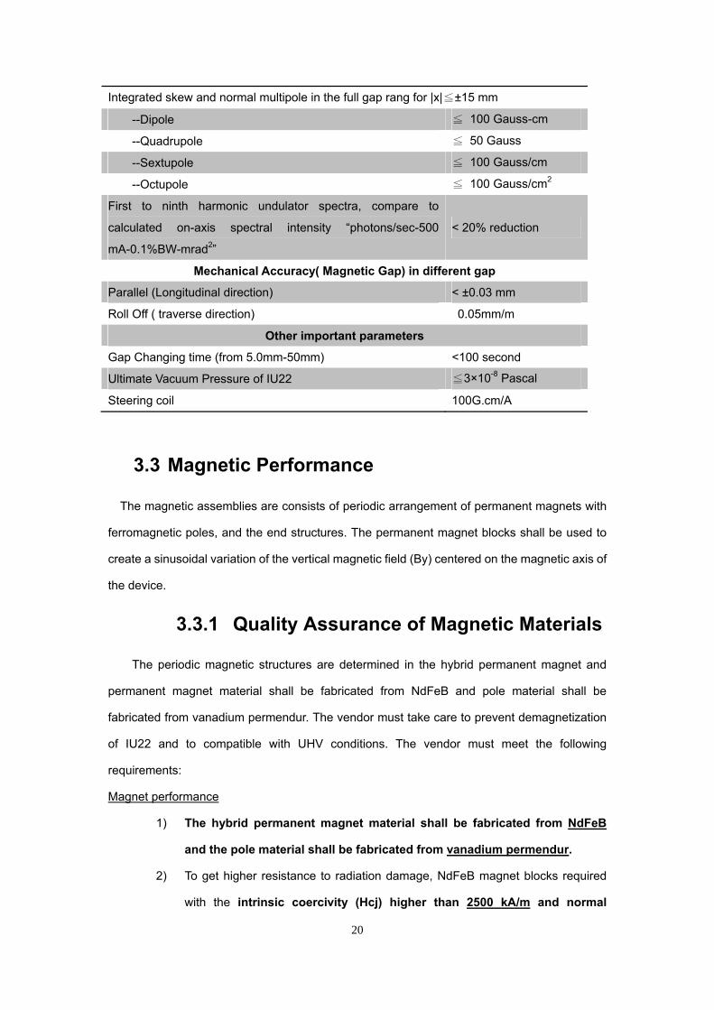
Integrated skew and normal multipole in the full gap rang for |x|≦±15 mm
--Dipole ≦ 100 Gauss-cm
--Quadrupole ≦ 50 Gauss
--Sextupole ≦ 100 Gauss/cm
--Octupole ≦ 100 Gauss/cm2
First to ninth harmonic undulator spectra, compare to
calculated on-axis spectral intensity “photons/sec-500
mA-0.1%BW-mrad2”
< 20% reduction
Mechanical Accuracy( Magnetic Gap) in different gap
Parallel (Longitudinal direction) < ±0.03 mm
Roll Off ( traverse direction) 0.05mm/m
Other important parameters
Gap Changing time (from 5.0mm-50mm) <100 second
Ultimate Vacuum Pressure of IU22 ≦3×10⁻⁸ Pascal
Steering coil 100G.cm/A
3.3 Magnetic Performance
The magnetic assemblies are consists of periodic arrangement of permanent magnets with
ferromagnetic poles, and the end structures. The permanent magnet blocks shall be used to
create a sinusoidal variation of the vertical magnetic field (By) centered on the magnetic axis of
the device.
3.3.1 Quality Assurance of Magnetic Materials
The periodic magnetic structures are determined in the hybrid permanent magnet and
permanent magnet material shall be fabricated from NdFeB and pole material shall be
fabricated from vanadium permendur. The vendor must take care to prevent demagnetization
of IU22 and to compatible with UHV conditions. The vendor must meet the following
requirements:
Magnet performance
1) The hybrid permanent magnet material shall be fabricated from NdFeB
and the pole material shall be fabricated from vanadium permendur.
2) To get higher resistance to radiation damage, NdFeB magnet blocks required
with the intrinsic coercivity (Hcj) higher than 2500 kA/m and normal

21
corecivity (Hcb) higher than 980 kA/m at room temperature.
3) Residual flux density (Br) of magnet should be higher than 1.20 T.
4) Maximum magnetic energy product (BH)max should be higher than 280 kJ/m3.
5) The total magnetic dipole moment of each block shall be within ±1% of
average value obtained for all the blocks at room temperature (25) after
thermal stability.
6) The direction of magnetization (easy axis) must be parallel their respective
nominal easy axis for all blocks, within 1°.
Aging process
7) All the magnet circuit modules need to conduct in in-vacuum aging process at
temperature of 145 Magnetic material has to be in its linear region of the
demagnetization curve and will not exceed allowed amount of irreversible
losses to a maximum temperature of 145.
8) The irreversible reduction rate of the permanent magnet block with permeance
coefficient 1 (145, 2 hours) is less than 0.1%, the undulator magnetic circuit
can achieve the following function.
1. Gap = 5 mm, magnetic field peak intensity B > 1.05 Tesla, effective
magnetic field intensity B>1.01 Tesla at room temperature (25)
2. Thermal process at 145 (Gap 50mm, 24 hours), the irreversible reduction
rate(∆B/B) : First time < 1% and Repeat < 0.02%.
Magnet size precision
9) The vendor shall measure the length, width and height of each magnet block
and pole with a precision of Hx Wx L ( ±0.03 x 0.00 0.05 x
-0.05 -0.10 mm) and record
them into the database against their identifier.
TiN Coating
10) The vendor must adopt adequate surface treatment to reduce out-gassing rate
and anti-radiation damage; the magnet should have TiN ion-plating coating. In
contrast, the treatment process shall not affect the magnetic field of magnet
structures. The thickness of coating is 5.5±1μm .
UHV compatibility Tests on magnet
11) To verify that the functions of this processing purposes will be available, an
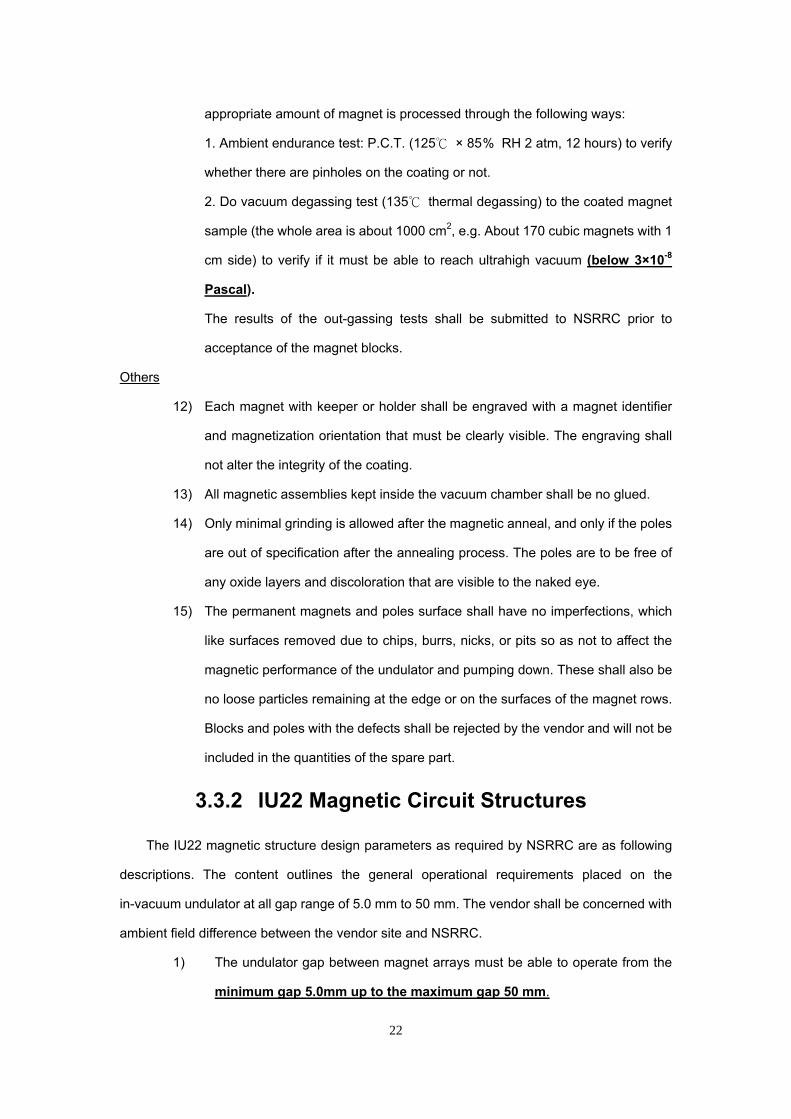
22
appropriate amount of magnet is processed through the following ways:
1. Ambient endurance test: P.C.T. (125 × 85% RH 2 atm, 12 hours) to verify
whether there are pinholes on the coating or not.
2. Do vacuum degassing test (135 thermal degassing) to the coated magnet
sample (the whole area is about 1000 cm2, e.g. About 170 cubic magnets with 1
cm side) to verify if it must be able to reach ultrahigh vacuum (below 3×10⁻⁸
Pascal).
The results of the out-gassing tests shall be submitted to NSRRC prior to
acceptance of the magnet blocks.
Others
12) Each magnet with keeper or holder shall be engraved with a magnet identifier
and magnetization orientation that must be clearly visible. The engraving shall
not alter the integrity of the coating.
13) All magnetic assemblies kept inside the vacuum chamber shall be no glued.
14) Only minimal grinding is allowed after the magnetic anneal, and only if the poles
are out of specification after the annealing process. The poles are to be free of
any oxide layers and discoloration that are visible to the naked eye.
15) The permanent magnets and poles surface shall have no imperfections, which
like surfaces removed due to chips, burrs, nicks, or pits so as not to affect the
magnetic performance of the undulator and pumping down. These shall also be
no loose particles remaining at the edge or on the surfaces of the magnet rows.
Blocks and poles with the defects shall be rejected by the vendor and will not be
included in the quantities of the spare part.
3.3.2 IU22 Magnetic Circuit Structures
The IU22 magnetic structure design parameters as required by NSRRC are as following
descriptions. The content outlines the general operational requirements placed on the
in-vacuum undulator at all gap range of 5.0 mm to 50 mm. The vendor shall be concerned with
ambient field difference between the vendor site and NSRRC.
1) The undulator gap between magnet arrays must be able to operate from the
minimum gap 5.0mm up to the maximum gap 50 mm.

23
2) The magnetic period length is 22 mm. The tolerance of the period length
shall be within 0.1%.
3) Hybrid magnet geometries will be designed and optimized by vendor base on
the field homogeneity and field errors requirements. The width of the iron
pole shall be greater than 42 mm.
4) The full magnetic peak field (vertical magnetic field) strength shall
greater than 1.05 Tesla/ effective magnetic field strength should greater
than 1.01 T at the minimum gap 5 mm.
5) The total number of poles with full magnetic field strength at 5 mm gap
would be 280 or more. The total number of pole has to be even number.
6) Vendor must design the first and final magnet end sections in the array to
have special arrangement, so the electron trajectory coincides with magnetic
axis.
7) Approval of the final design for the magnetic structure, including the
permanent-magnet with ferromagnetic pole materials, will be reported at the
Conceptual Design Review meeting.
3.3.3 Field Homogeneity Requirements
The transverse vertical magnetic field roll-off at a gap of 5 mm and at the centers of the
gap-independent full field strength poles, averaged over all gap-independent full field strength
poles, shall not exceed 0.1 % within x = ±13.0 mm and 0.7 % within x = ±15.0 mm, i.e., it
satisfied the equations
%1.0
0
131
xB
mmxB
y
y
and
%7.0
0
151
xB
mmxB
y
y
are calculated at peak field over all poles with full magnetic field strength, respectively.
3.3.4 Field Errors
The specifications of field errors are applied for in-vacuum undualtor

24
1) The first field integral on-axis (on ideal electron beam axis) shall be within the
tolerance as the table follows at all magnetic gaps. (Gap of 5, 6, 7, 8, 9, 10,
12, 14,16,18,20,22,24,26,28,30,40,45,50mm).
Vertical 1st field
Integral
Horizontal 1st field
Integral
With Steering Corrector yI ,1 30 Gauss-cm xI ,1 30 Gauss-cm
Without Steering Corrector yI ,1 100 Gauss-cm xI ,1 100 Gauss-cm
The “first field integrals” of the vertical and the horizontal magnetic field
component, I1,y and I1,x, are define as
dzzyyxxBzI 00
0z
y0y1 ,,, and
dzzyyxxBzI 00
0z
x0x1 ,,,
respectively, where the limits of the integral in z are in practice determined by
the phrase through the entire undulator.
2) The first field integral of the vertical and horizontal magnetic components, I1,y
and I1,x, could be dependent on not only the absolute magnetic gap, but also
the gap opening and closing sequences, i.e. the mechanical or magnetic
hysteresis effects can’t be ignored. With the same setting of the magnetic field
correctors and the magnetic gap values, the measured variation of the first
integral of the vertical or/and horizontal magnetic field due to mechanical as
well as magnetic hysteresis effects shall be within ±50 Gauss-cm at all
magnetic gaps.
3) The second field integral of field on axis shall be within the tolerance as the
table follows, at all magnetic gaps, with the help of tuning the built-in
correctors.
Vertical 2nd field integral Horizontal 2nd field integral
With Steering Corrector y2
I, 2000 Gauss-cm2 xI ,2 2000 Gauss-cm2

25
Without Steering Corrector y2
I, 35000 Gauss-cm2
x2I
, 35000 Gauss-cm2
The “second field integrals” of the vertical and the horizontal magnetic field
component, I2,y and I2,x, are define as
'', ,, dzzyyxxBzI 00
0z z
y0y2 and
'', ,, dzzyyxxBzI 00
0z z
x0x2
respectively, where the limits of the integral in z and z’ are in practice
determined by the phrase through the entire undulator.
4) The multipole components of the integral field are calculated according to the
measurement between x = ±15 mm, with suitable shimming, without tuning of
correctors, at all magnetic gaps (Gap of 5, 6, 7, 8, 9, 10, 12,
14,16,18,20,22,24,26,28,30,40,45,50mm)., and within the specified tolerance
in the table follows:
Multipole Normal Skew
Dipole 0
b 100 Gauss-cm 0
a 100 Gauss-cm
Quadrupole 1
b 50 Gauss 1
a 50 Gauss
Sextupole 2
b 100 Gauss/cm 2
a 100 Gauss/cm
Octupole 3
b 100 Gauss/cm2 3
a 100 Gauss/cm2
The definition used for the integrated normal (bn) and skew (an) “multipole
components” is:
4
0n
nnnyx iyxibadziBB
where the limits of the integral in z are in practice determined by the phrase
through the entire undulator. By and Bx are function of x, y, and z.

26
The multipole components shall be derived from the magnetic measurements
in horizontal scan (x direction) range between ±20 mm and the measurement
interval is 2 mm.
3.3.5 Field Error correction
Field correction methods used in the UHV condition shall be concerned with UHV
compatibility. Therefore, the vendor shall sort the magnet blocks to minimize the magnet block
imperfections which result in the reduction of undulator spectral intensity or systematically
integrated multi-pole magnetic field components. The sorting algorithm (or field correction
strategy) shall be reported at CDR and agreed upon with NSRRC. If the multipole errors of
magnet block cannot be corrected by sorting method, magnet blocks have to be replaced by
new magnet blocks. In order to correct the field integral errors, NSRRC requires all
mechanisms described in following section to field correction.
1) End Pole Correctors: The undulator shall be equipped with end structures at
both ends of the undulator not only satisfy the field integrals listed above but
also minimize the deviation of the trajectory in the undulator from the
trajectory with no field present. End-field clamp plates shall be provided so as
to reduce stray and fringe fields to a minimum. The final configuration shall be
approved at the conceptual design review.
2) Multipole Correction - Magic Fingers: A multipole correction module would
be used for the correction of the undulator magnetic field, first field integral,
and integrated multipoles if the field performance is out of specification. The
module shall be mechanically independent from other modules mounted on
the in-vacuum beam.
3) Correction Coils - Steering Corrector:
The vendor must provide two (2) electro correction coils at both end of IU22
and the specification of correction coils are described as follows:
a. The minimum tunable resolution of built-in correctors shall not be larger
than 2 Gauss-cm at all magnetic gaps.
b. The tunable range of corrector shall no less than 500 Gauss-cm,
excluding the steering strength to fulfill the magnetic field requirements at

27
the vendor site, at all gaps.
c. The interpolation method used for the gap-dependent setting values for
the correctors based on the measured results of the on-axis steering
compensations shall be reported in detail.
d. Vendor has to provide information of resistance(Ω) and inductance(mH)
of steering magnet, based on this information NSRRC will purchase
steering magnet power supply. Vendor has to provide information of
their steering magnet power supply as reference.
e. The width of coil (in z direction) must be less than 60mm.
f. Field integral on axis is required 100 gauss‧cm/A per horizontal and
perpendicular field each. Maximum ampere should be 5A.
g. The material of coils should be glass-fiber covered wire and temperature
durability has to be 300.
3.3.6 Spectral intensity Requirements
The spectral intensity requirements for in-vacuum at all gaps shows as following.
1) On comparison with the ideal on-axis, zero-emittance peak spectral intensity
of the first to ninth (1st -9th) harmonic undulator spectra, no more than
20% reduction of the calculated on-axis spectral intensity in terms of
“photons/sec-500 mA-0.1%BW-mrad2” shall be allowed at all magnetic gaps
with deflection parameter K larger than 1.
2) The rms. peak field of all full field strength poles [∆Bpeak / Bpeak]rms shall be
within ±0.50% at 5 mm gap, where
peak
pN1
1i p
2
peakpeak
peak
peak
B
NBB
B
B
/
,
Where
pNi
1i
peakp
peak BN
1B
and Np is the number of poles with full magnetic strength.

28
3) The absolute values of the peak fields of the magnetic poles excluding end
correctors shall be least-square fitted to a straight line:
Z1BzB 0peak
The absolute value of the slope from this fit shall be less than 8x10⁻⁴ / m at
all magnetic gaps with K larger than 1 or equal to 1. The total number of the
poles for this slope fitting shall be less than gap-independent full magnetic
field strength poles.
4) The maximum RMS phase error of the in-vacuum undulators shall be less
than 3° for full of gap range between 5-50 mm to preserve the intensity for
the high harmonics. Maximum RMS phase error must measure at final
vacuum chamber assembled condition. Re-assembly of vacuum
chambers is prohibited after in-situ magnetic field measurement.
5) In the periodic magnetic field, excluding the built-in vertical as well as
horizontal (if installed) end correctors, the averaged electron trajectory xR
and yR , i.e., averaged over each period to eliminate the periodic component
for the gap-independent full field strength poles, shall be straight within ±2 μm
in both the x and y directions at all gaps with K larger than 1, and with 3.0
GeV electron energy.
6) In the periodic magnetic field, excluding the end correctors, the angle
deviation of the averaged trajectory x and y , i.e., averaged over
each period to eliminate the periodic component for all full field strength poles,
shall be within ±3 micro-rad with 3.0 GeV electron energy in both the x and y
directions at all magnetic gaps with K larger than 1.
3.4 Mechanical Engineering Construction
3.4.1 Engineering Estimation
The vendor has to provide analysis data of structural, thermal, magnetic and electrical
considerations which influenced the implementation of IU22 and reported to NSRRC for

29
approval.
3.4.2 Main Structure
The main mechanical structure is designed for the long term operation of IU22. The
supporting structure and gap movement system of IU22 is intended to have large magnetic
forces. The entire support and drive system shall be strong enough to operate normally
under a magnetic load of 3.6 metric tons at gap of 5.0 mm for IU22. The mechanical
structure C-frame shall also be used as to provide the rigid support to hold magnetic
assemblies and gap movement system, and it must satisfy following requirements for IU22.
Mechanical C-Frame
1) The mechanical C-frames have to be made of steel (material of JIS SS400 or
ATSM 36 ).
2) The supporting beams shall be a robust construction with a very rigid area
moment of inertia to reduce the cross beam/ gap deformation to within
tolerance of ±0.005 mm under the worst condition at minimum gap of 5.0
mm for IU22.
3) Consideration of the frame rigidity, NSRRC requires four(4) or more
supporter columns of mechanical frame for IU22.
4) To determine the beam center, the gap between upper and lower the saddle
and gap between lower cross beam and base reference surface need to be
used.
Others
1) All of C-frame, saddle for moving upward or downward, out-of-vacuum beam,
positioning/leveling device and the vacuum system supporting device etc. are
subject to surface corrosion shall be, wherever possible, anodized, passivated,
or painted.
3.4.3 Gap driven System
The spindle driven system consists of motor, reducer, overload protection device, flexible
coupling connector, jack to move the beams for changing the undulator gap has to be provided
by vendor. Detail configuration layout of the entire driven system shall be determined by

30
NSRRC approval at DDR review.
General requirements
1) For IU22, the range of motion of the drive train allows for a minimum gap of
5.0 mm and a maximum service gap exceeding 50 mm. The type of drive
motors shall be capable of continuous and intermittent scanning over the
entire range of gap motion.
2) The design of the gap drive system shall allow gap speeds in the range from
0.0005 mm/s to 0.45 mm/s or above. The minimum speed is intended for
scans, the maximum speed allows a change of gap between minimum and
maximum in less than 100 seconds.
3) All coupling connections between shafts shall be of the stainless steel bellows
type using power lock. If vendor has different design of coupling connections,
the design has to be reviewed by NSRRC in DDR and CDR meeting.
Ball Screw and Nut
4) Ball screw for spindle shall be mounted into the frame support and they have
to experience zero radial forces and torques.
5) The ball screw has to have accuracy grade of JIS B1192 (1997) C3 or better
grade.
6) The nut of the jack connected with the saddle shall be anti-backlash and no
axial play.
7) High precision harmonic gear (phase adjuster) must implement between
two-pieces shafts. Harmonic gear needs to provide 100:1 reduction ratio by
adjusting the knurled outer ring. When the phase adjuster is locked,
harmonic gear on the rotating shaft works as rigid as shaft coupling. For gap
driven ball screw , the allowable transfer torque of harmonic gear need to be
above 25 kgm , GD2≥ 0.0135 kg-m2).
8) Two-pieces ball screw shaft system and fixed-fixed support system for ball
screw portion must be provided by vendor.
Drive train
9) The vendor shall use one(1) 5-phase stepping motor as driver motors for
IU22 gap control .

31
10) In order to fit NSRRC control system, vendor has to use motor driver:
SANYO DENIKI PMMBA55041 ( same product or above). If vendor wish
to use other motor controller, it must discuss with NSRRC representatives.
11) Stepping motor for the undulator must be located away from the mid-plane of
the magnetic structure. The motor must have no magnetic flux leakage to
affect the electron beam orbit.
12) In case of power lost, IU22 shall have self-locking system and no gap moving
due to attractive force.
13) The components of gap movement system have anti-backlash to allow us to
approach a given gap from both directions. Backlash has to be less than 10
μm.
14) When the undulator gap is varied within full gap range, the linear guides (NSK
RA-35 same product or above) shall be applied to limit the roll of the
out-of-vacuum beams, rotation of the individual girders on the Z axis must be
less than 0.015 mrad under the magnetic force loading condition.
Others
15) Vendor has to route all cables from motors and brakes shall to the electrical
junction box.
16) The type and specification of drive motors, motor drivers and controllers have
to electrically compatible with the NSRRC control system given in chapter 6
and devices has to satisfy CE and EMC electrical regulations. Final
choices have to be approved by representative of NSRRC in writing.
17) The vendor shall offer the operating characteristics of all drive motors
included in the design of the undulator in DDR.
3.4.4 Positioning and Leveling System
The positioning and leveling system shall be able to adjust the supporting structure in 6
degrees of freedom in space during the several occasions, such as mechanical tests,
magnetic measurement, and installation in the storage ring. This system shall be consists of
leveling screw jacks, supporting rails with adjustable positioning device and anchoring

32
structures to against the earthquake. Detailed design of the system shall be reported at CDR
and approved by NSRRC.
Positioning
1) Vendor has to provide at least six (6) pairs of base plates ( material of JIS
SS400 or ATSM 36) for undulator installation in storage ring.
2) This device shall be capable of supporting whole weight of the undulator. The
anchoring structure shall be floor mounted, using the mounting holes. The
locations of mounting hole shall be discussed with NSRRC. To avoid the crack
of concrete floor, the concentrated floor load under the undulator shall not
exceed 4,800,000 N/m2.
3) The C-frame structure is mounted on the positioning/leveling screw jack, for
alignment and positioning. The mechanical jacks shall provide individual fine
adjustments in a range of ±15 mm in the vertical direction.
4) Vendor has to provide a robust guide system to guild the IU22 vertical
movement and sufficient strong supporter against the earthquake of Richter
magnitude scale of four.
Leveling system
5) The vendor shall use one(1) 5-phase stepping motor as driver motors for
leveling system.
6) In order to fit NSRRC control system, vendor has to use motor driver:
SANYO DENIKI PMMBA55041 ( same product or above). If vendor wish
to use other motor controller, it must discuss with NSRRC representatives.
7) The driven system for the leveling system shall move with eight(8) screw
jacks. The leveling system shall have self-lock system.
18) The leveling system has to have adjustment resolution of 0.001 mm.
3.4.5 Fiducials
Fiducials are used to align an electron beam orbit to coincide with the magnetic field center.
When supporting structures of main frame and cross beams are installed, vendor needs to
ensure the magnetic X-Z plane is in a specified horizontal plane. The alignment survey marks
and the survey sockets shall meet the following requirement:

33
Fiducial targets
1) There shall be five (5) fiducial marks in the back of C-frame and support
structure as shown in NSRRC Drawing IU22-S&A1. The position of this
fiducial target shall be accurate to within 0.05 mm with respect to the
magnetic field mid-plane and vertical plane. The locations of these fiducial
marks are dependent on the vendor designed structure and shall be
determined by discussion with NSRRC representative before DDR.
Survey sockets
A total of eight survey sockets shall be required to mount on the undulator to align the roll, pitch,
and yaw of the undulator magnetic arrays. They shall meet the following requirements:
1) For alignment by laser tracker, ten(10) survey sockets shall be provided by
vendor. (shown in NSRRC Drawing IU22-S&A1.) They shall to be ground flat
and perpendicular to the axis and compatible with NSRRC standard survey
targets. The mounting of the survey sockets shall be adjustable.
2) The eight pin hole of the survey sockets shall be 6.35 mm within +0.02 +0.01 mm
and air-venting holes for pin sockets are necessary.
3) The X,Y,Z position of pin holes reference to the center of IU must provide by
vendor.
4) The surface of the fiducial bushings shall not be painted or otherwise marred.
Undulator horizontal base stand alignment
5) Before the magnetic field correction, the undulator horizontal base stand shall
be aligned to ensure the in-vacuum beam would be in specified horizontal
level. The vendor has to provide the preliminary alignment results to NSRRC.
6) Vendor has to provide preliminary alignment report ,for example tilt angle
around undulator horizontal base stand and vertical tilt angle of supporting
structure to NSRRC.
Others
7) Fiducial shall be included in CAD file before DDR meeting and reviewed by
NSRRC.
3.4.6 Wiring and junction boxes
Three main junction boxes

34
1) All cables from motors, rotary encoders , linear encoder and limit switches are
routed into one(1) junction box where locates bellow mid-plane of IU22.
2) Vendor must provide one(1) junction panel for bake-out, and the panel for
bake-out is prepared on the side of undulator to connect all heaters for baking.
3) Vendor must provide one(1) terminal box for thermocouples, the terminal box
is located bellow mid-plane of IU22.
4) The junction box for the connection of motor cables shall have enough extra
space to allow for the addition of ten (10) pairs of one-inch round cable
connectors.
Cable and Wiring
5) Vendor must provide forty (40 meter) cable from the junction control box
of IU22 to the control system, the detailed pin assignment has to be
specified and give to NSRRC before DDR meeting. (All cables and connectors
must be EMC compatible for EMI shielding.)
6) Vendor must use forty (40 meter) cable to test the connection between
NSRRC control system and IU22 at acceptance test.
7) Control level signals and electrical power level signals shall be separately
cabled to the patch panels.
8) All junction box and cable connectors shall have a bayonet or threaded
coupling and standard catalog items.
9) Only gold-plated connector pins are permitted for low-current connections.
Others
10) Other than limit switch signal sharing cables, no other signals to or from the
undulator shall be passed over the motor cables or through the motor cable
junction box.
11) Each signal terminated in a terminal block shall be clearly labeled with its
associated identifier in English.
12) All drive motor(s) shall have their own individual cable with wire color coding
following that of the motor manufacturer. All cables used for IU22 system shall
be clearly labeled.
13) All wiring diagrams, cable types, tabulated I/O and I/O labeling standard in

of t
Add
and
main
Gen
3.4
1)
2)
3)
4)
5)
6)
7)
3.5 In-v
An in-vacuu
he in-vacuu
itionally, in-v
IU operation
ntain at 120
neral requirem
1)
wiring diagra
the DDR me
and the vend
4.7 Coo
Vendor has
out-of-vacuu
arrangemen
approval.
All cooling
connect to c
Vendor has
Couple port
RC-1/2.
All the wate
test. Water p
is probation.
All the pipe
He-leakage
The flowing
or condensa
Plumbing sy
covers. Flex
vendor has
motion.
vacuum
um beam is u
m beam sh
vacuum beam
n. The tempe
and 25fo
ments
Vendor has
ams, schema
eeting and su
dor.
oling pip
s to provide
um beams,
nt configurati
piping on th
coupler. Wat
to use this c
size for wat
r pipe used
pressure of 1
.
includes its
test. Allowab
fluid into the
ation occurre
ystem need
xible hoses
to ensure
m Beam
used to moun
hall be very
m requires a
eratures of in
or bake-out a
s to provide s
35
atics on the
ubsequently
ping and
e heating /c
in-vacuum
on of piping
he mechanic
ter cooling s
condition to d
ter inlet has
in the vacuu
10Kgf/cm2 is
connector u
ble leak is les
e piping in the
ed.
to cover wi
made of sta
the hoes a
and Lin
nt magnet bl
y high in or
a temperatur
n-vacuum bea
and IU opera
several wate
components
agreed upo
d coupl
cooling chan
beams with
g layout shal
cal frame h
upply in NS
design coolin
to be RC-3/
um chamber
supplied for
used in the v
ss than 1.33
e vacuum is
th heat-proo
ainless steel
re move sm
nk Rods
locks, and th
rder to redu
re control me
ams with mo
ation, respect
er heating/co
s shall provid
n in writing b
ler
nnels on the
h clear labe
l be provide
as to use c
RRC is desc
g piping syst
/4, for water
r has to pass
r 30 minutes
acuum cham
x 10-10 [Pa.m
absolute inh
of(150) and
are used if
mooth with g
s
herefore the s
uce magnetic
echanism du
ounted magn
tively.
ooling channe
de to NSRR
between NS
e linear gu
els. The det
ed to NSRRC
copper pipe
cribed in pag
tem.
r outlet has t
s water pres
and any lea
mber has to
m3/sec].
ibition of lea
d radiation p
f it is neces
gap open/cl
surface prec
c field varia
uring IU bake
net blocks ha
els on in-vac
C on
RRC
ilder,
tailed
C for
and
ge 7.
to be
ssure
kage
pass
kage
proof
ssary,
osed
cision
ation.
e-out
ve to
cuum

36
beams for temperature control and stabilize purpose, and these channels
has to be made of oxygen-free copper.
2) The water heating/cooling channel shall be assembled at the aisle-faced
side.
3) Vendor has to use Swagelok® for connection in the heating/cooling channel
outside of the vacuum chamber. The channel has to go through the bellows
cup, and bellows work as intermediate media to absorb the variation of the
gap.
4) Vendor must provide mechanism for adjustment of gap parallelism at
least four (4) locations through whole undulator length IU22. High
precision harmonic gear (phase adjuster) must implement between
two-pieces shafts. Harmonic gear needs to provide 100:1 reduction ratio by
adjusting the knurled outer ring. When the phase adjuster is locked,
harmonic gear on the rotating shaft works as rigid as shaft coupling. For
driven system , the allowable transfer torque of harmonic gear need to be
above 6.3 kgm , GD2≥ 0.00149 kg-m2).
In-vacuum beam
5) The in-vacuum beams shall be made of aluminum alloy (A6061-T652
same product or above) or oxygen-free copper (C1011BB-0 same
product or above) and designed for high stiffness, high thermal conductivity
and lower out-gassing rate.
Link rods
6) Vendor has to provider at least sixteen (16) pairs of link rods for upper and
down side of main vacuum chamber.
7) The link rods must be sealed by UHV bellows and made of 304L stainless
steel.
8) The linear guides for link rods shall be preloaded cross-roller type (NSK
RA-25 same product or above) so as not to deform under the gap dependent
magnetic forces.

37
3.6 Mechanical precision inspection
The mechanical precision inspection has to be done at IU22 before magnet array assembly.
Upper cross beam parallelism has to be checked before and after vacuum components
/chambers assembly.
3.6.1 Crossed Beam parallelism precision
inspection
1) The horizontalness of upper cross beam and lower cross beam in the
longitudinal direction should be less than 0.01mm/m.
2) The horizontalness of upper cross beam and lower cross beam in
traverse direction should be less than 0.01mm/m.
3) Vendor must provide vertical and horizontal reference surfaces on upper and
lower cross beam. Cross beam vertical straightness should be less than
0.02mm and Cross beam horizontal straightness should be less than
0.02mm.
4) The displacement of upper cross beam and lower cross beam in traverse(X)
and longitudinal(Z) direction must be less than ±0.05mm.
5) In case of two unit of cross beam is in use, the space between two units of
upper cross beams or lower cross beams must be at 2±0.05mm.
3.6.2 In-vacuum Beam precision inspection
1) The surface of the in-vacuum beams facing the gap shall be machined to
a flatness and straightness of less than 0.020 mm over the entire length
of the beam.
3.6.3 Link rods supporter precision
1) For assembled precision check on the link rods supporter, the precision
measurement has to take on the lower side supporters and the
horizontalness level in the traverse direction ( X-direction ) must within ±
0.01mm/m.
2) Same method taken as 3.6.3(1), but measurement is taken in the longitudinal

38
direction ( Z-direction ) for inner and outer frame side. The horizontalness
shall have accuracy within ± 0.01mm in total length.
3) The distance variation between upper and lower link rods supporters shall be
less than ± 0.01mm in both X and Z direction.
4) The deflection of the in-vacuum beams shall be less than 0.005 mm
when the undulator gap is changed within the full range of gap changed.
3.6.4 Gap Movement inspection
1) During the opening and closing sequence at gap of 5.0-5.1mm, the dial
gauge measures the upper and lower cross beam movement. Vendor has to
repeat the gap measurement with 10 μm step feed at least 10 times, the error
for each step feed has to be less ±2μm, and total cumulative errors for each
test cannot be exceed ±10μm.
2) Vendor has to use the 10 μm step-feed movement of gap to check the back
lash in opposite-direction movement. The back lash value has to be less than
5μm.
3) Vendor has to measure the gap distance between 5-50mm from upstream
and downstream side (both inner and outer side of frame), and values
compared with rotary encoder indication must less than ±5μm.
4) When the magnetic gap is changed and then returned to any particular
reading on the encoder, the actual, physical magnetic gap of the
undulator final positioning shall be reproducible within 0.003 mm for the
same direction; and within 0.005 mm, for the opposite direction.
5) Magnetic gap must always maintain symmetry in a fixed reference Y-Z
plane as an electron beam center which can be defined as the middle of the
peak to peak centerline shift, within ±0.01 mm at all gap with K larger than
1.
6) After series of opening and closing sequence operation, vendor must do the
original position check at gap of 50mm, by means of measure the distance
between lower and upper cross beam to the reference surface. The original
position error has to be less than 0.05mm.

39
7) The vendor has to perform the test of maximum gap changing speed; time for
gap change from 5mm to 50mm has to be less than 100 seconds.
8) The limit switch operation check has to satisfy as requirements described in
section 3.10.
9) In the event of a power outage, the undulator shall hold its gap position to
within the tolerance of ±0.01 mm for the symmetry in the fixed referenced
Y-Z plane between the upper and lower magnetic assemblies relative to the
intended electron beam trajectory, and maintain its gap to within the
tolerances of ±0.005 mm for the magnetic gap reading.
3.7 Vacuum System
The undulator vacuum system is consists of main vacuum chambers, bellows, upstream and
downstream end chamber and a fixed tape section for mating with the NSRRC storage ring. In
the final vacuum condition, the main vacuum chamber of IU22 must reach an ultra high
vacuum pressure (≦3×10⁻⁸ Pascal). The requirements of vacuum system are as follows:
3.7.1 Vacuum components
1) The undulator vacuum system shall be equipped with Four(4) ion pumps
with magnetic shield and EIGHT(8) Non Evaporable Getter (NEG) pumps
for one set of IU22.
2) Four Ion pumps shall be selected from standard ANELVA sizes, Noble
pump 128 l/s . Ion pumps must be equipped with magnetic shield (at
least 5mm) to reduce the stray field to be less than 1 Gauss. .
3) Four Ion pump controllers are provided by vendor and their voltage
requires 120V.
4) Each Ion-pump need to have spring suspension support to absorbing
hear expansion during heat exhaust.
5) Bottom of Ion-pump must be assembled over 1850 mm from ground
level.
6) Eight NEG pumps shall be adopted the SAES getters-GP 500 MK5 or
equivalent. For the use of NEG pumps the vendor is responsible for the NEG
cartridges and the pump flange which includes heater, thermocouples, and

40
control units for NEG activation. Each NEG pump has to be connected to
one NEG pump controller voltage require 120V.
7) Vendor must provide two(2) BA gauges ( Anelva NIG-2TF same product or
above) at upstream and downstream of IU22 for vacuum pressure
measurement. Vendor must provide two (2) BA gauge controllers ( Anelva
M923HG same product or above) , which voltage requires 120V and
pressure readout is in Pascal .
8) At least one extractor gauge ports (ICF 35) for interlock has to be provided
by vendor and the port shall be colsed with Viton valve/ metal valve vault.
9) The vendor has to provide one empty port ( ICF 152) for Residual Gas
Analyser (RGA) installation and the port shall be closed with blank
plate .
10) Ion pump/ BA gauge controller shall have Ethernet ports.
11) Vendor has to provide BA gauge controller/ BA gauge/ Ion Pump cables
need to be radiation resistance and cable length is 40 meters .
12) Metal valve for pumping must be provided by Vendor.
3.7.2 Vacuum Chambers
Main chamber
1) All undulator vacuum chambers, forgings for flanges, and milled pieces
shall be fabricated from stainless steel grade 304 LN and allowable leak is
less than 1.33 x 10⁻¹⁰ [Pa.m3/sec].
2) The main chambers include several branches for connection of vacuum
pumps, vacuum diagnostics, valves, water-cooling pipes, and thermal
sensors etc. All connection ports shall use Conflat® flanges of standard
commercially available sizes. The vendor must send NSRRC a drawing for
each type of flange used together with the full material specification for
NSRRC approval.
3) Enough deoil treatment like electrolytic polishing should be performed on the
inside of vacuum chambers.
4) When connecting vacuum chambers, the flanges of beam support induction

41
part should be lined up using nock-pins..
5) The vendor shall provide material certificates for all manufactured
chambers, flanges, and subassemblies. The certificates are subject to
NSRRC approval.
6) Sheath heaters should be fit on the vacuum chamber and vacuum
components for bake-out at 250 . Two 200V 1200W sheath heaters per
main chamber.
Nipples and L tubes.
7) All Nipples and L tubes ports shall use Conflat® flanges of standard
commercially available sizes. The vendor must send NSRRC a drawing for
each type of flange used together with the full material specification for
NSRRC approval.
8) Each Nipples and L tubes need to fit with sheath heaters and ICF203 flange
size should have 200V600W sheath heaters. ICF 152 size flange size should
have 200V400W sheath heaters.
End chamber
9) Vendor must install two(2) end chambers at upstream and downstream of
the main vacuum vessel.
10) The chamber should hold the water-cooled flexible transition taper and
photon absorber. Each chamber shall also have at least one(1) view port.
11) Beam transport opening at upstream and downstream interface shall be
20 mm high by 68 mm wide, see Drawing No.: VG0056.
12) Sheath heaters should be fit on the end chambe for bake-out at 250 . Two
200V 600W sheath heaters per main chamber.
3.7.3 Photon absorbers
1) The vendor has responsible for design and implementation of one
downstream photon absorbers. The design shall be approved by NSRRC
in DDR. In case one downstream photon absorber is in use. The vendor must
provide the one(1) same photon absorber as downstream absorber to be
used as spare part.

42
2) The photon absorber shall be made of oxygen-free-copper (OFC). The
OFC must satisfy Japan class: JIS H3510 C1011-calss 1 or America class:
ASTM F68 Grade1 C10100-calss 1.
3) The thickness of photon absorbers must be greater than 25mm.
4) Photon absorber must be examined by Helium leakage test for the welding
points, test shall use 0.3 MPa Helium gas 1Hr pressure , and He allowable
leakage volume must below 10-10 Pa.m3/S. For He leakage test, the
allowable leakage volume must below 10-10 Pa.m3/S.
5) The photon absorber electricity conductivity at 20 need to be over 101
%.
6) Chemical composition inspection certificate need to be submit to NSRRC,
Cu+> 99.99%, PB<10ppm, Zn<1ppm, Bi<10ppm, Cd<1ppm, Hg<1ppm,
O<10ppm, S<18ppm, Se<10ppm,Te<10ppm.
7) All water cooling channel or coupling should be swag-lock type.
3.7.4 Final vacuum pressure inspection
1) After the complete vacuum system of the IU is cleaned and baked, it shall be
implemented ultimate pressure of the IU vacuum system of less than
3×10⁻⁸ Pascal.
2) All chambers and their flange connections shall allow a maximum bake-out
temperature of 250.
3) The vacuum frame stand shall concern the thermal expansion in thermal
degassing (bake) process; vendor should also pay attention to avoid the rising
of temperature of the frame stand installation part during the thermal
degassing (baking) process.
4) A vacuum leak test shall be performed after a bake-out of the vessel to 200.
A Helium leakage rate of QL < 1.00 x 10⁻¹⁰ [Pa.m3/sec] and a specific
desorption rate of Qsp < 1.00 x 10⁻¹³ [Pa.m3/sec/ cm2] is to be demonstrated.
5) The detailed parameter of pumping down curves and thermal degassing
processes shall be documented and delivery to NSRRC for operation and
maintain manual.

43
6) After pumping down to ultimate pressure, the temperature of magnet
assemblies shall be thermal controlled maintain within 25±0.5 while the
machine have being operated or characterized of the magnetic field.
Others
7) Any roughing pumps used by the vendor shall be oil-free.
8) All in-vacuum components shall be kept separately in polyethylene bags. All
components shall be identified with their drawing numbers.
3.8 Thermal sensors
To monitor bake-out temperature and protect the mechanism functionality, and maintain the
magnetic field performance, the vendor shall install sheath heater in vacuum system for
vacuum baking.
8) Vendor must provide ultra-vacuum compatible K type thermal couples.
Thermal couple has to have non-earth sheath, 4 circuits for 1 set with
compensation wire. Sheath length need to be over 1 m.
9) Total number of thermal couple should be twenty-four (24), there are
sixteen (16) for installing the up-down on the in-vacuum beam and these
thermal couples are distributed in four (4) vacuum ports, 8 thermal
couples have to be installed on RF transition tapper upstream and
downstream.
10) The thermal sensors shall be endured temperature variation range from -40
to 350.
11) The thermal sensors must be able to detect ≦ 0.1 variant. And the
capable of the thermal sensor to reproduce the temperature reading
better than ±1.5 over the range of -40 to 350. Furthermore, in which
of thermal sensors mounted into the in-vacuum beam for monitoring the
temperature of magnet structures, the accuracy of thermal sensors operated
in temperature range of 0 to 50 shall be accurate to less than ± 0.1.
12) Thermal sensors which installed inside vacuum chamber shall be pumping
down to 3×10⁻⁸ Pascal and must be required radiation resistance.
13) All thermal couple port need to inspect with 0.3 MPa Helium gas 1Hr pressure,

44
and He allowable leakage volume must below 10-10 Pa.m3/S . For He leakage
test, the allowable leakage volume must below 10-10 Pa.m3/S.
3.9 Impedance and Wake-field reduction devices
To minimize impedance discontinuity, vendor has to design and provide flexible transitions
tapers to provide a smooth transition between the vertical aperture of the adjacent fixed taper
sections and the magnet assemblies of the undulator. Another impedance reduction design is
a Cu-Ni foil placed on top of each magnet array. The foil terminated at the upstream and
downstream flexible tapers, which allow conducting the electron beam image currents across
the undulator.
RF transition taper
1) Vendor has to design a flexible transition taper to provide a smooth electrical
transition and minimizes the impedance discontinuity between the adjustable
vertical aperture (5.0 mm to 50 mm gap) of the in-vacuum beams and the
fixed transition to the NSRRC storage ring.
2) Flexible transitions tapers shall have longitudinal compliance to allow different
thermal expansion during bake-out. The maximum allowable longitudinal
thermal expansion needs to be less than 1mm.
3) Flexible transitions tapers should be made of Beryllium copper (material :
CuBe20C , same material or above).
4) To prevent deformation of RF transition taper, springs as well as a suspension
design shall be designed to allow a longitudinal movement of the flexible
tapers during bake-out. The spring constant has to be larger than 100 kg/m.
5) The vendor shall provide and assemble the flexible transition taper and water
cooling channel in end chamber. Water cooling channels should be made of
oxygen–free copper.
6) The cooling channel must be designed to remove heat load from RF transition
taper. With 25 ,7.0 kgf/cm2 water supply, maximum temperature of RF
transition taper must be less than 100.
Cu Ni-coated Sheet
7) A foil consisting of 0.060 mm thickness of Cu and 0.025 mm thickness of

45
Ni shall lie flat on surface of each magnet array facing the gap. The Cu-Ni foil
will have a tendency to bunch or ripple and shall require a mechanism for
adjusting and maintaining the foil tension.
8) Cu Ni-coated sheet need to use dehydrogen treatment more than 300
(more than 12 Hours) by reducing with hydrogen and oxidation surface
of copper plating.
9) The proper clamps for Cu Ni-coated Sheet is designed by vendor, and during
cooling process in bake-out, the Cu Ni-coated sheet cannot have any ripples.
10) No scratch is allowed on the Cu Ni-coated sheet.
11) Cu Ni-coated sheet must firmly attach on the magnet array to keep good heat
transfer.
3.10 Encoders(Movement Monitoring)
The gap position monitoring system including the encoders and transducers must be
connected to the control system. The selections of position monitoring components shall be
approval by NSRRC in writing.
General requirements
1) To determine the magnetic gap, the vendor shall install three(3) absolute
value type rotary position transducers. Two(2) rotary encoders are used
for gap drive mechanisms, location of encoders are at upstream and
downstream ends of IU22. One(1) rotary encoder is used for leveling
system.
Rotary encoders
2) NSRRC requires TR CE-100M-SSI (same product or above) absolute
rotary encoder.
3) Absolute rotary encoder shall have a encoder capacity of 25 bit or above.
Absolute rotary encoder shall equip with SSI protocol and data output
with RS422 standard.
4) These transducers must provide the means of establishing the gap
calibration of the undulator. The gap calibration procedures shall be reported.
The magnetic gap shall be moved in such a way that any reading on the
encoder is within ±0.0005 mm for full range of gap change.

46
5) To avoid the rotary encoder being damaged by radiation in the storage ring
tunnel, the covers are made by lead (thickness 5-10 mm) strictly to shield.
6) The encoders interface must be compatible with intelligent motor controller
directly. The state detection of the encoder signals shall be with the capability
of high noise-immunity.
Linear encoders
1) Vendor shall provide two (2) mechanical absolute type linear encoders to
measure gap directly. The linear encoders could be fixed on cross beam or
saddle of undualtor.
2) The resolution of linear encoder has to be better than +-0.0005 mm.
3) The linear encoders will be installed at the aisle-faced side.
3.11 Interlock and Protection System
The IU22 shall have both software safety and hardware interlock system to prevent
damage on the undulator, especially during the vacuum chamber and magnet assemblies.
These interlocks are designed for multiple defense levels to prevent possible damage in the
magnet structures, vacuum chamber or whole undulator. The levels of protection include 1.
gap command limits, 2. software limits, 3.High precision limit switches, 4. Mechanical limit
(hard stops) and 5. emergency-stop switches. All of the safety devices selection shall be
negotiated with NSRRC and approval by NSRRC in writing.
Software limit
1) The setting of gap motion by operator and user is limited to between 5 mm
and 50mm by software and the limits are not changeable by operator.
High precision Limit switches
2) The minimum gap limit switches shall be easily and accurately adjusted to
any value for gap size from 4.0 mm to 10.0 mm (preset accuracy 0.01 mm)
and be set to 4.9 mm as default value.
3) The maximum gap limit switches shall be fixed at gap 50.5 mm. It shall be also
easily and accurately adjusted to any value for gap size from 45 mm to 55 mm
(preset accuracy 0.01 mm).
4) The vendor shall provide four(4) high precision limit switches to interlock

47
magnet gap, which shall required with action accuracy and repeatability of
±0.01 mm. Type and location of limit switches shall be proposed at CDR and
approved by NSRRC.
5) The vendor shall also route the cables from the switches to electrical junction
box.
Mechanical limit (Hard stop)
6) The adjustable hard stops (at least four ( 4 )) for the minimum magnetic gap
shall be placed close to the spindle axis to stall the motor if the minimum gap
limit switches fail. The hard stops shall be easily adjusted for gap sizes from
5.0 mm to 8 mm using precision thread screws and be set to 4.8 mm as
default value.
7) The other adjustable hard stops (at least four ( 8 )) for the maximum magnetic
gap shall be also placed close to the spindle axis to stall the motor if the
maximum gap limit switches fail. The hard stops shall be easily adjusted for
gap sizes from 43 mm to 53 mm using precision thread screws and be fixed at
maximum gap 51 mm.
Emergency Stop
8) Vendor has to provide two(2) emergency stop switches to stop varying the
gap in the emergency situation. There are one in mainframe body and one in
the rack (NSRRC will install into its rack later in Taiwan), which shall place an
easily accessible. The switches shall normally be closed and shall open when
activated. When activated the switches shall cut power to the motor.
3.12 Other Requirements and Constraints
1) The ambient temperature in the magnet measurement area and in the
storage ring tunnel is 25±0.5.
2) All small tubing water-cooling connections shall be American standard
Swagelok fittings.
3) The support structure shall be able to withstand a relative humidity range of
0% to 90%.
4) All control wiring, sensor data sheets, connectors and control hardware shall

48
be submitted to NSRRC for review and acceptance prior to construction.
5) Tolerance, where not defined or where difficult to achieve, are subject to
negotiation and approval by NSRRC.
3.13 Bake-out facility
The vacuum bake-out process is commonly used to reach the ultra high vacuum pressure.
During the bake-out, the thermal control is important to avoid any damage of IU22. Therefore,
the vendor shall propose and implement a thermal controlling system that shall be agreed
upon and accepted by NSRRC in writing. NSRRC reserve the right to witness the bake-out
process.
Temperature control
5) The vendor shall provide bake-out facilities to bake vacuum chambers to
200±5. However, demagnetization of magnet block is prohibited resulting
from high temperature.
6) To achieve an ultra high vacuum pressure(≦3×10⁻⁸ Pascal), the bake-out
facilities shall maintain the vacuum vessel temperature around 200 for at
least 48 hours. At the same time, the magnet temperatures have to keep
around 120+2.5, and temperatures of out-of-vacuum shall keep below 90
. In addition, the temperature of RF transition taper shall be less than
140.
7) During 48 hours bake-out, magnet arrays need to be temperature control,
such as pressurized hot water circulation system. A higher temperature
may cause irreversible partial demagnetization of the magnet material and
thus the temperature MUST not exceed 135 during baking-out process.
8) Heating magnets from room temperature to bake-out temperature shall be
rose < 5 per 5 minutes. On the contrary, to lower the magnets
temperature during the cool down procedure shall be dropped < 2.5 per 5
minutes.
Thermal expansion
9) During heating up to the above room temperature or cool down to room
temperature process, relative position between the vacuum
chambers ,in-vacuum ,out-of-vacuum beams and mechanical performance

49
must be monitored by Dial gauge. The difference thermal
expansion/shrinkage between vacuum chamber and transition tapper must be
controlled within 1mm
10) The relative positions of upper and lower in-vacuum beam shall not change
during the bake-out, the bellow shaft position shall be locked. Vendor shall
provide a lockable mechanism on the bellow shafts or its supporters.
3.14 Safety and Radiation
All components shall be designed to operate in a radiation environment. The
manufacturer shall avoid using any materials that are subject to damage by radiation. Vendor
can use adequate shielding incorporated into the design to allow for long service life of the
component. All components shall have a minimum mean time between failures of 20 years in
the typical radiation environment.
1) Signs warning of high magnetic fields (symbol to be provided by NSRRC)
shall be affixed to the undulator so that at least one sign is visible and legible
from all sides of the undulator.
2) Vendor must use radiation resistant cables (all cables) for the undulator.
3) All cable cannot contain chemical component of cl- .
4) The connector insulation must be a material that is with no observable
degradation in performance.
5) Limit switches shall be radiation-hardened with no observable degradation
in performance.
6) The vendor shall take account of the radiation effect to drive motors and their
electronic system.
7) The vendor shall propose and follow the latest safety standards covering
occupational safety, electrical and electronic, welding and material.

Figu
50
ure 3.2 Pin-hoole arrangem
ments

Draw
51
wing No.: VGG0056

52
4 DESIGN REVIEW REPORT
4.1 General Requirements on CDR and DDR
1) After signing of the contract, the vendor shall submit the Conceptual
Design Report (CDR) within 120 days, and the Detailed Design Report
(DDR) within 255 days with ten (10) copies each.
2) If there is any deviation from the original specification, a special chapter in
CDR/DDR shall be written to describe the alternatives or differences. Without
agreement in writing signed a formal letter/report by NSRRC director or
authorized representatives from NSRRC, any kind of modifications,
assumptions, or interpretations of any item in this technical specification is
invalid.
3) The names of the appropriate personnel NSRRC may contact for each of
these items for more information and/or technical details of the items in
CDR/DDR submitted for approval shall be included in the reports.
4) After receipt of the CDR, the NSRRC staff will review the conceptual design of
the undulator preliminarily. The results of this review, in writing, will be
conveyed to the vendor at the earliest possible time. Subsequent to this,
NSRRC staff and the vendor will meet at NSRRC to resolve possible
questions with regard to any design aspects, as may have arisen in the
meeting.
5) All elements discussed and agreed upon in the CDR shall be included in a full
design report delivered 4 weeks before the detailed design review.
6) All design changes agreed upon in writing between NSRRC and the vendor
shall be implemented in a detailed design report and issued to NSRRC 28
days before the detailed design review meeting.
7) The procurement of long lead time items, which could have an influence upon
the time schedule, should be discussed at the conceptual design review
meeting.

53
4.2 Contents of the CDR
The CDR shall describe the vendor designed undulator in sufficient details so that an
assessment can be made by the NSRRC staff to yield the magnetic and mechanical
performance.
The contents of the CDR shall cover, but not necessarily be limited to, the following items:
General Requirements
a. The procedures, plans, and designs must be consistent with technical specification.
b. The vendor shall consider NSRRC utility (Chapter 1.3) to design interfaces of the IU
(such as compressed air, water, electrical voltage, vacuum) in order to operate IU22
in the NSRRC storage ring. NSRRC shall agree to those requirements in writing.
c. General design of the undulator, undulator parameters, overall layouts with
mechanical drawings if available.
d. Specifications, bill of materials, and vendor list for long lead items.
e. Detailed schedules for the design work required from the CDR review to the DDR
review. Each subsystem needs to have detailed address in vendor’s reports.
f. Vendor has to provide detailed design and construction schedule; magnetic field
correction, pre-acceptance test (at vendor site), joint assembly, in-situ field
measurement; shipment; and acceptance test (at NSRRC site), IU22 relevant
documentation and design review schedules.
g. Performances reports /test reports, etc.
Engineering Structure
a. The design of support structure and beams, stress and deformation analysis, the
estimation of mechanical reproducibility after disassembly and reassembly.
b. The vendor shall provide NSRRC with the detailed mechanical design for the
C-frame supporting structure, cross beam, link rods, in-vacuum beam, alignment
system, and mechanical subassemblies.
c. Manufacturing process and material certificates.
d. Procedure for assembly of the engineering structure.
e. Gap movement system: local controller, interfaces, driver train, position monitor and
mechanical protection system, etc.
f. Design and location of the survey fiducials on the support structure
g. Procedure for positioning the undulator fiducials to the shimmed undulator
centerline

54
h. Procedures for two in-vacuum beams alignment and in-vacuum beams taper
adjustment.
i. Procedures for installation of the magnet array and in-vacuum beam inside vacuum
chamber after field correction.
j. Detailed magnetic design of the undulator, mechanical assembly of magnets,
mechanical mounting of magnets on in-vacuum beams, mechanical holders, and
correction coils
k. Procedures for alignment and mounting of the magnets on the in-vacuum beams.
l Procedures for cooling channels on the in-vacuum beams.
Magnetic Design and Measurement
a. The dimension of permanent magnet and iron pole should be reported in the CDR
b. The name of the manufacturer and the specific product name for the magnet block
material with technical specification in detail (included specification of magnetic
materials, coating, and dimensions, etc).
c. Choice and characterization of permanent magnet material and high permeability
magnet pole material; undulator cell structure, undulator end structure; field
corrections; magnetic structure assembly.
d. The proposed dimensions of permanent magnet and poles for the periodic magnetic
structure for the undulator. The proposal shall include end pole design.
e. The alignment procedures used for the field measurement system.
f The procedures of magnetic field correction.
g The procedures of in-situ magnetic field correction after the vacuum chamber
assembled.
Vacuum System
a. Vacuum design for the vacuum system including the design of the chambers and
vacuum components.
b. Specification and location of all flanges, ports, vacuum windows, and all vacuum
feedthroughs.
c. Drawings of flanges to be used for the manufacture of the IU.
d. Required pumping speed, the type of pumps, their specifications, and specifications
of vacuum controllers.
e. A list of all vacuum instrumentation, gauges, and their specifications.
f. Design of bake-out system and the bake-out procedures.
g. Design of the water cooling system for the in-vacuum beams and flexible taper
including specification of the water mass flow rate and velocity. The vendor will
provide the expected temperature rise of the in-vacuum beams and flexible tapers
during bake-out and storage ring operation with and without cooling water.

55
h. Procedures for vacuum testing.
j. Manufacturing process and material certificates for vacuum components.
Control System Hardware Interface
a. The vendor shall provide the electrical specification and pin-assigment for all
instrumentation including but not limited to motors, sensors, power supplies,
correction coils, pumps, switches, encoders, and gauges.
Auxiliary System
a. Specification and arrangement of the thermal sensors of the IU22.
b. Procedures for assembly of RF flexible taper and Cu-Ni foil.
4.3 Contents of the DDR
After Conceptual Design Review (CDR) meeting, the vendor is required to produce and
complete a Detailed Design Review (DDR) report. This report shall cover all aspects of the
design, assembly, testing and field measurements of the undulator. It will also include the
elements described in the scope of work §1.4.The DDR report need to provide not only the
basic design descriptions but also layouts of the system and sub-elements and contain
essential engineering assembly/overview drawings with dimensions.
The contents of the DDR shall cover, but not necessarily be limited to, the following items:
a. All detailed drawings related to assembly of the magnets from the beams.
b. All assembly drawings.
c. All specifications and bill of materials.
d. Detailed schedules and procedures for the fabrication of mechanical frame, vacuum
components assembly, and magnetic field correction.
e. Detailed instructions for assembly of those subsystems to be supplied by the
vendor.
F Detailed schedule and procedures for the IU22 bake-out, pre-acceptance test,
acceptance test.
g. Utility requirements for those subsystems to be supplied by the vendor.
h. A comprehensive list of the spare components
The vendor shall provide NSRRC with the complete set of detailed 3D and 2D functional and
assembling drawings for the IU and three complete paper copies of the drawings and one
electronic copy on CD or DVD. The preferred format for the drawings is DRW, SLDDRW, DWG

56
or DXF, non-scalable formats are not acceptable, for the 3D models the preferable format is
SLDPRT, SLDASM, SAT, IGES, STEP or VDA. The final format of drawings and 3D models
shall be agreed upon with NSRRC in writing.
Any consequential revision or the latest version on the drawing shall also submitted to NSRRC
with detailed dimension in electronic files that file formation shall be compatible with the
NSRRC software - SolidWorks 2010.

57
5 Quality assurance and testing
5.1 Quality assurance program
The Vendor must provide a quality assurance document for the supplied equipment, certifying
that IU22 comply to the specifications and the supplied engineering drawings, the results of all
inspections and tests.
5.2 General agreements for Pre-acceptance tests
1) The pre-acceptance tests will be taken place after the magnetic field correction with
vacuum chamber installed and final bake-out procedures.
2) The pre-acceptance tests will preformed at the vendor’s factory and all items of IU22
must completely meet the performance requirements as described in this
specification ( Chapter3).
3) NSRRC reserves all right to observe all pre-acceptance tests. The vendor shall give
at least 21 day’s notice of any test date to allow the necessary travel arrangements
to be made.
4) NSRRC reserves the right to require more extensive tests in the events of marginal
design and performance.
5) Testing shall satisfy at all tie to the local safety regulations.
6) The vendor shall formulate pre-acceptance test and acceptance test procedures for
all systems and will provide the facility and instruments
7) The certified report for the pre-acceptance test shall be provided by the vendor at
least 14 days in advance before the NSRRC staffs arrive vendor site.
8) NSRRC will verify the pre-acceptance test by re-measuring some required items in
the pre-acceptance test.
5.3 Magnetic Field Measurement for the
Pre-acceptance Test
The vendor shall measure the magnetic field signatures of each module and provide them to
NSRRC after field correction is finished. The vendor may only measure 19 gap settings with
closing gap tuning sequences and another 19 different gap settings with opening sequences, if
the vendor can demonstrate the hysteresis effect is within 5 G-cm from the fitting curves of the

58
closing and opening measurement. These 19 different gap settings are 5, 6, 7, 8, 9, 10, 12,
14,16,18,20,22,24,26,28,30,40,45,50mm.
The required measurements are as follows:
1) The vendor shall measure the vertical, horizontal, and longitudinal magnetic
field profile of the undulator system by X-scan and Y-scan use the best
determined magnetic mid-plane. Hall probe scans shall measure magnetic
field Bx, By along straight lines parallel to the Z-axis through the entire
undulator. The magnetic field Bx, By shall be sampled longitudinally at
equidistant points of 0.200 mm.
2) The Hall probe measurement data shall be recorded and tabulated against
the X, Y, and Z position of the Hall probe.
3) The vendor shall measure the undulator horizontal and vertical first/second
field integral as a function of transverse and vertical position (integrated
multipoles) by X-scan and Y-scan.
4) The vendor shall measure the first and second field integral along the
centerline and calibrate the corrector coils to zero the integrals. This shall be
repeated at 19 different gaps settings.
5) The in-situ magnetic measurement has to perform in the same gap
settings. The results have to be compared with the final measurements
in the field correction and report to NSRRC. The magnetic
measurements and phase error calculation must be consistent.
The centerline measurement shall be performed using the Hall-probe measurement and the
moving stretch wire measurement system.
6) The centerline scan measurements shall be performed through the entire
undulator at 19 different gap settings. The centerline measurement set is
the only one which required to be done both with opening and closing
gap tuning sequences.
7) With these centerline scans, the vendor shall verify that the requirements in
this specification, summarized by the items of the following tables, are fulfilled.
a. Number of full-strength magnetic field poles at 5 mm gap

59
b. The first integral of the vertical and horizontal magnetic field at all specified 19
magnetic gaps.
c. The reduction of zero-emittance, on-axis spectral peak intensities of the
undulator first and ninth harmonics with ring energy 3.0 GeV calculated by the
on-axis measured magnetic field with same number of full-strength poles is
smaller than 20% of the maximum ideal value at all gaps with K larger than 1.
d. From Hall probe measurement the vendor shall calculate the phase angle
error as a function of gap for an electron beam energy of 3.0 GeV. The phase
error shall be evaluated on the best determined magnetic centerline.
e. The RMS. peak field variations through the entire undulator at 5 mm gap
f. The slope of the peak magnetic field strength pole, excluding the built-in
vertical as well as horizontal (if installed) end correctors value at all gaps with
K larger than 1
g. The trajectory deviations in horizontal (X) and vertical (Y) value at all gaps.
h. The first integral of the vertical and horizontal magnetic field through the entire
undulator without help of any end correctors at all specified 19 magnetic gaps.
i Phase error at all specified 19 magnetic gaps.
The X and Y -scan measurements shall be performed using the Hall-probe measurement, Bx
and By measurement system and the long-loop measurement system.
8) With these X-scans, the vendor shall verify that the requirements in this
specification are met in the horizontal good field region on integrated multipole
components.
a. The on-axis first integral of the vertical and horizontal magnetic field
b. The integrated normal and skew components of dipole, quadrupole,
sextupole, and octupole requirements as a function of gaps
c. For X scan, the transverse magnetic field roll-off at the 5 mm magnetic gap for
all full-strength poles
5.4 Mechanical Measurements for Pre-acceptance
Test
The mechanical operation and performance of the undulator shall be verified in terms of
mechanical system operating performance. The upper and lower cross beam parallelism must
be inspected in the longitudinal (Z-direction) and traverse(X-direction) direction. The results

60
have to satisfy with specification mentioned in chapter3.
The inspection of gap movement will be performed to check gap changing speed , encoders,
limit switches and mechanical backlash. The results have to satisfy with specification
mentioned in chapter3.
5.5 Ultimate Vacuum pressure for Pre-acceptance
Test
Vendor must do the bake-out of IU22 at vendor site to achieve the ultimate vacuum pressure
(≤ 310-8 Pascal) before shipment. During the bake-out, the thermal control is important to
avoid any damage of IU22.
1) The vacuum chamber shall be heated up around 200°C for a minimum of 48
hours and then finally cool down by convective cooling. The temperature of
the vacuum vessel, magnet arrays, and pressure of the IU will be monitored
during the bake-out. The gauges, RGA, and ion pumps shall be degassed and
flushed. The NEG pumps shall be activated.
2) Once the vacuum vessel has cool down and the vacuum vessel pressure has
reached a level of 3×10⁻⁸ Pascal or better the vessel will be Helium leak
checked with a sensitivity of 5×10-11 pascal·m3·s-1 . The allowable leak volume
should be less than 1.00 ×10⁻¹⁰ pascal·m3·s-1 and an RGA spectrum will be
taken.
Vendor has to provide its own heater, hot-water circulation system, dail-gague ,RGA, NEG
controller, BA gauge controller and ion-pump controller during the bake-out in pre-acceptance
test.
5.6 Measurement Data Analysis and Reports
All measurement data including raw data for the pre-acceptance test shall meet the following
requirements:
1) Data shall be provided on electric file and file format has to agree by NSRRC.
2) If any measured data should be manipulated, performed, or processed, the
raw data and the intermediary manipulated results shall also be provided to
NSRRC on electric file and file format has to agree by NSRRC.
3) The measured and processed data shall be stored in ASCII format in form of

61
tables without any compression procedure.
4) Each table shall have a header which describes the tabulated data. Detailed
description includes end-correction settings, undulator magnetic gap setting,
temperature, transverse offsets (Y, X coordinate value) of the measurement
line, applicable environmental parameters, and other parameters relevant for
the reproduction of the data need to be shown in figures.
5.7 Acceptance Test
Subsequent to shipment of the undulator to the NSRRC site, the IU performance and
operation will be tested at NSRRC site as an acceptance test.
The undulator shall be verified in terms of mechanical system precisions and magnetic field
performance. Moreover, the vacuum condition shall be examined. Satisfactory conclusion of
the acceptance tests and verification of acceptability of the magnetic field measurement
results shall constitute acceptability of the undulator.
1) During the acceptance test, vendor side engineers must be present at
NSRRC site to verity and assistant acceptance test results.
2) Acceptance shall be granted only after all sections of this specification or
modifications met the agreement of the vendor and NSRRC.
3) The vendor shall propose the acceptance test form 30 days before the
shipment of the undulator to the NSRRC site. The test form shall include the
testing procedures, equipment implementations and manpower for the
acceptance test and the form has to be agreed with NSRRC in writings.
4) NSRRC has the right to modify the vendor proposed acceptance test items
based on contract content.
5) During the acceptance test, the undulator shall be ready to re-measure any
results reported in acceptance test form.
6) NSRRC reserves the right to witness and verify all required acceptance tests.
7) Verification of measurement data and vendor’s analysis shall be carried out by
the NSRRC staff.
8) The vendor shall provide an acceptance test report with detail results.
9) Final acceptance of the undulator by NSRRC shall occur after acceptance

62
tests and magnetic measurements are carried out at NSRRC.
Magnetic measurements to verify that the requirements of the undulator magnetic
performance of the undulator in this specification are met with the following guideline:
10) The magnetic measurements to re-verify the technical requirements of the
undulator at NSRRC site shall include at least 20% of the magnetic field
measurement for each type scan and each measurement equipment except
centerline. The settings of magnetic gap and transverse coordinate location
can be decided after delivery of the undulator to NSRRC.
11) NSRRC will use its own measurement system to perform the magnetic
measurements.
Vacuum verifications of the vacuum system of the undulator to verify that the requirements
of the vacuum condition and thermal controlling system functions in this specification are met.
12) The IU will be transported to the NSRRC assigned location for vacuum
testing.
13) The vacuum pumps will be re-assembled in the NSRRC assigned location.
The vacuum instrumentation will be installed for pressure monitoring,
temperature monitoring of the in-vacuum beams and temperature monitoring
of the vacuum vessel.
14) The vacuum system shall be pumped down and the pressure will be
monitored and recorded as a function of time. After pumping down a Helium
leak check and an RGA scan shall be performed.
15) The vacuum chamber shall be heated up around 200°C for a minimum of 48
hours and then finally cool down by convective cooling. The temperature of
the vacuum vessel, magnet arrays, and pressure of the IU will be monitored
during the bake-out. The gauges, RGA, and ion pumps shall be degassed and
flushed. The NEG pumps shall be activated.
16) Once the vacuum vessel has cool down and the vacuum vessel pressure has
reached a level of 3×10⁻⁸ Pascal or better the vessel will be Helium leak
checked with a sensitivity of 5×10-11 pascal·m3·s-1 . The allowable leak volume
should be less than 1.00 ×10⁻¹⁰ pascal·m3·s-1 and an RGA spectrum will be
taken.

63
The other acceptance tests that are carried out at NSRRC shall include, but not be limited to
the following:
17) After bake-out the undulator system will be connected to the NSRRC control
system. The mechanical chain and motion control system shall be tested with
the encoders and protection system. Mechanical measurements of undulator
components are used to verify the requirements of the mechanical
dimensions and drive/protection system functions.
18) Electrical measurements will test to verify that the electrical requirements with
vendors control system first. After pass all electrical tests, NSRRC will
connect our own cables and repeat all electrical tests.
5.8 Test of Control Interfaces
1) The vendor and NSRRC staffs shall test the motion control system
functional requirements at NSRRC site.
2) The vendor has to bring their own control devices to NSRRC. Vendor
must test and pass the control functions of IU22 before NSRRC control
systems connect to IU22.
3) The vendor and NSRRC staffs shall perform a test on the functionality of
whole IU associated instrumentation including sensors, switches, encoders,
gauges and heaters.
4) The vendor and NSRRC staff shall perform a test of communication between
all hardware receiving control commands and insure that they completely
meet routine functional operation requirements as described in this
specification ( Chapter3).
5.9 DELIVERY
The vendor shall be responsible for the safety and quality insurance of the undulator during
the shipment.
5.10 Shipment to NSRRC
The following is a list of reminders and requirements:

64
1) In preparation for transportation to NSRRC the water channels of the IU shall
be blown to insure there is no water remaining in the lines. The vacuum
chamber shall be backfilled with 99.99% pure Nitrogen to above atmospheric
pressure and sealed.
2) The vendor shall attach eight (8) or sufficient, 5-G shock indicators, four on
the corners of the base and one on each vertical post, McMaster-Carr No.
1955T41 or equal.
3) The vendor shall attach six(6) non-reversible temperature monitors that cover
the range from 38 to 77C, OMEGALABELR No. 8MA-100/38 or equivalent,
to the vacuum vessel, placed at both ends and the middle of vacuum
chamber.
4) The vendor shall attach permanent tilt indicators to the shipping crate.
5) The vendor shall pack the undulator carefully to prevent the hazards
transportation condition and weather, and this has to be subject to NSRRC
review. The undulator shall be protected by a plastic sealed envelope from
which the maximum amount of air has been removed. This cover shall be
water tight.
6) The crate for transportation shall be designed such that it can be moved by a
standard forklift.
7) The vendor shall ship the undulator via an air flatbed truck from vendor site to
its nearest port, then via sea carrier to Port of Keelung ,Taiwan , and via an
air ride flatbed truck from Port of Keelung , Taiwan to NSRRC.
8) The vendor shall inform NSRRC about logistic company and shipping
schedule. Any changes in shipping mode shall be with NSRRC knowledge
and approval in writing.
9) At the time the vendor delivers the undulator to NSRRC, the vendor shall
deliver to NSRRC three (3) copies of the following items:
a.
Prints of all detailed drawings with the latest updates. All detailed drawings
related to assembly and disassembly of the vendor provided undulator
magnets from the beams shall be delivered.
b. Prints of all assembly drawings including parts lists with the latest updates.

65
c. All electrical and piping schematics.
d Magnet performance inspection certificate.
e. Mechanical Frame inspection certificates.
f Final magnetic measurements data at 19 gaps (include data taken at field
correction procedures) and inspection certificates.
g Vacuum chamber, photon absorber, RD transition taper chemical inspection
certificates.
h Bake-out pump down curves and residual gas analyzer results.
i. All assembly/installation of vacuum chamber/magnet array/link rods
instructions.
j. All alignment procedures and reports.
k. All recommended routine maintenance procedures.
l. All test procedures and data
m. All bake out and pump down procedures
10) At the time the vendor delivers the undulator to NSRRC, vendor shall deliver
to NSRRC:
a. All tooling, jigs and fixtures specifically constructed for fabrication and
assembly of the undulator
b. All unused material purchased for use in the manufacture of the undulator. A
list shall be reported in the pre-acceptance test report
11) The vendor shall contact vendor own representatives of the freight company
and shipment broker in Taiwan. The vendor is allowed to utilize the customs
broker of its own choice.
5.10.1 Concern on Transportation
1) The completed assembly of the undulator shall be capable of being lifted by a
crane or a forklift. Safety crane frame with hoist rings (eyes) shall be provided
and every ring can support the entire weight of the undulator without slipping.
Additionally, the entire IU shall be easily accommodated by a forklift without
slipping. The weight of the crane frame is included in the aforementioned 12
tons limitation. After being moved by a crane using the safety hoist rings or by
a forklift, the undulator shall still meet all magnetic field and mechanical
tolerances specified in these specifications.
66
2) The weighting center of the undulator shall be marked for identification.
5.11 Requirements on the Operating and
Maintenance Manuals
The vendor shall train and instruct NSRRC staff in operation and maintenance of the IU.
Furthermore, the vendor shall following the below lists to provide detailed documentation.
1) The vendor shall supply separately, even if partly covered in the CDR or DDR,
complete schematics, essentially operating instructions, complete sets of
engineering drawings with dimensions and other documentation, in essence a
complete system instruction manual, providing for a complete description of
the system and the safe operation thereof.
2) The vendor shall provide NSRRC a detailed description of the test procedures
to be followed and the actual detailed field measurement data, both after the
field mapping task at vendor site and, subsequent to shipment to the NSRRC,
five (5) copies are required.
3) The vendor shall provide the complete distribution of the heaters and thermal
sensors of bake-out system for operation and maintenance.
5.12 Spare Components and Guarantee
The lifetime of the IU and their subcomponents shall be at least 20 years of continuous
service in the NSRRC storage ring environment. The vendor shall satisfy this requirement by
specifying routine maintenance and replacement of a limited number of wearing parts.
1) The vendor spare list is also a part of NSRRC purchase. The spare part
list is shown in Table 5.1. The vendor can suggest spare parts not listed in
table 5.1. The quantity of spare elements estimation is taken the assumption
of 2000 opening and closing cycles of the undulator per year, for a total period
of five years.
2) For the complete undulator NSRRC requires at least five percent (5%)
additional permanent magnets and poles. ( 14 spare magnet modulus and
one set (1st and 2nd ) end magnet modulus)
3) The vendor shall warrant undulator system IU22 against parts failure and

67
defects in workmanship for a period of two years commencing after the time
of final acceptance passed at NSRRC.
4) The vendor shall provide the detailed engineering drawings or detailed
specifications and price of each item of the spare components.
Table 5.1 Spare part list
Item Number Note
Differential bellow shaft
supporters+ bellows shaft 2
Spare parts , if accident happens on link
rod bellows
Copper Nicole sheet 2 Spare parts
Spring water cooling pipe 4 Spare parts

68
6 Control System provided by NSRRC
The control system include softwares will be provided by NSRRC to comply with EPICS
control environment. The EPICS control includes EPICS Input Output Controller (IOC),
Operator Interface (OPI) and various EPICS toolkit software components. All sensing, safety
and control equipments of IU22 shall be direct interfaced with CompactPCI or MicroTCA
EPICS IOC crates running EPICS. It includes necessary software for control, start-up, and
operation [e.g. EDM GUI pages], and should be designed and developed to be easily
integrated in the NSRRC accelerator EPICS control system.The EPICS IOC will run Fedora
Core Linux (currently version Fedora Core 9, kernel 2.6.25). NSRRC will provide the
CompactPCI or MicroTCA crate, CPU module, digital I/O module, analog I/O module. The
operating system and the EPICS environment then will be installed by NSRRC. The NSRRC
will provide necessary support the control system integration but the responsibility is on the
vendor side.
6.1 General
1) The in-vacuum undulator shall be a real-time system and capable of
autonomous local and remote operation.
2) The control device for the in-vacuum undulator is not a part of the scope of
supply of this contract. NSRRC shall provide their control system to the site of
the vendor for the purpose of PRE-ACCEPTANCE TEST. At the
PRE-ACCEPTANCE TEST(Pre-acceptance test), the vendor shall provide
their simple control device, outside of the scope of supply, to perform the
PRE-ACCEPTANCE TEST. NSRRC control system shall be used as an
independent test.
3) The vendor shall use its own control system during the magnet field correction
and mechanical tests.
4) The vendor shall perform a series of tests to demonstrate that the IU motion
control system and routine operation functions are fully compatible with
NSRRC control system interface requirement.
5) The NSRRC control system is based on Linux (kernel 2.6). It will consist of a
69
CompactPCI or MicroTCA EPICS IOC. The EPICS IOC is connected to the
NSRRC Network (Ethernet 100BaseT or 1000BaseT). The preferred remote
control link for eventual subsystems is Ethernet (this is the case for the motor
controller). Other fieldbus like RS485 and RS232 can be used under certain
conditions.
6) The vendor is responsible for integration of different subsystems (ie. Power
supplies, and vacuum systems, interlocks, etc…). The vendor shall provide a
well-documented protocol for the remote control of different subsystems.
Example programs shall be included.
7) The vendor shall provide a PLC for interlocking the in-vacuum undulator
subsystems. The choice of PLC shall be decided in discussion with NSRRC
at the CDR.
8) The vendor shall provide the wire diagrams, signal specification, and
control concept for instrumentations (thermal sensors, vacuum gauges,
limit switches, flow switches etc…) integration to an Equipment
Protection System. NSRRC is responsible for integration of the
instrumentation control signals into the Equipment Protection System.
6.2 Hardware architecture
1) Fig. 3.1 shows the hardware architecture diagram for the NSRRC ID Control.

70
CompactPCI or MicroTCAEPICS IOC
(Linux)
Control Ethernet
GUI
Motion Controller(Ethernet Protocol) Trim Power Supply
InterlockPLC
MotorDriver
Encoder Limit Switches
Figure 3.1 NSRRC proposed hardware architecture
2) The vendor shall define and implement signals with interlocks and
ensure correct and safe operation for the device. These shall be managed
by PLC. The vendor is responsible for the design of the logic in the PLC. The
vendor shall also provide fully documented source code and development
tools to NSRRC. The structure of the interlocks must be proposed by vendor
and agreed by NSRRC.
3) EPICS IOC, motor controller and PLC are connected to the network.
Human-machine interfaces (monitor, control and archiver) will run in the
control room and will access to EPICS IOC through the network. For
acceptance tests, the human interface will run in a computer which is
connected to the network.
4) The standards of connectors and signals shall be agreed upon by the
CDR through discussion with NSRRC.
5) For connection of any controller to the control system, NSRRC prefers the
following controller interfaces in the order, TCP/IP over Ethernet. The
other interface can be used under certain conditions and agree by the NSRRC.
6) The interface between the control system and instrumentations of the IU22

71
can be negotiated between NSRRC and the vendor.
6.3 Rack Specification and cables
1) The control rack will be located in the NSRRC storage ring core area, so
vendor shall provide all the cables connected the undulator and control
rack .The length of cable has to be 40 meters long.
2) The detailed pin assignments have to discussion with NSRRC at DDR
meeting.
3) The acceptance test of the undulator system IU22 at NSRRC site shall be run
under the NSRRC specified control environment with the full 40 meters
cable length.
4) Power supply specification of all devices shall be negotiation with NSRRC and
approved.
5) If any commercial software is used to develop the local control mode
operation environment for the undulator system IU22, the vendor shall deliver
all related licenses of the software.
6) The vendor shall provide instruction, operation (with circuit diagrams),
maintenance manuals and manufacturer provided specifications or
technical information of all instruments including limit switches,
encoders, motor drivers and controllers etc.
6.4 Software Architecture
1) The software was provided by NSRRC, however, from the software point of
view (see Fig. 3.2), the architecture is distributed. The subassemblies and low
level hardware provide by the vendor shall be integrated into the NSRRC
control system. The specific low level software protocols and the associated
hardware shall be determined in discussion with NSRRC to insure ease of
integration and compatibility with the NSRRC control system.

72
GUI
Motion ControllerEPICS record (PVs)
Trim Power Supply
Controller
PLCs
CompactPCI or MicroTCA EPICS IOC (Linux)
Motor Driver
Motor
Figure 3.2 Proposed software architecture for factory test
2) The power supplies will be controlled via the analogue and digital interface
installed at CompactPCI or MicroTCA crate. NSRRC will provide a standard
I/O modules and EPICS supports to control the power supplies.
3) Naming of all signals (PV name, process variable name) should be discussed
with NSRRC for TPS project convention.
Related Documents


