TECHNICAL SPECIFICATIONS FOR FOR CONSTRUCTION OF SEWER MAINS AND APPURTENANCES TO BE CONNECTED TO THE PUBLIC SEWER SYSTEM MOUNT JOY BOROUGH AUTHORITY 21 East Main Street, P.O. Box 25 Mount Joy, PA 17552 Revised April, 2012 Effective May 1, 2012 ARRO Project No. 07037.00 ARRO Consulting, Inc. 108 West Airport Road, Lititz, PA 17543

Welcome message from author
This document is posted to help you gain knowledge. Please leave a comment to let me know what you think about it! Share it to your friends and learn new things together.
Transcript

TECHNICAL SPECIFICATIONS FOR
FOR CONSTRUCTION OF SEWER MAINS
AND APPURTENANCES TO BE CONNECTED
TO THE PUBLIC SEWER SYSTEM
MOUNT JOY BOROUGH AUTHORITY
21 East Main Street, P.O. Box 25
Mount Joy, PA 17552
Revised April, 2012
Effective May 1, 2012
ARRO Project No. 07037.00
ARRO Consulting, Inc.
108 West Airport Road,
Lititz, PA 17543

TABLE OF CONTENTS Page
Revised April, 2012 - i -
SECTION 1. GENERAL CONDITIONS......................................................................................................1 1.1 Scope ...........................................................................................................................1 1.2 Definitions...................................................................................................................3 1.3 Use of Explosives........................................................................................................4 1.4 Right-of-ways..............................................................................................................4
SECTION 2. TRENCH PREPARATION AND EXCAVATION................................................................5 2.1 General Requirements.................................................................................................5 2.2 Stream Crossings.........................................................................................................7 2.3 Boring, Jacking, and Tunneling..................................................................................8 2.4 Sinkholes .....................................................................................................................9
SECTION 3. PIPE BEDDING, TRENCH BACKFILL, AND GENERAL PIPE INSTALLATION REQUIREMENTS...................................................................................11 3.1 Bedding......................................................................................................................11 3.2 Backfilling.................................................................................................................11 3.3 General Pipe Installation Requirements ...................................................................13
SECTION 4. SEPARATION OF SEWERS AND WATER MAINS.........................................................16 4.1. Horizontal Separation ...............................................................................................16 4.2 Vertical Separation....................................................................................................16 4.3 Exceptions to Separation Requirements...................................................................17 4.4 Depth of Cover ..........................................................................................................17
SECTION 5. GRAVITY SEWERS .............................................................................................................18 5.1 Materials....................................................................................................................18 5.2 Installation .................................................................................................................21 5.3 Testing .......................................................................................................................22
SECTION 6. GRAVITY SERVICE LINES, SERVICE CONNECTIONS AND LATERAL CONNECTIONS ................................................................................................25 6.1 Materials....................................................................................................................25 6.2 Installation .................................................................................................................26 6.3 Special Conditions and Requirements......................................................................29
SECTION 7. FORCE MAINS......................................................................................................................30 7.1 Materials....................................................................................................................30 7.2 Installation .................................................................................................................35 7.3 Tests...........................................................................................................................36
SECTION 8. RESTORATION AND CLEAN-UP OF SURFACE............................................................39 8.1 Replacement of Property: .........................................................................................39 8.2 Pavement Restoration ...............................................................................................39 8.3 Seeding Restoration ..................................................................................................39

TABLE OF CONTENTS Page
Revised April, 2012 - ii -
SECTION 9. CLEAN-UP AND MAINTENANCE DURING CONSTRUCTION WORK 44 9.1 Clean-Up....................................................................................................................44 9.2 Repair or Correction of Unsatisfactory Conditions .................................................44 9.3 Temporary Pavement ................................................................................................44 9.4 Temporary Sanitary Facility .....................................................................................44
SECTION 10. PUMPING STATIONS..........................................................................................................45 10.1 General ......................................................................................................................45
SECTION 11. GRINDER PUMPING SYSTEMS........................................................................................46 11.1 General ......................................................................................................................46
SECTION 12. OIL AND GREASE INTERCEPTORS ................................................................................47 12.1 General ......................................................................................................................47
SECTION 13. SAMPLING AND FLOW MEASUREMENT .....................................................................48 13.1 General ......................................................................................................................48
APPENDICES
APPENDIX 1 SEWER TESTING FORMS
• SEWER FORCE MAIN PRESSURE TEST REPORT
• GRAVITY SEWER TEST REPORT
• MANHOLE VACUUM TEST REPORT
• LATERAL LOCATIONS
APPENDIX 2 STANDARD DETAILS

LIST OF DETAILS
Detail Detail
No.
Backfill and Pavement Restoration – State/Borough/Township Roads 1
Trench Restoration - Lawn/Agricultural Areas 2
Combined Trench Detail - Sewer Lateral/Water Service Line - State/Boro/Twp Roads 3
Combined Trench Detail - Sewer Lateral/Water Service Line - Lawn/Agricultural Areas 4
Combined Trench Detail – Force Main/Gravity Sewer 5
Force Main Crossing Utility Detail (using deflecting joints) 6
Gravity Sewer Crossing Utilities Detail 7
Casing Cradle Detail - Gravity Sewer - Installation via Boring/Jacking 8
Casing Cradle Detail (Open Cut or Force Main) 9
Standard Concrete Encasing Detail 10
Precast Manhole Detail - 8" thru 24" Sewers 11
Standard Manhole Frame & Cover Detail 12
“High Traffic” Manhole Frame & Cover Detail (Auth. Approval Req’d.) 13
Watertight Manhole Frame & Cover Detail 14
Precast Sanitary Manhole Inside Splash/Inside Drop Connection (8” – 10” Sewers) 15
Precast Channel Details 16
Gravity Sewer Connection to Existing Manhole Detail 17
Manhole Protection Posts (Agricultural Areas) 18
Force Main Valve & C.O. Detail - Manhole Type 1 19
Force Main Valve & C.O. Detail - Manhole Type 2 20
Air/Vacuum Valve Detail (Force Main Only) 21
Sampling Manhole Plan & Section 22
Restrained Pipe Length Schedule (Ductile Iron Pipe) 23
Sewer Lateral Installation Detail 24
Gravity Service Line Installation Detail 25
Typical Trap Assembly 26
Simplex Grinder Pump Plumbing Detail 27
Typical Dimensioned Sketch of New Service Installation 28
Typical Dimensioned Sketch of New Utility Installation 29
Vent & Cleanouts in Paved Area Detail 30
Revised April, 2012 - 1 -
TECHNICAL SPECIFICATIONS FOR CONSTRUCTION OF
SEWER MAINS AND APPURTENANCES
TO BE CONNECTED TO THE SEWER SYSTEM
OF THE MOUNT JOY BOROUGH AUTHORITY
SECTION 1. GENERAL CONDITIONS
1.1 Scope
A. These Technical Specifications cover the requirements for extensions of and
connections to the Authority Public Sewer System. All extensions and connections
shall be completed in accordance with the Rules and Regulations of the Authority
and these Technical Specifications. The work shall include furnishing of all plans,
labor, new materials, equipment, supplies, transportation, fuel, and power and
performing all work as required by the Rules and Regulations and Technical
Specifications, including such detail drawings as may be required to prosecute the
work. All furnished drawings shall contain design plans and profiles at a scale of
1”=20’ horizontal and 1”=5’ vertical unless otherwise approved by the Authority.
Qualified, careful and experienced workmen shall execute the work in the best and
most workmanlike manner.
B. The Authority reserves the right to establish special supplemental requirements for
any given extension or connection based upon unique features of the specific
project, recent changes in standard operating and construction practices which may
not be reflected within the Rules and Regulations and the Technical Specifications,
or for any other legal or administrative reasons which the Authority may identify.
C. The following items are required as part of the design, construction, and dedication
process for all extensions of and/or connections to the Authority Public Sewer
System:
1. All design/construction plans and specifications shall be sealed by a
Professional Engineer who is registered in the state of Pennsylvania prior to
approval of the documents by the Authority.
2. All design/construction plans shall include a note indicating that all
construction shall conform to the latest revision of Authority specifications at
the time of Final Plan approval by the Authority, and that all deviations from
Authority specifications shall require approval by the Authority prior to
construction.

Revised April, 2012 - 2 -
3. All design/construction plans shall be based on a U.S.G.S. datum. The
U.S.G.S. tie-in benchmark location must be either shown or referenced on the
plans.
4. As required by the Authority, shop drawings of all materials and equipment to
be installed as part of the construction project shall be submitted to the
Authority for review and approval prior to construction.
5. As required by the Authority, a complete construction schedule and
construction contact list shall be submitted to the Authority prior to
construction.
6. Construction shall not begin until the Authority has approved a Final Plan.
7. The Authority shall be notified one week prior to the beginning of
construction.
8. A pre-construction conference shall be conducted prior to construction.
Attendees shall include the Authority, Authority Engineer, Developer,
Developer’s Engineer, and Developer’s Contractor, unless otherwise approved
by the Authority.
9. As required by the Authority, complete record documents and operation and
maintenance manuals shall be submitted to the Authority for review and
approval. Dedication of facilities to the Authority shall not occur until
approval has been obtained.
10. Relative to projects involving several types of utility installations, the
Authority will only offer final approval of the design plans when design of all
other utility installations is complete and only after final approval of the plans
has been obtained by those agencies that regulate the other utility installations
(e.g., storm sewer, gas mains, electric utilities, etc.). At that point, the
Authority will require written confirmation that all other reviewing agencies
have approved the plans. The Authority shall then have the opportunity to re-
review the plans for conformance with Authority specifications. Should the
plans no longer be in conformance with Authority specifications, the
Authority will forward its concerns in the form of a review letter to the entity
responsible for the design. Only after all potential utility conflicts have been
addressed to the Authority’s approval will the design plans be finally approved
by the Authority. At no point during this process will the Authority permit the
construction of any utilities until all comments have been addressed to the
satisfaction of the Authority and until a final set of revised plans incorporating
all comments have been received and acknowledged by the Authority. During
construction, the Authority reserves the right to inspect any utility installation
that it deems in conflict or detrimental to those utilities owned or slated to be

Revised April, 2012 - 3 -
owned by the Authority. Any costs borne by the Authority for such inspection
shall be the responsibility of the Developer installing said utilities.
1.2 Definitions
A. Terms used in the Technical Specifications that are the same as terms used in the
Authority’s Rules and Regulations shall have the same meaning as established in
the Rules and Regulations. The following additional terms shall apply to the
Technical Specifications and shall have the meaning established below unless
indicated otherwise in the text.
1. Building: A building is a structure built, erected and framed of component
structural parts designed for the housing, shelter, enclosure or support of
persons, animals or property of any kind.
2. Cellar Drain: A protected and trapped drain for the purpose of carrying off
spent waters from the basement of a dwelling, factory, laboratory, workshop,
or other Building, but excluding any drainage resulting from rain water,
springs, wells, or other ground or surface water.
3. Natural Outlet: Any outlet into a watercourse, ditch, pond, lake or other body
of surface or groundwater.
4. Professional Engineer: An individual licensed and registered under the laws
of the Commonwealth of Pennsylvania to engage in the practice of
engineering.
5. Professional Land Surveyor: An individual licensed and registered under the
laws of the Commonwealth of Pennsylvania to engage in the practice of
surveying.
6. Vent Pipe: Shall mean any pipe extended vertically from a sewer to provide
ventilation for the Service Line.
7. Service Connection: That portion of, or place in, a Sanitary Sewer where the
Lateral Sewer connects to the Service Line
8. Lateral Sewer: Refers to the sewer line from the sewer main connection to a
point 5 foot behind the curb line or if there is no curb line 5 foot beyond the
edge of roadway, if there is no curb line or roadway it shall be delineated by
the edge of the right-of-way.
9. Service Line: That part of the main house drain or sewer line extending from
the outer building wall or foundation wall to its Connection with the Lateral
Sewer.

Revised April, 2012 - 4 -
1.3 Use of Explosives
A. Blasting and Explosives: Any extensions or modifications to the Authority’s water
system, which contemplates blasting or use of explosives, shall be submitted to the
Authority for review at least three (3) days prior to the commencement of such
work. The authority, in its discretion, may prohibit the use of explosives on any
such work or may limit the range or scope of blasting work if, in the opinion of the
Authority’s Administrator or Superintendent or its Consulting Engineer, the use of
explosives could cause damage or harm to the Authority’s existing water system.
B. When blasting is permitted by the Authority for any specific project, the use of
explosives shall be governed by the “Regulations for the Storage, Handling and Use
of Explosives” of the Pennsylvania Department of Labor & Industry as well as any
other applicable federal, state or local regulations governing the use of explosives.
In addition, the party seeking to use explosives shall obtain from the local
municipality any blasting permits required in order to use explosives for any part of
the construction of any work. Receipt of the Authority’s permission to use
explosives on any particular work does not constitute a release of liability of any
Extender, contractor or other party undertaking such project. Any harm caused to
the Authority’s facilities as a result of such blasting shall be repaired or replaced by
the party causing such harm. Where the Authority’s approval to use explosives in
any particular project is given, the Owner, Extender or contractor to whom such
permission is given shall: (a) comply with any additional requirements or
safeguards imposed by the Authority in addition to all other federal, state and local
bodies regulating the use of explosives and blasting; and (b) defend, indemnify and
hold harmless the Authority from and against all damages, injuries, and death
caused by use of such explosives.
1.4 Right-of-ways
Any time a Sewer Main extension or improvement is proposed and is to be dedicated to
the Authority that is not within a dedicated Municipal Right-of-way, the Extendor shall
provide the Authority with a thirty-foot (30’) wide perpetual right-of-way for the
privileges and rights of constructing, reconstructing, enlarging, repairing, inspecting,
maintaining, use, remove or relocate the Sewer Main. The Extendor shall be responsible
for legally recording the right-of-way and noted on adjacent property deeds.

Revised April, 2012 - 5 -
SECTION 2. TRENCH PREPARATION AND EXCAVATION
2.1 General Requirements
A. Perform sheeting and shoring as required by Federal, State, and local laws and
regulations and as otherwise required to protect workers, the public, and adjacent
structure, utilities, and other aboveground and belowground facilities.
B. Excavation of every description and of whatever substances encountered shall be
performed in accordance with all applicable Federal, State, and Local requirements.
C. Stripping, Storing and Restoring Surface Items: The Extender shall remove all
paving, sub-paving, curbing, gutters, brick, paving block, granite curbing, flagging
or other similar materials, and grub and clear the surface over the area to be
excavated. He shall properly store and preserve such materials that may be required
for future use in restoring the surface. The Extender shall be responsible for any
loss of damage to said materials because of careless removal or neglectful or
wasteful storage, disposal, or use of the materials.
D. Restoration: The Extender shall restore all shrubbery, fences, poles, or other
property and surface structures removed or disturbed as a part of the work, to a
condition equal to that before the work began, furnishing all labor and materials
incidental thereto.
E. Width of Trench: Pipe trenches shall be sufficiently true in alignment to permit the
pipe to be laid in the approximate center of the trench. The trench shall be wide
enough to provide a free working space on each side of the pipe. However, in no
case shall the trench, from 6 inches below the bottom of pipe to 12 inches above the
crown of the pipe, be wider than the pipe nominal diameter plus 12 inches on each
side of the pipe.
F. Length of Trench:
1. No trench shall be opened more than 100 feet in advance of the pipelines laid.
2. The Extender shall limit all trench openings to a distance commensurate with
all rules of safety.
3. If the work is stopped either totally or partially, the Extender shall refill the
trench and temporarily repave over the same and the trench shall not be
opened until he is ready to proceed with the construction of the pipeline.
4. The length of open trench shall not exceed what the Extender can complete
within that working day.

Revised April, 2012 - 6 -
G. Pumping and Draining: The Extender shall remove by pumping, draining, or
otherwise, any water which may accumulate in the trenches and other excavations
and shall build all dams and do all other work necessary to keep the trenches or
other excavation as free from water as possible.
H. Accommodations of Drainage: The Extender shall keep gutters, sewers, drains, and
ditches open at all times so that the flow of storm or other waters shall not be
obstructed. If the material excavated from the trenches must temporarily extend
over gutters or other waterways, it shall be the duty of the Extender to plank or
bridge over the gutters so that the flow of water is not impeded.
I. Maintenance of Traffic:
1. Work shall be conducted so as to cause a minimum of inconvenience to
pedestrian and vehicular traffic and to private and public properties along the
line of work. It shall be the duty of the Extender, at all times, to maintain
crossing, walks, sidewalks, and Streets open to traffic and in a satisfactory
condition, and to keep all fire hydrants, valves, fire alarm boxes, and letter
boxes accessible for use. Whenever it is necessary to maintain pedestrian
traffic over open trenches, a timber bridge at least three feet in width and
equipped with side railings shall be provided. When the excavated material
will encroach upon sidewalks or private property, planking shall be placed in
order to keep the sidewalk or private property clear of excavated material.
2. Maintenance and protection of traffic on Borough or Township Streets and
State Highways shall be in strict accordance with PennDOT 408
Specifications, Section 900; and Pennsylvania Title 67, Chapter 203. The
Extender shall modify the sign locations daily in order to protect that section
of Street to be disturbed during that same day.
J. Caution in Excavation: The Extender shall proceed with caution in the excavation
and preparation of the trench so that the exact location of underground structures,
both known and unknown, may be determined, and shall be held responsible for the
repair of such structures when broken or otherwise damaged due to carelessness on
his part.
K. Protection of Utilities, Property and Structures: The existence and location of
underground utilities as indicated on any plans of the Authority are presented
merely to serve as a notification that such utilities do exist in the general proximity
of the work. Any utilities not shown, or not located as shown, shall not be cause of
the Extender to deny responsibility for their protection and/or repair during
construction.
1. The Extender shall notify all utility companies in advance of construction to
include requesting the utilities to be located in accordance with Pennsylvania

Revised April, 2012 - 7 -
One Call Act 287/187/38 (811 or 1-800-242-1776) and cooperate with agents
of these companies during the progress of the work. Procedures for
emergency action and repairs to utilities shall be established with the utility
company prior to commencement of the work. During the course of his work,
if the Extender damages any of the aforementioned utilities, he shall
immediately follow the procedure of emergency action and repair as
established at his own expense.
2. Whenever the Extender, during the progress of the excavation, uncovers
service pipes or lines, which because of injury or age are in poor condition, he
shall immediately notify the proper authority in order that steps may be taken
for replacement or repair. Locations of repairs, and the procedures of repairs
that have been made shall be by the Extender.
3. The Extender shall sustain in their places and protect from direct or indirect
injury, all pipes, conduits, tracks, walls, Buildings, and other structures or
property in the vicinity of his work, whether above or below the ground, or
that may appear in the trench.
L. Excavation in Fill: When the pipe is laid in fill, the compacted embankment shall
be brought to a height of at least 24 inches above the proposed top of the pipe before
the trench is excavated.
2.2 Stream Crossings
A. Construct stream crossing in accordance with an approved Stream Crossing Plan
and an approved Sedimentation and Erosion Control Plan. Obtain all Federal, State,
and Local permits.
B. Make all necessary provisions for cofferdamming, dewatering, and removal of
excess excavated material.
C. Maintain the flow in the stream at all times.
D. Construct stream crossings as shown on either the Casing Cradle Detail – Gravity
Sewer Installation Via Boring/Jacking or the Casing Cradle Detail (Open Cut Or
Force Main), as applicable. Encase pipe to limits shown on the Standard Detail
with PennDOT 408 Class A concrete. The vertical distance between top of concrete
and the lowest point in the streambed shall be no less than 36 inches.
E. Where rock is encountered in the stream crossings, do not use forms to construct the
concrete encasement. Place concrete on firm rock below the pipe to provide a firm
bond between the encasement and the rock. Where concrete encasement to the
dimensions shown on either the Casing Cradle Detail – Gravity Sewer Installation

Revised April, 2012 - 8 -
Via Boring/Jacking or the Casing Cradle Detail (Open Cut Or Force Main), as
applicable is entirely in rock, the vertical distance between top of encasement and
the lowest point in the stream bed may be 12 inches, but no less.
2.3 Boring, Jacking, and Tunneling
A. General: Installation of pipe lines shall be by open-cut methods unless boring,
jacking, and/or tunneling is approved or required by the Authority, PennDOT,
railroad company, or other entity having jurisdiction over a particular location
where a pipe line is being installed. Prior to the start of such construction, complete
plans and specifications shall be submitted to and approved by the appropriate
entity.
B. Casing Pipe Materials:
1. Steel Casing Pipe: ASTM A53 or other suitable steel meeting the approval of
the appropriate entity.
a) 35,000 psi minimum yield strength.
b) Full circumference welded joints.
c) Asphalt coated.
d) Minimum wall thickness: 0.375 inch.
e) Steel casing pipe shall be at least 6 inches in diameter larger than the
outside diameter of the carrier pipe bell, or as required by the owner of
the right-of-way, the entity issuing the permit, or the Authority.
f) Smooth wall steel pipes with a nominal diameter of over 54 inches will
not be permitted for use as casing pipe.
2. Casing Spacer:
a) The Extender shall furnish and install casing spacers meeting the
following specifications:
1) Split ring bands with minimum of three runners on each half of the
band.
2) Band material: 14-gage hot rolled and pickled carbon steel with
epoxy coating.
3) Band liner: 0.090-inch thick PVC.
4) Riser material: 10-gage carbon steel with epoxy coating.
5) Runner material: UHMW polyethylene.

Revised April, 2012 - 9 -
6) Studs, nuts, and washers: Type 304 stainless steel.
7) Acceptable manufacturer: Advanced Products and Systems, Inc.
(APS) Model SI, Material Specification C1.
3. Casing End Seals: Synthetic rubber with Type 304 stainless steel bands; APS
Model AC or AW.
4. The type of casing spacer shown in either the Casing Cradle Detail – Gravity
Sewer Installation Via Boring/Jacking or the Casing Cradle Detail (Open Cut
Or Force Main), as applicable will also be approved for use on gravity sewers.
2.4 Sinkholes
A. Sinkholes: Where a sinkhole is found or formed during construction or warranty
period, the Authority shall be notified immediately. The Authority Engineer shall
conduct an evaluation of the sinkhole. The Authority Engineer shall choose a
method of sinkhole remediation. Remediation of the sinkhole shall be completed
under the direction of the Authority Engineer and as specified hereinafter.
B. Sinkhole Prevention and Remediation: Soil located above a zone of solution
activity is usually soft and wet. Contractor shall maintain the depth of excavation to
the absolute minimum required to accommodate the Work, and shall take measures
to prevent the development of localized low spots. If weak, yielding or saturated
conditions are encountered, Contractor shall perform excavation as described
below:
1. Perform excavation and backfill of unstable subgrade as follows:
a. If, during preparation of subgrade, soft or unstable subgrade areas are
detected, excavate the unsuitable subgrade to the limits directed by the
Engineer.
b. Backfill the excavated areas with on-site soil backfill material.
(1) Compact in layers not exceeding 6 inches loose depth. Compact to
95% of the soil's maximum standard dry density, to pipe trench
bottom or structure aggregate base bottom.
c. If during subgrade excavation operations a sinkhole develops, the
Contractor shall remove all soft or unstable soils located in the base of
the sinkhole and shall continue excavation until stable soils are
encountered, the "throat" of the sinkhole is exposed and/or the presence
of rock outcrops or the depth of excavation preclude further excavation.
Revised April, 2012 - 10 -
(1) Due to the instability of the sides of an existing sinkhole, extreme
caution must be exercised during sinkhole remediation to prevent
collapse of the soils due to pressure from equipment.
d. Following removal of all unstable soils from the base of the sinkhole, an
evaluation of the stability of the base and sidewalls shall be conducted
by Owner's Geotechnical Engineer. This evaluation will be used to
make specific recommendations regarding remediation of the cavity. As
a guide, the sinkhole should be backfilled as described below.
(1) If the base of the excavation exposes a "throat" or opening into
bedrock, grouting and/or concrete may be required to fill or block
the throat in order to prevent additional soil from collapsing or
being washed into the opening.
(2) Having established or modified the integrity of the base of the
sinkhole, Contractor may proceed with backfilling of the
excavation. Sinkhole shall be backfilled approximately 1-1/2 feet
with crushed aggregate having a maximum particle size of
approximately 3/4 inches.
(3) Backfill the final 1/2 to 2/3 of the excavation using site soils
compacted to at least 95% of soil's maximum dry density.
e. Payment for additional work will be made using the unit prices for
Miscellaneous Unclassified Excavation and Miscellaneous Aggregate
Backfill.

Revised April, 2012 - 11 -
SECTION 3. PIPE BEDDING, TRENCH BACKFILL, AND GENERAL PIPE
INSTALLATION REQUIREMENTS
3.1 Bedding
A. The trench shall be excavated to a depth of six (6) inches below the outside
diameter of the pipe barrel, or deeper if so specified. The resultant subgrade shall
be undisturbed, or compacted as approved. The bedding shall then be prepared by
placing thoroughly compacted PennDOT No. 1B coarse aggregate in 6-inch
(uncompacted thickness) layers to the spring line of the pipe. Bedding material
shall be chocked by hand method. Bedding material shall be deposited in the trench
for the full width below and on each side of the pipe and shall be brought up along
the each side of the pipe uniformly to avoid displacing the pipe. Bedding shall
provide uniform and continuous bearing and support for the pipe at every point
between pipe section ends.
B. Special Bedding:
1. Concrete Encasement: If concrete encasement is required, the trench shall be
excavated to a depth of six (6) inches below the outside of the barrel of pipes
24-inches in diameter or less and nine (9) inches below the outside of the
barrel of pipes larger than 24-inches in diameter.
2. Unstable Subgrade: Where the bottom of the trench at subgrade is found to
be unstable or to include ashes, cinders, any type of refuse, vegetable, or other
organic material, or large pieces or fragments of inorganic material, the
Extender shall excavate and remove such unsuitable material to an approved
width and depth. The unstable subgrade excavation shall be backfilled with
PennDOT No. 2B aggregate compacted in maximum 6-inch thick layers.
3.2 Backfilling
A. General: Backfilling shall not be done in freezing weather except by permission of
the Authority, and it shall not be done with frozen material. Do not backfill when
the material already in the trench is frozen.
B. Initial Backfill Over Pipe: From the centerline of the pipe and fittings to a depth of
one (1) foot above the top of the pipe, the trench shall be backfilled by hand or by
approved mechanical methods with PennDOT No. 1B aggregate. The Extender
shall use special care in placing this portion of the backfill so as to avoid damaging
or moving the pipe. The backfill shall be placed in 6-inch layers (uncompacted
thickness, unless State Highway) and spread evenly by hand or other approved
mechanical methods.

Revised April, 2012 - 12 -
C. Final Backfill:
1. Aggregate Backfill to Restoration Depth (State, City, Borough, and Township
Roads Including Driveways): From one (1) foot above the top of the pipe to
restoration depth, the trench shall be backfilled by hand or by approved
mechanical methods. Backfill in this section of the trench shall be PennDOT
2A aggregate material subject to limitations specified and consolidated in six
(6) inch layers by tamping or other approved mechanical methods. Any
consolidation method utilizing water such as jetting or puddling shall not be
permitted. Consolidation shall proceed from the center of the trench to the
sides to prevent arching.
2. Backfill Material to Restoration Depth (Lawns, Meadows and Cultivated
Fields): From one (1) foot above the top of the pipe to restoration depth, the
trench shall be backfilled by hand or by approved mechanical methods.
Backfill in this section of the trench shall be excavated material approved by
the Authority and containing no stones larger than eight (8) inches in
maximum dimension. A maximum of 20% of the backfill volume may be
stones if the stones are evenly distributed within the material. Excavated
material shall be free of organic material, refuse, and frozen materials subject
to limitations specified and shall be consolidated in eight (8) inch layers by
tamping or other approved mechanical methods. Any consolidation method
utilizing water, such as jetting or puddling shall not be permitted.
Consolidation shall proceed from the center of the trench to the sides to
prevent arching.
3. Compaction:
a) Within State Highway Right-of-Way: All trench backfill operations
within State Highway right-of-way will be subject to inspection by
representatives of the Commonwealth of Pennsylvania, Department of
Transportation, and the work must be performed in accordance with the
requirements of that Department. The Extender shall have no claim to
the Authority even though such requirements may entail more labor or
services than the methods herein described. Use mechanical tampers or
trench rollers to compact final backfill materials in trench refill
operations to produce a density of backfill at the bottom of each layer of
not less than 100 percent of maximum lab density as determined by
ASTM D698 or as determined by PennDOT requirements. The
Extender shall perform field determinations of density, when requested,
in accordance with ASTM D1556 or in accordance with PennDOT
requirements.
b) Areas Other Than State Highway Right-of-Way: Use mechanical
tampers or trench rollers to compact backfill materials in trench refill

Revised April, 2012 - 13 -
operations to produce a density of backfill at the bottom of each layer of
not less than 95 percent of maximum lab density as determined by
ASTM D698. The Extender shall perform field determinations of
density, when requested, in accordance with ASTM D1556.
3.3 General Pipe Installation Requirements
A. Variations: The Authority reserves the right to vary the line and/or grade from that
shown on the submitted drawings for the pipe lines and to vary the location of
fittings and valves when such changes may be necessary or advantageous. No
claims for cost compensation will be allowed for changes in location or grade
except as such changes are made after trenching has been done.
B. Sewers on Steep Slopes: Sewers on 15 percent slope or greater shall be anchored
securely with concrete anchors or equal, spaced as follows:
1. Not over 36 feet center to center on grades 15 percent and up to 35 percent.
2. Not over 25 feet center to center on grades 35 percent and up to 50 percent.
3. Not over 16 feet center to center on grades 50 percent and over.
C. Handling of Materials into Trench: Proper implements, tools and facilities
satisfactory to the Authority shall be provided and used by the Extender for the safe
and convenient prosecution of the work. All pipe, fittings, joining materials, etc.
shall be carefully lowered into the trench piece by piece by means of a derrick,
ropes, or other suitable tools or equipment, in such a manner as to prevent damage
to sewer line materials and/or workmen. Under no circumstances shall such
materials be dropped or dumped into the trench.
D. Pipe Clearance in Rocks: Ledge rock, boulders and large stones shall be removed to
provide a clearance of at least 6 inches below and on each side of all pipe, bells, and
fittings for pipes 24 inches in diameter or less, and 9 inches for pipes larger than 24
inches in diameter. The specified minimum clearances are the minimum clear
distances, which will be permitted between any part of the pipe and/or fitting being
laid and any part, protection or point of such rock, boulder or stone.
E. Concrete Encasement:
1. Preparation: Prior to the formation of the cradle or encasement, temporary
supports consisting of timber wedges and solid concrete bricks or cap blocks
shall be used to support the pipe in place. Temporary supports shall have
minimum dimensions and shall support the pipe at not more than two
locations, one at the bottom of the barrel of the pipe adjacent to the shoulder
of the socket and the other near the spigot end.

Revised April, 2012 - 14 -
2. Placing: After joining of the pipe has been completed, concrete shall be
uniformly poured beneath and on both sides of the pipe. The concrete shall be
wet enough during placement to permit its flow, without excessive prodding,
to all required points around the pipe surface. The width of cradle shall be
such as to fill completely the trench width. In case of extremely wide
trenches, concrete encasement may be confined above the top of the pipe to a
narrower width but in no case shall it be less than the width of trench required
for the size of pipe being used.
3. Before depositing concrete, the space within the limits of the pour shall have
been cleared of all debris and water. Water shall not be allowed to rise
adjacent to, or flow over, concrete for at least 24 hours. Concrete shall be
protected from the direct rays of the sun and kept moist, by a method
acceptable to the Authority, for a period of seven days or until backfilling is
begun. In no case shall backfilling begin within 7 days of the time of placing
and the Authority shall have strict control of the rate of backfilling.
F. Hammer Test: Ductile iron pipe and iron fittings shall be inspected for defects and
while suspended above grade, be rung with a light hammer to detect cracks.
G. Cleaning Pipe and Fittings: All lumps, blisters and excess coating shall be removed
from the bell and spigot end of each pipe, and the outside of the spigot and the
inside of the bell shall be wire brushed and wiped clean and dry and free from oil
and grease before the pipe is laid.
H. Laying Pipe: Every precaution shall be taken to prevent foreign material from
entering the pipe while the pipe is being placed in the trench. If the pipe laying
crew cannot put the pipe into the trench and in place without allowing earth into it,
the Authority may require that before lowering the pipe into the trench, a heavy,
tightly woven canvas bag of suitable size shall be placed over each end and left
there until the connection is to be made into the adjacent pipe. During laying
operations, no debris, tools, clothing or other material shall be placed in the pipe.
After placing a length of pipe in the trench, the spigot end shall be centered in the
bell and the pipe forced home and brought to correct line and grade. The pipe shall
be secured in place with approved aggregate material tamped under it except at the
joints. Pipe and fittings, which do not allow a sufficient and uniform space for
joints, shall be removed and replaced with pipe and fittings of proper dimensions to
insure such uniform space.
1. Precautions shall be taken to prevent dirt from entering the joint space.
2. At times when pipe laying is not in progress, the open ends of pipe shall be
closed by a watertight plug or other means approved by the Authority. This
provision shall apply during the noon hour as well as overnight. If water is in

Revised April, 2012 - 15 -
the trench, the seal shall remain in place until the trench is pumped completely
dry.
I. Cutting Pipe: The cutting of pipe for inserting valves, fittings or closure pieces
shall be done in a neat and workmanlike manner, without damage to the pipe, so as
to leave a smooth end at right angles to the axis of the pipe.
J. Permissible Deflection of Joints: If deflection is required, make after joint is
assembled. The amount of deflection shall not exceed the maximum limits as
specified in the AWWA C600 and C900.
K. Unsuitable Conditions for Laying Pipe: No pipe shall be laid in water or when, in
the opinion of the Authority, trench conditions are unsuitable.
L. Pipe Joining:
1. Mechanical Joints: The spigot end of the pipe shall be centrally located in the
bell so that the rubber gasket is evenly seated.
a) All loose rust or foreign matter shall be removed from the inside
surfaces of the bell and outside surface of the spigot prior to assembly.
Bolts shall be tightened uniformly with a ratchet wrench so as to affect
the joint seal. The normal range of bolt torques to be applied are:
Bolt Size (Inches) Torque-Ft. Lbs.
5/8 45 - 60
¾ 75 - 90
1 100 - 120
b) If effective sealing is not attained at the maximum torque indicated
above, the joint shall be disassembled and reassembled after thorough
cleaning.
2. Push-On Type Joints: Make joints as recommended by the manufacturer so as
to affect the joint seal.
3. Push On Field Lok Gaskets: Install as recommended by the manufacturer.

Revised April, 2012 - 16 -
SECTION 4. SEPARATION OF SEWERS AND WATER MAINS
4.1. Horizontal Separation
A. Do not install any sewer line closer than 10 feet horizontally to any potable water
line.
B. Where site conditions prohibit the 10-foot separation, with the approval of the
Authority, install the sewer line so that the top of the sewer line is at least 18 inches
vertically below the bottom of the potable water line.
4.2 Vertical Separation
A. Where a sewer line must cross under a potable water line, install the sewer line so
that the top of the sewer line is at least 18 inches below the bottom of the potable
water line. Maintain the 18-inch vertical separation for at least 10 feet on either side
of the potable water line as measured perpendicularly from the potable water line.
Provide structural support for the potable water line so that the pipe does not settle
or deflect during or after completion of construction.
B. Where the sewer line cannot be located to meet the requirements specified in
Section 4.2.A above, proceed as follows:
1. Relocate the potable water line to provide the 18-inch separation from top of
sewer line to bottom of water line, for a minimum distance of 10 feet on either
side of the sewer line as measured perpendicularly from the sewer line.
2. Center one full length (minimum 18 feet) of potable water pipe over the sewer
line so that the water line joints will be as far from the sewer line as possible.
3. Construct the relocated water line of AWWA C151 Special Class 52 ductile
iron pipe with push-on joints or mechanical joints.
4. Provide adequate structural support for the potable water line so that the pipe
does not settle or deflect during or after completion of construction.
5. Construct the sewer line for a minimum distance of 10 feet on either side of
the potable water line, as measured perpendicularly from the water line, of
AWWA C151 Special Class 52 ductile iron pipe with mechanical joints.
6. Prior to backfilling of the pipes, pressure test both the potable water line and
the sewer line to assure that any joint within 12 feet of the crossing point, as
measured perpendicularly from one pipe to the other pipe, will not leak.

Revised April, 2012 - 17 -
4.3 Exceptions to Separation Requirements
A. Where a sewer line must cross over a potable water line or the separation
requirements as specified above in Sections 4.1 and 4.2 cannot be met, contact the
Authority to determine materials, details, and extent of concrete encasement for
pipes.
4.4 Depth of Cover
A. Provide minimum cover of 4 feet from top of pipe to finished grade, unless
otherwise shown of the Drawings.

Revised April, 2012 - 18 -
SECTION 5. GRAVITY SEWERS
5.1 Materials
A. General: All materials shall be new, manufactured within 1 (one) year prior to date
of installation.
B. Pipe Joints: For pipe joints, use rubber gaskets suitable for conveying domestic
sewage.
C. Ductile Iron Pipe: Ductile iron cement lined pipe shall be in full accord with
AWWA C151, Latest Edition, for the material class or pressure designated and
AWWA C150, Latest Edition, for wall thickness.
1. Minimum diameter shall be 8 inches.
2. Minimum thickness shall be Special Class 52.
3. Factory coat outside of pipe and fittings with bituminous material. Coating
shall be in full accord with AWWA C104, Latest Edition, except the coating
shall not be less than 20 mil dry thickness.
4. Iron fittings shall be cement lined ductile or gray iron and shall be in full
accord with the standard specification set forth in AWWA C110 or AWWA
C153, Latest Editions. All fittings shall have a minimum pressure rating of
250 psi and shall have joints as required for pipe restraint.
5. Joints shall be of the push-on type or mechanical joint type in full accord with
AWWA C111 for all pipe except at changes in alignment, valves, casing, or
other conditions requiring restraints.
6. Inside of pipe shall be corrosion-resistant, in accordance with AWWA C104.
D. Polyvinyl Chloride Sewer Pipe: PVC pipe and fittings shall conform to ASTM
D3034, SDR 35 or SDR 26.
1. Minimum diameter shall be 8 inches.
2. Fittings shall conform to same ASTM standard as for pipe.
3. Joints shall be push-on with elastomeric gasket, ASTM D 3212 and ASTM F
477.

Revised April, 2012 - 19 -
E. PVC Waterstop for Use at Manhole Openings: Gasket-type waterstop composed of
virgin polyvinyl chloride (PVC) such as manufactured by Fernco Joint Sealer Co.,
The General Engineering Company, or equal.
F. Flexible Pipe Coupling: Clamped design with virgin PVC coupling and two Type
305 stainless steel bands, such as manufactured by Fernco Joint Sealer Company, or
equal.
G. Manhole Materials:
1. General: All pre-cast manhole components shall meet the requirements of
ASTM C478 unless otherwise specified below.
a) Acceptable Manufacturers:
1) Terre Hill Concrete Products.
2) Monarch.
3) Or Equal.
2. Precast manhole bases shall have flexible watertight joints at the point of entry
of any sewer pipe into the manhole. The rubber materials shall conform to
ASTM C 443. The gaskets shall be cast into the manhole base to become an
integral part of the concrete. The gaskets shall be A-Lok Rubberman, Dura-
Seal III as manufactured by Dura Tech Inc., Dual Seal II as supplied by Terre
Hill Concrete Products, PSX gasket by Press Seal Gasket (PSX gasket
requires two stainless steel bands with gasket), or equal.
3. Concrete for cast-in-place manhole components shall have a compressive
strength of not less than 4,000 psi at 28 days (tests shall be in accordance with
ASTM C 39). Aggregates shall be of quality, gradation and proportions as
approved by the Authority after submission of test results on the design mix.
Each cubic yard of concrete shall contain no less than six (6) bags of Portland
cement. Slump of concrete shall not exceed 4 inches. Ready-mixed concrete
shall conform to ASTM C 94. Portland Cement shall conform to ASTM C
150, Type II.
4. Manhole Steps: No. 4 Grade 60 steel reinforcing rod encapsulated in
polypropylene; MA Industries, Inc., or equal. The distance between rungs
shall be 12 inches. The rungs shall have end lugs to prevent side slippage, and
shall have a minimum clear rung width of 12 inches. The step surface shall be
non-slip. The steps shall be protected from dissimilar materials in accordance
with ASTM C 478, Latest Revision.
a) Manhole steps shall be positioned in the manhole in such a manner so as
to permit easy entrance and exit from the manhole and so as not to
conflict with any pipes, valves, or benches.

Revised April, 2012 - 20 -
b) Manhole steps shall be grouted in place using a non-shrink, non-metallic
grout.
c) The use of polypropylene inserts to secure the manhole steps shall not be
permitted, nor shall the use of epoxy to secure the steps.
5. Non-Shrink, Non-Metallic Grout (minimum of 2,500psi strength): Ready-mix
product such as Sonogrout by Sonneborn, Masterflow 713 Grout by Master
Builders, Darex Non-Metallic Grout by W. R. Grace and Company, F-100 by
Sauereisen Cement Company, Five Star by U. S. Grout Corporation, or equal.
6. Preformed Plastic Sealing Compound: ASTM C990, Rope Form, of butyl
rubber (not bitumen) composition, and shipped protected in a removable two-
piece wrapper. Size cross-section of rope form to provide squeeze-out of
material around entire interior and exterior circumference when joint is
complete.
a) Acceptable Manufacturers:
1) Press-Seal Gasket Pro-Stik or EZ Stik.
2) Henry Sealant Rub-R-Nek
3) Or equal.
7. Coatings:
a) Prepare surfaces to be coated in accordance with the written instructions
of the coating manufacturer, including cleaning, sandblasting, or acid
etching as necessary.
b) Coat precast components at the factory.
1) Exterior Surface Coating: Use one of the following:
2) Koppers Company, Inc. Bitumastic No. 300-M, 20-mil minimum
thickness.
3) MAB Ply-Tile Epoxy Tar Coating, 20-mil minimum thickness.
4) Or equal.
8. Manhole Frame and Cover: Gray/Cast Iron castings with built-in o-ring seal
conforming to ASTM A48, minimum Class 35B, designed for AASHTO
M105 and AASHTO Highway Loading HS-25. Provide castings of uniform
quality, free from blowholes, porosity, hard spots, shrinkage distortion or
other defects. Where water-tight frame and covers are required, also provide

Revised April, 2012 - 21 -
gray/cast iron inner sealing lid with steel locking bar, bronze locking screw,
and sealing gasket of commercial grade rubber.
a) Finish: Bearing surfaces shall be machined to prevent rocking and
rattling under traffic.
9. Exterior Manhole Encapsulation System: If directed by the Authority, wrap-
around heat-shrinkable sheeting consisting of a cross-linked polyolefin
backing, coated with a protective heat-activated adhesive. Manhole frame
hold-down bolts are not required with this system. The Authority reserves the
right to require manhole frame hold-down bolts. In this case, bolts shall be J
or L shape with standard coarse thread ends, ASTM A307, four per frame.
10. Grade Rings: Shall be manufactured as compressed molded reinforced
concrete meeting ASTM C – 478 specifications.
11. Underground Warning Tape: Printed polyethylene tape, 3 inches minimum
wide, magnetic for PVC pipe, green for sanitary sewers, 1-inch minimum
lettering, printed with name of utility buried below, and suitable for
installation in all soil types. Tape shall be placed 24” above all sewers and
force mains.
5.2 Installation
A. General: Design and installation must generally meet all requirements in the most
recent PADEP Domestic Wastewater Facilities Manual unless otherwise noted in
these Specifications. All pipe shall be laid to a uniform line and grade, bell ends
upgrade, with a firm and even bearing along the barrel of the pipe, close joints, and
smooth invert. The spigot end of the pipe shall be centered in, shoved tight and
secured against the bell of the previously laid pipe. The interior of each pipe section
shall be cleaned of all excess joint and foreign material before the next pipe is laid.
The pipe shall be laid in the aggregate materials as specified. Pipe laying shall
commence at the lowest point and proceed upgrade. At the close of each day’s
work, and at such other times when pipe is not being laid, the open end of the pipe
shall be protected with a close fitting stopper. Installation and joint assembly of
plastic pipe shall in accordance with ASTM D 2321 for PVC pipe and AWWA
C600 for ductile iron pipe. Sewers shall be designed with a minimum 0.50% grade
on non-terminal runs and minimum 1.00% grade on terminal runs unless otherwise
approved by the Authority. If SDR 26 pipe is required in a manhole run, the entire
run shall consist of SDR 26 pipe. This also applies to DICL pipe
B. Manholes: Manholes shall be placed at each change of grade, size and alignment of
the pipe, and at all intersections. Terminal cleanouts will not be acceptable.

Revised April, 2012 - 22 -
5.3 Testing
A. Alignment: After the sewers have been laid and backfilled, a mandrell shall be
pulled between manholes or manhole locations to determine whether the alignment
of the sewer is true and whether any pipe has been displaced, broken or otherwise
damaged subsequent to laying. This test will again be conducted before final
acceptance of the sewer. Each section (manhole to manhole) of sewer shall have the
mandrell test preformed throughout its length and any and all defects shall be
corrected by the Extender, to the satisfaction of the Authority, before the work shall
proceed and before acceptance shall be made.
B. General Requirements for Leakage Testing:
1. Perform leakage tests after backfilling of the sanitary sewer and adjacent
utilities are installed and backfilled, no sooner than five days after backfilling.
2. At the Extender’s option, preliminary leakage tests (for Extender’s
information only) may be performed before backfilling provided that:
a) There is no conflict with other Specification Sections which require that
no more than a specified length of trench be open at any time.
b) All pipe (sewer mains and service laterals) is sufficiently restrained to
prevent movement during the testing process.
c) Tests for pipeline acceptance are also made after backfilling.
3. At the Extender’s option, leakage testing for acceptance of the pipeline may
be performed with the pipe backfilled, but with the joints exposed, provided
that pipe joints are properly backfilled in accordance with the installation
Specifications and that the various types of materials used in bedding and
backfilling are not contaminated with foreign or incompatible materials.
C. Air Test for Leakage:
1. Perform air tests in accordance with the UniBell PVC Pipe Association test
procedure UNI-B-6-90.
2. Add air until the pressure in the pipe section is raised to 4 psi, plus the
groundwater correction pressure as specified in UNI-B-6-90, but in no case
more than 9.0 psi.
3. Wait five minutes for stabilization before beginning leakage test.

Revised April, 2012 - 23 -
4. At the end of five minutes, adjust the air pressure to 3.5 psi plus the
groundwater correction pressure as specified in UNI-B-6-90 and then start the
timing for the leakage acceptance test.
5. The pipe section will be considered to have passed the leakage test if the test
pressure drops 1.0 psi or less in the time period specified in Table I below.
TABLE I
MINIMUM TIME ALLOWED FOR A 1.0 PSIG PRESSURE
DROP FOR SIZE AND LENGTH OF PIPE INDICATED
Pipe
Diameter
(in.)
Time in Minutes:Seconds for the Pipe Test Section Length in Ft.(')
100' 150' 200' 250' 300' 350' 400' 450' 500'
4 3:46 3:46 3:46 3:46 3:46 3:46 3:46 3:46 3:46
6 5:40 5:40 5:40 5:40 5:40 5:40 5:42 6:24 7:07
8 7:34 7:34 7:34 7:34 7:36 8:52 10:08 11:24 12:40
10 9:26 9:26 9:26 9:53 11:52 13:51 15:49 17:48 19:45
12 11:20 11:20 11:24 14:15 17:05 19:56 22:47 25:38 28:28
15 14:10 14:10 17:48 22:15 26:42 31:09 35:36 40:04 44:31
18 17:00 19:13 25:38 32:03 38:27 44:52 51:16 57:41 64:03
21 19:50 26:10 34:54 43:37 52:21 61:00 69:48 78:31 87:11
24 22:47 34:11 45:34 56:58 68:22 79:46 91:10 102:33 114.03
27 28:51 43:16 57:41 72:07 86:32 100:57 115:22 129:48 144:20
30 35:37 53:25 71:13 89:02 106:50 124:38 142:26 160:15 177:53
33 43:05 64:38 86:10 107:43 129:16 150:43 172:21 193:53 215:34
36 51:17 76:55 102:34 128:12 153:50 179:29 205:07 230:46 256:33
Note: When length of the test section falls between the lengths shown in the table heading, use the specified
time for the longer of the two lengths.
D. Infiltration: After the air testing described in the preceding Section 5.3.C has been
completed by the Extender, regardless of any indications of the test results made by
the Authority, the Authority reserves the right to perform field investigations, prior
to final written acceptance of each sewer section by the Authority and/or during the
warranty period, to establish the leakage of groundwater into the sewer and laterals.
The cost of these investigations shall be borne by the Extender.
E. Deflection Testing of PVC Pipe:
1. Perform deflection test a minimum of 30 days after completion of backfilling
and after any adjacent utilities have been installed and backfilled on the pipe
section to be tested.
2. Use a mandrill with a diameter equal to 95 percent of the actual inside
diameter of the pipe. Do not use mechanical pulling devices to move the
mandrill through the pipe.

Revised April, 2012 - 24 -
3. Pipe section will be accepted if deflection does not exceed 5 percent of the
actual inside pipe diameter at any point in the section under test.
F. Vacuum Testing of Manhole:
1. The Authority reserves the right to require vacuum testing of manholes as
deemed necessary. Prior to testing manholes, thoroughly clean such and seal
openings, both to complete satisfaction of the Authority. Seal openings using
properly sized plugs. Perform testing with frames and covers installed. The
joint between the manhole and the manhole frame shall be included in the test.
a) Perform vacuum testing in accordance with the testing equipment
manufacturer’s written instructions.
b) Draw a vacuum of 10 inches of mercury and close the valves.
c) Consider manhole acceptable when vacuum does not drop below 9
inches of mercury for the following manhole sizes and times:
1) 4 foot diameter - 60 seconds.
2) 5 foot diameter - 75 seconds.
3) 6 foot diameter - 90 seconds
2. If any manhole fails to pass the vacuum test, the Extender shall determine at
his own expense the source or sources of leakage. The Extender shall repair
or replace all defective materials and/or workmanship and shall conduct such
additional retests as required to demonstrate that the manhole meets the
requirements, at his own expense and at no cost to the Authority. All
materials and methods used to repair the manholes shall meet with the
approval of the Authority.
G. Acceptance: Observation of successful testing of manholes or sewers by the
Authority does not constitute acceptance of the system or any portion thereof. Only
upon final inspection by the Authority and upon written acceptance for same will
the system or portion thereof be considered acceptable. Upon such acceptance, the
warranty period will commence. If, during this final inspection, any irregularities
are observed, the condition must be corrected at the Extender’s expense prior to
acceptance.

Revised April, 2012 - 25 -
SECTION 6. GRAVITY SERVICE LINES, SERVICE CONNECTIONS AND
LATERAL CONNECTIONS
6.1 Materials
A. Polyvinyl Chloride Pipe (PVC): As specified for Sewer Pipe and Fittings; 4-inch
minimum diameter. SDR-35 pipe is required between the main and extending 5
foot past curb or if there is no curbing 5 foot past edge of existing or proposed
roadway or if neither exists then to the right-of-way. Schedule 40 solvent joint,
SDR-35 or SDR 26 can be used between the right-of-way and the building,
including trap assembly. Colored primer must be used for all solvent joint
applications.
B. Pipe Plugs: Designed for permanent installation and removable. Obtain plugs for
various types of pipe used from the respective pipe manufacturer.
C. Service Saddles:
1. Saddle assembly consists of:
a) Saddle and bell.
b) Adapter as required to provide for push-on installation of Lateral Sewer
to Service Connection.
c) Service sealing gasket which fits in groove in either bell or adapter.
d) Tap gasket for sealing saddle/bell to collector pipe.
e) Strap and fasteners for securing saddle/bell to collector pipe.
2. Pressure rating of assembled push on connection: Minimum 7 psi.
3. Materials and Components:
a) Saddle/bell: Cast iron; ASTM A48, minimum Class 30 coated with
bituminous paint as required for AWWA C151 ductile iron pipe.
b) Service push-on joint sealing gasket: ASTM F477.
c) Adapter: PVC; ASTM D3034, SDR 35; epoxy bonded in cast iron bell.
d) Tap gasket: Synthetic rubber meeting requirements of ASTM C361 for
oil-resistant gaskets.

Revised April, 2012 - 26 -
e) Strap: Type 304 stainless steel; minimum thickness 24 gage; minimum
width 2.5 inches.
f) Strap bolts: Type 304 stainless steel; minimum diameter 3/8 inch.
g) Nuts and bolts: Type 304 stainless steel.
4. Use service saddles instead of in-line fittings only when approved by the
Engineer at locations where use of in-line fittings is unfeasible or
inappropriate. Service saddles may not be used for any lateral over 6 inches in
diameter.
5. Use "Y" pattern connections except:
a) For vertical riser laterals, where "T" pattern service connections may be
used.
b) Where "T" pattern service connections are approved by the Authority.
6. Manufacturer: Romak Saddle, Inserta Tee or equal.
6.2 Installation
A. Fittings (saddles, risers, bends, and plugs) and service pipe shall be furnished and
installed in strict accordance with these Technical Specifications and any and all
practices and precautions required above for the gravity Sanitary Sewers are equally
applicable to the Service Connection, Lateral Connection and Service Line. The
Extender shall place a 2”x 2” wooden marker at the end of each Lateral Sewer
unless connecting directly to an existing Service Line. The marker shall be one
piece and may not be constructed from two or more smaller pieces. The marker
shall extend from the Lateral Sewer invert to 24 inches above grade and must be
maintained by the Developer / Contractor / Extender. A PVC-compatible
mechanical joint (MJ) cap or plug shall be installed at the end of the lateral.
Laterals shall be attached to the sanitary sewer system via connection to the gravity
sanitary sewer piping only. In no case shall Service Connections, Lateral
Connections or Service Lines connect directly to manholes unless otherwise
approved by the Authority. If the main at the service connection is SDR 26 pipe,
the Lateral Sewer to the cleanout shall also utilize SDR 26 pipe, cleanout must be
on owners property and meet distance requirements stated in “definitions section for
Service Connection, Lateral Connection and Service Line”.
B. If rock is encountered during the installation of a Service Connection or Lateral
Sewer, the Extender shall construct the previously listed items to provide a
minimum “rock-free” distance of one foot beyond the end of the Service

Revised April, 2012 - 27 -
Connection or Lateral Sewer. No Service Connection or Lateral Sewer shall be
“butted” against rock.
C. All Service Connection, Lateral Sewer and Service Line shall be installed with a
minimum grade of one percent (1.00%). A straight alignment shall be maintained
where possible. A minimum cover of four feet (4’) shall be maintained to prevent
crushing and freezing of the pipe, unless the Authority approves a lesser minimum
cover.
D. No trench shall be backfilled until the Service Connection, Lateral Sewer or Service
Line has been visually inspected and approved by the Authority or Authority
Engineer’s Representative.
E. Trap:
1. A main or intercepting trap shall be placed between the end of the Lateral
Sewer and the Building, on the Service Line. The trap shall be a PVC trap
with Vent Pipe. The Vent Pipe shall be on the Building side of the trap.
Unless otherwise authorized by the Authority, the top of the Vent Pipe shall
be a minimum of 6 inches (6”) above the ground and shall have a cowl type
vent to prevent surface water from entering the Sewer.
2. A cleanout shall be installed as part of the trap assembly.
F. 90-degree bends shall not be permitted on Service Connections, Lateral Sewer,
Service Lines and Trap Assemblies. When directional changes are necessary, two
(2) 45-degree bends configured with a minimum one foot long stick of pipe between
each shall be used. Cleanouts shall be installed immediately adjacent to all
directional changes greater than 45 degrees, including locations where lesser bends
are used to accomplish a greater than 45-degree bend. Any exceptions must be
approved by the Authority.
G. All Service Connection, Lateral Sewer and Service Line shall be installed in an
orderly fashion, working from the sewer main toward the connecting Building.
H. The Authority reserves the right to test each Service Line prior to approval by the
Authority. The test shall be witnessed by an agent of the Authority and the Service
Line shall not be deemed acceptable until said Service Line has satisfactorily passed
the test hereinafter described. All costs of testing and any subsequent test(s),
including equipment, material, water or labor required shall be the responsibility of
the Owner.
1. The Service Line shall be tested by plugging the line at the Service
Connection / Lateral Sewer by the use of a “test tee” and by plugging the line
at its point of connection with the Building Sewer. All risers, vents, plugs and

Revised April, 2012 - 28 -
cleanouts shall be adequately blocked, plugged or supported to withstand the
pressure associated with the test. The test shall be made by either air or water.
In either case, the test shall be designed to provide a residual pressure of 5.0
psi throughout the length of the Service Line.
2. The test shall be made by attaching a water pump or air compressor testing
apparatus to any suitable opening and after closing and supporting all other
inlets and outlets to the Service Line, forcing air or water into the Service Line
until there is a uniform gauge pressure of 5.0 psi. The Service Line shall be
deemed acceptable if this pressure is maintained for 15 minutes without the
introduction of additional water or air.
3. Care shall be taken that the pressures generated by the test do not exceed the
pipe manufacturer’s recommendations.
I. Service Connection / Lateral Sewer shall be tested in accordance with the
procedures specified for gravity Sanitary Sewers.
J. The following requirements shall be applicable for that portion of a Service Line
installed five-feet past the curb or five-feet beyond paved roadway, or at the edge of
right-of-way if no paved road exists. It shall be the responsibility of the Owner of
the Improved Property served to require his plumber or contractor to adhere to these
requirements.
1. The trench shall be thoroughly compacted using mechanical tamping
equipment.
2. The trench area shall be graded to conform to existing grade.
3. No surplus excavated materials or debris shall be piled or stored in this area.
4. All Street surfaces which are disturbed or damaged by the Owner or his
plumber or contractor shall be properly repaired at the Owner’s cost.
5. Subsequent settlement of the Street resulting from improper construction
practices shall be promptly repaired at the Owner’s cost.
6. In no case, shall the Service Line be installed at a higher elevation than any
potable water service within 18-inches.
7. In no case, shall a Service Line be installed within an 18-inch radius of any
other utility.
8. If the Owner or his plumber or contractor fails to comply with any of the
requirements of this Subsection H, then after reasonable notice to the Owner,

Revised April, 2012 - 29 -
the Authority may proceed on its own to make any necessary corrections or
repairs so that the aforesaid requirements are fulfilled. If the Authority does
so repair, then the Owner of the Improved Property shall be liable to the
Authority for the entire cost of such repairs and said cost will be included in
the Owner’s next quarterly billing for sewer services.
6.3 Special Conditions and Requirements
A. Unless otherwise authorized by the Authority, cleanouts shall be provided in each
Service Line at fifty (50) foot intervals.
B. Cleanouts shall be constructed using a wye fitting in the run of the pipe with a 45-
degree bend (1/8 bend) and riser to the ground surface. The riser shall be provided
with a standard four-inch (4”) screw type ferrule.
C. Where the Service Line and the Lateral Sewer are both of the same size pipe,
connections shall be made by properly joining the spigot end of the Service Line
with the bell end of the Lateral Sewer. This connection shall be approved by the
Authority.
D. If the Service Line and Lateral Sewer are of unlike materials or sizes, the connection
shall be made with a fitting of PVC elastomeric sleeve or a flexible coupling or
reducing coupling with stainless steel straps suitable for the type and size of pipe to
be connected (Fernco Coupling, or equal). Sealing with grout or mastic will in no
circumstances be permitted.
E. All Service Connections to Sewers shall be made at the terminus of the Lateral
Sewer unless the Authority specifically authorizes otherwise.
F. When no Lateral Sewer was previously constructed, the connection to the Sewer
main and the construction of the Lateral Sewer from the Sewer main to the edge of
the right-of-way shall be made by the Authority or a contractor approved by the
Authority at the cost of the Owner.
G. Basement floor drains shall not be connected in any manner to the Sewer System.
The Authority will not be responsible for any damage that may result from
basements being flooded via floor drains due to the stoppage of sewers.

Revised April, 2012 - 30 -
SECTION 7. FORCE MAINS
7.1 Materials
A. Cement Lined Ductile Iron Pipe: Use ductile iron cement lined pipe conforming to
AWWA C151, Latest Edition, for the material class or pressure designated and
AWWA C150, Latest Edition, for wall thickness. Minimum wall thickness shall be
Special Class 52 except where flanged pipe is required. Use Special Class 53 pipe
where flanged connections are required.
AWWA rated SDR 18 PVC may be substituted where approved by the Authority.
1. Cement Mortar Linings: Conform to AWWA C104, Latest Edition, except
the thickness of linings should not be less than 1/8 inch.
2. Corrosion-Resistant Linings: Where directed by the Authority or Engineer.
3. Fittings: Ductile or gray iron in accordance with the requirements set forth in
AWWA C110 or C153, Latest Editions. All fittings shall be minimum Class
250 with cement lining and joints as required for pipe restraint. Iron fittings to
be enclosed in pits, vaults, or manholes shall be of the flanged type.
4. Joints: Push-on type or mechanical joint type in accordance with AWWA
C111, for all pipe except at changes in alignment, valves, tees, caps, casings,
and plugs .
a) Joints requiring pipe restraint shall be Lok-Type or TR Flex as
manufactured by U. S. Pipe; Super-Lock as manufactured by Clow; Lok-
Fast as manufactured by American Pipe; Snap-Lok or locked mechanical
joint as manufactured by Griffin; locked mechanical joint as
manufactured by Atlantic State; or approved equal.
b) In addition to restrained joints, adequate tie rods shall be provided to
develop full joint restraint and must extend to the adjacent fitting or
joint as approved by the Authority.
c) Mechanical joint retainer glands shall not be used. Only ductile or
SDR-8 Mega-lug style joint glands or approved equal shall be required.
d) Prior to construction, joint restraint system details shall be submitted for
Authority’s review and approval.
Revised April, 2012 - 31 -
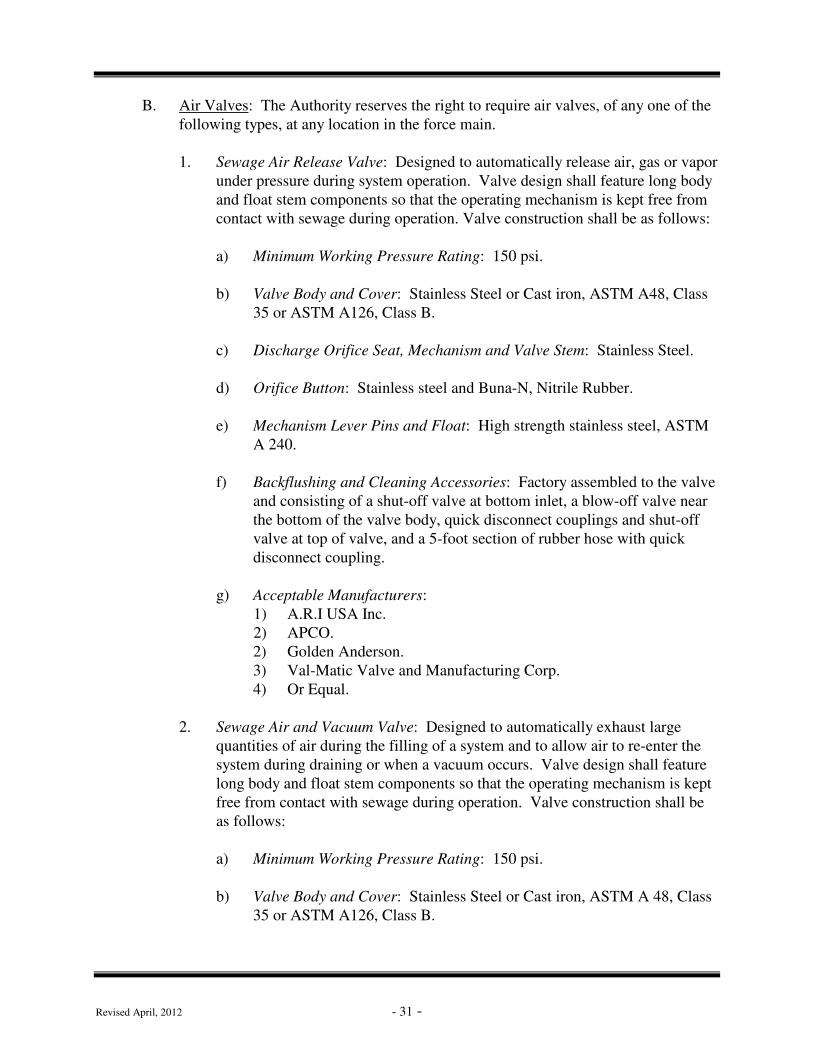
B. Air Valves: The Authority reserves the right to require air valves, of any one of the
following types, at any location in the force main.
1. Sewage Air Release Valve: Designed to automatically release air, gas or vapor
under pressure during system operation. Valve design shall feature long body
and float stem components so that the operating mechanism is kept free from
contact with sewage during operation. Valve construction shall be as follows:
a) Minimum Working Pressure Rating: 150 psi.
b) Valve Body and Cover: Stainless Steel or Cast iron, ASTM A48, Class
35 or ASTM A126, Class B.
c) Discharge Orifice Seat, Mechanism and Valve Stem: Stainless Steel.
d) Orifice Button: Stainless steel and Buna-N, Nitrile Rubber.
e) Mechanism Lever Pins and Float: High strength stainless steel, ASTM
A 240.
f) Backflushing and Cleaning Accessories: Factory assembled to the valve
and consisting of a shut-off valve at bottom inlet, a blow-off valve near
the bottom of the valve body, quick disconnect couplings and shut-off
valve at top of valve, and a 5-foot section of rubber hose with quick
disconnect coupling.
g) Acceptable Manufacturers:
1) A.R.I USA Inc.
2) APCO.
2) Golden Anderson.
3) Val-Matic Valve and Manufacturing Corp.
4) Or Equal.
2. Sewage Air and Vacuum Valve: Designed to automatically exhaust large
quantities of air during the filling of a system and to allow air to re-enter the
system during draining or when a vacuum occurs. Valve design shall feature
long body and float stem components so that the operating mechanism is kept
free from contact with sewage during operation. Valve construction shall be
as follows:
a) Minimum Working Pressure Rating: 150 psi.
b) Valve Body and Cover: Stainless Steel or Cast iron, ASTM A 48, Class
35 or ASTM A126, Class B.

Revised April, 2012 - 32 -
c) Float Stem and Guide: Bronze, ASTM B 584.
d) Floats: Stainless Steel, ASTM A 240.
e) Orifice Seat: Buna-N, Nitrile Rubber.
f) Backflushing and Cleaning Accessories: Factory assembled to the valve
and consisting of an inlet shut-off valve, a blow-off valve near the
bottom of the valve body, quick disconnect couplings and a shut-off
valve at the top of valve, and a 5-foot section of rubber hose with quick
disconnect coupling.
g) Acceptable Manufacturers:
1) A.R.I. USA Inc.
2) APCO.
2) Golden Anderson.
3) Val-Matic Valve and Manufacturing Corp.
4) Or Equal.
3. Sewage Combination Air Valves: Consisting of an air release valve and an air
and vacuum valve factory piped into a compact assembly. The combination
assembly shall automatically release air, gas or vapor under system operating
pressure and shall also allow air to re-enter the system during draining or
when a vacuum occurs. Combination valve designs shall feature long bodies
and float stem components so that the operating mechanisms are kept free
from contact with sewage during operation. Valve construction shall be as
follows:
a) Minimum Working Pressure Rating: 150 psi.
b) Valve Bodies and Covers: Cast iron, ASTM A 48, Class 35 or ASTM
A126, Class B.
c) Air Release Valve Discharge Orifice Seat, Mechanism and Valve Stem:
Stainless Steel.
d) Air Release Valve Orifice Button: Stainless Steel and Buna-N, Nitrile
Rubber.
e) Air Release Valve Mechanism Lever Pins and Float: High strength
stainless steel, ASTM A 240.
f) Air and Vacuum Valve Float Stem and Guide: Bronze, ASTM B 584.
g) Air and Vacuum Valve Floats: Stainless Steel, ASTM A 240.

Revised April, 2012 - 33 -
h) Air and Vacuum Valve Orifice Seat: Buna-N, Nitrile Rubber.
i) Backflushing and Cleaning Accessories: Factory assembled to the
combination valves and consisting of two inlet shut-off valves, two
blow-off valves, two clear water inlet valves, and a 5-foot section of
rubber hose and quick disconnect couplings.
j) Acceptable Manufacturers:
1) APCO.
2) Golden Anderson.
3) Val-Matic Valve and Manufacturing Corp.
4) Or Equal.
C. Underground Warning Tape: Printed polyethylene tape, 3 inches minimum width,
green for force mains, one-inch minimum lettering, printed with name of utility
buried below, and suitable for installation in all soil types. Tape must be placed
above all force mains. (Reference either the Backfill And Pavement Restoration
Detail For State/Boro/Twp Roads or Trench Restoration Lawn/Agricultural Areas
standard detail, as applicable.)
D. Cleanouts: Cleanouts shall be constructed as shown in either the Force Main Valve
& C.O. Detail – Manhole Type 1 or the Force Main Valve & C.O. Detail – Manhole
Type 2, as applicable. Valves shall be installed in each cleanout manhole.
E. Valves and Appurtenances:
1. Valves: Valves shall be installed on force main at locations shown in the
Standard Details and as required by the Authority.
2. Eccentric Plug Valves (3”-24” diameter): Valves installed in valve/cleanout
pits shall be actuated with a worm gear operator and hand wheel. Buried
valves shall be actuated with an underground actuator through a cast iron
valve box and a 2” operating nut. Eccentric plug valves as manufactured by
Clow / McWane, Inc. or approved equal.
a) Valves shall open left (counter-clockwise).
b) Buried valves shall have 2-inch square cast iron operating nuts. Each
valve shall also be supplied with a roadway type valve box.
c) Buried valves shall be supplied with mechanical joint end connections.
d) Valves located in vaults, pits, or manholes shall have flanged ends.

Revised April, 2012 - 34 -
3. Gate Valves (3”-12” in diameter):
a. Stem type when installed underground and rising stem type otherwise.
b. Valve stem seal of such design that allows replacement of O-rings with
valve under pressure in the fully open position.
c. Iron body, outside screw and yoke, bronze mounted with resilient-seated
wedge conforming to AWWA C 509.
d. Resilient seat of Styrene Butadiene SBR or Urethane Rubber bonded to
cast iron wedge.
e. Stem seals of “O”-ring type.
f. Valves equipped with 2-inch square operating nut and open counter-
clockwise. When the operating nut on the valve is more than 4’ below
finished grade, a valve operating nut extension shall be installed on the
valve.
g. Exterior to be asphalt varnish or epoxy coated; interior ferrous metal
parts to be epoxy coated, AWWA C 550.
h. Acceptable Manufacturers: American Flow Control, or approved equal.
4. Valve Boxes: Standard 5-1/4-inch cast iron extension roadway type valve
boxes shall be installed over buried valves and shall contain enough
adjustment threads for future adjustments of 6” up or down. Screw threads
shall be cast integrally with box wall. Welded screw threads are not
acceptable.
F. Access Hatches
Cleanout and Air/Vacuum chamber access frames and covers may be replaced with
access hatches if so approved by the Authority. If an access hatch is approved, the hatch
must either be watertight or contain a drainage coupling integral to the hatch channel
frame. The drainage coupling design must have a pipe installed from the drainage
coupling to the outside of the cleanout vault, turned down, and extended to an elevation
of 18” below finished grade. The pipe end must be located inside ½ cubic yard of PA
DOT 2B aggregate completely wrapped in PA DOT Class I geotextile material. Where
hatches have the potential of being placed under traffic and/or equipment loading, these
hatches must be rated for HS-25 loading. Where hatches will not be placed under traffic
and/or equipment loading, the Authority will consider hatches which do not meet HS-25
loading criteria. However, in this case, hatches must be located at least 18” above final
grade.

Revised April, 2012 - 35 -
7.2 Installation
A. Pipe Installation:
1. General: All pipe shall be laid and maintained to the required lines and
grades with fittings and valves at the required locations, spigots centered in
bells, and all valves plumb. Pipe laying shall commence at the lowest point
and proceed upgrade.
2. Construction Control: During the installation of a force main, the pipe shall
be laid at a constantly increasing grade to each high point, air valve, or point
of discharge. The Extender shall provide sufficient construction control to
assure that there are no sags in the force main which could tend to accumulate
air other than at the high points. Failure to comply with this requirement shall
necessitate that the Extender take remedial steps to correct this situation. All
associated costs shall be borne by the Extender.
B. Anchorage:
1. Concrete Thrust Blocks: ARE NOT PERMITTED
2. Reaction Backing: IS NOT PERMITTED
3. Metal Harness: Metal harness of tie rods of adequate strength to prevent
movement shall be used. Steel rods or clamps shall be type 304 stainless
steel.
4. Anchorage for Bends: All bends deflecting 11.25 degrees or more on force
mains 6 inches in diameter or greater shall be provided with a thrust restraint
system to prevent movement.
a) Either a restrained joint pipe or thrust block system (only by
authorization of the Authority ) will be permitted.
b) Suitable metal rods shall be used only as directed by the Authority.
c) Mechanical joint retainer glands shall not be used to obtain a restrained
joint.
d) “Duc-a-Lugs” ARE NOT PERMITTED.
C. Cleanout Installation: Cleanout manholes shall be provided at each dead end and at
400-foot intervals (maximum) on long stretches of force main. Terminal cleanout
manholes shall be used on all dead ends and at other locations as required by the
Authority.

Revised April, 2012 - 36 -
D. Setting Fittings and Valves:
1. General: Valves and fittings shall be set and jointed to pipe in the manner
specified previously for cleaning, laying, and jointing pipe.
2. Provide a concrete manhole for every air valve. Manholes shall meet the
requires specified above for gravity Sanitary Sewers. The manholes shall be
constructed to permit valve repairs and afford protection to the valve and pipe
from impact where they pass through the manhole walls. All valves and
fittings shall be supported by saddles. The saddles shall be continuous under
all valves and fittings within the valve manholes.
7.3 Tests
A. Hydrostatic Tests:
1. Pressure Test: After the pipe has been laid and backfilled as specified, all
newly laid pipe or any valved section thereof, shall be subjected to a
hydrostatic pressure of 150 psi or 50% in excess of the normal working
pressure, whichever is greater. Where any section of a main is provided with
concrete reaction backing, the hydrostatic pressure test shall not be made until
at least five days have elapsed after the concrete reaction backing was
installed. If high early strength cement is used in the concrete reaction
backing, the hydrostatic pressure test shall not be made until at least two days
have elapsed.
a) Duration of Test: At least two hours.
b) Procedure: Each section of pipe shall be slowly filled with water and
the specified test pressure, based on the elevation of the lowest point of
the line or section under test and corrected to the elevation of the test
gauge, shall be applied by means of a pump connected to the pipe in a
manner satisfactory to the Authority. The pump, pipe connections, and
all necessary apparatus including gauges, shall be furnished by the
Extender. The Extender will make all taps into the pipe, and furnish all
necessary assistance for conducting the tests.
c) Expelling Air Before Test: Before applying the specified test pressure,
all air shall be expelled from the pipe. If permanent air vents are not
located at all high points, the Extender shall make the necessary taps at
such points before the test is made. After the test has been completed,
the Extender shall insert plugs at the tapping points.
d) Examination Under Pressure: Any cracks or defective pipes, fittings, or
valves discovered in consequence of this pressure test, shall be removed

Revised April, 2012 - 37 -
and replaced by the Extender with sound material, and the test shall be
repeated until satisfactory to the Authority.
2. Leakage Test: A leakage test shall be conducted concurrently with the
pressure test. The Extender will furnish laboratory calibrated test gauge and
measuring device, and all necessary assistance to conduct the test.
a) Leakage Definition: Leakage is defined as the quantity of water that
must be supplied into the newly laid pipe, or any valve section thereof,
to maintain pressure within 5 psi of the specified leakage test pressure
after the pipe has been filled with water and the air expelled.
b) Permitted Leakage: No pipe installed will be accepted until the leakage
of the shortest valved section is less than the number of gallons per hour
as determined by the formula:
L = SD P
133 200,
in which “L” equals the allowable leakage in gallons per hour; “S” is the
length of pipeline tested in feet; “D” is the nominal diameter of the pipe,
in inches, and “P” is the average test pressure during the leakage test, in
pounds per square inch gauge. (The allowable leakage according to the
formula is equivalent to 11.65 U. S. Gal. per 24 hours per mile of pipe
per inch nominal diameter, for pipe in 18-foot lengths evaluated on a
pressure basis of 150 psi). When testing against closed metal seated
valves, an additional leakage per closed valve of 0.0078 gallon per hour
per inch of nominal valve size shall be allowed. When multiple valve
sections are tested together, the allowable leakage shall be calculated for
the shortest single section. There shall be no additional leakage allowed
for service connections.
c) The Authority will record both the makeup water and pressure at one-
half hour intervals during the test period.
e) Should any test of pipe laid disclose leakage greater than that specified
above, the Extender shall, at his own expense, locate, repair, and replace
the defective joints, pipe, or fittings until the leakage is within the
specified allowance.
3. Common Requirements:
a) Authority Presence: The Authority or Authority Engineer shall monitor
the pressure and leakage tests. The Extender shall notify the Authority
of the test day at least 48 hours (2 working days) in advance.

Revised April, 2012 - 38 -
b) If test fails to meet test requirements, the Extender shall pay for all
additional engineering personnel testing time.
c) Weather: No testing will be authorized unless air temperature is 35
degrees F. or higher.
d) Acceptance: Observation of successful testing of force mains by the
Authority does not constitute acceptance of the system or any portion
thereof. Upon completion of any determined portion of a total system,
and successful testing thereof, the Authority Engineer may recommend
final acceptance to the Authority. Only upon final inspection by the
Authority and upon written acceptance for same will the system or
portion thereof be considered acceptable. Upon such acceptance, the
warranty period shall commence. If, during this final inspection, any
irregularities are observed, the condition must be corrected at the
Extender’s expense prior to acceptance.

Revised April, 2012 - 39 -
SECTION 8. RESTORATION AND CLEAN-UP OF SURFACE
8.1 Replacement of Property:
A. The Extender shall restore (unless otherwise stipulated) all sidewalks, curbing,
gutters, shrubbery, fences, poles, sod, markings, traffic lines, or other property and
surface structures removed or disturbed as a part of the work to a condition equal to
that before the work began, furnishing all labor and materials incidental thereto.
8.2 Pavement Restoration
A. Restoration of State Highways shall be in accordance with Pennsylvania rules and
regulations, PennDOT requirements, and the provisions of the highway occupancy
permit. Restoration of Borough and Township Streets and other paved surfaces
shall be in accordance with the requirements of the authority having jurisdiction.
8.3 Seeding Restoration
A. Lawn Restoration Materials:
1. Permanent Seed Mixture: PennDOT 408, Section 804, Formula B.
a) Kentucky Blue Grass; a combination of improved certified varieties
with no one variety exceeding 25 percent of the total Blue Grass
component: 50 percent by weight.
b) Creeping Red or Chewings Fescue: 30 percent by weight.
c) Perennial Ryegrass; a combination of improved certified varieties with
no one variety exceeding 50 percent of the total Ryegrass component:
20 percent by weight.
2. Temporary Seed Mixture: PennDOT 408, Section 804, Formula E. Annual
Ryegrass: 100 percent.
3. Provide seed which complies with the Pennsylvania Seed Act of 1965, Act
No. 187, and regulations of the Pennsylvania Department of Agriculture,
Bureau of Plant Industry.
4. Lime: Pulverized agricultural limestone; PennDOT 408, Section 804.
5. Mulching Material: Oat or wheat straw, dry, free from weeds and foreign
matter detrimental to plant life. Hay or chopped cornstalks are not acceptable.

Revised April, 2012 - 40 -
6. Mulching Material: Wood cellulose fiber, free of growth or germination
inhibiting ingredients.
7. Planting Fertilizer: Dry formulation of 10-20-20 analysis; PennDOT 408,
Section 804.
8. Slow-Release Nitrogen Fertilizer: Dry formulation of 38-0-0 urea-form.
9. Water: Clean, fresh and free of substances or matter which could inhibit
vigorous growth of grass.
B. Restoration of Lawns, Pastures, Meadows, and Cultivated Fields:
1. General:
a) Topsoil shall be free from subsoil, brush, weeds, or other litter, clay
lumps and stones, but may contain decaying vegetable matter.
b) Comply with laws and regulations related to Sediment and Erosion
Control.
c) Seed shall be not more than two years old. Germination tests of seeds
shall be made not more than six months prior to seeding. Do not use
seed which has become wet, moldy, or otherwise damaged.
d) Submit all seed mixture formulas to the Authority for approval prior to
seeding.
e) The Extender shall be responsible for seeding all areas of bare soil
which result from his construction operations and for producing a stand
of grass in all seeded areas. Erosion, drought, or any other condition
will not relieve the Extender of this requirement.
2. Lawns:
a) Prior to construction, strip and stockpile the full depth of existing
topsoil, but no less than six inches, from all areas to be disturbed.
b) Scarify top of trench backfill to minimum depth of two inches before
placing topsoil.
c) Use stockpiled topsoil to bring the trench area to final grade.

Revised April, 2012 - 41 -
d) If stockpiled topsoil is not sufficient to provide at least six inches of
topsoil over area to be restored, import sufficient topsoil to provide such
coverage.
e) Use topsoil in relatively dry state. Place during dry weather.
f) Fine grade topsoil eliminating rough or low areas.
g) Remove stone, roots, grass, weeds, debris, and foreign material from
topsoil while spreading.
h) Manually spread topsoil around trees, plants, building, and paving to
prevent damage.
i) Lightly compact placed topsoil. Use roller weighing no more than 120
pounds per foot of roller width.
j) Remove surplus subsoil and topsoil from site.
k) Leave stockpile area and site clean and raked, ready to receive
landscaping.
l) Grading tolerance: Finished surface of topsoil shall not deviate by more
than 1/2 inch up or down from a straight edge or stringline placed across
the trench and held on existing grade on both sides of the trench.
m) Apply lime at the rate of 800 pounds per 1,000 sq. yd.
n) Do no apply fertilizer sooner than three days after lime application.
o) Apply planting fertilizer at the rate recommended by manufacturer.
Apply fertilizer after raking topsoil smooth and prior to roller
compaction. Do not apply fertilizer at the same time or with the same
machine as will be used to apply seed.
p) After spreading of fertilizer is complete, apply peat moss to a depth of
1/4-inch over the area to be seeded.
q) Mix lime, fertilizer, and peat moss thoroughly into the upper two inches
of topsoil.
r) Lightly water to aid the dispersion of fertilizer.
s) Apply seed at a rate of 21 lbs. per 1,000 sq. yd evenly in two intersecting
directions. Rake in lightly. Do not seed area in excess of that which can
be mulched on same day.

Revised April, 2012 - 42 -
t) Planting season: March 15 to June 1 and August 1 to October 15.
Areas in which trench backfilling operations are completed in other time
periods shall be seeded with annual Ryegrass (PennDOT 408, Section
804, Formula E) at the rate of 10 lbs. per 1,000 sq. yd to provide
temporary protection. Permanent seeding shall then be applied later
during the specified periods.
u) Do not sow seed immediately following rain, when ground is too dry, or
during windy periods.
v) Roll seeded area with roller not exceeding 120 lbs. per foot of roller
width.
w) Immediately following seeding and compacting, apply mulch at the rate
of 1,200 pounds per 1,000 sq. yd for straw or 320 pounds per 1,000 sq.
yd for wood cellulose fiber.
x) If straw is used for mulch, anchor straw with emulsified asphalt binder
or other material approved by Engineer.
y) Apply water with a fine spray immediately after each area has been
mulched.
z) At completion of Extender’s work, apply slow-release nitrogen fertilizer
to all seeded areas at the rate of 50 lbs. per 1,000 sq. yd.
aa) Re-seed areas which show bare spots prior to expiration of the
Extender’s warranty period.
3. Pasture and Meadows:
a) Prior to construction, strip and stockpile the full depth of the existing
topsoil, but no less than 12 inches, from all areas to be disturbed. Use
stockpiled topsoil to bring the trench area to final grade.
b) Remove all crushed stone and construction debris from the disturbed
area.
c) Planting season: Perform seeding no later than the start of the next
planting season following completion of trench backfilling. The
planting season shall be as established by the U. S. Agricultural Service
for the area of construction.
d) Seed mixture:

Revised April, 2012 - 43 -
1) Timothy 18%
2) Orchard Grass (Pennlate or Pennmeade) 46%
3) Redtop 18%
4) Kentucky Bluegrass 18%
e) Spread the seed using an approved seeding procedure at the rate of 22 to
25 pounds per acre.
4. Cultivated Fields:
a) Prior to construction, strip and stockpile the full depth of existing
topsoil, but no less than 12 inches, from all areas to be disturbed.
b) Upon completion of construction, remove all crushed stone and other
construction debris.
c) Use stockpiled topsoil to bring the trench area to final grade.
d) Scarify to minimum depth of 10 inches all areas that have been
compacted as a result of construction operations.

Revised April, 2012 - 44 -
SECTION 9. CLEAN-UP AND MAINTENANCE DURING CONSTRUCTION WORK
9.1 Clean-Up
A. During construction, surfaces of all areas including, but not limited to, Streets and
driveways shall be maintained on a daily basis to produce a safe, desirable, and
convenient condition.
1. Streets shall be swept and flushed after trench backfilling, and re-cleaned as
dust, mud, stones, and debris caused by the work, or related to the work, again
accumulates.
2. Failure of the Extender to perform this work shall be cause for the Authority
to order the work to be done by others and to charge all costs to the Extender.
3. During construction, Contractor is required to provide the necessary materials
and equipment to maintain dust control.
9.2 Repair or Correction of Unsatisfactory Conditions
A. Any subnormal or dangerous condition caused by the work, on any surface, shall be
repaired and/or corrected within two hours of observation or notification of its
existence. If repairs are not made with this two-hour period, the Authority shall
cause to have the work completed and the resulting cost will be charged to the
Extender.
9.3 Temporary Pavement
A. The Authority and/or PennDOT may require that the Extender construct temporary
pavement until conditions are suitable for placement of permanent pavement. The
Extender shall continuously maintain temporary pavement until it is replaced with
permanent pavement.
9.4 Temporary Sanitary Facility
A. The Authority and/or PennDOT may require that the Extender provide temporary
sanitary facilities throughout the project. The Extender shall place these facilities at
discrete location(s) as approved by the Authority.

Revised April, 2012 - 45 -
SECTION 10. PUMPING STATIONS
10.1 General
A. Use of pumping station systems will be approved by the Authority on a case-by-case
basis. In order to obtain approval of a pumping station system, the Owner shall
submit the following information to the Authority:
1. Capacity and horsepower for the proposed pump.
2. Size and construction of the dry well/wet well.
3. Details of the electrical power, control, and alarm systems.
4. Size and material of proposed pump discharge line and associated valves.
5. Details of the connection to the Sewer System.
6. Proposed location of all system components.
7. Design computations.
8. Copies of permits and approval notifications from agencies other than the
Authority.
B. Plans and specifications for all proposed pumping station system must be reviewed
and approved by the Authority before installation.
C. Following approval by the Authority, the Owner will be responsible for all costs
associated with construction of the system, for all permit and approval costs, and for
all costs which may result from damage to the Sewer System, or to other utilities
and facilities, during construction of the system.

Revised April, 2012 - 46 -
SECTION 11. GRINDER PUMPING SYSTEMS
11.1 General
A. Use of grinder pump systems will be approved by the Authority on a case-by-case
basis. In order to obtain approval of a grinder pumping system, the Owner shall
submit the following information to the Authority:
1. Capacity and horsepower for the proposed pump.
2. Size and construction of the wet well.
3. Details of the electrical power, control, and alarm systems.
4. Size and material of proposed pump discharge line and associated valves.
5. Details of the connection to the Sewer System.
6. Proposed location of all system components.
7. Design computations.
8. Copies of permits and approval notifications from agencies other than the
Authority.
B. Plans and specifications for all proposed grinder pump systems must be reviewed
and approved by the Authority before installation.
C. Following approval by the Authority, the Owner will be responsible for all costs
associated with construction of the system, for all permit and approval costs, and for
all costs which may result from damage to the Sewer System, or to other utilities
and facilities, during construction of the system. The Owner shall be responsible for
continuously maintaining the system after installation. Acceptable manufacturers
and specifications: Meyers, Hydro-Matic, or approved equal.

Revised April, 2012 - 47 -
SECTION 12. OIL AND GREASE INTERCEPTORS
12.1 General
A. When Sanitary Sewage and/or Industrial Waste which is being discharged to the
Authority Sewer System contains oil and/or grease in excess of the limits
established in the Authority’s Industrial Waste Resolution, oil and/or grease
interceptors shall be installed.
B. Installation plans and specifications for proposed oil and grease interceptor systems
shall be submitted to the Authority prior to the start of installation. Installation shall
not be started until approval of the system has been obtained from the Authority.

Revised April, 2012 - 48 -
SECTION 13. SAMPLING AND FLOW MEASUREMENT
13.1 General
A. When required by the Authority, the Owner of any property serviced by the Sewer
System shall install at his expense a suitable control manhole together with such
meters and other appurtenances in the Building Sewer and/or Service Line to
facilitate observation, sampling, and measurement of the waste generated on the
Owner’s property. All materials, use, and installation must be approved by the
Authority prior to the installation of such system.

APPENDICES
APPENDIX 1
Sewer Testing Forms

SEWER FORCE MAIN
PRESSURE TEST REPORT
Date: Computed By:
Development: Checked By:
Drawing No.: Sheet No. of
Contractor:
Average Test Pressure: _____________ Test Start: Test Finish
L = Allowable Leakage in Gallons (GPH) Location:
S = Length of Pipe Tested In Feet
D = Diameter of Pipe in Inches
P = Average Test Pressure in PSINOTE: 7.481 Gallons/FT3
TEST DATA NOTE: Allowed leakage based onLoss or shortest valve section in test.
Time Pressure Make up Water
Start CALCULATIONS
1/2 Hr. Reading
Repressure L =
1 Hr. Reading
Repressure
1-1/2 Hr. Reading
Repressure
2 Hr. Reading
Repressure
Total Leakage for 2 Hour Period
Allowed Leakage for 2 Hour Period
Line Passes or Fails Test (circle one) PASS / FAIL
MOUNT JOY BOROUGH AUTHORITY
forms\inspection forms\MJBA-Forcemain-Pressure.xls

MOUNT JOY BOROUGH AUTHORITYGravity Sewer Test Report
Development: Drawing No.: Sheet No. of
Contractor: Inspected By: Date:
Between Pipe Size & Time Pressure Test
Length Deflection PSIG PSIG PSIG Result
Street MH No. MH No. Tested Test Start Complete Start End Loss
forms\MJBA-Gravity-Sewer.xls

MOUNT JOY BOROUGH AUTHORITY
Lateral Locations
Development:
Contractor:
Material: Distance: Slope:
Street Name: In a Right-of-Way:
Lot Length Depth Station Manhole No. ______ Station Depth Length Lot
F
L
O
W
Manhole No. ______
Date Tested: Drawing No.:
Inspector: Prepared By:
forms\MJBA-Lateral-Location.xls

MOUNT JOY BOROUGH AUTHORITYManhole Vacuum Test Report
Development: Drawing No.: Sheet No. of
Contractor: Inspected By: Date:
Time Vacuum (inches of Hg) Result
Street Manhole Start Stop Start Stop Loss Pass Fail
NOTE: 4' Dia. = 60 sec. - 5' Dia. = 75 sec. - 6' Dia. = 90 sec. Inspector:forms\MJBA-Manhole-Vaccum.XLS

APPENDIX 2
Standard Details


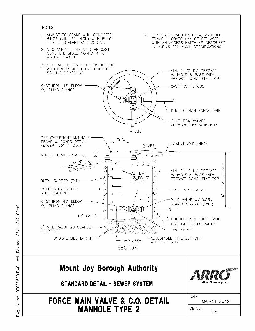


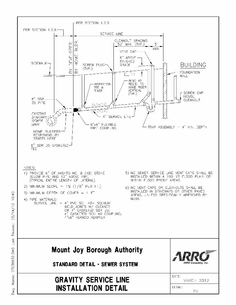


Related Documents