Prepared by: MEINHARDT PHILIPPINES, INC. 25F Chatham House 116 Valero corner V.A. Rufino Street Salcedo Village, Makati City 1227 Philippines 06 April 2018 ERWIN J. JUNASA Professional Electronics Engineer Reg. No : 862 PTR No. : 6619215 Date Issue : 05 January 2018 Issued at : Makati City TIN No : 157-691-905 100% DESIGN DEVELOPMENT Baguio City, Philippines Technical Specifications for Electronics Systems BAGUIO GENERAL HOSPITAL MEDICAL CENTER - PROPOSED MULTI-SPECIALTY CENTER

Welcome message from author
This document is posted to help you gain knowledge. Please leave a comment to let me know what you think about it! Share it to your friends and learn new things together.
Transcript

Prepared by: MEINHARDT PHILIPPINES, INC. 25F Chatham House 116 Valero corner V.A. Rufino Street Salcedo Village, Makati City 1227 Philippines 06 April 2018 ERWIN J. JUNASA Professional Electronics Engineer Reg. No : 862 PTR No. : 6619215 Date Issue : 05 January 2018 Issued at : Makati City TIN No : 157-691-905
100% DESIGN DEVELOPMENT
Baguio City, Philippines
Technical Specifications for
Electronics Systems
BAGUIO GENERAL HOSPITAL MEDICAL CENTER - PROPOSED MULTI-SPECIALTY CENTER
DIVISION 17 – ELECTRONICS
MEINHARDT PHILIPPINES INC.
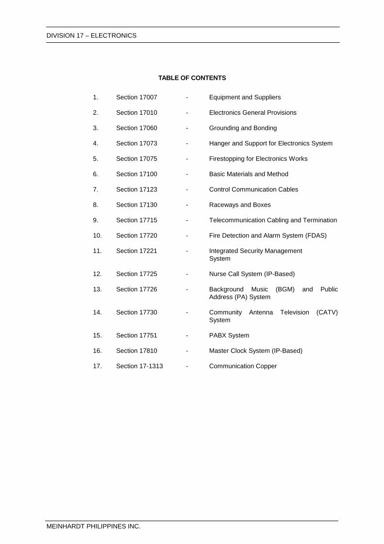
TABLE OF CONTENTS
1. Section 17007 - Equipment and Suppliers 2. Section 17010 - Electronics General Provisions 3. Section 17060 - Grounding and Bonding 4. Section 17073 - Hanger and Support for Electronics System 5. Section 17075 - Firestopping for Electronics Works 6. Section 17100 - Basic Materials and Method 7. Section 17123 - Control Communication Cables 8. Section 17130 - Raceways and Boxes
9. Section 17715 - Telecommunication Cabling and Termination
10. Section 17720 - Fire Detection and Alarm System (FDAS)
11. Section 17221 - Integrated Security Management
System
12. Section 17725 - Nurse Call System (IP-Based)
13. Section 17726 - Background Music (BGM) and Public Address (PA) System
14. Section 17730 - Community Antenna Television (CATV)
System
15. Section 17751 - PABX System
16. Section 17810 - Master Clock System (IP-Based)
17. Section 17-1313 - Communication Copper
DIVISION 17 - ELECTRONICS Equipment and Suppliers
SECTION 17007
MEINHARDT PHILIPPINES INC. Page 1 of 5 S:\admin\mpi\MP1716_Baguio General Hospital and Medical Trauma Center\000 - ACTIVE DOCUMENTS\09 - SPECS\2018-04-06_100% DD\03-ELECTRONICS\17007-Alternative Equipment and Suppliers.docx
SECTION 17007 EQUIPMENT AND SUPPLIERS
PART 1 - GENERAL INFORMATION
1.1 Where a choice of equipment is given, indicate selection by submitting this Section.
1.2 Where modifications to the work of Other Trades are required as a result or part of the alternative offered, include the cost of said modifications in the alternative price offered.
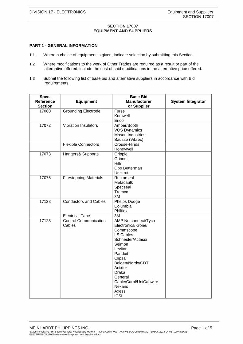
1.3 Submit the following list of base bid and alternative suppliers in accordance with Bid requirements.
Spec. Reference
Section Equipment
Base Bid Manufacturer or Supplier
System Integrator
17060 Grounding Electrode Furse Kumwell Erico
17072 Vibration Insulators Amber/Booth VOS Dynamics Mason Industries Sausse (Vibrex)
Flexible Connectors Crouse-Hinds Honeywell
17073 Hangers& Supports Gripple Grinnell Hilti Obo Betterman Unistrut
17075 Firestopping Materials Rectorseal Metacaulk Specseal Tremco 3M
17123 Conductors and Cables Phelps Dodge Columbia Philflex
Electrical Tape 3M 17123 Control Communication
Cables AMP Netconnect/Tyco Electronics/Krone/ Commscope LS Cables Schneider/Actassi Seimon Leviton Panduit Clipsal Belden/Nordx/CDT Anixter Draka General Cable/Carol/UniCabwire Nexans Axess ICSI

DIVISION 17 - ELECTRONICS Equipment and Suppliers
SECTION 17007
MEINHARDT PHILIPPINES INC. Page 2 of 5 S:\admin\mpi\MP1716_Baguio General Hospital and Medical Trauma Center\000 - ACTIVE DOCUMENTS\09 - SPECS\2018-04-06_100% DD\03-ELECTRONICS\17007-Alternative Equipment and Suppliers.docx
Spec.
Reference Section
Equipment Base Bid
Manufacturer or Supplier
System Integrator
17130 Metallic Conduit & Tubing
Allied Matsushita/Panasonic Mcgill Smart tube Royal Steel Sumitomo
17130 Manhole Covers/Cast Iron Boxes
Crouse – Hinds Makati Foundry
17130 Non-metallic Conduit & Tubing
Atlanta Emerald Moldex Neltex
17130 Wireways/Auxiliary Gutters
Asiaphil System Power Mark Total Powerbox Tomelekt Versatrunk Fumaco LJ Industrial Fabrication R.S. Thomas Gentech Obo Betterman
17130 Outlet, Junction, Pull-boxes
Amco Fumaco HKK Steel City Crouse-Hinds Amtec
17130 Flexible Connectors Amtec Crouse-Hinds Honeywell
17130 Liquid Flexible Steel Conduit
Appleton Matsushita/Panasonic
17140 Wiring Devices Bticino (Pass & Seymour) Clipsal Hubbel Legrand MK Electric National/Panasonic Toshiba
17210 Switches and Routers Cisco Allied Telesis HP

DIVISION 17 - ELECTRONICS Equipment and Suppliers
SECTION 17007
MEINHARDT PHILIPPINES INC. Page 3 of 5 S:\admin\mpi\MP1716_Baguio General Hospital and Medical Trauma Center\000 - ACTIVE DOCUMENTS\09 - SPECS\2018-04-06_100% DD\03-ELECTRONICS\17007-Alternative Equipment and Suppliers.docx
Spec.
Reference Section
Equipment Base Bid
Manufacturer or Supplier
System Integrator
17717 Communicating Horizontal Cabling
AMP Netconnect/Tyco Electronics/Krone/ Commscope LS Cables Schneider/Actassi Seimon Leviton Panduit Clipsal Belden/Nordx/CDT Anixter Draka Nexans Axess ICSI General Cable/Carol/UniCabwire
Saturn Beta Pronet Digicom Lantro IBMS Multi-line Optimum Equipment TSSI Micro Genesis MCM ISDN Mighty Lynx Linkwise Systec
17718 Conductors & Cables for Electronic Safety and Security
AMP Netconnect/Tyco Electronics/Krone/ Commscope LS Cables Schneider/Actassi Seimon Leviton Panduit Clipsal Belden/Nordx/CDT Anixter Draka ICSI General Cable/Carol/UniCabwire
17720 Fire Detection and Alarm System (FDAS)
Tyco/Simplex Honeywell Notifier Integlex/Nohmi Bosai Cooper Edwards UTC/GE Siemens/Cerberus Hochiki Approved Alternative: Bosch (UL Certified devices only)
Avesco Electro Systems FPI Loxon Multi-line Optimum Equipment PID Prestige Pronet Pulser Yek-yue
17721 Closed Circuit Television (CCTV)
Cameras, NVR: American Dynamics Avigilon Axis Bosch Flir Panasonic GE/UTC Honeywell Indigo Vision Philips Pelco Samsung
Fairetech Avesco Pronet Yek-yue ISDN Cylix ESSCOR I3 Netpacific IBMS Multiline Optimum Equipment Prestige

DIVISION 17 - ELECTRONICS Equipment and Suppliers
SECTION 17007
MEINHARDT PHILIPPINES INC. Page 4 of 5 S:\admin\mpi\MP1716_Baguio General Hospital and Medical Trauma Center\000 - ACTIVE DOCUMENTS\09 - SPECS\2018-04-06_100% DD\03-ELECTRONICS\17007-Alternative Equipment and Suppliers.docx
Spec.
Reference Section
Equipment Base Bid
Manufacturer or Supplier
System Integrator
Siqura Siemens CP Plus Honeywell Monitors: Samsung LG Management Softwares: Nuuo Verint Genetec Bosch Storage Devices: iOmega Quantum HP/3Par EMC²
iCom-Sec Electro-Systems ICSI MCM
17722 Integrated Security Management System (ISMS)
Honeywell Hirsch Bostex/Niagara TAC by Schneider Samsung GE/UTC Siemens Bosch Lenel Gallaqher CEM Approved Alternative: C-cure
Fairetech Avesco Pronet Yek-yue ISDN Cylix ESSCOR IBMS Multi-line Optimum Equipment Electro-Systems IOT MCM
17722-2 Intrusion Detection/Access Control System
UTC/GE Honeywell Tyco Sensormatic Hirsch DSC HID Gallagher Skidata Park Tronix
Fairetech Avesco Pronet Yek-yue ISDN ESSCOR Cylix Multi-line Optimum Equipment MCM I3 ENJ
17726 Public Address (PA) Bosch Bi-Amp/Vocia Honeywell TOA Philips Bose JBL Sony Pioneer Yamaha
Prestige Yek-yue Pronet Avesco EVI ISDN Fairtech Multi-line Optimum Equipment iCom-Sec MCM
DIVISION 17 - ELECTRONICS Equipment and Suppliers
SECTION 17007
MEINHARDT PHILIPPINES INC. Page 5 of 5 S:\admin\mpi\MP1716_Baguio General Hospital and Medical Trauma Center\000 - ACTIVE DOCUMENTS\09 - SPECS\2018-04-06_100% DD\03-ELECTRONICS\17007-Alternative Equipment and Suppliers.docx
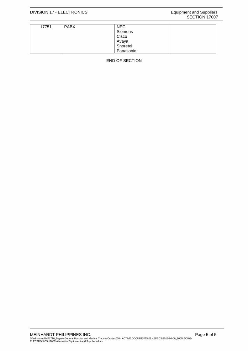
17751 PABX NEC Siemens Cisco Avaya Shoretel Panasonic
END OF SECTION

DIVISION 17 – ELECTRONICS Electronics General Provisions SECTION 17010
MEINHARDT PHILIPPINES INC.
PART 1 – GENERAL .................................. ............................................................................................ 1
1.1 DESCRIPTION .............................................................................................................................. 1 1.2 WORK INCLUDED ........................................................................................................................ 1 1.3 QUALITY ASSURANCE .................................................................................................................. 1 1.4 ABBREVIATIONS AND DEFINITIONS................................................................................................ 2 1.5 GUARANTEE ............................................................................................................................... 3 1.6 PROPOSED SEPARATION OF WORK BETWEEN THE TRADES: ......................................................... 3
PART 2 – PRODUCTS ......................................................................................................................... 10
2.1 EQUIPMENT AND MATERIALS ..................................................................................................... 10
PART 3 – EXECUTION ........................................................................................................................ 10
3.1 FEES AND PERMITS ................................................................................................................... 10 3.2 SUBMITTALS AND REVIEWS ........................................................................................................ 11 3.3 COORDINATION OF WORK .......................................................................................................... 13 3.4 EXAMINATION OF SITE ............................................................................................................... 15 3.5 EXCAVATION AND BACKFILL ....................................................................................................... 15 3.6 CUTTING AND PATCHING ........................................................................................................... 16 3.7 SEALING OF PENETRATIONS ...................................................................................................... 16 3.8 MOUNTING HEIGHTS ................................................................................................................. 17 3.9 CLEANING UP ........................................................................................................................... 17 3.10 WATERPROOFING ..................................................................................................................... 18 3.11 SUPPORTS................................................................................................................................ 18 3.12 FASTENINGS ............................................................................................................................. 18 3.13 IDENTIFICATION ......................................................................................................................... 19 3.14 EQUIPMENT PADS AND ANCHOR BOLTS ..................................................................................... 19 3.15 PROHIBITED LABELS AND IDENTIFICATIONS ................................................................................. 20 3.16 DELIVERY, DRAYAGE AND HAULING ........................................................................................... 20 3.17 EQUIPMENT AND MATERIAL PROTECTION ................................................................................... 20 3.18 TESTING OF ELECTRONICS SYSTEMS ......................................................................................... 21 3.19 OPERATING INSTRUCTIONS ........................................................................................................ 21 3.20 OPERATING AND MAINTENANCE MANUALS ................................................................................. 21 3.21 RECORD DRAWINGS .................................................................................................................. 22 3.22 FINAL PUNCHLIST ...................................................................................................................... 22
DIVISION 17 – ELECTRONICS Electronics General Provisions SECTION 17010
MEINHARDT PHILIPPINES INC. Page 1 of 22 S:\admin\mpi\MP1716_Baguio General Hospital and Medical Trauma Center\000 - ACTIVE DOCUMENTS\09 - SPECS\2018-04-06_100% DD\03-ELECTRONICS\17010-Electronics General Provisions.doc
SECTION 17010 ELECTRONICS GENERAL PROVISIONS
PART 1 – GENERAL 1.1 DESCRIPTION
A. The General and Supplementary Conditions are a part of the requirements for the work under this Division of the Specifications.
1.2 WORK INCLUDED
A. Provide labor and materials required to install, test and place into operation the ELECTRONICS systems as called for in the Contract Documents, and in accordance with applicable codes and regulations.
B. Provide labor, materials, and accessories required to provide complete, operating
ELECTRONICS systems. Labor, materials or accessories not specifically called for in the Contract Documents, but required to provide complete operating Electronics systems shall be provided without additional cost to the Owner.
C. Under this Division of the specifications, provide all materials and equipment and
perform all the work necessary for the complete execution of all the Electronics Works as shown on the Electronics Drawings, and on the General Construction Drawings, as herein specified, or both, except as otherwise excluded, and which w/o excluding the generality of the foregoing, shall include but not limited to the following principal items of work.
1. Fire Detection and Alarm System 2. Integrated Security Management System 3. Community Antenna Television (CATV) 4. Background Music and Public Address System 5. Master Clock System 6. Nurse Call System 7. Structured Cabling System 8. Complete Grounding System 9. Complete Testing and Commissioning of Electronics system. 10. Painting of electrical work (roughing-ins/containment systems, etc.) and
equipment 11. Firestopping of openings in floors and walls after all conduits or pipes or
ducts are in place and sealing of all such openings if not used. 12. Coordination with other trades especially coordinating provisions for
openings, chases, inserts, etc. at site and to warn the builder of any corresponding construction error. No extra claim will be entertained due to contractor’s failure to provide the above on item.
13. Provision of as-built drawings, operating instructions and maintenance manuals and training of employer’s staff.
14. Anything that has been omitted if any item of work or materials usually furnished which are necessary for the completion of the electronics work.
15. Preparation of Short Circuit and Coordination Study of overcurrent protective devices, conductors and all electrical equipment by a Third Party Agency.
1.3 QUALITY ASSURANCE
A. Comply with the current applicable codes, ordinances, and regulations of the authority or authorities having jurisdiction, the rules, regulations and requirements of the utility companies serving the project and the Owner’s insurance underwriter.
DIVISION 17 – ELECTRONICS Electronics General Provisions SECTION 17010
MEINHARDT PHILIPPINES INC. Page 2 of 22 S:\admin\mpi\MP1716_Baguio General Hospital and Medical Trauma Center\000 - ACTIVE DOCUMENTS\09 - SPECS\2018-04-06_100% DD\03-ELECTRONICS\17010-Electronics General Provisions.doc
B. Drawings, specifications, codes and standards are minimum requirements. Where requirements differ, the more stringent apply.
C. Should any change in drawings or specifications be required to comply with the
governing regulations, notify the Project Manager prior to submitting bid.
D. All equipment and installations shall meet or exceed minimum requirements of the Standards and Codes listed under item 1.4.
E. Execute work in strict accordance with the best practices of the trades in a thorough,
substantial, workmanlike manner by competent workmen. Provide a competent, experienced, full-time Superintendent who is authorized to make decisions on behalf of the Contractor.
F. Engineer In-Charge supervising the work shall be a duly registered Electronics
Engineer under the supervision of a Professional Electronics Engineer as required by RA 9292 and the revised IRR of The National Building Code of the Philippines.
1.4 ABBREVIATIONS AND DEFINITIONS
A. Abbreviations:
1. PS - Philippine Standard 2. PECE - Philippine Electronics Code 3. PEC - Philippine Electrical Code 4. ANSI - American National Standards Institute 5. ASTM - American Society for Testing and Materials 6. ETL - Electrical Testing Laboratories 7. NETA - International Electrical Testing Association 8. IEC - International Electro-Technical Committee 9. IEEE - Institute of Electrical and Electronic Engineers 10. IES - Illuminating Engineering Society 11. NEC - National Electrical Code 12. NEMA - National Electrical Manufacturer’s Association 13. NFPA - National Fire Protection Association 14. UL - Underwriters’ Laboratories Inc. 15. ISO - International Standard Organization 16. EITC - Design Guidelines for Telecommunication
Infrastructure 17. EIA/TIA - Building Telecommunications Wiring Standards 18. BTFSM - Building Telephone Facilities Standards Manual 19. BICSI - Telecommunications Distribution Methods Manual 20. FCC - Federal Communication Commission 21. PD NO. 1185 - The Fire Code of the Philippines and Regulation 22. Other International Accepted Standards.
B. Definitions
1. Where it is stated in these specifications to submit to Engineer for review, refer to Architectural General and Special Conditions for proper procedures.
2. FURNISH means to supply all materials, labor, equipment, testing apparatus, controls, tests, accessories, and all other items customarily required for the proper and complete application.
3. INSTALL means to join, fasten, link, attach, set up or otherwise connect together before testing and turning over to Owner, complete and ready for regular operation.
4. PROVIDE means to FURNISH and INSTALL. 5. AS DIRECTED means as directed by the Project Manager, or his
representative.

DIVISION 17 – ELECTRONICS Electronics General Provisions SECTION 17010
MEINHARDT PHILIPPINES INC. Page 3 of 22 S:\admin\mpi\MP1716_Baguio General Hospital and Medical Trauma Center\000 - ACTIVE DOCUMENTS\09 - SPECS\2018-04-06_100% DD\03-ELECTRONICS\17010-Electronics General Provisions.doc
6. CONCEALED means embedded in masonry or other construction, installed behind wall furring or within drywall partitions, furniture wiring management or installed within hung ceilings.
7. SUBMIT means submit to Project Manager for review. 8. “Architect”, “Project Manager/Engineer”, “Owner”, the Party or Parties
responsible for interpreting, accepting and otherwise ruling on the performance under “this Contract”.
1.5 GUARANTEE
A. Submit a single guarantee stating that the work is in accordance with the Contract Documents. Guarantee work against faulty and improper material and workmanship for a period of one year from the date of final acceptance by the Owner, except that where guarantees or warranties for longer terms are provided or specified herein, the longer term shall apply. Correct any deficiencies which occur during the guarantee period, within 24 hours of notification, without additional cost to the Owner, to the satisfaction of the Owner. Obtain similar guarantees from subcontractors, manufacturers, suppliers and sub-trade specialists.
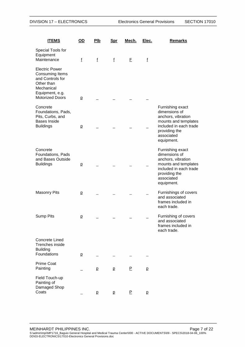
1.6 PROPOSED SEPARATION OF WORK BETWEEN THE TRADES:
A. The specifications describe in detail the proposed work included for each trade when the Main Contractor divides the work among their Sub-Contractors. The following summary is an outline of the work to be “Provided”, “Furnished” or “Installed” by each of the trades included in the contract, i.e., Plumbing and Sprinkler, HVAC (Div. 15), Electrical (Div. 16), and other Divisions 1-14.
B. In the absence of more detailed information, consider the list as specific instructions
to include such work in the named contract.
C. Abbreviations are as follows:
1. “OD” - By other specialists (or contract) 2. “Plb” - Plumbing – Division 15 3. “Spr” - Sprinkler – Division 15 4. “Mech” - Mechanical – Division 15 5. “Elec” - Electrical and Electronics – Division 16 and 17 6. “f” - Furnished 7. “I” - Installed 8. “p” - Provided (Furnished and Installed)

DIVISION 17 – ELECTRONICS Electronics General Provisions SECTION 17010
MEINHARDT PHILIPPINES INC. Page 4 of 22 S:\admin\mpi\MP1716_Baguio General Hospital and Medical Trauma Center\000 - ACTIVE DOCUMENTS\09 - SPECS\2018-04-06_100% DD\03-ELECTRONICS\17010-Electronics General Provisions.doc
ITEM OD Plb Spr. Mech. Elec. Remarks Motors for Mech’l., Plumbing, Fire Protection Equip’t
_
p
p
P
_
Feeder Cables from Electrical Panels to Motor Controls
_
_
_
_
p
Cables to be terminated in the Motor Controls by each trade.
Substation Transformer, HV/ MV/LV Switchgear, Capacitor Banks, Automatic Switchgear, & Gensets
_ _
_
_ p
Motor Controls for Mech’l., Plumbing, Fire Protection Equipment
_
p
p
P
_
Specification and drawings delineate detailed exceptions.
Wiring for Mech’l., Plumbing, Fire Protection Equip’t Motors including the feeder cables from motor controller
_
p
p
P
_
Specification and drawings delineate detailed exceptions.
Wiring for Mech’l Equipment Motor Controls and Alarms
_
p
p
p
_
Specifications and drawings delineate in detail the work to be performed by each trade.
BMS Control Field Devices
_
p
p
P
p
DDC Field Controllers _ _ _ _ _ Wiring Terminations
_
p
p
P
p
Contractor Who Supplied the Panel will do the termination
Temporary Light and Power
_
_
_
_
_
As per Contract Documents.
Temporary Water _ _ _ _ _ As per Contract
Documents. Toilets _ _ _ _ _ As per Contract
Documents. Temporary Fire Protection
_
_
_
_
_
As per Contract Documents.
Hoisting p p p P p

DIVISION 17 – ELECTRONICS Electronics General Provisions SECTION 17010
MEINHARDT PHILIPPINES INC. Page 5 of 22 S:\admin\mpi\MP1716_Baguio General Hospital and Medical Trauma Center\000 - ACTIVE DOCUMENTS\09 - SPECS\2018-04-06_100% DD\03-ELECTRONICS\17010-Electronics General Provisions.doc
ITEM OD Plb Spr. Mech. Remarks Rigging p p p p
Bracing of Building for Safe Rigging
p
_
_
_
Cutting, Chasing & Patching
p
_
_
_
Cost where due to late installation or improper coordination of work is the responsibility of the delinquent trade.
Framed Slots and Openings in Walls, Decks and Slabs
p
_
_
_
Includes drilling of holes when required. Cost where due to late installation or improper coordination of work is the responsibility of the delinquent trade.
Sleeves _ p p p Waterproof Sealing of Sleeves through Waterproof, Slabs, Decks and Walls
_
p
p
p
Fireproof Sealing of Excess Openings in Slabs, Decks and Fire Rated Walls
_
p
p
p
Excavation and Backfill Inside Buildings
_
p
p
p
Excavation and Backfill Outside Buildings
p
_
_
_
Coordination with the trades. Cost where due to late installation or improper coordination of work is the responsibility of the delinquent trade.
Keep Site and Excavation Free From Surface Water During Construction
p
_
_
_
Fastenings _ p p p Concrete Encasement of Electrical & Auxiliary Conduits
_
_
_
_
DIVISION 17 – ELECTRONICS Electronics General Provisions SECTION 17010
MEINHARDT PHILIPPINES INC. Page 6 of 22 S:\admin\mpi\MP1716_Baguio General Hospital and Medical Trauma Center\000 - ACTIVE DOCUMENTS\09 - SPECS\2018-04-06_100% DD\03-ELECTRONICS\17010-Electronics General Provisions.doc
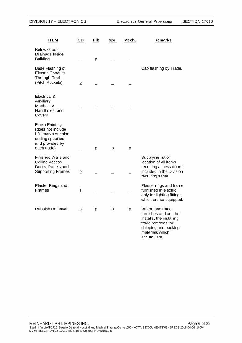
ITEM
OD
Plb
Spr.
Mech.
Remarks
Below Grade Drainage Inside Building
_
p
_
_
Base Flashing of Electric Conduits Through Roof (Pitch Pockets)
p
_
_
_
Cap flashing by Trade.
Electrical & Auxiliary Manholes/ Handholes, and Covers
_
_
_
_
Finish Painting (does not include I.D. marks or color coding specified and provided by each trade)
_
p
p
p
Finished Walls and Ceiling Access Doors, Panels and Supporting Frames
p
_
_
_
Supplying list of location of all items requiring access doors included in the Division requiring same.
Plaster Rings and Frames
i
_
_
_
Plaster rings and frame furnished in electric only for lighting fittings which are so equipped.
Rubbish Removal p p p p Where one trade
furnishes and another installs, the installing trade removes the shipping and packing materials which accumulate.
DIVISION 17 – ELECTRONICS Electronics General Provisions SECTION 17010
MEINHARDT PHILIPPINES INC. Page 7 of 22 S:\admin\mpi\MP1716_Baguio General Hospital and Medical Trauma Center\000 - ACTIVE DOCUMENTS\09 - SPECS\2018-04-06_100% DD\03-ELECTRONICS\17010-Electronics General Provisions.doc
ITEMS OD Plb Spr Mech. Elec. Remarks
Special Tools for Equipment Maintenance
f
f
f
F
f
Electric Power Consuming Items and Controls for Other than Mechanical Equipment, e.g. Motorized Doors
p
_
_
_
_
Concrete Foundations, Pads, Pits, Curbs, and Bases Inside Buildings
p
_
_
_
_
Furnishing exact dimensions of anchors, vibration mounts and templates included in each trade providing the associated equipment.
Concrete Foundations, Pads and Bases Outside Buildings
p
_
_
_
_
Furnishing exact dimensions of anchors, vibration mounts and templates included in each trade providing the associated equipment.
Masonry Pits p _ _ _ _ Furnishings of covers
and associated frames included in each trade.
Sump Pits p _ _ _ _ Furnishing of covers
and associated frames included in each trade.
Concrete Lined Trenches inside Building Foundations
p
_
_
_
_
Prime Coat Painting
_
p
p
P
p
Field Touch-up Painting of Damaged Shop Coats
_
p
p
P
p

DIVISION 17 – ELECTRONICS Electronics General Provisions SECTION 17010
MEINHARDT PHILIPPINES INC. Page 8 of 22 S:\admin\mpi\MP1716_Baguio General Hospital and Medical Trauma Center\000 - ACTIVE DOCUMENTS\09 - SPECS\2018-04-06_100% DD\03-ELECTRONICS\17010-Electronics General Provisions.doc
ITEM OD Plb Spr. Mech. Elec. Remarks
Rust proofing Field Cut and Assembled Iron Supporting Frames and Racks
_
p
p
P
p
Grating and Exterior Wall Louvers
p
_
_
_
_
Duct Connections to Louvers
_
_
_
P
_
Equipment Delivered and Set in Place
p
_
_
_
_
Except Mechanical and Electrical Equipment by Divisions 15, & 16.
Vinyl Tape or Painted Colour Coding, Banding Arrows and Similar Identification for Mechanical and Electrical Work
p
p
p
P
p
Under floor and Header Duct
_
_
_
_
p
Responsibility for coordination is included in this Section.
Lighting Fixtures _ _ _ _ p See Drawings. Elevators, Escalators and Dumbwaiters
p
_
_
_
_
Power connections to disconnect switch included in Electrical Section.
Catwalks and Ladders to Electrical Equipment
p
_
_
_
_
Drainage Lines For Elect’l Manholes/Sump Pits
p p
_ _
_ _
_ _
_ _
See Drawings See Drawings

DIVISION 17 – ELECTRONICS Electronics General Provisions SECTION 17010
MEINHARDT PHILIPPINES INC. Page 9 of 22 S:\admin\mpi\MP1716_Baguio General Hospital and Medical Trauma Center\000 - ACTIVE DOCUMENTS\09 - SPECS\2018-04-06_100% DD\03-ELECTRONICS\17010-Electronics General Provisions.doc
ITEM OD Plb. Spr. Mech. Elec. Remarks
Roughing to Equipment Furnished by Others
_
p
p
P
p
Auxiliary Systems Cabling and Conduiting including the supply and installation of equipment
p
As indicated on the plans and specifications.
D. Each Division is required to supply all necessary supervision and coordination
information to any other Division supplying work to accommodate that Division.
E. For items which are to be installed but not furnished as part of this Division, the electronics work includes:
1. Coordination of their delivery. 2. Unloading from delivery trucks driven into any point on the property line at
grade level. 3. Safe handling/keeping and field storage up to the time of permanent
placement in the project. 4. Correction of any damage, defacement or corrosion to which they may have
been subjected. 5. Field make-up and internal wiring as indicated for their proper operation. 6. Mounting in place. 7. Connection to building wiring, including the purchase and installation of all
termination junction boxes necessary to adapt and connect them to this wiring.
DIVISION 17 – ELECTRONICS Electronics General Provisions SECTION 17010
MEINHARDT PHILIPPINES INC. Page 10 of 22 S:\admin\mpi\MP1716_Baguio General Hospital and Medical Trauma Center\000 - ACTIVE DOCUMENTS\09 - SPECS\2018-04-06_100% DD\03-ELECTRONICS\17010-Electronics General Provisions.doc
PART 2 – PRODUCTS 2.1 EQUIPMENT AND MATERIALS
A. Provide products and materials that are new, clean, free of defects, and free of damage and corrosion.
B. Products and materials shall not contain asbestos or any other material which is
installed considered hazardous by the authority having jurisdiction.
C. Replace materials of less than specified quality and relocate work incorrectly installed as directed by the Project Manager.
D. Provide name/data plates on major components of equipment with manufacturer’s
name. Model number, serial number, capacity data and electrical or electronics characteristics attached in a conspicuous place.
E. Install materials and equipment with qualified trades people.
F. Maintain uniformity of manufacturer for equipment used in similar application and
sizes.
G. Fully lubricate equipment where required.
H. Follow manufacturer’s instructions for installing, connecting, and adjusting equipment. Provide a copy of such instructions at the equipment during installation.
I. Where factory testing of equipment is required to ascertain performance, and
attendance by the Owner’s representative is required to witness such tests, associated travel costs and subsistence shall be paid for by the Contractor.
J. Equipment capacities, ratings, etc., are scheduled or specified for job site operating
conditions. Equipment sensitive to altitude shall be derated with the method of derating identified on the submittals.
K. Enclosures for Electrical and Electronic equipment installed in mechanical equipment
rooms shall be NEMA type 1 gasketed. Enclosures for electrical and electronics equipment installed outdoors shall be NEMA type 4 or greater required.
L. Energy consuming equipment shall meet local energy ordinances.
PART 3 – EXECUTION 3.1 FEES AND PERMITS
A. Pay all required fees and obtain all required permits/right of ways related to the ELECTRONICS installation.
B. Pay royalties or fees required in connection with the use of patented devices and
systems. C. Provide controlled inspection where required by authorities having jurisdiction or by
these specifications.

DIVISION 17 – ELECTRONICS Electronics General Provisions SECTION 17010
MEINHARDT PHILIPPINES INC. Page 11 of 22 S:\admin\mpi\MP1716_Baguio General Hospital and Medical Trauma Center\000 - ACTIVE DOCUMENTS\09 - SPECS\2018-04-06_100% DD\03-ELECTRONICS\17010-Electronics General Provisions.doc
3.2 SUBMITTALS AND REVIEWS General:
A. Submit shop drawings, manufacturer’s product data sheets, samples, and test reports as specified.
B. Within two months after notice to proceed by the Project Managers, or after execution
of Owner/Contractor Agreement, submit a complete typed list of all ELECTRONICS equipment manufacturer’s and materials suppliers for the equipment proposed to be provided on this project, as well as names of all subcontractors.
C. Within four months after notice to proceed issued by the Project Managers, or after
execution of Owner/Contractor Agreement, prepare an index of all submittals for the project. Include a submittal identification number, a cross-reference to the Specification sections or Drawings number, and an item description. Prefix the submittal identification number by the Specification sections to which they apply. Indicate on each submittal, the submittal identification number in addition to the other data specified. All subcontractors shall utilize the assigned identification number.
D. After the Contract is awarded, obtain complete shop drawings, product data and
samples from the manufacturer, suppliers, vendors, and all subcontractors, for all materials and equipment as specified. Submit data and details of such materials and equipment for review. Prior to submissions, certify that the shop drawings, product data and samples are in compliance with the Contract Documents. Check all materials and equipment upon their arrival on the job site and verify their compliance with the Contract Documents. Modify any work which proceeds prior to receiving accepted shop drawings as required to comply with the Contract Documents and the shop drawings.
E. Review of submittals is for general compliance with the design concept and contract
documents. Comments or absence of comments shall not relieve the Contractor from compliance with the full scope and requirements of the Contract Documents. The Contractor remains solely responsible for details and accuracy, for confirming and correlating all quantities and dimensions, for selecting fabrication processes, for techniques of construction, for performing the work in a safe manner, and for coordinating the work with that of other trades.
F. No part of the work shall be started in the shop or in the field until the shop drawings
and samples for that portion of the work have been submitted and accepted as well as No equipment shall be procured nor delivered to the job site unless a shop drawing for the same has been submitted and accepted or approved or similar words.
G. A minimum period three working days, exclusive of transmittal time, will be required in
the Engineer’s office each time a shop drawing, product data and/or samples are submitted for review. This time period must be considered by the Contractor in the scheduling of the work.
H. Submit five (5) copies or as per Project Manager’s requirement items, shop drawings,
and manufacturer’s product submittals.

DIVISION 17 – ELECTRONICS Electronics General Provisions SECTION 17010
MEINHARDT PHILIPPINES INC. Page 12 of 22 S:\admin\mpi\MP1716_Baguio General Hospital and Medical Trauma Center\000 - ACTIVE DOCUMENTS\09 - SPECS\2018-04-06_100% DD\03-ELECTRONICS\17010-Electronics General Provisions.doc
I. Submittals will be stamped as follows:
Stamp Interpretation Approved/Unaltered Fabrication, manufacture, or
construction may proceed providing submittal complies with the Contract Documents.
Approved with corrections/comments as noted prior to general issue
Fabrication, manufacture, or construction may proceed providing submittal complies with the Contract Documents and the Engineer’s notation are complied with.
For Re-submission The submittal does not comply with the Contract Documents; do not proceed with fabrication, manufacture, or construction .The work and shop drawings are not permitted at the job site. Re-submit appropriate shop drawings.
J. Submit materials and equipment by manufacturer, trade name, and model number.
Include copies of applicable brochure or catalog material. Maintenance and operating manuals are not acceptable substitutes for shop drawings.
K. Identify each sheet of printed submittal pages (using arrows, underlining or circling) to
show applicable sizes, types, model numbers, ratings, capacities and options actually being proposed. Cross out non-applicable information. Note specified features such as materials or paint finishes.
L. Include dimensional data for roughing in and installation and technical data sufficient
to verify that equipment meets the requirements of the Contract Documents. Include wiring, piping and service connection data.
M. Maintain a complete set of reviewed and stamped shop drawings, product data and
samples on site. N. For each room or area of the building containing ELECTRONICS equipment, submit
the following:
1. Floor Plans: Plan and elevation layout drawings indicating the equipment in the exact location in which it is intended to be installed. These plans shall be of a scale not less than 1:50. They shall be prepared in the following manner:
Indicate the physical boundaries of the space including door swings and
ceiling heights and ceiling types (as applicable).
a. Illustrate all ELECTRONICS equipment proposed to be contained therein. Include top & bottom elevation of all ELECTRONICS equipment. The drawings shall be prepared utilizing the dimensions contained in the individual equipment submittals. Indicate code and manufacturer’s required clearances.
b. Illustrate all other equipment therein such as conduits, detectors, luminaries, ducts, registers, pull boxes, wire-way, structural elements, etc.
c. Indicate the operating weight of each piece of equipment. d. Indicate the heat release from each piece of Electronics and
Electrical equipment in terms of BTU per hour. This information shall be that which is supplied by the respective manufacturers.
e. Illustrate concrete pads, curbs, etc.
DIVISION 17 – ELECTRONICS Electronics General Provisions SECTION 17010
MEINHARDT PHILIPPINES INC. Page 13 of 22 S:\admin\mpi\MP1716_Baguio General Hospital and Medical Trauma Center\000 - ACTIVE DOCUMENTS\09 - SPECS\2018-04-06_100% DD\03-ELECTRONICS\17010-Electronics General Provisions.doc
f. Indicate dimensions to confirm compliance with code required clearances.
g. Indicate maximum normal allowable operating temperature for each piece of equipment (as per each respective manufacturer’s recommendations).
h. Equipment removal routes.
O. The work described in shop drawings submission shall be carefully checked by the Contractor for clearances (including those required for maintenance and servicing), field conditions, maintenance of architectural conditions and coordination with other trades on the job. Each submitted shop drawing shall include a certification that related job conditions have been checked by the Contractor and each Subcontractor and that conflicts do not exist.
P. The Contractor is not relieved of the responsibility for dimensions or errors that may
be contained on submissions, or for deviations from the requirements of the Contract Documents. The noting of some errors but overlooking others does not grant the Contractor permission to proceed in error. Regardless of any information contained in the Shop Drawings, product data and samples, the Contract Documents govern the work and are neither waived nor superseded in any way by the review of Shop Drawings, product data and samples.
Q. Inadequate or incomplete shop drawings, product data and/or samples will not be
reviewed and will be returned to the Contractor for re-submittal.
R. Indicate the following on the lower right hand corner of each shop drawing and on the front cover of each product data brochure cover. The submittal identification number; title of the sheet or brochure; name and location of the Product; names of the Architect, Engineer, Contractor, Subcontractor, manufacturer, supplier, and vendor; the date of submittal; and the date of each correction, version and revision. Number all pages and drawings in product data brochures consecutively from beginning to end. Unless the above information is included, the submittal will be returned for resubmission. Re-submittals of product data or brochures shall include a cover letter summarizing the corrections made in response to the review comments.
S. The distribution equipment, short circuit and coordination study (shall be submitted,
before or in parallel with the Panel boards/CB Submittals) and room layout submittals shall be submitted concurrently. Failure to submit concurrently may result in the immediate return of the submittal marked FOR RESUBMISSION.
3.3 COORDINATION OF WORK
A. Contract documents establish scope, materials and quality but are not detailed installation instruction. Drawings are diagrammatic.
B. Coordinate work with related trades and furnish in writing, any information necessary
to permit the work of related trades to be installed satisfactorily and with the least possible conflict or delay.
C. The ELECTRONICS drawings show the general arrangement of equipment and
appurtenances. Follow these drawings as closely as the actual construction and the work of other trades will permit. Provide off- sets, fittings, and accessories which may be required but not shown on the drawings. Investigate the site, and review drawings of other trades to determine conditions affecting the work, and provide such work and accessories as may be required to accommodate such conditions.
D. It shall be understood that the final location of outlets, lighting fixtures, sprinkler
heads, smoke detectors, speakers, clock supply & return air outlets, thermostats, electronics or electrical panelboards, etc. may be moved in the field by a distance of

DIVISION 17 – ELECTRONICS Electronics General Provisions SECTION 17010
MEINHARDT PHILIPPINES INC. Page 14 of 22 S:\admin\mpi\MP1716_Baguio General Hospital and Medical Trauma Center\000 - ACTIVE DOCUMENTS\09 - SPECS\2018-04-06_100% DD\03-ELECTRONICS\17010-Electronics General Provisions.doc
4.57 meters (15 ft.) from the location shown without extra cost, provided such notice is given prior to installation.
E. Exercise particular caution with reference to the location of panels, outlets, switches,
etc., and have the precise and definite locations accepted by the Project Manager before proceeding with the installation.
F. The drawings show only the general run of utilities and approximate location of
outlets. Any significant changes in location of outlets, cabinets, etc., necessary in order to meet field conditions shall be brought to the determine attention of the Project Manager for review before such alterations are made. Modifications shall be made at no additional cost to the Owner.
G. Verify with the Project Manager the exact location and mounting height of outlets,
thermostats and equipment not dimensionally located on the drawings.
H. Circuit tags in the form of numbers are used where shown to indicate the circuit designation numbers in electronics or electrical panels. Show the actual circuit numbers on the as built Record Drawings and on the associated typed panelboard directory card. Where circuiting is not indicated, provide required circuiting in accordance with the loading indicated on the drawings and/or as indicated.
I. The drawings generally do not indicate the number of wires in conduit for the branch
circuit wiring of fixtures and outlets, or the actual circuiting. Provide the correct wire size and quantity as required by the indicated circuiting and/or circuit numbers indicated, the control intent, referenced wiring diagrams (if any), the specified voltage drop or maximum distance limitations, and 5% maximum for feeders and branches (3% maximum on either feeder or branch).
J. Carefully check space requirements with other trades to ensure that equipment can
be installed in the space alloted.
K. Wherever work interconnects with work of other trades, coordinate with other trades to ensure that they have the information necessary so that they may properly install the necessary connections and equipment. Identify items (remote ballast, pull boxes, etc.) requiring access in order that the Ceiling Trade will know where to install access doors and panels.
L. Consult with other trades regarding equipment so that, wherever possible, motor
controls and distribution equipment are of the same manufacturer.
M. Furnish and set sleeves for passage of Electronics risers through structural masonry and concrete walls and floors and elsewhere as required for the proper protection of each Electronics riser passing through building surfaces.
N. Provide fire stopping of approved materials around all pipes, conduits, ducts, sleeves.
O. Provide detailed information on openings and holes required in pre-cast members for
ELECTRONICS utilities.
P. Provide required supports and hangers for conduit and equipment, designed so as not to exceed allowable loading of structures.
Q. Examine and compare the contract drawings and specifications with the drawings
and specifications of other trades, and report any discrepancies between them to the Project Manager and obtain written instructions for changes necessary in the work. Install and coordinate the work in cooperation with other related trades. Before installation, make proper provisions to avoid interference.

DIVISION 17 – ELECTRONICS Electronics General Provisions SECTION 17010
MEINHARDT PHILIPPINES INC. Page 15 of 22 S:\admin\mpi\MP1716_Baguio General Hospital and Medical Trauma Center\000 - ACTIVE DOCUMENTS\09 - SPECS\2018-04-06_100% DD\03-ELECTRONICS\17010-Electronics General Provisions.doc
R. Wherever the work is of sufficient complexity, prepare additional detail drawings scaled to coordinate the work with the work of other trades. Detailed work shall be clearly identified on the drawings as to the area to which it applies. Submit these drawings to the Architect for review. At completion include a set of these drawings with each set of record drawings.
S. Furnish services of an experienced Superintendent, who shall be in constant charge
of all work, and who shall coordinate work with the work of other trades. No work shall be installed without coordinating with other trades.
T. Coordinate with the local electric utility company, the local telephone company and
local cable TV company and their requirements for service connections and provide all necessary metering provisions, grounding, materials, equipment, labor, testing, and appurtenances.
U. Before commencing work, examine adjoining work on which this work is in any way
affected and report conditions which prevent performance of the work. Become thoroughly familiar with actual existing conditions to which connections must be made or which must be changed or altered.
V. Adjust location of conduits, panels, equipment, etc., to accommodate the work to
prevent interference, both anticipated and encountered. Determine the exact route and location of each conduit prior to fabrication.
1. Right-of-Way: Lines which pitch have the right-of-way over those which do
not pitch. For example: coordinate, steam, and plumbing drains normally have right-of-way. Lines whose elevations cannot be changed have right-of-way over lines whose elevations can be changed.
2. Provide offsets, transitions and changes in direction of conduit as required to maintain proper head room and pitch on sloping lines.
W. In cases of doubt as to the work intended, or in the event of need for explanation,
request supplementary instructions from the Project Manager. 3.4 EXAMINATION OF SITE
A. Prior to the re-submitting of bids, visit the project site and become familiar with all conditions affecting the proposed installation and make provisions as to the cost thereof.
B. The Contract Documents do not make representations regarding the character or
extent of the existing structural installations which will be encountered during the work, based on examination of the site or other information. Failure to examine the drawings or other information does not relieve the Contractor of responsibility for satisfactorily completion of the work.
3.5 EXCAVATION AND BACKFILL
A. Provide excavation for the work of this Division. Excavate all material encountered, to the depths indicated on the drawings or as required. Remove from the site excavated materials not required or suitable for backfill. Provide grading as may be necessary to prevent surface water from flowing into trenches or other excavations. Remove any water which accumulates. Provide sheeting and shoring as may be necessary for the protection of the work and for the safety of personnel.
B. Provide trenches of widths necessary for the proper execution of the work. Grade
bottom of the trenches accurately to provide uniform bearing and support the work on undisturbed soil at every point along its entire length. Except where rock is encountered, do not excavate below the depths indicated. Where rock excavations
DIVISION 17 – ELECTRONICS Electronics General Provisions SECTION 17010
MEINHARDT PHILIPPINES INC. Page 16 of 22 S:\admin\mpi\MP1716_Baguio General Hospital and Medical Trauma Center\000 - ACTIVE DOCUMENTS\09 - SPECS\2018-04-06_100% DD\03-ELECTRONICS\17010-Electronics General Provisions.doc
are required, excavate rock to a minimum overdepth of four inches below the trench depths indicated on the drawings or required. Backfill overdepths in the rock excavation and unauthorized overdepths with loose, granular, moist earth, thoroughly machine tamped to a compaction level of at least 95% to standard proctor density or 75% relative density or as specified by the Architect. Wherever unstable soil that is incapable of properly supporting the work is encountered in the bottom of the trench, remove soil to a depth required and backfill the trench to the proper grade with coarse sand, fine gravel or other suitable material.
C. Excavate trenches for utilities that will provide the following minimum depths of cover
from existing grade or from indicated finished grade, whichever is lower, unless otherwise specifically shown.
1. Electric service: 70 cm minimum 2. Telephone service: 70 cm minimum
D. Trenches should not be placed within 3 meters of foundation or soil surfaces which
must be resist horizontal forces.
E. Do not backfill until all required tests have been performed and installation observed by the Project Manager. Comply with the requirements of other sections of the specifications. Backfill shall consist of non-expansive soil with limited porosity. Deposit in 15 cm layers and thoroughly and carefully tamp until the work has a cover of not less than 30 cm. Backfill and tamp remainder of trench at 30 cm intervals until complete. Uniformly grade the finished surface.
3.6 CUTTING AND PATCHING
A. Where cutting, channeling, chasing or drilling of floors, walls, partitions, ceilings or other surfaces is necessary for the proper installation, support or anchorage of conduit or other equipment, layout the work carefully in advance. Repair any damage to the building, piping, equipment or defaced finish plaster, woodwork, metalwork, etc., using skilled trades people of the trades required at no additional cost to the Owner.
B. Do not cut, channel, chase or drill unfinished masonry, tile, etc., unless permission
from the Project Manager is obtained. If permission is granted, perform this work in a manner acceptable to the Project Manager.
C. Where conduit or equipment are mounted on a painted finished surface, or a surface
to be painted, paint to match the surface. Cold galvanize bare metal whenever support channels are cut.
D. Provide slots, chases, openings and recesses through floors, walls, ceilings, and
roofs as required. Where these openings are not provided, provide cutting and patching using appropriate Trade Contractor to accommodate penetrations at no additional cost to the Owner.
3.7 SEALING OF PENETRATIONS
A. Holes in Roof
1. Roof penetrations for passage of conduits or circular PVC and PVC Cables shall be sealed watertight using a flexible polypropylene conical sleeve designed to seal the pop or cable and the roof structure, regardless of the roof profile. Flashings to the roof strictly in accordance with the manufacturer’s instruction.
DIVISION 17 – ELECTRONICS Electronics General Provisions SECTION 17010
MEINHARDT PHILIPPINES INC. Page 17 of 22 S:\admin\mpi\MP1716_Baguio General Hospital and Medical Trauma Center\000 - ACTIVE DOCUMENTS\09 - SPECS\2018-04-06_100% DD\03-ELECTRONICS\17010-Electronics General Provisions.doc
2. All sharp metal edges, which may come in contact with the cable, shall be suitably bushed.
B. Air Tight Seals
1. All penetrations through the building fabric subject to suction or
pressurization shall be sealed airtight.
C. Fire Rated Penetrations
1. Where services penetrate any fire rated barrier, the Contractor shall seal the penetration with the use of an appropriate material to ensure the integrity of the fire barrier.
2. The Contractor shall seal the cable enclosures through fire rated barriers to ensure the integrity and rating of the fire barrier.
D. Acoustic Penetrations
1. Where services penetrate acoustic barriers, sealant shall be supplied and
installed to maintain the acoustic separation at least equal to the barrier penetration.
3.8 MOUNTING HEIGHTS
A. Mounting height of equipment listed below is from finished floor to center line of equipment unless specified or indicated otherwise.
1. Local switches: 1400mm 2. Wall receptacles: vertically
a. Above floors: 300mm b. Above top of counters or splash back: 150mm
3. Panelboards: 1800mm to top. 4. Telephone and data outlets above floor: 300mm vertically 5. Fire alarm pull stations: 1200mm 6. Fire alarm horns/bells: 2100mm 7. Emergency fire alarm telephones:1400mm 8. Television outlets above floor: 300mm 9. Wall-mounted speakers: 2100mm 10. Thermostats: 1400mm
B. If mounting height of equipment is not indicated, verify with Architect’s representative
before proceeding with installation. 3.9 CLEANING UP
A. Avoid accumulation of debris, boxes, loose materials, crates, etc., resulting from the installation of this work. Remove from the premises each day all debris, boxes, etc., and keep the premises clean and free of dust and debris.
B. Clean all fixtures and equipment at the completion of the project. Wipe clean exposed
lighting fixture reflectors and trim pieces with a non-abrasive just prior to occupancy.
C. All Electronics and Electrical equipment shall be thoroughly vacuumed and wiped clean prior to energization and at the completion of the project. Equipment shall be opened for observation by the Project Manager as required.
DIVISION 17 – ELECTRONICS Electronics General Provisions SECTION 17010
MEINHARDT PHILIPPINES INC. Page 18 of 22 S:\admin\mpi\MP1716_Baguio General Hospital and Medical Trauma Center\000 - ACTIVE DOCUMENTS\09 - SPECS\2018-04-06_100% DD\03-ELECTRONICS\17010-Electronics General Provisions.doc
3.10 WATERPROOFING
A. Restore waterproof integrity of walls or surfaces after they have been penetrated without additional cost to the Owner.
3.11 SUPPORTS
A. Support work in accordance with the best industry practice. Provide supports, hangers, auxiliary structural members and supplemental hardware required for support of the work.
B. Provide supporting frames or racks extending from floor slab to ceiling slab for work
indicated as being supported from walls where the walls are incapable of supporting the weight. In particular, provide such frames or racks in electronics and electrical closets and mechanical equipment room.
C. Provide supporting frames or racks for equipment which is installed in a free standing
position.
D. Supporting frames or racks shall be of standard angle, standard channel or specialty support system steel members, rigidly bolted or welded together and adequately braced to form a substantial structure. Racks shall be of ample size to assure a workmanlike arrangement of all equipment mounted on them.
E. Adequate support of equipment (including outlet, pull and junction boxes and fittings)
shall not depend on piping, electric conduits, raceways, or cables for support.
F. Any equipment shall not rest on or depend for support on suspended ceiling media (tiles, lath, plaster, as well as splines, runners, bars and the like in the plane of the ceiling). Provide independent support for ELECTRONICS equipment. Do not attach to supports provided for ductwork, piping or work of other trades.
G. Provide required supports and hangers for conduit, equipment, etc., so that loading
will not exceed allowable loadings of structure. ELECTRONICS equipment and supports shall not come in contact with work of each other’s trades.
3.12 FASTENINGS
A. Fasten equipment to building in accordance with the best industry practice.
B. Where weight applied to the attachment points is 45 kg or less, conform to the following as a minimum:
1. Wood : Wood screws 2. Concrete and solid masonry : Bolts and expansion shields 3. Solid metal : Machine screws in tapped holes or
with welded studs 4. Steel decking or sub-floor : Fastenings as specified below for applied weights in excess of 45 kg.
C. Where weight applied to the building attachment points exceeds 45 kg, but is 135 kg or less, conform to the following as a minimum:
1. At concrete slabs provide 60 cm x 60 cm x 13 cm steel fishplates on top with
through bolts. Fishplate assemblies shall be chased in and grouted flush with the top slabs screed line, where no fill is to be applied.
2. At steel decking or sub-floor for all fastenings, provide through bolts and threaded rods. The tops of bolts and rods shall be set at least one inch below the top fill screed line and grouted in. Suitable washers shall be used under bolt heads or nuts. In cases where the decking or sub-floor manufacturer

DIVISION 17 – ELECTRONICS Electronics General Provisions SECTION 17010
MEINHARDT PHILIPPINES INC. Page 19 of 22 S:\admin\mpi\MP1716_Baguio General Hospital and Medical Trauma Center\000 - ACTIVE DOCUMENTS\09 - SPECS\2018-04-06_100% DD\03-ELECTRONICS\17010-Electronics General Provisions.doc
produces specialty hangers to work with his decking or sub-floor such hangers shall be provided.
D. Where weight applied to building attachment points exceeds 135 kg, coordinate with
and obtain the approval of Project Manager and conform to the following as a minimum:
1. Provide suitable auxiliary channel or angle iron bridging between building
structural steel elements to establish fastening points. Bridging members shall be suitably welded or clamped to building steel. Provide threaded rods or bolts to attach to bridging members.
E. For items which are shown as being ceiling mounted at locations where fastening to
the building construction element above is not possible, provide suitable auxiliary channel or angle iron bridging tying to the building structural elements.
F. Wall mounted equipment may be directly secured to wall by means of steel bolts.
Groups or arrays of equipment may be mounted on adequately sized steel angles, channels, or bars. Prefabricated steel channels as manufactured by Hilti or Unistrut or Eristrutt are acceptable.
G. Where equipment is mounted on gypsum board partitions, the mounting screws shall
pass through the gypsum board and securely attach to the partition studs. As an alternative the mounting screws may pass through the gypsum board and be securely attached to 15 cm square, galvanized metal backplates which are attached to the gypsum board with an approved non-flammable adhesive. Toggle bolts installed in gypsum board partitions are not acceptable.
3.13 IDENTIFICATION
A. Identify ELECTRONICS equipment with permanently attached black phenolic nameplates with 13 mm high white engraved lettering. Identification shall include equipment name or load served as appropriate. Nameplates for equipment connected to the emergency power system shall be red white lettering. Nameplates shall be attached with cadmium plated screws; peel and stick tape or glue on type nameplates are unacceptable.
B. Cable tags shall be nameplate secured with nameplate non metallic cord.
C. Provide an engraved nameplate for each switch controlling loads which are not local
to the switch.
D. Wherever raceways for future use are terminated outside of the building, stake the location with a 60 cm long, 25 mm x 25 mm wooden stake.
E. See individual section for additional identification requirements.
3.14 EQUIPMENT PADS AND ANCHOR BOLTS
A. Provide concrete pads under all floor mounted electronics equipment. Equipment pads shall conform to the shape of the piece of equipment it serves with a minimum 25 mm margin around the equipment. Pads shall be a minimum of 10cm high or as shown in the drawing and made of a minimum of 28 day, 175 kgs/square cm concrete reinforced with 15 cm x 15 cm welded wire mesh. Trowel tops and sides of pad to smooth finishes, equal to those of the floors, with all external corners bull nosed to a 20 mm radius. Shop drawings stamped UNALTERED shall be used for dimensional guidance in sizing pads.
DIVISION 17 – ELECTRONICS Electronics General Provisions SECTION 17010
MEINHARDT PHILIPPINES INC. Page 20 of 22 S:\admin\mpi\MP1716_Baguio General Hospital and Medical Trauma Center\000 - ACTIVE DOCUMENTS\09 - SPECS\2018-04-06_100% DD\03-ELECTRONICS\17010-Electronics General Provisions.doc
B. Provide galvanized anchor bolts for all equipment placed on concrete equipment pads, inertia blocks, or on concrete slabs. Provide bolts of the size and number recommended by the manufacturer of the equipment and locate by means of suitable templates. Equipment installed on vibration isolators shall be secured to the isolator. Secure the isolator to the floor, pad, or support as recommended by the vibration isolation manufacturer.
3.15 PROHIBITED LABELS AND IDENTIFICATIONS
A. In all public areas, tenant areas, and similar locations within the project, the inclusion or installation of any equipment or assembly which bears on any surface any name, trademark, or other insignia which is intended to identify the manufacturer, the vendor, or other source(s) from which such object has been obtained, is prohibited.
B. Required UL labels shall not be removed nor shall identification specifically required
under the various technical sections of the Specifications be removed. 3.16 DELIVERY, DRAYAGE AND HAULING
A. Provide drayage, hauling, hoisting, shoring and placement in the building of equipment specified and be responsible for the timely delivery and installation of equipment as required by the construction schedule. If any item of equipment is received prior to the time it is required, the Contractor shall be responsible for its proper storage and protection until the time it is required. Pay for all costs of demurrage or storage.
B. If equipment is not delivered or installed at the project site in a timely manner as
required by the project construction schedule, the Contractor shall be responsible for resulting disassembly, re-assembly, manufacturer’s supervision, shoring, general construction modification, delays, overtime cost, etc., at no additional cost to the Owner.
3.17 EQUIPMENT AND MATERIAL PROTECTION
A. Protect the work, equipment, and material of other trades from damage by work or workmen of this trade, and correct damage caused without additional cost of the Owner.
B. Take responsibility for work, materials, and equipment until finally inspected, tested
and accepted. Protect work against theft, injury, or damage, and carefully store material and equipment received on site which is not immediately installed. Close open ends of work with temporary covers or plugs during construction to prevent entry of obstructing material. Cover and protect equipment and materials from damage due to water, spray-on fireproofing, construction debris, etc. Store equipment subject to moisture damage in dry, heated spaces.
C. Provide adequate means for fully protecting finished parts of materials and equipment
against damage from whatever cause during the progress of the work until final acceptance. Protect materials and equipment in storage and during construction in such a manner that no finished surfaces will be damaged or marred, and moving parts are kept clean and dry. Do not install damaged items; take immediate steps to obtain replacement or repair.
D. Lighting fixture troffers with parabolic reflectors shall be installed with factory mounted
plastic protective bags around parabolic reflector assembly. Remove protective bags just prior to occupancy.

DIVISION 17 – ELECTRONICS Electronics General Provisions SECTION 17010
MEINHARDT PHILIPPINES INC. Page 21 of 22 S:\admin\mpi\MP1716_Baguio General Hospital and Medical Trauma Center\000 - ACTIVE DOCUMENTS\09 - SPECS\2018-04-06_100% DD\03-ELECTRONICS\17010-Electronics General Provisions.doc
3.18 TESTING OF ELECTRONICS SYSTEMS
A. Comply with the project construction schedule for the date of final performance and acceptance testing, and complete work sufficiently in advance of the Contract completion date to permit the execution of the testing prior to occupancy and Contract closeout. Complete any adjustments and/or alterations which the final acceptance tests indicate as necessary for the proper functioning of all equipment prior to the completion date. See individual sections for extend of testing required.
B. Provide a detailed schedule of completion indicating when each system is to be
completed and outlining when field testing will be performed. Submit completion schedule for review within one week after the notice to proceed by Owner or Owner’s Representative has been given. Update this schedule periodically as the project progresses.
3.19 OPERATING INSTRUCTIONS
A. Provide the services of factory trained specialists to provide an operating instructions seminar for equipment and systems. The seminar shall be conducted over a five days (consecutive) period. Instruction time is defined as straight time working hours and does not include nights, weekends or travel time to and from the project.
B. Submit seminar agenda, schedule and list of representatives to the Owner for
approval one week prior to suggested date of seminar. Do not commence seminar until the Owner has issued a written acceptance of the starting time and attendees. Confirm attendance of seminar by written notification to participants.
C. Instruct Owner’s operating personnel in proper starting sequences, operation,
shutdown, general maintenance and preventative maintenance procedures, including normal and emergency procedures. Obtain signatures of Owner’s attendees.
D. Submit final copies of record drawings and operating and maintenance manuals to
Owner at Seminar.
E. Submit a written record of minutes and attendees of the seminar to the Owner. 3.20 OPERATING AND MAINTENANCE MANUALS
A. Provide Operating and Maintenance Manuals for equipment and materials furnished under this Division.
B. Submit five copies of Operating and Maintenance Manuals for review at least one
week before the completion date. Assemble data in a completely indexed volume or volumes in three-ring binders and identify the size, model, and features indicated for each item. Print the project name on the outside of the binders.
C. Maintenance manuals shall include complete cleaning and servicing data compiled in
a clear and easily understandable format. Show model numbers of each piece of equipment, complete lists of replacement parts, capacity ratings, and actual loads.
D. Provide the following where applicable:
1. Identifying name and mark number 2. Locations (where several similar items are used, provide a list) 3. Complete nameplate data 4. Certified Record Drawings and Final Reviewed submittals 5. Parts list 6. Performance curves and data 7. Wiring diagrams
DIVISION 17 – ELECTRONICS Electronics General Provisions SECTION 17010
MEINHARDT PHILIPPINES INC. Page 22 of 22 S:\admin\mpi\MP1716_Baguio General Hospital and Medical Trauma Center\000 - ACTIVE DOCUMENTS\09 - SPECS\2018-04-06_100% DD\03-ELECTRONICS\17010-Electronics General Provisions.doc
8. Manufacturer’ recommended operating and maintenance instructions with all non-applicable information deleted.
9. List of spare parts recommended for normal service requirements 10. Assembly and disassembly instructions for normal service requirements. 11. Test reports 12. Trouble shooting diagnostics instructions where applicable. 13. Address of service organization including phone and fax numbers.
3.21 RECORD DRAWINGS
A. Maintain on a daily basis at the project site a complete set of Record Drawings, reflecting an accurate dimensional record of deviations between work shown on Drawings and that actually installed.
B. Record dimensions clearly and accurately to delineate the work as installed; suitably
identify locations of all equipment by at least two dimensions to permanent structures. In addition, mark the Record Drawings to show the precise location of concealed work and equipment, including concealed or embedded raceways and cables and all changes and deviations in the Electronics work from that shown on the Contract Documents. This requirement shall not be construed as authorization to make changes in the layout or work.
C. Upon completion of the installation, obtain from the Architect’s representative, a
complete set of discs of architectural drawings. In a neat and accurate manner, provide a complete record of all revisions of the original changes as actually installed. The cost for transparencies and for making required changes shall be included in the contract. Submit one set of black line prints of those revised transparencies for review. After the review, make the necessary changes for accuracy or the Engineer will not assume responsibility in any of its inaccuracy or incompleteness.
D. All record drawings should be in Autocad 2004. Both prints (5 sets) and a disc file of
those record drawings should be submitted to the Owner after approval. 3.22 FINAL PUNCHLIST
A. Prior to the Final Punchlist, certify that systems and equipment are complete, operational, and are in compliance with the Contract Documents.
B. During the final punchlist, provide personnel with access keys, hand held radios, and necessary expertise to operate each system and piece of equipment to demonstrate operational compliance with the Contract Documents.
C. Any deficiencies noted on the Final Punchlist shall be expeditiously corrected and
certified in writing.
END OF SECTION

DIVISION 17 – ELECTRONICS Grounding and Bonding SECTION 17060
MEINHARDT PHILIPPINES INC.
PART 1 – GENERAL .................................. ............................................................................................ 1
1.1 DESCRIPTION .............................................................................................................................. 1 1.2 QUALITY ASSURANCE .................................................................................................................. 1 1.3 STANDARDS ................................................................................................................................ 1 1.4 SUBMITTALS ............................................................................................................................... 1 1.5 FIELD TESTING ........................................................................................................................... 1 1.6 IDENTIFICATION ........................................................................................................................... 2
PART 2 – PRODUCTS ........................................................................................................................... 2
2.1 GENERAL.................................................................................................................................... 2 2.2 GROUNDING WIRES .................................................................................................................... 2 2.3 GROUNDING ELECTRODE SYSTEM ............................................................................................... 2 2.4 GROUNDING BUS CABINETS ........................................................................................................ 2 2.5 TELECOMMUNICATIONS GROUNDING SYSTEM ............................................................................... 2
PART 3 – EXECUTION .......................................................................................................................... 3
3.1 GENERAL.................................................................................................................................... 3 3.2 PRIMARY EQUIPMENT AND CIRCUITS ............................................................................................ 3 3.3 SECONDARY EQUIPMENT AND CIRCUITS ....................................................................................... 4 3.4 CONDUCTIVE PIPING ................................................................................................................... 4 3.5 GROUND RESISTANCE ................................................................................................................. 4 3.6 GROUND ROD INSTALLATION ....................................................................................................... 5
DIVISION 17 – ELECTRONICS Grounding and Bonding SECTION 17060
MEINHARDT PHILIPPINES INC. Page 1 of 5 S:\admin\mpi\MP1716_Baguio General Hospital and Medical Trauma Center\000 - ACTIVE DOCUMENTS\09 - SPECS\2018-04-06_100% DD\03-ELECTRONICS\17060-Grounding and Bonding.doc
SECTION 17060 GROUNDING AND BONDING
PART 1 – GENERAL 1.1 DESCRIPTION
A. Provide grounding system in accordance with the Contract Documents. 1.2 QUALITY ASSURANCE
A. Utility company approval of service installation. 1.3 STANDARDS
A. American National Standards Institute (ANSI) : ANSI/IEEE 81 - Guide for Measuring Earth Resistivity, Ground Impedance and Earth
Surface Potentials of a Ground System Part 1: Nominal Measurements B. National Fire Protection Association (NFPA) C. Philippine Electrical Code (PEC):
PEC (PART 1&2: 2000)
D. Underwriters Laboratories, Inc. (UL):
UL 44 - Thermoset Insulated Wires and Cables UL 83 - Thermoplastic Insulated Wires and Cables UL 467 - Grounding and Bonding Equipment
E. Utility company requirements
1.4 SUBMITTALS
A. Shop Drawings:
1. Showing the location of system grounding electrode connections and the routing of grounding electrode conductor.
B. Test Reports:
1. Certified test reports of ground resistance.
C. Certifications: Two weeks prior to final inspection, deliver to the Resident Engineer four
copies of the certification that the material and installation is in accordance with the drawings and specifications and has been properly installed.
1.5 FIELD TESTING
A. Resistance testing of grounding rod system indicating maximum 2 ohms resistance to ground (except that it shall be 1 ohm maximum for telecommunications grounding system).
DIVISION 17 – ELECTRONICS Grounding and Bonding SECTION 17060
MEINHARDT PHILIPPINES INC. Page 2 of 5 S:\admin\mpi\MP1716_Baguio General Hospital and Medical Trauma Center\000 - ACTIVE DOCUMENTS\09 - SPECS\2018-04-06_100% DD\03-ELECTRONICS\17060-Grounding and Bonding.doc
1.6 IDENTIFICATION
A. Provide an identification nameplate for each ground bus cabinet. PART 2 – PRODUCTS 2.1 GENERAL
A. Grounding connections shall be brazed molded exothermic welded, bolted clamp terminal, or pressure connector type.
2.2 GROUNDING WIRES
A. General Purpose: UL and NEC approved types, copper, with TW, THW, XHHW or dual rated THHN-THWN insulation color identified green.
B. Isolated Power System: Type XHHW insulation with a dielectric constant of 3.5 or
less. C. Size wire not less than what is shown and not less than required by the NEC.
2.3 GROUNDING ELECTRODE SYSTEM
A. Provide the following grounding electrodes, bonded together to form the grounding electrode system:
1. Metal underground water pipe in direct contact with the ground for 3 meters or
more and electrically continuous to the points of connection of the grounding electrode conductor and the bonding conductors.
2. Concrete encased electrode consisting of a minimum of 6000 mm bare copper wire not smaller than 22 mm2 or zinc galvanized steel or electrically conductive coated steel reinforcing bars encased by a minimum of 50 mm concrete, located within and near the bottom of a concrete foundation or footing that is in direct contact with the ground. Provide one user ground for High Voltage and Low Voltage Switchgears , extend 20 mm conduit (minimum) with 80 mm2 (minimum) copper conductor from the lower most level of the building to each main grounding bus cabinet.
3. Grounding rod of copper clad steel, minimum 20 mm diameter, minimum 3 meters long, driven full length into the ground. If the maximum resistance to ground cannot be obtained with a single ground rod, provide additional ground rods installed not closer than 2 meters apart until the required maximum resistance to ground is obtained.
4. Other grounding electrodes as shown on the Drawings. 2.4 GROUNDING BUS CABINETS
A. Provide a grounding bus cabinet in the Main Electrical, Transformer and Genset room. Provide grounding bus cabinets in other locations shown on the Drawings.
B. Grounding bus cabinets shall be NEMA 1 enclosure with drilled copper bus on stand off
insulators.
2.5 TELECOMMUNICATIONS GROUNDING SYSTEM
A. Provide a continuous bare copper grounding conductor to each telecom terminal backboard and telecom terminal cabinet. Bond the telecommunications grounding system to the grounding electrode system.
DIVISION 17 – ELECTRONICS Grounding and Bonding SECTION 17060
MEINHARDT PHILIPPINES INC. Page 3 of 5 S:\admin\mpi\MP1716_Baguio General Hospital and Medical Trauma Center\000 - ACTIVE DOCUMENTS\09 - SPECS\2018-04-06_100% DD\03-ELECTRONICS\17060-Grounding and Bonding.doc
PART 3 – EXECUTION 3.1 GENERAL
A. Ground in accordance with the PEC9 and PEC3, as shown on drawings, and as
hereinafter specified. B. System Grounding:
1. Secondary service neutrals: Ground at the supply side of the secondary disconnecting means and at the related transformers.
2. Separately derived systems (transformers downstream from the service entrance): Ground the secondary neutral.
3. Isolation transformers and isolated power systems shall not be system grounded.
C. Equipment Grounding: Metallic structures (including ductwork and building steel),
enclosures, raceways, junction boxes, outlet boxes, cabinets, machine frames, and other conductive items in close proximity with electrical circuits shall be bonded and grounded.
1. Metallic structures, enclosures, raceways, junction boxes, outlet boxes,
cabinets, machine frames, and other conductive items in close proximity with electrical circuits shall be bonded to the grounding system for personnel safety and to provide a low impedance path for possible ground fault currents. Non conductive paint, enamel, or similar coating shall be removed at threads and contact surfaces to preserve grounding continuity or fittings shall be provided to make such removal unnecessary.
3.2 PRIMARY EQUIPMENT AND CIRCUITS
A. Switchgear: Provide a bare grounding electrode conductor from the switchgear ground bus to the grounding electrode system, metal underground water pipe or driven ground rods for the grounding electrode.
B. Duct Banks and Manholes:
1. Provide a bare equipment grounding conductor in each duct containing
medium or high voltage cables. Connect the grounding conductors to the switchgear ground bus, to all manhole hardware, to the cable shielding of medium or high voltage cable splices and terminations, and equipment enclosures.
2. Provide a grounding conductor having at least 50 percent ampacity of the largest phase conductor in the duct bank.
3. Connect the equipment grounding conductor to the ground rod.
C. Power Transformers: 1. Provide a driven ground rod and connect with a grounding electrode
conductor to the grounding facilities at the transformer. 2. Ground the secondary neutral. 3. Connect lightning arrester grounds to the pad ground per PEC.
D. Lightning Arresters: Connect lightning arresters grounds to the equipment ground bus or ground rods as applicable.
E. Outdoor Fences: Connect outdoor fences around electrical equipment to the
grounding electrode system.

DIVISION 17 – ELECTRONICS Grounding and Bonding SECTION 17060
MEINHARDT PHILIPPINES INC. Page 4 of 5 S:\admin\mpi\MP1716_Baguio General Hospital and Medical Trauma Center\000 - ACTIVE DOCUMENTS\09 - SPECS\2018-04-06_100% DD\03-ELECTRONICS\17060-Grounding and Bonding.doc
F. Metallic Conduit: Metallic conduits which terminate without mechanical connection to
a housing of electrical equipment by means of locknut and bushings or adapters, provided with grounding bushings. Connect bushings with a bare grounding conductor to the equipment ground bus.
3.3 SECONDARY EQUIPMENT AND CIRCUITS
A. Main Bonding Jumper: Connect the secondary service neutral to the ground bus in
the service equipment. B. Water Pipe and Supplemental Electrode:
1. Provide a ground conductor connection between the service equipment
ground bus and the metallic water pipe system. Jumper insulating joints in the water pipe.
2. Provide a supplemental ground electrode and bond to the water pipe ground, or connect to the service equipment ground bus.
C. Service Disconnect (Separate Individual Enclosure): Provide a ground bar bolted to
the enclosure with lugs for connecting the various grounding conductors. D. Conduit Systems:
1. Ground all metallic conduit systems. 2. Non-metallic conduit systems shall contain a grounding conductor. 3. Conduit provided for mechanical protection containing only a grounding
conductor, bond to that conductor at the entrance and exit from the conduit. E. Boxes, Cabinets, Enclosures, and Panelboards:
1. Bond the grounding wires to each pullbox, junction box, outlet box, cabinets, and other enclosures through which the ground wires pass.
2. Provide lugs in each box and enclosure for ground wire termination. 3. Provide ground bars in panelboards, bolted to the housing, with sufficient
lugs for terminating the ground wires.
F. Receptacles that are not approved for grounding through their mounting screws. Ground with a ground wire from green ground terminal on the receptacle to the outlet box ground screw.
G. Fixed electrical appliances and equipment shall have ground lug installed for
termination of the green ground conductor. 3.4 CONDUCTIVE PIPING
A. Bond all conductive piping systems in the building to the electrical system ground.
Bonding connections shall be made as close as practical to the water pipe ground or service equipment ground bus.
3.5 GROUND RESISTANCE
A. Grounding system ground resistance must not exceed to 2 ohms (1 ohm for
telecommunication systems). Final tests shall assure that this requirement is met. B. Services at power company interface points shall comply with the power company
ground resistance requirements.

DIVISION 17 – ELECTRONICS Grounding and Bonding SECTION 17060
MEINHARDT PHILIPPINES INC. Page 5 of 5 S:\admin\mpi\MP1716_Baguio General Hospital and Medical Trauma Center\000 - ACTIVE DOCUMENTS\09 - SPECS\2018-04-06_100% DD\03-ELECTRONICS\17060-Grounding and Bonding.doc
C. Make necessary modifications to the ground electrodes for compliance that are needed without additional cost to the Owner, including the provisions of a multi rod system.
3.6 GROUND ROD INSTALLATION
A. Drive each rod vertically in the earth for not less than ten feet in depth. B. Where permanently concealed ground connections are required, make the
connections by the exothermic process to form solid metal joints. Make accessible ground connections with mechanical pressure type ground connectors.
C. When making exothermic welds, wire brush or file the point of contact to a bare metal
surface. Use cartridges and molds in accordance with the manufacturer’s recommendations. After welds have been made and cooled, brush slag from the weld area and thoroughly clean the joint.
D. For compression connectors, use homogenous copper, anticorrosion, surface treatment
compound at connectors in accordance with connector manufacturer’s recommendations. Use connectors of proper size for conductors and ground rods specified. Use connector manufacturer’s compression tool. Notify Engineer prior to back filling any ground connections.
E. Grounding electrodes in horizontal trenches to achieve the specified resistance.
END OF SECTION
DIVISION 17 – ELECTRONICS Hangers and Supports for Electronics Systems SECTION 17073
MEINHARDT PHILIPPINES INC.
PART 1 - GENERAL .................................. ............................................................................................. 1
1.1 SUMMARY ................................................................................................................................ 1 1.2 PERFORMANCE REQUIREMENTS ................................................................................................ 1 1.3 SUBMITTALS ............................................................................................................................. 1 1.4 QUALITY ASSURANCE ............................................................................................................... 1
PART 2 – GENERAL .................................. ............................................................................................ 2
2.1 SUPPORT, ANCHORAGE, AND ATTACHMENT COMPONENTS .......................................................... 2 2.2 FABRICATED METAL EQUIPMENT SUPPORT ASSEMBLIES ............................................................. 3
PART 3 – EXECUTION .......................................................................................................................... 3
3.1 APPLICATION ............................................................................................................................. 3 3.2 SUPPORT INSTALLATION ............................................................................................................ 4 3.3 INSTALLATION OF FABRICATED METAL SUPPORTS ....................................................................... 5 3.4 CONCRETE BASES ..................................................................................................................... 5 3.5 PAINTING .................................................................................................................................. 5
DIVISION 17 – ELECTRONICS Hangers and Supports for Electronics Systems SECTION 17073
MEINHARDT PHILIPPINES INC. Page 1 of 5 S:\admin\mpi\MP1716_Baguio General Hospital and Medical Trauma Center\000 - ACTIVE DOCUMENTS\09 - SPECS\2018-04-06_100% DD\03-ELECTRONICS\17073-Hangers and Supports for Electronics System.doc
SECTION 17073 HANGERS AND SUPPORTS FOR ELECTRONICS SYSTEMS
PART 1 - GENERAL 1.1 SUMMARY
A. Section includes:
1. Hangers and supports for electronics equipment and systems. 2. Construction requirements for concrete bases.
1.2 PERFORMANCE REQUIREMENTS
A. Delegated Design: Design supports for multiple raceways, including comprehensive
engineering analysis by a qualified professional engineer, using performance requirements and design criteria indicated.
B. Design supports for multiple raceways capable of supporting combined weight of supported systems and its contents.
C. Design equipment supports capable of supporting combined operating weight of supported equipment and connected systems and components.
D. Rated Strength: Adequate in tension, shear, and pullout force to resist maximum
loads calculated or imposed for this Project, with a minimum structural safety factor of five (5) times the applied force.
1.3 SUBMITTALS
A. Product Data: For steel slotted support systems.
B. Retain first paragraph and subparagraphs below if supporting systems are required to
withstand specific design loads and Architect either has delegated design responsibility to Contractor or wants to review structural data as another way to verify supporting system's compliance with performance requirements. Professional engineer qualifications are specified in Division 1 Section "Quality Requirements."
C. Shop Drawings: [Signed and sealed by a qualified professional engineer.] Show fabrication and installation details and include calculations for the following: 1. Trapeze hangers. Include Product Data for components. 2. Steel slotted channel systems. Include Product Data for components. 3. Equipment supports.
D. Welding certificates.
1.4 QUALITY ASSURANCE
A. Welding: Qualify procedures and personnel according to AWS D1.1/D1.1M, "Structural Welding Code - Steel."
B. Comply with NFPA 70.
DIVISION 17 – ELECTRONICS Hangers and Supports for Electronics Systems SECTION 17073
MEINHARDT PHILIPPINES INC. Page 2 of 5 S:\admin\mpi\MP1716_Baguio General Hospital and Medical Trauma Center\000 - ACTIVE DOCUMENTS\09 - SPECS\2018-04-06_100% DD\03-ELECTRONICS\17073-Hangers and Supports for Electronics System.doc
PART 2 – GENERAL 2.1 SUPPORT, ANCHORAGE, AND ATTACHMENT COMPONENTS
A. Steel Slotted Support Systems: Comply with MFMA-4, factory-fabricated
components for field assembly.
1. See Editing Instruction No. 1 in the Evaluations for cautions about naming manufacturers and products. Retain one of two subparagraphs and list of manufacturers below. See Division 1 Section "Product Requirements."
2. Available Manufacturers: Subject to compliance with requirements, manufacturers offering products that may be incorporated into the Work include, but are not limited to, the following:
3. Manufacturers: Subject to compliance with requirements, provide products by one of the following: a. Allied Tube & Conduit. b. Cooper B-Line, Inc.; a division of Cooper Industries. c. ERICO International Corporation. d. GS Metals Corp. e. Thomas & Betts Corporation. f. Unistrut; Tyco International, Ltd. g. Wesanco, Inc. h. Asia Phil i. LJ Industrial Fabrication j. R. S. Thomas k. Versatrunk l. Obo Betterman
4. Metallic Coatings: Hot-dip galvanized after fabrication and applied according to MFMA-4.
5. Nonmetallic Coatings: Manufacturer's standard PVC, polyurethane, or polyester coating applied according to MFMA-4.
6. Painted Coatings: Manufacturer's standard painted coating applied according to MFMA-4.
7. Channel Dimensions: Selected for applicable load criteria.
B. Raceway and Cable Supports: As described in NECA 1 and NECA 101.
C. Conduit and Cable Support Devices: Steel and malleable-iron, hangers, clamps, and associated fittings, designed for types and sizes of raceway or cable to be supported.
D. Support for Conductors in Vertical Conduit: Factory-fabricated assembly consisting of threaded body and insulating wedging plug or plugs for non-armored electrical conductors or cables in riser conduits. Plugs shall have number, size, and shape of conductor gripping pieces as required to suit individual conductors or cables supported. Body shall be malleable iron.
E. Structural Steel for Fabricated Supports and Restraints: ASTM A 36/A 36M, steel plates, shapes, and bars; black and galvanized.
F. Mounting, Anchoring, and Attachment Components: Items for fastening electrical items or their supports to building surfaces include the following: 1. Powder-Actuated Fasteners: Threaded-steel stud, for use in hardened
portland cement concrete, steel, or wood, with tension, shear, and pullout capacities appropriate for supported loads and building materials where used.

DIVISION 17 – ELECTRONICS Hangers and Supports for Electronics Systems SECTION 17073
MEINHARDT PHILIPPINES INC. Page 3 of 5 S:\admin\mpi\MP1716_Baguio General Hospital and Medical Trauma Center\000 - ACTIVE DOCUMENTS\09 - SPECS\2018-04-06_100% DD\03-ELECTRONICS\17073-Hangers and Supports for Electronics System.doc
a. Available Manufacturers: Subject to compliance with requirements, manufacturers offering products that may be incorporated into the Work include, but are not limited to, the following:
b. Manufacturers: Subject to compliance with requirements, provide products by one of the following: 1) Hilti Inc. 2) ITW Ramset/Red Head; a division of Illinois Tool Works, Inc. 3) MKT Fastening, LLC. 4) Simpson Strong-Tie Co., Inc.; Masterset Fastening Systems
Unit. 5) Fischer/ E.C. Daughson
2. Mechanical-Expansion Anchors: Insert-wedge-type, zinc-coated stainless
steel, for use in hardened portland cement concrete with tension, shear, and pullout capacities appropriate for supported loads and building materials in which used. a. Available Manufacturers: Subject to compliance with requirements,
manufacturers offering products that may be incorporated into the Work include, but are not limited to, the following:
b. Manufacturers: Subject to compliance with requirements, provide products by one of the following: 1) Cooper B-Line, Inc.; a division of Cooper Industries. 2) Empire Tool and Manufacturing Co., Inc. 3) Hilti Inc. 4) ITW Ramset/Red Head; a division of Illinois Tool Works, Inc. 5) MKT Fastening, LLC. 6) Fischer/ E.C. Daughson
3. Concrete Inserts: Steel or malleable-iron, slotted support system units similar
to MSS Type 18; complying with MFMA-4 or MSS SP-58. 4. Clamps for Attachment to Steel Structural Elements: MSS SP-58, type
suitable for attached structural element. 5. Through Bolts: Structural type, hex head, and high strength. Comply with
ASTM A 325. 6. Toggle Bolts: All-steel springhead type. 7. Hanger Rods: Threaded steel.
2.2 FABRICATED METAL EQUIPMENT SUPPORT ASSEMBLIES
A. Description: Welded or bolted, structural-steel shapes, shop or field fabricated to fit
dimensions of supported equipment.
B. Materials: Comply with requirements in Division 5 Section "Metal Fabrications" for steel shapes and plates.
PART 3 – EXECUTION 3.1 APPLICATION
A. Comply with NECA 1 and NECA 101 for application of hangers and supports for
electrical and electronics equipment and systems except if requirements in this Section are stricter.
DIVISION 17 – ELECTRONICS Hangers and Supports for Electronics Systems SECTION 17073
MEINHARDT PHILIPPINES INC. Page 4 of 5 S:\admin\mpi\MP1716_Baguio General Hospital and Medical Trauma Center\000 - ACTIVE DOCUMENTS\09 - SPECS\2018-04-06_100% DD\03-ELECTRONICS\17073-Hangers and Supports for Electronics System.doc
B. In first paragraph below, support spacings in NECA 1, Table 1, are more detailed and specific and generally stricter than those permitted by NFPA 70 for EMT, IMC, and RMC. Revise to suit Project, and consider retaining reference to NECA table for critical projects.
C. Maximum Support Spacing and Minimum Hanger Rod Size for Raceway: Space
supports for EMT, IMC, and RMC shall be 1200mm interval minimum. Minimum rod size shall be 1/4 inch (6 mm) in diameter.
D. Multiple Raceways or Cables: Install trapeze-type supports fabricated with steel slotted support system, sized so capacity can be increased by at least 25 percent in future without exceeding specified design load limits.
1. Secure raceways and cables to these supports with two-bolt conduit clamps.
E. Spring-steel clamps designed for supporting single conduits without bolts may be
used for 1-1/2-inch (38-mm) and smaller raceways serving branch circuits and communication systems above suspended ceilings and for fastening raceways to trapeze supports.
3.2 SUPPORT INSTALLATION
A. Comply with NECA 1 and NECA 101 for installation requirements except as specified
in this Article.
B. Retain first paragraph below to permit raceways running perpendicular to bar joists and trusses to be supported by letting them rest within the joist or truss openings. NECA 1 does not mention this method. If seismic design requirements apply, consult structural engineer or authorities having jurisdiction before permitting this support method and specify seismic requirements in Division 16 Section "Vibration and Seismic Controls for Electrical/ Electronics Systems."
C. Raceway Support Methods: In addition to methods described in NECA 1, EMT, IMC, and RMC may be supported by openings through structure members, as permitted in NFPA 70.
D. Strength of Support Assemblies: Where not indicated, select sizes of components so strength will be adequate to carry present and future static loads within specified loading limits. Minimum static design load used for strength determination shall be weight of supported components plus 200 lb (90 kg).
E. Mounting and Anchorage of Surface-Mounted Equipment and Components: Anchor and fasten electrical items and their supports to building structural elements by the following methods unless otherwise indicated by code: 1. To Wood: Fasten with lag screws or through bolts. 2. To New Concrete: Bolt to concrete inserts. 3. To Masonry: Approved toggle-type bolts on hollow masonry units and
expansion anchor fasteners on solid masonry units. 4. To Existing Concrete: Expansion anchor fasteners. 5. Instead of expansion anchors, powder-actuated driven threaded studs
provided with lock washers and nuts may be used in existing standard-weight concrete 4 inches (100 mm) thick or greater. Do not use for anchorage to lightweight-aggregate concrete or for slabs less than 4 inches (100 mm) thick.
6. To Steel: Welded threaded studs complying with AWS D1.1/D1.1M, with lock washers and nuts, Beam clamps (MSS Type 19, 21, 23, 25, or 27) complying with MSS SP-69, Spring-tension clamps.
7. To Light Steel: Sheet metal screws.
DIVISION 17 – ELECTRONICS Hangers and Supports for Electronics Systems SECTION 17073
MEINHARDT PHILIPPINES INC. Page 5 of 5 S:\admin\mpi\MP1716_Baguio General Hospital and Medical Trauma Center\000 - ACTIVE DOCUMENTS\09 - SPECS\2018-04-06_100% DD\03-ELECTRONICS\17073-Hangers and Supports for Electronics System.doc
8. Items Mounted on Hollow Walls and Nonstructural Building Surfaces: Mount cabinets, panelboards, disconnect switches, control enclosures, pull and junction boxes, transformers, and other devices on slotted-channel racks attached to substrate by means that meet seismic-restraint strength and anchorage requirements.
F. Drill holes for expansion anchors in concrete at locations and to depths that avoid reinforcing bars.
3.3 INSTALLATION OF FABRICATED METAL SUPPORTS
A. Comply with installation requirements in Division 5 Section "Metal Fabrications" for
site-fabricated metal supports.
B. Cut, fit, and place miscellaneous metal supports accurately in location, alignment, and elevation to support and anchor electrical materials and equipment.
C. Field Welding: Comply with AWS D1.1/D1.1M.
3.4 CONCRETE BASES A. Construct concrete bases of dimensions indicated but not less than 4 inches (100
mm) larger in both directions than supported unit, and so anchors will be a minimum of 10 bolt diameters from edge of the base.
B. Use 3000-psi (20.7-MPa), 28-day compressive-strength concrete. Concrete materials, reinforcement, and placement requirements are specified in Division 3 Section Cast-in-Place Concrete.
C. Anchor equipment to concrete base.
1. Place and secure anchorage devices. Use supported equipment manufacturer's setting drawings, templates, diagrams, instructions, and directions furnished with items to be embedded.
2. Install anchor bolts to elevations required for proper attachment to supported equipment.
3. Install anchor bolts according to anchor-bolt manufacturer's written instructions.
3.5 PAINTING
A. Touchup: Clean field welds and abraded areas of shop paint. Paint exposed areas
immediately after erecting hangers and supports. Use same materials as used for shop painting. Comply with SSPC-PA 1 requirements for touching up field-painted surfaces. 1. Apply paint by brush or spray to provide minimum dry film thickness of 2.0
mils (0.05 mm).
B. Touchup: Comply with requirements in Division 9 Painting Sections for cleaning and touchup painting of field welds, bolted connections, and abraded areas of shop paint on miscellaneous metal.
C. Galvanized Surfaces: Clean welds, bolted connections, and abraded areas and apply galvanizing-repair paint to comply with ASTM A 780.
END OF SECTION

DIVISION 17 – ELECTRONICS Firestopping for Electronics Works SECTION 17075
MEINHARDT PHILIPPINES INC.
PART 1 - GENERAL ............................................................................................................................... 1
1.1 DESCRIPTION OF WORK .............................................................................................................. 1 1.2 RELATED DOCUMENTS ................................................................................................................ 1 1.3 QUALITY ASSURANCE .................................................................................................................. 1 1.4 APPLICABLE PUBLICATIONS .......................................................................................................... 2 1.5 SUBMITTALS ............................................................................................................................... 2 1.6 MANUFACTURERS ....................................................................................................................... 2
PART 2 - PRODUCTS ............................................................................................................................ 3
2.1 GENERAL PRODUCT REQUIREMENTS ............................................................................................ 3
PART 3 - EXECUTION ........................................................................................................................... 3
3.1 PREPARATION ............................................................................................................................. 3 3.2 COORDINATION ........................................................................................................................... 4 3.3 INSTALLATION ............................................................................................................................. 4 3.4 FIELD QUALITY CONTROL ............................................................................................................ 4 3.5 ADJUSTING AND CLEANING .......................................................................................................... 4 3.6 CERTIFICATION ........................................................................................................................... 4

DIVISION 17 – ELECTRONICS Firestopping for Electronics Works SECTION 17075
MEINHARDT PHILIPPINES INC. Page 1 of 4 S:\admin\mpi\MP1716_Baguio General Hospital and Medical Trauma Center\000 - ACTIVE DOCUMENTS\09 - SPECS\2018-04-06_100% DD\03-ELECTRONICS\17075-Firestopping for Electronics Works.doc
SECTION 17075 FIRESTOPPING FOR ELECTRONICS WORKS
PART 1 - GENERAL 1.1 DESCRIPTION OF WORK
Only tested firestop systems shall be used in specific locations as follows: A. Penetrations for the passage of duct, cable, cable tray, conduit, piping, electronics
and electrical busways and raceways through fire-rated vertical barriers (walls and partitions), horizontal barriers (floor/ceiling assemblies), and vertical service shaft walls and partitions.
B. Opening and penetrations in fire-rated partitions or walls containing fire doors.
C. Opening around structural members, which penetrate floors or walls.
1.2 RELATED DOCUMENTS
A. All work specified in this Section is subject to the provisions of Section 16010.
B. Refer to the following sections of related work in connection with Firestopping:
17010 - Electronics General Provisions 17072 - Electrical Equipment Noise Control, Vibration Isolation, and Seismic
Restraints 17130 - Raceways and Boxes 17120 - 600V Wires and Cables 17134 - Panelboards 17420 - Disconnect Switches & Individual Motor Controllers
C. Firestopping: Material or combination of materials used to retain integrity of fire-rated
construction by maintaining an effective barrier against the spread of flame, smoke, and hot gases through penetrations in fire rated wall and floor assemblies.
D. All works specified in this Section is subject to Architectural Fire Compartmentation
plans.
E. Firestopping rating shall be as follows:
(Except as noted in fire life safety/architectural drawings). However, the more stringent applies: Zone-to-Zone 2hrs Floor-to-Floor 2hrs Penetrations to External Wall 3hrs Critical Zone within compartmentation 1hr Penetrations to Lift stairwell shaft 2hrs & duct chases
1.3 QUALITY ASSURANCE
A. A manufacturer’s direct representative (not distributor or agent) to be on-site during initial installation of firestop systems to train appropriate contractor personnel in proper selection and installation procedures. This will be done per manufacturer’s written recommendations published in their literature and drawing details.
DIVISION 17 – ELECTRONICS Firestopping for Electronics Works SECTION 17075
MEINHARDT PHILIPPINES INC. Page 2 of 4 S:\admin\mpi\MP1716_Baguio General Hospital and Medical Trauma Center\000 - ACTIVE DOCUMENTS\09 - SPECS\2018-04-06_100% DD\03-ELECTRONICS\17075-Firestopping for Electronics Works.doc
B. Firestop System installation must meet requirements of ASTM E-814, UL 1479 or UL 2079 tested assemblies that provide a fire rating equal to that of construction being penetrated.
C. Proposed firestop materials and methods shall conform to applicable governing codes
having local jurisdiction.
D. Firestop Systems do not re-establish the structural integrity to load bearing partitions/assemblies, or support live loads and traffic. Installer shall consult the structural engineer prior to penetrating any load bearing assembly.
E. For those firestop applications that exist for which no UL tested system is available
through a manufacturer, an engineering judgement derived from similar UL system designs or other tests will be submitted to local authorities having jurisdiction for their review and approval prior to installation.
1.4 APPLICABLE PUBLICATIONS A. American Society for Testing and Materials (ASTM) : E 814 - Fire Tests of Through- Penetration Fire Stops
B. Underwriters Laboratories, Inc. (UL):
UL 1479 - Tests for Fire Resistance of Building Joint Systems UL 2079 - Fire Tests of Through -Penetration Fire Stops
1.5 SUBMITTALS
A. Submit Product Data: Manufacturer’s specifications and technical data for each material including the composition and limitations, documentation of UL firestop systems to be used and manufacturer’s installation instructions.
B. Manufacturer’s engineering judgement identification number and drawing details when
no UL system is available for an application. Engineer judgement must include both project name and contractor’s name that will install firestop system as described in drawing.
C. Submit material safety data sheets provided with product delivered to job-site.
1.6 MANUFACTURERS
A. The Firestopping Sealant shall be from one of the following manufacturers or approved equal.
1. Hilti 2. Promat 3. Metacaulk 4. Specseal (Specified Technology Inc.)
B. Installer qualification
Engage an experienced Installer who is certified, licensed, or otherwise qualified by the firestopping manufacturer as having been provided the necessary training to install manufacturer’s products per specified requirements. A supplier’s willingness to sell its firestopping products to the Contractor or to an Installer engaged by the Contractor does not in itself confer qualification on the buyer.
DIVISION 17 – ELECTRONICS Firestopping for Electronics Works SECTION 17075
MEINHARDT PHILIPPINES INC. Page 3 of 4 S:\admin\mpi\MP1716_Baguio General Hospital and Medical Trauma Center\000 - ACTIVE DOCUMENTS\09 - SPECS\2018-04-06_100% DD\03-ELECTRONICS\17075-Firestopping for Electronics Works.doc
PART 2 - PRODUCTS 2.1 GENERAL PRODUCT REQUIREMENTS
A. Provide firestopping composed of components that are compatible with each other,
the substrates forming openings, and the items, if any, penetrating the firestopping under conditions of service and application, as demonstrated by the firestopping manufacturer based on testing and field experience.
B. Provide components for each firestopping system that are needed to install fill
material. Use only components specified by the firestopping manufacturer and approved by the qualified testing agency for the designated fire-resistance-rated systems.
C. Firestopping Materials are either “cast-in-place” (integral with concrete placement) or
“post installed”. Provide cast-in-place firestop devices prior to concrete placement.
D. Use only firestop products that have been UL 1479, ASTM E-814, or UL 2079 tested for specific fire-rated construction conditions conforming to construction assembly type, penetrating item type, annular space requirements, and fire-rating involved for each separate instance.
E. Appropriate sealant shall be used in the following materials:
1. Cast-in place firestop devices for use with non-combustible plastic pipe
(closed and open piping systems) penetrating concrete floors. 2. Sealants or caulking materials for use with fire-rated construction joints and
other gaps. 3. Sealants, caulking or spray materials for use with fire-rated construction joints
and other gaps. 4. Intumescent sealants for caulking materials for use with combustible items
(penetrants consumed by high heat and flame) including insulated metal pipe, PV jacketed, flexible cable or cable bundles and plastic pipe.
5. Intumescent sealants, caulking or putty materials for use with flexible cable or cable bundles.
6. Non curing, re-penetrable intumescent sealant, caulking or putty materials for use with flexible cable or cable bundles.
7. Wall opening protective materials for use with UL listed metallic and specified non-metallic outlet boxes.
8. Firestop collar wrap devices attached to assembly around combustible plastic pipe (closed and open piping systems).
9. Materials used for large size/complex penetrations made to accommodate cable trays, multiple steel and copper pipes, electrical busways in raceways.
10. Non curing, re-penetrable materials used for large size/complex penetrations made to accommodate cable trays, multiple steel and copper pipes, electrical busways in raceways.
11. Provide a firestop system with an “F” Rating as determined by UL 1479 or ASTM E814, which is equal to the rating of construction being penetrated.
12. Provide a firestop system with an Assembly Rating as determined by UL 2079, which is equal to the time rating of construction being penetrated.
PART 3 - EXECUTION 3.1 PREPARATION
A. Verification of Conditions: Examine areas and conditions under which work is to be
performed and identify conditions detrimental to proper or timely completion.
1. Verify penetrations are properly size and in suitable condition for application materials.
DIVISION 17 – ELECTRONICS Firestopping for Electronics Works SECTION 17075
MEINHARDT PHILIPPINES INC. Page 4 of 4 S:\admin\mpi\MP1716_Baguio General Hospital and Medical Trauma Center\000 - ACTIVE DOCUMENTS\09 - SPECS\2018-04-06_100% DD\03-ELECTRONICS\17075-Firestopping for Electronics Works.doc
2. Surfaces to which firestop materials will be applied shall be free of dirt, grease, oil, rust, laitance, release agents, water repellents, and any other substances that may affect proper adhesion.
3. Provide masking and temporary covering to prevent soiling adjacent surfaces by firestopping materials.
4. Comply with manufacturer’s recommendations for temperature and humidity conditions before, during and after installation of firestopping.
5. Do not proceed until unsatisfactory conditions have been corrected.
3.2 COORDINATION A. Coordinate location and proper selection of cast-in-place Firestop Devices with trade
responsible for the work. Ensure device is installed before placement of concrete.
B. Responsible trade to provide adequate spacing of field run pipes to allow for installation of cast-in-place firestop devices without interferences.
3.3 INSTALLATION
A. Regulatory Requirements: Install firestop materials in accordance with UL Fire Resistance Directory.
B. Manufacturer’s Instructions: Comply with manufacturer’s instructions for installation of
through-penetration and construction joint materials.
1. Seal all holes or voids made by penetrations to ensure an air and water resistant seal.
2. Consult with mechanical engineer, project manager, and damper manufacturer prior to installation of UL firestop systems that might hammer the performance of fire dampers as it pertains to duct work.
3. Protect materials from damage on surfaces subjected to traffic. 3.4 FIELD QUALITY CONTROL
A. Examine sealed penetration areas to ensure proper installation before concealing areas.
B. Keep areas of work accessible until inspection by applicable code authorities.
C. Perform under this section patching and repairing of firestopping caused by cutting or
penetrating of existing firestop systems already installed by other trades. 3.5 ADJUSTING AND CLEANING
A. Remove equipment, materials and debris, leaving area in undamaged, clean condition.
B. Clean all surfaces adjacent to sealed holes and joints to be free of excess firestop
materials and soiling as work progresses. 3.6 CERTIFICATION
The Contractor shall secure certification from the Manufacturer (not distributor nor supplier) that the Installation done by the Contractor is in conformance set by the U.L.
END OF SECTION

DIVISION 17 – ELECTRONICS Basic Materials and Methods SECTION 17100
MEINHARDT PHILIPPINES INC.
PART 1 - GENERAL ............................................................................................................................... 1
1.1 DESCRIPTION ........................................................................................................................... 1 1.2 MINIMUM REQUIREMENTS ......................................................................................................... 1 1.3 TEST STANDARDS .................................................................................................................... 1 1.4 QUALIFICATIONS (PRODUCTS AND SERVICES) ........................................................................... 2 1.5 MANUFACTURED PRODUCTS..................................................................................................... 2 1.6 EQUIPMENT PROTECTION ......................................................................................................... 3 1.7 WORK PERFORMANCE ............................................................................................................. 3 1.8 EQUIPMENT INSTALLATION AND REQUIREMENTS ........................................................................ 3 1.9 EQUIPMENT IDENTIFICATION ..................................................................................................... 3 1.10 SUBMITTALS ............................................................................................................................ 4 1.11 SINGULAR NUMBER .................................................................................................................. 5

DIVISION 17 – ELECTRONICS Basic Materials and Methods SECTION 17100
MEINHARDT PHILIPPINES INC. Page 1 of 5 S:\admin\mpi\MP1716_Baguio General Hospital and Medical Trauma Center\000 - ACTIVE DOCUMENTS\09 - SPECS\2018-04-06_100% DD\03-ELECTRONICS\17100-Basic Materials and Methods.doc
SECTION 17100 BASIC MATERIALS AND METHODS
PART 1 - GENERAL 1.1 DESCRIPTION
A. This Section, Basic Methods and Requirements (Electronics) applies to all sections of
Division 17. B. Furnish and install electronics and electrical wiring, systems, equipment and
accessories in accordance with the specifications and drawings. Capacities and ratings of transformers, cable, switchboards, switchgear, panelboards, and other items and arrangements for the specified items are shown on drawings.
C. Electronics service entrance equipment (arrangements for temporary and permanent
connections to the Telecommunication company's system) shall conform to the Telecommunication company's requirements. Coordinate active and passive equipments with the telecommunication company's system, and obtain telecommunication company approval for sizes and settings of these devices.
D. Wiring ampacities specified or shown on the drawings are based on copper
conductors, with the conduit and raceways accordingly sized. Aluminum conductors are prohibited.
1.2 MINIMUM REQUIREMENTS
A. References to the Philippine Electrical Code (PEC), Philippine Electronics Code
(PECE), Underwriters Laboratories, Inc. (UL) and National Fire Protection Association (NFPA) National Electrical Code (NEC) are minimum installation requirement standards.
B. Drawings and other specification sections shall govern in those instances where
requirements are greater than those specified in the above standards. 1.3 TEST STANDARDS
A. All materials and equipment shall be listed, labeled or certified by a nationally
recognized testing laboratory to meet Underwriters Laboratories, Inc., standards where test standards have been established. Evidence of compliance shall include certified test reports and definitive shop drawings.
B. Definitions:
1. Listed; equipment or device of a kind mentioned which:
a. Is published by a nationally recognized laboratory which makes
periodic inspection of production of such equipment. b. States that such equipment meets nationally recognized standards or
has been tested and found safe for use in a specified manner. 2. Labeled; equipment or device is when:
a. It embodies a valid label, symbol, or other identifying mark of a
nationally recognized testing laboratory such as Underwriters Laboratories, Inc.
b. The laboratory makes periodic inspections of the production of such equipment.
DIVISION 17 – ELECTRONICS Basic Materials and Methods SECTION 17100
MEINHARDT PHILIPPINES INC. Page 2 of 5 S:\admin\mpi\MP1716_Baguio General Hospital and Medical Trauma Center\000 - ACTIVE DOCUMENTS\09 - SPECS\2018-04-06_100% DD\03-ELECTRONICS\17100-Basic Materials and Methods.doc
c. The labeling indicates compliance with nationally recognized standards or tests to determine safe use in a specified manner.
3. Certified; equipment or product is which:
a. Has been tested and found by a nationally recognized testing
laboratory to meet nationally recognized standards or to be safe for use in a specified manner.
b. Production of equipment or product is periodically inspected by a nationally recognized testing laboratory.
c. Bears a label, tag, or other record of certification. 4. Nationally recognized testing laboratory; laboratory which is approved, in
accordance with OSHA regulations.
1.4 QUALIFICATIONS (PRODUCTS AND SERVICES) A. Manufacturers Qualifications: The manufacturer shall regularly and presently produce,
as one of the manufacturer's principal products, the equipment and material specified for this project, and shall have manufactured the item for at least three years.
B. Product Qualification:
1. Manufacturer's product shall have been in satisfactory operation, on three
installations of similar size and type as this project, for approximately fifteen (15) years unless noted otherwise.
2. The Owner reserves the right to require the Contractor to submit a list of installations where the products have been in operation before approval.
C. Service Qualifications: There shall be a permanent service organization maintained or
trained by the manufacturer which will render satisfactory service to this installation within four hours of receipt of notification that service is needed. Submit name and address of service organizations.
1.5 MANUFACTURED PRODUCTS
A. Materials and equipment furnished shall be of current production by manufacturers
regularly engaged in the manufacture of such items, for which replacement parts shall be available.
B. When more than one unit of the same class of equipment is required, such units shall
be the product of a single manufacturer. C. Equipment Assemblies and Components:
1. Components of an assembled unit need not be products of the same
manufacturer. 2. Manufacturers of equipment assemblies, which include components made by
others, shall assume complete responsibility for the final assembled unit. 3. Components shall be compatible with each other and with the total assembly
for the intended service. 4. Constituent parts which are similar shall be the product of a single
manufacturer. D. Factory wiring shall be identified on the equipment being furnished and on all wiring
diagrams.
DIVISION 17 – ELECTRONICS Basic Materials and Methods SECTION 17100
MEINHARDT PHILIPPINES INC. Page 3 of 5 S:\admin\mpi\MP1716_Baguio General Hospital and Medical Trauma Center\000 - ACTIVE DOCUMENTS\09 - SPECS\2018-04-06_100% DD\03-ELECTRONICS\17100-Basic Materials and Methods.doc
E. When Factory Testing Is Specified: 1. The Owner/Engineer shall have the option of witnessing factory tests. The
contractor shall notify the Owner through the Engineer a minimum of 15 working days prior to the manufacturers making the factory tests.
2. Four copies of certified test reports containing all test data shall be furnished to the Engineer prior to final inspection and not more than 90 days after completion of the tests.
3. When equipment fails to meet factory test and re-inspection is required, the contractor shall be liable for all additional expenses, including expenses of the Owner/Engineer.
1.6 EQUIPMENT PROTECTION
Equipment and materials shall be protected during shipment and storage against physical
damage, dirt, moisture, cold and rain. A. During installation, enclosures, equipment, controls, controllers, circuit protective
devices, and other like items, shall be protected against entry of foreign matter; and be vacuum cleaned both inside and outside before testing and operating and repainting if required.
B. Damaged equipment shall be, as determined by the Engineer, placed in first class
operating condition or be returned to the source of supply for repair or replacement. C. Painted surfaces shall be protected with factory installed removable heavy kraft paper,
sheet vinyl or equal. D. Damaged paint on equipment and materials shall be refinished with the same quality
of paint and workmanship as used by the manufacturer so repaired areas are not obvious.
1.7 WORK PERFORMANCE
A. Coordinate location of equipment and conduit with other trades to minimize
interferences. See Section 17010 - Electronics General Provisions.
1.8 EQUIPMENT INSTALLATION AND REQUIREMENTS A. Equipment location shall be as close as practical to locations shown on the drawings. B. Working spaces shall not be less than specified in the PEC for all voltages specified. C. Inaccessible Equipment:
1. Where the Engineer determines that the Contractor has installed equipment
not conveniently accessible for operation and maintenance, the equipment shall be removed and reinstalled as directed at no additional cost to the Owner.
2. "Conveniently accessible" is defined as being capable of being reached without the use of ladders, or without climbing or crawling under or over obstacles such as, but not limited to, motors, pumps, belt guards, transformers, piping, ductwork, conduit and raceways.
1.9 EQUIPMENT IDENTIFICATION
A. In addition to the requirements of the NEC, install an identification sign which clearly
indicates information required for use and maintenance of items such as panelboards, cabinets, motor controllers (starters), safety switches, separately enclosed circuit
DIVISION 17 – ELECTRONICS Basic Materials and Methods SECTION 17100
MEINHARDT PHILIPPINES INC. Page 4 of 5 S:\admin\mpi\MP1716_Baguio General Hospital and Medical Trauma Center\000 - ACTIVE DOCUMENTS\09 - SPECS\2018-04-06_100% DD\03-ELECTRONICS\17100-Basic Materials and Methods.doc
breakers, individual breakers and controllers in switchboards, switchgear and motor control assemblies, control devices and other significant equipment.
B. Nameplates shall be laminated black phenolic resin with a white core with engraved
lettering, a minimum of 6 mm (1/4-inch) high. Secure nameplates with screws. Nameplates that are furnished by manufacturer as a standard catalog item, or where other method of identification is herein specified, are exceptions.
1.10 SUBMITTALS
A. The Owner's approval shall be obtained for all equipment and material before delivery
to the job site. Delivery, storage or installation of equipment or material which has not an approval from the engineer will not be permitted at the job site.
B. All submittals shall include adequate descriptive literature, catalog cuts, shop
drawings and other data necessary for the Owner to ascertain that the proposed equipment and materials comply with specification requirements. Catalog cuts submitted for approval shall be legible and clearly identify equipment being submitted.
C. Submittals for individual systems and equipment assemblies which consist of more
than one item or component shall be made for the system or assembly as a whole. Partial submittals will not be considered for approval.
1. Mark the submittals, "SUBMITTED UNDER
SECTION__________________". 2. Submittals shall be marked to show specification reference including the
section and paragraph numbers. 3. Submit each section separately.
D. The submittals shall include the following: 1. Information that confirms compliance with contract requirements. Include the
manufacturer's name, model or catalog numbers, catalog information, technical data sheets, shop drawings, pictures, nameplate data and test reports as required.
2. Elementary and interconnection wiring diagrams for communication and signal systems, control system and equipment assemblies. All terminal points and wiring shall be identified on wiring diagrams.
3. Parts list which shall include those replacement parts recommended by the equipment manufacturer, quantity of parts, current price and availability of each part.
F. Manuals:
1. Maintenance and Operation Manuals: Submit as required for systems and
equipment specified in the technical sections. Furnish eight copies, (One Original Copy), bound in hardback binders, (manufacturer's standard binders) or an approved equivalent. Furnish one complete manual as specified in the technical section but in no case later than prior to performance of systems or equipment test, and furnish the remaining manuals prior to contract completion.
2. Inscribe the following identification on the cover: the words "MAINTENANCE AND OPERATION MANUAL," the name and location of the system, equipment, building, name of Contractor, and contract number. Include in the manual the names, addresses, and telephone numbers of each subcontractor installing the system or equipment and the local representatives for the system or equipment.
3. Provide a "Table of Contents" and assemble the manual to conform to the
table of contents, with tab sheets placed before instructions covering the

DIVISION 17 – ELECTRONICS Basic Materials and Methods SECTION 17100
MEINHARDT PHILIPPINES INC. Page 5 of 5 S:\admin\mpi\MP1716_Baguio General Hospital and Medical Trauma Center\000 - ACTIVE DOCUMENTS\09 - SPECS\2018-04-06_100% DD\03-ELECTRONICS\17100-Basic Materials and Methods.doc
subject. The instructions shall be legible and easily read, with large sheets of drawings folded in.
4. The manuals shall include: a. Internal and interconnecting wiring and control diagrams with data to
explain detailed operation and control of the equipment. b. A control sequence describing start-up, operation, and shutdown. c. Description of the function of each principal item of equipment. d. Installation and maintenance instructions. e. Safety precautions. f. Diagrams and illustrations. g. Testing methods. h. Performance data. i. Lubrication schedule including type, grade, temperature range, and
frequency. j. Pictorial "exploded" parts list with part numbers. Emphasis shall be
placed on the use of special tools and instruments. The list shall indicate sources of supply, recommended spare parts, and name of servicing organization.
k. Appendix; list qualified permanent servicing organizations for support of the equipment, including addresses and certified qualifications.
G. Approvals will be based on complete submission of manuals together with shop
drawings. H. After approval and prior to installation, furnish the Engineer with one sample of each
of the following:
1. A 300 mm (12 inch) length of each type and size of wire and cable along with the tag from the coils of reels from which the samples were taken.
2. Each type of conduit coupling, bushing and termination fitting. 3. Conduit hangers, clamps and supports. 4. Duct sealing compound. 5. Each type of receptacle, toggle switch, outlet box, manual motor starter,
device plate, engraved nameplate, wire and cable splicing and terminating material and single pole molded case circuit breaker.
6. Each type of light fixture specified in Section 16500 or shown on the drawings.
1.11 SINGULAR NUMBER Where any device or part of equipment is referred to in these specifications in the singular
number (e.g., "the switch"), this reference shall be deemed to apply to as many such devices as are required to complete the installation as shown on the drawings.
END OF SECTION
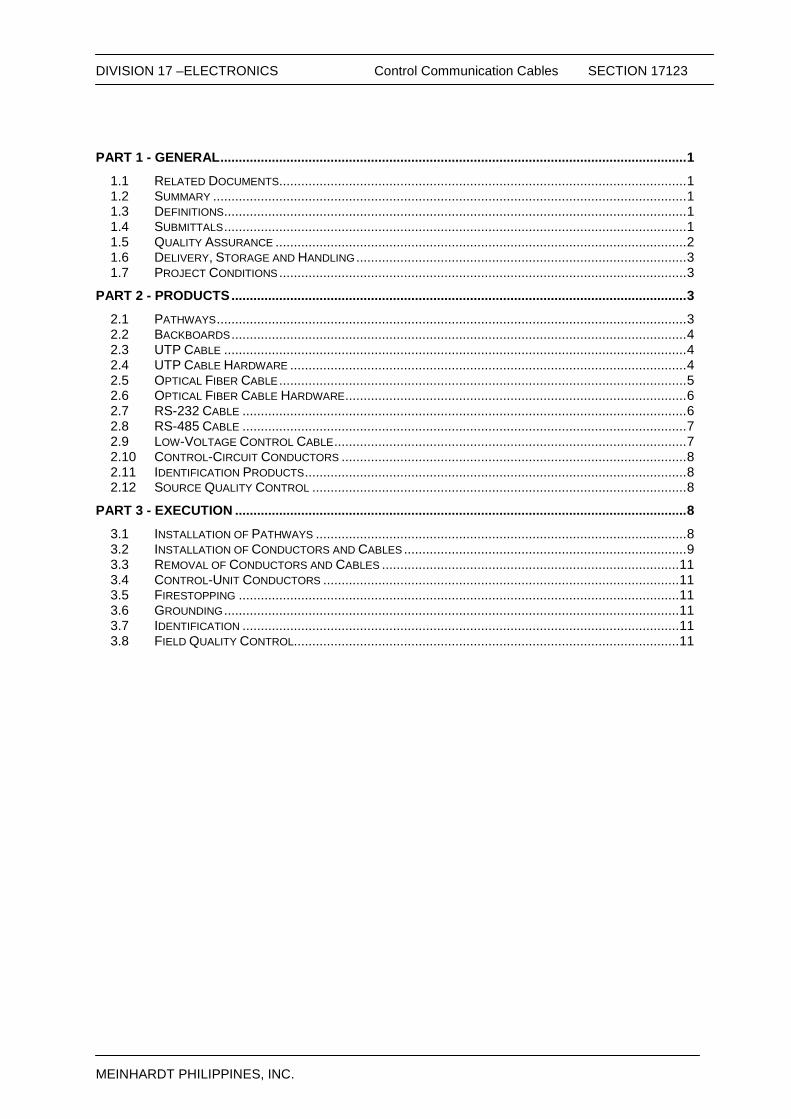
DIVISION 17 –ELECTRONICS Control Communication Cables SECTION 17123
MEINHARDT PHILIPPINES, INC.
PART 1 - GENERAL ............................................................................................................................... 1
1.1 RELATED DOCUMENTS ............................................................................................................... 1 1.2 SUMMARY ................................................................................................................................. 1 1.3 DEFINITIONS .............................................................................................................................. 1 1.4 SUBMITTALS .............................................................................................................................. 1 1.5 QUALITY ASSURANCE ................................................................................................................ 2 1.6 DELIVERY, STORAGE AND HANDLING .......................................................................................... 3 1.7 PROJECT CONDITIONS ............................................................................................................... 3
PART 2 - PRODUCTS ............................................................................................................................ 3
2.1 PATHWAYS ................................................................................................................................ 3 2.2 BACKBOARDS ............................................................................................................................ 4 2.3 UTP CABLE .............................................................................................................................. 4 2.4 UTP CABLE HARDWARE ............................................................................................................ 4 2.5 OPTICAL FIBER CABLE ............................................................................................................... 5 2.6 OPTICAL FIBER CABLE HARDWARE ............................................................................................. 6 2.7 RS-232 CABLE ......................................................................................................................... 6 2.8 RS-485 CABLE ......................................................................................................................... 7 2.9 LOW-VOLTAGE CONTROL CABLE ................................................................................................ 7 2.10 CONTROL-CIRCUIT CONDUCTORS .............................................................................................. 8 2.11 IDENTIFICATION PRODUCTS ........................................................................................................ 8 2.12 SOURCE QUALITY CONTROL ...................................................................................................... 8
PART 3 - EXECUTION ........................................................................................................................... 8
3.1 INSTALLATION OF PATHWAYS ..................................................................................................... 8 3.2 INSTALLATION OF CONDUCTORS AND CABLES ............................................................................. 9 3.3 REMOVAL OF CONDUCTORS AND CABLES ................................................................................. 11 3.4 CONTROL-UNIT CONDUCTORS ................................................................................................. 11 3.5 FIRESTOPPING ........................................................................................................................ 11 3.6 GROUNDING ............................................................................................................................ 11 3.7 IDENTIFICATION ....................................................................................................................... 11 3.8 FIELD QUALITY CONTROL ......................................................................................................... 11
DIVISION 17 –ELECTRONICS Control Communication Cables SECTION 17123
MEINHARDT PHILIPPINES, INC. Page 1 of 12 S:\admin\mpi\MP1716_Baguio General Hospital and Medical Trauma Center\000 - ACTIVE DOCUMENTS\09 - SPECS\2018-04-06_100% DD\03-ELECTRONICS\17123-Control Communication Cables.doc
SECTION 17123 CONTROL COMMUNICATION CABLES
PART 1 - GENERAL
1.1 RELATED DOCUMENTS
A. Drawings and general provisions of the Contract, including General and Supplementary Conditions and Division 1 Specification Sections, apply to this Section.
1.2 SUMMARY
A. Section Includes:
1. UTP cabling. 2. 50/125-micrometer, multimode optical fiber cabling. 3. RS-232 cabling. 4. RS-485 cabling. 5. Low-voltage control cabling. 6. Control-circuit conductors. 7. Identification products.
1.3 DEFINITIONS
A. Basket Cable Tray: A fabricated structure consisting of wire mesh bottom and side rails.
B. Channel Cable Tray: A fabricated structure consisting of a one-piece, ventilated-bottom or solid-bottom channel section.
C. EMI: Electromagnetic interference.
D. IDC: Insulation displacement connector. E. Ladder Cable Tray: A fabricated structure consisting of two longitudinal side rails
connected by individual transverse members (rungs).
F. Low Voltage: As defined in NFPA 70 for circuits and equipment operating at less than 50 V or for remote-control and signaling power-limited circuits.
G. Open Cabling: Passing telecommunications cabling through open space (e.g.,
between the studs of a wall cavity).
H. RCDD: Registered Communications Distribution Designer. I. Solid-Bottom or Nonventilated Cable Tray: A fabricated structure consisting of
integral or separate longitudinal side rails, and a bottom without ventilation openings. J. Trough or Ventilated Cable Tray: A fabricated structure consisting of integral or
separate longitudinal rails and a bottom having openings sufficient for the passage of air and using 75 percent or less of the plan area of the surface to support cables.
K. UTP: Unshielded twisted pair.
1.4 SUBMITTALS A. Product Data: For each type of product indicated.
DIVISION 17 –ELECTRONICS Control Communication Cables SECTION 17123
MEINHARDT PHILIPPINES, INC. Page 2 of 12 S:\admin\mpi\MP1716_Baguio General Hospital and Medical Trauma Center\000 - ACTIVE DOCUMENTS\09 - SPECS\2018-04-06_100% DD\03-ELECTRONICS\17123-Control Communication Cables.doc
B. Shop Drawings: For cable tray layout, showing cable tray route to scale, with relationship between the tray and adjacent structural, electrical, and mechanical elements. Include the following: 1. Vertical and horizontal offsets and transitions. 2. Clearances for access above and to side of cable trays. 3. Vertical elevation of cable trays above the floor or bottom of ceiling structure. 4. Load calculations to show dead and live loads as not exceeding
manufacturer's rating for tray and its support elements.
C. Qualification Data: For qualified layout technician, installation supervisor, and field inspector.
D. Source quality-control reports. E. Field quality-control reports.
F. Maintenance Data: For wire and cable to include in maintenance manuals.
1.5 QUALITY ASSURANCE
A. Products referenced under this section establish the minimum acceptable standards
of products quality, features and performance. 1. Codes
a. Philippine Electrical Code (PEC 200 Edition) b. National Electrical Code (NEC 1999 Edition) c. Philippine Fire Code (PFC Revised Edition) d. Philippine Society of Mechanical Engineers Code (PSME) e. National Fire Protection Code (NFPC) f. Uniform Plumbing Code (UPC 1991) g. National Plumbing Code of the Philippines (NDCP) h. Applicable Local Ordinances i. Revised National Building Code j. Philippine Electronics Code (PECE) Vol.1 and 2
2. Standards
a. Underwriters Laboratory (UL) b. American Society of Testing and Materials (ASTM) c. National Electrical Manufacturers Association d. National Fire Protection Association (NFPC) e. Institute of Electrical and Electronics Engineers (IEEE) f. American National Standards Institute (ANSI) g. International Electro-Technical Commission (IEC) h. American Society of Mechanical Engineers (ASME) i. Factory Mutual Engineering Corps (FMEC) j. International Standard Organization (ISO: 9000) k. Other Internationally Accepted Standards
B. Engineer in-charge supervising the work shall be a duly Registered Electronics under
the supervision of a Professional Electronics Engineer as required by R.A. 9292 and revised National Building Code.
DIVISION 17 –ELECTRONICS Control Communication Cables SECTION 17123
MEINHARDT PHILIPPINES, INC. Page 3 of 12 S:\admin\mpi\MP1716_Baguio General Hospital and Medical Trauma Center\000 - ACTIVE DOCUMENTS\09 - SPECS\2018-04-06_100% DD\03-ELECTRONICS\17123-Control Communication Cables.doc
1.6 DELIVERY, STORAGE AND HANDLING
A. Test cables upon receipt at Project site. 1. Test optical fiber cable to determine the continuity of the strand end to end.
Use optical fiber flashlight or optical loss test set. 2. Test optical fiber cable on reels. Use an optical time domain reflectometer to
verify the cable length and locate cable defects, splices, and connector; include the loss value of each. Retain test data and include the record in maintenance data.
3. Test each pair of UTP cable for open and short circuits.
1.7 PROJECT CONDITIONS
A. Environmental Limitations: Do not deliver or install UTP and optical fiber cables and connecting materials until wet work in spaces is complete and dry, and temporary HVAC system is operating and maintaining ambient temperature and humidity conditions at occupancy levels during the remainder of the construction period.
PART 2 - PRODUCTS
2.1 PATHWAYS
A. Support of Open Cabling: NRTL labeled for support of Category 5e and Category 6 cabling, designed to prevent degradation of cable performance and pinch points that could damage cable. 1. Support brackets with cable tie slots for fastening cable ties to brackets. 2. Lacing bars, spools, J-hooks, and D-rings. 3. Straps and other devices.
B. Cable Trays: 1. Manufacturers: Subject to compliance with requirements, [provide products
by one of the following] [available manufacturers offering products that may be incorporated into the Work include, but are not limited to, the following]:
a. Cable Management Solutions, Inc. b. Cablofil Inc. c. Cooper B-Line, Inc. d. Cope - Tyco/Allied Tube & Conduit. e. GS Metals Corp. f. Approved Equal
OBB Betterman
2. Cable Tray Materials: Metal, suitable for indoors and protected against corrosion by hot-dip galvanizing, complying with ASTM A 123/A 123M, Grade 0.55, not less than 0.002165 inch (0.055 mm) thick.
a. Basket Cable Trays: 6 inches (150 mm) wide and 2 inches (50 mm)
deep. Wire mesh spacing shall not exceed 2 by 4 inches (50 by 100 mm).
b. Trough or Ventilated Cable Trays: Nominally 6 inches (150 mm) wide.
c. Ladder Cable Trays: Nominally 18 inches (455 mm) wide, and a rung spacing of 12 inches (305 mm).
d. Channel Cable Trays: One-piece construction, nominally 4 inches (100 mm) wide. Slot spacing shall not exceed 4-1/2 inches (115 mm) o.c.
DIVISION 17 –ELECTRONICS Control Communication Cables SECTION 17123
MEINHARDT PHILIPPINES, INC. Page 4 of 12 S:\admin\mpi\MP1716_Baguio General Hospital and Medical Trauma Center\000 - ACTIVE DOCUMENTS\09 - SPECS\2018-04-06_100% DD\03-ELECTRONICS\17123-Control Communication Cables.doc
e. Solid-Bottom or Nonventilated Cable Trays: One-piece construction, nominally 12 inches (305 mm) wide. Provide with solid covers.
C. Conduit and Boxes: Comply with requirements in Division 17 Section "Raceways and
Boxes." Flexible metal conduit shall not be used. 1. Outlet boxes shall be no smaller than 2 inches (50 mm) wide, 3 inches (75
mm) high, and 2-1/2 inches (64 mm) deep.
2.2 BACKBOARDS
A. Description: Plywood, fire-retardant treated, 3/4 by 48 by 96 inches (19 by 1220 by 2440 mm). Comply with requirements for plywood backing panels in Division 6 Section "Rough Carpentry."
2.3 UTP CABLE
A. Manufacturers: Subject to compliance with requirements, available manufacturers offering products that may be incorporated into the Work include, but are not limited to, the following: 1. Belden CDT Inc.; Electronics Division. 2. Berk-Tek; a Nexans company. 3. CommScope, Inc. 4. Draka USA. 5. Genesis Cable Products; Honeywell International, Inc. 6. KRONE Incorporated. 7. Mohawk; a division of Belden CDT. 8. Nordex/CDT; a subsidiary of Cable Design Technologies. 9. Superior Essex Inc. 10. SYSTIMAX Solutions; a CommScope, Inc. brand. 11. 3M. 12. Tyco Electronics/AMP Netconnect; Tyco International Ltd. 13. Approved Equal/Refer to Section 17007
B. Description: 100-ohm, four-pair UTP. 1. Comply with ICEA S-90-661 for mechanical properties. 2. Comply with TIA/EIA-568-B.1 for performance specifications. 3. Comply with TIA/EIA-568-B.2 and TIA/EIA-568-C.2, Category 5e or
Category 6a Balanced twisted fair Telecommunication Cabling & component Standard.
4. Listed and labeled by an NRTL acceptable to authorities having jurisdiction as complying with UL 444 and NFPA 70 for the following types:
a. Communications, General Purpose: Type CM or Type CMG. b. Communications, Plenum Rated: Type CMP complying with
NFPA 262. c. Communications, Riser Rated: Type CMR complying with UL 1666. d. Communications, Limited Purpose: Type CMX e. Multipurpose: Type MP or Type MPG. f. Multipurpose, Plenum Rated: Type MPP, complying with NFPA 262. g. Multipurpose, Riser Rated: Type MPR complying with UL 1666.
2.4 UTP CABLE HARDWARE
A. Manufacturers: Subject to compliance with requirements, available manufacturers offering products that may be incorporated into the Work include, but are not limited to, the following:
DIVISION 17 –ELECTRONICS Control Communication Cables SECTION 17123
MEINHARDT PHILIPPINES, INC. Page 5 of 12 S:\admin\mpi\MP1716_Baguio General Hospital and Medical Trauma Center\000 - ACTIVE DOCUMENTS\09 - SPECS\2018-04-06_100% DD\03-ELECTRONICS\17123-Control Communication Cables.doc
1. American Technology Systems Industries, Inc. 2. Dynacom Corporation. 3. Hubbell Premise Wiring. 4. KRONE Incorporated. 5. Leviton Voice & Data Division. 6. Molex Premise Networks; a division of Molex, Inc. 7. Nordex/CDT; a subsidiary of Cable Design Technologies. 8. Panduit Corp. 9. Siemon Co. (The). 10. Tyco Electronics/AMP Netconnect; Tyco International Ltd. 11. Approved Equal/Refer to Section 17007
B. UTP Cable Connecting Hardware: IDC type, using modules designed for punch-down caps or tools. Cables shall be terminated with connecting hardware of the same category or higher.
C. Connecting Blocks: 110 style for Category 5e or 110 style for Category 6. Provide blocks for the number of cables terminated on the block, plus 25 percent spare; integral with connector bodies, including plugs and jacks where indicated.
2.5 OPTICAL FIBER CABLE
A. Manufacturers: Subject to compliance with requirements, provide products by one of the following: 1. Berk-Tek; a Nexans company. 2. CommScope, Inc. 3. Corning Cable Systems. 4. General Cable Technologies Corporation. 5. Mohawk; a division of Belden CDT. 6. Nordex/CDT; a subsidiary of Cable Design Technologies. 7. Optical Connectivity Solutions Division; Emerson Network Power. 8. Superior Essex Inc. 9. SYSTIMAX Solutions; a CommScope, Inc. brand. 10. 3M. 11. Tyco Electronics/AMP Netconnect; Tyco International Ltd. 12. Refer to Section 17007.
B. Description: Multimode, 50/125-micrometer, tight buffer, optical fiber cable. 1. Comply with ICEA S-83-596 for mechanical properties. 2. Comply with TIA/EIA-568-B.3 for performance specifications and TIA/EIA 568
C.3 optical fiber cabling components. 3. Comply with TIA/EIA-492AAAA-B or TIA/EIA-492AAAA-A for detailed
specifications. 4. Listed and labeled by an NRTL acceptable to authorities having jurisdiction
as complying with UL 444, UL 1651, and NFPA 70 for the following types:
a. General Purpose, Nonconductive: Type OFN or OFNG. b. Plenum Rated, Nonconductive: Type OFNP, complying with
NFPA 262. c. Riser Rated, Nonconductive: Type OFNR or Type OFNP, complying
with UL 1666. d. General Purpose, Conductive: Type OFC or Type OFCG. e. Plenum Rated, Conductive: Type OFCP or Type OFNP, complying
with NFPA 262. f. Riser Rated, Conductive: Type OFCR; complying with UL 1666.
5. Conductive cable shall be aluminum-armored type. 6. Maximum Attenuation: 3.5 dB/km at 850 nm; 1.5 dB/km at 1300 nm.
DIVISION 17 –ELECTRONICS Control Communication Cables SECTION 17123
MEINHARDT PHILIPPINES, INC. Page 6 of 12 S:\admin\mpi\MP1716_Baguio General Hospital and Medical Trauma Center\000 - ACTIVE DOCUMENTS\09 - SPECS\2018-04-06_100% DD\03-ELECTRONICS\17123-Control Communication Cables.doc
7. Minimum Modal Bandwidth: 160 MHz-km at 850 nm; 500 MHz-km at 1300 nm.
C. Jacket: 1. Jacket Color: Aqua for 50/125-micrometer cable. 2. Cable cordage jacket, fiber, unit, and group color shall be according to
TIA/EIA-598-B. 3. Imprinted with fiber count, fiber type, and aggregate length at regular
intervals not to exceed 40 inches (1000 mm).
2.6 OPTICAL FIBER CABLE HARDWARE
A. Manufacturers: Subject to compliance with requirements, available manufacturers offering products that may be incorporated into the Work include, but are not limited to, the following: 1. ADC. 2. American Technology Systems Industries, Inc. 3. Berk-Tek; a Nexans company. 4. Corning Cable Systems. 5. Dynacom Corporation. 6. Hubbell Premise Wiring. 7. Molex Premise Networks; a division of Molex, Inc. 8. Nordex/CDT; a subsidiary of Cable Design Technologies. 9. Optical Connectivity Solutions Division; Emerson Network Power. 10. Siemon Co. (The). 11. Approved Equal/Refer to Section 17007.
B. Cable Connecting Hardware: Comply with the Fiber Optic Connector Intermateability Standards (FOCIS) specifications of TIA/EIA-604-2, TIA/EIA-604-3-A, and TIA/EIA-604-12. Comply with TIA/EIA-568-B.3. 1. Quick-connect, simplex and duplex, connectors. Insertion loss not more than
0.75 dB. 2. Type SFF connectors may be used in termination racks, panels, and
equipment packages.
2.7 RS-232 CABLE A. Standard Cable: NFPA 70, Type CM.
1. Paired, two pairs, No. 22 AWG, stranded (7x30) tinned-copper conductors. 2. Polypropylene insulation. 3. Individual aluminum foil-polyester tape shielded pairs with 100 percent shield
coverage. 4. PVC jacket. 5. Pairs are cabled on common axis with No. 24 AWG, stranded (7x32) tinned-
copper drain wire. 6. Flame Resistance: Comply with UL 1581.
B. Plenum-Rated Cable: NFPA 70, Type CMP. 1. Paired, two pairs, No. 22 AWG, stranded (7x30) tinned-copper conductors. 2. Plastic insulation. 3. Individual aluminum foil-polyester tape shielded pairs with 100 percent shield
coverage. 4. Plastic jacket.

DIVISION 17 –ELECTRONICS Control Communication Cables SECTION 17123
MEINHARDT PHILIPPINES, INC. Page 7 of 12 S:\admin\mpi\MP1716_Baguio General Hospital and Medical Trauma Center\000 - ACTIVE DOCUMENTS\09 - SPECS\2018-04-06_100% DD\03-ELECTRONICS\17123-Control Communication Cables.doc
5. Pairs are cabled on common axis with No. 24 AWG, stranded (7x32) tinned-copper drain wire.
6. Flame Resistance: Comply with NFPA 262.
2.8 RS-485 CABLE
A. Standard Cable: NFPA 70, Type CM or Type CMG. 1. Paired, two pairs, twisted, No. 22 AWG, stranded (7x30) tinned-copper
conductors. 2. PVC insulation. 3. Unshielded. 4. PVC jacket. 5. Flame Resistance: Comply with UL 1581.
B. Plenum-Rated Cable: NFPA 70, Type CMP. 1. Paired, two pairs, No. 22 AWG, stranded (7x30) tinned-copper conductors. 2. Fluorinated ethylene propylene insulation. 3. Unshielded. 4. Fluorinated ethylene propylene jacket. 5. Flame Resistance: NFPA 262, Flame Test.
2.9 LOW-VOLTAGE CONTROL CABLE A. Paired Cable: NFPA 70, Type CMG.
1. One pair, twisted, No. 16 AWG, stranded (19x29) tinned-copper conductors. 2. PVC insulation. 3. Unshielded. 4. PVC jacket. 5. Flame Resistance: Comply with UL 1581.
B. Plenum-Rated, Paired Cable: NFPA 70, Type CMP. 1. One pair, twisted, No. 16 AWG, stranded (19x29) tinned-copper conductors. 2. PVC insulation. 3. Unshielded. 4. PVC jacket. 5. Flame Resistance: Comply with NFPA 262.
C. Paired Cable: NFPA 70, Type CMG. 1. One pair, twisted, No. 18 AWG, stranded (19x30) tinned-copper conductors. 2. PVC insulation. 3. Unshielded. 4. PVC jacket. 5. Flame Resistance: Comply with UL 1581.
D. Plenum-Rated, Paired Cable: NFPA 70, Type CMP. 1. One pair, twisted, No. 18 AWG, stranded (19x30) tinned-copper conductors. 2. Fluorinated ethylene propylene insulation. 3. Unshielded. 4. Plastic jacket. 5. Flame Resistance: NFPA 262, Flame Test.
DIVISION 17 –ELECTRONICS Control Communication Cables SECTION 17123
MEINHARDT PHILIPPINES, INC. Page 8 of 12 S:\admin\mpi\MP1716_Baguio General Hospital and Medical Trauma Center\000 - ACTIVE DOCUMENTS\09 - SPECS\2018-04-06_100% DD\03-ELECTRONICS\17123-Control Communication Cables.doc
2.10 CONTROL-CIRCUIT CONDUCTORS A. Class 1 Control Circuits: Stranded copper, Type THHN-THWN or Type XHHN, in
raceway, complying with UL 83 or UL 44.
B. Class 2 Control Circuits: Stranded copper, Type THHN-THWN, in raceway power-limited cable, concealed in building finishes, complying with UL 83 or UL 44.
C. Class 3 Remote-Control and Signal Circuits: Stranded copper, Type TW or Type TF,
complying with UL 83.
2.11 IDENTIFICATION PRODUCTS
A. Manufacturers: Subject to compliance with requirements, available manufacturers offering products that may be incorporated into the Work include, but are not limited to, the following: 1. Brady Corporation. 2. HellermannTyton. 3. Kroy LLC. 4. Panduit Corp. 5. Approved Equal
B. Comply with UL 969 for a system of labeling materials, including label stocks, laminating adhesives, and inks used by label printers.
C. Comply with requirements in Division 16 Section "Electrical Identification."
2.12 SOURCE QUALITY CONTROL A. Testing Agency: Engage a qualified testing agency to evaluate cables.
B. Factory test UTP and optical fiber cables on reels according to TIA/EIA-568-B.1. C. Factory test UTP cables according to TIA/EIA-568-B.2.
D. Factory test multimode optical fiber cables according to TIA/EIA-526-14-A and
TIA/EIA-568-B.3.
E. Cable will be considered defective if it does not pass tests and inspections.
F. Prepare test and inspection reports. PART 3 - EXECUTION
3.1 INSTALLATION OF PATHWAYS
A. Cable Trays: Comply with NEMA VE 2 and TIA/EIA-569-A-7.
B. Comply with TIA/EIA-569-A for pull-box sizing and length of conduit and number of
bends between pull points. C. Comply with requirements in Division 16 Section "Raceways and Boxes" for
installation of conduits and wireways. D. Install manufactured conduit sweeps and long-radius elbows if possible. E. Pathway Installation in Equipment Rooms:

DIVISION 17 –ELECTRONICS Control Communication Cables SECTION 17123
MEINHARDT PHILIPPINES, INC. Page 9 of 12 S:\admin\mpi\MP1716_Baguio General Hospital and Medical Trauma Center\000 - ACTIVE DOCUMENTS\09 - SPECS\2018-04-06_100% DD\03-ELECTRONICS\17123-Control Communication Cables.doc
1. Position conduit ends adjacent to a corner on backboard if a single piece of plywood is installed or in the corner of room if multiple sheets of plywood are installed around perimeter walls of room.
2. Install cable trays to route cables if conduits cannot be located in these positions.
3. Secure conduits to backboard if entering room from overhead. 4. Extend conduits 3 inches (75 mm) above finished floor. 5. Install metal conduits with grounding bushings and connect with grounding
conductor to grounding system.
F. Backboards: Install backboards with 96-inch (2440-mm) dimension vertical. Butt adjacent sheets tightly and form smooth gap-free corners and joints.
3.2 INSTALLATION OF CONDUCTORS AND CABLES
A. Comply with NECA 1.
B. General Requirements for Cabling:
1. Comply with TIA/EIA-568-B.1. 2. Comply with BICSI ITSIM, Ch. 6, "Cable Termination Practices." 3. Terminate all conductors; no cable shall contain unterminated elements.
Make terminations only at indicated outlets, terminals, and cross-connect and patch panels.
4. Cables may not be spliced. Secure and support cables at intervals not exceeding 30 inches (760 mm) and not more than 6 inches (150 mm) from cabinets, boxes, fittings, outlets, racks, frames, and terminals.
5. Bundle, lace, and train conductors to terminal points without exceeding manufacturer's limitations on bending radii, but not less than radii specified in BICSI ITSIM, "Cabling Termination Practices" Chapter. Install lacing bars and distribution spools.
6. Do not install bruised, kinked, scored, deformed, or abraded cable. Do not splice cable between termination, tap, or junction points. Remove and discard cable if damaged during installation and replace it with new cable.
7. Cold-Weather Installation: Bring cable to room temperature before dereeling. Heat lamps shall not be used for heating.
8. Pulling Cable: Comply with BICSI ITSIM, Ch. 4, "Pulling Cable." Monitor cable pull tensions.
C. UTP Cable Installation:
1. Comply with TIA/EIA-568-B.2 & C.2. 2. Install 110-style IDC termination hardware unless otherwise indicated. 3. Do not untwist UTP cables more than 1/2 inch (12 mm) from the point of
termination to maintain cable geometry.
D. Installation of Control-Circuit Conductors: 1. Install wiring in raceways. Comply with requirements specified in Division 16
Section "Raceways and Boxes."
E. Optical Fiber Cable Installation: 1. Comply with TIA/EIA-568-B.3 & C.3. 2. Cable shall be terminated on connecting hardware that is rack or cabinet
mounted.
F. Open-Cable Installation:

DIVISION 17 –ELECTRONICS Control Communication Cables SECTION 17123
MEINHARDT PHILIPPINES, INC. Page 10 of 12 S:\admin\mpi\MP1716_Baguio General Hospital and Medical Trauma Center\000 - ACTIVE DOCUMENTS\09 - SPECS\2018-04-06_100% DD\03-ELECTRONICS\17123-Control Communication Cables.doc
1. Install cabling with horizontal and vertical cable guides in telecommunications
spaces with terminating hardware and interconnection equipment. 2. Suspend copper cable not in a wireway or pathway a minimum of 8 inches
(200 mm) above ceilings by cable supports not more than 60 inches (1525 mm) apart.
3. Cable shall not be run through structural members or in contact with pipes, ducts, or other potentially damaging items.
G. Installation of Cable Routed Exposed under Raised Floors:
1. Install plenum-rated cable only. 2. Install cabling after the flooring system has been installed in raised floor
areas. 3. Coil cable 72 inches (1830 mm) long shall be neatly coiled not less than 12
inches (305 mm) in diameter below each feed point.
H. Separation from EMI Sources: 1. Comply with BICSI TDMM and TIA/EIA-569-A recommendations for
separating unshielded copper voice and data communication cable from potential EMI sources, including electrical power lines and equipment.
2. Separation between open communications cables or cables in nonmetallic raceways and unshielded power conductors and electrical equipment shall be as follows:
a. Electrical Equipment Rating Less Than 2 kVA: A minimum of 5
inches (127 mm). b. Electrical Equipment Rating between 2 and 5 kVA: A minimum of 12
inches (305 mm). c. Electrical Equipment Rating More Than 5 kVA: A minimum of 24
inches (600 mm).
3. Separation between communications cables in grounded metallic raceways and unshielded power lines or electrical equipment shall be as follows:
a. Electrical Equipment Rating Less Than 2 kVA: A minimum of 2-1/2
inches (64 mm). b. Electrical Equipment Rating between 2 and 5 kVA: A minimum of 6
inches (150 mm). c. Electrical Equipment Rating More Than 5 kVA: A minimum of 12
inches (305 mm).
4. Separation between communications cables in grounded metallic raceways and power lines and electrical equipment located in grounded metallic conduits or enclosures shall be as follows:
a. Electrical Equipment Rating Less Than 2 kVA: No requirement. b. Electrical Equipment Rating between 2 and 5 kVA: A minimum of 3
inches (75 mm). c. Electrical Equipment Rating More Than 5 kVA: A minimum of 6
inches (150 mm).
5. Separation between Cables and Electrical Motors and Transformers, 5 kVA or HP and Larger: A minimum of 48 inches (1200 mm).
6. Separation between Cables and Fluorescent Fixtures: A minimum of 5 inches (127 mm).
DIVISION 17 –ELECTRONICS Control Communication Cables SECTION 17123
MEINHARDT PHILIPPINES, INC. Page 11 of 12 S:\admin\mpi\MP1716_Baguio General Hospital and Medical Trauma Center\000 - ACTIVE DOCUMENTS\09 - SPECS\2018-04-06_100% DD\03-ELECTRONICS\17123-Control Communication Cables.doc
3.3 REMOVAL OF CONDUCTORS AND CABLES
A. Remove abandoned conductors and cables.
3.4 CONTROL-UNIT CONDUCTORS
A. Minimum Conductor Sizes: 1. Class 1 remote-control and signal circuits, No 14 AWG. 2. Class 2 low-energy, remote-control, and signal circuits, No. 16 AWG. 3. Class 3 low-energy, remote-control, alarm, and signal circuits, No 12 AWG.
3.5 FIRESTOPPING
A. Comply with requirements in Division 7 Section "Through-Penetration Firestop Systems."
B. Comply with TIA/EIA-569-A, Annex A, "Firestopping."
C. Comply with BICSI TDMM, "Firestopping Systems" Article.
3.6 GROUNDING
A. For data communication wiring, comply with ANSI-J-STD-607-A and with BICSI TDMM, "Grounding, Bonding, and Electrical Protection" Chapter.
B. For low-voltage wiring and cabling, comply with requirements in Division 16 Section "Grounding and Bonding."
3.7 IDENTIFICATION
A. Identify system components, wiring, and cabling according to TIA/EIA-606-A. Comply
with requirements for identification specified in Division 16 Section "Electrical Identification."
3.8 FIELD QUALITY CONTROL
A. Perform tests and inspections.
B. Tests and Inspections: 1. Visually inspect UTP and optical fiber cable jacket materials for UL or third-
party certification markings. Inspect cabling terminations to confirm color-coding for pin assignments, and inspect cabling connections to confirm compliance with TIA/EIA-568-B.1.
2. Visually inspect cable placement, cable termination, grounding and bonding, equipment and patch cords, and labeling of all components.
3. Test UTP cabling for DC loop resistance, shorts, opens, intermittent faults, and polarity between conductors. Test operation of shorting bars in connection blocks. Test cables after termination but not after cross connection.
a. Test instruments shall meet or exceed applicable requirements in
TIA/EIA-568-B.2. Perform tests with a tester that complies with performance requirements in "Test Instruments (Normative)" Annex, complying with measurement accuracy specified in "Measurement Accuracy (Informative)" Annex. Use only test cords and adapters that are qualified by test equipment manufacturer for channel or link test configuration.
4. Optical Fiber Cable Tests:

DIVISION 17 –ELECTRONICS Control Communication Cables SECTION 17123
MEINHARDT PHILIPPINES, INC. Page 12 of 12 S:\admin\mpi\MP1716_Baguio General Hospital and Medical Trauma Center\000 - ACTIVE DOCUMENTS\09 - SPECS\2018-04-06_100% DD\03-ELECTRONICS\17123-Control Communication Cables.doc
a. Test instruments shall meet or exceed applicable requirements in
TIA/EIA-568-B.1. Use only test cords and adapters that are qualified by test equipment manufacturer for channel or link test configuration.
b. Link End-to-End Attenuation Tests:
1) Multimode Link Measurements: Test at 850 or 1300 nm in one direction according to TIA/EIA-526-14-A, Method B, One Reference Jumper.
2) Attenuation test results for links shall be less than 2.0 dB. Attenuation test results shall be less than that calculated according to equation in TIA/EIA-568-B.1.
C. Document data for each measurement. Print data for submittals in a summary report
that is formatted using Table 10.1 in BICSI TDMM as a guide, or transfer the data from the instrument to the computer, save as text files, print, and submit.
D. End-to-end cabling will be considered defective if it does not pass tests and inspections.
E. Prepare test and inspection reports.
END OF SECTION
DIVISION 17 – ELECTRONICS Raceways and Boxes SECTION 17130
MEINHARDT PHILIPPINES INC.
PART 1 – GENERAL .................................. ............................................................................................ 1
1.1 DESCRIPTION .............................................................................................................................. 1 1.2 STANDARDS ................................................................................................................................ 1 1.3 SUBMITTALS ............................................................................................................................... 1 1.4 IDENTIFICATIONS ......................................................................................................................... 1
PART 2 – PRODUCTS ........................................................................................................................... 2
2.1 ACCEPTABLE MANUFACTURERS ................................................................................................... 2 2.2 CONDUIT AND FITTINGS ............................................................................................................... 2 2.3 WIREWAYS AND AUXILIARY GUTTERS ........................................................................................... 3
PART 3 – EXECUTION .......................................................................................................................... 4
3.1 GENERAL.................................................................................................................................... 4 3.2 WIREWAYS AND AUXILIARY GUTTERS ........................................................................................... 6 3.3 CABLE TRAY/TRUNKING/LADDER ................................................................................................. 6 3.4 OUTLET, JUNCTION, AND PULL BOXES ......................................................................................... 7 3.5 APPLICATION OF RACEWAYS ........................................................................................................ 8 3.6 APPLICATION OF BOXES OUTLET, JUNCTION AND PULL BOXES ...................................................... 8 3.7 SLEEVES .................................................................................................................................... 9
DIVISION 17 – ELECTRONICS Raceways and Boxes SECTION 17130
MEINHARDT PHILIPPINES INC. Page 1 of 9 S:\admin\mpi\MP1716_Baguio General Hospital and Medical Trauma Center\000 - ACTIVE DOCUMENTS\09 - SPECS\2018-04-06_100% DD\03-ELECTRONICS\17130-Raceways and Boxes.doc
SECTION 17130 RACEWAYS AND BOXES
PART 1 – GENERAL 1.1 DESCRIPTION A. Provide raceways and boxes in accordance with the Contract Documents.
1.2 STANDARDS
A. American Society for Testing and Materials (ASTM): ASTM A 446 - Steel Sheet Zinc-Coated (Galvanized) by the Hot Dip Process,
Structural Physical Quality ASTM A 525 - Steel Sheet Zinc-Coated, Galvanized by the Hot Dip Process B. American National Standards Institute (ANSI): ANSI 61 - Gray Enamel Finish Coat. ANSI C80.1 - Rigid Steel Conduit, Zinc-Coated. ANSI C80.3 - Electrical Metallic Tubing, Zinc- Coated. ANSI/NEMA FB 1- Fittings, Cast Metal Boxes, and Conduit Bodies for Conduit and
Cable Assemblies C. National Electrical Manufacturer’s Association (NEMA): NEMA OS 1 - Sheet -Steel Outlet Boxes, Device Boxes, Covers and Box Supports. NEMA VE 1 - Metallic Cable Tray Systems
D. Philippine Electrical Code (PEC): PEC 2000 (PART 1:2000)
1.3 SUBMITTALS A. Conduit, Boxes, Wireways, Manholes, Handholes and Auxiliary Gutters: 1. Manufacturer’s product data sheets
2. Samples
B. Shop Drawings:
1. Size and location of main feeders. Size and location of panels and pull boxes. Layout or required conduit penetrations through structural elements.
2. The specific item proposed and its area of application shall be marked on the catalog cuts.
1.4 IDENTIFICATIONS A. Mark junction box covers with permanent stencil identification of panelboard and circuit
numbers of wiring contained within. B. Paint fire alarm and life safety system boxes and conduits red.

DIVISION 17 – ELECTRONICS Raceways and Boxes SECTION 17130
MEINHARDT PHILIPPINES INC. Page 2 of 9 S:\admin\mpi\MP1716_Baguio General Hospital and Medical Trauma Center\000 - ACTIVE DOCUMENTS\09 - SPECS\2018-04-06_100% DD\03-ELECTRONICS\17130-Raceways and Boxes.doc
C. Paint boxes and conduits of other auxiliary systems in a color coding system or provide
color bonding for system every after 5m. PART 2 – PRODUCTS 2.1 ACCEPTABLE MANUFACTURERS A. Conduit
1. Metal Conduit: Matsushita/Panasonic, Allied, Sumitomo, or Royal Steel, Smart Tube
2. PVC Conduit: Neltex, Emerald, or Moldex B. Wireways and Auxiliary Gutters: 1. RS Thomas, Asiaphil, LJ Ind’l Fabrication, or Versa Trunk
C. Manhole Cover & Cast Iron Gutters Iron boxes: 1. Crouse - Hinds or Makati Foundry
2.2 CONDUIT AND FITTINGS A. Intermediate Metal Conduit: 1. Mild steel conduit, heavy wall, hot dipped galvanized inside and out, threaded
ends. 2. ANSI/NEMA FB1 – Threaded type fittings. B. Electrical Metallic Tubing: 1. ANSI C80.3; continuous, seamless steel tubing galvanized or sherardized on
exterior, coated on interior with smooth hard finish of lacquer, varnish or enamel. 2. NEMA FB1; Steel, set screw or compression type fittings. Provide concrete type
fittings where required. C. Flexible Steel Conduit: 1. Single strip, continuous, flexible interlocked double-wrapped steel, hot dip
galvanized inside and out forming smooth internal wiring channel. 2. NEMA FB 1; Steel, compression type fittings. D. Liquid Tight Flexible Conduit: 1. Same as flexible steel conduit except with tough, inert, watertight plastic outer
jacket. 2. NEMA FB1; Fittings shall be cast malleable iron body and gland nut, cadmium
plated with one-piece brass grounding bushings threaded to interior of conduit. Spiral molded vinyl sealing ring between gland nut and bushing and nylon insulated throat.
E. Polyvinylchloride (PVC) Conduit: 1. Schedule 40 polyvinyl chloride suitable for 90°C. 2. Solvent cemented type fittings.
3. 20 mm. Minimum.
DIVISION 17 – ELECTRONICS Raceways and Boxes SECTION 17130
MEINHARDT PHILIPPINES INC. Page 3 of 9 S:\admin\mpi\MP1716_Baguio General Hospital and Medical Trauma Center\000 - ACTIVE DOCUMENTS\09 - SPECS\2018-04-06_100% DD\03-ELECTRONICS\17130-Raceways and Boxes.doc
F. Cable Tray /Trunking/Ladder: 1. Cable raceway systems shall consist of straight sections, fittings, and required
and classified as equipment grounding conductors. Provide radiused elbows, tees, crosses, splice plates, wall and overhead supports, and other fittings necessary for a complete, continuously grounded system.
2. Pre-Galvanized Steel: Straight sections and fitting siderails and rungs shall be made from steel meeting the minimum mechanical properties of ASTM A446, Grade A and mill galvanized in accordance with ASTM A525, Coating Designation G90. Splice plates shall be manufactured from high strength steel,
using ribbed carriage bolts and serrated flange locknuts. 3. Ladder: Ladder type trays shall consists of two longitudinal members (siderails)
with transverse members (rungs) welded to the siderails. Rungs shall be spaced 15 cm on center. Rung spacing in radiused fittings shall be 22 cm measured at the center of the trays width. Rungs shall have a minimum cable bearing surface of 20 mm with radiused edges. No portion of the rungs shall protrude below the bottom plane of the siderails.
4. Trunking: Formed sheet steel, heavy duty type, standard baked enamel over lead primer finish. 1.6mm minimum thickness.
G. Loading capacity shall meet include weight of cables installed plus a safety factor of 1.5. 2.3 WIREWAYS AND AUXILIARY GUTTERS
A Sizes and shapes as indicated and/or as required. B. Provide necessary elbows, tees, connectors, adapters, etc. C. Continuous removable cover secured with screws and keyhole slots. Hinged cover
where installed above suspended ceiling.
D. Provide wire retainers at not greater than 30 cm on center. Outlet, Junction, and Pull Boxes
E. Cast Type Boxes: NEMA FB1
1. Ferrous alloy box with inside threaded hubs for rigid steel conduit.
2. Aluminum box with inside threaded hubs for rigid aluminum conduit. 3. Ferrous alloy box with compression or inside threaded hubs with adapter for
electrical metallic tubing. 4. Cast raised cover, size matched to contour of box. 5. Tapered threads for hubs.
F. Galvanized Pressed Steel Type Boxes: NEMA OS 1 1. General: a. Pressed steel, galvanized or cadmium-plated, 10 cm minimum
octagonal or square with galvanized cover or extension ring as required.
2. Lighting Fixture Box: a. 10 cm minimum octagon. b. Where fixtures are mounted on or in an accessible type ceiling and a
modular wiring system is not used, provide a junction box and extend flexible steel conduit to each fixture.
DIVISION 17 – ELECTRONICS Raceways and Boxes SECTION 17130
MEINHARDT PHILIPPINES INC. Page 4 of 9 S:\admin\mpi\MP1716_Baguio General Hospital and Medical Trauma Center\000 - ACTIVE DOCUMENTS\09 - SPECS\2018-04-06_100% DD\03-ELECTRONICS\17130-Raceways and Boxes.doc
3. Provide 10 mm bolt fixture studs where required. G. Sheet Steel Boxes: NEMA OS 1: 1. No. 12 gauge sheet steel for boxes with maximum side less than 1 meter, and
maximum area not exceeding 6,500 square cm; riveted or welded 20 mm flanges at exterior corners.
2. No. 10 gauge sheet steel for boxes with maximum side 1 meter to 1.5 meters, and maximum area 6,500 to 10,000 square cm; riveted or welded 20 mm flanges at exterior corners.
3. No. 10 gauge sheet steel riveted or welded to 40 mm x 40 mm x 6 mm welded angle iron framework for boxes with maximum side exceeding 1.5 meter and more than 10,000 square cm in area.
4. Covers: a. Same gauge steel as box. b. Subdivided single covers so no section of cover exceeds 23 kg. c. Machine bolts or machine screws threaded into tapped holes. 5. Paint: a. Rust inhibiting primer, ANSI 61 gray enamel finish coat. PART 3 – EXECUTION 3.1 GENERAL A. Provide raceways for all systems. Complete runs before pulling in cables or wires.
Provide insulated grounding conductor in metallic or nonmetallic raceways. Minimum conduit size shall be 25 mm. Wiring of each type and system shall be installed in separate raceways.
B. Protect metallic raceway in earth or fill from corrosion with two coats of corrosion
resistant paint or tape wrap.
C. Elbows for the connection of an exposed steel conduit above grade to the conduit installed below grade or embedded within floor slabs shall be rigid steel conduit with two coats of corrosion resistant paint or tape wrap.
D. Branch circuit conduits or wiring device conduits for miscellaneous systems shall not be
installed below slab on grade or embedded within floor slabs in tenant areas. E. Locate raceways so that the integrity of structural members is not affected and they do
not conflict with the services of other trades. Draw up couplings and fittings full and tight. Protect threads from corrosion after installation with zinc chromate or equivalent protection.
F. Conceal raceways except at surface mounted cabinets and freestanding equipment.
Provide flashing and counter-flashing for waterproofing of raceways which penetrate the roof. Route exposed raceways and raceways above suspended ceilings parallel or perpendicular to building lines with right angle turns and symmetrical bends. Provide sleeves in concrete walls, floor slabs and partitions. Waterproof sleeved raceways where required.
G. Provide raceway expansion joints for exposed and concealed raceways at expansion
joints and between structures to compensate for differential movement. Provide bonding conductor.
DIVISION 17 – ELECTRONICS Raceways and Boxes SECTION 17130
MEINHARDT PHILIPPINES INC. Page 5 of 9 S:\admin\mpi\MP1716_Baguio General Hospital and Medical Trauma Center\000 - ACTIVE DOCUMENTS\09 - SPECS\2018-04-06_100% DD\03-ELECTRONICS\17130-Raceways and Boxes.doc
H. Provide one empty 20 mm inch raceway for each three spare unused poles or spaces of flush-mounted panelboards. Terminate conduit in an accessible location for future extension.
I. Provide raceways with appropriate seal-offs, explosion-proof fittings, etc. in special
occupancy areas as required. Provide conduit seal-offs where portions of an interior raceway system pass through walls, ceiling or floors which separate adjacent rooms having substantially different maintained temperatures, refrigeration, or cold storage rooms.
J. Provide pull cord in empty raceways. Tag both ends noting destination. K. Clear raceway of all obstructions and dirt prior to pulling in wires or cables. Use ball
mandrel (diameter approximately 85% of conduit inside diameter) followed by close fitting wire brush and wad of felt or similar material. This assembly may be pulled with, but ahead of cable being installed. Clean empty raceways similarly. Clear or replace any raceway which rejects ball mandrel.
L. Secure raceway clamps or supports to masonry materials with toggle bolts, expansion
bolts, or steel inserts. Install raceway on steel construction with approved clamps which do not depend on friction or set-screw pressure alone.
M. Install exterior underground conduits 60 cm minimum below finished grade. Do not
penetrate waterproof membranes unless proper seal is provided. N. Raceways above Suspended Ceilings: 1. Single runs of 15 mm or 20 mm raceways may be supported from ceiling
support wires where permitted by the rating of the ceiling system. 2. Provide independent support of raceways larger than 20 mm. Provide
independent support of multiple raceways (more than one). Provide unistrut support and threaded rod to structure above. Attachment to ceiling support wires is not permitted.
3. Provide independent support of raceways installed above fire rated ceilings. Attachment to ceiling support wires is not permitted.
4. Install conduit 30 cm minimum above top of ceiling.
O. Conduit connected to rotating or vibrating equipment shall be flexible metal conduit or liquid tight flexible conduit.
P. Raceways Embedded in Floor Slabs:
1. Raceways shall not be installed in slab without the approval of the Structural
Engineer. 2. Raceways shall not interfere with placement of floor slab reinforcement
components. 3. Install raceways between the upper and the lower layers of reinforcing steel. Space raceways not less than 200mm on centers except where they converge
at panels or junction boxes. 4. Raceways running parallel to slabs supports, such as beams, columns and
structural walls, shall be installed not less than 300mm from such supporting elements.
Q. Non Metallic Raceway Installations: 1. Joints shall be made using the material recommended by the raceway
manufacturer. Components shall be cleaned prior to assembly. 2. Raceway cutoffs shall be square and shall not deform conduit. Ream rough
surfaces. 3. Provide male box adapters to terminate raceways.

DIVISION 17 – ELECTRONICS Raceways and Boxes SECTION 17130
MEINHARDT PHILIPPINES INC. Page 6 of 9 S:\admin\mpi\MP1716_Baguio General Hospital and Medical Trauma Center\000 - ACTIVE DOCUMENTS\09 - SPECS\2018-04-06_100% DD\03-ELECTRONICS\17130-Raceways and Boxes.doc
4. Where separable terminations are required, provide PVC threaded adapters with locknuts or bushings. Provide “O” rings for watertight installations.
5. Bends shall be made by methods that do not deform or damage the conduit. 6. Provide expansion fittings where required. 7. Raceway supports shall be installed to allow the non metallic conduit to slide
through the supports. 8. Non metallic raceway is not permitted within the building.
R. Underground Duct Banks: 1. Provide underground duct banks as indicated. Provide concrete encasement of
power systems duct banks except where duct banks run beneath building slab on grade. Provide concrete encasement of duct bank elbows for all systems. Provide steel reinforcing bars for concrete encased duct banks. Provide spacers to permit concrete to completely surround and encase each conduit. Concrete strength shall be 200 kgs/square meter. Provide red dye inhibiting agent in concrete mix.
2. Pitch conduit down and away where duct bank enters the building or equipment. 3. Support raceways installed in duct banks every 1.5 meters to assure correct
alignment prior to placing concrete. 4. Terminate raceways with flared end bells. Clear raceway terminations of burrs
and rough edges. S. Conductors serving electric fire pumps shall be either in conduit encased in a minimum
of 75 mm of concrete (concrete encasement is not required within fire pump room and electrical room where service originates), in conduit run beneath the slab on grade, or fire rated cable.
T. Raceways and fittings installed in hazardous (classified locations shall conform to local
electrical code requirements for the associated Class and Division.
3.2 WIREWAYS AND AUXILIARY GUTTERS A. Install wireways above suspended ceilings such that cover will hinge upward from side. B. Provide 30 mm clear from wireway cover when in open position. 3.3 CABLE TRAY/TRUNKING/LADDER
A. Cable Raceway shall be supported at a maximum of 1.5 meters on centers and at each bend, tee, cross, and elbow fitting. Supports shall be threaded rod trapeze style hangers or wall brackets. Side rails shall bear on the supports; rungs shall not bear on the supports.
B. Cable Raceway shall be installed level. Manufactured offsets shall be used to change
height or direction. C. Coordinate location of cable raceway with other trades to avoid conflicts and maintain
accessibility. Where installed above a ceiling, cable trays shall be not less than 30 cm above the bottom of the finished ceiling. Vertical clearance above the tray shall be a minimum of 30 cm.
D. Cable Raceway shall be continuous. Where cable raceway run is interrupted at a fire
rated wall, provide three 10 cm sleeves in fire rated wall. Provide bonding jumpers where cable trays are interrupted at fire rated walls and floors or are otherwise rendered electrically discontinuous.
E. Cable raceway installed in an environmental air plenum shall be solid bottom with
continuous cover, rated for installation in an environmental air plenum.
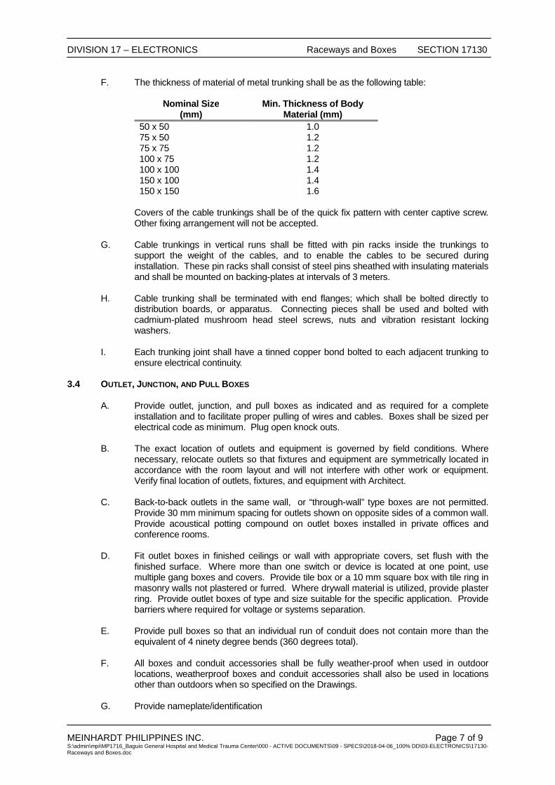
DIVISION 17 – ELECTRONICS Raceways and Boxes SECTION 17130
MEINHARDT PHILIPPINES INC. Page 7 of 9 S:\admin\mpi\MP1716_Baguio General Hospital and Medical Trauma Center\000 - ACTIVE DOCUMENTS\09 - SPECS\2018-04-06_100% DD\03-ELECTRONICS\17130-Raceways and Boxes.doc
F. The thickness of material of metal trunking shall be as the following table:
Nominal Size (mm)
Min. Thickness of Body Material (mm)
50 x 50 1.0 75 x 50 1.2 75 x 75 1.2 100 x 75 1.2 100 x 100 1.4 150 x 100 1.4 150 x 150 1.6
Covers of the cable trunkings shall be of the quick fix pattern with center captive screw. Other fixing arrangement will not be accepted.
G. Cable trunkings in vertical runs shall be fitted with pin racks inside the trunkings to
support the weight of the cables, and to enable the cables to be secured during installation. These pin racks shall consist of steel pins sheathed with insulating materials and shall be mounted on backing-plates at intervals of 3 meters.
H. Cable trunking shall be terminated with end flanges; which shall be bolted directly to
distribution boards, or apparatus. Connecting pieces shall be used and bolted with cadmium-plated mushroom head steel screws, nuts and vibration resistant locking washers.
I. Each trunking joint shall have a tinned copper bond bolted to each adjacent trunking to
ensure electrical continuity. 3.4 OUTLET, JUNCTION, AND PULL BOXES A. Provide outlet, junction, and pull boxes as indicated and as required for a complete
installation and to facilitate proper pulling of wires and cables. Boxes shall be sized per electrical code as minimum. Plug open knock outs.
B. The exact location of outlets and equipment is governed by field conditions. Where
necessary, relocate outlets so that fixtures and equipment are symmetrically located in accordance with the room layout and will not interfere with other work or equipment. Verify final location of outlets, fixtures, and equipment with Architect.
C. Back-to-back outlets in the same wall, or “through-wall” type boxes are not permitted.
Provide 30 mm minimum spacing for outlets shown on opposite sides of a common wall. Provide acoustical potting compound on outlet boxes installed in private offices and conference rooms.
D. Fit outlet boxes in finished ceilings or wall with appropriate covers, set flush with the
finished surface. Where more than one switch or device is located at one point, use multiple gang boxes and covers. Provide tile box or a 10 mm square box with tile ring in masonry walls not plastered or furred. Where drywall material is utilized, provide plaster ring. Provide outlet boxes of type and size suitable for the specific application. Provide barriers where required for voltage or systems separation.
E. Provide pull boxes so that an individual run of conduit does not contain more than the
equivalent of 4 ninety degree bends (360 degrees total).
F. All boxes and conduit accessories shall be fully weather-proof when used in outdoor locations, weatherproof boxes and conduit accessories shall also be used in locations other than outdoors when so specified on the Drawings.
G. Provide nameplate/identification
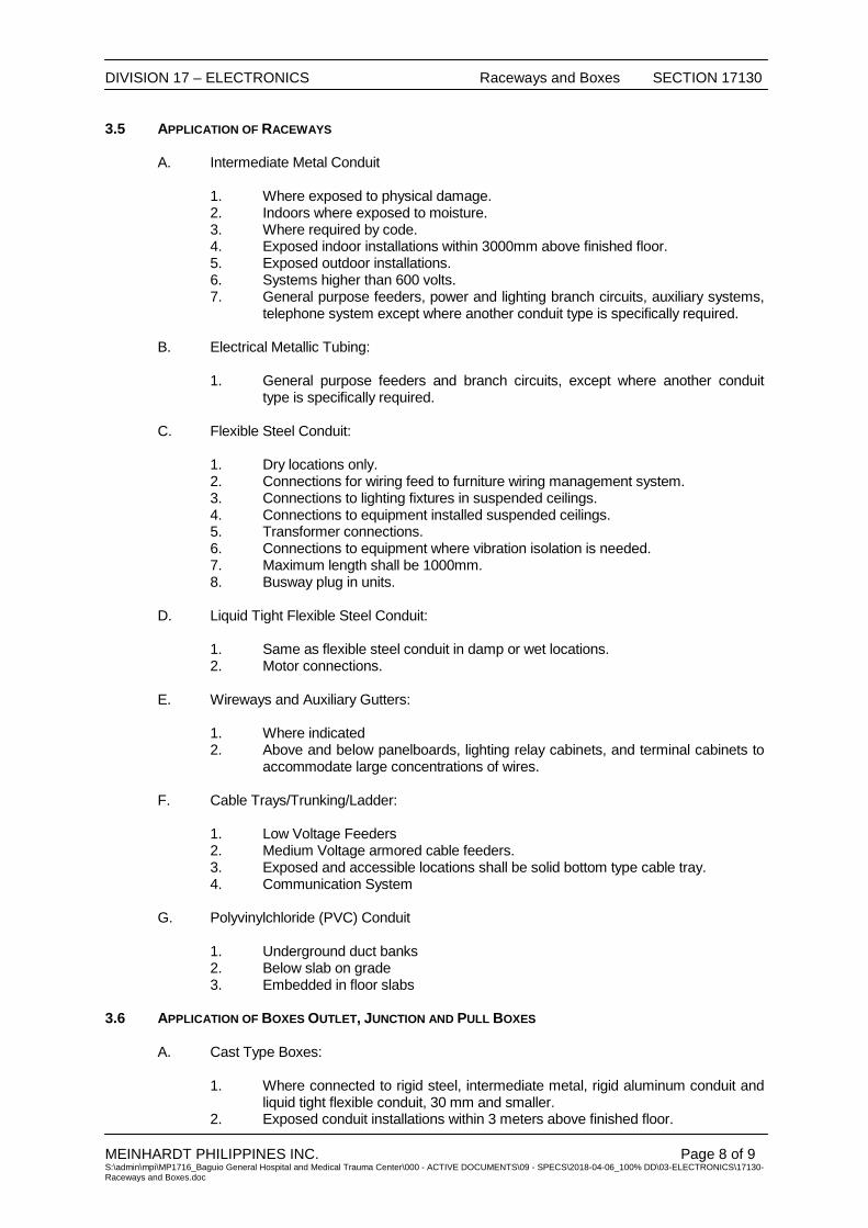
DIVISION 17 – ELECTRONICS Raceways and Boxes SECTION 17130
MEINHARDT PHILIPPINES INC. Page 8 of 9 S:\admin\mpi\MP1716_Baguio General Hospital and Medical Trauma Center\000 - ACTIVE DOCUMENTS\09 - SPECS\2018-04-06_100% DD\03-ELECTRONICS\17130-Raceways and Boxes.doc
3.5 APPLICATION OF RACEWAYS A. Intermediate Metal Conduit 1. Where exposed to physical damage. 2. Indoors where exposed to moisture. 3. Where required by code. 4. Exposed indoor installations within 3000mm above finished floor. 5. Exposed outdoor installations. 6. Systems higher than 600 volts. 7. General purpose feeders, power and lighting branch circuits, auxiliary systems,
telephone system except where another conduit type is specifically required.
B. Electrical Metallic Tubing:
1. General purpose feeders and branch circuits, except where another conduit type is specifically required.
C. Flexible Steel Conduit: 1. Dry locations only. 2. Connections for wiring feed to furniture wiring management system. 3. Connections to lighting fixtures in suspended ceilings. 4. Connections to equipment installed suspended ceilings. 5. Transformer connections. 6. Connections to equipment where vibration isolation is needed. 7. Maximum length shall be 1000mm. 8. Busway plug in units. D. Liquid Tight Flexible Steel Conduit: 1. Same as flexible steel conduit in damp or wet locations. 2. Motor connections. E. Wireways and Auxiliary Gutters: 1. Where indicated 2. Above and below panelboards, lighting relay cabinets, and terminal cabinets to
accommodate large concentrations of wires. F. Cable Trays/Trunking/Ladder: 1. Low Voltage Feeders 2. Medium Voltage armored cable feeders. 3. Exposed and accessible locations shall be solid bottom type cable tray. 4. Communication System
G. Polyvinylchloride (PVC) Conduit
1. Underground duct banks 2. Below slab on grade 3. Embedded in floor slabs
3.6 APPLICATION OF BOXES OUTLET, JUNCTION AND PULL BOXES A. Cast Type Boxes: 1. Where connected to rigid steel, intermediate metal, rigid aluminum conduit and
liquid tight flexible conduit, 30 mm and smaller. 2. Exposed conduit installations within 3 meters above finished floor.

DIVISION 17 – ELECTRONICS Raceways and Boxes SECTION 17130
MEINHARDT PHILIPPINES INC. Page 9 of 9 S:\admin\mpi\MP1716_Baguio General Hospital and Medical Trauma Center\000 - ACTIVE DOCUMENTS\09 - SPECS\2018-04-06_100% DD\03-ELECTRONICS\17130-Raceways and Boxes.doc
3. Where exposed to moisture and outdoors. B. Galvanized Pressed Steel Type Boxes: 1. Where connected to electrical metallic tubing and flexible steel conduit, 30 mm
and smaller. 2. Dry locations. 3. Where concealed in walls and above suspended ceilings.
C. Sheet Steel Boxes:
1. Where connected to conduit larger than 32 mm Ø. 3.7 SLEEVES A. Sleeves shall be 10 cm rigid steel nipples. Extend floor sleeves a minimum of 10 cm
above and below finished floor. Extend wall sleeves a minimum of 10 cm on either side of wall. Sleeve ends shall be threaded.
B. Provide sleeves between floors of telecommunication closets as in quantities and
locations shown on the Drawings.
C. Fire seal floor sleeves and sleeves in fire rated walls to maintain fire rating of wall after telephone cables are installed.
END OF SECTION

DIVISION 17 – ELECTRONICS Structured Cabling System SECTION 17715
MEINHARDT PHILIPPINES, INC. S:\admin\mpi\MP1716_Baguio General Hospital and Medical Trauma Center\000 - ACTIVE DOCUMENTS\09 - SPECS\2018-04-06_100% DD\03-ELECTRONICS\17715-Telecommunication Cabling and Termination.doc
PART 1 – GENERAL .................................. ............................................................................................ 1
1.1 DESCRIPTION OF WORK .............................................................................................................. 1 1.2 RELATED WORK .......................................................................................................................... 2 1.3 QUALITY ASSURANCE .................................................................................................................. 2 1.4 STANDARDS ................................................................................................................................ 2 1.5 SUBMITTALS ............................................................................................................................... 2 1.6 ACCEPTABLE MANUFACTURERS ................................................................................................... 3 1.7 TRAINING .................................................................................................................................... 3
PART 2 – PRODUCTS ........................................................................................................................... 3
2.1 ADMINISTRATION SUBSYSTEM...................................................................................................... 5 2.2 HORIZONTAL BACKBONE SUBSYSTEM .......................................................................................... 9 2.3 ENTRANCE FACILITY .................................................................................................................. 10 2.4 CABLING CONTAINMENT SYSTEM ............................................................................................... 11 2.5 PRODUCT DELIVERY AND STORAGE ........................................................................................... 11
PART 3 – EXECUTION ........................................................................................................................ 11
3.1 GENERAL INSTALLATION ............................................................................................................ 11 3.2 CABLE ROUTING ....................................................................................................................... 11 3.3 WORK AREA TERMINATION ........................................................................................................ 12 3.4 PULLING TENSION ..................................................................................................................... 13 3.5 BEND RADIUS ........................................................................................................................... 13 3.6 SLACK ...................................................................................................................................... 13 3.7 CABLE TIE WRAPS .................................................................................................................... 13 3.8 GROUNDING ............................................................................................................................. 13 3.9 FIRE PROTECTION ..................................................................................................................... 13 3.10 WORKMANSHIP ......................................................................................................................... 13 3.11 TESTING ................................................................................................................................... 14 3.12 ADMINISTRATION DOCUMENTATION............................................................................................ 15 3.13 WARRANTY .............................................................................................................................. 16

DIVISION 17 – ELECTRONICS Structured Cabling System SECTION 17715
MEINHARDT PHILIPPINES, INC. Page 1 of 17 S:\admin\mpi\MP1716_Baguio General Hospital and Medical Trauma Center\000 - ACTIVE DOCUMENTS\09 - SPECS\2018-04-06_100% DD\03-ELECTRONICS\17715-Telecommunication Cabling and Termination.doc
SECTION 17715 STRUCTURED CABLING SYSTEM
PART 1 – GENERAL 1.1 DESCRIPTION OF WORK A. The work to be done under this section of the specification shall consist of the furnishing
and installation of Structured Cabling System. B. The materials to be used shall be new, tested, labeled and approved by the appropriate
industry standards.
C. The complete Structured Cabling System shall consist of the following:
1. Administration/Equipment Room Subsystem Main Distribution Frame (MDF) / Consolidation Point (CP)
2. Horizontal Distribution System 3. Riser Backbone Subsystem
D. The horizontal subsystem provides connection from the Auxiliary Rooms to the information outlets (IO’s) I the work areas. It consists of the horizontal cable, the associated connection hardware terminating this cable IO’s and equipment cords in the work area.
E. The Administration Subsystem are the Main Cross-connect (MC)/MDF within the MDF
Cabinet. The Intermediate Cross-connect (IC)/IDF and the Horizontal Cross-connects/ Consolidated point within the area links the Horizontal and Backbone Subsystem. It consists of wiring blocks and distribution wire panels for termination of copper cables, labeling hardware for providing circuit identification and patch cords or jumper wire used for creating circuit connections and Cable Management System.
F. The main routes within the area is the Horizontal Backbone. They link all the Auxiliary
Rooms of the area to the Main Cross-connect. It consists of the backbone cable between these locations and the associated connecting hardware terminating this media.
G. The Cabling Containment System supports and protects horizontal distribution and
backbone cabling. It consists of raceways, fittings, and boxes/ hand holes.
H. All the passive components of this structured cabling system shall be in compliance with the existing industry standards on the latest performance parameters.
I. Review shop drawings, systems schematics and network diagrams submitted under this
and other Sections, as well as other Divisions, to ensure coordination between works required among different trades. Coordinate the installation sequence with other Contractors to avoid conflicts and to provide the fastest overall installation schedule. Coordinate installation with Architectural and Structural features, and equipment installed under other Sections of the Specifications.
J. The following work shall be carried out by others:
1. Other building auxiliary systems 2. Data Network Equipment 3. File Servers, Network OS and Application software
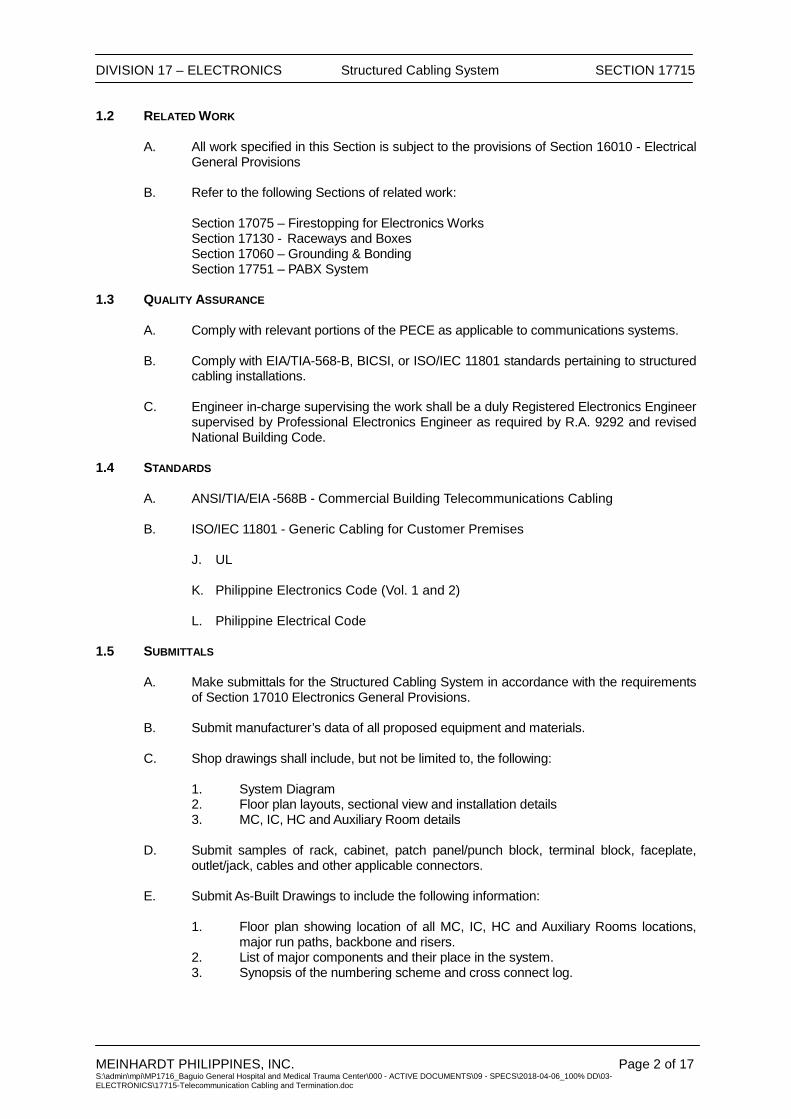
DIVISION 17 – ELECTRONICS Structured Cabling System SECTION 17715
MEINHARDT PHILIPPINES, INC. Page 2 of 17 S:\admin\mpi\MP1716_Baguio General Hospital and Medical Trauma Center\000 - ACTIVE DOCUMENTS\09 - SPECS\2018-04-06_100% DD\03-ELECTRONICS\17715-Telecommunication Cabling and Termination.doc
1.2 RELATED WORK A. All work specified in this Section is subject to the provisions of Section 16010 - Electrical
General Provisions B. Refer to the following Sections of related work:
Section 17075 – Firestopping for Electronics Works Section 17130 - Raceways and Boxes Section 17060 – Grounding & Bonding Section 17751 – PABX System
1.3 QUALITY ASSURANCE A. Comply with relevant portions of the PECE as applicable to communications systems. B. Comply with EIA/TIA-568-B, BICSI, or ISO/IEC 11801 standards pertaining to structured
cabling installations. C. Engineer in-charge supervising the work shall be a duly Registered Electronics Engineer
supervised by Professional Electronics Engineer as required by R.A. 9292 and revised National Building Code.
1.4 STANDARDS
A. ANSI/TIA/EIA -568B - Commercial Building Telecommunications Cabling B. ISO/IEC 11801 - Generic Cabling for Customer Premises
J. UL
K. Philippine Electronics Code (Vol. 1 and 2)
L. Philippine Electrical Code 1.5 SUBMITTALS
A. Make submittals for the Structured Cabling System in accordance with the requirements
of Section 17010 Electronics General Provisions.
B. Submit manufacturer’s data of all proposed equipment and materials. C. Shop drawings shall include, but not be limited to, the following:
1. System Diagram 2. Floor plan layouts, sectional view and installation details 3. MC, IC, HC and Auxiliary Room details
D. Submit samples of rack, cabinet, patch panel/punch block, terminal block, faceplate, outlet/jack, cables and other applicable connectors.
E. Submit As-Built Drawings to include the following information:
1. Floor plan showing location of all MC, IC, HC and Auxiliary Rooms locations,
major run paths, backbone and risers. 2. List of major components and their place in the system. 3. Synopsis of the numbering scheme and cross connect log.
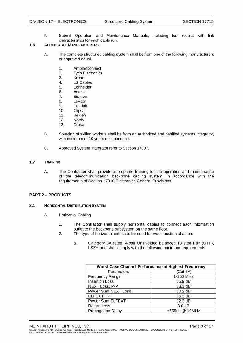
DIVISION 17 – ELECTRONICS Structured Cabling System SECTION 17715
MEINHARDT PHILIPPINES, INC. Page 3 of 17 S:\admin\mpi\MP1716_Baguio General Hospital and Medical Trauma Center\000 - ACTIVE DOCUMENTS\09 - SPECS\2018-04-06_100% DD\03-ELECTRONICS\17715-Telecommunication Cabling and Termination.doc
F. Submit Operation and Maintenance Manuals, including test results with link characteristics for each cable run.
1.6 ACCEPTABLE MANUFACTURERS A. The complete structured cabling system shall be from one of the following manufacturers
or approved equal. 1. Ampnetconnect 2. Tyco Electronics 3. Krone 4. LS Cables 5. Schneider 6. Actassi 7. Siemen 8. Leviton 9. Panduit 10. Clipsal 11. Belden 12. Nordx 13. Draka
B. Sourcing of skilled workers shall be from an authorized and certified systems integrator,
with minimum or 10 years of experience.
C. Approved System Integrator refer to Section 17007.
1.7 TRAINING A. The Contractor shall provide appropriate training for the operation and maintenance
of the telecommunication backbone cabling system, in accordance with the requirements of Section 17010 Electronics General Provisions.
PART 2 – PRODUCTS 2.1 HORIZONTAL DISTRIBUTION SYSTEM
A. Horizontal Cabling
1. The Contractor shall supply horizontal cables to connect each information outlet to the backbone subsystem on the same floor.
2. The type of horizontal cables to be used for work location shall be:
a. Category 6A rated, 4-pair Unshielded balanced Twisted Pair (UTP), LSZH and shall comply with the following minimum requirements:
Worst Case Channel Performance at Highest Frequency
Parameters (Cat 6A) Frequency Range 1-250 MHz Insertion Loss 35.9 dB NEXT Loss, P-P 33.1 dB Power Sum NEXT Loss 30.2 dB ELFEXT, P-P 15.3 dB Power Sum ELFEXT 12.3 dB Return Loss 8.0 dB Propagation Delay <555ns @ 10MHz
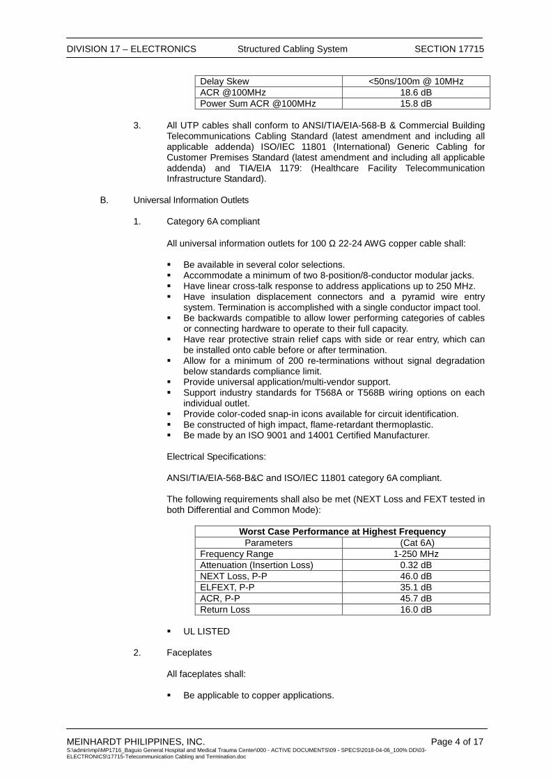
DIVISION 17 – ELECTRONICS Structured Cabling System SECTION 17715
MEINHARDT PHILIPPINES, INC. Page 4 of 17 S:\admin\mpi\MP1716_Baguio General Hospital and Medical Trauma Center\000 - ACTIVE DOCUMENTS\09 - SPECS\2018-04-06_100% DD\03-ELECTRONICS\17715-Telecommunication Cabling and Termination.doc
Delay Skew <50ns/100m @ 10MHz ACR @100MHz 18.6 dB Power Sum ACR @100MHz 15.8 dB
3. All UTP cables shall conform to ANSI/TIA/EIA-568-B & Commercial Building
Telecommunications Cabling Standard (latest amendment and including all applicable addenda) ISO/IEC 11801 (International) Generic Cabling for Customer Premises Standard (latest amendment and including all applicable addenda) and TIA/EIA 1179: (Healthcare Facility Telecommunication Infrastructure Standard).
B. Universal Information Outlets
1. Category 6A compliant
All universal information outlets for 100 Ω 22-24 AWG copper cable shall: Be available in several color selections. Accommodate a minimum of two 8-position/8-conductor modular jacks. Have linear cross-talk response to address applications up to 250 MHz. Have insulation displacement connectors and a pyramid wire entry
system. Termination is accomplished with a single conductor impact tool. Be backwards compatible to allow lower performing categories of cables
or connecting hardware to operate to their full capacity. Have rear protective strain relief caps with side or rear entry, which can
be installed onto cable before or after termination. Allow for a minimum of 200 re-terminations without signal degradation
below standards compliance limit. Provide universal application/multi-vendor support. Support industry standards for T568A or T568B wiring options on each
individual outlet. Provide color-coded snap-in icons available for circuit identification. Be constructed of high impact, flame-retardant thermoplastic. Be made by an ISO 9001 and 14001 Certified Manufacturer. Electrical Specifications: ANSI/TIA/EIA-568-B&C and ISO/IEC 11801 category 6A compliant. The following requirements shall also be met (NEXT Loss and FEXT tested in both Differential and Common Mode):
Worst Case Performance at Highest Frequency Parameters (Cat 6A)
Frequency Range 1-250 MHz Attenuation (Insertion Loss) 0.32 dB NEXT Loss, P-P 46.0 dB ELFEXT, P-P 35.1 dB ACR, P-P 45.7 dB Return Loss 16.0 dB
UL LISTED
2. Faceplates
All faceplates shall: Be applicable to copper applications.

DIVISION 17 – ELECTRONICS Structured Cabling System SECTION 17715
MEINHARDT PHILIPPINES, INC. Page 5 of 17 S:\admin\mpi\MP1716_Baguio General Hospital and Medical Trauma Center\000 - ACTIVE DOCUMENTS\09 - SPECS\2018-04-06_100% DD\03-ELECTRONICS\17715-Telecommunication Cabling and Termination.doc
Have write on designation labels for circuit identification together with a clear plastic cover.
Have several color selections. Be made by an ISO 9001 and 14001 Certified Manufacturer.
2.2 ADMINISTRATION SUBSYSTEM
A. Copper Termination Block (Voice Riser and Cross-connection) and Fiber Optics Termination Block (Data & Cross Connection).
B. The termination block shall support the appropriate Category applications and
facilitate cross-connection and inert-connection using either cross-connection wire or patch cords.
C. The termination block shall be 110-type or equivalent and shall comply with the
following: Be made of flame-retardant thermoplastic, with the base consisting of horizontal
index strips for terminating 100-pairs of conductors. Contain access openings for rear to front cable routing to the point of
termination. Have termination strips on the base to be notched and divided into 5-pair
increments. Have clear label holders with the appropriate colored inserts available for the
wiring blocks. The insert labels provided with the product shall contain vertical lines spaced on 5-pair circuit size and shall not interfere with running, tracing or removing patch cords. Label holders must be capable of mounting between each row of connecting blocks.
Have bases available in 19-inch panels and high-density frame configurations for rack or wall mounting with cable management/troughs hardware.
Have connecting blocks used for either the termination of cross-connect (jumper) wire or patch cords. The connecting blocks shall be in 5-pair size. All connecting blocks shall have color-coded tips of Blue, Orange, Green, Brown and Slate and be of single piece construction.
Have connecting blocks with a minimum of 200 terminations without signal degradation below standard compliance limit.
Support wire sizes: Solid 22-26 AWG Be made by an ISO 9001 and 14001 Certified Manufacturer. UL LISTED
D. Category 6A Modular Patch Panel
The panel shall: 1. Be made of black anodized aluminum, in 24 and 48-port configurations. 2. Accommodate at least 24 ports for each rack mount unit. 3. Have circuit boards tested in both directions as required by ANSI/TIA/EIA-
568-B and ISO/IEC 11801. 4. Have linear crosstalk response to address applications up to 250 MHz. 5. Have insulation displacement connectors with a pyramid wire entry system. 6. Have termination accomplished with a single conductor impact tool. 7. Be backwards compatible to allow lower performing categories of cables or
connecting hardware to operate to their full capacity. 8. Support industry standards for T568A or T568B wiring options on each
individual outlet. 9. Allow for a minimum of 200 re-terminations without signal degradation below
standards compliance limit. 10. Have a rear cable management bar for cable strain relief. 11. Have port identification numbers on both the front and rear of the panel.

DIVISION 17 – ELECTRONICS Structured Cabling System SECTION 17715
MEINHARDT PHILIPPINES, INC. Page 6 of 17 S:\admin\mpi\MP1716_Baguio General Hospital and Medical Trauma Center\000 - ACTIVE DOCUMENTS\09 - SPECS\2018-04-06_100% DD\03-ELECTRONICS\17715-Telecommunication Cabling and Termination.doc
12. Have optional adhesive circuit identification and color-coding designation strips provided with the panel.
13. Provide self adhesive, clear label holders and white designation labels with the panel, with optional color labels available.
14. Be made by an ISO 9001 and 14001 Certified Manufacturer.
Electrical Specifications:
15. ANSI/TIA/EIA-568-B and ISO/IEC 11801 category 6A compliant. 16. The following requirements shall also be met (NEXT Loss and FEXT tested in
both Differential and Common Mode):
Worst Case Performance at Highest Frequency Parameters (Cat 6A)
Frequency Range 1-250 MHz Attenuation (Insertion Loss) 0.32 dB NEXT Loss, P-P 46.0 dB Power Sum NEXT Loss 42.0 dB ELFEXT, P-P 35.1 dB Power Sum ELFEXT 32.1 dB Return Loss 16.0 dB
17. Be currently pending UL VERIFIED for TIA/EIA-B category 6A electrical
performance. 18. UL LISTED
E. Rack-Mounted, High Density Fiber Interconnect Center
The high density, rack mounted fiber interconnect center shall:
1. Available in 24 to 72 duplex ports or higher (24 – 144 fibers) version preloaded with MT-RJ/LC adapters/couplers through snap-in adapter plates. Ports preloading shall be dependent on the fiber riser requirement. (Most active equipment now are employing MT-RJ transceiver port, the contractor shall accordingly coordinate this with the LAN contractor prior to their execution of work. Appropriate jumper cordage ends connector shall match with this hardware and with the active equipment respectively.)
2. Have blank adapter plates for future growth of the fiber infrastructure. 3. Have fiber managers to effectively store fiber cable slack and comply with fiber
bend radius requirements. 4. Have removable back cover for ease of installations. 5. Have an adapter plate-mounting bracket which slides out to the front of the unit
for increased access. 6. Have anchor points for fiber cable(s) entering the unit. 7. Have labeling which meets or exceed ANSI/TIA/EIA-606 requirements and also
be laser printable. 8. Be able to mount both 19-inch and 23-inch rack/cabinets. 9. UL listed 10. Be made by an ISO 9001 and 14001 Certified Manufacturer.
F. Rack-Mounted, Low Profile Fiber Connect Panel
The low profile fiber connect panel shall: 1. Not be bigger then one rack mount space and accommodate up to 24 ports
for MT-RJ/LC snap-in adapter plates. 2. Have preloaded adapter plates with MT-RJ/LC fiber adapters in 12-port
version. Ports preloading shall be dependent on the fiber riser requirement. 3. Have blank adapter plates for future growth of the fiber infrastructure.

DIVISION 17 – ELECTRONICS Structured Cabling System SECTION 17715
MEINHARDT PHILIPPINES, INC. Page 7 of 17 S:\admin\mpi\MP1716_Baguio General Hospital and Medical Trauma Center\000 - ACTIVE DOCUMENTS\09 - SPECS\2018-04-06_100% DD\03-ELECTRONICS\17715-Telecommunication Cabling and Termination.doc
4. Be modular in design with internal fiber managers that provide slack storage to comply with fiber bend radius and the recommended slack storage length.
5. Be available with a drawer mechanism which allows the panel to slide forward for increased access.
6. Be made by an ISO 9001 and 14001 Certified Manufacturer. 7. UL listed.
G. Voice Cross-connect (Jumper) Wire
This wire will be used to cross-connect the Voice Riser and Inter-building backbone Wiring Blocks located in the Auxiliary Room to the PABX system.
The cross-connect wire shall: 1. Be available in 1 -pair reels of 305 meters (1000 ft). 2. Cat.6A verified, solid AWG 24 or 28. 3. Be made by an ISO 9001 and 14001 Certified Manufacturer. 4. UL listed and flame rated
H. Voice Riser Interconnect Patch Plugs/Cords
These plugs or cords will interconnect or patch the voice work area horizontal cable to the voice riser wiring blocks wired to the Auxiliary Room. The interconnect patch plug shall be: 1. Cat.6A verified. 2. In 1 and 2-pair versions. 3. Pair/s determination shall be dependent on telephone handsets type and
model (i.e.; some models digital phone sets require 4-wire). 4. Both ends with 110 (or equivalent) and RJ-45 modular plugs respectively. 5. UL listed and flame rated
I. Fiber Patch Cords
Fiber equipment cords shall:
Be available in variety of standard lengths to be able to interconnect panels and equipment placed separately on two adjacent racks and shall meet or exceed standards as defined in ANSI/TIA/EIA-568-B.3 and ISO/IEC 11801.
Utilize duplex fiber cable that is 50/125-micron multimode, OFNR riser grade, and must be UL listed.
Exhibit insertion loss typical at 0.10dB and at a maximum of 0.5dB and minimum return loss typical at 35dB for multimode 50/125 micron fiber patch cord.
Utilize cable where the attenuation shall not exceed 3.5 dB/km @ 850nm wavelength or 1.5 dB/km @ 1300nm.
The connectors shall be MT-RJ on both ends or a combination of MT-RJ and other small form factor such as LC and perform in accordance with TIA/EIA-568-B.3 for multimode 50/125 micron fiber.
Shall comply with the requirements of EIA/TIA-568-B and ISO 11801 for multimode 50/125 micron fiber to achieve 10GbE (IEEE 802.3ae 10-gigabit Ethernet) performance.
Be made by an ISO 9001 and 14001 Certified Manufacturer. Be UL approved.
J. Modular Equipment Cords: Category 6A compliant Category 6A, modular equipment cords shall:

DIVISION 17 – ELECTRONICS Structured Cabling System SECTION 17715
MEINHARDT PHILIPPINES, INC. Page 8 of 17 S:\admin\mpi\MP1716_Baguio General Hospital and Medical Trauma Center\000 - ACTIVE DOCUMENTS\09 - SPECS\2018-04-06_100% DD\03-ELECTRONICS\17715-Telecommunication Cabling and Termination.doc
Consist of eight insulated 24 AWG, stranded copper conductors, arranged in
four color-coded twisted-pairs. Be equipped with modular 8-position (RJ45 style) plugs on both ends, wired
straight through to T568B. Be backwards compatible with lower performing categories. Have color-coded insert molded strain relief boot with a latch guard to protect
against snagging. Be resistant to corrosion from humidity, extreme temperatures, and airborne
contaminants. Utilize cable that exhibits power sum NEXT performance. Be available in variety of standard lengths up to 50 feet to be able to connect
equipment placed quite far away from the switches or routers. Be made by an ISO 9001 and 14001 Certified Manufacturer.
Electrical Specifications:
Have a DC resistance per lead: 9.38 Ω / 100 m maximum. Have an input impedance without averaging: 100 Ω ± 15% from 1 to 100
MHz, ± 22% from 110 to 200 MHz and ± 32% from 200 to 250 MHz. Be 100% transmission tested with laboratory grade network analyzers for
proper performance up to 250 MHz. Vendor shall guarantee cords are compatible with category 6A links.
Be UL VERIFIED (or equivalent) or TIA/EIA category 6A electrical performance.
Be UL LISTED.
K. Enhanced Cable Management Rack
The rack shall:
1. 7 ft. in height and shall have 32.13 mm (1.265 in) by 152 mm (6 in) vertical cable channels as side rails.
2. Include dual vertical cable managers to arrange both the horizontal cables and the jumper and patch cords. These will be mounted on both sides of the channels with removable covers that can handle large quantities of cables and patch cords. Cable managers must retain cables even when covers are removed.
3. Have universal 5/8”-5/8”-1/2” mounting hole pattern that offers greater mounting flexibility and maximized mounting space usage. Shall also be compatible with conventional 1 ¼”-1/2” alternating hole pattern.
4. With two top angles and heavy-duty assembly hardware for increased load capacity.
5. Have floor mounting holes and a ground lug for 0-6 gauge ground cable provided.
6. Shall be provided with enough number of screws for mounting of cable panels and equipment.
7. Be made by an ISO 9001 and 14001 Certified Manufacturer.
L. Wall-mounted Racks
1. Be constructed as a single piece. 2. Be available in 2, 3, and 5 feet usable spaces. 3. With standard 5/5”-5/8”-1/2” mounting hole pattern. 4. Mounted with hinges to the right or the left. 5. 19” mounting width to accommodate standard 19” components 6. Have a cable rear support. 7. Depth should be enough to accommodate the most latest data equipment
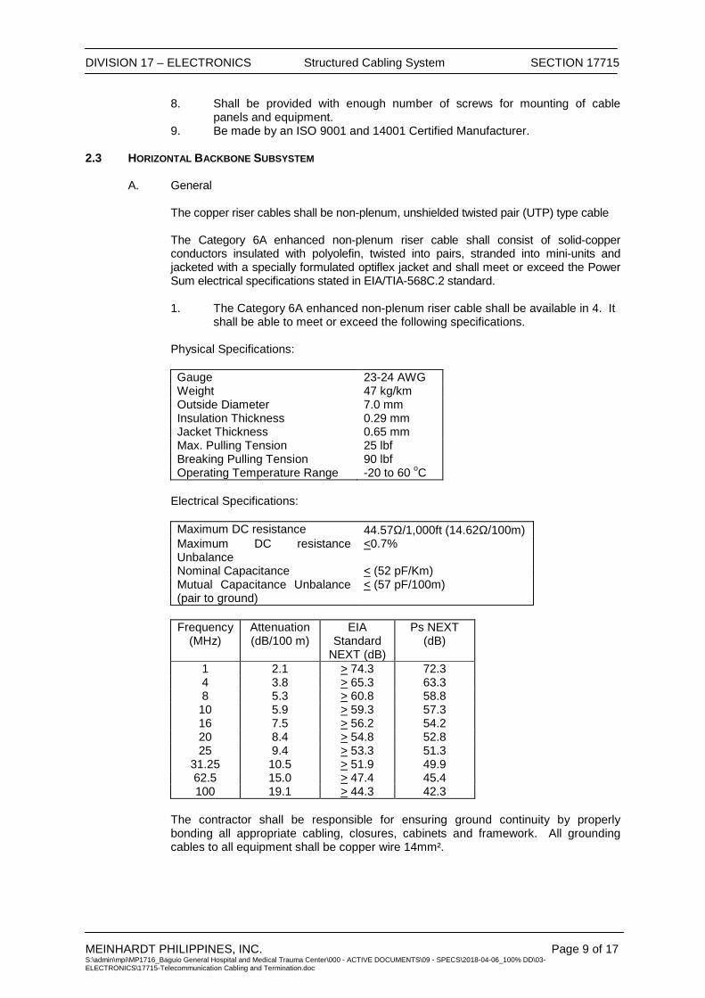
DIVISION 17 – ELECTRONICS Structured Cabling System SECTION 17715
MEINHARDT PHILIPPINES, INC. Page 9 of 17 S:\admin\mpi\MP1716_Baguio General Hospital and Medical Trauma Center\000 - ACTIVE DOCUMENTS\09 - SPECS\2018-04-06_100% DD\03-ELECTRONICS\17715-Telecommunication Cabling and Termination.doc
8. Shall be provided with enough number of screws for mounting of cable panels and equipment.
9. Be made by an ISO 9001 and 14001 Certified Manufacturer.
2.3 HORIZONTAL BACKBONE SUBSYSTEM
A. General The copper riser cables shall be non-plenum, unshielded twisted pair (UTP) type cable
The Category 6A enhanced non-plenum riser cable shall consist of solid-copper conductors insulated with polyolefin, twisted into pairs, stranded into mini-units and jacketed with a specially formulated optiflex jacket and shall meet or exceed the Power Sum electrical specifications stated in EIA/TIA-568C.2 standard.
1. The Category 6A enhanced non-plenum riser cable shall be available in 4. It
shall be able to meet or exceed the following specifications. Physical Specifications: Gauge 23-24 AWG Weight 47 kg/km Outside Diameter 7.0 mm Insulation Thickness 0.29 mm Jacket Thickness 0.65 mm Max. Pulling Tension 25 lbf Breaking Pulling Tension 90 lbf Operating Temperature Range -20 to 60 oC
Electrical Specifications: Maximum DC resistance 44.57Ω/1,000ft (14.62Ω/100m) Maximum DC resistance Unbalance
<0.7%
Nominal Capacitance < (52 pF/Km) Mutual Capacitance Unbalance (pair to ground)
< (57 pF/100m)
Frequency
(MHz) Attenuation (dB/100 m)
EIA Standard
NEXT (dB)
Ps NEXT (dB)
1 2.1 > 74.3 72.3 4 3.8 > 65.3 63.3 8 5.3 > 60.8 58.8 10 5.9 > 59.3 57.3 16 7.5 > 56.2 54.2 20 8.4 > 54.8 52.8 25 9.4 > 53.3 51.3
31.25 10.5 > 51.9 49.9 62.5 15.0 > 47.4 45.4 100 19.1 > 44.3 42.3
The contractor shall be responsible for ensuring ground continuity by properly bonding all appropriate cabling, closures, cabinets and framework. All grounding cables to all equipment shall be copper wire 14mm².
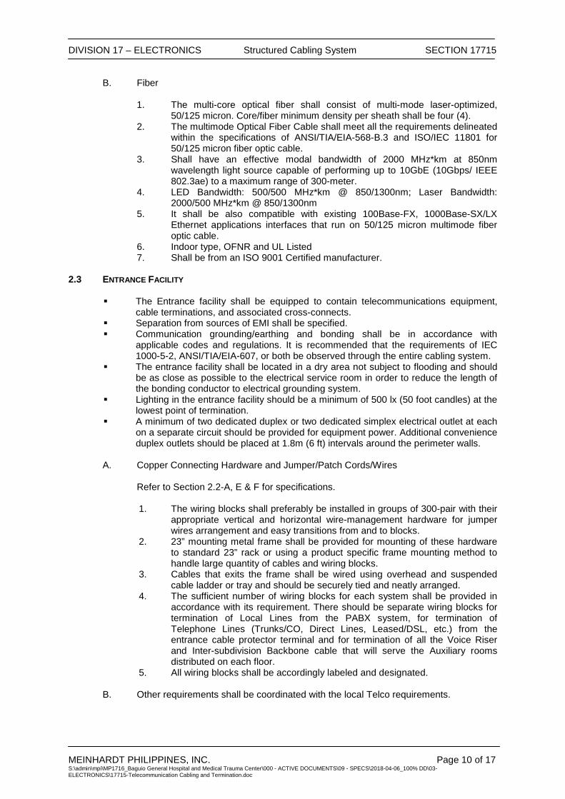
DIVISION 17 – ELECTRONICS Structured Cabling System SECTION 17715
MEINHARDT PHILIPPINES, INC. Page 10 of 17 S:\admin\mpi\MP1716_Baguio General Hospital and Medical Trauma Center\000 - ACTIVE DOCUMENTS\09 - SPECS\2018-04-06_100% DD\03-ELECTRONICS\17715-Telecommunication Cabling and Termination.doc
B. Fiber 1. The multi-core optical fiber shall consist of multi-mode laser-optimized,
50/125 micron. Core/fiber minimum density per sheath shall be four (4). 2. The multimode Optical Fiber Cable shall meet all the requirements delineated
within the specifications of ANSI/TIA/EIA-568-B.3 and ISO/IEC 11801 for 50/125 micron fiber optic cable.
3. Shall have an effective modal bandwidth of 2000 MHz*km at 850nm wavelength light source capable of performing up to 10GbE (10Gbps/ IEEE 802.3ae) to a maximum range of 300-meter.
4. LED Bandwidth: 500/500 MHz*km @ 850/1300nm; Laser Bandwidth: 2000/500 MHz*km @ 850/1300nm
5. It shall be also compatible with existing 100Base-FX, 1000Base-SX/LX Ethernet applications interfaces that run on 50/125 micron multimode fiber optic cable.
6. Indoor type, OFNR and UL Listed 7. Shall be from an ISO 9001 Certified manufacturer.
2.3 ENTRANCE FACILITY
The Entrance facility shall be equipped to contain telecommunications equipment, cable terminations, and associated cross-connects.
Separation from sources of EMI shall be specified. Communication grounding/earthing and bonding shall be in accordance with
applicable codes and regulations. It is recommended that the requirements of IEC 1000-5-2, ANSI/TIA/EIA-607, or both be observed through the entire cabling system.
The entrance facility shall be located in a dry area not subject to flooding and should be as close as possible to the electrical service room in order to reduce the length of the bonding conductor to electrical grounding system.
Lighting in the entrance facility should be a minimum of 500 lx (50 foot candles) at the lowest point of termination.
A minimum of two dedicated duplex or two dedicated simplex electrical outlet at each on a separate circuit should be provided for equipment power. Additional convenience duplex outlets should be placed at 1.8m (6 ft) intervals around the perimeter walls.
A. Copper Connecting Hardware and Jumper/Patch Cords/Wires Refer to Section 2.2-A, E & F for specifications.
1. The wiring blocks shall preferably be installed in groups of 300-pair with their appropriate vertical and horizontal wire-management hardware for jumper wires arrangement and easy transitions from and to blocks.
2. 23” mounting metal frame shall be provided for mounting of these hardware to standard 23” rack or using a product specific frame mounting method to handle large quantity of cables and wiring blocks.
3. Cables that exits the frame shall be wired using overhead and suspended cable ladder or tray and should be securely tied and neatly arranged.
4. The sufficient number of wiring blocks for each system shall be provided in accordance with its requirement. There should be separate wiring blocks for termination of Local Lines from the PABX system, for termination of Telephone Lines (Trunks/CO, Direct Lines, Leased/DSL, etc.) from the entrance cable protector terminal and for termination of all the Voice Riser and Inter-subdivision Backbone cable that will serve the Auxiliary rooms distributed on each floor.
5. All wiring blocks shall be accordingly labeled and designated. B. Other requirements shall be coordinated with the local Telco requirements.

DIVISION 17 – ELECTRONICS Structured Cabling System SECTION 17715
MEINHARDT PHILIPPINES, INC. Page 11 of 17 S:\admin\mpi\MP1716_Baguio General Hospital and Medical Trauma Center\000 - ACTIVE DOCUMENTS\09 - SPECS\2018-04-06_100% DD\03-ELECTRONICS\17715-Telecommunication Cabling and Termination.doc
2.4 CABLING CONTAINMENT SYSTEM A. All telecommunication backbone cabling and accessories shall be installed in a
raceway system as indicated on the Drawings. B. Raceways used for the telecommunication backbone cabling installation shall comply
with Section 17110. (Refer to Electronics) 2.5 PRODUCT DELIVERY AND STORAGE
A. Store telecommunication backbone cabling system equipment on elevated platforms
in a clean, dry location. Protect from dirt, water, construction debris, and traffic.
PART 3 – EXECUTION 3.1 GENERAL INSTALLATION
A. Install the system in accordance with the Plans and Specifications, all Local and National Applicable Codes, PECE Wiring Criteria, ANSI/EIA/TIA-568-B.series Commercial Building Wiring Standards and the Manufacturer’s recommendations.
B. The Contractor shall provide any necessary screws, anchors, clamps, tie wraps,
distribution rings, wire raceways, miscellaneous grounding and support hardware, etc. necessary to facilitate the installation of the system.
C. It shall be the responsibility of the Contractor to furnish any special installation
equipment or tools necessary to properly complete the system. This may include, but is not limited to, tools for terminating cables and testing equipment for copper cables, communication devices, jack stands for cable reels.
D. The Contractor shall be responsible for printed labels for all cables and cords,
distribution frames, and outlet locations.
E. The Contractor shall not place any distribution cabling alongside or near power lines, or share the same conduit, channels or sleeve with electrical apparatus.
F. The Contractor shall ensure that the maximum pulling tensions of the specified
distribution cables are not exceeded and cable bends maintain the proper radius during the placement of the facilities.
G. The Contractor shall be responsible for providing approved grounding at all newly
installed Auxiliary Rooms. The Contractor shall also be responsible for ensuring ground continuity by properly bonding all appropriate cabling, closures, cabinets, service boxes and framework.
H. All grounds shall consist of No. 6 AWG copper wire and shall be supplied from an
approved building ground and bonded to the main electrical ground.
3.2 CABLE ROUTING
A. All horizontal cables, regardless of media type, shall not exceed 90m (295 ft) from the telecommunications outlets in the work area to the horizontal cross connect.
B. The combined length of jumpers, or patch cords and equipment cables in the telecommunications room/closet and the work area should not exceed 10m (33 ft) unless used in conjunction with a multi-user telecommunications outlet.
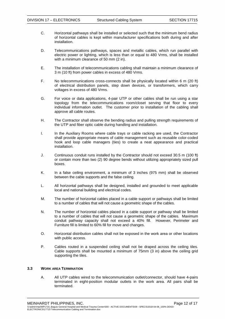
DIVISION 17 – ELECTRONICS Structured Cabling System SECTION 17715
MEINHARDT PHILIPPINES, INC. Page 12 of 17 S:\admin\mpi\MP1716_Baguio General Hospital and Medical Trauma Center\000 - ACTIVE DOCUMENTS\09 - SPECS\2018-04-06_100% DD\03-ELECTRONICS\17715-Telecommunication Cabling and Termination.doc
C. Horizontal pathways shall be installed or selected such that the minimum bend radius of horizontal cables is kept within manufacturer specifications both during and after installation.
D. Telecommunications pathways, spaces and metallic cables, which run parallel with
electric power or lighting, which is less than or equal to 480 Vrms, shall be installed with a minimum clearance of 50 mm (2 in).
E. The installation of telecommunications cabling shall maintain a minimum clearance of
3 m (10 ft) from power cables in excess of 480 Vrms. F. No telecommunications cross-connects shall be physically located within 6 m (20 ft)
of electrical distribution panels, step down devices, or transformers, which carry voltages in excess of 480 Vrms.
G. For voice or data applications, 4-pair UTP or other cables shall be run using a star
topology from the telecommunications room/closet serving that floor to every individual information outlet. The customer prior to installation of the cabling shall approve all cable routes.
H. The Contractor shall observe the bending radius and pulling strength requirements of
the UTP and fiber optic cable during handling and installation. I. In the Auxiliary Rooms where cable trays or cable racking are used, the Contractor
shall provide appropriate means of cable management such as reusable color-coded hook and loop cable managers (ties) to create a neat appearance and practical installation.
J. Continuous conduit runs installed by the Contractor should not exceed 30.5 m (100 ft)
or contain more than two (2) 90 degree bends without utilizing appropriately sized pull boxes.
K. In a false ceiling environment, a minimum of 3 inches (975 mm) shall be observed
between the cable supports and the false ceiling. L. All horizontal pathways shall be designed, installed and grounded to meet applicable
local and national building and electrical codes. M. The number of horizontal cables placed in a cable support or pathways shall be limited
to a number of cables that will not cause a geometric shape of the cables. N. The number of horizontal cables placed in a cable support or pathway shall be limited
to a number of cables that will not cause a geometric shape of the cables. Maximum conduit pathway capacity shall not exceed a 40% fill. However, Perimeter and Furniture fill is limited to 60% fill for move and changes.
O. Horizontal distribution cables shall not be exposed in the work area or other locations
with public access. P. Cables routed in a suspended ceiling shall not be draped across the ceiling tiles.
Cable supports shall be mounted a minimum of 75mm (3 in) above the ceiling grid supporting the tiles.
3.3 WORK AREA TERMINATION
A. All UTP cables wired to the telecommunication outlet/connector, should have 4-pairs terminated in eight-position modular outlets in the work area. All pairs shall be terminated.

DIVISION 17 – ELECTRONICS Structured Cabling System SECTION 17715
MEINHARDT PHILIPPINES, INC. Page 13 of 17 S:\admin\mpi\MP1716_Baguio General Hospital and Medical Trauma Center\000 - ACTIVE DOCUMENTS\09 - SPECS\2018-04-06_100% DD\03-ELECTRONICS\17715-Telecommunication Cabling and Termination.doc
B. The telecommunications outlet/connector shall be securely mounted at planned
locations. C. The height of the telecommunications faceplates shall be to applicable codes and
regulations.
3.4 PULLING TENSION
A. The maximum cable pulling tensions shall not exceed manufacturer’s specifications.
3.5 BEND RADIUS
A. The maximum cable bend radii shall not exceed manufacturer’s specifications. B. In spaces with UTP cable terminations, the maximum bend radius for 4-pair cable
shall not exceed four times the outside diameter of the cable and ten times for multi-pair cable. This shall be done unless this violates manufacturer specifications.
C. During the actual installation, bend radius on 4-pair cable shall not exceed eight times
the outside diameter of the cable and ten times for multi-pair cable. This shall be done unless this will violate manufacturer specifications.
3.6 SLACK
A. In the work area, a minimum of 300 mm (12 in) should be left for UTP cables. B. In Auxiliary Room a minimum of 3 m (10 ft) of slack should be left for all cable types.
This slack must be neatly managed on trays or other support types.
3.7 CABLE TIE WRAPS
A. Tie wraps shall be used at appropriate intervals to secure cable and to provide strain relief at termination points. These wraps shall not be over tightened to the point of deforming or crimping the cable sheath.
B. Hook and loop cable managers should be used in the closet where reconfiguration of
cables and terminations may be frequent.
3.8 GROUNDING
A. All grounding/earthing and bonding shall be done in accordance with applicable codes and regulations.
3.9 FIRE PROTECTION
A. Properly installed fire stop systems shall be installed to prevent or retard the spread of fire, smoke, water, and gases through every tenant. This requirement applies to openings designed for telecommunications use that may or may not be penetrated by cables, wires, or raceways.
B. Fire stops shall be done to applicable code. 3.10 WORKMANSHIP

DIVISION 17 – ELECTRONICS Structured Cabling System SECTION 17715
MEINHARDT PHILIPPINES, INC. Page 14 of 17 S:\admin\mpi\MP1716_Baguio General Hospital and Medical Trauma Center\000 - ACTIVE DOCUMENTS\09 - SPECS\2018-04-06_100% DD\03-ELECTRONICS\17715-Telecommunication Cabling and Termination.doc
A. All work shall be done in workman like fashion of the highest standards in the telecommunications industry. All equipment and materials are to be installed in a neat and secure manner, while cables are to be properly dressed. Workers must clean the worksite from any debris or trash at the close of each workday.
3.11 TESTING
A. Testing Procedures Testing of cable channels shall be performed prior to the system cut- over.
1. Copper Testing
All Category 6A field-testing shall be performed with an approved level II or III UTP field test device. All installed channels shall perform equal to or better than the minimum requirements as specified by the table below.
Worst Case Channel Performance at Highest Frequency Parameters (Cat 6A)
Frequency Range 1-250 MHz Attenuation 315.6 dB NEXT Loss 52.9 dB Power Sum NEXT Loss 51.7 dB ELFEXT 38.4 dB Power Sum ELFEXT 26 dB Return Loss 7.3 dB Propagation Delay 427 ns Delay Skew 212 ns ACR @100MHz 25.3 dB Power Sum ACR @ 100MHz 21.1 dB - All Cat. 6A channels are qualified for linear transmission performance
up to 300 MHz to ensure that high-frequency voltage phase and magnitude contributions do not prove cumulative or adversely affect channel performance.
- All UTP field testers shall be factory calibrated each calendar year by
the field test equipment manufacturer as stipulated by the manuals provided with the field test unit. The calibration certificate shall be provided for review prior to the start of testing.
- Auto test settings provided in the field tester for testing the installed
cabling shall be set to the default parameters.
- Test settings selected from options provided in the field testers shall be compatible with the installed cable under test.
- Category 6A or higher category backbone cables, that exceed 90 m
(295 ft) or 100 m (328 ft), but not less than 800 m (2,624 ft) or 815 m (2,674 ft), and applications warranty is desired, shall have 100 percent of the cables tested according to ISO/IEC Class A, B or C.
2. Fiber Optic Testing
- Fiber cables shall be 100% tested for attenuation and length.

DIVISION 17 – ELECTRONICS Structured Cabling System SECTION 17715
MEINHARDT PHILIPPINES, INC. Page 15 of 17 S:\admin\mpi\MP1716_Baguio General Hospital and Medical Trauma Center\000 - ACTIVE DOCUMENTS\09 - SPECS\2018-04-06_100% DD\03-ELECTRONICS\17715-Telecommunication Cabling and Termination.doc
- Attenuation shall be tested at 850nm and 1300nm cable in at least one direction using the 1-jumper method (ANSI/EIA/TIA-526-14A, Method B).
- Backbone Link Attenuation does not include any active devices or
passive devices other than cable, connectors and splices.
- Backbone link attenuation is calculated as follows:
Cable Attn. + Connector Attn + Splice Attn. = Link Attn.
Fiber Cable Type Wavelength Max Attn . (dB/km)
50/125 um 850nm 3.5 1300nm 1.5
Bandwidth (MHz-km) LED 500/500 LASER 2000/500 Notes: - Connector attenuation per mated pair is 0.75dB - For each splice, add 0.30 dB to the attenuation values in the
above chart (either 850nm or 1300nm) if applicable. - * Bandwidth is an important performance parameter, but
because it is intrinsic to the fiber and cannot be adversely affected by installation practices, it does not require testing in the field. Note that measurements for bandwidth have been performed at the factory in accordance with the procedures and overfilled launch conditions as specified within EIA/TIA-455-51 and IEC/ISO 793-1-C2A.
- ** The protocol pertinent to the transmission distances as noted is Gigabit Ethernet per IEEE 802.3z and 802.3ae (10Gbe).
3.12 ADMINISTRATION DOCUMENTATION A. Labeling 1. Cables
Backbone cables shall be labeled at each end. The cable or its label shall be marked with its identifier.
2. Racks, Panels, Blocks
A unique identifier shall be marked on each piece of connecting hardware to identify it as connecting hardware. Each port on the connecting hardware shall be labeled with its identifier.
B. Drawings
As-built drawing shall be supplied by the Contractor showing the locations of and identifiers for all: Horizontal cable routing and terminations Telecommunications outlets/connectors Backbone cable routing and terminations

DIVISION 17 – ELECTRONICS Structured Cabling System SECTION 17715
MEINHARDT PHILIPPINES, INC. Page 16 of 17 S:\admin\mpi\MP1716_Baguio General Hospital and Medical Trauma Center\000 - ACTIVE DOCUMENTS\09 - SPECS\2018-04-06_100% DD\03-ELECTRONICS\17715-Telecommunication Cabling and Termination.doc
C. Records
All records shall be created by the installation Contractor and turned over at the completion of work. The format shall be computer based and both soft copies and hard copies shall be part of the As-built package. The minimum requirements include: 1. Cable records must contain the identifier, cable type, termination positions at
both ends, splice information as well as any damaged pairs/conductors. 2. Connecting hardware and connecting hardware position records must contain
the identifier, type, damaged position numbers, and references to the cable identifier attached to it.
3. Test documentation on all cable types shall be included as part o the As-built package.
D. Reports
All reports shall be generated from the computer-based program used to create the records above. These reports should include but not limited to; 1. Cable Reports 2. Cross-connect Reports 3. Connecting Hardware Reports
3.13 WARRANTY
Either a basic link or channel model configuration may be applied to the horizontal and/or backbone sub-systems of the structured cabling system. Applications assurance is only applied to a channel model configuration.
A. System Warranty
A twenty (20) year warranty available for category 6A structured cabling system shall be provided for an end-to-end channel model installation which covers applications assurance, cable, connecting hardware and the labor cost for the repair or replacement thereof.
B. Product Warranty
The manufacturer of passive telecommunications equipment used in a manner not associated with the Systems Warranty must have a minimum twenty (20) year Component Warranty on all its product. The Products Warranty covers the components against defects in material under normal and proper use. - Applications Supported
Existing and future applications supported for a channel model warranty include those approved by the Institute of Electronic and Electrical Engineer (IEEE), the Asynchronous Transfer Mode (ATM) Forum, the American National Standards (ISO) that specify compatibility with the cable referenced herein. Additional applications that are covered by this warranty include those under development for use on Gigabit Ethernet (IEEE 802.3z, 802.3ab, 802.3ae) and 622 Mb/s ATM.
END OF SECTION

DIVISION 17 – ELECTRONICS Fire Detection and Alarm System (FDAS)
SECTION 17720
MEINHARDT PHILIPPINES INC. S:\admin\mpi\MP1716_Baguio General Hospital and Medical Trauma Center\000 - ACTIVE DOCUMENTS\09 - SPECS\2018-04-06_100% DD\03-ELECTRONICS\17720-Fire Detection and Alarm System (FDAS).doc
PART 1 – GENERAL ........................................................................................................................................... 1
1.1 DESCRIPTION ........................................................................................................................... 1
1.2 RELATED DOCUMENTS ............................................................................................................ 1
1.3 QUALITY ASSURANCE .............................................................................................................. 1
1.4 STANDARDS .............................................................................................................................. 2
1.5 ABBREVIATIONS........................................................................................................................ 2
1.6 SUBMITTALS ............................................................................................................................. 2
1.7 FIELD TESTING ......................................................................................................................... 3
1.8 IDENTIFICATION ........................................................................................................................ 3
1.9 SEQUENCE OF OPERATION ..................................................................................................... 3
1.10 SYSTEM ZONING ...................................................................................................................... 4
1.11 TRAINING .................................................................................................................................. 5
PART 2 – PRODUCT .......................................................................................................................................... 5
2.1 ACCEPTABLE MANUFACTURERS ............................................................................................. 5
2.2 LINE SUPERVISION ................................................................................................................... 5
2.3 STANDBY BATTERIES ............................................................................................................... 5
2.4 FIRE ALARM CONTROL PANEL (FACP) ................................................................................... 5
2.5 FIRE ALARM INITIATING DEVICES ............................................................................................ 6
2.6 FIREFIGHTER’S TELEPHONE SYSTEM (FTS) .......................................................................... 7
2.7 EMERGENCY VOICE EVACUATION PANEL (EVAC) PANEL ...................................................... 8
2.8 BATTERY AND CHARGER .......................................................................................................... 8
2.9 PRINTER ................................................................................................................................... 9
2.10 SYSTEM SOFTWARE ................................................................................................................ 9
2.11 MIMIC PANEL ............................................................................................................................ 9
PART 3 – EXECUTION ....................................................................................................................................... 9
3.1 GENERAL .................................................................................................................................. 9
3.2 TESTING AND COMMISSIONING ............................................................................................. 10

DIVISION 17 – ELECTRONICS Fire Detection and Alarm System (FDAS)
SECTION 17720
MEINHARDT PHILIPPINES INC. Page 1 of 11 S:\admin\mpi\MP1716_Baguio General Hospital and Medical Trauma Center\000 - ACTIVE DOCUMENTS\09 - SPECS\2018-04-06_100% DD\03-ELECTRONICS\17720-Fire Detection and Alarm System (FDAS).doc
SECTION 17720 FIRE DETECTION AND ALARM SYSTEM (FDAS)
PART 1 – GENERAL 1.1 DESCRIPTION
A. Provide fire detection and alarm system in accordance with the Permit Documents. B. The fire detection and alarm system shall be a stand alone system operating
independently of other control systems. It shall have an automatic dial-up feature to the nearest Fire Station.
C. Related work specified in other divisions of these specifications: 1. Sprinkler water flow and tamper switches. 2. Magnetic door holders and electric door locking hardware. 3. Installation of fire alarm speaker and firefighter's phone jack in elevator cabs. 4. Installation of duct smoke detectors.
5. Elevator Recall 6. Public Address Emergency Announcement
1.2 RELATED DOCUMENTS
A. All work specified in this Section is subject to the provisions of Section 17010 – Electronics General Provisions.
B. Refer to the following Sections of related work in connection with the Fire Detection and
Alarm System:
Section 17075 - Fire Stopping Materials Section 17130 - Raceways and Boxes Section 17060 - Grounding System Section 17721 - Security System Sections of Elevators Section 17726 - Public Address (PA) System
1.3 QUALITY ASSURANCE A. Fire Department approval of fire detection and alarm system. B. Manufacturer and equipment supplier shall have a minimum of ten years experience as
contractor of fire detection and alarm system and shall have at least five completed or on going FDAS installation in the Philippines.
C. Equipment supplier shall have 24 hour parts and labor service available with a maximum
4 hour response time.
D. Prior to making required submittals, system supplier shall meet with the Fire Department and make an informal presentation of the fire alarm and detection system. Meeting minutes shall be issued and comments incorporated into the required submittals.
E. Engineer In-Charge supervising the work shall be a duly registered Electronics Engineer supervising by a Professional Electronics Engineer as required by RA 9292 and the revised IRR of The National Building Code of the Philippines.
DIVISION 17 – ELECTRONICS Fire Detection and Alarm System (FDAS)
SECTION 17720
MEINHARDT PHILIPPINES INC. Page 2 of 11 S:\admin\mpi\MP1716_Baguio General Hospital and Medical Trauma Center\000 - ACTIVE DOCUMENTS\09 - SPECS\2018-04-06_100% DD\03-ELECTRONICS\17720-Fire Detection and Alarm System (FDAS).doc
1.4 STANDARDS
A. Fire Department Requirements B. National Building Code of the Philippines
C. National Fire Protection Association (NFPA 72, 101, 5000) D. Underwriters Laboratories, (UL):
• UL 268 - Smoke Detectors for Fire Alarm System • UL 268A - Smoke Detectors for Duct Application • UL 521 - Heat Detectors for Fire protective Signaling Systems
E. National Fire Code of the Philippines 1.5 ABBREVIATIONS A. MFACP Main Fire Alarm Control Panel B. FACP Fire Alarm Control Panel C. FTS Firefighter’s Telephone System D. FCIP Fire Command Center Intercom Phone E. FCC Fire Command Center 1.6 SUBMITTALS A. Minutes of system supplier's meeting with the Fire Department. B. Manufacturer's product data sheets for equipment including Fire Marshal listing
numbers.
C. Floor plans (minimum 1:100 scale) showing device locations and interconnecting conduit and wire. Floor plan (minimum 1:25 scale) of the Reception indicating fire management system equipment, equipment furnished by others, tables, plan racks, and required clearances. Elevations (minimum 1:25 scale) of each wall of the Reception.
D. Riser diagram showing devices, equipment, and interconnecting conduit and wire.
Indicate points of connection to other equipment such as motor control centers, damper actuators, fire pump controllers, dry pipe sprinkler systems, elevator machine rooms and shafts, electric door locking hardware, and magnetic door holders.
E. Scaled detail drawings of FACP F. Wiring diagram for each device.
G. Wiring diagrams for smoke control sequence. H. Voltage drop calculations. I. Battery sizing calculations. J. Visual alarm power supply sizing calculations.
K. Power supply calculations and interface installation shop drawing for magnetic door
DIVISION 17 – ELECTRONICS Fire Detection and Alarm System (FDAS)
SECTION 17720
MEINHARDT PHILIPPINES INC. Page 3 of 11 S:\admin\mpi\MP1716_Baguio General Hospital and Medical Trauma Center\000 - ACTIVE DOCUMENTS\09 - SPECS\2018-04-06_100% DD\03-ELECTRONICS\17720-Fire Detection and Alarm System (FDAS).doc
holders, and electric door locking hardware.
L. List of all devices with address identification.
M. Seismic restraint calculations.
1.7 FIELD TESTING A. Wiring shall be inspected and tested for continuity and short circuits. The minimum
allowable resistance between any two conductors or between conductors and ground is ten megohms measured with a 500 volt megger.
B. Field Test Reports: 1. Certification that equipment has been properly installed and is in satisfactory
operating condition. 2. Sensitivity settings for smoke detectors. 3. Detailed operational test report in matrix form indicating each initiating device,
each signaling device, each communication device, and each control and indicating light on each piece of equipment. Report shall certify the following:
a. Successful operation of each alarm and supervisory initiating device.
b. Successful operation of each signaling device. c. Successful operation of automatic smoke control sequences. d. Successful operation of FACP f. Successful operation of FTS g. Successful operation of elevator recall sequence. h. Successful operation of line supervision devices. i. Successful operation of off site alarm monitoring system connection
(optional). j. Successful operation of unlocking electronically locked doors. 1.8 IDENTIFICATION
A. Provide an identification nameplate for each equipment cabinet.
1.9 SEQUENCE OF OPERATION
A. A computerized intelligent addressable, non-coded, two stage evacuation system complete with integrated emergency voice two way communication system will be provided. The system will be designed using R.A-9514 Revised Fire Code of the Philippines and the National Building Code of the Philippines and other related standards such as NFPA as reference.
B. The main design principle of the proposed system is to provide localized microprocessor
based intelligent Fire Alarm Control Panel, FACP with Emergency Voice Evacuation System, Detectors and system are able to identify maintenance points, malfunctioning and line discontinuity.
C. The primary means of detection/suppression will be a system of smoke detectors
integrated with the automatic sprinkler system. Smoke detectors will be provided in all areas of the building to comply with local codes, and will be supplemented by the following types of early warning detection.
D. All detectors and zone control and monitor modules will be connected on an
addressable loop and each will posses a unique address to allow specific identification in

DIVISION 17 – ELECTRONICS Fire Detection and Alarm System (FDAS)
SECTION 17720
MEINHARDT PHILIPPINES INC. Page 4 of 11 S:\admin\mpi\MP1716_Baguio General Hospital and Medical Trauma Center\000 - ACTIVE DOCUMENTS\09 - SPECS\2018-04-06_100% DD\03-ELECTRONICS\17720-Fire Detection and Alarm System (FDAS).doc
the case of alarm or malfunction and environmental sensitivity adjustment.
E. Upon activation of any alarm, initiating devices the system will sends signal to:
1. Transmit an evacuation broadcast to the fire floor, floor above and floor below. 2. Transmit an alert broadcast to the remainder of the facility and the below grade
floors, IF: a. Fire alarm within the floor is not acknowledged within 5 minutes. b. Manual pull station is activated within the fire alarm floor. c. Sprinkler flow switch/ supervisory switch is activated. d. Another detector is triggered/ activated within the floor.
3. Automatically return all elevators to the ground floor sequentially. 4. Automatically stop all building floors recirculating air handling systems. 5. Automatically start all smoke removal and pressurization fan systems as well as
open/close appropriate dampers. 6. Activate all fire shutters to 1st stage position. 7. Release all secure door magnetic locks. 8. Annunciate all functions at the Fire Alarm Control Panel 9. Should the initial alarm not be acknowledge within five minutes, an evacuation
broadcast will be transmitted to the entire building complex. 10. Transmit signal to the local fire department. 11. A hard copy printout to be initiated at the printer.
F. If the fire condition is initialed from below grade levels, signals will be transmitted to all
below grade parking exhaust fan systems and activate all fan systems to operate at 100% for smoke exhaust use.
G. A selective paging system will be integrated with the signaling system to allow authorized
announcements.
H. An integrated UL listed dedicated two way fire fighter’s telephone system will be provided at each exit stair entry to allow direct communication between the fire fighters and the Reception.
I. The main control panel will consist of a central processing unit, printer and color LCD
unit annunciator with a complete graphics package identifying all fire zone status. J. The printer shall be as an event and status printer, it shall be laserjet type with a
minimum speed of 200 characters per second at 10 characters per inch.
K. The system shall be via high level interface of either LonWorks or Bacnet Protocol, provided guarantee of interoperability with other electronic systems.
L. The Main FACP shall be LonWorks, BACnet or TCP/IP
1.10 SYSTEM ZONING A. Firefighter's Telephone System: 1. Plug in jacks: Each stairwell shall be a separate, individual zone. 2. Emergency telephones: Each stairwell shall be a separate, individual zone. 3. Each bank of elevator cabs shall be a separate, individual zone. 4. Each elevator lobby bank riser shall be a separate, individual zone.
DIVISION 17 – ELECTRONICS Fire Detection and Alarm System (FDAS)
SECTION 17720
MEINHARDT PHILIPPINES INC. Page 5 of 11 S:\admin\mpi\MP1716_Baguio General Hospital and Medical Trauma Center\000 - ACTIVE DOCUMENTS\09 - SPECS\2018-04-06_100% DD\03-ELECTRONICS\17720-Fire Detection and Alarm System (FDAS).doc
1.11 TRAINING
A. The Contractor shall provide appropriate training for the operation and maintenance of the fire detection and alarm system, in accordance with the requirements of Section 17010.
PART 2 – PRODUCT 2.1 ACCEPTABLE MANUFACTURERS
A. Fire Alarm and Detection System components shall be of the same manufacturer, unless otherwise noted.
B. Acceptable Manufacturers: Refer to Section 17007.
C. Contractor must have at least 10 years of experience and existence.
2.2 LINE SUPERVISION A. All system equipment and wiring shall be supervised.
B. Style 7 wiring shall be arranged so that the system shall not be affected by a single open, short, or ground condition. Report trouble condition and automatically switch over to alternate wiring path.
C. Style Y wiring shall utilize end of line resistors. D. Addressable Channel Wiring: Style 6. E. Multiplex Channel Wiring: Style 7. F. Non Addressable Initiating Device Wiring: Style Y. G. VCS and FTS Device Wiring: Style Y. 2.3 STANDBY BATTERIES
A. Provide sufficient battery (NiCd) capacity to operate the entire system upon loss of power under maximum normal load for a minimum period of 24 hours with a minimum of 5 minutes of alarm operation at the end of this period.
B. The system shall automatically transfer to the standby batteries upon power failure.
Battery charging and recharging shall be automatic.
2.4 FIRE ALARM CONTROL PANEL (FACP)
A. Solid state, microprocessor based, modular design, fully supervised. Steel enclosure in standard finish, with hinged, locking door. Integral power supply, standby batteries, and battery charger.
B. Provide power on LED, power failure LED, system trouble LED, system reset switch,
alarm silence switch, trouble silence switch, manual evacuation switch, alarm acknowledge switch, trouble acknowledge switch, supervisory service acknowledge switch, lamp test button, tone alert, battery supervision LED, auxiliary relays, and other system indicators and controls necessary for processing alarm and signaling functions. Indicating lamps shall be LED type.
DIVISION 17 – ELECTRONICS Fire Detection and Alarm System (FDAS)
SECTION 17720
MEINHARDT PHILIPPINES INC. Page 6 of 11 S:\admin\mpi\MP1716_Baguio General Hospital and Medical Trauma Center\000 - ACTIVE DOCUMENTS\09 - SPECS\2018-04-06_100% DD\03-ELECTRONICS\17720-Fire Detection and Alarm System (FDAS).doc
C. Provide appropriate permanent identification labeling of control and indicating functions.
D. Annunciation:
Serial annunciator with back lit, alphanumeric, 80 character liquid crystal display indicating clear language information as to the type of alarm (device type), point status (alarm or trouble), number of alarms on the system, and a custom location label. Ability to scroll back through prior system actions.
E. System shall utilize analog type smoke detection with alarm verification, self test
feature, individual sensor automatic timed sensitivity adjustment, individual smoke sensor field adjustable sensitivity set from FACP, and automatic maintenance alarm feature.
F. With LonWorks Bacnet, or TCP/IP interface provided guarantee of seamless
interoperability with other high level interface.
G. Provide at least one (1) spare loop for maintenance purposes.
H. Networking Capable Panel (for FACP Interconnection) for integration with other building facilities, for future expansion or for addition of initiating and notification devices during fit-out.
2.5 FIRE ALARM INITIATING DEVICES A. General: 1. Intelligent Addressable type.
2. Provide auxiliary relays where required to satisfy system operational requirements.
3. Smoke detectors shall be intelligent addressable type. B. Manual Pull Stations:
1. Furnish and install where indicated on plan. 2. All manual pull station shall be single action non-coded break glass type. 3. Manual station shall be constructed of Die Cast Metal with clearly visible
operating instruction. 4. Station shall be suitable for surface mounting on matching back box. 5. Pulling the alarm handle shall activate the toggle switch which shall cause the
station n alarm position. 6. Push button type manual station shall not be acceptable.
C. Smoke and Heat Detectors:
1. Photoelectric smoke detector:
a. LED light source, silicon photodiode receiving element. Line filter and time delay circuitry to prevent transient false alarms.
b. 360o smoke entry, locking tamper screw, pulsating on power LED indicator, UL 268.
c. Adjustable obscuration/smoke detection levels. d. Provides maintenance identification alarm. e. Provides two LED function/working indication. f. Base sounders shall sound output not less than Y5dBA at pillow level.
DIVISION 17 – ELECTRONICS Fire Detection and Alarm System (FDAS)
SECTION 17720
MEINHARDT PHILIPPINES INC. Page 7 of 11 S:\admin\mpi\MP1716_Baguio General Hospital and Medical Trauma Center\000 - ACTIVE DOCUMENTS\09 - SPECS\2018-04-06_100% DD\03-ELECTRONICS\17720-Fire Detection and Alarm System (FDAS).doc
2. Heat detector:
a. 135o Combination fixed temperature and rate of rise heat detector b. Locking tamper screw, UL 521.
c. Provides maintenance identification alarm. d. Provides two LED function/working indication.
D. Device Monitoring Module
1. The device monitoring module shall permit the use of conventional detecting devices including sprinkler flow switches and supervisory switches on the addressable system. The module can be mounted together in the fire alarm cabinet or be in the standard outlet boxes located near the device being monitored.
E. Control Module
1. Interfaces a controlled device to the addressable system, This enables the
fire alarm panel to direct an instruction only to the intended device by addressing to its control module.
F. Speaker- Strobes
1. Fire lights shall ba a xenon-strobe type or equivalent. It shall be low-voltage
(24VDC). a. The maximum pulse duration shall be 2/10ths of one second (0.2
second with a maximum duty cycle of 40%). A pulse duration is defined as the time interval between initial and final points of 10% of maximum signal.
b. The intensity shall be minimum of 75 candela. c. The flash rate shall be minimum of 1Hz and a maximum of 3Hz.
2. The color shall be clear or nominal white (i.e. unfiltered or clear filtered
white light). 3. Electric, utilizing solid state electronic technology operating on a nominal 24
VDC, with a nominal rating of 82 dBA at 3m.
G. Annunciator Panel- Back Lit Graphic Type 1. Graphic annuciator showing the site plan, and access way shall be provided.
2. Indicating Lamps
a. Provide supervised light emitting diodes (LED’s) for indication.
2.6 FIREFIGHTER’S TELEPHONE SYSTEM (FTS)
A. Solid state, microprocessor based, modular design, fully supervised. Steel enclosure in
standard finish, with hinged, locking door. Integral power supply, standby batteries, and battery charger.
B. Two way voice communication between the Reception firefighter's phone jacks and
emergency telephones. Selective zone paging to all or any combination of telephone zones. Provide sound powered type system where required by the Fire Department, otherwise, provide electrical type system.
DIVISION 17 – ELECTRONICS Fire Detection and Alarm System (FDAS)
SECTION 17720
MEINHARDT PHILIPPINES INC. Page 8 of 11 S:\admin\mpi\MP1716_Baguio General Hospital and Medical Trauma Center\000 - ACTIVE DOCUMENTS\09 - SPECS\2018-04-06_100% DD\03-ELECTRONICS\17720-Fire Detection and Alarm System (FDAS).doc
C. Each telephone zone shall have a manual selection switch, red LED to indicate active
zone, and yellow LED to indicate speaker zone trouble. D. Acknowledge switch, system trouble, reset, and lamp test switch. E. Red telephone handset. F. Provide a remote handset in a lockable recessed cabinet. G. Auxiliary Devices:
1. Firefighter's phone jack: Recessed wall mounted telephone jack, stainless steel
faceplate engraved FIRE EMERGENCY PHONE. 2. Emergency telephone: Recessed wall mounted cabinet, hinged locking door
engraved LOCAL FIRE EMERGENCY PHONE, permanent handset with armored cable, and bread red glass.
3. Telephone handset cabinet: Surface mounted cabinet in FCR. Provide plug in type phones with coil cord and jack, quantity as required by the Fire Department.
H. Provide a dedicated telephone outlet with a direct line for fireman connection.
2.7 EMERGENCY VOICE EVACUATION PANEL (EVAC) PANEL
A. A fully automatic combination voice communication and fire fighters intercom system which provides automatic and alarm signaling per the NFPA 72.
B. One or two-way communications system for relocation/evacuation of building personnel
and assisting fire-fighting efforts in controlling smoke and fire. C. “ALL-CALL” tone and Voice Signaling. D. Selective Tone and Voice Signaling with Redundant tone generators. E. Module removal supervision
F. Service Diagnostic Center. G. “ALARM/RESOUND/RESTORE” Feature
H. Short Circuit Speaker Disconnect I. “On/Normal/Off” Auxiliary controls J. Local annunciation with Time-out of selective alarm signal to general alarm “ALL-CALL” K. Fully integratable with any Public Address system.
2.8 BATTERY AND CHARGER
A. Battery:
Nickel cadmium (NiCd) type, 24 volt nominal with sufficient capacity to power the fire alarm system for not less than twenty four (24) hours upon a normal AC power failure.
B. Charger:
DIVISION 17 – ELECTRONICS Fire Detection and Alarm System (FDAS)
SECTION 17720
MEINHARDT PHILIPPINES INC. Page 9 of 11 S:\admin\mpi\MP1716_Baguio General Hospital and Medical Trauma Center\000 - ACTIVE DOCUMENTS\09 - SPECS\2018-04-06_100% DD\03-ELECTRONICS\17720-Fire Detection and Alarm System (FDAS).doc
Automatic with constant potential charger maintaining the battery fully charged under all service conditions. Charger will operate at 230 volt, 60 Hz source.
2.9 PRINTER
Printer shall be of the automatic type with code, time date, location, category and condition. System printer shall be of high a reliability digital input device, UL approved, for fire alarm applications. The printer will operate at a minimum speed of 30 characters per second.
2.10 SYSTEM SOFTWARE
A. Automatic detector addressing and status indication. B. Secure signal transmission on unshielded cables.
C. Interfaces to Lon BACnet,TCP/IP protocol communication.
D. Intelligence distributed across the detectors and the fire control panel.
E. Drag & drop graphics and GUI interface.
F. Graphic screens are created with a built-in drawing utility of the protected area and are
linked to fire alarm devices.
G. Should a device got to alarm, the appropriate graphic floor plan is displayed along with operator instructions.
H. History manager which tracks and stores events. I. Must be able to control and monitor the system. J. Must be able to connect to other networks using TCP/IP Local Area Network (LAN)
2.11 MIMIC PANEL
A. 640-character display to present information from the fire detection and alarm system network.
B. Acting whether a special event is in progress, the large screen allows the operator to
view extended information in real time from the entire network.
PART 3 – EXECUTION 3.1 GENERAL
A. All equipment shall be installed and connected in accordance with the manufacturer's recommendations. Following the required specifications indicated here.
B. Wiring shall be color coded, and in accordance with the manufacturer's
recommendations and Fire Department requirements. Install wiring in an independent, dedicated metallic raceway system.
C. Connections to devices installed in accessible tile ceilings shall be in flexible conduit.
Device back boxes shall be securely attached to framing members. D. Provide wireways above and/or below equipment cabinets to accommodate large
concentrations of wiring. Conductors within equipment cabinets shall be carefully formed
DIVISION 17 – ELECTRONICS Fire Detection and Alarm System (FDAS)
SECTION 17720
MEINHARDT PHILIPPINES INC. Page 10 of 11 S:\admin\mpi\MP1716_Baguio General Hospital and Medical Trauma Center\000 - ACTIVE DOCUMENTS\09 - SPECS\2018-04-06_100% DD\03-ELECTRONICS\17720-Fire Detection and Alarm System (FDAS).doc
and harnessed. E. Connect equipment to emergency power system.
F. Provide power supply wiring to electric damper actuators used for smoke control that are not controlled by the temperature control system.
G. Furnish a fire alarm speaker and a firefighter's plug in jack for each elevator. Coordinate
installation with elevator equipment supplier.
H. Fiber Channel over IP and smoke control sequence wiring shall be dedicated and independent from other systems.
I. Provide a 25 mm empty conduit from the FACP to the nearest telecom terminal
backboard.
J. Speaker circuits on individual floor are to be wired in alternate pattern e.g. ‘a’-‘b’-‘a’-‘b’-‘a’.
3.2 TESTING AND COMMISSIONING
A. Provide the service of a competent factory-trained engineer or technical authorized by the manufacturer of the fire detection and alarm system equipment to technically supervise and participate during all of the adjustments and tests for the system. Make all adjustments and tests in the presence of the Project Manager.
B. When the system has been completed, and prior to the final inspection, furnish testing equipment and perform the following tests in the presence of the Engineer and the Local authority having jurisdiction.
1. Check installation, supervision and operation to ascertain that they will
function as specified. 2. When any defects are detected, make repairs or install replacement
components, and repeat the test.
C. At the final inspection, a factory-trained representative of the manufacturer of the major equipment shall perform the required test. In addition, the representative shall demonstrate that the systems function properly in every respect. The demonstration shall be made in the presence o the Owner’s Representative, Project Manager, Consultant and the local authority having jurisdiction.
END OF SECTION

DIVISION 17 – ELECTRONICS Security Management System SECTION 17721
MEINHARDT PHILIPPINES INC. S:\admin\mpi\MP1716_Baguio General Hospital and Medical Trauma Center\000 - ACTIVE DOCUMENTS\09 - SPECS\2018-04-06_100% DD\03-ELECTRONICS\17721-Security Management System.doc
PART 1 – GENERAL .................................. ............................................................................................ 1
1.1 DESCRIPTION OF WORK .............................................................................................................. 1 1.2 RELATED DOCUMENTS ................................................................................................................ 2 1.3 QUALITY ASSURANCE ................................................................................................................. 2 1.4 SUBMITTALS ............................................................................................................................... 2 1.5 APPROVED MANUFACTURERS ..................................................................................................... 3 1.6 TRAINING ................................................................................................................................... 3
PART 2 – PRODUCTS ........................................................................................................................... 3
2.1 GENERAL PRODUCT REQUIREMENTS ........................................................................................... 3 2.2 CLOSED-CIRCUIT TELEVISION SYSTEM (CCTV) ........................................................................... 3 2.3 INTRUSION DETECTION AND ACCESS CONTROL SYSTEM ............................................................... 7 2.4 INTERFACE WITH OTHER SYSTEMS ............................................................................................. 11 2.5 OPERATOR WORKSTATION ........................................................................................................ 11 2.6 SERVER COMPUTER ................................................................................................................. 11 2.7 PRODUCT DELIVERY AND STORAGE ........................................................................................... 12 2.8 BADGE PRINTER ....................................................................................................................... 12 2.9 SYSTEM SOFTWARE .................................................................................................................. 13 2.10 SYSTEM DATABASE................................................................................................................... 25
PART 3 – EXECUTION ........................................................................................................................ 29
3.1 INSTALLATION ........................................................................................................................... 29 3.2 TESTING AND COMMISSIONING .................................................................................................. 30

DIVISION 17 – ELECTRONICS Security Management System SECTION 17721
MEINHARDT PHILIPPINES INC. Page 1 of 31 S:\admin\mpi\MP1716_Baguio General Hospital and Medical Trauma Center\000 - ACTIVE DOCUMENTS\09 - SPECS\2018-04-06_100% DD\03-ELECTRONICS\17721-Security Management System.doc
SECTION 17721 INTEGRATED SECURITY MANAGEMENT SYSTEM
PART 1 – GENERAL 1.1 DESCRIPTION OF WORK A. Furnish all labor, materials, supplies, equipment, devices, appliances and perform all
operations necessary for the installation of the complete IP based/capable Integrated Security Management System.
B. The Security System shall conform to high level LonWorks BACneT or TCP/IP
integration. C. Any equipment not specifically mentioned in the Specifications or not shown on the
Contract Drawings, but deemed necessary for the satisfactory operation of the system, shall be provided. All cost of such equipment shall be included in the bid price.
D. The Contractor shall be responsible for coordination having properly assessed the fire
alarm, elevator control and other specified interfacing requirements and the conduit and wiring requirements relevant to their full compliance with this Specifications.
E. The system shall provide Security Management capable of allowing the on-duty guards
to monitor and keep under surveillance, the specific doors, rooms and areas of the building with a minimum effort but with maximum efficiency.
F. The system shall be microprocessor based capable of providing the Security System
Administrator advanced database entry, controllers’ configurations, systems graphics, reports, events/alarms management facilities.
G. The system shall be capable to provide complete integration of doors access, elevator
control, alarm monitoring, photo badging, card printing and CCTV control. H. A card access control sub-system shall be provided with a high level of flexibility and
comprehensive system management and database reporting facilities. I. Intrusion alarm shall comprise of intruder alarm door switches with sirens and strobe
lights on some doors/areas. J. A closed circuit television (CCTV) shall be installed and fully integrated with the Security
System allowing real time control and feedback from a CCTV camera directly from the Security System Administrator workstation.
K. All circuit wiring shall be continuously supervised from open or short circuit and
connection to earth and the system shall be able to detect tampering. L. All wiring and roughing-ins work for power and signal circuits of all security system
(CCTV cameras, control and monitoring modules, etc.) shall be by the Specialty Contractor.
M. Separate wiring and conduiting for power and signal system shall be provided by the
Specialty Contractor. N. During bid stage, the Contractor shall adequately and accurately describe the proposed
system at the time of bidding. O. The Contractor shall provide written statements of Year 2017 compliance for the
equipment offered, from the equipment manufacturer.
DIVISION 17 – ELECTRONICS Security Management System SECTION 17721
MEINHARDT PHILIPPINES INC. Page 2 of 31 S:\admin\mpi\MP1716_Baguio General Hospital and Medical Trauma Center\000 - ACTIVE DOCUMENTS\09 - SPECS\2018-04-06_100% DD\03-ELECTRONICS\17721-Security Management System.doc
P. System is easily expandable to accommodate fit-out and future expansion. 1.2 RELATED DOCUMENTS A. All work specified in this Section is subject to the provisions of Section 17010 –
Electronics General Provision.
B. Refer to the following Sections of related work in connection with the Security System:
Section 17075 - Fire Stopping Materials Section 17130 - Raceways and Boxes Section 17060 - Grounding and Bonding Section 17720 - Fire Detection and Alarm System Sections of Elevators
1.3 QUALITY ASSURANCE
A. The entire security system installation shall be carried out in accordance with the PEC. The Fire Code of the Philippines & Regulations, NFPA, latest National Building Code and applicable local ordinances of Baguio City.
B. The Contractor shall have 10 years minimum experience and with 24 hours service
department. C. Engineer in-charge supervising the work shall be a duly Registered Electronics Engineer
under the supervision of a Professional Electronics Engineer as required by R.A. 9292 and the revised National Building Code.
1.4 SUBMITTALS
A. Make submittals for the security system in accordance with the requirements of Section
17010.
B. The Contractor shall supply a full set of drawings, specifications and catalogue sheets describing the various components belonging to the offered system.
C. The following list of equipment does not require samples but shall have specification
sheets and catalogues, with sufficient details of mounting in control consoles, submitted before installation. Logo of UL listings shall be clearly indicated.
1. Equipment cabinets and panels / Control Consoles 2. CCTV cameras, lenses and monitors 3. CCTV video management system, network video recorder (NVR), Core
Switches and video alert systems 4. Security computers (Workstation and Server) 5. Computer software 6. Visual software 7. Visual display terminals (VDTs) 8. Printers
D. The following shop drawings are required as minimum:
1. System Block Diagram 2. Cabling & Wiring Diagrams 3. Connection Diagrams 4. Floor Plans & Sectional installation details including control console 5. Function Diagrams for all functions of the System and for the interfaces to
Systems provided by others. 6. Drawings showing field of view and depths of focus of CCTV cameras
DIVISION 17 – ELECTRONICS Security Management System SECTION 17721
MEINHARDT PHILIPPINES INC. Page 3 of 31 S:\admin\mpi\MP1716_Baguio General Hospital and Medical Trauma Center\000 - ACTIVE DOCUMENTS\09 - SPECS\2018-04-06_100% DD\03-ELECTRONICS\17721-Security Management System.doc
E. Submit O&M manuals, including test results. 1.5 APPROVED MANUFACTURERS Refer to Section 17007 1.6 TRAINING
A. The Contractor shall provide appropriate training for the operation and maintenance of the security system, in accordance with the requirements of Section 17010.
PART 2 – PRODUCTS
2.1 GENERAL PRODUCT REQUIREMENTS A. All materials, equipment, components and devices shall be new and unused, of current
manufacture and first quality. All equipment shall be previously tried and tested successfully in the field. The manufacturer shall be subject to the approval of the Consultant where this has not been specified.
B. Where in Specification or on the drawings the materials or equipments are referred to as
having “equivalent/equal to” particular trade names, brands and/or catalogue numbers. Such names and catalogue numbers specify the minimum acceptable characteristics of type, quality, appearance, finish, method of construction and/or performance.
C. All materials, equipment, components and devices shall be clearly marked and suitable
for the electrical power supply system to which it will be connected.
D. Provision for IP and LONBus or BACnet Interface with guarantee of seamless interoperability.
2.2 CLOSED-CIRCUIT TELEVISION SYSTEM (CCTV) A. General requirements are as follows:
1. The system shall be capable of capturing all camera pictures and shall provide a multi-screen camera display.
2. The Network Video Recorder (NVR) provided shall operate the recording process when the system is on the machine command mode.
1. System operation and programming shall be accomplished using a full function keyboard.
2. Permanent record of system status shall always be available showing time and date of changes such as: incoming alarms, acknowledgement of alarms, loading of sequences, user log-on to keyboard and a power-up reset message.
3. All devices equipment and enclosure shall be UL listed or equivalent. 4. The CCTV system shall utilize PoE (Power-over-Ethernet) technology based
on IEEE 802.3af standard Relay Servers (Integrated Security Switch) which shall serve as power supply for IP-based cameras.
5. Each camera and each relay server shall have an IP address on a network (i.e. LAN, WAN, VPN).
6. All control commands shall be transmitted over the network using TCP/IP protocol.
7. Video shall be transmitted over the network from each camera to a relay server, where it shall be relayed to viewers.
8. Control commands shall be communicated over the network to the relay server using a single set of commands made available in a fully documented HTTP API.

DIVISION 17 – ELECTRONICS Security Management System SECTION 17721
MEINHARDT PHILIPPINES INC. Page 4 of 31 S:\admin\mpi\MP1716_Baguio General Hospital and Medical Trauma Center\000 - ACTIVE DOCUMENTS\09 - SPECS\2018-04-06_100% DD\03-ELECTRONICS\17721-Security Management System.doc
9. Relay server shall translate HTTP API commands to the required protocol for designated devices and send these commands to these devices.
10. Video temporarily and/or permanently saved shall be stored on one or more disk drives in the relay server, on cameras in the system, or on other computers or storage devices with mapped drives on the network.
11. The video system shall be scalable from one to hundreds of cameras by adding relay servers.
12. System administration functions must be achieved from a web browser from either local or remote locations.
13. Viewing of video shall be through a PC or other client device accessing a relay server.
B. Video cameras shall comply with the following minimum requirements:
1. The IP-cameras utilizing CCD or CMOS shall be of fixed, pan/tilt/zoom type as indicated in the Drawings.
2. The Contractor shall propose the suitable lenses appropriate to the viewing areas and the sensor elements. Automatic aperture control shall be provided. Where zoom lenses are specified, these shall be motorized and shall also have an auto-iris and spot filter. The zoom lens shall be rated at 10:1.
3. The IP-cameras shall have RJ-45 port for integrated signal and power over Ethernet, optional 24VDC socket mounting holes; with built-in local memory storage (micro or mini-SD) for alarm capturing.
4. Where indicated in the plans, miniature CCTV cameras shall be provided. Miniature cameras shall be significantly smaller than the other cameras supplied, making them suitable for installation in small and concealed locations (i.e. inside elevator cars)
5. All miniature cameras for lift car shall be fully compactable with the rest of the CCTV system.
6. All miniature cameras for lift car shall be provided with the necessary modules for interfacing with the IP-based system.
7. Cameras shall be supplied from the manufacturer with a case to house the electronics and shall be UL listed. Cameras supplied as printed circuit board (PCB) assemblies without a case shall not be acceptable.
8. Where the lens is inbuilt into the camera (i.e. not interchangeable) a number of different focal length lens shall be available.
9. Video cameras shall comply with the following technical data (IP-based):
Image Sensor : As applicable/appropriate to the view area Resolution : min 30/25FPS, 1280 x 1024 pixels Illumination (min) : 1 lux (color) and/or 0.05 lux (B/W), LUX reflected light Video Compression : Motion JPEG; MPEG4; H.264 Power Supply : Power over Ethernet or 24VDC Environmental : 10oC to + 50oC, 95% RH; auto-back focus during relatively high temperature Standard : Open-IP Power over Ethernet : IEEE 802.3af compliant Capability : Color and Day/Night
11. Video cameras for elevator car (miniature type-analog) shall comply with the following technical data:
Image Sensor : As applicable/appropriate to the view area Resolution : 380 lines (miniature) Illumination (min) : 1 LUX reflected light Video Output : 1 Vpp at 75 Ohm Synchronization : mains coupled Auto Gain Control : max. 30 db S/N Ratio : min 52 db

DIVISION 17 – ELECTRONICS Security Management System SECTION 17721
MEINHARDT PHILIPPINES INC. Page 5 of 31 S:\admin\mpi\MP1716_Baguio General Hospital and Medical Trauma Center\000 - ACTIVE DOCUMENTS\09 - SPECS\2018-04-06_100% DD\03-ELECTRONICS\17721-Security Management System.doc
Power Supply : 220V ac ± 10%, 60 Hz Environmental : 10oC to + 50oC, 95% RH Standard : Analog (must be interfaced with the IP-
based system) Capability : Color and Day/Night
12. Universal mounting bracket for wall, ceiling and support mounting plate shall
be used for the installation of cameras. The proprietary bracket shall be compatible to the camera and housing. All brackets, mounts, housing and accessories, used both internally and externally, shall be suitably manufactured and installed to prevent corrosion, rusting and deterioration.
13. Cabling to all cameras shall be neatly loomed, and where housings are installed contained within a flexible conduit or similar. Flexible steel conduit shall be used for all external cameras. Sufficient, but not excessive, slack shall be provided to allow camera alignment and minimize mechanical stress on both the cable and associated connectors.
14. The camera housing shall be proprietary and shall suit the needs of the application. Cameras that will be used outdoor shall have a weatherproof type enclosure. In some areas, where aesthetics are a concern or camera concealment is necessary, a decorative enclosure shall be provided. The camera and lens package shall be suitably installed in the housing. The Contractor shall include full details of camera housings with the bid.
15. In addition to the requirements of this section, concealed housings for miniature cameras shall be appropriately dimensioned. The concealed housing shall provide a tinted dome, which effectively prevents the entry of light into the housing and conceals the camera position while providing an inconspicuous viewing window with no light attenuation or picture obstruction. The housing shall provide full adjustment for camera alignment.
16. In addition to the requirements of this section, dome housings, where required, shall be designed for ease of installation and service, and be suitable for usage in suspended ceiling grids, hard ceilings or external usage, as appropriate. The domes shall be provided with a black opaque lower dome which effectively prevents the entry of light into the dome and conceals the camera position while providing an inconspicuous viewing window with no light attenuation or picture obstruction, whilst providing full adjustment for camera alignment. If required and fitted with a P/T features the viewing window shall remain aligned with the camera. Internal domes shall be of a diameter not exceeding 200mm (8”) for both fixed and Pan/Tilt/Zoom (P/T/Z) cameras as required.
17. In addition to the above requirements of this section, cameras used for external surveillance where not protected by the building structure shall be housed in weatherproof, robust and tamper resistant housing. The housings shall be fitted with a sun shield to protect the enclosure from radiant heat and permit airflow over the exterior without interfering with the opening of the access cover. Efficient insulation shall be fitted to help maintain internal operating temperature within the operating limits. A thermostatically controlled internal blower unit shall be fitted to circulate air for maximum cooling in a high ambient temperature. Where necessary, a thermostatically controlled heater shall be fitted to prevent fogging.
18. The pan and tilt units shall be designed to contain the wiring and to minimize any visible cabling. The units shall be capable of panning through at least 350º and tilting through at least 89º. The minimum pan speed shall be 6º per second and the minimum tilt speed shall be 4º per second. The units shall be fully compatible with the camera housings and shall incorporate the following features:
a. Adjustable limit stops b. Pre-set position c. Motor stall protection – permanent stall without damage d. Maintenance free, self lubricated for life

DIVISION 17 – ELECTRONICS Security Management System SECTION 17721
MEINHARDT PHILIPPINES INC. Page 6 of 31 S:\admin\mpi\MP1716_Baguio General Hospital and Medical Trauma Center\000 - ACTIVE DOCUMENTS\09 - SPECS\2018-04-06_100% DD\03-ELECTRONICS\17721-Security Management System.doc
e. Die-cast aluminum case, finished to match camera or housing f. Capability of upright or inverted mounting with option of over-the-top
or slide-mount attachment g. Quiet operation h. Ability to accept plug-in auto-pan unit
19. The pan and tilt unit duties, and maximum loading, shall be in excess of those
required for the complete assembly. The unenergized holding torque for either pan or tilt shall be not less than 50Nm.
20. Final connections to the camera and pan/tilt assemblies shall be arranged in a neat and orderly manner with a minimal amount of exposed cabling.
D. Monitors shall comply with the following requirements:
1. High resolution color video LCD monitors confirming with NTSC standards shall be provided. Monitor size shall be as indicated in the drawings and can be used as desktop units or rack or console mounted. The equipment shall meet or exceed the following standard:
TV Standard : EIA, 525 lines, 60 Hz Power supply : 220 Vac ± 10%, 60 Hz Power Consumption : approx. 30W
Input : 1 Vpp can be looped through or terminated with 75 ohm by a switch
Resolution : >700 lines in center of picture Deflection Linearity : <10% (horizontal and vertical)
2. The monitor wall shall be installed within the visual angle view of the operators. The space below the monitors shall be built as 19” frame racks for installation for the video alarm units.
C. A full-function and ergonomically designed keyboard shall be provided. Function
shall be available and programmable to carry out instructions such as switching time-lapse mode, screen modes and operating modes.
D. Network Video Recorders shall comply with the following features and requirements:
1. Remote Image through Network (i.e. LAN, WAN, VPN) with password
protection for viewing. 2. High compression ratio supporting MPEG4, H,264 and MJPEG. 3. Watermarks video protection to avoid video tampering. 4. Scheduled recording: once daily, weekly, monthly. 5. Integrated video capture, video and audio recording over TCP/IP networks. 6. Image enhancement, zoom & scaling up to any size on screen. 7. Easy-to-use user friendly icon-based interface. 8. On-line context-sensitive help. 9. Video monitoring and recording on both server site and client site. 10. Instant retrieval of the specified video segment according to time and date. 11. Worldwide video standard: NTSC, PAL 12. Supports up to 16,32, or 64 devices 13. Video and Audio recording over TCP/IP networks. 14. Multitasking simultaneously record, playback, search, transmission,
schedules, alarm trigger etc. 15. Supports Terabyte (TB) capacity 16. Duplex operation: simultaneous recording and playback 17. Continuous and Alarm-based recording 18. Full-featured search capabilities: Search based on camera, time, or date 19. Video recording
Period – 90 days

DIVISION 17 – ELECTRONICS Security Management System SECTION 17721
MEINHARDT PHILIPPINES INC. Page 7 of 31 S:\admin\mpi\MP1716_Baguio General Hospital and Medical Trauma Center\000 - ACTIVE DOCUMENTS\09 - SPECS\2018-04-06_100% DD\03-ELECTRONICS\17721-Security Management System.doc
Recording at 25 to 30 frames per second. 20. Industry grade power supply and casings. 21. Internal RAID (Redundant Array of Independent Disks) Storage 22. Playback control, speed playback, frame by frame, fast forward, reverse etc. 23. Multi-level user password with audit trail 24. Full integration with the Video Management System and Integrated Web
Server Functionality 25. Built-in CD-writer for back up.
E. Network Switches
1. Acceptable Manufacturers: Subject to compliance with requirements, provide
or comparable product by one of the following:
a. HP b. Cisco
2. Device Performance: Provides Gigabit Uplink Connectivity and IEEE 802.3af
compliant for PoE camera availability. 3. Ports:
a. Auto-sensing 10/100 ports (IEEE802.3 Type 10Base-T, IEEE 802.3u
Type 100Base-TX); Media Type; Auto-MDIX; Duplex, half or fully only.
b. RJ45 serial console. c. Auto-sensing 10/100/1000 ports (IEEE802.3 Type 10Base-T, IEEE
802.3u Type 100Base-TX, IEEE 802.3ab Type 1000Base-T); Duplex: 10Base-T/100Base-TX, half or full ; 1000Base-T: full only. Open-mini-GBIC (SFP) slots.
d. Processor: 1Gig minimum, 16MB flash, 128MB SDRAM; packet buffer size: 1MB.
e. Performance: Up to 13.0million pps throughput, 17.6Gbps routing/ switching capacity, table size for 8000 entries.
f. Mounting: Standard 19-inch (483-mm) rack.
2.3 INTRUSION DETECTION AND ACCESS CONTROL SYSTEM
A. General requirements are as follows:
1. Magnetic door contacts shall be provided on selected doors (e.g. Highly-secured areas, fire exit stairs, plant rooms.
2. Alarm contacts of door detector shall be closed under normal conditions and open on alarm.
3. The security control panel shall be able to differentiate between open line conditions and alarms, and shall display a trouble condition in case of wire breaks.
4. Activation of the detection device shall alarm in the security control panel and display the respective zone or point.
5. Proximity card system shall be required as second level of security for higher security-areas as indicated in the plans.
6. Proximity card system shall be used for plant rooms. 7. All devices, equipment and enclosure shall be UL listed or approved equal. 8. The system shall be Open Database Connectivity (ODBC) complaint. This
shall facilitate enterprise-wide data transfer with third party applications such as interfacing with time keeping system and accounting system software with required data base input of Point dBF (data base file) and Text file.
9. The system shall be designed to maintain access control through two levels of degradation. Upon loss of communications with the intelligent terminal controller, the readers shall continue to control access using verification of the facility in the card.
DIVISION 17 – ELECTRONICS Security Management System SECTION 17721
MEINHARDT PHILIPPINES INC. Page 8 of 31 S:\admin\mpi\MP1716_Baguio General Hospital and Medical Trauma Center\000 - ACTIVE DOCUMENTS\09 - SPECS\2018-04-06_100% DD\03-ELECTRONICS\17721-Security Management System.doc
10. The system shall be able to designate certain readers to control only entry or exit, and shall require a cardholder using a card at entry reader to subsequently use it at as exit reader before again entering the secured area. This shall prevent ‘passing back’ a card to an unauthorized second user.
B. The master security control panel shall comply with the following requirements:
1. The Security Control Panel shall contain a microprocessor based CPU. It shall be modular in construction, programmable on site and equipped with LCD keypad that can be directly mounted on the panel or remotely located from the panel. The control panel shall provide intelligent, stand-alone control of access and security functions including integration to the Building Management System. It shall contain clock/ calendar, EEPROM, RAM, ROM, communication ports for communication to printers, modems, terminals and other third party devices.
2. The master Security Control panel shall perform access and security functions, control peripheral devices, and coordinate communications to other controllers in the network. It shall contain control programs in a combination of EPROM and battery backed-up RAM.
3. A minimum of 8 Mb of Ram shall be provided for Ethernet based controllers and 2Mb for ARCNet-based controllers. Each controller shall contain a minimum of 1 Mb of ROM memory for the system firmware. Firmware shall be socketable to allow for future upgrades.
4. LAN based controllers shall provide communication to both the high speed LAN and the field bus. A minimum of 1-RS232 or RS485 port shall be provided for connection to a workstation or laptop service tool. Any RS232C ports shall also be useable for connection to matrix switches, fire alarm panels, and other microprocessor based devices which communicate in ASCII.
5. The Master Security Control panel shall be able to exchange information with other controllers over high speed LAN. The network structure shall be transparent such that each controller may store and reference any global variables available in the network for use in the controllers calculations or programs.
6. The system shall also be protected from voltage surges or line transients including RFI and EMI.
7. A standby power pack shall be provided which shall be capable of operating the system continuously for 24 hours minimum without recharging. A charging circuit shall be provided in the pack to recharge the batteries after each use and to maintain the batteries in a fully charged condition. Input power shall be 220V, 1∅, 60 Hz.
C. Magnetic door detectors shall be recessed type suitable for mounting on all types of
doors and on any part of the door. The switch mechanism shall have dust-tight housing, which shall be connected to a terminal box with tamper proof cover. The magnetic switch contacts shall be closed by a magnetic repelling action.
D. The Electro-Magnetic lock shall be durable, easy installation to any type of door
(swing or slide, singles or pairs, manual or automatic, hollow metal, wood, aluminum or herculite) and no maintenance required. Holding force shall be field adjustable from 100lbs. to 1500lbs. with no residual magnetism. The Electro-Magnetic lock shall be positive fail-safe type, protected against power surge and shall have battery power capability. All wiring to the unit shall be self-contained. Electro-Magnetic lock shall be UL listed.
E. The intelligent access controller shall comply with the following requirements.
1. The central access controller shall communicate with the smart terminal units
of the system. Failure of a smart terminal unit shall be detected and reported to the printer connected to the SMS workstation. When a card is read, the

DIVISION 17 – ELECTRONICS Security Management System SECTION 17721
MEINHARDT PHILIPPINES INC. Page 9 of 31 S:\admin\mpi\MP1716_Baguio General Hospital and Medical Trauma Center\000 - ACTIVE DOCUMENTS\09 - SPECS\2018-04-06_100% DD\03-ELECTRONICS\17721-Security Management System.doc
card number and issue level are sent to the controller. The controller shall be programmed to control access and record the transaction, including date, time and location. The option of having the transaction printed as they occur shall also be provided.
2. If access is granted, the controller shall send a signal to the appropriate reader to activate the door lock. If access is denied, the transaction will be recorded and/or printed identifying the reason.
3. Access Controllers shall provide stand-alone operation of up to 8 doors on a standard controller. Each controller shall store the personnel records for up to 1500 card (or PIN) holders. In addition, each access controller contains inputs for monitoring door contacts, motion detectors and other supervised security input devices.
4. Control programs shall be stored in battery backed-up RAM and EPROM. Each controller shall have the intelligence to perform all access control strategies, without communication to other controllers, for control functions not requiring data from other controllers.
5. Each controller shall be able to have its program edited and/or modified either locally through a laptop service tool or through a dumb terminal or workstation connected to a Master Security Controller.. Each access controller shall complete its internal scan in less than one second. Each scan shall consist of updating of readers and keypads supervised inputs, importing of data from other controllers, performing mathematical calculations and sequencing appropriate outputs for local control of doors, elevators and other related devices. The maximum time for door opening from the proper presentation of a card shall be under 1 second.
6. Local access controllers shall have a minimum of 256K RAM, 512K ROM, and 1K EEPROM.
7. Access controllers shall provide communication to the field bus. In addition, a port shall be provided for connection to a laptop service tool to support local programming and parameter changes. It shall be possible from this port to access and program any controller on the field bus and Master Security Controller on the high speed LAN.
8. The controller shall provide an interface, which permits data to be stored on a tape cartridge, although this is not to be provided initially. In the event of a power loss, a backup battery, with minimum life of 5 years, shall provide full controller operation for up to eight hours, and memory retention up to 24 hours.
9. Cards shall be programmed into the controller individually, with additions, deletions, and changes able to be completed quickly and simply.
10. The intelligent terminal controller shall provide an output for annunciation of alarms.
11. The intelligent terminal controller shall provide a buffer to store at least 1000 historical transactions if communication is lost.
F. Input/Output requirements are as follows:
1. The input section of the access controllers shall provide a minimum of 4 card reader channels or optionally keypads. It shall be possible to expand the number of card readers per controller to a total of 8 readers. In addition, there shall be 32 supervised inputs on the base controller for request to exit, door status and general digital monitoring.
Card Readers - The card reader inputs shall accept proximity
readers and optionally Wiegand, swipe, magnetic stripe, and biometrics. Proximity readers may require an external 12 VDC source.
Supervised Inputs - Each supervised input shall be able to distinguish among normal operation, a short, open circuit, or a fault.

DIVISION 17 – ELECTRONICS Security Management System SECTION 17721
MEINHARDT PHILIPPINES INC. Page 10 of 31 S:\admin\mpi\MP1716_Baguio General Hospital and Medical Trauma Center\000 - ACTIVE DOCUMENTS\09 - SPECS\2018-04-06_100% DD\03-ELECTRONICS\17721-Security Management System.doc
Tamper Switch - A normally open momentary switch shall be used
for external tamper detection. The on-board switch will detect whenever the cabinet of the access controller has been opened.
2. Output types shall be digital for control of door strikes. In addition to the 2
door strike outputs, the controller shall contain one auxiliary output for ON/OFF control of annunciators, lights, etc. Outputs shall be available with built-in override switches.
Card Readers - The digital outputs shall be rated for 24V AC/DC
operation at 5 amps maximum. Each output shall have a corresponding LED for visual indication of its state.
Supervised Inputs - A board-mounted switch shall be provided for each output allowing local overrides. The position of the switch shall be detectable in software and available for alarm annunciation.
G. Access cards shall comply with the following requirements:
1. Individual cards may be programmed for special privileges to override access level and time zone parameters. Smart cards shall be customized to have ID card, access, accounting and time keeping card in one.
2. The access cards shall be of laminated plastic, coded with a combination of facility code and with an individual identification number included in the encoded information. The access cards shall be durable and difficult to duplicate without facilities of the type used in manufacture. Any access card technology, which allows field encoding of the cards shall not be acceptable.
3. The facility code shall be unique to the Clients premises. The Security System Contractor shall guarantee this facility code is not used for any other building or installation.
4. Credit card sized access cards shall permit direct color printing, including photographic information, on both sides of the card (100% edge-to-edge on the front and up to 80% on the back). Their operation shall be unaffected by metallic coins, mechanical keys and other electronic access cards, nor shall they affect bank magnetic stripe credit cards in a wallet.
5. All credit card sized access cards shall be delivered pre-punched to accept a clip for attachment to the clothing of the cardholder. The location of the hole (i.e.: for horizontal or vertical format cards) shall be confirmed by the Client prior to the card being offered.
6. Laminating punches shall be available as an option, at additional cost if required by the Client.
7. One thousand (1000) passive smart card shall be supplied under this Contract for employees, 200 prox. Cards for visitors.
8. Access cards, which can incorporate multiple compatible technologies (e.g. proximity/Wiegand, proximity/magnetic strips, etc.) shall be preferred.
H. The card reader and intelligent interface shall comply with the following requirements:
1. The card readers shall consist of an intelligent terminal interface with initially a proximity reader type.
2. The intelligent terminal interface shall control the electric door lock, visual access indicators, access and shunt timers, and an auxiliary access input.
3. The intelligent terminal interface shall monitor door status via a door or lock contact. An alarm shall be reported when the door is not closed and locked, and when the door is forced open.
4. Readers shall be surface or flush mounted.
DIVISION 17 – ELECTRONICS Security Management System SECTION 17721
MEINHARDT PHILIPPINES INC. Page 11 of 31 S:\admin\mpi\MP1716_Baguio General Hospital and Medical Trauma Center\000 - ACTIVE DOCUMENTS\09 - SPECS\2018-04-06_100% DD\03-ELECTRONICS\17721-Security Management System.doc
2.4 INTERFACE WITH OTHER SYSTEMS
A. CCTV Interface:
1. The CCTV system shall be fully integrated with the Security System and as such they should perform in unison. When an alarm event is reset on the Security System is shall not be necessary to reset the CCTV digital video recorder.
2. The interface shall provide all necessary hardware and software for automatic alarm switching of camera to monitors and all available Pan/Tilt/Zoom pre-set positions, where installed.
3. Alarm switching shall be via the Security System by operator command, time and event initiated programs (i.e. database programmable).
B. Fire Alarm System interface
1. The Security System Contractor shall provide a complete security/fire interface between the Security System and the main fire indication panel provided by the FDAS Contractor in the Security Room to comply with the full requirements in this Specification.
2. On receipt of the general fire alarm signal, the Security System shall, in accordance with pre-programmed database operations, release any electric locks on all emergency evacuation procedures are maintained in accordance with the building codes applicable. The doors shall remain unlocked until the fire alarm is reset.
3. When a fire system test mode signal is initiated, all the events received during the test and any fire event initiated outputs, (e.g. unlock prescribed doors), shall be suppressed as pre-programmed by the Client Administrator, until the test mode is reset. This shall ensure that testing of a fire system shall not compromise the security of the premises nor distract the guard from his normal duties.
4. The interface between the Security and the Fire System shall be at ”high level”, any other accessories contained within interface panels, to comply with the full requirements of this Specifications and safe operations.
2.5 OPERATOR WORKSTATION
A. The system shall be capable of supporting up to 40 simultaneous Operator Workstation connections using a TCP/IP Local Area Network (LAN) subject to hardware capacity on the server computer. The Network connection must allow a limitless number of casual users access to the 40 connections on a first-come-first-served basis.
B. The Operator Workstation shall comprise the following minimum hardware:
• A Quad Core CPU Intel core i7 (6th Gen) running at 3.3GHZ, 2.7GHZ clock
speed, 64 bit • 8 GB RAM • NDIVIA GE Force GTX 950 2GB GDDR5 SDRAM • A 1 TB Hard disk drive • A 12 function-key keyboard • A mouse pointing device • An Adapter for Ethernet Networking compatible with TCP/IP network protocols • 24” LED Monitor • Licensed Operating System Software
2.6 SERVER COMPUTER
A. The system server computer shall comprise of the following minimum hardware:

DIVISION 17 – ELECTRONICS Security Management System SECTION 17721
MEINHARDT PHILIPPINES INC. Page 12 of 31 S:\admin\mpi\MP1716_Baguio General Hospital and Medical Trauma Center\000 - ACTIVE DOCUMENTS\09 - SPECS\2018-04-06_100% DD\03-ELECTRONICS\17721-Security Management System.doc
• A Intel Quad Core running at 3 GHz clock, 64 bit, 24MB cache • 4 GB of RAM • A Super VGA graphics card capable of 1024x768 pixel resolution and 65K colors,
non-interlaced (70 Hz or better vertical refresh rate).) • A 12 function-key keyboard • Mouse pointing device • A 2 TB Hard disk drive • One 1.44 MB Floppy disk drive (optional) • A SCSI CD/DVD rewritable • An 8-line serial communications adapter • An Adapter for Ethernet Networking compatible with TCP/IP network protocols • Minimum of 2 ports type A USB • 32” Colored LCD Monitor
2.7 PRODUCT DELIVERY AND STORAGE
A. Deliver and store security system equipment in undamaged factory packaging
according to the requirements of Section 17010.
B. Store security system equipment on elevated platforms in a clean, dry location. Protect from dirt, water, construction debris, and traffic.
2.8 BADGE PRINTER
Printing Method Color Dye Sublimation / Monochrome Thermal Transfer
Resolution 300 dpi x 300 dpi
Display LCM control panel
Memory 32MB ; 1MB Flash (Minimum)
Printing Speed Speed Mode: 25 sec per YMCKO single side Premium photo mode: 32 sec per YMCKO printing (Minimum)
Accepted Card Specification
Size: CR-80 86mm(L) x 54mm(W) / 3.375"(L) x 2.125"(W) Thickness : 0.3 mm* to 1.0 mm / 10 mil* to 40 mil * 0.3mm (10mil) only supports single side printing
Card Input Capacity
100 Cards (0.76 mm / 30 mil thickness)
Card Out Capacity 100 Cards (0.76 mm / 30 mil thickness)
Software Driver Windows 2000 / XP, Mac OS 10.2 and above
Communication Interface
USB 1.1 / USB 2.0 full speed
System Request IBM-PC or compatible, Windows 2000/XP, Pentium class 133MHz Computer with 128MB of RAM or higher, 100 MB free hard disk space or higher
Power Supply 100 ~ 240 VAC; 50Hz ~ 60Hz
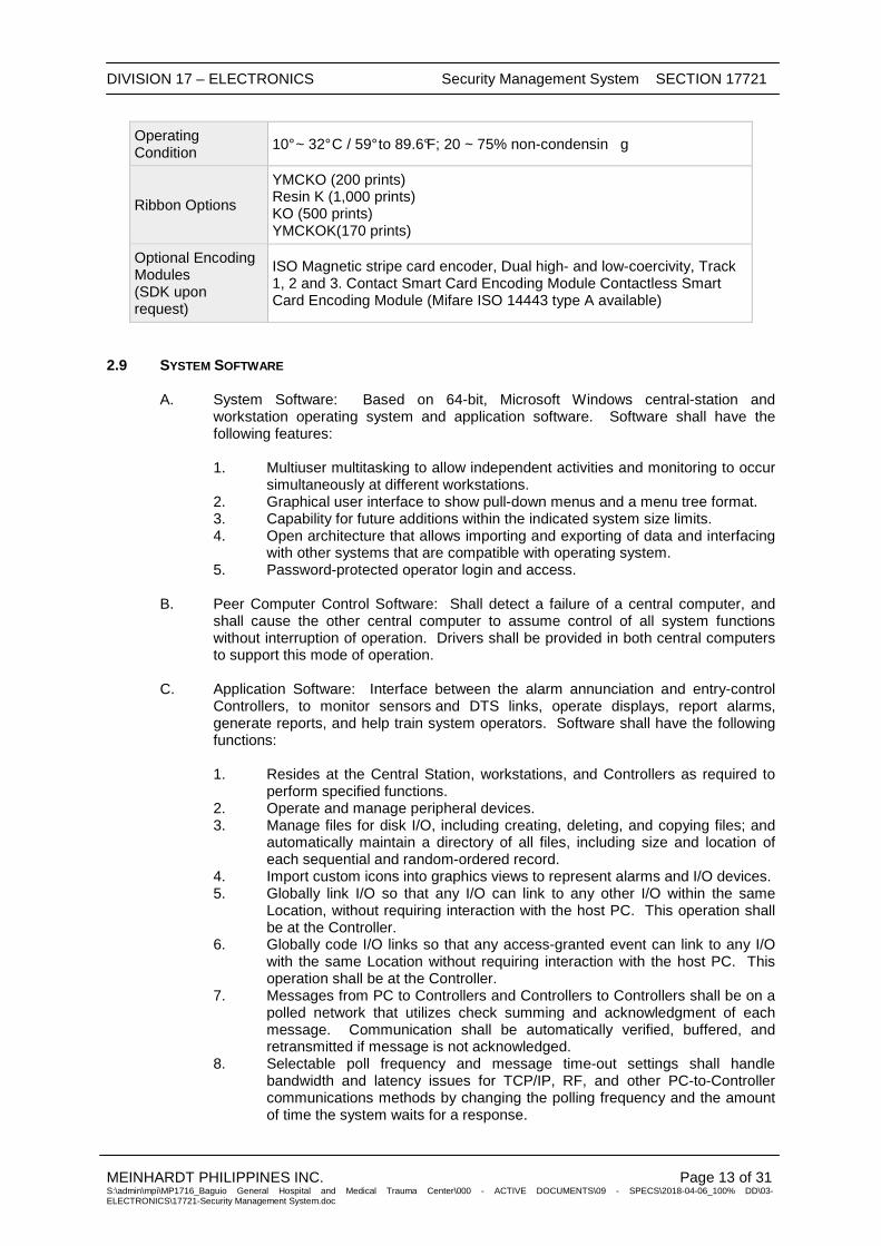
DIVISION 17 – ELECTRONICS Security Management System SECTION 17721
MEINHARDT PHILIPPINES INC. Page 13 of 31 S:\admin\mpi\MP1716_Baguio General Hospital and Medical Trauma Center\000 - ACTIVE DOCUMENTS\09 - SPECS\2018-04-06_100% DD\03-ELECTRONICS\17721-Security Management System.doc
Operating Condition
10° ~ 32° C / 59° to 89.6°F; 20 ~ 75% non-condensin g
Ribbon Options
YMCKO (200 prints) Resin K (1,000 prints) KO (500 prints) YMCKOK(170 prints)
Optional Encoding Modules (SDK upon request)
ISO Magnetic stripe card encoder, Dual high- and low-coercivity, Track 1, 2 and 3. Contact Smart Card Encoding Module Contactless Smart Card Encoding Module (Mifare ISO 14443 type A available)
2.9 SYSTEM SOFTWARE
A. System Software: Based on 64-bit, Microsoft Windows central-station and workstation operating system and application software. Software shall have the following features: 1. Multiuser multitasking to allow independent activities and monitoring to occur
simultaneously at different workstations. 2. Graphical user interface to show pull-down menus and a menu tree format. 3. Capability for future additions within the indicated system size limits. 4. Open architecture that allows importing and exporting of data and interfacing
with other systems that are compatible with operating system. 5. Password-protected operator login and access.
B. Peer Computer Control Software: Shall detect a failure of a central computer, and
shall cause the other central computer to assume control of all system functions without interruption of operation. Drivers shall be provided in both central computers to support this mode of operation.
C. Application Software: Interface between the alarm annunciation and entry-control Controllers, to monitor sensors and DTS links, operate displays, report alarms, generate reports, and help train system operators. Software shall have the following functions: 1. Resides at the Central Station, workstations, and Controllers as required to
perform specified functions. 2. Operate and manage peripheral devices. 3. Manage files for disk I/O, including creating, deleting, and copying files; and
automatically maintain a directory of all files, including size and location of each sequential and random-ordered record.
4. Import custom icons into graphics views to represent alarms and I/O devices. 5. Globally link I/O so that any I/O can link to any other I/O within the same
Location, without requiring interaction with the host PC. This operation shall be at the Controller.
6. Globally code I/O links so that any access-granted event can link to any I/O with the same Location without requiring interaction with the host PC. This operation shall be at the Controller.
7. Messages from PC to Controllers and Controllers to Controllers shall be on a polled network that utilizes check summing and acknowledgment of each message. Communication shall be automatically verified, buffered, and retransmitted if message is not acknowledged.
8. Selectable poll frequency and message time-out settings shall handle bandwidth and latency issues for TCP/IP, RF, and other PC-to-Controller communications methods by changing the polling frequency and the amount of time the system waits for a response.

DIVISION 17 – ELECTRONICS Security Management System SECTION 17721
MEINHARDT PHILIPPINES INC. Page 14 of 31 S:\admin\mpi\MP1716_Baguio General Hospital and Medical Trauma Center\000 - ACTIVE DOCUMENTS\09 - SPECS\2018-04-06_100% DD\03-ELECTRONICS\17721-Security Management System.doc
9. Automatic and encrypted backups for database and history backups shall be automatically stored at the central control PC and encrypted with a nine-character alphanumeric password, which must be used to restore or read data contained in backup.
10. Operator audit trail for recording and reporting all changes made to database and system software.
D. Workstation Software: 1. Password levels shall be individually customized at each workstation to allow
or disallow operator access to program functions for each Location. 2. Workstation event filtering shall allow user to define events and alarms that
will be displayed at each workstation. If an alarm is unacknowledged (not handled by another workstation) for a preset amount of time, the alarm will automatically appear on the filtered workstation.
E. Controller Software: 1. Controllers shall operate as an autonomous intelligent processing unit.
Controllers shall make decisions about access control, alarm monitoring, linking functions, and door locking schedules for its operation, independent of other system components. Controllers shall be part of a fully distributed processing control network. The portion of the database associated with a Controller and consisting of parameters, constraints, and the latest value or status of points connected to that Controller, shall be maintained in the Controller.
2. Functions: The following functions shall be fully implemented and operational within each Controller: a. Monitoring inputs. b. Controlling outputs. c. Automatically reporting alarms to the Central Station. d. Reporting of sensor and output status to Central Station on request. e. Maintaining real time, automatically updated by the Central Station at
least once a day. f. Communicating with the Central Station. g. Executing Controller resident programs. h. Diagnosing. i. Downloading and uploading data to and from the Central Station.
3. Controller Operations at a Location:
a. Location: Up to 64 Controllers connected to RS-485 communications
loop. Globally operating I/O linking and anti-passback functions between Controllers within the same Location without central-station or workstation intervention. Linking and anti-passback shall remain fully functional within the same Location even when the Central Station or workstations are off line.
b. In the event of communications failure between the Central Station and a Location, there shall be no degradation in operations at the Controllers at that Location. The Controllers at each Location shall be connected to a memory buffer with a capacity to store up to 10,000 events; there shall be no loss of transactions in system history files until the buffer overflows.
c. Buffered events shall be handled in a first-in-first-out mode of operation.
4. Individual Controller Operation:
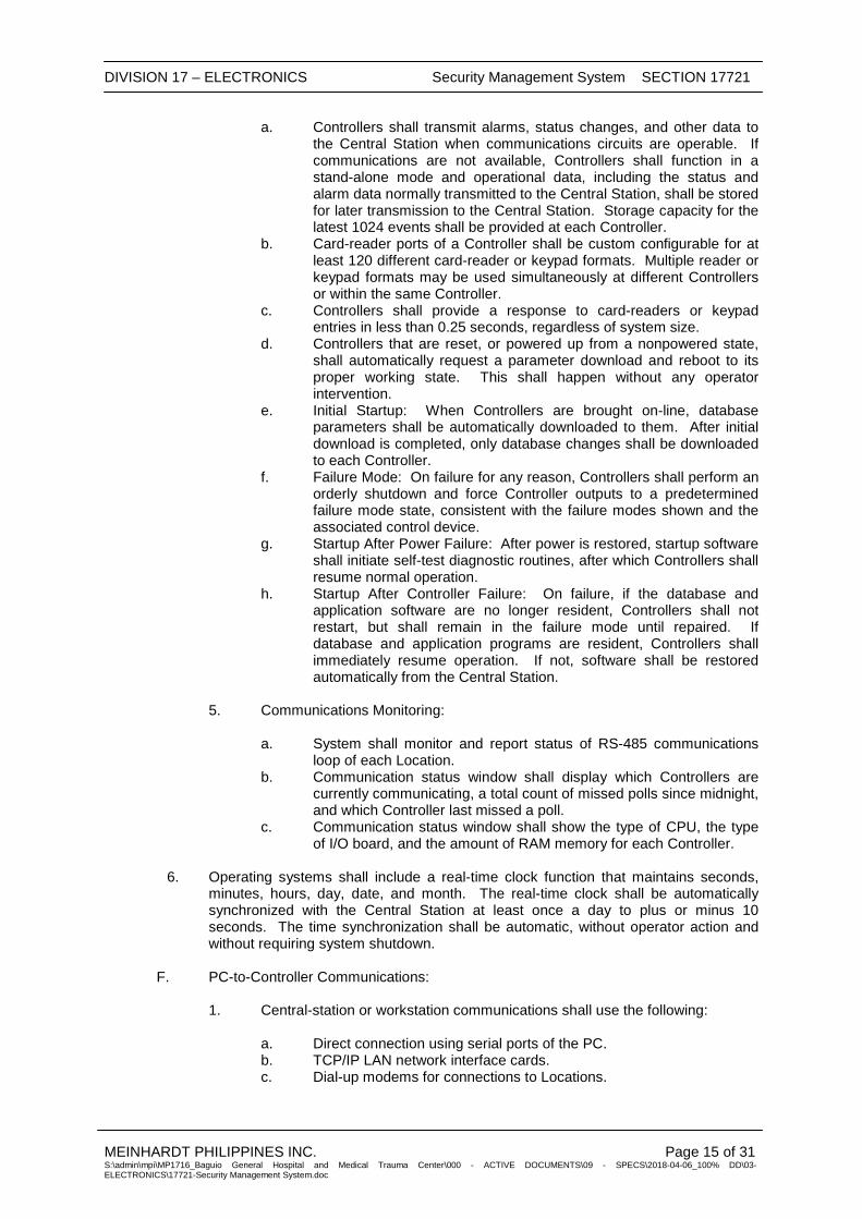
DIVISION 17 – ELECTRONICS Security Management System SECTION 17721
MEINHARDT PHILIPPINES INC. Page 15 of 31 S:\admin\mpi\MP1716_Baguio General Hospital and Medical Trauma Center\000 - ACTIVE DOCUMENTS\09 - SPECS\2018-04-06_100% DD\03-ELECTRONICS\17721-Security Management System.doc
a. Controllers shall transmit alarms, status changes, and other data to the Central Station when communications circuits are operable. If communications are not available, Controllers shall function in a stand-alone mode and operational data, including the status and alarm data normally transmitted to the Central Station, shall be stored for later transmission to the Central Station. Storage capacity for the latest 1024 events shall be provided at each Controller.
b. Card-reader ports of a Controller shall be custom configurable for at least 120 different card-reader or keypad formats. Multiple reader or keypad formats may be used simultaneously at different Controllers or within the same Controller.
c. Controllers shall provide a response to card-readers or keypad entries in less than 0.25 seconds, regardless of system size.
d. Controllers that are reset, or powered up from a nonpowered state, shall automatically request a parameter download and reboot to its proper working state. This shall happen without any operator intervention.
e. Initial Startup: When Controllers are brought on-line, database parameters shall be automatically downloaded to them. After initial download is completed, only database changes shall be downloaded to each Controller.
f. Failure Mode: On failure for any reason, Controllers shall perform an orderly shutdown and force Controller outputs to a predetermined failure mode state, consistent with the failure modes shown and the associated control device.
g. Startup After Power Failure: After power is restored, startup software shall initiate self-test diagnostic routines, after which Controllers shall resume normal operation.
h. Startup After Controller Failure: On failure, if the database and application software are no longer resident, Controllers shall not restart, but shall remain in the failure mode until repaired. If database and application programs are resident, Controllers shall immediately resume operation. If not, software shall be restored automatically from the Central Station.
5. Communications Monitoring: a. System shall monitor and report status of RS-485 communications
loop of each Location. b. Communication status window shall display which Controllers are
currently communicating, a total count of missed polls since midnight, and which Controller last missed a poll.
c. Communication status window shall show the type of CPU, the type of I/O board, and the amount of RAM memory for each Controller.
6. Operating systems shall include a real-time clock function that maintains seconds, minutes, hours, day, date, and month. The real-time clock shall be automatically synchronized with the Central Station at least once a day to plus or minus 10 seconds. The time synchronization shall be automatic, without operator action and without requiring system shutdown.
F. PC-to-Controller Communications: 1. Central-station or workstation communications shall use the following:
a. Direct connection using serial ports of the PC. b. TCP/IP LAN network interface cards. c. Dial-up modems for connections to Locations.
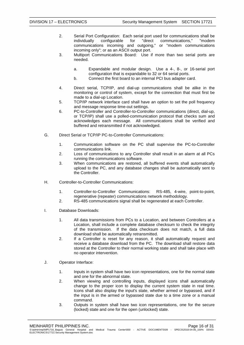
DIVISION 17 – ELECTRONICS Security Management System SECTION 17721
MEINHARDT PHILIPPINES INC. Page 16 of 31 S:\admin\mpi\MP1716_Baguio General Hospital and Medical Trauma Center\000 - ACTIVE DOCUMENTS\09 - SPECS\2018-04-06_100% DD\03-ELECTRONICS\17721-Security Management System.doc
2. Serial Port Configuration: Each serial port used for communications shall be individually configurable for "direct communications," "modem communications incoming and outgoing," or "modem communications incoming only"; or as an ASCII output port.
3. Multiport Communications Board: Use if more than two serial ports are needed. a. Expandable and modular design. Use a 4-, 8-, or 16-serial port
configuration that is expandable to 32 or 64 serial ports. b. Connect the first board to an internal PCI bus adapter card.
4. Direct serial, TCP/IP, and dial-up communications shall be alike in the
monitoring or control of system, except for the connection that must first be made to a dial-up Location.
5. TCP/IP network interface card shall have an option to set the poll frequency and message response time-out settings.
6. PC-to-Controller and Controller-to-Controller communications (direct, dial-up, or TCP/IP) shall use a polled-communication protocol that checks sum and acknowledges each message. All communications shall be verified and buffered and retransmitted if not acknowledged.
G. Direct Serial or TCP/IP PC-to-Controller Communications: 1. Communication software on the PC shall supervise the PC-to-Controller
communications link. 2. Loss of communications to any Controller shall result in an alarm at all PCs
running the communications software. 3. When communications are restored, all buffered events shall automatically
upload to the PC, and any database changes shall be automatically sent to the Controller.
H. Controller-to-Controller Communications: 1. Controller-to-Controller Communications: RS-485, 4-wire, point-to-point,
regenerative (repeater) communications network methodology. 2. RS-485 communications signal shall be regenerated at each Controller.
I. Database Downloads:
1. All data transmissions from PCs to a Location, and between Controllers at a
Location, shall include a complete database checksum to check the integrity of the transmission. If the data checksum does not match, a full data download shall be automatically retransmitted.
2. If a Controller is reset for any reason, it shall automatically request and receive a database download from the PC. The download shall restore data stored at the Controller to their normal working state and shall take place with no operator intervention.
J. Operator Interface: 1. Inputs in system shall have two icon representations, one for the normal state
and one for the abnormal state. 2. When viewing and controlling inputs, displayed icons shall automatically
change to the proper icon to display the current system state in real time. Icons shall also display the input's state, whether armed or bypassed, and if the input is in the armed or bypassed state due to a time zone or a manual command.
3. Outputs in system shall have two icon representations, one for the secure (locked) state and one for the open (unlocked) state.

DIVISION 17 – ELECTRONICS Security Management System SECTION 17721
MEINHARDT PHILIPPINES INC. Page 17 of 31 S:\admin\mpi\MP1716_Baguio General Hospital and Medical Trauma Center\000 - ACTIVE DOCUMENTS\09 - SPECS\2018-04-06_100% DD\03-ELECTRONICS\17721-Security Management System.doc
4. Icons displaying status of the I/O points shall be constantly updated to show their current real-time condition without prompting by the operator.
5. The operator shall be able to scroll the list of I/Os and press the appropriate toolbar button, or right click, to command the system to perform the desired function.
6. Graphic maps or drawings containing inputs, outputs, and override groups shall include the following: a. Database to import and store full-color maps or drawings and allow
for input, output, and override group icons to be placed on maps. b. Maps to provide real-time display animation and allow for control of
points assigned to them. c. System to allow inputs, outputs, and override groups to be placed on
different maps. d. Software to allow changing the order or priority in which maps will be
displayed.
7. Override Groups Containing I/Os: a. System shall incorporate override groups that provide the operator
with the status and control over user-defined "sets" of I/Os with a single icon.
b. Icon shall change automatically to show the live summary status of points in that group.
c. Override group icon shall provide a method to manually control or set to time zone points in the group.
d. Override group icon shall allow the expanding of the group to show icons representing the live status for each point in the group, individual control over each point, and the ability to compress the individual icons back into one summary icon.
8. Schedule Overrides of I/Os and Override Groups: a. To accommodate temporary schedule changes that do not fall within
the holiday parameters, the operator shall have the ability to override schedules individually for each input, output, or override group.
b. Each schedule shall be composed of a minimum of two dates with separate times for each date.
c. The first time and date shall be assigned the override state that the point shall advance to, when the time and date become current.
d. The second time and date shall be assigned the state that the point shall return to, when the time and date become current.
9. Copy command in database shall allow for like data to be copied and then edited for specific requirements, to reduce redundant data entry.
K. Operator Access Control: 1. Control operator access to system controls through three password-protected
operator levels. System operators and managers with appropriate password clearances shall be able to change operator levels for operators.
2. Three successive attempts by an operator to execute functions beyond their defined level during a 24-hour period shall initiate a software tamper alarm.
3. A minimum of 32 passwords shall be available with the system software. System shall display the operator's name or initials in the console's first field. System shall print the operator's name or initials, action, date, and time on the system printer at login and logoff.
4. The password shall not be displayed or printed. 5. Each password shall be definable and assignable for the following:
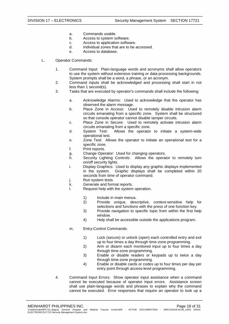
DIVISION 17 – ELECTRONICS Security Management System SECTION 17721
MEINHARDT PHILIPPINES INC. Page 18 of 31 S:\admin\mpi\MP1716_Baguio General Hospital and Medical Trauma Center\000 - ACTIVE DOCUMENTS\09 - SPECS\2018-04-06_100% DD\03-ELECTRONICS\17721-Security Management System.doc
a. Commands usable. b. Access to system software. c. Access to application software. d. Individual zones that are to be accessed. e. Access to database.
L. Operator Commands:
1. Command Input: Plain-language words and acronyms shall allow operators
to use the system without extensive training or data-processing backgrounds. System prompts shall be a word, a phrase, or an acronym.
2. Command inputs shall be acknowledged and processing shall start in not less than 1 second(s).
3. Tasks that are executed by operator's commands shall include the following: a. Acknowledge Alarms: Used to acknowledge that the operator has
observed the alarm message. b. Place Zone in Access: Used to remotely disable intrusion alarm
circuits emanating from a specific zone. System shall be structured so that console operator cannot disable tamper circuits.
c. Place Zone in Secure: Used to remotely activate intrusion alarm circuits emanating from a specific zone.
d. System Test: Allows the operator to initiate a system-wide operational test.
e. Zone Test: Allows the operator to initiate an operational test for a specific zone.
f. Print reports. g. Change Operator: Used for changing operators. h. Security Lighting Controls: Allows the operator to remotely turn
on/off security lights. i. Display Graphics: Used to display any graphic displays implemented
in the system. Graphic displays shall be completed within 20 seconds from time of operator command.
j. Run system tests. k. Generate and format reports. l. Request help with the system operation.
1) Include in main menus. 2) Provide unique, descriptive, context-sensitive help for
selections and functions with the press of one function key. 3) Provide navigation to specific topic from within the first help
window. 4) Help shall be accessible outside the applications program.
m. Entry-Control Commands:
1) Lock (secure) or unlock (open) each controlled entry and exit
up to four times a day through time-zone programming. 2) Arm or disarm each monitored input up to four times a day
through time-zone programming. 3) Enable or disable readers or keypads up to twice a day
through time-zone programming. 4) Enable or disable cards or codes up to four times per day per
entry point through access-level programming.
4. Command Input Errors: Show operator input assistance when a command cannot be executed because of operator input errors. Assistance screen shall use plain-language words and phrases to explain why the command cannot be executed. Error responses that require an operator to look up a

DIVISION 17 – ELECTRONICS Security Management System SECTION 17721
MEINHARDT PHILIPPINES INC. Page 19 of 31 S:\admin\mpi\MP1716_Baguio General Hospital and Medical Trauma Center\000 - ACTIVE DOCUMENTS\09 - SPECS\2018-04-06_100% DD\03-ELECTRONICS\17721-Security Management System.doc
code in a manual or other document are not acceptable. Conditions causing operator assistance messages include the following: a. Command entered is incorrect or incomplete. b. Operator is restricted from using that command. c. Command addresses a point that is disabled or out of service. d. Command addresses a point that does not exist. e. Command is outside the system's capacity.
M. Alarms:
1. System Setup:
a. Assign manual and automatic responses to incoming point status
change or alarms. b. Automatically respond to input with a link to other inputs, outputs,
operator-response plans, unique sound with use of WAV files, and maps or images that graphically represent the point location.
c. 60-character message field for each alarm. d. Operator-response-action messages shall allow message length of at
least 65,000 characters, with database storage capacity of up to 32,000 messages.
e. Secondary messages shall be assignable by the operator for printing to provide further information and shall be editable by the operator.
f. Allow 25 secondary messages with a field of 4 lines of 60 characters each.
g. Store the most recent 1000 alarms for recall by the operator using the report generator.
2. Software Tamper: a. Annunciate a tamper alarm when unauthorized changes to system
database files are attempted. Three consecutive unsuccessful attempts to log onto system shall generate a software tamper alarm.
b. Annunciate a software tamper alarm when an operator or other individual makes three consecutive unsuccessful attempts to invoke functions beyond their authorization level.
c. Maintain a transcript file of the last 5000 commands entered at each Central Station to serve as an audit trail. System shall not allow write access to system transcript files by any person, regardless of their authorization level.
d. Allow only acknowledgment of software tamper alarms.
3. Read access to system transcript files shall be reserved for operators with the highest password authorization level available in system.
4. Animated Response Graphics: Highlight alarms with flashing icons on graphic maps; display and constantly update the current status of alarm inputs and outputs in real time through animated icons.
5. Multimedia Alarm Annunciation: WAV files to be associated with alarm events for audio annunciation or instructions.
6. Alarm Handling: Each input may be configured so that an alarm cannot be cleared unless it has returned to normal, with options of requiring the operator to enter a comment about disposition of alarm. Allow operator to silence alarm sound when alarm is acknowledged.
7. Alarm Automation Interface: High-level interface to Central Station alarm automation software systems. Allows input alarms to be passed to and handled by automation systems in same manner as burglar alarms, using an RS-232 ASCII interface.
DIVISION 17 – ELECTRONICS Security Management System SECTION 17721
MEINHARDT PHILIPPINES INC. Page 20 of 31 S:\admin\mpi\MP1716_Baguio General Hospital and Medical Trauma Center\000 - ACTIVE DOCUMENTS\09 - SPECS\2018-04-06_100% DD\03-ELECTRONICS\17721-Security Management System.doc
8. CCTV Alarm Interface: Allow commands to be sent to CCTV systems during alarms (or input change of state) through serial ports.
9. Camera Control: Provides operator ability to select and control cameras from graphic maps.
N. Alarm Monitoring: Monitor sensors, Controllers, and DTS circuits and notify operators of an alarm condition. Display higher-priority alarms first and, within alarm priorities, display the oldest unacknowledged alarm first. Operator acknowledgment of one alarm shall not be considered acknowledgment of other alarms nor shall it inhibit reporting of subsequent alarms. 1. Displayed alarm data shall include type of alarm, location of alarm, and
secondary alarm messages. 2. Printed alarm data shall include type of alarm, location of alarm, date and
time (to nearest second) of occurrence, and operator responses. 3. Maps shall automatically display the alarm condition for each input assigned
to that map, if that option is selected for that input location. 4. Alarms initiate a status of "pending" and require the following two handling
steps by operators: a. First Operator Step: "Acknowledged." This action shall silence
sounds associated with the alarm. The alarm remains in the system "Acknowledged" but "Un-Resolved."
b. Second Operator Step: Operators enter the resolution or operator comment, giving the disposition of the alarm event. The alarm shall then clear.
5. Each workstation shall display the total pending alarms and total unresolved alarms.
6. Each alarm point shall be programmable to disallow the resolution of alarms until the alarm point has returned to its normal state.
7. Alarms shall transmit to Central Station in real time. 8. Alarms shall be displayed and managed from a minimum of four different
windows. a. Input Status Window: Overlay status icon with a large red blinking
icon. Selecting the icon will acknowledge the alarm. b. History Log Transaction Window: Display name, time, and date in
red text. Selecting red text will acknowledge the alarm. c. Alarm Log Transaction Window: Display name, time, and date in red.
Selecting red text will acknowledge the alarm. d. Graphic Map Display: Display a steady colored icon representing
each alarm input location. Change icon to flashing red when the alarm occurs. Change icon from flashing red to steady red when the alarm is acknowledged.
9. Once an alarm is acknowledged, the operator shall be prompted to enter comments about the nature of the alarm and actions taken. Operator's comments may be manually entered or selected from a programmed predefined list, or a combination of both.
10. For locations where there are regular alarm occurrences, provide programmed comments. Selecting that comment shall clear the alarm.
11. The time and name of the operator who acknowledged and resolved the alarm shall be recorded in the database.
12. Identical alarms from same alarm point shall be acknowledged at same time the operator acknowledges the first alarm. Identical alarms shall be resolved when the first alarm is resolved.
13. Alarm functions shall have priority over downloading, retrieving, and updating database from workstations and Controllers.

DIVISION 17 – ELECTRONICS Security Management System SECTION 17721
MEINHARDT PHILIPPINES INC. Page 21 of 31 S:\admin\mpi\MP1716_Baguio General Hospital and Medical Trauma Center\000 - ACTIVE DOCUMENTS\09 - SPECS\2018-04-06_100% DD\03-ELECTRONICS\17721-Security Management System.doc
14. When a reader-controlled output (relay) is opened, the corresponding alarm point shall be automatically bypassed.
O. Monitor Display: Display text and graphic maps that include zone status integrated into the display. Colors are used for the various components and current data. Colors shall be uniform throughout the system. 1. Color Code:
a. FLASHING RED: Alerts operator that a zone has gone into an alarm
or that primary power has failed. b. STEADY RED: Alerts operator that a zone is in alarm and alarm has
been acknowledged. c. YELLOW: Advises operator that a zone is in access. d. GREEN: Indicates that a zone is secure and that power is on.
2. Graphics:
a. Support 32,000 graphic display maps and allow import of maps from
a minimum of 16 standard formats from another drawing or graphics program.
b. Allow I/O to be placed on graphic maps by the drag-and-drop method.
c. Operators shall be able to view the inputs, outputs, and the point's name by moving the mouse cursor over the point on graphic map.
d. Inputs or outputs may be placed on multiple graphic maps. The operator shall be able to toggle to view graphic map associated with inputs or outputs.
e. Each graphic map shall have a display-order sequence number associated with it to provide a predetermined order when toggled to different views.
f. Camera icons shall have the ability to be placed on graphic maps that, when selected by an operator, will open a video window, display the camera associated with that icon, and provide pan-tilt-zoom control.
g. Input, output, or camera placed on a map shall allow the ability to arm or bypass an input, open or secure an output, or control the pan-tilt-zoom function of the selected camera.
P. System test software enables operators to initiate a test of the entire system or of a particular portion of the system. 1. Test Report: The results of each test shall be stored for future display or
printout. The report shall document the operational status of system components.
Q. Report Generator Software: Include commands to generate reports for displaying, printing, and storing on disk and tape. Reports shall be stored by type, date, and time. Report printing shall be the lowest priority activity. Report generation mode shall be operator selectable but set up initially as periodic, automatic, or on request. Include time and date printed and the name of operator generating the report. Report formats may be configured by operators. 1. Automatic Printing: Setup shall specify, modify, or inhibit the report to be
generated; the time the initial report is to be generated; the time interval between reports; the end of period; and the default printer.
2. Printing on Requests: An operator may request a printout of any report. 3. Alarm Reports: Reporting shall be automatic as initially set up. Include
alarms recorded by system over the selected time and information about the type of alarm such as door alarm, intrusion alarm, tamper alarm, etc. the type of sensor, the location, the time, and the action taken.
DIVISION 17 – ELECTRONICS Security Management System SECTION 17721
MEINHARDT PHILIPPINES INC. Page 22 of 31 S:\admin\mpi\MP1716_Baguio General Hospital and Medical Trauma Center\000 - ACTIVE DOCUMENTS\09 - SPECS\2018-04-06_100% DD\03-ELECTRONICS\17721-Security Management System.doc
4. Access and Secure Reports: Document zones placed in access, the time placed in access, and the time placed in secure mode.
5. Custom Reports: Reports tailored to exact requirements of who, what, when, and where. As an option, custom report formats may be stored for future printing.
6. Automatic History Reports: Named, saved, and scheduled for automatic generation.
7. Cardholder Reports: Include data, or selected parts of the data, as well as the ability to be sorted by name, card number, imprinted number, or by any of the user-defined fields.
8. Cardholder by Reader Reports: Based on who has access to a specific reader or group of readers by selecting the readers from a list.
9. Cardholder by Access-Level Reports: Display everyone that has been assigned to the specified access level.
10. Who Is In (Muster) Report: a. Emergency Muster Report: One click operation on toolbar launches
report. b. Cardholder Report. Contain a count of persons that are "In" at a
selected Location and a count with detailed listing of name, date, and time of last use, sorted by the last reader used or by the group assignment.
11. Panel Labels Reports: Printout of control-panel field documentation including the actual location of equipment, programming parameters, and wiring identification. Maintain system installation data within system database so that they are available on-site at all times.
12. Activity and Alarm On-Line Printing: Activity printers for use at workstations; prints all events or alarms only.
13. History Reports: Custom reports that allows the operator to select any date, time, event type, device, output, input, operator, Location, name, or cardholder to be included or excluded from the report. a. Initially store history on the hard disk of the host PC. b. Permit viewing of the history on workstations or print history to any
system printer. c. The report shall be definable by a range of dates and times with the
ability to have a daily start and stop time over a given date range. d. Each report shall depict the date, time, event type, event description,
device, or I/O name, cardholder group assignment, and cardholder name or code number.
e. Each line of a printed report shall be numbered to ensure that the integrity of the report has not been compromised.
f. Total number of lines of the report shall be given at the end of the report. If the report is run for a single event such as "Alarms," the total shall reflect how many alarms occurred during that period.
14. Reports shall have the following four options: a. View on screen. b. Print to system printer. Include automatic print spooling and "Print
To" options if more than one printer is connected to system. c. "Save to File" with full path statement. d. System shall have the ability to produce a report indicating status of
system inputs and outputs or of inputs and outputs that are abnormal, out of time zone, manually overridden, not reporting, or in alarm.
15. Custom Code List Subroutine: Allow the access codes of system to be sorted and printed according to the following criteria:

DIVISION 17 – ELECTRONICS Security Management System SECTION 17721
MEINHARDT PHILIPPINES INC. Page 23 of 31 S:\admin\mpi\MP1716_Baguio General Hospital and Medical Trauma Center\000 - ACTIVE DOCUMENTS\09 - SPECS\2018-04-06_100% DD\03-ELECTRONICS\17721-Security Management System.doc
a. Active, inactive, or future activate or deactivate. b. Code number, name, or imprinted card number. c. Group, Location, access levels. d. Start and stop code range. e. Codes that have not been used since a selectable number of days. f. In, out, or either status. g. Codes with trace designation.
16. The reports of system database shall allow options so that every data field
may be printed. 17. The reports of system database shall be constructed so that the actual
position of the printed data shall closely match the position of the data on the data-entry windows.
R. Anti-Passback: 1. System shall have global and local anti-passback features, selectable by
Location. System shall support hard and soft anti-passback. 2. Hard Anti-Passback: Once a credential holder is granted access through a
reader with one type of designation (IN or OUT), the credential holder may not pass through that type of reader designation until the credential holder passes though a reader of opposite designation.
3. Soft Anti-Passback: Should a violation of the proper IN or OUT sequence occur, access shall be granted, but a unique alarm shall be transmitted to the control station, reporting the credential holder and the door involved in the violation. A separate report may be run on this event.
4. Timed Anti-Passback: A Controller capability that prevents an access code from being used twice at the same device (door) within a user-defined amount of time.
5. Provide four separate zones per Location that can operate without requiring interaction with the host PC (done at Controller). Each reader shall be assignable to one or all four anti-passback zones. In addition, each anti-passback reader can be further designated as "Hard," "Soft," or "Timed" in each of the four anti-passback zones. The four anti-passback zones shall operate independently.
6. The anti-passback schemes shall be definable for each individual door. 7. The Master Access Level shall override anti-passback. 8. System shall have the ability to forgive (or reset) an individual credential
holder or the entire credential holder population anti-passback status to a neutral status.
S. Visitor Assignment: 1. Provide for and allow an operator to be restricted to only working with visitors.
The visitor badging subsystem shall assign credentials and enroll visitors. Allow only access levels that have been designated as approved for visitors.
2. Provide an automated log of visitor name, time and doors accessed, and whom visitor contacted.
3. Allow a visitor designation to be assigned to a credential holder. 4. Security access system shall be able to restrict the access levels that may be
assigned to credentials that are issued to visitors. 5. Allow operator to recall visitors' credential holder file, once a visitor is enrolled
in the system. 6. The operator may designate any reader as one that deactivates the
credential after use at that reader. The history log shall show the return of the credential.
7. System shall have the ability to use the visitor designation in searches and reports. Reports shall be able to print all or any visitor activity.
T. Time and Attendance:
DIVISION 17 – ELECTRONICS Security Management System SECTION 17721
MEINHARDT PHILIPPINES INC. Page 24 of 31 S:\admin\mpi\MP1716_Baguio General Hospital and Medical Trauma Center\000 - ACTIVE DOCUMENTS\09 - SPECS\2018-04-06_100% DD\03-ELECTRONICS\17721-Security Management System.doc
1. Time and attendance reporting shall be provided to match IN and OUT reads
and display cumulative time in for each day and cumulative time in for length of the report.
2. Shall be provided to match IN and OUT reads and display cumulative time in for each day and cumulative time in for length of the report.
3. System software setup shall allow designation of selected access-control readers as time and attendance hardware to gather the clock-in and clock-out times of the users at these readers. a. Reports shall show in and out times for each day, total in time for
each day, and a total in time for period specified by the user. b. Allow the operator to view and print the reports, or save the report to
a file. c. Alphabetically sort reports on the person's last name, by Location or
location group. Include all credential holders or optionally select individual credential holders for the report.
U. Training Software: Enables operators to practice system operation including alarm acknowledgment, alarm assessment, response force deployment, and response force communications. System shall continue normal operation during training exercises and shall terminate exercises when an alarm signal is received at the console.
V. Entry-Control Enrollment Software: Database management functions that allow operators to add, delete, and modify access data as needed.
1. The enrollment station shall not have alarm response or acknowledgment
functions. 2. Provide multiple, password-protected access levels. Database management
and modification functions shall require a higher operator access level than personnel enrollment functions.
3. The program shall provide means to disable the enrollment station when it is unattended to prevent unauthorized use.
4. The program shall provide a method to enter personnel identifying information into the entry-control database files through enrollment stations. In the case of personnel identity verification subsystems, this shall include biometric data. Allow entry of personnel identifying information into the system database using menu selections and data fields. The data field names shall be customized during setup to suit user and site needs. Personnel identity verification subsystems selected for use with the system shall fully support the enrollment function and shall be compatible with the entry-control database files.
5. Cardholder Data: Provide 99 user-defined fields. System shall have the ability to run searches and reports using any combination of these fields. Each user-defined field shall be configurable, using any combination of the following features: a. MASK: Determines a specific format that data must comply with. b. REQUIRED: Operator is required to enter data into field before
saving. c. UNIQUE: Data entered must be unique. d. DEACTIVATE DATE: Data entered will be evaluated as an
additional deactivate date for all cards assigned to this cardholder. e. NAME ID: Data entered will be considered a unique ID for the
cardholder.
6. Personnel Search Engine: A report generator with capabilities such as search by last name, first name, group, or any predetermined user-defined data field; by codes not used in definable number of days; by skills; or by seven other methods.
DIVISION 17 – ELECTRONICS Security Management System SECTION 17721
MEINHARDT PHILIPPINES INC. Page 25 of 31 S:\admin\mpi\MP1716_Baguio General Hospital and Medical Trauma Center\000 - ACTIVE DOCUMENTS\09 - SPECS\2018-04-06_100% DD\03-ELECTRONICS\17721-Security Management System.doc
7. Multiple Deactivate Dates for Cards: User-defined fields to be configured as additional stop dates to deactivate any cards assigned to the cardholder.
8. Batch card printing. 9. Default card data can be programmed to speed data entry for sites where
most card data are similar. 10. Enhanced ACSII File Import Utility: Allows the importing of cardholder data
and images. 11. Card Expire Function: Allows readers to be configured to deactivate cards
when a card is used at selected devices. 2.10 SYSTEM DATABASE
A. Database and database management software shall define and modify each point in database using operator commands. Definition shall include parameters and constraints associated with each system device.
B. Database Operations: 1. System data management shall be in a hierarchical menu tree format, with
navigation through expandable menu branches and manipulated with use of menus and icons in a main menu and system toolbar.
2. Navigational Aids:
a. Toolbar icons for add, delete, copy, print, capture image, activate, deactivate, and muster report.
b. Point and click feature to facilitate data manipulation. c. Next and previous command buttons visible when editing database
fields to facilitate navigation from one record to the next. d. Copy command and copy tool in the toolbar to copy data from one
record to create a new similar record.
3. All data entry shall be automatically checked for duplicate and illegal data and shall verify that data are in a valid format.
4. Provide a memo or note field for each item that is stored in database, allowing the storing of information about any defining characteristics of the item. Memo field is used for noting the purpose the item was entered for, reasons for changes that were made, and the like.
C. File Management: 1. Provide database backup and restoration system, allowing selection of
storage media, Zip and Jaz drives, and designated network resources. 2. Provide manual and automatic mode of backup operations. The number of
automatic sequential backups before the oldest backup becomes overwritten; FIFO mode shall be operator selectable.
3. Backup program shall provide manual operation from any PC on the LAN and shall operate while system remains operational.
D. Operator Passwords:
1. Software shall support up to 32,000 individual system operators, each with a
unique password. 2. Operator Password: Alphanumeric Characters 3. Allow passwords to be case sensitive. 4. Passwords shall not be displayed when entered. 5. Provide each password with a unique and customizable password profile,
and allow several operators to share a password profile. Include the following features in the password profile:

DIVISION 17 – ELECTRONICS Security Management System SECTION 17721
MEINHARDT PHILIPPINES INC. Page 26 of 31 S:\admin\mpi\MP1716_Baguio General Hospital and Medical Trauma Center\000 - ACTIVE DOCUMENTS\09 - SPECS\2018-04-06_100% DD\03-ELECTRONICS\17721-Security Management System.doc
a. Allow for at least 32,000 operator password profiles. b. Predetermine the highest-level password profile for access to all
functions and areas of program. c. Allow or disallow operator access to any program operation, including
the functions of View, Add, Edit, and Delete. d. Restrict which doors an operator can assign access to.
6. Operators shall use a user name and password to log on to system.
a. This user name and password is used to access database areas and programs as determined by the associated profile.
7. Make provision to allow the operator to log off without fully exiting program.
User may be logged off but program will remain running while displaying the login window for the next operator.
E. Access Card/Code Operation and Management: Access authorization shall be by card, by a manually entered code (PIN), or by a combination of both (card plus PIN). 1. Access authorization shall verify the facility code first, the card or card-and-
PIN validation second, and the access level (time of day, day of week, date), anti-passback status, and number of uses last.
2. Use data-entry windows to view, edit, and issue access levels. Access authorization entry management system shall maintain and coordinate all access levels to prevent duplication or the incorrect creation of levels.
3. Allow assignment of multiple cards/codes to a cardholder. 4. Allow assignment of up to four access levels for each Location to a
cardholder. Each access level may contain any combination of doors. 5. Each door may be assigned four time zones. 6. Access codes may be up to 11 digits in length. 7. Software shall allow the grouping of locations so cardholder data can be
shared by all locations in the group. 8. Visitor Access: Issue a visitor badge, without assigning that person a card or
code, for data tracking or photo ID purposes. 9. Cardholder Tracing: Allow for selection of cardholder for tracing. Make a
special audible and visual annunciation at control station when a selected card or code is used at a designated code reader. Annunciation shall include an automatic display of the cardholder image.
10. Allow each cardholder to be given either an unlimited number of uses or a number from 1 to 9998 that regulates the number of times the card can be used before it is automatically deactivated.
11. Provide for cards and codes to be activated and deactivated manually or automatically by date. Provide for multiple deactivate dates to be preprogrammed.
F. Security Access Integration:
1. Photo ID badging and photo verification shall use same database as the
security access and may query data from cardholder, group, and other personal information to build a custom ID badge.
2. Automatic or manual image recall and manual access based on photo verification shall also be a means of access verification and entry.
3. System shall allow sorting of cardholders together by group or other characteristic for a fast and efficient method of reporting on, and enabling or disabling, cards or codes.
G. Key control and tracking shall be an integrated function of cardholder data.

DIVISION 17 – ELECTRONICS Security Management System SECTION 17721
MEINHARDT PHILIPPINES INC. Page 27 of 31 S:\admin\mpi\MP1716_Baguio General Hospital and Medical Trauma Center\000 - ACTIVE DOCUMENTS\09 - SPECS\2018-04-06_100% DD\03-ELECTRONICS\17721-Security Management System.doc
1. Provide the ability to store information about which conventional metal keys are issued and to whom, along with key construction information.
2. Reports shall be designed to list everyone that has possession of a specified key.
H. Facility Codes: System shall accommodate up to 2048 facility codes per Location,
with the option of allowing facility codes to work at all doors or only particular doors.
I. Operator Comments: 1. With the press of one appropriate button on toolbar, the user shall be
permitted to make operator comments into history at anytime. 2. Automatic prompting of operator comment shall occur before the resolution of
each alarm. 3. Operator comments shall be recorded by time, date, and operator number. 4. Comments shall be sorted and viewed through reports and history.
5. The operator may enter comments in two ways; either or both may be used:
a. Manually entered through keyboard data entry (typed), up to 65,000 characters per each alarm.
b. Predefined and stored in database for retrieval on request.
6. System shall have a minimum of 999 predefined operator comments with up to 30 characters per comment.
J. Group:
1. Group names may be used to sort cardholders into groups that allow the
operator to determine the tenant, vendor, contractor, department, division, or any other designation of a group to which the person belongs.
2. System software shall have the capacity to assign 1 of 32,000 group names to an access authorization.
3. Make provision in software to deactivate and reactivate all access authorizations assigned to a particular group.
4. Allow sorting of history reports and code list printouts by group name.
K. Time Zones: 1. Each zone consists of a start and stop time for 7 days of the week and three
holiday schedules. A time zone is assigned to inputs, outputs, or access levels to determine when an input shall automatically arm or disarm, when an output automatically opens or secures, or when access authorization assigned to an access level will be denied or granted.
2. Up to four time zones may be assigned to inputs and outputs to allow up to four arm or disarm periods per day or four lock or unlock periods per day; up to three holiday override schedules may be assigned to a time zone.
3. Data-entry window shall display a dynamically linked bar graph showing active and inactive times for each day and holiday, as start and stop times are entered or edited.
4. System shall have the capacity for 2048 time zones for each Location.
L. Holidays: 1. Three different holiday schedules may be assigned to a time zone. Holiday
schedule consists of date in format MM/DD/YYYY and a description. When the holiday date matches the current date of the time zone, the holiday schedule replaces the time zone schedule for that 24-hour period.
2. System shall have the capacity for 32,000 holidays.
DIVISION 17 – ELECTRONICS Security Management System SECTION 17721
MEINHARDT PHILIPPINES INC. Page 28 of 31 S:\admin\mpi\MP1716_Baguio General Hospital and Medical Trauma Center\000 - ACTIVE DOCUMENTS\09 - SPECS\2018-04-06_100% DD\03-ELECTRONICS\17721-Security Management System.doc
3. Three separate holiday schedules may be applied to a time zone. 4. Holidays have an option to be designated as occurring on the designated
date each year. These holidays remain in system and will not be purged. 5. Holidays not designated to occur each year shall be automatically purged
from database after the date expires.
M. Access Levels: 1. System shall allow for the creation up to 32,000 access levels. 2. One level shall be predefined as the Master Access Level. The Master
Access Level shall work at all doors at all times and override any anti-passback.
3. System shall allow for access to be restricted to any area by reader and by time. Access levels shall determine when and where an Identifier is authorized.
4. System shall be able to create multiple door and time zone combinations under same access level so that an Identifier may be valid during different time periods at different readers even if the readers are on the same Controller.
N. User-Defined Fields:
1. System shall provide a minimum of 99 user-defined fields, each with up to 50
characters, for specific information about each credential holder. 2. System shall accommodate a title for each field; field length shall be 20
characters. 3. A "Required" option may be applied to each user-defined field that, when
selected, forces the operator to enter data in the user-defined field before the credential can be saved.
4. A "Unique" option may be applied to each user-defined field that, when selected, will not allow duplicate data from different credential holders to be entered.
5. Data format option may be assigned to each user-defined field that will require the data to be entered with certain character types in specific spots in the field entry window.
6. A user-defined field, if selected, will define the field as a deactivate date. The selection shall automatically cause the data to be formatted with the windows MM/DD/YYYY date format. The credential of the holder will be deactivated on that date.
7. A search function shall allow any one user-defined field or combination of user-defined fields to be searched to find the appropriate cardholder. The search function shall include search for a character string.
8. System shall have the ability to print cardholders based on and organized by the user-defined fields.
O. Code Tracing:
1. System shall perform code tracing selectable by cardholder and by reader. 2. Any code may be designated as a "traced code" with no limit to how many
codes can be traced. 3. Any reader may be designated as a "trace reader" with no limit to which or
how many readers can be used for code tracing. 4. When a traced code is used at a trace reader, the access-granted message
that usually appears on the monitor window of the Central Station shall be highlighted with a different color than regular messages. A short singular beep shall occur at the same time the highlighted message is displayed on the window.
5. The traced cardholder image (if image exists) shall appear on workstations when used at a trace reader.
DIVISION 17 – ELECTRONICS Security Management System SECTION 17721
MEINHARDT PHILIPPINES INC. Page 29 of 31 S:\admin\mpi\MP1716_Baguio General Hospital and Medical Trauma Center\000 - ACTIVE DOCUMENTS\09 - SPECS\2018-04-06_100% DD\03-ELECTRONICS\17721-Security Management System.doc
PART 3 – EXECUTION 3.1 INSTALLATION
A. All wiring shall be in a complete conduit system separate from other building wiring.
Wiring color code shall be maintained throughout the scope of the work. B. Installation equipment and services that pertain to other work in the Contract shall be
closely coordinated with the appropriate Contractors.
C. Space provision for camera mounting and wiring facilities shall be by the Lift Contractor, and the Security System Contractor shall ensure that all details are coordinated with the Lift Contractor.
D. Coordinate with Builder to ensure that:
1. All required building penetrations are provided, otherwise provide details (eg:
drawings) 2. Trimming shall be provided for all ceilings and walls where security detection
devices and cables are required provide details. 3. Interfaces between motorized doors and the Security System are fully
compatible, fully commissioned and tested, and provide all the control, monitoring signals and information required by the Security System.
A. Coordinate with the Elevator Contractor to ensure that:
1. Low level elevator interfaces provided for communications between the
elevator systems and Security System are fully compatible, fully commissioned and tested, and provide all the control, monitoring signals and information required by the Security System.
2. Adequate and suitable provision is made for the mounting of the equipment in each elevator car.
3. Inter-system cabling is properly labeled and terminated in an agreed fashion and fully documented to a level satisfactory to both Contractors.
4. All cabling run in riser shafts, on cable trays, in ducts, conduits, etc., from the elevator motor room to the security/elevator demarcation junction boxes are done in an orderly and neat fashion and which allows clear identification and segregation of the cable looms.
5. Location of intercom within the Security Control Room (on console) and associated installation is in accordance with the Security Control Room design.
6. The systems are tested and commissioned successfully.
B. Coordinate with the Electronics Contractor to ensure that:
1. No conflict occurs between cable conduit or cable tray routes for the two services.
2. Sufficient essential supply is supplied and installed to meet the requirements of the Security System Contractor.
3. The cabling is terminated in an agreed fashion and documented to a level satisfactory to both Contractors.
4. All cabling are done in an orderly and neat fashion and which allows clear identification and segregation of the cabling looms.
5. The systems are tested and commissioned successfully. 6. All interfaces are fully documented to the satisfaction of the Security System
and Electronics Contractors.
C. Coordinate with the Fire Alarm Contractor to ensure that:
DIVISION 17 – ELECTRONICS Security Management System SECTION 17721
MEINHARDT PHILIPPINES INC. Page 30 of 31 S:\admin\mpi\MP1716_Baguio General Hospital and Medical Trauma Center\000 - ACTIVE DOCUMENTS\09 - SPECS\2018-04-06_100% DD\03-ELECTRONICS\17721-Security Management System.doc
1. Interfacing compatibility between the Security and Fire System is achieved. 2. The Security and Fire Systems are fully operational and have been tested
and commissioned fully and meets the requirements of this Specification. 3. Inter-system cabling is terminated in an agreed fashion and documented to a
level satisfactory to both Contractors. 4. Junction boxes, properly labeled termination strips, conduits, cables are
suitably located for the Security-Fire system interface. 5. Location of intercom within the Security Control Room (on console) and
associated installation is in accordance with the Security Control Room design.
6. All Fire-Security interfaces are fully documented to the satisfaction of the Security System and Fire Contractors.
D. The manufacturer’s authorized representative shall provide all on-site software
modifications and supervision of installation of the complete Security System installation, perform a complete functional test of the system, and submit a written report to the Project Manager attesting to the proper operation of the complete system.
E. Unless specified otherwise, the manufacturer’s recommendations shall be followed
with regard to workmanship and associated materials, equipment, components and devices, whether or not the particular manufacturer has been specified.
F. Where equipment and materials enters in environmental condition e. g. temperature,
humidity, rain, fog, steam, etc., all said materials, equipment, components and devices which could be affected by such shall be selected and installed to ensure satisfactory operation.
G. The layout, dimensions and positions of equipment shown on the Drawings are
diagrammatic and indicative only and exact positions shall be determined on site.
H. Variations of positions shall be affected without cost variation if the change is advised before the equipment is cabled and it is not more than ten (10) meters distant.
I. All equipment and/or appliances provided under this Specification shall be designed
so that no interference shall caused to any radio or other electronic transmitting or receiving equipment in the same locality. In the event of the inherent characteristics of the electrical installation being such that interference is possible efficient devices capable of eliminating such interference shall be provided by the Security System Contractor.
J. Equipment supplied and installed shall be such that interference from outside sources
(magnetic, electrical or EMI noise distortion, etc.) shall not be accepted as reasons for non-operational equipment or systems.
3.2 TESTING AND COMMISSIONING
A. Provide the service of a competent factory-trained engineer or technical authorized by the manufacturer of the security system equipment to technically supervise and participate during all of the adjustments and tests for the system. Make all adjustments and tests in the presence of the Project Manager.
B. When the system has been completed, and prior to the final inspection, furnish testing
equipment and perform the following tests in the presence of the Engineer and the Local authority having jurisdiction.
DIVISION 17 – ELECTRONICS Security Management System SECTION 17721
MEINHARDT PHILIPPINES INC. Page 31 of 31 S:\admin\mpi\MP1716_Baguio General Hospital and Medical Trauma Center\000 - ACTIVE DOCUMENTS\09 - SPECS\2018-04-06_100% DD\03-ELECTRONICS\17721-Security Management System.doc
1. Before energizing the cables and wires, check for correct connections and test for short circuits, ground faults, continuity and insulation.
2. Test the insulation on all installed cable and wiring by standard methods as recommended by the equipment manufacturer.
3. Test all security system devices circuits for open and ground and verify response of trouble signals.
4. Check installation, supervision and operation to ascertain that they will function as specified.
5. When any defects are detected, make repairs or install replacement components, and repeat the test.
C. At the final inspection, a factory-trained representative of the manufacturer of the major
equipment shall perform the required test. In addition, the representative shall demonstrate that the systems function properly in every respect. The demonstration shall be made in the presence o the Owner’s Representative, Project Manager, Consultant and the local authority having jurisdiction.
END OF SECTION
DIVISION 17 – ELECTRONICS Nurse Call System (IP-Based) SECTION 17725
MEINHARDT PHILIPPINES INC S:\admin\mpi\MP1716_Baguio General Hospital and Medical Trauma Center\000 - ACTIVE DOCUMENTS\09 - SPECS\2018-04-06_100% DD\03-ELECTRONICS\17725-Nurse Call System.doc
PART 1 – GENERAL .................................. ............................................................................................ 1
1.1 DESCRIPTION OF WORK .............................................................................................................. 1 1.2 RELATED WORK .......................................................................................................................... 2 1.3 QUALITY ASSURANCE .................................................................................................................. 2 1.4 SUBMITTALS ............................................................................................................................... 2 1.5 ACCEPTABLE MANUFACTURERS ................................................................................................... 2 1.6 TRAINING .................................................................................................................................... 2
PART 2 – PRODUCTS ........................................................................................................................... 3
2.1 POWER SUPPLY UNIT .................................................................................................................. 3 2.2 INTERFACE MODULE.................................................................................................................... 3 2.3 PATIENT BED STATION ................................................................................................................ 3 2.4 TOILET EMERGENCY BUTTON ...................................................................................................... 4 2.5 NURSE PRESENCE BUTTON ......................................................................................................... 4 2.6 OVERDOOR LAMP ....................................................................................................................... 4 2.7 EMERGENCY ASSISTANCE BUTTON .............................................................................................. 4 2.8 MAIN CONSOLE ........................................................................................................................... 4 2.9 LOCAL CONSOLE ......................................................................................................................... 4 2.10 WIRING ................................................................................................................................... 4 2.11 PRODUCT DELIVERY AND STORAGE ......................................................................................... 4
PART 3 – EXECUTION .......................................................................................................................... 5
3.1 INSTALLATION ............................................................................................................................. 5 3.2 TESTING AND COMMISSIONING..................................................................................................... 5
DIVISION 17 – ELECTRONICS Nurse Call System (IP-Based) SECTION 17725
MEINHARDT PHILIPPINES INC. Page 1 of 5 S:\admin\mpi\MP1716_Baguio General Hospital and Medical Trauma Center\000 - ACTIVE DOCUMENTS\09 - SPECS\2018-04-06_100% DD\03-ELECTRONICS\17725-Nurse Call System.doc
SECTION 17725 NURSE CALL SYSTEM (IP-BASED)
PART 1 – GENERAL
1.1 DESCRIPTION OF WORK A. The Contractor shall furnish all equipment accessories, cables and materials required for
the installation of both Visual and Audio Visual Nurse Call System as described herein. All other necessary materials for the proper operation of the system not specifically required or described herein shall be deemed a part of this specification.
B. The Nurse call system shall conform to high level integration stated in Section 17965. C. The equipment described and furnished under these specifications shall be the standard
product of one manufacturer. All reference to pertinent data herein is intended to establish the standards of performance quality and appearance.
D. The nurse call system shall include, without limitation, the following:
1. Visual System
a. Power Supply b. Interface Modules c. Nurse Call Button
• Patient Bed Button with reset button • Toilet Emergency Station
d. Overdoor Lamp e. Emergency Assistance Button f. Main Console g. Local Console
2. Audio-Visual System
a. Power Supply Unit b. Interface Modules c. Nurse Call Button
• Patient Bed Station with Intercom (regular feature) and entertainment handset (9 stations for Rental Units)
• Toilet Emergency Station d. Overdoor Lamp e. Nurse Call Reset Button f. Main Console/Master Interphone Station g. Local Console/Secondary Interphone System
E. Visual Nurse Call System shall provide audible signaling and visual annunciation of patient calls with three call priority levels as code blue calls, normal calls, and emergency calls (from toilet emergency button), normal call (at bedside), and nurse presence call.
F. Audio-Visual Nurse Call System shall provide audible signaling, visual annunciation,
patient-to-staff communication and staff-to-staff communication. G. Audio-Visual Nurse Call System shall be microprocessor-controlled that can provide
more levels of calls and simplified cabling requirement.

DIVISION 17 – ELECTRONICS Nurse Call System (IP-Based) SECTION 17725
MEINHARDT PHILIPPINES INC. Page 2 of 5 S:\admin\mpi\MP1716_Baguio General Hospital and Medical Trauma Center\000 - ACTIVE DOCUMENTS\09 - SPECS\2018-04-06_100% DD\03-ELECTRONICS\17725-Nurse Call System.doc
1.2 RELATED WORK A. Section 17010 - General Provision. B. Section 17075 - Firestopping Materials
C. Section 17130 - Raceways and Boxes
D. Section 17060 - Grounding System E. Section 17965 – Building Management System
1.3 QUALITY ASSURANCE
A. Comply with relevant portions of the PEC as applicable to nurse call and communication systems.
B. Conform to the current NFPA Standards and shall be certified by a nationally recognized
testing laboratory as UL or its equivalent.
1.4 SUBMITTALS
A. Make submittals for the nurse call system in accordance with the requirements of Section 17010 (Electronics General Provision).
B. The Contractor shall submit a fully technical and mechanical description of every piece
of equipment and cables used, including manufacturer’s technical literature. C. The Contractor shall provide a description of the methods proposed to show that the
actual performance is in accordance with the specifications for technical performance including necessary test methods, procedures and equipment that will be used.
D. Submit as-built drawings to include the following:
1. System Diagram 2. Floor plan layouts, sectional view and installation details. 3. Detailed schematic wiring diagram showing all component units with type
references necessary to give the system performance as specified. 4. List of major components and their place in the system.
E. Submit samples of all components as required. F. Submit O&M Manuals, including test results.
1.5 ACCEPTABLE MANUFACTURERS A. The complete nurse call system shall be from one of the following manufacturers.
1. Austco 2. Responder 3. Maxicomm 4. Ackermann
1.6 TRAINING
A. The Contractor shall provide appropriate training of the operation and maintenance of the nurse call system, in accordance with the requirements of Section 17010.
DIVISION 17 – ELECTRONICS Nurse Call System (IP-Based) SECTION 17725
MEINHARDT PHILIPPINES INC. Page 3 of 5 S:\admin\mpi\MP1716_Baguio General Hospital and Medical Trauma Center\000 - ACTIVE DOCUMENTS\09 - SPECS\2018-04-06_100% DD\03-ELECTRONICS\17725-Nurse Call System.doc
PART 2 – PRODUCTS
2.1 POWER SUPPLY UNIT A. The Power Supply Unit shall provide power to operate audible and visual signals of a
complete Nurse Call System. B. Power Requirement: 230V, 1∅, 60Hz
C. All control voltages shall be maximum 24-volts filtered DC. D. Storage and operating temperature: -5 to 40oC E. Shall include battery back-up to approximately 4-hours.
2.2 INTERFACE MODULE A. Programmable microprocessor controlled module that manages and control room or
location devices. B. Functions as electronic processing unit. C. Connected to the system via bus networking. D. Accepts room or location devices such as call buttons, overdoor lamp, reset button. E. Surface-mounted in wall or either above or below false ceiling.
2.3 PATIENT BED STATION A. Standard Bedhead Cord
1. Flush wall-mounted unit with socket plugged with a 2-meter button cord and reassurance lamp.
2. Unplugging of this cord shall be detected to main console. 3. Applicable in Nursing floors, delivery/labor rooms, etc.
B. Reset/Emergency/Jack Socket Unit
1. Flush wall-mounted unit with socket plugged with 2-meter pushbutton cord, call reassurance lamp, emergency assistance pull/push switch and a call reset button with indicator lamp.
2. Unplugging of push button cord shall be detected to the main console. 3. Applicable in critical care unit rooms, telemetry, etc.
C. Bed Station with Interphone
1. Flush wall-mounted unit with socket plugged with 2-meter push button cord, call reassurance lamp, emergency assistance pull/push switch, loud-speaker and hands free microphone for interphone.
2. Provided also with “talk” indicator lamp that shall illuminate when the nurse depresses a patient call button in the main console to converse with or monitor the patient.
3. Unplugging of push button cord shall be detected to the main console. 4. Applicable in typical nursing units and presidential suite.
DIVISION 17 – ELECTRONICS Nurse Call System (IP-Based) SECTION 17725
MEINHARDT PHILIPPINES INC. Page 4 of 5 S:\admin\mpi\MP1716_Baguio General Hospital and Medical Trauma Center\000 - ACTIVE DOCUMENTS\09 - SPECS\2018-04-06_100% DD\03-ELECTRONICS\17725-Nurse Call System.doc
2.4 TOILET EMERGENCY BUTTON
A. Equipped with a pull-cord actuator that when activated shall register an emergency call at the main console.
B. Have visual indicator lamp also for all reassurance.
2.5 NURSE PRESENCE BUTTON
A Call-button hear the patient room door for use as management analysis of nurse productivity and also, location of nurse inside the patient rooms attending the call are known.
2.6 OVERDOOR LAMP
A. Bulkhead light(s) mounted along the corridor above each patient room door, patient location room door, or patient bed location.
B. Operation of overdoor lamp shall be able to display or distinguish different status of
call (normal, emergency, assistance, etc.).
C. Shall consist of lamp assemblies mounted on stainless steel or high impact plastic plates with front removable colour coded translucent cover.
2.7 EMERGENCY ASSISTANCE BUTTON
A. Flush wall mounted unit with emergency assistance pull/push switch and reassurance lamp.
B. When applied in psychiatric nursing units, this shall be tamper proof and discretely
operated.
2.8 MAIN CONSOLE
A. Provided with call placed holidays, call-answer button, reset button, call indicating tone, all controls and features and in addition, provided with speaker-microphone, handset, talk-listen switch and numeric dialing keypad for an audio-visual system.
B. Shall be desk-mounted type constructed of high impact or other durable materials.
2.9 LOCAL CONSOLE
A. Similar features with the main console with smaller capacity but without interphone and shall be provided as an addition to the main console in another location for local management of calls within that location.
2.10 WIRING A. Wiring shall be Cat.6A UTP UTP-LSZH in 20mmø EMT min. or as per
recommendation of systems manufacturer.
2.11 PRODUCT DELIVERY AND STORAGE A. Deliver and store nurse call system equipment in undamaged factory packaging
according to the requirements of Section 17010. B. Store nurse call system equipment on elevated platforms in a clean, dry location.
Protect from dirt, water, construction debris, and traffic.
DIVISION 17 – ELECTRONICS Nurse Call System (IP-Based) SECTION 17725
MEINHARDT PHILIPPINES INC. Page 5 of 5 S:\admin\mpi\MP1716_Baguio General Hospital and Medical Trauma Center\000 - ACTIVE DOCUMENTS\09 - SPECS\2018-04-06_100% DD\03-ELECTRONICS\17725-Nurse Call System.doc
PART 3 – EXECUTION
3.1 INSTALLATION
A. The Contractor shall provide and install the system in accordance with the Drawings, Specifications, all National and Local Applicable Codes, the PECE, and the manufacturers recommendations. All wiring shall be in a conduit system separate from other building wiring. Wiring colour code shall be maintained throughout the scope of the work.
B. Installation equipment and services that pertain to work in other Sections shall be
closely coordinated with the appropriate contractors.
3.2 TESTING AND COMMISSIONING
A. Provide the service of a competent factory trained Engineer or Technical staff authorized by the manufacturer of the nurse call equipment to technically supervise and participate during all of the adjustments and test of the system. Make all adjustment and tests in the presence of the Engineer.
B. The supplier shall test each component of the system and certify in writing to the`
Engineer that each component has been inspected, tested, and is operating and properly connected. He shall also certify plus demonstrate to the Engineer that the entire system has been tested and is operating properly.
C. When the system has been completed and prior to the final inspections, furnish-testing
equipment and perform the following tests in the presence of the Engineer.
1. Before energizing the cables and wires, check for correct connections and test for short circuits, ground faults, continuity and insulation.
2. Test the insulation on all installed cables and wiring by standard methods as recommended by the equipment manufacturer.
3. When any defects are detected, make repairs or install replacement components, and repeat the test as required by the Engineer.
END OF SECTION

DIVISION 17 – ELECTRONICS Public Address (PA) System SECTION 17726
MEINHARDT PHILIPPINES INC.
PART 1 – GENERAL .................................. ............................................................................................ 1
1.1 WORK INCLUDED ........................................................................................................................ 1 1.2 RELATED WORK ......................................................................................................................... 1 1.3 SCOPE OF THE SPECIFICATION ..................................................................................................... 1 1.4 SYSTEM DESCRIPTION ................................................................................................................ 1 L. OVERALL SYSTEM SUMMARY: ................................................................................................... 2 1.5 QUALITY ASSURANCE ................................................................................................................. 7 1.6 ACCEPTABLE MANUFACTURERS .................................................................................................. 7 1.7 SUBMITTALS ............................................................................................................................... 7 1.8 TRAINING ................................................................................................................................... 8 1.9 PRODUCT DELIVERY AND STORAGE ............................................................................................. 8
PART 2 – PRODUCTS ........................................................................................................................... 8
2.1 RADIO TUNER ............................................................................................................................. 8 2.2 COMPACT DISC PLAYER .............................................................................................................. 8 2.3 NETWORK CONTROLLER ............................................................................................................. 9 2.4 AUDIO EXPANDER ..................................................................................................................... 10 2.5 NETWORK SPLITTER ................................................................................................................. 11 2.6 FIBRE INTERFACE ..................................................................................................................... 11 2.7 POWER AMPLIFIERS .................................................................................................................. 12 2.8 CALL STATION BASIC ................................................................................................................ 16 2.9 CALL STATION KEYPAD ............................................................................................................. 17 2.10 CALL STATION KIT .................................................................................................................... 18 2.11 CALL STATION KEYPAD KIT ....................................................................................................... 19 2.12 LINE SUPERVISION SET ............................................................................................................. 20 2.13 CONFIGURATION/DIAGNOSTIC AND LOGGING SOFTWARE ............................................................ 20 2.14 FILE TRANSFER SOFTWARE ....................................................................................................... 22 2.15 TERMINAL BLOCKS .................................................................................................................... 22 2.16 POWER SUPPLY ........................................................................................................................ 22 2.17 EQUIPMENT RACK ..................................................................................................................... 23 2.18 CEILING MOUNTED LOUDSPEAKERS ........................................................................................... 23 2.19 WALL MOUNTED BOX SPEAKER ................................................................................................. 23 2.20 HORN SPEAKER ........................................................................................................................ 24 2.21 COLUMN SPEAKER .................................................................................................................... 24 2.22 VOLUME CONTROL.................................................................................................................... 24 2.23 WIRING .................................................................................................................................... 24
PART 3 – EXECUTION ........................................................................................................................ 25
3.1 INSTALLATION ........................................................................................................................... 25 3.2 TESTING AND COMMISSIONING .................................................................................................. 26
DIVISION 17 – ELECTRONICS Public Address (PA) System SECTION 17726
MEINHARDT PHILIPPINES INC. Page 1 of 26 S:\admin\mpi\MP1716_Baguio General Hospital and Medical Trauma Center\000 - ACTIVE DOCUMENTS\09 - SPECS\2018-04-06_100% DD\03-ELECTRONICS\17726-Background Music (BGM) and Public Address (PA) System.docx
SECTION 17726 PUBLIC ADDRESS (PA) SYSTEM
PART 1 – GENERAL 1.1 WORK INCLUDED
A. Furnish and install a complete and functional Background Music (BGM) and Public Address (PA) System integrated to the Fire Alarm System.
1.2 RELATED WORK
A. All work specified in this Section is subject to the provisions of Section 17010- General Provisions.
B. Refer to the following Sections for related work in connection with the Background
Music and Paging System.
Section 17075 - Firestopping Materials Section 17130 - Raceways and Boxes Section 17060 - Grounding System Section 17720 - Fire Detection and Alarm System 1.3 SCOPE OF THE SPECIFICATION
A. The specification covers the provision, installation and maintenance of the IP-based Background Music & Public Address System (BGM/PA) which includes various functional requirements of the system. The specification covers all the emergency requirements under IEC60849 and other emergency requirements enforce in various other countries. The specific requirements for digital announcements and chimes are also part of this specification.
B. Selection and combination of the required network based system units shall provide
the specific functions needed in any individual situation. The system can be extended in functionality and size by adding the required number of compatible units, thereby providing simple and cost effective solutions.
1.4 SYSTEM DESCRIPTION
A. The work covered in this Section of the Specification includes the furnishing of all labor, equipment, materials and performance of all operations associated with the installation of the IP-based background music and paging system as shown on the drawings and as herein specified.
B. The Contractor shall be capable of providing comprehensive digital sound distribution
via computer-operated matrix zone set-up and control.
C. All works shall be in accordance with governing Codes and Standards, Drawings, Specifications and all related Bid Documents. If a discrepancy is noted between the documents, this shall be notified to the Project Manager in writing and further clarification shall be given.
D. Any equipment/components not specifically mentioned in the specifications or not
shown on the Contract Drawings but deemed necessary for the satisfactory operation of the system shall be provided. All cost for such shall be included in the bid price.
E. All major equipment and materials used for the installation shall be of the same make
and type to ensure uniformly of standard and composition. All equipment and components shall be new and the manufacturer’s current model.

DIVISION 17 – ELECTRONICS Public Address (PA) System SECTION 17726
MEINHARDT PHILIPPINES INC. Page 2 of 26 S:\admin\mpi\MP1716_Baguio General Hospital and Medical Trauma Center\000 - ACTIVE DOCUMENTS\09 - SPECS\2018-04-06_100% DD\03-ELECTRONICS\17726-Background Music (BGM) and Public Address (PA) System.docx
F. All materials, appliances, equipment, and devices shall be tested, used, and listed by
Underwriters Laboratory (UL).
G. All equipment shall be mounted on standard equipment racks.
H. The system shall be provided to perform the following functions: 1. Distribute paging system or announcement that is selectable per zone from
the IP-based paging microphones. 2. Provide paging to car park area. 3. Distribute background music to any combination or individual speaker, either
in a single or multiple channels that could be selected locally. 4. Override distributed background music to some areas with the public address
& emergency announcement and automatically return to the background music after the announcement.
5. Distribute program material from a radio tuner as part of the multiple channel distribution to selected areas only.
6. Permit distribution of an emergency announcement to select all zones regardless of the volume controller, program selector or source selector settings.
7. Sound pressure level of music shall be 6dB above background noise level and paging system shall be 10dB above background noise level.
8. Audio Endpoints shall be IP capable.
I. The Contractor shall submit a detailed schematic wiring diagram showing all component units with type references, gain or loss, designed to operate to give the system performance as specified.
J. The Contractor shall submit a fully technical and mechanical description of every
piece of equipment and cables used, including manufacturer’s technical literature.
K. The work specified herein shall be coordinated with other trades involved in the construction. All work shall be carefully laid out in advance, coordinating system feature with Electrical, Mechanical, Architectural and Structural features of construction.
L. OVERALL SYSTEM SUMMARY:
1. The BGM/PA system shall provide digital audio signal processing and
transmission of audio signals via a simple network system. The audio transportation in the system shall be in digital form except for the loudspeaker lines from the power amplifiers. It shall be possible to use the system with or without a PC connected to the network controller. The network controller shall be based on web technology. The system shall be tested and certified to compliant to the IEC60849 specification.
2. The BGM/PA shall be a networked sound management system. The system elements shall be connected by the daisy chain principle. The interconnection between the system units shall be achieved by using either plastic or glass optical fibre cable. The units shall have individual addresses, which are automatically checked by the network controller. These addresses will be input by the user and the network controller shall verify the input data. The network controller shall have Ethernet and RS232 interfaces. The system cabling shall be done in such a way that a single failure on the system cable shall not affect the proper functioning of the system.
3. The system shall have both audio and data communication via the fibre cable. All equipment with either audio input or output functions shall have built-in audio processing facilities. The audio processing shall be done in the digital domain. The user-friendly audio-processing user interface can be used for adjusting the audio processor for various audio inputs and outputs.

DIVISION 17 – ELECTRONICS Public Address (PA) System SECTION 17726
MEINHARDT PHILIPPINES INC. Page 3 of 26 S:\admin\mpi\MP1716_Baguio General Hospital and Medical Trauma Center\000 - ACTIVE DOCUMENTS\09 - SPECS\2018-04-06_100% DD\03-ELECTRONICS\17726-Background Music (BGM) and Public Address (PA) System.docx
4. The public address and emergency sound system range shall include network controllers, power amplifiers, call stations, audio expanders and both high-and-low lever interfaces for connection to external systems. The system shall be able to monitor all equipment in the system and report faults to the network controller. Each audio input or output equipment shall have a headphone socket for audio monitoring. The network control shall have a loudspeaker, which can be used for audio monitoring.
5. The PA system has various functions, the most important of which are as below:
a. The PA system is the medium to make public broadcasts of routine,
situational, important and emergency announcements. b. The PA system shall provide simultaneous broadcasting of different
calls to different locations. c. The PA system is also the medium to broadcast background music to
all or selected locations.
6. All the main functions shall be provided by the system. The system shall be simple and logical to operate for anyone. The system shall provide a means to give customized indications for the selection buttons of the call stations.
7. The system shall store at least the last 200 fault messages in the memory of the network controller. It shall be possible to log any changes in status of the system in an external PC connected to the Ethernet port of the network controller.
M. System Functions:
1. The system in its complete configuration shall provide the following functions:
a. Routing of audio from any input to any output. The system shall be freely programmable.
b. Routing of multiple background music to different zones or audio outputs.
c. A minimum of 28 simultaneous audio channels shall be available for communication.
d. The system shall satisfy the emergency specification IEC60849 and shall be tested and certified to be compliant to IEC60849.
e. The system shall be configurable using the configuration software supplied.
f. The network controller shall be able to be connected to the local area network of the building, and shall be accessible by any of the workstations connected to the network with password protection.
g. The system shall control and execute calls and other activities according to priority settings.
h. The system shall monitor the correct operational status of the amplifiers and shall change over to a spare power amplifier in case of a fault.
i. The loudspeaker lines shall be monitored for short circuit, open circuit and short to ground. The loudspeaker line itself shall be communication medium for the end-of-line unit to the power amplifier.
j. All audio inputs and outputs shall be provided with digital parametric equalizers.
k. Audio transportation between all system units shall be in the digital domain.
l. The system shall provide interfaces to external systems either at high level or via control outputs. These interfaces may be for fault reporting or for reporting status changes.
m. The system shall be easily expandable by adding new hardware and reprogrammable the configuration data.
DIVISION 17 – ELECTRONICS Public Address (PA) System SECTION 17726
MEINHARDT PHILIPPINES INC. Page 4 of 26 S:\admin\mpi\MP1716_Baguio General Hospital and Medical Trauma Center\000 - ACTIVE DOCUMENTS\09 - SPECS\2018-04-06_100% DD\03-ELECTRONICS\17726-Background Music (BGM) and Public Address (PA) System.docx
n. The system shall include very user-friendly call stations at which the operator can easily determine whether the selected outputs are occupied by higher-or-lower-priority calls. The operator shall also have the option of listening to the chime/pre-recorded announcements via the loudspeaker in the call station.
o. Each part of the system from the call station microphone capsule to the end of the loudspeaker line shall be monitored. Any faults detected shall be reported to the network controller.
p. The power amplifier channels shall be provided with digital delay for audio outputs. This delay shall be configurable in the configuration software.
N. Compliance: The system shall be certified to be compliant to IEC60849 and compliant to other relevant local standards.
O. System Configuration:
The PA system shall be a networked configuration with the following system configuration: 1. Network controller, which controls and monitors all activities in the system. 2. Call stations, which can initiate any actions in the system. 3. Automatic messages stored in the network controller shall be able to be
activated by any of the control inputs or call stations. 4. The amplifier channels shall provide 100V, 70V or 50V audio outputs. 5. The power amplifier types shall be 1 x 500W, 2 x 250W, 4 x 125W or 4 x
60W. 6. Audio expander for providing additional audio inputs, audio outputs, control
inputs and control outputs. 7. The system shall have the possibility to provide custom-made call stations
using the standard available hardware. 8. The system shall have audio outputs, which can be used for recording of
emergency announcements.
P. System Installation and Interconnection: The following aspects must be taken into account in the installation of the PA/emergency system: 1. The whole building is divided into various functional zones. A functional zone
consists of single or multiple public address and emergency sound system zones.
2. The cable connections between the system units shall be arranged in a loop so that in case of a single interruption in the loop the system will still operate normally. The system cable fault shall be reported at the network controller.
3. The system network cable shall be plastic fibre or glass fibre. 4. It shall be possible to split the main fibre optic cable for branching of network
lines.
Q. Interfaces:
The network controller shall have provision for communication with the configuration PC via Ethernet.
R. Functional Specification: 1. The system shall be designed in such a way that the individual PA/
emergency/functional zone can be addressed.
DIVISION 17 – ELECTRONICS Public Address (PA) System SECTION 17726
MEINHARDT PHILIPPINES INC. Page 5 of 26 S:\admin\mpi\MP1716_Baguio General Hospital and Medical Trauma Center\000 - ACTIVE DOCUMENTS\09 - SPECS\2018-04-06_100% DD\03-ELECTRONICS\17726-Background Music (BGM) and Public Address (PA) System.docx
2. The whole building shall be divided into various emergency zones. An emergency zone shall consist of single or multiple PA zones. There emergency zones shall be individually addressable.
3. Some of the zones shall be designed to have dedicated local music sources. These music sources shall also be located at the zones where the music has to be broadcast. These zones shall be occupied with the local music source only when it is available. If the local music source is not available, the zone shall receive music from the common music channels.
4. It shall be possible to inject power to the system at any part of the system cabling using the network splitter or fibre interface.
5. The network controller, power amplifiers and audio expander shall have a 2 x 16 LCD display to show their own settings.
6. The system shall be able to perform monitoring of all equipment and cabling. Any faults in the system shall be reported to the network controller.
7. The system shall be configured from a PC connected to the network controller. The network controller shall be able to operate in stand-alone mode.
8. The system shall be able to make emergency calls (all calls) even if the network controller has failed.
9. The system shall have built-in and configurable facilities for automatic volume control.
10. The network controller shall be compatible for connection to a local area network. The call functioning shall be independent of any failure in the local area network.
11. It shall be possible to enable and disable any equipment in the system even though it is still physically present in the system.
12. It shall be possible to enable and disable any of the system’s inputs and outputs.
13. It shall be possible to assign an IP address to the network controller according to the local area network addresses used in the building.
14. The power switch of the power amplifiers shall be at the rear of the unit so that accidental switching is avoided.
15. The individual zones shall be able to have different volume settings using a two-time slot. The volume settings shall be different for background music and call.
16. The fans in the units shall be temperature controlled. 17. Is shall be possible to have one start chime and an end chime for a call. 18. The system shall have distributed audio processing facilities so that the
network controller is dedicated to routing and resource control functions. 19. The system shall have an internal real time clock. 20. The network controller shall have automatic message storage, with an audio
storage capacity depending only on the memory size of the flash card. The message player shall be able to play 4 audio messages simultaneously. The audio messages shall be monitored for presence.
21. The network controller shall be able to route up to 28 audio channels simultaneously through the network using dynamic channel allocation to avoid/minimize any call conflicts in the system.
22. The network controller shall store the last 200 fault messages in the system. 23. The network controller shall be able to be connected to the local area
network of the building. The system status can be viewed by authorized users with a valid access user id and password at a PC connected to the local area network.
24. It shall be possible to assemble customized call stations using standard hardware from the system.
25. The background music volume shall be able to be controlled from a call station, for zones, which are pre-assigned to the call station.
26. The control input shall be able to monitor the cable connected to it. 27. The system shall have distributed control inputs, which are freely
programmable.
DIVISION 17 – ELECTRONICS Public Address (PA) System SECTION 17726
MEINHARDT PHILIPPINES INC. Page 6 of 26 S:\admin\mpi\MP1716_Baguio General Hospital and Medical Trauma Center\000 - ACTIVE DOCUMENTS\09 - SPECS\2018-04-06_100% DD\03-ELECTRONICS\17726-Background Music (BGM) and Public Address (PA) System.docx
28. The characteristics of the control input shall be configurable for momentary or toggle. The characteristics can be configured using configuration software.
29. The system shall have distributed control outputs, which shall be freely programmable for faults or calls.
30. The power amplifiers shall be able to be placed anywhere in the system as long as the unit address matches with the hardware connections.
31. The power amplifiers shall be provided with control outputs, which can be locked to the amplifier channels (zones) so that these can be used for amplifier channel-related functions such as volume control override.
32. The power amplifiers shall have the provision to connect a 24V DC supply, and the availability of the 24V DC supply shall be monitored.
33. The power amplifiers temperature shall be measured, if the temperature rises above the normal operating level it shall be reported to the network controller.
34. All zones shall have individual amplifier channels. 35. It shall be possible to configure the system in off-line mode. This will allow
any modifications in the system configuration to be made in advance and downloaded when there is no activity in the system to avoid disturbances in the system.
36. The file transfer between the PC and the network controller shall use the standard Windows applications with a user-friendly user interface.
37. The operating status of the call station microphone capsule shall be monitored.
38. It shall be possible to monitor the audio output of the power amplifier using the headphone socket of the power amplifier. This display shall show the VU meter reading of all the amplifier channels in the default mode.
39. Faults in the system shall be acknowledged to mute a sounder connected to the audible alarm relay. The fault status shall be set automatically to resolved after the fault has been resolved, then the fault can be reset.
40. The call station shall be able to make a partial call. If a call is partially interrupted by a call with higher priority, the call shall be broadcast to the available zones without any interruption.
41. The call station keypad address shall be assigned with a switch so that in case of any fault the keypad can be replaced without any programming.
42. If a call macro is selected using a keypad key, the call macro associated with the press-to talk button shall be overruled by the selected call macro.
43. It shall be possible to recall the last call with a recall key. 44. The configuration settings shall be able to be downloaded to the PC from the
network controller. 45. It shall be possible to have real-time adjustment of the audio processing
facility with the user interface. 46. There shall be limited event logging on the network controller with the name
of the triggering unit of an activity. 47. Configuration changes in an operational system shall be made on a shadow
except for the real-time adjustments. These changes will become effective after saving and rebooting.
48. The user shall be able to give names to pre-recorded messages. The pre-recorded messages shall be stored as a set of wav files.
49. It shall be possible to allocate multiple pre-recorded messages to a selection key, together with the outputs and press-to-talk functions.
50. It shall be possible to create a call macro which is a combination of call activities, properties and destinations that can be used by any call station or control input.
51. The audio input type (line/mic.) shall be assigned in the configuration software.
52. It shall be possible to set the background music volume for individual zones. 53. All calls shall be logged with date, time, initiating unit, key details and
destinations in the PC log file. 54. The fault and event file in the network controller shall be a circular file so that
no file management is required. 55. The emergency call station shall be able to add zones to a running call.

DIVISION 17 – ELECTRONICS Public Address (PA) System SECTION 17726
MEINHARDT PHILIPPINES INC. Page 7 of 26 S:\admin\mpi\MP1716_Baguio General Hospital and Medical Trauma Center\000 - ACTIVE DOCUMENTS\09 - SPECS\2018-04-06_100% DD\03-ELECTRONICS\17726-Background Music (BGM) and Public Address (PA) System.docx
56. It shall be possible to make emergency announcements even if the network controller is faulty.
1.5 QUALITY ASSURANCE
A. Electronic Components: Comply with latest applicable standards of EIA; PEC/PECO;
standard industry grade; types and ratings commonly available in local distributor without prior written approval from the Project Manager.
B. Entire system, including mounting, installing, connecting, aligning, testing, and
adjusting, to be the responsibility of one Contractor. 1.6 ACCEPTABLE MANUFACTURERS
A. The complete background music and paging system shall be from one of the
following manufacturers.
1. Bosch 2. Bi-Amp 3. Bose 4. Bocuia 5. TOA 6. Installer: company specializing in sound system installation with 5 years
documented experience. 7. Refer to Section 17007
1.7 SUBMITTALS
A. Make submittals for the background music and public address system in accordance with the requirements of Section 17010.
B. The Contractor shall submit a fully technical and mechanical description of every
piece of equipment and cables to be used, including manufacturer’s technical literature.
C. The Contractor shall provide a description of the methods proposed to show that the
actual performance will be in accordance with the specifications for technical performance, including necessary test methods, procedures, and equipment that will be used.
D. Submit shop drawings to include the following:
1. System diagram 2. Floor plan layouts, sectional view and installation details.
E. Submit samples of cables and other components as required. F. Submit as-built drawings to include the following
1. Floor plan layouts, sectional view and installation details. 2. List of major components and their place in the system 3. Synopsis of the numbering scheme and cross connect log.
G. Submit O&M manuals, including test results.
DIVISION 17 – ELECTRONICS Public Address (PA) System SECTION 17726
MEINHARDT PHILIPPINES INC. Page 8 of 26 S:\admin\mpi\MP1716_Baguio General Hospital and Medical Trauma Center\000 - ACTIVE DOCUMENTS\09 - SPECS\2018-04-06_100% DD\03-ELECTRONICS\17726-Background Music (BGM) and Public Address (PA) System.docx
1.8 TRAINING
The Contractor shall provide appropriate training for the operation and maintenance of the background music and paging system in accordance with the requirements of Section 17010.
1.9 PRODUCT DELIVERY AND STORAGE
A. Deliver and store background music & public address system equipment in
undamaged factory packaging according to the requirements of Section 17010. B. Store background music & public address system equipment on elevated platforms in
a clean, dry location. Protect from dirt, water, construction debris, and traffic.
PART 2 – PRODUCTS 2.1 RADIO TUNER
A. Radio tuners shall have digitally synthesized tuning system and can receive both AM and FM signals. The tuner shall meet or exceed the following characteristics:
Frequency Range : 520-1610Khz (AM) 88-108 MHz (FM) Useable Sensitivity : 10.8 dBf (mono) Signal strength required : 15.9 dBf (mono) 50 dB quieting 37.3 dBf (stereo) Capture Ratio : 1.0 dB AM Suppression 65 dB Alternate Channel Selectivity : 80 dB Stereo Separation 60 dB at 1 KHz Total Harmonic Distortion : 0.05 % (mono) 0.08 % (stereo) At 1 KHz Signal to Noise Ratio : 85 dB (mono)
81 dB (stereo)
2.2 DVD/CDPLAYER
A. The DVD/CD Player at least 10 units shall have magazine, or separate tray to hold at least 5 disc at a time.
B. It shall at least have 18-bit, 8 x over sampling rate D/A converter and 3-beam laser
pick-up.
C. The disc player shall include, but not limited to the following features:
1. Disc play mode (single disc play/5-disc play) switch 2. Shuffle play (shuffle with 1 disc, shuffle with next random selected disc, etc). 3. 32-Random music selection (from 1-5 discs) 4. 5-way repeat mode (all disc/one disc/one selection/RMS/shuffle) 5. 6 mode time
D. The compact disc player shall meet or exceed the following electrical characteristics:
Frequency Response (Hz) : 20-20,000 (+ 0.5 dB) Signal-to-noise ratio (dB) : 100 min. Harmonic Distortion (% at 1 KHz) : 0.05 max.

DIVISION 17 – ELECTRONICS Public Address (PA) System SECTION 17726
MEINHARDT PHILIPPINES INC. Page 9 of 26 S:\admin\mpi\MP1716_Baguio General Hospital and Medical Trauma Center\000 - ACTIVE DOCUMENTS\09 - SPECS\2018-04-06_100% DD\03-ELECTRONICS\17726-Background Music (BGM) and Public Address (PA) System.docx
Dynamic Range (dB) : 88 min. Channel Separation (dB at 1 KHz) : 90 min. Output Level : 2 Vrms at 50K ohm
2.3 NETWORK CONTROLLER
The control unit is the heart of the public address system. The unit is capable of routing 28 audio channels, delivering power to the system, fault reporting and controlling of the system. The audio inputs can be calls from call stations, background music or local audio inputs. This unit can work either in stand-alone mode or with a PC connected to it. The control unit can be configured for any complex public address configuration via the PC. The PC connected to the network controller unit shows all status changes in the system with the configuration and diagnostic & logging software. The unit is supplied with user-friendly configuration and diagnostic & logging software. The unit shall be certified to be compliant to IEC60849 and compliant to other relevant local standards.
The unit can be installed freestanding on a tabletop or mounted in a 19" rack. It shall have the following functions:
• The network controller shall have 4 analogue audio inputs. Two of these inputs shall be
selectable between microphone and line. The other 2 inputs shall be fixed as line inputs. • There shall be 8 control inputs, which are freely programmable. These can be
programmed for actions to be done in the system and assigned priorities. • The network controller shall have 4 analogue audio line outputs. • The audio line outputs shall have a selectable 20kHz monitoring signal. • The control output shall be freely programmable for faults and calls. • The network controller shall be able to feed up to 61 nodes in a redundant ring network.
The unit shall be supplied with a switch mode power supply. • The network controller shall have a redundant network wiring capability. • The network controller shall have the capability to handle 256 priorities and 248 zones. • The front panel shall have a 2 x 16-character LCD display and a rotary control to navigate
through the menu. • The network controller shall be provided with a storage facility for the last 200 fault
messages in the system. • The network controller shall have a socket for the flash memory card, which is available
commercially as the storage device for the pre-recorded audio messages. The user shall be able to select the memory size of the compact flash memory card according to his storage requirements for the audio messages. The network controller shall be capable of playing four messages simultaneously. The status of the digital audio storage and the messages shall be monitored. The audio messages (stored as a set of wav files) can be downloaded from a computer via the Ethernet link.
• The network controller shall monitor the status of all equipment in the system and report status changes.
• The network controller shall monitor the microphone capsule of a call station microphone and report any fault.
• The external cables connected to the control inputs shall be monitored for short and open circuits.
• Attention and alarm tone definitions shall be stored in the network controller. These tones can be accessed by any call stations or control inputs for announcement broadcast or alarm broadcast. The network controller shall have an internal real time clock.
• The network control unit shall have extensive audio processing possibilities for audio inputs and audio inputs. Parametric equalisation, limiter, and gain can be adjusted with the configuration software.
A. Interfaces
1. Ethernet interface for connection to a PC or any external devices/systems. 2. 2x system network connection.
DIVISION 17 – ELECTRONICS Public Address (PA) System SECTION 17726
MEINHARDT PHILIPPINES INC. Page 10 of 26 S:\admin\mpi\MP1716_Baguio General Hospital and Medical Trauma Center\000 - ACTIVE DOCUMENTS\09 - SPECS\2018-04-06_100% DD\03-ELECTRONICS\17726-Background Music (BGM) and Public Address (PA) System.docx
B. Indications and Controls
1. 2 x 16-character LCD display for status display. 2. Rotary control for selection of system enquiry mode and change in volume for
the headphone or internal speaker. 3. Power supply ON/OFF switch and indication
C. Inputs
1. 8 x control inputs. 2. 2 x selectable analogue audio inputs between line and mic. 3. 2 x selectable analogue line audio inputs
D. Outputs
1. 5 x control outputs (of which two dedicated fault contacts) 2. analogue audio line outputs 3. 1 x internal speaker 4. 1 x headphone output
2.4 AUDIO EXPANDER
The audio expander shall be able to insert external audio signals to the system and extract audio signals from the system. This unit shall be provided with control inputs and control outputs for external interfacing. The audio inputs can be routed to any of the zones or other audio outputs permanently or conditionally. The routing condition can be configured using the configuration software. The audio output can be programmed for extracting audio from any of the audio inputs. The unit shall be certified to be compliant to IEC60849 and compliant to other relevant local standards.
The equipment can be used as tabletop or 19" rack mounting.
• The audio expander shall have 4 analogue audio inputs. Two of these inputs shall be selectable between microphone and line. The other 2 inputs shall be fixed as line inputs.
• There shall be 8 control inputs, which are freely programmable. These can be programmed for actions to be done in the system and assigned priorities.
• The audio expander shall have 4 analogue audio line outputs • The audio line outputs shall have a selectable 20kHz monitoring signal. • It shall have 5 control outputs, which are freely programmable for faults and calls. • It shall be possible to use the microphone/line input like a call station input if it is
programmed conditionally to any control input • The 2 x 16-character display and rotary control shall provide the possibility to carry
out status enquiries belonging to that particular unit. The display shall show the VU meter reading when the audio monitoring mode is selected. The audio output can be monitored by connecting a headphone to the headphone socket. The fault status of the unit shall be monitored continuously and reported back to the network controller.
• The control input shall be programmable for momentary or toggle operation. This selection can be made in the configuration software.
• Each control input shall have the ability to monitor the cable between the control input and the external switch for open and short circuits.
• The control output shall have break and make contacts. • The audio expander shall be designed for redundant network wiring
A. Interfaces
1. 2x system network connection.
B. Indications and Controls
DIVISION 17 – ELECTRONICS Public Address (PA) System SECTION 17726
MEINHARDT PHILIPPINES INC. Page 11 of 26 S:\admin\mpi\MP1716_Baguio General Hospital and Medical Trauma Center\000 - ACTIVE DOCUMENTS\09 - SPECS\2018-04-06_100% DD\03-ELECTRONICS\17726-Background Music (BGM) and Public Address (PA) System.docx
1. 2 x 16-character LCD display for status display. 2. Rotary control for selection of system enquiry mode and change in volume for the
headphone or internal speaker. 3. Power supply ON/OFF switch and indication.
C. Inputs
1. 8 x control inputs 2. 2 x selectable analogue audio inputs between line and mic. 3. 2 x analogue line level audio inputs
D. Outputs
1. 5 x control outputs 2. 4 x analogue line level audio outputs 3. 1 x headphone output
2.5 NETWORK SPLITTER
The network splitter is used in conjunction with the system installation to provide two tap offs in the main cable run. The unit can be connected to an external DC supply or it can use the supply from the network controller. If a local supply is connected, the unit shall automatically be powered from the local supply. It shall be possible to reduce the maximum power fed to tap-off outlets.
• The network splitter shall have 2 LEDs for diagnostic purposes. • The current limit shall be selectable. The selection can be made after opening the
cover.
A. Interfaces
1. 2 x system network main connection 2. 2 x system network tap off connection
B. Indications and Controls 1. 2 LEDs for the following status indications:
a. No power b. Functioning correctly c. No network connected or network fault
2. One jumper to select if power to the branches is switched off when the power
from the main branch is removed. 2.6 FIBRE INTERFACE
The fibre interface is used in conjunction with the system installation to convert from glass fibre optical cable to plastic fibre optical cable or vice versa. This unit shall support the redundant wiring topology. The unit can be provided with an external DC supply or it can use
DIVISION 17 – ELECTRONICS Public Address (PA) System SECTION 17726
MEINHARDT PHILIPPINES INC. Page 12 of 26 S:\admin\mpi\MP1716_Baguio General Hospital and Medical Trauma Center\000 - ACTIVE DOCUMENTS\09 - SPECS\2018-04-06_100% DD\03-ELECTRONICS\17726-Background Music (BGM) and Public Address (PA) System.docx
the supply from the network controller. If the local supply is connected, the unit shall automatically be powered from the local supply.
• The fibre interface has 2 LEDs for diagnostic purposes (see the table).
A. Interfaces
1. 1 x system network connection for plastic optical fibre. 2. 1 x system network connection for glass optical fibre.
B. Indications and Controls
1. 2 LEDs for status indications. Colours are yellow and green. Indications are as below:
a. Off; No external power b. Standby; external power to POF switched c. Operating; external power to POF d. Operating; no external power available but powered from the POF e. Fault; no external power available and no protocol f. Fault; external power available but no protocol received
C. Inputs
1. 2 x control inputs
2.7 POWER AMPLIFIERS
A. Power amplifier 1x500W The main function of the power amplifier is the amplification of audio signals for the loudspeakers. It shall be possible to select the output voltage between 100V, 70V or 50V by changing jumpers. The power amplifiers are provided with a 2 x 16-character display for status display. The unit shall be certified to be compliant to IEC60849 and compliant to other relevant local standards.
The equipment can be used as tabletop or 19" rack mounting.
• The power amplifiers shall have 2 auxiliary audio inputs. • The audio input of the power amplifier can be selected as automatic volume
control input. • The 8 x control inputs are freely programmable. These can be programmed for
actions to be initiated in the system and can be assigned with priorities. • The 1 x control output shall be freely programmable and can be programmed for
faults and calls.
• The 2 x 16-character display and rotary control on the front panel are used for status enquiries and monitoring functions. The display shall show the VU meter reading when the audio monitoring mode is selected. The audio output can be monitored by connecting a headphone to the headphone socket. Status changes of the unit shall be monitored continuously and reported to the network controller for fault/status reporting.
• The control input can be programmed for momentary or toggle operation. This selection can be made in the configuration software.
• The control input shall have the ability to monitor the cable between the control input and the external switch against open and short circuits.
• The power amplifier shall be designed for redundant network wiring. • The amplifier monitoring and changeover facility shall be incorporated in the
power amplifier. The changeover relays shall be included in the unit.
DIVISION 17 – ELECTRONICS Public Address (PA) System SECTION 17726
MEINHARDT PHILIPPINES INC. Page 13 of 26 S:\admin\mpi\MP1716_Baguio General Hospital and Medical Trauma Center\000 - ACTIVE DOCUMENTS\09 - SPECS\2018-04-06_100% DD\03-ELECTRONICS\17726-Background Music (BGM) and Public Address (PA) System.docx
• The unit shall incorporate digital audio processing possibilities for 3 sections of parametric equalisation and 2 sections of shelving equalisation and audio delay.
1. Interfaces
a. 2 x system network connection.
2. Indications and Controls a. 2 x 16-character LCD display for status display b. Rotary control for selection of system enquiry mode and change in
volume for the headphone c. Power supply ON/OFF switch on the back
3. Inputs a. 8 x control inputs b. 2 x audio inputs
4. Outputs a. Selectable 100V, 70V or 50V outputs for each power amplifier. An
additional fixed 50V output shall be provided for each amplifier channel.
b. 1 x control output c. 1 x amplifier channel outputs d. 1 x headphone output
B. Power Amplifier 2x250W
The main function of the power amplifier is the amplification of audio signals for the loudspeakers. It shall be possible to select the output voltage between 100V, 70V or 50V by changing jumpers. The power amplifiers are provided with a 2 x 16-character display for status display. The unit shall be certified to be compliant to IEC60849 and compliant to other relevant local standards.
The equipment can be used as tabletop or 19" rack mounting.
• The power amplifiers shall have 2 auxiliary audio inputs with microphone/line level selection.
• The audio input of the power amplifier can be selected as automatic volume control input.
• The 8 x control inputs are freely programmable. These can be programmed for actions to be initiated in the system and can be assigned with priorities.
• The 2 x control outputs shall be freely programmable and can be programmed for faults and calls.
• The 2 x 16-character display and rotary control on the front panel are used for status enquiries and monitoring functions. The display shall show the VU meter reading when the audio monitoring mode is selected. The audio output can be monitored by connecting a headphone to the headphone socket. Status changes of the unit shall be monitored continuously and reported to the network controller for fault/status reporting.
• The control input can be programmed for momentary or toggle operation. This selection can be made in the configuration software.
• The control input shall have the ability to monitor the cable between the control input and the external switch against open and short circuits.
• The power amplifier shall be designed for redundant network wiring.

DIVISION 17 – ELECTRONICS Public Address (PA) System SECTION 17726
MEINHARDT PHILIPPINES INC. Page 14 of 26 S:\admin\mpi\MP1716_Baguio General Hospital and Medical Trauma Center\000 - ACTIVE DOCUMENTS\09 - SPECS\2018-04-06_100% DD\03-ELECTRONICS\17726-Background Music (BGM) and Public Address (PA) System.docx
• The amplifier monitoring and changeover facility shall be incorporated in the power amplifier. The changeover relays shall be included in the unit.
• The unit shall incorporate digital audio processing possibilities for 3 sections of parametric equalisation and 2 sections of shelving equalisation and audio delay.
1. Interfaces
a. 2 x system network connection
2. Indications and Controls a. 2 x 16-character LCD display for status display b. Rotary control for selection of system enquiry mode and change in
volume for the headphone c. Power supply ON/OFF switch on the back
3. Inputs
a. 8 x control inputs b. 2 x audio inputs
4. Outputs a. Selectable 100V, 70V or 50V outputs for each amplifier channel. An
additional fixed 50V output shall be provided for each amplifier channel.
b. 2 x control outputs c. 2 x amplifier channel outputs d. 1 x headphone output
C. Power Amplifier 4x125W
The main function of the power amplifier is the amplification of audio signals for the loudspeakers. It shall be possible to select the output voltage between 100V, 70V or 50V by changing jumpers. The power amplifiers are provided with a 2 x 16-character display for status display. The unit shall be certified to be compliant to IEC60849 and compliant to other relevant local standards.
The equipment can be used as tabletop or 19" rack mounting.
• The power amplifiers shall have 2 auxiliary audio inputs with microphone/line level selection.
• The audio input of the power amplifier can be selected as automatic volume control input.
• The 8 x control inputs are freely programmable. These can be programmed for actions to be initiated in the system and can be assigned with priorities.
• The 4 x control outputs shall be freely programmable and can be programmed for faults and calls.
• The 2 x 16-character display and rotary control on the front panel are used for status enquiries and monitoring functions. The display shall show the VU meter reading when the audio monitoring mode is selected. The audio output can be monitored by connecting a headphone to the headphone socket. Status changes of the unit shall be monitored continuously and reported to the network controller for fault/status reporting.
• The control input can be programmed for momentary or toggle operation. This selection can be made in the configuration software.
• The control input shall have the ability to monitor the cable between the control input and the external switch against open and short circuits.
• The power amplifier shall be designed for redundant network wiring.

DIVISION 17 – ELECTRONICS Public Address (PA) System SECTION 17726
MEINHARDT PHILIPPINES INC. Page 15 of 26 S:\admin\mpi\MP1716_Baguio General Hospital and Medical Trauma Center\000 - ACTIVE DOCUMENTS\09 - SPECS\2018-04-06_100% DD\03-ELECTRONICS\17726-Background Music (BGM) and Public Address (PA) System.docx
• The amplifier monitoring and changeover facility shall be incorporated in the power amplifier. The changeover relays shall be included in the unit.
• The unit shall incorporate digital audio processing possibilities for 3 sections of parametric equalisation and 2 sections of shelving equalisation and audio delay.
1. Interfaces
a. 2 x system network connection
2. Indications and Controls
a. 2 x 16-character LCD display for status display b. Rotary control for selection of system enquiry mode and headphone
volume c. Power supply ON/OFF switch on the back
3. Inputs
a. 8 x control inputs b. 2 x audio inputs
4. Outputs
a. Selectable 100V, 70V or 50V outputs for each amplifier channel. An additional fixed 50V output shall be provided for each amplifier channel
b. 4 x control outputs c. 4 x amplifier channel outputs d. 1 x headphone output
D. Power Amplifier 4x60W
The main function of the power amplifier is the amplification of audio signals for the loudspeakers. It shall be possible to select the output voltage between 100V, 70V or 50V by changing jumpers. The power amplifiers are provided with 2 x 16-character display for status display. The unit shall be certified to be compliant to IEC60849 and compliant to other relevant local standards.
The equipment can be used as tabletop or 19" rack mounting
• The power amplifiers shall have 2 auxiliary audio inputs with microphone/line
level selection. • The audio input of the power amplifier can be selected as automatic volume
control input. • The 8 x control inputs are freely programmable. These can be programmed for
actions to be initiated in the system and can be assigned with priorities. • The 4 x control outputs shall be freely programmable and can be programmed for
faults and calls. • The 2 x 16-character display and rotary control on the front panel are used for
status enquiries and monitoring functions. The display shall show the VU meter reading when the audio monitoring mode is selected. The audio output can be monitored by connecting a headphone to the headphone socket. Status changes of the unit shall be monitored continuously and reported to the network controller for fault/status reporting.
• The control input can be programmed for momentary or toggle operation. This selection can be made in the configuration software.
• The control input shall have the ability to monitor the cable between the control input and the external switch against open and short circuits.
• The power amplifier shall be designed for redundant network wiring.

DIVISION 17 – ELECTRONICS Public Address (PA) System SECTION 17726
MEINHARDT PHILIPPINES INC. Page 16 of 26 S:\admin\mpi\MP1716_Baguio General Hospital and Medical Trauma Center\000 - ACTIVE DOCUMENTS\09 - SPECS\2018-04-06_100% DD\03-ELECTRONICS\17726-Background Music (BGM) and Public Address (PA) System.docx
• The amplifier monitoring and changeover facility shall be incorporated in the power amplifier. The changeover relays shall be included in the unit.
• The unit shall incorporate digital audio processing possibilities for 3 sections of parametric equalisation and 2 sections of shelving equalisation and audio delay.
1. Interfaces
a. 2 x system network connection. 2. Indications and Controls
a. 2 x 16-character LCD display for status display. b. Rotary control for selection of system enquiry mode and change in
volume for the headphone. c. Power supply ON/OFF switch on the back.
3. Inputs
a. 8 x control inputs b. 2 x audio inputs
4. Outputs
a. Selectable 100V, 70V or 50V outputs for each amplifier channel. An additional fixed 50V output shall be provided for each amplifier channel.
b. 4 x control outputs c. 4 x amplifier channel outputs d. 1 x headphone output
2.8 CALL STATION BASIC
The call station is used for making a manual or pre-recorded call to any pre-assigned zones or executing a predefined action. The call station shall have one key. The call station shall have a fixed microphone to transmit speech over the network and a press-to-talk key. The call station shall also have a headset socket. Once the headset is connected the microphone will be muted. The unit shall be certified to be compliant to IEC60849 and compliant to other relevant local standards.
• The call station shall have a speech filter with a cut-off frequency at 340Hz to improve intelligibility and prevent clipping of the audio input on low-frequency signals.
• The call station unit can be connected with a maximum of 16 call station keypad units via serial data communication links.
• The power supply to the call station keypad units shall be provided from the call station.
• The call station shall have a volume control for the monitoring loudspeaker at the call station. The volume control shall also control the volume of the headset.
• The call station shall be programmable for momentary actions on make contact and toggle actions without repeat on make contact.
• It shall be possible to assign 256 priorities. • Analogue-to-digital audio conversion shall be performed at the call station. • The call station shall also have a digital signal processor, which can be used for audio
processing. It can be used to adjust sensitivity, limiter and parametric equalizer. • The monitoring loudspeaker shall be on when that particular call station activates a
chime or pre-recorded message, and will be switched off when its own live audio channel is open.

DIVISION 17 – ELECTRONICS Public Address (PA) System SECTION 17726
MEINHARDT PHILIPPINES INC. Page 17 of 26 S:\admin\mpi\MP1716_Baguio General Hospital and Medical Trauma Center\000 - ACTIVE DOCUMENTS\09 - SPECS\2018-04-06_100% DD\03-ELECTRONICS\17726-Background Music (BGM) and Public Address (PA) System.docx
A. Interfaces
1. 2 x system network connection 2. Serial data and power supply interfaces for call station keypad units 3. Headset socket
a. Number of connectors: 1 b. Position: Front c. Type: 3.5mm jack d. Maximum cable length: 1.5m e. Audio: Mono microphone signal, mono earphone signal
B. Indications and Controls
1. The call station has three 2-color LEDs. These LEDs are used for the following indications:
a. Power on and no system/call station fault b. Power not available c. Fault in the system and power on d. Call station fault and power on e. Chime on or pre-recorded message f. Ready to talk/live speech g. No call status to display h. Emergency announcement is on in the system. Possible to make
normal calls to the zones which are not involved (emergency) indication has priority over other indications)
i. Lower-priority calls are on or reserved (to all or some of the pre-assigned zones of the PTT key of the call station and selected zones of the call station keypad unit if installed)
j. Calls with higher or the same priority (not emergency) are on or reserved (to all or some of the pre-assigned zones of the PTT key of the call station and selected zones of the call station keypad unit if installed)
k. No predefined or selected zones are in use or reserved by the system, nor is an emergency announcement being made
2. Volume control for loudspeaker/headset
2.9 CALL STATION KEYPAD
The call station keypad is used in combination with the call station basic unit for making a manual or pre-recorded call to any pre-assigned zones or executing a predefined action. The call station keypad shall have 8 keys. The unit shall be certified to be compliant to IEC60849 and compliant to other relevant local standards.
• The call station keypad keys can be programmed for the following actions:
Control system functions: recall of selection, live speech call, cancel selection, BGM off, BGM volume control, programmable key for any action.
Select resources: BGM selection, pre-recorded message selection, attention and alarm tone selection.
Zone selection, system control output
• Each key at the call station keypad shall have 2 colour LEDs. • The call station keypad shall be provided with in and out connections for serial data
and power supply. • The keys are to be provided with a label slot for indicating the name of the action
assigned to that particular key
DIVISION 17 – ELECTRONICS Public Address (PA) System SECTION 17726
MEINHARDT PHILIPPINES INC. Page 18 of 26 S:\admin\mpi\MP1716_Baguio General Hospital and Medical Trauma Center\000 - ACTIVE DOCUMENTS\09 - SPECS\2018-04-06_100% DD\03-ELECTRONICS\17726-Background Music (BGM) and Public Address (PA) System.docx
• The power supply for the call station keypad shall be provided from the call station basic unit.
• The call station keypad key can be programmed for momentary or toggle operation. A. Interfaces
1. Serial data and power supply interfaces for call station keypad units/call station basic.
B. Indications and Controls
The call station keypad has one 2-color LED per key. These LEDs are used for the following indications:
1. INDICATION 1..8
a. The selected resources are occupied by a lower-priority call b. The selected resources are occupied by a call with higher or equal
priority. c. The selected resources are available/reserved for executing an
action from that particular station
2. KEY 1..8
a. Nothing is active, no LED indication. A function is still active, LED indication is still on.
b. Function(s) is(are) activated, LED indication goes on
2.10 CALL STATION KIT The call station kit is used for making custom-made (emergency) call stations. The call station kit shall be suitable for making manual or pre-recorded calls to any pre-assigned zones or executing predefined actions. The call station kit shall have one control input and a headset socket. Once the headset is connected the microphone input will be muted. It shall be possible to connect an external power supply to the call station kit. The unit shall be certified to be compliant to IEC60849 and compliant to other relevant local standards.
• The call station kit shall have a speech filter with a cut-off frequency at 340Hz to
improve intelligibility and prevent clipping of the audio input on low-frequency signals. • The call station kit can be connected with a maximum of 16 call station keypads or keypad
kits via serial data communication links. • The power supply to the call station keypad (kit) units shall be provided from the call
station. • The call station kit shall have a volume control input, and the volume control shall
apply to both the monitoring loudspeaker and the headset. • The call station kit control input shall be programmable for momentary or toggle. • It shall be possible to assign 256 priorities. • Analogue-to-digital audio conversion shall be performed at the call station kit. • The call station kit shall also have a digital signal processor, which can be used for
audio processing. It can be used to adjust sensitivity, limiter and parametric equalizer.
A. Interfaces
1. 2 x system network connection 2. Serial data and power supply interfaces for call station keypad units 3. Headset socket
a. Number of connectors : 1 b. Position : Front
DIVISION 17 – ELECTRONICS Public Address (PA) System SECTION 17726
MEINHARDT PHILIPPINES INC. Page 19 of 26 S:\admin\mpi\MP1716_Baguio General Hospital and Medical Trauma Center\000 - ACTIVE DOCUMENTS\09 - SPECS\2018-04-06_100% DD\03-ELECTRONICS\17726-Background Music (BGM) and Public Address (PA) System.docx
c. Type : 3.5 mm jack d. Maximum cable length : 1.5m e. Audio : Mono microphone signal, mono earphone signal
4. Backup supply input 5. 2 x control inputs.
B. Indications and Controls
1. The call station kit has five colour LED outputs. These LED outputs are used
for the following indications.
a. Power on, no system/call station tool kit b. Power not available c. Fault in the system and power on d. Call station kit error and power on e. No error status f. Chime on or pre-recorded message playing g. Ready to talk/live speech h. No call status to display i. Emergency announcement is on in the system. Possible to make
normal calls to the zones which are not involved (emergency indication has precedence over other indications)
j. Lower-priority calls are on to all or some of the pre-assigned zones of the PTT key of the call station and selected zones of the call station extension unit, if installed)
k. Calls with higher or the same priority (not emergency) are on (to all or some of the pre-assigned zones of the PTT key of the call station and selected zones of the call station extension unit, if installed)
l. No calls are being made to the predefined zones (nor are emergency announcements being made)
2. Volume control for loudspeaker/headset 3. Connection for the control input
2.11 CALL STATION KEYPAD KIT The call station keypad kit is used in combination with a call station kit or call station basic unit for making a manual or pre-recorded call to any pre-assigned zones or executing a predefined action. The call station keypad has 8 input connections and 16 output connections. The input and outputs are freely programmable. The unit shall be certified to be compliant to IEC60849 and compliant to other relevant local standards.
• The call station keypad kit keys can be programmed for the following actions:
Control system functions: recall of selection, live speech call, cancel
selection, BGM off, BGM volume control, programmable key for any action. Select resources: BGM selection, pre-recorded message selection, attention
and alarm tone selection. Zone selection, system control output selection
• Each key at the call station keypad kit shall have two related contacts. • The call station keypad kit shall be provided with input and outputs for the serial
connection. • The power supply for the call station keypad kit can be provided from the call station. • The call station keypad kit key can be programmed for momentary or toggle
operation.
DIVISION 17 – ELECTRONICS Public Address (PA) System SECTION 17726
MEINHARDT PHILIPPINES INC. Page 20 of 26 S:\admin\mpi\MP1716_Baguio General Hospital and Medical Trauma Center\000 - ACTIVE DOCUMENTS\09 - SPECS\2018-04-06_100% DD\03-ELECTRONICS\17726-Background Music (BGM) and Public Address (PA) System.docx
A. Interfaces 1. 2 x system network connection 2. Serial data and power supply interfaces for call station keypad units
B. Indications and Controls
1. The call station keypad shall have 16 control outputs, which are
programmable for any zone status, function status or faults. 2. The input to the call station can be programmed for all the functions specified
for the call station keypad. 3. Call macros can be assigned to any of the inputs of the call station keypad
kit. 4. Once the control input is used for any function, the control output will be
linked to the specific action to be initiated by that input.
2.12 LINE SUPERVISION SET The system shall use the same loudspeaker line for communicating with the end-of- loudspeaker-line unit. The monitoring principle shall not be based on DC current or impedance measurement.
• The line monitoring unit shall be incorporated in the power amplifier unit itself to avoid any non-monitored parts of the cable.
• Loudspeaker line monitoring shall be provided without any additional wiring. • The tone generator for loudspeaker monitoring shall be incorporated in the amplifier
so that a single failure of the tone generator will not affect the monitoring of other amplifier channels.
• Loudspeaker line monitoring can be switched on/off from the configuration software. • The power for the end-of-line monitoring units shall be supplied from the power
amplifier.
2.13 CONFIGURATION/DIAGNOSTIC AND LOGGING SOFTWARE A. Configuration Software
The configuration software is used for configuring the system. The configuration software shall be located in the network controller except for the file transfer facilities. Any PC with Internet Explorer version 5.0 or above will be able to connect to the network controller to access the configuration and logging functions. No special software shall need to be installed in the PC for configuration or logging. The system shall be able to operate without the configuration PC. The configuration software shall be required only during the installation and when changes are to be made in the existing system.
Fault enquiries can be made via the diagnostic section of the web interface. The configuration software shall be designed in such a way that even first-time users can navigate through the configuration easily.
1. Configuration of system access rights. There are three authorization levels:
a. Administrator b. Installer c. User
2. The access rights for these three levels are different. 3. Configuration of call macro. Call macro is the function that allows the user to
program different functions and/or actions that can be assigned to any inputs
DIVISION 17 – ELECTRONICS Public Address (PA) System SECTION 17726
MEINHARDT PHILIPPINES INC. Page 21 of 26 S:\admin\mpi\MP1716_Baguio General Hospital and Medical Trauma Center\000 - ACTIVE DOCUMENTS\09 - SPECS\2018-04-06_100% DD\03-ELECTRONICS\17726-Background Music (BGM) and Public Address (PA) System.docx
such as control input, call station or audio input. A single call macro can be assigned to multiple inputs. The call macro will define:
a. Start chime b. Audio input c. Message(s) – sequence of messages, number of repetitions, interval d. End chime
4. Zone grouping allows the user to group zones covering the same types of areas.
5. In the zone configuration, zone-related items such as amplifier channel outputs, audio outputs and control outputs shall be grouped.
6. The power amplifier shall be linked to a spare power amplifier so that if there is a fault in the main power amplifier its functions shall automatically be taken over by the spare power amplifier. The ratio of main power amplifiers to spare power amplifiers shall be configured according to the specific requirements of the installation.
7. The configuration of all equipment inputs and outputs shall be carried out using configuration software.
8. All audio inputs and outputs shall have audio processing facilities. The audio processing facility shall allow the user to perform parametric equalisation with high- and low-pass filters for inputs and outputs, and gain and limiter adjustments for inputs only.
9. The power amplifier audio inputs shall be selectable between microphone and line
10. The delay can be configured for each amplifier channel individually. 11. The level of the 20kHz monitoring signal shall automatically be adjusted for
proper monitoring of the loudspeaker line. 12. The call station keypad shall be programmable for different functions. Details
of the functions for which the keys can be programmed are shown in the call station keypad section.
13. It shall be possible to define the call station as an emergency call station to provide additional functions such as the possibility to add zones or audio outputs during the call.
14. It shall be possible to configure a control input for a sequence of functions. 15. The call station basic/call station keypad/call kit/call station keypad kit shall
be programmable for the functions specified in their respective sections in the configuration software.
16. The control input shall be able to be configured for monitoring of cables connected to it for open and short circuit.
17. It shall be possible to configure each zone for 2 time-based volume settings. 18. The BGM sources shall be assigned to music channels, which can be
configured for different zones/audio outputs. B. Diagnostic and Logging Software
The diagnostic & logging software has the main function of monitoring and recording the status of all the units in the PA system. It shall log all events such as calls and status changes of system units, and provide a current view of the system status. This software section can be used for real-time logging by connecting a PC with web browser.
1. Modes of enquiry
a. General events b. Specific
1) Individual unit status 2) Call logging 3) Fault logging

DIVISION 17 – ELECTRONICS Public Address (PA) System SECTION 17726
MEINHARDT PHILIPPINES INC. Page 22 of 26 S:\admin\mpi\MP1716_Baguio General Hospital and Medical Trauma Center\000 - ACTIVE DOCUMENTS\09 - SPECS\2018-04-06_100% DD\03-ELECTRONICS\17726-Background Music (BGM) and Public Address (PA) System.docx
2. This part of the software shall be capable of monitoring the following
functions:
a. The fault status of the equipment b. Any status changes in the system
3. View historical log stored in the network controller 4. View logged events of monitored external devices 5. Control audible and visual fault indicators via the PC 6. Individual unit status shall be displayed in the individual unit status screen. 7. The alarm can be acknowledged and reset. The acknowledgment and reset
actions are logged 8. View the last 200 faults, which are stored on the network controller
B.1 Continuous Remote Logging of Multiple Systems
• A separate stand-alone PC-program shall allow for continuous logging of events and faults from up to four systems on a single network in a single view via a TCP/IP network connection the relevant systems.
2.14 FILE TRANSFER SOFTWARE
• PC application • Supplied together with the network controller • User-friendly audio file assembling The main purpose of the file transfer software is to transfer both the data and audio files from the PC to the network controller. It shall perform the following functions:
• User ID and password-protected access • Assembly of the message set (a set with multiple wav files). The message set
can be stored on the PC and can be sent to the network controller • Download configuration file from the network controller
2.15 TERMINAL BLOCKS
A. Cable terminal blocks shall be arranged in accordance with the group of speakers,
areas and function. These shall be capable of terminating 1.5mm copper wires and shall be conveniently located in the upper or lower portion of the rack.
2.16 POWER SUPPLY
A. The main power supply provided to the Equipment Rack for use of the Public Address
and Background Music System shall be as follows:
Voltage : 220V ± 6% single phase 2 wire Power Supply : 4 No 13A switched socket outlets Frequency Characteristics : 20 – 20,000Hz
B. The Contractor shall make due allowance by providing all necessary power supply
units, voltage regulators, spike eliminators, step down transformers, rectifiers, relays, radio suppresser, converters, etc. to ensure that all his equipment will perform completely and satisfactorily.
C. All necessary power supply required for the operation of amplifiers, speaker, sound
equipment, devices, controls etc. after the main power supply point, shall be supplied and installed by the Contractor.

DIVISION 17 – ELECTRONICS Public Address (PA) System SECTION 17726
MEINHARDT PHILIPPINES INC. Page 23 of 26 S:\admin\mpi\MP1716_Baguio General Hospital and Medical Trauma Center\000 - ACTIVE DOCUMENTS\09 - SPECS\2018-04-06_100% DD\03-ELECTRONICS\17726-Background Music (BGM) and Public Address (PA) System.docx
2.17 EQUIPMENT RACK A. All equipment such as power amplifiers, DVD/CD Player, tuner, etc. shall be mounted
onto a standard equipment rack. B. All inputs shall be of an interchangeable modular type such that the individual
modules can be mounted in mixer frames, or in mixed power amplifiers.
C. All system and peripheral units shall be properly matched with the equipment rack and provided compact neat installation.
D. Forced ventilation fans shall be incorporated for the equipment rack. E. All wiring within the rack shall be fixed securely without strain. For the purpose of
certification, all wires shall be numbered and/or color-coded. The wiring shall be formed in a neat and systematic manner, with cable supported clear of panels and without crossovers.
F. All incoming and outgoing signal sources from the equipment racks to the
microphone station and speaker zone shall be inter-connected via approved type of plugs and sockets.
2.18 CEILING MOUNTED LOUDSPEAKERS
A. All ceiling mounted loudspeakers shall be suitable for both voice and music
broadcasting and shall be recess mounted in the false ceiling. Where there is no false ceiling, surface type shall be provided.
B. The loudspeakers shall be 150mm diameter in public areas having viscous-damped
cone and ceramic magnet.
C. They shall have at least a frequency range of 100 Hz to 16,000 Hz at rated output.
D. Flux density shall be at least 10,000 gauss.
E. The loudspeakers shall have an output impedance of 8 ohms and power output tappings of 1.5, 3 and 6 watts (max.)
F. The sound pressure level shall be at least 90 dB at 1w, 1m.
G. Each loudspeaker shall be equipped with a line-matching transformer. Transformer
shall be provided for each speaker with power tap settings for 100V lines. Insertion loss of the transformers shall not exceed 1 dB.
H. Circular and recessed baffle grilles with torsion spring mounted shall be provided for
each loudspeaker in public areas. Construction shall be a minimum of 2mm steel with a white finish trim, matt black baffle grilles and acoustic enclosure. A sample shall be submitted to the Project Manager for the approval of the Consultant.
2.19 WALL MOUNTED BOX SPEAKER
A. The wall mounted box speaker shall come complete with matching transformer, connector and necessary mounting brackets. All metal parts shall be protected against rust and corrosion.
B. The finishing color of the box speaker shall be able to match with the wall and shall
be approved by the Engineer.
C. The technical performance of the speaker shall meet the following:

DIVISION 17 – ELECTRONICS Public Address (PA) System SECTION 17726
MEINHARDT PHILIPPINES INC. Page 24 of 26 S:\admin\mpi\MP1716_Baguio General Hospital and Medical Trauma Center\000 - ACTIVE DOCUMENTS\09 - SPECS\2018-04-06_100% DD\03-ELECTRONICS\17726-Background Music (BGM) and Public Address (PA) System.docx
91 dB Sound Pressure Level : 1 Watt, 1 Meter Coverage Angle : 180o Frequency Response : 100 Hz - 10,000 Hz Power Output (max.) : 6W Output Voltage : 100V
2.20 HORN SPEAKER
A. Horn speakers shall be strong, dust proof and water protected. B. It shall come complete with matching transformer, connector and necessary mounting
brackets. All metal parts shall be protected against rust and corrosion.
C. The technical performance of the horn speaker shall meet the following specification:
112 Db Sound Pressure Level : 1 Watt, 1 Meter Coverage Angle : 100o / 65o Frequency Response : 280 Hz - 12,500 Hz Power Output (max.) : 15W Output Voltage : 100V
2.21 COLUMN SPEAKER
A. The column speaker shall come complete with matching transformer, connector and necessary mounting brackets. All metal parts shall be protected against rust and corrosion.
B. The finishing color of the column speaker shall be able to match with the column or
wall finish and shall be approved by the Engineer.
C. The technical performance of the column speaker shall meet the following specification:
Sound Pressure Level : 90 dB at 1 Watt, 1 Meter Coverage Angle : 180o / 30o Frequency Response : 150 Hz - 10,000 Hz Power Output (max.) : 20W Output Voltage : 100V
2.22 VOLUME CONTROL(WHEREVER APPLICABLE)
A. Volume control shall be provided with appropriate wall plates, flush mounting over standard utility box and appropriate size of junction box.
B. Irrespective of the control position, it shall be capable to make the impedance of the
circuit constant.
C. Where common line transformer shall be required, the volume control capacity shall be suitable for each speaker or group of speakers for adjustment of the volume from zero to full load as required for the room or area in question.
2.23 WIRING
A. Wiring shall be in accordance with National Codes (e.g. NEC Article 760) and as recommended by the manufacturer of the system. All wires and cables shall comply with the requirements of the Underwriters Laboratories, the ASTM and ICEA or local agencies responsible. The size of conductor shall not be less 1.25 mm2 as indicated on the plans.
DIVISION 17 – ELECTRONICS Public Address (PA) System SECTION 17726
MEINHARDT PHILIPPINES INC. Page 25 of 26 S:\admin\mpi\MP1716_Baguio General Hospital and Medical Trauma Center\000 - ACTIVE DOCUMENTS\09 - SPECS\2018-04-06_100% DD\03-ELECTRONICS\17726-Background Music (BGM) and Public Address (PA) System.docx
B. Wiring and terminals cabinets shall be permanently tagged and identified with metal phenolic tags attached by nylon ties.
PART 3 – EXECUTION 3.1 INSTALLATION
A. General
1. An authorized representative of the manufacturer of the system shall install and be responsible for the satisfactory operation and certification of the complete system
2. Properly co-ordinate services of the various trades, carefully co-ordinate levels, work sequence, accessibility of various services.
3. All works shall be conducted under the supervision of company trained personnel, and shall be responsible for supervising the installation to the endorsement of the Project Manager.
4. All wirings inside panels and trunkings are to be properly grouped, strapped and fixed in location by endorsed type cable strap.
5. All wiring to be labeled with numbering markers on both ends which correspond to the numbering scheme of the shop drawings. All edges of the panel, support, frame etc. to be properly rounded off to prevent damage to the insulation. All wiring shall be terminated.
6. Proper segregation shall be maintained throughout for cable wiring carrying different voltage range. All signal and power cables shall be furnished with cable markers for distinguishing from other cables.
B. Electrical Power
1. Fabricate and install 3-wire isolated ground AC power strips in all floor mounted equipment racks, each with an adequate number of receptacles for all equipment served plus two additional utility receptacles. Provide separate 20A circuits for signal processing equipment and power amplifiers, distributing power amplifier loads such that no circuit draws more than 12A maximum under full power conditions.
2. Provide isolated ground receptacles for all power strips. Isolate AC power grounds from the power strip ducting and equipment racks, gather all grounds to a common 8mm2 bus, and terminate the ground bus to the equipment rack unipoint ground busbar with an 8mm2 minimum insulated cable.
C. Cabling:
1. Provide identical conductor color coding for all cables furnishing identical functions throughout the systems, isolate all audio and video lines from the conduit systems. Insulate shield drain wires with insulating heat-sink tubing.
2. All cables shall be run in conduits. The space factor for cables installed in conduit shall not exceed 40%.
D. Labeling:
1. Labels in general shall be made from white “Traffolite” laminated
white/black/white and suitably engraved with black lettering in English. 2. Labels shall be fixed by screws. 3. Each of the sound rack, wall plate and interfacing termination cabinet shall be
labeled on the front cover indicating the field equipment controlled by the unit. 4. Cables shall be labeled at appropriate locations for identification. 5. All equipment items, device plates, equipment rack panels, devices, controls,
receptacles, and cables shall be labeled as to the function performed and the
DIVISION 17 – ELECTRONICS Public Address (PA) System SECTION 17726
MEINHARDT PHILIPPINES INC. Page 26 of 26 S:\admin\mpi\MP1716_Baguio General Hospital and Medical Trauma Center\000 - ACTIVE DOCUMENTS\09 - SPECS\2018-04-06_100% DD\03-ELECTRONICS\17726-Background Music (BGM) and Public Address (PA) System.docx
area served. Exact dimension of the lettering shall suit particular item of the equipment and shall be submitted to the Project Manager for approval.
E. Equipment Racks
1. Arrange equipment to prevent temperatures form rising above 37.7oC with ambient room temperature of 21oC. Mount perforated ventilation panels above, below and between each power amplifier and at top and bottom of each equipment rack.
2. Locate equipment having operator employed controls and indicators centered at 150mm above the floor. Locate patch panels at least 75cm above the floor.
3. Install equipment to provide free access to all equipment terminations. Installation requiring the de-mounting or de-energizing of equipment for access to terminations is not acceptable.
4. Install hinges on any chassis over which mounts wired components for contractor fabricated equipment items. Dress and secure associated wiring.
5. Ventilation slots covered by vermin proof mesh shall be provided between each equipment for adequate ventilation.
6. Allow sufficient space for cooling of power amplifier heat sink.
3.2 TESTING AND COMMISSIONING A. Perform loop continuity test and megger test on all single core and multicore cable
with electronic components and equipment removed. B. Test all equipment and system according to manufacturer’s recommended procedure. C. Check proper connection and labeling of all system wiring.
D. For main background music equipment rack, adjust the system to proper condition
and output levels. Check operation of all equipment. Check and adjust output levels of all pre-amp and amplifiers so that they are not operated in saturation conditions.
E. Check that all connectors and plugs are compatible and the complete microphone
cassette player, amplifier and speaker can operate in harmony without mismatch.
F. Check zoning operation of speaker system under emergency override conditions.
At the final inspection, a factory-trained representative of the manufacturer of the major equipment shall repeat all the above tests. In addition, the representative shall demonstrate that the systems function properly in every respect. The demonstration shall be made in the presence of the Project Manager
END OF SECTION

DIVISION 17 – ELECTRONICS Community Antenna Television (CATV) System
SECTION 17730
MEINHARDT PHILIPPINES INC. S:\admin\mpi\MP1716_Baguio General Hospital and Medical Trauma Center\000 - ACTIVE DOCUMENTS\09 - SPECS\2018-04-06_100% DD\03-ELECTRONICS\17730-Community Antenna Television (CATV) System.doc
PART 1 – GENERAL .................................. ............................................................................................ 1
1.1 DESCRIPTION OF WORK .............................................................................................................. 1 1.2 RELATED WORK .......................................................................................................................... 1 1.3 QUALITY ASSURANCE .................................................................................................................. 1 1.4 SUBMITTALS ............................................................................................................................... 1 1.5 ACCEPTABLE MANUFACTURERS ................................................................................................... 1
PART 2 – PRODUCTS ........................................................................................................................... 2
2.1 CABLES (BY CATV PROVIDER).................................................................................................... 2 2.2 COAXIAL CABLE TV OUTLET (BY CATV PROVIDER) ..................................................................... 2 2.3 RACEWAY ................................................................................................................................... 2
PART 3 – EXECUTION .......................................................................................................................... 2
3.1 INSTALLATION ............................................................................................................................. 2 3.2 TESTING AND COMMISSIONING..................................................................................................... 3

DIVISION 17 – ELECTRONICS Community Antenna Television (CATV) System
SECTION 17730
MEINHARDT PHILIPPINES INC. Page 1 of 3 S:\admin\mpi\MP1716_Baguio General Hospital and Medical Trauma Center\000 - ACTIVE DOCUMENTS\09 - SPECS\2018-04-06_100% DD\03-ELECTRONICS\17730-Community Antenna Television (CATV) System.doc
SECTION 17730 COMMUNITY ANTENNA TELEVISION (CATV) SYSTEM
PART 1 – GENERAL 1.1 DESCRIPTION OF WORK A. The work covered in this section shall include the supply, delivery, installation, testing,
commissioning, and furnishing of all passive materials for the distribution and satisfactory operation of the Cable TV System to be provided by a Cable TV Service Company.
B. The Contractor shall provide the complete Raceway System to include use of shared
raceways complete with pullwires, junction boxes and other accessories. C. The Contractor shall construct the system following good engineering practices and in
accordance with applicable codes and safety precautions.
D. Requirements under this section shall be coordinated with the Local CATV Provider. 1.2 RELATED WORK A. Section 17010 - General Provision.
B. Section 17075 - Firestopping C. Section 17130 - Raceways and Boxes 1.3 QUALITY ASSURANCE
A. Comply with relevant portions of the PEC as applicable to Cable TV systems. B. Other requirements shall be coordinated with the CATV Provider.
1.4 SUBMITTALS
A. Make submittals for the Cable TV system in accordance with the requirements of Section 17010.
B. Submit manufacturer’s technical literature, and samples, for all cables and components
that will comprise the Cable TV system. C. Submit shop drawings indicating the following
1. Cable routes 2. Cable installation details 3. Outlet mounting details
D. Submit as-built drawings to include the following:
1. Floor plan layouts, sectional view and installation details. 2. List of major components and their place in the system
1.5 ACCEPTABLE MANUFACTURERS A. Cable TV System shall be from one of the following manufacturers.
1. As recommended by the Local CATV Provider
DIVISION 17 – ELECTRONICS Community Antenna Television (CATV) System
SECTION 17730
MEINHARDT PHILIPPINES INC. Page 2 of 3 S:\admin\mpi\MP1716_Baguio General Hospital and Medical Trauma Center\000 - ACTIVE DOCUMENTS\09 - SPECS\2018-04-06_100% DD\03-ELECTRONICS\17730-Community Antenna Television (CATV) System.doc
PART 2 – PRODUCTS
2.1 CABLES (BY CATV PROVIDER) A. 75-ohm impedance coaxial copper cable specially designed for transmitting (UHF and
VHF) signal shall be used. B. The attenuation loss of the coaxial cable shall not exceed 6dB/100m for main drops and
12dB/100m for secondary runs. C. The cable shall have polyethylene dielectric with single plain copper wire conductor and
copper braid screen and outer PVC sheath for protection. 2.2 COAXIAL CABLE TV OUTLET (BY CATV PROVIDER) A. Coaxial cable TV outlet shall either be wall, floor, or ceiling mounted type depending on
what is indicated on the plans.
C. Plates color and material shall match the interior design of the area and shall be subject to Architect’s approval.
C. Plate shall be in standard size and shall fits in standard size single gang electrical box. D. It shall be capable to withstand abusive environments. E. When floor-mounted, coaxial cable TV outlet shall be “pop-up” type, metal finished. F. Co-axial cable TV outlet shall be 9.6mm knockout hole in F-type connector pattern. 2.3 RACEWAY A. Cable raceway shall include both metal wireways and metallic conduit. B. Refer to Section 17130, for details of these materials. PART 3 – EXECUTION 3.1 INSTALLATION
A. Install the system in accordance with the plans and specification, all national and
local applicable codes, DEC wiring criteria and the manufacturer’s recommendation. B. All wiring shall be run in IMC conduit, minimum size to be used shall be 25mm
diameter.
C. All conduits in risers and above false ceilings shall be surface mounted. Conduits installed in public areas shall be concealed.
D. Coaxial cable shall not be bent to a radius smaller than 15 times the diameter of the cable. Joints in cable runs and looping of cables of outlet terminals shall not be allowed.
E. Installation of equipment and devices that pertain to other work in the Contract shall
be closely coordinated with the appropriate Contractor(s). F. Any tools or equipment required for the installation shall be provided free of charge by
the Contractor and shall remain his property.

DIVISION 17 – ELECTRONICS Community Antenna Television (CATV) System
SECTION 17730
MEINHARDT PHILIPPINES INC. Page 3 of 3 S:\admin\mpi\MP1716_Baguio General Hospital and Medical Trauma Center\000 - ACTIVE DOCUMENTS\09 - SPECS\2018-04-06_100% DD\03-ELECTRONICS\17730-Community Antenna Television (CATV) System.doc
3.2 TESTING AND COMMISSIONING
A. The Contractor together with the Cable TV Signal Provider shall carry out an output
level measurement at each and every outlet. The exact method of measurement shall be proposed by the Cable TV Signal Provider and agreed with the Consultant. All tests shall be witnessed by the Project Manager and Consultant and copies of the test results submitted for record.
B. In the event of the component units and/or cables failure in such tests and/or system
proposed cannot meet the requirements specified herein due to the usage of the inconsistent component units or cables, the Contractor shall re-design the system or replace with proper component units or cables and re-submit to the Project Manager for final approval before the installation is commenced. Any extra costs incurred by such re-design or replacement of component units and cables shall be borne by the Contractor with no charge to the Owner.
END OF SECTION

DIVISION 17 – ELECTRONICS PABX System SECTION 17751
MEINHARDT PHILIPPINES INC.
PART 1 – GENERAL .................................. ............................................................................................ 1
1.1 SCOPE OF WORK ....................................................................................................................... 1 1.2 RELATED WORK ......................................................................................................................... 1
PART 2 – PRODUCTS ............................................................................................................................ 1
2.1 ACCEPTABLE PRODUCTS AND MANUFACTURERS .......................................................................... 1 2.2 DESIGN CRITERIA ....................................................................................................................... 2 2.2 SYSTEM DESCRIPTION ................................................................................................................ 3 2.3 WORK BY OTHERS AND INTERFACES .......................................................................................... 4 2.4 TECHNICAL SPECIFICATION ......................................................................................................... 4
PART 3 – EXECUTION ........................................................................................................................... 7
3.1 INSTALLATION ............................................................................................................................. 7 3.2 PROOF OF PERFORMANCE TESTS ............................................................................................. 11 3.3 SYSTEM GUARANTY .................................................................................................................. 12

DIVISION 17 – ELECTRONICS PABX System SECTION 17751
MEINHARDT PHILIPPINES INC. Page 1 of 14 S:\admin\mpi\MP1716_Baguio General Hospital and Medical Trauma Center\000 - ACTIVE DOCUMENTS\09 - SPECS\2018-04-06_100% DD\03-ELECTRONICS\17751- PABX System.doc
SECTION 17751 PABX SYSTEM
PART 1 – GENERAL 1.1 SCOPE OF WORK
A. The Works to be executed under this Contract comprise, without limitation:
1. The design, procurement, manufacture, supply, delivery, installation, testing, commissioning and defects liability maintenance of the PABX System.
2. Obtaining all Relevant Authorities’ approvals and consents in respect of the Works.
B. The complete Telephone and PABX System shall include the following:
1. Private Automatic Branch Exchange (PABX) complete with distribution frame
located in the Building MDF Room at Basement 1. 2. Operator’s desk consoles 3. Operator’s headsets 4. Courtesy Phones 5. Cross connections, jumpers, cabling and connectors 6. Diagnostic facilities, development and commissioning of software 7. Grounding and necessary work and materials associated with efficient operation
of the telephone system 8. Uninterrupted Power Supply (UPS) System 9. Transient Voltage Surge Suppressor (TVSS) provision for the protection against
current fluctuation.
1.2 RELATED WORK
A. Section 17010 - General Provisions B. Section 17075 - Firestopping Materials C. Section 17060 - Grounding System
D. Section 17130 - Raceways and Boxes
E. Section 17715 - Telecommunication Cabling and Termination System PART 2 – PRODUCTS 2.1 ACCEPTABLE PRODUCTS AND MANUFACTURERS Contractors with minimum of 10 years experience. A. NEC B. Siemens C. Cisco D. Avaya
DIVISION 17 – ELECTRONICS PABX System SECTION 17751
MEINHARDT PHILIPPINES INC. Page 2 of 14 S:\admin\mpi\MP1716_Baguio General Hospital and Medical Trauma Center\000 - ACTIVE DOCUMENTS\09 - SPECS\2018-04-06_100% DD\03-ELECTRONICS\17751- PABX System.doc
2.2 DESIGN CRITERIA
A. The design criteria for the Taguig Hospital is as follows:
1. The Main Incoming Telephone Lines shall be the distributed into many different users groups. These shall have dedicated set of direct lines from the MDF.
B. PABX Design Criteria:
1. General
a. Private Automatic Branch Exchange equipment shall be a combination
of analog and fully digital communication system and be able to provide ultimate flexibility of the telephone communication networks.
b. The PABX equipment shall be expandable by adding standard modules and cubicles in future without the necessity of changing or replacing any installed components and interruption of operation. The type of system offered shall have capacity for up to 20% expansion to the present required capacity.
2. Operating Conditions
The PABX equipment shall be suitable for continuous operation at 240V, 60Hz AC electrical supply, ambient temperature at 15ºC to 40ºC and relative humidity of up to 100%.
3. System Capacity The PABX equipment be capable of handling minimum 90 incoming lines and 1000 local lines.
4. The PABX system provided shall be able to interface to the public automatic telephone network of Philippines and shall function satisfactorily with telephone instruments for the extensions provided by Public Telephone Network Provider (PTNP).
5. The PABX system provided shall allow integrated Service Digital Network (ISDN) access from Dual Tone Multiple Frequency (DTMF) Terminals.
6. All the equipment cabinets shall be of the latest design and completely sealed against entry of dust, moisture and vermin. The design shall allow easy access for maintenance purposes.
7. The PABX shall be designed based on the modular concept. This will afford a cost effective and systematic means for future expansion.
8. All equipment and circuit interfaces shall be compatible with PTNP public exchange network and shall conform to CCITT recommendations. The PABX equipment shall be able to accept “Line Tone Reversal” signal from PTNP without additional hardware.
9. UPS Battery back up shall be rated for 4 hours at busy hour load. 10. All frames shall be sized to the number of lines and extensions needed for the
covered area and have 25% of spare capacity for future expansion. 11. All termination for external extension lines shall be equipped with gas-discharge
protectors for surge protection.
C. Operations and Maintenance Design Criteria
1. All cable plant or telecom room shall be designed to permit simple and economic operation and maintenance.
2. All cable plant or telecom room shall be designed to include self-diagnostic functions to facilitate rapid location of faulty components or replaceable

DIVISION 17 – ELECTRONICS PABX System SECTION 17751
MEINHARDT PHILIPPINES INC. Page 3 of 14 S:\admin\mpi\MP1716_Baguio General Hospital and Medical Trauma Center\000 - ACTIVE DOCUMENTS\09 - SPECS\2018-04-06_100% DD\03-ELECTRONICS\17751- PABX System.doc
modules. Replacement of failed components or modules shall be easily undertaken with minimum reference to the Operation and Maintenance Manuals.
2.2 SYSTEM DESCRIPTION
A. The system shall be distributed throughout the Hotel from one (1) MC or MDF room located at basement level.
B. Provision at the MC or MDF will be made for up to two Public Telephone Network
Providers (PTNP) to interface with. C. There will be two entrance facilities and equipment rooms provided for use by the two
PTNP’s. Equipment rooms will be located adjacent to the MC or MDF Room at Level.
D. In the normal daily operation, incoming calls shall be answered by either the user (depending on the class of service and location) or by an operator who will then forward the call to the appropriate person or function.
E. For direct lines to the pay phones and card phones concessionaires, telephone systems,
and Hotel units shall also originated from the common MC or MDF and all the equipment, using the Structured Cabling System, to connect their end unit devices.
F. There shall be direct lines dedicated to the In-house security office and FCC room for
use by firemen, security, and aviation communications hotline systems.
G. The Telephone system shall have call accounting hardware, systems software, and application software that will allow reconciliation and billing of telephone usage, equipment, and features.
H. The telephone system shall have the following minimum features:
1. Class of Service Distinction 2. Automatic Call Distribution 3. Flexible Numbering System 4. System Park 5. Trunk Barring Service Classes 6. Night Routing Restriction 7. Add On Conference 8. Abbreviated Dialing 9. Automatic Call Forwarding 10. Automatic Ring Back 11. Distinctive Tones 12. Data Transmission 13. Tie Line Access 14. Call Forward 15. Hunting On Free 16. Call Waiting (Camp-on) 17. Call Pick-up 18. Call Transfer 19. Line Lockout 20. International Dialing 21. Access To Operator 22. Extension Hunting 23. Music on Hold/Camp-on 24. Call Back 25. Least Cost Routing (LCR) System 26. Caller ID Capability 27. Ready for VOIP system
DIVISION 17 – ELECTRONICS PABX System SECTION 17751
MEINHARDT PHILIPPINES INC. Page 4 of 14 S:\admin\mpi\MP1716_Baguio General Hospital and Medical Trauma Center\000 - ACTIVE DOCUMENTS\09 - SPECS\2018-04-06_100% DD\03-ELECTRONICS\17751- PABX System.doc
2.3 WORK BY OTHERS AND INTERFACES
A. Interface with Public Telephone Network Providers
B. Interface with Trunked Radio System
C. Power supply requirements
2.4 TECHNICAL SPECIFICATION
A. Private Automatic Branch Exchange (PABX)
1. The PABX equipment shall be solid state, stored program controlled, and time-division-switching system complete with on-line automatic, self-diagnostic maintenance features.
2. The signaling techniques used by the PABX equipment shall conform to the requirements of public carrier and otherwise with the Common Channel Signaling Scheme No. 7 as defined by CCITT.
3. The PABX equipment shall be based on a modular and interactive design in order to facilitate simple installation, expansion and maintenance.
4. Standalone PABX equipment cabinets shall be of the expandable type with interchangeable plug-in control cards, telephone line cards, external line cards and assemblies. The central processing equipment shall be designed with non-volatile memory and for DC operation.
5. The PABX, including any cabinets, shall be capable of future expansion with respect to the number of trunk lines, extensions and internal connecting links without causing interruption to normal operations being provided to existing users.
6. To permit maximum flexibility of operation, all extension telephone features between extensions shall be made through the PABX by software assignment. Hardware assignment of features shall not be acceptable.
7. Hardware equipment and software utilities shall be provided for the re-starting of the PABX. Upon resumption of power supply following a long term power failure, re-starting of the PABX shall be initiated automatically without manual intervention.
8. All PABX control and switching circuits shall utilize solid state, processor based technology and shall be stored-program controlled and shall be designed for 24 hours per day continuous operation and with a design life of at least 10 years.
9. All Printed Circuit Board’s shall be modular in construction and be arranged such that interconnection between different units can be achieved by means of prefabricated connectors.
10. The system memory shall have sufficient expansion capability not only to allow for the ultimate design capacity of the system but also to allow for new options and customized software utilities besides the standard packages required in this ER Specification.
11. Semiconductor memories used for controlling vital system functions, which are necessary for the system to operate, and set ups shall retain their stored data, resident in the semiconductor memory, for a period of at least 8 hours when the power supply has been cut off.
12. Secondary memory storage shall be provided for administration, maintenance and statistical purposes in the form of either high-speed tape or disk. The storage capacity shall be capable of storing all software programs and 6 months operational and accounting data for administration, maintenance and statistics during normal operation.
DIVISION 17 – ELECTRONICS PABX System SECTION 17751
MEINHARDT PHILIPPINES INC. Page 5 of 14 S:\admin\mpi\MP1716_Baguio General Hospital and Medical Trauma Center\000 - ACTIVE DOCUMENTS\09 - SPECS\2018-04-06_100% DD\03-ELECTRONICS\17751- PABX System.doc
B. Standard Extensions – Analogue
1. Extension circuits (ports) to support standard analogue telephone operation with DTMF signaling. Operation shall be over Unshielded Twisted Pair (UTP) category 6 cable.
C. Standard Extensions – Digital
1. Extension circuits (ports) to support system integral handsets capable of multi-
line / multifunction operation. 2. Protocol shall support the ISDN Basic Rate interface operation. 3. The circuits shall be capable of handling handset operation using the
Unshielded Twisted Pair (UTP) category 6 cable.
D. Links to Other Telephone System
1. Links shall be required to other telephone systems. The telephone system shall be capable of connection to these other telephone systems providing a level of facilities transparency utilizing a recognized protocol.
E. Loop-Dial Both-way Tie Lines
1. The loop-dial both-way tie lines shall be required to interconnect the telephone
system to the trunked mobile radio system and potentially other telephone systems.
2. The tie lines shall operate in accordance with the technical Requirements for Connection of CPE with base-band or DC Continuity Operation to Private Circuits with DTMF operation.
F. Four-Wire E&M Tie Lines
1. The four-wire E&M tie lines shall be required to interconnect the telephone
system to other telephone systems.
G. Power Fail Extensions
1. In the event of a loss of DC power or if a PABX has a major failure (e.g. central processors), the telephone system shall ‘switch’ to analogue outgoing exchange lines, nominated analogue extension telephones. The switching shall take place automatically in the event of loss of DC power; otherwise it shall be capable of being initialized manually.
H. Operator Console Facilities
1. The consoles shall as a minimum include a digital keypad with DTMF facilities
to signal numerical codes for initiating calls to extensions, exchange lines and tie lines as well as for other miscellaneous functions.
2. Access shall be available to the common store of the abbreviated dialing facility. 3. The console shall also include other single-function or multiple-function keys or
buttons, visual display and audible alarms as are detailed below and necessary to facilitate the speedy handling of calls.
I. Public Exchange Connections
1. Integrated Service Digital Network (ISDN) Primary Rate Links
a. The predominant connection to Philippine Public Network service or
equivalent shall be via an ISDN based service.

DIVISION 17 – ELECTRONICS PABX System SECTION 17751
MEINHARDT PHILIPPINES INC. Page 6 of 14 S:\admin\mpi\MP1716_Baguio General Hospital and Medical Trauma Center\000 - ACTIVE DOCUMENTS\09 - SPECS\2018-04-06_100% DD\03-ELECTRONICS\17751- PABX System.doc
b. The telephone system shall be capable of full operation with the public network service providers and the derived circuits shall be capable of being configured flexibly or used flexibly as incoming (with inward dialing) or outgoing circuits.
c. In particular, for outgoing calls, the telephone system shall be capable of detecting the called party answer to enable, accurate timing and therefore costing of chargeable calls.
J. Alternate Routing
1. The telephone system shall be programmable such that alternate routing can be
provided automatically for public network access, or tie lines.
K. System Traffic Handling Capacity
1. The telephone system must be equipped with sufficient internal traffic dependent and handling devices to satisfy a grade of service (GOS) of 0.001 bases on:
a. the extension and exchange line levels and operation as per the wired
for capacities given in the appended facilities schedule; and b. an average traffic level of 0.1E (Erlang) per extension with average call
hold time of 3 minutes (average of 2 calls/extension/hour);
L. Courtesy Phones
1. Courtesy Phones shall have the same characteristic as the digital phones but shall not have any keypad or feature buttons.
M. Station Message Detail Recording (SMDR) Analysis
1. The PABX shall provide the necessary equipment and software to analyze call
patterns and system resources to allow for tuning of the PABX System (e.g. adding PNTP lines, tie lines, hardware and software resources).
N. Battery System
The battery system shall include batteries, cables, do battery charges and control equipment and associated cables, supports and enclosures. They shall be located in the PABX cubicle. The dc power system shall be as required by the system. The maximum voltage of dc supply at the point of connection to dc submains shall be 116% of nominal volts under all conditions of battery operation or charge. The minimum end voltage of the dc supply at the point of connection to dc submains shall be 85% minimum of nominal volts or higher as required by the PABX equipment after supplying the full rated load for a period of twenty minutes without any power available from any source other than the batteries. Provide a battery cut off circuit to disconnect the load from the battery after the 20 minutes discharge period to prevent total discharge of the battery. Provide a set of voltage battery disconnect has occurred: - The batteries shall be nickel cadmium or equipment type. - Batteries shall be with a nominal lift of 10 years. - The battery system shall be capable of the performance specified without
sustaining damage. - Batteries shall be of the translucent case type to permit easy identification of

DIVISION 17 – ELECTRONICS PABX System SECTION 17751
MEINHARDT PHILIPPINES INC. Page 7 of 14 S:\admin\mpi\MP1716_Baguio General Hospital and Medical Trauma Center\000 - ACTIVE DOCUMENTS\09 - SPECS\2018-04-06_100% DD\03-ELECTRONICS\17751- PABX System.doc
electrolyte levels. - Filing, siphoning and testing equipment shall be supplied. - Battery links shall be copper bus bars. - All joints shall be treated with a corrosion inhibiting compound. Batteries shall be mounted on treated wooden or reinforced fiberglass stands with removable reinforced fiberglass drip trays under each rack of cells. The battery charger shall be mounted in a separate, fully enclosed, well ventilated metal cubicle. The charger shall be designed to float charge the batteries continuously and boost charge automatically from a fully discharged conditions to a fully charged condition within 15 hours whilst maintaining any standing loads. In addition, the battery charger shall be sized to maintain the full dc load where ac supply is available to the charger. Under such conditions the batteries shall not be discharging. All necessary regulators shall be built into the control cubicle. The voltage regulator shall be current rated at not less than the maximum charger output and system output and shall be capable of maintaining the dc supply voltage within the tolerances specified irrespective of the voltage required for boost or float charging the battery.
PART 3 – EXECUTION 3.1 INSTALLATION
A. System Installation
1. After award of contract, and within the time period specified in the contract, the Contractor shall deliver the total system in a manner that fully complies with the requirements of this specification. The Contractor shall make no substitutions or changes in the system without written approval from the RE and PM.
2. The Contractor shall install all equipment and systems in a manner that complies with accepted industry standards of good practice, the requirements of this specification, and in a manner which does not constitute a safety hazard. The Contractor shall ensure that all installation personnel understands and complies with all the requirements of this specification.
3. The Contractor shall install suitable filters, traps, directional couplers, splitters, telephone/data outlets, and pads for minimizing interference and for balancing the amplifiers and distribution system(s). Items used for balancing and minimizing interference shall be able to pass telephone and data channels in the frequency bands selected, in the directions specified, with low loss, and high isolation and with MIN delay of specified frequencies and signals.
4. All passive equipment shall be connected according to the OEM's specifications to ensure correct termination, isolation, impedance match and signal level balance at each telephone/data outlet.
5. Where telephone/data outlets are installed adjacent to each other, install one outlet for each instrument.
6. All lines shall be terminated in a suitable manner to facilitate future expansion of the system.
7. All vertical and horizontal copper and fiber optic lines shall be terminated so
shall require modifications of the system PABX or signal closet equipment only.
8. Terminating resistors or devices shall be used to terminate all unused branches, outlets, equipment ports of the system, and shall be devices
DIVISION 17 – ELECTRONICS PABX System SECTION 17751
MEINHARDT PHILIPPINES INC. Page 8 of 14 S:\admin\mpi\MP1716_Baguio General Hospital and Medical Trauma Center\000 - ACTIVE DOCUMENTS\09 - SPECS\2018-04-06_100% DD\03-ELECTRONICS\17751- PABX System.doc
designed for the purpose of terminating fiber optic or twisted pair cables carrying telephone and data.
9. Equipment installed outdoors shall be weatherproof or installed in weatherproof enclosures with hinged doors and locks with two keys.
10. Equipment installed indoors shall be installed in metal cabinets with hinged doors and locks with two keys.
B. Equipment Assembly
1. Consoles and Cabinets
a. Each console or cabinet (here-in-after referred to as “enclosure” )
shall have OEM produced top, bottom and side panels; except, enclosures mounted sided by side, where only two outside panels shall be included. Each enclosure shall be: Floor or wall mounted with standard knockout holes for conduit connection or cable entrance; provide for ventilation of the equipment; have front and rear locking doors (except, wall mounted cabinets that require only a front locking door is required - but, the entire enclosure shall be hinged at the wall anchor point to allow access to its inside); power outlet strip(s), bulkhead connector and patch panel(s).
b. Rack mounted equipment shall be installed on the enclosure’s equipment adjustable mounting racks with equipment normally requiring adjustment or observation mounted so operational adjustment(s) can be conveniently made. Heavy equipment shall be mounted with rack slides or rails allowing servicing from the front of the enclosure. Heavy equipment shall not depend only upon front panel mounting screws for support. Equipment shall be provided with sufficient cable slack to permit servicing by removal of the installed equipment from the front of the enclosure. A color matched blank panel (spacer) of 1.75 inches high, shall be installed between each piece of equipment (active or passive) to insure adequate air circulation. The enclosure shall be designed for efficient equipment cooling and air ventilation. Each console or cabinet shall be equipped with a quiet fan and non disposable air filter.
c. Enclosures and stand-alone radio relay racks shall be installed plumb and square. Each shall be permanently attached to the building structure and held firmly in place. Fifteen inches of front vertical space opening shall be provided for additional equipment with appropriate color matched blank panels installed to cover unused enclosure openings.
d. Signal connector, patch, and bulkhead panels (I.e.: audio, data, control, RF, TV, etc.) shall be connected so that output for from each source, device or system component shall enter the panel at the top row of jacks, beginning left to right as viewed from the front, which will be called "input". Each connection to a load, device or system component shall exit the panel at the bottom row of jacks, beginning left to right as viewed from the front, which will be called "output".
(1) Equipment installed indoors shall be installed in metal racks
or enclosures with hinged doors so as to be accessible for maintenance without interference to other nearby equipment.
(2) Cables shall enter the equipment racks or enclosures in such a manner that all doors or access panels shall open and close without disturbing or damaging the cables.
(3) All distribution hardware shall be securely mounted in a manner that shall provide access to the connections for testing and allow sufficient cable room for the doors or
DIVISION 17 – ELECTRONICS PABX System SECTION 17751
MEINHARDT PHILIPPINES INC. Page 9 of 14 S:\admin\mpi\MP1716_Baguio General Hospital and Medical Trauma Center\000 - ACTIVE DOCUMENTS\09 - SPECS\2018-04-06_100% DD\03-ELECTRONICS\17751- PABX System.doc
access panels to open and close without disturbing the cables.
2. Installation of the PABX
a. General
(1) The PABX installation shall comply with all laws and codes
applying to interconnected telephone installations in effect. (2) In the absence of specifications regarding details implies that
best general industry practices shall prevail and that first quality material and workmanship shall be provided.
(3) All material, provided by the Contractor, shall be new and thoroughly tested. All installation shall be carried out in a professional manner.
(4) The Contractor shall provide a triplex outlet with modular jacks with cover plate for each telephone outlet as shown on the drawings. The Contractor shall provide the appropriate modular jack (single or triplex) with appropriate cover plate for each 'OUTLET' location identified and verified on the drawings.
(5) The Contractor shall install all patient and wall telephone instruments on a single modular jack designed for wall telephone instruments and patient wall or PBPU installations.
(6) All permanent telephone cables and wires shall be installed in conduit or an enclosed duct system or be of the type approved for installation, as determined by Owner requirements, without conduit or enclosed duct system.
(7) Where cable and wire penetrate through fire/smoke partitions, firewalls, or floors, the Contractor shall provide fire/smoke stopping around the outside of any installed conduit/cable tray. The Contractor shall provide and install fire stopping material, type approved by the RE, inside the provided conduit/cable tray after installation is complete.
b. The Contractor shall
(1) Install the equipment in accordance with the specifications for
the PABX as specified and recommended by the OEM. (2) Provide a full time on-site Project Manager effective with
issuance of the notice to proceed. The Project Manager shall be responsible to fully coordinate and supervise all contractor/sub-contractor personnel in all phases of the installation, training, inspection, cutover, and final acceptance of the system. The Project Manager shall be provided a complete copy of these specifications to include all amendments prior to start of installation of the telephone system.
(3) Coordinate and conduct the PABX data base survey with a member of the RE. The Contractor is responsible for identifying all programming of features, classes of service, and equipment to be installed by types and physical locations as specified in this document and all attachments thereto. After the survey is completed, a complete list of equipment shall be provided to the RE for approval prior to start of installation .
(4) Be responsible for the removal and replacement of damaged ceiling tiles during installation and maintenance service of the

DIVISION 17 – ELECTRONICS PABX System SECTION 17751
MEINHARDT PHILIPPINES INC. Page 10 of 14 S:\admin\mpi\MP1716_Baguio General Hospital and Medical Trauma Center\000 - ACTIVE DOCUMENTS\09 - SPECS\2018-04-06_100% DD\03-ELECTRONICS\17751- PABX System.doc
cable and wire distribution system. The Contractor shall be responsible for restoring immediate areas (that is approximately three foot in diameter) that were damaged during the system installation and maintenance service.
(5) Run all cross connects to established circuits during installation and maintenance service for the contract life.
(6) Remove, on a daily basis, all debris and scrap generated in the conduct of work.
(7) Provide Contractor personnel (switch technicians, installers, trainers, and the project manager, etc.) on premise for seven consecutive days after cutover to clear any malfunctions which may develop, to assign/reassign any software features/COS, and conduct any additional training as required.
(8) Insure that the Project Manager and sufficient skilled personnel remain on premise until all items on the punch list, developed during inspection, cut-over, and acceptance testing of the system are completed, inspected, and accepted by the RE.
(9) Be responsible for any and all coordination with the local Telephone Company relative to interface with the commercial telephone system. The Contractor shall also be responsible for the removal of all voice and/or data equipment and cabling abandoned by the local Telephone Company, or other organizations and not retained for exclusive use by Owner as a result of this installation
(10) Connect all telephone equipment located in the equipment room to a common provided ground buss. The common system ground shall be in all telephone closets and the PABX switch room.
(11) Provide PABX ground between PABX and all interfaced systems such as dictation equipment chassis, radio page equipment chassis, etc.
(12) Ensure that other dedicated telecommunications systems applications within the Facility (i.e., pay stations, electro-writing equipment, facsimile etc.) that require space within switch room/telephone closets, conduits, and cable pair are accommodated. Coordination between applicable parties will be necessary to ensure accommodation of these systems. It shall be the responsibility of the bidders to determine the requirements and include them in his proposal.
(13) All portions of the system installation shall conform to local building and fire codes.
(14) The Contractor shall not use gasoline, benzene, alcohol, naphtha, carbon tetrachloride, or turpentine for cleaning any part of the equipment. Flammable materials shall be kept in suitable places outside the building. OSHA safety standards and local Facility safety standards shall prevail.
C. Conduit, Cables and Wiring, Cable Tray, Raceways, Signal Ducts, etc.
1. General
a. The Contractor shall employ the latest installation practices and materials.
b. All cables shall be installed in conduit and/or signal ducts

DIVISION 17 – ELECTRONICS PABX System SECTION 17751
MEINHARDT PHILIPPINES INC. Page 11 of 14 S:\admin\mpi\MP1716_Baguio General Hospital and Medical Trauma Center\000 - ACTIVE DOCUMENTS\09 - SPECS\2018-04-06_100% DD\03-ELECTRONICS\17751- PABX System.doc
3.2 PROOF OF PERFORMANCE TESTS
A. Acceptance Testing
1. The system shall be tested to verify that the system meets all the requirements of this document under operating conditions, and complies with all system performance standards listed herein. The Contractor shall give at least 20 working days advance notice, in writing to the RE, stating the tentative date(s) for conducting testing that will certify proof of performance of the system.
2. Test Procedure:
The test shall be performed on a "go-no-go" basis. Only those operator adjustments required to show proof of performance shall be allowed. The test shall demonstrate and verify that the installed system complies with the operational and technical requirements of this specification under operating conditions.
a. Documentation Review:
All system manuals, as-installed drawings, pretest form(s), computerized signal surveys, cabinet pictorial(s), outlets, distribution system details, etc., shall be reviewed at this time.
b. Mechanical and Physical Inspection:
Tour all areas the system is provided to insure that all systems and subsystems are installed in place. An inventory may be taken at this time.
c. Subsystem Functional Test:
After the above inspection, functional and operational testing shall commence in the following manner:
(1) First: The Contractor shall perform an operational test of
each subsystem to verify that all equipment is properly connected, interfaced and is functionally operational to meet the requirements of this document. If any subsystem is not functionally ready, that subsystem shall be declared unacceptable and all testing shall be terminated. At this point, the Contractor shall be permitted one hour to correct the deficiencies.
(2) Second: It may be mutually agreed upon, at this time, to wait one hour or to commence testing of the next subsystem.
(3) Third: Repeated failures of subsystem testing or total system testing, which results in a cumulative time of four hours to effect repairs, shall be grounds for declaring the entire system unacceptable and all testing to be terminated.
d. Subsystem Performance Test:
After the functional test, each subsystem shall be checked to verify that all performance requirements and standards are met. The performance requirements shall be verified using the necessary test equipment. A spectrum analyzer, signal level meter and BERT shall be used to verify there are no visible signal distortions, such as intermodulation, beats, etc. appearing on any received or generated
DIVISION 17 – ELECTRONICS PABX System SECTION 17751
MEINHARDT PHILIPPINES INC. Page 12 of 14 S:\admin\mpi\MP1716_Baguio General Hospital and Medical Trauma Center\000 - ACTIVE DOCUMENTS\09 - SPECS\2018-04-06_100% DD\03-ELECTRONICS\17751- PABX System.doc
telephone or data channel.
e. Total System Test:
The testing shall proceed until the system and subsystems are functionally tested and accepted. The total system tests shall verify that the requirements have been met for all system signals as described herein.
(1) LEC Point of Debarkation:
The system output(s) shall be checked to verify that all performance requirements are met
(2) PABX:
This test shall be conducted within 30 days following successful pre testing of the PABX. In addition to compliance with the technical characteristics and quantities of equipment specified herein, the Final Acceptance Test shall contain the provision that 30 continuous days uninterrupted telephone service, must be completed prior to the Contractor being deemed to be in compliance with the contract.
4. Test Conclusion:
a. At the conclusion of the Acceptance Test, the Project Manager and
the Contractor shall jointly agree to the results of the test, and reschedule testing on deficiencies and shortages, if any, with the RE. Any retests that are needed to reach agreement on the results of these tests or to later establish compliance with these specifications will be done at the Contractor's expense.
b. If the system is declared unacceptable without conditions, all rescheduled retest expenses will be born by the Contractor as described herein.
(1) END USERS SHOULD NOT BE PERMITTED TO USE THE
FACILITY WHERE PROJECT MANAGER HAS NOT ACCEPTED THE TELEPHONE PABX SYSTEM.
3.3 SYSTEM GUARANTY
A. Contractor’s Responsibility
The Contractor shall guarantee that all installed material and equipment will be free from defects, workmanship, and will remain so for a period of one year from date of final acceptance of the system by Project Manager. The Contractor shall provide OEM’s equipment warranty documents, to the RE, certifying that all equipment installed under this document conforms to its published specifications.
B. The Contractor shall provide a written commitment from the system equipment OEM
to the supply of parts and on-site engineering support services for the one year guaranty service (materials and labor) in the event of default or unsatisfactory service by the Contractor.
1. The OEM certification shall describe, in the event of default or unsatisfactory
service by the Contractor, the OEM or an authorized distributor shall fully support the contract (initial installation, guaranty service for the one year

DIVISION 17 – ELECTRONICS PABX System SECTION 17751
MEINHARDT PHILIPPINES INC. Page 13 of 14 S:\admin\mpi\MP1716_Baguio General Hospital and Medical Trauma Center\000 - ACTIVE DOCUMENTS\09 - SPECS\2018-04-06_100% DD\03-ELECTRONICS\17751- PABX System.doc
warranty period of the contract). 2. The system equipment OEM’s signatory of the certified written commitment
must be of an individual who has the full authority to obligate the OEM to this commitment. Names, corporate addresses, and telephone numbers of the individuals who have this authority shall be provided as a part of the commitment.
C. The Contractor's maintenance personnel shall have the ability to contact the
Contractor and OEM's central emergency assistance maintenance center and request remote diagnostic testing and assistance in resolving technical problems at any time, 365 days a year. The Contractor via a business telephone line at no additional cost shall provide this contact capability to Owner. Each Contractor maintenance and supervisor individual shall be fully qualified by the OEM and provide the RE with copies of current and qualified OEM training certificates.
D. Additionally, defining the FAR’s warranty outlines concerning this system, the
Contractor shall accomplish the following minimum requirements during the one year warranty period:
1. Response time during the one year warranty period
a. The Contractor shall respond on-site, during the standard work week,
to a routine trouble call within 24 hours of its report. A routine trouble is considered a trouble that causes a subsystem to be inoperable.
b. The Contractor shall respond on-site to an emergency trouble call
within eight hours of its report. An emergency trouble is considered a trouble that causes a system to be inoperable at anytime.
(1) An emergency trouble call shall be deemed appropriate when
a failure involves more than 20 voice and/or data circuits. (2) In addition, the failure of a common control unit, power
supply, signal generating device or attendant console shall also be deemed as an emergency maintenance call.
c. The Contractor shall respond on-site to a catastrophic trouble call
within four hours of its report. A catastrophic trouble call is considered a PABX failure.
(1) If a PABX failure cannot be corrected within six hours, the
Contractor shall be responsible for providing an alternate CSU equipped for a minimum of 100 main station lines, l0 CO trunks, l0 FTS access lines and two operator's console.
(2) This alternate system shall be operational within 12 hours (to commence at the end of the six-hour trouble shooting period) and shall provide emergency service to critical areas as determined by the Director.
(3) The alternate system shall be a programmable system and a pre-written program tape shall be provided to the Engineer prior to cut-over of the main telephone system.
d. Failures affecting operation of critical emergency health care facilities
(i.e., cardiac arrest teams, intensive care units, etc.) shall also be deemed as a catastrophic trouble call if so determined by the Facility Director. The Project Manager shall notify the Contractor of this type of trouble call at the direction of the Facility Director.
e. The Contractor shall respond on-site to installation of station or equipment requests or service within:

DIVISION 17 – ELECTRONICS PABX System SECTION 17751
MEINHARDT PHILIPPINES INC. Page 14 of 14 S:\admin\mpi\MP1716_Baguio General Hospital and Medical Trauma Center\000 - ACTIVE DOCUMENTS\09 - SPECS\2018-04-06_100% DD\03-ELECTRONICS\17751- PABX System.doc
(1) Eight hours for emergency installations designated by the
Project Manager, and (2) Three working days for routine installations designated by the
Project Manager. f. A standard workweek is considered 8:00 A.M. to 5:00 P.M., Monday
through Friday exclusive of Holidays. If any trouble cannot be corrected within one working day, the Contractor shall furnish and install compatible substitute equipment returning the system or subsystem to full operational capability, as described herein, until repairs are complete.
g. The RE and/or Project Manager are the Contractor’s reporting and
contact officials for system trouble calls, during the guaranty period. 2. Required on-site visits during the one year warranty period
a. The Contractor shall visit, on-site, for a minimum of eight hours, once every two weeks, during the guaranty period, to perform system preventive maintenance, equipment cleaning and operational adjustments to maintain the system according the descriptions identified in this SPECS.
(1) The Contractor shall arrange all Facility visits with the Project
Manager prior to performing the required maintenance visits. (2) The Contractor in accordance with the OEM’s recommended
practice and service intervals shall perform preventive maintenance during non-busy time agreed to by the Project Manager and Contractor.
(3) The preventive maintenance schedule shall be provided to and approved by the RE and Project Manager.
(4) Provide on-site a stock of replacement spare parts and equipment, plus test equipment, as specified herein, ensuring they meet the OEM’s minimum recommended spare parts stock sizing requirements for this specific system.
b. The Contractor shall provide the Project Manager a type written report
itemizing each deficiency found and the corrective action performed during each required visit or official reported trouble call. The Project Manager shall provide Owner, copies of these reports for evaluation.
(1) The Project Manager shall ensure copies of these reports are entered
into the system’s official acquisition documents.
(2) The Project Manager shall ensure copies of these reports are entered into the system’s official technical as-installed documents.
END OF SECTION

DIVISION 17 – ELECTRONICS Master Clock System (IP-Based) SECTION 17810
MEINHARDT PHILIPPINES INC. S:\admin\mpi\MP1716_Baguio General Hospital and Medical Trauma Center\000 - ACTIVE DOCUMENTS\09 - SPECS\2018-04-06_100% DD\03-ELECTRONICS\17810-Master Clock System.doc
PART 1 – GENERAL .................................. ............................................................................................ 1
1.1 DESCRIPTION OF WORK .............................................................................................................. 1 1.2 SUBMITTALS ............................................................................................................................... 1
PART 2 – PRODUCTS ........................................................................................................................... 1
2.1 SYSTEM OPERATION ................................................................................................................... 1 2.3 COMPONENT DESIGN .................................................................................................................. 2
PART 3 – EXECUTION ........................................................................................................................... 2
3.1 INSTALLATION, INSPECTION AND TESTING ..................................................................................... 2
DIVISION 17 – ELECTRONICS Master Clock System SECTION 17810
MEINHARDT PHILIPPINES INC. Page 1 of 2 S:\admin\mpi\MP1716_Baguio General Hospital and Medical Trauma Center\000 - ACTIVE DOCUMENTS\09 - SPECS\2018-04-06_100% DD\03-ELECTRONICS\17810-Master Clock System.doc
SECTION 17810 MASTER CLOCK SYSTEM (IP-BASED)
PART 1 – GENERAL 1.1 DESCRIPTION OF WORK
The work covered by this section includes the system equipment specified, installation and necessary control wiring. In addition, the initial installation shall include memory and software, push buttons, indicator lamps, and electronic hardware for an operable system. Wiring installation shall be as required by the Philippine Electrical Code.
1.2 SUBMITTALS
A. Manufacturer’s Data: Submit manufacturer’s data for all materials and equipment to be incorporated in the work such as:
1. Master time control clock; and 2. Secondary clock
B. Shop Drawings: Submit shop drawings for the over-all system and for each major
component. Drawings shall illustrate how each item of equipment will function in the system.
1. System wiring and interconnection diagrams.
1.3 QUALITY ASSURANCE A. Contractor shall have minimum of 10 years experiences and with 24 hours service
and maintenance group.
B. Engineer in-charge supervising the work shall be a duly Registered Professional Electronics Engineer as required by RA 9292 and the revised IRR of the National Building Code.
PART 2 – PRODUCTS 2.1 SYSTEM OPERATION
Master-clock System installed should be IP-Based. The time base provided will be of high accuracy with automatic synchronization set by NTP (Network Time Protocol). This time base will be relayed to unique DHCP or Static IP address of each slave digital clocks connected via Cat6A cable and is powered over Ethernet.
2.2 ACCEPTABLE MANUFACTURERS A. Time 2 lon
B. Notifier
C. Faraday D. Cincinnati E. ESE
DIVISION 17 – ELECTRONICS Master Clock System SECTION 17810
MEINHARDT PHILIPPINES INC. Page 2 of 2 S:\admin\mpi\MP1716_Baguio General Hospital and Medical Trauma Center\000 - ACTIVE DOCUMENTS\09 - SPECS\2018-04-06_100% DD\03-ELECTRONICS\17810-Master Clock System.doc
2.3 COMPONENT DESIGN
A. The Master Time Control Center (MC)
1. The MC shall be microprocessor-based solid state and shall provide accurate time keeping for control of secondary/indicating clocks.
2. The MC shall be a discrete, stand-alone, surface/semi-flush wall mount or rack mounted, multi-output, indicating clock synchronization device, powered from a 220 VAC, 60 Hz. It shall have user programmable time input. An LCD display shall be used to show the time and day of the week. The MC shall retain its program during a power failure and continue time keeping for up to 168 hours (7 days).
3. MC shall be capable of synchronizing competitive indicating clocks such as Honeywell, Faraday, National, Stromberg, Cincinnati, Standard, and others. The
MC shall also transmit a Binary Coded Decimal (BCD) digital signal containing the hour, minute, and second, and shall transmit this signal once each second. Clocks designed for operation utilizing this signal shall revert to the correct time within one second of the restoration of the ac power.
B. Secondary/Indicating Clocks:
1. Clocks shall be surface, semi-flush or double-dial as indicated on the drawings. Surface clocks shall utilize a single gang box provided by the installing contractor. Semi-flush and Double Dial clocks shall utilize a back box provided by the manufacturer. Double dial housings shall be made of case aluminum. Dials shall be with black character and black hands. Twelve inches model clocks shall be equipped with cast aluminum cases and shatterproof polycarbonate lenses.
2. Provide weatherproof clock at areas exposed to weather. 3. All clocks shall be equipped to operate with and be synchronized by the herein
specified central time system. 4. All clocks shall be grounded, per the manufacturer’s instructions and the
Philippine Electrical and Electronics Code. PART 3 – EXECUTION 3.1 INSTALLATION , INSPECTION AND TESTING
A. Install wiring as recommended by the Manufacturer. All wiring shall be color-coded to facilitate installation and service. All wires shall be tagged at all junction points and shall test free from grounds or crosses between conductors. First connections between master time center, distribution relays, secondary clocks and system wiring shall be made under the supervision of the manufacturer’s service technician.
B. Examine areas and conditions under which master time and program system is to be installed and notify the Engineer in writing of conditions detrimental to proper and timely completion of work. Do not proceed with the work until unsatisfactory conditions have been corrected.
C. Testing: The completed Master Time System shall be fully tested by the Contractor in the presence of the Owner’s representative. D. Training: The equipment manufacturer’s representative shall provide, as part of this contract, a minimum of three (3) working days of system operation training.
END OF SECTION
DIVISION 17 – ELECTRONICS Communications Copper Backbone Cabling (Backup System)
SECTION 17-1313
MEINHARDT PHILIPPINES INC. S:\admin\mpi\MP1716_Baguio General Hospital and Medical Trauma Center\000 - ACTIVE DOCUMENTS\09 - SPECS\2018-04-06_100% DD\03-ELECTRONICS\17-1313-Communications Copper Backbone Cabling (Backup System).doc
PART 1 – GENERAL .................................. ............................................................................................ 1
1.1 SUMMARY OF WORK INCLUDED.................................................................................................... 1 1.2 SYSTEM DESCRIPTION ................................................................................................................ 1
PART 2 – PRODUCTS ........................................................................................................................... 1
2.1 TERMINATIONS AND RELATED HARDWARE .................................................................................... 1 2.2 MULTI-PAIR COPPER CABLES ...................................................................................................... 1
PART 3 – EXECUTION .......................................................................................................................... 2
3.1 INSTALLATION ............................................................................................................................. 2 3.2 TESTING AND ADJUSTMENT ......................................................................................................... 2
DIVISION 17 – ELECTRONICS Communications Copper Backbone Cabling (Backup System)
SECTION 17-1313
MEINHARDT PHILIPPINES INC. Page 1 of 2 S:\admin\mpi\MP1716_Baguio General Hospital and Medical Trauma Center\000 - ACTIVE DOCUMENTS\09 - SPECS\2018-04-06_100% DD\03-ELECTRONICS\17-1313-Communications Copper Backbone Cabling (Backup System).doc
SECTION 17-1313 COMMUNICATIONS COPPER BACKBONE CABLING (BACKUP SYST EM)
PART 1 – GENERAL 1.1 SUMMARY OF WORK INCLUDED A. Scope includes all of the work indicated on, or reasonably inferred from the Drawings
and Specifications identified as a part of the contract documents including but not limited to:
1. Multi-pair copper backbone cables that extend between the several
communications rooms as shown in the drawings. 2. Termination of those cables at the locations shown using the specified cable
termination blocks.
B. Pay all fees and charges for inspections, permits, and other services required to legally accomplish this part of the work.
1.2 SYSTEM DESCRIPTION
A. The copper backbone wiring system shall provide metallic connectivity between communications rooms for those communications and signaling systems and devices requiring direct circuit connectivity. This shall be used as backup system to the Communications Fiber Backbone Cabling in section 17-1323.
B. Copper backbone cabling shall be furnished, installed, terminated and tested in the
quantities and at the locations shown on the drawings. 1.3 Related Work
A. 17 1000 – Structured Cabling Systems PART 2 – PRODUCTS
2.1 TERMINATIONS AND RELATED HARDWARE
A. Telephone Distribution Backboard Terminations.
1. General Description: All telephone distribution and riser wiring shall terminate
on backboards in the telecommunications rooms on the Intermediate Distribution Frames and on the Main Distribution Frame.
2.2 MULTI-PAIR COPPER CABLES
A. Voice/Data Riser Cable
1. General Description: Voice/Data riser cable shall comply with the
transmission requirements of the EIA/TIA 568B wiring standard for UTP cable and with the specific requirements for Category 6A cable.
2. Electrical Specifications: Cable shall consist of Cat 6A unshielded twisted pairs, 24 AWG, with an overall aluminum shield and PVC jacket. a. Impedance @ 1.0 to 16 mHz shall be 100 ohms +/-15%. b. Attenuation at 16 mHz shall be less than 7.6 dB per 100 m.
DIVISION 17 – ELECTRONICS Communications Copper Backbone Cabling (Backup System)
SECTION 17-1313
MEINHARDT PHILIPPINES INC. Page 2 of 2 S:\admin\mpi\MP1716_Baguio General Hospital and Medical Trauma Center\000 - ACTIVE DOCUMENTS\09 - SPECS\2018-04-06_100% DD\03-ELECTRONICS\17-1313-Communications Copper Backbone Cabling (Backup System).doc
3. Riser cable shall conform to all applicable NEC requirements. 4. Manufacturers: AMP, Axess, LS, T.E., Leviton, Clipsal, Link Basic
PART 3 – EXECUTION 3.1 INSTALLATION
A. Comply with application sections of the National Electrical Code (NEC).
B. Comply with the installation recommendations of the BICSI TDMM, latest edition. C. Install, test and adjust equipment and components in accordance with the
manufacturer’s recommendations. D. Seal cut ends of multi-pair cables with wax and tape to form a watertight seal prior to
pulling into conduits or installing in areas subject to presence of moisture. E. During installation, maintain minimum bending radius of 12 inches. Install for
maximum possible permanent bending radium; maintain minimum bending radius of 12 inches.
F. Install multi-pair cables in continuous run from IDF to MDF without splices. G. Support vertical runs of multi-pair cables at intervals of 15 feet, minimum. Support
horizontal runs of cable at intervals of 2.5 feet, minimum. Install supports to be tight enough to prevent slippage, but not tight enough to deform the jacket.
3.2 TESTING AND ADJUSTMENT
A. Conduct acceptance testing in accordance to direction given by The Owner. Testing will be supervised and witnessed by the designated Owner representative(s). Acceptance of the system shall be based on several factors including system availability, functional and electrical performance to the requirements of these specifications and the manufacturer’s specifications, and the overall system workmanship
B. Functional system tests shall include one hundred percent continuity testing of all pairs.
C. Engineer-in-charge supervising the work shall be a duly registered Professional
Electronics Engineer as required by RA9292 and the revised IRR of the National Building Code of the Philippines.
END OF SECTION
Related Documents