A-1 Cisco MGX 8230 Installation and Configuration Release 1.0, Part Number 78-10616-01, June 2000 APPENDIX A Technical Specifications This appendix provides the technical specifications relevant to the MGX 8230, its processor and service modules, and the applications and services that it provides. It contains the following sections: • MGX 8230 Enclosure, Power, and Performance Specifications • MGX 8230 Processor Switching Module Specifications • AUSM/B-8T1E1 Interface Characteristics • FRSM-2CT3 Specifications • FRSM-2T3E3 Specifications • FRSM-HS2 Specifications • Counters and Statistics for FRSM-2CT3, FRSM-2T3E3, and FRSM-HS2 • FRSM-8T1 Specification • FRSM-8E1 Specification • Circuit Emulation Service Module for T1 Operation • Circuit Emulation Service Module for E1 Operation • Physical and Electrical Characteristics for Cards • Electromagnetic Compatibility • Conformance MGX 8230 Enclosure, Power, and Performance Specifications This section describes the physical characteristics and system power requirements for the MGX 8230 feeder. The “MGX 8230 Processor Switching Module Specifications” section lists the dimensions, weight, and power consumption for each card. The appendix titled “Cabling Specifications” lists the AC power plugs for domestic and international use. Table A-1 shows the MGX 8230 enclosure and electrical characteristics.

Welcome message from author
This document is posted to help you gain knowledge. Please leave a comment to let me know what you think about it! Share it to your friends and learn new things together.
Transcript

Cisco MGXRelease 1.0, Part Number 78-10616-01, June 2000
A P P E N D I X A
Technical SpecificationsThis appendix provides the technical specifications relevant to the MGX 8230, its processor and service modules, and the applications and services that it provides. It contains the following sections:
• MGX 8230 Enclosure, Power, and Performance Specifications
• MGX 8230 Processor Switching Module Specifications
• AUSM/B-8T1E1 Interface Characteristics
• FRSM-2CT3 Specifications
• FRSM-2T3E3 Specifications
• FRSM-HS2 Specifications
• Counters and Statistics for FRSM-2CT3, FRSM-2T3E3, and FRSM-HS2
• FRSM-8T1 Specification
• FRSM-8E1 Specification
• Circuit Emulation Service Module for T1 Operation
• Circuit Emulation Service Module for E1 Operation
• Physical and Electrical Characteristics for Cards
• Electromagnetic Compatibility
• Conformance
MGX 8230 Enclosure, Power, and Performance SpecificationsThis section describes the physical characteristics and system power requirements for the MGX 8230 feeder. The “MGX 8230 Processor Switching Module Specifications” section lists the dimensions, weight, and power consumption for each card. The appendix titled “Cabling Specifications” lists the AC power plugs for domestic and international use.
Table A-1 shows the MGX 8230 enclosure and electrical characteristics.
A-1 8230 Installation and Configuration

Appendix A Technical SpecificationsMGX 8230 Enclosure, Power, and Performance Specifications
Table A-1 Enclosure and Electrical Characteristics
Item Value
Card Slot Capacity Supports combinations of full and single-height service modules.Two double-height slots reserved for PXMs.Up to 10 single-height slots for service modules orup to 5 double-height slots for service modules.
Enclosure Size,AC-powered system
DC-powered system
8 Rack Units highHeight: 14.00 inches (35.56 cm).Width: 17.72 ins (45.01 cm).Depth: 23.5 ins (59.69 cm) (excluding cable management)
7 Rack Units highHeight: 12.25 inches (63.50 cm).Width: 17.72 inches (45.01 cm).Depth: 23.5 inches (59.69 cm) (excluding cable management)
Shipping Weight forPopulated Enclosure
Approximately 150 lbs.
Clearance Requirement Minimum 30 inches front and rear; nominal 12-inch side clearance.
Power Input Voltage AC system: Normal operating range is 100–240 VAC, 47 to 63 Hz. The maximum voltage range is 90–264 VAC.DC system: –42 to –56 VDC.
Each AC supply can provide up to 1200 Watts at –48 VDC.
Current Requirements,AC System
Configuration-dependent: use Network Design Tool for exact requirements.
Current Requirements,DC System
Configuration-dependent: use Network Design Tool for exact requirements. For general planning purposes: 25 Amps at nominal –48 VDC; 29 Amps at –42 VDC maximum.
Input AC PowerConnector
IEC 320 C13 input connector. The Appendix titled “Cabling Specifications” lists the AC power cords for a variety of countries and regions.
AC Power Cable Provided with 8 feet (2.3 m) of 3-conductor wire with plug.
AC Plug atCustomer end
20 A NEMA L620, 3-prong plug (domestic U.S.) 13 A 250 Vac BS1363, 3-prong fused plug (UK, Ireland)CEE 7/7 (Continental Europe)AS3112 (Australia/New Zealand)CEI23-16/VII (Italy)125V/15A North America
DC Input Connections Three-position terminal block for 10 AWG wire (4 square millimeters).
Operating Environment 0°–40° C (32°–104° F) normal operation (50° C or 122° F up to 72 hours). Maximum 85% relative humidity.
Shock Withstands 10 G, 10 ms at 1/2 sine wave.
Vibration Withstands 1/4 G, 20–500 Hz.
Heat Transfer to Environment
AC-powered: 4,800 BTUs.DC-powered: 4,100 BTUs.
A-2Cisco MGX 8230 Installation and Configuration
Release 1.0, Part Number 78-10616-01, June 2000

Appendix A Technical SpecificationsMGX 8230 Processor Switching Module Specifications
MGX 8230 Processor Switching Module SpecificationsThis section contains general specifications for the MGX 8230 Processor Switch Module(MGX 8230-PXM). The information in Table A-2 includes information for the two types of back cards—the PXM-UI user interface for the switch and the uplink card for trunking and CPE access.
MGX 8230 Performance
Cell bus bandwidth
Slots 3 to 5, 10 to 12:
Slots 6 to 7, 13 to 14
~160 Mbps per slot, single speed~320 Mbps per slot, double speed
~160 Mbps per two slots, single speed~320 Mbps per two slots, double speed
Alarm and error handling
Same as MGX 8850 and IGX 8400 series switches
Table A-1 Enclosure and Electrical Characteristics (continued)
Item Value
Table A-2 PXM Specifications
Category Description
Maximum switch fabric throughput
2 times OC-12.
Control access
(These ports exits on the PXM-UI back card)
Control port: RJ-45 connector, EIA/TIA 232, DTE mode, asynchronous interface 19,200 baud, 1 start bit, 1 stop bit, no parity bits.
Maintenance port: RJ-45 connector, EIA/TIA 232, DTE mode, asynchronous interface 9600 baud, 1 start bit, 1 stop bit, no parity bits.
LAN port: RJ-45 connector, 10BASET, 802.3 Ethernet.
Uplink ports and connectors
(An uplink card can haveone of these number and type of connectors. The wavelength on optical lines is 1310 nm)
4 OC-3 multi-mode fiber, SC connectors4 OC-3 single-mode fiber, intermediate reach, SC connectors4 OC-3 single-mode fiber, long reach, SC connectors
Number of logical ports 32 across all physical ports on the uplink card (regardless of line type).
A-3Cisco MGX 8230 Installation and Configuration
Release 1.0, Part Number 78-10616-01, June 2000

Appendix A Technical SpecificationsMGX 8230 Processor Switching Module Specifications
LEDs on PXM front card
(LEDs display status, but alarm history is a switch)
Status for the card:
• Green means active.
• Red means failed.
• Yellow indicates the standby card.
LAN activity: flashing green indicates activity.
Node alarm:
• Blue indicates critical alarm
• Red indicates major alarm.
• Yellow indicates minor alarm.
Node power (note that each AC power supply also has an LED):
• “DC OK A” is green for okay or red for trouble.
• “DC OK B” is green for okay or red for trouble.
Alarm history: ACO
Port interface (for the uplink port):
• Green means active and okay.
• Red means active and local alarm.
• Yellow means active and remote alarm.
• No light means inactive or not provided.
LEDs on back cards Green means active. No light means inactive or not provided.
Synchronization
(These clock sources satisfy Stratum 4 requirements)
8 kHz clock derived from the following sources:
• Internal 8 kHz clock (10 ppm).
• Service modules or trunk line interfaces.
• External BITS clock port.
• T1 clock rate 1.544 MHz ± 32 ppm.
• E1 clock rate 2.048 MHz ± 50 ppm (can be either sync or data signal).
BITS clock interface E1/T1 with an RJ-45 connector.
E1 with an SMB connector.
Trunk history counters Ingress, per connection:Number of received cells with CLP = 0.Number of received cells with CLP = 1.
Egress, per connection:Number of received cells.Number of transmitted cells.Number of received cells with EFCI bit set.Number of transmitted cells with EFCI bit set.
Table A-2 PXM Specifications (continued)
Category Description
A-4Cisco MGX 8230 Installation and Configuration
Release 1.0, Part Number 78-10616-01, June 2000

Appendix A Technical SpecificationsAUSM/B-8T1E1 Interface Characteristics
AUSM/B-8T1E1 Interface CharacteristicsThis section contains details for the AUSM/B-8T1E1. For physical characteristics, see Table A-3. For the T1 and E1 characteristics, see Table A-3 and Table A-5, respectively. For ATM interface characteristics, see Table A-6. For statistics and counters, see Table A-7.l
Connection capacitiessupported by PXM
Maximum number of connections:16,000 bi-directional channels for local switching.32,000 bi-directional channels for switching across uplink card.
Maximum aggregate bandwidth:600 Mbps local switching (service module to service module).1,200 Mbps switching across uplink.
Cell memory: 256K cells.
Processor clock speed and memory specifics
Clock speed: 200 MHz internal, 50 MHz external.
Flash memory: 2 Mbytes.
DRAM: 64 Mbytes, upgradeable to 128 Mbytes.
Secondary cache: 512 Kbytes.
BRAM: 128 Kbytes.
Hard disk: 4 Gbytes.
Alarm indicators (audible and visual)
Central office-compatible alarm indicators and controls through a DB15 connector.
Maintenance features Internal isolation loopback.External remote loopback.Hot-pluggable.
Card dimensions Front card: 15.65 inches by 16.83 inches (39.75 cm by 42.75 cm)Back cards: 7.25 inches by 4.125 inches (18.42 cm by 10.48 cm)
Power Requires –48 VDC, dissipates 150W.
Table A-2 PXM Specifications (continued)
Category Description
Table A-3 Physical Characteristics of the AUSM/B-8T1E1
Category Description
LED Indicators Per Card Active (green), Standby (yellow), Fail (red)
LED Indicators Per Line One per line: Active and OK (green)Active and Local Alarm (red)Active and Remote Alarm (yellow)
Maintenance/Serviceability Facility loopback via loop up/down per ANSI T1.408 and ATT TR 62411 (T1), CCITT G.7xx (E1)Facility Loopback via Management ConsoleInternal Problem Isolation LoopbacksHot pluggable
A-5Cisco MGX 8230 Installation and Configuration
Release 1.0, Part Number 78-10616-01, June 2000

Appendix A Technical SpecificationsAUSM/B-8T1E1 Interface Characteristics
Card Size Front card: 7.25" x 16.25" (18.43 cm x 41.28 cm)Back cards: 7" x 4.5" (17.78 cm x 11.43 cm)
Power –48 VDC, 30W
Safety EN 60950 2nd edition (including EN 41003) UL 1950 2nd edition
Compliance T1: G.703, G.824E1: G.703, G.823
ESD IEC 61000-4-2
Table A-4 T1 Interface Characteristics
Category Description
Line Interface RJ-48 (100 ohms) on the LM-RJ48-8T1 back card
Line Rate 1.544 Mbps ± 50 bps (T1)
Synchronization Transmitter can be loop-timed, receiver, or synchronized to node (normal mode)
Line Code Bi-polar 8 Zero Substitution (B8ZS) per ANSI T1.408 (T1)
Line Framing Extended Superframe Format (ESF 24 frame multi-frame) per ANSI T1.408
ESF Maintenance Bit-oriented alarm and loopback messages of ESF Data Link per ANSI T1.408
Input Jitter Tolerance Per ITU-T G.824
Output Jitter Per ITU-T G.824 using normal mode synchronization.
Physical Layer Alarms
LOS, OOF, AIS, RAI
Physical LayerPerformance Statistics
LCV, LES, LSES, CV, ES, MGX 8230, SEFS, AISS, UAS
Table A-5 E1 Interface Characteristics
Category Description
Line Interface Connector
RJ-48 (120 ohms) on LM-RJ48-8E1, or SMB (75 ohms) on LM-SMB-8E1
Line Rate 2.048 Mbps ± 100 bps
Synchronization Transmitter can be: loop timed, receiver, or synchronized to shelf (normal mode)
Line Code HDB3 (E1)
Line Framing 16-frame multi-frame as in G.704
Input Jitter Tolerance As specified in ITU G.823 for 2.048 Mbps
Output Jitter Generation As specified in ITU G.823 for 2.048 Mbps
Table A-3 Physical Characteristics of the AUSM/B-8T1E1 (continued)
Category Description
A-6Cisco MGX 8230 Installation and Configuration
Release 1.0, Part Number 78-10616-01, June 2000

Appendix A Technical SpecificationsAUSM/B-8T1E1 Interface Characteristics
Physical Layer Alarms LOS, OOF, AIS, RAI
Physical Layer Statistics
LCV, LES, LSES, CV, ES, MGX 8230, SEFS, AISS, UAS
Table A-6 ATM Interface Characteristics
Category Description
Standards ATM UNI v3.1, ITU-T G.804, per CCITT I.361.
Channel Configuration 1000 per card, across any of the T1 or E1 ports.
VPI/VCI Ranges VPI: 0–255. VCI: 0–4096.
Traffic Classes CBR, VBR, VBR+.
UPC Parameters PCR, SCR (VBR), CCDV (CBR).
Congestion Control Support
ForeSight (toward Network for VBR+).
ForeSight Parameters MIR, PIR, Rate Up, Rate Down, QIR, QIR Timeout, IBS.
Table A-7 AUSM/B-8T1E1 Statistics and Counters
Counter Type Description
Per Port Number of cells received from the interface.Number of cells received with unknown VPI/VCI.Last known VPI/VCI received from the port.Number of cells discarded due to error in Cell Header.Number of cells received with non-zero GRC field.Number of cells transmitted to the interface.Number of cells transmitted for which EFCI was set.Number of egress cells discarded due to service interface physical alarm.
Endpoint (channel)
Ingress Number of cells received from port.Number of cells received from the port with CLP = 1.Number of cells received from the port with EFCI = 1.Number of cells from the port discarded due to queue exceeded QDepth.Number of cells (with CLP) set) discarded due to queue exceeded CLP threshold.Number of cells from the port for which CLP was set due to UPC violations.
ATMizer Channel Counters
Ingress Number of cells transmitted to cell bus.Number of cells to cell bus for which EFCI was set.Number of cells to cell bus discarded due to shelf alarm.
Table A-5 E1 Interface Characteristics (continued)
Category Description
A-7Cisco MGX 8230 Installation and Configuration
Release 1.0, Part Number 78-10616-01, June 2000

Appendix A Technical SpecificationsFRSM-2CT3 Specifications
FRSM-2CT3 SpecificationsThis section provides details for the FRSM-2CT3. Topics consist of the following:
• Transport technology standards with which the card complies (Table A-8)
• General physical attributes of the card, such as LEDs on the faceplate (Table A-9)
• Line and framer characteristics (Table A-10 and “FRSM-2CT3 Framer” section)
• Line alarms (“FRSM-2CT3 Line Alarms”)
Egress Number of cells received from the cell bus.Number of cells discarded due to queue exceeded QDepth (per Egress Q).Number of cells discarded due to queue exceeded CLP threshold (per Egress Q).
Number of cells received with CLP = 1.
Other Counters
Ingress Number of OAM cells discarded.Number of AIS cells received from the port.Number of RDI (FERF) cells received from the port.Number SegmentLpBk cells received from the port.Number of SegmentLpBk cells transmitted to cell bus.
Egress Number of OAM cells discarded.Number of AIS cells transmitted to the port.Number of SegmentLpBk cells transmitted to the port.Number of SegmentLpBk cells received from the port.
Diagnostic Statistics Peak Queue Depth (Ingress: per channel).
Table A-7 AUSM/B-8T1E1 Statistics and Counters
Counter Type Description
Table A-8 Frame Relay Interface Standards
Interface Standard
Frame Relay Interface ANSI T1.618, 2-octet header
ATM Layer CCITT I.361 and ATM UNI v3.1
AAL Layer AAL5 per ITU-T I.363
FR-Cell Interworking Per ITU-T I.555 and I.36x.1, as summarized in “ATM-to-Frame Relay Interoperability Implementation Agreement” v 1.0
Table A-9 FRSM-2CT3 Front Card Physical Characteristics
Feature Significance or Value
Power –48 VDC, 60W (estimated)
A-8Cisco MGX 8230 Installation and Configuration
Release 1.0, Part Number 78-10616-01, June 2000

Appendix A Technical SpecificationsFRSM-2CT3 Specifications
FRSM-2CT3 FramerThe FRSM-2CT3 line framer:
• Supports M13 or C-bit parity format.
• Performs required inversion of second and fourth multiplexed DS1 streams per ANSI T1.107.
• Generates loop-up code to the far-end device to loop back any of the DS1s or entire DS3 signal stream by way of the FEAC channel.
• Automatically detects the incoming loop-up codes from the far-end device as well as loop back any of the DS1s or entire DS3 signal stream back to the far-end device. The loopback occurs at the M13 framer chip.
FRSM-2CT3 Line AlarmsFor line alarms, the FRSM-2CT3 supports:
• Detection and generation of Remote Alarm Indicator (RAI) signal (also known as FERF and Yellow signal)
• Detection and generation of Alarm Indication Signal (AIS)
• Detection of Out of Frame (OOF) condition
Card Status Indicator LEDs
Active (Green),Failed (Red),Standby (Yellow)
Line Status Indicator LEDs
Active & Okay (Green), Active & Local Alarm (Red),Active & Remote Alarm (Yellow)
Reliability > 85000 hours MTBF (target)
Card Size 7.25 inches by 16.5 inches
Table A-10 FRSM-2CT3 Line Level
Feature Significance or Value
Number of T3 Lines Two
Line Interface Connector 75 ohm BNC
Line Rate 44.736 Mbps +/- 20 ppm
Line Coding B3ZS
Transmit Timing Normal or Loop timed
Input Jitter Tolerance Per GR-449-CORE, ITU-T G.824
Output Jitter 0.05 UI maximum with jitter-free input clock
Output Pulse Per T1.102.1993
Table A-9 FRSM-2CT3 Front Card Physical Characteristics (continued)
Feature Significance or Value
A-9Cisco MGX 8230 Installation and Configuration
Release 1.0, Part Number 78-10616-01, June 2000

Appendix A Technical SpecificationsFRSM-2T3E3 Specifications
• Detection of Loss of Frame (LOS) condition
• Automatic generation of Far End Block Error (FEBE)
FRSM-2T3E3 SpecificationsThis section provides details for the FRSM-2T3E3. Where appropriate, it has separate sections for T3 and E3 technologies. Topics consist of the following:
• Transport technology standards with which the card complies (Table A-11)
• General physical attributes of the card, such as LEDs on the faceplate (Table A-12)
• Line and framer characteristics for T3 operation (Table A-13 and “T3 Framer Level”)
• Line and framer characteristics for E3 operation (Table A-14 and “E3 Framer Level”)
• Line alarms (“FRSM-2T3E3 Line Alarms”)
FRSM-2T3E3 T3 LineThe T3 line characteristics appear in Table A-13.
Table A-11 Frame Relay Interface Standards
Interface Standard
Frame Relay Interface ANSI T1.618, 2-octet header
ATM Layer CCITT I.361 and ATM UNI v3.1
AAL Layer AAL5 ITU-T I.363
FR-Cell Interworking Per ITU-T I.555 and I.36x.1, as summarized in ATM-to-Frame Relay Interoperability Implementation Agreement v 1.0
Table A-12 FRSM-2T3E3 Front Card Physical Characteristics
Feature Significance or Value
Power –48 VDC, 60W (estimated)
Card Status Indicator LEDs Active (Green),Failed (Red),Standby (Yellow)
Line Status Indicator LEDs Active & Okay (Green), Active & Local Alarm (Red),Active & Remote Alarm (Yellow)
Reliability > 85000 hours MTBF (target)
Card Size 7.25 inches by 16.5 inches
Table A-13 T3 Line Level
Feature Significance or Value
Number of T3 Lines Two
A-10Cisco MGX 8230 Installation and Configuration
Release 1.0, Part Number 78-10616-01, June 2000

Appendix A Technical SpecificationsFRSM-2T3E3 Specifications
T3 Framer LevelFor the framing characteristics of T3 operation, the FRSM-2T3E3:
• Supports C-bit parity and M13 DS3 format.
• Frames to a DS3 signal with a maximum average reframe time that meets the requirements set by TR-TSY-000009 and GR-499-CORE.
• Detects the alarm indication signal (AIS) in milliseconds in the presence of a 10-3 bit error rate.
• When in-frame, indicates M-bit or F-bit framing errors as well as P-bit errors. In C-bit parity mode, it also indicates both C-bit parity errors and far end block errors.
FRSM-2T3E3 E3 LineFor characteristics of the line on an FRSM-2T3E3 with an E3 back card see figure A14:
E3 Framer LevelFor line framing, the E3 operation of the FRSM-2T3E3 complies with ITU-T G.751.
Line Interface Connector
75 ohm BNC
Line Rate 44.736 Mbps +/- 20 ppm
Line Coding B3ZS
Transmit Timing Normal or Loop timed
Input Jitter Tolerance Per GR-499-CORE, ITU-T G.824
Output Jitter 0.05 UI maximum with jitter-free input clock
Output Pulse Per ANSI T1.102
Table A-13 T3 Line Level (continued)
Feature Significance or Value
Table A-14 E3 Line Level
Feature Significance or Value
Number of E3 Lines Two
Line Interface Connector 75 ohm BNC
Line Rate 34.368 Mbps +/- 20 ppm
Line Coding HDB3
Transmit Timing Normal or Loop timed
Input Jitter Tolerance Per ITU-T G.823
Output Jitter 0.05 UI maximum with jitter-free input clock per AT&T TR54014
Output Pulse Per ITU-T G.703
A-11Cisco MGX 8230 Installation and Configuration
Release 1.0, Part Number 78-10616-01, June 2000

Appendix A Technical SpecificationsFRSM-HS2 Specifications
FRSM-2T3E3 Line AlarmsFor line alarms, the FRSM-2T3E3 supports:
• Detection and generation of Remote Alarm Indicator (RAI) signal (also known as FERF and Yellow signal)
• Detection and generation of Alarm Indication Signal (AIS)
• Detection of Out of Frame (OOF) condition
• Detection of Loss of Frame (LOS) condition
• Automatic generation of Far End Block Error (FEBE)
Statistics and Counter SpecificationsSee the section titled “Counters and Statistics for FRSM-2CT3, FRSM-2T3E3, and FRSM-HS2” for lists of applicable statistics and counters.
FRSM-HS2 SpecificationsThe FRSM-HS2 is the Frame Relay module with two HSSI ports. The topics in this section are:
• Transport technology standards with which the card complies (Table A-15)
• General physical attributes of the card, such as LEDs on the faceplate (Table A-16)
• Line and framer characteristics (Table A-17)
For lists of the counters and statistics that are available on the FRSM-VHS series of cards, see the section titled “Counters and Statistics for FRSM-2CT3, FRSM-2T3E3, and FRSM-HS2.”
Table A-15 Frame Relay Interface Standards
Interface Standard
Frame Relay Interface ANSI T1.618, 2-octet header
ATM Layer CCITT I.361 and ATM UNI v3.1
AAL Layer AAL5 per ITU-T I.363
FR-Cell Interworking Per ITU-T I.555 and I.36x.1, as summarized in ATM-to-Frame Relay Interoperability Implementation Agreement v 1.0
Table A-16 FRSM-HS2 Physical Characteristics
Feature Significance or Value
Power –48V, 75W (estimated)The SCSI2-2HSSI back card consumes 5 watts at5 VDC and 6 watts at -5 VDC.
Card Status Indicator LEDs Active (Green),Failed (Red),Standby (Yellow)
A-12Cisco MGX 8230 Installation and Configuration
Release 1.0, Part Number 78-10616-01, June 2000

Appendix A Technical SpecificationsCounters and Statistics for FRSM-2CT3, FRSM-2T3E3, and FRSM-HS2
Counters and Statistics for FRSM-2CT3, FRSM-2T3E3, and FRSM-HS2
This section lists counters and statistics that apply to most types of cards in the FRSM-VHS group.
Line Status Indicator LEDs
Active & Okay (Green), Active & Local Alarm (Red),Active & Remote Alarm (Yellow)
Reliability > 85000 hours MTBF (target)
Card Size Front card: 7.25" x 16.25" (18.43 cm x 41.28 cm)Back card: 7" x 4.5" (17.78 cm x 11.43 cm)
Table A-17 FRSM-HS2 Line Characteristics
Feature Significance or Value
Number of HSSI Lines Two
Connector Type SCSI-2
Signaling Rate 52 Mbps max
Line Alarms • Control lead is inactive
• Recovered clock does not match configured line rate
Synchronization Transmitter may be either loop-timed to Receiver (DTE mode) or synchronized to shelf (DCE mode)
Electrical Interchange Characteristics
ITU-T V.12
Table A-16 FRSM-HS2 Physical Characteristics (continued)
Feature Significance or Value
Table A-18 Counters per Line
Counter
Received frames lost due to aborts
Received frames lost due to illegal header (EA bit)
Received frames lost due to CRC errors
Received frames with bit alignment errors
Received frames with unknown DLCI
Received frames with illegal frame length
Received good frame
Transmit frames lost due to under-run/Abort count
Transmit good frame
A-13Cisco MGX 8230 Installation and Configuration
Release 1.0, Part Number 78-10616-01, June 2000

Appendix A Technical SpecificationsCounters and Statistics for FRSM-2CT3, FRSM-2T3E3, and FRSM-HS2
LMI status inquiry request count
LMI signaling protocol (keep-alive time-out count)
LMI sequence number error count
LMI status transmit count (in response to request)
LMI update status transmit count (in response to configuration changes
Frames with FECN set count
Frames with BECN set count
DE frames discarded count
Number of frames reassembled but discarded due to service interface physical layer alarm
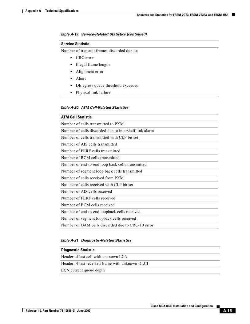
Table A-19 Service-Related Statistics
Service Statistic
Number of received frames
Number of bytes received
Number of frames received with DE=1
Number of frames received but discarded
Number of received bytes discarded
Number of frames received but discarded due to
• CRC error
• Illegal frame length
• Alignment error
• Abort
Number of frames reassembled and transmitted
Number of frames reassembled and transmitted with DE=1
Number of frames discarded due to reassembly errors
Number of frames transmitted
Number of bytes transmitted
Number of frames transmitted with DE set
Number of frames transmitted during LMI logical port alarm
Frames FECN set count
Frames BECN set count
Number of transmit frames discarded
Number of transmit bytes discarded
Table A-18 Counters per Line (continued)
Counter
A-14Cisco MGX 8230 Installation and Configuration
Release 1.0, Part Number 78-10616-01, June 2000
Appendix A Technical SpecificationsCounters and Statistics for FRSM-2CT3, FRSM-2T3E3, and FRSM-HS2
Number of transmit frames discarded due to:
• CRC error
• Illegal frame length
• Alignment error
• Abort
• DE egress queue threshold exceeded
• Physical link failure
Table A-20 ATM Cell-Related Statistics
ATM Cell Statistic
Number of cells transmitted to PXM
Number of cells discarded due to intershelf link alarm
Number of cells transmitted with CLP bit set
Number of AIS cells transmitted
Number of FERF cells transmitted
Number of BCM cells transmitted
Number of end-to-end loop back cells transmitted
Number of segment loop back cells transmitted
Number of cells received from PXM
Number of cells received with CLP bit set
Number of AIS cells received
Number of FERF cells received
Number of BCM cells received
Number of end-to-end loopback cells received
Number of segment loopback cells received
Number of OAM cells discarded due to CRC-10 error
Table A-21 Diagnostic-Related Statistics
Diagnostic Statistic
Header of last cell with unknown LCN
Header of last received frame with unknown DLCI
ECN current queue depth
Table A-19 Service-Related Statistics (continued)
Service Statistic
A-15Cisco MGX 8230 Installation and Configuration
Release 1.0, Part Number 78-10616-01, June 2000

Appendix A Technical SpecificationsFRSM-8T1 Specification
FRSM-8T1 SpecificationThis section provides information on the T1 operation of the FRSM-8T1E1 card set. Topics are
• General physical information about the card set (Table A-23)
• Information about the Frame Relay service (Table A-24)
• System-level interface (Table A-25)
• Statistics and counters (Table A-26)
Table A-22 Troubleshooting Statistics
Troubleshooting Statistic
ECN current queue depth, per channel
Table A-23 General Card Specifications
Category Description
Indicators per card Active (Green), Standby (Yellow), Fail (Red)
Indicators per line Active & Okay (Green) Active & Local Alarm (Red) Active & Remote Alarm (Yellow)
Line Interface connector RJ-48 when used with RJ48-8T1 back card
Line Rate 1.544 Mbps ± 50 bps
Line Framing ESF per ATT TR 54016
Maintenance/Serviceability Features
Internal Problem Isolation Loopbacks Hot-pluggable cards
Reliability, MTBF > 65000 hours
Card Size FRSM-8T1: 7.25" x 16.25" LM-DB15-8T1: 7.0" x 4.5" Power: –48 VDC, 30W with 8 active T1 lines
Table A-24 Frame Relay Service With T1 Lines
Category Description
Synchronization Transmitter may be either loop-timed to receiver or synchronized to shelf (called normal mode)
Input Jitter Tolerance Per ITU-T G.824
Output Jitter Generation Per ITU-T G.824 using normal mode synchronization
Physical Layer Alarms LOS, OOF, AIS, RAI
Number of Frame Relay Ports One–a single Frame Relay stream occupying N consecutive time slots
A-16Cisco MGX 8230 Installation and Configuration
Release 1.0, Part Number 78-10616-01, June 2000

Appendix A Technical SpecificationsFRSM-8T1 Specification
Frame Relay Interface Rates Either of the following:
• 56 Kbps
• N x 64 Kbps (where N is the number of consecutive time slots)
Frame Relay Interface Per ANSI T1.618, 2-octet header
Frame Relay Performance Counters (per Port; N x DS0)
Received frames discarded due to AbortsReceived frames discarded due to illegal header (EA bit)(s) Received frames discarded due to CRC errors (s)Received frames discarded due to alignment errors (s)Received frames discarded due to unknown DLCI (s)Received frames discarded due to illegal frame length (s)Received frames discarded due to DE threshold exceeded Received frames with DE already setReceived frames with FECN already setReceived frames with BECN already setReceived frames tagged FECNReceived frames (s)Received bytes (s)Transmit frames discarded due to underrunTransmit frames discarded due to Abort Transmit frames discarded due to egress Q-depth exceeded (s)Transmit bytes discarded due to egress Q-depth exceeded (s)Transmit frames discarded due to egress DE thresholdexceeded Transmit frames (s)
Transmit bytes(s)Transmit Frames with FECN set (s)Transmit Frames with BECN set (s)
LMI receive status inquiry request count (s)LMI transmit status inquiry request countLMI invalid receive status count (s)LMI signaling protocol (keep alive time-out count) (s)LMI sequence number error count (s)LMI receive status transmit count (in response to request)LMI transmit status transmit count (in response to request)Transmit frames during LMI alarm (s)Transmit bytes during LMI alarm (s)LMI update status transmit count (in response to configuration changes)
Diagnostics (per port) Last unknown DLCI received
Table A-24 Frame Relay Service With T1 Lines (continued)
Category Description
A-17Cisco MGX 8230 Installation and Configuration
Release 1.0, Part Number 78-10616-01, June 2000
Appendix A Technical SpecificationsFRSM-8T1 Specification
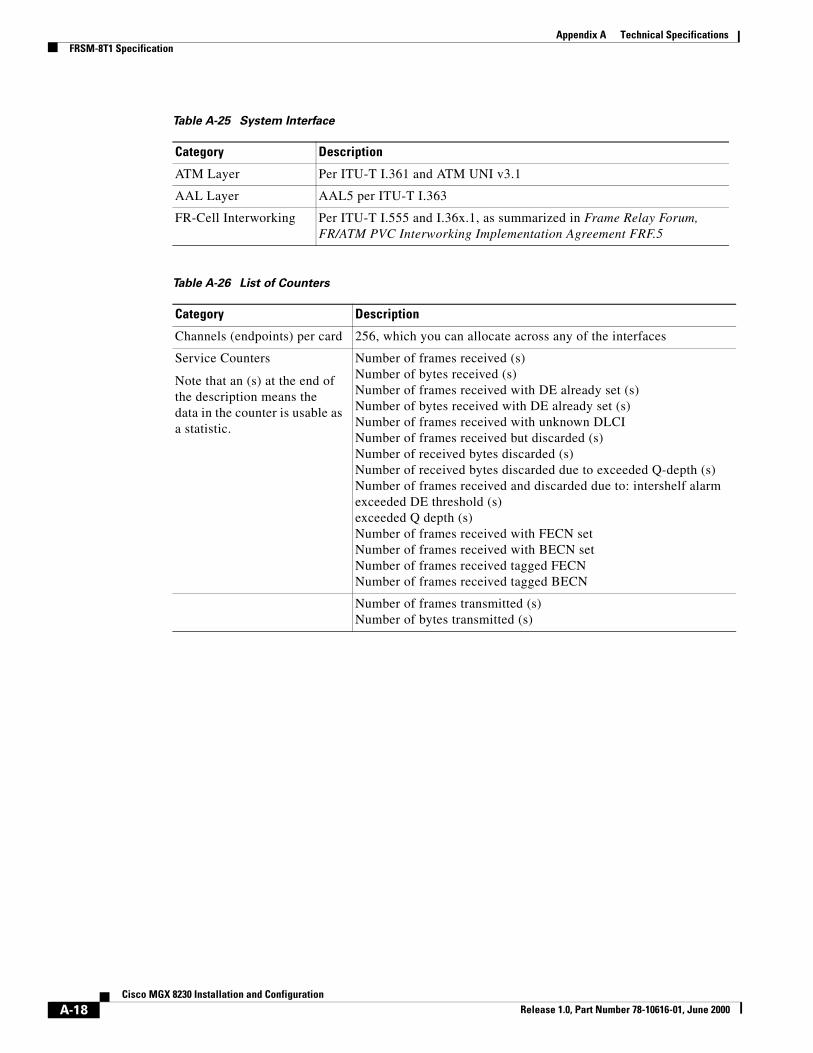
Table A-25 System Interface
Category Description
ATM Layer Per ITU-T I.361 and ATM UNI v3.1
AAL Layer AAL5 per ITU-T I.363
FR-Cell Interworking Per ITU-T I.555 and I.36x.1, as summarized in Frame Relay Forum, FR/ATM PVC Interworking Implementation Agreement FRF.5
Table A-26 List of Counters
Category Description
Channels (endpoints) per card 256, which you can allocate across any of the interfaces
Service Counters
Note that an (s) at the end ofthe description means thedata in the counter is usable as a statistic.
Number of frames received (s)Number of bytes received (s)Number of frames received with DE already set (s)Number of bytes received with DE already set (s)Number of frames received with unknown DLCINumber of frames received but discarded (s)Number of received bytes discarded (s)Number of received bytes discarded due to exceeded Q-depth (s)Number of frames received and discarded due to: intershelf alarmexceeded DE threshold (s)exceeded Q depth (s)Number of frames received with FECN setNumber of frames received with BECN setNumber of frames received tagged FECNNumber of frames received tagged BECN
Number of frames transmitted (s)Number of bytes transmitted (s)
A-18Cisco MGX 8230 Installation and Configuration
Release 1.0, Part Number 78-10616-01, June 2000

Appendix A Technical SpecificationsFRSM-8E1 Specification
FRSM-8E1 SpecificationThis section provides information on the E1 operation of the FRSM-8T1E1 card set. Topics are:
• General physical information about the card set (Table A-27)
• Information about the Frame Relay service (Table A-28)
• System-level interface (Table A-29)
• Statistics and counters (Table A-30)
Number of frames transmitted with DE set (s)Number of frames discarded due to reassembly errors (s)Number of frames transmitted during LMI logical port alarm(s)Number of frames transmitted with FECN set (s)Number of frames transmitted with BECN set (s)Number of transmit frames discarded (s)Number of transmit bytes discardedNumber of transmit frames discarded due to: CRC error (s)egress Q depth exceeded (s)egress DE threshold exceeded source abortphysical link failure (T1)ATM cells: Number of cells transmitted to PXMNumber of cells transmitted with CLP bit setNumber of OAM AIS cells transmitted (s)Number of OAM FERF cells transmitted (s)Number of BCM cells transmittedNumber of OAM end-to-end loopback cells transmitted (s)Number of OAM segment loopback cells transmittedNumber of cells received from PXMNumber of cells received with CLP bit setNumber of OAM AIS cells received (s)Number of OAM FERF cells received (s)Number of BCM cells receivedNumber of OAM end-to-end loopback cells received (s)Number of OAM segment loopback cells receivedNumber of OAM cells discarded due to CRC-10 error (s)
Statistics If any of the counters in the preceding category of Service Counters includes an “(s),” you can configure it for statistics usage
Diagnostics Last unknown LCN receivedNumber of cells with unknown LCN
Table A-26 List of Counters (continued)
Category Description
Table A-27 General Card Specifications
Category Description
Line Interface connector RJ-48 when used with RJ-48-8E1 line module. SMB when used with SMB-8E1 line module
Line Rate 2.048 Mbps ± 100 bps
A-19Cisco MGX 8230 Installation and Configuration
Release 1.0, Part Number 78-10616-01, June 2000

Appendix A Technical SpecificationsFRSM-8E1 Specification
Synchronization Transmitter may be either loop-timed to receiver or synchronized to shelf (normal mode)
Input Jitter Tolerance Per ITU-T G.823
Output Jitter Generation Per ITU-T G.823
Physical Layer Alarms LOS, OOF, AIS, RAI
Indicators per card Active (Green), Standby (Yellow), Fail (Red)
Indicators per line Active & Okay (Green) Active & Local Alarm (Red) Active & Remote Alarm (Yellow)
Maintenance/Serviceability Features
Internal Problem Isolation Loopbacks Hot-pluggable cards
Reliability, MTBF > 65000 hours
Card Size FRSM-8E1: 7.25" x 16.25" (18.43 cm x 41.28 cm)RJ48-8E1: 7.0" x 4.5" (17.78 cm x 11.43 cm)SMB-8E1: 7.0" x 4.5" (17.78 cm x 11.43 cm)
Power –48 VDC, 30W with 8 active E1 lines
Table A-28 Frame Relay Service With E1 Lines
Category Description
Number of Frame Interfaces 1–31 occupying N, where 1 < N < 31. Sum of all < 31 for CCS or 1–30 for CAS.
Frame Relay Interface Rates Either 56 Kbps orN x 64 Kbps, where N is the same as defined in the preceding item the preceding item “Number of Frame Interfaces.”
Ingress 8000-cell buffer shared between virtual channels/pathsstandard usage parameter control (UPC) Selective Cell Discard Virtual Circuit Queuing EFCI setting per VC
Egress 8000-cell storage capacity shared between four ports Up to 12 user-selectable egress queues per port Selective Cell DiscardEFCI setting per Queue
Frame Relay Interface Per ANSI T1.618, 2-octet header
Table A-27 General Card Specifications (continued)
Category Description
A-20Cisco MGX 8230 Installation and Configuration
Release 1.0, Part Number 78-10616-01, June 2000

Appendix A Technical SpecificationsFRSM-8E1 Specification
Frame Relay Performance Counters (per Port; N x DS0):
Received frames discarded due to AbortsReceived frames discarded due to illegal header (EA bit)(s)Received frames discarded due to CRC errors (s)Received frames discarded due to alignment errors (s)Received frames discarded due to unknown DLCI (s)Received frames discarded due to illegal frame length (s)Received frames discarded due to DE threshold exceededReceived frames with DE already setReceived frames with FECN already setReceived frames with BECN already setReceived frames tagged FECNReceived frames (s)Received bytes (s)
Transmit frames discarded due to underrunTransmit frames discarded due to Abort Transmit frames discarded due to egress Q-depth exceeded (s)Transmit bytes discarded due to egress Q-depth exceeded (s)Transmit frames discarded due to egress DE threshold exceeded Transmit frames (s)Transmit bytes(s)Transmit Frames with FECN set (s)Transmit Frames with BECN set (s)LMI receive status inquiry request count (s)LMI transmit status inquiry request countLMI invalid receive status count (s)LMI signaling protocol (keep alive time-out count) (s)LMI sequence number error count (s)LMI receive status transmit count (in response to request)LMI transmit status transmit count (in response to request)Transmit frames during LMI alarm (s)Transmit bytes during LMI alarm (s)LMI update status transmit count (in response to configuration changes)
Diagnostics (per port): Last unknown DLCI that arrived
Table A-29 System Interface
Category Description
ATM Layer Per ITU-T I.361 and ATM UNI v3.1
AAL Layer AAL5 per ITU-T I.363
FR-Cell Interworking Per ITU-T I.555 and I.36x.1, as summarized in Frame Relay Forum, FR/ATM PVC Interworking Implementation Agreement FERF.5
Table A-28 Frame Relay Service With E1 Lines (continued)
Category Description
A-21Cisco MGX 8230 Installation and Configuration
Release 1.0, Part Number 78-10616-01, June 2000

Appendix A Technical SpecificationsFRSM-8E1 Specification
Table A-30 List of Counters
Category Description
Channels (Endpoints) 256 per card—can be allocated across any of the Frame Relay interfaces
Counters Service Counters: Number of frames received (s)Number of bytes received (s)Number of frames received with DE already set (s)Number of bytes received with DE already set (s)Number of frames received with unknown DLCINumber of frames received but discarded (s)Number of received bytes discarded (s)Number of received bytes discarded due to exceeded Q-Depth (s)Number of frames received and discarded due to
• intershelf alarm
• exceeded DE threshold (s)
• exceeded Q depth (s)
Number of frames received with FECN setNumber of frames received with BECN set
Number of frames received tagged FECNNumber of frames received tagged BECNNumber of frames transmitted (s)Number of bytes transmitted (s)Number of frames transmitted with DE set (s)Number of frames discarded due to reassembly errors (s)Number of frames transmitted during LMI logical port alarm(s)Number of frames transmitted with FECN set (s)Number of frames transmitted with BECN set (s)Number of transmit frames discarded (s)Number of transmit bytes discardedNumber of transmit frames discarded due to: CRC error (s)egress Q depth exceeded (s)egress DE threshold exceeded source abort physical link failure (T1)
A-22Cisco MGX 8230 Installation and Configuration
Release 1.0, Part Number 78-10616-01, June 2000

Appendix A Technical SpecificationsCircuit Emulation Service Module for T1 Operation
Circuit Emulation Service Module for T1 OperationThis section contains operational details for the CESM 8T1E1 with the RJ48-8T1 back card.
ATM cells: Number of cells transmitted to PXMNumber of cells transmitted with CLP bit setNumber of OAM AIS cells transmitted (s)Number of OAM FERF cells transmitted (s)Number of BCM cells transmittedNumber of OAM end-to-end loopback cells transmitted (s)Number of OAM segment loopback cells transmittedNumber of cells received from PXMNumber of cells received with CLP bit setNumber of OAM AIS cells received (s)Number of OAM FERF cells received (s)Number of BCM cells receivedNumber of OAM end-to-end loopback cells received (s)Number of OAM segment loopback cells receivedNumber of OAM cells discarded due to CRC-10 error (s)Statistics: All of the above counters followed by an (s) can be configured as statistics.Diagnostics: Last unknown LCN receivedCells with unknown LCN countCard General
Table A-30 List of Counters (continued)
Category Description
Table A-31 CESM 8T1 Card Information
Category Description
Back Card RJ48-8T1
Line Rate T1: 1.544 Mbps ±50 bps
Transmit Clocking Normal clock or SRTS generated
Line Coding B8ZS
Frame mode ESF
Line alarms Loss or Signal (LOS)Loss of Frame (LOF)Loss of multiframe (LOMF)Remote loss of signal or frame (RAI)All ones received (AIS)Bi-polar violation
Alarm indication times Near end alarm up-countNear end alarm down-countNear end alarm maximum countFar end alarm up-countFar end alarm down-countFar end alarm maximum count
A-23Cisco MGX 8230 Installation and Configuration
Release 1.0, Part Number 78-10616-01, June 2000

Appendix A Technical SpecificationsCircuit Emulation Service Module for E1 Operation
Circuit Emulation Service Module for E1 OperationThis section contains operational details for the CESM-8T1E1 with an E1 back card.
Supported OAM cells AISFERFEnd-to-end loopbackSegment loopbackRTD loopbackBCM
Physical Layer Performance Statistics
N/A
LED Indicators Per Card Active (green), Failed (red), Standby (yellow)
BERT Active (green), Errors (yellow)
1:N Redundancy Active (green)
Indicator for each T1 Active (green)
Reliability, MTBF
Card Size Front card: 7.25" x 16.25" (18.43 cm x 41.28 cm)Back card: 7" x 4.5" (17.78 cm x 11.43 cm)
Power 48 VDC, 30W
Loopbacks On or Off
Table A-31 CESM 8T1 Card Information (continued)
Category Description
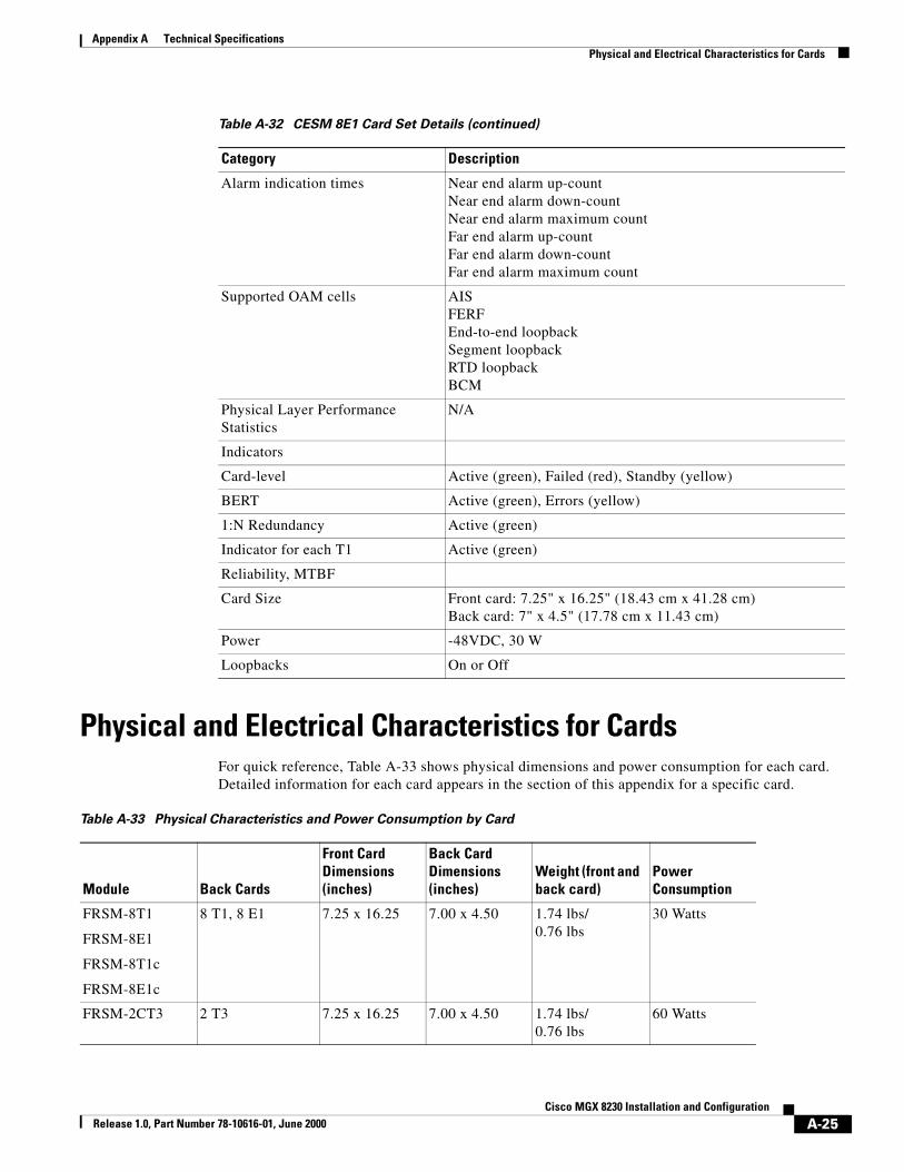
Table A-32 CESM 8E1 Card Set Details
Category Description
Back Card RJ48-8E or SMB-8E1
Line Rate E1: 2.048 Mbps ± 100 bps (50 ppm)
Transmit Clocking Normal clock or SRTS generated
Line Coding HDB3
Frame mode single-framemulti-frame
Line alarms Loss or Signal (LOS)Loss of Frame (LOF)Loss of multi-frame (LOMF)Remote loss of signal or frame (RAI)All ones received (AIS)Bi-polar violation
A-24Cisco MGX 8230 Installation and Configuration
Release 1.0, Part Number 78-10616-01, June 2000
Appendix A Technical SpecificationsPhysical and Electrical Characteristics for Cards
Physical and Electrical Characteristics for CardsFor quick reference, Table A-33 shows physical dimensions and power consumption for each card. Detailed information for each card appears in the section of this appendix for a specific card.
Alarm indication times Near end alarm up-countNear end alarm down-countNear end alarm maximum countFar end alarm up-countFar end alarm down-countFar end alarm maximum count
Supported OAM cells AISFERFEnd-to-end loopbackSegment loopbackRTD loopbackBCM
Physical Layer Performance Statistics
N/A
Indicators
Card-level Active (green), Failed (red), Standby (yellow)
BERT Active (green), Errors (yellow)
1:N Redundancy Active (green)
Indicator for each T1 Active (green)
Reliability, MTBF
Card Size Front card: 7.25" x 16.25" (18.43 cm x 41.28 cm)Back card: 7" x 4.5" (17.78 cm x 11.43 cm)
Power -48VDC, 30 W
Loopbacks On or Off
Table A-32 CESM 8E1 Card Set Details (continued)
Category Description
Table A-33 Physical Characteristics and Power Consumption by Card
Module Back Cards
Front Card Dimensions (inches)
Back Card Dimensions (inches)
Weight (front and back card)
Power Consumption
FRSM-8T1
FRSM-8E1
FRSM-8T1c
FRSM-8E1c
8 T1, 8 E1 7.25 x 16.25 7.00 x 4.50 1.74 lbs/0.76 lbs
30 Watts
FRSM-2CT3 2 T3 7.25 x 16.25 7.00 x 4.50 1.74 lbs/0.76 lbs
60 Watts
A-25Cisco MGX 8230 Installation and Configuration
Release 1.0, Part Number 78-10616-01, June 2000

Appendix A Technical SpecificationsElectromagnetic Compatibility
Electromagnetic CompatibilityThis section lists the national and international standards for electromagnetic compatibility to which the MGX 8230 complies. It consists of a list of reference documents, a table (Table A-34) that indicates applicability of the standards, and the test levels for CE mark immunity.
The applicable standards for electromagnetic compatibility are
• NEBS Systems Requirements (GR-1089-CORE)
• EN 55022/08.94
• EN 50081-1/01.92 and EN 50082-1/01.92 (Generic Immunity Requirements), International Electromechanical Commission (IEC 61000-4-2 through IEC 61000-4-5) European Norm designation EN 61000-4-2 through EN 61000-4-5
Details on how each standard applies in this Cisco product appear in Table A-34.
FRSM-2T3E3 2 T3, 2 E3 7.25 x 16.25 7.00 x 4.50 1.74 lbs/0.76 lbs
60 Watts
FRSM-HS2 2 HSSI 7.25 x 16.25 7.00 x 4.50 1.74 lbs/0.6 lbs
75 Watts
CESM-8T1E1 8 T1, 8 E1 7.25 x 16.25 7.00 x 4.50 1.74 lbs0.76 lbs
30 Watts
AUSM/B-8T1E1 8-T1, 8-E1 7.25 x 16.25 7.00 x 4.50 1.74 lbs0.76 lbs
30 Watts
PXM1 OC-3c/STM-1 15.65 x 15.83 7.00 x 4.5 4.80 lbs 100 Watts
Table A-33 Physical Characteristics and Power Consumption by Card (continued)
Module Back Cards
Front Card Dimensions (inches)
Back Card Dimensions (inches)
Weight (front and back card)
Power Consumption
Table A-34 Electromagnetic Compatibility and Immunity
Category AC-Powered (110/220 VAC DC-Powered (-48V)
U.S.A EMC FCC Part 15, Class A not applicable
Japan EMC Austel 3548 Class A not applicable
Australia EMC VCCI Class A not applicable
CE mark
Immunity
EMC: EN 55022 Class A
• EN 50082-1 (generic immunity)
• EN 61000-4-2 through -5
not applicable
A-26Cisco MGX 8230 Installation and Configuration
Release 1.0, Part Number 78-10616-01, June 2000

Appendix A Technical SpecificationsConformance
The levels for the mandatory CE mark immunity tests are
• For IEC 61000-4-2 (ESD), the test level is 4.
• For IEC 61000-4-3 (RS), the test level is 3.
• For IEC 61000-4-4 (EFT), the test level is 4.
• For IEC 61000-4-5 (Surge), the test level is 3.
ConformanceThis section contains standards compliance information for features on the MGX 8230.
ATM UNIThe ATM specifications for the User-Network Interface to which the MGX 8850 complies are
• ATM Forum–ATM UNI, V3.1, 1995.
• ITU Recommendation I.361–B-ISDN ATM Layer Specification, March 1993.
• ITU Recommendation I.371–Traffic Control and Congestion Control in B-ISDN, March 1993.
• ITU Recommendation I.432–B-ISDN User Network Interface—Physical Interface Specification, March 1993.
• ITU Recommendation I.610–B-ISDN Operation and Maintenance Principles and Functions, Specification, November 1995.
• ANSI T1E1.2/94-002R1, Draft–B-ISDN and DS1/ATM User Network Interfaces: Physical Layer Specification.
• ANSI T1E1.2/94-020, Draft–B-ISDN Customer Installation Interfaces, Physical Media Dependent Specification.
NEBS
(EMC)
not applicable EMC:GR-1089-CORE Class A (radiated and magnetic fields) and line conductance.
GR-1089-CORE ESD (8 KV contact) RS(10 V/meter) CS (clause 3.3.3)
European Telecom Standards (ETSI) for Surge:ETSI 300 386-1, DC power leads only(200 VAC–1000 VAC)
Table A-34 Electromagnetic Compatibility and Immunity (continued)
Category AC-Powered (110/220 VAC DC-Powered (-48V)
A-27Cisco MGX 8230 Installation and Configuration
Release 1.0, Part Number 78-10616-01, June 2000

Appendix A Technical SpecificationsConformance
SONET/SDHThe standards and responsible organizations with which MGX 8850 SONET technology complies are as follows:
• Bell Communications Research–SONET Transport Systems: Common Generic Criteria, GR-253-CORE, Issue 2, 1995.
• Bell Communications Research–Broadband Switching System Generic Requirements, GR-1110-CORE, Issue 1, Sept. 1994.
• Bell Communications Research–ATM and ATM AAL Protocols, GR-1113-CORE, Issue 1, July 1994.
• Bell Communications Research–Generic Requirements for Operations of Broadband Switching Systems, GR-1248-CORE, Issue 2, Rev 1.
• ITU-T G.707–Network Node Interface for the Synchronous Digital Hierarchy.
• ITU Recommendation G.782–Types and General Characteristics of Synchronous Digital Hierarchy (SDH) Equipment, January 1994.
• ITU Recommendation G.783–Characteristics of Synchronous Digital Hierarchy (SDH) Equipment Functional Blocks, January 1994.
• ITU Recommendation G.832–Transport of SDH Elements on PDH Networks: Frame and Multiplexing Structures, November 1993.
• ITU Recommendation G.958–Digital Line Systems based on the Synchronous Digital Hierarchy for use on Optical Fibre Cables, November 1994.
• ANSI T1.105–Digital Hierarchy–Optical Interface Rates and Formats Specifications (SONET), 1991.
• ANSI T1.231–Digital Hierarchy–Layer 1 In-Service Digital Transmission Performance Monitoring (SONET), 1993.
Frame RelayThe standards and responsible organizations with which MGX 8230 Frame Relay technology complies are as follows:
• FRF.1.1
• FRF.2.1
• FRF.3.1
• FRF.5
• FRF.6
• FRF.8
Circuit Emulations ServiceATM Forum CES 2.0.
A-28Cisco MGX 8230 Installation and Configuration
Release 1.0, Part Number 78-10616-01, June 2000
Appendix A Technical SpecificationsConformance
SafetyThe MGX 8230 enclosure meets all applicable regulatory agency Product Safety requirements.
• UL 1950, Third Edition (Standard for Safety, Information Technology Equipment, Including Electrical Business Equipment).
• CSA C22.2-#950- M95, (Standard for Safety, Information Technology Equipment, Including Electrical Business Equipment).
• EN 60 950 (Safety of Information Technology Equipment, Including Electrical Business Equipment).
• TS001 Austel-Safety Requirements for Customer Equipment. (Including AS3260, Safety of Information Technology Equipment)-Australia.
• EN 41003 (European Product Safety Standard for Telecommunications Equipment).
EnvironmentalThe MGX 8230 adheres to the Bellcore GR-63-CORE environmental standard.
A-29Cisco MGX 8230 Installation and Configuration
Release 1.0, Part Number 78-10616-01, June 2000

Appendix A Technical SpecificationsConformance
A-30Cisco MGX 8230 Installation and Configuration
Release 1.0, Part Number 78-10616-01, June 2000
Related Documents