________________________________________________________________________ Page 1 of 29 Specification No. CSC-V/R-II/DH/UH/P&D/2012-2013 TECHNICAL SPECIFICATION FOR Outdoor type Distribution Transformers of 11 kV/433-250 V Class 200, 400, 630 & 990 kVA with CSP (completely self protected) features Issue Month: April 2012 Common Specifications Committee (CSC Approval date ) UHBVN & DHBVN

Welcome message from author
This document is posted to help you gain knowledge. Please leave a comment to let me know what you think about it! Share it to your friends and learn new things together.
Transcript
________________________________________________________________________
Page 1 of 29
Specification No. CSC-V/R-II/DH/UH/P&D/2012-2013
TECHNICAL SPECIFICATION
FOR
Outdoor type Distribution Transformers of
11 kV/433-250 V Class 200, 400, 630 & 990 kVA
with CSP (completely self protected) features
Issue Month: April 2012 Common Specifications Committee
(CSC Approval date ) UHBVN & DHBVN
________________________________________________________________________
Page 2 of 29
TECHNICAL SPECIFICAIONS FOR OUTDOOR NON SEALED TYPE THREE PHASE 11 kV I 433-250V DISTRIBUTION TRANSFORMERS OF 200,400, 630 & 990 kVA CAPACITTES WITH INTERNAL CSP (COMPLETELY SELF PROTECTED) FEATURES / WITH MCCB 1.0 SCOPE: This specification covers the design, engineering, manufacture, shop testing, supply
& delivery of oil immersed, naturally cooled, three-phase, 50 Hz, double-wound, outdoor type
Distribution transformers of 200, 400, 630 & 990 kVA capacity with completely self protected
(CSP) Distribution Transformers for outdoor use along with metallic enclosure housing LV bushing & MCCB (if provided) with sealing facility.
1.1. It is not the intent to specify completely herein all the details of the design and
construction of equipment. However the equipment shall conform in all respects to
high standards of engineering, design and workmanship and shall be capable of
performing in continuous commercial operation upto the Bidder’s guarantee, in
manner acceptable to the purchaser, who will interpret the meanings of drawings and
specification and shall have the power to reject any work or material which, in his
judgment is not in accordance therewith. The offered equipment shall be complete
with all components necessary for their effective and trouble free operation. Such,
components be deemed to be within the scope of Bidder’s supply interceptive of
whether those are specifically brought out in this specification and / or the
commercial order or not.
Transformers will be plinth / POLE mounted.
2.0 STANDARDS: Unless otherwise modified in this specification the transformer/materials shall
conform in all respect to the relevant Indian/International Standard Specification, with
latest amendments thereof some of them are listed below:
Title India standard
International& Internationally recognized standard
Specification for Power Transformer IS-2026:1977-81 IEC-76 Insulating Oil for transformer & Switchgear
IS-335/1983 BS-148
Fittings & Accessories for Power Transformer
IS-3639:1968 ASTM D-1275
High Voltage Porcelain Bushings IS-2099:1986 IEC 296-1969 Low Voltage Porcelain Bushings IS-7421-1988 Dimensions for Outdoor Bushings IS-3347 DIN 42531 to 33 Specification for Copper wire rods IS-1244 ASTM B-49 Specification for colours for ready mixed paints
IS-5/1964 IEC-76
Guide for loading of oil immersed Transformers
IS-6600/1972 BS-148
Manual on Transformer CBI&P Publication No.275
ASTM D-1275
Specification for Power Transformer IS-2026:1977-81 IEC 296-1969 Insulating Oil for transformer & Switchgear
IS-335/1983
The bidder shall use ISS, however, wherever this standard is not available,
corresponding IEC may be followed.
________________________________________________________________________
Page 3 of 29
Material conforming to ISS or the internationally accepted standards, which
ensure equal or higher quality than the standards mentioned above, would also be
acceptable. In case the Bidders who wish to offer material conforming to the standards,
salient points of difference between the standards adopted and the specific standards
shall be clearly brought out in relevant schedule. Four copies of such standards with
authentic English translations shall be furnished along with the other.
3.0 SERVICE CONDITIONS:- The Distribution Transformers & other equipment/material to be supplied against
this specification shall be suitable for satisfactory operation under the following climatic
Conditions as per IS-2026 (Part-I) latest revision
i) Location At various locations in the state of Haryana
ii) Maximum ambient temperature (o 60 C)
iii) Minimum ambient air temperature (o -5 C)
iv) Maximum average daily ambient temperature
(o
40
C)
v) Maximum yearly weighed average ambient
temperature (o
32
C)
vi) Maximum altitude above mean sea level (m) 1000
vii) Minimum Relative Humidity (%) 26
viii) Maximum Relative Humidity (%) 95
ix) Average no of Rainy days/ year 120
x) Average annual rainfall 900 mm
xi) Maximum wind pressure 195 kg/m sq.
The equipment shall be for safe operation in moderately hot and humid tropical
climate, conducive to rust and fungus growth.
4.0 PRINCIPAL PARAMETERS OF THE TRANSFORMER The transformer shall be suitable for outdoor service as step down transformer.
The electrical parameters of the transformer shall be as follows:
1) Rated HV voltage 11 kV
2) Rated LV voltage 433 - 250 volts
3) Connection (HV) Delta
4) Connection (LV) Star
5) Vector Group Dyn - l1
6) Material of winding For 200 kVA Aluminum, Double wound type & for 400 kVA & above Copper, Double wound type
7) Type of cooling ONAN 8) Max. Current density in HV & LV winding
a) For Aluminum wound 200 kVA T/F 1.5 A l mm2
b) For copper wound T/F above 200 kVA 2.6 A / mm2
9) Method of system earthing Neutral Solidly earthed system

________________________________________________________________________
Page 4 of 29
5.0 NO-LOAD VOLTAGE RATIO
The no-load voltage ratio shall be 11000/433 V. 6.0 TEMPERATURE RISE
The transformer shall be capable of operating continuously at its normal rating
without exceeding the temperature rise limit. The temperature rise shall not exceed the
limits of 40°C (measured by resistance) for transformer windings and 35°C (measured
by thermometer) in top oil above the ambient temperature when tested in accordance
with IS. The Transformer with higher temperature rise shall not be acceptable. Hot spot
temperature shall not exceed 95°C when calculated on an annual weighted average
temperature of 35° C as per IS: 2026.
6.1 The limits of temperature rise mentioned above will have to be satisfied by the
manufacturer by carrying the Heat run test at the lowest negative tap by feeding
losses corresponding to the rated current of the tap. 7.0 LOSSES The total losses at 50% & 100% loading shall not exceed the values given below: -
kVA rating of T/F Max., losses at 50% (watts)
Max., losses at 100% (watts)
200 780 2300
The no load and load losses for 11/0.433kV shall not exceed the values given in
the following table
kVA rating of T/F
No Load losses in Watts (Max.)
Full load losses Rating Watts (Max.)
At 75 Deg.C
400 630 990
750 1000 1800
5000 7000 11000
These losses are maximum allowable and there would not be any positive
tolerance. However, the manufacturer can offer losses less than above.
The supplier shall quote No-Load loss in KW at the rated voltage and frequency.
The load loss in KW at rated voltage, frequency & out put, for the temperature of 75
degree centigrade shall also be quoted. The supplier shall guarantee these loss figures.
8.0 IMPEDANCE: The recommended percentage impedance at 75°C is 4.5 % up to 630 kVA &
5.0% for 990 kVA T/F with a tolerance as per IS 2026.
9.0 WINDING 9.1 The primary (HV) windings shall be connected in Delta and the secondary (LV)
winding in Star (Vector system DYn11) so as to produce a positive displacement
of 30 degree from the primary to secondary vectors of the same phase. The
neutral of secondary windings shall be brought out to a separate insulated
neutral terminal. The neutral is to be solidly earthed in a separate earth pit and
the transformer body is to be connected to station grounding system.
HV windings shall consist of single coil or cross over coil design. The copper
wires for coil formation shall be of sufficient cross-sectional area to impart
desired mechanical strength. All delta leads from HT coils as well as HT line
________________________________________________________________________
Page 5 of 29
leads should be taken out through DPC. The current density in these leads should
not exceed 0.8A /sq.mm.
9.2 The winding shall be so designed as to produce minimum out of balance forces in
the transformers. Transformers of 200 kVA shall be Aluminium wound and sizes
above 200 kVA shall be copper wound. The current density for Aluminium wound
transformer shall be limited to 1.5 A l mm2 and for copper wound transformer shall
be limited to 2.6 A l mm2
The insulation resistance values (HV windings) should be measured with a 2500
V Megger.
.
9.3 The winding design shall ensure that all the coil assemblies are of identical voltage
ratio and shall be interchangeable and repairing of the winding could be made easily
without special equipment.
9.4 The conductor used in the coil shall be best suitable to the equipment and all the
permanent current carrying joints in the winding and leads shall be properly sleeved
and crimped/brazed instead of jointing with solder or welding. All LV coil ends shall
be provided with brazed/crimped lugs and HV coil ends by brazing/crimping.
9.5 Double paper covering shall be used for winding insulation both for HV & LV
windings. Electrical grade epoxy coated insulated paper shall be used for inter-layer
insulation of the HV& LV coils, corrugated cylinder made of pre-compressed board
shall be provided between HV & LV winding. Angle shaped and rings made from pre-
compressed board shall be used between end coil and the core.
OR For 400/630/990 kVA transformers HT winding shall have enamel conductor and LT
winding shall have enamel copper insulation. (For 200 kVA transformers DPC
insulation shall be used)Electrical Grade insulation Kraft paper in layers of total
thickness not less than 4 mil shall be used for interlayer insulation, DPC and Kraft
paper used shall be of uniform density and free from any foreign particles and shall
conform to IS: 698/56 and latest amendments thereof. The end turn of each layer
shall be properly and fully covered to avoid interlayer flashover. Corrugated Cylinder
made from precompressed insulation board should preferably be used between LV
and HV windings. The insulation of coils shall be vacuum impregnated in oil to
develop full electrical strength in the windings. All material used in the insulation and
assembly of the winding shall be insoluble non catalytic and chemically inactive in
the hot transformer oil and shall not soften or otherwise be adversely effected under
operating conditions.
The core and coil assembly shall be fully dried out in 'Air Drying oven' till the coils are
shrunken to the designed level and are completely dried. Only then they will be
impregnated in the transformer oil.
9.6 Minimum gap of 25 mm shall be maintained between the end coils and core.
9.7 The minimum insulation resistance values in Mega Ohms between winding and earth
when the transformer is filled with oil should be:
________________________________________________________________ Insulation resistance between winding and earth
(Mega Ohm) 20°C 30°C 40°C 50°C 60°C HV winding 800 400 200 100 50 LV winding 400 200 100 50 25

________________________________________________________________________
Page 6 of 29
9.8 The overloading capacity transformer shall be as per IS-6600.
9.9 The value of unbalance current indicated by the ammeter shall not be more than
2% of the full load current.
10.0 CORE CONSTRUCTION 10.1 MATERIAL – CRGO METAL The core shall be stack / wound type generally of high grade rolled grain
annealed steel lamination having low loss and good grain properties, coated with hot oil
proof insulation, bolted together and to the frames firmly to prevent vibration or noise.
The complete design of core must ensure permanency of the core losses with
continuous working of the transformers. The value of the maximum flux density
allowed in the design and grade of lamination used be clearly stated in the offer. The
bidder should offer the core for inspection and approval by the purchaser during
manufacturing stage. Bidder’s shall give notice for inspection with the following
documents as applicable as a proof towards use of prime core material. 10.1.1 Invoice of the supplier 10.1.2 Mills Test Certificate 10.1.3. Packing List
10.1..4. Bill of Loading
101.5. Bill of entry certificate to customs
10.2.1 Core clamping for CRGO Stacked core.
10.2.1. MS channel shall be used on top and bottom
10.2.2. Core channel on LV side to be reinforced at equidistance, if holes/cutting is done
for LT lead in order to a avoid bending of channel.
10.2.3. MS channel shall be painted with varnish or oil resistant paint
10.2.4. Clamping & Tie-rods shall be made of HT steel and shall be parkarised.
10.3. Core clamping for CRGO wound core.
10.3.1. Core clamping shall be with top and bottom U-shaped core clamps made of
sheet steel clamped HT steel tie rods for efficient clamping
10.3.2. MS core clamps shall be painted with varnish or oil-resistant paint.
10.3.3. MS rods shall be used as tie rods.
10.4. Suitable provision shall be made in the bottom core clamp/ bottom plate of the
transformer to arrest movement or the active part.
10.5. The transformers core shall be suitable for over fluxing (due to combined effect of
voltage and frequency) upto 12.5% without injurious heating at full load
conditions and shall not get saturated. The Bidder shall furnish necessary design
data in support of this situation.
10.6. No load current shall not exceed 2% of full load current and will be measured by
energizing the transformer at 433 volts, 50c/s on the Secondary. Increase of
voltage of 433 volts by 12.5% shall not increase the no load current
disproportionately high. Test for magnetic balance by connecting the LV phase
by phase to rated phase voltage and measurement of an, bn, cn voltage will be
carried out.
10.7. ‘’The core material should be imported directly from the reputed manufacture. Core
material shall be processed by slitting only. Core cutting/slitting be done in front
________________________________________________________________________
Page 7 of 29
of inspecting officers deputed by UHBVN/DHBVN”. Details of the core shall be
filled & supplied as per Annexure-II.
10.7.1 Temperature rise
The temperature rise over ambient shall not exceed the limits described below:
i) Top oil temperature rise measured by thermometer: 35 deg. C
ii) Winding temperature rise measure by resistance: 40 deg. C
Bids not meeting the above limits of temperature rise will be treated as non-
responsive.
10.8 AMORPHOUS METAL.
10.8.1. The core shall be high quality Amorphous ribbons having very low loss
formed into wound cores of rectangular shape, bolted together to the
frames firmly to prevent vibration or noise. The complete design of core
must ensure permanency of the core loss with continuous working of the
transformers. The value of the flux density allowed in the design shall be
clearly stated in the offer. Curve showing the properties of the metal shall
be attached with the offer.
10.8.2 Core Clamping for Amorphous metal Transformers.
10.8.3 Core clamping shall be with top and bottom U-shaped core clamps made
of sheet steel clamped HT steel tie rods for efficient clamping.
10..8.4 MS core clamps shall be painted with varnish or oil-resistant paint.
10.8.5 Suitable provision shall be made in the bottom core clamp/ bottom plate
of the transformer to arrest movement of the active part.
10.8.6. The transformers core shall be suitable for over fluxing (due to combined
effect of voltage and frequency) upto 12.5% without injurious heating at
full load conditions and shall not get saturated. The Bidder shall furnish
necessary design data in support of this situation.
10.8.7. No load current shall not exceed 2% of full load current and will be
measured by energizing the transformer at 433 volts, 50c/s on the
Secondary. Increase of voltage of 433 volts by 12.5% shall not increase
the no load current disproportionately high. Test for magnetic balance by
connecting the LV phase by phase to rated phase voltage and
measurement of an, bn, cn voltage will be carried out.
NOTE:
I. “Equal weightage shall be given to the transformers with Amorphous
Metal Core and CRGO.
II) Wherever variable prices are provided IEEMA formula should be
applicable in such a way that indices applicable for CRGO are used for
amorphous material also since the indices for latter are not declared by
IEEMA.
11.0 TANK CONSTRUCTION
11.1 The tank shall be of robust construction in accordance with the best engineering
practice. The main tank of the transformer shall be fabricated from tested quality
________________________________________________________________________
Page 8 of 29
of mild steel of adequate thickness i.e. minimum 4.00 mm. (for side walls) and
6.00 mm. (for top & bottom plates). The tank shall be valid (V shape welding
fillet) inside of tank two outside welding of tank to bear more pressure to avoid
bursting.
11.2 To provide rigidity and to meet the pressure inside the tank, due to short circuit
current, the tank shall be suitably stiffened. The stiffeners wherever applicable
are provided on all the four side walls of the tank, designed not to retain water.
11.3 The tank cover shall be slightly sloping towards HV bushing and shall provide
facilities for draining of water.
11.4 The transformer tank shall be complete with all accessories, lifting lugs and shall
be designed as to allow the complete transformer tank, filled with oil to be lifted
by crane or other means without risk of any damage and transported by Rail /
Road without straining any joint and without causing leakage of oil.
11.5 Bolted inspection covers shall be provided on top cover to inspect core, winding
and have access to the bottom of bushing.
11.6 The tank shall be capable of with standing the pressure of +/- 1kg /cm2 without
deformation.
The transformer body should be welded from inside of the main tank body so that
the joint is stronger due to V-shape welding fillet besides the outside welding be
additional. The word UHBVNL/DHBVNL property shall be engraved on the top
cover plate and side of tank body.
11.7 INSULATION MATERIAL:- Material:-Electrical grade insulation Kraft papers and press Boards of standard
should be used. For the use standard material the names of following firms have been
approved.
Sr. No. Name of insulating material
Name of the firms
1 Press board a. Senapathy whitely b. Raman Board
2 Craft paper a. Ballarpur b. Padamjee c. Triveni d. M/s Skytouch Tapes Ltd., Mumbai. e. M/s KLIM Enterprises, Mumbai. f. M/s Vijaya Mercantile Ltd. New Delhi. g. M/s Badri Enterprises, New Delhi.
3 Press pahn paper Senapathy whitely 4 Gaskets a. New cork
b. Talbros c. M/s Skytouch Tapes Ltd., Mumbai. d. M/s KLIM Enterprises, Mumbai. e. M/s Vijaya Mercantile Ltd. New Delhi. f. M/s Badri Enterprises, New Delhi.
________________________________________________________________________
Page 9 of 29
11.8 Spacers, axial wedges / runners used in windings shall be made of pre-
compressed pressboard-solid, conforming to type B 3.1 of IEC 641-3-2. In case
of cross-over coil winding of HV all spacers shall be roperly sheared and dovetail
punched to ensure proper locking. All axial wedges/ runners shall be properly
milled to dovetail shape so that they pass through the designed spacers freely.
Insulation shearing, cutting, milling and punching operations shall be carried out
in such out in such a way, that there should not be any burr and dimensional
variations
12.0 SURFACE PREPARATION AND PAINTING 12.1 The painting procedure shall be in line with the UHBVN/DHBVN requirement.
12.2 All paints shall be applied in accordance with the paint manufacturer's
recommendations. Particular attention shall be paid to the following:
a) Proper storage to avoid exposure as well as extremes of temperature and shelf
life for storage
b) Surface preparation prior to painting.
c) Mixing and thinning
d) Application of paints and the recommended limit on time intervals between coats.
12.3 All paints, when applied in normal full coat, shall be free from runs, sags,
Wrinkles, patchiness or other defects.
12.4 All primers shall be well marked into the surface, particularly in areas where
painting is evident, and the first priming coat shall be applied as soon as possible
after cleaning. The paint shall be applied by airless spray according to the
manufacturer's recommendations. However, wherever airless spray is not
possible, conventional spray be used with prior approval of purchaser.
12.5 The supplier shall, prior to painting, protect nameplates, lettering gauges, sight
glasses, light fittings and similar such items.
12.6 Cleaning and Surface Preparation:
12.6.1 All machining, forming, welding and other manufacturing activities shall be
completed before surface preparation. All steel work surfaces shall be thoroughly
cleaned of rust, scale, welding slag or spatter and other contamination by sand /
shot blast cleaning or chemical cleaning by seven tank process including Phos-
phating to the appropriate quality in accordance with IS 6005.
12.6.2 The Pressure and Volume of the compressed air supply for the blast cleaning
shall meet the work requirements and shall be sufficiently free from all water
contamination.
12.6.3 All rough surfaces shall be filled with approved two pack filler and then rubbed
down to a smooth finish.
12.7 Protective Coating As soon as all items have been cleaned and phosphated within four hours of the
subsequent drying, they shall be given suitable anticorrosion protection of Zinc
chromate primer.
12.8 Paint Material
________________________________________________________________________
Page 10 of 29
Followings are the type of paints that may be suitably used for the transformer to
be painted at shop and supply of matching paint to site:
i) Heat resistant paint (Hot oil proof) for inside surface.
ii) For external surfaces one coat of Thermo Setting Paint or 2 coats of Zinc
chromate followed by 2 coats of polyurethane paint. The color of the finishing
coats shall be light admiral gray conforming to No. 697 of IS: 5:1961
12.9 Painting Procedure 12.9.1 All paints in anyone particular system, whether shop or site applied, shall originate
from one paint manufacturer.
12.9.2 The paint shall only be applied in the manner detailed by the manufacturer e.g.
conventional or airless spray and shall be applied under the manufacturer's
recommended conditions.
12.9.3 Where the quality of film is impaired by excess film thickness (wrinkling, mud
cracking or general softness) the supplier shall remove the unsatisfactory paint
coatings and apply another. As a general rule, dry film thickness should not exceed
the specified minimum dry film thickness by more than 25 %. In all instances, where
two or more coats of the same paints are applied, such coatings should be of slightly
contrasting colors.
12.9.4 Paint applied to items that are not being painted, shall be removed at
supplier's expense, leaving the surface clean, un-stained and undamaged.
12.10 Damaged Paint Work 12.10.01 Any damage occurring to any part of the painting scheme shall be made
good to the same standard of corrosion protection and appearance as that
originally employed.
12.10.2 Any damaged paint work shall be made good as follows:
12.10.3 The damaged area, together with an area extending 25 mm around its
boundary, shall be cleaned down to bare metal.
a) A priming coat shall immediately applied, followed by a full paint finish equal
to that originally applied and extending 50 mm around the perimeter of the
originally damaged.
b) The repainted surface shall present a smooth surface. This shall be obtained
by carefully chamfering the paint edges before & after priming.
12.11 Dry Film Thickness 12.11.1 To the maximum extent practicable, the coats shall be applied as a
continuous film of uniform thickness and free of pores. Over-spray, skips,
runs, sags and drips should be avoided.
12.11.2 Each coat of paint shall be allowed to hardened before the next is applied as
per manufacturer's recommendations.
12..11.3 Particular attention must be paid to full film thickness at edges.
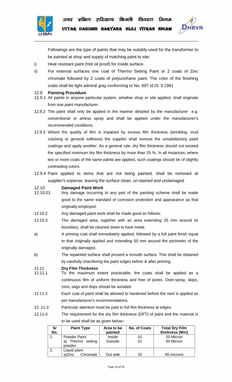
12.11.4 The requirement for the dry film thickness (DFT) of paint and the material is
to be used shall be as given below:-
Sr No.
Paint Type Area to be painted
No. of Coats Total Dry Film thickness (Min)
1. Powder Paint a) Thermo setting powder.
Inside Outside
01 01
20 Micron 60 Micron
2. Liquid paint a)Zinc Chromate
Out side
02
45 microns
________________________________________________________________________
Page 11 of 29
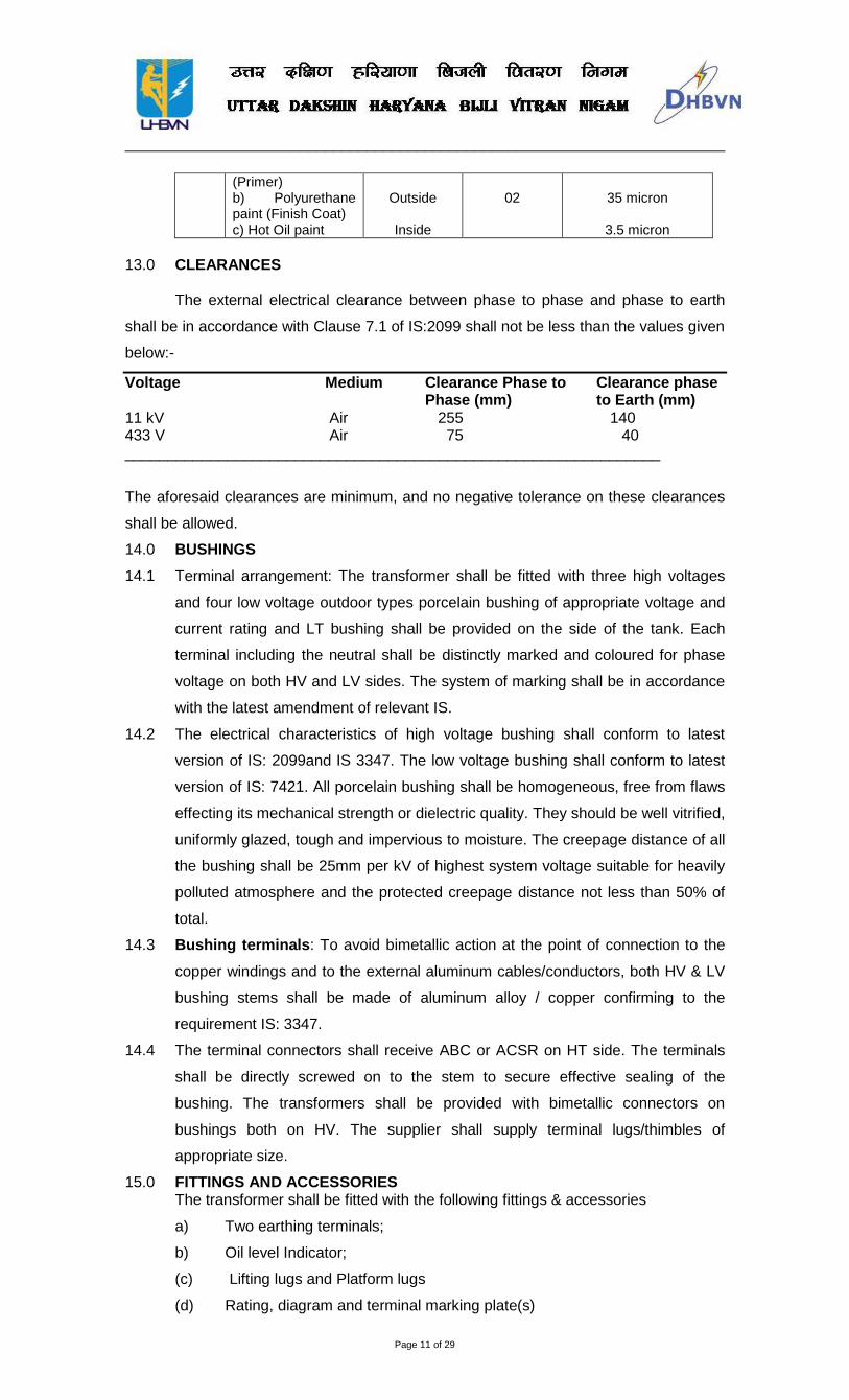
(Primer) b) Polyurethane paint (Finish Coat) c) Hot Oil paint
Outside
Inside
02
35 micron
3.5 micron
13.0 CLEARANCES The external electrical clearance between phase to phase and phase to earth
shall be in accordance with Clause 7.1 of IS:2099 shall not be less than the values given
below:-
Voltage Medium Clearance Phase to Clearance phase Phase (mm) to Earth (mm) 11 kV Air 255 140 433 V Air 75 40 _______________________________________________________________
The aforesaid clearances are minimum, and no negative tolerance on these clearances
shall be allowed.
14.0 BUSHINGS
14.1 Terminal arrangement: The transformer shall be fitted with three high voltages
and four low voltage outdoor types porcelain bushing of appropriate voltage and
current rating and LT bushing shall be provided on the side of the tank. Each
terminal including the neutral shall be distinctly marked and coloured for phase
voltage on both HV and LV sides. The system of marking shall be in accordance
with the latest amendment of relevant IS.
14.2 The electrical characteristics of high voltage bushing shall conform to latest
version of IS: 2099and IS 3347. The low voltage bushing shall conform to latest
version of IS: 7421. All porcelain bushing shall be homogeneous, free from flaws
effecting its mechanical strength or dielectric quality. They should be well vitrified,
uniformly glazed, tough and impervious to moisture. The creepage distance of all
the bushing shall be 25mm per kV of highest system voltage suitable for heavily
polluted atmosphere and the protected creepage distance not less than 50% of
total.
14.3 Bushing terminals: To avoid bimetallic action at the point of connection to the
copper windings and to the external aluminum cables/conductors, both HV & LV
bushing stems shall be made of aluminum alloy / copper confirming to the
requirement IS: 3347.
14.4 The terminal connectors shall receive ABC or ACSR on HT side. The terminals
shall be directly screwed on to the stem to secure effective sealing of the
bushing. The transformers shall be provided with bimetallic connectors on
bushings both on HV. The supplier shall supply terminal lugs/thimbles of
appropriate size.
15.0 FITTINGS AND ACCESSORIES The transformer shall be fitted with the following fittings & accessories
a) Two earthing terminals;
b) Oil level Indicator;
(c) Lifting lugs and Platform lugs
(d) Rating, diagram and terminal marking plate(s)
________________________________________________________________________
Page 12 of 29
(e) Silica gel breather of approved design containing min. 0.25kg dehydrated
Sllicagel.
(f) Drain-cum-sampling valve (steel) welded to the tank.
(g) Thermometer pocket with dial type thermometer on tank cover.
(h) Air Release Plug.
(i) Pressure relief device as standard fitment to operate at a pressue of 03 to 0.5 kg/cm2.
j) Filling hole having P 1-1/4 thread (with cover) on the conservator.
(k) Filter valve- 2 nos. on top and bottom ends of tank at opposite sides.
(I) Conservator with filling hole and drain plug
(m) Porcelain bushings with arcing horns and terminal connectors on HV side.
(n) Porcelain bushing on LV side and HV side conforming to IS-3347, part-I
and III of the latest version thereof with brass studs fitted with single gap
arcing horns.
(0) Offload tap changer (for above 200 kVA transformers with tapping range
of +3% to -6% in steps of 3% each with a locking device.
(p) Bimetallic terminal connector for HV/LV Bushings connecting to
ABC/ACSR.
(q) PSR Radiators duly tested for leakage and pressure.
(r) Plain rollers (4 nos., bi directional) suitable for use on 1000 mm gauge
track with clamping device or base mounting arrangement as required.
For transformers up to 200 kVA the mounting arrangement shall be as
per relevant IS.
Note: (i)
The fittings listed above are indicative and any other fittings which are generally required for satisfactory operation of the transformer are deemed to be included in the quoted price of the transformer.
16.0 CONSERVATORS 16.1 A Conservator shall be provided with each transformer.
The oil level gauge and the plain silica gel breathing device shall be fixed to the
conservator which shall also be provided with a drain plug and a filling hole with a
cover. In addition, the cover of the main tank shall be provided with an air release
plug to enable trapped air to be released unless the conservator is so located as
to eliminate the possibility of air being trapped in the main tank.
16.2 The inside diameter of the pipe connecting the conservator to the main tank shall
be within 20 to 50 mm and it should project into the conservator in such a way
that its end is approximately 20 mm above the bottom of the conservator, so as
to create a sump for collection of impurities. The minimum oil level
(corresponding to -5o
All sealing washers and gaskets shall be made of 'oil and heat resistant Nitrile /
Neoprene rubber/synthetic .rubber-bonded cork type RC-70C gaskets. The oil level in
the transformer shall be made up to the required level while the transformer filled with oil
C) should be above the sump level. Breather pipe should
be connected at top of the conservator tank with two bends at right angles.
17.0 SEALING GASKETS

________________________________________________________________________
Page 13 of 29
is maintained at a temperature of 45 Deg. C. All steel screws, nuts and fasteners
exposed to atmosphere shall be either galvanized or cadmium plated.
18.0 TRANSFORMER OIL The transformer oil used shall comply with the requirements of the specification
as per Annexure-IV enclosed in addition to the provision in the IS: 335-1993 (Latest). Oil
sample will also be taken out from fresh stock of T/F oil to be tested as per latest IS:
335-1993. 19.0 BASE MOUNTING ARRANGEMENT
The under base of all transformers shall be provided with two 75x40x6mm.
Channels with holes (at a centre to centre distance of 415mm) to make them suitable for
mounting on platform or plinth.
20.0 RATING AND TERMINAL MARKING PLATE(S)
Each transformer shall be provided with non-detachable rating diagaram and
terminal marking plate(s) of weather proof material, fitted in a visible position and
showing the complete information as given under clause 17ofIS: 1180(part-I)- 1981.
Further each transformer shall have inscription of Owner name- Purchase order and
date.
21.0 TESTS: 21.1 Routine Tests: All transformers shall be subjected to routine tests at the
manufacturer's works in accordance with IS: 2026 and IS: 1180(part-I).
21.2 Acceptance tests: The following tests acceptance tests are to be carried out in
presence of purchaser's representative in accordance with procedure mentioned
in the General specifications:
(a) Measurement of winding resistance
(b) Measurement of voltage ratio and check of voltage vector relationship
(c) Measurement of impedance voltage/short circuit impedance and load-loss
(d) Measurement of no-load loss and current at full voltage.
(e) Measurement of insulation resistance
(f) Induced over-voltage withstand test
(g) Separate-source voltage withstand test
(h) Dielectric tests
(i) Oil sample test for BDV and moisture content
(j) Visual examination& Measurement of Dimensions
21.3 Type Tests:
TYPE TESTS TO BE CONDUCTED ON ONE UNIT: In addition to the Tests mentioned in para 21 following Tests shall be conducted.
21.3.1. Temperature rise test for determining the maximum temperature rise after
continuous full load run. The ambient temperature and time of test should
be stated in the test certificate.
21.3.2. Impulse voltage test: As per Clause No. 13 (With chopped wave) of IS –
2026 part-III latest version. BIL for 11kV shall be 95 kV Peak instead of 75 kV.
________________________________________________________________________
Page 14 of 29
21.3.3. Air Pressure Test: As per CI. - 22.5 of IS- 1180/part-I/1989.
21.3.4. Short Circuit withstand test: Thermal and dynamic ability.
21.3.5. Magnetic Balance Test.
21.3.6 The type test report(s) submitted by the bidder/ supplier from any NABL
accredited laboratory shall be acceptable for participation of the bidder in the
procurement/ empanelment process. In case NABL accredited laboratory
happens to be that of manufacturer itself added precaution shall be taken to get
type test and other tests witnessed in the laboratory by Nigam representative at
the time of acceptance of material
Type test certificates for the tests carried out on prototype of same specifications
shall be submitted along with the bid.
The purchaser may select the transformer for type tests randomly
NOTE: Purchaser reserves the right to get all or any type/ special test carried out on one
sample per 100 units or a part thereof. The test shall be conducted at
manufacturer's works or any recognized laboratory or a Govt test house.
The supplier shall furnish calculations in accordance with IS: 2026 to
demonstrate the thermal ability of the transformers to withstand short-circuit.
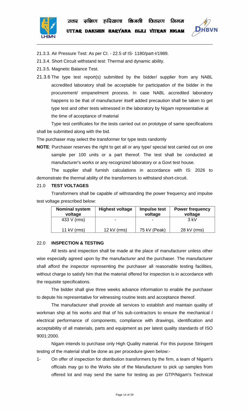
21.0 TEST VOLTAGES
Transformers shall be capable of withstanding the power frequency and impulse
test voltage prescribed below:
Nominal system voltage
Highest voltage Impulse test voltage
Power frequency voltage
433 V (rms)
11 kV (rms)
-
12 kV (rms)
-
75 kV (Peak)
3 kV
28 kV (rms)
22.0 INSPECTION & TESTING
All tests and inspection shall be made at the place of manufacturer unless other
wise especially agreed upon by the manufacturer and the purchaser. The manufacturer
shall afford the inspector representing the purchaser all reasonable testing facilities,
without charge to satisfy him that the material offered for inspection is in accordance with
the requisite specifications.
The bidder shall give three weeks advance information to enable the purchaser
to depute his representative for witnessing routine tests and acceptance thereof.
The manufacturer shall provide all services to establish and maintain quality of
workman ship at his works and that of his sub-contractors to ensure the mechanical I
electrical performance of components, compliance with drawings, identification and
acceptability of all materials, parts and equipment as per latest quality standards of ISO
9001:2000.
Nigam intends to purchase only High Quality material. For this purpose Stringent
testing of the material shall be done as per procedure given below:-
1- On offer of inspection for distribution transformers by the firm, a team of Nigam's
officials may go to the Works site of the Manufacturer to pick up samples from
offered lot and may send the same for testing as per GTP/Nigam's Technical

________________________________________________________________________
Page 15 of 29
Specifications at some Central Govt. Testing Lab. Or at Nigam's Transformer
Workshop at Nigam's cost.
2- At the same time after receipt of offer for inspection, Inspection Agency will be
deputed to inspect100% of the offered lot.
3- The checking inspection reports received from both the agencies i.e. sample
checking report from Central Govt. Testing Lab. and inspection report of
inspecting agency will be scrutinized by Office of CGM/MM and, if both the
reports are found O.K. the dispatch authorization will be issued to the firm.
4- After the receipt of material in the Stores, the tests for no load and full load
losses shall be carried out on each TIF through post receipt inspection
Committee constituted for the purpose.
5- (i) NO LOAD LOSSES AND FULL LOAD LOSSES ARE FIXED. (ii) During post receipt inspection if the losses of any transformer are found more
than the prescribed limit given in the technical specification, the transformer(s)
shall be got replaced and in addition the penalty equivalent to the cost of the
transformer supplied will be charged from the firm for supplying inferior quality
material.
6- If during the post receipt inspection the failure rate of Transformer is more than
10% (Ten percent) of the lot supplied then the entire lot will be rejected and firm
will not be entitle for any payment. The payment, if any, made will have to be
refunded back within 10 days of giving such notice of failure to the supplier.
7- Inspection will be conducted every year, for the first 5 years on a 2% sample of
the quantities supplied. Samples will be collected at random to establish that the
guaranteed technical parameters are as per the submitted bid by the supplier. In
the case of non-adherence, the purchaser may take suitable action on the
supplier including cancellation of vendor registration and banning further
dealings, depending on the gravity of the deviation. These random inspections
may be entrusted to a third party.
8- If the distribution transformer rejection rate exceeds 5% of the total supply, the
firm will be automatically blacklisted.
9- All such firm's who after giving inspection call do not put up materials to
Inspecting Officer for inspection due to one or other reason, shall be required to
remit Rs.20,000/- as penalty for every such call made by the supplier.
23.0 STAGE INSPECTION
The purchaser's representative may carry out stage inspection of the
transformers during manufacturing / assembling stage. The purchaser shall have
absolute right to reject the raw material/component / sub assemblies or complete
equipment not found to be conforming to the requirement of specification or
being of poor quality / workmanship. The stage inspection will particularly include
following tests / check besides the general Routine tests to be conducted during
manufacturing stages as per manufacturer's standard practice.
a) Physical inspection / checking of winding insulating material, core material for
annealing and prime quality and other accessories /fitting of Transformer.
________________________________________________________________________
Page 16 of 29
b) Measurement of Core area and flux density.
c) Verification of HV & L.V coils, conductor’s size, I.D., O.D., Axial length, Weight,
Insulation covering etc.
d) Measurement of thickness of tank plates (Top, bottom and sides) and to conduct
air pressure & vacuum tests as specified in the specification, to ensure the
adequate strength of the transformer tank body.
e) Sample testing of core material for checking specific loss and thickness of core plates.
f) Visual and dimensional check during assembly stage of core. g) Check for proper provisions of spacers and bracing outline drawing, provision for
all fittings, finishing etc. The purchaser at his option may collect the sample of the
following raw material / component for independent testing:
a) CRGO Lamination - One specimen sheet of 300- 500 mm length and 50-75 mm
width ( for each lot)
b) HV Winding wire- 1250 mm length specimen for each type
c) LV Winding wire- 1250 mm length specimen for each type
d) Transformer oil - 2 samples of 5 Liters each
To facilitate stage inspection, the supplier should intimate complete schedule of
manufacturing programme of the transformers at least 15 days in advance to the
concerned purchasing authority. At least 25% of the transformers shall be offered
in the shape of finished core - coil assembly. The inspecting officers during the
course of stage inspection may seal these core-coil assemblies.
a) The manufacturing program shall not be interrupted in case purchaser's
representative does not reach within seven days of the date of intimation.
24.0 WARRANTEE PERIOD
The supplier shall be responsible to replace, free of cost, with no transportation
or insurance cost to the Purchaser, up to destination, the whole or any part of the
material which in normal and proper use proves the defective in quality or workmanship,
subject to the condition that the defect is noticed within 78 months from the date of
receipt of material in stores or 72 months from the date of commissioning whichever
period may expire earlier. The consignee or any other officer of Nigam actually using
the material will give prompt notice of each such defect to the supplier. The replacement
shall be effected by the supplier within a reasonable time, but not, in any case,
exceeding 45 days. The supplier shall, also, arrange to remove the defective within a
reasonable period, but not exceeding 45 days from the date of issue of notice in respect
thereof, failing which, the purchaser reserve the right to dispose of defective material in
any manner considered fit by him (Purchaser), at the sole risk and cost of the supplier.
Any sale proceeds of the defective material after meeting the expenses incurred on its
custody, disposal handling etc., shall however be credited to the supplier’s account and
set off against any outstanding dues of the purchaser against the supplier. The warranty
for 72/78 months shall be one time.
25.1 DOCUMENTATION:
________________________________________________________________________
Page 17 of 29
All drawings shall conform to International Standards Organization (ISO) 'A'
series of drawings sheet/ Indian Standards Specification IS-656. All drawings shall be in
ink and suitable for microfilming. All dimensions and data shall be in SI Units 25.2 LIST OF DRAWINGS AND DOCUMENTS: The tenderer shall furnish four sets of following drawings along with his offer:-
a) General outline and assembly drawings of the equipment.
b) Graphs showing the performance of equipment in regard to magnetization
characteristics.
c) Sectional views showing:
a. General constructional features.
i) The materials / gaskets/ sealing used.
ii) The Insulation, the winding arrangements, method of connection of the
primary / secondary winding to the primary / secondary terminals etc.
iii) Porcelain used and its dimensions along with the mechanical and
electrical characteristics.
d) Arrangement of terminals and details of connection studs provided.
e) Name Plate.
f) Schematic drawing.
g) Type test reports in case the equipment has already been type tested.
h) Test reports, literature, pamphlets of the bought out items and raw
material.
25.3 The successful tenderer’s shall within 15 days of placement of order, submit
three sets of final versions of all the above sai9 drawings for purchaser's
approval. The purchaser shall communicate his comments / approval on the
drawings to the supplier within 30 days. The supplier shall, if necessary, modify
the drawings and submit three copies of the modified drawings for purchaser's
comments. After receipt of purchaser's approval, the suppliers shall within 15
days, submit 12 prints and two good qualities reproducible of the approved
drawings for purchaser's use.
25.4 Six sets of the type test reports, duly approved by the purchaser, shall be
submitted by the supplier for distribution before commencement of supply.
Adequate copies acceptance and routine test certificates, duly approved by the
purchaser, shall accompany the dispatched consignment.
25.5 The manufacturing of the equipment shall be strictly in accordance with the
approved drawings and no deviation shall be permitted without the written
approval of the purchaser. All manufacturing and fabrication work is connection
with the equipment prior to the approval of the drawing shall be at the supplier's
risk.
25.6 16 sets of nicely printed and bound volumes of operation, maintenance and
erection manuals in English Language, for each type and rating of equipment
supplied shall be submitted by the supplier for distribution, prior to the dispatch of
the equipment. The manual shall contain all the drawings and information
required for erection, operation and maintenance of the distribution transformer.
________________________________________________________________________
Page 18 of 29
The manual shall also contain a set of all the approved drawings, type test
reports etc.
25.7 Approval of drawings / work by purchaser shall not relieve the supplier of his
responsibility and liability for ensuring correctness and correct interpretation of
the drawings for meeting the requirement of the latest version of applicable
standards, rules and codes of practices. The equipment shall confirm in all
respects to high standards engineering, design workmanship and latest revisions
of relevant standards at the time to ordering and purchaser shall have the power
to reject any work or materials which, in hisjudgement is not in full accordance
therewith.
26.0 PACKING Transformer shall be suitably packed as per the standard practice while
dispatching from the works. Although the method of packing is left to the discretion of the
manufacturer it should be robust enough for handling normally encountered during
transportation by road/rail.
All accessories shall be dispatched in suitable boxes or crates. They shall be
securely bound with wire and shall have all descriptive marking stamped thereon.
27.0 INSTRUCTIONS MANUAL Eight sets of the instruction manuals shall be supplied at least four (4) weeks
before the actual dispatch of equipment. The manuals shall be in bound volumes and
shall contain all the drawings and information required for erection, operation and
maintenance of the transformer. The manuals include amongst others, the following
particulars:
a) Marked erection prints identifying the components, parts of the
transformer as dispatched with assembly drawings.
b) Salient technical particulars of the transformer..
c) Copies of all final approved drawings.
d) Detailed O&M instructions with periodical check lists and Performa etc.
28.0 COMPLETENESS OF EQUIPMENT
i) All fittings and accessories, which may not be specifically mentioned in the
specification but which are necessary for the satisfactory operation of the plant,
shall be deemed to be included in the specification and shall be furnished by the
contractor without extra charges. The equipment shall be complete in all details,
whether such details are mentioned in the specification or not, without any
financial liability to the Purchaser under any circumstances.
ii) All deviations from this specification shall be separately listed under the requisite
schedules, in the absence of which it will be presumed that all the provisions of
the specification are complied with by the bidder.
29. INSPECTION:
All tests and inspection shall be made at the place of manufacturer and unless
other wise especially agreed upon the manufacturer and the purchaser at the time of
purchase. The manufacturer shall afford the inspector representing the purchaser all
________________________________________________________________________
Page 19 of 29
reasonable facilities, without charge to satisfy him that the material is being furnished in
accordance with specification.
The bidder shall give 15 days (for local supplies) and 30 days (in case of foreign
bidders) advance information to enable the purchaser to depute his representative for
witnessing acceptance routine tests.
The manufacturer shall provide all services to establish and maintain quality of workman
ship in his works and that of his sub-contractors to ensure the mechanical/electrical
performance of components, compliance with drawings, identification and acceptability
of all materials, parts and equipment as per Nigam intends to purchase only High Quality
material. For this purpose stringent testing of the material can be done. Inspection can
be got done from third party Inspection agency or from Nigam’s own officers. Nigam
reserves the right of 100% testing of the transformers. The details of source of material
shall be supplied duly filled as per Annexure-III.
30. QUALITY ASSURANCE PLAN: 30.1 The Bidder shall furnish following information along with his bid.
Information shall be separately given for individual type of material offered.
30.2 Statement giving list of important raw materials, names of sub-supplies for the
raw materials, list of standards according to which the raw materials are tested.
List of tests normally carried out on raw materials in the presence of Bidder’s
representative, copies of test certificates.
30.3 Information and copies of test certificates as in (1) above in respect of bought out
accessories.
30.4 List of manufacturing facilities available.
30.5 Level of automation achieved and list of areas where manual processing exists.
30.6 List of areas in manufacturing process, where stage inspections are normally
carried out for quality control and details of such test and inspection.
30.7 List of testing equipment available with the bidder for final testing of equipment
along with valid calibration reports shall be furnished with the bid. Manufacturer
shall posses 0.1 class instruments for measurement of losses.
30.8 Quality Assurance Plan (QAP) with hold points for purchases/ inspection as per
Annexure.
30.9 The successful Bidder shall within 30 days of placement of order submit following
information regarding list of new materials as well as bought out accessories and
the names of sub-suppliers selected from those furnished along with offer.
31. DOCUMENTATION: The Bidder shall furnish along with the bid the dimensional drawings of the stems
offered indicating all the fittings.
31.1 Dimension’s tolerances
31.2 Weight of individual components and total weight.
32. PACKING & FORWARDING: 32.1 The packing shall be done as per the manufacturer’s standard practice.
However, it should be ensured that the packing is such that, the material would
not get damaged during by Rail/ Road/ Sea.
________________________________________________________________________
Page 20 of 29
32.2 The marking on each package shall be as per the relevant IS.
33. MANDATORY SPARES: Mandatory spares shall be supplied as per the purchaser’s requirement.
34. COMPLETELY SELF PROTECTED (CSP) FEATURES (ADDITIONAL) UHBVN / DHBVN reserves the option of asking bidders to incorporate the
following CSP (Completely Self Protected) features in the Distribution Transformers of all
kVA capacities. However this shall be specifically defined in the tender by the Nigam.
The transformers shall have the following CSP features:
34.1 Internal HV fuse on the HT side of transformer:
Specification for the HV fuse: Expulsion/any other suitable type of fuse placed in
series with the primary winding. The fuse is mounted normally inside of the
primary bushing for the three phases and it is connected to the high voltage
winding through a terminal block. This has to protect that part of the electrical
distribution system, which is ahead of the distribution transformers from faults,
which occur inside the distribution transformers i.e. either on the windings or
some other part of the transformers. It shall be ensured that the fuse does not
blow for faults on the secondary side (LT side) of the transformer i.e. the blowing
characteristics of the fuse and LT breaker shall be so coordinated such that the
fuse shall not blow for any faults on the secondary side of the transformer
beyond LT breakers and those faults shall be cleared by the LT breaker only.
34.2 Internally mounted oil immersed LT breaker on the LV side of the transformer:
34.3 3 Pole LT circuit breaker: All LT faults after the breaker shall be clear by this
breaker. As such it shall be designed for perfect coordination with the HT fuse
link. The bidder shall furnish the time/current characteristics of LT circuit breaker
of 11 kV fuses for various current multiples.
The two characteristics shall be drawn on the same sheet to indicate
coordination between the circuit breaker and fuse. The Bidder shall carry out
coordination test as indicated above and this forms one of the tests as for acceptance
test.
The breaker shall be coordinated thermally with the transformer design to follow
closely the variations of coil acceptance test.
The breaker shall be coordinated thermally with the transformer design to follow
closely the variations of coil temperature due to fluctuating load and ambient
temperatures.
This is to be accomplished by connecting the breaker in series between the
secondary windings and the secondary bushings. The breaker shall be located in the
same oil as the core and coil assembly so that the bimetal are sensitive to the
temperature of oil as well as the load current
The circuit breaker shall also be closed and opened manually standing on
ground. The current carrying parts of breakers shall be copper plus a set of copper
tungsten current interrupting contacts.
________________________________________________________________________
Page 21 of 29
The cross section of the current carrying parts of the breakers shall withstand the
full load current at a current density not more than 2.5 A/Sq.mm (for additional
mechanical strength the area should be more).
12.1.1.2. Unity P.F. & 12.1.1.3. 0.8 P.F. 12.1.1.4. 125% load 12.1.1.5. 100% load 12.1.1.6. 75% load 12.1.1.7. 50% load 12.1.1.8. 25% load 12.1.1.9. Regulation at The bidder may offer with Micro processor based MCCB with Time-Current
characteristics complying with IS:6600 of appropriate rating & good quality from reputed
manufacturer in the metal-box of the distribution transformer instead of internal LV
breaker.
NOTE: - The breaker-trip setting shall be done considering loading of 130% loading for 6
hours duration at an average ambient temperature of 400 C for internal breaker as well
as MCCB (if provided).
35.
37.3 Purchaser reserves the right to reject any transformer during the test at
supplier’s works, if the temperature rise exceeds the guaranteed values.
Transformer & Metallic box Sealing facility
The transformer should have facility to seal the transformers Top Plate & its body
and also the Metal box. The metal box shall have pad-lock arrangement & complete
protection from dirt, rain-water & other pollutants & shall comply to IP:53 protection or
better.
36. RATING AND TERMINAL MARKING PLATES:
There shall be rating plates on the transformer containing the information
specified in clause 15.2 of IS: 2026-1977 (part-i). No load & full load losses of the
transformer should also be mentioned on the rating plate. The following additional
information must also be punched on the plate and imposed two opposite sides of the
body of T/F.
i) Purchase Order No & Date. ii) Date of inspection. iii) Property of UHBVN / DHBVN iv) Make v) Guarantee period
vi) 4-Star rating label in accordance with colour design, logo etc., shall be provided on the transformer as per the design / recommendations of Bureau of Efficiency (BEE)/Wherever BEE certification exists.
37. PENALTY FOR NON PERFORMANCE: 37.1. Purchaser reserves the right to reject any transformer during the test at
supplier’s works, if it is found that actual measured losses are more than the
values quoted by the bidder
37.2 Transformer with temperature rise and impedance beyond the Guaranteed
values.
________________________________________________________________________
Page 22 of 29

________________________________________________________________________
Page 23 of 29
2) 100 % laod
ANNEXURE-1 GUARANTEED & OTHER PARTICULARS FOR DISTRIBUTION TRANSFORMERS (CSP type) -200, 400, 630 & 990, 11/0.433 kV DTs (To be furnished by the Manufacturer) SI.N Description 1. Make & Manufacturer
2. Place of Manufacture
3. Voltage in kV
4. Rating in kVA
5. Core Material used and Grade
a) Flux density
b) Over fluxing without saturation (Curve to be furnished
by the Manufacturer in support of his claim)
6. Maximum temperature rise of
a) Windings by resistance method
b) Oil by Thermometer
7. Magnetizing (No load) Current at
a) Normal Voltage
b) Maximum Voltage
8. Core loss in watts
a) Normal Voltage
b) Maximum Voltage
9. Resistance of Windings at 20 deg. C
(with 5% tolerance)
a) HV Winding (ohms)
b) LV Winding (ohms)
10. No-Load Losses.
11. Total losses at 100% load at 75 deg.c
12. Total losses at 50% load at 75 deg.c
13. Current density used for
a) HV Winding
b) LV Winding
14. Clearances
a) Core & LV
b) LV & HV
c) HV Phase to Phase
d) End insulation clearance to Earth
e) Any point of winding to tank
15. Efficiency at 75 deg. C.
a) Unity P.F. &
b) 0.8 P.F
1) 125 % load

________________________________________________________________________
Page 24 of 29
3) 75 % load
4) 50 % load
5) 25 % load
16. Regulation at
a) Unity P.F.
b) 0.8 P.F. at 75 deg. C
17. % Impedance at 75 deg. C
18. Flash Test
HV 28 kV/ 50 HZ for 1 minute
LV 3 kV/ 50 HZ for 1 minute
19. Over potential Test Double Voltage &
20. Double frequency for 1 minute
21. Impulse test
22. Weight content of
a) Core Lamination (min.)
b) Windings (min.)
c) Tank & Fittings (Thickness of side walls & thickness of top/bottom plate of DT) d) Oil
e) Oil qty (min.)
f) Total Weight
23. Oil Data
1. Qty for first filling (mm)
2. Grade of oil used
3. Maker’s name
4. BDV at the time of filling
24. Transformer:
1) Overall length x breadth x height
2) Tank length x breadth x height
3) Thickness of plates for
a) Side plate (min.) b) Top & Bottom plate (min.) 25. Radiation:
1) Heat dissipation by tank walls exclusive & bottom
2) Heat dissipation by cooling tube
3) Dia. & thickness of cooling tube
4) Whether calculation sheet for selecting cooling
area to ensure that the transformer is capable
of giving continuous rated output without exceeding
temperature rise is enclosed.
26. Inter layer insulation provided in design for
1) Top & bottom layer
2) In between all layer
3) Details of end insulation

________________________________________________________________________
Page 25 of 29
4) Whether wedges are provide at 50 % turns of the HV coil
27. Insulation materials provided
a) For Conductors (1) HV (2) LV
b) For Core
28. Material and Size of the wire used
1) HV
a) SWG/mm
b) Dia
2) LV
a) Strip size.
b) No. of Conductors in parallel.
c) Total area of cross section (sq. mm.)
29. Is the name plate gives all particulars as required in Tender
30. MCCB (if provided) as per Nigam latest technical specification.
31. Particulars of Bushings HV/ LV
1) Maker’s name 2) Type IS-3347/IS- 1180 3) Rating as per I.S. 4) Dry power frequency voltage withstand test
5) Wet power frequency voltage withstand test
Note: The following shall be specifically confirmed
1. Whether the offer conforms to the limits of impedance mentioned in the Specification 2. Whether the offer conforms to the limits of temperature rise mentioned in the specification. 3. Whether the losses of the transformers offered are within the limits specified 4. Whether the transformers offered is already type for the design and test reports enclosed.
________________________________________________________________________
Page 26 of 29
ANNEXURE-II
ADDITIONAL DETAILS SI. No. Description
1. Core Grade
2. Core diameter ( mm)
3. Gross Core area (cm)
4. Net Core area (cm)
5. Flux density (Tesla)
6. Wt. of Core (kg.)
7. Loss per kg. of Core at the
Specified Flux density (Watts)
8. Core window height
9. Center to center distance of the core (mm)
10. No. of LV. Turns
11. No. of HV turns
12. Size of LV Conductor bare/ covered (mm)
13. Size of HV conductor bare/ covered (mm)
14. No. of parallels
15. Current density of LV winding amps/sq.mm.
16. Current density of HV winding amps/ sq.mm
17. Wt. of the LV winding for Transformer kg.
18. Wt. of the HV winding for Transformer kg.
19. No. of LV Coils/phase
20. No. of HV coils/phase
21. Height of LV Windings mm
22. Height of HV Windings mm
23. ID/OD of LV Winding mm
24. ID/OD of HV winding mm
25. Size of the duct in LV winding mm
26. Size of the duct in HV winding mm
27. Size of the duct between HV & LV mm
28. HV winding to LV winding clearance mm
29. HV winding to tank clearance mm
30. Calculated impedance %
31. HV to earth creepage distance mm
32. LV to earth creepage distance mm
________________________________________________________________________
Page 27 of 29
ANNEXURE-3 SOURCE OF MATERIALS/PLACES OF MANUFACTURE TESTING AND INSPECTION SI. No. Item Source of Material Place of Place of testing and Manufacture
inspection
1. Laminations
2. Aluminium Conductor
3. Insulated winding wires
4. Oil
5. Press Boards
6. Kraft Paper
7. MS Plated / Angles/ Channels
8. Gaskets
9. Bushing HV/ LV
10. Paints
________________________________________________________________________
Page 28 of 29
ACRONYMS ---------------------------------------------------------------------------------------------------------------- Reference Abbreviations Name and Asset
------------------------------------------------------------------------------------------------------------
----
IEC International Electro Technical
Commission Bureau Central de la
Commission Electro Technique
International, Rue de verembe
Geneva, Switzerland.
ISO International Organization for
Standardization.
Danish Board of Standardization
Aurchoegyej-12
DK-2900, Heerpup
DENMARK
ISS Indian Standard Bureau of
Indian Standards
Nanak Bhawan
9, Bahadur Shah Zafar Marg,
NEW DELHI-110002, INDIA
----------------------------------------------------------------------------------------------------------------

________________________________________________________________________
Page 29 of 29
ANNEXURE ‘IV’ GUARANTEED CHARACTERISTICS OF NEW TRANSFORMER OIL IN DRUMS/TANKERS AND IN TRANSFORMERS A. OIL IN DRUMS/TANKERS S.No. Characteristics Requirement 1. Appearance Oil shall be clear & transparent &
free from suspended matter or sediments.
2. Density at 29.5o 0.89 g/cmC (Max.) 2 3. Kinematics viscosity at 27o 27CST C (Min.) 4. Interfacial tension at 27o 0.04 N/M C (min.) 5. Flash point (Min.) 140oC 6. Pour point (Max.) -6oC 7. Neutralization value
a) Total acidity (Max.) b) In organic acidity
0.03 mg KOH/gm Nil
8. Corrosive sulphur Non-corrosive 9. Electric strength (Break down voltage) Min.
a) New untreated oil: If the above value is not obtained the oil shall be treated.
b) After treatment.
a) 30 kV (rms) b) 60 kV (rms)
10. Dielectric dissipation factor (Tan-delta) at 90o 0.002 (Max.) C 11. Water content )Max.) 50 ppm 12. Specific resistance (resistivity)
a) At 90oC (Min.) b) At 27o
a) 35x10
C (Min.) 12 ohm-cm
b) 900 x1012 ohm-cm 13. Oxidation stability
a)Neutralization value after oxidation (max.) b)Total sludge after oxidation (Max.)
0.40 mg KOH/gm 0.10% by weight
14. Ageing characteristics after accelerated ageing (open breaker method with copper catalyst) a) Specific resistance (Resistivity) i) At 27oC Min.) ii) At 90oC (Min.) b) Dielectric dissipation factor (Tan delta) at 90o
2.5 x 10
C c) Total acidity (Max.) d) Total sludge value percent by weight
12 ohm-cm 0.2 x 10¹² ohm-cm 0.2 Max. 0.05 mg KOH/gm 0.05 Max.
15. Presence of oxidation inhibitor Absent B. CHARACTERSTICS OF OIL IN THE TRANSFORMERS The important characteristics of the transformer oil after it is filled in the transformer (within 3 months of filling) shall be as follows:- Sr No Characteristics Permissible limit satisfactory for use 1. Electric Strength (Breakdown voltage
kV) Prior to energisation 50 kV minimum
2. Water content (PPM) 25 PPM (max.) 3. Specific Resistance (Resistivity) ohm-
cm at 90o2X10
C 12 ohm-Cm (Min)
4. Dielectric dissipation factor tan delta) at 90o
0.01 (Max) C
5. Neutralization value (Total acidity) 0.055 mg. KOH/gm (Max) 6. Sediment and/or perceptible sludge Absent 7. Flash point 140oC (Min) 8. Interfacial tension at 27o 0.030 N/m(Min). C
Related Documents