Technical Specification SFBP‐011‐001 Rev 08 Technical Specification SFBP‐011‐001 For the Construction of a 67 ft Pilot Boat Snow and Company | Seattle, Washington USA Camarc Design | Argyll Scotland, UK San Francisco Bar Pilots | San Francisco, California USA Page | i

Welcome message from author
This document is posted to help you gain knowledge. Please leave a comment to let me know what you think about it! Share it to your friends and learn new things together.
Transcript

Technical Specification SFBP‐011‐001 Rev 08
Technical Specification SFBP‐011‐001 For the Construction of a 67 ft Pilot Boat
Snow and Company | Seattle, Washington USA Camarc Design | Argyll Scotland, UK
San Francisco Bar Pilots | San Francisco, California USA
P a g e | i

Technical Specification SFBP‐011‐001 Rev 08
Revisions 01 First Working Draft 05/14/2020
02 Second Working Draft 06/04/2020
03 Third Working Draft 06/28/2020
04 Fourth Working Draft 07/23/2020
05 Final Draft 08/06/2020
06 Update to: 08/10/2020
660 Seating model
07 Update to: 08/21/2020
all‐ replace Swagelok with Swagelok or equal all update grammar and spelling throughout 150 revised seal description 167 correct frame 13 and frame 20 WT door mfg 247 clarified hydraulic interface 302 add exemption to OEM cables that cannot be severed 436 clarify WIF sensor monitoring 440 indicate TBD EPIRB is not provided but owner furnished 512 remove reference to dry zone 529 swap alarm vs pump order 625 revise adhesive description 640 replace Ayers with Ayers or equal
08 Update to: 10/16/2020
241 Transmission changed to TD MGX 6599SC
P a g e | ii

Technical Specification SFBP‐011‐001 Rev 08
Table of Contents 000 | DESIGN AND GENERAL INFORMATION........................................................................................ 1
010 DOCUMENTATIONS............................................................................................................................ 2 020 DEFINITIONS & ACRONYMS ............................................................................................................... 3 030 VESSEL PARAMETERS ......................................................................................................................... 4 040 OPERATING PARAMETERS ................................................................................................................. 5 050 SPEED AND RANGE............................................................................................................................. 6 070 ENVIRONMENTAL CONDITIONS AND REQUIREMENTS...................................................................... 7 080 NOISE REQUIREMENTS....................................................................................................................... 8 090 REGULATORY REQUIREMENTS........................................................................................................... 9 096 WEIGHT ............................................................................................................................................ 10 097 STABILITY..........................................................................................................................................11
100 | STRUCTURE .............................................................................................................................. 12
101 STRUCTURAL MATERIALS................................................................................................................. 13 102 STRUCTURAL WELDING.................................................................................................................... 14 110 HULL STRUCTURE ............................................................................................................................. 15 114 HULL FENDERING ............................................................................................................................. 16 126 INTEGRAL FUEL TANK....................................................................................................................... 17 150 SUPERSTRUCTURE............................................................................................................................ 18 163 SEA CHEST ........................................................................................................................................19 167 HULL DOOR, HATCHES AND MANHOLES ......................................................................................... 20 168 SUPERSTRUCTURE DOORS ............................................................................................................... 21 170 MAST ................................................................................................................................................ 22
200 | PROPULSION ............................................................................................................................ 23
233 PROPULSION ENGINES ..................................................................................................................... 24 241 REDUCTION GEARS .......................................................................................................................... 25 243 PROPULSION SHAFTING................................................................................................................... 26 247 WATERJETS.......................................................................................................................................27 252 PROPULSION & STEERING CONTROL ............................................................................................... 28 256 PROPULSION ENGINE COOLING....................................................................................................... 29 259 PROPULSION ENGINE EXHAUST....................................................................................................... 31 261 PROPULSION ENGINE FUEL .............................................................................................................. 32 262 PROPULSION ENGINE LUBE OIL ....................................................................................................... 33 265 DEF SYSTEM......................................................................................................................................34
300 | ELECTRICAL............................................................................................................................... 35
301 POWER AND CONTROL WIRING....................................................................................................... 36 302 HULL – SUPERSTRUCTURE‐HULL ELECTRICAL DISCONNECT ............................................................ 37 303 ELECTRICAL LOAD ANALYSIS ............................................................................................................ 38 304 ELECTRICAL MOTORS ....................................................................................................................... 39 310 ELECTRICAL POWER GENERATION – AC........................................................................................... 40 311 ELECTRICAL POWER GENERATION ‐ DC ........................................................................................... 41
P a g e | iii

45
50
55
60
65
70
75
80
85
Technical Specification SFBP‐011‐001 Rev 08
320 ELECTRICAL DISTRIBUTION – AC ...................................................................................................... 42 321 ELECTRICAL DISTRIBUTION – DC ...................................................................................................... 43 331 LIGHTING – INTERIOR....................................................................................................................... 44 332 LIGHTING – EXTERIOR ...................................................................................................................... 341 GENERATOR COOLING ..................................................................................................................... 46 342 GENERATOR EXHAUST ..................................................................................................................... 47 343 GENERATOR FUEL ............................................................................................................................ 48
400 | COMMAND AND CONTROL....................................................................................................... 49
421 COMPASS ......................................................................................................................................... 422 NAVIGATION LIGHTS ........................................................................................................................ 51
436 INTEGRATED BRIDGE ALARM, CONTROL AND MONITORING..........................................................
450 CCTV SYSTEM ...................................................................................................................................
423 ELECTRONIC NAVIGATION SYSTEMS................................................................................................ 52 424 DEPTH SOUNDER.............................................................................................................................. 53 435 FIRE DETECTION AND ALARM SYSTEM ............................................................................................ 54
440 EXTERIOR COMMUNICATION SYSTEMS........................................................................................... 58 443 HORN................................................................................................................................................ 59
500 | AUXILIARY MECHANICAL .......................................................................................................... 61
511 COMPARTMENT HEATING ............................................................................................................... 62
514 HEATING VENTILATION AND COOLING............................................................................................
533 POTABLE WATER SYSTEM ................................................................................................................
581 ANCHORING .....................................................................................................................................
512 COMPARTMENT VENTILATION ‐ EXCEPT ENGINE COMPARTMENT ................................................ 63 513 HULL COMPARTMENT VENTILATION – ENGINE COMPARTMENT ................................................... 64
515 WINDOW DEFROST ......................................................................................................................... 66 521 FIRE MAIN ........................................................................................................................................67 526 SCUPPERS AND DECK DRAIN............................................................................................................ 68 529 BILGE SYSTEM ..................................................................................................................................69
555 FIRE EXTINGUISHING SYSTEM.......................................................................................................... 71 556 HYDRAULIC SYSTEM ......................................................................................................................... 72 565 TRIM AND RIDE CONTROL SYSTEM.................................................................................................. 73 573 MOB RESCUE BASKET....................................................................................................................... 74
582 MOORING.........................................................................................................................................76 583 LIFE SAVING......................................................................................................................................77 593 MARINE SANITATION ....................................................................................................................... 78
600 | OUTFIT ..................................................................................................................................... 79
602 HULL MARKINGS .............................................................................................................................. 603 DRAFT MARKS ..................................................................................................................................81 612 RAILINGS
625 WINDOWS........................................................................................................................................
..........................................................................................................................................82 622 FLOOR PLATES ..................................................................................................................................83 623 LADDERS AND STAIRS....................................................................................................................... 84
P a g e | iv

Technical Specification SFBP‐011‐001 Rev 08
626 WINDOW WIPERS AND WASH SYSTEM ........................................................................................... 86 631 PAINTING..........................................................................................................................................87 633 CATHODIC PROTECTION................................................................................................................... 88 634 EXTERIOR DECK COVERINGS ............................................................................................................ 89 635 INSULATION .....................................................................................................................................90 640 INTERIOR OUTFIT ............................................................................................................................. 91 650 EXTERIOR OUTFIT............................................................................................................................. 92 660 SEATING ...........................................................................................................................................93
P a g e | v

000 | DESIGN AND GENERAL INFORMATION
This document describes the requirements and specification of systems and components for a 67 ft pilot transfer vessel for the San Francisco Bar Pilots.
The vessel is intended to be for a one‐off custom designed, custom built vessel. At the writing of this specification the design of the vessel is in progress, as a result while some components and sizes are know at this time are and described specifically, in other cases where the design is not complete requirements for the sizing or selection of components are provided instead.
The vessel design is based upon previous vessel designs by the Designer built by various builders around the world, and shares many features included hull form, arrangement, and other details with those designs.
The hull will be sub‐divided into the following compartments by main transverse watertight bulkheads (MTWB):
Waterjet Compartment Engine Compartment Accommodations Compartment Void Compartment Collision Void
The superstructure will consist of the following spaces:
Pilothouse The fixed area atop the superstructure main roof forming the bottom of the fixed mast will be
considered the fiddley. The portion of the superstructure fixed to the hull above the main deck (not resiliently
mounted) will consist of the cuddy, which is considered part of the Accommodations Compartment.
The main deck area will be divided into the following areas:
Foredeck – area forward of the cuddy front Sidedecks – area outboard of the pilothouse and cuddy Aft deck – area aft of the pilothouse
P a g e | 1

010 DOCUMENTATIONS
This document is intended to accompany other documents to describe not only the vessel but the purchase of such vessel. In the event of inconsistencies, the order of precedence among the following documents will be observed:
1) Contract
2) Specification, this document
3) General Arrangement drawing
4) All others.
P a g e | 2

020 DEFINITIONS & ACRONYMS
Throughout this specification the following names/terms are defined to mean the following:
BUILDER: Snow and Company | Seattle WA USA
DESIGNER: Camarc Design | Argyll Scotland UK
OWNER: San Francisco Bar Pilots Benevolent and Protective Association | San Francisco CA USA
Throughout this specification the following acronyms are used to mean the following:
ANSI: American National Standards Institute
ASHRAE: American Society of Heating, Refrigeration and Air‐Conditioning
ASTM: American Society of Testing and Materials
CARB: California Air Resources Board
CFR: United States Code of Federal Regulations
DEF: Diesel Exhaust Fluid (urea/water)
ELA: Electrical Load Analysis
EPA: Environmental Protection Agency
IACS: International Association of Classification Societies
MARPOL: International Convention for the Prevention of Marine Pollution from Ships
MTWB: Main Transverse Watertight Bulkhead
OSHA: Occupational Safety and Health Administration
SCR: Selective Catalyst Reactor
USCG: United States Coast Guard
P a g e | 3

030 VESSEL PARAMETERS
The below table describes the principle characteristics of the vessel:
CHARACTERISTIC US Standard Units SI UNITS LENGTH, OVERALL 73.3 ft 22.3 m LENGTH, MOLDED 67.3 ft 20.5 m BEAM, OVERALL 20.3 ft 6.2 m BEAM, MOLDED 19.0 ft 5.8 m DEPTH, MOLDED 9.8 ft 3.0 m DRAFT, DESIGN 3.6 ft 1.1 m AIR DRAFT, @ DESIGN DRAFT, LEVEL TRIM
27.9 ft 8.5 m
DISPLACEMENT, FULL LOAD 110,000 lbs 50,000 kg FUEL TANK VOLUME 1,300 gal 5,000 liter DEF TANK VOLUME 2x 50 gal 2x 200 liters FRESH WATER TANK VOLUME 50 gal 190 liter PERSONS 2 Crew, 12 Pilots
P a g e | 4

040 OPERATING PARAMETERS
The vessel is to operate within the interior of San Francisco Bay and out through the Gate 11 nm to the station transfer vessel.
The vessel performs two typical runs throughout the day. One typical run consists of leaving the dock, transiting out to the station vessel for pilot transfer and return. This route has the following profile:
TYPICAL STATION VESSEL RUN DESCRIPTION TIME SPEED POWER FACTOR IDLE‐STAR UP 5 min ‐ 3% 0.15 MANEUVER‐DOCKING
5 min 5 knots 15% 0.75
TRANSIT 27 min 25 knots 80% 21.6 MANEUVER‐TRANSFER
5 min 10 knots 50% 2.50
TRANSIT 27 min 25 knots 80% 21.6 MANEUVER‐DOCKING
5 min 5 knots 15% 0.75
IDLE‐SHUTDOWN
10 min ‐ 3% 0.30
TOTAL 84 min 57% 47.65
The second typical route consists of leaving the dock, performing transfer(s) within the Bay to a vessel at an anchorage and return. This route can vary depending upon the number of transfers and the location of transfers, but an average run may have the following profile:
TYPICAL BAY RUN DESCRIPTION TIME SPEED POWER FACTOR IDLE‐STAR UP 5 min ‐ 3% 0.15 MANEUVER‐DOCKING
5 min 5 knots 15% 0.75
TRANSIT 15 min 25 knots 80% 12.00 MANEUVER‐TRANSFER
5 min 10 knots 50% 2.50
TRANSIT 15 min 25 knots 80% 12.00 MANEUVER‐DOCKING
5 min 5 knots 15% 0.75
IDLE‐SHUTDOWN
10 min ‐ 3% 0.30
TOTAL 60 min 47% 28.45
The vessel has expected annual hours of up to 4,000 per year. Based upon distribution of 1/3 station vessel runs and 2/3 bay runs, the vessel is expected to have an annual load profile of ~ 50%.
P a g e | 5

050 SPEED AND RANGE
Speed estimated to be approximately 30 knots at 100% MCR at full load in flat water conditions.
Speed estimated to be approximately 25 knots at ~80% MCR at full load in flat water conditions
Fuel Consumption for the MAN 2862 LE 438 engine is taken from the graph below. From which the vessel will burn approximately 2x160 l/h (85 gph) at 80% MCR cruise and 2x 218 l/h (115 gph) at 100%.
With allowance for generator consumption, and less than engine manufacturer ideal conditions the vessel will have approximately 350 l/h (92 gph) consumption at cruise speed.
Based upon the usable portion (90%) the fuel tank, the vessel will have a cruise range of approximately 320 nm
Image taken from MAN Tech Date Sheet 25.07.2019 (version 1)
NOTES:
1. Vessel speed is function of weight, installed power, propulsion efficiencies, hull efficiencies and environmental conditions.
2. Hull efficiencies are a product of the decisions of the selected hull by the Designer. 3. Propulsion efficiencies are a product of the decision for the selected waterjet propulsor. 4. Installed power is a product of the decision for the selected propulsion engine. 5. Environmental condition effects vary and not within the decision matrix. 6. Weight is a product of ALL decisions that comprise this specification. Increased weight will
result in relatively lower top speeds or more fuel consumption for a given speed. The below speed and range estimates are based upon the selected propulsion components and anticipated weight of the vessel as describe within this specification. Changes to the specification that increase weight will negatively impact speed and range.
P a g e | 6

070 ENVIRONMENTAL CONDITIONS AND REQUIREMENTS
The vessel will meet the EPA requirements for emissions, for this vessel that requirement is EPA Tier4 Marine Propulsion Engine for Commercial Use.
The vessel will meet the MARPOL requirements for pollution discharge per current US ratification.
The vessel is intended to operate within the following range of environmental conditions based upon ASHRAE design conditions for San Francisco, CA USA.
Mean maximum dry bulb air temperature 95 °F Extreme maximum wet bulb air temperature 72 °F Minimum 99% dew point for heating: 28 °F Maximum 0.4% dew point for cooling: 83 °F
The vessel is intended to operate within a range of water from Freshwater (0.999 spgr) through brackish to saltwater (1.025 spgr)
The vessel is intended to operate within San Francisco Bay and out to beyond the SF Bar.
Historic climate data summary is not immediately available for Scripps Data Buoy # 46237 – SF Bar (37.786 N 122.635 W). In its place historic wind and sea conditions based upon Climatic Summary of National Data Buoy # 46026 – 18 NM West of SF (37.754 N 122.839 W) is below.
Wind Average Speed: up to 45 knots Wind Peak Gust: up to 58 knots Average Wave Period: 6 to 8 seconds (mean), 5 to 10 seconds (1 std) Dominant Wave Period: 9 to 13 seconds (mean), 6 to 16 seconds (1 std) Significant Wave Height: 1.5 m to 2.5m (mean), up to 3.5m (1std) Sea Water Temperature: 44 °F to 68 °F
P a g e | 7

080 NOISE REQUIREMENTS
The main propulsion diesel engines are the primary source of noise while the vessel is operating at full speed. In addition, the waterjet and wave induced hull noise provide secondary noise sources. The airborne noise from the engine is also transmitted to the structure and transferred as structural borne noise throughout the hull.
To mitigate the noise sources, the engine compartment and portions of the hull accommodation space will be outfitted with noise abating material adhered to the hull to limit the transmission of airborne to structural borne noise and damp the structure. The engines and reduction gears will be mounted to the hull via vibration isolating mounts to reduce structural borne noise.
To isolate the primary occupied space from the hull noise, the superstructure will be resiliently mounted to the hull on vibration isolators.
Based upon prior vessel builds of similar design (similar power, similar hull size, resiliently mounted pilothouse), the anticipated noise levels in the vessel are expected to be:
Pilothouse:
Pilot Seats, middle row, seated head position height: 65‐67 dBA (slow response) target.
Hull Accommodation Compartment:
Noise levels in the hull accommodation compartments is expected to be less than 85 dB SPL (OSHA 8‐hour exposure limit)
Hull forward voids:
Due to wave interaction with the hull and structural borne noise from the engines and waterjets, the noise levels in the forward hull voids is expected to exceed 85 dB SPL. These spaces are un‐occupied.
Engine Compartment, and Jet Compartment:
Noise level in the engine compartment with the engines at full power are expected to exceed 115 dB SPL, and therefore entrances to the compartment will be labeled with Hearing Protection Required notice labels. Noise levels in the jet compartment with the engines at full power are expected to exceed 90 DB SPL, since the entry to the jet compartment is normally through the engine compartment, then same hearing protection will be recommended.
P a g e | 8

090 REGULATORY REQUIREMENTS
The vessel is intended to be documented with the US National Vessel Documentation Center by the OWNER to receive a Certificate of Documentation (COD) and Official Number. The vessel will be measured via the simplified system for domestic tonnage. The vessel will not have any endorsements with primary service to be UNCLASSIFIED VESSEL. The BUILDER will provide the OWNER with the necessary information for the OWNER to certify the vessel.
P a g e | 9

096 WEIGHT
Weight characteristics of the vessel will be provided by the Designer and reviewed by the Builder during the design phase based upon the vessel as described within this Specification. After the design phase is complete, the Builder will continually monitor weight and centers for any deviations from the design to as‐built configuration. At the completion of the build, an in‐water inclining experiment and deadweight survey will be performed by the builder, the results of which will be provided to the Designer for calculation of the As‐Built Vessel’s official lightship weight and center of gravity.
LIGHTSHIP:
The vessel ready for service with all gear and equipment installed, all systems with fluids at operating conditions.
FULL LOAD:
The vessel in the lightship condition plus deadweight per below.
DEAD WEIGHT:
In addition to the lightship condition, the vessel is intended to operate with the following deadweight:
2 crew – 225 lbs with personal kit, located in pilothouse 12 pilots – 225 lbs with personal kit, located in pilothouse Fuel, tank filled to 95% capacity DEF, tank filled to 95% capacity Potable water, tank 100% filled All other tanks at normal operating levels. Miscellaneous deadweight allowance of 600 lbs for tools, onboard spares, and other items;
located at lightship LCG and a VCG of main deck amidships
P a g e | 10

097 STABILITY
The vessel is to be designed to meet the intact stability requirements of IMO A>749(18) Chapter 3 in all conditions of loading and operation.
The vessel is to be designed to meet the damaged stability requirements for single compartment flooding (remain upright without main deck immersion) in all conditions of loading and operation.
Based upon the results of the inclining experiment, the Designer will provide the Builder and Owner with a stability report (book) and guidance (equivalent to what would be required to achieve regulatory approval), for the vessel in the As‐Built lightship weight and center and the loading conditions described within this report (see Section 096)
SERVICE LIFE MARGIN:
To account for future weight growth over the life of the vessel, a Service Life Margin of 1,000 lbs located 3 ft above the main deck at light ship LCG will be included in all stability calculations.
P a g e | 11

100 | STRUCTURE
The vessel’s hull and superstructure are to be fabricated of marine grade welded aluminum.
P a g e | 12

101 STRUCTURAL MATERIALS
Structural marine grade aluminum will be used throughout the hull and superstructure.
Plating:
5086‐H116 (ASTM B928) 5083‐H116 (ASTM B928)
Extrusion in direct contact with sea water:
5086‐H32 or 5086‐H111 or ‐H112
Extrusion not in direct contact with sea water:
5086‐H32 or 5086‐H111 or ‐H112 6061‐T6 (ASTM B221) 6063‐T6 or ‐T52 (ASTM B221)
P a g e | 13

102 STRUCTURAL WELDING
The builder will maintain weld procedures approved by and IACS member (DNV or other) and the American Welding Society for aluminum for both FCAW and GMAW processes used in aluminum boat building.
P a g e | 14

110 HULL STRUCTURE
The hull will be fabricated welded marine aluminum.
Insert plates in the main deck should be positioned such that the thickness increase is to the interior of the vessel (downward)
Inserts plates, in the hull shell will be positioned such that the thickness increases to the interior of the vessel (inward)
The hull structure will be designed to the below scantling rules. The sides / topsides will be of increased strength for pilot boat boarding operations. Structure will be locally re‐enforced in way of mooring bits, and other concentrated loads.
110 DESIGN REQUIREMENTS HULL SCANTLINGS BV class standards, BV NR 396
P a g e | 15
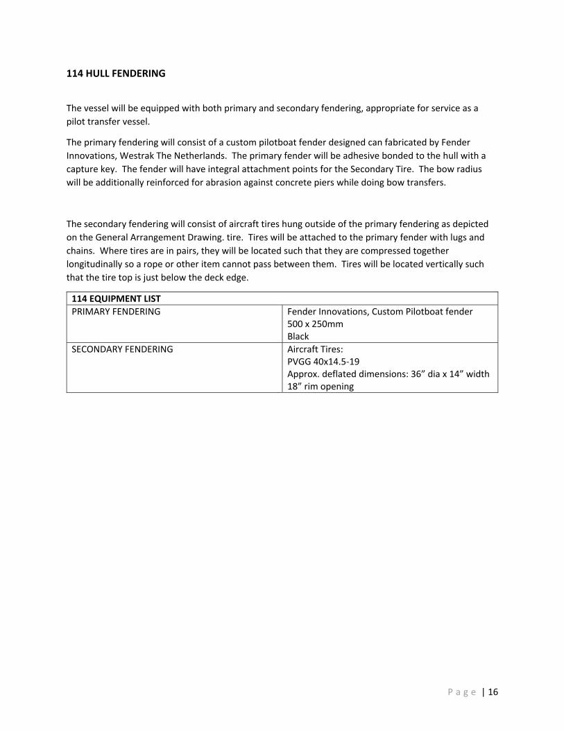
114 HULL FENDERING
The vessel will be equipped with both primary and secondary fendering, appropriate for service as a pilot transfer vessel.
The primary fendering will consist of a custom pilotboat fender designed can fabricated by Fender Innovations, Westrak The Netherlands. The primary fender will be adhesive bonded to the hull with a capture key. The fender will have integral attachment points for the Secondary Tire. The bow radius will be additionally reinforced for abrasion against concrete piers while doing bow transfers.
The secondary fendering will consist of aircraft tires hung outside of the primary fendering as depicted on the General Arrangement Drawing. tire. Tires will be attached to the primary fender with lugs and chains. Where tires are in pairs, they will be located such that they are compressed together longitudinally so a rope or other item cannot pass between them. Tires will be located vertically such that the tire top is just below the deck edge.
114 EQUIPMENT LIST PRIMARY FENDERING Fender Innovations, Custom Pilotboat fender
500 x 250mm Black
SECONDARY FENDERING Aircraft Tires: PVGG 40x14.5‐19 Approx. deflated dimensions: 36” dia x 14” width 18” rim opening
P a g e | 16

126 INTEGRAL FUEL TANK
A single structurally integral fuel tank will be located between the inboard engine girders. The fuel tank will provide fuel for both propulsion engines and generator(s).
The fuel tank will contain a single suction located at the aft end of the tank routed to a supply manifold. The tank suction will be located approximately 1 suction pipe diameter above the tank bottom. The suction will be isolated from the supply manifold with a single cable operated fuel shut off valve. The manual operator for the fuel shut off valve will be located on the main deck, aft of the pilothouse.
A fueling station with be located on the main deck, just aft of the pilothouse. The fueling station will contain a single fill connection and vent. A spill containment coaming with drain plug will surround the fill and vent. A high fuel alarm with audible and visual indication will be announced at the filling station. (see Section 440). The fill and vent are to be electrically connected to the fuel tank (bonded across any hose sections) to prevent the possibility of static build up and discharge.
The fuel tank will be fitted with a level indicator and high‐level and low‐level alarms per Section 436.
126 EQUIPMENT LIST ACCESS HATCHES Tiona 20” with aluminum plate tops FUEL SHUT‐OFF VALVE Full port valve, manual
push‐pull cable FUEL LEVEL AND ALARMS See Section 436
Piping for the fuel tank fill vent and sound will be per the below schedule.
126 FUEL FILL, VENT AND SOUND MATERIAL SCHEDULE FILL AND VENT PIPING Piping: Aluminum
Fill Size: 1 ½” Flanges: ANSI B16.5 Class 150, flat or raised face
The sizing of pipes and components for the fuel tank will be designed to meet the following requirements.
126 DESIGN REQUIREMENTS FUEL TANK SIZING Based upon two 12‐hour day operation at
average of route profiles (see Section 040) plus 5%.
SUPPLY MANIFOLD VELOCITY 7 feet per second
P a g e | 17

150 SUPERSTRUCTURE
The hull will be fabricated welded marine aluminum.
The pilothouse will be resiliently mounted to the hull structure with vibration isolation mounts to reduce noise and vibration transmitted from the hull to the pilothouse. Bolted panels located around the perimeter of the house skirt will allow access to the vibration mounts. The access from the pilothouse to the hull accommodations apartment will be surrounded by a weathertight perimeter seal.
150 EQUIPMENT LIST RESILIENT MOUNTS Trelleborg, Evolo 600 Series
All electrical connections between the hull and house will be made in the electoral junction space between the hull and house. The electrical junction space will be accessible through a hatch beneath the pilothouse console (see Section 168)
P a g e | 18
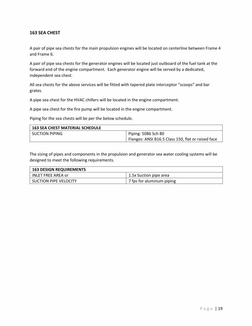
163 SEA CHEST
A pair of pipe sea chests for the main propulsion engines will be located on centerline between Frame 4 and Frame 6.
A pair of pipe sea chests for the generator engines will be located just outboard of the fuel tank at the forward end of the engine compartment. Each generator engine will be served by a dedicated, independent sea chest.
All sea chests for the above services will be fitted with tapered plate interceptor “scoops” and bar grates.
A pipe sea chest for the HVAC chillers will be located in the engine compartment.
A pipe sea chest for the fire pump will be located in the engine compartment.
Piping for the sea chests will be per the below schedule.
163 SEA CHEST MATERIAL SCHEDULE SUCTION PIPING Piping: 5086 Sch 80
Flanges: ANSI B16.5 Class 150, flat or raised face
The sizing of pipes and components in the propulsion and generator sea water cooling systems will be designed to meet the following requirements.
163 DESIGN REQUIREMENTS INLET FREE AREA or 1.5x Suction pipe area SUCTION PIPE VELOCITY 7 fps for aluminum piping
P a g e | 19

167 HULL DOOR, HATCHES AND MANHOLES Watertight closures will be installed in the hull per the table below:
167 EQUIPMENT LIST WATERJET COMPARTMENT DECK HATCH Make: Freeman Marine
Coaming drain overboard Model: 2400 Series A‐K, Hinged Clear Opening: 24” x 24”
ENGINE COMPARTMENT DECK HATCH Make: Freeman Marine Coaming drain overboard Model: 2400 Series A‐K, Hinged Clear Opening: 24” x 24”
ENGINE COMPARTMENT REMOVAL HATCH Builder Fabricated aluminum Internally accessed bolted flange Gasketed seal
ACCOMMODATIONS COMPARTMENT ESCAPE HATCH (EXTERIOR CUDDY TOP)
Make: Freeman Marine Model: 2400 Series A‐K, Hinged Clear Opening: 15” x 24”
ACCOMMODATION COMPARTMENT ACCESS HATCH (INTERIOR PILOTHOUSE)
Make: FabTek Hydraulic Assist Aluminum WT quick acting door Single lever Clear Opening: 24” x 36”
COLLISION VOID DECK HATCH Make: Freeman Marine Coaming drain overboard Model: 2400 Series A‐K, Hinged Clear Opening: 15” x 24”
MTWB No. 4 WATERTIGHT DOOR Make: FabTek Single Lever View Port Aluminum WT quick acting door Clear Opening: 24” x 70”
MTWB No. 13 WATERTIGHT DOOR Make: FabTek Single Lever View Port Aluminum WT quick acting door Clear Opening: 24” x 70”
MTWB No. 20 WATERTIGHT HATCH Make: FabTek Aluminum WT quick acting door Clear Opening: 30” x 30”
Watertight doors through MTWBs will be fitted with open alarm sensors integrated into the Central monitoring system (see Section 436)
P a g e | 20

168 SUPERSTRUCTURE DOORS Weather tight closures will be installed in the superstructure per the table below:
168 EQUIPMENT LIST PILOTHOUSE AFT DOOR Make: FabTek
Two dogs with handle Maximum size upper window Clear Opening: 30” x 70”
ELECTRICAL DISCONNECT ACCESS HATCH Make: Freeman Marine Model: Series 2400 Vertical Series 2400 Vertical
P a g e | 21

170 MAST
The mast will be comprised of two parts, a lower fabricated box that is structurally part of the house top (aka fiddley), and an upper demountable pipe part. The lower part will support both radar array units. The upper part will support lights, antenna etc.
A halyard will be provided to fly an ensign aft off the upper mast.
P a g e | 22

200 | PROPULSION
The vessel will be powered by a pair of marine diesel engines providing power to a pair of waterjets for propulsion and steering. Each diesel engine and its support systems will be configured to allow a single engine to operate independent of the other.
P a g e | 23

233 PROPULSION ENGINES
Vessel power will be provided by a pair of marine diesel engines. The propulsion integrator will provide the engines close coupled to the reduction gears and outfitted for electrical, cooling and lube oil as described below.
233 EQUIPMENT LIST Propulsion Integrator RDI Marine, Seattle WA Propulsion engines Make: MAN
Model: D2862 LE 438 Rated Power: 1,200 HP Rated Speed: 2,100 rpm Emissions: EPA Tier4 Marine Commercial Rating: MAN Medium Duty
COOLING Raw water heat exchanger CHARGING – Primary alternators 24 VDC, OEM SUMP CONNECTIONS See Section 262
The propulsion integrator will perform a Torsional Vibration Analysis (TVA) to confirm the acceptability of the engine, engine mounts, gear, shafting and water jet.
The engine and reduction gear will be mounted on OEM vibration isolators to reduce noise and vibration from the engine to the ship’s structure.
P a g e | 24

241 REDUCTION GEARS
Torque from the propulsion engines will be transmitted to the propulsion shafting (see Section 243) via a reducing, reversing marine transmission. The reduction gear will be cooled from the propulsion engine raw water‐cooling loop (see Section 259). The installation of the torsional coupling and initial mating of the reduction gear to the propulsion engine will be performed by the propulsion integrator.
241 EQUIPMENT LIST PROPULSION INTEGRATOR RDI Marine, Seattle WA REDUCTION GEARS Make: TwinDisc
Model: MGX 6599 SC Gear Ratio: 1.8667 Rating: Medium Duty
The selection of the gear ratio will be performed by the waterjet supplier with designer approval based upon the commercially available ratio and impeller options. If no combination of impeller and reduction ratio is available, then and only then will a custom ratio be considered.
P a g e | 25

243 PROPULSION SHAFTING
A carbon fiber universal joint driveshaft will transmit torque from the reduction gears to the waterjets. The specification and sizing of the driveshaft and its components will be the responsibility of the shafting integrator.
The drive shaft will pass through the watertight bulkhead that separates the engine compartment from the waterjet compartment. A bulkhead seal will maintain watertight integrity.
The drive shaft configuration will allow for the servicing of the waterjet bearings and seals without removal of the main carbon driveshaft section from the vessel. This allowance will be attained by mounting the shaft seal in a bolt in plate in the Waterjet Compartment / Engine Compartment bulkhead of sufficient clearance such that with the plate removed, that the drive shaft can be lifted above or to the side of the required service area.
243 EQUIPMENT LIST SHAFTING INTEGRATOR Driveline Service of Portland, Portland OR DRIVE SHAFT Make: EuroCardon
Model: DLS 214519‐00 BULKHEAD SEAL Fully split non‐contact, aluminum.
The sizing of the shafting will be designed to meet the following requirements.
243 DESIGN REQUIREMENTS ALL Responsibility of Shafting Integrator
P a g e | 26
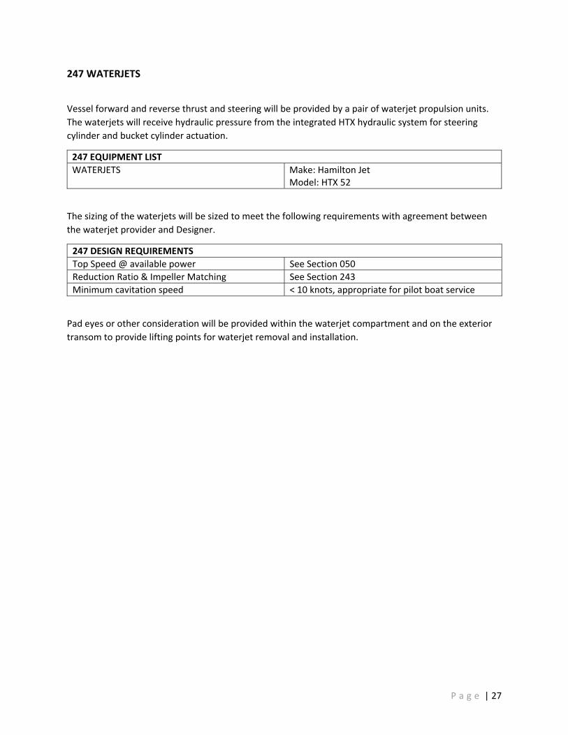
247 WATERJETS
Vessel forward and reverse thrust and steering will be provided by a pair of waterjet propulsion units. The waterjets will receive hydraulic pressure from the integrated HTX hydraulic system for steering cylinder and bucket cylinder actuation.
247 EQUIPMENT LIST WATERJETS Make: Hamilton Jet
Model: HTX 52
The sizing of the waterjets will be sized to meet the following requirements with agreement between the waterjet provider and Designer.
247 DESIGN REQUIREMENTS Top Speed @ available power See Section 050 Reduction Ratio & Impeller Matching See Section 243 Minimum cavitation speed < 10 knots, appropriate for pilot boat service
Pad eyes or other consideration will be provided within the waterjet compartment and on the exterior transom to provide lifting points for waterjet removal and installation.
P a g e | 27

252 PROPULSION & STEERING CONTROL
Propulsion and steering control will be provided by an integrated control system. The primary operating station will be in the pilothouse. A secondary operating station will be on the aft deck for operation of the boat in conjunction with MOB recovery.
252 EQUIPMENT LIST CONTROL SYSTEM Hamilton Jet AVX
with Jet Anchor with AP interface
PRIMARY CONTROL STATION ‐ PILOTHOUSE Steering: Helm Tiller Unit Throttle: Dual Lever Unit Bucket: Dual Lever Unit Docking: Mouseboat Unit
SECONDARY CONTROL STATION – AFT DECK Steering: Helm Tiller Unit Throttle: Dual Lever Unit Bucket: Dual Lever Unit
DATA RECORDER Hamilton Jet VDRIU
The control system will be powered from an independent, isolated power system. (see Section 321)
Alarm and monitoring of the propulsion engines and the waterjets will be integrated with the centralized alarm and monitoring systems (see Section 436) to the extent possible by the existing I/O provided the OEM equipment.
P a g e | 28

256 PROPULSION ENGINE COOLING
The propulsion engines will be sea water / heat exchanger cooled. The engine supplied raw water pump will take suction through the sea chest (See Section 163) and sea water suction piping.
Each sea chest will be separated from a simplex strainer by a sea valve. Strainers outlets will be fitted with discharge valves to allow for strainer isolation during basket cleaning. The discharge of each strainer will be connected in an “H” with cross over valve to connect both engine suctions to a single sea chest.
Raw water will be diverted to the reduction gear cooler (See Section 241) and be discharged to the wet exhaust injection ring (see Section 259). To meet engine manufacture’s requirements for exhaust back pressure, a raw water overboard by‐pass with orifice plate will be installed in the discharge line between the engine and the exhaust connection. An anti‐siphon loop will be installed between the raw water pump suction and wet‐exhaust injection point.
OEM Block heaters will be proved for each propulsion engine.
256 EQUIPMENT LIST SEA STRAINERS Style: Simplex
Make and Model: Miller Leaman, Thompson SeaStrainer Material: CuNi
BLOCK HEATER Make: MAN (factory equipped) Size: 2x 1100 Watts Power: VAC shore power only
Seawater piping for the propulsion engine cooling system will be per the below schedule.
256 SEAWATER PIPING MATERIAL SCHEDULE SHELL TO ISOLATION VALVE PIPING Piping: 5086 Sch80
Flanges: ANSI B16.5 Class 150, flat or raised face Propress
ISOLATION VALVE Butterfly, lugged body, epoxy coated iron body Bronze or CRES stem and disk, isolation kit
ISOLATION VALVE TO ENGINE PIPING Piping: ASTM B466 90/10 CuNi Class 200 Flanges: ANSI B16.5 Class 150, flat or raised faced
OVERBOARD FLANGE TO SHELL PIPING Piping: 5086 Sch80 Flanges: ANSI B16.5 Class 150, flat or raised face
OTHER PIPING Piping: ASTM B466 90/10 CuNi Class 200 Flanges: ANSI B16.5 Class 150, flat or raised faced Hose: USCG w/barb or weld bead, 2x 316 stainless clamps
FLEXIBLE CONNECTION Flanged Bellows or USCG Hose w/barb or weld bead, 2x 316 stainless clamps
P a g e | 29

The sizing of pipes and components in the propulsion sea water cooling system will be designed to meet the following requirements.
256 DESIGN REQUIREMENTS Strainer sizing Both engines running combined on only one
strainer at 80% MCR SUCTION LOSS Per raw water pump requirements DISCHARGE PRESSURE Per exhaust back pressure requirements
Adjusted with orifice plate sizing FLOW VELOCITY LIMITS Alum: 9 fps suction, 12 fps discharge
CuNi: 12 fps
P a g e | 30

259 PROPULSION ENGINE EXHAUST
Exhaust from the propulsion engines will pass through dry pipe sections to the MAN provided Dosing unit and SCR. Exhaust discharge from the SCR will route to a water injection ring that receives raw water discharged from the propulsion engines sea water cooling system. Wet, mixed exhaust combine in a surge tube and pass through the watertight bulkhead and then travel through a water lift muffler and discharge at the transom corners.
259 EQUIPMENT LIST SCR and Dosing Units Make: MAN INJECTION RING Material: 316L stainless MUFFLER Make: Marine Exhaust Systems
FRP waterlift
The dosing units will consume DEF at a % of diesel fuel use (see Sect 265).
MAN SCR and dosing units are supplied with sheathed insulation. Other dry piping section will be insulated with removable exhaust lagging. Exhaust lagging will be pre‐sewn and removable, laced preferably with spring fasteners
The dry exhaust piping and the SCR components will be mounted to account for working thermal expansion and to minimize thermal sound and vibration transmission.
Exhaust piping will be per the below schedule.
259 EXHAUST PIPING MATERIAL SCHEDULE DRY PIPING 316L Sch 10s WET PIPING FRP marine exhaust SHELL CONNECTION Piping: 5086 Sch80
See Section 631 for coating of faying surfaces DRY PIPING, FLEX CONNECTION Marine Exhaust WET PIPING, FLEX CONNECTION Silicone, single or double hump, 2x 316 clamps
The sizing of pipes and components in the exhaust system will be designed to meet the following requirements.
259 DESIGN REQUIREMENTS BACK PRESSURE Per engine mfg requirements TURBO FLANGE LOADING Per engine mfg requirements INSULATION LEVELS Limit of 150°F surface temperature FUTURE CARB FILTER Provide a pipe spool piece between the turbo
expansion joint and the input to the Dosing Box to allow for a 36” long by 18” diameter future Diesel Particulate Filter.
P a g e | 31

261 PROPULSION ENGINE FUEL
The propulsion engines will draw fuel from the integral fuel tank (see Section 123) via the fuel supply manifold. Each engine will have an independently run full supply line from the manifold to its primary fuel filter. An isolation valve will connect each supply run to the manifold. The primary fuel filter will be fitted with isolation valves at each side of the filter and will be positioned above a drip pan to catch fuel spillage during element transfer.
Each engine will have an independently run fuel return directly back to the fuel tank without any valves. Fuel return piping will penetration the tank top and extend and extend to within 6 inches of the tank bottom. The fuel return pipe will have anti‐siphon holes just below the tank top to prevent siphoning.
261 EQUIPMENT LIST PRIMARY FUEL FILTERS Racor, Marine Duplex Turbine Series, Poly bowl,
WIF sensor, Micron Rating per engine mfg., vacuum gauge
Fuel piping for the propulsion engine fuel system will be per the below schedule. Piping will be primarily tube with flexible hose lengths and connections minimized.
261 DIESEL FUEL PIPING MATERIAL SCHEDULE SUPPLY AND RETURN PIPING Tube: 316 (min 0.035 wall)
Hose: USCG approved FITTINGS Tube: 316 Swagelock or equal
Hose: JIC 37° flare Other: NPT or flanged Flanges: ANSI B16.5
VALVES Full port ball, 316
The sizing of pipes and components in the fuel system will be designed to meet the following requirements.
261 DESIGN REQUIREMENTS SUCTION LOSS Per engine requirements SUCTION VELOCITY 7 fps DISCHARGE VELOCITY 12 fps
P a g e | 32

262 PROPULSION ENGINE LUBE OIL
The propulsion engine oil pan and the lower reduction gear casing discharge ports will be fitted with remote suctions. A section of hose will be run from the isolation valve to above the floor plating. The hose ends will be fitted with quick disconnect fittings and caps.
If allowed by the respective OEMs, the propulsion engines, generator engines and transmission will be filled with the same lube oil.
262 LUBE OIL PIPING MATERIAL SCHEDULE SUPPLY AND RETURN PIPING Hose, engine: OEM
Hose, gear: USCG approved FITTINGS Engine: OEM
gear: JIC 37° flare, Q/D: Bronze
The sizing of pipes and components in the fuel system will be designed to meet the following requirements.
262 DESIGN REQUIREMENTS PRESSURE AND VELOCITY No requirement, size at ¾”
A lube oil storage rack will be fitted in the Waterjet Compartment. The lube oil storage rack will allow secure storage of four 5‐gal buckets and four 1‐gal bottles.
P a g e | 33

265 DEF SYSTEM
Each exhaust system will be supplied with Diesel Exhaust Fluid (DEF) as required by the SCR. The exhaust system dosing units will take DEF supply from the DEF tank. Each propulsion engine will be served by an independent DEF tank. DEF tanks will be polyethylene, sized per the requirements below. Tanks will be isolated from the aluminum structure by high durometer neoprene to prevent chaffing. All penetrations through the DEF tank will be through the tank top to minimize the potential of leaks. Each DEF tank will be fitted with a high‐level alarm, low level alarm, and tank level indication.
265 DEF PIPING MATERIAL SCHEDULE SYSTEM PIPING Tube: 316 (min 0.035 wall)
Hose: USCG approved SYSTEM FITTINGS Tube: 316 Swagelock or Equal
Hose: JIC 37° flare Other: NPT or flanged Flanges: ANSI B16.5
VALVES Full port ball, 316 FILL AND VENT PIPING Pipe: 5086 Sch 40 Aluminum
Hose: SAE J1942A1 w/double hose clamp
265 DESIGN REQUIREMENTS DEF TANK CAPACITY % of fuel tank capacity per MAN
P a g e | 34

300 | ELECTRICAL
The vessel will utilize both an AC power system and a DC power system to supply electrical power to required loads.
AC power will be arranged as 3‐phase Wye, 120/208 VAC, 4‐pole, 5‐wire (A‐B‐C‐N‐G).
The AC system will be configured as an ungrounded system with a single point hull safety ground. Electrical components will not be grounded to the hull. Were required, safety grounds should be returned to the distribution power panel provided power to the piece of equipment. The AC neutral and the AC safety ground will be made common within the main AC switchboard and a ground fault indicator and test functionality will be provided. An AC ground will be connected to the hull at a single point to serve as a hull safety ground. The single point hull safety ground will be made in an easy to access location and be labeled as such.
The single point hull ground will also serve as the location of the AC ground – DC neutral single point common connection.
DC power will be arranged as a 24V system (28.8 VDC).
The DC system will be configured as an ungrounded system. DC branch circuit positive and negative conductors will be returned to their source or panel.
Equipment that is case grounded will be isolated from the aluminum hull.
The sizing of power wiring we be designed to meet the following requirements for ampacity and allowable voltage drop.
300 DESIGN REQUIREMENTS Power wiring ampacity and voltage drop ABYC E‐11
P a g e | 35

301 POWER AND CONTROL WIRING
Wire for all powering circuits will be UL listed 1426 boat cable or IEEE‐45/1580 shipboard cable.
Wiring for non‐powering circuits will be multi‐strand conductor type and UL listed for its intended purpose.
Unless required otherwise for OEM compatibility, crimp connectors will be ring type. A maximum of two ring connectors will be landed on any single terminal. If more conductors are needed to be landed, a terminal board with jumpers or a bus bar will be used.
Deutch DTM series style connectors may be installed between OEM pigtails and Builder supplied cable to allow for assembly, removal, and maintenance.
Wago Splicing connectors (Type 222‐###) may be used for multi‐conductor connection of low amperage DC LED lighting.
Where heat shrink is used it will be of the cross‐linked polyolefin type.
DC wiring will be Red (positive), Black or Yellow (negative), Green or Green/ Yellow (safety ground).
AC wiring will be Red, Black, Orange (Phase), White (neutral), Green (safety ground)
Wire cables will be labeled at entry to each panel or junction box. Conductors will be labeled at each termination. Wire labels will be printed (not handwritten).
Watertight wire multi transits will utilize the Rise FIWA sealing system.
Watertight singe cable transits will utilize Rise or a welded threading coupling and a watertight cord grip.
P a g e | 36

302 HULL – SUPERSTRUCTURE‐HULL ELECTRICAL DISCONNECT
Wires passing from the hull to the superstructure will have disconnect plugs to allow for complete removal of the superstructure from the hull. Wire that are not allowed to be severed by OEM will pass through mechanical WT glands or penetrations.
Plugs connecting AC, DC equipment will be a minimum IP 67 rated. (Deutch DTM or SMS)
Plugs connection navigation, control, alarm or communication equipment will be at a minimum IP 68 rated. (LEMO T series or SMS)
Were possible multi conductor plugs will be utilized to reduce the number of plugs. Multi‐conductor plugs will be grouped by function. AC power, DC power and other sources will not be combined into a single plug to minimize possible interference and line noise.
Plugs will be arranged or mechanically keyed to prevent incorrect assembly.
P a g e | 37

303 ELECTRICAL LOAD ANALYSIS
An AC and DC electrical loads analysis will be created during the design of the vessel. The ELA will be maintained through the design and construction of the vessel and updated with actual purchased equipment as the information becomes available.
P a g e | 38

304 ELECTRICAL MOTORS
Unless only available otherwise from OEM, AC motors ¾ HP and larger will be 3‐phase VAC (A‐B‐C). AC motors ½ HP and smaller will be 1‐phase 120 VAC (A‐N) or 1‐phase 240 VAC (A‐B).
P a g e | 39

310 ELECTRICAL POWER GENERATION – AC
AC power will be provided from marine generator sets while underway and shore power connection while dockside.
Generators will be located transversely in the engine compartment. Generator sets will be fitted with sound enclosures.
310 AC POWER GENERATION EQUIPMENT LIST AC GENERATOR QTY 2
Make: Northern Lights Model: M944T3F 38 kW 60 Hz @ 1,800 rpm 120 / 208 VAC 3‐phase 0.8 pf 24 VDC electrical system No charging alternators
The shore power connection will be located on the aft deck in the aft control station, recessed and downward angled. The shore power connection will be isolated from the hull. Shore power will be fed from the shore power connection point to a main shore power disconnect breaker. NOTE: due to the use of 100A 120/208 3ph Shore power, an ELCI shore power breaker will not be used due to lack of commercially available product. A Delta:Wye isolation transformer will be located between the main shore power disconnect breaker and the AC switchboard. The transformer will provide isolation and create the Neutral for the 120 VAC service.
Transfer from shore power to generator will be provided by remote switching located in the pilothouse.
Starting of generators will be proved by both a local start panel and a remote started located in the pilothouse.
P a g e | 40

311 ELECTRICAL POWER GENERATION ‐ DC
DC power will be provided by the engine alternators and AC powered battery chargers.
Each propulsion engine will be equipped with a primary alternator. This alternator will provide charging for the propulsion engine battery. The propulsion engine battery will provide power only to the respective propulsion engine E‐Box and starter under normal operation. Start batteries will be cross connected with a manual emergency cross over battery switch.
An emergency battery will be located pilothouse to supply emergency power for minimal navigation and lighting for 6‐hour duration. The emergency battery will be maintained via an ACR between the emergency and house battery.
Propulsion engine batteries and the house battery will be charged/maintained by a multi‐output battery charger while underway (via generator) or on shore power (shore bus).
Each generator will be provided with dedicated start battery that will be charged by the generator’s on engine alternator. A multi‐outlet battery charger will charge/maintain voltage while on shore power. Start batteries will be cross connected with a manual emergency cross over battery switch.
The waterjet control system will be powered by two dedicated control batteries providing primary and secondary control power to each waterjet. These batteries will be charged by a dedicated Isolated DC‐DC converter/charger with input from the propulsion batteries to allow continuous operation in the event of AC power system failure.
311 DC POWER GENERATION EQUIPMENT LIST PROPULSION / HOUSE BATTERY CHARGER Make: TBD GENERATOR BATTERY CHARGER Make: TBD WATERJET CONVERTER / CHARGER Make: Newmar
Model: 48‐24‐18I
P a g e | 41

320 ELECTRICAL DISTRIBUTION – AC
AC power will be distributed from the AC switchboard in the hull accommodations compartment. The AC Switchboard will receive power from either the generator(s) or shore power. Power transfer between the generator(s) and shore power will of the dead bus type. Power transfer will be accomplished either locally at the AC switchboard, or remotely from the pilothouse console.
The AC switchboard will have a local metering for frequency, current and voltage and remote metering from the pilothouse console
The AC switchboard will have circuit breakers for the pilothouse sub‐panel and all AC power circuits in the hull.
The AC switchboard will have a separate shore power bus that will only be powered while the vessel is connected to shore power. The shore power bus will be connected to the same mechanical interlock for shore power vs generator source selection. The breaker to the HVAC engine panel will be able to load‐shed in case too high load demand.
The pilothouse AC sub‐panel will have a main disconnect breaker and circuits for all AC power circuits in the superstructure.
Panel circuits will be labeled and back lit.
120 VAC receptacles will be located throughout the vessel per the following schedule
320 AC RECEPTACLE SCHEDULE PILOTHOUSE – outboard of pilot seats 6 x 120VAC duplex receptacles with USB PILOTHOUSE ‐ console 2 x 120VAC duplex receptacles with USB PILOTHOUSE – under console 1 x 120VAC duplex receptacles ACCOMMODATIONS 2 x 120VAC duplex receptacles HEAD 1 x 120VAC duplex receptacles ENGINE COMPARTMENT 4 x 120VAC duplex receptacles with hinged cover
plates WATERJET COMPARTMENT 1 x 120VAC duplex receptacles with hinged cover
plates
P a g e | 42
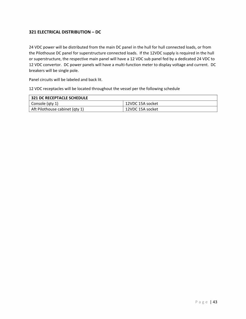
321 ELECTRICAL DISTRIBUTION – DC
24 VDC power will be distributed from the main DC panel in the hull for hull connected loads, or from the Pilothouse DC panel for superstructure connected loads. If the 12VDC supply is required in the hull or superstructure, the respective main panel will have a 12 VDC sub panel fed by a dedicated 24 VDC to 12 VDC convertor. DC power panels will have a multi‐function meter to display voltage and current. DC breakers will be single pole.
Panel circuits will be labeled and back lit.
12 VDC receptacles will be located throughout the vessel per the following schedule
321 DC RECEPTACLE SCHEDULE Console (qty 1) 12VDC 15A socket Aft Pilothouse cabinet (qty 1) 12VDC 15A socket
P a g e | 43

331 LIGHTING – INTERIOR Lighting throughout the interior of the vessel will be LED.
Pilothouse: Red / white dimmable overhead space lighting, three‐way switched from the console and aft
bulkhead near pilothouse door. Red / white dimmable overhead reading (spot) lights centered above each pair of pilot seats,
locally switched from the overhead. Waterjet Compartment:
Overhead space lighting switched at the Frame 3 watertight door. Engine compartment:
Overhead space lighting, three‐way switched from within engine compartment near aft watertight door / ladder and switched within hull accommodations space near watertight door. Lights located within the overhead of the soft patch will be fitted with Deutch DTM connectors for removal.
Hull accommodations compartment: Step lighting, switched at console Overhead space lighting, switch at the base of the stairwell.
Head: Overhead light, switch within the space.
Forward Void: Overhead space lighting switched at the Frame 19 watertight hatch within accommodations
space. 331 INTERIOR LIGHTING EQUIPMENT LIST PILOTHOUSE OVERHEAD LIGHTS (QTY 12) Imtra, Red/White LED, DC PILOTHOUSE PILOT READING LIGHTS (6) Imtra, White, TBD, LED, DC WATERJET COMPARTMENT LIGHTS (QTY 4) Imtra Linear High output LED, AC 24” ENGINE COMPARTMENT LIGHTS (QTY 10) Imtra Linear High output LED, AC 24” ACCOMMODATIONS COMPARTMENT LIGHTS (QTY 4)
Imtra Linear High output LED, AC 24”
STEP LIGHTS (1 per step) Imtra, LED HEAD LIGHT (1) Imtra, White LED FWD VOID LIGHT (2) Imtra Linear High output LED COLLISION VOID LIGHT none
Emergency lighting will be provided by a reduced quantity of the normally used space lights. The reduced quantity of emergency lighting will allow egress and passage through the space. Emergency lights will be switched as the primary light switch but will turn on if loss of main power via relay switch. AC emergency lighting in the hull will be powered via DC:AC invertor off the house batteries.
P a g e | 44

332 LIGHTING – EXTERIOR
Lighting throughout the exterior of the vessel will be LED.
All exterior lighting will be switchable from the control console in the pilothouse.
The searchlight controls will be located on the console such that either the helm or navigator can operate. The searchlight IR camera will display on the integrated bridge system displays (see Section 436)
332 EXTERIOR LIGHTING EQUIPMENT LIST SEARCHLIGHT Luminell CLITE2 IR LED with AIS and 121.5
tracking from Rhotheta RT 500 MAIN DECK LOW LEVEL DECK LIGHTING (house and cuddy perimeter, aft console (1 lot)
Imtra, Livewell, DC
BOARDING (2 on cuddy front) Imtra, Lo Pro Bar, 32” 60deg flood
APPROACH / DISEMBARKING (1 port, 1 stbd, House front visor)
Imtra, Offshore 20 40deg flood
SIDE DECK FLOOD LIGHTS (1 port, 1 stbd) Pilothouse top
Imtra, Offshore 20 60deg wideflood
AFT DECK FLOOD LIGHTS (2) Imtra, Offshore 20 60deg wideflood
MOB TRANSOM FLOOD LIGHTS (2) Imtra, Offshore 12 60deg wideflood
BOW BOARDING LOW LEVEL DECK LIGHTING (between and around bow handrails)
Imtra, Livewell, DC
P a g e | 45

341 GENERATOR COOLING
The generator engines will be sea water / heat exchanger cooled. The engine supplied raw water pump will take suction through the sea chest (See Section 163) and sea water suction piping. Raw water will be discharged to the wet exhaust injection elbow. An anti‐siphon loop will be installed between the raw water pump suction and wet‐exhaust injection point.
Each generator engine will have an independent sea water cooling loop.
341 EQUIPMENT LIST SEA STRAINERS Style: Simplex
Groco, Bronze, poly bowl BLOCK HEATER Make: MAN (factory equipped)
Power: VAC shore power only
Seawater piping for the generator engine cooling system will be per the below schedule.
341 SEAWATER PIPING MATERIAL SCHEDULE SHELL TO ISOLATION VALVE PIPING Piping: 5086 Sch80
Flanges: ANSI B16.5 Class 150, flat or raised face Propress
ISOLATION VALVE Bronze, full port ball, flanged ISOLATION VALVE TO ENGINE PIPING Piping: ASTM B466 90/10 CuNi Class 200
Flanges: ANSI B16.5 Class 150, flat or raised faced OVERBOARD FLANGE TO SHELL PIPING Piping: 5086 Sch80
Flanges: ANSI B16.5 Class 150, flat or raised face OTHER PIPING Piping: ASTM B466 90/10 CuNi Class 200
Flanges: ANSI B16.5 Class 150, flat or raised faced Hose: USCG w/barb or weld bead, 2x 316 stainless clamps
FLEXIBLE CONNECTION Flanged Bellows or USCG Hose w/barb or weld bead, 2x 316 stainless clamps
P a g e | 46

342 GENERATOR EXHAUST Each generator will be fitted with a wet exhaust system. Exhaust hose will run from a on generator engine, OEM, wet exhaust elbow to FRP water lift muffler. The outlet of the muffler will discharge via FRP pipe riser and then exit the hull side above the full load waterline in a downward sloping run.
342 EXHAUST MATERIAL SCHEDULE DRY PIPING None WET PIPING FRP exhaust
Marine exhaust hose FLEXIBLE CONNECTIONS High temperature silicone w/ double hose clamps
P a g e | 47

343 GENERATOR FUEL
The generator engines will draw fuel from the fuel tank (see Section 123) via the fuel supply manifold. Each engine will have an independently run full supply line from the manifold to its primary fuel filter. An isolation valve will connect each supply run to the manifold. The primary fuel filter will be fitted with isolation valves at each side of the filter and will be positioned above a drip pan to catch fuel spillage during element transfer.
Each engine will have an independently run fuel return directly back to the fuel tank without any valves. Fuel return piping will penetration the tank top and extend and extend to within 6 inches of the tank bottom. The fuel return pipe will have anti‐siphon holes just below the tank top to prevent siphoning.
343 EQUIPMENT LIST PRIMARY FUEL FILTERS Racor, Marine Duplex Turbine Series, Poly bowl,
WIF sensor, Micron Rating per engine mfg., vacuum gauge
Fuel piping for the propulsion engine fuel system will be per the below schedule. Piping will be primarily tube with flexible hose lengths and connections minimized.
343 DIESEL FUEL PIPING MATERIAL SCHEDULE SUPPLY AND RETURN PIPING Tube: 316 (min 0.035 wall)
Hose: USCG approved FITTINGS Tube: 316 Swagelock or Equal
Hose: JIC 37° flare Other: NPT or flanged Flanges: ANSI B16.5
VALVES Full port ball, 316
P a g e | 48

400 | COMMAND AND CONTROL
P a g e | 49

421 COMPASS
A magnetic compass will be installed on CL directly in front of the helm position on top of the console. The Compass will be illuminated with a dimmable light.
421 COMPASS EQUIPMENT LIST MAGNETIC COMPASS Make: Ritchie
Model: SuperSport 1002
P a g e | 50

422 NAVIGATION LIGHTS
Navigation lights will be provided for a vessel < 50m for operation as a power‐driven vessel underway, a vessel at anchor and a pilot vessel underway.
Red and white all‐around lights located on the mast will comprise of two lights, mounted back to back against the mast.
The navigation lights will be controlled via the integrated control system (see Section 436)
422 NAVIGATION LIGHTING EQUIPMENT LIST NAVIGATION LIGHTS Imtra DHR60 MASTHEAD LIGHT 225 deg white, 5nm SIDE LIGHTS 112.5 deg red/green, 2nm STERN LIGHT 135 deg white, 2nm ANCHOR/PILOT LIGHT 2x 360 deg white, 2nm PILOT LIGHT 2x 360 deg red, 2nm
P a g e | 51

423 ELECTRONIC NAVIGATION SYSTEMS
The following electronic navigation equipment will be installed and interconnection to work together and work with the Integrated bridge system (See Section 436)
Installation, Testing, Termination and commissioning will be performed by the electronics integrator.
Antenna will be located upon the pilothouse top and mast and arranged to minimize induced vibrations in interference.
423 ELECTRONIC NAVIGATION SYSTEM EQUIPMENT LIST Electronics Integrator Mackay Marine RADAR (Qty 2) FURUNO FAR2228BB/NXT
Processor Unit Keyboard with trackball
RADAR ARRAY (Qty 2) FURUNO XN12CF/4 X‐band, 4ft open array
NAVIGATION COMPUTER Marinized DC computer, solid state drives Rose Point ECS Commercial Grade Navigation
SAT (GPS) COMPASS FURUNO SC70 AUTOPILOT FURUNO 711C RDF Rhotheta RT‐500‐M AIS FURUNO FA170
Dedicated GPS and VHF ANEMOMETER RM Young Ultrasonic RADIO RECEIVER FUSION, AM/FM, SiriusXM ready
SIRIUSXM SCV3000 Receiver SIRIUSXM Low profile marine antenna Speakers (qty 4 pair)
P a g e | 52

424 DEPTH SOUNDER
A thru‐hull transducer to measure depth/speed/water temperature will be mounted through the hull bottom. The transducer will communicate to the electronic navigation system (see Section 423)
421 COMPASS EQUIPMENT LIST Depth Transducer Make: Airmar
Model: DST800 (stainless)
P a g e | 53

435 FIRE DETECTION AND ALARM SYSTEM
The vessel will be fitted with a central fire detection and alarm system. While the alarm system will be fully independent, it will also announce to the Integrated bridge system (see Section 436)
All compartments with a detector will be equipped with a manual pull station near the primary exit and an overhead horn/strobe.
435 FIRE DETECTION AND ALARM SYSTEM EQUIPMENT LIST ALARM SYSTEM Kidde Fire WATERJET COMPARTMENT Rate of Rise detector ENGINE COMPARTMENT 2 x Rate of rise detector HULL ACCOMMODATION PhotoElectric detector PILOTHOUSE PhotoElectric detector
P a g e | 54

436 INTEGRATED BRIDGE ALARM, CONTROL AND MONITORING
The vessel will be fitted with a Boning integrated bridge control and monitoring. The Boning system will integrate with the following WBS, providing centralized control and monitoring.
WBS ITEM INTERFACED / FUNCTIONALITY 126 Fuel tank level indication and hi/low alarm 167 Watertight door alarm 233 Propulsion engine Start‐Stop, display and alarm monitoring 247 Waterjet alarm monitoring 256 DEF tank level indication and hi/low alarm 310 Generator engine Start‐Stop, display and alarm monitoring
Battery charger monitoring 320 DC power switching, display and monitoring 321 AC power switching, display and monitoring 332 Searchlight IR camera display 350 WIF sensor 423 Electronic navigation system display and control integration 422 Navigation light monitoring and control 435 Fire detection and alarm 443 Fog signal control 450 CCTV System display 513 Engine compartment ventilation monitoring and control 529 Bilge alarm monitoring 533 Potable water low level alarm 555 Engine compartment fire extinguishing system alarm monitoring
The following diagrams depict the system and interconnections are currently established and understood.
P a g e | 55

P a g e | 56

P a g e | 57

440 EXTERIOR COMMUNICATION SYSTEMS
The vessel will be outfitted with the external communications systems per the below equipment list.
440 EXTERIOR COMMUNICATIONS EQUIPMENT LIST VHF #1 Furuno FM8900S
Furuno RB8900 remote handset Remote Speaker in overhead
VHF #2 Furuno FM8900S Furuno RB8900 remote handset Remote Speaker in overhead
VHF #3 Furuno FM8900S Furuno RB8900 remote handset Remote Speaker in overhead
Hailer Furuno LH5000 Exterior talkback horns fwd and aft
Boom Microphone Shure VHF Antenna MORAD 6db gain hot rod, black EPIRB TBD, float free, mounted to aft house overhang
Owner furnished; builder installed
Each VHF radio and the hailer will have the ability to transmit through the boom microphone by pressing a button at boom mike’s base.
VHF antenna will be located on the mast. VHF antenna cables will be provided with service loops to allow replacement of faulty end connectors without replacing the entire length of cable.
EPIRB?
P a g e | 58

443 HORN
An air powered signaling horn / foghorn will be mounted to the superstructure top for a vessel less then 50M in length. The horn will be controlled by a horn control panel located on the console. The horn control panel will provide signaling options for fog.
The horn compressor will be in the fiddley / mast base.
The horn controller will integrate with the central control system. (see Section 436)
443 HORN EQUIPMENT LIST HORN Make: Kahlenberg
Model: S‐330 COMPRESSOR Make: Kahlenberg
Model: P449‐25 HORN CONTROL Make: Kahlenberg
Model: Signal Controller M‐512
P a g e | 59

450 CCTV SYSTEM
The vessel will be equipped with CCTV system with interior and exterior cameras throughout the boat per the below schedule. Images will be displayed on the Integrated bridge system (see Section 436) displays.
450 CCTV SYSTEM LIST Waterjet Compartment 1, aft facing CL Engine Compartment 1 fwd facing CL, 2 aft facing outboard Aft Deck 1, aft facing Port Side Deck 1 fwd facing, 1 aft facing Stbd Side Deck 1 fwd facing, 1 aft facing Boarding areas 1 port, 1 stbd
P a g e | 60

500 | AUXILIARY MECHANICAL
P a g e | 61

511 COMPARTMENT HEATING
Hull compartments and the pilothouse will be provided electric heat as described in the table below.
The waterjet compartment heater is intended to provide minimal temperature elevation to minimize condensation. The waterjet compartment heater will be connected to the shore power bus.
The engine compartment will be heated by radiant heat from the propulsion engine and generator engine block heaters. Engine block heaters will be connected to the shore power bus.
The hull accommodations compartment and the pilothouse will be heated from the HVAC system. Other compartments will not be heated.4
511 COMPARTMENT HEATING LIST WATERJET COMPARTMENT SPACE HEATER
Make: King Model: Pic‐A‐Watt Output: 1000 W
ENGINE COMPARTMENT See Section 256 See Section 341
HULL ACCOMMODATIONS See Section 514
FORWARD VOID None COLLISION VOID None PILOTHOUSE See Section 514
P a g e | 62

512 COMPARTMENT VENTILATION ‐ EXCEPT ENGINE COMPARTMENT
All hull compartments will be ventilated.
Compartments with non‐powered ventilation will be fitted with two vent pipe connections, one connection will be deck connected with no interior tube, the other connection will have an internal tube led down to promote thermal circulation. All vent pipes will be of the inverted ball check type. Vents will be located near CL to further mitigate water ingestion. If possible, vent risers will be integrated into railing stanchions to minimize deck penetrations and clutter.
The hull accommodations compartment will be provided with natural inlet with a forced air exhaust. An exhaust fan will be in the head overhead to provide air exchanges. The head door will have a lower louver to allow air to pass.
The pilothouse will take air from the fiddley directly into one of the HVAC unit to provide heating, cooling and/or de‐humidification of the makeup air as required. See Section 514. Pilothouse air will exhaust via a dedicated exhaust fan located in the aft bulkhead.
512 COMPARTMENT VENTILATION LIST WATERJET COMPARTMENT Natural ENGINE COMPARTMENT See Section 513 HULL ACCOMMODATIONS COMPARTMENT Exhaust Fan, 24 VDC FORWARD VOID Natural COLLISION VOID Natural PILOTHOUSE Exhaust Fan, 24 VDC
Sizing of ventilation fans for air exchanges will be based upon the following requirements.
512 DESIGN REQUIREMENTS HULL ACCOMMODATIONS COMPARTMENT FORCED AIR EXCHANGES
2 persons x 6 changes per hour
PILOTHOUSE HOUSE FORCE AIR EXCHANGES 14 persons x 6 changes per hour
P a g e | 63

513 HULL COMPARTMENT VENTILATION – ENGINE COMPARTMENT
The engine compartment will be ventilated with inlet supply fans that positively pressurize the space, providing combustion air to the propulsion engines and to the generator engines and allow for exhaust air and heat to naturally exhaust. The supply fans will be VFD controlled by a fan temperature controller.
Air inlets and air outlets will be fitted with water rejecting de‐misters
Ducting at the engine compartment entry and exit will be fitted with automatic fire dampers.
513 ENGINE COMPARTMENT VENTILATION LIST DEMISTERS Delta‐T Systems INLET FANS Delta‐T Systems
21 inch 3 HP 208 VAC, Frequency drive control
FIRE DAMPERS Delta‐T Systems FAN CONTROLLER Delta‐T Systems T6
P a g e | 64

514 HEATING VENTILATION AND COOLING
The HVAC system will provide heated, cooled, de‐humidified air to the pilothouse and hull accommodations space. The HVAC will be of the chilled water type, with the chiller(s) located within the engine compartment, serving air handler units located in the individual spaces.
The chillers will have a dedicated, independent raw water loop that will circulate sea water from a sea chest, through the chiller and discharge overboard. Sea water piping will be per Section 256.
The chillers will have a chilled water loop that will circulate water/glycol mixture to the air handlers and back. Chilled water piping will be insulated. Chilled water piping to the pilothouse will have a double valve arrangement with a removable hose section to allow closing of the system and removal of the pilothouse with minimal chilled water loss. Chilled water piping will be fitted with air bleaders at all high spots. Chilled water disconnect for house removal will be accomplished by two isolation valves with a short removable jumper hose between. To remove the house, the isolation valves will be closed, and the house jumper removed. Re‐installation will introduce a small amount of air into the system and must be bled.
HVAC chiller(s), raw water pump(s) and chilled water pump(s) will be powered from a localized HVAC power panel located in proximity to the chillers and pumps in the engine compartment.
All air handlers will be fitted with condensate drip pans. The drains for the drip pans will be aft to allow draining while underway with bow up running trim. Air handlers in the pilothouse will drain onto the main deck. The air handler in the accommodates space will drain into the sink sump (see Section 593)
The pilothouse will be divided into two zones. A pair of air handlers will provide air to above the pilot seats in one zone. Air from these units will be distributed in linear slow drop registers to minimize air velocity and cold “spikes”. A third air handler will provide air the above the helm / navigator seats in a second zone.
The hull accommodations compartment will be provided air to a centralized overhead duct by a single air handler.
P a g e | 65

515 WINDOW DEFROST
The forward‐facing windows and the forward most side windows in the pilothouse will be installed with force hot air defrosters. A single VFD will control all three fan motors which will supply forced air, heated via inline duct heaters, delivered to each window via directional slots below each window.
The side windows in the pilothouse will be installed with forced hot air defrosters. A single VFD will control both fam motors which will supply forced air, heated via inline duct heaters, delivered to each window via directional slots below each window.
All window defrost will be controlled from the console. Defrost heaters will be thermostatically controlled and interlocked to their respective fans.
515 WINDOW DEFROST EQUIPMENT LIST FORWARD WINDOW FANS (QTY 3) 208VAC, 1 ½ HP FORWARD WINDOW HEATER (QTY 3) 2kW SIDE WINDOW FANS (QTY 2) 208VAC, 1 ½ HP SIDE WINDOW HEATERS (QTY 2) 2kW
P a g e | 66

521 FIRE MAIN
The vessel will be fitted with a general service / fire pump. The general service / fire pump will take suction from either a suction box located within the engine compartment for dewatering or from a dedicated sea chest. Pump discharge will be either to an overboard discharge or to the fire hydrant on the aft deck.
The pump motor will have both local start/stop and remote start/stop from the console.
The fire hose will be stored in an FRP box.
521 FIRE MAIN EQUIPMENT LIST Fire / General Service Pump TBD
Self‐priming 208VAC
Fire Hose 1 ½” 50’ fire hose
Seawater piping for the fire main system will be per the below schedule.
521 SEAWATER PIPING MATERIAL SCHEDULE SHELL TO ISOLATION VALVE PIPING Piping: 5086 Sch80
Flanges: ANSI B16.5 Class 150, flat or raised face Propress
ISOLATION VALVE Bronze, full port ball, flanged SUCTION PIPING Piping: ASTM B466 90/10 CuNi Class 200
Flanges: ANSI B16.5 Class 150, flat or raised faced OVERBOARD FLANGE TO SHELL PIPING Piping: 5086 Sch80
Flanges: ANSI B16.5 Class 150, flat or raised face DISCHARGE PIPING Piping: ASTM B466 90/10 CuNi Class 200
Flanges: ANSI B16.5 Class 150, flat or raised faced Hose: USCG w/barb or weld bead, 2x 316 stainless clamps
FLEXIBLE CONNECTION Flanged Bellows
The fire pump will be selected to meet the following requirements.
521 DESIGN REQUIREMENTS Pump sizing 50 gpm at 60 psi at the pump outlet
P a g e | 67

526 SCUPPERS AND DECK DRAIN
The superstructure top is not fitted with deck drains. The after end of the roof panels will have a flat bar upstand to prevent rain/sea water from dripping off the aft edge of the pilothouse overhang.
The main deck is cambered and completely self‐bailing without bulwarks. The main deck does not have deck drains. The recesses for the deck matting will drain over the sheer.
P a g e | 68
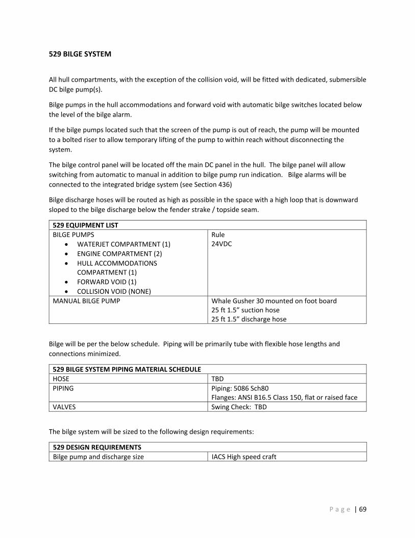
529 BILGE SYSTEM
All hull compartments, with the exception of the collision void, will be fitted with dedicated, submersible DC bilge pump(s).
Bilge pumps in the hull accommodations and forward void with automatic bilge switches located below the level of the bilge alarm.
If the bilge pumps located such that the screen of the pump is out of reach, the pump will be mounted to a bolted riser to allow temporary lifting of the pump to within reach without disconnecting the system.
The bilge control panel will be located off the main DC panel in the hull. The bilge panel will allow switching from automatic to manual in addition to bilge pump run indication. Bilge alarms will be connected to the integrated bridge system (see Section 436)
Bilge discharge hoses will be routed as high as possible in the space with a high loop that is downward sloped to the bilge discharge below the fender strake / topside seam.
529 EQUIPMENT LIST BILGE PUMPS
WATERJET COMPARTMENT (1) ENGINE COMPARTMENT (2) HULL ACCOMMODATIONS
COMPARTMENT (1) FORWARD VOID (1) COLLISION VOID (NONE)
Rule 24VDC
MANUAL BILGE PUMP Whale Gusher 30 mounted on foot board 25 ft 1.5” suction hose 25 ft 1.5” discharge hose
Bilge will be per the below schedule. Piping will be primarily tube with flexible hose lengths and connections minimized.
529 BILGE SYSTEM PIPING MATERIAL SCHEDULE HOSE TBD PIPING Piping: 5086 Sch80
Flanges: ANSI B16.5 Class 150, flat or raised face VALVES Swing Check: TBD
The bilge system will be sized to the following design requirements:
529 DESIGN REQUIREMENTS Bilge pump and discharge size IACS High speed craft
P a g e | 69

533 POTABLE WATER SYSTEM
A potable freshwater system will supply hot and cold water to the galley sink faucet and head sink faucet. An expansion tank (accumulator) will be fitted after the pump discharge.
An inline water filter will be installed in the cold‐water service to the galley faucet.
Potable water will be stored in a polyethylene water tank. Only the tank top will be penetrated for tank connections. Tank fill will be atop the cuddy roof and the tank vent will be in the cuddy side,
The water tank will not be fitted with tank level indication but will be fitted with a low‐level alarm connected to the integrated bridge monitoring system (see Section 436)
533 EQUIPMENT LIST PRESSURE PUMP Jabsco Par‐Max
6 gpm 24 VDC
WATER FILTER 3M Aqua Pure Under Sink WATER HEATER Raritan 1700 series
6 gal 120 VAC
Piping for the potable water system will be per the below schedule. Piping will be primarily tube with flexible hose lengths and connections minimized.
533 POTABLE WATER SYSTEM PIPING MATERIAL SCHEDULE HOSE PVC TUBE PEX VALVES AND FITTINGS All: Brass, NSF approved for potable water
P a g e | 70

555 FIRE EXTINGUISHING SYSTEM
The engine compartment will be outfitted with a manual marine fixed gas fire suppression system. The fire system will consist of an agent cylinder plumbed to two overhead discharge nozzles located within the engine compartment
Activation of the fire system will trigger a 30 second delay with siren via a nitrogen pilot bottle.
Activation of the fire system will be by manual pull boxes adjacent to the watertight doors in the adjacent spaces.
Activation of the fire system will shut down the propulsion engines, generator engines and engine compartment ventilation system.
555 FIRE EXTINGUISHING EQUIPMENT LIST Engineered fixed fire extinguishing system Alexander Gow Fire Equipment – Kiddie Fire
Systems. Fire Agent FM‐200
P a g e | 71
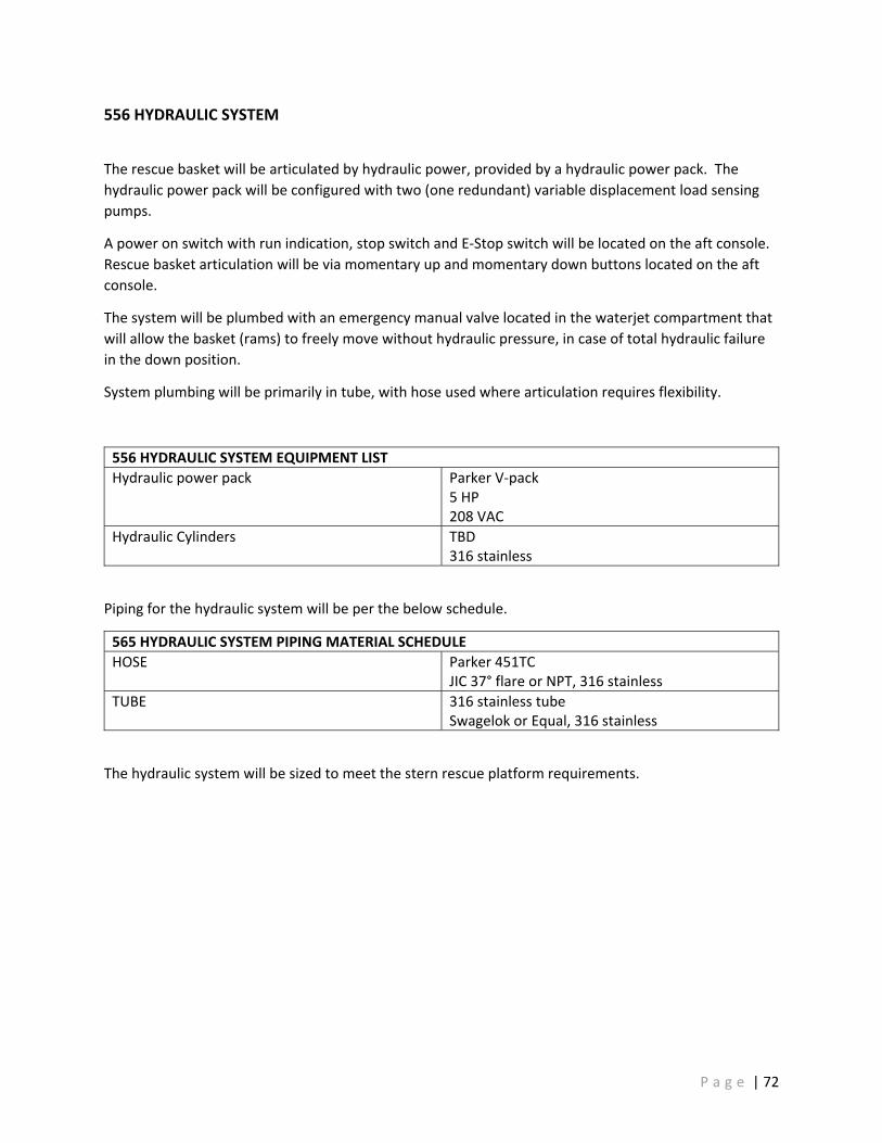
556 HYDRAULIC SYSTEM
The rescue basket will be articulated by hydraulic power, provided by a hydraulic power pack. The hydraulic power pack will be configured with two (one redundant) variable displacement load sensing pumps.
A power on switch with run indication, stop switch and E‐Stop switch will be located on the aft console. Rescue basket articulation will be via momentary up and momentary down buttons located on the aft console.
The system will be plumbed with an emergency manual valve located in the waterjet compartment that will allow the basket (rams) to freely move without hydraulic pressure, in case of total hydraulic failure in the down position.
System plumbing will be primarily in tube, with hose used where articulation requires flexibility.
556 HYDRAULIC SYSTEM EQUIPMENT LIST Hydraulic power pack Parker V‐pack
5 HP 208 VAC
Hydraulic Cylinders TBD 316 stainless
Piping for the hydraulic system will be per the below schedule.
565 HYDRAULIC SYSTEM PIPING MATERIAL SCHEDULE HOSE Parker 451TC
JIC 37° flare or NPT, 316 stainless TUBE 316 stainless tube
Swagelok or Equal, 316 stainless
The hydraulic system will be sized to meet the stern rescue platform requirements.
P a g e | 72

565 TRIM AND RIDE CONTROL SYSTEM
Adjustable interceptors will be equipped on the transom to provide both trim and ride control. Interceptor controls will be located on the console.
565 TRIM AND RIDE CONTROL EQUIPMENT LIST INTERCEPTORS Make: Humphrees
Model: TBD by Humphrees during design phase Size: TBD by Humphrees during design phase
CONTROL SYSTEM Make: Humphrees: Package: Active+
Auto Trim Auto List Coordinated Turn Roll and Pitch Stabilization
P a g e | 73

573 MOB RESCUE BASKET
An articulating MOB rescue platform will be installed on the transom of the vessel to provide man overboard recovery. The MOB rescue basket will be controlled from the aft control station (see Section 556).
The basket frame and arm will be fabricated of aluminum. The basket will be woven netting.
A pair of cam‐locking detents will secure the basket in the up position. The hydraulic force will be sufficient to overcome and release the detents to lower the basket.
The rescue basket to the following design requirements:
557 DESIGN REQUIREMENTS Weight of MOB 350 lbs Lower Time 12 seconds or less (to be compared to prior
designs and adjusted accordingly) Raise Time, loaded, vessel at rest 12 seconds or less (to be compared to prior
designs and adjusted accordingly) Raise empty @ speed 5 knots in reverse
P a g e | 74
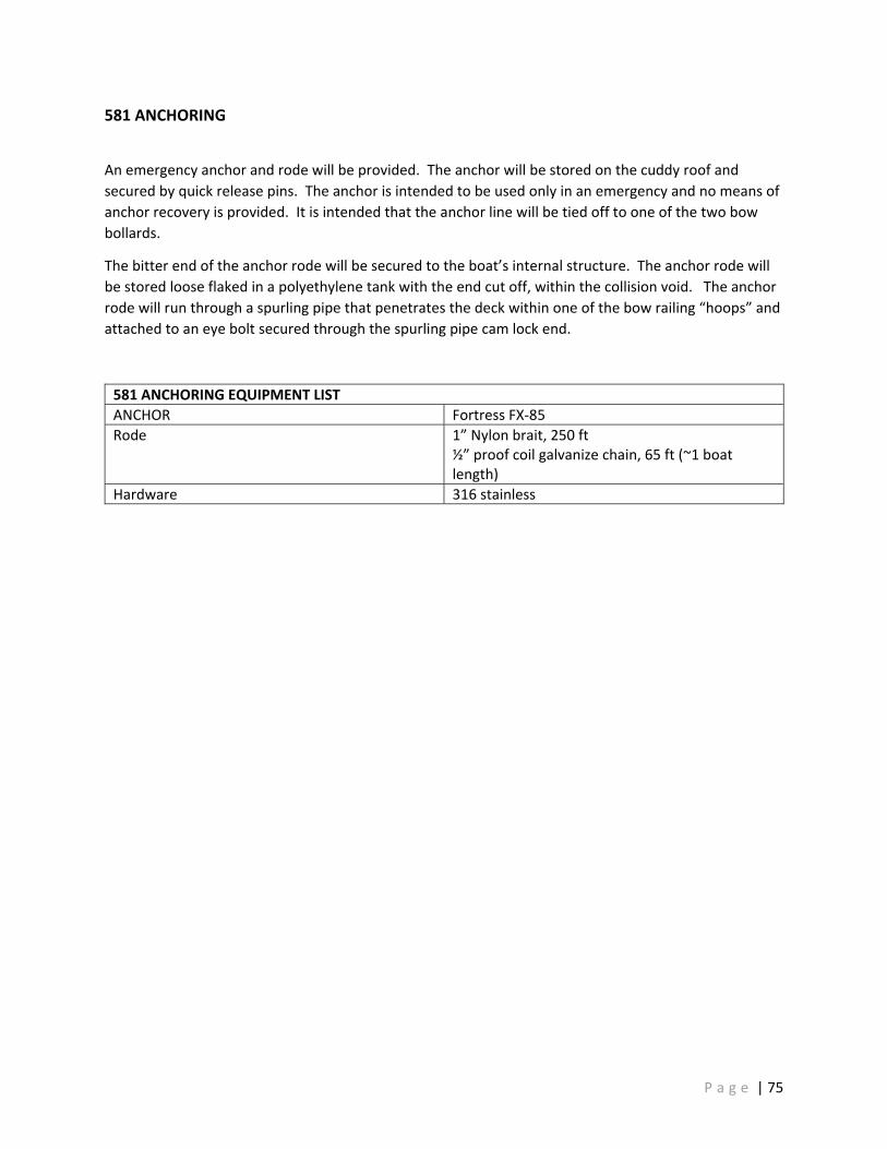
581 ANCHORING
An emergency anchor and rode will be provided. The anchor will be stored on the cuddy roof and secured by quick release pins. The anchor is intended to be used only in an emergency and no means of anchor recovery is provided. It is intended that the anchor line will be tied off to one of the two bow bollards.
The bitter end of the anchor rode will be secured to the boat’s internal structure. The anchor rode will be stored loose flaked in a polyethylene tank with the end cut off, within the collision void. The anchor rode will run through a spurling pipe that penetrates the deck within one of the bow railing “hoops” and attached to an eye bolt secured through the spurling pipe cam lock end.
581 ANCHORING EQUIPMENT LIST ANCHOR Fortress FX‐85 Rode 1” Nylon brait, 250 ft
½” proof coil galvanize chain, 65 ft (~1 boat length)
Hardware 316 stainless
P a g e | 75

582 MOORING
Bow, midship and stern mooring bitts will be installed on each side of the vessel. The mooring bitts will be fabricated of welded aluminum pipe and consist of a single vertical bollard, cross bar, and top cap. Cross bars will extend 6‐inches from each side and have rounded ends. The top cap will overhang the bollard pipe and have a bull nose rounded over edge.
The bow bitts will be set inboard and under the bow railings. The midship bitts will be recessed in the house cuddy sides. The aft bitts will be located on the aft stern corners but set in from the sheer such that contact between the bitt top and an alongside vessel is not possible.
P a g e | 76

583 LIFE SAVING
The below list of rescue and lifesaving equipment will be installed on the vessel.
The MOD marker pylon will be deployed via a remote switch located at the helm station.
Life raft cradles will be provided for Owner supplied Subscription life raft service.
583 LIFE SAVING EQUIPMENT LIST Personal Floatation Devices x 14 Mustang 4‐0ne or similar
USCG Type I, with personal light and whistle Type IV Ring Buoy x4 (bow rail, house side p/s, aft console)
LSS 244 or similar 24 inch Reflective markings
MOB marker light x3 (house side p/s, aft console)
LSS 314 or similar With tether and clip
Rescue Throw Bag x2 (aft rails p/s)
LSS 237‐P or similar
MOB marker pylon (transom)
Switlik MOM 8‐A
Boat hook x2 (house side p/s)
TBD
Life Rafts (aft console p/s)
Cradle only provided for OWNER furnished rafts
P a g e | 77
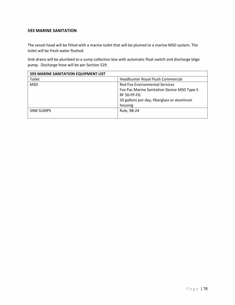
593 MARINE SANITATION
The vessel head will be fitted with a marine toilet that will be plumed to a marine MSD system. The toilet will be fresh water flushed.
Sink drains will be plumbed to a sump collection box with automatic float switch and discharge bilge pump. Discharge hose will be per Section 529.
593 MARINE SANITATION EQUIPMENT LIST Toilet Headhunter Royal Flush Commercial MSD Red Fox Environmental Services
Fox Pac Marine Sanitation Device MSD Type II RF 50‐FP‐FG 50 gallons per day, fiberglass or aluminum housing
SINK SUMPS Rule, 98‐24
P a g e | 78

600 | OUTFIT
P a g e | 79

602 HULL MARKINGS
All hull and house markings s (see Section 603) will be painted. See Section 631 for paint specification.
The vessel will be marked as per the table below.
602 HULL MARKING LIST VESSEL NAME Hull sides, bow (p/s) below fender
Black with white boarder PILOT House side (p/s)
Cuddy top Orange with black border
VESSEL NAME SAN FRANCISCO
Transom Black with white border
P a g e | 80

603 DRAFT MARKS
Forward and aft draft marks will be welded to the bow and stern port and stbd side. Draft marks will be 6 inches in height and 0.190” thick.
Draft marks will be painted a contrasting color to the hull / topsides.
P a g e | 81
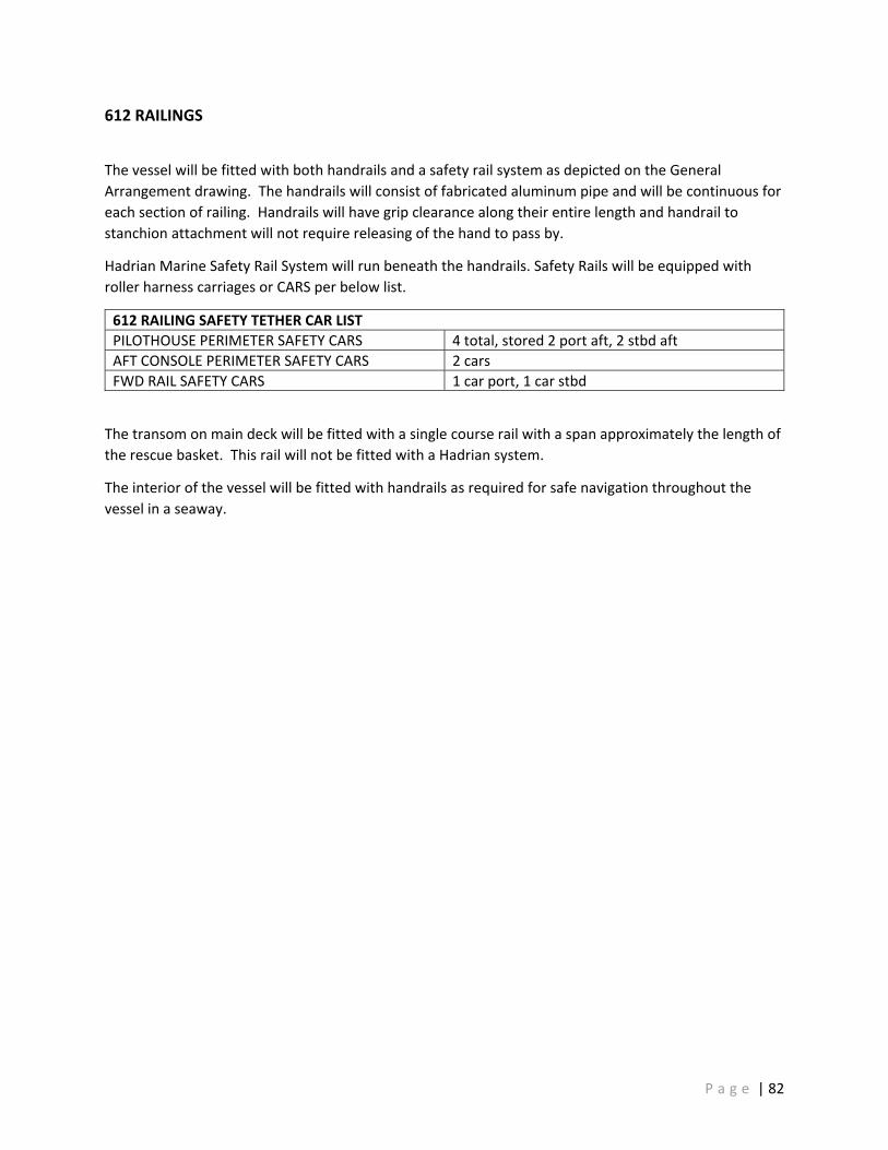
612 RAILINGS
The vessel will be fitted with both handrails and a safety rail system as depicted on the General Arrangement drawing. The handrails will consist of fabricated aluminum pipe and will be continuous for each section of railing. Handrails will have grip clearance along their entire length and handrail to stanchion attachment will not require releasing of the hand to pass by.
Hadrian Marine Safety Rail System will run beneath the handrails. Safety Rails will be equipped with roller harness carriages or CARS per below list.
612 RAILING SAFETY TETHER CAR LIST PILOTHOUSE PERIMETER SAFETY CARS 4 total, stored 2 port aft, 2 stbd aft AFT CONSOLE PERIMETER SAFETY CARS 2 cars FWD RAIL SAFETY CARS 1 car port, 1 car stbd
The transom on main deck will be fitted with a single course rail with a span approximately the length of the rescue basket. This rail will not be fitted with a Hadrian system.
The interior of the vessel will be fitted with handrails as required for safe navigation throughout the vessel in a seaway.
P a g e | 82

622 FLOOR PLATES
The Waterjet Compartment, Engine Compartment and Void Compartment will have aluminum diamond tread floor plates. Floor plates will have upturned edges. Floorplates will be bolted, if access for routine maintenance is required, floorplates in the area will be hinged.
P a g e | 83

623 LADDERS AND STAIRS
Access from the aft main deck to the superstructure top will be via a fabricated aluminum pipe ladder. Compartment ladders will be fabricated of aluminum pipe / tube. Ladder rungs will be fitted with 3M safety walk tape.
Two SFBP specified ladders will be stored on the main deck, attached to the superstructure top ladder. Ladder #1 is 12’‐4” long and ladder #2 is 7’‐7” long. The ladders will have similar spacing and width as the house top ladder such that as lashed together, they can still be climbed.
P a g e | 84

625 WINDOWS
Pilot house windows will be of the bonded. Adhesive will follow manufactures requirements for UV protection. If required interior fritting will be applied to the inner glass surface to protect the window adhesive per the adhesive manufacturer’s recommendations. Pilothouse windows will be recess set into the house side such that the outer window surface and outer house surface are flush. Overhead windows will be recess set into the house top such that the outer window surface and the outer roof surface are flush.
625 WINDOW EQUIPMENT LIST FORWARD WINDSHIELD Non‐tinted, heated FORWARD SIDE WINDOWS Non‐tinted, heated MID SIDE WINDOWS Tinted AFT SIDE WINDOWS Tinted AFT WINDOWS Tinted OVERHEAD Tinted
Windows will be monolithic glass. Where windows are fitted with heating elements an additional bonded glass layer for distortion control, only the primary window will be structurally considered.
625 DESIGN REQUIREMENTS WINDOW STRENGTH Based upon minimum of IACS rules
All pilothouse non‐tinted windows will be fitted with solar shades, with the exception of the overhead windows which will be fitted with removable covers
P a g e | 85

626 WINDOW WIPERS AND WASH SYSTEM
The forward windshields and forward most side windows will be fitted with wipers. Wiper arm and blade size will be arranged to maximize wiper coverage area. Forward windshield will have Pantograph arms. Side windows will have radial arms. Wiper motors and wash fittings will be mounted through aluminum shell below the windows.
Wiper wash water will be provided via the freshwater system (See Section 533). Each wiper arm will have a dedicated solenoid valve.
626 WIPER AND WASH EQUIPMENT LIST WIPERS Make: Exalto HD2 WIPER CONTROL Exalto Wiper Control‐5
P a g e | 86

631 PAINTING
The vessel will be painted by a paint sub‐contractor to the following paint specification:
631 PAINT SCHEDULE HULL BOTTOM Intersleek 1100 system
Color: Black TBD HULL SIDES Awl Grip 545 / Topcoat
Color: International Orange MAIN DECK Awl Grip 545 / Topcoat
Non‐skid additive with drain paths Color: Grey TBD
SUPER STRUCTURE SIDES Awl Grip 545 / Topcoat Color: Snow White
SUPER STRUCTURE TOPS Awl Grip 545 / Topcoat Color: International Orange Non‐skid additive on walking surfaces
MAST Awl Grip 545 / Topcoat Color: Super Jet Black
RAILINGS Awl Grip 545 / Topcoat Color: Snow White
RESCUE BASKET AND STERN GUARD Awl Grip 545 / Topcoat Color: Snow White
MOORING BITTS Awl Grip 545 / Topcoat Color: Snow White
FAYING SURFACES Behind Fender Sea valve flange faces Exhaust hose
Awl Grip 545 Epoxy Primer
WATERJETS TBD
The surfaces within the void between the superstructure and hull, including the hull soft patch will not be painted.
P a g e | 87

633 CATHODIC PROTECTION
The hull will be fitted with pockets for flush mounted hull anodes. The transom will be fitted with non‐flush mounted anodes. Hull anode size and location will be determined during the detailed design process.
Seachests will be fitted with pencil anodes.
P a g e | 88

634 EXTERIOR DECK COVERINGS
The main deck area in way of the boarding area will be covered with deck matting per the following schedule and area diagram. Deck matting will be recessed into the deck such that the top of the rubber mat and the nominal deck top are at the same level.
634 DECK COVERING SCHEDULE PILOT BOARDING AREAS Crown SafeWalk or San‐Eze No Trak
7/8” rubber food service mat
P a g e | 89

635 INSULATION
Unless indicated otherwise, insulation will be glass mineral wool, density and thickness per the below schedule. Insulation will wrap around stiffeners and frames/girders. Hull side insulation will extend from the overhead and terminate at the lowest longitudinal stiffener above the lower chine flat to prevent wicking. Insulation will be taped and pinned.
635 INSULATION SCHEDULE Hull Insulation Isover Ultimate U SeaProtect
Thickness: 30,50,70 mm Density: 24,36,56,66 kg/m³ Facing: per below
ENGINE COMPARTMENT OVERHEAD Facing: alum foil/glass cloth ENGINE COMPARTMENT SIDES AND BULKHEAD Facing: alum foil/glass cloth HULL ACCOMMODATIONS COMPARTMENT OVERHEAD
Facing: alum foil/glass cloth
HULL ACCOMMODATIONS COMPARTMENT JOINER EXTERIOR PARTITIONS
Facing: glass cloth
PILOTHOUSE OVERHEAD Facing: alum foil/glass cloth PILOTHOUSE SIDES AND ENDS Facing: alum foil/glass cloth PILOTHOUSE UNDERSIDE Facing: alum foil/glass cloth
635 DESIGN REQUIREMENTS Thickness and density Thickness and density to be sized to match
performance on past Pilot boat projects.
P a g e | 90
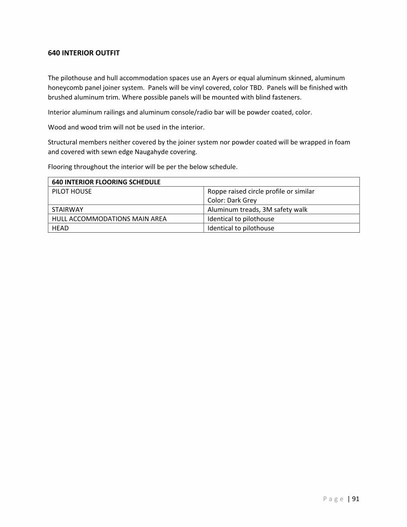
640 INTERIOR OUTFIT
The pilothouse and hull accommodation spaces use an Ayers or equal aluminum skinned, aluminum honeycomb panel joiner system. Panels will be vinyl covered, color TBD. Panels will be finished with brushed aluminum trim. Where possible panels will be mounted with blind fasteners.
Interior aluminum railings and aluminum console/radio bar will be powder coated, color.
Wood and wood trim will not be used in the interior.
Structural members neither covered by the joiner system nor powder coated will be wrapped in foam and covered with sewn edge Naugahyde covering.
Flooring throughout the interior will be per the below schedule.
640 INTERIOR FLOORING SCHEDULE PILOT HOUSE Roppe raised circle profile or similar
Color: Dark Grey STAIRWAY Aluminum treads, 3M safety walk HULL ACCOMMODATIONS MAIN AREA Identical to pilothouse HEAD Identical to pilothouse
P a g e | 91

650 EXTERIOR OUTFIT
Welded “U’s” will be positioned above the forward side windows port and starboard. Clamp on style bus/truck mirrors will be attached to the provide the helmsperson with a view of the side decks looking aft.
P a g e | 92

660 SEATING
Fixed marine seating will be provided per the equipment list below. Pilot seats to be
660 SEATING EQUIPMENT LIST HELM SEAT Make: Imtra
Model: NorSap 1600 Adjustable linear base
NAVIGATOR SEAT Make: Imtra Model: NorSap 1600
PILOT SEATS (12) Make: UES Model: Luxform Journey
P a g e | 93
Related Documents