STANDARD TECHNICAL SPECIFCATION FOR 3Ph 4 WIRE HT CT/PT OPERATED FULLY STATIC AMR COMPATIBLE TRI-VECTOR ENERGY METERS DLMS COMPLIANT – CATEGORY „C‟ FOR 11KV BULK CONSUMER METER

Welcome message from author
This document is posted to help you gain knowledge. Please leave a comment to let me know what you think about it! Share it to your friends and learn new things together.
Transcript
STANDARD TECHNICAL SPECIFCATION
FOR
3Ph 4 WIRE HT CT/PT OPERATED FULLY STATIC
AMR COMPATIBLE TRI-VECTOR ENERGY METERS
DLMS COMPLIANT – CATEGORY „C‟
FOR
11KV BULK CONSUMER METER
2
TECHNICAL SPECIFCATION FOR 3PHASE 4 WIRE CT/PT OPERATED FULLY STATIC
AMR COMPATIBLE TRI-VECTOR ENERGY METERS FOR BULK CONSUMER
1.0 SCOPE:
Design, manufacturing, testing, supply and delivery of AC, 3 Phase 4wire, CT/PT operated
lag only, fully Static and AMR compatible Tri-Vector Energy Meters for measurement of
different electrical parameters listed elsewhere in the document including Active Energy
(kWh/MWh), Reactive Energy (kVArh/MVArh), Apparent Energy (kVAh/MVAh) etc.
2.0 APPLICATION:
CONSUMER METER – Category “C”
3.0 STANDARDS TO WHICH METERS SHALL COMPLY:
IS 14697:1999(2004) Specification for AC Static Transformer operated Watt Hour & VAR-Hour
meters (class 0.5S);
IS 15959:2011 Data Exchange For Electricity Meter Reading Tariff & Load Control –
Companion Specification
CBIP - 304 Manual on Standardization of AC Static Electrical Energy Meter
IEC 62052-11 Electricity metering equipment (AC) –General requirements, tests and test
conditions -Part 11: Metering equipment;
IEC 62053-22 Electricity metering equipment (AC) –Particular requirements - Part-22: Static
Meters for Active Energy (Class 0.5S);
IEC 62053-23 Electricity metering equipment (AC) –Particular requirements - Part-23: Static
Meters for Reactive Energy;
IS 15707 Specification for Testing, evaluation, installation & maintenance of AC Electricity
Meters-Code of Practice.
Guidelines on “Data Exchange for Electricity Meter Reading, Tariff and Load Control –
Companion Specification”
IEC 62056-21 Electricity metering: Data exchange for meter reading, tariff and load control-
Part 21: Direct local data exchange
IEC 62056-31 Electricity metering: Data exchange for meter reading, tariff and load control -
Part 31: Local Area Network data exchange
IEC 62056-61 Electricity metering: Data exchange for meter reading, tariff and load control-
Part 61: Object identification system (OBIS)
The equipment meeting with the requirements of other authoritative standards, which ensure
equal or better quality than the standard mentioned above, also shall be considered.
3
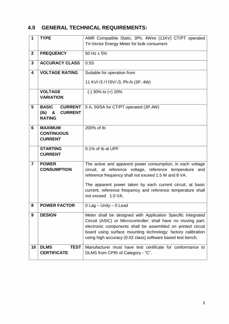
4.0 GENERAL TECHNICAL REQUIREMENTS:
1 TYPE AMR Compatible Static, 3Ph, 4Wire (11KV) CT/PT operated
Tri-Vector Energy Meter for bulk consumers
2 FREQUENCY 50 Hz ± 5%
3 ACCURACY CLASS 0.5S
4 VOLTAGE RATING Suitable for operation from
11 KV/√3 /110V/√3, Ph-N (3P, 4W)
VOLTAGE
VARIATION
(-) 30% to (+) 20%
5 BASIC CURRENT
(Ib) & CURRENT
RATING
5 A, 50/5A for CT/PT operated (3P,4W)
6 MAXIMUM
CONTINUOUS
CURRENT
200% of Ib
STARTING
CURRENT
0.1% of Ib at UPF
7 POWER
CONSUMPTION
The active and apparent power consumption, in each voltage
circuit, at reference voltage, reference temperature and
reference frequency shall not exceed 1.5 W and 8 VA.
The apparent power taken by each current circuit, at basic
current, reference frequency and reference temperature shall
not exceed 1.0 VA.
8 POWER FACTOR 0 Lag – Unity – 0 Lead
9 DESIGN Meter shall be designed with Application Specific Integrated
Circuit (ASIC) or Microcontroller; shall have no moving part;
electronic components shall be assembled on printed circuit
board using surface mounting technology; factory calibration
using high accuracy (0.02 class) software based test bench.
10 DLMS TEST
CERTIFICATE
Manufacturer must have test certificate for conformance to
DLMS from CPRI of Category - “C”.
4
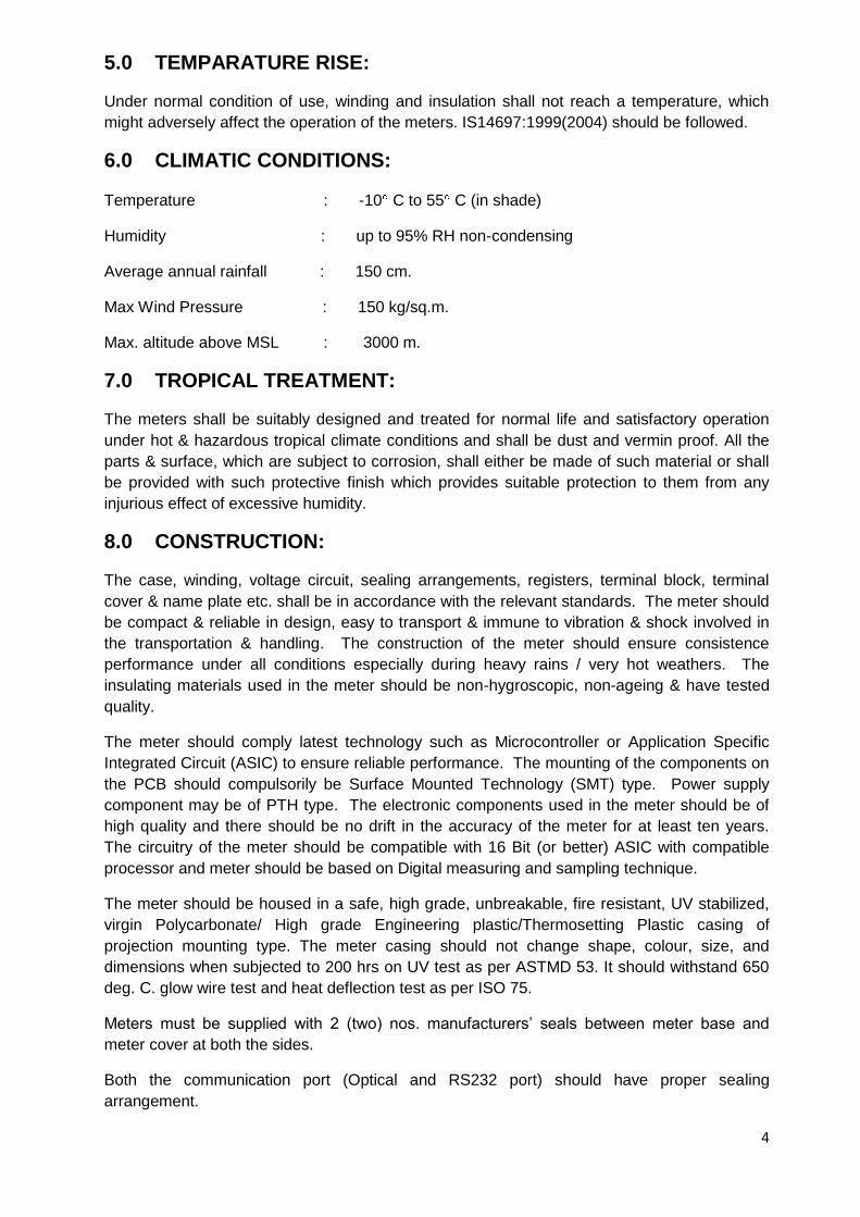
5.0 TEMPARATURE RISE:
Under normal condition of use, winding and insulation shall not reach a temperature, which
might adversely affect the operation of the meters. IS14697:1999(2004) should be followed.
6.0 CLIMATIC CONDITIONS:
Temperature : -10 C to 55 C (in shade)
Humidity : up to 95% RH non-condensing
Average annual rainfall : 150 cm.
Max Wind Pressure : 150 kg/sq.m.
Max. altitude above MSL : 3000 m.
7.0 TROPICAL TREATMENT:
The meters shall be suitably designed and treated for normal life and satisfactory operation
under hot & hazardous tropical climate conditions and shall be dust and vermin proof. All the
parts & surface, which are subject to corrosion, shall either be made of such material or shall
be provided with such protective finish which provides suitable protection to them from any
injurious effect of excessive humidity.
8.0 CONSTRUCTION:
The case, winding, voltage circuit, sealing arrangements, registers, terminal block, terminal
cover & name plate etc. shall be in accordance with the relevant standards. The meter should
be compact & reliable in design, easy to transport & immune to vibration & shock involved in
the transportation & handling. The construction of the meter should ensure consistence
performance under all conditions especially during heavy rains / very hot weathers. The
insulating materials used in the meter should be non-hygroscopic, non-ageing & have tested
quality.
The meter should comply latest technology such as Microcontroller or Application Specific
Integrated Circuit (ASIC) to ensure reliable performance. The mounting of the components on
the PCB should compulsorily be Surface Mounted Technology (SMT) type. Power supply
component may be of PTH type. The electronic components used in the meter should be of
high quality and there should be no drift in the accuracy of the meter for at least ten years.
The circuitry of the meter should be compatible with 16 Bit (or better) ASIC with compatible
processor and meter should be based on Digital measuring and sampling technique.
The meter should be housed in a safe, high grade, unbreakable, fire resistant, UV stabilized,
virgin Polycarbonate/ High grade Engineering plastic/Thermosetting Plastic casing of
projection mounting type. The meter casing should not change shape, colour, size, and
dimensions when subjected to 200 hrs on UV test as per ASTMD 53. It should withstand 650
deg. C. glow wire test and heat deflection test as per ISO 75.
Meters must be supplied with 2 (two) nos. manufacturers‟ seals between meter base and
meter cover at both the sides.
Both the communication port (Optical and RS232 port) should have proper sealing
arrangement.
5
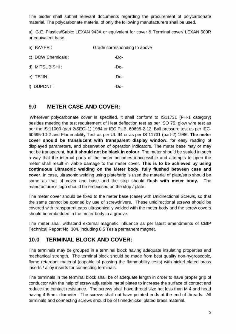
The bidder shall submit relevant documents regarding the procurement of polycarbonate
material. The polycarbonate material of only the following manufacturers shall be used.
a) G.E. Plastics/Sabic: LEXAN 943A or equivalent for cover & Terminal cover/ LEXAN 503R
or equivalent base.
b) BAYER : Grade corresponding to above
c) DOW Chemicals : -Do-
d) MITSUBISHI : -Do-
e) TEJIN : -Do-
f) DUPONT : -Do-
9.0 METER CASE AND COVER:
Wherever polycarbonate cover is specified, it shall conform to IS11731 (FH-1 category)
besides meeting the test requirement of Heat deflection test as per ISO 75, glow wire test as
per the IS:11000 (part 2/SEC–1) 1984 or IEC PUB, 60695-2-12, Ball pressure test as per IEC-
60695-10-2 and Flammability Test as per UL 94 or as per IS 11731 (part-2) 1986. The meter
cover should be translucent with transparent display window, for easy reading of
displayed parameters, and observation of operation indicators. The meter base may or may
not be transparent, but it should not be black in colour. The meter should be sealed in such
a way that the internal parts of the meter becomes inaccessible and attempts to open the
meter shall result in viable damage to the meter cover. This is to be achieved by using
continuous Ultrasonic welding on the Meter body, fully flushed between case and
cover. In case, ultrasonic welding using plate/strip is used the material of plate/strip should be
same as that of cover and base and the strip should flush with meter body. The
manufacturer‟s logo should be embossed on the strip / plate.
The meter cover should be fixed to the meter base (case) with Unidirectional Screws, so that
the same cannot be opened by use of screwdrivers. These unidirectional screws should be
covered with transparent caps ultrasonically welded with the meter body and the screw covers
should be embedded in the meter body in a groove.
The meter shall withstand external magnetic influence as per latest amendments of CBIP
Technical Report No. 304. including 0.5 Tesla permanent magnet.
10.0 TERMINAL BLOCK AND COVER:
The terminals may be grouped in a terminal block having adequate insulating properties and
mechanical strength. The terminal block should be made from best quality non-hygroscopic,
flame retardant material (capable of passing the flammability tests) with nickel plated brass
inserts / alloy inserts for connecting terminals.
The terminals in the terminal block shall be of adequate length in order to have proper grip of
conductor with the help of screw adjustable metal plates to increase the surface of contact and
reduce the contact resistance. The screws shall have thread size not less than M 4 and head
having 4-6mm. diameter. The screws shall not have pointed ends at the end of threads. All
terminals and connecting screws should be of tinned/nickel plated brass material.
6
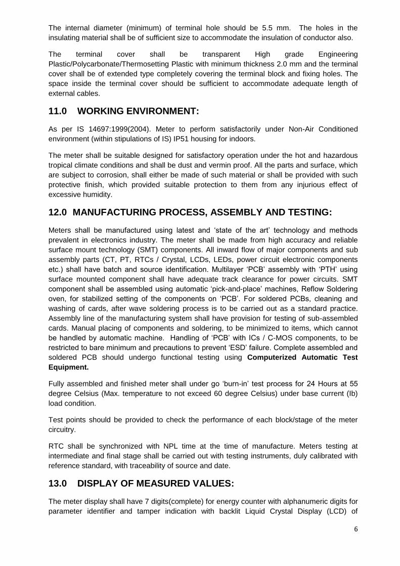
The internal diameter (minimum) of terminal hole should be 5.5 mm. The holes in the
insulating material shall be of sufficient size to accommodate the insulation of conductor also.
The terminal cover shall be transparent High grade Engineering
Plastic/Polycarbonate/Thermosetting Plastic with minimum thickness 2.0 mm and the terminal
cover shall be of extended type completely covering the terminal block and fixing holes. The
space inside the terminal cover should be sufficient to accommodate adequate length of
external cables.
11.0 WORKING ENVIRONMENT:
As per IS 14697:1999(2004). Meter to perform satisfactorily under Non-Air Conditioned
environment (within stipulations of IS) IP51 housing for indoors.
The meter shall be suitable designed for satisfactory operation under the hot and hazardous
tropical climate conditions and shall be dust and vermin proof. All the parts and surface, which
are subject to corrosion, shall either be made of such material or shall be provided with such
protective finish, which provided suitable protection to them from any injurious effect of
excessive humidity.
12.0 MANUFACTURING PROCESS, ASSEMBLY AND TESTING:
Meters shall be manufactured using latest and „state of the art‟ technology and methods
prevalent in electronics industry. The meter shall be made from high accuracy and reliable
surface mount technology (SMT) components. All inward flow of major components and sub
assembly parts (CT, PT, RTCs / Crystal, LCDs, LEDs, power circuit electronic components
etc.) shall have batch and source identification. Multilayer „PCB‟ assembly with „PTH‟ using
surface mounted component shall have adequate track clearance for power circuits. SMT
component shall be assembled using automatic „pick-and-place‟ machines, Reflow Soldering
oven, for stabilized setting of the components on „PCB‟. For soldered PCBs, cleaning and
washing of cards, after wave soldering process is to be carried out as a standard practice.
Assembly line of the manufacturing system shall have provision for testing of sub-assembled
cards. Manual placing of components and soldering, to be minimized to items, which cannot
be handled by automatic machine. Handling of „PCB‟ with ICs / C-MOS components, to be
restricted to bare minimum and precautions to prevent „ESD‟ failure. Complete assembled and
soldered PCB should undergo functional testing using Computerized Automatic Test
Equipment.
Fully assembled and finished meter shall under go „burn-in‟ test process for 24 Hours at 55
degree Celsius (Max. temperature to not exceed 60 degree Celsius) under base current (Ib)
load condition.
Test points should be provided to check the performance of each block/stage of the meter
circuitry.
RTC shall be synchronized with NPL time at the time of manufacture. Meters testing at
intermediate and final stage shall be carried out with testing instruments, duly calibrated with
reference standard, with traceability of source and date.
13.0 DISPLAY OF MEASURED VALUES:
The meter display shall have 7 digits(complete) for energy counter with alphanumeric digits for
parameter identifier and tamper indication with backlit Liquid Crystal Display (LCD) of
7
minimum 10 mm height, wide viewing angle suitable for temperature withstand of 70° C. LCD
to be of „STN‟ (super twisted numeric) type construction.
The data stored in the meters shall not be lost in the event of power failure. The meter shall
have Non Volatile Memory (NVM), which does not need any battery backup. The NVM shall
have a minimum retention period of 10 years.
Meter shall have Scroll Lock facility to display any one desired parameter continuously from
display parameters.
Auto display cycling of each parameter should be minimum 10-12 Seconds. The time between
two auto display cycles shall preferably be within 120 sec. OBIS code in display is optional .
It should be possible to easily identify the single or multiple displayed parameters through
symbols/legend on the meter display itself or through display annunciation.
AUTO MODE:
i) LCD Test
ii) Rising Apparent Demand with elapsed time
iii) Real Time & Date (DD/MM/YYYY)
iv) Cumulative Power off Hours
v) Cumulative Total Active Energy (with high resolution)
vi) Cumulative Total Reactive Energy Lag (with high resolution)
vii) Cumulative Total Reactive Energy Lead (with high resolution)
viii) Cumulative Apparent Energy (with high resolution) – Lag Only
viii) Apparent Max. Demand (with high resolution) – Lag Only
ix) TOD Wise Total Active Energies
x) TOD Wise Apparent Energies
xi) TOD Wise Apparent Max. Demand (MD)
xii) Cumulative Apparent Maximum Demand
xiii) Cumulative Billing Count
xiv) Cumulative Tamper Count
xv) Phase Sequence
xvi) Connection Check
xvii) Self Diagnosis
PUSH BUTTON MODE:
i) LCD Test
ii) Rising Apparent Demand with elapsed time
8
iii) Real Time & Date (DD/MM/YYYY)
iv) Cumulative Power off Hours
v) Cumulative Total Active Energy (with high resolution)
vi) Cumulative Total Reactive Energy Lag (with high resolution)
vii) Cumulative Total Reactive Energy Lead (with high resolution)
viii) Cumulative Apparent Energy (with high resolution) – Lag Only
ix) Apparent Max. Demand (with high resolution) – Lag Only
x) TOD Wise Total Active Energies
xi) TOD Wise Apparent Energies
xii) TOD Wise Apparent Max. Demand (MD)
xiii) Cumulative Apparent Maximum Demand
xiv) Cumulative Billing Count
xv) Cumulative Tamper Count
xvi) Cumulative Programming Count
xvii) Last Billing Date & Time
xviii) Inst. Secondary Voltages – Phase Wise (Ph-N for 3-Ph, 4-Wire)
xix) Inst. Secondary Currents – Phase Wise & Neutral
xx) Signed Inst. Power Factor – Phase Wise
xxi) Three Phase Power Factor
xxii) Signed Inst. Active Power,
xxiii) Inst. Apparent Power
xxiv) Inst. Frequency
xxv) Present Tamper Status (PT/CT/Other)
xxvi) First Occurrence with Date & Time
xxvii) Last Occurrence with Date & Time
xxviii) Last Restoration with Date & Time
xxix) Phase Sequence
xxx) Connection Check
xxxi) Self Diagnosis
9
The register shall be able to record and display starting from zero, for a minimum of 1500
hours, the energy corresponding to rated maximum current at reference voltage and unity
power factor. The register should not roll over in between this duration.
High resolution registers required in display min 4 digits (for kWh/kVArh/kVAh) and 6 digit (for
MWh/MVArh/MVAh) after decimal in case of Energy & Min 1 to 2 digits after decimal in case of
Demand.
Push button mechanism should be of high quality and should provide trouble free service for a
long span of time. Up and Down scrolling facility should be there for Push Button Mode.
14.0 MAXIMUM DEMAND:
The meter should be capable of recording the Apparent/Active MD with integration period of
15 minutes.
MD RESET OPTION
i) Billing Date at 24:00 Hrs (Programmable)
ii) Push button
iii) By Authenticated Command from BCS through HHU or directly from PC/REMOTE
MD reset button should have proper sealing arrangement.
15.0 PERFORMANCE UNDER INFLUENCE QUANTITIES:
The meters performance under influence quantities shall be governed by IS 14697:1999
(2004) and CBIP 304. The accuracy of meter shall not exceed the permissible limits of
accuracy as per standard IS 14697:1999(2004) and CBIP 304.
16.0 OUTPUT DEVICE:
Energy Meter shall have test output, accessible from the front, and be capable of being
monitored with suitable testing equipment while in operation at site. The operation indicator
must be visible from the front and test output device shall be provided in the form of LED.
Resolution of the test output device shall be sufficient to enable the starting current test in less
than 10 minutes. Minimum gap should be maintained between Active & Reactive Test LED.
17.0 REAL TIME INTERNAL CLOCK (RTC):
RTC shall be pre-programmed for more than 20 Years Day/date is preferable without any
necessity for correction. The maximum drift shall not exceed ± 300 Seconds per year.
The clock day/date setting and synchronization shall only be possible through password/Key
code command from one of the following:
10
a) Hand Held Unit (HHU) or directly through BCS and this shall be authenticated from BCS for
individual meter.
b) From remote server through suitable communication network with authentication from BCS.
18.0 TIME OF DAY FACILITIES:
The meter should have facilities to record Active, Apparent Energies and MD with a facility of
8 time zones. The time zones should be user programmable through authenticated command
from BCS with the help of HHU. Necessary software for the same has to be provided.
19.0 METER READING DURING POWER OFF:
It should be possible to read the meter-display visually and with MRI and in absence of input
voltages with the help of internal battery for display in power off condition or external battery
pack/PPU. The interface preferred will be inductive coupling.
20.0 BASE COMPUTER SOFTWARE (BCS): Exclusively used for
the manufacturers meter only.
The BCS should be user friendly. Windows XP and Windows 7 based BCS shall be
supplied. The data transfer should be reliable and fraud proof. BCS should give all details
pertaining to billing and load survey data. The meter condition details should also be
transferred into the BCS including abnormalities/anomalies of voltage current conditions or
tamper conditions which can occur due to mistake in connections or intentionally done for the
purpose of tamper.
The software should show electrical conditions existing at the time of reading the meter in
tabular forms as well as in graphical format (Phase diagram).
All the information about energy, maximum demand and their respective TOD register
readings, billing register readings and billing history readings should be shown in a manner
which user can understand quickly, preferably in tabular format.
All the load survey data should be available in numerical as well as graphical format. It should
also be possible to view this data in daily, weekly and monthly formats. The load survey graph
should show values.
All the information about tamper events should be accompanied with date and time stamping
along with the „SNAPSHOT‟ (details) of the respective electrical conditions. This information
should be displayed in the sequence in which it happened, in cumulative format as well as in
summary format. The cumulative format should segregate a particular tamper information and
summary report should show count of tamper occurrence, restoration and the duration for
which meter has remained under tamper condition.
Facility to view data incorporating External multiplying factor due to Installed CTs & PT should
be provided.
The software should be capable of preparing CMRI to read the meter information or to
reconfigure the meter to change the setting of the meter as per IS 15959:2011.
The BCS should have the facility for ASCII conversion of all recorded meter data. There
should be "user friendly" approach for viewing meter data for the reading collected now or for
the reading collected in the past. All information about a particular consumer should be
11
segregated and available at one place so that locating any consumer's past data is easy. It
should be possible to locate/retrieve data on the basis of one of the following particulars:
a) Consumer ID/Number.
b) Meter Sr. No.
c) Date of meter reading.
d) Location.
The BCS shall have multi level password for data protection and security. The first level
should allow the user to enter the system. The different software features shall be protected by
different passwords. The configuration of passwords should be user definable. The software
installed on one PC should not be copy-able on to another PC.
It is very important that the BCS has the feature to export available data to ASCII format
for integrating with the WBSEDCL's billing system. Here again a "Wizard" utility should
be available whereby user can select file format (for ASCII), what data to export, the
field width selection (whether 8 characters or 10 characters, to include decimal point or
not, number of digits after decimal point) etc.
Help should be available with the software so that user can use all the features of the software
by just reading the Help contents.
21.0 LOAD SURVEY: The meter should be capable of recording load survey data of Phase wise current, Phase
wise Voltage, Active Energy, Apparent Energy, Apparent Demand for a period of minimum
35 days for 15-minute integration period.
22.0 MEASUREMENT OF ENERGY:
The meter should be capable of measuring fundamental energy as well total energy i.e.
fundamental plus Harmonics energy. Total Energy shall be made available on meter-display
and the same only shall be used for billing purpose.
The Fundamental Energy shall be logged in the meter & show in display.
23.0 MARKING OF METERS:
Every meter shall have a nameplate clearly visible and indelible and distinctly marked in
accordance with the relevant Standard mentioning Category - C. The following information
should appear on an external plate attached to the meter cover.
i) Manufacturers Name or trademark and place of manufacture. ii) Designation of type. iii) Number of phases and wires. iv) Serial number of meter. v) Month and year of manufacture. vi) Principal unit of measurement. vii) P.T. Ratio. viii) Basic Current and rated maximum current. ix) C.T. Ratio. x) Reference frequency in Hz. xi) Meter constant (impulse/unit).
12
xii) Class index of meter. xiii) Reference temperature. xiv) “ Property of WBSEDCL” xv) Purchaser‟s Order No. & Date. xvi) Guarantee for 5 & ½ years from the date of supply. xvii) Sign. of insulation. xviii) Bar coding of Serial Number, month & year of manufacture.
The meter shall also store name plate details as given in the Annexure – F of IS 15959:2011
24.0 COMMUNICATION CAPABILITY:
The meter shall be provided with two ports for communication of the measured/collected data.
The hardware port (with sealing facility) compatible with RS 232 specifications which shall be
used for remote access through suitable Modem and an Optical port complying with hardware
specifications detailed in IEC-62056-21. This shall be used for local data downloading through
a DLMS compliant HHU or direct through BCS.
Both ports shall support the default and minimum baud rate of 9600 bps.
Optical Cord (i.e. Optical Port of Meter to PC) preferably is USB type. Direct serial port
(9pin) is not acceptable.
Data downloading time from meter to HHU/PC should be within 10 min (all data)
25.0 HAND HELD UNIT (HHU):
To enable local reading of meters data a DLMS compliant HHU (Windows Based) shall be
used. The HHU shall be as per IS 15959:2011. It shall be compatible to the DLMS compliant
energy meters that are to be procured / supplied on the basis of the specification having at
least one USB communication port.
26.0 TAMPER & FRAUD MONITORING FEATURES:
The meter shall work satisfactorily under presence of various influencing conditions like
External Magnetic Field, Electromagnetic Field, Radio Frequency Interference, Vibrations,
Harmonic Distortion, Voltage/Frequency Fluctuations, and Electromagnetic High Frequency
Fields etc. The meter shall be immune to abnormal voltage/frequency generating devices and
shall record the occurrence and restoration of all tampers and related snapshots as per
Annexure – G of IS 15959:2011
The accuracy of meter should not be affected with the application of abnormal voltage/
frequency generating device such as spark discharge of approximately 35 kV.
The meters should work even in the presence of any two Potential wires.
Meter should work correctly irrespective of phase sequence.
Meter should work correctly without neutral wire.
Also, Meter should also be immune for tamper by application of remote induction device i.e.
radiated spark through Jammer circuit.
Meter should record Invalid Phase Association Tamper.
13
Tamper details shall be stored in internal memory for retrieval by authorized personnel through
either of the following:
Multiple Tamper should not occur for a particular tamper situation.
a) DLMS compliant HHU.
b) Remote access through suitable communication network.
c) Direct by PC.
Minimum 400 numbers preferable (compartment wise) of events (i.e. 200 no. events for
occurrences & 200 no. events for restoration with date & time and snapshot) should be
available in the meter memory.
Default occurrence and restoration time should not be less than 3 minutes and not
more than 5 minutes (except magnetic Tamper) but it shall be programmable.
All the tamper information logged by the meter should be available in BCS with snapshot, Date
& Time as per Table 39 of IS 15959:2011 with occurrence and restoration.
Properly designed meter tamper logic with threshold value, should be provided and clearly
explained in the bid. The tamper logic should be capable of discriminating the system
abnormalities from source side and load side and it should not log / record tamper due
to source side abnormalities. The meter should be able to distinguish between HT PT
fuse blowing and Single Phasing and record the former.
27.0 TYPE TESTS:
Meters shall be fully type tested as per relevant Standard (latest version). The type test
certificates should be submitted along with the offer. Offer without Type Test Report shall be
liable for rejection. The type test certificate shall not be more than five years old.
28.0 ACCEPTANCE & ROUTINE TESTS:
All acceptance tests as per relevant standards shall be carried out in the presence of utility representatives.
Further Purchaser shall reserve the right to pick up energy meters at random from the lots
offered and get the meter tested from NABL accredited lab. The supplier has no right to
contest the test results NABL accredited lab or for additional test and has to replace/take
corrective action at the cost of the supplier.
29.0 INSPECTION:
The inspection shall be carried out at any stage of manufacture, by the WBSEDCL authorized
representatives, with prior intimation to the supplier. The manufacturer shall grant all
reasonable facilities for testing free of charge for inspection and testing to satisfy the
purchaser that the materials to be supplied are in accordance with their specification.
The supplier shall keep the WBSEDCL informed in advance, about the manufacturing
program so that the arrangement can be made for inspection.
14
The representative / Engineer of the WBSEDCL attending the above testing shall carry out
testing as per relevant standards and issue test certificate approval to the manufacturer and
give clearance for dispatch.
30.0 QUALITY ASSURANCE:
The manufacturer shall have a comprehensive quality assurance program at all stages of
manufacture for ensuring products giving reliable, trouble free performance. Details of the
bidder‟s quality assurance and test set up shall be furnished with the bid. A detailed quality
assurance program shall be finalized with the successful bidder during the award stage.
Bidder shall furnish following information along with his bid:
a) Organization structure of the manufacturer and his main sub-suppliers (PCBs, SMT cards,
CT/PT) with details of „QA‟ setup, overall workflow.
b) Copy of system manual showing „QAP‟ (Quality Assurance Plan) as actually practiced
during manufacturing and final testing.
c) List of raw materials and critical components (ASIC chip, crystal clock, memory
register Chip, transformers, optical ports etc.) with their suppliers and procurement
details.
d) Stage inspection of product before final testing.
e) Procedure adopted for „In-situ‟ testing of PCBs, after placement of surface mounted
component, for quantitative parametric variation of tolerance by self or sub-contractor.
f) Testing and calibration facility, date of calibration of test bench, manpower data of bench
operators;
g) Sample copies of test certificate of bought out components.
31.0 TESTING FACILITIES:
The Bidder shall have Auto Test Bench facilities and at least the following testing facilities to
ensure accurate calibration:
a) Insulation resistance measurement
b) Starting current test
c) Running at no load
d) Limits of error
e) Dial Test
f) Tamper Test
h) Power loss in voltage and current ckt.
i) Transportation test
i) Ageing Test
15
The Bidder shall give a detailed list of bought out items with name of the manufacturer and
details about quality control.
32.0 GUARANTEE:
Equipment (Meter) supplied shall be guaranteed for a period of 66 months from the date of
supply or 5 years from the date of installation, whichever is earlier. Bidders shall guarantee to
replace the meters, which are found to be defective/ inoperative at the time of installation, or
become inoperative/ defective during guarantee period. Replacements shall be effected within
1 month from the date of intimation.
To cover the back up guarantee, the 2nd part bank guarantee i.e. 2.5% of the ordered value
shall be valid for a total period of 7½ years and an additional claim period of six months after
the date of expiry of validity period.
33.0 FIXING & SEALING ARRANGEMENT:
Every meter shall have three fixing holes one at the top and two at the bottom. The top hole
shall be provided with a special clip at the back of the meter so that holding screw is not
accessible to the consumer after the fixing of the meters. The lower fixing screws shall be
provided under the sealed terminal cover. The requisite fixing screws shall be supplied with
each meter.
The manufacturers seal (two nos.) provided with the meter should be of high quality with
tamper proof features. Necessary provision shall be kept for fixing utility seal also.
34.0 Supply of Power Pack, HHU, Communication Cord: (HHU to PC
& Meter to PC)
For every 100 nos. of meters and part thereof one power pack (if not internal battery) and one
HHU(Windows Based) & 20 nos. communication cord for each type should be supplied free
of cost. The guarantee period of HHU and Power Pack will be of 66 months from the date of
supply.
35.0 SUBMISSION OF SAMPLE & DOCUMENTS:
While submitting the Quotation to the Chief Engineer, Procurement & Contract, Vidyut
Bhavan, 4th Floor, B – Block Kolkata- 700 091, a sample meter having all the mentioned
features, BCS with allied software and sample of seal etc. along with the Type Test
Certificates, DLMS Certificate and with the test results and ISI Certificate, Tamper
Logic, Display Parameters List and other relevant documents are to be submitted to C.E.
(DTD), Abhikshan within 12:00 hrs. on the due date of opening of tender and copy of letter
indicating acceptance of Sample by the Office of the C.E. (DTD) is to be submitted to the Chief
Engineer, (Procurement & Contract) during submission of tender documents. Tender
documents are to be submitted within 14:00 hrs. on the due date of opening of tender. Offer
will not be accepted without submission of sample and the Tender will not be opened. Any
other accessories required for observing the performance & capabilities of the Meter are to be
submitted along with offer.
16
Sample meters shall be submitted along with 1 no. ultrasonically welded case and cover to
C.E. (DTD). A confirmation from C.E. (DTD) regarding submission of sample as detailed below
shall have to be submitted along with the Techno-Commercial Bid.
3-Phase 4-Wire 11KV, 50/5A. Class of Accuracy 0.5s meter – 2Nos.
HHU, Power-Pack, Modem along with SIM Card, if required, to be brought at the time of
testing of sample meters, submitted against the tender.
36.0 SCHEDULES:
The Bidder shall submit the following schedules (as per Standard Format), which is part and
parcel of the Specification.
Schedule A Guaranteed Technical Particulars Schedule B List of Raw Material(as per enclosed format) Schedule C Pre Qualification Condition Schedule D List of Documents to be submitted during sample submission Schedule E Component Specifications Schedule F Deviations from Specified Standards (As per standard format of the Bidder) Schedule G Deviations from Specified Test Requirements (As per standard format of the Bidder) Schedule H Deviations from Technical Specification (As per Annexure –IV – Deviation sheet of GCC) Schedule I Bidders Experience (As per standard format of the bidder and also Copies of order executed along with GTP of the supplied meters.)
*********************
17
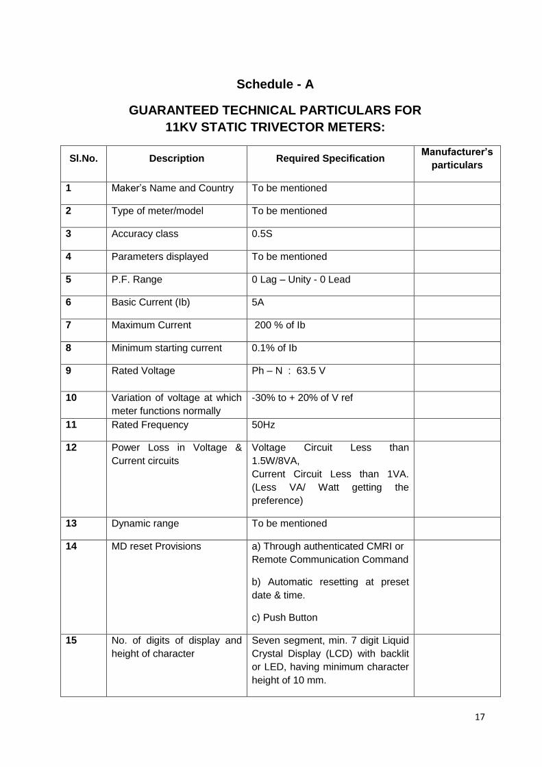
Schedule - A
GUARANTEED TECHNICAL PARTICULARS FOR
11KV STATIC TRIVECTOR METERS:
Sl.No. Description Required Specification Manufacturer‟s
particulars
1 Maker‟s Name and Country To be mentioned
2 Type of meter/model To be mentioned
3 Accuracy class 0.5S
4 Parameters displayed To be mentioned
5 P.F. Range 0 Lag – Unity - 0 Lead
6 Basic Current (Ib) 5A
7 Maximum Current 200 % of Ib
8 Minimum starting current 0.1% of Ib
9 Rated Voltage Ph – N : 63.5 V
10 Variation of voltage at which
meter functions normally
-30% to + 20% of V ref
11 Rated Frequency 50Hz
12 Power Loss in Voltage &
Current circuits
Voltage Circuit Less than
1.5W/8VA,
Current Circuit Less than 1VA.
(Less VA/ Watt getting the
preference)
13 Dynamic range To be mentioned
14 MD reset Provisions a) Through authenticated CMRI or
Remote Communication Command
b) Automatic resetting at preset
date & time.
c) Push Button
15 No. of digits of display and
height of character
Seven segment, min. 7 digit Liquid
Crystal Display (LCD) with backlit
or LED, having minimum character
height of 10 mm.
18
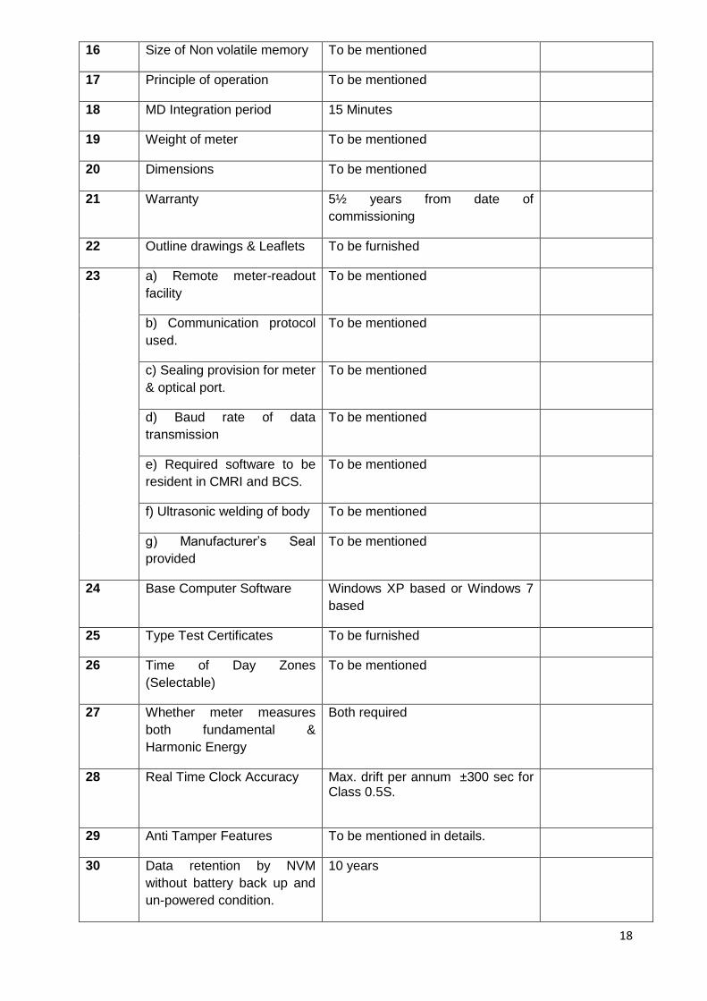
16 Size of Non volatile memory To be mentioned
17 Principle of operation To be mentioned
18 MD Integration period 15 Minutes
19 Weight of meter To be mentioned
20 Dimensions To be mentioned
21 Warranty 5½ years from date of
commissioning
22 Outline drawings & Leaflets To be furnished
23
a) Remote meter-readout
facility
To be mentioned
b) Communication protocol
used.
To be mentioned
c) Sealing provision for meter
& optical port.
To be mentioned
d) Baud rate of data
transmission
To be mentioned
e) Required software to be
resident in CMRI and BCS.
To be mentioned
f) Ultrasonic welding of body To be mentioned
g) Manufacturer‟s Seal
provided
To be mentioned
24 Base Computer Software Windows XP based or Windows 7
based
25 Type Test Certificates To be furnished
26 Time of Day Zones
(Selectable)
To be mentioned
27 Whether meter measures
both fundamental &
Harmonic Energy
Both required
28
Real Time Clock Accuracy Max. drift per annum ±300 sec for Class 0.5S.
29 Anti Tamper Features To be mentioned in details.
30 Data retention by NVM
without battery back up and
un-powered condition.
10 years
19
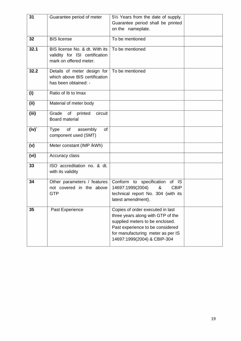
31 Guarantee period of meter 5½ Years from the date of supply.
Guarantee period shall be printed
on the nameplate.
32 BIS license To be mentioned
32.1 BIS license No. & dt. With its
validity for ISI certification
mark on offered meter.
To be mentioned
32.2 Details of meter design for
which above BIS certification
has been obtained: -
To be mentioned
(i) Ratio of Ib to Imax
(ii) Material of meter body
(iii) Grade of printed circuit
Board material
(iv)` Type of assembly of
component used (SMT)
(v) Meter constant (IMP /kWh)
(vi) Accuracy class
33 ISO accreditation no. & dt.
with its validity
34 Other parameters / features
not covered in the above
GTP
Conform to specification of IS
14697:1999(2004) & CBIP
technical report No. 304 (with its
latest amendment).
35 Past Experience Copies of order executed in last
three years along with GTP of the
supplied meters to be enclosed.
Past experience to be considered
for manufacturing meter as per IS
14697:1999(2004) & CBIP-304
20
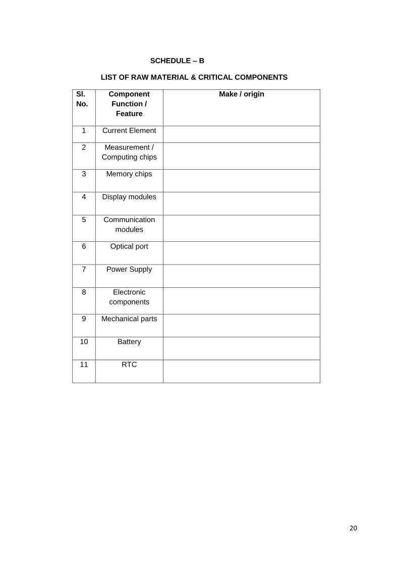
SCHEDULE – B
LIST OF RAW MATERIAL & CRITICAL COMPONENTS
Sl.
No.
Component
Function /
Feature
Make / origin
1 Current Element
2 Measurement /
Computing chips
3 Memory chips
4 Display modules
5 Communication
modules
6 Optical port
7 Power Supply
8 Electronic
components
9 Mechanical parts
10 Battery
11 RTC
21
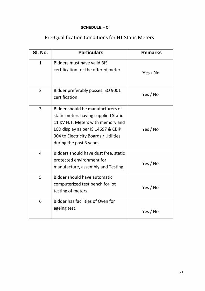
SCHEDULE – C
Pre-Qualification Conditions for HT Static Meters
Sl. No. Particulars Remarks
1 Bidders must have valid BIS
certification for the offered meter.
Yes / No
2 Bidder preferably posses ISO 9001
certification Yes / No
3 Bidder should be manufacturers of
static meters having supplied Static
11 KV H.T. Meters with memory and
LCD display as per IS 14697 & CBIP
304 to Electricity Boards / Utilities
during the past 3 years.
Yes / No
4 Bidders should have dust free, static
protected environment for
manufacture, assembly and Testing.
Yes / No
5 Bidder should have automatic
computerized test bench for lot
testing of meters.
Yes / No
6 Bidder has facilities of Oven for
ageing test.
Yes / No
22
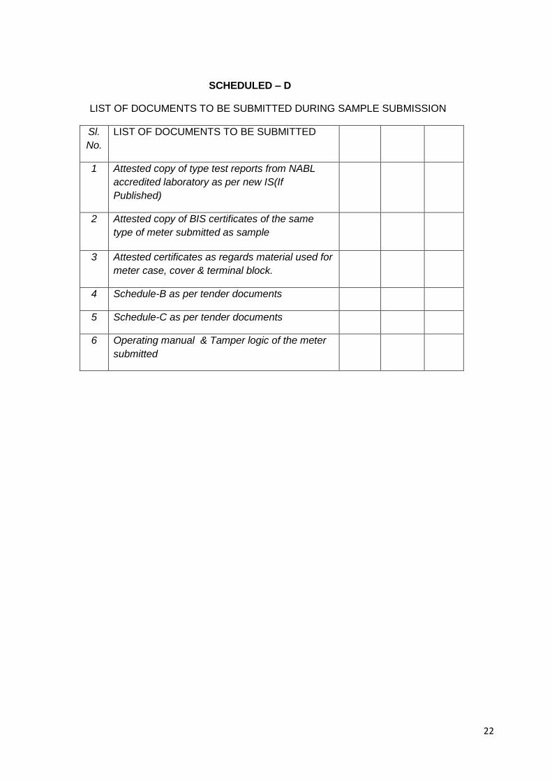
SCHEDULED – D
LIST OF DOCUMENTS TO BE SUBMITTED DURING SAMPLE SUBMISSION
Sl.
No.
LIST OF DOCUMENTS TO BE SUBMITTED
1 Attested copy of type test reports from NABL
accredited laboratory as per new IS(If
Published)
2 Attested copy of BIS certificates of the same
type of meter submitted as sample
3 Attested certificates as regards material used for
meter case, cover & terminal block.
4 Schedule-B as per tender documents
5 Schedule-C as per tender documents
6 Operating manual & Tamper logic of the meter
submitted
23
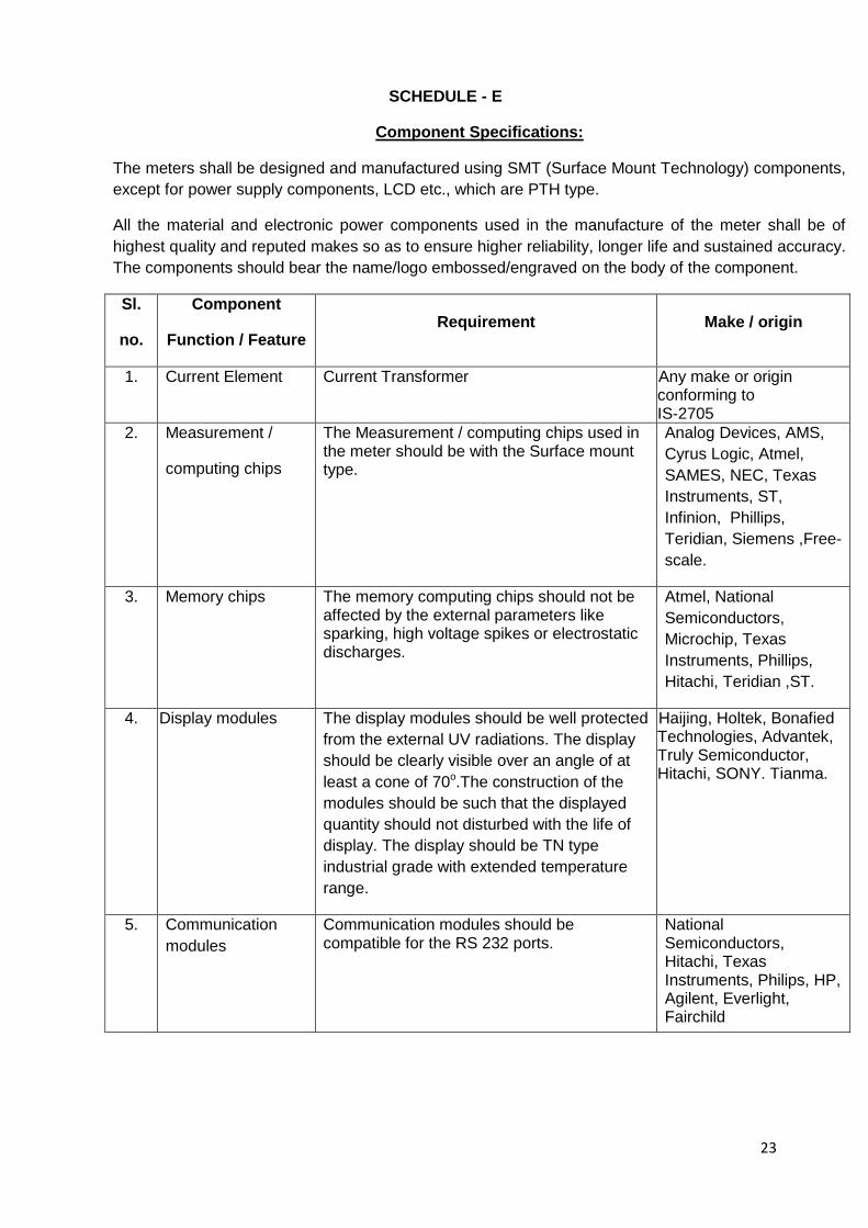
SCHEDULE - E
Component Specifications:
The meters shall be designed and manufactured using SMT (Surface Mount Technology) components,
except for power supply components, LCD etc., which are PTH type.
All the material and electronic power components used in the manufacture of the meter shall be of
highest quality and reputed makes so as to ensure higher reliability, longer life and sustained accuracy.
The components should bear the name/logo embossed/engraved on the body of the component.
Sl.
no.
Component
Function / Feature Requirement Make / origin
1. Current Element Current Transformer Any make or origin conforming to IS-2705
2. Measurement /
computing chips
The Measurement / computing chips used in the meter should be with the Surface mount type.
Analog Devices, AMS,
Cyrus Logic, Atmel,
SAMES, NEC, Texas
Instruments, ST,
Infinion, Phillips,
Teridian, Siemens ,Free-
scale.
3. Memory chips
The memory computing chips should not be affected by the external parameters like sparking, high voltage spikes or electrostatic discharges.
Atmel, National
Semiconductors,
Microchip, Texas
Instruments, Phillips,
Hitachi, Teridian ,ST.
4. Display modules The display modules should be well protected
from the external UV radiations. The display
should be clearly visible over an angle of at
least a cone of 70o.The construction of the
modules should be such that the displayed
quantity should not disturbed with the life of
display. The display should be TN type
industrial grade with extended temperature
range.
Haijing, Holtek, Bonafied Technologies, Advantek, Truly Semiconductor, Hitachi, SONY. Tianma.
5. Communication
modules
Communication modules should be compatible for the RS 232 ports.
National Semiconductors, Hitachi, Texas Instruments, Philips, HP, Agilent, Everlight, Fairchild
24
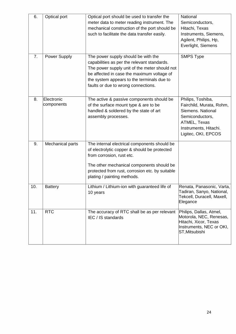
6. Optical port
Optical port should be used to transfer the
meter data to meter reading instrument. The
mechanical construction of the port should be
such to facilitate the data transfer easily.
National
Semiconductors,
Hitachi, Texas
Instruments, Siemens,
Agilent, Philips, Hp,
Everlight, Siemens
7. Power Supply
The power supply should be with the
capabilities as per the relevant standards.
The power supply unit of the meter should not
be affected in case the maximum voltage of
the system appears to the terminals due to
faults or due to wrong connections.
SMPS Type
8. Electronic components
The active & passive components should be
of the surface mount type & are to be
handled & soldered by the state of art
assembly processes.
Philips, Toshiba,
Fairchild, Murata, Rohm,
Siemens. National
Semiconductors,
ATMEL, Texas
Instruments, Hitachi.
Ligitec, OKI, EPCOS
9. Mechanical parts
The internal electrical components should be
of electrolytic copper & should be protected
from corrosion, rust etc.
The other mechanical components should be
protected from rust, corrosion etc. by suitable
plating / painting methods.
10. Battery
Lithium / Lithium-ion with guaranteed life of
10 years
Renata, Panasonic, Varta, Tadiran, Sanyo, National, Tekcell, Duracell, Maxell, Elegance
11. RTC The accuracy of RTC shall be as per relevant
IEC / IS standards
Philips, Dallas, Atmel, Motorola, NEC, Renesas, Hitachi, Xicor, Texas Instruments, NEC or OKI, ST,Mitsubishi

25
Related Documents