Customer Name: J.Ray McDermott Proposal Number: 8781-1 Rev 00 Project Name: DB-32 – AmClyde Model 50 Date: May 6, 2011 AmClyde™ Model 50 1500MT Heavy Lift Crane Proposal No.8781-1 May 6, 2011 Prepared for: J.Ray McDermott DB-32 Hydralift AmClyde, Inc. 240 East Plato Boulevard St. Paul, Minnesota 55107 Phone: 651 293-4646 Fax: 651 293-4648 The contents of this proposal are the property of Hydralift AmClyde, Inc. and are confidential between Hydralift AmClyde, Inc. and the customer. The contents may not be duplicated or distributed without the written consent of Hydralift AmClyde, Inc.

Technical Spec P-8781-1 Rev 00
Nov 27, 2015
M50 pedestal crane
Welcome message from author
This document is posted to help you gain knowledge. Please leave a comment to let me know what you think about it! Share it to your friends and learn new things together.
Transcript

Customer Name: J.Ray McDermott Proposal Number: 8781-1 Rev 00 Project Name: DB-32 – AmClyde Model 50 Date: May 6, 2011
AmClyde™ Model 50 1500MT Heavy Lift Crane
Proposal No.8781-1 May 6, 2011
Prepared for:
J.Ray McDermott DB-32
Hydralift AmClyde, Inc. 240 East Plato Boulevard St. Paul, Minnesota 55107 Phone: 651 293-4646 Fax: 651 293-4648
The contents of this proposal are the property of Hydralift AmClyde, Inc. and are confidential between Hydralift AmClyde, Inc. and the customer. The contents may not be duplicated or distributed without the written consent of Hydralift AmClyde, Inc.
Customer Name: J.Ray McDermott Proposal Number: 8781-1 Rev 00 Project Name: DB-32 – AmClyde Model 50 Date: May 6, 2011
Page 2 of 35
TABLE OF CONTENTS
PROPOSAL NO.8781-1 ................................................................................................................................ 1 MAY 6, 2011 ............................................................................................................................................... 1
1 INTRODUCTION AND SCOPE OF SUPPLY .......................................................................... 4 1.1 SCOPE ........................................................................................................................................... 4 1.2 CONTRACTOR’S OBLIGATION .................................................................................................... 4 1.3 EXCLUSIONS ................................................................................................................................ 4
2 REGULATIONS, STANDARDS, AND CODES ....................................................................... 5 2.1 GENERAL ...................................................................................................................................... 5 2.2 AUTHORITIES ............................................................................................................................... 5 2.3 INDUSTRY STANDARDS .............................................................................................................. 5 2.4 CERTIFICATION ............................................................................................................................ 5 2.5 DESIGN BASIS .............................................................................................................................. 6
2.5.1 GENERAL PHILOSOPHY ...................................................................................................................... 6 2.5.2 UTILIZATION .......................................................................................................................................... 6 2.5.3 ENVIRONMENTAL CONDITIONS ......................................................................................................... 6
2.6 QUALITY ASSURANCE/QUALITY CONTROL .............................................................................. 7 2.6.1 MATERIAL TRACEABILITY ................................................................................................................... 7 2.6.2 CASTING/FORGING INSPECTION ....................................................................................................... 7 2.6.3 FABRICATION INSPECTION ................................................................................................................. 7
3 CRANE CAPACITIES, PERFORMANCE, AND SPECIFICS .................................................. 8 3.1 RATING AND DESIGN CONDITIONS ............................................................................................ 8 3.2 MAIN, AUX, & WHIP FALL CAPACITIES ..................................................................................... 10 3.3 PERFORMANCE .......................................................................................................................... 11 3.4 CRITICAL DIMENSIONS .............................................................................................................. 11
3.4.1 CRANE (GENERAL) ............................................................................................................................. 11 3.4.2 FOUNDATION ...................................................................................................................................... 11 3.4.3 BOOM LENGTH .................................................................................................................................... 11
3.5 STRUCTURAL.............................................................................................................................. 12 3.5.1 GENERAL ............................................................................................................................................. 12 3.5.2 ROTATING DECK ................................................................................................................................. 12 3.5.3 MACHINERY CAB ................................................................................................................................ 12 3.5.4 A-FRAME & BACKLEG ........................................................................................................................ 13 3.5.5 WALKWAYS, STAIRS AND LADDERS ................................................................................................ 13 3.5.6 BOOM ................................................................................................................................................... 14 3.5.7 BOOM HINGE PIN ASSEMBLY ........................................................................................................... 15 3.5.8 BOOM STOPS ...................................................................................................................................... 15 3.5.9 SHEAVES ............................................................................................................................................. 15
3.6 ROTATING GEAR ........................................................................................................................ 15 3.6.1 CENTER PIN ASSEMBLY .................................................................................................................... 16 3.6.2 SPUD LOCK ......................................................................................................................................... 16 3.6.3 SLEWING MACHINERY ....................................................................................................................... 17 3.6.4 BULLGEAR ........................................................................................................................................... 18 3.6.5 CONTAINER RING ROLLER SYSTEM ................................................................................................ 18 3.6.6 HOOK ROLLER SYSTEM .................................................................................................................... 18
Customer Name: J.Ray McDermott Proposal Number: 8781-1 Rev 00 Project Name: DB-32 – AmClyde Model 50 Date: May 6, 2011
Page 3 of 35
3.7 TUB & TUB COLLAR DESIGN ..................................................................................................... 19 3.8 WIRE ROPE AND TACKLE .......................................................................................................... 19
3.8.1 WIRE ROPE .......................................................................................................................................... 19 3.8.2 TACKLE DATA ...................................................................................................................................... 19 3.8.3 HOOKS ................................................................................................................................................. 20 3.8.4 BLOCKS ................................................................................................................................................ 20
3.9 MECHANICAL .............................................................................................................................. 21 3.9.1 MAIN HOIST MACHINERY .................................................................................................................. 21 3.9.2 BOOM HOISTING SYSTEM ................................................................................................................. 23 3.9.3 TUGGER WINCHES ............................................................................................................................. 24 3.9.4 PNEUMATIC SYSTEM ......................................................................................................................... 25 3.9.5 LUBRICATION ...................................................................................................................................... 25
3.10 ELECTRICAL ............................................................................................................................... 26 3.10.1 LIGHTING ............................................................................................................................................. 26 3.10.2 ELECTRICAL HOUSE AIR CONDITIONER ......................................................................................... 28 3.10.3 ELECTRICAL RECEPTICALS .............................................................................................................. 28 3.10.4 CRANE POWER ................................................................................................................................... 28 3.10.5 COLLECTOR RINGS ............................................................................................................................ 29
3.11 OPERATOR’S CAB ...................................................................................................................... 30 3.11.1 SPECIAL FEATURES ........................................................................................................................... 31
3.12 BALLAST ...................................................................................................................................... 32 3.13 FEATURES AND SAFETY DEVICES ........................................................................................... 32
4 COMPONENT WEIGHTS ...................................................................................................... 33 5 SURFACE PREPARATION AND PAINTING ........................................................................ 34 6 FACTORY ACCEPTANCE TESTS (FAT) ............................................................................. 35 7 DRAWINGS ........................................................................................................................... 35

Customer Name: J.Ray McDermott Proposal Number: 8781-1 Rev 00 Project Name: DB-32 – AmClyde Model 50 Date: May 6, 2011
Page 4 of 35
1 INTRODUCTION AND SCOPE OF SUPPLY
1.1 SCOPE The work described in this specification covers the design and fabrication of a Heavy Lift Crane for installation on a crane vessel. The vessel will be used for offshore construction in world-wide service. The crane will be capable of lifting 1500 metric tons full revolving at a 35 meter radius at a ± 1.0 degree crossangle. The crane will be totally self-sufficient from the vessel services except for auxiliary and standby electric power. The design of the tub and tub collar are by Hydralift AmClyde with supply of the tub and tub collar by others.
1.2 CONTRACTOR’S OBLIGATION Hydralift AmClyde will accept responsibility for the design, fabrication and performance as identified in this specification. The equipment supplied by Hydralift AmClyde or it’s subcontractors will conform to all applicable regulations, codes and specifications. Hydralift AmClyde will transfer all warranties received from subcontractors of manufactured equipment. Hydralift AmClyde will be responsible for work performed by its subcontractors.
1.3 EXCLUSIONS
The crane will be complete in all respects, except for those items normally furnished by the purchaser specifically including, but not necessarily limited to, the following:
1. All lubricants used in testing and final assembly. 2. Transportation of all equipment to final erection site 3. Walkie-talkies for use during erection and testing. 4. Boom cradle. 5. Counterweight (ballast) – none required. 6. Field erection. 7. Field welding. 8. Touch-up field painting. 9. Test load and slings. 10. Counterweight supports – none required. 11. Crane pedestal (tub)

Customer Name: J.Ray McDermott Proposal Number: 8781-1 Rev 00 Project Name: DB-32 – AmClyde Model 50 Date: May 6, 2011
Page 5 of 35
2 REGULATIONS, STANDARDS, AND CODES
2.1 GENERAL The crane will be designed and fabricated in accordance with the following rules and regulations, published and in force at time of contract award, as applicable to this type of crane.
2.2 AUTHORITIES The crane will be designed in accordance with the American Bureau of Shipping (ABS) – Guide for Certification of Lifting Appliances (latest edition).
2.3 INDUSTRY STANDARDS
• (AISC) American Institute of Steel Construction
Specification for the Design, Fabrication and Erection of Structural Steel. All structural steel will conform to American Society for testing materials standards.
• Steel castings will conform to ASTM-A148.
• Steel for mechanical components conforms to American Iron and Steel Institute or Society of Automotive Engineers.
• The National Electric Code (USA).
• Institute of Electrical and Electronic Engineers – IEEE-45.
• American Welding Society Structural Welding Code
D1.1-81 Sections 1 through 8.
• American National Standards Institute – ANSI B30.8
2.4 CERTIFICATION The crane design will be reviewed and approved by the American Bureau of Shipping. The certifying authority will witness and review fabrication and shop testing of the crane components as required for certification of the crane. Final Load testing of the crane is by customer.

Customer Name: J.Ray McDermott Proposal Number: 8781-1 Rev 00 Project Name: DB-32 – AmClyde Model 50 Date: May 6, 2011
Page 6 of 35
2.5 DESIGN BASIS
2.5.1 GENERAL PHILOSOPHY
The design integrates Hydralift AmClyde's many years of experience in design and manufacture of cranes for the offshore construction industry. Use of finite element analysis and space frame analysis provides designs with maximum strength combined with minimum weight. Special attention is paid to application requirements and to simplicity of design to assure serviceability and reliability.
2.5.2 UTILIZATION The Hydralift AmClyde crane will be suitable for the following principle utilization: • Handling of loads at sea.
• Handling of jackets, pilings and modules from/to the cargo barge to/from a platform.
• Handling of loads on the main deck.
• The Main, Aux. and Whip Blocks are not designed for personnel handling.
• One Tugger Hoist will be designed and rated for personnel handling.
2.5.3 ENVIRONMENTAL CONDITIONS
The crane is designed for operation in an offshore environment. Operational conditions will be as listed by these specifications.
• Design temperature for structural components -10ºC
• Minimum service temperature for the crane -10ºC
• Maximum service temperature for the crane +45ºC
• Wind - Operating Condition 20 m/s
• Wind - Survival Condition 63 m/s

Customer Name: J.Ray McDermott Proposal Number: 8781-1 Rev 00 Project Name: DB-32 – AmClyde Model 50 Date: May 6, 2011
Page 7 of 35
2.6 QUALITY ASSURANCE/QUALITY CONTROL An ISO-9001 Certified Quality Assurance Program is in place at the AmClyde Engineering and Manufacturing Facilities. The following items highlight some of the Q.A. procedures:
2.6.1 MATERIAL TRACEABILITY
1. Material certificates including physical and chemical analysis will be provided for all materials.
2. The traceability of materials during receiving, fabrication and assembly will be soft marked with the purchase order number. This soft marking will be visible until blasting/painting commences.
3. The markings are transferred to a drawing. Traceability is maintained from this drawing, material lists and material certificates.
2.6.2 CASTING/FORGING INSPECTION
Casting and forgings will be inspected in accordance with NOV Specification #1525327 - Q.C. Requirements, Steel Castings.
2.6.3 FABRICATION INSPECTION
All welding will be inspected in accordance with NOV Specification #1525339 - Weld NDE Specification.
Customer Name: J.Ray McDermott Proposal Number: 8781-1 Rev 00 Project Name: DB-32 – AmClyde Model 50 Date: May 6, 2011
Page 8 of 35
3 CRANE CAPACITIES, PERFORMANCE, AND SPECIFICS
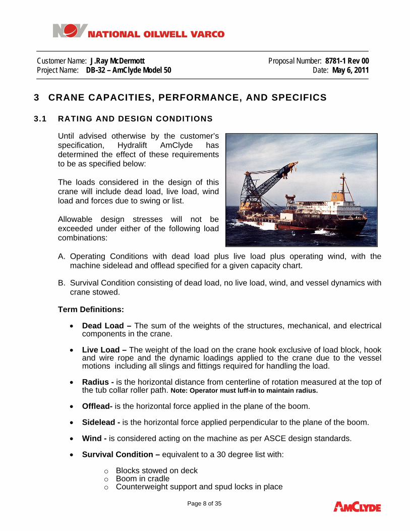
3.1 RATING AND DESIGN CONDITIONS Until advised otherwise by the customer’s specification, Hydralift AmClyde has determined the effect of these requirements to be as specified below: The loads considered in the design of this crane will include dead load, live load, wind load and forces due to swing or list. Allowable design stresses will not be exceeded under either of the following load combinations:
A. Operating Conditions with dead load plus live load plus operating wind, with the
machine sidelead and offlead specified for a given capacity chart.
B. Survival Condition consisting of dead load, no live load, wind, and vessel dynamics with crane stowed.
Term Definitions:
• Dead Load – The sum of the weights of the structures, mechanical, and electrical components in the crane.
• Live Load – The weight of the load on the crane hook exclusive of load block, hook and wire rope and the dynamic loadings applied to the crane due to the vessel motions including all slings and fittings required for handling the load.
• Radius - is the horizontal distance from centerline of rotation measured at the top of the tub collar roller path. Note: Operator must luff-in to maintain radius.
• Offlead- is the horizontal force applied in the plane of the boom.
• Sidelead - is the horizontal force applied perpendicular to the plane of the boom.
• Wind - is considered acting on the machine as per ASCE design standards.
• Survival Condition – equivalent to a 30 degree list with:
o Blocks stowed on deck o Boom in cradle o Counterweight support and spud locks in place

Customer Name: J.Ray McDermott Proposal Number: 8781-1 Rev 00 Project Name: DB-32 – AmClyde Model 50 Date: May 6, 2011
Page 9 of 35
Note: In compliance with Classification Society requirements, the structural design of this equipment will take into account the combined effect of static and dynamic motions and loadings, while mechanical components will be designed for the static motions and loadings.
CONDITIONAL INPUTS
CASE WIND
SPEED (MPS)
IMPACT ON LOAD
(%)
SIDE LEAD (DEG)
OFFLEAD (DEG)
Main Hook – Special Revolving (I) 20 10 1.0 1.0
Main Hook –Full Revolving (II) 20 10 3.0 3.0
Aux Hook –Full Revolving (III) 20 10 3.0 3.0
Whip Hook –Full Revolving (IV) 20 30 3.0 3.0
SURVIVAL* 63 30 equiv.
• SURVIVAL CONDITION EXAMPLE - based on maximum single amplitude and a 10 second period.
o Roll ±20º o Pitch ±12.5º o Heave 0.2g o Rolling Axis on Vessel Centerline 23m Below Boom Hinge o Pitching Axis:
Below Boom Hinge 23m Forward of the Slewing Center of the Crane 50m
NOTE: The above are estimated values for design purposes. The vessel designer should verify these values.

Customer Name: J.Ray McDermott Proposal Number: 8781-1 Rev 00 Project Name: DB-32 – AmClyde Model 50 Date: May 6, 2011
Page 10 of 35
3.2 MAIN, AUX, & WHIP FALL CAPACITIES The capacities illustrated below are in Metric Tons.
Rad ius
Spec ia l
Revolving Case I
Fu l l
Revolving Case I I
Aux
Case I I I
Whip
Case IV
20.3 1500 1225 23.1 1500 1225 400 25.0 1500 1225 400 75 30 1500 1225 400 7535 1500 1225 400 7540 1215 1160 400 7545 1010 1010 400 7550 855 850 400 7555 735 725 400 7560 635 625 400 7565 535 525 400 7570 435 450 400 7575 330 330 400 7580 390 7585 300 7590 75 95 75
Notes:
1. Radii are measured on a horizontal line at the top of the roller path with luffing required to maintain radius as the machine trim changes.
2. Minimum radius is available only with level barge 3. The full revolving rating is with a maximum allowable out of plane angle of the load to the plane of
the boom of 3.0 degrees. 4. The special revolving rating is with a maximum allowable out of plane angle of the load to the plane
of the boom of 1.0 degree. 5. Minimum (Min.) radius is the closest distance to the center of a level crane that a vertically hanging
load can be handled. 6. Maximum (Max.) radius is the farthest distance from the center of a level crane that a vertically
hanging load can be handled. 7. Main and Auxiliary load ratings include the ABS required 10% Dynamic Amplification Factor (DAF). 8. Whip load ratings include the ABS required 30% Dynamic Amplification Factor (DAF).

Customer Name: J.Ray McDermott Proposal Number: 8781-1 Rev 00 Project Name: DB-32 – AmClyde Model 50 Date: May 6, 2011
Page 11 of 35
3.3 PERFORMANCE
I tem
Main
Aux
Whip
Boom
Sw ing Capacity 1500 400 75 - - - - - -
Parts of Line 30 8 2 32 - - - SPEEDS - Main Hoist (No – Load) 4.3 m / min - - - - - - - - - - - - - Main Hoist w/ 1500 mT 2.4 m / min - - - - - - - - - - - - - Aux Hoist (No – Load) - - - 17.1 m / min - - - - - - - - - - Aux Hoist w / 400 mT - - - 10.4 m / min - - - - - - - - - - Whip Hoist w / 75 mT - - 54.0 m / min - - - - - Boom – Horiz. to Min Radius - - - - - - - - - 16 min - - - - Slewing - - - - - - - - - - - - 0.3 RPM HOOK REACH (Below Boom Foot) 25 m 25 m 25 m - - - - - -
3.4 CRITICAL DIMENSIONS
3.4.1 CRANE (GENERAL)
Description DimensionTailswing 14.0 m Centerline Boom Seat to Barge Deck 20.0 m Centerline to centerline boom seats 10.0 m Centerline Rotation to Centerline Boom Seat 8.0 m Bottom of Rail Circle to Centerline Boom Seat 5.0 m
3.4.2 FOUNDATION
Description DimensionTub diameter 15.2 m Outer Container Ring Circle Diameter 15.2 m Top of tub to vessel main deck 15.0 m Bullgear Pitch Diameters 12.56 m Hook Roller Circle Diameter 15.8 m
3.4.3 BOOM LENGTH • To Main Block 70.0 Meters • To Auxiliary Block 80.0 Meters • To Whip Block 85.7 Meters

Customer Name: J.Ray McDermott Proposal Number: 8781-1 Rev 00 Project Name: DB-32 – AmClyde Model 50 Date: May 6, 2011
Page 12 of 35
3.5 STRUCTURAL
3.5.1 GENERAL The A-Frame, backleg, superstructure, rotating frame and boom (structural steel members) will be designed according to American Bureau of Shipping requirements as applicable to this type of equipment. The crane will be designed for continuous full operation with maximum operating load and wind from the most adverse direction, or survival condition. The crane will be designed to facilitate ease of inspection, access and maintenance. Necessary stairs, ladders and platforms will be installed for access to all routine maintenance areas such as hinge pins, roller paths, bull gears, sheaves, lights, hoists, winches, and other such items. All enclosed welded structures of importance (boxes and tubes, etc.) will be seal welded. No holes will be drilled in these structures.
3.5.2 ROTATING DECK The rotating deck is a plated structure that transfers and distributes the boom and A-Frame loads into the rotating gear, in addition to supporting all hoisting machinery, swing drives, electrical equipment king pin housing and other equipment. The truss frame is a multi-panel truss structure made of box girders. The hook roller beam is an arc segment located at the rear of the rotating deck. Pillars are attached to the arced girder and the rear of the rotating deck to transfer the uplift loads into the deck. There are pillars located around the front and sides of the rotating deck to support the hook roller container ring around the remainder of its circumference. The rotating deck is analyzed using a Finite Element Analysis to optimize the structure for the loads applied. In addition to the optimization of the structural members, the FEA model is utilized to establish the finished contour of the upper rail mounting surface in order to assure proper distribution of the loads into the load rollers.
3.5.3 MACHINERY CAB
1. GENERAL Machinery requiring protection from environmental elements will be enclosed in the machinery cab. The machinery cab will be constructed in a configuration to provide ample room for access and maintenance purposes. The machinery cab will be fabricated from structural steel shapes and formed sheet steel. The machinery cab will have hinged metal doors and glass windows. Windows will be positioned for maximum light.

Customer Name: J.Ray McDermott Proposal Number: 8781-1 Rev 00 Project Name: DB-32 – AmClyde Model 50 Date: May 6, 2011
Page 13 of 35
2. MACHINERY CAB VENTILATION
Forced ventilation fans will be provided to allow one air change every 10 minutes.
3. WIRE ROPE OPENINGS Wire rope openings in the machinery cab will be provided with covers to minimize the rain coming inside the cab.
4. ELECTRICAL ROOM VENTILATION Air conditioner units will be provided to maintain a maximum 30°C temperature in the electrical rooms.
3.5.4 A-FRAME & BACKLEG The mast and backleg are plate box girder construction with transverse bracing to support the non-operating side loads. The mast and backleg are pinned together as well as both being pinned to the truss frame. The mast has an integral structure for supporting the load hoist fleeting sheaves. The fleeting sheaves have bronze journal bearings that run on massive support axles. The boom inner bail is a built-in style with the sheaves mounted on sealed tapered roller bearings. A substantial boom stop will be provided to guard against the boom being pulled back over the machinery cab.
3.5.5 WALKWAYS, STAIRS AND LADDERS
The crane will have a system of stairways, ladders, walkways and platforms, for easy access to the A-Frame, cab roof, machinery house, fire monitors and operator’s cab. Stairways will be used instead of ladders wherever possible. Adequate hand railings and posts, in compliance with National Authorities requirements, will be provided where required to provide access to all maintenance and service points.

Customer Name: J.Ray McDermott Proposal Number: 8781-1 Rev 00 Project Name: DB-32 – AmClyde Model 50 Date: May 6, 2011
Page 14 of 35
3.5.6 BOOM
The boom is a fully welded design consisting of a four chord latticed construction. The boom chords square boxes fabricated from high strength steel strips and the lacings are rolled structural steel square tubing. The boom outer is a fully plated structure with bores for mounting the upper main fall sheave assembly and boom bail outer sheave assembly. The upper auxiliaries and upper whips sheave assemblies are likewise built into the jib section. This eliminates the need for hanging upper tackle and increases the effective hoisting height. All the sheaves are mounted on sealed roller bearings with grease passages through the axles. The sheaves are lubricated at remote manifold locations that are easily accessible from the boom walkway. The boom foot pin is fixed to the boom and rotates on bronze journal bearings located in the rotating deck. The boom will have block stowage pockets for both the Main and Auxiliary Blocks. The design of the stowage pockets allows the blocks to be in the pockets for the full operating range of the boom. While the boom is in the boom rest support, the Main and Auxiliary Blocks are to be stored in pockets on the boom rest (Main) and on the ship’s structure (Aux.). The right hand side of the boom is equipped with a walkway and handrails along the top of the boom. In addition, a separate walkway with handrails is provided inside the boom. The walkways will go from the boom foot pin to the very tip of the boom with access ladders and platforms to each of the sheave locations on the boom.

Customer Name: J.Ray McDermott Proposal Number: 8781-1 Rev 00 Project Name: DB-32 – AmClyde Model 50 Date: May 6, 2011
Page 15 of 35
3.5.7 BOOM HINGE PIN ASSEMBLY The boom will pivot on straight aluminum bronze bushings designed for easy maintenance as illustrated in the view to the right. The stationary hinge pins will be supported by self-aligning spherical ball bushings installed in the boom seats of the main rotating deck structure. The spherical bushings are to be used for alignment only.
3.5.8 BOOM STOPS The boom stop is a tubular truss member pinned to the A-frame and bumps against a shock absorbing material attached to the boom center section. A mast strut is located between the mast and the backleg to support the out of plane loads applied by the boom stop action. Pinned lacing members in the boom are designed to collapse before causing a boom chord or side panel lacing failure. The boom stops are designed to make contact at a boom angle of 85 degrees with respect to the plane of the machinery deck.
3.5.9 SHEAVES
All sheaves will be medium carbon cast steel or roll forged with hardened grooves. The grooves will be proportioned to give correct support to the wire ropes. They will be installed on anti-friction bearings except for the A-Frame fleeting sheaves, which are bronze bushed. Each sheave will be fitted with individual grease fittings. Fixed position sheaves will be greased through center drilled pins and fleeting sheaves will be greased through their hubs. All anti-friction sheave bearings will be provided with seals to reduce the number of times lubrication is necessary. The sheaves and bearings will be designed for forces resulting from 5° rope offlead, which is arrived at from “Two-Block” position. The minimum D/d ratio for all sheaves is 20:1.
3.6 ROTATING GEAR The rotating gear consists of a “full compliment load and hook roller” container ring system, bullgear, swingers, center pin and spud locks. The load roller portion and hook roller portion of the main bearing system are comprised of container rings in concentric paths. The load rollers and hook rollers are double flanged, heat treated and have a radius contoured tread surface. All rails are heat treated crane rails that are rolled to the proper radius and fastened to the tub and crane upper by rail clips.

Customer Name: J.Ray McDermott Proposal Number: 8781-1 Rev 00 Project Name: DB-32 – AmClyde Model 50 Date: May 6, 2011
Page 16 of 35
3.6.1 CENTER PIN ASSEMBLY
The center pin assembly is a bronze bushed fabricated steel bearing housing and a retaining collar. The bronze bushing will be grease lubricated. The center pin will be welded into the rotating foundation center and the bearing housing will be bolted to the bottom of the rotating frame. The center pin assembly is designed to resist all horizontal forces resulting from crane operation with rated capacities. Special care has been taken to insure that the center pin does not see loads excessively larger than those for the operating conditions. Examples of this are as follows:
• The spud lock carries most of the lateral loads in the stowed condition.
• All uplift is carried on the hook rollers, and none on the center pin.
• The center pin will be sized to allow passage of electrical cables.
• The center pin assembly will be designed for easy removal, maintenance and bushing replacement without jacking up the crane.
3.6.2 SPUD LOCK An air operated locking device will be furnished to prevent crane rotation while in the stowed condition.

Customer Name: J.Ray McDermott Proposal Number: 8781-1 Rev 00 Project Name: DB-32 – AmClyde Model 50 Date: May 6, 2011
Page 17 of 35
3.6.3 SLEWING MACHINERY
Six independent electric powered swingers will be provided to rotate the crane at rated loads under the list and wind conditions as specified in this proposal. The swingers will be installed forward and aft of centerline of rotation. Swingers will have the following construction features: • The oil tight housing will be
constructed of welded steel plates.
• Gearing is steel with cut spur type teeth.
• All bearings are anti-friction, except for the bronze bull pinion shaft bushing.
• The vertical shaft will be splined.
• All high speed gearing and bearings within the housing run in oil. Slow speed gearing will be grease lubricated. The bronze bull pinion bushings are high pressure grease lubricated.
• Number of Swingers: (6) Units
• Swinger Motor Type: A.C. Variable Frequency
• Motor Voltage: 600 Volts
• Motor Size: (6) 150 KW
• Motor Brake Type: Parking – Disc Type
• Number of Disc Brakes: (1) Per Unit
• Bullgear Pitch Diameter: 12,560mm

Customer Name: J.Ray McDermott Proposal Number: 8781-1 Rev 00 Project Name: DB-32 – AmClyde Model 50 Date: May 6, 2011
Page 18 of 35
3.6.4 BULLGEAR The bull gear will be made of high strength low alloy cast steel segments. The segments will be machined and bolted together to form a true circle. The bull gear will be fastened to the tub collar with high strength bolts and shear lugs around the circumference. Lubrication will be grease, manually applied. Actual forces on the bull gear are shown on the Foundation Plan.
3.6.5 CONTAINER RING ROLLER SYSTEM The roller system will consist of (2) sets of upper and lower rail circles with a full complement of flanged rollers acting together as the rotate bearing. The rollers will be assembled in container rings which consist of rolled inner and outer support plates with axles and bushings to maintain location of each roller. The rails will be set on a properly leveled surfaces and fastened to the tub collar and lower deck to maintain correct radius and tight splices by means of welded shear lugs. The circles will be made of rolled, large section, steel crane rails. The rollers will be made of high-strength steel and be of a flanged crane wheel profile. Actual forces on the roller paths are shown on the Foundation Plan drawing provided with this proposal.
3.6.6 HOOK ROLLER SYSTEM The hook roller system will be designed to carry all overturning moments for operating capacities (full revolving and/or special lift), and loads resulting from an occasional accidental overload. This system uses a continuous circle of rollers mounted in container ring assembly. This assembly consist of rolled inner and outer support plates with axles and bushings to maintain location of each roller. Rollers will be installed with bushings on axles and designed for easy maintenance. Brackets and equalizers will minimize deflections and maintain correct alignments. Rollers will be steel with high hardness for strength and long wearing characteristics.

Customer Name: J.Ray McDermott Proposal Number: 8781-1 Rev 00 Project Name: DB-32 – AmClyde Model 50 Date: May 6, 2011
Page 19 of 35
3.7 TUB & TUB COLLAR DESIGN
AmClyde will provide design and detail drawings for fabrication of a tub collar and tub walls. The scope of this work is for design of components for tub collar to connect to the vessel above the deck, suitable to handle the crane foundation loads. Not included is the design or details of below deck bulkheads, internal platforms, internal walkways, internal stairways, openings or compartments.
3.8 WIRE ROPE AND TACKLE
3.8.1 WIRE ROPE
The Boom, Main, and Aux hoisting wire ropes will be 6x47WS, high strength, with independent wire rope core, regular lay, preformed, uncoated and factory lubricated with an asphalt base lubricant. The ropes for the Whip hoist will be Dyform 34LR with the same coating specifications as above. The ropes for the Tugger winches will be 6 x 19 construction with the same coating specifications as above. The Boom hoist rope length will be calculated with half a layer of rope on the boom hoist with boom in cradle. The rope lengths for the other hoists will have a minimum of three dead wraps on the load drums with the hooks at low reach. The rope sizes as specified in the table below are to A.B.S. Rules. Rope test certificates will be obtained and submitted to the owner. All wire rope will be furnished by Hydralift AmClyde. .
3.8.2 TACKLE DATA
COMPONENT R ATED LO AD (MT)
Trave l Be low Boom Hinge
(m)
Par ts o f L ine
D I A (mm)
BREAKING STRENGTH
(MT)
Rope SF
W/ EFF (1 )
SHEAVE TO
ROPE D:d
R ATIO (2 )
Boom - - - - - - 32 50 235 3 .5 m in 20 (m in )
Ma in Hook 1500 35 30 50 235 3 .5 min 20 (min )
Aux i l i a ry Hook 400 35 8 50 235 3 .5 min 20 (min )
Wh ip Hook 75 35 2 50 235 3 .7 min 20 (min )
Load Tuggers (2 ) 40 35 1 44 137 .7 3 .4
Ma in B l k Tugger 12 .5 x 2 - - - 2@1 26 48 3 .8
Aux B lk Tugger 12 .5 x 2 - - - 2@1 26 48 3 .8
(1) Based on A.B.S. rules (2) Based on diameter at base of groove.

Customer Name: J.Ray McDermott Proposal Number: 8781-1 Rev 00 Project Name: DB-32 – AmClyde Model 50 Date: May 6, 2011
Page 20 of 35
3.8.3 HOOKS
All hooks will be of heat treated, alloy steel to insure notch toughness under cold weather conditions. The hooks will swivel on anti friction thrust bearings. The prongs will be sized to minimize damage to slings from maximum loads on each hook. The prong points are inside the widest point of the hook to minimize chances of being caught on objects. Hooks are equipped with hook latches. The Main hook will have 4 prongs, the Aux hook will have 4 prongs and the Whip hook will have 2 prongs. The hooks, blocks and shackles will be certified as to Safe Working Load (SWL). The load blocks may not be tested, but will be certified by calculation and by non-destructive examination to A.B.S. requirements. Two prongs on the auxiliary hook are designed to sustain the full Safe Working Load (SWL). The main load hook is designed to carry the SWL on all four prongs with a load distribution of 20% - 20% - 30% - 30% or 50% on each of two opposite prongs with a maximum sling angle of 30 degrees.
3.8.4 BLOCKS The Main, Aux, and Whip blocks falls be designed and certified for safe working loads of 1500 MT, 400 MT, and 75 MT, respectively. All blocks with hooks will be of sufficient weight to permit overhauling of block without load. All sheaves within blocks will be well guarded to prevent slack ropes from running out of the grooves. The edges of lower blocks will be rounded to prevent snagging of blocks on any obstructions. Ends of pins and grease fittings will be protected.

Customer Name: J.Ray McDermott Proposal Number: 8781-1 Rev 00 Project Name: DB-32 – AmClyde Model 50 Date: May 6, 2011
Page 21 of 35
3.9 MECHANICAL
3.9.1 MAIN HOIST MACHINERY
The main, auxiliary, and whip hoist will be electric powered and air controlled. An integral unit centrally installed on the machinery deck will have the following construction features: • The hoist bed will be made from heavy structural steel weldments, rigidly braced and
provided with machined mounting pads for installation of the machinery components.
• Each drum will have one air-operated internal expanding band type heavy duty friction clutch. The single clutch per drum gives positive engagement and simplifies the maintenance of the clutch due to a minimum number of moving parts. The clutch will be made in several segments to facilitate removal during lining replacement.
• Heavy duty, dual, external contracting band brakes will be used on each drum. The brake lining pressures will be minimized to reduce lining wear and heat build-up. The brakes will be air-operated with a spring engaged air-released safety feature in the case of air pressure loss.
• Motor power will be transmitted to the hoist gear train through a heavy-duty parallel shaft gear box.
• The steel compression pawls on each drum are air engaged, air released with the ratchet being an integral part of the drum.
• Rope anchors will be made through the drum flanges.
• In the event of main power loss, the drum brakes can be released with the air supply and lower the SWL.
• All drum shaft assemblies will be designed so that main power is transferred directly from gear train to load hoist drums thus eliminating the need to transfer torque through the drum shafts. This minimizes the potential for fatigue failures at keyways and other stress risers that may be inherent to the drum shaft design.
• All stress levels and design specifications will meet or exceed the requirements as specified. Areas of complex loading such as rope drums will be verified through comparison with field proven Hydralift AmClyde equipment.
• All drums will have emergency free wheeling capabilities.
• Due to the magnitude of the line pulls and the physical size of the hoists, special attention has been given to the type of drum flange design to insure maximum quality during the manufacturing process and ultimate reliable operation in cold weather environments. The critical components will be made of material that has good notch toughness (Charpy impact) capability. This is being provided by Hydralift AmClyde to insure reliable performance.

Customer Name: J.Ray McDermott Proposal Number: 8781-1 Rev 00 Project Name: DB-32 – AmClyde Model 50 Date: May 6, 2011
Page 22 of 35
• Lebus counterbalanced lagging will be provided on all hoist drums.
• Motor power will be transmitted to the hoist through a heavy-duty parallel shaft reduction gear box mounted on the side of the hoist.
HOIST CONFIGURATION • Number of Drums (3)
• Drum Brake Type Band
• Number of Bands (2) Per Drum
• Drum Brake Actuation Spring Set – Air Released
• Load Hoist Motor Type A.C. VFD
• Motor Voltage 690Volt
• Motor Size (1) – 858 kW
• Motor Brake Spring Set – Air Released
3-Drum Frame 24-20-14 Main Auxiliary Whip Frame Size 24 20 14 Drums: Diameter Length Flange Diameter
940 2210 2692
1041 1524 2286
940 1778 1753
Required Line Pull 68,100 kg 58,600 kg 34,460 kg Line Speed @ Required Line Pull 72 m/min 83 m/min 108 m/min

Customer Name: J.Ray McDermott Proposal Number: 8781-1 Rev 00 Project Name: DB-32 – AmClyde Model 50 Date: May 6, 2011
Page 23 of 35
3.9.2 BOOM HOISTING SYSTEM The Frame 20 Boom Hoist will be designed with similar features as the main hoists described earlier with the following exceptions: • Hoist clutches will not be
provided which will eliminate the possibility emergency release.
• The boom hoist will be an electric powered, single drum, independent unit.
• Motor power will be transmitted to the hoist gear train through heavy duty parallel shaft reduction gear boxes. One motor will independently drive the boom hoist.
The independent boom hoist will have a fixed drum, with spring-set, air-released drum brakes, air operating features on pawls, with similar features as the main hoist. • Number of Drums (1)
• Drum Brake Type Band
• Number of Bands (2) Per Drum
• Drum Brake Actuation Spring Set – Air Released
• Boom Hoist Motor Type A.C. VFD
• Motor Voltage 690 Volt
• Motor Size (1) –450 kW
• Motor Brake Spring Set – Air Released
Customer Name: J.Ray McDermott Proposal Number: 8781-1 Rev 00 Project Name: DB-32 – AmClyde Model 50 Date: May 6, 2011
Page 24 of 35
3.9.3 TUGGER WINCHES
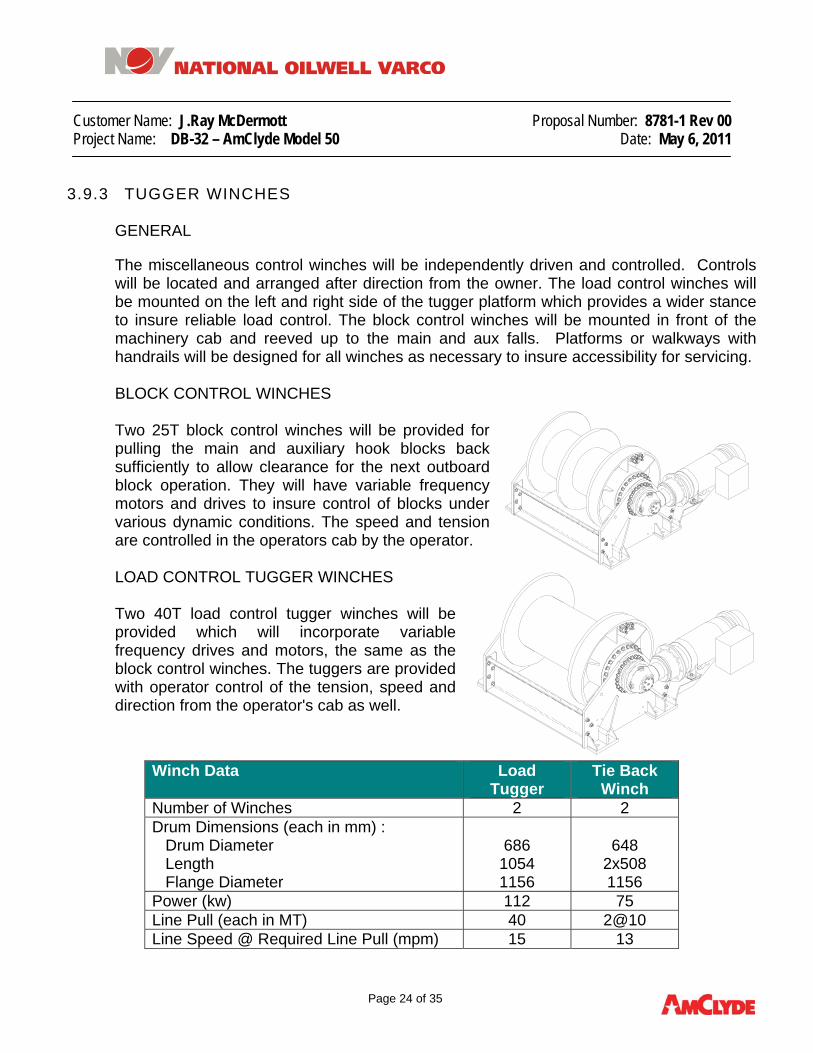
GENERAL The miscellaneous control winches will be independently driven and controlled. Controls will be located and arranged after direction from the owner. The load control winches will be mounted on the left and right side of the tugger platform which provides a wider stance to insure reliable load control. The block control winches will be mounted in front of the machinery cab and reeved up to the main and aux falls. Platforms or walkways with handrails will be designed for all winches as necessary to insure accessibility for servicing. BLOCK CONTROL WINCHES Two 25T block control winches will be provided for pulling the main and auxiliary hook blocks back sufficiently to allow clearance for the next outboard block operation. They will have variable frequency motors and drives to insure control of blocks under various dynamic conditions. The speed and tension are controlled in the operators cab by the operator. LOAD CONTROL TUGGER WINCHES Two 40T load control tugger winches will be provided which will incorporate variable frequency drives and motors, the same as the block control winches. The tuggers are provided with operator control of the tension, speed and direction from the operator's cab as well.
Winch Data Load Tugger
Tie Back Winch
Number of Winches 2 2 Drum Dimensions (each in mm) : Drum Diameter Length Flange Diameter
686
1054 1156
648
2x508 1156
Power (kw) 112 75 Line Pull (each in MT) 40 2@10 Line Speed @ Required Line Pull (mpm) 15 13
Customer Name: J.Ray McDermott Proposal Number: 8781-1 Rev 00 Project Name: DB-32 – AmClyde Model 50 Date: May 6, 2011
Page 25 of 35
3.9.4 PNEUMATIC SYSTEM
Air compressors are sized to operate all air operated equipment (hoist brakes, swing brakes and miscellaneous items) plus provide air to operate hand operated, pneumatic tools in and around the machinery cab. Two air headers with several taps each will be provided in the machinery cab for use with pneumatic hand equipment. One 15 KW, electric, air compressor with dual pilots and a 454 liter tank will be provided. The compressor will be provided with an after cooler and the system will have a refrigeration type air dryer to remove excessive moisture. Also filters and lubricators will be provided. Separate receiver tanks will be mounted on the main and boom hoists and supply air to relay valves mounted on the hoists. The relay valves are controlled by pilot pressure from the foot valves in the operator's cab. The parking brakes, and pawls for the hoists and swing parking brakes are operated by pneumatic solenoid valves and controlled from the operators cab. The spud lock is operated by a pneumatic solenoid valve and controlled from the operators cab. Windshield Wipers in the operators cab are air operated with adjustable controls. All air piping material will be furnished.
3.9.5 LUBRICATION
All mechanical operating parts will be provided with means of applying the correct type of lubricant. Lubrication fittings for bearings will be easily accessible and, where necessary, will be piped to a convenient location. Access to all grease stations and grouped grease fittings will be provided.
Customer Name: J.Ray McDermott Proposal Number: 8781-1 Rev 00 Project Name: DB-32 – AmClyde Model 50 Date: May 6, 2011
Page 26 of 35
3.10 ELECTRICAL
3.10.1 LIGHTING
Adequate lighting is provided in the machinery cab, the operator’s cab, and for access stairs and platforms. Note: The charts used in this section are representative of the quantities of lights being utilized in the crane. They were obtained from previous contracts and are provided as reference only. The figures referenced in the charts are not applicable to this proposal.
• OBSTRUCTION LIGHTS One pair of red aircraft obstruction lights is located on the A-frame and one pair on the boom. Each pair of lights is controlled by a light-sensing controller that turns the lights on at dusk and off at dawn.
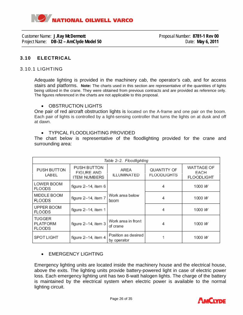
• TYPICAL FLOODLIGHTING PROVIDED
The chart below is representative of the floodlighting provided for the crane and surrounding area:
• EMERGENCY LIGHTING
Emergency lighting units are located inside the machinery house and the electrical house, above the exits. The lighting units provide battery-powered light in case of electric power loss. Each emergency lighting unit has two 8-watt halogen lights. The charge of the battery is maintained by the electrical system when electric power is available to the normal lighting circuit.

Customer Name: J.Ray McDermott Proposal Number: 8781-1 Rev 00 Project Name: DB-32 – AmClyde Model 50 Date: May 6, 2011
Page 27 of 35
• TYPICAL AREA LIGHTING PROVIDED
The chart listed below is representative of the area lighting provided for the crane and surrounding area:

Customer Name: J.Ray McDermott Proposal Number: 8781-1 Rev 00 Project Name: DB-32 – AmClyde Model 50 Date: May 6, 2011
Page 28 of 35
3.10.2 ELECTRICAL HOUSE AIR CONDITIONER Air conditioner units will be provided to maintain a maximum 30°C temperature in the electrical rooms.
3.10.3 ELECTRICAL RECEPTICALS Electrical receptacles provided are listed as follows:
LOCATION QUANTITY VOLTAGE Operators cab control console 2 duplex
120VAC,
60Hz
Visitors Cab 2 duplex Machinery House 4 duplex Electrical House 2 duplex Boom Walkway 1 duplex
3.10.4 CRANE POWER
Power for regular lifting operations of the crane is supplied by a pair of diesel-electric generator sets located on the crane machinery deck with the following characteristics:
• Diesel engine Caterpillar 3512 or equal • Alternator rated 1100 KVA, 3 phase, 60 Hz (Prime) • Fuel Tank – 1000 Gallon on right side of crane • Engine is equipped with the following features:
o Air cooled engine radiator with blower fan o Electronic governor o Engine jacket water heater o Fuel filter, spin-on o Oil filter – spin on o Safety shutoff protection, electrical, energized to shut off o Electric starting system (24 VDC) o Air inlet shutoff

Customer Name: J.Ray McDermott Proposal Number: 8781-1 Rev 00 Project Name: DB-32 – AmClyde Model 50 Date: May 6, 2011
Page 29 of 35
3.10.5 COLLECTOR RINGS
While the crane main power comes from self contained diesel generator sets mounted on the crane, a source of power for operating heaters and lighting will be required from the vessel. This is provided by a low voltage collector ring rated as follows:
• Three rings rated for 200 amps, 220v, 3 phase.
• Thirty six rings rated for 20 amps for communication, monitoring and customer use.

Customer Name: J.Ray McDermott Proposal Number: 8781-1 Rev 00 Project Name: DB-32 – AmClyde Model 50 Date: May 6, 2011
Page 30 of 35
3.11 OPERATOR’S CAB
The operator’s enclosure will be positioned forward and to the right of the machinery house to provide an unobstructed view of the boom and load at all positions. Entry to the cab will be by means of a ladder and railing entry platform. The operators cab will have two fixed front windows, two upper sloped windows, sliding windows on both sides of the operator for ventilation, an overhead window with sunscreen, and a lower side base level window. All windows will be tinted safety glass. A comfortable, fully adjustable, cushioned operator’s seat will be provided.
• Width of Cab: 2.8 m
• Wall Height: 2.4 m
• Length of Cab: 4.8 m
The operator's cab will be weatherproof and fabricated of sheet steel with full seam welding over a structural steel framework. The cab will be insulated and constructed of fire resistant materials. The cab will have a partition behind the operator which provides approximately a 1.5 m deep room for the observer and to prevent interference with the operator.
The cab platform will be configured to provide quick escape from any crane position in the event of an emergency. Two windshield wipers will be furnished on the front window and one on the overhead window. Windshield washers and reservoirs will be furnished for all windshield wipers
Customer Name: J.Ray McDermott Proposal Number: 8781-1 Rev 00 Project Name: DB-32 – AmClyde Model 50 Date: May 6, 2011
Page 31 of 35
3.11.1 SPECIAL FEATURES
• An air horn and a loudspeaker will be mounted beneath the operator’s cab. Two
combination air conditioner/heaters will be furnished in the operator’s cab. Controls for the tuggers will be in the operator’s console.
• Folding arm rests will be provided on the operator’s seat. Two air operated
windshield wipers will be furnished on the front window, and one on the overhead window. A service platform will be provided for access to the operator’s cab front window. The operator’s cab will be divided approximately three feet aft of the operator by a glass door to prevent observer interference with the operator.
• A hoist television monitoring system consisting of one camera for boom hoist and
one camera on each hoist drum will be provided.
• Powered communication system will be provided between the operator’s cab, the machinery cab, and the electrical equipment house.
• A window defroster system will be furnished in the operator’s cab.
• A load moment system is incorporated within the load indicating system for all
ratings at all radii for the main, auxiliary’s and whip load blocks with automatic shutdown if an overload or over moment occurs.
• Wind speed indicator will be provided with read-out meter in operator’s cabin.
• The operator’s cabin will be extra large with a separate spectator viewing room behind the operator, separated by clear plexiglass.
• The operator’s cabin will be heated and air conditioned .
• The operator’s cabin will be equipped with tinted, safety glass windows and will have window washing platforms on both sides.
• The operator’s cabin will be equipped with a roof mounted, steerable searchlight.

Customer Name: J.Ray McDermott Proposal Number: 8781-1 Rev 00 Project Name: DB-32 – AmClyde Model 50 Date: May 6, 2011
Page 32 of 35
3.12 BALLAST
No ballast is required for this crane.
3.13 FEATURES AND SAFETY DEVICES
1. MECHANICAL COMPONENTS
• Spring engaged brakes on each drum in addition to one motor brake on each electric motor.
• Drum brakes and clutch interlocks are provided on all load drums to prevent accidental freewheeling of a load drum.
• Loss of air pressure causes the spring engaged brakes to activate on all drum and swinger brake circuits.
• All boom and load hoist drum brakes will be spring set – air released.
• Pawls and ratchets on all hoist drums.
2. STRUCTURAL COMPONENTS
• All steel in the critical load path will have the notch toughness required to operate at the stated service temperatures.
• Front and rear hook rollers are provided and sized per Code.
• A spud lock is provided to prevent crane rotation while in the stowed condition.
• A center pin assembly is designed to resist horizontal forces resulting from crane operation with rated capacities.
• All hooks will be of heat treated, alloy steel with the notch toughness required to operate at the stated service temperatures.
3. OPERATIONAL SAFETY FEATURES
• Emergency stop switches will be provided in the machinery cab and operator’s cabin to stop all crane functions automatically.
• Limit switch on the spud lock to disengage slewing system when the spud lock is in position.
• High lift and low reach limits for main, auxiliary and whip load blocks will be provided.

Customer Name: J.Ray McDermott Proposal Number: 8781-1 Rev 00 Project Name: DB-32 – AmClyde Model 50 Date: May 6, 2011
Page 33 of 35
• Boom will be equipped with limit switches for automatic shutdown for (high) minimum radius and (low) horizontal position.
• Hook latches as sling guards for main, auxiliary and whip blocks are included.
• The boom, main, auxiliary, and whip drums will be fitted with over speed limit switches.
• A slewing alarm bell and rotating warning light will be provided at the underside, rear of the rotating machinery deck.
• Smoke detector system will be provided in the machinery cab and electrical rooms.
• Fire extinguishers (20 lb. CO2 type, ABC rated) will be located in the operator’s cabin, the machinery house and electrical house.
4 COMPONENT WEIGHTS
Component Weights (MT) Rotating Gear 200 Rotating Upper Assembly 797 Boom Assembly 222 Main/Aux/Whip Lower Blocks 70 Wire Rope Boom/Main/Aux/Whip/Tuggers 90 Counterweight 0 Total 1379

Customer Name: J.Ray McDermott Proposal Number: 8781-1 Rev 00 Project Name: DB-32 – AmClyde Model 50 Date: May 6, 2011
Page 34 of 35
5 SURFACE PREPARATION AND PAINTING
GENERAL: After fabrication, all weld slag and spatter will be removed and will be ground smooth to commercially acceptable standards.
• EXTERIOR PAINTING – STRUCTURAL:
Blasting will be according to paint manufacturer’s instructions. All steel surfaces will be given the following coatings:
1) Primer Coat – Zinc Rich 2) Intermediate - Cross-Linked Epoxy 3) Top Coat - Polyurethane
• INTERIOR PAINTING - STRUCTURAL
Surface preparation will be according to paint manufacturer’s instructions. All steel surfaces will be given the following coatings:
1) Primer Coat - Epoxy 2) Top Coat - Polyurethane
• EXTERIOR PAINTING - MECHANICAL
Blasting will be according to paint manufacturer’s instructions. All steel surfaces will be given the following coatings:
1) Primer Coat – Zinc Rich 2) Intermediate - Cross-Linked Epoxy 3) Top Coat - Polyurethane
• INTERIOR PAINTING - MECHANICAL
Surface preparation will be according to paint manufacturer’s instructions. All steel surfaces will be given the following coatings:
1) Primer Coat - Epoxy 2) Top Coat – Polyurethane
Notes
1) Machinery and electrical equipment will be shop finished in accordance with vendors standards
2) Finish coat color is to be customer’s choice

Customer Name: J.Ray McDermott Proposal Number: 8781-1 Rev 00 Project Name: DB-32 – AmClyde Model 50 Date: May 6, 2011
Page 35 of 35
6 FACTORY ACCEPTANCE TESTS (FAT) Hydralift AmClyde or its subcontractors will provide working (no load) function tests where possible in the fabrication stage for systems and mechanical components before final erection at the shipyard. The electrical vendor will perform functional tests at full rated voltage on all equipment within the system at factory.
Hoists, swingers and other machinery will be shop assembled to facilitate shop testing without load. All mating structural and mechanical components will be shop assembled in those areas possible to assure fit-up during the critical erection phase, and only such dismantling will be performed as is necessary to transport the equipment to the site of erection. The rotating frame, A-frame, backleg, boom, operator’s cab and platforms will be shop assembled and then disassembled as required to ship the equipment to the site of erection. Complete inspection of all circuits with high and low voltage testing will be performed on all equipment in accordance with the requirements of regulatory bodies as applicable. Customer and regulatory bodies may witness any or all tests, and test results will be provided as required.
7 DRAWINGS
• 1812199 REV.1 – Sheet 1 - GENERAL ASSEMBLY
• 1812199 REV 1 – Sheet 2 - MACHINERY PLAN
• 1812281 REV 0 – FOUNDATION PLAN
• 1525327 – Q.C. Requirements for Steel Castings
• 1525339 – Weld NDE Specifications


Related Documents