Department of the Interior National Park Service EMERGENCY SERVICES TECHNICAL RESCUE HANDBOOK 11 th Edition

Welcome message from author
This document is posted to help you gain knowledge. Please leave a comment to let me know what you think about it! Share it to your friends and learn new things together.
Transcript
Department of the Interior National Park Service EMERGENCY SERVICES
TE
CH
NIC
AL
RE
SC
UE
HA
ND
BO
OK
11th Edition

ii
This Page Intentionally Left Blank
i
NATIONAL PARK SERVICE TECHNICAL RESCUE HANDBOOK
Eleventh Edition. August 2014 Published by the U.S. Department of the Interior, National Park Service. First edition- initially publication 1995. Tenth edition published 2005. As a publication of the federal government this handbook is not copyrighted under the copyright laws of the United States, however this book does contain copyrighted images, illustrations and trademark logos. Such material is protected by United States Copyright Law and may not be reproduced without the express permission of the owner. Written and illustrated by Ken Phillips, National Park Service Branch Chief of Search and Rescue. Contributions from James Thompson (Paramedic), EMS Coordinator, Grand Canyon National Park All images, unless otherwise noted, are credited National Park Service. Every effort has been made to utilize images which reflect the most technically accurate procedures, however like the real world achieving perfection is elusive and slight inaccuracies may still be observed. The use of commercial products and trade names is for illustrative and educational purposes only and does not constitute an official endorsement by the National Park Service. All copyrighted trademark logos have been reproduced with permission of the owners. .
Cover Photo: An NPS rescuer at Grand Canyon National Park works at the cliff edge, secured by means of a safety line with two points of attachment to their harness.
WARNING Technical rescue involves unique hazards, which can be fatal. This textbook contains information on specialized rescue techniques and is intended for use as a part of a training course involving closely supervised field training with qualified instructors. A person cannot become proficient in technical rope rescue by simply reading this handbook. Every rescue situation is unique, requiring size-up and decision-making skills gained through personal experience.
ii
Preface This handbook is intended to provide a comprehensive instruction manual as well as point of reference for National Park Service (NPS) personnel involved in technical rope rescue. The techniques provided in the text reflect the consensus of acceptable practices for use with the NPS as established by subject-matter experts both internally and outside the agency. This text has evolved from a few pages originally used as class handouts for the NPS Basic Technical Rescue Training Course starting in 1995. Rope rescue, like other emergency disciplines, constantly changes with advances in equipment designs, field testing and lessons learned from accidents. Many practices that were dogma in technical rescue have been invalidated through thorough analysis and destructive testing. Maintaining perishable personal rigging skills associated with rope rescue requires conducting regular recurrent training. Manipulative drills will directly increase personal proficiency and improve organizational readiness. Rescuers need to stay current with accepted industry practices. It is also critical that commercial rescue equipment be employed in a manner that complies with the manufacturer’s operating instructions. In the rush to respond, rescue personnel repeatedly and intentionally take shortcuts with their personal safety. This human error is the leading cause of accidents.
• Always drive with due care when responding to an emergency. • Constantly use all your personal protective equipment, including helmet, gloves
and eye protection. • Be disciplined about tying in to a safety line when working in an area where the
potential for a fall exists. • Avoid a back injury, which is the most common SAR-related injury, by getting
additional assistance with heavy loads. Finally, truly recognize the associated risk with technical rescue operations and make effective decisions to reduce or eliminate risk whenever possible. Strive to learn from any operational shortcomings and continue to seek out new information.

iii
ACKNOWLEDGEMENTS This handbook would not possible without the generous professional support and editorial assistance of Jim Frank, Kirk Mauthner and Cedric Smith. Additionally the contributions of the following personnel is greatly appreciated; Terry Ascherin Stephen W. Attaway, Ph.D. Jeremy Bernfeld Eduardo Cartaya John Dill Aaron Dick Joe Flachman Mike Gibbs Michel Goulet Lisa Hendy Steve Hudson Dana Jordan Brandon Latham Rick Lipke Loui McCurley
Kevin Moses Zach Nelson Jeff Ohlfs Dave Pope Jason Ramsdell Dean Ross Michelle Schonzeit Bruce Smith Will Smith, MD James Thompson Rock Thompson Brandon Torres Craig Thexton Dave Weber
All the dedicated rope rescue instructors within the National Park Service. Finally, I want to recognize the incredible patience, emotional support and hand modeling provided by Annie Phillips and Connor Phillips. Copyrighted images found in this text have all been reprinted with the express permission of ARC Products, Black Diamond Equipment, CMC Rescue, Cascade Rescue, Conterra Technical Systems, Dillon/Quality Plus, Harken, Hilti, International Safety Components (UK), Junkin Safety Appliance Company, Kong (Italy), Peguet (France), Petzl America, Pigeon Mountain Industries (PMI), Rock Exotica, Skedco, SkyHook Rescue Systems, SMC Gear, Sterling Rope, Tactical Medical Solutions and Traverse Rescue (Canada). All copyrighted logos have been reproduced with the express written permission of American National Standards Institute, ASTM, Deutsches Institut für Normung, Cordage Institute, International Organization for Standardization, National Fire Protection Association and Underwriters Laboratory.

iv
Table of Contents
Preface .......................................................................................................................................................... ii
Chapter 1 INTRODUCTION .......................................................................................................................... 1
Chapter 2 SAFETY CONSIDERATIONS ...................................................................................................... 9
Chapter 3 COMMUNICATIONS .................................................................................................................. 16
Chapter 4 SAFETY FACTORS AND FORCES .......................................................................................... 21
Chapter 5 STANDARDS AND INDUSTRY RATINGS ................................................................................ 27
Chapter 6 EQUIPMENT .............................................................................................................................. 33
• PERSONAL PROTECTIVE EQUIPMENT ................................................................................. 68
Chapter 7 GENERAL RIGGING CONSIDERATIONS ................................................................................ 79
Chapter 8 TIES: KNOTS, BENDS, AND HITCHES .................................................................................... 84
Chapter 9 BELAYING TECHNIQUES ......................................................................................................... 94
• LOAD RELEASE DEVICES ..................................................................................................... 110
Chapter 10 ANCHOR SYSTEMS ............................................................................................................. 112
Chapter 11 RAPPELLING ......................................................................................................................... 138
Chapter 12 ASCENDING .......................................................................................................................... 142
Chapter 13 RESCUE LOWERING SYSTEMS ......................................................................................... 152
• EDGE MANAGEMENT ............................................................................................................ 154
Chapter 14 MECHANICAL ADVANTAGE ................................................................................................ 163
Chapter 15 KNOT PASSING TECHNIQUE .............................................................................................. 182
Chapter 16 RESCUE LITTERS................................................................................................................. 187
Chapter 17 LITTER LOWER/RAISE TECHNIQUE................................................................................... 193
• CHANGEOVER TECHNIQUE- RESCUE LOAD ..................................................................... 200
• PIKE AND PIVOT TECHNIQUE .............................................................................................. 202
Chapter 18 STEEP ANGLE TECHNIQUE ................................................................................................ 205
• LOW-ANGLE LITTER EVACUATION ...................................................................................... 208
• LITTER WHEEL ....................................................................................................................... 209
Chapter 19 STRANDED PATIENT PICK-OFF ......................................................................................... 211
• GUIDING LINE TECHNIQUE .................................................................................................. 216
• IMPROVISED TECHNIQUES .................................................................................................. 219
Chapter 20 PATIENT PACKAGING .......................................................................................................... 223
Chapter 21 MEDICAL CONSIDERATIONS .............................................................................................. 230
Chapter 22 NIGHT RESCUE OPERATIONS ........................................................................................... 244

v
APPENDIX 1- Purcell Prusik System ........................................................................................................ 249
APPENDIX 2- Technical Rescue Checklist .............................................................................................. 255
APPENDIX 3- Search and Rescue Pack Checklist .................................................................................. 256
APPENDIX 4- Example Equipment List- Personal Rescue Gear ............................................................. 259
APPENDIX 5- Industry Standards ............................................................................................................ 262
APPENDIX 6- Equipment Specifications .................................................................................................. 269
APPENDIX 7- Rescue Field References .................................................................................................. 270
REFERENCES .......................................................................................................................................... 273
Index .......................................................................................................................................................... 279
1 | P a g e
Chapter 1
INTRODUCTION NPS TECHNICAL RESCUE- HISTORICAL BACKGROUND
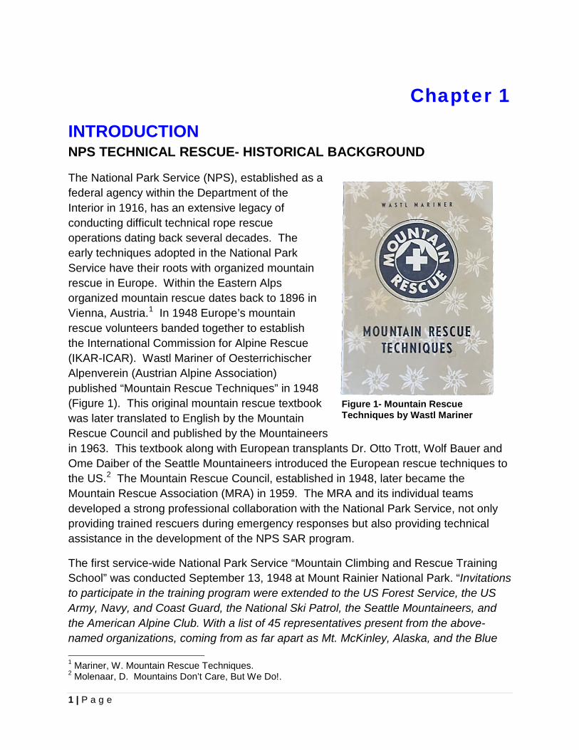
The National Park Service (NPS), established as a federal agency within the Department of the Interior in 1916, has an extensive legacy of conducting difficult technical rope rescue operations dating back several decades. The early techniques adopted in the National Park Service have their roots with organized mountain rescue in Europe. Within the Eastern Alps organized mountain rescue dates back to 1896 in Vienna, Austria.1 In 1948 Europe’s mountain rescue volunteers banded together to establish the International Commission for Alpine Rescue (IKAR-ICAR). Wastl Mariner of Oesterrichischer Alpenverein (Austrian Alpine Association) published “Mountain Rescue Techniques” in 1948 (Figure 1). This original mountain rescue textbook was later translated to English by the Mountain Rescue Council and published by the Mountaineers in 1963. This textbook along with European transplants Dr. Otto Trott, Wolf Bauer and Ome Daiber of the Seattle Mountaineers introduced the European rescue techniques to the US.2 The Mountain Rescue Council, established in 1948, later became the Mountain Rescue Association (MRA) in 1959. The MRA and its individual teams developed a strong professional collaboration with the National Park Service, not only providing trained rescuers during emergency responses but also providing technical assistance in the development of the NPS SAR program.
The first service-wide National Park Service “Mountain Climbing and Rescue Training School” was conducted September 13, 1948 at Mount Rainier National Park. “Invitations to participate in the training program were extended to the US Forest Service, the US Army, Navy, and Coast Guard, the National Ski Patrol, the Seattle Mountaineers, and the American Alpine Club. With a list of 45 representatives present from the above-named organizations, coming from as far apart as Mt. McKinley, Alaska, and the Blue 1 Mariner, W. Mountain Rescue Techniques. 2 Molenaar, D. Mountains Don’t Care, But We Do!.
Figure 1- Mountain Rescue Techniques by Wastl Mariner
2 | P a g e
Ridge, the school got under way at Longmire, Washington… The five-day program, included practical instruction in knot-tying and roped party management, proper use of rock and ice climbing equipment, belays, rappels, self and party arrests, crevasse rescue of all types, tying-in of stretcher cases, improvisation of stretchers, belaying stretcher cases (in ascent, descent and traverse), construction of Tyrolean traverses with A-frames, and rope bridges…..It is hoped that the extreme enthusiasm and cooperation which were in evidence during the school may be indicative of the efficiency with which future mountaineering activities and rescue operations will be conducted.” 3
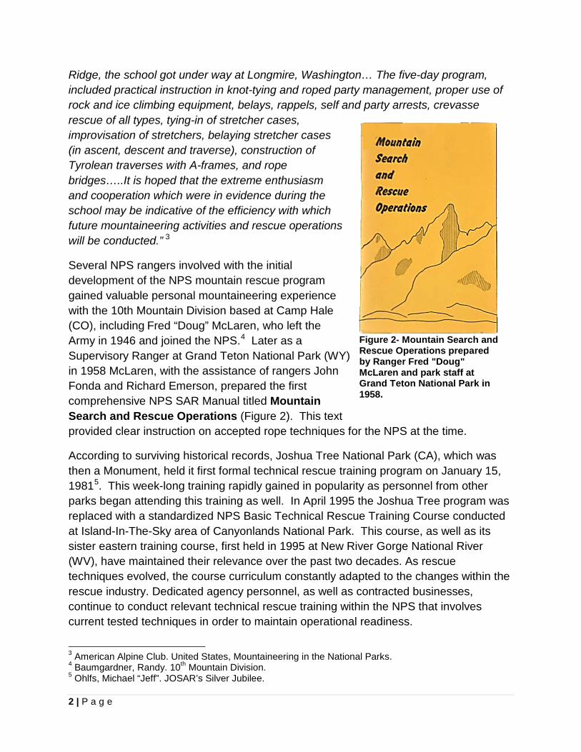
Several NPS rangers involved with the initial development of the NPS mountain rescue program gained valuable personal mountaineering experience with the 10th Mountain Division based at Camp Hale (CO), including Fred “Doug” McLaren, who left the Army in 1946 and joined the NPS.4 Later as a Supervisory Ranger at Grand Teton National Park (WY) in 1958 McLaren, with the assistance of rangers John Fonda and Richard Emerson, prepared the first comprehensive NPS SAR Manual titled Mountain Search and Rescue Operations (Figure 2). This text provided clear instruction on accepted rope techniques for the NPS at the time.
According to surviving historical records, Joshua Tree National Park (CA), which was then a Monument, held it first formal technical rescue training program on January 15, 19815. This week-long training rapidly gained in popularity as personnel from other parks began attending this training as well. In April 1995 the Joshua Tree program was replaced with a standardized NPS Basic Technical Rescue Training Course conducted at Island-In-The-Sky area of Canyonlands National Park. This course, as well as its sister eastern training course, first held in 1995 at New River Gorge National River (WV), have maintained their relevance over the past two decades. As rescue techniques evolved, the course curriculum constantly adapted to the changes within the rescue industry. Dedicated agency personnel, as well as contracted businesses, continue to conduct relevant technical rescue training within the NPS that involves current tested techniques in order to maintain operational readiness.
3 American Alpine Club. United States, Mountaineering in the National Parks. 4 Baumgardner, Randy. 10th Mountain Division. 5 Ohlfs, Michael “Jeff”. JOSAR’s Silver Jubilee.
Figure 2- Mountain Search and Rescue Operations prepared by Ranger Fred "Doug" McLaren and park staff at Grand Teton National Park in 1958.
3 | P a g e
INTRODUCTION TO RESCUE OPERATIONS In order to have an efficient response system in place for emergency rescues, effective pre-planning needs to be accomplished in advance. This requires a strong commitment by personnel that will result in improved operational readiness. SAR NEEDS ASSESSMENT PRE-PLANNING • Examine the SAR history of the area. • Note the incident types and severity that routinely take
place as well as could potentially occur. • Record the locations that generate incidents or have
existing hazards. • Review the rescue tactics that are employed and
recognize training deficiencies. • Inventory available equipment and resources, including
skill levels. Is your team ready for your most difficult rescue? What can be done to address this?
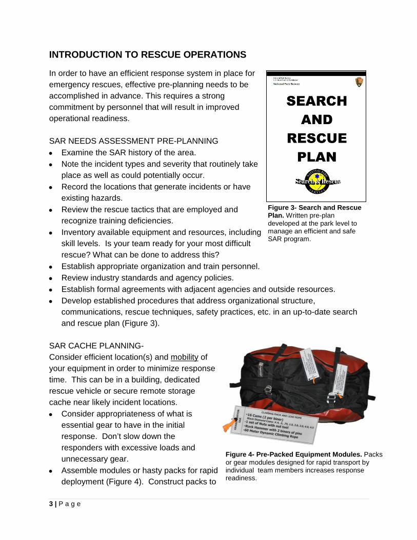
• Establish appropriate organization and train personnel. • Review industry standards and agency policies. • Establish formal agreements with adjacent agencies and outside resources. • Develop established procedures that address organizational structure,
communications, rescue techniques, safety practices, etc. in an up-to-date search and rescue plan (Figure 3).
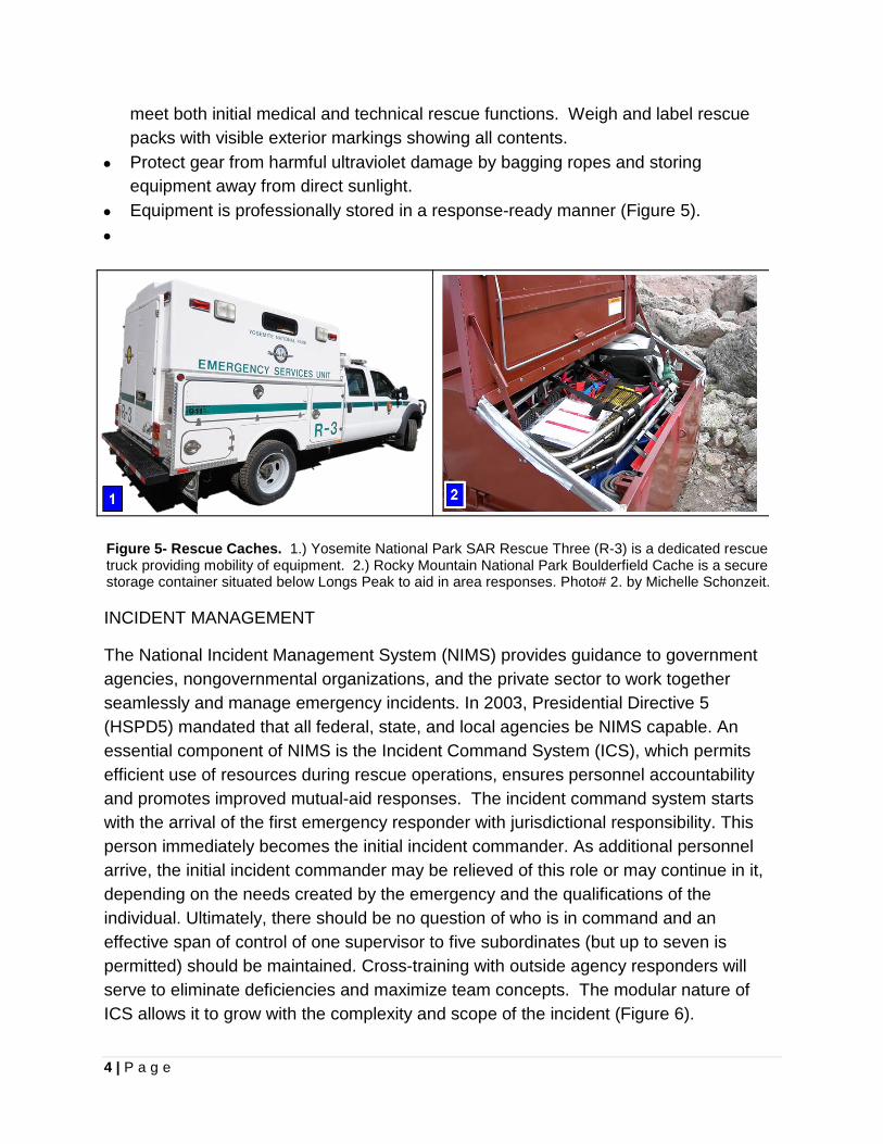
SAR CACHE PLANNING- Consider efficient location(s) and mobility of your equipment in order to minimize response time. This can be in a building, dedicated rescue vehicle or secure remote storage cache near likely incident locations. • Consider appropriateness of what is
essential gear to have in the initial response. Don’t slow down the responders with excessive loads and unnecessary gear.
• Assemble modules or hasty packs for rapid deployment (Figure 4). Construct packs to
Figure 3- Search and Rescue Plan. Written pre-plan developed at the park level to manage an efficient and safe SAR program.
Figure 4- Pre-Packed Equipment Modules. Packs or gear modules designed for rapid transport by individual team members increases response readiness.
4 | P a g e
meet both initial medical and technical rescue functions. Weigh and label rescue packs with visible exterior markings showing all contents.
• Protect gear from harmful ultraviolet damage by bagging ropes and storing equipment away from direct sunlight.
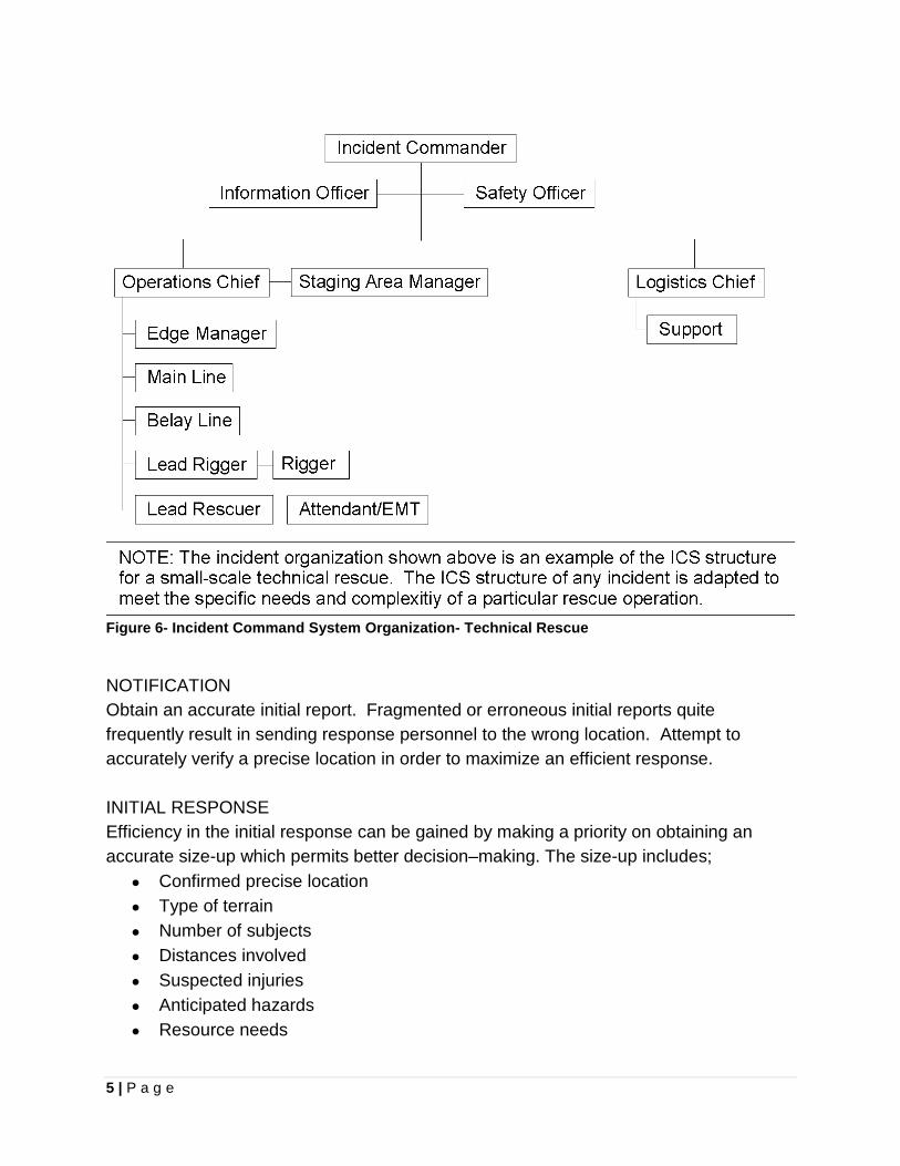
• Equipment is professionally stored in a response-ready manner (Figure 5). •
Figure 5- Rescue Caches. 1.) Yosemite National Park SAR Rescue Three (R-3) is a dedicated rescue truck providing mobility of equipment. 2.) Rocky Mountain National Park Boulderfield Cache is a secure storage container situated below Longs Peak to aid in area responses. Photo# 2. by Michelle Schonzeit.
INCIDENT MANAGEMENT
The National Incident Management System (NIMS) provides guidance to government agencies, nongovernmental organizations, and the private sector to work together seamlessly and manage emergency incidents. In 2003, Presidential Directive 5 (HSPD5) mandated that all federal, state, and local agencies be NIMS capable. An essential component of NIMS is the Incident Command System (ICS), which permits efficient use of resources during rescue operations, ensures personnel accountability and promotes improved mutual-aid responses. The incident command system starts with the arrival of the first emergency responder with jurisdictional responsibility. This person immediately becomes the initial incident commander. As additional personnel arrive, the initial incident commander may be relieved of this role or may continue in it, depending on the needs created by the emergency and the qualifications of the individual. Ultimately, there should be no question of who is in command and an effective span of control of one supervisor to five subordinates (but up to seven is permitted) should be maintained. Cross-training with outside agency responders will serve to eliminate deficiencies and maximize team concepts. The modular nature of ICS allows it to grow with the complexity and scope of the incident (Figure 6).
5 | P a g e
Figure 6- Incident Command System Organization- Technical Rescue
NOTIFICATION Obtain an accurate initial report. Fragmented or erroneous initial reports quite frequently result in sending response personnel to the wrong location. Attempt to accurately verify a precise location in order to maximize an efficient response. INITIAL RESPONSE Efficiency in the initial response can be gained by making a priority on obtaining an accurate size-up which permits better decision–making. The size-up includes;
• Confirmed precise location • Type of terrain • Number of subjects • Distances involved • Suspected injuries • Anticipated hazards • Resource needs
6 | P a g e
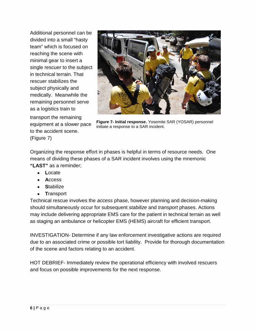
Additional personnel can be divided into a small “hasty team” which is focused on reaching the scene with minimal gear to insert a single rescuer to the subject in technical terrain. That rescuer stabilizes the subject physically and medically. Meanwhile the remaining personnel serve as a logistics train to
transport the remaining equipment at a slower pace to the accident scene. (Figure 7) Organizing the response effort in phases is helpful in terms of resource needs. One means of dividing these phases of a SAR incident involves using the mnemonic “LAST” as a reminder;
• Locate • Access • Stabilize • Transport
Technical rescue involves the access phase, however planning and decision-making should simultaneously occur for subsequent stabilize and transport phases. Actions may include delivering appropriate EMS care for the patient in technical terrain as well as staging an ambulance or helicopter EMS (HEMS) aircraft for efficient transport. INVESTIGATION- Determine if any law enforcement investigative actions are required due to an associated crime or possible tort liability. Provide for thorough documentation of the scene and factors relating to an accident. HOT DEBRIEF- Immediately review the operational efficiency with involved rescuers and focus on possible improvements for the next response.
Figure 7- Initial response. Yosemite SAR (YOSAR) personnel initiate a response to a SAR incident.
7 | P a g e
INCIDENT REVIEW (After-Action Review) • A formal incident review is frequently scheduled for larger incidents to conduct an
honest review of the incident with all involved agencies. • A moderator leads the review with a posted agenda to evaluate the operational
safety, effectiveness and efficiency. Using a structured format for the review will assist in keeping it on track.
CISM- Provide for the Critical Incident Stress Management (CISM) needs of involved personnel. Conduct defusing sessions when appropriate to provide for the mental health of emergency responders. PREVENTIVE SEARCH AND RESCUE- Implement preventive search and rescue (PSAR) actions to mitigate potential accidents in advance. Seek effective strategies to provide information for the public that encourages safe behavior. Analyze accident statistics to understand where efforts should be focused. KEY POINTS TOWARD MAINTAINING AN ORGANIZED RESCUE • Initiate a quick “size-up” of the incident to verify initial report. • Organize an immediate initial response to reach and stabilize the victim. • Utilize ICS and identify positions (verbally on the radio and use of vests). • Establish an accessible staging area for your equipment. • Limit communications with technical rescuer(s) to the Edge Manager or the
Operations Chief (Rescue Group Supervisor). • Provide for investigative considerations at an “accident scene,” which includes
preserving evidence at the location a subject fell from, obtaining witness statements, photographing the scene and considering the possibility of foul play.
• Stay ahead of the logistics curve. Plan and act now.... Be mentally prepared for a rescue to take longer than you expect.
• Keep rescue systems simple and safe. An overly complex system may compromise your efficiency.
OPERATIONAL CHECKLIST FOR EFFICIENT SAR RESPONSES: � Level of response reflects effective risk management for rescuers? � Utilizing appropriate techniques for the task?
o Alternate methods adequately evaluated o Operations within equipment and personnel performance capabilities o Initial response rescuers prepared to provide EMS care
� Adequate ICS organization in place? o “Command” has been identified to involved personnel
8 | P a g e
o Personnel accountability established o Check-in, flight following, span of control and demobilization in place
� Effective communications in place? o Mission briefings conducted for all involved personnel o Clear instructions provided without assumptions being made o Tactical and command radio frequencies established
� Strategically reviewed plan for omissions or deficiencies? o Effectively planning to stay ahead of the “power curve” o Anticipating and working to prevent possible mission delays
� Safety truly being openly promoted? o Compliance with safe working practices o Established policies and procedures known by incident personnel
� Is staging of additional resources identified and being employed? o Stage EMS resources (ambulance or helicopter) for efficient patient transfer
� Have you planned for rest and rehabilitation of involved personnel? o Fatigue, stress and dehydration profoundly affect performance o Employ rotations of rested personnel o Provide for CISM support
9 | P a g e
Chapter 2
SAFETY CONSIDERATIONS Remember your priorities for operational safety:
1. You are number ONE! 2. Your fellow rescuers are your SECOND concern. 3. The subject is your THIRD priority.
We also have an operational responsibility to protect bystanders at the scene. Safety is of paramount importance at all times. If you see any action that is unsafe, it is your responsibility to speak up!
Remember that no one is infallible and that includes you! The worst-case scenario is having a rescuer injured, resulting in two patients. Don't create an incident within an incident.
INCIDENT RISK MANAGEMENT PROCESS6
STEP 1- Situational Awareness • Gather Information Objectives Incident organization Communication Local factors/terrain/hazards Weather forecast
STEP 2- Hazard Assessment
• Identify tactical hazards • Consider complexity of incident
STEP 3- Hazard Control
• Mitigate potential hazards through safety procedures & protective equipment
6 NWCG Incident Response Pocket Guide (NFES #1077), NIFC, Boise, p. xii-1
10 | P a g e
STEP 4- Decision Point GO or NO-GO -To implement planned course of action STEP 5- Evaluate
• Human Factors: Low experience level for activity? Distracted from primary task? Fatigue or stress reaction? Hazardous attitude?
• Situation: What is changing? Are strategy and tactics working?
OPERATIONAL RISK MANAGEMENT
The U.S. Coast Guard (USCG) has an excellent tradition of conducting hazardous SAR operations in the maritime environment. Tragically, between 1991 and 1993 they experienced four major marine mishaps, which caused the National Transportation Safety Board (NTSB) to issue a recommendation for the agency to implement a more formal risk assessment training program. As a result, in 1996 the USCG executed a systematic process to continuously assess and manage risks, known as “Operational Risk Management” (ORM)7. ORM identifies and controls risks in all activities by applying appropriate management policies and procedures. As an operation progresses and evolves, personnel should continuously employ the following key operational risk management principles: 1. Accept No Unnecessary Risk: SAR operations entail risk. Unnecessary risk conveys no commensurate benefit to safety of a mission. The most logical courses of action for accomplishing a mission are those meeting all mission requirements while exposing personnel and resources to the lowest possible risk. 2. Accept Necessary Risk When Benefits Outweigh Costs: The process of weighing risks against opportunities and benefits helps to maximize unit capability. Even high-risk endeavors may be undertaken when decision-makers clearly acknowledge the sum of the benefits exceeds the sum of the costs.
3. Make Risk Decisions at the Appropriate Level: The appropriate level to make risk decisions is that which most effectively allocates resources to reduce the risk, eliminate 7 U.S. Coast Guard, Commandant Instruction 3500.3- Operational Risk Management.
11 | P a g e
the hazard, and implement controls. Incident personnel must ensure subordinates are aware of their own limitations and when to refer a decision to a higher level. 4. Integrate ORM into Operations and Planning at All Levels: While ORM is critically important in an operation’s planning stages; risk can change dramatically during an actual mission. Incident personnel should remain flexible and integrate ORM in executing tasks as much as in planning for them.
GAR Risk Assessment Model A remarkably effective ORM tool is the GAR (Green-Amber-Red) Risk Assessment Model, which creates a GO-NO GO decision tool. GAR Model incorporates the opinions of multiple involved personnel, which is a limitation of other risk assessment tools that are only completed by a single person. GAR respondents independently assign a personal risk score to eight different elements associated with a mission. The risk score is zero (No Risk) through 10 (Maximum Risk), which is a personal estimate of risk.
The following elements are evaluated in the GAR Model:
• SUPERVISION- The presence of qualified, accessible and effective supervision on the incident. A clear chain of command is in place.
• PLANNING- Adequate incident information is available and clear. There is sufficient time to plan, operational guidelines are current, briefing of personnel is being conducted and team input solicited.
• CONTINGENCY RESOURCES- Backup resources that can assist if needed. Evaluate shared communications plan and frequencies. Has an alternative plan been evaluated?
• COMMUNICATION- Evaluate how well personnel are briefed and communicating. How effective is communication system and is there is an established communication plan? Does the operational environment value input
• TEAM SELECTION- Team selection should consider the qualifications and experience level of the individuals. Consider the experience for the mission being performed.
• TEAM FITNESS- Consider physical and mental state of the crew. Evaluate team morale and any distractions.
• ENVIRONMENT- Consider factors affecting performance of personnel and equipment such as time, temperature, precipitation, topography and altitude. Evaluate site factors such as narrow canyons, forest canopy, technical terrain, snow, swiftwater, etc.
• INCIDENT COMPLEXITY- Evaluate severity, exposure time and probability of mishap. Assess difficulty of the mission and proficiency of personnel.
12 | P a g e
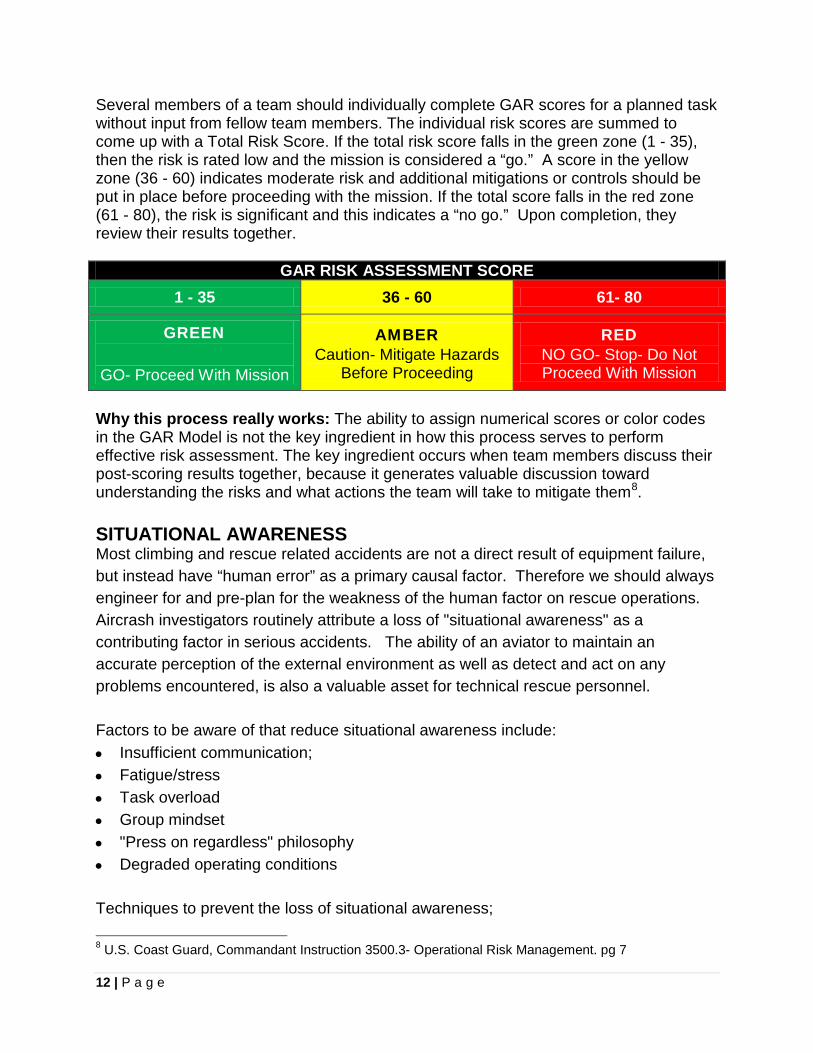
Several members of a team should individually complete GAR scores for a planned task without input from fellow team members. The individual risk scores are summed to come up with a Total Risk Score. If the total risk score falls in the green zone (1 - 35), then the risk is rated low and the mission is considered a “go.” A score in the yellow zone (36 - 60) indicates moderate risk and additional mitigations or controls should be put in place before proceeding with the mission. If the total score falls in the red zone (61 - 80), the risk is significant and this indicates a “no go.” Upon completion, they review their results together.
GAR RISK ASSESSMENT SCORE 1 - 35 36 - 60 61- 80
GREEN
GO- Proceed With Mission
AMBER Caution- Mitigate Hazards
Before Proceeding
RED NO GO- Stop- Do Not Proceed With Mission
Why this process really works: The ability to assign numerical scores or color codes in the GAR Model is not the key ingredient in how this process serves to perform effective risk assessment. The key ingredient occurs when team members discuss their post-scoring results together, because it generates valuable discussion toward understanding the risks and what actions the team will take to mitigate them8. SITUATIONAL AWARENESS Most climbing and rescue related accidents are not a direct result of equipment failure, but instead have “human error” as a primary causal factor. Therefore we should always engineer for and pre-plan for the weakness of the human factor on rescue operations. Aircrash investigators routinely attribute a loss of "situational awareness" as a contributing factor in serious accidents. The ability of an aviator to maintain an accurate perception of the external environment as well as detect and act on any problems encountered, is also a valuable asset for technical rescue personnel. Factors to be aware of that reduce situational awareness include: • Insufficient communication; • Fatigue/stress • Task overload • Group mindset • "Press on regardless" philosophy • Degraded operating conditions Techniques to prevent the loss of situational awareness; 8 U.S. Coast Guard, Commandant Instruction 3500.3- Operational Risk Management. pg 7
13 | P a g e
• Actively question and evaluate your mission progress • Update and revise your image of the mission • Use appropriate assertive behaviors when necessary;
Make suggestions Provide relevant information without being asked Confront ambiguities in assignments State opinion on decisions and procedures
• Refuse unreasonable requests IMPORTANT SAFETY REMINDERS “Slow is smooth... smooth is fast.” This mantra from military marksmanship emphasizes that rushing in a reckless manner is much riskier than slow careful and deliberate actions. By being well organized a rescue team can breed efficiency in their emergency response efforts. A disciplined team communicates effectively and they accomplish their tasks without rushing or yelling. Team members know what to do and are trained to the level of competency. Here is how a team can achieve getting to this level of competence. • Speed- Do not rush! Maintain a sense of "controlled urgency." • Proficiency- Use well-trained, competent rescuers for the core of the team. • Safety Officer- Designate a Safety Officer for the
operation. Avoid having this be a collateral role for a rescuer with another task.
• Safety Checks- Do a thorough visual and tactile (look, touch and talk) rigging safety check prior to use of a system. Recheck equipment during use, since carabiners can unlock or rigging can become misaligned.
• Redundancy- Create a system with backups. • Communication- Use standard terminology. • PPE- Aggressively employ appropriate personal
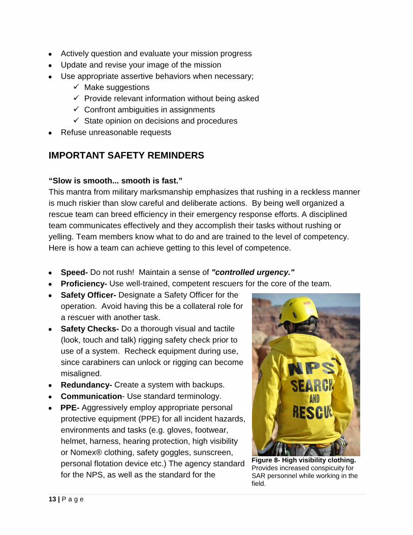
protective equipment (PPE) for all incident hazards, environments and tasks (e.g. gloves, footwear, helmet, harness, hearing protection, high visibility or Nomex® clothing, safety goggles, sunscreen, personal flotation device etc.) The agency standard for the NPS, as well as the standard for the
Figure 8- High visibility clothing. Provides increased conspicuity for SAR personnel while working in the field.
14 | P a g e
industry, is to wear high visibility outerwear for enhanced personal safety (Figure 8). Have spare PPE equipment available (Additional information on PPE is covered in Chapter 8- Equipment).
• Equipment Staging - Secure unused equipment in a gear cache adjacent to the rescue operations area.
• Contingency Tools- Keep a Prusik and cutting tool (e.g. trauma shears) immediately accessible for use.
• Carabiner Use- Be aware to prevent "cross-gate forces" and three-way forces on carabiners.
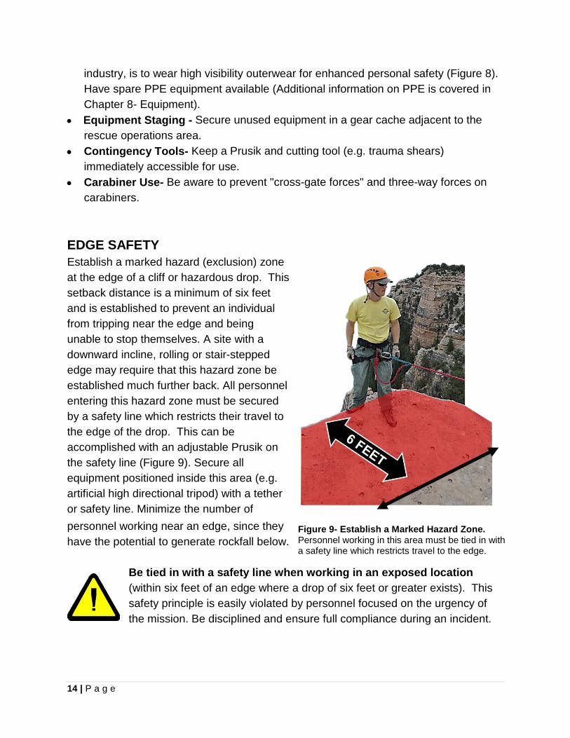
EDGE SAFETY Establish a marked hazard (exclusion) zone at the edge of a cliff or hazardous drop. This setback distance is a minimum of six feet and is established to prevent an individual from tripping near the edge and being unable to stop themselves. A site with a downward incline, rolling or stair-stepped edge may require that this hazard zone be established much further back. All personnel entering this hazard zone must be secured by a safety line which restricts their travel to the edge of the drop. This can be accomplished with an adjustable Prusik on the safety line (Figure 9). Secure all equipment positioned inside this area (e.g. artificial high directional tripod) with a tether or safety line. Minimize the number of personnel working near an edge, since they have the potential to generate rockfall below.
Be tied in with a safety line when working in an exposed location (within six feet of an edge where a drop of six feet or greater exists). This safety principle is easily violated by personnel focused on the urgency of the mission. Be disciplined and ensure full compliance during an incident.
Figure 9- Establish a Marked Hazard Zone. Personnel working in this area must be tied in with a safety line which restricts travel to the edge.

15 | P a g e
Recoil or Snapback Hazard When a tensioned rope breaks or a component forming a rope bight fails, the energy within the rope will cause it to recoil back in unpredictable directions with great force, resulting in possible injury to persons in the path. Avoid having personnel standing or working in the potential path of a rope bight under tension (Figure 10).
Avoid standing inside a bight of rope (vector zone) under tension, such as inside of a pulley system.
Figure 10- Don't stand inside a bight of rope under tension! You make yourself a target in the event of equipment failure.
16 | P a g e
Chapter 3
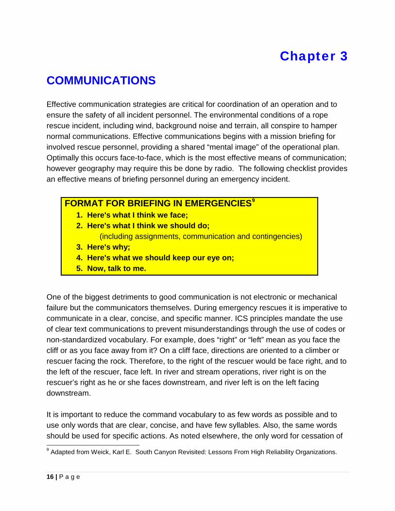
COMMUNICATIONS Effective communication strategies are critical for coordination of an operation and to ensure the safety of all incident personnel. The environmental conditions of a rope rescue incident, including wind, background noise and terrain, all conspire to hamper normal communications. Effective communications begins with a mission briefing for involved rescue personnel, providing a shared “mental image” of the operational plan. Optimally this occurs face-to-face, which is the most effective means of communication; however geography may require this be done by radio. The following checklist provides an effective means of briefing personnel during an emergency incident.
One of the biggest detriments to good communication is not electronic or mechanical failure but the communicators themselves. During emergency rescues it is imperative to communicate in a clear, concise, and specific manner. ICS principles mandate the use of clear text communications to prevent misunderstandings through the use of codes or non-standardized vocabulary. For example, does “right” or “left” mean as you face the cliff or as you face away from it? On a cliff face, directions are oriented to a climber or rescuer facing the rock. Therefore, to the right of the rescuer would be face right, and to the left of the rescuer, face left. In river and stream operations, river right is on the rescuer’s right as he or she faces downstream, and river left is on the left facing downstream. It is important to reduce the command vocabulary to as few words as possible and to use only words that are clear, concise, and have few syllables. Also, the same words should be used for specific actions. As noted elsewhere, the only word for cessation of 9 Adapted from Weick, Karl E. South Canyon Revisited: Lessons From High Reliability Organizations.
FORMAT FOR BRIEFING IN EMERGENCIES9 1. Here's what I think we face; 2. Here's what I think we should do;
(including assignments, communication and contingencies) 3. Here's why; 4. Here's what we should keep our eye on; 5. Now, talk to me.
17 | P a g e
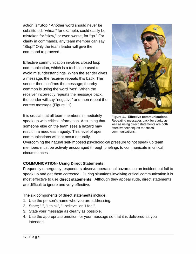
action is “Stop!” Another word should never be substituted; “whoa,” for example, could easily be mistaken for “slow,” or even worse, for “go.” For clarity in commands, any team member can say “Stop!” Only the team leader will give the command to proceed. Effective communication involves closed loop communication, which is a technique used to avoid misunderstandings. When the sender gives a message, the receiver repeats this back. The sender then confirms the message; thereby common is using the word “yes”. When the receiver incorrectly repeats the message back, the sender will say “negative” and then repeat the correct message (Figure 11). It is crucial that all team members immediately speak up with critical information. Assuming that someone else on the team sees a hazard may result in a needless tragedy. This level of open communications will not occur naturally. Overcoming the natural self-imposed psychological pressure to not speak up team members must be actively encouraged through briefings to communicate in critical circumstances. COMMUNICATION- Using Direct Statements: Frequently emergency responders observe operational hazards on an incident but fail to speak up and get them corrected. During situations involving critical communication it is most effective to use direct statements. Although they appear rude, direct statements are difficult to ignore and very effective. The six components of direct statements include: 1. Use the person's name who you are addressing. 2. State; "I", "I think", "I believe" or "I feel". 3. State your message as clearly as possible. 4. Use the appropriate emotion for your message so that it is delivered as you
intended.
Figure 11- Effective communications. Repeating messages back for clarity as well as using direct statements are both effective techniques for critical communications.
18 | P a g e
5. Require a response by using such statements as "What do you think?" or "Don't you agree?"
6. Don't let it go. Don't disengage with the other person till an understanding is achieved.
Example: "Jane, I think we need additional personnel for this rescue operation. Don't you agree?"
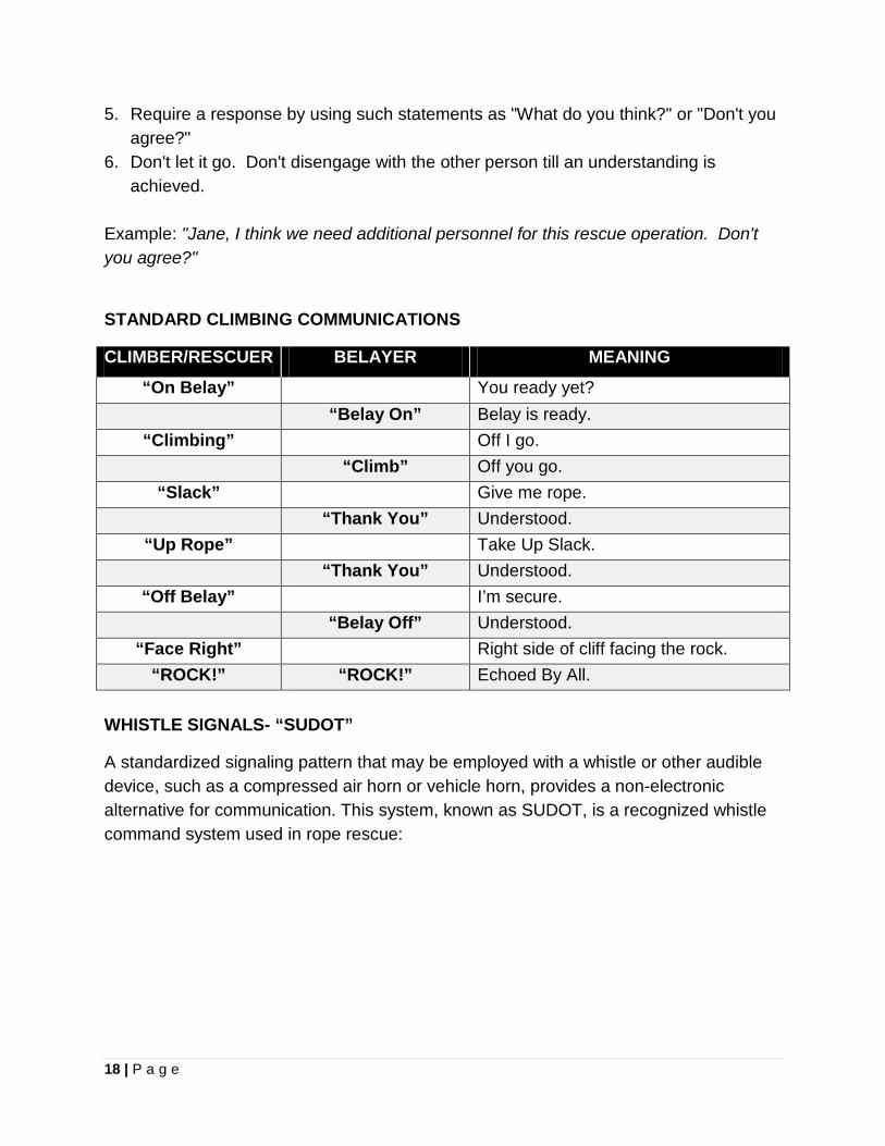
STANDARD CLIMBING COMMUNICATIONS
CLIMBER/RESCUER BELAYER MEANING
“On Belay” You ready yet? “Belay On” Belay is ready.
“Climbing” Off I go. “Climb” Off you go.
“Slack” Give me rope. “Thank You” Understood.
“Up Rope” Take Up Slack. “Thank You” Understood.
“Off Belay” I’m secure. “Belay Off” Understood.
“Face Right” Right side of cliff facing the rock. “ROCK!” “ROCK!” Echoed By All.
WHISTLE SIGNALS- “SUDOT”
A standardized signaling pattern that may be employed with a whistle or other audible device, such as a compressed air horn or vehicle horn, provides a non-electronic alternative for communication. This system, known as SUDOT, is a recognized whistle command system used in rope rescue:
19 | P a g e
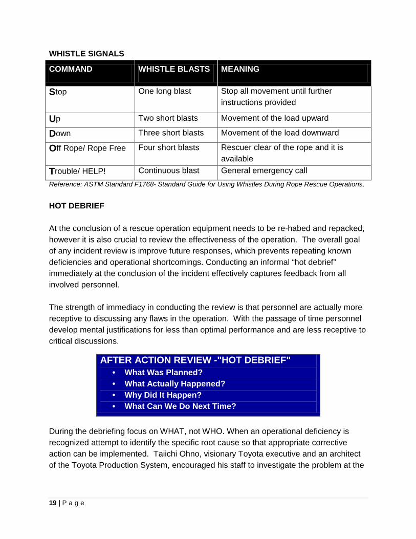
WHISTLE SIGNALS
COMMAND WHISTLE BLASTS MEANING
Stop One long blast Stop all movement until further instructions provided
Up Two short blasts Movement of the load upward
Down Three short blasts Movement of the load downward
Off Rope/ Rope Free Four short blasts Rescuer clear of the rope and it is available
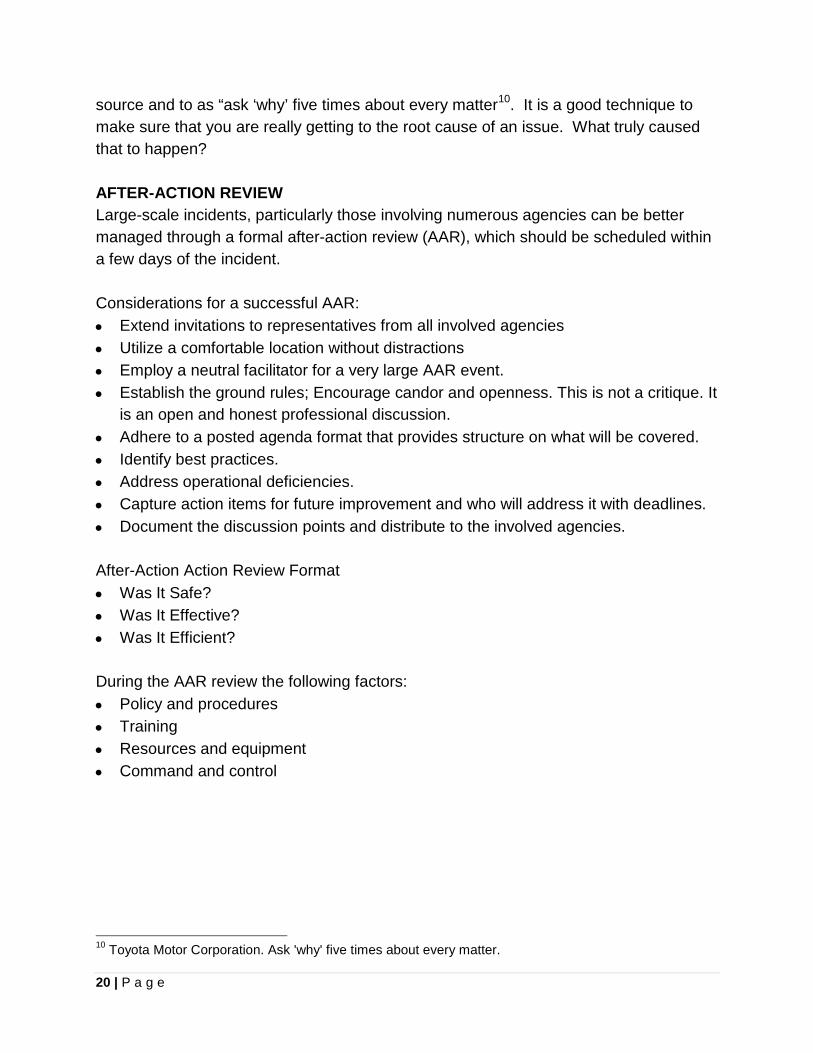
Trouble/ HELP! Continuous blast General emergency call Reference: ASTM Standard F1768- Standard Guide for Using Whistles During Rope Rescue Operations. HOT DEBRIEF At the conclusion of a rescue operation equipment needs to be re-habed and repacked, however it is also crucial to review the effectiveness of the operation. The overall goal of any incident review is improve future responses, which prevents repeating known deficiencies and operational shortcomings. Conducting an informal “hot debrief” immediately at the conclusion of the incident effectively captures feedback from all involved personnel. The strength of immediacy in conducting the review is that personnel are actually more receptive to discussing any flaws in the operation. With the passage of time personnel develop mental justifications for less than optimal performance and are less receptive to critical discussions. During the debriefing focus on WHAT, not WHO. When an operational deficiency is recognized attempt to identify the specific root cause so that appropriate corrective action can be implemented. Taiichi Ohno, visionary Toyota executive and an architect of the Toyota Production System, encouraged his staff to investigate the problem at the
AFTER ACTION REVIEW -"HOT DEBRIEF" • What Was Planned? • What Actually Happened? • Why Did It Happen? • What Can We Do Next Time?
20 | P a g e
source and to as “ask ‘why’ five times about every matter10. It is a good technique to make sure that you are really getting to the root cause of an issue. What truly caused that to happen? AFTER-ACTION REVIEW Large-scale incidents, particularly those involving numerous agencies can be better managed through a formal after-action review (AAR), which should be scheduled within a few days of the incident. Considerations for a successful AAR: • Extend invitations to representatives from all involved agencies • Utilize a comfortable location without distractions • Employ a neutral facilitator for a very large AAR event. • Establish the ground rules; Encourage candor and openness. This is not a critique. It
is an open and honest professional discussion. • Adhere to a posted agenda format that provides structure on what will be covered. • Identify best practices. • Address operational deficiencies. • Capture action items for future improvement and who will address it with deadlines. • Document the discussion points and distribute to the involved agencies. After-Action Action Review Format • Was It Safe? • Was It Effective? • Was It Efficient? During the AAR review the following factors: • Policy and procedures • Training • Resources and equipment • Command and control
10 Toyota Motor Corporation. Ask 'why' five times about every matter.

21 | P a g e
Chapter 4
SAFETY FACTORS AND FORCES SAFETY FACTOR A safety factor, also referred to as a factor of safety, for a given system is a determination of how much stronger a system is than the intended load. More precisely, for the purposes of rope rescue, the Static System Safety Factor (SSSF) is the ratio between the equipment breaking strength and the maximum expected static force. In contrast, a Dynamic Safety Factor (DSF) is calculated for the strength of system to protect against the dynamic impact force associated with a falling load, which is considered the “worst case scenario.” This sounds like a straightforward process, unfortunately it is not that simple. Dr. Stephen Attaway, a researcher at Sandia National Labs, who has an M.S. in Civil Engineering and Ph.D. in Computational Mechanics, which is the field of science related to numerical modeling of the stresses and strains associated with displacement of materials, provides some great insight. According to Dr. Attaway, who is also an active member of Albuquerque Mountain Rescue Council (AMRC); “The rescue community is still struggling with what is the correct approach for a system design. In many cases, the ability to estimate the dynamic loads is beyond the ability of most rescuers in the field. In some cases, the science of predicting loads in rescue systems is still imprecise. Thus, in the absence of the ability to compute the dynamic loads in the field, the default is to apply a static safety factor……It is up to the designer of the system to insure that the design criteria are not exceeded. (Think of a weight limit on trucks for bridges, or the number of people allowed in an elevator).”11 The majority of mountain rescuers have adopted a 10:1 SSSF in rope rescue systems, with the primary premise to provide sufficient rigging strength that the peak force of a relative worst case event would be less than failure level (breaking strength or failure yield) of the equipment. Why employ a 10:1 Static System Safety Factor? A “load case,” which is a combination of different types of loads with safety factors applied to them, is used in engineering to check for the strength and serviceability of a structure. This analysis of
11 Design Criteria for Rescue Systems, Attaway, Stephen. Personal correspondence. 2014.

22 | P a g e
load cases determines the ultimate limit state (ULS) for a structure and involves applying the following definitions;
• Dead Load; static (non-moving) weight being applied as well as structural weight • Live Load; dynamic (changing in magnitude) loads caused by snow and ice,
wind, seismic events, impact forces, etc. The following formula, which applies statistically determined multipliers, is typically used by engineers in determining load cases;12
1.2 x Dead Load + 1.6 x Live Load This computed load case is compared to the overall system strength with a safety factor applied. In the following case, a load limit safety factor of 75% (.75) has been applied, which is a factor routinely used in structural engineering13,14
1.2 x Dead Load + 1.6 x Live Load < .75 x System Strength Adhering to this keeps the maximum stress on the system to less than the strength of the system. In applying the 10:1 SSSF in rescue rigging, a similar relationship is found between the “worst case” and the system strength. It is still important to understand that a system component safety factor of 10:1 or higher can still be unsafe, if the equipment is rigged in an improper manner. When rigging a rescue system it is important to always consider the weakest link or component in your design. KILONEWTONS AND THE TECHNICAL RESCUER A kilonewton (kN) is a measure of force and has much more relevance to rescuers than say a measure of just mass. A falling rescuer or climber is mass accelerating under the pull of gravity. Most rescue equipment manufacturers label their wares according to a specific kN rating for strength. A Newton is the force required to accelerate one kilogram, one meter per second. 1 kN or 1,000 Newtons is the force required to accelerate 1,000 kilograms, one meter per second. For conversion purposes, 1 kN is the force approximately equal to one rescuer plus gear, or 225 lbs of force (lbf).
12 Wikipedia. Structural Engineering Theory. http://en.wikipedia.org/wiki/Structural_engineering_theory 13 Design of Reinforced Concrete, 9th edition. McCormac, Jack and Russell Brown. 14 Steel Construction Manual, 14th Ed., Third Printing. AISC.
Standard Rescue Load Definitions Description Kilograms Pounds Represents Single Rescuer (~1kN) 100 kg 220 lbs Rescuer + Gear Rescue Load (~2 kN) 200 kg 440 lbs Victim + Rescuer + Gear

23 | P a g e
Source: ASTM F2266-03 (2008)
RESCUE TERMINOLOGY AND PHYSICS
Mass- A measure of the amount or quantity of matter. By international agreement the standard unit of mass, with which the masses of all other objects are compared, is a platinum-iridium cylinder of one kilogram. In countries that favor the English system (avoirdupois system- based upon a pound of 16 ounces) of measurement over the International System of Units (SI), the avoirdupois pound, a measure of mass, is used instead. Finally another unit of mass is the slug, which is associated with Imperial units and equals 14.59 kg (32.17 lbm). In contrast to "weight", mass remains constant regardless of its location, under ordinary circumstances. A satellite launched into space for example, weighs increasingly less the further it travels away from the earth. Its mass, however, stays the same. Force- The term "weight" is considered ambiguous in rescue rigging. Weight essentially constitutes the force exerted on matter by the gravitational attraction of the Earth, and so it varies from place to place. Force is the action of one body on another body. Are you referring to a force acting on the rope or a mass suspended on it? Acceleration- The rate at which an object changes its velocity. An object is accelerating if it is changing its velocity, however an object with a constant velocity is not accelerating. The relationship between force, mass and acceleration is expressed in the equation “force= mass X acceleration” (F=ma). Force (Newton, N) = mass (kilogram, kg) x acceleration (meters per second squared, m/s2). Newton- It is defined as that force necessary to provide a mass of one kilogram with an acceleration of one meter per second per second (N=kg/s2). One Newton is equal to a force of 0.2248 pound in the foot-pound-second (English or customary) system. The Newton was named for Sir Isaac Newton, whose second law of motion describes the changes that a force can produce in the motion of a body. For reference 1000 Newtons (N) equals 1 kilonewton (kN). NOTE: A technical rescuer needs to understand; 1 kN = 225 lbs of force (lbf)
Three Person Load 280 kg 617 lbs Victim + Two Rescuers + Gear
24 | P a g e
Tension- To refer to a "load" on a rope is another ambiguous use of terminology in rescue rigging. It is more accurate to say tension the rope, instead of load the rope. Shock Force- The resulting tension in a system when a mass is transferred to a system in a catastrophic manner. The term shock force is more accurate than the ambiguous expression of "shock load." There is a distinct difference between units of measure for force and mass.
FORCE MASS US system Pound-force (lbf) Slug SI System (International System of Units) Newton (N) kilogram (kg)
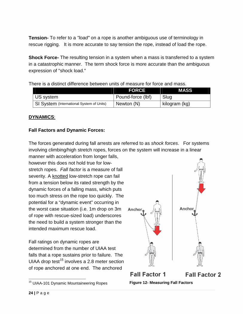
DYNAMICS: Fall Factors and Dynamic Forces: The forces generated during fall arrests are referred to as shock forces. For systems involving climbing/high stretch ropes, forces on the system will increase in a linear manner with acceleration from longer falls, however this does not hold true for low-stretch ropes. Fall factor is a measure of fall severity. A knotted low-stretch rope can fail from a tension below its rated strength by the dynamic forces of a falling mass, which puts too much stress on the rope too quickly. The potential for a “dynamic event” occurring in the worst case situation (i.e. 1m drop on 3m of rope with rescue-sized load) underscores the need to build a system stronger than the intended maximum rescue load. Fall ratings on dynamic ropes are determined from the number of UIAA test falls that a rope sustains prior to failure. The UIAA drop test15 involves a 2.8 meter section of rope anchored at one end. The anchored
15 UIAA-101 Dynamic Mountaineering Ropes Figure 12- Measuring Fall Factors

25 | P a g e
end is .3 meters away from a carabiner with an 80 kg mass on the remaining 2.5 meters of slack. The resultant fall of 5 meters generates a fall factor of 1.78. Fall factor is calculated from the length of the fall divided by rope available for energy absorption. Typically a factor 2 fall is the highest encountered in a climbing situation, where the rescuer lead climbs above the belayer (Figure 12). This might involve falling 20 feet (6 meters) with 10 feet (3 meters) of rope available for energy absorption. A fall factor 2 on low-stretch rope generates enough force to cause injury or death. However it is recommended that only a maximum fall factor of 0.25 be permitted in a rescue system16. Keeping this principle in mind, one of the potential scenarios for generating the highest shock forces is during an edge transition, either down over or up to, with a rescue-sized load and with little rope in service. Fall Factor: ______Fall Distance______ Amount of Rope for Energy Absorption Knowledge regarding dynamic forces can be applied practically by rescuers in the field. As an extreme example, ask yourself how could you safely lead climb up a tower using low-stretch rope, while keeping the fall factor at an acceptable level? The solution is to increase the amount of rope available for energy absorption by moving the anchor out away from the base. BELAY COMPETENCE DROP TEST METHOD Developed by British Columbia Council of Technical Rescue (BCCTR) in the early 1980’s, the Belay Competency Drop Test uses a one meter drop on three meters of rope with a 200 kg mass, which is only a fall factor 0.3. The peak force generated by this test using the Tandem Prusik Belay, the 540O TM Rescue Belay and the CMC Rescue MPD™ is <15 kN* (typical peak force is below 10-12 kN). *This is distributed between each individual mass in the system, such as the rescuer or victim, which does not result in such a peak force applied per person. The Belay Competency Drop Test Method has now been adapted into ASTM F2436-05 Standard Test Method for Measuring the Performance of Synthetic Rope Rescue Belay Systems Using a Drop Test.17 The NFPA 1983 Standard on Life Safety Equipment and
16 NFPA 1983- Standard on Life Safety Equipment and Rope- 2012 ed., sec. A.1.3.4 17 ASTM
26 | P a g e
Rope utilizes the ASTM Belay Test Method as the test method for belay devices. The performance requirements are the same as the original BCCTR criteria. The National Fire Protection Association (NFPA) Standard- NFPA1983, which is utilized by the fire service, states; “when fall factors of greater than 0.25 are anticipated, such as are possible in lead climbing, dynamic ropes specifically designed for climbing should be considered.” Additionally “for the purposes of this document fall factors greater than 0.25 generate unacceptable impact loads.”18 If we build a system with a static system safety factor of 10:1 for the relative worst case event, we will likely wind up with a 2:1 DSF. The relative worst case scenario is defined as a one meter drop on three meters of rope with a rescue-sized load. Looking at the example of the Belay Competence Drop Test above, we should attempt to achieve a constant goal of 20-24 kN (4,496- 5,395 lbf) strength (twice the amount seen in the peak force) in order to not exceed the yield point of equipment due to a dynamic event. SYSTEMS ANALYSIS
CRITICAL POINT TEST; examines what would happen to the rescuers and the victim if any single piece of equipment were to fail at any particular moment. Would there be anything to back it up? If there is no backup, then it is a "critical point." WHISTLE TEST; examines what would happen to the rescuers and the victim if at any time during the operation everyone were to let go. This duplicates what would happen if rescuers were struck by lightning or if someone forgot to do his job. Does the system function automatically? Based upon these working definitions, here is a progressive method for evaluating safe rescue system designs; 1. Whiteboard Analysis- Diagram the system and thoroughly examine all the details
for function as intended. Will it function properly? Does it have sufficient strength? 2. Critical Point Test- Examine every component of a system to locate any "critical
points." If one point fails, is there a redundant backup to prevent catastrophic failure?
3. Whistle Test- If a whistle were sounded, and every rescuer let go of the ropes, would the system properly engage and prevent a fall?
If these are all answered positively, then the system is likely safe to use. 18 NFPA. NFPA 1983. 2012 ed. Sec A.1.3.4

27 | P a g e
Chapter 5
STANDARDS AND INDUSTRY RATINGS Note: A more detailed reference to the specifics within several applicable industry standards may be found in Appendix 5. Industry standards and certifications relating to rescue equipment as well as technical rescue practices have created a body of generally accepted “best practices” that directly influence organizations and agencies. It is important to follow the development of these external benchmarks A manufacturer may select to advertise their products as “compliant with” as opposed to “certified to” a specific industry standard. Certification to a standard typically requires that a manufacturer contract with an outside independent third-party (e.g. Underwriters Laboratory) for product testing and certification. In addition to third party testing, NFPA requires an ISO 9000 level quality assurance program by the manufacturer. On the other hand, compliance typically means that the manufacturer has self-audited their manufacturing processes and product testing to meet or exceed the associated industry standard. ANSI- The American National Standards Institute is a non-profit organization which develops voluntary consensus standards for products, services, processes, systems, and personnel in the United States. ANSI is also actively engaged in accrediting programs that assess conformance to standards – including globally-recognized cross-sector programs such as the ISO 9000 (quality) and ISO 14000 (environmental) management systems. ANSI is the official U.S. representative to the International Organization for Standardization (ISO).
The American Society of Safety Engineers (ASSE) is secretariat for several American National Standards Institute ﴾ANSI) committees and projects including ANZI/ASSE Z359- Fall Protection Code, which is the national voluntary consensus fall protection equipment standard for general industry.

28 | P a g e
ASTM- Known until 2001 as the American Society for Testing and Materials, ASTM is one of the largest standards setting organizations in the world and a not-for-profit corporation. They provide a forum for development of voluntary test methods. All actions are conducted through full consensus of the membership. The F-32 Committee is currently working on standards for search and rescue. C.E.N.- European Economic Community Law has dictated that recreational climbing equipment and equipment for work-at-height be subject to uniform C.E.N. (Comité Européen de Normalisation) Standards, in order to be distributed in European Market Countries. C.E.N. adopted common labeling, terminology, and strength ratings for all classes of products. Equipment is marked “CE” (Conformité Européenne), which is the manufacturer's declaration that the product complies with the requirements of the relevant European health, safety and environmental protection directives. CEN is officially recognized as a European standards body by the European Union (EU). CORDAGE INSTITUTE- Established in 1920, the Cordage Institute is an international trade association of fiber rope manufacturers, their suppliers, and affiliated end-user organizations. The organization develops and publishes technical standards regarding the safe use of rope and cordage. The Cordage Institute creates standards through a technical committee and specialized sub-committees. Typical standards include performance characteristics for rope products, usage guidelines and testing procedures. These standards are available for reference and may be used during specification, purchase, testing, or use of rope products.
D.I.N.- Deutsches Institut für Normung (DIN), the German Institute for Standardization, is the German national organization for standardization and is that country's ISO member body. By agreement with the German Federal Government, DIN is the acknowledged national standards body that represents German interests in European and international standards organizations. Some recreational climbing equipment may carry the DIN mark.
29 | P a g e
ISO- the International Organization for Standardization (ISO), established in 1947, located in Geneva, Switzerland is the world’s largest developer of voluntary International Standards. ISO is an association of approximately 149 national standards bodies. American National Standards Institute (ANSI) is the "member body" for the US. ISO develops international standards including the ISO 9000 standards, specifically ISO 9001:2008 and ISO 9004:2009, which address quality management and quality assurance. In order for a manufacturer to qualify for ISO "certification" certain test methods, standard quality-control procedures, and documentation must be met. A product manufactured in an ISO 9000 factory can be traced back to a specific product “batch.” NFPA- the National Fire Protection Association (NFPA) develops consensus standards and operating guidelines for the fire service, which include several that relate directly to "technical rescue" operations. Technical rescue personnel should have a working knowledge of these guidelines, because although NPS SAR incidents are not considered the “fire ground”, other organizations such as ASTM are harmonizing criteria from NFPA guidelines into their standards. Additionally, it is important to understand that a rescue operation involving multiple responding agencies, including a fire department, could easily involve the application and interpretation of NFPA standards The result is that NFPA guidelines have a direct impact on all technical rescue personnel.
• NFPA 1006- Standard for Rescue Technician Professional Qualifications- identifies the job performance requirements for a technical rescuer, including "requisite knowledge" and "requisite skills", involved in rope rescue, confined space rescue, trench rescue, structural collapse, vehicle rescue, surface water rescue, swiftwater rescue, dive rescue, ice rescue, surf rescue, wilderness rescue, mine and tunnel rescue, cave rescue and machinery rescue.
o LEVEL I TECHNICAL RESCUER- This level applies to individuals who identify hazards, use equipment, and apply limited techniques specified in this standard to perform technical rescue operations.
o LEVEL II TECHNICAL RESCUER- This level applies to individuals who identify hazards, use equipment, and apply advanced techniques specified in this standard to perform technical rescue operations.
30 | P a g e
• NFPA 1600- Standard on Disaster/Emergency Management and Business Continuity Programs- establishes a common set of criteria for all hazards disaster/emergency management. This standard addresses Emergency Operations/Response Plans, prevention, mitigation, warning, notifications, operational procedures and incident management.
• NFPA 1670- Standard on Operations and Training for Technical Rescue Incidents- addresses technical search and rescue standards for fire service agencies in rescues involving rope rescue, structural collapse, confined space, vehicle search and rescue, water search and rescue, wilderness search and rescue, trench and excavation search and rescue, machinery search and rescue, cave, mine and tunnel search and rescue, and helicopter search and rescue.
Identifies three different levels of operational capability for rescue organizations; 1. Awareness Level- minimum capability of organizations that provide response
to technical search and rescue incidents.
2. Operations Level- capability of organizations to respond to technical search and rescue incidents and to identify hazards, use equipment, and apply limited techniques specified in this standard to support and participate in technical search and rescue incidents.
3. Technician Level- capability of organizations to respond to technical search and rescue incidents and to identify hazards, use equipment, and apply advanced techniques specified in this standard necessary to coordinate, perform, and supervise technical search and rescue incidents.
• NFPA 1983- Standard on Fire Service Life Safety Rope and System
Components The standard applies to the performance, testing and certification of “new life safety rope, escape rope, water rescue throwlines, life safety harnesses, belts, manufacturer-supplied eye terminations, moderate elongation laid life safety rope, belay devices and auxiliary equipment.” NFPA 1983 is explicitly a standard for manufacturers as opposed to a usage document for rescuers.
NOTE: Unfortunately technical rescue personnel have developed numerous misconceptions regarding the intent of NFPA 1983, particularly with the interpretation of earlier versions of the document. These flawed misconceptions include;
31 | P a g e
• Only metal connectors and components constructed of steel. o Components may be constructed of ferrous metal, stainless steel,
aluminum, brass, copper or zinc. • Only single use of a rope for emergencies is permitted prior to disposal.
o Incorrect- such a requirement was included in the 1990 edition; however it is was removed from the standard in 1995.
• A 15:1 safety factor is required in rope rescue. o This became misapplied from an earlier version of NFPA 1983, when
the NFPA committee was developing a performance requirement for a general-use life safety rope and starting with a 600 lbf design load picked a multiple of fifteen to get 9,000 lbf requirement
NFPA 1983 EQUIPMENT LABELING DESIGNATIONS: There are three designations for manufacturers to utilize in labeling rescue component equipment as "Meets NFPA 1983 (2012 ed.)," which include; • GENERAL USE, labeled "G". Heavier components providing a higher margin
of safety, which might be chosen by an organization based upon their operational capabilities
• TECHNICAL USE, labeled “T”. Lighter components with a lower breaking strength which might be chosen as acceptable by an organization with highly trained personnel capable of conducting complex rescue operations.
o Note: Equipment is in use that is marked “P” (Personal) or “L” (Light), which were the designations in previous editions of NFPA 1983.
• ESCAPE USE, labeled “E”. Employed for immediate self-rescue or bailout by firefighters.
OSHA- Occupational Safety and Health Administration (OSHA); Department of Labor, regulates workplace and employee safety through enforcement of applicable statutes. 29 CFR, part 1926, section 1926.500, subpart M, "Fall Protection in Construction Workplaces." These regulations apply to industrial fall protection in the workplace, but do not apply to emergency responders involved in technical rescue operations. However, it is important to note that OSHA requires fall protection to be employed, where exposure is six feet or greater.
29 CFR 1926.501 (b)(1) Each employee on a walking/working surface (horizontal and vertical surface) with an unprotected side or edge which is 6 feet (1.8 m) or more above a lower level shall be protected from falling by the use of guardrail
32 | P a g e
systems, safety net systems, or personal fall arrest systems. [Refer htttp://www.osha.gov]
UL- Underwriters Laboratory is the world's largest, not-for-profit product safety testing and certification organization. If a product carries the UL Listed Mark, it means UL found that representative samples of this product met UL's safety requirements. UL serves as a third-party certification organization that permits manufacturers to mark products as being “certified” to meet standards such as those published by the NFPA.
UIAA- UIAA International Mountaineering and Climbing Federation (Union International D’ Association D’Alpinisme), established in 1928 and located in Switzerland, the UIAA developed the first standards for mountaineering and climbing equipment in the world. In 1964 the UIAA developed the first common test procedures and minimum standards for climbing rope. UIAA Standards are considered the “globally recognized” standards for mountaineering equipment, which also include helmets, harnesses, ice axes, and carabiners. In order to prevent duplicity the UIAA collaborates with the CEN and bases associated UIAA standards on the current EN standards. Many of the related EN Standards are based on the original UIAA Standards, which were developed first.
3 SIGMA (3S)- A rating system derived from established accepted statistical principles and engineering practices in North America. The mean value for the breaking strength of a component is first calculated by a uniform test method along with the standard deviation. The standard deviation of a sample is a measure of the average variability between the mean, or average, of a sample or population, and the individual data points that make up the total sample. If a manufacturer chooses to rate their products three deviations (3 sigma) less than the mean breaking strength, statistics indicate that 99.87% of all product will exceed this value (e.g. a batch of 10,000 units would include 13 units which could fail below the reported strength). A three deviation rating standard is used by NFPA 1983 (2012 ED).
33 | P a g e
Chapter 6
EQUIPMENT ROPE
Rope, which is the primary tool in technical rigging applications, has a remarkable ancient history. Evidence of early handmade ropes date back as far as 17,000 BC. Most of the early ropes were relatively short and hand twisted or braided. The expansion of shipping and the increase in ship size drove the necessity for longer ropes. Construction of ropes was done in a “rope walk”, a long alley with fixed spinning wheels at the upper end and a wheel and a capstan at the lower end.19 Although modern rescue ropes are constructed with advanced materials and precision controlled manufacturing equipment, it ultimately involves fibers being twisted and braided together, much like our ancestors constructed. When rescue ropes are employed in a conventional manner they will reliably handle rescue rated loads without failure. Important characteristics and properties of rope used when comparing different rope materials include: • Strength • Abrasion resistance and durability • Flexibility, handling and knotability • Elongation (rope stretch) • Shock (energy) absorption • Melting point ROPE MATERIALS
NATURAL FIBERS Hemp, sisal, manila and other natural fibers are no longer used in rescue applications. These materials will rot, have less energy absorption and are weaker than modern synthetic fibers. SYNTHETIC FIBERS Nylon (Polyamide- Chemical name). Nylon was invented by DuPont in 1938 and nylon ropes were used in WWII. Nylon 6 and Nylon 6.6 are the common ingredients in current
19 Sterling Rope Guide to Rope Engineering, Design, and Use- Volume 1.

34 | P a g e
rescue rope fibers. Nylon is lighter but slightly weaker than polyester. It has good flexibility and abrasion resistance. A significant disadvantage is that it can lose up to 20% of its strength when wet, which will vary based upon immersion time.20 The melting point Nylon 6 and Nylon 6.6 is 218°C and 258°C.21 Synthetic- Polyolefin Class Polyester (Polyethylene terephthalate or PET). Technically the same material as found in soda bottles, polyester has low elongation and energy absorption (less than nylon and same as polypropylene). It retains high tensile strength when wet, highly resists abrasion and is less affected by ultraviolet light. Specific gravity is 1.38. Melting point 480°F (249°C).
Polypropylene Polypropylene, which is an inexpensive fiber to produce, has low elongation and energy absorption (apx. 60% of nylon). It deteriorates quickly with ultraviolet exposure. Polypropylene melts at a low temperature and it's easy to generate sufficient frictional heat to cause damage or failure. With a specific gravity of 0.91, polypropylene floats making it a good choice for water rescue applications.
Synthetic- Ultra-High-Molecular-Weight Polyethylene Ultra-High-Molecular-Weight Polyethylene (UHMWPE) is a subset of the thermoplastic polyethylene that is also known as high-modulus polyethylene, (HMPE). It has extremely long chains, which serve to transfer loads through strong intermolecular interactions, resulting in a very tough material. UHMWPE is an excellent material for ropes as it is light enough to float, takes up no water and offers a very high degree of UV light and chemical resistance. However, the fiber's very high lubricity leads to poor knot-holding ability. Spectra® and Dyneema® are two different brand names of UHMWPE. Dyneema is manufactured by the Dutch firm DSM and marketed in Europe.22 Spectra is manufactured by Honeywell International in the US.23
• Ten times stronger than steel cable • Low stretch results in poor shock absorbing capability • Low melting point= 297°F (147°C)
UHMWPE IN MOUNTAIN RESCUE Dyneema® rope systems are being utilized in some limited applications within mountain rescue, particularly in Europe, which employ 8mm diameter rope with a 5,000 kg (11,023 lbs) breaking strength. The lack of stretch in these ropes therefore requires an
20 CMC Rope Rescue Manual, pg 325. 21 CI 2003. Fibers for Cable, Cordage, Rope and Twine. Cordage Institute. 2005. 22 http://www.dyneema.com/americas/about-dyneema.aspx. Accessed 03-02-2014. 23 http://www.honeywell-advancedfibersandcomposites.com/. Accessed 03-02-2014.
35 | P a g e
in-line load limiter device to be placed close to the load as a shock absorber. Operational limitations currently in place for Dyneema, by Austrian mountain rescue teams, include raising and lowering applications, but no rappelling and no use of knots. End loops are spliced in the rope address the knot issue24
Synthetics- Liquid Crystal Polymer (LCP)
Vectran®- a manufactured fiber, spun from a liquid crystal polymer (LCP) created by Celanese Acetate LLC and now manufactured by Kuraray Co., Ltd. Chemically it is an aromatic polyester. This is a very strong fiber with minimal stretch and no propensity to creep. It has excellent abrasion resistance is complimented by good fatigue strength.25 Vectran is very expensive and exhibits poor resistance to UV light so needs to be used inside a rope sheath constructed of another material.
Synthetics- Aramids
Aramids are extremely strong synthetic fibers which are heat resistant. These include Kevlar®, Technora®, and Twaron®. In spite of aramids being very strong, some of their properties make them less than ideal ropes. This includes poor resistance to UV light which can be overcome with careful construction and ensuring that the core is always covered and not exposed to daylight. Low breaking strength when knotted can also be overcome terminating the ends in a splice.
Kevlar® (DuPont trade name for aramid fibers) • High strength. • Easily damaged by repetitive bending, abrasion or when knotted. • Low stretch and therefore poor shock absorbing qualities. • Specific gravity= 1.44
Technora® is an aramid that is useful for a variety of applications that require high strength or chemical resistance. It is a brand name of the company Teijin It was independently developed by Teijin and has been commercially available since 1987.26 Technora fiber is strong, lightweight and has good fatigue resistance.
• Eight times stronger than steel and three times stronger nylon fibers • Technora is highly resistant to acids, alkalis and organic solvents • No melting point. Thermal decomposition threshold at 932°F
24 IKAR-CISA 2012 25 http://www.vectranfiber.com/. Accessed 03-02-2014. 26 Teijin Aramid. Technora product description.
36 | P a g e
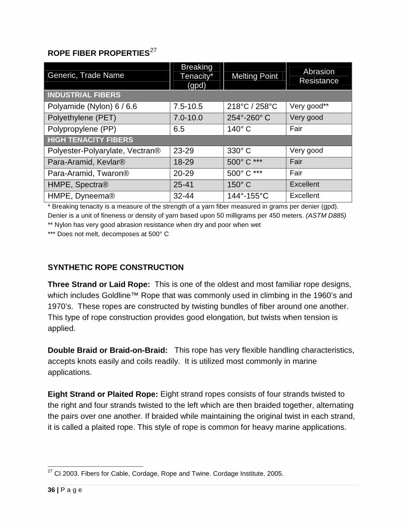
ROPE FIBER PROPERTIES27
Generic, Trade Name Breaking Tenacity*
(gpd) Melting Point Abrasion
Resistance
INDUSTRIAL FIBERS Polyamide (Nylon) 6 / 6.6 7.5-10.5 218°C / 258°C Very good** Polyethylene (PET) 7.0-10.0 254°-260° C Very good Polypropylene (PP) 6.5 140° C Fair HIGH TENACITY FIBERS Polyester-Polyarylate, Vectran® 23-29 330° C Very good Para-Aramid, Kevlar® 18-29 500° C *** Fair Para-Aramid, Twaron® 20-29 500° C *** Fair HMPE, Spectra® 25-41 150° C Excellent HMPE, Dyneema® 32-44 144°-155°C Excellent * Breaking tenacity is a measure of the strength of a yarn fiber measured in grams per denier (gpd). Denier is a unit of fineness or density of yarn based upon 50 milligrams per 450 meters. (ASTM D885) ** Nylon has very good abrasion resistance when dry and poor when wet *** Does not melt, decomposes at 500° C
SYNTHETIC ROPE CONSTRUCTION
Three Strand or Laid Rope: This is one of the oldest and most familiar rope designs, which includes Goldline™ Rope that was commonly used in climbing in the 1960’s and 1970’s. These ropes are constructed by twisting bundles of fiber around one another. This type of rope construction provides good elongation, but twists when tension is applied. Double Braid or Braid-on-Braid: This rope has very flexible handling characteristics, accepts knots easily and coils readily. It is utilized most commonly in marine applications. Eight Strand or Plaited Rope: Eight strand ropes consists of four strands twisted to the right and four strands twisted to the left which are then braided together, alternating the pairs over one another. If braided while maintaining the original twist in each strand, it is called a plaited rope. This style of rope is common for heavy marine applications.
27 CI 2003. Fibers for Cable, Cordage, Rope and Twine. Cordage Institute. 2005.
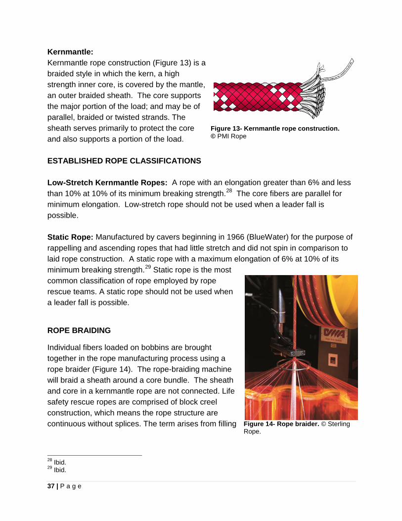
37 | P a g e
Kernmantle: Kernmantle rope construction (Figure 13) is a braided style in which the kern, a high strength inner core, is covered by the mantle, an outer braided sheath. The core supports the major portion of the load; and may be of parallel, braided or twisted strands. The sheath serves primarily to protect the core and also supports a portion of the load. ESTABLISHED ROPE CLASSIFICATIONS Low-Stretch Kernmantle Ropes: A rope with an elongation greater than 6% and less than 10% at 10% of its minimum breaking strength.28 The core fibers are parallel for minimum elongation. Low-stretch rope should not be used when a leader fall is possible. Static Rope: Manufactured by cavers beginning in 1966 (BlueWater) for the purpose of rappelling and ascending ropes that had little stretch and did not spin in comparison to laid rope construction. A static rope with a maximum elongation of 6% at 10% of its minimum breaking strength.29 Static rope is the most common classification of rope employed by rope rescue teams. A static rope should not be used when a leader fall is possible.
ROPE BRAIDING
Individual fibers loaded on bobbins are brought together in the rope manufacturing process using a rope braider (Figure 14). The rope-braiding machine will braid a sheath around a core bundle. The sheath and core in a kernmantle rope are not connected. Life safety rescue ropes are comprised of block creel construction, which means the rope structure are continuous without splices. The term arises from filling
28 Ibid. 29 Ibid.
Figure 13- Kernmantle rope construction. © PMI Rope
Figure 14- Rope braider. © Sterling Rope.
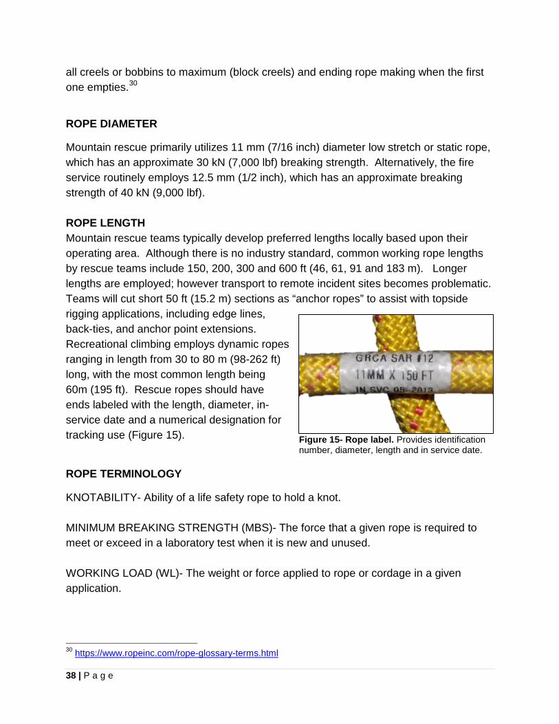
38 | P a g e
all creels or bobbins to maximum (block creels) and ending rope making when the first one empties.30
ROPE DIAMETER
Mountain rescue primarily utilizes 11 mm (7/16 inch) diameter low stretch or static rope, which has an approximate 30 kN (7,000 lbf) breaking strength. Alternatively, the fire service routinely employs 12.5 mm (1/2 inch), which has an approximate breaking strength of 40 kN (9,000 lbf). ROPE LENGTH Mountain rescue teams typically develop preferred lengths locally based upon their operating area. Although there is no industry standard, common working rope lengths by rescue teams include 150, 200, 300 and 600 ft (46, 61, 91 and 183 m). Longer lengths are employed; however transport to remote incident sites becomes problematic. Teams will cut short 50 ft (15.2 m) sections as “anchor ropes” to assist with topside rigging applications, including edge lines, back-ties, and anchor point extensions. Recreational climbing employs dynamic ropes ranging in length from 30 to 80 m (98-262 ft) long, with the most common length being 60m (195 ft). Rescue ropes should have ends labeled with the length, diameter, in-service date and a numerical designation for tracking use (Figure 15). Figure 15- Rope label. Provides identification
number, diameter, length and in service date.
ROPE TERMINOLOGY
KNOTABILITY- Ability of a life safety rope to hold a knot. MINIMUM BREAKING STRENGTH (MBS)- The force that a given rope is required to meet or exceed in a laboratory test when it is new and unused. WORKING LOAD (WL)- The weight or force applied to rope or cordage in a given application.
30 https://www.ropeinc.com/rope-glossary-terms.html
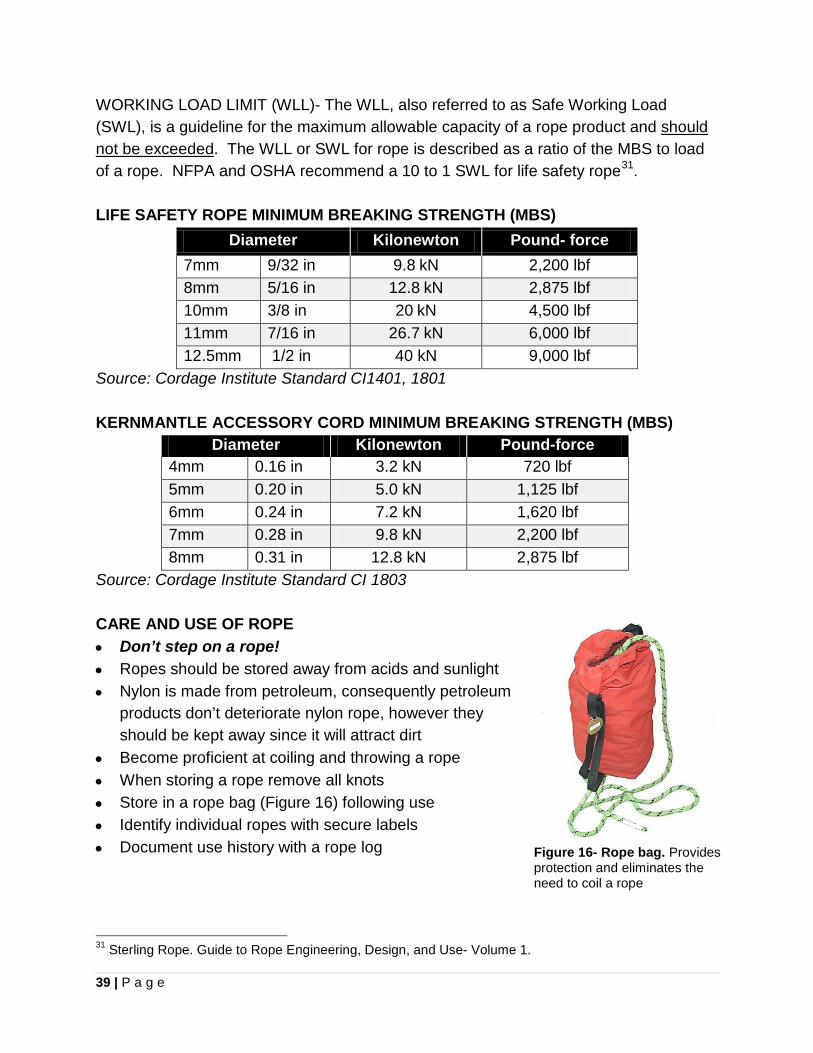
39 | P a g e
WORKING LOAD LIMIT (WLL)- The WLL, also referred to as Safe Working Load (SWL), is a guideline for the maximum allowable capacity of a rope product and should not be exceeded. The WLL or SWL for rope is described as a ratio of the MBS to load of a rope. NFPA and OSHA recommend a 10 to 1 SWL for life safety rope31. LIFE SAFETY ROPE MINIMUM BREAKING STRENGTH (MBS)
Diameter Kilonewton Pound- force 7mm 9/32 in 9.8 kN 2,200 lbf 8mm 5/16 in 12.8 kN 2,875 lbf 10mm 3/8 in 20 kN 4,500 lbf 11mm 7/16 in 26.7 kN 6,000 lbf 12.5mm 1/2 in 40 kN 9,000 lbf
Source: Cordage Institute Standard CI1401, 1801 KERNMANTLE ACCESSORY CORD MINIMUM BREAKING STRENGTH (MBS)
Diameter Kilonewton Pound-force 4mm 0.16 in 3.2 kN 720 lbf 5mm 0.20 in 5.0 kN 1,125 lbf 6mm 0.24 in 7.2 kN 1,620 lbf 7mm 0.28 in 9.8 kN 2,200 lbf 8mm 0.31 in 12.8 kN 2,875 lbf
Source: Cordage Institute Standard CI 1803 CARE AND USE OF ROPE
• Don’t step on a rope! • Ropes should be stored away from acids and sunlight • Nylon is made from petroleum, consequently petroleum
products don’t deteriorate nylon rope, however they should be kept away since it will attract dirt
• Become proficient at coiling and throwing a rope • When storing a rope remove all knots • Store in a rope bag (Figure 16) following use • Identify individual ropes with secure labels • Document use history with a rope log 31 Sterling Rope. Guide to Rope Engineering, Design, and Use- Volume 1.
Figure 16- Rope bag. Provides protection and eliminates the need to coil a rope
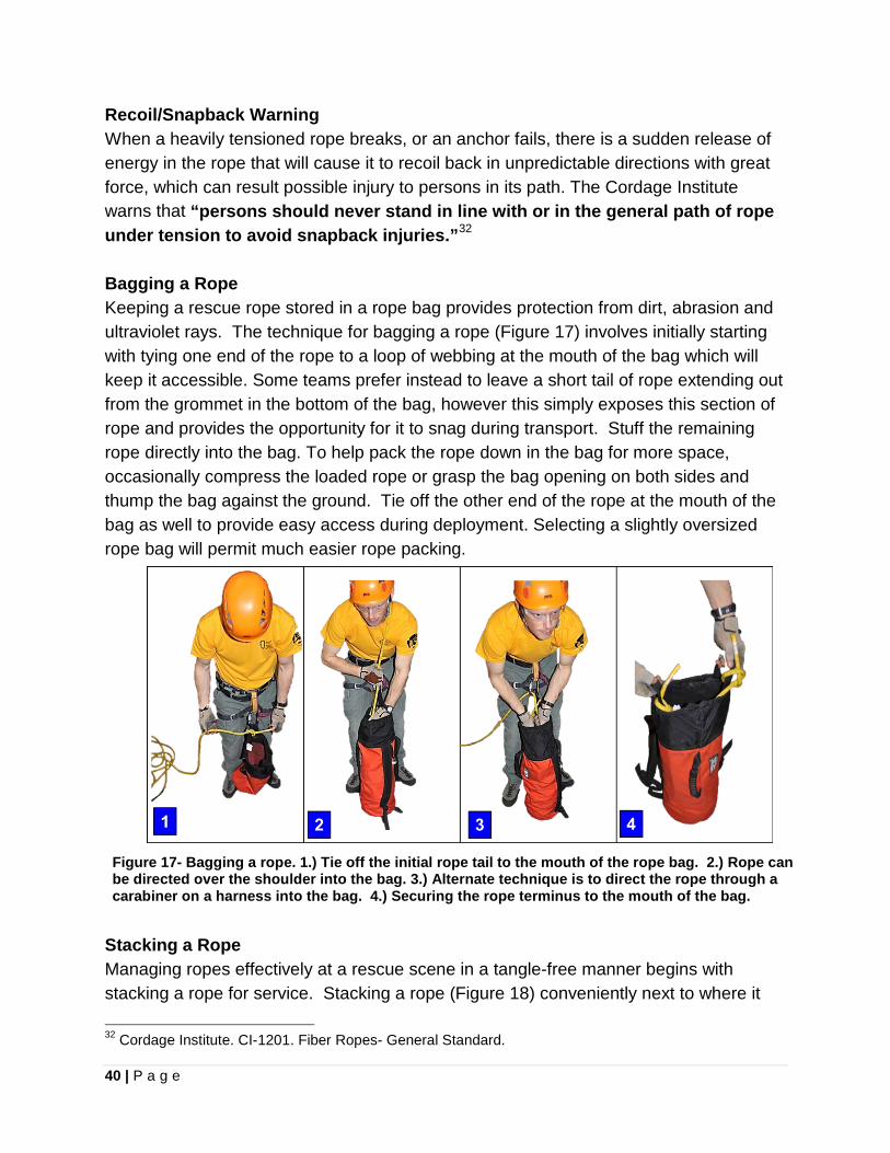
40 | P a g e
Recoil/Snapback Warning When a heavily tensioned rope breaks, or an anchor fails, there is a sudden release of energy in the rope that will cause it to recoil back in unpredictable directions with great force, which can result possible injury to persons in its path. The Cordage Institute warns that “persons should never stand in line with or in the general path of rope under tension to avoid snapback injuries.”32 Bagging a Rope Keeping a rescue rope stored in a rope bag provides protection from dirt, abrasion and ultraviolet rays. The technique for bagging a rope (Figure 17) involves initially starting with tying one end of the rope to a loop of webbing at the mouth of the bag which will keep it accessible. Some teams prefer instead to leave a short tail of rope extending out from the grommet in the bottom of the bag, however this simply exposes this section of rope and provides the opportunity for it to snag during transport. Stuff the remaining rope directly into the bag. To help pack the rope down in the bag for more space, occasionally compress the loaded rope or grasp the bag opening on both sides and thump the bag against the ground. Tie off the other end of the rope at the mouth of the bag as well to provide easy access during deployment. Selecting a slightly oversized rope bag will permit much easier rope packing.
Figure 17- Bagging a rope. 1.) Tie off the initial rope tail to the mouth of the rope bag. 2.) Rope can be directed over the shoulder into the bag. 3.) Alternate technique is to direct the rope through a carabiner on a harness into the bag. 4.) Securing the rope terminus to the mouth of the bag.
Stacking a Rope Managing ropes effectively at a rescue scene in a tangle-free manner begins with stacking a rope for service. Stacking a rope (Figure 18) conveniently next to where it
32 Cordage Institute. CI-1201. Fiber Ropes- General Standard.
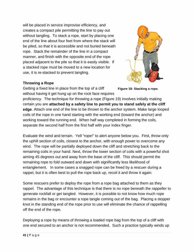
41 | P a g e
will be placed in service improvise efficiency, and creates a compact pile permitting the line to pay out without tangling. To stack a rope, start by placing one end of the line about four feet from where the stack will be piled, so that it is accessible and not buried beneath rope. Stack the remainder of the line in a compact manner, and finish with the opposite end of the rope placed adjacent to the pile so that it is easily visible. If a stacked rope must be moved to a new location for use, it is re-stacked to prevent tangling. Throwing a Rope Getting a fixed line in place from the top of a cliff without having it get hung up on the rock face requires proficiency. The technique for throwing a rope (Figure 19) involves initially making certain you are attached by a safety line to permit you to stand safely at the cliff edge. Attach one end of the line to be thrown to the anchor system. Make large looped coils of the rope in one hand starting with the working end (toward the anchor) and working toward the running end. When half way completed in forming the coils, separate the second half from the first half with your index finger. Evaluate the wind and terrain. Yell “rope!” to alert anyone below you. First, throw only the uphill section of coils, closest to the anchor, with enough power to overcome any wind. The rope will be partially deployed down the cliff and stretching back to the remaining coils in your hand. Next, throw the lower section of coils with a powerful shot aiming 45 degrees out and away from the base of the cliff. This should permit the remaining rope to fold outward and down with significantly less likelihood of entanglement. In some cases a snagged rope can be freed by a rescuer during a rappel, but it is often best to pull the rope back up, recoil it and throw it again. Some rescuers prefer to deploy the rope from a rope bag attached to them as they rappel. The advantage of this technique is that there is no rope beneath the rappeller to generate rockfall or get tangled. However, it is possible to not know how much rope remains in the bag or encounter a rope tangle coming out of the bag. Placing a stopper knot in the standing end of the rope prior to use will eliminate the chance of rappelling off the end of the rope. Deploying a rope by means of throwing a loaded rope bag from the top of a cliff with one end secured to an anchor is not recommended. Such a practice typically winds up
Figure 18- Stacking a rope.
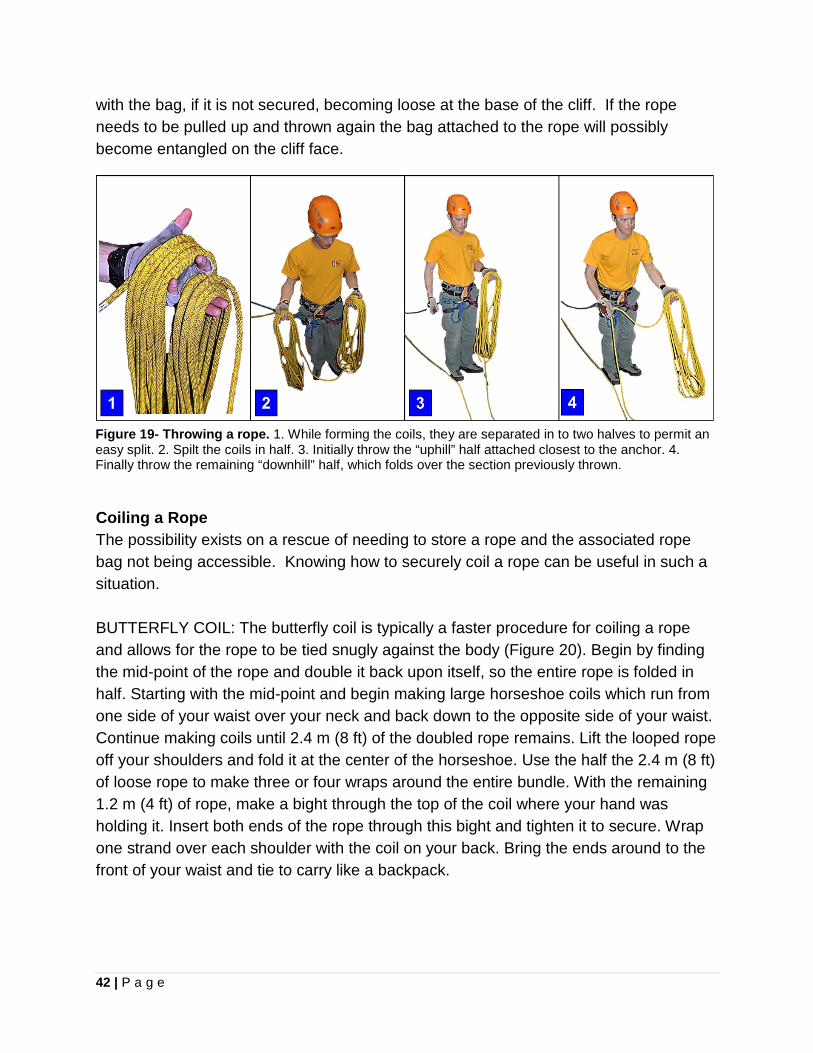
42 | P a g e
with the bag, if it is not secured, becoming loose at the base of the cliff. If the rope needs to be pulled up and thrown again the bag attached to the rope will possibly become entangled on the cliff face.
Figure 19- Throwing a rope. 1. While forming the coils, they are separated in to two halves to permit an easy split. 2. Spilt the coils in half. 3. Initially throw the “uphill” half attached closest to the anchor. 4. Finally throw the remaining “downhill” half, which folds over the section previously thrown.
Coiling a Rope The possibility exists on a rescue of needing to store a rope and the associated rope bag not being accessible. Knowing how to securely coil a rope can be useful in such a situation. BUTTERFLY COIL: The butterfly coil is typically a faster procedure for coiling a rope and allows for the rope to be tied snugly against the body (Figure 20). Begin by finding the mid-point of the rope and double it back upon itself, so the entire rope is folded in half. Starting with the mid-point and begin making large horseshoe coils which run from one side of your waist over your neck and back down to the opposite side of your waist. Continue making coils until 2.4 m (8 ft) of the doubled rope remains. Lift the looped rope off your shoulders and fold it at the center of the horseshoe. Use the half the 2.4 m (8 ft) of loose rope to make three or four wraps around the entire bundle. With the remaining 1.2 m (4 ft) of rope, make a bight through the top of the coil where your hand was holding it. Insert both ends of the rope through this bight and tighten it to secure. Wrap one strand over each shoulder with the coil on your back. Bring the ends around to the front of your waist and tie to carry like a backpack.
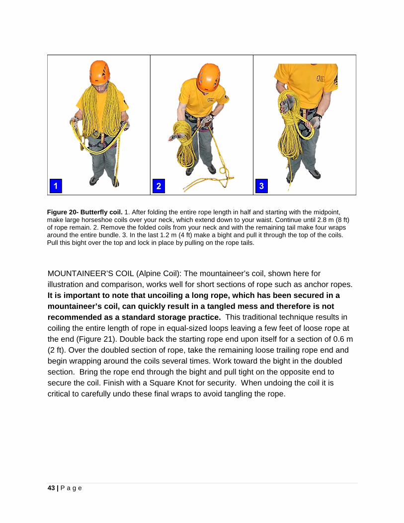
43 | P a g e
Figure 20- Butterfly coil. 1. After folding the entire rope length in half and starting with the midpoint, make large horseshoe coils over your neck, which extend down to your waist. Continue until 2.8 m (8 ft) of rope remain. 2. Remove the folded coils from your neck and with the remaining tail make four wraps around the entire bundle. 3. In the last 1.2 m (4 ft) make a bight and pull it through the top of the coils. Pull this bight over the top and lock in place by pulling on the rope tails. MOUNTAINEER’S COIL (Alpine Coil): The mountaineer’s coil, shown here for illustration and comparison, works well for short sections of rope such as anchor ropes. It is important to note that uncoiling a long rope, which has been secured in a mountaineer’s coil, can quickly result in a tangled mess and therefore is not recommended as a standard storage practice. This traditional technique results in coiling the entire length of rope in equal-sized loops leaving a few feet of loose rope at the end (Figure 21). Double back the starting rope end upon itself for a section of 0.6 m (2 ft). Over the doubled section of rope, take the remaining loose trailing rope end and begin wrapping around the coils several times. Work toward the bight in the doubled section. Bring the rope end through the bight and pull tight on the opposite end to secure the coil. Finish with a Square Knot for security. When undoing the coil it is critical to carefully undo these final wraps to avoid tangling the rope.
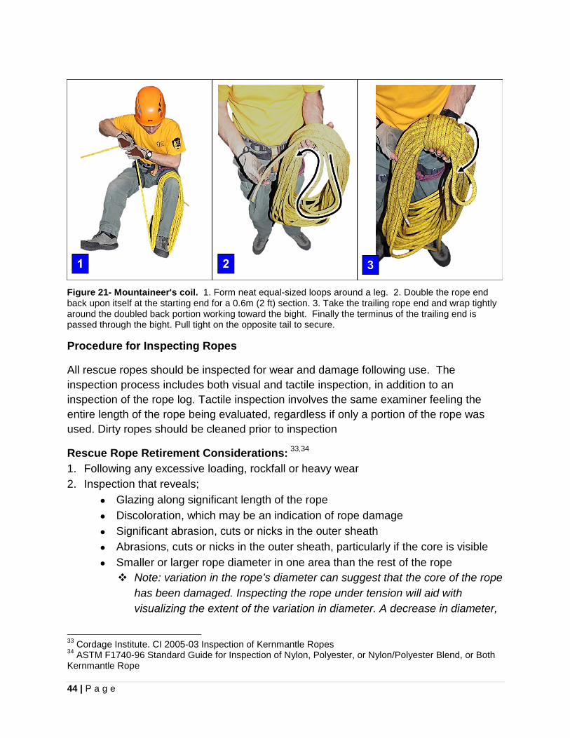
44 | P a g e
Figure 21- Mountaineer's coil. 1. Form neat equal-sized loops around a leg. 2. Double the rope end back upon itself at the starting end for a 0.6m (2 ft) section. 3. Take the trailing rope end and wrap tightly around the doubled back portion working toward the bight. Finally the terminus of the trailing end is passed through the bight. Pull tight on the opposite tail to secure.
Procedure for Inspecting Ropes
All rescue ropes should be inspected for wear and damage following use. The inspection process includes both visual and tactile inspection, in addition to an inspection of the rope log. Tactile inspection involves the same examiner feeling the entire length of the rope being evaluated, regardless if only a portion of the rope was used. Dirty ropes should be cleaned prior to inspection
Rescue Rope Retirement Considerations: 33,34 1. Following any excessive loading, rockfall or heavy wear 2. Inspection that reveals;
• Glazing along significant length of the rope • Discoloration, which may be an indication of rope damage • Significant abrasion, cuts or nicks in the outer sheath • Abrasions, cuts or nicks in the outer sheath, particularly if the core is visible • Smaller or larger rope diameter in one area than the rest of the rope Note: variation in the rope’s diameter can suggest that the core of the rope
has been damaged. Inspecting the rope under tension will aid with visualizing the extent of the variation in diameter. A decrease in diameter,
33 Cordage Institute. CI 2005-03 Inspection of Kernmantle Ropes 34 ASTM F1740-96 Standard Guide for Inspection of Nylon, Polyester, or Nylon/Polyester Blend, or Both Kernmantle Rope
45 | P a g e
hour-glass appearance, is caused by separation of core fibers. An increase in diameter can be due to bunching of the core.
• Excessive sheath wear (broken fibers creating a fuzzy appearance) • If a part of the rope feels “mushy” or soft in any area • If the rope feels more stiff or “brittle”-feeling than the rest of the rope. Stiffness
or a “brittle-feeling” is likely due to it being overstressed in that area. 3. Chemical contamination, including sign or smell indicating contamination by an acid,
alkaline, oxidizing agent, bleach, or other hazardous chemical 4. Suspect or unknown rope history 5. Age exceeding seven years in used rope. (See box below) 6. “When in doubt... Throw it out.”
Cordage Institute- Rope Retirement Guideline
“Any rope which is greater than ten years’ old shall be retired, regardless of history and usage. NOTE: There is, at this writing, no universally agreed-upon “shelf life” for nylon, polyester, or nylon/polyester rope products. Shelf life will vary according to local atmosphere, storage conditions, heat, light, temperature, and other variables. The ten-year period recommended in this document should be considered carefully by any person(s) using this document, with the understanding that depending on circumstances specific to each situation, rope strength may actually be reduced to unacceptable levels in a shorter period of time. While there is no conclusive data to show the precise effects of rope aging, user’s experience, as well as research such as that done by Smith, et al, 1988, and Mammut Ropes, 1973, may provide some subjective criteria for decision-making about ropes based upon rope age and usage.” - CI-2005 Inspection of Kernmantle Ropes
Retirement Age of Rope (Study on Rope Aging)
In order to calculate a deterioration rate for nylon rope, Bruce Smith conducted pull testing of aged unused 11mm rope samples. He measured a 1.5-1.8% loss of strength per year in relatively unused PMI and BlueWater rope. This results in a 15-18% strength loss for unused rope after ten years. Citing a military ten-year retirement guideline for life safety support nylon products, Smith concluded that "used rope would need to be discarded at approximately seven years if the same ten year new margins wish to be maintained." AGING ROPE- Study on Rope Aging, Bruce Smith, Nylon Highway, Issue #25, January 1988, National Speleological Society (NSS). Hixson, TN.
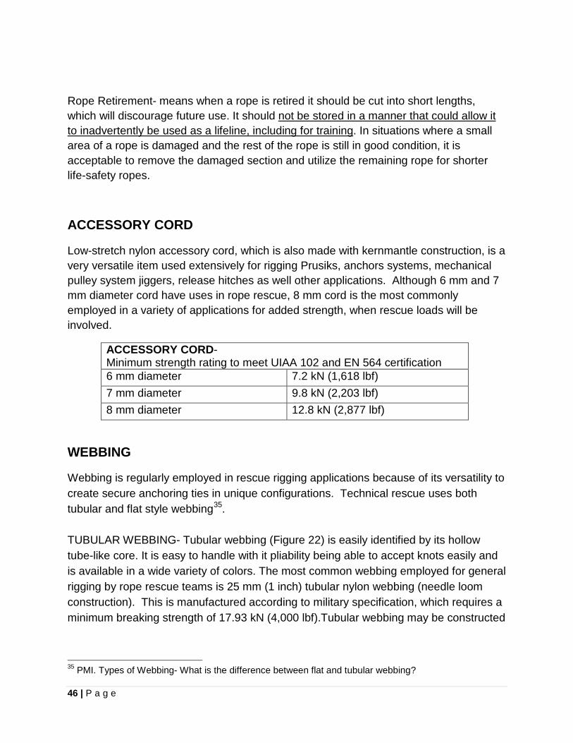
46 | P a g e
Rope Retirement- means when a rope is retired it should be cut into short lengths, which will discourage future use. It should not be stored in a manner that could allow it to inadvertently be used as a lifeline, including for training. In situations where a small area of a rope is damaged and the rest of the rope is still in good condition, it is acceptable to remove the damaged section and utilize the remaining rope for shorter life-safety ropes.
ACCESSORY CORD
Low-stretch nylon accessory cord, which is also made with kernmantle construction, is a very versatile item used extensively for rigging Prusiks, anchors systems, mechanical pulley system jiggers, release hitches as well other applications. Although 6 mm and 7 mm diameter cord have uses in rope rescue, 8 mm cord is the most commonly employed in a variety of applications for added strength, when rescue loads will be involved.
ACCESSORY CORD- Minimum strength rating to meet UIAA 102 and EN 564 certification 6 mm diameter
7.2 kN (1,618 lbf) 7 mm diameter
9.8 kN (2,203 lbf) 8 mm diameter 12.8 kN (2,877 lbf)
WEBBING
Webbing is regularly employed in rescue rigging applications because of its versatility to create secure anchoring ties in unique configurations. Technical rescue uses both tubular and flat style webbing35. TUBULAR WEBBING- Tubular webbing (Figure 22) is easily identified by its hollow tube-like core. It is easy to handle with it pliability being able to accept knots easily and is available in a wide variety of colors. The most common webbing employed for general rigging by rope rescue teams is 25 mm (1 inch) tubular nylon webbing (needle loom construction). This is manufactured according to military specification, which requires a minimum breaking strength of 17.93 kN (4,000 lbf).Tubular webbing may be constructed
35 PMI. Types of Webbing- What is the difference between flat and tubular webbing?
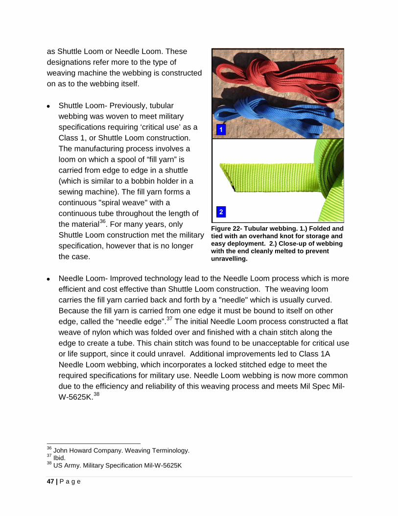
47 | P a g e
as Shuttle Loom or Needle Loom. These designations refer more to the type of weaving machine the webbing is constructed on as to the webbing itself. • Shuttle Loom- Previously, tubular
webbing was woven to meet military specifications requiring ‘critical use’ as a Class 1, or Shuttle Loom construction. The manufacturing process involves a loom on which a spool of “fill yarn” is carried from edge to edge in a shuttle (which is similar to a bobbin holder in a sewing machine). The fill yarn forms a continuous "spiral weave" with a continuous tube throughout the length of the material36. For many years, only Shuttle Loom construction met the military specification, however that is no longer the case.
• Needle Loom- Improved technology lead to the Needle Loom process which is more efficient and cost effective than Shuttle Loom construction. The weaving loom carries the fill yarn carried back and forth by a "needle" which is usually curved. Because the fill yarn is carried from one edge it must be bound to itself on other edge, called the “needle edge”.37 The initial Needle Loom process constructed a flat weave of nylon which was folded over and finished with a chain stitch along the edge to create a tube. This chain stitch was found to be unacceptable for critical use or life support, since it could unravel. Additional improvements led to Class 1A Needle Loom webbing, which incorporates a locked stitched edge to meet the required specifications for military use. Needle Loom webbing is now more common due to the efficiency and reliability of this weaving process and meets Mil Spec Mil-W-5625K.38
36 John Howard Company. Weaving Terminology. 37 Ibid. 38 US Army. Military Specification Mil-W-5625K
Figure 22- Tubular webbing. 1.) Folded and tied with an overhand knot for storage and easy deployment. 2.) Close-up of webbing with the end cleanly melted to prevent unravelling.
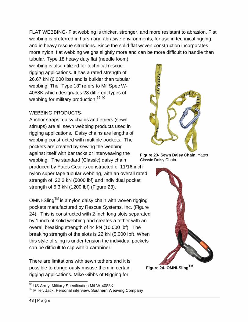
48 | P a g e
FLAT WEBBING- Flat webbing is thicker, stronger, and more resistant to abrasion. Flat webbing is preferred in harsh and abrasive environments, for use in technical rigging, and in heavy rescue situations. Since the solid flat woven construction incorporates more nylon, flat webbing weighs slightly more and can be more difficult to handle than tubular. Type 18 heavy duty flat (needle loom) webbing is also utilized for technical rescue rigging applications. It has a rated strength of 26.67 kN (6,000 lbs) and is bulkier than tubular webbing. The “Type 18” refers to Mil Spec W-4088K which designates 28 different types of webbing for military production.39 40 WEBBING PRODUCTS- Anchor straps, daisy chains and etriers (sewn stirrups) are all sewn webbing products used in rigging applications. Daisy chains are lengths of webbing constructed with multiple pockets. The pockets are created by sewing the webbing against itself with bar tacks or interweaving the webbing. The standard (Classic) daisy chain produced by Yates Gear is constructed of 11/16 inch nylon super tape tubular webbing, with an overall rated strength of 22.2 kN (5000 lbf) and individual pocket strength of 5.3 kN (1200 lbf) (Figure 23). OMNI-SlingTM is a nylon daisy chain with woven rigging pockets manufactured by Rescue Systems, Inc. (Figure 24). This is constructed with 2-inch long slots separated by 1-inch of solid webbing and creates a tether with an overall breaking strength of 44 kN (10,000 Ibf). The breaking strength of the slots is 22 kN (5,000 Ibf). When this style of sling is under tension the individual pockets can be difficult to clip with a carabiner. There are limitations with sewn tethers and it is possible to dangerously misuse them in certain rigging applications. Mike Gibbs of Rigging for 39 US Army. Military Specification Mil-W-4088K 40 Miller, Jack. Personal interview. Southern Weaving Company
Figure 23- Sewn Daisy Chain. Yates Classic Daisy Chain.
Figure 24- OMNI-SlingTM
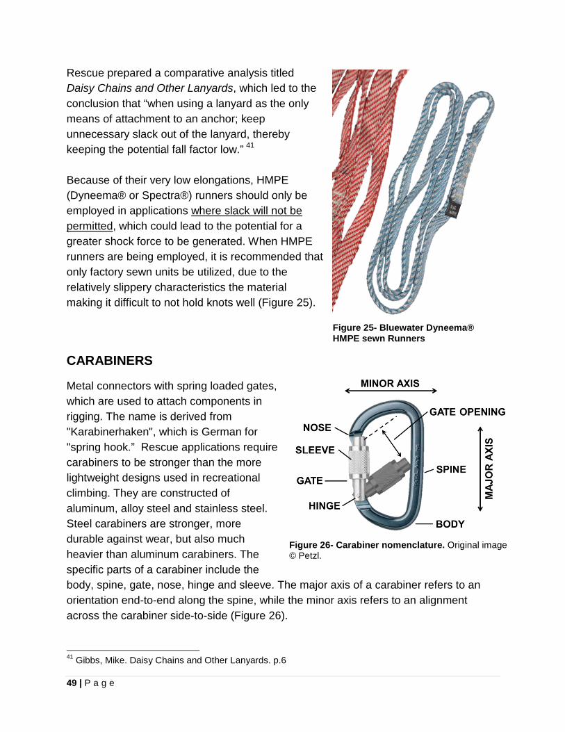
49 | P a g e
Rescue prepared a comparative analysis titled Daisy Chains and Other Lanyards, which led to the conclusion that “when using a lanyard as the only means of attachment to an anchor; keep unnecessary slack out of the lanyard, thereby keeping the potential fall factor low.” 41 Because of their very low elongations, HMPE (Dyneema® or Spectra®) runners should only be employed in applications where slack will not be permitted, which could lead to the potential for a greater shock force to be generated. When HMPE runners are being employed, it is recommended that only factory sewn units be utilized, due to the relatively slippery characteristics the material making it difficult to not hold knots well (Figure 25).
Figure 25- Bluewater Dyneema® HMPE sewn Runners
CARABINERS
Metal connectors with spring loaded gates, which are used to attach components in rigging. The name is derived from "Karabinerhaken", which is German for "spring hook.” Rescue applications require carabiners to be stronger than the more lightweight designs used in recreational climbing. They are constructed of aluminum, alloy steel and stainless steel. Steel carabiners are stronger, more durable against wear, but also much heavier than aluminum carabiners. The specific parts of a carabiner include the body, spine, gate, nose, hinge and sleeve. The major axis of a carabiner refers to an orientation end-to-end along the spine, while the minor axis refers to an alignment across the carabiner side-to-side (Figure 26). 41 Gibbs, Mike. Daisy Chains and Other Lanyards. p.6
Figure 26- Carabiner nomenclature. Original image © Petzl.
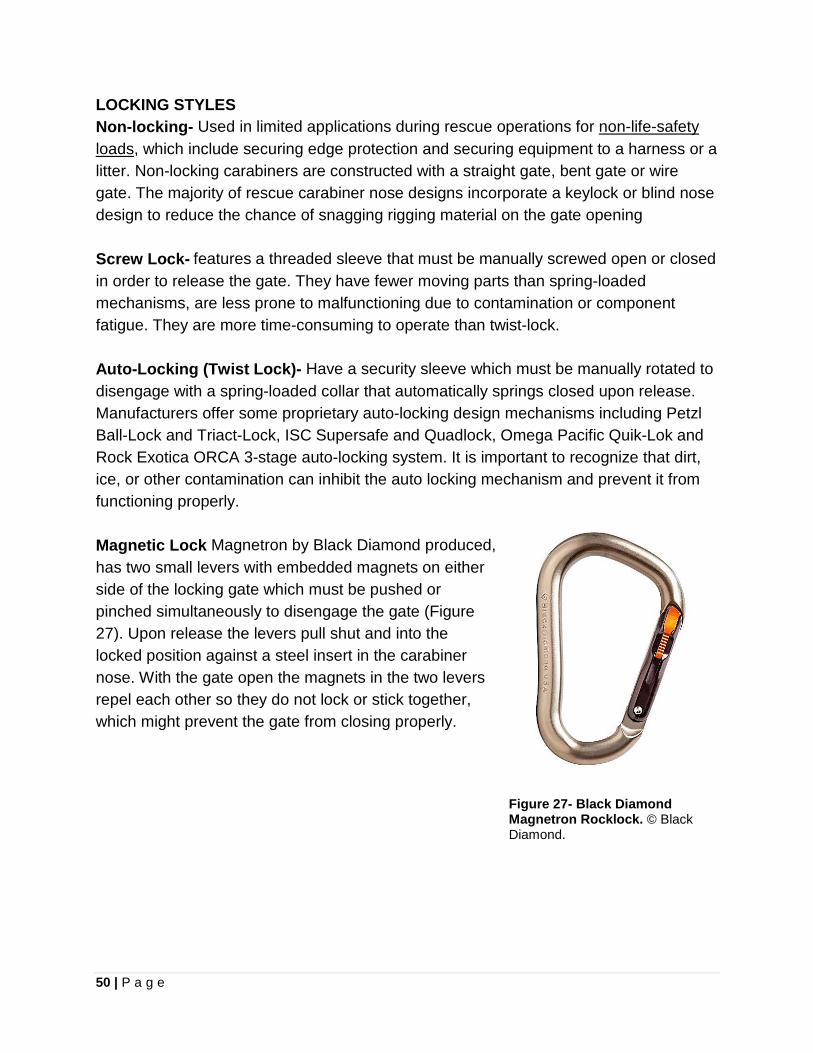
50 | P a g e
LOCKING STYLES Non-locking- Used in limited applications during rescue operations for non-life-safety loads, which include securing edge protection and securing equipment to a harness or a litter. Non-locking carabiners are constructed with a straight gate, bent gate or wire gate. The majority of rescue carabiner nose designs incorporate a keylock or blind nose design to reduce the chance of snagging rigging material on the gate opening Screw Lock- features a threaded sleeve that must be manually screwed open or closed in order to release the gate. They have fewer moving parts than spring-loaded mechanisms, are less prone to malfunctioning due to contamination or component fatigue. They are more time-consuming to operate than twist-lock. Auto-Locking (Twist Lock)- Have a security sleeve which must be manually rotated to disengage with a spring-loaded collar that automatically springs closed upon release. Manufacturers offer some proprietary auto-locking design mechanisms including Petzl Ball-Lock and Triact-Lock, ISC Supersafe and Quadlock, Omega Pacific Quik-Lok and Rock Exotica ORCA 3-stage auto-locking system. It is important to recognize that dirt, ice, or other contamination can inhibit the auto locking mechanism and prevent it from functioning properly. Magnetic Lock Magnetron by Black Diamond produced, has two small levers with embedded magnets on either side of the locking gate which must be pushed or pinched simultaneously to disengage the gate (Figure 27). Upon release the levers pull shut and into the locked position against a steel insert in the carabiner nose. With the gate open the magnets in the two levers repel each other so they do not lock or stick together, which might prevent the gate from closing properly.
Figure 27- Black Diamond Magnetron Rocklock. © Black Diamond.
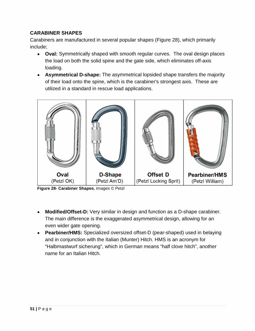
51 | P a g e
CARABINER SHAPES Carabiners are manufactured in several popular shapes (Figure 28), which primarily include;
• Oval: Symmetrically shaped with smooth regular curves. The oval design places the load on both the solid spine and the gate side, which eliminates off-axis loading.
• Asymmetrical D-shape: The asymmetrical lopsided shape transfers the majority of their load onto the spine, which is the carabiner's strongest axis. These are utilized in a standard in rescue load applications.
Figure 28- Carabiner Shapes. Images © Petzl
• Modified/Offset-D: Very similar in design and function as a D-shape carabiner.
The main difference is the exaggerated asymmetrical design, allowing for an even wider gate opening.
• Pearbiner/HMS: Specialized oversized offset-D (pear-shaped) used in belaying and in conjunction with the Italian (Munter) Hitch. HMS is an acronym for “Halbmastwurf sicherung”, which in German means “half clove hitch”, another name for an Italian Hitch.
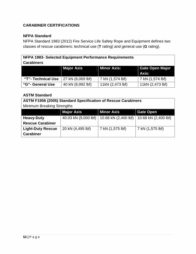
52 | P a g e
CARABINER CERTIFICATIONS NFPA Standard NFPA Standard 1983 (2012) Fire Service Life Safety Rope and Equipment defines two classes of rescue carabiners; technical use (T rating) and general use (G rating). NFPA 1983- Selected Equipment Performance Requirements Carabiners Major Axis Minor Axis: Gate Open Major
Axis: “T”- Technical Use 27 kN (6,069 lbf) 7 kN (1,574 lbf) 7 kN (1,574 lbf) “G”- General Use 40 kN (8,992 lbf) 11kN (2,473 lbf) 11kN (2,473 lbf) ASTM Standard ASTM F1956 (2005) Standard Specification of Rescue Carabiners Minimum Breaking Strengths Major Axis Minor Axis Gate Open Heavy-Duty Rescue Carabiner
40.03 kN (9,000 lbf) 10.68 kN (2,400 lbf) 10.68 kN (2,400 lbf)
Light-Duty Rescue Carabiner
20 kN (4,495 lbf) 7 kN (1,575 lbf) 7 kN (1,575 lbf)
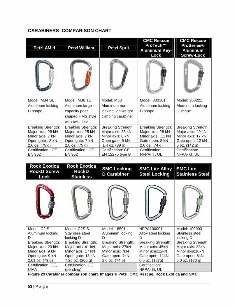
53 | P a g e
CARABINERS- COMPARISON CHART
Petzl AM’d
Model: M34 SL Aluminum locking D shape
Breaking Strength: Major axis: 28 kN Minor axis: 7 kN Open gate : 8 kN 2.6 oz. (75 g) Certification : CE EN 362
Petzl William
Model: M36 TL Aluminum large capacity pear shaped HMS style with twist lock Breaking Strength: Major axis: 25 kN Minor axis: 7 kN Open gate: 7 kN 2.6 oz. (75 g) Certification : CE EN 362
Petzl Sprit
Model: M53 Aluminum non-locking lightweight climbing carabiner
Breaking Strength: Major axis: 23 kN Minor axis: 8 kN Open gate: 9 kN 1.4 oz. (39 g) Certification: CE EN 12275 type B
CMC Rescue ProTech™
Aluminum Key-Lock
Model: 300161 Aluminum locking D shape
Breaking Strength:Major axis: 28 kN Minor axis: 11 kN Gate open: 8 kN 2.6 oz. (74 g) Certification: NFPA- T, UL
CMC Rescue ProSeries® Aluminum
Screw-Lock
Model: 300221 Aluminum locking D shape
Breaking Strength: Major axis: 49 kN Minor axis: 17 kN Gate open: 12 kN 5 oz. (142 g) Certification: NFPA- G, UL
Rock Exotica RockD Screw
Lock
Model: C2 S Aluminum locking D Breaking Strength: Major axis: 29 kN Minor axis: 9 kN Open gate: 9 kN 2.61 oz. (73 g) Certification: CE, UIAA
Rock Exotica RockD
Stainless
Model: C2S S Stainless steel locking D Breaking Strength: Major axis: 41 kN Minor axis: 17 kN Open gate: 13 kN 7.26 oz. (206 g) Certification: CE (pending)
SMC Locking D Carabiner
Model: 18501 Aluminum locking D Breaking Strength: Major axis: 27kN Minor axis: 7kN Gate open: 7kN 2.6 oz. (74 g)
SMC Lite Alloy Steel Locking
NFPA100001 Alloy steel locking D Breaking Strength: Major axis: 45kN Minor axis:12kN Gate open: 11kN 6.6 oz. (187g) Certification: NFPA- G, UL
SMC Lite Stainless Steel
Model: 100003 Stainless steel locking D Breaking Strength: Major axis: 33kN Minor axis:10kN Gate open: 8kN 6.0 oz. (170 g)
Figure 29 Carabiner comparison chart. Images © Petzl, CMC Rescue, Rock Exotica and SMC.
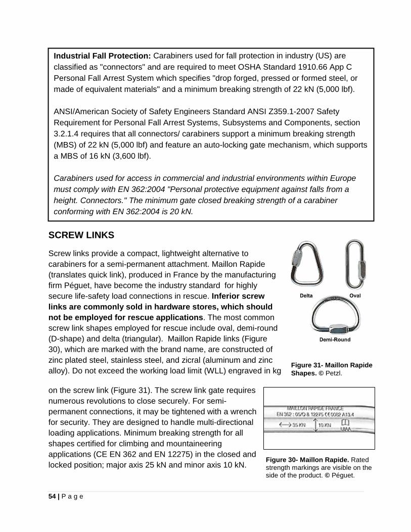
54 | P a g e
Industrial Fall Protection: Carabiners used for fall protection in industry (US) are classified as "connectors" and are required to meet OSHA Standard 1910.66 App C Personal Fall Arrest System which specifies "drop forged, pressed or formed steel, or made of equivalent materials" and a minimum breaking strength of 22 kN (5,000 lbf). ANSI/American Society of Safety Engineers Standard ANSI Z359.1-2007 Safety Requirement for Personal Fall Arrest Systems, Subsystems and Components, section 3.2.1.4 requires that all connectors/ carabiners support a minimum breaking strength (MBS) of 22 kN (5,000 lbf) and feature an auto-locking gate mechanism, which supports a MBS of 16 kN (3,600 lbf). Carabiners used for access in commercial and industrial environments within Europe must comply with EN 362:2004 "Personal protective equipment against falls from a height. Connectors." The minimum gate closed breaking strength of a carabiner conforming with EN 362:2004 is 20 kN.
SCREW LINKS
Screw links provide a compact, lightweight alternative to carabiners for a semi-permanent attachment. Maillon Rapide (translates quick link), produced in France by the manufacturing firm Péguet, have become the industry standard for highly secure life-safety load connections in rescue. Inferior screw links are commonly sold in hardware stores, which should not be employed for rescue applications. The most common screw link shapes employed for rescue include oval, demi-round (D-shape) and delta (triangular). Maillon Rapide links (Figure 30), which are marked with the brand name, are constructed of zinc plated steel, stainless steel, and zicral (aluminum and zinc alloy). Do not exceed the working load limit (WLL) engraved in kg
on the screw link (Figure 31). The screw link gate requires numerous revolutions to close securely. For semi-permanent connections, it may be tightened with a wrench for security. They are designed to handle multi-directional loading applications. Minimum breaking strength for all shapes certified for climbing and mountaineering applications (CE EN 362 and EN 12275) in the closed and locked position; major axis 25 kN and minor axis 10 kN.
Figure 31- Maillon Rapide Shapes. © Petzl.
Figure 30- Maillon Rapide. Rated strength markings are visible on the side of the product. © Péguet.
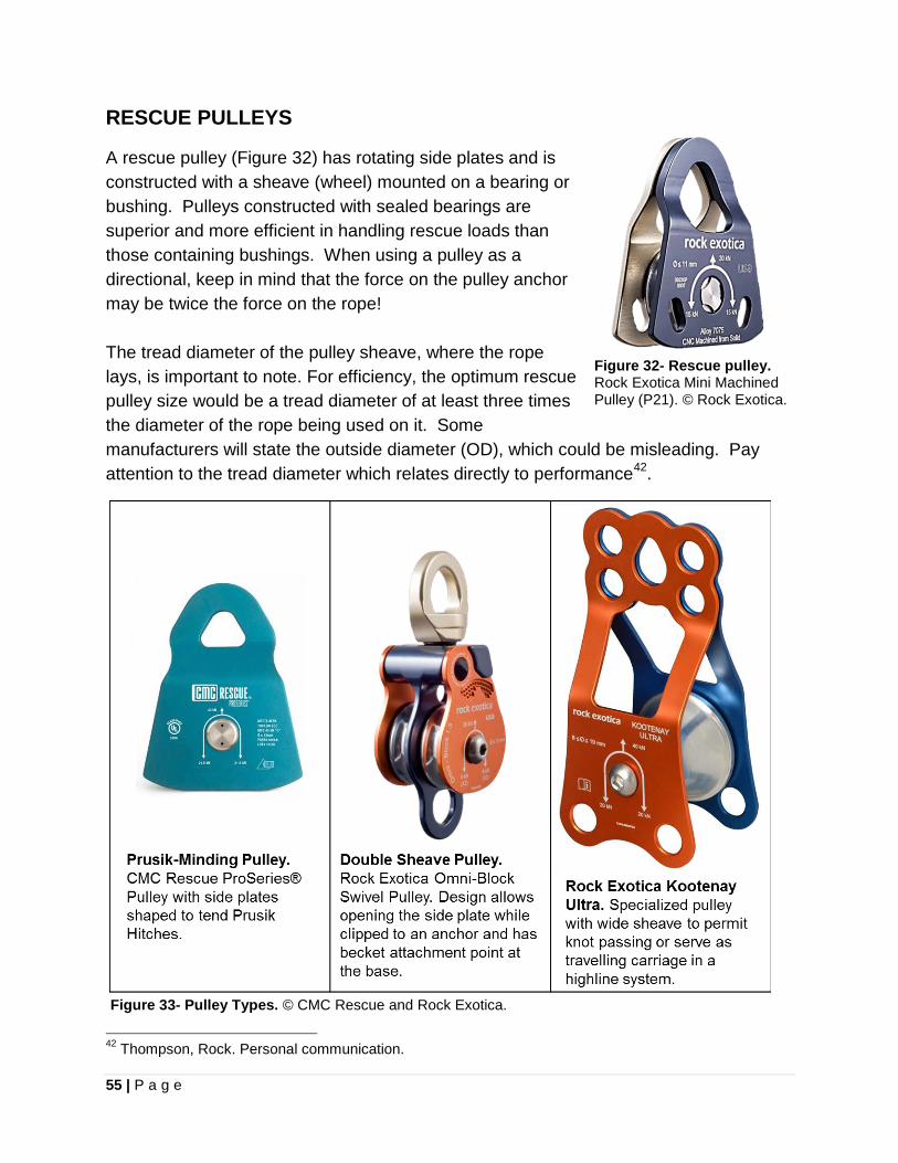
55 | P a g e
RESCUE PULLEYS
A rescue pulley (Figure 32) has rotating side plates and is constructed with a sheave (wheel) mounted on a bearing or bushing. Pulleys constructed with sealed bearings are superior and more efficient in handling rescue loads than those containing bushings. When using a pulley as a directional, keep in mind that the force on the pulley anchor may be twice the force on the rope! The tread diameter of the pulley sheave, where the rope lays, is important to note. For efficiency, the optimum rescue pulley size would be a tread diameter of at least three times the diameter of the rope being used on it. Some manufacturers will state the outside diameter (OD), which could be misleading. Pay attention to the tread diameter which relates directly to performance42.
Figure 32- Rescue pulley. Rock Exotica Mini Machined Pulley (P21). © Rock Exotica.
Figure 33- Pulley Types. © CMC Rescue and Rock Exotica.
42 Thompson, Rock. Personal communication.
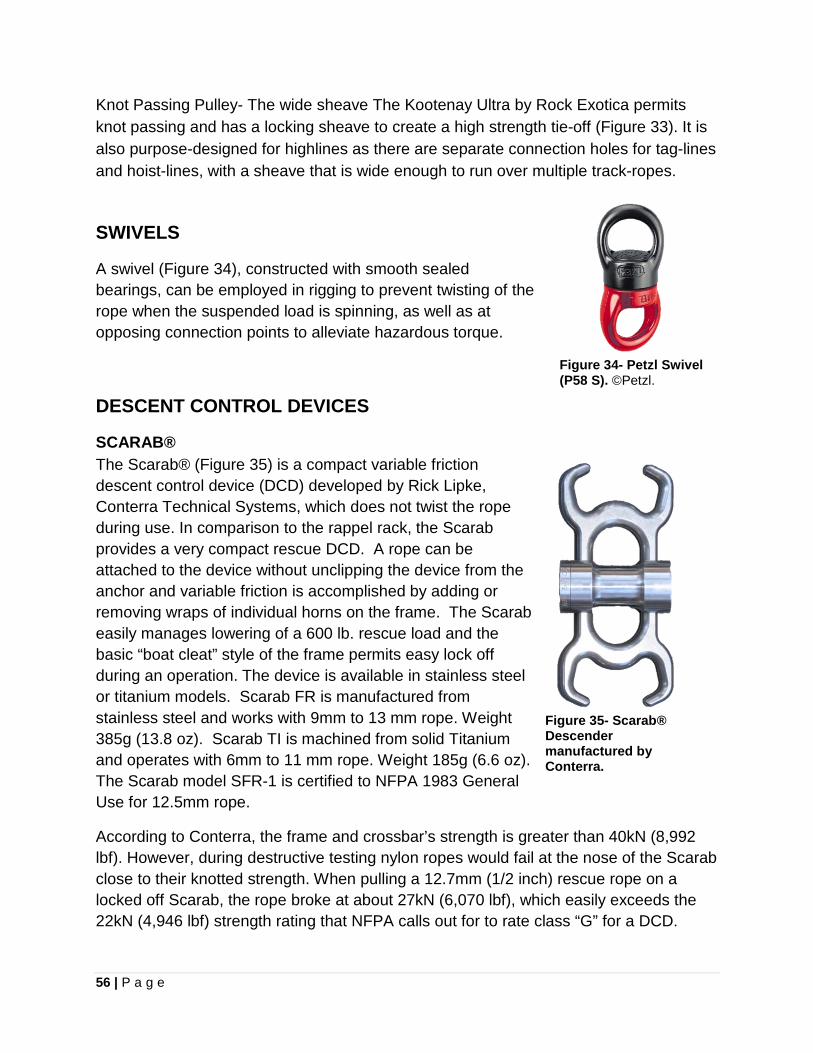
56 | P a g e
Knot Passing Pulley- The wide sheave The Kootenay Ultra by Rock Exotica permits knot passing and has a locking sheave to create a high strength tie-off (Figure 33). It is also purpose-designed for highlines as there are separate connection holes for tag-lines and hoist-lines, with a sheave that is wide enough to run over multiple track-ropes.
SWIVELS
A swivel (Figure 34), constructed with smooth sealed bearings, can be employed in rigging to prevent twisting of the rope when the suspended load is spinning, as well as at opposing connection points to alleviate hazardous torque.
Figure 34- Petzl Swivel (P58 S). ©Petzl.
DESCENT CONTROL DEVICES
The Scarab® (Figure 35) is a compact variable friction descent control device (DCD) developed by Rick Lipke, Conterra Technical Systems, which does not twist the rope during use. In comparison to the rappel rack, the Scarab provides a very compact rescue DCD. A rope can be attached to the device without unclipping the device from the anchor and variable friction is accomplished by adding or removing wraps of individual horns on the frame. The Scarab easily manages lowering of a 600 lb. rescue load and the basic “boat cleat” style of the frame permits easy lock off during an operation. The device is available in stainless steel or titanium models. Scarab FR is manufactured from stainless steel and works with 9mm to 13 mm rope. Weight 385g (13.8 oz). Scarab TI is machined from solid Titanium and operates with 6mm to 11 mm rope. Weight 185g (6.6 oz). The Scarab model SFR-1 is certified to NFPA 1983 General Use for 12.5mm rope.
SCARAB®
According to Conterra, the frame and crossbar’s strength is greater than 40kN (8,992 lbf). However, during destructive testing nylon ropes would fail at the nose of the Scarab close to their knotted strength. When pulling a 12.7mm (1/2 inch) rescue rope on a locked off Scarab, the rope broke at about 27kN (6,070 lbf), which easily exceeds the 22kN (4,946 lbf) strength rating that NFPA calls out for to rate class “G” for a DCD.
Figure 35- Scarab® Descender manufactured by Conterra.
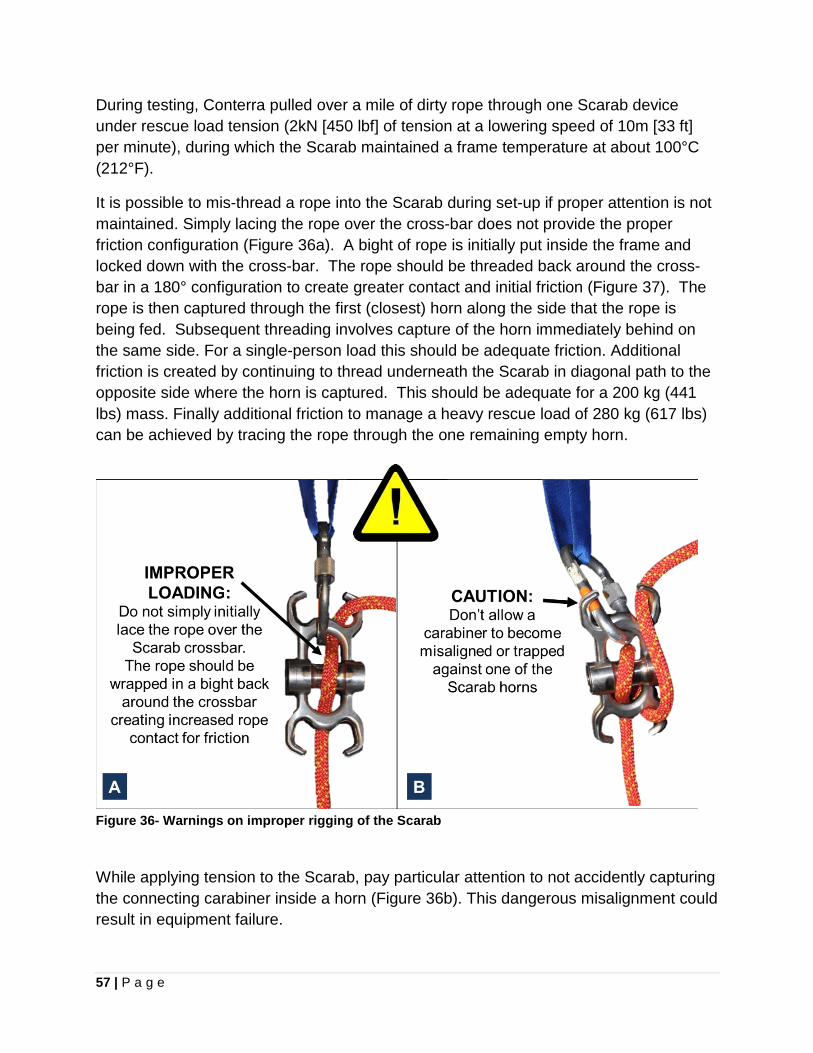
57 | P a g e
During testing, Conterra pulled over a mile of dirty rope through one Scarab device under rescue load tension (2kN [450 lbf] of tension at a lowering speed of 10m [33 ft] per minute), during which the Scarab maintained a frame temperature at about 100°C (212°F).
It is possible to mis-thread a rope into the Scarab during set-up if proper attention is not maintained. Simply lacing the rope over the cross-bar does not provide the proper friction configuration (Figure 36a). A bight of rope is initially put inside the frame and locked down with the cross-bar. The rope should be threaded back around the cross-bar in a 180° configuration to create greater contact and initial friction (Figure 37). The rope is then captured through the first (closest) horn along the side that the rope is being fed. Subsequent threading involves capture of the horn immediately behind on the same side. For a single-person load this should be adequate friction. Additional friction is created by continuing to thread underneath the Scarab in diagonal path to the opposite side where the horn is captured. This should be adequate for a 200 kg (441 lbs) mass. Finally additional friction to manage a heavy rescue load of 280 kg (617 lbs) can be achieved by tracing the rope through the one remaining empty horn.
Figure 36- Warnings on improper rigging of the Scarab
While applying tension to the Scarab, pay particular attention to not accidently capturing the connecting carabiner inside a horn (Figure 36b). This dangerous misalignment could result in equipment failure.
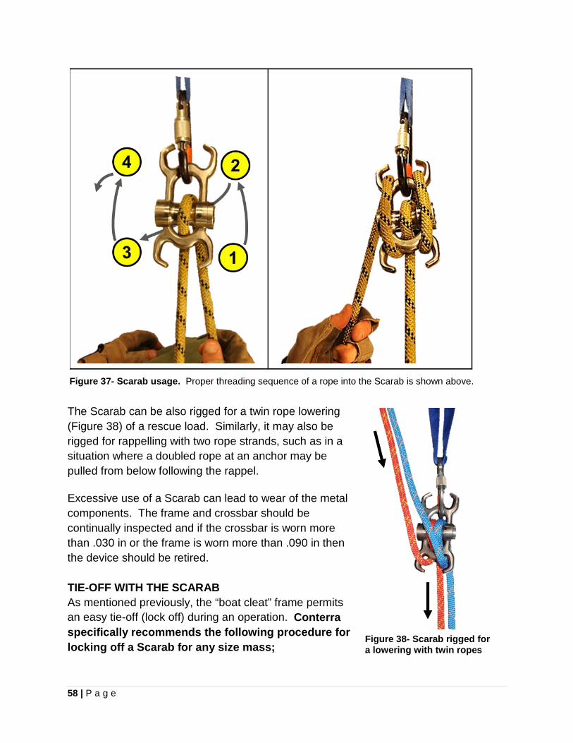
58 | P a g e
Figure 37- Scarab usage. Proper threading sequence of a rope into the Scarab is shown above. The Scarab can be also rigged for a twin rope lowering (Figure 38) of a rescue load. Similarly, it may also be rigged for rappelling with two rope strands, such as in a situation where a doubled rope at an anchor may be pulled from below following the rappel.
Excessive use of a Scarab can lead to wear of the metal components. The frame and crossbar should be continually inspected and if the crossbar is worn more than .030 in or the frame is worn more than .090 in then the device should be retired. TIE-OFF WITH THE SCARAB As mentioned previously, the “boat cleat” frame permits an easy tie-off (lock off) during an operation. Conterra specifically recommends the following procedure for locking off a Scarab for any size mass;
Figure 38- Scarab rigged for a lowering with twin ropes
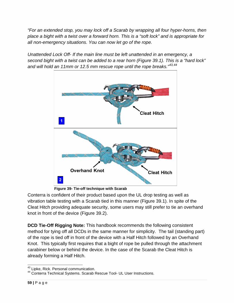
59 | P a g e
“For an extended stop, you may lock off a Scarab by wrapping all four hyper-horns, then place a bight with a twist over a forward horn. This is a “soft lock” and is appropriate for all non-emergency situations. You can now let go of the rope. Unattended Lock Off- If the main line must be left unattended in an emergency, a second bight with a twist can be added to a rear horn (Figure 39.1). This is a “hard lock” and will hold an 11mm or 12.5 mm rescue rope until the rope breaks.”43,44
Conterra is confident of their product based upon the UL drop testing as well as vibration table testing with a Scarab tied in this manner (Figure 39.1). In spite of the Cleat Hitch providing adequate security, some users may still prefer to tie an overhand knot in front of the device (Figure 39.2). DCD Tie-Off Rigging Note: This handbook recommends the following consistent method for tying off all DCDs in the same manner for simplicity. The tail (standing part) of the rope is tied off in front of the device with a Half Hitch followed by an Overhand Knot. This typically first requires that a bight of rope be pulled through the attachment carabiner below or behind the device. In the case of the Scarab the Cleat Hitch is already forming a Half Hitch.
43 Lipke, Rick. Personal communication. 44 Conterra Technical Systems. Scarab Rescue Tool- UL User Instructions.
Figure 39- Tie-off technique with Scarab
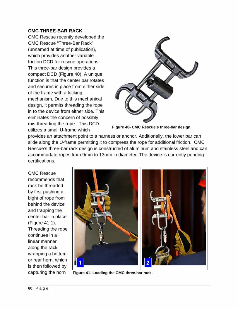
60 | P a g e
CMC THREE-BAR RACK CMC Rescue recently developed the CMC Rescue “Three-Bar Rack” (unnamed at time of publication), which provides another variable friction DCD for rescue operations. This three-bar design provides a compact DCD (Figure 40). A unique function is that the center bar rotates and secures in place from either side of the frame with a locking mechanism. Due to this mechanical design, it permits threading the rope in to the device from either side. This eliminates the concern of possibly mis-threading the rope. This DCD utilizes a small U-frame which provides an attachment point to a harness or anchor. Additionally, the lower bar can slide along the U-frame permitting it to compress the rope for additional friction. CMC Rescue’s three-bar rack design is constructed of aluminum and stainless steel and can accommodate ropes from 9mm to 13mm in diameter. The device is currently pending certifications. CMC Rescue recommends that rack be threaded by first pushing a bight of rope from behind the device and trapping the center bar in place (Figure 41.1). Threading the rope continues in a linear manner along the rack wrapping a bottom or rear horn, which is then followed by capturing the horn
Figure 40- CMC Rescue’s three-bar design.
Figure 41- Loading the CMC three-bar rack.
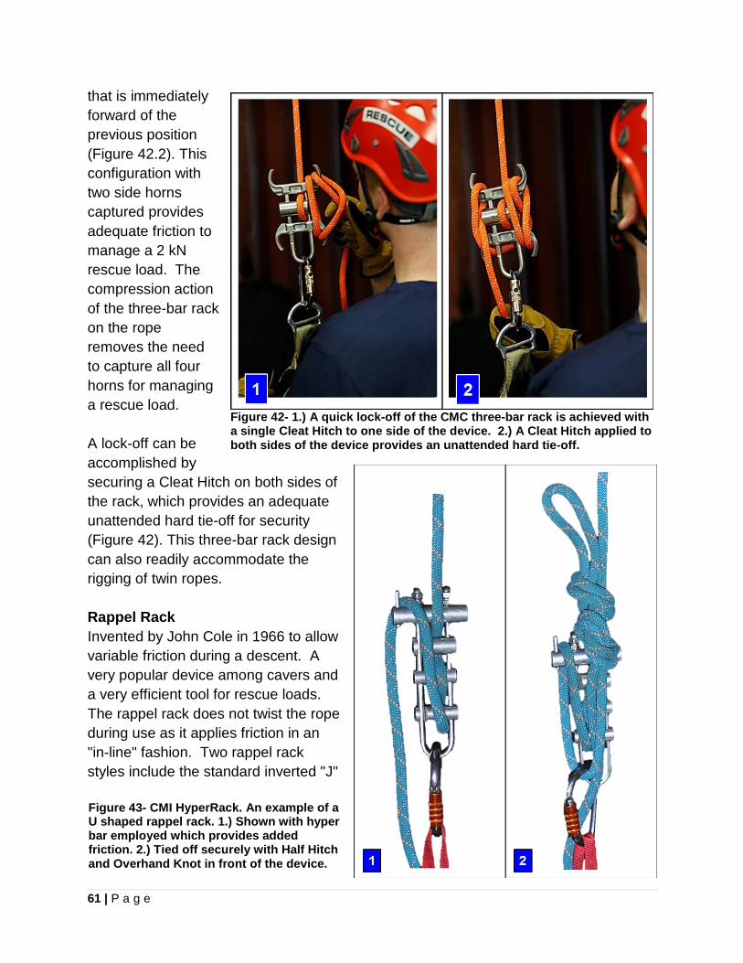
61 | P a g e
that is immediately forward of the previous position (Figure 42.2). This configuration with two side horns captured provides adequate friction to manage a 2 kN rescue load. The compression action of the three-bar rack on the rope removes the need to capture all four horns for managing a rescue load. A lock-off can be accomplished by securing a Cleat Hitch on both sides of the rack, which provides an adequate unattended hard tie-off for security (Figure 42). This three-bar rack design can also readily accommodate the rigging of twin ropes. Rappel Rack Invented by John Cole in 1966 to allow variable friction during a descent. A very popular device among cavers and a very efficient tool for rescue loads. The rappel rack does not twist the rope during use as it applies friction in an "in-line" fashion. Two rappel rack styles include the standard inverted "J"
Figure 42- 1.) A quick lock-off of the CMC three-bar rack is achieved with a single Cleat Hitch to one side of the device. 2.) A Cleat Hitch applied to both sides of the device provides an unattended hard tie-off.
Figure 43- CMI HyperRack. An example of a U shaped rappel rack. 1.) Shown with hyper bar employed which provides added friction. 2.) Tied off securely with Half Hitch and Overhand Knot in front of the device.
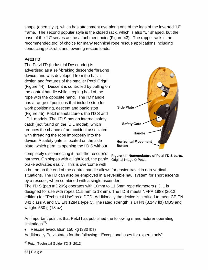
62 | P a g e
shape (open style), which has attachment eye along one of the legs of the inverted "U" frame. The second popular style is the closed rack, which is also "U" shaped, but the base of the "U" serves as the attachment point (Figure 43). The rappel rack is the recommended tool of choice for many technical rope rescue applications including conducting pick-offs and lowering rescue loads. Petzl I'D The Petzl I'D (Industrial Descender) is advertised as a self-braking descender/braking device, and was developed from the basic design and features of the smaller Petzl Grigri (Figure 44). Descent is controlled by pulling on the control handle while keeping hold of the rope with the opposite hand. The I'D handle has a range of positions that include stop for work positioning, descent and panic stop (Figure 45). Petzl manufacturers the I’D S and I’D L models. The I’D S has an internal safety catch (not found on the ID’L model), which reduces the chance of an accident associated with threading the rope improperly into the device. A safety gate is located on the side plate, which permits opening the I’D S without
completely disconnecting it from the rescuer’s harness. On slopes with a light load, the panic brake activates easily. This is overcome with a button on the end of the control handle allows for easier travel in non-vertical situations. The I’D can also be employed in a reversible haul system for short ascents by a rescuer, when combined with a single ascender. The I’D S (part # D20S) operates with 10mm to 11.5mm rope diameters (I’D L is designed for use with ropes 11.5 mm to 13mm). The I’D S meets NFPA 1983 (2012 edition) for “Technical Use” as a DCD. Additionally the device is certified to meet CE EN 341 class A and CE EN 12841 type C. The rated strength is 14 kN (3,147 lbf) MBS and weighs 530 g (18 oz). An important point is that Petzl has published the following manufacturer operating limitations45: • Rescue evacuation 150 kg (330 lbs) Additionally Petzl states for the following- “Exceptional uses for experts only”; 45 Petzl. Technical Guide- I’D S. 2013
Figure 44- Nomenclature of Petzl I'D S parts. Original image © Petzl.
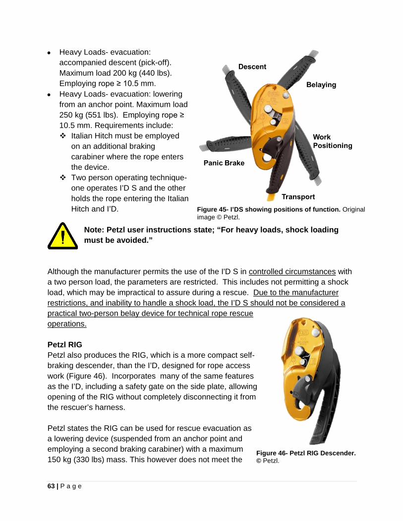
63 | P a g e
• Heavy Loads- evacuation: accompanied descent (pick-off). Maximum load 200 kg (440 lbs). Employing rope ≥ 10.5 mm.
• Heavy Loads- evacuation: lowering from an anchor point. Maximum load 250 kg (551 lbs). Employing rope ≥ 10.5 mm. Requirements include: Italian Hitch must be employed
on an additional braking carabiner where the rope enters the device.
Two person operating technique- one operates I’D S and the other holds the rope entering the Italian Hitch and I’D.
Note: Petzl user instructions state; “For heavy loads, shock loading must be avoided.”
Figure 45- I’DS showing positions of function. Original image © Petzl.
Although the manufacturer permits the use of the I'D S in controlled circumstances with a two person load, the parameters are restricted. This includes not permitting a shock load, which may be impractical to assure during a rescue. Due to the manufacturer restrictions, and inability to handle a shock load, the I’D S should not be considered a practical two-person belay device for technical rope rescue operations. Petzl RIG Petzl also produces the RIG, which is a more compact self-braking descender, than the I’D, designed for rope access work (Figure 46). Incorporates many of the same features as the I’D, including a safety gate on the side plate, allowing opening of the RIG without completely disconnecting it from the rescuer’s harness. Petzl states the RIG can be used for rescue evacuation as a lowering device (suspended from an anchor point and employing a second braking carabiner) with a maximum 150 kg (330 lbs) mass. This however does not meet the
Figure 46- Petzl RIG Descender. © Petzl.
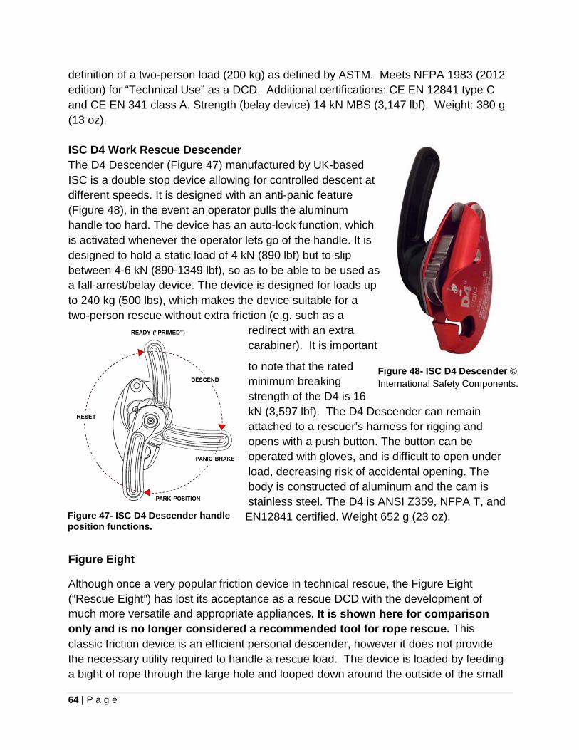
64 | P a g e
definition of a two-person load (200 kg) as defined by ASTM. Meets NFPA 1983 (2012 edition) for “Technical Use” as a DCD. Additional certifications: CE EN 12841 type C and CE EN 341 class A. Strength (belay device) 14 kN MBS (3,147 lbf). Weight: 380 g (13 oz). ISC D4 Work Rescue Descender The D4 Descender (Figure 47) manufactured by UK-based ISC is a double stop device allowing for controlled descent at different speeds. It is designed with an anti-panic feature (Figure 48), in the event an operator pulls the aluminum handle too hard. The device has an auto-lock function, which is activated whenever the operator lets go of the handle. It is designed to hold a static load of 4 kN (890 lbf) but to slip between 4-6 kN (890-1349 lbf), so as to be able to be used as a fall-arrest/belay device. The device is designed for loads up to 240 kg (500 lbs), which makes the device suitable for a two-person rescue without extra friction (e.g. such as a
redirect with an extra carabiner). It is important
to note that the rated minimum breaking strength of the D4 is 16 kN (3,597 lbf). The D4 Descender can remain attached to a rescuer’s harness for rigging and opens with a push button. The button can be operated with gloves, and is difficult to open under load, decreasing risk of accidental opening. The body is constructed of aluminum and the cam is stainless steel. The D4 is ANSI Z359, NFPA T, and EN12841 certified. Weight 652 g (23 oz).
Figure 48- ISC D4 Descender © International Safety Components.
Figure 47- ISC D4 Descender handle position functions.
Figure Eight
Although once a very popular friction device in technical rescue, the Figure Eight (“Rescue Eight”) has lost its acceptance as a rescue DCD with the development of much more versatile and appropriate appliances. It is shown here for comparison only and is no longer considered a recommended tool for rope rescue. This classic friction device is an efficient personal descender, however it does not provide the necessary utility required to handle a rescue load. The device is loaded by feeding a bight of rope through the large hole and looped down around the outside of the small
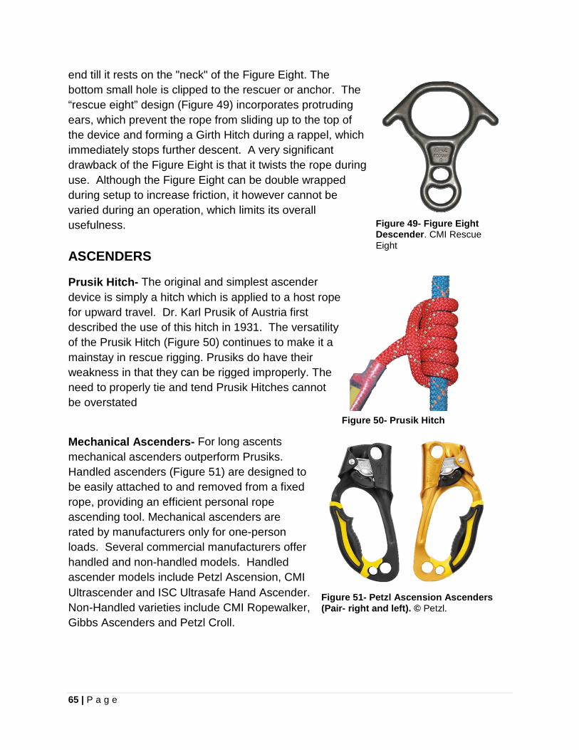
65 | P a g e
end till it rests on the "neck" of the Figure Eight. The bottom small hole is clipped to the rescuer or anchor. The “rescue eight” design (Figure 49) incorporates protruding ears, which prevent the rope from sliding up to the top of the device and forming a Girth Hitch during a rappel, which immediately stops further descent. A very significant drawback of the Figure Eight is that it twists the rope during use. Although the Figure Eight can be double wrapped during setup to increase friction, it however cannot be varied during an operation, which limits its overall usefulness.
Figure 49- Figure Eight Descender. CMI Rescue Eight
ASCENDERS
Prusik Hitch- The original and simplest ascender device is simply a hitch which is applied to a host rope for upward travel. Dr. Karl Prusik of Austria first described the use of this hitch in 1931. The versatility of the Prusik Hitch (Figure 50) continues to make it a mainstay in rescue rigging. Prusiks do have their weakness in that they can be rigged improperly. The need to properly tie and tend Prusik Hitches cannot be overstated Figure 50- Prusik Hitch
Mechanical Ascenders- For long ascents mechanical ascenders outperform Prusiks. Handled ascenders (Figure 51) are designed to be easily attached to and removed from a fixed rope, providing an efficient personal rope ascending tool. Mechanical ascenders are rated by manufacturers only for one-person loads. Several commercial manufacturers offer handled and non-handled models. Handled ascender models include Petzl Ascension, CMI Ultrascender and ISC Ultrasafe Hand Ascender. Non-Handled varieties include CMI Ropewalker, Gibbs Ascenders and Petzl Croll.
Figure 51- Petzl Ascension Ascenders (Pair- right and left). © Petzl.
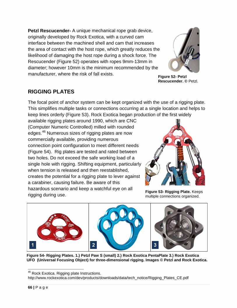
66 | P a g e
Petzl Rescucender- A unique mechanical rope grab device, originally developed by Rock Exotica, with a curved cam interface between the machined shell and cam that increases the area of contact with the host rope, which greatly reduces the likelihood of damaging the host rope during a shock force. The Rescucender (Figure 52) operates with ropes 9mm-13mm in diameter; however 10mm is the minimum recommended by the manufacturer, where the risk of fall exists.
RIGGING PLATES
The focal point of anchor system can be kept organized with the use of a rigging plate. This simplifies multiple tasks or connections occurring at a single location and helps to keep lines orderly (Figure 53). Rock Exotica began production of the first widely available rigging plates around 1990, which are CNC (Computer Numeric Controlled) milled with rounded edges.46 Numerous sizes of rigging plates are now commercially available, providing numerous connection point configuration to meet different needs (Figure 54). Rig plates are tested and rated between two holes. Do not exceed the safe working load of a single hole with rigging. Shifting equipment, particularly when tension is released and then reestablished, creates the potential for a rigging plate to lever against a carabiner, causing failure. Be aware of this hazardous scenario and keep a watchful eye on all rigging during use.
46 Rock Exotica. Rigging plate Instructions. http://www.rockexotica.com/dev/products/downloads/data/tech_notice/Rigging_Plates_CE.pdf
Figure 52- Petzl Rescucender. © Petzl.
Figure 53- Rigging Plate. Keeps multiple connections organized.
Figure 54- Rigging Plates. 1.) Petzl Paw S (small) 2.) Rock Exotica PentaPlate 3.) Rock Exotica UFO (Universal Focusing Object) for three-dimensional rigging. Images © Petzl and Rock Exotica.

67 | P a g e
MANUFACTURER BREAKING STRENGTHS OF RESCUE EQUIPMENT
Note: All strength ratings shown reflect ideal conditions with new products. Remember that rope, cordage and webbing loose significant strength when wet or rigged with knots.
ITEM kN Force pounds
CORDAGE/ROPE: 4 mm Accessory Cord (PMI) 3.8 kN 854 lbf 5 mm Accessory Cord (PMI) 5.8 kN 1,304 lbf 5.9 mm PowerCORD (Technora core) (Sterling Rope) 19 kN 4,271 lbf 6 mm Accessory Cord (PMI) 7.5 kN 1,686 lbf 7 mm Prusik Cord (PMI) 10.7 kN 2,405 lbf 8 mm Prusik Cord (PMI) 13.4 kN 3,012 lbf 11 mm Static Nylon Rope (PMI Pro Classic Max-Wear) 28.6 kN 6,430 lbf 11mm HTP (High Tenacity Polyester) (Sterling) 30.5 kN 6,856 lbf WEBBING: 1 inch Mil-Spec Tubular Webbing (PMI) 18 kN 4,000 lbf 1 inch Type 18 Woven Flat Webbing (PMI) 27 kN 6,000 lbf Climb Spec Webbing, 15mm (9/16") (BlueWater) 10.2 kN 2,300 lbf SpectraTM Sewn Titan Sling, 13mm (1/2") (BlueWater) 27 kN 6,069 lbf HARDWARE: Petzl Minder (Prusik-Minding) Pulley (P60A) (97% efficiency) 36 kN 8,093 lbf Rock Exotica 2.0 Prusik Minding Pulley 36 kN 8,093 lbf Rock Exotica Omni-Block 2.0 Pulley 36 kN 8,093 lbf Traverse Rescue 5400 TM Rescue Belay 40 kN 8,992 lbf CMC MPD 44 kN 9,891 lbf Conterra Scarab (rope breaks at 27kN) 40kN 8,992 lbf Petzl I’D 14 kN 3,147 lbf ISC D4 Descender 16 kN 3,597 lbf CMI Mini Hyper Rack 62 kN 14,000 lbf SMC Figure Eight with Ears, NFPA128701 32kN 7,194 lbf Petzl Delta Triangular Screw-Link, 10 mm (P11) 25 kN 5,620 lbf Source: Manufacturer websites
Note: 1 Kilonewton (kN) = force of 225 lbs
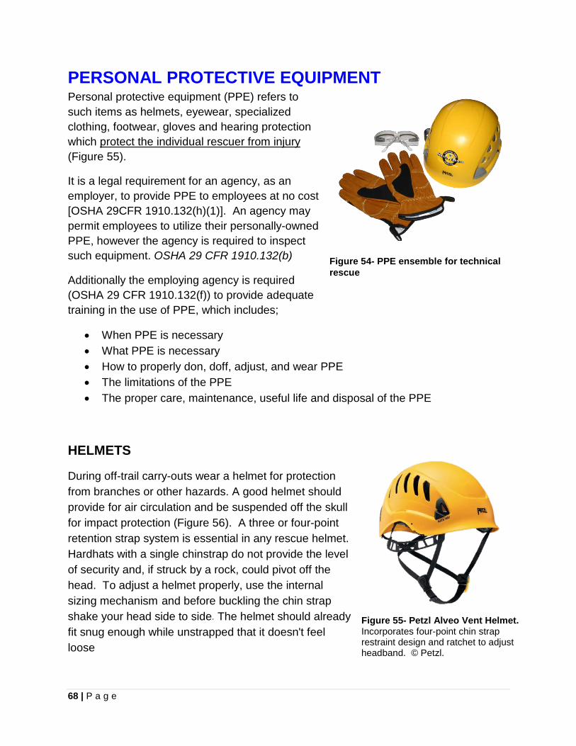
68 | P a g e
PERSONAL PROTECTIVE EQUIPMENT Personal protective equipment (PPE) refers to such items as helmets, eyewear, specialized clothing, footwear, gloves and hearing protection which protect the individual rescuer from injury (Figure 55).
It is a legal requirement for an agency, as an employer, to provide PPE to employees at no cost [OSHA 29CFR 1910.132(h)(1)]. An agency may permit employees to utilize their personally-owned PPE, however the agency is required to inspect such equipment. OSHA 29 CFR 1910.132(b)
Additionally the employing agency is required (OSHA 29 CFR 1910.132(f)) to provide adequate training in the use of PPE, which includes;
• When PPE is necessary • What PPE is necessary • How to properly don, doff, adjust, and wear PPE • The limitations of the PPE • The proper care, maintenance, useful life and disposal of the PPE
Figure 54- PPE ensemble for technical rescue
HELMETS
During off-trail carry-outs wear a helmet for protection from branches or other hazards. A good helmet should provide for air circulation and be suspended off the skull for impact protection (Figure 56). A three or four-point retention strap system is essential in any rescue helmet. Hardhats with a single chinstrap do not provide the level of security and, if struck by a rock, could pivot off the head. To adjust a helmet properly, use the internal sizing mechanism and before buckling the chin strap shake your head side to side. The helmet should already fit snug enough while unstrapped that it doesn't feel loose
Figure 55- Petzl Alveo Vent Helmet. Incorporates four-point chin strap restraint design and ratchet to adjust headband. © Petzl.
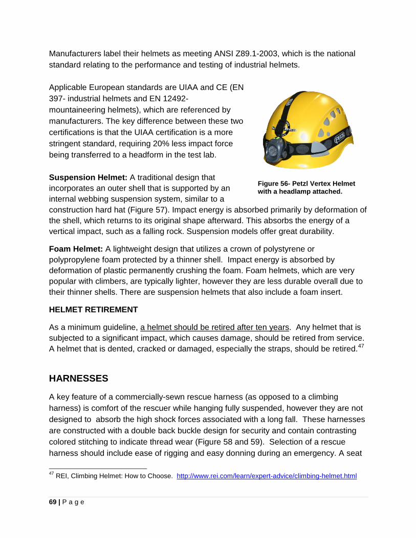
69 | P a g e
Manufacturers label their helmets as meeting ANSI Z89.1-2003, which is the national standard relating to the performance and testing of industrial helmets. Applicable European standards are UIAA and CE (EN 397- industrial helmets and EN 12492- mountaineering helmets), which are referenced by manufacturers. The key difference between these two certifications is that the UIAA certification is a more stringent standard, requiring 20% less impact force being transferred to a headform in the test lab. Suspension Helmet: A traditional design that incorporates an outer shell that is supported by an internal webbing suspension system, similar to a construction hard hat (Figure 57). Impact energy is absorbed primarily by deformation of the shell, which returns to its original shape afterward. This absorbs the energy of a vertical impact, such as a falling rock. Suspension models offer great durability.
Foam Helmet: A lightweight design that utilizes a crown of polystyrene or polypropylene foam protected by a thinner shell. Impact energy is absorbed by deformation of plastic permanently crushing the foam. Foam helmets, which are very popular with climbers, are typically lighter, however they are less durable overall due to their thinner shells. There are suspension helmets that also include a foam insert.
HELMET RETIREMENT
As a minimum guideline, a helmet should be retired after ten years. Any helmet that is subjected to a significant impact, which causes damage, should be retired from service. A helmet that is dented, cracked or damaged, especially the straps, should be retired.47
Figure 56- Petzl Vertex Helmet with a headlamp attached.
HARNESSES
A key feature of a commercially-sewn rescue harness (as opposed to a climbing harness) is comfort of the rescuer while hanging fully suspended, however they are not designed to absorb the high shock forces associated with a long fall. These harnesses are constructed with a double back buckle design for security and contain contrasting colored stitching to indicate thread wear (Figure 58 and 59). Selection of a rescue harness should include ease of rigging and easy donning during an emergency. A seat
47 REI, Climbing Helmet: How to Choose. http://www.rei.com/learn/expert-advice/climbing-helmet.html
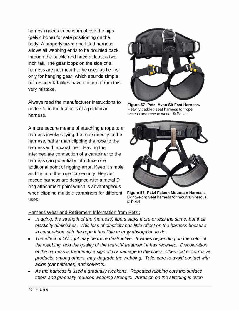
70 | P a g e
harness needs to be worn above the hips (pelvic bone) for safe positioning on the body. A properly sized and fitted harness allows all webbing ends to be doubled back through the buckle and have at least a two inch tail. The gear loops on the side of a harness are not meant to be used as tie-ins, only for hanging gear, which sounds simple but rescuer fatalities have occurred from this very mistake. Always read the manufacturer instructions to understand the features of a particular harness.
A more secure means of attaching a rope to a harness involves tying the rope directly to the harness, rather than clipping the rope to the harness with a carabiner. Having the intermediate connection of a carabiner to the harness can potentially introduce one additional point of rigging error. Keep it simple and tie in to the rope for security. Heavier rescue harness are designed with a metal D-ring attachment point which is advantageous when clipping multiple carabiners for different uses.
Harness Wear and Retirement Information from Petzl; • In aging, the strength of the (harness) fibers stays more or less the same, but their
elasticity diminishes. This loss of elasticity has little effect on the harness because in comparison with the rope it has little energy absorption to do.
• The effect of UV light may be more destructive. It varies depending on the color of the webbing, and the quality of the anti-UV treatment it has received. Discoloration of the harness is frequently a sign of UV damage to the fibers. Chemical or corrosive products, among others, may degrade the webbing. Take care to avoid contact with acids (car batteries) and solvents.
• As the harness is used it gradually weakens. Repeated rubbing cuts the surface fibers and gradually reduces webbing strength. Abrasion on the stitching is even
Figure 57- Petzl Avao Sit Fast Harness. Heavily padded seat harness for rope access and rescue work. © Petzl.
Figure 58- Petzl Falcon Mountain Harness. Lightweight Seat harness for mountain rescue. © Petzl.
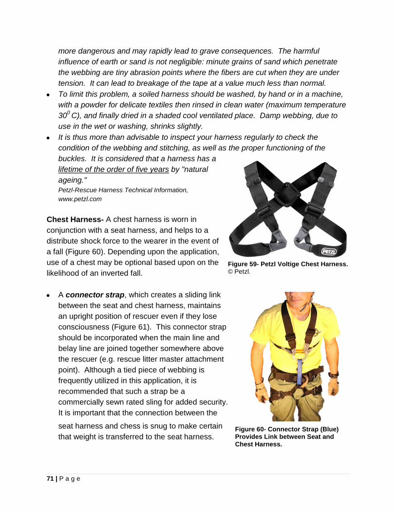
71 | P a g e
more dangerous and may rapidly lead to grave consequences. The harmful influence of earth or sand is not negligible: minute grains of sand which penetrate the webbing are tiny abrasion points where the fibers are cut when they are under tension. It can lead to breakage of the tape at a value much less than normal.
• To limit this problem, a soiled harness should be washed, by hand or in a machine, with a powder for delicate textiles then rinsed in clean water (maximum temperature 300 C), and finally dried in a shaded cool ventilated place. Damp webbing, due to use in the wet or washing, shrinks slightly.
• It is thus more than advisable to inspect your harness regularly to check the condition of the webbing and stitching, as well as the proper functioning of the buckles. It is considered that a harness has a lifetime of the order of five years by "natural ageing." Petzl-Rescue Harness Technical Information, www.petzl.com
Chest Harness- A chest harness is worn in conjunction with a seat harness, and helps to a distribute shock force to the wearer in the event of a fall (Figure 60). Depending upon the application, use of a chest may be optional based upon on the likelihood of an inverted fall. • A connector strap, which creates a sliding link
between the seat and chest harness, maintains an upright position of rescuer even if they lose consciousness (Figure 61). This connector strap should be incorporated when the main line and belay line are joined together somewhere above the rescuer (e.g. rescue litter master attachment point). Although a tied piece of webbing is frequently utilized in this application, it is recommended that such a strap be a commercially sewn rated sling for added security. It is important that the connection between the
seat harness and chess is snug to make certain that weight is transferred to the seat harness.
Figure 59- Petzl Voltige Chest Harness. © Petzl.
Figure 60- Connector Strap (Blue) Provides Link between Seat and Chest Harness.
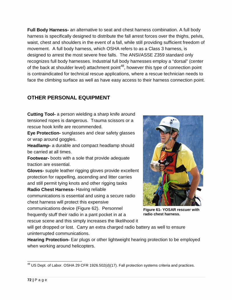
72 | P a g e
Full Body Harness- an alternative to seat and chest harness combination. A full body harness is specifically designed to distribute the fall arrest forces over the thighs, pelvis, waist, chest and shoulders in the event of a fall, while still providing sufficient freedom of movement. A full body harness, which OSHA refers to as a Class 3 harness, is designed to arrest the most severe free falls. The ANSI/ASSE Z359 standard only recognizes full body harnesses. Industrial full body harnesses employ a “dorsal” (center of the back at shoulder level) attachment point48, however this type of connection point is contraindicated for technical rescue applications, where a rescue technician needs to face the climbing surface as well as have easy access to their harness connection point.
OTHER PERSONAL EQUIPMENT
Cutting Tool- a person wielding a sharp knife around tensioned ropes is dangerous. Trauma scissors or a rescue hook knife are recommended. Eye Protection- sunglasses and clear safety glasses or wrap around goggles. Headlamp- a durable and compact headlamp should be carried at all times. Footwear- boots with a sole that provide adequate traction are essential. Gloves- supple leather rigging gloves provide excellent protection for rappelling, ascending and litter carries and still permit tying knots and other rigging tasks Radio Chest Harness- Having reliable communications is essential and using a secure radio chest harness will protect this expensive communications device (Figure 62). Personnel frequently stuff their radio in a pant pocket in at a rescue scene and this simply increases the likelihood it will get dropped or lost. Carry an extra charged radio battery as well to ensure uninterrupted communications. Hearing Protection- Ear plugs or other lightweight hearing protection to be employed when working around helicopters. 48 US Dept. of Labor. OSHA 29 CFR 1926.502(d)(17). Fall protection systems criteria and practices.
Figure 61- YOSAR rescuer with radio chest harness.
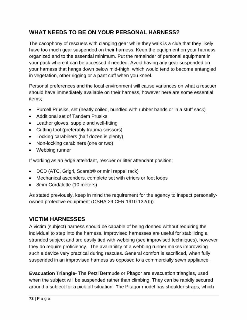
73 | P a g e
WHAT NEEDS TO BE ON YOUR PERSONAL HARNESS?
The cacophony of rescuers with clanging gear while they walk is a clue that they likely have too much gear suspended on their harness. Keep the equipment on your harness organized and to the essential minimum. Put the remainder of personal equipment in your pack where it can be accessed if needed. Avoid having any gear suspended on your harness that hangs down below mid-thigh, which would tend to become entangled in vegetation, other rigging or a pant cuff when you kneel.
Personal preferences and the local environment will cause variances on what a rescuer should have immediately available on their harness, however here are some essential items;
• Purcell Prusiks, set (neatly coiled, bundled with rubber bands or in a stuff sack) • Additional set of Tandem Prusiks • Leather gloves, supple and well-fitting • Cutting tool (preferably trauma scissors) • Locking carabiners (half dozen is plenty) • Non-locking carabiners (one or two) • Webbing runner
If working as an edge attendant, rescuer or litter attendant position;
• DCD (ATC, Grigri, Scarab® or mini rappel rack) • Mechanical ascenders, complete set with etriers or foot loops • 8mm Cordalette (10 meters)
As stated previously, keep in mind the requirement for the agency to inspect personally-owned protective equipment (OSHA 29 CFR 1910.132(b)).
VICTIM HARNESSES A victim (subject) harness should be capable of being donned without requiring the individual to step into the harness. Improvised harnesses are useful for stabilizing a stranded subject and are easily tied with webbing (see improvised techniques), however they do require proficiency. The availability of a webbing runner makes improvising such a device very practical during rescues. General comfort is sacrificed, when fully suspended in an improvised harness as opposed to a commercially sewn appliance. Evacuation Triangle- The Petzl Bermude or Pitagor are evacuation triangles, used when the subject will be suspended rather than climbing. They can be rapidly secured around a subject for a pick-off situation. The Pitagor model has shoulder straps, which
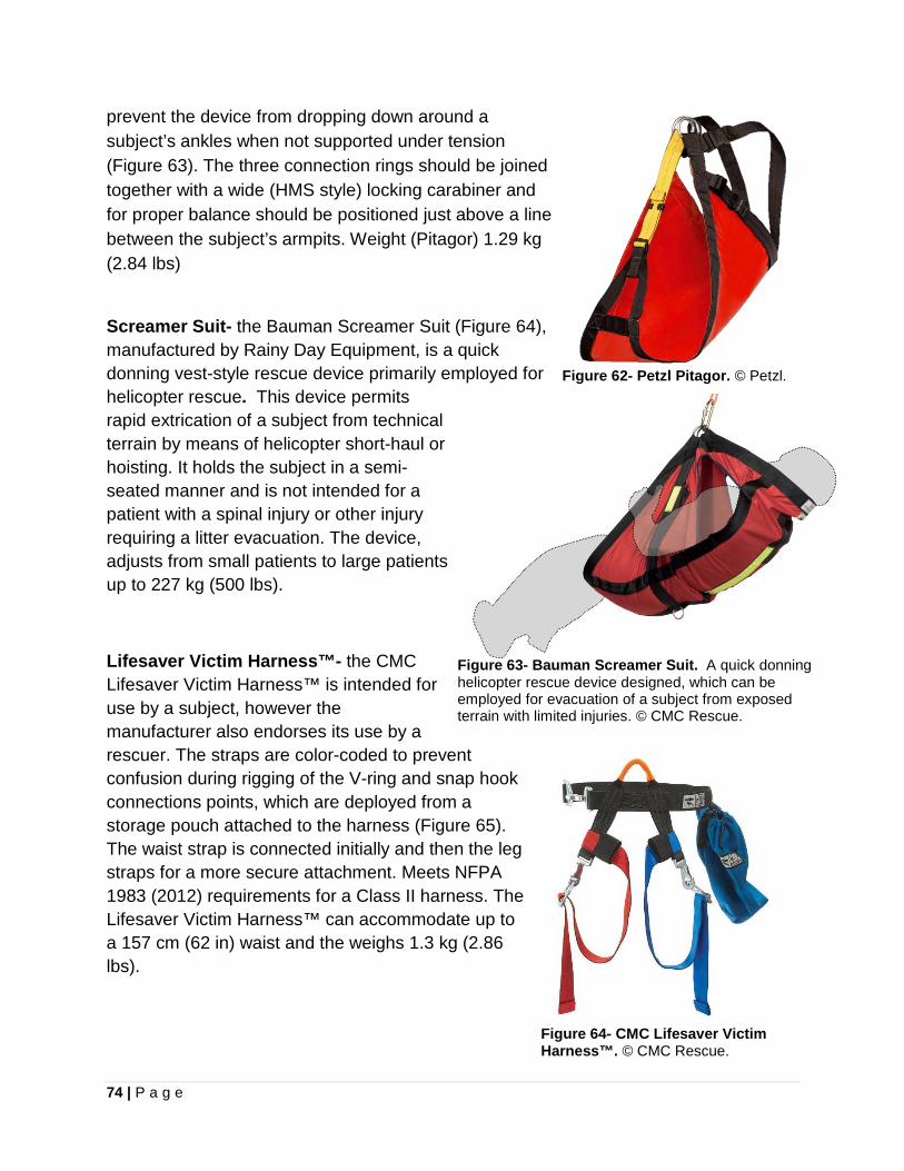
74 | P a g e
prevent the device from dropping down around a subject’s ankles when not supported under tension (Figure 63). The three connection rings should be joined together with a wide (HMS style) locking carabiner and for proper balance should be positioned just above a line between the subject’s armpits. Weight (Pitagor) 1.29 kg (2.84 lbs)
Screamer Suit- the Bauman Screamer Suit (Figure 64), manufactured by Rainy Day Equipment, is a quick donning vest-style rescue device primarily employed for helicopter rescue. This device permits rapid extrication of a subject from technical terrain by means of helicopter short-haul or hoisting. It holds the subject in a semi-seated manner and is not intended for a patient with a spinal injury or other injury requiring a litter evacuation. The device, adjusts from small patients to large patients up to 227 kg (500 lbs).
Lifesaver Victim Harness™- the CMC Lifesaver Victim Harness™ is intended for use by a subject, however the manufacturer also endorses its use by a rescuer. The straps are color-coded to prevent confusion during rigging of the V-ring and snap hook connections points, which are deployed from a storage pouch attached to the harness (Figure 65). The waist strap is connected initially and then the leg straps for a more secure attachment. Meets NFPA 1983 (2012) requirements for a Class II harness. The Lifesaver Victim Harness™ can accommodate up to a 157 cm (62 in) waist and the weighs 1.3 kg (2.86 lbs).
Figure 62- Petzl Pitagor. © Petzl.
Figure 63- Bauman Screamer Suit. A quick donning helicopter rescue device designed, which can be employed for evacuation of a subject from exposed terrain with limited injuries. © CMC Rescue.
Figure 64- CMC Lifesaver Victim Harness™. © CMC Rescue.

75 | P a g e
EQUIPMENT CARE AND RETIREMENT49
Proper storage and general treatment will greatly extend the useful service life of all rescue equipment. Keep in mind that life safety equipment is designed to keep you safe. Develop a strong discipline of good housekeeping and storage of all equipment in a response-ready state. Store equipment in a well-ventilated area out of direct sunlight, to avoid the possibility of degradation from ultra-violet exposure. Do not store near corrosive substances or acids (vehicle battery acid). Avoid storing equipment in a damp place where mold can develop (damp closets, bags and waterproof containers with moisture inside). The following recommendation regarding retirement timeframes is made by Petzl, regarding the lifetime of their equipment; “The maximum lifetime is up to ten years from the date of manufacture for plastic and textile products. The lifetime is indefinite for metal products. Warning: An unusual event may require you to retire a product after only one use. This may involve the type and intensity of use, or the environment in which it is used: aggressive environments, sharp edges, extreme temperatures, chemicals.” When determining the age of equipment, recognize that manufacturers who meet EN (CE) requirements, mark the year of production and lot number on an item in some manner (Figure 66). Retire gear when necessary, including; • Over ten years old and made of plastic or textiles • When subjected to a major fall or impact force • When it fails to pass an inspection • If the reliability of the equipment is in question • The usage history is unknown (e.g. not marked, missing rope log, etc.) • Obsolete design due to changes in standards, technique, or equipment compatibility 49 Adapted from Petzl- “Tips for Protecting Your Equipment” http://www.petzl.com/files/all/technical-notice/both/protecting-equipment-tips_EN.pdf
Figure 65- Year of manufacture. Etched marking indicates this carabiner was manufactured in 2010. Marking arrangements vary between manufacturers.
76 | P a g e
• Destroy any retired equipment to prevent further use in a life safety application • Check all carabiner surfaces regularly for cracks, sharp edges, corrosion, burrs or
excessive wear. Hairline cracks can result in significantly reduced carabiner strength.
• Check carabiners gates to make certain they open and close quickly and easily. Be sure all gates, as well as any locking mechanisms, close freely and properly. Retire any carabiner, if the gate does not function properly, or is out of alignment.
• Carabiners that have been dropped a significant distance should be retired. A dropped carabiner can suffer significant damage yet still appear visually intact. When in doubt, remove it from service.
CARABINER CLEANING
• Clean gates by blowing dust and dirt from the hinge area. • For a sticky gate, wash in warm soapy water, rinse thoroughly, and allow to dry. • Lubricate carabiners with a general purpose lubricating oil (e.g. 3-IN-ONE®) or
Teflon based (PTFE) lubricant (e.g. Tri-Flow®) around the hinge area, the spring hole and the locking mechanism. Wipe off excess lubricant. o Do not use WD-40 as it can dry out the hinge and spring, accelerating aging. o Do not use graphite based lubricants, which promotes corrosion in aluminum.
• Do remove any sharp burrs that can damage rope, sand them using fine grit sandpaper. Do not file carabiners to remove a burr.
• Clean and lube carabiners after contact with saltwater or salt air. • Do not use a high pressure water sprayer, which can dry out the gate hinge. HELMET CARE AND CLEANING
• Hemet manufacturers oppose marking a helmet will numerous decals or paint, due to the possible degradation.
• Do not compress a helmet inside a pack • Do not sit on a helmet. • Clean a helmet with household soap and rinse with water. • Do not use solvents, stain removers, degreasers, etc. that are not compatible with
polycarbonate, polystyrene, or nylon, and can degrade the helmet. • Shell of ABS helmets can be cleaned with a cloth moistened with rubbing alcohol. HARNESS CARE AND CLEANING
• Inspect the stitching and condition of the straps on a clean textile product. • After use in a salty environment (seaside), rinse with fresh water.
77 | P a g e
• Wash a harness in lukewarm soapy water, then rinse thoroughly with fresh water. Use a small brush to remove stubborn spots (oily dirt or mud).
• Clean in washer on delicate setting (max 86°F or 30°C), without spin cycle. • Wash in a cloth bag to avoid damaging machine drum from metal harness parts. • Use only household face or body soap (Do not use laundry detergent). Solvents,
stain removers, or degreasers are incompatible and can degrade nylon. • Hang harness on a line to dry ROPE CARE AND CLEANING
• Do not walk or stand on ropes. • Aggressively protect ropes from edge abrasion, by using rope protectors and rollers. • Avoid descending too fast on a rope as this heats the sheath and accelerates wear. • Rapid descents can cause a rappel device to heat up (446°F or 230 °C) and melt
nylon rope fibers. • Store ropes uncoiled in a bag to protect them from dirt. • Keep rope away from contact with sharp objects (ice screws, ice axes, crampons). • Keep your ropes clean. A rope's condition can have an impact on the wear of other
gear. For example, a muddy rope can inhibit the proper function of an ascender. A wet, sandy rope can cause premature wear of ascenders, descenders and carabiners.
• Use a hot knife to get a neat, clean cut. • Mark each rope end with in-service date, diameter, and rope length. • Use labels or adhesive tape to record information and protect the label with a heat-
shrink tubing (WARNING: do not exceed 176°F or 80 °C). • After use in a salty environment, rinse with fresh water. • Wash ropes in lukewarm soapy water (ph neutral, 86°F or 30°C maximum), and
rinse thoroughly with water. • Clean in washer on a delicate setting (max 86°F or 30°C), without spin cycle. • Use only household face or body soap (Do not use laundry detergent). • Solvents, stain removers, or degreasers are incompatible and can degrade nylon. • Hang to air dry. MARKING EQUIPMENT
• Use of a metal stamp or punch for identification is unacceptable. • However, you can use an electric engraving pen (depth less than 0.1 mm) on the
frame, next to the serial number.

78 | P a g e
• You can also mark your metal equipment with a small amount of paint (paint pen or "metal writing" paint). Warning: do not dip your equipment in paint. Apply a small, thin marking of paint, not too thick. Avoid marking any working areas which would immediately cause the marking to worn off.
• The marks must be made on a part of the body where there is no rubbing against another device, or rope. The marks must not hide the original marking (serial number, standards, etc.) This type of marking is prohibited on plastic pieces, as the chemical agents in paints can weaken the structure of
• You can use adhesive tape on the areas where the rope does not run.
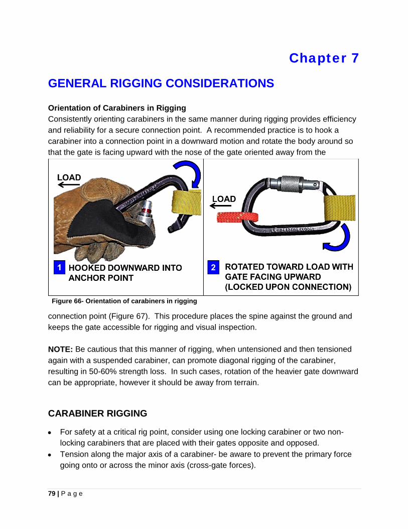
79 | P a g e
Chapter 7
GENERAL RIGGING CONSIDERATIONS Orientation of Carabiners in Rigging Consistently orienting carabiners in the same manner during rigging provides efficiency and reliability for a secure connection point. A recommended practice is to hook a carabiner into a connection point in a downward motion and rotate the body around so that the gate is facing upward with the nose of the gate oriented away from the
connection point (Figure 67). This procedure places the spine against the ground and keeps the gate accessible for rigging and visual inspection. NOTE: Be cautious that this manner of rigging, when untensioned and then tensioned again with a suspended carabiner, can promote diagonal rigging of the carabiner, resulting in 50-60% strength loss. In such cases, rotation of the heavier gate downward can be appropriate, however it should be away from terrain.
CARABINER RIGGING
• For safety at a critical rig point, consider using one locking carabiner or two non-locking carabiners that are placed with their gates opposite and opposed.
• Tension along the major axis of a carabiner- be aware to prevent the primary force going onto or across the minor axis (cross-gate forces).
Figure 66- Orientation of carabiners in rigging
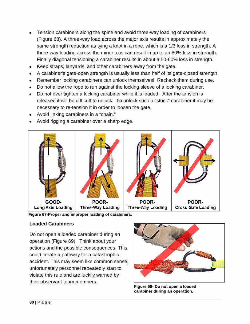
80 | P a g e
• Tension carabiners along the spine and avoid three-way loading of carabiners (Figure 68). A three-way load across the major axis results in approximately the same strength reduction as tying a knot in a rope, which is a 1/3 loss in strength. A three-way loading across the minor axis can result in up to an 80% loss in strength. Finally diagonal tensioning a carabiner results in about a 50-60% loss in strength.
• Keep straps, lanyards, and other carabiners away from the gate. • A carabiner's gate-open strength is usually less than half of its gate-closed strength. • Remember locking carabiners can unlock themselves! Recheck them during use. • Do not allow the rope to run against the locking sleeve of a locking carabiner. • Do not over tighten a locking carabiner while it is loaded. After the tension is
released it will be difficult to unlock. To unlock such a "stuck" carabiner it may be necessary to re-tension it in order to loosen the gate.
• Avoid linking carabiners in a “chain.” • Avoid rigging a carabiner over a sharp edge.
Figure 67-Proper and improper loading of carabiners.
Loaded Carabiners
Do not open a loaded carabiner during an operation (Figure 69). Think about your actions and the possible consequences. This could create a pathway for a catastrophic accident. This may seem like common sense, unfortunately personnel repeatedly start to violate this rule and are luckily warned by their observant team members.
Figure 68- Do not open a loaded carabiner during an operation.
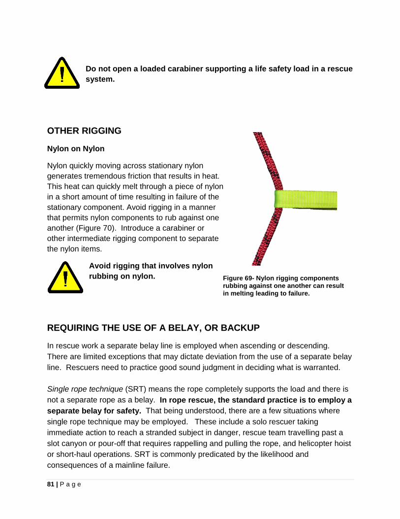
81 | P a g e
Do not open a loaded carabiner supporting a life safety load in a rescue system.
OTHER RIGGING
Nylon on Nylon
Nylon quickly moving across stationary nylon generates tremendous friction that results in heat. This heat can quickly melt through a piece of nylon in a short amount of time resulting in failure of the stationary component. Avoid rigging in a manner that permits nylon components to rub against one another (Figure 70). Introduce a carabiner or other intermediate rigging component to separate the nylon items.
Avoid rigging that involves nylon rubbing on nylon.
Figure 69- Nylon rigging components rubbing against one another can result in melting leading to failure.
REQUIRING THE USE OF A BELAY, OR BACKUP In rescue work a separate belay line is employed when ascending or descending. There are limited exceptions that may dictate deviation from the use of a separate belay line. Rescuers need to practice good sound judgment in deciding what is warranted. Single rope technique (SRT) means the rope completely supports the load and there is not a separate rope as a belay. In rope rescue, the standard practice is to employ a separate belay for safety. That being understood, there are a few situations where single rope technique may be employed. These include a solo rescuer taking immediate action to reach a stranded subject in danger, rescue team travelling past a slot canyon or pour-off that requires rappelling and pulling the rope, and helicopter hoist or short-haul operations. SRT is commonly predicated by the likelihood and consequences of a mainline failure.
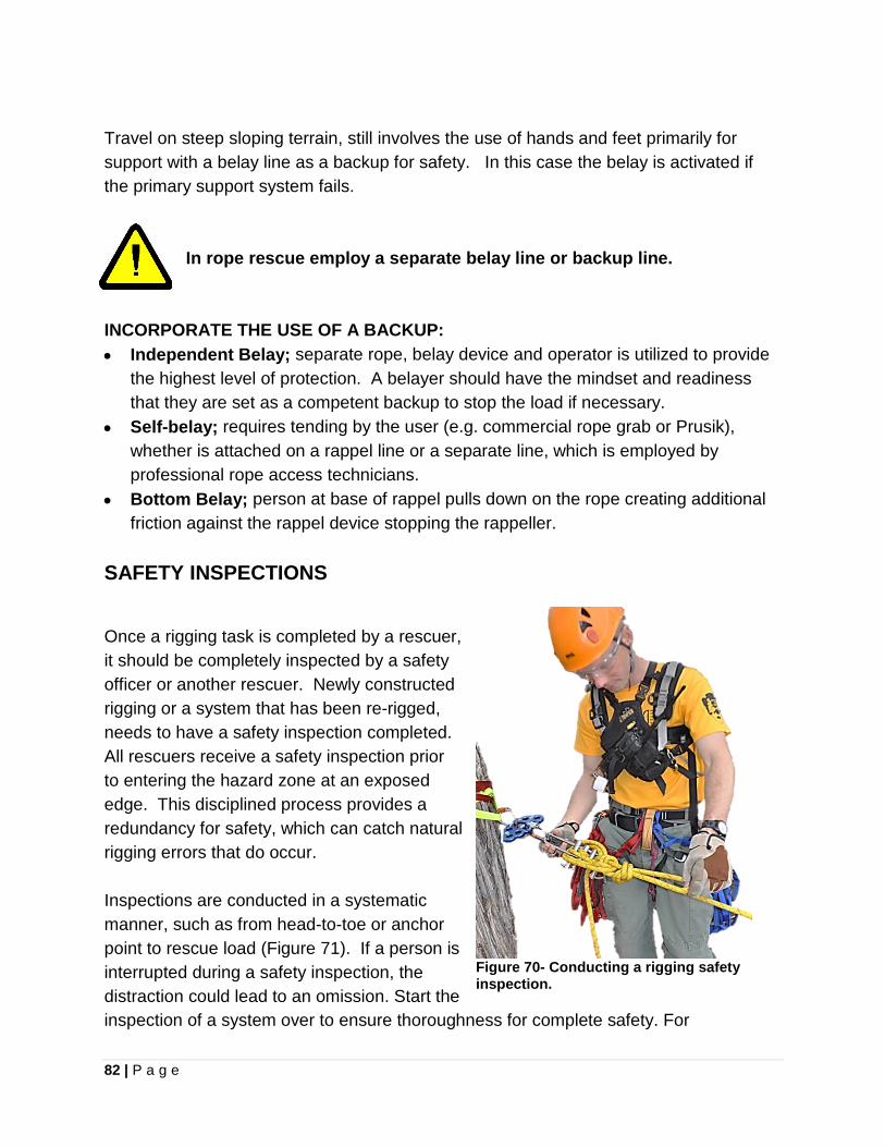
82 | P a g e
Travel on steep sloping terrain, still involves the use of hands and feet primarily for support with a belay line as a backup for safety. In this case the belay is activated if the primary support system fails.
In rope rescue employ a separate belay line or backup line.
INCORPORATE THE USE OF A BACKUP: • Independent Belay; separate rope, belay device and operator is utilized to provide
the highest level of protection. A belayer should have the mindset and readiness that they are set as a competent backup to stop the load if necessary.
• Self-belay; requires tending by the user (e.g. commercial rope grab or Prusik), whether is attached on a rappel line or a separate line, which is employed by professional rope access technicians.
• Bottom Belay; person at base of rappel pulls down on the rope creating additional friction against the rappel device stopping the rappeller.
SAFETY INSPECTIONS
Once a rigging task is completed by a rescuer, it should be completely inspected by a safety officer or another rescuer. Newly constructed rigging or a system that has been re-rigged, needs to have a safety inspection completed. All rescuers receive a safety inspection prior to entering the hazard zone at an exposed edge. This disciplined process provides a redundancy for safety, which can catch natural rigging errors that do occur. Inspections are conducted in a systematic manner, such as from head-to-toe or anchor point to rescue load (Figure 71). If a person is interrupted during a safety inspection, the distraction could lead to an omission. Start the inspection of a system over to ensure thoroughness for complete safety. For
Figure 70- Conducting a rigging safety inspection.

83 | P a g e
thoroughness, the actual safety inspection should involve three distinct actions by the inspector, including looking, touching and talking. 1. LOOK- Visually inspect all rigging; Rigging meets acceptable techniques. Knots are
correctly tied and dressed. Carabiners are locked. Buckles are secure. PPE is being completely employed. Housekeeping of all rigging has been addressed.
2. TOUCH- Physically touch and trace the rigging; Squeeze carabiners to verify security with a “press check.” Pull on harnesses. Pull on anchor points and systems for confirmation.
3. TALK- Verbally talk (even if it is only to yourself) about what you are inspecting; State what you observe and what you are looking for. Ask questions of the rigger.
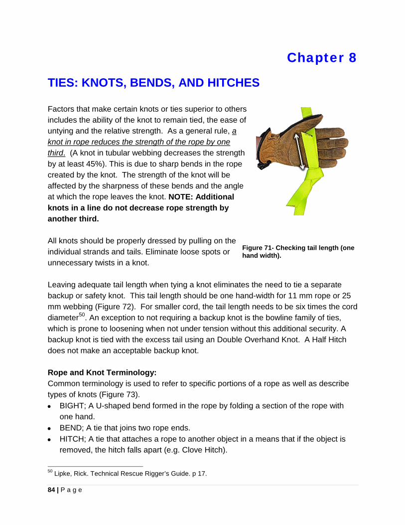
84 | P a g e
Chapter 8
TIES: KNOTS, BENDS, AND HITCHES Factors that make certain knots or ties superior to others includes the ability of the knot to remain tied, the ease of untying and the relative strength. As a general rule, a knot in rope reduces the strength of the rope by one third. (A knot in tubular webbing decreases the strength by at least 45%). This is due to sharp bends in the rope created by the knot. The strength of the knot will be affected by the sharpness of these bends and the angle at which the rope leaves the knot. NOTE: Additional knots in a line do not decrease rope strength by another third. All knots should be properly dressed by pulling on the individual strands and tails. Eliminate loose spots or unnecessary twists in a knot. Leaving adequate tail length when tying a knot eliminates the need to tie a separate backup or safety knot. This tail length should be one hand-width for 11 mm rope or 25 mm webbing (Figure 72). For smaller cord, the tail length needs to be six times the cord diameter50. An exception to not requiring a backup knot is the bowline family of ties, which is prone to loosening when not under tension without this additional security. A backup knot is tied with the excess tail using an Double Overhand Knot. A Half Hitch does not make an acceptable backup knot. Rope and Knot Terminology: Common terminology is used to refer to specific portions of a rope as well as describe types of knots (Figure 73). • BIGHT; A U-shaped bend formed in the rope by folding a section of the rope with
one hand. • BEND; A tie that joins two rope ends. • HITCH; A tie that attaches a rope to another object in a means that if the object is
removed, the hitch falls apart (e.g. Clove Hitch).
50 Lipke, Rick. Technical Rescue Rigger’s Guide. p 17.
Figure 71- Checking tail length (one hand width).
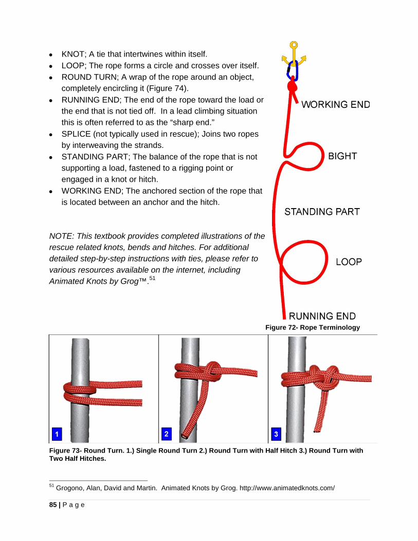
85 | P a g e
• KNOT; A tie that intertwines within itself. • LOOP; The rope forms a circle and crosses over itself. • ROUND TURN; A wrap of the rope around an object,
completely encircling it (Figure 74). • RUNNING END; The end of the rope toward the load or
the end that is not tied off. In a lead climbing situation this is often referred to as the “sharp end.”
• SPLICE (not typically used in rescue); Joins two ropes by interweaving the strands.
• STANDING PART; The balance of the rope that is not supporting a load, fastened to a rigging point or engaged in a knot or hitch.
• WORKING END; The anchored section of the rope that is located between an anchor and the hitch.
NOTE: This textbook provides completed illustrations of the rescue related knots, bends and hitches. For additional detailed step-by-step instructions with ties, please refer to various resources available on the internet, including Animated Knots by Grog™.51
51 Grogono, Alan, David and Martin. Animated Knots by Grog. http://www.animatedknots.com/
Figure 72- Rope Terminology
Figure 73- Round Turn. 1.) Single Round Turn 2.) Round Turn with Half Hitch 3.) Round Turn with Two Half Hitches.
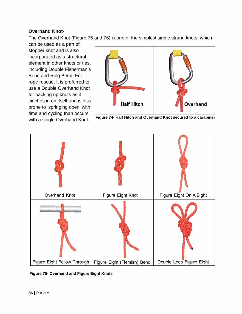
86 | P a g e
Overhand Knot- The Overhand Knot (Figure 75 and 76) is one of the simplest single strand knots, which can be used as a part of stopper knot and is also incorporated as a structural element in other knots or ties, including Double Fisherman’s Bend and Ring Bend. For rope rescue, it is preferred to use a Double Overhand Knot for backing up knots as it cinches in on itself and is less prone to ‘springing open’ with time and cycling than occurs with a single Overhand Knot.
Figure 74- Half Hitch and Overhand Knot secured to a carabiner
Figure 75- Overhand and Figure Eight Knots
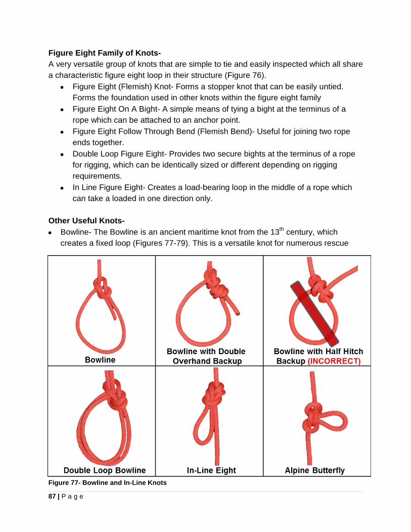
87 | P a g e
Figure Eight Family of Knots- A very versatile group of knots that are simple to tie and easily inspected which all share a characteristic figure eight loop in their structure (Figure 76).
• Figure Eight (Flemish) Knot- Forms a stopper knot that can be easily untied. Forms the foundation used in other knots within the figure eight family
• Figure Eight On A Bight- A simple means of tying a bight at the terminus of a rope which can be attached to an anchor point.
• Figure Eight Follow Through Bend (Flemish Bend)- Useful for joining two rope ends together.
• Double Loop Figure Eight- Provides two secure bights at the terminus of a rope for rigging, which can be identically sized or different depending on rigging requirements.
• In Line Figure Eight- Creates a load-bearing loop in the middle of a rope which can take a loaded in one direction only.
Other Useful Knots- • Bowline- The Bowline is an ancient maritime knot from the 13th century, which
creates a fixed loop (Figures 77-79). This is a versatile knot for numerous rescue
Figure 77- Bowline and In-Line Knots
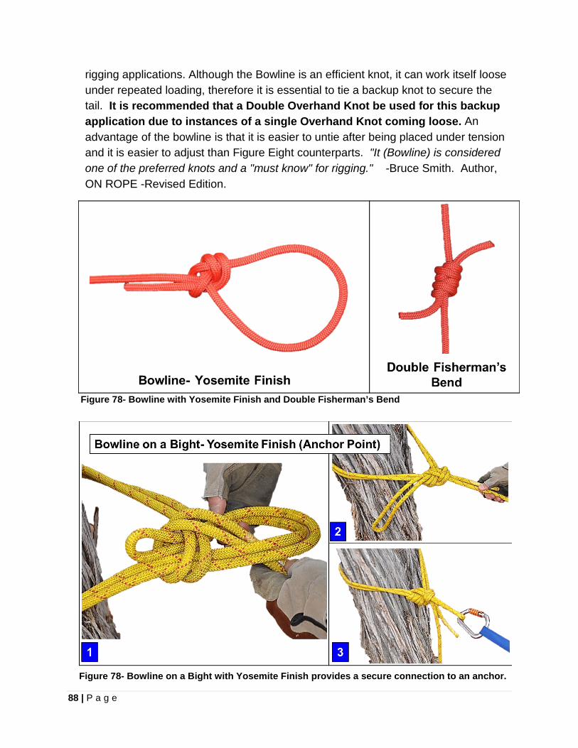
88 | P a g e
rigging applications. Although the Bowline is an efficient knot, it can work itself loose under repeated loading, therefore it is essential to tie a backup knot to secure the tail. It is recommended that a Double Overhand Knot be used for this backup application due to instances of a single Overhand Knot coming loose. An advantage of the bowline is that it is easier to untie after being placed under tension and it is easier to adjust than Figure Eight counterparts. "It (Bowline) is considered one of the preferred knots and a "must know" for rigging." -Bruce Smith. Author, ON ROPE -Revised Edition.
Figure 78- Bowline with Yosemite Finish and Double Fisherman’s Bend
Figure 78- Bowline on a Bight with Yosemite Finish provides a secure connection to an anchor.
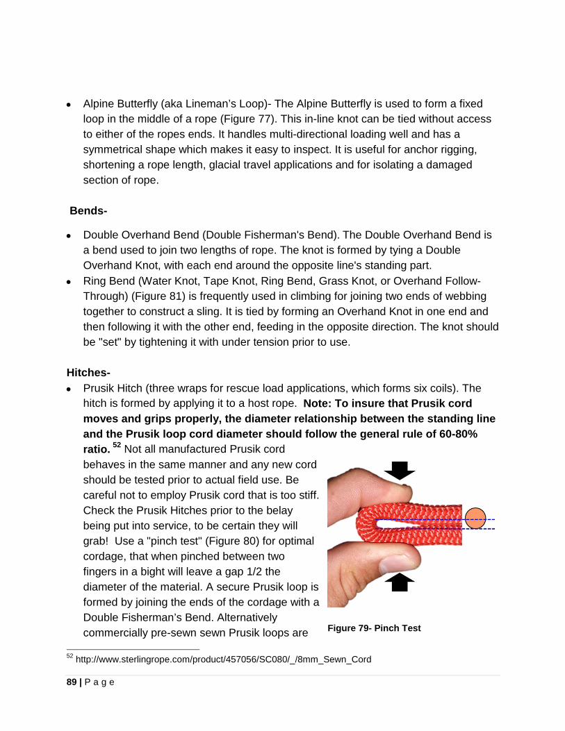
89 | P a g e
• Alpine Butterfly (aka Lineman’s Loop)- The Alpine Butterfly is used to form a fixed
loop in the middle of a rope (Figure 77). This in-line knot can be tied without access to either of the ropes ends. It handles multi-directional loading well and has a symmetrical shape which makes it easy to inspect. It is useful for anchor rigging, shortening a rope length, glacial travel applications and for isolating a damaged section of rope.
Bends-
• Double Overhand Bend (Double Fisherman's Bend). The Double Overhand Bend is a bend used to join two lengths of rope. The knot is formed by tying a Double Overhand Knot, with each end around the opposite line's standing part.
• Ring Bend (Water Knot, Tape Knot, Ring Bend, Grass Knot, or Overhand Follow-Through) (Figure 81) is frequently used in climbing for joining two ends of webbing together to construct a sling. It is tied by forming an Overhand Knot in one end and then following it with the other end, feeding in the opposite direction. The knot should be "set" by tightening it with under tension prior to use.
Hitches- • Prusik Hitch (three wraps for rescue load applications, which forms six coils). The
hitch is formed by applying it to a host rope. Note: To insure that Prusik cord moves and grips properly, the diameter relationship between the standing line and the Prusik loop cord diameter should follow the general rule of 60-80% ratio. 52 Not all manufactured Prusik cord behaves in the same manner and any new cord should be tested prior to actual field use. Be careful not to employ Prusik cord that is too stiff. Check the Prusik Hitches prior to the belay being put into service, to be certain they will grab! Use a "pinch test" (Figure 80) for optimal cordage, that when pinched between two fingers in a bight will leave a gap 1/2 the diameter of the material. A secure Prusik loop is formed by joining the ends of the cordage with a Double Fisherman’s Bend. Alternatively commercially pre-sewn sewn Prusik loops are
52 http://www.sterlingrope.com/product/457056/SC080/_/8mm_Sewn_Cord
Figure 79- Pinch Test
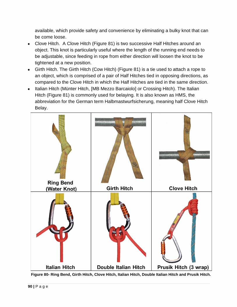
90 | P a g e
available, which provide safety and convenience by eliminating a bulky knot that can be come loose.
• Clove Hitch. A Clove Hitch (Figure 81) is two successive Half Hitches around an object. This knot is particularly useful where the length of the running end needs to be adjustable, since feeding in rope from either direction will loosen the knot to be tightened at a new position.
• Girth Hitch. The Girth Hitch (Cow Hitch) (Figure 81) is a tie used to attach a rope to an object, which is comprised of a pair of Half Hitches tied in opposing directions, as compared to the Clove Hitch in which the Half Hitches are tied in the same direction.
• Italian Hitch (Münter Hitch, [MB Mezzo Barcaiolo] or Crossing Hitch). The Italian Hitch (Figure 81) is commonly used for belaying. It is also known as HMS, the abbreviation for the German term Halbmastwurfsicherung, meaning half Clove Hitch Belay.
Figure 80- Ring Bend, Girth Hitch, Clove Hitch, Italian Hitch, Double Italian Hitch and Prusik Hitch.
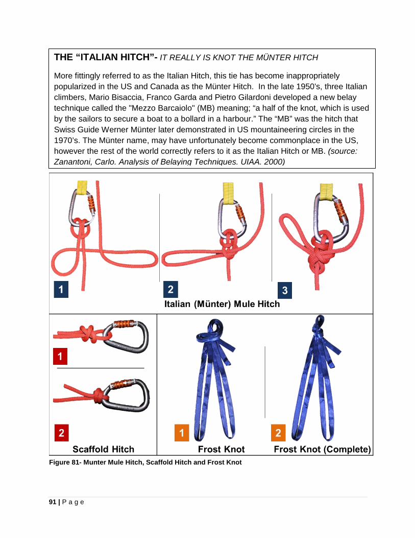
91 | P a g e
THE “ITALIAN HITCH”- IT REALLY IS KNOT THE MÜNTER HITCH
More fittingly referred to as the Italian Hitch, this tie has become inappropriately popularized in the US and Canada as the Münter Hitch. In the late 1950's, three Italian climbers, Mario Bisaccia, Franco Garda and Pietro Gilardoni developed a new belay technique called the "Mezzo Barcaiolo" (MB) meaning; “a half of the knot, which is used by the sailors to secure a boat to a bollard in a harbour.” The “MB” was the hitch that Swiss Guide Werner Münter later demonstrated in US mountaineering circles in the 1970’s. The Münter name, may have unfortunately become commonplace in the US, however the rest of the world correctly refers to it as the Italian Hitch or MB. (source: Zanantoni, Carlo. Analysis of Belaying Techniques. UIAA. 2000)
Figure 81- Munter Mule Hitch, Scaffold Hitch and Frost Knot
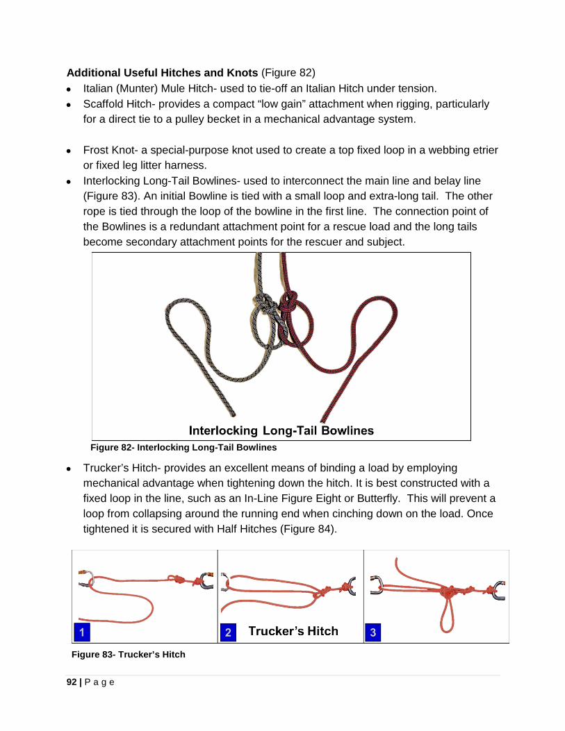
92 | P a g e
Additional Useful Hitches and Knots (Figure 82) • Italian (Munter) Mule Hitch- used to tie-off an Italian Hitch under tension. • Scaffold Hitch- provides a compact “low gain” attachment when rigging, particularly
for a direct tie to a pulley becket in a mechanical advantage system. • Frost Knot- a special-purpose knot used to create a top fixed loop in a webbing etrier
or fixed leg litter harness. • Interlocking Long-Tail Bowlines- used to interconnect the main line and belay line
(Figure 83). An initial Bowline is tied with a small loop and extra-long tail. The other rope is tied through the loop of the bowline in the first line. The connection point of the Bowlines is a redundant attachment point for a rescue load and the long tails become secondary attachment points for the rescuer and subject.
Figure 82- Interlocking Long-Tail Bowlines • Trucker’s Hitch- provides an excellent means of binding a load by employing
mechanical advantage when tightening down the hitch. It is best constructed with a fixed loop in the line, such as an In-Line Figure Eight or Butterfly. This will prevent a loop from collapsing around the running end when cinching down on the load. Once tightened it is secured with Half Hitches (Figure 84).
Figure 83- Trucker’s Hitch
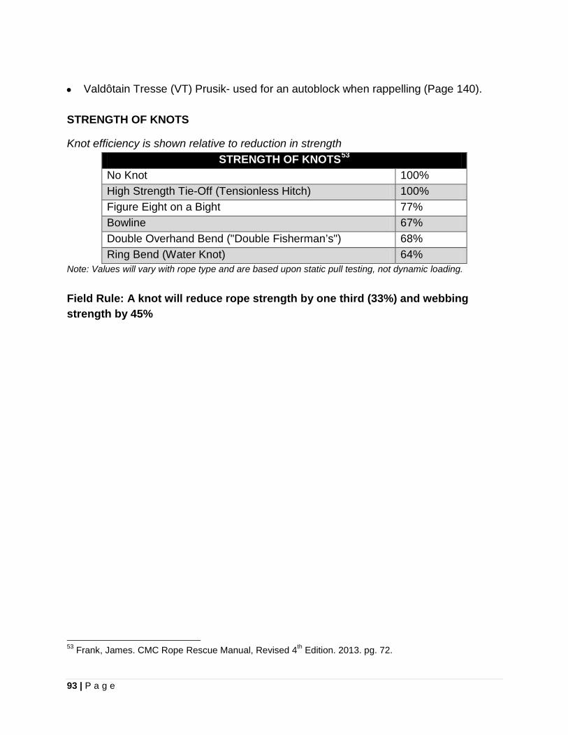
93 | P a g e
• Valdôtain Tresse (VT) Prusik- used for an autoblock when rappelling (Page 140). STRENGTH OF KNOTS
Knot efficiency is shown relative to reduction in strength STRENGTH OF KNOTS53
No Knot 100% High Strength Tie-Off (Tensionless Hitch) 100% Figure Eight on a Bight 77% Bowline 67% Double Overhand Bend ("Double Fisherman’s") 68% Ring Bend (Water Knot) 64%
Note: Values will vary with rope type and are based upon static pull testing, not dynamic loading. Field Rule: A knot will reduce rope strength by one third (33%) and webbing strength by 45%
53 Frank, James. CMC Rope Rescue Manual, Revised 4th Edition. 2013. pg. 72.
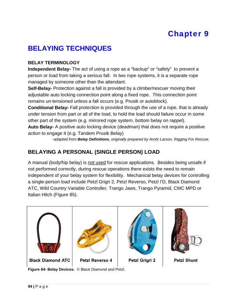
94 | P a g e
Chapter 9
BELAYING TECHNIQUES BELAY TERMINOLOGY Independent Belay- The act of using a rope as a “backup” or “safety” to prevent a person or load from taking a serious fall. In two rope systems, it is a separate rope managed by someone other than the attendant. Self-Belay- Protection against a fall is provided by a climber/rescuer moving their adjustable auto locking connection point along a fixed rope. This connection point remains un-tensioned unless a fall occurs (e.g. Prusik or autoblock). Conditional Belay- Fall protection is provided through the use of a rope, that is already under tension from part or all of the load, to hold the load should failure occur in some other part of the system (e.g. mirrored rope system, bottom belay on rappel). Auto Belay- A positive auto locking device (deadman) that does not require a positive action to engage it (e.g. Tandem Prusik Belay)
-adapted from Belay Definitions, originally prepared by Arnör Larson, Rigging For Rescue. BELAYING A PERSONAL (SINGLE PERSON) LOAD
A manual (body/hip belay) is not used for rescue applications. Besides being unsafe if not performed correctly, during rescue operations there exists the need to remain independent of your belay system for flexibility. Mechanical belay devices for controlling a single-person load include Petzl Grigri 2, Petzl Reverso, Petzl I’D, Black Diamond ATC, Wild Country Variable Controller, Trango Jaws, Trango Pyramid, CMC MPD or Italian Hitch (Figure 85).
Figure 84- Belay Devices. © Black Diamond and Petzl.
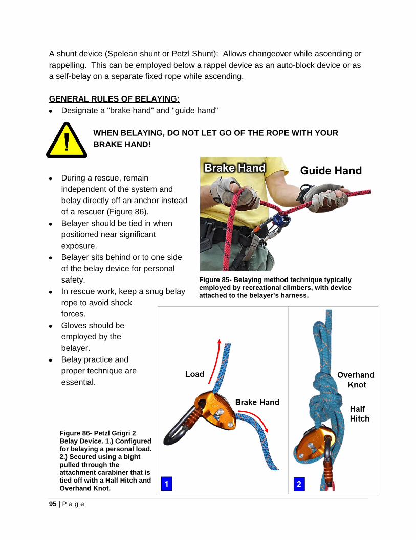
95 | P a g e
A shunt device (Spelean shunt or Petzl Shunt): Allows changeover while ascending or rappelling. This can be employed below a rappel device as an auto-block device or as a self-belay on a separate fixed rope while ascending. GENERAL RULES OF BELAYING: • Designate a "brake hand" and "guide hand"
WHEN BELAYING, DO NOT LET GO OF THE ROPE WITH YOUR BRAKE HAND!
• During a rescue, remain
independent of the system and belay directly off an anchor instead of a rescuer (Figure 86).
• Belayer should be tied in when positioned near significant exposure.
• Belayer sits behind or to one side of the belay device for personal safety.
• In rescue work, keep a snug belay rope to avoid shock forces.
• Gloves should be employed by the belayer.
• Belay practice and proper technique are essential.
Figure 85- Belaying method technique typically employed by recreational climbers, with device attached to the belayer’s harness.
Figure 86- Petzl Grigri 2 Belay Device. 1.) Configured for belaying a personal load. 2.) Secured using a bight pulled through the attachment carabiner that is tied off with a Half Hitch and Overhand Knot.
96 | P a g e
BELAYING A RESCUE LOAD
• In 1982 the British Columbia Council of Technical Rescue (BCCTR) tested many standard belay devices, and found these techniques were unable to hold a zero fall factor with a 200 kg (440 lbs) rescue load mass on a static line. The following techniques were unable to hold a static fall; Italian Hitch, Stitch Belay Plate, Figure Eight and the body belay.
• Rescue teams have previously employed a Gibbs Ascender as a rescue belay
device. However, during drop testing, a Gibbs Ascender catching a rescue load dropping greater than 51 cm (20 in) severed the rope. It is important to understand that a Gibbs ascender was only designed as a rope grab device to handle a single person load on an overhead fixed rope. The manufacturer does not endorse its use as a rescue load belay device. Rescue personnel should always read and follow the manufacturer recommendations for the use of any commercial rope rescue product.
Characteristics of a Good Rescue Belay:
1. Be able to catch a fall without rescuer attending it. 2. Catch a fall without damaging the line to the point of being useless. 3. Stop a fall in the shortest distance possible, commensurate with an acceptable
minimum impact force. 4. Minimum capacity of handling a 440 lb. (200 kg) "rescue load".
Source: British Columbia Council of Technical Rescue (BCCTR) Some rescuers cling to the misguided notion that a Figure Eight or other single-person DCD is an appropriate belay tool for a rescue load (200 kg or 400 lbs). This has been disproved in repeated drop testing experiments. Currently the most consistently reliable techniques for belaying a rescue load are;
1. CMC Rescue MPD™ (Multi-Purpose Device) 2. 540°™ Rescue Belay 3. Tandem Prusik Belay Technique
CMC RESCUE MPD™ (MULTI-PURPOSE DEVICE)
Originally designed by Kirk Mauthner of Base Camp Innovations Ltd., the MPD™ (Multi- Purpose Device) is manufactured by Rock Exotica and sold exclusively by CMC Rescue (Figure 88). This device serves as high-efficiency pulley, DCD and a belay device that permits immediately switching from lowering to raising without any change in hardware. The MPD pulley has an integral rope-grab mechanism allowing it to be used as a

97 | P a g e
lowering device on the main line and belay line systems, while permitting a quick change to a raising system without switching out hardware. Additionally the MPD permits the main line and belay line to be rigged as mirrored systems with the use of two devices. The MPD meets the British Columbia Council of Technical Rescue (BCCTR) Rescue Belay Competency Drop Test. Total weight of the device is 1.2 kg (2 lb 10 oz).
The 11mm Model of the MPD (Model # 333010) is intended for use with 11mm (7/16 inch) static or low-stretch kernmantle rope. It is important to note that the use of CE marked ropes, which may be 10.5mm in diameter, in contrast to 11mm ropes meeting CI-1801 (Low Stretch and Static Kermantle Life Safety Ropes) can create operating problems with the MPD. Performance issues with CE marked ropes being operated in conjunction with rescue loads resulting in performance issues is not unique to the MPD, and has occurred with the Petzl I’D as well54. Be certain to use rope meeting the diameter requirements of the device. Additionally, wet, icy or muddy ropes could affect the proper function of the device, and additional friction may need to be applied by the operator.
Prior to use the MPD should be inspected for any damaged, dirty or sticky components, as well as excessive wear to the device.
To load the MPD, hold the device with the back plate facing up and rotate the back plate allowing it to open (Figure 89). A diagram on the MPD itself shows how the rope should be correctly loaded; observe the required rope requirements prior to opening and rotating the side plate. It is important to verify that the rope enters and exits the device exactly as intended and is not mis-threaded (Figure 90).
54 Mauthner, Kirk. Personal communication.
Figure 87- CMC Rescue MPD, 11mm Model illustrating nomenclature of parts. Original image © CMC Rescue.
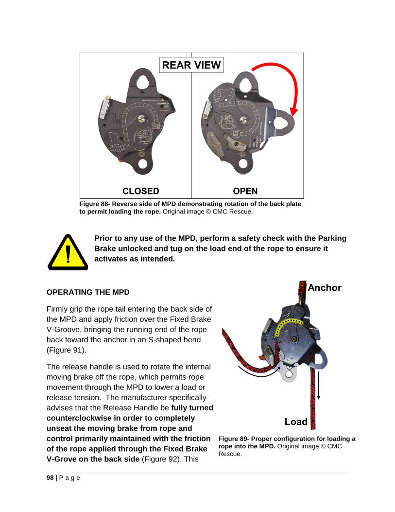
98 | P a g e
Figure 88- Reverse side of MPD demonstrating rotation of the back plateto permit loading the rope. Original image © CMC Rescue.
Prior to any use of the MPD, perform a safety check with the Parking Brake unlocked and tug on the load end of the rope to ensure it activates as intended.
OPERATING THE MPD
Firmly grip the rope tail entering the back side of the MPD and apply friction over the Fixed Brake V-Groove, bringing the running end of the rope back toward the anchor in an S-shaped bend (Figure 91).
The release handle is used to rotate the internal moving brake off the rope, which permits rope movement through the MPD to lower a load or release tension. The manufacturer specifically advises that the Release Handle be fully turned counterclockwise in order to completely unseat the moving brake from rope and control primarily maintained with the friction of the rope applied through the Fixed Brake V-Grove on the back side (Figure 92). This
Figure 89- Proper configuration for loading a rope into the MPD. Original image © CMC Rescue.
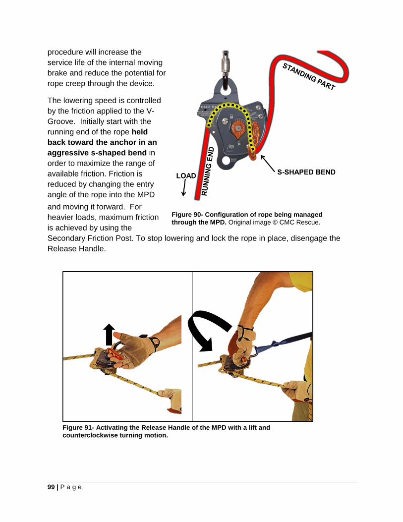
99 | P a g e
procedure will increase the service life of the internal moving brake and reduce the potential for rope creep through the device.
The lowering speed is controlled by the friction applied to the V-Groove. Initially start with the running end of the rope held back toward the anchor in an aggressive s-shaped bend in order to maximize the range of available friction. Friction is reduced by changing the entry angle of the rope into the MPD and moving it forward. For heavier loads, maximum friction is achieved by using the Secondary Friction Post. To stop lowering and lock the rope in place, disengage the Release Handle.
Figure 90- Configuration of rope being managed through the MPD. Original image © CMC Rescue.
Figure 91- Activating the Release Handle of the MPD with a lift and counterclockwise turning motion.
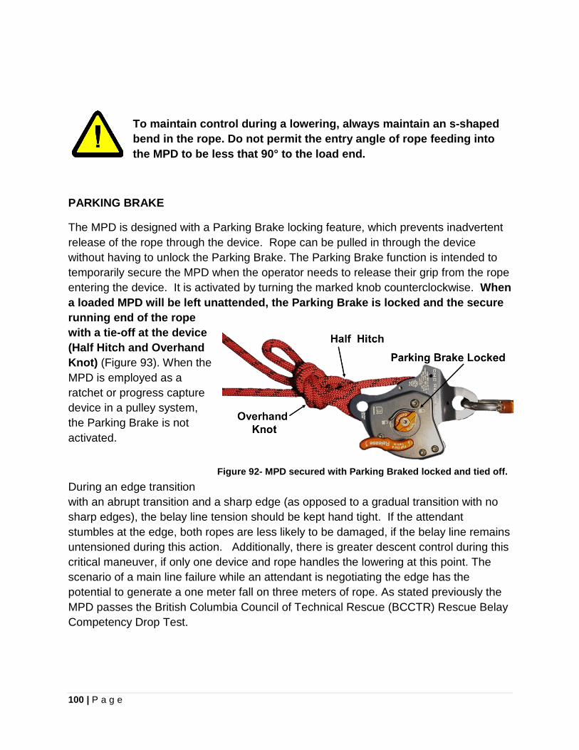
100 | P a g e
To maintain control during a lowering, always maintain an s-shaped bend in the rope. Do not permit the entry angle of rope feeding into the MPD to be less that 90° to the load end.
PARKING BRAKE
The MPD is designed with a Parking Brake locking feature, which prevents inadvertent release of the rope through the device. Rope can be pulled in through the device without having to unlock the Parking Brake. The Parking Brake function is intended to temporarily secure the MPD when the operator needs to release their grip from the rope entering the device. It is activated by turning the marked knob counterclockwise. When a loaded MPD will be left unattended, the Parking Brake is locked and the secure running end of the rope with a tie-off at the device (Half Hitch and Overhand Knot) (Figure 93). When the MPD is employed as a ratchet or progress capture device in a pulley system, the Parking Brake is not activated.
During an edge transition with an abrupt transition and a sharp edge (as opposed to a gradual transition with no sharp edges), the belay line tension should be kept hand tight. If the attendant stumbles at the edge, both ropes are less likely to be damaged, if the belay line remains untensioned during this action. Additionally, there is greater descent control during this critical maneuver, if only one device and rope handles the lowering at this point. The scenario of a main line failure while an attendant is negotiating the edge has the potential to generate a one meter fall on three meters of rope. As stated previously the MPD passes the British Columbia Council of Technical Rescue (BCCTR) Rescue Belay Competency Drop Test.
Figure 92- MPD secured with Parking Braked locked and tied off.
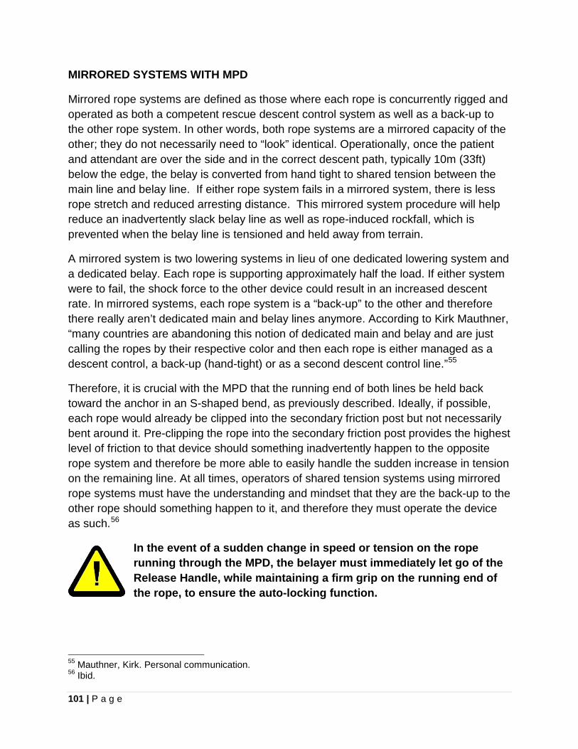
101 | P a g e
MIRRORED SYSTEMS WITH MPD
Mirrored rope systems are defined as those where each rope is concurrently rigged and operated as both a competent rescue descent control system as well as a back-up to the other rope system. In other words, both rope systems are a mirrored capacity of the other; they do not necessarily need to “look” identical. Operationally, once the patient and attendant are over the side and in the correct descent path, typically 10m (33ft) below the edge, the belay is converted from hand tight to shared tension between the main line and belay line. If either rope system fails in a mirrored system, there is less rope stretch and reduced arresting distance. This mirrored system procedure will help reduce an inadvertently slack belay line as well as rope-induced rockfall, which is prevented when the belay line is tensioned and held away from terrain.
A mirrored system is two lowering systems in lieu of one dedicated lowering system and a dedicated belay. Each rope is supporting approximately half the load. If either system were to fail, the shock force to the other device could result in an increased descent rate. In mirrored systems, each rope system is a “back-up” to the other and therefore there really aren’t dedicated main and belay lines anymore. According to Kirk Mauthner, “many countries are abandoning this notion of dedicated main and belay and are just calling the ropes by their respective color and then each rope is either managed as a descent control, a back-up (hand-tight) or as a second descent control line.”55
Therefore, it is crucial with the MPD that the running end of both lines be held back toward the anchor in an S-shaped bend, as previously described. Ideally, if possible, each rope would already be clipped into the secondary friction post but not necessarily bent around it. Pre-clipping the rope into the secondary friction post provides the highest level of friction to that device should something inadvertently happen to the opposite rope system and therefore be more able to easily handle the sudden increase in tension on the remaining line. At all times, operators of shared tension systems using mirrored rope systems must have the understanding and mindset that they are the back-up to the other rope should something happen to it, and therefore they must operate the device as such.56
In the event of a sudden change in speed or tension on the rope running through the MPD, the belayer must immediately let go of the Release Handle, while maintaining a firm grip on the running end of the rope, to ensure the auto-locking function.
55 Mauthner, Kirk. Personal communication. 56 Ibid.
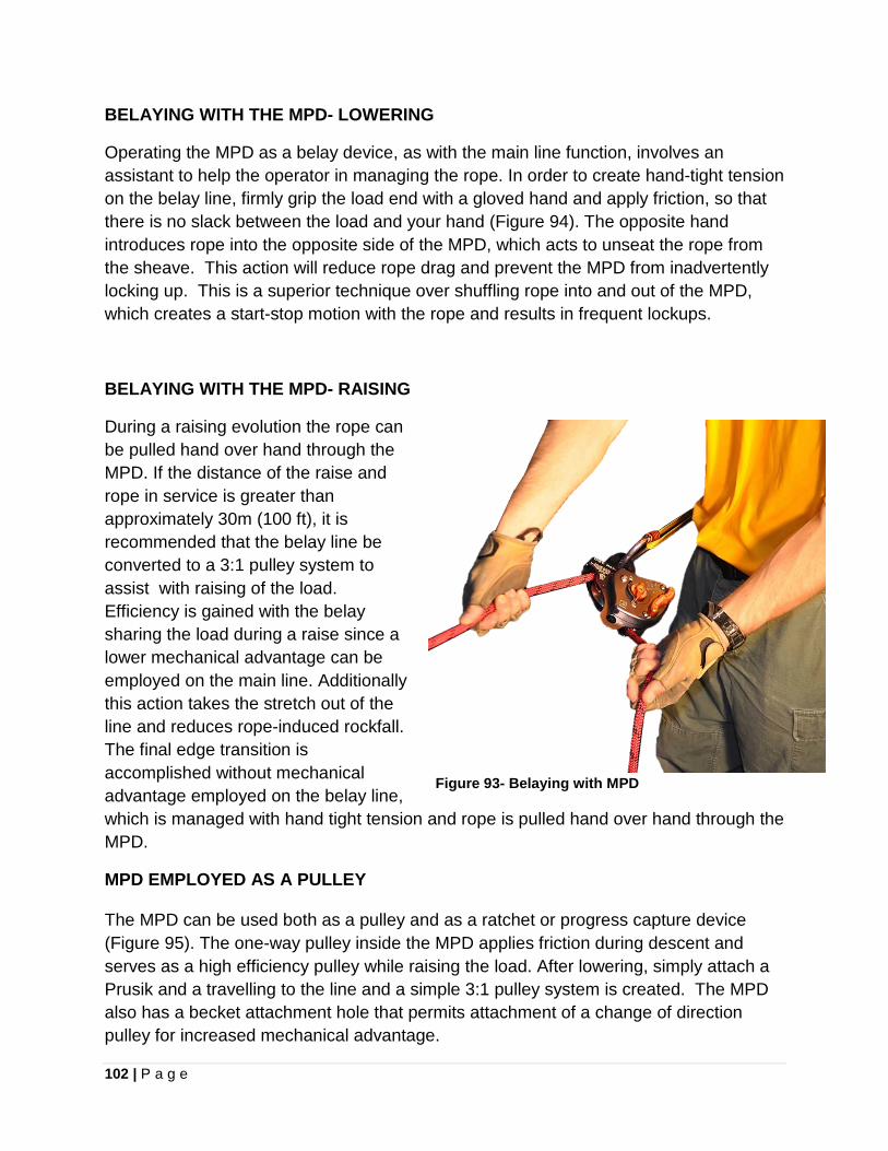
102 | P a g e
BELAYING WITH THE MPD- LOWERING
Operating the MPD as a belay device, as with the main line function, involves an assistant to help the operator in managing the rope. In order to create hand-tight tension on the belay line, firmly grip the load end with a gloved hand and apply friction, so that there is no slack between the load and your hand (Figure 94). The opposite hand introduces rope into the opposite side of the MPD, which acts to unseat the rope from the sheave. This action will reduce rope drag and prevent the MPD from inadvertently locking up. This is a superior technique over shuffling rope into and out of the MPD, which creates a start-stop motion with the rope and results in frequent lockups.
BELAYING WITH THE MPD- RAISING
During a raising evolution the rope can be pulled hand over hand through the MPD. If the distance of the raise and rope in service is greater than approximately 30m (100 ft), it is recommended that the belay line be converted to a 3:1 pulley system to assist with raising of the load. Efficiency is gained with the belay sharing the load during a raise since a lower mechanical advantage can be employed on the main line. Additionally this action takes the stretch out of the line and reduces rope-induced rockfall. The final edge transition is accomplished without mechanical advantage employed on the belay line, which is managed with hand tight tension and rope is pulled hand over hand through the MPD.
Figure 93- Belaying with MPD
MPD EMPLOYED AS A PULLEY
The MPD can be used both as a pulley and as a ratchet or progress capture device (Figure 95). The one-way pulley inside the MPD applies friction during descent and serves as a high efficiency pulley while raising the load. After lowering, simply attach a Prusik and a travelling to the line and a simple 3:1 pulley system is created. The MPD also has a becket attachment hole that permits attachment of a change of direction pulley for increased mechanical advantage.
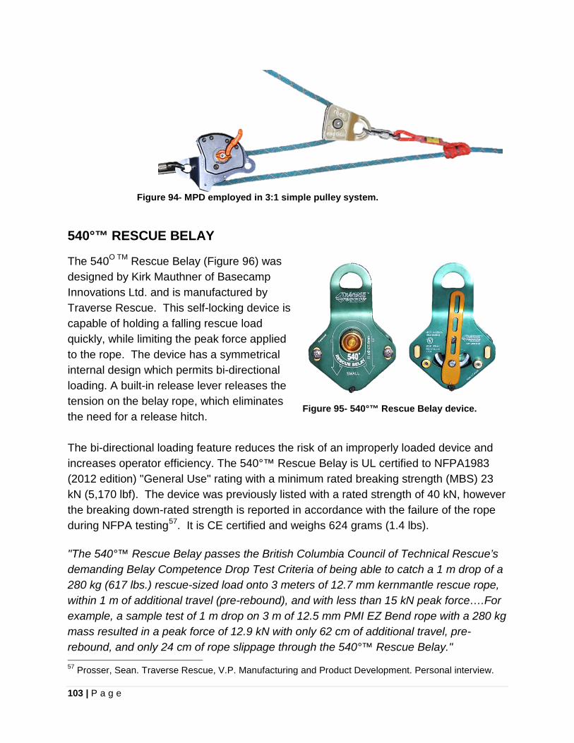
103 | P a g e
Figure 94- MPD employed in 3:1 simple pulley system.
540°™ RESCUE BELAY
The 540O TM Rescue Belay (Figure 96) was designed by Kirk Mauthner of Basecamp Innovations Ltd. and is manufactured by Traverse Rescue. This self-locking device is capable of holding a falling rescue load quickly, while limiting the peak force applied to the rope. The device has a symmetrical internal design which permits bi-directional loading. A built-in release lever releases the tension on the belay rope, which eliminates the need for a release hitch. The bi-directional loading feature reduces the risk of an improperly loaded device and increases operator efficiency. The 540°™ Rescue Belay is UL certified to NFPA1983 (2012 edition) "General Use" rating with a minimum rated breaking strength (MBS) 23 kN (5,170 lbf). The device was previously listed with a rated strength of 40 kN, however the breaking down-rated strength is reported in accordance with the failure of the rope during NFPA testing57. It is CE certified and weighs 624 grams (1.4 lbs). "The 540°™ Rescue Belay passes the British Columbia Council of Technical Rescue’s demanding Belay Competence Drop Test Criteria of being able to catch a 1 m drop of a 280 kg (617 lbs.) rescue-sized load onto 3 meters of 12.7 mm kernmantle rescue rope, within 1 m of additional travel (pre-rebound), and with less than 15 kN peak force….For example, a sample test of 1 m drop on 3 m of 12.5 mm PMI EZ Bend rope with a 280 kg mass resulted in a peak force of 12.9 kN with only 62 cm of additional travel, pre-rebound, and only 24 cm of rope slippage through the 540°™ Rescue Belay." 57 Prosser, Sean. Traverse Rescue, V.P. Manufacturing and Product Development. Personal interview.
Figure 95- 540°™ Rescue Belay device.
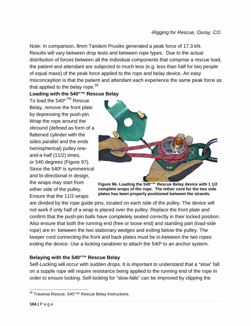
104 | P a g e
-Rigging for Rescue, Ouray, CO. Note: In comparison, 8mm Tandem Prusiks generated a peak force of 17.3 kN. Results will vary between drop tests and between rope types. Due to the actual distribution of forces between all the individual components that comprise a rescue load, the patient and attendant are subjected to much less (e.g. less than half for two people of equal mass) of the peak force applied to the rope and belay device. An easy misconception is that the patient and attendant each experience the same peak force as that applied to the belay rope.58 Loading with the 540°™ Rescue Belay To load the 540º TM Rescue Belay, remove the front plate by depressing the push-pin. Wrap the rope around the obround (defined as form of a flattened cylinder with the sides parallel and the ends hemispherical) pulley one-and-a-half (11/2) times, or 540 degrees (Figure 97). Since the 540º is symmetrical and bi-directional in design, the wraps may start from either side of the pulley. Ensure that the 11/2 wraps are divided by the rope guide pins, located on each side of the pulley. The device will not work if only half of a wrap is placed over the pulley. Replace the front plate and confirm that the push-pin balls have completely seated correctly in their locked position. Also ensure that both the running end (free or loose end) and standing part (load-side rope) are in- between the two stationary wedges and exiting below the pulley. The keeper cord connecting the front and back plates must be in-between the two ropes exiting the device. Use a locking carabiner to attach the 540º to an anchor system.
Figure 96- Loading the 540°™ Rescue Belay device with 1 1/2 complete wraps of the rope. The tether cord for the two side plates has been properly positioned between the strands.
Belaying with the 540°™ Rescue Belay Self-Locking will occur with sudden drops. It is important to understand that a “slow” fall on a supple rope will require resistance being applied to the running end of the rope in order to ensure locking. Self-locking for “slow-falls” can be improved by clipping the
58 Traverse Rescue. 540°™ Rescue Belay Instructions.
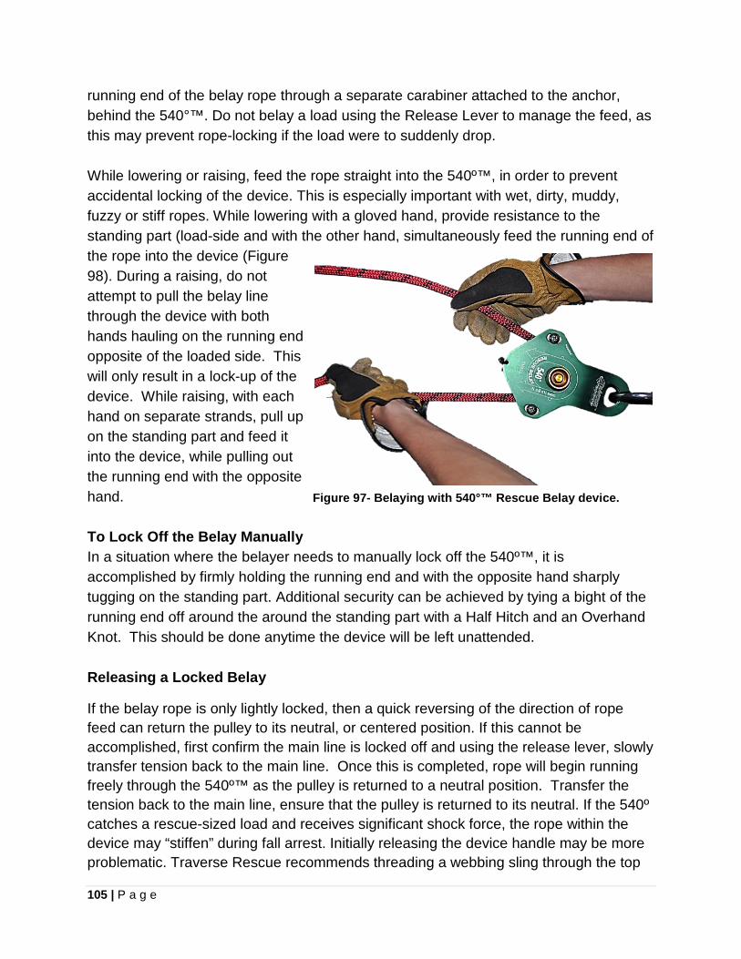
105 | P a g e
running end of the belay rope through a separate carabiner attached to the anchor, behind the 540°™. Do not belay a load using the Release Lever to manage the feed, as this may prevent rope-locking if the load were to suddenly drop. While lowering or raising, feed the rope straight into the 540º™, in order to prevent accidental locking of the device. This is especially important with wet, dirty, muddy, fuzzy or stiff ropes. While lowering with a gloved hand, provide resistance to the standing part (load-side and with the other hand, simultaneously feed the running end of the rope into the device (Figure 98). During a raising, do not attempt to pull the belay line through the device with both hands hauling on the running end opposite of the loaded side. This will only result in a lock-up of the device. While raising, with each hand on separate strands, pull up on the standing part and feed it into the device, while pulling out the running end with the opposite hand. Figure 97- Belaying with 540°™ Rescue Belay device. To Lock Off the Belay Manually In a situation where the belayer needs to manually lock off the 540º™, it is accomplished by firmly holding the running end and with the opposite hand sharply tugging on the standing part. Additional security can be achieved by tying a bight of the running end off around the around the standing part with a Half Hitch and an Overhand Knot. This should be done anytime the device will be left unattended. Releasing a Locked Belay
If the belay rope is only lightly locked, then a quick reversing of the direction of rope feed can return the pulley to its neutral, or centered position. If this cannot be accomplished, first confirm the main line is locked off and using the release lever, slowly transfer tension back to the main line. Once this is completed, rope will begin running freely through the 540º™ as the pulley is returned to a neutral position. Transfer the tension back to the main line, ensure that the pulley is returned to its neutral. If the 540º catches a rescue-sized load and receives significant shock force, the rope within the device may “stiffen” during fall arrest. Initially releasing the device handle may be more problematic. Traverse Rescue recommends threading a webbing sling through the top
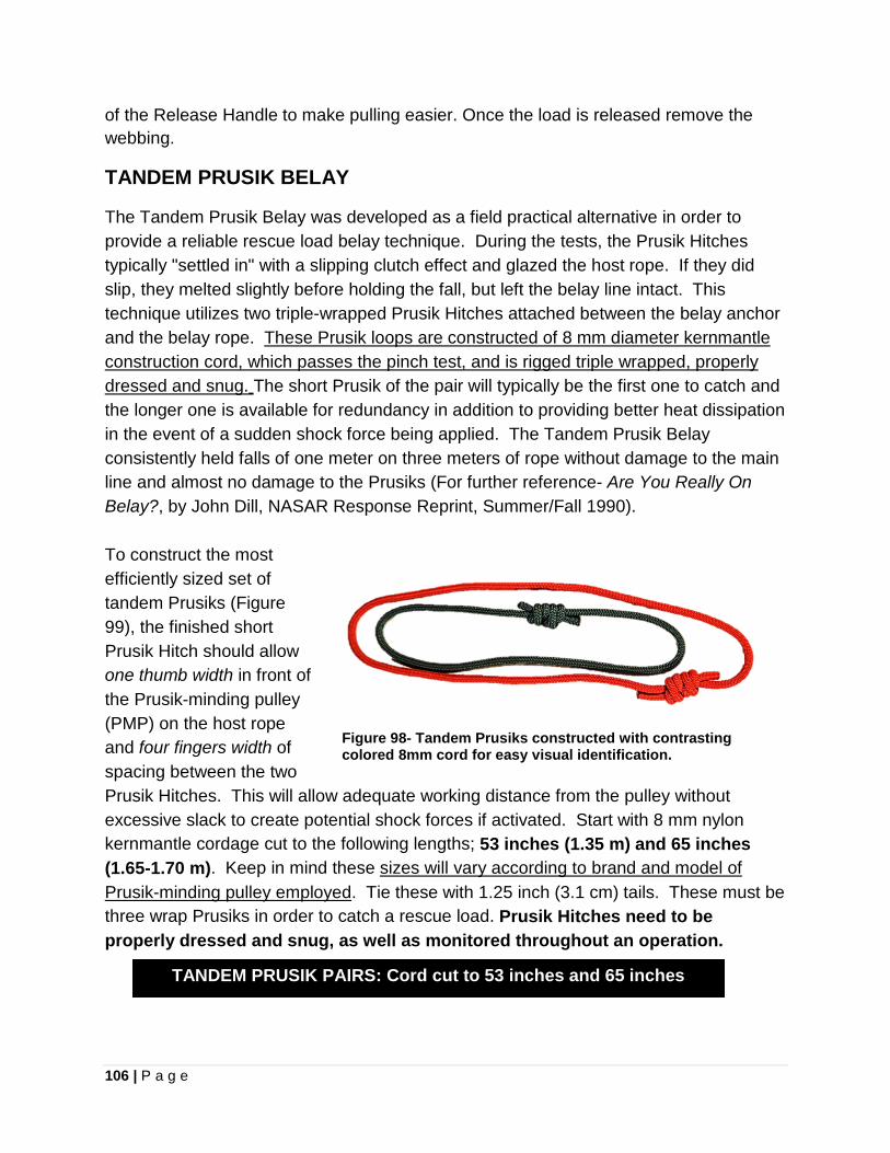
106 | P a g e
of the Release Handle to make pulling easier. Once the load is released remove the webbing. TANDEM PRUSIK BELAY
The Tandem Prusik Belay was developed as a field practical alternative in order to provide a reliable rescue load belay technique. During the tests, the Prusik Hitches typically "settled in" with a slipping clutch effect and glazed the host rope. If they did slip, they melted slightly before holding the fall, but left the belay line intact. This technique utilizes two triple-wrapped Prusik Hitches attached between the belay anchor and the belay rope. These Prusik loops are constructed of 8 mm diameter kernmantle construction cord, which passes the pinch test, and is rigged triple wrapped, properly dressed and snug. The short Prusik of the pair will typically be the first one to catch and the longer one is available for redundancy in addition to providing better heat dissipation in the event of a sudden shock force being applied. The Tandem Prusik Belay consistently held falls of one meter on three meters of rope without damage to the main line and almost no damage to the Prusiks (For further reference- Are You Really On Belay?, by John Dill, NASAR Response Reprint, Summer/Fall 1990). To construct the most efficiently sized set of tandem Prusiks (Figure 99), the finished short Prusik Hitch should allow one thumb width in front of the Prusik-minding pulley (PMP) on the host rope and four fingers width of spacing between the two Prusik Hitches. This will allow adequate working distance from the pulley without excessive slack to create potential shock forces if activated. Start with 8 mm nylon kernmantle cordage cut to the following lengths; 53 inches (1.35 m) and 65 inches (1.65-1.70 m). Keep in mind these sizes will vary according to brand and model of Prusik-minding pulley employed. Tie these with 1.25 inch (3.1 cm) tails. These must be three wrap Prusiks in order to catch a rescue load. Prusik Hitches need to be properly dressed and snug, as well as monitored throughout an operation.
Figure 98- Tandem Prusiks constructed with contrasting colored 8mm cord for easy visual identification.
TANDEM PRUSIK PAIRS: Cord cut to 53 inches and 65 inches
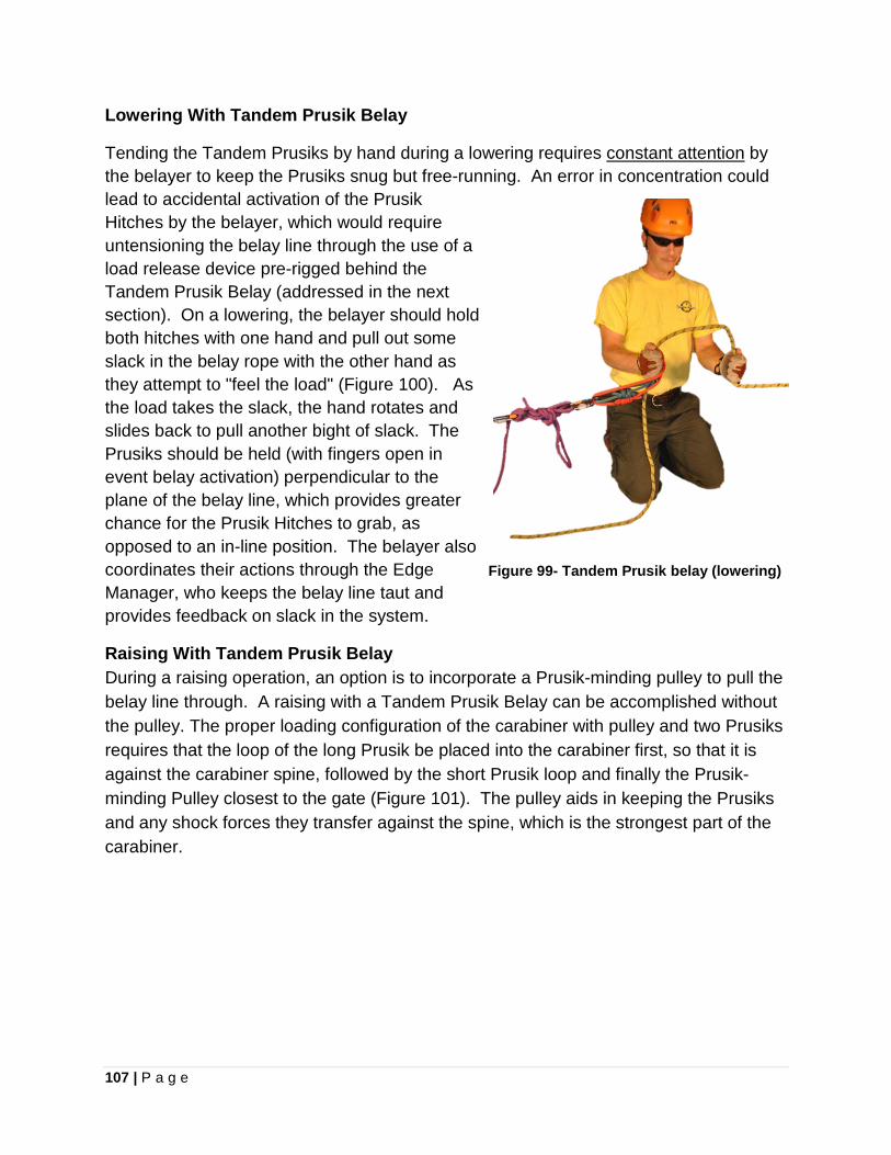
107 | P a g e
Lowering With Tandem Prusik Belay
Tending the Tandem Prusiks by hand during a lowering requires constant attention by the belayer to keep the Prusiks snug but free-running. An error in concentration could lead to accidental activation of the Prusik Hitches by the belayer, which would require untensioning the belay line through the use of a load release device pre-rigged behind the Tandem Prusik Belay (addressed in the next section). On a lowering, the belayer should hold both hitches with one hand and pull out some slack in the belay rope with the other hand as they attempt to "feel the load" (Figure 100). As the load takes the slack, the hand rotates and slides back to pull another bight of slack. The Prusiks should be held (with fingers open in event belay activation) perpendicular to the plane of the belay line, which provides greater chance for the Prusik Hitches to grab, as opposed to an in-line position. The belayer also coordinates their actions through the Edge Manager, who keeps the belay line taut and provides feedback on slack in the system.
Figure 99- Tandem Prusik belay (lowering)
Raising With Tandem Prusik Belay During a raising operation, an option is to incorporate a Prusik-minding pulley to pull the belay line through. A raising with a Tandem Prusik Belay can be accomplished without the pulley. The proper loading configuration of the carabiner with pulley and two Prusiks requires that the loop of the long Prusik be placed into the carabiner first, so that it is against the carabiner spine, followed by the short Prusik loop and finally the Prusik-minding Pulley closest to the gate (Figure 101). The pulley aids in keeping the Prusiks and any shock forces they transfer against the spine, which is the strongest part of the carabiner.
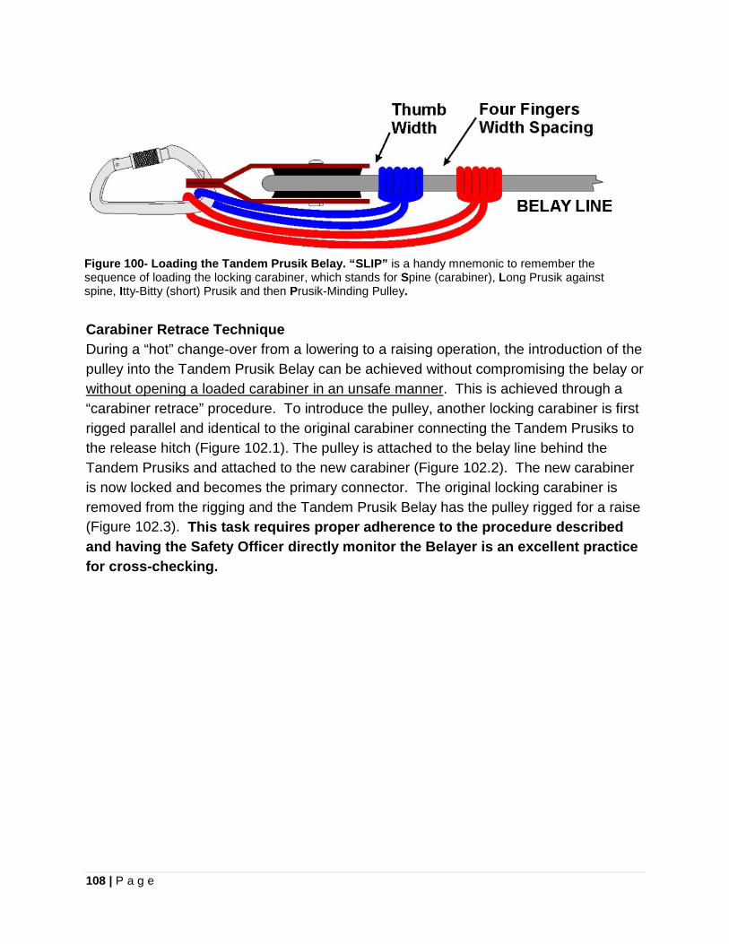
108 | P a g e
Figure 100- Loading the Tandem Prusik Belay. “SLIP” is a handy mnemonic to remember the sequence of loading the locking carabiner, which stands for Spine (carabiner), Long Prusik against spine, Itty-Bitty (short) Prusik and then Prusik-Minding Pulley. Carabiner Retrace Technique During a “hot” change-over from a lowering to a raising operation, the introduction of the pulley into the Tandem Prusik Belay can be achieved without compromising the belay or without opening a loaded carabiner in an unsafe manner. This is achieved through a “carabiner retrace” procedure. To introduce the pulley, another locking carabiner is first rigged parallel and identical to the original carabiner connecting the Tandem Prusiks to the release hitch (Figure 102.1). The pulley is attached to the belay line behind the Tandem Prusiks and attached to the new carabiner (Figure 102.2). The new carabiner is now locked and becomes the primary connector. The original locking carabiner is removed from the rigging and the Tandem Prusik Belay has the pulley rigged for a raise (Figure 102.3). This task requires proper adherence to the procedure described and having the Safety Officer directly monitor the Belayer is an excellent practice for cross-checking.
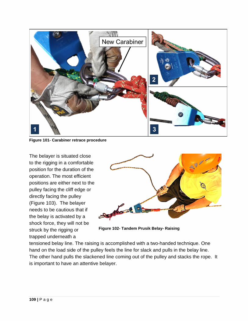
109 | P a g e
Figure 101- Carabiner retrace procedure
The belayer is situated close to the rigging in a comfortable position for the duration of the operation. The most efficient positions are either next to the pulley facing the cliff edge or directly facing the pulley (Figure 103). The belayer needs to be cautious that if the belay is activated by a shock force, they will not be struck by the rigging or trapped underneath a tensioned belay line. The raising is accomplished with a two-handed technique. One hand on the load side of the pulley feels the line for slack and pulls in the belay line. The other hand pulls the slackened line coming out of the pulley and stacks the rope. It is important to have an attentive belayer.
Figure 102- Tandem Prusik Belay- Raising
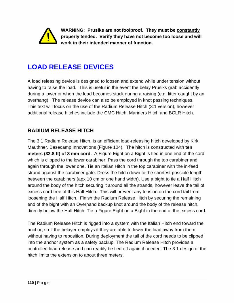
110 | P a g e
WARNING: Prusiks are not foolproof. They must be constantly properly tended. Verify they have not become too loose and will work in their intended manner of function.
LOAD RELEASE DEVICES A load releasing device is designed to loosen and extend while under tension without having to raise the load. This is useful in the event the belay Prusiks grab accidently during a lower or when the load becomes stuck during a raising (e.g. litter caught by an overhang). The release device can also be employed in knot passing techniques. This text will focus on the use of the Radium Release Hitch (3:1 version), however additional release hitches include the CMC Hitch, Mariners Hitch and BCLR Hitch.
RADIUM RELEASE HITCH
The 3:1 Radium Release Hitch, is an efficient load-releasing hitch developed by Kirk Mauthner, Basecamp Innovations (Figure 104). The hitch is constructed with ten meters (32.8 ft) of 8 mm cord. A Figure Eight on a Bight is tied in one end of the cord which is clipped to the lower carabiner. Pass the cord through the top carabiner and again through the lower one. Tie an Italian Hitch in the top carabiner with the in-feed strand against the carabiner gate. Dress the hitch down to the shortest possible length between the carabiners (apx 10 cm or one hand width). Use a bight to tie a Half Hitch around the body of the hitch securing it around all the strands, however leave the tail of excess cord free of this Half Hitch. This will prevent any tension on the cord tail from loosening the Half Hitch. Finish the Radium Release Hitch by securing the remaining end of the bight with an Overhand backup knot around the body of the release hitch, directly below the Half Hitch. Tie a Figure Eight on a Bight in the end of the excess cord. The Radium Release Hitch is rigged into a system with the Italian Hitch end toward the anchor, so if the belayer employs it they are able to lower the load away from them without having to reposition. During deployment the tail of the cord needs to be clipped into the anchor system as a safety backup. The Radium Release Hitch provides a controlled load-release and can readily be tied off again if needed. The 3:1 design of the hitch limits the extension to about three meters.
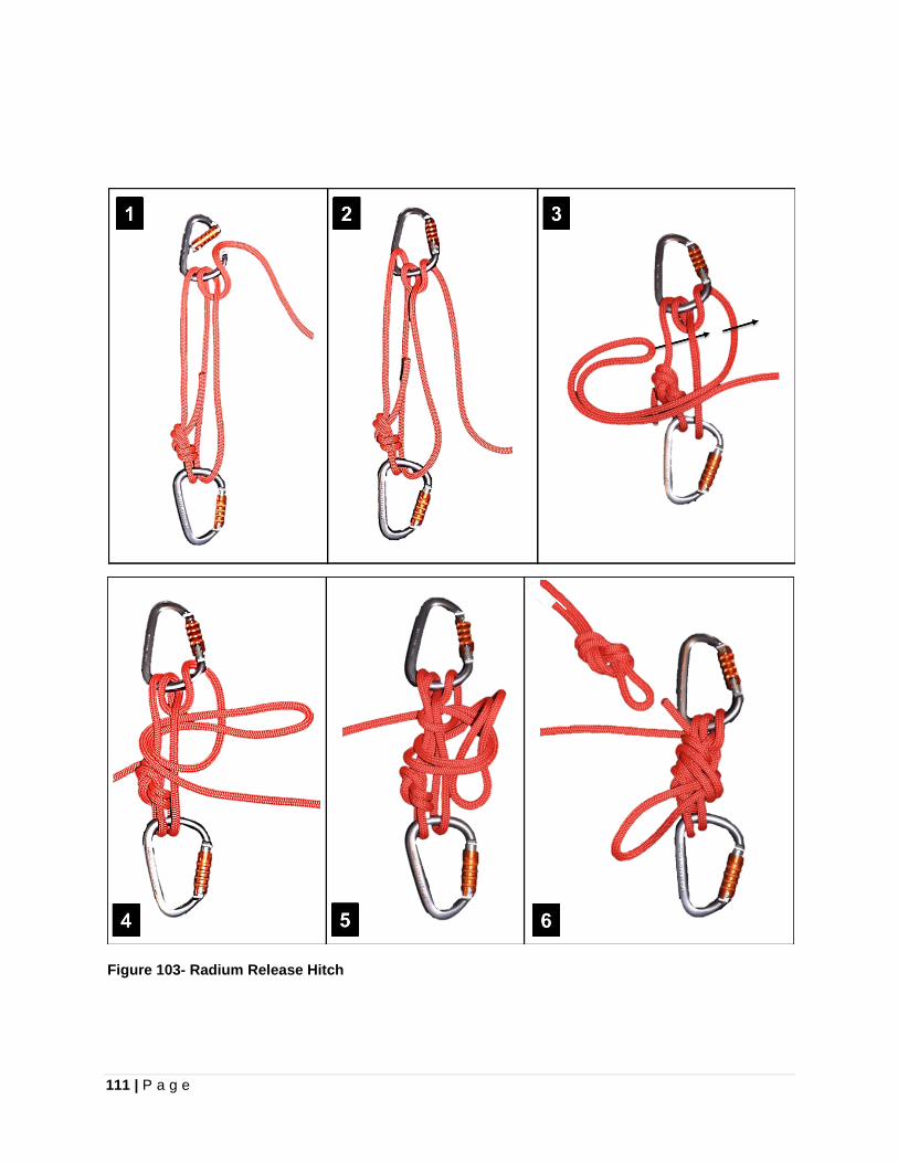
111 | P a g e
Figure 103- Radium Release Hitch
112 | P a g e
Chapter 10
ANCHOR SYSTEMS
GUIDELINES FOR ANCHOR SYSTEM CONSTRUCTION: Technical rescue employs anchor points rigged together into an anchor system. Constructing a rescue anchor system does not require an engineering degree, however a solid understanding of sound anchor rigging concepts is essential to be a competent rescuer. Upon arriving at a rescue scene, the following considerations for team leaders are useful to assist in maintaining efficient scene management; Where do you need to go? • Select an efficient fall line in order to reach the victim. • Don’t fall into the trap of rappelling directly down on top of fallen subject (non- pickoff
situation) in a manner that might cause rockfall injury. Generally a descent adjacent to the patient’s location makes more sense. Packaging the patient can occur at their resting point and then the litter can be traversed to the raising or lowering system.
• Lowering route selection should avoid additional hazardous terrain if possible. • Is a deviation pulley required to redirect the fall line of the rope? • What rescue tasks need to be accomplished (e.g. edge management, lowering,
raising or a traverse)? Where should the anchor "focal point" be located? • Raising the focal point off the ground increases efficiency of belayer/attendant. • Is a floating focal point necessary? • Does the focal point require pretensioned back-ties or front-ties? • Focal point prevents extension of an anchor point in a load-sharing anchor system. What anchor points should be used? • Pad anchor points with sharp edges. • Evaluate the integrity of the anchor points being utilized. • Anchor point should not be hot to the touch or expose the rope to Haz-Mat. • Seek system-wide redundancy, which can require use of more than one anchor
point. Avoid overreliance on a single feature or placement of one piece of artificial protection (e.g. bolt or camming device).
• Attach at the base of an "anchor point" to prevent a leverage situation.
113 | P a g e
What directionals are available if needed? • A directional may be needed for the use of certain anchor points. • Is an artificial high directional needed at the edge? • Rig the focal point high to take advantage of any natural high directional (e.g. stair-
stepped edge) and allow for more efficient edge management with a litter. ANCHOR CONSTRUCTION DEFINITIONS: ANCHOR POINT- Single connection point (e.g. tree, boulder, camming device, etc.). ANCHOR SYSTEM- Multiple anchor points rigged together creating redundant system. DEVIATION- Redirects the natural fall line of the rope on the rock face. A deviation point may or may not to be subjected to the same force as the primary rig point. DIRECTIONAL- Rigging technique to change the natural line of a rope with a carabiner or pulley attached to an alternative anchor. FOCAL POINT- A location, floating or fixed, where all rigging is directed for anchor points. This concept disciplines rescuers to construct rigging which joins together at an efficient point, rather than unwittingly resorting to wherever the knot that joins all anchor points ends up due to the length of material used; the latter can result in an awkward spot to manage rope handling tasks. SERENE ANCHOR SYTEMS SERENE, modified from the American Mountain Guides Association (AMGA) by John Long59, is a convenient acronym relating to the essential concepts climbing anchor construction. SERENE CLIMBING ANCHORS S - Strong (or Solid)– Select anchor points that are capable of holding the load. E - Equalized– Anchor systems should be constructed so that each anchor point carries an equally appropriate amount of the load. R - Redundant– Anchor systems should consist of multiple components in case one or more components fail. E - Efficient– Anchor systems should be as simple and timely as possible without giving up any of the other SERENE qualities.
59 Long, John. How to Rock Climb. pg 113.
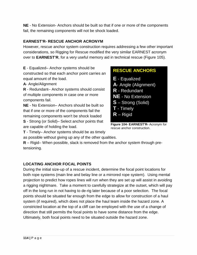
114 | P a g e
NE - No Extension- Anchors should be built so that if one or more of the components fail, the remaining components will not be shock loaded. EARNEST’R- RESCUE ANCHOR ACRONYM However, rescue anchor system construction requires addressing a few other important considerations, so Rigging for Rescue modified the very similar EARNEST acronym over to EARNEST’R, for a very useful memory aid in technical rescue (Figure 105). E - Equalized– Anchor systems should be constructed so that each anchor point carries an equal amount of the load. A- Angle/Alignment R - Redundant– Anchor systems should consist of multiple components in case one or more components fail. NE - No Extension– Anchors should be built so that if one or more of the components fail the remaining components won't be shock loaded S - Strong (or Solid)– Select anchor points that are capable of holding the load. T - Timely– Anchor systems should be as timely as possible without giving up any of the other qualities. R – Rigid– When possible, slack is removed from the anchor system through pre-tensioning. LOCATING ANCHOR FOCAL POINTS During the initial size-up of a rescue incident, determine the focal point locations for both rope systems (main line and belay line or a mirrored rope system). Using mental projection to predict how ropes lines will run when they are set up will assist in avoiding a rigging nightmare. Take a moment to carefully strategize at the outset, which will pay off in the long run in not having to de-rig later because of a poor selection. The focal points should be situated far enough from the edge to allow for construction of a haul system (if required), which does not place the haul team inside the hazard zone. A constricted location at the top of a cliff can be employed with the use of a change of direction that still permits the focal points to have some distance from the edge. Ultimately, both focal points need to be situated outside the hazard zone.
Figure 104- EARNEST'R- Acronym for rescue anchor construction.
RESCUE ANCHORS
E - Equalized A- Angle (Alignment) R - Redundant NE - No Extension S – Strong (Solid) T - Timely R – Rigid
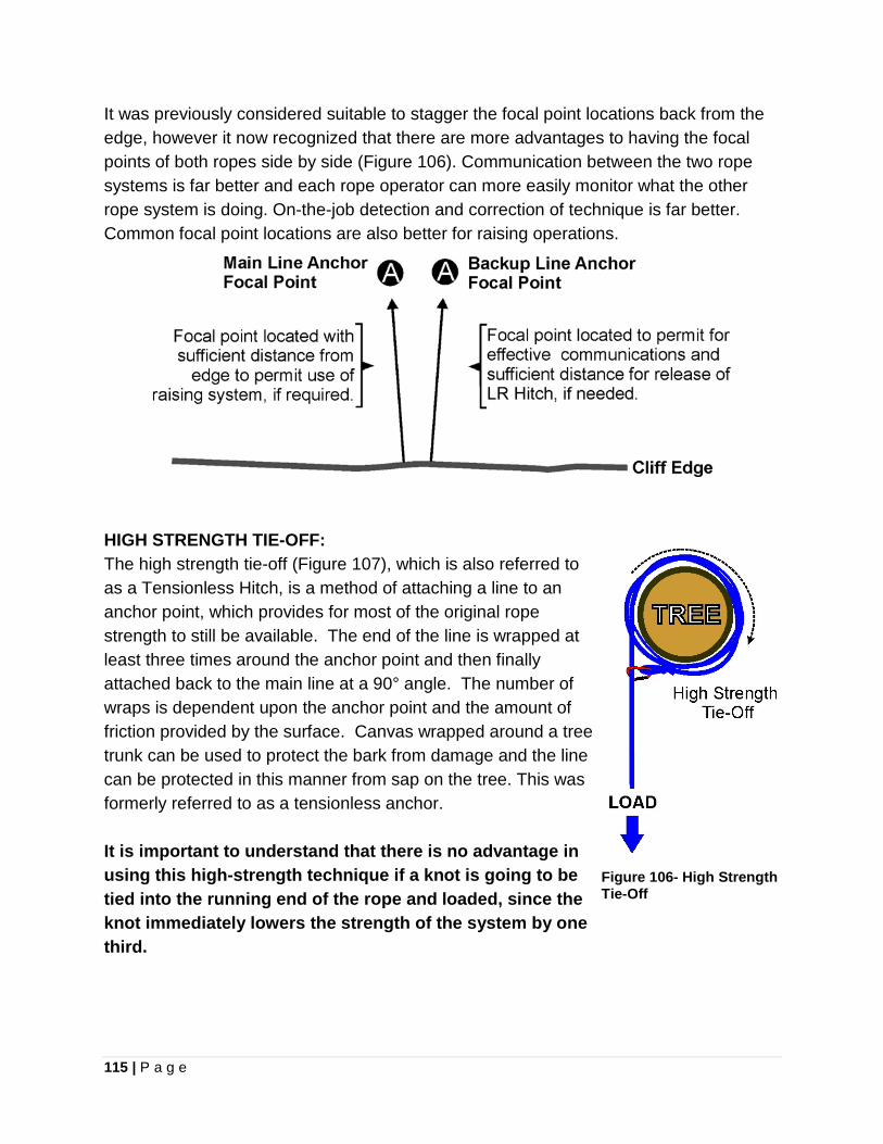
115 | P a g e
It was previously considered suitable to stagger the focal point locations back from the edge, however it now recognized that there are more advantages to having the focal points of both ropes side by side (Figure 106). Communication between the two rope systems is far better and each rope operator can more easily monitor what the other rope system is doing. On-the-job detection and correction of technique is far better. Common focal point locations are also better for raising operations.
Figure 105- Locating main line and backup (belay) line anchor focal points
HIGH STRENGTH TIE-OFF: The high strength tie-off (Figure 107), which is also referred to as a Tensionless Hitch, is a method of attaching a line to an anchor point, which provides for most of the original rope strength to still be available. The end of the line is wrapped at least three times around the anchor point and then finally attached back to the main line at a 90° angle. The number of wraps is dependent upon the anchor point and the amount of friction provided by the surface. Canvas wrapped around a tree trunk can be used to protect the bark from damage and the line can be protected in this manner from sap on the tree. This was formerly referred to as a tensionless anchor. It is important to understand that there is no advantage in using this high-strength technique if a knot is going to be tied into the running end of the rope and loaded, since the knot immediately lowers the strength of the system by one third.
Figure 106- High Strength Tie-Off
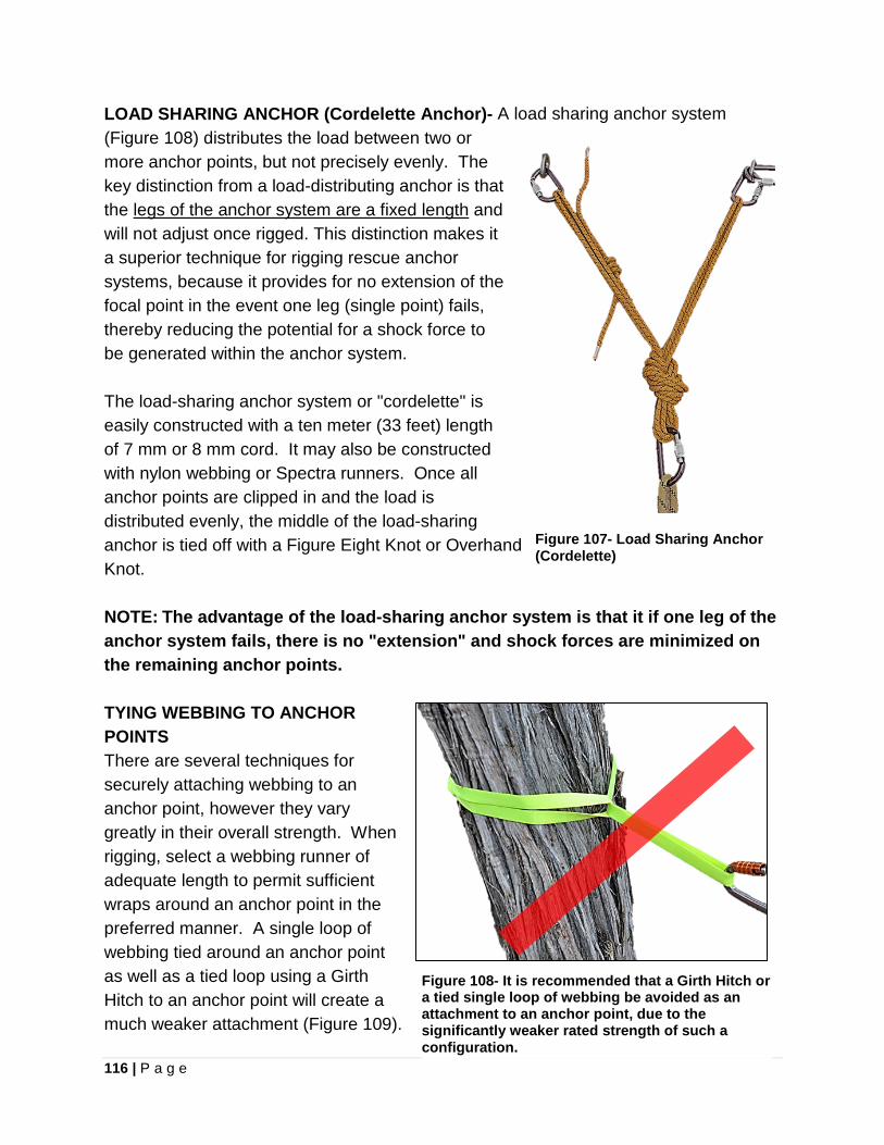
116 | P a g e
LOAD SHARING ANCHOR (Cordelette Anchor)- A load sharing anchor system (Figure 108) distributes the load between two or more anchor points, but not precisely evenly. The key distinction from a load-distributing anchor is that the legs of the anchor system are a fixed length and will not adjust once rigged. This distinction makes it a superior technique for rigging rescue anchor systems, because it provides for no extension of the focal point in the event one leg (single point) fails, thereby reducing the potential for a shock force to be generated within the anchor system. The load-sharing anchor system or "cordelette" is easily constructed with a ten meter (33 feet) length of 7 mm or 8 mm cord. It may also be constructed with nylon webbing or Spectra runners. Once all anchor points are clipped in and the load is distributed evenly, the middle of the load-sharing anchor is tied off with a Figure Eight Knot or Overhand Knot.
Figure 107- Load Sharing Anchor (Cordelette)
NOTE: The advantage of the load-sharing anchor system is that it if one leg of the anchor system fails, there is no "extension" and shock forces are minimized on the remaining anchor points. TYING WEBBING TO ANCHOR POINTS There are several techniques for securely attaching webbing to an anchor point, however they vary greatly in their overall strength. When rigging, select a webbing runner of adequate length to permit sufficient wraps around an anchor point in the preferred manner. A single loop of webbing tied around an anchor point as well as a tied loop using a Girth Hitch to an anchor point will create a much weaker attachment (Figure 109).
Figure 108- It is recommended that a Girth Hitch or a tied single loop of webbing be avoided as an attachment to an anchor point, due to the significantly weaker rated strength of such a configuration.
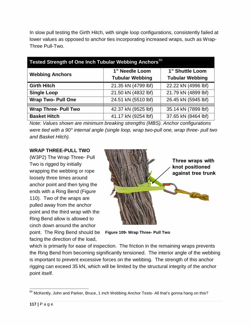
117 | P a g e
In slow pull testing the Girth Hitch, with single loop configurations, consistently failed at lower values as opposed to anchor ties incorporating increased wraps, such as Wrap-Three Pull-Two.
Tested Strength of One Inch Tubular Webbing Anchors60
Webbing Anchors 1” Needle Loom Tubular Webbing
1” Shuttle Loom Tubular Webbing
Girth Hitch 21.35 kN (4799 lbf) 22.22 kN (4996 lbf) Single Loop 21.50 kN (4832 lbf) 21.79 kN (4899 lbf) Wrap Two- Pull One 24.51 kN (5510 lbf) 26.45 kN (5945 lbf)
Wrap Three- Pull Two 42.37 kN (9525 lbf) 35.14 kN (7899 lbf) Basket Hitch 41.17 kN (9254 lbf) 37.65 kN (8464 lbf) Note: Values shown are minimum breaking strengths (MBS). Anchor configurations were tied with a 90° internal angle (single loop, wrap two-pull one, wrap three- pull two and Basket Hitch). WRAP THREE-PULL TWO (W3P2) The Wrap Three- Pull Two is rigged by initially wrapping the webbing or rope loosely three times around anchor point and then tying the ends with a Ring Bend (Figure 110). Two of the wraps are pulled away from the anchor point and the third wrap with the Ring Bend allow is allowed to cinch down around the anchor point. The Ring Bend should be facing the direction of the load, which is primarily for ease of inspection. The friction in the remaining wraps prevents the Ring Bend from becoming significantly tensioned. The interior angle of the webbing is important to prevent excessive forces on the webbing. The strength of this anchor rigging can exceed 35 kN, which will be limited by the structural integrity of the anchor point itself. 60 McKently, John and Parker, Bruce, 1 inch Webbing Anchor Tests- All that’s gonna hang on this?
Figure 109- Wrap Three- Pull Two
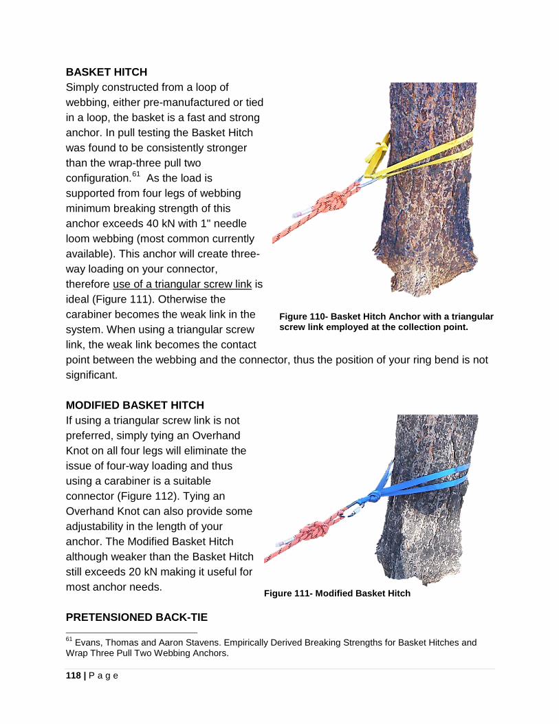
118 | P a g e
BASKET HITCH Simply constructed from a loop of webbing, either pre-manufactured or tied in a loop, the basket is a fast and strong anchor. In pull testing the Basket Hitch was found to be consistently stronger than the wrap-three pull two configuration.61 As the load is supported from four legs of webbing minimum breaking strength of this anchor exceeds 40 kN with 1" needle loom webbing (most common currently available). This anchor will create three-way loading on your connector, therefore use of a triangular screw link is ideal (Figure 111). Otherwise the carabiner becomes the weak link in the system. When using a triangular screw link, the weak link becomes the contact point between the webbing and the connector, thus the position of your ring bend is not significant.
Figure 110- Basket Hitch Anchor with a triangular screw link employed at the collection point.
MODIFIED BASKET HITCH If using a triangular screw link is not preferred, simply tying an Overhand Knot on all four legs will eliminate the issue of four-way loading and thus using a carabiner is a suitable connector (Figure 112). Tying an Overhand Knot can also provide some adjustability in the length of your anchor. The Modified Basket Hitch although weaker than the Basket Hitch still exceeds 20 kN making it useful for most anchor needs. PRETENSIONED BACK-TIE 61 Evans, Thomas and Aaron Stavens. Empirically Derived Breaking Strengths for Basket Hitches and Wrap Three Pull Two Webbing Anchors.
Figure 111- Modified Basket Hitch
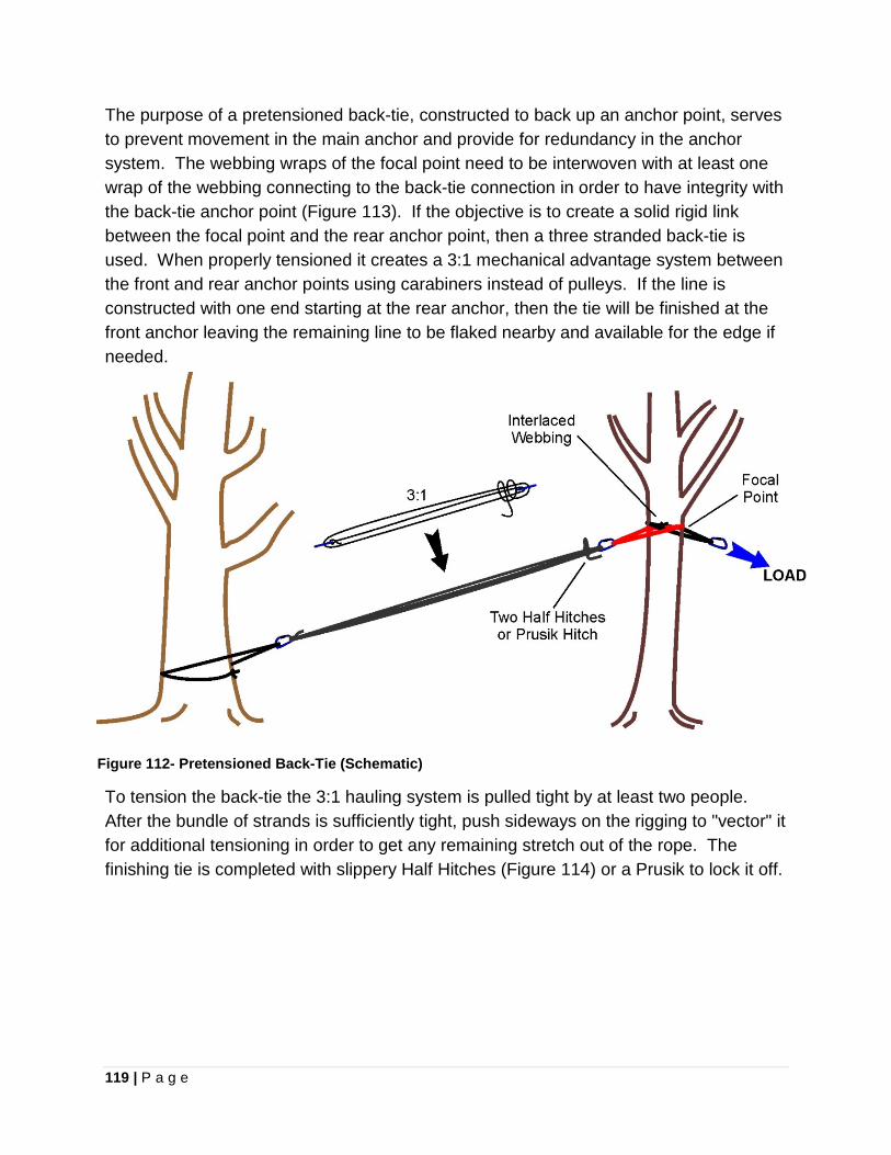
119 | P a g e
The purpose of a pretensioned back-tie, constructed to back up an anchor point, serves to prevent movement in the main anchor and provide for redundancy in the anchor system. The webbing wraps of the focal point need to be interwoven with at least one wrap of the webbing connecting to the back-tie connection in order to have integrity with the back-tie anchor point (Figure 113). If the objective is to create a solid rigid link between the focal point and the rear anchor point, then a three stranded back-tie is used. When properly tensioned it creates a 3:1 mechanical advantage system between the front and rear anchor points using carabiners instead of pulleys. If the line is constructed with one end starting at the rear anchor, then the tie will be finished at the front anchor leaving the remaining line to be flaked nearby and available for the edge if needed.
Figure 112- Pretensioned Back-Tie (Schematic)
To tension the back-tie the 3:1 hauling system is pulled tight by at least two people. After the bundle of strands is sufficiently tight, push sideways on the rigging to "vector" it for additional tensioning in order to get any remaining stretch out of the rope. The finishing tie is completed with slippery Half Hitches (Figure 114) or a Prusik to lock it off.
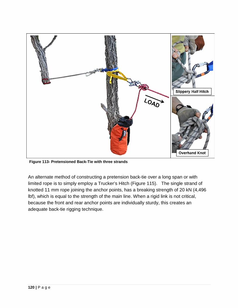
120 | P a g e
Figure 113- Pretensioned Back-Tie with three strands
An alternate method of constructing a pretension back-tie over a long span or with limited rope is to simply employ a Trucker’s Hitch (Figure 115). The single strand of knotted 11 mm rope joining the anchor points, has a breaking strength of 20 kN (4,496 lbf), which is equal to the strength of the main line. When a rigid link is not critical, because the front and rear anchor points are individually sturdy, this creates an adequate back-tie rigging technique.
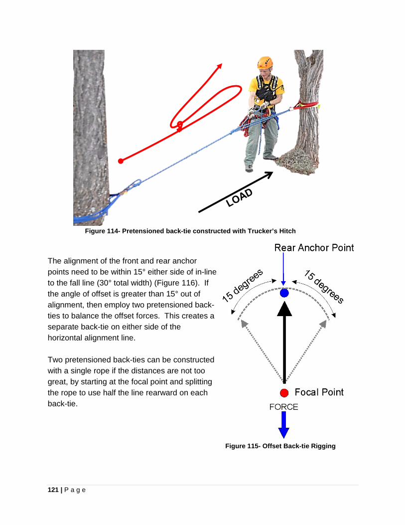
121 | P a g e
Figure 114- Pretensioned back-tie constructed with Trucker’s Hitch
The alignment of the front and rear anchor points need to be within 15° either side of in-line to the fall line (30° total width) (Figure 116). If the angle of offset is greater than 15° out of alignment, then employ two pretensioned back-ties to balance the offset forces. This creates a separate back-tie on either side of the horizontal alignment line. Two pretensioned back-ties can be constructed with a single rope if the distances are not too great, by starting at the focal point and splitting the rope to use half the line rearward on each back-tie.
Figure 115- Offset Back-tie Rigging
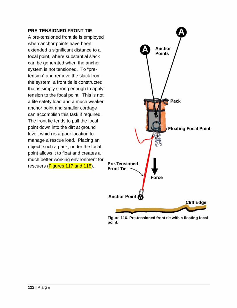
122 | P a g e
PRE-TENSIONED FRONT TIE A pre-tensioned front tie is employed when anchor points have been extended a significant distance to a focal point, where substantial slack can be generated when the anchor system is not tensioned. To “pre-tension” and remove the slack from the system, a front tie is constructed that is simply strong enough to apply tension to the focal point. This is not a life safety load and a much weaker anchor point and smaller cordage can accomplish this task if required. The front tie tends to pull the focal point down into the dirt at ground level, which is a poor location to manage a rescue load. Placing an object, such a pack, under the focal point allows it to float and creates a much better working environment for rescuers (Figures 117 and 118).
Figure 116- Pre-tensioned front tie with a floating focal point.
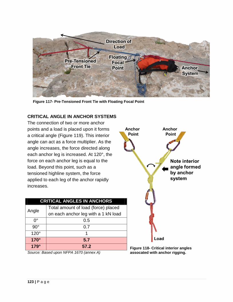
123 | P a g e
Figure 117- Pre-Tensioned Front Tie with Floating Focal Point
CRITICAL ANGLE IN ANCHOR SYSTEMS The connection of two or more anchor points and a load is placed upon it forms a critical angle (Figure 119). This interior angle can act as a force multiplier. As the angle increases, the force directed along each anchor leg is increased. At 120°, the force on each anchor leg is equal to the load. Beyond this point, such as a tensioned highline system, the force applied to each leg of the anchor rapidly increases.
Source: Based upon NFPA 1670 (annex A)
CRITICAL ANGLES IN ANCHORS
Angle Total amount of load (force) placed on each anchor leg with a 1 kN load
0° 0.5 90° 0.7
120° 1 170° 5.7 179° 57.2 Figure 118- Critical interior angles
assocated with anchor rigging.
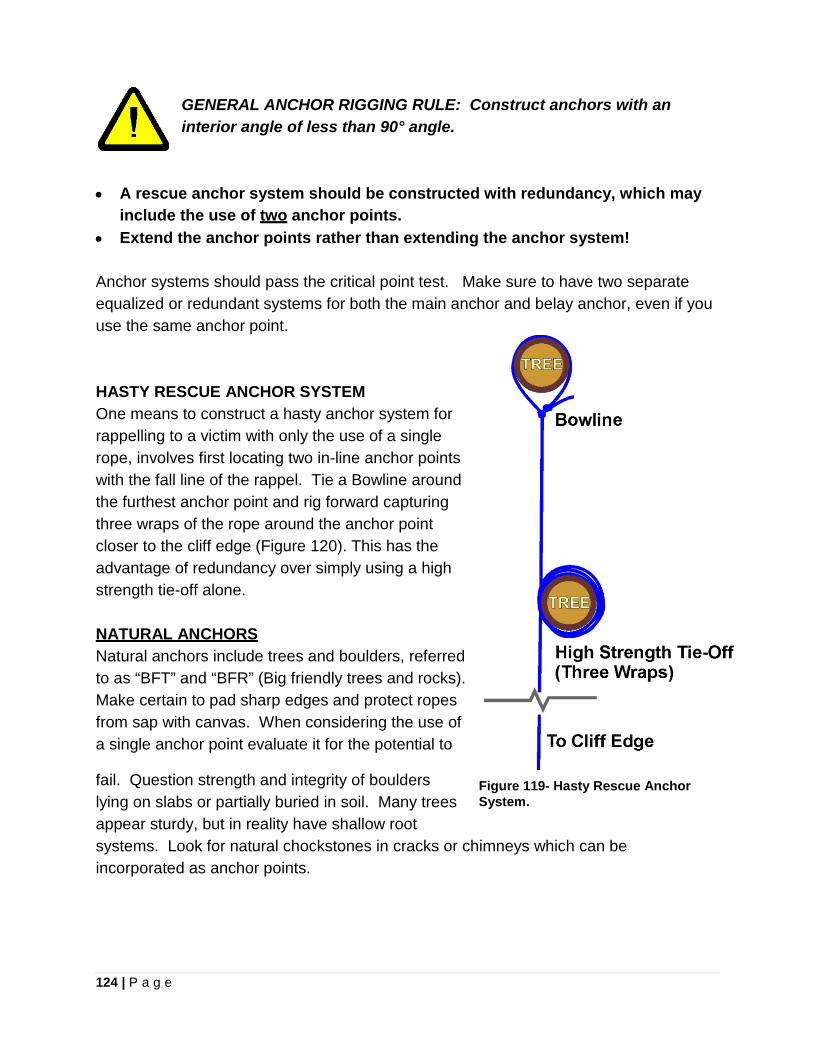
124 | P a g e
GENERAL ANCHOR RIGGING RULE: Construct anchors with an interior angle of less than 90° angle.
• A rescue anchor system should be constructed with redundancy, which may
include the use of two anchor points. • Extend the anchor points rather than extending the anchor system! Anchor systems should pass the critical point test. Make sure to have two separate equalized or redundant systems for both the main anchor and belay anchor, even if you use the same anchor point. HASTY RESCUE ANCHOR SYSTEM One means to construct a hasty anchor system for rappelling to a victim with only the use of a single rope, involves first locating two in-line anchor points with the fall line of the rappel. Tie a Bowline around the furthest anchor point and rig forward capturing three wraps of the rope around the anchor point closer to the cliff edge (Figure 120). This has the advantage of redundancy over simply using a high strength tie-off alone. NATURAL ANCHORS Natural anchors include trees and boulders, referred to as “BFT” and “BFR” (Big friendly trees and rocks). Make certain to pad sharp edges and protect ropes from sap with canvas. When considering the use of a single anchor point evaluate it for the potential to
fail. Question strength and integrity of boulders lying on slabs or partially buried in soil. Many trees appear sturdy, but in reality have shallow root systems. Look for natural chockstones in cracks or chimneys which can be incorporated as anchor points.
Figure 119- Hasty Rescue Anchor System.
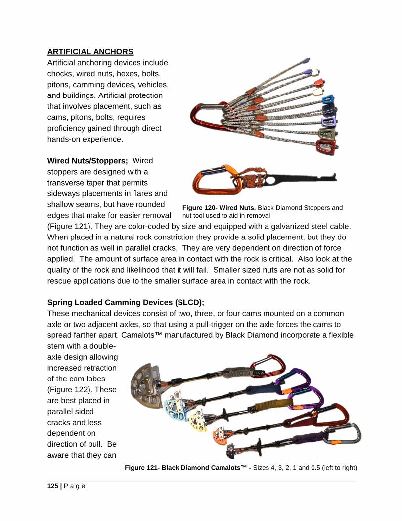
125 | P a g e
ARTIFICIAL ANCHORS Artificial anchoring devices include chocks, wired nuts, hexes, bolts, pitons, camming devices, vehicles, and buildings. Artificial protection that involves placement, such as cams, pitons, bolts, requires proficiency gained through direct hands-on experience. Wired Nuts/Stoppers; Wired stoppers are designed with a transverse taper that permits sideways placements in flares and shallow seams, but have rounded edges that make for easier removal (Figure 121). They are color-coded by size and equipped with a galvanized steel cable. When placed in a natural rock constriction they provide a solid placement, but they do not function as well in parallel cracks. They are very dependent on direction of force applied. The amount of surface area in contact with the rock is critical. Also look at the quality of the rock and likelihood that it will fail. Smaller sized nuts are not as solid for rescue applications due to the smaller surface area in contact with the rock.
Figure 120- Wired Nuts. Black Diamond Stoppers and nut tool used to aid in removal
Spring Loaded Camming Devices (SLCD); These mechanical devices consist of two, three, or four cams mounted on a common axle or two adjacent axles, so that using a pull-trigger on the axle forces the cams to spread farther apart. Camalots™ manufactured by Black Diamond incorporate a flexible stem with a double-axle design allowing increased retraction of the cam lobes (Figure 122). These are best placed in parallel sided cracks and less dependent on direction of pull. Be aware that they can
Figure 121- Black Diamond Camalots™ - Sizes 4, 3, 2, 1 and 0.5 (left to right)
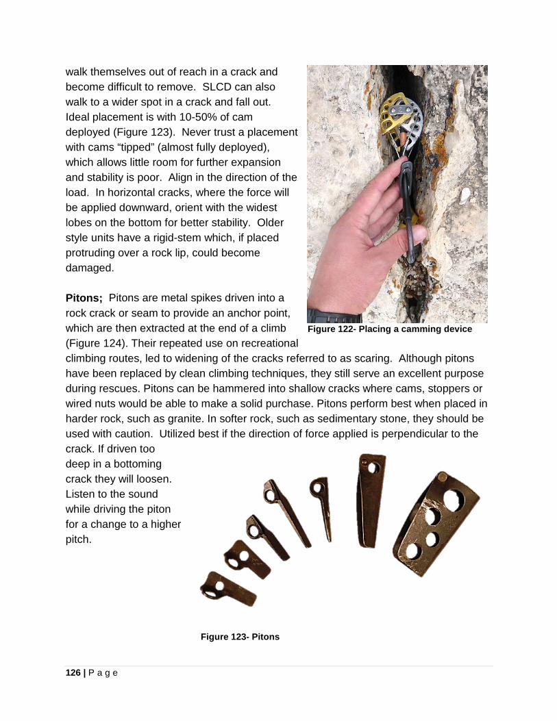
126 | P a g e
walk themselves out of reach in a crack and become difficult to remove. SLCD can also walk to a wider spot in a crack and fall out. Ideal placement is with 10-50% of cam deployed (Figure 123). Never trust a placement with cams “tipped” (almost fully deployed), which allows little room for further expansion and stability is poor. Align in the direction of the load. In horizontal cracks, where the force will be applied downward, orient with the widest lobes on the bottom for better stability. Older style units have a rigid-stem which, if placed protruding over a rock lip, could become damaged. Pitons; Pitons are metal spikes driven into a rock crack or seam to provide an anchor point, which are then extracted at the end of a climb (Figure 124). Their repeated use on recreational climbing routes, led to widening of the cracks referred to as scaring. Although pitons have been replaced by clean climbing techniques, they still serve an excellent purpose during rescues. Pitons can be hammered into shallow cracks where cams, stoppers or wired nuts would be able to make a solid purchase. Pitons perform best when placed in harder rock, such as granite. In softer rock, such as sedimentary stone, they should be used with caution. Utilized best if the direction of force applied is perpendicular to the crack. If driven too deep in a bottoming crack they will loosen. Listen to the sound while driving the piton for a change to a higher pitch.
Figure 122- Placing a camming device
Figure 123- Pitons
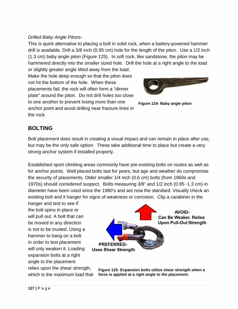
127 | P a g e
Drilled Baby Angle Pitons- This is quick alternative to placing a bolt in solid rock, when a battery-powered hammer drill is available. Drill a 3/8 inch (0.95 cm) hole for the length of the piton. Use a 1/2 inch (1.3 cm) baby angle piton (Figure 125). In soft rock, like sandstone, the piton may be hammered directly into the smaller sized hole. Drill the hole at a right angle to the load or slightly greater angle tilted away from the load. Make the hole deep enough so that the piton does not hit the bottom of the hole. When these placements fail, the rock will often form a "dinner plate" around the piton. Do not drill holes too close to one another to prevent losing more than one anchor point and avoid drilling near fracture lines in the rock.
Figure 124- Baby angle piton
BOLTING
Bolt placement does result in creating a visual impact and can remain in place after use, but may be the only safe option. These take additional time to place but create a very strong anchor system if installed properly. Established sport climbing areas commonly have pre-existing bolts on routes as well as for anchor points. Well placed bolts last for years, but age and weather do compromise the security of placements. Older smaller 1/4 inch (0.6 cm) bolts (from 1960s and 1970s) should considered suspect. Bolts measuring 3/8” and 1/2 inch (0.95 -1.3 cm) in diameter have been used since the 1980’s and are now the standard. Visually check an existing bolt and it hanger for signs of weakness or corrosion. Clip a carabiner in the hanger and test to see if the bolt spins in place or will pull out. A bolt that can be moved in any direction is not to be trusted. Using a hammer to bang on a bolt in order to test placement will only weaken it. Loading expansion bolts at a right angle to the placement relies upon the shear strength, which is the maximum load that
Figure 125- Expansion bolts utilize shear strength when a force is applied at a right angle to the placement.
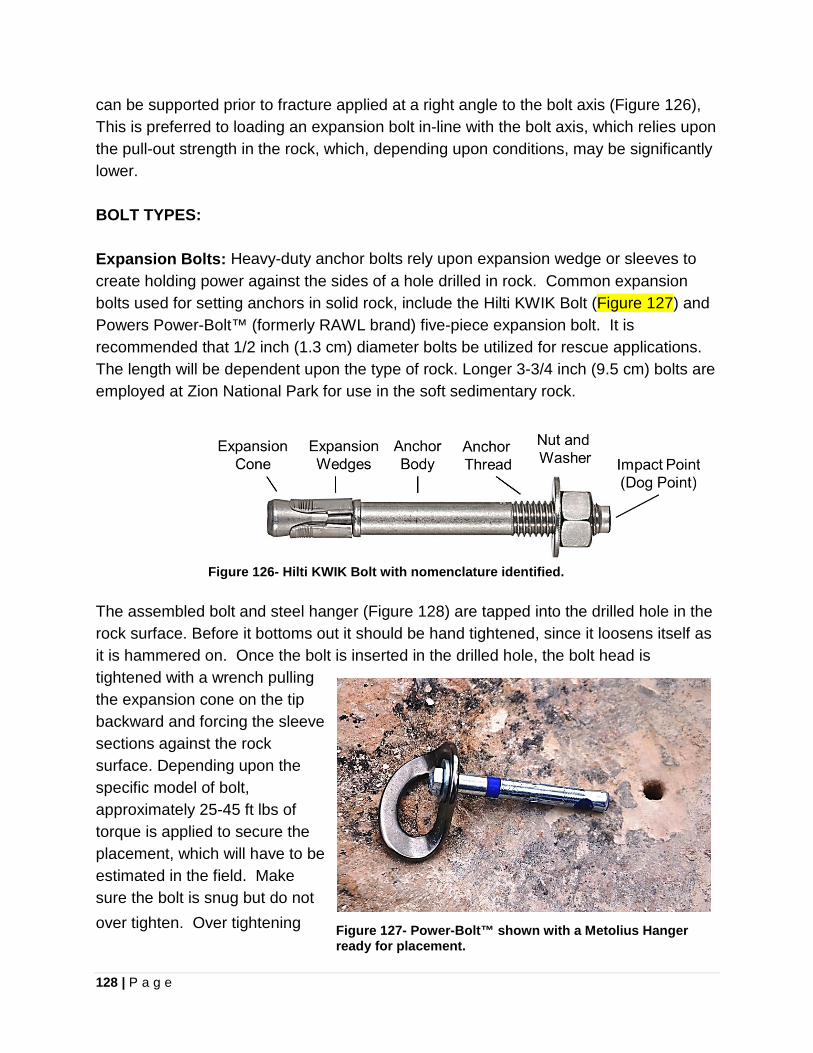
128 | P a g e
can be supported prior to fracture applied at a right angle to the bolt axis (Figure 126), This is preferred to loading an expansion bolt in-line with the bolt axis, which relies upon the pull-out strength in the rock, which, depending upon conditions, may be significantly lower. BOLT TYPES: Expansion Bolts: Heavy-duty anchor bolts rely upon expansion wedge or sleeves to create holding power against the sides of a hole drilled in rock. Common expansion bolts used for setting anchors in solid rock, include the Hilti KWIK Bolt (Figure 127) and Powers Power-Bolt™ (formerly RAWL brand) five-piece expansion bolt. It is recommended that 1/2 inch (1.3 cm) diameter bolts be utilized for rescue applications. The length will be dependent upon the type of rock. Longer 3-3/4 inch (9.5 cm) bolts are employed at Zion National Park for use in the soft sedimentary rock.
Figure 126- Hilti KWIK Bolt with nomenclature identified.
The assembled bolt and steel hanger (Figure 128) are tapped into the drilled hole in the rock surface. Before it bottoms out it should be hand tightened, since it loosens itself as it is hammered on. Once the bolt is inserted in the drilled hole, the bolt head is tightened with a wrench pulling the expansion cone on the tip backward and forcing the sleeve sections against the rock surface. Depending upon the specific model of bolt, approximately 25-45 ft lbs of torque is applied to secure the placement, which will have to be estimated in the field. Make sure the bolt is snug but do not over tighten. Over tightening Figure 127- Power-Bolt™ shown with a Metolius Hanger
ready for placement.
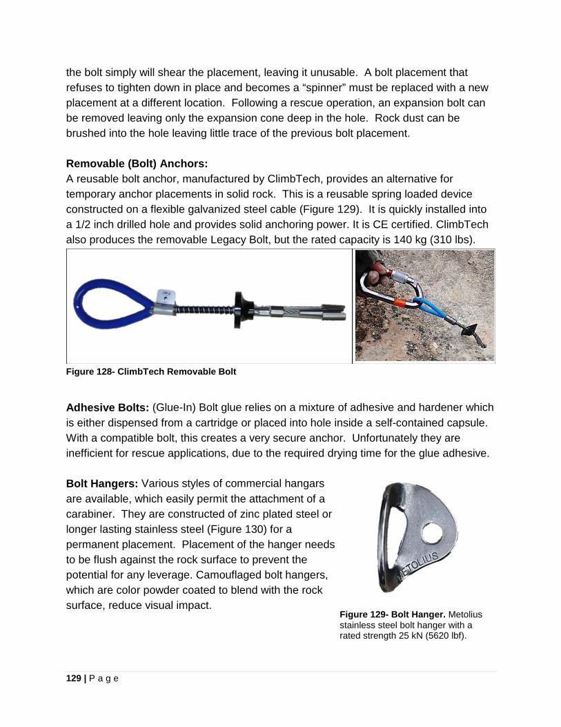
129 | P a g e
the bolt simply will shear the placement, leaving it unusable. A bolt placement that refuses to tighten down in place and becomes a “spinner” must be replaced with a new placement at a different location. Following a rescue operation, an expansion bolt can be removed leaving only the expansion cone deep in the hole. Rock dust can be brushed into the hole leaving little trace of the previous bolt placement. Removable (Bolt) Anchors: A reusable bolt anchor, manufactured by ClimbTech, provides an alternative for temporary anchor placements in solid rock. This is a reusable spring loaded device constructed on a flexible galvanized steel cable (Figure 129). It is quickly installed into a 1/2 inch drilled hole and provides solid anchoring power. It is CE certified. ClimbTech also produces the removable Legacy Bolt, but the rated capacity is 140 kg (310 lbs).
Figure 128- ClimbTech Removable Bolt
Adhesive Bolts: (Glue-In) Bolt glue relies on a mixture of adhesive and hardener which is either dispensed from a cartridge or placed into hole inside a self-contained capsule. With a compatible bolt, this creates a very secure anchor. Unfortunately they are inefficient for rescue applications, due to the required drying time for the glue adhesive. Bolt Hangers: Various styles of commercial hangars are available, which easily permit the attachment of a carabiner. They are constructed of zinc plated steel or longer lasting stainless steel (Figure 130) for a permanent placement. Placement of the hanger needs to be flush against the rock surface to prevent the potential for any leverage. Camouflaged bolt hangers, which are color powder coated to blend with the rock surface, reduce visual impact.
Figure 129- Bolt Hanger. Metolius stainless steel bolt hanger with a rated strength 25 kN (5620 lbf).
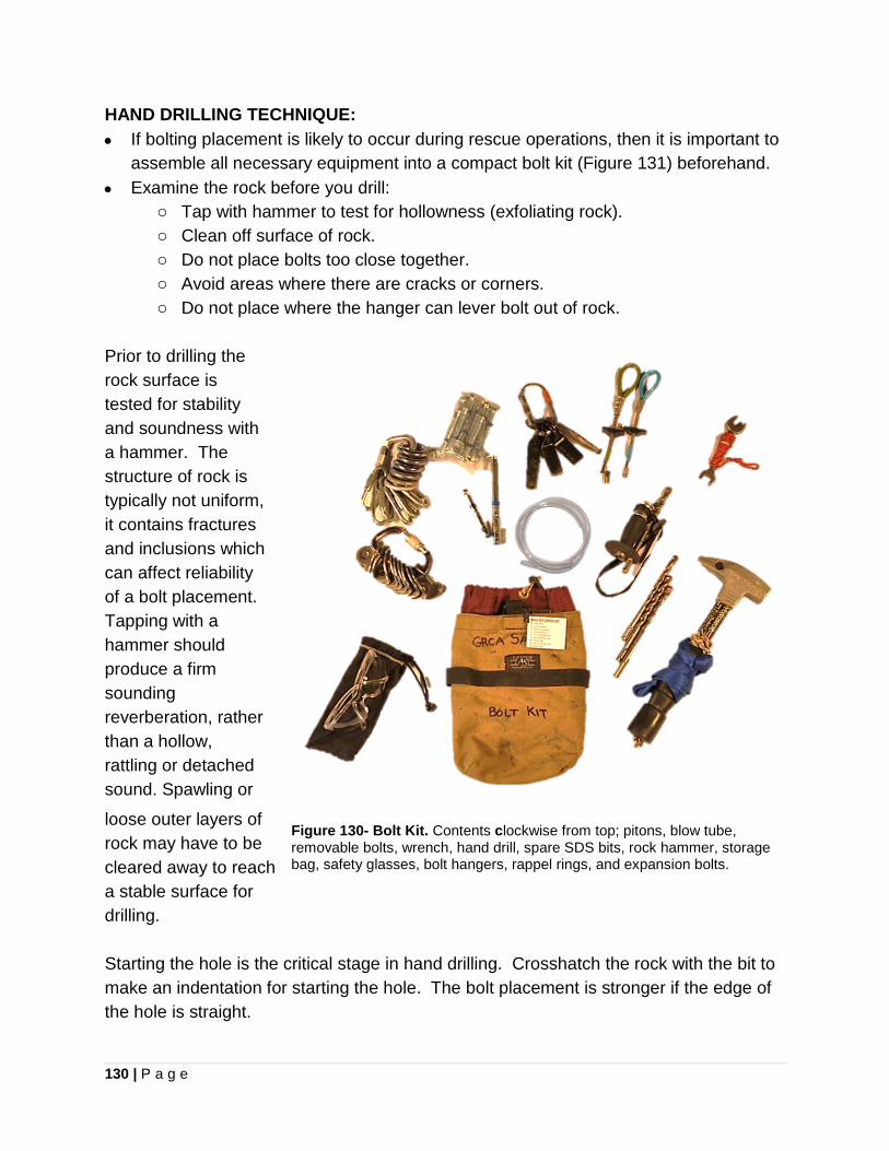
130 | P a g e
HAND DRILLING TECHNIQUE: • If bolting placement is likely to occur during rescue operations, then it is important to
assemble all necessary equipment into a compact bolt kit (Figure 131) beforehand. • Examine the rock before you drill:
o Tap with hammer to test for hollowness (exfoliating rock). o Clean off surface of rock. o Do not place bolts too close together. o Avoid areas where there are cracks or corners. o Do not place where the hanger can lever bolt out of rock.
Prior to drilling the rock surface is tested for stability and soundness with a hammer. The structure of rock is typically not uniform, it contains fractures and inclusions which can affect reliability of a bolt placement. Tapping with a hammer should produce a firm sounding reverberation, rather than a hollow, rattling or detached sound. Spawling or
loose outer layers of rock may have to be cleared away to reach a stable surface for drilling. Starting the hole is the critical stage in hand drilling. Crosshatch the rock with the bit to make an indentation for starting the hole. The bolt placement is stronger if the edge of the hole is straight.
Figure 130- Bolt Kit. Contents clockwise from top; pitons, blow tube, removable bolts, wrench, hand drill, spare SDS bits, rock hammer, storage bag, safety glasses, bolt hangers, rappel rings, and expansion bolts.
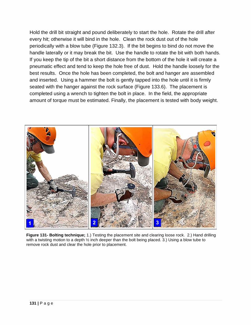
131 | P a g e
Hold the drill bit straight and pound deliberately to start the hole. Rotate the drill after every hit; otherwise it will bind in the hole. Clean the rock dust out of the hole periodically with a blow tube (Figure 132.3). If the bit begins to bind do not move the handle laterally or it may break the bit. Use the handle to rotate the bit with both hands. If you keep the tip of the bit a short distance from the bottom of the hole it will create a pneumatic effect and tend to keep the hole free of dust. Hold the handle loosely for the best results. Once the hole has been completed, the bolt and hanger are assembled and inserted. Using a hammer the bolt is gently tapped into the hole until it is firmly seated with the hanger against the rock surface (Figure 133.6). The placement is completed using a wrench to tighten the bolt in place. In the field, the appropriate amount of torque must be estimated. Finally, the placement is tested with body weight.
Figure 131- Bolting technique; 1.) Testing the placement site and clearing loose rock. 2.) Hand drilling with a twisting motion to a depth ½ inch deeper than the bolt being placed. 3.) Using a blow tube to remove rock dust and clear the hole prior to placement.
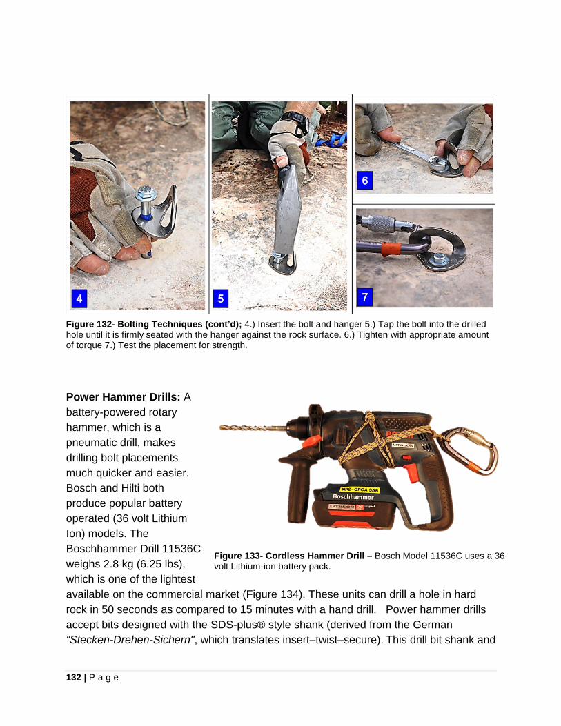
132 | P a g e
Figure 132- Bolting Techniques (cont’d); 4.) Insert the bolt and hanger 5.) Tap the bolt into the drilled hole until it is firmly seated with the hanger against the rock surface. 6.) Tighten with appropriate amount of torque 7.) Test the placement for strength.
Power Hammer Drills: A battery-powered rotary hammer, which is a pneumatic drill, makes drilling bolt placements much quicker and easier. Bosch and Hilti both produce popular battery operated (36 volt Lithium Ion) models. The Boschhammer Drill 11536C weighs 2.8 kg (6.25 lbs), which is one of the lightest available on the commercial market (Figure 134). These units can drill a hole in hard rock in 50 seconds as compared to 15 minutes with a hand drill. Power hammer drills accept bits designed with the SDS-plus® style shank (derived from the German “Stecken-Drehen-Sichern", which translates insert–twist–secure). This drill bit shank and
Figure 133- Cordless Hammer Drill – Bosch Model 11536C uses a 36 volt Lithium-ion battery pack.
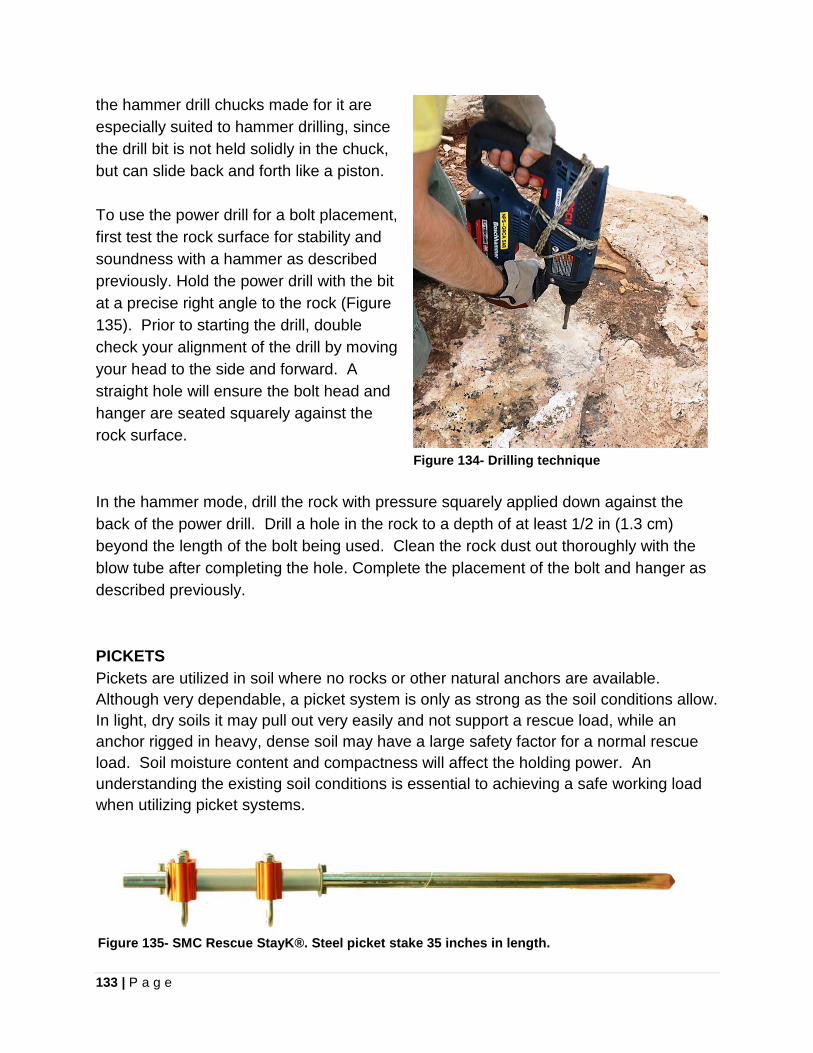
133 | P a g e
the hammer drill chucks made for it are especially suited to hammer drilling, since the drill bit is not held solidly in the chuck, but can slide back and forth like a piston. To use the power drill for a bolt placement, first test the rock surface for stability and soundness with a hammer as described previously. Hold the power drill with the bit at a precise right angle to the rock (Figure 135). Prior to starting the drill, double check your alignment of the drill by moving your head to the side and forward. A straight hole will ensure the bolt head and hanger are seated squarely against the rock surface. In the hammer mode, drill the rock with pressure squarely applied down against the back of the power drill. Drill a hole in the rock to a depth of at least 1/2 in (1.3 cm) beyond the length of the bolt being used. Clean the rock dust out thoroughly with the blow tube after completing the hole. Complete the placement of the bolt and hanger as described previously. PICKETS Pickets are utilized in soil where no rocks or other natural anchors are available. Although very dependable, a picket system is only as strong as the soil conditions allow. In light, dry soils it may pull out very easily and not support a rescue load, while an anchor rigged in heavy, dense soil may have a large safety factor for a normal rescue load. Soil moisture content and compactness will affect the holding power. An understanding the existing soil conditions is essential to achieving a safe working load when utilizing picket systems.
Figure 134- Drilling technique
Figure 135- SMC Rescue StayK®. Steel picket stake 35 inches in length.

134 | P a g e
• Picket systems, like placing bolts, requires additional set-up time • Employ quality steel stakes (Figure 136), as opposed to steel rebar which can bend • Ideal material is 1 in diameter rolled steel pointed at one end • Utilize eye protection and gloves when pounding steel stakes • Minimum length of 3 foot metal stake with 3/4 of the length driven into the ground • Common configuration is three pickets oriented in a straight line away from the
direction of the load (Figure 137), also referred to as a “1-1-1 combination” • Each picket is spaced one picket length away from the other • Pickets should be driven into the ground at a 20° angle away from the load62 • Lash top of front picket to the base of rear picket • Tension picket cordage using a Trucker’s Hitch (Figure 138) or a Spanish Windlass. • Spanish Windlass (Figure 139) is constructed by placing a smaller stake between
the multiple strands of connecting cordage and twisting to create tension. The smaller stake is then driven in the ground to secure it.
Figure 137- Picket system using Trucker's Hitch for tensioning between stakes
Figure 136- Picket anchor system (1-1-1 combination) constructed with a set of SMC Rescue StayK weighing 13 kg (28 lbs).
62 Seattle Manufacturing Corporation. Rescue StayK® Anchor and Load Equalizing Anchor System. pg. 6
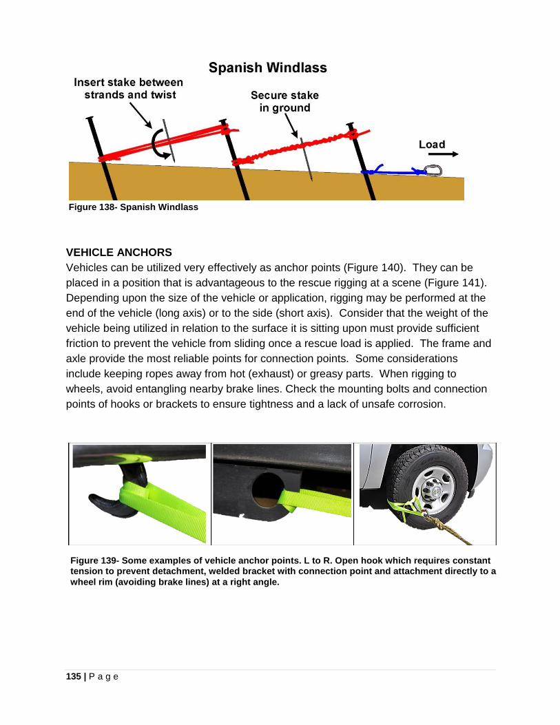
135 | P a g e
Figure 138- Spanish Windlass VEHICLE ANCHORS Vehicles can be utilized very effectively as anchor points (Figure 140). They can be placed in a position that is advantageous to the rescue rigging at a scene (Figure 141). Depending upon the size of the vehicle or application, rigging may be performed at the end of the vehicle (long axis) or to the side (short axis). Consider that the weight of the vehicle being utilized in relation to the surface it is sitting upon must provide sufficient friction to prevent the vehicle from sliding once a rescue load is applied. The frame and axle provide the most reliable points for connection points. Some considerations include keeping ropes away from hot (exhaust) or greasy parts. When rigging to wheels, avoid entangling nearby brake lines. Check the mounting bolts and connection points of hooks or brackets to ensure tightness and a lack of unsafe corrosion.
Figure 139- Some examples of vehicle anchor points. L to R. Open hook which requires constant tension to prevent detachment, welded bracket with connection point and attachment directly to a wheel rim (avoiding brake lines) at a right angle.
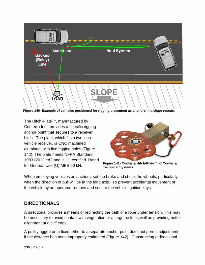
136 | P a g e
Figure 140- Example of vehicles positioned for rigging placement as anchors in a slope rescue. The Hitch-Plate™, manufactured by Conterra Inc., provides a specific rigging anchor point that secures to a receiver hitch. The plate, which fits a two inch vehicle receiver, is CNC machined aluminum with five rigging holes (Figure 142). The plate meets NFPA Standard 1983 (2012 ed.) and is UL certified. Rated for General Use (G) MBS 50 kN. When employing vehicles as anchors, set the brake and chock the wheels, particularly when the direction of pull will be in the long axis. To prevent accidental movement of the vehicle by an operator, remove and secure the vehicle ignition keys.
Figure 141- Conterra Hitch-Plate™. © Conterra Technical Systems.
DIRECTIONALS
A directional provides a means of redirecting the path of a rope under tension. This may be necessary to avoid contact with vegetation or a large rock, as well as providing better alignment at a cliff edge.
A pulley rigged on a fixed tether to a separate anchor point does not permit adjustment if the distance has been improperly estimated (Figure 142). Constructing a directional
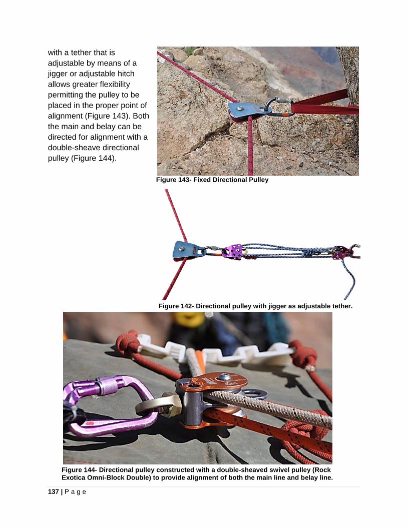
137 | P a g e
with a tether that is adjustable by means of a jigger or adjustable hitch allows greater flexibility permitting the pulley to be placed in the proper point of alignment (Figure 143). Both the main and belay can be directed for alignment with a double-sheave directional pulley (Figure 144).
Figure 142- Directional pulley with jigger as adjustable tether.
Figure 144- Directional pulley constructed with a double-sheaved swivel pulley (Rock Exotica Omni-Block Double) to provide alignment of both the main line and belay line.
Figure 143- Fixed Directional Pulley
138 | P a g e
Chapter 11
RAPPELLING Rappelling, also referred to as rapping or the European “abseiling” (from the German word abseilen, meaning "to rope down"), is the controlled descent down a steep terrain using a fixed rope. The original body rappel, known as the “Dulfersitz”, ran the rope around the rappeller’s body for friction. Modern rappelling techniques employ some type of descender or friction device. This permits a rescuer to quickly access an injured or stranded subject in technical terrain. It is important to understand that rappelling is dangerous. Rappelling accidents resulting in injury or death are frighteningly common. The following are important safety considerations relating to rappelling; • Verify the rope reaches the target • Double check your harness, carabiners, and all rigging prior to going over the edge • Check that carabiners are locked and not cross loaded • Use a buddy check system to have your rigging inspected by other rescuers • Employ a secondary conditional self-belay (autoblock, VT Prusik, etc.) as a backup • Keep the brake hand below the descending device- NEVER LET GO! • Keep hair and clothing away from the descending device • Carry a cutting tool and a backup Prusik for emergencies • Remember that a rope under tension cuts extremely easily • Avoid dislodging rocks with the rope • Do not bounce during a rappel- dangerously shocks the rappel anchor • Descend slowly and avoid excessive heat buildup • Use well-fitting gloves when rappelling- otherwise they become a safety hazard.
RAPPELLING TECHNIQUE- MINI RAPPEL RACK
The mini-rappel rack is a versatile and efficient rappelling device for the technical rescuer. To conduct a rappel;
• Attach one end of the rappel rope to a solid anchor system. Keep in mind that besides rappelling out of control, a frequent cause of rappelling accidents is due to the failure of inadequate anchors.
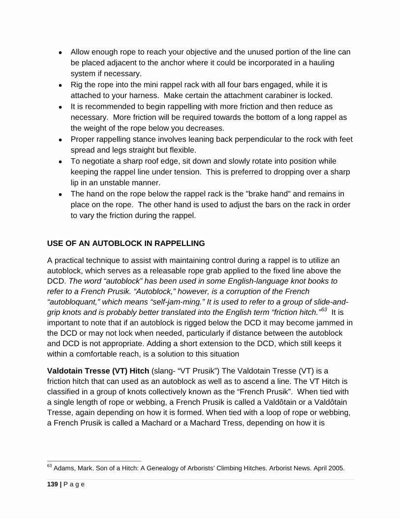
139 | P a g e
• Allow enough rope to reach your objective and the unused portion of the line can be placed adjacent to the anchor where it could be incorporated in a hauling system if necessary.
• Rig the rope into the mini rappel rack with all four bars engaged, while it is attached to your harness. Make certain the attachment carabiner is locked.
• It is recommended to begin rappelling with more friction and then reduce as necessary. More friction will be required towards the bottom of a long rappel as the weight of the rope below you decreases.
• Proper rappelling stance involves leaning back perpendicular to the rock with feet spread and legs straight but flexible.
• To negotiate a sharp roof edge, sit down and slowly rotate into position while keeping the rappel line under tension. This is preferred to dropping over a sharp lip in an unstable manner.
• The hand on the rope below the rappel rack is the "brake hand" and remains in place on the rope. The other hand is used to adjust the bars on the rack in order to vary the friction during the rappel.
USE OF AN AUTOBLOCK IN RAPPELLING
A practical technique to assist with maintaining control during a rappel is to utilize an autoblock, which serves as a releasable rope grab applied to the fixed line above the DCD. The word “autoblock” has been used in some English-language knot books to refer to a French Prusik. “Autoblock,” however, is a corruption of the French “autobloquant,” which means “self-jam-ming.” It is used to refer to a group of slide-and-grip knots and is probably better translated into the English term “friction hitch.”63 It is important to note that if an autoblock is rigged below the DCD it may become jammed in the DCD or may not lock when needed, particularly if distance between the autoblock and DCD is not appropriate. Adding a short extension to the DCD, which still keeps it within a comfortable reach, is a solution to this situation
Valdotain Tresse (VT) Hitch (slang- “VT Prusik”) The Valdotain Tresse (VT) is a friction hitch that can used as an autoblock as well as to ascend a line. The VT Hitch is classified in a group of knots collectively known as the “French Prusik”. When tied with a single length of rope or webbing, a French Prusik is called a Valdôtain or a Valdôtain Tresse, again depending on how it is formed. When tied with a loop of rope or webbing, a French Prusik is called a Machard or a Machard Tress, depending on how it is
63 Adams, Mark. Son of a Hitch: A Genealogy of Arborists’ Climbing Hitches. Arborist News. April 2005.
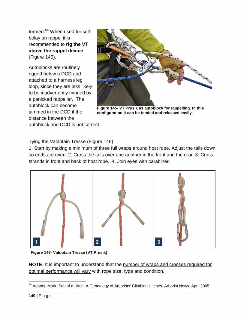
140 | P a g e
formed.64 When used for self-belay on rappel it is recommended to rig the VT above the rappel device (Figure 145).
Autoblocks are routinely rigged below a DCD and attached to a harness leg loop, since they are less likely to be inadvertently minded by a panicked rappeller. The autoblock can become jammed in the DCD if the distance between the autoblock and DCD is not correct.
Figure 145- VT Prusik as autoblock for rappelling. In this configuration it can be tended and released easily.
Tying the Valdotain Tresse (Figure 146) 1. Start by making a minimum of three full wraps around host rope. Adjust the tails down so ends are even. 2. Cross the tails over one another in the front and the rear. 3. Cross strands in front and back of host rope. 4. Join eyes with carabiner.
NOTE: It is important to understand that the number of wraps and crosses required for optimal performance will vary with rope size, type and condition.
64 Adams, Mark. Son of a Hitch: A Genealogy of Arborists’ Climbing Hitches. Arborist News. April 2005.
Figure 146- Valdotain Tresse (VT Prusik)

141 | P a g e
The Valdotain Tresse is commonly utilized in arborist work and canyoneering, and is also finding applications in technical rescue work. An excellent use is as a personal autoblock device when rappelling. BlueWater Ropes and Sterling Rope both manufacture cord with sewn loop terminations, which is constructed of a heat resistant aramid sheath on a nylon core. The BlueWater VT Prusik is 8mm cord, 31 in length, with a rated strength end-to-end of 19.5 kN (4400 lbf). In a basket configuration the rated strength is 29 kN (6500 lbf).
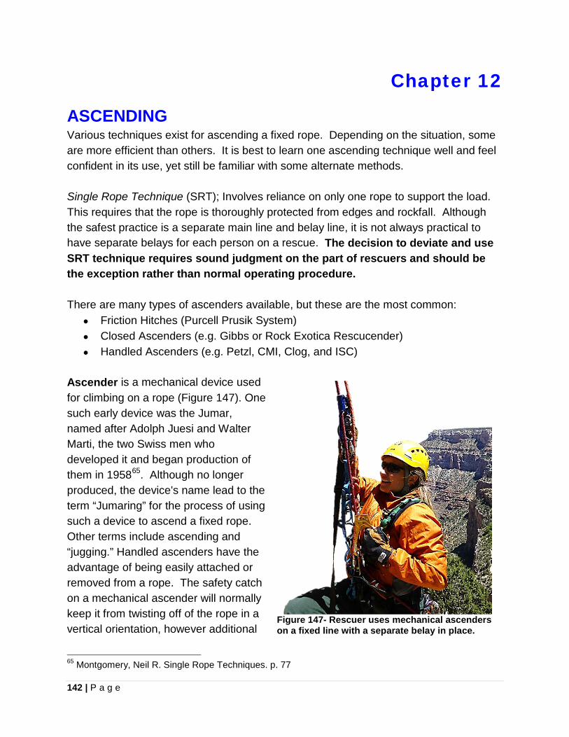
142 | P a g e
Chapter 12
ASCENDING Various techniques exist for ascending a fixed rope. Depending on the situation, some are more efficient than others. It is best to learn one ascending technique well and feel confident in its use, yet still be familiar with some alternate methods. Single Rope Technique (SRT); Involves reliance on only one rope to support the load. This requires that the rope is thoroughly protected from edges and rockfall. Although the safest practice is a separate main line and belay line, it is not always practical to have separate belays for each person on a rescue. The decision to deviate and use SRT technique requires sound judgment on the part of rescuers and should be the exception rather than normal operating procedure. There are many types of ascenders available, but these are the most common:
• Friction Hitches (Purcell Prusik System) • Closed Ascenders (e.g. Gibbs or Rock Exotica Rescucender) • Handled Ascenders (e.g. Petzl, CMI, Clog, and ISC)
Ascender is a mechanical device used for climbing on a rope (Figure 147). One such early device was the Jumar, named after Adolph Juesi and Walter Marti, the two Swiss men who developed it and began production of them in 195865. Although no longer produced, the device's name lead to the term “Jumaring” for the process of using such a device to ascend a fixed rope. Other terms include ascending and “jugging.” Handled ascenders have the advantage of being easily attached or removed from a rope. The safety catch on a mechanical ascender will normally keep it from twisting off of the rope in a vertical orientation, however additional
65 Montgomery, Neil R. Single Rope Techniques. p. 77
Figure 147- Rescuer uses mechanical ascenders on a fixed line with a separate belay in place.
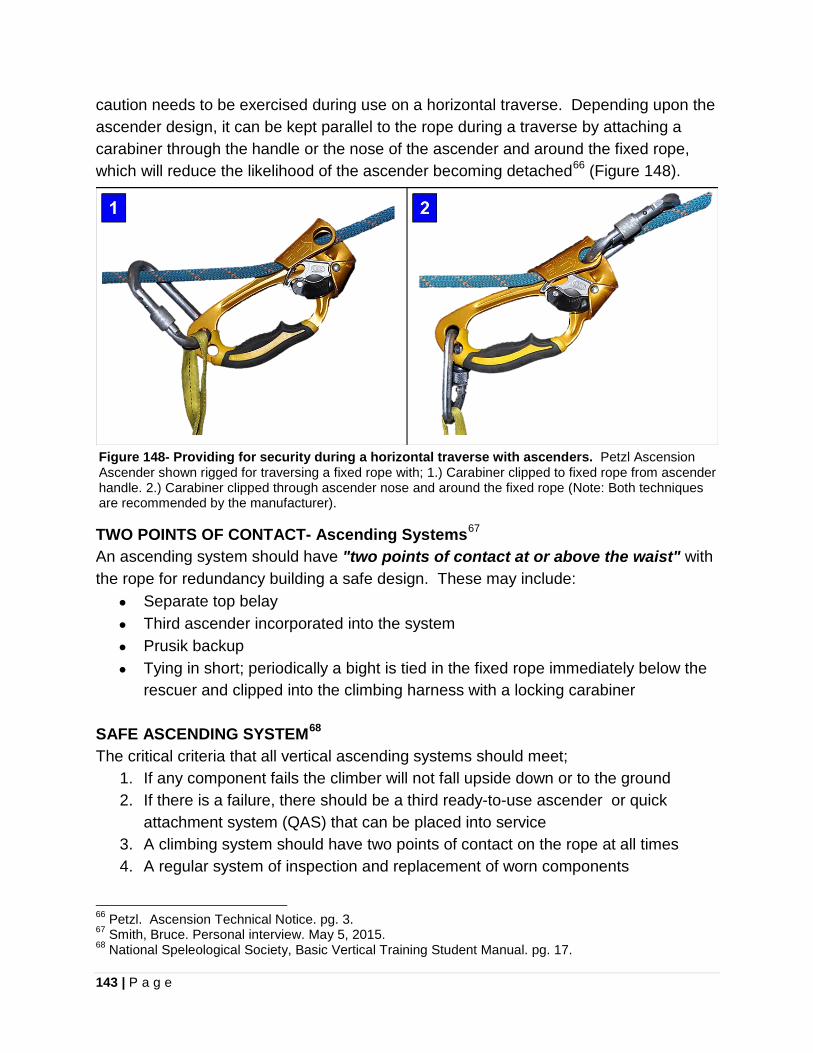
143 | P a g e
caution needs to be exercised during use on a horizontal traverse. Depending upon the ascender design, it can be kept parallel to the rope during a traverse by attaching a carabiner through the handle or the nose of the ascender and around the fixed rope, which will reduce the likelihood of the ascender becoming detached66 (Figure 148).
Figure 148- Providing for security during a horizontal traverse with ascenders. Petzl Ascension Ascender shown rigged for traversing a fixed rope with; 1.) Carabiner clipped to fixed rope from ascender handle. 2.) Carabiner clipped through ascender nose and around the fixed rope (Note: Both techniques are recommended by the manufacturer).
TWO POINTS OF CONTACT- Ascending Systems67 An ascending system should have "two points of contact at or above the waist" with the rope for redundancy building a safe design. These may include:
• Separate top belay • Third ascender incorporated into the system • Prusik backup • Tying in short; periodically a bight is tied in the fixed rope immediately below the
rescuer and clipped into the climbing harness with a locking carabiner SAFE ASCENDING SYSTEM68 The critical criteria that all vertical ascending systems should meet;
1. If any component fails the climber will not fall upside down or to the ground 2. If there is a failure, there should be a third ready-to-use ascender or quick
attachment system (QAS) that can be placed into service 3. A climbing system should have two points of contact on the rope at all times 4. A regular system of inspection and replacement of worn components
66 Petzl. Ascension Technical Notice. pg. 3. 67 Smith, Bruce. Personal interview. May 5, 2015. 68 National Speleological Society, Basic Vertical Training Student Manual. pg. 17.
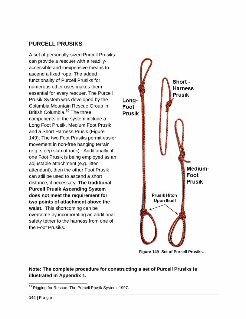
144 | P a g e
PURCELL PRUSIKS
A set of personally-sized Purcell Prusiks can provide a rescuer with a readily-accessible and inexpensive means to ascend a fixed rope. The added functionality of Purcell Prusiks for numerous other uses makes them essential for every rescuer. The Purcell Prusik System was developed by the Columbia Mountain Rescue Group in British Columbia.69 The three components of the system include a Long Foot Prusik, Medium Foot Prusik and a Short Harness Prusik (Figure 149). The two Foot Prusiks permit easier movement in non-free hanging terrain (e.g. steep slab of rock). Additionally, if one Foot Prusik is being employed as an adjustable attachment (e.g. litter attendant), then the other Foot Prusik can still be used to ascend a short distance, if necessary. The traditional Purcell Prusik Ascending System does not meet the requirement for two points of attachment above the waist. This shortcoming can be overcome by incorporating an additional safety tether to the harness from one of the Foot Prusiks.
Note: The complete procedure for constructing a set of Purcell Prusiks is illustrated in Appendix 1. 69 Rigging for Rescue. The Purcell Prusik System. 1997.
Figure 149- Set of Purcell Prusiks.
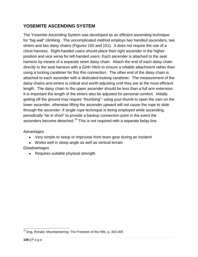
145 | P a g e
YOSEMITE ASCENDING SYSTEM
The Yosemite Ascending System was developed as an efficient ascending technique for “big wall” climbing. The uncomplicated method employs two handled ascenders, two etriers and two daisy chains (Figures 150 and 151). It does not require the use of a chest harness. Right-handed users should place their right ascender in the higher position and vice versa for left-handed users. Each ascender is attached to the seat harness by means of a separate sewn daisy chain. Attach the end of each daisy chain directly to the seat harness with a Girth Hitch to ensure a reliable attachment rather than using a locking carabiner for this this connection. The other end of the daisy chain is attached to each ascender with a dedicated locking carabiner. The measurement of the daisy chains and etriers is critical and worth adjusting until they are at the most efficient length. The daisy chain to the upper ascender should be less than a full arm extension. It is important the length of the etriers also be adjusted for personal comfort. Initially getting off the ground may require “thumbing”- using your thumb to open the cam on the lower ascender, otherwise lifting the ascender upward will not cause the rope to slide through the ascender. If single rope technique is being employed while ascending, periodically “tie in short” to provide a backup connection point in the event the ascenders become detached.70 This is not required with a separate belay line. Advantages
• Very simple to setup or improvise from team gear during an incident • Works well in steep angle as well as vertical terrain
Disadvantages • Requires suitable physical strength
70 Eng, Ronald. Mountaineering: The Freedom of the Hills. p. 303-305
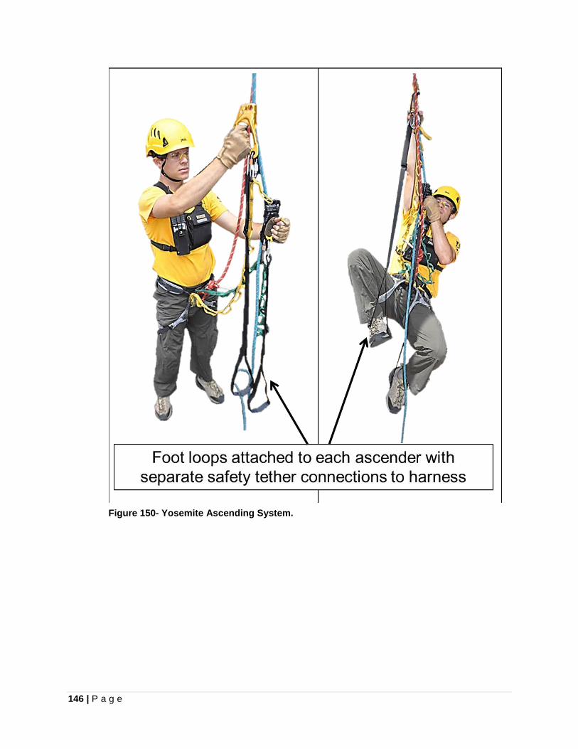
146 | P a g e
Figure 150- Yosemite Ascending System.
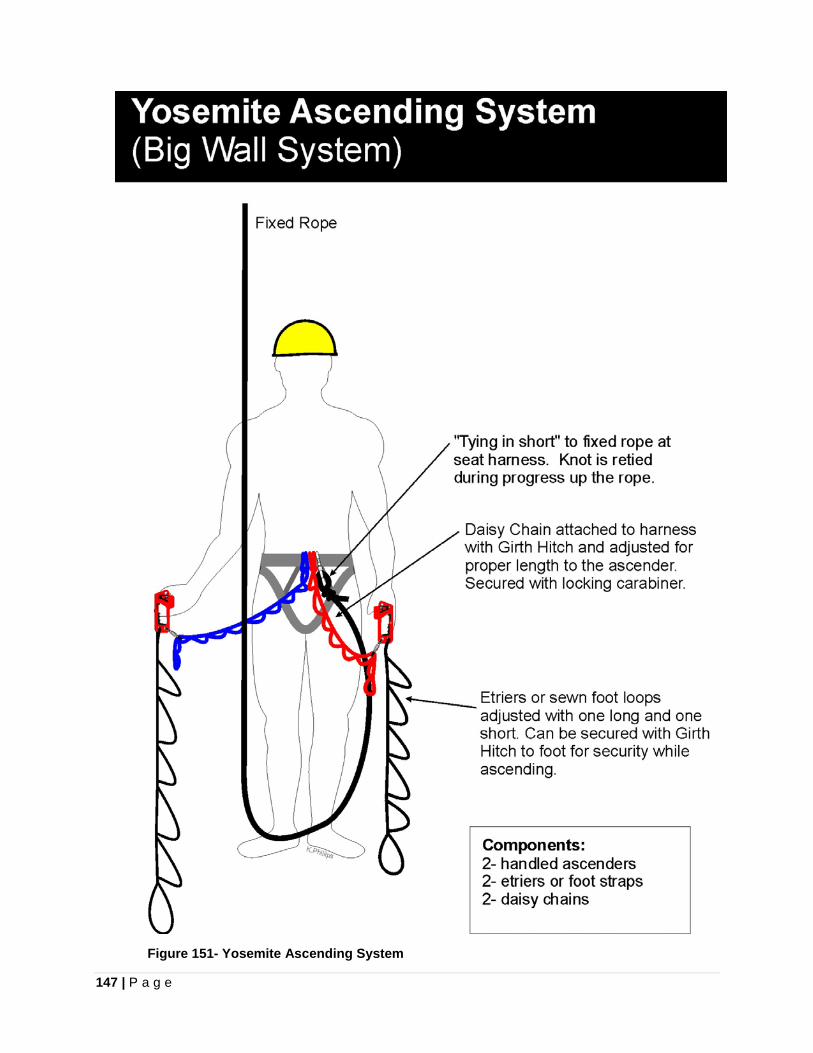
147 | P a g e
Figure 151- Yosemite Ascending System

148 | P a g e
TEXAS ASCENDING SYSTEM
The Texas System is considered the original sit-stand ascending system71. As opposed to a ropewalker configuration, which uses independent ascenders to each foot, a sit-stand ascending system uses one ascender (originally Prusik Hitches) to both feet. The rope ascending cycle involves sitting down to lift the feet and move the foot ascender upward. This is followed by standing up and moving a second ascender, attached to the harness, upward. For shorter technical ascents, less fit individuals find a sit-stand system less strenuous, however there are much more efficient ascending systems in existence72. The Texas System components are configured with the foot ascender attached to the rope well below a second ascender on a sling going to the harness (Figure 152). The length of the lower ascender sling determines the possible travel distance during each cycle. A shorter sling will permit greater travel distance. A safety tether needs to be rigged from the foot ascender to the harness. The Texas System can also be rigged with only one foot sling allowing the other leg to remain free for balance73. Although a sit-stand system only requires two ascenders, a QAS should be available as a safety when negotiating cliff edges or anchor point bypasses. Advantages
• Simple and easy to set up • Does not require a chest harness • Can be employed by less fit individuals
Disadvantages • Less efficient over long distances
The Texas System differs from the Frog System, another popular sit-stand ascending configuration for cavers, which according to Bruce Smith is likely the most popular system in the world74. The Frog System varies with the mandatory use of a chest harness and the foot ascender is rigged above the harness ascender on the rope being climbed.
71 Montgomery, Neil R. Single Rope Techniques. p. 94. 72 Montgomery, Neil R. Single Rope Techniques. p. 91. 73 Smith, Bruce and Allen Padgett. On Rope. p. 141. 74 Ibid. p. 142.
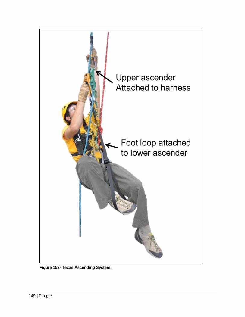
149 | P a g e
Figure 152- Texas Ascending System.
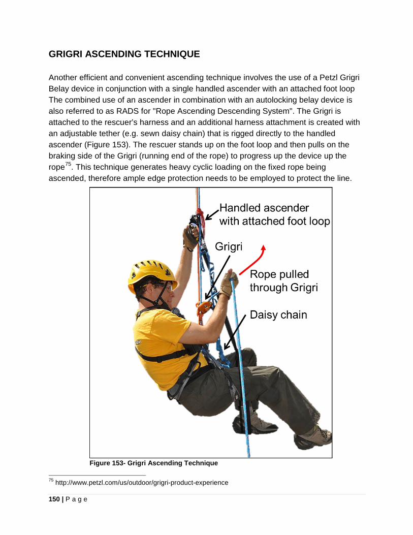
150 | P a g e
GRIGRI ASCENDING TECHNIQUE Another efficient and convenient ascending technique involves the use of a Petzl Grigri Belay device in conjunction with a single handled ascender with an attached foot loop The combined use of an ascender in combination with an autolocking belay device is also referred to as RADS for "Rope Ascending Descending System". The Grigri is attached to the rescuer’s harness and an additional harness attachment is created with an adjustable tether (e.g. sewn daisy chain) that is rigged directly to the handled ascender (Figure 153). The rescuer stands up on the foot loop and then pulls on the braking side of the Grigri (running end of the rope) to progress up the device up the rope75. This technique generates heavy cyclic loading on the fixed rope being ascended, therefore ample edge protection needs to be employed to protect the line.
Figure 153- Grigri Ascending Technique
75 http://www.petzl.com/us/outdoor/grigri-product-experience
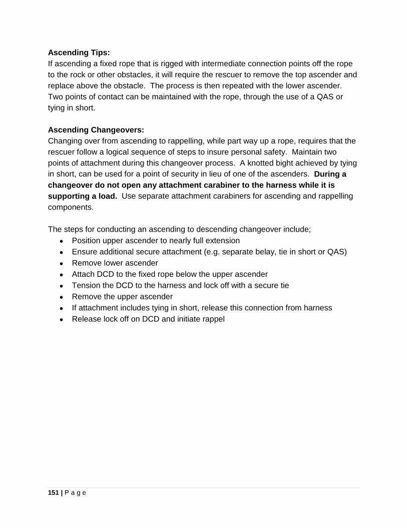
151 | P a g e
Ascending Tips: If ascending a fixed rope that is rigged with intermediate connection points off the rope to the rock or other obstacles, it will require the rescuer to remove the top ascender and replace above the obstacle. The process is then repeated with the lower ascender. Two points of contact can be maintained with the rope, through the use of a QAS or tying in short. Ascending Changeovers: Changing over from ascending to rappelling, while part way up a rope, requires that the rescuer follow a logical sequence of steps to insure personal safety. Maintain two points of attachment during this changeover process. A knotted bight achieved by tying in short, can be used for a point of security in lieu of one of the ascenders. During a changeover do not open any attachment carabiner to the harness while it is supporting a load. Use separate attachment carabiners for ascending and rappelling components. The steps for conducting an ascending to descending changeover include;
• Position upper ascender to nearly full extension • Ensure additional secure attachment (e.g. separate belay, tie in short or QAS) • Remove lower ascender • Attach DCD to the fixed rope below the upper ascender • Tension the DCD to the harness and lock off with a secure tie • Remove the upper ascender • If attachment includes tying in short, release this connection from harness • Release lock off on DCD and initiate rappel
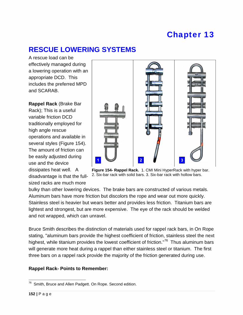
152 | P a g e
Chapter 13
RESCUE LOWERING SYSTEMS A rescue load can be effectively managed during a lowering operation with an appropriate DCD. This includes the preferred MPD and SCARAB. Rappel Rack (Brake Bar Rack); This is a useful variable friction DCD traditionally employed for high angle rescue operations and available in several styles (Figure 154). The amount of friction can be easily adjusted during use and the device dissipates heat well. A disadvantage is that the full-sized racks are much more bulky than other lowering devices. The brake bars are constructed of various metals. Aluminum bars have more friction but discolors the rope and wear out more quickly. Stainless steel is heavier but wears better and provides less friction. Titanium bars are lightest and strongest, but are more expensive. The eye of the rack should be welded and not wrapped, which can unravel. Bruce Smith describes the distinction of materials used for rappel rack bars, in On Rope stating, "aluminum bars provide the highest coefficient of friction, stainless steel the next highest, while titanium provides the lowest coefficient of friction.”76 Thus aluminum bars will generate more heat during a rappel than either stainless steel or titanium. The first three bars on a rappel rack provide the majority of the friction generated during use. Rappel Rack- Points to Remember:
76 Smith, Bruce and Allen Padgett. On Rope. Second edition.
Figure 154- Rappel Rack. 1. CMI Mini HyperRack with hyper bar. 2. Six-bar rack with solid bars. 3. Six-bar rack with hollow bars.
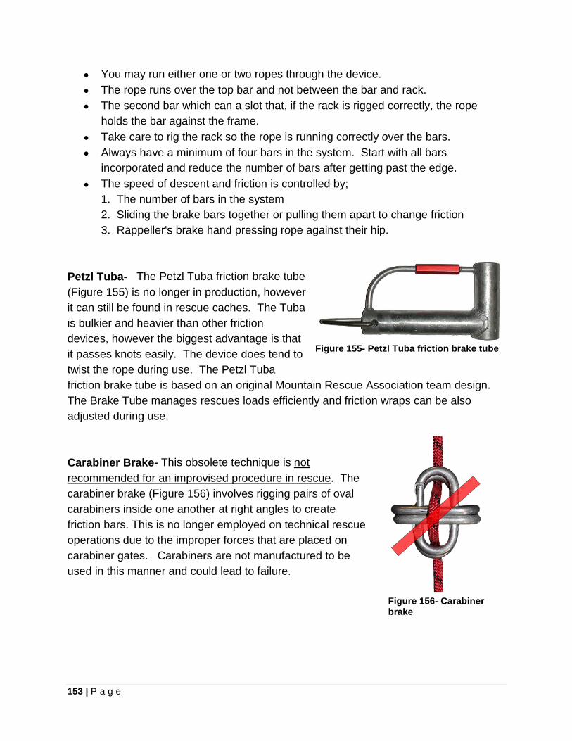
153 | P a g e
• You may run either one or two ropes through the device. • The rope runs over the top bar and not between the bar and rack. • The second bar which can a slot that, if the rack is rigged correctly, the rope
holds the bar against the frame. • Take care to rig the rack so the rope is running correctly over the bars. • Always have a minimum of four bars in the system. Start with all bars
incorporated and reduce the number of bars after getting past the edge. • The speed of descent and friction is controlled by;
1. The number of bars in the system 2. Sliding the brake bars together or pulling them apart to change friction 3. Rappeller's brake hand pressing rope against their hip.
Petzl Tuba- The Petzl Tuba friction brake tube (Figure 155) is no longer in production, however it can still be found in rescue caches. The Tuba is bulkier and heavier than other friction devices, however the biggest advantage is that it passes knots easily. The device does tend to twist the rope during use. The Petzl Tuba friction brake tube is based on an original Mountain Rescue Association team design. The Brake Tube manages rescues loads efficiently and friction wraps can be also adjusted during use.
Figure 155- Petzl Tuba friction brake tube
Carabiner Brake- This obsolete technique is not recommended for an improvised procedure in rescue. The carabiner brake (Figure 156) involves rigging pairs of oval carabiners inside one another at right angles to create friction bars. This is no longer employed on technical rescue operations due to the improper forces that are placed on carabiner gates. Carabiners are not manufactured to be used in this manner and could lead to failure.
Figure 156- Carabiner brake
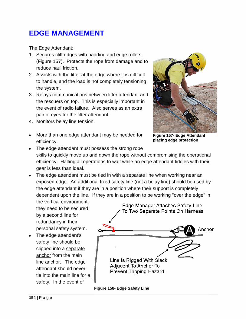
154 | P a g e
EDGE MANAGEMENT
The Edge Attendant: 1. Secures cliff edges with padding and edge rollers
(Figure 157). Protects the rope from damage and to reduce haul friction.
2. Assists with the litter at the edge where it is difficult to handle, and the load is not completely tensioning the system.
3. Relays communications between litter attendant and the rescuers on top. This is especially important in the event of radio failure. Also serves as an extra pair of eyes for the litter attendant.
4. Monitors belay line tension. • More than one edge attendant may be needed for
efficiency. • The edge attendant must possess the strong rope
skills to quickly move up and down the rope without compromising the operational efficiency. Halting all operations to wait while an edge attendant fiddles with their gear is less than ideal.
• The edge attendant must be tied in with a separate line when working near an exposed edge. An additional fixed safety line (not a belay line) should be used by the edge attendant if they are in a position where their support is completely dependent upon the line. If they are in a position to be working "over the edge" in the vertical environment, they need to be secured by a second line for redundancy in their personal safety system.
• The edge attendant's safety line should be clipped into a separate anchor from the main line anchor. The edge attendant should never tie into the main line for a safety. In the event of
Figure 157- Edge Attendant placing edge protection
Figure 158- Edge Safety Line
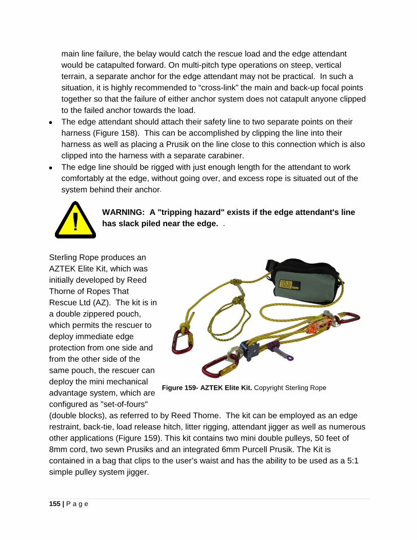
155 | P a g e
main line failure, the belay would catch the rescue load and the edge attendant would be catapulted forward. On multi-pitch type operations on steep, vertical terrain, a separate anchor for the edge attendant may not be practical. In such a situation, it is highly recommended to “cross-link” the main and back-up focal points together so that the failure of either anchor system does not catapult anyone clipped to the failed anchor towards the load.
• The edge attendant should attach their safety line to two separate points on their harness (Figure 158). This can be accomplished by clipping the line into their harness as well as placing a Prusik on the line close to this connection which is also clipped into the harness with a separate carabiner.
• The edge line should be rigged with just enough length for the attendant to work comfortably at the edge, without going over, and excess rope is situated out of the system behind their anchor.
WARNING: A "tripping hazard" exists if the edge attendant's line has slack piled near the edge. .
Sterling Rope produces an AZTEK Elite Kit, which was initially developed by Reed Thorne of Ropes That Rescue Ltd (AZ). The kit is in a double zippered pouch, which permits the rescuer to deploy immediate edge protection from one side and from the other side of the same pouch, the rescuer can deploy the mini mechanical advantage system, which are configured as "set-of-fours" (double blocks), as referred to by Reed Thorne. The kit can be employed as an edge restraint, back-tie, load release hitch, litter rigging, attendant jigger as well as numerous other applications (Figure 159). This kit contains two mini double pulleys, 50 feet of 8mm cord, two sewn Prusiks and an integrated 6mm Purcell Prusik. The Kit is contained in a bag that clips to the user’s waist and has the ability to be used as a 5:1 simple pulley system jigger.
Figure 159- AZTEK Elite Kit. Copyright Sterling Rope
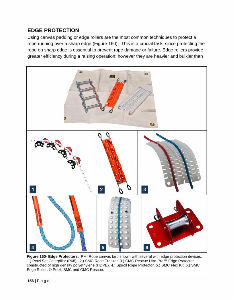
156 | P a g e
EDGE PROTECTION Using canvas padding or edge rollers are the most common techniques to protect a rope running over a sharp edge (Figure 160). This is a crucial task, since protecting the rope on sharp edge is essential to prevent rope damage or failure. Edge rollers provide greater efficiency during a raising operation; however they are heavier and bulkier than
Figure 160- Edge Protectors. PMI Rope canvas tarp shown with several with edge protection devices. 1.) Petzl Set Caterpillar (P68). 2.) SMC Rope Tracker. 3.) CMC Rescue Utra-Pro™ Edge Protector constructed of high density polyethylene (HDPE). 4.) Spiroll Rope Protector. 5.) SMC Flex Kit 6.) SMC Edge Roller. © Petzl, SMC and CMC Rescue.
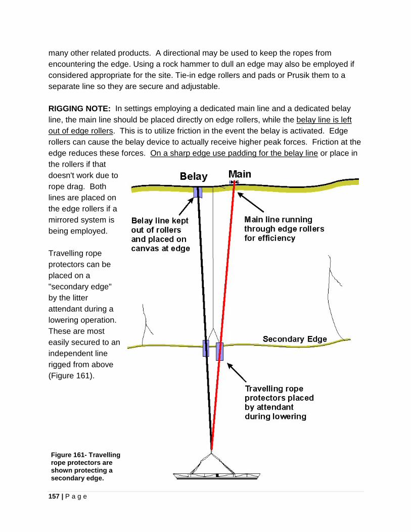
157 | P a g e
many other related products. A directional may be used to keep the ropes from encountering the edge. Using a rock hammer to dull an edge may also be employed if considered appropriate for the site. Tie-in edge rollers and pads or Prusik them to a separate line so they are secure and adjustable. RIGGING NOTE: In settings employing a dedicated main line and a dedicated belay line, the main line should be placed directly on edge rollers, while the belay line is left out of edge rollers. This is to utilize friction in the event the belay is activated. Edge rollers can cause the belay device to actually receive higher peak forces. Friction at the edge reduces these forces. On a sharp edge use padding for the belay line or place in the rollers if that doesn't work due to rope drag. Both lines are placed on the edge rollers if a mirrored system is being employed. Travelling rope protectors can be placed on a "secondary edge" by the litter attendant during a lowering operation. These are most easily secured to an independent line rigged from above (Figure 161).
Figure 161- Travelling rope protectors are shown protecting a secondary edge.
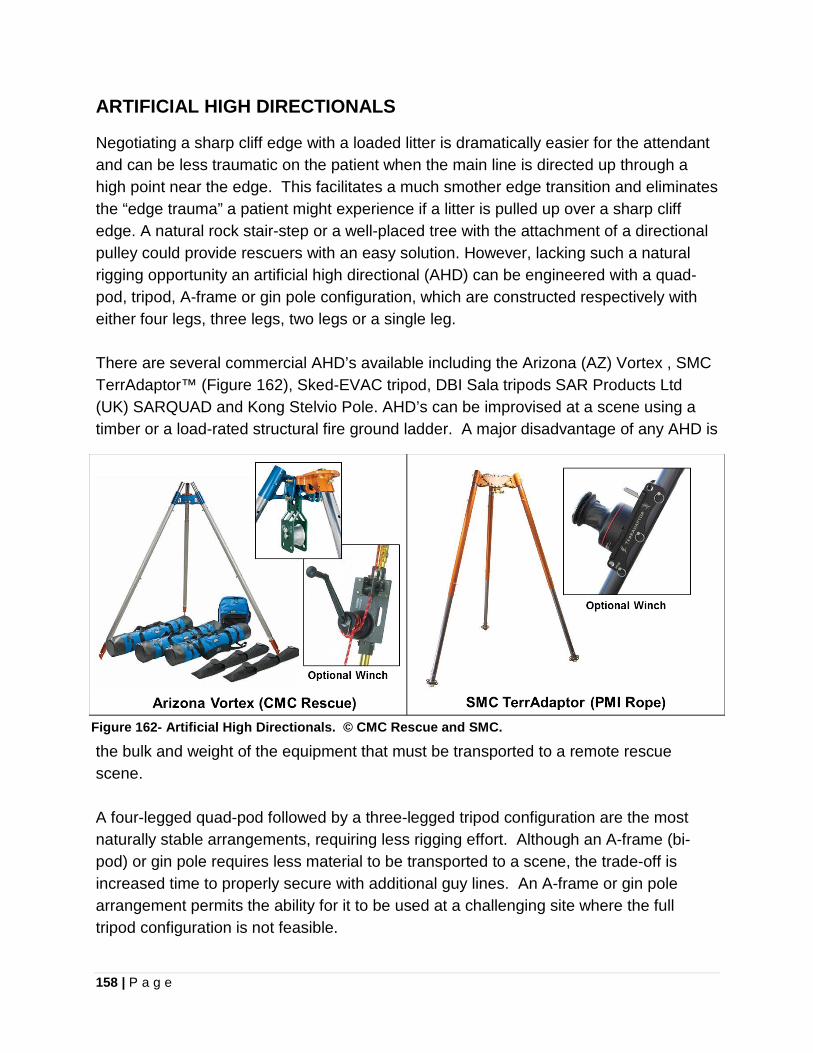
158 | P a g e
ARTIFICIAL HIGH DIRECTIONALS
Negotiating a sharp cliff edge with a loaded litter is dramatically easier for the attendant and can be less traumatic on the patient when the main line is directed up through a high point near the edge. This facilitates a much smother edge transition and eliminates the “edge trauma” a patient might experience if a litter is pulled up over a sharp cliff edge. A natural rock stair-step or a well-placed tree with the attachment of a directional pulley could provide rescuers with an easy solution. However, lacking such a natural rigging opportunity an artificial high directional (AHD) can be engineered with a quad-pod, tripod, A-frame or gin pole configuration, which are constructed respectively with either four legs, three legs, two legs or a single leg. There are several commercial AHD’s available including the Arizona (AZ) Vortex , SMC TerrAdaptor™ (Figure 162), Sked-EVAC tripod, DBI Sala tripods SAR Products Ltd (UK) SARQUAD and Kong Stelvio Pole. AHD’s can be improvised at a scene using a timber or a load-rated structural fire ground ladder. A major disadvantage of any AHD is
the bulk and weight of the equipment that must be transported to a remote rescue scene. A four-legged quad-pod followed by a three-legged tripod configuration are the most naturally stable arrangements, requiring less rigging effort. Although an A-frame (bi-pod) or gin pole requires less material to be transported to a scene, the trade-off is increased time to properly secure with additional guy lines. An A-frame or gin pole arrangement permits the ability for it to be used at a challenging site where the full tripod configuration is not feasible.
Figure 162- Artificial High Directionals. © CMC Rescue and SMC.
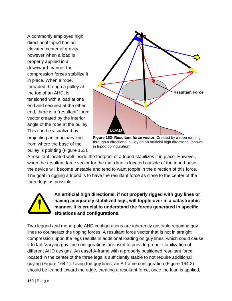
159 | P a g e
A commonly employed high directional tripod has an elevated center of gravity, however when a load is properly applied in a downward manner the compression forces stabilize it in place. When a rope, threaded through a pulley at the top of an AHD, is tensioned with a load at one end and secured at the other end, there is a “resultant” force vector created by the interior angle of the rope at the pulley. This can be visualized by projecting an imaginary line from where the base of the pulley is pointing (Figure 163). A resultant located well inside the footprint of a tripod stabilizes it in place. However, when the resultant force vector for the main line is located outside of the tripod base, the device will become unstable and tend to want topple in the direction of this force. The goal in rigging a tripod is to have the resultant force as close to the center of the three legs as possible.
An artificial high directional, if not properly rigged with guy lines or having adequately stabilized legs, will topple over in a catastrophic manner. It is crucial to understand the forces generated in specific situations and configurations.
Two legged and mono-pole AHD configurations are inherently unstable requiring guy lines to counteract the tipping forces. A resultant force vector that is not in straight compression upon the legs results in additional loading on guy lines, which could cause it to fail. Varying guy line configurations are used to provide proper stabilization of different AHD designs. An easel A-frame with a properly positioned resultant force located in the center of the three legs is sufficiently stable to not require additional guying (Figure 164.1). Using the guy lines, an A-frame configuration (Figure 164.2) should be leaned toward the edge, creating a resultant force, once the load is applied,
Figure 163- Resultant force vector. Created by a rope running through a directional pulley on an artificial high directional (shown in tripod configuration).
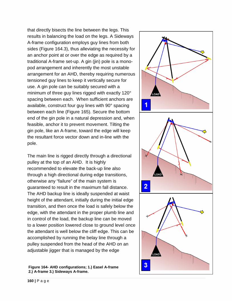
160 | P a g e
that directly bisects the line between the legs. This results in balancing the load on the legs. A Sideways A-frame configuration employs guy lines from both sides (Figure 164.3), thus alleviating the necessity for an anchor point at or over the edge as required by a traditional A-frame set-up. A gin (jin) pole is a mono-pod arrangement and inherently the most unstable arrangement for an AHD, thereby requiring numerous tensioned guy lines to keep it vertically secure for use. A gin pole can be suitably secured with a minimum of three guy lines rigged with exactly 120° spacing between each. When sufficient anchors are available, construct four guy lines with 90° spacing between each line (Figure 165). Secure the bottom end of the gin pole in a natural depression and, when feasible, anchor it to prevent movement. Tilting the gin pole, like an A-frame, toward the edge will keep the resultant force vector down and in-line with the pole. The main line is rigged directly through a directional pulley at the top of an AHD. It is highly recommended to elevate the back-up line also through a high directional during edge transitions, otherwise any “failure” of the main system is guaranteed to result in the maximum fall distance. The AHD backup line is ideally suspended at waist height of the attendant, initially during the initial edge transition, and then once the load is safely below the edge, with the attendant in the proper plumb line and in control of the load, the backup line can be moved to a lower position lowered close to ground level once the attendant is well below the cliff edge. This can be accomplished by running the belay line through a pulley suspended from the head of the AHD on an adjustable jigger that is managed by the edge
Figure 164- AHD configurations; 1.) Easel A-frame 2.) A-frame 3.) Sideways A-frame.
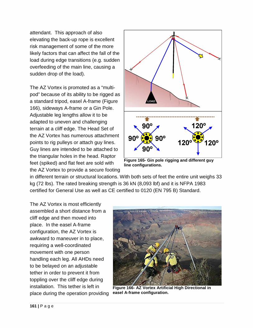
161 | P a g e
attendant. This approach of also elevating the back-up rope is excellent risk management of some of the more likely factors that can affect the fall of the load during edge transitions (e.g. sudden overfeeding of the main line, causing a sudden drop of the load). The AZ Vortex is promoted as a “multi-pod” because of its ability to be rigged as a standard tripod, easel A-frame (Figure 166), sideways A-frame or a Gin Pole. Adjustable leg lengths allow it to be adapted to uneven and challenging terrain at a cliff edge. The Head Set of the AZ Vortex has numerous attachment points to rig pulleys or attach guy lines. Guy lines are intended to be attached to the triangular holes in the head. Raptor feet (spiked) and flat feet are sold with the AZ Vortex to provide a secure footing in different terrain or structural locations. With both sets of feet the entire unit weighs 33 kg (72 lbs). The rated breaking strength is 36 kN (8,093 lbf) and it is NFPA 1983 certified for General Use as well as CE certified to 0120 (EN 795 B) Standard.
Figure 165- Gin pole rigging and different guy line configurations.
The AZ Vortex is most efficiently assembled a short distance from a cliff edge and then moved into place. In the easel A-frame configuration, the AZ Vortex is awkward to maneuver in to place, requiring a well-coordinated movement with one person handling each leg. All AHDs need to be belayed on an adjustable tether in order to prevent it from toppling over the cliff edge during installation. This tether is left in place during the operation providing
Figure 166- AZ Vortex Artificial High Directional in easel A-frame configuration.
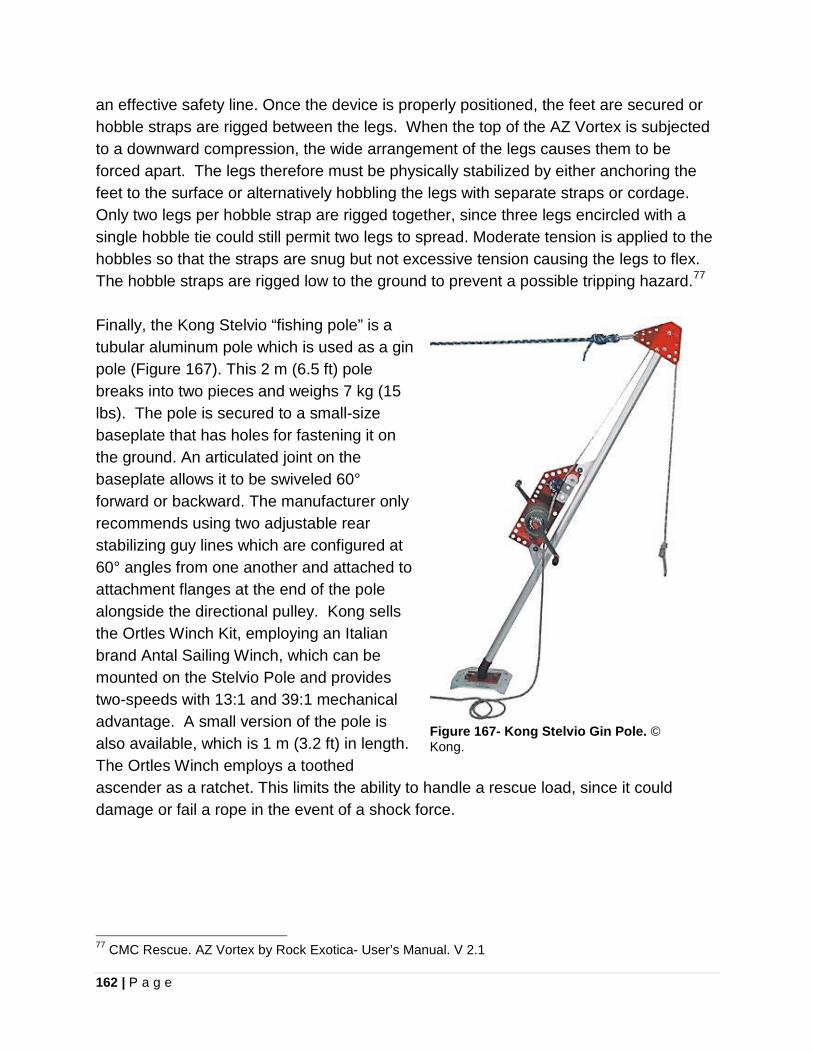
162 | P a g e
an effective safety line. Once the device is properly positioned, the feet are secured or hobble straps are rigged between the legs. When the top of the AZ Vortex is subjected to a downward compression, the wide arrangement of the legs causes them to be forced apart. The legs therefore must be physically stabilized by either anchoring the feet to the surface or alternatively hobbling the legs with separate straps or cordage. Only two legs per hobble strap are rigged together, since three legs encircled with a single hobble tie could still permit two legs to spread. Moderate tension is applied to the hobbles so that the straps are snug but not excessive tension causing the legs to flex. The hobble straps are rigged low to the ground to prevent a possible tripping hazard.77 Finally, the Kong Stelvio “fishing pole” is a tubular aluminum pole which is used as a gin pole (Figure 167). This 2 m (6.5 ft) pole breaks into two pieces and weighs 7 kg (15 lbs). The pole is secured to a small-size baseplate that has holes for fastening it on the ground. An articulated joint on the baseplate allows it to be swiveled 60° forward or backward. The manufacturer only recommends using two adjustable rear stabilizing guy lines which are configured at 60° angles from one another and attached to attachment flanges at the end of the pole alongside the directional pulley. Kong sells the Ortles Winch Kit, employing an Italian brand Antal Sailing Winch, which can be mounted on the Stelvio Pole and provides two-speeds with 13:1 and 39:1 mechanical advantage. A small version of the pole is also available, which is 1 m (3.2 ft) in length. The Ortles Winch employs a toothed ascender as a ratchet. This limits the ability to handle a rescue load, since it could damage or fail a rope in the event of a shock force.
77 CMC Rescue. AZ Vortex by Rock Exotica- User’s Manual. V 2.1
Figure 167- Kong Stelvio Gin Pole. © Kong.
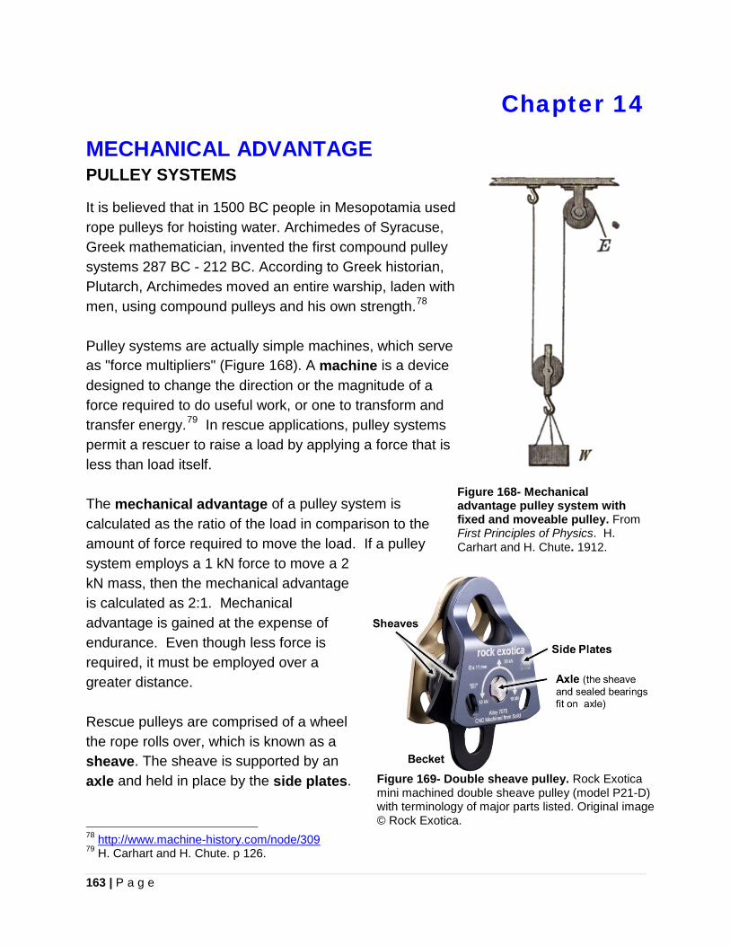
163 | P a g e
Chapter 14
MECHANICAL ADVANTAGE PULLEY SYSTEMS
It is believed that in 1500 BC people in Mesopotamia used rope pulleys for hoisting water. Archimedes of Syracuse, Greek mathematician, invented the first compound pulley systems 287 BC - 212 BC. According to Greek historian, Plutarch, Archimedes moved an entire warship, laden with men, using compound pulleys and his own strength.78 Pulley systems are actually simple machines, which serve as "force multipliers" (Figure 168). A machine is a device designed to change the direction or the magnitude of a force required to do useful work, or one to transform and transfer energy.79 In rescue applications, pulley systems permit a rescuer to raise a load by applying a force that is less than load itself. The mechanical advantage of a pulley system is calculated as the ratio of the load in comparison to the amount of force required to move the load. If a pulley system employs a 1 kN force to move a 2 kN mass, then the mechanical advantage is calculated as 2:1. Mechanical advantage is gained at the expense of endurance. Even though less force is required, it must be employed over a greater distance. Rescue pulleys are comprised of a wheel the rope rolls over, which is known as a sheave. The sheave is supported by an axle and held in place by the side plates.
78 http://www.machine-history.com/node/309 79 H. Carhart and H. Chute. p 126.
Figure 168- Mechanical advantage pulley system with fixed and moveable pulley. From First Principles of Physics. H. Carhart and H. Chute. 1912.
Figure 169- Double sheave pulley. Rock Exotica mini machined double sheave pulley (model P21-D) with terminology of major parts listed. Original image © Rock Exotica.

164 | P a g e
A set of pulleys assembled in a manner so that they rotate independently on the same axle form a block. This is known as a double sheave pulley (Figure 169). A block and tackle is assembled so one block is attached to a becket (fixed anchor point) eye and the other is attached to the moving load. The mechanical advantage of the block and tackle is equal to the number of rope strands that support the moving block. Pulley efficiency is reduced as a result of friction loss and other factors, such as bending and unbending of the rope. The measure of pulley efficiency is calculated by the output force coming out of a pulley over the input force going into a pulley, which is expressed as a percent. As an example, if a 95N force is required on one side of a pulley to hold a 100N load, then the efficiency of the pulley is calculated to be 95% (95/100). 90-95% is the typical efficiency of a rescue pulley (Figure 170).
Figure 170- A pulley with 95% efficiency is depicted in this example. Original image © Rock Exotica.
Factors influencing the efficiency of a pulley, as well as the entire pulley system include; • Pulley sheave (wheel which rope runs on) size, since a larger diameter sheave
gives a larger moment to overcome bearing friction and the radius of rope bending as well as unbending is less, therefore more energy is transferred through.
• Pulleys with self-lubricating bushings are efficient; however sealed ball bearings are more efficient and require very little maintenance.
• The Angle of the load line and haul line, since lines kept at 180° result in improved pulley system efficiency.
• Threading pulleys to ensure ropes don't rub on each other, or result in twisting, which decreases efficiency. Twisting can be lessened with the use of pulleys with swivel connections.
Efficiency of a pulley system is also evaluated in terms of what will provide the best output for the operation. If a 5:1 pulley system will comfortably move a load, then using a 12:1 pulley system would be less efficient, since it requires more time and movement of more rope through a system to move the load the same distance. The following terminology is used to describe the mechanical advantage of a pulley system:
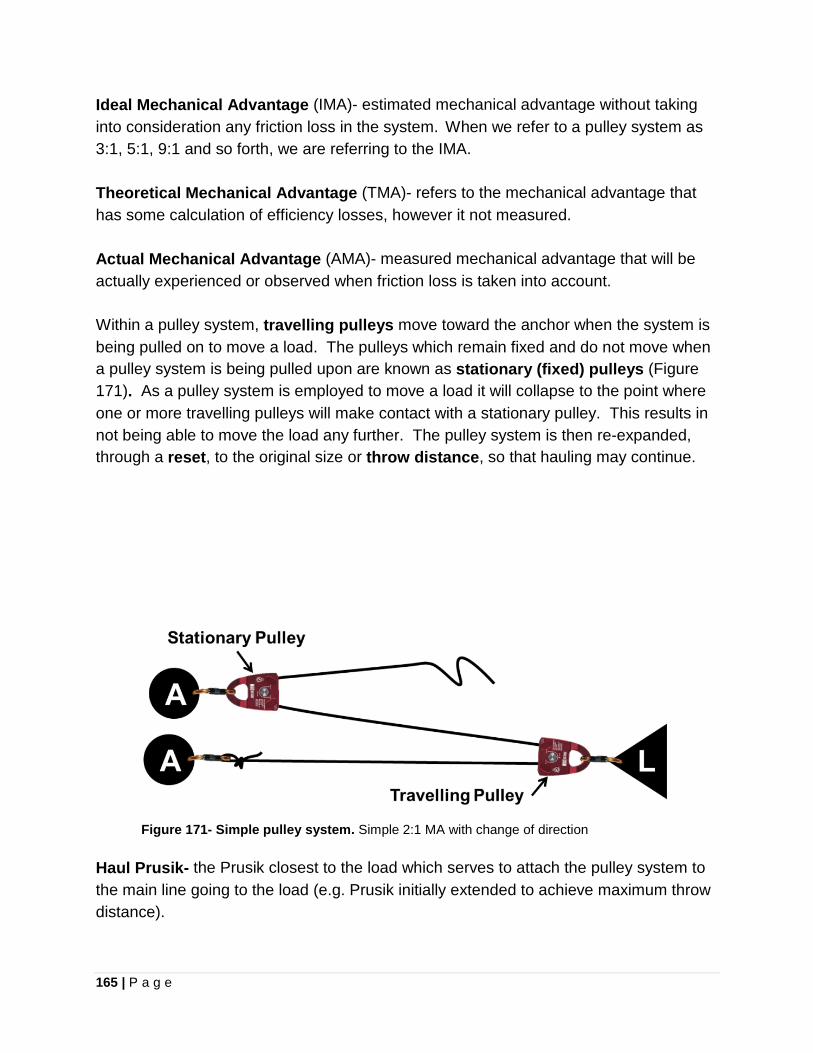
165 | P a g e
Ideal Mechanical Advantage (IMA)- estimated mechanical advantage without taking into consideration any friction loss in the system. When we refer to a pulley system as 3:1, 5:1, 9:1 and so forth, we are referring to the IMA. Theoretical Mechanical Advantage (TMA)- refers to the mechanical advantage that has some calculation of efficiency losses, however it not measured. Actual Mechanical Advantage (AMA)- measured mechanical advantage that will be actually experienced or observed when friction loss is taken into account. Within a pulley system, travelling pulleys move toward the anchor when the system is being pulled on to move a load. The pulleys which remain fixed and do not move when a pulley system is being pulled upon are known as stationary (fixed) pulleys (Figure 171). As a pulley system is employed to move a load it will collapse to the point where one or more travelling pulleys will make contact with a stationary pulley. This results in not being able to move the load any further. The pulley system is then re-expanded, through a reset, to the original size or throw distance, so that hauling may continue.
Figure 171- Simple pulley system. Simple 2:1 MA with change of direction
Haul Prusik- the Prusik closest to the load which serves to attach the pulley system to the main line going to the load (e.g. Prusik initially extended to achieve maximum throw distance).
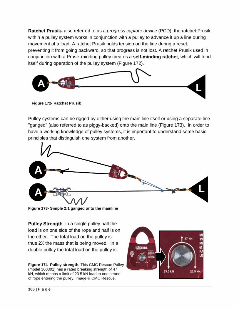
166 | P a g e
Ratchet Prusik- also referred to as a progress capture device (PCD), the ratchet Prusik within a pulley system works in conjunction with a pulley to advance it up a line during movement of a load. A ratchet Prusik holds tension on the line during a reset, preventing it from going backward, so that progress is not lost. A ratchet Prusik used in conjunction with a Prusik minding pulley creates a self-minding ratchet, which will tend itself during operation of the pulley system (Figure 172).
Figure 172- Ratchet Prusik
Pulley systems can be rigged by either using the main line itself or using a separate line "ganged" (also referred to as piggy-backed) onto the main line (Figure 173). In order to have a working knowledge of pulley systems, it is important to understand some basic principles that distinguish one system from another.
Figure 173- Simple 2:1 ganged onto the mainline
Pulley Strength- in a single pulley half the load is on one side of the rope and half is on the other. The total load on the pulley is thus 2X the mass that is being moved. In a double pulley the total load on the pulley is
Figure 174- Pulley strength. This CMC Rescue Pulley (model 300301) has a rated breaking strength of 47 kN, which means a limit of 23.5 kN load to one strand of rope entering the pulley. Image © CMC Rescue.

167 | P a g e
4X the load on the four individual ropes (the force on a double pulley is still twice the load since each individual rope is supporting 1/4 of the load). This strength rating is illustrated on the side of a pulley (Figure 174). Pulley system classifications include;
1. Simple systems 2. Compound systems 3. Complex systems
SIMPLE PULLEY SYSTEM These are identified by having one continuous rope flowing back and forth between the pulleys on the load and anchor. Additionally, all pulleys on the load side (known as travelling pulleys) move toward the anchor at the same speed. All pulleys at the anchor remain stationary and tension in the rope is constant throughout the pulley system (Figure 175). In a simple pulley system, when the rope end terminates and is attached at the anchor, then the TMA will result in an even number (e.g. 2:1, 4:1, 6:1, etc.). When the rope end terminates and is attached at the load, then the resulting TMA will be an odd number (e.g. 3:1, 5:1, etc.). If the last pulley in simple pulley system (closest to the haulers) is attached to the anchor, it does not add mechanical advantage, but serves as a change of direction. The TMA can be calculated for a simple pulley system by counting the number of rope strands directly supporting the load (located on the load side of the pulley system). The number of pulleys required to construct a simple pulley system, without a change of direction, is one less than the TMA. In order to incorporate a self-minding ratchet at the anchor as a progress capture device, the TMA of a simple pulley system must be an odd number. A self-minding ratchet can be constructed with a Prusik Hitch and Prusik Minding Pulley (Figure 175.a) or a self-ratcheting device, such as an MPD™ (Figure 176)
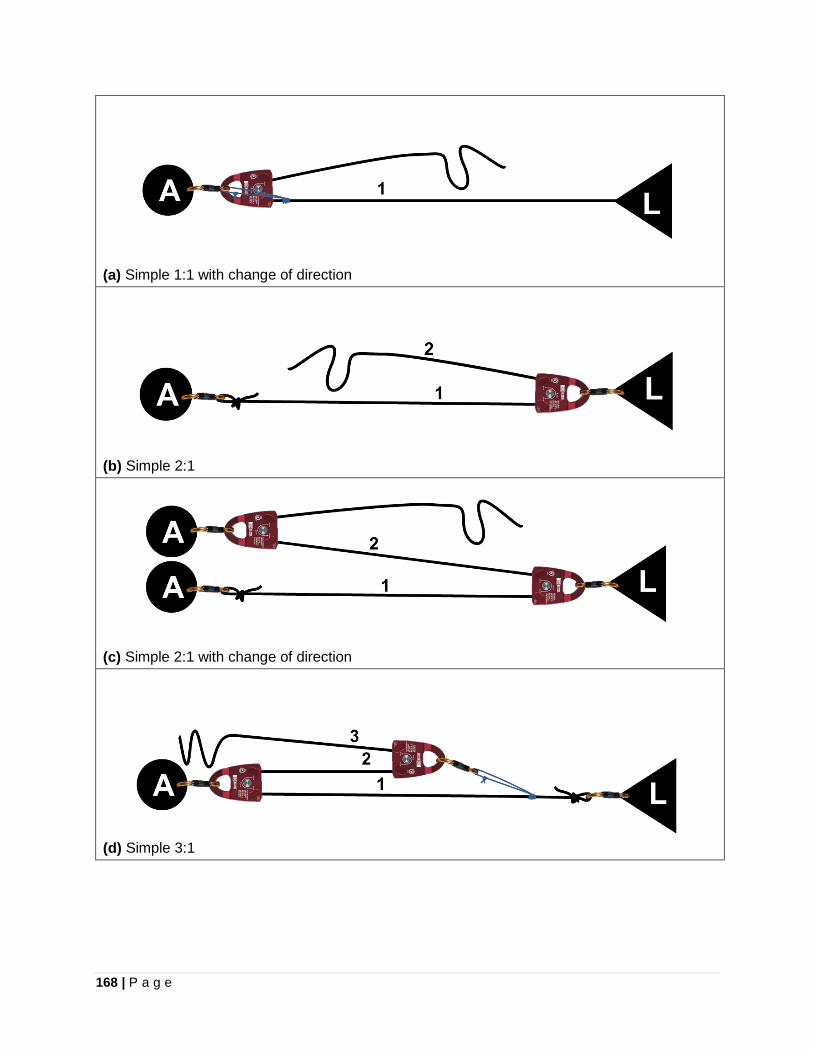
168 | P a g e
(a) Simple 1:1 with change of direction
(b) Simple 2:1
(c) Simple 2:1 with change of direction
(d) Simple 3:1
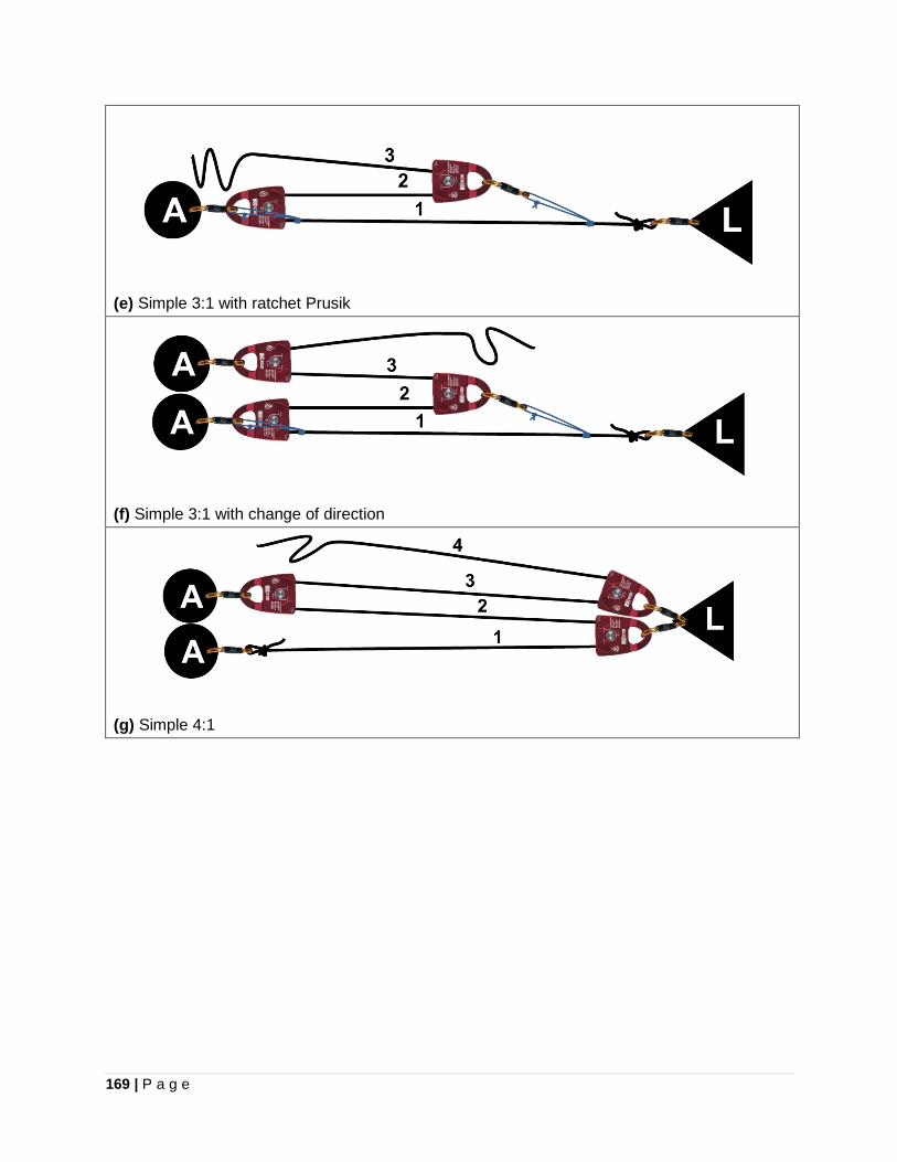
169 | P a g e
(e) Simple 3:1 with ratchet Prusik
(f) Simple 3:1 with change of direction
(g) Simple 4:1
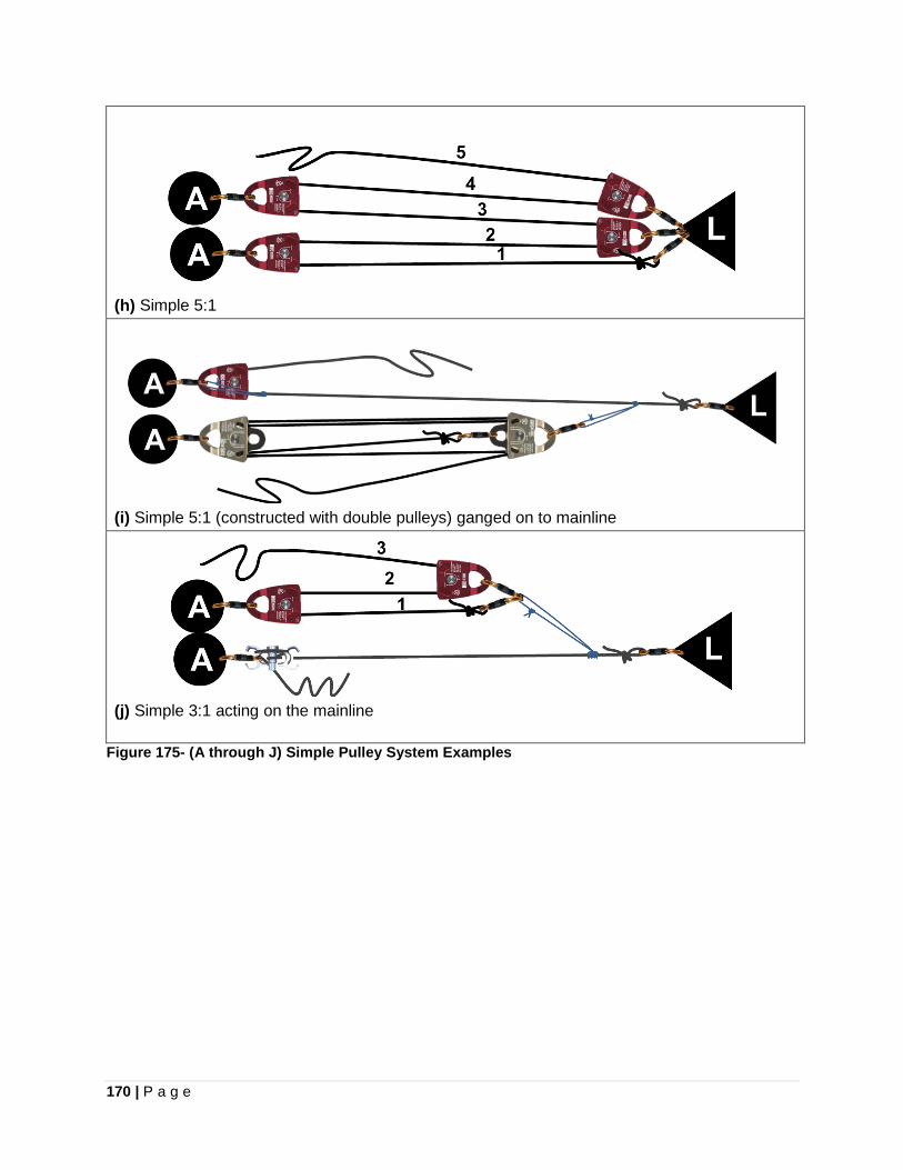
170 | P a g e
(h) Simple 5:1
(i) Simple 5:1 (constructed with double pulleys) ganged on to mainline
(j) Simple 3:1 acting on the mainline
Figure 175- (A through J) Simple Pulley System Examples

171 | P a g e
(a) Simple 3:1 using MPD™
(b) Simple 5:1 using MPD™ Figure 176- Simple pulley systems utilizing the MPD™ (Multi-purpose Device) as a ratchet
COMPOUND PULLEY SYSTEM Compound pulley systems are identified as one simple pulley system acting on another simple pulley system (Figure 177). Travelling pulleys in the system move towards the anchor at different speeds. Compound pulleys systems are useful because they can provide greater mechanical advantage than simple systems for the same number of pulleys. The TMA of a compound pulley system is calculated by multiplying the individual TMA of each simple pulley system together. A simple 2:1 pulling on a simple 3:1, results in a compound pulley system with 6:1TMA. Using a compound system that is comprised of two dissimilar MA simple pulley systems, the system with the smaller MA will collapse first. To maximize efficiency in raising a load with the fewest resets, locate the pulley systems so the system with the higher MA is pulling on the lower MA system (e.g. have a 3:1 pull on a 2:1 in a compound 6:1). Positioning sufficient distance between the anchor points of the individual simple pulley systems in a compound system can improve the throw distance per reset by allowing both systems to collapse at the same time. If a compound pulley system is comprised of two simple 3:1 systems, then the rearward (furthest from load) system must have a reset distance of three times the of the forward system. This is because the three times more rope must be pulled through the rearward 3:1 than the forward 3:1.
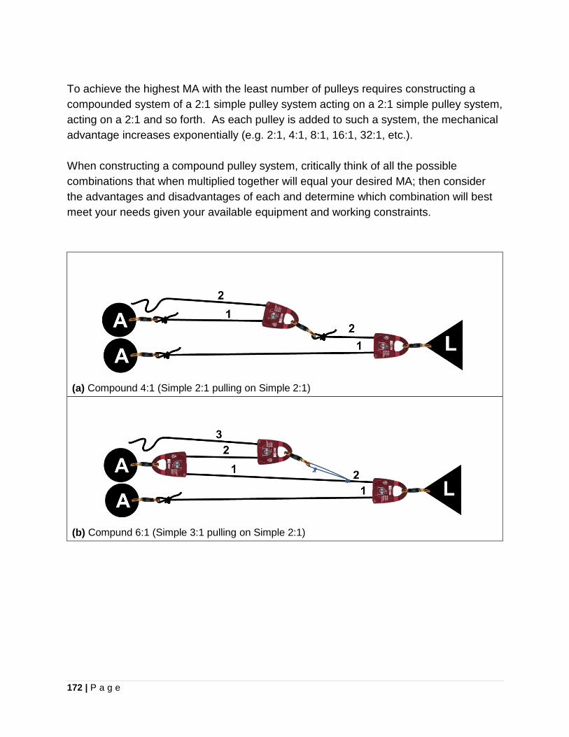
172 | P a g e
To achieve the highest MA with the least number of pulleys requires constructing a compounded system of a 2:1 simple pulley system acting on a 2:1 simple pulley system, acting on a 2:1 and so forth. As each pulley is added to such a system, the mechanical advantage increases exponentially (e.g. 2:1, 4:1, 8:1, 16:1, 32:1, etc.). When constructing a compound pulley system, critically think of all the possible combinations that when multiplied together will equal your desired MA; then consider the advantages and disadvantages of each and determine which combination will best meet your needs given your available equipment and working constraints.
(a) Compound 4:1 (Simple 2:1 pulling on Simple 2:1)
(b) Compund 6:1 (Simple 3:1 pulling on Simple 2:1)
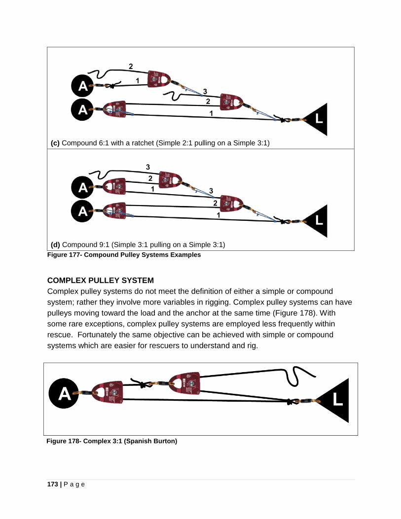
173 | P a g e
(c) Compound 6:1 with a ratchet (Simple 2:1 pulling on a Simple 3:1)
(d) Compound 9:1 (Simple 3:1 pulling on a Simple 3:1) Figure 177- Compound Pulley Systems Examples
COMPLEX PULLEY SYSTEM Complex pulley systems do not meet the definition of either a simple or compound system; rather they involve more variables in rigging. Complex pulley systems can have pulleys moving toward the load and the anchor at the same time (Figure 178). With some rare exceptions, complex pulley systems are employed less frequently within rescue. Fortunately the same objective can be achieved with simple or compound systems which are easier for rescuers to understand and rig.
Figure 178- Complex 3:1 (Spanish Burton)
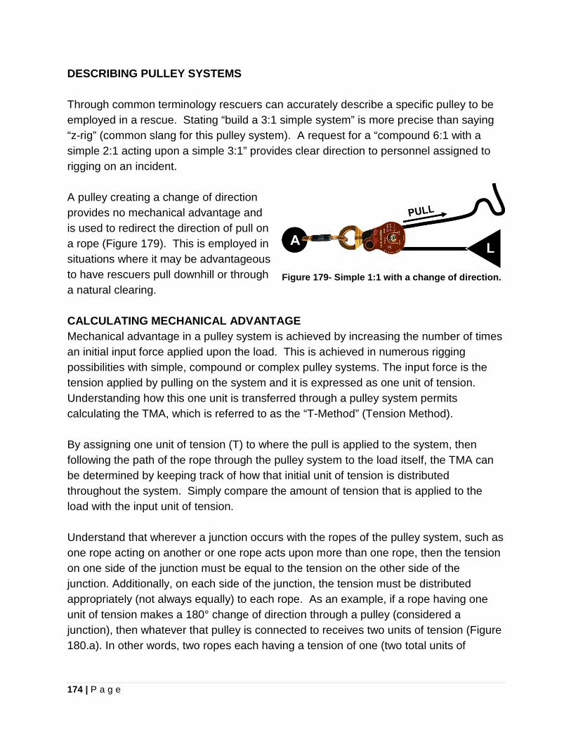
174 | P a g e
DESCRIBING PULLEY SYSTEMS Through common terminology rescuers can accurately describe a specific pulley to be employed in a rescue. Stating “build a 3:1 simple system” is more precise than saying “z-rig” (common slang for this pulley system). A request for a “compound 6:1 with a simple 2:1 acting upon a simple 3:1” provides clear direction to personnel assigned to rigging on an incident. A pulley creating a change of direction provides no mechanical advantage and is used to redirect the direction of pull on a rope (Figure 179). This is employed in situations where it may be advantageous to have rescuers pull downhill or through a natural clearing.
Figure 179- Simple 1:1 with a change of direction.
CALCULATING MECHANICAL ADVANTAGE Mechanical advantage in a pulley system is achieved by increasing the number of times an initial input force applied upon the load. This is achieved in numerous rigging possibilities with simple, compound or complex pulley systems. The input force is the tension applied by pulling on the system and it is expressed as one unit of tension. Understanding how this one unit is transferred through a pulley system permits calculating the TMA, which is referred to as the “T-Method” (Tension Method). By assigning one unit of tension (T) to where the pull is applied to the system, then following the path of the rope through the pulley system to the load itself, the TMA can be determined by keeping track of how that initial unit of tension is distributed throughout the system. Simply compare the amount of tension that is applied to the load with the input unit of tension. Understand that wherever a junction occurs with the ropes of the pulley system, such as one rope acting on another or one rope acts upon more than one rope, then the tension on one side of the junction must be equal to the tension on the other side of the junction. Additionally, on each side of the junction, the tension must be distributed appropriately (not always equally) to each rope. As an example, if a rope having one unit of tension makes a 180° change of direction through a pulley (considered a junction), then whatever that pulley is connected to receives two units of tension (Figure 180.a). In other words, two ropes each having a tension of one (two total units of
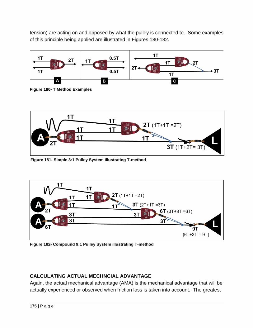
175 | P a g e
tension) are acting on and opposed by what the pulley is connected to. Some examples of this principle being applied are illustrated in Figures 180-182.
Figure 180- T Method Examples
Figure 181- Simple 3:1 Pulley System illustrating T-method
Figure 182- Compound 9:1 Pulley System illustrating T-method
CALCULATING ACTUAL MECHNCIAL ADVANTAGE Again, the actual mechanical advantage (AMA) is the mechanical advantage that will be actually experienced or observed when friction loss is taken into account. The greatest
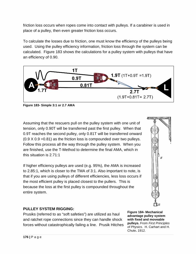
176 | P a g e
friction loss occurs when ropes come into contact with pulleys. If a carabiner is used in place of a pulley, then even greater friction loss occurs. To calculate the losses due to friction, one must know the efficiency of the pulleys being used. Using the pulley efficiency information, friction loss through the system can be calculated. Figure 183 shows the calculations for a pulley system with pulleys that have an efficiency of 0.90.
Figure 183- Simple 3:1 or 2.7 AMA
Assuming that the rescuers pull on the pulley system with one unit of tension, only 0.90T will be transferred past the first pulley. When that 0.9T reaches the second pulley, only 0.81T will be transferred onward (0.9 X 0.9 =0.81) as the friction loss is compounded over two pulleys. Follow this process all the way through the pulley system. When you are finished, use the T-Method to determine the final AMA, which in this situation is 2.71:1 If higher efficiency pulleys are used (e.g. 95%), the AMA is increased to 2.85:1, which is closer to the TMA of 3:1. Also important to note, is that if you are using pulleys of different efficiencies, less loss occurs if the most efficient pulley is placed closest to the pullers. This is because the loss at the first pulley is compounded throughout the entire system. PULLEY SYSTEM RIGGING: Prusiks (referred to as “soft safeties”) are utilized as haul and ratchet rope connections since they can handle shock forces without catastrophically failing a line. Prusik Hitches
Figure 184- Mechanical advantage pulley system with fixed and moveable pulleys. From First Principles of Physics. H. Carhart and H. Chute. 1912.

177 | P a g e
employed in such a manner need to be triple wrapped (six coil) to prevent slippage under load.
Do not use a mechanical ascender in a pulley system in place of a haul or ratchet Prusik.
• Obtain the greatest mechanical advantage in a hauling system by reducing as much
friction as possible through rigging lines so they do not directly touch sharp rock edges or run directly along the ground.
• A change of direction pulley, which adds no mechanical advantage to a hauling
system is frequently employed to orient the line in a position of convenience for hauling (e.g. pulling at a right angle from the main anchor).
• Keep mechanical advantage lines parallel for maximum practical mechanical
advantage. A directional pulley may be used to achieve this if hauling is being directed away from the main pulley system.
STANDARD HAUL SYSTEM COMMANDS- ROLE CALL
Command Whistle Signal Meaning/Action "Haulers Ready?" Team should be prepared to haul "Attendant Ready?" Attendant is ready to be raised "Up", "Haul Slow" Two Blasts Team begins hauling "Set" Team stops and resets the ratchet "Reset" Team resets for a new bite of rope "Stop!" One Blast All movement stops and tension held "Down" Three Blasts Lower the load “Stop-Stop-Why Stop?” Used to alert personnel when a line
will not move Communications during a raising evolution must be clearly understood by all personnel. Use common single syllable words. Have a single person giving the commands and restrict all excess verbal bantering among topside personnel. The operation should work like a well-oiled machine (Figure 185).
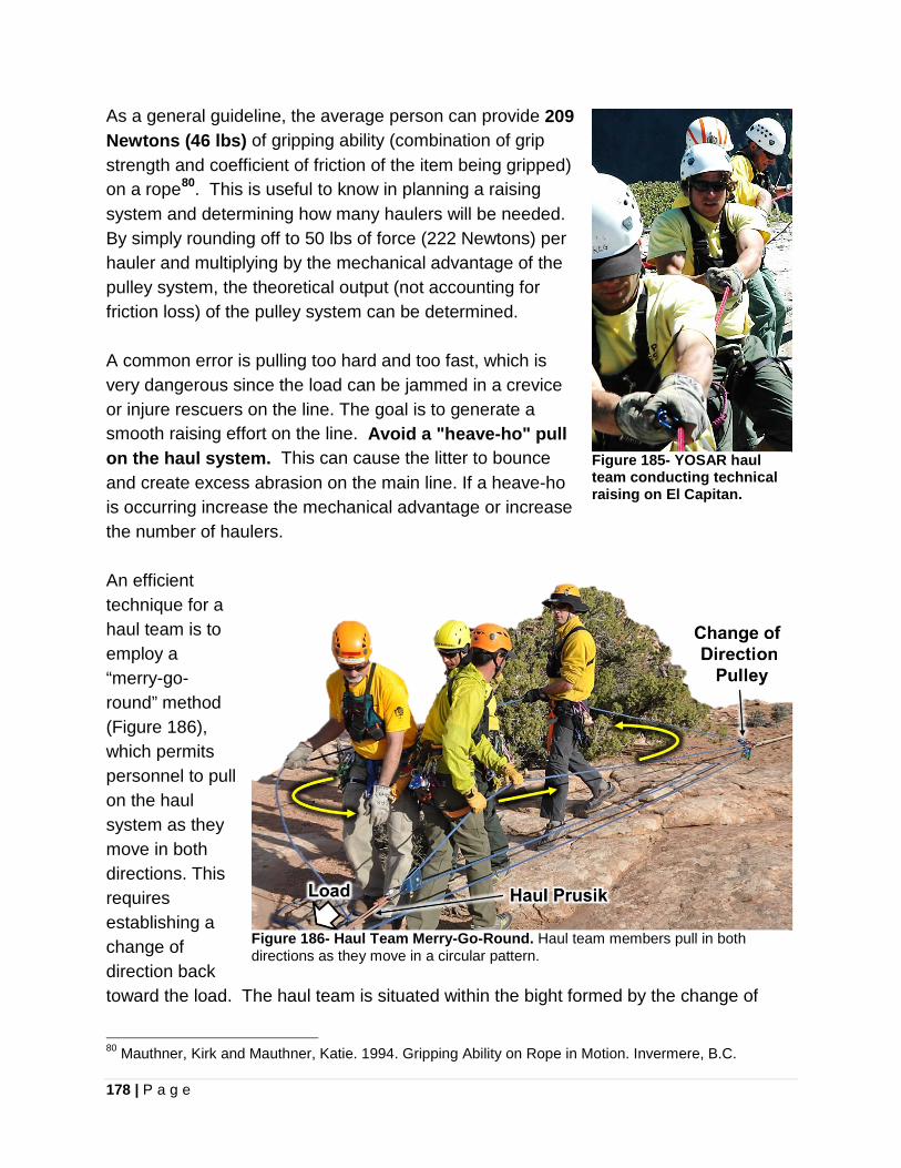
178 | P a g e
As a general guideline, the average person can provide 209 Newtons (46 lbs) of gripping ability (combination of grip strength and coefficient of friction of the item being gripped) on a rope80. This is useful to know in planning a raising system and determining how many haulers will be needed. By simply rounding off to 50 lbs of force (222 Newtons) per hauler and multiplying by the mechanical advantage of the pulley system, the theoretical output (not accounting for friction loss) of the pulley system can be determined. A common error is pulling too hard and too fast, which is very dangerous since the load can be jammed in a crevice or injure rescuers on the line. The goal is to generate a smooth raising effort on the line. Avoid a "heave-ho" pull on the haul system. This can cause the litter to bounce and create excess abrasion on the main line. If a heave-ho is occurring increase the mechanical advantage or increase the number of haulers. An efficient technique for a haul team is to employ a “merry-go-round” method (Figure 186), which permits personnel to pull on the haul system as they move in both directions. This requires establishing a change of direction back toward the load. The haul team is situated within the bight formed by the change of
80 Mauthner, Kirk and Mauthner, Katie. 1994. Gripping Ability on Rope in Motion. Invermere, B.C.
Figure 185- YOSAR haul team conducting technical raising on El Capitan.
Figure 186- Haul Team Merry-Go-Round. Haul team members pull in both directions as they move in a circular pattern.
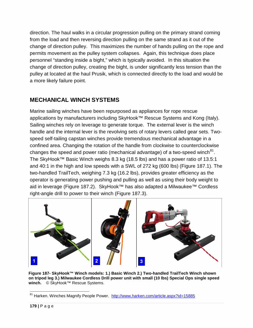
179 | P a g e
direction. The haul walks in a circular progression pulling on the primary strand coming from the load and then reversing direction pulling on the same strand as it out of the change of direction pulley. This maximizes the number of hands pulling on the rope and permits movement as the pulley system collapses. Again, this technique does place personnel “standing inside a bight,” which is typically avoided. In this situation the change of direction pulley, creating the bight, is under significantly less tension than the pulley at located at the haul Prusik, which is connected directly to the load and would be a more likely failure point.
MECHANICAL WINCH SYSTEMS
Marine sailing winches have been repurposed as appliances for rope rescue applications by manufacturers including SkyHook™ Rescue Systems and Kong (Italy). Sailing winches rely on leverage to generate torque. The external lever is the winch handle and the internal lever is the revolving sets of rotary levers called gear sets. Two-speed self-tailing capstan winches provide tremendous mechanical advantage in a confined area. Changing the rotation of the handle from clockwise to counterclockwise changes the speed and power ratio (mechanical advantage) of a two-speed winch81. The SkyHook™ Basic Winch weighs 8.3 kg (18.5 lbs) and has a power ratio of 13.5:1 and 40:1 in the high and low speeds with a SWL of 272 kg (600 lbs) (Figure 187.1). The two-handled TrailTech, weighing 7.3 kg (16.2 lbs), provides greater efficiency as the operator is generating power pushing and pulling as well as using their body weight to aid in leverage (Figure 187.2). SkyHook™ has also adapted a Milwaukee™ Cordless right-angle drill to power to their winch (Figure 187.3).
Figure 187- SkyHook™ Winch models: 1.) Basic Winch 2.) Two-handled TrailTech Winch shown on tripod leg 3.) Milwaukee Cordless Drill power unit with small (10 lbs) Special Ops single speed winch. © SkyHook™ Rescue Systems.
81 Harken. Winches Magnify People Power. http://www.harken.com/article.aspx?id=15885
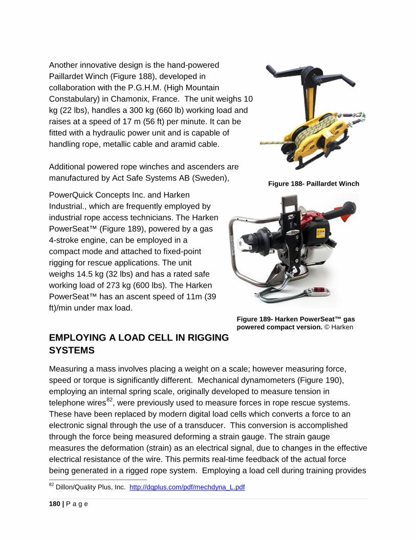
180 | P a g e
Another innovative design is the hand-powered Paillardet Winch (Figure 188), developed in collaboration with the P.G.H.M. (High Mountain Constabulary) in Chamonix, France. The unit weighs 10 kg (22 lbs), handles a 300 kg (660 lb) working load and raises at a speed of 17 m (56 ft) per minute. It can be fitted with a hydraulic power unit and is capable of handling rope, metallic cable and aramid cable. Additional powered rope winches and ascenders are manufactured by Act Safe Systems AB (Sweden),
PowerQuick Concepts Inc. and Harken Industrial., which are frequently employed by industrial rope access technicians. The Harken PowerSeat™ (Figure 189), powered by a gas 4-stroke engine, can be employed in a compact mode and attached to fixed-point rigging for rescue applications. The unit weighs 14.5 kg (32 lbs) and has a rated safe working load of 273 kg (600 lbs). The Harken PowerSeat™ has an ascent speed of 11m (39 ft)/min under max load.
Figure 188- Paillardet Winch
Figure 189- Harken PowerSeat™ gas powered compact version. © Harken
EMPLOYING A LOAD CELL IN RIGGING SYSTEMS
Measuring a mass involves placing a weight on a scale; however measuring force, speed or torque is significantly different. Mechanical dynamometers (Figure 190), employing an internal spring scale, originally developed to measure tension in telephone wires82, were previously used to measure forces in rope rescue systems. These have been replaced by modern digital load cells which converts a force to an electronic signal through the use of a transducer. This conversion is accomplished through the force being measured deforming a strain gauge. The strain gauge measures the deformation (strain) as an electrical signal, due to changes in the effective electrical resistance of the wire. This permits real-time feedback of the actual force being generated in a rigged rope system. Employing a load cell during training provides 82 Dillon/Quality Plus, Inc. http://dqplus.com/pdf/mechdyna_L.pdf

181 | P a g e
a valuable tool to examine and validate the actual forces being applied in hauling systems or other applications, such as suspended highlines. When employing a load cell within a system, it should always be backed up for safety in the event of catastrophic failure. Rock Exotica produces a compact aluminum load cell known as the Enforcer, which was co-developed by Kirk Mauthner and Helgi Hall. The Enforcer (Figure 191) is capable of maximum readings up to 20 kN (4, 496 lbf) and has a MBS of 40 kN (8,992 lbf). The small design facilitates “in-line” use in rigging systems. It is capable of two sampling modes, which include in either a “slow” for monitoring rigged systems during use or “fast” for drop testing analysis (averaged 500 sampling points per second from 4,000 s/sec). The device has Bluetooth connectivity for data transfer and can obtain high resolution analysis of a dynamic event lasting up to four seconds. Readings can be displayed in kg, kN or lbf. Swivel attachment points permit proper alignment of the load cell during usage. Calibration can be accomplished using a known load mass. Weight 14 ounces with batteries.
Figure 190- Mechanical Dynomometer. Dillon Dynamometer. Model 30006-084. 10,000 lbs capacity. Image © Dillon/Quality Plus.
Figure 191- Rock Exotica Enforcer Load Cell
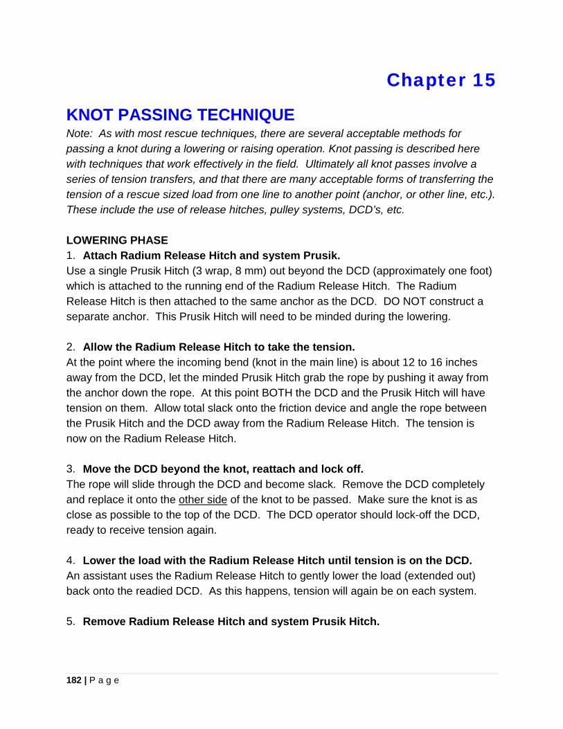
182 | P a g e
Chapter 15
KNOT PASSING TECHNIQUE
Note: As with most rescue techniques, there are several acceptable methods for passing a knot during a lowering or raising operation. Knot passing is described here with techniques that work effectively in the field. Ultimately all knot passes involve a series of tension transfers, and that there are many acceptable forms of transferring the tension of a rescue sized load from one line to another point (anchor, or other line, etc.). These include the use of release hitches, pulley systems, DCD’s, etc. LOWERING PHASE 1. Attach Radium Release Hitch and system Prusik. Use a single Prusik Hitch (3 wrap, 8 mm) out beyond the DCD (approximately one foot) which is attached to the running end of the Radium Release Hitch. The Radium Release Hitch is then attached to the same anchor as the DCD. DO NOT construct a separate anchor. This Prusik Hitch will need to be minded during the lowering. 2. Allow the Radium Release Hitch to take the tension. At the point where the incoming bend (knot in the main line) is about 12 to 16 inches away from the DCD, let the minded Prusik Hitch grab the rope by pushing it away from the anchor down the rope. At this point BOTH the DCD and the Prusik Hitch will have tension on them. Allow total slack onto the friction device and angle the rope between the Prusik Hitch and the DCD away from the Radium Release Hitch. The tension is now on the Radium Release Hitch. 3. Move the DCD beyond the knot, reattach and lock off. The rope will slide through the DCD and become slack. Remove the DCD completely and replace it onto the other side of the knot to be passed. Make sure the knot is as close as possible to the top of the DCD. The DCD operator should lock-off the DCD, ready to receive tension again. 4. Lower the load with the Radium Release Hitch until tension is on the DCD. An assistant uses the Radium Release Hitch to gently lower the load (extended out) back onto the readied DCD. As this happens, tension will again be on each system. 5. Remove Radium Release Hitch and system Prusik Hitch.
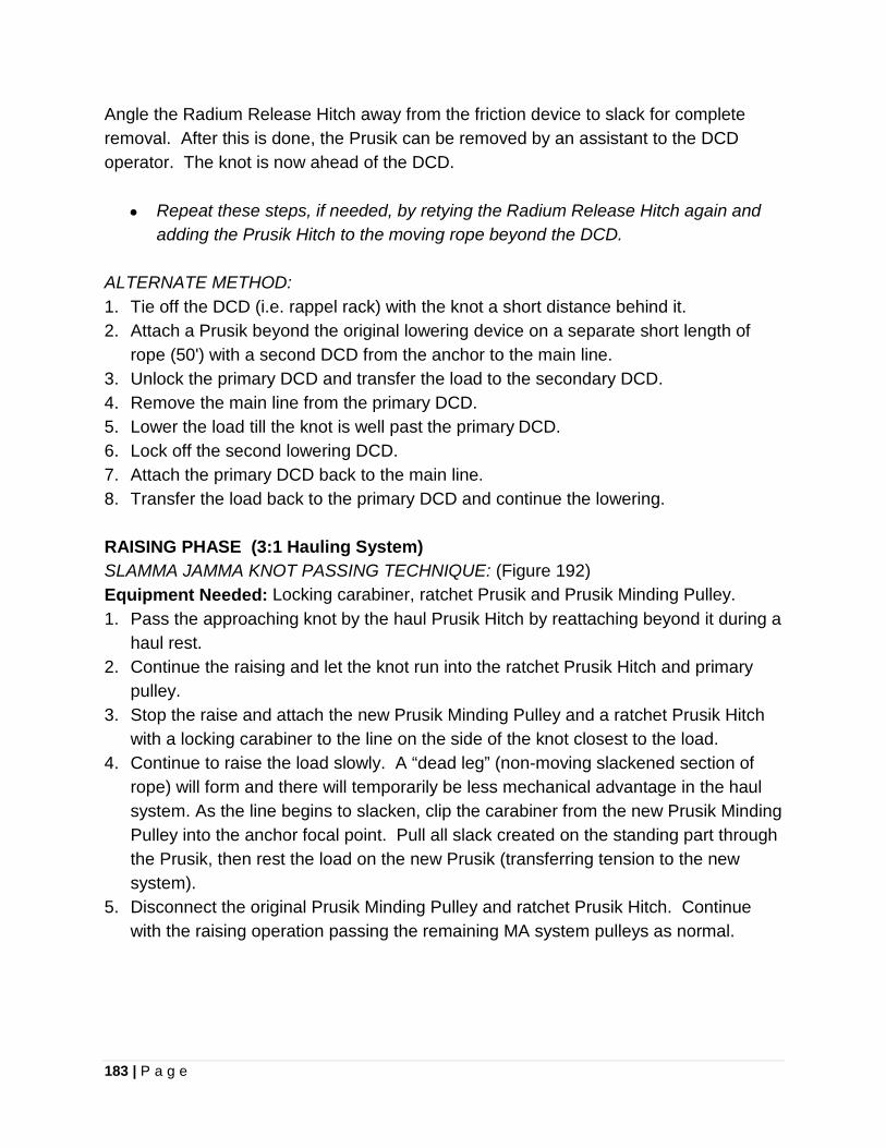
183 | P a g e
Angle the Radium Release Hitch away from the friction device to slack for complete removal. After this is done, the Prusik can be removed by an assistant to the DCD operator. The knot is now ahead of the DCD.
• Repeat these steps, if needed, by retying the Radium Release Hitch again and adding the Prusik Hitch to the moving rope beyond the DCD.
ALTERNATE METHOD: 1. Tie off the DCD (i.e. rappel rack) with the knot a short distance behind it. 2. Attach a Prusik beyond the original lowering device on a separate short length of
rope (50') with a second DCD from the anchor to the main line. 3. Unlock the primary DCD and transfer the load to the secondary DCD. 4. Remove the main line from the primary DCD. 5. Lower the load till the knot is well past the primary DCD. 6. Lock off the second lowering DCD. 7. Attach the primary DCD back to the main line. 8. Transfer the load back to the primary DCD and continue the lowering. RAISING PHASE (3:1 Hauling System) SLAMMA JAMMA KNOT PASSING TECHNIQUE: (Figure 192) Equipment Needed: Locking carabiner, ratchet Prusik and Prusik Minding Pulley. 1. Pass the approaching knot by the haul Prusik Hitch by reattaching beyond it during a
haul rest. 2. Continue the raising and let the knot run into the ratchet Prusik Hitch and primary
pulley. 3. Stop the raise and attach the new Prusik Minding Pulley and a ratchet Prusik Hitch
with a locking carabiner to the line on the side of the knot closest to the load. 4. Continue to raise the load slowly. A “dead leg” (non-moving slackened section of
rope) will form and there will temporarily be less mechanical advantage in the haul system. As the line begins to slacken, clip the carabiner from the new Prusik Minding Pulley into the anchor focal point. Pull all slack created on the standing part through the Prusik, then rest the load on the new Prusik (transferring tension to the new system).
5. Disconnect the original Prusik Minding Pulley and ratchet Prusik Hitch. Continue with the raising operation passing the remaining MA system pulleys as normal.
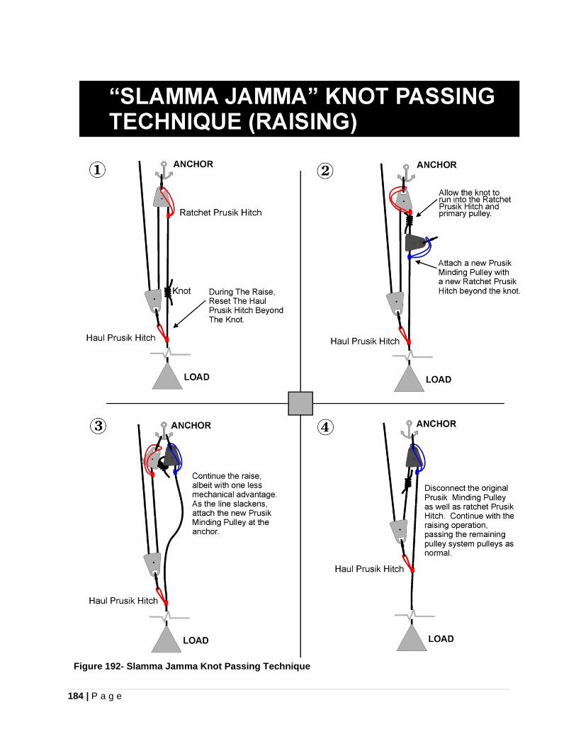
184 | P a g e
Figure 192- Slamma Jamma Knot Passing Technique
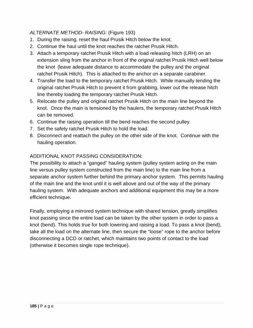
185 | P a g e
ALTERNATE METHOD- RAISING: (Figure 193) 1. During the raising, reset the haul Prusik Hitch below the knot. 2. Continue the haul until the knot reaches the ratchet Prusik Hitch. 3. Attach a temporary ratchet Prusik Hitch with a load releasing hitch (LRH) on an
extension sling from the anchor in front of the original ratchet Prusik Hitch well below the knot (leave adequate distance to accommodate the pulley and the original ratchet Prusik Hitch). This is attached to the anchor on a separate carabiner.
4. Transfer the load to the temporary ratchet Prusik Hitch. While manually tending the original ratchet Prusik Hitch to prevent it from grabbing, lower out the release hitch line thereby loading the temporary ratchet Prusik Hitch.
5. Relocate the pulley and original ratchet Prusik Hitch on the main line beyond the knot. Once the main is tensioned by the haulers, the temporary ratchet Prusik Hitch can be removed.
6. Continue the raising operation till the bend reaches the second pulley. 7. Set the safety ratchet Prusik Hitch to hold the load. 8. Disconnect and reattach the pulley on the other side of the knot. Continue with the
hauling operation. ADDITIONAL KNOT PASSING CONSIDERATION: The possibility to attach a “ganged” hauling system (pulley system acting on the main line versus pulley system constructed from the main line) to the main line from a separate anchor system further behind the primary anchor system. This permits hauling of the main line and the knot until it is well above and out of the way of the primary hauling system. With adequate anchors and additional equipment this may be a more efficient technique. Finally, employing a mirrored system technique with shared tension, greatly simplifies knot passing since the entire load can be taken by the other system in order to pass a knot (bend). This holds true for both lowering and raising a load. To pass a knot (bend), take all the load on the alternate line, then secure the “loose” rope to the anchor before disconnecting a DCD or ratchet, which maintains two points of contact to the load (otherwise it becomes single rope technique).
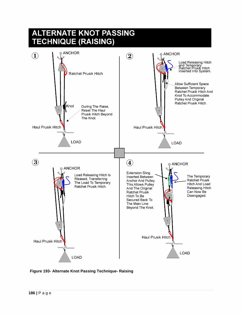
186 | P a g e
Figure 193- Alternate Knot Passing Technique- Raising
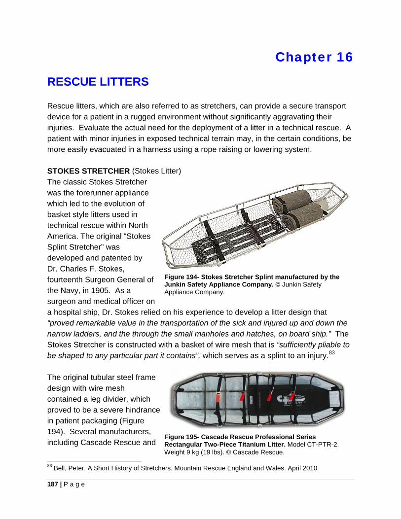
187 | P a g e
Chapter 16
RESCUE LITTERS
Rescue litters, which are also referred to as stretchers, can provide a secure transport device for a patient in a rugged environment without significantly aggravating their injuries. Evaluate the actual need for the deployment of a litter in a technical rescue. A patient with minor injuries in exposed technical terrain may, in the certain conditions, be more easily evacuated in a harness using a rope raising or lowering system. STOKES STRETCHER (Stokes Litter) The classic Stokes Stretcher was the forerunner appliance which led to the evolution of basket style litters used in technical rescue within North America. The original “Stokes Splint Stretcher” was developed and patented by Dr. Charles F. Stokes, fourteenth Surgeon General of the Navy, in 1905. As a surgeon and medical officer on a hospital ship, Dr. Stokes relied on his experience to develop a litter design that “proved remarkable value in the transportation of the sick and injured up and down the narrow ladders, and the through the small manholes and hatches, on board ship.” The Stokes Stretcher is constructed with a basket of wire mesh that is “sufficiently pliable to be shaped to any particular part it contains”, which serves as a splint to an injury.83 The original tubular steel frame design with wire mesh contained a leg divider, which proved to be a severe hindrance in patient packaging (Figure 194). Several manufacturers, including Cascade Rescue and
83 Bell, Peter. A Short History of Stretchers. Mountain Rescue England and Wales. April 2010
Figure 194- Stokes Stretcher Splint manufactured by the Junkin Safety Appliance Company. © Junkin Safety Appliance Company.
Figure 195- Cascade Rescue Professional Series Rectangular Two-Piece Titanium Litter. Model CT-PTR-2. Weight 9 kg (19 lbs). © Cascade Rescue.
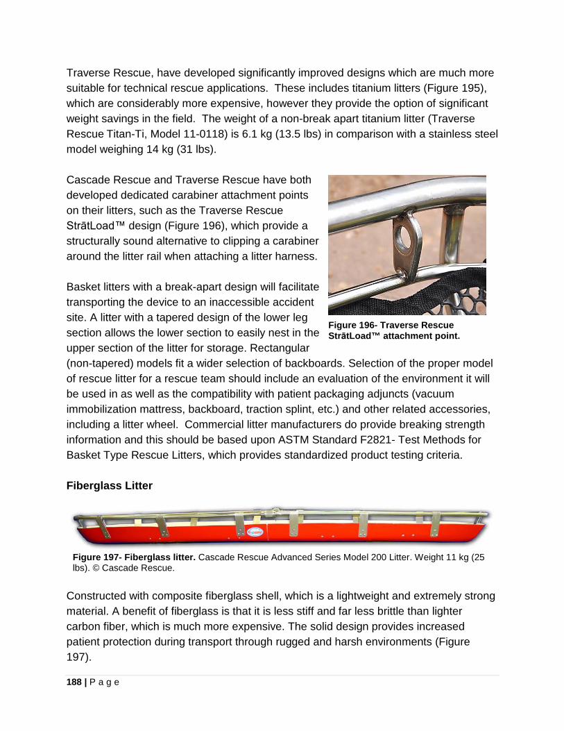
188 | P a g e
Traverse Rescue, have developed significantly improved designs which are much more suitable for technical rescue applications. These includes titanium litters (Figure 195), which are considerably more expensive, however they provide the option of significant weight savings in the field. The weight of a non-break apart titanium litter (Traverse Rescue Titan-Ti, Model 11-0118) is 6.1 kg (13.5 lbs) in comparison with a stainless steel model weighing 14 kg (31 lbs). Cascade Rescue and Traverse Rescue have both developed dedicated carabiner attachment points on their litters, such as the Traverse Rescue StrātLoad™ design (Figure 196), which provide a structurally sound alternative to clipping a carabiner around the litter rail when attaching a litter harness. Basket litters with a break-apart design will facilitate transporting the device to an inaccessible accident site. A litter with a tapered design of the lower leg section allows the lower section to easily nest in the upper section of the litter for storage. Rectangular (non-tapered) models fit a wider selection of backboards. Selection of the proper model of rescue litter for a rescue team should include an evaluation of the environment it will be used in as well as the compatibility with patient packaging adjuncts (vacuum immobilization mattress, backboard, traction splint, etc.) and other related accessories, including a litter wheel. Commercial litter manufacturers do provide breaking strength information and this should be based upon ASTM Standard F2821- Test Methods for Basket Type Rescue Litters, which provides standardized product testing criteria. Fiberglass Litter
Constructed with composite fiberglass shell, which is a lightweight and extremely strong material. A benefit of fiberglass is that it is less stiff and far less brittle than lighter carbon fiber, which is much more expensive. The solid design provides increased patient protection during transport through rugged and harsh environments (Figure 197).
Figure 196- Traverse Rescue StrātLoad™ attachment point.
Figure 197- Fiberglass litter. Cascade Rescue Advanced Series Model 200 Litter. Weight 11 kg (25 lbs). © Cascade Rescue.
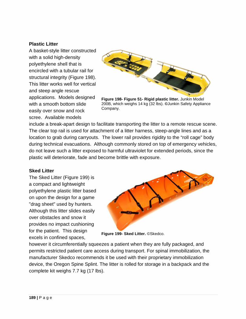
189 | P a g e
Plastic Litter A basket-style litter constructed with a solid high-density polyethylene shell that is encircled with a tubular rail for structural integrity (Figure 198). This litter works well for vertical and steep angle rescue applications. Models designed with a smooth bottom slide easily over snow and rock scree. Available models include a break-apart design to facilitate transporting the litter to a remote rescue scene. The clear top rail is used for attachment of a litter harness, steep-angle lines and as a location to grab during carryouts. The lower rail provides rigidity to the “roll cage” body during technical evacuations. Although commonly stored on top of emergency vehicles, do not leave such a litter exposed to harmful ultraviolet for extended periods, since the plastic will deteriorate, fade and become brittle with exposure.
Figure 198- Figure 51- Rigid plastic litter. Junkin Model 200B, which weighs 14 kg (32 lbs). ©Junkin Safety Appliance Company.
Sked Litter The Sked Litter (Figure 199) is a compact and lightweight polyethylene plastic litter based on upon the design for a game "drag sheet" used by hunters. Although this litter slides easily over obstacles and snow it provides no impact cushioning for the patient. This design excels in confined spaces, however it circumferentially squeezes a patient when they are fully packaged, and permits restricted patient care access during transport. For spinal immobilization, the manufacturer Skedco recommends it be used with their proprietary immobilization device, the Oregon Spine Splint. The litter is rolled for storage in a backpack and the complete kit weighs 7.7 kg (17 lbs).
Figure 199- Sked Litter. ©Skedco.
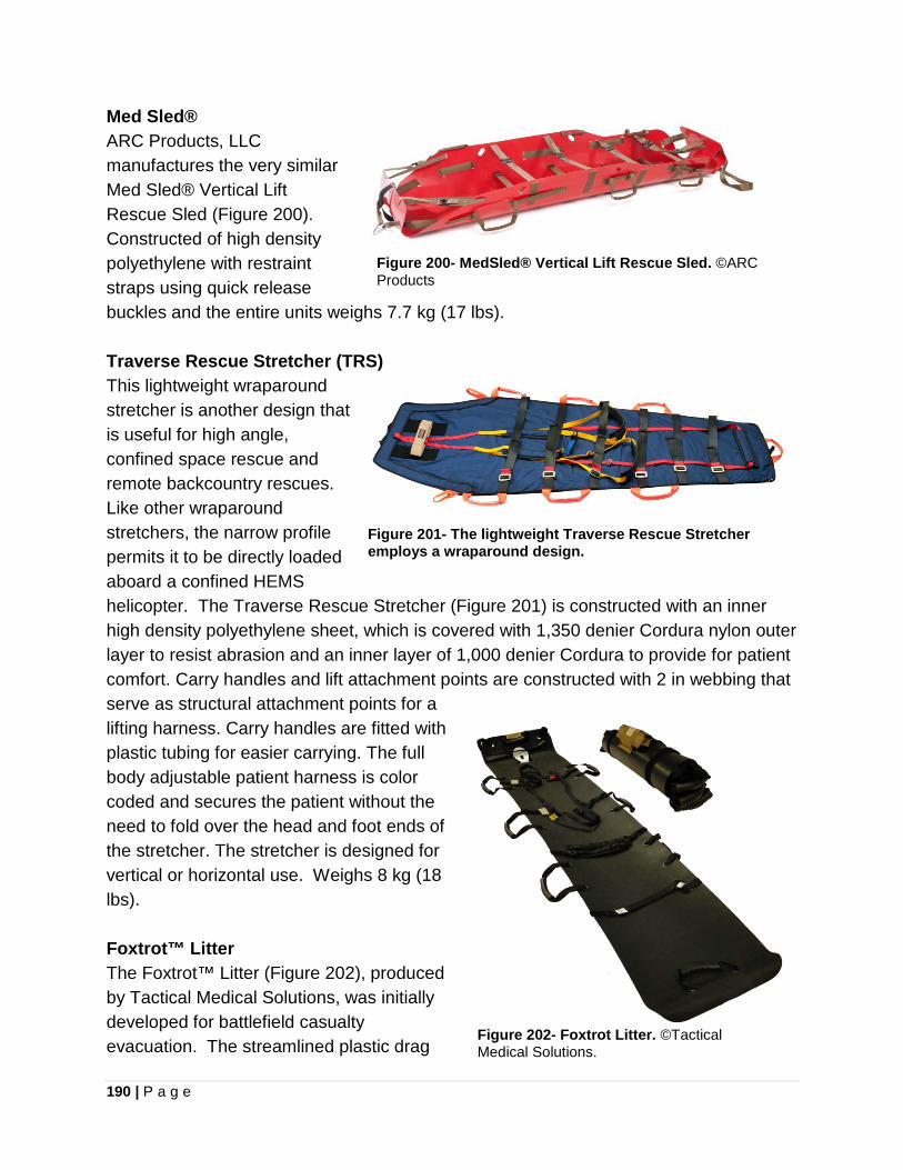
190 | P a g e
Med Sled® ARC Products, LLC manufactures the very similar Med Sled® Vertical Lift Rescue Sled (Figure 200). Constructed of high density polyethylene with restraint straps using quick release buckles and the entire units weighs 7.7 kg (17 lbs).
Figure 200- MedSled® Vertical Lift Rescue Sled. ©ARC Products
Traverse Rescue Stretcher (TRS) This lightweight wraparound stretcher is another design that is useful for high angle, confined space rescue and remote backcountry rescues. Like other wraparound stretchers, the narrow profile permits it to be directly loaded aboard a confined HEMS helicopter. The Traverse Rescue Stretcher (Figure 201) is constructed with an inner high density polyethylene sheet, which is covered with 1,350 denier Cordura nylon outer layer to resist abrasion and an inner layer of 1,000 denier Cordura to provide for patient comfort. Carry handles and lift attachment points are constructed with 2 in webbing that serve as structural attachment points for a lifting harness. Carry handles are fitted with plastic tubing for easier carrying. The full body adjustable patient harness is color coded and secures the patient without the need to fold over the head and foot ends of the stretcher. The stretcher is designed for vertical or horizontal use. Weighs 8 kg (18 lbs).
Figure 201- The lightweight Traverse Rescue Stretcher employs a wraparound design.
Foxtrot™ Litter The Foxtrot™ Litter (Figure 202), produced by Tactical Medical Solutions, was initially developed for battlefield casualty evacuation. The streamlined plastic drag
Figure 202- Foxtrot Litter. ©Tactical Medical Solutions.
191 | P a g e
sheet provides a lightweight interim transport device, permitting a patient to be dragged or carried by rescuers. This is not recommended as a stand-alone transport appliance for high angle technical rescue operations; however it does provide some versatility in remote SAR operations. The compact size could permit rescuers to carry a Foxtrot™ Litter during a hasty search effort and have an immediate transport device to initiate patient movement while a conventional litter is being brought to the scene. The litter weighs 2 kg (4.6 lbs) with carrier. Litter Harness (aka Bridle) The litter harness permits rigging of the litter in a horizontal or vertical orientation for technical raising and lowering operations with an attendant to guide the litter and provide limited patient care. Many commercial litter harnesses are designed to be adjustable when tensioned. It is possible to change the head or foot end of the litter for terrain obstacles and patient care. Carabiners used to connect the litter harness to the litter are rigged with the gates down and facing inward. It is preferable to pre-rig a litter harness in advance as to improvising one on scene. A fixed leg litter harness can be constructed with webbing to optimal leg lengths (Figure 203). Employ contrasting colors of webbing for the head and foot sections, and utilize “red to head” to reduce the likelihood of human error during rigging at a scene.
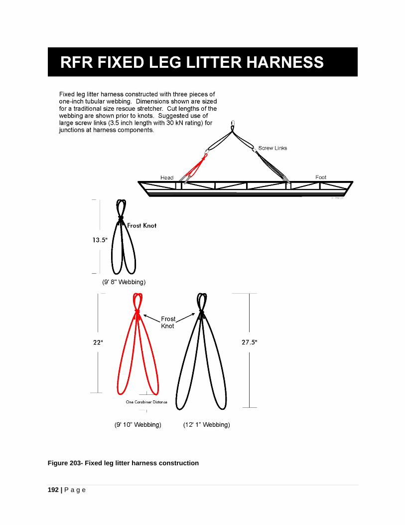
192 | P a g e
Figure 203- Fixed leg litter harness construction
193 | P a g e
Chapter 17
LITTER LOWER/RAISE TECHNIQUE
LITTER RIGGING The main line and belay (backup) line are joined together with long-tailed interlocking Bowlines and then connected to the litter harness through the point where the knots are linked. Slope angle and the load that is required to be supported by the rescuers dictate the number of attendants. In vertical terrain, simplicity and risk management require the use of a single attendant as the most preferred technique. If two attendants are to be used, it is recommended that the second attendant be on independent lines and they can either ascend next to the litter or be raised from above. The litter attendant is secured via two points of attachment (Figure 204). Their primary attachment is an adjustable tether from their harness connector strap to the top of the litter harness. This adjustable tether can be either a personal jigger (Figure 205) or Purcell Prusik. Secondarily the attendant is attached to one of the long tails coming from the interlocking long-tailed Bowlines. The second long tail is attached to the patient’s harness. Pre-configuring proper length of the long tails in advance is important. The length of the long tails must be adequate to permit attendant travel to a low position at the foot of the litter when in a vertical litter orientation, as well as adequate distance to the patient in order to accommodate any changes in litter orientation. A proper height adjustment for the litter attendant allows them to reach the rock face with their legs and have minimal clearance of the litter above their thighs. The attendant uses their legs to push from the rock face and arms to pull the litter away from the face. During a lowering or raising evolution the attendant may find it useful to move into an upper attendant position above the litter. The litter attendant moves into the upper position by shortening their adjustable tether, grabbing the litter harness ring or the upper ends of the litter harness legs and pulling themselves upward till they are standing on the inside and outside litter rails. This maneuver is performed cautiously as the attendant steps around the patient. The attendant attaches their harness connector strap into the apex of the litter harness (Figure 206), and moves into a position between the litter harness legs where they hang suspended above the patient (Figure 207). This upper attendant position technique is less fatiguing on the rescuer, since their legs are doing the majority of the work, and negotiating overhangs during a raise is much easier.

194 | P a g e
This technique is best applied in vertical faces and overhangs. Negotiating a cliff edge or encountering inclined slopes forces the attendant to change to the lower position, which is easily accomplished.
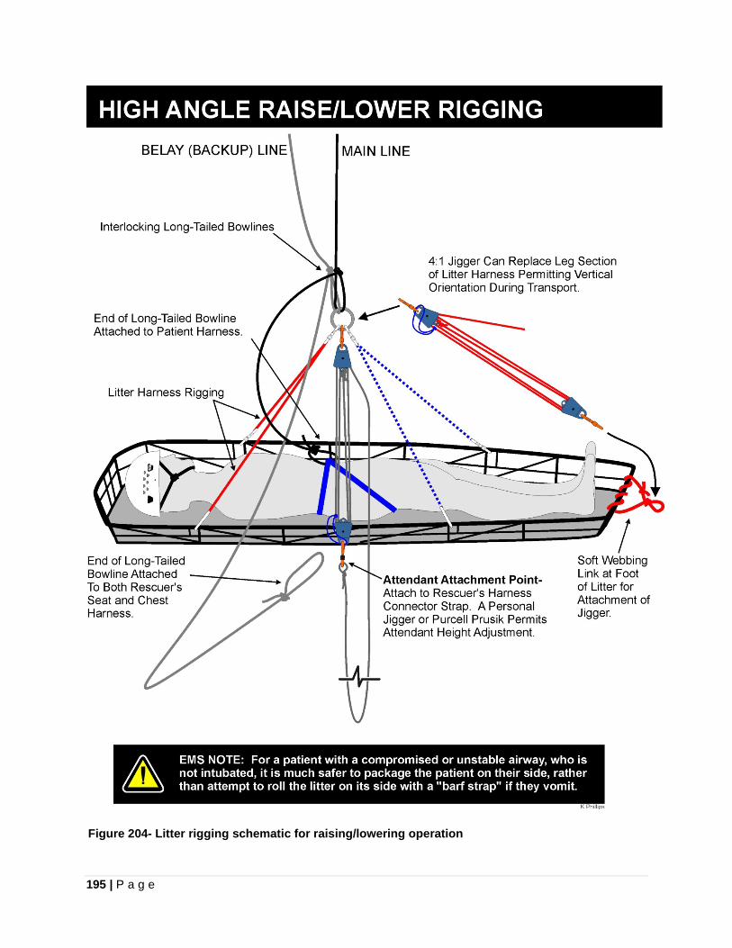
195 | P a g e
Figure 204- Litter rigging schematic for raising/lowering operation
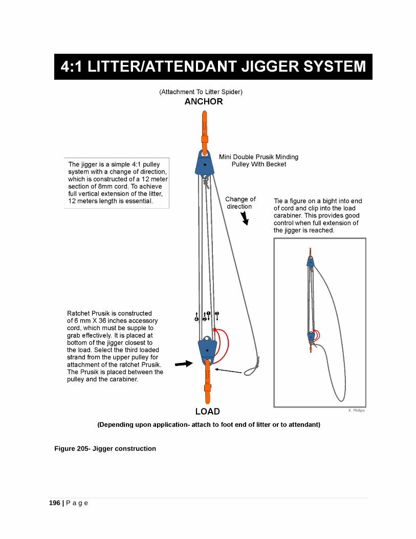
196 | P a g e
Figure 205- Jigger construction
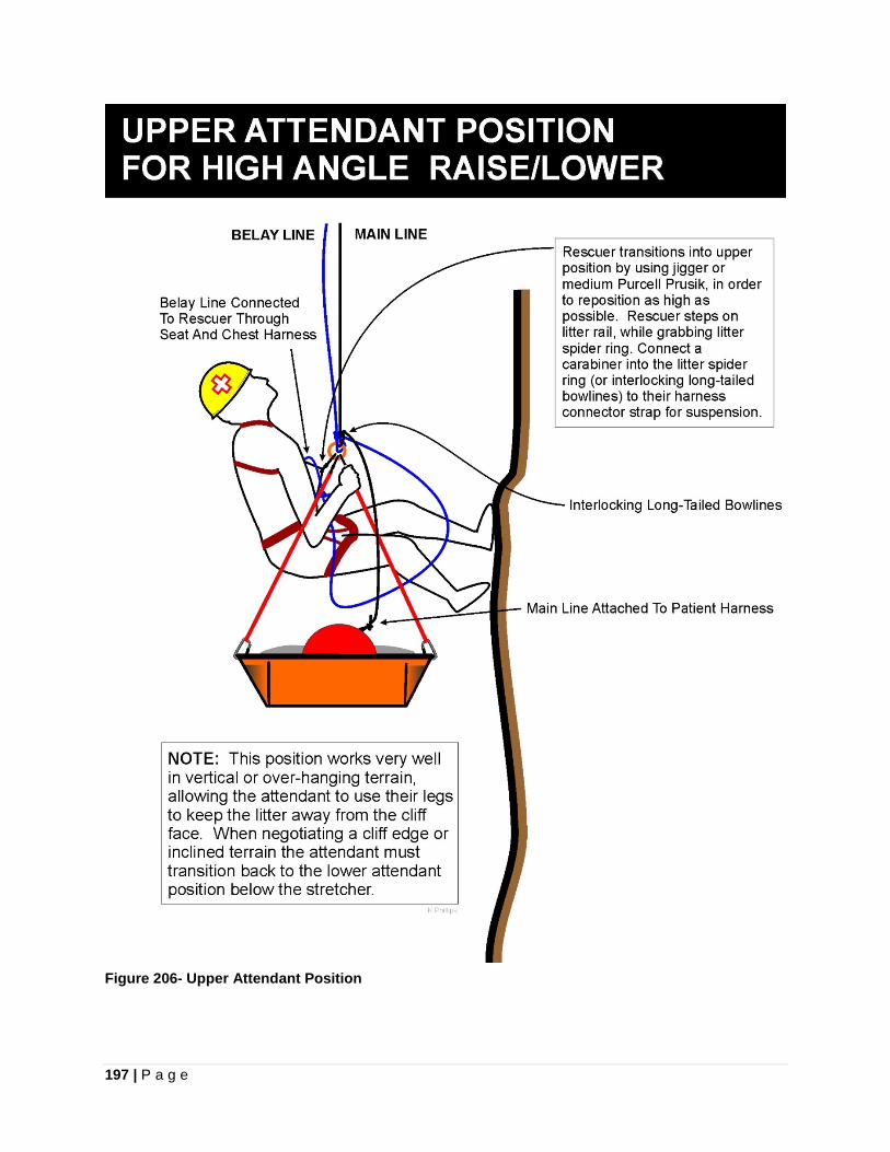
197 | P a g e
Figure 206- Upper Attendant Position
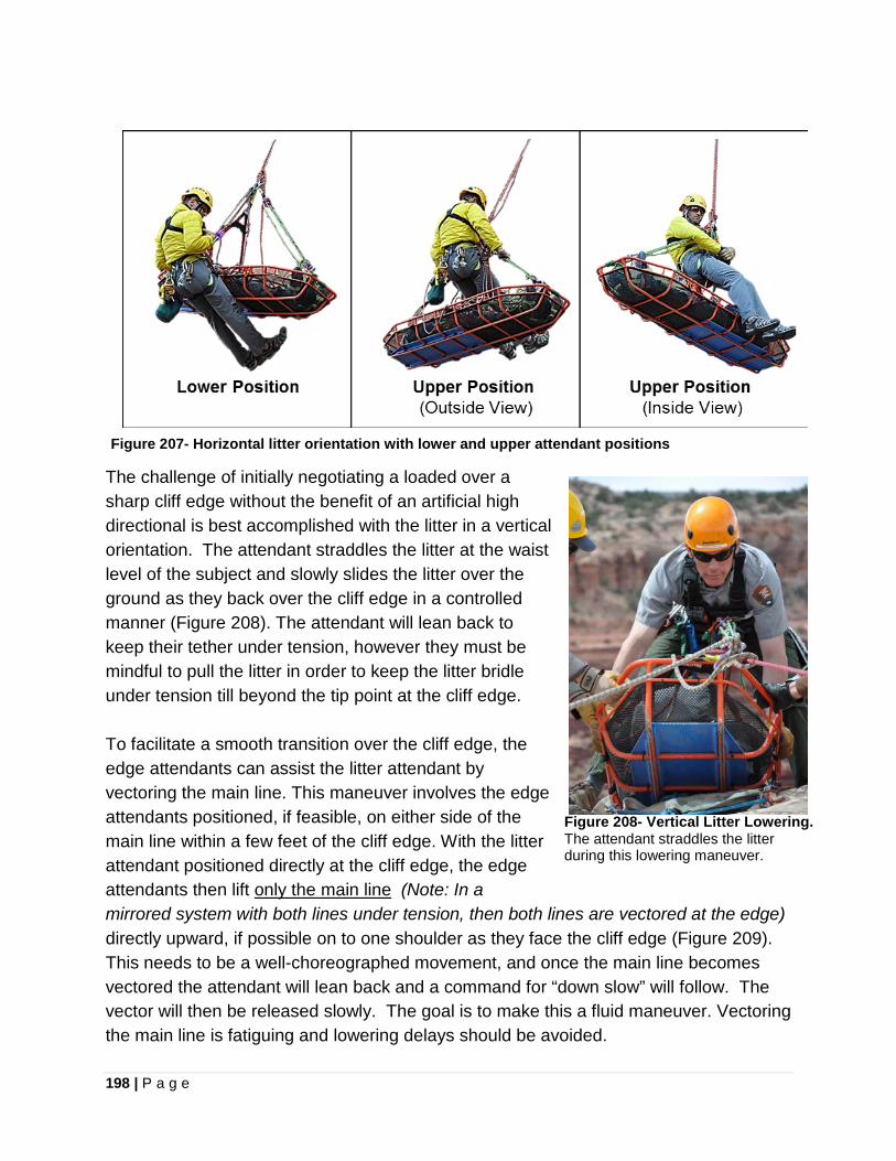
198 | P a g e
Figure 207- Horizontal litter orientation with lower and upper attendant positions
The challenge of initially negotiating a loaded over a sharp cliff edge without the benefit of an artificial high directional is best accomplished with the litter in a vertical orientation. The attendant straddles the litter at the waist level of the subject and slowly slides the litter over the ground as they back over the cliff edge in a controlled manner (Figure 208). The attendant will lean back to keep their tether under tension, however they must be mindful to pull the litter in order to keep the litter bridle under tension till beyond the tip point at the cliff edge. To facilitate a smooth transition over the cliff edge, the edge attendants can assist the litter attendant by vectoring the main line. This maneuver involves the edge attendants positioned, if feasible, on either side of the main line within a few feet of the cliff edge. With the litter attendant positioned directly at the cliff edge, the edge attendants then lift only the main line (Note: In a mirrored system with both lines under tension, then both lines are vectored at the edge) directly upward, if possible on to one shoulder as they face the cliff edge (Figure 209). This needs to be a well-choreographed movement, and once the main line becomes vectored the attendant will lean back and a command for “down slow” will follow. The vector will then be released slowly. The goal is to make this a fluid maneuver. Vectoring the main line is fatiguing and lowering delays should be avoided.
Figure 208- Vertical Litter Lowering. The attendant straddles the litter during this lowering maneuver.

199 | P a g e
Figure 209- Vectoring the mainline. The vectoring maneuver with the mainline should keep the belay line no higher than the waist height off the ground.
The table below reflects standardized communications with a role call for a lowering operation to faciliate an efficient manuver. This includes a stop at the cliff edge for a final “pre-departure briefing,” which is suggested by Kirk Mauthner, Basecamp Innovations, Ltd. This provides a final opportunity to ensure all personnel have a shared mental image of the critical tasks ahead in full agreement and serves to heighten the awareness of all involved team members.
LOWERING EVOLUTION- ROLE CALL:
Operations/Control: Response: Operations/Control "Belay ready?" "Belay Ready!" "Standby!" "Advise When Ready" "Main Line Ready?" "Main Line Ready" "Edge Ready?" "Edge Ready" "Attendant Ready?" "Attendant Ready" "Attendant, Approach Edge!" "Tension all lines" (Main line, belay line, edge and attendant tension lines) “STOP”- Conduct Pre-Departure Briefing (Last reminder. Full agreement on actions) "Vector Main Line!" (Edge deflects main line upward- no rope let through the brake) "Attendant Lean Back!” (Litter cleared of all obstructions) “Main Line, Down Slow!” "Release Vector!" (Slowly initially, then quicker) “Down, Down” (Requested by attendant for increased speed)
200 | P a g e
Patient protection during rockfall provides a very difficult situation for the attendant. The attendant has a duty to protect patient, but not at the risk of personal sacrifice. Options for them are to jump on top of the patient, if rescuer is wearing a backpack, or roll the litter on the side and duck in as close as possible. Litter shields can provide patient protection from rockfall and are discussed on page 229.
CHANGEOVER TECHNIQUE- RESCUE LOAD
LOWERING TO RAISING
Conducting a changeover from lowering to raising involves transferring tension off the DCD. This can be accomplished through the use of an extended long Prusik, referred to as a “jumper,” which bypasses the DCD (Figure 210). The attendant calls for a “stop” and communicates “rig for raise.” The DCD is manually held at full stop without a tie-off. The Jumper is rigged on the line and attached to the rigging plate at focal point. The attendant is advised to “prepare for settling.” The main line is lowered out, which transfers tension to the Jumper. As additional rope is fed through the DCD, the device becomes slackened and can be removed from the system. Once the rope is released from the lowering device, the pulley system is constructed for the raise. As the raise is initiated, the Jumper is removed, while the raising operation continues.
RAISING TO LOWERING
During a raising operation the load can be quickly lowered back down a short distance by the haul team simply letting out on the main line with the ratchet on the haul system held open, so it does not set. Although less commonly employed during a rescue, a complete changeover from a raising to lowering operation is accomplished through another transfer of tension maneuver. When a “stop” is called on the raising operation, a Jumper, with a LRH attaching it to the rigging plate, is rigged on the tensioned line in front of the Ratchet Prusik Hitch with enough distance to rig the DCD after the line is slackened. The attendant is advised to “prepare for settling,” as the haul system is lowered back out while the ratchet is manually held open. This allows the tension to settle on to the Jumper. This will permit the haul system to be slackened and removed. The DCD is rigged to the slackened line behind the Jumper and tied off. The LRH is then let out to transfer tension over to the descender.
Note: The use of a CMC MPD™ preconfigures a lowering or raising system for an immediate changeover without having to complete the steps shown above.
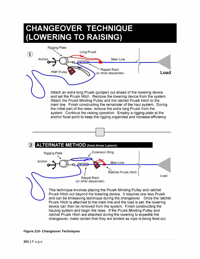
201 | P a g e
Figure 210- Changeover Techniques
202 | P a g e
PIKE AND PIVOT TECHNIQUE (aka Vertical Litter Edge Transition Technique)
Attempting to raise a loaded litter in a horizontal orientation up over a sharp (90°) cliff edge, without the benefit of an artificial high direction, can quickly result in “edge trauma” to the patient. During such a maneuver the inside rail of the litter will have a natural tendency to catch on the edge of the cliff and cause the loaded litter to roll inward against the rock face. Orienting the litter in a vertical orientation is only part of the solution. In a raising with a vertical orientation, the head of the litter will become jammed against the cliff edge by the hauling system. Overcoming this tendency of the litter to be pulled against the lip of a cliff involves placing a pivot point further down on a vertically oriented litter.
The Pike and Pivot (Vertical Litter Edge Transition Technique), also simply referred to the “V-Strap Technique,” is an excellent procedure for negotiating a sharp edge on a raise without the benefit of a high directional. To accomplish the maneuver, the litter is placed in a vertical orientation below the lip by the attendant during the raising operation. The raising is halted when the knots at the master attachment point (long-tailed interlocking bowlines) just reach the edge protection at the cliff edge. This position places the loaded litter a few feet below the cliff edge. A pre-rigged V-strap, which is constructed from a ten meter section of 8 mm cord, is put in service. The V-strap has a small bight knotted at the middle of the cord with locking carabiners attached to bights placed at each terminus of the cord. The ends of the V-strap are dropped down to the attendant and the V-strap is attached to the outside of the litter at the patient’s mid-thigh or knee level. If possible, the connections to the litter should be made directly to a stanchion that is oriented horizontally in order to prevent excessive torque on the carabiners. As the V-strap is positioned up over the cliff edge, it must be threaded under the belay (backup) line, otherwise it will trap the line during the final raising effort.
To avoid trapping the belay line during a Pike and Pivot Maneuver, position the V-strap under the belay line before attaching to the haul system.
The forward part of the pulley system is detached from the haul Prusik Hitch and transferred over to the bight on the upper end of the V-Strap. At this point the section of the main line, which comes off the head end of the litter will become "dead" and go slack during the final raise. An option is to add an additional Prusik Hitch on the opposite side of Prusik-Minding Pulley containing the ratchet Prusik Hitch to thoroughly deaden this section of line. This action locks the main line in place in front of the hauling
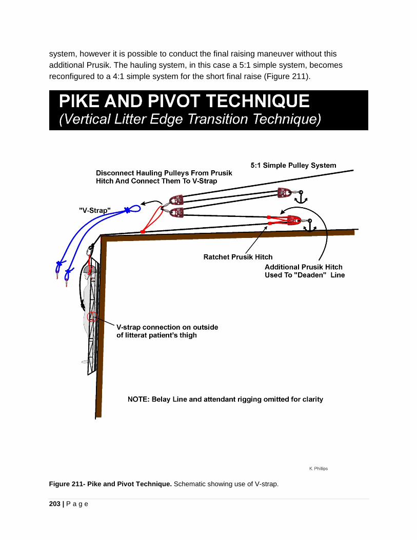
203 | P a g e
system, however it is possible to conduct the final raising maneuver without this additional Prusik. The hauling system, in this case a 5:1 simple system, becomes reconfigured to a 4:1 simple system for the short final raise (Figure 211).
Figure 211- Pike and Pivot Technique. Schematic showing use of V-strap.
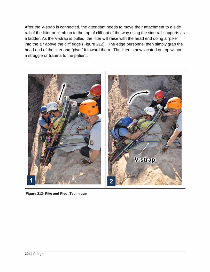
204 | P a g e
After the V-strap is connected, the attendant needs to move their attachment to a side rail of the litter or climb up to the top of cliff out of the way using the side rail supports as a ladder. As the V-strap is pulled, the litter will raise with the head end doing a “pike” into the air above the cliff edge (Figure 212). The edge personnel then simply grab the head end of the litter and “pivot” it toward them. The litter is now located on top without a struggle or trauma to the patient.
Figure 212- Pike and Pivot Technique
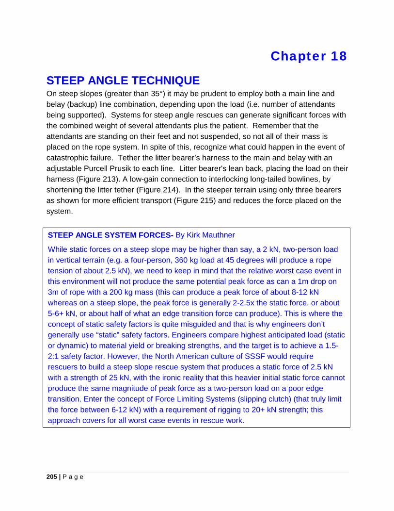
205 | P a g e
Chapter 18
STEEP ANGLE TECHNIQUE On steep slopes (greater than 35°) it may be prudent to employ both a main line and belay (backup) line combination, depending upon the load (i.e. number of attendants being supported). Systems for steep angle rescues can generate significant forces with the combined weight of several attendants plus the patient. Remember that the attendants are standing on their feet and not suspended, so not all of their mass is placed on the rope system. In spite of this, recognize what could happen in the event of catastrophic failure. Tether the litter bearer’s harness to the main and belay with an adjustable Purcell Prusik to each line. Litter bearer's lean back, placing the load on their harness (Figure 213). A low-gain connection to interlocking long-tailed bowlines, by shortening the litter tether (Figure 214). In the steeper terrain using only three bearers as shown for more efficient transport (Figure 215) and reduces the force placed on the system. • On steep slopes (20° to 50°) use a main line and belay line combination.
Systems for low-angle rescues can easily generate extreme loads with the combined weight of several attendants plus the patient. Rescuers are not standing on their feet and not suspended, so not all of their weight is placed on the rope system. Recognize what could happen in the event of catastrophic failure. Tether the litter bearer’s harness to the main and belay with an adjustable Purcell Prusik to each line. Litter bearer's lean back, placing the load on their harness (Figure 207). A low-gain connection to interlocking long-tailed bowlines, by shortening the litter tether (Figure 208). In the steeper terrain use only three bearers as shown for more efficient transport (Figure 209).
This section is pretty confusing. I understand what you are trying to say but I think that the wording could use some streamlining. When adding or subtracting rescuers force on system, force on the rescuers, likelihood of a fall, and consequences of a fall should all be considered
STEEP ANGLE SYSTEM FORCES- By Kirk Mauthner
While static forces on a steep slope may be higher than say, a 2 kN, two-person load in vertical terrain (e.g. a four-person, 360 kg load at 45 degrees will produce a rope tension of about 2.5 kN), we need to keep in mind that the relative worst case event in this environment will not produce the same potential peak force as can a 1m drop on 3m of rope with a 200 kg mass (this can produce a peak force of about 8-12 kN whereas on a steep slope, the peak force is generally 2-2.5x the static force, or about 5-6+ kN, or about half of what an edge transition force can produce). This is where the concept of static safety factors is quite misguided and that is why engineers don’t generally use “static” safety factors. Engineers compare highest anticipated load (static or dynamic) to material yield or breaking strengths, and the target is to achieve a 1.5-2:1 safety factor. However, the North American culture of SSSF would require rescuers to build a steep slope rescue system that produces a static force of 2.5 kN with a strength of 25 kN, with the ironic reality that this heavier initial static force cannot produce the same magnitude of peak force as a two-person load on a poor edge transition. Enter the concept of Force Limiting Systems (slipping clutch) (that truly limit the force between 6-12 kN) with a requirement of rigging to 20+ kN strength; this approach covers for all worst case events in rescue work.
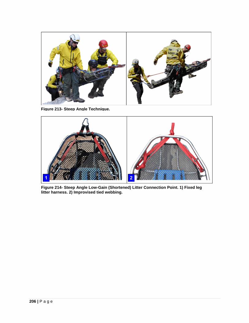
206 | P a g e
Figure 213- Steep Angle Technique.
Figure 214- Steep Angle Low-Gain (Shortened) Litter Connection Point. 1) Fixed leg litter harness. 2) Improvised tied webbing.
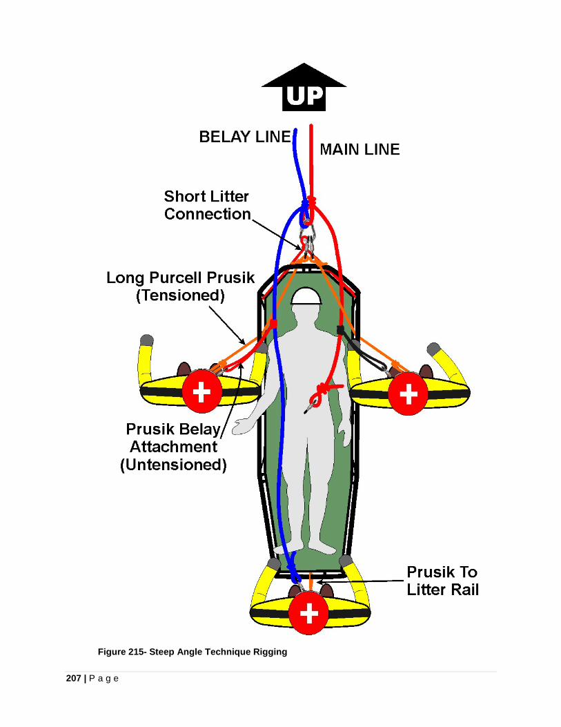
207 | P a g e
Figure 215- Steep Angle Technique Rigging
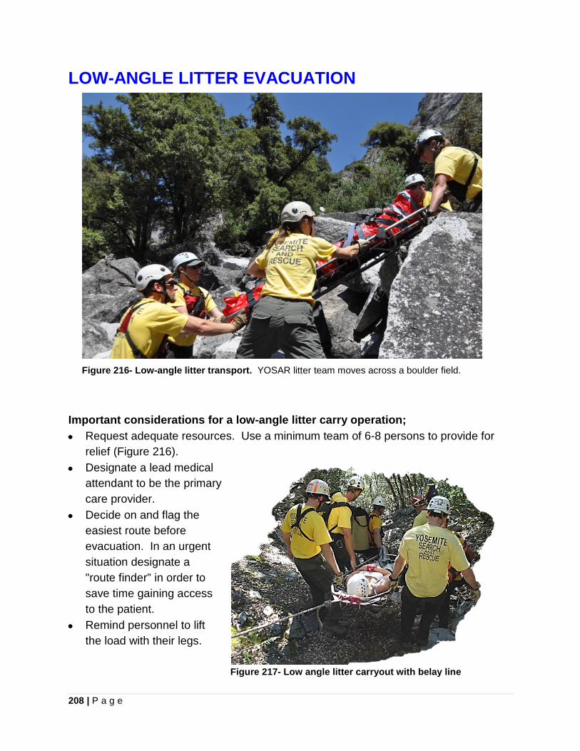
208 | P a g e
LOW-ANGLE LITTER EVACUATION
Figure 216- Low-angle litter transport. YOSAR litter team moves across a boulder field. Important considerations for a low-angle litter carry operation; • Request adequate resources. Use a minimum team of 6-8 persons to provide for
relief (Figure 216). • Designate a lead medical
attendant to be the primary care provider.
• Decide on and flag the easiest route before evacuation. In an urgent situation designate a "route finder" in order to save time gaining access to the patient.
• Remind personnel to lift the load with their legs.
Figure 217- Low angle litter carryout with belay line
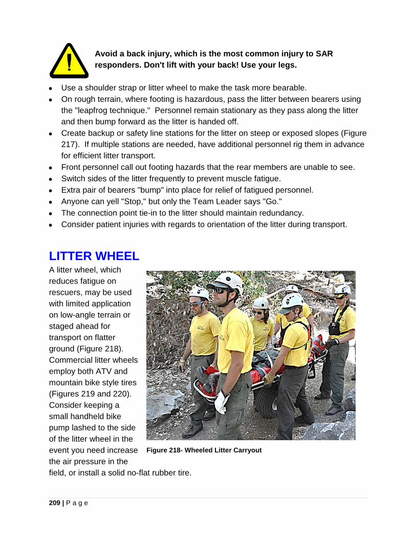
209 | P a g e
Avoid a back injury, which is the most common injury to SAR responders. Don't lift with your back! Use your legs.
• Use a shoulder strap or litter wheel to make the task more bearable. • On rough terrain, where footing is hazardous, pass the litter between bearers using
the "leapfrog technique." Personnel remain stationary as they pass along the litter and then bump forward as the litter is handed off.
• Create backup or safety line stations for the litter on steep or exposed slopes (Figure 217). If multiple stations are needed, have additional personnel rig them in advance for efficient litter transport.
• Front personnel call out footing hazards that the rear members are unable to see. • Switch sides of the litter frequently to prevent muscle fatigue. • Extra pair of bearers "bump" into place for relief of fatigued personnel. • Anyone can yell "Stop," but only the Team Leader says "Go." • The connection point tie-in to the litter should maintain redundancy. • Consider patient injuries with regards to orientation of the litter during transport.
LITTER WHEEL A litter wheel, which reduces fatigue on rescuers, may be used with limited application on low-angle terrain or staged ahead for transport on flatter ground (Figure 218). Commercial litter wheels employ both ATV and mountain bike style tires (Figures 219 and 220). Consider keeping a small handheld bike pump lashed to the side of the litter wheel in the event you need increase the air pressure in the field, or install a solid no-flat rubber tire.
Figure 218- Wheeled Litter Carryout
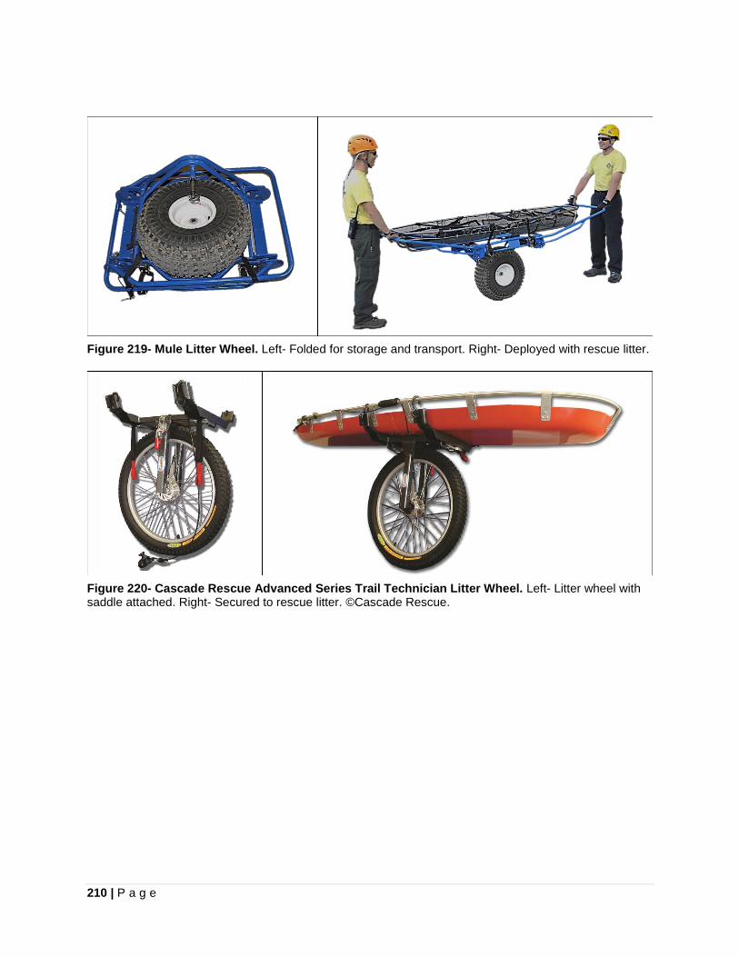
210 | P a g e
Figure 219- Mule Litter Wheel. Left- Folded for storage and transport. Right- Deployed with rescue litter.
Figure 220- Cascade Rescue Advanced Series Trail Technician Litter Wheel. Left- Litter wheel with saddle attached. Right- Secured to rescue litter. ©Cascade Rescue.
211 | P a g e
Chapter 19
STRANDED PATIENT PICK-OFF A pick-off technique is employed to rescue a stranded climber or a subject with minor injuries which does not require the use of a litter. The preferred method, if resources permit, is to have the primary rescuer lowered from above. This avoids over-tasking the rescuer and permits a simple changeover to a raise, if required. Ideally a rescuer in vertical terrain will utilize a chest harness and connector strap combination, however in less than vertical terrain this is not as essential. Consider selecting a descent path for the rescuer which will not generate rockfall on the subject. If necessary, the rescuer must remember to bring a pick-off harness and helmet for the stranded subject(s). If the subject is suspended on another line, transferring their tension requires a short raise, once a connection tether has been established by the rescuer. This can be conducted with a jigger system ganged on to the main line. Alternatively the tail of the main line in a lowering system can be rigged as a haul system in front of the locked off descent device for a short raise. Finally, a complete changeover to a raising evolution can also be conducted once the subject is contacted and secure.
Cutting the subject’s line during a pick-off could result in a shock load to the rescue system. Raising the rescue load on to rescue system is a more controlled means of safely transferring the load.
BC PICK-OFF The BC (Better Control) Pick-off is described here with some adaptations from the method originally developed by Arnör Larson (Figure 221). The working ends of the main line and belay line are joined together with interlocking long-tailed bowlines. The rescuer uses a Medium Purcell Prusik, which is attached at the interlocking junction, as well as the tail of the belay line as their connection points. A Long Purcell Prusik and the tail of the main line are retained by the rescuer to connect to the subject’s harness. The rescuer is lowered down to the subject and calls a stop at the first opportunity the rescuer can clip the Long Purcell Prusik tether to the subject’s harness. The Purcell Prusik to the subject permits adjustment of tension and positioning of the height of the subject by the rescuer. The main line tail is attached to the subject’s harness as a secondary attachment point. The Purcell Prusik provides valuable adjustability as a tether to the subject, in comparison to the possibility that the subject will grab it and make premature adjustments. Unauthorized changes to the Purcell Prusik by the
212 | P a g e
subject can be prevented through a firm warning. The rescuer can piggyback the subject with the tether run over one shoulder, allowing the opportunity to keep the subject away from the rock face. Another method is for the rescue to cradle-carry the suspended subject in front of them. With this method, it is advantageous to attach the patient as close as possible to the interlocking bowlines carabiner. Finally, a stable uninjured subject can easily be transported laterally adjacent to the rescuer. If a raising is conducted back up over a sharp cliff edge, without the benefit of an artificial high direction, the subject should be positioned immediately adjacent to the rescuer. If this is not done, the suspended weight of a subject behind the rescuer will trap the rescuer against the cliff edge.
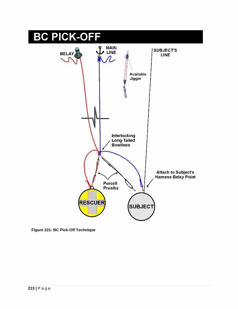
213 | P a g e
Figure 221- BC Pick-Off Technique
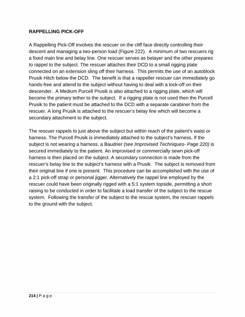
214 | P a g e
RAPPELLING PICK-OFF A Rappelling Pick-Off involves the rescuer on the cliff face directly controlling their descent and managing a two-person load (Figure 222). A minimum of two rescuers rig a fixed main line and belay line. One rescuer serves as belayer and the other prepares to rappel to the subject. The rescuer attaches their DCD to a small rigging plate connected on an extension sling off their harness. This permits the use of an autoblock Prusik Hitch below the DCD. The benefit is that a rappeller rescuer can immediately go hands-free and attend to the subject without having to deal with a lock-off on their descender. A Medium Purcell Prusik is also attached to a rigging plate, which will become the primary tether to the subject. If a rigging plate is not used then the Purcell Prusik to the patient must be attached to the DCD with a separate carabiner from the rescuer. A long Prusik is attached to the rescuer’s belay line which will become a secondary attachment to the subject.
The rescuer rappels to just above the subject but within reach of the patient's waist or harness. The Purcell Prusik is immediately attached to the subject’s harness. If the subject is not wearing a harness, a Baudrier (see Improvised Techniques- Page 220) is secured immediately to the patient. An improvised or commercially sewn pick-off harness is then placed on the subject. A secondary connection is made from the rescuer’s belay line to the subject’s harness with a Prusik. The subject is removed from their original line if one is present. This procedure can be accomplished with the use of a 2:1 pick-off strap or personal jigger. Alternatively the rappel line employed by the rescuer could have been originally rigged with a 5:1 system topside, permitting a short raising to be conducted in order to facilitate a load transfer of the subject to the rescue system. Following the transfer of the subject to the rescue system, the rescuer rappels to the ground with the subject.
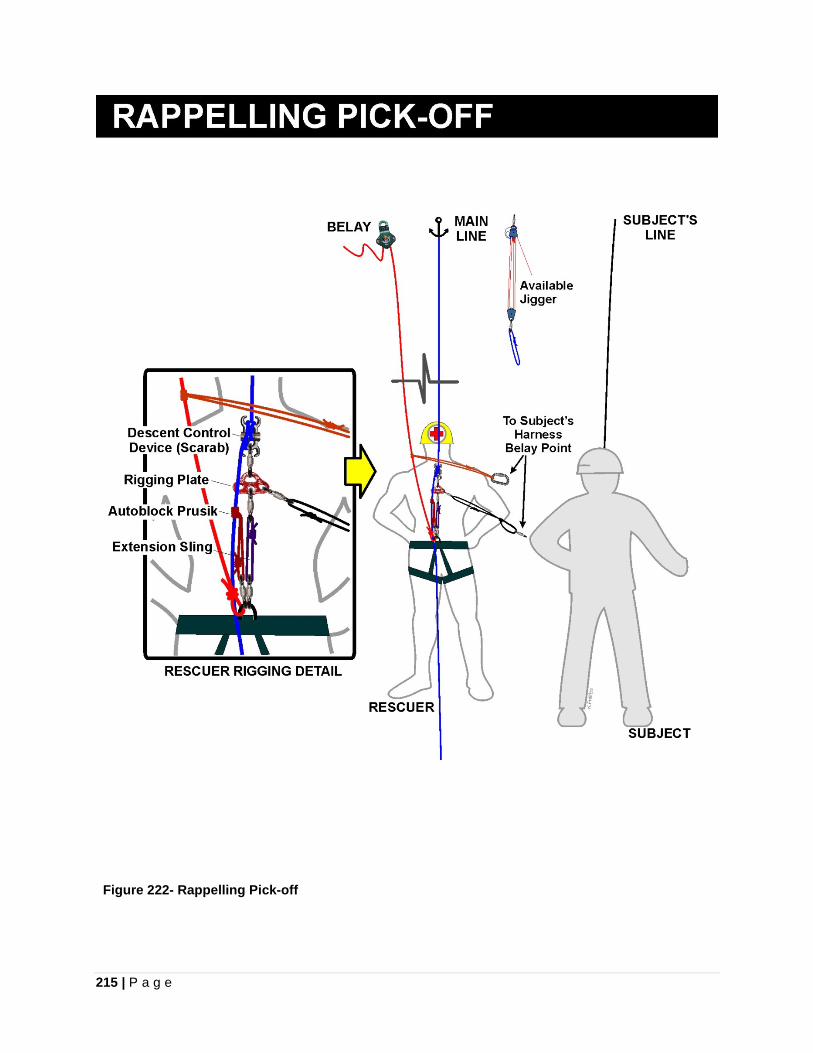
215 | P a g e
Figure 222- Rappelling Pick-off
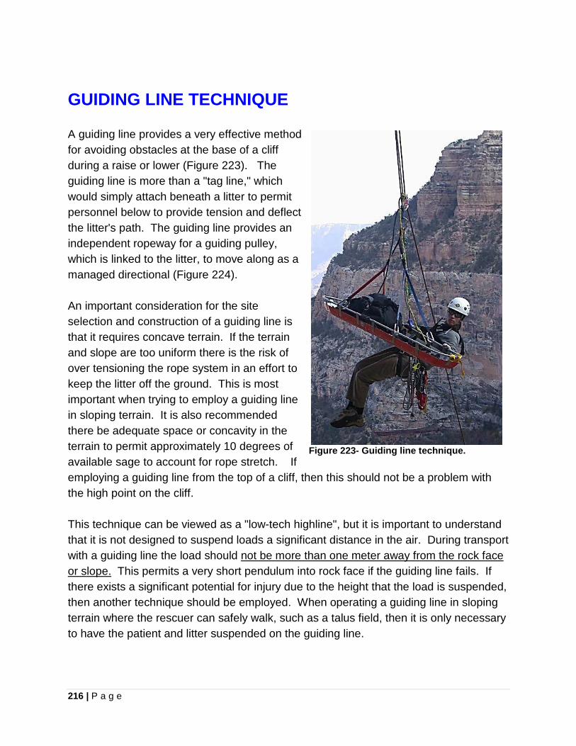
216 | P a g e
GUIDING LINE TECHNIQUE A guiding line provides a very effective method for avoiding obstacles at the base of a cliff during a raise or lower (Figure 223). The guiding line is more than a "tag line," which would simply attach beneath a litter to permit personnel below to provide tension and deflect the litter's path. The guiding line provides an independent ropeway for a guiding pulley, which is linked to the litter, to move along as a managed directional (Figure 224). An important consideration for the site selection and construction of a guiding line is that it requires concave terrain. If the terrain and slope are too uniform there is the risk of over tensioning the rope system in an effort to keep the litter off the ground. This is most important when trying to employ a guiding line in sloping terrain. It is also recommended there be adequate space or concavity in the terrain to permit approximately 10 degrees of available sage to account for rope stretch. If employing a guiding line from the top of a cliff, then this should not be a problem with the high point on the cliff. This technique can be viewed as a "low-tech highline", but it is important to understand that it is not designed to suspend loads a significant distance in the air. During transport with a guiding line the load should not be more than one meter away from the rock face or slope. This permits a very short pendulum into rock face if the guiding line fails. If there exists a significant potential for injury due to the height that the load is suspended, then another technique should be employed. When operating a guiding line in sloping terrain where the rescuer can safely walk, such as a talus field, then it is only necessary to have the patient and litter suspended on the guiding line.
Figure 223- Guiding line technique.
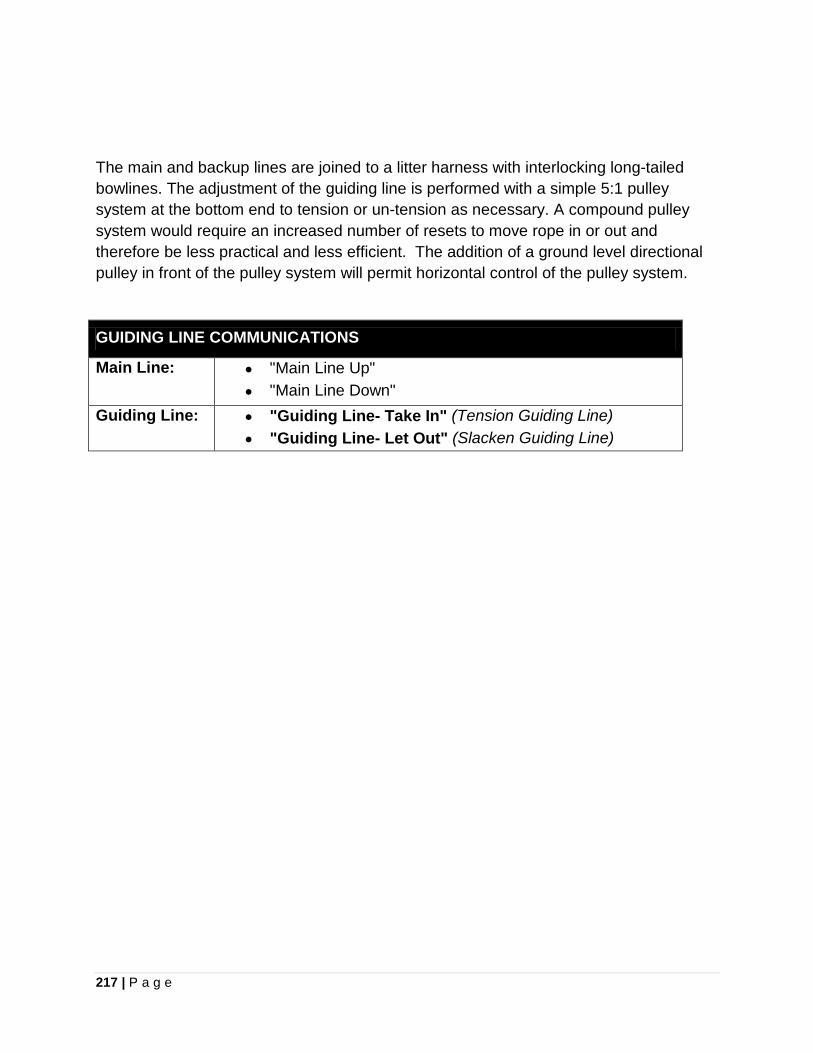
217 | P a g e
The main and backup lines are joined to a litter harness with interlocking long-tailed bowlines. The adjustment of the guiding line is performed with a simple 5:1 pulley system at the bottom end to tension or un-tension as necessary. A compound pulley system would require an increased number of resets to move rope in or out and therefore be less practical and less efficient. The addition of a ground level directional pulley in front of the pulley system will permit horizontal control of the pulley system.
GUIDING LINE COMMUNICATIONS
Main Line:
• "Main Line Up" • "Main Line Down"
Guiding Line:
• "Guiding Line- Take In" (Tension Guiding Line) • "Guiding Line- Let Out" (Slacken Guiding Line)
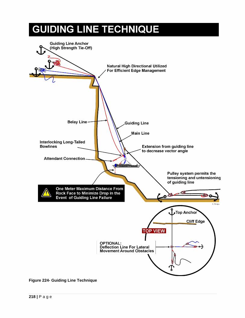
218 | P a g e
Figure 224- Guiding Line Technique
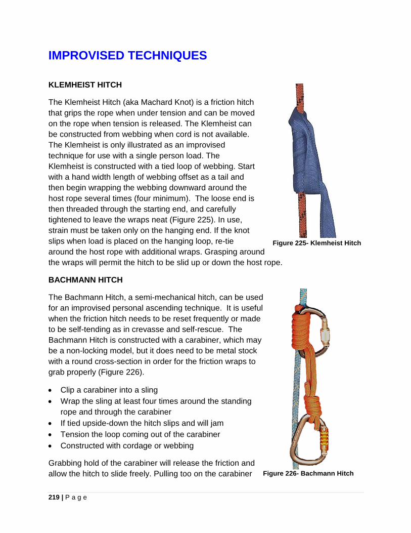
219 | P a g e
IMPROVISED TECHNIQUES
KLEMHEIST HITCH
The Klemheist Hitch (aka Machard Knot) is a friction hitch that grips the rope when under tension and can be moved on the rope when tension is released. The Klemheist can be constructed from webbing when cord is not available. The Klemheist is only illustrated as an improvised technique for use with a single person load. The Klemheist is constructed with a tied loop of webbing. Start with a hand width length of webbing offset as a tail and then begin wrapping the webbing downward around the host rope several times (four minimum). The loose end is then threaded through the starting end, and carefully tightened to leave the wraps neat (Figure 225). In use, strain must be taken only on the hanging end. If the knot slips when load is placed on the hanging loop, re-tie around the host rope with additional wraps. Grasping around the wraps will permit the hitch to be slid up or down the host rope.
BACHMANN HITCH
The Bachmann Hitch, a semi-mechanical hitch, can be used for an improvised personal ascending technique. It is useful when the friction hitch needs to be reset frequently or made to be self-tending as in crevasse and self-rescue. The Bachmann Hitch is constructed with a carabiner, which may be a non-locking model, but it does need to be metal stock with a round cross-section in order for the friction wraps to grab properly (Figure 226).
• Clip a carabiner into a sling • Wrap the sling at least four times around the standing
rope and through the carabiner • If tied upside-down the hitch slips and will jam • Tension the loop coming out of the carabiner • Constructed with cordage or webbing
Grabbing hold of the carabiner will release the friction and allow the hitch to slide freely. Pulling too on the carabiner
Figure 225- Klemheist Hitch
Figure 226- Bachmann Hitch
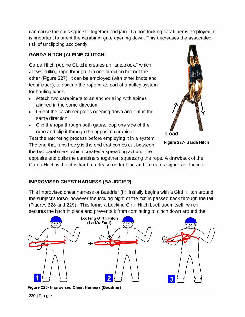
220 | P a g e
can cause the coils squeeze together and jam. If a non-locking carabiner is employed, it is important to orient the carabiner gate opening down. This decreases the associated risk of unclipping accidently.
GARDA HITCH (ALPINE CLUTCH)
Garda Hitch (Alpine Clutch) creates an “autoblock,” which allows pulling rope through it in one direction but not the other (Figure 227). It can be employed (with other knots and techniques), to ascend the rope or as part of a pulley system for hauling loads. • Attach two carabiners to an anchor sling with spines
aligned in the same direction • Orient the carabiner gates opening down and out in the
same direction • Clip the rope through both gates, loop one side of the
rope and clip it through the opposite carabiner Test the ratcheting process before employing it in a system. The end that runs freely is the end that comes out between the two carabiners, which creates a spreading action. The opposite end pulls the carabiners together, squeezing the rope. A drawback of the Garda Hitch is that it is hard to release under load and it creates significant friction.
Figure 227- Garda Hitch
IMPROVISED CHEST HARNESS (BAUDRIER)
This improvised chest harness or Baudrier (fr), initially begins with a Girth Hitch around the subject’s torso, however the locking bight of the itch is passed back through the tail (Figures 228 and 229). This forms a Locking Girth Hitch back upon itself, which secures the hitch in place and prevents it from continuing to cinch down around the
Figure 228- Improvised Chest Harness (Baudrier)
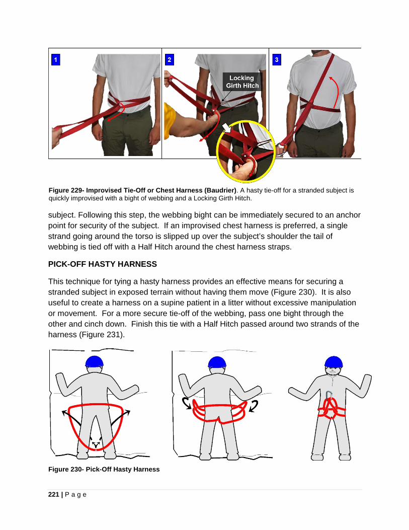
221 | P a g e
Figure 229- Improvised Tie-Off or Chest Harness (Baudrier). A hasty tie-off for a stranded subject is quickly improvised with a bight of webbing and a Locking Girth Hitch.
subject. Following this step, the webbing bight can be immediately secured to an anchor point for security of the subject. If an improvised chest harness is preferred, a single strand going around the torso is slipped up over the subject’s shoulder the tail of webbing is tied off with a Half Hitch around the chest harness straps.
PICK-OFF HASTY HARNESS
This technique for tying a hasty harness provides an effective means for securing a stranded subject in exposed terrain without having them move (Figure 230). It is also useful to create a harness on a supine patient in a litter without excessive manipulation or movement. For a more secure tie-off of the webbing, pass one bight through the other and cinch down. Finish this tie with a Half Hitch passed around two strands of the harness (Figure 231).
Figure 230- Pick-Off Hasty Harness
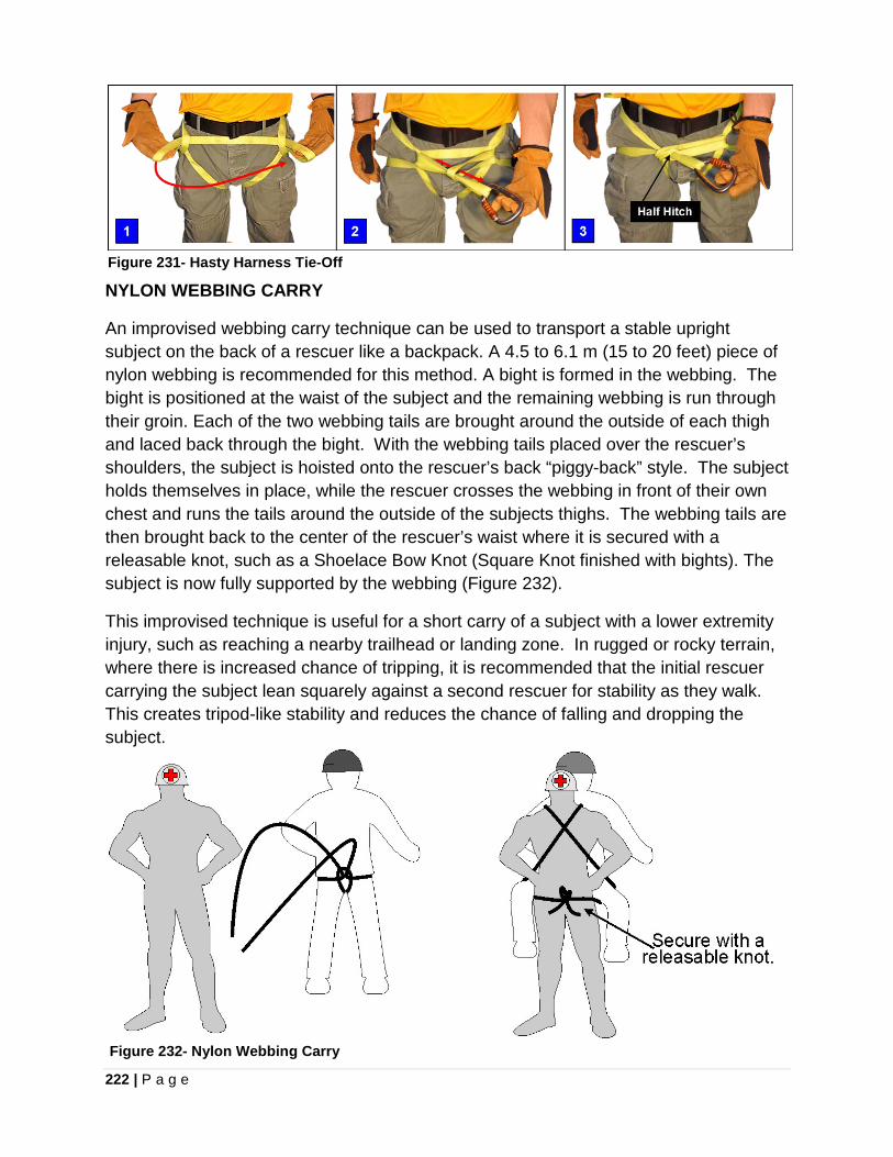
222 | P a g e
Figure 231- Hasty Harness Tie-Off NYLON WEBBING CARRY
An improvised webbing carry technique can be used to transport a stable upright subject on the back of a rescuer like a backpack. A 4.5 to 6.1 m (15 to 20 feet) piece of nylon webbing is recommended for this method. A bight is formed in the webbing. The bight is positioned at the waist of the subject and the remaining webbing is run through their groin. Each of the two webbing tails are brought around the outside of each thigh and laced back through the bight. With the webbing tails placed over the rescuer’s shoulders, the subject is hoisted onto the rescuer’s back “piggy-back” style. The subject holds themselves in place, while the rescuer crosses the webbing in front of their own chest and runs the tails around the outside of the subjects thighs. The webbing tails are then brought back to the center of the rescuer’s waist where it is secured with a releasable knot, such as a Shoelace Bow Knot (Square Knot finished with bights). The subject is now fully supported by the webbing (Figure 232).
This improvised technique is useful for a short carry of a subject with a lower extremity injury, such as reaching a nearby trailhead or landing zone. In rugged or rocky terrain, where there is increased chance of tripping, it is recommended that the initial rescuer carrying the subject lean squarely against a second rescuer for stability as they walk. This creates tripod-like stability and reduces the chance of falling and dropping the subject.
Figure 232- Nylon Webbing Carry
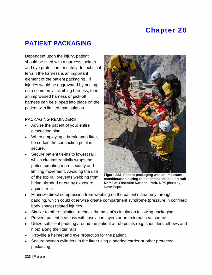
223 | P a g e
Chapter 20
PATIENT PACKAGING Dependent upon the injury, patient should be fitted with a harness, helmet and eye protection for safety. In technical terrain the harness is an important element of the patient packaging. If injuries would be aggravated by putting on a commercial climbing harness, then an improvised harness or pick-off harness can be slipped into place on the patient with limited manipulation. PACKAGING REMINDERS • Advise the patient of your entire
evacuation plan. • When employing a break apart litter,
be certain the connection point is secure.
• Secure patient tie-ins to lowest rail, which circumferentially wraps the patient creating more security and limiting movement. Avoiding the use of the top rail prevents webbing from being abraded or cut by exposure against rock.
• Minimize direct compression from webbing on the patient’s anatomy through padding, which could otherwise create compartment syndrome (pressure in confined body space) related injuries.
• Similar to other splinting, recheck the patient's circulation following packaging. • Prevent patient heat loss with insulation layers or an external heat source. • Utilize sufficient padding around the patient at rub points (e.g. shoulders, elbows and
hips) along the litter rails. • Provide a helmet and eye protection for the patient. • Secure oxygen cylinders in the litter using a padded carrier or other protected
packaging.
Figure 233- Patient packaging was an important consideration during this technical rescue on Half Dome at Yosemite National Park. NPS photo by Dave Pope.
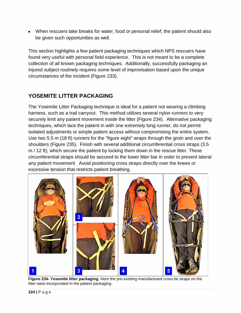
224 | P a g e
• When rescuers take breaks for water, food or personal relief, the patient should also be given such opportunities as well.
This section highlights a few patient packaging techniques which NPS rescuers have found very useful with personal field experience. This is not meant to be a complete collection of all known packaging techniques. Additionally, successfully packaging an injured subject routinely requires some level of improvisation based upon the unique circumstances of the incident (Figure 233).
YOSEMITE LITTER PACKAGING The Yosemite Litter Packaging technique is ideal for a patient not wearing a climbing harness, such as a trail carryout. This method utilizes several nylon runners to very securely limit any patient movement inside the litter (Figure 234). Alternative packaging techniques, which lace the patient in with one extremely long runner, do not permit isolated adjustments or simple patient access without compromising the entire system. Use two 5.5 m (18 ft) runners for the "figure eight" wraps through the groin and over the shoulders (Figure 235). Finish with several additional circumferential cross straps (3.5 m / 12 ft), which secure the patient by locking them down in the rescue litter. These circumferential straps should be secured to the lower litter bar in order to prevent lateral any patient movement Avoid positioning cross straps directly over the knees or excessive tension that restricts patient breathing.
Figure 234- Yosemite litter packaging. Here the pre-existing manufactured cross-tie straps on the litter were incorporated in the patient packaging.
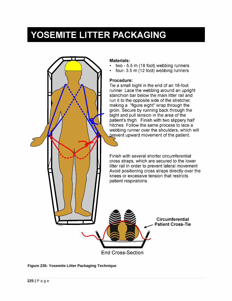
225 | P a g e
Figure 235- Yosemite Litter Packaging Technique
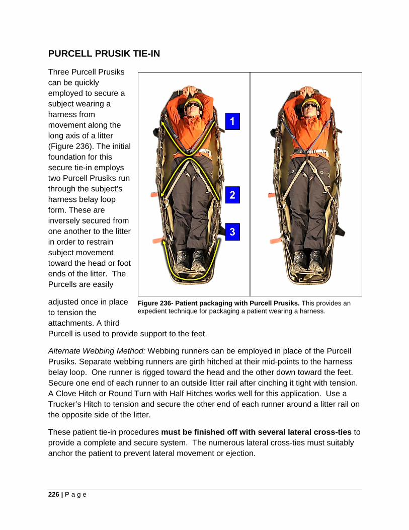
226 | P a g e
PURCELL PRUSIK TIE-IN
Three Purcell Prusiks can be quickly employed to secure a subject wearing a harness from movement along the long axis of a litter (Figure 236). The initial foundation for this secure tie-in employs two Purcell Prusiks run through the subject’s harness belay loop form. These are inversely secured from one another to the litter in order to restrain subject movement toward the head or foot ends of the litter. The Purcells are easily
adjusted once in place to tension the attachments. A third Purcell is used to provide support to the feet.
Alternate Webbing Method: Webbing runners can be employed in place of the Purcell Prusiks. Separate webbing runners are girth hitched at their mid-points to the harness belay loop. One runner is rigged toward the head and the other down toward the feet. Secure one end of each runner to an outside litter rail after cinching it tight with tension. A Clove Hitch or Round Turn with Half Hitches works well for this application. Use a Trucker’s Hitch to tension and secure the other end of each runner around a litter rail on the opposite side of the litter.
These patient tie-in procedures must be finished off with several lateral cross-ties to provide a complete and secure system. The numerous lateral cross-ties must suitably anchor the patient to prevent lateral movement or ejection.
Figure 236- Patient packaging with Purcell Prusiks. This provides an expedient technique for packaging a patient wearing a harness.
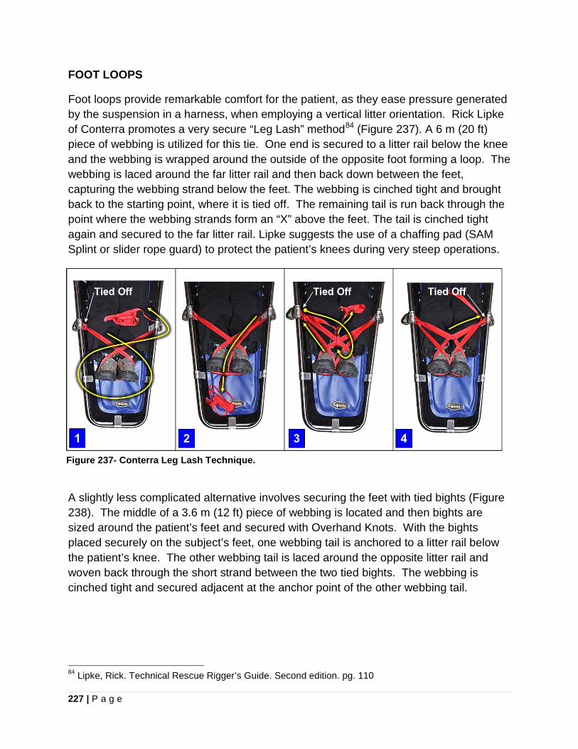
227 | P a g e
FOOT LOOPS
Foot loops provide remarkable comfort for the patient, as they ease pressure generated by the suspension in a harness, when employing a vertical litter orientation. Rick Lipke of Conterra promotes a very secure “Leg Lash” method84 (Figure 237). A 6 m (20 ft) piece of webbing is utilized for this tie. One end is secured to a litter rail below the knee and the webbing is wrapped around the outside of the opposite foot forming a loop. The webbing is laced around the far litter rail and then back down between the feet, capturing the webbing strand below the feet. The webbing is cinched tight and brought back to the starting point, where it is tied off. The remaining tail is run back through the point where the webbing strands form an “X” above the feet. The tail is cinched tight again and secured to the far litter rail. Lipke suggests the use of a chaffing pad (SAM Splint or slider rope guard) to protect the patient’s knees during very steep operations.
Figure 237- Conterra Leg Lash Technique.
A slightly less complicated alternative involves securing the feet with tied bights (Figure 238). The middle of a 3.6 m (12 ft) piece of webbing is located and then bights are sized around the patient’s feet and secured with Overhand Knots. With the bights placed securely on the subject’s feet, one webbing tail is anchored to a litter rail below the patient’s knee. The other webbing tail is laced around the opposite litter rail and woven back through the short strand between the two tied bights. The webbing is cinched tight and secured adjacent at the anchor point of the other webbing tail.
84 Lipke, Rick. Technical Rescue Rigger’s Guide. Second edition. pg. 110
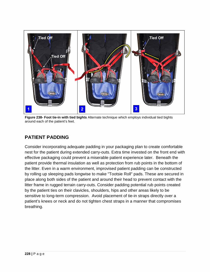
228 | P a g e
Figure 238- Foot tie-in with tied bights Alternate technique which employs individual tied bights around each of the patient’s feet.
PATIENT PADDING
Consider incorporating adequate padding in your packaging plan to create comfortable nest for the patient during extended carry-outs. Extra time invested on the front end with effective packaging could prevent a miserable patient experience later. Beneath the patient provide thermal insulation as well as protection from rub points in the bottom of the litter. Even in a warm environment, improvised patient padding can be constructed by rolling up sleeping pads longwise to make "Tootsie Roll" pads. These are secured in place along both sides of the patient and around their head to prevent contact with the litter frame in rugged terrain carry-outs. Consider padding potential rub points created by the patient ties on their clavicles, shoulders, hips and other areas likely to be sensitive to long-term compression. Avoid placement of tie-in straps directly over a patient’s knees or neck and do not tighten chest straps in a manner that compromises breathing.
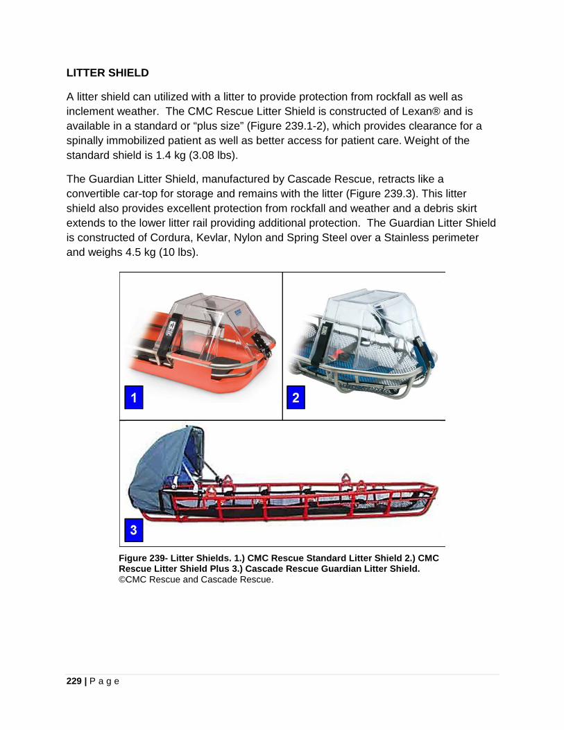
229 | P a g e
LITTER SHIELD
A litter shield can utilized with a litter to provide protection from rockfall as well as inclement weather. The CMC Rescue Litter Shield is constructed of Lexan® and is available in a standard or “plus size” (Figure 239.1-2), which provides clearance for a spinally immobilized patient as well as better access for patient care. Weight of the standard shield is 1.4 kg (3.08 lbs).
The Guardian Litter Shield, manufactured by Cascade Rescue, retracts like a convertible car-top for storage and remains with the litter (Figure 239.3). This litter shield also provides excellent protection from rockfall and weather and a debris skirt extends to the lower litter rail providing additional protection. The Guardian Litter Shield is constructed of Cordura, Kevlar, Nylon and Spring Steel over a Stainless perimeter and weighs 4.5 kg (10 lbs).
Figure 239- Litter Shields. 1.) CMC Rescue Standard Litter Shield 2.) CMC Rescue Litter Shield Plus 3.) Cascade Rescue Guardian Litter Shield. ©CMC Rescue and Cascade Rescue.
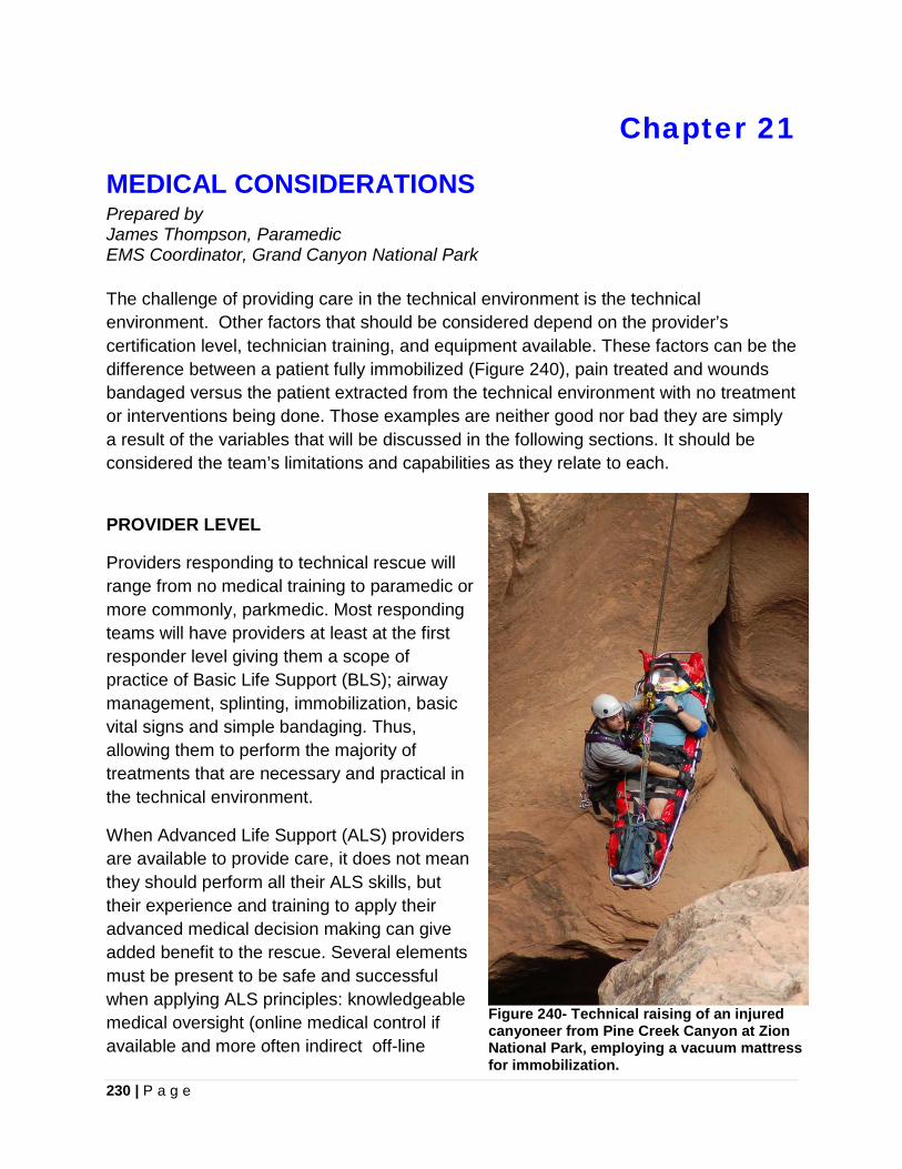
230 | P a g e
Chapter 21
MEDICAL CONSIDERATIONS Prepared by James Thompson, Paramedic EMS Coordinator, Grand Canyon National Park The challenge of providing care in the technical environment is the technical environment. Other factors that should be considered depend on the provider’s certification level, technician training, and equipment available. These factors can be the difference between a patient fully immobilized (Figure 240), pain treated and wounds bandaged versus the patient extracted from the technical environment with no treatment or interventions being done. Those examples are neither good nor bad they are simply a result of the variables that will be discussed in the following sections. It should be considered the team’s limitations and capabilities as they relate to each.
PROVIDER LEVEL
Providers responding to technical rescue will range from no medical training to paramedic or more commonly, parkmedic. Most responding teams will have providers at least at the first responder level giving them a scope of practice of Basic Life Support (BLS); airway management, splinting, immobilization, basic vital signs and simple bandaging. Thus, allowing them to perform the majority of treatments that are necessary and practical in the technical environment.
When Advanced Life Support (ALS) providers are available to provide care, it does not mean they should perform all their ALS skills, but their experience and training to apply their advanced medical decision making can give added benefit to the rescue. Several elements must be present to be safe and successful when applying ALS principles: knowledgeable medical oversight (online medical control if available and more often indirect off-line
Figure 240- Technical raising of an injured canyoneer from Pine Creek Canyon at Zion National Park, employing a vacuum mattress for immobilization.
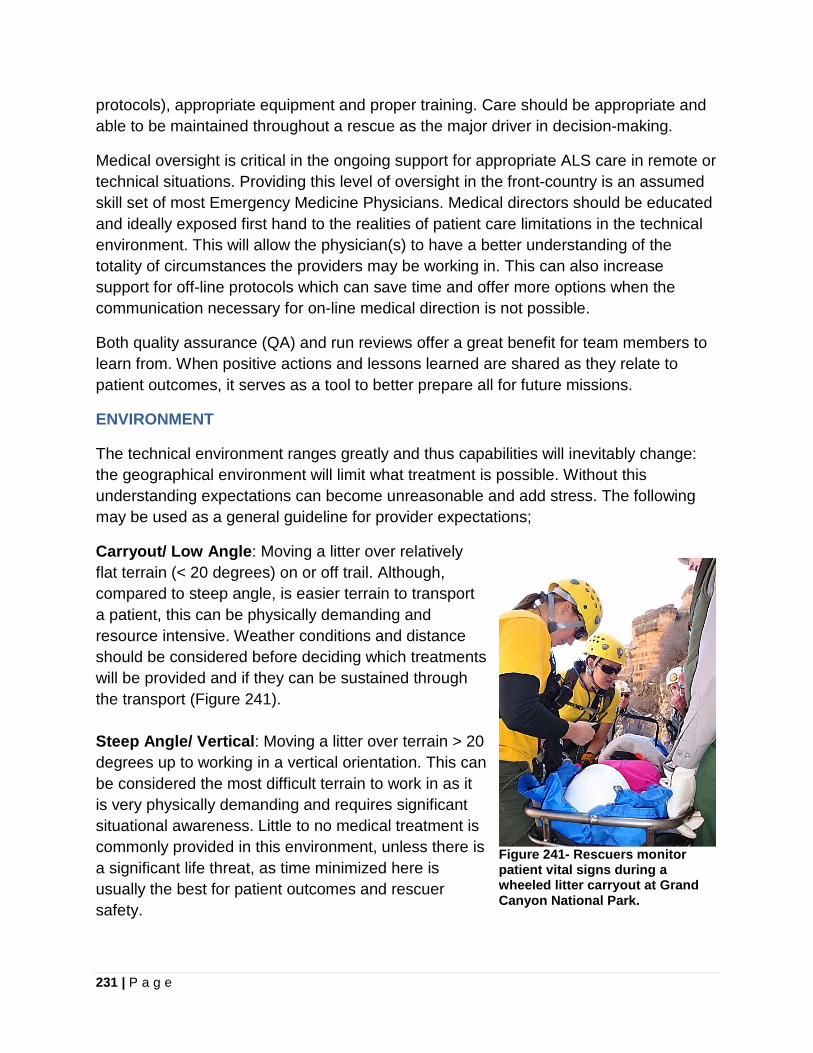
231 | P a g e
protocols), appropriate equipment and proper training. Care should be appropriate and able to be maintained throughout a rescue as the major driver in decision-making.
Medical oversight is critical in the ongoing support for appropriate ALS care in remote or technical situations. Providing this level of oversight in the front-country is an assumed skill set of most Emergency Medicine Physicians. Medical directors should be educated and ideally exposed first hand to the realities of patient care limitations in the technical environment. This will allow the physician(s) to have a better understanding of the totality of circumstances the providers may be working in. This can also increase support for off-line protocols which can save time and offer more options when the communication necessary for on-line medical direction is not possible.
Both quality assurance (QA) and run reviews offer a great benefit for team members to learn from. When positive actions and lessons learned are shared as they relate to patient outcomes, it serves as a tool to better prepare all for future missions.
ENVIRONMENT
The technical environment ranges greatly and thus capabilities will inevitably change: the geographical environment will limit what treatment is possible. Without this understanding expectations can become unreasonable and add stress. The following may be used as a general guideline for provider expectations;
Carryout/ Low Angle: Moving a litter over relatively flat terrain (< 20 degrees) on or off trail. Although, compared to steep angle, is easier terrain to transport a patient, this can be physically demanding and resource intensive. Weather conditions and distance should be considered before deciding which treatments will be provided and if they can be sustained through the transport (Figure 241). Steep Angle/ Vertical: Moving a litter over terrain > 20 degrees up to working in a vertical orientation. This can be considered the most difficult terrain to work in as it is very physically demanding and requires significant situational awareness. Little to no medical treatment is commonly provided in this environment, unless there is a significant life threat, as time minimized here is usually the best for patient outcomes and rescuer safety.
Figure 241- Rescuers monitor patient vital signs during a wheeled litter carryout at Grand Canyon National Park.
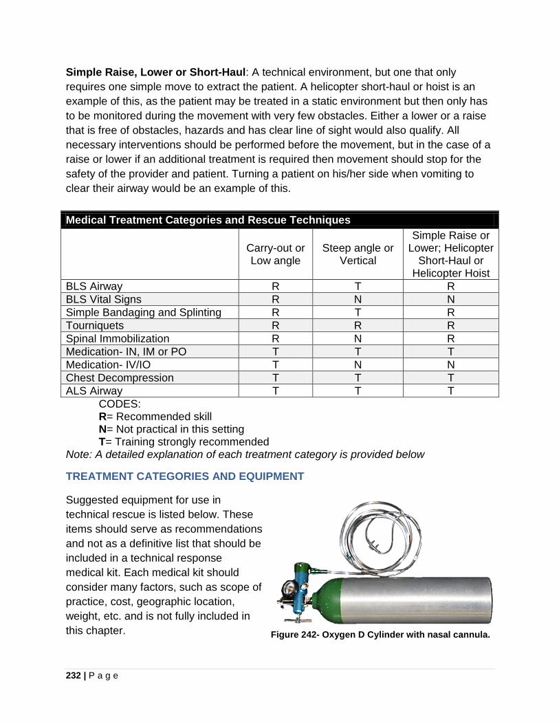
232 | P a g e
Simple Raise, Lower or Short-Haul: A technical environment, but one that only requires one simple move to extract the patient. A helicopter short-haul or hoist is an example of this, as the patient may be treated in a static environment but then only has to be monitored during the movement with very few obstacles. Either a lower or a raise that is free of obstacles, hazards and has clear line of sight would also qualify. All necessary interventions should be performed before the movement, but in the case of a raise or lower if an additional treatment is required then movement should stop for the safety of the provider and patient. Turning a patient on his/her side when vomiting to clear their airway would be an example of this. Medical Treatment Categories and Rescue Techniques
Carry-out or Low angle
Steep angle or Vertical
Simple Raise or Lower; Helicopter
Short-Haul or Helicopter Hoist
BLS Airway R T R BLS Vital Signs R N N Simple Bandaging and Splinting R T R Tourniquets R R R Spinal Immobilization R N R Medication- IN, IM or PO T T T Medication- IV/IO T N N Chest Decompression T T T ALS Airway T T T
CODES: R= Recommended skill N= Not practical in this setting T= Training strongly recommended
Note: A detailed explanation of each treatment category is provided below
TREATMENT CATEGORIES AND EQUIPMENT
Suggested equipment for use in technical rescue is listed below. These items should serve as recommendations and not as a definitive list that should be included in a technical response medical kit. Each medical kit should consider many factors, such as scope of practice, cost, geographic location, weight, etc. and is not fully included in this chapter. Figure 242- Oxygen D Cylinder with nasal cannula.
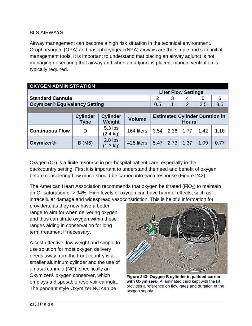
233 | P a g e
BLS AIRWAYS
Airway management can become a high risk situation in the technical environment. Oropharyngeal (OPA) and nasopharyngeal (NPA) airways are the simple and safe initial management tools. It is important to understand that placing an airway adjunct is not managing or securing that airway and when an adjunct is placed, manual ventilation is typically required.
Oxygen (O2) is a finite resource in pre-hospital patient care, especially in the backcountry setting. First it is important to understand the need and benefit of oxygen before considering how much should be carried into each response (Figure 242).
The American Heart Association recommends that oxygen be titrated (FiO2) to maintain an O2 saturation of > 94%. High levels of oxygen can have harmful effects, such as intracellular damage and widespread vasoconstriction. This is helpful information for providers, as they now have a better range to aim for when delivering oxygen and thus can titrate oxygen within these ranges aiding in conservation for long term treatment if necessary.
A cost effective, low weight and simple to use solution for most oxygen delivery needs away from the front country is a smaller aluminum cylinder and the use of a nasal cannula (NC), specifically an Oxymizer® oxygen conserver, which employs a disposable reservoir cannula. The pendant style Oxymizer NC can be
OXYGEN ADMINISTRATION Liter Flow Settings
Standard Cannula 2 3 4 5 6 Oxymizer® Equivalency Setting 0.5 1 2 2.5 3.5 Cylinder
Type Cylinder Weight Volume Estimated Cylinder Duration in
Hours
Continuous Flow D 5.3 lbs (2.4 kg) 164 liters 3.54 2.36 1.77 1.42 1.18
Oxymizer® B (M6) 2.8 lbs (1.3 kg) 425 liters 5.47 2.73 1.37 1.09 0.77
Figure 243- Oxygen B cylinder in padded carrier with Oxymizer®. A laminated card kept with the kit provides a reference on flow rates and duration of the oxygen supply.
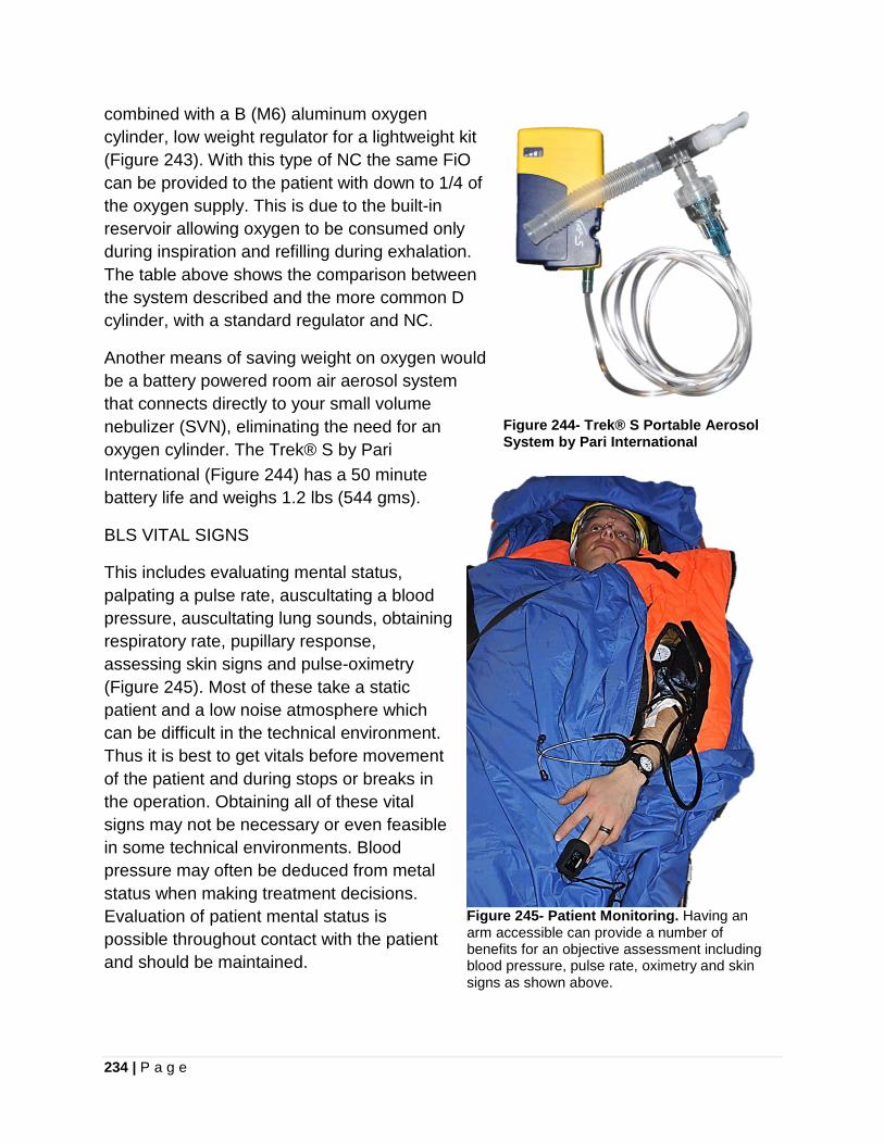
234 | P a g e
combined with a B (M6) aluminum oxygen cylinder, low weight regulator for a lightweight kit (Figure 243). With this type of NC the same FiO can be provided to the patient with down to 1/4 of the oxygen supply. This is due to the built-in reservoir allowing oxygen to be consumed only during inspiration and refilling during exhalation. The table above shows the comparison between the system described and the more common D cylinder, with a standard regulator and NC.
Another means of saving weight on oxygen would be a battery powered room air aerosol system that connects directly to your small volume nebulizer (SVN), eliminating the need for an oxygen cylinder. The Trek® S by Pari International (Figure 244) has a 50 minute battery life and weighs 1.2 lbs (544 gms).
Figure 244- Trek® S Portable Aerosol System by Pari International
BLS VITAL SIGNS
This includes evaluating mental status, palpating a pulse rate, auscultating a blood pressure, auscultating lung sounds, obtaining respiratory rate, pupillary response, assessing skin signs and pulse-oximetry (Figure 245). Most of these take a static patient and a low noise atmosphere which can be difficult in the technical environment. Thus it is best to get vitals before movement of the patient and during stops or breaks in the operation. Obtaining all of these vital signs may not be necessary or even feasible in some technical environments. Blood pressure may often be deduced from metal status when making treatment decisions. Evaluation of patient mental status is possible throughout contact with the patient and should be maintained.
Figure 245- Patient Monitoring. Having an arm accessible can provide a number of benefits for an objective assessment including blood pressure, pulse rate, oximetry and skin signs as shown above.
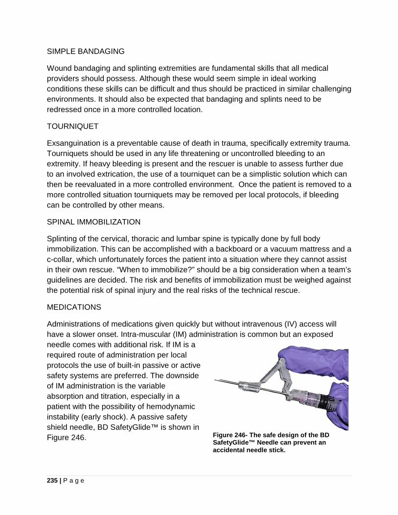
235 | P a g e
SIMPLE BANDAGING
Wound bandaging and splinting extremities are fundamental skills that all medical providers should possess. Although these would seem simple in ideal working conditions these skills can be difficult and thus should be practiced in similar challenging environments. It should also be expected that bandaging and splints need to be redressed once in a more controlled location.
TOURNIQUET
Exsanguination is a preventable cause of death in trauma, specifically extremity trauma. Tourniquets should be used in any life threatening or uncontrolled bleeding to an extremity. If heavy bleeding is present and the rescuer is unable to assess further due to an involved extrication, the use of a tourniquet can be a simplistic solution which can then be reevaluated in a more controlled environment. Once the patient is removed to a more controlled situation tourniquets may be removed per local protocols, if bleeding can be controlled by other means.
SPINAL IMMOBILIZATION
Splinting of the cervical, thoracic and lumbar spine is typically done by full body immobilization. This can be accomplished with a backboard or a vacuum mattress and a c-collar, which unfortunately forces the patient into a situation where they cannot assist in their own rescue. “When to immobilize?” should be a big consideration when a team’s guidelines are decided. The risk and benefits of immobilization must be weighed against the potential risk of spinal injury and the real risks of the technical rescue.
MEDICATIONS
Administrations of medications given quickly but without intravenous (IV) access will have a slower onset. Intra-muscular (IM) administration is common but an exposed needle comes with additional risk. If IM is a required route of administration per local protocols the use of built-in passive or active safety systems are preferred. The downside of IM administration is the variable absorption and titration, especially in a patient with the possibility of hemodynamic instability (early shock). A passive safety shield needle, BD SafetyGlide™ is shown in Figure 246.
Figure 246- The safe design of the BD SafetyGlide™ Needle can prevent an accidental needle stick.
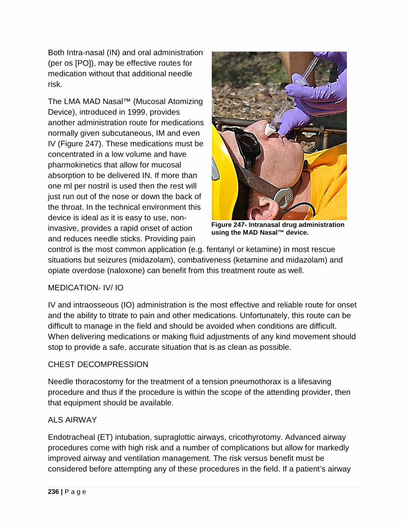
236 | P a g e
Both Intra-nasal (IN) and oral administration (per os [PO]), may be effective routes for medication without that additional needle risk.
The LMA MAD Nasal™ (Mucosal Atomizing Device), introduced in 1999, provides another administration route for medications normally given subcutaneous, IM and even IV (Figure 247). These medications must be concentrated in a low volume and have pharmokinetics that allow for mucosal absorption to be delivered IN. If more than one ml per nostril is used then the rest will just run out of the nose or down the back of the throat. In the technical environment this device is ideal as it is easy to use, non-invasive, provides a rapid onset of action and reduces needle sticks. Providing pain control is the most common application (e.g. fentanyl or ketamine) in most rescue situations but seizures (midazolam), combativeness (ketamine and midazolam) and opiate overdose (naloxone) can benefit from this treatment route as well.
Figure 247- Intranasal drug administration using the MAD Nasal™ device.
MEDICATION- IV/ IO
IV and intraosseous (IO) administration is the most effective and reliable route for onset and the ability to titrate to pain and other medications. Unfortunately, this route can be difficult to manage in the field and should be avoided when conditions are difficult. When delivering medications or making fluid adjustments of any kind movement should stop to provide a safe, accurate situation that is as clean as possible.
CHEST DECOMPRESSION
Needle thoracostomy for the treatment of a tension pneumothorax is a lifesaving procedure and thus if the procedure is within the scope of the attending provider, then that equipment should be available.
ALS AIRWAY
Endotracheal (ET) intubation, supraglottic airways, cricothyrotomy. Advanced airway procedures come with high risk and a number of complications but allow for markedly improved airway and ventilation management. The risk versus benefit must be considered before attempting any of these procedures in the field. If a patient’s airway
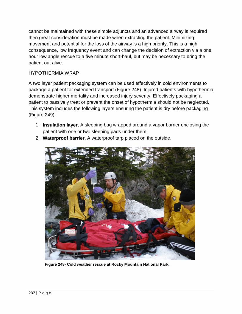
237 | P a g e
cannot be maintained with these simple adjuncts and an advanced airway is required then great consideration must be made when extracting the patient. Minimizing movement and potential for the loss of the airway is a high priority. This is a high consequence, low frequency event and can change the decision of extraction via a one hour low angle rescue to a five minute short-haul, but may be necessary to bring the patient out alive.
HYPOTHERMIA WRAP
A two layer patient packaging system can be used effectively in cold environments to package a patient for extended transport (Figure 248). Injured patients with hypothermia demonstrate higher mortality and increased injury severity. Effectively packaging a patient to passively treat or prevent the onset of hypothermia should not be neglected. This system includes the following layers ensuring the patient is dry before packaging (Figure 249).
1. Insulation layer. A sleeping bag wrapped around a vapor barrier enclosing the patient with one or two sleeping pads under them.
2. Waterproof barrier. A waterproof tarp placed on the outside.
Figure 248- Cold weather rescue at Rocky Mountain National Park.
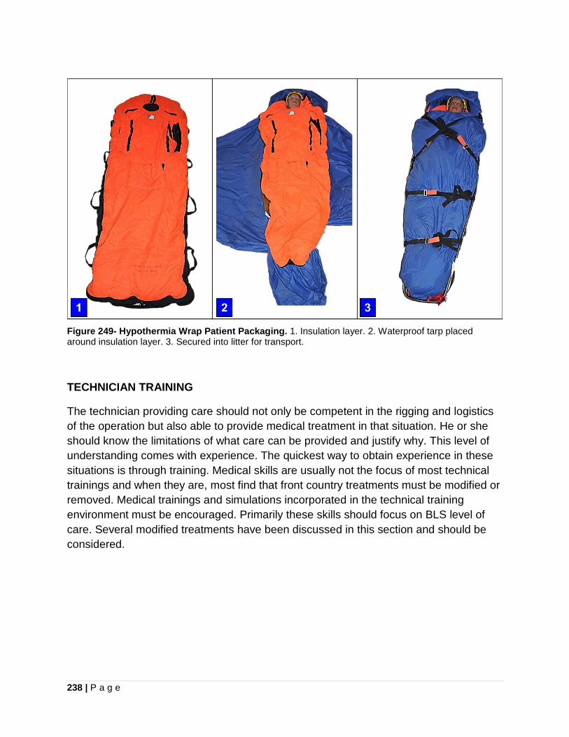
238 | P a g e
Figure 249- Hypothermia Wrap Patient Packaging. 1. Insulation layer. 2. Waterproof tarp placed around insulation layer. 3. Secured into litter for transport.
TECHNICIAN TRAINING
The technician providing care should not only be competent in the rigging and logistics of the operation but also able to provide medical treatment in that situation. He or she should know the limitations of what care can be provided and justify why. This level of understanding comes with experience. The quickest way to obtain experience in these situations is through training. Medical skills are usually not the focus of most technical trainings and when they are, most find that front country treatments must be modified or removed. Medical trainings and simulations incorporated in the technical training environment must be encouraged. Primarily these skills should focus on BLS level of care. Several modified treatments have been discussed in this section and should be considered.
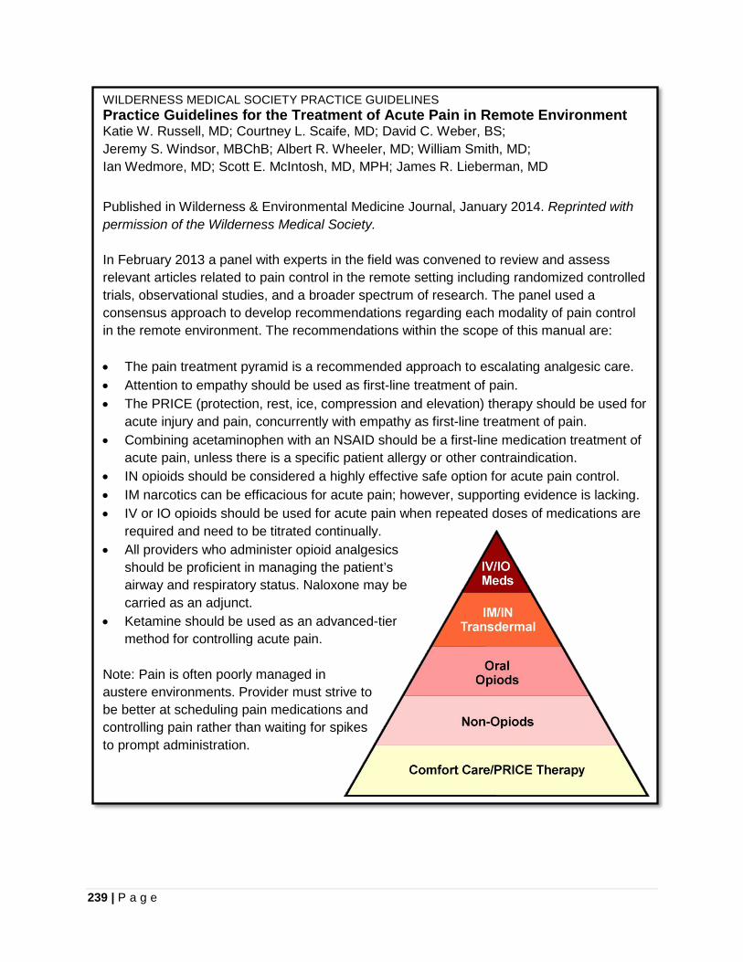
239 | P a g e
WILDERNESS MEDICAL SOCIETY PRACTICE GUIDELINES Practice Guidelines for the Treatment of Acute Pain in Remote Environment Katie W. Russell, MD; Courtney L. Scaife, MD; David C. Weber, BS; Jeremy S. Windsor, MBChB; Albert R. Wheeler, MD; William Smith, MD; Ian Wedmore, MD; Scott E. McIntosh, MD, MPH; James R. Lieberman, MD Published in Wilderness & Environmental Medicine Journal, January 2014. Reprinted with permission of the Wilderness Medical Society. In February 2013 a panel with experts in the field was convened to review and assess relevant articles related to pain control in the remote setting including randomized controlled trials, observational studies, and a broader spectrum of research. The panel used a consensus approach to develop recommendations regarding each modality of pain control in the remote environment. The recommendations within the scope of this manual are: • The pain treatment pyramid is a recommended approach to escalating analgesic care. • Attention to empathy should be used as first-line treatment of pain. • The PRICE (protection, rest, ice, compression and elevation) therapy should be used for
acute injury and pain, concurrently with empathy as first-line treatment of pain. • Combining acetaminophen with an NSAID should be a first-line medication treatment of
acute pain, unless there is a specific patient allergy or other contraindication. • IN opioids should be considered a highly effective safe option for acute pain control. • IM narcotics can be efficacious for acute pain; however, supporting evidence is lacking. • IV or IO opioids should be used for acute pain when repeated doses of medications are
required and need to be titrated continually. • All providers who administer opioid analgesics
should be proficient in managing the patient’s airway and respiratory status. Naloxone may be carried as an adjunct.
• Ketamine should be used as an advanced-tier method for controlling acute pain.
Note: Pain is often poorly managed in austere environments. Provider must strive tobe better at scheduling pain medications and controlling pain rather than waiting for spikes to prompt administration.

240 | P a g e
ORTHOSTATIC INTOLERANCE
(i.e. Suspension Trauma, Harness Induced Pathology and Harness Hang Syndrome) Orthostatic Intolerance: the development of symptoms such as light-headedness, palpitations, tremulousness, poor concentration, fatigue, nausea, dizziness, headache, sweating, weakness and occasional fainting during upright standing. When motionless in an upright position blood can accumulate in the veins due to gravity and failure of the venous pump, called “venous pooling,” and cause orthostatic intolerance. When a person is standing or in a vertical position and they lose consciousness, he or she will fall into a horizontal position. This position will self-correct this venous pooling, as the legs are now at the same level as the heart and brain with a rapid return to consciousness. This pathology becomes a serious concern when remaining suspended upright and unconscious. Because this cannot be corrected by falling to a horizontal position, the body continues to be hypo-perfused as brain injury and cardiac arrest become a real possibility, because the body is suffering from regional hypoxia. Rescue personnel must be aware of this danger to a suspended victim (and themselves) and make every effort to get them to the ground (horizontal) as quickly as possible! • If a patient must be raised or lowered in a vertical orientation, attempt to minimize
the time suspended in this orientation. Elevate their legs if warning signs develop. • Having a conscious patient do leg contractions can assist with circulation in their
legs. • Suspension trauma has resulted in the death of relatively uninjured casualties,
depending on the subject and their harness type, while suspended upright for as little as 10-30 minutes.
References: 1. Mortimer, Dr. Roger, Risks and Management of Prolonged Suspension in an
Alpine Harness, Wilderness & Environmental Medicine, Vol. 22, number 1, 2011. http://www.wemjournal.org/article/S1080-6032(10)00320-0/fulltext Accessed 03-09-2014.
2. Occupational Safety & Health Administration, Suspension Trauma/Orthostatic Intolerance, Safety and Health Information Bulletin, 2011. https://www.osha.gov/dts/shib/shib032404.html Accessed 03-09-2014.
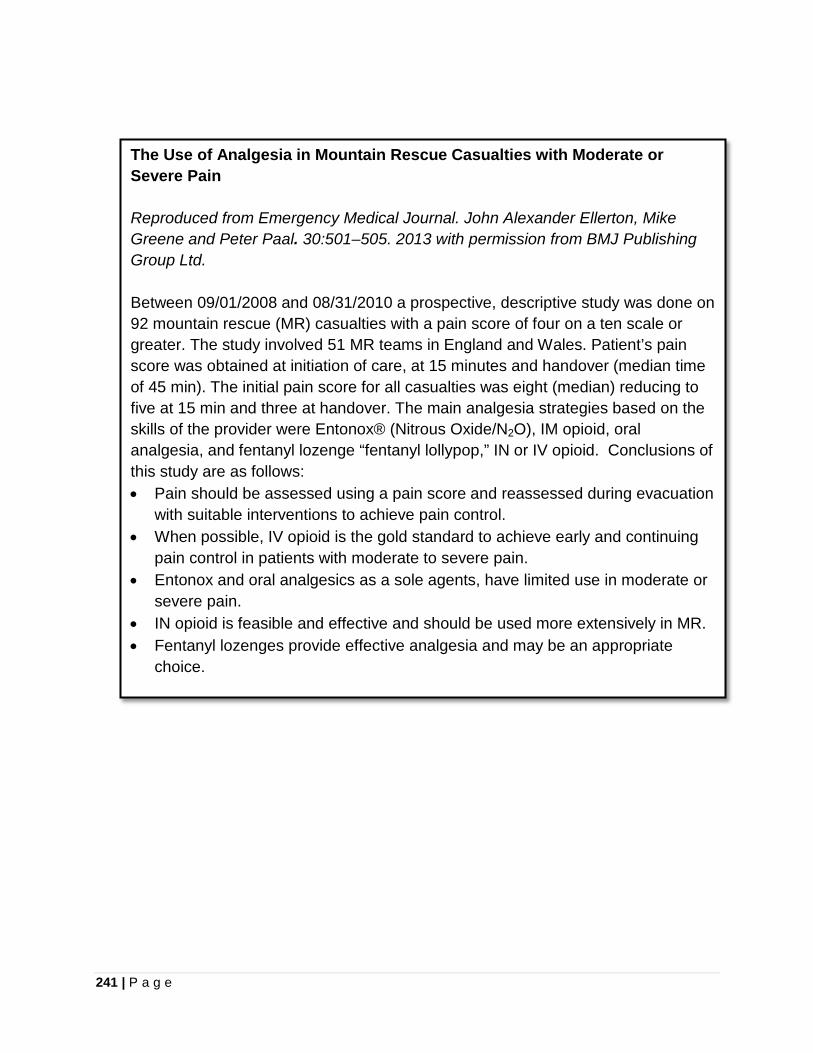
241 | P a g e
The Use of Analgesia in Mountain Rescue Casualties with Moderate or Severe Pain Reproduced from Emergency Medical Journal. John Alexander Ellerton, Mike Greene and Peter Paal. 30:501–505. 2013 with permission from BMJ Publishing Group Ltd. Between 09/01/2008 and 08/31/2010 a prospective, descriptive study was done on 92 mountain rescue (MR) casualties with a pain score of four on a ten scale or greater. The study involved 51 MR teams in England and Wales. Patient’s pain score was obtained at initiation of care, at 15 minutes and handover (median time of 45 min). The initial pain score for all casualties was eight (median) reducing to five at 15 min and three at handover. The main analgesia strategies based on the skills of the provider were Entonox® (Nitrous Oxide/N2O), IM opioid, oral analgesia, and fentanyl lozenge “fentanyl lollypop,” IN or IV opioid. Conclusions of this study are as follows: • Pain should be assessed using a pain score and reassessed during evacuation
with suitable interventions to achieve pain control. • When possible, IV opioid is the gold standard to achieve early and continuing
pain control in patients with moderate to severe pain. • Entonox and oral analgesics as a sole agents, have limited use in moderate or
severe pain. • IN opioid is feasible and effective and should be used more extensively in MR. • Fentanyl lozenges provide effective analgesia and may be an appropriate
choice.
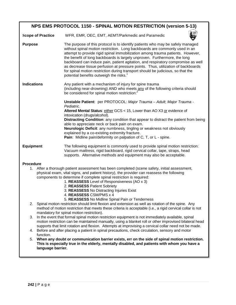
242 | P a g e
NPS EMS PROTOCOL 1150 - SPINAL MOTION RESTRICTION (version 5-13) Scope of Practice WFR, EMR, OEC, EMT, AEMT/Parkmedic and Paramedic Purpose The purpose of this protocol is to identify patients who may be safely managed
without spinal motion restriction. Long backboards are commonly used in an attempt to provide rigid spinal immobilization among trauma patients. However, the benefit of long backboards is largely unproven. Furthermore, the long backboard can induce pain, patient agitation, and respiratory compromise as well as decrease tissue perfusion at pressure points. Thus, utilization of backboards for spinal motion restriction during transport should be judicious, so that the potential benefits outweigh the risks.1
Indications Any patient with a mechanism of injury for spine trauma (including near-drowning) AND who meets any of the following criteria should be considered for spinal motion restriction:2
Unstable Patient: per PROTOCOL: Major Trauma – Adult; Major Trauma - Pediatric. Altered Mental Status: either GCS < 15, Lower than AO X3 or evidence of intoxication (drugs/alcohol). Distracting Condition: any condition that appear to distract the patient from being able to appreciate neck or back pain on exam. Neurologic Deficit: any numbness, tingling or weakness not obviously explained by a co-existing extremity fracture. Pain: Midline pain/deformity on palpation of C, T, or L - spine.
Equipment The following equipment is commonly used to provide spinal motion restriction:
Vacuum mattress, rigid backboard, rigid cervical collar, tape, straps, head supports. Alternative methods and equipment may also be acceptable.
Procedure
1. After a thorough patient assessment has been completed (scene safety, initial assessment, physical exam, vital signs, and patient history), the provider can reassess the following components to determine if complete spinal restriction is required: 1. REASSESS Level of Responsiveness (AO x 3) 2. REASSESS Patient Sobriety 3. REASSESS No Distracting Injuries Exist 4. REASSESS CSM/PMS x 4 5. REASSESS No Midline Spinal Pain or Tenderness
2. Spinal motion restriction should limit flexion and extension as well as rotation of the spine. Any method of motion restriction that meets these criteria is acceptable (i.e., a rigid cervical collar is not mandatory for spinal motion restriction).
3. In the event that formal spinal motion restriction equipment is not immediately available, spinal motion restriction can be maintained manually, using a blanket roll or other improvised bilateral head supports that limit rotation and flexion. Attempts at improvising a cervical collar need not be made.
4. Before and after placing a patient in spinal precautions, check circulation, sensory and motor function.
5. When any doubt or communication barrier exists, err on the side of spinal motion restriction. This is especially true in the elderly, mentally disabled, and patients with whom you have a language barrier.
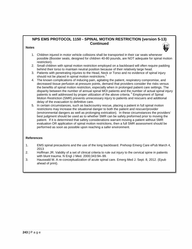
243 | P a g e
NPS EMS PROTOCOL 1150 - SPINAL MOTION RESTRICTION (version 5-13) Continued
Notes
1. Children injured in motor vehicle collisions shall be transported in their car seats whenever possible (Booster seats, designed for children 40-80 pounds, are NOT adequate for spinal motion restriction).
2. Small children with spinal motion restriction employed on a backboard will often require padding behind their torso to maintain neutral position because of their relatively large head.
3. Patients with penetrating injuries to the Head, Neck or Torso and no evidence of spinal injury should not be placed in spinal motion restrictions.1
4. The known complications of inducing pain, agitating the patient, respiratory compromise, and decreased tissue perfusion at pressure points, demand that providers consider the risks versus the benefits of spinal motion restriction, especially when in prolonged patient care settings. The disparity between the number of annual spinal MOI patients and the number of actual spinal injury patients is well addressed by proper utilization of the above criteria. 3 Employment of Spinal Motion Restriction (SMR) prevents unnecessary injury to patients and rescuers and additional delay of the evacuation to definitive care.
5. In certain circumstances, such as backcountry rescue, placing a patient in full spinal motion restrictions may increase the situational danger to both the patient and rescuer/provider (environmental dangers as well as prolonging extrication). In these circumstances the providers’ best judgment should be used as to whether SMR can be safely preformed prior to moving the patient. If it is determined that safety considerations warrant moving a patient without SMR evaluation OR application of spinal motion restrictions, then a full SMR assessment should be performed as soon as possible upon reaching a safer environment.
References 1. EMS spinal precautions and the use of the long backboard. Prehosp Emerg Care ePub March 4,
2013 2. Hoffman JR. Validity of a set of clinical criteria to rule out injury to the cervical spine in patients
with blunt trauma. N Engl J Med. 2000;343:94–99. 3. Hauswald M. A re-conceptualization of acute spinal care. Emerg Med J. Sept. 8, 2012. (Epub
ahead of print).
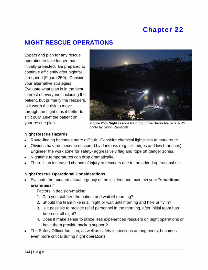
244 | P a g e
Chapter 22
NIGHT RESCUE OPERATIONS
Expect and plan for any rescue operation to take longer than initially projected. Be prepared to continue efficiently after nightfall, if required (Figure 250). Consider your alternative strategies. Evaluate what plan is in the best interest of everyone, including the patient, but primarily the rescuers. Is it worth the risk to move through the night or is it better to sit it out? Brief the patient on your rescue plan. Night Rescue Hazards • Route-finding becomes more difficult. Consider chemical lightsticks to mark route. • Obvious hazards become obscured by darkness (e.g. cliff edges and low branches).
Engineer the work zone for safety- aggressively flag and rope off danger zones. • Nighttime temperatures can drop dramatically. • There is an increased chance of injury to rescuers due to the added operational risk. Night Rescue Operational Considerations • Evaluate the updated actual urgency of the incident and maintain your "situational
awareness." Factors in decision-making: 1. Can you stabilize the patient and wait till morning? 2. Should the team hike in all night or wait until morning and hike or fly in? 3. Is it possible to provide relief personnel in the morning, after initial team has
been out all night? 4. Does it make sense to utilize less experienced rescuers on night operations or
have them provide backup support? • The Safety Officer function, as well as safety inspections among peers, becomes
even more critical during night operations.
Figure 250- Night rescue training in the Sierra Nevada. NPS photo by Jason Ramsdell

245 | P a g e
• The initial response team should travel as a group in the backcountry. Don’t allow them to separate and get lost enroute.
• Scout and flag the access route with teams of two rescuers. Consider using reflective flagging or chemical light sticks.
• Leave a rescuer at the bottom of the cliff as a spotter out of the danger of rockfall. • Bring what you need, since extra food and supplies cannot be flown in at night. • Drink water during night operations. It is very easy to overlook your personal
hydration on an emergency operation. • Conserve your radios. Not all of them need to be on at once, when rescuers are in
close proximity. • In cold temperature extremes keep your radio inside an insulating layer close to your
body. This will help prevent battery power loss. • Take opportunities to rest the team and prevent unsafe levels of fatigue. • Keep equipment and the scene well organized, which will prevent gear from
scattering and disappearing into the darkness. • Be aware that voices may carry farther in the darkness on a calm night. Personal Preparedness • Carry a headlamp even during day rescues, including extra bulb and batteries. • A backup light source should be carried with you. • Strobe lights are a very effective signaling, attraction or marking device.
HEADLAMPS
Headlamps provide an efficient light source for rescuers, while permitting them to keep their hands free for rigging tasks. Popular climbing helmets are designed with clips or brackets on the brim exterior to secure a headlamp in place. The development of headlamps equipped with LED's (light emitting diodes) have been a significant improvement for small battery-operated headlamps (Figure 251), however LED technology has existed for a long time. Oleg Losev, a Russian scientist, created the first LED in 1927.85 An LED is illuminated by the movement of electrons in a 85 Zheludev, Nikolay. The Life and Times of the LED- a 100-year history.
Figure 251- Petzl Pixa 3 LED headlamp can provide 50 lumens of constant lighting. © Petzl.

246 | P a g e
semiconductor material through the process of electroluminescence. Significant advances in LED technology are now matching incandescent bulb output. An LED uses ten times less current and therefore will operate ten times longer with the same battery. An LED doesn't have a filament that will burn out, with a possible useful life span of 100,000 hours, which translates to over 27 years of constant use.86 A PRIMER ON BATTERY TYPES87 Batteries store chemical energy and convert it to electrical energy. They are divided into two categories which include “primary” or non-rechargeable (disposable) and “secondary” or rechargeable.
Figure 252- Alkaline AA (LR6) size primary 1.5 volt battery cell can provide 1700 to 3000 milliamp-hours capacity.
PRIMARY (NON RECHARGEABLE) BATTERIES: Carbon Zinc- These low cost batteries are the older zinc-acidic manganese dioxide style, which are often marketed as “heavy duty” batteries. They provide very low power, but have a good shelf life. Alkaline- The zinc-alkaline manganese dioxide battery is the most commonly used primary battery (Figure 252). They provide more power-per-use than carbon-zinc as well in comparison to rechargeable (secondary) batteries. Alkaline batteries have an excellent shelf life. Lithium Cells- Lithium batteries offer some distinct performance advantages including a shelf-life exceeding 10-years and ability to work at very low temperatures. However, lithium batteries are mainly used in smaller formats (coins cells up to about AA size) because they can develop a hazardous phenomenon known as “thermal runaway” which would create a risk to consumers in larger sizes. Silver Oxide Cells- These batteries have a very high energy density, but are very expensive due to the high cost of silver. Silver oxide cells are primarily used in button cell format for watches and calculators. SECONDARY (RECHARGEABLE) BATTERIES: Rechargeable Alkaline- Rechargeable alkaline batteries are the lowest cost rechargeable cells. They provide a long shelf life for moderate-power applications; however their cycle life is less than most other rechargeable batteries. They do not contain toxic ingredients and can be disposed in regular landfills.
86 100,000 hour LED Lifespan. http://www.rabweb.com/100k.php 87 Pure Energy Solutions. Battery Types: Which Batteries to Use?
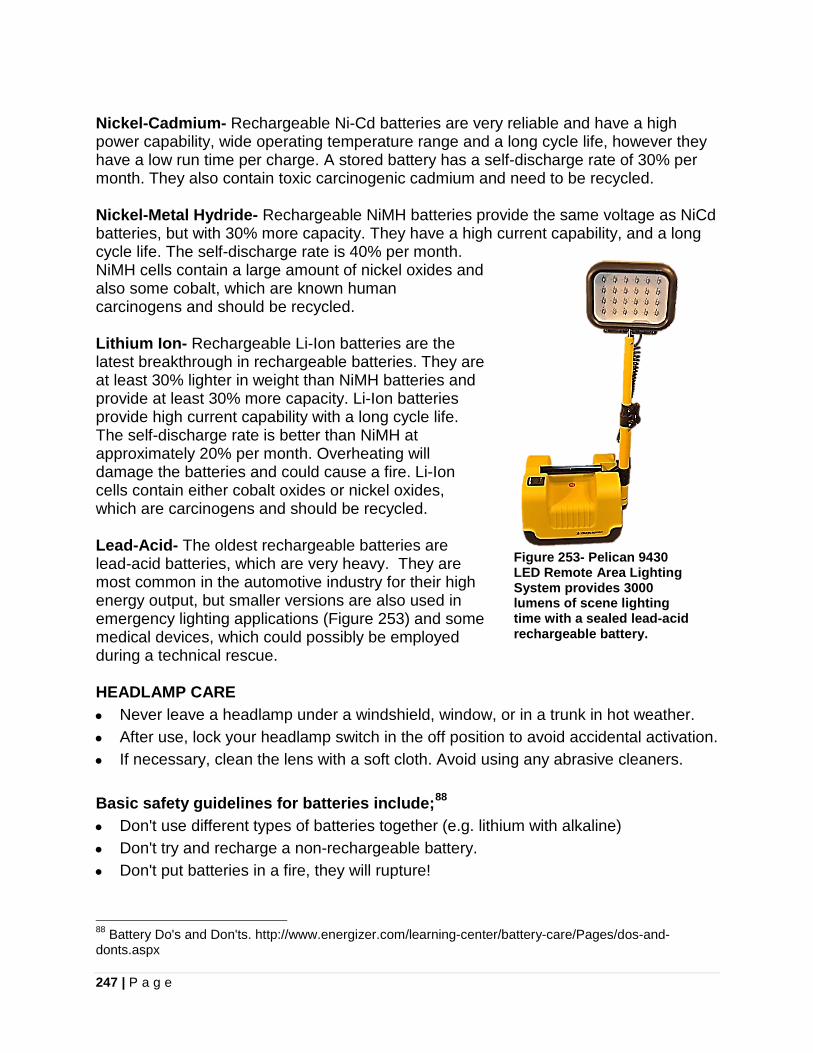
247 | P a g e
Nickel-Cadmium- Rechargeable Ni-Cd batteries are very reliable and have a high power capability, wide operating temperature range and a long cycle life, however they have a low run time per charge. A stored battery has a self-discharge rate of 30% per month. They also contain toxic carcinogenic cadmium and need to be recycled. Nickel-Metal Hydride- Rechargeable NiMH batteries provide the same voltage as NiCd batteries, but with 30% more capacity. They have a high current capability, and a long cycle life. The self-discharge rate is 40% per month. NiMH cells contain a large amount of nickel oxides and also some cobalt, which are known human carcinogens and should be recycled. Lithium Ion- Rechargeable Li-Ion batteries are the latest breakthrough in rechargeable batteries. They are at least 30% lighter in weight than NiMH batteries and provide at least 30% more capacity. Li-Ion batteries provide high current capability with a long cycle life. The self-discharge rate is better than NiMH at approximately 20% per month. Overheating will damage the batteries and could cause a fire. Li-Ion cells contain either cobalt oxides or nickel oxides, which are carcinogens and should be recycled. Lead-Acid- The oldest rechargeable batteries are lead-acid batteries, which are very heavy. They are most common in the automotive industry for their high energy output, but smaller versions are also used in emergency lighting applications (Figure 253) and some medical devices, which could possibly be employed during a technical rescue.
Figure 253- Pelican 9430 LED Remote Area Lighting System provides 3000 lumens of scene lighting time with a sealed lead-acid rechargeable battery.
HEADLAMP CARE • Never leave a headlamp under a windshield, window, or in a trunk in hot weather. • After use, lock your headlamp switch in the off position to avoid accidental activation. • If necessary, clean the lens with a soft cloth. Avoid using any abrasive cleaners. Basic safety guidelines for batteries include;88 • Don't use different types of batteries together (e.g. lithium with alkaline) • Don't try and recharge a non-rechargeable battery. • Don't put batteries in a fire, they will rupture!
88 Battery Do's and Don'ts. http://www.energizer.com/learning-center/battery-care/Pages/dos-and-donts.aspx

248 | P a g e
• Don’t carry loose batteries in a pocket with metal objects like coins, paper clips, etc. This can short-circuit the battery, leading to high heat or leakage.
• Store batteries at normal room temperature. Refrigerator storage is not necessary. • Do preserve battery life by switching off a device and removing the batteries when it
is not being used, and is not expected to be used for extended periods of time. • Check your batteries and discard if they show signs of leakage.
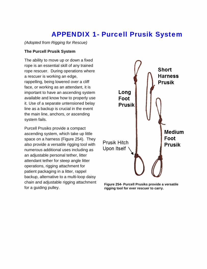
APPENDIX 1- Purcell Prusik System (Adopted from Rigging for Rescue)
The Purcell Prusik System
The ability to move up or down a fixed rope is an essential skill of any trained rope rescuer. During operations where a rescuer is working an edge, rappelling, being lowered over a cliff face, or working as an attendant, it is important to have an ascending system available and know how to properly use it. Use of a separate untensioned belay line as a backup is crucial in the event the main line, anchors, or ascending system fails.
Purcell Prusiks provide a compact ascending system, which take up little space on a harness (Figure 254). They also provide a versatile rigging tool with numerous additional uses including as an adjustable personal tether, litter attendant tether for steep angle litter operations, rigging attachment for patient packaging in a litter, rappel backup, alternative to a multi-loop daisy chain and adjustable rigging attachment for a guiding pulley.
Figure 254- Purcell Prusiks provide a versatile rigging tool for ever rescuer to carry.
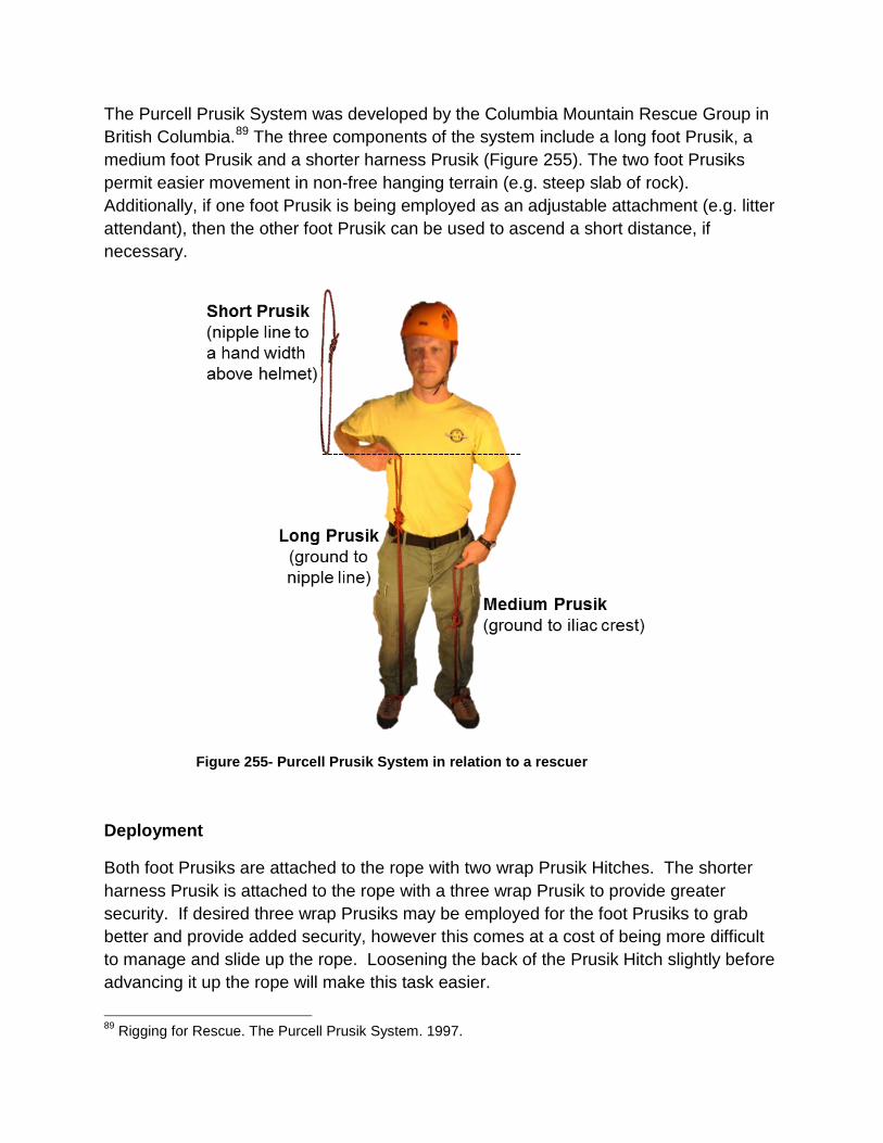
The Purcell Prusik System was developed by the Columbia Mountain Rescue Group in British Columbia.89 The three components of the system include a long foot Prusik, a medium foot Prusik and a shorter harness Prusik (Figure 255). The two foot Prusiks permit easier movement in non-free hanging terrain (e.g. steep slab of rock). Additionally, if one foot Prusik is being employed as an adjustable attachment (e.g. litter attendant), then the other foot Prusik can be used to ascend a short distance, if necessary.
Figure 255- Purcell Prusik System in relation to a rescuer
Deployment
Both foot Prusiks are attached to the rope with two wrap Prusik Hitches. The shorter harness Prusik is attached to the rope with a three wrap Prusik to provide greater security. If desired three wrap Prusiks may be employed for the foot Prusiks to grab better and provide added security, however this comes at a cost of being more difficult to manage and slide up the rope. Loosening the back of the Prusik Hitch slightly before advancing it up the rope will make this task easier.
89 Rigging for Rescue. The Purcell Prusik System. 1997.
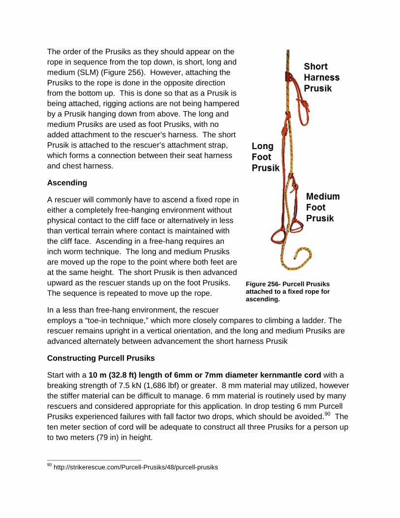
The order of the Prusiks as they should appear on the rope in sequence from the top down, is short, long and medium (SLM) (Figure 256). However, attaching the Prusiks to the rope is done in the opposite direction from the bottom up. This is done so that as a Prusik is being attached, rigging actions are not being hampered by a Prusik hanging down from above. The long and medium Prusiks are used as foot Prusiks, with no added attachment to the rescuer’s harness. The short Prusik is attached to the rescuer’s attachment strap, which forms a connection between their seat harness and chest harness.
Ascending
A rescuer will commonly have to ascend a fixed rope in either a completely free-hanging environment without physical contact to the cliff face or alternatively in less than vertical terrain where contact is maintained with the cliff face. Ascending in a free-hang requires an inch worm technique. The long and medium Prusiks are moved up the rope to the point where both feet are at the same height. The short Prusik is then advanced upward as the rescuer stands up on the foot Prusiks. The sequence is repeated to move up the rope.
In a less than free-hang environment, the rescuer employs a “toe-in technique,” which more closely compares to climbing a ladder. The rescuer remains upright in a vertical orientation, and the long and medium Prusiks are advanced alternately between advancement the short harness Prusik
Figure 256- Purcell Prusiks attached to a fixed rope for ascending.
Constructing Purcell Prusiks
Start with a 10 m (32.8 ft) length of 6mm or 7mm diameter kernmantle cord with a breaking strength of 7.5 kN (1,686 lbf) or greater. 8 mm material may utilized, however the stiffer material can be difficult to manage. 6 mm material is routinely used by many rescuers and considered appropriate for this application. In drop testing 6 mm Purcell Prusiks experienced failures with fall factor two drops, which should be avoided.90 The ten meter section of cord will be adequate to construct all three Prusiks for a person up to two meters (79 in) in height.
90 http://strikerescue.com/Purcell-Prusiks/48/purcell-prusiks
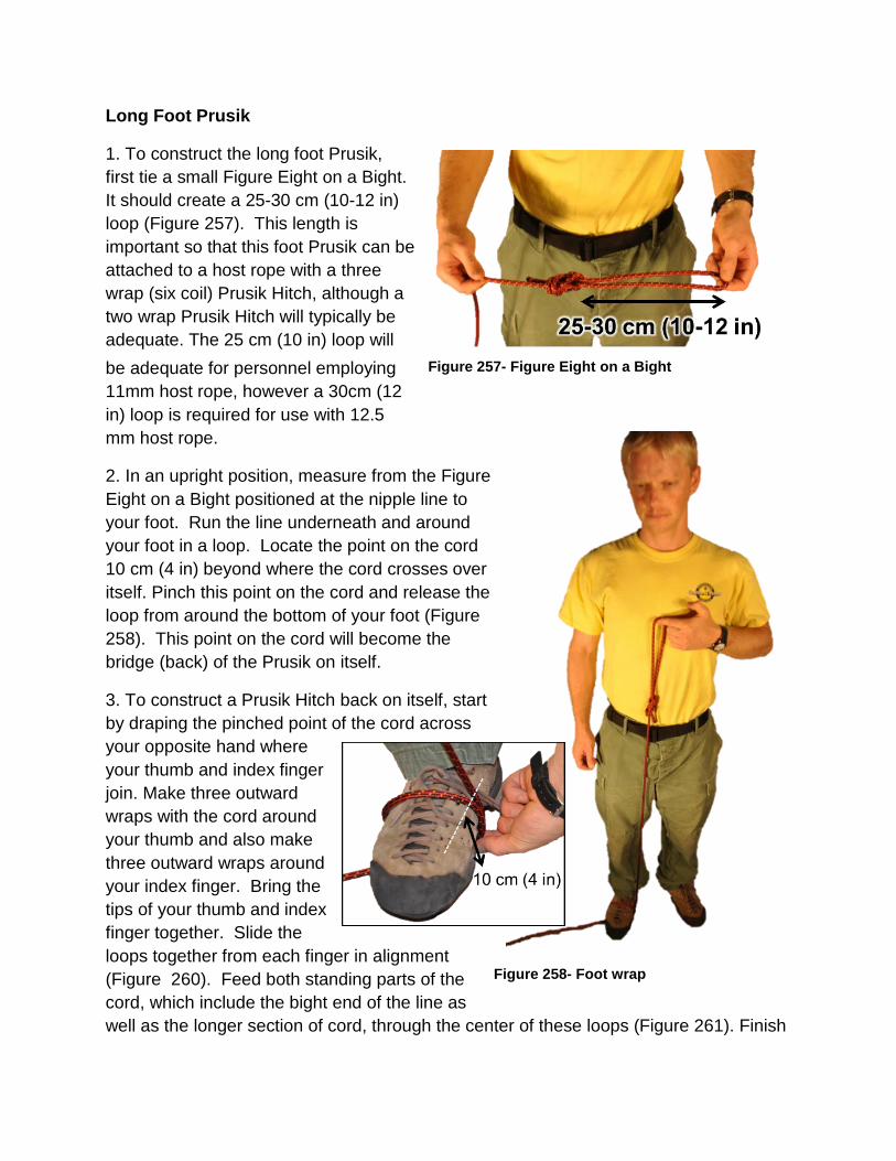
Long Foot Prusik
1. To construct the long foot Prusik, first tie a small Figure Eight on a Bight. It should create a 25-30 cm (10-12 in) loop (Figure 257). This length is important so that this foot Prusik can be attached to a host rope with a three wrap (six coil) Prusik Hitch, although a two wrap Prusik Hitch will typically be adequate. The 25 cm (10 in) loop will be adequate for personnel employing 11mm host rope, however a 30cm (12 in) loop is required for use with 12.5 mm host rope.
Figure 257- Figure Eight on a Bight
2. In an upright position, measure from the Figure Eight on a Bight positioned at the nipple line to your foot. Run the line underneath and around your foot in a loop. Locate the point on the cord 10 cm (4 in) beyond where the cord crosses over itself. Pinch this point on the cord and release the loop from around the bottom of your foot (Figure 258). This point on the cord will become the bridge (back) of the Prusik on itself.
3. To construct a Prusik Hitch back on itself, start by draping the pinched point of the cord across your opposite hand where your thumb and index finger join. Make three outward wraps with the cord around your thumb and also make three outward wraps around your index finger. Bring the tips of your thumb and index finger together. Slide the loops together from each finger in alignment (Figure 260). Feed both standing parts of the cord, which include the bight end of the line as well as the longer section of cord, through the center of these loops (Figure 261). Finish
Figure 258- Foot wrap
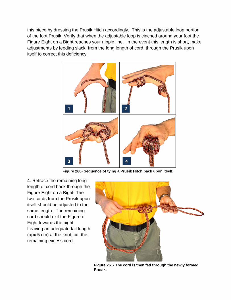
this piece by dressing the Prusik Hitch accordingly. This is the adjustable loop portion of the foot Prusik. Verify that when the adjustable loop is cinched around your foot the Figure Eight on a Bight reaches your nipple line. In the event this length is short, make adjustments by feeding slack, from the long length of cord, through the Prusik upon itself to correct this deficiency.
Figure 260- Sequence of tying a Prusik Hitch back upon itself.
4. Retrace the remaining long length of cord back through the Figure Eight on a Bight. The two cords from the Prusik upon itself should be adjusted to the same length. The remaining cord should exit the Figure of Eight towards the bight. Leaving an adequate tail length (apx 5 cm) at the knot, cut the remaining excess cord.
Figure 261- The cord is then fed through the newly formed Prusik.

Medium Foot Prusik
Repeat the steps for making the long foot Prusik, however use your iliac crest (upper lateral margin of the pelvis marked by a bulge at the waist) as the landmark for height.
Short Harness Prusik
With the remaining cord, construct a short harness Prusik. Secure this loop of cord using a Double Fisherman Bend with apx. 5 cm (2 in) tails. This finished Prusik loop length should reach from your nipple line to a hand width above your helmet.
Test the finished set of Purcell Prusiks for proper length by ascending a rope. Make adjustments to shorten or lengthen the components, as necessary for personal sizing.
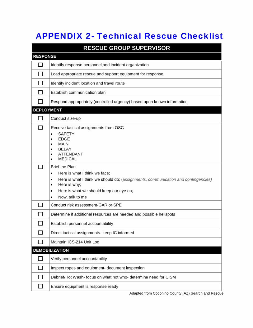
APPENDIX 2- Technical Rescue Checklist RESCUE GROUP SUPERVISOR
RESPONSE
Identify response personnel and incident organization
Load appropriate rescue and support equipment for response
Identify incident location and travel route
Establish communication plan
Respond appropriately (controlled urgency) based upon known information
DEPLOYMENT
Conduct size-up
Receive tactical assignments from OSC • SAFETY • EDGE • MAIN • BELAY • ATTENDANT • MEDICAL
Brief the Plan • Here is what I think we face; • Here is what I think we should do; (assignments, communication and contingencies) • Here is why; • Here is what we should keep our eye on; • Now, talk to me
Conduct risk assessment-GAR or SPE
Determine if additional resources are needed and possible helispots
Establish personnel accountability
Direct tactical assignments- keep IC informed
Maintain ICS-214 Unit Log
DEMOBILIZATION
Verify personnel accountability
Inspect ropes and equipment- document inspection
Debrief/Hot Wash- focus on what not who- determine need for CISM
Ensure equipment is response ready Adapted from Coconino County (AZ) Search and Rescue
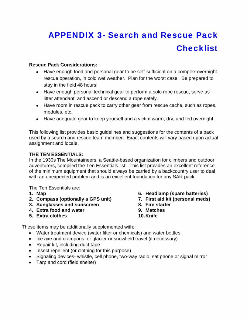
APPENDIX 3- Search and Rescue Pack Checklist
Rescue Pack Considerations:
• Have enough food and personal gear to be self-sufficient on a complex overnight rescue operation, in cold wet weather. Plan for the worst case. Be prepared to stay in the field 48 hours!
• Have enough personal technical gear to perform a solo rope rescue, serve as litter attendant, and ascend or descend a rope safely.
• Have room in rescue pack to carry other gear from rescue cache, such as ropes, modules, etc.
• Have adequate gear to keep yourself and a victim warm, dry, and fed overnight.
This following list provides basic guidelines and suggestions for the contents of a pack used by a search and rescue team member. Exact contents will vary based upon actual assignment and locale. THE TEN ESSENTIALS: In the 1930s The Mountaineers, a Seattle-based organization for climbers and outdoor adventurers, compiled the Ten Essentials list. This list provides an excellent reference of the minimum equipment that should always be carried by a backcountry user to deal with an unexpected problem and is an excellent foundation for any SAR pack. The Ten Essentials are: 1. Map 2. Compass (optionally a GPS unit) 3. Sunglasses and sunscreen 4. Extra food and water 5. Extra clothes
6. Headlamp (spare batteries) 7. First aid kit (personal meds) 8. Fire starter 9. Matches 10. Knife
These items may be additionally supplemented with:
• Water treatment device (water filter or chemicals) and water bottles • Ice axe and crampons for glacier or snowfield travel (if necessary) • Repair kit, including duct tape • Insect repellent (or clothing for this purpose) • Signaling devices- whistle, cell phone, two-way radio, sat phone or signal mirror • Tarp and cord (field shelter)
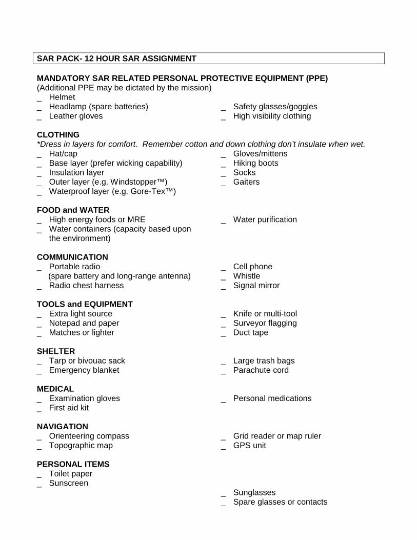
SAR PACK- 12 HOUR SAR ASSIGNMENT MANDATORY SAR RELATED PERSONAL PROTECTIVE EQUIPMENT (PPE) (Additional PPE may be dictated by the mission) _ Helmet _ Headlamp (spare batteries) _ Leather gloves
_ Safety glasses/goggles _ High visibility clothing
CLOTHING *Dress in layers for comfort. Remember cotton and down clothing don’t insulate when wet._ Hat/cap _ Base layer (prefer wicking capability) _ Insulation layer _ Outer layer (e.g. Windstopper™) _ Waterproof layer (e.g. Gore-Tex™)
_ Gloves/mittens _ Hiking boots _ Socks _ Gaiters
FOOD and WATER _ High energy foods or MRE _ Water containers (capacity based upon
the environment)
_ Water purification
COMMUNICATION _ Portable radio (spare battery and long-range antenna) _ Radio chest harness
_ Cell phone _ Whistle _ Signal mirror
TOOLS and EQUIPMENT _ Extra light source _ Notepad and paper _ Matches or lighter
_ Knife or multi-tool _ Surveyor flagging _ Duct tape
SHELTER _ Tarp or bivouac sack _ Emergency blanket
_ Large trash bags _ Parachute cord
MEDICAL _ Examination gloves _ First aid kit
_ Personal medications
NAVIGATION _ Orienteering compass _ Topographic map
_ Grid reader or map ruler _ GPS unit
PERSONAL ITEMS _ Toilet paper _ Sunscreen
_ Sunglasses _ Spare glasses or contacts
NPS Basic Technical Rescue- 11th Edition
258 | P a g e
TRAVEL _ Hiking poles _ In-step crampons _ Skis/snowshoes
_ Avalanche beacon and probe pole _ Snow shovel
CLIMBING _ Webbing _ Harness
_ Carabiners _ Belay device
SAR PACK- 24 HOUR SAR ASSIGNMENT (or longer) Supplement the 12 hour pack with the following additions as appropriate: _ Sleeping bag _ Sleeping pad _ Small tent _ Extra clothing
_ Additional food _ Stove and Fuel _ Cook gear _ Toiletries
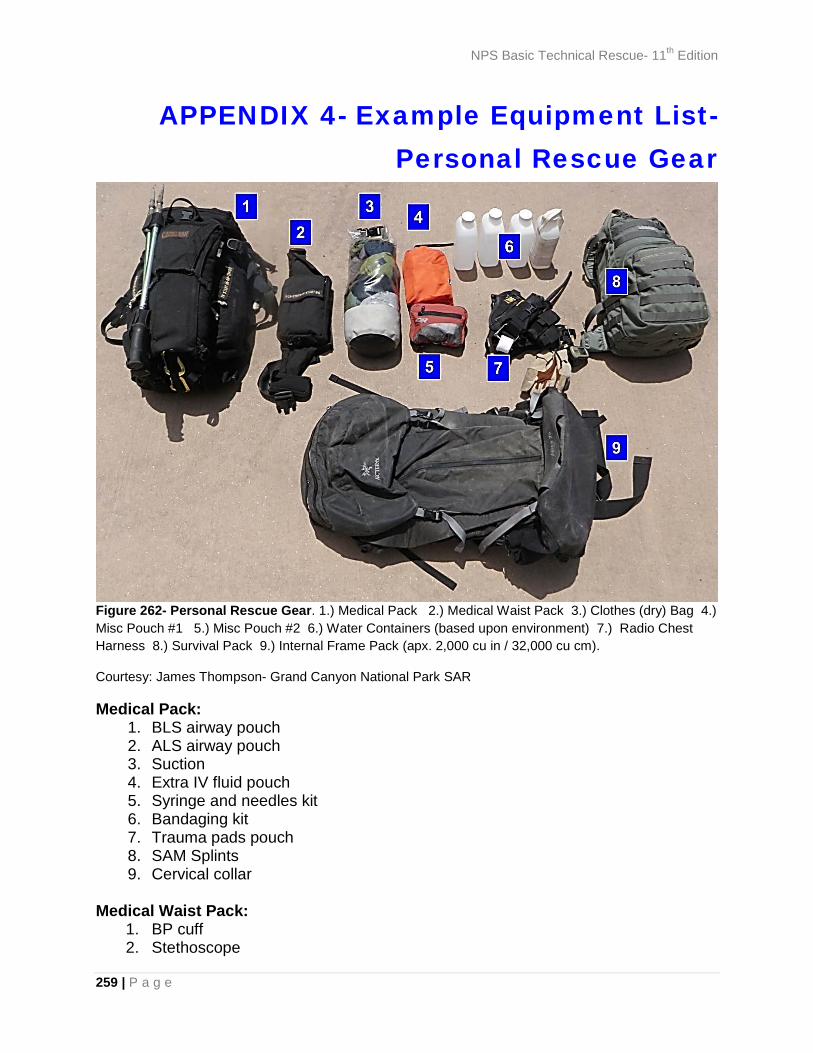
NPS Basic Technical Rescue- 11th Edition
259 | P a g e
APPENDIX 4- Example Equipment List- Personal Rescue Gear
Figure 262- Personal Rescue Gear. 1.) Medical Pack 2.) Medical Waist Pack 3.) Clothes (dry) Bag 4.) Misc Pouch #1 5.) Misc Pouch #2 6.) Water Containers (based upon environment) 7.) Radio Chest Harness 8.) Survival Pack 9.) Internal Frame Pack (apx. 2,000 cu in / 32,000 cu cm).
Courtesy: James Thompson- Grand Canyon National Park SAR
Medical Pack: 1. BLS airway pouch 2. ALS airway pouch 3. Suction 4. Extra IV fluid pouch 5. Syringe and needles kit 6. Bandaging kit 7. Trauma pads pouch 8. SAM Splints 9. Cervical collar
Medical Waist Pack:
1. BP cuff 2. Stethoscope

NPS Basic Technical Rescue- 11th Edition
260 | P a g e
3. IV start pouch 4. Gloves and biohazard PPE kit 5. Patient care reporting (PCR) forms
Clothes Bag:
1. Dry bag 2. Medium weight base layer, top and bottoms 3. Lightweight shell, top and bottoms 4. Lightweight vest 5. Synthetic t-shirt 6. Synthetic neck gaiter 7. Synthetic lightweight beanie 8. Synthetic lightweight gloves 9. Cotton scarf 10. Cotton neck gaiter
Misc. Pouch 1:
1. Headlamp 2. Safety glasses 3. Sunglasses 4. 1 gallon Ziploc™ bag 5. Ear protection 6. 4- H2O tablets 7. Alum (silty river water treatment) 8. Sunblock 9. Chapstick 10. AAA and AA batteries
Misc. Pouch 2:
1. Emergency tarp 2. 2 garbage bags 3. 4- 1 gallon Ziploc™ bags 4. 30 ft of cord 5. 10 zip ties 6. Lighter and 4 H2O tablets in Ziploc™ bag 7. Matches in waterproof case 8. Fire starter in film canister 9. Duct tape 10. Body glide (blister prevention) 11. Toilet paper 12. Hand sanitizer
Radio Chest Harness:
1. Radio 2. GPS 3. Compass
NPS Basic Technical Rescue- 11th Edition
261 | P a g e
4. Flashlight 5. Headlamp 6. Note pad, pen and Sharpie marker 7. Trauma shears 8. Latex gloves x 2 pair 9. 1.5” cloth tape 10. Roll of flagging tape in film canister 11. Ear protection (also in film canister)
Survival Pack (used primarily for helicopter medical evacuations)
1. Pack with two-liter Camelbak® hydration bladder 2. Water, one liter 3. Gatorade®, 1/2 liter 4. Fleece pullover 5. Food (+3,500 calories) 6. Misc. pouch #1 7. Extra radio battery 8. Sky Probe brand long-range extendable radio antenna 9. Sun screen 10. Hat 11. Chemical Light sticks- 3 12. Smoke and aerial signal, whistle 13. Extra batteries 14. Headlamps- 2 15. Note pad, pens and Sharpie marker 16. Topographic map 17. Lightweight bivy (bivouac) sack

NPS Basic Technical Rescue- 11th Edition
262 | P a g e
APPENDIX 5- Industry Standards ASTM STANDARDS
List of SAR related standards applicable to technical rope rescue and ground SAR
Number ASTM Standard F1422-08 Guide for Using the Incident Command System Framework in
Managing Search and Rescue Operations F1583-95(2012) Practice for Communications Procedures- Phonetics F1740-96(2012) Guide for Inspection of Nylon, Polyester, or Nylon/Polyester Blend,
or Both Kernmantle Rope F1768-97(2007) Guide for Using Whistle Signal During Rope Rescue Operations F1772-12 Specification for Harnesses for Rescue, Safety, and Sport Activities F1773-09 Terminology Relating to Climbing, Mountaineering, Search and
Rescue Equipment and Practices F1774-99(2005) Specification for Climbing and Mountaineering Carabiners F1956-99(2005) Specification for Rescue Carabiners F1993-99(2005) Classification System of Human Search and Rescue Resources F2116-01(2007) Specification for Low Stretch and Static Kernmantle Life Safety
Rope F2209-10 Guide for Training of Level I Land Search Team Member F2266-03(2008) Specification for Masses Used In Testing Rescue Systems and
Components F2436-05(2011) Test Method for Measuring the Performance of Synthetic Rope
Rescue Belay Systems Using a Drop Test F2491-05(2010) Guide for Determining Load Ratios for Technical Rescue Systems
and Equipment F2684/F2684M- 07(2012)
Test Method for Portable High Anchor Devices
F2685-07 Guide for Training of a Level II Land Search Team Member F2751-09 Guide for Training of Support Level Rescue Team Member (LRT-
Support) Member F2752-09 Guide for Training for Level I Rope Rescue (R1) Rescuer
Endorsement F2821-10 Test Methods for Basket Type Rescue Litters F2822-10 Specification for Fixed Anchorage Installed on Structures Used for
Rope Rescue Training F2890-12 Guide for Hazard Awareness for Search and Rescue Personnel F2954-12 Guide for Training for Level II Rope Rescue (R2) Rescuer
Endorsement F2955-12 Guide for Training for Level III Rope Rescue (R3) Rescuer
Endorsement F3024-13 Guide for Training of a Land Search and Rescue (SAR) Strike
Team/Task Force Leader
NPS Basic Technical Rescue- 11th Edition
263 | P a g e
CORDAGE INSTITUTE STANDARDS
Applicable Cordage Institute (CI) Rope Rescue Related Standards
CI-1301* Polypropylene Fiber Rope- 3-Strand and 8-Strand Constructions CI-1201* Fiber Ropes, General Standard CI-1310 Nylon (Polyamide) Fiber Rope- High Performance Double Braid
Construction CI-1312* Standard: Nylon (Polyamide) Fiber Rope, CI-1202 Terminology for Fiber Rope CI-1401* Safer Use of Fiber Rope CI-1500* Test Methods for Fiber Rope CI-1801* Low Stretch/Static Kernmantle Safety Rope CI-1803* Kernmantle Accessory Cords for Life Safety Applications CI-1805* Standard: 3-Strand Life Safety Rope, CI-1903* Aramid Fiber Rope CI-1904 HMPE Fiber Rope CI-2001* Fiber Rope Inspection and Retirement Criteria CI-2002* Determination of Cordage Institute Minimum Breaking Strengths CI-2005* Inspection of Kernmantle Ropes for Life Safety Applications
* Documents with an asterisk next to their number are available for free download.
NATIONAL FIRE PROTECTION ASSOCIATION (NFPA) GUIDELINES NFPA 1006- STANDARD FOR RESCUE TECHNICIAN PROFESSIONAL QUALIFICATIONS (2013 Edition)
Chapter 4- Level of Qualification: • LEVEL I TECHNICAL RESCUER- This level applies to individuals who identify
hazards, use equipment, and apply limited techniques specified in this standard to perform technical rescue operations.
• LEVEL II TECHNICAL RESCUER- This level applies to individuals who identify hazards, use equipment, and apply advanced techniques specified in this standard to perform technical rescue operations.
Chapter 6- Job Performance Requirements (Rope Rescue): LEVEL I GENERAL REQUIREMENTS-
• Direct a team in the operation of a simple mechanical advantage system
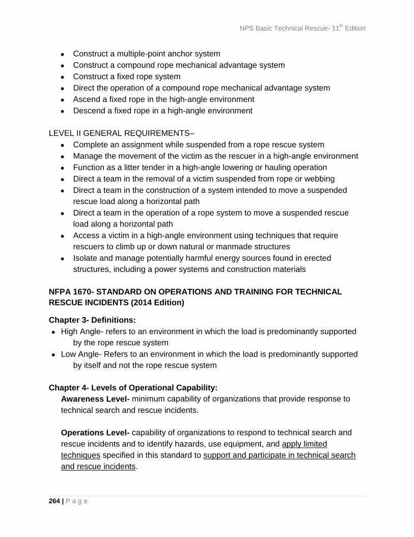
NPS Basic Technical Rescue- 11th Edition
264 | P a g e
• Construct a multiple-point anchor system • Construct a compound rope mechanical advantage system • Construct a fixed rope system • Direct the operation of a compound rope mechanical advantage system • Ascend a fixed rope in the high-angle environment • Descend a fixed rope in a high-angle environment
LEVEL II GENERAL REQUIREMENTS–
• Complete an assignment while suspended from a rope rescue system • Manage the movement of the victim as the rescuer in a high-angle environment • Function as a litter tender in a high-angle lowering or hauling operation • Direct a team in the removal of a victim suspended from rope or webbing • Direct a team in the construction of a system intended to move a suspended
rescue load along a horizontal path • Direct a team in the operation of a rope system to move a suspended rescue
load along a horizontal path • Access a victim in a high-angle environment using techniques that require
rescuers to climb up or down natural or manmade structures • Isolate and manage potentially harmful energy sources found in erected
structures, including a power systems and construction materials
NFPA 1670- STANDARD ON OPERATIONS AND TRAINING FOR TECHNICAL RESCUE INCIDENTS (2014 Edition)
Chapter 3- Definitions: • High Angle- refers to an environment in which the load is predominantly supported
by the rope rescue system • Low Angle- Refers to an environment in which the load is predominantly supported
by itself and not the rope rescue system Chapter 4- Levels of Operational Capability:
Awareness Level- minimum capability of organizations that provide response to technical search and rescue incidents. Operations Level- capability of organizations to respond to technical search and rescue incidents and to identify hazards, use equipment, and apply limited techniques specified in this standard to support and participate in technical search and rescue incidents.
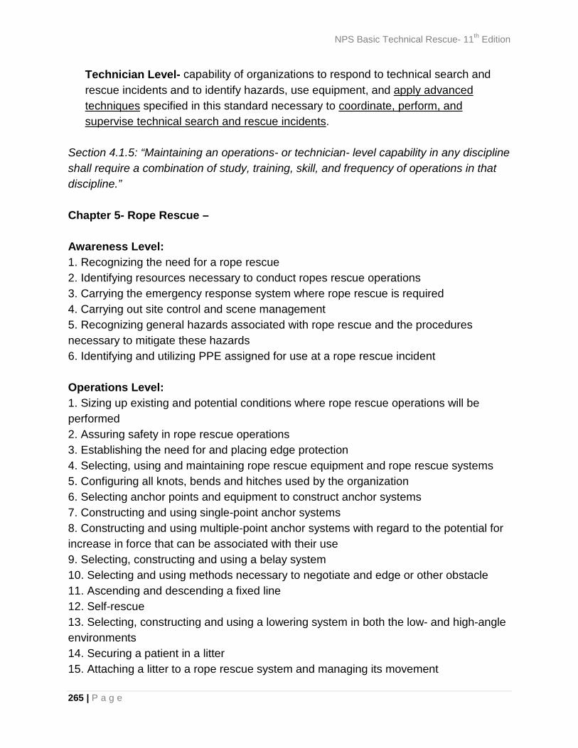
NPS Basic Technical Rescue- 11th Edition
265 | P a g e
Technician Level- capability of organizations to respond to technical search and rescue incidents and to identify hazards, use equipment, and apply advanced techniques specified in this standard necessary to coordinate, perform, and supervise technical search and rescue incidents.
Section 4.1.5: “Maintaining an operations- or technician- level capability in any discipline shall require a combination of study, training, skill, and frequency of operations in that discipline.” Chapter 5- Rope Rescue – Awareness Level: 1. Recognizing the need for a rope rescue 2. Identifying resources necessary to conduct ropes rescue operations 3. Carrying the emergency response system where rope rescue is required 4. Carrying out site control and scene management 5. Recognizing general hazards associated with rope rescue and the procedures necessary to mitigate these hazards 6. Identifying and utilizing PPE assigned for use at a rope rescue incident Operations Level: 1. Sizing up existing and potential conditions where rope rescue operations will be performed 2. Assuring safety in rope rescue operations 3. Establishing the need for and placing edge protection 4. Selecting, using and maintaining rope rescue equipment and rope rescue systems 5. Configuring all knots, bends and hitches used by the organization 6. Selecting anchor points and equipment to construct anchor systems 7. Constructing and using single-point anchor systems 8. Constructing and using multiple-point anchor systems with regard to the potential for increase in force that can be associated with their use 9. Selecting, constructing and using a belay system 10. Selecting and using methods necessary to negotiate and edge or other obstacle 11. Ascending and descending a fixed line 12. Self-rescue 13. Selecting, constructing and using a lowering system in both the low- and high-angle environments 14. Securing a patient in a litter 15. Attaching a litter to a rope rescue system and managing its movement
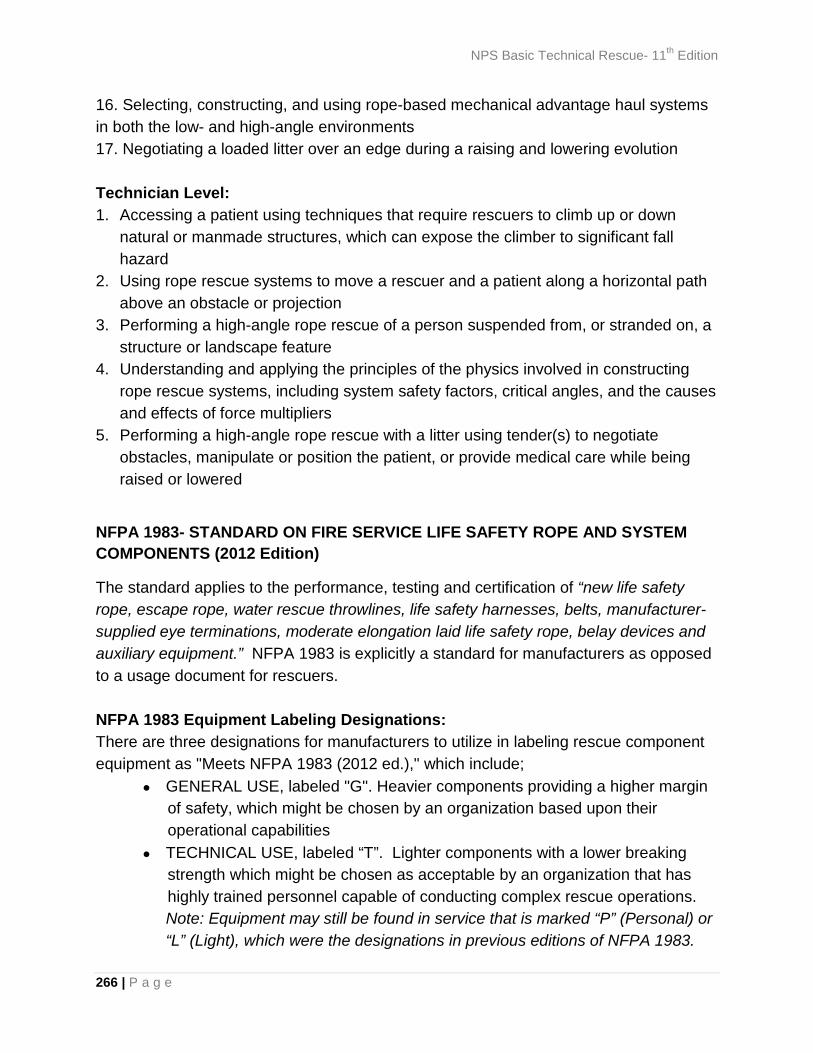
NPS Basic Technical Rescue- 11th Edition
266 | P a g e
16. Selecting, constructing, and using rope-based mechanical advantage haul systems in both the low- and high-angle environments 17. Negotiating a loaded litter over an edge during a raising and lowering evolution Technician Level: 1. Accessing a patient using techniques that require rescuers to climb up or down
natural or manmade structures, which can expose the climber to significant fall hazard
2. Using rope rescue systems to move a rescuer and a patient along a horizontal path above an obstacle or projection
3. Performing a high-angle rope rescue of a person suspended from, or stranded on, a structure or landscape feature
4. Understanding and applying the principles of the physics involved in constructing rope rescue systems, including system safety factors, critical angles, and the causes and effects of force multipliers
5. Performing a high-angle rope rescue with a litter using tender(s) to negotiate obstacles, manipulate or position the patient, or provide medical care while being raised or lowered
NFPA 1983- STANDARD ON FIRE SERVICE LIFE SAFETY ROPE AND SYSTEM COMPONENTS (2012 Edition)
The standard applies to the performance, testing and certification of “new life safety rope, escape rope, water rescue throwlines, life safety harnesses, belts, manufacturer-supplied eye terminations, moderate elongation laid life safety rope, belay devices and auxiliary equipment.” NFPA 1983 is explicitly a standard for manufacturers as opposed to a usage document for rescuers. NFPA 1983 Equipment Labeling Designations: There are three designations for manufacturers to utilize in labeling rescue component equipment as "Meets NFPA 1983 (2012 ed.)," which include;
• GENERAL USE, labeled "G". Heavier components providing a higher margin of safety, which might be chosen by an organization based upon their operational capabilities
• TECHNICAL USE, labeled “T”. Lighter components with a lower breaking strength which might be chosen as acceptable by an organization that has highly trained personnel capable of conducting complex rescue operations. Note: Equipment may still be found in service that is marked “P” (Personal) or “L” (Light), which were the designations in previous editions of NFPA 1983.

NPS Basic Technical Rescue- 11th Edition
267 | P a g e
• ESCAPE USE, labeled “E”. Employed for immediate self-rescue or bailout by firefighters.
NFPA 1983- Selected Equipment Performance Requirements “T”- Technical Use “G”- General Use Carabiners Major axis (gate
closed): 27 kN (6,069 lbf) MBS
Major axis (gate closed): 40 kN (8,992 lbf) MBS
Gate open major axis: 7 kN (1,574 lbf) MBS
Gate open major axis: 11kN (2,473 lbf) MBS
Minor axis: 7 kN (1,574 lbf) MBS
Minor axis: 11kN (2,473 lbf) MBS
Life Safety Rope 20 kN (4,496 lbf) MBS. Minimum 1% elongation at 10% breaking strength
40 kN (8,992 lbf) MBS. Minimum 1% elongation at 10% breaking strength
diameter range: ≥9.5 mm (3/8 in) to < 12.5mm (1/2 in)
diameter range: >11 mm (7/16 in) to ≤ 16 mm (5/8 in)
Descent Control Device 13.5 kN (3,034 lbf) 22 kN (4,946 lbf) MBS Multiple Configuration Straps (e.g. basket, choker and end-to-end straps)
32 kN (7,194 lbf) in basket configuration
45 kN (10,120 lbf) in basket configuration
End-to-End Straps (e.g. pick-off, load-releasing and vertical lifting straps)
20 kN (4,500 lbf) 27 kN (6,070 lbf)
Pulleys 22 kN (4,946 lbf) MBS 36 kN (8,093 lbf) MBS Portable Anchor Devices 22 kN (4,946 lbf) MBS 36 kN (8,093 lbf) MBS NFPA 1983 Equipment Definitions: • CLASS II Harness- Fastens around waist and buttocks. Designed for rescue with a
design load of 2.67 kN (600 lbf) • CLASS III Harness- Fastens around the waist, around thighs or under buttocks, and
over shoulders. Designed for rescue with a design load of 2.67 kN (600 lbf). • Belt- Fastens only around the waist as a positioning device. • Carabiners- must be of a self-closing and locking design.
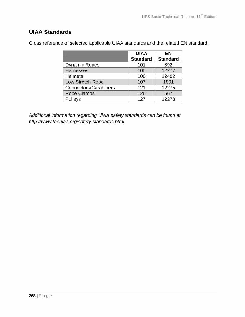
NPS Basic Technical Rescue- 11th Edition
268 | P a g e
UIAA Standards
Cross reference of selected applicable UIAA standards and the related EN standard.
UIAA Standard
EN Standard
Dynamic Ropes 101 892 Harnesses 105 12277 Helmets 106 12492 Low Stretch Rope 107 1891 Connectors/Carabiners 121 12275 Rope Clamps 126 567 Pulleys 127 12278
Additional information regarding UIAA safety standards can be found at http://www.theuiaa.org/safety-standards.html

NPS Basic Technical Rescue- 11th Edition
269 | P a g e
APPENDIX 6- Equipment Specifications Equipment Specifications- Black Diamond Camalot™
Black Diamond Camalot™ Specifications SIZE EXPANSION RANGE STRENGTH WEIGHT 0.3 13.8-23.4 mm (0.54-0.92 in) 8 kN, 1798 lbf 75 g (2.65 oz) 0.4 15.5-26.7 mm (0.61-1.05 in) 10 kN, 2248 lbf 83 g (2.93 oz) 0.5 19.6-33.5 mm (0.77-1.32 in) 12 kN, 2698 lbf 99 g (3.49 oz)
0.75 23.9-41.2 mm (0.94-1.62 in) 14 kN, 3147 lbf 119 g (4.18 oz) 1 30.2-52.1 mm (1.19-2.05 in) 14 kN, 3147 lbf 136 g (4.8 oz) 2 37.2-64.9 mm (1.46-2.55 in) 14 kN, 3147 lbf 155 g (5.47 oz) 3 50.7-87.9 mm (2.00-3.46 in) 14 kN, 3147 lbf 201 g (7.1 oz) 4 66.0-114.7 mm (2.60-4.51 in) 14 kN, 3147 lbf 289 g (10.2 oz) 5 85.4-148.5 mm (3.36-5.85 in) 14 kN, 3147 lbf 380 g (13.4 oz) 6 114.1-195.0 mm (4.50-7.68 in) 14 kN, 3147 lbf 557 g (1 lb 4 oz)
Source: www.blackdiamondequipment.com
Equipment Specifications- Wild Country Helium Friends
Wild Country Helium Friends Specifications
Size Color Expansion Range
(mm/inches) Weight
(grams/ounces) Minor Axis Strength
Major Axis Strength
0.0 Blue 14 - 22.54 mm 0.55 - 0.89 in 87 g 3.07 oz 12 kN 11 kN
0.5 Red 16.56 - 26.66 mm 0.65 - 1.05 in 91 g 3.21 oz 12 kN 11 kN
1.0 Gold 19.71 - 31.73 mm 0.78 - 1.25 in 95 g 3.35 oz 12 kN 11 kN
1.5 Silver 23.59 - 37.98 mm 0.93 - 1.5 in 104 g 3.67 oz 12 kN 12 kN
2.0 Red 28.41 - 45.73 mm 1.12 - 1.80 in 109 g 3.84 oz 12 kN 12 kN
2.5 Gold 34.4 0- 55.39 mm 1.35 - 2.18 in 117 g 4.13 oz 12 kN 12 kN
3.0 Purple 41.9 - 67.47 mm 1.65 - 2.66 in 145 g 5.11 oz 12 kN 12 kN
3.5 Blue 51.34 - 82.65 mm 2.02 - 3.25 in 171 g 6.03 oz 12 kN 12 kN
4.0 Silver 63.25 - 101.83 mm 2.49 - 4.01 in 208 g 7.34 oz 12 kN 12 kN Source: www.wildcountry.com
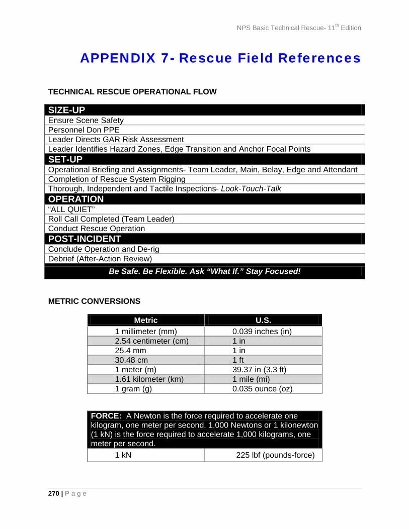
NPS Basic Technical Rescue- 11th Edition
270 | P a g e
APPENDIX 7- Rescue Field References
TECHNICAL RESCUE OPERATIONAL FLOW
SIZE-UP Ensure Scene Safety Personnel Don PPE Leader Directs GAR Risk Assessment Leader Identifies Hazard Zones, Edge Transition and Anchor Focal Points SET-UP Operational Briefing and Assignments- Team Leader, Main, Belay, Edge and Attendant Completion of Rescue System Rigging Thorough, Independent and Tactile Inspections- Look-Touch-Talk OPERATION “ALL QUIET” Roll Call Completed (Team Leader) Conduct Rescue Operation POST-INCIDENT Conclude Operation and De-rig Debrief (After-Action Review)
Be Safe. Be Flexible. Ask “What If.” Stay Focused!
METRIC CONVERSIONS
Metric U.S. 1 millimeter (mm) 0.039 inches (in) 2.54 centimeter (cm) 1 in 25.4 mm 1 in 30.48 cm 1 ft 1 meter (m) 39.37 in (3.3 ft) 1.61 kilometer (km) 1 mile (mi) 1 gram (g) 0.035 ounce (oz)
FORCE: A Newton is the force required to accelerate one kilogram, one meter per second. 1,000 Newtons or 1 kilonewton (1 kN) is the force required to accelerate 1,000 kilograms, one meter per second.
1 kN 225 lbf (pounds-force)
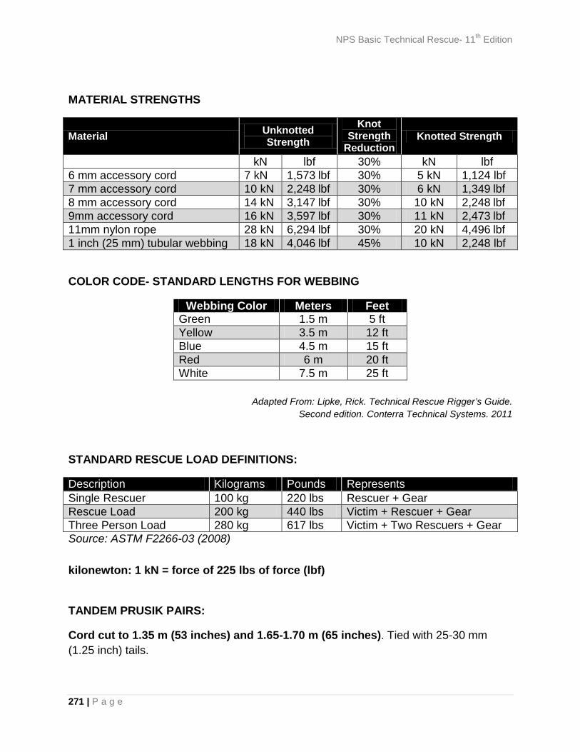
NPS Basic Technical Rescue- 11th Edition
271 | P a g e
MATERIAL STRENGTHS
Material Unknotted Strength
Knot Strength
Reduction Knotted Strength
kN lbf 30% kN lbf 6 mm accessory cord 7 kN 1,573 lbf 30% 5 kN 1,124 lbf 7 mm accessory cord 10 kN 2,248 lbf 30% 6 kN 1,349 lbf 8 mm accessory cord 14 kN 3,147 lbf 30% 10 kN 2,248 lbf 9mm accessory cord 16 kN 3,597 lbf 30% 11 kN 2,473 lbf 11mm nylon rope 28 kN 6,294 lbf 30% 20 kN 4,496 lbf 1 inch (25 mm) tubular webbing 18 kN 4,046 lbf 45% 10 kN 2,248 lbf
COLOR CODE- STANDARD LENGTHS FOR WEBBING
Webbing Color Meters Feet Green 1.5 m 5 ft Yellow 3.5 m 12 ft Blue 4.5 m 15 ft Red 6 m 20 ft White 7.5 m 25 ft
Adapted From: Lipke, Rick. Technical Rescue Rigger’s Guide. Second edition. Conterra Technical Systems. 2011
STANDARD RESCUE LOAD DEFINITIONS:
Description Kilograms Pounds Represents Single Rescuer 100 kg 220 lbs Rescuer + Gear Rescue Load 200 kg 440 lbs Victim + Rescuer + Gear Three Person Load 280 kg 617 lbs Victim + Two Rescuers + Gear Source: ASTM F2266-03 (2008) kilonewton: 1 kN = force of 225 lbs of force (lbf)
TANDEM PRUSIK PAIRS:
Cord cut to 1.35 m (53 inches) and 1.65-1.70 m (65 inches). Tied with 25-30 mm (1.25 inch) tails.
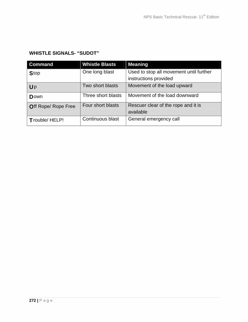
NPS Basic Technical Rescue- 11th Edition
272 | P a g e
WHISTLE SIGNALS- “SUDOT” Command Whistle Blasts Meaning
Stop One long blast Used to stop all movement until further instructions provided
Up Two short blasts Movement of the load upward
Down Three short blasts Movement of the load downward
Off Rope/ Rope Free Four short blasts Rescuer clear of the rope and it is available
Trouble/ HELP! Continuous blast General emergency call

NPS Basic Technical Rescue- 11th Edition
273 | P a g e
REFERENCES Adams, Mark. Son of a Hitch: A Genealogy of Arborists’ Climbing Hitches. Arborist News. April 2005. International Society of Arboriculture http://www.treebuzz.com/pdf/0505_geneology.pdf Accessed 02-14-2014. American Alpine Club. United States, Mountaineering in the National Parks. Golden, CO. Original copyright 1949. http://publications.americanalpineclub.org/articles/12194922202/United-States-Mountaineering-in-the-National-Parks Accessed 02-14-2014
American Institute of SteeI Construction. Steel Construction Manual, 14th Ed., Third Printing. AISC. Chicago, IL. ASTM International. F1740-96 Standard Guide for Inspection of Nylon, Polyester, or Nylon/Polyester Blend, or Both Kernmantle Rope. 2012. Conshohocken, PA. ASTM International. Annual Book of ASTM Standards. Section 13- Medical Devices and Services. Volume 13.02. 2013 edition. Conshohocken, PA. Attaway, Stephen. Design Criteria for Rescue Systems. Personal correspondence. Albuquerque, NM. 2014. Baumgardner, Randy. 10th Mountain Division. Turner Publishing. Nashville, Tennessee 1998. Briggs, Tom. Vertical Academy. Lulu Press, Inc. 2013. http://verticalacademy.com/ Buchmann, Isidor. Battery University- Learn About Batteries. Cadex Electronics, Inc. British Columbia, Canada. 2011. http://batteryuniversity.com/learn/ Accessed 03-22-2014. CMC Rescue. AZ Vortex by Rock Exotica- User’s Manual. Version 2.1. CMC Rescue, Inc. Santa Barbara, CA. 2013. http://www.cmcrescue.com/wp-content/uploads/2013/06/727300.00.120513-AZV-NFPA-CE.pdf Accessed 05-15-2014. Conterra Technical Systems. Scarab Rescue Tool- UL User Instructions. Bellingham, WA. 2012. Cordage Institute. CI 1201. Fiber Ropes- General Standard. Wayne, PA. 2006. http://www.ropecord.com Accessed 03-31-2014. Cordage Institute. CI 1801. Low Stretch and Static Kernmantle Life Safety Rope. Wayne, PA. 2007. http://www.ropecord.com Accessed 03-31-2014.
NPS Basic Technical Rescue- 11th Edition
274 | P a g e
Cordage Institute. CI 2003. Fibers for Cable, Cordage, Rope and Twine. Wayne, PA. 2005. http://www.ropecord.com Accessed 03-31-2014. Cordage Institute. CI 2005-03 Inspection of Kernmantle Ropes. Wayne, PA. 2003. http://www.ropecord.com Accessed 03-31-2014. Dillon/Quality Plus, Inc. Product brochure. Liberty, MO. 2012. http://dqplus.com/pdf/mechdyna_L.pdf. Accessed 03-25-2014. Eng, Ronald. Mountaineering: The Freedom of the Hills. 8th Edition. The Mountaineers. Seattle, WA. 2010. Energizer. Battery Do's and Don'ts. Energizer Holdings, Inc., St. Louis, MO. 2014. http://www.energizer.com/learning-center/battery-care/Pages/dos-and-donts.aspx Evans, Thomas and Aaron Stavens. Empirically Derived Breaking Strengths for Basket Hitches and Wrap Three Pull Two Webbing Anchors. Montana State University, Department of Earth Sciences, Bozeman, MT. Presented at 2011 International Technical Rescue Symposium. Frank, James A. CMC Rope Rescue Manual. Revised fourth edition. CMC Rescue, Inc. Santa Barbara, CA. 2013. Gibbs, Mike. Daisy Chains and Other Lanyards: Some shocking results when shock loaded. Rigging for Rescue, Ouray, CO. Published in the conference proceedings International Technical Rescue Symposium (ITRS) 2005. Grogono, Alan, David and Martin. Animated Knots by Grog™ Grog LLC. Austin, TX. http://www.animatedknots.com Accessed 03-31-2014 Harken. Winches Magnify People Power. Harken, Inc. Pewaukee, Wisconsin. 2014. http://www.harken.com/article.aspx?id=15885 Accessed 05-21-2014 IKAR-CISA 2012- Video Highlights and Summary of the International Commission for Alpine Rescue Congress. Krynica-Zdroj, Poland October 3 – 7, 2012. Topograph Media. http://www.topographmedia.com/ikar2012.html Accessed 10-15-2013. John Howard Company, Inc. Weaving Terminology. Chino, CA. 2014. http://www.johnhowardcompany.com/Weaving_Terminology.html Accessed 03-25-2014
Lipke, Rick. Owner, Conterra Technical Systems. Bellingham, WA. Personal interview. July 30, 2014.
Lipke, Rick. Technical Rescue Rigger’s Guide. Second edition. Conterra Technical Systems. Bellingham, WA. 2011.
NPS Basic Technical Rescue- 11th Edition
275 | P a g e
Long, John. How to Rock Climb! (How to Rock Climb Series). Third edition. Falcon Guides. Guilford, CT. 1998
Mariner, Wastl. Mountain Rescue Techniques. Innsbruck, Austria. 1963.
Mauthner, Kirk. Owner, Basecamp Innovations Ltd. Invermere, BC. Personal communications. 06-29-2014. Mauthner, Kirk and Mauthner, Katie. Gripping Ability on Rope in Motion. Invermere, British Columbia, Canada. 1994. (Presented October 1993- International Technical Rescue Symposium). McCormac, Jack and Brown, Russell. Design of Reinforced Concrete, 9th edition. John Wiley and Sons, Hoboken, NJ. 2014. McKently, John and Parker, Bruce. One Inch Webbing Anchor Tests- All that’s gonna hang on this? CMC Rescue, Inc. Santa Barbara, CA. Presented at ITRS. 2000 Miller, Jack. Technical Sales Manager. Southern Weaving Company, Greenville, NC. Personal interview 04-02-2014. Molenaar, Dee. Mountains Don’t Care, But We Do! Mountaineers Books. Seattle, WA 2009. Montgomery, Neil R. Single Rope Techniques- a guide for vertical cavers. Sydney Speleological Society. NSW, Australia. 1982. National Fire Protection Association (NFPA). NFPA 1983 Standard on Life Safety Rope and Equipment for Emergency Services. 2012 edition. Quincy, MA. National Speleological Society (NSS). Basic Vertical Training Student Manual. Vertical Section of the National Speleological Society, Inc. Huntsville, AL. 2005. http://www.caves.org/section/vertical/2012%20Basic%20Vertical%20Manual.pdf Accessed 05-05-2014. National Wildfire Coordinating Group (NWCG), Incident Response Pocket Guide, NFES 1077. Boise, ID. 2014. http://www.nwcg.gov/pms/pubs/pms461/pms461.pdf Accessed 03-25-2014.
NPS Basic Technical Rescue- 11th Edition
276 | P a g e
Ohlfs, Michael “Jeff”. JOSAR’s Silver Jubilee, Joshua Tree National Park, 29 Palms Historical Society (CA), Old Schoolhouse Journal, Winter 2006, p. 18-24 Petzl. Technical Guide- I’D S (Small) Self-braking Descender/Belay Device. Crolles, France. 2013. http://www.petzl.com/files/all/technical-notice/Pro/D20S-IDS.pdf Accessed 05-08-2014 Petzl. Tips for Protecting Your Equipment. Crolles, France. 2012. http://www.petzl.com/files/all/technical-notice/both/protecting-equipment-tips_EN.pdf Accessed 03-23-2014. Pigeon Mountain Industries. Types of Webbing- What is the difference between flat and tubular webbing? Pigeon Mountain Industries (PMI), Inc. LaFayette, GA. 2004. http://www.ahsrescue.com/t-webbingtypes.aspx. Accessed 03-25-2014. Prosser, Sean. Traverse Rescue. Vice President Manufacturing and Product Development. Mississauga, ON. Canada. Personal interview 05-05-2014. Pure Energy Solutions. Battery Types: Which Batteries to Use? Boulder, CO. 2014. http://www.pureenergybattery.com/pdf/batterytypes.pdf Accessed 03-22-2014. Rab Lighting- 100,000 Hour LED Lifespan. Rab Lighting Inc. Northvale, NJ. 2014 http://www.rabweb.com/100k.php Accessed 03-22-2014. Recreational Equipment, Inc. Climbing Helmet: How to Choose. REI. Sumner, WA. 2014 http://www.rei.com/learn/expert-advice/climbing-helmet.html Accessed 03-23-2014. Rock Exotica. Rig Plate Instructions. Clearfield, UT. 2010. http://www.rockexotica.com/dev/products/downloads/data/tech_notice/Rigging_Plates_CE.pdf Accessed 05-08-2014. Seattle Manufacturing Corporation (SMC). Rescue StayK® Anchor and Load Equalizing Anchor System- User Instructions. Ferndale, WA. 2012. http://smcgear.net/fileuploader/download/download/?d=1&file=custom%2Fupload%2FFile-1347263486.pdf. Accessed 05-03-2014 Smith, Bruce. Author and owner, On Rope 1. Harrison, TN. Personal interview. May 5, 2014. Smith, Bruce and Allen Padgett. On Rope. Revised edition. National Speleological Society. Huntsville, AL. 1996.

NPS Basic Technical Rescue- 11th Edition
277 | P a g e
Sterling Rope Guide to Rope Engineering, Design, and Use- Volume 1. Sterling Rope Company, Inc., Scarborough, ME. 2009 http://www.sterlingrope.com/media/document/techmanual.pdf Accessed 04-04-2014. Teijin Aramid Ltd. Technora® product description. Arnhem, Netherlands. http://www.teijinaramid.com/aramids/technora. Accessed 08-04-2014. Thompson, Rock. Owner, Rock Exotica. Clearfield, UT. Personal communication. 07-29-2014. Tote Systems Australia. Dyneema®- Brief History of DSM High Performance Fibres. Queensland, Australia. 2014. http://www.tote.com.au/dyneema.htm Accessed 03-25-2014. Toyota Motor Corporation. Ask 'why' five times about every matter. http://www.toyota-global.com/company/toyota_traditions/quality/mar_apr_2006.html. Accessed 07-29-2014. Traverse Rescue. 540°™ Rescue Belay Instructions. Mississauga, Ontario, Canada. 2009. https://traverserescue.com/downloads/540%20Belay%20Instructions-Small_Feb5-09.pdf Accessed 05-04-2014. Union Internationale Des Associations D’alpinisme (UIAA). UIAA-101 (Ropes). Bern, Switzerland. 2009. http://www.theuiaa.org/safety-standards.html Accessed 05-07-2014. US Army. Military Specification Mil-W-4088K; Webbing, Textile, Woven Nylon. Department of Defense, Washington DC. 1988. US Army. Military Specification Mil-W-5625K; Webbing, Textile, Nylon, Tubular. Department of Defense, Washington DC. 1991.
US Coast Guard, Commandant Instruction 3500.3- Operational Risk Management. 11-23-99. http://www.uscg.mil/directives/ci/3000-3999/CI_3500_3.pdf. Accessed 08-04-12 U.S. Department of Labor. Occupational Safety & Health Administration. 29 CFR 1926.502- Fall protection systems criteria and practices. Washington, DC. 1995. https://www.osha.gov/pls/oshaweb/owadisp.show_document?p_id=10758&p_table=STANDARDS Accessed 04-29-2014. U.S. Department of Labor. Occupational Safety & Health Administration Suspension Trauma/Orthostatic Intolerance. Safety and Health Information Bulletin- SHIB 03-24-2004, updated 2011. Washington, DC https://www.osha.gov/dts/shib/shib032404.html Accessed 02-13-2014.

NPS Basic Technical Rescue- 11th Edition
278 | P a g e
Weick, Karl E. PhD. South Canyon Revisited: Lessons from High Reliability Organizations. Published in Proceedings of Wildland Firefighters Human Factors Workshop. University of Michigan. 1995. http://www.fs.fed.us/t-d/pubs/htmlpubs/htm95512855/page15.htm Accessed 03-25-2014. Zanantoni, Carlo. Analysis of Belaying Techniques: A Typical UIAA Activity. Union Internationale Des Associations D’alpinisme (UIAA). Bern, Switzerland. 2000. http://theuiaa.org/upload_area/files/1/Analysis_of_Belaying_Techniques.pdf. Accessed 08-04-2014. Zheludev, Nikolay. The Life and Times of the LED- a 100-year history. Nature Photonics. Vol. 1. Nature Publishing Group. London, UK. 2007. http://holly.orc.soton.ac.uk/fileadmin/downloads/100_years_of_optoelectronics__2_.pdf Accessed 03-22-2014

NPS Basic Technical Rescue- 11th Edition
279 | P a g e
Index
1 10: 1 SSSF, 21 10th Mountain Division, 2, 274
3 3 Sigma (3S), 33
A abseiling. See Rappelling Acceleration, 23 Accessory Cord, 40, 47 Advanced Life Support, 231 after-action review (AAR), 7, 20 Alpine Clutch. See Garda Hitch American Alpine Club, 1, 274 American Heart Association, 234 American Society of Safety
Engineers (ASSE), 28 anchor focal point, 67, 113, 114,
115, 116, 117, 120, 122, 123, 184, 201
Anchor focal point, 114 anchor point, 84, 113, 114, 115,
117, 120, 121, 122, 123, 124, 125, 128, 136, 172, 266
anchor ropes, 39, 44 anchor straps, 49 anchor system, 42, 67, 105, 111,
113, 115, 117, 120, 123, 125, 128, 139, 156, 186, 265
Anchor System, 114 Anchor Systems: EARNEST’R,
115; SERENE, 114 anchors: critical cngles, 124 Anchors: force multiplier, 124;
natural, 125 Animated Knots by Grog, 86,
275 ANSI, 28, 30, 65, 70, 73 ANZI/ASSE Z359- Fall
Protection Code, 28 Aramid fibers, 36 Archimedes of Syracuse, 164 Aritificial High Directional (AHD):
gin pole, 159, 161, 163 Artificial Anchors, 126
Artificial High Directional (AHD), 159, 160, 161; Arizona (AZ) Vortex, 159; guy line configurations, 160; Kong Stelvio Fishing Pole, 163; Kong Stelvio Pole, 159; resultant force, 25, 160, 161; SAR Products Ltd (UK) SARQUAD, 159; Sked-EVAC tripod, 159; SMC TerrAdaptor, 159
Artificial HighDirectional (AHD): A-frame, 159, 160, 161, 162; Sideways A-frame, 161
Ascender: CMI Ropewalker, 66; CMI Ultrascender, 66; Gibbs, 50, 66, 97, 143, 275; ISC Ultrasafe, 66; Petzl Croll, 66
Ascenders: Petzl Ascension, 66, 144
Ascending: Closed Ascenders, 143; Friction Hitches, 143; Grigri Ascending Technique, 151; Handled Ascenders, 143; Juesi, Adolph and Walter Marti (Jumar), 143; Jumar, 143; Jumaring, 143; QAS (Quick Attachment System), 144, 149, 152; quick attachment system (QAS), 144; RADS (Rope Ascending Descending System), 151; ropewalker configuration, 149; safe ascending system, 144; sit-stand method, 149; Texas System, 149; two points of contact, 144; tying in short, 152; Yosemite Ascending System, 146
Ascending technique, 38, 66, 73, 82, 96, 143, 144, 146, 149, 151, 152, 220, 250, 255
ASTM, iii, 19, 23, 25, 29, 30, 37, 45, 53, 65, 189, 263, 272, 274
ASTM Standards, 263 Attaway, Dr. Stephen, 21 autoblock, 94, 95, 139, 140, 141,
142, 214, 221 Avalanche beacon, 259 avoirdupois pound, 23
AZTEK Elite Kit, 156
B Bachmann Hitch, 220 back-ties, 39, 113, 122 Bagging a rope, 41 Bandaging, 236 Basic Life Support, 231 Batteries, 247, 274, 277;
Alkaline, 247; Carbon Zinc, 247; Lead-Acid, 248; leakage, 249; Lithium batteries, 247; Lithium Ion, 133, 248; Nickel-Cadmium, 248; Nickel-Metal Hydride, 248; Rechargeable Alkaline, 247; safety guidelines, 248; Silver Oxide Cells, 247
Baudrier, 215, 221 Bauer, Wolf, 1 BC (Better Control) Pick-off, 212 becket, 93, 103, 165 Belay: use of a backup line, 83 Belay Competency Drop Test
Method, 25 belayer, 25, 83, 96, 102, 106,
108, 110, 111, 113, 214 Belaying, iv, 95, 96, 97, 103;
Auto Belay, 95; body/hip belay, 95; Conditional Belay, 95; Independent Belay, 83, 95; mechanical belay devices, 95; Rescue Belay Competency Drop Test, 98, 101; Self-Belay, 95
bivy (bivouac) sack, 262 Black Diamond, iii, 51, 126, 270 Black Diamond ATC, 95 Black Diamond Equipment:
Camalots™, 126 block creel construction, 38 BLS Airway, 234 BLS Vital Signs, 235 BlueWater, 38, 68, 142 bolt, 113, 128, 129, 130, 131,
132, 133, 134 Bolting, 128; Bolt Hangers, 130;
Boschhammer Drill, 133; Expansion Bolts, 129; Glue-In

NPS Basic Technical Rescue- 11th Edition
280 | P a g e
Bolts, 130; Hand drilling technique, 131; Hilti KWIK Bolt, 129; Power Hammer Drills, 133; Powers Power-Bolt™, 129; Removable Bolt Anchors, 130; SDS-plus® style drill bits, 133
BP cuff, 260 Brake Bar Rack. See rappel rack break apart litter, 224 Breaking tenacity, 37 briefing, 11, 16, 200 British Columbia Council of
Technical Rescue (BCCTR), 25, 97, 101
buddy check system, 139 Butterfly Coil, 43
C C.E.N. (Comité Européen de
Normalisation), 29 camming device, 113, 114 Canyonlands National Park, 2 carabiner, 50; keylock, 51; major
axis, 50, 55, 80, 81, 268; minor axis, 50, 55, 80, 81
Carabiner: Asymmetrical D-shape, 52; Auto-Locking (Twist Lock), 51; Ball-Lock, 51; Cleaning, 77; D-shape, 52, 55; Magnetron, 51; Modified/Offset-D, 52; NFPA- general use, 53; NFPA- technical use, 53; ORCA 3-stage auto-locking system, 51; Oval, 52; Pearbiner/HMS, 52; Quadlock, 51; Quik-Lok, 51; Screw Lock, 51, 54; Shapes, 52; spine, 50, 52, 80, 81, 108, 236; Supersafe, 51; Triact-Lock, 51
Carabiner Brake, 154 Carabiner Retrace Technique,
109 Carabiner rigging, 80 carabiners, 13, 14, 33, 51, 53,
55, 71, 74, 77, 78, 80, 81, 84, 111, 120, 139, 152, 154, 203, 221
Carabiners, 52, 53, 77, 80, 81, 84, 154, 192, 259, 263, 268, 269; orientation in rigging, 80
Cascade Rescue, 188, 189
CE (Conformité Européenne), 29 Certification, 28, 54 Cervical collar, 260 change of direction, 103, 115,
168, 169, 170, 175, 178, 179 changeover, 96, 152, 201, 212 Chemical light sticks, 262 Chest Decompression, 233 chest harness, 72, 222, 252 chockstones, 125 Cleat Hitch, 60, 62 ClimbTech, 130 closed loop communication, 17 Clothing, high visibility, 258 CMC Lifesaver Victim
Harness™, 75 CMC MPD, 68, 95, 201 CMC Rescue, iii, 25, 54, 61, 97,
163, 230, 274, 275, 276 CMC Rescue MPD, 25, 97, 98,
99, 100, 101, 102, 103, 153, 168, 172; use of secondary friction post, 102; Use of the Parking Brake, 99, 101
CMC Rescue MPD™, 25, 97 CMC Rescue Three-Bar Rack,
61 CMI Mini Hyper Rack, 68 CNC (Computer Numerical
Control), 67, 137 Coiling a rope, 43 Cole, John, 62 Columbia Mountain Rescue
Group, 145, 251 communication, 11, 12, 16, 17,
18, 56, 60, 98, 232, 256, 258, 278
communications, 3, 7, 8, 11, 16, 17, 73, 155, 178, 200, 218, 263, 276
compartment syndrome, 224 Compass, 257, 261 compound pulley system, 172,
173, 218 Conterra Hitch-Plate™, 137 Conterra Scarab, 57, 59, 153 Cordage Institute, iii, 29, 35, 37,
40, 41, 45, 264, 274, 275 Cordage Institute Standards,
264 Cordelette Anchor. See Load
Sharing Anchor Cow Hitch. See Girth Hitch
Critical Incident Stress Management, 7
critical point test, 125 Critical Point Test, 26 cross-gate forces, 14, 80 Crossing Hitch. See Italian Hitch Cutting tool, 73
D Daiber, Ome, 1 daisy chain, 49, 146, 151, 250 daisy chains, 49, 146 dead load, 22 Denier, 37 Descent control device (DCD),
57, 60, 61, 63, 65, 74, 97, 140, 141, 152, 153, 183, 184, 186, 201, 214, 215
Deutsches Institut für Normung (DIN), 29
Deviation, 114 deviation pulley, 113 Dill, John, iii, 107 direct statements, 17 directional, 14, 55, 56, 90, 104,
105, 114, 137, 158, 159, 160, 161, 163, 178, 199, 203, 217, 218
Directional, 114 Double Braid or Braid-on-Braid
Rope, 37 Dulfersitz. See Rappelling DuPont, 34 dynamic, 21, 24, 25, 26, 39, 94,
182 Dynamic Safety Factor (DSF),
21 dynamometer, 181 Dyneema®, 35, 37, 50, 278
E Edge Attendant, 155 edge lines, 39 edge management, 113, 114 Edge management, iv, 155 Edge Manager, 7, 108 edge protection, 51, 151, 156,
203, 266 Edge protection, 157; edge
rollers, 157, 158; protecting a secondary edge, 158

NPS Basic Technical Rescue- 11th Edition
281 | P a g e
Edge transition, 25, 101, 103, 159, 161
Eight Strand or Plaited Rope, 37 Equipment care and retirement,
76 Equipment marking, 78 Equipment retirement, 76 Equipment Retirement, 45 Equipment Specifications, v, 270 Equipment storage: danger of
battery acid, 76 etriers, 49, 74, 146 European Union (EU), 29 Evacuation Triangle, 74 Eye protection, 73
F fall factor, 25, 50, 97, 252 Fall factor, 24, 25 fall line, 113, 114, 122, 125 fatigue, 36, 51, 210, 241, 246 Figure Eight (“Rescue Eight”)
Descender, 65 flagging, 246, 258, 262 Flashlight, 262 Focal Points: locating, 115 Footwear, 73 Force, 23, 24, 68, 263 French Prusik. See autoblock front tie, 123 full body harness, 73
G GAR (Green-Amber-Red) Risk
Assessment Model, 11 garbage bags, 261 Garda Hitch, 221 Gibbs, Mike, iii, 49 Girth Hitch, 66, 91, 117, 118,
146, 221 gloves, ii, 13, 65, 69, 73, 74,
135, 139, 258, 261, 262 Goldline™ Rope, 37 GPS, 257, 258, 261 Grand Canyon National Park, i,
231, 260 Grand Teton National Park, 2 guiding line communications,
218 Guiding Line Technique, iv, 217
H Half Hitch, 60, 101, 106, 111,
222 Handheld radio, 73, 258, 260,
261 Harken PowerSeat™, 181 harness, i, 13, 51, 61, 63, 64, 65,
70, 71, 72, 73, 74, 75, 78, 93, 139, 140, 141, 144, 145, 146, 149, 151, 152, 156, 188, 189, 190, 191, 192, 194, 206, 212, 214, 215, 218, 221, 222, 224, 225, 227, 228, 241, 250, 251, 252, 255, 258; connector strap, 72, 194, 212; dorsal attachment, 73; gear loops, 71; metal D-ring attachment point, 71
Harness, 71, 72, 73, 75, 145, 241, 255, 259, 260, 261, 268; Care and cleaning, 77; Retirement, 71
Harness Hang Syndrome. See orthostatic intolerance
Harness Induced Pathology. See harness induced pathology
hasty packs, 3 Hasty Rescue Anchor System,
125 hasty team, 6 haul system, 63, 115, 179, 184,
201, 203, 212 hazard (exclusion) zone, 14 hazard zone, 14, 83, 115 Haz-Mat, 113 headlamp, 73, 246, 248 Headlamp, 73, 257, 258, 261,
262 Headlamps, 246, 262 hearing protection, 13, 69, 73 Helicopter EMS (HEMS), 6 helicopter hoisting, 75, 164 helicopter short-haul, 75, 233 helmet, ii, 13, 69, 70, 77, 212,
224, 255, 277 Helmet, 70, 258, 277; Care and
cleaning, 77; Foam, 70; Retirement, 70; Suspension, 70
hemp, 34 high strength tie-off, 57, 116,
125 high visibility, 13
highlines, 57, 182 high-modulus polyethylene,
(HMPE), 35 HMPE. See high-modulus
polyethylene HMS. See Italian Hitch hot debrief, 6, 19 human error, ii, 12, 192 Human Factors, 10, 279 hydration bladder, 262
I ICS, 4, 7, 16, 256 IKAR-ICAR, 1 Imperial units, 23 In Line Figure Eight: In Line
Figure Eight, 88 Incident Command System, 4, 5,
263 Industry Standards, v, 263 initial report, 5, 7 interlocking long-tailed bowlines,
206, 212, 218 International Organization for
Standardization (ISO), 28, 30 International System of Units
(SI), 23 Intra-muscular (IM), 236 Intra-nasal (IN), 237 intravenous (IV), 236 investigation, 6 ISC, 51, 65, 143 ISC D4 Work Rescue
Descender, 65 ISCD4 Descender, 68 ISO 9000, 28, 30 Italian Hitch, 52, 64, 91, 93, 95,
97, 111
J jigger, 138, 156, 161, 194, 212,
215 Joshua Tree National Park, 2
K Kernmantle, 38, 45, 263, 264,
274, 275 Kevlar®, 36, 37 kilonewton (kN), 22, 23 Klemheist Hitch, 220
NPS Basic Technical Rescue- 11th Edition
282 | P a g e
Knot Passing Technique, iv, 183; Slamma Jamma Technique, 184
Knotability, 39 Knots: adequate tail length, 85;
Alpine Butterfly, 90; backup knot, 85, 89, 111; Bend, 85; Bight, 85; Bowline, 88, 89, 93, 94, 125; Clove Hitch, 85, 91, 227; Double Fisherman’s Bend, 87, 90; Double Loop Figure Eight, 88; Double Overhand Bend, 90, 94; Double Overhand Knot, 85, 87, 89, 90; Figure Eight (Flemish) Knot, 88; Figure Eight Family of Knots, 88; Figure Eight Follow Through Bend (Flemish Bend), 88; Figure Eight on a Bight, 94, 111, 253, 254; Figure Eight On A Bight, 88; Frost Knot, 93; Half Hitch, 85; Hitch, 85, 111, 119, 220, 221; Interlocking Long-Tail Bowlines, 93; Italian (Munter) Mule Hitch, 93; Locking Girth Hitch, 221; Loop, 86; Overhand Knot, 60, 87, 89, 90, 101, 106, 117, 119; Prusik Hitch, 183, 184, 186, 203, 251, 253, 254; reduces the strength of the rope by one third, 85; Relative knot strengths, 94; Ring Bend, 87, 90, 94, 118; Round Turn, 86; Running End, 86; Scaffold Hitch, 93; Shoelace Bow Knot, 223; Slippery Half Hitch, 120; Splice, 86; Trucker’s Hitch, 93, 121, 135, 227
Kong Ortles Winch, 163
L laid rope, 37 Larson, Arnör, 95, 212 LAST, SAR acronym, 6 LED (light emitting diode), 246,
247, 277, 279 Life safety rescue rope, 38 Life Safety Rope, 40, 267 Liquid Crystal Polymer (LCP), 36
litter: master attachment point, 203
Litter bridle. See litter harness Litter Harness, 192 Litter Lower/Raise Technique, iv,
194 litter rigging: master attachment
point, 72 Litter rigging, 194; interlocking
long-tailed Bowlines, 194; litter attendant, 74, 145, 155, 158, 194, 199, 250, 251, 257; number of attendants, 194, 206; upper attendant position, 194; vertical litter orientation, 143, 192, 199, 203, 232, 241, 252
litter shield, 230 litter wheel, 189, 210 live load, 22 load cell, 181, 182 Load Release Devices, iv, 111 Load Sharing Anchor, 117 Long, John, 114 Losev, Oleg, 246 Low-angle litter evacuation:
leapfrog technique, 210 Low-Angle Litter Evacuation, iv,
209 Lowering Evolution- Role Call,
200 Low-Stretch Kernmantle Rope,
38
M Machard Knot. See Klemheist
Hitch Machard Tress, 140 MAD Nasal™ (Mucosal
Atomizing Device), 237 Maillon Rapide, 55 Main line, 60, 72, 93, 98, 101,
102, 103, 106, 107, 115, 116, 121, 143, 155, 156, 158, 159, 160, 161, 166, 167, 179, 183, 184, 186, 194, 199, 200, 201, 203, 206, 212, 214, 250
manila, 34 Manipulative drills, ii Manufacturer Breaking
Strengths of Rescue Equipment- Table, 68
Mariner, Wastl, 1
Mass, 23 Material Strengths, 272 Mauthner, Kirk, iii, 97, 102, 104,
111, 182, 200 MB (Mezzo Barcaiolo). See
Italian Hitch McLaren, Fred “Doug”, 2 mechanical advantage, 93, 103,
120, 156, 163, 164, 165, 166, 168, 172, 173, 175, 176, 178, 179, 180, 184, 264, 265, 267
Mechanical advantage: Actual Mechanical Advantage (AMA), 166; calculating actual mechanical advantage, 176; calculating mechanical advantage, 175; complex pulley system, 174; compound pulley system, 172; describing pulley systems, 175; fixed pulleys, 166; ganged pulley systems, 167, 171, 186, 212; Haul Prusik, 166; Ideal Mechanical Advantage (IMA), 166; merry-go-round method, 179; pulley systems, 164, 167, 172, 174, 175, 183; pulley systems as force multipliers, 164; Ratchet Prusik, 167; self-minding ratchet, 167, 168; simple pulley system, 168; standard haul system commands, 178; Theoretical Mechanical Advantage (TMA), 166; throw distance, 166, 172; travelling pulleys, 166, 168; unit of tension (T Method), 175, 177; winch systems, 180
Mechanical Ascenders, 66 Mechnical advantage: block and
tackle, 165; reset, 166, 167, 172, 186, 220
Medical considerations: ALS Airway, 237; hypothermia, 238; Hypothermia Wrap, 238; intraosseous (IO), 237; ketamine, 237; Medications, 236; midazolam, 237; naloxone, 237; vapor barrier, 238
Mesopotamia, early rope pulleys, 164
Metric Conversions, 271

NPS Basic Technical Rescue- 11th Edition
283 | P a g e
minimum breaking strength (MBS), 39, 40
Mirrored rope system, 102, 158, 186, 199
Mount Rainier National Park, 1 Mountain Rescue Association, 1,
154 Mountain Rescue Council, 1, 21,
See Mountain Rescue Association
Mountain Search and Rescue Operations, training manual, 2
Mountaineer’s Coil (Alpine Coil), 44
Mountaineers, 1, 275, 276 Mountaineers, The, 257 Münter Hitch. See Italian Hitch
N National Incident Management
System (NIMS), 4 National Ski Patrol, 1 National Transportation Safety
Board, 10 New River Gorge National River,
2 Newton, 22, 23, 24, 271 Newton, Sir Isaac, 23 NFPA, 25, 26, 28, 30, 31, 32, 33,
40, 53, 54, 57, 63, 65, 75, 104, 124, 137, 162, 264, 265, 267, 268, 274, 276; Escape Use, 32, 268; General Use, 32, 267; Technical Use, 32, 267
NFPA 1983 Equipment Definitions, 268
NFPA Guidelines, 264 Night Rescue Operations, iv,
245; hazards, 245 Nomex®, 13 NPS Basic Technical Rescue
Training Course, ii Nylon, 34, 37, 40, 45, 68, 82,
230, 263, 264, 274, 278 Nylon Webbing Carry, 223
O Oesterrichischer Alpenverein
(Austrian Alpine Association, 1
Ohno, Taiichi, 19
Omega Pacific, 51 OMNI-SlingTM, 49 Operational Risk Management”
(ORM), 10 Operations Chief, 7 oral administration (per os [PO]),
237 Orthostatic intolerance: venous
pooling, 241 Orthostatic Intolerance, 241, 278 OSHA (Occupational Safety and
Health Administration), 32, 40, 69, 73, 74
Overhand Follow-Through. See Ring Bend
overhand knot, 60 Oxygen, 234 oxygen cylinders, 224 Oxymizer®, 234
P P.G.H.M. (High Mountain
Constabulary), 181 Paillardet Winch, 181 Patient packaging: foot loops,
228; Tootsie Roll pads, 229 Patient Packaging, iv, 224 Péguet. See Maillon Rapide personnel accountability, 4, 256 Petzl, iii, 51, 54, 63, 64, 66, 68,
71, 72, 76, 96, 98, 143, 144, 151, 277
Petzl Bermude and Pitagor, 74 Petzl Grigri, 63, 74, 95, 151 Petzl Grigri 2, 95 Petzl I’D, 63, 68 Petzl I'D, 95 Petzl Rescucender, 67 Petzl Reverso, 95 Petzl RIG, 64 Petzl Tuba, 154 Pickets, 134, 135; Spanish
Windlass, 135 Pick-off Hasty Harness, 222 pick-off strap, 215 pick-off technique, 212 Pike and Pivot Technique, iv,
203 Pitons, 127, 128; Drilled Baby
Angle, 128 PMI (Pigeon Mountain
Industries), iii, 47, 68, 104, 277
Polyamide. See Nylon Polyester, 35, 37, 45, 68, 263,
274 Polyethylene terephthalate
(PET), 35 Polypropylene, 35, 37, 264 Pound-force, 24, 40 PPE, 13, 69, 84, 258, 261, 266,
271 Presidential Directive 5
(HSPD5), 4 pretension back-tie, 121 pre-tensioned front tie, 123 preventive search and rescue, 7 progress capture device, 101,
103, 167, 168 Prusik, v, 14, 25, 68, 83, 90, 94,
95, 103, 107, 108, 109, 120, 139, 140, 143, 144, 145, 149, 156, 158, 168, 170, 177, 178, 180, 183, 184, 186, 194, 201, 203, 206, 212, 215, 250, 251, 252, 253, 254, 255; cordage pinch test, 90, 107
Prusik Hitch, 66 Prusik, Dr. Karl, 66 Prusik-minding pulley, 107, 108 Prusik-Minding Pulley, 203 Pulley efficiency, 165 Purcell Prusik, 145, 212, 215 Purcell Prusik Patient Tie-in, 227 Purcell Prusik System, 250 Purcell Prusiks, 74, 145, 227,
250, 252, 255
Q quality assurance (QA), 232
R radio chest harness, 73 Radium Release Hitch, 111,
183, 184 Rainy Day Equipment, 75;
Screamer Suit, 75 rappel rack, 57, 62, 74, 139,
140, 153, 184 Rappel Rack, 62, 153 rappelling, 36, 38, 42, 59, 73, 82,
94, 96, 113, 125, 139, 140, 142, 152, 250
Rappelling Pick-Off, 214

NPS Basic Technical Rescue- 11th Edition
284 | P a g e
ratchet, 101, 103, 163, 167, 168, 170, 172, 174, 177, 178, 184, 186, 201, 203
Recoil or Snapback Hazard, 14 Rescue Field References, v, 271 Rescue litters, iv, 188; break-
apart design, 189, 190; Cascade Rescue, iii, 230; fiberglass Litter, 189; Foxtrot™ Litter, 191, 192; litter harness, 192, 194; Med Sled, 191; plastic Litter, 190; Sked Litter, 190; Traverse Rescue StrātLoad™ feature, 189; Traverse Rescue Stretcher (TRS), 191
rescue load, 24, 52, 57, 58, 59, 62, 65, 83, 90, 93, 97, 104, 105, 107, 123, 134, 136, 153, 156, 163, 212, 265
Rescue Load Definitions, 272 Rescue Pulley, 56; double
sheave, 165; Knot Passing Pulley, 57; Kootenay Ultra, 57; sheave, 56, 57, 103, 138, 164, 165; tread diameter, 56
Rescue pulleys: bushings, 56, 165
Rescue Pulleys: Pulley Strength, 167
Rescue Systems, Inc, 49 Retirement, 47, 264 Rigging for Rescue, 50, 105,
115, 145, 250, 251, 275 Rigging For Rescue, 95 Rigging Plates, 67 risk assessment, 10, 11, 12, 256 risk management, 7, 10, 162,
194 Risk Management Process, 9 Rock Exotica, iii, 51, 54, 57, 67,
68, 97, 143, 163, 182, 274, 277, 278
Rock Exotica Enforcer, 182 rockfall, 14, 42, 45, 102, 103,
113, 143, 201, 212, 230, 246 rope, ii, iii, 18, 19, 25, 26, 31, 34,
35, 37, 40, 45, 47, 53, 68, 85, 94, 101, 143, 149, 153, 179, 263, 264, 266, 268, 269, 273, 274, 275, 276, 277, 278
Rope: care, 40; glazing, 45; heat-shrink tubing, 78; hot knife, 78; inspection, 45;
Marking, 78; muddy rope, 78; natural fibers, 34; sheath wear, 46; Standing part, 86; synthetic fibers, 34; Working End, 86
rope bag, 40, 41, 42, 43 Rope Braiding, 38 Rope Diameter, 39 Rope Length, 39 rope log, 40, 45, 76 rope walk, 34
S Safe Working Load (SWL), 40 safety factor, 21, 22, 26, 32, 134 Safety glasses, 258, 261 Safety Inspection: look-touch-
talk, 84 Safety Inspections, 83 safety line, i, ii, 14, 42, 155, 156,
163, 210 Safety Officer, 13, 109, 245 SAM Splint, 228, 260 SAR Cache, 3 SAR Needs Assessment, 3 Scarab, 57, 58, 59, 60, 68, 74,
274; hard lock, 60 Scarab®, 74 Screw links, 55 Search and Rescue Pack
Checklist, v, 257 search and rescue plan, 3 Seattle Mountaineers, 1 Secondary (rechargeable)
batteries, 247 self-imposed psychological
pressure, 17 shared mental image, 16 shock force, 24, 50, 67, 72, 102,
106, 107, 110, 117, 163 shock forces, 24, 25, 70, 96,
107, 108, 117, 177 Shunt device, 96 Single Rope Technique (SRT),
82, 143 sisal, 34 situational awareness, 9, 12,
232, 245 size-up, 5, 7, 115, 256 SkyHook™ Winch, 180 Slug, 24 small volume nebulizer (SVN),
235
SMC, 54, 68, 277 SMC (Seattle Manufacturing
Corporation), iii, 159 Smith, Bruce, iii, 89, 149, 153 snapback, 41 span of control, 4, 8 Spectra®, 35, 37, 50 Spinal Immobilization, 233, 236 splints, 236 Spring Loaded Camming
Devices (SLCD), 126 Stacking a rope, 41 standard climbing
communications, 18 standards, 3, 28, 29, 30, 31, 33,
70, 76, 79, 263, 269, 278 Static Rope, 38 Static System Safety Factor
(SSSF), 21 Steep Angle Technique, iv, 206 Sterling Rope, 142, 156 Stethoscope, 260 Stokes litter: Stokes, Dr. Charles
F. Stokes, 188 Stokes Litter, 188 Stranded Patient Pick-off, iv, 212 stretchers. See rescue litters SUDOT, 18, 273 Suspension Trauma. See
orthostatic intolerance swivel, 57, 165
T tactical assignments, 256 tag line, 217 Tandem Prusik, 107, 108, 109 Tandem Prusik Belay, 97 Tandem Prusik Belay
Technique, 74, 105, 107, 108, 109
Tandem Prusiks, Cordage Lengths, 272
Technical Rescue Checklist, v, 256
Technical Rescue Operational Flow, 271
Technora®, 36, 278 Ten Essentials, The
Mountaineers, 257 tension, 24 Tensionless Hitch. See high
strength tie-off Thorne, Reed, 156

NPS Basic Technical Rescue- 11th Edition
285 | P a g e
Throwing a rope, 42 Topographic map, 258, 262 Tourniquets, 233, 236 Toyota Production System, 19 Trango Jaws, 95 Trango Pyramid, 95 Trauma shears, 262 Traverse Rescue, iii, 68, 104,
105, 106, 189, 191, 277, 278 Traverse Rescue 540°™ Rescue
Belay, 97, 104, 105, 106, 278 Traverse Rescue 5400 TM
Rescue Belay, 68 Treatment categories and
equipment, 233 Trek® S by Pari International,
235 Triangular screw link, 119 Trott, Dr. Otto, 1 Twaron®, 36, 37
U U.S. Coast Guard, 10, 12 UIAA, 24, 47, 54, 70, 269, 278,
279 UIAA (Union International D’
Association D’Alpinisme), 33 UIAA Standards, 33, 269
Ultra-High-Molecular-Weight Polyethylene (UHMWPE), 35
Underwriters Laboratory, iii, 28, 33
Unit Log- ICS 214, 256 US Forest Service, 1
V Valdotain Tresse (VT) Hitch, 140 vector, 15, 120, 160, 199 Vectran®, 36, 37 Vehicle anchors, 136 Vertical Litter Edge Transition
Technique. See Pike and Pivot Technique
V-Strap Technique. See Pike and Pivot Technique
VT Prusik, 142, See Valdotain Tresse (VT) Hitch
W Water Knot. See Ring Bend webbing, 41, 47, 48, 49, 68, 70,
71, 72, 74, 85, 90, 93, 94, 106, 117, 118, 119, 191, 192, 220, 222, 223, 224, 227, 228, 265, 272, 277; flat, 49
Webbing, 47, 49, 68, 74, 118, 119, 120, 140, 227, 259, 272, 275, 276, 277, 278; Basket Hitch, 118, 119; chain stitch, 48; fill yarn, 48; Needle Loom, 48, 118; Shuttle Loom, 48, 118; Wrap Three- Pull Two, 118; Wrap Two- Pull One, 118; Wrap-Three Pull-Two, 118
Webbing- Color Code Standard Lengths, 272
Whistle Test, 26 Whiteboard Analysis, 26 Wild Country Variable Controller,
95 Wired Nuts/Stoppers, 126 Working Load (WL), 39 Working Load Limit (WLL), 40
Y Yates Gear, 49 Yosemite Litter Packaging, 225
Z Zion National Park, 129 Ziploc™ bag, 261
Related Documents