Comparison 2010 and 1991 ADA Standards for Accessible Design Technical Requirements This document on technical requirements and its companion document on scoping requirements were created as references to understand the differences between the 1991 and the 2010 ADA Standards for Accessible Design. The documents only include sections of the Standards that are new or different. Technical requirements are the design and construction specifications e.g., Door opening shall provide clear width of 32 inches minimum, Thresholds shall be ½ inch high maximum. Scoping indicates what needs to be accessible and how many e.g., At least 60% of all public entrances need to comply with 404. These documents are intended as informal guidance; they have not been reviewed by any federal agencies. If you have corrections or additions to these documents please send an email to: [email protected] Prepared by: New England ADA Center A project of the Institute for Human Centered Design 617-695-0085 v/tty [email protected] For technical assistance on the ADA contact your regional ADA Center 800-949-4232 v/tty The contents of this document on technical requirements and its companion on scoping requirements were developed under a grant from the Department of Education, NIDRR grant number H133A110028. However, those contents do not necessarily represent the policy of the Department of Education, and you should not assume endorsement by the Federal Government.

Welcome message from author
This document is posted to help you gain knowledge. Please leave a comment to let me know what you think about it! Share it to your friends and learn new things together.
Transcript

Comparison 2010 and 1991 ADA Standards for Accessible Design Technical Requirements
This document on technical requirements and its companion document on scoping requirements were created as references to understand the differences between the 1991 and the 2010 ADA Standards for Accessible Design. The documents only include sections of the Standards that are new or different.
Technical requirements are the design and construction specifications e.g., Door opening shall provide clear width of 32 inches minimum, Thresholds shall be ½ inch high maximum. Scoping indicates what needs to be accessible and how many e.g., At least 60% of all public entrances need to comply with 404.
These documents are intended as informal guidance; they have not been reviewed by any federal agencies. If you have corrections or additions to these documents please send an email to: [email protected]
Prepared by: New England ADA Center A project of the Institute for Human Centered Design 617-695-0085 v/tty [email protected]
For technical assistance on the ADA contact your regional ADA Center 800-949-4232 v/tty
The contents of this document on technical requirements and its companion on scoping requirements were developed under a grant from the Department of Education, NIDRR grant number H133A110028. However, those contents do not necessarily represent the policy of the Department of Education, and you should not assume endorsement by the Federal Government.

Table of Contents
New England ADA Center • www.NewEnglandADA.org • [email protected] • 617-695-0085 v/tty
Page | 2
Chapter 3: Building Blocks .......................................................................................................................................... 5
304 Turning Space ............................................................................................................................................................... 5
307 Protruding Objects ....................................................................................................................................................... 5
308 Reach Ranges ............................................................................................................................................................... 5
Chapter 4: Accessible Routes ...................................................................................................................................... 6
403 Walking Surfaces .......................................................................................................................................................... 6
404 Doors, Doorways and Gates ......................................................................................................................................... 6
405 Ramps ........................................................................................................................................................................... 9
406 Curb Ramps ................................................................................................................................................................ 10
407 Elevators ..................................................................................................................................................................... 10
408 Limited-Use/Limited-Application Elevators ............................................................................................................... 11
409 Private Residence Elevators ....................................................................................................................................... 11
410 Platform Lifts .............................................................................................................................................................. 11
Chapter 5:General Site and Building Elements .......................................................................................................... 11
502 Parking Spaces ............................................................................................................................................................ 11
503 Passenger Loading Zones ........................................................................................................................................... 12
504 Stairways .................................................................................................................................................................... 13
505 Handrails .................................................................................................................................................................... 13
Chapter 6 Plumbing Elements and Facilities .............................................................................................................. 14
602Drinking Fountains ...................................................................................................................................................... 14
603 Toilet and Bathing Rooms .......................................................................................................................................... 15
604 Water Closet and Toilet Compartments .................................................................................................................... 15
605 Urinals ........................................................................................................................................................................ 18
606 Lavatories and Sinks ................................................................................................................................................... 19
607 Bathtubs ..................................................................................................................................................................... 20
608 Shower Compartments .............................................................................................................................................. 21
609 Grab Bars .................................................................................................................................................................... 22
Table of Contents
New England ADA Center • www.NewEnglandADA.org • [email protected] • 617-695-0085 v/tty
Page | 3
610 Seats ........................................................................................................................................................................... 23
611 Washing Machines and Clothes Dryers ...................................................................................................................... 24
612 Saunas and Steam Rooms .......................................................................................................................................... 25
Chapter 7: Communication Elements and Features ................................................................................................... 25
702 Fire Alarm Systems ..................................................................................................................................................... 25
703 Signs ........................................................................................................................................................................... 26
704 Telephones ................................................................................................................................................................. 29
705 Detectable Warnings .................................................................................................................................................. 30
706 Assistive Listening Systems ........................................................................................................................................ 30
707 Automatic Teller Machines and Fares Machines ....................................................................................................... 31
708Two-Way Communication Systems ............................................................................................................................ 31
Chapter 8: Special Rooms, Spaces and Elements ....................................................................................................... 31
802 Wheelchair Spaces, Companions Seats and Designated Aisle Seats ......................................................................... 31
803 Dressing, Fitting and Locker Rooms ........................................................................................................................... 33
804 Kitchens and Kitchenettes .......................................................................................................................................... 34
806 Transient Lodging Guest Rooms ................................................................................................................................ 34
807 Holding Cells and Housing Cells ................................................................................................................................. 35
808 Courtrooms ................................................................................................................................................................ 35
809 Residential Dwelling Units ......................................................................................................................................... 35
810 Transportation Facilities ............................................................................................................................................. 35
811 Storage ....................................................................................................................................................................... 36
Chapter 9: Built-in Elements ..................................................................................................................................... 36
902 Dining Surfaces and Work Surfaces ........................................................................................................................... 36
903 Benches ...................................................................................................................................................................... 37
904 Check-Out Aisles and Sales Services Counters ........................................................................................................... 37
Chapter 10: Recreation Facilities .............................................................................................................................. 39
1002 Amusement Rides .................................................................................................................................................... 39
1003 Recreation Boating Facilities .................................................................................................................................... 39
Table of Contents
New England ADA Center • www.NewEnglandADA.org • [email protected] • 617-695-0085 v/tty
Page | 4
1004 Exercise Machines and Equipment .......................................................................................................................... 39
1005 Fishing Piers and Platforms ...................................................................................................................................... 39
1006 Golf Facilities ............................................................................................................................................................ 39
1007 Miniature Golf Facilities ........................................................................................................................................... 39
1008 Play Areas ................................................................................................................................................................. 39
1009 Swimming Pools, Wading Pools and Spa ................................................................................................................. 39
1010 Shooting Facilities with Firing Positions ................................................................................................................... 39

ADA Technical Requirements Comparison
1991 ADA Standards for Accessible Design
2010 ADA Standards for Accessible Design
What’s New/Different
New England ADA Center • www.NewEnglandADA.org • [email protected] • 617-695-0085 v/tty
Page | 5
Chapter 3: Building Blocks
304 Turning Space
304.3.1 Circular Space. The turning space shall be a space of 60 inches (1525 mm) diameter minimum. The space shall be permitted to include knee and toe clearance complying with 306.
Clarification about knee & toe clearance.
304.4 Door Swing. Doors shall be permitted to swing into turning spaces.
Clarification: Doors are permitted to swing into the turning space.
307 Protruding Objects
4.4.2 Head Room. Walks, halls, corridors, passageways, aisles, or other circulation spaces shall have 80 in (2030 mm) minimum clear head room (see Fig. 8(a)). If vertical clearance of an area adjoining an accessible route is reduced to less than 80 in (nominal dimension), a barrier to warn blind or visually-impaired persons shall be provided.
307.4 Vertical Clearance. Vertical clearance shall be 80 inches (2030 mm) high minimum. Guardrails or other barriers shall be provided where the vertical clearance is less than 80 inches (2030 mm) high. The leading edge of such guardrail or barrier shall be located 27 inches (685 mm) maximum above the finish floor or ground.
Exceptions: Door closers and door stops shall be permitted to be 78 inches (1980 mm) minimum above the finish floor or ground.
New
Exception is new
4.2 Space Allowance and Reach Ranges
308 Reach Ranges
4.2.6 Side Reach. If the clear floor space allows parallel approach by a person in a wheelchair, the maximum high side reach allowed shall be 54 in (1370 mm) and the low side reach shall be no less than 9 in (230 mm) above the floor (Fig. 6(a) and (b)).
308.3 Side Reach.
308.3.1 Unobstructed. Where a clear floor or ground space allows a parallel approach to an element and the side reach is unobstructed, the high side reach shall be 48 inches (1220 mm) maximum and the low side reach shall be 15 inches (380 mm) minimum above the finish floor or ground.
Exceptions: 1. The top of washing machines and clothes dryers shall be permitted to be 36 inches (915 mm) maximum above the finish floor. 2. Operable parts of fuel dispensers shall be permitted to be 54 inches (1370 mm)
Side reach range changed from 54 inches to 48 inches.
Exception is new.

ADA Technical Requirements Comparison
1991 ADA Standards for Accessible Design
2010 ADA Standards for Accessible Design
What’s New/Different
New England ADA Center • www.NewEnglandADA.org • [email protected] • 617-695-0085 v/tty
Page | 6
maximum measured from the surface of the vehicular way where fuel dispensers are installed on existing curbs.
Chapter 4: Accessible Routes
4.3.7 Accessible Route 403 Walking Surfaces
4.3.7 Slope. An accessible route with a running slope greater than 1:20 is a ramp and shall comply with 4.8. Nowhere shall the cross slope of an accessible route exceed 1:50.
403.3 Slope. The running slope of walking surfaces shall not be steeper than 1:20. The cross slope of walking surfaces shall not be steeper than 1:48.
Change: Steeper cross slope allowed.
4.2.1 Wheelchair Passage Width. The minimum clear width for single wheelchair passage shall be 32 in (815 mm) at a point and 36 in (915 mm) continuously (see Fig. 1 and 24(e)).
NOTE: Figure 1 indicates the minimum clear passage width for a single wheelchair shall be 36 inches (915 mm) minimum along an accessible route, but may be reduced to 32 inches (815 mm) minimum at a point for a maximum depth of 24 inches (610 mm), such as at a doorway.
403.5.1 Clear Width. Except as provided in 403.5.2 and 403.5.3, the clear width of walking surfaces shall be 36 inches (915 mm) minimum.
Exception: The clear width shall be permitted to be reduced to 32 inches (815 mm) minimum for a length of 24 inches (610 mm) maximum provided that reduced width segments are separated by segments that are 48 inches (1220 mm) long minimum and 36 inches (915 mm) wide minimum.
Exception is new
403.6 Handrails. Where handrails are provided along walking surfaces with running slopes not steeper than 1:20 they shall comply with 505.
New: If handrails are provided is shall comply with requirements.
4.13 Doors 404 Doors, Doorways and Gates
4.13.5 Clear Width. Doorways shall have a minimum clear opening of 32 in (815 mm) with the door open 90 degrees, measured between the face of the door and the opposite stop (see Fig. 24(a), (b), (c), and (d)). Openings more than 24 in (610 mm) in depth shall comply with 4.2.1 and 4.3.3.
404.2.3 Clear Width. Door openings shall provide a clear width of 32 inches (815 mm) minimum. Clear openings of doorways with swinging doors shall be measured between the face of the door and the stop, with the door open 90 degrees. Openings more than 24 inches (610 mm) deep shall provide a clear opening of 36 inches (915 mm) minimum. There shall be no projections into the required clear opening width lower than 34 inches (865 mm) above the finish floor or ground. Projections into the clear opening width between 34 inches (865 mm) and 80 inches (2030 mm) above the finish floor or ground shall not exceed 4
New: Projection into the opening width allowed.
ADA Technical Requirements Comparison
1991 ADA Standards for Accessible Design
2010 ADA Standards for Accessible Design
What’s New/Different
New England ADA Center • www.NewEnglandADA.org • [email protected] • 617-695-0085 v/tty
Page | 7
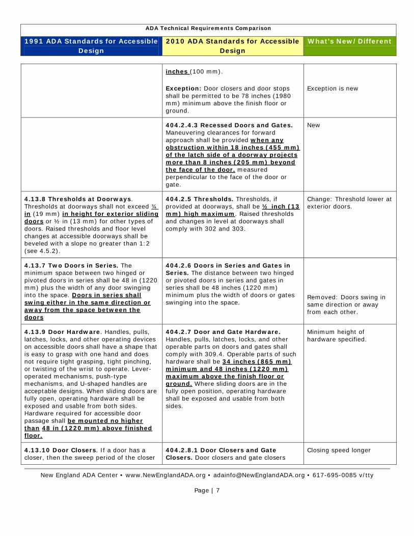
inches (100 mm).
Exception: Door closers and door stops shall be permitted to be 78 inches (1980 mm) minimum above the finish floor or ground.
Exception is new
404.2.4.3 Recessed Doors and Gates. Maneuvering clearances for forward approach shall be provided when any obstruction within 18 inches (455 mm) of the latch side of a doorway projects more than 8 inches (205 mm) beyond the face of the door, measured perpendicular to the face of the door or gate.
New
4.13.8 Thresholds at Doorways. Thresholds at doorways shall not exceed ¾ in (19 mm) in height for exterior sliding doors or ½ in (13 mm) for other types of doors. Raised thresholds and floor level changes at accessible doorways shall be beveled with a slope no greater than 1:2 (see 4.5.2).
404.2.5 Thresholds. Thresholds, if provided at doorways, shall be ½ inch (13 mm) high maximum. Raised thresholds and changes in level at doorways shall comply with 302 and 303.
Change: Threshold lower at exterior doors.
4.13.7 Two Doors in Series. The minimum space between two hinged or pivoted doors in series shall be 48 in (1220 mm) plus the width of any door swinging into the space. Doors in series shall swing either in the same direction or away from the space between the doors
404.2.6 Doors in Series and Gates in Series. The distance between two hinged or pivoted doors in series and gates in series shall be 48 inches (1220 mm) minimum plus the width of doors or gates swinging into the space.
Removed: Doors swing in same direction or away from each other.
4.13.9 Door Hardware. Handles, pulls, latches, locks, and other operating devices on accessible doors shall have a shape that is easy to grasp with one hand and does not require tight grasping, tight pinching, or twisting of the wrist to operate. Lever-operated mechanisms, push-type mechanisms, and U-shaped handles are acceptable designs. When sliding doors are fully open, operating hardware shall be exposed and usable from both sides. Hardware required for accessible door passage shall be mounted no higher than 48 in (1220 mm) above finished floor.
404.2.7 Door and Gate Hardware. Handles, pulls, latches, locks, and other operable parts on doors and gates shall comply with 309.4. Operable parts of such hardware shall be 34 inches (865 mm) minimum and 48 inches (1220 mm) maximum above the finish floor or ground. Where sliding doors are in the fully open position, operating hardware shall be exposed and usable from both sides.
Minimum height of hardware specified.
4.13.10 Door Closers. If a door has a closer, then the sweep period of the closer
404.2.8.1 Door Closers and Gate Closers. Door closers and gate closers
Closing speed longer

ADA Technical Requirements Comparison
1991 ADA Standards for Accessible Design
2010 ADA Standards for Accessible Design
What’s New/Different
New England ADA Center • www.NewEnglandADA.org • [email protected] • 617-695-0085 v/tty
Page | 8
shall be adjusted so that from an open position of 70 degrees, the door will take at least 3 seconds to move to a point 3 in (75 mm) from the latch, measured to the leading edge of the door.
shall be adjusted so that from an open position of 90 degrees, the time required to move the door to a position of 12 degrees from the latch is 5 seconds minimum.
404.2.8.2 Spring Hinges. Door and gate spring hinges shall be adjusted so that from the open position of 70 degrees, the door or gate shall move to the closed position in 1.5 seconds minimum.
New
404.2.10 Door and Gate Surfaces. Swinging door and gate surfaces within 10 inches (255 mm) of the finish floor or ground measured vertically shall have a smooth surface on the push side extending the full width of the door or gate. Parts creating horizontal or vertical joints in these surfaces shall be within 1/16 inch (1.6 mm) of the same plane as the other. Cavities created by added kick plates shall be capped.
New
404.2.11 Vision Lights. Doors, gates, and side lights adjacent to doors or gates, containing one or more glazing panels that permit viewing through the panels shall have the bottom of at least one glazed panel located 43 inches (1090 mm) maximum above the finish floor.
Exceptions: Vision lights with the lowest part more than 66 inches (1675 mm) from the finish floor or ground shall not be required to comply with 404.2.11.
New
4.13.12 Automatic Doors and Power-Assisted Doors. If an automatic door is used, then it shall comply with ANSI/BHMA A156.10-1985. Slowly opening, low-powered, automatic doors shall comply with ANSI A156.19-1984. Such doors shall not open to back check faster than 3 seconds and shall require no more than 15 lbf (66.6N) to stop door movement. If a power-assisted door is used, its door-opening force shall comply with 4.13.11 and its closing shall conform to the requirements in ANSI A156.19-1984.
404.3 Automatic and Power-Assisted Doors and Gates. Automatic doors and automatic gates shall comply with 404.3. Full-powered automatic doors shall comply with ANSI/BHMA A156.10 (incorporated by reference, see "Referenced Standards" in Chapter 1). Low-energy and power-assisted doors shall comply with ANSI/BHMA A156.19 (1997 or 2002 edition) (incorporated by reference, see "Referenced Standards" in Chapter 1).
Reference changed

ADA Technical Requirements Comparison
1991 ADA Standards for Accessible Design
2010 ADA Standards for Accessible Design
What’s New/Different
New England ADA Center • www.NewEnglandADA.org • [email protected] • 617-695-0085 v/tty
Page | 9
404.3.2 Maneuvering Clearance. Clearances at power-assisted doors and gates shall comply with 404.2.4. Clearances at automatic doors and gates without standby power and serving an accessible means of egress shall comply with 404.2.4.
Exceptions: Where automatic doors and gates remain open in the power-off condition, compliance with 404.2.4 shall not be required.
New
4.8 Ramps 405 Ramps
4.8.6 Cross Slope and Surfaces. The cross slope of ramp surfaces shall be no greater than 1:50.
405.3 Cross Slope. Cross slope of ramp runs shall not be steeper than 1:48.
Change: Steeper cross slope allowed.
4.8.3 Clear Width. The minimum clear width of a ramp shall be 36 in (915 mm).
405.5 Clear Width. The clear width of a ramp run and, where handrails are provided, the clear width between handrails shall be 36 inches (915 mm) minimum.
Exception: Within employee work areas, the required clear width of ramps that are a part of common use circulation paths shall be permitted to be decreased by work area equipment provided that the decrease is essential to the function of the work being performed.
Exception is new
4.13.6 (4) If a doorway is located at a landing, then the area in front of the doorway shall comply with 4.13.6.
405.7.5 Doorways. Where doorways are located adjacent to a ramp landing, maneuvering clearances required by 404.2.4 and 404.3.2 shall be permitted to overlap the required landing area.
Clarification: Doors located at landing shall be permitted to overlap.
4.8.5 Handrails. If a ramp run has a rise greater than 6 in (150 mm) or a horizontal projection greater than 72 in (1830 mm), then it shall have handrails on both sides.
405.8 Handrails. Ramp runs with a rise greater than 6 inches (150 mm) shall have handrails complying with 505.
Horizontal projection removed.
4.8.7 Edge Protection. Ramps and landings with drop-offs shall have curbs, walls, railings, or projecting surfaces that prevent people from slipping off the ramp. Curbs shall be a minimum of 2 in (50 mm) high.
405.9 Curb or Barrier Edge Protection. Edge protection complying with 405.9.1 or 405.9.2 shall be provided on each side of ramp runs and at each side of ramp landings.
Minimum of 2 inches high removed.
ADA Technical Requirements Comparison
1991 ADA Standards for Accessible Design
2010 ADA Standards for Accessible Design
What’s New/Different
New England ADA Center • www.NewEnglandADA.org • [email protected] • 617-695-0085 v/tty
Page | 10
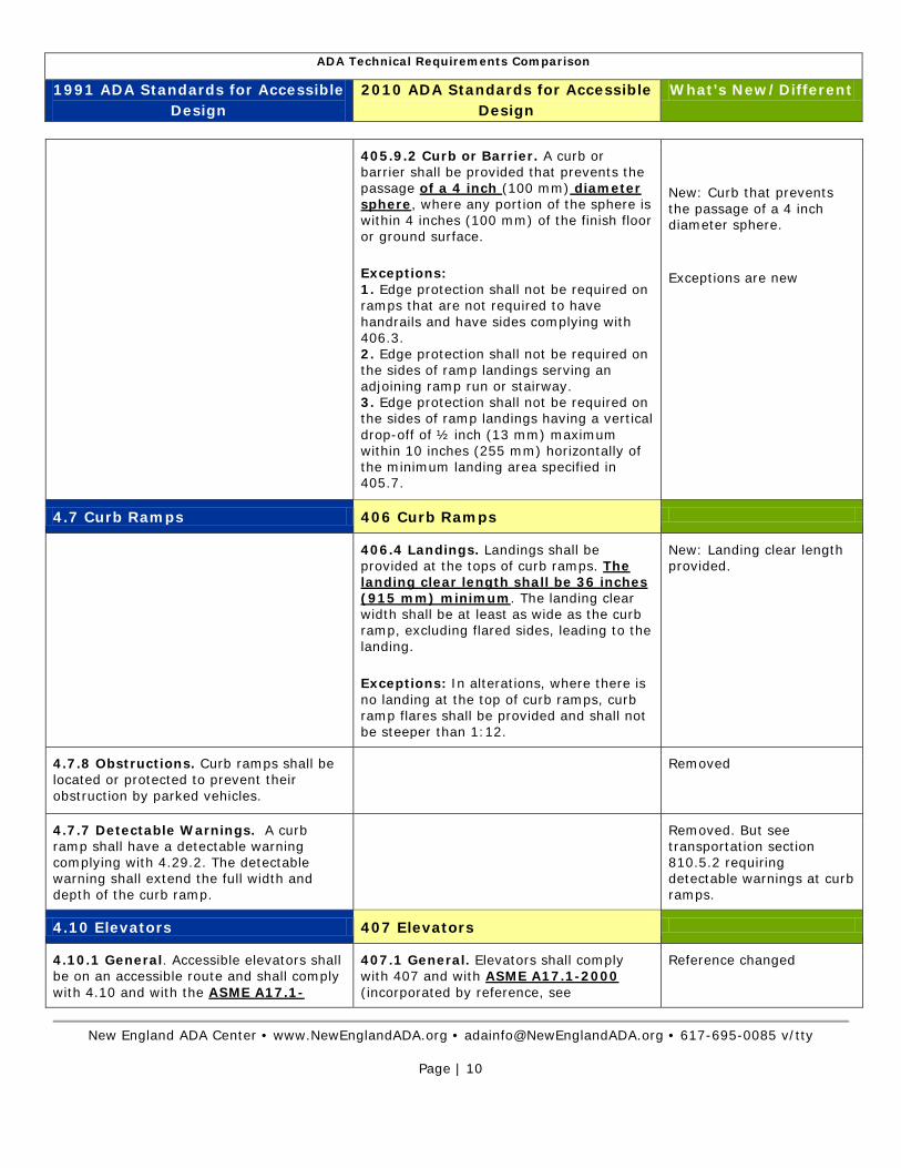
405.9.2 Curb or Barrier. A curb or barrier shall be provided that prevents the passage of a 4 inch (100 mm) diameter sphere
Exceptions: 1. Edge protection shall not be required on ramps that are not required to have handrails and have sides complying with 406.3. 2. Edge protection shall not be required on the sides of ramp landings serving an adjoining ramp run or stairway. 3. Edge protection shall not be required on the sides of ramp landings having a vertical drop-off of ½ inch (13 mm) maximum within 10 inches (255 mm) horizontally of the minimum landing area specified in 405.7.
, where any portion of the sphere is within 4 inches (100 mm) of the finish floor or ground surface.
New: Curb that prevents the passage of a 4 inch diameter sphere.
Exceptions are new
4.7 Curb Ramps 406 Curb Ramps
406.4 Landings. Landings shall be provided at the tops of curb ramps. The landing clear length shall be 36 inches (915 mm) minimum. The landing clear width shall be at least as wide as the curb ramp, excluding flared sides, leading to the landing.
Exceptions: In alterations, where there is no landing at the top of curb ramps, curb ramp flares shall be provided and shall not be steeper than 1:12.
New: Landing clear length provided.
4.7.8 Obstructions. Curb ramps shall be located or protected to prevent their obstruction by parked vehicles.
Removed
4.7.7 Detectable Warnings. A curb ramp shall have a detectable warning complying with 4.29.2. The detectable warning shall extend the full width and depth of the curb ramp.
Removed. But see transportation section 810.5.2 requiring detectable warnings at curb ramps.
4.10 Elevators 407 Elevators
4.10.1 General. Accessible elevators shall be on an accessible route and shall comply with 4.10 and with the ASME A17.1-
407.1 General. Elevators shall comply with 407 and with ASME A17.1-2000 (incorporated by reference, see
Reference changed
ADA Technical Requirements Comparison
1991 ADA Standards for Accessible Design
2010 ADA Standards for Accessible Design
What’s New/Different
New England ADA Center • www.NewEnglandADA.org • [email protected] • 617-695-0085 v/tty
Page | 11
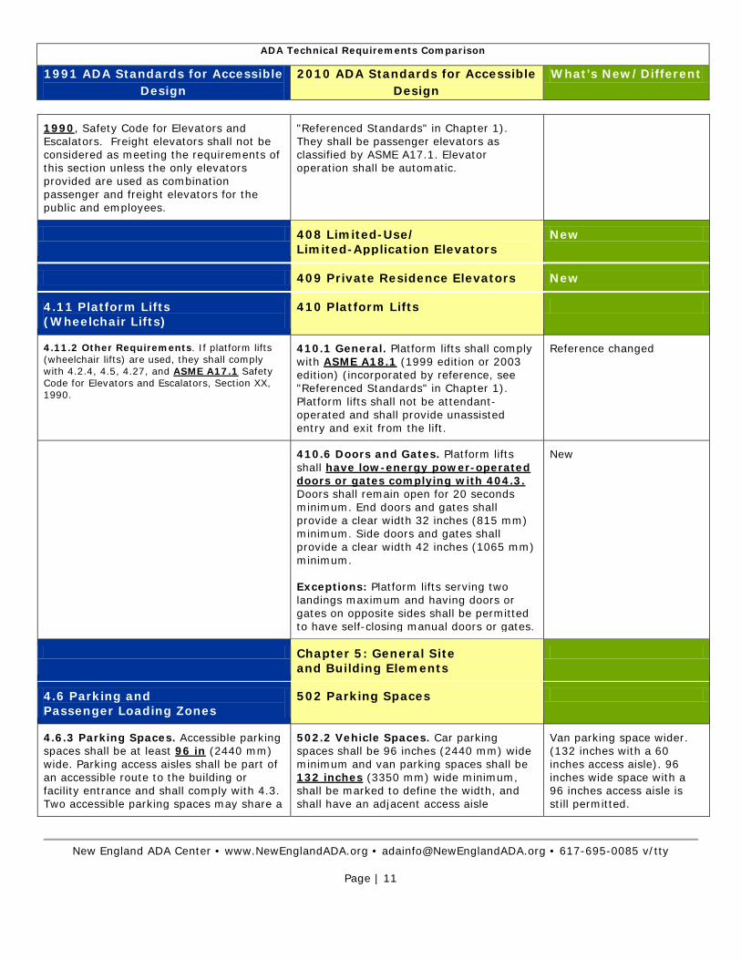
1990, Safety Code for Elevators and Escalators. Freight elevators shall not be considered as meeting the requirements of this section unless the only elevators provided are used as combination passenger and freight elevators for the public and employees.
"Referenced Standards" in Chapter 1). They shall be passenger elevators as classified by ASME A17.1. Elevator operation shall be automatic.
408 Limited-Use/ Limited-Application Elevators
New
409 Private Residence Elevators New
4.11 Platform Lifts (Wheelchair Lifts)
410 Platform Lifts
4.11.2 Other Requirements. If platform lifts (wheelchair lifts) are used, they shall comply with 4.2.4, 4.5, 4.27, and ASME A17.1 Safety Code for Elevators and Escalators, Section XX, 1990.
410.1 General. Platform lifts shall comply with ASME A18.1 (1999 edition or 2003 edition) (incorporated by reference, see "Referenced Standards" in Chapter 1). Platform lifts shall not be attendant-operated and shall provide unassisted entry and exit from the lift.
Reference changed
410.6 Doors and Gates. Platform lifts shall have low-energy power-operated doors or gates complying with 404.3. Doors shall remain open for 20 seconds minimum. End doors and gates shall provide a clear width 32 inches (815 mm) minimum. Side doors and gates shall provide a clear width 42 inches (1065 mm) minimum. Exceptions: Platform lifts serving two landings maximum and having doors or gates on opposite sides shall be permitted to have self-closing manual doors or gates.
New
Chapter 5: General Site and Building Elements
4.6 Parking and Passenger Loading Zones
502 Parking Spaces
4.6.3 Parking Spaces. Accessible parking spaces shall be at least 96 in (2440 mm) wide. Parking access aisles shall be part of an accessible route to the building or facility entrance and shall comply with 4.3. Two accessible parking spaces may share a
502.2 Vehicle Spaces. Car parking spaces shall be 96 inches (2440 mm) wide minimum and van parking spaces shall be 132 inches (3350 mm) wide minimum, shall be marked to define the width, and shall have an adjacent access aisle
Van parking space wider. (132 inches with a 60 inches access aisle). 96 inches wide space with a 96 inches access aisle is still permitted.

ADA Technical Requirements Comparison
1991 ADA Standards for Accessible Design
2010 ADA Standards for Accessible Design
What’s New/Different
New England ADA Center • www.NewEnglandADA.org • [email protected] • 617-695-0085 v/tty
Page | 12
common access aisle. complying with 502.3.
Exceptions: Van parking spaces shall be permitted to be 96 inches (2440 mm) wide minimum where the access aisle is 96 inches (2440 mm) wide minimum.
502.3.3 Marking. Access aisles shall be marked so as to discourage parking in them.
New: Access aisles shall be marked.
502.3.4 Location. Access aisles shall not overlap the vehicular way. Access aisles shall be permitted to be placed on either side of the parking space except for angled van parking spaces which shall have access aisles located on the passenger side of the parking spaces.
New: Access aisles shall be located on the passenger side for angled van parking spaces.
4.6.4 Signage. Accessible parking spaces shall be designated as reserved by a sign showing the symbol of accessibility (see 4.30.7). Spaces complying with 4.1.2(5)(b) shall have an additional sign "Van-Accessible" mounted below the symbol of accessibility. Such signs shall be located so they cannot be obscured by a vehicle parked in the space.
502.6 Identification. Parking space identification signs shall include the International Symbol of Accessibility complying with 703.7.2.1. Signs identifying van parking spaces shall contain the designation "van accessible." Signs shall be 60 inches (1525 mm) minimum above the finish floor or ground surface measured to the bottom of the sign.
New: Sign height specified.
4.6 Parking and Passenger Loading Zones
503 Passenger Loading Zones
4.6.6 Passenger Loading Zones. Passenger loading zones shall provide an access aisle at least 60 in (1525 mm) wide and 20 ft (240 in) (6100 mm) long adjacent and parallel to the vehicle pull-up space.
503.2 Vehicle Pull-Up Space. Passenger loading zones shall provide a vehicular pull-up space 96 inches (2440 mm) wide minimum and 20 feet (6100 mm) long minimum.
New: Access aisle wider.
503.3 Access Aisle. Passenger loading zones shall provide access aisles complying with 503 adjacent to the vehicle pull-up space. Access aisles shall adjoin an accessible route and shall not overlap the vehicular way.
New
Changed
New: Access aisles shall be marked.
503.3.2 Length. Access aisles shall extend the full length of the vehicle pull-up spaces they serve.
503.3.3 Marking. Access aisles shall be marked so as to discourage parking in

ADA Technical Requirements Comparison
1991 ADA Standards for Accessible Design
2010 ADA Standards for Accessible Design
What’s New/Different
New England ADA Center • www.NewEnglandADA.org • [email protected] • 617-695-0085 v/tty
Page | 13
them.
4.9 Stairs 504 Stairways
4.9.2 Treads and Risers. On any given flight of stairs, all steps shall have uniform riser heights and uniform tread widths. Stair treads shall be no less than 11 in (280 mm) wide, measured from riser to riser (see Fig. 18(a)). Open risers are not permitted.
504.2 Treads and Risers. All steps on a flight of stairs shall have uniform riser heights and uniform tread depths. Risers shall be 4 inches (100 mm) high minimum and 7 inches (180 mm) high maximum. Treads shall be 11 inches (280 mm) deep minimum.
New: Riser heights specified.
4.26 Handrails, Grab Bars 505 Handrails
4.9.4 Handrails. Stairways shall have handrails at both sides of all stairs. Handrails shall comply with 4.26 and shall have the following features:
(1) Handrails shall be continuous along both sides of stairs. The inside handrail on switchback or dogleg stairs shall always be continuous.
505.2 Where Required. Handrails shall be provided on both sides of stairs and ramps.
Exceptions: In assembly areas, handrails shall not be required on both sides of aisle ramps where a handrail is provided at either side or within the aisle width.
Exception is new
4.9.4(3) The clear space between [stair] handrails and wall shall be 1½ in (38 mm).
505.5 Clearance. Clearance between handrail gripping surfaces and adjacent surfaces shall be 1½ inches (38 mm) minimum.
Clearance changed from absolute to minimum.
4.26.2 Size and Spacing of Grab Bars and Handrails. The diameter or width of the gripping surfaces of a handrail or grab bar shall be 1¼ in to 1½ in (32 mm to 38 mm), or the shape shall provide an equivalent gripping surface.
505.7.1 Circular Cross Section. Handrail gripping surfaces with a circular cross section shall have an outside diameter of 1¼ inches (32 mm) minimum and 2 inches (51 mm) maximum.
Maximum diameter increased.
4.9.4(2) If handrails are not continuous, they shall extend at least 12 in (305 mm) beyond the top riser and at least 12 in (305 mm) plus the width of one tread beyond the bottom riser. At the top, the extension shall be parallel with the floor or ground surface. At the bottom, the handrail shall continue to slope for a distance of the width of one tread from the bottom riser; the remainder of the extension shall be horizontal.
505.10.3 Bottom Extension at Stairs. At the bottom of a stair flight, handrails shall extend at the slope of the stair flight for a horizontal distance at least equal to one tread depth beyond the last riser nosing. Extension shall return to a wall, guard, or the landing surface, or shall be continuous to the handrail of an adjacent stair flight.
12” horizontal extension at the bottom removed.

ADA Technical Requirements Comparison
1991 ADA Standards for Accessible Design
2010 ADA Standards for Accessible Design
What’s New/Different
New England ADA Center • www.NewEnglandADA.org • [email protected] • 617-695-0085 v/tty
Page | 14
Chapter 6: Plumbing Elements and Facilities
415 Drinking Fountains 602 Drinking Fountains
4.15.5 Clearances.
(1) Wall- and post-mounted cantilevered units shall have a clear knee space between the bottom of the apron and the floor or ground at least 27 in (685 mm) high, 30 in (760 mm) wide, and 17 in to 19 in (430 mm to 485 mm) deep (see Fig. 27(a) and (b)). Such units shall also have a minimum clear floor space 30 in by 48 in (760 mm by 1220 mm) to allow a person in a wheelchair to approach the unit facing forward.
602.2 Clear Floor Space. Units shall have a clear floor or ground space complying with 305 positioned for a forward approach and centered on the unit. Knee and toe clearance complying with 306 shall be provided.
Exceptions: A parallel approach complying with 305 shall be permitted at units for children's use where the spout is 30 inches (760 mm) maximum above the finish floor or ground and is 3½ inches (90 mm) maximum from the front edge of the unit, including bumpers.
New: Clear floor space centered at the unit.
Exception is new
4.15.3 Spout Location. The spouts of drinking fountains and water coolers shall be at the front of the unit and shall direct the water flow in a trajectory that is parallel or nearly parallel to the front of the unit. The spout shall provide a flow of water at least 4 in (100 mm) high so as to allow the insertion of a cup or glass under the flow of water. On an accessible drinking fountain with a round or oval bowl, the spout must be positioned so the flow of water is within 3 in (75 mm) of the front edge of the fountain.
602.5 Spout Location. The spout shall be located 15 inches (380 mm) minimum from the vertical support and 5 inches (125 mm) maximum from the front edge of the unit, including bumpers. 602.6 Water Flow. The spout shall provide a flow of water 4 inches (100 mm) high minimum and shall be located 5 inches (125 mm) maximum from the front of the unit. The angle of the water stream shall be measured horizontally relative to the front face of the unit. Where spouts are located less than 3 inches (75 mm) of the front of the unit, the angle of the water stream shall be 30 degrees maximum. Where spouts are located between 3 inches (75 mm) and 5 inches (125 mm) maximum from the front of the unit, the angle of the water stream shall be 15 degrees maximum.
New: Specification for spout location.
Clarification for water flow and water stream degrees.
602.7 Drinking Fountains for Standing Persons. Spout outlets of drinking fountains for standing persons shall be 38 inches (965 mm) minimum and 43 inches (1090 mm) maximum above the finish floor or ground.
New: Dimension specified.

ADA Technical Requirements Comparison
1991 ADA Standards for Accessible Design
2010 ADA Standards for Accessible Design
What’s New/Different
New England ADA Center • www.NewEnglandADA.org • [email protected] • 617-695-0085 v/tty
Page | 15
4.22 Toilet Rooms 4.23 Bathrooms, Bathing Facilities, and Shower Rooms
603 Toilet and Bathing Rooms
4.22.2 Doors [Toilet Rooms]. All doors to accessible toilet rooms shall comply with 4.13. Doors shall not swing into the clear floor space required for any fixture.
603.2.3 Door Swing. Doors shall not swing into the clear floor space or clearance required for any fixture. Doors shall be permitted to swing into the required turning space.
Exceptions: 1. Doors to a toilet room or bathing room for a single occupant accessed only through a private office and not for common use or public use shall be permitted to swing into the clear floor space or clearance provided the swing of the door can be reversed to comply with 603.2.3. 2. Where the toilet room or bathing room is for individual use and a clear floor space complying with 305.3 is provided within the room beyond the arc of the door swing, doors shall be permitted to swing into the clear floor space or clearance required for any fixture.
Exception 2 is new: Door may swing in into clear floor spaces required at fixtures if a 30 inches by 48 inches minimum clear floor space is provided beyond the door swing.
4.19.6 Mirrors. Mirrors shall be mounted with the bottom edge of the reflecting surface no higher than 40 in (1015 mm) above the finish floor.
603.3 Mirrors. Mirrors located above lavatories or countertops shall be installed with the bottom edge of the reflecting surface 40 inches (1015 mm) maximum above the finish floor or ground. Mirrors not located above lavatories or countertops shall be installed with the bottom edge of the reflecting surface 35 inches (890 mm) maximum above the finish floor or ground.
New: Specification for mirrors not located above lavatories.
603.4 Coat Hooks and Shelves. Coat hooks shall be located within one of the reach ranges specified in 308. Shelves shall be located 40 inches (1015 mm) minimum and 48 inches (1220 mm) maximum above the finish floor.
Clarification for mounting height of shelves.
4.16 Water Closets 4.17 Toilet Stalls
604 Water Closet and Toilet Compartment
NOTE: In Figure 30(a) The centerline of the water closet shall be 18 inches (455 mm) from the side wall.
604.2 Location. The water closet shall be positioned with a wall or partition to the rear and to one side. The centerline of the
Centerline no longer absolute at water closet.

ADA Technical Requirements Comparison
1991 ADA Standards for Accessible Design
2010 ADA Standards for Accessible Design
What’s New/Different
New England ADA Center • www.NewEnglandADA.org • [email protected] • 617-695-0085 v/tty
Page | 16
water closet shall be 16 inches (405 mm) minimum to 18 inches (455 mm) maximum from the side wall or partition, except that the water closet shall be 17 inches (430 mm) minimum and 19 inches (485 mm) maximum from the side wall or partition in the ambulatory accessible toilet compartment specified in 604.8.2. Water closets shall be arranged for a left-hand or right-hand approach.
4.16.4 Grab Bars. Grab bars for water closets not located in stalls shall comply with 4.26 and Fig. 29. The grab bar behind the water closet shall be 36 in (915 mm) minimum.
NOTE: In Figure 29(a) a 36 inch (915 mm) minimum length grab bar is required behind the water closet mounted at a height between 33 and 36 inches (840-915 mm). The grab bar must extend a minimum of 12 inches (305) beyond the center of the water closet toward the side wall and a minimum of 24 inches (610 mm) toward the open side for either a left or right side approach.
604.5.2 Rear Wall. The rear wall grab bar shall be 36 inches (915 mm) long minimum and extend from the centerline of the water closet 12 inches (305 mm) minimum on one side and 24 inches (610 mm) minimum on the other side.
Exception: 1. The rear grab bar shall be permitted to be 24 inches (610 mm) long minimum, centered on the water closet, where wall space does not permit a length of 36 inches (915 mm) minimum due to the location of a recessed fixture adjacent to the water closet.
Exception is new
4.16.5 Flush Controls. Flush controls shall be hand operated or automatic and shall comply with 4.27.4. Controls for flush valves shall be mounted on the wide side of toilet areas no more than 44 in (1120 mm) above the floor.
604.6 Flush Controls. Flush controls shall be hand operated or automatic. Hand operated flush controls shall comply with 309. Flush controls shall be located on the open side of the water closet except in ambulatory accessible compartments complying with 604.8.2.
Greater height options
4.16.6 Dispensers. Toilet paper dispensers shall be installed within reach, as shown in Fig. 29(b). Dispensers that control delivery, or that do not permit continuous paper flow, shall not be used.
NOTE: In Figure 29(b) the toilet paper dispenser is required to be mounted at a minimum height of 19 inches (485 mm). (4.16.3, 4.16.4, 4.16.6).
604.7 Dispensers. Toilet paper dispensers shall comply with 309.4 and shall be 7 inches (180 mm) minimum and 9 inches (230 mm) maximum in front of the water closet measured to the centerline of the dispenser. The outlet of the dispenser shall be 15 inches (380 mm) minimum and 48 inches (1220 mm) maximum above the finish floor and shall not be located behind grab bars. Dispensers shall not be of a type that controls delivery or that does not allow continuous paper flow.
Dispenser location clarified.
Minimum height changed.
New: Maximum height specified.
604.8 Toilet Compartments. Wheelchair accessible toilet compartments shall meet the requirements of 604.8.1 and 604.8.3.
Name changed – from toilet stalls to toilet compartment.
ADA Technical Requirements Comparison
1991 ADA Standards for Accessible Design
2010 ADA Standards for Accessible Design
What’s New/Different
New England ADA Center • www.NewEnglandADA.org • [email protected] • 617-695-0085 v/tty
Page | 17
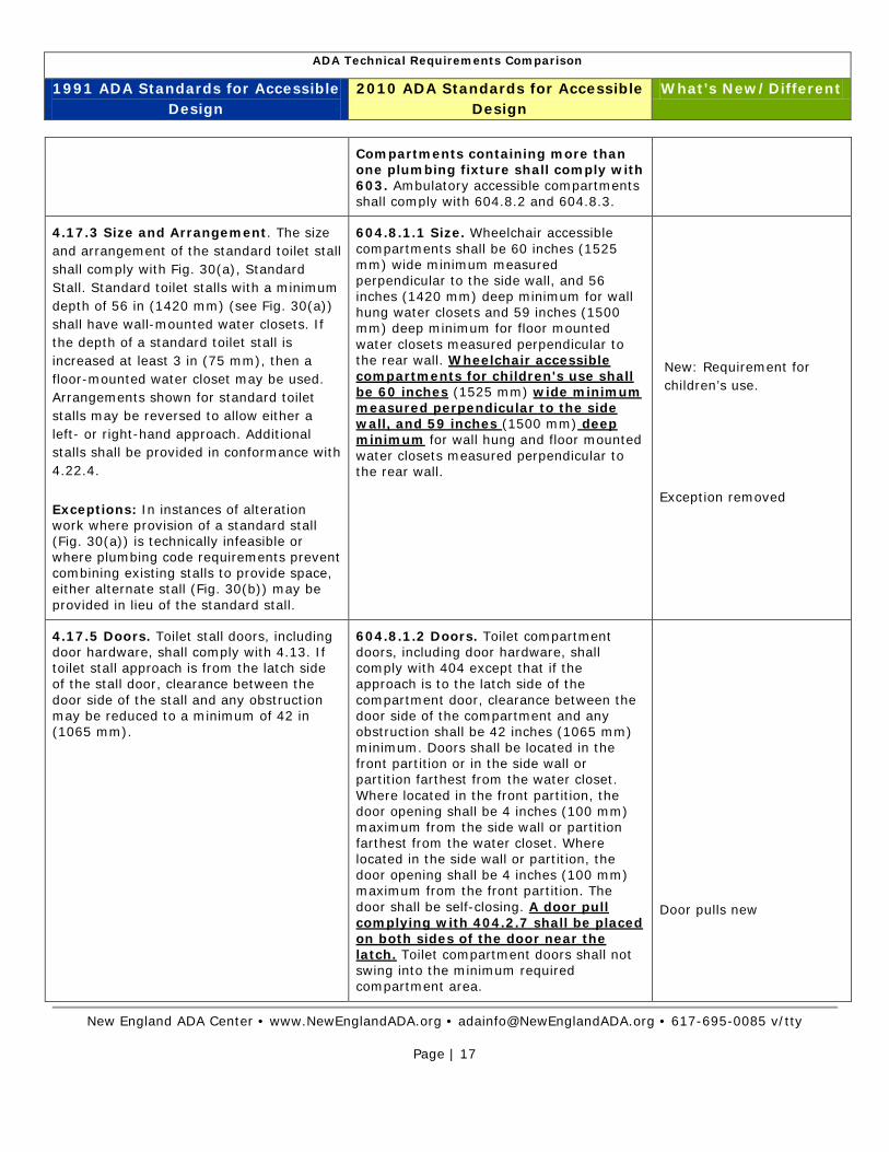
Compartments containing more than one plumbing fixture shall comply with 603. Ambulatory accessible compartments shall comply with 604.8.2 and 604.8.3.
4.17.3 Size and Arrangement. The size and arrangement of the standard toilet stall shall comply with Fig. 30(a), Standard Stall. Standard toilet stalls with a minimum depth of 56 in (1420 mm) (see Fig. 30(a)) shall have wall-mounted water closets. If the depth of a standard toilet stall is increased at least 3 in (75 mm), then a floor-mounted water closet may be used. Arrangements shown for standard toilet stalls may be reversed to allow either a left- or right-hand approach. Additional stalls shall be provided in conformance with 4.22.4.
Exceptions: In instances of alteration work where provision of a standard stall (Fig. 30(a)) is technically infeasible or where plumbing code requirements prevent combining existing stalls to provide space, either alternate stall (Fig. 30(b)) may be provided in lieu of the standard stall.
604.8.1.1 Size. Wheelchair accessible compartments shall be 60 inches (1525 mm) wide minimum measured perpendicular to the side wall, and 56 inches (1420 mm) deep minimum for wall hung water closets and 59 inches (1500 mm) deep minimum for floor mounted water closets measured perpendicular to the rear wall. Wheelchair accessible compartments for children's use shall be 60 inches (1525 mm) wide minimum measured perpendicular to the side wall, and 59 inches (1500 mm) deep minimum for wall hung and floor mounted water closets measured perpendicular to the rear wall.
New: Requirement for children’s use.
Exception removed
4.17.5 Doors. Toilet stall doors, including door hardware, shall comply with 4.13. If toilet stall approach is from the latch side of the stall door, clearance between the door side of the stall and any obstruction may be reduced to a minimum of 42 in (1065 mm).
604.8.1.2 Doors. Toilet compartment doors, including door hardware, shall comply with 404 except that if the approach is to the latch side of the compartment door, clearance between the door side of the compartment and any obstruction shall be 42 inches (1065 mm) minimum. Doors shall be located in the front partition or in the side wall or partition farthest from the water closet. Where located in the front partition, the door opening shall be 4 inches (100 mm) maximum from the side wall or partition farthest from the water closet. Where located in the side wall or partition, the door opening shall be 4 inches (100 mm) maximum from the front partition. The door shall be self-closing. A door pull complying with 404.2.7 shall be placed on both sides of the door near the latch. Toilet compartment doors shall not swing into the minimum required compartment area.
Door pulls new
ADA Technical Requirements Comparison
1991 ADA Standards for Accessible Design
2010 ADA Standards for Accessible Design
What’s New/Different
New England ADA Center • www.NewEnglandADA.org • [email protected] • 617-695-0085 v/tty
Page | 18
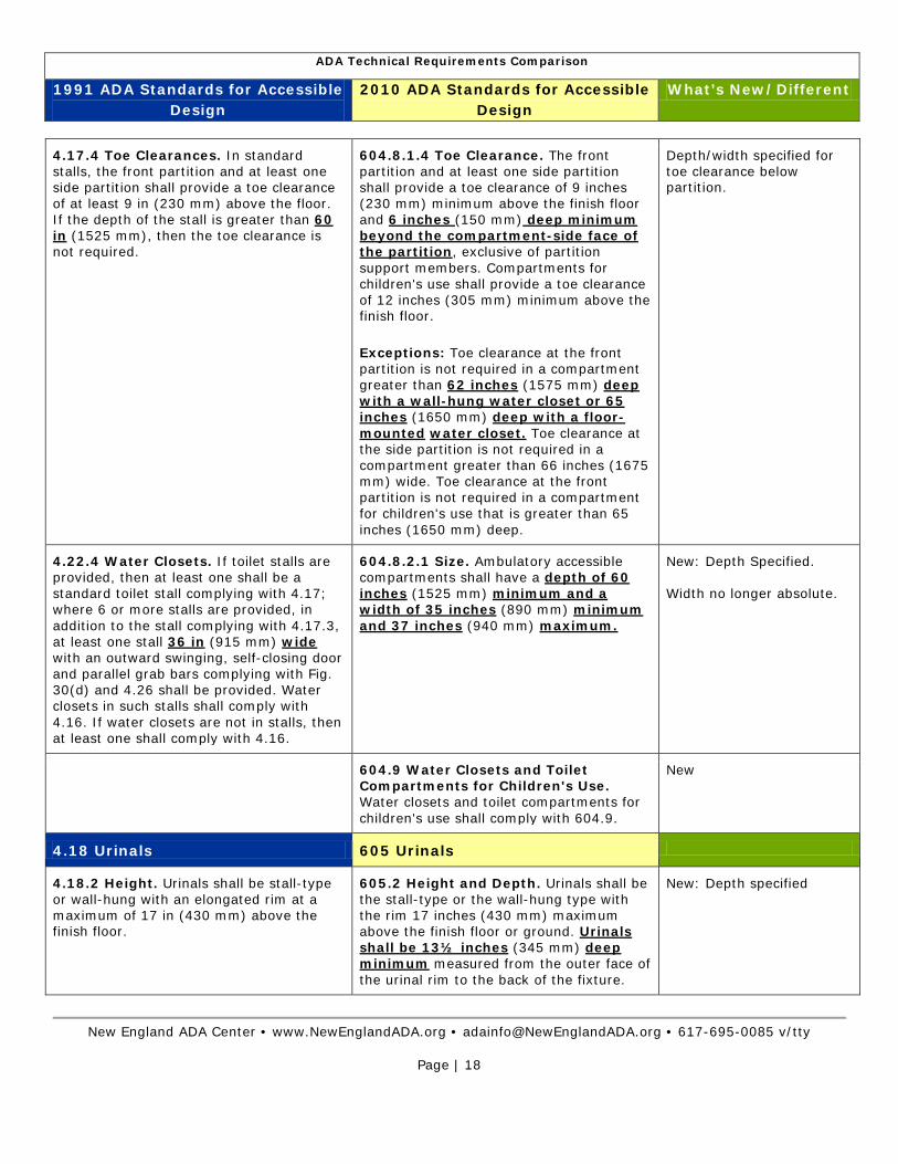
4.17.4 Toe Clearances. In standard stalls, the front partition and at least one side partition shall provide a toe clearance of at least 9 in (230 mm) above the floor. If the depth of the stall is greater than 60 in (1525 mm), then the toe clearance is not required.
604.8.1.4 Toe Clearance. The front partition and at least one side partition shall provide a toe clearance of 9 inches (230 mm) minimum above the finish floor and 6 inches (150 mm) deep minimum beyond the compartment-side face of the partition, exclusive of partition support members. Compartments for children's use shall provide a toe clearance of 12 inches (305 mm) minimum above the finish floor.
Exceptions: Toe clearance at the front partition is not required in a compartment greater than 62 inches (1575 mm) deep with a wall-hung water closet or 65 inches (1650 mm) deep with a floor-mounted water closet. Toe clearance at the side partition is not required in a compartment greater than 66 inches (1675 mm) wide. Toe clearance at the front partition is not required in a compartment for children's use that is greater than 65 inches (1650 mm) deep.
Depth/width specified for toe clearance below partition.
4.22.4 Water Closets. If toilet stalls are provided, then at least one shall be a standard toilet stall complying with 4.17; where 6 or more stalls are provided, in addition to the stall complying with 4.17.3, at least one stall 36 in (915 mm) wide with an outward swinging, self-closing door and parallel grab bars complying with Fig. 30(d) and 4.26 shall be provided. Water closets in such stalls shall comply with 4.16. If water closets are not in stalls, then at least one shall comply with 4.16.
604.8.2.1 Size. Ambulatory accessible compartments shall have a depth of 60 inches (1525 mm) minimum and a width of 35 inches (890 mm) minimum and 37 inches (940 mm) maximum.
New: Depth Specified. Width no longer absolute.
604.9 Water Closets and Toilet Compartments for Children's Use. Water closets and toilet compartments for children's use shall comply with 604.9.
New
4.18 Urinals 605 Urinals
4.18.2 Height. Urinals shall be stall-type or wall-hung with an elongated rim at a maximum of 17 in (430 mm) above the finish floor.
605.2 Height and Depth. Urinals shall be the stall-type or the wall-hung type with the rim 17 inches (430 mm) maximum above the finish floor or ground. Urinals shall be 13½ inches (345 mm) deep minimum measured from the outer face of the urinal rim to the back of the fixture.
New: Depth specified

ADA Technical Requirements Comparison
1991 ADA Standards for Accessible Design
2010 ADA Standards for Accessible Design
What’s New/Different
New England ADA Center • www.NewEnglandADA.org • [email protected] • 617-695-0085 v/tty
Page | 19
4.18.3 Clear Floor Space. A clear floor space 30 in by 48 in (760 mm by 1220 mm) shall be provided in front of urinals to allow forward approach. This clear space shall adjoin or overlap an accessible route and shall comply with 4.2.4. Urinal shields that do not extend beyond the front edge of the urinal rim may be provided with 29 in (735 mm) clearance between them.
605.3 Clear Floor Space. A clear floor or ground space complying with 305 positioned for forward approach shall be provided.
Urinal shields no longer required.
4.18.4 Flush Controls. Flush controls shall be hand operated or automatic, and shall comply with 4.27.4, and shall be mounted no more than 44 in (1120 mm) above the finish floor.
605.4 Flush Controls. Flush controls shall be hand operated or automatic. Hand operated flush controls shall comply with 309.
More height options
4.19 Lavatories and Mirrors 4.24 Sinks
606 Lavatories and Sinks
4.19.3 Clear Floor Space. A clear floor space 30 in by 48 in (760 mm by 1220 mm) complying with 4.2.4 shall be provided in front of a lavatory to allow forward approach. Such clear floor space shall adjoin or overlap an accessible route and shall extend a maximum of 19 in (485 mm) underneath the lavatory (see Fig. 32).
606.2 Clear Floor Space. A clear floor space complying with 305, positioned for a forward approach, and knee and toe clearance complying with 306 shall be provided.
Exceptions: 1. A parallel approach complying with 305 shall be permitted to a kitchen sink in a space where a cook top or conventional range is not provided and to wet bars. 2. A lavatory in a toilet room or bathing facility for a single occupant accessed only through a private office and not for common use or public use shall not be required to provide knee and toe clearance complying with 306. 3. In residential dwelling units, cabinetry shall be permitted under lavatories and kitchen sinks provided that all of the following conditions are met: (a) the cabinetry can be removed without removal or replacement of the fixture; (b) the finish floor extends under the cabinetry; and (c) the walls behind and surrounding the cabinetry are finished. 4. A knee clearance of 24 inches (610 mm) minimum above the finish floor or ground shall be permitted at lavatories and sinks used primarily by children 6 through 12 years where the rim or counter surface is
Exceptions are new

ADA Technical Requirements Comparison
1991 ADA Standards for Accessible Design
2010 ADA Standards for Accessible Design
What’s New/Different
New England ADA Center • www.NewEnglandADA.org • [email protected] • 617-695-0085 v/tty
Page | 20
31 inches (785 mm) maximum above the finish floor or ground. 5. A parallel approach complying with 305 shall be permitted to lavatories and sinks used primarily by children 5 years and younger. 6. The dip of the overflow shall not be considered in determining knee and toe clearances. 7. No more than one bowl of a multi-bowl sink shall be required to provide knee and toe clearance complying with 306.
4.19.2 Height and Clearances. Lavatories shall be mounted with the rim or counter surface no higher than 34 in (865 mm) above the finish floor. Provide a clearance of at least 29 in (735 mm) above the finish floor to the bottom of the apron.
606.3 Height. Lavatories and sinks shall be installed with the front of the higher of the rim or counter surface 34 inches (865 mm) maximum above the finish floor or ground.
29” apron height no longer required.
4.20 Bathtubs 607 Bathtubs
4.20.2 Floor Space. Clear floor space in front of bathtubs shall be as shown in Fig. 33.
NOTE: Figure 33(a) indicates that, if the approach is parallel to the bathtub, a 30 inch (760 mm) minimum width by 60 inch (1525 mm) minimum length clear space is required alongside the bathtub. If the approach is perpendicular to the bathtub, a 48 inch (1220 mm) minimum width by 60 inch (1525 mm) minimum length clear space is required.
607.2 Clearance. Clearance in front of bathtubs shall extend the length of the bathtub and shall be 30 inches (760 mm) wide minimum. A lavatory complying with 606 shall be permitted at the control end of the clearance. Where a permanent seat is provided at the head end of the bathtub, the clearance shall extend 12 inches (305 mm) minimum beyond the wall at the head end of the bathtub.
New: Additional 12 inches required where permanent seat is provided.
4.20.4 Grab Bars. Grab bars complying with 4.26 shall be provided as shown in Fig. 33 and 34.
NOTE: Figure 34(a) indicates at the foot of the tub, the grab bar shall be 24 inches (610 mm) minimum in length measured from the outer edge of the tub. On the back wall, two grab bars are required. The grab bars mounted on the back (long) wall shall be a minimum 24 inches (610 mm) in length located 12 inches (305 mm) maximum from the foot of the tub and 24 inches (610 mm) maximum from the head of the tub. One grab bar shall be located 9
607.4.1.1 Back Wall. Two grab bars shall be installed on the back wall, one located in accordance with 609.4 and the other located 8 inches (205 mm) minimum and 10 inches (255 mm) maximum above the rim of the bathtub. Each grab bar shall be installed 15 inches (380 mm) maximum from the head end wall and 12 inches (305 mm) maximum from the control end wall.
Grab bar height no longer absolute.

ADA Technical Requirements Comparison
1991 ADA Standards for Accessible Design
2010 ADA Standards for Accessible Design
What’s New/Different
New England ADA Center • www.NewEnglandADA.org • [email protected] • 617-695-0085 v/tty
Page | 21
inches (230 mm) above the rim of the tub. The others shall be 33 to 36 inches (840 mm to 910 mm) above the bathroom floor. At the head of the tub, the grab bar shall be a minimum of 12 inches (305 mm) in length measured from the outer edge of the tub.
4.20.6 Shower Unit. A shower spray unit with a hose at least 60 in (1525 mm) long that can be used both as a fixed shower head and as a hand-held shower shall be provided.
607.6 Shower Spray Unit and Water. A shower spray unit with a hose 59 inches (1500 mm) long minimum that can be used both as a fixed-position shower head and as a hand-held shower shall be provided. The shower spray unit shall have an on/off control with a non-positive shut-off. If an adjustable-height shower head on a vertical bar is used, the bar shall be installed so as not to obstruct the use of grab bars. Bathtub shower spray units shall deliver water that is 120°F (49°C) maximum.
Length changed for shower spray hose.
New: Water temperature specified.
4.21 Shower Stalls 608 Shower Compartments
See 9.1.2 Accessible Units, Sleeping Rooms, and Suites. Accessible sleeping rooms or suites that comply with the requirements of 9.2 (Requirements for Accessible Units, Sleeping Rooms, and Suites) shall be provided in conformance with the table below. In addition, in hotels, of 50 or more sleeping rooms or suites, additional accessible sleeping rooms or suites that include a roll-in shower shall also be provided Such accommodations shall comply with the requirements of 9.2, 4.21, and Fig 57(a) or (b)
Note Fig 57 (b): A folding seat, mounted adjacent to the entry to the shower, is provided in a 36 in by 60 inches (915 mm by 1220 mm) minimum roll-in shower stall. The width of the stall opening shall be a minimum of 36 inches (915 mm) clear located on a long wall at the opposite end of the shower from the controls. The shower seat shall be 24 inches (610 mm) minimum in length by 16 inches (330 mm) minimum in width and may be rectangular in shape. The seat shall be located next to the opening to the shower and adjacent to the end wall containing the shower head
608.5.3 Alternate Roll-In Type Shower Compartments. In alternate roll-in type shower compartments, the controls, faucets, and shower spray unit shall be located above the grab bar, but no higher than 48 inches (1220 mm) above the shower floor. Where a seat is provided, the controls, faucets, and shower spray unit shall be located on the side wall adjacent to the seat 27 inches (685 mm) maximum from the side wall behind the seat or shall be located on the back wall opposite the seat 15 inches (380 mm) maximum, left or right, of the centerline of the seat. Where a seat is not provided, the controls, faucets, and shower spray unit shall be installed on the side wall farthest from the compartment entry.
Allowed in all facilities of facilities (1991 Standard allows the design only in transient lodging).
New: Controls on the back wall permitted.
ADA Technical Requirements Comparison
1991 ADA Standards for Accessible Design
2010 ADA Standards for Accessible Design
What’s New/Different
New England ADA Center • www.NewEnglandADA.org • [email protected] • 617-695-0085 v/tty
Page | 22
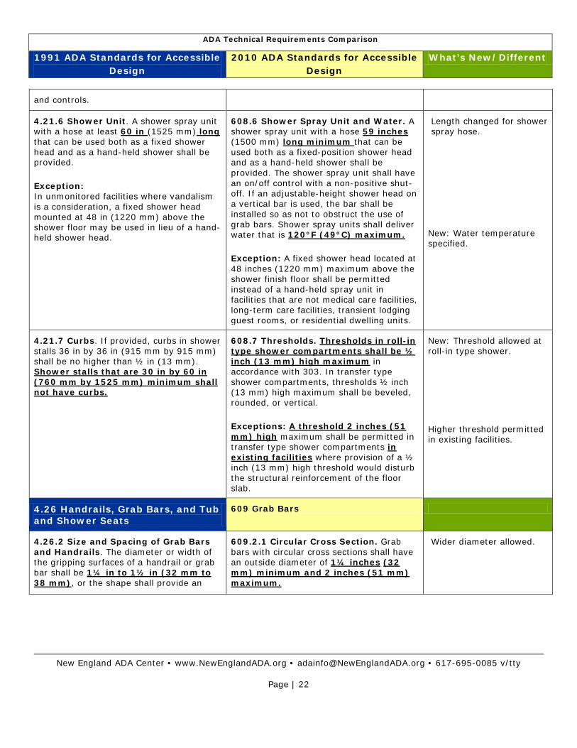
and controls.
4.21.6 Shower Unit. A shower spray unit with a hose at least 60 in (1525 mm) long that can be used both as a fixed shower head and as a hand-held shower shall be provided.
Exception: In unmonitored facilities where vandalism is a consideration, a fixed shower head mounted at 48 in (1220 mm) above the shower floor may be used in lieu of a hand-held shower head.
608.6 Shower Spray Unit and Water. A shower spray unit with a hose 59 inches (1500 mm) long minimum that can be used both as a fixed-position shower head and as a hand-held shower shall be provided. The shower spray unit shall have an on/off control with a non-positive shut-off. If an adjustable-height shower head on a vertical bar is used, the bar shall be installed so as not to obstruct the use of grab bars. Shower spray units shall deliver water that is 120°F (49°C) maximum.
Exception: A fixed shower head located at 48 inches (1220 mm) maximum above the shower finish floor shall be permitted instead of a hand-held spray unit in facilities that are not medical care facilities, long-term care facilities, transient lodging guest rooms, or residential dwelling units.
Length changed for shower spray hose.
New: Water temperature specified.
4.21.7 Curbs. If provided, curbs in shower stalls 36 in by 36 in (915 mm by 915 mm) shall be no higher than ½ in (13 mm). Shower stalls that are 30 in by 60 in (760 mm by 1525 mm) minimum shall not have curbs.
608.7 Thresholds. Thresholds in roll-in type shower compartments shall be ½ inch (13 mm) high maximum in accordance with 303. In transfer type shower compartments, thresholds ½ inch (13 mm) high maximum shall be beveled, rounded, or vertical.
Exceptions: A threshold 2 inches (51 mm) high maximum shall be permitted in transfer type shower compartments in existing facilities where provision of a ½ inch (13 mm) high threshold would disturb the structural reinforcement of the floor slab.
New: Threshold allowed at roll-in type shower.
Higher threshold permitted in existing facilities.
4.26 Handrails, Grab Bars, and Tub and Shower Seats
609 Grab Bars
4.26.2 Size and Spacing of Grab Bars and Handrails. The diameter or width of the gripping surfaces of a handrail or grab bar shall be 1¼ in to 1½ in (32 mm to 38 mm), or the shape shall provide an
609.2.1 Circular Cross Section. Grab bars with circular cross sections shall have an outside diameter of 1¼ inches (32 mm) minimum and 2 inches (51 mm) maximum.
Wider diameter allowed.

ADA Technical Requirements Comparison
1991 ADA Standards for Accessible Design
2010 ADA Standards for Accessible Design
What’s New/Different
New England ADA Center • www.NewEnglandADA.org • [email protected] • 617-695-0085 v/tty
Page | 23
equivalent gripping surface. If handrails or grab bars are mounted adjacent to a wall, the space between the wall and the grab bar shall be 1½ in (38 mm) (see Fig. 39(a), (b), (c), and (e)). Handrails may be located in a recess if the recess is a maximum of 3 in (75 mm) deep and extends at least 18 in (455 mm) above the top of the rail (see Fig. 39(d)).
609.2.2 Non-Circular Cross Section. Grab bars with non-circular cross sections shall have a cross-section dimension of 2 inches (51 mm) maximum and a perimeter dimension of 4 inches (100 mm) minimum and 4.8 inches (120 mm) maximum.
New: Specifications for non- circular grab bars.
Projecting objects space above grab bars reduced.
609.3 Spacing. The space between the wall and the grab bar shall be 1½ inches (38 mm). The space between the grab bar and projecting objects below and at the ends shall be 1½ inches (38 mm) minimum. The space between the grab bar and projecting objects above shall be 12 inches (305 mm) minimum.
Exceptions: The space between the grab bars and shower controls, shower fittings, and other grab bars above shall be permitted to be 1½ inches (38 mm) minimum.
610 Seats
4.20.3 An in-tub seat or a seat at the head end of the tub shall be provided as shown in Fig. 33. The structural strength of seats and their attachments shall comply with 4.26.3. Seats shall be mounted securely and shall not slip during use.
Note: Fig 33(b): If the approach is parallel to the bathtub, a 30 inches (760 mm) minimum width by 75 inches (1905 mm) minimum length clear space is required alongside the bathtub. The seat width shall be 15 inches (380 mm), measured from the back wall to the front of the seat, and shall extend the full width of the tub. An accessible lavatory is permitted within the clear space at the foot end of the tub.
610.2 Bathtub Seats. The top of bathtub seats shall be 17 inches (430 mm) minimum and 19 inches (485 mm) maximum above the bathroom finish floor. The depth of a removable in-tub seat shall be 15 inches (380 mm) minimum and 16 inches (405 mm) maximum. The seat shall be capable of secure placement. Permanent seats at the head end of the bathtub shall be 15 inches (380 mm) deep minimum and shall extend from the back wall to or beyond the outer edge of the bathtub.
New: Height of seat top specified.
New: Depth of removable seat specified.
Change: Depth of permanent seat no longer 15” absolute.
4.21.3 Seat. A seat shall be provided in shower stalls 36 in by 36 in (915 mm by 915mm) and shall be as shown in Fig. 36. The seat shall be mounted 17 in to 19 in (430 mm to 485 mm) from the bathroom floor and shall extend the full depth of the stall. In a 36 in by 36 in (915 mm by 915 mm) shower stall, the seat shall be on
610.3 Shower Compartment Seats. Where a seat is provided in a standard roll-in shower compartment, it shall be a folding type, shall be installed on the side wall adjacent to the controls, and shall extend from the back wall to a point within 3 inches (75 mm) of the compartment entry. Where a seat is provided in an alternate roll-in type shower
Change: Seat extension changed.
ADA Technical Requirements Comparison
1991 ADA Standards for Accessible Design
2010 ADA Standards for Accessible Design
What’s New/Different
New England ADA Center • www.NewEnglandADA.org • [email protected] • 617-695-0085 v/tty
Page | 24
the wall opposite the controls.
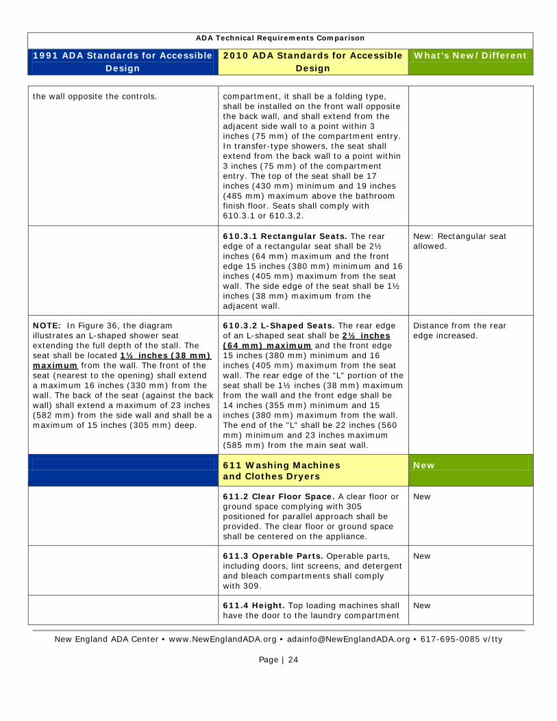
compartment, it shall be a folding type, shall be installed on the front wall opposite the back wall, and shall extend from the adjacent side wall to a point within 3 inches (75 mm) of the compartment entry. In transfer-type showers, the seat shall extend from the back wall to a point within 3 inches (75 mm) of the compartment entry. The top of the seat shall be 17 inches (430 mm) minimum and 19 inches (485 mm) maximum above the bathroom finish floor. Seats shall comply with 610.3.1 or 610.3.2.
610.3.1 Rectangular Seats. The rear edge of a rectangular seat shall be 2½ inches (64 mm) maximum and the front edge 15 inches (380 mm) minimum and 16 inches (405 mm) maximum from the seat wall. The side edge of the seat shall be 1½ inches (38 mm) maximum from the adjacent wall.
New: Rectangular seat allowed.
NOTE: In Figure 36, the diagram illustrates an L-shaped shower seat extending the full depth of the stall. The seat shall be located 1½ inches (38 mm) maximum from the wall. The front of the seat (nearest to the opening) shall extend a maximum 16 inches (330 mm) from the wall. The back of the seat (against the back wall) shall extend a maximum of 23 inches (582 mm) from the side wall and shall be a maximum of 15 inches (305 mm) deep.
610.3.2 L-Shaped Seats. The rear edge of an L-shaped seat shall be 2½ inches (64 mm) maximum and the front edge 15 inches (380 mm) minimum and 16 inches (405 mm) maximum from the seat wall. The rear edge of the "L" portion of the seat shall be 1½ inches (38 mm) maximum from the wall and the front edge shall be 14 inches (355 mm) minimum and 15 inches (380 mm) maximum from the wall. The end of the "L" shall be 22 inches (560 mm) minimum and 23 inches maximum (585 mm) from the main seat wall.
Distance from the rear edge increased.
611 Washing Machines and Clothes Dryers
New
611.2 Clear Floor Space. A clear floor or ground space complying with 305 positioned for parallel approach shall be provided. The clear floor or ground space shall be centered on the appliance.
New
611.3 Operable Parts. Operable parts, including doors, lint screens, and detergent and bleach compartments shall comply with 309.
New
611.4 Height. Top loading machines shall have the door to the laundry compartment
New
ADA Technical Requirements Comparison
1991 ADA Standards for Accessible Design
2010 ADA Standards for Accessible Design
What’s New/Different
New England ADA Center • www.NewEnglandADA.org • [email protected] • 617-695-0085 v/tty
Page | 25
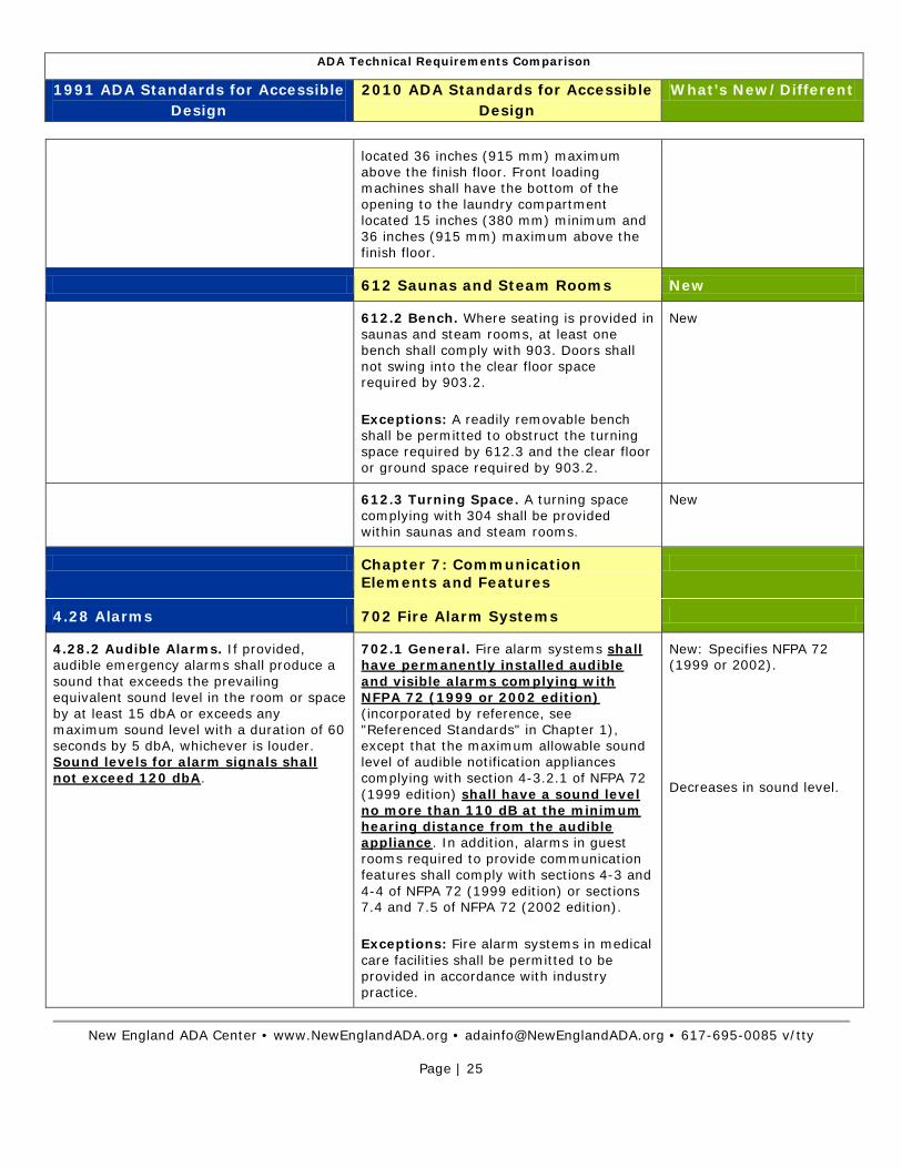
located 36 inches (915 mm) maximum above the finish floor. Front loading machines shall have the bottom of the opening to the laundry compartment located 15 inches (380 mm) minimum and 36 inches (915 mm) maximum above the finish floor.
612 Saunas and Steam Rooms New
612.2 Bench. Where seating is provided in saunas and steam rooms, at least one bench shall comply with 903. Doors shall not swing into the clear floor space required by 903.2.
Exceptions: A readily removable bench shall be permitted to obstruct the turning space required by 612.3 and the clear floor or ground space required by 903.2.
New
612.3 Turning Space. A turning space complying with 304 shall be provided within saunas and steam rooms.
New
Chapter 7: Communication Elements and Features
4.28 Alarms 702 Fire Alarm Systems
4.28.2 Audible Alarms. If provided, audible emergency alarms shall produce a sound that exceeds the prevailing equivalent sound level in the room or space by at least 15 dbA or exceeds any maximum sound level with a duration of 60 seconds by 5 dbA, whichever is louder. Sound levels for alarm signals shall not exceed 120 dbA.
702.1 General. Fire alarm systems shall have permanently installed audible and visible alarms complying with NFPA 72 (1999 or 2002 edition) (incorporated by reference, see "Referenced Standards" in Chapter 1), except that the maximum allowable sound level of audible notification appliances complying with section 4-3.2.1 of NFPA 72 (1999 edition) shall have a sound level no more than 110 dB at the minimum hearing distance from the audible appliance. In addition, alarms in guest rooms required to provide communication features shall comply with sections 4-3 and 4-4 of NFPA 72 (1999 edition) or sections 7.4 and 7.5 of NFPA 72 (2002 edition).
Exceptions: Fire alarm systems in medical care facilities shall be permitted to be provided in accordance with industry practice.
New: Specifies NFPA 72 (1999 or 2002).
Decreases in sound level.

ADA Technical Requirements Comparison
1991 ADA Standards for Accessible Design
2010 ADA Standards for Accessible Design
What’s New/Different
New England ADA Center • www.NewEnglandADA.org • [email protected] • 617-695-0085 v/tty
Page | 26
4.30 Signage 703 Signs
4.30.1 General. Signage required to be accessible by 4.1 shall comply with the applicable provisions of 4.30.
703.1 General. Signs shall comply with 703. Where both visual and tactile characters are required, either one sign with both visual and tactile characters, or two separate signs, one with visual, and one with tactile characters, shall be provided.
Clarification.
703.2.3 Style. Characters shall be sans serif. Characters shall not be italic, oblique, script, highly decorative, or of other unusual forms.
Sans serif only.
No longer allowed simple serif.
4.30.2 Character Proportion. Letters and numbers on signs shall have a width-to-height ratio between 3:5 and 1:1 and a stroke-width-to-height ratio between 1:5 and 1:10.
703.2.4 Character Proportions. Characters shall be selected from fonts where the width of the uppercase letter "O" is 55 percent minimum and 110 percent maximum of the height of the uppercase letter "I".
New
4.30.3 Character Height. Characters and numbers on signs shall be sized according to the viewing distance from which they are to be read. The minimum height is measured using an upper case X. Lower case characters are permitted.
703.2.5 Character Height. Character height measured vertically from the baseline of the character shall be ⅝ inch (16 mm) minimum and 2 inches (51 mm) maximum based on the height of the uppercase letter "I".
Exceptions: Where separate raised and visual characters with the same information are provided, raised character height shall be permitted to be ½ inch (13 mm) minimum.
Exception is new.
703.2.7 Character Spacing. Character spacing shall be measured between the two closest points of adjacent raised characters within a message, excluding word spaces. Where characters have rectangular cross sections, spacing between individual raised characters shall be ⅛ inch (3.2 mm) minimum and 4 times the raised character stroke width maximum. Where characters have other cross sections, spacing between individual raised characters shall be 1/16 inch (1.6 mm) minimum and 4 times the raised character stroke width maximum at the base of the cross sections, and ⅛ inch (3.2 mm) minimum and 4 times the raised character stroke width maximum at the top
New

ADA Technical Requirements Comparison
1991 ADA Standards for Accessible Design
2010 ADA Standards for Accessible Design
What’s New/Different
New England ADA Center • www.NewEnglandADA.org • [email protected] • 617-695-0085 v/tty
Page | 27
of the cross sections. Characters shall be separated from raised borders and decorative elements ⅜ inch (9.5 mm) minimum.
703.2.8 Line Spacing. Spacing between the baselines of separate lines of raised characters within a message shall be 135 percent minimum and 170 percent maximum of the raised character height.
New
703.3.1 Dimensions and Capitalization. Braille dots shall have a domed or rounded shape and shall comply with Table 703.3.1. The indication of an uppercase letter or letters shall only be used before the first word of sentences, proper nouns and names, individual letters of the alphabet, initials, and acronyms.
New: Braille dimension specified (dot and base diameter, dot and cell spacing).
4.30.6 Mounting Location and Height. Where permanent identification is provided for rooms and spaces, signs shall be installed on the wall adjacent to the latch side of the door. Where there is no wall space to the latch side of the door, including at double leaf doors, signs shall be placed on the nearest adjacent wall. Mounting height shall be 60 in (1525 mm) above the finish floor to the centerline of the sign. Mounting location for such signage shall be so that a person may approach within 3 in (76 mm) of signage without encountering protruding objects or standing within the swing of a door.
703.4.1 Height Above Finish Floor or Ground. Tactile characters on signs shall be located 48 inches (1220 mm) minimum above the finish floor or ground surface, measured from the baseline of the lowest tactile character and 60 inches (1525 mm) maximum above the finish floor or ground surface, measured from the baseline of the highest tactile character.
Exceptions: Tactile characters for elevator car controls shall not be required to comply with 703.4.1.
Minimum mounting height specified for tactile characters.
No centerline of sign.
703.4.2 Location. Where a tactile sign is provided at a door, the sign shall be located alongside the door at the latch side. Where a tactile sign is provided at double doors with one active leaf, the sign shall be located on the inactive leaf. Where a tactile sign is provided at double doors with two active leafs, the sign shall be located to the right of the right hand door. Where there is no wall space at the latch side of a single door or at the right side of double doors, signs shall be located on the nearest adjacent wall. Signs containing tactile characters shall be located so that a clear floor space of 18 inches (455
New: Sign location at double doors.
New: Floor space centered on the tactile character.

ADA Technical Requirements Comparison
1991 ADA Standards for Accessible Design
2010 ADA Standards for Accessible Design
What’s New/Different
New England ADA Center • www.NewEnglandADA.org • [email protected] • 617-695-0085 v/tty
Page | 28
mm) minimum by 18 inches (455 mm) minimum, centered on the tactile characters, is provided beyond the arc of any door swing between the closed position and 45 degree open position.
4.30.5 Finish and Contrast. The characters and background of signs shall be eggshell, matte, or other non-glare finish. Characters and symbols shall contrast with their background -- either light characters on a dark background or dark characters on a light background.
703.5.1 Finish and Contrast. Characters and their background shall have a non-glare finish. Characters shall contrast with their background with either light characters on a dark background or dark characters on a light background.
Change: Character background required to have non-glare finish only.
703.5.3 Style. Characters shall be conventional in form. Characters shall not be italic, oblique, script, highly decorative, or of other unusual forms.
New
703.5.4 Character Proportions. Characters shall be selected from fonts where the width of the uppercase letter "O" is 55 percent minimum and 110 percent maximum of the height of the uppercase letter "I".
New
4.30.3 Character Height. Characters and numbers on signs shall be sized according to the viewing distance from which they are to be read. The minimum height is measured using an upper case X. Lower case characters are permitted.
703.5.5 Character Height. Minimum character height shall comply with Table 703.5.5. Viewing distance shall be measured as the horizontal distance between the character and an obstruction preventing further approach towards the sign. Character height shall be based on the uppercase letter "I".
New: Minimum height specified.
Viewing distance clarified.
703.5.6 Height From Finish Floor or Ground. Visual characters shall be 40 inches (1015 mm) minimum above the finish floor or ground.
Exceptions: Visual characters indicating elevator car controls shall not be required to comply with 703.5.6.
Minimum mounting height specified for visual characters.
703.5.7 Stroke Thickness. Stroke thickness of the uppercase letter "I" shall be 10 percent minimum and 30 percent maximum of the height of the character.
New
703.5.8 Character Spacing. Character spacing shall be measured between the
New

ADA Technical Requirements Comparison
1991 ADA Standards for Accessible Design
2010 ADA Standards for Accessible Design
What’s New/Different
New England ADA Center • www.NewEnglandADA.org • [email protected] • 617-695-0085 v/tty
Page | 29
two closest points of adjacent characters, excluding word spaces. Spacing between individual characters shall be 10 percent minimum and 35 percent maximum of character height.
703.5.9 Line Spacing. Spacing between the baselines of separate lines of characters within a message shall be 135 percent minimum and 170 percent maximum of the character height.
New
703.6 Pictograms. Pictograms shall comply with 703.6.
New
703.6.1 Pictogram Field. Pictograms shall have a field height of 6 inches (150 mm) minimum. Characters and Braille shall not be located in the pictogram field.
New
703.6.2 Finish and Contrast. Pictograms and their field shall have a non-glare finish. Pictograms shall contrast with their field with either a light pictogram on a dark field or a dark pictogram on a light field.
New
703.6.3 Text Descriptors. Pictograms shall have text descriptors located directly below the pictogram field. Text descriptors shall comply with 703.2, 703.3 and 703.4.
New
4.31 Telephones 704 Telephones
4.31.5 Hearing Aid Compatible and Volume Control Telephones Required by 4.1. (1) Telephones shall be hearing aid compatible. (2) Volume controls, capable of a minimum of 12 dbA and a maximum of 18 dbA above normal, shall be provided in accordance with 4.1.3. If an automatic reset is provided then 18 dbA may be exceeded.
704.3 Volume Control Telephones. Public telephones required to have volume controls shall be equipped with a receive volume control that provides a gain adjustable up to 20 dB minimum. For incremental volume control, provide at least one intermediate step of 12 dB of gain minimum. An automatic reset shall be provided.
Changed: dB Volume control higher.
704.4.1 Height. When in use, the touch surface of TTY keypads shall be 34 inches (865 mm) minimum above the finish floor.
Exceptions: Where seats are provided,
New

ADA Technical Requirements Comparison
1991 ADA Standards for Accessible Design
2010 ADA Standards for Accessible Design
What’s New/Different
New England ADA Center • www.NewEnglandADA.org • [email protected] • 617-695-0085 v/tty
Page | 30
TTYs shall not be required to comply with 704.4.1.
4.29 Detectable Warnings 705 Detectable Warnings
4.29.2 Detectable Warnings on Walking Surfaces. Detectable warnings shall consist of raised truncated domes with a diameter of nominal 0.9 in (23 mm), a height of nominal 0.2 in (5 mm) and a center-to-center spacing of nominal 2.35 in (60 mm) and shall contrast visually with adjoining surfaces, either light-on-dark, or dark-on-light.
705.1.1 Dome Size. Truncated domes in a detectable warning surface shall have a base diameter of 0.9 inch (23 mm) minimum and 1.4 inches (36 mm) maximum, a top diameter of 50 percent of the base diameter minimum to 65 percent of the base diameter maximum, and a height of 0.2 inch (5.1 mm).
Diameter range instead of absolute.
Spacing changed
705.1.2 Dome Spacing. Truncated domes in a detectable warning surface shall have a center-to-center spacing of 1.6 inches (41 mm) minimum and 2.4 inches (61 mm) maximum, and a base-to-base spacing of 0.65 inch (17 mm) minimum, measured between the most adjacent domes on a square grid.
706 Assistive Listening Systems
706.2 Receiver Jacks. Receivers required for use with an assistive listening system shall include a ⅛ inch (3.2 mm) standard mono jack.
New
706.3 Receiver Hearing-Aid Compatibility. Receivers required to be hearing-aid compatible shall interface with telecoils in hearing aids through the provision of neckloops.
New
706.4 Sound Pressure Level. Assistive listening systems shall be capable of providing a sound pressure level of 110 dB minimum and 118 dB maximum with a dynamic range on the volume control of 50 dB.
New
706.5 Signal-to-Noise Ratio. The signal-to-noise ratio for internally generated noise in assistive listening systems shall be 18 dB minimum.
New
706.6 Peak Clipping Level. Peak clipping shall not exceed 18 dB of clipping relative to the peaks of speech.
New
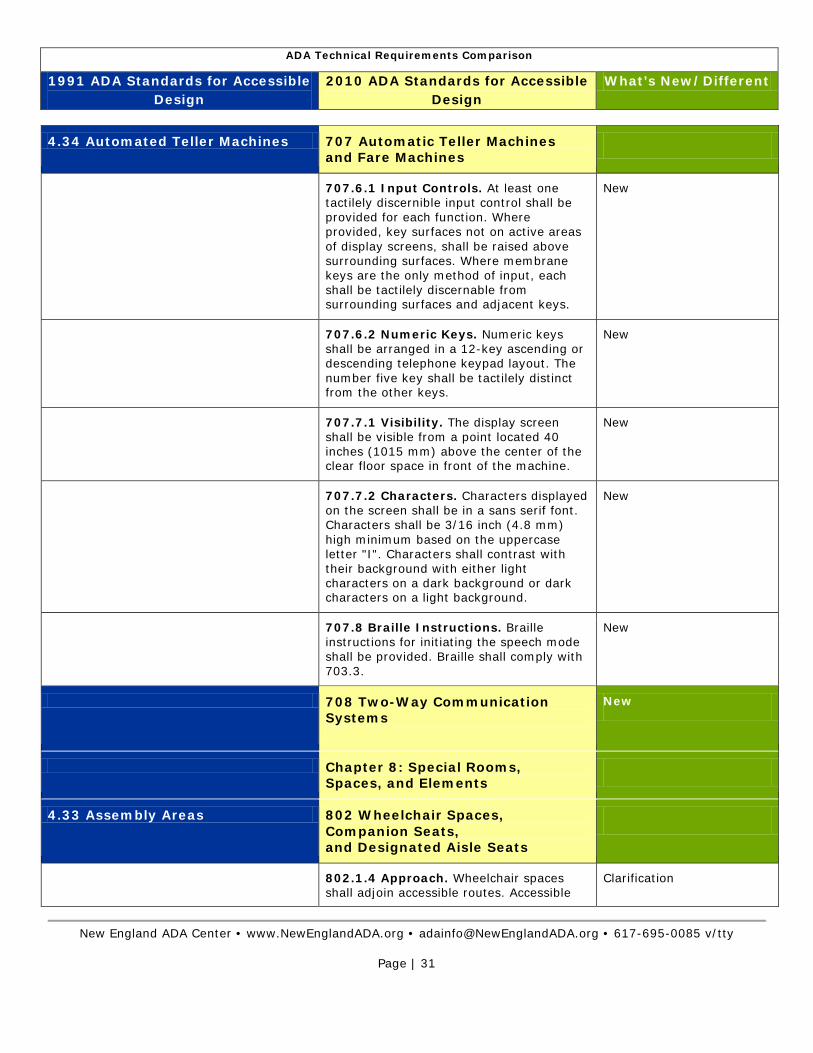
ADA Technical Requirements Comparison
1991 ADA Standards for Accessible Design
2010 ADA Standards for Accessible Design
What’s New/Different
New England ADA Center • www.NewEnglandADA.org • [email protected] • 617-695-0085 v/tty
Page | 31
4.34 Automated Teller Machines 707 Automatic Teller Machines and Fare Machines
707.6.1 Input Controls. At least one tactilely discernible input control shall be provided for each function. Where provided, key surfaces not on active areas of display screens, shall be raised above surrounding surfaces. Where membrane keys are the only method of input, each shall be tactilely discernable from surrounding surfaces and adjacent keys.
New
707.6.2 Numeric Keys. Numeric keys shall be arranged in a 12-key ascending or descending telephone keypad layout. The number five key shall be tactilely distinct from the other keys.
New
707.7.1 Visibility. The display screen shall be visible from a point located 40 inches (1015 mm) above the center of the clear floor space in front of the machine.
New
707.7.2 Characters. Characters displayed on the screen shall be in a sans serif font. Characters shall be 3/16 inch (4.8 mm) high minimum based on the uppercase letter "I". Characters shall contrast with their background with either light characters on a dark background or dark characters on a light background.
New
707.8 Braille Instructions. Braille instructions for initiating the speech mode shall be provided. Braille shall comply with 703.3.
New
708 Two-Way Communication Systems
New
Chapter 8: Special Rooms, Spaces, and Elements
4.33 Assembly Areas 802 Wheelchair Spaces, Companion Seats, and Designated Aisle Seats
802.1.4 Approach. Wheelchair spaces shall adjoin accessible routes. Accessible
Clarification
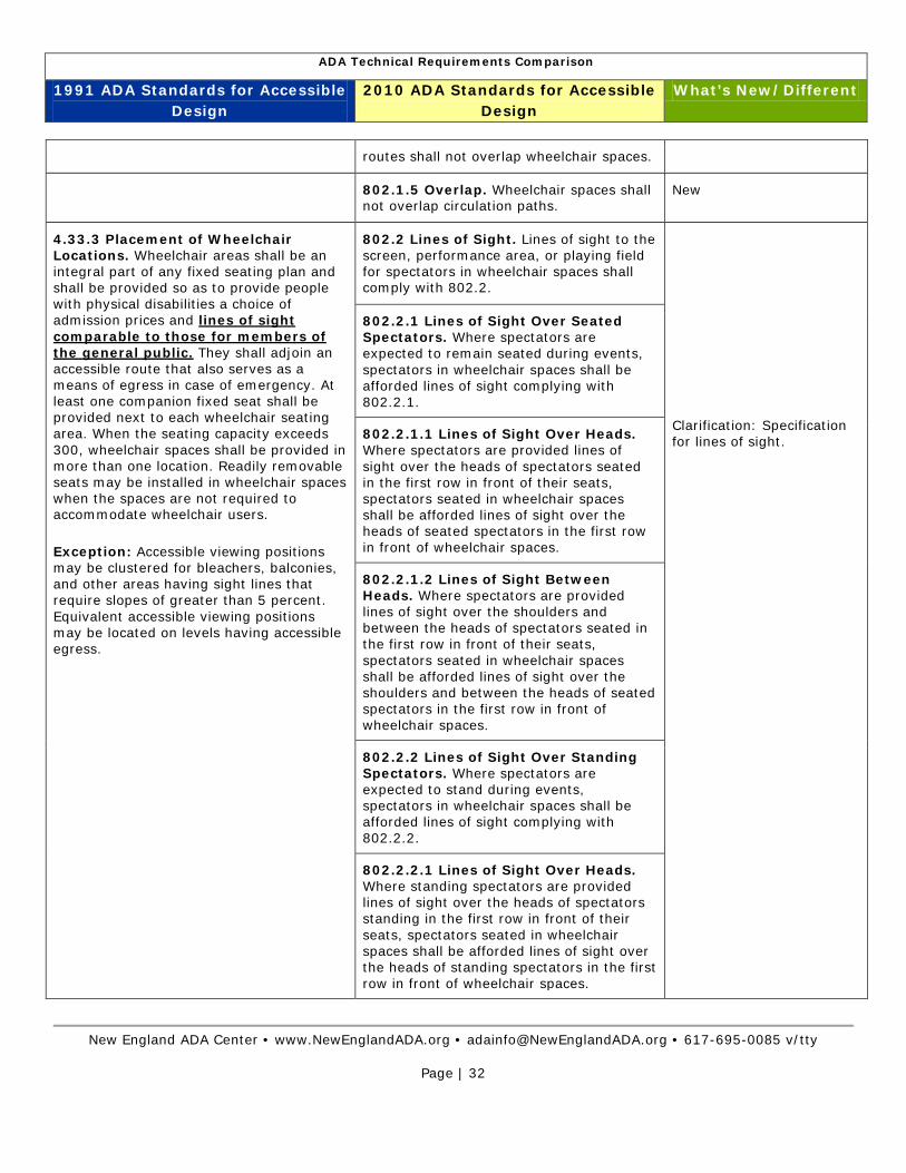
ADA Technical Requirements Comparison
1991 ADA Standards for Accessible Design
2010 ADA Standards for Accessible Design
What’s New/Different
New England ADA Center • www.NewEnglandADA.org • [email protected] • 617-695-0085 v/tty
Page | 32
routes shall not overlap wheelchair spaces.
802.1.5 Overlap. Wheelchair spaces shall not overlap circulation paths.
New
4.33.3 Placement of Wheelchair Locations. Wheelchair areas shall be an integral part of any fixed seating plan and shall be provided so as to provide people with physical disabilities a choice of admission prices and lines of sight comparable to those for members of the general public. They shall adjoin an accessible route that also serves as a means of egress in case of emergency. At least one companion fixed seat shall be provided next to each wheelchair seating area. When the seating capacity exceeds 300, wheelchair spaces shall be provided in more than one location. Readily removable seats may be installed in wheelchair spaces when the spaces are not required to accommodate wheelchair users.
Exception: Accessible viewing positions may be clustered for bleachers, balconies, and other areas having sight lines that require slopes of greater than 5 percent. Equivalent accessible viewing positions may be located on levels having accessible egress.
802.2 Lines of Sight. Lines of sight to the screen, performance area, or playing field for spectators in wheelchair spaces shall comply with 802.2.
Clarification: Specification for lines of sight.
802.2.1 Lines of Sight Over Seated Spectators. Where spectators are expected to remain seated during events, spectators in wheelchair spaces shall be afforded lines of sight complying with 802.2.1.
802.2.1.1 Lines of Sight Over Heads. Where spectators are provided lines of sight over the heads of spectators seated in the first row in front of their seats, spectators seated in wheelchair spaces shall be afforded lines of sight over the heads of seated spectators in the first row in front of wheelchair spaces.
802.2.1.2 Lines of Sight Between Heads. Where spectators are provided lines of sight over the shoulders and between the heads of spectators seated in the first row in front of their seats, spectators seated in wheelchair spaces shall be afforded lines of sight over the shoulders and between the heads of seated spectators in the first row in front of wheelchair spaces.
802.2.2 Lines of Sight Over Standing Spectators. Where spectators are expected to stand during events, spectators in wheelchair spaces shall be afforded lines of sight complying with 802.2.2.
802.2.2.1 Lines of Sight Over Heads. Where standing spectators are provided lines of sight over the heads of spectators standing in the first row in front of their seats, spectators seated in wheelchair spaces shall be afforded lines of sight over the heads of standing spectators in the first row in front of wheelchair spaces.

ADA Technical Requirements Comparison
1991 ADA Standards for Accessible Design
2010 ADA Standards for Accessible Design
What’s New/Different
New England ADA Center • www.NewEnglandADA.org • [email protected] • 617-695-0085 v/tty
Page | 33
802.2.2.2 Lines of Sight Between Heads. Where standing spectators are provided lines of sight over the shoulders and between the heads of spectators standing in the first row in front of their seats, spectators seated in wheelchair spaces shall be afforded lines of sight over the shoulders and between the heads of standing spectators in the first row in front of wheelchair spaces.
4.33.3 Placement of Wheelchair Locations. Wheelchair areas shall be an integral part of any fixed seating plan and shall be provided so as to provide people with physical disabilities a choice of admission prices and lines of sight comparable to those for members of the general public. They shall adjoin an accessible route that also serves as a means of egress in case of emergency. At least one companion fixed seat shall be provided next to each wheelchair seating area. When the seating capacity exceeds 300, wheelchair spaces shall be provided in more than one location. Readily removable seats may be installed in wheelchair spaces when the spaces are not required to accommodate wheelchair users.
802.3.1 Alignment. In row seating, companion seats shall be located to provide shoulder alignment with adjacent wheelchair spaces. The shoulder alignment point of the wheelchair space shall be measured 36 inches (915 mm) from the front of the wheelchair space. The floor surface of the companion seat shall be at the same elevation as the floor surface of the wheelchair space.
New
802.3.2 Type. Companion seats shall be equivalent in size, quality, comfort, and amenities to the seating in the immediate area. Companion seats shall be permitted to be movable.
New
802.4.1 Armrests. Where armrests are provided on the seating in the immediate area, folding or retractable armrests shall be provided on the aisle side of the seat.
New: applies to designated aisles seats.
4.35 Dressing, Fitting and Locker Rooms
803 Dressing, Fitting and Locker Rooms
4.35.3 Doors. All doors to accessible dressing rooms shall be in compliance with section 4.13.
803.3 Door Swing. Doors shall not swing into the room unless a clear floor or ground space complying with 305.3 is provided beyond the arc of the door swing.
New
4.35.4 Bench. Every accessible dressing room shall have a 24 in by 28 in (610 mm
803.4 Benches. A bench complying with 903 shall be provided within the room.
New: Bench required in locker rooms.

ADA Technical Requirements Comparison
1991 ADA Standards for Accessible Design
2010 ADA Standards for Accessible Design
What’s New/Different
New England ADA Center • www.NewEnglandADA.org • [email protected] • 617-695-0085 v/tty
Page | 34
by 1220 mm) bench fixed to the wall along the longer dimension. The bench shall be mounted 17 in to 19 in (430 mm to 485 mm) above the finish floor. Clear floor space shall be provided alongside the bench to allow a person using a wheelchair to make a parallel transfer onto the bench. The structural strength of the bench and attachments shall comply with 4.26.3. Where installed in conjunction with showers, swimming pools, or other wet locations, water shall not accumulate upon the surface of the bench and the bench shall have a slip-resistant surface.
803.5 Coat Hooks and Shelves. Coat hooks provided within the room shall be located within one of the reach ranges specified in 308. Shelves shall be 40 inches (1015 mm) minimum and 48 inches (1220 mm) maximum above the finish floor or ground.
New
804 Kitchens and Kitchenettes New
9.2 Requirements for Accessible Units, Sleeping Rooms & Suites
806 Transient Lodging Guest Rooms
806.2.4.1 Vanity Counter Top Space. If vanity counter top space is provided in non-accessible guest toilet or bathing rooms, comparable vanity counter top space, in terms of size and proximity to the lavatory, shall also be provided in accessible guest toilet or bathing rooms.
New
Plus for housing at places of education see additional requirements for counters and turning spaces at 28 CFR Part 35.151 (f) and 28 CFR Part 36.406 (e).
9.2.2(7) Kitchens, Kitchenettes, or Wet Bars. When provided as accessory to a sleeping room or suite, kitchens, kitchenettes, wet bars, or similar amenities shall be accessible. Clear floor space for a front or parallel approach to cabinets, counters, sinks, and appliances shall be provided to comply with 4.2.4. Countertops and sinks shall be mounted at a maximum height of 34 in (865 mm) above the floor. At least fifty percent of shelf space in cabinets or refrigerator/freezers shall be within the reach ranges of 4.2.5 or 4.2.6 and space shall be designed to allow for the operation of cabinet and/or appliance
806.2.5 Kitchens and Kitchenettes. Kitchens and kitchenettes shall comply with 804.
More options for kitchen/kitchenettes.

ADA Technical Requirements Comparison
1991 ADA Standards for Accessible Design
2010 ADA Standards for Accessible Design
What’s New/Different
New England ADA Center • www.NewEnglandADA.org • [email protected] • 617-695-0085 v/tty
Page | 35
doors so that all cabinets and appliances are accessible and usable. Controls and operating mechanisms shall comply with 4.27.
807 Holding Cells and Housing Cells
New
808 Courtrooms New
809 Residential Dwelling Units New
10 Transportation Facilities 810. Transportation Facilities
10.2.1(1) Where new bus stop pads are constructed at bus stops, bays or other areas where a lift or ramp is to be deployed, they shall have a firm, stable surface; a minimum clear length of 96 inches (measured from the curb or vehicle roadway edge) and a minimum clear width of 60 inches (measured parallel to the vehicle roadway) to the maximum extent allowed by legal or site constraints; and shall be connected to streets, sidewalks or pedestrian paths by an accessible route complying with 4.3 and 4.4. The slope of the pad parallel to the roadway shall, to the extent practicable, be the same as the roadway. For water drainage, a maximum slope of 1:50 (2%) perpendicular to the roadway is allowed.
810.2.4 Slope. Parallel to the roadway, the slope of the bus stop boarding and alighting area shall be the same as the roadway, to the maximum extent practicable. Perpendicular to the roadway, the slope of the bus stop boarding and alighting area shall not be steeper than 1:48.
Steeper slope allowed.
10.2.1(3) Where provided, all new bus route identification signs shall comply with 4.30.5. In addition, to the maximum extent practicable, all new bus route identification signs shall comply with 4.30.2 and 4.30.3. Signs that are sized to the maximum dimensions permitted under legitimate local, state or federal regulations or ordinances shall be considered in compliance with 4.30.2 and 4.30.3 for purposes of this section.
810.4 Bus Signs. Bus route identification signs shall comply with 703.5.1 through 703.5.4, and 703.5.7 and 703.5.8. In addition, to the maximum extent practicable, bus route identification signs shall comply with 703.5.5.
Change: 703.5.1 Finish and Contrast.
New: 703.5.4 Character Proportion; 703.5.7 Stroke Thickness; 703.5.8 Character Spacing.
ADA Technical Requirements Comparison
1991 ADA Standards for Accessible Design
2010 ADA Standards for Accessible Design
What’s New/Different
New England ADA Center • www.NewEnglandADA.org • [email protected] • 617-695-0085 v/tty
Page | 36
810.5 Rail Platforms. Rail platforms shall comply with 810.5.
New 810.5.1 Slope. Rail platforms shall not
exceed a slope of 1:48 in all directions.
EXCEPTION: Where platforms serve vehicles operating on existing track or track laid in existing roadway, the slope of the platform parallel to the track shall be permitted to be equal to the slope (grade) of the roadway or existing track.
10.3.1(11) Illumination levels in the areas where signage is located shall be uniform and shall minimize glare on signs. Lighting along circulation routes shall be of a type and configuration to provide uniform illumination.
Deleted
4.25 Storage 811 Storage
4.25.3 Height. Accessible storage spaces shall be within at least one of the reach ranges specified in 4.2.5 and 4.2.6. Clothes rods or shelves shall be a maximum of 54 in (1370 mm) above the finish floor for a side approach. Where the distance from the wheelchair to the clothes rod or shelf exceeds 10 in (255 mm) (as in closets without accessible doors) the height and depth to the rod or shelf shall comply with Fig. 38(a) and Fig. 38(b).
811.3 Height. Storage elements shall comply with at least one of the reach ranges specified in 308.
Change: Reach ranges maximum height lower, 48 inches instead of 54 inches.
Chapter 9: Built –in Elements
4.32 Fixed or Built-in Seating and Tables
902 Dining Surfaces and Work Surfaces
4.32.2 Seating. If seating spaces for people in wheelchairs are provided at fixed tables or counters, clear floor space complying with 4.2.4 shall be provided. Such clear floor space shall not overlap knee space by more than 19 in (485 mm).
902.2 Clear Floor or Ground Space. A clear floor space complying with 305 positioned for a forward approach shall be provided. Knee and toe clearance complying with 306 shall be provided.
Clarification of clear floor space.
902.4 Dining Surfaces and Work Surfaces for Children's Use. Accessible
New
ADA Technical Requirements Comparison
1991 ADA Standards for Accessible Design
2010 ADA Standards for Accessible Design
What’s New/Different
New England ADA Center • www.NewEnglandADA.org • [email protected] • 617-695-0085 v/tty
Page | 37
dining surfaces and work surfaces for children's use shall comply with 902.4.
Exception: Dining surfaces and work surfaces that are used primarily by children 5 years and younger shall not be required to comply with 902.4 where a clear floor or ground space complying with 305 positioned for a parallel approach is provided.
903 Benches New
4.35.4 Bench. Every accessible dressing room shall have a 24 in by 48 in (610 mm by 1220 mm) bench fixed to the wall along the longer dimension. The bench shall be mounted 17 in to 19 in (430 mm to 485 mm) above the finish floor. Clear floor space shall be provided alongside the bench to allow a person using a wheelchair to make a parallel transfer onto the bench. The structural strength of the bench and attachments shall comply with 4.26.3. Where installed in conjunction with showers, swimming pools, or other wet locations, water shall not accumulate upon the surface of the bench and the bench shall have a slip-resistant surface.
903.2 Clear Floor or Ground Space. Clear floor or ground space complying with 305 shall be provided and shall be positioned at the end of the bench seat and parallel to the short axis of the bench.
New: Scoping requirement in Saunas and Steam Rooms (612).
Dressing, Fitting and Lockers rooms (803)
Longer bench requirement.
New: Specification for back support.
903.3 Size. Benches shall have seats that are 42 inches (1065 mm) long minimum and 20 inches (510 mm) deep minimum and 24 inches (610 mm) deep maximum.
903.4 Back Support. The bench shall provide for back support or shall be affixed to a wall. Back support shall be 42 inches (1065 mm) long minimum and shall extend from a point 2 inches (51 mm) maximum above the seat surface to a point 18 inches (455 mm) minimum above the seat surface. Back support shall be 2½ inches (64 mm) maximum from the rear edge of the seat measured horizontally.
7.2 Sales and Service Counters, Teller Windows, Information Counters.
904 Check-Out Aisles and Sales Service Counters
904.3.3 Check Writing Surfaces. Where provided, check writing surfaces shall comply with 902.3.
New
7.2 (1) In department stores and miscellaneous retail stores where counters have cash registers and are provided for sales or distribution of goods or services to the public, at least one of each type shall have a portion of the counter which is at least 36 in (915mm) in length with a
904.4 Sales and Service Counters. Sales counters and service counters shall comply with 904.4.1 or 904.4.2. The accessible portion of the counter top shall extend the same depth as the sales or service counter top.
Same requirements for sales and service counters.
Clarification on the accessible portion of the counter.

ADA Technical Requirements Comparison
1991 ADA Standards for Accessible Design
2010 ADA Standards for Accessible Design
What’s New/Different
New England ADA Center • www.NewEnglandADA.org • [email protected] • 617-695-0085 v/tty
Page | 38
maximum height of 36 in (915
mm) above the finish floor. It shall be on an accessible route complying with 4.3. The accessible counters must be dispersed throughout the building or facility. In alterations where it is technically infeasible to provide an accessible counter, an auxiliary counter meeting these requirements may be provided.
(2) At ticketing counters, teller stations in a bank, registration counters in hotels and motels, box office ticket counters, and other counters that may not have a cash register but at which goods or services are sold or distributed,
either:
(i) a portion of the main counter which is a minimum of 36 in (915 mm) in length shall be provided with a maximum height of 36 in (915 mm); or
(ii) an auxiliary counter with a maximum height of 36 in (915 mm) in close proximity to the main counter shall be provided; or
(iii) equivalent facilitation shall be
provided (e.g., at a hotel registration counter, equivalent facilitation might consist of: (1) provision of a folding shelf attached to the main counter on which an individual with disabilities can write, and (2) use of the space on the side of the counter or at the concierge desk, for handing materials back and forth).
Exceptions: In alterations, when the provision of a counter complying with 904.4 would result in a reduction of the number of existing counters at work stations or a reduction of the number of existing mail boxes, the counter shall be permitted to have a portion which is 24 inches (610 mm) long minimum complying with 904.4.1 provided that the required clear floor or ground space is centered on the accessible length of the counter.
Exception is new.
Auxiliary counter removed.
5.6 Tableware and Condiment Areas. Self-service shelves and dispensing devices for tableware, dishware, condiments, food and beverages shall be installed to comply with 4.2 (see Fig. 54).
NOTE: Figure 54 indicates the maximum height is 54 inches (1370 mm).
904.5.1 Self-Service Shelves and Dispensing Devices. Self-service shelves and dispensing devices for tableware, dishware, condiments, food and beverages shall comply with 308.
Change: The maximum height is 48 inches.

ADA Technical Requirements Comparison
1991 ADA Standards for Accessible Design
2010 ADA Standards for Accessible Design
What’s New/Different
New England ADA Center • www.NewEnglandADA.org • [email protected] • 617-695-0085 v/tty
Page | 39
5.5 Food Services Lines. Food service lines shall have a minimum clear width of 36 in (915 mm), with a preferred clear width of 42 in (1065) to allow passage around a person using a wheelchair. Tray slides shall be mounted no higher than 34 in (865) above the floor.
904.5.2 Tray Slides. The tops of tray slides shall be 28 inches (710 mm) minimum and 34 inches (865 mm) maximum above the finish floor or ground.
Minimum height specified
Chapter 10: Recreation Facilities New
1002 Amusement Rides New
1003 Recreational Boating Facilities
New
1004 Exercise Machines and Equipment
New
1005 Fishing Piers and Platforms New
1006 Golf Facilities New
1007 Miniature Golf Facilities New
1008 Play Areas New
1009 Swimming Pools, Wading Pools, and Spas
New
1010 Shooting Facilities with Firing Positions
New
Related Documents


