ThruFlow™ Inc. Technical Reports for ThruFlow™ Interlocking Panels 700 Gillard Street, Wallaceburg, Ontario, Canada N8A 4Z5 Tel: 519-627-7428 Website: www.thruflow.com

Welcome message from author
This document is posted to help you gain knowledge. Please leave a comment to let me know what you think about it! Share it to your friends and learn new things together.
Transcript

ThruFlow™ Inc.
Technical Reports for ThruFlow™ Interlocking Panels
700 Gillard Street, Wallaceburg, Ontario, Canada N8A 4Z5 Tel: 519-627-7428 Website: www.thruflow.com
Detailed Technical Reports
• Light Penetration • Load Capacity • Simulated Uniformly Distributed Load/Concentrated Load • Izod Impact • Coefficient of Linear Thermal Expansion • Creep Relaxation
o 3 foot panel o 4 foot panel o 5 foot panel
• Baseline Flexural Properties o 3 foot panel o 4 foot panel o 5 foot panel
• Flexural Properties at Elevated Temperatures • Coefficient of friction • Oil-Wet Ramp Slip Resistance • Wet Slip Resistance
o Slider Rubber 96 o Slider Rubber 55
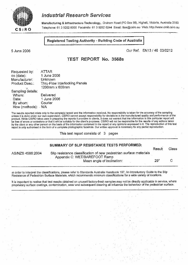
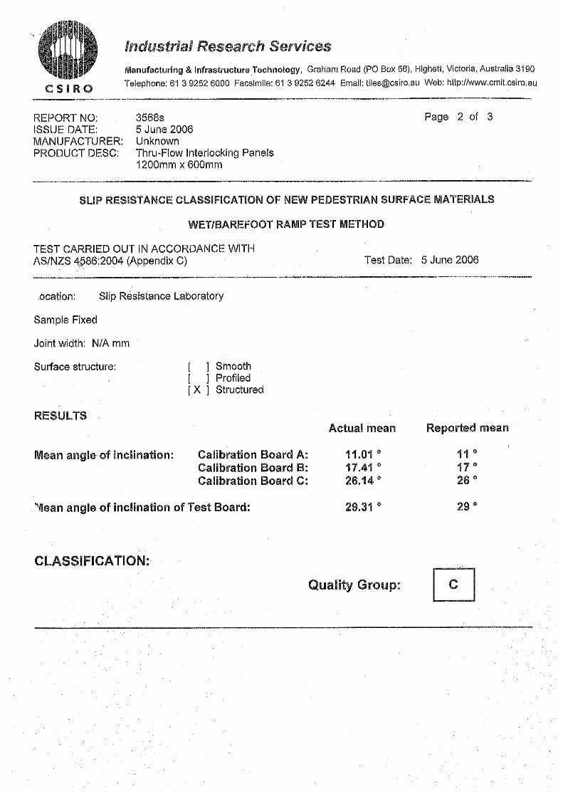
• Wet/Barefoot Ramp
Compiled by Karen Dunlop August 29th, 2007
ThruFlow Inc.
700 Gillard Street, Wallaceburg, Ontario, Canada N8A 4Z5 Tel: 519-627-7428 Website: www.thruflow.com
Product Development6991 Millcreek Drive, Unit 13,
Mississauga, Ontario L5N 6B9 Tel: (905) 812-3856 Fax: (905) 812-3866
www.cambridgematerials.com
ISO 17025 Accredited
This report is subject to the following terms and conditions: 1. This report relates only to the specimen provided and there is no representation or warranty that it applies to similar substances or materials or the bulk of which the specimen is a part. 2. The content of this report is for the information of the customer identified above only and it shall not be reprinted, published or disclosed to any other party except in full. Prior written consent from Cambridge Materials Testing Limited is required. 3. The name Cambridge Materials Testing Limited shall not be used in connection with the specimen reported on or any substance or materials similar to that specimen without the prior written consent of Cambridge Materials Testing Limited. 4. Neither Cambridge Materials Testing Limited nor any of its employees shall be responsible or held liable for any claims, loss or damages arising in consequence of reliance on this report or any default, error or omission in its preparation or the tests conducted. 5. Specimens are retained 3 months, test reports and test data are retained 10 years from date of final test report and then disposed of, unless instructed otherwise in writing.
Report For: Thruflow Inc. Laboratory #: 354661-04 P.O. Box 40 760 Lowe Avenue Wallaceburg, ON Report Date: March 10, 2004 Canada N8A 4Z9 Received Date: March 10, 2004 Phone: 519 627 7960 Customer P.O.#: 2 Fax: 519 627 7969 Attention: Derek McGivern
TEST REPORT
LIGHT AVAILABILITY OTRON THRUFLOW DOCK PANEL
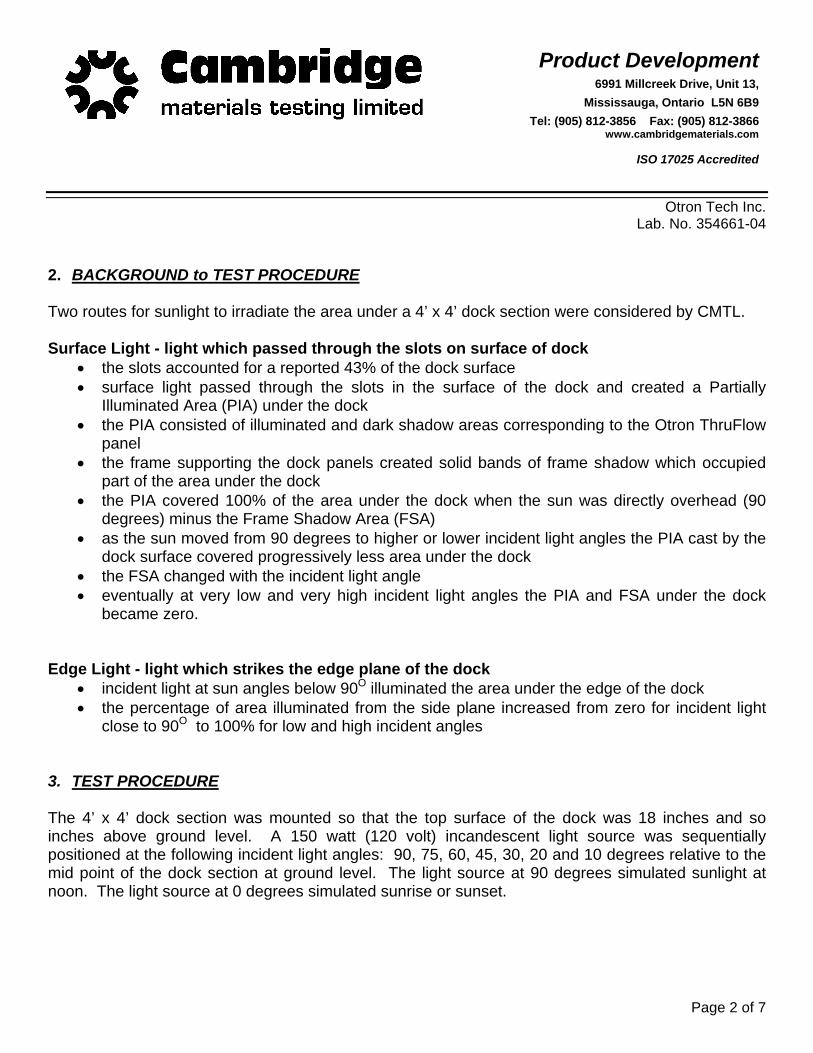
1. INTRODUCTION Otron requested the assistance of Cambridge Materials Testing Limited (CMTL) to estimate the amount of sunlight which would be available under a 4’ x 4’ section of dock surfaced with their ThruFlow Flooring System. The amount of available light under the dock is an important factor with regard to the sustainability of plant and animal life under dock structures. Otron supplied an assembled 4’ x 4’ dock section for this testing. The section consisted of four ThruFlow panels (12” x 48”) fastened to a metal frame. Two dock surface heights were tested:
• eighteen (18) inches (tested under CMTL Lab. No. 304167-02) • sixty (60) inches (tested under CMTL Lab. No. 307535-02).
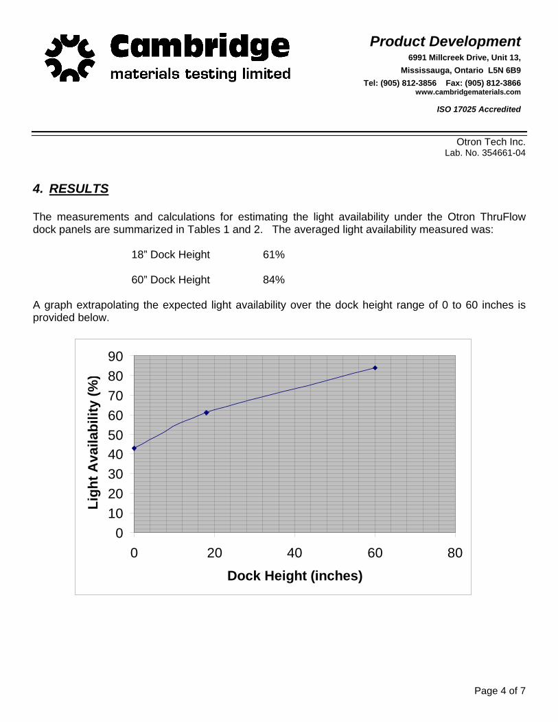
A graph extrapolating the expected light availability over the dock height range of 0 to 60 inches is provided in this report.
Product Development6991 Millcreek Drive, Unit 13,
Mississauga, Ontario L5N 6B9 Tel: (905) 812-3856 Fax: (905) 812-3866
www.cambridgematerials.com
ISO 17025 Accredited
Page 2 of 7
Otron Tech Inc. Lab. No. 354661-04
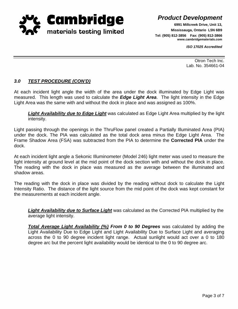
2. BACKGROUND to TEST PROCEDURE Two routes for sunlight to irradiate the area under a 4’ x 4’ dock section were considered by CMTL. Surface Light - light which passed through the slots on surface of dock
• the slots accounted for a reported 43% of the dock surface • surface light passed through the slots in the surface of the dock and created a Partially
Illuminated Area (PIA) under the dock • the PIA consisted of illuminated and dark shadow areas corresponding to the Otron ThruFlow
panel • the frame supporting the dock panels created solid bands of frame shadow which occupied
part of the area under the dock • the PIA covered 100% of the area under the dock when the sun was directly overhead (90
degrees) minus the Frame Shadow Area (FSA) • as the sun moved from 90 degrees to higher or lower incident light angles the PIA cast by the
dock surface covered progressively less area under the dock • the FSA changed with the incident light angle • eventually at very low and very high incident light angles the PIA and FSA under the dock
became zero. Edge Light - light which strikes the edge plane of the dock
• incident light at sun angles below 90O illuminated the area under the edge of the dock • the percentage of area illuminated from the side plane increased from zero for incident light
close to 90O to 100% for low and high incident angles 3. TEST PROCEDURE The 4’ x 4’ dock section was mounted so that the top surface of the dock was 18 inches and so inches above ground level. A 150 watt (120 volt) incandescent light source was sequentially positioned at the following incident light angles: 90, 75, 60, 45, 30, 20 and 10 degrees relative to the mid point of the dock section at ground level. The light source at 90 degrees simulated sunlight at noon. The light source at 0 degrees simulated sunrise or sunset.
Product Development6991 Millcreek Drive, Unit 13,
Mississauga, Ontario L5N 6B9 Tel: (905) 812-3856 Fax: (905) 812-3866
www.cambridgematerials.com
ISO 17025 Accredited
Page 3 of 7
Otron Tech Inc. Lab. No. 354661-04
3.0 TEST PROCEDURE (CON’D) At each incident light angle the width of the area under the dock illuminated by Edge Light was measured. This length was used to calculate the Edge Light Area. The light intensity in the Edge Light Area was the same with and without the dock in place and was assigned as 100%.
Light Availability due to Edge Light was calculated as Edge Light Area multiplied by the light intensity.
Light passing through the openings in the ThruFlow panel created a Partially Illuminated Area (PIA) under the dock. The PIA was calculated as the total dock area minus the Edge Light Area. The Frame Shadow Area (FSA) was subtracted from the PIA to determine the Corrected PIA under the dock. At each incident light angle a Sekonic Illuminometer (Model 246) light meter was used to measure the light intensity at ground level at the mid point of the dock section with and without the dock in place. The reading with the dock in place was measured as the average between the illuminated and shadow areas. The reading with the dock in place was divided by the reading without dock to calculate the Light Intensity Ratio. The distance of the light source from the mid point of the dock was kept constant for the measurements at each incident angle.
Light Availability due to Surface Light was calculated as the Corrected PIA multiplied by the average light intensity.
Total Average Light Availability (%) From 0 to 90 Degrees was calculated by adding the Light Availability Due to Edge Light and Light Availability Due to Surface Light and averaging across the 0 to 90 degree incident light range. Actual sunlight would act over a 0 to 180 degree arc but the percent light availability would be identical to the 0 to 90 degree arc.
Product Development6991 Millcreek Drive, Unit 13,
Mississauga, Ontario L5N 6B9 Tel: (905) 812-3856 Fax: (905) 812-3866
www.cambridgematerials.com
ISO 17025 Accredited
Page 4 of 7
Otron Tech Inc. Lab. No. 354661-04
4. RESULTS The measurements and calculations for estimating the light availability under the Otron ThruFlow dock panels are summarized in Tables 1 and 2. The averaged light availability measured was: 18” Dock Height 61% 60” Dock Height 84% A graph extrapolating the expected light availability over the dock height range of 0 to 60 inches is provided below.
0102030405060708090
0 20 40 60 8
Dock Height (inches)
Ligh
t Ava
ilabi
lity
(%
0
)

Product Development6991 Millcreek Drive, Unit 13,
Mississauga, Ontario L5N 6B9 Tel: (905) 812-3856 Fax: (905) 812-3866
www.cambridgematerials.com
ISO 17025 Accredited
Page 5 of 7
Otron Tech Inc. Lab. No. 354661-04
Table 1 Light Availability – Otron Thruflow Panel
18 inch dock height
Incident Light Angle 0 10 20 30 45 60 75 90
Surface Light Partially Illuminated Area (%)
0
0
0
42
73
89
97
100
Frame Shadow Area (%) 8 21 22 12 6 Corrected Partially Illuminated Area 34 52 66 85 94
Light Intensity Light Intensity (Lx)- without dock 160 380 410 440 220 Light Intensity (Lx) - with dock 40 140 160 180 100 Light Intensity Ratio 25 37 39 41 45 Light Availability due to Surface Light (%)
0
0
0
8
19
26
35
43
Edge Light
Edge Illumination (inches) 48.0 48.0 48.0 28.0 13.0 5.5 1.4 0.0 Edge Illumination (%) 100 100 100 58 27 11 3 0
Light Availability due to Edge Light (%) 100 100 100 67 46 37 38 43
Total Average Light Availability (%), 0 - 90O 61%
Product Development6991 Millcreek Drive, Unit 13,
Mississauga, Ontario L5N 6B9 Tel: (905) 812-3856 Fax: (905) 812-3866
www.cambridgematerials.com
ISO 17025 Accredited
Page 6 of 7
Otron Tech Inc. Lab. No. 354661-04
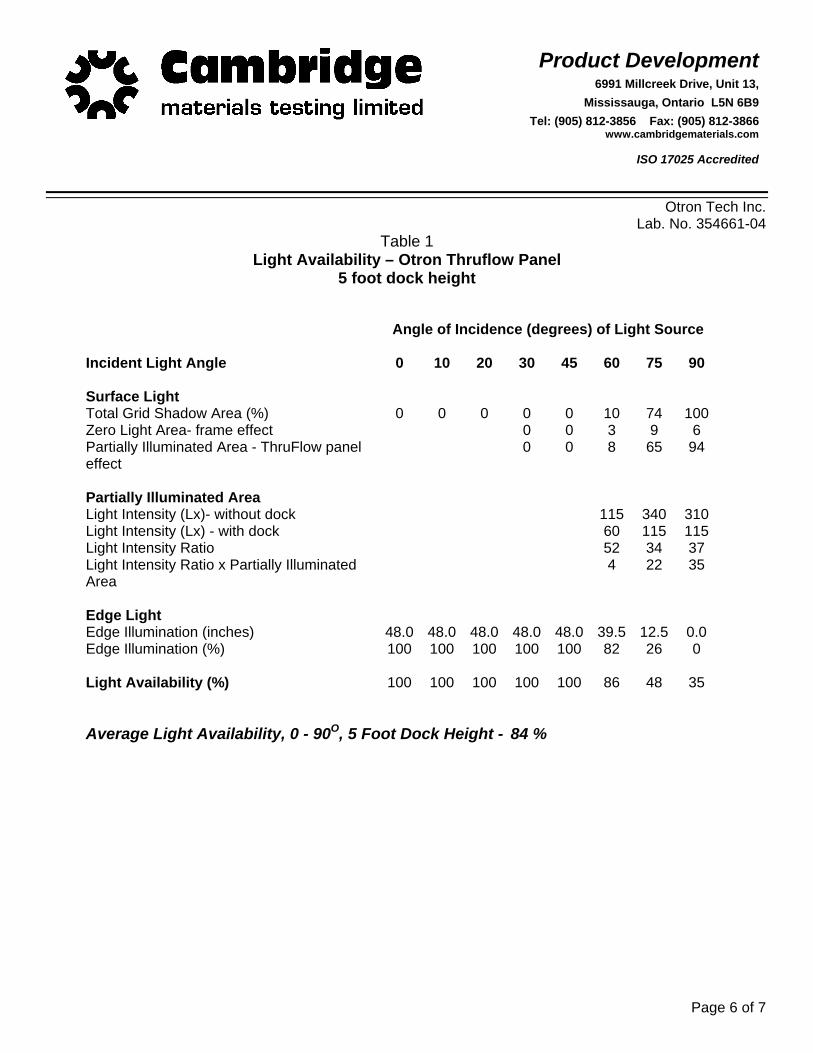
Table 1 Light Availability – Otron Thruflow Panel
5 foot dock height
Angle of Incidence (degrees) of Light Source
Incident Light Angle 0 10 20 30 45 60 75 90
Surface Light Total Grid Shadow Area (%) 0 0 0 0 0 10 74 100 Zero Light Area- frame effect 0 0 3 9 6 Partially Illuminated Area - ThruFlow panel effect
0 0 8 65 94
Partially Illuminated Area Light Intensity (Lx)- without dock 115 340 310 Light Intensity (Lx) - with dock 60 115 115 Light Intensity Ratio 52 34 37 Light Intensity Ratio x Partially Illuminated Area
4 22 35
Edge Light Edge Illumination (inches) 48.0 48.0 48.0 48.0 48.0 39.5 12.5 0.0 Edge Illumination (%) 100 100 100 100 100 82 26 0
Light Availability (%) 100 100 100 100 100 86 48 35
Average Light Availability, 0 - 90O, 5 Foot Dock Height - 84 %
Product Development6991 Millcreek Drive, Unit 13,
Mississauga, Ontario L5N 6B9 Tel: (905) 812-3856 Fax: (905) 812-3866
www.cambridgematerials.com
ISO 17025 Accredited
Page 7 of 7
Otron Tech Inc. Lab. No. 354661-04
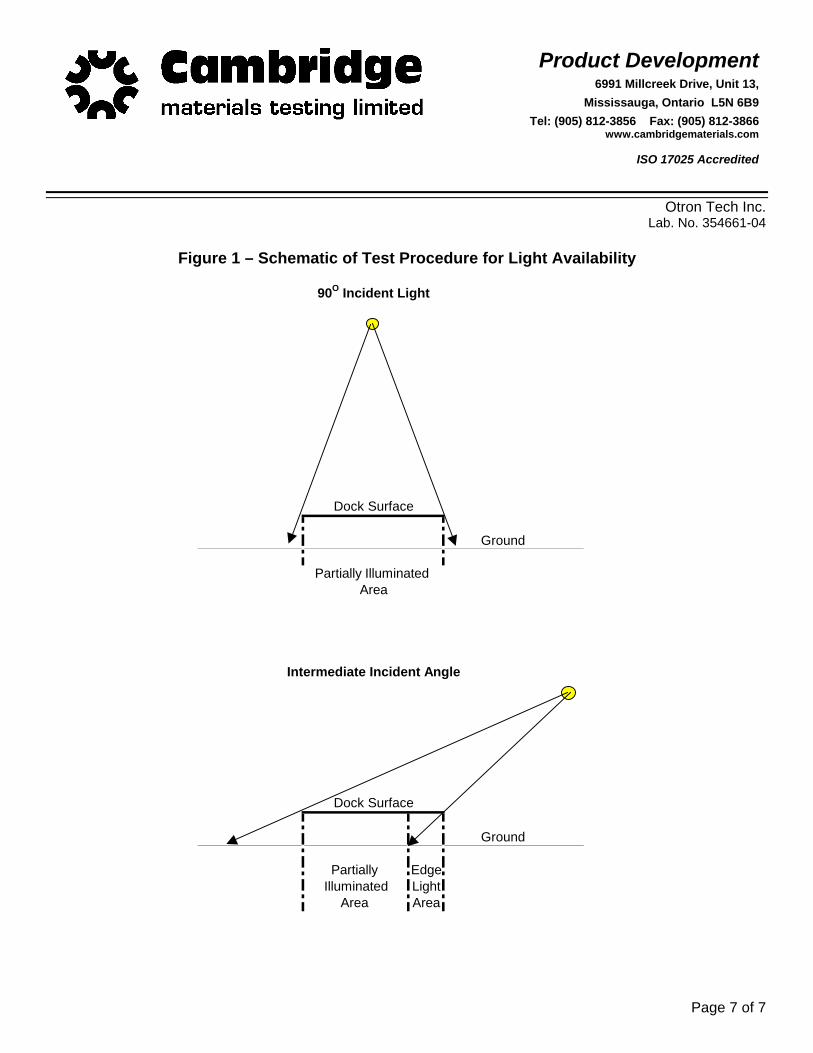
Figure 1 – Schematic of Test Procedure for Light Availability
Ground
Ground
EdgeLight
Area Area
90O Incident Light
Dock Surface
Partially Illuminated
Intermediate Incident Angle
Dock Surface
Partially Illuminated Area
The information in this report may contain confidential information and therefore should be directed only to the person(s) addressed below. If you are not authorized to have this material or you have received this material in error, please either direct it to the correct individual or contact the office of the Wood Science and Technology Centre. The test results provided in this report relate only to the specimens provided by the Client. This report should only be reproduced in its entirety and only with the authorization of the Client.
WSTC Reference #:ThruFlow0609-1
REPORT Load Capacity Testing of ThruFlowTM Decking Panel
Submitted to:
Derick McGivern
ThruFlowTM 1239-B Dufferin Avenue
Wallaceburg, Ontario Canada N8A 2W3 Tel: (888) 478-3569
Submitted by:
Wood Science and Technology Centre Hugh John Flemming Forestry Centre
1350 Regent Street Fredericton, NB
Canada E3C 2G6 Tel: (506) 453-4507 Fax: (506) 453-3574
Email : [email protected] Prepared by: Reviewed by: __Andrew Sutherland _______ __Michael Albright_________ Andrew Sutherland, P.Tech. Michael Albright, P.Eng. Project Officer Manager
September 28, 2006
Thru-Flow Page 2 of 7 ThruFlow0609-1: September 28, 2006
PREFACE
The University of New Brunswick Wood Science and Technology Centre (WSTC) has been assessed under the authority of the Standards Council of Canada Act and found to comply with the requirements of ISO/IEC 17025 and other conditions established by the Standards Council of Canada. WSTC is recognized as an Accredited Testing Laboratory for specific tests or types of tests listed in our scope of accreditation approved by the Standards Council of Canada. For the current status of our laboratory and scope of accreditation visit www.scc.ca, accredited laboratory number 108.
ThurFlow0609-1 Report.doc Wood Science and Technology Centre
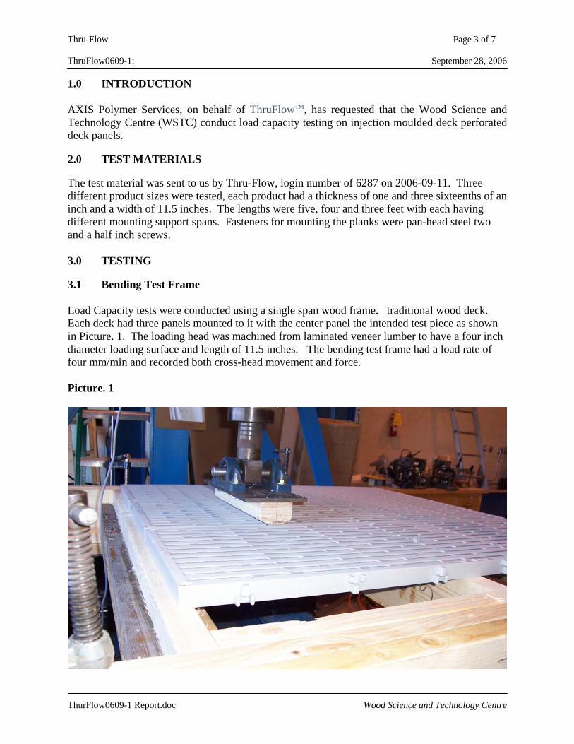
Thru-Flow Page 3 of 7 ThruFlow0609-1: September 28, 2006 1.0 INTRODUCTION AXIS Polymer Services, on behalf of ThruFlowTM, has requested that the Wood Science and Technology Centre (WSTC) conduct load capacity testing on injection moulded deck perforated deck panels. 2.0 TEST MATERIALS The test material was sent to us by Thru-Flow, login number of 6287 on 2006-09-11. Three different product sizes were tested, each product had a thickness of one and three sixteenths of an inch and a width of 11.5 inches. The lengths were five, four and three feet with each having different mounting support spans. Fasteners for mounting the planks were pan-head steel two and a half inch screws. 3.0 TESTING 3.1 Bending Test Frame Load Capacity tests were conducted using a single span wood frame. traditional wood deck. Each deck had three panels mounted to it with the center panel the intended test piece as shown in Picture. 1. The loading head was machined from laminated veneer lumber to have a four inch diameter loading surface and length of 11.5 inches. The bending test frame had a load rate of four mm/min and recorded both cross-head movement and force. Picture. 1
ThurFlow0609-1 Report.doc Wood Science and Technology Centre
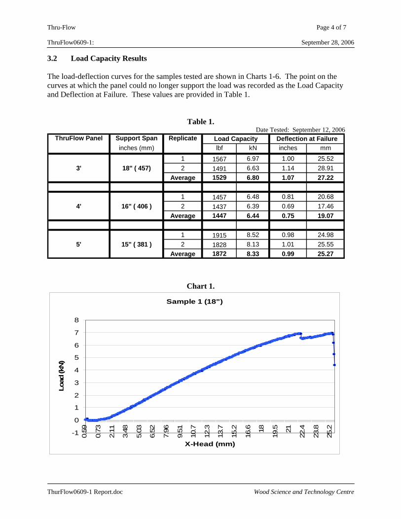
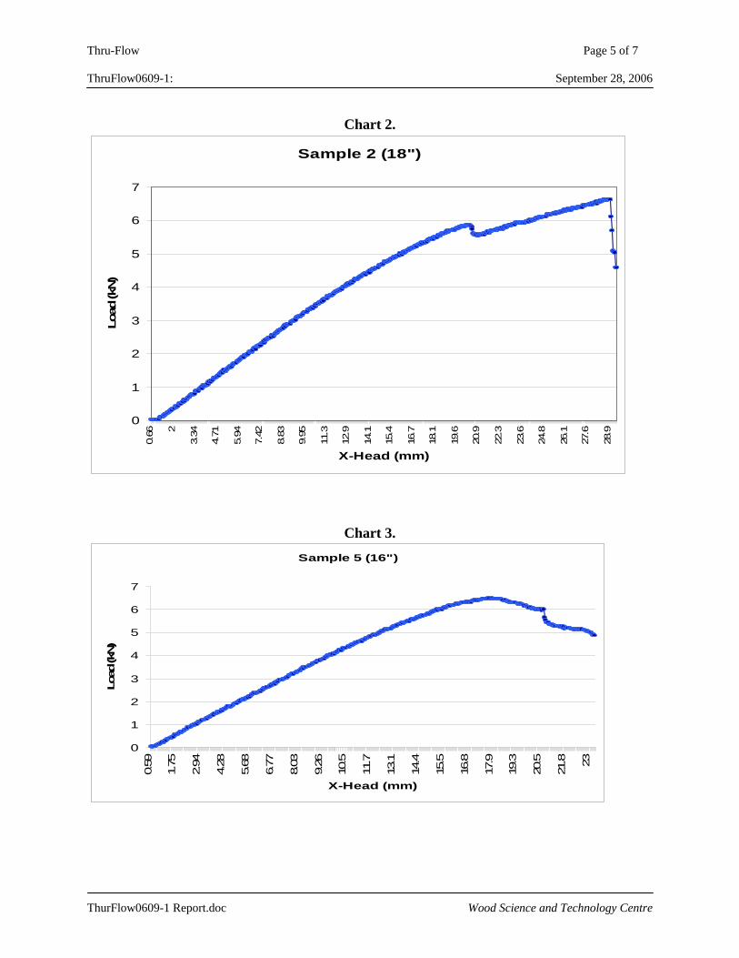
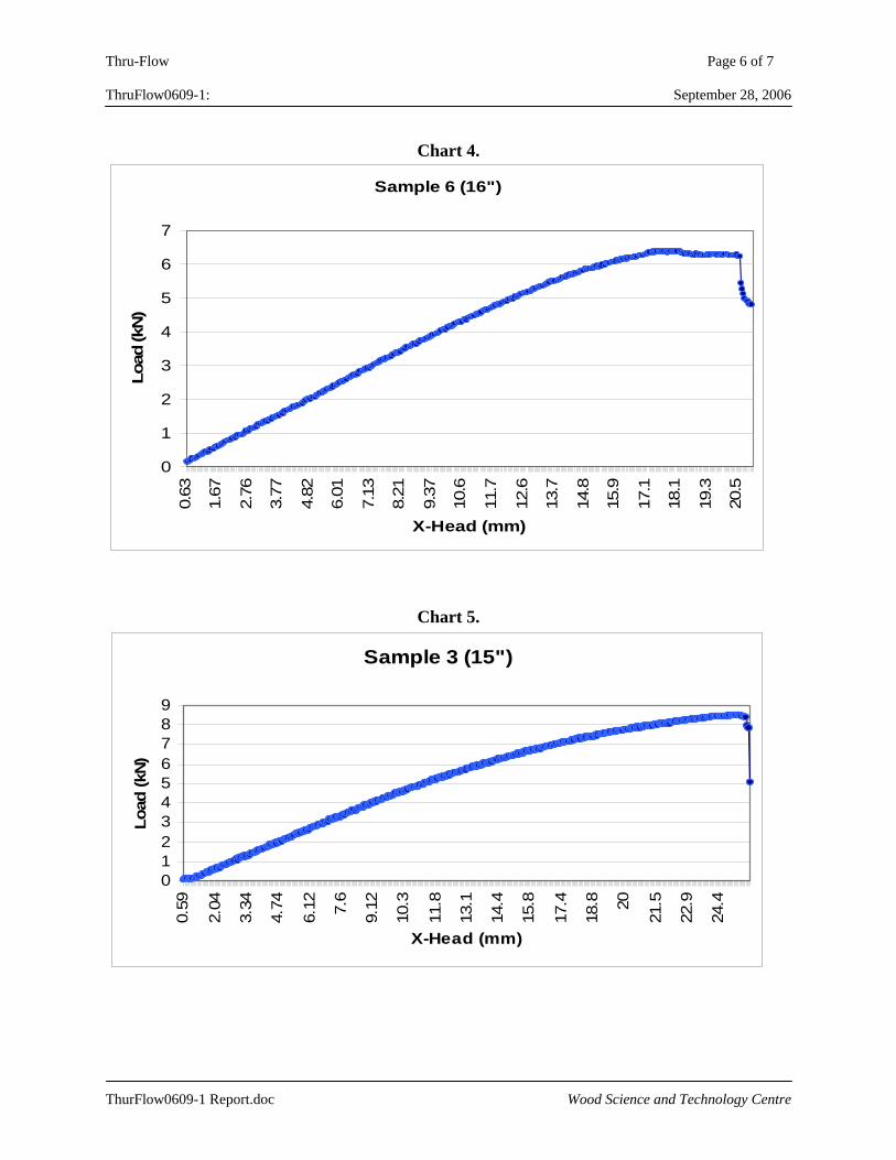
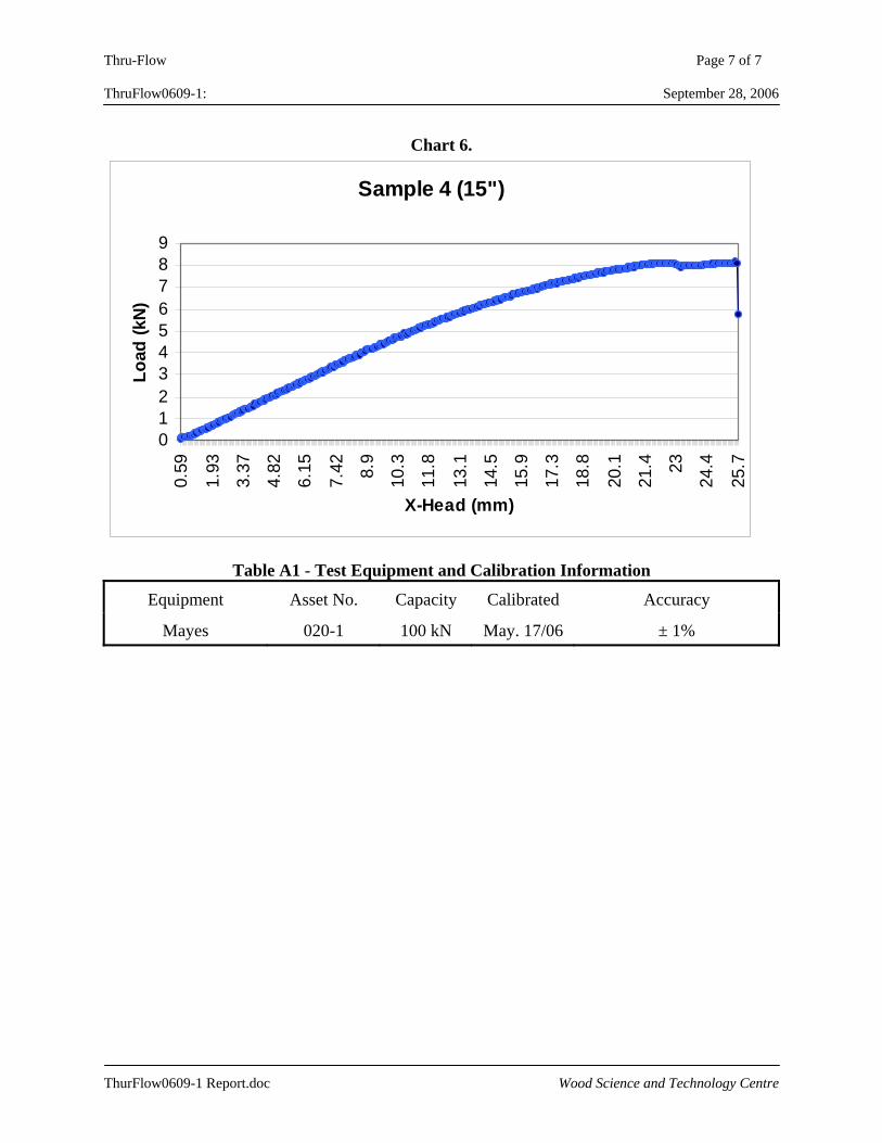
Thru-Flow Page 4 of 7 ThruFlow0609-1: September 28, 2006 3.2 Load Capacity Results The load-deflection curves for the samples tested are shown in Charts 1-6. The point on the curves at which the panel could no longer support the load was recorded as the Load Capacity and Deflection at Failure. These values are provided in Table 1.
Table 1.
Date Tested: September 12, 2006 ThruFlow Panel Support Span Replicate
inches (mm) lbf kN inches mm1 1567 6.97 1.00 25.52
3' 18" ( 457) 2 1491 6.63 1.14 28.91Average 1529 6.80 1.07 27.22
1 1457 6.48 0.81 20.684' 16" ( 406 ) 2 1437 6.39 0.69 17.46
Average 1447 6.44 0.75 19.07
1 1915 8.52 0.98 24.985' 15" ( 381 ) 2 1828 8.13 1.01 25.55
Average 1872 8.33 0.99 25.27
Load Capacity Deflection at Failure
Chart 1.
Sample 1 (18")
-1
0
1
2
3
4
5
6
7
8
0.59
0.73
2.11
3.48
5.03
6.52
7.96
9.51
10.7
12.3
13.7
15.2
16.6 18
19.5 21
22.4
23.8
25.2
X-Head (mm)
Load
(kN
)
ThurFlow0609-1 Report.doc Wood Science and Technology Centre
Thru-Flow Page 5 of 7 ThruFlow0609-1: September 28, 2006
Chart 2.
Sample 2 (18")
0
1
2
3
4
5
6
7
0.66 2
3.34
4.71
5.94
7.42
8.83
9.95
11.3
12.9
14.1
15.4
16.7
18.1
19.6
20.9
22.3
23.6
24.8
26.1
27.6
28.9
X-Head (mm)
Load
(kN
)
Chart 3. Sample 5 (16")
0
1
2
3
4
5
6
7
0.59
1.75
2.94
4.28
5.68
6.77
8.03
9.26
10.5
11.7
13.1
14.4
15.5
16.8
17.9
19.3
20.5
21.8 23
X-Head (mm)
Load
(kN)
ThurFlow0609-1 Report.doc Wood Science and Technology Centre
Thru-Flow Page 6 of 7 ThruFlow0609-1: September 28, 2006
Chart 4.
Sample 6 (16")
0
1
2
3
4
5
6
7
0.63
1.67
2.76
3.77
4.82
6.01
7.13
8.21
9.37
10.6
11.7
12.6
13.7
14.8
15.9
17.1
18.1
19.3
20.5
X-Head (mm)
Load
(kN
)
Chart 5.
Sample 3 (15")
0123456789
0.59
2.04
3.34
4.74
6.12 7.6
9.12
10.3
11.8
13.1
14.4
15.8
17.4
18.8 20
21.5
22.9
24.4
X-Head (mm)
Load
(kN)
ThurFlow0609-1 Report.doc Wood Science and Technology Centre
Thru-Flow Page 7 of 7 ThruFlow0609-1: September 28, 2006
Chart 6.
Sample 4 (15")
0123456789
0.59
1.93
3.37
4.82
6.15
7.42 8.9
10.3
11.8
13.1
14.5
15.9
17.3
18.8
20.1
21.4 23
24.4
25.7
X-Head (mm)
Load
(kN)
Table A1 - Test Equipment and Calibration Information
Equipment Asset No. Capacity Calibrated Accuracy
Mayes 020-1 100 kN May. 17/06 ± 1%
ThurFlow0609-1 Report.doc Wood Science and Technology Centre
Unit 1/15 Pickering Road Mulgrave Victoria 3170 Telephone 03 9560 2759 Mobile 0419 116 733
MelbourneTestingServices
MelbourneTestingServices
IN CONFIDENCE TO THE CLIENT
REPORT NO: MT-06/169
TESTING OF THRUFLOW WALKWAY PANELS
CLIENT: DAVID PADFIELD ATTAR PO BOX 286 SPRINGVALE VIC 3171 DATE OF TESTING: MAY 25TH 2006 DATE OF REPORT: MAY 25TH 2006
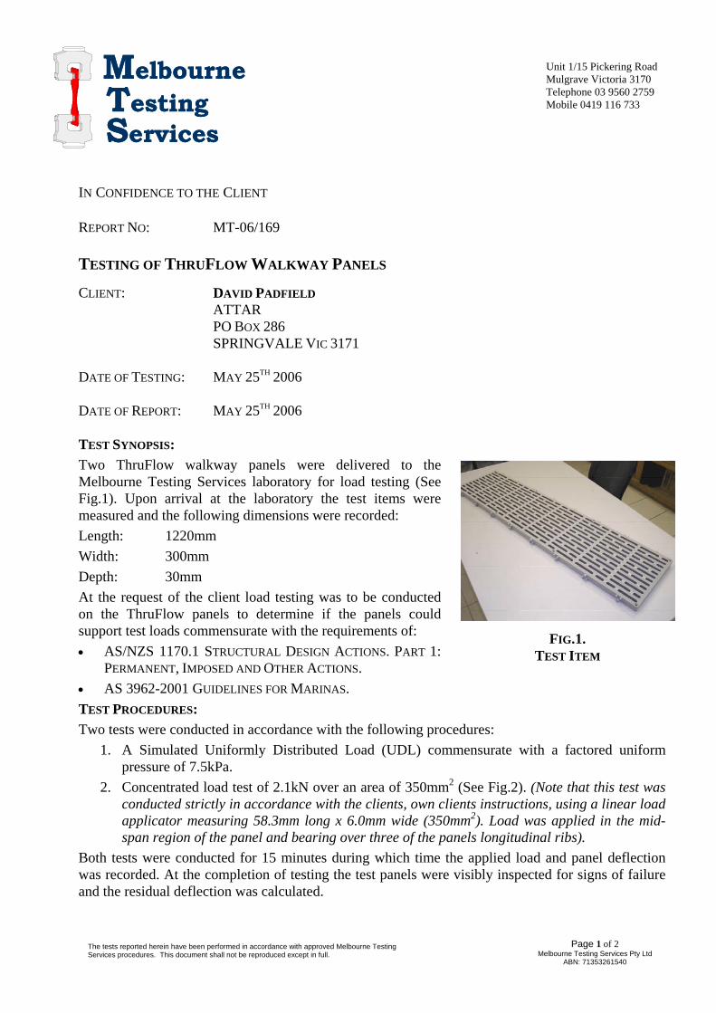
TEST SYNOPSIS: Two ThruFlow walkway panels were delivered to the Melbourne Testing Services laboratory for load testing (See Fig.1). Upon arrival at the laboratory the test items were measured and the following dimensions were recorded:
FIG.1. TEST ITEM
Length: 1220mm Width: 300mm Depth: 30mm At the request of the client load testing was to be conducted on the ThruFlow panels to determine if the panels could support test loads commensurate with the requirements of: • AS/NZS 1170.1 STRUCTURAL DESIGN ACTIONS. PART 1:
PERMANENT, IMPOSED AND OTHER ACTIONS. • AS 3962-2001 GUIDELINES FOR MARINAS. TEST PROCEDURES: Two tests were conducted in accordance with the following procedures:
1. A Simulated Uniformly Distributed Load (UDL) commensurate with a factored uniform pressure of 7.5kPa.
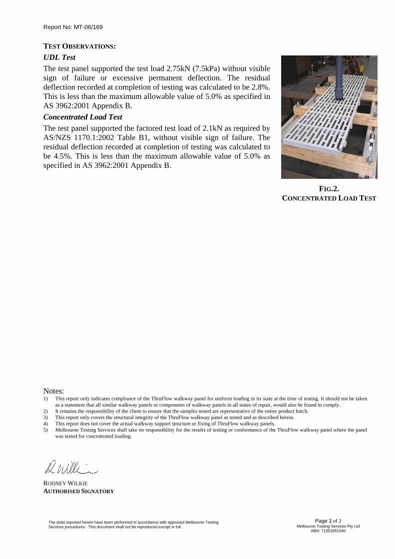
2. Concentrated load test of 2.1kN over an area of 350mm2 (See Fig.2). (Note that this test was conducted strictly in accordance with the clients, own clients instructions, using a linear load applicator measuring 58.3mm long x 6.0mm wide (350mm2). Load was applied in the mid-span region of the panel and bearing over three of the panels longitudinal ribs).
Both tests were conducted for 15 minutes during which time the applied load and panel deflection was recorded. At the completion of testing the test panels were visibly inspected for signs of failure and the residual deflection was calculated.
Page 1 of 2 Melbourne Testing Services Pty Ltd
ABN: 71353261540 The tests reported herein have been performed in accordance with approved Melbourne Testing Services procedures. This document shall not be reproduced except in full.
Report No: MT-06/169
TEST OBSERVATIONS: UDL Test
FIG.2. CONCENTRATED LOAD TEST
The test panel supported the test load 2.75kN (7.5kPa) without visible sign of failure or excessive permanent deflection. The residual deflection recorded at completion of testing was calculated to be 2.8%. This is less than the maximum allowable value of 5.0% as specified in AS 3962:2001 Appendix B. Concentrated Load Test The test panel supported the factored test load of 2.1kN as required by AS/NZS 1170.1:2002 Table B1, without visible sign of failure. The residual deflection recorded at completion of testing was calculated to be 4.5%. This is less than the maximum allowable value of 5.0% as specified in AS 3962:2001 Appendix B. Notes: 1) This report only indicates compliance of the ThruFlow walkway panel for uniform loading in its state at the time of testing. It should not be taken
as a statement that all similar walkway panels or components of walkway panels in all states of repair, would also be found to comply. 2) It remains the responsibility of the client to ensure that the samples tested are representative of the entire product batch. 3) This report only covers the structural integrity of the ThruFlow walkway panel as tested and as described herein. 4) This report does not cover the actual walkway support structure or fixing of ThruFlow walkway panels. 5) Melbourne Testing Services shall take no responsibility for the results of testing or conformance of the ThruFlow walkway panel where the panel
was tested for concentrated loading.
RODNEY WILKIE AUTHORISED SIGNATORY
Page 2 of 2 The tests reported herein have been performed in accordance with approved Melbourne Testing
Melbourne Testing Services Pty Ltd ABN: 71353261540 Services procedures. This document shall not be reproduced except in full.
Product Development6991 Millcreek Drive, Unit 13,
Mississauga, Ontario L5N 6B9 Tel: (905) 812-3856 Fax: (905) 812-3866
www.cambridgematerials.com
ISO Accredited (1989)
Page 1 of 1
This report is subject to the following terms and conditions: 1. This report relates only to the specimen provided and there is no representation or warranty that it applies to similar substances or materials or the bulk of which the specimen is a part. 2. The content of this report is for the information of the customer identified above only and it shall not be reprinted, published or disclosed to any other party except in full. Prior written consent from Cambridge Materials Testing Limited is required. 3. The name Cambridge Materials Testing Limited shall not be used in connection with the specimen reported on or any substance or materials similar to that specimen without the prior written consent of Cambridge Materials Testing Limited. 4. Neither Cambridge Materials Testing Limited nor any of its employees shall be responsible or held liable for any claims, loss or damages arising in consequence of reliance on this report or any default, error or omission in its preparation or the tests conducted. 5. Specimens are retained 3 months, test reports and test data are retained 10 years from date of final test report and then disposed of, unless instructed otherwise in writing.
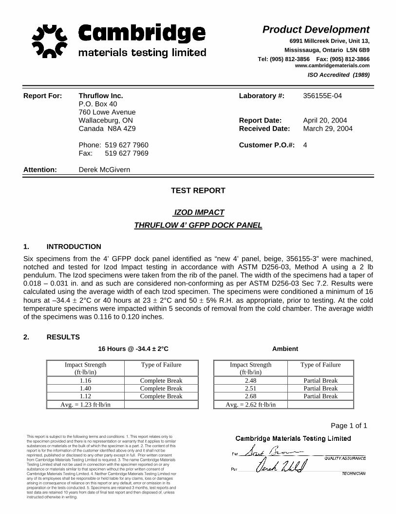
Report For: Thruflow Inc. Laboratory #: 356155E-04 P.O. Box 40 760 Lowe Avenue Wallaceburg, ON Report Date: April 20, 2004 Canada N8A 4Z9 Received Date: March 29, 2004 Phone: 519 627 7960 Customer P.O.#: 4 Fax: 519 627 7969 Attention: Derek McGivern
TEST REPORT
IZOD IMPACT
THRUFLOW 4’ GFPP DOCK PANEL 1. INTRODUCTION Six specimens from the 4’ GFPP dock panel identified as “new 4’ panel, beige, 356155-3” were machined, notched and tested for Izod Impact testing in accordance with ASTM D256-03, Method A using a 2 lb pendulum. The Izod specimens were taken from the rib of the panel. The width of the specimens had a taper of 0.018 – 0.031 in. and as such are considered non-conforming as per ASTM D256-03 Sec 7.2. Results were calculated using the average width of each Izod specimen. The specimens were conditioned a minimum of 16 hours at –34.4 ± 2°C or 40 hours at 23 ± 2°C and 50 ± 5% R.H. as appropriate, prior to testing. At the cold temperature specimens were impacted within 5 seconds of removal from the cold chamber. The average width of the specimens was 0.116 to 0.120 inches. 2. RESULTS
16 Hours @ -34.4 ± 2°C Ambient
Impact Strength (ft·lb/in)
Type of Failure Impact Strength (ft·lb/in)
Type of Failure
1.16 Complete Break 2.48 Partial Break 1.40 Complete Break 2.51 Partial Break 1.12 Complete Break 2.68 Partial Break
Avg. = 1.23 ft·lb/in Avg. = 2.62 ft·lb/in
Product Development6991 Millcreek Drive, Unit 13,
Mississauga, Ontario L5N 6B9 Tel: (905) 812-3856 Fax: (905) 812-3866
www.cambridgematerials.com
ISO Accredited (1989)
Page 1 of 1
This report is subject to the following terms and conditions: 1. This report relates only to the specimen provided and there is no representation or warranty that it applies to similar substances or materials or the bulk of which the specimen is a part. 2. The content of this report is for the information of the customer identified above only and it shall not be reprinted, published or disclosed to any other party except in full. Prior written consent from Cambridge Materials Testing Limited is required. 3. The name Cambridge Materials Testing Limited shall not be used in connection with the specimen reported on or any substance or materials similar to that specimen without the prior written consent of Cambridge Materials Testing Limited. 4. Neither Cambridge Materials Testing Limited nor any of its employees shall be responsible or held liable for any claims, loss or damages arising in consequence of reliance on this report or any default, error or omission in its preparation or the tests conducted. 5. Specimens are retained 3 months, test reports and test data are retained 10 years from date of final test report and then disposed of, unless instructed otherwise in writing.
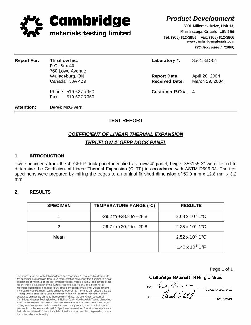
Report For: Thruflow Inc. Laboratory #: 356155D-04 P.O. Box 40 760 Lowe Avenue Wallaceburg, ON Report Date: April 20, 2004 Canada N8A 4Z9 Received Date: March 29, 2004 Phone: 519 627 7960 Customer P.O.#: 4 Fax: 519 627 7969 Attention: Derek McGivern
TEST REPORT
COEFFICIENT OF LINEAR THERMAL EXPANSION
THRUFLOW 4’ GFPP DOCK PANEL 1. INTRODUCTION Two specimens from the 4’ GFPP dock panel identified as “new 4’ panel, beige, 356155-3” were tested to determine the Coefficient of Linear Thermal Expansion (CLTE) in accordance with ASTM D696-03. The test specimens were prepared by milling the edges to a nominal finished dimension of 50.9 mm x 12.8 mm x 3.2 mm. 2. RESULTS
SPECIMEN TEMPERATURE RANGE (°C) RESULTS
1 -29.2 to +28.8 to –28.8 2.68 x 10⁻⁵ 1°C
2 -28.7 to +30.2 to –29.8 2.35 x 10⁻⁵ 1°C
Mean 2.52 x 10⁻⁵ 1°C
1.40 x 10⁻⁵ 1°F

Product Development6991 Millcreek Drive, Unit 13,
Mississauga, Ontario L5N 6B9 Tel: (905) 812-3856 Fax: (905) 812-3866
www.cambridgematerials.com
ISO 17025 Accredited
This report is subject to the following terms and conditions: 1. This report relates only to the specimen provided and there is no representation or warranty that it applies to similar substances or materials or the bulk of which the specimen is a part. 2. The content of this report is for the information of the customer identified above only and it shall not be reprinted, published or disclosed to any other party except in full. Prior written consent from Cambridge Materials Testing Limited is required. 3. The name Cambridge Materials Testing Limited shall not be used in connection with the specimen reported on or any substance or materials similar to that specimen without the prior written consent of Cambridge Materials Testing Limited. 4. Neither Cambridge Materials Testing Limited nor any of its employees shall be responsible or held liable for any claims, loss or damages arising in consequence of reliance on this report or any default, error or omission in its preparation or the tests conducted. 5. Specimens are retained 6 months, test reports and test data are retained 7 years from date of final test report and then disposed of, unless instructed otherwise in writing.
Page 1 of 2
Report for: THRUFLOW Laboratory #: 427785D-06P.O. Box 40, Stn. Main REVISED 1239 Dufferin Avenue, Suite B Report Date: October 19th, 2006 WALLACEBURG, Ontario Received Date: August 24th, 2006
N8A 2W3
Phone: 519-627-7428 Ext.112 Customer P.O. #: 613Fax: 519-627-7428
E-Mail: [email protected]
Attention: Derek McGivern
TEST REPORT PROPERTIES OF THRUFLOW DECKING PANELS
CREEP RELAXATION
1. INTRODUCTION On August 24th, 2006, CMTL received, a three (3) foot Thruflow Reinforced Polypropylene (RPP) dock panel to determine the creep relaxation properties at 73°F as per the request of AXIS Polymer Services Inc.
2. TEST METHOD
The Thruflow dock panel was tested according to the creep relaxation requirements outlined in ICC AC174 (Approved Feb. 2005) and ASTM D7032-05, Section 5.4. The testing was conducted using a support span of 18 inches on center for three (3) foot panels.

Product Development6991 Millcreek Drive, Unit 13,
Mississauga, Ontario L5N 6B9 Tel: (905) 812-3856 Fax: (905) 812-3866
www.cambridgematerials.com
ISO 17025 Accredited
Page 2 of 2
Laboratory #427785D-06 REVISED
AXIS Polymer Services Inc.
2. TEST METHOD (Cont’d)
Three (3) boards were tested as per ASTM D6109-05 modified for quarter point loading. The boards were placed across the support noses. A calibrated dial gauge was secured under the deck boards and the initial deflection at the mid-span was recorded. A pre-weighed loading nose assembly was placed on the boards. Weights were added to the assembly until a load corresponding to 100 psf, 120 psf, 140 psf, 160 psf and 200 psf (2x design load) were applied. The 200 psf load was left in place for 24 hours and the total deflection was recorded. The load was removed and deflection was recorded immediately. The boards were allowed to recover for 24 hours at which time the deflection was measured. The percent recovered deflection was calculated as follows:
Percent recovered deflection =
(total deflection after 24hr loading period – residual deflection after 24hr recovery period) x 100 total deflection after 24hr loading period
3. RESULTS
18” Support Span
Deflection (inches)Board 1 Board 2 Board 3 Mean
100 psf 0.0893 0.0872 0.0807 0.0857120 psf 0.1087 0.1058 0.0987 0.1044140 psf 0.1253 0.1227 0.1163 0.1214160 psf 0.1440 0.1428 0.1365 0.1411 – total deflection after 24hr loading period 0.2377 0.2304 0.2205 0.2295 – residual deflection after 24hr recovery period 0.0168 0.0144 0.0127 0.0146 – percent recovered deflection +93% +94% +94% +94%
Product Development6991 Millcreek Drive, Unit 13,
Mississauga, Ontario L5N 6B9 Tel: (905) 812-3856 Fax: (905) 812-3866
www.cambridgematerials.com
ISO 17025 Accredited
This report is subject to the following terms and conditions: 1. This report relates only to the specimen provided and there is no representation or warranty that it applies to similar substances or materials or the bulk of which the specimen is a part. 2. The content of this report is for the information of the customer identified above only and it shall not be reprinted, published or disclosed to any other party except in full. Prior written consent from Cambridge Materials Testing Limited is required. 3. The name Cambridge Materials Testing Limited shall not be used in connection with the specimen reported on or any substance or materials similar to that specimen without the prior written consent of Cambridge Materials Testing Limited. 4. Neither Cambridge Materials Testing Limited nor any of its employees shall be responsible or held liable for any claims, loss or damages arising in consequence of reliance on this report or any default, error or omission in its preparation or the tests conducted. 5. Specimens are retained 6 months, test reports and test data are retained 7 years from date of final test report and then disposed of, unless instructed otherwise in writing.
Page 1 of 2
Report for: THRUFLOW Laboratory #: 427785E-06P.O. Box 40, Stn. Main REVISED 1239 Dufferin Avenue, Suite B Report Date: October 19th, 2006 WALLACEBURG, Ontario Received Date: August 24th, 2006
N8A 2W3
Phone: 519-627-7428 Ext.112 Customer P.O. #: 613Fax: 519-627-7428
E-Mail: [email protected]
Attention: Derek McGivern
TEST REPORT PROPERTIES OF THRUFLOW DECKING PANELS
CREEP RELAXATION
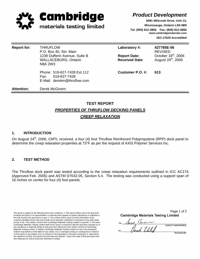
1. INTRODUCTION On August 24th, 2006, CMTL received, a four (4) foot Thruflow Reinforced Polypropylene (RPP) dock panel to determine the creep relaxation properties at 73°F as per the request of AXIS Polymer Services Inc.
2. TEST METHOD
The Thruflow dock panel was tested according to the creep relaxation requirements outlined in ICC AC174 (Approved Feb. 2005) and ASTM D7032-05, Section 5.4. The testing was conducted using a support span of 16 inches on center for four (4) foot panels.

Product Development6991 Millcreek Drive, Unit 13,
Mississauga, Ontario L5N 6B9 Tel: (905) 812-3856 Fax: (905) 812-3866
www.cambridgematerials.com
ISO 17025 Accredited
Page 2 of 2
Laboratory #427785E-06 REVISED
AXIS Polymer Services Inc.
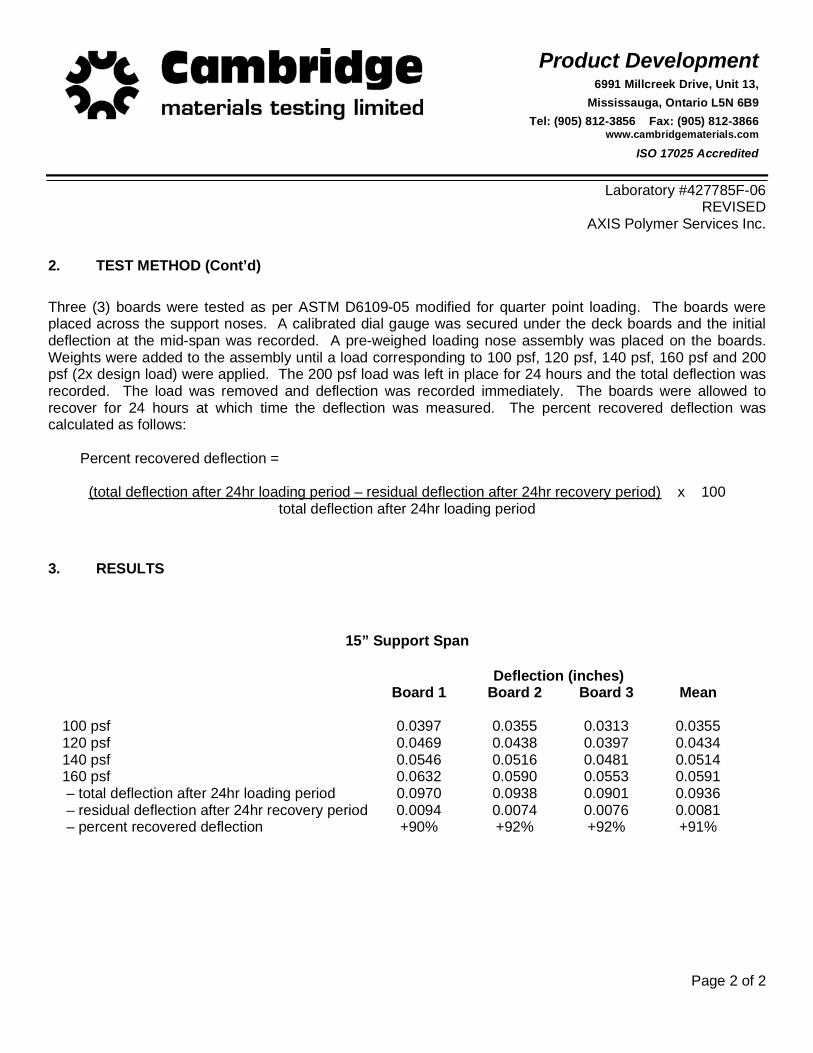
2. TEST METHOD (Cont’d)
Three (3) boards were tested as per ASTM D6109-05 modified for quarter point loading. The boards were placed across the support noses. A calibrated dial gauge was secured under the deck boards and the initial deflection at the mid-span was recorded. A pre-weighed loading nose assembly was placed on the boards. Weights were added to the assembly until a load corresponding to 100 psf, 120 psf, 140 psf, 160 psf and 200 psf (2x design load) were applied. The 200 psf load was left in place for 24 hours and the total deflection was recorded. The load was removed and deflection was recorded immediately. The boards were allowed to recover for 24 hours at which time the deflection was measured. The percent recovered deflection was calculated as follows:
Percent recovered deflection =
(total deflection after 24hr loading period – residual deflection after 24hr recovery period) x 100 total deflection after 24hr loading period
3. RESULTS
16” Support Span
Deflection (inches)Board 1 Board 2 Board 3 Mean
100 psf 0.0516 0.0539 0.0467 0.0507120 psf 0.0653 0.0682 0.0605 0.0647140 psf 0.0745 0.0783 0.0701 0.0743160 psf 0.0857 0.0906 0.0812 0.0858 – total deflection after 24hr loading period 0.1244 0.1300 0.1212 0.1252 – residual deflection after 24hr recovery period 0.0010 0.0154 0.0063 0.0076 – percent recovered deflection +99% +88% +95% +94%

Product Development6991 Millcreek Drive, Unit 13,
Mississauga, Ontario L5N 6B9 Tel: (905) 812-3856 Fax: (905) 812-3866
www.cambridgematerials.com
ISO 17025 Accredited
This report is subject to the following terms and conditions: 1. This report relates only to the specimen provided and there is no representation or warranty that it applies to similar substances or materials or the bulk of which the specimen is a part. 2. The content of this report is for the information of the customer identified above only and it shall not be reprinted, published or disclosed to any other party except in full. Prior written consent from Cambridge Materials Testing Limited is required. 3. The name Cambridge Materials Testing Limited shall not be used in connection with the specimen reported on or any substance or materials similar to that specimen without the prior written consent of Cambridge Materials Testing Limited. 4. Neither Cambridge Materials Testing Limited nor any of its employees shall be responsible or held liable for any claims, loss or damages arising in consequence of reliance on this report or any default, error or omission in its preparation or the tests conducted. 5. Specimens are retained 6 months, test reports and test data are retained 7 years from date of final test report and then disposed of, unless instructed otherwise in writing.
Page 1 of 2
Report for: THRUFLOW Laboratory #: 427785F-06P.O. Box 40, Stn. Main REVISED 1239 Dufferin Avenue, Suite B Report Date: October 19th, 2006 WALLACEBURG, Ontario Received Date: August 24th, 2006
N8A 2W3
Phone: 519-627-7428 Ext.112 Customer P.O. #: 613Fax: 519-627-7428
E-Mail: [email protected]
Attention: Derek McGivern
TEST REPORT PROPERTIES OF THRUFLOW DECKING PANELS
CREEP RELAXATION
1. INTRODUCTION On August 24th, 2006, CMTL received, a five (5) foot Thruflow Reinforced Polypropylene (RPP) dock panel to determine the creep relaxation properties at 73°F as per the request of AXIS Polymer Services Inc.
2. TEST METHOD
The Thruflow dock panel was tested according to the creep relaxation requirements outlined in ICC AC174 (Approved Feb. 2005) and ASTM D7032-05, Section 5.4. The testing was conducted using a support span of 15 inches on center for five (5) foot panels.
Product Development6991 Millcreek Drive, Unit 13,
Mississauga, Ontario L5N 6B9 Tel: (905) 812-3856 Fax: (905) 812-3866
www.cambridgematerials.com
ISO 17025 Accredited
Page 2 of 2
Laboratory #427785F-06 REVISED
AXIS Polymer Services Inc.
2. TEST METHOD (Cont’d)
Three (3) boards were tested as per ASTM D6109-05 modified for quarter point loading. The boards were placed across the support noses. A calibrated dial gauge was secured under the deck boards and the initial deflection at the mid-span was recorded. A pre-weighed loading nose assembly was placed on the boards. Weights were added to the assembly until a load corresponding to 100 psf, 120 psf, 140 psf, 160 psf and 200 psf (2x design load) were applied. The 200 psf load was left in place for 24 hours and the total deflection was recorded. The load was removed and deflection was recorded immediately. The boards were allowed to recover for 24 hours at which time the deflection was measured. The percent recovered deflection was calculated as follows:
Percent recovered deflection =
(total deflection after 24hr loading period – residual deflection after 24hr recovery period) x 100 total deflection after 24hr loading period
3. RESULTS
15” Support Span
Deflection (inches)Board 1 Board 2 Board 3 Mean
100 psf 0.0397 0.0355 0.0313 0.0355120 psf 0.0469 0.0438 0.0397 0.0434140 psf 0.0546 0.0516 0.0481 0.0514160 psf 0.0632 0.0590 0.0553 0.0591 – total deflection after 24hr loading period 0.0970 0.0938 0.0901 0.0936 – residual deflection after 24hr recovery period 0.0094 0.0074 0.0076 0.0081 – percent recovered deflection +90% +92% +92% +91%
Product Development6991 Millcreek Drive, Unit 13,
Mississauga, Ontario L5N 6B9 Tel: (905) 812-3856 Fax: (905) 812-3866
www.cambridgematerials.com
ISO 17025 Accredited
This report is subject to the following terms and conditions: 1. This report relates only to the specimen provided and there is no representation or warranty that it applies to similar substances or materials or the bulk of which the specimen is a part. 2. The content of this report is for the information of the customer identified above only and it shall not be reprinted, published or disclosed to any other party except in full. Prior written consent from Cambridge Materials Testing Limited is required. 3. The name Cambridge Materials Testing Limited shall not be used in connection with the specimen reported on or any substance or materials similar to that specimen without the prior written consent of Cambridge Materials Testing Limited. 4. Neither Cambridge Materials Testing Limited nor any of its employees shall be responsible or held liable for any claims, loss or damages arising in consequence of reliance on this report or any default, error or omission in its preparation or the tests conducted. 5. Specimens are retained 6 months, test reports and test data are retained 7 years from date of final test report and then disposed of, unless instructed otherwise in writing.
Page 1 of 3
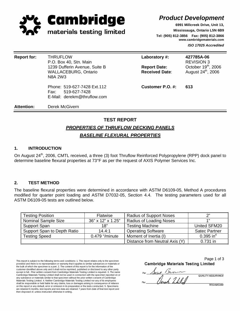
Report for: THRUFLOW Laboratory #: 427785A-06P.O. Box 40, Stn. Main REVISION 3 1239 Dufferin Avenue, Suite B Report Date: October 19th, 2006 WALLACEBURG, Ontario Received Date: August 24th, 2006
N8A 2W3
Phone: 519-627-7428 Ext.112 Customer P.O. #: 613Fax: 519-627-7428
E-Mail: [email protected]
Attention: Derek McGivern
TEST REPORT PROPERTIES OF THRUFLOW DECKING PANELS
BASELINE FLEXURAL PROPERTIES
1. INTRODUCTION On August 24th, 2006, CMTL received, a three (3) foot Thruflow Reinforced Polypropylene (RPP) dock panel to determine baseline flexural properties at 73°F as per the request of AXIS Polymer Services Inc.
2. TEST METHOD The baseline flexural properties were determined in accordance with ASTM D6109-05, Method A procedures modified for quarter point loading and ASTM D7032-05, Section 4.4. The testing parameters used for all ASTM D6109-05 tests are outlined below.
Testing Position Flatwise Radius of Support Noses 2”Nominal Sample Size 36” x 12” x 1.25” Radius of Loading Noses 1”Support Span 18” Testing Machine United SFM20 Support Span to Depth Ratio 14.4:1 Operating Software Satec Partner Testing Speed 0.479 “/minute Moment of Inertia (I) 0.395 in4
Distance from Neutral Axis (Y) 0.731 in

Product Development6991 Millcreek Drive, Unit 13,
Mississauga, Ontario L5N 6B9 Tel: (905) 812-3856 Fax: (905) 812-3866
www.cambridgematerials.com
ISO 17025 Accredited
Page 2 of 3
Laboratory #427785A-06 REVISION 3
AXIS Polymer Services Inc.
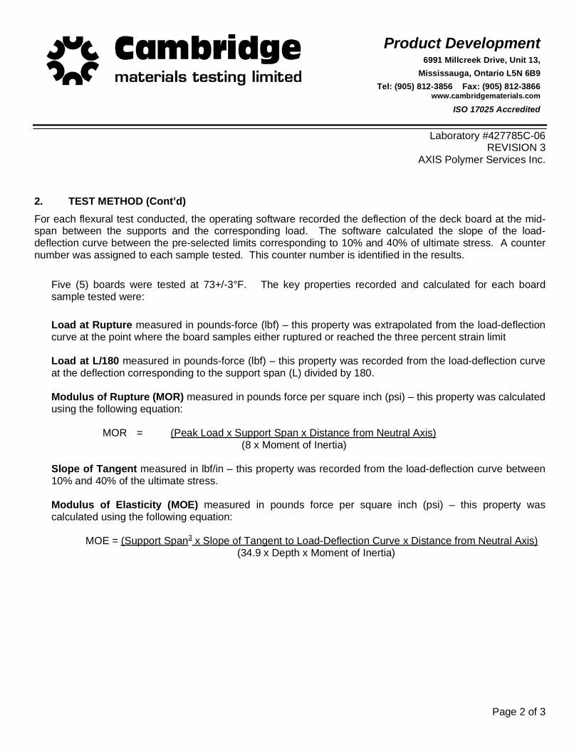
2. TEST METHOD (Cont’d) For each flexural test conducted, the operating software recorded the deflection of the deck board at the mid-span between the supports and the corresponding load. The software calculated the slope of the load-deflection curve between the pre-selected limits corresponding to 10% and 40% of ultimate stress. A counter number was assigned to each sample tested. This counter number is identified in the results.
Five (5) boards were tested at 73+/-3°F. The key properties recorded and calculated for each board sample tested were:
Load at Rupture measured in pounds-force (lbf) – this property was extrapolated from the load-deflection curve at the point where the board samples either ruptured or reached the three percent strain limit
Load at L/180 measured in pounds-force (lbf) – this property was recorded from the load-deflection curve at the deflection corresponding to the support span (L) divided by 180.
Modulus of Rupture (MOR) measured in pounds force per square inch (psi) – this property was calculated using the following equation:
MOR = (Peak Load x Support Span x Distance from Neutral Axis) (8 x Moment of Inertia)
Slope of Tangent measured in lbf/in – this property was recorded from the load-deflection curve between 10% and 40% of the ultimate stress.
Modulus of Elasticity (MOE) measured in pounds force per square inch (psi) – this property was calculated using the following equation:
MOE = (Support Span3 x Slope of Tangent to Load-Deflection Curve x Distance from Neutral Axis) (34.9 x Depth x Moment of Inertia)
Product Development6991 Millcreek Drive, Unit 13,
Mississauga, Ontario L5N 6B9 Tel: (905) 812-3856 Fax: (905) 812-3866
www.cambridgematerials.com
ISO 17025 Accredited
Page 3 of 3
Laboratory #427785A-06 REVISION 3
AXIS Polymer Services Inc.
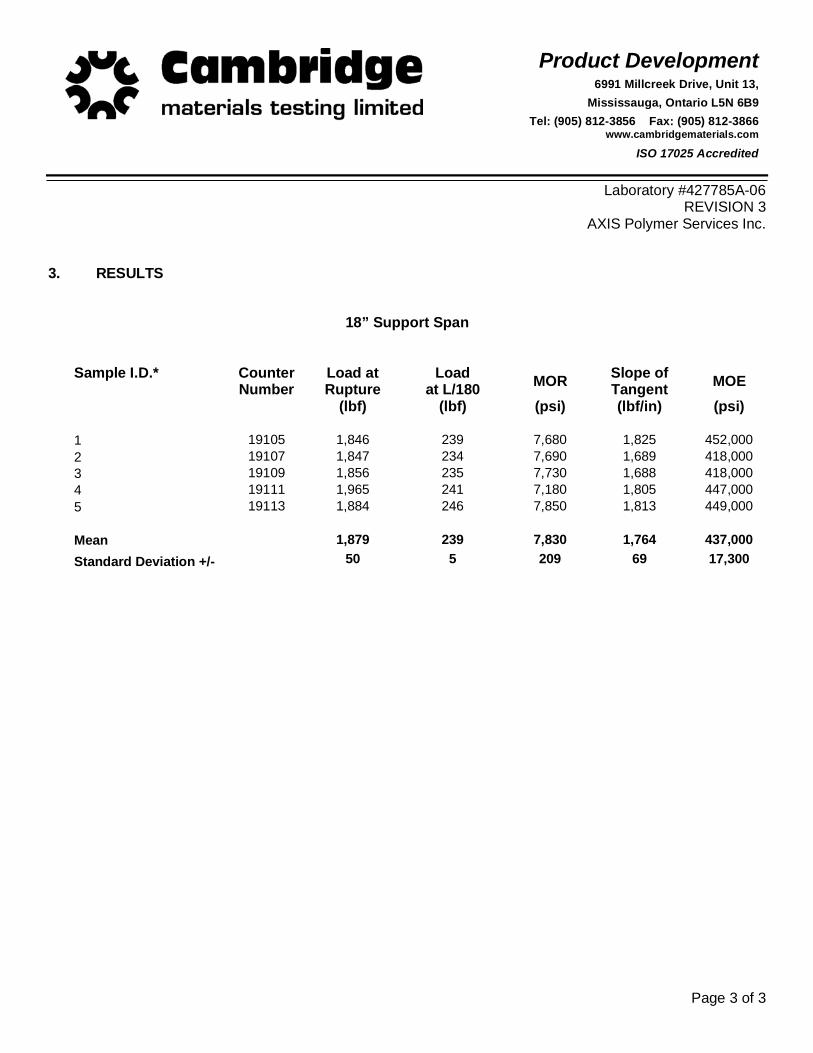
3. RESULTS
18” Support Span
Sample I.D.* CounterNumber
Load at Rupture
Loadat L/180 MOR Slope of
Tangent MOE (lbf) (lbf) (psi) (lbf/in) (psi)
1 19105 1,846 239 7,680 1,825 452,000 2 19107 1,847 234 7,690 1,689 418,000 3 19109 1,856 235 7,730 1,688 418,000 4 19111 1,965 241 7,180 1,805 447,000 5 19113 1,884 246 7,850 1,813 449,000
Mean 1,879 239 7,830 1,764 437,000 Standard Deviation +/- 50 5 209 69 17,300

Product Development6991 Millcreek Drive, Unit 13,
Mississauga, Ontario L5N 6B9 Tel: (905) 812-3856 Fax: (905) 812-3866
www.cambridgematerials.com
ISO 17025 Accredited
This report is subject to the following terms and conditions: 1. This report relates only to the specimen provided and there is no representation or warranty that it applies to similar substances or materials or the bulk of which the specimen is a part. 2. The content of this report is for the information of the customer identified above only and it shall not be reprinted, published or disclosed to any other party except in full. Prior written consent from Cambridge Materials Testing Limited is required. 3. The name Cambridge Materials Testing Limited shall not be used in connection with the specimen reported on or any substance or materials similar to that specimen without the prior written consent of Cambridge Materials Testing Limited. 4. Neither Cambridge Materials Testing Limited nor any of its employees shall be responsible or held liable for any claims, loss or damages arising in consequence of reliance on this report or any default, error or omission in its preparation or the tests conducted. 5. Specimens are retained 6 months, test reports and test data are retained 7 years from date of final test report and then disposed of, unless instructed otherwise in writing.
Page 1 of 3
Report for: THRUFLOW Laboratory #: 427785B-06P.O. Box 40, Stn. Main REVISION 3 1239 Dufferin Avenue, Suite B Report Date: October 19th, 2006 WALLACEBURG, Ontario Received Date: August 24th, 2006
N8A 2W3
Phone: 519-627-7428 Ext.112 Customer P.O. #: 613Fax: 519-627-7428
E-Mail: [email protected]
Attention: Derek McGivern
TEST REPORT PROPERTIES OF THRUFLOW DECKING PANELS
BASELINE FLEXURAL PROPERTIES
1. INTRODUCTION On August 24th, 2006, CMTL received, a four (4) foot Thruflow Reinforced Polypropylene (RPP) dock panel to determine baseline flexural properties at 73°F as per the request of AXIS Polymer Services Inc.
2. TEST METHOD The baseline flexural properties were determined in accordance with ASTM D6109-05, Method A procedures modified for quarter point loading and ASTM D7032-05, Section 4.4. The testing parameters used for all ASTM D6109-05 tests are outlined below.
Testing Position Flatwise Radius of Support Noses 2”Nominal Sample Size 48” x 12” x 1.25” Radius of Loading Noses 1”Support Span 16” Testing Machine United SFM20 Support Span to Depth Ratio 12.8:1 Operating Software Satec Partner Testing Speed 0.378 “/minute Moment of Inertia (I) 0.395 in4
Distance from Neutral Axis (Y) 0.731 in

Product Development6991 Millcreek Drive, Unit 13,
Mississauga, Ontario L5N 6B9 Tel: (905) 812-3856 Fax: (905) 812-3866
www.cambridgematerials.com
ISO 17025 Accredited
Page 2 of 3
Laboratory #427785B-06 REVISION 3
AXIS Polymer Services Inc.
2. TEST METHOD (Cont’d) For each flexural test conducted, the operating software recorded the deflection of the deck board at the mid-span between the supports and the corresponding load. The software calculated the slope of the load-deflection curve between the pre-selected limits corresponding to 10% and 40% of ultimate stress. A counter number was assigned to each sample tested. This counter number is identified in the results.
Five (5) boards were tested at 73+/-3°F. The key properties recorded and calculated for each board sample tested were:
Load at Rupture measured in pounds-force (lbf) – this property was extrapolated from the load-deflection curve at the point where the board samples either ruptured or reached the three percent strain limit
Load at L/180 measured in pounds-force (lbf) – this property was recorded from the load-deflection curve at the deflection corresponding to the support span (L) divided by 180.
Modulus of Rupture (MOR) measured in pounds force per square inch (psi) – this property was calculated using the following equation:
MOR = (Peak Load x Support Span x Distance from Neutral Axis) (8 x Moment of Inertia)
Slope of Tangent measured in lbf/in – this property was recorded from the load-deflection curve between 10% and 40% of the ultimate stress.
Modulus of Elasticity (MOE) measured in pounds force per square inch (psi) – this property was calculated using the following equation:
MOE = (Support Span3 x Slope of Tangent to Load-Deflection Curve x Distance from Neutral Axis) (34.9 x Depth x Moment of Inertia)
Product Development6991 Millcreek Drive, Unit 13,
Mississauga, Ontario L5N 6B9 Tel: (905) 812-3856 Fax: (905) 812-3866
www.cambridgematerials.com
ISO 17025 Accredited
Page 3 of 3
Laboratory #427785B-06 REVISION 3
AXIS Polymer Services Inc.
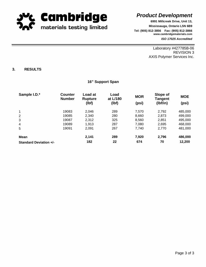
3. RESULTS
16” Support Span
Sample I.D.* CounterNumber
Load at Rupture
Loadat L/180 MOR Slope of
Tangent MOE (lbf) (lbf) (psi) (lbf/in) (psi)
1 19083 2,046 289 7,570 2,792 485,000 2 19085 2,340 280 8,660 2,873 499,000 3 19087 2,312 325 8,560 2,851 495,000 4 19089 1,913 287 7,080 2,695 468,000 5 19091 2,091 267 7,740 2,770 481,000
Mean 2,141 289 7,920 2,796 486,000 Standard Deviation +/- 182 22 674 70 12,200
Product Development6991 Millcreek Drive, Unit 13,
Mississauga, Ontario L5N 6B9 Tel: (905) 812-3856 Fax: (905) 812-3866
www.cambridgematerials.com
ISO 17025 Accredited
U:\PDF\427785c.R3.axispolymer.doc This report is subject to the following terms and conditions: 1. This report relates only to the specimen provided and there is no representation or warranty that it applies to similar substances or materials or the bulk of which the specimen is a part. 2. The content of this report is for the information of the customer identified above only and it shall not be reprinted, published or disclosed to any other party except in full. Prior written consent from Cambridge Materials Testing Limited is required. 3. The name Cambridge Materials Testing Limited shall not be used in connection with the specimen reported on or any substance or materials similar to that specimen without the prior written consent of Cambridge Materials Testing Limited. 4. Neither Cambridge Materials Testing Limited nor any of its employees shall be responsible or held liable for any claims, loss or damages arising in consequence of reliance on this report or any default, error or omission in its preparation or the tests conducted. 5. Specimens are retained 6 months, test reports and test data are retained 7 years from date of final test report and then disposed of, unless instructed otherwise in writing.
Page 1 of 3
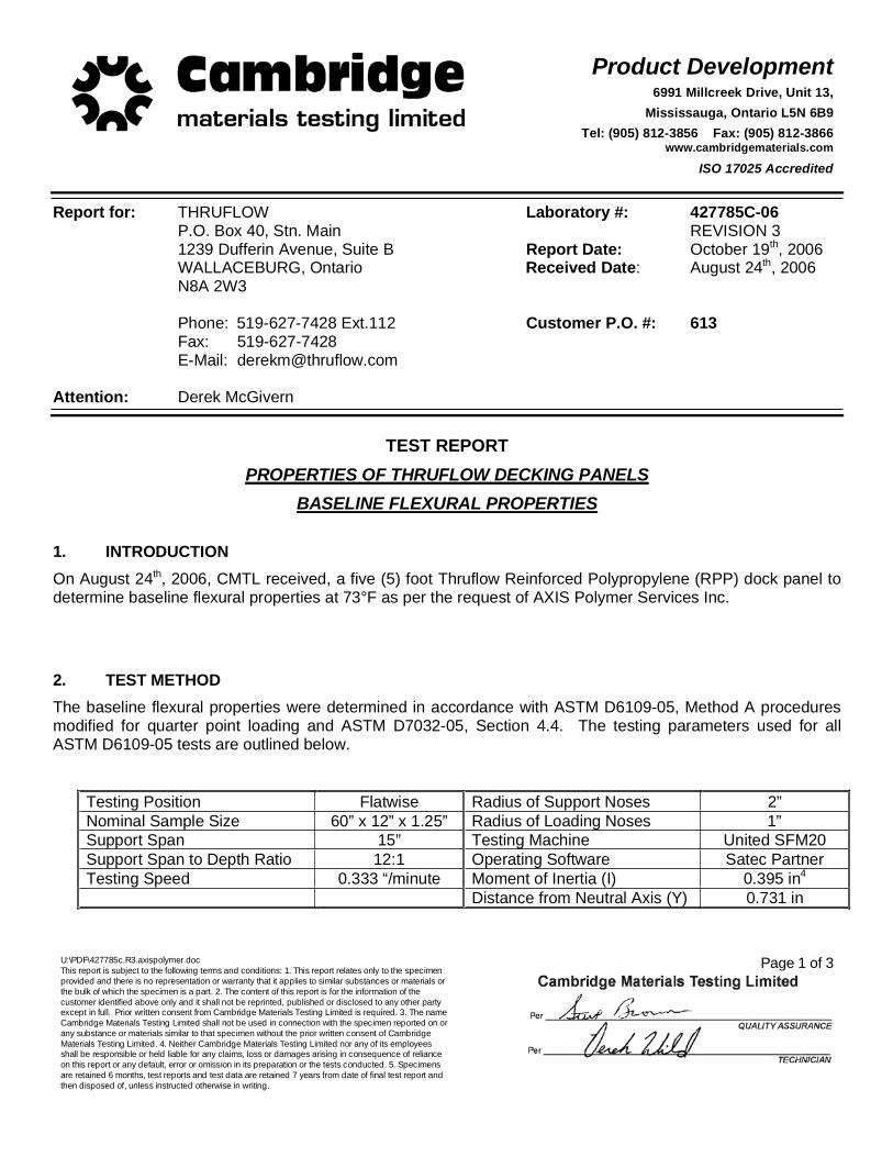
Report for: THRUFLOW Laboratory #: 427785C-06P.O. Box 40, Stn. Main REVISION 3 1239 Dufferin Avenue, Suite B Report Date: October 19th, 2006 WALLACEBURG, Ontario Received Date: August 24th, 2006
N8A 2W3
Phone: 519-627-7428 Ext.112 Customer P.O. #: 613Fax: 519-627-7428
E-Mail: [email protected]
Attention: Derek McGivern
TEST REPORT PROPERTIES OF THRUFLOW DECKING PANELS
BASELINE FLEXURAL PROPERTIES
1. INTRODUCTION On August 24th, 2006, CMTL received, a five (5) foot Thruflow Reinforced Polypropylene (RPP) dock panel to determine baseline flexural properties at 73°F as per the request of AXIS Polymer Services Inc.
2. TEST METHOD The baseline flexural properties were determined in accordance with ASTM D6109-05, Method A procedures modified for quarter point loading and ASTM D7032-05, Section 4.4. The testing parameters used for all ASTM D6109-05 tests are outlined below.
Testing Position Flatwise Radius of Support Noses 2”Nominal Sample Size 60” x 12” x 1.25” Radius of Loading Noses 1”Support Span 15” Testing Machine United SFM20 Support Span to Depth Ratio 12:1 Operating Software Satec Partner Testing Speed 0.333 “/minute Moment of Inertia (I) 0.395 in4
Distance from Neutral Axis (Y) 0.731 in
Product Development6991 Millcreek Drive, Unit 13,
Mississauga, Ontario L5N 6B9 Tel: (905) 812-3856 Fax: (905) 812-3866
www.cambridgematerials.com
ISO 17025 Accredited
Page 2 of 3
Laboratory #427785C-06 REVISION 3
AXIS Polymer Services Inc.
2. TEST METHOD (Cont’d) For each flexural test conducted, the operating software recorded the deflection of the deck board at the mid-span between the supports and the corresponding load. The software calculated the slope of the load-deflection curve between the pre-selected limits corresponding to 10% and 40% of ultimate stress. A counter number was assigned to each sample tested. This counter number is identified in the results.
Five (5) boards were tested at 73+/-3°F. The key properties recorded and calculated for each board sample tested were:
Load at Rupture measured in pounds-force (lbf) – this property was extrapolated from the load-deflection curve at the point where the board samples either ruptured or reached the three percent strain limit
Load at L/180 measured in pounds-force (lbf) – this property was recorded from the load-deflection curve at the deflection corresponding to the support span (L) divided by 180.
Modulus of Rupture (MOR) measured in pounds force per square inch (psi) – this property was calculated using the following equation:
MOR = (Peak Load x Support Span x Distance from Neutral Axis) (8 x Moment of Inertia)
Slope of Tangent measured in lbf/in – this property was recorded from the load-deflection curve between 10% and 40% of the ultimate stress.
Modulus of Elasticity (MOE) measured in pounds force per square inch (psi) – this property was calculated using the following equation:
MOE = (Support Span3 x Slope of Tangent to Load-Deflection Curve x Distance from Neutral Axis) (34.9 x Depth x Moment of Inertia)

Product Development6991 Millcreek Drive, Unit 13,
Mississauga, Ontario L5N 6B9 Tel: (905) 812-3856 Fax: (905) 812-3866
www.cambridgematerials.com
ISO 17025 Accredited
Page 3 of 3
Laboratory #427785C-06 REVISION 3
AXIS Polymer Services Inc.
3. RESULTS
15” Support Span
Sample I.D.* CounterNumber
Load at Rupture
Loadat L/180 MOR Slope of
Tangent MOE (lbf) (lbf) (psi) (lbf/in) (psi)
1 19093 2,774 334 9,620 3,113 446,000 2 19095 2,321 329 8,050 2,926 419,000 3 19097 2,714 354 9,420 2,953 423,000 4 19099 2,734 348 9,490 2,980 427,000 5 19101 2,703 337 9,380 2,910 417,000
Mean 2,649 340 9,190 2,976 426,000 Standard Deviation +/- 185 11 645 81 11,600
Product Development6991 Millcreek Drive, Unit 13,
Mississauga, Ontario L5N 6B9 Tel: (905) 812-3856 Fax: (905) 812-3866
www.cambridgematerials.com
ISO 17025 Accredited
This report is subject to the following terms and conditions: 1. This report relates only to the specimen provided and there is no representation or warranty that it applies to similar substances or materials or the bulk of which the specimen is a part. 2. The content of this report is for the information of the customer identified above only and it shall not be reprinted, published or disclosed to any other party except in full. Prior written consent from Cambridge Materials Testing Limited is required. 3. The name Cambridge Materials Testing Limited shall not be used in connection with the specimen reported on or any substance or materials similar to that specimen without the prior written consent of Cambridge Materials Testing Limited. 4. Neither Cambridge Materials Testing Limited nor any of its employees shall be responsible or held liable for any claims, loss or damages arising in consequence of reliance on this report or any default, error or omission in its preparation or the tests conducted. 5. Specimens are retained 6 months, test reports and test data are retained 7 years from date of final test report and then disposed of, unless instructed otherwise in writing.
Page 1 of 3
Report for: THRUFLOW Laboratory #: 427785G-06P.O. Box 40, Stn. Main REVISION 3 1239 Dufferin Avenue, Suite B Report Date: October 19th, 2006 WALLACEBURG, Ontario Received Date: August 24th, 2006
N8A 2W3
Phone: 519-627-7428 Ext.112 Customer P.O. #: 613Fax: 519-627-7428
E-Mail: [email protected]
Attention: Derek McGivern
TEST REPORT PROPERTIES OF THRUFLOW DECKING PANELS
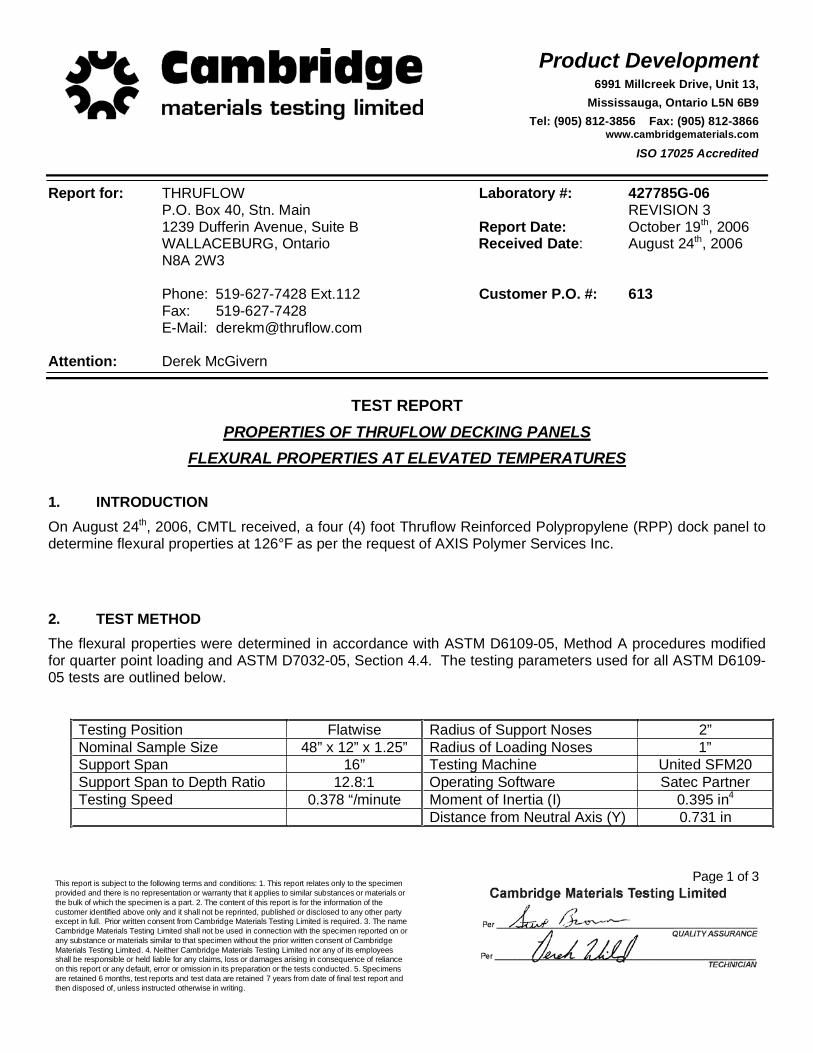
FLEXURAL PROPERTIES AT ELEVATED TEMPERATURES
1. INTRODUCTION On August 24th, 2006, CMTL received, a four (4) foot Thruflow Reinforced Polypropylene (RPP) dock panel to determine flexural properties at 126°F as per the request of AXIS Polymer Services Inc.
2. TEST METHOD The flexural properties were determined in accordance with ASTM D6109-05, Method A procedures modified for quarter point loading and ASTM D7032-05, Section 4.4. The testing parameters used for all ASTM D6109-05 tests are outlined below.
Testing Position Flatwise Radius of Support Noses 2”Nominal Sample Size 48” x 12” x 1.25” Radius of Loading Noses 1”Support Span 16” Testing Machine United SFM20 Support Span to Depth Ratio 12.8:1 Operating Software Satec Partner Testing Speed 0.378 “/minute Moment of Inertia (I) 0.395 in4
Distance from Neutral Axis (Y) 0.731 in

Product Development6991 Millcreek Drive, Unit 13,
Mississauga, Ontario L5N 6B9 Tel: (905) 812-3856 Fax: (905) 812-3866
www.cambridgematerials.com
ISO 17025 Accredited
Page 2 of 3
Laboratory #427785G-06 REVISION 3
AXIS Polymer Services Inc.
2. TEST METHOD (Cont’d) For each flexural test conducted, the operating software recorded the deflection of the deck board at the mid-span between the supports and the corresponding load. The software calculated the slope of the load-deflection curve between the pre-selected limits corresponding to 10% and 40% of ultimate stress. A counter number was assigned to each sample tested. This counter number is identified in the results.
Five (5) boards were tested at 126+/-3°F. The key properties recorded and calculated for each board sample tested were:
Load at Rupture measured in pounds-force (lbf) – this property was extrapolated from the load-deflection curve at the point where the board samples either ruptured or reached the three percent strain limit
Load at L/180 measured in pounds-force (lbf) – this property was recorded from the load-deflection curve at the deflection corresponding to the support span (L) divided by 180.
Modulus of Rupture (MOR) measured in pounds force per square inch (psi) – this property was calculated using the following equation:
MOR = (Peak Load x Support Span x Distance from Neutral Axis) (8 x Moment of Inertia)
Slope of Tangent measured in lbf/in – this property was recorded from the load-deflection curve between 10% and 40% of the ultimate stress.
Modulus of Elasticity (MOE) measured in pounds force per square inch (psi) – this property was calculated using the following equation:
MOE = (Support Span3 x Slope of Tangent to Load-Deflection Curve x Distance from Neutral Axis) (34.9 x Depth x Moment of Inertia)

Product Development6991 Millcreek Drive, Unit 13,
Mississauga, Ontario L5N 6B9 Tel: (905) 812-3856 Fax: (905) 812-3866
www.cambridgematerials.com
ISO 17025 Accredited
Page 3 of 3
Laboratory #427785G-06 REVISION 3
AXIS Polymer Services Inc.
3. RESULTS
16” Support Span
Sample I.D. CounterNumber
Load at Rupture
Loadat L/180 MOR Slope of
Tangent MOE (lbf) (lbf) (psi) (lbf/in) (psi)
1 19115 1,883 226 6,970 2,222 386,000 2 19117 1,334 251 4,940 1,978 344,000 3 19119 1,736 239 6,430 1,973 343,000 4 19123 1,720 244 6,370 1,920 334,000 5 19125 1,355 237 5,020 2,009 349,000
Mean 1,606 239 5,950 2,020 351,000 Standard Deviation +/- 247 9 913 117 20,200
Product Development6991 Millcreek Drive, Unit 13,
Mississauga, Ontario L5N 6B9 Tel: (905) 812-3856 Fax: (905) 812-3866
www.cambridgematerials.com
ISO Accredited (1989)
Page 1 of 1
This report is subject to the following terms and conditions: 1. This report relates only to the specimen provided and there is no representation or warranty that it applies to similar substances or materials or the bulk of which the specimen is a part. 2. The content of this report is for the information of the customer identified above only and it shall not be reprinted, published or disclosed to any other party except in full. Prior written consent from Cambridge Materials Testing Limited is required. 3. The name Cambridge Materials Testing Limited shall not be used in connection with the specimen reported on or any substance or materials similar to that specimen without the prior written consent of Cambridge Materials Testing Limited. 4. Neither Cambridge Materials Testing Limited nor any of its employees shall be responsible or held liable for any claims, loss or damages arising in consequence of reliance on this report or any default, error or omission in its preparation or the tests conducted. 5. Specimens are retained 3 months, test reports and test data are retained 10 years from date of final test report and then disposed of, unless instructed otherwise in writing.
Report For: Thruflow Inc. Laboratory #: 356155J-04 P.O. Box 40 760 Lowe Avenue Wallaceburg, ON Report Date: April 30, 2004 Canada N8A 4Z9 Received Date: March 29, 2004 Phone: 519 627 7960 Customer P.O.#: 4 Fax: 519 627 7969 Attention: Derek McGivern
TEST REPORT
COEFFICIENT OF FRICTION
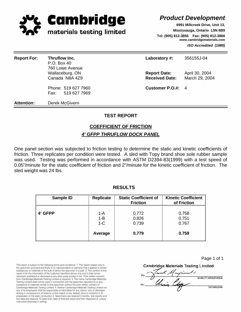
4’ GFPP THRUFLOW DOCK PANEL One panel section was subjected to friction testing to determine the static and kinetic coefficients of friction. Three replicates per condition were tested. A sled with Topy brand shoe sole rubber sample was used. Testing was performed in accordance with ASTM D2394-83(1999) with a test speed of 0.05”/minute for the static coefficient of friction and 2”/minute for the kinetic coefficient of friction. The sled weight was 24 lbs.
RESULTS
Sample ID Replicate Static Coefficient of Friction
Kinetic Coefficient of Friction
4’ GFPP
1-A 1-B 1-C
Average
0.772 0.826 0.739
0.779
0.758 0.751 0.767
0.759
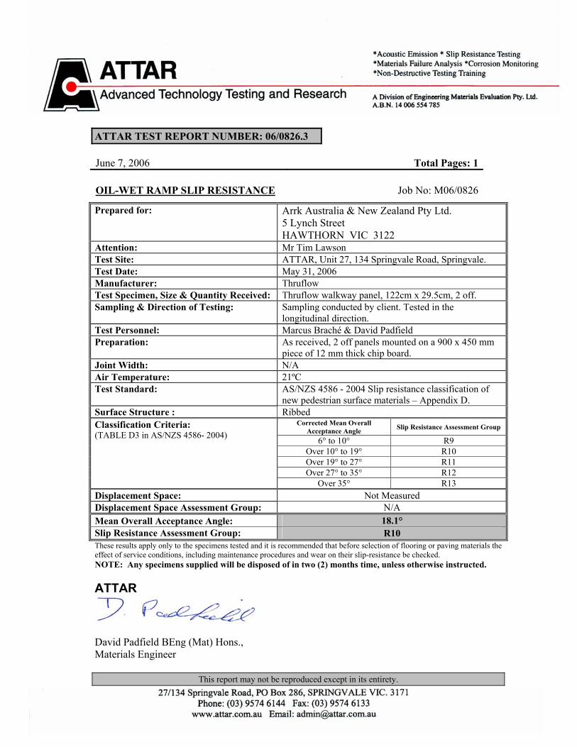
ATTAR TEST REPORT NUMBER: 06/0826.3 June 7, 2006 Total Pages: 1
This report may not be reproduced except in its entirety.
OIL-WET RAMP SLIP RESISTANCE Job No: M06/0826
Prepared for:
Arrk Australia & New Zealand Pty Ltd. 5 Lynch Street HAWTHORN VIC 3122
Attention: Mr Tim Lawson Test Site: ATTAR, Unit 27, 134 Springvale Road, Springvale. Test Date: May 31, 2006 Manufacturer: Thruflow Test Specimen, Size & Quantity Received: Thruflow walkway panel, 122cm x 29.5cm, 2 off. Sampling & Direction of Testing: Sampling conducted by client. Tested in the
longitudinal direction. Test Personnel: Marcus Braché & David Padfield Preparation: As received, 2 off panels mounted on a 900 x 450 mm
piece of 12 mm thick chip board. Joint Width: N/A Air Temperature: 21ºC Test Standard:
AS/NZS 4586 - 2004 Slip resistance classification of new pedestrian surface materials – Appendix D.
Surface Structure : Ribbed Corrected Mean Overall
Acceptance Angle Slip Resistance Assessment Group 6° to 10° R9
Over 10° to 19° R10 Over 19° to 27° R11 Over 27° to 35° R12
Classification Criteria: (TABLE D3 in AS/NZS 4586- 2004)
Over 35° R13 Displacement Space: Not Measured Displacement Space Assessment Group: N/A Mean Overall Acceptance Angle: 18.1° Slip Resistance Assessment Group: R10 These results apply only to the specimens tested and it is recommended that before selection of flooring or paving materials the effect of service conditions, including maintenance procedures and wear on their slip-resistance be checked. NOTE: Any specimens supplied will be disposed of in two (2) months time, unless otherwise instructed. ATTAR
David Padfield BEng (Mat) Hons., Materials Engineer
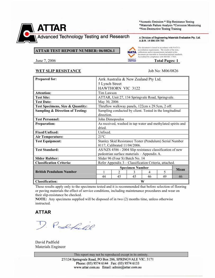
ATTAR TEST REPORT NUMBER: 06/0826.1 June 7, 2006 Total Pages: 1
This report may not be reproduced except in its entirety. 1
This document is issued in accordance with NATA’s accreditation requirements. The results of the tests, calibrations and/or measurements included in this document are traceable to Australian/national standards. Accredited for compliance with ISO/IEC 17025.
WET SLIP RESISTANCE Job No: M06/0826
Prepared for:
Arrk Australia & New Zealand Pty Ltd. 5 Lynch Street HAWTHORN VIC 3122
Attention: Tim Lawson Test Site: ATTAR, Unit 27, 134 Springvale Road, Springvale. Test Date: May 30, 2006 Test Specimens, Size & Quantity: Thruflow walkway panels, 122cm x 29.5cm, 2 off. Sampling & Direction of Testing: Sampling conducted by client. Tested in the longitudinal
direction. Test Personnel: John Dimopoulos Preparation: As received, washed in tap water and methylated spirits and
dried. Fixed/Unfixed: Unfixed. Air Temperature: 21ºC Test Equipment: Stanley Skid Resistance Tester (Pendulum) Serial Number
8117, Calibrated 11/04/2006. Test Standard:
AS/NZS 4586 - 2004 Slip resistance classification of new pedestrian surface materials – Appendix A.
Slider Rubber: Slider 96 (Four S) Batch No. 14 Classification Criteria: Refer Appendix 3 – Classification Criteria, attached.
Specimen Number 1 2 3 4 5
Mean British Pendulum Number 44 45 45 46 49 46
Classification: W These results apply only to the specimens tested and it is recommended that before selection of flooring or paving materials the effect of service conditions, including maintenance procedures and wear on their slip-resistance be checked. NOTE: Any specimens supplied will be disposed of in two (2) months time, unless otherwise instructed. ATTAR
David Padfield Materials Engineer
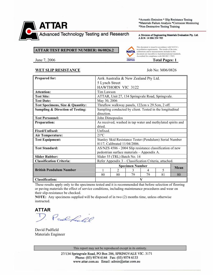
ATTAR TEST REPORT NUMBER: 06/0826.2 June 7, 2006 Total Pages: 1
This report may not be reproduced except in its entirety. 1
This document is issued in accordance with NATA’s accreditation requirements. The results of the tests, calibrations and/or measurements included in this document are traceable to Australian/national standards. Accredited for compliance with ISO/IEC 17025.
WET SLIP RESISTANCE Job No: M06/0826
Prepared for:
Arrk Australia & New Zealand Pty Ltd. 5 Lynch Street HAWTHORN VIC 3122
Attention: Tim Lawson Test Site: ATTAR, Unit 27, 134 Springvale Road, Springvale. Test Date: May 30, 2006 Test Specimens, Size & Quantity: Thruflow walkway panels, 122cm x 29.5cm, 2 off. Sampling & Direction of Testing: Sampling conducted by client. Tested in the longitudinal
direction. Test Personnel: John Dimopoulos Preparation: As received, washed in tap water and methylated spirits and
dried. Fixed/Unfixed: Unfixed. Air Temperature: 21ºC Test Equipment: Stanley Skid Resistance Tester (Pendulum) Serial Number
8117, Calibrated 11/04/2006. Test Standard:
AS/NZS 4586 - 2004 Slip resistance classification of new pedestrian surface materials – Appendix A.
Slider Rubber: Slider 55 (TRL) Batch No. 14 Classification Criteria: Refer Appendix 3 – Classification Criteria, attached.
Specimen Number 1 2 3 4 5
Mean British Pendulum Number 80 80 79 79 81 80
Classification: V These results apply only to the specimens tested and it is recommended that before selection of flooring or paving materials the effect of service conditions, including maintenance procedures and wear on their slip-resistance be checked. NOTE: Any specimens supplied will be disposed of in two (2) months time, unless otherwise instructed. ATTAR
David Padfield Materials Engineer
Related Documents