TECHNICAL REPORT BRL-TR-2992 BRL IMPROVED ACCURACY AND COLLIMATION PROCEDURES OF THE M-26/27 MUZZLE BORESIGHT DEVICE CPT CURTIS L. McCOY SFC MICHAEL R. WOMER Sr. LAWSON F. NARVELL __ w BRUCE E. AMREIN DTIC ELECTE MAY 1989 $ MAY 02LCj0 APPROVED FOR PUBLIC RELEASE, DISTRIBUTION UNLIMITED. U.S. ARMY LABORATORY COMMAND BALLISTIC RESEARCH LABORATORY ABERDEEN PROVING GROUND, MARYLAND 089 5 02 042

Welcome message from author
This document is posted to help you gain knowledge. Please leave a comment to let me know what you think about it! Share it to your friends and learn new things together.
Transcript

TECHNICAL REPORT BRL-TR-2992
BRLIMPROVED ACCURACY AND COLLIMATION
PROCEDURES OF THE M-26/27MUZZLE BORESIGHT DEVICE
CPT CURTIS L. McCOYSFC MICHAEL R. WOMER Sr.
LAWSON F. NARVELL __ wBRUCE E. AMREIN DTIC
ELECTE
MAY 1989 $ MAY 02LCj0
APPROVED FOR PUBLIC RELEASE, DISTRIBUTION UNLIMITED.
U.S. ARMY LABORATORY COMMAND
BALLISTIC RESEARCH LABORATORYABERDEEN PROVING GROUND, MARYLAND
089 5 02 042

DESTRUCTION NOTICE
Destroy this report when it is no longer needed. DO NOT return it to theoriginator.
Additional copies of this report may be obtained fran the National TechnicalInformation Service, U.S. Department of Cammerce, Springfield, VA 22161.
The findings of this report are not to be construed as an official Departntof the Army position, unless so designated by other authorized doc..nents.
The use of trade names or manufacturers' names in this report does not con-stitute Lndorsernent of any camercial product.
UNCLASSIFIEDSECURITY CLASSIFICATION OF Ttm S PAGE
REPORT DOCUMENTATION PAGE Form Approved
I0MB No. 0704.0158Ia. REPORT SECURITY CLASSiFiCATION lb RESTRICTIVE MARKINGS
UNCLASSIFIED2a. SECURITY CLASSIFICATION AUTHORIT'y 3 DISTRIBUTION /AVAILABILITY OF REPORT
2 _ _ __ _ __EC_ __ _ __ _ __SS_ __ _ _ Approved for public release; distributionZb. DECLASSIFICATION I/DOWNGRADING SCHEDULE is unlimited.
4- PERFORMING ORGANIZATION REPORT NUMBER(S) 5. MONITORING ORGANIZATION REPORT NUMBER(S)
BRL-TR-2992
6a. NAME OF PERFORMING ORGANIZATION 6b, OFFICE SYMBOL 7a. NAME OF MONITORING ORGANIZATION
US Army Ballistic Research (if applicable)Laboratory ISLCBR-DD-T _______________________
6c. ADDRESS (City, State, and ZIP Code) 7b. ADDRESS (City, State, and ZIP Code)
Aberdeen Proving Ground, MD 21005-5066&a. NAME OF FUNDING i SPONSORiNG B b OFFICE SYMBOL 9 PROCUREMENT INSTRUMENT IDENTIFICATION NUMBER
ORGANIZATION (if applicable)
8c. ADDRESS (City, State, and ZIP Code) 10 SOURCE OF FUNDING NUMBERSPROGRAM PROJECT TASK WORK UNITELEMENT NO. NO. 1Ll626 NO. ACCESSION NO.
________________________________62618A 18AH80 00 001AJ
11. TITLE (include Security ClassificatIon)
Improved Accuracy and Collimation Procedures for the M-26/27 Muzzle Boresight Defice12. PERSONAL AUTHOR(S) McCoy, Curtis L. CPT; Womer, Michael R. Sr. MSG; Narvell, Lawson F. (HEL);
Anirein, Bruce E. (HEL)13.. TYPE OF REPORT 13b TIME COVERED eb814. DATE OF REPORT (Year, Month, Day) 15. PAGE COUNT
Final IFROM Feb87 ;.TO Fb8 February 1989 3416. SUPPLEMENTARY NOTATION
17. COSATi CODES l e SUBJECT TERMS (Continue on reverse if necessary and identify by block number)FIELD GROUP SUB-GROUP CAT, Standard Army "G" Pattern, Gunners Primary Sight COPS),
19 03 Muzzle Boresight Device (MBD), Optical Reticle Wedge,
19 04 1Collar Wrench, Tank Gun Accuracy, Boresighting, (Cont'd)19. ABSTRACT (Continue on reverse if necessary and identify by block number)
During normal use the M-26/27 muzzle boresight device is a very accurate device forboresighting tank cannons. This report proposes technical improvements to the tool usedfor the collimation of the M-26/27 muzzle boresight device (MBD). In addition, thisreport makes recommendations to improve present allowable tolerances in these MBDs andsuggests a field expedient method of correcting MBDs which exceed tolerances under fieldconditions. ,!L yi~ ~ '') I II -1 - .*, , t
20. DISTRIBUTION /AVAILABILITY OF ABSTRACT 21 ABSTRACT SECURITY CLASSIFICATIONQIUNCLASSIFIEO/UNLiMITED M SAME AS RPT. 0 OTIC USERS UNCLASSIFIED
22a. NAME OF RESPONSIBLE INDIVIDUAL 22b TELEPHONE (include Area Code) 22c. OFFICE SYMBOLCPT McCoy/MSG Warner 301-278-6648 SLCBR-SE-B
DD Form 1473. JUN 86 Previous editions are Obsolete. SECURITY CLASSIFICATION OF THIS PAGE
UNCLASSIFIED

18. Subject Terms (Cont'd)
M468 cannon, 11256 cannon
2
ACKNOWLEDGEMENTS
The authors would like to thank the following people and organizations for their ideasand assistance. Without their help this work could not have been done.
SFC Edward A.H. Braese of Company A 2nd Battalion 64th Armor for suggesting that weaddress the problem of modifying the tools.
SFC James E. Dale of the United States Army Armor School, Weapons Department fortechnical assistance in formalizing the procedures for collimation of the muzzle boresightdevice.
The metal workers of the US Army Ballistic Research Laboratory, Experimental FabricationDivision for procuring the necessary stock and fabrication of the test tools.
Accession For
NTIS GRA&IDTIC TABUnannounced 0Justifloation
Distribut ion/
Avallebility 00ods
Dist Spools1
The following page is blank.
3

TABLE OF CONTENTS
Page
ACKNOW LEDGEM ENTS ................................................................................................................. 3
TABLE OF CONTENT'S................................................................................. 5
LIST O F FIG U R E S .............................................................................................................................. 7
I. THE PROBLEM AND ITS BACKGROUND ...................................................................... 9
II. O BJE CT IV E .................................................................................................................................... 10
III. DESIGN AND MANUFACTURE OF THE IMPROVED TOOLS .............................. 10
IV. FIELD EXPEDIENT PROCEDURES FOR COLLIMATION/ALIGNMENTOF THE M-26/27 MUZZLE BORESIGHT DEVICE ..................................................... 10
V. BORESIGHT DEVICE ERROR .......................................................................................... 17
VI. OBSERVATIONS AND CONCLUSIONS ........................................................................ 17
VII. RECOM M ENDATIONS ..................................................................................................... 24
R E FE R E N C E S ...................................................................................................................................... 25
APPENDIX A - THE FIELD EXPEDIENT METHOD OF ALIGNMENT/COLLIMATION OF THE M-26/27 MUZZLE BORESIGHTDEVICE ON THE M1/M1A1 MAIN BATILE TANK ........................................... 27
D ISTR IBU TIO N LIST ......................................................................................................................... 33
The following page is blank.
5

LIST OF FIGURES
Page
1. Engineering Drawings of Original MBD Tool ............................................. 11
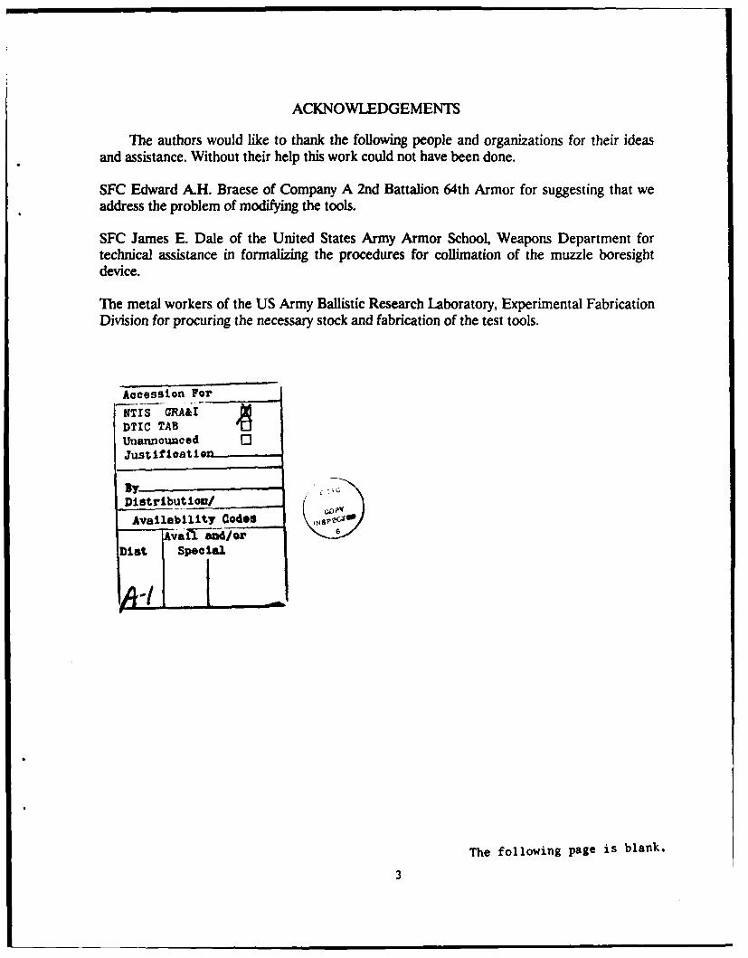
2. Retainer/Sealer Plugs/Adjusting Screw andAssociated Parts ................................................................................. 12
3. Optical Unit and Related Parts ............................................................... 13
4. Engineering Drawings of Improved MBD Tools........................................... 14-16
5. Predicted Impact at 900m; M490 TP-T ...................................................... 18
6. Predicted Impact at 1200m; M490 TP-T..................................................... 19
7. Predicted Impact at 1500m; M490 TP-T..................................................... 20
8. Predicted Impact at 900m; M724 TPDS-T ................................................. 21
9. Predicted Impact at 1200m; M724 TPDS-T................................................. 22
10. Predicted Impact at 1500m; M724 TPDS-T................................................ 23
A-1. Reticle Movement In MBD................................................................ 31
The following page is blank.
7

AN INVESTIGATION INTO THE ACCURACY AND COLLIMATION PROCEDURESOF THE M-26/27 MUZZLE BORESIGHT DEVICE
1. THE PROBLEM AND ITS BACKGROUND
The accuracy of tank cannons has long been considered extremely important to a crew'ssurvivability on the modern battlefield. One of the integral components of a crew's tank gunaccuracy is their ability to accurately align the cannon's center of bore with the optics of thefire control system (boresight).
The United States Army has two doctrinal methods of boresighting tank cannons. Theprimary method requires the use of the M-26/27 Muzzle Boresight Device (MBD). Thealternate is known as the "two-point method" which requires thread, tape, and a pair of bino-culars. The two-point method is used only when a MBD is not available or the MBD can notbe used because of excessive gun tube wear.
In November 1986, the Science Advisor to the Commander in Chief, US Army Europe(USAREUR) and the 7th Army, requested the US Army Ballistic Research Laboratory(BRL), Aberdeen Proving Ground (APG), MD, to present possible enhancements to tankgun accuracy available to support the Canadian Army Trophy (CAT) Teams of the US Army.During the presentations in Germany to the CAT 87 teams it was brought to BRL's attentionby SFC Edward Braese, Master Gunner for Company A, 2nd Battalion, 64th Armor, thatthere was a need to improve the current tools required to collimate the M26/27 MBD andthat the allowable tolerance for the MBD excessive. After discussion with the Science Advi-sor, it was agreed that the BRL would look for a solution to the problem.
The MBD can be collimated to an error of 0.15 mil, but a problem arises on how toachieve this level of accuracy under field conditions. The Department of the Army (DA)Field Manual 17-12-1 and DA Field Circular 17-12-1Al allow the device to have 1.0 mil oferror in elevation and 0.50 mil of error in deflection. According to the MBD operator'smanual (TM 9-4933-249-24&P) as well as the Ml and M1A1 Abrams operator's manual(TM9-2350-255-10 and TM 9-3908-4312-10) for the tank, there is no allowance for any error.Both of the above technical manuals simply state that upon rotating the MBD 180 degreesthe aiming dot must remain on the same aiming point. If not, then the MBD is to be turnedin to organizational maintenance. The organizational maintenance manual (TM 9-4933-249-24&P) states that there can be up to 1.0 mil of tolerance in both elevation and deflection.
Under current maintenance repair procedures, the device must be evacuated throughdirect support maintenance to general support maintenance for collimation and alignment ifit exceeds established tolerances. The ensuing delay is extremely time consuming and cancost training time. Even after repair/realignment, there is a possibility that the M-26/27could return with a large amount of error just under the tolerance windows because of thetools used to adjust the aiming dot of the MBD.
The tools required for the actual adjustment of the optical wedge in the MBD requireimprovement to consistently obtain the 0.15 mil accuracy. The actual tools required for align-ment are a collar/spanner wrench and a 5/32 hex wrench (Figure 1). The MBD is designed
9

with the retainer plug concentric about the adjusting screws (Figure 2) used to adjust the opt-ical wedge of the MBD (Figure 3). Since the adjusting screws are not held in position whiletightening the retainer plugs, the adjusting screws are able to move, and error is induced.Given the proper tools this procedure can be done more efficiently and expeditiously.
II. OBJECTIVE
The objectives of this effort were first, to improve the tools necessary for collimation ofthe M-26/27 MBD; second, to demonstrate to the user that the amount of allowable error inboresight devices was excessive and suggest recommendations for improvement; and last, toformalize and submit for approval a field expedient method of collimating MBDs.
III. DESIGN AND MANUFACTURE OF THE IMPROVED TOOLS
After a careful look at the tools in use, it was determined that the current tools could beslightly modified to provide the desired results. The modification required drilling a hole13/64 inch in diameter through the collar/spanner wrench and the manufacturing of a handletype assembly with a 5/32 inc 1 hex wrench end attached to it. Figure 4 shows the engineeringdrawings that were prepared. The results of this effort provided a pair of tools that couldachieve the maximum acceptable error, 0.15 mil, when collimating the MBD.
IV. FIELD EXPEDIENT PROCEDURES FOR COLLIMATION/ALIGNMENTOF THE M-26/27 MUZZLE BORESIGHT DEVICE
The U.S. Army's goal is to issue a MBD per tank in the inventory. Most USAREURunits have achieved the Army's goal of one MBD per tank. It became clear that a fieldexpedient method for collimation and alignment of the MBD was being used by US troops inGermany, although the procedure had never been formalized. Since the method is very use-ful, we have developed a description of the procedure and coordinated with the proponent,the Weapons Dtepartment, US Army Armor Center and School. This description is includedat Appendix A.
The procedure enables a tank crew to fine tune a MBD in an existing tube without send-ing the device to maintenance for repair. The process of MBD collimation at the operatorlevel was demonstrated very successfully during CAT 87.
1 Rough sketches were prepared by MSG Michael R?. Womer Sr, US Army Ballistic ResearchLaborato.y, and engneering drawings were prepared by Mr. Lawson . Narveli, HumanEngineenng Laboratory.
2 Point of contatfor boresighting and muzzle boresighting device was SFC James E. Dale, USArmy Armor Sctool, Fort Xnox, Ky.
10

. .7- DI.. '
Standard Locking Tool
Standard 5/32 Allen Wrench
Figure 1. Engineering Drawings of Original MBD Tools
11.
Item DescriptionAdjusting Screw
2 Plug. Retaining3 Plug Sealing
Figure 2. Retainer/Sealer Plugs/Adjusting Screw and Associated Parts
12

2
1 A
Item Description
I Prism, Optical Wedge Reticle2 Prism, Optical Instrument
Figure 3. Optical Unit and Related Parts
13

Adjusting Tool
.as.K P% I. - ... ..-
Locking Tool
Figure 4. Engineering Drawings of Improved MBD Tools
14

1/16 Dia. Drill Rod X 1/4 Lg./" Silver Solder
RAD
15-16IrSilver Solder .340 t .00215/16 9 to
r '46 -.01 1
1/4 Ref 1/6 1 - 13/64 Dia. Thru
12
2 3/8
Locking Tool
Matl. Steel FS-4130 or 4140Provide Carburized Finish
Figure 4a. Engineering Drawings of Improved MBD Tools
15

Course Knurl
Silver Solder - Silver Solder 3/4 Dia.Break Edge Typ. 3/16 /i / 1 S
f 3/16Dia. zz~L. Standardj~~
-.4 /j6 Hex Stock f1'(approx)
2
5
Adjusting ToolMail. Steel FS-4130 or 4140
Provide Carburized Finish
Figure 4b. Engineering Drawings of Improved MBD Tools
16

V. EFFECTS OF BORESIGHT DEVICE ERRORON TANK GUN ACCURACY
It is essential that the allowable tolerance in MBDs be reduced to more acceptable lev-els. Currently, the amount of tolerance is up to 1.0 mil in elevation and 0.50 mil in deflection.These values are in accordance with DA Field Manual 17-12-1 and DA Field Circular 17-12-Al. There are other publications which allow for even greater tolerances; however, the pre-
viously stated publications are the primary references used by Armor units in the Army today.
During the actual boresight procedure one must rotate the MBD 180 degrees to deter-mine its accuracy in locating the exact center of bore of the gun tube. If after rotating theMBD 180 degrees, its aiming dot does not exactly realign with the original aiming point, thedifference must be divided by two to determine the mean boresight readings (actual center ofbore). The greater the difference between the first boresight reading and the second, thegreater the opportunity for crew error in applying a correct boresight to their fire control sys-tem. The ability of a crew to accurately collimate a M26/27 MBD to their specific tank,would enhance the crew's confidence that their tank will be able to hit targets through a moreaccurately boresighted fire control system.
If the maximum errors stated above actually existed, then one would induce 1/2 ofthose errors into the fire control system by splitting the differences as directed in theboresighting procedures. This error could be eliminated by performing an independent zeroof the gun. However, it is policy that individual zero exercises are not conducted. Instead,the gun is fired from the boresight with a common computer correction factor for a specifictype of ammunition. This procedure does not allow for an error in the strike of the roundfrom the aimpoint as a result of different gun tube characteristics or fire control errorsinduced as a result of a faulty MBD.
Assuming all other error sources were corrected, the effects of a faulty MBD can beexamined. The results of a .5 mil (elevation) by .25 mU (deflection) MBD error induced dur-ing boresighting procedures on M490 TP-T ammunition are depicted in Figures 5-7. Therange is varied from 900 meters to 1500 meters to demonstrate the increasing effect at thegreater ranges. The same conditions and ranges were examined for M724 TPDS-T ammuni-tion (Figures 8-10). The plots clearly show the M1 fire control system cannot hit its desiredaim point because of the error induced by the MBD. When the MBD error is coupled with allother error sources, the tank fire control system Ph is lowered.
VI. OBSERVATIONS AND CONCLUSIONS
This effort has been a quick reaction to provide the soldiers in the field with an alterna-tive to accurately align MBDs when boresighting a tank cannon. If a MBD is out of toler-ance, the Ph of the tank main gun ammunition is greatly reduced. The purpose of theboresighting is to accurately calibrate a main gun.
17

105mm M490 TP-TRange = 900 meters
1.25
V)_ 1.00
a) 0.75E
1 0.50(
- 0.25U
Q_ 0.00 0
- -0.25
-0.50(U
-0.75-
-1.25 "
HORIZONTAL IMPACT - meters
Figure S. Predicted Impact at 900m; M490 TP-T.
18

105mm M490 TP-TRange = 1200 meters
1.25
(nL- 1.00-
V 0.75-
0.50-
t 0.25-
U ---0.25-
-0.5-
I-- - 0.75-
uJ-1.00-
-1.25 n "" ' 1' ° .0 , o ° 1.0 0 o 0. . 0o . , ' O ,S oo~ -0 , . .000S 0 /* 20?
HORIZONTAL IMPACT - meters
Figure 6. Predicted Imvact at 1200m: M490 TP-T.
19
105mm M490 TP-TRange = 1500 meters
1.25-U.)_ 1.00-
a~ 0.75-E0.50-
F- 0.25-
-0.25--J
-0.50-U
F- -0.75-crLU -1.00
-1.25 , ,-, ',oO 'o "'o 0o 0o 0o 0o {7~.0 ,0 00 0~0 ~ 0 ~S*o,,
HORIZONTAL IMPACT - meters
Figure 7. Predicted Impact at 1500m; M490 TP-T.
20

105mm M724 TPDS-T(using M392A2 solution)
Ronge = 900 meters1.25
V)L. 1.00
0 0.75-E0.50-
- 0.25-U
D_ 0.00-
- 0.25-
-0.50U-- -0.75
LL> -1.00
-1.25 ,", ;,o 0 oO -10 0 O , 0o 0, oHORIZONTAL'IMPCT - meters
Figure 8. Predicted Impact at 900m; M724 TPDS-T.
21

105mm M724 TPDS-T(using M392A2 solution)
Range = 1200 meters1.25
. 1.00
W 0.75E0 50
- 0.25U
0 0a- 0.00
- -0.25._J
-0.50UI -0.75-
LU..J -1.00
- 1.25,
S 1. 0~ "0 0 . s 03 - 5> 0 0o >HORIZONTALIMPACT - meters
Figure 9. Predicted Impact at 1200m; M724 TPDS-T.
22

105mm M724 TPDS-T(using M392A2 solution)
Range = 1500 meters1.25 -
L. 1.00U,
V, 0.75 0
0.50
- 0.25Ua. *OO
-0.25--J
-0.50-U
H-0.75 0
LLI> -1.00-
- 1.25 . 5 , I . i
0 0o 0 000 7 7o" -0 SO "0 " 0 0 "' S'
HORIZON 1AL IMPA8 T - meters
Figure 10. Predicted Impact at 1S00m; M724 TPDS-T.
23

VII. RECOMMENDATIONS
The authors make the following recommendations:
* That the Army review and accept the new configuration of these tools.
" That the Army review the field expedient procedures for alignment/collimation of the M-26/27 muzzle boresight and adopt a policy for its use under special conditions.
* That the Army review the amount of acceptable tolerance in the M-26/27 MBD and reducethose tolerances accordingly.
24

REFERENCES
FM 17-12-1, Tank Combat Tables M- 1, 3 Nov 86.FM17-12-1A1, Tank Combat Tables M-1A1, 30 Apr 86.TM9-4933-249-24&P, M-26 Boresight w/case, 9 Jul 85.TM9-3908-4312-10, M-26 Muzzle Boresight, 13 Dec 82.TM9-2350-264-10-2, Tank Combat FT 120mm M1A1, 30 Dec 85.TM9-2350-255-10-2, Tank Combat FT 105mm M1, 30 Nov 81.
The following page is blank.
25

APPENDIX A
THE FIELD EXPEDIENT METHOD OF ALIGNMENT/COLLIMATION OF THEM-26/27 MUZZLE BORESIGHT DEVICE ON THE M1/M1A1 MAIN BATTLE TANK
MSG MICHAEL R. WOMER SR.US ARMY BALLISTIC RESEARCH LABORATORY
SFC JAMES E. DALEUS ARMY ARMOR SCHOOL
The following page is blank.
27

APPENDIX A
THE FIELD EXPEDIENT METHOD OF ALIGNMENT/COLLIMATION OF ThEM-26/27 MUZZLE BORESIGHT DEVICE ON THE M1/M1A1 MAIN BATTLE TANK
1. Purpose: To fine tune the MBD to a specific gun tube or align the device without the sup-port of intermediate general support maintenance.
2. Procedure:
a. Position the vehicle on level ground.
b. Prepare the gunners station for operation lAW TM9-2350-264-10-2 (see page 2-194through 2-222).
c. Select a boresight target as close to 1200 meters away as possible. Target should beplaced so the main gun is over the front of the tank when it is aligned with target.
d. Make sure that gunner's hydraulic pressure gage shows 1500 to 1700 psi.
e. Set GUN SELECT switch to MAIN.
f. Set MAGNIFICATION lever to 1OX.
g. Make sure FILTER/CLEAR/SHUTTER switch is set to CLEAR.
h. Make sure DAY ballistic door is open.
i. Set FIRE CONTROL MODE switch to EMERGENCY.
j. Using the gunner's power control handles, look in gunner's primary sight (GPS) eye-piece, lay reticle aiming circle on center of target, and lase to the target.
k. Set FIRE CONTROL MODE switch to MANUAL
I. Remove muzzle plug from main gun.
m. Remove protective cover from MBD. (Note: Two individuals required).
n. Remove the two sealing plugs in order to expose the retaining plugs and the adjustingshoulder screws.
o. Insert the MBD into the end of the gun tube. The locating pad assembly should be atthe 12 o'clock position.
29

p. With the master gunner looking through the MBD and giving directions, the gunnerwill use manual controls to lay the aimpoint of the MBD to the upper left hand corner of theboresight target. The standard US Army "G" Pattern (method used to manipulate gun con-trols) will be used. This becomes the starting point.
q. Rotate the MBD to the 6 o'clock position. If the aiming dot has moved away morethan 1/3 the width of the dot, the device is out of alignment.
(Note: Rotating the MBD while still in the main gun may result in damage to the deviceand or the main gun. Remove the MBD from the gun barrel for rotating.)
r. To adjust, slightly loosen the retainer plugs that secure the optical wedge shoulderscrews.
s. Utilizing the 5/32 hex wrench, adjust the aiming dot 1/2 the distance between theaiming points in step p and q above by turning the optical wedge adjusting screws.
(Note: The reticle in the MBD does not move left to right or up and down as normalsight reticles, but in a curve as shown in Figure A-1. It should also be noted that the adjustingscrews do not have a mechanical stop.)
t. Repeat steps p through s as many times as necessary in order to align the device towithin .15 mil.
(Note: If after several attempts to align the device the aiming dot is still off, gun tubewear (muzzle bell) may be present.
u. After alignment is complete use the improved tool set to hold the adjusting screw inplace and tighten the retainer plugs. Make sure that the aiming dot does not move duringthis step.
v. Replace the sealing plug.
w. Replace the protective cover.
x. The device is now aligned for the specific gun in which it was adjusted. If used inanother gun, check the alignment and adjust as needed.
30

The following page is blank.
Figure A-I. Reticle Movement in MBD.
31
DISTRIBUTION LIST
No. of No. ofCopies Organization Copies Organization
12 Administrator 1 CommanderDefense Technical Info Center US Army Aviation Systems CommandATTN: DTIC-DDA ATTN: AMSAV-DACLCameron Station 4300 Goodfellow Blvd.Alexandria, VA 22305-6145 St. Louis, MO 63120-1798
HQDA (SARD-TR) 1 DirectorWashington, DC 20310-0001 US Army Aviation Research
and Technology ActivityCommander Ames Research CenterUS Army Materiel Command Moffett Field, CA 94035-1099ATTN: AMCDRA-ST5001 Eisenhower AvenueAlexandria, VA 22333-0001
CommanderUS Army Laboratory CommandATTN: AMSLC-DLAdelphi, MD 20783-1145 Commander
US Army Missile CommandCommander ATTN: AMSMI-ASArmament R&D CenterUS Army AMCCOM Redstone Arsenal, AL 35898-5000ATTN: SMCAR-MSIPicatinny Arsenal, NJ 07806-5000 1 Commander
US Army Tank Automotive CommandCommander ATTN: AMSTA-TSLArmament R&D Center Warren, MI 48090-5000US Army AMCCOMATTN: SMCAR-TDC 1 DirectorPicatinny Arsenal, NJ 07806-5000 US Army TRADOC Analysis Command
ATTN: ATAA-SLDirector White Sands Missile Range, NMBenet Weapons Laboratory 88002Armament R&D CenterUS Army AMCCOM 1 CommandantATTN: SMCAR-LCB-TL US Army Infantry SchoolWatervliet, NY 12189-4050 ATTN: ATSH-CD-CSO-OR
Fort Benning, GA 31905CommanderUS Army Armament, Munitions 1 AFWL/SUL
and Chemical Command Kirtland AFB, NM 87177ATTN: SMCAR-ESP-LRock Island, IL 61299-5000 1 Air Force Armament Laboratory
ATTN: AFATL/DLODLEglin AFB, FL 32542-5000
33

DISTRIBUTION LIST (Cont'd)
No ofCopies Organization
1 CommanderFORSCOMATTN: AFCC-CGFort McPherson, GA 30330-6000
1 CommanderUS Army Combined Arms CenterATTN: ATZL-CGFort Leavenworth, KS 66048
1 CommanderUS Army Logistic CenterATTN: ATCL-CGFort Lee, VA 23801
1 CommanderIII CorpsATTN: AFZF-CGFort Hood, TX 76544
3 CommandantUS Army Armor SchoolATTN: ATZK-CG
ATSB-CD-ML (Mr. Montgomery)(2 cys)
Fort Knox, KY 40121
3 CINCUSAREURATTN: AEAGC-CG
AEAGX-SA (Mr. Eckles)(2 cys)
APO, NY 09403
Aberdeen Proving GroundDir, USAMSAA
ATTN: AMXSY-DAMXSY-MP, H. Cohen
AMXSY-LBDAR (Mr. Fox)
(Mr. Astor)Cdr, USATECOM
ATTN: AMSTE-TO-F
Cdr, CRDC, AMCCOMATTN: SMCCR-RSP-A
SMCCR-MUSMCCR-SPS-IL
Dir, HELATTN: SLCHE-SS-ED (5 cys)
Cdr, USAOC&SATTN: ATSE-CG (Mr. Senn)
ATSL-DTM-WS (2 cys)
34

USER EVALUATION SHEET/CHANGE OF ADDRESS
This laboratory undertakes a continuing effort to improve the quality of the reports it publishes. Yourcomments/answers below will aid us in our efforts.
1. Does tt.'s report satisfy a need? (Comment on purpose, related project, or other area of interest for whichthe rec:: will be used.)
2. How, spec.ifcally, is the report being used? (Information source, design data, procedure, source of ideas,etc.)
3. Has the information in this report led to any quantitative savings as far as man-hours or dollars saved,operating costs avoided, or efficiencies achieved, etc? If so, please elaborate.
4. Genera: Connents. What do you think should be changed to improve future reports? (Indicate changes toorga-zzat:on, technical content, format, etc.)
BRL .eport Number Division Symbol
Check here if desire to be removed from distribution list.
Check here for address change.
Current address: Organization
Address
-- --------- --------- FOLD AND TAPE CLOSED---------------------------
Director NECESSARYU.S. Army Ballistic Research Laboratory OF MAILEN• IN THE
ATTN: SLCBR-DD-T (NEI) UNITED STATESAberdeen Proving Ground, MD 21005-5066OFF ICIAL BUSINESS
PENAYOPP USE 300 BUSINESS REPLY LABELFIRST CLASS PERMIT NO, 17062 WASHINGTON D.C.
POSTAGE WILL IE PAID IY DEPARIMENT Of THE ARMY
DirectorU.S. Army Ballistic Research LaboratoryATTN: SLCBR-DD-T (NEI)Aberdeen Proving Ground, MD 21005-9989
Related Documents