Technical Memorandum Lincoln Avenue Water Company (LAWC) Treatment System National Aeronautics and Space Administration, Jet Propulsion Laboratory, Pasadena, California Final April 27, 2007 This technical memorandum documents the performance of the groundwater treatment system implemented at the Lincoln Avenue Water Company (LAWC) through February 2007. The treatment system was implemented as a removal action as part of the Comprehensive Environmental Response, Compensation, and Liability Act (CERCLA) Program at the National Aeronautics and Space Administration (NASA) Jet Propulsion Laboratory (JPL). The Action Memorandum for this removal action was signed on August 23, 2004 1 . Table 1 is an overview of the system operations to date, which began on July 28, 2004. Table 1. LAWC System Operational Summary (August 2004 through February 2007) Parameter Units LAWC #3 LAWC #5 Total Total Volume of Groundwater Extracted Acre-ft 3,398 2,341 5739 Mass of Perchlorate Removed lbs 220 41 261 Mass of Carbon Tetrachloride (CCl4) Removed lbs 25.1 4 29.1 Mass of Trichloroethene (TCE) Removed lbs 27.1 27 54.1 BACKGROUND Liquid wastes generated at JPL in the 1940s and 1950s (such as cleaning solvents, solid and liquid rocket propellants, cooling tower chemicals, and analytical laboratory chemicals) were disposed of in seepage pits, a then common and acceptable practice. Some of these wastes contained chemicals (e.g., perchlorate and chlorinated solvents containing volatile organic compounds [VOCs]) that have been found in groundwater beneath and adjacent to JPL, including groundwater extracted from two drinking water wells operated by LAWC (LAWC# 3 and LAWC# 5). Figure 1 is a location map showing JPL and the LAWC production wells. In 1981, VOCs were first detected in LAWC#3 and LAWC# 5. By 1984, VOC concentrations were increasing and both wells were shut down. With NASA funding, LAWC installed a VOC treatment facility for the wells in the early 1990s. NASA funded the ongoing operations of the plant as well. The existing VOC treatment facility consists of four 12-ft-diameter treatment vessels (Calgon Carbon Model 12 Adsorption Systems), each containing 20,000 lb of liquid-phase granular activated carbon (LGAC). The LGAC treatment facility was operated under an Operations Plan approved by the California Department of Health Services (DHS) (revised September 2002). 1 NASA. 2004. Action Memorandum for the Lincoln Avenue Water Company (LAWC), Altadena, California Associated with Groundwater Cleanup at the National Aeronautics and Space Administration, Jet Propulsion Laboratory, Pasadena, California. August.

Welcome message from author
This document is posted to help you gain knowledge. Please leave a comment to let me know what you think about it! Share it to your friends and learn new things together.
Transcript
Technical Memorandum Lincoln Avenue Water Company (LAWC) Treatment System National Aeronautics and Space Administration, Jet Propulsion Laboratory, Pasadena, California
Final April 27, 2007
This technical memorandum documents the performance of the groundwater treatment system implemented at the Lincoln Avenue Water Company (LAWC) through February 2007. The treatment system was implemented as a removal action as part of the Comprehensive Environmental Response, Compensation, and Liability Act (CERCLA) Program at the National Aeronautics and Space Administration (NASA) Jet Propulsion Laboratory (JPL). The Action Memorandum for this removal action was signed on August 23, 20041. Table 1 is an overview of the system operations to date, which began on July 28, 2004.
Table 1. LAWC System Operational Summary (August 2004 through February 2007) Parameter Units LAWC #3 LAWC #5 Total
Total Volume of Groundwater Extracted Acre-ft 3,398 2,341 5739
Mass of Perchlorate Removed lbs 220 41 261
Mass of Carbon Tetrachloride (CCl4) Removed lbs 25.1 4 29.1
Mass of Trichloroethene (TCE) Removed lbs 27.1 27 54.1
BACKGROUND
Liquid wastes generated at JPL in the 1940s and 1950s (such as cleaning solvents, solid and liquid rocket propellants, cooling tower chemicals, and analytical laboratory chemicals) were disposed of in seepage pits, a then common and acceptable practice. Some of these wastes contained chemicals (e.g., perchlorate and chlorinated solvents containing volatile organic compounds [VOCs]) that have been found in groundwater beneath and adjacent to JPL, including groundwater extracted from two drinking water wells operated by LAWC (LAWC#3 and LAWC#5). Figure 1 is a location map showing JPL and the LAWC production wells.
In 1981, VOCs were first detected in LAWC#3 and LAWC#5. By 1984, VOC concentrations were increasing and both wells were shut down. With NASA funding, LAWC installed a VOC treatment facility for the wells in the early 1990s. NASA funded the ongoing operations of the plant as well. The existing VOC treatment facility consists of four 12-ft-diameter treatment vessels (Calgon Carbon Model 12 Adsorption Systems), each containing 20,000 lb of liquid-phase granular activated carbon (LGAC). The LGAC treatment facility was operated under an Operations Plan approved by the California Department of Health Services (DHS) (revised September 2002).
1 NASA. 2004. Action Memorandum for the Lincoln Avenue Water Company (LAWC), Altadena, California Associated with Groundwater Cleanup at the National Aeronautics and Space Administration, Jet Propulsion Laboratory, Pasadena, California. August.
Administrator
Text Box
NAS7.10454 NASA-JPL SSIC No. 9661

Figure 1. Location Map
Perchlorate concentrations were first detected in samples collected from the LAWC wells in 1997, when an improved analytical method, using ion chromatography, was developed to detect low levels of perchlorate. Since 1997, perchlorate concentrations in samples from the LAWC wells have ranged from less than 4 micrograms per liter (µg/L) to 46 µg/L. In July 2004, an ion exchange system was incorporated into the treatment train at LAWC, consisting of LGAC, chlorination, and blending with Foothill Municipal Water District (FMWD) water in the Olive Sump. Water in the Olive Sump is pumped into the distribution system for potable use by LAWC customers. A process flow diagram for this entire treatment system is provided as Figure 2.
Ion exchange (IX) treatment consists of a USFilter Model HP1220DS Hi-Flow System. The HP1220DS System has two 12-ft-diameter ion exchange vessels, with a nominal treatment capacity of 2,000 gpm. Each ion exchange unit contains 300 cubic feet of Rohm and Haas Amberlite™ PWA2 Strongly Basic Anion Exchange Resin, which is designed for selective removal of perchlorate from potable water. DHS issued a permit amendment on July 26, 2004 for the LAWC system, a copy of which was provided in the Technical Memorandum submitted in 20052.
2 NASA. 2005. Technical Memorandum, Lincoln Avenue Water Company (LAWC) Treatment System, National Aeronautics and Space Administration, Jet Propulsion Laboratory, Pasadena, California. May.
- 2 -

Ion Exchange Liquid-Phase Granular Activated CarbonUSFilter Model HP1220DS Calgon Carbon Model 12 Adsorption SystemsBag Filter Hi-Flow System
Hayward Maxline MBF0802HE Filter Vessel
GranularGranularAcActivatedvatedti 4th
CaC rbonarbon Port
Ion ExIon Ex. . Ion ExIon Ex. . UnUnit ti UnUnit ti
GranularGranularAcActivatedvated 4thti CaC rbonarbon Port
1,000-gpm 1,000-gpm Water Purchased Pump Pump From FMWD
GranularGranularAcActivatedvated 4thtiTo Distribution
LAWC#3 LAWC#5 CaC rbonarbon PortSystem
Olive SumpExplanation GranularGranular
Pump AcActivatedvated 4thti CaC rbonarbon PortValve Chlorine
Sampling Port
Note: The Liquid-Phase Granular Activated Carbon removes volatile organic compounds from the water. Figure 2. Process Flow Diagram
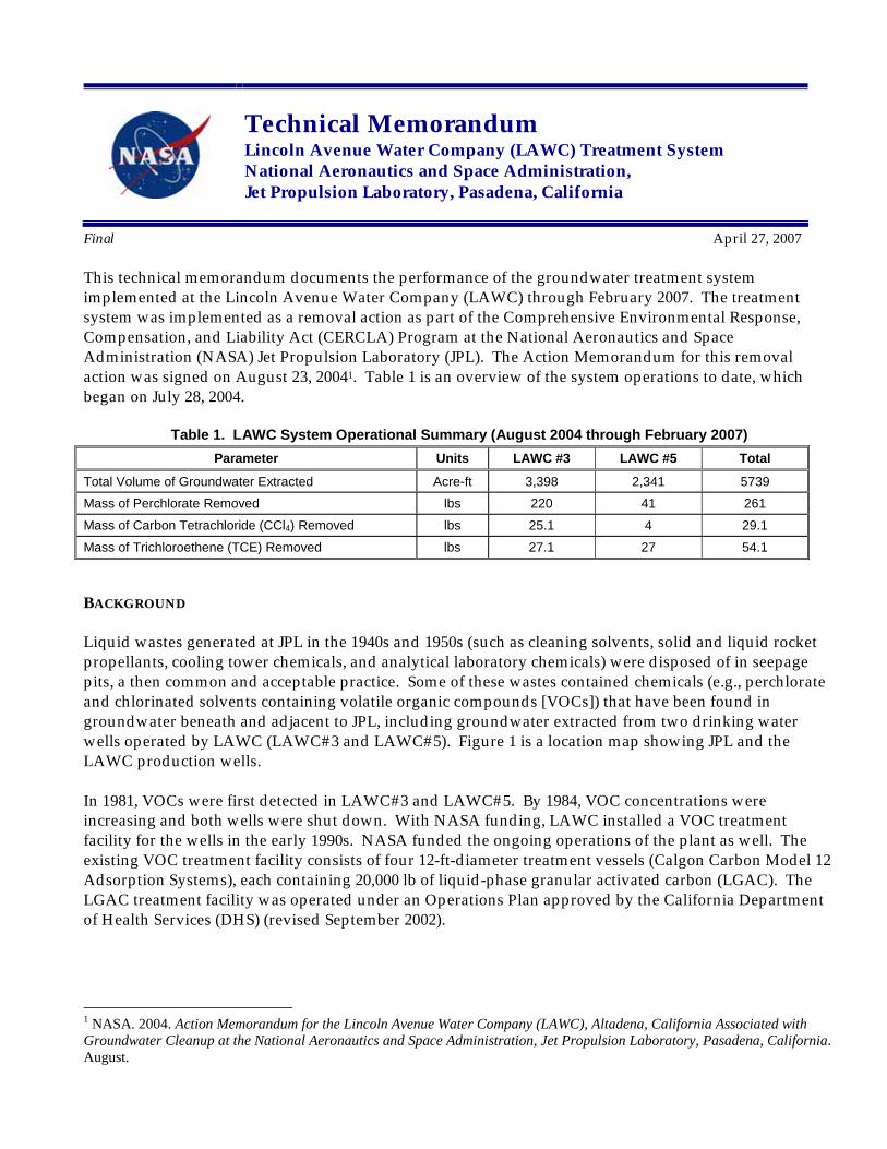
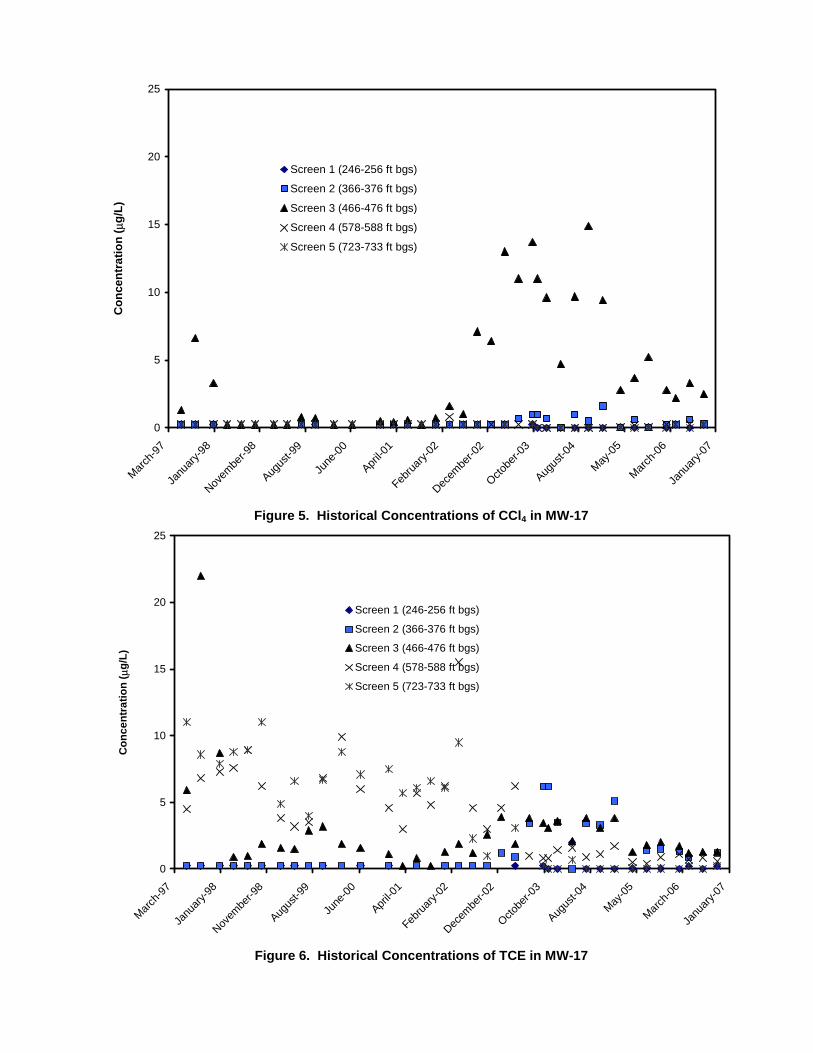
LAWC#3, LAWC#5, AND MW-17 Table 2 summarizes minimum and maximum carbon tetrachloride (CCl4), trichloroethene (TCE), and perchlorate concentrations detected in LAWC#3 and LAWC#5. Figures 3 and 4 are graphs of historical concentrations in extracted groundwater samples collected from LAWC#3 and LAWC#5. Trends in LAWC#3 indicated a general decrease in TCE concentrations and a general increase in CCl4 and perchlorate concentrations. No clear trends were observed in LAWC#5. NASA-JPL has a multiport monitoring well, MW-17, located less than 500 ft upgradient of LAWC#3 (see Figure 1). Table 2 also summarizes CCl4, TCE, and perchlorate detections in samples collected from the five sampling screens (discrete sampling intervals) of MW-17. This monitoring well serves as the best available indicator of near-future (1-2 years) concentrations that may be observed in LAWC wells. Figures 5, 6, and 7 provide the historical concentrations of CCl4, TCE, and perchlorate in MW-17. Sampling of MW-17 (Screen 3) indicated a decreasing perchlorate concentration trend, with concentrations below 100 µg/L throughout 2006. The highest perchlorate concentration detected in MW-17 (Screen 3) was 209 µg/L in July/August 2003.
Table 2. Summary of Highest Chemical Concentrations Historically Detected LAWC#3 LAWC#5 MW-17 (Maximum Levels) Regulatory
Analyte Units LevelMin Max Min Max S1 S2 S3 S4 S5 CCl4 µg/L <0.5 4 <0.5 1.9 <0.5 1.6 14.9 0.8 <0.5 0.5 TCE µg/L <0.5 20.8 <0.5 57.4 2 6.2 23 15.5 16 5
Perchlorate µg/L <4.0 46 <4.0 15 <4.0 17 209 17 22 6 Note: MW-17 is a multiport monitoring well containing five separate sampling screens, denoted S1 through S5

Octobe
r-95
June
-96
Februa
ry-97
Octobe
r-97
June
-98
Februa
ry-9 9
Octobe
r-99
June
-00
Februa
ry-01
Octobe
r-01
June
-02
Februa
ry-03
Octobe
r-03
June
-04
Februa
ry-05
Octobe
r-05
June
-06
Februa
ry-07
Octobe
r-95
June
-96
Februa
ry-97
Octobe
r-97
June
-98
Februa
ry-99
Octobe
r-99
June
-00
Februa
ry-01
Octobe
r-01
June
-02
Februa
ry-03
Octobe
r-03
June
-04
Februa
ry-05
Octobe
r-05
June
-06
Februa
ry-07
0. 0
5. 0
10. 0
15. 0
20. 0
25. 0
30. 0
35. 0
40. 0
45. 0
50. 0
Con
cent
ratio
n ( µ
g/L)
Perchl orat e
Car bon T e t r achl ori d e
TC E
Figure 3. Historical Concentrations of CCl4, TCE, and Perchlorate in LAWC#3
0. 0
5. 0
10. 0
15. 0
20. 0
25. 0
30. 0
35. 0
40. 0
45. 0
50. 0
Con
cent
ratio
n ( µ
g/L)
Per c hlor ate
C a rbo n T e trac hlor ide
TC E
Figure 4. Historical Concentrations of CCl4, TCE, and Perchlorate in LAWC#5
- 4 -
March-9
7
Janu
ary-98
Novem
ber-9
8
Augus
t-99
June
-00
April-0
1
Februa
ry-02
Decem
ber-0
2
Octobe
r-03
Augus
t-04
May-05
March-0
6
Janu
ary-07
March-9
7
Janu
ary-98
Novem
ber-9
8
Augus
t-9 9
June
-00
April-0
1
Februa
ry-02
Decem
ber-0
2
Octobe
r-03
Augus
t-04
May-05
March-0
6
Janu
ary-07
0
5
10
15
20
25
Con
cent
ratio
n ( µ
g/L)
Screen 1 (246-256 ft bgs)
Screen 2 (366-376 ft bgs)
Screen 3 (466-476 ft bgs)
Screen 4 (578-588 ft bgs)
Screen 5 (723-733 ft bgs)
Figure 5. Historical Concentrations of CCl4 in MW-17
0
5
10
15
20
25
Con
cent
ratio
n ( µ
g/L)
Screen 1 (246-256 ft bgs)
Screen 2 (366-376 ft bgs)
Screen 3 (466-476 ft bgs)
Screen 4 (578-588 ft bgs)
Screen 5 (723-733 ft bgs)
Figure 6. Historical Concentrations of TCE in MW-17
March-9
7
Janu
ary-98
Novem
ber-9
8
Augus
t-99
June
-00
April-0
1
Februa
ry-02
Decem
ber-0
2
Octobe
r-03
Augus
t-04
May-05
March-0
6
Janu
ary-07
0
50
100
150
200
250
Perc
hlor
ate
Con
cent
ratio
n ( µ
g/L) Screen 1 (246-256 ft bgs)
Screen 2 (366-376 ft bgs)
Screen 3 (466-476 ft bgs)
Screen 4 (578-588 ft bgs)
Screen 5 (723-733 ft bgs)
Figure 7. Historical Concentrations of Perchlorate in MW-17
ROUTINE MONITORING
Table 3 summarizes the routine monitoring schedule for the ion exchange and LGAC system. Analytical results from samples collected from LAWC#3 and LAWC#5 are presented in Figures 3 and 4, respectively.
Figure 8 shows perchlorate analytical results associated with the ion exchange system. Perchlorate broke through the lead IX vessel five times during 2006, but never through the second (“lag”) IX vessel. The system was shutdown in late January 2006 to implement improvements to the manifold to prevent channeling within the IX vessels, and the system was restarted in early March 2006.
Table 4 summarizes the LGAC changeout dates and frequency based on the 4th port analytical results. Carbon tetrachloride consistently breaks through prior to other chemicals. In 2006, typical breakthrough occurred between 48 and 180 operating days, with an overall average of 119 days.
Table 5 summarizes the LGAC effluent and combined effluent sampling results. These effluent samples have not contained detectable CCl4, TCE, PCE, or perchlorate at any time since startup in July 2004.
- 6 -

July-
04
Octobe
r-04
Decem
ber-0
4
Februa
ry-05
May-05
July-
05
Octobe
r-05
Decem
ber-0
5
Februa
ry-06
May-06
July-
06
Octobe
r-06
Decem
ber-0
6
Februa
ry-07
Table 3. Sampling Locations and Monitoring Schedule
Analyte Method LAW
C#3
LAW
C#5
IX In
fluen
t
Lead
IX E
fflue
nt
Lag
IX E
fflue
nt
LGA
C- 4
th P
ort (a
)
LGA
C-E
fflue
nt(a
)
Com
bine
dEf
fluen
t
CCl4 EPA 524.2 M M - - - W M M
TCE EPA 524.2 M M - - - W M M
PCE EPA 524.2 M M - - - W M M
Perchlorate EPA 314.0 M M W W W - - M
Nitrate EPA 300.0 - - M M M - - -
Total Coliform EPA 1604 M M - - - - M W
Heterotrophic Plate Count 9215B - - - - - - M W (a) Samples collected from each of the 4 LGAC vessels M = Monthly; W = Weekly Note: Sampling locations are shown on Figure 2.
0.0
5.0
10.0
15.0
20.0
25.0
30.0
35.0
40.0
Perc
hlor
ate
Con
cent
ratio
n (µ
g/L)
IX Influent Lead IX Effluent Lag IX Effluent
Figure 8. Ion Exchange System Performance

- 8 -
Table 4. Carbon Changeout Frequency Based on LGAC 4th Port VOC Sampling
Description 1st Vessel 2nd Vessel 3rd Vessel 4th Vessel
Date of 1st Changeout 12/14/2004 11/23/2004 3/22/2005 12/21/2004 Date of 2nd Changeout 7/19/2005 2/1/2005 7/26/2005 7/26/2005 Days between changeouts 217 70 126 217 Date of 3rd Changeout 11/22/2005 7/12/2005 11/15/2005 11/8/2005 Days between changeouts 126 161 112 105 Date of 4th Changeout 1/3/2006 11/1/2005 1/20/2006 1/20/2006 Days between changeouts 42 112 66 73 Date of 5th Changeout 5/31/2006 12/20/2005 3/9/2006 3/9/2006 Days between changeouts 148 49 48 48 Date of 6th Changeout 10/17/2006 3/9/2006 9/5/2006 8/29/2006 Days between changeouts 139 79 180 173 Date of 7th Changeout 9/5/2006 1/16/2007 12/19/2006 Days between changeouts 180 133 112 Date of 8th Changeout 12/26/2006 Days between changeouts 112 Average days between changeouts 134 109 111 121 Minimum days between changeouts 42 49 48 48 Maximum days between changeouts 217 180 180 217
(a) Changeout triggered after detection of VOCs, typically carbon tetrachloride, at the LGAC 4th Port

Table 5. Effluent Sampling Results
Date LGAC Effluent
VOCs(a) Combined Effluent(b)
08/03/04 ND ND 09/07/04 ND ND 10/05/04 ND ND 11/02/04 ND ND 12/07/04 ND ND 01/04/05 ND ND 02/01/05 ND ND 03/01/05 ND ND 04/05/05 ND ND 05/05/05 ND ND 06/07/05 ND ND 07/05/05 ND ND 08/02/05 ND ND 09/13/05 ND ND 10/04/05 ND ND 11/02/05 ND ND 12/06/05 ND ND 01/03/06 ND ND 02/07/06 ND ND 03/01/06 ND ND 04/07/06 ND ND 05/02/06 ND ND 06/06/06 ND ND 07/05/06 ND ND 08/01/06 ND ND 09/05/06 ND ND 10/03/06 ND ND 11/07/06 ND ND 12/05/06 ND ND 01/02/07 ND ND 02/05/07 ND ND
(a) TCE, CCl4, and PCE with detection limit of 0.5 µg/L from each of the 4 LGAC vessels effluent (b) TCE, CCl4, and PCE with detection limit of 0.5 µg/L and perchlorate with detection limit of 4.0 µg/L
ENTRAINED AIR INVESTIGATION On July 11, 2006, Siemens Water Technologies contracted an independent engineering consultant (Don Howard Engineering) to conduct an inspection of the LAWC production wells and treatment system. Attachment 1 contains a copy of the technical report submitted by Don Howard Engineering and Attachment 2 contains a transmittal from letter Siemens Water Technologies to LAWC referencing the inspection. During this inspection, entrained air was observed in the discharge line of each production well prior to entering the treatment system. It was also determined that entrained air was likely causing fluidization of the IX resin which resulted in water short circuiting the treatment vessels. This was evidenced by decreases in perchlorate removal efficiency across the lead IX vessel. The source of the
- 10 -
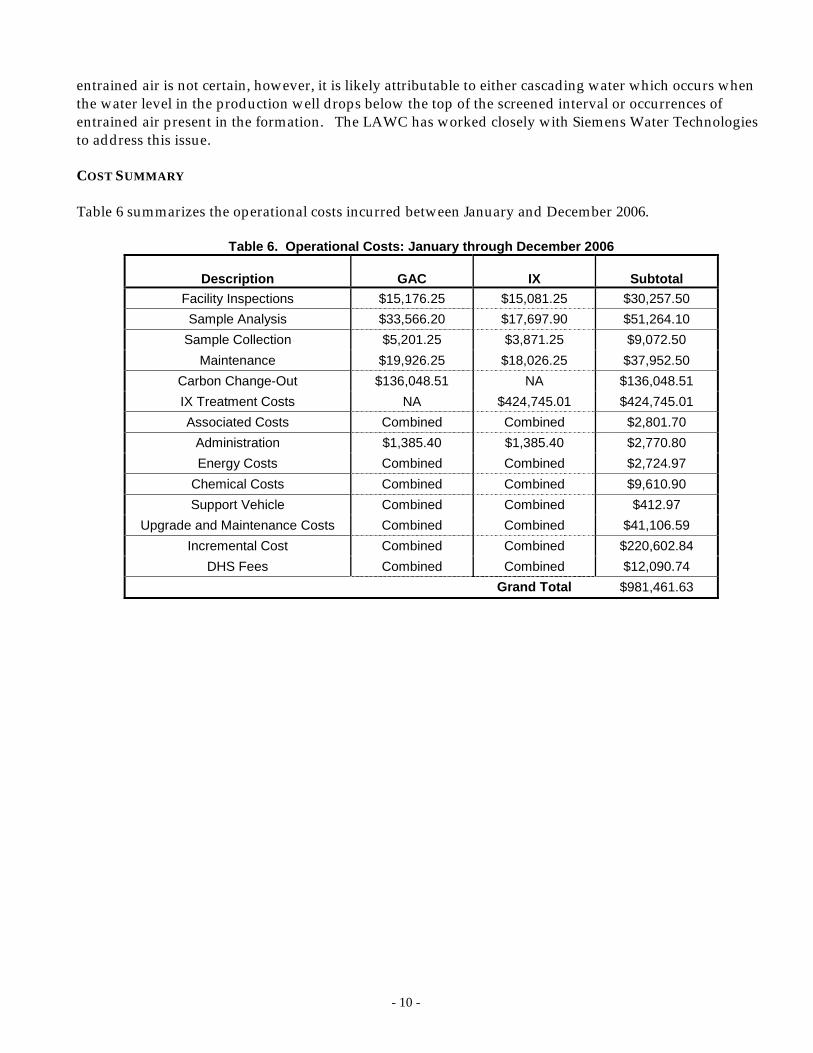
entrained air is not certain, however, it is likely attributable to either cascading water which occurs when the water level in the production well drops below the top of the screened interval or occurrences of entrained air present in the formation. The LAWC has worked closely with Siemens Water Technologies to address this issue. COST SUMMARY Table 6 summarizes the operational costs incurred between January and December 2006.
Table 6. Operational Costs: January through December 2006
Description GAC IX Subtotal Facility Inspections $15,176.25 $15,081.25 $30,257.50 Sample Analysis $33,566.20 $17,697.90 $51,264.10
Sample Collection $5,201.25 $3,871.25 $9,072.50 Maintenance $19,926.25 $18,026.25 $37,952.50
Carbon Change-Out $136,048.51 NA $136,048.51 IX Treatment Costs NA $424,745.01 $424,745.01 Associated Costs Combined Combined $2,801.70
Administration $1,385.40 $1,385.40 $2,770.80 Energy Costs Combined Combined $2,724.97
Chemical Costs Combined Combined $9,610.90 Support Vehicle Combined Combined $412.97
Upgrade and Maintenance Costs Combined Combined $41,106.59 Incremental Cost Combined Combined $220,602.84
DHS Fees Combined Combined $12,090.74 Grand Total $981,461.63

ATTACHMENT 1: INSPECTION REPORT FROM DON HOWARD ENGINEERING

July 19, 2006
Mr. Larry BurbachUS Filter—Environmental ServicesA Siemens Company14250 Gannet StreetLa Mirada, CA 90638
Dear Larry,
Per your request we have reviewed the data supplied by Lincoln Avenue Water Company ontheir Wells 3 and 5 to determine, if possible, the source of the air in the well water. The dataprovided included well completion reports, Southern California Edison pump efficiency tests,maintenance records, and videos logs. The following table is a synopsis of data for each wellfrom the California Department of Health Services Well Data Sheet dated 2004. This data is tomost recent data for each well.
Well DataItem Well 3 Well 5
Year Drilled 1924 1971Flow Rate in gpm 1080 1050Static Water Level in fbgs 216 212Pumping Water Level in fbgs 233 281Top of Perforations in fbgs 261 390Pump Setting in fbgs 385 340Depth in fbgs 593 588
On July 11, 2006 I inspected the water treatment system and wells at Lincoln Avenue WaterCompany. I observed air entrained in the discharge of each well prior to the treatment system.Air in the discharge of a well can be attributed to several things including cascading water,turbulence, and air entrained in the aquifer. The most common cause of entrained air iscascading water. Cascading water occurs when the static and/or pumping level drops below thetop of the perforations and groundwater continues to flow into the well through the exposedperforations running down the sides of the well casing; thus, causing turbulence at the waterinterface. Turbulence can also occur when the entrance velocity into the well is too high.Finally, air can become entrained in the aquifer during groundwater recharge operations.
Under normal operating conditions air in the discharge is not a significant problem and willdissipate in the storage facilities; however, the water from Wells 3 and 5 goes directly to aPerchlorate treatment system and then to a Volatile Organic Chemical (VOC) treatment system.The entrained air is reducing the efficiency of the perchlorate treatment process.
In addition both wells were drilled using the cable tool method and are prone to sanding. Ascable tool wells age the perforations tend to enlarge as a result of rusting. When this happenslarger particles dislodge from the formation. During the most recent resin change-out US Filterfound particles up to marble size in the bag filters.
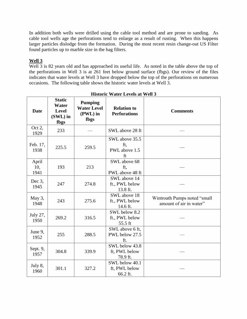
Well 3Well 3 is 82 years old and has approached its useful life. As noted in the table above the top ofthe perforations in Well 3 is at 261 feet below ground surface (fbgs). Our review of the filesindicates that water levels at Well 3 have dropped below the top of the perforations on numerousoccasions. The following table shows the historic water levels at Well 3.
Historic Water Levels at Well 3
Date
StaticWaterLevel
(SWL) infbgs
PumpingWater Level
(PWL) infbgs
Relation toPerforations Comments
Oct 2,1929 233 — SWL above 28 ft —
Feb. 17,1938 225.5 259.5
SWL above 35.5ft,
PWL above 1.5ft
—
April10,
1941193 213
SWL above 68ft,
PWL above 48 ft—
Dec 3,1945 247 274.8
SWL above 14ft., PWL below
13.8 ft.—
May 3,1948 243 275.6
SWL above 18ft., PWL below
14.6 ft.
Wintroath Pumps noted “small amount of air in water”
July 27,1950 269.2 316.5
SWL below 8.2ft., PWL below
55.5 ft—
June 9,1952 255 288.5
SWL above 6 ft,PWL below 27.5
ft.—
Sept. 9,1957 304.8 339.9
SWL below 43.8ft, PWL below
78.9 ft.—
July 8,1960 301.1 327.2
SWL below 40.1ft, PWL below
66.2 ft.—

Date
StaticWaterLevel
(SWL) infbgs
PumpingWater Level
(PWL) infbgs
Relation toPerforations Comments
June 9,1980 240 267.6
SWL above 21ft., PWL below
6.6 ft.—
August6, 1982 273 305
SWL below 12ft., PWL below
44 ft.
In a letter dated Dec 28, 1982 fromRoscoe Moss Company commentsare made as to age of Well 3 and
suggests reducing the pumping rateto minimize the sanding and
pumping of air.Sept.25,
2001252.8 — SWL above 8.2
ft. —
We noted during the data review that the air entrainment problem was mentioned on severaloccasions; first in 1948 by Wintroath Pump and next in 1982 by Roscoe Moss, attached.
As previously stated, as cable tool wells age the perforations tend to enlarge as a result ofrusting. When this happens larger particles dislodge from the formation. We viewed the postwire brush video survey performed by Pacific Surveys on September 25, 2001. While the videolog shows the casing to be in relatively good condition it confirms that the perforations areirregular in shape and enlarged. Based on our observations of the video survey in 2001 we haveestimated the current entrance velocity in the well to be 0.12 fps. The recommended entrancevelocity is 0.1 fps. Entrance velocity in excess of 0.1 fps can result in turbulence.
Well 5Well 5 is 35 years old. The top of the perforations at Well 5 are located at 390 fbgs, this issignificantly lower than the perforations in Well 2. The records for Well 5 do not refer to airentrainment and the data indicate that the water levels have not dropped below the top of theperforations. The following table shows historic static and pumping water levels at Well 5.
Historic Water Levels at Well 5
Date Static Water Level(SWL) in fbgs
Pumping Water Level(PWL) in fbgs Relation to Perforations
July 21,1971 245 347 SWL above 145 ft., PWL
above 43 ft.March 11,
1981 — 333.6 PWL above 56.4 ft.
April 8,1982 281 339.9 SWL above 109 ft., PWL
above 50.1 ft.Nov. 1,2004 212 281 SWL above 178 ft., PWL
above 109 ft.


ATTACHMENT 2: TRANSMITTAL LETTER FROM SIEMENS WATER TECHNOLOGIES

Siemens Water Technologies
Siemens Water Technologies Corp. 14250 Gannet St. La Mirada, CA 90638
Larry K. Burbach Western Regional Sales Manager562-413-4357
July 20, 2006 Mr. Bob Hayward General Manager Lincoln Avenue Water Company 564 West Harriet Street Altadena, California 91001 Reference: GAC – Perchlorate System Recommendations Dear Bob: We would like to thank you for your confidence in Siemens Water Technologies. Our objective continues to be providing you the best service and technologies available. On July 11, we hired Don Howard Engineering as our consultant to provide an independent engineering audit of the equipment and well log data. I have enclosed his findings for your review. The well sand and debris fouling that we experienced in both the carbon and resin beds during the initial stages of the program was eliminated with the installation of the bag filters. Although this was a necessary addition, it did not solve the bed displacement and short run issues in the perchlorate vessels. In reviewing similar GAC – perchlorate system configurations, the one key difference is the significant volume of entrained air in the water from the wells. It is believed that the age of the current wells is probably the key factor contributing to the entrained air in the treatment system – and short of replacing these wells, we can only attempt to minimize the effects on the resin beds by changing the flow so that the carbon beds will precede the perchlorate treatment. GAC beds are much more stable and virtually impervious to displacement from entrained air. It is believed that most of the air could be eliminated across the GAC treatment system – allowing much less air to reach the perchlorate system – where resin can be easily ‘fluidized’ during the turbulence caused by high volumes of air and water during the hard starts’ we routinely experience in this system – and to a lesser extent throughout the service cycle. Again this would only be a procedure that might minimize the impact of the entrained air but is not a substitute for fixing the root cause of the entrained air. For consistent resin performance, the bed ‘ion exchange zone’ must remain static and level across the diameter of the vessel - so that exhausted resin remains at the top of the bed –

Siemens Water Technologies July 20, 2006
and short circuiting or channeling of the influent water does not occur. Once the resin bed has been disturbed, the spent resin normally at the top of the bed will be mixed throughout the resin bed – eventually causing early breakthrough. As you are aware during the past three plus years, Siemens Water Technologies, formerly known as US Filter, has diligently worked to maintain the performance of the perchlorate treatment system at your Harriet Street Treatment Facility within the expectations of the resin throughput capacity developed during the design of the system. Operation of the system during the past three years has resulted in continued concerns maintaining a static – level resin bed within each of the vessels during service. During that time the following equipment modifications/additions and media replacement services have performed without charge to LAWC.
1. Inlet distribution headers were upgraded to improve flow distribution and eliminate resin displacement within the vessels. Vessels we disinfected and re-bedded after completion of header installation.
2. Three inlet cartridge filter systems were provided for your operators to install to eliminate the sand and debris from the well from fouling the treatment beds.
3. Both lead and lag perchlorate vessels have been re-bedded with new resin – total of 1200 ft3 of R&H PWA-2 – the last lead bed replacement occurring after less than 20% of the bed capacity had been utilized.
4. Recently hired an independent Engineering Firm to provide an audit of the two supply wells and recommendations as to how best to eliminate the entrained air from the system – a problem we believe is the root cause of the resin bed displacement / fluidization during system operation – which has caused the ‘short run’ phenomenon we have experienced from the outset with our perchlorate resin.
The total expense for the equipment and resin supplied to date is $187,000. This figure does not include the additional service hours and disinfection procedures required throughout this process. With your approval, we will submit a detailed invoice for this total in the next 30 days. We will continue to work with you going forward to mitigate these issues – to include providing engineering support to reroute the influent flow from the filters to the carbon beds, followed by the resin beds. If you have any questions, please contact me at your convenience. Thank you. Larry K Burbach Siemens Water Technologies Western Region Sales Manager
Related Documents